JP7074672B2 - Systems and methods for augmented reality near-eye wearable displays - Google Patents
Systems and methods for augmented reality near-eye wearable displays Download PDFInfo
- Publication number
- JP7074672B2 JP7074672B2 JP2018531339A JP2018531339A JP7074672B2 JP 7074672 B2 JP7074672 B2 JP 7074672B2 JP 2018531339 A JP2018531339 A JP 2018531339A JP 2018531339 A JP2018531339 A JP 2018531339A JP 7074672 B2 JP7074672 B2 JP 7074672B2
- Authority
- JP
- Japan
- Prior art keywords
- light
- eye
- lens
- display
- optical
- Prior art date
- Legal status (The legal status is an assumption and is not a legal conclusion. Google has not performed a legal analysis and makes no representation as to the accuracy of the status listed.)
- Active
Links
- 230000003190 augmentative effect Effects 0.000 title claims description 11
- 238000000034 method Methods 0.000 title description 7
- 230000003287 optical effect Effects 0.000 claims description 67
- 230000000295 complement effect Effects 0.000 claims description 2
- 230000005540 biological transmission Effects 0.000 claims 1
- 210000001508 eye Anatomy 0.000 description 27
- 210000001747 pupil Anatomy 0.000 description 14
- 239000010409 thin film Substances 0.000 description 9
- 210000005252 bulbus oculi Anatomy 0.000 description 7
- 230000000007 visual effect Effects 0.000 description 7
- 238000000926 separation method Methods 0.000 description 5
- 238000012937 correction Methods 0.000 description 4
- 238000010586 diagram Methods 0.000 description 4
- 238000001228 spectrum Methods 0.000 description 4
- 239000003086 colorant Substances 0.000 description 3
- 210000001525 retina Anatomy 0.000 description 3
- 239000007787 solid Substances 0.000 description 3
- 230000004308 accommodation Effects 0.000 description 2
- 230000004075 alteration Effects 0.000 description 2
- 230000000694 effects Effects 0.000 description 2
- 238000005516 engineering process Methods 0.000 description 2
- 238000003384 imaging method Methods 0.000 description 2
- 239000000463 material Substances 0.000 description 2
- 238000012986 modification Methods 0.000 description 2
- 230000004048 modification Effects 0.000 description 2
- 238000000206 photolithography Methods 0.000 description 2
- 230000008569 process Effects 0.000 description 2
- 230000004434 saccadic eye movement Effects 0.000 description 2
- 239000004065 semiconductor Substances 0.000 description 2
- 229910001218 Gallium arsenide Inorganic materials 0.000 description 1
- 230000009471 action Effects 0.000 description 1
- 230000009286 beneficial effect Effects 0.000 description 1
- 239000011248 coating agent Substances 0.000 description 1
- 238000000576 coating method Methods 0.000 description 1
- 230000008878 coupling Effects 0.000 description 1
- 238000010168 coupling process Methods 0.000 description 1
- 238000005859 coupling reaction Methods 0.000 description 1
- 230000001419 dependent effect Effects 0.000 description 1
- 230000003292 diminished effect Effects 0.000 description 1
- 230000005284 excitation Effects 0.000 description 1
- 239000000835 fiber Substances 0.000 description 1
- 210000001061 forehead Anatomy 0.000 description 1
- 239000011521 glass Substances 0.000 description 1
- 238000004519 manufacturing process Methods 0.000 description 1
- 238000005457 optimization Methods 0.000 description 1
- 230000005693 optoelectronics Effects 0.000 description 1
- 230000035699 permeability Effects 0.000 description 1
- 229920000642 polymer Polymers 0.000 description 1
- 230000001681 protective effect Effects 0.000 description 1
- 238000006467 substitution reaction Methods 0.000 description 1
- 238000001429 visible spectrum Methods 0.000 description 1
Images


Classifications
-
- G—PHYSICS
- G02—OPTICS
- G02B—OPTICAL ELEMENTS, SYSTEMS OR APPARATUS
- G02B27/00—Optical systems or apparatus not provided for by any of the groups G02B1/00 - G02B26/00, G02B30/00
- G02B27/01—Head-up displays
- G02B27/017—Head mounted
- G02B27/0172—Head mounted characterised by optical features
-
- G—PHYSICS
- G02—OPTICS
- G02B—OPTICAL ELEMENTS, SYSTEMS OR APPARATUS
- G02B27/00—Optical systems or apparatus not provided for by any of the groups G02B1/00 - G02B26/00, G02B30/00
- G02B27/0093—Optical systems or apparatus not provided for by any of the groups G02B1/00 - G02B26/00, G02B30/00 with means for monitoring data relating to the user, e.g. head-tracking, eye-tracking
-
- G—PHYSICS
- G02—OPTICS
- G02B—OPTICAL ELEMENTS, SYSTEMS OR APPARATUS
- G02B27/00—Optical systems or apparatus not provided for by any of the groups G02B1/00 - G02B26/00, G02B30/00
- G02B27/01—Head-up displays
- G02B27/0179—Display position adjusting means not related to the information to be displayed
-
- G—PHYSICS
- G02—OPTICS
- G02B—OPTICAL ELEMENTS, SYSTEMS OR APPARATUS
- G02B27/00—Optical systems or apparatus not provided for by any of the groups G02B1/00 - G02B26/00, G02B30/00
- G02B27/42—Diffraction optics, i.e. systems including a diffractive element being designed for providing a diffractive effect
- G02B27/4205—Diffraction optics, i.e. systems including a diffractive element being designed for providing a diffractive effect having a diffractive optical element [DOE] contributing to image formation, e.g. whereby modulation transfer function MTF or optical aberrations are relevant
-
- G—PHYSICS
- G02—OPTICS
- G02B—OPTICAL ELEMENTS, SYSTEMS OR APPARATUS
- G02B5/00—Optical elements other than lenses
- G02B5/18—Diffraction gratings
- G02B5/1842—Gratings for image generation
-
- G—PHYSICS
- G06—COMPUTING; CALCULATING OR COUNTING
- G06T—IMAGE DATA PROCESSING OR GENERATION, IN GENERAL
- G06T19/00—Manipulating 3D models or images for computer graphics
- G06T19/006—Mixed reality
-
- G—PHYSICS
- G02—OPTICS
- G02B—OPTICAL ELEMENTS, SYSTEMS OR APPARATUS
- G02B27/00—Optical systems or apparatus not provided for by any of the groups G02B1/00 - G02B26/00, G02B30/00
- G02B27/01—Head-up displays
- G02B27/0101—Head-up displays characterised by optical features
- G02B2027/0123—Head-up displays characterised by optical features comprising devices increasing the field of view
-
- G—PHYSICS
- G02—OPTICS
- G02B—OPTICAL ELEMENTS, SYSTEMS OR APPARATUS
- G02B27/00—Optical systems or apparatus not provided for by any of the groups G02B1/00 - G02B26/00, G02B30/00
- G02B27/01—Head-up displays
- G02B27/0101—Head-up displays characterised by optical features
- G02B2027/0138—Head-up displays characterised by optical features comprising image capture systems, e.g. camera
-
- G—PHYSICS
- G02—OPTICS
- G02B—OPTICAL ELEMENTS, SYSTEMS OR APPARATUS
- G02B27/00—Optical systems or apparatus not provided for by any of the groups G02B1/00 - G02B26/00, G02B30/00
- G02B27/01—Head-up displays
- G02B27/017—Head mounted
- G02B27/0172—Head mounted characterised by optical features
- G02B2027/0174—Head mounted characterised by optical features holographic
-
- G—PHYSICS
- G02—OPTICS
- G02B—OPTICAL ELEMENTS, SYSTEMS OR APPARATUS
- G02B27/00—Optical systems or apparatus not provided for by any of the groups G02B1/00 - G02B26/00, G02B30/00
- G02B27/01—Head-up displays
- G02B27/017—Head mounted
- G02B2027/0178—Eyeglass type
-
- G—PHYSICS
- G02—OPTICS
- G02B—OPTICAL ELEMENTS, SYSTEMS OR APPARATUS
- G02B27/00—Optical systems or apparatus not provided for by any of the groups G02B1/00 - G02B26/00, G02B30/00
- G02B27/01—Head-up displays
- G02B27/0179—Display position adjusting means not related to the information to be displayed
- G02B2027/0187—Display position adjusting means not related to the information to be displayed slaved to motion of at least a part of the body of the user, e.g. head, eye
Description
関連出願の相互参照
本出願は、2015年12月18日出願の米国仮特許出願第62/269,510号の優先権を主張するものであり、上記仮特許出願は、参照によりその全体が本出願に援用される。
Cross-reference to related applications This application claims the priority of US Provisional Patent Application No. 62 / 269,510 filed December 18, 2015, and the above provisional patent application is in its entirety by reference. Incorporated in the application.
本開示の一態様は、概してウェアラブル電子機器に関し、より詳細には拡張現実(augmented reality:AR)ニアアイウェアラブルディスプレイに関する。 One aspect of the present disclosure relates generally to wearable electronic devices, and more particularly to augmented reality (AR) near-eye wearable displays.
ウェアラブル光学電子装置は、集積回路及びディスプレイのサイズ、並びに関連するコストが縮小するに従って、一般化している。ウェアラブル光学電子装置は、多数の市販、軍事及び消費者向け用途を有する。従来のニアアイウェアラブルディスプレイによる解決策は、ユーザの快適さ又は審美性を考慮しない、煩わしく低解像度のアプローチを使用することが多い。 Wearable optics are becoming more common as the size of integrated circuits and displays, as well as the associated costs, shrinks. Wearable optics have a number of commercial, military and consumer applications. Traditional near-eye wearable display solutions often use a cumbersome, low-resolution approach that does not consider user comfort or aesthetics.
本明細書中の実施形態は、添付の図面の図において、限定ではなく例示として図示されており、これらの図では、同様の参照番号は同様の要素を示す。本開示中における、本発明の「ある(an)」又は「一(one)」実施形態に対する言及は、必ずしも1つの同一の実施形態に対するものではなく、これらの言及は「少なくとも1つ(at least one)」を意味していることに留意されたい。また、図面を簡潔にし、また図面の総数を低減するために、ある1つの所与の図を用いて本発明の2つ以上の実施形態の特徴を図示する場合があり、また、ある1つの所与の実施形態にとって、このような図中の全ての要素が必要なわけではない場合がある。 Embodiments herein are illustrated as illustrations, but not limitations, in the accompanying drawings, in which similar reference numbers indicate similar elements. References in the present disclosure to "an" or "one" embodiments of the invention are not necessarily to one and the same embodiment, and these references are "at least one". Note that it means "one)". Also, in order to simplify the drawings and reduce the total number of drawings, one given figure may be used to illustrate the features of two or more embodiments of the invention, and also one. Not all elements in such a figure may be required for a given embodiment.
これより、添付の図面を参照していくつかの実施形態を説明する。態様が明示的に定義されていない場合は常に、本開示の範囲は図示されている複数の部分のみに限定されず、これらの部分は単に説明を目的としたものである。また、数多くの詳細を記載するものの、いくつかの実施形態はこれらの詳細を用いずに実践され得ることが理解される。他の例では、公知の回路、構造及び技法は、本説明の理解を不明瞭にしないよう、詳細に示されていない。 Hereinafter, some embodiments will be described with reference to the accompanying drawings. Whenever an embodiment is not explicitly defined, the scope of the present disclosure is not limited to the plurality of parts illustrated, and these parts are for illustration purposes only. It is also understood that some embodiments can be practiced without these details, although many details are given. In other examples, known circuits, structures and techniques are not shown in detail so as not to obscure the understanding of this description.
本発明者らは、形状因子が小さく、また例えば美観上満足できるものである消費者向け眼鏡フレームでの使用に好適な、高解像度の拡張現実ニアアイウェアラブルディスプレイの必要を理解している。本明細書に記載の実施形態は、このような拡張現実ニアアイウェアラブルディスプレイを提供する。 We understand the need for a high resolution augmented reality near eyewearable display suitable for use in consumer spectacle frames that have small shape factors and are, for example, aesthetically pleasing. The embodiments described herein provide such an augmented reality near eyewearable display.
本明細書中の実施形態は、1つ又は複数の発光型ディスプレイ素子(本明細書ではイメージャ又は光変調器と呼ばれる)を備えてよく、これらは一般的な眼鏡フレームのブリッジ又はフレームに埋め込むことができる。本明細書に記載の実施形態の1つ又は複数のレンズは、透過型回折光学素子(TDOE)及び部分反射型回折光学素子(RDOE)を備えてよい。ディスプレイ出力はレンズ素子に向かって配向され、次に回折素子が上記出力を視認者のアイボックスに向けて配向する。 Embodiments herein may include one or more light emitting display elements (referred to herein as imagers or light modulators), which are embedded in a bridge or frame of a typical spectacle frame. Can be done. One or more lenses of the embodiments described herein may include a transmissive diffractive optical element (TDOE) and a partially reflective diffractive optical element (RDOE). The display output is oriented towards the lens element, which in turn directs the output towards the viewer's eyebox.
一実施形態では、拡張現実(AR)ディスプレイシステム(本明細書ではARウェアラブルディスプレイと呼ばれる)を提供する能力を備えた、消費者向け眼鏡の一般的な(又は典型的な)見た目のセットとして構成できる、ニアアイウェアラブルディスプレイを開示する。一実施形態では、上記眼鏡は湾曲視認レンズを有する。 In one embodiment, it is configured as a general (or typical) appearance set of consumer eyeglasses with the ability to provide an augmented reality (AR) display system (referred to herein as an AR wearable display). Disclose a near-eye wearable display that can be done. In one embodiment, the spectacles have a curved visual recognition lens.
一実施形態では、本開示のARウェアラブルディスプレイは、眼鏡の通常の(又は典型的な)見た目のセットのフレームシャーシ内に埋め込まれた、1つ又は複数の発光型マイクロピクセル光変調器を使用し、上記マイクロピクセル光変調器は、独立してアドレス指定できるフルカラー発光型マイクロピクセルのアレイと、上記発光型マイクロピクセルアレイを駆動するよう構成された電子回路とを備える、光電子半導体デバイスであり、これらは全て、眼鏡フレーム内に埋め込むために十分に小さい体積の単一の半導体チップ又はパッケージ内に集積される。 In one embodiment, the AR wearable display of the present disclosure uses one or more light emitting micropixel light modulators embedded within a frame chassis of a normal (or typical) appearance set of eyeglasses. The micropixel light modulator is a photoelectron semiconductor device comprising an array of independently addressable full-color light emitting micropixels and an electronic circuit configured to drive the light emitting micropixel array. Are all integrated in a single semiconductor chip or package with a volume small enough to be embedded in the spectacle frame.
本明細書中の実施形態は、上述の光変調式発光型ディスプレイ素子の使用に限定されないこと、並びにOLED又は好適な電気的及び光学的特徴を有する同様のディスプレイ素子といったいずれの様式の電子ディスプレイ素子を用いてよく、これらは本開示の実施形態に関するいずれの請求項の精神及び範囲内であることを明記しておく。 Embodiments herein are not limited to the use of the photomodulated light emitting display elements described above, and any form of electronic display element such as an OLED or similar display element with suitable electrical and optical characteristics. It is noted that these are within the spirit and scope of any of the claims relating to the embodiments of the present disclosure.
1つの例示的実施形態では、ARウェアラブルディスプレイ眼鏡のフレーム内に埋め込まれた発光型マイクロピクセル光変調器デバイスは、量子フォトニックイメージャ(Quantum Photonic Imager)、即ち「QPI(登録商標)」イメージャをベースとしてよい。QPI(登録商標)は、 Ostendo Technologies, Inc.の登録商標である。H. El‐Ghorouryらが2010年3月19日に出願した米国特許第8,049,231号を参照されたい。これは、高解像度GaN‐GaAs積層ピクセルアレイの背面に集積された電源及び論理回路を有し、またピクセル積層体の上部に直接集積された超小型光学部品層を有する、超小型発光型固体光放出構造体技術である。この形態のイメージャは、極めて小さな体積しか占有しない、高電力効率ディスプレイを形成する。 In one exemplary embodiment, the light emitting micropixel light modulator device embedded within the frame of an AR wearable display eyeglass is based on a Quantum Photonic Imager, or "QPI®" imager. May be. QPI® is described by Ostendo Technologies, Inc. Is a registered trademark of. H. See US Pat. No. 8,049,231 filed by El-Ghorory et al. On March 19, 2010. It has an integrated power supply and logic circuit on the back of a high resolution GaN-GaAs stacked pixel array, and also has an ultra-compact optical component layer integrated directly on top of the pixel laminate, ultra-compact luminescent solid-state light. Release structure technology. This form of imager forms a high power efficiency display that occupies a very small volume.
本明細書に記載の実施形態と共に使用するために好適な、例示的なQPIイメージャ(超小型発光型固体光放出ディスプレイ素子)としては、限定するものではないが、米国特許第7,623,560号;米国特許第7,829,902号;米国特許第8,567,960号;米国特許第7,767,479号;米国特許第8,049,231号;米国特許第8,243,770号に開示されているものが挙げられ、これらの特許はそれぞれ「Quantum Photonic Imagers and Methods of Fabrication Thereof」という名称であり、本出願人に譲渡されており、各特許の内容全体が参照により本出願に援用される。 An exemplary QPI imager (ultra-compact light emitting solid light emitting display element) suitable for use with the embodiments described herein is, but is not limited to, US Pat. No. 7,623,560. No.; US Pat. No. 7,829,902; US Pat. No. 8,567,960; US Pat. No. 7,767,479; US Pat. No. 8,049,231; US Pat. No. 8,243,770; Each of these patents is named "Quantum Photonic Images and Methods of Fabrication Thereof" and has been transferred to the applicant, and the entire contents of each patent are applied by reference. Incorporated in.
上述のQPIイメージャは、全ての必要なディスプレイ駆動回路構成を含む単一の発光型ディスプレイデバイスにおいて、高い輝度、非常に高速の光の多色強度、及び空間変調能力を特徴とする。本明細書に記載の実施形態の文脈において、用語「イメージャ」及び「光変調器デバイス」は、発光型マイクロスケール固体光(solid state light:SSL)放出ピクセルのアレイを備える光電子デバイスを包含することを意図したものである。このようなデバイスのSSL放出ピクセルは、発光ダイオード(LED)、又はレーザダイオード(LD)、又は発光型マイクロスケールピクセルアレイがその上に形成された若しくは埋め込まれたCMOS回路内に内包された駆動回路構成によってそのオン・オフ状態が制御されるいずれの固体光放出構造体であってよい。 The QPI imager described above features high luminance, very fast multicolor intensity of light, and spatial modulation capability in a single light emitting display device that includes all the required display drive circuit configurations. In the context of the embodiments described herein, the terms "imager" and "light modulator device" include an optoelectronic device comprising an array of emission microscale solid state (SSL) emission pixels. Is intended. The SSL emission pixels of such a device are a light emitting diode (LED), or a laser diode (LD), or a drive circuit in which a light emitting microscale pixel array is encapsulated in a CMOS circuit formed or embedded on it. It may be any solid light emitting structure whose on / off state is controlled by the configuration.
QPIイメージャの発光性マイクロスケールピクセルアレイ内のピクセルは、駆動CMOS回路構成によって空間、色、時間的に個々にアドレス指定可能であり、これによりQPIイメージャは、空間、色、時間的に変調された光を放出できる。QPIイメージャが放出する複数の色が、同一のピクセルアパーチャを共有すると有益である。QPIイメージャは、コリメートされた(又は非ランバート)光を、約±5°~約±45°の発散角度で放出する。QPIイメージャの発光性アレイを構成するピクセルのサイズは典型的にはおよそ5~20マイクロメートルであり、このデバイスの典型的な発光表面積は、およそ15~150平方ミリメートルとなる。QPIイメージャは、その発光性ピクセルアレイと上記イメージャの物理的縁部との間に最小の間隙を備えるように設計でき、これにより、多数のQPIイメージャを傾斜させて、任意のサイズの表示領域を生成できる。 The pixels in the luminescent microscale pixel array of the QPI imager can be individually addressed in space, color, and time by the drive CMOS circuit configuration, which causes the QPI imager to be spatially, color, and temporally modulated. Can emit light. It is beneficial for multiple colors emitted by the QPI imager to share the same pixel aperture. The QPI imager emits collimated (or non-Lambert) light at a divergence angle of about ± 5 ° to about ± 45 °. The size of the pixels that make up the light emitting array of the QPI imager is typically about 5 to 20 micrometers, and the typical light emitting surface area of this device is about 15 to 150 square millimeters. The QPI imager can be designed to have a minimum gap between its luminescent pixel array and the physical edges of the imager, thereby tilting a large number of QPI imagers to provide a display area of any size. Can be generated.
投影に関わる距離(投射距離)が比較的小さくなるため、QPIイメージャを用いて投影されたディスプレイを、大きな電力を必要とすることなく、極めて高輝度のものとすることができる。上述の米国特許のQPIイメージャの微小光学素子及び集束モジュールは明らかに、非直線状投影表面及び投射距離を考慮して設計される。当然のことながら、QPIイメージャを、イメージャ若しくは光変調器として、又はイメージャ若しくは光変調器内で使用することが理想的であるものの、本明細書中の実施形態はそのように限定されず、望ましい場合には、本開示のイメージャ若しくは光変調器として、又は本開示のイメージャ若しくは光変調器内で、他のイメージャを使用してもよい。 Since the distance involved in projection (projection distance) is relatively small, the display projected using the QPI imager can be made extremely bright without requiring a large amount of electric power. The US patented QPI Imager micro-optics and focusing modules described above are clearly designed with non-linear projection surfaces and projection distances in mind. Of course, although it is ideal to use the QPI imager as an imager or light modulator, or within an imager or light modulator, the embodiments herein are not so limited and are preferred. In some cases, other imagers may be used as the imagers or light modulators of the present disclosure, or within the imagers or light modulators of the present disclosure.
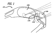
図1に示すように、少なくとも2つの発光型マイクロピクセル光変調器デバイス110a、110bを、眼鏡フレーム100のブリッジ部分内に埋め込んでよく、少なくとも1つの上記デバイスが各側に存在し、また各デバイスは、その発光アパーチャ光軸が、それぞれの側の眼鏡レンズ120a、120bに向かって配向されるように位置決めされる。
As shown in FIG. 1, at least two light emitting micropixel
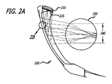
各光変調器デバイスの発光アパーチャは、発光型マイクロピクセル光変調器デバイスが眼鏡ブリッジ部分の体積範囲内に完全に埋め込まれた状態を維持しながら、マイクロピクセル光変調器の光軸を、それぞれの側の眼鏡レンズに向かって配向するのを補助する、光学「カバー」を含んでよい。一実施形態では、各光変調器デバイスに関連する光学カバーは、光変調器デバイス及びその光学カバーを眼鏡ブリッジ部分の体積範囲内に完全に埋め込むことができるよう、体積が小さい。一実施形態では、光変調器デバイスを眼鏡ブリッジ部分の体積範囲内に完全に埋め込むことができるような体積効率を達成するために、光学カバーを透過型回折光学素子(本明細書中では「TDOE」と呼ぶ)として提供してよい。光変調器デバイスを回折光学素子と組み合わせる、ここで議論される構成により、湾曲したレンズを有する眼鏡を備える拡張現実ウェアラブルディスプレイを提供できる。よって、顔に近接してフィットする眼鏡フレームを、拡張現実ニアアイデバイスとして提供できる。TDOE光学カバーを有する眼鏡フレームの一例を、図2A、2Bの例に示す。 The light emission aperture of each light modulator device has its own optical axis of the micropixel light modulator, while maintaining the light emitting micropixel light modulator device completely embedded within the volume range of the spectacle bridge portion. It may include an optical "cover" that assists in orienting towards the spectacle lens on the side. In one embodiment, the optical cover associated with each light modulator device is small in volume so that the light modulator device and its optical cover can be completely embedded within the volume range of the spectacle bridge portion. In one embodiment, in order to achieve volumetric efficiency such that the light modulator device can be completely embedded within the volume range of the spectacle bridge portion, the optical cover is a transmissive diffractive optical element (in the present specification, "TDOE". May be provided as). The configurations discussed here, which combine a light modulator device with a diffractive optic, can provide an augmented reality wearable display with eyeglasses with curved lenses. Therefore, a spectacle frame that fits close to the face can be provided as an augmented reality near-eye device. An example of a spectacle frame having a TDOE optical cover is shown in FIGS. 2A and 2B.
図2A及び2Bに移ると、眼鏡フレーム100と同様、眼鏡フレーム200は、光学レンズ220及び光変調器デバイス210を含む。図2A、2Bの実施形態では、光変調器デバイス210の発光アパーチャは、光変調器210の光軸を眼鏡レンズ220に向けて配向するのを補助するための、TDOE光学カバー215を含む。TDOE260は、レンズ220の、眼球230に対面する表面に堆積される。光変調器210から放出された光は、光学カバー215によってTDOE260に向かって配向され、次に、レンズ220の、周囲のシーンに対面する表面内に埋め込まれた、反射型回折光学素子(RDOE)250によって、部分的に反射される。RDOE250は、放出された光を眼球230の瞳孔に向かって反射し、これを網膜上に集束させる。図6は、ある例示的実施形態による、眼鏡フレーム600を装着したARニアアイディスプレイの視認者が知覚する、形成された仮想画像610の位置を示す。眼鏡フレーム600は例えば、図1に示す眼鏡フレーム100又は図2A、2Bに示す眼鏡フレーム200であってよい。
Moving on to FIGS. 2A and 2B, like the
図2A、2Bの実施形態に示すように、光学カバー215等のTDOE光学カバーは、各光変調器デバイス210(例えば110a、110b)に関連付けられる。TDOE光学カバー215は、各アレイ内の光変調器デバイス210の各ピクセルの主な光線を、所望の角度方向にマッピングするよう構成してよく、これにより、光変調器デバイスのピクセルから放出された主な光線は、レンズ220からの反射後に眼球230の中央を通過し、従って快適な視認に必要な瞳孔適合機能が達成される。このようにして、各光変調器デバイスから放出される光を、瞳孔に向かうように操作できる。図2A、2Bに示す光線は、可視光スペクトル内の様々な色を表し得る。
As shown in the embodiments of FIGS. 2A and 2B, a TDOE optical cover such as the
更に、各光変調器デバイス(例えば210)に関連付けられた本記載のTDOE光学カバー215は、光変調器デバイスの各ピクセルから放出された主な光線を、所望の方向にマッピングすることが望ましく、これによって、網膜に投影された仮想画像の歪みを、光学歪み及び収差に関して十分に補正する。
Further, it is desirable that the TDOE
他の実施形態ではTDOE光学カバー215は任意であってよいことに留意されたい。例えば、光変調器デバイスの各ピクセルからの光錐が大きく、輝度のロールオフが許容可能なレベルである状況では、TDOE光学カバー215を省略してよい。
Note that the TDOE
各光変調器デバイス210に関連付けられたTDOE光学カバー215は、表面レリーフ又は体積レリーフナノインプリント技法を用いて実現してよい。一実施形態では、TDOE薄膜を、フォトリソグラフィプロセスを用いて実現してよい。一実施形態では、TDOE光学カバーの厚さは10~30マイクロメートル(例えば10、13、15、20又は30マイクロメートル)であってよい。一実施形態では、TDOE光学カバーは、ブラッグ格子(例えばファイバブラッグ格子)であってよい。一実施形態では、TDOEは、体積ホログラフィック格子を備える。一実施形態では、上記格子は複数の直線で構成される。一実施形態では、上記格子は直線状ではない。一実施形態では、上記格子によって生成される面は、平面ではない。例えば上記格子は、高次多項式からなってよい。一実施形態では、上記格子は均一でなく、傾斜している。例えば上記格子は局在化されていてよく、及び/又は自由形状であってよく、形状は、眼鏡レンズの曲率半径及びニアアイディスプレイの視野によって規定される。一実施形態では、上記格子の上部及び底部は対称である。一実施形態では、上記格子の複数の線は、レンズの視認面全体にわたって連続していない(例えば不均一である)。一実施形態では、TDOEは、眼鏡レンズの全表面を被覆しない。一実施形態では、上記格子の複数の線は、光学画像全体を横断しなくてよい。
The TDOE
少なくとも図1、2A、2B、9に示すように、眼鏡のフレーム及びレンズ(例えば100、200)は、ヒトの前頭部の曲率半径と同一形状であってよく、光学カバーを通して光変調器デバイスのピクセルから放出された主な光線が、ヒトの眼の瞳孔と略共軸となる所定の位置において、眼鏡の湾曲したレンズと交差できるよう、十分な曲率半径を有する。図2A、2Bの実施形態では、TDOE光学カバー215を通して光変調器デバイス210のピクセルから放出された光線は、眼鏡フレーム200の湾曲したレンズに入射し、ニアアイディスプレイ装着者の瞳孔を名目上組み込んだニアアイディスプレイ200の視認アイボックスに向かって反射される。
As shown at least in FIGS. 1, 2A, 2B, 9 the spectacle frame and lens (eg, 100, 200) may have the same shape as the radius of curvature of the human forehead and the optical modulator device through the optical cover. It has a sufficient radius of curvature so that the main light beam emitted from the pixel of the eye can cross the curved lens of the spectacles at a predetermined position substantially co-axis with the pupil of the human eye. In the embodiments of FIGS. 2A and 2B, the light rays emitted from the pixels of the
図2A、2Bの光線進路において更に示されているように、一実施形態では、ニアアイディスプレイのアイボックスの直径240は約16mmであってよく、これは、ディスプレイ装着者の瞳孔の公称位置に眼球のサッカード(即ちある点から別の点へと焦点を変化させる瞳孔の運動)のためのマージンを加えたものを収容するために十分なものである。図7は、例示的な一実施形態による、ARニアアイディスプレイによって形成される1対のアイボックス730a、730bのサイズ及び眼鏡フレーム200に対する位置を示す、眼鏡フレーム200の正面図である。
As further shown in the ray paths of FIGS. 2A and 2B, in one embodiment, the
図3は、2つのイメージャを含む実施形態の上面図であり、イメージャ310a、310bがそれぞれ眼鏡フレーム300のブリッジの一部分に埋め込まれている。眼鏡フレーム300は、眼鏡フレーム100又は眼鏡フレーム200と同様であってよい。図4は、この実施形態の側面図を示し、各イメージャ310(それぞれ310a、310b)が眼鏡フレーム300のブリッジの一部分に埋め込まれている。図5は、一実施形態による、眼鏡フレームのブリッジの部分に埋め込まれた2つのイメージャ510a、510bの詳細な図であり、上記眼鏡フレームは眼鏡フレーム100、200又は300と同様であってよく、光の光線進路は視認者のアイボックス520a、520bへと配向される。
FIG. 3 is a top view of an embodiment including two imagers, in which the
図8は、イメージャ810が放出する光の光線進路が、視認者の眼球に対面する表面上にTDOE層830を有するARニアアイディスプレイレンズ820に向かって配向される様子を示す。放出された光は次に、レンズ820内に埋め込まれたRDOE層840によって、視認者のアイボックスに向かって反射される。図8に示されている光線の束850(それぞれ850a、850b、850c)は、可視光スペクトル内の様々な色を表し得る。
FIG. 8 shows how the light path of the light emitted by the
一実施形態では、レンズ820、光変調器デバイス810、TDOE830、RDOE840は、光線の束(850a、850b、850c)がそれぞれ、図8に示されている略同一の地点で出会うように構成され、これにより眼が視野を増大させることができる。図8の実施形態では、光変調器810のピクセルの放出角度は平坦であり、従ってTDOE光学カバー(図2A、2Bに図示)が不要となっていると想定している。
In one embodiment, the
図8は、光変調器デバイス810から放出された光のイメージング経路が眼鏡レンズ820と交差して眼へと戻る様子を示す。図8には、眼鏡レンズの前面を通って眼へと伝達される周囲環境からの光が図示されていない。これを補償するために、一実施形態では、上述のTDOE光学カバー830に加えて、眼鏡フレームは、眼鏡レンズ820の外側表面(例えば眼鏡レンズの、周囲環境に対面する表面)上に設けられた、別のTDOEを有する。この第2のTDOEは、第1のTDOE830の光学的相補物であってよい。例えば第2のTDOEは、第1のTDOE830とは逆の傾斜及び方向を有してよい。従って第2のTDOEは、レンズを通して伝達された光の光学的効果を打ち消すことができる。
FIG. 8 shows how the imaging path of the light emitted from the
再び図2A、2Bを参照すると、一実施形態では、眼鏡フレーム200に対する眼球230の寸法(例えば角度、長さ)も決定してよい。直径240を含むアイボックスの寸法も決定される。これらの寸法を、眼鏡フレームのブリッジ上の光変調器デバイスの位置、及び選択された画像倍率と共に用いて、視野を算出する。光変調器デバイスが放出した光線は眼球内へと配向されてコリメートされるものと仮定して、光線及び眼鏡の表面の方向を考慮する。一実施形態では、上述の基準を用いて、TDOE及びRDOEを設計するためのパラメータを算出する。一実施形態では、最適化アルゴリズムを用いて上記パラメータを算出する。一実施形態では、光線眼鏡レンズの視認領域全体にわたるTDOE又はRDOEの特徴を包含又はサンプリングするために、多数の光線を追跡し、各位置における特徴を算出する。
With reference to FIGS. 2A and 2B again, in one embodiment, the dimensions (eg, angle, length) of the
16mmのアイボックスを有する上述の例示的実施形態では、ニアアイディスプレイの全視野(field of view:FOV)はおよそ10°である。しかしながら、アイボックスのサイズを例えば8mmまで低減すると、ニアアイディスプレイのFOVは15°超まで増大する。なお、8mmのアイボックスは、ディスプレイ装着者の瞳孔の公称位置にサッカードを加えたものを収容するために十分な大きさである。 In the above exemplary embodiment with a 16 mm eyebox, the field of view (FOV) of the near-eye display is approximately 10 °. However, if the eyebox size is reduced to, for example, 8 mm, the FOV of the near-eye display will increase to over 15 °. The 8 mm eyebox is large enough to accommodate a display wearer's nominal position plus saccade.
ニアアイディスプレイ眼鏡の湾曲したレンズの反射性の態様は、眼鏡の湾曲したレンズ内に、図8の例においてRDOE840によって、及び図2A、2Bの例においてRDOE250によって示される部分反射型回折光学素子(RDOE)薄膜を埋め込むことによって、実現できる。眼鏡の湾曲したレンズ内へのDOEの埋め込みは、眼鏡の湾曲したレンズの片側上をコーティングした後、ポリマーの保護薄層で更にコーティングされる薄膜として、DOEを提供することによって実現できる。一実施形態では、RDOE薄膜を、眼鏡の視認用レンズの外側表面(例えばレンズの、周囲環境又はシーンに対面する表面)上に設ける。 The reflective aspect of the curved lens of the near-eye display spectacles is the partially reflective diffractive optics shown in the curved lens of the spectacles by RDOE840 in the example of FIG. 8 and by RDOE250 in the examples of FIGS. 2A and 2B. RDOE) This can be achieved by embedding a thin film. Embedding of DOE in a curved lens of eyeglasses can be achieved by coating one side of the curved lens of eyeglasses and then providing the DOE as a thin film further coated with a protective thin layer of polymer. In one embodiment, the RDOE thin film is provided on the outer surface of the visual lens of the spectacles (eg, the surface of the lens facing the ambient environment or the scene).
一実施形態では、ニアアイディスプレイの湾曲したレンズ内に埋め込まれたRDOE薄膜は、ニアアイディスプレイの湾曲したレンズを通して周囲環境を見ることができるようにするために十分な透過性を有し、これにより本実施形態のニアアイディスプレイは、AR性能を有する、光学的に「シースルーの」(optical see‐through:OST)拡張現実(AR)システムとなる。一実施形態では、RDOE薄膜は部分的に反射性である。一実施形態では、RDOEは30%の反射率特性を有してよい。一実施形態では、RDOEの反射率は20~60%であってよい。RDOEの反射率特性が高すぎると、ニアアイディスプレイ装着者による周囲環境の視認が限定される場合があることに留意されたい。しかしながら、RDOEは、光変調器デバイスから放出された光を効果的に反射するために十分な大きさの反射率特性を有していなければならない。従って一実施形態では、体積格子として実装されたRDOEを、シースルー光経路に対しては略透過性であるまま、光変調器デバイスからの光経路内の高反射率部品として挙動するように構成できる。この構成により、周囲シーンの輝度の効率が高まり、ほとんど低下しないことが保証される。 In one embodiment, the RDOE thin film embedded within the curved lens of the near-eye display has sufficient permeability to allow the ambient environment to be seen through the curved lens of the near-eye display. This makes the near-eye display of this embodiment an optically "see-through" (OST) augmented reality (AR) system with AR performance. In one embodiment, the RDOE thin film is partially reflective. In one embodiment, the RDOE may have a reflectance characteristic of 30%. In one embodiment, the reflectance of RDOE may be 20-60%. It should be noted that if the reflectance characteristics of the RDOE are too high, the visibility of the surrounding environment by the near-eye display wearer may be limited. However, the RDOE must have a reflectance characteristic large enough to effectively reflect the light emitted from the light modulator device. Therefore, in one embodiment, the RDOE mounted as a volume grid can be configured to behave as a high reflectance component in the optical path from the light modulator device while remaining substantially transparent to the see-through optical path. .. This configuration ensures that the brightness of the surrounding scene is more efficient and hardly diminished.
ニアアイディスプレイの湾曲したレンズ内に埋め込まれたRDOE薄膜は、表面レリーフ又は体積レリーフナノインプリント技法を用いて実現してよい。一実施形態では、RDOE薄膜を、フォトリソグラフィプロセスを用いて実現してよい。一実施形態では、RDOE光学カバーの厚さは10~30マイクロメートル(例えば10、13、15、20又は30マイクロメートル)であってよい。一実施形態では、RDOE光学カバーは、ブラッグ格子であってよい。一実施形態では、RDOEは、体積ホログラフィック格子を備える。一実施形態では、上記格子は複数の直線で構成される。一実施形態では、上記格子は直線状ではない。一実施形態では、上記格子によって生成される面は、平面ではない。例えば上記格子は、高次多項式からなってよい。一実施形態では、上記格子は均一でなく、傾斜している。例えば上記格子は局在化されていてよく、及び/又は自由形状であってよく、形状は、眼鏡レンズの曲率半径及びニアアイディスプレイの視野によって規定される。一実施形態では、上記格子の上部及び底部は対称である。一実施形態では、上記格子の複数の線は、レンズの視認面全体にわたって連続していない(例えば不均一である)。一実施形態では、RDOEは、眼鏡レンズの全表面を被覆しない。一実施形態では、上記格子の複数の線は、光学画像全体を横断しなくてよい。 The RDOE thin film embedded in the curved lens of the near-eye display may be implemented using surface relief or volumetric relief nanoimprint techniques. In one embodiment, the RDOE thin film may be realized using a photolithography process. In one embodiment, the thickness of the RDOE optical cover may be 10 to 30 micrometers (eg, 10, 13, 15, 20 or 30 micrometers). In one embodiment, the RDOE optical cover may be a Bragg grid. In one embodiment, the RDOE comprises a volumetric holographic grating. In one embodiment, the grid is composed of a plurality of straight lines. In one embodiment, the grid is not linear. In one embodiment, the surface produced by the grid is not a plane. For example, the grid may consist of high-order polynomials. In one embodiment, the grid is not uniform and is inclined. For example, the grid may be localized and / or may be free-form, the shape being defined by the radius of curvature of the spectacle lens and the field of view of the near-eye display. In one embodiment, the top and bottom of the grid are symmetrical. In one embodiment, the plurality of lines of the grid are not continuous (eg, non-uniform) over the entire viewing surface of the lens. In one embodiment, the RDOE does not cover the entire surface of the spectacle lens. In one embodiment, the plurality of lines in the grid need not traverse the entire optical image.
光変調器デバイスから放出された光を装着者の眼に向かって配向するのに加えて、ニアアイディスプレイの湾曲したレンズ内に埋め込まれたRDOE薄膜は、ニアアイディスプレイ装着者が知覚する仮想画像の十分な補正を保証するために、光学的倍率及びチルト収差補正を提供してよい。 In addition to directing the light emitted by the optical modulator device toward the wearer's eyes, the RDOE thin film embedded within the curved lens of the near-eye display is a virtual image perceived by the near-eye display wearer. Optical magnification and tilt aberration corrections may be provided to ensure sufficient correction of.
一実施形態では、ニアアイディスプレイの、ナノインプリントされたTDOE及びRDOE層は、広域光を回折させるよう設計される。一実施形態では、ニアアイディスプレイの、ナノインプリントされたTDOE及びRDOE層は、可視光スペクトルを包含する広域光を回折させるよう設計される。 In one embodiment, the nanoimprinted TDOE and RDOE layers of the near-eye display are designed to diffract wide area light. In one embodiment, the nanoimprinted TDOE and RDOE layers of the near-eye display are designed to diffract wide area light including the visible light spectrum.
DOEによって達成される回折角度は、典型的には波長に左右され、また、各光変調器デバイスに関連付けられたTDOE光学カバーを通って伝達される光、及びニアアイディスプレイの湾曲したレンズ内に埋め込まれたRDOEによって反射された光の、色分離を引き起こす。この色分離は、TDOE及びRDOEそれぞれを、可視スペクトルのある1つの部分帯域の光を回折させるよう設計された多層として実現することによって、緩和できる。 The diffraction angle achieved by the DOE is typically wavelength dependent and is also transmitted through the TDOE optical cover associated with each light modulator device, and within the curved lens of the near-eye display. Causes color separation of the light reflected by the embedded RDOE. This color separation can be mitigated by implementing each of the TDOE and RDOE as a multilayer designed to diffract light in one partial band of the visible spectrum.
本明細書中の実施形態のニアアイディスプレイの新規の特徴は、TDOE及びRDOEを用いて互いの色分離を補償する点である。この色分離補償アプローチでは、TDOE及びRDOEの両方を、可視光スペクトルの中央の波長、およそ550nmの波長をベースとして設計し、そしてTDOEの回折軸を、RDOEの対向する軸内となるように整列させ、これにより、550nm未満の波長の光をTDOEによってある方向に回折させた後で、RDOEによって、上記550nmの光の角度と同一の角度に向かって戻るように回折させる。同様の効果が、550nm超の波長を有する光に関しても発生する。この光はまず、TDOEによって、上記550nmの光の反対側において回折させられ、その後RDOEによって、上記550nmの光の角度と同一の角度に向かって戻るように回折させられる。 A novel feature of the near-eye display of the embodiments herein is that TDOE and RDOE are used to compensate for each other's color separation. In this color separation compensation approach, both TDOE and RDOE are designed based on the central wavelength of the visible light spectrum, a wavelength of approximately 550 nm, and the axis of diffraction of TDOE is aligned within the opposite axis of RDOE. This causes light having a wavelength of less than 550 nm to be diffracted in a certain direction by TDOE, and then diffracted by RDOE so as to return toward the same angle as the light of 550 nm. Similar effects occur for light with wavelengths above 550 nm. This light is first diffracted by TDOE on the opposite side of the 550 nm light and then diffracted by RDOE back towards the same angle as the 550 nm light.
本明細書中の実施形態のニアアイディスプレイの更なる新規の特徴は、光変調器デバイスを用いた補正をデジタル方式で実施して、色分離を補償するために、赤色及び青色ソース画像のデジタルワーピング及びスケーリングを利用する点である。 A further novel feature of the near-eye display of the embodiments herein is a digital correction of red and blue source images to compensate for color separation by digitally performing corrections using light modulator devices. The point is to use warping and scaling.
本明細書中の実施形態のARニアアイウェアラブルディスプレイは更に、ARニアアイウェアラブルディスプレイの各レンズの入力画像アパーチャに結合された少なくとも1つの画像ソース(又はイメージャ)を備え、各イメージャは、複数の多色ピクセルを備えるデジタル画像を生成でき、また、ARニアアイウェアラブルディスプレイのレンズの入力画像アパーチャの面積及び必要な発散角度に概ね一致する光出力アパーチャを有する。 The AR near-eye wearable display of the embodiments herein further comprises at least one image source (or imager) coupled to the input image aperture of each lens of the AR near-eye wearable display, where each imager has a plurality. It can generate digital images with multicolored pixels and also has an optical output aperture that roughly matches the area and required divergence angle of the input image aperture of the lens of the AR near-eyewearable display.
1つ又は複数のイメージャを、ARニアアイウェアラブルディスプレイのレンズに光学的に結合することにより、単一ビュー画像又はマルチビュー光照射野画像を変調できる。ARウェアラブルディスプレイのレンズに光学的に結合されたイメージャは、ARウェアラブルディスプレイの視認者の視野を妨害する大きな突出を引き起こさずにレンズに結合できるよう、十分に小型である。 A single-view image or a multi-view light field image can be modulated by optically coupling one or more imagers to the lens of an AR near-eye wearable display. The imager optically coupled to the lens of the AR wearable display is small enough to be coupled to the lens without causing large protrusions that obstruct the visual field of the viewer of the AR wearable display.
一実施形態では、ARウェアラブルディスプレイのレンズに光学的に結合されたイメージャは、これを発光タイプとし、ARウェアラブルディスプレイの装着者の視野を妨げる突出をもたらす嵩高い光学素子を備える光学的インタフェース(又はリレー)を必要とすることなく、その発光表面から直接、レンズの入力画像アパーチャの面積及び必要な発散角度と概ね一致する画像を生成できるようにすることにより、必須のコンパクトさを達成する。 In one embodiment, the imager optically coupled to the lens of the AR wearable display is of the light emitting type and is an optical interface (or an optical interface) comprising a bulky optical element that provides a protrusion that obstructs the wearer's view of the AR wearable display. The required compactness is achieved by allowing an image that roughly matches the area of the lens's input image aperture and the required divergence angle to be generated directly from its light emitting surface without the need for a relay).
ARウェアラブルディスプレイのレンズに光学的に結合されるイメージャは、約1~15ルーメンの範囲内においてデジタル方式で制御可能な輝度を有するビデオ画像を生成するよう構成してよい。一実施形態では、ARウェアラブルディスプレイのレンズに光学的に結合されるイメージャは、ARウェアラブルディスプレイの小型構成内に実用上統合できる最小の電力消費で、約1~15ルーメンの範囲内においてデジタル方式で制御可能な輝度を有するビデオ画像を生成するよう構成してよい。 The imager optically coupled to the lens of the AR wearable display may be configured to produce a video image with digitally controllable brightness within the range of about 1-15 lumens. In one embodiment, the imager optically coupled to the lens of the AR wearable display is digitally within the range of about 1-15 lumens with the minimum power consumption that can be practically integrated into the compact configuration of the AR wearable display. It may be configured to produce a video image with controllable brightness.
イメージャの制御可能な輝度レベルを用いて、ARウェアラブルディスプレイの動作モードに適合した適切な輝度レベルを生成できる。ARウェアラブルディスプレイのレンズに光学的に結合されたイメージャは、(変調されて入力アパーチャに結合されるピクセルの数及び境界に関して)デジタル制御可能な画像サイズ及び形状を生成でき、この制御可能な画像サイズ及び形状を用いて、可変制御サイズ及び形状を有する画像を、ARウェアラブルディスプレイのレンズの出口アパーチャに結合させる。 The imager's controllable brightness level can be used to generate an appropriate brightness level that matches the operating mode of the AR wearable display. An imager optically coupled to the lens of an AR wearable display can generate digitally controllable image sizes and shapes (with respect to the number and boundaries of pixels that are modulated and coupled to the input aperture), and this controllable image size. And shapes are used to couple images with variable control sizes and shapes to the exit aperture of the lens of an AR wearable display.
一実施形態では、画像の輝度の均一性を、光変調器デバイスの励起によって制御してよい。 In one embodiment, the brightness uniformity of the image may be controlled by excitation of the light modulator device.
図10、11に移ると、これらの図は、2つのイメージャ1100a、1100bがブリッジ部分の両側に埋め込まれ、2つのイメージャ1200a、1200bがARニアアイディスプレイのアーム組立体に埋め込まれた、実施形態を示す。図10、11はまた、眼鏡レンズによってARニアアイディスプレイ1000の2つのアイボックス1300a、1300b内へと再配向される、上記4つのイメージャから生成された光の光線進路を示す。
Moving on to FIGS. 10 and 11, in these figures, two
よって、ARウェアラブルディスプレイのレンズに光学的に結合されたイメージャは、(上述のような)各レンズに対する少なくとも1つのイメージャ、又は各レンズの複数の入力画像アパーチャに連結された複数のイメージャとして構成してよく、後者に関して、各イメージャはレンズアパーチャの異なる領域に結合される。複数のイメージャを伴う実施形態では、複数のDOE特徴部分を用いてよく、例えば各イメージャに対して1つのDOEを用いてよい。これらのDOE特徴部分は、眼鏡レンズを覆う領域として分布してよく、又は空間的に重複若しくは混在していてもよい。 Thus, the imager optically coupled to the lens of the AR wearable display is configured as at least one imager for each lens (as described above) or multiple imagers coupled to multiple input image apertures for each lens. Often, with respect to the latter, each imager is coupled to a different region of the lens aperture. In embodiments involving a plurality of imagers, a plurality of DOE feature portions may be used, for example, one DOE may be used for each imager. These DOE feature portions may be distributed as a region covering the spectacle lens, or may be spatially overlapped or mixed.
一実施形態では、ARニアアイウェアラブルディスプレイの各レンズの複数の入力画像アパーチャに結合された複数のイメージャ(それぞれレンズアパーチャの異なる領域に結合される)と、上記複数のイメージャからレンズの部分領域を通る光経路との使用により、異なるイメージャから放出された光を、異なる複数の方向から視認者の各瞳孔に集束させ、ここで各部分領域に関連するイメージャは好ましくは、異なる視線からのビュー(perspective view)を変調し、これによりARニアアイウェアラブルディスプレイにマルチビュー光照射野を表示させることができる。 In one embodiment, a plurality of imagers (each coupled to different regions of the lens aperture) coupled to a plurality of input image apertures of each lens of an AR near-eye wearable display and a partial region of the lens from the plurality of imagers. By use with the light path through, the light emitted from different imagers is focused on each pupil of the viewer from different directions, where the imager associated with each subregion is preferably viewed from different gazes ( Persective view) can be modulated, which allows the AR near-eyewearable display to display a multi-view light field.
ARニアアイウェアラブルディスプレイの各レンズの複数の入力画像アパーチャに結合された複数のマルチビュー光照射野イメージャの使用により、視認者の各瞳孔に十分な数のビュー(一実施形態では瞳孔1つに対して8~12個のビュー(ただし少なくとも6つのビューが水平視差に沿っている))を提供する光照射野を、いわゆる「輻輳調節矛盾(vergence accommodation conflict:VAC)」効果(これは視認者の深刻な不快感を引き起こすものであり、また従来技術のニアアイ自動立体ディスプレイにおいて典型的に発生するものである)を実質的に排除する程度まで変調でき、従って本開示のARニアアイウェアラブルディスプレイをVACフリーディスプレイとすることができる。 By using multiple multi-view light field imagers coupled to multiple input image accommodations for each lens of an AR near-eye wearable display, a sufficient number of views (one pupil in one embodiment) for each pupil of the viewer. A light field that provides 8-12 views (although at least 6 views are along the horizontal pupil) is the so-called "vergence accommodation control (VAC)" effect (which is the viewer). The AR near-eye wearable display of the present disclosure can be modulated to a degree that substantially eliminates (which causes serious discomfort and is typical of prior art near-eye automatic stereoscopic displays). It can be a VAC-free display.
ARニアアイウェアラブルディスプレイの各レンズの複数の入力画像アパーチャに結合された複数のイメージャの使用により、例えば1つの眼に対して100万ピクセルを実現するために、それぞれ500,000個の10マイクロメートルのピクセルを有する2つのイメージャを用いて、各ディスプレイレンズに光学的に結合されるイメージャの数を増加させることにより、又は例えば1つの眼に対して100万ピクセルという上述のものと同一のディスプレイ解像度を可能とするために、上述の例と同一の物理的サイズを有するものの100万個の5マイクロメートルのピクセルを有するイメージャを1つの眼に対して1つ用いて、イメージャのピクセルサイズを低減することにより、(視認者に対して表示されるピクセルの数という点で)ディスプレイの解像度を更に上昇させることができる。 By using multiple imagers coupled to multiple input image apertures for each lens of an AR near-eye wearable display, for example, 500,000 10 micrometer each to achieve 1 million pixels per eye. By increasing the number of imagers optically coupled to each display lens using two imagers with pixels of, or for example, 1 million pixels per eye, the same display resolution as described above. To reduce the pixel size of the imager by using one imager for each eye with the same physical size as the example above but with one million 5 micrometer pixels. This can further increase the resolution of the display (in terms of the number of pixels displayed to the viewer).
ARニアアイウェアラブルディスプレイの各レンズの複数の入力画像アパーチャに結合された複数のイメージャの使用により、1つの眼に対する高いピクセル解像度によって、視認者の各瞳孔に対して十分な数のビューを変調できるようになり、これにより、視認者に対するデジタルホログラフィック画像を変調できる。 The use of multiple imagers coupled to multiple input image apertures for each lens of an AR near-eye wearable display allows a sufficient number of views to be modulated for each pupil of the viewer with high pixel resolution for one eye. This allows the digital holographic image to be modulated by the viewer.
一実施形態によるARニアアイウェアラブルディスプレイは更に、1つの眼に対して少なくとも1つの眼追跡センサを備えてよく、この眼追跡センサの出力を用いて、各眼の角度位置(又は視角)、虹彩の直径、2つの瞳孔の間の距離を含むがこれらに限定されない、視認者の眼の複数の所定のパラメータが検出される。 The AR near-eye wearable display according to one embodiment may further include at least one eye tracking sensor for one eye, and the output of this eye tracking sensor is used to determine the angular position (or viewing angle) of each eye, the iris. Multiple predetermined parameters of the visual eye are detected, including, but not limited to, the diameter of the two pupils.
一実施形態によるARニアアイウェアラブルディスプレイの眼追跡センサは、1つの眼に対してイメージングを行うようにそれぞれ位置決めされた1対のミニチュアカメラであってよい。一実施形態では、ARニアアイウェアラブルディスプレイの眼追跡センサは、眼鏡のブリッジ部分等、眼の視野(FOV)を妨げない位置に配置してよい。 The eye tracking sensor of the AR near-eye wearable display according to one embodiment may be a pair of miniature cameras each positioned to perform imaging on one eye. In one embodiment, the eye tracking sensor of the AR near-eye wearable display may be placed at a position that does not obstruct the visual field (FOV) of the eye, such as the bridge portion of the spectacles.
一実施形態によるARニアアイウェアラブルディスプレイの眼追跡センサは、ARニアアイウェアラブルディスプレイの複数のディスプレイ部分領域にわたる輝度及び色均一性を検出するよう構成してよく、眼追跡センサが捕捉した画像を分析して、各ディスプレイ部分領域の輝度及び色が決定され、その後、決定された値を比較して、ARニアアイウェアラブルディスプレイの各レンズの複数の入力画像アパーチャに結合された複数のイメージャの輝度及び/又は色を、全ディスプレイアパーチャにわたる色及び輝度に従って調整することによって、所定の閾値、例えば10%以内で均一となるようにすることができる。 The eye tracking sensor of an AR near eyewearable display according to one embodiment may be configured to detect brightness and color uniformity across multiple display regions of the AR near eyewearable display and analyze the image captured by the eye tracking sensor. Then, the brightness and color of each display subregion are determined, and then the determined values are compared to determine the brightness and brightness of the plurality of imagers coupled to the multiple input image apertures of each lens of the AR near-eye wearable display. / Or the color can be adjusted according to the color and brightness across the entire display aperture so that it is uniform within a predetermined threshold, eg, 10%.
当業者は、本明細書において議論した実施形態の精神及び範囲から逸脱することなく、多数の改変及び修正を実施してよい。従って、図示されている実施形態は例示のみを目的として記載されていること、及び図示されている実施形態は、本明細書に記載の実施形態を、本出願に対する優先権を主張するいずれの後続の出願のいずれの請求項によって定義されるように限定するものとして解釈してはならないことを理解しなければならない。 One of ordinary skill in the art may make numerous modifications and modifications without departing from the spirit and scope of the embodiments discussed herein. Accordingly, the embodiments shown are described for purposes of illustration only, and the embodiments illustrated are any successors of the embodiments described herein claiming priority to the present application. It must be understood that it should not be construed as limiting as defined by any claim of the application.
例えば、いずれのこのような請求項の複数の要素がある特定の組み合わせで記載される場合があるという事実にもかかわらず、本開示の実施形態は、上で開示されている更に少ない、更に多い、又は異なる要素の他の組み合わせを、最初にはこのような組み合わせで請求されていない場合でさえ、含んでよいことを、はっきりと理解しなければならない。 For example, despite the fact that any of the plurality of elements of such claims may be described in a particular combination, the embodiments of the present disclosure are even less, more numerous as disclosed above. It must be clearly understood that, or other combinations of different elements, may be included, even if initially not claimed in such a combination.
様々な実施形態を説明するために本明細書中で使用される語句は、その一般的に定義された意味だけでなく、本明細書中での特別な定義によって、一般的に定義された意味を超える構造、材料、又は行為を含むものとして理解するべきである。従って、本明細書の文脈において、ある要素が2つ以上の意味を含むものとして理解できる場合、後続の請求項における上記要素の使用は、本明細書及びその語句自体がサポートするあらゆる可能な意味を包括するものとして理解しなければならない。 The terms used herein to describe various embodiments are not only their generally defined meanings, but also the meanings commonly defined by the special definitions herein. It should be understood as including structures, materials, or acts that exceed. Accordingly, in the context of the present specification, where an element can be understood as having more than one meaning, the use of the above elements in subsequent claims is any possible meaning supported by the present specification and the phrase itself. Must be understood as inclusive.
従って、本出願に対する優先権を主張するいずれの後続の出願のいずれの請求項の語句又は要素の定義は、逐語的に記載された要素の組み合わせだけでなく、略同一の結果を得るために略同一の方法で略同一の機能を実施するいずれの同等の構造、材料又は行為も含むものと定義するべきである。従ってこの意味において、以下の請求項中の要素のうちのいずれの1つに対して2つ以上の要素での置換を行うことができること、又はこのような請求項中の2つ以上の要素に対して単一の要素での置換を行うことができることが考えられる。 Therefore, the definition of the phrase or element of any claim of any subsequent application claiming priority to this application is not only a combination of the elements described verbatim, but is omitted in order to obtain substantially the same result. It should be defined as including any equivalent structure, material or action that performs substantially the same function in the same manner. Therefore, in this sense, it is possible to replace any one of the elements in the following claims with two or more elements, or to two or more elements in such claims. On the other hand, it is conceivable that replacement with a single element can be performed.
以上において、複数の要素が特定の組み合わせで作用するものとして説明されている場合があり、また以下でそのように請求されている場合があるが、請求されている組み合わせからの1つ又は複数の要素を、場合によっては上記組み合わせから削除できること、及びこのような請求されている組み合わせから部分組み合わせ又は部分組み合わせの変形例を導くことができることを、はっきりと理解されたい。 In the above, multiple elements may be described as acting in a particular combination, and may be so claimed below, but one or more from the claimed combination. It should be clearly understood that the element can be removed from the above combinations in some cases, and that such claimed combinations can lead to partial combinations or variants of the partial combinations.
現時点で公知の又は将来考案される、いずれの以下で請求される主題からの、当業者から見て非現実的な変更は、同様にこのような請求項の範囲内であるものと明らかに考えられる。従って、現時点で又は将来において当業者に公知である明らかな置換は、定義されている要素の範囲内であるものとして定義される。 It is clearly believed that changes unrealistic to those skilled in the art from any of the subjects claimed below, known at this time or devised in the future, are also within the scope of such claims. Be done. Therefore, obvious substitutions known to those of skill in the art now or in the future are defined as being within the defined elements.
よって、本出願に対する優先権を主張するいずれの後続の出願のいずれの請求項は、以上で具体的に例示及び説明されたもの、概念的に同等であるもの、明確に置換可能なもの、及び本明細書に記載の実施形態の基本的着想を本質的に援用するものを含むものとして理解するべきである。 Thus, any claim of any subsequent application claiming priority to this application is specifically exemplified and described above, conceptually equivalent, clearly substitutable, and. It should be understood as including those that essentially incorporate the basic ideas of the embodiments described herein.
Claims (1)
前記拡張現実ディスプレイシステムは、1つの光学レンズ素子であって、前記光学レンズ素子は、前記光学レンズ素子の内側表面上の第1の透過型回折光学素子と、前記第1の透過型回折光学素子の光学的相補物であり、前記光学レンズ素子の外側表面を透過した周囲環境からの光を補償する、前記光学レンズ素子の前記外側表面上の第2の透過型回折光学素子と、部分反射型回折光学素子と、を有する、前記光学レンズ素子と、
光学画像を出力するよう構成された発光型ディスプレイデバイスと、を備え;
前記発光型ディスプレイデバイスは、前記第1の透過型回折光学素子へと光を配向するように構成され、
前記第1の透過型回折光学素子へ配向された前記光は、前記部分反射型回折光学素子へ向けて回折され、前記部分反射型回折光学素子は、前記配向された前記光を前記光学画像として視認者のアイボックスへと部分的に反射するよう構成される、拡張現実ディスプレイシステム。 Augmented reality display system:
The augmented reality display system is one optical lens element, wherein the optical lens element is a first transmissive diffractive optical element on the inner surface of the optical lens element and the first transmissive diffractive optical element. A second transmissive diffractive optical element on the outer surface of the optical lens element and a partial reflection type that is an optical complement of the optical lens element and compensates for light from the ambient environment that has passed through the outer surface of the optical lens element. The optical lens element, which comprises a diffractive optical element,
Equipped with a light emitting display device configured to output an optical image;
The light emitting display device is configured to direct light toward the first transmissive diffractive optical element.
The light oriented to the first transmission diffractive optical element is diffracted toward the partially reflective diffractive optical element, and the partially reflected diffractive optical element uses the oriented light as the optical image. An augmented reality display system configured to partially reflect into the viewer's eyebox.
Applications Claiming Priority (5)
| Application Number | Priority Date | Filing Date | Title |
|---|---|---|---|
| US201562269510P | 2015-12-18 | 2015-12-18 | |
| US62/269,510 | 2015-12-18 | ||
| US15/381,459 | 2016-12-16 | ||
| US15/381,459 US10345594B2 (en) | 2015-12-18 | 2016-12-16 | Systems and methods for augmented near-eye wearable displays |
| PCT/US2016/067623 WO2017106873A1 (en) | 2015-12-18 | 2016-12-19 | Systems and methods for augmented near-eye wearable displays |
Publications (3)
| Publication Number | Publication Date |
|---|---|
| JP2019500649A JP2019500649A (en) | 2019-01-10 |
| JP2019500649A5 JP2019500649A5 (en) | 2020-02-06 |
| JP7074672B2 true JP7074672B2 (en) | 2022-05-24 |
Family
ID=59057723
Family Applications (1)
| Application Number | Title | Priority Date | Filing Date |
|---|---|---|---|
| JP2018531339A Active JP7074672B2 (en) | 2015-12-18 | 2016-12-19 | Systems and methods for augmented reality near-eye wearable displays |
Country Status (6)
| Country | Link |
|---|---|
| US (2) | US10345594B2 (en) |
| JP (1) | JP7074672B2 (en) |
| KR (1) | KR20180094013A (en) |
| CN (1) | CN108604012B (en) |
| TW (1) | TWI720092B (en) |
| WO (1) | WO2017106873A1 (en) |
Families Citing this family (50)
| Publication number | Priority date | Publication date | Assignee | Title |
|---|---|---|---|---|
| US10073264B2 (en) | 2007-08-03 | 2018-09-11 | Lumus Ltd. | Substrate-guide optical device |
| US10261321B2 (en) | 2005-11-08 | 2019-04-16 | Lumus Ltd. | Polarizing optical system |
| KR102387314B1 (en) * | 2013-03-11 | 2022-04-14 | 매직 립, 인코포레이티드 | System and method for augmented and virtual reality |
| NZ751602A (en) | 2013-03-15 | 2020-01-31 | Magic Leap Inc | Display system and method |
| IL232197B (en) | 2014-04-23 | 2018-04-30 | Lumus Ltd | Compact head-mounted display system |
| IL235642B (en) | 2014-11-11 | 2021-08-31 | Lumus Ltd | Compact head-mounted display system protected by a hyperfine structure |
| US10345594B2 (en) * | 2015-12-18 | 2019-07-09 | Ostendo Technologies, Inc. | Systems and methods for augmented near-eye wearable displays |
| CN107272319A (en) * | 2016-04-07 | 2017-10-20 | 中强光电股份有限公司 | Projection arrangement and image projecting method |
| US10353202B2 (en) * | 2016-06-09 | 2019-07-16 | Microsoft Technology Licensing, Llc | Wrapped waveguide with large field of view |
| KR102614047B1 (en) * | 2016-09-13 | 2023-12-15 | 삼성전자주식회사 | Electronic apparatus comprising flexible display |
| KR20230066124A (en) | 2016-10-09 | 2023-05-12 | 루머스 리미티드 | Aperture multiplier using a rectangular waveguide |
| RU2763850C2 (en) | 2016-11-08 | 2022-01-11 | Люмус Лтд | Lightguide device with edge providing optical cutoff and corresponding manufacturing methods |
| KR102338472B1 (en) | 2017-02-22 | 2021-12-14 | 루머스 리미티드 | light guide optical assembly |
| CN117572644A (en) | 2017-03-22 | 2024-02-20 | 鲁姆斯有限公司 | Method for producing a light-guiding optical element and optical system |
| IL251645B (en) | 2017-04-06 | 2018-08-30 | Lumus Ltd | Light-guide optical element and method of its manufacture |
| CN109116558B (en) * | 2017-06-26 | 2020-04-07 | 京东方科技集团股份有限公司 | Augmented reality glasses |
| US10338400B2 (en) | 2017-07-03 | 2019-07-02 | Holovisions LLC | Augmented reality eyewear with VAPE or wear technology |
| US10859834B2 (en) | 2017-07-03 | 2020-12-08 | Holovisions | Space-efficient optical structures for wide field-of-view augmented reality (AR) eyewear |
| CN110869839B (en) | 2017-07-19 | 2022-07-08 | 鲁姆斯有限公司 | Liquid crystal on silicon illuminator with light guide optical element |
| US10551544B2 (en) | 2018-01-21 | 2020-02-04 | Lumus Ltd. | Light-guide optical element with multiple-axis internal aperture expansion |
| IL259518B2 (en) | 2018-05-22 | 2023-04-01 | Lumus Ltd | Optical system and method for improvement of light field uniformity |
| TWI813691B (en) | 2018-05-23 | 2023-09-01 | 以色列商魯姆斯有限公司 | Optical system including light-guide optical element with partially-reflective internal surfaces |
| US11415812B2 (en) | 2018-06-26 | 2022-08-16 | Lumus Ltd. | Compact collimating optical device and system |
| WO2020009251A1 (en) * | 2018-07-03 | 2020-01-09 | 광운대학교 산학협력단 | Full-color augmented reality implementation device using reflective holographic optical element |
| US11493768B2 (en) * | 2018-07-17 | 2022-11-08 | Ostendo Technologies, Inc. | Augmented/virtual reality near eye display with edge imaging spectacle lens |
| US11347056B2 (en) * | 2018-08-22 | 2022-05-31 | Microsoft Technology Licensing, Llc | Foveated color correction to improve color uniformity of head-mounted displays |
| JP7407458B2 (en) | 2018-09-09 | 2024-01-04 | ルムス エルティーディー. | Optical system including light-guiding optical element with two-dimensional extension |
| WO2020152688A1 (en) | 2019-01-24 | 2020-07-30 | Lumus Ltd. | Optical systems including loe with three stage expansion |
| CN109917908B (en) * | 2019-02-01 | 2023-03-24 | 谷东科技有限公司 | Image acquisition method and system of AR glasses |
| US11849262B2 (en) | 2019-03-12 | 2023-12-19 | Lumus Ltd. | Image projector |
| BR112021022229A2 (en) | 2019-06-27 | 2022-02-22 | Lumus Ltd | Device |
| IL309979A (en) | 2019-07-04 | 2024-03-01 | Lumus Ltd | Image waveguide with symmetric beam multiplication |
| US11360557B2 (en) | 2019-08-06 | 2022-06-14 | Apple Inc. | Eye tracking system |
| CN112346558A (en) | 2019-08-06 | 2021-02-09 | 苹果公司 | Eye tracking system |
| KR20190106878A (en) * | 2019-08-28 | 2019-09-18 | 엘지전자 주식회사 | Electronic device |
| CA3162579C (en) | 2019-12-05 | 2024-01-30 | Lumus Ltd | Light-guide optical element employing complementary coated partial reflectors, and light-guide optical element having reduced light scattering |
| EP4042232A4 (en) | 2019-12-08 | 2022-12-28 | Lumus Ltd. | Optical systems with compact image projector |
| CN114846384A (en) | 2019-12-30 | 2022-08-02 | 鲁姆斯有限公司 | Optical system comprising a light-guiding optical element with a two-dimensional extension |
| EP4062101B1 (en) | 2020-05-24 | 2023-11-29 | Lumus Ltd. | Method of fabrication of compound light-guide optical elements |
| WO2022045707A1 (en) | 2020-08-25 | 2022-03-03 | Samsung Electronics Co., Ltd. | Augmented reality device based on waveguide with holographic diffractive grating structure and apparatus for recording the holographic diffractive grating structure |
| DE202021104723U1 (en) | 2020-09-11 | 2021-10-18 | Lumus Ltd. | Image projector coupled to an optical light guide element |
| KR20220079199A (en) * | 2020-12-04 | 2022-06-13 | 삼성전자주식회사 | Light combiner and augmented reality device including the same |
| TWI775240B (en) * | 2020-12-14 | 2022-08-21 | 台灣愛司帝科技股份有限公司 | Intelligent virtual display device |
| CN114879359A (en) * | 2021-02-05 | 2022-08-09 | 华为技术有限公司 | Near-to-eye display device |
| KR102620208B1 (en) | 2021-02-25 | 2023-12-29 | 루머스 리미티드 | Optical aperture multiplier with rectangular waveguide |
| CN113219667B (en) * | 2021-04-30 | 2022-07-22 | 歌尔股份有限公司 | Optical lens group and head-mounted display device |
| US11789264B2 (en) | 2021-07-04 | 2023-10-17 | Lumus Ltd. | Display with stacked light-guide elements providing different parts of field of view |
| KR20240032940A (en) * | 2021-08-20 | 2024-03-12 | 주식회사 프라젠 | augmented reality device |
| US11886008B2 (en) | 2021-08-23 | 2024-01-30 | Lumus Ltd. | Methods of fabrication of compound light-guide optical elements having embedded coupling-in reflectors |
| US11817022B2 (en) * | 2021-11-30 | 2023-11-14 | Meta Platforms Technologies, Llc | Correcting artifacts in tiled display assemblies for artificial reality headsets |
Citations (1)
| Publication number | Priority date | Publication date | Assignee | Title |
|---|---|---|---|---|
| JP2005331767A (en) | 2004-05-20 | 2005-12-02 | Sony Corp | Image display device |
Family Cites Families (211)
| Publication number | Priority date | Publication date | Assignee | Title |
|---|---|---|---|---|
| US4427912A (en) | 1982-05-13 | 1984-01-24 | Ausonics Pty. Ltd. | Ultrasound transducer for enhancing signal reception in ultrasound equipment |
| US4757714A (en) | 1986-09-25 | 1988-07-19 | Insight, Inc. | Speed sensor and head-mounted data display |
| AU5748790A (en) | 1989-06-09 | 1991-01-07 | John L. O'neal | Biofeedback device for monitoring muscular movement |
| CA2030874C (en) | 1989-11-30 | 1994-11-01 | Ronald G. Hegg | Dual-mirror virtual image display for vehicle instrument cluster |
| GB9116108D0 (en) * | 1991-07-25 | 1991-11-06 | Pilkington Perkin Elmer Ltd | Improvements in or relating to displays |
| KR930020867A (en) * | 1992-03-02 | 1993-10-20 | 빈센트 비.인그라시아 | Remote Sensing Units and Drivers |
| US5696521A (en) | 1994-06-22 | 1997-12-09 | Astounding Technologies (M) Sdn. Bhd. | Video headset |
| US5544268A (en) | 1994-09-09 | 1996-08-06 | Deacon Research | Display panel with electrically-controlled waveguide-routing |
| US5619373A (en) | 1995-06-07 | 1997-04-08 | Hasbro, Inc. | Optical system for a head mounted display |
| US5986811A (en) | 1995-06-07 | 1999-11-16 | Meso Scale Technologies Llp | Method of and apparatus for generating a 3-D image from a 2-D image having a changeable focusing micro-lens array |
| US5818359A (en) | 1995-07-10 | 1998-10-06 | Beach; Kirk | Process and apparatus for computerizing translation of motion of subcutaneous body parts |
| US5886822A (en) | 1996-10-08 | 1999-03-23 | The Microoptical Corporation | Image combining system for eyeglasses and face masks |
| DE69626208T2 (en) | 1996-12-20 | 2003-11-13 | Hitachi Europ Ltd | Method and system for recognizing hand gestures |
| US6764012B2 (en) | 1997-02-10 | 2004-07-20 | Symbol Technologies, Inc. | Signaling arrangement for and method of signaling in a wireless local area network |
| US20020075232A1 (en) | 1997-08-15 | 2002-06-20 | Wolfgang Daum | Data glove |
| US6583772B1 (en) | 1998-08-05 | 2003-06-24 | Microvision, Inc. | Linked scanner imaging system and method |
| US6151167A (en) | 1998-08-05 | 2000-11-21 | Microvision, Inc. | Scanned display with dual signal fiber transmission |
| US6937221B2 (en) | 1998-08-05 | 2005-08-30 | Microvision, Inc. | Scanned beam display |
| US6681031B2 (en) | 1998-08-10 | 2004-01-20 | Cybernet Systems Corporation | Gesture-controlled interfaces for self-service machines and other applications |
| US6147807A (en) | 1999-05-04 | 2000-11-14 | Honeywell, Inc. | High brightness see-through head-mounted display |
| US6353503B1 (en) | 1999-06-21 | 2002-03-05 | The Micropitical Corporation | Eyeglass display lens system employing off-axis optical design |
| US6515781B2 (en) | 1999-08-05 | 2003-02-04 | Microvision, Inc. | Scanned imaging apparatus with switched feeds |
| US6795221B1 (en) | 1999-08-05 | 2004-09-21 | Microvision, Inc. | Scanned display with switched feeds and distortion correction |
| US6924476B2 (en) | 2002-11-25 | 2005-08-02 | Microvision, Inc. | Resonant beam scanner with raster pinch compensation |
| US6525310B2 (en) | 1999-08-05 | 2003-02-25 | Microvision, Inc. | Frequency tunable resonant scanner |
| US6433907B1 (en) | 1999-08-05 | 2002-08-13 | Microvision, Inc. | Scanned display with plurality of scanning assemblies |
| US6456438B1 (en) | 1999-08-12 | 2002-09-24 | Honeywell Inc. | Variable immersion vignetting display |
| GB2360603A (en) | 2000-03-20 | 2001-09-26 | Cambridge 3D Display Ltd | Planar optical waveguide and float glass process |
| WO2001086398A1 (en) | 2000-05-11 | 2001-11-15 | Clothing Plus Oy | Wearable projector and intelligent clothing |
| ATE473464T1 (en) | 2000-06-05 | 2010-07-15 | Lumus Ltd | OPTICAL BEAM EXPANDER WITH SUBSTRATE LIGHT WAVE GUIDE |
| US20040051392A1 (en) | 2000-09-22 | 2004-03-18 | Ziad Badarneh | Operating device |
| JP4436445B2 (en) | 2000-11-17 | 2010-03-24 | キヤノン株式会社 | Inventory management system, inventory management method and program |
| US6724012B2 (en) | 2000-12-14 | 2004-04-20 | Semiconductor Energy Laboratory Co., Ltd. | Display matrix with pixels having sensor and light emitting portions |
| US7193758B2 (en) | 2001-02-06 | 2007-03-20 | Microvision, Inc. | Scanner and method for sweeping a beam across a target |
| WO2002077972A1 (en) | 2001-03-27 | 2002-10-03 | Rast Associates, Llc | Head-worn, trimodal device to increase transcription accuracy in a voice recognition system and to process unvocalized speech |
| US7061450B2 (en) | 2001-04-09 | 2006-06-13 | Microvision, Inc. | Electronically scanned beam display |
| JP4772204B2 (en) | 2001-04-13 | 2011-09-14 | オリンパス株式会社 | Observation optical system |
| US6529331B2 (en) | 2001-04-20 | 2003-03-04 | Johns Hopkins University | Head mounted display with full field of view and high resolution |
| US6731434B1 (en) | 2001-05-23 | 2004-05-04 | University Of Central Florida | Compact lens assembly for the teleportal augmented reality system |
| US20040125076A1 (en) | 2001-06-08 | 2004-07-01 | David Green | Method and apparatus for human interface with a computer |
| US6666825B2 (en) | 2001-07-05 | 2003-12-23 | General Electric Company | Ultrasound transducer for improving resolution in imaging system |
| JP2006504116A (en) | 2001-12-14 | 2006-02-02 | ディジタル・オプティクス・インターナショナル・コーポレイション | Uniform lighting system |
| US6719693B2 (en) | 2002-03-29 | 2004-04-13 | Becs Technology, Inc. | Apparatus and system for real-time synthetic focus ultrasonic imaging |
| EP1508242B1 (en) | 2002-05-17 | 2012-05-09 | Microvision, Inc. | Apparatus and method for sweeping an image beam in one dimension and bidirectionally sweeping an image beam in a second dimension |
| US6984208B2 (en) | 2002-08-01 | 2006-01-10 | The Hong Kong Polytechnic University | Method and apparatus for sensing body gesture, posture and movement |
| US6747785B2 (en) | 2002-10-24 | 2004-06-08 | Hewlett-Packard Development Company, L.P. | MEMS-actuated color light modulator and methods |
| US7071594B1 (en) | 2002-11-04 | 2006-07-04 | Microvision, Inc. | MEMS scanner with dual magnetic and capacitive drive |
| US20040138935A1 (en) | 2003-01-09 | 2004-07-15 | Johnson Christopher D. | Visualizing business analysis results |
| US7145722B2 (en) | 2003-04-24 | 2006-12-05 | Banpil Photonics, Inc. | Optical filter and method of manufacturing thereof |
| JP4741488B2 (en) | 2003-07-03 | 2011-08-03 | ホロタッチ, インコーポレイテッド | Holographic human machine interface |
| GB2403814A (en) | 2003-07-10 | 2005-01-12 | Ocuity Ltd | Directional display apparatus with birefringent lens structure |
| GB2403815A (en) | 2003-07-10 | 2005-01-12 | Ocuity Ltd | Birefringent lens array structure |
| US7106519B2 (en) | 2003-07-31 | 2006-09-12 | Lucent Technologies Inc. | Tunable micro-lens arrays |
| US7209538B2 (en) | 2003-08-07 | 2007-04-24 | Xoran Technologies, Inc. | Intraoperative stereo imaging system |
| CN1898563B (en) | 2003-09-24 | 2011-11-23 | 肿瘤疗法科学股份有限公司 | Method of diagnosing breast cancer |
| US7232071B2 (en) | 2003-11-14 | 2007-06-19 | Microvision, Inc. | Scanned beam imager |
| US6999238B2 (en) | 2003-12-01 | 2006-02-14 | Fujitsu Limited | Tunable micro-lens array |
| GB0328904D0 (en) | 2003-12-12 | 2004-01-14 | Swan Thomas & Co Ltd | Scarab |
| DE102005001417B4 (en) | 2004-01-29 | 2009-06-25 | Heidelberger Druckmaschinen Ag | Projection screen-dependent display / operating device |
| US7482730B2 (en) | 2004-02-09 | 2009-01-27 | Microvision, Inc. | High performance MEMS scanner |
| US9652032B2 (en) | 2004-03-02 | 2017-05-16 | Brian T. Mitchell | Simulated training environments based upon fixated objects in specified regions |
| US7724210B2 (en) | 2004-05-07 | 2010-05-25 | Microvision, Inc. | Scanned light display system using large numerical aperture light source, method of using same, and method of making scanning mirror assemblies |
| US7486255B2 (en) | 2004-07-21 | 2009-02-03 | Microvision, Inc. | Scanned beam system and method using a plurality of display zones |
| US7545571B2 (en) | 2004-09-08 | 2009-06-09 | Concurrent Technologies Corporation | Wearable display system |
| US20060132383A1 (en) | 2004-09-27 | 2006-06-22 | Idc, Llc | System and method for illuminating interferometric modulator display |
| US7619807B2 (en) | 2004-11-08 | 2009-11-17 | Angstrom, Inc. | Micromirror array lens with optical surface profiles |
| US7747301B2 (en) | 2005-03-30 | 2010-06-29 | Skyline Biomedical, Inc. | Apparatus and method for non-invasive and minimally-invasive sensing of parameters relating to blood |
| US7190508B2 (en) | 2005-06-15 | 2007-03-13 | Miradia Inc. | Method and structure of patterning landing pad structures for spatial light modulators |
| US20070083120A1 (en) | 2005-09-22 | 2007-04-12 | Cain Charles A | Pulsed cavitational ultrasound therapy |
| WO2007111909A2 (en) | 2006-03-24 | 2007-10-04 | Northwestern University | Haptic device with indirect haptic feedback |
| US20070276658A1 (en) | 2006-05-23 | 2007-11-29 | Barry Grayson Douglass | Apparatus and Method for Detecting Speech Using Acoustic Signals Outside the Audible Frequency Range |
| US7542210B2 (en) | 2006-06-29 | 2009-06-02 | Chirieleison Sr Anthony | Eye tracking head mounted display |
| EP2503362A1 (en) | 2006-07-10 | 2012-09-26 | Sony Corporation | Liquid lens array |
| US9319741B2 (en) | 2006-09-07 | 2016-04-19 | Rateze Remote Mgmt Llc | Finding devices in an entertainment system |
| US7804624B2 (en) | 2006-11-30 | 2010-09-28 | Honeywell International Inc. | Image capture device |
| US7369321B1 (en) | 2007-01-16 | 2008-05-06 | University Of Central Florida Research Foundation, Inc. | Variable-focus liquid lens |
| EP2115528B1 (en) | 2007-01-25 | 2017-03-29 | Rodenstock GmbH | Glasses and eyeglass lens for data reflection |
| WO2008118967A1 (en) | 2007-03-26 | 2008-10-02 | University Of Washington | Smart sunglasses, helmet faceshields and goggles based on electrochromic polymers |
| US7623560B2 (en) | 2007-09-27 | 2009-11-24 | Ostendo Technologies, Inc. | Quantum photonic imagers and methods of fabrication thereof |
| US8031172B2 (en) | 2007-10-12 | 2011-10-04 | Immersion Corporation | Method and apparatus for wearable remote interface device |
| US8672752B2 (en) | 2007-11-09 | 2014-03-18 | Wms Gaming, Inc. | Interface for wagering game environments |
| US8519950B2 (en) | 2007-11-19 | 2013-08-27 | Nokia Corporation | Input device |
| JP4958757B2 (en) * | 2007-12-13 | 2012-06-20 | キヤノン株式会社 | Image display device |
| US7791810B2 (en) | 2007-12-21 | 2010-09-07 | Microvision, Inc. | Scanned beam display having high uniformity and diminished coherent artifacts |
| JP2011515017A (en) | 2008-02-12 | 2011-05-12 | クォルコム・メムズ・テクノロジーズ・インコーポレーテッド | Two-layer thin film holographic solar collector and solar concentrator |
| US7945338B2 (en) | 2008-03-03 | 2011-05-17 | Rockwell Automation Technologies, Inc. | Automation human machine interface having virtual graphic controls |
| US8293354B2 (en) * | 2008-04-09 | 2012-10-23 | The Regents Of The University Of Michigan | UV curable silsesquioxane resins for nanoprint lithography |
| US8447704B2 (en) | 2008-06-26 | 2013-05-21 | Microsoft Corporation | Recognizing gestures from forearm EMG signals |
| US7954953B2 (en) | 2008-07-30 | 2011-06-07 | Microvision, Inc. | Scanned beam overlay projection |
| JP4858512B2 (en) | 2008-08-21 | 2012-01-18 | ソニー株式会社 | Head-mounted display |
| US20100053151A1 (en) | 2008-09-02 | 2010-03-04 | Samsung Electronics Co., Ltd | In-line mediation for manipulating three-dimensional content on a display device |
| US8098265B2 (en) | 2008-10-10 | 2012-01-17 | Ostendo Technologies, Inc. | Hierarchical multicolor primaries temporal multiplexing system |
| US8289162B2 (en) | 2008-12-22 | 2012-10-16 | Wimm Labs, Inc. | Gesture-based user interface for a wearable portable device |
| US9569001B2 (en) | 2009-02-03 | 2017-02-14 | Massachusetts Institute Of Technology | Wearable gestural interface |
| US8510244B2 (en) | 2009-03-20 | 2013-08-13 | ISC8 Inc. | Apparatus comprising artificial neuronal assembly |
| US8107147B2 (en) | 2009-03-27 | 2012-01-31 | Microvision, Inc. | Two-mirror scanning system |
| US9317128B2 (en) | 2009-04-02 | 2016-04-19 | Oblong Industries, Inc. | Remote devices used in a markerless installation of a spatial operating environment incorporating gestural control |
| US20150138086A1 (en) | 2009-04-02 | 2015-05-21 | John S. Underkoffler | Calibrating control device for use with spatial operating system |
| WO2010123934A1 (en) | 2009-04-20 | 2010-10-28 | The Arizona Board Of Regents On Behalf Of The University Of Arizona | Optical see-through free-form head-mounted display |
| WO2010149587A2 (en) | 2009-06-23 | 2010-12-29 | Seereal Technologies S.A. | Light modulation device for a display for representing two- and/or three-dimensional image content |
| JP5545076B2 (en) * | 2009-07-22 | 2014-07-09 | ソニー株式会社 | Image display device and optical device |
| JP4988016B2 (en) | 2009-08-27 | 2012-08-01 | 韓國電子通信研究院 | Finger motion detection apparatus and method |
| US9981193B2 (en) | 2009-10-27 | 2018-05-29 | Harmonix Music Systems, Inc. | Movement based recognition and evaluation |
| KR101647722B1 (en) | 2009-11-13 | 2016-08-23 | 엘지전자 주식회사 | Image Display Device and Operating Method for the Same |
| US8482859B2 (en) | 2010-02-28 | 2013-07-09 | Osterhout Group, Inc. | See-through near-eye display glasses wherein image light is transmitted to and reflected from an optically flat film |
| US8467133B2 (en) | 2010-02-28 | 2013-06-18 | Osterhout Group, Inc. | See-through display with an optical assembly including a wedge-shaped illumination system |
| AU2011220382A1 (en) | 2010-02-28 | 2012-10-18 | Microsoft Corporation | Local advertising content on an interactive head-mounted eyepiece |
| US8477425B2 (en) | 2010-02-28 | 2013-07-02 | Osterhout Group, Inc. | See-through near-eye display glasses including a partially reflective, partially transmitting optical element |
| US9097890B2 (en) | 2010-02-28 | 2015-08-04 | Microsoft Technology Licensing, Llc | Grating in a light transmissive illumination system for see-through near-eye display glasses |
| WO2011113066A1 (en) | 2010-03-12 | 2011-09-15 | The University Of North Carolina At Greensboro | Methods and systems using integrated metabolomics and pharmacokinetics for multi-component drug evaluation |
| US9110505B2 (en) | 2010-04-16 | 2015-08-18 | Innovative Devices Inc. | Wearable motion sensing computing interface |
| JP2011244425A (en) | 2010-04-23 | 2011-12-01 | Canon Inc | Electromechanical transducer and its manufacturing method |
| CN102782562B (en) | 2010-04-30 | 2015-07-22 | 北京理工大学 | Wide angle and high resolution tiled head-mounted display device |
| US9501145B2 (en) | 2010-05-21 | 2016-11-22 | Disney Enterprises, Inc. | Electrovibration for touch surfaces |
| US9916006B2 (en) | 2010-07-23 | 2018-03-13 | Telepatheye Inc. | Eye-wearable device user interface and method |
| US8743145B1 (en) | 2010-08-26 | 2014-06-03 | Amazon Technologies, Inc. | Visual overlay for augmenting reality |
| DE102010040962A1 (en) | 2010-09-17 | 2012-03-22 | Carl Zeiss Ag | Display device with an attachable to the head of a user holding device |
| US8941559B2 (en) | 2010-09-21 | 2015-01-27 | Microsoft Corporation | Opacity filter for display device |
| US20120075196A1 (en) | 2010-09-23 | 2012-03-29 | Nokia Corporation | Apparatus and method for user input |
| US20120075173A1 (en) | 2010-09-23 | 2012-03-29 | Nokia Corporation | Apparatus and method for user input |
| US9632315B2 (en) | 2010-10-21 | 2017-04-25 | Lockheed Martin Corporation | Head-mounted display apparatus employing one or more fresnel lenses |
| US9529191B2 (en) | 2010-11-03 | 2016-12-27 | Trex Enterprises Corporation | Dynamic foveal vision display |
| KR101670927B1 (en) | 2010-11-05 | 2016-11-01 | 삼성전자주식회사 | Display apparatus and method |
| US20140049983A1 (en) | 2010-11-18 | 2014-02-20 | Anthony John Nichol | Light emitting device comprising a lightguide film and aligned coupling lightguides |
| JP5659768B2 (en) | 2010-12-16 | 2015-01-28 | 凸版印刷株式会社 | Oblique electric field liquid crystal display device |
| KR101544524B1 (en) | 2010-12-16 | 2015-08-17 | 한국전자통신연구원 | Display system for augmented reality in vehicle, and method for the same |
| US8994718B2 (en) | 2010-12-21 | 2015-03-31 | Microsoft Technology Licensing, Llc | Skeletal control of three-dimensional virtual world |
| CN103298410B (en) | 2011-01-06 | 2015-07-15 | 株式会社日立医疗器械 | Ultrasonic probe |
| RU2480941C2 (en) | 2011-01-20 | 2013-04-27 | Корпорация "Самсунг Электроникс Ко., Лтд" | Method of adaptive frame prediction for multiview video sequence coding |
| US20120236201A1 (en) | 2011-01-27 | 2012-09-20 | In The Telling, Inc. | Digital asset management, authoring, and presentation techniques |
| US20120195461A1 (en) | 2011-01-31 | 2012-08-02 | Qualcomm Incorporated | Correlating areas on the physical object to areas on the phone screen |
| US20130169536A1 (en) | 2011-02-17 | 2013-07-04 | Orcam Technologies Ltd. | Control of a wearable device |
| CN103460256B (en) | 2011-03-29 | 2016-09-14 | 高通股份有限公司 | In Augmented Reality system, virtual image is anchored to real world surface |
| US10061387B2 (en) | 2011-03-31 | 2018-08-28 | Nokia Technologies Oy | Method and apparatus for providing user interfaces |
| WO2012139241A1 (en) | 2011-04-11 | 2012-10-18 | Intel Corporation | Hand gesture recognition system |
| US8912017B2 (en) | 2011-05-10 | 2014-12-16 | Ostendo Technologies, Inc. | Semiconductor wafer bonding incorporating electrical and optical interconnects |
| US20120290943A1 (en) | 2011-05-10 | 2012-11-15 | Nokia Corporation | Method and apparatus for distributively managing content between multiple users |
| US8508830B1 (en) | 2011-05-13 | 2013-08-13 | Google Inc. | Quantum dot near-to-eye display |
| US8619049B2 (en) | 2011-05-17 | 2013-12-31 | Microsoft Corporation | Monitoring interactions between two or more objects within an environment |
| US20120299962A1 (en) | 2011-05-27 | 2012-11-29 | Nokia Corporation | Method and apparatus for collaborative augmented reality displays |
| KR101423536B1 (en) | 2011-06-14 | 2014-08-01 | 한국전자통신연구원 | System for constructiing mixed reality using print medium and method therefor |
| US9218058B2 (en) | 2011-06-16 | 2015-12-22 | Daniel Bress | Wearable digital input device for multipoint free space data collection and analysis |
| US20120326948A1 (en) | 2011-06-22 | 2012-12-27 | Microsoft Corporation | Environmental-light filter for see-through head-mounted display device |
| PT105814A (en) | 2011-07-14 | 2013-01-14 | Yd Ynvisible S A | METHOD FOR THE PRODUCTION OF ELECTROCHROMIC PARTICLES AND CONTROL OF THEIR NIR AND VIS SPECIAL PROPERTIES |
| US8471967B2 (en) | 2011-07-15 | 2013-06-25 | Google Inc. | Eyepiece for near-to-eye display with multi-reflectors |
| US8508851B2 (en) | 2011-07-20 | 2013-08-13 | Google Inc. | Compact see-through display system |
| US9931230B2 (en) | 2011-08-01 | 2018-04-03 | George Mason University | Artificial body part control system using ultrasonic imaging |
| US9274595B2 (en) | 2011-08-26 | 2016-03-01 | Reincloud Corporation | Coherent presentation of multiple reality and interaction models |
| CA2750287C (en) | 2011-08-29 | 2012-07-03 | Microsoft Corporation | Gaze detection in a see-through, near-eye, mixed reality display |
| US9672049B2 (en) | 2011-09-22 | 2017-06-06 | Qualcomm Incorporated | Dynamic and configurable user interface |
| US20130083303A1 (en) | 2011-10-04 | 2013-04-04 | Palo Alto Research Center Incorporated | Multi-Level Imaging Using Single-Pass Imaging System Having Spatial Light Modulator and Anamorphic Projection Optics |
| US8773599B2 (en) | 2011-10-24 | 2014-07-08 | Google Inc. | Near-to-eye display with diffraction grating that bends and focuses light |
| US8279716B1 (en) | 2011-10-26 | 2012-10-02 | Google Inc. | Smart-watch including flip up display |
| US8553910B1 (en) | 2011-11-17 | 2013-10-08 | Jianchun Dong | Wearable computing device with behind-ear bone-conduction speaker |
| US8872853B2 (en) | 2011-12-01 | 2014-10-28 | Microsoft Corporation | Virtual light in augmented reality |
| US8928969B2 (en) | 2011-12-06 | 2015-01-06 | Ostendo Technologies, Inc. | Spatio-optical directional light modulator |
| US8854724B2 (en) | 2012-03-27 | 2014-10-07 | Ostendo Technologies, Inc. | Spatio-temporal directional light modulator |
| EP2802861A4 (en) | 2012-01-11 | 2015-08-19 | Hughes Howard Med Inst | Multi-dimensional imaging using multi-focus microscopy |
| US8894484B2 (en) | 2012-01-30 | 2014-11-25 | Microsoft Corporation | Multiplayer game invitation system |
| US20130225999A1 (en) | 2012-02-29 | 2013-08-29 | Toshiba Medical Systems Corporation | Gesture commands user interface for ultrasound imaging systems |
| US20130286053A1 (en) | 2012-04-25 | 2013-10-31 | Rod G. Fleck | Direct view augmented reality eyeglass-type display |
| WO2013177111A1 (en) | 2012-05-21 | 2013-11-28 | Medplate Lifesciences Corporation | Collapsible, shape memory alloy structures and methods for forming same |
| US9179126B2 (en) | 2012-06-01 | 2015-11-03 | Ostendo Technologies, Inc. | Spatio-temporal light field cameras |
| CN103546181A (en) | 2012-07-17 | 2014-01-29 | 高寿谦 | Wearable wireless intelligent electronic device with detachable and free combination functions |
| US8754829B2 (en) | 2012-08-04 | 2014-06-17 | Paul Lapstun | Scanning light field camera and display |
| US20140049417A1 (en) | 2012-08-20 | 2014-02-20 | Playtabase, LLC | Wireless motion activated command transfer device, system, and method |
| US20140085177A1 (en) | 2012-09-21 | 2014-03-27 | Nokia Corporation | Method and apparatus for responding to input based upon relative finger position |
| US10620902B2 (en) | 2012-09-28 | 2020-04-14 | Nokia Technologies Oy | Method and apparatus for providing an indication regarding content presented to another user |
| US9921687B2 (en) | 2012-10-02 | 2018-03-20 | Autodesk, Inc. | Always-available input through finger instrumentation |
| US10234941B2 (en) | 2012-10-04 | 2019-03-19 | Microsoft Technology Licensing, Llc | Wearable sensor for tracking articulated body-parts |
| KR20140052640A (en) | 2012-10-25 | 2014-05-07 | 삼성전자주식회사 | Method for displaying a cursor on a display and system performing the same |
| WO2014071254A1 (en) | 2012-11-01 | 2014-05-08 | Eyecam, LLC | Wireless wrist computing and control device and method for 3d imaging, mapping, networking and interfacing |
| US10185416B2 (en) | 2012-11-20 | 2019-01-22 | Samsung Electronics Co., Ltd. | User gesture input to wearable electronic device involving movement of device |
| US9274608B2 (en) | 2012-12-13 | 2016-03-01 | Eyesight Mobile Technologies Ltd. | Systems and methods for triggering actions based on touch-free gesture detection |
| US9345609B2 (en) | 2013-01-11 | 2016-05-24 | Elwha Llc | Position sensing active torso support |
| JP6010450B2 (en) | 2012-12-20 | 2016-10-19 | 浜松ホトニクス株式会社 | Light observation apparatus and light observation method |
| US20140176417A1 (en) | 2012-12-21 | 2014-06-26 | Ian A. Young | Wearable projector for portable display |
| US8947783B2 (en) * | 2013-01-02 | 2015-02-03 | Google Inc. | Optical combiner for near-eye display |
| US9057826B2 (en) * | 2013-01-31 | 2015-06-16 | Google Inc. | See-through near-to-eye display with eye prescription |
| US10386970B2 (en) | 2013-02-08 | 2019-08-20 | Apple Inc. | Force determination based on capacitive sensing |
| WO2014127126A1 (en) | 2013-02-14 | 2014-08-21 | New York University | Handphone |
| US9223139B2 (en) | 2013-02-15 | 2015-12-29 | Google Inc. | Cascading optics in optical combiners of head mounted displays |
| US20140301662A1 (en) | 2013-03-17 | 2014-10-09 | ISC8 Inc. | Analysis, Labeling and Exploitation of Sensor Data in Real Time |
| US20140304646A1 (en) | 2013-04-04 | 2014-10-09 | Klip, Inc. | Sliding side menu gui with menu items displaying indicia of updated content |
| US9405124B2 (en) | 2013-04-09 | 2016-08-02 | Massachusetts Institute Of Technology | Methods and apparatus for light field projection |
| DE202014010839U1 (en) | 2013-05-15 | 2016-11-16 | Google Inc. | Efficient retrieval of map data during animation |
| US8725842B1 (en) | 2013-07-11 | 2014-05-13 | Khalid Al-Nasser | Smart watch |
| US20140129207A1 (en) | 2013-07-19 | 2014-05-08 | Apex Technology Ventures, LLC | Augmented Reality Language Translation |
| US9451162B2 (en) | 2013-08-21 | 2016-09-20 | Jaunt Inc. | Camera array including camera modules |
| US9164290B2 (en) | 2013-11-06 | 2015-10-20 | Microsoft Corporation | Grating configurations for a tiled waveguide display |
| CN103558918B (en) | 2013-11-15 | 2016-07-27 | 上海威璞电子科技有限公司 | The method realizing Gesture Recognition in intelligent watch |
| KR102268462B1 (en) | 2013-11-27 | 2021-06-22 | 매직 립, 인코포레이티드 | Virtual and augmented reality systems and methods |
| US9582034B2 (en) | 2013-11-29 | 2017-02-28 | Motiv, Inc. | Wearable computing device |
| US9244539B2 (en) | 2014-01-07 | 2016-01-26 | Microsoft Technology Licensing, Llc | Target positioning with gaze tracking |
| US9651784B2 (en) | 2014-01-21 | 2017-05-16 | Osterhout Group, Inc. | See-through computer display systems |
| US10554962B2 (en) | 2014-02-07 | 2020-02-04 | Samsung Electronics Co., Ltd. | Multi-layer high transparency display for light field generation |
| JP2015184560A (en) | 2014-03-25 | 2015-10-22 | ソニー株式会社 | Light guide device, image display device, and display device |
| US9465215B2 (en) * | 2014-03-28 | 2016-10-11 | Google Inc. | Lightguide with multiple in-coupling holograms for head wearable display |
| US20150323998A1 (en) | 2014-05-06 | 2015-11-12 | Qualcomm Incorporated | Enhanced user interface for a wearable electronic device |
| CN103995354B (en) * | 2014-05-16 | 2016-05-04 | 北京理工大学 | Based on the achromatic waveguide display system of hologram diffraction optical element |
| CN104468578B (en) | 2014-12-10 | 2017-12-26 | 怀效宁 | The priority traffic system and the means of communication of a kind of wireless telecommunications |
| US10234952B2 (en) | 2014-07-18 | 2019-03-19 | Maxim Integrated Products, Inc. | Wearable device for using human body as input mechanism |
| US9335602B2 (en) | 2014-07-25 | 2016-05-10 | Tintable Kibing Co., Ltd. | Method for control of electrochromic device |
| CN104460992B (en) | 2014-11-20 | 2017-07-21 | 大连理工大学 | The finger motion detection means and method of a kind of use infrared radiation carpal ligaments |
| US11166698B2 (en) | 2015-01-30 | 2021-11-09 | Canon Medical Systems Corporation | Ultrasonic diagnostic apparatus |
| US10295990B2 (en) | 2015-05-18 | 2019-05-21 | Milwaukee Electric Tool Corporation | User interface for tool configuration and data capture |
| US10080950B2 (en) | 2015-09-05 | 2018-09-25 | Aspire Sports Inc. | System of communication in a wearable device |
| US9898869B2 (en) | 2015-09-09 | 2018-02-20 | Microsoft Technology Licensing, Llc | Tactile interaction in virtual environments |
| US10345594B2 (en) * | 2015-12-18 | 2019-07-09 | Ostendo Technologies, Inc. | Systems and methods for augmented near-eye wearable displays |
| US10578882B2 (en) | 2015-12-28 | 2020-03-03 | Ostendo Technologies, Inc. | Non-telecentric emissive micro-pixel array light modulators and methods of fabrication thereof |
| US10054503B2 (en) | 2016-03-11 | 2018-08-21 | Microsoft Technology Licensing, Llc | Force sensor |
-
2016
- 2016-12-16 US US15/381,459 patent/US10345594B2/en not_active Expired - Fee Related
- 2016-12-19 TW TW105142108A patent/TWI720092B/en not_active IP Right Cessation
- 2016-12-19 KR KR1020187019641A patent/KR20180094013A/en active IP Right Grant
- 2016-12-19 JP JP2018531339A patent/JP7074672B2/en active Active
- 2016-12-19 CN CN201680082085.XA patent/CN108604012B/en not_active Expired - Fee Related
- 2016-12-19 WO PCT/US2016/067623 patent/WO2017106873A1/en active Application Filing
-
2019
- 2019-07-08 US US16/505,186 patent/US10585290B2/en not_active Expired - Fee Related
Patent Citations (1)
| Publication number | Priority date | Publication date | Assignee | Title |
|---|---|---|---|---|
| JP2005331767A (en) | 2004-05-20 | 2005-12-02 | Sony Corp | Image display device |
Also Published As
| Publication number | Publication date |
|---|---|
| CN108604012B (en) | 2021-12-31 |
| WO2017106873A1 (en) | 2017-06-22 |
| US20170176755A1 (en) | 2017-06-22 |
| US10585290B2 (en) | 2020-03-10 |
| TWI720092B (en) | 2021-03-01 |
| US10345594B2 (en) | 2019-07-09 |
| JP2019500649A (en) | 2019-01-10 |
| CN108604012A (en) | 2018-09-28 |
| TW201732369A (en) | 2017-09-16 |
| US20190331925A1 (en) | 2019-10-31 |
| KR20180094013A (en) | 2018-08-22 |
Similar Documents
| Publication | Publication Date | Title |
|---|---|---|
| JP7074672B2 (en) | Systems and methods for augmented reality near-eye wearable displays | |
| US10983350B2 (en) | Augmented/virtual reality near-eye displays with edge imaging lens comprising a plurality of display devices | |
| US11714284B2 (en) | Display device including foveal and peripheral projectors | |
| US11199712B2 (en) | Virtual image display device including incident side and emission side diffraction elements | |
| CN107771297B (en) | Free-form nanostructured surfaces for virtual and augmented reality near-eye displays | |
| US10935807B2 (en) | Display device | |
| JP2021060625A (en) | Spectacle lens for display device that can be fitted on head of user and generates image | |
| US9442291B1 (en) | Segmented diffractive optical elements for a head wearable display | |
| KR20190126410A (en) | Method and system for waveguide projector with wide field of view | |
| US20070008624A1 (en) | Optical image display system and image display unit | |
| JP2021531503A (en) | Augmented Reality / Virtual Reality Near Eye Display with Edge Imaging Eyeglass Lens | |
| US20230044063A1 (en) | Ar headset with an improved displa | |
| US20170219824A1 (en) | Micro-display having non-planar image surface and head-mounted displays including same | |
| TWI775392B (en) | Augmented reality glasses | |
| JP6675387B2 (en) | A spectacle lens for a display device that can be placed on a user's head and generates an image, and a display device including such a spectacle lens | |
| CN115248500B (en) | Augmented reality glasses |
Legal Events
| Date | Code | Title | Description |
|---|---|---|---|
| A521 | Request for written amendment filed |
Free format text: JAPANESE INTERMEDIATE CODE: A523 Effective date: 20191219 |
|
| A621 | Written request for application examination |
Free format text: JAPANESE INTERMEDIATE CODE: A621 Effective date: 20191219 |
|
| A977 | Report on retrieval |
Free format text: JAPANESE INTERMEDIATE CODE: A971007 Effective date: 20201023 |
|
| A131 | Notification of reasons for refusal |
Free format text: JAPANESE INTERMEDIATE CODE: A131 Effective date: 20201110 |
|
| A521 | Request for written amendment filed |
Free format text: JAPANESE INTERMEDIATE CODE: A523 Effective date: 20210210 |
|
| A131 | Notification of reasons for refusal |
Free format text: JAPANESE INTERMEDIATE CODE: A131 Effective date: 20210727 |
|
| A601 | Written request for extension of time |
Free format text: JAPANESE INTERMEDIATE CODE: A601 Effective date: 20211027 |
|
| A601 | Written request for extension of time |
Free format text: JAPANESE INTERMEDIATE CODE: A601 Effective date: 20211227 |
|
| A521 | Request for written amendment filed |
Free format text: JAPANESE INTERMEDIATE CODE: A523 Effective date: 20220127 |
|
| TRDD | Decision of grant or rejection written | ||
| A01 | Written decision to grant a patent or to grant a registration (utility model) |
Free format text: JAPANESE INTERMEDIATE CODE: A01 Effective date: 20220412 |
|
| A61 | First payment of annual fees (during grant procedure) |
Free format text: JAPANESE INTERMEDIATE CODE: A61 Effective date: 20220512 |
|
| R150 | Certificate of patent or registration of utility model |
Ref document number: 7074672 Country of ref document: JP Free format text: JAPANESE INTERMEDIATE CODE: R150 |