JP7073389B2 - Overmolded textile cushion - Google Patents
Overmolded textile cushion Download PDFInfo
- Publication number
- JP7073389B2 JP7073389B2 JP2019546853A JP2019546853A JP7073389B2 JP 7073389 B2 JP7073389 B2 JP 7073389B2 JP 2019546853 A JP2019546853 A JP 2019546853A JP 2019546853 A JP2019546853 A JP 2019546853A JP 7073389 B2 JP7073389 B2 JP 7073389B2
- Authority
- JP
- Japan
- Prior art keywords
- face
- cushion
- textile
- contact
- area
- Prior art date
- Legal status (The legal status is an assumption and is not a legal conclusion. Google has not performed a legal analysis and makes no representation as to the accuracy of the status listed.)
- Active
Links
- 239000004753 textile Substances 0.000 title claims description 346
- 239000000463 material Substances 0.000 claims description 228
- 230000029058 respiratory gaseous exchange Effects 0.000 claims description 70
- 238000007789 sealing Methods 0.000 claims description 51
- 230000007704 transition Effects 0.000 claims description 28
- 230000000241 respiratory effect Effects 0.000 claims description 23
- 229920001296 polysiloxane Polymers 0.000 claims description 22
- 239000013536 elastomeric material Substances 0.000 claims description 11
- 239000002131 composite material Substances 0.000 claims description 10
- 229920002379 silicone rubber Polymers 0.000 description 117
- 239000010410 layer Substances 0.000 description 91
- 210000001331 nose Anatomy 0.000 description 82
- 239000004945 silicone rubber Substances 0.000 description 81
- 239000006261 foam material Substances 0.000 description 60
- 238000000034 method Methods 0.000 description 42
- 230000008569 process Effects 0.000 description 40
- 239000004944 Liquid Silicone Rubber Substances 0.000 description 36
- 229920001971 elastomer Polymers 0.000 description 29
- 239000000806 elastomer Substances 0.000 description 27
- 230000000087 stabilizing effect Effects 0.000 description 27
- 239000007789 gas Substances 0.000 description 23
- 238000005470 impregnation Methods 0.000 description 17
- 238000003856 thermoforming Methods 0.000 description 16
- 238000000465 moulding Methods 0.000 description 12
- 239000011324 bead Substances 0.000 description 11
- 229920002725 thermoplastic elastomer Polymers 0.000 description 11
- 230000002093 peripheral effect Effects 0.000 description 10
- 229920001410 Microfiber Polymers 0.000 description 9
- 239000002648 laminated material Substances 0.000 description 9
- 239000003658 microfiber Substances 0.000 description 9
- 239000002356 single layer Substances 0.000 description 9
- 239000006260 foam Substances 0.000 description 8
- 239000004744 fabric Substances 0.000 description 7
- 239000000835 fiber Substances 0.000 description 7
- 239000011230 binding agent Substances 0.000 description 6
- 238000002347 injection Methods 0.000 description 5
- 239000007924 injection Substances 0.000 description 5
- XLYOFNOQVPJJNP-UHFFFAOYSA-N water Substances O XLYOFNOQVPJJNP-UHFFFAOYSA-N 0.000 description 5
- 239000004677 Nylon Substances 0.000 description 4
- 230000001815 facial effect Effects 0.000 description 4
- 210000001503 joint Anatomy 0.000 description 4
- 238000004519 manufacturing process Methods 0.000 description 4
- 229920001778 nylon Polymers 0.000 description 4
- 229920000728 polyester Polymers 0.000 description 4
- 229920006395 saturated elastomer Polymers 0.000 description 4
- 208000029497 Elastoma Diseases 0.000 description 3
- 239000000203 mixture Substances 0.000 description 3
- 230000004048 modification Effects 0.000 description 3
- 238000012986 modification Methods 0.000 description 3
- 239000002245 particle Substances 0.000 description 3
- 230000035515 penetration Effects 0.000 description 3
- 210000002345 respiratory system Anatomy 0.000 description 3
- 238000009966 trimming Methods 0.000 description 3
- 230000000007 visual effect Effects 0.000 description 3
- 239000004433 Thermoplastic polyurethane Substances 0.000 description 2
- 230000008901 benefit Effects 0.000 description 2
- 230000001680 brushing effect Effects 0.000 description 2
- 239000003086 colorant Substances 0.000 description 2
- 238000010586 diagram Methods 0.000 description 2
- 229920002803 thermoplastic polyurethane Polymers 0.000 description 2
- 238000005452 bending Methods 0.000 description 1
- 230000015572 biosynthetic process Effects 0.000 description 1
- 230000000903 blocking effect Effects 0.000 description 1
- 238000011513 continuous positive airway pressure therapy Methods 0.000 description 1
- 238000005520 cutting process Methods 0.000 description 1
- 230000006866 deterioration Effects 0.000 description 1
- 239000013013 elastic material Substances 0.000 description 1
- 230000006870 function Effects 0.000 description 1
- 230000005484 gravity Effects 0.000 description 1
- 238000005304 joining Methods 0.000 description 1
- 238000009940 knitting Methods 0.000 description 1
- 230000000737 periodic effect Effects 0.000 description 1
- 239000004033 plastic Substances 0.000 description 1
- 229920003023 plastic Polymers 0.000 description 1
- 238000010926 purge Methods 0.000 description 1
- 238000002560 therapeutic procedure Methods 0.000 description 1
- 229920001169 thermoplastic Polymers 0.000 description 1
- 239000012815 thermoplastic material Substances 0.000 description 1
- 239000004416 thermosoftening plastic Substances 0.000 description 1
- 230000037303 wrinkles Effects 0.000 description 1
Images


Classifications
-
- A—HUMAN NECESSITIES
- A61—MEDICAL OR VETERINARY SCIENCE; HYGIENE
- A61M—DEVICES FOR INTRODUCING MEDIA INTO, OR ONTO, THE BODY; DEVICES FOR TRANSDUCING BODY MEDIA OR FOR TAKING MEDIA FROM THE BODY; DEVICES FOR PRODUCING OR ENDING SLEEP OR STUPOR
- A61M16/00—Devices for influencing the respiratory system of patients by gas treatment, e.g. mouth-to-mouth respiration; Tracheal tubes
- A61M16/06—Respiratory or anaesthetic masks
- A61M16/0605—Means for improving the adaptation of the mask to the patient
- A61M16/0616—Means for improving the adaptation of the mask to the patient with face sealing means comprising a flap or membrane projecting inwards, such that sealing increases with increasing inhalation gas pressure
-
- A—HUMAN NECESSITIES
- A61—MEDICAL OR VETERINARY SCIENCE; HYGIENE
- A61M—DEVICES FOR INTRODUCING MEDIA INTO, OR ONTO, THE BODY; DEVICES FOR TRANSDUCING BODY MEDIA OR FOR TAKING MEDIA FROM THE BODY; DEVICES FOR PRODUCING OR ENDING SLEEP OR STUPOR
- A61M16/00—Devices for influencing the respiratory system of patients by gas treatment, e.g. mouth-to-mouth respiration; Tracheal tubes
- A61M16/0057—Pumps therefor
- A61M16/0066—Blowers or centrifugal pumps
- A61M16/0069—Blowers or centrifugal pumps the speed thereof being controlled by respiratory parameters, e.g. by inhalation
-
- A—HUMAN NECESSITIES
- A61—MEDICAL OR VETERINARY SCIENCE; HYGIENE
- A61M—DEVICES FOR INTRODUCING MEDIA INTO, OR ONTO, THE BODY; DEVICES FOR TRANSDUCING BODY MEDIA OR FOR TAKING MEDIA FROM THE BODY; DEVICES FOR PRODUCING OR ENDING SLEEP OR STUPOR
- A61M16/00—Devices for influencing the respiratory system of patients by gas treatment, e.g. mouth-to-mouth respiration; Tracheal tubes
- A61M16/021—Devices for influencing the respiratory system of patients by gas treatment, e.g. mouth-to-mouth respiration; Tracheal tubes operated by electrical means
- A61M16/022—Control means therefor
-
- A—HUMAN NECESSITIES
- A61—MEDICAL OR VETERINARY SCIENCE; HYGIENE
- A61M—DEVICES FOR INTRODUCING MEDIA INTO, OR ONTO, THE BODY; DEVICES FOR TRANSDUCING BODY MEDIA OR FOR TAKING MEDIA FROM THE BODY; DEVICES FOR PRODUCING OR ENDING SLEEP OR STUPOR
- A61M16/00—Devices for influencing the respiratory system of patients by gas treatment, e.g. mouth-to-mouth respiration; Tracheal tubes
- A61M16/06—Respiratory or anaesthetic masks
- A61M16/0605—Means for improving the adaptation of the mask to the patient
- A61M16/0616—Means for improving the adaptation of the mask to the patient with face sealing means comprising a flap or membrane projecting inwards, such that sealing increases with increasing inhalation gas pressure
- A61M16/0622—Means for improving the adaptation of the mask to the patient with face sealing means comprising a flap or membrane projecting inwards, such that sealing increases with increasing inhalation gas pressure having an underlying cushion
-
- A—HUMAN NECESSITIES
- A61—MEDICAL OR VETERINARY SCIENCE; HYGIENE
- A61M—DEVICES FOR INTRODUCING MEDIA INTO, OR ONTO, THE BODY; DEVICES FOR TRANSDUCING BODY MEDIA OR FOR TAKING MEDIA FROM THE BODY; DEVICES FOR PRODUCING OR ENDING SLEEP OR STUPOR
- A61M16/00—Devices for influencing the respiratory system of patients by gas treatment, e.g. mouth-to-mouth respiration; Tracheal tubes
- A61M16/10—Preparation of respiratory gases or vapours
- A61M16/1075—Preparation of respiratory gases or vapours by influencing the temperature
- A61M16/109—Preparation of respiratory gases or vapours by influencing the temperature the humidifying liquid or the beneficial agent
-
- A—HUMAN NECESSITIES
- A61—MEDICAL OR VETERINARY SCIENCE; HYGIENE
- A61M—DEVICES FOR INTRODUCING MEDIA INTO, OR ONTO, THE BODY; DEVICES FOR TRANSDUCING BODY MEDIA OR FOR TAKING MEDIA FROM THE BODY; DEVICES FOR PRODUCING OR ENDING SLEEP OR STUPOR
- A61M16/00—Devices for influencing the respiratory system of patients by gas treatment, e.g. mouth-to-mouth respiration; Tracheal tubes
- A61M16/10—Preparation of respiratory gases or vapours
- A61M16/14—Preparation of respiratory gases or vapours by mixing different fluids, one of them being in a liquid phase
- A61M16/16—Devices to humidify the respiration air
-
- A—HUMAN NECESSITIES
- A61—MEDICAL OR VETERINARY SCIENCE; HYGIENE
- A61M—DEVICES FOR INTRODUCING MEDIA INTO, OR ONTO, THE BODY; DEVICES FOR TRANSDUCING BODY MEDIA OR FOR TAKING MEDIA FROM THE BODY; DEVICES FOR PRODUCING OR ENDING SLEEP OR STUPOR
- A61M16/00—Devices for influencing the respiratory system of patients by gas treatment, e.g. mouth-to-mouth respiration; Tracheal tubes
- A61M16/06—Respiratory or anaesthetic masks
- A61M16/0683—Holding devices therefor
-
- A—HUMAN NECESSITIES
- A61—MEDICAL OR VETERINARY SCIENCE; HYGIENE
- A61M—DEVICES FOR INTRODUCING MEDIA INTO, OR ONTO, THE BODY; DEVICES FOR TRANSDUCING BODY MEDIA OR FOR TAKING MEDIA FROM THE BODY; DEVICES FOR PRODUCING OR ENDING SLEEP OR STUPOR
- A61M2205/00—General characteristics of the apparatus
- A61M2205/33—Controlling, regulating or measuring
- A61M2205/3368—Temperature
-
- A—HUMAN NECESSITIES
- A61—MEDICAL OR VETERINARY SCIENCE; HYGIENE
- A61M—DEVICES FOR INTRODUCING MEDIA INTO, OR ONTO, THE BODY; DEVICES FOR TRANSDUCING BODY MEDIA OR FOR TAKING MEDIA FROM THE BODY; DEVICES FOR PRODUCING OR ENDING SLEEP OR STUPOR
- A61M2207/00—Methods of manufacture, assembly or production
- A61M2207/10—Device therefor
Description
本開示は、一般に、呼吸インターフェースのためのシール、並びにこのようなシールを備え、且つマスク又はマスク及びヘッドギヤのいずれかを備えるインターフェースに関する。より詳細には、本開示の特定の態様は、テキスタイル部分とエラストマ部分とを有するクッションに関する。 The present disclosure generally relates to a seal for a breathing interface, as well as an interface comprising such a seal and either a mask or a mask and a headgear. More specifically, a particular aspect of the present disclosure relates to a cushion having a textile portion and an elastomer moiety.
呼吸インターフェースは、CPAP(又は他の陽圧)療法における空気などの1種以上の呼吸ガスを陽圧下でユーザに供給するために使用される。呼吸インターフェースは、ユーザの鼻及び口にガスを送る。呼吸インターフェースは、呼吸インターフェースを介してユーザに加圧されたガスを送るために、ユーザの顔に対して実質的に気密のシールを提供する。 The respiratory interface is used to supply one or more breathing gases, such as air, in CPAP (or other positive pressure) therapy to the user under positive pressure. The breathing interface sends gas to the user's nose and mouth. The breathing interface provides a substantially airtight seal to the user's face in order to deliver the pressurized gas to the user through the breathing interface.
好ましくは、呼吸インターフェースは、ユーザが装着したときに柔らかく、快適で、軽量であり、寝室に調和する美観を有するように構成される。呼吸インターフェースは、呼吸インターフェースの特定の部分が、装着中の呼吸インターフェースの締め過ぎにより潰れるのを防ぐのに十分な剛性を提供するように、複数の材料から形成され得る。他の部分は、柔らかい感触及び寝室に調和する美観を有する外観を提供し得る。 Preferably, the breathing interface is configured to be soft, comfortable, lightweight and aesthetically pleasing to the bedroom when worn by the user. The breathing interface can be formed from multiple materials such that certain parts of the breathing interface are rigid enough to prevent collapse due to overtightening of the breathing interface during wear. Other parts may provide an appearance with a soft feel and an aesthetic that harmonizes with the bedroom.
本明細書で説明されるシステム、方法、及びデバイスは、革新的な態様を有し、それらのうちのどれ1つとして、それらの望ましい属性に不可欠であったり、単独で責任を負ったりするものではない。ここで、特許請求の範囲を限定することなく、いくつかの有利な特徴を概説する。 The systems, methods, and devices described herein have innovative aspects, one of which is integral to or solely responsible for their desired attributes. is not. Here, we outline some advantageous features without limiting the scope of the claims.
本明細書で開示される実施形態のうちの少なくとも1つによれば、呼吸マスクのためのクッションが提供される。クッションが、連続気泡フォーム材料を含み、顔に接触する部分が、使用中に呼吸ガスの供給源をユーザの気道に提供するための開口部を備える、顔に接触する部分と、エラストマ材料を含む、顔に接触しない部分と、顔に接触する部分と顔に接触しない部分との間に形成された中間領域と、を備える。顔に接触しない部分のエラストマ材料が、中間領域において連続気泡フォーム材料の連続気泡に受け入れられる。 According to at least one of the embodiments disclosed herein, a cushion for a respiratory mask is provided. The cushion comprises an open cell foam material, the face contact portion comprises an elastoma material, and the face contact portion comprises an opening for providing a source of respiratory gas to the user's airway during use. It comprises an intermediate region formed between a portion that does not come into contact with the face and a portion that comes into contact with the face and a portion that does not come into contact with the face. The part of the elastomer material that does not come into contact with the face is accepted by the open cells of the open cell foam material in the intermediate region.
さらなる態様によれば、中間領域が、クッションの周縁の周囲に少なくとも部分的に延びる。 According to a further aspect, the intermediate region extends at least partially around the periphery of the cushion.
さらなる態様によれば、中間領域が、クッションの周縁の周囲に延びる。 According to a further aspect, the intermediate region extends around the perimeter of the cushion.
さらなる態様によれば、中間領域が、クッションの周縁の周囲全体に延びる。 According to a further aspect, the intermediate region extends all around the perimeter of the cushion.
さらなる態様によれば、顔に接触する部分が、口の領域と鼻の領域とを備える。 According to a further aspect, the portion in contact with the face comprises a mouth area and a nose area.
さらなる態様によれば、鼻の領域が、連続気泡フォーム材料から構成される。 According to a further aspect, the nasal area is composed of open cell foam material.
さらなる態様によれば、鼻の領域が、テキスタイル材料から構成される。 According to a further aspect, the area of the nose is composed of textile material.
さらなる態様によれば、口の領域が、顔に接触しない部分と同じ材料を含む。 According to a further aspect, the area of the mouth contains the same material as the part that does not come into contact with the face.
さらなる態様によれば、中間領域が、顔に接触する部分に沿って周縁から開口部まで延びる。 According to a further aspect, the intermediate region extends from the periphery to the opening along the portion in contact with the face.
さらなる態様によれば、顔に接触する部分が、積層材料を含む。 According to a further aspect, the portion in contact with the face comprises a laminated material.
さらなる態様によれば、連続気泡フォーム材料が、フォーム及びファブリック積層材料の一部を形成する。 According to a further aspect, the open cell foam material forms part of the foam and fabric laminated material.
本明細書で開示される実施形態のうちの少なくとも1つによれば、呼吸マスクのためのクッションが提供される。クッションが、マスクに対してユーザの顔を配置するための配置領域とユーザの顔に対してシールを提供するためのシール領域とを含む顔に接触する部分と、顔に接触しない部分と、を備える。シール領域が配置領域を取り囲み、配置領域がテキスタイル材料を含む。 According to at least one of the embodiments disclosed herein, a cushion for a respiratory mask is provided. A portion of the cushion that contacts the face, including an arrangement area for placing the user's face on the mask and a sealing area for providing a seal on the user's face, and a portion that does not contact the face. Be prepared. The sealing area surrounds the placement area and the placement area contains textile material.
さらなる態様によれば、シール領域が、エラストマ材料を含む。 According to a further aspect, the sealing area comprises an elastomeric material.
さらなる態様によれば、顔に接触しない部分及びシール領域が同じ材料を含む。 According to a further aspect, the non-face contact area and the sealing area include the same material.
さらなる態様によれば、顔に接触しない材料がシリコーン材料を含む。 According to a further aspect, the material that does not come into contact with the face comprises a silicone material.
さらなる態様によれば、シール領域が、シール領域と配置領域との間に延びる移行領域を備える。 According to a further aspect, the sealing area comprises a transition area extending between the sealing area and the placement area.
さらなる態様によれば、移行領域が複合材料を含む。 According to a further aspect, the transition region comprises a composite material.
さらなる態様によれば、移行領域が、シール領域のエラストマ材料で含浸されたテキスタイル材料を含む。 According to a further aspect, the transition region comprises a textile material impregnated with an elastomeric material in the seal region.
さらなる態様によれば、使用中、移行領域及びシール領域が、ユーザの顔に対してシールを形成するように構成される。 According to a further aspect, during use, the transition area and the seal area are configured to form a seal on the user's face.
さらなる態様によれば、配置領域が、使用中に呼吸ガスの供給が配置領域を介してユーザの気道に提供され得るように通気性の連続表面を備える。 According to a further aspect, the placement area comprises a breathable continuous surface so that the supply of respiratory gas can be provided to the user's airway through the placement area during use.
さらなる態様によれば、配置領域が、使用中に少なくとも患者の鼻に呼吸ガスを供給するように構成された第1の開口部を備える。 According to a further aspect, the placement area comprises a first opening configured to supply respiratory gas to at least the patient's nose during use.
さらなる態様によれば、第1の開口部が、呼吸ガスの供給を患者の鼻に送達するように構成された鼻用の開口部である。 According to a further aspect, the first opening is a nasal opening configured to deliver a supply of respiratory gas to the patient's nose.
さらなる態様によれば、第1の開口部が、呼吸ガスの供給を患者の口及び鼻に送達するように構成された口鼻用の開口部である。 According to a further aspect, the first opening is a mouth and nose opening configured to deliver a respiratory gas supply to the patient's mouth and nose.
さらなる態様によれば、配置領域が、使用中に、鼻用の開口部の下に配置された口用の開口部をさらに備える。 According to a further aspect, the placement area further comprises an opening for the mouth that is placed below the opening for the nose during use.
さらなる態様によれば、配置領域のテキスタイル材料が2つ以上の層を含む。 According to a further aspect, the textile material in the placement region comprises two or more layers.
さらなる態様によれば、移行領域が、配置領域よりも肉厚である。 According to a further aspect, the transition region is thicker than the placement region.
さらなる態様によれば、移行領域が、クッションの内部に向かって厚さ方向に突出する。 According to a further aspect, the transition region projects in the thickness direction toward the inside of the cushion.
さらなる態様によれば、移行領域が、顔に接触する部分の内面から突出し、顔に接触する部分の外面が、滑らかな連続表面である。 According to a further aspect, the transition region projects from the inner surface of the portion in contact with the face, and the outer surface of the portion in contact with the face is a smooth continuous surface.
本明細書で開示される実施形態のうちの少なくとも1つによれば、呼吸マスクのためのクッションが提供される。クッションが、マスクに対してユーザの顔を配置するための配置領域とユーザの顔に対してシールを提供するためのシール領域とを含む顔に接触する部分と、エラストマ材料を含む顔に接触しない部分と、を備える。配置領域が、テキスタイル材料から形成され、テキスタイル材料が、所定の3次元輪郭形状を有するように構成される。シール領域が、シール領域が配置領域を取り囲み、テキスタイル材料の所定の3次元輪郭形状を少なくとも部分的に画定するように、配置領域の周りに配置される。 According to at least one of the embodiments disclosed herein, a cushion for a respiratory mask is provided. The cushion does not touch the face-contacting portion, including the placement area for placing the user's face against the mask and the sealing area for providing the seal to the user's face, and the face containing the elastomeric material. With a part. The placement region is formed from the textile material and the textile material is configured to have a predetermined three-dimensional contour shape. The sealing area is arranged around the placement area so that the sealing area surrounds the placement area and at least partially defines a predetermined three-dimensional contour shape of the textile material.
さらなる態様によれば、テキスタイル材料が、シール領域によって張力下で支持されて、テキスタイル材料の所定の3次元輪郭形状を形成する。 According to a further aspect, the textile material is supported under tension by the sealing region to form a predetermined three-dimensional contour shape of the textile material.
さらなる態様によれば、テキスタイル材料が、単一の軸線で伸縮可能である。 According to a further aspect, the textile material is stretchable on a single axis.
さらなる態様によれば、テキスタイル材料が、複数の軸線で伸縮可能である。 According to a further aspect, the textile material is stretchable on multiple axes.
さらなる態様によれば、テキスタイル材料が、2つの軸線で伸縮可能である。 According to a further aspect, the textile material is stretchable on two axes.
さらなる態様によれば、シール領域が複合材料を含む。 According to a further aspect, the sealing area comprises a composite material.
さらなる態様によれば、複合材料が、顔に接触しない部分と同じエラストマ材料により、テキスタイルがエラストマ材料で含浸されるように、オーバーモールドされる、配置領域の伸縮性テキスタイル材料の外周を備える。 According to a further aspect, the composite comprises an outer circumference of the stretchable textile material in the placement area, which is overmolded so that the textile is impregnated with the elastomer material by the same elastomer material as the non-face contact portion.
さらなる態様によれば、クッションが、安定化層であって、安定化層が、配置領域の少なくとも一部を支持するエラストマ材料の層を含む、安定化層をさらに備える。 According to a further aspect, the cushion further comprises a stabilizing layer, wherein the stabilizing layer comprises a layer of elastomeric material that supports at least a portion of the placement region.
さらなる態様によれば、安定化層が、顔に接触する部分の上半分に配置され、使用中、患者の鼻に力をかけて、患者の顔の上でクッションを安定させるように構成される。 According to a further aspect, a stabilizing layer is placed in the upper half of the area in contact with the face and is configured to exert force on the patient's nose to stabilize the cushion on the patient's face during use. ..
さらなる態様によれば、安定化層が、顔に接触する部分の鼻梁部分を横切って延びる。 According to a further aspect, the stabilizing layer extends across the nasal bridge portion of the part in contact with the face.
さらなる態様によれば、安定化層が、テキスタイル層から分離されている。 According to a further aspect, the stabilizing layer is separated from the textile layer.
さらなる態様によれば、安定化層が、鼻梁部分に配置される。 According to a further aspect, the stabilizing layer is placed on the bridge of the nose.
さらなる態様によれば、安定化層が、シール領域の内周に取り付けられた外縁と、自由な内縁と、を有する。 According to a further aspect, the stabilizing layer has an outer edge attached to the inner circumference of the sealing region and a free inner edge.
さらなる態様によれば、安定化層が、使用中にユーザの鼻の両側にそれぞれ配置される一対の安定化層を含む。 According to a further aspect, the stabilizing layer comprises a pair of stabilizing layers, each placed on either side of the user's nose during use.
さらなる態様によれば、シール領域が、複合材料を含み、顔に接触しない部分内に延びる。 According to a further aspect, the sealing area extends into a portion that contains the composite material and does not come into contact with the face.
本明細書で開示される実施形態のうちの少なくとも1つによれば、呼吸マスクのためのクッションが提供される。クッションが、顔に接触する部分と顔に接触しない部分とを備える。顔に接触する部分の少なくとも一部が浸透性材料を含み、顔に接触しない部分がエラストマ材料を含む。顔に接触する部分の浸透性材料部分が、エラストマ材料を浸透性材料の少なくとも一部に浸透させることにより顔に接触しない部分に接合される。 According to at least one of the embodiments disclosed herein, a cushion for a respiratory mask is provided. The cushion comprises a portion that comes into contact with the face and a portion that does not come into contact with the face. At least part of the part that comes into contact with the face contains the permeable material, and the part that does not come into contact with the face contains the elastomer material. The permeable material portion of the portion in contact with the face is joined to the portion not in contact with the face by allowing the elastomer material to penetrate at least a portion of the permeable material.
さらなる態様によれば、顔に接触する部分の少なくとも一部がエラストマ材料で構成され、顔に接触する部分の浸透性材料部分が、顔に接触する部分のエラストマ材料を浸透性材料に浸透させることにより顔に接触しない部分に接合される。 According to a further aspect, at least a part of the portion in contact with the face is composed of the elastomer material, and the portion of the permeable material in the portion in contact with the face allows the elastomer material in the portion in contact with the face to penetrate the permeable material. It is joined to the part that does not come into contact with the face.
さらなる態様によれば、顔に接触する部分のエラストマ材料部分が、顔に接触しない部分と一体である。 According to a further aspect, the elastomeric material portion of the portion in contact with the face is integral with the portion not in contact with the face.
さらなる態様によれば、顔に接触する部分が、配置領域とシール領域とを備え、シール領域が、配置領域を取り囲み、配置領域が、顔に接触する部分の浸透性材料部分を組み込む。 According to a further aspect, the portion in contact with the face comprises a placement area and a sealing area, the sealing area surrounds the placement area, and the placement area incorporates a permeable material portion of the portion in contact with the face.
さらなる態様によれば、顔に接触する部分が、配置領域とシール領域とを備え、シール領域が、配置領域を取り囲み、シール領域が、顔に接触する部分のエラストマ材料部分を組み込む。 According to a further aspect, the portion in contact with the face comprises a placement area and a sealing area, the sealing area surrounds the placement area, and the sealing area incorporates an elastomer material portion of the portion in contact with the face.
さらなる態様によれば、顔に接触する部分の全体が浸透性材料を含み、顔に接触する部分が、顔に接触しない部分のエラストマ材料を顔に接触する部分の浸透性材料に浸透させることにより顔に接触しない部分に接合される。 According to a further aspect, the entire face-contacting portion contains the permeable material, and the face-contacting portion allows the elastomeric material of the non-face-contacting portion to penetrate the permeable material of the face-contacting portion. It is joined to the part that does not come into contact with the face.
本明細書で開示される実施形態のうちの少なくとも1つによれば、呼吸マスクのためのクッションが提供される。クッションが、顔に接触する部分と顔に接触しない部分とを有するエラストマシール構造と、テキスタイル層と、を備える。テキスタイル層が、エラストマシール構造の顔に接触しない部分の外面に永続的に固定される。 According to at least one of the embodiments disclosed herein, a cushion for a respiratory mask is provided. The cushion comprises an elastomer seal structure having a portion that contacts the face and a portion that does not contact the face, and a textile layer. The textile layer is permanently secured to the outer surface of the face-free portion of the elastomeric seal structure.
さらなる態様によれば、顔に接触する部分が、エラストマ材料を含む。 According to a further aspect, the portion in contact with the face comprises an elastomeric material.
さらなる態様によれば、テキスタイル層が非伸縮性テキスタイルを含む。 According to a further aspect, the textile layer comprises a non-stretchable textile.
さらなる態様によれば、テキスタイル層が、テキスタイル層がクッションの顔に接触しない部分の外面に適合することを可能にするように構成された細隙をさらに備える。 According to a further aspect, the textile layer further comprises a gap configured to allow the textile layer to fit the outer surface of the portion of the cushion that does not contact the face.
さらなる態様によれば、顔に接触する部分が、マスクに対してユーザの顔を配置するための配置領域と、ユーザの顔に対してシールを提供するためのシール領域と、をさらに備える。 According to a further aspect, the portion in contact with the face further comprises an arrangement area for arranging the user's face with respect to the mask and a seal area for providing a seal to the user's face.
さらなる態様によれば、配置領域が、使用中に呼吸ガスの供給が配置領域を介してユーザの気道に提供され得るように通気性の連続表面を備える。 According to a further aspect, the placement area comprises a breathable continuous surface so that the supply of respiratory gas can be provided to the user's airway through the placement area during use.
さらなる態様によれば、テキスタイル層が、顔に接触する部分の配置領域から、クッションの呼吸チャンバへの吸気口を画定する開口部から離間した距離にある顔に接触しない部分の周縁まで延びる。 According to a further aspect, the textile layer extends from the placement area of the face-contacting portion to the periphery of the non-face-contacting portion at a distance from the opening defining the intake port to the breathing chamber of the cushion.
さらなる態様によれば、テキスタイル層が、顔に接触する部分の配置領域から、クッションの顔に接触しない部分の吸気口を過ぎて外向きに延びる露出した周縁まで延びる。 According to a further aspect, the textile layer extends from the placement area of the face-contacting portion to the exposed rim extending outwardly past the air intake of the non-face-contacting portion of the cushion.
さらなる態様によれば、配置領域が、3次元編物テキスタイル材料を含む。 According to a further aspect, the placement area comprises a three-dimensional knit textile material.
さらなる態様によれば、配置領域の3次元編物テキスタイル材料が2つ以上の層を含む。 According to a further aspect, the three-dimensional knit textile material in the placement region comprises two or more layers.
本明細書で開示される実施形態のうちの少なくとも1つによれば、呼吸マスクのためのクッションが提供される。クッションが、ユーザの顔に対してシールするように構成された少なくとも1つの壁を有する可撓性シール構造と、テキスタイル層と、を備える。テキスタイル層が、可撓性シール構造の少なくとも1つの壁内に収容される。 According to at least one of the embodiments disclosed herein, a cushion for a respiratory mask is provided. The cushion comprises a flexible sealing structure having at least one wall configured to seal against the user's face, and a textile layer. The textile layer is housed within at least one wall of the flexible sealing structure.
さらなる態様によれば、テキスタイル層が、可撓性シール構造を備えるエラストマ材料を通してクッションの外側から見える。 According to a further aspect, the textile layer is visible from the outside of the cushion through an elastomer material with a flexible sealing structure.
さらなる態様によれば、可撓性シール構造が、第2の壁をさらに備えて、少なくとも1つの壁及び第2の壁が呼吸チャンバを画定する。 According to a further aspect, the flexible seal structure further comprises a second wall, at least one wall and the second wall defining the breathing chamber.
さらなる態様によれば、テキスタイル層が少なくとも1つの壁から第2の壁まで連続的に延び、テキスタイル層が可撓性シール構造の第2の壁内に収容される。 According to a further aspect, the textile layer extends continuously from at least one wall to the second wall, and the textile layer is housed in the second wall of the flexible sealing structure.
さらなる態様によれば、少なくとも1つの壁が、マスクに対してユーザの顔を配置するための配置領域と、ユーザの顔に対してシールを提供するためのシール領域と、をさらに備える。 According to a further aspect, the at least one wall further comprises an arrangement area for placing the user's face on the mask and a sealing area for providing a seal on the user's face.
さらなる態様によれば、配置領域が、使用中に呼吸ガスの供給が配置領域を介してユーザの気道のうちの少なくとも1つに提供され得るように通気性の連続表面を備える。 According to a further aspect, the placement area comprises a breathable continuous surface such that a respiratory gas supply can be provided through the placement area to at least one of the user's airways during use.
さらなる態様によれば、配置領域が、3次元編物テキスタイル材料を含む。 According to a further aspect, the placement area comprises a three-dimensional knit textile material.
さらなる態様によれば、配置領域の3次元編物テキスタイル材料が2つ以上の層を含む。 According to a further aspect, the three-dimensional knit textile material in the placement region comprises two or more layers.
本明細書で開示される実施形態のうちの少なくとも1つによれば、呼吸マスクのためのクッションが提供される。クッションが、ユーザの顔に対してシールするように構成された顔に接触する部分と、顔に接触しない部分と、を有する可撓性シール構造であって、シール構造が、エラストマ層と、第1のテキスタイル層と、第2のテキスタイル層と、を備える、可撓性シール構造を備える。第1のテキスタイル層が、顔に接触する部分の少なくとも一部を形成し、第2のテキスタイル層が、顔に接触しない部分の少なくとも一部を形成し、エラストマ層が、顔に接触する部分及び顔に接触しない部分の少なくとも内部部分を形成する。 According to at least one of the embodiments disclosed herein, a cushion for a respiratory mask is provided. A flexible sealing structure in which the cushion has a face-contacting portion and a non-face-contacting portion configured to seal against the user's face, wherein the sealing structure comprises an elastoma layer and a second. It comprises a flexible sealing structure comprising one textile layer and a second textile layer. The first textile layer forms at least part of the part that comes into contact with the face, the second textile layer forms at least part of the part that does not come into contact with the face, and the elastomer layer forms at least part of the part that comes into contact with the face. Form at least the inner part of the part that does not touch the face.
さらなる態様によれば、第1のテキスタイル層及び第2のテキスタイル層が、伸縮性テキスタイル材料から形成される。 According to a further aspect, the first textile layer and the second textile layer are formed from the stretchable textile material.
さらなる態様によれば、伸縮性テキスタイル材料が、1つ以上のテキスタイルシート層の積層体を含む。 According to a further aspect, the stretchable textile material comprises a laminate of one or more textile sheet layers.
さらなる態様によれば、第1のテキスタイル層及び第2のテキスタイル層のうちの少なくとも1つが、3次元編物テキスタイル材料で形成される。 According to a further aspect, at least one of a first textile layer and a second textile layer is formed of a three-dimensional knitted textile material.
さらなる態様によれば、顔に接触する部分が、ユーザの鼻及び口を受け入れるように構成された口鼻用の開口部を備える。 According to a further aspect, the portion in contact with the face comprises a mouth and nose opening configured to receive the user's nose and mouth.
さらなる態様によれば、顔に接触する部分が、通気性配置領域を備える。 According to a further aspect, the portion in contact with the face comprises a breathable placement area.
さらなる態様によれば、第1のテキスタイル層が第1の伸縮性テキスタイル材料で形成され、第2のテキスタイル層が第1の伸縮性テキスタイル材料とは異なる第2の伸縮性テキスタイル材料で形成される。 According to a further aspect, the first textile layer is formed of a first stretch textile material and the second textile layer is formed of a second stretch textile material that is different from the first stretch textile material. ..
さらなる態様によれば、エラストマ層が、シームにおいて第1のテキスタイル層と第2のテキスタイル層とを接合する。 According to a further aspect, the elastomer layer joins the first textile layer and the second textile layer at the seam.
さらなる態様によれば、クッションが、第1のテキスタイル層の内側と第2のテキスタイル層の内側との間に介在する結合材をさらに備え、結合材が、顔に接触する部分と顔に接触しない部分とを接合して、クッションの呼吸チャンバを画定する。 According to a further aspect, the cushion further comprises a binder interposed between the inside of the first textile layer and the inside of the second textile layer so that the binder does not come into contact with the part that comes into contact with the face. Join the pieces to define the breathing chamber of the cushion.
さらなる態様によれば、顔に接触する部分及び顔に接触しない部分が、クッションの顔に接触しない部分の同一平面の外面を画定する。 According to a further aspect, the portion in contact with the face and the portion not in contact with the face define the coplanar outer surface of the portion of the cushion that does not contact the face.
さらなる態様によれば、結合材がエラストマ材料である。 According to a further aspect, the binder is an elastomeric material.
本明細書で開示される実施形態のうちの少なくとも1つによれば、呼吸マスクのためのクッションが提供される。クッションが、ユーザの顔に向かって配置されるように構成された第1の部分と、ユーザの顔から離れて配置されるように構成された第2の部分と、を有する可撓性シール構造と、テキスタイルカバーであって、テキスタイルカバーが第1の部分の少なくとも一部を覆う被覆状態、又はテキスタイルカバーが第1の部分を覆わない非被覆状態に選択的に配置されるように構成される、テキスタイルカバーと、を備える。テキスタイルカバーが、クッションに永続的に固定される。 According to at least one of the embodiments disclosed herein, a cushion for a respiratory mask is provided. A flexible seal structure with a first portion configured such that the cushion is disposed towards the user's face and a second portion configured to be disposed away from the user's face. The textile cover is configured to be selectively arranged in a covered state in which the textile cover covers at least a part of the first portion, or in a non-covered state in which the textile cover does not cover the first portion. , With a textile cover. The textile cover is permanently secured to the cushion.
さらなる態様によれば、第1の部分がクッションの顔に接触する部分を画定し、第2の部分がクッションの顔に接触しない部分を画定する。 According to a further aspect, the first portion defines the portion of the cushion that contacts the face and the second portion defines the portion of the cushion that does not contact the face.
さらなる態様によれば、テキスタイルカバーが、クッションに固定された第1の端部と、第1の端部とは反対側の自由端部と、をさらに備える。 According to a further aspect, the textile cover further comprises a first end secured to the cushion and a free end opposite to the first end.
さらなる態様によれば、テキスタイルカバーの第1の端部が、クッションの第2の部分の外面に永続的に固定される。 According to a further aspect, the first end of the textile cover is permanently secured to the outer surface of the second portion of the cushion.
さらなる態様によれば、テキスタイルカバーの第1の端部が、クッションの第2の部分の外面に着脱可能に固定される。 According to a further aspect, the first end of the textile cover is detachably secured to the outer surface of the second portion of the cushion.
さらなる態様によれば、クッションの第1の部分及び第2の部分が、呼吸チャンバを画定する。 According to a further aspect, the first and second parts of the cushion define the breathing chamber.
さらなる態様によれば、テキスタイルカバーが、クッションの呼吸チャンバの少なくとも一部に固定される。 According to a further aspect, the textile cover is secured to at least a portion of the cushion's breathing chamber.
さらなる態様によれば、テキスタイルカバーが、クッションの高さ及び幅よりも小さい高さをさらに含む。 According to a further aspect, the textile cover further comprises a height smaller than the height and width of the cushion.
さらなる態様によれば、クッションの第1の部分が、ユーザの顔に係合するように構成されたシール領域をさらに備え、テキスタイルカバーが、被覆状態のときに、自由端部がシール領域を少なくとも部分的に覆うのに十分な長さをさらに備える。 According to a further aspect, the first portion of the cushion further comprises a sealing area configured to engage the user's face, and the free end at least covers the sealing area when the textile cover is in the covered state. It also has enough length to cover it partially.
さらなる態様によれば、クッションが、クッションの第1の部分に口鼻用の開口部をさらに備え、テキスタイルカバーの自由端部が、被覆状態にあるときに、口鼻用の開口部に対して固定されるように構成される。 According to a further aspect, the cushion further comprises an opening for the mouth and nose in the first portion of the cushion, with respect to the opening for the mouth and nose when the free end of the textile cover is in the covering state. It is configured to be fixed.
さらなる態様によれば、テキスタイルカバーが、伸縮性テキスタイル材料で形成される。 According to a further aspect, the textile cover is made of elastic textile material.
本開示の上述及び他の特徴は、以下の説明及び添付の特許請求の範囲を添付の図面と併せて読めば、より十分に明らかになるはずである。これらの図面は、本開示によるいくつかの実施形態のみを示し、その範囲を限定するものと見なされるべきではないことを理解された上で、本開示は、添付図面の使用を通じて追加の特異性及び詳細と共に説明される。 The above and other features of the present disclosure should be more fully understood by reading the following description and the appended claims in conjunction with the accompanying drawings. It is understood that these drawings show only some embodiments according to the present disclosure and should not be considered to limit their scope, and the present disclosure has additional specificity through the use of the accompanying drawings. And explained in detail.
ここで、アセンブリ及び製造のシステム、構成要素、及び方法の実施形態を添付の図面を参照して説明するが、全体を通して、同様の数字は同様の又は同様の要素を指す。いくつかの実施形態、例、及び例示を以下に開示するが、本明細書に記載の発明は、具体的に開示された実施形態、例、及び例示を超えて広がり、本発明の他の使用及び明らかな修正並びにその均等物を含むことができることを当業者であれば理解されよう。特許請求の範囲に記載の発明の主題の範囲から逸脱することなく、例示的な実施形態及び/又は異なる実施形態の個々の特徴を組み合わせたり、他の実施形態を利用したり、構造的変更を行ったりすることができる。本明細書で提示される説明で使用される用語は、本発明の特定の具体的な実施形態の詳細な説明と併せて使用されているという理由だけで、限定的又は制限的に解釈されることを意図しない。さらに、本発明の実施形態は、いくつかの新規な特徴を含むことができ、いかなる単一の特徴も、その望ましい属性に単独で責任を負わない、又は本明細書に記載の本発明を実施するのに不可欠とされるものではない。 Here, embodiments of assembly and manufacturing systems, components, and methods are described with reference to the accompanying drawings, but throughout, similar numbers refer to similar or similar elements. Although some embodiments, examples, and examples are disclosed below, the inventions described herein extend beyond the specifically disclosed embodiments, examples, and examples to other uses of the invention. And those skilled in the art will appreciate that obvious modifications and their equivalents can be included. Without departing from the scope of the subject matter of the invention described in the claims, the individual features of the exemplary and / or different embodiments may be combined, other embodiments may be utilized, or structural changes may be made. You can go. The terms used in the description presented herein are to be construed in a limited or restrictive manner solely because they are used in conjunction with a detailed description of certain specific embodiments of the invention. Not intended. Moreover, embodiments of the invention may include several novel features, no single feature is solely responsible for its desired attributes, or the invention described herein is practiced. It is not essential to do so.
以下の説明では、参照のみを目的として特定の用語を使用する場合があり、従って、これらの特定の用語は限定することを意図したものではない。例えば、「上(above)」や「下(below)」などの用語は、参照される図面における方向を指す。本明細書で使用する場合、「前(front)」、「後(rear)」、「上(upper)」、及び「下(lower)」という用語は、ユーザに対する呼吸マスクの一部又は部分の位置を指すものとする。ここで、「前(front)」とは、(マスクが使用されている場合)ユーザから遠位の位置を指し、「後(rear)」とは、比較するとユーザから近位の位置を指す。「上(upper)」及び「下(lower)」という用語は、マスクが使用中であり、ユーザが直立姿勢で座っているときのマスクの残りの部分に対するマスクの部品又は構成要素の位置を指す。さらに、個別の構成要素を説明するために「第1」、「第2」、「第3」などの用語が使用される場合がある。そのような用語は、上で具体的に言及された単語、それらの派生語、及び類似の意味の単語を含み得る。 In the following description, certain terms may be used for reference purposes only and are therefore not intended to be limiting. For example, terms such as "above" and "below" refer to directions in the referenced drawing. As used herein, the terms "front," "rear," "upper," and "lower" refer to parts or parts of the respiratory mask for the user. It shall indicate the position. Here, "front" refers to a position distal to the user (when a mask is used), and "rear" refers to a position proximal to the user in comparison. The terms "upper" and "lower" refer to the position of a mask component or component with respect to the rest of the mask when the mask is in use and the user is sitting upright. .. In addition, terms such as "first," "second," and "third" may be used to describe the individual components. Such terms may include the words specifically mentioned above, their derivatives, and words with similar meanings.
図1は、ユーザによって着用され、かつ導管又はチューブ12によってCPAPシステム10に接続されたインターフェース110を介して、加熱及び加湿された空気流をユーザUに提供するための持続的気道陽圧(CPAP)システム10の形態の陽圧呼吸療法システムの概略図である。加湿チャンバ14は、空気流を加湿するために加湿器17のヒータプレート16と接触する熱伝導性ベースを有する。導管12は、加湿チャンバ14の排気口13に接続され、加湿された空気をユーザインターフェース110に運ぶ。加湿器17は、例えば、これに限定されないが、関連するメモリに格納されたコンピュータソフトウェアコマンドを実行するマイクロプロセッサベースのコントローラなどのコントローラ18を備える。コントローラ18は、ユーザUに供給される加湿空気の湿度、温度、又は他の特性の所定値の設定を可能にする、ダイヤル又はタッチスクリーンなどのユーザ入力インターフェース19を含む複数のソースから入力コマンドを受信する。コントローラ18はまた、例えば、コントローラ18と通信するためにコネクタ22を介して接続される温度及び/若しくは流速センサ20及び21、並びに/又はヒータプレート温度センサ23などの1つ以上の他の供給源からの入力を受信できる。選択された湿度又は温度の値に応じて、コントローラ19は、加湿チャンバ14に含まれる水を適切に加熱するために、いつ、及び/又はどのレベルでヒータプレート16に通電すべきかを決定する。
FIG. 1 is a continuous positive airway pressure (CPAP) for providing a heated and humidified air flow to a user U via an
チャンバ内の水塊が加熱されると、水蒸気が水面から上にあるチャンバの空間を満たし始める。水蒸気は、送風機27などの供給源25から供給され、吸気口26を通って加湿チャンバ30に入る空気流と共に、加湿チャンバの排気口13から出る。送風機27は、可変速度ファンとすることもできるし、可変圧力調整器を備えることもできる。送風機27は、吸気口28を通して空気を引き込む。送風機は、例えば、コントローラ29又はコントローラ18によって制御され得る。コントローラ18又は29は、任意の適切な基準に従って送風機の速度、調整された圧力などを制御することができる。例えば、コントローラ29は、コントローラ18からの入力と、ユーザインターフェース30(例えば、ダイヤル)で設定可能な圧力及び/又はファン速度のユーザ設定値(例えば、事前設定値)に応じてもよい。
As the water mass in the chamber heats up, water vapor begins to fill the chamber space above the surface of the water. The water vapor is supplied from the supply source 25 such as the blower 27, and exits from the exhaust port 13 of the humidification chamber together with the air flow entering the
本開示のシール及びインターフェースは、加湿されているか否かに関わらず、上述のようなCPAPシステムにおいて、又は代替的に、例えばVPAP(可変気道陽圧)システム、BiPAP(2相式気道陽圧)、又は人工呼吸器を備えたシステムなどの他の形態の呼吸システムで使用でき、本明細書では単なる例としてCPAP療法に関連して一般的に説明される。 The seals and interfaces of the present disclosure, whether humidified or not, in or as an alternative to a CPAP system as described above, eg, a VPAP (variable positive airway pressure) system, BiPAP (two-phase positive airway pressure). , Or in other forms of respiratory systems, such as systems with a ventilator, are generally described herein in the context of CPAP therapy as merely an example.
図2A及び図2Bは、図1のシステム10のインターフェースアセンブリ又はインターフェース110の例を示している。インターフェース110は、フルフェイスマスク112を備え、フルフェイスマスク112は、いくつかの構成では、クッション114とフレームアセンブリ又はフレーム116とを備える。インターフェース110はまた、マスク112をユーザに固定するためのヘッドギヤ118を備える。フルフェイスマスク112は、ユーザの口の周り及びユーザの鼻の下面をシールするように構成される。本明細書に記載のクッション実施形態の特徴は、フルフェイスマスク及び鼻マスク又は直接鼻マスクを含むがこれらに限定されない任意のマスク構成に適用され得る。よって、フルフェイスマスクに固有の機能の説明は単なる例に過ぎず、そのような説明は別のマスク又はインターフェースタイプの適切な説明で置き換えることができる。例えば、口鼻用の開口部への言及は、1つ以上の鼻用の開口部への言及に置き換えることができる。
2A and 2B show an example of the interface assembly or
いくつかの構成では、インターフェース110はまた、CPAPシステム10又は他の呼吸システムの供給管12に接続するマスク112の前面の中央接続部などから、マスク112から延びる短い可撓性の供給管又はチューブ120を備える。導管120は、直接、又は中空エルボなどの適切なコネクタを介してマスク112に接続される。いくつかの構成では、導管120は、ユーザの顔上のマスク112の配置に対する導管120の経路がユーザの就寝中の位置に適応できるように、マスク112に対して1つ以上の旋回軸を中心に旋回することができる。122の反対側の導管120の端部は、導管120を供給管12に接続するための適切なコネクタを備えることができる。いくつかの構成では、コネクタは、導管120と供給管12との間の相対回転を可能にするスイベルコネクタとすることもできるし、スイベルコネクタを備えることもできる。
In some configurations, the
上述のように、マスク112は、クッション114とフレーム116とを備えることができる。いくつかの構成では、クッション114がハウジング124を有し、クッション114とフレーム116とが一緒に、CPAPシステム10からのガス流入口を有するエンクロージャ又は呼吸チャンバと、ユーザまでクッション114を貫通する開口部(複数可)128と、を形成するように、ハウジング124がフレーム116に結合される。いくつかの構成では、フレーム116は、クッション114の少なくとも一部よりも高剛性とすることができる。
As described above, the
フォーム及びシリコーン含浸接合
図3A~図3Fは、図1のCPAPシステム10と共に使用するためのマスク112のクッション114の例示的な構成を示している。図示のように、クッション114が、ユーザの顔に接触する部分202と顔に接触しない部分204とを備える。顔に接触しない部分204は、部分的に囲まれた呼吸チャンバ130の前方に面する部分又は比較的遠位の部分を形成する。顔に接触する部分204は、呼吸チャンバ130の後方に面する部分又は比較的近位の部分を形成し、ユーザの顔と係合し、ユーザの顔に対して実質的に気密なシールを形成するように構成される。顔に接触する部分202及び顔に接触しない部分204は、それぞれの縁に沿って中間領域206によって接続される。
Foam and Silicone Impregnated Bonds FIGS. 3A-3F show an exemplary configuration of
顔に接触する部分202は、ユーザの鼻及び口を実質的に囲むシールを提供するようにユーザの顔に接触する。すなわち、顔に接触する部分202は、ユーザの顔と係合し、ユーザの顔に対して実質的に気密なシールを形成するように構成される。顔に接触する部分202は、ユーザの鼻及び口を受け入れる口鼻用の開口部134を有する。導管120によって供給された加圧ガスは、呼吸チャンバ130に入り、口鼻用の開口部134を介してユーザによって受け入れられる。
The face-contacting
顔に接触する部分202は、連続気泡フォーム材料から形成される。好ましくは、顔に接触する部分202は、ユーザの顔に接触するクッション114の部分が接触及び外観において柔らかいように、連続気泡フォーム材料310から形成される。すなわち、連続気泡フォーム材料310は、ユーザの顔に対して快適な柔らかい感触と、寝室環境において快適で望ましい外観と、を提供する。連続気泡フォーム材料310はまた、顔に接触する部分202に構造及び安定性を提供する一方、異なる顔のジオメトリに適合するように適合可能である。連続気泡フォーム材料310は、クッション114の全重量を低減する軽量の顔に接触する部分202を提供する。より軽いクッションは、より重いクッションよりもより少ないヘッドギヤ保持力を必要とし、これによりユーザの快適さを改善することができる。連続気泡フォーム材料310はまた、ユーザの皮膚が呼吸できるように通気性であってもよく、これによりクッション114の快適性が改善される。いくつかの実施形態では、連続気泡フォーム材料310は、気密であってもよいし、いくつかの気密領域を少なくとも有してもよい。他の実施形態では、連続気泡フォーム材料310は、ガス漏れの流れを拡散する漏れ拡散器を形成して、漏れをユーザにとって目立たせず、混乱させないように噴射を防止又は抑制することができる。
The
いくつかの構成では、顔に接触する部分202は、Breath-o-prene(登録商標)などの連続気泡フォーム材料310を含む、熱成形材料から形成され得る。顔に接触する部分202は、ユーザの顔と係合して適合するように輪郭付けられた3次元ジオメトリを有するように熱成形されてもよい。好ましくは、顔に接触する部分202は、比較的薄い壁構造(すなわち、5mm未満の厚さ)を有する。いくつかの構成では、顔に接触する部分202は、その長さ、幅、及び深さに沿って一定又は可変の厚さを有し得る。
In some configurations, the
顔に接触する部分202の連続気泡フォーム材料310は、ユーザの顔に接触する外面212を有することができる。連続気泡フォーム材料310は軽量であり、手触りが柔らかく、美的外観のテクスチャを提供する。いくつかの実施形態における連続気泡フォームは、外面212を提供するテキスタイルカバーを有する。いくつかの実施形態では、連続気泡フォーム材料は、1つ以上のテキスタイルシート層を含む積層体の形態であり得る。これらの実施形態では、テキスタイルは、ユーザの顔にある顔の毛と噛み合うことができる、ブラッシング、フロック加工、又はパイル/起毛又はテクスチャを有することができる。すなわち、外面212は、フロック加工されたテキスタイルを含んでもよい。例えば、Breath-o-prene(登録商標)は、テキスタイルの外側層を備えたテキスタイル及びフォーム積層材料である。
The open
いくつかの構成では、顔に接触しない部分204は、クッション114のハウジング124を画定する。顔に接触しない部分204は、フレーム116に係合するフレーム接続開口部132を有する(図2A及び図2Bを参照)。フレーム接続開口部132は、加圧空気の供給が呼吸チャンバ130に入る吸気口を提供する。図示の構成では、顔に接触しない部分204は、シリコーンゴム312などの弾性熱可塑性エラストマ材料から形成されて、支持構造を提供し、ユーザの気道に供給される空気を加圧することを可能にする気密呼吸チャンバ130を画定する。顔に接触しない部分204をシリコーンゴム312から形成することにより、クッション114を軽量化し、可撓性及び耐久性のあるようにすることができる。さらに、弾性シリコーン構造は、顔に接触する部分202に支持を提供することができ、これにより、ユーザにマスクを嵌めることの容易さを改善する。
In some configurations, the
顔に接触する部分202は、中間領域206に沿って顔に接触しない部分204に永続的に結合される。すなわち、中間領域206は、顔に接触する部分202と顔に接触しない部分204との間に配置される。いくつかの構成では、中間領域206は、顔に接触する部分202及び顔に接触しない部分204のうちの少なくとも1つの外周及び/又は周辺縁部によって実質的に画定され得る。顔に接触する部分202、顔に接触しない部分204、及び中間領域206は、システム10からのガス流入口を有するエンクロージャ又は呼吸チャンバ130を一緒に形成する。以下により詳細に説明するように、顔に接触しない部分204は、オーバーモールドプロセスによって中間領域206に沿って顔に接触する部分202に結合される。図示のように、中間領域206は、クッション114の周縁の周囲に延びる。いくつかの構成では、中間領域206は、クッション114の周縁の周囲に少なくとも部分的又は完全に延びる。いくつかの構成では、周縁は、クッション114の外縁又は範囲として定義され得る。例えば、いくつかの構成では、中間領域206は、図3Bのクッション114の正面図に示されるように、クッション114の最も外側の周縁を画定してもよい。クッション114の最も外側の周縁は、クッション114の前方を向いた表面と後方を向いた表面との間の周辺縁部である。他の構成では、中間領域206は、クッション114の最も外側の周縁の半径方向内側にあるクッション114の周縁の周囲に延びていてもよい。いくつかの構成では、中間領域206は、クッション114の前方又は後方を向いた表面に配置されてもよい。
The face-contacting
中間領域206は、シーム232と、フォーム及び生地積層材料含浸領域234とを含む。シーム232は、顔に接触する部分202の連続気泡フォーム材料310と顔に接触しない部分204のシリコーンゴム312との間に突き合わせ接合部を提供する。シーム232は、シーム232がユーザの顔に接触しないように、クッション114の前方を向いた表面に配置される。突き合わせ接合部は、クッション114の外面間に鋭利な縁又は段のない滑らかな接合部(例えば、同一平面)を形成する。さらに、熱成形された顔に接触する部分202の連続気泡フォーム材料310の未加工の縁部は、オーバーモールドされたシリコーンゴム312によってシールされ、これにより、きちんとした仕上げが提供され、顔に接触する部分202の縁部のほつれ又は劣化を防ぐ。含浸領域234は、オーバーモールドプロセス中に、顔に接触する部分202と顔に接触しない部分204とが一体的に形成されるように、顔に接触する部分202にシリコーンゴム312を含浸させることにより形成される。顔に接触する部分202にシリコーンゴム312を含浸させると、連続気泡フォーム材料310とシリコーンゴム312との間に強力な機械的結合が得られ、これにより、顔に接触する部分202が支持され、クッション114の耐久性が向上し得る。
The
シーム232は、顔に接触する部分202の縁部の厚さに沿って延びる。いくつかの構成では、シーム232が顔に接触する部分202の周縁を画定するように、シーム232は、(クッション114の前部又は後部から見たときに)クッションの最大の周縁の周囲に延びる。いくつかの構成では、シーム232は、顔に接触する部分202と顔に接触しない部分204との間の滑らかでシームレスな移行を提供し得る。他の構成では、顔に接触する部分202及び顔に接触しない部分204は、顔に接触する部分202及び顔に接触しない部分204の外面を越えて延びる隆起部又は突出部を備えてもよい。シーム232は、その長さに沿って一定又は可変の厚さを有し得る。
The
中間領域206は、顔に接触する部分202と顔に接触しない部分204との両方の外周部分から実質的に形成される。含浸領域234は、シーム232に当接し、シーム232から顔に接触する部分202内に延びる。すなわち、顔に接触する部分202の外周に、含浸領域234に沿ってシリコーンゴム312を含浸させることができる。含浸領域234は、オーバーモールドプロセス中に顔に接触する部分202の連続気泡フォーム材料310にシリコーンゴム312を含浸させることにより形成される。すなわち、含浸領域234は、オーバーモールドされたシリコーンを連続気泡フォーム材料310の構造に浸透させることにより形成される。いくつかの構成では、連続気泡フォーム材料310の連続気泡は、シリコーンゴム312で満たされる。いくつかの構成では、外面212を提供するテキスタイルカバーの繊維は、シリコーンゴム312によって飽和される。
The
含浸領域234は、クッション114の前方を向いた側から、シーム232から顔に接触する部分202の後方に向いた側に延びる。いくつかの実施形態では、オーバーモールディングツールは、含浸領域234の形状、サイズ、及びジオメトリを決定することができる。すなわち、シリコーンゴム312は、含浸領域234が他の領域に比べて特定の領域でより広く、より深く、及び/又はより厚くなるように、特定の領域で連続気泡フォーム材料310内にさらに延びることができる。シリコーンゴム312が連続気泡フォーム材料310内にさらに延びる領域は、シリコーンゴム312が連続気泡フォーム材料310内により小さい又は浅い距離で延びる連続気泡フォーム材料310の部分よりも剛性が高く、可撓性が低くなり得る。含浸領域234の形状、サイズ、及び深さは、意図的な漏れ経路を制御又は提供するように、及び/又は顔に接触する部分202の特定の領域の構造を増加させるように調整することができる。
The
製造プロセス
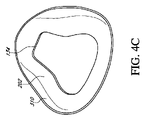
図4A~図4Gは、連続気泡フォーム材料310及び液体シリコーンゴム312からクッション114を形成するためのステップを示している。すなわち、図4A~図4Gは、連続気泡フォーム材料310のシートから顔に接触する部分202を形成し、顔に接触する部分202上に、液体シリコーンゴム312から顔に接触しない部分204をオーバーモールドして、図3A~図3Fのクッション114を形成するためのステップを示している。
Manufacturing Process FIGS. 4A-4G show the steps for forming the
図4Aに示すように、連続気泡フォーム材料310が、熱成形ツール300の第1及び第2の熱成形ツール部分302、304の間に配置される。連続気泡フォーム材料310は、1つ以上のテキスタイルシート層を含む積層体の形態であり得る。第1及び第2の熱成形ツール部分302、304は、連続気泡フォーム材料310が第1及び第2の熱成形ツール部分302、304の3次元輪郭に適合するように、連続気泡フォーム材料310を挟んで圧縮する。いくつかの構成では、第1及び第2の熱成形ツール部分302、304に対して真空引きを行って、連続気泡フォーム材料310を第1及び第2の熱成形ツール部分302、304の3次元輪郭に適合させる力を加えることができる、並びに/又は連続気泡フォーム材料310を第1及び第2の熱成形ツール部分302、304の顔に接触する部分の空洞306内に引き込むことができる。連続気泡フォーム材料310は、連続気泡フォーム材料310が第1及び第2の熱成形ツール部分302、304のジオメトリに従って塑性変形されるように、形成温度まで加熱される。
As shown in FIG. 4A, the open
図4Bに示すように、連続気泡フォーム材料310が、冷却され、第1及び第2の熱成形ツール部分302、304から取り外される。図示のように、連続気泡フォーム材料310は、熱成形され、3次元の輪郭形状を保持する。図4Cに示すように、連続気泡フォーム材料310は、クッション114の顔に接触する部分202を形成するようなサイズ及び形状に切断される。すなわち、連続気泡フォーム材料310は、顔に接触する部分202の外側周縁部を形成するようにトリミングされて仕上げられ、連続気泡フォーム材料310に孔を形成して、口鼻用の開口部134などの顔に接触する部分202の形体を提供する。いくつかの構成では、連続気泡フォーム材料310は、ダイカット、レーザーカットなどされ得る。
As shown in FIG. 4B, the open
図4Dに示すように、顔に接触する部分202は、オーバーモールディングツール320内に配置される。顔に接触する部分202は、オーバーモールディングツール320の第1の成形ツール部分322の顔に接触する部分の空洞326内に挿入される。図4Eに示すように、成形ツールコア324は、第1の成形ツール部分322上に配置され、第2の成形ツール部分(図示せず)によって封入され、液体シリコーンゴム312が圧力下でオーバーモールディングツール320内に射出されて、顔に接触しない部分204を成形し、さらに顔に接触する部分202と顔に接触しない部分204とを接合する。成形ツールコア324は、密閉された呼吸チャンバ130を形成するために液体シリコーンゴム312が流れる内部コアとして機能する。いくつかの構成では、オーバーモールディングツール320は、熱可塑性ポリウレタン(TPU)、熱可塑性エラストマ(TPE)、熱可塑性加硫物(TPV)などの熱可塑性材料を注入されてもよい。注入後、液体シリコーンゴム312は冷却され固化される。図4Fに示すように、クッション114は、オーバーモールディングツール320から取り外される。
As shown in FIG. 4D, the
オーバーモールディングツール320内への液体シリコーンゴム312の注入中、顔に接触する部分202の周縁には、中間領域206を形成する液体シリコーンゴム312が含浸される。すなわち、液体シリコーンゴム312は、顔に接触する部分202と顔に接触しない部分204とがそれぞれの縁部に沿って接合されるように、顔に接触する部分202の開いた外縁に流れ込むように強制される。シーム232は、顔に接触する部分202と顔に接触しない部分204との間に形成され、含浸領域234は、液体シリコーンゴム312を顔に接触する部分202の連続気泡フォーム材料310内に注入することにより形成される。液体シリコーンゴム312は、連続気泡フォーム材料310に押し込まれて、顔に接触する部分202の開いた外縁部から顔に接触する部分202内に距離Dだけ延びる含浸領域234を形成する。すなわち、距離Dは、顔に接触する部分202の連続気泡フォーム材料310内のシリコーン含浸の量を示す。
During the injection of the
連続気泡フォーム材料310内へのシリコーン含浸量は、液体シリコーンゴム312の注入圧力、注入時間、顔に接触しない部分204の厚さに対する顔に接触する部分202の厚さなどによって変わり得る。いくつかの構成では、顔に接触する部分202の厚さは、液体シリコーンゴム312が顔に接触する部分202の外面212上に流れないように、顔に接触しない部分204の厚さに実質的に等しい。いくつかの構成では、顔に接触する部分202の領域への流れは、顔に接触する部分202を狭めること又はクランプすることを介して制限され得る。例えば、オーバーモールディングツール320の成形ツール部分及び成形ツールコアは、液体シリコーンゴム312が連続気泡フォーム材料310内に流入するのが抑制されるように、顔に接触する部分202の連続気泡フォーム材料310の厚さをクランプ又は狭める領域を備え得る。
The amount of silicone impregnated into the open
部分的フォーム及びテキスタイル材料
図5は、図1のCPAPシステム10と共に使用するためのクッション114のための代替構成を示している。2つの構成間の特定の類似性の説明は、簡潔さのため、及び便宜上、本明細書では省略される場合があるが、そのような省略は限定ではない。クッション114は、顔に接触する部分202と顔に接触しない部分204とから構成される。顔に接触する部分202は、口の領域142と鼻の領域144とから構成される。顔に接触しない部分204は、シリコーンゴム312から形成される。顔に接触する部分202は、シリコーンゴム312及び/又は連続気泡フォーム材料310の領域を有する。より具体的には、顔に接触する部分202の鼻の領域144は、連続気泡フォーム材料310から形成され、口の領域142は、シリコーンゴム312から形成される。連続気泡フォーム材料310から鼻の領域144を形成することにより、圧力に対してより敏感なユーザの鼻の領域に柔らかい質感が提供されると共に、ユーザの口の周りを効果的にシールする顔に接触する部分202が提供される。いくつかの構成では、鼻の領域144は、テキスタイル材料、積層材料、及び/又はフォーム及びファブリック積層材料から形成されてもよい。クッション114と同様に、含浸領域234は、顔に接触する部分202の連続気泡フォーム材料310内に液体シリコーンゴム312を注入することにより形成され、これにより、連続気泡フォーム材料310とシリコーンゴム312との間に強い機械的結合が提供され、クッション114の耐久性を向上させることができる。
Partial Foam and Textile Materials FIG. 5 shows an alternative configuration for
クッション114は、連続気泡フォーム材料310の周縁の周囲に延びる含浸領域234を備えた中間領域206を備える。図5に示すように、中間領域206は、顔に接触する部分202の外周から、顔に接触する部分202を横切って口鼻用の開口部134に向かって延びる。いくつかの構成では、中間領域206の一部は、口鼻用の開口部134の一部を画定してもよい。
The
図示のように、クッション114は、連続気泡フォーム材料310の連続部分又は領域と、シリコーンゴム312の連続部分又は領域と、から構成される、顔に接触する部分202を有する。いくつかの構成では、口の領域142及び顔に接触しない部分204は両方とも、連続シリコーンゴム312から一体に形成される。すなわち、口の領域142と顔に接触しない部分204とは同じ材料で形成される。他の構成では、口の領域142と顔に接触しない部分204とは、異なる材料から形成される。
As shown, the
いくつかの構成では、連続気泡フォーム材料310及び/又はシリコーンゴム312の複数の連続部分又は領域を顔に接触する部分202の周りに配置することができる。例えば、顔に接触する部分202は、顔に接触する部分202の顎に接触する部分の近くに配置された第2の連続気泡フォーム材料310を含むことができる。連続気泡フォーム材料310及び/又はシリコーンゴム312の領域は、顔に接触する部分202上の様々な領域(すなわち、円周方向、半径方向内側/外側、周期的、又はそれらの任意の組み合わせなど)に配置して、ユーザに快適性、通気性、密閉性、可撓性などを提供できることを当業者には理解されたい。すなわち、連続気泡フォーム材料310の任意の部分にシリコーンゴム312を含浸させることができる。
In some configurations, a plurality of continuous portions or regions of the open
完全に含浸されたテキスタイル材料
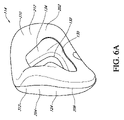
図6A~図6Fは、図1のCPAPシステム10と共に使用するためのクッション414の代替構成を示している。2つの構成間の特定の類似性の説明は、簡潔さのため、及び便宜上、本明細書では省略される場合があるが、そのような省略は限定ではない。クッション414は、顔に接触する部分202と顔に接触しない部分204とから構成される。顔に接触する部分202は、シリコーンゴム312でオーバーモールドされたテキスタイル材料310の層を含む複合材料構造を備える。換言すれば、テキスタイル材料310は、顔に接触する部分の内面及び外面が両方ともシリコーンゴム312から形成されるように、シリコーンゴム312によって完全に含浸される。すなわち、顔に接触する部分202の全体が、シリコーンゴム312が含浸されたテキスタイル材料310から構成される。
Fully Impregnated Textile Materials FIGS. 6A-6F show an alternative configuration of
顔に接触する部分202の完全に含浸されたテキスタイル材料310は、テキスタイル材料310とシリコーンゴム312との両方の特性を提供する。顔に接触する部分202は、シリコーンゴムの表面テクスチャを提供しながらテキスタイルの外観を有する。テキスタイルの外観は、寝室環境において快適であり、望ましいものであり得る、より柔らかい美観を提供し得る。テキスタイル材料310はまた、審美的に好ましい外観を提供するシリコーンゴム312に対して対比的な色を有してもよい。対比的な色はまた、ユーザの顔へのクッション414の配置可能性及び取り付け具合に関する視覚的な指示をユーザに提供し得る。シリコーンの表面テクスチャにより、顔に接触する部分が気密になり、気密である顔に接触する部分は、ユーザの顔に対して容易にシールする。完全に含浸されたテキスタイル材料310はまた、支持構造と、ユーザの気道への空気の供給を加圧可能にする気密呼吸チャンバと、を提供する。いくつかの構成において、完全に含浸されたテキスタイル材料310によって提供される気密構造は、気流がユーザから離れるように誘導及び/又は拡散され得るように、多孔性及び空気透過性領域と共に使用され得る。支持構造はまた、ユーザの顔に対するクッションの配置可能性及び取り付け具合を改善する。さらに、含浸シリコーンゴム312は、顔に接触する部分202が様々なユーザの顔のジオメトリに適合することを可能にする弾性構造を提供する。
The fully impregnated
いくつかの構成では、顔に接触しない部分204は、顔に接触する部分202よりも大きい(すなわち、より厚い)壁厚を有してもよい。すなわち、顔に接触する部分202におけるシリコーンゴム312の壁厚は、顔に接触する部分202が顔に接触しない部分204よりも可撓性が大きくなり得るように、顔に接触しない部分204におけるシリコーンゴム312の壁厚よりも薄くすることができる。より厚い顔に接触しない部分204はまた、クッション414のハウジング124及び呼吸チャンバ130の剛性をより大きくする。いくつかの構成では、顔に接触しない部分204は、顔に接触する部分202と実質的に等しい壁厚を有し得る。
In some configurations, the
クッション414は、クッション114と同様のオーバーモールディングツールで製造される。いくつかの構成では、顔に接触する部分202のテキスタイル材料310は、オーバーモールディングツール320に挿入される前に熱成形(図4Aに示す)及びトリミング(図4Bに示す)を必要としない。より具体的には、テキスタイル材料310は、オーバーモールドされる前に、オーバーモールディングツール320の第1の成形ツール部分322上に引き伸ばされ、その後、余分なテキスタイル材料310がトリミングされる。いくつかの構成では、テキスタイル材料310を第1の成形ツール部分322内に配置し、テキスタイル材料310の粒子が顔に接触する部分202の湾曲に従うようにオーバーモールドしてもよい。顔に接触しない部分204及び/又はユーザに対してテキスタイル材料310の粒子の方向を配向することにより、ユーザの快適性、密閉性、配置可能性、美観などを改善することができる。
The
テキスタイル及びシリコーン含浸接合
図7A~図7Fは、図1のCPAPシステム10と共に使用するためのクッション424の代替構成を示している。2つの構成間の特定の類似性の説明は、簡潔さのため、及び便宜上、本明細書では省略される場合があるが、そのような省略は限定ではない。図示のように、クッション424が、ユーザの顔に接触する部分202と顔に接触しない部分204とを備える。顔に接触しない部分204は、シリコーンゴム312などの熱可塑性エラストマ材料から形成される。いくつかの構成では、顔に接触しない部分204は、顔に接触する部分202よりも大きい(すなわち、より厚い)壁厚を有してもよい。他の構成では、顔に接触しない部分204は、顔に接触する部分202と実質的に等しい壁厚を有し得る。
Textile and Silicone Impregnated Joins FIGS. 7A-7F show an alternative configuration of
顔に接触する部分202は、配置領域242とシール領域244とから構成される。シール領域244は、ユーザの鼻及び口の周りに気密シールを形成するためにユーザの顔と係合する滑らかで連続表面を提供するシリコーンゴム312などのエラストマ材料から形成される。シール領域244及び顔に接触しない部分204は、同じ材料から形成されてもよい。例えば、シール領域244と顔に接触しない部分204との両方をシリコーンゴム312から形成することができる。いくつかの構成では、シール領域244と顔に接触しない部分204とは、異なる材料から形成されてもよい。シール領域244は、配置領域242の周縁の周囲に延びる。すなわち、シール領域244は、口鼻用の開口部134に対して配置領域242の半径方向外側に配置される。換言すれば、シール領域244は、配置領域242を取り囲む。シール領域244は、顔に接触しない部分204と一体に形成され、クッション424の後方又はユーザの方を向いた側に位置する顔に接触しない部分204の一部であってもよい。
The
配置領域242は、2重層テキスタイル材料314から形成される。配置領域242のテキスタイル層は、ユーザの顔のジオメトリに適合し、ユーザの顔上にクッションを(すなわち、視覚的に、触覚的になど)配置するように構成される。いくつかの実施形態では、2重層テキスタイル材料314は、異なる特性を有する第1及び第2の層を備えてもよい。例えば、2重層テキスタイル材料314は、ユーザの顔と接触するシール領域244を増加させ、実現されるシールを改善するために、気密である少なくとも1つの層を有する積層材料を含み得る。2重層テキスタイル材料314はまた、配置領域242の柔らかさ、クッション性、テクスチャ、通気性などを高めるために、少なくとも1つの快適層を備えてもよい。いくつかの構成では、配置領域242は、単一の層又は複数の層を備えてもよい。
The
配置領域242の2重層テキスタイル材料314は、シール領域244と一体的に形成される。すなわち、2重層テキスタイル材料314の外周は、シール領域244にオーバーモールドされる。移行領域208が、配置領域242とシール領域244との間に配置され、延びる。図7A及び図7Cに示すように、移行領域208は、配置領域242と、クッション114の後方かつユーザの方を向いた表面に配置されたシール領域244と、の間の周辺縁部であってもよい。いくつかの構成では、移行領域208は、クッション424の前方を向いた表面と後方を向いた表面との間の周辺縁部であってもよい。
The
移行領域208は、シーム232とテキスタイル含浸領域234とを備える。シーム232は、配置領域242の単層テキスタイル材料316からシール領域244のシリコーンゴム312への移行部によって形成される。含浸領域234は、配置領域242とシール領域244とが一体的に形成されるように、オーバーモールドプロセス中に配置領域242の2重層テキスタイル材料314にシリコーンゴム312を含浸させることにより形成される。従って、移行領域208は、2重層テキスタイル材料314とシリコーンゴム312との複合材料を含む。シーム232は、テキスタイル含浸領域234の周縁の周囲に延び、配置領域242とシール領域244との間の滑らかでシームレスな移行を提供することができる。含浸領域234は、2重層テキスタイル材料314の半径方向外周の周りに延び、シリコーンゴム312は、シーム232から2重層テキスタイル材料314内に浸透する。移行領域208及びシール領域244は、ユーザの顔に対して実質的に気密シールを形成するように構成される。
The
上述の含浸プロセスと同様に、含浸領域234は、オーバーモールディングツール320を使用して2重層テキスタイル材料314にシリコーンゴム312を含浸させることにより形成される。オーバーモールディングツール320は、含浸領域234のサイズ及び形状を決定することができる。すなわち、シリコーンゴム312を2重層テキスタイル材料314の特定の領域に浸透させて、ユーザの顔とのシールを改善する形状の含浸領域234を提供することができる。同様に、シリコーンゴム312はまた、2重層テキスタイル材料314の特定の領域への浸透を制限又は抑制されて、気流が配置領域242を通過できるようにする形状を有する含浸領域234を提供してもよい。いくつかの実施形態では、含浸領域234のシリコーンゴム312は、可変の厚さを有することができる(すなわち、いくつかの領域では他の領域よりも厚くすることができる)。
Similar to the impregnation process described above, the
クッション424は、クッション114と同様のオーバーモールディングツールで製造される。いくつかの構成では、顔に接触する部分202の2重層テキスタイル材料314は、オーバーモールディングツール320に挿入される前に熱成形(図4Aに示す)及びトリミング(図4Bに示す)を必要としない。より具体的には、2重層テキスタイル材料314は、オーバーモールドされる前に、切断されて、オーバーモールディングツール320の第1の成形ツール部分322内にサイズに合わせて配置される。
The
配置領域242の2重層テキスタイル材料314は、シリコーンゴム表面よりも触感が柔らかい3次元形状を提供し、シールに色ディテールを提供する。従って、クッション424は、ユーザの顔に対してより快適であり、寝室環境において快適であり、望ましい外観を有する。配置領域242の2重層テキスタイル材料314はまた、2重層テキスタイル材料314の柔軟な性質の結果として、顔に接触する部分202に可撓性及び適合性を提供する。いくつかの構成では、配置領域242の2重層テキスタイル材料314は、2重層テキスタイル材料314の一部が張力下にあるように形成されてもよい。すなわち、オーバーモールドプロセス中に2重層テキスタイル材料314内に張力が生じ得る。張力は、ある程度の弾力性を提供して、クッション424をユーザの顔に確実に配置できるようにする。
The
鼻下スリング
図8は、図1のCPAPシステム10と共に使用するためのクッション434のための代替構成を示している。2つの構成間の特定の類似性の説明は、簡潔さのため、及び便宜上、本明細書では省略される場合があるが、そのような省略は限定ではない。図示のように、クッション434が、ユーザの顔に接触する部分202と顔に接触しない部分204とを備える。顔に接触する部分202は、配置領域242とシール領域244とから構成される。顔に接触する部分202の配置領域242は、シール領域244と一体的に形成された単層テキスタイル材料316から構成される。単層テキスタイル領域316の外周は、シール領域244にオーバーモールドされる。いくつかの構成では、配置領域242は、複数の層を有するテキスタイル材料を含んでもよい。いくつかの構成では、配置領域242は、使用中に呼吸ガスの供給が配置領域を介してユーザの気道に提供され得るように通気性材料から形成された連続表面を備えてもよい。
Subnasal sling FIG. 8 shows an alternative configuration for
配置領域242は、口用の開口部136と鼻用の開口部138とを含む2つの開口部を備える。口用の開口部136は、ユーザの口を取り囲むように構成され、鼻用の開口部138は、ユーザの鼻孔を取り囲むように構成される。すなわち、口用の開口部136は、ユーザの口に呼吸ガスの供給を提供するように構成され、鼻用の開口部138は、ユーザの鼻孔に呼吸ガスの供給を提供するように構成される。口用の開口部136及び鼻用の開口部138は、顔に接触する部分202を横切って横方向に延びるテキスタイル材料の条片である鼻下スリング140を形成する。鼻下スリング140は、ユーザの鼻の下に配置されて、クッション434をユーザの顔の上に配置することと、クッション434がユーザの顔に乗り上げることを防ぐことと、を助けるように構成される。すなわち、鼻下スリング140は、ユーザの鼻がクッション434に深く入り込み過ぎることを防止することにより、クッション434の不適切な装着を防止する。鼻下スリング140は、単層テキスタイル材料316の口用の開口部136及び鼻用の開口部138用の孔を切削することによって形成されてもよい。いくつかの構成では、鼻下スリング140は、口用の開口部136及び鼻用の開口部138によって画定される。
The
移行領域208が、配置領域242とシール領域244との間に配置される。移行領域208は、シーム232とテキスタイル含浸領域234とを備える。シーム232は、配置領域242の単層テキスタイル材料316からシール領域244のシリコーンゴム312への移行部によって形成される。含浸領域234は、配置領域242とシール領域244とが一体的に形成されるように、オーバーモールドプロセス中に配置領域242の単層テキスタイル材料316にシリコーンゴム312を含浸させることにより形成される。従って、移行領域208は、単層テキスタイル材料316とシリコーンゴム312との複合材料を含む。シーム232は、テキスタイル含浸領域234の周縁の周囲に延び、配置領域242とシール領域244との間の滑らかでシームレスな移行を提供することができる。
The
テキスタイル及びシリコーン含浸接合
図9A~図9Cは、図1のCPAPシステム10と共に使用するためのクッション444の代替構成を示している。2つの構成間の特定の類似性の説明は、簡潔さのため、及び便宜上、本明細書では省略される場合があるが、そのような省略は限定ではない。図8のクッション434と同様に、クッション444は、鼻下スリング140を画定する口用の開口部136と鼻用の開口部138とを含む2つの開口部を備える配置領域242から構成される。
Textile and Silicone Impregnated Joins FIGS. 9A-9C show an alternative configuration of
図8のクッション434とは対照的に、クッション444は、顔に接触する部分202の内面218上に隆起したビード236を備えたシーム232から構成される移行領域208を有する。隆起したビード236は、顔に接触する部分202の一部であり、囲まれた呼吸チャンバ130に向かって内側に延びている。そのため、シーム232は、移行領域の内面からクッション444の内部に向かって延びる厚さが増加している。隆起したビード236は、配置領域242の周縁に沿ってシーム232の周囲に延びる。隆起したビード236は、2重層テキスタイル材料314の内部又は内側を向く表面248上に延びる。図9Bは、単層テキスタイル領域316から形成された配置領域242に適用された隆起したビード236を示している。図9Cは、2重層テキスタイル領域314から形成された配置領域242に適用された隆起したビード236を示している。隆起したビード236は、シーム232への結合及び構造の強度を高めるように構成される。隆起したビード236の厚さは、隆起したビード236が顔に接触する部分202がユーザの顔に対してシールを形成する能力を妨げないように、顔に接触する部分202の内面218で肉厚にされる。すなわち、顔に接触する部分204の外面は、ユーザの顔に対する快適な表面及び実質的に気密なシールを提供しながら、結合及び構造の強度を高める滑らかで連続表面である。
In contrast to the
開口部のないシリコーン含浸テキスタイルシール領域
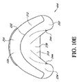
図10A~図10Fは、図1のCPAPシステム10と共に使用するためのクッション454の代替構成を示している。2つの構成間の特定の類似性の説明は、簡潔さのため、及び便宜上、本明細書では省略される場合があるが、そのような省略は限定ではない。図8のクッション114と同様に、クッション454は、ユーザの顔に接触する部分202と顔に接触しない部分204とを備える。クッション114とは対照的に、クッション454は、口鼻用の開口部を持たない。クッション454の顔に接触する部分202は、ユーザの鼻及び/又は口を受け入れるための開口部のない、伸縮性テキスタイル材料318の連続した途切れのないシートを備える。顔に接触する部分202は、通気性配置領域238とシール領域244とを備える。通気性配置領域238は、呼吸チャンバ130内の加圧ガスが伸縮性テキスタイル材料318を通してユーザによって受け取られるように、多孔性かつ通気性の領域である。換言すれば、ユーザは、通気性配置領域238を介して呼吸することができる。いくつかの構成では、シール領域244は、シリコーンゴム含浸連続気泡フォーム又はテキスタイル材料などの複合材料から形成される。他の構成では、シール領域244はシリコーンゴム312から形成される。シール領域244は、通気性配置領域238の周縁の周囲に延びる。すなわち、シール領域244は、口鼻用の開口部134に対して通気性配置領域238の半径方向外側に配置される。換言すれば、シール領域244は、通気性配置領域238を取り囲む。
Silicone impregnated textile seal area without openings FIGS. 10A-10F show an alternative configuration of
図8のクッション114と同様に、顔に接触しない部分204は、オーバーモールドプロセスによって中間領域206に沿って顔に接触する部分202の外周に結合される。すなわち、顔に接触しない部分204は、伸縮性テキスタイル材料318が伸縮性テキスタイル材料318の外周に沿ってシリコーンゴム312で含浸される、含浸領域234を備える。伸縮性テキスタイル材料318の含浸されていない通気性配置領域238は、含浸領域234の半径方向内側に配置される。すなわち、顔に接触する部分202の外周にはシリコーンゴム312が含浸されており、顔に接触する部分202の内部領域にはシリコーンゴム312が含浸されていない。通気性配置領域238の外周は、含浸領域234の内周で画定される。図10Cに示すように、含浸領域234の内周及び通気性配置領域238の外周は、破線によって規定される。
Similar to the
通気性配置領域238の伸縮性テキスタイル材料318は、使用されていないとき、シール面のジオメトリによって少なくとも部分的に決定される所定の3次元輪郭を有する。伸縮性テキスタイル材料318は、所定の3次元輪郭を形成するために、シール領域244によって張力下で支持される。すなわち、伸縮性テキスタイル材料318の部分は、使用されておらず、かつ通気性配置領域238に力が加えられないときに、通気性配置領域238が輪郭形状を有するように張力を受け得る。通気性配置領域238は、単一の軸線、2つの軸線、又は複数の軸線で伸縮可能な材料から形成されてもよい。伸縮の軸線を設けることにより、ユーザが装着したときに通気性配置領域238がどのように伸縮するかを決めることができる。いくつかの構成では、通気性配置領域238は、非伸縮性テキスタイル、フォーム、又は積層材料から形成され得る。
The
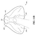
クッション454を装着すると、ユーザの鼻は、呼吸チャンバ130に向かって変位する通気性配置領域238に対して押し下げられる。図11A~図11Cに示すように、顔に接触する部分202に口鼻用の開口部がないことにより、ユーザの鼻が通気性配置領域238に対して押し下げられたときに、顔に接触する部分202の上部の角222が、ユーザの鼻の側面に向かって内側にすぼまることを促進する。すなわち、ユーザの鼻が顔に接触する部分202内に突出すると、伸縮性テキスタイル材料318は緊張状態になり、クッション454の呼吸チャンバ130内に変位する。クッション454の呼吸チャンバ130内に伸縮性テキスタイル材料318が押し込まれた結果、伸縮性テキスタイル材料318は、上部の角222を互いに向けて呼吸チャンバ130内に引き込む。上部の角222は、互いに向けて引っ張られた結果、半径方向内側に変形し得る、及び/又は潰れ得る。これにより、顔に接触する部分202のシール領域244がユーザの鼻の側面を挟み込み、従って、クッション454とユーザの顔との間のシールが改善される。
When the
通気性配置領域238は、ユーザの鼻及び口を受け入れるように構成される。すなわち、伸縮性テキスタイル材料318は、伸縮して、ユーザの鼻の形状に適合するように構成され得る。いくつかの構成において、通気性配置領域238は、クッション454がユーザによって着用されていないときに通気性配置領域238が緩く、実質的に張力がないように、ある量の緩み、弛み、又は下垂を有し得る。この緩みは、通気性配置領域238の張力を低減し、これによりユーザの鼻に対する圧力を低減し得る。いくつかの構成では、伸縮性テキスタイル材料318は、ユーザの鼻が通気性配置領域238に押し下げられたときに拡張するように成形及び構成されるベローズ又はプリーツで形成されてもよい。他の構成では、ユーザの鼻が通気性配置領域238に対して押し下げられたときに通気性配置領域238が伸びるように、通気性配置領域238は弾性材料から形成されてもよい。いくつかの実施形態では、伸縮性テキスタイル材料318は、ユーザの顔と接触するシール領域244を増加させ、顔に接触する部分202のシール性を改善するために、一部の領域において気密である少なくとも1つの層を有する積層材料を含み得る。
The
クッション414は、クッション114と同様のオーバーモールディングツールで製造される。いくつかの構成では、顔に接触する部分202の伸縮性テキスタイル材料318は、オーバーモールディングツール320に挿入される前に熱成形(図4Aに示す)及びトリミング(図4Bに示す)を必要としない。より具体的には、伸縮性テキスタイル材料318は、オーバーモールドされる前に、オーバーモールディングツール320の第1の成形ツール部分322上に引き伸ばされる、可撓性シートである。いくつかの構成では、第1及び第2の熱成形ツール部分302、304に真空を適用して、伸縮性テキスタイル材料318を伸張状態に維持することができる。オーバーモールディングの前に伸縮性テキスタイル材料318を引き伸ばすことにより、通気性配置領域238は、クッション454がユーザによって着用されていないときに通気性配置領域238が緩く、実質的に張力がないように、ある量の緩み、弛み、又は下垂を含むことができる。クッション454がシリコーンゴム312でオーバーモールドされた後、余分な伸縮性テキスタイル材料318はシーム232でトリミングされる。オーバーモールディングツール320は、シリコーンゴム312が伸縮性テキスタイル材料318内にどれだけ流れ込むかを規定し制限する遮断ゾーンを含むことができる。伸縮性テキスタイル材料318内への浸透の深さは、シール領域244の形状を規定する。
The
通気性配置領域238に緩みを設けることにより、クッション414に挿入されたときにユーザの鼻の先端にかかり得る張力が低減される。緩みがない場合、テキスタイル材料318はユーザの鼻の上に伸びる必要があり、その結果、鼻にかかる張力レベルが増加することがあり、それは不快なものになり得る。
The slack in the
シリコーン安定化層を備えたシリコーン含浸されたテキスタイルシール領域
図12A~図12Cは、図1のCPAPシステム10と共に使用するためのクッション464の代替構成を示している。2つの構成間の特定の類似性の説明は、簡潔さのため、及び便宜上、本明細書では省略される場合があるが、そのような省略は限定ではない。図10A~図10Fのクッション454と同様に、クッション464は、ユーザが呼吸チャンバ130から加圧ガスを受け取るための多孔質で通気性の通気性配置領域238を備える。クッション454とは対照的に、クッション464は、顔に接触する部分202の伸縮性テキスタイル材料318の下に安定化層246を備える。すなわち、安定化層246は、呼吸チャンバ130と顔に接触する部分202の伸縮性テキスタイル材料318との間に配置される。安定化層246は、顔に接触する部分202の上半分に配置され、使用中、患者の鼻に力をかけて、患者の顔の上でクッションを安定させるように構成される。
Silicone impregnated textile seal areas with a silicone stabilizing layer FIGS. 12A-12C show an alternative configuration of
図示のように、安定化層246は、ユーザの鼻梁及び頬領域の周りで、顔に接触する部分202の伸縮性テキスタイル材料318に支持を提供するように構成される逆U字形を有する。すなわち、安定化層246は、クッション464の両側面上のクッション464の頬領域間、及び顔に接触する部分202の鼻梁領域上に延びる、アーチ状の輪郭形状を有してもよい。安定化層246は、ユーザの顔上でのクッション464の安定性を高め、装着中のマスクの締め過ぎにより顔に接触する部分202が潰れた結果としてハウジング124がユーザの鼻梁に食い込むのを防ぐ。従って、安定化層246は、顔に接触する部分202のシール性を改善する。
As shown, the stabilizing
安定化層246は、シリコーンゴム312から形成され、顔に接触しない部分204と独立して又は一体的に形成されてもよい。安定化層246は、伸縮性テキスタイル材料318から分離される、及び/又はそれに取り付けられない。安定化層246は、シール領域244の内周に取り付けられた外縁と、呼吸チャンバ130内に延びる内縁と、を有する。すなわち、安定化層246は、シール領域244に固定された第1の端部と、自由な第2の端部と、を有することができる。安定化層246は、顔に接触する部分202の伸縮性テキスタイル材料318の下に配置されるシリコーンゴムの3次元層を含む。安定化層246は、顔に接触しない部分204の厚さよりも厚い、薄い、又はそれに等しい厚さを有することができる。いくつかの構成では、安定化層246は、シール領域244の含浸領域234に置き換わってもよいし、それに追加されてもよい。他の構成において、安定化層は、顎領域又は上唇領域(鼻インターフェース用)などであるがこれらに限定されないクッションの他の領域に提供されてもよい。いくつかの構成では、安定化層246は、使用中にユーザの鼻の両側にそれぞれが配置される複数の層を備えてもよい。いくつかの構成では、安定化層246は、使用中に、ユーザの鼻の両側に配置されてもよいが、ユーザの鼻梁部分を越えて延びない。
The stabilizing
図9B、図11B、及び図11Cは、クッション444、464のハウジング124に取り付けられたフレームクリップ252を示している。フレームクリップ252は、ハウジング124のフレーム接続開口部132に永続的に取り付けられるプラスチックから形成された剛性リングである。フレームクリップ252は、マスクフレームとクッションとの間に取り外し可能な接続を提供する。フレームクリップ252は、スナップ嵌め、摩擦嵌め、溶接継手などによって互いに永続的に接合される内側部分254及び外側部分256を備えることができる。フレームクリップ252は、シリコーンハウジングをフレームに直接接続するよりも、フレームへの信頼性の高い接続を提供する。すなわち、フレームクリップ252の剛性の増加により、クッション444、464の曲げ又は変形によるクッション444、464と導管120との間の漏れの可能性が減少する。
9B, 11B, and 11C show a
部分的に含浸可能なテキスタイル材料
図13A~図13Cは、図1のCPAPシステム10と共に使用するためのクッション510の例示的な構成を示している。クッション510は、顔に接触する部分202と顔に接触しない部分204とを備える。顔に接触しない部分204は、上述のように、部分的に囲まれた呼吸チャンバ130の前方に面する部分又は比較的遠位の部分を形成する。顔に接触する部分202は、呼吸チャンバ130の後方に面する部分又は比較的近位の部分を形成し、ユーザの顔と係合し、ユーザの顔に対して実質的に気密なシールを形成するように構成される。中間領域206は、顔に接触する部分202と顔に接触しない部分204をそれぞれの縁に沿って相互接続する。
Partially Impregnable Textile Materials FIGS. 13A-13C show an exemplary configuration of
顔に接触する部分202は、ユーザの鼻及び口を実質的に囲むシールを提供するようにユーザの顔に接触する。すなわち、顔に接触する部分202は、ユーザの顔と係合し、ユーザの顔に対して実質的に気密なシールを形成するように構成される。顔に接触する部分202は、ユーザの鼻及び口を受け入れる口鼻用の開口部134を有する。導管120によって供給された加圧ガスは、呼吸チャンバ130に入り、口鼻用の開口部134を介してユーザによって受け入れられる。
The face-contacting
顔に接触する部分202は、シール領域244を備えてもよい。図示のように、顔に接触する部分202とシール領域244との両方は、ユーザの鼻及び口の周りに気密シール(すなわち、口鼻用の開口部134の周りの気密シール)を形成するためにユーザの顔と係合する滑らかで連続表面を提供するシリコーンゴム312などのエラストマ材料から形成される。顔に接触しない部分204はまた、シリコーンゴム312から形成され得る。シリコーンゴム312は、ユーザに快適さ、密閉性、柔軟性などを提供するために、顔に接触する部分202の周囲又は顔に接触する部分202の様々な領域に連続的に配置されてもよい。他の実施形態では、顔に接触する部分202及び顔に接触しない部分204は、TPE材料などの異なる材料から形成されてもよいし、異なる材料を含んでもよい。
The
顔に接触しない部分204は、下層又は内層及び上層又は外層を含む2重層構造を有してもよい。下層は、顔に接触する部分202と同じシリコーンゴム312又はエラストマ材料で形成されてもよい。上層は、非伸縮性テキスタイル513などのテキスタイルで形成されてもよいが、いくつかの構成では伸縮性テキスタイルで形成されてもよい。他の構成では、最上層は、2つ以上の繊維のブレンドを有するテキスタイル513で形成されてもよい。そのような構成では、テキスタイル513は、約70~90%のナイロンと10~30%のポリエステル織物マイクロファイバとのブレンドを含んでもよい。例えば、テキスタイルは、約70%のナイロン及び約30%のポリエステル織物マイクロファイバ、又は約80%のナイロン及び約20%のポリエステル織物マイクロファイバ、又は約90%のナイロン及び約10%のポリエステル織物マイクロファイバを有するブレンドを含んでもよいが、他のパーセンテージ構成及び他の適切なテキスタイル材料を使用してもよい。適切な非伸縮性テキスタイル513又は伸縮性テキスタイル513は、液体シリコーンゴム312の硬化プロセス中に使用される工具の高温に耐える(すなわち、高温下で溶けない)。非伸縮性テキスタイル513は、顔に接触しない部分204が非伸縮性テキスタイル513によって実質的に覆われるように、顔に接触しない部分204の周りに連続的に配置されてもよい。図13Aに示すように、いくつかの構成では、非伸縮性マイクロファイバテキスタイル513は、口鼻用の開口部134の縁部から間隔を空けて配置されてもよい。従って、顔に接触しない部分204の下層の一部は、非伸縮性マイクロファイバテキスタイル513と口鼻用の開口部134との間に露出されてもよい。
The
非伸縮性テキスタイル513は、非伸縮性マイクロファイバテキスタイル513などの高密度繊維で形成されたテキスタイルを含む。非伸縮性マイクロファイバテキスタイル513などのマイクロファイバテキスタイルは、一般に、1デニール未満(すなわち、約10マイクロメートル未満)の繊維径を有する。クッション510の製造中に、非伸縮性テキスタイル513をオーバーモールディングツール320のキャビティに配置し、液体シリコーンゴム312をオーバーモールディングツール320内に注入して、非伸縮性テキスタイル513を注入されるシリコーンゴム312の一部と接合し、クッション510の顔に接触しない部分204を形成する。液体シリコーンゴム312は、非伸縮性テキスタイル513のユーザに面する側又は内側の繊維構造に部分的に押し込まれる。図6A~図6Fの完全に含浸されたテキスタイル材料とは対照的に、非伸縮性テキスタイル513の高密度繊維構造は、液体シリコーンゴム312の流れに対して少なくとも部分的に含浸可能である。代わりに、非伸縮性テキスタイル513を顔に接触しない部分204の下層に取り付ける間、シリコーンゴム312は、非伸縮性テキスタイル513のユーザに面する側の厚さの一部にしか貫通できない。従って、非伸縮性テキスタイル513は、顔に接触しない部分204の下層に固定されるが、非伸縮性テキスタイル513の露出側のシリコーンゴム312によって飽和されない前向きテキスタイル表面511を形成する。いくつかの構成では、非伸縮性マイクロファイバテキスタイル513以外の材料を使用して、上述のBreath-o-prene(登録商標)材料などの前向きテキスタイル表面511を形成することができる。さらなる構成では、Breath-o-prene(登録商標)材料は、顔に接触しない部分204のすべて又は一部を形成する。
上述のように、クッション510の顔に接触しない部分204は、非伸縮性テキスタイル513のテクスチャ、外観、及び他の特性を保持する前向きテキスタイル表面511を備える。顔に接触しない部分204は、多くの場合、クッション511がユーザによって着用されたときに一番目立ち、よく見えるクッション511の態様である。好適には、非伸縮性テキスタイル513の柔らかい感触を保持しながら、寝室環境においてより快適で視覚的に魅力的なテキスタイル美観を提供する前向きテキスタイル表面511を含む。いくつかの構成では、非伸縮性テキスタイル513はまた、審美的に好ましい外観を提供するシリコーンゴム312に対して対比的な色を有してもよい。対比的な色はまた、ユーザの顔へのクッション510の配置可能性及び取り付け具合に関する視覚的な指示をユーザに提供し得る。この対比的な色は、クッション510をCPAPマスクシステム10の他の構成要素と共に組み立てるための視覚的な組み立て指示又は合図を提供することもできる。前向きテキスタイル表面511はまた、クッション510の下にあるシリコーンゴム構造を、クッション510を着用又は脱着するときにユーザの手によって引き起こされる摩滅及び摩耗から保護する。
As mentioned above, the
顔に接触しない部分204の連続的な湾曲及び非伸縮性テキスタイル513の非伸縮性は、図13Aに示す滑らかな(例えば、しわのない)表面仕上げを得ると同時に、顔に接触しない部分204に非伸縮性テキスタイル513を固定することの困難さを増大させる。図13Cに示すように、非伸縮性テキスタイル513は、実質的に2次元の非伸縮性テキスタイル513がオーバーモールディングツール320、最終的にはクッション510の3次元形状に適合することを可能にする1つ以上の細隙514を含み得る。各細隙514は、非伸縮性テキスタイル513がクッション510の3次元形状により密接に適合することを可能にする追加の自由度を提供する。1つ以上の細隙514のそれぞれが、非伸縮性テキスタイル513の外周から非伸縮性テキスタイル513の内周まで延びていてもよい。従って、細隙514は、非伸縮性テキスタイル513の外周から口鼻用の開口部134の外周まで延びることができる。いくつかの構成では、細隙514は、非伸縮性テキスタイル513の外周と内周との間の距離全体に延びていなくてもよい。さらなる構成では、非伸縮性テキスタイル513は、クッション510の底部(例えば、ユーザの顎領域の近く)に配置された細隙514を含んで、使用中のユーザから見えるクッション510の部分によりきれいな美観を提供することができる。
The continuous curvature of the
テキスタイル及びシリコーン含浸接合
図14A及び図14Bは、図1のCPAPシステム10と共に使用するためのクッション520の構成を示している。図10A~図10Fのクッション454と同様に、クッション520は、ユーザの顔に接触する部分202と顔に接触しない部分204とを備える。クッション520の顔に接触する部分202は、口鼻用の開口部134を含まず、代わりに、連続的かつ途切れのない3次元編物テキスタイル材料521を含んで、ユーザの鼻及び/又は口を受け入れる。顔に接触する部分202は、通気性配置領域238とシール領域244とを備える。通気性配置領域238は、呼吸チャンバ130内の加圧ガスが伸縮性テキスタイル材料521を通してユーザによって受け取られるように、多孔性かつ通気性の領域である。通気性配置領域238は、顔に接触する部分202の中央に配置されて、ユーザの鼻及び/又は口と係合する、及び/又は覆う。いくつかの構成では、シール領域244は、ユーザの顔に対する快適な表面と実質的な気密シールを提供するために、3次元編物テキスタイル材料521内に含浸されるシリコーンゴム312などの複合材料から形成される。他の構成では、シール領域244は、シリコーンゴム312のみで形成される。シール領域244は、通気性配置領域238の周縁の一部又は全体の周囲に延びる。すなわち、シール領域244は、クッション520の重心に対して通気性配置領域238の半径方向外側に配置される。換言すれば、シール領域244は、通気性配置領域238を部分的又は完全に取り囲む。
Textile and Silicone Impregnated Joins FIGS. 14A and 14B show the configuration of the
図10A~図10Fのクッション454と同様に、顔に接触しない部分204は、オーバーモールドプロセスによって中間領域206に沿って顔に接触する部分202の外周に沿って形成される。すなわち、クッション520は、3次元編物テキスタイル材料521が、顔に接触しない部分204の一部又は全体内で、中間領域206及び/又は顔に接触する部分202の外周に沿って、シリコーンゴム312で含浸される含浸領域234を備える。従って、3次元編物521及び含浸領域234は、顔に接触しない部分204上に部分的にしか延びない(すなわち、完全に覆わない)。3次元編物テキスタイル材料521の含浸されていない通気性配置領域238は、含浸領域234の半径方向内側に配置される。すなわち、顔に接触する部分202の外周の少なくとも一部にはシリコーンゴム312が含浸されており、顔に接触する部分202の内部領域の少なくとも一部にはシリコーンゴム312が含浸されていない。いくつかの構成では、通気性配置領域238の外周は、含浸領域234の内周を画定する。
Similar to the
図10A~図10Fのクッション454とは対照的に、クッション520の顔に接触する部分202は、伸縮性テキスタイル材料318の実質的に2次元のシートではなく、3次元編物テキスタイル材料521を含む。伸縮性テキスタイル材料318の2次元シートは、使用されていないときのシール領域244のジオメトリによって決定される所定の3次元輪郭を有することに制限され得る。いくつかの構成では、3次元編物テキスタイル材料521は、シールのジオメトリに実質的に一致するそのような3次元輪郭を備える。好適には、他の構成では、3次元編物テキスタイル材料521の3次元編物により、3次元編物テキスタイル材料521は、シール領域244のジオメトリとは独立した形状、輪郭、又は形態を備えることができる。従って、いくつかの構成では、3次元編物テキスタイル材料521は、靴下、ドーム、密閉チューブ、又は様々な凹面の3次元形状を備えてもよい。さらなる構成では、特定のユーザの特定の顔の特徴に適応するように3次元編物テキスタイル材料521をカスタマイズして、クッション520の快適性及び密閉性を高めることができる。
In contrast to the
クッション520を装着すると、ユーザの鼻は、呼吸チャンバ130に向かって変位する通気性配置領域238に対して押し下げられる。通気性配置領域238は、ユーザの鼻及び口を受け入れるように構成される。すなわち、3次元編物テキスタイル材料521は、伸縮して、ユーザの鼻の形状に適合するように構成され得る。いくつかの構成では、3次元編物テキスタイル材料521の粒子方向は、顔に接触する部分202の3次元編物テキスタイル材料521全体にわたって高伸縮性及び低伸縮性領域の両方を作成するように調整される。さらなる構成では、通気性配置領域238の中心付近に高伸縮性領域を配置して、異なるサイズの鼻を有する複数のユーザのための適応性を高めることができる。そのような構成では、中央に配置された高伸縮性領域は、ユーザの鼻上で通気性配置領域238の圧力を減らすことにより、ユーザの快適性を改善する。好適には、3次元編物テキスタイル材料521によって提供される優れた適応性(例えば、シールのジオメトリ、高伸縮領域、及び低伸縮領域とは独立したテキスタイル形状)により、3次元編物テキスタイル材料521は、顔に接触する部分202から、クッション520の外周の周りにおいて、顔に接触しない部分204の一部の上に容易に適合することができる。従って、3次元編物テキスタイル材料521は、オーバーモールドプロセスの結果として顔に接触しない部分204の外周又は一部に発生するテキスタイルのしわ(すなわち、過剰な材料によって引き起こされる)を最小限に抑えるのに役立つ。
When the
図15A~図15Dは、図1のCPAPシステム10と共に使用するためのクッション520の代替構成を示している。2つの構成間の特定の類似性の説明は、簡潔さのため、及び便宜上、本明細書では省略される場合があるが、そのような省略は限定ではない。図14A及び図14Bのクッション520と同様に、クッション520は、中間領域206によって相互接続されたユーザの顔に接触する部分202と顔に接触しない部分204とを備える。顔に接触する部分202は、上述のように、3次元編物テキスタイル材料521と、通気性配置領域238と、シール領域244と、外周と、を備える。顔に接触しない部分204は、含浸領域234を備える。
15A-15D show an alternative configuration of
図14A及び図14Bのクッション520とは対照的に、本構成では、3次元編物材料521は、図15Bに示すように、クッション520の顔に接触する部分202からクッション520の顔に接触しない部分204まで延び、クッション520の顔に接触しない部分204を完全に覆う。それに対応して、そのような構成では、3次元編物テキスタイル材料521がシリコーンゴム312で含浸される含浸領域234は、顔に接触しない部分204を完全に覆う。図15B及び図15Dに示されるように、3次元編物テキスタイル材料521は、顔に接触する部分202から顔に接触しない部分204まで延びて、呼吸チャンバ130を画定する。顔に接触しない部分204の3次元編物テキスタイル材料521は、顔に接触しない部分204の3次元編物テキスタイル材料521がシリコーンゴム312で完全に含浸され、従って収容されるように、シリコーンゴム312でオーバーモールドされる。従って、顔に接触しない部分の最も外側の層及び最も内側の層は、シリコーンゴム312で形成され、3次元編物テキスタイル材料521が内部に埋め込まれる。本構成のシリコーンゴム312は透明であるが、一部の構成は半透明又は不透明のシリコーンゴム312を利用し得る。従って、顔に接触しない部分204は、耐久性のあるシリコーンゴム表面のテクスチャを提供しながらテキスタイルの外観を保持する。そのような実施形態では、顔に接触しない部分204のシリコーンゴムの外面は、支持構造と、ユーザの気道への空気の供給を加圧可能にする気密呼吸チャンバ130と、を提供する。含浸領域234は、顔に接触しない部分204が顔に接触する部分202を支持できるように、中間領域206の厚さよりも厚い、薄い、又はそれに等しい厚さを有してもよい。従って、本構成では、顔に接触する部分202は、3次元編物テキスタイル材料521で形成された通気性配置領域238の快適性及び適合性を保持し、顔に接触しない部分204は、テキスタイル美観を保持し、クッション520のためのシリコーンゴム支持構造を提供する。
In contrast to the
いくつかの構成では、3次元編物テキスタイル材料521は、顔に接触しない部分204が、図15B及び図15Cに示すように、呼吸チャンバ130の開口部の周りの3次元編物テキスタイル材料521の飽和していない露出した周縁525を含むように、含浸領域234を少なくともわずかに超えて延びる。3次元編物テキスタイル材料521のこの露出した周縁525は、オーバーモールディングツール320によって所定の位置に固定されて、3次元編物テキスタイル材料521がオーバーモールドプロセス中に塊になる(例えば、しわになる)ことを防止することができる。オーバーモールドプロセスが完了した後、露出した周縁525をトリミングするか、そうでなければ除去することができる。クッション520はまた、寝室環境において快適であり、望ましいものであり得る、より柔らかい美観を提供する、テキスタイルの外観を全体的に提供する。さらに、クッション520に目に見えるシーム又は接合部がないことにより、視覚的に洗練された外観が得られ、それによりユーザの顔と接触した場合に不快な粗い縁部を避けることができる。
In some configurations, the 3D knitted
図15Cは、3次元編物テキスタイル材料521及び液体シリコーンゴム312からクッション520を形成するためのオーバーモールディングツール320の代替構成の断面図を示している。すなわち、図15Cは、オーバーモールディングツール320と、3次元編物テキスタイル材料521から顔に接触する部分202及び顔に接触しない部分204を形成し、液体シリコーンゴム312をシール領域244、中間領域206、及び顔に接触しない部分206上にオーバーモールドするための対応するプロセスと、を示している。3次元編物テキスタイル材料521のシートは、コア528上に配置され、開閉式ツールであり得る、オーバーモールディングツール320の第1及び第2の部分526、527によって保持される(例えば、クランプされる)。3次元編物テキスタイル材料521は、その3次元編物並びに高伸縮性領域及び低伸縮性領域のためにコア528に適合する。第1のツール部分526は、顔に接触する部分202と呼吸チャンバ130の一部とを画定し、第2のツール部分527は、顔に接触しない部分204と、呼吸チャンバ130の開口部と、呼吸チャンバ130の少なくとも一部と、を画定する。いくつかの構成では、第2の成形ツール部分527は、3次元編物テキスタイル材料521の露出した周縁525を所定の位置に固定して、成形プロセス中にテキスタイルが塊になるのを防ぐ。
FIG. 15C shows a cross-sectional view of an alternative configuration of the
3次元編物テキスタイル材料521がオーバーモールディングツール320内に固定されると、液体シリコーンゴム312が、コア528を介するなどしてオーバーモールディングツール320内に、またコア528と3次元編物テキスタイル材料521との間の空間内に注入される。このように、液体シリコーンゴム312は、3次元編物テキスタイル材料521の内面に注入される。液体シリコーンゴム312をオーバーモールディングツール320内に注入する間、3次元編物テキスタイル材料521のシール領域244、中間部分206、及び含浸領域234は、液体シリコーンゴム312で含浸されて、図15A、図15B、及び図15Dに示されているクッション520に到る。すなわち、液体シリコーンゴム312は、3次元編物テキスタイル材料521の特定の領域に浸透して、顔に接触する部分202とユーザの顔とのシールを改善できる一方で、通気性配置領域238を画定する領域に浸透することを制限又は禁止することができる。いくつかの構成では、配置領域238は、シリコーンゴム312が3次元編物テキスタイル材料521に流れ込むのを防ぐために、コア528と第1のツール部分526との間にクランプされる。いくつかの構成では、液体シリコーンゴム312の代わりに、別の適切な熱可塑性エラストマ(例えば、TPE)をオーバーモールディングツールに注入してもよい。TPEは冷却すると密度が増し、一部の構成では、TPEのこの密度増加の側面により、エラストマが3次元編物テキスタイル材料521に完全に含浸するのを抑制又は防止できる。上記のように、部分的に含浸されるテキスタイル材料は、テキスタイルが液体シリコーンゴム312で完全に飽和したときに失われる可能性のあるテキスタイルの感触、外観、及び他の態様を保持するため、有利な構造である。
When the 3D knitted
テキスタイル間の接合
図16A~図16Cは、テキスタイル外面を備えた顔に接触する部分202と、テキスタイル外面を備えた顔に接触しない部分204と、を備えるクッション530を形成するためのステップを示している。図16Aに示すうに、伸縮性テキスタイル材料318の第1シートが、オーバーモールディングツール533の第1の部分535とコア534との間に配置される。伸縮性テキスタイル材料318の第2のシートが、オーバーモールディングツール533のコア534と第2の部分536との間に配置される。コア534は、クッション530の呼吸チャンバ130を規定する。いくつかの構成では、伸縮性テキスタイル材料318の一方又は両方のシートは、1つ以上のテキスタイルシート層を含む積層体の形態であり得る。いくつかの構成では、伸縮性テキスタイル材料318は、クッション520などの3次元編物テキスタイル材料521を含んでもよい。他の構成では、伸縮性テキスタイル材料318は、予め形成された3次元形状を有してもよい。第1の部分535は、クッション530の顔に接触する部分202を画定し、第2の部分536は、顔に接触しない部分204を画定する。いくつかの構成では、顔に接触する部分202は、図16Cに示されるように、口鼻用の開口部134を画定する。他の構成では、顔に接触する部分202は、口鼻用の開口部134を持たないが、代わりに、図14A及び図14B、図15A~図15Dのクッション520と同様の通気性配置領域238を備える。
Joining between Textiles FIGS. 16A-16C show steps for forming a
オーバーモールディングツール533の第1及び第2の部分535、536がコア534の周りで一緒にクランプされると、伸縮性テキスタイル材料318の第1及び第2のシートは引き伸ばされる(すなわち、張力がかかった状態で保持される)。図16Bに示すように、オーバーモールディングツール533の第1及び第2の部分535、536をコア534に対して一緒にクランプすることにより、伸縮性テキスタイル材料318の第1及び第2シートがそれぞれの縁部で一緒にクランプされて、シーム537を形成する。液体シリコーンゴム312又はTPEは、コア534と伸縮性テキスタイル材料318の第1及び第2のシートとの間の空間内にコア534を介するなどして注入され、これは、伸縮性テキスタイル材料318の外面までは完全に浸透しないが、伸縮性テキスタイル材料318の呼吸チャンバ側に含浸し、その際、エラストマ層538が、顔に接触する部分202と顔に接触しない部分204との間に連続的に延び、シーム537において伸縮性テキスタイル材料318の第1及び第2シートを接合する。いくつかの構成では、TPEをオーバーモールディングツール533に注入して、伸縮性テキスタイル材料318に完全に含浸する可能性を減らすことにより、クッション520の製造プロセスの制御を改善する。シーム537における余分な伸縮性テキスタイル材料318は、図16Cに示すきれいなシームを得るために、オーバーモールドプロセスの後、クッション530からトリミング又は除去される。
When the first and
図4を参照して説明した成形プロセスと同様に、伸縮性テキスタイル材料318内へのシリコーン含浸量は、液体シリコーンゴム312の注入圧力、注入時間、顔に接触しない部分204の厚さに対する顔に接触する部分202の厚さ、伸縮性テキスタイル材料318の密度などによって変わり得る。従って、エラストマ層538は、顔に接触しない部分204の任意の部分から、顔に接触する部分202の口鼻用の開口部134まで延びることができる。クッション530が口鼻用の開口部134を持たないいくつかの構成では、エラストマ層538は、通気性配置領域238を画定する顔に接触する部分202の周縁まで延びることができる。
Similar to the molding process described with reference to FIG. 4, the amount of silicone impregnated into the
図17A~図17Cは、クッション530の代替構成を形成するためのステップを示している。2つのプロセス間の特定の類似性の説明は、簡潔さのため、及び便宜上、本明細書では省略される場合があるが、そのような省略は限定ではない。図16A~図16Cのクッション530と同様に、本実施形態のクッション530は、液体シリコーンゴム312又は他の適切なエラストマ材料がツールに注入されるオーバーモールドプロセスで形成されるテキスタイル外面を備えた顔に接触する部分202と、テキスタイル外面を備えた顔に接触しない部分204と、を備える。上述のように、液体シリコーンゴム312又は他のエラストマの流れは、テキスタイル材料がクッション530のより小さい部分を覆うオーバーモールドプロセス中においてより容易に制御される。
17A-17C show steps for forming an alternative configuration of
図17Aに示すように、伸縮性テキスタイル材料318の第1のシートは、第1の形成ツール533Aの第1の部分と第2の部分との間に配置される。伸縮性テキスタイル材料318の第2のシートは、第2の形成ツール533Bの第1の部分と第2の部分との間に配置される。第1の形成ツール533Aの部分は、一緒に押圧又はクランプされ、液体シリコーンゴム312又は他の適切なエラストマ材料が注入されて、伸縮性テキスタイル材料318の第1のシートを顔に接触する部分202に形成する。第2の形成ツール533Bの部分は、一緒に押圧又はクランプされ、液体シリコーンゴム312又は他の適切なエラストマ材料が注入されて、伸縮性テキスタイル材料318の第2のシートを顔に接触しない部分204に形成する。図17Bに示すように、オーバーモールドプロセスは、好ましくは、所望に応じて、伸縮性テキスタイル材料318の各シートの内側にエラストマ層538で含浸する。さらなるステップにおいて、図17Bに示すように、顔に接触する部分202及び顔に接触しない部分204は、部分202、204の縁部が同一面で互いに当接するように位置合わせされる。次いで、図17Cに示すように、結合材539が顔に接触する部分202及び顔に接触しない部分204の内側に適用されて、部分202、204を相互接続し、それによりクッション530を形成する。結合材539は、液体シリコーンゴム312、別の適切なエラストマ材料、又は任意の適切な結合材であってもよく、任意の適切なプロセスによって適用されてもよい。
As shown in FIG. 17A, a first sheet of
いくつかの構成では、顔に接触する部分202及び顔に接触しない部分204は、それぞれのツール533A、533Bから取り外された後、オーバーモールドプロセスによって互いに接続される。オーバーモールドプロセス中に、顔に接触する部分202及び顔に接触しない部分204は、オーバーモールディングツール内で、部分202、204の縁部が同一面で互いに当接するように位置合わせされ、次いで、シリコーンゴム312又は他のエラストマが、接合縁部に隣接する、顔に接触する部分202及び顔に接触しない部分204の少なくとも領域の少なくとも内側に導入されて、部分202、204を相互接続し、クッション530を形成する。
In some configurations, the face-contacting
上述のプロセスは、顔に接触する部分202及び顔に接触しない部分204の外面にテキスタイルの感触及び外観を保持するクッション530を実現し、それにより、寝室環境において快適であり、望ましいものであり得る柔らかい美観を提供する。さらに、テキスタイルコンポーネントが小さければ小さいほど、オーバーモールドプロセス中の液体シリコーンゴム312又は他のエラストマの流れを制御しやすくなる。この点で、図16A~図16Cに示されるプロセスは、単一のより大きなテキスタイル構成要素の代わりに、2つのテキスタイル構成要素(例えば、顔に接触する部分202及び顔に接触しない部分204)のオーバーモールドを伴うため有利である。図17A~図17Cに示されるプロセスは、この点でさらに有利であり、それは、液体シリコーンゴム312又は他のエラストマの流れに対する制御を強化できるように、顔に接触する部分と顔に接触しない部分とを別々にオーバーモールドすることを含むためである。図17A~図17Cのプロセスはまた、部分202、204の間に滑らかな外部接合部も提供し、この接合部は、目立たず、視覚的に魅力的であり、接合部に鋭い又は粗い縁がないためユーザにとってより快適であり得る。いくつかの構成では、クッション530は、異なるテキスタイル材料で形成された顔に接触する部分202と顔に接触しない部分とを備えてもよい。従って、顔に接触する部分202は、顔に接触しない部分204のものとは異なる色、材料、及び/又は表面仕上げを含むことができる。他の構成では、伸縮性又は非伸縮性テキスタイル材料318を使用して、部分202、204のいずれかを形成することができる。通気性配置領域238を含む構成では、顔に接触する部分202は、上述の3次元編物テキスタイル材料521を含むことができる。
The process described above provides a
テキスタイルカバー
図18A~図18Dは、図1のCPAPシステム10と共に使用するためのクッション540の構成を示している。クッション540と上述のクッションとの間の特定の類似性の説明は、簡潔さのため、及び便宜上、本明細書では省略される場合があるが、そのような省略は限定ではない。クッション510と同様に、クッション540は、顔に接触する部分202と顔に接触しない部分204とを備える。顔に接触する部分202は、顔に接触しない部分204に(例えば、前述のようにオーバーモールドによって)取り付けられてもよいし、顔に接触しない部分204と一体に形成されてもよい。呼吸チャンバ130は、顔に接触する部分202と顔に接触しない部分204によって画定される内部空間内に画定される。いくつかの構成では、顔に接触する部分202は、図18A及び図18Bに示されるように、ユーザの鼻及び/又は口を受け入れる口鼻用の開口部134を備える。導管120によって供給された加圧ガスは、呼吸チャンバ130に入り、口鼻用の開口部134を介してユーザによって受け入れられる。他の構成では、顔に接触する部分202は、加圧ガスが呼吸チャンバ130に供給される通気性配置領域238を有するテキスタイル材料のシートを備える。
Textile Covers FIGS. 18A-18D show the configuration of the
上述のクッションとは対照的に、クッション540はテキスタイルカバー541を備える。テキスタイルカバー541は、クッション540に固定された固定端部543と自由端部542とを備える、管状又は円筒状の編物チューブであってもよい。図18A及び図18Bに示すように、テキスタイルカバー541は、顔に接触しない部分204に永続的に固定されてもよい。いくつかの構成では、テキスタイルカバー541は、テキスタイルカバー541がクッション540の他の部分に対して置き換え可能又は交換可能となり得るように、顔に接触しない部分に着脱可能に固定されてもよい。他の構成では、図18Bに示すように、テキスタイルカバー541は、クッション540の呼吸チャンバ130の全体又は実質的に全体に沿って配置されてもよい。いくつかの構成では、テキスタイルカバー541は、呼吸チャンバ130の内表面の少なくとも90%及び/又はクッション540の開口部(例えば、開口部134又は吸気口開口部)を囲むリム部分以外のすべてに沿って配置される。テキスタイルカバー541の固定端部543は、上述のものと同様のオーバーモールドプロセスを使用して、クッション540の内側(例えば、呼吸チャンバに面する側)にオーバーモールドされてもよい。さらなる構成では、テキスタイルカバー541は、上述の伸縮性テキスタイル材料318などの伸縮性材料を含んでもよい。
In contrast to the cushions described above, the
テキスタイルカバー541は、図18A及び図18Bの非被覆状態と図18C及び図18Dの被覆状態との間で、ユーザによって選択的に移動可能である。非被覆状態では、自由端部542は、顔に接触する部分202から取り外され、顔に接触しない部分204に向かって又は顔に接触しない部分204に移動され、それにより図18A及び図18Bに示すように、顔に接触する部分202、シール領域244、及び顔に接触しない部分204を露出させる。好適には、非被覆状態では、シール領域244は、テキスタイルカバー541とは独立して容易に洗浄することができる。いくつかの実施形態では、顔に接触する部分202及び/又は顔に接触しない部分204は、部分202、204がクッション540の呼吸チャンバ130の全体を覆う固定端部543のテキスタイル外観を保持することを可能にするシリコーンゴム312などの透明エラストマを含む。
The
図18Bに示すように、テキスタイルカバー541は、長さL及び直径Dを有する。直径Dは、顔に接触する部分202の高さ及び/又は幅よりも小さい。従って、被覆状態では、テキスタイルカバー541の自由端部542は、顔に接触しない部分204、シール領域244、及び顔に接触する部分202の上に収まるように引き伸ばされなければならない。顔に接触する部分202上に引き伸ばされると、伸縮性テキスタイルカバー541の自由端部542は、その直径Dに戻ろうとし、それにより、自由端部542が被覆状態に保持される。直径Dの説明は、円形断面を有する実質的に円筒形を想定している。他の断面形状では、伸縮性テキスタイルカバー541の自由端部542は、顔に接触する部分202の対応する寸法よりも小さい高さ及び/又は幅を有することが好ましい。非被覆状態では、図18Bに示すように、テキスタイルカバー541の長さLは、呼吸チャンバ130及び顔に接触しない部分204から外向きに延びる。長さLは、テキスタイルカバー541がシール領域244を完全に覆い、被覆状態のときに口鼻用の開口部134の縁部又は周縁をオーバーハング又はオーバーラップして、それにより、より柔らかいシール面を提供できるようにするために必要な距離に等しい。従って、被覆状態では、テキスタイルカバー541は、口鼻用の開口部134内に半径方向内向きに延びて、口鼻用の開口部134上に載る又は固定されるテキスタイルリップ部を形成する。被覆状態のいくつかの構成では、図18Dに示されるように、テキスタイルカバー541の自由端部542がシール領域244上に引っ張られ、顔に接触する部分202に固定される。他の構成の被覆状態では、図18Cに示すように、自由端部542が口鼻用の開口部134の周りに引っ張られて固定される。さらなる構成では、テキスタイルカバー541の固定端部543は、口鼻用の開口部134に固定され、被覆状態で顔に接触しない部分204上に引き伸ばされて保持される。構成に関わらず、被覆状態では、クッション540は、寝室環境によりふさわしい美観を有するテキスタイルカバー541の柔らかな感触と外観と共に、シール領域244の密封性を提供する。
As shown in FIG. 18B, the
文脈上明らかに他の意味に解釈すべき場合を除いて、説明及び特許請求の範囲を通して、語「含む(comprise)」、「含む(comprising)」のなど語は、排他的又は網羅的な意味であるのとは反対に、包括的な意味で解釈される、すなわち、「含むが、それらに限定されない」と解釈される。 Throughout the scope of the description and claims, terms such as "comprise" and "comprising" have exclusive or exhaustive meaning, unless the context clearly dictates otherwise. In contrast to, it is interpreted in a comprehensive sense, that is, "including, but not limited to,".
本明細書における、いかなる従来技術への参照も、その従来技術が世界中のいずれかの国の努力傾注分野における共通の一般知識の一部を形成するということを承認するものでも何らかの形態で示唆するものでもなく、またそのように解釈されるべきではない。 References to any prior art herein are in some form suggestive of acknowledging that the prior art forms part of the common general knowledge in the field of effort focus in any country around the world. It does not do, and should not be interpreted that way.
本発明はまた、本出願の明細書で言及又は指示した部分、要素、及び特徴から、個別的又は集合的に、前記部分、要素、又は特徴のうちの2つ以上のいずれか又はすべての組み合わせで構成されると広く言うことができる。 The present invention also, individually or collectively, from the parts, elements, and features referred to or indicated in the specification of the present application, any or all combinations of two or more of the parts, elements, or features. It can be widely said that it is composed of.
上の説明において、既知の均等物を有する完全体又は構成要素を参照している場合、それらの完全体は、個別に説明されたかのように本明細書に組み込まれる。 Where in the above description are references or components having known equivalents, those perfections are incorporated herein as if they were described individually.
本明細書に記載の現在好ましい実施形態に対する様々な変更及び修正が、当業者には明らかであることを留意されたい。そのような変更及び修正は、本発明の趣旨及び範囲から逸脱することなく、またそれに付随する利点を損なうことなく行うことができる。例えば、様々な構成要素を必要に応じて再配置できる。従って、そのような変更及び修正は、本発明の範囲内に含まれることが意図されている。さらに、本発明を実施するために、特徴、態様、及び利点のすべてが必ずしも必須ではない。従って、本発明の範囲は、以下の添付の特許請求の範囲によってのみ定義されることが意図されている。 It should be noted that various changes and amendments to the currently preferred embodiments described herein will be apparent to those of skill in the art. Such changes and modifications can be made without departing from the spirit and scope of the invention and without compromising the benefits associated with it. For example, various components can be rearranged as needed. Therefore, such changes and modifications are intended to be included within the scope of the invention. Moreover, not all features, embodiments, and advantages are essential for the practice of the present invention. Therefore, the scope of the present invention is intended to be defined only by the following appended claims.
Claims (12)
前記呼吸マスクに対してユーザの顔を配置するための通気性配置領域と、ユーザの顔に対してシールを提供するためのシール領域とを備える、顔に接触する部分であって、前記シール領域が、該シール領域と前記配置領域との間で延びる移行領域を備える、顔に接触する部分と、
顔に接触しない部分と
を備え、
前記シール領域が前記配置領域の半径方向外側に配置され、
前記配置領域がテキスタイル材料を含み、
前記移行領域が、前記シール領域のエラストマ材料で含浸されたテキスタイル材料を含む、呼吸マスクのためのクッション。 A cushion for a breathing mask
A portion in contact with the face, comprising a breathable placement area for placing the user's face on the breathing mask and a sealing area for providing a seal on the user's face, the sealing area. A portion in contact with the face, comprising a transition area extending between the seal area and the placement area.
With a part that does not touch the face,
The seal area is located radially outside the placement area.
The placement area contains textile material and
A cushion for a breathing mask, wherein the transition area comprises a textile material impregnated with the elastomeric material of the sealing area.
Priority Applications (2)
| Application Number | Priority Date | Filing Date | Title |
|---|---|---|---|
| JP2022078144A JP7436112B2 (en) | 2017-03-03 | 2022-05-11 | overmolded textile cushion |
| JP2024016109A JP2024042086A (en) | 2017-03-03 | 2024-02-06 | overmolded textile cushion |
Applications Claiming Priority (3)
| Application Number | Priority Date | Filing Date | Title |
|---|---|---|---|
| US201762466608P | 2017-03-03 | 2017-03-03 | |
| US62/466,608 | 2017-03-03 | ||
| PCT/NZ2018/050023 WO2018160077A1 (en) | 2017-03-03 | 2018-03-02 | Overmolded textile cushion |
Related Child Applications (1)
| Application Number | Title | Priority Date | Filing Date |
|---|---|---|---|
| JP2022078144A Division JP7436112B2 (en) | 2017-03-03 | 2022-05-11 | overmolded textile cushion |
Publications (4)
| Publication Number | Publication Date |
|---|---|
| JP2020508764A JP2020508764A (en) | 2020-03-26 |
| JP2020508764A5 JP2020508764A5 (en) | 2021-04-15 |
| JPWO2018160077A5 JPWO2018160077A5 (en) | 2022-03-31 |
| JP7073389B2 true JP7073389B2 (en) | 2022-05-23 |
Family
ID=63370899
Family Applications (3)
| Application Number | Title | Priority Date | Filing Date |
|---|---|---|---|
| JP2019546853A Active JP7073389B2 (en) | 2017-03-03 | 2018-03-02 | Overmolded textile cushion |
| JP2022078144A Active JP7436112B2 (en) | 2017-03-03 | 2022-05-11 | overmolded textile cushion |
| JP2024016109A Pending JP2024042086A (en) | 2017-03-03 | 2024-02-06 | overmolded textile cushion |
Family Applications After (2)
| Application Number | Title | Priority Date | Filing Date |
|---|---|---|---|
| JP2022078144A Active JP7436112B2 (en) | 2017-03-03 | 2022-05-11 | overmolded textile cushion |
| JP2024016109A Pending JP2024042086A (en) | 2017-03-03 | 2024-02-06 | overmolded textile cushion |
Country Status (7)
| Country | Link |
|---|---|
| US (2) | US11369764B2 (en) |
| EP (1) | EP3589346B1 (en) |
| JP (3) | JP7073389B2 (en) |
| CN (2) | CN115779218A (en) |
| AU (1) | AU2018227305A1 (en) |
| SG (2) | SG11201907734XA (en) |
| WO (1) | WO2018160077A1 (en) |
Families Citing this family (13)
| Publication number | Priority date | Publication date | Assignee | Title |
|---|---|---|---|---|
| SG11201907734XA (en) * | 2017-03-03 | 2019-09-27 | Fisher & Paykel Healthcare Ltd | Overmolded textile cushion |
| US11590310B2 (en) | 2018-06-26 | 2023-02-28 | ResMed Pty Ltd | Headgear tubing for a patient interface |
| AU2019298839A1 (en) * | 2018-07-05 | 2021-01-21 | Fisher & Paykel Healthcare Limited | A composite textile cushion |
| JP2022505134A (en) | 2018-10-16 | 2022-01-14 | レスメド・プロプライエタリー・リミテッド | Patient interface |
| US20200246572A1 (en) * | 2018-10-16 | 2020-08-06 | ResMed Pty Ltd | Textile seal-forming structure with multiple curvatures |
| WO2021207799A1 (en) * | 2020-04-16 | 2021-10-21 | ResMed Pty Ltd | Elastomeric seal-forming structure with multiple curvatures |
| JP7087207B2 (en) | 2019-02-13 | 2022-06-20 | レスメド・プロプライエタリー・リミテッド | Woven seal with air-assisted urging |
| US11571537B2 (en) * | 2019-03-28 | 2023-02-07 | Koninklijke Philips N.V. | Adhesive alignment system for patient interfaces |
| WO2020261139A1 (en) * | 2019-06-28 | 2020-12-30 | ResMed Pty Ltd | Seal-forming structure for patient interface including textile seal member |
| CN114401761A (en) * | 2019-07-31 | 2022-04-26 | 瑞思迈私人有限公司 | Patient interface with variably configurable seal-forming structure |
| US11844887B2 (en) | 2019-10-16 | 2023-12-19 | ResMed Pty Ltd | Textile seal-forming structure with multiple curvatures |
| AU2021289611A1 (en) * | 2020-06-09 | 2023-01-19 | ResMed Pty Ltd | Patient interface |
| WO2022061401A1 (en) * | 2020-09-22 | 2022-03-31 | ResMed Pty Ltd | Patient interface with blowout prevention for seal-forming portion |
Citations (5)
| Publication number | Priority date | Publication date | Assignee | Title |
|---|---|---|---|---|
| JP2014524801A (en) | 2011-07-12 | 2014-09-25 | レスメド・リミテッド | Fabric mask system |
| JP2014527418A (en) | 2011-06-30 | 2014-10-16 | コーニンクレッカ フィリップス エヌ ヴェ | Skin contact products with humidity and microclimate control |
| US20150374945A1 (en) | 2013-02-14 | 2015-12-31 | Tomtec Nv | Medical support for delivery of a treatment to the nose |
| US20160001029A1 (en) | 2014-06-17 | 2016-01-07 | Resmed Limited | Seal forming portion, pad and cushion for a patient interface and method of manufacturing |
| US20160256655A1 (en) | 2015-03-04 | 2016-09-08 | ResMed Asia Operations Pty Ltd. | Plastic to textile coupling for a patient interface and methods of manufacturing same |
Family Cites Families (21)
| Publication number | Priority date | Publication date | Assignee | Title |
|---|---|---|---|---|
| US7640933B1 (en) * | 2004-02-13 | 2010-01-05 | RIC Investment, Inc. | Hybrid textured/polished respiratory mask seal and respiratory mask using same |
| DE102004055433B3 (en) * | 2004-11-17 | 2005-11-17 | Drägerwerk AG | Breathing mask with integrated suction area |
| US20080142015A1 (en) * | 2006-01-27 | 2008-06-19 | David Groll | Apparatus to provide continuous positive airway pressure |
| EP3053621B1 (en) * | 2006-07-28 | 2019-10-16 | ResMed Pty Ltd | Patient interface for delivery of respiratory therapy |
| WO2009026627A1 (en) * | 2007-08-31 | 2009-03-05 | Resmed Ltd | Respiratory mask with textile features |
| US9981104B1 (en) * | 2008-02-19 | 2018-05-29 | Circadiance, Llc | Full face cloth respiratory mask |
| US10071216B2 (en) * | 2008-05-29 | 2018-09-11 | Naturs Design, Inc. | Liner for use with respiratory mask |
| NZ711508A (en) * | 2010-09-01 | 2017-07-28 | Resmed Ltd | Mask system |
| US20120204881A1 (en) * | 2011-02-09 | 2012-08-16 | Resmed Limited | Pad for a mask |
| EP2808050A3 (en) * | 2011-06-30 | 2015-05-20 | Koninklijke Philips N.V. | User interface device providing improved load distribution functionality |
| US20180200468A1 (en) * | 2013-12-18 | 2018-07-19 | Koninklijke Philips N.V. | Patient interface device fabric support sleeve |
| AU2015237279B2 (en) * | 2014-03-26 | 2020-03-12 | Mask Solutions Llc | Cushion for patient interface device, breathing mask with cushion, and method and apparatus for same |
| US10888678B2 (en) * | 2014-08-28 | 2021-01-12 | Koninklijke Philips N.V. | CPAP pressurized gas permeable mask cushion |
| EP3865167A1 (en) * | 2014-11-26 | 2021-08-18 | ResMed Pty Ltd | Textile patient interface |
| US10881825B2 (en) * | 2014-12-30 | 2021-01-05 | Koninklijke Philips N.V. | Sealing cushion for a patient interface device that has a custom cushion support assembly |
| CN204655725U (en) * | 2015-02-05 | 2015-09-23 | 深圳瑞之谷医疗科技有限公司 | Nose cup |
| JP7044707B2 (en) * | 2016-01-14 | 2022-03-30 | レスメド・プロプライエタリー・リミテッド | Oral and nose patient interface |
| EP3423138B1 (en) * | 2016-03-14 | 2022-08-10 | Koninklijke Philips N.V. | Fabric cushion member |
| US11253667B2 (en) * | 2016-06-03 | 2022-02-22 | Koninklijke Philips N.V. | Cushion member and method of manufacturing same |
| SG11201907734XA (en) * | 2017-03-03 | 2019-09-27 | Fisher & Paykel Healthcare Ltd | Overmolded textile cushion |
| AU2019298839A1 (en) * | 2018-07-05 | 2021-01-21 | Fisher & Paykel Healthcare Limited | A composite textile cushion |
-
2018
- 2018-03-02 SG SG11201907734XA patent/SG11201907734XA/en unknown
- 2018-03-02 EP EP18760712.2A patent/EP3589346B1/en active Active
- 2018-03-02 CN CN202211062281.4A patent/CN115779218A/en active Pending
- 2018-03-02 WO PCT/NZ2018/050023 patent/WO2018160077A1/en active Application Filing
- 2018-03-02 CN CN201880015657.1A patent/CN110382028B/en active Active
- 2018-03-02 AU AU2018227305A patent/AU2018227305A1/en active Pending
- 2018-03-02 SG SG10202109610T patent/SG10202109610TA/en unknown
- 2018-03-02 JP JP2019546853A patent/JP7073389B2/en active Active
- 2018-03-02 US US16/490,306 patent/US11369764B2/en active Active
-
2022
- 2022-05-11 JP JP2022078144A patent/JP7436112B2/en active Active
- 2022-05-23 US US17/751,437 patent/US20220362500A1/en active Pending
-
2024
- 2024-02-06 JP JP2024016109A patent/JP2024042086A/en active Pending
Patent Citations (5)
| Publication number | Priority date | Publication date | Assignee | Title |
|---|---|---|---|---|
| JP2014527418A (en) | 2011-06-30 | 2014-10-16 | コーニンクレッカ フィリップス エヌ ヴェ | Skin contact products with humidity and microclimate control |
| JP2014524801A (en) | 2011-07-12 | 2014-09-25 | レスメド・リミテッド | Fabric mask system |
| US20150374945A1 (en) | 2013-02-14 | 2015-12-31 | Tomtec Nv | Medical support for delivery of a treatment to the nose |
| US20160001029A1 (en) | 2014-06-17 | 2016-01-07 | Resmed Limited | Seal forming portion, pad and cushion for a patient interface and method of manufacturing |
| US20160256655A1 (en) | 2015-03-04 | 2016-09-08 | ResMed Asia Operations Pty Ltd. | Plastic to textile coupling for a patient interface and methods of manufacturing same |
Also Published As
| Publication number | Publication date |
|---|---|
| JP2022106966A (en) | 2022-07-20 |
| JP7436112B2 (en) | 2024-02-21 |
| WO2018160077A1 (en) | 2018-09-07 |
| CN110382028A (en) | 2019-10-25 |
| SG10202109610TA (en) | 2021-10-28 |
| AU2018227305A1 (en) | 2019-09-19 |
| SG11201907734XA (en) | 2019-09-27 |
| CN110382028B (en) | 2022-09-20 |
| JP2020508764A (en) | 2020-03-26 |
| EP3589346B1 (en) | 2022-05-04 |
| EP4059555A1 (en) | 2022-09-21 |
| EP3589346A1 (en) | 2020-01-08 |
| EP3589346A4 (en) | 2021-01-06 |
| US20200016358A1 (en) | 2020-01-16 |
| US20220362500A1 (en) | 2022-11-17 |
| CN115779218A (en) | 2023-03-14 |
| US11369764B2 (en) | 2022-06-28 |
| JP2024042086A (en) | 2024-03-27 |
Similar Documents
| Publication | Publication Date | Title |
|---|---|---|
| JP7073389B2 (en) | Overmolded textile cushion | |
| AU2021225241A1 (en) | An elbow assembly of a patient interface, an anti-asphyxia valve for an elbow assembly and a connector | |
| JP6918883B2 (en) | Mask headgear | |
| JP6931326B2 (en) | Headgear assembly and interface assembly with headgear | |
| CN101495170B (en) | Delivery of respiratory therapy | |
| JP5509088B2 (en) | Buffer structure | |
| US20210260324A1 (en) | A composite textile cushion | |
| US9162034B2 (en) | Delivery of respiratory therapy | |
| US20130139822A1 (en) | Mask system | |
| JP2018528042A5 (en) | ||
| JP2017531464A5 (en) | ||
| JPWO2018160077A5 (en) | ||
| CN104605970A (en) | Medical headgear | |
| EP4059555B1 (en) | Overmolded textile cushion | |
| JP7467565B2 (en) | headgear |
Legal Events
| Date | Code | Title | Description |
|---|---|---|---|
| A521 | Request for written amendment filed |
Free format text: JAPANESE INTERMEDIATE CODE: A523 Effective date: 20191029 |
|
| A521 | Request for written amendment filed |
Free format text: JAPANESE INTERMEDIATE CODE: A523 Effective date: 20210225 |
|
| A621 | Written request for application examination |
Free format text: JAPANESE INTERMEDIATE CODE: A621 Effective date: 20210225 |
|
| A977 | Report on retrieval |
Free format text: JAPANESE INTERMEDIATE CODE: A971007 Effective date: 20211216 |
|
| A131 | Notification of reasons for refusal |
Free format text: JAPANESE INTERMEDIATE CODE: A131 Effective date: 20211221 |
|
| A524 | Written submission of copy of amendment under article 19 pct |
Free format text: JAPANESE INTERMEDIATE CODE: A524 Effective date: 20220322 |
|
| TRDD | Decision of grant or rejection written | ||
| A01 | Written decision to grant a patent or to grant a registration (utility model) |
Free format text: JAPANESE INTERMEDIATE CODE: A01 Effective date: 20220412 |
|
| A61 | First payment of annual fees (during grant procedure) |
Free format text: JAPANESE INTERMEDIATE CODE: A61 Effective date: 20220511 |
|
| R150 | Certificate of patent or registration of utility model |
Ref document number: 7073389 Country of ref document: JP Free format text: JAPANESE INTERMEDIATE CODE: R150 |