[1.パチンコ機の全体構造]
本発明の一実施形態であるパチンコ機1について、図面を参照して詳細に説明する。まず、図1乃至図12を参照して本実施形態のパチンコ機1の全体構成について説明する。図1は本発明の一実施形態であるパチンコ機の正面図である。図2はパチンコ機の右側面図であり、図3はパチンコ機の左側面図であり、図4はパチンコ機の背面図である。図5はパチンコ機を右前から見た斜視図であり、図6はパチンコ機を左前から見た斜視図であり、図7はパチンコ機を後ろから見た斜視図である。図8は演出操作ユニットの押圧操作部が上昇位置の時のパチンコ機の正面図であり、図9は演出操作ユニットの押圧操作部が上昇位置の時のパチンコ機を右前から見た斜視図である。また、図10は、本体枠から扉枠を開放させると共に、外枠から本体枠を開放させた状態で前から見たパチンコ機の斜視図である。図11はパチンコ機を扉枠、遊技盤、本体枠、及び外枠に分解して前から見た分解斜視図であり、図12はパチンコ機を扉枠、遊技盤、本体枠、及び外枠に分解して後ろから見た分解斜視図である。
[1. Overall structure of pachinko machine]
The pachinko machine 1 according to the embodiment of the present invention will be described in detail with reference to the drawings. First, the overall configuration of the pachinko machine 1 of the present embodiment will be described with reference to FIGS. 1 to 12. FIG. 1 is a front view of a pachinko machine according to an embodiment of the present invention. FIG. 2 is a right side view of the pachinko machine, FIG. 3 is a left side view of the pachinko machine, and FIG. 4 is a rear view of the pachinko machine. FIG. 5 is a perspective view of the pachinko machine viewed from the front right, FIG. 6 is a perspective view of the pachinko machine viewed from the front left, and FIG. 7 is a perspective view of the pachinko machine viewed from the back. FIG. 8 is a front view of the pachinko machine when the pressing operation unit of the staging operation unit is in the raised position, and FIG. 9 is a perspective view of the pachinko machine when the pressing operation unit of the staging operation unit is in the raised position. be. Further, FIG. 10 is a perspective view of the pachinko machine viewed from the front with the door frame opened from the main body frame and the main body frame opened from the outer frame. FIG. 11 is an exploded perspective view of the pachinko machine disassembled into a door frame, a game board, a main body frame, and an outer frame, and FIG. 12 is an exploded perspective view of the pachinko machine as a door frame, a game board, a main body frame, and an outer frame. It is an exploded perspective view seen from the back after being disassembled into.
本実施形態のパチンコ機1は、遊技ホールの島設備(図示しない)に設置される枠状の外枠2と、外枠2の前面を開閉可能に閉鎖する扉枠3と、扉枠3を開閉可能に支持していると共に外枠2に開閉可能に取付けられている本体枠4と、本体枠4に前側から着脱可能に取付けられると共に扉枠3を通して遊技者側から視認可能とされ遊技者によって遊技球B(図90を参照)が打込まれる遊技領域5aを有した遊技盤5と、を備えている。
The pachinko machine 1 of the present embodiment includes a frame-shaped outer frame 2 installed in an island facility (not shown) of a game hall, a door frame 3 for opening and closing the front surface of the outer frame 2, and a door frame 3. The main body frame 4 which is openable and closable and is attached to the outer frame 2 so as to be openable and closable, and the main body frame 4 which is detachably attached from the front side and is visible from the player side through the door frame 3. It includes a game board 5 having a game area 5a into which a game ball B (see FIG. 90) is hit.
外枠2は、正面視の形状が上下に延びた四角形の枠に形成されている。外枠2は、左右に離間しており上下に延びている外枠左組立体10及び外枠右組立体20と、外枠左組立体10及び外枠右組立体20の上端同士を連結している外枠上部材30と、外枠左組立体10及び外枠右組立体20の下端同士を連結している外枠下組立体40と、外枠上部材30の上面左端に取付けられている外枠上ヒンジ組立体50と、外枠左組立体10の右側面下部と外枠下組立体40の上面左端に取付けられている外枠下ヒンジ部材60と、を備えている。
The outer frame 2 is formed in a quadrangular frame having a front view extending vertically. The outer frame 2 connects the outer frame left assembly 10 and the outer frame right assembly 20 which are separated from each other to the left and right and extend vertically, and the upper ends of the outer frame left assembly 10 and the outer frame right assembly 20. The outer frame upper member 30 is attached to the outer frame lower assembly 40 connecting the lower ends of the outer frame left assembly 10 and the outer frame right assembly 20, and the upper left end of the outer frame upper member 30. The outer frame upper hinge assembly 50 and the outer frame lower hinge member 60 attached to the lower right side of the outer frame left assembly 10 and the upper left end of the outer frame lower assembly 40 are provided.
外枠2は、パチンコ機1が設置される遊技ホールの島設備に取付けられ、外枠上ヒンジ組立体50と外枠下ヒンジ部材60とによって、本体枠4の本体枠上ヒンジ部材510と本体枠下ヒンジ組立体520とを同軸上で回転可能に支持して、本体枠4を正面視左側を中心にして前方へ開閉可能に取付けるためのものである。
The outer frame 2 is attached to the island equipment of the game hall where the pachinko machine 1 is installed, and the hinge member 510 on the main body frame of the main body frame 4 and the main body are formed by the hinge assembly 50 on the outer frame and the hinge member 60 below the outer frame. The hinge under-frame hinge assembly 520 is rotatably supported on the same axis, and the main body frame 4 is mounted so as to be openable and closable forward with the left side of the front view as the center.
また、扉枠3は、本体枠4を閉じた時に、外枠下組立体40が、本体枠4における基板ユニット620のスピーカユニット620aと協働して、本体枠スピーカ622のエンクロージャ624の一部を形成し、本体枠スピーカ622の後方へ出力されたサウンドを、位相反転させて前方へ放射することで、より重低音のサウンドを遊技者に聴かせることができるものである。
Further, in the door frame 3, when the main body frame 4 is closed, the outer frame lower assembly 40 cooperates with the speaker unit 620a of the board unit 620 in the main body frame 4 to be a part of the enclosure 624 of the main body frame speaker 622. Is formed, and the sound output to the rear of the main body frame speaker 622 is phase-inverted and radiated to the front, so that the player can hear a deeper bass sound.
扉枠3は、遊技球Bが打込まれる遊技盤5の遊技領域5aを前側から視認可能に閉鎖し、遊技領域5a内に打込むための遊技球Bを貯留すると共に、貯留している遊技球Bを遊技領域5a内へ打込むために遊技者が操作するハンドル182を備えているものである。また、扉枠3は、パチンコ機1の前面全体を装飾するものである。
The door frame 3 visibly closes the game area 5a of the game board 5 into which the game ball B is driven, stores the game ball B for driving into the game area 5a, and stores the stored game. It is provided with a handle 182 operated by a player to drive the ball B into the game area 5a. Further, the door frame 3 decorates the entire front surface of the pachinko machine 1.
また、扉枠3は、ハンドル182とは別に遊技者が操作可能な演出操作部301を備えており、遊技者参加型演出が実行された際に、遊技者が演出操作部301を操作することで遊技者が演出に参加できるようになり、遊技球Bによる遊技に加えて、演出操作部301の操作によっても遊技者を楽しませることができるようにしている。
Further, the door frame 3 is provided with an effect operation unit 301 that can be operated by the player separately from the handle 182, and the player operates the effect operation unit 301 when the player participation type effect is executed. The player can participate in the production, and the player can be entertained by operating the production operation unit 301 in addition to the game by the game ball B.
本体枠4は、後部が外枠2の枠内に挿入可能とされると共に遊技盤5の外周を支持可能とされた枠状の本体枠ベースユニット500と、本体枠4を外枠2に対して開閉可能に取付けると共に扉枠3を開閉可能に取付けるための本体枠上ヒンジ部材510及び本体枠下ヒンジ組立体520と、本体枠ベースユニット500を補強している本体枠補強フレーム530と、遊技盤5の遊技領域5a内に遊技球Bを打込むための球発射装置540と、遊技ホールの島設備から供給される遊技球Bを受取る払出ベースユニット550と、払出ベースユニット550で受取った遊技球Bを遊技者側へ払出すための払出ユニット560と、電源基板630や払出制御基板633を有している基板ユニット620と、本体枠ベース501に取付けられた遊技盤5の後側を覆う裏カバー640と、外枠2と本体枠4、及び扉枠3と本体枠4の間を施錠する施錠ユニット650と、を備えている。
The main body frame 4 has a frame-shaped main body frame base unit 500 having a rear portion that can be inserted into the frame of the outer frame 2 and can support the outer periphery of the game board 5, and the main body frame 4 with respect to the outer frame 2. The hinge member 510 above the main body frame and the hinge assembly 520 below the main body frame for attaching the door frame 3 so as to be openable and closable, and the main body frame reinforcing frame 530 reinforcing the main body frame base unit 500, and the game. A ball launching device 540 for driving a game ball B into the game area 5a of the board 5, a payout base unit 550 for receiving the game ball B supplied from the island equipment of the game hall, and a game received by the payout base unit 550. Covers the payout unit 560 for paying out the ball B to the player side, the board unit 620 having the power supply board 630 and the payout control board 633, and the rear side of the game board 5 attached to the main body frame base 501. It includes a back cover 640, an outer frame 2 and a main body frame 4, and a locking unit 650 that locks between the door frame 3 and the main body frame 4.
本体枠4は、遊技球Bを打込むことで遊技が行われる遊技領域5aを有した遊技盤5を保持すると共に、遊技球Bを遊技者側へ払出したり、遊技に使用された遊技球Bをパチンコ機1の後方(遊技ホールの島設備側)へ排出したり、するためのものである。本体枠4は、前方が開放された箱状に形成されており、内部に前方から遊技盤5が着脱可能に収容される。また、本体枠4は、正面左辺側前端の上下において、遊技ホールの島設備に取付けられる枠状の外枠2に開閉可能に取付けられると共に、開放された前面側が閉鎖されるように扉枠3が開閉可能に取付けられる。
The main body frame 4 holds a game board 5 having a game area 5a in which a game is played by hitting the game ball B, and at the same time, pays out the game ball B to the player side or uses the game ball B for the game. Is for discharging to the rear of the pachinko machine 1 (on the island equipment side of the game hall). The main body frame 4 is formed in a box shape with an open front, and the game board 5 is detachably housed inside from the front. Further, the main body frame 4 is openably attached to the frame-shaped outer frame 2 attached to the island equipment of the game hall above and below the front end on the left side of the front side, and the door frame 3 is closed so that the opened front side is closed. Can be installed so that it can be opened and closed.
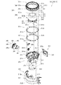
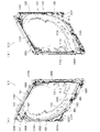
遊技盤5は、遊技者の操作によって遊技球Bが行われる遊技領域5aと、遊技領域5aの外周を区画し外形が正面視略四角形状とされた前構成部材1000と、前構成部材1000の後側に取付けられており遊技領域5aの後端を区画する板状の遊技パネル1100と、遊技パネル1100の後側下部に取付けられている基板ホルダ1200と、基板ホルダ1200の後面に取付けられており主制御基板1310を有している主制御ユニット1300と、主制御基板1310からの制御信号に基づいて遊技状況を表示する機能表示ユニット1400と、遊技パネル1100の後側に配置されている周辺制御ユニット1500(図12を参照)と、正面視において遊技領域5aの中央に配置されており所定の演出画像を表示可能な演出表示装置1600と、遊技パネル1100の前面に取付けられる表ユニット2000と、遊技パネル1100の後面に取付けられる裏ユニット3000と、を備えている。裏ユニット3000には、遊技状態に応じて可動演出や発光演出を行うことが可能な各種の演出ユニットを備えている。
The game board 5 includes a game area 5a in which a game ball B is played by a player's operation, a front component 1000 that divides the outer periphery of the game area 5a into a substantially square shape in front view, and a front component 1000. A plate-shaped game panel 1100 that is attached to the rear side and divides the rear end of the game area 5a, a board holder 1200 that is attached to the lower part of the rear side of the game panel 1100, and a board holder 1200 that is attached to the rear surface of the board holder 1200. The main control unit 1300 having the cage main control board 1310, the function display unit 1400 that displays the game status based on the control signal from the main control board 1310, and the periphery arranged behind the game panel 1100. A control unit 1500 (see FIG. 12), an effect display device 1600 arranged in the center of the game area 5a in front view and capable of displaying a predetermined effect image, and a table unit 2000 mounted on the front surface of the game panel 1100. , A back unit 3000 attached to the rear surface of the game panel 1100. The back unit 3000 is provided with various effect units capable of performing a movable effect and a light emitting effect according to the game state.
遊技盤5の遊技領域5a内には、遊技球Bと当接し所定のゲージ配列で植設されている複数の障害釘Nと、遊技球Bの受入れ又は通過により遊技者に対して所定の特典(例えば、所定数の遊技球Bの払出し)を付与する一般入賞口2001、第一始動口2002、ゲート部2003、第二始動口2004、第一大入賞口2005、及び第二大入賞口2006と、を備えている。障害釘Nは、遊技パネル1100の前面に植設されている。一般入賞口2001、第一始動口2002、ゲート部2003、第二始動口2004、第一大入賞口2005、及び第二大入賞口2006は、表ユニット2000に備えられている。
In the game area 5a of the game board 5, a plurality of obstacle nails N that are in contact with the game ball B and are planted in a predetermined gauge arrangement, and a predetermined privilege for the player by accepting or passing the game ball B. (For example, payout of a predetermined number of game balls B) General winning opening 2001, first starting opening 2002, gate portion 2003, second starting opening 2004, first large winning opening 2005, and second large winning opening 2006 And have. The obstacle nail N is planted in front of the game panel 1100. The general winning opening 2001, the first starting opening 2002, the gate portion 2003, the second starting opening 2004, the first large winning opening 2005, and the second large winning opening 2006 are provided in the table unit 2000.
遊技盤5の遊技領域5a内には、遊技者がハンドルユニット180のハンドル182を操作することで、遊技球Bを打込むことができる。これにより、遊技球Bが、遊技領域5a内の一般入賞口2001、第一始動口2002、ゲート部2003、第二始動口2004、第一大入賞口2005、及び第二大入賞口2006等に、受入れられたり通過したりするように、遊技者に対してハンドル182の打込操作を楽しませることができる。
A player can drive the game ball B into the game area 5a of the game board 5 by operating the handle 182 of the handle unit 180. As a result, the game ball B becomes the general winning opening 2001, the first starting opening 2002, the gate portion 2003, the second starting opening 2004, the first big winning opening 2005, the second big winning opening 2006, etc. in the game area 5a. , It is possible to entertain the player with the driving operation of the handle 182 so as to be accepted or passed.
また、遊技盤5は、遊技領域5a内に遊技球Bを打込むことで変化する遊技状態に応じて、演出表示装置1600に所定の演出画像を表示させたり、裏後演出ユニット3100、裏下左演出ユニット3200、裏下右演出ユニット3250、裏下中演出ユニット3300、裏上演出ユニット3400、裏後左演出ユニット3500、裏後右演出ユニット3600、裏前左演出ユニット3700、裏前右演出ユニット3800、等により発光演出や可動演出等を行わせたりして、遊技者を楽しませることができる。
Further, the game board 5 may display a predetermined effect image on the effect display device 1600 according to the game state changed by driving the game ball B into the game area 5a, or may display a predetermined effect image on the effect display device 1600, or the back-back effect unit 3100 and the back bottom. Left production unit 3200, back bottom right production unit 3250, back bottom middle production unit 3300, back top production unit 3400, back rear left production unit 3500, back rear right production unit 3600, back front left production unit 3700, back front right production The unit 3800 or the like can be used to perform a light emitting effect, a movable effect, or the like to entertain the player.
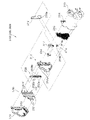
[2.外枠の全体構成]
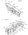
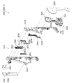
パチンコ機1の外枠2について、図13乃至図18を参照して説明する。図13はパチンコ機における外枠の正面図であり、図14は外枠の背面図であり、図15は外枠の右側面図である。また、図16は外枠を前から見た斜視図であり、図17は外枠を後ろから見た斜視図である。図18は、外枠を主な部材毎に分解して前から見た分解斜視図である。外枠2は、遊技ホール等のパチンコ機1が設置される島設備(図示は省略)に取付けられるものである。外枠2は、正面視の形状が上下に延びた四角形の枠に形成されている。
[2. Overall composition of the outer frame]
The outer frame 2 of the pachinko machine 1 will be described with reference to FIGS. 13 to 18. 13 is a front view of the outer frame of the pachinko machine, FIG. 14 is a rear view of the outer frame, and FIG. 15 is a right side view of the outer frame. Further, FIG. 16 is a perspective view of the outer frame viewed from the front, and FIG. 17 is a perspective view of the outer frame viewed from the back. FIG. 18 is an exploded perspective view of the outer frame disassembled for each main member and viewed from the front. The outer frame 2 is attached to an island facility (not shown) in which a pachinko machine 1 such as a game hall is installed. The outer frame 2 is formed in a quadrangular frame having a front view extending vertically.
外枠2は、図示するように、左右に離間しており上下に延びている外枠左組立体10及び外枠右組立体20と、外枠左組立体10及び外枠右組立体20の上端同士を連結している外枠上部材30と、外枠左組立体10及び外枠右組立体20の下端同士を連結している外枠下組立体40と、外枠上部材30の上面左端に取付けられている外枠上ヒンジ組立体50と、外枠左組立体10の右側面下部と外枠下組立体40の上面左端に取付けられている外枠下ヒンジ部材60と、を備えている。
As shown in the figure, the outer frame 2 includes an outer frame left assembly 10 and an outer frame right assembly 20 which are separated from each other to the left and right and extend vertically, and an outer frame left assembly 10 and an outer frame right assembly 20. The outer frame upper member 30 connecting the upper ends, the outer frame lower assembly 40 connecting the lower ends of the outer frame left assembly 10 and the outer frame right assembly 20, and the upper surface of the outer frame upper member 30. The outer frame upper hinge assembly 50 attached to the left end, and the outer frame lower hinge member 60 attached to the lower right side of the outer frame left assembly 10 and the upper left end of the outer frame lower assembly 40 are provided. ing.
外枠2は、本体枠4を閉じた時に、外枠下組立体40が、本体枠4における基板ユニット620のスピーカユニット620aと協働して、本体枠スピーカ622のエンクロージャ624の一部を形成していると共に、本体枠スピーカ622の後方へ出力されたサウンドを、位相反転させて前方へ放射することができるものである。
In the outer frame 2, when the main body frame 4 is closed, the outer frame lower assembly 40 cooperates with the speaker unit 620a of the board unit 620 in the main body frame 4 to form a part of the enclosure 624 of the main body frame speaker 622. At the same time, the sound output to the rear of the main body frame speaker 622 can be phase-inverted and radiated to the front.
外枠2は、外枠上ヒンジ組立体50が、本体枠4の本体枠上ヒンジ部材510を着脱可能に支持することができる。外枠2は、外枠上ヒンジ組立体50と外枠下ヒンジ部材60とによって、本体枠4の本体枠上ヒンジ部材510と本体枠下ヒンジ組立体520とを同軸上で回転可能に支持することができ、本体枠4を正面視左側を中心にして前方へ開閉可能に取付けることができる。
In the outer frame 2, the hinge assembly 50 on the outer frame can detachably support the hinge member 510 on the main body frame of the main body frame 4. The outer frame 2 coaxially and rotatably supports the main body frame upper hinge member 510 and the main body frame lower hinge assembly 520 of the main body frame 4 by the outer frame upper hinge assembly 50 and the outer frame lower hinge member 60. The main body frame 4 can be attached so as to be openable and closable forward with the left side of the front view as the center.
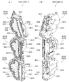
[2-1.外枠左組立体及び外枠右組立体]
外枠2の外枠左組立体10及び外枠右組立体20について、主に図19を参照して詳細に説明する。図19は、外枠の外枠左組立体及び外枠右組立体を夫々分解して前から見た分解斜視図である。外枠2の外枠左組立体10及び外枠右組立体20は、夫々が上下に延びており、互いに左右に離間して配置されている。外枠左組立体10及び外枠右組立体20は、本体枠4の本体枠上ヒンジ部材510及び本体枠下ヒンジ組立体520を同軸上で回転可能に支持して、外枠2に対して本体枠4を開閉可能に取付けるためのものである。
[2-1. Outer frame left assembly and outer frame right assembly]
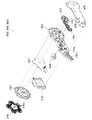
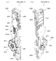
The outer frame left assembly 10 and the outer frame right assembly 20 of the outer frame 2 will be described in detail mainly with reference to FIG. FIG. 19 is an exploded perspective view of the outer frame left assembly and the outer frame right assembly of the outer frame disassembled and viewed from the front. The outer frame left assembly 10 and the outer frame right assembly 20 of the outer frame 2 extend vertically, respectively, and are arranged so as to be separated from each other on the left and right sides. The outer frame left assembly 10 and the outer frame right assembly 20 coaxially and rotatably support the main body frame upper hinge member 510 and the main body frame lower hinge assembly 520 of the main body frame 4 with respect to the outer frame 2. This is for mounting the main body frame 4 so that it can be opened and closed.
まず、外枠左組立体10は、前後方向が一定の幅(奥行)で上下に延びている外枠左部材11と、外枠左部材11の右側面上端に取付けられている左上連結部材12と、外枠左部材11の右側面下端に取付けられている左下連結部材13と、を備えている。
First, in the outer frame left assembly 10, the outer frame left member 11 extending vertically with a constant width (depth) in the front-rear direction and the upper left connecting member 12 attached to the upper end of the right side surface of the outer frame left member 11 And a lower left connecting member 13 attached to the lower end of the right side surface of the outer frame left member 11.
外枠左部材11は、一定の断面形状で上下に延びており、アルミ合金の押出型材によって形成されている。外枠左部材11は、左側面における前後方向を三等分したうちの後側の部位において平坦状に右方へ窪んでいる凹部11aと、右側面における凹部11aとは反対側の部位から右方へ膨出している膨出部11bと、膨出部11bを上下に貫通している空洞部11cと、を備えている。外枠左部材11は、凹部11aや膨出部11bによって、強度・剛性が高められていると共に、空洞部11cによって、重量が軽減されている。
The outer frame left member 11 extends vertically with a constant cross-sectional shape, and is formed of an aluminum alloy extruded mold material. The outer frame left member 11 has a concave portion 11a that is flatly recessed to the right in the rear portion of the left side surface divided into three equal parts in the front-rear direction, and a portion on the right side surface that is opposite to the concave portion 11a to the right. It includes a bulging portion 11b that bulges toward the direction and a hollow portion 11c that vertically penetrates the bulging portion 11b. The strength and rigidity of the outer frame left member 11 is increased by the concave portion 11a and the bulging portion 11b, and the weight is reduced by the hollow portion 11c.
また、外枠左部材11は、左右両側面において、上下に延びた複数の溝が形成されている。左側面の複数の溝は、V字状に形成されており、右側面の複数の溝は、半円形状に形成されている。外枠左部材11は、後述する外枠右組立体20の外枠右部材21と左右対称形状に形成されている。
Further, the outer frame left member 11 is formed with a plurality of grooves extending vertically on both the left and right sides. The plurality of grooves on the left side surface are formed in a V shape, and the plurality of grooves on the right side surface are formed in a semicircular shape. The outer frame left member 11 is formed in a symmetrical shape with the outer frame right member 21 of the outer frame right assembly 20 described later.
左上連結部材12は、外枠左部材11の上端と外枠上部材30の左端とを連結するためのものである。左上連結部材12は、水平に延びた平板状の水平固定部12aと、水平固定部12aの左辺における前後方向の中間から上方へ延出している平板状の上横固定部12bと、水平固定部12aの左辺における上横固定部12bの前後両側から下方へ延出している平板状の一対の下横固定部12cと、を備えている。左上連結部材12は、平板状の金属板を屈曲させて形成されている。
The upper left connecting member 12 is for connecting the upper end of the outer frame left member 11 and the left end of the outer frame upper member 30. The upper left connecting member 12 includes a horizontally extending flat plate-shaped horizontal fixing portion 12a, a flat plate-shaped upper-horizontal fixing portion 12b extending upward from the middle in the front-rear direction on the left side of the horizontal fixing portion 12a, and a horizontal fixing portion. It is provided with a pair of flat plate-shaped lower horizontal fixing portions 12c extending downward from both front and rear sides of the upper horizontal fixing portion 12b on the left side of 12a. The upper left connecting member 12 is formed by bending a flat metal plate.
左上連結部材12は、後側の下横固定部12cを外枠左部材11の空洞部11c内に挿入させると共に、水平固定部12aを外枠左部材11の上端に当接させ、更に、前側及び後側の下横固定部12cを外枠左部材11の右側面に当接させた状態で、外枠左部材11の左側面の外側から下横固定部12cにビスを捩じ込むことで、外枠左部材11に取付けられる。また、左上連結部材12は、水平固定部12aを外枠上部材30の左端側の下面に当接させると共に、上横固定部12bを外枠上部材30の左側面の切欠部30a内に挿入させた状態で、水平固定部12a及び上横固定部12bを通して外枠上部材30にビスを捩じ込むことで、外枠上部材30に取付けられる。
In the upper left connecting member 12, the lower horizontal fixing portion 12c on the rear side is inserted into the cavity portion 11c of the outer frame left member 11, the horizontal fixing portion 12a is brought into contact with the upper end of the outer frame left member 11, and further, the front side. In a state where the lower horizontal fixing portion 12c on the rear side is in contact with the right side surface of the outer frame left member 11, a screw is screwed into the lower horizontal fixing portion 12c from the outside of the left side surface of the outer frame left member 11. , Attached to the outer frame left member 11. Further, in the upper left connecting member 12, the horizontal fixing portion 12a is brought into contact with the lower surface on the left end side of the outer frame upper member 30, and the upper horizontal fixing portion 12b is inserted into the notch 30a on the left side surface of the outer frame upper member 30. In this state, it is attached to the outer frame upper member 30 by screwing a screw into the outer frame upper member 30 through the horizontal fixing portion 12a and the upper horizontal fixing portion 12b.
左下連結部材13は、外枠左部材11の下端と外枠下組立体40(外枠下部材41)の左端とを連結するためのものである。左下連結部材13は、水平に延びた平板状の水平固定部13aと、水平固定部13aの左辺から上方へ延出していると共に水平固定部13aよりも後方へ延出している平板状の上横固定部13bと、上横固定部13bの下辺における水平固定部よりも後側の部位から下方へ延出している平板状の下横固定部13cと、上横固定部13bの後辺から右方へ短く延出している平板状の当接部13dと、を備えている。左下連結部材13は、平板状の金属板を屈曲させて形成されている。
The lower left connecting member 13 is for connecting the lower end of the outer frame left member 11 and the left end of the outer frame lower assembly 40 (outer frame lower member 41). The lower left connecting member 13 has a horizontally extending flat plate-shaped horizontal fixing portion 13a and a flat plate-shaped upper side extending upward from the left side of the horizontal fixing portion 13a and extending rearward from the horizontal fixing portion 13a. The fixed portion 13b, the flat plate-shaped lower lateral fixing portion 13c extending downward from the portion posterior to the horizontal fixing portion on the lower side of the upper lateral fixing portion 13b, and the upper lateral fixing portion 13b to the right from the rear side. It is provided with a flat plate-shaped contact portion 13d extending shortly to. The lower left connecting member 13 is formed by bending a flat metal plate.
左下連結部材13は、当接部13dの後面を外枠左部材11の膨出部11bの前面に当接させると共に、上横固定部13bの左側面を外枠左部材11の右側面に当接させ、水平固定部13aの下面を外枠左部材11の下端と一致させた状態で、外枠左部材11の左側面の外側から上横固定部13bにビスを捩じ込むことで、外枠左部材11に取付けられる。また、左下連結部材13は、水平固定部13aを外枠下部材41の左端側の上面に当接させると共に、下横固定部13cを外枠下部材41の左側面の切欠部41aに挿入させた状態で、水平固定部13a及び下横固定部13cを通して外枠下部材にビスを捩じ込むことで、外枠下部材41に取付けられる。
In the lower left connecting member 13, the rear surface of the contact portion 13d is brought into contact with the front surface of the bulging portion 11b of the outer frame left member 11, and the left surface of the upper horizontal fixing portion 13b is in contact with the right surface of the outer frame left member 11. With the lower surface of the horizontal fixing portion 13a in contact with the lower end of the outer frame left member 11, a screw is screwed into the upper horizontal fixing portion 13b from the outside of the left side surface of the outer frame left member 11 to the outside. It is attached to the frame left member 11. Further, in the lower left connecting member 13, the horizontal fixing portion 13a is brought into contact with the upper surface on the left end side of the outer frame lower member 41, and the lower horizontal fixing portion 13c is inserted into the notch portion 41a on the left side surface of the outer frame lower member 41. In this state, it is attached to the outer frame lower member 41 by screwing a screw into the outer frame lower member through the horizontal fixing portion 13a and the lower horizontal fixing portion 13c.
次に、外枠右組立体20は、前後方向が一定の幅(奥行)で上下に延びている外枠右部材21と、外枠右部材21の左側面上端に取付けられている右上連結部材22と、外枠右部材21の左側面下端に取付けられている右下連結部材23と、外枠右部材21の左側面上部に取付けられている上鉤掛部材24と、外枠右部材21の左側面下部に取付けられている下鉤掛部材25と、を備えている。
Next, in the outer frame right assembly 20, the outer frame right member 21 extending vertically with a certain width (depth) in the front-rear direction and the upper right connecting member attached to the upper end of the left side surface of the outer frame right member 21. 22, the lower right connecting member 23 attached to the lower end of the left side surface of the outer frame right member 21, the upper hooking member 24 attached to the upper part of the left side surface of the outer frame right member 21, and the outer frame right member 21. It is provided with a lower hook member 25 attached to the lower part of the left side surface.
外枠右部材21は、一定の断面形状で上下に延びており、アルミ合金の押出型材によって形成されている。外枠右部材21は、右側面における前後方向を三等分したうちの後側の部位において平坦状に左方へ窪んでいる凹部21aと、左側面における凹部21aとは反対側の部位から左方へ膨出している膨出部21bと、膨出部21bを上下に貫通している空洞部21cと、を備えている。外枠右部材21は、凹部21aや膨出部21bによって、強度・剛性が高められていると共に、空洞部21cによって、重量が軽減されている。
The outer frame right member 21 extends vertically with a constant cross-sectional shape, and is formed of an aluminum alloy extruded mold material. The outer frame right member 21 has a concave portion 21a that is flatly recessed to the left in the rear portion of the right side surface divided into three equal parts in the front-rear direction, and a portion on the left side surface that is opposite to the concave portion 21a to the left. It includes a bulging portion 21b that bulges toward the direction and a hollow portion 21c that vertically penetrates the bulging portion 21b. The strength and rigidity of the outer frame right member 21 is increased by the concave portion 21a and the bulging portion 21b, and the weight is reduced by the hollow portion 21c.
また、外枠右部材21は、左右両側面において、上下に延びた複数の溝が形成されている。右側面の複数の溝は、V字状に形成されており、左側面の複数の溝は、半円形状に形成されている。外枠右部材21は、外枠左組立体10の外枠左部材11と左右対称形状に形成されている。
Further, the outer frame right member 21 is formed with a plurality of grooves extending vertically on both the left and right sides. The plurality of grooves on the right side surface are formed in a V shape, and the plurality of grooves on the left side surface are formed in a semicircular shape. The outer frame right member 21 is formed in a symmetrical shape with the outer frame left member 11 of the outer frame left assembly 10.
右上連結部材22は、外枠右部材21の上端と外枠上部材30の右端とを連結するためのものである。右上連結部材22は、水平に延びた平板状の水平固定部22aと、水平固定部22aの右辺における前後方向の中間から上方へ延出している平板状の上横固定部22bと、水平固定部22aの右辺における上横固定部22bの前後両側から下方へ延出している平板状の一対の下横固定部22cと、を備えている。右上連結部材22は、平板状の金属板を屈曲させて形成されている。
The upper right connecting member 22 is for connecting the upper end of the outer frame right member 21 and the right end of the outer frame upper member 30. The upper right connecting member 22 includes a horizontally extending flat plate-shaped horizontal fixing portion 22a, a flat plate-shaped upper-horizontal fixing portion 22b extending upward from the middle in the front-rear direction on the right side of the horizontal fixing portion 22a, and a horizontal fixing portion. It is provided with a pair of flat plate-shaped lower horizontal fixing portions 22c extending downward from both front and rear sides of the upper horizontal fixing portion 22b on the right side of 22a. The upper right connecting member 22 is formed by bending a flat metal plate.
右上連結部材22は、後側の下横固定部22cを外枠右部材21の空洞部21c内に挿入させると共に、水平固定部22aを外枠右部材21の上端に当接させ、更に、前側及び後側の下横固定部22cを外枠右部材21の左側面に当接させた状態で、外枠右部材21の右側面の外側から下横固定部22cにビスを捩じ込むことで、外枠右部材21に取付けられる。また、右上連結部材22は、水平固定部22aを外枠上部材30の右端側の下面に当接させると共に、上横固定部22bを外枠上部材30の右側面の切欠部30a内に挿入させた状態で、水平固定部22a及び上横固定部22bを通して外枠上部材30にビスを捩じ込むことで、外枠上部材30に取付けられる。
In the upper right connecting member 22, the lower horizontal fixing portion 22c on the rear side is inserted into the hollow portion 21c of the outer frame right member 21, the horizontal fixing portion 22a is brought into contact with the upper end of the outer frame right member 21, and further, the front side. In a state where the lower horizontal fixing portion 22c on the rear side is in contact with the left side surface of the outer frame right member 21, a screw is screwed into the lower horizontal fixing portion 22c from the outside of the right side surface of the outer frame right member 21. , Attached to the outer frame right member 21. Further, in the upper right connecting member 22, the horizontal fixing portion 22a is brought into contact with the lower surface on the right end side of the outer frame upper member 30, and the upper horizontal fixing portion 22b is inserted into the notch 30a on the right side surface of the outer frame upper member 30. In this state, it is attached to the outer frame upper member 30 by screwing a screw into the outer frame upper member 30 through the horizontal fixing portion 22a and the upper horizontal fixing portion 22b.
右下連結部材23は、外枠右部材21の下端と外枠下組立体40(外枠下部材41)の右端とを連結するためのものである。右下連結部材23は、水平に延びた平板状の水平固定部23aと、水平固定部23aの右辺から上方へ延出していると共に水平固定部23aよりも後方へ延出している平板状の上横固定部23bと、上横固定部23bの下辺における水平固定部よりも後側の部位から下方へ延出している平板状の下横固定部23cと、上横固定部23bの後辺から左方へ短く延出している平板状の当接部23dと、を備えている。右下連結部材23は、平板状の金属板を屈曲させて形成されている。
The lower right connecting member 23 is for connecting the lower end of the outer frame right member 21 and the right end of the outer frame lower assembly 40 (outer frame lower member 41). The lower right connecting member 23 has a horizontally extending flat plate-shaped horizontal fixing portion 23a and a flat plate-shaped upper portion extending upward from the right side of the horizontal fixing portion 23a and extending rearward from the horizontal fixing portion 23a. The horizontal fixing portion 23b, the flat plate-shaped lower horizontal fixing portion 23c extending downward from the portion posterior to the horizontal fixing portion on the lower side of the upper horizontal fixing portion 23b, and the left from the rear side of the upper horizontal fixing portion 23b. It is provided with a flat plate-shaped contact portion 23d that extends shortly toward the direction. The lower right connecting member 23 is formed by bending a flat metal plate.
右下連結部材23は、当接部23dの後面を外枠右部材21の膨出部21bの前面に当接させると共に、上横固定部23bの右側面を外枠右部材21の左側面に当接させ、水平固定部23aの下面を外枠右部材21の下端と一致させた状態で、外枠右部材21の右側面の外側から上横固定部23bにビスを捩じ込むことで、外枠右部材21に取付けられる。また、右下連結部材23は、水平固定部23aを外枠下部材41の右端側の上面に当接させると共に、下横固定部23cを外枠下部材41の右側面の切欠部41aに挿入させた状態で、水平固定部23a及び下横固定部23cを通して外枠下部材にビスを捩じ込むことで、外枠下部材41に取付けられる。
In the lower right connecting member 23, the rear surface of the contact portion 23d is brought into contact with the front surface of the bulging portion 21b of the outer frame right member 21, and the right surface of the upper horizontal fixing portion 23b is attached to the left surface of the outer frame right member 21. By abutting and in a state where the lower surface of the horizontal fixing portion 23a is aligned with the lower end of the outer frame right member 21, a screw is screwed into the upper horizontal fixing portion 23b from the outside of the right side surface of the outer frame right member 21. It is attached to the outer frame right member 21. Further, in the lower right connecting member 23, the horizontal fixing portion 23a is brought into contact with the upper surface on the right end side of the outer frame lower member 41, and the lower horizontal fixing portion 23c is inserted into the notch portion 41a on the right side surface of the outer frame lower member 41. In this state, it is attached to the outer frame lower member 41 by screwing a screw into the outer frame lower member through the horizontal fixing portion 23a and the lower horizontal fixing portion 23c.
上鉤掛部材24及び下鉤掛部材25は、後述する本体枠4における施錠ユニット650の外枠用鉤653が掛止されるものである。上鉤掛部材24は、前後方向に一定の幅で上下に延びており外枠右部材21の左側面に取付けられる平板状の取付部24aと、取付部24aの前辺から左方へ延出しており上側の外枠用鉤653が掛止される平板状の掛止片部24bと、を備えている。
The upper hook hook member 24 and the lower hook hook member 25 are for hooking the outer frame hook 653 of the locking unit 650 in the main body frame 4, which will be described later. The upper hook member 24 extends vertically with a certain width in the front-rear direction, and extends to the left from the front side of the flat plate-shaped mounting portion 24a mounted on the left side surface of the outer frame right member 21 and the mounting portion 24a. It is provided with a flat plate-shaped hook piece portion 24b on which the hook 653 for the outer frame on the upper side of the cage is hooked.
下鉤掛部材25は、前後方向に一定の幅で上下に延びており外枠右部材21の左側面に取付けられる平板状の取付部25aと、取付部25aの前辺から左方へ延出しており下側の外枠用鉤653が掛止される平板状の掛止片部25bと、掛止片部25bを前後に貫通しており下側の外枠用鉤653が挿通可能な挿通口25cと、を備えている。
The lower hook member 25 extends vertically with a certain width in the front-rear direction, and has a flat plate-shaped mounting portion 25a mounted on the left side surface of the outer frame right member 21 and a flat plate-shaped mounting portion 25a extending from the front side of the mounting portion 25a to the left. A flat plate-shaped hook piece portion 25b on which the lower outer frame hook 653 is hooked and an insertion through which the lower outer frame hook 653 can be inserted through the hook piece portion 25b in the front-rear direction. It has a mouth 25c and.
[2-2.外枠上部材]
外枠2の外枠上部材30について、主に図18を参照して詳細に説明する。外枠上部材30は、左右に離間している外枠左組立体10及び外枠右組立体20の上端同士を連結するためのものである。外枠上部材30は、前後方向の幅が、外枠左部材11及び外枠右部材21の前後方向と略同じ幅で、上下方向の厚さが一定で、左右方向に延びており、木材によって形成されている。外枠上部材30は、左右方向の長さが、後述する外枠下組立体40の外枠下部材41の左右方向の長さと同じに形成されている。
[2-2. Outer frame upper member]
The outer frame upper member 30 of the outer frame 2 will be described in detail mainly with reference to FIG. The outer frame upper member 30 is for connecting the upper ends of the outer frame left assembly 10 and the outer frame right assembly 20 that are separated from each other to the left and right. The width of the outer frame upper member 30 in the front-rear direction is substantially the same as the width in the front-rear direction of the outer frame left member 11 and the outer frame right member 21, the thickness in the vertical direction is constant, and the width extends in the left-right direction. Is formed by. The outer frame upper member 30 is formed so that the length in the left-right direction is the same as the length in the left-right direction of the outer frame lower member 41 of the outer frame lower assembly 40 described later.
外枠上部材30は、左右両側面における前後方向の中央において、上下に貫通した状態で左右方向中央側へ夫々窪んでいる切欠部30aを備えている。これら左右両端の切欠部30aには、左上連結部材12の上横固定部12b及び右上連結部材22の上横固定部22bが夫々挿入された状態で取付けられる。
The outer frame upper member 30 is provided with a notch 30a that is recessed toward the center side in the left-right direction in a state of penetrating up and down at the center in the front-rear direction on both left and right side surfaces. The upper lateral fixing portion 12b of the upper left connecting member 12 and the upper lateral fixing portion 22b of the upper right connecting member 22 are attached to the cutout portions 30a at both left and right ends in a state of being inserted respectively.
また、外枠上部材30は、左側端部において、上面と前面が一般面よりも窪んだ取付段部30bを備えている。この取付段部30bには、後述する外枠上ヒンジ組立体50が取付けられる。
Further, the outer frame upper member 30 includes a mounting step portion 30b whose upper surface and front surface are recessed from the general surface at the left end portion. A hinge assembly 50 on an outer frame, which will be described later, is mounted on the mounting step portion 30b.
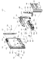
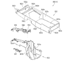
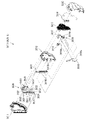
[2-3.外枠下組立体]
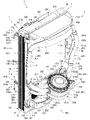
外枠2の外枠下組立体40について、主に図20を参照して詳細に説明する。図20は、外枠の外枠下組立体を分解して前から見た分解斜視図である。外枠下組立体40は、左右に離間している外枠左組立体10及び外枠右組立体20の下端同士を連結すると共に、パチンコ機1において扉枠3よりも下側を閉鎖して装飾するためのものである。
[2-3. Assembly under the outer frame]
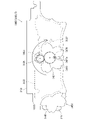
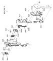
The outer frame lower assembly 40 of the outer frame 2 will be described in detail mainly with reference to FIG. FIG. 20 is an exploded perspective view of the outer frame lower assembly of the outer frame as viewed from the front by disassembling. The outer frame lower assembly 40 connects the lower ends of the outer frame left assembly 10 and the outer frame right assembly 20 that are separated from each other to the left and right, and closes the lower side of the pachinko machine 1 below the door frame 3. It is for decoration.
外枠下組立体40は、左右に離間している外枠左組立体10及び外枠右組立体20の下端同士を連結しており左右に延びている外枠下部材41と、外枠下部材41の前方に配置されており外枠下部材41に沿って左右に延びていると共に後方が開放されている箱状の幕板前部材42と、幕板前部材42の後側に取付けられていると共に外枠下部材41の上面に取付けられており前方が開放されている左右に延びた箱状の幕板後部材43と、幕板後部材43の上面における左端に形成されている球噛防止機構44と、を備えている。
The outer frame lower assembly 40 has an outer frame lower member 41 that connects the lower ends of the outer frame left assembly 10 and the outer frame right assembly 20 that are separated to the left and right and extends to the left and right, and the outer frame lower assembly 40. A box-shaped front curtain plate member 42 that is arranged in front of the member 41 and extends to the left and right along the outer frame lower member 41 and is open at the rear, and is attached to the rear side of the front curtain plate member 42. A box-shaped rear curtain plate member 43 that is attached to the upper surface of the outer frame lower member 41 and has an open front, and a ball bite prevention formed on the left end of the upper surface of the curtain plate rear member 43. It is equipped with a mechanism 44.
外枠下部材41は、前後方向の幅が、外枠左部材11及び外枠右部材21の前後方向と略同じ幅で、上下方向の厚さが一定で、左右方向に延びており、木材によって形成されている。外枠下部材41は、左右方向の長さが、外枠上部材30の左右方向の長さと同じに形成されている。
The width of the outer frame lower member 41 in the front-rear direction is substantially the same as the width in the front-rear direction of the outer frame left member 11 and the outer frame right member 21, the thickness in the vertical direction is constant, and the width extends in the left-right direction. Is formed by. The outer frame lower member 41 is formed so that the length in the left-right direction is the same as the length in the left-right direction of the outer frame upper member 30.
外枠下部材41は、左右両側面における前後方向の中央において、上下に貫通した状態で左右方向中央側へ夫々窪んでいる切欠部41aを備えている。これら左右両端の切欠部41aには、左下連結部材13の下横固定部13c及び右下連結部材23の下横固定部23cが夫々挿入された状態で取付けられる。これにより、外枠左部材11及び外枠右部材21の下端同士を連結することができる。
The outer frame lower member 41 is provided with a notch 41a that is recessed toward the center side in the left-right direction in a state of penetrating up and down at the center in the front-rear direction on both left and right side surfaces. The lower lateral fixing portion 13c of the lower left connecting member 13 and the lower lateral fixing portion 23c of the lower right connecting member 23 are attached to the cutout portions 41a at both left and right ends in a state of being inserted respectively. Thereby, the lower ends of the outer frame left member 11 and the outer frame right member 21 can be connected to each other.
また、外枠下部材41は、上面から凹んでおり、幕板後部材43の下部が挿入される凹部41bを備えている。凹部41bは、左右に延びていると共に、前後方向中央の後ろ寄りの位置から前端側へ抜けている。この凹部41bにより、幕板前部材42及び幕板後部材43により形成される幕板内部空間40aの容積を可及的に広くしている。
Further, the outer frame lower member 41 is recessed from the upper surface, and has a recess 41b into which the lower portion of the curtain plate rear member 43 is inserted. The concave portion 41b extends to the left and right, and is removed from the position toward the rear in the center in the front-rear direction toward the front end side. The recess 41b makes the volume of the curtain plate internal space 40a formed by the curtain plate front member 42 and the curtain plate rear member 43 as wide as possible.
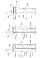
幕板前部材42は、左右方向の長さが外枠下部材41と同じ長さに延びており、高さに対して前後方向の奥行が短い横長の直方体状の箱状に形成されており、後側の全面が開放されている。幕板前部材42は、開放されている後側を、幕板後部材43によって閉鎖することで、幕板後部材43と協働して本体枠スピーカ622のエンクロージャ624の一部となる幕板内部空間40aを形成する。幕板前部材42は、右端付近の前面において、前後に貫通していると共に左右に延びている長孔状の開口部42aを備えている。
The curtain plate front member 42 has a length in the left-right direction extending to the same length as the outer frame lower member 41, and is formed in a horizontally long rectangular parallelepiped box shape having a short depth in the front-rear direction with respect to the height. The entire rear side is open. The curtain plate front member 42 is closed on the open rear side by the curtain plate rear member 43, so that the curtain plate front member 42 cooperates with the curtain plate rear member 43 to become a part of the enclosure 624 of the main body frame speaker 622. It forms a space 40a. The curtain plate front member 42 has an elongated hole-shaped opening 42a that penetrates back and forth and extends left and right on the front surface near the right end.
幕板後部材43は、左右方向の長さが外枠下部材41よりも若干短く延びており、前方が開放された箱状に形成されている。幕板後部材43は、前面に幕板前部材42を取付けることで、幕板前部材42と協働して本体枠スピーカ622のエンクロージャ624の一部となる幕板内部空間40aを形成する。幕板後部材43は、上面における左右方向中央部において、左右に延びていると共に上方へ突出しており幕板内部空間40aと連通している筒状の接続筒部43aを有している。接続筒部43aは、上端が、幕板後部材43の一般的な上面と一致している前端側から後方へ向かうほど上方へ位置するように傾斜している。本実施形態では、接続筒部43aの上端は、45度の角度で傾斜している。
The curtain plate rear member 43 has a length in the left-right direction slightly shorter than that of the outer frame lower member 41, and is formed in a box shape with an open front. By attaching the curtain plate front member 42 to the front surface of the curtain plate rear member 43, the curtain plate front member 42 cooperates with the curtain plate front member 42 to form a curtain plate internal space 40a that becomes a part of the enclosure 624 of the main body frame speaker 622. The curtain plate rear member 43 has a tubular connecting cylinder portion 43a that extends left and right and projects upward at the central portion in the left-right direction on the upper surface and communicates with the curtain plate internal space 40a. The upper end of the connecting cylinder portion 43a is inclined so as to be positioned upward from the front end side, which coincides with the general upper surface of the curtain plate rear member 43, toward the rear. In the present embodiment, the upper end of the connecting cylinder portion 43a is inclined at an angle of 45 degrees.
この接続筒部43aは、左右方向の長さが、幕板後部材43全体の約1/3の長さに形成されていると共に、前後方向の奥行が、幕板後部材43全体の奥行よりも若干短く形成されている。接続筒部43a内には、前端側と後端側とを結ぶ複数のリブ43bが備えられている。この接続筒部43aの上端には、外枠2に対して本体枠4を閉じた時に、本体枠4における基板ユニット620のスピーカユニット620aにおけるスピーカカバー621の接続部621cが接続されて、スピーカユニット620aの内部空間と連通した状態となり、エンクロージャ624を形成する。
The length of the connecting cylinder portion 43a in the left-right direction is formed to be about 1/3 of the length of the entire curtain plate rear member 43, and the depth in the front-rear direction is greater than the depth of the entire curtain plate rear member 43. Is also formed slightly shorter. A plurality of ribs 43b connecting the front end side and the rear end side are provided in the connection cylinder portion 43a. When the main body frame 4 is closed with respect to the outer frame 2, the connection portion 621c of the speaker cover 621 in the speaker unit 620a of the board unit 620 in the main body frame 4 is connected to the upper end of the connection cylinder portion 43a. It communicates with the internal space of the 620a and forms the enclosure 624.
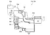
球噛防止機構44は、幕板後部材43の上面における左端において、外枠下ヒンジ部材60の部位に遊技球Bが滞留することで、外枠2と本体枠4との間に遊技球Bが挟まれるのを防止するためのものである。
In the ball biting prevention mechanism 44, the game ball B stays at the portion of the outer frame lower hinge member 60 at the left end on the upper surface of the curtain plate rear member 43, so that the game ball B is between the outer frame 2 and the main body frame 4. Is to prevent being pinched.
球噛防止機構44は、幕板後部材43の上面における左端に形成されており、後述する外枠下ヒンジ部材60が際されるように平坦に形成された載置部44aと、載置部44aの左端において上方へ向かって開口している第一排出口44bと、載置部44aにおける第一排出口44bよりも右方で上方へ向かって開口している第二排出口44cと、載置部44aの後辺及び右辺から上方へ延出している立壁部44dと、立壁部44dの上端から前方へ突出していると共に上面が後方へ向かうに従って上方に位置するように傾斜している上端突出部44eと、を備えている。
The ball biting prevention mechanism 44 is formed at the left end on the upper surface of the curtain plate rear member 43, and is a mounting portion 44a formed flat so that the hinge member 60 under the outer frame, which will be described later, is highlighted, and a mounting portion. The first discharge port 44b that opens upward at the left end of 44a and the second discharge port 44c that opens upward to the right of the first discharge port 44b in the mounting portion 44a are mounted. A vertical wall portion 44d extending upward from the rear side and the right side of the placement portion 44a, and an upper end protrusion protruding forward from the upper end of the vertical wall portion 44d and inclined so that the upper surface is positioned upward as the upper surface moves backward. It is provided with a portion 44e.
第一排出口44bは、後述する外枠下ヒンジ部材60の排出孔60dと一致する位置に形成されている。第一排出口44b及び第二排出口44cは、遊技球Bが通過可能な大きさに形成されている。第一排出口44b及び第二排出口44cは、幕板内部空間40aとは連通しておらず、幕板後部材43の後面に開口している。従って、第一排出口44b及び第二排出口44cに進入した遊技球Bを、幕板後部材43の後方へ排出することができる。
The first discharge port 44b is formed at a position corresponding to the discharge hole 60d of the outer frame lower hinge member 60, which will be described later. The first discharge port 44b and the second discharge port 44c are formed in a size that allows the game ball B to pass through. The first discharge port 44b and the second discharge port 44c do not communicate with the curtain plate internal space 40a and are open to the rear surface of the curtain plate rear member 43. Therefore, the game ball B that has entered the first discharge port 44b and the second discharge port 44c can be discharged to the rear of the curtain plate rear member 43.
この球噛防止機構44は、球噛防止機構44は、外枠下ヒンジ部材60と後述する本体枠下ヒンジ組立体520との間の隙間を通して、ピアノ線等の不正な工具が挿入された場合、載置部44aの後端から立上っている立壁部44dにより、不正な工具の侵入を阻止することができる。仮に、不正な工具の先端が立壁部44dに当接することで、上方へ曲がったとしても、立壁部44dの上端に備えられている前方へ突出した上端突出部44eに当接し、これ以上の侵入を阻止することができる。従って、外枠下ヒンジ部材60の部位を介して、不正行為が行われるのを防止することができる。
The ball biting prevention mechanism 44 is a case where an illegal tool such as a piano wire is inserted through the gap between the outer frame lower hinge member 60 and the main body frame lower hinge assembly 520 described later. The standing wall portion 44d rising from the rear end of the mounting portion 44a can prevent an unauthorized tool from entering. Even if the tip of an illegal tool comes into contact with the standing wall portion 44d and bends upward, it comes into contact with the forward protruding upper end protruding portion 44e provided at the upper end of the standing wall portion 44d and further invades. Can be blocked. Therefore, it is possible to prevent fraudulent acts from being performed through the portion of the hinge member 60 under the outer frame.
ところで、載置部44aの後端に立壁部44dを備えた場合、外枠2に対して本体枠4を開けた時に、何らかの理由により載置部44a上に落下した遊技球Bが、立壁部44dによって外枠2の後方への移動が阻止されるため、載置部44a上に遊技球Bが滞留し易くなる。そして、載置部44a上に遊技球Bが滞留していると、外枠2に対して本体枠4を閉じる際に、外枠2と本体枠4との間に遊技球Bが挟み込まれてしまい、本体枠4を閉じることができなくなる問題が発生する。
By the way, when the standing wall portion 44d is provided at the rear end of the mounting portion 44a, the game ball B that has fallen on the mounting portion 44a for some reason when the main body frame 4 is opened with respect to the outer frame 2 is the standing wall portion. Since the movement of the outer frame 2 to the rear is prevented by the 44d, the game ball B is likely to stay on the mounting portion 44a. When the game ball B stays on the mounting portion 44a, the game ball B is sandwiched between the outer frame 2 and the main body frame 4 when the main body frame 4 is closed with respect to the outer frame 2. This causes a problem that the main body frame 4 cannot be closed.
これに対して、本実施形態の球噛防止機構44では、外枠下ヒンジ部材60上や載置部44a上に落下した遊技球Bを、外枠下ヒンジ部材60の排出孔60dと第一排出口44bを通して、又は、第二排出口44cを通して、遊技球Bを幕板後部材43の後方(外枠2の後方)へ排出することができ、外枠2と本体枠4との間に遊技球Bが挟まれるのを防止することができる。
On the other hand, in the ball biting prevention mechanism 44 of the present embodiment, the game ball B that has fallen on the outer frame lower hinge member 60 or on the mounting portion 44a is first referred to as the discharge hole 60d of the outer frame lower hinge member 60. The game ball B can be discharged to the rear of the curtain plate rear member 43 (behind the outer frame 2) through the discharge port 44b or the second discharge port 44c, and is between the outer frame 2 and the main body frame 4. It is possible to prevent the game ball B from being pinched.
外枠下組立体40は、幕板前部材42及び幕板後部材43の上面に左右に離間して配置されている一対の案内部材45と、幕板前部材42の開口部42aを後側から閉鎖している平板状のグリル部材46と、グリル部材46を挟んで開口部42aを閉鎖するように幕板前部材42の内部に取付けられており前後に延びた二つの円筒を有したポート部材47と、幕板後部材43の接続筒部43aの上端に配置される枠状のシール部材48と、を備えている。
The outer frame lower assembly 40 closes a pair of guide members 45 arranged apart from each other on the upper surfaces of the curtain plate front member 42 and the curtain plate rear member 43, and the opening 42a of the curtain plate front member 42 from the rear side. A flat plate-shaped grill member 46 and a port member 47 having two cylinders that are attached to the inside of the curtain plate front member 42 so as to close the opening 42a across the grill member 46 and extend back and forth. A frame-shaped seal member 48 arranged at the upper end of the connection cylinder portion 43a of the curtain plate rear member 43 is provided.
一対の案内部材45は、外枠2に対して本体枠4を閉じた時に、扉枠3の下端が当接するものである。案内部材45は、摩擦抵抗の低い低摩擦材料によって形成されており、本体枠4の下端を滑り易くして、開閉を容易にしている。
The pair of guide members 45 are such that the lower end of the door frame 3 comes into contact with the outer frame 2 when the main body frame 4 is closed. The guide member 45 is made of a low-friction material having low frictional resistance, and makes the lower end of the main body frame 4 slippery to facilitate opening and closing.
グリル部材46は、無数の小穴を有したパンチングメタルにより形成されている。ポート部材47は、二つの円筒により、グリル部材46を介して幕板内部空間40a(エンクロージャ624)と外枠2の前方とを連通させている。ポート部材47は、二つの円筒が、所定の内径で所定の長さに形成されており、ヘルムホルツ共鳴の原理により本体枠スピーカ622から後方(エンクロージャ624内)へ発せられた低音を共振・増幅させて、豊かな低音を外枠2の前方(遊技者側)へ放射することができる。つまり、本実施形態では、本体枠スピーカ622のエンクロージャ624がバスレフ型とされており、遊技者に対して重低音を聞かせることができる。
The grill member 46 is formed of a punching metal having innumerable small holes. The port member 47 communicates the curtain plate internal space 40a (enclosure 624) with the front of the outer frame 2 via the grill member 46 by two cylinders. The port member 47 has two cylinders formed with a predetermined inner diameter and a predetermined length, and resonates and amplifies the bass emitted from the main body frame speaker 622 to the rear (inside the enclosure 624) by the principle of Helmholtz resonance. Therefore, rich bass can be radiated to the front (player side) of the outer frame 2. That is, in the present embodiment, the enclosure 624 of the main body frame speaker 622 is a bass reflex type, and the player can hear the deep bass.
シール部材48は、外枠2に対して本体枠4を閉じた時に、接続筒部43aの上端と本体枠4におけるスピーカカバー621の接続部621cの下端との間に挟まれて圧縮されるものであり、接続筒部43aと接続部621cとの間から本体枠スピーカ622のエンクロージャ624内の音が漏れるのを防止するものである。
The seal member 48 is sandwiched and compressed between the upper end of the connection cylinder portion 43a and the lower end of the connection portion 621c of the speaker cover 621 in the main body frame 4 when the main body frame 4 is closed with respect to the outer frame 2. This is to prevent the sound in the enclosure 624 of the main body frame speaker 622 from leaking from between the connection cylinder portion 43a and the connection portion 621c.
[2-4.外枠上ヒンジ組立体]
外枠2の外枠上ヒンジ組立体50について、主に図21を参照して詳細に説明する。図21(a)は外枠の外枠上ヒンジ組立体を分解して前上から見た分解斜視図であり、(b)は(a)を前下から見た分解斜視図である。外枠上ヒンジ組立体50は、外枠左組立体10の上端と外枠上部材30の左端に取付けられるものであり、外枠2に対して本体枠4をヒンジ回転可能に取付けるためのものである。外枠上ヒンジ組立体50は、外枠左部材11の凹部11aの上端と外枠上部材30の取付段部30bとに取付けられる外枠上ヒンジ部材51と、外枠上ヒンジ部材51に取付けられているロック部材52と、ロック部材52を外枠上ヒンジ部材51に取付けている取付ビス53と、を備えている。
[2-4. Hinge assembly on outer frame]
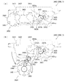
The hinge assembly 50 on the outer frame of the outer frame 2 will be described in detail mainly with reference to FIG. 21. 21 (a) is an exploded perspective view of the hinge assembly on the outer frame of the outer frame disassembled and viewed from the front upper side, and FIG. 21 (b) is an exploded perspective view of (a) viewed from the front lower surface. The outer frame upper hinge assembly 50 is attached to the upper end of the outer frame left assembly 10 and the left end of the outer frame upper member 30, and is for attaching the main body frame 4 to the outer frame 2 so that the hinge can be rotated. Is. The outer frame upper hinge assembly 50 is attached to the outer frame upper hinge member 51 attached to the upper end of the recess 11a of the outer frame left member 11 and the mounting step portion 30b of the outer frame upper member 30, and to the outer frame upper hinge member 51. The lock member 52 is provided with a locking member 52 and a mounting screw 53 for attaching the lock member 52 to the hinge member 51 on the outer frame.
外枠上ヒンジ部材51は、水平に延びた平板状で外枠上部材30の取付段部30bの上面に取付けられる上固定部51aと、上固定部51aの前辺から前方へ延出している平板状の前方延出部51bと、前方延出部51bの右辺の途中から前方へ向かうに従って前方延出部51bの左右中央へ延びており上下に貫通している軸受溝51cと、上固定部51aの左辺から下方へ延びている平板状の横固定部51dと、前方延出部51bの左辺から前辺を周って軸受溝51cが開口している部位までの端縁から下方へ延びており横固定部51dと連続している平板状の端縁壁部51eと、を備えている。外枠上ヒンジ部材51は、金属板をプレス成型により打抜き・屈曲させて形成されている。外枠上ヒンジ部材51は、軸受溝51c内において、本体枠上ヒンジ部材510の後述する本体枠上ヒンジピン512を回転可能に支持することができる。
The outer frame upper hinge member 51 has an upper fixing portion 51a that is horizontally extended and is attached to the upper surface of the mounting step portion 30b of the outer frame upper member 30, and extends forward from the front side of the upper fixing portion 51a. A flat plate-shaped front extending portion 51b, a bearing groove 51c extending vertically from the middle of the right side of the front extending portion 51b to the left and right center of the front extending portion 51b and penetrating vertically, and an upper fixing portion. The flat plate-shaped horizontal fixing portion 51d extending downward from the left side of the 51a and the end edge extending downward from the left side of the front extending portion 51b to the portion where the bearing groove 51c is opened around the front side. It is provided with a flat plate-shaped edge wall portion 51e that is continuous with the cage horizontal fixing portion 51d. The hinge member 51 on the outer frame is formed by punching and bending a metal plate by press molding. The outer frame upper hinge member 51 can rotatably support the main body frame upper hinge pin 512 described later of the main body frame upper hinge member 510 in the bearing groove 51c.
ロック部材52は、前後に延びている帯板状のロック本体52aと、ロック本体52aの後端から右方へ突出している操作片52bと、ロック本体52aの後端から左方へ延びた後に斜め左前方へ延びている弾性変形可能な棒状の弾性部52cと、ロック本体52aの後端付近で上下に貫通している取付孔52dと、を備えている。ロック部材52は、合成樹脂によって形成されている。ロック部材52は、取付ビス53によって、外枠上ヒンジ部材51における前方延出部51bの下面で、軸受溝51cよりも後側の部位に回動可能に取付けられる。
The lock member 52 has a strip-shaped lock body 52a extending back and forth, an operation piece 52b protruding to the right from the rear end of the lock body 52a, and after extending to the left from the rear end of the lock body 52a. It is provided with an elastically deformable rod-shaped elastic portion 52c extending diagonally to the left front and a mounting hole 52d penetrating vertically near the rear end of the lock body 52a. The lock member 52 is made of synthetic resin. The lock member 52 is rotatably attached to a portion of the outer frame upper hinge member 51 on the lower surface of the front extending portion 51b behind the bearing groove 51c by the mounting screw 53.
ロック部材52は、外枠上ヒンジ部材51に取付けた状態で、ロック本体52aが、平面視で軸受溝51cを遮ることができると共に、前端付近の右側面が、外枠上ヒンジ部材51の端縁壁部51eにおける軸受溝51cの開口まで延びている部位と当接可能となるように前方へ延びている。また、ロック本体52aの後端から左方へ延びている弾性部52cの先端は、外枠上ヒンジ部材51における端縁壁部51eの内周面に当接している。このロック部材52は、弾性部52cの付勢力によって取付孔52dを中心に、前端が左方へ回動する方向に付勢されている。従って、通常の状態では、ロック部材52のロック本体52aの前端付近の右側面が、端縁壁部51eに当接している。この状態では、軸受溝51cにおけるロック本体52aよりも前側の部位に、本体枠上ヒンジ部材510の本体枠上ヒンジピン512を収容可能な空間が形成される。
When the lock member 52 is attached to the hinge member 51 on the outer frame, the lock body 52a can block the bearing groove 51c in a plan view, and the right side surface near the front end is the end of the hinge member 51 on the outer frame. It extends forward so that it can come into contact with a portion of the edge wall portion 51e that extends to the opening of the bearing groove 51c. Further, the tip of the elastic portion 52c extending to the left from the rear end of the lock main body 52a is in contact with the inner peripheral surface of the end edge wall portion 51e of the hinge member 51 on the outer frame. The lock member 52 is urged by the urging force of the elastic portion 52c in a direction in which the front end rotates to the left around the mounting hole 52d. Therefore, in a normal state, the right side surface of the lock member 52 near the front end of the lock body 52a is in contact with the edge wall portion 51e. In this state, a space that can accommodate the hinge pin 512 on the main body frame of the hinge member 510 on the main body frame is formed in a portion of the bearing groove 51c on the front side of the lock main body 52a.
このロック部材52は、操作片52bを操作することで、弾性部52cの付勢力に抗してロック本体52aを回動させることができる。そして、操作片52bの操作によって、ロック本体52aを、その前端が左方へ移動する方向へ回動させることで、平面視において軸受溝51cからロック本体52aを後退させることができ、軸受溝51cが全通している状態とすることができる。これにより、軸受溝51c内に本体枠上ヒンジピン512を挿入したり、軸受溝51c内から本体枠上ヒンジピン512を外したりすることができる。
By operating the operation piece 52b, the lock member 52 can rotate the lock body 52a against the urging force of the elastic portion 52c. Then, by operating the operation piece 52b, the lock body 52a is rotated in the direction in which the front end thereof moves to the left, so that the lock body 52a can be retracted from the bearing groove 51c in a plan view, and the bearing groove 51c can be retracted. Can be in a state of being fully passed. As a result, the hinge pin 512 on the main body frame can be inserted into the bearing groove 51c, and the hinge pin 512 on the main body frame can be removed from the inside of the bearing groove 51c.
[2-5.外枠下ヒンジ部材]
外枠2の外枠下ヒンジ部材60について、主に図18を参照して詳細に説明する。外枠下ヒンジ部材60は、水平に延びた平板状の水平部60aと、水平部60aの左辺において前後方向中央よりも後側の部位から上方へ立上っている平板状の立上部60bと、水平部60aの前端付近から上方へ突出している外枠下ヒンジピン60cと、水平部60aを上下に貫通しており遊技球Bが一つのみ通過可能な大きさの排出孔60dと、を備えている。この外枠下ヒンジ部材60は、金属板をプレス成型により打抜き・屈曲させて形成されている。
[2-5. Hinge member under the outer frame]
The hinge member 60 below the outer frame of the outer frame 2 will be described in detail mainly with reference to FIG. The outer frame lower hinge member 60 includes a horizontally extending flat plate-shaped horizontal portion 60a and a flat plate-shaped rising portion 60b rising upward from a portion posterior to the center in the front-rear direction on the left side of the horizontal portion 60a. It is provided with a hinge pin 60c under the outer frame protruding upward from the vicinity of the front end of the horizontal portion 60a, and a discharge hole 60d having a size that allows only one game ball B to pass through the horizontal portion 60a up and down. ing. The outer frame lower hinge member 60 is formed by punching and bending a metal plate by press molding.
外枠下ヒンジ部材60の水平部60aは、平面視において、左辺を底辺とした台形に形成されている。外枠下ヒンジピン60cは、円柱状で、上下方向中央よりも上部が、上端が窄まった円錐台状に形成されている。この外枠下ヒンジピン60cは、水平部60aの前端付近における左寄りの位置に取付けられている。排出孔60dは、水平部60aにおいて、立上部60bの前後方向中央の部位と接し、水平部60aの左辺から右方へ逆U字状に延びるように形成されている。この排出孔60dは、外枠下組立体40における球噛防止機構44の第一排出口44bと、略同じ大きさに形成されている。
The horizontal portion 60a of the outer frame lower hinge member 60 is formed in a trapezoidal shape with the left side as the base in a plan view. The lower hinge pin 60c of the outer frame is columnar and is formed in a truncated cone shape whose upper end is narrowed above the center in the vertical direction. The lower hinge pin 60c of the outer frame is attached to a position on the left side near the front end of the horizontal portion 60a. The discharge hole 60d is formed in the horizontal portion 60a so as to be in contact with the central portion in the front-rear direction of the rising portion 60b and extend from the left side of the horizontal portion 60a to the right in an inverted U shape. The discharge hole 60d is formed to have substantially the same size as the first discharge port 44b of the ball biting prevention mechanism 44 in the outer frame lower assembly 40.
外枠下ヒンジ部材60は、外枠2に組立てた状態で、水平部60aの後部が、外枠下組立体40における幕板後部材43の載置部44a上に載置され、図示しないビスによって幕板後部材43に固定されている。また、立上部60bが、外枠左部材11の右側面における膨出部11bよりも前側の部位に、図示しないビスによって取付けられている。この外枠下ヒンジ部材60は、外枠下ヒンジピン60cを、本体枠4の本体枠下ヒンジ組立体520における外枠用下ヒンジ孔521aに挿通させることで、外枠上ヒンジ部材51と協働して本体枠4を開閉可能に取付けることができる。
In the state where the outer frame lower hinge member 60 is assembled on the outer frame 2, the rear portion of the horizontal portion 60a is mounted on the mounting portion 44a of the curtain plate rear member 43 in the outer frame lower assembly 40, and a screw (not shown) is provided. It is fixed to the member 43 behind the curtain plate. Further, the rising portion 60b is attached to a portion on the right side surface of the outer frame left member 11 on the front side of the bulging portion 11b by a screw (not shown). The outer frame lower hinge member 60 cooperates with the outer frame upper hinge member 51 by inserting the outer frame lower hinge pin 60c into the outer frame lower hinge hole 521a in the main body frame lower hinge assembly 520 of the main body frame 4. Then, the main body frame 4 can be attached so as to be openable and closable.
また、外枠2を組立てた状態では、排出孔60dが、外枠下組立体40における球噛防止機構44の第一排出口44bと一致している。これにより、水平部60a上の遊技球Bを、排出孔60d及び第一排出口44bを通して、外枠2の後方へ落下(排出)させることができる。詳述すると、外枠2に対して本体枠4を閉じる時に、外枠2と本体枠4との間に落下した遊技球Bが、本体枠4が閉じられるのに従って、外枠2と本体枠4との間が徐々に狭くなることから、間隔が広い後方側へ転動とすることとなり、排出孔60dから排出させることができる。この際に、排出孔60dが、パチンコ機1に組立てた状態で、外枠2に対して本体枠4を閉じた時に、本体枠4の後端と略同じとなる位置に形成されているため、外枠2と本体枠4との間に落下した遊技球Bを、排出孔60dから排出させることで本体枠4よりも後側へ転動するのを阻止し易くすることができ、外枠下ヒンジ部材60の部位に遊技球Bが留まり難くすることができる。
Further, in the state where the outer frame 2 is assembled, the discharge hole 60d coincides with the first discharge port 44b of the ball biting prevention mechanism 44 in the outer frame lower assembly 40. As a result, the game ball B on the horizontal portion 60a can be dropped (discharged) to the rear of the outer frame 2 through the discharge hole 60d and the first discharge port 44b. More specifically, when the main body frame 4 is closed with respect to the outer frame 2, the game ball B that has fallen between the outer frame 2 and the main body frame 4 is closed, and the outer frame 2 and the main body frame 4 are closed. Since the space between the cloaca and the cloaca is gradually narrowed, the cloaca is rolled to the rear side where the distance is wide, and the cloaca can be discharged from the discharge hole 60d. At this time, since the discharge hole 60d is formed at a position substantially the same as the rear end of the main body frame 4 when the main body frame 4 is closed with respect to the outer frame 2 in the state of being assembled in the pachinko machine 1. By discharging the game ball B that has fallen between the outer frame 2 and the main body frame 4 from the discharge hole 60d, it is possible to easily prevent the game ball B from rolling to the rear side of the main body frame 4, and the outer frame can be easily prevented from rolling. The game ball B can be made difficult to stay at the portion of the lower hinge member 60.
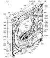
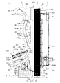
[3.扉枠の全体構成]
パチンコ機1の扉枠3について、主に図22乃至図30を参照して詳細に説明する。図22はパチンコ機における扉枠の表面図であり、図23は扉枠の背面図であり、図24は扉枠の左側面図であり、図25は扉枠の右側面図である。図26は扉枠を右前から見た斜視図であり、図27は扉枠を左前から見た斜視図であり、図28は扉枠を後ろから見た斜視図である。図29は扉枠を主な部材毎に分解して前から見た分解斜視図であり、図30は扉枠を主な部材毎に分解して後ろから見た分解斜視図である。
[3. Overall configuration of door frame]
The door frame 3 of the pachinko machine 1 will be described in detail mainly with reference to FIGS. 22 to 30. 22 is a front view of the door frame in the pachinko machine, FIG. 23 is a rear view of the door frame, FIG. 24 is a left side view of the door frame, and FIG. 25 is a right side view of the door frame. FIG. 26 is a perspective view of the door frame viewed from the front right, FIG. 27 is a perspective view of the door frame viewed from the front left, and FIG. 28 is a perspective view of the door frame viewed from the rear. FIG. 29 is an exploded perspective view of the door frame disassembled for each main member and viewed from the front, and FIG. 30 is an exploded perspective view of the door frame disassembled for each main member and viewed from the rear.
扉枠3は、外枠2の枠内と略同じ大きさで正面視において上下に延びた四角形に形成されており、本体枠4を介して外枠2の枠内を前側から開閉可能に取付けられている。扉枠3は、遊技球Bが打込まれる遊技盤5の遊技領域5aを前側から視認可能に閉鎖し、遊技領域5a内に打込むための遊技球Bを貯留すると共に、貯留している遊技球Bを遊技領域5a内へ打込むために遊技者が操作するハンドル182を備えているものである。また、扉枠3は、パチンコ機1の前面全体を装飾するものである。
The door frame 3 has substantially the same size as the inside of the outer frame 2 and is formed in a quadrangle extending vertically in front view, and the inside of the outer frame 2 can be opened and closed from the front side via the main body frame 4. Has been done. The door frame 3 visibly closes the game area 5a of the game board 5 into which the game ball B is driven, stores the game ball B for driving into the game area 5a, and stores the stored game. It is provided with a handle 182 operated by a player to drive the ball B into the game area 5a. Further, the door frame 3 decorates the entire front surface of the pachinko machine 1.
扉枠3は、正面視の外形が上下に延びた四角形で枠状の扉枠ベースユニット100と、扉枠ベースユニット100に着脱可能に取付けられており本体枠4に取付けられた遊技盤5の遊技領域5aを前方から視認可能に閉鎖しているガラスユニット160と、ガラスユニット160の下部を後側から覆うように扉枠ベースユニット100に取付けられている防犯カバー170と、扉枠ベースユニット100の前面右下隅に取付けられているハンドルユニット180と、扉枠ベースユニット100の前面下部に取付けられている皿ユニット200と、皿ユニット200の上側で扉枠ベースユニット100の前面左部に取付けられている扉枠左サイドユニット400と、皿ユニットの上側で扉枠ベースユニット100の前面右部に取付けられている扉枠右サイドユニット410と、扉枠左サイドユニット400及び扉枠右サイドユニット410の上側で扉枠ベースユニット100の前面上部に取付けられている扉枠トップユニット450と、を備えている。
The door frame 3 is a square and frame-shaped door frame base unit 100 having a front view extending vertically, and a game board 5 detachably attached to the door frame base unit 100 and attached to the main body frame 4. A glass unit 160 that visibly closes the game area 5a from the front, a security cover 170 that is attached to the door frame base unit 100 so as to cover the lower part of the glass unit 160 from the rear side, and a door frame base unit 100. The handle unit 180 attached to the lower right corner of the front surface of the door frame, the dish unit 200 attached to the lower part of the front surface of the door frame base unit 100, and the upper side of the dish unit 200 attached to the front left portion of the door frame base unit 100. The door frame left side unit 400, the door frame right side unit 410 attached to the front right part of the door frame base unit 100 on the upper side of the dish unit, the door frame left side unit 400, and the door frame right side unit 410. The door frame top unit 450, which is attached to the upper part of the front surface of the door frame base unit 100 on the upper side of the door frame, is provided.
扉枠ベースユニット100は、正面視の外形が上下に延びた四角形(長方形)に形成されており前後に貫通している扉窓101aを有した扉枠ベース101と、扉枠ベース101の前面右下に取付けられているハンドル取付部材102と、扉枠ベース101の後側で背面視右下隅に取付けられているスピーカダクト103と、扉枠ベース101の後側の下部における背面視右端付近に取付けられている扉枠主中継基板104と、扉枠主中継基板104の背面視左方に取付けられている扉枠副中継基板105と、扉枠副中継基板105の背面視左方に取付けられているハンドル後中継基板106と、扉枠主中継基板104と扉枠副中継基板105の一部とを後側から被覆する扉枠中継基板カバー107と、ハンドル後中継基板106を後側から被覆するハンドル後中継基板カバー108と、配線ケーブルを被覆するケーブルカバー109と、を備えている。
The door frame base unit 100 has a door frame base 101 having a door window 101a which is formed in a square shape (rectangular shape) whose outer shape extends vertically and penetrates back and forth, and a front right of the door frame base 101. The handle mounting member 102 mounted below, the speaker duct 103 mounted in the lower right corner of the rear view on the rear side of the door frame base 101, and the speaker duct 103 mounted near the right end of the rear view in the lower rear side of the door frame base 101. The door frame main relay board 104, the door frame sub-relay board 105 attached to the left side of the door frame main relay board 104, and the door frame sub-relay board 105 attached to the left side of the rear view. Covers the rear relay board 106 after the handle, the door frame relay board cover 107 that covers the door frame main relay board 104 and a part of the door frame sub relay board 105 from the rear side, and the door frame rear relay board 106 from the rear side. It includes a relay board cover 108 after the handle and a cable cover 109 that covers the wiring cable.
また、扉枠ベースユニット100は、扉枠ベース101の後側に取付けられている枠状の扉枠補強ユニット110と、扉枠補強ユニット110に取付けられている扉枠上ヒンジ組立体120及び扉枠下ヒンジ部材125と、扉枠補強ユニット110に取付けられている開閉用のシリンダ錠130と、扉枠ベース101の後側でハンドル後中継基板106の上方に取付けられている球送給ユニット140と、扉枠ベース101の後側の下部における背面視右側に取付けられているファールカバーユニット150と、を備えている。
Further, the door frame base unit 100 includes a frame-shaped door frame reinforcing unit 110 attached to the rear side of the door frame base 101, a hinge assembly 120 on the door frame attached to the door frame reinforcing unit 110, and a door. The hinge member 125 under the frame, the cylinder lock 130 for opening and closing attached to the door frame reinforcing unit 110, and the ball feeding unit 140 attached above the relay board 106 after the handle on the rear side of the door frame base 101. And a foul cover unit 150 attached to the right side of the rear view at the lower part of the rear side of the door frame base 101.
扉枠補強ユニット110は、扉枠ベース101の後側に取付けられることで、扉枠ベース101を補強して剛性を付与するものである。扉枠上ヒンジ組立体120及び扉枠下ヒンジ部材125は、扉枠3を本体枠4に対して開閉可能に取付けるためのものである。シリンダ錠130は、本体枠4の施錠ユニット650と協働して、扉枠3と本体枠4との開閉、及び、外枠2と本体枠4との開閉施錠に使用されるものである。
The door frame reinforcing unit 110 is attached to the rear side of the door frame base 101 to reinforce the door frame base 101 and impart rigidity. The door frame upper hinge assembly 120 and the door frame lower hinge member 125 are for attaching the door frame 3 to the main body frame 4 so as to be openable and closable. The cylinder lock 130 is used in cooperation with the locking unit 650 of the main body frame 4 to open and close the door frame 3 and the main body frame 4, and to open and close the outer frame 2 and the main body frame 4.
また、球送給ユニット140は、上皿201内の遊技球Bを一つずつ本体枠4の球発射装置540へ供給するためのものである。ファールカバーユニット150は、球発射装置540により発射されて遊技盤5の遊技領域5a内に到達しなかった遊技球B(ファール球)を、下皿202に誘導すると共に、払出装置580から払出された遊技球Bを、上皿201又は下皿202に誘導するためのものである。
Further, the ball feeding unit 140 is for supplying the game balls B in the upper plate 201 one by one to the ball launching device 540 of the main body frame 4. The foul cover unit 150 guides the game ball B (foul ball), which is launched by the ball launcher 540 and does not reach the game area 5a of the game board 5, to the lower plate 202 and is discharged from the payout device 580. This is for guiding the game ball B to the upper plate 201 or the lower plate 202.
ガラスユニット160は、透明なガラス板162を有しており扉枠ベース101の扉窓101aを閉鎖している。防犯カバー170は、ガラスユニット160の下部を後方から覆うように扉枠ベース101に取付けられている。ハンドルユニット180は、遊技者が回転操作可能なハンドル182を備えており、ハンドル182を操作することで、上皿201内の遊技球Bを、球発射装置540によって遊技盤5の遊技領域5a内に打込む遊技を行うためのものである。
The glass unit 160 has a transparent glass plate 162 and closes the door window 101a of the door frame base 101. The security cover 170 is attached to the door frame base 101 so as to cover the lower portion of the glass unit 160 from the rear. The handle unit 180 includes a handle 182 that can be rotated by a player, and by operating the handle 182, the game ball B in the upper plate 201 is moved into the game area 5a of the game board 5 by the ball launcher 540. It is for playing a game to be driven into.
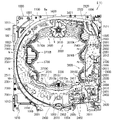
[3-1.扉枠ベースユニットの全体構成]
扉枠3の扉枠ベースユニット100について、主に図31乃至図33を参照して詳細に説明する。図31(a)は扉枠の扉枠ベースユニットを前から見た斜視図であり、(b)は扉枠ベースユニットを後ろから見た斜視図である。図32は扉枠ベースユニットを主な部材毎に分解して前から見た分解斜視図であり、図33は扉枠ベースユニットを主な部材毎に分解して後ろから見た分解斜視図である。
[3-1. Overall configuration of door frame base unit]
The door frame base unit 100 of the door frame 3 will be described in detail mainly with reference to FIGS. 31 to 33. FIG. 31 (a) is a perspective view of the door frame base unit of the door frame as viewed from the front, and FIG. 31 (b) is a perspective view of the door frame base unit as viewed from the rear. FIG. 32 is an exploded perspective view of the door frame base unit disassembled for each main member and viewed from the front, and FIG. 33 is an exploded perspective view of the door frame base unit disassembled for each main member and viewed from the rear. be.
扉枠ベースユニット100は、正面視左辺側が本体枠4に対してヒンジ回転可能に取付けられ、本体枠4の前面を開閉可能に閉鎖していると共に、本体枠4に取付けられている遊技盤の遊技領域を前方から視認可能としている。扉枠ベースユニット100は、外形が上下に延びた四角形で平板状の扉枠ベース101と、扉枠ベース101の前面右下に取付けられておりハンドルユニット180を取付けるためのハンドル取付部材102と、扉枠ベース101の後側で背面視右下隅に取付けられているスピーカダクト103と、を備えている。
The door frame base unit 100 is attached so that the left side side of the front view can be hinged with respect to the main body frame 4 so that the front surface of the main body frame 4 can be opened and closed, and the game board attached to the main body frame 4 is closed. The game area is visible from the front. The door frame base unit 100 includes a rectangular flat plate-shaped door frame base 101 whose outer shape extends vertically, a handle mounting member 102 mounted on the lower right front of the door frame base 101 for mounting the handle unit 180, and a handle mounting member 102. It is provided with a speaker duct 103 attached to the lower right corner of the rear view on the rear side of the door frame base 101.
また、扉枠ベースユニット100は、扉枠ベース101の後側の下部における背面視右端付近に取付けられている扉枠主中継基板104と、扉枠ベース101の後側の下部における扉枠主中継基板104の背面視左方に取付けられている扉枠副中継基板105と、扉枠ベース101の後側の下部における扉枠副中継基板105の背面視左方に取付けられているハンドル後中継基板106と、扉枠ベース101の後側に取付けられており扉枠主中継基板104と扉枠副中継基板105の一部とを後側から被覆する扉枠中継基板カバー107と、扉枠ベース101の後側に取付けられておりハンドル後中継基板106を後側から被覆するハンドル後中継基板カバー108と、扉枠ベース101の後側に取付けられており配線ケーブルを被覆するケーブルカバー109と、を備えている。
Further, the door frame base unit 100 includes a door frame main relay board 104 attached near the right end of the rear view at the lower rear side of the door frame base 101 and a door frame main relay at the lower rear side of the door frame base 101. The door frame sub-relay board 105 mounted on the left side of the rear view of the board 104, and the rear handle relay board mounted on the left side of the rear view of the door frame sub-relay board 105 at the lower rear side of the door frame base 101. The door frame relay board cover 107, which is attached to the rear side of the door frame base 101 and covers a part of the door frame main relay board 104 and the door frame sub relay board 105 from the rear side, and the door frame base 101. The rear relay board cover 108, which is attached to the rear side and covers the rear relay board 106 from the rear side, and the cable cover 109, which is attached to the rear side of the door frame base 101 and covers the wiring cable, are attached. I have.
更に、扉枠ベースユニット100は、扉枠ベース101の後側に取付けられている枠状の扉枠補強ユニット110と、扉枠補強ユニット110に取付けられている扉枠上ヒンジ組立体120及び扉枠下ヒンジ部材125と、扉枠補強ユニット110に取付けられている開閉用のシリンダ錠130と、扉枠ベース101の後側でハンドル後中継基板106の上方に取付けられている球送給ユニット140と、扉枠ベース101の後側の下部における背面視右側に取付けられているファールカバーユニット150と、を備えている。
Further, the door frame base unit 100 includes a frame-shaped door frame reinforcing unit 110 attached to the rear side of the door frame base 101, a hinge assembly 120 on the door frame attached to the door frame reinforcing unit 110, and a door. The hinge member 125 under the frame, the cylinder lock 130 for opening and closing attached to the door frame reinforcing unit 110, and the ball feeding unit 140 attached above the relay board 106 after the handle on the rear side of the door frame base 101. And a foul cover unit 150 attached to the right side of the rear view at the lower part of the rear side of the door frame base 101.
この扉枠ベースユニット100には、前面下隅にハンドルユニット180が、扉窓101aの下側前面に皿ユニット200が、扉窓101aの左外側前面に扉枠左サイドユニット400が、扉窓101aの右外側前面に扉枠右サイドユニット410が、扉窓101aの上外側前面に扉枠トップユニット450が、夫々取付けられるものである。
The door frame base unit 100 has a handle unit 180 in the lower front corner, a dish unit 200 in the lower front surface of the door window 101a, a door frame left side unit 400 in the left outer front surface of the door window 101a, and a door window 101a. The door frame right side unit 410 is attached to the right outer front surface, and the door frame top unit 450 is attached to the upper outer front surface of the door window 101a.
また、扉枠ベースユニット100には、扉窓101aを後方から閉鎖するようにガラスユニット160が取付けられると共に、ガラスユニット160の下部を後方から覆うように透明な防犯カバー170が取付けられるものである。
Further, a glass unit 160 is attached to the door frame base unit 100 so as to close the door window 101a from the rear, and a transparent security cover 170 is attached so as to cover the lower portion of the glass unit 160 from the rear. ..
[3-1a.扉枠ベース]
扉枠3における扉枠ベースユニット100の扉枠ベース101について、主に図31乃至図33を参照して詳細に説明する。扉枠ベース101は、正面視の外形が上下に延びた四角形(長方形)に形成されている。扉枠ベース101は、前後に貫通しており、正面視における内周形状が上下に延びた略四角形に形成された扉窓101aを備えている。扉窓101aは、内周を形成している上辺及び左右両辺が、扉枠ベース101の外周辺に夫々接近しており、内周を形成している下辺が、扉枠ベース101の下端から上下方向の約1/3の高さに位置している。このように、扉枠ベース101は、前後に貫通している扉窓101aにより全体が枠状に形成されている。この扉枠ベース101は、合成樹脂により一体成形されている。
[3-1a. Door frame base]
The door frame base 101 of the door frame base unit 100 in the door frame 3 will be described in detail mainly with reference to FIGS. 31 to 33. The door frame base 101 is formed in a quadrangle (rectangle) whose outer shape in front view extends vertically. The door frame base 101 penetrates back and forth, and includes a door window 101a formed in a substantially quadrangular shape having an inner peripheral shape extending vertically in a front view. In the door window 101a, the upper side and the left and right sides forming the inner circumference are close to the outer periphery of the door frame base 101, respectively, and the lower side forming the inner circumference is up and down from the lower end of the door frame base 101. It is located at a height of about 1/3 in the direction. As described above, the door frame base 101 is entirely formed in a frame shape by the door windows 101a penetrating the front and rear. The door frame base 101 is integrally molded with a synthetic resin.
扉枠ベース101は、前面における正面視右下隅に形成されており左端側が右端側よりも前方へやや突出するように傾斜しているハンドル取付座面101bと、ハンドル取付座面101bと扉窓101aとの間で正面視右端付近に後面から前方へ向かって窪み、扉枠補強ユニット110のシリンダ取付フレーム115が挿入される挿入凹部101cと、挿入凹部101cにおいて前後に貫通しておりシリンダ錠130のシリンダ本体131が挿通されるシリンダ挿通孔101dと、シリンダ挿通孔101d及びハンドル取付座面101bの正面視左側で前後に貫通しており球送給ユニット140の進入口141a及び球抜口141bを前方に臨ませるための球送給開口101eと、を備えている。
The door frame base 101 is formed in the lower right corner of the front view and is inclined so that the left end side slightly protrudes forward from the right end side, the handle mounting seat surface 101b, the handle mounting seat surface 101b, and the door window 101a. The cylinder lock 130 is recessed from the rear surface to the front near the right end of the front view, and penetrates back and forth between the insertion recess 101c into which the cylinder mounting frame 115 of the door frame reinforcing unit 110 is inserted and the insertion recess 101c. The cylinder insertion hole 101d through which the cylinder body 131 is inserted, the cylinder insertion hole 101d, and the handle mounting seat surface 101b penetrate the front and rear on the left side of the front view, and the entry entrance 141a and the ball outlet 141b of the ball feeding unit 140 are forward. It is equipped with a ball feeding opening 101e for facing the cylinder.
また、扉枠ベース101は、左右方向中央より左寄りで且つハンドル取付座面101bと略同じ高さで前後に貫通しておりファールカバーユニット150の球放出口150dを前方に臨ませる下皿用球通過口101fと、正面視左端付近で扉窓101aの下辺に隣接するように前後に貫通しておりファールカバーユニット150の貫通球通路150aを前方に臨ませる上皿用球通過口101gと、扉窓101aの内周に沿って後面から前方へ向かって窪み、ガラスユニット160のガラス枠161が挿入されるガラスユニット取付部101hと、を備えている。
Further, the door frame base 101 is to the left of the center in the left-right direction and penetrates back and forth at substantially the same height as the handle mounting seat surface 101b, so that the ball discharge port 150d of the foul cover unit 150 faces forward. The passage port 101f, the upper plate ball passage port 101g that penetrates the front and rear so as to be adjacent to the lower side of the door window 101a near the left end of the front view and faces the through ball passage 150a of the foul cover unit 150 to the front, and the door. It is provided with a glass unit mounting portion 101h that is recessed from the rear surface to the front along the inner circumference of the window 101a and into which the glass frame 161 of the glass unit 160 is inserted.
また、扉枠ベース101は、正面視左下隅(上皿用球通過口101gの下方)に形成されており前後に貫通した縦長の複数のスリット101iを、備えている。複数のスリット101iの後側にスピーカダクト103が取付けられる。また、複数のスリット101iは、パチンコ機1を組立てた状態で、前方に皿ユニット200における皿ユニットベース211のスピーカ口211bが位置していると共に、後方に本体枠4のスピーカユニット620aにおける本体枠スピーカ622が位置しており、本体枠スピーカ622からの音を前方へ放射することができる。
Further, the door frame base 101 is formed in the lower left corner of the front view (below the upper plate ball passage port 101 g), and is provided with a plurality of vertically long slits 101i that penetrate the front and rear. The speaker duct 103 is attached to the rear side of the plurality of slits 101i. Further, in the plurality of slits 101i, in the state where the pachinko machine 1 is assembled, the speaker port 211b of the dish unit base 211 in the dish unit 200 is located in front, and the main body frame in the speaker unit 620a of the main body frame 4 is rearward. The speaker 622 is located, and the sound from the main body frame speaker 622 can be radiated forward.
更に、扉枠ベース101は、扉窓101aの下方でハンドル取付座面101bの上方において、前後に貫通している貫通孔101jを備えている。この貫通孔101jは、扉枠ベースユニット100側と皿ユニット200側とを接続する配線ケーブル(図示は省略)が挿通されるものであり、後述する扉枠補強ユニット110における中間補強フレーム114の貫通部114bと一致するように形成されている。
Further, the door frame base 101 is provided with a through hole 101j penetrating back and forth below the door window 101a and above the handle mounting seat surface 101b. A wiring cable (not shown) connecting the door frame base unit 100 side and the dish unit 200 side is inserted through the through hole 101j, and the intermediate reinforcing frame 114 in the door frame reinforcing unit 110 described later is penetrated. It is formed so as to coincide with the portion 114b.
[3-1b.ハンドル取付部材]
扉枠ベースユニット100のハンドル取付部材102について、主に図31乃至図33を参照して詳細に説明する。ハンドル取付部材102は、扉枠ベース101の前面にハンドルユニットを取付けるためのものであり、扉枠ベース101の前面のハンドル取付座面101bに取付けられる。
[3-1b. Handle mounting member]
The handle mounting member 102 of the door frame base unit 100 will be described in detail mainly with reference to FIGS. 31 to 33. The handle mounting member 102 is for mounting the handle unit on the front surface of the door frame base 101, and is mounted on the handle mounting seat surface 101b on the front surface of the door frame base 101.
ハンドル取付部材102は、前後方向へ延びた円筒状の筒部102aと、筒部102aの後端から筒部102aの軸に対して直角方向外方へ延びた円環状のフランジ部102bと、筒部102a内に突出していると共に筒部102aの軸方向全長に亘って延びており筒部102aの周方向に対して不等間隔に配置された複数(本実施形態では三つ)の突条102cと、筒部102aの外周面とフランジ部102bの前面とを繋ぎ、筒部102aの周方向に対して複数配置された補強リブ102dと、を備えている。
The handle mounting member 102 includes a cylindrical tubular portion 102a extending in the front-rear direction, an annular flange portion 102b extending outward in a direction perpendicular to the axis of the tubular portion 102a from the rear end of the tubular portion 102a, and a cylinder. A plurality of (three in this embodiment) ridges 102c that project into the portion 102a and extend over the entire axial length of the cylinder portion 102a and are arranged at irregular intervals with respect to the circumferential direction of the cylinder portion 102a. And a plurality of reinforcing ribs 102d which connect the outer peripheral surface of the cylinder portion 102a and the front surface of the flange portion 102b and are arranged in a plurality of directions in the circumferential direction of the cylinder portion 102a.
ハンドル取付部材102は、フランジ部102bの後面を、扉枠ベース101におけるハンドル取付座面101bの前面に当接させた状態で、ビスによってハンドル取付座面101bに取付けられる。
The handle mounting member 102 is mounted on the handle mounting seat surface 101b with screws in a state where the rear surface of the flange portion 102b is in contact with the front surface of the handle mounting seat surface 101b of the door frame base 101.
筒部102aは、内径がハンドルユニット180におけるハンドルベース181の基部181aの外径よりも若干大きく形成されている。三つの突条102cは、一つが筒部102aの上部に備えられており、残り二つが筒部102aの下部に備えられている。これら三つの突条102cは、ハンドルベース181における三つの溝部181cと対応する位置に形成されている。従って、ハンドル取付部材102は、三つの突条102cと、ハンドルベース181の三つの溝部181cとを一致させた状態でのみ、筒部102a内にハンドルベース181の基部181aを挿入させることができ、扉枠ベース101に対してハンドルベース181(ハンドルユニット180)の回転位置を規制することができる。
The inner diameter of the tubular portion 102a is formed to be slightly larger than the outer diameter of the base portion 181a of the handle base 181 in the handle unit 180. One of the three ridges 102c is provided on the upper portion of the tubular portion 102a, and the other two are provided on the lower portion of the tubular portion 102a. These three ridges 102c are formed at positions corresponding to the three groove portions 181c in the handle base 181. Therefore, the handle mounting member 102 can insert the base portion 181a of the handle base 181 into the tubular portion 102a only when the three protrusions 102c and the three groove portions 181c of the handle base 181 are aligned with each other. The rotation position of the handle base 181 (handle unit 180) can be restricted with respect to the door frame base 101.
なお、ハンドル取付部材102は、フランジ部102bの後面に対して、筒部102aの軸線が垂直に延びていることから、扉枠ベース101の傾斜しているハンドル取付座面101bに取付けることで、筒部102aの軸線が右前方へ延びるように傾いた状態となり、ハンドルユニット180を同様に傾いた状態で扉枠ベース101に取付けることができる。
Since the axis of the tubular portion 102a extends perpendicularly to the rear surface of the flange portion 102b, the handle mounting member 102 can be attached to the inclined handle mounting seat surface 101b of the door frame base 101. The axis of the tubular portion 102a is tilted so as to extend to the front right, and the handle unit 180 can be attached to the door frame base 101 in the same tilted state.
[3-1c.スピーカダクト]
扉枠ベースユニット100のスピーカダクト103について、主に図31乃至図33を参照して詳細に説明する。このスピーカダクト103は、筒状に形成されており、扉枠ベース101の後側において複数のスリット101iが形成されている部位に取付けられる。スピーカダクト103は、パチンコ機1を組立てた状態で、筒状の部位の後端が、本体枠4の本体枠スピーカ622の前方に位置している。これにより、本体枠4の本体枠スピーカ622から放射(出力)された音(サウンド)を、拡散させることなく前方へ誘導することができ、扉枠ベース101の複数のスリット101i及び皿ユニット200の皿ユニットベース211におけるスピーカ口211bを通して、パチンコ機1の前方(遊技者側)へ良好に誘導することができる。
[3-1c. Speaker duct]
The speaker duct 103 of the door frame base unit 100 will be described in detail mainly with reference to FIGS. 31 to 33. The speaker duct 103 is formed in a cylindrical shape, and is attached to a portion where a plurality of slits 101i are formed on the rear side of the door frame base 101. In the speaker duct 103, when the pachinko machine 1 is assembled, the rear end of the cylindrical portion is located in front of the main body frame speaker 622 of the main body frame 4. As a result, the sound (sound) radiated (output) from the main body frame speaker 622 of the main body frame 4 can be guided forward without being diffused, and the plurality of slits 101i of the door frame base 101 and the dish unit 200 can be guided. It can be satisfactorily guided to the front (player side) of the pachinko machine 1 through the speaker port 211b in the dish unit base 211.
また、スピーカダクト103は、筒状の部位の下方の後面に、接続ケーブル503を保持するケーブルホルダ103aを備えている。ケーブルホルダ103aは、扉枠中継基板カバー107よりも正面視左方に配置されており、扉枠主中継基板104及び扉枠副中継基板105に接続されている接続ケーブル503を、扉枠3の左端側へ延びるように保持している。
Further, the speaker duct 103 is provided with a cable holder 103a for holding the connection cable 503 on the lower rear surface of the cylindrical portion. The cable holder 103a is arranged on the left side of the door frame relay board cover 107 when viewed from the front, and the connection cable 503 connected to the door frame main relay board 104 and the door frame sub-relay board 105 is connected to the door frame 3. It is held so as to extend to the left end side.
[3-1d.扉枠主中継基板・扉枠副中継基板・ハンドル後中継基板]
扉枠ベースユニット100の扉枠主中継基板104、扉枠副中継基板105、ハンドル後中継基板106について、主に図32及び図33等を参照して説明する。扉枠主中継基板104は、外形が上下に延びた四角形に形成されており、扉枠ベース101の後側の下部における背面視右下隅に取付けられる。扉枠主中継基板104は、ハンドル後中継基板106と本体枠4の基板ユニット620におけるインターフェイス基板635との接続を中継するためのものであり、本体枠4から延びている接続ケーブル503(図83及び図84を参照)の一部が接続される。
[3-1d. Door frame main relay board, door frame sub relay board, rear relay board after handle]
The door frame main relay board 104, the door frame sub-relay board 105, and the rear-handle relay board 106 of the door frame base unit 100 will be described mainly with reference to FIGS. 32 and 33. The door frame main relay board 104 is formed in a quadrangle whose outer shape extends vertically, and is attached to the lower right corner of the rear side of the door frame base 101 in the lower right corner of the rear view. The door frame main relay board 104 is for relaying the connection between the relay board 106 after the handle and the interface board 635 in the board unit 620 of the main body frame 4, and the connection cable 503 extending from the main body frame 4 (FIG. 83). And a part of (see FIG. 84) are connected.
扉枠副中継基板105は、外形が、上下に延びた四角形の上部の正面視右側に左右に延びた四角形が組み合された逆L字状に形成されており、上下に延びているが扉枠主中継基板104の背面視左方に隣接するように、扉枠ベース101の後側に取付けられている。扉枠副中継基板105は、ハンドルユニット180のハンドル装飾基板184、皿ユニット200の皿ユニット中継基板214、扉枠左サイドユニット400の扉枠左サイド装飾基板402、扉枠右サイドユニット410のサイド窓内装飾部装飾基板413及び扉枠右サイド装飾基板418、扉枠トップユニット450の扉枠トップ中継基板467等と、本体枠4のインターフェイス基板635との接続を中継するためのものであり、本体枠4から延びている接続ケーブル503の残りが接続される。
The door frame sub-relay board 105 is formed in an inverted L shape in which the quadrangles extending to the left and right are combined on the right side of the front view of the upper part of the quadrangles extending vertically, and the outer shape is formed in an inverted L shape. It is attached to the rear side of the door frame base 101 so as to be adjacent to the left side of the frame main relay board 104 when viewed from the rear. The door frame sub-relay board 105 is the handle decorative board 184 of the handle unit 180, the dish unit relay board 214 of the dish unit 200, the door frame left side decorative board 402 of the door frame left side unit 400, and the side of the door frame right side unit 410. The purpose is to relay the connection between the decorative board 413 of the decorative portion in the window, the decorative board 418 on the right side of the door frame, the door frame top relay board 467 of the door frame top unit 450, and the interface board 635 of the main body frame 4. The rest of the connection cable 503 extending from the main body frame 4 is connected.
扉枠主中継基板104及び扉枠副中継基板105は、接続端子が後方へ向かって突出するように、扉枠ベース101に取付けられる。扉枠主中継基板104及び扉枠副中継基板105は、扉枠ベースユニット100を組立てた状態で、扉枠主中継基板104と扉枠副中継基板105の上下に延びている部位とが、扉枠中継基板カバー107によって後側が被覆された状態となり、扉枠副中継基板105の残りの部位が、ファールカバーユニット150によって後側が被覆された状態となる。
The door frame main relay board 104 and the door frame sub-relay board 105 are attached to the door frame base 101 so that the connection terminals project rearward. In the door frame main relay board 104 and the door frame sub-relay board 105, the door frame main relay board 104 and the parts extending vertically of the door frame sub-relay board 105 are doors in a state where the door frame base unit 100 is assembled. The rear side is covered by the frame relay board cover 107, and the remaining portion of the door frame sub-relay board 105 is covered by the foul cover unit 150.
ハンドル後中継基板106は、外形が左右に延びた四角形に形成されており、扉枠ベース101の後側における球送給開口101eの下方でハンドル取付座面101bの後側に取付けられる。ハンドル後中継基板106は、扉枠主中継基板104とハンドルユニット180のハンドル回転検知センサ189、ハンドルタッチセンサ192、単発ボタン操作センサ194、及び球送給ユニット140の球送給ソレノイド145との接続を中継するためのものである。ハンドル後中継基板106は、扉枠ベースユニット100を組立てた状態で、ハンドル後中継基板カバー108によって後側が被覆された状態となる。
The rear handle relay board 106 is formed in a quadrangle whose outer shape extends to the left and right, and is mounted on the rear side of the handle mounting seat surface 101b below the ball feeding opening 101e on the rear side of the door frame base 101. The rear-handle relay board 106 is connected to the door frame main relay board 104, the handle rotation detection sensor 189 of the handle unit 180, the handle touch sensor 192, the single-shot button operation sensor 194, and the ball feed solenoid 145 of the ball feed unit 140. Is for relaying. The rear side of the handle rear relay board 106 is covered with the handle rear relay board cover 108 in a state where the door frame base unit 100 is assembled.
[3-1e.扉枠中継基板カバー・ハンドル後中継基板カバー・ケーブルカバー]
扉枠ベースユニット100の扉枠中継基板カバー107、ハンドル後中継基板カバー108、及びケーブルカバー109について、主に図31乃至図33を参照して説明する。扉枠中継基板カバー107は、扉枠ベース101の後側に取付けることで、扉枠主中継基板104と扉枠副中継基板の一部(逆L字状の上下に延びている部位)の後側を被覆するものである。扉枠中継基板カバー107は、前方及び正面視左方が開放された箱状に形成されている。扉枠ベースユニット100に組立てた状態では、後側を被覆している扉枠主中継基板104及び扉枠副中継基板105の接続端子が扉枠中継基板カバー107の内部に露出しており、開放されている左側から接続ケーブル503を内部に挿入して、それら端子に接続することができる。
[3-1e. Door frame relay board cover / rear relay board cover / cable cover]
The door frame relay board cover 107, the rear relay board cover 108 after the handle, and the cable cover 109 of the door frame base unit 100 will be described mainly with reference to FIGS. 31 to 33. By attaching the door frame relay board cover 107 to the rear side of the door frame base 101, the door frame main relay board 104 and a part of the door frame sub-relay board (a portion extending up and down in an inverted L shape) are rear. It covers the side. The door frame relay board cover 107 is formed in a box shape with the front side and the left side when viewed from the front open. In the state of being assembled to the door frame base unit 100, the connection terminals of the door frame main relay board 104 and the door frame sub relay board 105 covering the rear side are exposed inside the door frame relay board cover 107 and are open. The connection cable 503 can be inserted inside from the left side and connected to those terminals.
ハンドル後中継基板カバー108は、ハンドル後中継基板106の後側を被覆するように扉枠ベース101の後側に取付けられるものである。ケーブルカバー109は、扉枠補強ユニット110における中間補強フレーム114の後側に取付けられ、扉枠主中継基板104と皿ユニット200の球貸操作ユニット220とを接続する配線ケーブル(図示は省略)を被覆するためのものである。ケーブルカバー109は、左右に延びた箱状に形成されており、前面の左端付近と下面の左右方向中央に、配線ケーブルを通すための開口が形成されている。
The rear-handle relay board cover 108 is attached to the rear side of the door frame base 101 so as to cover the rear side of the rear-handle relay board 106. The cable cover 109 is attached to the rear side of the intermediate reinforcing frame 114 in the door frame reinforcing unit 110, and has a wiring cable (not shown) connecting the door frame main relay board 104 and the ball rental operation unit 220 of the dish unit 200. It is for covering. The cable cover 109 is formed in a box shape extending to the left and right, and openings for passing wiring cables are formed near the left end of the front surface and in the center of the lower surface in the left-right direction.
[3-1f.扉枠補強ユニット]
扉枠ベースユニット100の扉枠補強ユニット110について、主に図31乃至図33を参照して詳細に説明する。扉枠補強ユニット110は、扉枠ベース101の後側に取付けられることで、平板状の扉枠ベース101を補強して、扉枠ベースユニット100に剛性を付与している。扉枠補強ユニット110は、左右に離間して配置されている上下に延びた左補強フレーム111及び右補強フレーム112と、左補強フレーム111及び右補強フレーム112の上端同士を連結している左右に延びた上補強フレーム113と、左補強フレーム111の下端から上寄りの位置に左端側が取付けられており右補強フレーム112付近まで右方へ延びた中間補強フレーム114と、中間補強フレーム114の右端と右補強フレーム112とを連結しているシリンダ取付フレーム115と、右補強フレーム112の後側に上下に離間して複数取付けられており本体枠4の施錠ユニット650の扉枠用鉤652が掛止される鉤掛部材116と、を備えている。
[3-1f. Door frame reinforcement unit]
The door frame reinforcing unit 110 of the door frame base unit 100 will be described in detail mainly with reference to FIGS. 31 to 33. The door frame reinforcing unit 110 is attached to the rear side of the door frame base 101 to reinforce the flat plate-shaped door frame base 101 and impart rigidity to the door frame base unit 100. The door frame reinforcing unit 110 is provided on the left and right sides connecting the left and right reinforcing frames 111 and the right reinforcing frame 112, which are arranged apart from each other on the left and right, and the upper ends of the left reinforcing frame 111 and the right reinforcing frame 112. The extended upper reinforcing frame 113, the intermediate reinforcing frame 114 extending to the right to the vicinity of the right reinforcing frame 112 with the left end side attached at a position upward from the lower end of the left reinforcing frame 111, and the right end of the intermediate reinforcing frame 114. A cylinder mounting frame 115 connecting the right reinforcing frame 112 and a plurality of mounted cylinder mounting frames 115 vertically separated from each other on the rear side of the right reinforcing frame 112, and hooks 652 for the door frame of the locking unit 650 of the main body frame 4 are hooked. The hooking member 116 and the hooking member 116 are provided.
左補強フレーム111及び右補強フレーム112は、左右方向が一定の幅で、扉枠ベース101の上下の高さと略同じ長さで上下に延びている。右補強フレーム112には、上下方向に離間しており、前後方向に貫通している複数の挿通孔が形成されている。これら挿通孔は、本体枠4に対して扉枠3を閉めた時に、施錠ユニット650の扉枠用鉤652の先端が挿通される。上補強フレーム113は、上下方向が一定の幅で、扉枠ベース101の左右の幅と略同じ長さで左右に延びている。
The left reinforcing frame 111 and the right reinforcing frame 112 have a constant width in the left-right direction, and extend vertically at substantially the same length as the vertical height of the door frame base 101. The right reinforcing frame 112 is formed with a plurality of insertion holes that are separated in the vertical direction and penetrate in the front-rear direction. The tip of the door frame hook 652 of the locking unit 650 is inserted into these insertion holes when the door frame 3 is closed with respect to the main body frame 4. The upper reinforcing frame 113 has a constant width in the vertical direction, and extends to the left and right with substantially the same length as the left and right width of the door frame base 101.
中間補強フレーム114は、上下方向が上補強フレーム113の上下の幅よりも広い幅で左右に延びている。中間補強フレーム114は、左端付近において上端から下方へ四角く切欠かれた切欠部114aと、右端付近において前後に貫通している貫通部114bと、を有している。切欠部114aは、扉枠ベース101の上皿用球通過口101gと、貫通部114bは、扉枠ベース101の貫通孔101jと、夫々一致する位置に形成されている。
The intermediate reinforcing frame 114 extends to the left and right in the vertical direction with a width wider than the vertical width of the upper reinforcing frame 113. The intermediate reinforcing frame 114 has a notch 114a which is notched downward from the upper end in the vicinity of the left end, and a penetrating portion 114b which penetrates back and forth in the vicinity of the right end. The notch 114a is formed at a position corresponding to the upper plate ball passage port 101g of the door frame base 101, and the penetrating portion 114b is formed at a position corresponding to the through hole 101j of the door frame base 101.
シリンダ取付フレーム115は、左右に離間して配置されており正面視において上下に延びた四角形の平板状に形成されている一対の後片部と、一対の後片部の対面している夫々の辺から前方へ平板状に延出している一対の側片部と、一対の前方延出部の前端の辺同士を連結している平板状の前片部と、を備えている。このシリンダ取付フレーム115は、平面視の形状が前方へ突出した凸形状に形成されている。シリンダ取付フレーム115は、左側の後片部が中間補強フレーム114の右端に取付けられ、右側の後片部が右補強フレーム112に取付けられる。このシリンダ取付フレーム115は、前片部にシリンダ錠130が取付けられる。
The cylinder mounting frame 115 is arranged so as to be separated from each other on the left and right sides, and has a pair of rear pieces that are formed in a rectangular flat plate shape that extends vertically when viewed from the front, and a pair of rear pieces that face each other. It includes a pair of side pieces extending in a flat plate shape from the side to the front, and a flat plate-shaped front piece portion connecting the front end sides of the pair of front extending portions. The cylinder mounting frame 115 is formed in a convex shape in which the shape in a plan view protrudes forward. The cylinder mounting frame 115 has a rear piece on the left side mounted on the right end of the intermediate reinforcing frame 114 and a rear piece on the right side mounted on the right reinforcing frame 112. A cylinder lock 130 is attached to the front piece of the cylinder mounting frame 115.
鉤掛部材116は、右補強フレーム112の後側において、前後に貫通している挿通孔の部位に取付けられている。これら鉤掛部材116は、施錠ユニット650の扉枠用鉤652が掛止される。
The hook member 116 is attached to the portion of the insertion hole penetrating the front and rear on the rear side of the right reinforcing frame 112. The hook 652 for the door frame of the locking unit 650 is hooked on these hook members 116.
扉枠補強ユニット110を構成している左補強フレーム111、右補強フレーム112、上補強フレーム113、中間補強フレーム114、シリンダ取付フレーム115、及び鉤掛部材116は、金属板をプレス成型によって打抜き・屈曲することで形成されている。これらは、リベットによって組立てられている。
The left reinforcing frame 111, the right reinforcing frame 112, the upper reinforcing frame 113, the intermediate reinforcing frame 114, the cylinder mounting frame 115, and the hooking member 116 constituting the door frame reinforcing unit 110 are punched out metal plates by press molding. It is formed by bending. These are assembled by rivets.
扉枠補強ユニット110は、左補強フレーム111、右補強フレーム112、及び上補強フレーム113が、扉枠ベース101の左辺、右辺、及び上辺に沿うように組立てられていると共に、中間補強フレーム114が、扉枠ベース101の扉窓101aの下方に位置するように組立てられている。
In the door frame reinforcing unit 110, the left reinforcing frame 111, the right reinforcing frame 112, and the upper reinforcing frame 113 are assembled so as to be along the left side, the right side, and the upper side of the door frame base 101, and the intermediate reinforcing frame 114 is provided. , Is assembled so as to be located below the door window 101a of the door frame base 101.
扉枠補強ユニット110は、図示しない複数のビスにより扉枠ベース101の後側に取付けられる。この扉枠補強ユニット110は、扉枠ベース101に取付けた状態で、中間補強フレーム114の切欠部114a及び貫通部114bが、扉枠ベース101の上皿用球通過口101g及び貫通孔101jと一致した状態となると共に、シリンダ取付フレーム115が、扉枠ベース101の挿入凹部101c内に挿入された状態となる。
The door frame reinforcing unit 110 is attached to the rear side of the door frame base 101 by a plurality of screws (not shown). When the door frame reinforcing unit 110 is attached to the door frame base 101, the notch 114a and the penetrating portion 114b of the intermediate reinforcing frame 114 coincide with the upper plate ball passage port 101g and the through hole 101j of the door frame base 101. The cylinder mounting frame 115 is inserted into the insertion recess 101c of the door frame base 101.
[3-1g.扉枠上ヒンジ組立体]
扉枠ベースユニット100の扉枠上ヒンジ組立体120について、主に図31乃至図33を参照して説明する。扉枠上ヒンジ組立体120は、扉枠補強ユニット110の正面視左上隅に取付けられる。扉枠上ヒンジ組立体120は、扉枠3を、扉枠下ヒンジ部材125と協働して本体枠4に対してヒンジ回転可能に取付けるためのものである。扉枠上ヒンジ組立体120は、扉枠補強ユニット110に取付けられるヒンジブラケット121と、ヒンジブラケット121に上下方向へ移動可能に取付けられる扉枠上ヒンジピン122と、扉枠上ヒンジピン122に取付けられる鍔部材123と、扉枠上ヒンジピン122を上方へ移動するように付勢しているロックバネ124と、を備えている。
[3-1 g. Hinge assembly on door frame]
The hinge assembly 120 on the door frame of the door frame base unit 100 will be described mainly with reference to FIGS. 31 to 33. The hinge assembly 120 on the door frame is attached to the upper left corner of the door frame reinforcing unit 110 when viewed from the front. The door frame upper hinge assembly 120 is for attaching the door frame 3 to the main body frame 4 in cooperation with the door frame lower hinge member 125 so that the hinge can be rotated. The door frame upper hinge assembly 120 includes a hinge bracket 121 attached to the door frame reinforcing unit 110, a door frame upper hinge pin 122 attached to the hinge bracket 121 so as to be movable in the vertical direction, and a flange attached to the door frame upper hinge pin 122. It includes a member 123 and a lock spring 124 that urges the hinge pin 122 on the door frame to move upward.
ヒンジブラケット121は、正面視四角形の平板状の取付片121aと、取付片121aの上辺及び下辺から前方へ延出している平板状の突出片121bと、を備えている。ヒンジブラケット121は、取付片121aが扉枠補強ユニット110に取付けられる。ヒンジブラケット121は、金属板を屈曲させて形成されている。
The hinge bracket 121 includes a flat plate-shaped mounting piece 121a having a rectangular front view, and a flat plate-shaped protruding piece 121b extending forward from the upper and lower sides of the mounting piece 121a. In the hinge bracket 121, the mounting piece 121a is mounted on the door frame reinforcing unit 110. The hinge bracket 121 is formed by bending a metal plate.
扉枠上ヒンジピン122は、円柱状の金属棒をL字状に屈曲させたものである。扉枠上ヒンジピン122は、扉枠上ヒンジ組立体120に組立てた状態で、上下に延びている部位が、ヒンジブラケット121における一対の突出片121bの前端付近において下方から貫通し、上端が上側の突出片121bよりも上方へ延び出していると共に、水平に延びている部位が下側の突出片121bの下面に当接している。扉枠上ヒンジピン122は、上端が本体枠4の本体枠上ヒンジ部材510における上ヒンジ本体511の扉枠用上ヒンジ孔511aに回転可能に挿通される。
The hinge pin 122 on the door frame is a columnar metal rod bent into an L shape. In the state where the hinge pin 122 on the door frame is assembled to the hinge assembly 120 on the door frame, a portion extending vertically penetrates from below near the front end of the pair of projecting pieces 121b in the hinge bracket 121, and the upper end is on the upper side. A portion extending upward from the protruding piece 121b and extending horizontally is in contact with the lower surface of the lower protruding piece 121b. The upper end of the door frame upper hinge pin 122 is rotatably inserted into the door frame upper hinge hole 511a of the upper hinge main body 511 in the main body frame upper hinge member 510 of the main body frame 4.
鍔部材123は、Eリングとされており、扉枠上ヒンジピン122における一対の突出片121bの間となる部位に取付けられている。ロックバネ124は、コイル状に形成されており、鍔部材123とヒンジブラケット121における下側の突出片121bとの間において扉枠上ヒンジピン122の上下に延びている部位の周りに被せられている。このロックバネ124により、鍔部材123を介して扉枠上ヒンジピン122が上方へ付勢されている。
The flange member 123 is an E-ring, and is attached to a portion of the hinge pin 122 on the door frame between the pair of projecting pieces 121b. The lock spring 124 is formed in a coil shape and is placed around a portion extending vertically on the hinge pin 122 on the door frame between the flange member 123 and the lower protruding piece 121b of the hinge bracket 121. The lock spring 124 urges the hinge pin 122 on the door frame upward via the flange member 123.
扉枠上ヒンジ組立体120は、扉枠上ヒンジピン122がロックバネ124により上方へ付勢された状態となっており、扉枠上ヒンジピン122における下端の水平に延びている部位が下側の突出片121bの下面に当接することで、これ以上の上方への移動が規制されている。この状態では、扉枠上ヒンジピン122の上端が、上側の突出片121bの上面よりも所定量上方に突出している。
In the door frame upper hinge assembly 120, the door frame upper hinge pin 122 is in a state of being urged upward by the lock spring 124, and the horizontally extending portion of the lower end of the door frame upper hinge pin 122 is a lower protruding piece. Further upward movement is restricted by abutting on the lower surface of 121b. In this state, the upper end of the hinge pin 122 on the door frame protrudes above the upper surface of the upper protruding piece 121b by a predetermined amount.
扉枠上ヒンジ組立体120は、扉枠上ヒンジピン122における下端の水平に延びている部位を、ロックバネ124の付勢力に抗してその部位を下方へ移動させると、扉枠上ヒンジピン122を全体的に下方へ移動させることができ、扉枠上ヒンジピン122の上端を、上側の突出片121bの上面よりも下方へ没入させることができる。従って、扉枠上ヒンジ組立体120は、扉枠上ヒンジピン122の上端を、本体枠上ヒンジ部材510の扉枠用上ヒンジ孔511aに対して下方から挿入させたり、下方へ抜いたりすることができる。これにより、扉枠上ヒンジピン122の上端を、本体枠上ヒンジ部材510の扉枠用上ヒンジ孔511aに挿入させることで、扉枠3の正面視上部左端を、本体枠4に対してヒンジ回転可能に支持させることができる。
When the horizontally extending portion of the lower end of the door frame upper hinge pin 122 is moved downward against the urging force of the lock spring 124, the door frame upper hinge assembly 120 moves the door frame upper hinge pin 122 as a whole. The upper end of the hinge pin 122 on the door frame can be immersed below the upper surface of the upper protruding piece 121b. Therefore, in the door frame upper hinge assembly 120, the upper end of the door frame upper hinge pin 122 may be inserted from below into the door frame upper hinge hole 511a of the main body frame upper hinge member 510, or may be pulled out downward. can. As a result, the upper end of the door frame upper hinge pin 122 is inserted into the door frame upper hinge hole 511a of the main body frame upper hinge member 510, so that the upper left end of the door frame 3 in front view is hinged with respect to the main body frame 4. It can be supported as much as possible.
また、扉枠上ヒンジ組立体120は、扉枠上ヒンジピン122における上下に延びている部位が、後述する扉枠下ヒンジ部材125の扉枠下ヒンジピン126と同軸上に位置している。これにより、扉枠上ヒンジピン122と扉枠下ヒンジピン126とによって、扉枠3を本体枠4に対して良好な状態でヒンジ回転させることができる。
Further, in the door frame upper hinge assembly 120, a portion of the door frame upper hinge pin 122 extending vertically is located coaxially with the door frame lower hinge pin 126 of the door frame lower hinge member 125 described later. As a result, the door frame 3 can be hinged and rotated with respect to the main body frame 4 by the door frame upper hinge pin 122 and the door frame lower hinge pin 126.
[3-1h.扉枠下ヒンジ部材]
扉枠ベースユニット100の扉枠下ヒンジ部材125について、主に図31乃至図33を参照して説明する。扉枠下ヒンジ部材125は、扉枠補強ユニット110の正面視左下隅に取付けられる。扉枠下ヒンジ部材125は、扉枠3を、扉枠上ヒンジ組立体120と協働して本体枠4に対してヒンジ回転可能に取付けるためのものである。
[3-1h. Hinge member under the door frame]
The hinge member 125 under the door frame of the door frame base unit 100 will be described mainly with reference to FIGS. 31 to 33. The door frame lower hinge member 125 is attached to the front left lower corner of the door frame reinforcing unit 110. The door frame lower hinge member 125 is for attaching the door frame 3 to the main body frame 4 in cooperation with the door frame upper hinge assembly 120 so that the hinge can be rotated.
扉枠下ヒンジ部材125は、扉枠補強ユニット110に取付けられ正面視四角形で平板状の取付片125aと、取付片125aの下辺から前方へ延出している平板状の突出片125bと、突出片125bの前端付近の下面から下方へ突出している扉枠下ヒンジピン126(図22等を参照)と、を備えている。
The door frame lower hinge member 125 is attached to the door frame reinforcing unit 110 and has a square flat plate-shaped mounting piece 125a, a flat plate-shaped projecting piece 125b extending forward from the lower side of the mounting piece 125a, and a projecting piece. The door frame lower hinge pin 126 (see FIG. 22 and the like) projecting downward from the lower surface near the front end of 125b is provided.
扉枠下ヒンジ部材125の取付片125a及び突出片125bは、金属板を屈曲させて形成されている。扉枠下ヒンジピン126は、円柱状の金属棒で、下端部の外周にテーパ状の面取りが施されている。この扉枠下ヒンジピン126は、扉枠ベースユニット100に組立てた状態で、突出片125bにおける扉枠上ヒンジ組立体120の扉枠上ヒンジピン122の上下に延びている部位と同軸上となる部位に取付けられている。
The mounting piece 125a and the protruding piece 125b of the hinge member 125 under the door frame are formed by bending a metal plate. The hinge pin 126 under the door frame is a columnar metal rod having a tapered chamfer on the outer periphery of the lower end portion. The door frame lower hinge pin 126 is located coaxially with the portion extending vertically of the door frame upper hinge pin 122 of the door frame upper hinge assembly 120 in the protruding piece 125b in a state of being assembled to the door frame base unit 100. It is installed.
この扉枠下ヒンジ部材125は、扉枠下ヒンジピン126を本体枠側下ヒンジ部材の扉枠用ヒンジ孔に挿入することで、扉枠3を本体枠4に対してヒンジ回転可能に支持することができる。
The door frame lower hinge member 125 supports the door frame 3 so as to be rotatable with respect to the main body frame 4 by inserting the door frame lower hinge pin 126 into the door frame hinge hole of the main body frame side lower hinge member. Can be done.
[3-1i.シリンダ錠]
扉枠ベースユニット100のシリンダ錠130について、主に図31乃至図33を参照して詳細に説明する。シリンダ錠130は、扉枠補強ユニット110のシリンダ取付フレーム115に取付けられ、後述する施錠ユニット650と協働して、扉枠3と本体枠4との開閉、及び、外枠2と本体枠4との開閉施錠に使用されるものである。シリンダ錠130は、前後に延びた円柱状のシリンダ本体131と、シリンダ本体131の前端面に形成されている鍵穴132と、シリンダ本体131の後側に取付けられており鍵穴132に挿入され正規の鍵を回転させると一緒に回転する回転伝達部材133と、を備えている。
[3-1i. Cylinder lock]
The cylinder lock 130 of the door frame base unit 100 will be described in detail mainly with reference to FIGS. 31 to 33. The cylinder lock 130 is attached to the cylinder mounting frame 115 of the door frame reinforcing unit 110, and cooperates with the locking unit 650 described later to open and close the door frame 3 and the main body frame 4, and the outer frame 2 and the main body frame 4. It is used for opening and closing locks. The cylinder lock 130 is a regular columnar cylinder body 131 extending back and forth, a keyhole 132 formed on the front end surface of the cylinder body 131, and a keyhole 132 attached to the rear side of the cylinder body 131 and inserted into the keyhole 132. It includes a rotation transmission member 133 that rotates with the rotation of the key.
シリンダ錠130のシリンダ本体131は、シリンダ取付フレーム115の前片部を後方から貫通して後端が前片部に取付けられている。回転伝達部材133は、後方が開放された円筒状(詳しくは、後方へ向かうに従って直径が大きくなる円錐筒状)に形成されており、中心軸を挟んで対向した位置に後端から前方へ向かって切欠かれた一対の切欠部を有している。回転伝達部材133は、本体枠4における施錠ユニット650の伝達シリンダ654が後方から挿入されるように形成されており、伝達シリンダ654の一対の突起が一対の切欠部内に挿入されることで、回転伝達部材133(鍵穴132に挿入された鍵)の回転を、伝達シリンダ654に伝達させて回転させることができる。
The cylinder body 131 of the cylinder lock 130 penetrates the front piece of the cylinder mounting frame 115 from the rear, and the rear end is attached to the front piece. The rotation transmission member 133 is formed in a cylindrical shape with an open rear (specifically, a conical cylinder whose diameter increases toward the rear), and faces forward from the rear end to positions facing each other across the central axis. It has a pair of notches that are notched. The rotation transmission member 133 is formed so that the transmission cylinder 654 of the locking unit 650 in the main body frame 4 is inserted from the rear, and the pair of protrusions of the transmission cylinder 654 is inserted into the pair of notches to rotate. The rotation of the transmission member 133 (the key inserted in the keyhole 132) can be transmitted to the transmission cylinder 654 to be rotated.
シリンダ錠130は、扉枠3に組立てた状態で、シリンダ本体131の前端が皿ユニット200における皿ユニット本体252のシリンダ挿通口252hの前端と略一致した状態となる(図22等を参照)。
When the cylinder lock 130 is assembled to the door frame 3, the front end of the cylinder body 131 is in a state of substantially coincident with the front end of the cylinder insertion port 252h of the dish unit main body 252 in the dish unit 200 (see FIG. 22 and the like).
[3-1j.球送給ユニット]
扉枠ベースユニット100の球送給ユニット140について、主に図34及び図35を参照して詳細に説明する。図34(a)は扉枠ベースユニットの球送給ユニットを前から見た斜視図であり、(b)は球送給ユニットを後ろから見た斜視図である。図35(a)は球送給ユニットを分解して前から見た分解斜視図であり、(b)は球送給ユニットの後ケースと不正防止部材を外して後から見た分解斜視図である。球送給ユニット140は、皿ユニット200の上皿201から供給される遊技球Bを一つずつ本体枠4の球発射装置540へ供給することができると共に、上皿201内に貯留された遊技球Bを、上皿球抜ボタン222の操作によって下皿202へ抜くことができるものである。
[3-1j. Ball feeding unit]
The ball feeding unit 140 of the door frame base unit 100 will be described in detail mainly with reference to FIGS. 34 and 35. FIG. 34 (a) is a perspective view of the ball feeding unit of the door frame base unit as viewed from the front, and FIG. 34 (b) is a perspective view of the ball feeding unit as viewed from the rear. FIG. 35A is an exploded perspective view of the ball feeding unit disassembled and viewed from the front, and FIG. 35B is an exploded perspective view of the ball feeding unit after removing the rear case and the fraud prevention member. be. The ball feeding unit 140 can supply the game balls B supplied from the upper plate 201 of the plate unit 200 one by one to the ball launching device 540 of the main body frame 4, and the game stored in the upper plate 201. The ball B can be pulled out to the lower plate 202 by operating the upper plate ball removal button 222.
球送給ユニット140は、皿ユニット200の上皿201から遊技球Bが供給され前後方向に貫通している進入口141a、及び進入口141aの下側に開口する球抜口141bを有し後方が開放された箱状の前カバー141と、前カバー141の後端を閉鎖すると共に前方が開放された箱状で、前後方向に貫通している前カバー141の進入口141aから進入した遊技球Bを球発射装置540へ供給するための打球供給口142aを有した後カバー142と、後カバー142及び前カバー141の間で前後方向へ延びた軸周りに回動可能に軸支され前カバー141の後側で進入口141aと球抜口141bとの間を仕切る仕切部143aを有した球抜部材143と、球抜部材143の仕切部143a上の遊技球Bを一つずつ後カバー142の打球供給口142aへ送り、前カバー141と後カバー142との間で上下方向へ延びた軸周りに回動可能に支持された球送給部材144と、球送給部材144を回動させる球送給ソレノイド145と、を備えている。
The ball feeding unit 140 has an entrance 141a to which the game ball B is supplied from the upper plate 201 of the plate unit 200 and penetrates in the front-rear direction, and a ball outlet 141b which opens to the lower side of the entrance 141a. A game ball that has entered from the entrance 141a of the box-shaped front cover 141 that is open and the front cover 141 that is open in the front and rear while closing the rear end of the front cover 141. The front cover is rotatably supported around an axis extending in the front-rear direction between the rear cover 142 having a ball hitting supply port 142a for supplying B to the ball launcher 540, the rear cover 142, and the front cover 141. A ball pulling member 143 having a partition portion 143a for partitioning between the entrance 141a and the ball pulling port 141b on the rear side of 141, and a game ball B on the partition portion 143a of the ball pulling member 143 are rear-covered 142 one by one. The ball feeding member 144, which is rotatably supported around an axis extending in the vertical direction between the front cover 141 and the rear cover 142, and the ball feeding member 144 are rotated. It is equipped with a ball feeding solenoid 145.
この球送給ユニット140は、図示するように、正面視で、球送給部材144が進入口141aの右側に配置されており、球送給部材144の左側に球抜部材143が、球送給部材144の右側に球送給ソレノイド145が夫々配置されている。
As shown in the figure, in the ball feeding unit 140, the ball feeding member 144 is arranged on the right side of the entrance 141a in the front view, and the ball feeding member 143 is ball feeding on the left side of the ball feeding member 144. Ball feeding solenoids 145 are arranged on the right side of the feeding member 144, respectively.
球送給ユニット140の前カバー141は、正面視で球抜口141bの左側に、球抜部材143の回転中心に対して同心円状に形成された円弧状のスリット141cを備えており、このスリット141cから後述する球抜部材143の作動棹143cが前方へ延びだすようになっている。また、前カバー141は、進入口141aの上縁から上側が上方へ延びだしており、扉枠3を組立てた際に、上皿球抜後ユニット240における後ベース241の球送給誘導路241b及び球抜誘導路241cの上流端側の後方へ開放されている部位を後側から閉鎖するように形成されている。
The front cover 141 of the ball feeding unit 140 is provided with an arcuate slit 141c formed concentrically with respect to the rotation center of the ball pulling member 143 on the left side of the ball pulling port 141b when viewed from the front. From 141c, the operating rod 143c of the ball pulling member 143, which will be described later, extends forward. Further, the front cover 141 extends upward from the upper edge of the entrance 141a, and when the door frame 3 is assembled, the ball feeding guide path 241b of the rear base 241 in the upper plate ball removing rear unit 240 And the portion of the ball ejection taxiway 241c that is open to the rear on the upstream end side is closed from the rear side.
球抜部材143は、進入口141aよりも下側で進入口141aと球抜口141bとの間を仕切り上面が球送給部材144の方向へ向かって低くなる仕切部143aと、仕切部143aの球送給部材144とは反対側の端部から下方へ延出すると共に上下方向の中間付近から球抜口141bの下側中央へ向かってく字状に屈曲し下端が前後方向へ延びた軸周りに回動可能に支持される回動棹部143bと、回動棹部143bの上端から前方へ向かって突出する棒状の作動棹143cと、作動棹143cよりも下側で回動棹部143bの側面から仕切部143aとは反対側へ突出した錘部143dと、を備えている。球抜部材143の作動棹143cは、前カバー141に形成された円弧状のスリット141cを通して前方へ突出するように形成されている(図34(a)を参照)。作動棹143cは、扉枠ベース101の球送給開口101eを介して皿ユニット200の上皿球抜ボタン222の押圧操作によって下方へ移動する上皿球抜スライダ242の作動伝達部242bの上端(上面)と当接する。
The ball pulling member 143 has a partition portion 143a and a partition portion 143a whose upper surface is lowered toward the ball feeding member 144, which is below the entrance 141a and between the entrance 141a and the ball ejection port 141b. Around the axis that extends downward from the end opposite to the ball feeding member 144 and bends in a dogleg shape from the vicinity of the middle in the vertical direction toward the lower center of the ball ejection port 141b and the lower end extends in the front-rear direction. A rotating rod portion 143b that is rotatably supported, a rod-shaped operating rod 143c that protrudes forward from the upper end of the rotating rod portion 143b, and a rotating rod portion 143b that is below the operating rod 143c. It is provided with a weight portion 143d protruding from the side surface to the side opposite to the partition portion 143a. The actuating rod 143c of the ball pulling member 143 is formed so as to project forward through the arcuate slit 141c formed in the front cover 141 (see FIG. 34 (a)). The actuating rod 143c is the upper end of the operation transmission portion 242b of the upper plate ball removal slider 242 that moves downward by the pressing operation of the upper plate ball removal button 222 of the plate unit 200 through the ball feeding opening 101e of the door frame base 101. Contact with the upper surface).
球送給部材144は、進入口141a及び球抜部材143の仕切部143aの方を向き上下方向へ延びた回転軸芯を中心とした平面視が扇状の遮断部144aと、遮断部144aの後端から回転軸芯側へ円弧状に窪んだ球保持部144bと、球保持部144bの後端から下方へ延出する棒状の棹部144cと、を備えている。球送給部材144における遮断部144aと球保持部144bは、夫々回転軸芯を中心とした約180゜の角度範囲内に隣接して形成されている。また、球送給部材144の球保持部144bは、一つの遊技球Bを保持可能な大きさとされている。球送給部材144は、球送給ソレノイド145の駆動によって回転軸芯と偏芯した位置に配置された棹部144cが左右方向へ移動させられることで、回転軸芯周りに回動する。
The ball feeding member 144 is after the blocking portion 144a and the blocking portion 144a having a fan-shaped plan view centered on the rotation axis extending in the vertical direction toward the partition portion 143a of the entrance entrance 141a and the ball pulling member 143. It is provided with a ball holding portion 144b recessed in an arc shape from the end toward the rotation axis core side, and a rod-shaped rod-shaped rod portion 144c extending downward from the rear end of the ball holding portion 144b. The blocking portion 144a and the ball holding portion 144b of the ball feeding member 144 are formed adjacent to each other within an angle range of about 180 ° about the center of rotation axis. Further, the ball holding portion 144b of the ball feeding member 144 has a size capable of holding one game ball B. The ball feeding member 144 rotates around the rotating shaft core by driving the ball feeding solenoid 145 to move the rod portion 144c arranged at a position eccentric to the rotating shaft core in the left-right direction.
この球送給部材144は、遮断部144aが仕切部143aの方向を向くと同時に球保持部144bが打球供給口142aと連通した方向を向いた供給位置と、球保持部144bが仕切部143aの方向へ向いた保持位置との間で回動するようになっている。球送給部材144が供給位置の時には、球保持部144bに保持された遊技球Bが、打球供給口142aから球発射装置540へ供給されると共に、進入口141aから仕切部143a上に進入した遊技球Bが、遮断部144aによって球保持部144b(打球供給口142a)側への移動が遮断されて仕切部143a上に留まった状態となる。一方、球送給部材144が保持位置へ回動すると、球保持部144bが仕切部143aの方向を向くと共に、球保持部144bの棹部144c側の端部が打球供給口142aを閉鎖した状態となり、仕切部143a上の遊技球Bが一つだけ球保持部144b内に保持される。
The ball feeding member 144 has a supply position in which the blocking portion 144a faces the direction of the partition portion 143a and at the same time the ball holding portion 144b faces the direction in which the ball holding portion 144b communicates with the hit ball supply port 142a, and the ball holding portion 144b faces the partition portion 143a. It is designed to rotate between the holding position and the holding position facing in the direction. When the ball feeding member 144 is in the supply position, the game ball B held by the ball holding portion 144b is supplied to the ball launching device 540 from the hit ball supply port 142a and enters the partition portion 143a from the advance entrance 141a. The game ball B is blocked from moving toward the ball holding portion 144b (striking ball supply port 142a) by the blocking portion 144a and stays on the partition portion 143a. On the other hand, when the ball feeding member 144 rotates to the holding position, the ball holding portion 144b faces the direction of the partition portion 143a, and the end portion of the ball holding portion 144b on the rod portion 144c side closes the ball hitting supply port 142a. Therefore, only one game ball B on the partition portion 143a is held in the ball holding portion 144b.
また、球送給ユニット140は、球送給ソレノイド145の駆動(通電)によって先端が上下方向へ揺動する球送給作動棹146と、球送給作動棹146における上下方向へ揺動する先端の動きによって前後方向へ延びた軸周りに回動すると共に、球送給部材144を上下方向へ延びた軸周りに回動させる球送給クランク147と、を備えている。
Further, the ball feeding unit 140 has a ball feeding operating rod 146 whose tip swings in the vertical direction by driving (energization) of the ball feeding solenoid 145 and a tip swinging in the vertical direction in the ball feeding operating rod 146. It is provided with a ball feeding crank 147 that rotates around an axis extending in the front-rear direction and rotates a ball feeding member 144 around an axis extending in the vertical direction.
球送給作動棹146は、球送給ソレノイド145の下方の部位に鉄板146aを備えている。球送給作動棹146は、左右に延びており、球送給クランク147とは反対側の端部(右端部)が前後に延びた軸周りに回転可能に前カバー141及び後カバー142に取付けられている。球送給作動棹146は、球送給ソレノイド145が駆動されると、発生する磁力によって鉄板146aが球送給ソレノイド145の方(上方)へ引寄せられ、右端部を中心にして球送給クランク147に近い左端部側が上方へ移動するように回動する。その後、球送給ソレノイド145の駆動が解除されると、磁力が消滅することによって鉄板146aの自重が作用して、右端部を中心にして球送給クランク147に近い左端部側が下方へ移動するように回動して初めの状態に復帰する。これにより、球送給作動棹146は、球送給ソレノイド145によって、球送給クランク147に近い左端部(先端)が上下方向に揺動することとなる。
The ball feeding operation rod 146 is provided with an iron plate 146a at a portion below the ball feeding solenoid 145. The ball feeding operation rod 146 extends to the left and right, and the end (right end) opposite to the ball feeding crank 147 is rotatably attached to the front cover 141 and the rear cover 142 around the axis extending back and forth. Has been done. When the ball feeding solenoid 145 is driven, the iron plate 146a is attracted to the ball feeding solenoid 145 (upward) by the generated magnetic force, and the ball feeding operation rod 146 is centered on the right end portion. The left end side near the crank 147 rotates so as to move upward. After that, when the drive of the ball feeding solenoid 145 is released, the magnetic force disappears and the weight of the iron plate 146a acts, and the left end side close to the ball feeding crank 147 moves downward around the right end. It rotates in this way and returns to the initial state. As a result, in the ball feeding operation rod 146, the left end portion (tip) near the ball feeding crank 147 swings in the vertical direction by the ball feeding solenoid 145.
球送給クランク147は、球送給作動棹146の上下動する先端と係合可能とされ左右方向へ延びた係合部147aと、係合部147aの球送給作動棹146と係合する側とは反対側に配置され前カバー141と後カバー142との間で前後方向へ延びた軸周りに回動可能に軸支される軸部147bと、軸部147bから上方へ延出しており、球送給部材144における回動中心に対して偏芯した位置から下方へ突出する棒状の棹部144c(図35(b)を参照)と係合する伝達部147cと、を備えている。
The ball feeding crank 147 engages with the engaging portion 147a extending in the left-right direction so as to be able to engage with the vertically moving tip of the ball feeding operating rod 146, and the ball feeding operating rod 146 of the engaging portion 147a. A shaft portion 147b that is arranged on the opposite side to the side and is rotatably supported around an axis extending in the front-rear direction between the front cover 141 and the rear cover 142, and extends upward from the shaft portion 147b. The ball feeding member 144 includes a transmission portion 147c that engages with a rod-shaped rod-shaped rod portion 144c (see FIG. 35 (b)) that protrudes downward from a position eccentric with respect to the center of rotation.
この球送給ユニット140は、球送給ソレノイド145の駆動により球送給作動棹146の先端(左端)を上方へ移動させることで、球送給作動棹146を介して球送給クランク147を前後に延びた軸周りに回動させることができる。
The ball feeding unit 140 moves the tip (left end) of the ball feeding operating rod 146 upward by driving the ball feeding operating solenoid 145, thereby moving the ball feeding crank 147 via the ball feeding operating rod 146. It can be rotated around an axis that extends back and forth.
球送給ユニット140は、球送給ソレノイド145の非駆動時(通常時)では、球送給作動棹146が球送給ソレノイド145の下端から離れて先端が下方へ位置した状態となり、この状態では球送給部材144が供給位置に位置した状態となる。また、球送給ソレノイド145の駆動時では、球送給作動棹146が球送給ソレノイド145の下端に吸引されて先端(左端)が上方へ位置した状態となり、球送給部材144が保持位置へ回動する。つまり、球送給ソレノイド145が駆動される(ONの状態)と、球送給部材144が遊技球Bを一つ受入れ、球送給ソレノイド145の駆動が解除される(OFFの状態)と、球送給部材144が受入れた遊技球Bを球発射装置540側へ送る(供給する)ことができる。この球送給ユニット140における球送給ソレノイド145の駆動は、払出制御基板633の発射制御部633b(図206を参照)により発射ソレノイド542の駆動制御と同期して制御される。
When the ball feeding solenoid 145 is not driven (normal time), the ball feeding unit 140 is in a state where the ball feeding operating rod 146 is separated from the lower end of the ball feeding solenoid 145 and the tip is positioned downward. Then, the ball feeding member 144 is in a state of being positioned at the supply position. Further, when the ball feeding solenoid 145 is driven, the ball feeding operating rod 146 is sucked by the lower end of the ball feeding solenoid 145 and the tip (left end) is positioned upward, and the ball feeding member 144 is in the holding position. Rotate to. That is, when the ball feeding solenoid 145 is driven (ON state), the ball feeding member 144 receives one game ball B, and the driving of the ball feeding solenoid 145 is released (OFF state). The game ball B received by the ball feeding member 144 can be sent (supplied) to the ball launching device 540 side. The drive of the ball feed solenoid 145 in the ball feed unit 140 is controlled by the launch control unit 633b (see FIG. 206) of the payout control board 633 in synchronization with the drive control of the launch solenoid 542.
また、球送給ユニット140は、回動可能に軸支されている球抜部材143か、錘部143dによって正面視反時計周りの方向へ回転するようなモーメントがかかるようになっている。しかしながら、球抜部材143の前方へ突出している作動棹143cが、皿ユニット200の上皿球抜ボタン222の押圧操作によって動作する上皿球抜スライダ242の作動伝達部242bの上端と当接することで、その回動が規制されているため、通常の状態では、球抜部材143の仕切部143aが進入口141aと球抜口141bとの間に位置して仕切っており、球抜口141b側へ遊技球Bが侵入することはない。
Further, the ball feeding unit 140 is adapted to apply a moment such that it rotates in a counterclockwise direction when viewed from the front by a ball pulling member 143 rotatably supported by the shaft or a weight portion 143d. However, the operating rod 143c projecting forward of the ball removing member 143 comes into contact with the upper end of the operation transmitting portion 242b of the upper plate ball removing slider 242 operated by the pressing operation of the upper plate ball removing button 222 of the plate unit 200. Since the rotation is restricted, the partition portion 143a of the ball pulling member 143 is positioned and partitioned between the entrance 141a and the ball pulling port 141b under the normal state, and is on the ball pulling port 141b side. The game ball B does not invade.
そして、遊技者が、皿ユニット200の上皿球抜ボタン222を下方へ押圧操作すると、上皿球抜スライダ242が作動伝達部242bと共に下方へスライドし、作動伝達部242bの下方への移動に伴って作動棹143cも相対的に下方へ移動することとなる。作動伝達部242bと共に作動棹143cが下方へ移動すると、球抜部材143が正面視反時計周りの方向へ回動し、仕切部143aが進入口141aと球抜口141bとの間から移動して仕切りが解除される。これにより、進入口141aから進入した遊技球Bが、球抜口141b側へ落下し、球抜口141bから皿ユニット200における上皿球抜後ユニット240の球抜誘導路241cへと排出され、下皿球供給口211cを介して下皿202へ排出(供給)させることができる。
Then, when the player presses the upper plate ball removal button 222 of the plate unit 200 downward, the upper plate ball removal slider 242 slides downward together with the operation transmission unit 242b to move downward of the operation transmission unit 242b. Along with this, the operating plate 143c also moves relatively downward. When the operating rod 143c moves downward together with the operation transmitting portion 242b, the ball pulling member 143 rotates in the counterclockwise direction when viewed from the front, and the partition portion 143a moves from between the entrance 141a and the ball pulling port 141b. The partition is released. As a result, the game ball B that has entered from the entrance 141a falls to the ball extraction port 141b side, and is discharged from the ball extraction port 141b to the ball extraction guide path 241c of the upper plate ball extraction unit 240 in the plate unit 200. It can be discharged (supplied) to the lower plate 202 via the lower plate ball supply port 211c.
なお、球抜部材143の作動棹143cが当接する作動伝達部242bが形成されている上皿球抜スライダ242は、バネ243によって上方へ付勢されているので、仕切部143a上に遊技球Bが勢い良く供給されても、その衝撃を、作動棹143cを介してバネ243によって吸収させることができ、球抜部材143等が破損するのを防止することができると共に、遊技球Bが仕切部143aで跳ね返るのを防止することができる。
Since the upper plate ball pulling slider 242 on which the working transmission portion 242b with which the working rod 143c of the ball pulling member 143 abuts is formed is urged upward by the spring 243, the game ball B is placed on the partition portion 143a. Even if the plate is vigorously supplied, the impact can be absorbed by the spring 243 via the operating rod 143c, the ball pulling member 143 and the like can be prevented from being damaged, and the game ball B is the partition portion. It is possible to prevent it from bouncing off at 143a.
また、球送給ユニット140は、後カバー142における打球供給口142aの背面視で右上に前方へ窪んだ矩形状の取付凹部142b(図35(b)等を参照)が形成されていると共に、その取付凹部142b内に不正防止部材148が取付けられている。球送給ユニット140の不正防止部材148は、工具鋼やステンレス等の硬質の金属板により形成されており、後カバー142の取付凹部142b内に対して後側から脱着可能に取付けられている。
Further, the ball feeding unit 140 is formed with a rectangular mounting recess 142b (see FIG. 35 (b) and the like) recessed forward in the upper right corner of the ball feeding port 142a in the rear cover 142 when viewed from the rear. The fraud prevention member 148 is mounted in the mounting recess 142b. The fraud prevention member 148 of the ball feeding unit 140 is formed of a hard metal plate such as tool steel or stainless steel, and is detachably attached to the inside of the mounting recess 142b of the rear cover 142 from the rear side.
不正防止部材148は、正面視の外形が左右に延びた長方形状に形成されており、右辺から左方へ所定距離の間において、上下方向略中央で上下に分離している上片部148a及び下片部148bと、上片部148a及び下片部148bの互いに対向している辺の先端側(正面視右端側)でC面取り状に夫々形成されている傾斜部148cと、を備えている。不正防止部材148の上片部148aは、不正防止部材148の一般面に対して、正面視右端が後方へ突出するように屈曲させられている。下片部148bは、不正防止部材148の一般面と同一面上に延びている。これにより、平面視において、上片部148aと下片部148bとによって、右方に向かうに従って広がるV字状の溝を形成している。
The fraud prevention member 148 is formed in a rectangular shape with the outer shape of the front view extending to the left and right, and the upper piece portion 148a and the upper piece portion 148a which are separated vertically at substantially the center in the vertical direction within a predetermined distance from the right side to the left. It is provided with a lower piece portion 148b and an inclined portion 148c formed in a C chamfer shape on the tip end side (right end side in front view) of the side facing each other of the upper piece portion 148a and the lower piece portion 148b. .. The upper piece portion 148a of the fraud prevention member 148 is bent so that the right end of the front view projects rearward with respect to the general surface of the fraud prevention member 148. The lower piece portion 148b extends on the same surface as the general surface of the fraud prevention member 148. As a result, in a plan view, the upper piece portion 148a and the lower piece portion 148b form a V-shaped groove that widens toward the right.
不正防止部材148は、後カバー142の取付凹部142bに取付けられることで、上片部148aと下片部148bとで形成されるV字状の溝が、打球供給口142a内と連通した状態となる。
The fraud prevention member 148 is attached to the mounting recess 142b of the rear cover 142 so that the V-shaped groove formed by the upper piece portion 148a and the lower piece portion 148b communicates with the inside of the ball striking supply port 142a. Become.
この不正防止部材148によれば、紐を取付けた不正な遊技球Bを、上皿から球送給ユニット140を介して球発射装置540により遊技領域5a内に打込み、不正な遊技球Bに取付けられた紐を操作して、不正な遊技球Bを第一始動口2002等に出し入れさせるような不正行為が行われる際に、球発射装置540により発射(打球)された不正な遊技球Bの勢いによって、不正な遊技球Bに取付けられた紐を、上片部148aと下片部148bとの間に挿入させた上で、上片部148aと下片部148bとによって形成されたV字状の狭くなった部位により切断させることができ、紐を取付けた不正な遊技球Bを用いた不正行為が行われるのを防止することができる。
According to the fraud prevention member 148, the fraudulent game ball B to which the string is attached is driven into the game area 5a by the ball launcher 540 from the upper plate via the ball feeding unit 140 and attached to the fraudulent game ball B. The illegal game ball B launched (struck) by the ball launcher 540 when an illegal act such as operating the string to move the illegal game ball B in and out of the first starting port 2002 or the like is performed. A string attached to the illegal game ball B is inserted between the upper piece 148a and the lower piece 148b by the momentum, and then a V-shape formed by the upper piece 148a and the lower piece 148b. It can be cut by the narrowed portion of the shape, and it is possible to prevent fraudulent acts using the fraudulent game ball B to which the string is attached.
[3-1k.ファールカバーユニット]
扉枠ベースユニット100のファールカバーユニット150について、主に図36及び図37を参照して詳細に説明する。図36(a)は扉枠ベースユニットのファールカバーユニットを前から見た斜視図であり、(b)はファールカバーユニットを後ろから見た斜視図である。また、図37は、蓋部材を外した状態のファールカバーユニットの正面図である。ファールカバーユニット150は、扉枠ベース101の後側の下部における背面視右側に取付けられている。ファールカバーユニット150は、球発射装置540により発射されて遊技盤5の遊技領域5a内に到達しなかった遊技球B(ファール球)を、下皿202に誘導すると共に、払出装置580から払出された遊技球Bを、上皿201又は下皿202に誘導するためのものである。ファールカバーユニット150は、図示するように、扉枠ベース101の後側に取付けられ前側が開放された浅い箱状のユニット本体151と、ユニット本体151の前面に取付けられている平板状の蓋部材152と、を備えている。
[3-1k. Foul cover unit]
The foul cover unit 150 of the door frame base unit 100 will be described in detail mainly with reference to FIGS. 36 and 37. FIG. 36A is a perspective view of the foul cover unit of the door frame base unit as viewed from the front, and FIG. 36B is a perspective view of the foul cover unit as viewed from the rear. Further, FIG. 37 is a front view of the foul cover unit with the lid member removed. The foul cover unit 150 is attached to the right side in the rear view at the lower part of the rear side of the door frame base 101. The foul cover unit 150 guides the game ball B (foul ball), which is launched by the ball launcher 540 and does not reach the game area 5a of the game board 5, to the lower plate 202 and is discharged from the payout device 580. This is for guiding the game ball B to the upper plate 201 or the lower plate 202. As shown in the figure, the foul cover unit 150 includes a shallow box-shaped unit main body 151 attached to the rear side of the door frame base 101 and the front side open, and a flat plate-shaped lid member attached to the front surface of the unit main body 151. It is equipped with 152.
ファールカバーユニット150は、正面視左上隅において前後に貫通しており本体枠4の下部満タン球経路ユニット610の下部通常払出通路610aと皿ユニット200の上皿球供給口211aとを連通させる貫通球通路150aと、貫通球通路150aの正面視右下側で後方へ向かって開口しており本体枠4の下部満タン球経路ユニット610の下部満タン払出通路610bと連通可能な満タン球受口150bと、を備えている。
The foul cover unit 150 penetrates back and forth in the upper left corner of the front view, and penetrates the lower normal payout passage 610a of the lower full tank path unit 610 of the main body frame 4 and the upper dish ball supply port 211a of the dish unit 200. A full tank receiver that opens toward the rear on the lower right side of the front view of the ball passage 150a and the penetrating ball passage 150a and can communicate with the lower full tank payout passage 610b of the lower full ball path unit 610 of the main body frame 4. It has a mouth 150b and.
また、ファールカバーユニット150は、満タン球受口150bの正面視右側で上方へ向かって開口しており本体枠4の球発射装置540により発射されにも関わらず遊技領域5a内へ到達しなかった遊技球B(ファール球)を受けるファール球受口150cと、正面視右下隅付近で前方へ向かって開口しており満タン球受口150b及びファール球受口150cに受入れられた遊技球Bを前方へ放出すると共に皿ユニット200の下皿球供給口211cと連通する球放出口150dと、を備えている。
Further, the foul cover unit 150 opens upward on the right side of the front view of the full tank ball receiving port 150b, and does not reach the game area 5a even though it is launched by the ball launching device 540 of the main body frame 4. A foul ball receiving port 150c that receives the foul ball B (foul ball), and a game ball B that is open forward near the lower right corner of the front view and is received by the full tank ball receiving port 150b and the foul ball receiving port 150c. The ball discharge port 150d communicates with the lower dish ball supply port 211c of the dish unit 200 while discharging the ball forward.
更に、ファールカバーユニット150は、ユニット本体151及び蓋部材152によって、満タン球受口150b及びファール球受口150cと球放出口150dとの間に形成されており所定量の遊技球Bを貯留可能な広さを有している貯留通路150eを、備えている。
Further, the foul cover unit 150 is formed by the unit body 151 and the lid member 152 between the full tank ball receiving port 150b, the foul ball receiving port 150c, and the ball discharging port 150d, and stores a predetermined amount of the game ball B. It is provided with a storage passage 150e having a possible size.
貫通球通路150aは、ユニット本体151と蓋部材152の両方に跨って形成されている。満タン球受口150b及びファール球受口150cは、ユニット本体151に形成されている。球放出口150dは、蓋部材152に形成されている。貯留通路150eは、ユニット本体151と蓋部材152とで形成されている。
The penetrating ball passage 150a is formed so as to straddle both the unit main body 151 and the lid member 152. The full tank ball receiving port 150b and the foul ball receiving port 150c are formed in the unit main body 151. The ball discharge port 150d is formed on the lid member 152. The storage passage 150e is formed by the unit main body 151 and the lid member 152.
また、ファールカバーユニット150は、貯留通路150eの内壁の一部を構成しており下端が回動可能にユニット本体151及び蓋部材152に取付けられている平板状の可動片153と、可動片153の貯留通路150eから遠ざかる方向への回動を検知する満タン検知センサ154と、可動片153を貯留通路150e側へ付勢しているバネ155と、を備えている。
Further, the foul cover unit 150 constitutes a part of the inner wall of the storage passage 150e, and has a flat plate-shaped movable piece 153 and a movable piece 153 whose lower ends are rotatably attached to the unit main body 151 and the lid member 152. It is provided with a full tank detection sensor 154 that detects rotation in a direction away from the storage passage 150e, and a spring 155 that urges the movable piece 153 toward the storage passage 150e.
このファールカバーユニット150は、皿ユニット200の下皿202内が遊技球Bで一杯になって、球放出口150dから遊技球Bが下皿202側へ放出されなくなると、貯留通路150e内にある程度の数の遊技球Bを貯留することができる。そして、貯留通路150e内にある程度の数の遊技球Bが貯留されると、遊技球Bの重さによって可動片153の上端がバネ155の付勢力に抗して貯留通路150eから遠ざかる方向へ移動するように可動片153が回動し、その回動が満タン検知センサ154によって検知される。これにより、下皿202が遊技球Bで満タンになっていると判断することができるため、満タン検知センサ154により満タンが検知されると、これ以上の遊技球Bの払出しを停止させると共に、その旨を遊技者や遊技ホールの係員等に報知して、下皿202の満タンを解消させるように促すことができる。
In this foul cover unit 150, when the lower plate 202 of the plate unit 200 is filled with the game ball B and the game ball B is not discharged from the ball discharge port 150d to the lower plate 202 side, the storage passage 150e is filled to some extent. The number of game balls B can be stored. Then, when a certain number of game balls B are stored in the storage passage 150e, the upper end of the movable piece 153 moves in a direction away from the storage passage 150e against the urging force of the spring 155 due to the weight of the game balls B. The movable piece 153 rotates so as to do so, and the rotation is detected by the full tank detection sensor 154. As a result, it can be determined that the lower plate 202 is full with the game ball B. Therefore, when the full tank detection sensor 154 detects that the lower plate 202 is full, the payout of the game ball B is stopped. At the same time, it is possible to notify the player, the person in charge of the game hall, or the like to that effect, and urge the player to eliminate the full tank of the lower plate 202.
また、ファールカバーユニット150は、ユニット本体151の後側で貫通球通路150aの下側に取付けられており、本体枠4の後述する払出ユニット560における下部満タン球経路ユニット610の払出通路開閉扉613の作動突部613aが当接可能な扉開閉当接部150fを備えている(図91を参照)。扉開閉当接部150fは、後面が下方へ向かうに従って前方へ移動するように傾斜している。この扉開閉当接部150fに払出通路開閉扉613の作動突部613aが当接することで、払出通路開閉扉613を回動させて下部通常払出通路610a及び下部満タン払出通路610bの下流端(前側開口)を開放させることができる。
Further, the foul cover unit 150 is attached to the lower side of the penetrating ball passage 150a on the rear side of the unit main body 151, and the payout passage opening / closing door of the lower full tank path unit 610 in the payout unit 560 described later in the main body frame 4. The actuating protrusion 613a of the 613 is provided with a door opening / closing contact portion 150f that can be contacted (see FIG. 91). The door opening / closing contact portion 150f is inclined so as to move forward as the rear surface moves downward. When the actuating protrusion 613a of the payout passage opening / closing door 613 comes into contact with the door opening / closing contact portion 150f, the payout passage opening / closing door 613 is rotated to rotate the downstream end of the lower normal payout passage 610a and the lower full tank payout passage 610b. The front opening) can be opened.
[3-2.ガラスユニット]
扉枠3におけるガラスユニット160について、主に図29及び図30等を参照して詳細に説明する。ガラスユニット160は、扉枠ベースユニット100における扉枠ベース101の扉窓101aを閉鎖するように、後方からガラスユニット取付部101h内に挿入されて着脱可能に取付けられている。このガラスユニット160は、扉枠3を本体枠4に対して閉めた時に、本体枠4に取付けられている遊技盤5の遊技領域5aを遊技者側(前方)から視認可能とすると共に、遊技領域5aの前方を閉鎖するものである。
[3-2. Glass unit]
The glass unit 160 in the door frame 3 will be described in detail mainly with reference to FIGS. 29 and 30 and the like. The glass unit 160 is inserted into the glass unit mounting portion 101h from the rear so as to close the door window 101a of the door frame base 101 in the door frame base unit 100, and is detachably mounted. When the door frame 3 is closed with respect to the main body frame 4, the glass unit 160 makes the game area 5a of the game board 5 attached to the main body frame 4 visible from the player side (front), and also makes the game visible. It closes the front of the region 5a.
ガラスユニット160は、扉枠ベース101の扉窓101aの内周形状よりも大きくガラスユニット取付部101hに取付可能な枠状のガラス枠161と、ガラス枠161の枠内を閉鎖し外周がガラス枠161に取付けられている透明な二つのガラス板162と、扉枠ベースユニット100における扉枠ベース101の後側に回転可能に取付けられガラス枠161を扉枠ベース101に取付けるための一対のガラスユニット取付部材163と、を備えている。
The glass unit 160 has a frame-shaped glass frame 161 that is larger than the inner peripheral shape of the door window 101a of the door frame base 101 and can be attached to the glass unit mounting portion 101h, and the glass frame 161 is closed and the outer periphery is a glass frame. Two transparent glass plates 162 attached to 161 and a pair of glass units rotatably attached to the rear side of the door frame base 101 in the door frame base unit 100 to attach the glass frame 161 to the door frame base 101. It is provided with a mounting member 163.
ガラス枠161は、正面視左右上隅よりも下側の位置から外方へ平板状に延出している一対の取付片161aと、下端から下方へ突出していると共に下辺に沿って延びている帯板状の係止片161bと、を有している。ガラス枠161の取付片161aは、ガラスユニット取付部材163の突出部163bと当接可能とされている。係止片161bは、扉枠ベース101と扉枠補強ユニット110の中間補強フレーム114との間の空間内に挿入可能とされている(図97を参照)。二つのガラス板162は、ガラス枠161の前端側と後端側とに夫々取付けられており、互いの間に空間が形成されるように前後に離間している(図97を参照)。
The glass frame 161 is a pair of mounting pieces 161a extending outward in a flat plate shape from a position below the upper left and right corners in the front view, and a band extending downward from the lower end and extending along the lower side. It has a plate-shaped locking piece 161b and. The mounting piece 161a of the glass frame 161 can be brought into contact with the protruding portion 163b of the glass unit mounting member 163. The locking piece 161b can be inserted into the space between the door frame base 101 and the intermediate reinforcing frame 114 of the door frame reinforcing unit 110 (see FIG. 97). The two glass plates 162 are attached to the front end side and the rear end side of the glass frame 161, respectively, and are separated from each other in the front-rear direction so as to form a space between them (see FIG. 97).
ガラスユニット取付部材163は、扉枠ベース101の後側で前後に延びた軸線周りに対して回転可能に取付けられる円盤状の基部163aと、基部163aから回転軸線に対して直角方向へ棒状に突出している突出部163bと、を有している。ガラスユニット取付部材163は、扉枠ベース101の後面における扉窓101aの四隅のうち上側の二つの隅の外側に、夫々回転可能に取付けられる。
The glass unit mounting member 163 has a disk-shaped base 163a that is rotatably mounted around an axis extending back and forth on the rear side of the door frame base 101, and a rod-shaped protrusion from the base 163a in a direction perpendicular to the rotation axis. It has a protruding portion 163b and a protruding portion 163b. The glass unit mounting member 163 is rotatably mounted on the outer sides of the upper two corners of the four corners of the door window 101a on the rear surface of the door frame base 101.
ガラスユニット160を扉枠ベース101に取付けるには、まず、扉枠ベース101に取付けられているガラスユニット取付部材163を、突出部163bが基部163aよりも上方に位置するように回転させた状態とする。そして、扉枠ベース101の後側から、ガラスユニット160のガラス枠161の係止片161bを、扉枠ベース101と扉枠補強ユニット110の中間補強フレーム114との間の隙間に上方から挿入した上で、ガラス枠161の前端を扉枠ベース101のガラスユニット取付部101hの後面に当接させる。その後、ガラスユニット取付部材163を、突出部163bが基部163aよりも下方に位置するように回転させて、突出部163bをガラス枠161の取付片161aの後面と当接させる。これにより、ガラスユニット160が扉枠ベース101に取付けられる。
To mount the glass unit 160 on the door frame base 101, first, the glass unit mounting member 163 mounted on the door frame base 101 is rotated so that the protruding portion 163b is located above the base 163a. do. Then, from the rear side of the door frame base 101, the locking piece 161b of the glass frame 161 of the glass unit 160 was inserted from above into the gap between the door frame base 101 and the intermediate reinforcing frame 114 of the door frame reinforcing unit 110. Above, the front end of the glass frame 161 is brought into contact with the rear surface of the glass unit mounting portion 101h of the door frame base 101. After that, the glass unit mounting member 163 is rotated so that the protruding portion 163b is located below the base portion 163a, and the protruding portion 163b is brought into contact with the rear surface of the mounting piece 161a of the glass frame 161. As a result, the glass unit 160 is attached to the door frame base 101.
ガラスユニット160を扉枠ベース101から取外す場合は、上記と逆の手順により、取外すことができる。これにより、ガラスユニット160は、扉枠ベース101(扉枠ベースユニット100)に対して着脱可能となっている。
When the glass unit 160 is removed from the door frame base 101, it can be removed by the reverse procedure of the above. As a result, the glass unit 160 can be attached to and detached from the door frame base 101 (door frame base unit 100).
なお、ガラスユニット160では、ガラスユニット取付部材163の突出部163bが、基部163aよりも下方に位置している回転位置の時に、突出部163bによりガラス枠161の後方への移動を規制しているため、ガラスユニット取付部材163に振動等が作用しても、突出部163bが基部163aよりも上方となるように位置へ回転することはない。従って、ガラス枠161の後方への移動の規制が自然に解除されることはなく、ガラスユニット160が扉枠ベース101から自然に外れることはない。
In the glass unit 160, when the protruding portion 163b of the glass unit mounting member 163 is in the rotational position located below the base portion 163a, the protruding portion 163b restricts the movement of the glass frame 161 to the rear. Therefore, even if vibration or the like acts on the glass unit mounting member 163, the protruding portion 163b does not rotate to a position above the base portion 163a. Therefore, the restriction on the rearward movement of the glass frame 161 is not naturally lifted, and the glass unit 160 is not naturally disengaged from the door frame base 101.
[3-3.防犯カバー]
扉枠3における防犯カバー170について、主に図29及び図30等を参照して詳細に説明する。防犯カバー170は、ガラスユニット160の後面下部を覆うように扉枠ベースユニット100の後側に取付けられ、透明な合成樹脂により形成されている。防犯カバー170は、外周が所定形状に形成された平板状の本体部171と、本体部171の外周縁に沿って後方へ短く突出した平板状の後方突片172と、左右に離間して配置され本体部171よりも前方に突出し、扉枠ベース101の後側に係止可能とされている一対の係止片173と、を備えている。
[3-3. Security cover]
The security cover 170 in the door frame 3 will be described in detail mainly with reference to FIGS. 29 and 30 and the like. The security cover 170 is attached to the rear side of the door frame base unit 100 so as to cover the lower part of the rear surface of the glass unit 160, and is made of a transparent synthetic resin. The security cover 170 is arranged so as to be separated from each other to the left and right by a flat plate-shaped main body portion 171 having a predetermined outer periphery and a flat plate-shaped rear projecting piece 172 protruding rearward along the outer peripheral edge of the main body portion 171. It is provided with a pair of locking pieces 173 that project forward from the main body portion 171 and can be locked to the rear side of the door frame base 101.
防犯カバー170の本体部171は、扉枠ベースユニット100に取付けた状態で下端がガラスユニット160の下端よりも下方へ突出するように形成されている。また、本体部171は、上端が、パチンコ機1に組立てた状態で、遊技盤5における遊技領域5aの下端に沿った形状に形成されている。詳述すると、本体部171の上端は、後述する前構成部材1000の内レール1002の一部、アウト誘導部1003、右下レール1004の一部、及び右レール1005に沿った形状に形成されており、パチンコ機1に組立てた状態で遊技領域5a内に突出しないように形成されている。
The main body 171 of the security cover 170 is formed so that the lower end thereof protrudes downward from the lower end of the glass unit 160 when attached to the door frame base unit 100. Further, the upper end of the main body 171 is formed in a shape along the lower end of the game area 5a in the game board 5 in a state where the upper end is assembled to the pachinko machine 1. More specifically, the upper end of the main body portion 171 is formed in a shape along a part of the inner rail 1002 of the front component 1000, which will be described later, an out guide portion 1003, a part of the lower right rail 1004, and the right rail 1005. The rails are formed so as not to protrude into the game area 5a in a state of being assembled in the pachinko machine 1.
後方突片172は、本体部171の外周縁の略全周に亘って形成されている。従って、防犯カバー170は、本体部171と後方突片172とによって、後方へ開放された浅い箱状に形成されており、強度・剛性が高くなっている。また、後方突片172は、本体部171の外周縁とは異なる本体部171の後面の一部からも後方に突出している。この本体部171の後面の一部から後方に突出している後方突片172は、パチンコ機1に組立てた状態で遊技盤5の前構成部材1000における外レール1001の一部と沿うように形成されている。
The rear projecting piece 172 is formed over substantially the entire circumference of the outer peripheral edge of the main body portion 171. Therefore, the crime prevention cover 170 is formed in a shallow box shape that is opened rearward by the main body portion 171 and the rear projecting piece 172, and has high strength and rigidity. Further, the rear projecting piece 172 also protrudes rearward from a part of the rear surface of the main body portion 171 which is different from the outer peripheral edge of the main body portion 171. The rear projecting piece 172 projecting rearward from a part of the rear surface of the main body 171 is formed along a part of the outer rail 1001 in the front component 1000 of the game board 5 in a state of being assembled in the pachinko machine 1. ing.
なお、後方突片172は、パチンコ機1に組立てた状態で、遊技盤5における外レール1001と内レール1002との間に位置する部位には形成されていない。これにより、外レール1001と内レール1002との間を通る遊技球B(球発射装置540により発射された遊技球B)が、防犯カバー170の後方突片172に当接することはなく、遊技領域5a内への遊技球Bの打込みを阻害することはない。
The rear projecting piece 172 is not formed at a portion of the game board 5 located between the outer rail 1001 and the inner rail 1002 in a state of being assembled on the pachinko machine 1. As a result, the game ball B (game ball B launched by the ball launcher 540) passing between the outer rail 1001 and the inner rail 1002 does not come into contact with the rear projecting piece 172 of the security cover 170, and the game area. It does not hinder the driving of the game ball B into 5a.
一対の係止片173は、扉枠ベースユニット100(スピーカダクト103及びケーブルカバー109)の後側に弾性係止される。これにより、防犯カバー170は、扉枠ベースユニット100に対して容易に着脱することができる。
The pair of locking pieces 173 are elastically locked to the rear side of the door frame base unit 100 (speaker duct 103 and cable cover 109). As a result, the security cover 170 can be easily attached to and detached from the door frame base unit 100.
防犯カバー170は、パチンコ機1に組立てた状態で、本体部171の前面がガラスユニット160の後面(ガラス枠161の後端)と当接し、本体部171の下辺から後方へ突出している部位を除いた後方突片172が、前構成部材1000の防犯凹部1009内に挿入された状態となる。また、防犯カバー170は、本体部171の下辺から後方に突出している後方突片172が、前構成部材1000の下面と接するように前構成部材1000の前面よりも後方へ突出している状態となる。これにより、防犯カバー170と遊技盤5(前構成部材1000)との間が、防犯カバー170の後方突片172と前構成部材1000の防犯凹部1009とによって複雑に屈曲した状態となるため、遊技盤5の前面下方より防犯カバー170と前構成部材1000との間を通してピアノ線等の不正な工具を遊技領域5a内に侵入させようとしても、後方突片172や防犯凹部1009に阻まれることとなり、遊技領域5a内への不正な工具の侵入を阻止することができる。
When the security cover 170 is assembled in the pachinko machine 1, the front surface of the main body 171 is in contact with the rear surface of the glass unit 160 (the rear end of the glass frame 161), and the portion protruding rearward from the lower side of the main body 171 is formed. The removed rear projecting piece 172 is in a state of being inserted into the security recess 1009 of the front component 1000. Further, the security cover 170 is in a state in which the rear projecting piece 172 projecting rearward from the lower side of the main body portion 171 projects rearward from the front surface of the front component member 1000 so as to be in contact with the lower surface of the front component member 1000. .. As a result, the space between the security cover 170 and the game board 5 (front component 1000) is complicatedly bent by the rear projecting piece 172 of the security cover 170 and the security recess 1009 of the front component 1000. Even if an unauthorized tool such as a piano wire is attempted to enter the game area 5a from below the front surface of the board 5 through between the security cover 170 and the front component 1000, it will be blocked by the rear projecting piece 172 and the security recess 1009. , It is possible to prevent an unauthorized tool from entering the game area 5a.
[3-4.ハンドルユニット]
扉枠3におけるハンドルユニット180について、主に図38等を参照して詳細に説明する。図38(a)は扉枠におけるハンドルユニットを分解して前から見た分解斜視図であり、(b)はハンドルユニットを分解して後ろから見た分解斜視図である。ハンドルユニット180は、扉枠ベースユニット100のハンドル取付部材102に取付けられ、遊技者が操作することで、上皿201内の遊技球Bを遊技盤5の遊技領域5a内に打込むことができるものである。
[3-4. Handle unit]
The handle unit 180 in the door frame 3 will be described in detail mainly with reference to FIG. 38 and the like. FIG. 38 (a) is an exploded perspective view of the handle unit in the door frame disassembled and viewed from the front, and FIG. 38 (b) is an exploded perspective view of the handle unit disassembled and viewed from the rear. The handle unit 180 is attached to the handle mounting member 102 of the door frame base unit 100, and by being operated by the player, the game ball B in the upper plate 201 can be driven into the game area 5a of the game board 5. It is a thing.
ハンドルユニット180は、扉枠ベースユニット100におけるハンドル取付部材102の筒部102aに取付けられるハンドルベース181と、ハンドルベース181の前端に回転可能に取付けられるハンドル182と、ハンドル182の前端側を覆うようにハンドルベース181に取付けられる円盤状のカバー台座183と、カバー台座183の前側に取付けられており前面に複数のLEDが実装されているハンドル装飾基板184と、ハンドル装飾基板184の前側を覆うようにカバー台座183に取付けられているハンドルカバー185と、を備えている。
The handle unit 180 covers the handle base 181 attached to the tubular portion 102a of the handle mounting member 102 in the door frame base unit 100, the handle 182 rotatably attached to the front end of the handle base 181 and the front end side of the handle 182. Covers the disk-shaped cover pedestal 183 attached to the handle base 181 and the handle decorative board 184 mounted on the front side of the cover pedestal 183 and having multiple LEDs mounted on the front side, and the front side of the handle decorative board 184. The handle cover 185, which is attached to the cover pedestal 183, is provided.
また、ハンドルユニット180は、ハンドル182の後側でハンドルベース181の前面に取付けられるインナーベース186と、前端にハンドル182が取付けられると共にインナーベース186とハンドルベース181とによって回転可能に取付けられ外周に駆動ギア部187aを有している軸部材187と、軸部材187の駆動ギア部187aと噛合している伝達ギア188と、伝達ギア188と一体回転する検知軸189aを有しハンドルベース181とインナーベース186との間に挟持されているハンドル回転検知センサ189と、を備えている。
Further, the handle unit 180 has an inner base 186 attached to the front surface of the handle base 181 on the rear side of the handle 182, and a handle 182 attached to the front end thereof, and is rotatably attached to the outer periphery by the inner base 186 and the handle base 181. The handle base 181 and the inner have a shaft member 187 having a drive gear portion 187a, a transmission gear 188 meshing with the drive gear portion 187a of the shaft member 187, and a detection shaft 189a that rotates integrally with the transmission gear 188. It is equipped with a handle rotation detection sensor 189 sandwiched between the base 186 and the base 186.
更に、ハンドルユニット180は、一端側がハンドルベース181に取付けられると共に他端側がハンドル182に取付けられハンドル182を初期回転位置(正面視で反時計周りの方向への回転端)へ復帰させるように付勢しているハンドル復帰バネ190と、一端側がインナーベース186に取付けられると共に他端側が伝達ギア188に取付けられ伝達ギア188を介してハンドル回転検知センサ189の検知軸189aを正面視で時計回りの方向へ付勢している補助バネ191と、を備えている。
Further, the handle unit 180 is attached so that one end side is attached to the handle base 181 and the other end side is attached to the handle 182 so that the handle 182 is returned to the initial rotation position (rotation end in the counterclockwise direction when viewed from the front). The steering wheel return spring 190 and the other end side are attached to the inner base 186 and the other end side is attached to the transmission gear 188, and the detection shaft 189a of the handle rotation detection sensor 189 is viewed clockwise through the transmission gear 188. It is equipped with an auxiliary spring 191 that is urging in the direction.
また、ハンドルユニット180は、インナーベース186の後方でハンドルベース181に取付けられているハンドルタッチセンサ192と、先端側がハンドルベース181の前端外周面の正面視おける左側から外方に突出していると共に基端側がインナーベース186の後方でハンドルベース181に前後に延びた軸周りに回転可能に取付けられている単発ボタン193と、単発ボタン193の押圧操作を検知しハンドルベース181に取付けられている単発ボタン操作センサ194と、を備えている。
Further, the handle unit 180 has a handle touch sensor 192 attached to the handle base 181 behind the inner base 186, and the tip side of the handle unit 180 protrudes outward from the left side of the front outer peripheral surface of the handle base 181 when viewed from the front. A single-shot button 193 whose end side is rotatably attached to the handle base 181 behind the inner base 186 around an axis extending back and forth, and a single-shot button that detects the pressing operation of the single-shot button 193 and is attached to the handle base 181. It is equipped with an operation sensor 194.
ハンドルユニット180のハンドルベース181は、前後に延びた円筒状の基部181aと、基部181aの前端から半径方向へ突出している円盤状の前端部181bと、円筒状の基部181aの外周面から窪んでいると共に軸方向に延びており周方向へ不等間隔で三つ形成されている溝部181cと、を備えている。ハンドルベース181の基部181aは、外径がハンドル取付部材102の筒部102aの内径よりも若干小さく形成されている。また、三つの溝部181cは、ハンドル取付部材102における筒部102aの三つの突条102cと対応した位置に形成されている。従って、三つの溝部181cを三つの突条102cと一致させた状態で、基部181aをハンドル取付部材102の筒部102a内に挿入させることができると共に、三つの溝部181c内に夫々突条102cが挿入されることで、ハンドルベース181がハンドル取付部材102に対して相対回転不能な状態となる。
The handle base 181 of the handle unit 180 is recessed from a cylindrical base 181a extending back and forth, a disk-shaped front end 181b protruding radially from the front end of the base 181a, and an outer peripheral surface of the cylindrical base 181a. It also has three groove portions 181c that extend in the axial direction and are formed at irregular intervals in the circumferential direction. The base portion 181a of the handle base 181 is formed so that the outer diameter is slightly smaller than the inner diameter of the tubular portion 102a of the handle mounting member 102. Further, the three groove portions 181c are formed at positions corresponding to the three ridges 102c of the tubular portion 102a in the handle mounting member 102. Therefore, in a state where the three groove portions 181c are aligned with the three ridges 102c, the base portion 181a can be inserted into the tubular portion 102a of the handle mounting member 102, and the ridges 102c are respectively formed in the three groove portions 181c. By being inserted, the handle base 181 becomes in a state where it cannot rotate relative to the handle mounting member 102.
ハンドル182は、外周面から周方向に離れて外方へ突出している四つの第一突起182a、第二突起182b、第三突起182c、及び第四突起182dと、回転軸(軸部材187)を中心として円弧状に延びていると共に前後方向に貫通している二つのスリット182eと、スリット182eよりも回転中心に対して内側の位置から後方に突出しておりハンドル復帰バネ190の他端側が係止される係止突部182fと、を備えている。
The handle 182 has four first protrusions 182a, a second protrusion 182b, a third protrusion 182c, and a fourth protrusion 182d protruding outward from the outer peripheral surface in the circumferential direction, and a rotation shaft (shaft member 187). Two slits 182e extending in an arc shape as the center and penetrating in the front-rear direction, and protruding rearward from a position inside the rotation center with respect to the slit 182e, the other end side of the handle return spring 190 is locked. It is provided with a locking protrusion 182f and the like.
四つの第一突起182a、第二突起182b、第三突起182c、及び第四突起182dは、正面視において時計回りの方向に順番に備えられている。詳述すると、第一突起182aは、ハンドル182の一般外周面から最も突出した部位の正面視時計回りの方向の側面が、外側へ膨らむように膨出しており、反対側である反都決周りの方向の側面が、内側へ湾曲するように凹んでいる(抉れている)。第二突起182bは、ハンドル182の一般外周面から最も突出した部位が、第一突起182aの最も突出した部位から時計回りの方向へ約85度の回転角度で離れており、第一突起182aよりはやや低く突出している。この第二突起182bは、最も突出した部位の正面視時計回りの方向の側面が、外側へ膨らむように膨出しており、反対側である反時計周りの方向の側面が、内側へ湾曲するように凹んでおり、第一突起182aと相似した形状に形成されている。
The four first protrusions 182a, the second protrusions 182b, the third protrusions 182c, and the fourth protrusions 182d are sequentially provided in the clockwise direction in the front view. More specifically, the first protrusion 182a has a side surface in the front-view clockwise direction of the portion most protruding from the general outer peripheral surface of the handle 182, which bulges outward so as to bulge outward, and is the opposite side of the anti-city area. The side surface in the direction of is dented (cut) so as to curve inward. In the second protrusion 182b, the most protruding portion from the general outer peripheral surface of the handle 182 is separated from the most protruding portion of the first protrusion 182a in the clockwise direction at a rotation angle of about 85 degrees, and the second protrusion 182b is separated from the first protrusion 182a. It protrudes slightly low. The second protrusion 182b bulges outward so that the side surface in the front-view clockwise direction of the most protruding portion bulges outward, and the side surface in the counterclockwise direction on the opposite side curves inward. It is recessed in the shape of the first protrusion 182a and is formed in a shape similar to that of the first protrusion 182a.
第三突起182cは、ハンドル182の一般外周面から最も突出した部位が、第二突起182bの最も突出した部位から時計回りの方向へ約70度の回転角度で離れており、第一突起182aの約半分の高さで突出している。この第三突起182cは、両側の側面が略直線状に傾斜しており、時計回りの方向の側面が反対側である反時計回りの方向の側面よりもなだらかに傾斜している。第四突起182dは、ハンドル182の一般外周面から最も突出した部位が、第三突起182cの最も突出した部位から時計回りの方向へ約55度の回転角度で離れており、第一突起182aよりもやや高く突出している。この第四突起182dは、両側の側面が略直線状に傾斜しており、略二等辺三角形に形成されている。
In the third protrusion 182c, the portion most protruding from the general outer peripheral surface of the handle 182 is separated from the most protruding portion of the second protrusion 182b in the clockwise direction at a rotation angle of about 70 degrees, and the third protrusion 182a has a rotation angle of about 70 degrees. It protrudes at about half the height. The side surfaces of the third protrusion 182c are inclined substantially linearly on both sides, and the side surface in the clockwise direction is inclined more gently than the side surface in the counterclockwise direction on the opposite side. In the fourth protrusion 182d, the most protruding portion from the general outer peripheral surface of the handle 182 is separated from the most protruding portion of the third protrusion 182c in the clockwise direction at a rotation angle of about 55 degrees, and the fourth protrusion 182d is separated from the first protrusion 182a. It protrudes slightly higher. The fourth protrusion 182d has side surfaces on both sides that are inclined in a substantially straight line, and is formed into a substantially isosceles triangle.
カバー台座183は、円盤状に形成されており、後面から後方へ突出している三つの取付ボス183aを備えている。三つの取付ボス183aは、ハンドル182のスリット182eを前方から貫通してハンドルベース181の前面に取付けられる。ハンドルカバー185の取付ボス183aが、ハンドル182のスリット182eを貫通していることから、取付ボス183aがスリット182eの周方向端部に当接することとなり、ハンドル182の回転角度を規制している。本実施形態では、ハンドル182を、約120度の回転角度の範囲内で回転させることができる。
The cover pedestal 183 is formed in a disk shape and includes three mounting bosses 183a projecting rearward from the rear surface. The three mounting bosses 183a penetrate the slit 182e of the handle 182 from the front and are mounted on the front surface of the handle base 181. Since the mounting boss 183a of the handle cover 185 penetrates the slit 182e of the handle 182, the mounting boss 183a comes into contact with the circumferential end of the slit 182e, which regulates the rotation angle of the handle 182. In this embodiment, the handle 182 can be rotated within a rotation angle of about 120 degrees.
ハンドルカバー185は、前面が前方へ丸く膨出しており、透光性を有している。ハンドルカバー185は、内部に、透明な部材で立体的に形成されたレンズ部材が備えられている。このハンドルカバー185は、ハンドル装飾基板184の前面のLEDを適宜発光させることで、発光装飾させられる。
The front surface of the handle cover 185 is rounded forward and has translucency. The handle cover 185 is provided with a lens member three-dimensionally formed of a transparent member inside. The handle cover 185 is decorated with light emission by appropriately causing the LED on the front surface of the handle decoration substrate 184 to emit light.
このハンドルユニット180は、扉枠ベース101のハンドル取付座面101bに対して、ハンドル取付部材102を介して取付けられる。この扉枠ベース101のハンドル取付座面101bは、平面視において、右端側が左端側よりも後方に位置するように傾斜しており、外側(開放側)を向いているため、ハンドル取付部材102を介して取付けられるハンドルユニット180も平面視で外側に傾斜(換言すると、パチンコ機1の前面に直交する線に対してその先端部がパチンコ機1の外側に向かうように傾斜している。)して扉枠3に取付固定される。これにより、遊技者がハンドルユニット180のハンドル182が握り易く、違和感がなく回動操作を行わせることができる。
The handle unit 180 is attached to the handle mounting seat surface 101b of the door frame base 101 via the handle mounting member 102. The handle mounting seat surface 101b of the door frame base 101 is inclined so that the right end side is located behind the left end side in a plan view and faces the outside (open side). Therefore, the handle mounting member 102 is attached. The handle unit 180 attached via the slingshot unit 180 is also tilted outward in a plan view (in other words, its tip is tilted toward the outside of the pachinko machine 1 with respect to a line orthogonal to the front surface of the pachinko machine 1). It is attached and fixed to the door frame 3. As a result, the player can easily grip the handle 182 of the handle unit 180 and perform the rotation operation without any discomfort.
ハンドルユニット180のハンドル回転検知センサ189は、可変抵抗器とされており、ハンドル182を回転させると、軸部材187及び伝達ギア188を介してハンドル回転検知センサ189の検知軸189aが回転する。この検知軸189aの回転角度に応じてハンドル回転検知センサ189の内部抵抗が変化し、ハンドル回転検知センサ189の内部抵抗に応じて後述する球発射装置540における発射ソレノイド542の駆動力が変化して、ハンドル182の回転角度に応じた強さで遊技球Bが遊技領域5a内へ打込まれる。
The handle rotation detection sensor 189 of the handle unit 180 is a variable resistor, and when the handle 182 is rotated, the detection shaft 189a of the handle rotation detection sensor 189 rotates via the shaft member 187 and the transmission gear 188. The internal resistance of the handle rotation detection sensor 189 changes according to the rotation angle of the detection shaft 189a, and the driving force of the launch solenoid 542 in the ball launcher 540 described later changes according to the internal resistance of the handle rotation detection sensor 189. , The game ball B is driven into the game area 5a with a strength corresponding to the rotation angle of the handle 182.
ハンドルタッチセンサ192は、ハンドルユニット180に作用する静電気を検知するものであり、遊技者がハンドル182等に接触することで、遊技者から作用する静電気を検知し、遊技者のハンドル182等への接触を検出する。そして、ハンドルタッチセンサ192が遊技者の接触を検出している時に、ハンドル182を回動させると、ハンドル回転検知センサ189の検知が受付けられ、ハンドル182の回転角度に応じた強さで発射ソレノイド542の駆動が制御されて、遊技球Bを打込むことができる。つまり、遊技者がハンドル182に触れずに、何らかの方法でハンドル182を回転させて遊技球Bを遊技領域5a内に打込もうとしても、ハンドルタッチセンサ192が遊技者の接触を検知していないことから、発射ソレノイド542は駆動されず、遊技球Bを打込むことができないようになっている。これにより、遊技者が本来とは異なる方法でハンドル182を回転させて遊技が行われるのを防止することができ、パチンコ機1を設置する遊技ホールに係る負荷(負担)を軽減させることができる。
The steering wheel touch sensor 192 detects static electricity acting on the steering wheel unit 180, and when the player comes into contact with the steering wheel 182 or the like, the static electricity acting from the player is detected and the static electricity acting on the steering wheel 182 or the like of the player is detected. Detect contact. Then, when the handle 182 is rotated while the handle touch sensor 192 is detecting the contact of the player, the detection of the handle rotation detection sensor 189 is received, and the firing solenoid has a strength corresponding to the rotation angle of the handle 182. The drive of the 542 is controlled, and the game ball B can be driven. That is, even if the player tries to drive the game ball B into the game area 5a by rotating the handle 182 in some way without touching the handle 182, the handle touch sensor 192 does not detect the player's contact. Therefore, the firing solenoid 542 is not driven, and the game ball B cannot be driven. As a result, it is possible to prevent the player from rotating the handle 182 by a method different from the original method to play the game, and it is possible to reduce the load (burden) on the game hall in which the pachinko machine 1 is installed. ..
また、ハンドルユニット180は、遊技者がハンドル182を回転操作中に、単発ボタン193を押圧すると、単発ボタン操作センサ194が単発ボタン193の操作を検知し、払出制御基板633の発射制御部633bによって発射ソレノイド542の駆動が停止させられる。これにより、ハンドル182の回転操作を戻さなくても、遊技球Bの発射を一時的に停止させることができると共に、単発ボタン193の押圧操作を解除することで、単発ボタン193を操作する前の打込強さで再び遊技球Bを遊技領域5a内に打込むことができる。
Further, in the handle unit 180, when the player presses the single-shot button 193 while the player is rotating the handle 182, the single-shot button operation sensor 194 detects the operation of the single-shot button 193, and the launch control unit 633b of the payout control board 633 determines. The drive of the firing solenoid 542 is stopped. As a result, the firing of the game ball B can be temporarily stopped without returning the rotation operation of the handle 182, and by releasing the pressing operation of the single-shot button 193, before operating the single-shot button 193. The game ball B can be driven into the game area 5a again with the driving strength.
更に、ハンドルユニット180は、ハンドル182に、四つの第一突起182a、第二突起182b、第三突起182c、及び第四突起182dを備えており、ハンドル182を正面視時計回りの方向へ最も回転させて、遊技球Bを最も強く遊技領域5a内に打込むようにした(所謂、「右打ち」した)時に、第四突起182dが、ハンドル182を回転させていない時の第一突起182aの位置と、略同じ位置となるため、第四突起182dを第一突起182aとしてハンドル182を持ち替えることで、遊技者が楽な状態で「右打ち」の位置でハンドル182を維持させることができ、遊技者の疲労感を軽減させて遊技に対する興趣の低下を抑制させることができる。
Further, the handle unit 180 includes four first protrusions 182a, a second protrusion 182b, a third protrusion 182c, and a fourth protrusion 182d on the handle 182, and rotates the handle 182 most in the front-view clockwise direction. When the game ball B is driven into the game area 5a most strongly (so-called "right-handed"), the fourth protrusion 182d of the first protrusion 182a when the handle 182 is not rotated. Since the position is almost the same as the position, by changing the handle 182 with the fourth protrusion 182d as the first protrusion 182a, the player can maintain the handle 182 in the "right-handed" position in a comfortable state. It is possible to reduce the feeling of fatigue of the player and suppress the decline in the interest in the game.
[3-5.皿ユニットの全体構成]
扉枠3における皿ユニット200について、主に図39乃至図42を参照して詳細に説明する。図39は扉枠の皿ユニットを見た斜視図であり、図40は皿ユニットを後ろから見た斜視図である。図41は皿ユニットを主な部材毎に分解して前から見た分解斜視図であり、図42は皿ユニットを主な部材毎に分解して後ろから見た分解斜視図である。皿ユニット200は、扉枠ベースユニット100の扉枠ベース101の前面における扉窓101aよりも下側の部位に取付けられる。皿ユニット200は、遊技領域5a内に打込むための遊技球Bを貯留する上皿201と、上皿201の下側に配置されており上皿201やファールカバーユニット150から供給される遊技球Bを貯留可能な下皿202と、を備えている。
[3-5. Overall configuration of the dish unit]
The dish unit 200 in the door frame 3 will be described in detail mainly with reference to FIGS. 39 to 42. FIG. 39 is a perspective view of the plate unit of the door frame, and FIG. 40 is a perspective view of the plate unit as viewed from behind. FIG. 41 is an exploded perspective view of the dish unit disassembled for each main member and viewed from the front, and FIG. 42 is an exploded perspective view of the dish unit disassembled for each main member and viewed from the rear. The dish unit 200 is attached to a portion on the front surface of the door frame base 101 of the door frame base unit 100 below the door window 101a. The plate unit 200 has an upper plate 201 for storing a game ball B for driving into the game area 5a, and a game ball arranged below the upper plate 201 and supplied from the upper plate 201 and the foul cover unit 150. It is provided with a lower plate 202 capable of storing B.
皿ユニット200は、上皿201を有しており扉枠ベースユニット100の扉枠ベース101の前面に取付けられている皿ベースユニット210と、皿ベースユニット210の前面に取付けられており下皿202を有している皿装飾ユニット250と、皿装飾ユニット250及び皿ベースユニット210の前面に取付けられており遊技者が操作可能な演出操作ユニット300と、を備えている。
The plate unit 200 has an upper plate 201, a plate base unit 210 attached to the front surface of the door frame base 101 of the door frame base unit 100, and a lower plate 202 attached to the front surface of the plate base unit 210. It is provided with a plate decoration unit 250 having a plate decoration unit 250, and a production operation unit 300 attached to the front surface of the plate decoration unit 250 and the plate base unit 210 and operated by a player.
皿ベースユニット210は、左右に延びた平板状の皿ユニットベース211と、皿ユニットベース211の前面上部に取付けられ上皿201を有している上皿本体212と、上皿本体212の右方に取付けられており前方へ突出している取付ベース213と、取付ベース213の右方に取付けられている皿ユニット中継基板214と、取付ベース213の上面に取付けられている球貸操作ユニット220と、取付ベース213の下方に取付けられている上皿球抜前ユニット230と、上皿球抜前ユニット230の後方に取付けられている上皿球抜後ユニット240と、を備えている。
The plate base unit 210 includes a flat plate-shaped plate unit base 211 extending to the left and right, an upper plate main body 212 attached to the upper part of the front surface of the plate unit base 211 and having an upper plate 201, and the right side of the upper plate main body 212. The mounting base 213 mounted on the mounting base 213 and protruding forward, the dish unit relay board 214 mounted on the right side of the mounting base 213, and the ball rental operation unit 220 mounted on the upper surface of the mounting base 213. The upper plate ball removal unit 230 mounted below the mounting base 213 and the upper plate ball removal unit 240 mounted behind the upper plate ball removal unit 230 are provided.
皿装飾ユニット250は、皿ユニットベース211の前面下部に取付けられており下皿202を有している下皿本体251と、下皿本体251の外周を覆うように皿ユニットベース211の前面に取付けられる皿ユニット本体252と、下皿本体251の下面に取付けられている下皿球抜ユニット260と、皿ユニット本体252の前面上部に左右に離間して夫々取付けられている皿左上装飾ユニット270及び皿右上装飾ユニット275と、皿左上装飾ユニット270及び皿右上装飾ユニット275の夫々の下方に取付けられている皿左下装飾ユニット280及び皿右下装飾ユニット285と、を備えている。
The plate decoration unit 250 is attached to the lower part of the front surface of the plate unit base 211 and is attached to the front surface of the lower plate main body 251 having the lower plate 202 and the lower plate main body 251 so as to cover the outer periphery of the lower plate main body 251. The dish unit main body 252, the lower dish ball pulling unit 260 attached to the lower surface of the lower dish main body 251 and the dish upper left decorative unit 270 attached to the upper part of the front surface of the dish unit main body 252, respectively. It includes a plate upper right decoration unit 275, a plate upper left decoration unit 270, and a plate upper left decoration unit 280 and a plate lower right decoration unit 285 attached below each of the plate upper right decoration unit 275.
演出操作ユニット300は、遊技者が操作可能な演出操作部301として、遊技者が回転操作可能な回転操作部302と、遊技者が押圧操作可能な押圧操作部303と、を備えている。演出操作ユニット300は、皿装飾ユニット250の前面に取付けられる演出操作部カバーユニット310と、演出操作部カバーユニット310に内に収容される操作部ベース320と、操作部ベース320の上面に取付けられており回転操作部302を有している円環状の演出操作リング330と、回転操作部302を回転させる回転駆動ユニット340と、回転駆動ユニット340の回転を回転操作部302に伝達させる操作リング用伝達ギア350と、操作リング用伝達ギア350を回転可能に取付けているギア取付部材351と、を備えている。
The effect operation unit 300 includes a rotation operation unit 302 that can be rotated by the player and a pressing operation unit 303 that can be pressed by the player as the effect operation unit 301 that can be operated by the player. The effect operation unit 300 is attached to the upper surface of the effect operation unit cover unit 310 mounted on the front surface of the dish decoration unit 250, the operation unit base 320 housed in the effect operation unit cover unit 310, and the operation unit base 320. For an annular effect operation ring 330 having a rotation operation unit 302, a rotation drive unit 340 for rotating the rotation operation unit 302, and an operation ring for transmitting the rotation of the rotation drive unit 340 to the rotation operation unit 302. It includes a transmission gear 350 and a gear mounting member 351 that rotatably mounts the transmission gear 350 for an operation ring.
また、演出操作ユニット300は、演出操作リング330を発光装飾させる演出操作リング装飾基板352と、演出操作リング装飾基板352の上側を覆う装飾基板カバー353と、操作部ベース320の下面に取付けられている振動スピーカ354と、演出操作リング330の環内に臨むように操作部ベース320に取付けられている演出操作ボタンユニット360と、操作部ベース320の後面に取付けられている操作部中継基板ユニット390と、を備えている。
Further, the staging operation unit 300 is attached to the staging operation ring decorative substrate 352 that emits and decorates the staging operation ring 330, the decorative substrate cover 353 that covers the upper side of the staging operation ring decorative substrate 352, and the lower surface of the operation unit base 320. The vibration speaker 354, the effect operation button unit 360 attached to the operation unit base 320 so as to face the inside of the ring of the effect operation ring 330, and the operation unit relay board unit 390 attached to the rear surface of the operation unit base 320. And have.
皿ユニット200は、全体が前方へ膨出しており、左右方向中央において演出操作部301の上面が斜め上前方を向くように演出操作ユニット300が配置されており、上面における演出操作ユニット300の左側に上皿201が演出操作ユニット300の右側に球貸操作ユニット220が配置されていると共に、上皿201の下側で演出操作ユニット300の左側に下皿202が配置されている。
The plate unit 200 bulges forward as a whole, and the staging operation unit 300 is arranged so that the upper surface of the staging operation unit 301 faces diagonally upward and forward at the center in the left-right direction, and the left side of the staging operation unit 300 on the upper surface. The upper plate 201 has a ball lending operation unit 220 arranged on the right side of the effect operation unit 300, and the lower plate 202 is arranged on the lower side of the upper plate 201 and on the left side of the effect operation unit 300.
[3-5a.上皿]
皿ユニット200の上皿201について、主に図39乃至図42等を参照して詳細に説明する。上皿201は、皿ユニットベース211と上皿本体212とによって形成されており、正面視左右の中央より左側の方が大きく前方へ膨出し、上方へ開放された容器状に形成されている。上皿201(上皿本体212)は、扉枠3の左右方向の幅に対して左端から右方へ約1/3の部位が最も前方に膨出している。上皿201は、最も膨出した部位から正面視右方へ向かうに従って、前端が後方へ後退しており、前後方向の奥行が遊技球Bの外径よりも若干大きい誘導通路部201a(図46を参照)を有している。上皿201は、誘導通路部201aを含む底面の全体が、右端側が低くなるように傾斜しており、誘導通路部201aの正面視右端側が、球貸操作ユニット220の下方へ潜り込んでいる。
[3-5a. Upper plate]
The upper plate 201 of the plate unit 200 will be described in detail mainly with reference to FIGS. 39 to 42 and the like. The upper plate 201 is formed by the plate unit base 211 and the upper plate main body 212, and is formed in a container shape in which the left side side bulges forward more than the center of the left and right sides of the front view and is opened upward. In the upper plate 201 (upper plate main body 212), a portion of about 1/3 from the left end to the right with respect to the width in the left-right direction of the door frame 3 bulges most forward. The front end of the upper plate 201 recedes backward from the most bulging portion toward the right in the front view, and the depth in the front-rear direction is slightly larger than the outer diameter of the game ball B. Guidance passage portion 201a (FIG. 46). See). The entire bottom surface of the upper plate 201 including the guide passage portion 201a is inclined so that the right end side is lowered, and the front view right end side of the guide passage portion 201a is submerged below the ball lending operation unit 220.
上皿201は、皿ユニット200に組立てた状態で、その底面が、皿ユニットベース211の上皿球供給口211aよりも下側の位置から上皿球送給口211eの上端に対して遊技球Bの外径よりも若干下側の位置へ向かって低くなるように傾斜している。これにより、上皿球供給口211aから前方へ放出された遊技球Bが、上皿201内に受けられて貯留させることができると共に、受けられた遊技球Bを誘導通路部201aの右端側から上皿球送給口211eを通って球送給ユニット140側へ供給させることができる。
In the state where the upper plate 201 is assembled to the plate unit 200, the bottom surface of the upper plate 201 is a game ball from a position lower than the upper plate ball supply port 211a of the plate unit base 211 with respect to the upper end of the upper plate ball feeding port 211e. It is inclined so as to be slightly lower than the outer diameter of B. As a result, the game ball B discharged forward from the upper plate ball supply port 211a can be received and stored in the upper plate 201, and the received game ball B can be received from the right end side of the guide passage portion 201a. It can be supplied to the ball feeding unit 140 side through the upper plate ball feeding port 211e.
なお、誘導通路部201aには、パチンコ機1において電気的に接地(アース)されている金属製のアース金具201bが備えられており、遊技球Bが接触(転動)することで、遊技球Bに帯電した静電気を除去させることができる。
The guide passage portion 201a is provided with a metal ground fitting 201b that is electrically grounded in the pachinko machine 1, and the game ball B comes into contact with (rolls) to the game ball. The static electricity charged in B can be removed.
[3-5b.下皿]
皿ユニット200の下皿202について、主に図39乃至図42等を参照して詳細に説明する。下皿202は、上皿201の下方で、正面視おいて皿ユニット200(扉枠3)の左右方向中央よりも左側に配置されている。下皿202は、下皿本体251と皿ユニットベース211とで形成されている。下皿202は、遊技球Bを貯留可能な容器状に形成されており、底壁に上下に貫通し遊技球Bを排出可能とされた下皿球抜孔202aを備えている。下皿202の下皿球抜孔202aは、下皿球抜ユニット260によって開閉可能に閉鎖されている。
[3-5b. Lower plate]
The lower plate 202 of the plate unit 200 will be described in detail mainly with reference to FIGS. 39 to 42 and the like. The lower plate 202 is arranged below the upper plate 201 and on the left side of the center of the plate unit 200 (door frame 3) in the left-right direction when viewed from the front. The lower plate 202 is formed of a lower plate main body 251 and a plate unit base 211. The lower plate 202 is formed in a container shape capable of storing the game ball B, and is provided with a lower plate ball extraction hole 202a that penetrates vertically through the bottom wall and is capable of discharging the game ball B. The lower plate ball extraction hole 202a of the lower plate 202 is closed so as to be openable and closable by the lower plate ball extraction unit 260.
下皿202は、平面視の形状が左右に延びた略四角形に形成されており、左右方向中央より左側の前端が右側よりも前方へ突出している。下皿202は、上下に貫通している下皿球抜孔202aが、右端付近の前端付近に配置されている。この下皿202は、底面が下皿球抜孔202aへ向かって低くなるように傾斜している。下皿202の下皿球抜孔202aは、皿ユニット200に組立てた状態で、下皿球供給口211cの前方で演出操作ユニット300の下方に位置している。
The lower plate 202 is formed in a substantially quadrangular shape in which the shape in a plan view extends to the left and right, and the front end on the left side from the center in the left-right direction protrudes forward from the right side. In the lower plate 202, a lower plate ball extraction hole 202a penetrating vertically is arranged near the front end near the right end. The bottom surface of the lower plate 202 is inclined so as to be lower toward the lower plate ball extraction hole 202a. The lower plate ball extraction hole 202a of the lower plate 202 is located in front of the lower plate ball supply port 211c and below the staging operation unit 300 in a state of being assembled in the plate unit 200.
下皿202は、下皿球抜孔202aを閉鎖している状態で、下皿球供給口211cから前方へ放出された遊技球Bを貯留することができると共に、下皿球抜孔202aを開放することで貯留されている遊技球Bを皿ユニット200の下方(例えば、ドル箱)へ排出させることができる。また、下皿202の下皿球抜孔202aが開放されている状態では、下皿球抜孔202aが下皿球供給口211cの前方に配置されていることから、下皿球供給口211cから前方へ放出された遊技球Bを、最短距離の移動で速やかに下皿球抜孔202aから下方へ排出させることができる。
The lower plate 202 can store the game ball B discharged forward from the lower plate ball supply port 211c in a state where the lower plate ball extraction hole 202a is closed, and at the same time, the lower plate ball extraction hole 202a is opened. The game ball B stored in the plate unit 200 can be discharged below the plate unit 200 (for example, a dollar box). Further, in the state where the lower plate ball extraction hole 202a of the lower plate 202 is open, since the lower plate ball extraction hole 202a is arranged in front of the lower plate ball supply port 211c, the lower plate ball supply port 211c is forward. The released game ball B can be quickly discharged downward from the lower plate ball extraction hole 202a by moving the shortest distance.
[3-5c.皿ベースユニット]
皿ユニット200における皿ベースユニット210について、主に図43乃至図46を参照して詳細に説明する。図43は皿ユニットにおける皿ベースユニットを前から見た斜視図であり、図44は皿ユニットにおける皿ベースユニットを後ろから見た斜視図である。また、図45は皿ベースユニットを主な部材毎に分解して前から見た分解斜視図であり、図46は皿ベースユニットを主な部材毎に分解して後ろから見た分解斜視図である。皿ベースユニット210は、扉枠ベースユニット100の扉枠ベース101の前面における扉窓101aの下方に取付けられると共に、前面に、皿装飾ユニット250及び演出操作ユニット300が取付けられるものである。
[3-5c. Plate base unit]
The dish base unit 210 in the dish unit 200 will be described in detail mainly with reference to FIGS. 43 to 46. FIG. 43 is a perspective view of the plate base unit in the plate unit as viewed from the front, and FIG. 44 is a perspective view of the plate base unit in the plate unit as viewed from the rear. Further, FIG. 45 is an exploded perspective view of the dish base unit disassembled for each main member and viewed from the front, and FIG. 46 is an exploded perspective view of the dish base unit disassembled for each main member and viewed from the rear. be. The plate base unit 210 is attached below the door window 101a on the front surface of the door frame base 101 of the door frame base unit 100, and the plate decoration unit 250 and the staging operation unit 300 are attached to the front surface.
皿ベースユニット210は、扉枠ベースユニット100の前面下部に取付けられ左右に延びた平板状の皿ユニットベース211と、皿ユニットベース211の前面上部に取付けられ上皿201を有している上皿本体212と、皿ユニットベース211の前面上部における上皿本体212の右方に取付けられており前方へ突出している取付ベース213と、皿ユニットベース211の前面で取付ベース213の右方に取付けられている皿ユニット中継基板214と、を備えている。
The plate base unit 210 has a flat plate-shaped plate unit base 211 attached to the lower part of the front surface of the door frame base unit 100 and extending to the left and right, and an upper plate attached to the upper part of the front surface of the plate unit base 211 and having an upper plate 201. The main body 212, the mounting base 213 mounted on the right side of the upper dish main body 212 at the upper front surface of the dish unit base 211 and protruding forward, and the mounting base 213 mounted on the front side of the dish unit base 211 on the right side of the mounting base 213. The dish unit relay board 214 is provided.
また、皿ベースユニット210は、取付ベース213の上面に取付けられている球貸操作ユニット220と、取付ベース213の下方で皿ユニットベース211の前面に取付けられている上皿球抜前ユニット230と、上皿球抜前ユニット230の後方で皿ユニットベース211の後側に取付けられている上皿球抜後ユニット240と、を備えている。
Further, the plate base unit 210 includes a ball lending operation unit 220 mounted on the upper surface of the mounting base 213 and an upper plate ball pulling-out unit 230 mounted on the front surface of the dish unit base 211 below the mounting base 213. The upper plate ball removal unit 240, which is attached to the rear side of the plate unit base 211 behind the upper plate ball removal unit 230, is provided.
[3-5c-1.皿ユニットベース]
皿ベースユニット210の皿ユニットベース211について、主に図45及び図46を参照して詳細に説明する。皿ユニットベース211は、扉枠ベースユニット100の扉枠ベース101の前面における扉窓101aの下方に取付けられ、扉枠ベース101の全幅に亘って左右に延びた平板状(後方が開放された浅い箱状)に形成されている。
[3-5c-1. Dish unit base]
The dish unit base 211 of the dish base unit 210 will be described in detail mainly with reference to FIGS. 45 and 46. The dish unit base 211 is attached below the door window 101a on the front surface of the door frame base 101 of the door frame base unit 100, and has a flat plate shape (shallow with the rear open) extending to the left and right over the entire width of the door frame base 101. It is formed in a box shape).
皿ユニットベース211は、正面視左上隅付近で前後に貫通していると共に後方へ筒状に延びている上皿球供給口211aと、上皿球供給口211aの下方で前後に貫通しており前側にパンチングメタルが取付けられているスピーカ口211bと、正面視左右中央に対して左寄りの下部において前後に貫通していると共に後方へ筒状に延びている下皿球供給口211cと、下皿球供給口211cの後方へ筒状に延びている部位の右側壁において遊技球Bが通過可能な大きさに切欠かれている切欠部211dと、下皿球供給口211cの正面視右上側で前後に貫通していると共に上下に延びており上部が上皿本体212の右端に位置する上皿球送給口211eと、を備えている。
The plate unit base 211 penetrates back and forth near the upper left corner of the front view and also penetrates back and forth below the upper plate ball supply port 211a and the upper plate ball supply port 211a extending rearward in a tubular shape. The speaker port 211b to which the punching metal is attached on the front side, the lower plate ball supply port 211c that penetrates back and forth at the lower part on the left side with respect to the center of the left and right sides of the front view and extends to the rear in a tubular shape, and the lower plate. A notch 211d cut out to a size that allows the game ball B to pass through the right wall of a portion extending in a tubular shape to the rear of the ball supply port 211c, and front and rear on the upper right side of the front view of the lower plate ball supply port 211c. It is provided with an upper plate ball feeding port 211e whose upper portion is located at the right end of the upper plate main body 212.
また、皿ユニットベース211は、上皿球送給口211eの右方で前方へ突出しており取付ベースが載置される載置突部211fと、上皿球送給口211eの左方で上皿本体の下方において前後に貫通しており上皿球抜後ユニット240における上皿球抜スライダ242の作動伝達部242bが挿通されるスライダ挿通口211gと、正面視右下隅で前後に貫通しており扉枠ベースユニット100のハンドル取付部材102の筒部102aが挿通されるハンドル挿通口211hと、正面視右隅付近で前後に貫通しておりシリンダ錠130のシリンダ本体131が挿通されるシリンダ挿通口211iと、を備えている。
Further, the plate unit base 211 protrudes forward on the right side of the upper plate ball feeding port 211e, and is on the left side of the mounting protrusion 211f on which the mounting base is placed and the upper plate ball feeding port 211e. It penetrates back and forth under the plate body and penetrates back and forth at the slider insertion port 211g through which the operation transmission portion 242b of the upper plate ball removal slider 242 in the upper plate ball removal slider 242 is inserted and in the lower right corner of the front view. Cylinder insertion through which the cylinder portion 102a of the handle mounting member 102 of the cage door frame base unit 100 is inserted and the cylinder body 131 of the cylinder lock 130 which penetrates back and forth near the right corner of the front view. It is equipped with a mouth 211i.
皿ユニットベース211の上皿球供給口211aは、扉枠3に組立てた状態で、前端が上皿201の後壁に開口し、筒状の後端が扉枠ベース101の上皿用球通過口101gを前側から貫通してファールカバーユニット150の貫通球通路150aの前端と接続している。これにより、払出ユニット560の払出装置580から払出された遊技球Bが、上皿球供給口211aを通って上皿201内に供給(払出)される。
The upper plate ball supply port 211a of the plate unit base 211 is assembled in the door frame 3, the front end opens to the rear wall of the upper plate 201, and the cylindrical rear end passes through the upper plate ball of the door frame base 101. The mouth 101g is penetrated from the front side and connected to the front end of the penetrating ball passage 150a of the foul cover unit 150. As a result, the game ball B paid out from the payout device 580 of the payout unit 560 is supplied (paid out) into the upper plate 201 through the upper plate ball supply port 211a.
下皿球供給口211cは、扉枠3に組立てた状態で、前端が下皿202の後壁に開口し、筒状の後端が扉枠ベース101の下皿用球通過口101fを前側から貫通してファールカバーユニット150の球放出口150dの前端と接続している。これにより、ファールカバーユニット150の貯留通路150e内を流通する遊技球Bが、下皿球供給口211cを通って下皿202内に供給される。また、下皿球供給口211cの筒状に延びている部位に形成されている切欠部211dには、上皿球抜後ユニット240の後ベース241における球抜誘導路241cの下流端が接続されている。これにより、上皿201に貯留されている遊技球Bが、上皿球抜ボタン222の操作により、上皿球送給口211e、球送給ユニット140の進入口141a及び球抜口141b、上皿球抜後ユニット240の球送給誘導路241b及び球抜誘導路241c、及び切欠部211dを介して、下皿球供給口211cから下皿202内に排出される。
The lower plate ball supply port 211c has a front end opening to the rear wall of the lower plate 202 and a tubular rear end having a lower plate ball passage port 101f of the door frame base 101 from the front side in a state of being assembled to the door frame 3. It penetrates and is connected to the front end of the ball discharge port 150d of the foul cover unit 150. As a result, the game ball B circulating in the storage passage 150e of the foul cover unit 150 is supplied into the lower plate 202 through the lower plate ball supply port 211c. Further, the downstream end of the ball removal guide path 241c in the rear base 241 of the upper plate ball removal unit 240 is connected to the notch portion 211d formed in the cylindrically extending portion of the lower plate ball supply port 211c. ing. As a result, the game ball B stored in the upper plate 201 can be moved to the upper plate ball feeding port 211e, the taxiway 141a and the ball removing port 141b of the ball feeding unit 140 by operating the upper plate ball removing button 222. After the dish ball is pulled out, the dish is discharged from the lower dish ball supply port 211c into the lower dish 202 via the ball feeding guide path 241b and the ball pulling guide path 241c of the unit 240, and the notch 211d.
上皿球送給口211eは、皿ベースユニット210に組立てた状態で、上皿球抜後ユニット240における後ベース241の球受口241aの前方に位置しており、上皿201内の遊技球Bが、上皿球抜後ユニット240の球受口241aから球送給誘導路241bへ供給される。
The upper plate ball feeding port 211e is located in front of the ball receiving port 241a of the rear base 241 in the unit 240 after removing the upper plate ball in a state of being assembled to the plate base unit 210, and is a game ball in the upper plate 201. B is supplied to the ball feeding guide path 241b from the ball receiving port 241a of the unit 240 after the upper plate ball is removed.
[3-5c-2.上皿本体]
皿ベースユニット210の上皿本体212について、主に図45及び図46等を参照して詳細に説明する。上皿本体212は、皿ユニットベース211の前面に取付けられ、皿ユニットベース211と協働して上皿201を形成するものである。上皿本体212は、上方及び後方が開放された容器状(皿状)に形成されている。上皿本体212は、左右に延びており、正面視左右の中央より左側の方が大きく前方へ膨出している。上皿本体212は、最も前方へ膨出した部位から正面視右方へ向かうに従って、前端が後方へ後退しており、前後方向の奥行が遊技球Bの外径よりも若干大きい幅に形成されている。上皿本体212の底面は、右端が最も低くなるように傾斜している。上皿本体212は、右端付近の上方が閉鎖されている。
[3-5c-2. Precision plate body]
The upper plate main body 212 of the plate base unit 210 will be described in detail mainly with reference to FIGS. 45 and 46 and the like. The upper plate main body 212 is attached to the front surface of the plate unit base 211 and cooperates with the plate unit base 211 to form the upper plate 201. The upper plate main body 212 is formed in a container shape (dish shape) with the upper and rear sides open. The upper plate main body 212 extends to the left and right, and the left side is larger and bulges forward than the center of the left and right in the front view. The front end of the upper plate main body 212 is retracted backward from the most forward bulging portion toward the right side of the front view, and the depth in the front-rear direction is formed to be slightly larger than the outer diameter of the game ball B. ing. The bottom surface of the upper plate body 212 is inclined so that the right end is the lowest. The upper part of the upper plate main body 212 is closed near the right end.
上皿本体212は、皿ユニット200に組立てた状態で、右端付近の上方が閉鎖されている部位が、球貸操作ユニット220の下方に潜り込むように取付けられている。また、上皿本体212は、上部における左右方向の中間部に、演出操作ユニット取付部212aが形成されており、この演出操作ユニット取付部212aに演出操作ユニット300の一部が取付けられる。
In the state of being assembled to the plate unit 200, the upper plate main body 212 is attached so that the portion where the upper part near the right end is closed is recessed below the ball lending operation unit 220. Further, in the upper plate main body 212, a staging operation unit mounting portion 212a is formed in an intermediate portion in the left-right direction at the upper part, and a part of the staging operation unit 300 is mounted on the staging operation unit mounting portion 212a.
[3-5c-3.取付ベース]
皿ベースユニット210の取付ベース213について、主に図45及び図46を参照して詳細に説明する。取付ベース213は、皿ユニットベース211の載置突部211fの上面に載置された状態で皿ユニットベース211の前面に取付けられると共に、上側に球貸操作ユニット220が取付けられるものである。取付ベース213は、上方が開放された浅い箱状に形成されている。取付ベース213は、左端付近において上下に貫通している挿通口213aと、後端右隅において上下に貫通している貫通口213bと、を備えている。
[3-5c-3. Mounting base]
The mounting base 213 of the dish base unit 210 will be described in detail mainly with reference to FIGS. 45 and 46. The mounting base 213 is mounted on the front surface of the dish unit base 211 in a state of being mounted on the upper surface of the mounting protrusion 211f of the dish unit base 211, and the ball lending operation unit 220 is mounted on the upper side. The mounting base 213 is formed in a shallow box shape with an open upper part. The mounting base 213 includes an insertion port 213a that penetrates vertically near the left end and a through opening 213b that penetrates vertically at the right corner of the rear end.
取付ベース213の挿通口213aは、上皿球抜前ユニット230の前スライダ232が挿通されるものである。また、貫通口213bは、球貸操作ユニット220と扉枠主中継基板104とを接続するための配線ケーブルが挿通されるものである。
The front slider 232 of the upper plate ball removal unit 230 is inserted into the insertion port 213a of the mounting base 213. Further, the through port 213b is inserted with a wiring cable for connecting the ball rental operation unit 220 and the door frame main relay board 104.
[3-5c-4.皿ユニット中継基板]
皿ベースユニット210の皿ユニット中継基板214は、扉枠ベースユニット100における扉枠副中継基板105と、皿左上装飾基板273、皿右上装飾基板278、皿左下装飾基板283、皿右下装飾基板288、及び操作部中継基板392との接続を中継するためのものである。皿ユニット中継基板214は、皿ユニットベース211の前面における載置突部211fより右側に取付けられる。この皿ユニット中継基板214は、皿ユニットベース211に取付けた状態では、後面が皿ユニットベース211の後側に臨んでいる。
[3-5c-4. Dish unit relay board]
The dish unit relay board 214 of the dish base unit 210 includes the door frame sub-relay board 105 in the door frame base unit 100, the dish upper left decorative board 273, the dish upper right decorative board 278, the dish lower left decorative board 283, and the dish lower right decorative board 288. , And to relay the connection with the operation unit relay board 392. The dish unit relay board 214 is attached to the right side of the mounting protrusion 211f on the front surface of the dish unit base 211. When the dish unit relay board 214 is attached to the dish unit base 211, its rear surface faces the rear side of the dish unit base 211.
[3-5c-5.球貸操作ユニット]
皿ベースユニット210の球貸操作ユニット220について、主に図39乃至図46等を参照して詳細に説明する。球貸操作ユニット220は、取付ベース213を介して皿ユニットベース211の前面に取付けられている。この球貸操作ユニット220は、上皿201に貯留されている遊技球Bを下皿202へ排出したり、パチンコ機1に隣接して設けられた球貸機(例えば、CRユニット)(図示は省略)に対して現金やプリペイドカードを投入した上で、所定数の遊技球Bを皿ユニット200の上皿201内へ貸出したり、球貸機に投入された現金やプリペイドカードの残量を表示したり、球貸機に投入された現金やプリペイドカードを貸出された遊技球Bの分を差し引いて返却したり、するためのものである。
[3-5c-5. Ball rental operation unit]
The ball lending operation unit 220 of the plate base unit 210 will be described in detail mainly with reference to FIGS. 39 to 46 and the like. The ball lending operation unit 220 is mounted on the front surface of the dish unit base 211 via the mounting base 213. The ball lending operation unit 220 discharges the game ball B stored in the upper plate 201 to the lower plate 202, or is a ball lending machine (for example, a CR unit) provided adjacent to the pachinko machine 1 (not shown). After inserting cash or prepaid card for (omitted), a predetermined number of game balls B can be lent out into the upper plate 201 of the plate unit 200, or the remaining amount of cash or prepaid card inserted in the ball lending machine is displayed. The purpose is to return the cash or prepaid card inserted in the ball lending machine after deducting the amount of the rented game ball B.
球貸操作ユニット220は、取付ベース213の上側に取付けられるベース部221と、ベース部221の上面の左端付近に配置されている上皿球抜ボタン222と、ベース部221の上面における上皿球抜ボタン222の右方に配置されており透光性を有した円盤状の球貸操作ベース223と、球貸操作ベース223の前部左側に配置されている球貸ボタン224と、球貸操作ベース223の前部右側に配置されている返却ボタン225と、球貸操作ベース223の後部下方に配置されている球貸表示部(図示は省略)と、を備えている。
The ball lending operation unit 220 includes a base portion 221 mounted on the upper side of the mounting base 213, an upper plate ball removal button 222 arranged near the left end of the upper surface of the base portion 221 and an upper plate ball on the upper surface of the base portion 221. A disk-shaped ball lending operation base 223 that is arranged on the right side of the pull-out button 222 and has transparency, a ball lending button 224 that is arranged on the front left side of the ball lending operation base 223, and a ball lending operation. It includes a return button 225 arranged on the right side of the front part of the base 223, and a ball lending display unit (not shown) arranged below the rear part of the ball lending operation base 223.
上皿球抜ボタン222は、ベース部221の上面から円柱状に上方へ突出しており、遊技者が押圧操作することで下方へ移動することができる。球貸ボタン224は、円形状に形成されている。返却ボタン225は、三角形状に形成されている。球貸表示部は、三つの7セグメントLEDにより構成されており、発光している状態で透明な球貸操作ベース223を通して視認することができる。
The upper plate ball removal button 222 projects upward in a columnar shape from the upper surface of the base portion 221 and can be moved downward by a pressing operation by the player. The ball lending button 224 is formed in a circular shape. The return button 225 is formed in a triangular shape. The ball lending display unit is composed of three 7-segment LEDs, and can be visually recognized through the transparent ball lending operation base 223 in a light emitting state.
球貸操作ユニット220は、上皿球抜ボタン222を押圧操作することで、上皿201に貯留されている遊技球Bを下皿へ排出することができる。また、球貸機に現金や残金のあるプリペイドカードを投入した上で、球貸ボタン224を押圧操作すると、所定数の遊技球Bが上皿201に供給される。返却ボタン225を押圧操作すると、球貸機に投入されている現金やプリペイドカードに対して、貸出された遊技球Bの分を差し引いて返却する。球貸表示部には、球貸機に投入されている現金やプリペイドカードの残量が表示される。また、球貸表示部には、球貸機が故障した時にエラーコードが表示される。
The ball lending operation unit 220 can discharge the game ball B stored in the upper plate 201 to the lower plate by pressing the upper plate ball removal button 222. Further, when a prepaid card having cash or a balance is inserted into the ball lending machine and then the ball lending button 224 is pressed, a predetermined number of game balls B are supplied to the upper plate 201. When the return button 225 is pressed, the cash or prepaid card inserted in the ball lending machine is returned after deducting the amount of the rented game ball B. The ball lending display unit displays the remaining amount of cash and prepaid cards inserted in the ball lending machine. In addition, an error code is displayed on the ball lending display unit when the ball lending machine breaks down.
[3-5c-6.上皿球抜前ユニット及び上皿球抜後ユニット]
皿ベースユニット210における上皿球抜前ユニット230及び上皿球抜後ユニット240について、主に図45及び図46等を参照して詳細に説明する。上皿球抜前ユニット230及び上皿球抜後ユニット240は、球貸操作ユニット220の上皿球抜ボタン222が押圧操作された時に、球送給ユニット140と協働して、上皿201内に貯留されている遊技球Bを下皿202へ排出させるためのものである。
[3-5c-6. Unit before removing the upper plate ball and unit after removing the upper plate ball]
The unit 230 before removing the upper plate ball and the unit 240 after removing the upper plate ball in the plate base unit 210 will be described in detail mainly with reference to FIGS. 45 and 46. The upper plate ball removal unit 230 and the upper plate ball removal unit 240 cooperate with the ball feeding unit 140 when the upper plate ball removal button 222 of the ball lending operation unit 220 is pressed, and the upper plate 201 This is for discharging the game ball B stored in the lower plate 202 to the lower plate 202.
上皿球抜前ユニット230は、皿ユニットベース211の前面における載置突部211fの左方で球貸操作ユニット220の下方に取付けられる。上皿球抜後ユニット240は、皿ユニットベース211の後面における上皿球抜前ユニット230の後方となる部位に取付けられる。
The upper plate ball removal unit 230 is attached below the ball lending operation unit 220 on the left side of the mounting protrusion 211f on the front surface of the plate unit base 211. The upper plate ball removal unit 240 is attached to a portion on the rear surface of the plate unit base 211 behind the upper plate ball removal unit 230.
上皿球抜前ユニット230は、皿ユニットベース211の前面に取付けられており上下に延びた筒状の前ベース231と、前ベース231の筒内に上下方向へ移動可能に挿入されている前スライダ232と、を備えている。前ベース231は、皿ユニットベース211の前面における上皿球送給口211e及びスライダ挿通口211gの前方付近に取付けられている。前スライダ232は、上下に延びており、上端が上皿球抜ボタン222の下端と当接していると共に、下端が上皿球抜後ユニット240の上皿球抜スライダ242の作動受部242aの上面と当接している。
The upper plate ball removal unit 230 is attached to the front surface of the plate unit base 211 and has a vertically extending tubular front base 231 and a front that is movably inserted into the cylinder of the front base 231 in the vertical direction. The slider 232 and the like are provided. The front base 231 is attached near the front of the upper dish ball feeding port 211e and the slider insertion port 211g on the front surface of the dish unit base 211. The front slider 232 extends up and down, and the upper end is in contact with the lower end of the upper plate ball removal button 222, and the lower end is the actuating receiving portion 242a of the upper plate ball removal slider 242 of the unit 240 after the upper plate ball removal. It is in contact with the upper surface.
上皿球抜後ユニット240は、上皿球送給口211e及びスライダ挿通口211gを後方から閉鎖するように皿ユニットベース211の後面に取付けられる後ベース241と、後ベース241の前面に上下方向へスライド可能に取付けられている上皿球抜スライダ242と、上皿球抜スライダ242を上方へ付勢しているバネ243と、後ベース241の後側に取付けられている後カバー244と、を備えている。
The unit 240 after removing the upper plate ball has a rear base 241 attached to the rear surface of the plate unit base 211 so as to close the upper plate ball feeding port 211e and the slider insertion port 211g from the rear, and a vertical direction on the front surface of the rear base 241. An upper plate ball pulling slider 242 mounted so as to be slidable to, a spring 243 for urging the upper plate ball pulling slider 242 upward, and a rear cover 244 attached to the rear side of the rear base 241. It is equipped with.
後ベース241は、上皿球抜スライダ242をスライド可能に取付ける部位から上方へ突出していると共に前方へ向かって開口しており遊技球Bが通過可能な球受口241aと、球受口241aに受入れられた遊技球Bを後ベース241の後面において下方へ誘導した後に後方へ誘導する球送給誘導路241bと、後ベース241の後面において球送給誘導路241bよりも下側の位置から遊技球Bを下方へ誘導した後に背面視右方へ誘導する球抜誘導路241cと、を備えている。
The rear base 241 protrudes upward from the portion where the upper plate ball removal slider 242 is slidably attached and is open forward, so that the ball receiving port 241a and the ball receiving port 241a through which the game ball B can pass can be used. A game from a position below the ball feeding taxiway 241b on the rear surface of the rear base 241 and a ball feeding taxiway 241b that guides the received game ball B downward on the rear surface of the rear base 241 and then guides it backward. It is provided with a taxiway 241c for guiding the ball B downward and then to the right in the rear view.
球受口241aは、皿ベースユニット210に組立てた状態で、上皿201の誘導通路部201a下流端(正面視右端)において、皿ユニットベース211の上皿球送給口211eを通して前方へ向かって開口する位置に形成されている。球送給誘導路241bは、扉枠3に組立てた状態で、下部の後方に球送給ユニット140の進入口141aが位置するように形成されている。これにより、上皿201に供給された遊技球Bが、球受口241a及び球送給誘導路241bを通って球送給ユニット140の進入口141aに進入するようになっている。
The ball receiving port 241a is assembled in the plate base unit 210, and at the downstream end (right end in the front view) of the guide passage portion 201a of the upper plate 201, the ball receiving port 241a is directed forward through the upper plate ball feeding port 211e of the plate unit base 211. It is formed at the opening position. The ball feeding guide path 241b is formed so that the entrance / exit 141a of the ball feeding unit 140 is located behind the lower part in a state of being assembled to the door frame 3. As a result, the game ball B supplied to the upper plate 201 enters the entrance 141a of the ball feeding unit 140 through the ball receiving port 241a and the ball feeding guide path 241b.
球抜誘導路241cの左右に延びている部位は、上皿球抜スライダ242をスライド可能に取付けている部位よりも背面視右方へ突出していると共に、背面視右端側が低くなるように傾斜しており、背面視右側面に開口している。球抜誘導路241cの左右に延びている部位は、後側が後カバー244によって閉鎖される。球抜誘導路241cは、扉枠3に組立てた状態で、球送給誘導路241bの下方で上下に延びている部位の上部が、球送給ユニット140の球抜口141bの前方に位置すると共に、左右に延びている部位の背面視右端が皿ユニットベース211における下皿球供給口211cの切欠部211dに接続されるように形成されている。これにより、球送給ユニット140の球抜口141bから排出された遊技球Bは、球抜誘導路241c及び切欠部211dを介して下皿球供給口211cから下皿202内へ放出される。
The portion extending to the left and right of the ball removal taxiway 241c protrudes to the right of the rear view from the portion where the upper plate ball removal slider 242 is slidably attached, and is inclined so that the right end side of the rear view is lower. It is open on the right side of the rear view. The rear side of the portion extending to the left and right of the ball removal taxiway 241c is closed by the rear cover 244. In the state where the ball feeding guide path 241c is assembled to the door frame 3, the upper part of the portion extending vertically below the ball feeding guiding path 241b is located in front of the ball feeding port 141b of the ball feeding unit 140. At the same time, the right end of the portion extending to the left and right is formed so as to be connected to the cutout portion 211d of the lower plate ball supply port 211c in the plate unit base 211. As a result, the game ball B discharged from the ball ejection port 141b of the ball feeding unit 140 is discharged into the lower plate 202 from the lower plate ball supply port 211c via the ball extraction guide path 241c and the notch 211d.
上皿球抜スライダ242は、正面視の形状が四角形に形成されており、左上隅から前方へ突出している作動受部242aと、作動受部242aの後側となる後面から後方へ突出している作動伝達部242bと、を備えている。作動受部242aは、上面が平坦に形成されている。また、作動伝達部242bは、上面が後方へ向かうに従って下方へ位置するように傾斜しており、上面の後端と繋がるように下面が水平に延びている。
The upper plate ball pulling slider 242 has a quadrangular shape in front view, and protrudes rearward from the actuating receiving portion 242a projecting forward from the upper left corner and the rear surface on the rear side of the actuating receiving portion 242a. The operation transmission unit 242b and the like are provided. The upper surface of the actuating receiving portion 242a is formed flat. Further, the operation transmitting portion 242b is inclined so that the upper surface is positioned downward toward the rear, and the lower surface thereof extends horizontally so as to be connected to the rear end of the upper surface.
上皿球抜スライダ242は、扉枠3に組立てた状態で、作動受部242aが、皿ユニットベース211のスライダ挿通口211gを後側から貫通して前方へ突出していると共に、作動受部242aの上面に上皿球抜前ユニット230の前スライダ232の下端が当接している。また、上皿球抜スライダ242は、扉枠3に組立てた状態で、作動伝達部242bが、後ベース241の後方に突出していると共に、上面に球送給ユニット140の球抜部材143における作動棹143cが当接している。
In the state where the upper plate ball removing slider 242 is assembled to the door frame 3, the actuating receiving portion 242a penetrates the slider insertion port 211g of the plate unit base 211 from the rear side and protrudes forward, and the actuating receiving portion 242a. The lower end of the front slider 232 of the upper plate ball extraction unit 230 is in contact with the upper surface of the above. Further, in the state where the upper plate ball pulling slider 242 is assembled on the door frame 3, the operation transmitting portion 242b projects to the rear of the rear base 241 and operates on the ball feeding unit 140 on the upper surface. The door 143c is in contact with the door.
バネ243は、上端が後ベース241に取付けられていると共に、下端が上皿球抜スライダ242に取付けられており、上皿球抜スライダ242を上方へ付勢している。従って、上皿球抜スライダ242は、バネ243の付勢力により上方への移動端に位置しており、バネ243の付勢力に抗することで下方へ移動することができる。
The upper end of the spring 243 is attached to the rear base 241 and the lower end is attached to the upper plate ball removal slider 242 to urge the upper plate ball removal slider 242 upward. Therefore, the upper plate ball pulling slider 242 is located at the upward moving end by the urging force of the spring 243, and can move downward by resisting the urging force of the spring 243.
上皿球抜前ユニット230及び上皿球抜後ユニット240は、バネ243の付勢力により、上皿球抜スライダ242が上方への移動端に位置させていると共に、上皿球抜スライダ242の作動受部242aの上面に当接している前スライダ232を介して上皿球抜ボタン222を上方へ移動端に位置させている。また、バネ243の付勢力により、上皿球抜スライダ242が上方への移動端に位置させていることから、作動伝達部242bの上面に当接している作動棹143cの下方への移動を阻止しており、球抜部材143の仕切部143aを進入口141aと球抜口141bとの間に位置させて、両者の間を仕切っている。
In the upper plate ball removal unit 230 and the upper plate ball removal unit 240, the upper plate ball removal slider 242 is positioned at the upward moving end by the urging force of the spring 243, and the upper plate ball removal slider 242 The upper plate ball removal button 222 is positioned upward at the moving end via the front slider 232 that is in contact with the upper surface of the actuating receiving portion 242a. Further, since the countersunk ball pulling slider 242 is positioned at the upward moving end by the urging force of the spring 243, the downward movement of the working rod 143c which is in contact with the upper surface of the working transmission portion 242b is prevented. The partition portion 143a of the ball pulling member 143 is positioned between the entrance 141a and the ball pulling port 141b to partition the two.
従って、上皿球抜ボタン222を押圧していない状態では、球送給ユニット140において進入口141aと球抜口141bとの間が仕切られており、上皿201から球受口241aへ送られた遊技球Bを、進入口141a及び球送給部材144を介して打球供給口142aから球発射装置540側へ送ることができる。
Therefore, when the upper plate ball ejection button 222 is not pressed, the ball feeding unit 140 is partitioned between the entrance entrance 141a and the ball ejection port 141b, and is sent from the upper plate 201 to the ball receiving port 241a. The game ball B can be sent from the hit ball supply port 142a to the ball launcher 540 side via the entrance entrance 141a and the ball feeding member 144.
一方、上皿球抜ボタン222を、バネ243の付勢力に抗して下方へ押圧すると、前スライダ232を介して上皿球抜スライダ242が下方へ移動し、上皿球抜スライダ242の作動伝達部242bの上面に当接している球抜部材143の作動棹143cが下方へ移動できるようになり、球抜部材143の錘部143dの荷重により球抜部材143が回動して仕切部143aが進入口141aと球抜口141bとの間から後退する。これにより、上皿201から球受口241a及び球送給誘導路241bを通って進入口141aに進入した遊技球Bが、進入口141aの下方に開口している球抜口141bから前方へ排出されることとなる。そして、球抜口141bから前方へ排出された遊技球Bは、球抜誘導路241cを通って切欠部211dから下皿球供給口211c内へ誘導された後に、下皿球供給口211cから下皿202内へ放出され、上皿201内の遊技球Bが下皿202内へ排出されることとなる。
On the other hand, when the upper plate ball removal button 222 is pressed downward against the urging force of the spring 243, the upper plate ball removal slider 242 moves downward via the front slider 232, and the upper plate ball removal slider 242 operates. The operating rod 143c of the ball pulling member 143 that is in contact with the upper surface of the transmitting portion 242b can move downward, and the ball pulling member 143 rotates due to the load of the weight portion 143d of the ball pulling member 143 to rotate the partition portion 143a. Retreats from between the entrance 141a and the ball outlet 141b. As a result, the game ball B that has entered the entrance 141a from the upper plate 201 through the ball receiving port 241a and the ball feeding guide path 241b is discharged forward from the ball outlet 141b that is open below the entrance 141a. Will be done. Then, the game ball B discharged forward from the ball ejection port 141b is guided into the lower plate ball supply port 211c from the notch portion 211d through the ball extraction guide path 241c, and then lower from the lower plate ball supply port 211c. It is discharged into the plate 202, and the game ball B in the upper plate 201 is discharged into the lower plate 202.
上皿球抜ボタン222の下方への押圧を解除すると、バネ243の付勢力により上皿球抜スライダ242が上方へ移動し、作動受部242aと当接している前スライダ232を介して上皿球抜ボタン222が上昇すると共に、作動伝達部242bと当接している作動棹143cにより球抜部材143が回動して進入口141aと球抜口141bとの間に仕切部143aが位置して元の状態に復帰することとなる。
When the downward pressure of the upper plate ball removal button 222 is released, the upper plate ball removal slider 242 moves upward due to the urging force of the spring 243, and the upper plate is passed through the front slider 232 that is in contact with the actuating receiving portion 242a. As the ball pulling button 222 rises, the ball pulling member 143 rotates due to the working rod 143c in contact with the working transmission portion 242b, and the partition portion 143a is located between the entrance 141a and the ball pulling port 141b. It will return to the original state.
このように、上皿球抜前ユニット230及び上皿球抜後ユニット240によって、上皿201内の遊技球Bを、球送給ユニット140を介して球発射装置540側へ送給したり、下皿202側へ排出したりすることができる。
In this way, the game ball B in the upper plate 201 can be fed to the ball launching device 540 side via the ball feeding unit 140 by the upper plate ball removal unit 230 and the upper plate ball removal unit 240. It can be discharged to the lower plate 202 side.
[3-5d.皿装飾ユニット]
皿ユニット200における皿装飾ユニット250について、主に図47乃至図50等を参照して詳細に説明する。図47は皿ユニットにおける皿装飾ユニットを前から見た斜視図であり、図48は皿装飾ユニットを後ろから見た斜視図である。また、図49は皿装飾ユニットを主な部材毎に分解して前から見た分解斜視図であり、図50は皿装飾ユニットを主な部材毎に分解して後ろから見た分解斜視図である。皿装飾ユニット250は、下皿202を有しており皿ベースユニット210の前面に取付けられると共に、左右方向中央に前方から演出操作ユニット300が取付けられるものである。皿装飾ユニット250は、皿ユニット200の略全体を装飾している。
[3-5d. Dish decoration unit]
The plate decoration unit 250 in the plate unit 200 will be described in detail mainly with reference to FIGS. 47 to 50 and the like. FIG. 47 is a perspective view of the plate decoration unit in the plate unit as viewed from the front, and FIG. 48 is a perspective view of the plate decoration unit as viewed from the back. Further, FIG. 49 is an exploded perspective view of the dish decoration unit disassembled for each main member and viewed from the front, and FIG. 50 is an exploded perspective view of the dish decoration unit disassembled for each main member and viewed from the rear. be. The plate decoration unit 250 has a lower plate 202 and is attached to the front surface of the plate base unit 210, and the staging operation unit 300 is attached to the center in the left-right direction from the front. The dish decoration unit 250 decorates substantially the entire dish unit 200.
皿装飾ユニット250は、皿ユニットベース211の前面下部に取付けられ皿ユニットベース211と協働して下皿202を形成する下皿本体251と、下皿本体251の外周を覆うように皿ユニットベース211の前面に取付けられる皿ユニット本体252と、下皿本体251の下面に取付けられている下皿球抜ユニット260と、皿ユニット本体252の前面上部に左右に離間して夫々取付けられている皿左上装飾ユニット270及び皿右上装飾ユニット275と、皿ユニット本体252の全面で皿左上装飾ユニット270及び皿右上装飾ユニット275の夫々の下方に取付けられている皿左下装飾ユニット280及び皿右下装飾ユニット285と、を備えている。
The plate decoration unit 250 is attached to the lower part of the front surface of the plate unit base 211 to form the lower plate 202 in cooperation with the plate unit base 211, and the plate unit base so as to cover the outer periphery of the lower plate body 251. The plate unit main body 252 attached to the front surface of the 211, the lower plate ball removal unit 260 attached to the lower surface of the lower plate main body 251 and the plates attached to the upper part of the front surface of the plate unit main body 252, respectively, separated from each other to the left and right. The upper left decoration unit 270 and the upper right decoration unit 275 of the plate, and the lower left decoration unit 280 and the lower right decoration unit of the plate attached below the upper left decoration unit 270 and the upper right decoration unit 275 of the plate on the entire surface of the plate unit main body 252. 285 and.
[3-5d-1.下皿本体]
皿装飾ユニット250における下皿本体251について、主に図47乃至図50等を参照して詳細に説明する。下皿本体251は、皿ベースユニット210の皿ユニットベース211と協働して下皿202を形成するものである。下皿本体251は、左右に延びていると共に、上方及び後方が開放された容器状(皿状)に形成されている。この下皿本体251は、皿ユニットベース211の前面下部における左右方向中央より左側の部位に、開放されている後方が閉鎖されるように取付けられる。
[3-5d-1. Lower plate body]
The lower plate main body 251 in the plate decoration unit 250 will be described in detail mainly with reference to FIGS. 47 to 50 and the like. The lower plate main body 251 cooperates with the plate unit base 211 of the plate base unit 210 to form the lower plate 202. The lower plate body 251 extends to the left and right, and is formed in a container shape (dish shape) with the upper and rear sides open. The lower plate body 251 is attached to a portion on the left side of the center in the left-right direction in the lower part of the front surface of the plate unit base 211 so that the open rear portion is closed.
下皿本体251は、平面視の形状が左右に延びた略四角形に形成されており、左右方向中央より左側の前端が右側よりも前方へ突出している。下皿本体251には、平面視において、右端の前端付近において、上下に貫通している下皿球抜孔202aが形成されている。下皿本体251は、底面が、下皿球抜孔202aへ向かって低くなるように傾斜している。下皿球抜孔202aは、下皿球抜ユニット260の下皿球抜蓋265によって開閉可能に閉鎖される。
The lower plate main body 251 is formed in a substantially quadrangular shape in which the shape in a plan view extends to the left and right, and the front end on the left side from the center in the left-right direction protrudes forward from the right side. The lower plate main body 251 is formed with a lower plate ball extraction hole 202a penetrating up and down in the vicinity of the front end of the right end in a plan view. The bottom surface of the lower plate main body 251 is inclined so as to be lowered toward the lower plate ball extraction hole 202a. The lower plate ball extraction hole 202a is closed by the lower plate ball extraction lid 265 of the lower plate ball extraction unit 260 so as to be openable and closable.
下皿本体251は、皿装飾ユニット250に組立てた状態で、外周と下面の一部とが皿ユニット本体252に覆われた状態となる。また、下皿本体251は、皿ユニット200に組立てた状態で、底面が皿ユニットベース211の下皿球供給口211cよりも下方に位置していると共に、下皿球抜孔202aが下皿球供給口211cの前方に位置している。これにより、下皿球供給口211cから前方へ放出された遊技球Bを、貯留することができる。
The lower plate main body 251 is in a state of being assembled to the plate decoration unit 250, and the outer periphery and a part of the lower surface are covered with the plate unit main body 252. Further, in the state where the lower plate main body 251 is assembled to the plate unit 200, the bottom surface is located below the lower plate ball supply port 211c of the plate unit base 211, and the lower plate ball extraction hole 202a supplies the lower plate ball. It is located in front of the mouth 211c. As a result, the game ball B discharged forward from the lower plate ball supply port 211c can be stored.
[3-5d-2.皿ユニット本体]
皿装飾ユニット250における皿ユニット本体252について、主に図47乃至図50等を参照して詳細に説明する。皿ユニット本体252は、皿ベースユニット210における皿ユニットベース211の前面に取付けられ、皿ユニット200の前面を装飾するものである。皿ユニット本体252は、上部側では左右方向の中央が前方へ突出するように膨出しており、下部側では左右方向の左側が前方へ突出するように膨出している。また、皿ユニット本体252は、上面が、左右方向の中央が最も低くなるように湾曲している。皿ユニット本体252は、後方へ開放された箱状に形成されている。
[3-5d-2. Dish unit body]
The plate unit main body 252 in the plate decoration unit 250 will be described in detail mainly with reference to FIGS. 47 to 50 and the like. The plate unit main body 252 is attached to the front surface of the plate unit base 211 in the plate base unit 210 to decorate the front surface of the plate unit 200. The dish unit main body 252 bulges so that the center in the left-right direction protrudes forward on the upper side, and the left side in the left-right direction protrudes forward on the lower side. Further, the upper surface of the dish unit main body 252 is curved so that the center in the left-right direction is the lowest. The dish unit main body 252 is formed in a box shape that is open to the rear.
皿ユニット本体252は、上部において左右両端から左右方向中央へ向かうに従って前方へ膨出していると共に下方へ延びており左右に離間している上部サイド膨出部252aと、下部において左右方向中央より左側が下皿本体251の外周を被覆するように前方へ膨出している下部前面装飾部252bと、下部前面装飾部252bの下端から後方へ平板状に延びている底板部252cと、を備えている。
The dish unit main body 252 has an upper side bulging portion 252a that bulges forward from both left and right ends toward the center in the left-right direction and extends downward and is separated to the left and right, and a left side from the center in the left-right direction at the lower part. Includes a lower front decorative portion 252b that bulges forward so as to cover the outer periphery of the lower plate main body 251 and a bottom plate portion 252c that extends rearward from the lower end of the lower front decorative portion 252b in a flat plate shape. ..
左右の上部サイド膨出部252aは、後方が開放された箱状に形成されており、夫々の前面に皿左上装飾ユニット270及び皿左下装飾ユニット280と皿右上装飾ユニット275及び皿右下装飾ユニット285が取付けられる。左側の上部サイド膨出部252aは、下面の右端が下部前面装飾部252bと接続されている。また、右側の上部サイド膨出部252aは、下端が下部前面装飾部252bと接続されている。
The left and right upper side bulging portions 252a are formed in a box shape with the rear open, and the upper left decorative unit 270 and the lower left decorative unit 280 of the plate, the upper right decorative unit 275 of the plate, and the lower right decorative unit of the plate are formed in front of each of them. 285 is attached. The right end of the lower surface of the upper side bulging portion 252a on the left side is connected to the lower front decorative portion 252b. Further, the lower end of the upper side bulging portion 252a on the right side is connected to the lower front decorative portion 252b.
皿ユニット本体252は、左側の上部サイド膨出部252aと下部前面装飾部252bとの間で前後に貫通している下皿開口部252dが形成されている。下皿開口部252dは、遊技者の手指が挿入可能な大きさで、左方へ向かうに従って上下が広くなるように形成されている。下皿開口部252dは、下皿本体251と左側の上部サイド膨出部252aの下面とによって、前後に延びた筒状に形成されている。
The plate unit main body 252 is formed with a lower plate opening 252d that penetrates back and forth between the upper side bulging portion 252a on the left side and the lower front decorative portion 252b. The lower plate opening 252d has a size that allows the player's fingers to be inserted, and is formed so as to become wider in the vertical direction toward the left. The lower plate opening 252d is formed in a tubular shape extending back and forth by the lower plate main body 251 and the lower surface of the upper side bulging portion 252a on the left side.
また、皿ユニット本体252は、下部前面装飾部252bにおける下皿本体251の外周を被覆している部位の前面下端から上方へ切欠かれている前面切欠部252eと、底板部252cにおける下皿本体251の下方となる部位において切欠かれている底面切欠部252fと、を備えている。前面切欠部252e及び底面切欠部252fには、下皿球抜ユニット260が挿入される。
Further, the plate unit main body 252 has a front notch portion 252e cut upward from the lower front end of the portion covering the outer periphery of the lower plate main body 251 in the lower front decorative portion 252b, and the lower plate main body 251 in the bottom plate portion 252c. It is provided with a bottom surface notch 252f, which is notched in a portion below the above. The lower plate ball removing unit 260 is inserted into the front notch 252e and the bottom notch 252f.
更に、皿ユニット本体252は、下部前面装飾部252bの右下隅において前後に貫通しておりハンドル取付部材102の筒部102aが挿通されるハンドル挿通口252gと、ハンドル挿通口252gの上方で下部前面装飾部252bを前後に貫通しておりシリンダ錠130のシリンダ本体131が挿通されるシリンダ挿通口252hと、左右方向中央となる一対の上部サイド膨出部252aの間に形成されており演出操作ユニット300が取付けられる演出操作ユニット取付部252iと、を備えている。演出操作ユニット取付部252iは、皿ユニット本体252の左右方向の幅の約1/3の幅に形成されている。
Further, the dish unit main body 252 penetrates back and forth in the lower right corner of the lower front decorative portion 252b, and has a handle insertion port 252 g through which the cylinder portion 102a of the handle mounting member 102 is inserted, and a lower front surface above the handle insertion port 252 g. It is formed between the cylinder insertion port 252h, which penetrates the decorative portion 252b back and forth and into which the cylinder body 131 of the cylinder lock 130 is inserted, and the pair of upper side bulging portions 252a which are centered in the left-right direction. It is provided with a staging operation unit mounting portion 252i to which the 300 is mounted. The staging operation unit mounting portion 252i is formed to have a width of about 1/3 of the width in the left-right direction of the dish unit main body 252.
皿ユニット本体252は、皿ユニット200に組立てた状態で、皿ベースユニット210の前面を全体的に覆うように形成されており、下皿開口部252dを通してスピーカ口211bが前方へ臨んだ状態となる。また、皿装飾ユニット250に組立てた状態では、前面切欠部252eから下皿球抜ユニット260の下皿球抜ボタン263が前方へ臨むと共に、下皿球抜ユニット260の下皿球抜ベース261が底面切欠部252fを閉鎖して下面同士が同一面上の状態となる。
The plate unit main body 252 is formed so as to completely cover the front surface of the plate base unit 210 in a state of being assembled to the plate unit 200, and the speaker port 211b faces forward through the lower plate opening 252d. .. Further, in the state of being assembled to the plate decoration unit 250, the lower plate ball removal button 263 of the lower plate ball removal unit 260 faces forward from the front notch 252e, and the lower plate ball removal base 261 of the lower plate ball removal unit 260 faces forward. The bottom surface notch 252f is closed so that the bottom surfaces are on the same surface.
[3-5d-3.下皿球抜ユニット]
皿装飾ユニット250における下皿球抜ユニット260について、主に図47乃至図50等を参照して詳細に説明する。下皿球抜ユニット260は、下皿本体251の下面に取付けられ、下皿球抜孔202aを開閉させることで、下皿202に遊技球Bを貯留させたり、下皿202から遊技球Bを排出させたりするためのものである。
[3-5d-3. Lower plate ball removal unit]
The lower plate ball removing unit 260 in the plate decoration unit 250 will be described in detail mainly with reference to FIGS. 47 to 50 and the like. The lower plate ball removing unit 260 is attached to the lower surface of the lower plate main body 251 and opens and closes the lower plate ball removing hole 202a to store the game ball B in the lower plate 202 and discharge the game ball B from the lower plate 202. It is for letting you do it.
下皿球抜ユニット260は、下皿本体251の下面に取付けられており平面視右前隅に上下に貫通している貫通孔を有した平板状の下皿球抜ベース261と、下皿球抜ベース261の上面側において前後へスライド可能に取付けられているスライダ262と、スライダ262の前端に取付けられている下皿球抜ボタン263と、スライダ262を前方へ付勢しているバネ264と、スライダ262の前後方向への移動によって貫通孔を開閉する下皿球抜蓋265と、スライダ262を介して下皿球抜蓋265を開状態に保持する保持機構266と、を備えている。
The lower plate ball removal unit 260 is attached to the lower surface of the lower plate main body 251 and has a flat plate-shaped lower plate ball removal base 261 having a through hole penetrating up and down in the right front corner in a plan view, and a lower plate ball removal unit. A slider 262 that is slidably attached back and forth on the upper surface side of the base 261, a lower plate ball removal button 263 that is attached to the front end of the slider 262, and a spring 264 that urges the slider 262 forward. It is provided with a lower plate ball removing lid 265 that opens and closes a through hole by moving the slider 262 in the front-rear direction, and a holding mechanism 266 that holds the lower plate ball removing lid 265 in an open state via the slider 262.
下皿球抜ベース261は、皿ユニット本体252の底面切欠部252fを閉鎖する大きさに形成されており、下皿202(下皿本体251)の下皿球抜孔202aと一致する位置に上下に貫通している貫通孔が形成されている。下皿球抜ベース261の貫通孔は、下皿球抜孔202aと同じ大きさに形成されている。スライダ262は、前後に延びた平板状に形成されており、下皿球抜ベース261における左右方向中央から左寄りの部位に、前後へスライド可能に取付けられている。スライダ262は、上方へ円柱状に突出している突ピンを備えている。
The lower plate ball removal base 261 is formed in a size that closes the bottom notch 252f of the plate unit main body 252, and is vertically located at a position corresponding to the lower plate ball extraction hole 202a of the lower plate 202 (lower plate main body 251). A through hole is formed through. The through hole of the lower plate ball extraction base 261 is formed to have the same size as the lower plate ball extraction hole 202a. The slider 262 is formed in a flat plate shape extending in the front-rear direction, and is slidably attached to a portion of the lower plate ball removal base 261 to the left from the center in the left-right direction. The slider 262 includes a protruding pin that projects upward in a columnar shape.
下皿球抜蓋265は、左端側が、スライダ262よりも左方の位置で、上下に延びた軸周りに対して回転可能に下皿球抜ベース261に取付けられており、右端側が、スライダ262を越えて右方へ延出しており右端側が貫通孔を閉鎖可能に形成されている。下皿球抜蓋265には、スライダ262の突ピンが摺動可能に挿入される左右に延びたスリットが形成されている。
The lower plate ball removal lid 265 is attached to the lower plate ball removal base 261 so that the left end side can rotate around the axis extending vertically at a position to the left of the slider 262, and the right end side is the slider 262. It extends to the right beyond the above, and the right end side is formed so that the through hole can be closed. The lower plate ball removing lid 265 is formed with a slit extending to the left and right into which the protrusion pin of the slider 262 is slidably inserted.
下皿球抜ユニット260は、皿装飾ユニット250に組立てた状態で、下皿球抜ベース261が皿ユニット本体252の底面切欠部252fを閉鎖していると共に、下皿球抜ベース261の下面が底板部252cの下面と同一面上に位置している。また、下皿球抜ボタン263が、皿ユニット本体252の前面切欠部252eから前方に臨んでいる。下皿球抜ユニット260は、通常の状態では、スライダ262がバネ264の付勢力により前方側の移動端に位置していると共に、下皿球抜蓋265の右端側が貫通孔の直上に位置しており、貫通孔(下皿球抜孔202a)を閉鎖している。
In the state where the lower plate ball removal unit 260 is assembled to the plate decoration unit 250, the lower plate ball removal base 261 closes the bottom notch 252f of the plate unit main body 252, and the lower surface of the lower plate ball removal base 261 is It is located on the same surface as the lower surface of the bottom plate portion 252c. Further, the lower plate ball removal button 263 faces forward from the front notch 252e of the plate unit main body 252. In the lower plate ball removing unit 260, under normal conditions, the slider 262 is located at the moving end on the front side due to the urging force of the spring 264, and the right end side of the lower plate ball removing lid 265 is located directly above the through hole. The through hole (lower plate ball extraction hole 202a) is closed.
この通常の状態では、下皿球抜孔202aが下皿球抜蓋265によって閉鎖されており、下皿202に遊技球Bを貯留させることができる。また、通常の状態では、下皿球抜ボタン263の前面が、下部前面装飾部252bの前面における前面切欠部252eの周囲の前面と略一致している。
In this normal state, the lower plate ball extraction hole 202a is closed by the lower plate ball extraction lid 265, and the game ball B can be stored in the lower plate 202. Further, in a normal state, the front surface of the lower plate ball removal button 263 substantially coincides with the front surface around the front surface notch portion 252e in the front surface of the lower front surface decorative portion 252b.
通常の状態において、下皿球抜ボタン263を後方へ押圧して、バネ264の付勢力に抗して後方へ移動させると、下皿球抜ボタン263と伴にスライダ262が後方へ移動することとなる。このスライダ262が後方へ移動することで、スライダ262の突ピンがスリットを介して下皿球抜蓋265を後方へ押圧し、下皿球抜蓋265が左端側を中心にして右端側が後方へ移動する方向へ回動することとなる。そして、貫通孔の直上に位置していた下皿球抜蓋265の右端側が、貫通孔の位置から後方へ移動することで、貫通孔が開放されて下皿球抜孔202aが開いた状態となり、下皿球抜孔202aを通して下皿202内の遊技球Bを皿ユニット200の下方へ排出させることができる。
In the normal state, when the lower plate ball removal button 263 is pressed backward and moved backward against the urging force of the spring 264, the slider 262 moves backward together with the lower plate ball removal button 263. It becomes. When the slider 262 moves backward, the protruding pin of the slider 262 pushes the lower plate ball removal lid 265 backward through the slit, and the lower plate ball removal lid 265 moves backward with the left end side as the center. It will rotate in the direction of movement. Then, the right end side of the lower plate ball removal lid 265 located directly above the through hole moves rearward from the position of the through hole, so that the through hole is opened and the lower plate ball removal hole 202a is opened. The game ball B in the lower plate 202 can be discharged below the plate unit 200 through the lower plate ball extraction hole 202a.
なお、下皿球抜ボタン263の押圧によりスライダ262を後方へ移動させると、スライダ262の後端が保持機構266によって保持されるようになっており、下皿球抜ボタン263の押圧を解除しても、スライダ262がバネ264の付勢力によって前方へ移動することはない。これにより、下皿球抜蓋265の右端側が後方へ回動したままの状態となり、下皿球抜孔202aが開放されたままの状態で維持され、下皿202内の遊技球Bを連続して下方へ排出させることができる。
When the slider 262 is moved backward by pressing the lower plate ball removal button 263, the rear end of the slider 262 is held by the holding mechanism 266, and the pressing of the lower plate ball removal button 263 is released. However, the slider 262 does not move forward due to the urging force of the spring 264. As a result, the right end side of the lower plate ball removal lid 265 remains rotated backward, the lower plate ball extraction hole 202a is maintained in the open state, and the game balls B in the lower plate 202 are continuously played. It can be discharged downward.
この状態から下皿球抜孔202aを閉鎖するには、下部前面装飾部252bの前面よりも後退している下皿球抜ボタン263を後方へ押圧すると、保持機構266によるスライダ262の保持が解除される。そして、下皿球抜ボタン263の押圧を放すと、スライダ262がバネ264の付勢力により前方へ移動し、下皿球抜ボタン263の前面が下部前面装飾部252bの前面と一致した状態に復帰すると共に、下皿球抜蓋265が回動して右端側が貫通孔の直上に位置し、下皿球抜孔202aが下皿球抜蓋265により閉鎖された状態となる。これにより、下皿202内に遊技球Bを貯留させることができる。
To close the lower plate ball extraction hole 202a from this state, press the lower plate ball extraction button 263, which is recessed from the front surface of the lower front decorative portion 252b, backward, and the holding of the slider 262 by the holding mechanism 266 is released. To. Then, when the pressure of the lower plate ball removal button 263 is released, the slider 262 moves forward by the urging force of the spring 264, and the front surface of the lower plate ball removal button 263 returns to the state of matching the front surface of the lower front decorative portion 252b. At the same time, the lower plate ball removal lid 265 is rotated so that the right end side is located directly above the through hole, and the lower plate ball removal hole 202a is closed by the lower plate ball removal lid 265. As a result, the game ball B can be stored in the lower plate 202.
[3-5d-4.皿左上装飾ユニット及び皿右上装飾ユニット]
皿装飾ユニット250における皿左上装飾ユニット270及び皿右上装飾ユニット275について、主に図47乃至図50等を参照して詳細に説明する。皿左上装飾ユニット270及び皿右上装飾ユニット275は、皿ユニット本体252の上部サイド膨出部252aにおける前面の上部に取付けられる。皿左上装飾ユニット270及び皿右上装飾ユニット275は、皿ユニット200の上部で演出操作ユニット300の左右両側を装飾するものである。
[3-5d-4. Plate upper left decoration unit and plate upper right decoration unit]
The plate upper left decoration unit 270 and the plate upper right decoration unit 275 in the plate decoration unit 250 will be described in detail mainly with reference to FIGS. 47 to 50 and the like. The dish upper left decorative unit 270 and the dish upper right decorative unit 275 are attached to the upper part of the front surface of the upper side bulging portion 252a of the dish unit main body 252. The plate upper left decoration unit 270 and the plate upper right decoration unit 275 decorate both the left and right sides of the staging operation unit 300 at the upper part of the plate unit 200.
皿左上装飾ユニット270は、半円筒状で左右に延びており透光性を有している皿左上装飾体271と、皿左上装飾体271の後側に取付けられている皿左上リフレクタ272と、皿左上リフレクタ272の後側に取付けられており前面に複数のLEDが実装されている皿左上装飾基板273と、を備えている。
The dish upper left decorative unit 270 has a semi-cylindrical, left-right extending dish upper left decorative body 271 and a dish upper left reflector 272 attached to the rear side of the dish upper left decorative body 271. It is equipped with a dish upper left decorative board 273 which is attached to the rear side of the dish upper left reflector 272 and has a plurality of LEDs mounted on the front surface.
皿左上装飾体271は、左端から右端へ向かうに従って、前方へ移動すると共に下方へ移動するように曲線状に延びており、左側の上部サイド膨出部252aの上部に取付けられる。皿左上装飾体271は、前方へ膨出した半円弧が、左端では中心軸が斜め左上に延びていると共に、右端では中心軸が左右に延びており、半円筒が捩れているような形状に形成されている。この皿左上装飾体271は、乳白色に形成されている。
The dish upper left decorative body 271 extends in a curved shape so as to move forward and downward from the left end to the right end, and is attached to the upper part of the left upper side bulging portion 252a. The dish upper left decorative body 271 has a semi-circular shape that bulges forward, with the central axis extending diagonally to the upper left at the left end and the central axis extending left and right at the right end, forming a twisted semi-cylinder. It is formed. The upper left decorative body 271 of the plate is formed to be milky white.
皿左上リフレクタ272は、皿左上装飾体271の内部に後方から挿入されており、皿左上装飾基板273のLEDと対応している部位に貫通孔が形成されている。皿左上装飾基板273に実装されている複数のLEDは、フルカラーLEDとされており、発光させることで、皿左上装飾体271を発光装飾させることができる。
The dish upper left reflector 272 is inserted from the rear inside the dish upper left decorative body 271, and a through hole is formed in a portion corresponding to the LED of the dish upper left decorative substrate 273. The plurality of LEDs mounted on the plate upper left decorative substrate 273 are full-color LEDs, and by emitting light, the plate upper left decorative body 271 can be luminescently decorated.
皿左上装飾ユニット270は、扉枠3に組立てた状態で、左端が扉枠左サイドユニット400の下端と連続し、右端が演出操作ユニット300におけるユニット前カバー312の皿中央上装飾体312aの左端と連続している。皿左上装飾ユニット270は、皿左上装飾体271において長手方向の途中にリブを有していないことから、皿左上装飾基板273の複数のLEDを発光させると、皿左上装飾体271の前面全体を略均一に発光装飾させることができ、蛍光灯が埋め込まれているように見せることができる。
In the state where the plate upper left decorative unit 270 is assembled to the door frame 3, the left end is continuous with the lower end of the door frame left side unit 400, and the right end is the left end of the plate center upper decorative body 312a of the unit front cover 312 in the staging operation unit 300. Is continuous. Since the plate upper left decorative unit 270 does not have a rib in the middle of the plate upper left decorative body 271 in the longitudinal direction, when a plurality of LEDs of the plate upper left decorative substrate 273 are made to emit light, the entire front surface of the plate upper left decorative body 271 is emitted. It can be decorated with light emission almost uniformly, and it can be made to look like a fluorescent lamp is embedded.
皿右上装飾ユニット275は、半円筒状で左右に延びており透光性を有している皿右上装飾体276と、皿右上装飾体276の後側に取付けられている皿右上リフレクタ277と、皿右上リフレクタ277の後側に取付けられており前面に複数のLEDが実装されている皿右上装飾基板278と、を備えている。
The dish upper right decorative unit 275 has a semi-cylindrical, left-right extending dish upper right decorative body 276, a dish upper right decorative body 276 attached to the rear side of the dish upper right decorative body 276, and a dish upper right reflector 277. It is equipped with a dish upper right decorative board 278, which is attached to the rear side of the dish upper right reflector 277 and has a plurality of LEDs mounted on the front surface.
皿右上装飾体276は、右端から左端へ向かうに従って、前方へ移動すると共に下方へ移動するように曲線状に延びており、右側の上部サイド膨出部252aの上部に取付けられる。皿右上装飾体276は、前方へ膨出した半円弧が、右端では中心軸が斜め右上に延びていると共に、左端では中心軸が左右に延びており、半円筒が捩れているような形状に形成されている。この皿右上装飾体276は、乳白色に形成されている。
The dish upper right decorative body 276 extends in a curved shape so as to move forward and downward from the right end to the left end, and is attached to the upper part of the upper side bulging portion 252a on the right side. The dish upper right decorative body 276 has a semi-circular bulging forward, with the central axis extending diagonally to the upper right at the right end and the central axis extending left and right at the left end, forming a twisted semi-cylinder. It is formed. The upper right decorative body 276 of the plate is formed in a milky white color.
皿右上リフレクタ277は、皿右上装飾体276の内部に後方から挿入されており、皿右上装飾基板278のLEDと対応している部位に貫通孔が形成されている。皿右上装飾基板278に実装されている複数のLEDは、フルカラーLEDとされており、発光させることで、皿右上装飾体276を発光装飾させることができる。
The dish upper right reflector 277 is inserted from the rear inside the dish upper right decorative body 276, and a through hole is formed in a portion corresponding to the LED of the dish upper right decorative substrate 278. The plurality of LEDs mounted on the plate upper right decorative substrate 278 are full-color LEDs, and by emitting light, the plate upper right decorative body 276 can be light-emitting and decorated.
皿右上装飾ユニット275は、扉枠3に組立てた状態で、右端が扉枠右サイドユニット410の下端と連続し、左端が演出操作ユニット300におけるユニット前カバー312の皿中央上装飾体312aの右端と連続している。皿右上装飾ユニット275は、皿右上装飾体276において長手方向の途中にリブを有していないことから、皿右上装飾基板278の複数のLEDを発光させると、皿右上装飾体276の前面全体を略均一に発光装飾させることができ、蛍光灯が埋め込まれているように見せることができる。
In the state where the plate upper right decorative unit 275 is assembled to the door frame 3, the right end is continuous with the lower end of the door frame right side unit 410, and the left end is the right end of the plate center upper decorative body 312a of the unit front cover 312 in the staging operation unit 300. Is continuous. Since the plate upper right decorative unit 275 does not have a rib in the middle of the longitudinal direction in the plate upper right decorative unit 276, when a plurality of LEDs of the plate upper right decorative substrate 278 are made to emit light, the entire front surface of the plate upper right decorative body 276 is emitted. It can be decorated with light emission almost uniformly, and it can be made to look like a fluorescent lamp is embedded.
皿左上装飾ユニット270及び皿右上装飾ユニット275は、扉枠3に組立てた状態で、皿装飾ユニット250の皿ユニット本体252における上部サイド膨出部252aの前端よりも一部が上方へ突出しており、上部サイド膨出部252aとの間で皿左上装飾ユニット270及び皿右上装飾ユニット275側が高くなった段差を形成することができる。これにより、皿左上装飾ユニット270及び皿右上装飾ユニット275と上部サイド膨出部252aとの段差を利用して、遊技者が指を引掛けることができ、上皿201内の遊技球Bを均したり、後述する演出操作部301を操作したり、する際の指掛りとすることができる。また、皿左上装飾ユニット270及び皿右上装飾ユニット275と上部サイド膨出部252aとの段差により、上部サイド膨出部252a上の遊技球Bが、前方へ流出することを防止することができる。
A part of the plate upper left decoration unit 270 and the plate upper right decoration unit 275, in a state of being assembled on the door frame 3, protrudes upward from the front end of the upper side bulging portion 252a in the plate unit main body 252 of the plate decoration unit 250. It is possible to form a step in which the upper left decorative unit 270 of the plate and the decorative unit 275 on the upper right of the plate are raised between the upper side bulging portion 252a. As a result, the player can hook his finger by using the step between the plate upper left decoration unit 270 and the plate upper right decoration unit 275 and the upper side bulging portion 252a, and the game ball B in the upper plate 201 is leveled. It can be used as a finger hook when operating the effect operation unit 301, which will be described later. Further, the step between the plate upper left decorative unit 270 and the plate upper right decorative unit 275 and the upper side bulging portion 252a can prevent the game ball B on the upper side bulging portion 252a from flowing forward.
[3-5d-5.皿左下装飾ユニット及び皿右下装飾ユニット]
皿装飾ユニット250における皿左下装飾ユニット280及び皿右下装飾ユニット285について、主に図47乃至図50等を参照して詳細に説明する。皿左下装飾ユニット280及び皿右下装飾ユニット285は、皿左上装飾ユニット270及び皿右上装飾ユニット275に夫々沿って延びるように、皿ユニット本体252の上部サイド膨出部252aにおける前面の下部に取付けられる。皿左下装飾ユニット280及び皿右下装飾ユニット285は、皿左上装飾ユニット270及び皿右上装飾ユニット275と協働して、皿ユニット200の前面と演出操作ユニット300の左右両側を装飾するものである。
[3-5d-5. Lower left decorative unit of the plate and lower right decorative unit of the plate]
The lower left decorative unit 280 and the lower right decorative unit 285 of the dish decoration unit 250 will be described in detail mainly with reference to FIGS. 47 to 50 and the like. The lower left decorative unit 280 and the lower right decorative unit 285 of the plate are attached to the lower part of the front surface of the upper side bulge 252a of the plate unit main body 252 so as to extend along the upper left decorative unit 270 and the upper right decorative unit 275 of the plate, respectively. Be done. The lower left plate decoration unit 280 and the lower right plate decoration unit 285 cooperate with the upper left plate decoration unit 270 and the upper right plate decoration unit 275 to decorate the front surface of the plate unit 200 and the left and right sides of the staging operation unit 300. ..
皿左下装飾ユニット280は、半円筒状で左右に延びており透光性を有している皿左下装飾体281と、皿左下装飾体281の後側に取付けられている皿左下リフレクタ282と、皿左下リフレクタ282の後側に取付けられており前面に複数のLEDが実装されている皿左下装飾基板283と、を備えている。
The lower left dish decorative unit 280 has a semi-cylindrical shape extending to the left and right to have translucency, a lower left dish decorative body 281, and a lower left dish reflector 282 attached to the rear side of the lower left dish decorative body 281. It is equipped with a lower left decorative substrate 283 of the dish, which is attached to the rear side of the lower left reflector 282 of the dish and has a plurality of LEDs mounted on the front surface.
皿左下装飾体281は、左端から右端へ向かうに従って、前方へ移動すると共に下方へ移動するように曲線状に延びていると共に、平面視において後方に中心を有した円弧状に延びており、左側の上部サイド膨出部252aの下部に取付けられる。皿左下装飾体281は、皿左上装飾体271及び皿右上装飾体276よりも小さい半径で前方へ膨出した半円弧が、左端では中心軸がやや斜め左上後方に延びていると共に、右端では中心軸が左右に延びており、半円筒が曲げられているような形状に形成されている。皿左下装飾体281は、左端が球面状に形成されている。皿左下装飾体281は、左端側へ向かうに従って細くなるように半円弧の曲率が変化している。この皿左下装飾体281は、乳白色に形成されている。
The lower left decorative body 281 of the dish extends in a curved shape so as to move forward and downward from the left end to the right end, and also extends in an arc shape having a center in the rear in a plan view, and is on the left side. It is attached to the lower part of the upper side bulging portion 252a of the above. The lower left decorative body 281 of the plate has a semi-circular shape that bulges forward with a radius smaller than that of the upper left decorative body 271 of the plate and the upper right decorative body 276 of the plate. The shaft extends to the left and right, and is formed in a shape in which a semi-cylinder is bent. The left end of the lower left decorative body 281 of the plate is formed in a spherical shape. The curvature of the semi-arc of the lower left decorative body 281 of the plate changes so as to become thinner toward the left end side. The lower left decorative body 281 of the plate is formed in a milky white color.
皿左下リフレクタ282は、皿左下装飾体281の内部に後方から挿入されており、皿左下装飾基板283のLEDと対応している部位に貫通孔が形成されている。皿左下装飾基板283に実装されている複数のLEDは、フルカラーLEDとされており、発光させることで、皿左下装飾体281を発光装飾させることができる。
The lower left dish reflector 282 is inserted into the lower left dish decorative body 281 from the rear, and a through hole is formed in a portion corresponding to the LED of the lower left dish decorative substrate 283. The plurality of LEDs mounted on the lower left decorative substrate 283 of the plate are full-color LEDs, and the decorative body 281 on the lower left of the plate can be light-emitting and decorated by emitting light.
皿左下装飾ユニット280は、扉枠3に組立てた状態で、左端が皿左上装飾ユニット270の左端の下方に位置し、右端が演出操作ユニット300におけるユニット前カバー312の皿中央下装飾体312bの左端と連続している。皿左下装飾ユニット280は、皿左下装飾体281の左端が球面状に形成されていることから、左端が扉枠3内へ潜り込んでいるように見える。皿左下装飾ユニット280は、皿左下装飾体281において長手方向の途中にリブを有していないことから、皿左下装飾基板283の複数のLEDを発光させると、皿左下装飾体281の前面全体を略均一に発光装飾させることができ、蛍光灯が埋め込まれているように見せることができる。
The left end of the dish lower left decorative unit 280 is located below the left end of the dish upper left decorative unit 270 in the state of being assembled to the door frame 3, and the right end is the dish center lower decorative body 312b of the unit front cover 312 in the staging operation unit 300. It is continuous with the left end. Since the left end of the lower left decorative unit 281 of the plate is formed in a spherical shape, the lower left decorative unit 280 seems to have the left end sunk into the door frame 3. Since the lower left decorative unit 280 of the dish does not have a rib in the middle of the lower left decorative body 281 in the longitudinal direction, when a plurality of LEDs of the lower left decorative substrate 283 of the dish are made to emit light, the entire front surface of the lower left decorative body 281 of the dish is emitted. It can be decorated with light emission almost uniformly, and it can be made to look like a fluorescent lamp is embedded.
皿右下装飾ユニット285は、半円筒状で左右に延びており透光性を有している皿右下装飾体286と、皿右下装飾体286の後側に取付けられている皿右下リフレクタ287と、皿右下リフレクタ287の後側に取付けられており前面に複数のLEDが実装されている皿右下装飾基板288と、を備えている。
The lower right decorative unit 285 of the plate has a semi-cylindrical shape extending to the left and right and has transparency, and the lower right decorative unit 286 of the plate and the lower right of the plate attached to the rear side of the lower right decorative body 286 of the plate. It includes a reflector 287 and a decorative substrate 288 on the lower right side of the plate, which is attached to the rear side of the reflector 287 on the lower right side of the plate and has a plurality of LEDs mounted on the front surface.
皿右下装飾体286は、右端から左端へ向かうに従って、前方へ移動すると共に下方へ移動するように曲線状に延びていると共に、平面視において後方に中心を有した円弧状に延びており、右側の上部サイド膨出部252aの下部に取付けられる。皿右下装飾体286は、皿左上装飾体271及び皿右上装飾体276よりも小さい半径で前方へ膨出した半円弧が、右端では中心軸がやや斜め右上後方に延びていると共に、左端では中心軸が左右に延びており、半円筒が曲げられているような形状に形成されている。皿右下装飾体286は、右端が球面状に形成されている。皿右下装飾体286は、右端側へ向かうに従って細くなるように半円弧の曲率が変化している。この皿右下装飾体286は、乳白色に形成されている。
The lower right decorative body 286 of the dish extends in a curved shape so as to move forward and downward from the right end to the left end, and also extends in an arc shape having a center in the rear in a plan view. It is attached to the lower part of the upper side bulge 252a on the right side. The lower right decorative body 286 of the plate has a semi-circular shape that bulges forward with a radius smaller than that of the upper left decorative body 271 of the plate and the upper right decorative body 276 of the plate. The central axis extends to the left and right, and the shape is such that the semi-cylinder is bent. The right end of the lower right decorative body 286 of the plate is formed in a spherical shape. The curvature of the semi-arc of the lower right decorative body 286 of the plate changes so as to become thinner toward the right end side. The lower right decorative body 286 of the dish is formed in a milky white color.
皿右下リフレクタ287は、皿右下装飾体286の内部に後方から挿入されており、皿右下装飾基板288のLEDと対応している部位に貫通孔が形成されている。皿右下装飾基板288に実装されている複数のLEDは、フルカラーLEDとされており、発光させることで、皿右下装飾体286を発光装飾させることができる。
The lower right reflector 287 of the dish is inserted from the rear inside the lower right decorative body 286 of the dish, and a through hole is formed in a portion corresponding to the LED of the lower right decorative substrate 288 of the dish. The plurality of LEDs mounted on the lower right decorative substrate 288 of the plate are full-color LEDs, and the decorative body 286 on the lower right of the plate can be light-emitting and decorated by emitting light.
皿右下装飾ユニット285は、扉枠3に組立てた状態で、右端が皿右上装飾ユニット275の右端の下方に位置し、左端が演出操作ユニット300におけるユニット前カバー312の皿中央下装飾体312bの右端と連続している。皿右下装飾ユニット285は、皿右下装飾体286の右端が球面状に形成されていることから、右端が扉枠3内へ潜り込んでいるように見える。皿右下装飾ユニット285は、皿右下装飾体286において長手方向の途中にリブを有していないことから、皿右下装飾基板288の複数のLEDを発光させると、皿右下装飾体286の前面全体を略均一に発光装飾させることができ、蛍光灯が埋め込まれているように見せることができる。
The lower right decorative unit 285 of the plate is assembled on the door frame 3, the right end is located below the right end of the upper right decorative unit 275 of the plate, and the left end is the lower right decorative unit 312b of the unit front cover 312 of the staging operation unit 300. It is continuous with the right end of. Since the right end of the lower right decorative unit 286 of the plate is formed in a spherical shape, the lower right decorative unit 285 seems to have the right end submerged in the door frame 3. Since the lower right decorative unit 285 of the plate does not have a rib in the middle of the longitudinal direction of the lower right decorative unit 286, when a plurality of LEDs of the lower right decorative substrate 288 of the plate are made to emit light, the lower right decorative unit 286 of the plate is emitted. The entire front surface of the plate can be decorated with light emission almost uniformly, and it can be made to appear as if a fluorescent lamp is embedded.
[3-5e.演出操作ユニットの全体構成]
皿ユニット200における演出操作ユニット300の全体構成について、主に図51乃至図54等を参照して詳細に説明する。図51は、皿ユニットにおける演出操作ユニットを演出操作ボタンの進退方向から見た平面図である。図52(a)は演出操作ユニットを前から見た斜視図であり、(b)は演出操作ユニットを後ろから見た斜視図である。図53は演出操作ユニットを主な部材毎に分解して前から見た分解斜視図であり、図54は演出操作ユニットを主な部材毎に分解して後ろから見た分解斜視図である。演出操作ユニット300は、皿ユニット200における左右方向中央に備えられており、皿ユニット200を装飾していると共に、遊技者参加型演出が実行された際に遊技者が操作して演出に参加することができるものである。演出操作ユニット300は、皿ベースユニット210と皿装飾ユニット250とに取付けられている。
[3-5e. Overall configuration of the staging operation unit]
The overall configuration of the staging operation unit 300 in the dish unit 200 will be described in detail mainly with reference to FIGS. 51 to 54 and the like. FIG. 51 is a plan view of the staging operation unit in the dish unit as viewed from the advancing / retreating direction of the staging operation button. 52 (a) is a perspective view of the staging operation unit as viewed from the front, and FIG. 52 (b) is a perspective view of the staging operation unit as viewed from the back. FIG. 53 is an exploded perspective view of the staging operation unit disassembled for each main member and viewed from the front, and FIG. 54 is an exploded perspective view of the staging operation unit disassembled for each main member and viewed from the rear. The effect operation unit 300 is provided in the center of the plate unit 200 in the left-right direction, decorates the plate unit 200, and is operated by the player to participate in the effect when the player participation type effect is executed. It is something that can be done. The staging operation unit 300 is attached to the plate base unit 210 and the plate decoration unit 250.
演出操作ユニット300は、遊技者が操作可能な演出操作部301を備えている。演出操作部301は、遊技者が回転操作可能な回転操作部302と、遊技者が押圧操作可能な押圧操作部303と、から構成されている。演出操作部301は、回転操作部302が、外径に対して約3/5の大きさの内径を有した円環状に形成されており、その環内に押圧操作部303が配置されている。押圧操作部303は、回転操作部302の中心に配置され、回転操作部302の内径の半分よりも若干大きい直径の中央押圧操作部303aと、中央押圧操作部303aの外周と回転操作部302の内周との間に配置されている円環状の外周押圧操作部303bとで構成されている。
The staging operation unit 300 includes a staging operation unit 301 that can be operated by the player. The effect operation unit 301 includes a rotation operation unit 302 that allows the player to perform a rotation operation, and a pressing operation unit 303 that allows the player to perform a pressing operation. In the staging operation unit 301, the rotation operation unit 302 is formed in an annular shape having an inner diameter of about 3/5 of the outer diameter, and the pressing operation unit 303 is arranged in the ring. .. The pressing operation unit 303 is arranged in the center of the rotation operation unit 302, and has a central pressing operation unit 303a having a diameter slightly larger than half the inner diameter of the rotation operation unit 302, and an outer circumference of the central pressing operation unit 303a and the rotation operation unit 302. It is composed of an annular outer peripheral pressing operation unit 303b arranged between the inner circumference and the inner circumference.
演出操作ユニット300は、皿装飾ユニット250の前面に取付けられる演出操作部カバーユニット310と、演出操作部カバーユニット310に内に収容される操作部ベース320と、操作部ベース320の上面に取付けられており回転操作部302を有している円環状の演出操作リング330と、演出操作リング330の回転操作部302を回転させる回転駆動ユニット340と、回転駆動ユニット340と演出操作リング330の回転操作部302との間で回転を伝達させる操作リング用伝達ギア350と、操作リング用伝達ギア350を回転可能に操作部ベース320に取付けているギア取付部材351と、を備えている。
The effect operation unit 300 is attached to the upper surface of the effect operation unit cover unit 310 mounted on the front surface of the dish decoration unit 250, the operation unit base 320 housed in the effect operation unit cover unit 310, and the operation unit base 320. An annular effect operation ring 330 having a rotation operation unit 302, a rotation drive unit 340 for rotating the rotation operation unit 302 of the effect operation ring 330, and a rotation operation of the rotation drive unit 340 and the effect operation ring 330. It includes a transmission gear 350 for an operation ring that transmits rotation to and from the unit 302, and a gear mounting member 351 that rotatably attaches the transmission gear 350 for the operation ring to the operation unit base 320.
また、演出操作ユニット300は、演出操作リング330の下方で操作部ベース320の上面に取付けられており上面に複数のLEDが実装されている演出操作リング装飾基板352と、演出操作リング装飾基板352の上側を覆うように操作部ベース320に取付けられている装飾基板カバー353と、操作部ベース320の下面に取付けられている振動スピーカ354と、演出操作リング330の環内に臨むように操作部ベース320に取付けられている演出操作ボタンユニット360と、操作部ベース320の後面に取付けられている操作部中継基板ユニット390と、を備えている。
Further, the staging operation unit 300 is attached to the upper surface of the operation unit base 320 below the staging operation ring 330, and the staging operation ring decorative board 352 and the staging operation ring decorative board 352 on which a plurality of LEDs are mounted on the upper surface. The decorative board cover 353 attached to the operation unit base 320 so as to cover the upper side of the operation unit base 320, the vibration speaker 354 attached to the lower surface of the operation unit base 320, and the operation unit so as to face the inside of the ring of the staging operation ring 330. It includes an effect operation button unit 360 attached to the base 320, and an operation unit relay board unit 390 attached to the rear surface of the operation unit base 320.
[3-5e-1.演出操作部カバーユニット]
演出操作ユニット300の演出操作部カバーユニット310について、主に図53及び図54等を参照して詳細に説明する。演出操作部カバーユニット310は、皿装飾ユニット250の皿ユニット本体252の演出操作ユニット取付部252iに取付けられ、皿ユニット200の左右方向中央で演出操作ユニット300の前面を装飾するものである。演出操作部カバーユニット310は、上方及び後方が開放された容器状に形成されている。
[3-5e-1. Production operation unit cover unit]
The staging operation unit cover unit 310 of the staging operation unit 300 will be described in detail mainly with reference to FIGS. 53 and 54. The effect operation unit cover unit 310 is attached to the effect operation unit mounting portion 252i of the plate unit main body 252 of the plate decoration unit 250, and decorates the front surface of the effect operation unit 300 at the center in the left-right direction of the plate unit 200. The staging operation unit cover unit 310 is formed in the shape of a container with the upper and rear sides open.
演出操作部カバーユニット310は、下方へ窪んだ半球状のユニット下カバー311と、ユニット下カバー311の前側上端に取付けられており前方へ膨出した半円環状のユニット前カバー312と、ユニット前カバー312の皿中央上装飾体312a内に後方から取付けられている皿中央上リフレクタ313と、皿中央上リフレクタ313に取付けられており前方へ向かって光を照射可能な複数のLEDが実装されている皿中央上装飾基板314と、ユニット前カバー312の皿中央下装飾体312b内に後方から取付けられている皿中央下リフレクタ315と、皿中央下リフレクタ315に取付けられており前方へ向かって光を照射可能な複数のLEDが実装されている皿中央下装飾基板316と、を備えている。
The effect operation unit cover unit 310 includes a hemispherical unit lower cover 311 that is recessed downward, a semi-annular unit front cover 312 that is attached to the front upper end of the unit lower cover 311 and bulges forward, and the front of the unit. A reflector 313 on the center of the dish mounted from the rear inside the decorative body 312a on the center of the dish of the cover 312, and a plurality of LEDs mounted on the reflector 313 on the center of the dish and capable of irradiating light toward the front are mounted. The dish center upper decorative substrate 314, the dish center lower reflector 315 attached to the dish center lower decorative body 312b of the unit front cover 312 from the rear, and the dish center lower reflector 315 attached to the dish center lower reflector 315 and light toward the front. It is provided with a dish center lower decorative substrate 316 on which a plurality of LEDs capable of illuminating the plate are mounted.
ユニット下カバー311は、ユニット下カバー311は、前後方向中央後寄りから前側が、下方へ膨出した半球面状に形成されており、これより後側が、皿ユニット本体252の演出操作ユニット取付部252iに、上方から載置されるように取付けられる。ユニット下カバー311は、前部の半円弧状に延びている上端縁に形成される仮想の平面に垂直な軸線が、上方へ向かうに従って前方へ位置するように、傾斜した状態で取付けられる。本実施形態では、鉛直線に対して約18度(18.65度)の角度で傾斜している。ユニット下カバー311は、皿ユニット200に組立てた時に、最も低くなる部位に複数の排水孔311aが形成されている。
The unit lower cover 311 is formed in a hemispherical shape in which the front side of the unit lower cover 311 bulges downward from the rear side in the center in the front-rear direction, and the rear side is the staging operation unit mounting portion of the dish unit main body 252. It is attached to the 252i so as to be mounted from above. The unit lower cover 311 is attached in an inclined state so that the axis perpendicular to the virtual plane formed on the upper end edge extending in the shape of a semicircle at the front is positioned forward as it goes upward. In this embodiment, it is tilted at an angle of about 18 degrees (18.65 degrees) with respect to the vertical line. When the unit lower cover 311 is assembled to the dish unit 200, a plurality of drain holes 311a are formed at the lowest portion.
ユニット前カバー312は、ユニット前カバー312は、平面視の形状がユニット下カバー311の前端に沿うように前方へ膨出した半円弧状に形成されており、ユニット下カバー311の前部上端に取付けられている。ユニット前カバー312は、前方へ膨出した半円弧がユニット下カバー311の前端に沿うように半円弧状に延びている皿中央上装飾体312aと、皿中央上装飾体312aの下方で前方へ膨出した半円弧がユニット下カバー311の前端に沿うように半円弧状に延びている皿中央下装飾体312bと、を備えている。ユニット前カバー312は、皿中央下装飾体312bの下端がユニット下カバー311に取付けられている。
The unit front cover 312 is formed in a semicircular shape in which the plan view shape is bulged forward along the front end of the unit lower cover 311 and is formed on the upper end of the front portion of the unit lower cover 311. It is installed. The unit front cover 312 has a semi-circular arc extending forward along the front end of the unit lower cover 311 in a semi-arc shape, and the dish center upper decorative body 312a and the lower plate center upper decorative body 312a forward. It is provided with a dish center lower decorative body 312b in which a bulging semicircle extends in a semicircular shape along the front end of the unit lower cover 311. In the unit front cover 312, the lower end of the dish center lower decorative body 312b is attached to the unit lower cover 311.
ユニット前カバー312の皿中央上装飾体312aと皿中央下装飾体312bは、略同じ太さ(半径)の円筒を、半割にした上で割面を中心側へ向けて半円弧状に延びるように屈曲させた形状に形成されている。皿中央上装飾体312aに対して皿中央下装飾体312bは、大きい曲率で半円弧状に延びていると共に、皿中央上装飾体312aに対して皿中央下装飾体312bは、若干細い太さの半円筒状に形成されている。ユニット前カバー312は、皿ユニット200に組立てた状態で、皿中央上装飾体312aの前端が、皿中央下装飾体312bの前端よりも前方へ突出している。また、皿ユニット200に組立てた状態では、皿中央上装飾体312aの左右両端が、皿左上装飾ユニット270の右端及び皿右上装飾ユニット275の左端と夫々連続していると共に、皿中央下装飾体312bの左右両端が、皿左下装飾ユニット280の右端及び皿右下装飾ユニット285の左端と夫々連続している。ユニット前カバー312は、透光性を有し、乳白色に形成されている。
The dish center upper decorative body 312a and the dish center lower decorative body 312b of the unit front cover 312 are formed by dividing a cylinder having substantially the same thickness (radius) into half and extending the split surface toward the center in a semicircular shape. It is formed in such a bent shape. The dish center lower decoration 312b extends in a semicircular shape with a large curvature with respect to the dish center upper decoration 312a, and the dish center lower decoration 312b has a slightly thinner thickness than the dish center upper decoration 312a. It is formed in the shape of a semi-cylindrical shape. When the unit front cover 312 is assembled in the dish unit 200, the front end of the dish center upper decorative body 312a protrudes forward from the front end of the dish center lower decorative body 312b. Further, in the state of being assembled in the plate unit 200, the left and right ends of the plate center upper decoration unit 312a are continuous with the right end of the plate upper left decoration unit 270 and the left end of the plate upper right decoration unit 275, respectively, and the plate center lower decoration body. The left and right ends of the 312b are continuous with the right end of the lower left decorative unit 280 of the plate and the left end of the lower right decorative unit 285 of the plate, respectively. The unit front cover 312 has translucency and is formed in a milky white color.
また、ユニット前カバー312は、扉枠3に組立てた状態で、その前端が扉枠3の前端となっており、扉枠ベース101の前面からユニット前カバー312の前端までの距離が、扉枠ベース101の左右方向の全幅の約1/2の距離となっている。
Further, the front end of the unit front cover 312 is the front end of the door frame 3 in a state of being assembled to the door frame 3, and the distance from the front surface of the door frame base 101 to the front end of the unit front cover 312 is the door frame. The distance is about 1/2 of the total width of the base 101 in the left-right direction.
皿中央上リフレクタ313は、前方へ膨出した半円弧状に形成されており、ユニット前カバー312の皿中央上装飾体312a内に後方から挿入されて取付けられる。皿中央上リフレクタ313は、皿中央上装飾基板314に実装されているLEDからの光が、後方(内側)へ漏れるのを遮断している。皿中央上装飾基板314は、皿中央上装飾体312aに沿うように半円弧状に形成されており、上面に前方(外側)へ向かって光を照射可能な複数のLEDが実装されている。皿中央上装飾基板314の複数のLEDは、フルカラーLEDとされており、発光させることで皿中央上装飾体312aを発光装飾させることができる。
The dish center upper reflector 313 is formed in a semicircular shape that bulges forward, and is inserted and attached from the rear into the dish center upper decorative body 312a of the unit front cover 312. The reflector 313 on the center of the plate blocks the light from the LED mounted on the decorative substrate 314 on the center of the plate from leaking to the rear (inside). The decorative substrate 314 on the center of the plate is formed in a semicircular shape along the decorative body 312a on the center of the plate, and a plurality of LEDs capable of irradiating light toward the front (outside) are mounted on the upper surface. The plurality of LEDs of the decorative substrate 314 on the center of the plate are full-color LEDs, and the decorative body 312a on the center of the plate can be luminescently decorated by emitting light.
皿中央下リフレクタ315は、前方へ膨出した半円弧状に形成されており、ユニット前カバー312の皿中央下装飾体312b内に後方から挿入されて取付けられる。皿中央下リフレクタ315は、皿中央下装飾基板316に実装されているLEDからの光が、後方(内側)へ漏れるのを遮断している。皿中央下装飾基板316は、皿中央下装飾体312bに沿うように半円弧状に形成されており、上面に前方(外側)へ向かって光を照射可能な複数のLEDが実装されている。皿中央下装飾基板316の複数のLEDは、フルカラーLEDとされており、発光させることで皿中央下装飾体312bを発光装飾させることができる。
The dish center lower reflector 315 is formed in a semicircular shape that bulges forward, and is inserted and attached from the rear into the dish center lower decorative body 312b of the unit front cover 312. The dish center lower reflector 315 blocks the light from the LED mounted on the dish center lower decorative substrate 316 from leaking to the rear (inside). The dish center lower decorative substrate 316 is formed in a semicircular shape along the dish center lower decorative body 312b, and a plurality of LEDs capable of irradiating light toward the front (outside) are mounted on the upper surface. The plurality of LEDs of the dish center lower decorative substrate 316 are full-color LEDs, and the dish center lower decorative body 312b can be luminescently decorated by emitting light.
演出操作部カバーユニット310は、ユニット前カバー312の皿中央上装飾体312a及び皿中央下装飾体312bにおいて、半円弧状に延びている途中に補強用のリブを有していないことから、皿中央上装飾基板314のLED及び皿中央下装飾基板316のLEDを発光させると、夫々の全体を略均一に発光装飾させることができ、蛍光灯が埋め込まれているように見せることができる。
Since the effect operation unit cover unit 310 does not have a rib for reinforcement in the middle of extending in a semi-arc shape in the dish center upper decorative body 312a and the dish center lower decorative body 312b of the unit front cover 312, the dish When the LED of the decorative substrate 314 on the upper center and the LED of the decorative substrate 316 below the center of the plate are made to emit light, the whole of each can be luminescent and decorated substantially uniformly, and it can be made to appear as if a fluorescent lamp is embedded.
演出操作部カバーユニット310は、皿ユニット200に組立てた状態で、前端が、上皿201や下皿202よりも前方へ大きく突出している。また、演出操作部カバーユニット310は、皿中央上装飾体312aが皿左上装飾体271及び皿右上装飾体276と連続していると共に、皿中央下装飾体312bが皿左下装飾体281及び皿右下装飾体286と連続している。これにより、演出操作ユニット300を目立たせていると共に、一体的な装飾により見栄えを良くしている。
The front end of the staging operation unit cover unit 310 is greatly projected forward from the upper plate 201 and the lower plate 202 in a state of being assembled to the plate unit 200. Further, in the effect operation unit cover unit 310, the plate center upper decorative body 312a is continuous with the plate upper left decorative body 271 and the plate upper right decorative body 276, and the plate center lower decorative body 312b is the plate lower left decorative body 281 and the plate right. It is continuous with the lower decoration body 286. As a result, the staging operation unit 300 is made to stand out, and the appearance is improved by the integrated decoration.
[3-5e-2.操作部ベース]
演出操作ユニット300の操作部ベース320について、主に図53及び図54等を参照して詳細に説明する。操作部ベース320は、演出操作部カバーユニット310内に上方から挿入され、下端が演出操作部カバーユニット310に取付けられると共に、上部後端が皿ベースユニット210における上皿本体212の演出操作ユニット取付部212aに取付けられる。操作部ベース320は、上方が開放された容器状に形成されている。
[3-5e-2. Operation unit base]
The operation unit base 320 of the staging operation unit 300 will be described in detail mainly with reference to FIGS. 53 and 54. The operation unit base 320 is inserted into the effect operation unit cover unit 310 from above, the lower end is attached to the effect operation unit cover unit 310, and the upper rear end is the effect operation unit attachment of the upper plate body 212 on the plate base unit 210. It is attached to the portion 212a. The operation unit base 320 is formed in the shape of a container with an open upper part.
操作部ベース320は、外形が略立方体の箱状に形成されており上方が開放されている本体部321と、本体部321の上端から外方へ延出しており外周が円形状に形成されているフランジ部322と、本体部321の底面から下方へ突出している複数(ここでは四つ)の脚部323と、フランジ部322の後端に形成されており皿ベースユニット210に取付けられる上部取付部324と、本体部321の左外側でフランジ部322を貫通して上方に開口しており操作リング用伝達ギア350を回転可能に支持するためのギア軸受部325と、を備えている。
The operation unit base 320 has a main body portion 321 whose outer shape is formed in a substantially cubic box shape and whose upper portion is open, and a main body portion 321 which extends outward from the upper end of the main body portion 321 and has a circular outer circumference. The flange portion 322, the plurality of (four in this case) leg portions 323 protruding downward from the bottom surface of the main body portion 321 and the upper mounting formed at the rear end of the flange portion 322 and attached to the dish base unit 210. It is provided with a portion 324 and a gear bearing portion 325 that rotatably supports the transmission gear 350 for an operation ring, which is open upward through the flange portion 322 on the left outer side of the main body portion 321.
操作部ベース320は、本体部321が、内部に演出操作ボタンユニット360を収容可能な大きさに形成されている。本体部321は、底壁に下側から振動スピーカ354が取付けられると共に、下面における振動スピーカ354が取付けられる部位が平坦面に形成されている。本体部321の底壁は、振動スピーカ354からの振動に対して共振し易く形成されており、振動を増幅させることができると共に、振動を音声や音楽等のサウンドに変換して出力させることができる。
The operation unit base 320 is formed in such a size that the main body unit 321 can accommodate the effect operation button unit 360 inside. The main body portion 321 has a vibration speaker 354 attached to the bottom wall from below, and a portion on the lower surface to which the vibration speaker 354 is attached is formed on a flat surface. The bottom wall of the main body 321 is formed so as to easily resonate with the vibration from the vibration speaker 354, and the vibration can be amplified and the vibration can be converted into a sound such as voice or music and output. can.
本体部321の底壁の上面には、演出操作ボタンユニット360におけるボタンユニットベース361の脚部361bが取付けられる。また、本体部321は、底壁の外周縁において、本体部321内に侵入した液体を排出させる貫通孔が形成されている。本体部321は、左側壁外側に回転駆動ユニット340が取付けられると共に、後側壁外側に操作部中継基板ユニット390が取付けられる。
The leg portion 361b of the button unit base 361 in the staging operation button unit 360 is attached to the upper surface of the bottom wall of the main body portion 321. Further, the main body portion 321 is formed with a through hole on the outer peripheral edge of the bottom wall for discharging the liquid that has entered the main body portion 321. The rotation drive unit 340 is attached to the outside of the left side wall of the main body 321 and the operation unit relay board unit 390 is attached to the outside of the rear side wall.
フランジ部322は、外周がユニット前カバー312の皿中央上装飾体312aの内周と略一致する直径に形成されている。フランジ部322の上面には、演出操作リング装飾基板352及び装飾基板カバー353が取付けられると共に、演出操作リング330のリング取付ベース331が取付けられる。複数の脚部323は、下端が演出操作部カバーユニット310におけるユニット下カバー311の上面に取付けられる。
The flange portion 322 has a diameter whose outer circumference substantially coincides with the inner circumference of the decorative body 312a on the center of the dish of the unit front cover 312. The staging operation ring decorative substrate 352 and the decorative substrate cover 353 are attached to the upper surface of the flange portion 322, and the ring mounting base 331 of the staging operation ring 330 is attached. The lower ends of the plurality of legs 323 are attached to the upper surface of the unit lower cover 311 in the staging operation unit cover unit 310.
ギア軸受部325は、ギア取付部材と協働して操作リング用伝達ギアを、左右に延びた軸周りに対して回転可能に取付けることができる。ギア軸受部325に操作リング用伝達ギア350を取付けた状態では、操作リング用伝達ギア350の上部が上方へ突出した状態となると共に、操作リング用伝達ギア350の駆動側ギア部350bがフランジ部322の下方において外側に露出した状態となる。
The gear bearing portion 325 can rotatably mount the transmission gear for the operation ring around the axis extending to the left and right in cooperation with the gear mounting member. When the operation ring transmission gear 350 is attached to the gear bearing portion 325, the upper portion of the operation ring transmission gear 350 protrudes upward, and the drive side gear portion 350b of the operation ring transmission gear 350 is a flange portion. Below 322, it is exposed to the outside.
操作部ベース320は、演出操作ユニット300に組立てた状態で、フランジ部322の上面が、ユニット前カバー312の皿中央上装飾体312aの上面よりも若干下方に位置している。また、演出操作ユニット300に組立てた状態では、本体部321の下面に振動スピーカ354が接した状態で取付けられている。
When the operation unit base 320 is assembled to the staging operation unit 300, the upper surface of the flange portion 322 is located slightly below the upper surface of the dish center upper decorative body 312a of the unit front cover 312. Further, in the state of being assembled to the staging operation unit 300, the vibration speaker 354 is attached to the lower surface of the main body portion 321 in a state of being in contact with the lower surface.
[3-5e-3.演出操作リング]
演出操作ユニット300の演出操作リング330について、主に図55及び図56等を参照して詳細に説明する。図55(a)は演出操作ユニットの演出操作リングを上前から見た斜視図であり、(b)は演出操作リングを下前から見た斜視図である。図56(a)は演出操作リングを分解して上前から見た分解斜視図であり、(b)は演出操作リングを分解して下前から見た分解斜視図である。演出操作リング330は、操作部ベース320におけるフランジ部322の上面に取付けられ、遊技者が回転操作可能な回転操作部302を有している。演出操作リング330(回転操作部302)は、直径(外径)が上皿201の前後方向の寸法の約2倍の大きさとされており、内径が外径の約3/5の大きさの円環状に形成されている。本実施形態では、演出操作リング330の外径が約13cmとされている。
[3-5e-3. Production operation ring]
The staging operation ring 330 of the staging operation unit 300 will be described in detail mainly with reference to FIGS. 55 and 56. FIG. 55 (a) is a perspective view of the staging operation ring of the staging operation unit as viewed from the top front, and FIG. 55 (b) is a perspective view of the staging operation ring as viewed from the bottom front. FIG. 56A is an exploded perspective view of the staging operation ring disassembled and viewed from above, and FIG. 56B is an exploded perspective view of the staging operation ring disassembled and viewed from below. The effect operation ring 330 is attached to the upper surface of the flange portion 322 of the operation unit base 320, and has a rotation operation unit 302 that can be rotated by the player. The diameter (outer diameter) of the staging operation ring 330 (rotation operation unit 302) is about twice the size of the upper plate 201 in the front-rear direction, and the inner diameter is about 3/5 of the outer diameter. It is formed in an annular shape. In the present embodiment, the outer diameter of the staging operation ring 330 is set to about 13 cm.
演出操作リング330は、操作部ベース320のフランジ部322の上面に取付けられる円環状のリング取付ベース331と、リング取付ベース331に回転可能に載置される円環状の回転ベース332と、回転ベース332の外周面と当接しリング取付ベース331に上下に延びた軸周りに回転可能に取付けられている複数のブッシュ333と、リング取付ベース331に取付けられており回転ベース332の上方への移動を規制しているリング抜止部材334と、を備えている。
The effect operation ring 330 includes an annular ring mounting base 331 mounted on the upper surface of the flange portion 322 of the operating portion base 320, an annular rotation base 332 rotatably mounted on the ring mounting base 331, and a rotation base. A plurality of bushes 333 that are in contact with the outer peripheral surface of 332 and are rotatably mounted around the axis extending vertically on the ring mounting base 331, and the rotation base 332 that is mounted on the ring mounting base 331 and moves upward. It is equipped with a regulated ring retaining member 334.
また、演出操作リング330は、回転ベース332の上面に取付けられており回転操作部302の一部を構成しているリング外上カバー335と、リング外上カバー335の下側に取付けられており回転操作部302の一部を構成しているリング外下カバー336と、リング外上カバー335の内周側で回転ベース332の上面に取付けられており回転操作部302の一部を構成しているリング内カバー337と、を備えている。リング外上カバー335、リング外下カバー336、及びリング内カバー337は、夫々透光性を有した円環状に形成されている。
Further, the effect operation ring 330 is attached to the upper surface of the rotation base 332 and is attached to the lower side of the ring outer upper cover 335 and the ring outer upper cover 335 which form a part of the rotation operation unit 302. The ring outer lower cover 336, which constitutes a part of the rotation operation unit 302, and the ring outer upper cover 335, which are attached to the upper surface of the rotation base 332 on the inner peripheral side, form a part of the rotation operation unit 302. It is equipped with a ring inner cover 337 and a cover. The ring outer upper cover 335, the ring outer lower cover 336, and the ring inner cover 337 are each formed in an annular shape having translucency.
リング取付ベース331は、外径が操作部ベース320のフランジ部322の外径よりも若干大きく、内径がフランジ部322の内径と略同じ大きさに形成されている。リング取付ベース331は、内周縁に沿った上面側に回転ベース332が周方向へ摺動可能に載置される載置部331aと、上面における載置部331aよりも外側で周方向へ離間して複数(ここでは四つ)の部位から上方へ円筒状に突出しておりブッシュ333を回転可能に取付けるためのボス部331bと、上面における載置部331aよりも外側で周方向へ間隔をあけて複数の部位において上下に貫通している貫通口331cと、を備えている。複数の貫通口331cは、演出操作リング装飾基板352のLEDと対応する位置に形成されている。
The ring mounting base 331 has an outer diameter slightly larger than the outer diameter of the flange portion 322 of the operation portion base 320, and the inner diameter is formed to be substantially the same as the inner diameter of the flange portion 322. The ring mounting base 331 is separated from the mounting portion 331a on which the rotary base 332 is slidably mounted on the upper surface side along the inner peripheral edge in the circumferential direction outside the mounting portion 331a on the upper surface. The boss portion 331b, which protrudes upward in a cylindrical shape from a plurality of (here, four) parts and for rotatably mounting the bush 333, and the mounting portion 331a on the upper surface are spaced outward from each other in the circumferential direction. It is provided with a through-hole 331c that penetrates up and down in a plurality of parts. The plurality of through holes 331c are formed at positions corresponding to the LEDs of the effect operation ring decorative substrate 352.
回転ベース332は、外径がリング取付ベース331の載置部331aの直径(外径)よりも若干小さく、内径がリング取付ベース331の内径よりも小さく形成されている。回転ベース332は、下面から下方へ突出していると共に周方向へ延びているリングギア332aを備えている。リングギア332aは、回転ベース332の中心側へ向かうに従って下方へ突出するように傘歯車に形成されている。リングギア332aは、リング取付ベース331の内径よりも外径が小さく形成されており、演出操作リング330に組立てた状態では、リング取付ベース331の内周側から下方へ臨んだ状態となる。このリングギア332aは、演出操作ユニット300に組立てた状態で、操作リング用伝達ギア350のリング側ギア部350aと噛合する。
The rotation base 332 is formed so that the outer diameter is slightly smaller than the diameter (outer diameter) of the mounting portion 331a of the ring mounting base 331 and the inner diameter is smaller than the inner diameter of the ring mounting base 331. The rotary base 332 includes a ring gear 332a that projects downward from the lower surface and extends in the circumferential direction. The ring gear 332a is formed on the bevel gear so as to project downward toward the center side of the rotation base 332. The ring gear 332a is formed to have an outer diameter smaller than the inner diameter of the ring mounting base 331, and when assembled to the staging operation ring 330, the ring gear 332a faces downward from the inner peripheral side of the ring mounting base 331. The ring gear 332a meshes with the ring-side gear portion 350a of the operation ring transmission gear 350 in a state of being assembled to the staging operation unit 300.
リング外上カバー335は、円形における外部且つ上部を構成している円弧が円環状に延びている外上表面部335aと、外上表面部335aに立体的に形成されており周方向へ複数配置されている装飾部335bと、外上表面部335aの内周端から下方へ延出した後に中心側へ延出しており周方向へ複数配置されている外上カバー取付部335cと、を備えている。リング外上カバー335の外上表面部335aは、円の1/4の範囲の円弧が円環状に延びた形状に形成されている。装飾部335bは、外形が六角形に形成されている。外上カバー取付部335cは、外上表面部335aの下端よりも若干下方へ延出しており、回転ベース332の上面に取付けられるものである。
The ring outer upper cover 335 is three-dimensionally formed on the outer upper surface portion 335a and the outer upper surface portion 335a in which the arcs constituting the outer and upper parts of the circle extend in an annular shape, and a plurality of rings are arranged in the circumferential direction. It is provided with a decorative portion 335b that is provided, and an outer upper cover mounting portion 335c that extends downward from the inner peripheral end of the outer upper surface portion 335a and then extends toward the center side and is arranged in a plurality of circumferential directions. There is. The outer upper surface portion 335a of the ring outer upper cover 335 is formed in a shape in which an arc in the range of 1/4 of the circle extends in an annular shape. The decorative portion 335b has a hexagonal outer shape. The outer upper cover mounting portion 335c extends slightly downward from the lower end of the outer upper surface portion 335a, and is mounted on the upper surface of the rotation base 332.
リング外下カバー336は、円形における外部且つ下部を構成している円弧が円環状に延びている外下表面部336aと、外下表面部336aの内側から上方且つ中心側へ突出し周方向に複数配置されている外下カバー取付部336bと、を備えている。リング外下カバー336の外下表面部336aは、円の1/8の範囲の円弧が円環状に延びた形状に形成されている。外下カバー取付部336bは、リング外上カバー335に取付けられるものである。
The ring outer lower cover 336 has a plurality of outer lower surface portions 336a in which the arcs constituting the outer and lower parts of the circle extend in an annular shape, and a plurality of outer lower surface portions 336a projecting upward and toward the center from the inside and in the circumferential direction. It is provided with an outer lower cover mounting portion 336b, which is arranged. The outer lower surface portion 336a of the outer lower cover 336 of the ring is formed in a shape in which an arc in the range of 1/8 of the circle extends in an annular shape. The outer lower cover mounting portion 336b is attached to the ring outer upper cover 335.
リング内カバー337は、円形における内部且つ上部を構成している円弧が円環状に延びている内表面部337aと、内表面部337aの内側端部から中心軸に平行に下方へ延びている筒状の筒表面部337bと、筒表面部337bの外周に形成されており周方向へ複数配置されている内カバー取付部337cと、を備えている。リング内カバー337の内表面部337aは、円の1/8の範囲の円弧が円環状に延びた形状に形成されている。筒表面部337bは、円筒状の内径が回転ベース332の内径と同じ大きさである。内カバー取付部337cは、回転ベース332の上面に取付けられるものである。
The ring inner cover 337 is a cylinder having an inner surface portion 337a in which an arc constituting the inner and upper parts of a circle extends in an annular shape and a cylinder extending downward in parallel with the central axis from the inner end portion of the inner surface portion 337a. It is provided with a cylindrical surface portion 337b and an inner cover mounting portion 337c formed on the outer periphery of the tubular surface portion 337b and arranged in a plurality in the circumferential direction. The inner surface portion 337a of the ring inner cover 337 is formed in a shape in which an arc in the range of 1/8 of the circle extends in an annular shape. The cylindrical inner diameter of the cylinder surface portion 337b is the same as the inner diameter of the rotary base 332. The inner cover mounting portion 337c is mounted on the upper surface of the rotation base 332.
リング外上カバー335、リング外下カバー336、及びリング内カバー337は、演出操作リング330に組立てた状態で、外上表面部335a、外下表面部336a、及び内表面部337aが、連続するように形成されており、外上表面部335a、外下表面部336a、及び内表面部337aによって、円の1/2以上の範囲の部位を構成し、全体がドーナツ状となる。演出操作リング330は、演出操作リング装飾基板352によって発光装飾可能とされている。
When the ring outer upper cover 335, the ring outer lower cover 336, and the ring inner cover 337 are assembled to the staging operation ring 330, the outer upper surface portion 335a, the outer lower surface portion 336a, and the inner surface portion 337a are continuous. The outer upper surface portion 335a, the outer lower surface portion 336a, and the inner surface portion 337a form a portion in a range of 1/2 or more of the circle, and the whole is donut-shaped. The staging operation ring 330 can be light-emitting decorated by the staging operation ring decorative substrate 352.
[3-5e-4.回転駆動ユニット]
演出操作ユニット300における回転駆動ユニット340について、主に図57乃至図59等を参照して詳細に説明する。図57(a)は演出操作ユニットの回転駆動ユニットを前から見た斜視図であり、(b)は回転駆動ユニットを後ろから見た斜視図である。図58は回転駆動ユニットを分解して右前から見た分解斜視図であり、図59は回転駆動ユニットを分解して左前から見た分解斜視図である。回転駆動ユニット340は、演出操作リング330の回転操作部302を回転駆動させたり、回転操作部302の回転操作を検知したりするためのものである。回転駆動ユニット340は、操作部ベース320の本体部321における左側面の外側に取付けられる。
[3-5e-4. Rotation drive unit]
The rotation drive unit 340 in the staging operation unit 300 will be described in detail mainly with reference to FIGS. 57 to 59 and the like. FIG. 57 (a) is a perspective view of the rotary drive unit of the staging operation unit as viewed from the front, and FIG. 57 (b) is a perspective view of the rotary drive unit as viewed from the rear. FIG. 58 is an exploded perspective view of the rotary drive unit disassembled and viewed from the front right, and FIG. 59 is an exploded perspective view of the rotary drive unit disassembled and viewed from the front left. The rotation drive unit 340 is for driving the rotation operation unit 302 of the effect operation ring 330 to rotate and detecting the rotation operation of the rotation operation unit 302. The rotation drive unit 340 is attached to the outside of the left side surface of the main body portion 321 of the operation portion base 320.
回転駆動ユニット340は、操作部ベース320の本体部321に取付けられる回転駆動ベース341と、回転駆動ベース341の右側面後部に回転軸が左方へ突出するように取付けられる操作リング駆動モータ342と、操作リング駆動モータ342の回転軸に取付けられる駆動ギア343と、駆動ギア343により回転させられる変速ギア344と、変速ギア344により回転させられると共に操作リング用伝達ギア350を回転させる伝達検知ギア部材345と、変速ギア344及び伝達検知ギア部材345を回転駆動ベースと協働して回転可能に取付けていると共に駆動ギア343、変速ギア344及び伝達検知ギア部材345左方から被覆しているギアカバー346と、を備えている。
The rotation drive unit 340 includes a rotation drive base 341 attached to the main body 321 of the operation unit base 320, and an operation ring drive motor 342 attached to the rear portion of the right side surface of the rotation drive base 341 so that the rotation shaft projects to the left. , A drive gear 343 attached to the rotating shaft of the operation ring drive motor 342, a speed change gear 344 rotated by the drive gear 343, and a transmission detection gear member rotated by the speed change gear 344 and rotating the operation ring transmission gear 350. A gear cover that rotatably attaches the 345, the speed change gear 344, and the transmission detection gear member 345 in cooperation with the rotary drive base, and covers the drive gear 343, the speed change gear 344, and the transmission detection gear member 345 from the left side. It is equipped with 346.
また、回転駆動ユニット340は、ギアカバー346に取付けられており伝達検知ギア部材345の回転位置を検知している第一回転検知センサ347及び第二回転検知センサ348と、第一回転検知センサ347及び第二回転検知センサ348を左方から覆うようにギアカバー346に取付けられているセンサカバー349と、を備えている。
Further, the rotation drive unit 340 includes a first rotation detection sensor 347 and a second rotation detection sensor 348, which are attached to the gear cover 346 and detect the rotation position of the transmission detection gear member 345, and a first rotation detection sensor 347. And a sensor cover 349 attached to the gear cover 346 so as to cover the second rotation detection sensor 348 from the left side.
回転駆動ベース341は、左右方向が短く前後方向へ長く延びており左方へ開放されている浅い箱状に形成されている。操作リング駆動モータ342は、ステッピングモータとされている。駆動ギア343は、平歯車とされている。変速ギア344は、駆動ギアと噛合する平歯車状の第一ギア344aと、第一ギア344aと一体回転すると共に大径に形成されている平歯車状の第二ギア344bと、から構成されている。変速ギア344の第二ギア344bは、伝達検知ギア部材345のギア部345aと噛合する。
The rotary drive base 341 is formed in a shallow box shape that is short in the left-right direction and long in the front-rear direction and is open to the left. The operation ring drive motor 342 is a stepping motor. The drive gear 343 is a spur gear. The transmission gear 344 is composed of a spur gear-shaped first gear 344a that meshes with the drive gear and a spur gear-shaped second gear 344b that rotates integrally with the first gear 344a and is formed with a large diameter. There is. The second gear 344b of the transmission gear 344 meshes with the gear portion 345a of the transmission detection gear member 345.
伝達検知ギア部材345は、変速ギア344よりも大径(第二ギア344bの直径の2倍の大きさ)のギア部345aと、ギア部345aの左側面から左方へ突出しており周方向に一定の間隔で列設されている複数の検知片345bと、を備えている。ギア部345aは、変速ギア344の第二ギア344bと噛合すると共に、操作リング用伝達ギア350の駆動側ギア部350bと噛合する。複数の検知片345bは、周方向の長さが周方向へ離間している間隔と同じ長さとされている。本実施形態では、検知片345bは、45度の回転角度の間隔で、周方向に八つ配置されている。これら検知片345bは、第一回転検知センサ347及び第二回転検知センサ348によって検知される。
The transmission detection gear member 345 has a gear portion 345a having a diameter larger than that of the transmission gear 344 (twice the diameter of the second gear 344b) and a gear portion 345a projecting to the left from the left side surface of the gear portion 345a in the circumferential direction. A plurality of detection pieces 345b, which are arranged in a row at regular intervals, are provided. The gear portion 345a meshes with the second gear 344b of the transmission gear 344 and also meshes with the drive side gear portion 350b of the transmission gear 350 for the operation ring. The plurality of detection pieces 345b have the same length as the interval in which the length in the circumferential direction is separated in the circumferential direction. In this embodiment, eight detection pieces 345b are arranged in the circumferential direction at intervals of a rotation angle of 45 degrees. These detection pieces 345b are detected by the first rotation detection sensor 347 and the second rotation detection sensor 348.
第一回転検知センサ347及び第二回転検知センサ348は、伝達検知ギア部材345の検知片345bを検知するものである。第一回転検知センサ347及び第二回転検知センサ348は、周方向へ列設されている検知片345bの間隔に対して、整数倍とは異なる間隔で周方向へ離間して配置されている。本実施形態では、第一回転検知センサ347及び第二回転検知センサ348は、101.25度の回転角度で離間している。これにより、伝達検知ギア部材345が回転した時に、第一回転検知センサ347及び第二回転検知センサ348が同じタイミングで検知片345bを検知することはなく、一方が先に検知片345bを検知するようになっている。これにより、伝達検知ギア部材345を介して演出操作リング330における回転操作部302の回転方向や回転速度を検知することができる。
The first rotation detection sensor 347 and the second rotation detection sensor 348 detect the detection piece 345b of the transmission detection gear member 345. The first rotation detection sensor 347 and the second rotation detection sensor 348 are arranged apart from each other in the circumferential direction at intervals different from an integral multiple with respect to the spacing between the detection pieces 345b arranged in the circumferential direction. In this embodiment, the first rotation detection sensor 347 and the second rotation detection sensor 348 are separated by a rotation angle of 101.25 degrees. As a result, when the transmission detection gear member 345 rotates, the first rotation detection sensor 347 and the second rotation detection sensor 348 do not detect the detection piece 345b at the same timing, and one of them first detects the detection piece 345b. It has become like. Thereby, the rotation direction and the rotation speed of the rotation operation unit 302 in the effect operation ring 330 can be detected via the transmission detection gear member 345.
回転駆動ユニット340は、組立てた状態で、伝達検知ギア部材345のギア部345aの上部が上方へ露出しており、ギア部345aの露出した部位が操作リング用伝達ギア350の駆動側ギア部350bと噛合する。また、回転駆動ユニット340は、演出操作ユニット300に組立てた状態で、全体が演出操作部カバーユニット310内に位置している。
In the assembled state of the rotary drive unit 340, the upper portion of the gear portion 345a of the transmission detection gear member 345 is exposed upward, and the exposed portion of the gear portion 345a is the drive side gear portion 350b of the transmission gear 350 for the operation ring. To mesh with. Further, the rotation drive unit 340 is entirely located in the staging operation unit cover unit 310 in a state of being assembled in the staging operation unit 300.
回転駆動ユニット340は、操作リング駆動モータ342の駆動により、駆動ギア343、変速ギア344、伝達検知ギア部材345、及び操作リング用伝達ギアを介して、演出操作リング330の回転操作部302を任意の方向へ回転させることができる。また、回転駆動ユニット340は、操作リング駆動モータ342により駆動ギア343を、所定の回転角度の範囲で正転・逆転を繰返させることで、回転操作部302を往復回動させて振動させることができる。
The rotation drive unit 340 arbitrarily drives the rotation operation unit 302 of the effect operation ring 330 via the drive gear 343, the transmission gear 344, the transmission detection gear member 345, and the transmission gear for the operation ring by driving the operation ring drive motor 342. Can be rotated in the direction of. Further, the rotation drive unit 340 can reciprocate and vibrate the rotation operation unit 302 by repeating forward rotation and reverse rotation of the drive gear 343 by the operation ring drive motor 342 within a range of a predetermined rotation angle. can.
また、回転駆動ユニット340は、遊技者により演出操作リング330の回転操作部302が回転させられると、操作リング用伝達ギア350を介して伝達検知ギア部材345が回転し、伝達検知ギア部材345の検知片345bが第一回転検知センサ347及び第二回転検知センサ348によって検知され、回転操作部302の回転操作を検知することができる。従って、回転操作部302の回転方向に応じて遊技者参加型演出の内容を変化させることができる。
Further, in the rotation drive unit 340, when the rotation operation unit 302 of the effect operation ring 330 is rotated by the player, the transmission detection gear member 345 rotates via the operation ring transmission gear 350, and the transmission detection gear member 345 The detection piece 345b is detected by the first rotation detection sensor 347 and the second rotation detection sensor 348, and can detect the rotation operation of the rotation operation unit 302. Therefore, the content of the player participation type effect can be changed according to the rotation direction of the rotation operation unit 302.
また、回転駆動ユニット340では、第一回転検知センサ347及び第二回転検知センサ348によって回転操作部302の回転操作を検知することができるため、回転操作された回転方向と同じ方向へ操作リング駆動モータ342を駆動させることで、遊技者の回転操作をアシストすることができる。或いは、回転操作部302の回転方向とは反対の方向へ操作リング駆動モータ342を駆動させることで、遊技者の回転操作に負荷を与えることができる。従って、これらを適宜組合せることで、回転操作部302に、遊技者参加型演出の内容に応じた操作感を付与したり、クリック感を付与したりすることができる。
Further, in the rotation drive unit 340, since the rotation operation of the rotation operation unit 302 can be detected by the first rotation detection sensor 347 and the second rotation detection sensor 348, the operation ring is driven in the same direction as the rotation operation. By driving the motor 342, it is possible to assist the player in the rotation operation. Alternatively, by driving the operation ring drive motor 342 in the direction opposite to the rotation direction of the rotation operation unit 302, a load can be applied to the rotation operation of the player. Therefore, by appropriately combining these, it is possible to give the rotation operation unit 302 an operation feeling according to the content of the player participation type staging, or to give a click feeling.
[3-5e-5.操作リング用伝達ギア]
演出操作ユニット300の操作リング用伝達ギア350について、主に図53及び図54等を参照して詳細に説明する。操作リング用伝達ギア350は、回転駆動ユニット340の伝達検知ギア部材345と演出操作リング330の回転操作部302の回転ベース332との間で回転を伝達させるものであり、操作部ベース320のギア軸受部325に回転可能に取付けられるものである。
[3-5e-5. Transmission gear for operation ring]
The operation ring transmission gear 350 of the staging operation unit 300 will be described in detail mainly with reference to FIGS. 53 and 54. The transmission gear 350 for the operation ring transmits rotation between the transmission detection gear member 345 of the rotation drive unit 340 and the rotation base 332 of the rotation operation unit 302 of the effect operation ring 330, and is a gear of the operation unit base 320. It is rotatably attached to the bearing portion 325.
操作リング用伝達ギア350は、演出操作リング330の回転ベース332におけるリングギア332aと噛合する傘歯車状のリング側ギア部350aと、リング側ギア部350aと一体回転し回転駆動ユニット340の伝達検知ギア部材345におけるギア部345aと噛合する平歯車状の駆動側ギア部350bと、を備えている。リング側ギア部350aと駆動側ギア部350bは、ピッチ円が同じ直径に形成されている。傘歯車状のリング側ギア部350aは、回転ベース332の回転軸の方向へ窄まっている。
The transmission gear 350 for the operation ring rotates integrally with the ring-side gear portion 350a in the shape of a bevel gear that meshes with the ring gear 332a in the rotation base 332 of the effect operation ring 330, and the transmission detection of the rotation drive unit 340. A spur gear-shaped drive-side gear portion 350b that meshes with the gear portion 345a of the gear member 345 is provided. The ring-side gear portion 350a and the drive-side gear portion 350b have pitch circles having the same diameter. The bevel gear-shaped ring-side gear portion 350a is narrowed in the direction of the rotation axis of the rotation base 332.
操作リング用伝達ギア350は、回転軸が左右方向へ延びていると共に、演出操作リング330の回転ベース332の回転軸と交わるように、操作部ベース320に取付けられる。操作リング用伝達ギア350は、操作部ベース320のギア軸受部325に上方から挿入された上で、ギア取付部材351が操作部ベース320に取付けられることで、操作部ベース320に回転可能に取付けられる。
The operation ring transmission gear 350 is attached to the operation unit base 320 so that the rotation axis extends in the left-right direction and intersects with the rotation axis of the rotation base 332 of the staging operation ring 330. The transmission gear 350 for the operation ring is rotatably attached to the operation unit base 320 by being inserted into the gear bearing portion 325 of the operation unit base 320 from above and then the gear mounting member 351 is attached to the operation unit base 320. Be done.
操作リング用伝達ギア350は、演出操作ユニット300に組立てられた状態で、リング側ギア部350aが演出操作リング330における回転ベース332のリングギア332aと噛合していると共に、駆動側ギア部350bが回転駆動ユニット340における伝達検知ギア部材345のギア部345aと噛合している。従って、操作リング用伝達ギア350は、演出操作リング330の回転操作部302の回転操作を回転駆動ユニット340側へ伝達させることができると共に、回転駆動ユニット340の操作リング駆動モータ342の回転駆動を演出操作リング330の回転操作部302に伝達させて回転させることができる。
In the state where the operation ring transmission gear 350 is assembled to the effect operation unit 300, the ring side gear portion 350a meshes with the ring gear 332a of the rotation base 332 in the effect operation ring 330, and the drive side gear portion 350b It meshes with the gear portion 345a of the transmission detection gear member 345 in the rotation drive unit 340. Therefore, the operation ring transmission gear 350 can transmit the rotation operation of the rotation operation unit 302 of the effect operation ring 330 to the rotation drive unit 340 side, and at the same time, the rotation drive of the operation ring drive motor 342 of the rotation drive unit 340. It can be transmitted to the rotation operation unit 302 of the effect operation ring 330 and rotated.
[3-5e-6.演出操作リング装飾基板]
演出操作ユニット300における演出操作リング装飾基板352について、主に図53及び図54等を参照して説明する。演出操作リング装飾基板352は、操作部ベース320におけるフランジ部322の上面に取付けられ、上面に複数のLEDが実装されている。演出操作リング装飾基板352は、演出操作リング330の下方に取付けられており、複数のLEDを適宜発光させることで演出操作リング330(回転操作部302)を発光装飾させることができる。
[3-5e-6. Direction operation ring decorative board]
The staging operation ring decorative substrate 352 in the staging operation unit 300 will be described mainly with reference to FIGS. 53 and 54. The effect operation ring decorative substrate 352 is attached to the upper surface of the flange portion 322 of the operation portion base 320, and a plurality of LEDs are mounted on the upper surface. The staging operation ring decorative substrate 352 is attached below the staging operation ring 330, and the staging operation ring 330 (rotation operation unit 302) can be light-lit and decorated by appropriately emitting light from a plurality of LEDs.
演出操作リング装飾基板352は、円環を前後に分割したような形態に形成されており、前側の前装飾基板352aと、後側の後装飾基板352bとで構成されている。前装飾基板352a及び後装飾基板352bの上面の夫々に、複数のLEDが外周に沿って列設されている。演出操作リング装飾基板352の複数のLEDは、フルカラーLEDとされている。
The staging operation ring decorative substrate 352 is formed in a form in which an annulus is divided into front and rear parts, and is composed of a front decorative substrate 352a on the front side and a rear decorative substrate 352b on the rear side. A plurality of LEDs are arranged along the outer circumference on each of the upper surfaces of the front decorative substrate 352a and the rear decorative substrate 352b. The plurality of LEDs of the effect operation ring decorative substrate 352 are full-color LEDs.
演出操作リング装飾基板352は、演出操作ユニット300に組立てた状態で、演出操作リング330のリング取付ベース331の下方に位置している。演出操作リング装飾基板352は、上側が透明な装飾基板カバー353によって被覆されている。装飾基板カバー353は、演出操作リング装飾基板352と同様に、前後に分割された形態に形成されており、前装飾基板352aを上側から覆い操作部ベース320のフランジ部322に取付けられる前基板カバー353aと、後装飾基板352bを上側から覆い操作部ベース320のフランジ部322に取付けられる後基板カバー353bと、で構成されている。
The staging operation ring decorative substrate 352 is located below the ring mounting base 331 of the staging operation ring 330 in a state of being assembled to the staging operation unit 300. The effect operation ring decorative substrate 352 is covered with a transparent decorative substrate cover 353 on the upper side. The decorative substrate cover 353 is formed in a front and rear divided form like the staging operation ring decorative substrate 352, and covers the front decorative substrate 352a from above and is attached to the flange portion 322 of the operation portion base 320. It is composed of a rear substrate cover 353b that covers the rear decorative substrate 352b from above and is attached to the flange portion 322 of the operation unit base 320.
演出操作リング装飾基板352は、上面に実装されている複数のLEDを発光させることで、装飾基板カバー353及びリング取付ベース331の貫通口331cを通して、回転操作部302を構成しているリング外上カバー335、リング外下カバー336、及びリング内カバー337を、内部から発光装飾させることができる。従って、回転操作部302内にLEDが備えられているような発光装飾を遊技者に見せることができる。
The effect operation ring decorative substrate 352 emits light from a plurality of LEDs mounted on the upper surface, thereby passing through the decorative substrate cover 353 and the through hole 331c of the ring mounting base 331, and above the ring constituting the rotation operation unit 302. The cover 335, the outer and lower cover 336 of the ring, and the inner cover 337 of the ring can be decorated with light emission from the inside. Therefore, it is possible to show the player a light emitting decoration as if an LED is provided in the rotation operation unit 302.
[3-5e-7.振動スピーカ]
演出操作ユニット300における振動スピーカ354について、主に図53及び図54等を参照して詳細に説明する。振動スピーカ354は、操作部ベース320における本体部321の下面に出力方向を上方へ向けて取付けられており、音声や音楽等のサウンドに加えて、多彩な周波数の振動を出力することができるものである。
[3-5e-7. Vibration speaker]
The vibration speaker 354 in the staging operation unit 300 will be described in detail mainly with reference to FIGS. 53 and 54. The vibration speaker 354 is attached to the lower surface of the main body 321 of the operation unit base 320 with the output direction facing upward, and can output vibrations of various frequencies in addition to sounds such as voice and music. Is.
振動スピーカ354は、操作部ベース320の底壁を振動板として振動させることで、音声や音楽等のサウンド(音)を出力することができる。また、振動スピーカ354は、操作部ベース320を介して演出操作ユニット300全体を振動させることができる。この振動スピーカ354は、偏芯させた錘をモータで回転させる振動装置と比較して、様々な周波数の振動を発生させることができ、より多彩な演出を遊技者に提示することができる。
The vibration speaker 354 can output a sound (sound) such as voice or music by vibrating the bottom wall of the operation unit base 320 as a diaphragm. Further, the vibration speaker 354 can vibrate the entire staging operation unit 300 via the operation unit base 320. This vibration speaker 354 can generate vibrations of various frequencies as compared with a vibration device that rotates an eccentric weight with a motor, and can present a more diverse effect to the player.
[3-5e-8.演出操作ボタンユニット]
演出操作ユニット300における演出操作ボタンユニット360について、主に図60乃至図62等を参照して詳細に説明する。図60は演出操作ユニットの演出操作ボタンユニットを分解して前上から見た分解斜視図であり、図61は演出操作ボタンユニットを分解して前下から見た分解斜視図である。図62(a)は押圧操作部が下降位置の時の演出操作ボタンユニットの断面図であり、(b)押圧操作部が上昇位置の時の演出操作ボタンユニットの断面図である。演出操作ボタンユニット360は、演出操作リング330の環内に臨むように操作部ベース320に取付けられており、遊技者が押圧操作可能な押圧操作部303を有している。演出操作ボタンユニット360の押圧操作部303は、円柱状の中央押圧操作部303aと、中央押圧操作部303aの外周を覆うように形成されている円筒状の外周押圧操作部303bと、で構成されている。
[3-5e-8. Direction operation button unit]
The staging operation button unit 360 in the staging operation unit 300 will be described in detail mainly with reference to FIGS. 60 to 62 and the like. FIG. 60 is an exploded perspective view of the staging operation button unit of the staging operation unit disassembled and viewed from the front upper side, and FIG. 61 is an exploded perspective view of the staging operation button unit disassembled and viewed from the front lower side. 62 (a) is a cross-sectional view of the effect operation button unit when the pressing operation unit is in the descending position, and FIG. 62 (b) is a cross-sectional view of the effect operation button unit when the pressing operation unit is in the ascending position. The effect operation button unit 360 is attached to the operation unit base 320 so as to face the inside of the ring of the effect operation ring 330, and has a pressing operation unit 303 that can be pressed by the player. The pressing operation unit 303 of the staging operation button unit 360 is composed of a cylindrical central pressing operation unit 303a and a cylindrical outer peripheral pressing operation unit 303b formed so as to cover the outer periphery of the central pressing operation unit 303a. ing.
演出操作ボタンユニット360は、外周が略円形状に形成されており操作部ベース320の本体部321内に取付けられるボタンユニットベース361と、ボタンユニットベース361の中心軸を境にして対象に配置されており上方へ円柱状に延出している一対のガイドシャフト362と、一対のガイドシャフト362の上端同士を連結しており外周がボタンユニットベース361よりも小さい円形状に形成されている円盤状の上部ベース363と、上部ベース363とボタンユニットベース361との間において一対のガイドシャフト362によって上下方向へ移動可能に取付けられており外周がボタンユニットベース361と略同じ大きさの円形状に形成されている円盤状の昇降ベース364と、一対のガイドシャフト362が夫々挿通されており昇降ベース364を上方へ付勢している一対の昇降バネ365と、を備えている。
The effect operation button unit 360 has a substantially circular outer circumference and is arranged on the target with the button unit base 361 mounted in the main body 321 of the operation unit base 320 and the central axis of the button unit base 361 as a boundary. A disk-shaped guide shaft 362 that extends upward in a columnar shape and the upper ends of the pair of guide shafts 362 are connected to each other and the outer circumference is formed in a circular shape smaller than the button unit base 361. The upper base 363 is movably attached between the upper base 363 and the button unit base 361 by a pair of guide shafts 362 in the vertical direction, and the outer circumference is formed in a circular shape having substantially the same size as the button unit base 361. It is provided with a disk-shaped elevating base 364 and a pair of elevating springs 365 through which a pair of guide shafts 362 are inserted to urge the elevating base 364 upward.
また、演出操作ボタンユニット360は、ボタンユニットベース361の中心から上方へ円柱状に延出しており上端が上部ベース363に取付けられている中央シャフト366と、ボタンユニットベース361の下面に回転軸が上方へ突出するように取付けられている操作ボタン昇降駆動モータ367と、操作ボタン昇降駆動モータ367の回転軸に取付けられている平歯車状の昇降駆動ギア368と、昇降駆動ギア368と噛合しておりボタンユニットベース361の上側に回転可能に取付けられている平歯車状の従動ギア369と、従動ギア369により回転させられ中央シャフト366が挿通されて回転可能に取付けられている昇降カム駆動ギア部材370と、昇降カム駆動ギア部材370と下端が連結されていると共に中央シャフト366が挿通されて回転可能に取付けられており回転することで昇降ベース364を昇降させる昇降カム部材371と、昇降駆動ギア368、従動ギア369、及び昇降カム駆動ギア部材370を上方から覆うようにボタンユニットベース361の上側に取付けられている円盤状のギアカバー372と、を備えている。
Further, the effect operation button unit 360 has a central shaft 366 extending upward from the center of the button unit base 361 in a columnar shape and having an upper end attached to the upper base 363, and a rotation shaft on the lower surface of the button unit base 361. The operation button elevating drive motor 367 mounted so as to project upward, the spur gear-shaped elevating drive gear 368 attached to the rotating shaft of the operation button elevating drive motor 367, and the elevating drive gear 368 mesh with each other. A spur gear-shaped driven gear 369 rotatably mounted on the upper side of the cage button unit base 361, and an elevating cam drive gear member rotatably mounted by inserting a central shaft 366 rotated by the driven gear 369. The 370, the elevating cam drive gear member 370 and the lower end are connected, and the central shaft 366 is inserted and rotatably attached. It includes a 368, a driven gear 369, and a disk-shaped gear cover 372 attached to the upper side of the button unit base 361 so as to cover the elevating cam drive gear member 370 from above.
更に、演出操作ボタンユニット360は、内径が上部ベースよりも大径で上下に延びた有底筒状に形成されており昇降ベース364より上側で一対のガイドシャフト362によって上下方向へ移動可能に取付けられている中央ボタン本体373と、中央ボタン本体373と昇降ベース364との間に配置されており中央ボタン本体373を上方へ付勢している一対のボタンバネ374と、中央ボタン本体373と略同じ径で上端側が閉鎖された有底筒状に形成されており上部ベース363の上方を覆うように中央ボタン本体373の上端に取付けられている中央ボタンカバー375と、上部ベース363の上面に取付けられており上方へ光を照射可能な複数のLEDが実装されている中央ボタン装飾基板376と、を備えている。演出操作ボタンユニット360は、中央ボタン本体373と中央ボタンカバー375とで中央押圧操作部303aを構成している。
Further, the effect operation button unit 360 is formed in a bottomed cylindrical shape having an inner diameter larger than that of the upper base and extending vertically, and is mounted on the upper side of the elevating base 364 so as to be movable in the vertical direction by a pair of guide shafts 362. The center button body 373, the pair of button springs 374 that are arranged between the center button body 373 and the elevating base 364 and urge the center button body 373 upward, and the center button body 373 are substantially the same. The central button cover 375, which is formed in a bottomed cylinder shape with the upper end side closed by diameter and is attached to the upper end of the central button body 373 so as to cover the upper part of the upper base 363, and is attached to the upper surface of the upper base 363. It is equipped with a central button decorative substrate 376 on which a plurality of LEDs capable of irradiating light upward are mounted. In the staging operation button unit 360, the center button main body 373 and the center button cover 375 constitute a center pressing operation unit 303a.
また、演出操作ボタンユニット360は、昇降ベース364の上面における中央ボタン本体373よりも外側の部位に取付けられており上面に複数のLEDが実装されている円環状の外周ボタン装飾基板377と、外周ボタン装飾基板377の上側を覆うと共に中央ボタン本体373の外周を覆うように昇降ベース364に取付けられている外周基板カバー378と、外周基板カバー378における中央ボタン本体373の外周を覆っている部位の外周側で外周ボタン装飾基板377の上方に配置されており立体的な装飾が施された透光性を有する円筒状の外周装飾レンズ379と、外周装飾レンズ379の外周及び上面を覆うように昇降ベース364に取付けられており中央において中央ボタンカバー375が上方へ臨む透明な外周ボタンカバー380と、を備えている。演出操作ボタンユニット360は、外周基板カバー378と外周装飾レンズ379と外周ボタンカバー380とで、外周押圧操作部303bを構成している。
Further, the effect operation button unit 360 is attached to a portion of the upper surface of the elevating base 364 outside the central button body 373, and has an annular outer peripheral button decorative substrate 377 on which a plurality of LEDs are mounted on the upper surface, and an outer circumference. The outer peripheral board cover 378 attached to the elevating base 364 so as to cover the upper side of the button decorative board 377 and the outer circumference of the central button main body 373, and the portion of the outer peripheral board cover 378 that covers the outer circumference of the central button main body 373. A cylindrical outer peripheral decorative lens 379 that is arranged above the outer peripheral button decorative substrate 377 on the outer peripheral side and has a three-dimensional decoration and has translucency, and is moved up and down so as to cover the outer circumference and the upper surface of the outer peripheral decorative lens 379. It is attached to the base 364 and has a transparent outer peripheral button cover 380 in which the central button cover 375 faces upward in the center. The effect operation button unit 360 includes an outer peripheral substrate cover 378, an outer peripheral decorative lens 379, and an outer peripheral button cover 380, and constitutes an outer peripheral pressing operation unit 303b.
また、演出操作ボタンユニット360は、ボタンユニットベース361に取付けられており押圧操作部303の押圧操作を検知する押圧検知センサ381と、ボタンユニットベース361に取付けられており昇降カム駆動ギア部材370の回転位置を検知することで昇降ベース364の昇降を検知する昇降検知センサ382と、を備えている。
Further, the staging operation button unit 360 is attached to the button unit base 361 and is attached to the press detection sensor 381 to detect the pressing operation of the pressing operation unit 303, and is attached to the button unit base 361 and is attached to the elevating cam drive gear member 370. It is equipped with an elevating detection sensor 382 that detects the elevating of the elevating base 364 by detecting the rotation position.
ボタンユニットベース361は、円盤状に形成されているベース本体361aと、ベース本体361aから下方へ突出している複数の脚部361bと、を備えている。ボタンユニットベース361のベース本体361aは、外径が、操作部ベース320における本体部321の内周径よりも若干小さい大きさに形成されている。このベース本体361aは、上面に、一対のガイドシャフト362、中央シャフト366、従動ギア369、昇降カム駆動ギア部材370、及びギアカバー372が取付けられ、下面に、押圧検知センサ381及び昇降検知センサ382が取付けられる。ボタンユニットベース361は、脚部361bの下端が操作部ベース320における本体部321の底壁に取付けられる。
The button unit base 361 includes a base body 361a formed in a disk shape, and a plurality of legs 361b protruding downward from the base body 361a. The base main body 361a of the button unit base 361 is formed so that the outer diameter is slightly smaller than the inner peripheral diameter of the main body portion 321 in the operation unit base 320. A pair of guide shafts 362, a central shaft 366, a driven gear 369, an elevating cam drive gear member 370, and a gear cover 372 are attached to the upper surface of the base body 361a, and a pressure detection sensor 381 and an elevating detection sensor 382 are attached to the lower surface. Is attached. The lower end of the leg portion 361b of the button unit base 361 is attached to the bottom wall of the main body portion 321 of the operation portion base 320.
一対のガイドシャフト362は、ボタンユニットベース361のベース本体361aの上面において、中心から前方及び後方へ、ベース本体361aの直径の半分の距離の位置に夫々取付けられている。一対のガイドシャフト362及び中央シャフト366は、金属棒によって形成されている。一対のガイドシャフト362は、中央シャフト366よりも太く形成されている。
The pair of guide shafts 362 are attached to the upper surface of the base body 361a of the button unit base 361 from the center to the front and the rear at a distance of half the diameter of the base body 361a, respectively. The pair of guide shafts 362 and the center shaft 366 are formed of metal rods. The pair of guide shafts 362 are formed thicker than the central shaft 366.
上部ベース363は、外径がボタンユニットベース361のベース本体361aの外径の約1/2の大きさに形成されている。一対の昇降バネ365は、コイルスプリングとされており、下端がボタンユニットベース361のベース本体361aに当接していると共に、上端が昇降ベース364に当接している。昇降バネ365は、ボタンバネ374よりも付勢力の強いバネとされている。
The outer diameter of the upper base 363 is formed to be about ½ of the outer diameter of the base body 361a of the button unit base 361. The pair of elevating springs 365 are coil springs, the lower end of which is in contact with the base body 361a of the button unit base 361, and the upper end of which is in contact with the elevating base 364. The elevating spring 365 is a spring having a stronger urging force than the button spring 374.
昇降ベース364は、外径がボタンユニットベース361のベース本体361aの外径と略同じ大きさに形成されている。昇降ベース364は、一対のガイドシャフト362が夫々摺動可能に挿入される一対のガイド孔364aと、中央において昇降カム部材371が通過可能な大きさで上下に貫通している中央孔364bと、中央孔364bの周縁から上方へ円筒状に突出している立壁部364cと、立壁部364cの下端付近において中央孔364bの内へ互いに対向するように突出している一対の案内ピン364dと、を備えている。一対の案内ピン364dは、同一軸芯上で互いに対向していると共に、軸芯周りに回転可能に取付けられている。
The elevating base 364 is formed so that the outer diameter is substantially the same as the outer diameter of the base body 361a of the button unit base 361. The elevating base 364 includes a pair of guide holes 364a into which a pair of guide shafts 362 are slidably inserted, and a central hole 364b in which the elevating cam member 371 is vertically penetrated in a size that allows the elevating cam member 371 to pass therethrough. A vertical wall portion 364c projecting upward from the peripheral edge of the central hole 364b in a cylindrical shape, and a pair of guide pins 364d projecting into the central hole 364b so as to face each other near the lower end of the vertical wall portion 364c. There is. The pair of guide pins 364d face each other on the same axis and are rotatably attached around the axis.
昇降ベース364は、一対のガイド孔364aに一対のガイドシャフト362が挿通されることで、上下方向へ昇降可能に案内される。昇降ベース364は、立壁部364cの上端が上部ベース363に当接することで、上方への移動が規制されると共に、上部ベース363との間に中央ボタン本体373の底部373bが移動可能な空間を形成している。また、昇降ベース364は、一対の案内ピン364dが、昇降カム部材371のカム部371aに案内されることで、上下方向へ移動させられる。
The elevating base 364 is guided so as to be able to move up and down in the vertical direction by inserting the pair of guide shafts 362 into the pair of guide holes 364a. The elevating base 364 has a space in which the upper end of the vertical wall portion 364c abuts on the upper base 363 to restrict upward movement and the bottom portion 373b of the central button body 373 can move between the elevating base 364 and the upper base 363. Is forming. Further, the elevating base 364 is moved in the vertical direction by the pair of guide pins 364d being guided by the cam portion 371a of the elevating cam member 371.
昇降カム駆動ギア部材370は、従動ギア369と噛合する平歯車状のギア部370aと、ギア部370aから上方へ突出しており昇降カム部材371の下端が連結される連結部370bと、ギア部370aから下方へ筒状に突出していると共に対向している二箇所が切欠かれており昇降検知センサ382により検知される昇降検知片370cと、を備えている。昇降カム駆動ギア部材370は、ギア部370aの中心に中央シャフト366が挿入されることで、回転可能に取付けられる。
The elevating cam drive gear member 370 includes a spur gear-shaped gear portion 370a that meshes with the driven gear 369, a connecting portion 370b that protrudes upward from the gear portion 370a and is connected to the lower end of the elevating cam member 371, and a gear portion 370a. It is provided with an elevating detection piece 370c, which protrudes downward from the top in a cylindrical shape and has two notches facing each other and is detected by the elevating detection sensor 382. The elevating cam drive gear member 370 is rotatably attached by inserting the central shaft 366 into the center of the gear portion 370a.
昇降カム部材371は、中心に中央シャフト366が挿通されることで、回転可能に取付けられる。昇降カム部材371は、円柱状の外周面において周方向へ180度離間しており、外方へ突出している一対のカム部371aを備えている。一対のカム部371aは、昇降ベース364の案内ピン364dを案内するものである。
The elevating cam member 371 is rotatably attached by inserting the central shaft 366 in the center. The elevating cam member 371 is provided with a pair of cam portions 371a that are separated by 180 degrees in the circumferential direction on the outer peripheral surface of the columnar column and protrude outward. The pair of cam portions 371a guide the guide pin 364d of the elevating base 364.
カム部371aは、下端付近において軸芯に対して直角方向へ延びている第一カム371bと、第一カム371bの中間で上方へ窪んでいる係止部371cと、第一カム371bの一方の端部から軸芯と平行に上方へ延びている第二カム371dと、第一カム371bの第二カム371dとは反対側の端部から螺旋状に上方へ延びている第三カム371eと、を備えている(図62を参照)。第二カム371dと第三カム371eは、同じ高さまで上方へ延びており、隣接するカム部371a同士の間では、昇降ベース364の案内ピン364dの直径よりも小さい距離で離間している。
The cam portion 371a is one of a first cam 371b extending in a direction perpendicular to the axis near the lower end, a locking portion 371c recessed upward in the middle of the first cam 371b, and a first cam 371b. The second cam 371d extending upward from the end in parallel with the axis, and the third cam 371e spirally extending upward from the end opposite to the second cam 371d of the first cam 371b. (See FIG. 62). The second cam 371d and the third cam 371e extend upward to the same height, and are separated from each other by a distance smaller than the diameter of the guide pin 364d of the elevating base 364 between the adjacent cam portions 371a.
また、昇降カム部材371は、下端に昇降カム駆動ギア部材370の連結部370bと連結する被連結部371fを備えている。
Further, the elevating cam member 371 is provided with a connected portion 371f connected to the connecting portion 370b of the elevating cam drive gear member 370 at the lower end.
昇降カム部材371は、カム部371aにおいて、第二カム371dが、昇降カム部材371を平面視において反時計回りの方向へ回転させた時に、第一カム371bの後端側から上方へ延出するように形成されている。昇降カム部材371は、回転することで、カム部371aにより昇降ベース364の案内ピン364dを案内して昇降ベース364を昇降させることができる。
The elevating cam member 371 extends upward from the rear end side of the first cam 371b in the cam portion 371a when the second cam 371d rotates the elevating cam member 371 in the counterclockwise direction in a plan view. It is formed like this. By rotating the elevating cam member 371, the elevating base 364 can be moved up and down by guiding the guide pin 364d of the elevating base 364 by the cam portion 371a.
中央ボタン本体373は、中央ボタン本体373は、上下に延びた円筒状の筒部373aと、筒部373aの下端側を閉鎖している底部373bと、底部373bを貫通しており一対のガイドシャフト362が摺動可能に挿入される一対のガイド孔373cと、底部373bの中央において昇降ベース364の立壁部364cの外径よりも大きい径で貫通している中央口373dと、底部373bから下方へ突出しており押圧検知センサ381により検知される押圧検知片373eと、底部373bから後方へ円柱状に突出しておりボタンバネ374に挿通される一対のガイドボス373fと、を備えている。
The center button body 373 has a pair of guide shafts that penetrate the cylindrical cylinder portion 373a extending vertically, the bottom portion 373b that closes the lower end side of the cylinder portion 373a, and the bottom portion 373b. A pair of guide holes 373c into which the 362 is slidably inserted, a central opening 373d penetrating at the center of the bottom 373b with a diameter larger than the outer diameter of the vertical wall portion 364c of the elevating base 364, and a downward direction from the bottom 373b. It includes a pressing detection piece 373e that protrudes and is detected by the pressing detection sensor 381, and a pair of guide bosses 373f that protrudes rearward from the bottom 373b in a cylindrical shape and is inserted through the button spring 374.
中央ボタン本体373は、筒部373aと底部373bとによって、有底筒状に形成されている。中央ボタン本体373は、底部373bが上部ベース363と昇降ベース364との間に配置されると共に、筒部373aの上端が上部ベース363よりも上方へ突出するように形成されている。中央口373dは、下方へ短く延びた円筒状に形成されており、下端が昇降ベース364の上面に当接することで、中央ボタン本体373の下方への移動が規制される。中央ボタン本体373の中央口373dを通って、昇降ベース364の立壁部364cの上端が上部ベース363に当接する。
The central button main body 373 is formed in a bottomed tubular shape by a cylindrical portion 373a and a bottom portion 373b. The central button body 373 is formed so that the bottom portion 373b is arranged between the upper base 363 and the elevating base 364, and the upper end of the tubular portion 373a projects upward from the upper base 363. The central opening 373d is formed in a cylindrical shape that extends downward shortly, and the lower end abuts on the upper surface of the elevating base 364 to restrict the downward movement of the central button body 373. The upper end of the vertical wall portion 364c of the elevating base 364 abuts on the upper base 363 through the central opening 373d of the central button main body 373.
中央ボタン本体373は、一対のガイドボス373fが挿通されている一対のボタンバネ374によって上方へ付勢されている。一対のガイドボス373fは、下端が昇降ベース364を貫通して下方へ延出するように形成されており、下端にワッシャが挿通されたビスが取付けられる。ガイドボス373fの下端に取付けられたワッシャが昇降ベース364の下面に当接することで、中央ボタン本体373の上方への移動が規制される。
The central button body 373 is urged upward by a pair of button springs 374 through which a pair of guide bosses 373f are inserted. The pair of guide bosses 373f are formed so that the lower end penetrates the elevating base 364 and extends downward, and a screw having a washer inserted is attached to the lower end. The washer attached to the lower end of the guide boss 373f abuts on the lower surface of the elevating base 364, thereby restricting the upward movement of the center button body 373.
中央ボタン本体373の押圧検知片373eは、一対のボタンバネ374の付勢力に抗して中央ボタン本体373の底部373b(中央口373dの下端)が昇降ベース364の上面に当接した時に、昇降ベース364を貫通して下方へ突出するように形成されている。この中央ボタン本体373は、不透明に形成されている。一対のボタンバネ374は、昇降バネ365よりも付勢力の弱いコイルバネとされている。
The press detection piece 373e of the central button main body 373 is the elevating base when the bottom portion 373b (lower end of the central opening 373d) of the central button main body 373 abuts on the upper surface of the elevating base 364 against the urging force of the pair of button springs 374. It is formed so as to penetrate 364 and project downward. The center button body 373 is formed opaquely. The pair of button springs 374 are coil springs having a weaker urging force than the elevating spring 365.
中央ボタンカバー375は、中央ボタン本体373の筒部373aと略同じ直径の円盤状の天板部375aと、天板部375aの外周から下方へ延出している筒状の周壁部375bと、を備えており、透光性を有するように形成されている。中央ボタンカバー375は、天板部375aと周壁部375bとによって有底筒状に形成されている。この中央ボタンカバー375は、周壁部375bの下端が中央ボタン本体373における筒部373aの上端に取付けられる。
The central button cover 375 includes a disk-shaped top plate portion 375a having substantially the same diameter as the cylindrical portion 373a of the central button main body 373, and a tubular peripheral wall portion 375b extending downward from the outer periphery of the top plate portion 375a. It is provided and is formed to have translucency. The central button cover 375 is formed in a bottomed cylindrical shape by the top plate portion 375a and the peripheral wall portion 375b. The lower end of the peripheral wall portion 375b of the central button cover 375 is attached to the upper end of the tubular portion 373a of the central button main body 373.
中央ボタン装飾基板376は、上面に実装されている複数のLEDがフルカラーLEDとされている。中央ボタン装飾基板376は、複数のLEDを適宜発光させることで、中央ボタンカバー375を発光装飾させることができる。外周ボタン装飾基板377は、上面に実装されている複数のLEDがフルカラーLEDとされている。外周ボタン装飾基板377は、複数のLEDを適宜発光させることで、外周装飾レンズ379及び外周ボタンカバー380を発光装飾させることができる。
In the central button decorative substrate 376, a plurality of LEDs mounted on the upper surface are full-color LEDs. The central button decoration substrate 376 can make the center button cover 375 emit light by appropriately emitting light from a plurality of LEDs. In the outer peripheral button decorative substrate 377, a plurality of LEDs mounted on the upper surface are full-color LEDs. The outer peripheral button decorative substrate 377 can illuminate and decorate the outer peripheral decorative lens 379 and the outer peripheral button cover 380 by appropriately emitting light from a plurality of LEDs.
外周基板カバー378は、外周ボタン装飾基板377の上側を覆い昇降ベース364に取付けられる円環状の基板部378aと、基板部378aの内周から上方へ筒状に延出しており中央ボタン本体373の外周を覆う円筒部378bと、を備えている。外周基板カバー378は、透明に形成されている。
The outer peripheral board cover 378 has an annular board portion 378a that covers the upper side of the outer peripheral button decorative board 377 and is attached to the elevating base 364, and the outer peripheral board portion 378 that extends upward from the inner circumference of the board portion 378a in a cylindrical shape. It is provided with a cylindrical portion 378b that covers the outer periphery. The outer peripheral substrate cover 378 is formed transparently.
外周装飾レンズ379は、上方へ向かうに従って周方向へ移動するように延びている捩れた部位が、周方向に一定の間隔で列設されている。外周装飾レンズ379は、外周基板カバー378における基板部378aの上側に取付けられている。外周ボタンカバー380は、外周装飾レンズ379の外周を覆う円筒状の筒状部380aと、筒状部380aの上端から中心側へ延出している円環状の環状部380bと、を備えている。外周ボタンカバー380は、筒状部380aの下端が昇降ベース364に取付けられる。環状部380bは、内径が外周基板カバー378の円筒部378bと略同じ大きさに形成されている。
In the outer peripheral decorative lens 379, twisted portions extending so as to move in the circumferential direction toward the upward direction are arranged in a row at regular intervals in the circumferential direction. The outer peripheral decorative lens 379 is attached to the upper side of the substrate portion 378a of the outer peripheral substrate cover 378. The outer peripheral button cover 380 includes a cylindrical tubular portion 380a that covers the outer periphery of the outer peripheral decorative lens 379, and an annular annular portion 380b that extends from the upper end of the tubular portion 380a toward the center. The lower end of the cylindrical portion 380a of the outer peripheral button cover 380 is attached to the elevating base 364. The inner diameter of the annular portion 380b is formed to be substantially the same as that of the cylindrical portion 378b of the outer peripheral substrate cover 378.
演出操作ボタンユニット360は、組立てた状態では、図62(a)に示すように、昇降ベース364が一対の昇降バネ365によって上方へ付勢された状態で、昇降ベース364の案内ピン364dが、昇降カム部材371のカム部371aにおける係止部371cに下方から挿入されている。この状態では、昇降ベース364が下方へ移動した下降位置の状態となっており、一対の昇降バネ365が圧縮されている。また、この状態では、中央ボタン本体373がボタンバネ374の付勢力により上方側への移動端に位置しており、中央ボタンカバー375の上面が、外周ボタンカバー380の上面よりも上方へ突出した状態となっている。
In the assembled state of the effect operation button unit 360, as shown in FIG. 62 (a), the guide pin 364d of the elevating base 364 is in a state where the elevating base 364 is urged upward by the pair of elevating springs 365. It is inserted from below into the locking portion 371c of the cam portion 371a of the elevating cam member 371. In this state, the elevating base 364 is in the descending position moved downward, and the pair of elevating springs 365 are compressed. Further, in this state, the central button main body 373 is located at the upward moving end due to the urging force of the button spring 374, and the upper surface of the central button cover 375 protrudes upward from the upper surface of the outer peripheral button cover 380. It has become.
従って、演出操作ユニット300に組立てた状態では、外周ボタンカバー380の上面が演出操作リング330の上面よりも僅かに上方へ突出していると共に、中央ボタンカバー375の上面が外周ボタンカバー380の上面よりも上方へ突出している(図63等を参照)。
Therefore, in the state of being assembled to the staging operation unit 300, the upper surface of the outer peripheral button cover 380 protrudes slightly upward from the upper surface of the staging operation ring 330, and the upper surface of the central button cover 375 protrudes from the upper surface of the outer peripheral button cover 380. Also protrudes upward (see FIG. 63 and the like).
この状態(図62(a)の状態)で、中央ボタンカバー375(中央押圧操作部303a)を下方へ押圧して、ボタンバネ374の付勢力に抗して下方へ移動させると、中央ボタン本体373の押圧検知片373eが押圧検知センサ381により検知され、中央押圧操作部303aの押圧操作が検知される。中央押圧操作部303aを押圧操作した状態では、中央ボタンカバー375の上面が、外周ボタンカバー380の上面と略一致した高さとなっている(図65(c)を参照)。
In this state (state of FIG. 62A), when the central button cover 375 (center pressing operation unit 303a) is pressed downward and moved downward against the urging force of the button spring 374, the central button main body 373 is moved downward. The pressing detection piece 373e is detected by the pressing detection sensor 381, and the pressing operation of the central pressing operation unit 303a is detected. In the state where the central pressing operation unit 303a is pressed, the upper surface of the central button cover 375 has a height substantially coincided with the upper surface of the outer peripheral button cover 380 (see FIG. 65 (c)).
また、この状態で、外周ボタンカバー380(外周押圧操作部303b)を下方へ押圧操作しても、外周ボタンカバー380は下方へ移動することはなく、中央ボタン本体373の押圧検知片373eが押圧検知センサ381に検知されることもない。つまり、押圧操作部303の押圧操作が検知されない。
Further, even if the outer peripheral button cover 380 (outer peripheral pressing operation unit 303b) is pressed downward in this state, the outer peripheral button cover 380 does not move downward, and the pressing detection piece 373e of the central button main body 373 presses. It is not detected by the detection sensor 381. That is, the pressing operation of the pressing operation unit 303 is not detected.
この下降位置の状態で、操作ボタン昇降駆動モータ367により昇降駆動ギア368を平面視において反時計回りの方向へ回転させると、昇降駆動ギア368と噛合している従動ギア369を介して昇降カム駆動ギア部材370が平面視反時計回りの方向へ回転し、昇降カム駆動ギア部材370と連結されている昇降カム部材371も同じ方向へ回転することとなる。この昇降カム部材371が反時計回りの方向へ回転すると、図62において正面に見えているカム部371aが右方へ移動することとなり、昇降ベース364の案内ピン364dが、係止部371cから第一カム371bにおける係止部371cの左方の部位へ転動すると共に、案内ピン364dを介して昇降ベース364が昇降バネ365の付勢力に抗して下方へ移動する。
When the elevating drive gear 368 is rotated in the counterclockwise direction in the plan view by the operation button elevating drive motor 367 in this descending position, the elevating cam is driven via the driven gear 369 meshing with the elevating drive gear 368. The gear member 370 rotates in the counterclockwise direction in a plan view, and the elevating cam member 371 connected to the elevating cam drive gear member 370 also rotates in the same direction. When the elevating cam member 371 rotates in the counterclockwise direction, the cam portion 371a seen in the front in FIG. 62 moves to the right, and the guide pin 364d of the elevating base 364 moves from the locking portion 371c to the third. One cam 371b rolls to the left portion of the locking portion 371c, and the elevating base 364 moves downward against the urging force of the elevating spring 365 via the guide pin 364d.
そして、昇降カム部材371の回転に伴って、第一カム371bに沿って相対的に左方へ転動する案内ピン364dが、第一カム371bの左端から第二カム371d側へ位置すると、第二カム371dが第一カム371bに対して垂直に上方へ延びていることから、昇降バネ365の付勢力により案内ピン364dが第二カム371dに沿って上方へ移動することとなり、案内ピン364dと一緒に昇降ベース364が上昇して上昇位置の状態となる。
Then, when the guide pin 364d that rolls relatively to the left along the first cam 371b with the rotation of the elevating cam member 371 is located from the left end of the first cam 371b to the second cam 371d side, the second cam Since the second cam 371d extends vertically upward with respect to the first cam 371b, the guide pin 364d moves upward along the second cam 371d due to the urging force of the elevating spring 365, and the guide pin 364d and the guide pin 364d. At the same time, the elevating base 364 rises and is in the ascending position.
上昇位置の状態では、図62(b)に示すように、昇降ベース364の案内ピン364dが、一方のカム部371aの第二カム371dと残りのカム部371aの第三カム371eとに接した状態となっている。この状態で、操作ボタン昇降駆動モータ367の駆動が一旦停止される。
In the raised position, as shown in FIG. 62B, the guide pin 364d of the elevating base 364 is in contact with the second cam 371d of one cam portion 371a and the third cam 371e of the remaining cam portion 371a. It is in a state. In this state, the drive of the operation button elevating drive motor 367 is temporarily stopped.
上昇位置の状態では、昇降ベース364の立壁部364cの上端が上部ベース363の下面に当接しており、昇降ベース364のこれ以上の上方への移動が規制されている。また、上昇位置の状態では、下降位置の時の中央ボタンカバー375(中央押圧操作部303a)と外周ボタンカバー380(外周押圧操作部303b)との位置関係が保持されており、中央ボタンカバー375及び外周ボタンカバー380を含む押圧操作部303全体が上方へ移動していると共に、中央ボタンカバー375の上面が外周ボタンカバー380の上面よりも上方へ突出している。
In the raised position, the upper end of the vertical wall portion 364c of the elevating base 364 is in contact with the lower surface of the upper base 363, and further upward movement of the elevating base 364 is restricted. Further, in the ascending position, the positional relationship between the central button cover 375 (center pressing operation unit 303a) and the outer peripheral button cover 380 (outer peripheral pressing operation unit 303b) in the descending position is maintained, and the central button cover 375 is maintained. The entire pressing operation unit 303 including the outer peripheral button cover 380 is moved upward, and the upper surface of the central button cover 375 projects upward from the upper surface of the outer peripheral button cover 380.
演出操作ユニット300に組立てた状態で、上昇位置へ移動させると、中央ボタンカバー375及び外周ボタンカバー380が、演出操作リング330の上面よりも大きく突出した状態となる(図65(b)等を参照)。
When the center button cover 375 and the outer peripheral button cover 380 are moved to the ascending position in the state of being assembled to the staging operation unit 300, the central button cover 375 and the outer peripheral button cover 380 are in a state of protruding more than the upper surface of the staging operation ring 330 (FIG. 65 (b) and the like). reference).
この上昇位置の状態で、中央ボタンカバー375(中央押圧操作部303a)を、ボタンバネ374の付勢力よりも強い力で下方へ押圧した場合、中央ボタンカバー375及び中央ボタン本体373がボタンバネ374の付勢力に抗して下方へ移動し、中央ボタン本体373が昇降ベース364に当接することとなる。中央ボタン本体373が昇降ベース364に当接している状態では、中央ボタン本体373の押圧検知片373eが昇降ベース364よりも下方へ突出した状態となっているが、昇降ベース364がボタンユニットベース361から離れているため、押圧検知片373eが押圧検知センサ381によって検知されることはない。
When the center button cover 375 (center pressing operation unit 303a) is pressed downward with a force stronger than the urging force of the button spring 374 in this raised position, the center button cover 375 and the center button body 373 are attached with the button spring 374. It moves downward against the force, and the center button body 373 comes into contact with the elevating base 364. In the state where the center button main body 373 is in contact with the elevating base 364, the press detection piece 373e of the central button main body 373 is in a state of protruding downward from the elevating base 364, but the elevating base 364 is the button unit base 361. The press detection piece 373e is not detected by the press detection sensor 381 because it is separated from the press detection piece 373e.
中央ボタンカバー375(中央押圧操作部303a)を、昇降バネ365の付勢力よりも強い力で下方へ押圧した場合、中央ボタンカバー375及び中央ボタン本体373がボタンバネ374の付勢力に抗して、中央ボタン本体373が昇降ベース364に当接した上で、昇降ベース364が、昇降バネ365の付勢力に抗して下方へ移動し、昇降ベース364の下端がボタンユニットベース361に当接することとなる。昇降ベース364がボタンユニットベース361に当接することで、昇降ベース364が下降位置の状態となり、昇降ベース364と共に外周ボタンカバー380(外周押圧操作部303b)も下降位置の状態となる。
When the central button cover 375 (center pressing operation unit 303a) is pressed downward with a force stronger than the urging force of the elevating spring 365, the center button cover 375 and the center button body 373 resist the urging force of the button spring 374. After the center button body 373 abuts on the elevating base 364, the elevating base 364 moves downward against the urging force of the elevating spring 365, and the lower end of the elevating base 364 abuts on the button unit base 361. Become. When the elevating base 364 comes into contact with the button unit base 361, the elevating base 364 is in the lowered position, and the outer peripheral button cover 380 (outer peripheral pressing operation unit 303b) is also in the lowered position together with the elevating base 364.
このように、中央ボタン本体373が昇降ベース364に当接した状態で、昇降ベース364がボタンユニットベース361に当接すると、昇降ベース364から下方へ突出している中央ボタン本体373の押圧検知片373eが、押圧検知センサ381に検知された状態となり、中央ボタンカバー375(中央押圧操作部303a)の押圧が検知される。
In this way, when the elevating base 364 abuts on the button unit base 361 while the center button body 373 abuts on the elevating base 364, the press detection piece 373e of the center button body 373 protruding downward from the elevating base 364e. Is detected by the press detection sensor 381, and the press of the center button cover 375 (center press operation unit 303a) is detected.
一方、上昇位置の状態で、外周ボタンカバー380(外周押圧操作部303b)を、昇降バネ365の付勢力よりも力で下方へ押圧した場合、外周ボタンカバー380を介して昇降ベース364が昇降バネ365の付勢力に抗して下方へ移動し、昇降ベース364の下端がボタンユニットベース361に当接することとなる。この状態では、昇降ベース364と共に外周ボタンカバー380が下降位置の状態となるが、中央ボタンカバー375(中央押圧操作部303a)がボタンバネ374の付勢力により上方へ突出していることから、中央ボタン本体373の押圧検知片373eが昇降ベース364から下方へ突出しておらず、押圧検知片373eが押圧検知センサ381により検知されない。
On the other hand, when the outer peripheral button cover 380 (outer peripheral pressing operation unit 303b) is pressed downward by a force higher than the urging force of the elevating spring 365 in the raised position, the elevating base 364 via the outer peripheral button cover 380 raises and lowers the spring. It moves downward against the urging force of 365, and the lower end of the elevating base 364 comes into contact with the button unit base 361. In this state, the outer peripheral button cover 380 is in the lowered position together with the elevating base 364, but since the center button cover 375 (center pressing operation unit 303a) protrudes upward due to the urging force of the button spring 374, the center button main body The press detection piece 373e of 373 does not protrude downward from the elevating base 364, and the press detection piece 373e is not detected by the press detection sensor 381.
中央ボタンカバー375及び外周ボタンカバー380を(押圧操作部303を)、上昇位置から下降位置へ戻すには、操作ボタン昇降駆動モータ367により、昇降カム部材371を平面視反時計回りの方向へ回転させると、図62(b)において、昇降ベース364の案内ピン364dの左上と当接している第三カム371eが、右方(案内ピン364dの方向)へ移動することとなるため、第三カム371eによって案内ピン364dが下方へ押圧され、案内ピン364dを介して昇降ベース364が昇降バネ365の付勢力に抗して下方へ移動することとなる。
To return the center button cover 375 and the outer peripheral button cover 380 (pressing operation unit 303) from the ascending position to the descending position, the elevating cam member 371 is rotated counterclockwise in a plan view by the operation button elevating drive motor 367. Then, in FIG. 62B, the third cam 371e, which is in contact with the upper left of the guide pin 364d of the elevating base 364, moves to the right (direction of the guide pin 364d), so that the third cam The guide pin 364d is pressed downward by the 371e, and the elevating base 364 moves downward against the urging force of the elevating spring 365 via the guide pin 364d.
そして、昇降カム部材371の回転に伴って案内ピン364dが第三カム371eの下端から第一カム371b側へ移動すると、昇降ベース364の下方への移動が停止し、案内ピン364dが第一カム371bに沿って転動する。その後、案内ピン364dが第一カム371bの途中の係止部371cの位置に到達すると、昇降バネ365の付勢力により案内ピン364dが上方へ窪んだ係止部371c内に挿入されると共に、操作ボタン昇降駆動モータ367による昇降カム部材371の回転を停止させることで、元の下降位置の状態となる。
Then, when the guide pin 364d moves from the lower end of the third cam 371e to the first cam 371b side with the rotation of the elevating cam member 371, the downward movement of the elevating base 364 stops and the guide pin 364d moves to the first cam. Roll along 371b. After that, when the guide pin 364d reaches the position of the locking portion 371c in the middle of the first cam 371b, the guide pin 364d is inserted into the locking portion 371c recessed upward by the urging force of the elevating spring 365, and the operation is performed. By stopping the rotation of the elevating cam member 371 by the button elevating drive motor 367, the original descending position is restored.
[3-5e-9.操作部中継基板ユニット]
演出操作ユニット300における操作部中継基板ユニット390について、主に図53及び図54等を参照して詳細に説明する。操作部中継基板ユニット390は、操作部ベース320の後面に取付けられている。操作部中継基板ユニット390は、操作部ベース320における本体部321の後面に取付けられる箱状の基板ボックス391と、基板ボックス391内に取付けられている操作部中継基板392と、を備えている。
[3-5e-9. Operation unit relay board unit]
The operation unit relay board unit 390 in the staging operation unit 300 will be described in detail mainly with reference to FIGS. 53 and 54. The operation unit relay board unit 390 is attached to the rear surface of the operation unit base 320. The operation unit relay board unit 390 includes a box-shaped substrate box 391 attached to the rear surface of the main body portion 321 of the operation unit base 320, and an operation unit relay board 392 installed in the substrate box 391.
基板ボックス391は、演出操作ユニット300に組立てた時に、回転駆動ユニット340の操作リング駆動モータ342を後側から覆うモータカバー部391aを有している。操作部中継基板392は、皿中央上装飾基板314、皿中央下装飾基板316、操作リング駆動モータ342、第一回転検知センサ347、第二回転検知センサ348、演出操作リング装飾基板352、振動スピーカ354、操作ボタン昇降駆動モータ367、中央ボタン装飾基板376、外周ボタン装飾基板377、押圧検知センサ381、及び昇降検知センサ382と、皿ベースユニット210の皿ユニット中継基板214との接続を中継している。
The board box 391 has a motor cover portion 391a that covers the operation ring drive motor 342 of the rotary drive unit 340 from the rear side when assembled to the staging operation unit 300. The operation unit relay board 392 includes a dish center upper decorative board 314, a dish center lower decorative board 316, an operation ring drive motor 342, a first rotation detection sensor 347, a second rotation detection sensor 348, an effect operation ring decorative board 352, and a vibration speaker. 354, operation button elevating drive motor 367, center button decorative board 376, outer peripheral button decorative board 377, press detection sensor 381, and elevating detection sensor 382, relaying the connection between the dish unit relay board 214 of the dish base unit 210. There is.
[3-5e-10.演出操作ユニットの作用]
次に、演出操作ユニット300の作用について、主に図63乃至図65等を参照して詳細に説明する。図63は、演出操作ユニットの左側面図において演出操作リングと回転駆動ユニットとの関係を示す説明図である。図64は、演出操作ユニットを押圧操作部の押圧方向から見た平面図において演出操作リングと演出操作リング装飾基板との関係を示す説明図である。図65(a)は通常の状態で示す皿ユニットの正面図であり、(b)は押圧操作部が上昇位置の時の皿ユニットの正面図であり、(c)は押圧操作部の中央押圧操作部を押圧した時の皿ユニットの正面図である。
[3-5e-10. Action of staging operation unit]
Next, the operation of the staging operation unit 300 will be described in detail mainly with reference to FIGS. 63 to 65 and the like. FIG. 63 is an explanatory diagram showing the relationship between the effect operation ring and the rotation drive unit in the left side view of the effect operation unit. FIG. 64 is an explanatory diagram showing the relationship between the staging operation ring and the staging operation ring decorative substrate in a plan view of the staging operation unit viewed from the pressing direction of the pressing operation unit. FIG. 65A is a front view of the dish unit shown in a normal state, FIG. 65B is a front view of the dish unit when the pressing operation unit is in the raised position, and FIG. 65C is a central pressing of the pressing operation unit. It is a front view of the dish unit when the operation part is pressed.
演出操作ユニット300は、上面に遊技者が操作可能な演出操作部301を備えている。演出操作部301は、大きな円環状の回転操作部302と、回転操作部302の環内に配置されている押圧操作部303とで構成されている。押圧操作部303は、回転操作部302の中心に位置する円柱状の中央押圧操作部303aと、中央押圧操作部303aと回転操作部302との間に配置されている円環状の外周押圧操作部303bとで構成されている。
The staging operation unit 300 is provided with a staging operation unit 301 on the upper surface thereof, which can be operated by the player. The effect operation unit 301 is composed of a large annular rotation operation unit 302 and a pressing operation unit 303 arranged in the ring of the rotation operation unit 302. The pressing operation unit 303 is a cylindrical central pressing operation unit 303a located at the center of the rotation operation unit 302, and an annular outer peripheral pressing operation unit arranged between the central pressing operation unit 303a and the rotation operation unit 302. It is composed of 303b.
回転操作部302は、演出操作リング330のリング外上カバー335、リング外下カバー336、及びリング内カバー337によって形成されている。中央押圧操作部303aは、演出操作ボタンユニット360の中央ボタンカバー375及び中央ボタン本体373によって形成されており、外周押圧操作部303bは、外周ボタンカバー380及び外周基板カバー378によって形成されている。
The rotation operation unit 302 is formed by a ring outer upper cover 335, a ring outer lower cover 336, and a ring inner cover 337 of the effect operation ring 330. The central pressing operation unit 303a is formed by the central button cover 375 and the central button main body 373 of the staging operation button unit 360, and the outer peripheral pressing operation unit 303b is formed by the outer peripheral button cover 380 and the outer peripheral board cover 378.
演出操作ユニット300は、円環状の回転操作部302(演出操作リング330)の上面によって形成される仮想の平面の前方側が低くなるように傾斜した状態で皿ユニット200に組立てられる。従って、回転操作部302の環内に配置されている押圧操作部303の押圧方向が、下方へ向かうに従って後方へ移動する(換言すると、上方へ向かうに従って前方へ移動する)ように傾斜している。
The effect operation unit 300 is assembled to the dish unit 200 in a state of being inclined so that the front side of the virtual plane formed by the upper surface of the annular rotation operation unit 302 (effect operation ring 330) is lowered. Therefore, the pressing direction of the pressing operation unit 303 arranged in the ring of the rotation operating unit 302 is inclined so as to move backward as it goes downward (in other words, it moves forward as it goes upward). ..
演出操作ユニット300は、通常の状態では、回転操作部302の上面よりも押圧操作部303が僅かに上方へ突出した状態となっている。詳しくは、演出操作リング330の上面よりも外周ボタンカバー380の上面が僅かに上方へ突出していると共に、外周ボタンカバー380の上面よりも中央ボタンカバー375の上面が上方へ突出した状態となっている(図63等を参照)。
In the normal state, the staging operation unit 300 is in a state in which the pressing operation unit 303 slightly protrudes upward from the upper surface of the rotation operation unit 302. Specifically, the upper surface of the outer peripheral button cover 380 slightly protrudes upward from the upper surface of the staging operation ring 330, and the upper surface of the central button cover 375 protrudes upward from the upper surface of the outer peripheral button cover 380. (See Fig. 63, etc.).
この通常の状態で、回転駆動ユニット340の操作リング駆動モータ342により、伝達検知ギア部材345を左側面視で時計回りの方向へ回転させると、操作リング用伝達ギア350を介して演出操作リング330の回転操作部302が、平面視において時計周りの方向へ回転する。一方、操作リング駆動モータ342により、伝達検知ギア部材345を左側面視で反時計周りの方向へ回転させると、演出操作リング330の回転操作部302が平面視において反時計回りの方向へ回転する。
In this normal state, when the transmission detection gear member 345 is rotated in the clockwise direction by the operation ring drive motor 342 of the rotation drive unit 340 in the left side view, the effect operation ring 330 is passed through the transmission gear 350 for the operation ring. The rotation operation unit 302 of the above rotates in the clockwise direction in a plan view. On the other hand, when the transmission detection gear member 345 is rotated in the counterclockwise direction in the left side view by the operation ring drive motor 342, the rotation operation unit 302 of the effect operation ring 330 rotates in the counterclockwise direction in the plan view. ..
操作リング駆動モータ342は、ステッピングモータとされており、所定の回転角度の範囲で正転・逆転を繰返させることで、回転操作部302を往復回動させて振動させることができる。この振動は、振動スピーカ354による振動とは異なり、回転操作部302のみが振動する。
The operation ring drive motor 342 is a stepping motor, and by repeatedly rotating forward and reverse within a predetermined rotation angle range, the rotation operation unit 302 can be reciprocally rotated and vibrated. This vibration is different from the vibration caused by the vibration speaker 354, and only the rotation operation unit 302 vibrates.
演出操作リング330の回転操作部302は、操作リング駆動モータ342により回転させられるだけでなく、遊技者によっても回転させることができる。回転操作部302を平面視において時計回りの方向へ回転させると、操作リング用伝達ギア350を介して回転駆動ユニット340の伝達検知ギア部材345が左側面視において時計回りの方向へ回転し、回転操作部302を平面視において反時計回りの方向へ回転させると、伝達検知ギア部材345が左側面視において反時計回りの方向へ回転する。この伝達検知ギア部材345は、第一回転検知センサ347と第二回転検知センサ348の二つのセンサによって回転を検知している。
The rotation operation unit 302 of the effect operation ring 330 is not only rotated by the operation ring drive motor 342, but can also be rotated by the player. When the rotation operation unit 302 is rotated in the clockwise direction in the plan view, the transmission detection gear member 345 of the rotation drive unit 340 is rotated in the clockwise direction in the left side view via the transmission gear 350 for the operation ring and rotates. When the operation unit 302 is rotated in the counterclockwise direction in the plan view, the transmission detection gear member 345 rotates in the counterclockwise direction in the left side view. The transmission detection gear member 345 detects rotation by two sensors, a first rotation detection sensor 347 and a second rotation detection sensor 348.
伝達検知ギア部材345の回転は、複数の検知片345bを第一回転検知センサ347及び第二回転検知センサ348によって検知することで、回転を検知している。詳述すると、周方向に等間隔で列設されている複数の検知片345bの間隔に対して、周方向に離間している第一回転検知センサ347と第二回転検知センサ348との間隔が、整数倍とならない間隔とされている。これにより、第一回転検知センサ347と第二回転検知センサ348とが、同じタイミングで検知片345bを検知しないように構成されている。
The rotation of the transmission detection gear member 345 is detected by detecting a plurality of detection pieces 345b by the first rotation detection sensor 347 and the second rotation detection sensor 348. More specifically, the distance between the first rotation detection sensor 347 and the second rotation detection sensor 348 separated in the circumferential direction is equal to the distance between the plurality of detection pieces 345b arranged at equal intervals in the circumferential direction. , The interval is not an integral multiple. As a result, the first rotation detection sensor 347 and the second rotation detection sensor 348 are configured so as not to detect the detection piece 345b at the same timing.
本実施形態では、伝達検知ギア部材345が左側面視において時計回りの方向へ回転すると、第二回転検知センサ348が検知片345bを検知してから第一回転検知センサ347が検知片345bを検知する。これに対して、伝達検知ギア部材345が左側面視において反時計回りの方向へ回転すると、第一回転検知センサ347が検知片345bを検知してから第二回転検知センサ348が検知片345bを検知する。従って、第一回転検知センサ347と第二回転検知センサ348とが、検知片345bを検知する順番によって、伝達検知ギア部材345(回転操作部302)の回転方向を検知することができる。また、第一回転検知センサ347及び第二回転検知センサ348における検知片345bの検知時間によって、伝達検知ギア部材345(回転操作部302)の回転速度を検知することができる。
In the present embodiment, when the transmission detection gear member 345 rotates in the clockwise direction in the left side view, the second rotation detection sensor 348 detects the detection piece 345b, and then the first rotation detection sensor 347 detects the detection piece 345b. do. On the other hand, when the transmission detection gear member 345 rotates in the counterclockwise direction in the left side view, the first rotation detection sensor 347 detects the detection piece 345b, and then the second rotation detection sensor 348 detects the detection piece 345b. Detect. Therefore, the first rotation detection sensor 347 and the second rotation detection sensor 348 can detect the rotation direction of the transmission detection gear member 345 (rotation operation unit 302) in the order of detecting the detection piece 345b. Further, the rotation speed of the transmission detection gear member 345 (rotation operation unit 302) can be detected by the detection time of the detection piece 345b in the first rotation detection sensor 347 and the second rotation detection sensor 348.
このように、回転操作部302の回転操作を検知することができるため、回転操作部302の回転方向に応じて遊技者参加型演出の内容を変化させることができる。また、回転操作部302の回転操作を検知した時に、操作リング駆動モータ342により、回転操作部302を回転操作方向と同じ方向へ回転駆動させることで、回転操作を軽くしてアシストすることができる。或いは、操作リング駆動モータ342により、回転操作部302を回転操作方向と反対方向へ回転駆動させることで、回転操作を重くしたり、クリック感を付与したりすることができる。
In this way, since the rotation operation of the rotation operation unit 302 can be detected, the content of the player participation type effect can be changed according to the rotation direction of the rotation operation unit 302. Further, when the rotation operation of the rotation operation unit 302 is detected, the rotation operation unit 302 is rotationally driven in the same direction as the rotation operation direction by the operation ring drive motor 342, so that the rotation operation can be lightened and assisted. .. Alternatively, the rotation operation unit 302 can be rotationally driven in the direction opposite to the rotation operation direction by the operation ring drive motor 342 to make the rotation operation heavier or give a click feeling.
演出操作リング330の回転操作部302は、リング外上カバー335、リング外下カバー336、及びリング内カバー337によって形成されており、円の半分以上の円弧が環状に延びている形状に形成されている。換言すると、回転操作部302がドーナツ状に形成されている。そして、回転操作部302は、図示するように、外周面、上面、及び内周面の一部、が露出した状態で取付けられているため、遊技者の手で掴み易い形状に形成されている。
The rotation operation unit 302 of the effect operation ring 330 is formed by a ring outer upper cover 335, a ring outer lower cover 336, and a ring inner cover 337, and is formed in a shape in which an arc of more than half of a circle extends in an annular shape. ing. In other words, the rotation operation unit 302 is formed in a donut shape. As shown in the figure, the rotation operation unit 302 is attached in a state where the outer peripheral surface, the upper surface, and a part of the inner peripheral surface are exposed, so that the rotation operation unit 302 is formed in a shape that can be easily grasped by the player's hand. ..
これにより、回転操作部302に対して遊技者が様々な方向から触れることができるため、遊技者のやり易い思い思いの仕方で回転操作部302を回転操作させることができ、回転操作部302の操作性が高められている。また、回転操作部302は、押圧操作部303が下降位置又は上昇位置の何れの状態の時でも、回転操作することができる。なお、回転操作部302は、下面側が操作部ベース320に取付けられているため、自動車のハンドルのように握ることはできない。
As a result, the player can touch the rotation operation unit 302 from various directions, so that the rotation operation unit 302 can be rotated in a way that is easy for the player to do, and the rotation operation unit 302 can be operated. The sex is enhanced. Further, the rotation operation unit 302 can be rotated while the pressing operation unit 303 is in either the descending position or the ascending position. Since the lower surface side of the rotation operation unit 302 is attached to the operation unit base 320, the rotation operation unit 302 cannot be gripped like a steering wheel of an automobile.
演出操作ユニット300は、図64に示すように、演出操作リング330の下方に、複数のLEDが円環状に列設されている演出操作リング装飾基板352を備えている。これにより、演出操作リング装飾基板352のLEDを発光させることで、演出操作リング330の回転操作部302を発光装飾させることができる。また、演出操作リング装飾基板352では、複数のLEDを回転操作部302に沿って環状に列設しているため、回転操作部302の回転に合わせて、列設されている複数のLEDを順次発光させることで、回転している回転操作部302の特定の部位のみを発光装飾させることができる。これにより、回転する回転操作部302内に、LED(装飾基板)が備えられているように遊技者を錯覚させることができる。
As shown in FIG. 64, the staging operation unit 300 includes a staging operation ring decorative substrate 352 in which a plurality of LEDs are arranged in an annular shape below the staging operation ring 330. As a result, the rotation operation unit 302 of the effect operation ring 330 can be light-emitting and decorated by causing the LED of the effect operation ring decoration substrate 352 to emit light. Further, in the effect operation ring decorative substrate 352, since a plurality of LEDs are arranged in a ring shape along the rotation operation unit 302, the plurality of LEDs arranged in a row are sequentially arranged according to the rotation of the rotation operation unit 302. By emitting light, only a specific portion of the rotating rotation operation unit 302 can be light-emitting and decorated. This makes it possible for the player to have the illusion that an LED (decorative substrate) is provided in the rotating rotation operation unit 302.
演出操作ユニット300は、通常の状態では、図65(a)に示すように、回転操作部302の環内に配置されている押圧操作部303が、その上面が回転操作部302の上面よりも僅かに上方に突出した下降位置の状態となっている。この状態では、回転操作部302を回転させることができると共に、押圧操作部303における中央押圧操作部303aを押圧操作することができる。中央押圧操作部303aを下方へ押圧操作すると、中央押圧操作部303a(中央ボタンカバー375)の上面が、外周押圧操作部303b(外周ボタンカバー380)の上面と略同じ高さまで下降し、押圧検知センサ381により押圧が検知される。
In the normal state of the staging operation unit 300, as shown in FIG. 65A, the pressing operation unit 303 arranged in the ring of the rotation operation unit 302 has an upper surface thereof more than the upper surface of the rotation operation unit 302. It is in a descending position that protrudes slightly upward. In this state, the rotation operation unit 302 can be rotated, and the central pressing operation unit 303a in the pressing operation unit 303 can be pressed. When the central pressing operation unit 303a is pressed downward, the upper surface of the central pressing operation unit 303a (center button cover 375) descends to substantially the same height as the upper surface of the outer peripheral pressing operation unit 303b (outer peripheral button cover 380), and the pressing is detected. Pressing is detected by the sensor 381.
この通常(下降位置)の状態では、押圧操作部303における外周押圧操作部303bを下方へ押圧しても、外周押圧操作部303b(外周ボタンカバー380)が下方へ移動することはなく、押圧検知センサ381により押圧が検知されることはない。
In this normal (lowering position) state, even if the outer peripheral pressing operation unit 303b in the pressing operation unit 303 is pressed downward, the outer peripheral pressing operation unit 303b (outer peripheral button cover 380) does not move downward, and the pressing is detected. No pressing is detected by the sensor 381.
通常の状態で、操作ボタン昇降駆動モータ367により、昇降カム部材371を平面視において反時計回りの方向へ回転させると、昇降ベース364の案内ピン364dがカム部371a(第一カム371b)から外れて、一対の昇降バネ365の付勢力により、昇降ベース364と共に押圧操作部303が勢いよく上方へ突出して上昇位置の状態となる(図65(b)を参照)。この上昇位置の状態では、押圧操作部303の上面が回転操作部302の上面よりも大きく上方に位置している。換言すると、中央ボタンカバー375及び外周ボタンカバー380が、演出操作リング330の上面よりも大きく上方へ突出している。
In a normal state, when the elevating cam member 371 is rotated in the counterclockwise direction in a plan view by the operation button elevating drive motor 367, the guide pin 364d of the elevating base 364 is disengaged from the cam portion 371a (first cam 371b). Then, due to the urging force of the pair of elevating springs 365, the pressing operation unit 303 vigorously protrudes upward together with the elevating base 364 to be in the ascending position (see FIG. 65 (b)). In this raised position, the upper surface of the pressing operation unit 303 is located above the upper surface of the rotation operating unit 302. In other words, the central button cover 375 and the outer peripheral button cover 380 project significantly upward from the upper surface of the staging operation ring 330.
押圧操作部303が上昇位置の状態で、中央押圧操作部303aを下方へ押圧すると、まず、ボタンバネ374の付勢力に抗して中央押圧操作部303aが下方へ移動し、中央押圧操作部303aの上面と外周押圧操作部303bの上面とが略同じ高さの状態となる。この状態では、押圧検知センサ381が押圧を検知しない。更に、昇降バネ365の付勢力に抗して中央押圧操作部303aが外周押圧操作部303bと一緒に下方へ移動し、中央押圧操作部303a及び外周押圧操作部303bの上面が回転操作部302の上面と略同じ高さの状態となる(図65(c)を参照)。この状態では、押圧検知センサ381が押圧を検知する。
When the central pressing operation unit 303a is pressed downward while the pressing operation unit 303 is in the raised position, first, the central pressing operation unit 303a moves downward against the urging force of the button spring 374, and the central pressing operation unit 303a The upper surface and the upper surface of the outer peripheral pressing operation unit 303b are in a state of substantially the same height. In this state, the press detection sensor 381 does not detect the press. Further, the central pressing operation unit 303a moves downward together with the outer peripheral pressing operation unit 303b against the urging force of the elevating spring 365, and the upper surfaces of the central pressing operation unit 303a and the outer peripheral pressing operation unit 303b are the rotation operation unit 302. It is in a state of substantially the same height as the upper surface (see FIG. 65 (c)). In this state, the press detection sensor 381 detects the press.
また、押圧操作部303が上昇位置の状態で、外周押圧操作部303bを下方へ押圧すると、中央押圧操作部303aの上面が外周押圧操作部303bの上面よりも上方へ突出している状態のまま、外周押圧操作部303bと中央押圧操作部303aとが下方へ移動し、外周押圧操作部303bの上面が回転操作部302の上面と略同じ高さの状態となる(図65(a)を参照)。この状態では、押圧検知センサ381が押圧を検知しない。
Further, when the outer peripheral pressing operation unit 303b is pressed downward while the pressing operation unit 303 is in the raised position, the upper surface of the central pressing operation unit 303a remains projected upward from the upper surface of the outer peripheral pressing operation unit 303b. The outer peripheral pressing operation unit 303b and the central pressing operation unit 303a move downward, and the upper surface of the outer peripheral pressing operation unit 303b is in a state of substantially the same height as the upper surface of the rotation operation unit 302 (see FIG. 65 (a)). .. In this state, the press detection sensor 381 does not detect the press.
このように、本実施形態の押圧操作部303は、下降位置或いは上昇位置に関わらず、中央押圧操作部303aを、下方への移動端まで押圧しないと、押圧検知センサ381により検知されないようになっている。従って、遊技者に対して、中央押圧操作部303aをしっかりと押圧操作させることを促すことが可能となるため、遊技者参加型演出において演出操作部301の操作に注意を引付けさせることができ、遊技者参加型演出をより楽しませることができる。
As described above, the pressing operation unit 303 of the present embodiment is not detected by the pressing detection sensor 381 unless the central pressing operation unit 303a is pressed to the downward moving end regardless of the descending position or the ascending position. ing. Therefore, since it is possible to urge the player to firmly press the center pressing operation unit 303a, it is possible to draw attention to the operation of the staging operation unit 301 in the player participation type production. , Player participation type production can be more enjoyed.
なお、押圧操作部303が上昇位置の状態でも、回転操作部302を回転させることができる。従って、押圧操作部303を上昇位置の状態とした時では、遊技者によっては、押圧操作部303を手がかりにして回転操作が楽になったり、押圧操作部303が邪魔になって回転操作がし難くなったりすることから、回転操作部302の操作性を変化させることができ、より多彩な操作を楽しませることができる。
The rotation operation unit 302 can be rotated even when the pressing operation unit 303 is in the raised position. Therefore, when the pressing operation unit 303 is in the raised position, depending on the player, the pressing operation unit 303 may be used as a clue to facilitate the rotation operation, or the pressing operation unit 303 may be an obstacle to perform the rotation operation. The operability of the rotation operation unit 302 can be changed, and more various operations can be enjoyed.
[3-6.扉枠左サイドユニット]
扉枠3における扉枠左サイドユニット400について、主に図66乃至図68を参照して詳細に説明する。図66(a)は扉枠の扉枠左サイドユニットを前から見た斜視図であり、(b)は扉枠左サイドユニットを後ろから見た斜視図である。図67は扉枠左サイドユニットを分解して前から見た分解斜視図であり、図68は扉枠左サイドユニットを分解して後ろから見た分解斜視図である。扉枠左サイドユニット400は、皿ユニット200の上側で扉枠ベースユニット100の前面左部に取付けられており、正面視において遊技領域5aの左外側を装飾するものである。
[3-6. Door frame left side unit]
The door frame left side unit 400 in the door frame 3 will be described in detail mainly with reference to FIGS. 66 to 68. FIG. 66A is a perspective view of the door frame left side unit of the door frame as viewed from the front, and FIG. 66B is a perspective view of the door frame left side unit as viewed from the rear. FIG. 67 is an exploded perspective view of the door frame left side unit disassembled and viewed from the front, and FIG. 68 is an exploded perspective view of the door frame left side unit disassembled and viewed from the rear. The door frame left side unit 400 is attached to the front left portion of the door frame base unit 100 on the upper side of the plate unit 200, and decorates the left outer side of the game area 5a in the front view.
扉枠左サイドユニット400は、扉枠ベースユニット100の扉枠ベース101の前面における扉窓101aの左外側に取付けられる扉枠左サイドベース401と、扉枠左サイドベース401の前面に取付けられており前面に複数のLEDが実装されている扉枠左サイド装飾基板402と、扉枠左サイド装飾基板402の前側を覆うように扉枠左サイドベース401に取付けられている左サイドリフレクタ403と、左サイドリフレクタ403の前側を覆うように扉枠左サイドベース401に取付けられている扉枠左サイド装飾体404と、を備えている。
The door frame left side unit 400 is attached to the front surface of the door frame left side base 401 attached to the left outer side of the door window 101a on the front surface of the door frame base 101 of the door frame base unit 100 and the front surface of the door frame left side base 401. The door frame left side decorative board 402 on which multiple LEDs are mounted on the front of the cage, and the left side reflector 403 attached to the door frame left side base 401 so as to cover the front side of the door frame left side decorative board 402. A door frame left side decorative body 404 attached to the door frame left side base 401 so as to cover the front side of the left side reflector 403 is provided.
扉枠左サイドベース401は、上下に延びており前方へ開放された箱状に形成されている。扉枠左サイド装飾基板402は、上下に延びた帯板状に形成されており、左サイド上装飾基板402aと左サイド下装飾基板402bとで構成されている。扉枠左サイド装飾基板402は、前面に実装されている複数のLEDが、フルカラーLEDとされている。扉枠左サイド装飾基板402は、複数のLEDを適宜発光させることで、扉枠左サイド装飾体404を発光装飾させることができる。
The door frame left side base 401 extends vertically and is formed in a box shape that is open to the front. The door frame left side decorative substrate 402 is formed in the shape of a strip extending vertically, and is composed of a left side upper decorative substrate 402a and a left side lower decorative substrate 402b. In the door frame left side decorative board 402, a plurality of LEDs mounted on the front surface are full-color LEDs. The door frame left side decorative substrate 402 can illuminate and decorate the door frame left side decorative body 404 by appropriately causing a plurality of LEDs to emit light.
左サイドリフレクタ403は、扉枠左サイド装飾基板402に実装されているLEDと対応する位置に前後に貫通している貫通孔403aが形成されている。扉枠左サイド装飾体404は、透光性を有した乳白色に形成されている。扉枠左サイド装飾体404は、前方へ膨出した半円弧が上下に延びた形態に形成されている。これにより、扉枠左サイド装飾体404は、後方へ開放された半チューブ状に形成されている。
The left side reflector 403 has a through hole 403a formed in the front and rear at a position corresponding to the LED mounted on the door frame left side decorative substrate 402. The door frame left side decorative body 404 is formed in a milky white color having translucency. The door frame left side decorative body 404 is formed in a form in which a semi-arc bulging forward extends vertically. As a result, the door frame left side decorative body 404 is formed in a semi-tube shape that is open to the rear.
扉枠左サイドユニット400は、下端が皿ユニット200における皿左上装飾ユニット270の皿左上装飾体271の左端と連続するように形成されており、上端が扉枠トップユニット450扉枠トップ装飾体453の左側下端と連続するように形成されている。
The lower end of the door frame left side unit 400 is formed so as to be continuous with the left end of the dish upper left decorative unit 271 of the dish upper left decorative unit 270 in the dish unit 200, and the upper end is formed so as to be continuous with the left end of the dish upper left decorative unit 270. It is formed so as to be continuous with the lower left end of the door.
扉枠左サイドユニット400は、左右方向の幅と前後方向の奥行が、略同じ距離に形成されている。扉枠左サイドユニット400は、扉枠3に組立てた状態で、扉枠ベース101の扉窓101aの左外側を装飾しており、円柱状の蛍光灯が埋め込まれているように見せている。
The door frame left side unit 400 is formed so that the width in the left-right direction and the depth in the front-rear direction are substantially the same distance. The door frame left side unit 400, in a state of being assembled to the door frame 3, decorates the left outer side of the door window 101a of the door frame base 101, and makes it appear that a cylindrical fluorescent lamp is embedded.
[3-7.扉枠右サイドユニット]
扉枠3における扉枠右サイドユニット410について、主に図69乃至図71を参照して詳細に説明する。図69(a)は扉枠の扉枠右サイドユニットを前から見た斜視図であり、(b)は扉枠右サイドユニットを後ろから見た斜視図である。図70は扉枠右サイドユニットを分解して前から見た分解斜視図であり、図71は扉枠右サイドユニットを分解して後ろから見た分解斜視図である。扉枠右サイドユニット410は、皿ユニット200の上側で扉枠ベースユニット100の前面右部に取付けられており、正面視において遊技領域5aの右外側を装飾するものである。
[3-7. Door frame right side unit]
The door frame right side unit 410 in the door frame 3 will be described in detail mainly with reference to FIGS. 69 to 71. FIG. 69A is a perspective view of the door frame right side unit of the door frame as viewed from the front, and FIG. 69B is a perspective view of the door frame right side unit as viewed from the rear. FIG. 70 is an exploded perspective view of the door frame right side unit disassembled and viewed from the front, and FIG. 71 is an exploded perspective view of the door frame right side unit disassembled and viewed from the rear. The door frame right side unit 410 is attached to the front right portion of the door frame base unit 100 on the upper side of the dish unit 200, and decorates the right outer side of the game area 5a in the front view.
扉枠右サイドユニット410は、扉枠3の右辺から皿ユニット200の上皿201や下皿202と略同じ位置まで前方へ平板状に延出しており、左右方向へ貫通しているサイド窓410aと、サイド窓410a内に複数配置されている発光可能なサイド窓内装飾部410bと、を備えている。この扉枠右サイドユニット410は、パチンコ機1が設置された遊技ホール等において、右側に配置されているパチンコ機の遊技領域内を見え難くしたり、右側のパチンコ機で遊技している遊技者から本パチンコ機1の遊技領域5a内を見え難くしたりすることができ、遊技のプライバシーを保護するような遊技者のパーソナル空間を形成することができる。
The door frame right side unit 410 extends forward in a flat plate shape from the right side of the door frame 3 to substantially the same position as the upper plate 201 and the lower plate 202 of the plate unit 200, and the side window 410a penetrates in the left-right direction. And, a plurality of light emitting side window interior decorative portions 410b arranged in the side window 410a are provided. The door frame right side unit 410 makes it difficult to see the inside of the game area of the pachinko machine arranged on the right side in the game hall or the like where the pachinko machine 1 is installed, or a player playing a game with the pachinko machine on the right side. Therefore, it is possible to make it difficult to see the inside of the game area 5a of the pachinko machine 1, and it is possible to form a personal space for the player that protects the privacy of the game.
扉枠右サイドユニット410は、扉枠ベースユニット100の扉枠ベース101の前面における扉窓101aの右外側に取付けられ上下に延びている扉枠右サイドベース411と、扉枠右サイドベース411の前面に取付けられており前方へ円筒状に延出し上下に列設されている複数のサイド窓内装飾部410bを有するサイド窓内装飾部材412と、前面におけるサイド窓内装飾部材412の複数のサイド窓内装飾部410bと対応する部位に複数のLEDが実装されており扉枠右サイドベース411の前側に取付けられているサイド窓内装飾部装飾基板413と、サイド窓内装飾部材412の複数のサイド窓内装飾部410bの内部に夫々挿入されている内部リフレクタ414と、を備えている。
The door frame right side unit 410 is a door frame right side base 411 attached to the right outside of the door window 101a on the front surface of the door frame base 101 of the door frame base unit 100 and extending vertically, and a door frame right side base 411. A side window decoration member 412 having a plurality of side window interior decoration members 410b mounted on the front surface and extending forward in a cylindrical shape and arranged vertically, and a plurality of sides of the side window interior decoration member 412 on the front surface. A plurality of LEDs are mounted on the portion corresponding to the window decoration portion 410b, and the side window decoration portion decoration substrate 413 mounted on the front side of the door frame right side base 411 and a plurality of side window decoration members 412. It is provided with an internal reflector 414 inserted into each of the side window interior decoration portions 410b.
また、扉枠右サイドユニット410は、サイド窓内装飾部材412の前端よりも前方に配置されており上下に延びている右サイドリフレクタ415と、扉枠右サイドベース411に取付けられており扉枠右サイドベース411と右サイドリフレクタ415の右側面を被覆するように上下方向及び前後方向へ平板状に延びていると共に左右方向へ貫通しサイド窓410aを構成する貫通口416aが形成されている扉枠右サイド外パネル416と、扉枠右サイドベース411及び右サイドリフレクタ415に取付けられており扉枠右サイドベース411と右サイドリフレクタ415の左側面を被覆するように上下方向及び前後方向へ平板状に延びていると共に左右方向へ貫通しサイド窓410aを構成する貫通口417aが形成されている扉枠右サイド内パネル417と、を備えている。
Further, the door frame right side unit 410 is attached to the right side reflector 415, which is arranged in front of the front end of the side window decorative member 412 and extends vertically, and the door frame right side base 411, and is attached to the door frame. A door that extends in a flat plate shape in the vertical and front-rear directions so as to cover the right side surface of the right side base 411 and the right side reflector 415, and also has a through opening 416a that penetrates in the left-right direction and constitutes a side window 410a. It is attached to the frame right side outer panel 416, the door frame right side base 411 and the right side reflector 415, and is flat plate in the vertical and front-back directions so as to cover the left side surface of the door frame right side base 411 and the right side reflector 415. It is provided with a door frame right side inner panel 417 which extends in a shape and penetrates in the left-right direction to form a through opening 417a forming a side window 410a.
更に、扉枠右サイドユニット410は、右サイドリフレクタ415の後面に取付けられており前面に複数のLEDが実装されている扉枠右サイド装飾基板418と、右サイドリフレクタ415の前側を覆うように右サイドリフレクタ415に取付けられている扉枠右サイド装飾体419と、を備えている。
Further, the door frame right side unit 410 is attached to the rear surface of the right side reflector 415 so as to cover the door frame right side decorative board 418 on which a plurality of LEDs are mounted on the front surface and the front side of the right side reflector 415. It is provided with a door frame right side decorative body 419 attached to the right side reflector 415.
扉枠右サイドベース411は、上下に延びており後方へ開放された箱状に形成されている。サイド窓内装飾部材412は、上下方向に列設されている複数(ここでは三つ)のサイド窓内装飾部410bの下端同士を連結している平板状の連結ベース412aを有している。サイド窓内装飾部材412のサイド窓内装飾部410bは、前端側が後端側よりも外径がやや小さくなった円錐台状の円筒に形成されていると共に、円筒の前端が半球状に形成されている。サイド窓内装飾部材412は、サイド窓内装飾部410bの前端が扉枠右サイド外パネル416に取付けられる。サイド窓内装飾部材412は、扉枠右サイドベース411の前面において、上下方向中央に対して下寄りの位置から上側の部位に取付けられる。サイド窓内装飾部材412は、透光性を有した乳白色に形成されている。
The door frame right side base 411 extends vertically and is formed in a box shape that is open to the rear. The side window interior decorative member 412 has a flat plate-shaped connecting base 412a that connects the lower ends of a plurality of (here, three) side window interior decoration members 410b arranged in a vertical direction. The side window interior decoration portion 410b of the side window interior decoration member 412 is formed into a truncated cone-shaped cylinder whose outer diameter is slightly smaller than that of the rear end side on the front end side, and the front end of the cylinder is formed in a hemispherical shape. ing. In the side window interior decoration member 412, the front end of the side window interior decoration portion 410b is attached to the door frame right side outer panel 416. The decorative member 412 in the side window is attached to a portion on the front surface of the right side base 411 of the door frame from a position lower to the center in the vertical direction to an upper portion. The decorative member 412 in the side window is formed in a milky white color having translucency.
サイド窓内装飾部装飾基板413は、扉枠右サイドベース411の前面において、サイド窓内装飾部材412の連結ベース412aの後方となる部位に取付けられる。サイド窓内装飾部装飾基板413に備えられている複数のLEDは、フルカラーLEDとされている。サイド窓内装飾部装飾基板413は、複数のサイド窓内装飾部410bの夫々の後方となる部位に、四つのLEDがサイド窓内装飾部410bの軸芯を中心として上下左右の十字状に配置されている。
The decorative substrate 413 for the decorative portion in the side window is attached to a portion on the front surface of the right side base 411 of the door frame, which is behind the connecting base 412a of the decorative member 412 in the side window. The plurality of LEDs provided on the decorative substrate 413 of the decorative portion in the side window are considered to be full-color LEDs. In the side window decorative portion decorative substrate 413, four LEDs are arranged in a cross shape up, down, left and right around the axis of the side window interior decorative portion 410b at a portion behind each of the plurality of side window interior decorative portions 410b. Has been done.
内部リフレクタ414は、正面視の形状がX状に形成されており、挿入されるサイド窓内装飾部410bの内面に沿うように前後方向に延びている。内部リフレクタ414は、サイド窓内装飾部410bの内部を、上下左右の四つに仕切っている。
The internal reflector 414 has an X-shaped front view, and extends in the front-rear direction along the inner surface of the side window interior decorative portion 410b to be inserted. The internal reflector 414 divides the inside of the side window interior decoration portion 410b into four parts, top, bottom, left, and right.
右サイドリフレクタ415は、扉枠右サイドベース411と同じ高さで上下に延びており、前後方向の形状が、上端から下端へ向かうに従って、前方へ移動した後に後方へ移動するような波状に形成されている。右サイドリフレクタ415は、前後に貫通し、扉枠右サイド装飾基板418のLEDが前方へ臨む複数の貫通孔415aが形成されている。
The right side reflector 415 extends vertically at the same height as the door frame right side base 411, and the shape in the front-rear direction is formed in a wavy shape that moves forward and then backward as it goes from the upper end to the lower end. Has been done. The right side reflector 415 penetrates back and forth, and a plurality of through holes 415a through which the LED of the door frame right side decorative substrate 418 faces forward are formed.
扉枠右サイド外パネル416は、平板状で上下及び前後に延びており、後辺が鉛直に直線状に延びていると共に、前辺が右サイドリフレクタ415に沿って波状に延びている。扉枠右サイド外パネル416は、左右方向へ貫通している貫通口416aが、上下に延びた変楕円形状に形成されていると共に、サイド窓内装飾部材412の連結ベース412aの前側と扉枠右サイド装飾基板418(右サイドリフレクタ415)の後側とを被覆可能に形成されている。扉枠右サイド外パネル416は、不透光性に形成されている。
The door frame right side outer panel 416 is flat and extends vertically and back and forth, and the rear side extends vertically and linearly, and the front side extends in a wavy shape along the right side reflector 415. In the door frame right side outer panel 416, the through hole 416a penetrating in the left-right direction is formed in a variable elliptical shape extending vertically, and the front side of the connecting base 412a of the decorative member 412 in the side window and the door frame. It is formed so as to be able to cover the rear side of the right side decorative substrate 418 (right side reflector 415). The outer panel 416 on the right side of the door frame is formed to be translucent.
扉枠右サイド内パネル417は、平板状で上下及び前後に延びており、後辺が鉛直に直線状に延びていると共に、前辺が右サイドリフレクタ415に沿って波状に延びている。扉枠右サイド内パネル417は、左右方向へ貫通している貫通口417aが、上下に延びた変楕円形状に形成されていると共に、サイド窓内装飾部材412の連結ベース412aの前側と扉枠右サイド装飾基板418(右サイドリフレクタ415)の後側とを被覆可能に形成されている。扉枠右サイド内パネル417は、不透光性に形成されている。
The inner panel 417 on the right side of the door frame is flat and extends vertically and back and forth, and the rear side extends vertically and linearly, and the front side extends in a wavy shape along the right side reflector 415. The inner panel 417 on the right side of the door frame has a through hole 417a penetrating in the left-right direction formed in a variable elliptical shape extending vertically, and the front side of the connecting base 412a of the decorative member 412 in the side window and the door frame. It is formed so as to be able to cover the rear side of the right side decorative substrate 418 (right side reflector 415). The inner panel 417 on the right side of the door frame is formed to be translucent.
扉枠右サイド装飾基板418は、上下に延びた帯板状に形成されており、右サイド上装飾基板418aと、右サイド下装飾基板418bとで構成されている。扉枠右サイド装飾基板418は、前面に実装されている複数のLEDが、フルカラーLEDとされている。扉枠右サイド装飾基板418は、複数のLEDを適宜発光させることで、扉枠右サイド装飾体419を発光装飾させることができる。
The door frame right side decorative substrate 418 is formed in the shape of a strip extending vertically, and is composed of a right side upper decorative substrate 418a and a right side lower decorative substrate 418b. In the door frame right side decorative board 418, a plurality of LEDs mounted on the front surface are full-color LEDs. The door frame right side decorative substrate 418 can illuminate and decorate the door frame right side decorative body 419 by appropriately emitting light from a plurality of LEDs.
扉枠右サイド装飾体419は、透光性を有した乳白色に形成されている。扉枠右サイド装飾体419は、前方へ膨出した半円弧が、右サイドリフレクタ415に沿うように波状に上下に延びた形態に形成されている。これにより、扉枠右サイド装飾体419は、後方へ開放された半チューブ状に形成されている。
The decorative body 419 on the right side of the door frame is formed in a milky white color having translucency. The door frame right side decorative body 419 is formed in a form in which a semi-arc bulging forward extends vertically in a wavy shape along the right side reflector 415. As a result, the door frame right side decorative body 419 is formed in a semi-tube shape that is open to the rear.
扉枠右サイドユニット410は、下端が皿ユニット200における皿右上装飾ユニット275の皿右上装飾体276の右端と連続するように形成されていると共に、上端が扉枠トップユニット450の扉枠トップ装飾体453の右側下端と連続するように形成されている。
The lower end of the door frame right side unit 410 is formed so as to be continuous with the right end of the dish upper right decorative body 276 of the dish upper right decorative unit 275 in the dish unit 200, and the upper end is the door frame top decoration of the door frame top unit 450. It is formed so as to be continuous with the lower right end of the body 453.
扉枠右サイドユニット410は、扉枠3に組立てた状態で、扉枠ベース101の扉窓101aの右外側を装飾しており、扉枠右サイド装飾体419の部位が円柱状の蛍光灯が埋め込まれているように見える。扉枠右サイドユニット410は、上から1/4の部位が最も前方へ突出するように前端(前辺)が波状に前方へ延びており、衝立状に形成されている。扉枠右サイドユニット410は、左右方向へ貫通しているサイド窓410aを有しており、サイド窓410aを通して反対側を視認することができる。
The door frame right side unit 410 decorates the right outside of the door window 101a of the door frame base 101 in a state of being assembled to the door frame 3, and the part of the door frame right side decorative body 419 is a cylindrical fluorescent lamp. Looks like it's embedded. The front end (front side) of the door frame right side unit 410 extends forward in a wavy shape so that the portion 1/4 from the top protrudes most forward, and is formed in a tsuitate shape. The door frame right side unit 410 has a side window 410a penetrating in the left-right direction, and the opposite side can be visually recognized through the side window 410a.
扉枠右サイドユニット410は、サイド窓410a内に、前後に延びた円筒状(円柱状)のサイド窓内装飾部410bを備えており、サイド窓内装飾部装飾基板413のLEDを発光させることで、サイド窓内装飾部410bを発光装飾させることができる。そして、サイド窓内装飾部410bを発光装飾させることで、サイド窓410a内を眩しくすることができ、サイド窓410aを通して反対側を見え難くすることができる。
The door frame right side unit 410 includes a cylindrical (cylindrical) side window interior decoration portion 410b extending in the front-rear direction in the side window 410a, and causes the LED of the side window interior decoration portion decoration substrate 413 to emit light. Therefore, the decorative portion 410b in the side window can be decorated by light emission. Then, by illuminating the decoration portion 410b in the side window, the inside of the side window 410a can be dazzled, and the opposite side can be made difficult to see through the side window 410a.
本実施形態の扉枠右サイドユニット410によれば、通常の状態では、複数のサイド窓内装飾部410bを発光装飾させるサイド窓内装飾部装飾基板413のLEDが消灯しているため、サイド窓410aにおける三つのサイド窓内装飾部410bの間を通して、本パチンコ機1の横(島設備の端)から遊技領域5a内を視認することができる。従って、遊技をするパチンコ機として本パチンコ機1(本遊技盤5)を探している遊技者が、島設備に沿って本パチンコ機1の前方まで移動しなくても、本パチンコ機1を簡単に見つけることができ、本パチンコ機1での遊技に対する期待感を高めさせて興趣の低下を抑制させることができる。
According to the door frame right side unit 410 of the present embodiment, in a normal state, the LED of the side window interior decoration portion decoration substrate 413 that emits and decorates the plurality of side window interior decoration portions 410b is turned off, so that the side window The inside of the game area 5a can be visually recognized from the side (the end of the island equipment) of the pachinko machine 1 through between the three side window decoration portions 410b in the 410a. Therefore, a player who is looking for the pachinko machine 1 (the game board 5) as a pachinko machine to play a game can easily use the pachinko machine 1 without having to move to the front of the pachinko machine 1 along the island facility. It can be found in, and it is possible to raise the expectation for the game with this pachinko machine 1 and suppress the deterioration of the interest.
また、扉枠右サイドユニット410にサイド窓410aが貫通していてもサイド窓内装飾部410bを含むその他の部位によって、近隣に位置している遊技者の視線を遮ることができるため、他の遊技者から遊技領域5aの全体を見え辛くすることができ、他の遊技者から見られているような感じを受け難くすることで他の遊技者に気兼ねすることなく遊技を行わせることができる。
Further, even if the side window 410a penetrates the door frame right side unit 410, the line of sight of a player located in the vicinity can be blocked by other parts including the side window interior decoration portion 410b. It is possible to make the entire game area 5a difficult for the player to see, and to make it difficult for the player to feel as if it is being seen by another player, so that the other player can play the game without hesitation. ..
更に、サイド窓内装飾部装飾基板413のLEDにより三つのサイド窓内装飾部410bを発光させると、その光によりサイド窓410a内を眩しくすることができ、サイド窓410aを通した視認性を変化させる。この際に、三つのサイド窓内装飾部410bを、円柱状としていることから、光が帯状且つ放射状に放射されることとなるため、サイド窓内装飾部410bを眩しくさせて間から反対側を視認し難くすることができ、隣等の他の遊技者から遊技領域5a内を覗かれ難くすることができる。このように、遊技領域5a内を覗かれ難くすることができることから、他の遊技者が本パチンコ機1に注目するのを回避させることができるため、注目されることで他の遊技者が気になって遊技に専念できないことから不快感を覚えたり、ミスが誘発されることで損した気分になったりするのを防止することができ、遊技者を遊技に専念させることで遊技をより楽しませて興趣の低下を抑制させることができる。
Further, when the three side window decoration portions 410b are made to emit light by the LED of the side window interior decoration portion decoration substrate 413, the inside of the side window 410a can be dazzled by the light, and the visibility through the side window 410a is changed. Let me. At this time, since the three side window interior decoration portions 410b are columnar, light is radiated in a band-like and radial manner. It is possible to make it difficult to see, and it is possible to make it difficult for other players such as those next to each other to look into the game area 5a. In this way, since it is possible to make it difficult for the inside of the game area 5a to be seen, it is possible to prevent other players from paying attention to the pachinko machine 1, and the attention is paid to other players. It is possible to prevent the player from feeling uncomfortable because he / she cannot concentrate on the game, or feeling lost due to the induction of mistakes, and by devoting the player to the game, he / she can enjoy the game more. However, it is possible to suppress the decline in interest.
[3-8.扉枠トップユニット]
扉枠3における扉枠トップユニット450について、主に図72乃至図74等を参照して詳細に説明する。図72(a)は扉枠における扉枠トップユニットを前から見た斜視図であり、(b)は扉枠トップユニットを後ろから見た斜視図であり、(c)はトップ下カバーを外した状態で示す扉枠トップユニットの底面図である。図73は扉枠トップユニットを分解して前上から見た分解斜視図であり、図74は扉枠トップユニットを分解して前下から見た分解斜視図である。扉枠トップユニット450は、扉枠左サイドユニット400及び扉枠右サイドユニット410の上側で扉枠ベースユニット100の前面上部に取付けられるものである。
[3-8. Door frame top unit]
The door frame top unit 450 in the door frame 3 will be described in detail mainly with reference to FIGS. 72 to 74 and the like. 72 (a) is a perspective view of the door frame top unit in the door frame as viewed from the front, (b) is a perspective view of the door frame top unit as viewed from the back, and (c) is a top bottom cover removed. It is the bottom view of the door frame top unit shown in this state. FIG. 73 is an exploded perspective view of the door frame top unit disassembled and viewed from the front upper side, and FIG. 74 is an exploded perspective view of the door frame top unit disassembled and viewed from the front lower side. The door frame top unit 450 is attached to the upper part of the front surface of the door frame base unit 100 above the door frame left side unit 400 and the door frame right side unit 410.
扉枠トップユニット450は、扉枠ベースユニット100の扉枠ベース101の前面における扉窓101aよりも上側に取付けられる扉枠トップベース451と、扉枠トップベース451の左右両側と前面上部を覆うように扉枠トップベース451に取付けられているトップ上カバー452と、トップ上カバー452の前端に取付けられている扉枠トップ装飾体453と、扉枠トップ装飾体453の下端と扉枠トップベース451の下端とを連結している扉枠トップ底板454と、を添えている。
The door frame top unit 450 covers the door frame top base 451 mounted above the door window 101a on the front surface of the door frame base 101 of the door frame base unit 100, and the left and right sides and the front upper portion of the door frame top base 451. The top top cover 452 attached to the door frame top base 451, the door frame top decorative body 453 attached to the front end of the top top cover 452, the lower end of the door frame top decorative body 453, and the door frame top base 451. The door frame top bottom plate 454, which is connected to the lower end of the door frame, is attached.
また、扉枠トップユニット450は、扉枠トップ装飾体453の後方でトップ上カバー452の前面中央に取付けられており前面に複数のLEDが実装されている扉枠トップ中央装飾基板455と、扉枠トップ装飾体453の後方でトップ上カバー452の前面における扉枠トップ中央装飾基板455の左方に取付けられており前面に複数のLEDが実装されている扉枠トップ左装飾基板456と、扉枠トップ装飾体453の後方でトップ上カバー452の前面における扉枠トップ中央装飾基板455の右方に取付けられており前面に複数のLEDが実装されている扉枠トップ右装飾基板457と、を備えている。
Further, the door frame top unit 450 is attached to the center of the front surface of the top top cover 452 behind the door frame top decorative body 453, and has a door frame top central decorative board 455 on which a plurality of LEDs are mounted on the front surface, and a door. Door frame top left decorative board 456 mounted on the left side of the door frame top central decorative board 455 on the front side of the top top cover 452 behind the frame top decorative body 453 and having a plurality of LEDs mounted on the front, and a door. A door frame top right decorative board 457, which is attached to the right side of the door frame top center decorative board 455 on the front side of the top top cover 452 behind the frame top decorative body 453 and has a plurality of LEDs mounted on the front surface. I have.
また、扉枠トップユニット450は、扉枠トップ装飾体453と扉枠トップ中央装飾基板455との間に配置されトップ上カバー452の前面に取付けられているトップ中央リフレクタ458と、扉枠トップ装飾体453と扉枠トップ左装飾基板456との間に配置されトップ上カバー452の前面に取付けられているトップ左リフレクタ459と、扉枠トップ装飾体453と扉枠トップ右装飾基板457との間に配置されトップ上カバー452の前面に取付けられているトップ右リフレクタ460と、を備えている。
Further, the door frame top unit 450 has a top center reflector 458 arranged between the door frame top decorative body 453 and the door frame top central decorative substrate 455 and attached to the front surface of the top top cover 452, and the door frame top decoration. Between the top left reflector 459 arranged between the body 453 and the door frame top left decorative board 456 and attached to the front of the top top cover 452, and between the door frame top decorative body 453 and the door frame top right decorative board 457. It is provided with a top right reflector 460, which is arranged in and attached to the front surface of the top top cover 452.
更に、扉枠トップユニット450は、扉枠トップ底板454の上面中央に取付けられている中央スピーカボックス461と、中央スピーカボックス461に下方へ向けて取付けられている一対のトップ中央スピーカ462と、扉枠トップベース451の前面左右両端付近に取付けられている一対のスピーカブラケット463と、一対のスピーカブラケット463に夫々取付けられている一対のトップサイドスピーカ464と、扉枠トップ底板454を下方から覆うように扉枠トップ底板454に取付けられているトップ下カバー465と、トップ下カバー465の外周縁を下方から押圧するように扉枠トップ底板454に取付けられている下カバー枠466と、扉枠トップベース451の上部右端付近に取付けられている扉枠トップ中継基板467と、扉枠トップベース451の上方を覆うようにトップ上カバー452に取付けられている扉枠トップ天板468と、を備えている。
Further, the door frame top unit 450 includes a central speaker box 461 attached to the center of the upper surface of the door frame top bottom plate 454, a pair of top central speakers 462 attached downward to the central speaker box 461, and a door. To cover the pair of speaker brackets 463 attached to the front left and right ends of the frame top base 451, the pair of top side speakers 464 attached to the pair of speaker brackets 463, and the door frame top bottom plate 454 from below. The top lower cover 465 attached to the door frame top bottom plate 454, the lower cover frame 466 attached to the door frame top bottom plate 454 so as to press the outer peripheral edge of the top lower cover 465 from below, and the door frame top. The door frame top relay board 467 attached near the upper right end of the base 451 and the door frame top top plate 468 attached to the top top cover 452 so as to cover the upper part of the door frame top base 451 are provided. There is.
扉枠トップベース451は、扉枠ベースユニット100の扉枠ベース101の左右方向の幅と同じ長さで左右に延びている平板状の本体部451aと、本体部451aの前面における左右両端付近から前方へ突出している前方突出部451bと、を備えている。本体部451aは、下辺が、扉枠ベース101における扉窓101aの上縁と沿うように、左右方向の中央が上方へ位置するような湾曲状に形成されている。左右の前方突出部451bは、前端が下方へ向かうに従って後方へ移動するように傾斜しており、後方へ開放された箱状に形成されている。正面視右側の前方突出部451bは、上方にも開放されている。
The door frame top base 451 has a flat plate-shaped main body portion 451a extending left and right with the same length as the width in the left-right direction of the door frame base 101 of the door frame base unit 100, and from the vicinity of both left and right ends on the front surface of the main body portion 451a. It is provided with a front protruding portion 451b that protrudes forward. The main body portion 451a is formed in a curved shape such that the lower side thereof is aligned with the upper edge of the door window 101a in the door frame base 101 and the center in the left-right direction is located upward. The left and right front protrusions 451b are inclined so as to move backward as the front ends move downward, and are formed in a box shape that is open to the rear. The front protrusion 451b on the right side of the front view is also open upward.
トップ上カバー452は、正面視の形状が、扉枠トップベース451と略同じ形状に形成されている。トップ上カバー452は、扉枠トップベース451の左右の前方突出部451bの夫々の外側を覆うと共に、左右の前方突出部451bの前端上部の間を結ぶような形状に形成されている。トップ上カバー452の前端は、左右方向中央が前方へ最も突出しており、左右方向中央から左右方向両端へ向かうに従って、下方及び後方へ移動するように湾曲状に延びている。また、トップ上カバー452は、上面に後端から前方へ向かって大きく切欠かれた開口部452aを有している。この開口部452aは、扉枠トップ天板468によって閉鎖される。
The top top cover 452 is formed so that the front view shape is substantially the same as that of the door frame top base 451. The top top cover 452 is formed so as to cover the outside of each of the left and right front protrusions 451b of the door frame top base 451 and to connect between the upper front ends of the left and right front protrusions 451b. The front end of the top top cover 452 projects most forward in the center in the left-right direction, and extends in a curved shape so as to move downward and backward from the center in the left-right direction toward both ends in the left-right direction. Further, the top top cover 452 has an opening 452a on the upper surface, which is largely cut out from the rear end toward the front. The opening 452a is closed by the door frame top top plate 468.
扉枠トップ装飾体453は、透光性を有した乳白色に形成されている。扉枠トップ装飾体453は、前方へ膨出した半円弧が、左右両端から左右方向中央へ向かうに従って曲率が小さくなると共に、トップ上カバー452の前端に沿うように、左右方向へ延びた形態に形成されている。これにより、扉枠トップ装飾体453は、後方へ開放された半チューブ状に形成されている。扉枠トップ装飾体453は、左右方向の両端が下方へ延びるように向いており、扉枠左サイド装飾体404及び扉枠右サイド装飾体419の上端と夫々連続するように形成されている。
The door frame top decorative body 453 is formed in a milky white color having translucency. The door frame top decorative body 453 has a shape in which a semi-arc that bulges forward decreases in curvature toward the center in the left-right direction from both left and right ends, and extends in the left-right direction along the front end of the top cover 452. It is formed. As a result, the door frame top decorative body 453 is formed in a semi-tube shape that is open to the rear. The door frame top decorative body 453 is oriented so that both ends in the left-right direction extend downward, and is formed so as to be continuous with the upper ends of the door frame left side decorative body 404 and the door frame right side decorative body 419, respectively.
扉枠トップ底板454は、扉枠トップ装飾体453の下端と扉枠トップベース451の本体部451aの下端同士を連結するように前後方向へ延びていると共に、左右方向中央が上方へ膨出するように左右方向へ延びている。扉枠トップ底板454は、前後方向の中央が下方へ突出するように折れ曲がった形態に形成されている。扉枠トップ底板454は、左右方向へ離間しており前端と後端とを結ぶと共に上方へ平板状に延びている一対の補強リブ454aと、一対の補強リブ454aの間において上下に貫通しておりトップ中央スピーカ462が臨む一対の中央スピーカ口454bと、一対の補強リブ454aの夫々の左右方向外側において上下に貫通しておりトップサイドスピーカ464が臨む一対のサイドスピーカ口454cと、を有している。扉枠トップ底板454の上面における一対の補強リブ454aの間に中央スピーカボックス461が取付けられる。
The door frame top bottom plate 454 extends in the front-rear direction so as to connect the lower end of the door frame top decorative body 453 and the lower end of the main body portion 451a of the door frame top base 451, and the center in the left-right direction bulges upward. It extends in the left-right direction. The door frame top bottom plate 454 is formed in a bent shape so that the center in the front-rear direction protrudes downward. The door frame top bottom plate 454 penetrates vertically between the pair of reinforcing ribs 454a, which are separated in the left-right direction, connect the front end and the rear end, and extend upward in a flat plate shape, and the pair of reinforcing ribs 454a. It has a pair of central speaker openings 454b facing the top central speaker 462, and a pair of side speaker openings 454c penetrating up and down on the outer left and right sides of each of the pair of reinforcing ribs 454a and facing the top side speaker 464. ing. The central speaker box 461 is mounted between the pair of reinforcing ribs 454a on the upper surface of the door frame top bottom plate 454.
扉枠トップ中央装飾基板455は、左右に延びた帯板状に形成されている。扉枠トップ中央装飾基板455は、前面に実装されている複数のLEDが、フルカラーLEDとされている。この扉枠トップ中央装飾基板455は、複数のLEDを適宜発光させることで、扉枠トップ装飾体453の中央部分を発光装飾させることができる。
The door frame top center decorative substrate 455 is formed in the shape of a strip extending to the left and right. In the door frame top center decorative board 455, a plurality of LEDs mounted on the front surface are full-color LEDs. The door frame top central decorative substrate 455 can illuminate and decorate the central portion of the door frame top decorative body 453 by appropriately emitting light from a plurality of LEDs.
扉枠トップ左装飾基板456は、左右に延びた帯板状に形成されている。扉枠トップ左装飾基板456は、前面に実装されている複数のLEDが、フルカラーLEDとされている。この扉枠トップ左装飾基板456は、複数のLEDを適宜発光させることで、扉枠トップ装飾体453の左部分を発光装飾させることができる。
The door frame top left decorative substrate 456 is formed in the shape of a strip extending to the left and right. In the door frame top left decorative board 456, a plurality of LEDs mounted on the front surface are full-color LEDs. The door frame top left decorative substrate 456 can illuminate and decorate the left portion of the door frame top decorative body 453 by appropriately emitting a plurality of LEDs.
扉枠トップ右装飾基板457は、左右に延びた帯板状に形成されている。扉枠トップ右装飾基板457は、前面に実装されている複数のLEDが、フルカラーLEDとされている。この扉枠トップ右装飾基板457は、複数のLEDを適宜発光させることで、扉枠トップ装飾体453の右部分を発光装飾させることができる。
The door frame top right decorative substrate 457 is formed in the shape of a strip extending to the left and right. In the door frame top right decorative board 457, a plurality of LEDs mounted on the front surface are full-color LEDs. The door frame top right decorative substrate 457 can illuminate and decorate the right portion of the door frame top decorative body 453 by appropriately emitting light from a plurality of LEDs.
トップ中央リフレクタ458、トップ左リフレクタ459、及びトップ右リフレクタ460は、夫々左右方向に延びており、扉枠トップ中央装飾基板455、扉枠トップ左装飾基板456、及び扉枠トップ右装飾基板457に夫々実装されているLEDと対応する位置に前後に貫通している貫通孔が形成されている。
The top center reflector 458, the top left reflector 459, and the top right reflector 460 extend in the left-right direction, respectively, on the door frame top center decorative board 455, the door frame top left decorative board 456, and the door frame top right decorative board 457. Through holes penetrating back and forth are formed at positions corresponding to the mounted LEDs.
中央スピーカボックス461は、左右に延びた箱状に形成され、一対のトップ中央スピーカ462が下前を向くように取付けられる。この中央スピーカボックス461は、扉枠トップ底板454の上面における一対の補強リブ454aの間に取付けられる。トップ中央スピーカ462は、フルレンジスピーカとされており、広い周波数帯域で音声や音楽等のサウンドを出力するものである。
The central speaker box 461 is formed in a box shape extending to the left and right, and a pair of top center speakers 462 are attached so as to face downward and forward. The central speaker box 461 is mounted between a pair of reinforcing ribs 454a on the upper surface of the door frame top bottom plate 454. The top center speaker 462 is a full-range speaker, and outputs sounds such as voice and music in a wide frequency band.
スピーカブラケット463は、扉枠トップベース451における左右の前方突出部451bの下面に取付けられる。トップサイドスピーカ464は、ツイータとされており、音声や音楽等のサウンドの高音域を出力するものである。
The speaker bracket 463 is attached to the lower surface of the left and right front protrusions 451b in the door frame top base 451. The top-side speaker 464 is a tweeter and outputs a high frequency range of sounds such as voice and music.
トップ下カバー465は、無数の貫通孔を有した金属板からなるパンチングメタルによって形成されている。トップ下カバー465を通して、トップ中央スピーカ462やトップサイドスピーカ464から出力されたサウンドが、前方且つ下方へ向けて放射される。
The top lower cover 465 is formed of a punching metal made of a metal plate having innumerable through holes. The sound output from the top center speaker 462 and the top side speaker 464 is radiated forward and downward through the top lower cover 465.
扉枠トップ中継基板467は、扉枠トップ中央装飾基板455、扉枠トップ左装飾基板456、扉枠トップ右装飾基板457、トップ中央スピーカ462、及びトップサイドスピーカ464と、扉枠ベースユニット100の扉枠副中継基板105との接続を中継するためのものである。
The door frame top relay board 467 includes a door frame top central decorative board 455, a door frame top left decorative board 456, a door frame top right decorative board 457, a top center speaker 462, a top side speaker 464, and a door frame base unit 100. The purpose is to relay the connection with the door frame sub-relay board 105.
扉枠トップ天板468は、トップ上カバー452の開口部452aを閉鎖するものであり、前端がトップ上カバー452に係止されると共に、後端が扉枠ベースユニット100に取付けられる。
The door frame top top plate 468 closes the opening 452a of the top top cover 452, the front end is locked to the top top cover 452, and the rear end is attached to the door frame base unit 100.
扉枠トップユニット450は、扉枠3に組立てた状態で、扉枠ベース101の扉窓101aの上外側を装飾している。扉枠トップユニット450は、扉枠トップ装飾体453の左右両端が、扉枠左サイド装飾体404及び扉枠右サイド装飾体419の上端と夫々連続しており、一体的な装飾を形成している。また、扉枠トップユニット450は、一対のトップ中央スピーカ462及び一対のトップサイドスピーカ464によって、音声や音楽等のサウンドを遊技者側へ出力することができる。
The door frame top unit 450 is assembled on the door frame 3 and decorates the upper and outer sides of the door window 101a of the door frame base 101. In the door frame top unit 450, the left and right ends of the door frame top decorative body 453 are continuous with the upper ends of the door frame left side decorative body 404 and the door frame right side decorative body 419, respectively, forming an integrated decoration. There is. Further, the door frame top unit 450 can output sounds such as voice and music to the player side by the pair of top center speakers 462 and the pair of top side speakers 464.
[3-9.扉枠の装飾]
扉枠3における装飾について、主に図75等を参照して詳細に説明する。図75は、各装飾基板と共に示す扉枠の正面図である。扉枠3は、図示するように、正面視中央に、ガラスユニット160の透明なガラス板162によって閉鎖されている上下に延びた略四角形の扉窓101aを有している。扉枠3は、皿ユニット200の皿左上装飾体271、皿右上装飾体276、演出操作ユニット300の皿中央上装飾体312a、扉枠左サイドユニット400の扉枠左サイド装飾体404、扉枠右サイドユニット410の扉枠右サイド装飾体419、及び扉枠トップユニット450の扉枠トップ装飾体453によって、扉窓101aの外周が全周に亘って囲まれている。
[3-9. Door frame decoration]
The decoration of the door frame 3 will be described in detail mainly with reference to FIG. 75 and the like. FIG. 75 is a front view of the door frame shown together with each decorative substrate. As shown in the figure, the door frame 3 has a substantially rectangular door window 101a extending vertically and closed by a transparent glass plate 162 of the glass unit 160 in the center of the front view. The door frame 3 includes a dish upper left decorative body 271 of the dish unit 200, a dish upper right decorative body 276, a dish center upper decorative body 312a of the effect operation unit 300, a door frame left side decorative body 404 of the door frame left side unit 400, and a door frame. The outer periphery of the door window 101a is surrounded by the door frame right side decorative body 419 of the right side unit 410 and the door frame top decorative body 453 of the door frame top unit 450 over the entire circumference.
扉窓101aの外周を囲っている皿左上装飾体271、皿右上装飾体276、皿中央上装飾体312a、扉枠左サイド装飾体404、扉枠右サイド装飾体419、及び扉枠トップ装飾体453は、半チューブ状に形成されているため、扉窓101aの全周が蛍光灯で囲まれているような装飾を遊技者に見せることができる。
Plate upper left decorative body 271, plate upper right decorative body 276, plate center upper decorative body 312a, door frame left side decorative body 404, door frame right side decorative body 419, and door frame top decorative body surrounding the outer periphery of the door window 101a. Since the 453 is formed in a semi-tube shape, it is possible to show the player a decoration in which the entire circumference of the door window 101a is surrounded by a fluorescent lamp.
扉枠3では、扉窓101aの外周を囲っている皿左上装飾体271、皿右上装飾体276、皿中央上装飾体312a、扉枠左サイド装飾体404、扉枠右サイド装飾体419、及び扉枠トップ装飾体453の後方に、皿左上装飾基板273、皿右上装飾基板278、皿中央上装飾基板314、扉枠左サイド装飾基板402、扉枠右サイド装飾基板418、扉枠トップ中央装飾基板455、扉枠トップ左装飾基板456、及び扉枠トップ右装飾基板457が配置されているため、それら装飾基板のLEDを適宜発光させることで、扉窓101aの外周全体を発光装飾させたり、扉窓101aの外周に沿って光が移動するように発光演出を遊技者に見せたり、することができる。
In the door frame 3, the dish upper left decorative body 271 surrounding the outer periphery of the door window 101a, the dish upper right decorative body 276, the dish center upper decorative body 312a, the door frame left side decorative body 404, the door frame right side decorative body 419, and Behind the door frame top decorative body 453, the dish upper left decorative board 273, the dish upper right decorative board 278, the dish center upper decorative board 314, the door frame left side decorative board 402, the door frame right side decorative board 418, the door frame top center decoration Since the substrate 455, the door frame top left decorative substrate 456, and the door frame top right decorative substrate 457 are arranged, the entire outer periphery of the door window 101a can be illuminated and decorated by appropriately emitting the LEDs of the decorative substrate. It is possible to show the player a light emitting effect so that the light moves along the outer periphery of the door window 101a.
扉枠3の皿ユニット200では、上面に、上皿201の前後方向の距離よりも直径が大きい円環状でドーナツ形状の回転操作部302と、回転操作部302の環内に同軸状に配置された円筒状の外周押圧操作部303bと円柱状の中央押圧操作部303aとからなる押圧操作部303とが取付けられていると共に、回転操作部302の下方に回転操作部302と同じような半円弧のドーナツ形状(半円筒状、若しくは、半チューブ状)で直径の大きな二つの皿中央上装飾体312a及び皿中央下装飾体312bが上下に二つ離間して取付けられていると共に、皿中央上装飾体312a及び皿中央下装飾体312bの両端と連続するように同じような形状の扉枠左サイドユニット400の扉枠左サイド装飾体404、扉枠右サイドユニット410の扉枠右サイド装飾体419、及び扉枠トップユニット450の扉枠トップ装飾体453が遊技領域5aの外周を囲むように扉枠ベース101の扉窓101aの外側に取付けられている。
In the plate unit 200 of the door frame 3, an annular and donut-shaped rotation operation unit 302 having a diameter larger than the distance in the front-rear direction of the upper plate 201 is arranged coaxially in the ring of the rotation operation unit 302 on the upper surface. A pressing operation unit 303 consisting of a cylindrical outer peripheral pressing operation unit 303b and a cylindrical central pressing operation unit 303a is attached, and a semi-circular arc similar to the rotation operation unit 302 is attached below the rotation operation unit 302. Two donut-shaped (semi-cylindrical or semi-tube-shaped) large-diameter upper dish center upper decorative body 312a and dish center lower decorative body 312b are attached vertically apart from each other, and above the center of the dish. Door frame left side decorative body 404 of door frame left side unit 400 and door frame right side decorative body of door frame right side unit 410 having the same shape so as to be continuous with both ends of decorative body 312a and dish center lower decorative body 312b. The 419 and the door frame top decorative body 453 of the door frame top unit 450 are attached to the outside of the door window 101a of the door frame base 101 so as to surround the outer periphery of the game area 5a.
これにより、皿ユニット200において、回転操作部302と二つの皿中央上装飾体312a及び皿中央下装飾体312bとで三つのドーナツ形状の部材が上下に並んでいると共に、回転操作部302、外周押圧操作部303b、及び中央押圧操作部303aが同心円状に並んでいるため、見た目のインパクトを高めることができ、回転操作部302や押圧操作部303を目立たせることができる。
As a result, in the dish unit 200, three donut-shaped members are vertically arranged by the rotation operation unit 302, the two dish center upper decorative bodies 312a, and the dish center lower decorative body 312b, and the rotation operation unit 302 and the outer periphery thereof. Since the pressing operation unit 303b and the central pressing operation unit 303a are arranged concentrically, the impact of appearance can be enhanced, and the rotation operation unit 302 and the pressing operation unit 303 can be made conspicuous.
また、皿左上装飾体271、皿右上装飾体276、及び皿中央上装飾体312aの下方に配置されている皿左下装飾体281、皿右下装飾体286及び皿中央下装飾体312bを、半チューブ状のチューブの太さを若干細くしていると共に、皿中央下装飾体312bの下方に半球面状のユニット下カバー311を備えている。これにより、演出操作ユニット300では下端から上方へ向かうほど大きくなっているため、上下方向に対する遠近感を強調することが可能となり、上側に配置されている遊技者が操作可能な回転操作部302や押圧操作部303を大きく見せることができ、遊技者の関心を皿ユニット200の上面の演出操作ユニット300における回転操作部302や押圧操作部303へ強く引付けさせて興趣の低下を抑制させることができる。
Further, the dish upper left decorative body 271, the dish upper right decorative body 276, and the dish lower left decorative body 281, the dish lower right decorative body 286, and the dish center lower decorative body 312b arranged below the dish central upper decorative body 312a are half. The thickness of the tubular tube is slightly reduced, and a hemispherical unit lower cover 311 is provided below the dish center lower decorative body 312b. As a result, since the staging operation unit 300 becomes larger from the lower end toward the upper side, it is possible to emphasize the perspective in the vertical direction, and the rotation operation unit 302 arranged on the upper side can be operated by the player. The pressing operation unit 303 can be made to look large, and the player's interest can be strongly attracted to the rotation operation unit 302 and the pressing operation unit 303 in the effect operation unit 300 on the upper surface of the plate unit 200, and the deterioration of the interest can be suppressed. can.
更に、皿ユニット200の上面に、ドーナツ形状の回転操作部302を上方へ向かうに従って前方へ位置するように延びている軸周りに回転可能に取付けており、回転操作部302の上面が、前端側が低くなるように傾斜した状態となるため、回転操作部302や押圧操作部303の上面が本パチンコ機1の前方に着座した遊技者の頭(顔)の方向を向くこととなり、遊技者から回転操作部302や押圧操作部303の全容を見え易くすることができ、回転操作部302や押圧操作部303を大きく見せることができる。また、上述したように、回転操作部302や押圧操作部303の全容が判り易くなるため、遊技者に対して回転操作部302がドーナツ形状であることを認識させ易くすることができる。従って、遊技者に対して、ドーナツ形状の回転操作部302が回転操作するものであることを即座に認識させることができるため、遊技者参加型演出が実行された時に、即座に遊技者が回転操作部302を回転操作することができ、回転操作部302の操作により遊技者参加型演出を楽しませて興趣の低下を抑制させることができる。
Further, a donut-shaped rotation operation unit 302 is rotatably attached to the upper surface of the dish unit 200 around an axis extending so as to be positioned forward as it goes upward, and the upper surface of the rotation operation unit 302 has a front end side. Since the rotation operation unit 302 and the pressing operation unit 303 are tilted so as to be lowered, the upper surfaces of the rotation operation unit 302 and the pressing operation unit 303 face the direction of the player's head (face) seated in front of the pachinko machine 1, and the rotation operation unit 302 rotates from the player. The entire operation unit 302 and the pressing operation unit 303 can be easily seen, and the rotation operation unit 302 and the pressing operation unit 303 can be made to look larger. Further, as described above, since it is easy to understand the whole picture of the rotation operation unit 302 and the pressing operation unit 303, it is possible to make it easy for the player to recognize that the rotation operation unit 302 has a donut shape. Therefore, since the player can immediately recognize that the donut-shaped rotation operation unit 302 is to be rotated, the player immediately rotates when the player participation type effect is executed. The operation unit 302 can be rotated, and the operation of the rotation operation unit 302 can entertain the player-participation-type production and suppress the deterioration of the interest.
また、回転操作部302の直径を上皿201の前後方向の距離よりも大きくしていると共に、皿中央上装飾体312a及び皿中央下装飾体312bの直径を回転操作部302よりも大きくしており、パチンコ機1の皿ユニット200において、回転操作部302や皿中央上装飾体312a及び皿中央下装飾体312bの前端側が上皿201よりも前方へ大きく突出した状態となると共に、皿中央上装飾体312a及び皿中央下装飾体312bが回転操作部302の外周を装飾している状態となるため、回転操作部302や皿中央上装飾体312a及び皿中央下装飾体312bを大きく目立たせることができると同時に、皿中央上装飾体312a及び皿中央下装飾体312bによって回転操作部302周りの見栄えを良くすることができる。従って、遊技者に対して、一見して他のパチンコ機とは異なるパチンコ機1であることを認識させることができ、遊技者の関心を強く引付けさせることができると共に、遊技者に対する訴求力を高めることができ、遊技するパチンコ機として本パチンコ機1を選択させ易くすることができる。
Further, the diameter of the rotation operation unit 302 is made larger than the distance in the front-rear direction of the upper plate 201, and the diameters of the upper plate center upper decorative body 312a and the plate center lower decorative body 312b are made larger than the rotation operation unit 302. In the plate unit 200 of the pachinko machine 1, the front end side of the rotation operation unit 302, the plate center upper decorative body 312a, and the plate center lower decorative body 312b is in a state of protruding forward from the upper plate 201, and is on the plate center. Since the decorative body 312a and the plate center lower decorative body 312b are in a state of decorating the outer periphery of the rotation operation unit 302, the rotation operation unit 302, the plate center upper decorative body 312a, and the plate center lower decorative body 312b should be greatly conspicuous. At the same time, the appearance around the rotation operation unit 302 can be improved by the decorative body 312a on the center of the plate and the decorative body 312b on the lower center of the plate. Therefore, it is possible to make the player recognize that the pachinko machine 1 is different from other pachinko machines at first glance, and it is possible to strongly attract the player's interest and appeal to the player. This makes it easier to select the pachinko machine 1 as the pachinko machine to play.
[4.本体枠の全体構成]
パチンコ機1における本体枠4の全体構成について、主に図76乃至図82を参照して詳細に説明する。図76はパチンコ機における本体枠の正面図であり、図77はパチンコ機における本体枠の背面図である。図78は本体枠を右前から見た斜視図であり、図79は本体枠を左前から見た斜視図であり、図80は本体枠を後ろから見た斜視図である。図81は本体枠を主な部材毎に分解して前から見た分解斜視図であり、図82は本体枠を主な部材毎に分解して後ろから見た分解斜視図である。
[4. Overall configuration of the main body frame]
The overall configuration of the main body frame 4 in the pachinko machine 1 will be described in detail mainly with reference to FIGS. 76 to 82. FIG. 76 is a front view of the main body frame of the pachinko machine, and FIG. 77 is a rear view of the main body frame of the pachinko machine. 78 is a perspective view of the main body frame viewed from the front right, FIG. 79 is a perspective view of the main body frame viewed from the front left, and FIG. 80 is a perspective view of the main body frame viewed from the back. FIG. 81 is an exploded perspective view of the main body frame disassembled for each main member and viewed from the front, and FIG. 82 is an exploded perspective view of the main body frame disassembled for each main member and viewed from the rear.
本体枠4は、遊技球Bを打込むことで遊技が行われる遊技領域5aを有した遊技盤5を保持すると共に、遊技球Bを遊技者側へ払出したり、遊技に使用された遊技球Bをパチンコ機1の後方(遊技ホールの島設備側)へ排出したり、するためのものである。本体枠4は、図示するように、前方が開放された箱状に形成されており、内部に前方から遊技盤5が着脱可能に収容される。本体枠4は、正面左辺側前端の上下において、遊技ホールの島設備に取付けられる枠状の外枠2に開閉可能に取付けられると共に、開放された前面側が閉鎖されるように扉枠3が開閉可能に取付けられる。
The main body frame 4 holds a game board 5 having a game area 5a in which a game is played by hitting the game ball B, and at the same time, pays out the game ball B to the player side or uses the game ball B for the game. Is for discharging to the rear of the pachinko machine 1 (on the island equipment side of the game hall). As shown in the figure, the main body frame 4 is formed in a box shape with an open front, and the game board 5 is detachably housed inside from the front. The main body frame 4 is operably attached to a frame-shaped outer frame 2 attached to the island equipment of the game hall above and below the front end on the left side of the front, and the door frame 3 is opened and closed so that the opened front side is closed. Can be installed.
本体枠4は、後部が外枠2の枠内に挿入可能とされると共に遊技盤5の外周を支持可能とされた枠状の本体枠ベースユニット500と、本体枠ベースユニット500の正面視左側の上端に取付けられ外枠2の外枠上ヒンジ組立体50に回転可能に取付けられると共に扉枠3の扉枠上ヒンジ組立体120が回転可能に取付けられる本体枠上ヒンジ部材510と、本体枠ベースユニット500の正面視左側の下端に取付けられ外枠2の外枠下ヒンジ部材60に回転可能に取付けられると共に扉枠3の扉枠下ヒンジ部材125が回転可能に取付けられる本体枠下ヒンジ組立体520と、を備えている。
The main body frame 4 has a frame-shaped main body frame base unit 500 whose rear portion can be inserted into the frame of the outer frame 2 and which can support the outer periphery of the game board 5, and the left side of the main body frame base unit 500 when viewed from the front. The hinge member 510 on the main body frame, which is attached to the upper end of the outer frame 2 and is rotatably attached to the hinge assembly 50 on the outer frame of the outer frame 2, and the hinge assembly 120 on the door frame of the door frame 3 is rotatably attached, and the main body frame. Main body frame lower hinge assembly that is attached to the lower end on the left side of the front view of the base unit 500 and is rotatably attached to the outer frame lower hinge member 60 of the outer frame 2 and the door frame lower hinge member 125 of the door frame 3 is rotatably attached. It is equipped with a three-dimensional 520.
また、本体枠4は、本体枠ベースユニット500の正面視左側面に取付けられる本体枠補強フレーム530と、本体枠ベースユニット500の前面下部に取付けられており遊技盤5の遊技領域5a内に遊技球Bを打込むための球発射装置540と、本体枠ベースユニット500の後側における正面視上辺及び左辺に沿って取付けられている逆L字状の払出ベースユニット550と、払出ベースユニット550の後側に取付けられており遊技者側へ遊技球Bを払出すための払出ユニット560と、本体枠ベースユニット500の後面下部に取付けられている基板ユニット620と、本体枠ベースユニット500の後側に開閉可能に取付けられ本体枠ベース501に取付けられた遊技盤5の後側を覆う裏カバー640と、本体枠ベースユニット500の正面視右側面に取付けられており外枠2と本体枠4、及び扉枠3と本体枠4の間を施錠する施錠ユニット650と、を備えている。
Further, the main body frame 4 is attached to the main body frame reinforcing frame 530 attached to the left side surface of the main body frame base unit 500 and the lower front portion of the main body frame base unit 500, and is attached to the game area 5a of the game board 5. A ball launcher 540 for driving a ball B, an inverted L-shaped payout base unit 550 attached along the front side and the left side on the rear side of the main body frame base unit 500, and a payout base unit 550. A payout unit 560 attached to the rear side for paying out the game ball B to the player side, a board unit 620 attached to the lower part of the rear surface of the main body frame base unit 500, and the rear side of the main body frame base unit 500. The back cover 640 that covers the rear side of the game board 5 that is openable and closable and is attached to the main body frame base 501, and the outer frame 2 and the main body frame 4 that are attached to the right side surface of the main body frame base unit 500 when viewed from the front. It also includes a locking unit 650 that locks between the door frame 3 and the main body frame 4.
本体枠ベースユニット500は、正面視の形状が上下に延びた長方形の枠状に形成されている本体枠ベース501と、扉枠3側と接続するための接続ケーブル503を案内する接続ケーブル案内部材502と、遊技盤5を着脱可能に保持するための遊技盤ロック部材505と、を備えている。
The main body frame base unit 500 is a connection cable guide member that guides the main body frame base 501, which is formed in a rectangular frame shape whose front view shape extends vertically, and the connection cable 503 for connecting to the door frame 3 side. It includes a 502 and a game board lock member 505 for holding the game board 5 detachably.
払出ベースユニット550は、本体枠ベースユニット500の本体枠ベース501の後側に取付けられる払出ベース551と、払出ベース551に取付けられており左右に延びた箱状で上方へ開放されている球タンク552と、球タンク552の左側に取付けられており上方へ開放された溝状に左方へ延びているタンクレール553と、タンクレール553の上端に取付けられている第一レールカバー554と、第一レールカバー554から正面視左方に離間してタンクレール553の上端に取付けられている第二レールカバー555と、第一レールカバー554と第二レールカバー555の間の位置でタンクレール553の上端に取付けられている球整流部材556と、タンクレール553の下流側端に取付けられている球止部材557と、を備えている。
The payout base unit 550 is a payout base 551 attached to the rear side of the main body frame base 501 of the main body frame base unit 500, and a ball tank attached to the payout base 551 and open upward in a box shape extending to the left and right. The 552, the tank rail 553 attached to the left side of the ball tank 552 and extending to the left in a groove shape open upward, the first rail cover 554 attached to the upper end of the tank rail 553, and the first rail. The second rail cover 555 attached to the upper end of the tank rail 555 separated from the rail cover 554 to the left in the front view, and the tank rail 555 at a position between the first rail cover 554 and the second rail cover 555. It includes a ball rectifying member 556 attached to the upper end and a ball stopping member 557 attached to the downstream end of the tank rail 553.
払出ユニット560は、タンクレール553からの遊技球Bを蛇行状に下方へ誘導する球誘導ユニット570と、球誘導ユニット570により誘導された遊技球Bを払出制御基板633からの指示に基づいて一つずつ払出す払出装置580と、払出装置580を通った遊技球Bを下方へ誘導する上部満タン球経路ユニット600と、上部満タン球経路ユニット600を通った遊技球Bを扉枠3側又は基板ユニット620側へ誘導する下部満タン球経路ユニット610と、を備えている。
The payout unit 560 includes a ball guide unit 570 that guides the game ball B from the tank rail 553 downward in a meandering manner, and a game ball B guided by the ball guide unit 570 based on an instruction from the payout control board 633. The payout device 580 to be paid out one by one, the upper full tank path unit 600 for guiding the game ball B passing through the payout device 580 downward, and the game ball B passing through the upper full tank path unit 600 are placed on the door frame 3 side. Alternatively, it is provided with a lower full tank path unit 610 that guides the substrate unit to the 620 side.
基板ユニット620は、本体枠ベースユニット500の本体枠ベース501に取付けられるスピーカユニット620aと、本体枠ベース501の後面に取付けられるベースユニット620bと、ベースユニット620bの後側に取付けられている電源ユニット620cと、電源ユニット620cの後側に取付けられている払出制御ユニット620dと、スピーカユニット620aの後面に取付けられているインターフェイスユニット620eと、を備えている。
The board unit 620 includes a speaker unit 620a attached to the main body frame base 501 of the main body frame base unit 500, a base unit 620b attached to the rear surface of the main body frame base 501, and a power supply unit attached to the rear side of the base unit 620b. It includes a 620c, a payout control unit 620d attached to the rear side of the power supply unit 620c, and an interface unit 620e attached to the rear surface of the speaker unit 620a.
施錠ユニット650は、本体枠ベース501に取付けられるユニットベース651と、ユニットベース651から前方へ突出しており扉枠3と係止可能な複数の扉枠用鉤652と、ユニットベース651から後方へ突出しており外枠2と係止可能な複数の外枠用鉤653と、扉枠用鉤652又は外枠用鉤653を上下方向へ移動させる伝達シリンダ654と、扉枠用鉤652を下方へ付勢していると共に外枠用鉤653を上方へ付勢している錠バネ655と、外枠用鉤653を下方へ移動させる外枠用開錠レバー656と、を備えている。
The locking unit 650 has a unit base 651 attached to the main body frame base 501, a plurality of door frame hooks 652 that project forward from the unit base 651 and can be locked to the door frame 3, and project rearward from the unit base 651. A plurality of outer frame hooks 653 that can be locked to the outer frame 2, a transmission cylinder 654 that moves the door frame hook 652 or the outer frame hook 653 in the vertical direction, and a door frame hook 652 are attached downward. It is equipped with a lock spring 655 that is urging and urging the outer frame hook 653 upward, and an outer frame unlocking lever 656 that moves the outer frame hook 653 downward.
[4-1.本体枠ベースユニット]
本体枠4における本体枠ベースユニット500について、主に図76乃至図84等を参照して詳細に説明する。図83(a)は本体枠における正面左下隅を示す拡大斜視図であり、(b)は本体枠に対して扉枠を開いた時の本体枠の正面左下隅を示す拡大斜視図である。図84の(a)~(c)は、本体枠に対する扉枠の開閉時における本体枠の接続ケーブル案内部材の動作を示す説明図である。本体枠ベースユニット500は、前方から後部が外枠2の枠内に挿入されると共に、前方から挿入された遊技盤5の外周を保持するものである。
[4-1. Body frame base unit]
The main body frame base unit 500 in the main body frame 4 will be described in detail mainly with reference to FIGS. 76 to 84 and the like. FIG. 83A is an enlarged perspective view showing a front left lower corner of the main body frame, and FIG. 83B is an enlarged perspective view showing a front left lower corner of the main body frame when the door frame is opened with respect to the main body frame. FIGS. 84A to 84C are explanatory views showing the operation of the connection cable guide member of the main body frame when the door frame is opened and closed with respect to the main body frame. The main body frame base unit 500 is inserted from the front to the rear into the frame of the outer frame 2, and holds the outer periphery of the game board 5 inserted from the front.
本体枠ベースユニット500は、正面視の形状が上下に延びた長方形の枠状に形成されている本体枠ベース501と、本体枠ベース501の前面における左下隅に取付けられており接続ケーブル503を案内する接続ケーブル案内部材502と、本体枠ベース501の前面下部に前後に延びた軸周りに回転可能に取付けられており遊技盤5を着脱可能に保持するための遊技盤ロック部材505と、を備えている。
The main body frame base unit 500 is attached to the main body frame base 501, which is formed in a rectangular frame shape in which the shape of the front view extends vertically, and the lower left corner on the front surface of the main body frame base 501, and guides the connection cable 503. It is provided with a connection cable guide member 502 to be connected, and a game board lock member 505 that is rotatably attached to the lower part of the front surface of the main body frame base 501 around an axis extending back and forth and for holding the game board 5 detachably. ing.
本体枠ベースユニット500の本体枠ベース501は、正面視の形状が上下に延びた長方形に形成されているベース本体501aと、ベース本体501aの上端よりやや下側の位置から全高の約3/4の高さの範囲で前後に貫通しており遊技盤5が前側から挿入される遊技盤挿入口501bと、遊技盤挿入口501bの下辺を形成しており遊技盤5が載置される遊技盤載置部501cと、遊技盤載置部501cの左右方向中央から上方へ突出しており遊技盤5の下端の左右及び後方への移動を規制する遊技盤規制部501dと、を備えている。
The main body frame base 501 of the main body frame base unit 500 has a base main body 501a whose front view shape is formed in a rectangular shape extending vertically, and about 3/4 of the total height from a position slightly below the upper end of the base main body 501a. A game board that penetrates back and forth within the range of the height of the game board and forms the lower side of the game board insertion port 501b into which the game board 5 is inserted from the front side and the game board insertion port 501b on which the game board 5 is placed. It includes a mounting portion 501c and a gaming board regulating section 501d that projects upward from the center in the left-right direction of the gaming board mounting section 501c and regulates the movement of the lower end of the game board 5 to the left and right and to the rear.
また、本体枠ベース501は、ベース本体501aの前面における遊技盤載置部501cの正面視右下側で後方へ窪んでおり球発射装置540を取付けるための発射装置取付部501eと、発射装置取付部501eの正面視右側で前後に貫通しており施錠ユニット650の伝達シリンダ654が挿通されるシリンダ挿通口501fと、遊技盤載置部501cの正面視左下側で前後に貫通しており基板ユニット620におけるスピーカユニット620aの本体枠スピーカ622を前方へ臨ませる円形状のスピーカ用開口部501gと、本体枠ベース501は、スピーカ用開口部501gの下方で後方へ窪んでいると共に左右に延びており接続ケーブル案内部材502が取付けられるケーブル取付凹部501hと、ケーブル取付凹部501hの正面視右端上部において前後に貫通しているケーブル挿通口501iと、を備えている。
Further, the main body frame base 501 is recessed rearward on the lower right side of the front view of the game board mounting portion 501c on the front surface of the base main body 501a, and the launcher mounting portion 501e for mounting the ball launcher 540 and the launcher mounting portion 501e. The board unit penetrates back and forth on the right side of the front view of the portion 501e and penetrates back and forth on the lower left side of the front view of the cylinder insertion port 501f through which the transmission cylinder 654 of the locking unit 650 is inserted and the game board mounting portion 501c. The circular speaker opening 501 g for the main body frame speaker 622 of the speaker unit 620a in the 620 and the main body frame base 501 are recessed rearward and extend to the left and right below the speaker opening 501 g. It is provided with a cable mounting recess 501h to which the connection cable guide member 502 is mounted, and a cable insertion port 501i penetrating back and forth at the upper right end of the cable mounting recess 501h when viewed from the front.
更に、本体枠ベース501は、ベース本体501aにおける遊技盤挿入口501bの正面視右辺から後方へ板状に延出しており、右側面に施錠ユニット650が取付けられると共に、後端に裏カバー640が回動可能に取付けられる後方延出部501jと、ベース本体501aの後面における正面視左端の上下両端部付近に形成されており、本体枠上ヒンジ部材510及び本体枠下ヒンジ組立体520を取付けるための上ヒンジ取付部501k及び下ヒンジ取付部501lと、を備えている。
Further, the main body frame base 501 extends from the right side of the game board insertion port 501b in the base main body 501a to the rear in a plate shape, the locking unit 650 is attached to the right side surface, and the back cover 640 is attached to the rear end. A rear extending portion 501j that is rotatably attached and is formed near both upper and lower ends of the left end of the front view on the rear surface of the base main body 501a to attach the hinge member 510 on the main body frame and the hinge assembly 520 below the main body frame. It includes an upper hinge mounting portion 501k and a lower hinge mounting portion 501l.
本体枠ベース501には、前面における遊技盤載置部501cの下方でスピーカ用開口部501gの右方の位置に、遊技盤ロック部材505が前後に延びた軸周りに回転可能に取付けられる。遊技盤ロック部材505は、遊技盤挿入口501bに挿通された遊技盤5の前方への移動を規制可能とすることで、遊技盤挿入口501bに挿入された遊技盤5を着脱可能としている。
The game board lock member 505 is rotatably attached to the main body frame base 501 at a position on the right side of the speaker opening 501 g below the game board mounting portion 501c on the front surface and around an axis extending back and forth. The game board lock member 505 makes it possible to restrict the forward movement of the game board 5 inserted through the game board insertion port 501b, so that the game board 5 inserted into the game board insertion port 501b can be attached and detached.
本体枠ベース501のケーブル取付凹部501hは、下ヒンジ取付部501lの右端側からスピーカ用開口部501gよりも右方で遊技盤ロック部材505が取付けられ部位の下方の位置まで左右方向に延びている。ケーブル取付凹部501hは、接続ケーブル案内部材502を収容可能な大きさに形成されており、接続ケーブル案内部材502の右端側を上下に延びた軸周りに回転可能に取付けることができる。
The cable mounting recess 501h of the main body frame base 501 extends in the left-right direction from the right end side of the lower hinge mounting portion 501l to the right side of the speaker opening 501g to the position below the portion where the game board lock member 505 is mounted. .. The cable mounting recess 501h is formed in a size that can accommodate the connection cable guide member 502, and the right end side of the connection cable guide member 502 can be rotatably mounted around an vertically extending axis.
本体枠ベースユニット500の接続ケーブル案内部材502は、左右に延びた平板状の案内本体502aと、案内本体502aの上下両辺において夫々前方へ突出していると共に案内本体502aの右端よりも右方へ延出している帯板状の一対の枠片502bと、一対の枠片502bの右端同士を連結している円柱状の取付軸502cと、案内本体502aの上下両端において前後に貫通していると共に左右方向へ列設されている複数の貫通孔502dと、を備えている。
The connection cable guide member 502 of the main body frame base unit 500 protrudes forward on both the upper and lower sides of the flat guide main body 502a extending to the left and right and the upper and lower sides of the guide main body 502a, and extends to the right of the right end of the guide main body 502a. A pair of strip-shaped frame pieces 502b that are exposed, a columnar mounting shaft 502c that connects the right ends of the pair of frame pieces 502b, and the upper and lower ends of the guide body 502a that penetrate back and forth and are left and right. It is provided with a plurality of through holes 502d arranged in a row in the direction.
接続ケーブル案内部材502は、左右方向の長さが、本体枠ベース501のケーブル取付凹部501hの左右方向の長さよりも若干短い長さとされており、ケーブル取付凹部501h内に収容可能な大きさに形成されている。接続ケーブル案内部材502は、取付軸502cが、ケーブル取付凹部501h内における右端付近において上下に延びた軸周りに回転可能に取付けられる。これにより、接続ケーブル案内部材502は、左端側が前方へ突出するように回動(ヒンジ回転)することができる。
The length of the connection cable guide member 502 in the left-right direction is slightly shorter than the length in the left-right direction of the cable mounting recess 501h of the main body frame base 501, and has a size that can be accommodated in the cable mounting recess 501h. It is formed. The connection cable guide member 502 is rotatably mounted around a shaft whose mounting shaft 502c extends vertically near the right end in the cable mounting recess 501h. As a result, the connection cable guide member 502 can be rotated (hinge rotation) so that the left end side projects forward.
この接続ケーブル案内部材502は、接続ケーブル503を案内するためのものである。接続ケーブル503は、複数の配線コードからなり、一方の端部が基板ユニット620のインターフェイス基板635に接続されると共に、反対側の端部が扉枠3の扉枠主中継基板104及び扉枠副中継基板105に接続される。
The connection cable guide member 502 is for guiding the connection cable 503. The connection cable 503 is composed of a plurality of wiring cords, one end of which is connected to the interface board 635 of the board unit 620, and the other end of the door frame 3 is the door frame main relay board 104 and the door frame sub. It is connected to the relay board 105.
続いて、接続ケーブル案内部材502による作用効果について説明する。接続ケーブル案内部材502は、図84等に示すように、本体枠ベース501に対して、左右方向における扉枠3をヒンジ回転可能に取付ける側(左側)とは反対側の端部(右側端部)が、扉枠3のヒンジ軸と平行に延びた軸周りに回転可能に取付けられる。
Subsequently, the action and effect of the connection cable guide member 502 will be described. As shown in FIG. 84 and the like, the connection cable guide member 502 has an end portion (right end portion) opposite to the side (left side) on which the door frame 3 is rotatably attached in the left-right direction with respect to the main body frame base 501. ) Is rotatably attached around an axis extending parallel to the hinge axis of the door frame 3.
そして、本体枠4のインターフェイス基板635と扉枠3の扉枠主中継基板104及び扉枠副中継基板105とを接続する接続ケーブル503は、インターフェイス基板635に接続されている側が、接続ケーブル案内部材502の案内本体502aの右方から左方へ延びるように案内本体502aの前面に当接させた状態で、案内本体502aの上下両端側に形成されている複数の貫通孔502dのうち左右方向が同じ位置の一組の貫通孔502dに挿通した結束バンド504により、案内本体502aと一緒に締付けられることで、案内本体502aに取付けられる。
The connection cable 503 that connects the interface board 635 of the main body frame 4 to the door frame main relay board 104 and the door frame sub-relay board 105 of the door frame 3 has a connection cable guide member on the side connected to the interface board 635. The left and right directions of the plurality of through holes 502d formed on the upper and lower ends of the guide body 502a are in contact with the front surface of the guide body 502a so as to extend from the right side to the left side of the guide body 502a. It is attached to the guide body 502a by being fastened together with the guide body 502a by a binding band 504 inserted through a set of through holes 502d at the same position.
本体枠4の接続ケーブル案内部材502は、パチンコ機1に組立て扉枠3を本体枠4に対して閉じた状態で、扉枠3の扉枠主中継基板104及び扉枠副中継基板105の後方に位置している(図84(a)を参照)。この状態では、接続ケーブル503が、接続ケーブル案内部材502から左方へ延び出した後、下ヒンジ取付部501lの前方で曲げ返されて扉枠3のケーブルホルダ103aを通って扉枠中継基板カバー107内へ延出している。扉枠3のケーブルホルダ103aは、接続ケーブル案内部材502の左端よりも左方に配置されている。
The connection cable guide member 502 of the main body frame 4 is assembled in the pachinko machine 1 and the door frame 3 is closed with respect to the main body frame 4. Behind the door frame main relay board 104 and the door frame sub relay board 105 of the door frame 3. (See FIG. 84 (a)). In this state, the connection cable 503 extends to the left from the connection cable guide member 502, is bent back in front of the lower hinge mounting portion 501l, passes through the cable holder 103a of the door frame 3, and covers the door frame relay board. It extends into 107. The cable holder 103a of the door frame 3 is arranged to the left of the left end of the connection cable guide member 502.
この状態で、扉枠3を本体枠4に対して開くようにヒンジ回転させると、接続ケーブル案内部材502の左端側が、接続ケーブル503における扉枠3に取付けられている側によって前方へ引っ張られ、接続ケーブル案内部材502が右端の取付軸502cを中心にして回動することとなる。この際に、本実施形態では、扉枠3の開角度αと、接続ケーブル案内部材502の開角度βとの関係が、 α/2≧β (望ましくは、α/3≧β) を満たすように形成されている(図84(b)を参照)。
In this state, when the door frame 3 is hinged to open with respect to the main body frame 4, the left end side of the connection cable guide member 502 is pulled forward by the side of the connection cable 503 attached to the door frame 3. The connection cable guide member 502 rotates about the mounting shaft 502c at the right end. At this time, in the present embodiment, the relationship between the opening angle α of the door frame 3 and the opening angle β of the connecting cable guide member 502 satisfies α / 2 ≧ β (preferably α / 3 ≧ β). (See FIG. 84 (b)).
接続ケーブル案内部材502の開角度βは、扉枠3が閉じている状態(扉枠3の開角度αが0度の状態)では、0度となっている。接続ケーブル案内部材502の開角度βは、扉枠3を開いて開角度αが大きくなるに従って、大きくなるが、開角度αがある程度(例えば、約90度)よりも大きくなると、増加が停止するように推移する。本実施形態では、開角度βの最大角度が、45度未満とされている。
The opening angle β of the connection cable guide member 502 is 0 degrees when the door frame 3 is closed (the opening angle α of the door frame 3 is 0 degrees). The opening angle β of the connection cable guide member 502 increases as the opening angle α increases when the door frame 3 is opened, but the increase stops when the opening angle α becomes larger than a certain level (for example, about 90 degrees). It changes like this. In the present embodiment, the maximum opening angle β is set to be less than 45 degrees.
このように、扉枠3を開けた時に、接続ケーブル案内部材502の左端側が、本体枠ベース501よりも前方へ移動するように接続ケーブル案内部材502が回動するため、接続ケーブル案内部材502に接続ケーブル503が案内されることで、扉枠3と本体枠4との間で接続ケーブル503が垂れ下がってしまうのを防止することができる。
In this way, when the door frame 3 is opened, the connection cable guide member 502 rotates so that the left end side of the connection cable guide member 502 moves forward from the main body frame base 501, so that the connection cable guide member 502 By guiding the connection cable 503, it is possible to prevent the connection cable 503 from hanging between the door frame 3 and the main body frame 4.
開いた扉枠3を閉める時には、接続ケーブル503における扉枠3に取付けられている部位が相対的に後方へ移動することとなるため、接続ケーブル503によって接続ケーブル案内部材502の左端側が後方へ押圧され、接続ケーブル案内部材502が取付軸502cを中心にして左端側が後方へ移動するように回動することとなる。この際に、接続ケーブル案内部材502が、45度未満の開角度βで開いているため、接続ケーブル案内部材502が扉枠3の閉じる方向への移動を阻害することはなく、扉枠3をスムーズに閉めることができる。また、接続ケーブル503が接続ケーブル案内部材502に案内されているため、扉枠3を閉める際に、接続ケーブル503が扉枠3と本体枠4との間に挟まれることはなく、接続ケーブル503に不具合が生じるのを防止することができる。
When the opened door frame 3 is closed, the portion of the connection cable 503 attached to the door frame 3 moves relatively rearward, so that the left end side of the connection cable guide member 502 is pressed backward by the connection cable 503. Then, the connection cable guide member 502 rotates about the mounting shaft 502c so that the left end side moves rearward. At this time, since the connection cable guide member 502 is opened at an opening angle β of less than 45 degrees, the connection cable guide member 502 does not hinder the movement of the door frame 3 in the closing direction, and the door frame 3 is opened. It can be closed smoothly. Further, since the connection cable 503 is guided by the connection cable guide member 502, the connection cable 503 is not sandwiched between the door frame 3 and the main body frame 4 when the door frame 3 is closed, and the connection cable 503 is not sandwiched between the door frame 3 and the main body frame 4. It is possible to prevent problems from occurring in the door.
また、本体枠4に対して扉枠3を閉じた時に、接続ケーブル案内部材502に案内されている接続ケーブル503を、180度折返していることから、接続ケーブル503の折返している部位に、折り癖を付けることができる。これにより、扉枠3を開くことで、接続ケーブル503の180度折返されている部位が開くように変化した時に、折り癖により接続ケーブル503に対して閉じようとする力が作用することとなるため、扉枠3を閉じる際に、その折り癖により接続ケーブル503(接続ケーブル案内部材502)が開く方向へ移動するのを阻止することができると共に、接続ケーブル503(接続ケーブル案内部材502)を閉じる方向へ誘導させることができ、扉枠3を円滑に閉じさせることができる。
Further, when the door frame 3 is closed with respect to the main body frame 4, the connection cable 503 guided by the connection cable guide member 502 is folded 180 degrees, so that the connection cable 503 is folded at the folded portion. You can make a habit. As a result, when the door frame 3 is opened and the portion of the connection cable 503 folded 180 degrees is changed to open, a force to close the connection cable 503 is exerted due to the folding habit. Therefore, when the door frame 3 is closed, it is possible to prevent the connection cable 503 (connection cable guide member 502) from moving in the opening direction due to the bending habit, and the connection cable 503 (connection cable guide member 502) can be prevented from moving. It can be guided in the closing direction, and the door frame 3 can be closed smoothly.
更に、扉枠3側において、折返されている接続ケーブル503を接続ケーブル案内部材502の先端よりも扉枠上ヒンジピン122及び扉枠下ヒンジピン126の中心軸(軸芯)に近い位置でケーブルホルダ103aによって保持していることから、本体枠4に対して扉枠3を閉じる際に、ケーブルホルダ103aによって保持されている接続ケーブル503により、接続ケーブル案内部材502の先端側を扉枠上ヒンジピン122及び扉枠下ヒンジピン126の中心軸(軸芯)側へ引寄せることができる。
Further, on the door frame 3 side, the folded connection cable 503 is placed closer to the central axis (axis core) of the hinge pin 122 above the door frame and the hinge pin 126 below the door frame than the tip of the connection cable guide member 502. When the door frame 3 is closed with respect to the main body frame 4, the connection cable 503 held by the cable holder 103a causes the tip end side of the connection cable guide member 502 to be held by the hinge pin 122 on the door frame and the hinge pin 122 on the door frame. It can be pulled toward the central axis (axis core) side of the hinge pin 126 under the door frame.
また、本実施形態では、接続ケーブル案内部材502の回転中心を通り、扉枠上ヒンジピン122及び扉枠下ヒンジピン126の中心軸(軸芯)を中心として、スピーカダクト103におけるケーブルホルダ103aよりも扉枠上ヒンジピン122及び扉枠下ヒンジピン126の中心軸(軸芯)側で後方へ突出している部位(押圧部)を通る円に接する接線と、本体枠4の前面と交差する角度が、45度以下となるように構成している。これにより、これにより、本体枠4に対して扉枠3を閉じる時に、押圧部が接続ケーブル503に当接することにより、接続ケーブル503を介して開いている接続ケーブル案内部材502の先端側を閉じる方向へ押圧することができるため、扉枠3の閉方向への移動に伴って接続ケーブル案内部材502をスムーズに閉じさせることができ、扉枠3を確実に閉じることができる。また、扉枠3の開閉に伴って回転(開閉)する接続ケーブル案内部材502の最大開角度βを、45度以下とすることができるため、扉枠3を閉じる際に、接続ケーブル案内部材502を閉じる方向へ確実に回転させることができ、上述と同様の作用効果を奏することができる。
Further, in the present embodiment, the door passes through the rotation center of the connection cable guide member 502, is centered on the central axis (axis core) of the hinge pin 122 above the door frame and the hinge pin 126 below the door frame, and is closer to the door than the cable holder 103a in the speaker duct 103. The angle between the tangent line tangent to the circle passing through the portion (pressing portion) protruding rearward on the central axis (axis core) side of the hinge pin 122 above the frame and the hinge pin 126 below the door frame and the front surface of the main body frame 4 is 45 degrees. It is configured as follows. As a result, when the door frame 3 is closed with respect to the main body frame 4, the pressing portion abuts on the connection cable 503, thereby closing the tip end side of the connection cable guide member 502 that is open via the connection cable 503. Since it can be pressed in the direction, the connection cable guide member 502 can be smoothly closed as the door frame 3 moves in the closing direction, and the door frame 3 can be reliably closed. Further, since the maximum opening angle β of the connection cable guide member 502 that rotates (opens and closes) with the opening and closing of the door frame 3 can be set to 45 degrees or less, the connection cable guide member 502 is used when the door frame 3 is closed. Can be reliably rotated in the closing direction, and the same effects as described above can be obtained.
[4-2.本体枠上ヒンジ部材]
本体枠4における本体枠上ヒンジ部材510について、主に図81及び図82等を参照して詳細に説明する。本体枠上ヒンジ部材510は、本体枠ベースユニット500の本体枠ベース501における上ヒンジ取付部501kに取付けられ、外枠2の外枠上ヒンジ組立体50に回転可能に取付けられると共に、扉枠3の扉枠上ヒンジ組立体120を回転可能に取付けるものである。
[4-2. Hinge member on the main body frame]
The hinge member 510 on the main body frame in the main body frame 4 will be described in detail mainly with reference to FIGS. 81 and 82 and the like. The hinge member 510 on the main body frame is attached to the upper hinge mounting portion 501k in the main body frame base 501 of the main body frame base unit 500, and is rotatably attached to the outer frame upper hinge assembly 50 of the outer frame 2 and the door frame 3 is attached. The hinge assembly 120 on the door frame is rotatably attached.
本体枠上ヒンジ部材510は、水平に延びた平板状の板材の後部が下方へL字状に折り曲げられている上ヒンジ本体511と、上ヒンジ本体511の前端から上方へ円柱状に突出しており外枠上ヒンジ組立体50に軸支される本体枠上ヒンジピン512と、を備えている。上ヒンジ本体511は、水平に延びた部位における本体枠上ヒンジピン512の正面視左側で上下方向に貫通しており扉枠上ヒンジ組立体120を軸支するための扉枠用上ヒンジ孔511aを備えている。
The hinge member 510 on the main body frame has an upper hinge main body 511 in which the rear portion of a horizontally extending flat plate is bent downward in an L shape, and the upper hinge main body 511 projects upward in a columnar shape from the front end. The hinge pin 512 on the main body frame, which is pivotally supported by the hinge assembly 50 on the outer frame, is provided. The upper hinge main body 511 penetrates in the vertical direction on the left side of the front view of the main body frame upper hinge pin 512 in a horizontally extended portion, and provides a door frame upper hinge hole 511a for axially supporting the door frame upper hinge assembly 120. I have.
本体枠上ヒンジ部材510は、上ヒンジ本体511における下方へ折り曲げられて上下に延びている部位が、本体枠ベースユニット500の本体枠ベース501における上ヒンジ取付部501kに取付けられる。本体枠上ヒンジ部材510は、本体枠上ヒンジピン512が、外枠上ヒンジ組立体50における外枠上ヒンジ部材51の軸受溝51c内に挿入されて軸支される。上ヒンジ本体511の扉枠用上ヒンジ孔511aには、扉枠3の扉枠上ヒンジ組立体120における扉枠上ヒンジピン122が下方から回転可能に挿入される。
In the main body frame upper hinge member 510, a portion of the upper hinge main body 511 that is bent downward and extends vertically is attached to the upper hinge mounting portion 501k of the main body frame base 501 of the main body frame base unit 500. The main body frame upper hinge member 510 is pivotally supported by the main body frame upper hinge pin 512 inserted into the bearing groove 51c of the outer frame upper hinge member 51 in the outer frame upper hinge assembly 50. The hinge pin 122 on the door frame of the door frame upper hinge assembly 120 of the door frame 3 is rotatably inserted into the door frame upper hinge hole 511a of the upper hinge main body 511 from below.
この本体枠上ヒンジ部材510は、本体枠下ヒンジ組立体520と協働して、本体枠4を外枠2に対してヒンジ回転可能に取付けることができると共に、本体枠4に対して扉枠3をヒンジ回転可能に取付けることができる。
The main body frame upper hinge member 510 can cooperate with the main body frame lower hinge assembly 520 to rotatably attach the main body frame 4 to the outer frame 2 and the door frame to the main body frame 4. 3 can be attached so that the hinge can be rotated.
[4-3.本体枠下ヒンジ組立体]
本体枠4における本体枠下ヒンジ組立体520について、主に図81及び図82等を参照して詳細に説明する。本体枠下ヒンジ組立体520は、本体枠ベースユニット500の本体枠ベース501における下ヒンジ取付部501lに取付けられ、外枠2の外枠下ヒンジ部材60に回転可能に取付けられると共に、扉枠3の扉枠下ヒンジ部材125が回転可能に取付けられる。
[4-3. Hinge assembly under the main body frame]
The hinge assembly 520 under the main body frame in the main body frame 4 will be described in detail mainly with reference to FIGS. 81 and 82 and the like. The main body frame lower hinge assembly 520 is attached to the lower hinge mounting portion 501l of the main body frame base 501 of the main body frame base unit 500, and is rotatably attached to the outer frame lower hinge member 60 of the outer frame 2, and the door frame 3 is attached. The hinge member 125 under the door frame is rotatably attached.
本体枠下ヒンジ組立体520は、水平に延びた平板状の板材の後部が上方へL字状に折り曲げられている下ヒンジ第一本体521と、下ヒンジ第一本体521の上側に配置されており水平に延びた平板状の板材の後部が上方へL字状に折り曲げられている下ヒンジ第二本体522と、を備えている。本体枠下ヒンジ組立体520は、下ヒンジ第一本体521の水平に延びている部位から上方へ間隔をあけて下ヒンジ第二本体522の水平に延びている部位が配置されていると共に、下ヒンジ第一本体521の垂直に延びている部位の前面に、下ヒンジ第二本体522の垂直に延びている部位が当接している。
The lower hinge assembly 520 of the main body frame is arranged above the lower hinge first main body 521 and the lower hinge first main body 521 in which the rear portion of a horizontally extending flat plate is bent upward in an L shape. It is provided with a lower hinge second main body 522 in which the rear portion of a flat plate-like plate extending horizontally is bent upward in an L shape. In the lower hinge assembly 520 of the main body frame, the horizontally extending portion of the lower hinge second main body 522 is arranged at an upward interval from the horizontally extending portion of the lower hinge first main body 521, and the lower portion is arranged. The vertically extending portion of the lower hinge second main body 522 is in contact with the front surface of the vertically extending portion of the hinge first main body 521.
下ヒンジ第一本体521は、水平に延びている部位の前端付近で上下に貫通しており外枠2の外枠下ヒンジ部材60における外枠下ヒンジピン60cが下方から挿入される外枠用下ヒンジ孔521aを有している。外枠用下ヒンジ孔521aは、本体枠上ヒンジ部材510の本体枠上ヒンジピン512と同軸上に形成されている。
The lower hinge first main body 521 penetrates up and down near the front end of the horizontally extending portion, and the lower hinge pin 60c for the outer frame of the outer frame lower hinge member 60 of the outer frame 2 is inserted from below. It has a hinge hole 521a. The lower hinge hole 521a for the outer frame is formed coaxially with the hinge pin 512 on the main body frame of the hinge member 510 on the main body frame.
下ヒンジ第二本体522は、水平に延びている部位の前端付近で上下に貫通しており扉枠3の扉枠下ヒンジ部材125の扉枠下ヒンジピン126が上方から挿入される扉枠用下ヒンジ孔522aと、水平に延びている部位の左辺における扉枠用下ヒンジ孔522aよりも後側の位置から上方へ延出しており扉枠3の回動範囲を規制するための規制片522bと、を備えている。扉枠用下ヒンジ孔522aは、本体枠上ヒンジ部材510の上ヒンジ本体511における扉枠用上ヒンジ孔511aと同軸上に形成されている。
The lower hinge second main body 522 penetrates up and down near the front end of the horizontally extending portion, and the lower hinge pin 126 for the door frame lower hinge member 125 of the door frame lower hinge member 125 of the door frame 3 is inserted from above. A hinge hole 522a and a restricting piece 522b extending upward from a position behind the lower hinge hole 522a for the door frame on the left side of the horizontally extending portion to regulate the rotation range of the door frame 3. , Is equipped. The lower hinge hole 522a for the door frame is formed coaxially with the upper hinge hole 511a for the door frame in the upper hinge main body 511 of the upper hinge member 510 of the main body frame.
本体枠下ヒンジ組立体520は、下ヒンジ第一本体521と下ヒンジ第二本体522とにおける垂直に延びている部位が、本体枠ベースユニット500の本体枠ベース501における下ヒンジ取付部501lに取付けられる。本体枠下ヒンジ組立体520は、本体枠上ヒンジ部材510と協働して、本体枠4を外枠2に対してヒンジ回転可能に取付けることができると共に、本体枠4に対して扉枠3をヒンジ回転可能に取付けることができる。
In the main body frame lower hinge assembly 520, the vertically extending portions of the lower hinge first main body 521 and the lower hinge second main body 522 are attached to the lower hinge mounting portion 501l of the main body frame base 501 of the main body frame base unit 500. Be done. The main body frame lower hinge assembly 520 can cooperate with the main body frame upper hinge member 510 to attach the main body frame 4 to the outer frame 2 so that the hinge can be rotated, and the door frame 3 to the main body frame 4. Can be mounted so that the hinge can be rotated.
[4-4.本体枠補強フレーム]
本体枠4における本体枠補強フレーム530について、主に図81及び図82等を参照して詳細に説明する。本体枠補強フレーム530は、本体枠ベースユニット500における本体枠ベース501の左側面に取付けられる。本体枠補強フレーム530は、平面視の断面形状が、右側が開放されたコ字状に形成されており、一定の断面形状で上下に延びている。本実施形態では、本体枠補強フレーム530が、金属の押出型材によって形成されている。
[4-4. Body frame reinforcement frame]
The main body frame reinforcing frame 530 in the main body frame 4 will be described in detail mainly with reference to FIGS. 81 and 82 and the like. The main body frame reinforcing frame 530 is attached to the left side surface of the main body frame base 501 in the main body frame base unit 500. The main body frame reinforcing frame 530 has a cross-sectional shape in a plan view formed in a U-shape with the right side open, and extends vertically with a constant cross-sectional shape. In the present embodiment, the main body frame reinforcing frame 530 is formed of an extruded metal material.
本体枠補強フレーム530には、前端から右方へ延びている部位の後側に、本体枠ベース501の遊技盤挿入口501bに挿入された遊技盤5が前方及び上下に移動するのを規制する左位置規制部材531が、上下に離間して二つ取付けられている。
The main body frame reinforcing frame 530 restricts the game board 5 inserted into the game board insertion port 501b of the main body frame base 501 from moving forward and up and down on the rear side of the portion extending to the right from the front end. Two left position restricting members 531 are attached vertically separated from each other.
本体枠補強フレーム530は、平面視において右側が開放されたコ字状に形成されている前側に、右方へ開放されていると共に上下に延びている溝部530aを有している。この溝部530aは、本体枠4に対して扉枠3を閉じた時に、扉枠3における扉枠補強ユニット110の左補強フレーム111の後部左端が挿入されるものである。溝部530a内に左補強フレーム111が挿入されることで、平面視において、本体枠補強フレーム530と左補強フレーム111との間の隙間が蛇行した状態となり、パチンコ機1の左側面から不正な工具が内部に挿入されることを防止することができる。本体枠補強フレーム530は、本体枠ベースユニット500の本体枠ベース501の左側(ヒンジ側)を補強していると共に、外枠2と本体枠4の間を通した左側からの本体枠4内(遊技盤5)への不正な工具の差し込みを防止している。
The main body frame reinforcing frame 530 has a groove portion 530a that is open to the right and extends vertically on the front side that is formed in a U shape with the right side open in a plan view. When the door frame 3 is closed with respect to the main body frame 4, the groove portion 530a is inserted into the rear left end of the left reinforcing frame 111 of the door frame reinforcing unit 110 in the door frame 3. By inserting the left reinforcing frame 111 into the groove portion 530a, the gap between the main body frame reinforcing frame 530 and the left reinforcing frame 111 becomes meandering in a plan view, and an illegal tool is used from the left side surface of the pachinko machine 1. Can be prevented from being inserted inside. The main body frame reinforcing frame 530 reinforces the left side (hinge side) of the main body frame base 501 of the main body frame base unit 500, and the inside of the main body frame 4 from the left side passing between the outer frame 2 and the main body frame 4 ( It prevents unauthorized insertion of tools into the game board 5).
[4-5.球発射装置]
本体枠4における球発射装置540について、主に図85等を参照して詳細に説明する。図85(a)は本体枠における球発射装置を前から見た斜視図であり、(b)は球発射装置を後ろから見た斜視図である。球発射装置540は、本体枠ベースユニット500の前面下部に取付けられており、扉枠3における皿ユニット200の上皿201に貯留されている遊技球Bを、本体枠4に取付けられた遊技盤5の遊技領域5a内に打込むためのものである。球発射装置540は、扉枠3の前面右下隅のハンドルユニット180のハンドル182の回動角度に応じた強さで遊技球Bを打込むことができる。
[4-5. Ball launcher]
The ball launcher 540 in the main body frame 4 will be described in detail mainly with reference to FIG. 85 and the like. FIG. 85A is a perspective view of the ball launching device in the main body frame as viewed from the front, and FIG. 85B is a perspective view of the ball launching device as viewed from the rear. The ball launcher 540 is attached to the lower part of the front surface of the main body frame base unit 500, and the game ball B stored in the upper plate 201 of the plate unit 200 in the door frame 3 is attached to the main body frame 4. It is for driving into the game area 5a of 5. The ball launcher 540 can drive the game ball B with a strength corresponding to the rotation angle of the handle 182 of the handle unit 180 at the lower right corner of the front surface of the door frame 3.
球発射装置540は、本体枠ベースユニット500における本体枠ベース501の発射装置取付部501eに取付けられる平板状の発射ベース541と、発射ベース541の正面視右部の後面に取付けられており回動軸が発射ベース541を貫通して前方へ延出しているロータリーソレノイドからなる発射ソレノイド542と、発射ソレノイド542の回転軸に基端が取付けられている打球槌543と、打球槌543の先端付近から左斜め上方へ延出するように発射ベース541の前面に取付けられており遊技球Bが転動可能な発射レール544と、を備えている。
The ball launcher 540 is attached to the flat plate-shaped launch base 541 attached to the launcher mounting portion 501e of the main body frame base 501 of the main body frame base unit 500, and the rear surface of the right portion of the launch base 541 in front view and rotates. From the launch solenoid 542, which consists of a rotary solenoid whose shaft extends forward through the launch base 541, the hitting mallet 543 whose base end is attached to the rotation shaft of the firing solenoid 542, and the vicinity of the tip of the hitting mallet 543. It is equipped with a launch rail 544 that is attached to the front surface of the launch base 541 so as to extend diagonally upward to the left and on which the game ball B can roll.
球発射装置540は、扉枠3の球送給ユニット140から遊技球Bが発射レール544の上面右端に供給されるようになっており、発射レール544の上面右端に遊技球Bが供給されている状態で、ハンドル182を回動操作すると、その回動操作角度に応じた強さで発射ソレノイド542が駆動して、打球槌543により遊技球Bを打球する。そして、打球槌543により打たれた遊技球Bは、発射レール544を通って遊技盤5の外レール1001及び内レール1002に案内されて遊技領域5a内に打込まれる。
In the ball launcher 540, the game ball B is supplied from the ball feeding unit 140 of the door frame 3 to the upper right end of the launch rail 544, and the game ball B is supplied to the upper right end of the launch rail 544. When the handle 182 is rotated in this state, the firing solenoid 542 is driven with a strength corresponding to the rotation operation angle, and the game ball B is hit by the hitting mallet 543. Then, the game ball B hit by the hitting mallet 543 is guided to the outer rail 1001 and the inner rail 1002 of the game board 5 through the launch rail 544 and is driven into the game area 5a.
なお、遊技球Bの打込強さ等の関係で、打球した遊技球Bが遊技領域5a内に到達しなかった場合は、発射レール544と遊技盤5(外レール1001及び内レール1002)との間から、下方のファールカバーユニット150のファール球受口150cへ落下し、ファールカバーユニット150内を通って下皿202に排出される。
If the hit game ball B does not reach the game area 5a due to the driving strength of the game ball B, the launch rail 544 and the game board 5 (outer rail 1001 and inner rail 1002) are used. From between, it falls to the foul ball receiving port 150c of the lower foul cover unit 150, passes through the inside of the foul cover unit 150, and is discharged to the lower plate 202.
[4-6.払出ベースユニット]
本体枠4における払出ベースユニット550について、主に図86等を参照して詳細に説明する。図86(a)は本体枠の払出ベースユニットを前から見た斜視図であり、(b)は払出ベースユニットを後ろから見た斜視図である。払出ベースユニット550は、逆L字状に形成されており、本体枠ベースユニット500の後側に取付けられる。
[4-6. Payout base unit]
The payout base unit 550 in the main body frame 4 will be described in detail mainly with reference to FIG. 86 and the like. FIG. 86A is a perspective view of the payout base unit of the main body frame as viewed from the front, and FIG. 86B is a perspective view of the payout base unit as viewed from the rear. The payout base unit 550 is formed in an inverted L shape and is attached to the rear side of the main body frame base unit 500.
払出ベースユニット550は、本体枠ベースユニット500における本体枠ベース501の後側に取付けられる払出ベース551を備えている。払出ベース551は、前後方向が略一定の幅で左右に延びている天板部551aと、天板部551aの正面視左辺から前後方向の幅が天板部と略同じ幅で下方へ長く延びている左側板部551bと、天板部551aの正面視右辺から前後方向の幅が天板部551aと略同じ幅で下方へ短く延びている右側板部551cと、天板部551aの後辺から右側板部551cの下辺と同じ位置まで下方へ延びている背板上部551dと、左側板部551bの後辺よりも前方寄りの位置から右方へ略一定の幅で下端付近まで延びている背板左部551eと、背板左部551eの右辺から後方へ左側板部551bの後辺と同じ位置まで延びている内側板部551fと、左側板部551bの下辺の前部から右方へ背板左部551eの右辺と略同じ位置まで延びている底板部551gと、底板部551gの右辺と内側板部551fの下辺とを連結している連結板部551hと、を備えている。払出ベース551は、正面視において逆L字状に形成されており、前方とL字の内方へ開放された箱状に形成されている。
The payout base unit 550 includes a payout base 551 attached to the rear side of the main body frame base 501 in the main body frame base unit 500. The payout base 551 has a top plate portion 551a extending to the left and right with a substantially constant width in the front-rear direction, and a width in the front-rear direction extending downward from the left side of the top plate portion 551a in the front-rear direction with substantially the same width as the top plate portion. The left side plate portion 551b, the right side plate portion 551c whose width in the front-rear direction from the right side of the top plate portion 551a in the front-rear direction is substantially the same as that of the top plate portion 551a, and the rear side of the top plate portion 551a. The upper part of the back plate 551d extending downward to the same position as the lower side of the right side plate portion 551c, and extending from the position closer to the front than the rear side of the left side plate portion 551b to the right with a substantially constant width to the vicinity of the lower end. The left side of the back plate 551e, the inner plate 551f extending rearward from the right side of the left side of the back plate 551e to the same position as the rear side of the left side plate 551b, and the front side of the lower side of the left side plate 551b to the right. It includes a bottom plate portion 551g extending to substantially the same position as the right side of the back plate left portion 551e, and a connecting plate portion 551h connecting the right side of the bottom plate portion 551g and the lower side of the inner plate portion 551f. The payout base 551 is formed in an inverted L shape in front view, and is formed in a box shape open to the front and inward of the L shape.
払出ベース551は、天板部551aが本体枠ベース501の遊技盤挿入口501bの左右方向の幅と略同じ長さで左右に延びていると共に、左側板部551bが遊技盤挿入口501bの上下方向の高さと略同じ長さで上下に延びている。払出ベース551は、天板部551a、左側板部551b、及び右側板部551cの前端が本体枠ベース501の後側に取付けられる。
In the payout base 551, the top plate portion 551a extends to the left and right with substantially the same length as the width in the left-right direction of the game board insertion port 501b of the main body frame base 501, and the left side plate portion 551b extends above and below the game board insertion port 501b. It extends up and down with approximately the same length as the height in the direction. In the payout base 551, the front ends of the top plate portion 551a, the left plate portion 551b, and the right side plate portion 551c are attached to the rear side of the main body frame base 501.
また、払出ベース551は、左側板部551b、背板左部551e、及び内側板部551fによって、後方へ開放されており上下に延びている浅い凹部状の部位を備えており、その部位に払出ユニット560が取付けられる。また、払出ベース551は、内側板部551fの正面視右側面の上部において右方へ突出しており、裏カバー640が取付けられる裏カバー取付部551iを有している。
Further, the payout base 551 is provided with a shallow concave portion that is opened rearward and extends vertically by the left plate portion 551b, the back plate left portion 551e, and the inner plate portion 551f, and the payout base 551 is provided at the portion. The unit 560 is mounted. Further, the payout base 551 projects to the right at the upper part of the right side surface of the inner plate portion 551f when viewed from the front, and has a back cover mounting portion 551i to which the back cover 640 is mounted.
払出ベースユニット550は、払出ベース551の天板部551aの上面に取付けられており左右に延びた箱状で上方へ開放されている球タンク552と、払出ベース551の左右に延びている部位の上側における球タンク552の左側に取付けられており上方へ開放された溝状に左方へ延びているタンクレール553と、を備えている。
The payout base unit 550 is a box-shaped ball tank 552 that is attached to the upper surface of the top plate portion 551a of the payout base 551 and is open upward in a box shape that extends to the left and right, and a portion that extends to the left and right of the payout base 551. It is provided with a tank rail 553 attached to the left side of the ball tank 552 on the upper side and extending to the left in a groove shape open upward.
また、払出ベースユニット550は、タンクレール553の上端における左右方向の途中に取付けられている第一レールカバー554と、第一レールカバー554から正面視左方に離間してタンクレール553の上端に取付けられておりタンクレール553の左端まで延びている第二レールカバー555と、第一レールカバー554と第二レールカバー555の間の位置でタンクレール553の上端に取付けられている球整流部材556と、タンクレール553の下端における正面視左端付近に取付けられている球止部材557と、を備えている。
Further, the payout base unit 550 is located at the upper end of the tank rail 553, separated from the first rail cover 554 attached in the middle of the upper end of the tank rail 555 in the left-right direction and leftward in the front view. The second rail cover 555 that is attached and extends to the left end of the tank rail 555, and the ball rectifying member 556 that is attached to the upper end of the tank rail 555 at a position between the first rail cover 554 and the second rail cover 555. And a ball stop member 557 attached near the left end of the front view at the lower end of the tank rail 553.
球タンク552は、左右方向が払出ベース551の天板部551aの左右方向の幅の約半分の長さに形成されていると共に、前後方向が天板部551aの前後方向の奥行よりも短い長さに形成されている。球タンク552は、天板部551aの上面において、左右方向の右寄りの位置に取付けられている。球タンク552の底面は、左端側が低くなるように傾斜している。球タンク552は、左端側がタンクレール553と連通している。
The ball tank 552 is formed so that the left-right direction is about half the width of the top plate portion 551a of the payout base 551 in the left-right direction, and the front-rear direction is shorter than the depth of the top plate portion 551a in the front-rear direction. It is formed in the direction. The ball tank 552 is attached to the upper surface of the top plate portion 551a at a position to the right in the left-right direction. The bottom surface of the ball tank 552 is inclined so that the left end side is low. The left end side of the ball tank 552 communicates with the tank rail 553.
タンクレール553は、払出ベース551の天板部551aの上面における左右方向中央より左側の後端付近に取付けられている。タンクレール553は、平面視の形状が、球タンク552と連通している右端から左方且つ後方へ斜めで前後方向の奥行が遊技球Bの外径の数倍の奥行から略一つ分の奥行になるように延びた後に、前後方向の奥行が遊技球Bの外径よりも若干大きい奥行で左方へ真直ぐに延びた形状に形成されている。タンクレール553は、左端側が低くなるように底面が傾斜しており、底面の左端が遊技球Bの外径よりも若干大きい大きさで下方へ向かって開口している。タンクレール553の底面の左端の開口が、払出ユニット560の球誘導ユニット570における誘導通路570aの上端開口と連通している。
The tank rail 553 is attached to the vicinity of the rear end on the left side of the center in the left-right direction on the upper surface of the top plate portion 551a of the payout base 551. The shape of the tank rail 553 in a plan view is diagonally to the left and rearward from the right end communicating with the ball tank 552, and the depth in the front-rear direction is about one from the depth several times the outer diameter of the game ball B. After extending to the depth, the depth in the front-rear direction is formed in a shape extending straight to the left with a depth slightly larger than the outer diameter of the game ball B. The bottom surface of the tank rail 553 is inclined so that the left end side is lower, and the left end of the bottom surface is slightly larger than the outer diameter of the game ball B and opens downward. The opening at the left end of the bottom surface of the tank rail 553 communicates with the upper end opening of the guidance passage 570a in the ball guidance unit 570 of the payout unit 560.
また、タンクレール553は、左方へ真直ぐに延びている部位の上端が、左端側の高さが遊技球Bの外径よりも若干大きい高さとなるように、底面よりも水平に対して急な角度で左端側が低くなるように傾斜している。タンクレール553は、左方へ真直ぐに延びている部位の後端が、天板部551aの後辺と略一致するように天板部551aの上面に取付けられる。また、タンクレール553は、左方へ真直ぐ延びている部位の上端に、第一レールカバー554、第二レールカバー555、球整流部材556、及び球止部材557が取付けられる。
Further, the tank rail 553 is steeper than the bottom surface so that the upper end of the portion extending straight to the left has a height slightly larger than the outer diameter of the game ball B on the left end side. It is tilted so that the left end side is low at an angle. The tank rail 553 is attached to the upper surface of the top plate portion 551a so that the rear end of the portion extending straight to the left substantially coincides with the rear side of the top plate portion 551a. Further, in the tank rail 555, the first rail cover 554, the second rail cover 555, the ball rectifying member 556, and the ball stopping member 557 are attached to the upper end of the portion extending straight to the left.
第一レールカバー554及び第二レールカバー555は、タンクレール553における左方へ真直ぐに延びている部位の上端に取付けられる。第一レールカバー554及び第二レールカバー555は、タンクレール553の上端の前後方向の奥行が、タンクレール553内の遊技球Bの圧力によって、広がったり、狭くなったりするのを防止するためのものである。
The first rail cover 554 and the second rail cover 555 are attached to the upper end of a portion of the tank rail 553 that extends straight to the left. The first rail cover 554 and the second rail cover 555 are for preventing the depth of the upper end of the tank rail 553 in the front-rear direction from expanding or narrowing due to the pressure of the game ball B in the tank rail 553. It is a thing.
球整流部材556は、タンクレール553の上端における第一レールカバー554と第二レールカバー555との間に部位において、第一レールカバー554側の端部が前後方向に延びた軸周りに対して回転可能に取付けられている。球整流部材556は、タンクレール553内へ突出し左右方向に延びている整流片556aを備えている(図92を参照)。この整流片556aによって上下二段になって流通している遊技球Bの上段側の遊技球Bの流れを遅らせて、下流側では一段となって流れるように整流することで、タンクレール553内の高さが低くなっても球詰りしないようにしている。
The ball rectifying member 556 is provided at a portion between the first rail cover 554 and the second rail cover 555 at the upper end of the tank rail 555 with respect to the axis around which the end on the first rail cover 554 side extends in the front-rear direction. It is mounted rotatably. The ball rectifying member 556 includes a rectifying piece 556a that protrudes into the tank rail 553 and extends in the left-right direction (see FIG. 92). The rectifying piece 556a delays the flow of the game ball B on the upper stage side of the game ball B that is distributed in two upper and lower stages, and rectifies the game ball B so that it flows in one stage on the downstream side. I try not to clog the ball even if the height becomes low.
球止部材557は、タンクレール553の下面における正面視左端付近において、左右方向へスライド可能に取付けられており、左方へスライドさせることで、タンクレール553の底面左端の開口を閉鎖して、タンクレール553から下流の払出ユニット側へ遊技球Bが流通しないようにすることができる。
The ball stop member 557 is slidably attached in the left-right direction near the left end of the front view on the lower surface of the tank rail 553, and by sliding it to the left, the opening at the left end of the bottom surface of the tank rail 553 is closed. It is possible to prevent the game ball B from flowing from the tank rail 553 to the payout unit side downstream.
更に、払出ベースユニット550は、払出ベース551の左右に延びている部位の上面における球タンク552の正面視左方に取付けられている外部端子板558を、更に備えている。外部端子板558は、パチンコ機1とパチンコ機1が設置される遊技ホールの島設備との間で電気的な接続を行うためのものである。外部端子板558は、図示は省略するが、本体枠ベース501の遊技盤挿入口501b側へ臨んだアース接続部を備えている。アース接続部には、遊技盤5側から延びたアース線が接続される。
Further, the payout base unit 550 further includes an external terminal board 558 attached to the left side of the front view of the ball tank 552 on the upper surface of the portion extending to the left and right of the payout base 551. The external terminal board 558 is for making an electrical connection between the pachinko machine 1 and the island equipment of the game hall where the pachinko machine 1 is installed. Although not shown, the external terminal plate 558 is provided with a ground connection portion facing the game board insertion slot 501b side of the main body frame base 501. A ground wire extending from the game board 5 side is connected to the ground connection portion.
[4-7.払出ユニットの全体構成]
本体枠4における払出ユニット560の全体構成について、主に図87及び図88等を参照して詳細に説明する。図87(a)は本体枠における払出ユニットを前から見た斜視図であり、(b)は払出ユニットを後ろから見た斜視図である。図88(a)は払出ユニットを主な構成毎に分解して前から見た分解斜視図であり、(b)は払出ユニットを主な構成毎に分解して後ろから見た分解斜視図である。払出ユニット560は、払出ベースユニット550の払出ベース551の背板左部551eの後面に取付けられるものである。
[4-7. Overall configuration of payout unit]
The overall configuration of the payout unit 560 in the main body frame 4 will be described in detail mainly with reference to FIGS. 87 and 88. FIG. 87 (a) is a perspective view of the payout unit in the main body frame as viewed from the front, and FIG. 87 (b) is a perspective view of the payout unit as viewed from the back. FIG. 88 (a) is an exploded perspective view of the payout unit disassembled for each main configuration and viewed from the front, and FIG. 88 (b) is an exploded perspective view of the payout unit disassembled for each main configuration and viewed from behind. be. The payout unit 560 is attached to the rear surface of the back plate left portion 551e of the payout base 551 of the payout base unit 550.
払出ユニット560は、タンクレール553からの遊技球Bを蛇行状に下方へ誘導する球誘導ユニット570と、球誘導ユニット570の下側に配置されており球誘導ユニット570により誘導された遊技球Bを払出制御基板633からの指示に基づいて一つずつ払出す払出装置580と、払出装置580を通った遊技球Bを下方へ誘導する上部満タン球経路ユニット600と、上部満タン球経路ユニット600を通った遊技球Bを扉枠3側又は基板ユニット620側へ誘導する下部満タン球経路ユニット610と、を備えている。
The payout unit 560 has a ball guiding unit 570 that guides the game ball B from the tank rail 553 downward in a meandering manner, and a game ball B that is arranged below the ball guiding unit 570 and is guided by the ball guiding unit 570. A payout device 580 that pays out one by one based on an instruction from the payout control board 633, an upper full tank path unit 600 that guides the game ball B that has passed through the payout device 580 downward, and an upper full tank path unit. It includes a lower full tank path unit 610 that guides the game ball B that has passed through 600 to the door frame 3 side or the board unit 620 side.
球誘導ユニット570は、タンクレール553により一列に整列された遊技球Bを、払出装置580へ供給する。払出装置580は、球誘導ユニット570から供給された遊技球Bが流通可能な払出通路580aと、払出通路580aの途中から分岐している球抜通路580bとを有しており、通常の状態では、払出制御基板633からの指示に基づいて払出通路580aから上部満タン球経路ユニット600側へ遊技球Bを放出し、球抜レバー593が操作される球抜通路580bから上部満タン球経路ユニット600側へ遊技球Bを放出するものである。
The ball guidance unit 570 supplies the game balls B arranged in a row by the tank rail 553 to the payout device 580. The payout device 580 has a payout passage 580a through which the game ball B supplied from the ball guidance unit 570 can be distributed, and a ball ejection passage 580b branching from the middle of the payout passage 580a. , The game ball B is discharged from the payout passage 580a to the upper full tank path unit 600 side based on the instruction from the payout control board 633, and the ball pulling lever 593 is operated from the ball pulling passage 580b to the upper full tank path unit. The game ball B is released to the 600 side.
上部満タン球経路ユニット600は、払出装置580の払出通路580aから放出された遊技球Bと、球抜通路580bから放出された遊技球Bとを、分けて下方へ誘導するものである。下部満タン球経路ユニット610は、上部満タン球経路ユニット600を介して、払出装置580の払出通路580aから放出された遊技球Bを扉枠3側へ誘導し、球抜通路580bから放出された遊技球Bを基板ユニット620側へ誘導するものである。
The upper full tank path unit 600 separately guides the game ball B discharged from the payout passage 580a of the payout device 580 and the game ball B discharged from the ball ejection passage 580b downward. The lower full tank path unit 610 guides the game ball B discharged from the payout passage 580a of the payout device 580 to the door frame 3 side via the upper full tank path unit 600, and is discharged from the ball ejection passage 580b. The game ball B is guided to the substrate unit 620 side.
[4-7a.球誘導ユニット]
払出ユニット560における球誘導ユニット570について、主に図87及び図88等を参照して詳細に説明する。球誘導ユニット570は、払出ベースユニット550における払出ベース551の背板左部551eの後面上部に後方から取付けられ、タンクレール553からの遊技球Bを受取って払出装置580側へ遊技球Bを誘導するためのものである。
[4-7a. Ball guidance unit]
The ball guidance unit 570 in the payout unit 560 will be described in detail mainly with reference to FIGS. 87 and 88 and the like. The ball guidance unit 570 is attached from the rear to the upper part of the rear surface of the left side portion 551e of the back plate of the payout base 551 in the payout base unit 550, receives the game ball B from the tank rail 553, and guides the game ball B to the payout device 580 side. It is for doing.
球誘導ユニット570は、遊技球Bが流通可能な蛇行状に延びた誘導通路570aを有しており前方へ開放されている箱状の誘導ユニットベース571と、誘導ユニットベース571の前側を閉鎖している平板状の誘導通路前蓋572と、誘導通路570a内を流通する遊技球Bにより可動する可動片部材573と、可動片部材573の可動を検知することで誘導通路570a内の遊技球Bの有無を検知する球切検知センサ574と、を備えている(図92を参照)。
The ball guidance unit 570 has a meandering guidance passage 570a through which the game ball B can flow, and closes a box-shaped guidance unit base 571 that is open forward and the front side of the guidance unit base 571. The flat plate-shaped guide passage front lid 572, the movable piece member 573 that is movable by the game ball B circulating in the guide passage 570a, and the game ball B in the guide passage 570a by detecting the movement of the movable piece member 573. It is equipped with a ball-cutting detection sensor 574 that detects the presence or absence of a ball (see FIG. 92).
球誘導ユニット570は、誘導ユニットベース571及び誘導通路前蓋572の正面視の形状が、上下に延びた四角形に形成されている。誘導通路570aは、誘導ユニットベース571の上面の左端付近において上方へ開口しており、上端から誘導ユニットベース571の高さ方向中央付近まで垂直に下方へ延びた後に、右方へ屈曲し、誘導ユニットベース571の左右方向の幅の間で折返しを繰返しながら蛇行状に下方へ延びて、誘導ユニットベース571の下面の左端付近において下方へ開口している。
In the ball guidance unit 570, the shape of the guidance unit base 571 and the guidance passage front lid 572 in front view is formed in a quadrangle extending vertically. The guidance passage 570a opens upward near the left end of the upper surface of the guidance unit base 571, extends vertically downward from the upper end to the vicinity of the center in the height direction of the guidance unit base 571, and then bends to the right to guide. It extends downward in a meandering manner while repeatedly folding back between the widths of the unit base 571 in the left-right direction, and opens downward near the left end of the lower surface of the induction unit base 571.
誘導通路570aは、遊技球Bが流通する流通方向に対して、前後右方の奥行と、左右方向の幅とが、遊技球Bの外径よりも若干大きく形成されており、遊技球Bを一列で誘導することができる。
The guide passage 570a has a depth on the front-back right side and a width in the left-right direction slightly larger than the outer diameter of the game ball B with respect to the distribution direction in which the game ball B is distributed. It can be guided in a row.
球誘導ユニット570は、上部付近において、可動片部材573が誘導通路570a内へ進退可能に取付けられている。詳しくは、可動片部材573は、上部が誘導通路570aの正面視右外側の部位で前後に延びた軸周りに回転可能に取付けられており、自重により下端の一部が誘導通路570a内へ突出するように形成されている。この可動片部材573は、誘導通路570a内へ突出している部位に遊技球Bが当接することで、突出している部位が遊技球Bに押されて誘導通路570a内から後退して突出していない状態となる。
In the ball guidance unit 570, a movable piece member 573 is attached in the vicinity of the upper portion so as to be able to advance and retreat into the guidance passage 570a. Specifically, the movable piece member 573 is rotatably attached around an axis whose upper portion extends back and forth at the right outer portion of the guide passage 570a in front view, and a part of the lower end protrudes into the guide passage 570a due to its own weight. It is formed to do. The movable piece member 573 is in a state in which the game ball B abuts on the portion protruding into the guide passage 570a, so that the protruding portion is pushed by the game ball B and retracts from the inside of the guide passage 570a and does not protrude. It becomes.
球切検知センサ574は、可動片部材573の一部が誘導通路570a内へ突出している時には、可動片部材573を検知せず、可動片部材573の一部が誘導通路570a内から後退して突出していない時には、可動片部材573を検知する。従って、球切検知センサ574は、誘導通路570a内に遊技球Bが存在している時には検知の状態となり、誘導通路570a内に遊技球Bが存在していない時には非検知の状態となる。
When a part of the movable piece member 573 protrudes into the guide passage 570a, the ball cutting detection sensor 574 does not detect the movable piece member 573, and a part of the movable piece member 573 retracts from the inside of the guide passage 570a. When it is not protruding, the movable piece member 573 is detected. Therefore, the ball cut detection sensor 574 is in the detection state when the game ball B is present in the guidance passage 570a, and is in the non-detection state when the game ball B is not present in the guidance passage 570a.
球誘導ユニット570は、本体枠4に組立てた状態で、誘導通路570aの上流端が、タンクレール553の下流端と連通していると共に、誘導通路570aの下流端が、払出装置580の払出通路580aの上流端と連通している。球誘導ユニット570は、遊技球Bを誘導する誘導通路570aが蛇行状に延びていることから、球誘導ユニット570の全高によりも誘導通路570aが長く延びており、誘導通路570a内に多くの遊技球Bを貯留することができる。また、球誘導ユニット570は、球切検知センサ574によって誘導通路570a内の遊技球Bの有無を検知することができるため、誘導通路570aを介して球タンク552内の遊技球Bの有無を検知することができる。
In the state where the ball guiding unit 570 is assembled in the main body frame 4, the upstream end of the guiding passage 570a communicates with the downstream end of the tank rail 553, and the downstream end of the guiding passage 570a is the payout passage of the payout device 580. It communicates with the upstream end of 580a. In the ball guidance unit 570, since the guidance passage 570a for guiding the game ball B extends in a meandering shape, the guidance passage 570a extends longer than the total height of the ball guidance unit 570, and many games are played in the guidance passage 570a. The sphere B can be stored. Further, since the ball guidance unit 570 can detect the presence / absence of the game ball B in the guidance passage 570a by the ball cut detection sensor 574, the presence / absence of the game ball B in the ball tank 552 is detected via the guidance passage 570a. can do.
[4-7b.払出装置]
払出ユニット560における払出装置580について、主に図87乃至図90等を参照して詳細に説明する。図89は、払出ユニットの払出装置を払出羽根の前後方向中央で切断した背面断面図である。図90(a)は球抜可動片が開状態の時に払出装置を払出羽根の前後方向中央で切断した背面断面図であり、(b)は(a)におけるA-A線で切断した断面図である。払出装置580は、払出ベースユニット550の払出ベース551における背板左部551eの後面の球誘導ユニット570の下側に後方から着脱可能に取付けられる。
[4-7b. Payout device]
The payout device 580 in the payout unit 560 will be described in detail mainly with reference to FIGS. 87 to 90 and the like. FIG. 89 is a rear sectional view of the payout device of the payout unit cut at the center in the front-rear direction of the payout blade. FIG. 90 (a) is a rear sectional view of the payout device cut at the center in the front-rear direction of the payout blade when the movable ball-extracting piece is in the open state, and FIG. 90 (b) is a cross-sectional view taken along the line AA in (a). Is. The payout device 580 is detachably attached from the rear to the lower side of the ball guidance unit 570 on the rear surface of the left side portion 551e of the back plate in the payout base 551 of the payout base unit 550.
払出装置580は、後方へ開放された箱状で遊技球Bが流通可能な払出通路580a及び払出通路580aの途中から分岐している球抜通路580bを有している払出装置本体581と、払出装置本体581を後側から閉鎖している平板状の払出装置後蓋582と、払出装置本体581の前側に取付けられており後方へ開放された浅い箱状の払出装置前蓋583と、を備えている。
The payout device 580 includes a payout device main body 581 having a box-shaped payout passage 580a open to the rear and a ball ejection passage 580b branching from the middle of the payout passage 580a through which the game ball B can be distributed, and a payout device main body 581. It is provided with a flat plate-shaped payout device rear lid 582 that closes the device main body 581 from the rear side, and a shallow box-shaped payout device front lid 583 that is attached to the front side of the payout device main body 581 and is open to the rear. ing.
また、払出装置580は、払出装置本体581の後面に取付けられており回転軸が払出装置本体581と払出装置前蓋583との間に突出している払出モータ584と、払出モータ584の回転軸に取付けられている平歯車状の駆動ギア585と、駆動ギア585と噛合しており払出装置本体581と払出装置前蓋583とによって回転可能に取付けられている平歯車状の第一伝達ギア586と、第一伝達ギア586と噛合しており払出装置本体581と払出装置前蓋583とによって回転可能に取付けられている平歯車状の第二伝達ギア587と、第二伝達ギア587と噛合している平歯車状の払出ギア588a及び払出ギア588aよりも外方へ延出している複数の検知片588bを有し払出装置本体581と払出装置前蓋583との間で回転可能に取付けられている払出ギア部材588と、払出装置本体581と払出装置後蓋582との間で払出ギア部材588と一体回転し払出通路580a内に突出している複数の羽根片589aを有した払出羽根589と、払出装置本体581の後側に取付けられており払出ギア部材588の検知片588bを検知する羽根回転検知センサ590と、を備えている。
Further, the payout device 580 is attached to the payout motor 584, which is attached to the rear surface of the payout device main body 581 and whose rotary shaft projects between the payout device main body 581 and the payout device front lid 583, and the rotary shaft of the payout motor 584. A spur gear-shaped drive gear 585 that is attached, and a spur gear-shaped first transmission gear 586 that meshes with the drive gear 585 and is rotatably attached by the payout device main body 581 and the payout device front lid 583. , The spur gear-shaped second transmission gear 587, which is meshed with the first transmission gear 586 and is rotatably attached by the payout device main body 581 and the payout device front lid 583, is meshed with the second transmission gear 587. It has a spur gear-shaped payout gear 588a and a plurality of detection pieces 588b extending outward from the payout gear 588a, and is rotatably attached between the payout device main body 581 and the payout device front lid 583. The payout gear member 588, the payout blade 589 having a plurality of blade pieces 589a that rotate integrally with the payout gear member 588 between the payout device main body 581 and the payout device rear lid 582 and project into the payout passage 580a, and the payout blade 589. It is equipped with a blade rotation detection sensor 590 that is attached to the rear side of the apparatus main body 581 and detects the detection piece 588b of the payout gear member 588.
更に、払出装置580は、払出通路580aの下流端において払出装置本体581と払出装置後蓋582とによって取付けられており遊技球Bを検知する払出検知センサ591と、払出装置本体581と払出装置後蓋582とによって払出通路580aから分岐する部位で球抜通路580bを開閉可能に取付けられている球抜可動片592と、球抜可動片592が球抜通路580bを閉鎖している位置で保持可能とされており払出装置本体581と払出装置後蓋582とによって上下方向へスライド可能に取付けられている球抜レバー593と、を備えている。
Further, the payout device 580 is attached by a payout device main body 581 and a payout device rear lid 582 at the downstream end of the payout passage 580a, and has a payout detection sensor 591 for detecting the game ball B, and a payout device main body 581 and after the payout device. A ball-extracting movable piece 592 attached so that the ball-extracting passage 580b can be opened and closed at a portion branched from the payout passage 580a by the lid 582, and a ball-extracting movable piece 592 can be held at a position where the ball-extracting passage 580b is closed. It is provided with a ball pulling lever 593 that is slidably attached in the vertical direction by the payout device main body 581 and the payout device rear lid 582.
払出装置580は、平面視の形状が上下に延びた四角形に形成されている。払出装置580は、左右方向の幅が、球誘導ユニット570の左右方向の幅よりも正面視右方へ大きく形成されている。
The payout device 580 is formed in a quadrangle whose plan view shape extends vertically. The payout device 580 is formed so that the width in the left-right direction is larger to the right in the front view than the width in the left-right direction of the ball guidance unit 570.
払出装置580の払出通路580aは、図89に示すように、背面視において、上流端が左右方向の中央から左寄りの位置で上方へ開口しており、下流端が左右方向の右端付近の位置で下方へ開口している。払出通路580aは、上流端から下方へ向かうに従って少しずつ左方へ移動するように上から全高の約1/3の高さほど下方へ斜めに延び、そこから右方やや斜め下へ折れ曲がった後に、左右の幅の約1/3のところで折れ曲がって払出羽根589の中心(回転軸)へ向かうように下方へ略垂直に延びている。そして、払出羽根589の中心よりも上側において、遊技球Bの外径よりも若干大きい幅で背面視右方へ折れ曲がった後に、払出羽根589の外周との間に遊技球Bよりも若干大きい隙間が形成されるように払出羽根589と同心円の円弧状に下方へ延びた上で、払出羽根589の中心よりも背面視右方の位置で下流端まで下方へ垂直に延びている。
As shown in FIG. 89, the payout passage 580a of the payout device 580 has an upstream end opening upward from the center in the left-right direction to the left and a downstream end near the right end in the left-right direction. It opens downward. The payout passage 580a extends diagonally downward from the top to a height of about 1/3 of the total height so as to gradually move to the left from the upstream end, and then bends slightly diagonally downward to the right. It bends at about 1/3 of the width of the left and right and extends substantially vertically downward toward the center (rotation axis) of the payout blade 589. Then, on the upper side of the center of the payout blade 589, after bending to the right in the rear view with a width slightly larger than the outer diameter of the game ball B, a gap slightly larger than the game ball B is formed between the payout blade 589 and the outer circumference. It extends downward in an arc shape concentric with the payout blade 589 so as to form, and then extends vertically downward to the downstream end at a position on the right side of the rear view from the center of the payout blade 589.
払出通路580a内において、払出羽根589よりも下方で下流端の直上に払出検知センサ591が配置されている。
In the payout passage 580a, the payout detection sensor 591 is arranged below the payout blade 589 and directly above the downstream end.
球抜通路580bは、払出通路580a内における上流端から斜め下方へ延びて右方へ折れ曲がっている部位で分岐して、背面視左辺に沿って下端まで垂直に延びており、底面の背面視における左端付近で下方へ開口している。
The ball ejection passage 580b branches at a portion of the payout passage 580a that extends diagonally downward from the upstream end and bends to the right, and extends vertically to the lower end along the left side of the rear view, and is seen in the back view of the bottom surface. It opens downward near the left end.
払出装置本体581及び払出装置後蓋582は、払出通路580aと球抜通路580bとが分岐している部位における球抜可動片592が取付けられている側において、互いに対向し遊技球Bの外径よりも狭い隙間を形成するように夫々から後方及び前方へ突出していると共に、夫々が払出通路580aと球抜通路580bの背面視における左側壁と連続するように形成されている本体側ガイド壁581a及び後蓋側ガイド壁582aを備えている。本体側ガイド壁581a及び後蓋側ガイド壁582aは、払出通路580aにおける球抜通路580bと分岐して上から約1/3の高さの位置で背面視右方へ延びている部位の背面視左方の位置に形成されている。本体側ガイド壁581a及び後蓋側ガイド壁582aは、背面視において左斜め上へ窪むように湾曲しており、主に球抜通路580bの側壁を構成するように形成されている。本体側ガイド壁581aと後蓋側ガイド壁582aとの間を通って球抜可動片592が回動する。
The payout device main body 581 and the payout device rear lid 582 face each other on the side where the ball pulling movable piece 592 is attached at the portion where the payout passage 580a and the ball pulling passage 580b are branched, and the outer diameter of the game ball B is opposed to each other. The main body side guide wall 581a is formed so as to project rearward and forward from each so as to form a narrower gap, and to be continuous with the left side wall in the rear view of the payout passage 580a and the ball ejection passage 580b, respectively. And a rear lid side guide wall 582a is provided. The guide wall 581a on the main body side and the guide wall 582a on the rear lid side branch from the ball ejection passage 580b in the payout passage 580a and extend to the right in the rear view at a height of about 1/3 from the top. It is formed in the left position. The main body side guide wall 581a and the rear lid side guide wall 582a are curved so as to be recessed diagonally upward to the left in the rear view, and are mainly formed to form a side wall of the ball ejection passage 580b. The ball-extracting movable piece 592 rotates between the guide wall 581a on the main body side and the guide wall 582a on the rear lid side.
払出モータ584は、払出装置本体581における払出通路580aが上流端から斜め下方へ延びている部位の背面視右方に取付けられている。駆動ギア585、第一伝達ギア586、第二伝達ギア587、及び払出ギア部材588は、払出装置本体581の前方に配置されており、前側が払出装置前蓋583によって被覆されている。払出ギア部材588は、外方へ延出している平板状の検知片588bが、周方向へ120度の角度の間隔で三つ備えられている。
The payout motor 584 is attached to the right side of the rear view of the portion of the payout device main body 581 where the payout passage 580a extends diagonally downward from the upstream end. The drive gear 585, the first transmission gear 586, the second transmission gear 587, and the payout gear member 588 are arranged in front of the payout device main body 581, and the front side is covered with the payout device front lid 583. The payout gear member 588 is provided with three flat plate-shaped detection pieces 588b extending outward at intervals of 120 degrees in the circumferential direction.
払出羽根589は、払出装置本体581と払出装置後蓋582との間に配置されている。払出羽根589は、外方へ平板状に延出している複数の羽根片589aが、周方向へ120度の角度の間隔で三つ備えられている。羽根片589aは、払出通路580a内における上方から回転軸に向かって延びた後に背面視右方へ延びている部位において、払出通路の側壁との間が遊技球Bの外径よりも狭くなるように、払出通路580a内へ突出している。払出羽根589は、三つの羽根片589aの間に、中心側へ遊技球Bの半径よりも若大きい半径の円弧で窪んだ球収容部589bを備えている。この球収容部589bには、遊技球Bを一つのみ収容可能とされている。これにより、払出羽根589は、羽根片589aによって払出通路580a内の遊技球Bが、払出羽根589よりも下流側へ移動するのを規制することができると共に、背面視時計回りの方向へ回転することで球収容部589bに収容された遊技球Bを下流側へ移動させることができる。
The payout blade 589 is arranged between the payout device main body 581 and the payout device rear lid 582. The payout blade 589 is provided with a plurality of blade pieces 589a extending outward in a flat plate shape at intervals of 120 degrees in the circumferential direction. The blade piece 589a extends from above toward the rotation axis in the payout passage 580a and then extends to the right in the rear view so that the space between the blade piece 589a and the side wall of the payout passage becomes narrower than the outer diameter of the game ball B. In addition, it protrudes into the payout passage 580a. The payout blade 589 includes a ball accommodating portion 589b recessed between the three blade pieces 589a with an arc having a radius younger than the radius of the game ball B toward the center. Only one game ball B can be accommodated in the ball accommodating portion 589b. As a result, the payout blade 589 can be restricted from moving the game ball B in the payout passage 580a to the downstream side of the payout blade 589 by the blade piece 589a, and is rotated in the clockwise direction in the rear view. As a result, the game ball B accommodated in the ball accommodating portion 589b can be moved to the downstream side.
払出ギア部材588と払出羽根589は、払出装置後蓋582と払出装置前蓋583とによって同軸上で一体回転可能に取付けられている。羽根回転検知センサ590は、背面視において、払出ギア部材588の回転軸の背面視左方に配置されている。羽根回転検知センサ590は、払出羽根589と一体回転する払出ギア部材588の検知片588bを検知することで、払出羽根589の回転を検知するためのものである。
The payout gear member 588 and the payout blade 589 are coaxially and integrally rotatably attached by the payout device rear lid 582 and the payout device front lid 583. The blade rotation detection sensor 590 is arranged on the left side of the rotation shaft of the payout gear member 588 in the rear view. The blade rotation detection sensor 590 is for detecting the rotation of the payout blade 589 by detecting the detection piece 588b of the payout gear member 588 that rotates integrally with the payout blade 589.
球抜可動片592は、上端が、本体側ガイド壁581a及び後蓋側ガイド壁582aの上端において前後に延びた軸周りに回転可能に取付けられている。球抜可動片592は、く字状に屈曲しており、窪んでいる側が払出通路580a内を向くように取付けられている。球抜可動片592は、前後方向の奥行が、本体側ガイド壁581aと後蓋側ガイド壁582aとの間の隙間よりも小さく形成されており、本体側ガイド壁581a及び後蓋側ガイド壁582aの間の隙間を通って、球抜通路580b内へ突出したり球抜通路580b外へ後退したりすることができる。
The ball pulling movable piece 592 is rotatably attached around an axis extending back and forth at the upper ends of the main body side guide wall 581a and the rear lid side guide wall 582a. The ball-extracting movable piece 592 is bent in a dogleg shape, and is attached so that the recessed side faces the inside of the payout passage 580a. The ball-extracting movable piece 592 is formed so that the depth in the front-rear direction is smaller than the gap between the main body side guide wall 581a and the rear lid side guide wall 582a, and the main body side guide wall 581a and the rear lid side guide wall 582a are formed. Through the gap between them, it is possible to project into the ball pulling passage 580b or retreat to the outside of the ball pulling passage 580b.
球抜レバー593は、球抜可動片592の上端付近の背面視左方において上下方向へスライド可能に、払出装置本体581及び払出装置後蓋582に取付けられている。球抜レバー593は、一部が払出装置後蓋582を貫通して後方へ突出しており、その突出している部位を操作することで、スライドさせることができる。球抜レバー593は、下降端に位置させることで、下部が球抜可動片592と当接可能となり、球抜可動片592の背面視時計回りの方向への回動を規制することができ、球抜可動片592によって球抜通路580bを閉鎖させることができる。また、球抜レバー593は、上昇端に位置させることで、球抜可動片592を球抜通路580bの外側へ回動できるようにすることができ、球抜通路580bを開くことができる(図90を参照)。
The ball pulling lever 593 is attached to the payout device main body 581 and the payout device rear lid 582 so as to be slidable in the vertical direction on the left side of the rear view near the upper end of the ball pulling movable piece 592. A part of the ball pulling lever 593 penetrates the rear lid 582 of the payout device and protrudes rearward, and can be slid by operating the protruding portion. By locating the ball pulling lever 593 at the descending end, the lower part can come into contact with the ball pulling movable piece 592, and the rotation of the ball pulling movable piece 592 in the clockwise direction of the rear view can be restricted. The ball pulling passage 580b can be closed by the ball pulling movable piece 592. Further, by locating the ball pulling lever 593 at the rising end, the ball pulling movable piece 592 can be rotated to the outside of the ball pulling passage 580b, and the ball pulling passage 580b can be opened (FIG. FIG. See 90).
球抜レバー593を上昇させて球抜可動片592を回動可能な状態とすると、球抜可動片592の上流側で数珠繋ぎのような状態となっていた遊技球Bが、球抜可動片592を越えて球抜通路580b側へ流下することとなる。この際に、球抜通路580bが払出通路580aの上流側から真直ぐに直線状に延びているため、払出通路580aの上流から流下してきた遊技球Bが、真直ぐに球抜通路580b側へ流下すると共に、球抜通路580bの下流側が島設備側に連通していることから、払出羽根589のように遊技球Bの流れを抑制するようなものがないため、遊技球Bが払出通路580a側よりも早く流下することとなる。
When the ball pulling lever 593 is raised to make the ball pulling movable piece 592 rotatable, the game ball B, which has been in a state like a string of beads on the upstream side of the ball pulling movable piece 592, becomes a ball pulling movable piece 592. It will flow down to the ball ejection passage 580b side beyond the above. At this time, since the ball ejection passage 580b extends straight from the upstream side of the payout passage 580a, the game ball B flowing down from the upstream side of the payout passage 580a flows straight down to the ball ejection passage 580b side. At the same time, since the downstream side of the ball ejection passage 580b communicates with the island equipment side, there is no such thing as the payout blade 589 that suppresses the flow of the game ball B, so that the game ball B is from the payout passage 580a side. Will flow down soon.
このように、球抜可動片592を回動可能としている状態では、球抜通路580b内を遊技球Bが早い速度で流下することから、球抜通路580b内に突出している球抜可動片592の下端側に遊技球Bが勢い良く当接することとなるが、球抜可動片592が払出装置本体581の本体側ガイド壁581aと払出装置後蓋582の後蓋側ガイド壁582aとの間を通して球抜通路580bの内面よりも外側へ移動することができることから、その当接の力によって球抜可動片592が球抜通路580bの外側へ移動することとなるため、球抜可動片592が球抜通路580bの壁面と遊技球Bとの間に挟まれることはなく、遊技球Bにより球抜可動片592に強い力が作用しないようにすることができ、遊技球Bの衝突による球抜可動片592の耐久性の低下や破損を抑制させることができる。
In this way, in the state where the ball-extracting movable piece 592 is rotatable, the game ball B flows down in the ball-extracting passage 580b at a high speed, so that the ball-extracting movable piece 592 projecting into the ball-extracting passage 580b. The game ball B vigorously abuts on the lower end side of the ball, but the ball-extracting movable piece 592 passes between the main body side guide wall 581a of the payout device main body 581 and the rear lid side guide wall 582a of the payout device rear lid 582. Since the ball-extracting movable piece 592 can move to the outside of the ball-extracting passage 580b due to the contact force, the ball-extracting movable piece 592 moves to the outside of the ball-extracting passage 580b. It is not sandwiched between the wall surface of the pull-out passage 580b and the game ball B, and the game ball B can prevent a strong force from acting on the ball pull-out movable piece 592, and the ball can be pulled out by the collision of the game ball B. It is possible to suppress a decrease in durability and damage of the piece 592.
このようなことから、球抜可動片592を破損し難くすることができることから、球抜通路580bの下流側の島設備側へより多くの遊技球Bをより早く排出させることができるため、パチンコ機1の交換やメンテナンス等にかかる時間の増加を抑制させることができ、遊技ホール側の負担を軽減させることができる。
For this reason, since the movable ball-extracting piece 592 can be made difficult to be damaged, more game balls B can be discharged to the island equipment side on the downstream side of the ball-extracting passage 580b more quickly, so that the pachinko machine can be used. It is possible to suppress an increase in the time required for replacement and maintenance of the machine 1, and it is possible to reduce the burden on the game hall side.
また、球抜可動片592が回動可能な状態の時に、球抜可動片592が遊技球Bよりも狭い間隔の本体側ガイド壁581aと後蓋側ガイド壁582aとの間を通して球抜通路580bの外側へ移動するため、球抜通路580b内に突出している球抜可動片592に遊技球Bが当接することで球抜可動片592が本体側ガイド壁581aと後蓋側ガイド壁582aとの間を通して外側へ移動する際に、球抜可動片592と一緒に遊技球Bが本体側ガイド壁581aと後蓋側ガイド壁582aとの間側へ移動しても、遊技球Bよりも間隔の狭い本体側ガイド壁581aと後蓋側ガイド壁582aとの間により、遊技球Bのみが外側への移動を阻止することができる。
Further, when the ball pulling movable piece 592 is in a rotatable state, the ball pulling movable piece 592 passes between the main body side guide wall 581a and the rear lid side guide wall 582a at a narrower interval than the game ball B, and the ball pulling passage 580b. In order to move to the outside of the ball pulling passage 580b, the game ball B comes into contact with the ball pulling movable piece 592 protruding into the ball pulling passage 580b, so that the ball pulling movable piece 592 comes into contact with the main body side guide wall 581a and the rear lid side guide wall 582a. Even if the game ball B moves to the side between the main body side guide wall 581a and the rear lid side guide wall 582a together with the ball pulling movable piece 592 when moving to the outside through the space, the space is larger than that of the game ball B. Only the game ball B can be prevented from moving outward due to the space between the narrow main body side guide wall 581a and the rear lid side guide wall 582a.
そして、本体側ガイド壁581aと後蓋側ガイド壁582aとの間によって遊技球Bの外側への移動が阻止されることで、球抜可動片592から遊技球Bが離れることとなり、その後の球抜可動片592の移動が慣性力によることとなるため、球抜可動片592に対して強い力が作用することはなく、球抜可動片592を破損し難くすることができると共に、本体側ガイド壁581aと後蓋側ガイド壁582aとの間から遊技球Bが球抜通路580bの外側へ飛び出すことはなく、遊技球Bを球抜通路580bの下流側へ確実に流通させることができる。
Then, the movement of the game ball B to the outside is blocked by the space between the main body side guide wall 581a and the rear lid side guide wall 582a, so that the game ball B is separated from the ball pulling movable piece 592, and the subsequent ball. Since the movement of the movable ball-pulling piece 592 is due to the inertial force, a strong force does not act on the movable ball-pulling piece 592, and the movable ball-pulling piece 592 can be made difficult to be damaged, and the guide on the main body side. The game ball B does not jump out of the ball pulling passage 580b from between the wall 581a and the rear lid side guide wall 582a, and the game ball B can be reliably distributed to the downstream side of the ball pulling passage 580b.
[4-7c.上部満タン球経路ユニット]
払出ユニット560における上部満タン球経路ユニット600について、主に図87及び図88等を参照して詳細に説明する。上部満タン球経路ユニット600は、払出ベースユニット550における払出ベース551の背板左部551eの後面下部で払出装置580の下側に後方から取付けられる。上部満タン球経路ユニット600は、払出装置580から下方へ放出され遊技球Bを、下部満タン球経路ユニット610へ誘導するためのものである。上部満タン球経路ユニット600は、正面視の形状が上下に延びた四角形に形成されている。
[4-7c. Upper full tank path unit]
The upper full tank path unit 600 in the payout unit 560 will be described in detail mainly with reference to FIGS. 87 and 88 and the like. The upper full tank path unit 600 is attached from the rear to the lower side of the payout device 580 at the lower part of the rear surface of the left side portion 551e of the back plate of the payout base 551 in the payout base unit 550. The upper full tank path unit 600 is for guiding the game ball B downward from the payout device 580 to the lower full tank path unit 610. The upper full tank path unit 600 is formed in a quadrangle whose front view shape extends vertically.
上部満タン球経路ユニット600は、払出ベース551に取付けられ後側が開放された箱状の上部満タンベース601と、上部満タンベース601の後側に取付けられており前側が開放された箱状の上部満タンカバー602と、上部満タンカバー602の上端付近に回転可能に取付けられており払出装置580を上方へ押圧可能な払出装置押圧部材603と、を備えている。上部満タンベース601は、正面視右辺から右方へ突出しており、裏カバーを取付けるための裏カバー取付部601aを備えている。
The upper full tank path unit 600 has a box-shaped upper full tank base 601 attached to the payout base 551 and the rear side is open, and a box shape attached to the rear side of the upper full tank base 601 and the front side is open. The upper full tank cover 602 and the payout device pressing member 603 rotatably attached near the upper end of the upper full tank cover 602 and capable of pressing the payout device 580 upward are provided. The upper full tank base 601 projects to the right from the right side of the front view, and includes a back cover mounting portion 601a for mounting the back cover.
また、上部満タン球経路ユニット600は、上面における正面視左端付近において上方へ開口しており下から全高の約2/3の高さの位置まで左辺に沿って下方へ延出している上部払出球受通路600aと、上部払出球受通路600aと連通しており正面視右方へ全幅の約3/4ほど延びていると共に下から全高の約1/6の高さまで下方へ延出している上部球貯留通路600bと、上部球貯留通路600bの左右方向中央より正面視左側から下方へ延びており下面において下方へ開口している上部通常払出通路600cと、上部通常払出通路600cと隣接し上部球貯留通路600bの左右方向中央より正面視右側から下方へ延びており下面において下方へ開口している上部満タン払出通路600dと、上面における正面視右端付近において上方へ開口して下方へ略垂直に延びた後に下面の右端付近において下方へ開口している上部球抜通路600eと、を備えている(図92を参照)。
Further, the upper full tank path unit 600 is open upward near the left end of the front view on the upper surface, and extends downward along the left side from the bottom to a position at a height of about 2/3 of the total height. It communicates with the ball receiving passage 600a and the upper payout ball receiving passage 600a, and extends to the right of the front view by about 3/4 of the total width and downwards from the bottom to a height of about 1/6 of the total height. The upper sphere storage passage 600b, the upper normal payout passage 600c extending downward from the left side in the front view from the center of the upper sphere storage passage 600b in the left-right direction and opening downward on the lower surface, and the upper normal payout passage 600c adjacent to the upper normal payout passage 600c. The upper full tank payout passage 600d extending downward from the right side of the front view from the center of the ball storage passage 600b in the left-right direction and opening downward on the lower surface, and the upper full tank payout passage 600d opening upward near the right end of the front view on the upper surface and substantially vertical downward. It is provided with an upper ball-extracting passage 600e, which is open downward near the right end of the lower surface after extending to (see FIG. 92).
上部満タン球経路ユニット600は、下面において、正面視左側から、上部通常払出通路600c、上部満タン払出通路600d、及び上部球抜通路600eが、順に並んで下方へ開口している。上部満タン球経路ユニット600は、払出ユニット560に組立てた状態で、上部払出球受通路600aの上流端が、払出装置580における払出通路580aの下流端の直下で開口しており、上部球抜通路600eの上流端が、払出装置580における球抜通路580bの下流端の直下で開口している。これにより、払出装置580の払出通路580aから放出(払出)された遊技球Bは、上部払出球受通路600a及び上部球貯留通路600bを通って、上部通常払出通路600c又は上部満タン払出通路600dの何れかから下方へ放出される。また、払出装置580の球抜通路580bから下方へ放出された遊技球Bは、上部球抜通路600eを通って下方へ放出される。
In the upper full tank path unit 600, the upper normal payout passage 600c, the upper full tank payout passage 600d, and the upper ball removal passage 600e are opened downward in order from the left side of the front view on the lower surface. In the state where the upper full tank path unit 600 is assembled in the payout unit 560, the upstream end of the upper payout ball receiving passage 600a is open just below the downstream end of the payout passage 580a in the payout device 580, and the upper ball is pulled out. The upstream end of the passage 600e is open just below the downstream end of the ball ejection passage 580b in the payout device 580. As a result, the game ball B discharged (paid out) from the payout passage 580a of the payout device 580 passes through the upper payout ball receiving passage 600a and the upper ball storage passage 600b, and passes through the upper normal payout passage 600c or the upper full tank payout passage 600d. It is released downward from any of the above. Further, the game ball B discharged downward from the ball pulling passage 580b of the payout device 580 is discharged downward through the upper ball pulling passage 600e.
[4-7d.下部満タン球経路ユニット]
払出ユニット560における下部満タン球経路ユニット610について、主に図87及び図88等を参照して詳細に説明する。下部満タン球経路ユニット610は、払出ベースユニット550における払出ベース551の底板部551gに載置されると共に、上部満タン球経路ユニット600の下部に取付けられる。下部満タン球経路ユニット610は、上部満タン球経路ユニット600から下方へ放出された遊技球Bを、扉枠3側へ誘導したり、基板ユニット620側へ誘導したりするものである。下部満タン球経路ユニット610は、前端側が低くなるように前後方向に延びていると共に、後端が上方へ延びている。
[4-7d. Lower full tank path unit]
The lower full tank path unit 610 in the payout unit 560 will be described in detail mainly with reference to FIGS. 87 and 88 and the like. The lower full tank path unit 610 is mounted on the bottom plate portion 551 g of the payout base 551 in the payout base unit 550, and is attached to the lower part of the upper full tank path unit 600. The lower full tank path unit 610 guides the game ball B discharged downward from the upper full tank path unit 600 to the door frame 3 side or to the substrate unit 620 side. The lower full tank path unit 610 extends in the front-rear direction so that the front end side is low, and the rear end extends upward.
下部満タン球経路ユニット610は、下部通常払出通路610a、下部満タン払出通路610b、及び下部球抜通路610cを有しており前後方向に延びていると共に上方へ開放されている下部満タンベース611と、下部満タンベース611の上側に取付けられている下部満タンカバー612と、下部満タンベース611の前端に前後に延びた軸周りに回動可能に取付けられており下部通常払出通路610a及び下部満タン払出通路610bの下流端開口を開閉可能としている払出通路開閉扉613と、下部通常払出通路610a及び下部満タン払出通路610bの下流端開口を閉鎖する方向へ払出通路開閉扉613を付勢している閉鎖バネ614と、を備えている。
The lower full tank path unit 610 has a lower normal payout passage 610a, a lower full tank payout passage 610b, and a lower ball removal passage 610c, and is a lower full tank base that extends in the front-rear direction and is open upward. The 611, the lower full tank cover 612 attached to the upper side of the lower full tank base 611, and the lower normal payout passage 610a and the lower normal payout passage 610a rotatably attached to the front end of the lower full tank base 611 around an axis extending back and forth. A payout passage opening / closing door 613 that can open and close the downstream end opening of the lower full tank payout passage 610b, and a payout passage opening / closing door 613 in the direction of closing the downstream end opening of the lower normal payout passage 610a and the lower full tank payout passage 610b are attached. It is equipped with a closing spring 614, which is in force.
下部満タン球経路ユニット610は、後端の上方へ延びている部位の上面に、正面視左から順に、下部通常払出通路610a、下部満タン払出通路610b、及び下部球抜通路610cが並んだ状態で、夫々の上流端が上方へ向かって開口している。下部通常払出通路610a及び下部満タン払出通路610bは、左右に並んだ状態で前方へ延びた上で、下部満タン球経路ユニット610の前端において前方へ向かって開口している。下部満タン払出通路610bは、下部通常払出通路610aよりも若干低い状態で前方へ延びている。下部球抜通路610cは、下部満タン払出通路610bの正面視右側面に沿って前方へ延びており、前後方向の途中において右方へ向かって開口している。
In the lower full tank path unit 610, the lower normal payout passage 610a, the lower full tank payout passage 610b, and the lower ball removal passage 610c are arranged in this order from the left when viewed from the front on the upper surface of the portion extending upward from the rear end. In the state, each upstream end opens upward. The lower normal payout passage 610a and the lower full tank payout passage 610b extend forward in a state of being arranged side by side, and then open forward at the front end of the lower full tank ball path unit 610. The lower full tank payout passage 610b extends forward in a state slightly lower than the lower normal payout passage 610a. The lower ball ejection passage 610c extends forward along the front right side surface of the lower full tank payout passage 610b, and opens to the right in the middle of the front-rear direction.
払出通路開閉扉613は、下部通常払出通路610aと下部満タン払出通路610bとの夫々の前端開口の間の位置で回動可能に取付けられている。この払出通路開閉扉613は、閉鎖バネ614によって正面視時計回りの方向へ付勢されており、通常の状態では、下部通常払出通路610a及び下部満タン払出通路610bの夫々の前端開口(下流端開口)を閉鎖している。払出通路開閉扉613は、前方へ突出している作動突部613aを備えている。作動突部613aは、正面視の形状が、払出通路開閉扉613の回動中心を中心とした短い円弧状に形成されており、前端面が、反時計回りの方向の端部側へ近付くに従って前方へ突出するように傾斜している。この作動突部613aは、本体枠4に対して扉枠3を閉めた時に、扉枠3におけるファールカバーユニット150の扉開閉当接部150fと当接するように形成されている。
The payout passage opening / closing door 613 is rotatably attached at a position between the front end openings of the lower normal payout passage 610a and the lower full tank payout passage 610b. The payout passage opening / closing door 613 is urged in the clockwise direction in the front view by the closing spring 614. Under normal conditions, the front end openings (downstream ends) of the lower normal payout passage 610a and the lower full tank payout passage 610b are provided. The opening) is closed. The payout passage opening / closing door 613 is provided with an actuating protrusion 613a projecting forward. The actuating protrusion 613a is formed in a front view shape in a short arc shape centered on the rotation center of the payout passage opening / closing door 613, and as the front end surface approaches the end side in the counterclockwise direction. It is tilted so that it protrudes forward. The actuating protrusion 613a is formed so as to come into contact with the door opening / closing contact portion 150f of the foul cover unit 150 in the door frame 3 when the door frame 3 is closed with respect to the main body frame 4.
下部満タン球経路ユニット610は、払出ユニット560に組立てた状態で、後部上端において上方へ開口している下部通常払出通路610a、下部満タン払出通路610b、下部球抜通路610cが、夫々上部満タン球経路ユニット600の上部通常払出通路600c、上部満タン払出通路600d、及び上部球抜通路600eの下流端の直下に位置している。これにより、上部通常払出通路600cから下方へ放出された遊技球Bは、下部通常払出通路610aを流通し、上部満タン払出通路600dから下方へ放出された遊技球Bは下部満タン払出通路610bを流通し、上部球抜通路600eから下方へ放出された遊技球Bは下部球抜通路610cを流通することとなる。
When the lower full tank path unit 610 is assembled to the payout unit 560, the lower normal payout passage 610a, the lower full tank payout passage 610b, and the lower ball removal passage 610c, which are open upward at the upper end of the rear portion, are each upper full. It is located directly below the downstream end of the upper normal payout passage 600c, the upper full tank payout passage 600d, and the upper ball removal passage 600e of the tongue path unit 600. As a result, the game ball B discharged downward from the upper normal payout passage 600c circulates in the lower normal payout passage 610a, and the game ball B discharged downward from the upper full tank payout passage 600d circulates in the lower full tank payout passage 610b. The game ball B discharged downward from the upper ball pulling passage 600e will circulate in the lower ball pulling passage 610c.
また、下部満タン球経路ユニット610は、パチンコ機1に組立てた状態で、下部通常払出通路610a及び下部満タン払出通路610bの前端(下流端)が、扉枠3におけるファールカバーユニット150の貫通球通路150a及び満タン球受口150bの直後で開口している。また、下部球抜通路610cの下流端は、基板ユニット620のベースユニット620bにおける左方へ開口した球抜誘導部627と対向するように開口している。
Further, in the state where the lower full tank ball path unit 610 is assembled in the pachinko machine 1, the front end (downstream end) of the lower normal payout passage 610a and the lower full tank payout passage 610b penetrates the foul cover unit 150 in the door frame 3. It opens immediately after the ball passage 150a and the full ball receiving port 150b. Further, the downstream end of the lower ball pulling passage 610c is opened so as to face the ball pulling guide portion 627 opened to the left in the base unit 620b of the substrate unit 620.
下部満タン球経路ユニット610は、通常の状態(本体枠4に対して扉枠3を閉じている状態)では、払出通路開閉扉613の作動突部613aがファールカバーユニット150の扉開閉当接部150fと当接することで、閉鎖バネ614の付勢力に抗して正面視反時計回りの方向へ回動している。これにより、下部通常払出通路610a及び下部満タン払出通路610bの夫々の下流端の開口が開いた状態となっており、ファールカバーユニット150の貫通球通路150a及び満タン球受口150bと連通した状態となっている。
In the lower full tank path unit 610, in a normal state (a state in which the door frame 3 is closed with respect to the main body frame 4), the operating protrusion 613a of the payout passage opening / closing door 613 is in contact with the door opening / closing contact of the foul cover unit 150. By abutting against the portion 150f, it rotates in the counterclockwise direction in the front view against the urging force of the closing spring 614. As a result, the openings at the downstream ends of the lower normal payout passage 610a and the lower full tank payout passage 610b are open, and communicate with the through ball passage 150a and the full tank receiving port 150b of the foul cover unit 150. It is in a state.
一方、本体枠4に対して扉枠3を開いた状態とすると、払出通路開閉扉613の作動突部613aがファールカバーユニット150の扉開閉当接部150fから離れることとなり、払出通路開閉扉613が閉鎖バネ614の付勢力によって正面視時計回りの方向へ回動し、下部通常払出通路610a及び下部満タン払出通路610bの夫々の下流端の開口が閉じられた状態となる。この状態では、下部通常払出通路610a及び下部満タン払出通路610b内の遊技球Bが、夫々の前端開口から前方へ移動することができなくなる。これにより、本体枠4に対して扉枠3を開けても、下部通常払出通路610a及び下部満タン払出通路610bから遊技球Bがこぼれることはない。
On the other hand, when the door frame 3 is opened with respect to the main body frame 4, the operating protrusion 613a of the payout passage opening / closing door 613 is separated from the door opening / closing contact portion 150f of the foul cover unit 150, and the payout passage opening / closing door 613 is separated from the door opening / closing contact portion 150f. Is rotated in the clockwise direction in the front view by the urging force of the closing spring 614, and the openings at the downstream ends of the lower normal payout passage 610a and the lower full tank payout passage 610b are closed. In this state, the game balls B in the lower normal payout passage 610a and the lower full tank payout passage 610b cannot move forward from their respective front end openings. As a result, even if the door frame 3 is opened with respect to the main body frame 4, the game ball B does not spill from the lower normal payout passage 610a and the lower full tank payout passage 610b.
[4-7e.払出ユニットにおける遊技球の流れ]
続いて、払出ユニット560における遊技球Bの流れについて、主に図92を参照して詳細に説明する。払出ユニット560は、本体枠4に組立てた状態では、払出ベース551の後面に取付けられている。通常の状態では、払出装置580の球抜レバー593が下降端に位置しており、払出通路580aから分岐している球抜通路580bを分岐部分において閉鎖している。また、下部満タン球経路ユニット610では、払出通路開閉扉613が開状態となっている。
[4-7e. Flow of game balls in payout unit]
Subsequently, the flow of the game ball B in the payout unit 560 will be described in detail mainly with reference to FIG. 92. The payout unit 560 is attached to the rear surface of the payout base 551 when assembled on the main body frame 4. In a normal state, the ball ejection lever 593 of the payout device 580 is located at the descending end, and the ball ejection passage 580b branching from the payout passage 580a is closed at the branch portion. Further, in the lower full tank path unit 610, the payout passage opening / closing door 613 is in an open state.
上方へ開放されている球タンク552には、パチンコ機1を設置している遊技ホール島設備から、例えば、球誘導ユニット570の球切検知センサ574による球切れの検知に基づいて、所定数の遊技球Bが供給される。球タンク552に供給・貯留された遊技球Bは、タンクレール553によって一列に整列された状態で、球誘導ユニット570の誘導通路570aを通って払出装置580の払出通路580a内へと送られる。払出モータ584が回転していない状態では、遊技球Bが払出羽根589よりも下流側へ移動(流下)することができず、払出羽根589よりも上流側に複数の遊技球Bが滞留した状態となる。
In the ball tank 552 opened upward, a predetermined number of balls are detected by the ball cutting detection sensor 574 of the ball guidance unit 570, for example, from the game hall island facility in which the pachinko machine 1 is installed. The game ball B is supplied. The game balls B supplied and stored in the ball tank 552 are sent to the payout passage 580a of the payout device 580 through the guide passage 570a of the ball guide unit 570 in a state of being aligned in a row by the tank rail 555. When the payout motor 584 is not rotating, the game ball B cannot move (flow down) to the downstream side of the payout blade 589, and a plurality of game balls B stay on the upstream side of the payout blade 589. Will be.
そして、球誘導ユニット570の誘導通路570a内の遊技球Bが可動片部材573を押圧し、球切検知センサ574が可動片部材573を検知することなる。これにより、少なくとも可動片部材573から払出羽根589までの間の通路内に遊技球Bが貯留されていることが判る。
Then, the game ball B in the guiding passage 570a of the ball guiding unit 570 presses the movable piece member 573, and the ball cutting detection sensor 574 detects the movable piece member 573. As a result, it can be seen that the game ball B is stored in the passage between at least the movable piece member 573 and the payout blade 589.
この状態で、払出モータ584により払出羽根589が背面視時計周りの方向へ回転すると、球収容部589bに収容された遊技球Bが背面視時計回りの方向へ移動し、払出通路580aにおける払出羽根589よりも下流側へ放出される。そして、払出羽根589(球収容部589b)から放出された遊技球Bは、払出検知センサ591に検知された後に、上部満タン球経路ユニット600の上部払出球受通路600aへと送られる。
In this state, when the payout blade 589 is rotated in the rear view clockwise direction by the payout motor 584, the game ball B housed in the ball accommodating portion 589b moves in the rear view clockwise direction, and the payout blade 580a in the payout passage 580a moves. It is released to the downstream side of 589. Then, the game ball B released from the payout blade 589 (ball accommodating portion 589b) is sent to the upper payout ball receiving passage 600a of the upper full tank ball path unit 600 after being detected by the payout detection sensor 591.
上部満タン球経路ユニット600の上部払出球受通路600aへ送られた遊技球Bは、通常の状態では、上部球貯留通路600bを通って、上部払出球受通路600aの直下に配置されている上部通常払出通路600cへと流下する。そして、上部通常払出通路600cへと流下した遊技球Bは、下部満タン球経路ユニット610の下部通常払出通路610a、扉枠3のファールカバーユニット150の貫通球通路150aを通って、皿ユニット200における皿ユニットベース211の上皿球供給口211aから上皿201内へ放出される。
The game ball B sent to the upper payout ball receiving passage 600a of the upper full tank ball path unit 600 is normally arranged through the upper ball storage passage 600b and directly below the upper payout ball receiving passage 600a. It flows down to the upper normal payout passage 600c. Then, the game ball B flowing down to the upper normal payout passage 600c passes through the lower normal payout passage 610a of the lower full tank path unit 610 and the through ball passage 150a of the foul cover unit 150 of the door frame 3, and the dish unit 200. It is discharged into the upper plate 201 from the upper plate ball supply port 211a of the plate unit base 211 in the above.
払出装置580から多くの遊技球Bが払出されて、上皿201内が遊技球Bで一杯になると、上皿球供給口211aから前方へ遊技球Bを放出することができなくなるため、払出装置580から払出された遊技球Bが、下部満タン球経路ユニット610の下部通常払出通路610a内に滞留するようになり、更に遊技球Bが払出されると、下部通常払出通路610aと上流側で連通している上部満タン球経路ユニット600の上部通常払出通路600c内にも滞留することとなる。そして、上部通常払出通路600c内が遊技球Bで一杯になった状態で、更に遊技球Bが払出されると、上部通常払出通路600cの上流側で連通している上部球貯留通路600b内に遊技球Bが滞留し始める共に、遊技球Bが上部通常払出通路600cと隣接している上部満タン払出通路600d側へ流下し初める。
When a large number of game balls B are paid out from the payout device 580 and the inside of the upper plate 201 is filled with the game balls B, the game balls B cannot be discharged forward from the upper plate ball supply port 211a, so that the payout device The game ball B paid out from the 580 stays in the lower normal payout passage 610a of the lower full tank path unit 610, and when the game ball B is further paid out, the lower normal payout passage 610a and the upstream side It will also stay in the upper normal payout passage 600c of the upper full tank path unit 600 that communicates. Then, when the game ball B is further discharged while the upper normal payout passage 600c is filled with the game ball B, the upper normal payout passage 600c is in the upper ball storage passage 600b communicating with the upstream side of the upper normal payout passage 600c. As the game ball B begins to stay, the game ball B begins to flow down to the upper full tank payout passage 600d adjacent to the upper normal payout passage 600c.
そして、上部満タン払出通路600d側へ流下した遊技球Bは、下部満タン球経路ユニット610の下部満タン払出通路610bを通って、扉枠3のファールカバーユニット150における満タン球受口150bに受けられる。その後、満タン球受口150bに受けられた遊技球Bは、貯留通路150e、球放出口150d、及び皿ユニットベース211の下皿球供給口211cを通って下皿202内へ放出される。これにより、上皿201が遊技球Bで満タンになった状態で、更に遊技球Bが払出された場合、遊技球Bを自動的に下皿202へ払出させることができる。
Then, the game ball B that has flowed down to the upper full tank payout passage 600d passes through the lower full tank payout passage 610b of the lower full tank path unit 610, and passes through the lower full tank payout passage 610b, and the full tank ball receiving port 150b in the foul cover unit 150 of the door frame 3 Can be received by. After that, the game ball B received by the full tank ball receiving port 150b is discharged into the lower plate 202 through the storage passage 150e, the ball discharging port 150d, and the lower plate ball supply port 211c of the plate unit base 211. As a result, when the upper plate 201 is filled with the game ball B and the game ball B is further paid out, the game ball B can be automatically paid out to the lower plate 202.
なお、下皿202が遊技球Bで一杯になって、下皿球供給口211cから前方へ遊技球Bを放出することができなくなった状態で、更に遊技球Bが払出されると、下皿球供給口211cの上流側のファールカバーユニット150の貯留通路150e内に遊技球Bが滞留して貯留されることとなる。そして、貯留通路150e内にある程度の数の遊技球Bが貯留されると、可動片153が可動して満タン検知センサ154に検知され、上皿201及び下皿202が遊技球Bで満杯(満タン)になっていることを遊技者に案内すると共に、払出装置580の払出モータ584を、満タン検知センサ154が非検知の状態となるまで一時的に停止させる。
When the lower plate 202 is filled with the game ball B and the game ball B cannot be discharged forward from the lower plate ball supply port 211c, the lower plate B is further discharged. The game ball B is retained and stored in the storage passage 150e of the foul cover unit 150 on the upstream side of the ball supply port 211c. When a certain number of game balls B are stored in the storage passage 150e, the movable piece 153 moves and is detected by the full tank detection sensor 154, and the upper plate 201 and the lower plate 202 are filled with the game balls B (the upper plate 201 and the lower plate 202 are full. The player is informed that the tank is full), and the payout motor 584 of the payout device 580 is temporarily stopped until the full tank detection sensor 154 becomes a non-detection state.
パチンコ機1のメンテナンスや交換等の際に、球タンク552内に貯留されている遊技球Bをパチンコ機1から排出する場合は、払出装置580の球抜レバー593を下降端の位置から上方へスライドさせて上昇端の位置の状態とする。その後、球抜可動片592の下端側が遊技球Bに押されて、背面視時計回りの方向へ回動することとなり、球抜可動片592が本体側ガイド壁581aと後蓋側ガイド壁582aとの間を通って、球抜通路580bの外側へ押し出された状態となる。これにより、払出通路580aから分岐している球抜通路580bへ遊技球Bが進入可能となり、上流側の遊技球Bが球抜通路580bを通って下方へ放出される。
When discharging the game ball B stored in the ball tank 552 from the pachinko machine 1 during maintenance or replacement of the pachinko machine 1, move the ball pulling lever 593 of the payout device 580 upward from the position of the lower end. Slide it to the position of the rising end. After that, the lower end side of the ball-extracting movable piece 592 is pushed by the game ball B and rotates in the clockwise direction of the rear view, and the ball-extracting movable piece 592 becomes the main body side guide wall 581a and the rear lid side guide wall 582a. It is in a state of being pushed out to the outside of the ball ejection passage 580b through the space. As a result, the game ball B can enter the ball removal passage 580b branching from the payout passage 580a, and the game ball B on the upstream side is discharged downward through the ball removal passage 580b.
この際に、球抜可動片592の部位では、流下する遊技球Bが、球抜可動片592よりも本体側ガイド壁581a及び後蓋側ガイド壁582aに強く当接するため、球抜可動片592が破損し難くなっている。
At this time, at the portion of the ball-pulling movable piece 592, the flowing game ball B abuts more strongly on the main body side guide wall 581a and the rear lid side guide wall 582a than the ball-pulling movable piece 592, so that the ball-pulling movable piece 592 Is less likely to be damaged.
そして、払出装置580の球抜通路580bから下方へ放出された遊技球Bは、上部満タン球経路ユニット600の上部球抜通路600e、及び下部満タン球経路ユニット610の下部球抜通路610cを通って、下部球抜通路610cの下流端開口から基板ユニット620の球抜誘導部627へ放出された後に、排出球受部628及び球排出口629を通ってパチンコ機1の後方外部(遊技ホールの島設備側)に排出される。
Then, the gaming ball B discharged downward from the ball pulling passage 580b of the payout device 580 passes through the upper ball pulling passage 600e of the upper full tank path unit 600 and the lower ball pulling passage 610c of the lower full tank path unit 610. After being discharged from the downstream end opening of the lower ball ejection passage 610c to the ball ejection guiding portion 627 of the substrate unit 620, it passes through the ejection ball receiving portion 628 and the ball ejection port 629 to the rear outside of the pachinko machine 1 (game hole). It is discharged to the island facility side).
[4-8.基板ユニット]
本体枠4における基板ユニット620について、主に図93乃至図97等を参照して詳細に説明する。図93(a)は本体枠の基板ユニットを前から見た斜視図であり、(b)は基板ユニットを後ろから見た斜視図である。図94は、基板ユニットを後ろ下から見た斜視図である。図95は基板ユニットを主な構成毎に分解して前から見た分解斜視図であり、図96は基板ユニットを主な構成毎に分解して後ろから見た分解斜視図である。図97は、左右方向中央で切断したパチンコ機の下部を示す拡大側面断面図である。基板ユニット620は、本体枠ベースユニット500の後面下部に取付けられている。
[4-8. Board unit]
The substrate unit 620 in the main body frame 4 will be described in detail mainly with reference to FIGS. 93 to 97 and the like. FIG. 93 (a) is a perspective view of the substrate unit of the main body frame as viewed from the front, and FIG. 93 (b) is a perspective view of the substrate unit as viewed from the rear. FIG. 94 is a perspective view of the substrate unit as viewed from the lower rear. FIG. 95 is an exploded perspective view of the substrate unit disassembled for each main configuration and viewed from the front, and FIG. 96 is an exploded perspective view of the substrate unit disassembled for each main configuration and viewed from the rear. FIG. 97 is an enlarged side sectional view showing the lower part of the pachinko machine cut at the center in the left-right direction. The board unit 620 is attached to the lower part of the rear surface of the main body frame base unit 500.
基板ユニット620は、本体枠ベースユニット500における本体枠ベース501の後面における遊技盤載置部501cよりも下側に取付けられるスピーカユニット620aと、スピーカユニット620aの一部を後方から覆うように本体枠ベース501の後面に取付けられるベースユニット620bと、ベースユニット620bの後側に取付けられている電源ユニット620cと、電源ユニット620cの後側に取付けられている払出制御ユニット620dと、払出制御ユニット620dの一部を後方から覆うようにスピーカユニット620aの後面に取付けられているインターフェイスユニット620eと、を備えている。
The board unit 620 has a speaker unit 620a mounted below the game board mounting portion 501c on the rear surface of the main body frame base 501 of the main body frame base unit 500, and a main body frame so as to cover a part of the speaker unit 620a from the rear. A base unit 620b mounted on the rear surface of the base 501, a power supply unit 620c mounted on the rear side of the base unit 620b, a payout control unit 620d mounted on the rear side of the power supply unit 620c, and a payout control unit 620d. It includes an interface unit 620e attached to the rear surface of the speaker unit 620a so as to partially cover the speaker unit 620a from the rear.
スピーカユニット620aは、本体枠ベースユニット500における本体枠ベース501の後面における遊技盤載置部501cよりも下側に取付けられるスピーカカバー621と、スピーカカバー621の後面における正面視左端付近において前方へ向けて取付けられている本体枠スピーカ622と、本体枠スピーカ622の後側を覆うようにスピーカカバー621の後側に取付けられており前方へ開放された容器状のスピーカボックス623と、を備えている。
The speaker unit 620a has a speaker cover 621 mounted below the game board mounting portion 501c on the rear surface of the main body frame base 501 of the main body frame base unit 500, and the speaker unit 621 faces forward near the left end of the front view on the rear surface of the speaker cover 621. It is provided with a main body frame speaker 622 attached to the main body frame speaker 622, and a container-shaped speaker box 623 attached to the rear side of the speaker cover 621 so as to cover the rear side of the main body frame speaker 622 and opened forward. ..
スピーカカバー621は、左右方向へ延びており、正面視左端付近において前後に貫通しており上下に延びた複数のスリットにより構成されている円形状のスピーカ取付部621aと、スピーカ取付部621aの正面視右方側で後方から前方へ膨出するように窪んでいる空間用前凹部621bと、空間用前凹部621bの下面から下方へ突出していると共に左右方向へ延びており斜め下後へ向けて開口している接続部621cと、を備えている。
The speaker cover 621 extends in the left-right direction, penetrates back and forth near the left end of the front view, and is composed of a plurality of vertically extending slits, and is a circular speaker mounting portion 621a and a front surface of the speaker mounting portion 621a. The space front recess 621b, which is recessed so as to bulge from the rear to the front on the right side of the view, and the space front recess 621b, which protrudes downward from the lower surface and extends in the left-right direction, diagonally downward and backward. It is provided with an open connection portion 621c.
スピーカカバー621のスピーカ取付部621aに、後側から本体枠スピーカ622が前方へ向けて取付けられる。また、スピーカカバー621の接続部621cは、下端が外枠2の外枠下組立体40における幕板後部材43の接続筒部43aの上端と一致するように45度の角度で傾斜している。本体枠スピーカ622は、主に低音を出力するコーン型スピーカとされている
The main body frame speaker 622 is attached to the speaker mounting portion 621a of the speaker cover 621 from the rear side toward the front. Further, the connection portion 621c of the speaker cover 621 is inclined at an angle of 45 degrees so that the lower end coincides with the upper end of the connection cylinder portion 43a of the curtain plate rear member 43 in the outer frame lower assembly 40 of the outer frame 2. .. The main body frame speaker 622 is a cone type speaker that mainly outputs bass.
スピーカボックス623は、前方へ開放された容器状に形成されており、本体枠スピーカ622の後側となる部位が後方へ最も大きく突出しており、正面視右方へ向かうに従って、階段状に後方への突出が小さくなるように形成されている。これにより、スピーカボックス623の正面視中央より右側の後方の空間を十分に確保することができ、ベースユニット620bや電源ユニット620c等が配置できるようにしている。スピーカボックス623は、スピーカカバー621の接続部621cを除いた後面の全体を被覆する(閉じる)ように形成されている。
The speaker box 623 is formed in a container shape that is open to the front, and the portion on the rear side of the main body frame speaker 622 protrudes most rearward. It is formed so that the protrusion of the speaker is small. As a result, a sufficient space behind the center of the front view of the speaker box 623 can be secured, and the base unit 620b, the power supply unit 620c, and the like can be arranged. The speaker box 623 is formed so as to cover (close) the entire rear surface of the speaker cover 621 except for the connection portion 621c.
スピーカユニット620aは、スピーカカバー621とスピーカボックス623とで本体枠スピーカ622から後方へ出力されるサウンドを封じ込めるエンクロージャ624の一部を形成している。このエンクロージャ624は、スピーカカバー621においてスピーカ取付部621aの正面視右方に前方へ膨出した空間用前凹部621bが形成されていることから、スピーカボックス623が右方へ向かうに従って後方への突出量が小さくなるように階段状に形成されていても、本体枠スピーカ622よりも右方の空間を充分に広く確保されている。
The speaker unit 620a forms a part of an enclosure 624 in which the speaker cover 621 and the speaker box 623 contain the sound output rearward from the main body frame speaker 622. Since the enclosure 624 has a front recess 621b for space that bulges forward to the right of the front view of the speaker mounting portion 621 in the speaker cover 621, the speaker box 623 projects rearward as it goes to the right. Even if it is formed in a stepped shape so that the amount is small, the space to the right of the main body frame speaker 622 is sufficiently widened.
スピーカユニット620aは、外枠2に対して本体枠4を閉じた状態とすると、スピーカカバー621の接続部621cがシール部材48を挟むように接続筒部43aに接続され、本体枠スピーカ622の後方の空間と、外枠2の幕板内部空間40aとが連通した状態となる。従って、本体枠スピーカ622の後側に、スピーカカバー621、スピーカボックス623、幕板前部材42、及び幕板後部材43によって、広い空間のエンクロージャ624を形成することができ、本体枠スピーカ622の後方へ出力されたサウンドを幕板前部材42の開口部42aから前方へ出力(放射)させることができる。
When the main body frame 4 of the speaker unit 620a is closed with respect to the outer frame 2, the connection portion 621c of the speaker cover 621 is connected to the connection cylinder portion 43a so as to sandwich the seal member 48, and is behind the main body frame speaker 622. The space of the above and the space 40a inside the curtain plate of the outer frame 2 are in communication with each other. Therefore, an enclosure 624 in a wide space can be formed by the speaker cover 621, the speaker box 623, the curtain plate front member 42, and the curtain plate rear member 43 on the rear side of the main body frame speaker 622, and behind the main body frame speaker 622. The sound output to can be output (radiated) forward from the opening 42a of the curtain plate front member 42.
詳述すると、上述したように、スピーカユニット620aでは、本体枠スピーカ622の後方の空間(エンクロージャ624の一部)を、比較的広い奥行で正面視右方まで延出させて、接続部621c及び接続筒部43aを介して外枠下組立体40側へ連通させていることから、本体枠スピーカ622から後方へ出力されたサウンドにおいて、特に低音域を減衰させることなく、外枠下組立体40側へ伝達させることができると共に、伝達された低音域を二つのポート部材47を通すことで共振・増幅させて幕板前部材42の開口部42aから前方へ放射することができる。
More specifically, as described above, in the speaker unit 620a, the space behind the main body frame speaker 622 (a part of the enclosure 624) is extended to the right side of the front view with a relatively wide depth, and the connection portion 621c and the connection portion 621c are extended. Since it is communicated to the outer frame lower assembly 40 side via the connection cylinder portion 43a, the outer frame lower assembly 40 does not particularly attenuate the bass range in the sound output rearward from the main body frame speaker 622. It can be transmitted to the side, and the transmitted bass range can be resonated and amplified by passing through the two port members 47 and radiated forward from the opening 42a of the curtain plate front member 42.
この際に、幕板前部材42の開口部42aから前方へ放射されるサウンドは、位相が反転された状態で、放射されるようにしているため、本体枠スピーカ622の前面から出力されて皿ユニット200のスピーカ口211bから放射されたサウンドに対して、増幅させるように共振することとなり、本体枠スピーカ622の口径が小さくても重低音が響く大きなサウンドを出力することができる。
At this time, since the sound radiated forward from the opening 42a of the curtain plate front member 42 is radiated in a state where the phase is inverted, it is output from the front surface of the main body frame speaker 622 and is a dish unit. The sound radiated from the speaker port 211b of the 200 is resonated so as to be amplified, and even if the diameter of the main body frame speaker 622 is small, a large sound with deep bass can be output.
つまり、本実施形態では、本体枠スピーカ622のエンクロージャ624がバスレフ型とされており、遊技者に対して重低音を聞かせることができる。これにより、本体枠スピーカ622の前面から出力されて皿ユニット200のスピーカ口211bから放射されるサウンドと、本体枠スピーカ622の後面から出力されて外枠2のグリル部材46から放射されるサウンドとによって、豊かな低音を有したサウンドを遊技者に聴かせることができる。
That is, in the present embodiment, the enclosure 624 of the main body frame speaker 622 is a bass reflex type, and the player can hear the deep bass. As a result, the sound output from the front surface of the main body frame speaker 622 and radiated from the speaker port 211b of the dish unit 200 and the sound output from the rear surface of the main body frame speaker 622 and radiated from the grill member 46 of the outer frame 2 Allows the player to hear a sound with rich bass.
また、スピーカユニット620aは、スピーカカバー621に、スピーカ取付部621aの下部と空間用前凹部621bとの間の位置で前後方向に貫通している貫通口621dが形成されていると共に、スピーカボックス623に、貫通口621dと連通して筒状に延びており前後に貫通している貫通筒623aが形成されている。スピーカユニット620aに組立てた状態では、貫通口621dと貫通筒623aが互いに連通し、エンクロージャ624とは独立した状態となる。これら貫通口621d及び貫通筒623aには、接続ケーブル503が挿通される。
Further, the speaker unit 620a is formed with a through hole 621d penetrating in the front-rear direction at a position between the lower portion of the speaker mounting portion 621a and the front recess for space 621b in the speaker cover 621, and the speaker box 623. A through-cylinder 623a that communicates with the through-hole 621d and extends in a tubular shape and penetrates back and forth is formed. In the state of being assembled to the speaker unit 620a, the through port 621d and the through cylinder 623a communicate with each other and become independent from the enclosure 624. A connection cable 503 is inserted through the through port 621d and the through cylinder 623a.
基板ユニット620のベースユニット620bは、スピーカボックス623の一部を後方から覆うように本体枠ベース501の後面に取付けられる前ベース625と、前ベース625の後側に取付けられており後面に電源ユニット620cが取付けられる後ベース626と、を備えている。
The base unit 620b of the board unit 620 has a front base 625 mounted on the rear surface of the main body frame base 501 so as to cover a part of the speaker box 623 from the rear, and a power supply unit mounted on the rear side of the front base 625. It is equipped with a rear base 626 to which the 620c is mounted.
また、ベースユニット620bは、前ベース625と後ベース626とで協働して形成しており、下部満タン球経路ユニット610の下部球抜通路610cから放出された遊技球Bを受取って正面視右方へ誘導する球抜誘導部627と、球抜誘導部627の下流側で正面視右方において上方へ開口しており遊技盤5から下方に排出された遊技球Bを受ける排出球受部628と、球抜誘導部627及び排出球受部628を通った遊技球Bを下方へ排出する球排出口629と、を備えている。
Further, the base unit 620b is formed in cooperation with the front base 625 and the rear base 626, and receives the game ball B released from the lower ball removal passage 610c of the lower full tank path unit 610 and is viewed from the front. A ball ejection guide portion 627 that guides to the right, and a discharge ball receiving portion that is open upward on the right side of the front view on the downstream side of the ball ejection guidance portion 627 and receives the game ball B discharged downward from the game board 5. It is provided with a 628 and a ball discharge port 629 for downwardly discharging the game ball B that has passed through the ball ejection guidance unit 627 and the discharge ball receiving unit 628.
球抜誘導部627は、上流端が正面視において左側面の上部に左方へ向けて開口しており、下流端が排出球受部628の左端側に開口している。球抜誘導部627は、本体枠4に組立てた状態で、上流端の開口が、下部満タン球経路ユニット610の下部球抜通路610cの下流端開口と一致するように対向しており、下部球抜通路610cから放出された遊技球Bを受取って、排出球受部628へ誘導することができる。
The ball ejection guide portion 627 has an upstream end opening to the upper part of the left side surface toward the left in front view, and a downstream end opening to the left end side of the discharge ball receiving portion 628. In the state of being assembled to the main body frame 4, the ball pulling guide portion 627 faces the opening at the upstream end so as to coincide with the opening at the downstream end of the lower ball pulling passage 610c of the lower full tank path unit 610. The game ball B released from the ball removal passage 610c can be received and guided to the discharge ball receiving portion 628.
排出球受部628は、上方へ開放されていると共に、左右に長く延びている。排出球受部628の底面は、正面視左端が球抜誘導部627の底面と連続しており、右方へ向かうに従って低くなるように傾斜している。
The discharge ball receiving portion 628 is open upward and extends long to the left and right. The bottom surface of the discharge ball receiving portion 628 is inclined so that the left end of the front view is continuous with the bottom surface of the ball ejection guiding portion 627 and becomes lower toward the right.
ベースユニット620bは、球タンク552から抜かれた遊技球Bや、遊技盤5から排出された遊技球Bを、球抜誘導部627や排出球受部628によって正面視右方へ誘導した後に、球排出口629から下方へ排出するようにしているため、正面視において左右方向中央より左側の空間を広く確保し易くすることができる。これにより、スピーカユニット620aのエンクロージャ624の空間を広くすることができ、従来のパチンコ機よりも豊かな低音を有したサウンドを遊技者に聴かせることができる。
The base unit 620b guides the game ball B ejected from the ball tank 552 and the game ball B ejected from the game board 5 to the right in the front view by the ball ejection guiding portion 627 and the ejecting ball receiving portion 628, and then the ball. Since the space is discharged downward from the discharge port 629, it is possible to easily secure a large space on the left side of the center in the left-right direction in the front view. As a result, the space of the enclosure 624 of the speaker unit 620a can be widened, and the player can hear the sound having richer bass than the conventional pachinko machine.
基板ユニット620の電源ユニット620cは、ベースユニット620bの後ベース626の後側に取付けられている電源基板630と、電源基板630の後側を覆うように後ベース626に取付けられている電源基板カバー631と、を備えている。
The power supply unit 620c of the board unit 620 has a power supply board 630 attached to the rear side of the rear base 626 of the base unit 620b and a power supply board cover attached to the rear base 626 so as to cover the rear side of the power supply board 630. It is equipped with 631 and.
払出制御ユニット620dは、電源ユニット620cにおける電源基板カバー631の後側に着脱可能に取付けられる箱状の払出制御基板ボックス632と、払出制御基板ボックス632内に収容されている払出制御基板633(図97を参照)と、を備えている。払出制御基板633は、皿ユニット200における球貸操作ユニット220の球貸ボタン224の押圧操作や、遊技盤5の主制御基板1310等からの払出コマンドに応じて、払出装置580の払出モータ584を制御して、指示された数の遊技球Bを遊技者側(上皿201又は下皿202)に払出すためのものである。払出制御基板ボックス632は、開閉の痕跡が残るように形成されている。これにより、払出制御基板633に対する不正な改造を察知することができ、不正行為に対する抑止力を高めている。
The payout control unit 620d has a box-shaped payout control board box 632 detachably attached to the rear side of the power supply board cover 631 in the power supply unit 620c, and a payout control board 633 housed in the payout control board box 632 (FIG. 97) and. The payout control board 633 provides a payout motor 584 of the payout device 580 in response to a pressing operation of the ball lending button 224 of the ball lending operation unit 220 in the dish unit 200 and a payout command from the main control board 1310 or the like of the game board 5. It is for controlling and paying out the instructed number of game balls B to the player side (upper plate 201 or lower plate 202). The payout control board box 632 is formed so as to leave a trace of opening and closing. As a result, it is possible to detect an unauthorized modification of the payout control board 633, and the deterrence against the unauthorized activity is enhanced.
インターフェイスユニット620eは、スピーカユニット620aにおけるスピーカボックス623の後側に取付けられている基板ベース634と、基板ベース634の後面に取付けられているインターフェイス基板635と、インターフェイス基板635の後側を覆うように基板ベース634に取付けられているインターフェイス基板カバー636と、を備えている。
The interface unit 620e covers the board base 634 mounted on the rear side of the speaker box 623 in the speaker unit 620a, the interface board 635 mounted on the rear surface of the board base 634, and the rear side of the interface board 635. It includes an interface board cover 636 attached to the board base 634.
基板ベース634は、スピーカボックス623の後面における本体枠スピーカ622の後方となる後方へ最も突出している部位に取付けられている。インターフェイス基板635は、接続ケーブル503の一方(本体枠4側)の端部が接続されている。インターフェイス基板635は、電源基板630、払出制御基板633、主制御基板1310、周辺制御基板1510、等が接続されると共に、パチンコ機1の外部に設置されているCRユニットと接続される。インターフェイス基板カバー636は、払出制御ユニット620dの一部を覆うように基板ベース634(インターフェイス基板635)よりも正面視右方へ延出している。
The board base 634 is attached to a portion of the rear surface of the speaker box 623 that protrudes most rearward from the main body frame speaker 622. The interface board 635 is connected to one end of the connection cable 503 (main body frame 4 side). The interface board 635 is connected to a power supply board 630, a payout control board 633, a main control board 1310, a peripheral control board 1510, and the like, and is also connected to a CR unit installed outside the pachinko machine 1. The interface board cover 636 extends to the right of the front view from the board base 634 (interface board 635) so as to cover a part of the payout control unit 620d.
[4-9.裏カバー]
本体枠4における裏カバー640について、主に図76乃至図82を参照して詳細に説明する。裏カバー640は、本体枠ベースユニット500の本体枠ベース501の遊技盤挿入口501b内に前方から挿入されて取付けられた遊技盤5の後側を覆うものである。裏カバー640は、正面視における右辺が、本体枠ベース501の後方延出部501jの上下に延びている後端に、上下に延びた軸周りに回転可能に取付けられ、左辺が、払出ベース551の裏カバー取付部551iと上部満タン球経路ユニット600の裏カバー取付部601aとに取付けられる。
[4-9. Back cover]
The back cover 640 in the main body frame 4 will be described in detail mainly with reference to FIGS. 76 to 82. The back cover 640 covers the rear side of the game board 5 inserted and attached from the front into the game board insertion port 501b of the main body frame base 501 of the main body frame base unit 500. The back cover 640 is rotatably attached to the rear end where the right side in front view extends up and down the rear extension portion 501j of the main body frame base 501 around the axis extending up and down, and the left side is the payout base 551. It is attached to the back cover mounting portion 551i of the above and the back cover mounting portion 601a of the upper full tank ball path unit 600.
裏カバー640は、上下左右に延びた平板の正面視右辺側が前方へ折り曲げられたような形状に形成されており、本体枠4に組立てた状態で、後面が払出ベース551の背板上部551dの後面と略同一面上に位置するように形成されている。裏カバー640は、前後に貫通し上下に延びている複数のスリット641が形成されている。本実施形態では、裏カバー640は、透明な合成樹脂によって形成されており、パチンコ機1の後側から本体枠4内を視認することができる。
The back cover 640 is formed in a shape in which the right side of the flat plate extending vertically and horizontally is bent forward, and the rear surface of the back plate upper portion 551d of the payout base 551 is formed in a state of being assembled to the main body frame 4. It is formed so as to be located on substantially the same surface as the rear surface. The back cover 640 is formed with a plurality of slits 641 that penetrate back and forth and extend vertically. In the present embodiment, the back cover 640 is made of a transparent synthetic resin, and the inside of the main body frame 4 can be visually recognized from the rear side of the pachinko machine 1.
[4-10.施錠ユニット]
本体枠4における施錠ユニット650について、主に図98を参照して詳細に説明する。図98(a)は本体枠の施錠ユニットを前から見た斜視図であり、(b)は施錠ユニットを後ろから見た斜視図である。施錠ユニット650は、本体枠4の本体枠ベース501に取付けられ、本体枠4と扉枠3、本体枠4と外枠2、との間を施錠するものである。
[4-10. Locking unit]
The locking unit 650 in the main body frame 4 will be described in detail mainly with reference to FIG. 98. FIG. 98 (a) is a perspective view of the locking unit of the main body frame as viewed from the front, and FIG. 98 (b) is a perspective view of the locking unit as viewed from the rear. The locking unit 650 is attached to the main body frame base 501 of the main body frame 4 and locks between the main body frame 4 and the door frame 3, and between the main body frame 4 and the outer frame 2.
施錠ユニット650は、本体枠ベース501の後方延出部501jの右側面に取付けられ上下に延びているユニットベース651と、ユニットベース651から前方へ突出しており扉枠3と係止可能な複数の扉枠用鉤652と、ユニットベース651から後方へ突出しており外枠2と係止可能な複数の外枠用鉤653と、ユニットベース651の前端下部から前方へ突出しており回転方向によって扉枠用鉤652又は外枠用鉤653を上下方向へ移動させる伝達シリンダ654と、を備えている。
The locking unit 650 includes a unit base 651 that is attached to the right side surface of the rear extending portion 501j of the main body frame base 501 and extends vertically, and a plurality of units that project forward from the unit base 651 and can be locked to the door frame 3. Door frame hook 652, multiple outer frame hooks 653 that project rearward from the unit base 651 and can be locked to the outer frame 2, and door frame that protrudes forward from the lower part of the front end of the unit base 651 depending on the direction of rotation. It is provided with a transmission cylinder 654 for moving the hook 652 or the hook 653 for the outer frame in the vertical direction.
また、施錠ユニット650は、扉枠用鉤652を下方へ付勢していると共に外枠用鉤653を上方へ付勢している錠バネ655と、ユニットベース651の前端における伝達シリンダ654よりも上方の位置から前方へ突出しており下方へスライドさせることで、外枠用鉤653を下方へ移動させる外枠用開錠レバー656と、を備えている。
Further, the lock unit 650 is more than a lock spring 655 that urges the door frame hook 652 downward and an outer frame hook 653 upward, and a transmission cylinder 654 at the front end of the unit base 651. It is equipped with an outer frame unlocking lever 656 that projects forward from an upper position and slides downward to move the outer frame hook 653 downward.
施錠ユニット650は、本体枠4に組立てた状態で、複数(三つ)の扉枠用鉤652、伝達シリンダ654、及び外枠用開錠レバー656が、本体枠ベース501の前面よりも前方へ突出している。伝達シリンダ654は、本体枠ベース501のシリンダ挿通口501fを通って前方へ突出し、本体枠4に対して扉枠3を閉じた状態とすることで、前端が扉枠3のシリンダ錠130の回転伝達部材133と係合し、鍵穴132に挿入された鍵の回転が伝達されて回転する。
When the locking unit 650 is assembled on the main body frame 4, a plurality of (three) door frame hooks 652, a transmission cylinder 654, and an outer frame unlocking lever 656 are moved forward from the front surface of the main body frame base 501. It stands out. The transmission cylinder 654 protrudes forward through the cylinder insertion port 501f of the main body frame base 501, and the door frame 3 is closed with respect to the main body frame 4, so that the front end of the cylinder lock 130 of the door frame 3 rotates. Engages with the transmission member 133, and the rotation of the key inserted in the keyhole 132 is transmitted and rotates.
施錠ユニット650は、複数(三つ)の扉枠用鉤652が、扉枠3の扉枠ベースユニット100における扉枠補強ユニット110の鉤掛部材116に係止され、複数(二つ)の外枠用鉤653が、外枠2における外枠右組立体20の上鉤掛部材24と下鉤掛部材25とに係止される。
In the locking unit 650, a plurality of (three) door frame hooks 652 are locked to the hook member 116 of the door frame reinforcing unit 110 in the door frame base unit 100 of the door frame 3, and the outside of the plurality (two). The frame hook 653 is locked to the upper hook member 24 and the lower hook member 25 of the outer frame right assembly 20 in the outer frame 2.
施錠ユニット650は、パチンコ機1に組立てた状態で、シリンダ錠130の鍵穴132に対応している鍵を差し込んで、正面視反時計回りの方向へ回転させると、伝達シリンダ654を介して複数の扉枠用鉤652が上方へ移動し、本体枠4に対して扉枠3が開錠される。一方、鍵を正面視時計回りの方向へ回転させると、伝達シリンダ654を介して複数の外枠用鉤653が下方へ移動し、外枠2に対して本体枠4が開錠される。本体枠4に対して扉枠3を開いた状態では、外枠用開錠レバー656を下方へスライドさせると、複数の外枠用鉤653が下方へ移動し、外枠2に対して本体枠4が開錠される。このようにして、本体枠4と扉枠3との間や、本体枠4と外枠2との間の施錠を、開錠することができる。
When the lock unit 650 is assembled in the pachinko machine 1, the key corresponding to the keyhole 132 of the cylinder lock 130 is inserted and rotated in the counterclockwise direction when viewed from the front, a plurality of lock units 650 are inserted via the transmission cylinder 654. The door frame hook 652 moves upward, and the door frame 3 is unlocked with respect to the main body frame 4. On the other hand, when the key is rotated in the clockwise direction in the front view, a plurality of outer frame hooks 653 move downward via the transmission cylinder 654, and the main body frame 4 is unlocked with respect to the outer frame 2. When the door frame 3 is opened with respect to the main body frame 4, when the outer frame unlocking lever 656 is slid downward, a plurality of outer frame hooks 653 move downward, and the main body frame with respect to the outer frame 2 is moved downward. 4 is unlocked. In this way, the lock between the main body frame 4 and the door frame 3 and between the main body frame 4 and the outer frame 2 can be unlocked.
本体枠4と扉枠3との間や、本体枠4と外枠2との間を施錠する場合は、扉枠用鉤652及び外枠用鉤653の先端側が細くなるように傾斜しているため、本体枠4に対して扉枠3を閉じたり、外枠2に対して本体枠4を閉じたりすると、扉枠用鉤652や外枠用鉤653が、鉤掛部材116や上鉤掛部材24及び下鉤掛部材25を乗り越えるように下方や上方へ移動した後に、錠バネ655の付勢力によって施錠状態となる。
When locking between the main body frame 4 and the door frame 3 or between the main body frame 4 and the outer frame 2, the tip side of the door frame hook 652 and the outer frame hook 653 is inclined so as to be thin. Therefore, when the door frame 3 is closed with respect to the main body frame 4 or the main body frame 4 is closed with respect to the outer frame 2, the hook 652 for the door frame and the hook 653 for the outer frame are replaced with the hook member 116 and the upper hook member. After moving downward or upward so as to get over the 24 and the lower hook member 25, the lock is locked by the urging force of the lock spring 655.
[4-11.本体枠上部の詳細な構成]
続いて、本体枠4の上部の詳細な構成について、主に図99乃至図106を参照して詳細に説明する。図99(a)は本体枠の平面図であり、(b)は(a)におけるB-B線で切断した断面図である。図100は、本体枠を後ろから見た斜視図において上部を拡大して示す拡大図である。図101(a)は球タンクにタンクレール等を組立てた状態で前上から見た斜視図であり、(b)は(a)を前下から見た斜視図である。図102は、図101(a)を分解して前から見た分解斜視図である。図103は、本体枠上部における球タンクから溢れた遊技球が流通する領域を示す説明図である。図104は、本体枠上部における球タンクから溢れた遊技球の流れを示す説明図である。図105は、本体枠上部における迂回通路への遊技球の流れを示す説明図である。図106は、本体枠をヒンジ側の後ろから見た斜視図においてタンクレール付近を拡大して示す拡大図である。
[4-11. Detailed configuration of the upper part of the main body frame]
Subsequently, the detailed configuration of the upper part of the main body frame 4 will be described in detail mainly with reference to FIGS. 99 to 106. FIG. 99 (a) is a plan view of the main body frame, and FIG. 99 (b) is a cross-sectional view taken along the line BB in (a). FIG. 100 is an enlarged view showing an enlarged upper portion in a perspective view of the main body frame as viewed from behind. FIG. 101 (a) is a perspective view seen from the front upper side with a tank rail or the like assembled on a ball tank, and FIG. 101 (b) is a perspective view seen from the front lower side of (a). FIG. 102 is an exploded perspective view of FIG. 101 (a) as viewed from the front. FIG. 103 is an explanatory diagram showing a region in the upper part of the main body frame where game balls overflowing from the ball tank circulate. FIG. 104 is an explanatory diagram showing the flow of a game ball overflowing from the ball tank at the upper part of the main body frame. FIG. 105 is an explanatory diagram showing the flow of the game ball to the detour passage in the upper part of the main body frame. FIG. 106 is an enlarged view showing the vicinity of the tank rail in an enlarged perspective view of the main body frame as viewed from behind on the hinge side.
本体枠4は、上述したように、後部が外枠2の枠内に挿入可能とされると共に本体枠上ヒンジ部材510及び本体枠下ヒンジ組立体520により外枠2に対して着脱可能且つヒンジ回転可能に取付けられ遊技盤5の外周を支持可能とされた枠状の本体枠ベース501と、本体枠ベース501の後側における正面視上辺及び左辺に沿って取付けられている逆L字状の払出ベース551と、払出ベース551に取付けられており左右に延びた箱状(容器状)で上方へ開放されている球タンク552と、球タンク552の左側に取付けられており上方へ開放された溝状に左方へ延びているタンクレール553と、タンクレール553の上端の一部に取付けられている第一レールカバー554と、第一レールカバー554から正面視左方に離間してタンクレール553の上端に取付けられている第二レールカバー555と、第一レールカバー554と第二レールカバー555の間の位置でタンクレール553の上端に取付けられている球整流部材556と、タンクレール553の下流側端に取付けられている球止部材557と、払出ベース551の後側でタンクレール553の下流側に取付けられており遊技者側へ遊技球Bを払出すための払出装置580と、を備えている。
As described above, the main body frame 4 has a rear portion that can be inserted into the frame of the outer frame 2, and is removable and hinged to the outer frame 2 by the hinge member 510 on the main body frame and the hinge assembly 520 below the main body frame. A frame-shaped main frame base 501 that is rotatably attached and can support the outer periphery of the game board 5, and an inverted L-shaped base that is attached along the upper side and the left side of the front view on the rear side of the main body frame base 501. The payout base 551, the ball tank 552 attached to the payout base 551 and open upward in a box shape (container shape) extending to the left and right, and the ball tank 552 attached to the left side of the ball tank 552 and opened upward. The tank rail 553 extending to the left in a groove shape, the first rail cover 554 attached to a part of the upper end of the tank rail 553, and the tank rail separated from the first rail cover 554 to the left in the front view. The second rail cover 555 attached to the upper end of the 555, the ball rectifying member 556 attached to the upper end of the tank rail 555 at the position between the first rail cover 554 and the second rail cover 555, and the tank rail 555. A ball stop member 557 attached to the downstream end of the ball, and a payout device 580 attached to the downstream side of the tank rail 553 on the rear side of the payout base 551 to pay out the game ball B to the player side. It is equipped with.
球タンク552は、平面視の形状が左右方向へ延びた四角形に形成されており正面視において左側が低くなるように傾斜している底壁552aと、底壁552aの前辺及び後辺から夫々上方へ延びている前壁552b及び後壁552cと、底壁552aの左右両辺から夫々上方へ延びている左側壁552d及び右側壁552eと、を有し、上側が開放されている容器状に形成されている。球タンク552には、パチンコ機1が設置される遊技ホール等の島設備から供給される遊技球Bが貯留される。
The ball tank 552 has a bottom wall 552a which is formed in a quadrangle whose shape in a plan view extends in the left-right direction and is inclined so that the left side is lowered in a front view, and the bottom wall 552a from the front side and the rear side, respectively. It has a front wall 552b and a rear wall 552c extending upward, and a left side wall 552d and a right side wall 552e extending upward from both the left and right sides of the bottom wall 552a, respectively, and is formed in a container shape with the upper side open. Has been done. The ball tank 552 stores the game ball B supplied from the island equipment such as the game hall where the pachinko machine 1 is installed.
また、球タンク552は、前壁552bにおいて上方から切欠いて残りの外周上端縁よりも低く形成されている越流部552fを有している。この越流部552fは、前壁552bにおける左側壁552dの端部側から反対側(右側壁552e側)の端部へ向かって、前壁552bの左右方向の長さの約3/4の長さに亘って形成されている。
Further, the ball tank 552 has an overflow portion 552f which is notched from above in the front wall 552b and is formed lower than the remaining outer peripheral upper end edge. This overflow portion 552f has a length of about 3/4 of the lateral length of the front wall 552b from the end side of the left side wall 552d of the front wall 552b toward the end on the opposite side (right side wall 552e side). It is formed over the length.
タンクレール553は、正面視において右端側(上流側)が球タンク552の内部と連通していると共に、球タンク552から遠ざかるように下流側が左右方向の一方側(左方側)へ延びている。タンクレール553は、底部において上流付近から下流端まで延びており遊技球Bの流通方向に直交する幅方向が遊技球Bを一つのみ流通可能に形成されている樋状の主誘導部553aを有している。主誘導部553aは、正面視左方へ向かうほど低くなるように傾斜している。また、主誘導部553aは、平面視において、右端側から左方へ左右方向に延びた軸線に対して平行に右端から左右方向の全長の約1/10の位置まで延びた後に、左方へ向かうに従って後方へ移動するように右端から左右方向の全長の約4/10の位置まで斜めに延び、そこから左右方向に延びた軸線に対して平行に左端まで延びたクランク状に形成されている。タンクレール553は、主誘導部553aにおいて、左端から右方へ左右方向に延びた軸線に対して平行に延びている部位が、同じ幅で上端まで延びており、この部位の上端に第一レールカバー554、第二レールカバー555、及び球整流部材556が取付けられることで上側が閉鎖される。また、タンクレール553は、上側が閉鎖される部位において、遊技球Bが流通する流路の高さが下流端(左端)へ向かうに従って低くなるように形成されており、下流端では遊技球Bが一つのみ流通可能な高さ(遊技球Bの外径よりも若干高い高さ)に形成されている。
The right end side (upstream side) of the tank rail 553 communicates with the inside of the ball tank 552 when viewed from the front, and the downstream side extends to one side (left side) in the left-right direction so as to move away from the ball tank 552. .. The tank rail 553 has a gutter-shaped main guide portion 553a that extends from the vicinity of the upstream to the downstream end at the bottom and is formed so that only one game ball B can be distributed in the width direction orthogonal to the distribution direction of the game ball B. Have. The main guide portion 553a is inclined so as to be lower toward the left side of the front view. Further, in the plan view, the main guide portion 553a extends to the left from the right end to a position of about 1/10 of the total length in the left-right direction in parallel with the axis extending in the left-right direction from the right end side. It is formed in a crank shape that extends diagonally from the right end to a position of about 4/10 of the total length in the left-right direction so as to move backward as it goes toward it, and extends parallel to the axis line extending in the left-right direction to the left end. .. In the tank rail 553, a portion of the main guide portion 553a extending parallel to the axis extending from the left end to the right in the left-right direction extends to the upper end with the same width, and the first rail extends to the upper end of this portion. The upper side is closed by attaching the cover 554, the second rail cover 555, and the ball rectifying member 556. Further, the tank rail 553 is formed so that the height of the flow path through which the game ball B flows becomes lower toward the downstream end (left end) at the portion where the upper side is closed, and the game ball B is formed at the downstream end. Is formed at a height at which only one can be distributed (a height slightly higher than the outer diameter of the game ball B).
また、タンクレール553は、主誘導部553aよりも上方で上流端から上側が閉鎖される部位まで延びており、遊技球Bの流通方向に直交する幅方向へ遊技球Bが複数並ぶように主誘導部553aの幅よりも広く膨出していると共に上流端から下流側へ向かって幅方向が狭くなって主誘導部553aの幅と一致するように変化している膨出部553bを有している。この膨出部553bによって、上流側では幅方向に広がっていた複数の遊技球Bを、下流側へ向かうに従って、幅方向を遊技球B一つ分の幅となるように整列させることができる。また、膨出部553bは、上端側から下方の主誘導部553aへ向かうに従って幅方向が狭くなるように形成されている。このようなことから、タンクレール553は、膨出部553bを流通している複数の遊技球Bを、下流側及び下方側へ向かうに従って、幅方向が一列となるように整列させることができる。
Further, the tank rail 553 extends above the main guide portion 553a from the upstream end to a portion where the upper side is closed, and the game balls B are mainly arranged in the width direction orthogonal to the distribution direction of the game balls B. It has a bulging portion 553b that bulges wider than the width of the guiding portion 553a and that narrows in the width direction from the upstream end toward the downstream side and changes to match the width of the main guiding portion 553a. There is. With this bulging portion 553b, a plurality of game balls B that have spread in the width direction on the upstream side can be aligned so that the width direction becomes the width of one game ball B toward the downstream side. Further, the bulging portion 553b is formed so that the width direction becomes narrower from the upper end side toward the lower main guiding portion 553a. For this reason, the tank rail 553 can align the plurality of game balls B circulating in the bulging portion 553b so that the width directions become one line toward the downstream side and the downward side.
タンクレール553の膨出部553bは、曲率の中心が内部側に配置されており、三次元的に湾曲した形状に形成されている。膨出部553bは、湾曲している曲率の中心が、主誘導部553aよりも上方に配置されているため、タンクレール553では、主誘導部553aと膨出部553bとの境に、わずかに面取りされた角が形成されている。また、膨出部553bは、上流側よりも下流側の方が、湾曲している曲率が大きく形成されている。このようなことから、三次元的に湾曲している膨出部553bを流通する遊技球Bでは、当接する膨出部553bの位置によって、膨出部553b側からの反力が作用する向きが様々に方向へ変化することとなり、膨出部553b内において球ガミの発生を抑制させることができる。詳述すると、膨出部553bを一定に延びている形状に形成した場合、膨出部553b内を流通する遊技球Bには、膨出部553bの内面から常に一定の方向へ反力が作用することとなり、反力が分散し難くなるため、内部の遊技球Bが常に一定の方向へ押されることで、遊技球Bが逃げ難くなり、球詰り(球ガミ)が発生し易くなる。これに対して、膨出部553bを三次元的な湾曲面としていることから、遊技球Bの位置によって膨出部553bの内面から作用する反力の向きが区々となるため、内部を流通する複数の遊技球Bの押される方向が分散されることで、押された遊技球Bを逃げ易くすることができ、球詰り(球ガミ)を発生し難くすることができる。
The bulging portion 553b of the tank rail 553 has the center of curvature arranged on the inner side, and is formed in a three-dimensionally curved shape. Since the center of the curved curvature of the bulging portion 553b is arranged above the main guiding portion 553a, the tank rail 553 is slightly at the boundary between the main guiding portion 553a and the bulging portion 553b. Chamfered corners are formed. Further, the bulging portion 553b is formed to have a larger curvature on the downstream side than on the upstream side. For this reason, in the game ball B flowing through the three-dimensionally curved bulging portion 553b, the direction in which the reaction force from the bulging portion 553b side acts depends on the position of the bulging portion 553b that abuts. It changes in various directions, and it is possible to suppress the generation of ball shavings in the bulging portion 553b. More specifically, when the bulging portion 553b is formed into a shape that extends constantly, a reaction force always acts in a constant direction from the inner surface of the bulging portion 553b on the game ball B circulating in the bulging portion 553b. Since the reaction force is difficult to disperse, the internal game ball B is always pushed in a certain direction, so that the game ball B is difficult to escape and ball clogging (ball shaving) is likely to occur. On the other hand, since the bulging portion 553b has a three-dimensional curved surface, the direction of the reaction force acting from the inner surface of the bulging portion 553b varies depending on the position of the game ball B, so that the reaction force flows inside. By dispersing the pushed directions of the plurality of game balls B to be pushed, it is possible to make it easier for the pushed game balls B to escape, and it is possible to make it difficult for ball clogging (ball shavings) to occur.
また、タンクレール553は、透明な素材により形成されており、外側から内部を視認することができるように構成されている。これにより、仮に、タンクレール553内において球詰り(球ガミ)が発生しても、外側からタンクレール553内の遊技球Bの状態を見ることができるため、球詰りしている場所を素早く特定することができる。従って、タンクレール553内での球詰りを、素早く解消させることができるため、球詰りの発生による遊技の中断を可及的に短くすることができ、遊技の中断による遊技者の遊技に対する興趣の低下を抑制させることができる。また、タンクレール553を透明にしていることから、後方からタンクレール553を通して本体枠4に取付けられている遊技盤5の後側(裏ユニット3000)を視認することができるため、遊技盤5の可動演出ユニット等において可動の不具合が発生した時に、遊技盤5を本体枠4に取付けたままの状態で、駆動モータやギアやベルト等の伝達機構の状況を確認することができ、上記と同様の作用効果を奏することができる。
Further, the tank rail 553 is made of a transparent material and is configured so that the inside can be visually recognized from the outside. As a result, even if a ball jam (ball gummy) occurs in the tank rail 553, the state of the game ball B in the tank rail 553 can be seen from the outside, so that the location where the ball is jammed can be quickly identified. can do. Therefore, since the ball clogging in the tank rail 553 can be quickly cleared, the interruption of the game due to the occurrence of the ball clogging can be shortened as much as possible, and the player's interest in the game due to the interruption of the game can be achieved. The decrease can be suppressed. Further, since the tank rail 553 is made transparent, the rear side (back unit 3000) of the game board 5 attached to the main body frame 4 can be visually recognized from the rear through the tank rail 553, so that the game board 5 can be visually recognized. When a movable defect occurs in the movable staging unit or the like, the status of the transmission mechanism such as the drive motor, gears, belts, etc. can be checked with the game board 5 attached to the main body frame 4, and the same as above. It is possible to play the action effect of.
本体枠4は、球タンク552の前側に備えられ、前後方向へ延びていると共に左右方向におけるタンクレール553の下流側と同じ側(正面視において左側)が球タンク552の左側壁552dよりも外方(左方)へ延びており、球タンク552から前方へ溢れた遊技球Bを球タンク552へ戻すために後端側が越流部552fと同じ高さで前端側が高くなるように傾斜している越流面部501mと、越流面部501mの後端における球タンク552の左側壁552dの外側からタンクレール553における上側が開放されている膨出部553bの上方まで後方へ延び、後端側が低くなるように傾斜していると共に、左右方向において球タンク552から遠ざかっている側(左側)が低くなるように傾斜しており、球タンク552から越流面部501mに溢れた遊技球Bの一部を誘導する迂回通路552gと、を備えている。
The main body frame 4 is provided on the front side of the ball tank 552, extends in the front-rear direction, and the same side (left side in the front view) as the downstream side of the tank rail 553 in the left-right direction is outside the left side wall 552d of the ball tank 552. In order to return the game ball B, which extends to the left (left) and overflows forward from the ball tank 552, to the ball tank 552, the rear end side is inclined so that the rear end side is at the same height as the detour portion 552f and the front end side is higher. It extends rearward from the outside of the left side wall 552d of the ball tank 552 at the rear end of the overflow surface portion 501 m and the overflow surface portion 501 m to the upper side of the bulging portion 553b where the upper side of the tank rail 553 is open, and the rear end side is low. A part of the game ball B that overflows from the ball tank 552 to the overflow surface portion 501 m because it is tilted so that the side (left side) away from the ball tank 552 is lowered in the left-right direction. It is equipped with a detour passage 552 g for guiding the vehicle.
また、本体枠4は、迂回通路552gの左右方向両外側のうち球タンク552の左側壁552dとは反対側に備えられており、左右方向の間隔が遊技球の外径よりも広く、底面の高さがタンクレール553における上側が開放されている部位よりも低い排出部551jと、排出部551jを間にして迂回通路552gとは反対側で、越流面部501mよりも低い位置に備えられており、後方から電気配線を接続可能とされている複数の電線接続端子558aを有した外部端子板558と、複数の電線接続端子558a(外部端子板558)の上側を覆い、上面が越流面部501mよりも高い位置で水平に延びている端子カバー551kと、を備えている。
Further, the main body frame 4 is provided on the side opposite to the left side wall 552d of the ball tank 552 on both outer sides of the detour passage 552 g in the left-right direction, and the distance in the left-right direction is wider than the outer diameter of the game ball and the bottom surface. It is provided at a position lower than the overflow surface portion 501 m on the opposite side of the detour passage 552 g between the discharge portion 551j whose height is lower than the portion where the upper side of the tank rail 553 is open and the discharge portion 551j. It covers the upper side of an external terminal board 558 having a plurality of electric wire connection terminals 558a to which electrical wiring can be connected from the rear and a plurality of electric wire connection terminals 558a (external terminal board 558), and the upper surface is an overflow surface portion. It is equipped with a terminal cover 551k that extends horizontally at a position higher than 501 m.
越流面部501mは、本体枠ベース501に形成されている。越流面部501mは、正面視の形状が上下に延びた長方形に形成されているベース本体501aの後面における上辺から遊技球Bの外径の2倍~4倍の距離低い位置から後方へ平板状に延出している。越流面部501mは、左右方向の長さが、本体枠ベース501の左右方向の長さの約1/3の長さに形成されており、正面視における左端が、本体枠ベース501の左端から左右方向の全長の1/3よりも右方に位置している。越流面部501mは、前端から後端までの高さが、遊技球Bの外径の約1/2の高さに形成されている。この越流面部501mは、本体枠4を外枠2に対して閉じた状態で、外枠上部材30との間に、遊技球Bの外径の約2倍の距離の隙間が形成される。
The overflow surface portion 501m is formed on the main body frame base 501. The overflow surface portion 501 m has a flat plate shape from a position lower than the outer diameter of the game ball B by a distance of 2 to 4 times from the upper side on the rear surface of the base body 501a, which is formed in a rectangular shape with the shape of the front view extending vertically. It has been extended to. The overflow surface portion 501 m is formed so that the length in the left-right direction is about 1/3 of the length in the left-right direction of the main body frame base 501, and the left end in the front view is from the left end of the main body frame base 501. It is located to the right of 1/3 of the total length in the left-right direction. The height of the overflow surface portion 501 m from the front end to the rear end is formed to be about ½ of the outer diameter of the game ball B. In the overflow surface portion 501m, a gap having a distance of about twice the outer diameter of the game ball B is formed between the main body frame 4 and the outer frame upper member 30 in a state where the main body frame 4 is closed with respect to the outer frame 2. ..
本体枠ベース501は、越流面部501mの左右両側に配置されており、越流面部501mの前端と同じ高さで略水平に延びている平板状の左段部501n及び右段部501oと、左段部501n及び右段部501oの夫々の左右方向両外側において左段部501n及び右段部501oよりも上端が高く前後方向へ帯板状に延びており、左右方向へ遊技球Bの外径よりも狭い間隔で列設されている複数のリブ501pと、を有している。左段部501nは、前後方向の長さに対して、左右方向の長さが短く形成されている。また、左段部501nは、水平面に対して、正面視において後端右隅が僅かに低くなるように傾斜している。右段部501oは、前後方向の長さに対して、左右方向の長さが長く形成されている。また、右段部501oは、水平面に対して、正面視において後端左隅が僅かに低くなるように傾斜している。
The main body frame base 501 is arranged on both the left and right sides of the overflow surface portion 501 m, and has a flat plate-shaped left step portion 501n and a right step portion 501o extending substantially horizontally at the same height as the front end of the overflow surface portion 501 m. The upper ends of the left-stage portion 501n and the right-stage portion 501o are higher than those of the left-stage portion 501n and the right-stage portion 501o on both lateral sides in the left-right direction, and extend in a strip shape in the front-rear direction, and are outside the game ball B in the left-right direction. It has a plurality of ribs 501p, which are arranged in rows at intervals narrower than the diameter. The left-stage portion 501n is formed so that the length in the left-right direction is shorter than the length in the front-rear direction. Further, the left step portion 501n is inclined so that the right corner at the rear end is slightly lower than the horizontal plane in the front view. The right-stage portion 501o is formed to have a length in the left-right direction longer than the length in the front-rear direction. Further, the right step portion 501o is inclined so that the left corner at the rear end is slightly lower than the horizontal plane in the front view.
本体枠ベース501の複数のリブ501pは、端子カバー551kの上面よりも高く形成されており、本体枠4を外枠2に対して閉じた状態では、外枠2の外枠上部材30の下面との間の隙間が、遊技球Bの外径よりも狭くなる高さに形成されている。
The plurality of ribs 501p of the main body frame base 501 are formed higher than the upper surface of the terminal cover 551k, and when the main body frame 4 is closed with respect to the outer frame 2, the lower surface of the outer frame upper member 30 of the outer frame 2 is formed. The gap between the ball and the ball B is formed at a height that is narrower than the outer diameter of the game ball B.
本体枠ベース501は、本体枠4に組立てた状態で、正面視において、越流面部501mの右端が球タンク552における越流部552fの右端と左右方向が一致していると共に、越流面部501mの左端が迂回通路552gの左端と左右方向が度一致しており、右段部501oの右端が球タンク552の右側壁552eと左右方向が一致している。
When the main body frame base 501 is assembled to the main body frame 4, the right end of the overflow surface portion 501 m coincides with the right end of the overflow portion 552f in the ball tank 552 in the left-right direction, and the overflow surface portion 501 m. The left end of the detour passage 552g coincides with the left end of the detour passage 552g in the left-right direction, and the right end of the right step portion 501o coincides with the right end wall 552e of the ball tank 552 in the left-right direction.
迂回通路552gは、球タンク552と一体に形成されている。なお、以下では、底壁552a、前壁552b、後壁552c、左側壁552d、及び右側壁552eで囲まれた容器状の領域を、単に球タンク552とも称する。迂回通路552gは、球タンク552の左側壁552dの外側から左方へ平板状に延出しており前端が越流部552fと同じ高さで後端が低くなるように傾斜している通路面552hと、通路面552hにおける左側壁552dとは反対側の端辺から上方へ左側壁552dと同じ高さまで延出している堰部と、を有している。迂回通路552gの通路面552hの後端辺は、正面視において後端辺の左端側(堰部552i側)が、球タンク552の後壁552cと同じ位置まで後方に延びており、その左端側から右端側へ向かうに従って前方へ移動するように斜めに延びている。なお、迂回通路552gの通路面552hは、左右方向の傾斜を水平にしても良い。
The detour passage 552 g is integrally formed with the ball tank 552. In the following, the container-shaped region surrounded by the bottom wall 552a, the front wall 552b, the rear wall 552c, the left side wall 552d, and the right side wall 552e is also simply referred to as a ball tank 552. The detour passage 552g extends from the outside of the left side wall 552d of the ball tank 552 to the left in a flat plate shape, and the front end is the same height as the overflow portion 552f and the rear end is inclined so as to be low. And a weir portion extending upward from the end side of the passage surface 552h opposite to the left side wall 552d to the same height as the left side wall 552d. As for the rear end side of the passage surface 552h of the detour passage 552g, the left end side (weir portion 552i side) of the rear end side extends rearward to the same position as the rear wall 552c of the ball tank 552 in the front view, and the left end side thereof. It extends diagonally so that it moves forward toward the right end. The passage surface 552h of the detour passage 552g may be inclined in the left-right direction horizontally.
迂回通路552gは、本体枠4に組立てた状態で、後端が、左右方向へクランク状に延びているタンクレール553において、左右方向に対して斜めに延びている部位の前端側と沿うように延びている。つまり、迂回通路552gの後端は、左右方向に対して斜めに延びている。これにより、迂回通路552gにより後方へ誘導された遊技球Bは、斜めになっている後端より、その流通方向が斜めの後端に対して垂直方向となるように変化することとなる。迂回通路552gの斜めに延びている後端は、タンクレール553の斜めに延びている部位と、略平行(タンクレール553内における遊技球Bの流通方向)に延びている。従って、迂回通路552gの後端からは、タンクレール553の流通方向(幅方向)に対して略垂直な方向へ遊技球Bが放出されるため、タンクレール553で幅の広い部位で迂回通路552gからの遊技球Bを受けることができる。また、迂回通路552gからタンクレール553内へは、遊技球Bの流通方向に対して略垂直方向(直角方向)に遊技球Bが供給されるため、迂回通路552gからの遊技球Bによるタンクレール553内での球詰りを発生し難くすることができる。
The detour passage 552g is assembled on the main body frame 4 so that the rear end of the tank rail 553 extending in a crank shape in the left-right direction is along the front end side of the portion extending diagonally in the left-right direction. It is extended. That is, the rear end of the detour passage 552 g extends diagonally in the left-right direction. As a result, the game ball B guided backward by the detour passage 552 g changes from the slanted rear end so that its distribution direction is perpendicular to the slanted rear end. The diagonally extending rear end of the detour passage 552g extends substantially parallel to the diagonally extending portion of the tank rail 553 (the distribution direction of the game ball B in the tank rail 553). Therefore, since the game ball B is discharged from the rear end of the detour passage 552g in a direction substantially perpendicular to the distribution direction (width direction) of the tank rail 553, the detour passage 552g is discharged at a wide portion of the tank rail 553. You can receive the game ball B from. Further, since the game ball B is supplied from the detour passage 552 g into the tank rail 553 in a direction substantially perpendicular (perpendicular direction) to the distribution direction of the game ball B, the tank rail by the game ball B from the detour passage 552 g. It is possible to make it difficult for ball clogging in 553 to occur.
迂回通路552gは、後端が、タンクレール553の下流側へ向かうに従って後方へ移動するように、左右方向に対して斜めに延びているため、迂回通路552gからタンクレール553側へ遊技球Bが放出される際に、斜めに延びている後端により、遊技球Bを、タンクレール553の幅が狭くなっている下流側よりも幅の広くなっている上流側へ放出することができ、幅の広い部位に放出することでタンクレール553内での球ガミの発生を抑制することができる。
Since the detour passage 552 g extends diagonally in the left-right direction so that the rear end moves rearward toward the downstream side of the tank rail 553, the game ball B moves from the detour passage 552 g to the tank rail 553 side. When released, the diagonally extending rear end allows the game ball B to be discharged to the upstream side, which is wider than the downstream side, where the width of the tank rail 553 is narrower. By releasing it to a wide area of the tank rail 553, it is possible to suppress the generation of ball shavings in the tank rail 553.
また、迂回通路552gにより遊技球Bを誘導する部位は、タンクレール553において、球タンク552の左側壁552dの後部と後壁552cの正面視左部の外側に該当している。この部位には、球タンク552内から、球タンク552の案内面部552jの下側(開口部552kの天井側)を潜った遊技球Bが流通する。このようなことから、タンクレール553における迂回通路552gの後方となる部位では、上下方向に積み重なった複数の遊技球Bの高さが、開口部552kの天井の高さ(タンクレール553の壁の高さ)を越えることはない。従って、タンクレール553における球タンク552の下流側、つまり、迂回通路552gの後端側において、上側へ遊技球Bを積み重ねることが可能なスペース(空き)を確保することができるため、迂回通路552gにより後方へ誘導された遊技球Bを、タンクレール553において確実に受取ることができ、タンクレール553から遊技球Bが後方へこぼれることはない。
Further, the portion for guiding the game ball B by the detour passage 552g corresponds to the rear portion of the left side wall 552d of the ball tank 552 and the outside of the left portion of the rear wall 552c in the front view in the tank rail 553. A game ball B that has submerged under the guide surface portion 552j of the ball tank 552 (the ceiling side of the opening 552k) is distributed from inside the ball tank 552 to this portion. For this reason, at the portion of the tank rail 553 behind the detour passage 552 g, the height of the plurality of game balls B stacked in the vertical direction is the height of the ceiling of the opening 552 k (of the wall of the tank rail 553). Height) will not be exceeded. Therefore, on the downstream side of the ball tank 552 in the tank rail 553, that is, on the rear end side of the detour passage 552 g, it is possible to secure a space (vacant space) in which the game balls B can be stacked on the upper side. The game ball B guided to the rear can be reliably received by the tank rail 553, and the game ball B does not spill backward from the tank rail 553.
球タンク552は、前壁552b、後壁552c、及び左側壁552dに囲まれた内側において、左側壁552dにおける越流部552fよりも若干低い位置から右方へ低くなるように延びている平板状の案内面部552jを有している。案内面部552jは、前後方向が前壁552bから後壁552cまで延びている。また、案内面部552jは、正面視において右端辺が、前壁552bにおける左端から前壁552bの左右方向の全長の約1/3の位置から、前壁552bにおける左端から前壁552bの左右方向の全長の約1/9で前壁552bから左側壁552dの前後方向の全長の約1/2付近の位置まで後方へ斜めに延びた後に、左側壁552dと平行に後壁552cの近傍まで延び、そこから後壁552cに平行に前後方向が一定の幅で後壁552cの左端から後壁552cの左右方向の全長の約1/3の位置まで延びた形状に形成されている。
The ball tank 552 has a flat plate shape extending to the right from a position slightly lower than the overflow portion 552f on the left side wall 552d inside surrounded by the front wall 552b, the rear wall 552c, and the left side wall 552d. It has a guide surface portion 552j. The guide surface portion 552j extends from the front wall 552b to the rear wall 552c in the front-rear direction. Further, the guide surface portion 552j has the right end side in the front view from the position of about 1/3 of the total length in the left-right direction of the front wall 552b from the left end of the front wall 552b, and the left end of the front wall 552b in the left-right direction of the front wall 552b. Approximately 1/9 of the total length extends diagonally backward from the front wall 552b to a position near about 1/2 of the total length in the anteroposterior direction of the left side wall 552d, and then extends parallel to the left side wall 552d to the vicinity of the rear wall 552c. From there, it is formed in a shape extending parallel to the rear wall 552c with a constant width in the front-rear direction from the left end of the rear wall 552c to a position of about 1/3 of the total length in the left-right direction of the rear wall 552c.
球タンク552には、平面視において、上記のような形状に形成されている案内面部552jの右端辺と、当該右端辺の前壁552b側の端と後壁552c側の端とを結んだ直線とで囲まれた領域が、上下方向に貫通するように形成された開口部552kを有している。また、球タンク552は、右側壁552eの前端側と迂回通路552gの堰部552iの前端側に、夫々前壁552bと同一面上で左右方向外方及び上下方向に延びている平板状のフランジ部552lを有している。球タンク552は、前壁552bにおける越流部552fを除いた部位の上端縁と、二つのフランジ部552lの上端縁の高さが、左側壁552dや後壁552cの上端縁(本体枠ベース501の左段部501n及び右段部501oの上面)よりも高く形成されている。
In the ball tank 552, a straight line connecting the right end side of the guide surface portion 552j formed in the above-mentioned shape in a plan view, the end of the right end side on the front wall 552b side, and the end on the rear wall 552c side. The area surrounded by and has an opening 552k formed so as to penetrate in the vertical direction. Further, the ball tank 552 is a flat plate-shaped flange extending in the lateral direction and the vertical direction on the same surface as the front wall 552b, respectively, on the front end side of the right side wall 552e and the front end side of the weir portion 552i of the detour passage 552g. It has a portion 552 liters. In the ball tank 552, the height of the upper end edge of the portion of the front wall 552b excluding the overflow portion 552f and the upper end edge of the two flange portions 552l is the upper end edge of the left side wall 552d and the rear wall 552c (main body frame base 501). It is formed higher than the left step portion 501n and the upper surface of the right step portion 501o).
球タンク552とタンクレール553は、互いに組立てた状態では、球タンク552の開口部552kに、タンクレール553の上流端(正面視において右端)が接続されている。また、平面視においてクランク状に左右方向へ延びているタンクレール553の斜めに延びている部位とその左側の左右方向へ真直ぐに延びている部位とは、球タンク552よりも後方に位置(突出)している。そして、球タンク552の左側壁552dの左側の迂回通路552gの後端辺は、クランク状に左右方向へ延びているタンクレール553の斜めに延びている部位の前端に位置している。
When the ball tank 552 and the tank rail 555 are assembled from each other, the upstream end (right end in the front view) of the tank rail 553 is connected to the opening 552k of the ball tank 552. Further, in a plan view, the diagonally extending portion of the tank rail 553 extending in the left-right direction in a crank shape and the portion extending straight in the left-right direction on the left side thereof are located rearward (protruding) from the ball tank 552. )are doing. The rear end side of the detour passage 552g on the left side of the left side wall 552d of the ball tank 552 is located at the front end of the diagonally extending portion of the tank rail 553 extending in the left-right direction in a crank shape.
排出部551jは、払出ベース551の上面に形成されている。排出部551jは、本体枠4に組立てた状態で、迂回通路552gよりも低い高さから球タンク552の底壁552aと同じ高さまで後方へ向かって階段状に低くなるように、球タンク552における正面視左側のフランジ部552lの後側からタンクレール553まで後方へ延びた後に、タンクレール553に沿って左方へタンクレール553の上端よりも高くなる位置(第二レールカバー555の左右方向中央付近の位置)まで延びた上で、後方へ向かって延びている。
The discharge portion 551j is formed on the upper surface of the payout base 551. The discharge portion 551j is in the ball tank 552 so as to be stepped rearward from a height lower than the detour passage 552 g to the same height as the bottom wall 552a of the ball tank 552 in a state of being assembled to the main body frame 4. After extending backward from the rear side of the flange portion 552l on the left side of the front view to the tank rail 553, a position higher than the upper end of the tank rail 553 to the left along the tank rail 553 (center in the left-right direction of the second rail cover 555). It extends to a nearby position) and then extends backwards.
外部端子板558は、後面に複数の電線接続端子558aが左右方向へ並んだ状態で取付けられている。この電線接続端子558aは、レバーの操作により把持部が開いて電気配線の先端を把持することができワンタッチターミナルである。外部端子板558は、本体枠4に組立てた状態で、タンクレール553における上側が第一レールカバー554、第二レールカバー555、及び球整流部材556により閉鎖される部位の前方に配置されている。外部端子板558(複数の電線接続端子558a)の上側を覆う端子カバー551kは、払出ベース551の上面に形成されている。端子カバー551kの上面は、球タンク552におけるフランジ部552lの上端と略同じ高さに形成されている。
The external terminal board 558 is attached with a plurality of electric wire connection terminals 558a arranged side by side in the left-right direction on the rear surface. The electric wire connection terminal 558a is a one-touch terminal in which the grip portion can be opened by operating the lever to grip the tip of the electric wiring. The external terminal plate 558 is arranged in front of the portion closed by the first rail cover 554, the second rail cover 555, and the ball rectifying member 556 on the upper side of the tank rail 555 in the state of being assembled on the main body frame 4. .. The terminal cover 551k that covers the upper side of the external terminal board 558 (a plurality of electric wire connection terminals 558a) is formed on the upper surface of the payout base 551. The upper surface of the terminal cover 551k is formed at substantially the same height as the upper end of the flange portion 552l in the ball tank 552.
次に、パチンコ機1における本体枠4の上部の作用効果について説明する。まず、越流面部501m、左段部501n、右段部501o、及び迂回通路552gは、図103において白抜きの矢印で示すように、越流面部501mと迂回通路552gは後端側が低くなるように傾斜しており、左段部501nは後端右隅が、右段部501oは後端左隅が、夫々低くなるように傾斜している。また、球タンク552の底壁552a及びタンクレール553(主誘導部553a)は、正面視において、夫々左端側が低くなるように傾斜している。また、球タンク552の案内面部552jは、底壁552aとは逆方向の右端側が低くなるように傾斜している。
Next, the action and effect of the upper part of the main body frame 4 in the pachinko machine 1 will be described. First, the overflow surface portion 501m, the left step portion 501n, the right step portion 501o, and the detour passage 552g are such that the overflow surface portion 501m and the detour passage 552g are lower on the rear end side as shown by the white arrows in FIG. 103. The left corner portion 501n is inclined so that the rear end right corner is lowered, and the right stage portion 501o is inclined so that the rear end left corner is lowered. Further, the bottom wall 552a and the tank rail 553 (main guide portion 553a) of the ball tank 552 are inclined so that the left end side thereof is lower in the front view. Further, the guide surface portion 552j of the ball tank 552 is inclined so that the right end side in the direction opposite to the bottom wall 552a is lower.
そして、島設備から供給されることで球タンク552内に貯留されている遊技球Bの量が増えてくると、まず初めに、外周上端縁のうち最も高さの低い越流部552fを越えて球タンク552の外側(前方)へ流出させることができ、球タンク552から溢れた遊技球Bを越流面部501mに逃すことができると共に、球タンク552から前方の越流面部501mへ流出させた遊技球Bを、越流面部501mの傾斜により球タンク552内へ戻すことができる(図104を参照)。従って、球タンク552内でのこれ以上の遊技球Bの増加を防止することができるため、球タンク552内において遊技球B同士が強く押し合うこと(球圧の増加)を抑制させることができ、球タンク552内において遊技球B同士の噛み合いによる詰り(所謂、球ガミ)の発生を防止することができる。
Then, when the amount of the game ball B stored in the ball tank 552 increases due to being supplied from the island equipment, first of all, it exceeds the overflow portion 552f, which is the lowest height among the upper edge of the outer circumference. It can be discharged to the outside (front) of the ball tank 552, and the game ball B overflowing from the ball tank 552 can be released to the overflow surface portion 501 m, and is also discharged from the ball tank 552 to the front overflow surface portion 501 m. The game ball B can be returned to the ball tank 552 by tilting the overflow surface portion 501 m (see FIG. 104). Therefore, since it is possible to prevent the game balls B from further increasing in the ball tank 552, it is possible to suppress the strong pressing of the game balls B against each other (increase in the ball pressure) in the ball tank 552. , It is possible to prevent the occurrence of clogging (so-called ball shaving) due to the engagement between the game balls B in the ball tank 552.
また、迂回通路552gを備えていることから、図105に示すように、球タンク552から越流面部501mに溢れた遊技球Bを、迂回通路552gを介してタンクレール553へ送ることができる。これにより、越流面部501mに溜った遊技球Bにより球タンク552内の遊技球Bに後方への押圧力が強く作用することを回避させることができ、球タンク552内における遊技球Bの詰りを防止することができる。また、迂回通路552gを介して遊技球Bをタンクレール553へ送ることができるため、球タンク552や越流面部501mから溢れた遊技球Bが本体枠4の外側(後側)にこぼれるのを防止することができる。従って、本体枠4の外側にこぼれた遊技球Bが、外枠2と本体枠4との間に挟まれて本体枠4が開閉できなくなるような不具合の発生を回避させることができる。
Further, since the detour passage 552 g is provided, as shown in FIG. 105, the game ball B overflowing from the ball tank 552 to the overflow surface portion 501 m can be sent to the tank rail 553 via the detour passage 552 g. As a result, it is possible to prevent the game ball B accumulated in the overflow surface portion 501 m from exerting a strong backward pressing force on the game ball B in the ball tank 552, and the game ball B in the ball tank 552 is clogged. Can be prevented. Further, since the game ball B can be sent to the tank rail 553 via the detour passage 552 g, the game ball B overflowing from the ball tank 552 and the overflow surface portion 501 m can be prevented from spilling to the outside (rear side) of the main body frame 4. Can be prevented. Therefore, it is possible to avoid the occurrence of a problem that the game ball B spilled on the outside of the main body frame 4 is sandwiched between the outer frame 2 and the main body frame 4 and the main body frame 4 cannot be opened or closed.
更に、球タンク552から越流面部501mに溢れた遊技球Bの一部を、迂回通路552gによりタンクレール553の下流側へ誘導することができると共に、球タンク552から遠ざかっている左側に沿った一定の位置から遊技球Bをタンクレール553へ送ることができるため、迂回通路552gによってタンクレール553へ送られた遊技球Bによる流れ(圧力)をタンクレール553の下流側へ向けさせることができ、タンクレール553内において遊技球B同士が強く押し合うのを抑制して遊技球Bが詰まるのを防止することができる。
Further, a part of the game ball B overflowing from the ball tank 552 to the overflow surface portion 501 m can be guided to the downstream side of the tank rail 553 by the detour passage 552 g, and along the left side away from the ball tank 552. Since the game ball B can be sent to the tank rail 553 from a fixed position, the flow (pressure) of the game ball B sent to the tank rail 553 by the detour passage 552 g can be directed to the downstream side of the tank rail 553. , It is possible to prevent the game balls B from being clogged by suppressing the strong pressing of the game balls B against each other in the tank rail 553.
また、球タンク552の外周上端縁において、越流部552f以外の残りの上端縁の高さを越流部552fよりも高くしていることから、球タンク552と迂回通路552gとの間の球タンク552における左右方向の一方側の左側壁552dの上端縁が、越流部552f、つまり、越流面部501mの後端よりも高くなっている。これにより、球タンク552から越流部552fを越えて越流面部501mに溢れた上で、越流面部501mから迂回通路552gへ流通している遊技球Bが、球タンク552の一方側の左側壁552dにより遮られることで、迂回通路552gから球タンク552側へ戻ってしまうことを防止することができ、迂回通路552g側の遊技球Bが球タンク552内の遊技球Bを押圧して球タンク552内において遊技球Bの詰りが発生することを防止することができる。
Further, since the height of the remaining upper end edges other than the overflow portion 552f is higher than that of the overflow portion 552f at the outer peripheral upper end edge of the ball tank 552, the ball between the ball tank 552 and the detour passage 552g. The upper end edge of the left side wall 552d on one side in the left-right direction of the tank 552 is higher than the overflow portion 552f, that is, the rear end of the overflow surface portion 501 m. As a result, the game ball B, which overflows from the ball tank 552 beyond the overflow portion 552f to the overflow surface portion 501m and is distributed from the overflow surface portion 501m to the detour passage 552g, is on the left side of one side of the ball tank 552. By being blocked by the wall 552d, it is possible to prevent the detour passage 552g from returning to the ball tank 552 side, and the game ball B on the detour passage 552g side presses the game ball B in the ball tank 552. It is possible to prevent the game ball B from being clogged in the tank 552.
更に、上述したように、球タンク552と迂回通路552gとの間の左側壁552dの上端縁が、越流面部501mの後端(迂回通路552gにおける遊技球Bが転動する通路面552h)よりも高くなっているため、越流面部501mを介することなく遊技球Bが球タンク552から迂回通路552gへ溢れてしまうことを防止することができる。これにより、迂回通路552gに対して横(球タンク552)からの遊技球Bの流入を防止することができるため、迂回通路552gにおける遊技球Bの流れを、前端側の越流面部501mから後端側のタンクレール553へ向かう一定の方向の流れとすることができ、迂回通路552gからタンクレール553へ誘導される遊技球Bの圧力を一定方向とすることができる。従って、タンクレール553内において、遊技球Bにかかる圧力の向きがばらばらとなることで遊技球B同士が押し合って噛み込んでしまうことを防止することができ、遊技球Bの詰りの発生を防止することができる。
Further, as described above, the upper end edge of the left side wall 552d between the ball tank 552 and the detour passage 552g is from the rear end of the overflow surface portion 501m (passage surface 552h in which the game ball B in the detour passage 552g rolls). It is possible to prevent the game ball B from overflowing from the ball tank 552 to the detour passage 552 g without passing through the overflow surface portion 501 m. As a result, the inflow of the game ball B from the side (ball tank 552) to the detour passage 552 g can be prevented, so that the flow of the game ball B in the detour passage 552 g is rearward from the overflow surface portion 501 m on the front end side. The flow can be in a fixed direction toward the tank rail 553 on the end side, and the pressure of the game ball B guided from the detour passage 552 g to the tank rail 553 can be in a fixed direction. Therefore, it is possible to prevent the game balls B from pushing each other and biting each other due to the different directions of the pressure applied to the game balls B in the tank rail 553, and the game balls B are clogged. Can be prevented.
また、タンクレール553の底部に、下流端まで延びている主誘導部553aを備えていることから、タンクレール553内の遊技球Bが主誘導部553aに到達することで、左右方向へ一列に並んだ状態となるため、タンクレール553内の遊技球Bを整列させることができ、遊技球Bを下流側の払出装置580へ確実に誘導することができる。また、タンクレール553における上側が開放されている部位において、複数の遊技球Bが並ぶことが可能な幅の広い膨出部553bを備えているため、迂回通路552gの後端から放出された遊技球Bを確実に受けることができ、上述した作用効果を確実に奏することができる。
Further, since the bottom of the tank rail 553 is provided with a main guide portion 553a extending to the downstream end, the game balls B in the tank rail 553 reach the main guide portion 553a in a row in the left-right direction. Since the game balls B are arranged side by side, the game balls B in the tank rail 553 can be aligned, and the game balls B can be reliably guided to the payout device 580 on the downstream side. Further, since the tank rail 553 is provided with a wide bulging portion 553b in which a plurality of game balls B can be lined up in a portion where the upper side is open, the game released from the rear end of the detour passage 552 g. The sphere B can be reliably received, and the above-mentioned action and effect can be reliably achieved.
また、タンクレール553の膨出部553bを、上流端から上側が閉鎖されている部位まで延びるようにすると共に、上流端から下流側へ向かって幅方向が狭くなって主誘導部553aの幅と一致するように変化させるようにしているため、複数の遊技球Bが膨出部553b内において下流側へ向かうに従って、それらが幅方向に対して一列となるように整列させられることができる。また、タンクレール553における上側が閉鎖されている部位を、遊技球Bが流通する流路の高さが下流端へ向かうに従って低くなるように形成しているため、上流側(球タンク552側)において高さ方向へ複数段に積み重なっていた複数の遊技球Bを、タンクレール553における上側が閉鎖されている部位を通って下流側へ流通させることで、高さ方向の段数を少なくして一列に整列させることができる。従って、タンクレール553により、複数の遊技球Bを、一列に整列させた状態で下流側(払出装置580側)へ誘導することができる。
Further, the bulging portion 553b of the tank rail 553 is extended from the upstream end to the portion where the upper side is closed, and the width direction is narrowed from the upstream end to the downstream side to match the width of the main guiding portion 553a. Since they are changed to match, the plurality of game balls B can be aligned so as to be in a line with respect to the width direction as the plurality of game balls B are directed toward the downstream side in the bulging portion 553b. Further, since the portion of the tank rail 553 where the upper side is closed is formed so that the height of the flow path through which the game ball B flows decreases toward the downstream end, the upstream side (ball tank 552 side). By distributing a plurality of game balls B stacked in a plurality of stages in the height direction to the downstream side through a portion of the tank rail 553 where the upper side is closed, the number of stages in the height direction is reduced in a row. Can be aligned with. Therefore, the tank rail 553 can guide a plurality of game balls B to the downstream side (payout device 580 side) in a state of being aligned in a row.
更に、越流面部501m及び迂回通路552gを備えていることから、それらにおいて或る程度の数の遊技球Bを貯留することが可能となると共に、タンクレール553に膨出部553bを備えていることから、タンクレール553内の容積を大きくすることができるため、球タンク552と合わせてより多くの遊技球Bを貯留することができる。
Further, since the overflow surface portion 501 m and the detour passage 552 g are provided, it is possible to store a certain number of game balls B in them, and the tank rail 553 is provided with a bulge portion 553 b. Therefore, since the volume inside the tank rail 553 can be increased, more game balls B can be stored together with the ball tank 552.
また、迂回通路552g及び排出部551jを間にして球タンク552とは反対側に、電気配線が接続される複数の電線接続端子558aを備えた外部端子板558と、複数の電線接続端子558a(外部端子板558)の上側を覆う端子カバー551kとを備えているため、島設備から遊技球Bが供給される球タンク552に対して、電線接続端子558a及び端子カバー551kを遠くすることができるため、島設備から供給された遊技球Bが、球タンク552や越流面部501mにおいて跳ねたり勢いよく供給されたりしても、電線接続端子558a等に到達(当接)し難くすることができ、遊技球Bの当接によりショートしたり電気配線が外れたりするような不具合が発生することはない。
Further, an external terminal board 558 provided with a plurality of electric wire connection terminals 558a to which electrical wiring is connected and a plurality of electric wire connection terminals 558a on the opposite side of the ball tank 552 with the detour passage 552 g and the discharge portion 551j in between. Since the terminal cover 551k that covers the upper side of the external terminal board 558) is provided, the electric wire connection terminal 558a and the terminal cover 551k can be far from the ball tank 552 to which the game ball B is supplied from the island facility. Therefore, even if the game ball B supplied from the island facility bounces or is vigorously supplied in the ball tank 552 or the overflow surface portion 501 m, it can be difficult to reach (contact) the electric wire connection terminal 558a or the like. , There is no problem such as short circuit or disconnection of the electric wiring due to the contact of the game ball B.
また、複数の電線接続端子558aを後方へ向けると共に、端子カバー551kの上面を、越流面部501mよりも高くしているため、島設備から球タンク552に供給された遊技球Bが球タンク552や越流面部501mで跳ねても、端子カバー551kの上面に乗り難くすることができると共に、端子カバー551kの上面に遊技球Bが乗っても、後側から落下し難くすることができ上述したような不具合の発生を回避させ易くすることができる。
Further, since the plurality of electric wire connection terminals 558a are directed to the rear and the upper surface of the terminal cover 551k is higher than the overflow surface portion 501m, the game ball B supplied from the island equipment to the ball tank 552 is the ball tank 552. Even if it bounces on the overflow surface portion 501 m, it can be made difficult to get on the upper surface of the terminal cover 551k, and even if the game ball B gets on the upper surface of the terminal cover 551k, it can be made difficult to fall from the rear side. It is possible to easily avoid the occurrence of such a problem.
更に、越流面部501mから球タンク552の案内面部552jに戻された遊技球Bは、案内面部552jの傾斜により球タンク552の上流側(図104において右方向)へ送られる。これにより、案内面部552j上の遊技球Bが、球タンク552内の遊技球Bに対して下流方向へ押圧することを防止することができ、球タンク552内において遊技球Bの詰りが発生することを防止することができる。
Further, the game ball B returned from the overflow surface portion 501 m to the guide surface portion 552j of the ball tank 552 is sent to the upstream side (right direction in FIG. 104) of the ball tank 552 due to the inclination of the guide surface portion 552j. As a result, it is possible to prevent the game ball B on the guide surface portion 552j from pressing the game ball B in the ball tank 552 in the downstream direction, and the game ball B is clogged in the ball tank 552. Can be prevented.
また、島設備から球タンク552に供給された遊技球Bが、球タンク552や越流面部501mで跳ねて、越流面部501mの左右両側にある左段部501nや右段部501oに乗っても、図104に示すように、それらの傾斜により遊技球Bを越流面部501mや迂回通路552gへ誘導することができ、本体枠4の外側に遊技球Bがこぼれることで不具合が発生するのを防止することができる。
Further, the game ball B supplied from the island equipment to the ball tank 552 bounces on the ball tank 552 and the overflow surface portion 501 m, and rides on the left stage portion 501n and the right stage portion 501o on the left and right sides of the overflow surface portion 501 m. However, as shown in FIG. 104, the game ball B can be guided to the overflow surface portion 501 m and the detour passage 552 g by their inclination, and the game ball B spills on the outside of the main body frame 4, which causes a problem. Can be prevented.
また、球タンク552からタンクレール553側へ遊技球Bが流通する際に、遊技球Bが案内面部552jの下側を通る構成としているため、案内面部552jによりタンクレール553において上側に積み重なる遊技球Bの量(高さ)を、案内面部552jの下面よりも高くならないように規制することができる。従って、タンクレール553における球タンク552(案内面部552j)の下流側、つまり、迂回通路552gの後端側において、上側へ遊技球Bを積み重ねることが可能なスペース(空き)を確保することができ、迂回通路552gにより誘導された遊技球Bを確実に受取ることができる。
Further, since the game ball B is configured to pass under the guide surface portion 552j when the game ball B is distributed from the ball tank 552 to the tank rail 553 side, the game balls stacked on the upper side of the tank rail 552 by the guide surface portion 552j. The amount (height) of B can be regulated so as not to be higher than the lower surface of the guide surface portion 552j. Therefore, on the downstream side of the ball tank 552 (guide surface portion 552j) in the tank rail 553, that is, on the rear end side of the detour passage 552 g, it is possible to secure a space (vacant space) in which the game balls B can be stacked upward. , The game ball B guided by the detour passage 552 g can be reliably received.
更に、複数の電線接続端子558a及び端子カバー551kを、タンクレール553における上側が閉鎖されている部位の前方に配置しているため、端子カバー551kから後方へ遊技球Bが落下しても、その遊技球Bがタンクレール553に受入られることはなく、当該遊技球Bがタンクレール553内の遊技球Bに影響を与えて不具合が発生することを防止することができる。
Further, since the plurality of electric wire connection terminals 558a and the terminal cover 551k are arranged in front of the portion where the upper side of the tank rail 553 is closed, even if the game ball B falls backward from the terminal cover 551k, the game ball B can be dropped. The game ball B is not accepted by the tank rail 553, and it is possible to prevent the game ball B from affecting the game ball B in the tank rail 553 and causing a problem.
[5.遊技盤の全体構成]
パチンコ機1における遊技盤5の全体構成について、主に図107乃至図115を参照して詳細に説明する。図107は、パチンコ機において前構成部材、遊技パネル、及び表ユニット等を不透明にした遊技盤の正面図である。図108は図107の遊技盤を右前から見た斜視図であり、図109は図107の遊技盤を左前から見た斜視図であり、図110は遊技盤を後ろから見た斜視図である。図111は、前構成部材、遊技パネル、及び表ユニット等を透明にした状態の遊技盤の正面図である。図112は遊技盤を主な部材毎に分解して前から見た分解斜視図であり、図113は遊技盤を主な部材毎に分解して後ろから見た分解斜視図である。図114は図107におけるC-C線で切断した断面図である。図115は、遊技パネルの面と平行に表ユニットを切断して遊技球が流通する遊技領域内と障害釘とを現した状態で示す遊技盤の正面図である。
[5. Overall configuration of the game board]
The overall configuration of the gaming board 5 in the pachinko machine 1 will be described in detail mainly with reference to FIGS. 107 to 115. FIG. 107 is a front view of a gaming board in which the front components, the gaming panel, the front unit, and the like are opaque in the pachinko machine. FIG. 108 is a perspective view of the game board of FIG. 107 from the front right, FIG. 109 is a perspective view of the game board of FIG. 107 from the front left, and FIG. 110 is a perspective view of the game board from the back. .. FIG. 111 is a front view of the game board in a state where the front components, the game panel, the front unit, and the like are transparent. FIG. 112 is an exploded perspective view of the game board disassembled for each main member and viewed from the front, and FIG. 113 is an exploded perspective view of the game board disassembled for each main member and viewed from the rear. FIG. 114 is a cross-sectional view taken along the line CC in FIG. 107. FIG. 115 is a front view of the game board showing a state in which the front unit is cut in parallel with the surface of the game panel to show the inside of the game area in which the game ball is distributed and the obstacle nail.
なお、以下では、装飾基板の面に対して垂直方向から見た時に、装飾基板に実装されたLEDの形状が正方形の時には、当該LEDが装飾基板の面に対して垂直方向へ光を照射するもの(トップビューLED)であり、装飾基板に実装されたLEDの形状が長方形の時には、当該LEDが装飾基板の面に平行な方向へ光を照射するもの(サイドビューLED)であることを表しており、詳細な説明は省略する。
In the following, when the shape of the LED mounted on the decorative substrate is square when viewed from the direction perpendicular to the surface of the decorative substrate, the LED irradiates light in the direction perpendicular to the surface of the decorative substrate. When the shape of the LED mounted on the decorative substrate is rectangular, it indicates that the LED irradiates light in a direction parallel to the surface of the decorative substrate (side view LED). The detailed explanation is omitted.
パチンコ機1の遊技盤5は、遊技者がハンドルユニット180のハンドル182を操作することで遊技球Bが打込まれる遊技領域5aを有している。遊技領域5aには、遊技球Bの受入れ又は通過により遊技者に対して所定の特典(例えば、所定数の遊技球Bの払出し)を付与する一般入賞口2001、第一始動口2002、ゲート部2003、第二始動口2004、第一大入賞口2005、及び第二大入賞口2006が備えられている。この遊技盤5は、遊技球Bが、遊技領域5a内の一般入賞口2001、第一始動口2002、ゲート部2003、第二始動口2004、第一大入賞口2005、及び第二大入賞口2006等に、受入れられる又は通過するように、ハンドル182の打込操作と遊技領域5a内での遊技球Bの流通とを楽しませる遊技を行うためのものである。
The game board 5 of the pachinko machine 1 has a game area 5a in which the game ball B is driven by the player operating the handle 182 of the handle unit 180. In the game area 5a, a general winning opening 2001, a first starting port 2002, and a gate portion that grant a predetermined privilege (for example, payout of a predetermined number of game balls B) to a player by accepting or passing the game ball B. 2003, a second starting port 2004, a first major winning opening 2005, and a second major winning opening 2006 are provided. In this game board 5, the game ball B has a general winning opening 2001, a first starting opening 2002, a gate portion 2003, a second starting opening 2004, a first major winning opening 2005, and a second major winning opening in the game area 5a. The purpose is to perform a game in which the driving operation of the handle 182 and the distribution of the game ball B in the game area 5a are enjoyed so as to be accepted or passed in 2006 or the like.
遊技盤5は、遊技領域5aの外周を区画し外形が正面視略四角形状とされた前構成部材1000と、前構成部材1000の後側に取付けられており遊技領域5aの後端を区画する板状の遊技パネル1100と、を備えている。遊技パネル1100の前面における遊技領域5a内となる部位には、遊技球Bと当接する複数の障害釘N(図115等を参照)が所定のゲージ配列で植設されている。また、遊技盤5は、遊技パネル1100の後側下部に取付けられている基板ホルダ1200と、基板ホルダ1200の後面に取付けられており遊技球Bを遊技領域5a内へ打込むことで行われる遊技内容を制御する主制御基板1310(図114及び図206等を参照)を有している主制御ユニット1300と、を備えている。
The game board 5 is attached to the rear side of the front component 1000, which divides the outer periphery of the game area 5a and has a substantially square shape in front view, and divides the rear end of the game area 5a. It is equipped with a plate-shaped game panel 1100. A plurality of obstacle nails N (see FIG. 115 and the like) that come into contact with the game ball B are planted in a predetermined gauge arrangement in a portion within the game area 5a on the front surface of the game panel 1100. Further, the game board 5 is a game played by driving the game ball B into the game area 5a, which is attached to the rear surface of the board holder 1200 attached to the lower rear side of the game panel 1100 and the board holder 1200. It includes a main control unit 1300 having a main control board 1310 (see FIGS. 114 and 206, etc.) for controlling the contents.
また、遊技盤5は、主制御基板1310からの制御信号に基づいて遊技状況を表示し前構成部材1000の左上隅に遊技者側へ視認可能に取付けられている機能表示ユニット1400と、遊技パネル1100の後側に配置されている周辺制御ユニット1500と、正面視において遊技領域5aの中央に配置されており所定の演出画像を表示可能な演出表示装置1600と、遊技パネル1100の後側に配置されている駆動基板ユニット1700と、遊技パネル1100の前面に取付けられる表ユニット2000と、遊技パネル1100の後面に取付けられる裏ユニット3000と、を更に備えている。
Further, the game board 5 displays a game status based on a control signal from the main control board 1310, and has a function display unit 1400 and a game panel visibly attached to the player side in the upper left corner of the front component 1000. The peripheral control unit 1500 arranged on the rear side of the 1100, the effect display device 1600 arranged in the center of the game area 5a in front view and capable of displaying a predetermined effect image, and the effect display device 1600 arranged on the rear side of the game panel 1100. It further includes a drive board unit 1700, a front unit 2000 attached to the front surface of the game panel 1100, and a back unit 3000 attached to the rear surface of the game panel 1100.
裏ユニット3000の後面に演出表示装置1600が取付けられていると共に、演出表示装置1600の後面に周辺制御ユニット1500が取付けられている。また、演出表示装置1600の後方で裏ユニット3000の後面に、駆動基板ユニット1700が取付けられている。
The effect display device 1600 is attached to the rear surface of the back unit 3000, and the peripheral control unit 1500 is attached to the rear surface of the effect display device 1600. Further, a drive board unit 1700 is attached to the rear surface of the back unit 3000 behind the staging display device 1600.
前構成部材1000は、全体が透明に形成されている。前構成部材1000は、正面視の外形が略正方形とされ、内形が略円形状に前後方向へ貫通しており、内形の内周によって遊技領域5aの外周を区画している。
The front component 1000 is entirely transparently formed. The front component 1000 has a substantially square outer shape in front view, and has a substantially circular inner shape penetrating in the front-rear direction, and the inner circumference of the inner shape divides the outer periphery of the game area 5a.
遊技パネル1100は、外周が枠状の前構成部材1000の内周よりもやや大きく形成されていると共に透明な平板状のパネル板1110と、パネル板1110の外周を保持しており前構成部材1000の後側に取付けられると共に後面に裏ユニット3000が取付けられる枠状のパネルホルダ1120(図116等を参照)と、を備えている。
The game panel 1100 holds a transparent flat plate-shaped panel plate 1110 and a transparent flat plate-shaped panel plate 1110 having an outer periphery slightly larger than the inner circumference of the frame-shaped front constituent member 1000, and holds the outer periphery of the panel plate 1110. It is provided with a frame-shaped panel holder 1120 (see FIG. 116 and the like), which is attached to the rear side and to which the back unit 3000 is attached to the rear surface.
駆動基板ユニット1700は、主制御基板1310と周辺制御基板1510との接続を中継しているパネル中継基板1710と、周辺制御基板1510からのコマンドに応じて表ユニット2000や裏ユニット3000に備えられている装飾基板、駆動モータ及び駆動ソレノイド等を駆動させる演出駆動基板1720と、パネル中継基板1710と演出駆動基板1720とを収容している駆動基板ボックス1730と、を備えている。駆動基板ボックス1730は、背面視左辺側が裏ユニット3000における裏箱3010の後面にヒンジ回転可能に取付けられていると共に、背面視右辺側が演出表示装置1600の後面に着脱可能に取付けられている。
The drive board unit 1700 is provided in the panel relay board 1710 that relays the connection between the main control board 1310 and the peripheral control board 1510, and the front unit 2000 and the back unit 3000 in response to a command from the peripheral control board 1510. It includes a production drive board 1720 for driving a decorative board, a drive motor, a drive solenoid, and the like, and a drive board box 1730 for accommodating a panel relay board 1710 and a production drive board 1720. The drive board box 1730 is rotatably attached to the rear surface of the back box 3010 in the back unit 3000 on the left side in the rear view, and is detachably attached to the rear surface in the staging display device 1600 on the right side in the rear view.
表ユニット2000は、遊技領域5a内に打込まれた遊技球Bを受入可能に常時開口している複数(ここでは四つ)の一般入賞口2001と、複数の一般入賞口2001とは遊技領域5a内の異なる位置で遊技球Bを受入可能に常時開口している第一始動口2002と、遊技領域5a内の所定位置に取付けられており遊技球Bの通過を検知するゲート部2003と、遊技球Bがゲート部2003を通過することにより抽選される普通抽選結果に応じて遊技球Bの受入れが可能となる第二始動口2004と、第一始動口2002又は第二始動口2004への遊技球Bの受入れにより抽選される第一特別抽選結果又は第二特別抽選結果に応じて遊技球Bの受入れが可能となる第一大入賞口2005と、第一始動口2002又は第二始動口2004への遊技球Bの受入れにより抽選される第一特別抽選結果又は第二特別抽選結果に応じて遊技球Bの受入れが可能となる第二大入賞口2006と、を備えている。
The table unit 2000 has a plurality of (here, four) general winning openings 2001 that are always open so that the gaming ball B driven into the gaming area 5a can be received, and the plurality of general winning openings 2001 are in the gaming area. The first start port 2002, which is always open so that the game ball B can be received at different positions in 5a, and the gate portion 2003, which is attached to a predetermined position in the game area 5a and detects the passage of the game ball B, To the second starting port 2004 and the first starting port 2002 or the second starting port 2004, in which the game ball B can be accepted according to the normal lottery result drawn by passing the game ball B through the gate portion 2003. The first big winning opening 2005 and the first starting opening 2002 or the second starting opening that can accept the game ball B according to the result of the first special lottery or the second special lottery result drawn by the acceptance of the game ball B. It is provided with a first special lottery result drawn by accepting the game ball B in 2004 or a second big winning opening 2006 capable of accepting the game ball B according to the second special lottery result.
また、表ユニット2000は、遊技領域5aの下端に設けられており遊技球Bを遊技領域5a内から排出するアウト口2010と、遊技領域5a内の上下方向の途中に設けられており遊技球Bを遊技領域5a内から排出する第一サブアウト口2011及び第二サブアウト口2012と、を備えている。
Further, the table unit 2000 is provided at the lower end of the game area 5a and has an out port 2010 for discharging the game ball B from the game area 5a, and is provided in the middle of the game area 5a in the vertical direction and is provided in the game ball B. The game area 5a is provided with a first sub-out port 2011 and a second sub-out port 2012.
また、表ユニット2000は、遊技領域5a内の左右方向中央で遊技領域5aの下端の直上に取付けられており第一始動口2002を有している始動口ユニット2100と、始動口ユニット2100の正面視左方で内レール1002に沿うように設けられており三つの一般入賞口2001を有しているサイドユニット2200と、サイドユニット2200の正面視左方のやや上側に設けられているサイド左上ユニット2300と、遊技領域5a内の正面視右下隅となる始動口ユニット2100の正面視右方に設けられており第二始動口2004、第一大入賞口2005、及び第一サブアウト口2011を有している第一アタッカユニット2400と、始動口ユニット2100及びサイドユニット2200よりも上方で、遊技領域5a内の正面視略中央やや上寄りに設けられている枠状のセンター役物2500と、センター役物2500の右方で第一アタッカユニット2400の上方に設けられており第二大入賞口2006を有している第二アタッカユニット2600と、第二アタッカユニット2600の上方に設けられており一つの一般入賞口2001及び第二サブアウト口2012を有しているサイド右中ユニット2700と、サイド右中ユニット2700の上方に設けられておりゲート部2003を有しているゲート部材2800と、を備えている。
Further, the table unit 2000 is attached to the center of the game area 5a in the left-right direction and directly above the lower end of the game area 5a, and has a start port unit 2100 having a first start port 2002 and a front surface of the start port unit 2100. A side unit 2200 that is provided along the inner rail 1002 on the left side of the view and has three general winning openings 2001, and a side upper left unit that is provided slightly above the left side of the front view of the side unit 2200. It is provided on the right side of the front view of the start port unit 2100, which is the lower right corner of the front view in the game area 5a, and has a second start port 2004, a first prize winning opening 2005, and a first sub-out opening 2011. The first attacker unit 2400, the frame-shaped center accessory 2500 provided above the starting port unit 2100 and the side unit 2200, and slightly above the center of the front view in the game area 5a, and the center role. The second attacker unit 2600, which is provided above the first attacker unit 2400 on the right side of the object 2500 and has the second large winning opening 2006, and the second attacker unit 2600, which is provided above the second attacker unit 2600, are one. A side right middle unit 2700 having a general winning opening 2001 and a second sub-out opening 2012, and a gate member 2800 provided above the side right middle unit 2700 and having a gate portion 2003 are provided. There is.
裏ユニット3000は、遊技パネル1100のパネルホルダ1120の後面に取付けられ前方が開放されている箱状で後壁に四角い開口部3010aを有している裏箱3010と、裏箱3010の後面に取付けられており演出表示装置1600を着脱可能に取付けるためのロック機構3020と、を備えている。
The back unit 3000 is attached to the back surface of the back box 3010, which is attached to the rear surface of the panel holder 1120 of the game panel 1100 and has a box-shaped opening at the front and has a square opening 3010a on the rear wall, and the back surface of the back box 3010. It is provided with a lock mechanism 3020 for detachably attaching the effect display device 1600.
また、裏ユニット3000は、裏箱3010の前端の左右両端付近に夫々設けられている平板状の裏前左装飾体3030及び裏前右装飾体3040と、裏箱3010内の前端の下部に設けられている裏誘導ユニット3050と、裏箱3010内の後端に設けられている裏後演出ユニット3100と、裏箱3010内の下部における裏誘導ユニット3050の後方で左右に離隔して設けられている裏下左演出ユニット3200及び裏下右演出ユニット3250と、裏箱3010内における裏下左演出ユニット3200及び裏下右演出ユニット3250の後方に設けられている裏下中演出ユニット3300と、を備えている。
Further, the back unit 3000 is provided at the lower part of the front end in the back box 3010, the flat plate-shaped back front left decorative body 3030 and the back front right decorative body 3040 provided near the left and right ends of the front end of the back box 3010, respectively. The back guide unit 3050 is provided, the back rear effect unit 3100 provided at the rear end in the back box 3010, and the back guide unit 3050 at the lower part of the back box 3010 are separated from each other to the left and right. The back bottom left effect unit 3200 and the back bottom right effect unit 3250, and the back bottom middle effect unit 3300 provided behind the back bottom left effect unit 3200 and the back bottom right effect unit 3250 in the back box 3010. I have.
更に、裏ユニット3000は、裏箱3010内の上部における裏後演出ユニット3100の前方に設けられている裏上演出ユニット3400と、裏箱3010内における裏前左装飾体3030の後方に設けられている裏後左演出ユニット3500と、裏箱3010内における裏前右装飾体3040の後方に設けられている裏後右演出ユニット3600と、裏箱3010内における裏前左装飾体3030と裏後左演出ユニット3500との間に設けられている裏前左演出ユニット3700と、裏箱3010内における裏前右装飾体3040と裏後右演出ユニット3600との間に設けられている裏前右演出ユニット3800と、を備えている。
Further, the back unit 3000 is provided behind the back top effect unit 3400 provided in front of the back back effect unit 3100 in the upper part of the back box 3010 and the back front left decoration body 3030 in the back box 3010. The back-back-left staging unit 3500, the back-back-right staging unit 3600 provided behind the back-front-right decorative body 3040 in the back box 3010, and the back-front-left decorative body 3030 and the back-back-left in the back box 3010. The back front left effect unit 3700 provided between the effect unit 3500, and the back front right effect unit provided between the back front right decorative body 3040 and the back rear right effect unit 3600 in the back box 3010. It is equipped with 3800.
[5-1.前構成部材]
遊技盤5における前構成部材1000について、主に図116を参照して詳細に説明する。図116(a)は遊技盤における前構成部材及び遊技パネルを前から見た斜視図であり、(b)は前構成部材及び遊技パネルを後ろから見た斜視図である。
[5-1. Front component]
The front component 1000 in the game board 5 will be described in detail mainly with reference to FIG. 116. FIG. 116 (a) is a perspective view of the front component and the game panel of the game board as viewed from the front, and FIG. 116 (b) is a perspective view of the front component and the game panel as viewed from the rear.
前構成部材1000は、全体が透明に形成されている。前構成部材1000は、正面視の外形が略正方形とされ、内形が略円形状に前後方向へ貫通しており、内形の内周によって遊技領域5aの外周を区画している。この前構成部材1000は、正面視で左右方向中央から左寄りの下端から時計回りの周方向へ沿って円弧状に延び正面視左右方向中央上端を通り過ぎて右斜め上部まで延びた外レール1001と、外レール1001に略沿って前構成部材1000の内側に配置され正面視左右方向中央下部から正面視左斜め上部まで円弧状に延びた内レール1002と、内レール1002の下端の正面視右側で遊技領域5aの最も低くなった位置に形成されており後方(アウト口2010)へ向かって低くなるように傾斜しているアウト誘導部1003と、を備えている。
The front component 1000 is entirely transparently formed. The front component 1000 has a substantially square outer shape in front view, and has a substantially circular inner shape penetrating in the front-rear direction, and the inner circumference of the inner shape divides the outer periphery of the game area 5a. The front component 1000 includes an outer rail 1001 extending in an arc shape from the lower end on the left side from the center in the left-right direction in the front view in an arc shape along the circumferential direction in the clockwise direction, passing through the upper end in the center in the left-right direction in the front view, and extending to the upper right diagonally. A game is played on the inner rail 1002, which is arranged inside the front component 1000 substantially along the outer rail 1001 and extends in an arc shape from the lower center in the left-right direction in the front view to the diagonally upper left in the front view, and the right side in the front view of the lower end of the inner rail 1002. It includes an out guide portion 1003, which is formed at the lowest position of the region 5a and is inclined so as to be lowered toward the rear (out port 2010).
また、前構成部材1000は、アウト誘導部1003の正面視右端から前構成部材1000の右辺付近まで右端側が僅かに高くなるように直線状に傾斜している右下レール1004と、右下レール1004の右端から前構成部材1000の右辺に沿って外レール1001の上端の下側まで延びており上部が前構成部材1000の内側へ湾曲している右レール1005と、右レール1005の上端と外レール1001の上端とを繋いでおり外レール1001に沿って転動して来た遊技球Bが当接する衝止部1006と、を備えている。
Further, the front component 1000 has a lower right rail 1004 and a lower right rail 1004 that are linearly inclined so that the right end side is slightly higher from the right end of the front view of the out guide portion 1003 to the vicinity of the right side of the front component 1000. Right rail 1005 extending from the right end of the front component 1000 to the lower side of the upper end of the outer rail 1001 along the right side of the front component 1000, and the upper end curved inward of the front component 1000, and the upper end and outer rail of the right rail 1005. It is provided with an abutting portion 1006 that is connected to the upper end of the 1001 and is in contact with the game ball B that has rolled along the outer rail 1001.
また、前構成部材1000は、内レール1002の上端に回動可能に軸支され、外レール1001との間を閉鎖するように内レール1002の上端から上方へ延出した閉鎖位置と正面視時計回りの方向へ回動して外レール1001との間を開放した開放位置との間でのみ回動可能とされると共に閉鎖位置側へ復帰するように図示しないバネによって付勢された逆流防止部材1007を、備えている。
Further, the front component 1000 is rotatably supported on the upper end of the inner rail 1002, and has a closing position and a front view clock extending upward from the upper end of the inner rail 1002 so as to close between the front constituent member 1000 and the outer rail 1001. Backflow prevention member urged by a spring (not shown) so that it can rotate only with the open position that rotates in the circumferential direction and opens between the outer rail 1001 and returns to the closed position side. It is equipped with 1007.
更に、前構成部材1000は、枠内における正面視左右方向中央下部で、アウト誘導部1003の後端において前後に貫通しているアウト口2010を備えている。アウト口2010は、二つの遊技球Bが左右方向へ十分に並ぶ幅で貫通している。アウト誘導部1003によって後方へ誘導された遊技球Bは、アウト口2010及び後述する裏ユニット3000のアウト球検知部材3080を通って前構成部材1000(遊技パネル1100)の後方へ排出される。
Further, the front component 1000 includes an out port 2010 that penetrates back and forth at the rear end of the out guide portion 1003 at the lower center in the left-right direction in the front view in the frame. The out port 2010 penetrates the two game balls B with a width sufficiently aligned in the left-right direction. The game ball B guided backward by the out guide unit 1003 is discharged to the rear of the front component 1000 (game panel 1100) through the out ball detection member 3080 of the out port 2010 and the back unit 3000 described later.
また、前構成部材1000は、外レール1001及び内レール1002における下端から略垂直に延びた付近の部位の外側、アウト誘導部1003及び右下レール1004の下側、及び右レール1005の外側、の夫々の部位において、前端から後方へ窪んだ防犯凹部1009を備えている。この防犯凹部1009は、遊技盤5を本体枠4に取付けて、本体枠4に対して扉枠3を閉じた状態とすると、扉枠3における防犯カバー170の後方へ突出した後方突片172が挿入された状態となる。これにより、防犯カバー170と遊技盤5(前構成部材1000)との間が、防犯カバー170の後方突片172と前構成部材1000の防犯凹部1009とによって複雑に屈曲した状態となるため、遊技盤5の前面下方より防犯カバー170と前構成部材1000との間を通してピアノ線等の不正な工具を遊技領域5a内に侵入させようとしても、後方突片172や防犯凹部1009に阻まれることとなり、遊技領域5a内への不正な工具の侵入を阻止することができる。
Further, the front component 1000 is formed on the outside of a portion of the outer rail 1001 and the inner rail 1002 that extends substantially vertically from the lower end, the lower side of the out guide portion 1003 and the lower right rail 1004, and the outer side of the right rail 1005. Each part is provided with a security recess 1009 recessed from the front end to the rear. When the game board 5 is attached to the main body frame 4 and the door frame 3 is closed with respect to the main body frame 4, the security recess 1009 has a rear projection piece 172 protruding rearward of the security cover 170 in the door frame 3. It will be in the inserted state. As a result, the space between the security cover 170 and the game board 5 (front component 1000) is complicatedly bent by the rear projecting piece 172 of the security cover 170 and the security recess 1009 of the front component 1000. Even if an unauthorized tool such as a piano wire is attempted to enter the game area 5a from below the front surface of the board 5 through between the security cover 170 and the front component 1000, it will be blocked by the rear projecting piece 172 and the security recess 1009. , It is possible to prevent an unauthorized tool from entering the game area 5a.
また、前構成部材1000は、正面視左下隅において下端から上方へ切欠かれている切欠部1010を備えている。この切欠部1010は、遊技パネル1100におけるパネルホルダ1120の切欠部1122と一致しており、遊技盤5を本体枠4に取付けた時に、切欠部1010及び切欠部を貫通して下部満タン球経路ユニット610の下部通常払出通路610a及び下部満タン払出通路610bの前端開口が前方へ臨むようになっている。
Further, the front component 1000 includes a notch portion 1010 notched upward from the lower end in the lower left corner of the front view. This notch 1010 coincides with the notch 1122 of the panel holder 1120 in the game panel 1100, and when the game board 5 is attached to the main body frame 4, the lower full ball path penetrates the notch 1010 and the notch. The front end openings of the lower normal payout passage 610a and the lower full tank payout passage 610b of the unit 610 face forward.
更に、前構成部材1000は、正面視において左上隅に形成されており、機能表示ユニット1400が取付けられる機能表示ユニット取付部1011と、左下隅に形成されている証紙貼付部1012と、を備えている。
Further, the front component 1000 is formed in the upper left corner in the front view, and includes a function display unit mounting portion 1011 to which the function display unit 1400 is mounted, and a certificate stamp attaching portion 1012 formed in the lower left corner. There is.
また、前構成部材1000は、略全体が透明に形成されており、後側に配置されている遊技パネル1100や裏ユニット3000等を前方から視認することができる。この前構成部材1000は、後側に取付けられる遊技パネル1100と伴に透明に形成されているため、遊技盤5に組立てた時に、遊技領域5aの境界が明瞭に見えることを低減させることができ、遊技者に対して開放感を与えることができると共に、実際の遊技領域5aの大きさが変わらないものの、遊技者に対して遊技領域5aを大きく(広く)見せることができる。
Further, the front component 1000 is formed substantially entirely transparently, and the game panel 1100 and the back unit 3000 arranged on the rear side can be visually recognized from the front. Since the front component 1000 is transparently formed together with the game panel 1100 attached to the rear side, it is possible to reduce that the boundary of the game area 5a is clearly visible when assembled on the game board 5. It is possible to give a feeling of openness to the player, and to make the game area 5a look larger (wider) to the player, although the size of the actual game area 5a does not change.
また、前構成部材1000を、遊技パネル1100と伴に透明としているため、演出表示装置1600、表ユニット2000や裏ユニット3000、等からの光を、前方(遊技者側)へ反射させたり屈折させたりすることで発光しているように見せることができ、遊技盤5の全体の装飾性をより高めることができる。
Further, since the front component 1000 is transparent together with the game panel 1100, the light from the effect display device 1600, the front unit 2000, the back unit 3000, etc. is reflected or refracted forward (on the player side). By doing so, it can be made to appear to emit light, and the overall decorativeness of the game board 5 can be further enhanced.
[5-2.遊技パネル]
遊技盤5における遊技パネル1100について、主に図116等を参照して詳細に説明する。遊技パネル1100は、前構成部材1000の後面に取付けられており、表ユニット2000及び裏ユニット3000が取付けられるものである。遊技パネル1100は、外周が枠状の前構成部材1000の内周よりもやや大きく形成されていると共に透明な合成樹脂で形成されている平板状のパネル板1110と、パネル板1110の外周を保持しており前構成部材1000の後側に取付けられると共に後面に裏ユニット3000が取付けられる枠状のパネルホルダ1120と、を備えている。遊技パネル1100におけるパネル板1110の前面には、所定のゲージ配列で複数の障害釘Nが植設されている(図115等を参照)。
[5-2. Game panel]
The game panel 1100 in the game board 5 will be described in detail mainly with reference to FIG. 116 and the like. The game panel 1100 is attached to the rear surface of the front component 1000, and the front unit 2000 and the back unit 3000 are attached. The game panel 1100 holds a flat plate-shaped panel plate 1110 whose outer circumference is slightly larger than the inner circumference of the frame-shaped front component 1000 and is made of a transparent synthetic resin, and the outer circumference of the panel plate 1110. It is provided with a frame-shaped panel holder 1120 which is attached to the rear side of the front component 1000 and to which the back unit 3000 is attached to the rear surface. A plurality of obstacle nails N are planted in a predetermined gauge arrangement on the front surface of the panel plate 1110 in the game panel 1100 (see FIG. 115 and the like).
遊技パネル1100のパネル板1110は、アクリル樹脂、ポリカーボネイト樹脂、ポリアリレート樹脂、メタクリル樹脂等の合成樹脂板や、ガラスや金属等の無機質板により形成されている。このパネル板1110の板厚は、パネルホルダよりも薄く、障害釘Nを前面に植設したり表ユニット2000を取付けたりしても十分に保持可能な必要最低限の厚さ(8~10mm)とされている。なお、本実施形態では、透明な合成樹脂板によってパネル板1110が形成されている。
The panel plate 1110 of the game panel 1100 is formed of a synthetic resin plate such as acrylic resin, polycarbonate resin, polyarylate resin, and methacrylic resin, or an inorganic plate such as glass or metal. The plate thickness of this panel plate 1110 is thinner than the panel holder, and is the minimum necessary thickness (8 to 10 mm) that can be sufficiently held even if the obstacle nail N is planted on the front surface or the front unit 2000 is attached. It is said that. In this embodiment, the panel plate 1110 is formed of a transparent synthetic resin plate.
パネル板1110は、遊技領域5a内において最も低い位置となり前構成部材1000のアウト口2010と対応した位置が、下端から上方へ窪んでいる。また、パネル板1110には、前後に貫通しており表ユニット2000を取付けるための開口部1112が複数形成されている。
The panel plate 1110 is at the lowest position in the game area 5a, and the position corresponding to the out port 2010 of the front component 1000 is recessed upward from the lower end. Further, the panel plate 1110 is formed with a plurality of openings 1112 that penetrate the panel plate 1110 in the front-rear direction and for mounting the table unit 2000.
また、図示は省略するが、パネル板1110は、前後に貫通した丸孔及び短い長孔に形成されている複数の位置決孔と、上縁と下縁とにおいて夫々左右方向へ離隔しており板厚が薄く形成されている複数の係合段部と、を備えている。位置決孔は、パネルホルダ1120の突出ピン(図示は省略)が挿入されることで、パネルホルダ1120との位置決めをするためのものである。係合段部は、パネルホルダ1120の係合爪(図示は省略)や係合片(図示は省略)に係合されることで、パネルホルダ1120に対して着脱可能に取付けられるためのものである。
Further, although not shown, the panel plate 1110 is separated from each other in the left-right direction at the upper edge and the lower edge by a plurality of positioning holes formed in a round hole penetrating the front and rear and a short elongated hole. It is provided with a plurality of engaging step portions, which are formed to have a thin plate thickness. The positioning hole is for positioning with the panel holder 1120 by inserting a protruding pin (not shown) of the panel holder 1120. The engaging step portion is for being detachably attached to the panel holder 1120 by being engaged with the engaging claw (not shown) or the engaging piece (not shown) of the panel holder 1120. be.
パネル板1110は、図116に示すように、センター役物2500を取付けるための大きな開口部1112が、正面視において中央よりも右上にオフセットしている。これにより、パネル板1110が枠状となっており、正面視において、遊技球Bの流通方向(枠状の周方向)に対して直交している幅が、中央より左側と下側が複数の遊技球Bが並ぶことが可能な広い幅となっており、上側が複数の遊技球Bが並ぶことが不能な狭い幅となっている。
As shown in FIG. 116, the panel plate 1110 has a large opening 1112 for mounting the center accessory 2500 offset to the upper right of the center in the front view. As a result, the panel plate 1110 has a frame shape, and the width orthogonal to the distribution direction (circumferential direction of the frame shape) of the game ball B in the front view is a plurality of games on the left side and the lower side from the center. The width is wide so that the balls B can be lined up, and the upper side has a narrow width where a plurality of game balls B cannot be lined up.
遊技パネル1100のパネルホルダ1120は、パネル板1110を包含する大きさで外形が略四角形状とされ、パネル板1110よりも厚く(本実施形態では、約20mm)形成されている。パネルホルダ1120は、透明な合成樹脂(例えば、熱可塑性合成樹脂)により形成されている。このパネルホルダ1120は、パネル板1110と略同じ大きさで前面側から後方側に向かって凹んでいる保持段部(図示は省略)と、保持段部を略遊技領域5aと同等の大きさで前後方向に貫通している貫通口1121を備えている。
The panel holder 1120 of the game panel 1100 has a size including the panel plate 1110 and has a substantially square outer shape, and is formed to be thicker than the panel plate 1110 (about 20 mm in this embodiment). The panel holder 1120 is made of a transparent synthetic resin (for example, a thermoplastic synthetic resin). The panel holder 1120 has a holding step portion (not shown) that is substantially the same size as the panel plate 1110 and is recessed from the front side to the rear side, and the holding step portion is substantially the same size as the game area 5a. It is provided with a through port 1121 that penetrates in the front-rear direction.
また、パネルホルダ1120は、正面視左下隅において下端から上方へ切欠かれている切欠部1122を備えている。この切欠部1122は、前構成部材1000の切欠部1010と一致するように形成されており、遊技盤5を本体枠4に取付けた時に、切欠部1010及び切欠部を貫通して貫通して下部満タン球経路ユニット610の下部通常払出通路610a及び下部満タン払出通路610bの前端開口が前方へ臨むようになっている。
Further, the panel holder 1120 includes a cutout portion 1122 that is cut out upward from the lower end in the lower left corner of the front view. The notch 1122 is formed so as to coincide with the notch 1010 of the front component 1000, and when the game board 5 is attached to the main body frame 4, it penetrates through the notch 1010 and the notch and lowers. The front end openings of the lower normal payout passage 610a and the lower full tank payout passage 610b of the full tank path unit 610 face forward.
更に、パネルホルダ1120には、下端からアウト口2010に対応した位置まで上方へ延びており、後面から前方へ向かって窪んでいるアウト凹部1123が形成されている。アウト凹部1123は、上部がアウト口2010と連通している。このアウト凹部1123には、後述する裏ユニット3000の裏誘導ユニット3050におけるアウト球検知部材3080の筒部3081が挿入される。
Further, the panel holder 1120 is formed with an out recess 1123 that extends upward from the lower end to a position corresponding to the out port 2010 and is recessed from the rear surface toward the front. The upper portion of the out recess 1123 communicates with the out port 2010. A tubular portion 3081 of the out ball detection member 3080 in the back guidance unit 3050 of the back unit 3000, which will be described later, is inserted into the out recess 1123.
また、パネルホルダ1120は、図示は省略するが、保持段部から前方へ突出しておりパネル板1110の複数の位置決孔に夫々が挿入される複数の突出ピンと、保持段部よりも外側に配置されておりパネル板1110の上側と左下の傾斜している部位の係合段部に対して弾性係合する三つの係合爪と、保持段部の下外側から上方へ突出しておりパネル板1110の下辺の二つの係合段部と夫々係合する一対の係合片と、を備えている。パネルホルダ1120は、前方斜め上からパネル板1110の下辺の係合段部を、係合片に係合させた上で、パネル板1110の上部を後方へ移動させて、上側と左下の傾斜している部位の係合段部を係合爪に弾性係合させることで、パネル板1110を保持段部に収容した状態で着脱可能に取付けることができる。この際に、パネル板1110の位置決孔に、パネルホルダ1120の突出ピンが挿入され、パネル板1110がパネルホルダ1120に対して所定の位置に位置決めされる。
Further, although not shown, the panel holder 1120 is arranged outside the holding step portion and a plurality of protruding pins each projecting forward from the holding step portion and being inserted into a plurality of positioning holes of the panel plate 1110. Three engaging claws that elastically engage with the engaging step portion of the inclined portion on the upper side and the lower left of the panel plate 1110, and the panel plate 1110 protruding upward from the lower outside of the holding step portion. It comprises two engaging steps on the lower side and a pair of engaging pieces that engage with each other. The panel holder 1120 tilts the upper side and the lower left by moving the upper part of the panel plate 1110 backward after engaging the engaging step portion of the lower side of the panel plate 1110 with the engaging piece from diagonally above the front. By elastically engaging the engaging step portion of the portion to be engaged with the engaging claw, the panel plate 1110 can be detachably attached while being housed in the holding step portion. At this time, the protruding pin of the panel holder 1120 is inserted into the positioning hole of the panel plate 1110, and the panel plate 1110 is positioned at a predetermined position with respect to the panel holder 1120.
この遊技パネル1100は、前側に取付けられる前構成部材1000と伴に透明に形成されているため、遊技盤5に組立てた時に、遊技領域5aの境界が明瞭に見えることを低減させることができ、遊技者に対して開放感を与えることができると共に、実際の遊技領域5aの大きさが変わらないものの、遊技者に対して遊技領域5aを大きく(広く)見せることができる。
Since the game panel 1100 is transparently formed together with the front component 1000 attached to the front side, it is possible to reduce that the boundary of the game area 5a is clearly visible when assembled on the game board 5. It is possible to give a feeling of openness to the player, and to make the game area 5a look larger (wider) to the player, although the size of the actual game area 5a does not change.
また、遊技パネル1100を、前構成部材1000と伴に透明としているため、演出表示装置1600、表ユニット2000や裏ユニット3000、等からの光を、前方(遊技者側)へ反射させたり屈折させたりすることで発光しているように見せることができ、遊技盤5の全体の装飾性をより高めることができる。
Further, since the game panel 1100 is transparent together with the front component 1000, the light from the effect display device 1600, the front unit 2000, the back unit 3000, etc. is reflected or refracted forward (on the player side). By doing so, it can be made to appear to emit light, and the overall decorativeness of the game board 5 can be further enhanced.
[5-3.基板ホルダ]
遊技盤5における基板ホルダ1200について、主に図112及び図113等を参照して詳細に説明する。基板ホルダ1200は、上方及び前方が開放された横長の箱状に形成されており、底面が左右方向中央へ向かって低くなるように傾斜している。基板ホルダ1200は、底面における左右方向中央において、前端から後方へ向かって切欠かれている排出部1201を有している。この基板ホルダ1200は、遊技盤5に組立てた状態で、遊技パネル1100の後側に取付けられている裏ユニット3000の下部を下側及び後側から覆っていると共に、後面に主制御ユニット1300の主制御基板ボックス1320が取付けられている。
[5-3. Board holder]
The substrate holder 1200 in the game board 5 will be described in detail mainly with reference to FIGS. 112 and 113. The substrate holder 1200 is formed in a horizontally long box shape with the upper side and the front side open, and the bottom surface is inclined so as to be lowered toward the center in the left-right direction. The substrate holder 1200 has a discharge portion 1201 notched from the front end to the rear at the center in the left-right direction on the bottom surface. The board holder 1200 covers the lower part of the back unit 3000 attached to the rear side of the game panel 1100 from the lower side and the rear side in a state of being assembled on the game board 5, and the main control unit 1300 is on the rear surface. The main control board box 1320 is attached.
基板ホルダ1200は、パチンコ機1に組立てた状態で、排出部1201が、本体枠4の基板ユニット620におけるベースユニット620bの排出球受部628の直上に位置していると共に、裏ユニット3000のアウト球検知部材3080の直下に位置している。この基板ホルダ1200は、表ユニット2000及び裏ユニット3000から下方へ排出された遊技球B、を全て受けることができ、底面に形成された排出部1201から下方の排出球受部628へ排出させることができる。
When the board holder 1200 is assembled in the pachinko machine 1, the discharge unit 1201 is located directly above the discharge ball receiving unit 628 of the base unit 620b in the board unit 620 of the main body frame 4, and the back unit 3000 is out. It is located directly below the ball detection member 3080. The board holder 1200 can receive all the game balls B discharged downward from the front unit 2000 and the back unit 3000, and is discharged from the discharge unit 1201 formed on the bottom surface to the discharge ball receiving unit 628 below. Can be done.
[5-4.主制御基板ユニット]
遊技盤5における主制御ユニット1300について、主に図112乃至図114等を参照して詳細に説明する。主制御ユニット1300は、基板ホルダ1200の後面に着脱可能に取付けられている。主制御ユニット1300は、遊技内容及び遊技球Bの払出し等を制御する主制御基板1310(図206を参照)と、主制御基板1310を収容しており基板ホルダ1200に取付けられる主制御基板ボックス1320と、を備えている。
[5-4. Main control board unit]
The main control unit 1300 in the game board 5 will be described in detail mainly with reference to FIGS. 112 to 114 and the like. The main control unit 1300 is detachably attached to the rear surface of the board holder 1200. The main control unit 1300 houses the main control board 1310 (see FIG. 206) that controls the game content, the payout of the game ball B, and the like, and the main control board box 1320 that houses the main control board 1310 and is attached to the board holder 1200. And have.
主制御基板ボックス1320は、複数の封印機構を備えており、一つの封印機構を用いて主制御基板ボックス1320を閉じると、次に、主制御基板ボックス1320を開けるためにはその封印機構を破壊する必要があり、主制御基板ボックス1320の開閉の痕跡を残すことができる。従って、開閉の痕跡を見ることで、主制御基板ボックス1320の不正な開閉を発見することができ、主制御基板1310への不正行為に対する抑止力が高められている。
The main control board box 1320 is provided with a plurality of sealing mechanisms, and when the main control board box 1320 is closed by using one sealing mechanism, the sealing mechanism is destroyed in order to open the main control board box 1320. It is necessary to leave a trace of opening and closing of the main control board box 1320. Therefore, by looking at the traces of opening and closing, it is possible to detect unauthorized opening and closing of the main control board box 1320, and the deterrence against illegal acts on the main control board 1310 is enhanced.
主制御ユニット1300の主制御基板1310は、インターフェイス基板635、及び周辺制御基板1510と、接続されている。また、主制御基板1310は、機能表示ユニット1400、第一始動口センサ3052、ゲートセンサ2801、第二始動口センサ2401、一般入賞口センサ3051、第一大入賞口センサ2402、第二大入賞口センサ2601、アウト口センサ3053、第一サブアウト口センサ2403、第二サブアウト口センサ3054、及び磁気センサ2404,2602,3055、等と接続されている。
The main control board 1310 of the main control unit 1300 is connected to the interface board 635 and the peripheral control board 1510. Further, the main control board 1310 includes a function display unit 1400, a first start port sensor 3052, a gate sensor 2801, a second start port sensor 2401, a general winning opening sensor 3051, a first major winning opening sensor 2402, and a second major winning opening. It is connected to a sensor 2601, an out port sensor 3053, a first sub out port sensor 2403, a second sub out port sensor 3054, a magnetic sensor 2404, 2602, 3055, and the like.
[5-5.機能表示ユニット]
遊技盤5における機能表示ユニット1400について、主に図107等を参照して詳細に説明する。機能表示ユニット1400は、遊技領域5aの外側で前構成部材1000の左上隅に取付けられている。機能表示ユニット1400は、パチンコ機1に組立てた状態で、扉枠3の扉窓101aを通して前方(遊技者側)から視認することができる。この機能表示ユニット1400は、主制御基板1310からの制御信号に基づき複数のLEDを用いて、遊技状態(遊技状況)や、普通抽選結果や特別抽選結果等を表示するものである。
[5-5. Function display unit]
The function display unit 1400 in the game board 5 will be described in detail mainly with reference to FIG. 107 and the like. The function display unit 1400 is attached to the upper left corner of the front component 1000 on the outside of the game area 5a. The function display unit 1400 can be visually recognized from the front (player side) through the door window 101a of the door frame 3 in a state of being assembled in the pachinko machine 1. The function display unit 1400 uses a plurality of LEDs based on control signals from the main control board 1310 to display a game state (game status), a normal lottery result, a special lottery result, and the like.
機能表示ユニット1400は、詳細な図示は省略脛が、遊技状態を表示する三つのLEDからなる状態表示器と、ゲート部2003での遊技球Bの通過により抽選される普通抽選結果を表示する二つのLEDからなる普通図柄表示器と、ゲート部2003での遊技球Bの通過に係る保留数を表示する二つのLEDからなる普通保留表示器と、を備えている。
The function display unit 1400 is not shown in detail. The shin displays a status indicator consisting of three LEDs for displaying the game status, and a normal lottery result drawn by the passage of the game ball B at the gate unit 2003. It includes a normal symbol display consisting of one LED and a normal holding display consisting of two LEDs that display the number of holdings related to the passage of the game ball B at the gate unit 2003.
また、機能表示ユニット1400は、第一始動口2002への遊技球Bの受入れにより抽選された第一特別抽選結果を表示する八つのLEDからなる第一特別図柄表示器と、第一始動口2002への遊技球Bの受入れに係る保留数を表示する二つのLEDからなる第一特別保留数表示器と、第二始動口2004への遊技球Bの受入れにより抽選された第二特別抽選結果を表示する八つのLEDからなる第二特別図柄表示器と、第二始動口2004への遊技球Bの受入れに係る保留数を表示する二つのLEDからなる第二特別保留数表示器と、を備えている。
Further, the function display unit 1400 has a first special symbol display consisting of eight LEDs for displaying the result of the first special lottery drawn by accepting the game ball B into the first starting port 2002, and the first starting port 2002. The first special hold number indicator consisting of two LEDs indicating the number of holds related to the acceptance of the game ball B to the second start port 2004, and the second special lottery result drawn by the acceptance of the game ball B to the second start port 2004. It is equipped with a second special symbol display consisting of eight LEDs to display, and a second special holding number display consisting of two LEDs displaying the number of holdings related to the acceptance of the game ball B into the second starting port 2004. ing.
更に、機能表示ユニット1400は、第一特別抽選結果又は第二特別抽選結果が「当り」等の時に、第一大入賞口2005又は第二大入賞口2006の開閉パターンの繰返し回数(ラウンド数)を表示する五つのLEDからなるラウンド表示器、を備えている。
Further, the function display unit 1400 repeats the opening / closing pattern of the first special winning opening 2005 or the second special winning opening 2006 (number of rounds) when the first special lottery result or the second special lottery result is "hit" or the like. It is equipped with a round display, which consists of five LEDs to display.
この機能表示ユニット1400では、備えられているLEDを、適宜、点灯、消灯、及び、点滅、等させることにより、保留数や図柄等を表示することができる。
In this function display unit 1400, the number of holds, the design, etc. can be displayed by appropriately turning on, turning off, blinking, and the like the LED provided.
[5-6.周辺制御ユニット]
遊技盤5における周辺制御ユニット1500について、主に図110、図113、及び図114等を参照して説明する。周辺制御ユニット1500は、裏ユニット3000の裏箱3010の後面に取付けられている演出表示装置1600の後側に取付けられている。周辺制御ユニット1500は、主制御基板1310からの制御信号に基づいて遊技者に提示する演出を制御する周辺制御基板1510(図206を参照)と、周辺制御基板1510を収容している周辺制御基板ボックス1520と、を備えている。周辺制御基板1510は、発光演出、サウンド演出、及び可動演出、等を制御するための周辺制御部1511と、演出画像を制御するための演出表示制御部1512と、を備えている。
[5-6. Peripheral control unit]
The peripheral control unit 1500 in the game board 5 will be described mainly with reference to FIGS. 110, 113, 114 and the like. The peripheral control unit 1500 is attached to the rear side of the effect display device 1600 attached to the rear surface of the back box 3010 of the back unit 3000. The peripheral control unit 1500 includes a peripheral control board 1510 (see FIG. 206) that controls an effect presented to the player based on a control signal from the main control board 1310, and a peripheral control board that houses the peripheral control board 1510. It is equipped with a box 1520. The peripheral control board 1510 includes a peripheral control unit 1511 for controlling light emission effect, sound effect, movable effect, and the like, and an effect display control unit 1512 for controlling an effect image.
周辺制御ユニット1500の周辺制御基板1510は、主制御基板1310、演出操作ユニット300、扉枠3側の各種装飾基板、演出表示装置1600、等と接続されている。
The peripheral control board 1510 of the peripheral control unit 1500 is connected to the main control board 1310, the effect operation unit 300, various decorative boards on the door frame 3 side, the effect display device 1600, and the like.
[5-7.演出表示装置]
遊技盤5における演出表示装置1600について、主に図112及び図113等を参照して説明する。演出表示装置1600は、正面視において遊技領域5aの中央に配置されており、遊技パネル1100の後側に、裏ユニット3000の裏箱3010を介して取付けられている。演出表示装置1600は、裏箱3010の後壁の略中央の後面に対して、着脱可能に取付けられている。演出表示装置1600は、遊技盤5を組立てた状態で、枠状のセンター役物2500の枠内を通して、前側(遊技者側)から視認することができる。演出表示装置1600は、演出表示装置1600の表示領域を除いて非導電性を有する透明な樹脂により成型される保護カバー体1601により覆われている。保護カバー体1601の裏面側には、保護カバー体1601の上下方向に沿って各種配線を係止するためのL字状の配線処理片1601aが複数形成されていると共に、上下方向に長い通風長孔が上下左右に整列した状態で複数形成されている。
[5-7. Production display device]
The effect display device 1600 in the game board 5 will be described mainly with reference to FIGS. 112 and 113. The effect display device 1600 is arranged in the center of the game area 5a in the front view, and is attached to the rear side of the game panel 1100 via the back box 3010 of the back unit 3000. The effect display device 1600 is detachably attached to the rear surface at the substantially center of the rear wall of the back box 3010. The effect display device 1600 can be visually recognized from the front side (player side) through the frame of the frame-shaped center accessory 2500 in a state where the game board 5 is assembled. The effect display device 1600 is covered with a protective cover body 1601 molded of a non-conductive transparent resin except for the display area of the effect display device 1600. On the back surface side of the protective cover body 1601, a plurality of L-shaped wiring processing pieces 1601a for locking various wirings along the vertical direction of the protective cover body 1601 are formed, and a long ventilation length in the vertical direction is formed. A plurality of holes are formed in a state where the holes are aligned vertically and horizontally.
演出表示装置1600は、白色LEDをバックライトとした19inchのフルカラーの液晶表示装置であり、裏箱3010における後壁の左右方向の幅と略同じ幅である。演出表示装置1600は、周辺制御ユニット1500に接続されており、所定の静止画像や動画を表示することができる。
The effect display device 1600 is a 19-inch full-color liquid crystal display device backed by a white LED, and has substantially the same width as the width of the rear wall in the back box 3010 in the left-right direction. The effect display device 1600 is connected to the peripheral control unit 1500, and can display a predetermined still image or moving image.
演出表示装置1600は、上端面から上方へ突出している二つの上固定片1601bと、下端面から下方へ突出している一つの下固定片1601cと、を備えている。この演出表示装置1600は、液晶画面を前方へ向けた状態で、後述する裏箱3010の枠状の液晶取付部3010b内の上内周面に開口している二つの固定溝3010cに、裏箱3010の斜め後方から二つの上固定片1601bを挿入した上で、下固定片1601c側を前方へ移動させて、下固定片1601cをロック機構3020の開口部内に挿入し、ロック機構3020を背面視において右方へスライドさせることにより、裏箱3010に取付けられる。
The effect display device 1600 includes two upper fixing pieces 1601b protruding upward from the upper end surface and one lower fixing piece 1601c protruding downward from the lower end surface. The effect display device 1600 has a back box in two fixing grooves 3010c opened on the upper inner peripheral surface in the frame-shaped liquid crystal mounting portion 3010b of the back box 3010, which will be described later, with the liquid crystal screen facing forward. After inserting the two upper fixing pieces 1601b diagonally from the rear of 3010, the lower fixing piece 1601c side is moved forward, the lower fixing piece 1601c is inserted into the opening of the lock mechanism 3020, and the lock mechanism 3020 is viewed from the rear. It is attached to the back box 3010 by sliding it to the right.
[5-8.表ユニットの全体構成]
遊技盤5における表ユニット2000について、主に図117を参照して詳細に説明する。図117(a)は遊技盤における表ユニットを前から見た斜視図であり、(b)は遊技盤における表ユニットを後ろから見た斜視図である。表ユニット2000は、遊技パネル1100のパネル板1110に、前方から取付けられており、前端がパネル板1110の前面よりも前方へ突出していると共に、後端の一部がパネル板1110の開口部1112を貫通してパネル板1110の後面よりも後方へ突出している。
[5-8. Overall configuration of table unit]
The table unit 2000 in the game board 5 will be described in detail mainly with reference to FIG. 117. FIG. 117 (a) is a perspective view of the front unit of the game board as viewed from the front, and FIG. 117 (b) is a perspective view of the front unit of the game board as viewed from the back. The table unit 2000 is attached to the panel plate 1110 of the game panel 1100 from the front, the front end protrudes forward from the front surface of the panel plate 1110, and a part of the rear end is an opening 1112 of the panel plate 1110. It penetrates through and protrudes rearward from the rear surface of the panel plate 1110.
表ユニット2000は、遊技領域5a内に打込まれた遊技球Bを受入可能としており常時開口している複数(ここでは四つ)の一般入賞口2001と、複数の一般入賞口2001とは遊技領域5a内の異なる位置で遊技球Bを受入可能に常時開口している第一始動口2002と、遊技領域5a内の所定位置に設けられており遊技球Bの通過を検知するゲート部2003と、遊技球Bがゲート部2003を通過することにより抽選される普通抽選結果に応じて遊技球Bの受入れが可能となる第二始動口2004と、第一始動口2002又は第二始動口2004への遊技球Bの受入れにより抽選される第一特別抽選結果又は第二特別抽選結果に応じて遊技球Bの受入れが可能となる第一大入賞口2005と、第一大入賞口2005とは異なる位置に設けられており第一始動口2002又は第二始動口2004への遊技球Bの受入れにより抽選される第一特別抽選結果又は第二特別抽選結果に応じて遊技球Bの受入れが可能となる第二大入賞口2006と、を備えている。
The table unit 2000 is capable of accepting the game ball B driven into the game area 5a, and the plurality of (here, four) general winning openings 2001 that are always open, and the plurality of general winning openings 2001 are games. A first start port 2002 that is always open so that the game ball B can be received at different positions in the area 5a, and a gate portion 2003 that is provided at a predetermined position in the game area 5a and detects the passage of the game ball B. To the second starting port 2004 and the first starting port 2002 or the second starting port 2004, which can accept the game ball B according to the result of the normal lottery drawn by the game ball B passing through the gate portion 2003. The first big winning opening 2005, which enables the acceptance of the game ball B according to the result of the first special lottery or the second special lottery result drawn by the acceptance of the game ball B, is different from the first big winning opening 2005. It is possible to accept the game ball B according to the result of the first special lottery or the result of the second special lottery, which is provided at the position and is drawn by accepting the game ball B to the first start port 2002 or the second start port 2004. It is equipped with the second major winning opening 2006.
複数(ここでは四つ)の一般入賞口2001は、三つが遊技領域5a内の下部における左右方向中央に対して左側に配置されており、残りの一つが遊技領域5a内の右部における上下方向中央より上側に配置されている。第一始動口2002は、遊技領域5a内の左右方向中央で最下端にあるアウト口2010の直上に配置されている。ゲート部2003は、遊技領域5a内における正面視右端付近で上下方向の下から約3/4の高さに配置されている。第二始動口2004は、遊技領域5aの右下隅で左端の一般入賞口2001よりも若干高い高さに配置されている。第一大入賞口2005は、第一始動口2002と第二始動口2004との間に配置されている。第二大入賞口2006は、第二始動口2004の上方で右側の一般入賞口2001の直下に配置されている。
Three (four in this case) general winning openings 2001 are arranged on the left side of the center in the left-right direction in the lower part of the game area 5a, and the remaining one is in the vertical direction in the right part in the game area 5a. It is located above the center. The first starting port 2002 is arranged directly above the out port 2010 at the lowermost end in the center in the left-right direction in the game area 5a. The gate portion 2003 is arranged at a height of about 3/4 from the bottom in the vertical direction near the right end of the front view in the game area 5a. The second starting port 2004 is arranged at a height slightly higher than the general winning opening 2001 at the left end in the lower right corner of the game area 5a. The first prize-winning opening 2005 is arranged between the first starting port 2002 and the second starting port 2004. The second major winning opening 2006 is located above the second starting opening 2004 and directly below the general winning opening 2001 on the right side.
第一サブアウト口2011は、第二始動口2004の下方に配置されており、第二サブアウト口2012は、右側の一般入賞口2001の右側に配置されている。
The first sub-out port 2011 is arranged below the second starting port 2004, and the second sub-out port 2012 is arranged on the right side of the general winning opening 2001 on the right side.
また、表ユニット2000は、遊技領域5a内の左右方向中央で遊技領域5aの下端の直上に取付けられており第一始動口2002を有している始動口ユニット2100と、始動口ユニット2100の正面視左方で内レール1002に沿うように設けられており三つの一般入賞口2001を有しているサイドユニット2200と、サイドユニット2200の正面視左方のやや上側に設けられているサイド左上ユニット2300と、遊技領域5a内の正面視右下隅となる始動口ユニット2100の正面視右方に設けられており第二始動口2004、第一大入賞口2005、及び第一サブアウト口2011を有している第一アタッカユニット2400と、始動口ユニット2100及びサイドユニット2200よりも上方で、遊技領域5a内の正面視略中央やや上寄りに設けられている枠状のセンター役物2500と、を備えている。
Further, the table unit 2000 is attached to the center of the game area 5a in the left-right direction and directly above the lower end of the game area 5a, and has a start port unit 2100 having a first start port 2002 and a front surface of the start port unit 2100. A side unit 2200 that is provided along the inner rail 1002 on the left side of the view and has three general winning openings 2001, and a side upper left unit that is provided slightly above the left side of the front view of the side unit 2200. It is provided on the right side of the front view of the start port unit 2100, which is the lower right corner of the front view in the game area 5a, and has a second start port 2004, a first prize winning opening 2005, and a first sub-out opening 2011. It is provided with a first attacker unit 2400, and a frame-shaped center accessory 2500 provided above the starting port unit 2100 and the side unit 2200 and slightly above the center of the front view in the game area 5a. ing.
更に、表ユニット2000は、センター役物2500の右方で第一アタッカユニット2400の上方に設けられており第二大入賞口2006を有している第二アタッカユニット2600と、第二アタッカユニット2600の上方に設けられており一つの一般入賞口2001及び第二サブアウト口2012を有しているサイド右中ユニット2700と、サイド右中ユニット2700の上方に設けられておりゲート部2003を有しているゲート部材2800と、を備えている。
Further, the front unit 2000 is a second attacker unit 2600 and a second attacker unit 2600, which are provided above the first attacker unit 2400 on the right side of the center accessory 2500 and have a second major winning opening 2006. It has a side right middle unit 2700 which is provided above the side right middle unit 2001 and has one general winning opening 2001 and a second sub out opening 2012, and a gate portion 2003 which is provided above the side right middle unit 2700. The gate member 2800 and the gate member 2800 are provided.
[5-8a.始動口ユニット]
表ユニット2000の始動口ユニット2100について、主に図118乃至図120等を参照して詳細に説明する。図118(a)は表ユニットにおける始動口ユニットとサイドユニットを前から見た斜視図であり、(b)は表ユニットにおける始動口ユニットとサイドユニットを後ろから見た斜視図であり、(c)は始動口ユニットの左側面図であり、(d)はサイドユニットの左側面図である。図119は、一般入賞口の前面の傾斜と、開状態の時の可変入賞口の扉部材の傾斜とを比較した説明図である。図120は、遊技盤における始動口ユニット及びサイドユニットの部位を示す拡大正面図である。表ユニット2000の始動口ユニット2100は、遊技領域5a内において、左右方向中央の下端部付近でアウト口2010の直上に配置されており、遊技パネル1100に前方から取付けられている。始動口ユニット2100は、遊技球Bが一つのみ受入可能な幅で上方へ向かって常時開口している第一始動口2002を有している。
[5-8a. Starting port unit]
The starting port unit 2100 of the table unit 2000 will be described in detail mainly with reference to FIGS. 118 to 120 and the like. FIG. 118 (a) is a perspective view of the start port unit and the side unit in the front unit as viewed from the front, and FIG. 118 (b) is a perspective view of the start port unit and the side unit in the front unit as viewed from the rear, (c). ) Is a left side view of the starting port unit, and (d) is a left side view of the side unit. FIG. 119 is an explanatory diagram comparing the inclination of the front surface of the general winning opening and the inclination of the door member of the variable winning opening in the open state. FIG. 120 is an enlarged front view showing the portions of the start port unit and the side unit in the game board. The start port unit 2100 of the table unit 2000 is arranged in the game area 5a near the lower end portion in the center in the left-right direction and directly above the out port 2010, and is attached to the game panel 1100 from the front. The start port unit 2100 has a first start port 2002 that is always open upward with a width that allows only one game ball B to be accepted.
始動口ユニット2100は、遊技領域5a(遊技パネル1100)の面と平行に延びている前壁部2101と、前壁部2101の周縁から後方へ延出している周壁部2102と、周壁部2102の前後方向の途中から左右方向外方へ延出している平板状のフランジ部2103と、を備えており、全体が透明な部材により形成されている。前壁部2101は、正面視の形状が、左右に長い長方形の部位と、その長方形の部位の下辺を弦とした半円形の部位と、を組合せたような形状に形成されている。周壁部2102は、前壁部2101の上辺を除いた周縁から後方へ延出しており、上方が開放された樋状に形成されている。この周壁部2102の底面は、後端側が低くなるように傾斜しており、遊技球Bを後方へ誘導することができる。
The starting port unit 2100 includes a front wall portion 2101 extending parallel to the surface of the game area 5a (game panel 1100), a peripheral wall portion 2102 extending rearward from the peripheral edge of the front wall portion 2101, and a peripheral wall portion 2102. It is provided with a flat plate-shaped flange portion 2103 extending outward from the middle in the front-rear direction, and is entirely formed of a transparent member. The front wall portion 2101 is formed so that the shape of the front view is a combination of a rectangular portion long to the left and right and a semi-circular portion having the lower side of the rectangular portion as a chord. The peripheral wall portion 2102 extends rearward from the peripheral edge excluding the upper side of the front wall portion 2101, and is formed in the shape of a gutter with an open upper portion. The bottom surface of the peripheral wall portion 2102 is inclined so that the rear end side is low, and the game ball B can be guided backward.
始動口ユニット2100は、周壁部2102の途中から左右方向へ延出したフランジ部2103が遊技パネル1100のパネル板1110の前面に当接させられた状態で、パネル板1110に取付けられる。始動口ユニット2100は、パネル板1110に取り付けられた状態で、パネル板1110よりも前方へ突出している前壁部2101と周壁部2102とにより、遊技球Bを受入可能な第一始動口2002を形成している。
The starting port unit 2100 is attached to the panel plate 1110 in a state where the flange portion 2103 extending in the left-right direction from the middle of the peripheral wall portion 2102 is in contact with the front surface of the panel plate 1110 of the game panel 1100. The start port unit 2100, in a state of being attached to the panel plate 1110, has a first start port 2002 capable of receiving the game ball B by the front wall portion 2101 and the peripheral wall portion 2102 protruding forward from the panel plate 1110. Is forming.
始動口ユニット2100は、遊技パネル1100に取付けることで、第一始動口2002が、遊技パネル1100の前面よりも前方に突出した上で、上方へ開放された状態となり、センター役物2500のステージ2513の中央の直下に位置する。従って、ステージ2513の中央放出部2513aから下方へ遊技球Bが放出されると、極めて高い確率で第一始動口2002に受入れられる。
By attaching the start port unit 2100 to the game panel 1100, the first start port 2002 protrudes forward from the front surface of the game panel 1100 and is opened upward, so that the stage 2513 of the center accessory 2500 is in a state of being opened upward. Located just below the center of. Therefore, when the game ball B is discharged downward from the central discharge portion 2513a of the stage 2513, it is received by the first starting port 2002 with an extremely high probability.
始動口ユニット2100は、遊技パネル1100に取付けた状態で、第一始動口2002に受入れられた遊技球Bを、樋状の周壁部2102の傾斜により遊技パネル1100の後方へ誘導し、裏ユニット3000における裏誘導ユニット3050の第一受渡口3061に受け渡すことができる。裏誘導ユニット3050の第一受渡口3061に受け渡された遊技球Bは、第一始動口センサ3052により検知された上で、下方の基板ホルダ1200上に排出される。
The start port unit 2100 guides the game ball B received in the first start port 2002 to the rear of the game panel 1100 by the inclination of the gutter-shaped peripheral wall portion 2102 in a state of being attached to the game panel 1100, and the back unit 3000. It can be delivered to the first delivery port 3061 of the back guidance unit 3050 in the above. The game ball B delivered to the first delivery port 3061 of the back guidance unit 3050 is detected by the first start port sensor 3052 and then discharged onto the lower substrate holder 1200.
なお、図示は省略するが、前壁部2101の前面には、装飾用のシールが貼り付けられており、サイドユニット2200の一般入賞口2001よりも目立つようになっている。これにより、遊技者の関心を一般入賞口2001よりも第一始動口2002へ向けさせることができ、遊技者に対して第一始動口2002を狙った遊技球Bの打込操作を促すことができると共に、第一始動口2002に遊技球Bを受入れさせることにより、「大当り」遊技等の遊技者が有利となる有利遊技状態が発生する特別抽選結果(第一特別抽選結果)の抽選が行われるため、第一始動口2002への遊技球Bの受入れにより抽選される特別抽選結果に対する期待感を高めさせることができ、遊技者の興趣の低下を抑制させることができる。
Although not shown, a decorative sticker is attached to the front surface of the front wall portion 2101 so as to be more conspicuous than the general winning opening 2001 of the side unit 2200. As a result, the player's attention can be directed to the first starting port 2002 rather than the general winning opening 2001, and the player can be urged to drive the game ball B aiming at the first starting port 2002. At the same time, by letting the first starting port 2002 accept the game ball B, a special lottery result (first special lottery result) is drawn in which an advantageous game state occurs in which the player such as a "big hit" game is advantageous. Therefore, it is possible to raise the expectation for the special lottery result drawn by accepting the game ball B to the first starting port 2002, and it is possible to suppress the deterioration of the player's interest.
この始動口ユニット2100は、遊技球Bを後方へ誘導する周壁部2102の底面が、サイドユニット2200の第一前壁部2203の傾斜している部位よりも緩い角度(水平に近い角度)で傾斜しているため、相対的に後方への遊技球Bの移動速度(転動速度)が遅くなっている。従って、第一始動口2002に遊技球Bが受入れられると、一般入賞口2001に受入れられた遊技球Bよりも長い時間、受入れられた遊技球Bが見えることとなるため、遊技者に対して遊技球Bが第一始動口2002に受入れられたことを確実に認識させることができると共に、第一始動口2002に遊技球Bが受入れられたことに対する喜び(優越感)を、一般入賞口2001に受入れられた時よりも長い時間味わわせることができる。
In this starting port unit 2100, the bottom surface of the peripheral wall portion 2102 that guides the game ball B to the rear is inclined at a gentler angle (an angle close to horizontal) than the inclined portion of the first front wall portion 2203 of the side unit 2200. Therefore, the moving speed (rolling speed) of the game ball B to the rear is relatively slow. Therefore, when the game ball B is accepted in the first starting port 2002, the accepted game ball B can be seen for a longer time than the game ball B accepted in the general winning opening 2001. It is possible to surely recognize that the game ball B has been accepted by the first starting port 2002, and at the same time, the general winning opening 2001 gives the joy (superiority complex) that the game ball B has been accepted by the first starting port 2002. It can be tasted for a longer time than when it was accepted.
また、始動口ユニット2100は、遊技盤5に組立てた状態では、図120に示すように、後方に裏ユニット3000の裏下中演出ユニット3300が位置し、裏下中演出ユニット3300に設けられている裏下中装飾体ユニット3320の裏下中第一装飾基板3322や裏下中第二装飾基板3329等のLEDからの光により、発光装飾されるようになっている。
Further, in the state where the start port unit 2100 is assembled on the game board 5, as shown in FIG. 120, the back bottom middle effect unit 3300 of the back unit 3000 is located behind and is provided in the back bottom middle effect unit 3300. The light from the LEDs of the lower back middle decorative substrate unit 3320, such as the lower back middle first decorative substrate 3322 and the lower back middle second decorative substrate 3329, is used for light emission decoration.
更に、詳細な図示は省略するが、始動口ユニット2100において、第一始動口2002における前壁部2101と周壁部2102の底部とに跨るリブを設けるようにしても良い。このリブは、側面視において三角形(一部分が丸みを帯びていてもよい)に形成されており、上面が、サイドユニット2200における右側から二つの一般入賞口2001の第一前壁部2203における傾斜している部分と、略同じ角度で傾斜させると共に、第一前壁部2203の上端までの距離を、サイドユニット2200の第一前壁部2203において上端から傾斜している部位までの距離よりも長くしている(リブの位置を第一前壁部2203における傾斜している部位よりも下方にしている)。これにより、第一始動口2002に受入れられた遊技球Bが、リブに当接して後方へ誘導されるタイミングを、一般入賞口2001に受入れられた遊技球Bが、第一前壁部2203における傾斜している部位に当接して後方へ誘導されるタイミングよりも遅くすることができ、上述と同様の作用効果を奏することができる。
Further, although detailed illustration is omitted, the starting port unit 2100 may be provided with a rib straddling the front wall portion 2101 and the bottom portion of the peripheral wall portion 2102 in the first starting port 2002. The ribs are formed in a triangular shape (which may be partially rounded) in a side view, and the upper surface is inclined from the right side of the side unit 2200 to the first front wall portion 2203 of the two general winning openings 2001. The distance to the upper end of the first front wall portion 2203 is longer than the distance from the upper end to the inclined part in the first front wall portion 2203 of the side unit 2200 while inclining at substantially the same angle as the portion. (The position of the rib is lower than the inclined portion in the first front wall portion 2203). As a result, the game ball B received in the general winning opening 2001 is in the first front wall portion 2203 at the timing when the game ball B received in the first starting port 2002 abuts on the rib and is guided backward. It can be delayed from the timing at which it comes into contact with the inclined portion and is guided backward, and the same action and effect as described above can be obtained.
[5-8b.サイドユニット]
表ユニット2000におけるサイドユニット2200について、主に図118乃至図120等を参照して詳細に説明する。表ユニット2000のサイドユニット2200は、遊技領域5a内において、始動口ユニット2100の左方で内レール1002に沿うように延びており、遊技パネル1100に前方から取付けられている。サイドユニット2200は、遊技球Bを常時受入可能に開口している三つの一般入賞口2001を備えている。サイドユニット2200の三つの一般入賞口2001は、内レール1002に沿うように円弧状に列設されている。右側の二つの一般入賞口2001は上方へ向けて開口しており、左側の一般入賞口2001は左上へ向けて開口している。
[5-8b. Side unit]
The side unit 2200 in the table unit 2000 will be described in detail mainly with reference to FIGS. 118 to 120 and the like. The side unit 2200 of the table unit 2000 extends to the left of the starting port unit 2100 along the inner rail 1002 in the game area 5a, and is attached to the game panel 1100 from the front. The side unit 2200 includes three general winning openings 2001 that are open so that the game ball B can be accepted at all times. The three general winning openings 2001 of the side unit 2200 are arranged in an arc shape along the inner rail 1002. The two general winning openings 2001 on the right side open upward, and the general winning opening 2001 on the left side opens toward the upper left.
サイドユニット2200は、平板状の台板と、台板から前後に樋状に延出していると共に前端が下方へ向かうに従って後方へ移動するように傾斜しており左右に離隔している二つ第一誘導樋と、二つの第一誘導樋の夫々の前端側を閉鎖している第一前壁部と、二つの第一誘導樋よりも左方において台板から前後に樋状に延出している第二誘導樋と、第二誘導樋の前端側を閉鎖している第二前壁部と、を備えている。サイドユニット2200は、全体が透明な部材により形成されている。
The side unit 2200 has a flat plate and a gutter-shaped extension back and forth from the base plate, and the front end is inclined so as to move backward as it goes downward, and is separated from each other to the left and right. One gutter, the first front wall that closes the front end side of each of the two first gutters, and the left side of the two first gutters, extending from the base plate back and forth in a gutter shape. It is equipped with a second guide gutter and a second front wall portion that closes the front end side of the second guide gutter. The side unit 2200 is entirely formed of a transparent member.
第一誘導樋2202及び第二誘導樋2204は、断面がU字状に形成されている。第一誘導樋2202は、U字の開放されている部位が上方へ向けられており、第二誘導樋2204は、U字の開放されている部位が左上へ向けられている。第一誘導樋2202の前端は、下から約3/4の高さの部位を境にして、上側が垂直に延びていると共に、下側が下方へ向かうに従って後方へ移動するように台板2201付近まで斜めに延びている。従って、第一誘導樋2202の前端側を閉鎖している第一前壁部2203は、下から約3/4の高さの位置で、下側が後方へ折れ曲がった形状となっている。
The first lead gutter 2202 and the second lead gutter 2204 have a U-shaped cross section. In the first guide gutter 2202, the U-shaped open portion is directed upward, and in the second guide gutter 2204, the U-shaped open portion is directed upward. The front end of the first guide gutter 2202 extends vertically on the upper side with a portion at a height of about 3/4 from the bottom as a boundary, and near the base plate 2201 so that the lower side moves backward as it goes downward. It extends diagonally to. Therefore, the first front wall portion 2203 that closes the front end side of the first guide gutter 2202 is at a height of about 3/4 from the bottom, and the lower side is bent backward.
第二誘導樋2204は、前端側が垂直となっている。従って、第二誘導樋2204の前端側を閉鎖している第二前壁部2205は、台板2201と平行に垂直に延びている。
The front end side of the second guide gutter 2204 is vertical. Therefore, the second front wall portion 2205 that closes the front end side of the second guide gutter 2204 extends vertically in parallel with the base plate 2201.
このサイドユニット2200は、台板2201が遊技パネル1100のパネル板1110の前面に当接させられた状態で、パネル板1110に取付けられる。そして、第一誘導樋2202及び第二誘導樋2204におけるパネル板1110よりも前方に突出している部位と、第一前壁部2203及び第二前壁部2205とで、遊技球Bを受入可能な一般入賞口2001を形成している。また、サイドユニット2200は、パネル板1110に取付けた状態では、第一誘導樋2202及び第二誘導樋2204における台板2201よりも後方に突出している部位が、パネル板1110の開口部1112を貫通してパネル板1110の後面よりも後方に突出している。これら第一誘導樋2202及び第二誘導樋2204は、底面が後方へ向かって低くなるように傾斜しており、一般入賞口2001に受入れられた遊技球Bを後方へ誘導することができる。
The side unit 2200 is attached to the panel plate 1110 in a state where the base plate 2201 is in contact with the front surface of the panel plate 1110 of the game panel 1100. Then, the game ball B can be received by the portion of the first guide gutter 2202 and the second guide gutter 2204 that protrudes forward from the panel plate 1110, and the first front wall portion 2203 and the second front wall portion 2205. It forms a general winning opening 2001. Further, when the side unit 2200 is attached to the panel plate 1110, a portion of the first guide gutter 2202 and the second guide gutter 2204 that protrudes rearward from the base plate 2201 penetrates the opening 1112 of the panel plate 1110. Then, it protrudes rearward from the rear surface of the panel plate 1110. The bottom surface of the first guide gutter 2202 and the second guide gutter 2204 is inclined so as to be lowered toward the rear, and the game ball B accepted in the general winning opening 2001 can be guided backward.
サイドユニット2200は、遊技盤5に組立てた状態で、三つの一般入賞口2001が遊技パネル1100の前面よりも前方に突出している。このサイドユニット2200は、一般入賞口2001に受入れられた遊技球Bを、遊技パネル1100の後方に誘導し、裏ユニット3000における裏誘導ユニット3050の第二受渡口3062、第三受渡口3063、及び第四受渡口3064の何れかに受け渡すことができる。裏誘導ユニット3050の第二受渡口3062、第三受渡口3063、及び第四受渡口3064の何れかに受け渡された遊技球Bは、一般入賞口センサ3051により検知された上で、下方の基板ホルダ1200上に排出される。
When the side unit 2200 is assembled on the game board 5, the three general winning openings 2001 project forward from the front surface of the game panel 1100. The side unit 2200 guides the game ball B received in the general winning opening 2001 to the rear of the game panel 1100, and the second delivery port 3062, the third delivery port 3063, and the third delivery port 3063 of the back guidance unit 3050 in the back unit 3000. It can be delivered to any of the fourth delivery ports 3064. The game ball B delivered to any of the second delivery port 3062, the third delivery port 3063, and the fourth delivery port 3064 of the back guidance unit 3050 is detected by the general winning port sensor 3051 and then lowered. It is discharged onto the board holder 1200.
サイドユニット2200は、始動口ユニット2100とは異なり、一般入賞口2001の前面を形成している第一前壁部2203や第二前壁部2205に装飾用のシールが貼り付けられておらず、第一始動口2002よりは目立たないようになっている。なお、サイドユニット2200における二つの一般入賞口2001では、前端を傾斜させているため、それら一般入賞口2001の立体感を強調することができ、前面に装飾用のシールを貼り付けていなくても、見栄えが悪くなることはない。
Unlike the starting port unit 2100, the side unit 2200 does not have a decorative sticker attached to the first front wall portion 2203 or the second front wall portion 2205 forming the front surface of the general winning opening 2001. It is less noticeable than the first starting port 2002. Since the front ends of the two general winning openings 2001 in the side unit 2200 are inclined, the three-dimensional effect of the general winning openings 2001 can be emphasized, even if a decorative sticker is not attached to the front surface. , It doesn't look bad.
サイドユニット2200は、遊技盤5に組立てた状態では、図120に示すように、後方に裏ユニット3000の裏下左演出ユニット3200が位置しており、裏下左演出ユニット3200における裏下左装飾基板3203のLEDからの光により発光装飾することができると共に、裏下左回転装飾体3201を良好な状態で視認させることができる。また、サイドユニット2200は、二つの一般入賞口2001の前端を夫々形成している第一前壁部2203に傾斜している部位を有しているため、当該部位により裏ユニット3000における裏下左演出ユニット3200の裏下左装飾基板3203から前方へ照射された光を、パチンコ機1の前方に着座している遊技者の頭部付近へ反射(又は屈折)させることができ、パチンコ機1の見栄えを良くすることができる。
When the side unit 2200 is assembled on the game board 5, as shown in FIG. 120, the back lower left effect unit 3200 of the back unit 3000 is located behind, and the back lower left decoration of the back lower left effect unit 3200. The light emitted from the LED of the substrate 3203 can be used for light emission decoration, and the lower back left rotation decoration body 3201 can be visually recognized in a good state. Further, since the side unit 2200 has a portion inclined to the first front wall portion 2203 forming the front ends of the two general winning openings 2001, the lower left of the back unit 3000 in the back unit 3000 due to the portion. The light radiated forward from the lower left decorative substrate 3203 of the staging unit 3200 can be reflected (or refracted) near the head of the player sitting in front of the pachinko machine 1, and the pachinko machine 1 can be used. It can improve the appearance.
このサイドユニット2200は、第一前壁部2203における折れ曲がって斜めに延びている部位が、始動口ユニット2100における周壁部2102の底面よりも急な角度で傾斜しているため、相対的に後方への遊技球Bの移動速度(転動速度)が速くなっている。なお、第一誘導樋2202及び第二誘導樋2204の底面は、始動口ユニット2100における周壁部2102の底面と、略同じ角度で傾斜している。従って、一般入賞口2001に遊技球Bが受入れられると、第一始動口2002に受入れられた遊技球Bよりも短い時間で、受入れられた遊技球Bが見えなくなる。これにより、遊技者に対して一般入賞口2001への遊技球Bの受入れを確実に認識させつつ、遊技者の関心が一般入賞口2001に対して無用に長く引き付けられることを抑制することが可能となるため、遊技者の関心を次の遊技球Bや第一始動口2002、第一大入賞口2005及び第二大入賞口2006等の他の入賞口へ向けさせ易くすることができ、引き続き遊技領域5a内での遊技を楽しませて興趣の低下を抑制させることができる。
In this side unit 2200, since the bent and diagonally extending portion of the first front wall portion 2203 is inclined at a steeper angle than the bottom surface of the peripheral wall portion 2102 of the starting port unit 2100, the side unit 2200 is relatively rearward. The moving speed (rolling speed) of the game ball B is high. The bottom surfaces of the first guide gutter 2202 and the second guide gutter 2204 are inclined at substantially the same angle as the bottom surface of the peripheral wall portion 2102 in the starting port unit 2100. Therefore, when the game ball B is received in the general winning opening 2001, the received game ball B cannot be seen in a shorter time than the game ball B received in the first starting port 2002. As a result, it is possible to make the player surely recognize the acceptance of the game ball B into the general winning opening 2001, and to prevent the player's interest from being attracted to the general winning opening 2001 unnecessarily for a long time. Therefore, it is possible to easily direct the player's interest to the next game ball B, the first starting opening 2002, the first major winning opening 2005, the second major winning opening 2006, and other winning openings, and the game continues. It is possible to entertain the game in the game area 5a and suppress the deterioration of the interest.
換言すると、サイドユニット2200の第一前壁部2203における折れ曲がって斜めに延びている部位を、始動口ユニット2100における周壁部2102の底面よりも急な角度で傾斜させているため、一般入賞口2001に受入れられた遊技球Bの転動速度よりも、第一始動口2002に受入れられた遊技球Bの転動速度を遅くすることができる。従って、第一始動口2002に遊技球Bが受入れられると、一般入賞口2001に受入れられた遊技球Bよりも長い時間、受入れられた遊技球Bが見えることとなるため、遊技者に対して遊技球Bが第一始動口2002に受入れられたことを確実に認識させることができると共に、第一始動口2002に遊技球Bが受入れられたことに対する喜び(優越感)を、一般入賞口2001に受入れられた時よりも長い時間味わわせることができる。
In other words, since the bent and diagonally extending portion of the first front wall portion 2203 of the side unit 2200 is inclined at a steeper angle than the bottom surface of the peripheral wall portion 2102 of the starting port unit 2100, the general winning opening 2001 The rolling speed of the game ball B received in the first starting port 2002 can be made slower than the rolling speed of the game ball B received in. Therefore, when the game ball B is accepted in the first starting port 2002, the accepted game ball B can be seen for a longer time than the game ball B accepted in the general winning opening 2001. It is possible to surely recognize that the game ball B has been accepted by the first starting port 2002, and at the same time, the general winning opening 2001 gives the joy (superiority complex) that the game ball B has been accepted by the first starting port 2002. It can be tasted for a longer time than when it was accepted.
ところで、サイドユニット2200では、二つの一般入賞口2001の前端を夫々形成している第一前壁部2203を傾斜させているため、第一誘導樋2202の側方から、第一前壁部2203の傾斜している部位の前方を遊技球Bが通過することが可能となる。遊技球Bが第一前壁部2203の前方を通過した場合、正面から見ると遊技球Bが一般入賞口2001と重なって見えるため、遊技者によっては遊技球Bが一般入賞口2001に受入れられたと錯覚してしまい、遊技球Bの払出しが行われないことでパチンコ機1や遊技ホール側への不信感を覚えてしまい、遊技に対する興趣を低下させてしまう恐れがある。これに対して、本実施形態のサイドユニット2200では、上述したように、第一前壁部2203の傾斜している部位と第一誘導樋2202とで、一般入賞口2001に受入れられて後方へ誘導される遊技球Bを、短時間ながら遊技者に視認させることができるため、遊技球Bが一般入賞口2001に受入れられたことを認識させることができる。従って、第一前壁部2203の前方を通過した遊技球Bが一般入賞口2001に受入れられたと錯覚しても、直ちに錯覚であると認識させることができる。
By the way, in the side unit 2200, since the first front wall portion 2203 forming the front ends of the two general winning openings 2001 is inclined, the first front wall portion 2203 is tilted from the side of the first guide gutter 2202. The game ball B can pass in front of the inclined portion of the gutter. When the game ball B passes in front of the first front wall portion 2203, the game ball B appears to overlap the general winning opening 2001 when viewed from the front, so that the game ball B is accepted by the general winning opening 2001 depending on the player. If the game ball B is not paid out, the pachinko machine 1 and the game hall side may feel distrustful, which may reduce the interest in the game. On the other hand, in the side unit 2200 of the present embodiment, as described above, the inclined portion of the first front wall portion 2203 and the first guide gutter 2202 are accepted by the general winning opening 2001 and moved backward. Since the guided game ball B can be visually recognized by the player for a short time, it is possible to recognize that the game ball B has been accepted by the general winning opening 2001. Therefore, even if it is an illusion that the game ball B that has passed in front of the first front wall portion 2203 has been accepted by the general winning opening 2001, it can be immediately recognized as an illusion.
また、このサイドユニット2200では、第一前壁部2203の前方を遊技球Bの一部が通過可能とするようにしているため、一般入賞口2001の第一前壁部2203の前方を遊技球Bが通過した時に、正面視において、遊技球Bの大部分(少なくとも遊技球Bの半分以上)が一般入賞口2001と重なっていると、遊技者によっては当該遊技球Bが一般入賞口2001に受入れられたかのように錯覚させることができ、遊技者を楽しませることができる。この際に、遊技球Bの一部が一般入賞口2001と重なっていないことから、遊技球Bが一般入賞口2001に受入れられたと強く認識することはなく、錯覚であったとも思わせることができるため、その後に特典(遊技球Bの払出しや第一特別抽選結果の抽選)が付与されなくても、パチンコ機1や遊技ホール側に対して不信感を抱いてしまうことを回避させることができ、遊技者に対して引続き遊技を楽しませて興趣の低下を抑制させることができる。
Further, in this side unit 2200, since a part of the game ball B can pass in front of the first front wall portion 2203, the game ball is in front of the first front wall portion 2203 of the general winning opening 2001. When B passes, if most of the game ball B (at least half or more of the game ball B) overlaps with the general winning opening 2001 in the front view, the game ball B becomes the general winning opening 2001 depending on the player. It can give the illusion of being accepted and entertain the player. At this time, since a part of the game ball B does not overlap with the general winning opening 2001, it is not strongly recognized that the game ball B has been accepted by the general winning opening 2001, and it may be an illusion. Therefore, even if the privilege (payout of game ball B or lottery of the first special lottery result) is not given after that, it is possible to avoid feeling distrust toward the pachinko machine 1 or the game hall side. It is possible to keep the player entertained and suppress the decline in interest.
また、サイドユニット2200は、三つの一般入賞口2001のうち、最も左側(左端)の一般入賞口2001の前端を、第二前壁部2205により遊技パネル1100(パネル板1110)と平行に延びており、始動口ユニット2100の第一始動口2002と同じような形状としている。これにより、左端の一般入賞口2001に遊技球Bが受入れられると、遊技者によっては始動口に受入れられたと錯覚させることができる。そして、始動口であると錯覚した一般入賞口2001に遊技球Bが受入れられても、特別抽選結果の抽選が行われないため、パチンコ機1や遊技ホール側に対して不信感を覚えてしまう恐れがある。しかしながら、当該一般入賞口2001を、左右方向中央の第一始動口2002から左方へ離れたサイドユニット2200の左端(「右打ち」では受入れさせることができない位置)に設けていると共に、第二前壁部2205の前面に始動口を示すような装飾用のシールが貼り付けられていないため、始動口ではないと再確認させることができ、遊技者が不信感を覚えることで遊技に対する興趣を低下させてしまうことを回避させることができる。
Further, the side unit 2200 extends the front end of the leftmost (leftmost) general winning opening 2001 by the second front wall portion 2205 in parallel with the game panel 1100 (panel plate 1110) among the three general winning openings 2001. The shape is similar to that of the first starting port 2002 of the starting port unit 2100. As a result, when the game ball B is received in the leftmost general winning opening 2001, it is possible for some players to have the illusion that the game ball B has been accepted in the starting opening. Then, even if the game ball B is accepted in the general winning opening 2001, which is an illusion that it is the starting opening, the lottery of the special lottery result is not performed, so that the pachinko machine 1 and the game hall side feel distrust. There is a fear. However, the general winning opening 2001 is provided at the left end of the side unit 2200 (a position that cannot be accepted by "right-handed") away from the first starting opening 2002 in the center in the left-right direction to the left, and the second Since there is no decorative sticker attached to the front of the front wall 2205 to indicate the starting port, it is possible to reconfirm that it is not the starting port, and the player feels distrust and enjoys the game. It is possible to avoid lowering it.
また、サイドユニット2200は、二つの一般入賞口2001の前端を傾斜させているため、それらの前端を遊技パネル1100の面と平行にした場合と比較して、サイドユニット2200に必要な素材の量を低減させることができると共に、一般入賞口2001の前面に装飾用のシールを貼り付けないようにしているため、パチンコ機1にかかるコストを低減させることができる。
Further, since the side unit 2200 has the front ends of the two general winning openings 2001 inclined, the amount of material required for the side unit 2200 is compared with the case where the front ends thereof are parallel to the surface of the game panel 1100. Since the decorative sticker is not attached to the front surface of the general winning opening 2001, the cost of the pachinko machine 1 can be reduced.
なお、サイドユニット2200(一般入賞口2001)の第一前壁部2203における水平からの傾斜角度は、図示は省略するが、大入賞口や役物入賞口等の可変入賞口を開閉可能に閉鎖する入賞口扉が、遊技球Bを入賞口側へ誘導するように、上辺が前方へ移動するように下辺を中心に回動して開状態となった時の水平からの傾斜角度よりも大きい角度としている。詳述すると、遊技者によっては、可変入賞口への遊技球Bの受入れにより払出される遊技球Bの数を一般入賞口2001よりも多くした場合、当該可変入賞口への遊技球Bの多くの入賞を願うようになる。或いは、規定入賞数が定められている可変入賞口(大入賞口)であっても、規定数以上の入賞を願うようになる。従って、当該可変入賞口の入賞口扉の傾斜を、一般入賞口2001(第一前壁部2203)よりも緩くしていることで、入賞口扉上を転動する遊技球Bの速度が遅くなり、上述したように、可変入賞口に遊技球Bが受入れられると、一般入賞口2001に受入れられた遊技球Bよりも長い時間、受入れられた遊技球Bが見えることとなるため、遊技者に対して遊技球Bが可変入賞口に受入れられたことを確実に認識させることができると共に、可変入賞口に遊技球Bが受入れられたことに対する喜び(優越感)を、一般入賞口2001に受入れられた時よりも長い時間味わわせることができる。また、開状態の時の入賞口扉の角度が緩いことから、開状態の入賞口扉が閉状態となるまでの時間が長くなるため、遊技者に対して規定数以上に遊技球Bが入賞するように思わせることができる。
The angle of inclination from the horizontal on the first front wall portion 2203 of the side unit 2200 (general winning opening 2001) is not shown, but the variable winning openings such as the large winning opening and the accessory winning opening can be opened and closed. The winning opening door is larger than the horizontal inclination angle when the game ball B is rotated around the lower side so as to move forward so as to guide the game ball B to the winning opening side. It is an angle. More specifically, depending on the player, when the number of game balls B paid out by accepting the game ball B to the variable winning opening is larger than that of the general winning opening 2001, many of the game balls B to the variable winning opening are used. I will hope for a prize. Alternatively, even if the variable winning opening (large winning opening) has a specified number of winnings, the player will wish to win more than the specified number. Therefore, by making the inclination of the winning opening door of the variable winning opening gentler than that of the general winning opening 2001 (first front wall portion 2203), the speed of the game ball B rolling on the winning opening door is slow. Therefore, as described above, when the game ball B is accepted in the variable winning opening, the accepted game ball B can be seen for a longer time than the game ball B accepted in the general winning opening 2001. In addition to being able to reliably recognize that the game ball B has been accepted into the variable winning opening, the general winning opening 2001 is given the joy (superiority complex) that the game ball B has been accepted into the variable winning opening. You can enjoy it for a longer time than when it was accepted. In addition, since the angle of the winning door in the open state is loose, it takes a long time for the winning door in the open state to close, so that the player can win more game balls B than the specified number. It can make you think that you will.
また、サイドユニット2200における右側の二つの一般入賞口2001では、第一前壁部2203における上端から下方へ垂直に延びている部位の距離よりも、当該部位の下端から斜め下方へ延びている部位の距離の方が長く形成されている。これにより、当該入賞口が一般入賞口2001であることから、遊技球Bの払出しは行われるものの普通抽選や特別抽選等の抽選は行われないので、一般入賞口2001に受入れられた遊技球Bを早期に遊技者の視界から見えなくすることができる。
Further, in the two general winning openings 2001 on the right side of the side unit 2200, the portion extending diagonally downward from the lower end of the portion of the first front wall portion 2203 is longer than the distance of the portion extending vertically downward from the upper end. The distance of is formed longer. As a result, since the winning opening is the general winning opening 2001, the game ball B is paid out, but the lottery such as the normal lottery or the special lottery is not performed. Therefore, the game ball B accepted in the general winning opening 2001. Can be made invisible from the player's field of vision at an early stage.
更に、上記の実施形態では、サイドユニット2200において、複数ある一般入賞口2001のうち特定の一般入賞口2001の前面を傾斜させたものを示したが、これに限定するものではなく、全ての一般入賞口2001の前面を傾斜させるようにしても良い。また、本実施形態では、前面を傾斜させていない一般入賞口2001を、通常の遊技状態の時の発射位置(所謂、「左打ち」)に発射された遊技球Bが入球可能とされる位置に設けたものを示したが、これに限定するものではなく、前面を傾斜させていない一般入賞口2001を、有利遊技状態(「時短」や「確変」や「大当り」中)のときの発射位置(所謂、「右打ち」)に発射された遊技球Bが入球可能とされる位置に設けるようにしても良いし、両方に設けるようにしても良い。
Further, in the above embodiment, in the side unit 2200, among a plurality of general winning openings 2001, the one in which the front surface of the specific general winning opening 2001 is inclined is shown, but the present invention is not limited to this, and all the general winning openings 2001 are general. The front surface of the winning opening 2001 may be tilted. Further, in the present embodiment, the game ball B launched at the launch position (so-called “left-handed”) in the normal gaming state can enter the general winning opening 2001 whose front surface is not tilted. The one provided at the position is shown, but it is not limited to this, and the general winning opening 2001 whose front is not tilted is in an advantageous gaming state (during "time saving", "probability change", or "big hit"). The game ball B launched at the launch position (so-called “right-handed”) may be provided at a position where the ball can enter, or may be provided at both.
また、図119に示すように、前面に傾斜を設けた一般入賞口2001の傾斜角度は、可変入賞口(例えば、大入賞口)が閉鎖しているときから開放させたときの開放角度よりも狭い角度としている。大入賞口への入賞したときの遊技球Bの払出し個数を一般入賞口2001よりも多くした場合、規定入賞数が定められている大入賞口であっても規定数以上の入賞を遊技者は願う。そのため、大入賞口へ入賞した遊技球Bが奥側に転がるときの速度は、前面を傾斜させた一般入賞口2001に入賞した遊技球Bが奥側に転がるときの速度よりも遅いとされている。言い換えると、大入賞口へ入賞したときの払出し数よりも少ない一般入賞口2001へ入賞した場合には、大入賞口へ入賞した遊技球Bが奥側に転がるときの速度に比べて速いとされている。つまり、払出しが多い入賞口ほど、遊技者の視界から消える時間が遅い、ということが言える。これにより、払出しが多い入賞口ほど、入賞したときの喜びの時間を長く提供することができる。
Further, as shown in FIG. 119, the inclination angle of the general winning opening 2001 having an inclination on the front surface is larger than the opening angle when the variable winning opening (for example, the large winning opening) is opened from the time when it is closed. It has a narrow angle. If the number of game balls B paid out when winning a prize in the large winning opening is larger than that in the general winning opening 2001, the player will win more than the specified number even in the large winning opening for which the specified number of winnings is set. I hope. Therefore, it is said that the speed at which the game ball B that has won the big prize opening rolls to the back side is slower than the speed at which the game ball B that has won the general winning opening 2001 with the front tilted rolls to the back side. There is. In other words, if you win a prize in the general winning slot 2001, which is less than the number of payouts when you win in the big winning slot, it is said that the speed at which the game ball B winning in the big winning slot rolls to the back side is faster. ing. In other words, it can be said that the more payouts are made, the slower the time it takes for the player to disappear from the player's field of view. As a result, the more payouts are made, the longer the time of joy when winning can be provided.
[5-8c.サイド左上ユニット]
表ユニット2000におけるサイド左上ユニット2300について、主に図117等を参照して詳細に説明する。表ユニット2000のサイド左上ユニット2300は、遊技領域5a内において、サイドユニット2200の左方で内レール1002に接するように、遊技パネル1100に前方から取付けられている。サイド左上ユニット2300は、右方へ低くなるように傾斜した棚部2301を有している。このサイド左上ユニット2300は、全体が透明に形成されている。
[5-8c. Side upper left unit]
The side upper left unit 2300 in the table unit 2000 will be described in detail mainly with reference to FIG. 117 and the like. The side upper left unit 2300 of the front unit 2000 is attached to the game panel 1100 from the front so as to be in contact with the inner rail 1002 on the left side of the side unit 2200 in the game area 5a. The side upper left unit 2300 has a shelf portion 2301 inclined so as to be lowered to the right. The side upper left unit 2300 is entirely transparently formed.
サイド左上ユニット2300は、遊技盤5に組立てた状態で、棚部2301が遊技パネル1100の前面よりも前方へ突出している。サイド左上ユニット2300は、センター役物2500の左側を流下してきた遊技球Bを、棚部2301により、センター役物2500の下方となる右方側へ誘導することができる。
In the state where the side upper left unit 2300 is assembled on the game board 5, the shelf portion 2301 protrudes forward from the front surface of the game panel 1100. The side upper left unit 2300 can guide the game ball B that has flowed down the left side of the center accessory 2500 to the right side below the center accessory 2500 by the shelf portion 2301.
[5-8d.第一アタッカユニット]
表ユニット2000における第一アタッカユニット2400について、主に図121乃至図125等を参照して詳細に説明する。図121(a)は表ユニットにおける第一アタッカユニットを前から見た斜視図であり、(b)は表ユニットにおける第一アタッカユニットを後ろから見た斜視図である。図122は第一アタッカユニットを分解して前から見た分解斜視図であり、図123は第一アタッカユニットを分解して後ろから見た分解斜視図である。図124は、第一アタッカユニットにおける第一大入賞口扉の動きを左側面から示す説明図である。図125は、第一アタッカユニットにおける遊技球の通路を断面で示す説明図である。
[5-8d. First attacker unit]
The first attacker unit 2400 in the table unit 2000 will be described in detail mainly with reference to FIGS. 121 to 125 and the like. FIG. 121 (a) is a perspective view of the first attacker unit in the front unit as viewed from the front, and FIG. 121 (b) is a perspective view of the first attacker unit in the front unit as viewed from the rear. FIG. 122 is an exploded perspective view of the first attacker unit disassembled and viewed from the front, and FIG. 123 is an exploded perspective view of the first attacker unit disassembled and viewed from the rear. FIG. 124 is an explanatory diagram showing the movement of the first prize-winning door in the first attacker unit from the left side. FIG. 125 is an explanatory view showing a passage of a game ball in the first attacker unit in a cross section.
表ユニット2000の第一アタッカユニット2400は、遊技領域5a内において、正面視右下隅となる始動口ユニット2100の正面視右方に配置されており、遊技パネル1100のパネル板1110の前面に前方から取付けられている。この第一アタッカユニット2400は、第二始動口2004、第一大入賞口2005、及び第一サブアウト口2011を備えている(図130等を参照)。第一アタッカユニット2400では、正面視において、第二始動口2004が左右方向中央から右寄りの上部に設けられており、第一大入賞口2005が左右方向中央より左側で第二始動口2004よりも低い位置に設けられており、第一サブアウト口2011が第二始動口2004の下方で第一大入賞口2005よりも低い位置に設けられている。
The first attacker unit 2400 of the table unit 2000 is arranged in the game area 5a on the right side of the front view of the start port unit 2100 which is the lower right corner of the front view, and is arranged from the front on the front surface of the panel plate 1110 of the game panel 1100. It is installed. The first attacker unit 2400 includes a second starting port 2004, a first winning opening 2005, and a first sub-out opening 2011 (see FIG. 130 and the like). In the first attacker unit 2400, the second starting port 2004 is provided in the upper part on the right side from the center in the left-right direction in the front view, and the first prize-winning opening 2005 is on the left side of the center in the left-right direction and more than the second starting port 2004. It is provided at a lower position, and the first sub-out port 2011 is provided below the second starting port 2004 and at a position lower than the first big winning opening 2005.
また、第一アタッカユニット2400は、第二始動口2004に受入れられた遊技球Bを検知する第二始動口センサ2401と、第一大入賞口2005に受入れられた遊技球Bを検知する第一大入賞口センサ2402と、第一サブアウト口2011に受入れられた遊技球Bを検知する第一サブアウト口センサ2403と、不正な磁気を検知する磁気センサ2404と、を備えている。第一大入賞口センサ2402と磁気センサ2404は、夫々二つずつ設けられている。
Further, the first attacker unit 2400 has a second start port sensor 2401 that detects the game ball B received in the second start port 2004, and a first that detects the game ball B received in the first big winning opening 2005. It includes a large winning opening sensor 2402, a first sub-out opening sensor 2403 that detects a game ball B received in the first sub-out opening 2011, and a magnetic sensor 2404 that detects illegal magnetism. The first large winning opening sensor 2402 and the magnetic sensor 2404 are provided in twos each.
第一アタッカユニット2400は、パネル板1110に取付けられるユニットベース2411と、ユニットベース2411の前側に取付けられ遊技球Bの流路を形成している前カバー2412と、ユニットベース2411の後側に取付けられている後カバー2413と、ユニットベース2411に取付けられており第二始動口2004を閉鎖可能な第二始動口扉2414と、第二始動口扉2414を可動させて第二始動口2004を開閉させるための始動口ソレノイド2415と、始動口ソレノイド2415を覆っているソレノイドカバー2416と、ユニットベース2411に取付けられており第一大入賞口2005を閉鎖可能な第一大入賞口扉2417と、第一大入賞口扉2417を可動させて第一大入賞口2005を開閉させるための第一アタッカソレノイド2418と、第一アタッカソレノイド2418の進退を伝達して第一大入賞口扉2417を可動させる伝達部材2419と、を備えている。
The first attacker unit 2400 is attached to the unit base 2411 attached to the panel plate 1110, the front cover 2412 attached to the front side of the unit base 2411 to form the flow path of the game ball B, and the rear side of the unit base 2411. The rear cover 2413, the second starting port door 2414 attached to the unit base 2411 and capable of closing the second starting port 2004, and the second starting port door 2414 are moved to open and close the second starting port 2004. The start port solenoid 2415 for making the start port solenoid 2415, the solenoid cover 2416 covering the start port solenoid 2415, the first prize opening door 2417 attached to the unit base 2411 and capable of closing the first prize opening 2005, and the first The first attacker solenoid 2418 for moving the first prize opening door 2417 to open and close the first prize opening 2005, and the transmission to move the first prize opening door 2417 by transmitting the advance and retreat of the first attacker solenoid 2418. It is provided with a member 2419.
また、第一アタッカユニット2400は、後カバー2413に取付けられており第一大入賞口2005を発光装飾させるための第一大入賞口装飾基板2420と、後カバー2413の後面に取付けられており、第二始動口センサ2401、第一大入賞口センサ2402、第一サブアウト口センサ2403、磁気センサ2404、始動口ソレノイド2415、第一アタッカソレノイド2418、及び第一大入賞口装飾基板2420とパネル中継基板1710との接続を中継するための第一アタッカ中継基板2421と、を備えている。
Further, the first attacker unit 2400 is attached to the rear cover 2413, and is attached to the first prize opening decorative substrate 2420 for light-emitting decoration of the first prize opening 2005 and the rear surface of the rear cover 2413. Second start port sensor 2401, first prize opening sensor 2402, first sub-out port sensor 2403, magnetic sensor 2404, start port solenoid 2415, first attacker solenoid 2418, and first prize opening decorative board 2420 and panel relay board. It includes a first attacker relay board 2421 for relaying the connection with the 1710.
ユニットベース2411は、透明な部材により形成されている。ユニットベース2411は、左右方向中央から右寄りの上端付近において前後に貫通している第一開口部2411aと、第一開口部2411aの下方で前後に貫通している第一誘導孔2411bと、左右方向中央より左側の上部において左右に長く前後に貫通している第二開口部2411cと、第二開口部2411cの下方で左右に並んで前後に貫通している二つの第二誘導孔2411dと、第一誘導孔2411bの下方で前後に貫通している第一サブアウト口2011と、を有している。
The unit base 2411 is formed of a transparent member. The unit base 2411 has a first opening 2411a penetrating back and forth near the upper end to the right from the center in the left-right direction, and a first guide hole 2411b penetrating back and forth below the first opening 2411a. A second opening 2411c that penetrates long left and right in the upper part on the left side from the center, and two second guide holes 2411d that line up side by side and penetrate front and back below the second opening 2411c. It has a first sub-out port 2011 that penetrates back and forth below one guide hole 2411b.
ユニットベース2411の第一開口部2411aは、左右の幅が遊技球Bの直径よりも若干長く形成されており、第二始動口扉2414の扉部2414aが挿通される。第一誘導孔2411bは、上下方向中央より下側の位置に設けられている。第一誘導孔2411bは、筒状に後方へ突出しており、後端側が低くなるように傾斜している。第二開口部2411cは、遊技球Bの直径の4倍~6倍の長さで左右に延びており、第一大入賞口扉2417の扉部2417aが挿通される。第二誘導孔2411dは、夫々が筒状に後方へ突出しており、後端側が低くなるように傾斜している。
The left and right widths of the first opening 2411a of the unit base 2411 are formed to be slightly longer than the diameter of the game ball B, and the door portion 2414a of the second starting door 2414 is inserted through the first opening 2411a. The first guide hole 2411b is provided at a position below the center in the vertical direction. The first guide hole 2411b projects rearward in a cylindrical shape and is inclined so that the rear end side is lowered. The second opening 2411c extends to the left and right with a length of 4 to 6 times the diameter of the game ball B, and the door portion 2417a of the first prize-winning door 2417 is inserted through the second opening 2411c. Each of the second guide holes 2411d projects rearward in a cylindrical shape and is inclined so that the rear end side is lowered.
また、ユニットベース2411は、第二開口部2411cの上辺に沿って左右に並んでおり、三角形状に前方へ突出した二つの当接部2411eを有している。これら当接部2411eは、第一大入賞口2005が閉状態の時に、第一大入賞口扉2417の扉部2417a上を転動している遊技球Bを、前カバー2412の当接部と協働して、前後方向へ大きくジグザグ状に流通させるものである。
Further, the unit base 2411 is arranged side by side along the upper side of the second opening 2411c, and has two contact portions 2411e protruding forward in a triangular shape. These contact portions 2411e use the game ball B rolling on the door portion 2417a of the first prize opening door 2417 as the contact portion of the front cover 2412 when the first prize opening 2005 is closed. In cooperation with each other, they are distributed in a large zigzag shape in the front-back direction.
ユニットベース2411には、第一誘導孔2411bの直上において、ユニットベース2411の前面から検知孔を前方へ突出させた状態で第二始動口センサ2401が取付けられている。また、二つの第二誘導孔2411dの夫々の直上において、ユニットベース2411の前面から検知孔を前方へ突出させた状態で第一大入賞口センサ2402が取付けられている。更に、第一サブアウト口2011の後端において、検知孔が一致するように第一サブアウト口センサ2403がユニットベース2411に取付けられている。また、ユニットベース2411の後面における第一誘導孔2411bよりも左側の部位と、二つの第二誘導孔2411dよりも右側の部位とに、夫々磁気センサ2404が取付けられている。
A second start port sensor 2401 is attached to the unit base 2411 directly above the first guide hole 2411b with the detection hole protruding forward from the front surface of the unit base 2411. Further, directly above each of the two second guide holes 2411d, the first large winning opening sensor 2402 is attached with the detection hole protruding forward from the front surface of the unit base 2411. Further, at the rear end of the first sub-out port 2011, the first sub-out port sensor 2403 is attached to the unit base 2411 so that the detection holes match. Further, magnetic sensors 2404 are attached to a portion on the rear surface of the unit base 2411 on the left side of the first guide hole 2411b and a portion on the right side of the two second guide holes 2411d, respectively.
前カバー2412は、後方へ開放された箱状に形成されており、透明に部材に形成されている。前カバー2412は、ユニットベース2411の前面に、遊技球Bの通路を形成するためのものである。前カバー2412は、図125に示すように、正面視において、右上隅付近から左方へ低くなるように延びている第一棚部2412aと、第一棚部2412aの左端から左方へ遊技球Bの直径よりも若干長く間隔をあけると共に第一棚部2412aの左端よりも低い位置から左方へ低くなるように第一棚部2412aよりも短く延びており、第一棚部2412aとの間で第二始動口2004を形成している第二棚部2412bと、第二棚部2412bの左端よりも左方で遊技球Bの直径よりも低い位置から左方へ低くなるように第二棚部2412bよりも短く延びている第三棚部2412cと、第三棚部2412cの左端から左方へ遊技球Bの直径の4倍~6倍の長さの間隔をあけると共に第三棚部2412cよりも低い位置から左方へ低くなるように延びており、第三棚部2412cとの間で第一大入賞口2005を形成している第四棚部2412dと、を有している。
The front cover 2412 is formed in a box shape that is open to the rear, and is transparently formed in a member. The front cover 2412 is for forming a passage for the game ball B on the front surface of the unit base 2411. As shown in FIG. 125, the front cover 2412 has a first shelf portion 2412a extending so as to be lowered to the left from the vicinity of the upper right corner and a game ball from the left end of the first shelf portion 2412a to the left in the front view. It extends slightly longer than the diameter of B and is shorter than the first shelf 2412a so as to be lower to the left from a position lower than the left end of the first shelf 2412a, and is between the first shelf 2412a and the first shelf 2412a. The second shelf 2412b forming the second starting port 2004 and the second shelf so as to be lower to the left from a position lower than the diameter of the game ball B on the left side of the left end of the second shelf 2412b. The third shelf 2412c, which extends shorter than the portion 2412b, and the third shelf 2412c are spaced from the left end to the left by a length of 4 to 6 times the diameter of the game ball B, and the third shelf 2412c. It has a fourth shelf portion 2412d, which extends from a lower position to the left and forms a first large winning opening 2005 with the third shelf portion 2412c.
第一棚部2412aの右端は、前カバー2412の右辺から、遊技球Bの直径よりも若干長く左方へ離れている。第一棚部2412a、第二棚部2412b、第三棚部2412cは、夫々が同じ角度で傾斜しており、第四棚部2412dは、第一棚部2412a等よりも急な角度で傾斜している。
The right end of the first shelf portion 2412a is slightly longer than the diameter of the game ball B and is separated to the left from the right side of the front cover 2412. The first shelf 2412a, the second shelf 2412b, and the third shelf 2412c are each inclined at the same angle, and the fourth shelf 2412d is inclined at a steeper angle than the first shelf 2412a and the like. ing.
また、前カバー2412は、第一棚部2412aの右端から下方へ垂直に延びている第一立壁部2412eと、第一棚部2412aの左端から下方へ垂直に第一立壁部2412eの下端と同じ高さまで延びている第二立壁部2412fと、第二棚部2412bの右端から下方へ垂直に第一立壁部2412eの下端と同じ高さまで延びている第三立壁部2412gと、第三棚部2412cの右端から下方へ垂直に前カバー2412の下辺まで延びている第四立壁部2412hと、第三棚部2412cの左端から下方へ延びている第五立壁部2412iと、第四棚部2412dの右端から下方へ延びている第六立壁部2412jと、第四棚部2412dの左端から下方へ延びている第七立壁部2412kと、を有している。
Further, the front cover 2412 is the same as the first standing wall portion 2412e extending vertically downward from the right end of the first shelf portion 2412a and the lower end of the first standing wall portion 2412e vertically downward from the left end of the first shelf portion 2412a. The second standing wall portion 2412f extending to the height, the third standing wall portion 2412g extending vertically downward from the right end of the second shelf portion 2412b to the same height as the lower end of the first standing wall portion 2412e, and the third shelf portion 2412c. The fourth standing wall portion 2412h extending vertically downward from the right end to the lower side of the front cover 2412, the fifth standing wall portion 2412i extending downward from the left end of the third shelf portion 2412c, and the right end of the fourth shelf portion 2412d. It has a sixth vertical wall portion 2412j extending downward from the surface and a seventh vertical wall portion 2412k extending downward from the left end of the fourth shelf portion 2412d.
第五立壁部2412iは、第三棚部2412cの左端から下方へ第四棚部2412dよりも低い位置まで延びた後に左方へ低くなるように遊技球Bの直径よりも若干長く延びた上で、更に下方へ前カバー2412の下辺まで延びている。また、第六立壁部2412jは、第四棚部2412dの右端から下方へ第四棚部2412dよりも低い位置まで延びた後に右方へ低くなるように遊技球Bの直径よりも若干長く延びた上で、更に下方へ前カバー2412の下辺まで延びている。第五立壁部2412iと第六立壁部2412jとの下部同士の左右方向の間隔は、遊技球Bの直径の2倍よりも長い間隔である。
The fifth standing wall portion 2412i extends downward from the left end of the third shelf portion 2412c to a position lower than the fourth shelf portion 2412d, and then extends slightly longer than the diameter of the game ball B so as to be lower to the left. Further downward, it extends to the lower side of the front cover 2412. Further, the sixth standing wall portion 2412j extends slightly longer than the diameter of the game ball B so as to extend downward from the right end of the fourth shelf portion 2412d to a position lower than the fourth shelf portion 2412d and then lower to the right. Above, further down, extends to the bottom of the front cover 2412. The distance between the lower portions of the fifth standing wall portion 2412i and the sixth standing wall portion 2412j in the left-right direction is longer than twice the diameter of the game ball B.
更に、前カバー2412は、第一立壁部2412e、第二立壁部2412f、及び第三立壁部2412gの下端同士を連結している第一横壁部2412lと、前カバー2412の右辺における第一立壁部2412eの下端よりも低い位置から、第一横壁部2412lとの間で遊技球Bが流通可能な間隔をあけて左方へ低くなるように傾斜した後に左方の第四立壁部2412hの途中へ向かって高くなるように傾斜している第二横壁部2412mと、を有している。第一横壁部2412lは、ユニットベース2411における第一誘導孔2411bの下端と同じ高さに設けられている。第二横壁部2412mは、第二始動口2004の下方の第一サブアウト口2011の部位が最も低くなるように形成されている。
Further, the front cover 2412 includes a first horizontal wall portion 2412l connecting the lower ends of the first standing wall portion 2412e, the second standing wall portion 2412f, and the third standing wall portion 2412g, and the first standing wall portion on the right side of the front cover 2412. From a position lower than the lower end of 2412e, after inclining so that the game ball B is lowered to the left with a space between the first lateral wall portion 2412l and the first lateral wall portion 2412l, and then to the middle of the fourth standing wall portion 2412h on the left side. It has a second side wall portion of 2412 m, which is inclined so as to be higher toward it. The first lateral wall portion 2412l is provided at the same height as the lower end of the first guide hole 2411b in the unit base 2411. The second lateral wall portion 2412 m is formed so that the portion of the first sub-out port 2011 below the second starting port 2004 is the lowest.
また、前カバー2412は、第五立壁部2412i及び第六立壁部2412jの夫々の下部付近から、互いに接近する方向へ、夫々第五立壁部2412iと第六立壁部2412jとの間の中央付近まで延びている第三横壁部2412nと、二つの第三横壁部2412nの対向している夫々の端部同士を連結していると共に上方へ延出している仕切部2412oと、を有している。第三横壁部2412nは、ユニットベース2411における第二誘導孔2411dの下端と同じ高さに設けられている。
Further, the front cover 2412 extends from the lower part of each of the fifth standing wall portion 2412i and the sixth standing wall portion 2412j to the vicinity of the center between the fifth standing wall portion 2412i and the sixth standing wall portion 2412j in the direction of approaching each other. It has a third lateral wall portion 2412n extending and a partition portion 2412o extending upward while connecting the opposite ends of the two third lateral wall portions 2412n to each other. The third lateral wall portion 2412n is provided at the same height as the lower end of the second guide hole 2411d in the unit base 2411.
更に、前カバー2412は、前カバーの上辺に沿って左方へ低くなるように階段状に延びており、第二棚部2412b及び第三棚部2412cの間で遊技球Bが流通可能な間隔をあけて設けられている。上棚部2412pを、有している。上棚部2412pは、右端が第一棚部2412aの左端の直上に位置しており、左端が第四棚部2412dの右端よりも若干右方に位置している。また、上棚部2412pは、右端付近が右方へ低くなるように傾斜している。
Further, the front cover 2412 extends stepwise along the upper side of the front cover so as to be lowered to the left, and the interval at which the game ball B can be distributed between the second shelf portion 2412b and the third shelf portion 2412c. It is provided with an open space. It has an upper shelf portion 2412p. The right end of the upper shelf portion 2412p is located directly above the left end of the first shelf portion 2412a, and the left end is located slightly to the right of the right end of the fourth shelf portion 2412d. Further, the upper shelf portion 2412p is inclined so that the vicinity of the right end is lowered to the right.
また、前カバー2412は、図示は省略するが、ユニットベース2411の当接部2411eの前方となると共に、ユニットベース2411の二つの当接部2411eに対して左右方向へ互い違いとなる部位に、三角形状に後方へ突出している二つの当接部を、有している。これら当接部は、第一大入賞口2005が閉状態の時に、第一大入賞口扉2417の扉部2417a上を転動している遊技球Bを、ユニットベース2411の当接部2411eと協働して、前後方向へ大きくジグザグ状に流通させるものである。
Further, although not shown, the front cover 2412 is located in front of the contact portion 2411e of the unit base 2411 and is triangular at a portion that is alternated in the left-right direction with respect to the two contact portions 2411e of the unit base 2411. It has two abutting portions that project rearward in shape. These contact portions refer the game ball B rolling on the door portion 2417a of the first prize opening door 2417 to the contact portion 2411e of the unit base 2411 when the first prize opening 2005 is closed. In cooperation with each other, they are distributed in a large zigzag shape in the front-back direction.
後カバー2413は、前方へ開放された箱状に形成されている。後カバー2413は、ユニットベース2411と協働して、第二始動口扉2414、ソレノイドカバー2416、第一大入賞口扉2417、第一アタッカソレノイド2418、等を保持している。また、後カバー2413は、前カバー2412と協働して、第二始動口センサ2401、第一大入賞口センサ2402、及び第一サブアウト口センサ2403を、挟持するように保持している。
The rear cover 2413 is formed in a box shape that is open forward. The rear cover 2413 cooperates with the unit base 2411 to hold the second starting door 2414, the solenoid cover 2416, the first prize-winning door 2417, the first attacker solenoid 2418, and the like. Further, the rear cover 2413 cooperates with the front cover 2412 to hold the second starting port sensor 2401, the first large winning opening sensor 2402, and the first sub-out port sensor 2403 so as to sandwich it.
第二始動口扉2414は、平板状の扉部2414aと、扉部2414aから下方へ延出しているアーム部2414bと、アーム部2414bの下端から左右方向へ延出しており、ユニットベース2411に対して回転可能に取付けられる回転軸2414cと、アーム部2414bの下部における回転軸2414cから離れた部位に設けられており始動口ソレノイド2415のプランジャの先端と接続させる接続部2414dと、を有している。
The second start port door 2414 extends in the left-right direction from the flat plate-shaped door portion 2414a, the arm portion 2414b extending downward from the door portion 2414a, and the lower end of the arm portion 2414b, with respect to the unit base 2411. It has a rotating shaft 2414c that is rotatably attached to the arm portion 2414b, and a connecting portion 2414d that is provided at a portion of the lower part of the arm portion 2414b away from the rotating shaft 2414c and is connected to the tip of the plunger of the starting port solenoid 2415. ..
第二始動口扉2414の扉部2414aは、左端側が低くなるように傾斜している。第二始動口扉2414のアーム部2414bは、扉部2414aの後端から下方へ延びた後に、扉部2414aの前端と略同じ位置まで前方へ屈曲している。接続部2414dは、アーム部2414bにおける回転軸2414cよりも扉部2414aに近い側に設けられている。
The door portion 2414a of the second starting port door 2414 is inclined so that the left end side is lowered. The arm portion 2414b of the second starting port door 2414 extends downward from the rear end of the door portion 2414a and then bends forward to a position substantially the same as the front end of the door portion 2414a. The connecting portion 2414d is provided on the side of the arm portion 2414b closer to the door portion 2414a than the rotating shaft 2414c.
この第二始動口扉2414は、扉部2414aにより第二始動口2004を閉鎖することができる。第二始動口扉2414は、始動口ソレノイド2415のプランジャの前後方向への進退により、回転軸2414cを中心として回転(回動)することで、扉部2414aが前後方向へ移動して、第二始動口2004を開閉することができる。
The second starting port door 2414 can close the second starting port 2004 by the door portion 2414a. The second start port door 2414 rotates (rotates) around the rotation shaft 2414c due to the advancement and retreat of the plunger of the start port solenoid 2415 in the front-rear direction, so that the door portion 2414a moves in the front-rear direction and the second The starting port 2004 can be opened and closed.
始動口ソレノイド2415は、プランジャが突出している向きを前方へ向けて取付けられている。この始動口ソレノイド2415は、通電していない状態では図示しないバネの付勢力によってプランジャが前方へ突出しており、通電することによりプランジャが後退する。
The starting port solenoid 2415 is attached so that the direction in which the plunger protrudes is directed forward. When the starting port solenoid 2415 is not energized, the plunger protrudes forward due to the urging force of a spring (not shown), and the plunger retracts when energized.
第一大入賞口扉2417は、左右に長い平板状の扉部2417aと、扉部2417aの左右方向両端から夫々下方へ延出している一対のアーム部2417bと、一対のアーム部2417bの夫々の下端から互いに同軸上で左右方向へ夫々が延出している回転軸2417cと、右側のアーム部2417bの下部から右方へ突出している円柱状のリンクピン2417dと、を有している。
The first prize-winning door 2417 has a flat plate-shaped door portion 2417a that is long to the left and right, a pair of arm portions 2417b extending downward from both ends in the left-right direction of the door portion 2417a, and a pair of arm portions 2417b, respectively. It has a rotating shaft 2417c extending coaxially with each other in the left-right direction from the lower end, and a columnar link pin 2417d protruding to the right from the lower part of the right arm portion 2417b.
第一大入賞口扉2417の扉部2417aは、左端側が低くなるように傾斜している。一対のアーム部2417bは、扉部2417aの後端から下方へ延びた後に、扉部2417aの前端と略同じ位置まで前方へ屈曲している。リンクピン2417dは、アーム部2417bの下部における回転軸2417cよりも扉部2417aに近い側に設けられている。このリンクピン2417dは、後述する伝達部材2419の上下に延びているスリット2419c内に、摺動可能に挿入される。
The door portion 2417a of the first prize-winning door 2417 is inclined so that the left end side is lowered. The pair of arm portions 2417b extend downward from the rear end of the door portion 2417a and then bend forward to substantially the same position as the front end of the door portion 2417a. The link pin 2417d is provided on the lower side of the arm portion 2417b on the side closer to the door portion 2417a than the rotating shaft 2417c. The link pin 2417d is slidably inserted into the slit 2419c extending vertically and vertically of the transmission member 2419 described later.
この第一大入賞口扉2417は、扉部2417aにより第一大入賞口2005を閉鎖することができる。第一大入賞口扉2417は、第一アタッカソレノイド2418のプランジャの前後方向への進退により、回転軸2417cを中心として回転(回動)することで、扉部2417aが前後方向へ移動して、第一大入賞口2005を開閉することができる。
The first prize-winning door 2417 can close the first prize-winning door 2005 by the door portion 2417a. The first prize-winning door 2417 rotates (rotates) around the rotation shaft 2417c due to the advancement and retreat of the plunger of the first attacker solenoid 2418 in the front-rear direction, so that the door portion 2417a moves in the front-rear direction. The first prize opening 2005 can be opened and closed.
第一アタッカソレノイド2418は、プランジャが突出している向きを前方へ向けて取付けられている。この第一アタッカソレノイド2418は、通電していない状態では図示しないバネの付勢力によってプランジャが前方へ突出しており、通電することによりプランジャが後退する。
The first attacker solenoid 2418 is attached so that the direction in which the plunger protrudes is directed forward. When the first attacker solenoid 2418 is not energized, the plunger protrudes forward due to the urging force of a spring (not shown), and the plunger retracts when energized.
伝達部材2419は、第一アタッカソレノイド2418のプランジャの先端に取付けられる基部2419aと、基部2419aから前方へ延出している延出部2419bと、延出部2419bの前端付近で左右方向へ貫通していると共に上下に延びているスリット2419cと、を有している。伝達部材2419のスリット2419c内には、第一大入賞口扉2417のリンクピン2417dが摺動可能に挿入される。
The transmission member 2419 penetrates in the left-right direction near the front end of the base portion 2419a attached to the tip of the plunger of the first attacker solenoid 2418, the extension portion 2419b extending forward from the base portion 2419a, and the extension portion 2419b. It also has a slit 2419c that extends up and down. The link pin 2417d of the first prize-winning door 2417 is slidably inserted into the slit 2419c of the transmission member 2419.
第一大入賞口装飾基板2420は、前方へ光を照射可能な複数のLEDが前面に実装されている。第一大入賞口装飾基板2420の複数のLEDは、フルカラーLEDである。第一大入賞口装飾基板2420は、複数のLEDを発光させることで、第一大入賞口2005を発光装飾させることができる。
A plurality of LEDs capable of irradiating light forward are mounted on the front surface of the first large winning opening decorative substrate 2420. The plurality of LEDs of the first grand prize opening decorative board 2420 are full-color LEDs. The first prize-winning opening decoration substrate 2420 can make the first prize-winning opening 2005 emit light by emitting light from a plurality of LEDs.
第一アタッカユニット2400は、通常の状態では、始動口ソレノイド2415及び第一アタッカソレノイド2418が、夫々非通電(OFF)の状態となっている。この通常の状態では、始動口ソレノイド2415のプランジャが、図示しないバネの付勢力により前方へ突出していると共に、第二始動口扉2414の扉部2414aがユニットベース2411の第一開口部2411aを通って前方へ突出している。この状態では、第二始動口扉2414の扉部2414aが、第二始動口2004の上方に位置しており、扉部2414aにより第二始動口2004への遊技球Bの受入れが不能な状態となっている。つまり、第二始動口2004が第二始動口扉2414(扉部2414a)により閉鎖されている(図125を参照)。
In the first attacker unit 2400, in a normal state, the start port solenoid 2415 and the first attacker solenoid 2418 are in a non-energized (OFF) state, respectively. In this normal state, the plunger of the start port solenoid 2415 protrudes forward due to the urging force of a spring (not shown), and the door portion 2414a of the second start port door 2414 passes through the first opening 2411a of the unit base 2411. Protruding forward. In this state, the door portion 2414a of the second starting port door 2414 is located above the second starting port 2004, and the door portion 2414a cannot accept the game ball B into the second starting port 2004. It has become. That is, the second starting port 2004 is closed by the second starting port door 2414 (door portion 2414a) (see FIG. 125).
また、通常の状態では、第一アタッカソレノイド2418のプランジャが、図示しないバネの付勢力により前方へ突出していると共に、第一大入賞口扉2417の扉部2417aがユニットベース2411の第二開口部2411cを通って前方へ突出している。この状態では、第一大入賞口扉2417の扉部2417aが、第一大入賞口2005の上方に位置しており、扉部2417aにより第一大入賞口2005への遊技球Bの受入れが不能な状態となっている。つまり、第一大入賞口2005が第一大入賞口扉2417(扉部2417a)により閉鎖されている(図124及び図125を参照)。
Further, in a normal state, the plunger of the first attacker solenoid 2418 protrudes forward due to the urging force of a spring (not shown), and the door portion 2417a of the first prize-winning door 2417 is the second opening of the unit base 2411. It projects forward through 2411c. In this state, the door portion 2417a of the first prize opening door 2417 is located above the first prize opening 2005, and the door portion 2417a cannot accept the game ball B into the first prize opening 2005. It is in a state of being. That is, the first prize-winning door 2005 is closed by the first prize-winning door 2417 (door portion 2417a) (see FIGS. 124 and 125).
この通常の状態で、第一棚部2412a上に遊技球Bが流下すると、第一棚部2412aの傾斜により遊技球Bが左方へ転動し、第二始動口扉2414の扉部2414aの上面、及び第二棚部2412bを転動した上で、第二棚部2412bの左端から左方へ放出される。第二棚部2412bから左方へ放出された遊技球Bは、その勢いに応じて、第三棚部2412c又は第一大入賞口扉2417の扉部2417a上に落下し、それらの傾斜により左方へ転動する。なお、第二棚部2412bから左方へ放出された遊技球Bが、上棚部2412pの下面に当接して右方へ跳ね返ると、第二棚部2412bと第三棚部2412cとの間の隙間に進入することがある。
When the game ball B flows down onto the first shelf portion 2412a in this normal state, the game ball B rolls to the left due to the inclination of the first shelf portion 2412a, and the door portion 2414a of the second start opening door 2414 After rolling the upper surface and the second shelf portion 2412b, the second shelf portion 2412b is discharged from the left end to the left. The game ball B released to the left from the second shelf 2412b falls on the third shelf 2412c or the door 2417a of the first prize-winning door 2417 according to its momentum, and is left due to their inclination. Roll to the direction. When the game ball B discharged to the left from the second shelf 2412b abuts on the lower surface of the upper shelf 2412p and bounces to the right, the gap between the second shelf 2412b and the third shelf 2412c May enter.
この際に、第一大入賞口2005を閉鎖している扉部2417a上を転動している遊技球Bは、ユニットベース2411の当接部2411eと前カバー2412の当接部に対して、交互に当接することとなり、前後方向へジグザグしながら左方へ転動することとなる。扉部2417a上を左方へ転動した遊技球Bは、第四棚部2412dを転動した後に、その左端から第一アタッカユニット2400外へ放出される。
At this time, the game ball B rolling on the door portion 2417a that closes the first prize-winning opening 2005 with respect to the contact portion 2411e of the unit base 2411 and the contact portion of the front cover 2412. They will come into contact with each other alternately, and will roll to the left while zigzag in the front-back direction. The game ball B that has rolled to the left on the door portion 2417a is released from the left end thereof to the outside of the first attacker unit 2400 after rolling the fourth shelf portion 2412d.
この第一アタッカユニット2400では、第一棚部2412aよりも右方に遊技球Bが流下すると、第一立壁部2412eの右側を通り、第二横壁部2412mの右端付近に落下し、第二横壁部2412mの傾斜により左方へ転動して第一サブアウト口2011に進入する。また、遊技球Bが、第二棚部2412bと第三棚部2412cとの間の隙間に進入すると、第三立壁部2412gと第四立壁部2412hとの間を通って第二横壁部2412mの左端付近に落下し、第二横壁部2412mの傾斜により右方へ転動して第一サブアウト口2011に進入する。
In this first attacker unit 2400, when the game ball B flows down to the right of the first shelf portion 2412a, it passes through the right side of the first standing wall portion 2412e and falls near the right end of the second side wall portion 2412 m, and falls near the right end of the second side wall portion 2412 m. Due to the inclination of the part 2412m, it rolls to the left and enters the first sub-out port 2011. Further, when the game ball B enters the gap between the second shelf portion 2412b and the third shelf portion 2412c, the second horizontal wall portion 2412m passes between the third standing wall portion 2412g and the fourth standing wall portion 2412h. It falls near the left end, rolls to the right due to the inclination of the second side wall portion 2412 m, and enters the first sub-out port 2011.
第一サブアウト口2011に進入した遊技球Bは、第一サブアウト口センサ2403により検知された上で、遊技領域5a内に戻されることなく裏ユニット3000における裏誘導ユニット3050の第五受渡口3065に受け渡され、裏誘導ユニット3050から下方の基板ホルダ1200上に排出される。この第一アタッカユニット2400では、第一棚部2412aの右側を流通した遊技球Bと、第二棚部2412bと第三棚部2412cの間の隙間を通った遊技球Bとが、何れも第一サブアウト口2011に進入するように形成されており、実質的に第一サブアウト口2011が二つ設けられている。
The game ball B that has entered the first sub-out port 2011 is detected by the first sub-out port sensor 2403 and then enters the fifth delivery port 3065 of the back guidance unit 3050 in the back unit 3000 without being returned to the game area 5a. It is delivered and discharged from the back induction unit 3050 onto the lower substrate holder 1200. In the first attacker unit 2400, the game ball B circulating on the right side of the first shelf portion 2412a and the game ball B passing through the gap between the second shelf portion 2412b and the third shelf portion 2412c are both first. It is formed so as to enter one sub-out port 2011, and substantially two first sub-out ports 2011 are provided.
この通常の状態において、ゲート部2003を遊技球Bが通過することで抽選された普通抽選結果に応じて、始動口ソレノイド2415に通電(ON)されると、バネの付勢力に抗してプランジャが後退し、第二始動口扉2414のアーム部2414bにおける回転軸2414cよりも上側(扉部2414a側)の接続部2414dが、プランジャの先端により後方へ引っ張られる。これにより、第二始動口扉2414が、回転軸2414cを中心として、扉部2414aが後方に移動する方向へ回動することとなる。そして、扉部2414aがユニットベース2411の前面から後退するように回動することにより、第二始動口2004の上方が開放された状態となり、第二始動口2004への遊技球Bの受入れが可能となる。つまり、第二始動口2004が開状態となる。
In this normal state, when the start port solenoid 2415 is energized (ON) according to the normal lottery result drawn by the game ball B passing through the gate portion 2003, the plunger is resisted against the urging force of the spring. 2414d is retracted, and the connection portion 2414d on the upper side (door portion 2414a side) of the rotation shaft 2414c in the arm portion 2414b of the second starting port door 2414 is pulled backward by the tip of the plunger. As a result, the second start opening door 2414 rotates about the rotation shaft 2414c in the direction in which the door portion 2414a moves rearward. Then, by rotating the door portion 2414a so as to retract from the front surface of the unit base 2411, the upper part of the second starting port 2004 is opened, and the game ball B can be received in the second starting port 2004. Will be. That is, the second starting port 2004 is in the open state.
第二始動口2004が開状態の時に、遊技球Bが第二始動口2004に受入れられると、第二立壁部2412fと第三立壁部2412gとの間を流下し、第二始動口センサ2401に検知された後に、第一横壁部2412l上に落下する。この第一横壁部2412lにおける第二立壁部2412fと第三立壁部2412gとの間の部位は、後方へ低くなるように傾斜しており、その傾斜により遊技球Bが後方へ転動し、ユニットベース2411の第一誘導孔2411bに進入し、その後端から後方へ放出される。第一誘導孔2411bの後端から後方へ放出された遊技球Bは、裏ユニット3000における裏誘導ユニット3050の第五受渡口3065に受け渡され、裏誘導ユニット3050から下方の基板ホルダ1200上に排出される。
When the game ball B is received in the second starting port 2004 when the second starting port 2004 is in the open state, it flows down between the second standing wall portion 2412f and the third standing wall portion 2412g and becomes the second starting port sensor 2401. After being detected, it falls on the first lateral wall portion 2412 l. The portion of the first lateral wall portion 2412l between the second standing wall portion 2412f and the third standing wall portion 2412g is inclined so as to be lowered rearward, and the game ball B rolls backward due to the inclination, and the unit. It enters the first guide hole 2411b of the base 2411 and is discharged rearward from its trailing end. The game ball B discharged rearward from the rear end of the first guide hole 2411b is delivered to the fifth delivery port 3065 of the back guide unit 3050 in the back unit 3000, and is delivered onto the substrate holder 1200 below the back guide unit 3050. It is discharged.
一方、通常の状態において、第一始動口2002や第二始動口2004に遊技球Bが受入れられることで抽選された特別抽選結果(第一特別抽選結果や第二特別抽選結果)に応じて、第一アタッカソレノイド2418に通電(ON)されると、バネの付勢力に抗してプランジャが、その先端に取付けられている伝達部材2419と一緒に後退する。この伝達部材2419が後退すると、伝達部材2419のスリット2419cに挿入されている第一大入賞口扉2417のリンクピン2417dが、スリット2419c内を摺動しながらスリット2419cの内壁により後方へ押圧されることとなる。
On the other hand, in a normal state, according to the special lottery result (first special lottery result or second special lottery result) drawn by accepting the game ball B in the first start port 2002 or the second start port 2004. When the first attacker solenoid 2418 is energized (ON), the plunger retracts together with the transmission member 2419 attached to the tip thereof against the urging force of the spring. When the transmission member 2419 retracts, the link pin 2417d of the first prize-winning door 2417 inserted into the slit 2419c of the transmission member 2419 is pressed backward by the inner wall of the slit 2419c while sliding in the slit 2419c. It will be.
これにより、第一大入賞口扉2417が、回転軸2417cを中心にして扉部2417aが後方へ移動するように回動することとなり、扉部2417aの前端がユニットベース2411の前面よりも後方へ移動することとなる。この第一大入賞口扉2417の扉部2417aが、ユニットベース2411の前面よりも後方へ移動することにより、第一大入賞口2005が上方へ開放された状態となり、第一大入賞口2005への遊技球Bの受入れが可能な状態となる(図124を参照)。つまり、第一大入賞口2005が開状態となる。
As a result, the first prize-winning door 2417 rotates around the rotation shaft 2417c so that the door portion 2417a moves rearward, and the front end of the door portion 2417a is rearward from the front surface of the unit base 2411. It will move. By moving the door portion 2417a of the first prize-winning door 2417 to the rear of the front surface of the unit base 2411, the first prize-winning door 2005 is opened upward and the first prize-winning door 2005 is reached. The game ball B is ready to be accepted (see FIG. 124). That is, the first big winning opening 2005 is opened.
第一大入賞口2005が開状態の時に、遊技球Bが第一大入賞口2005に受入れられると、第五立壁部2412iと第六立壁部2412jとの間を通った上で、第五立壁部2412iと仕切部2412oとの間、又は、第六立壁部2412jと仕切部2412oとの間を通って、二つの第一大入賞口センサ2402のうちの一つに検知された上で、第三横壁部2412n上に落下する。この第三横壁部2412nは、上面から後方へ向かって低くなるように傾斜しており、第三横壁部2412n上に落下した遊技球Bは、その傾斜により後方へ転動し、ユニットベース2411の第二誘導孔2411dを通って後方へ放出される。第二誘導孔2411dから後方へ放出された遊技球Bは、裏ユニット3000における裏誘導ユニット3050の第六受渡口3066に受け渡され、裏誘導ユニット3050から下方の基板ホルダ1200上に排出される。
When the game ball B is accepted into the first prize opening 2005 when the first prize opening 2005 is open, it passes between the fifth standing wall portion 2412i and the sixth standing wall portion 2412j, and then the fifth standing wall. After passing between the portion 2412i and the partition portion 2412o or between the sixth standing wall portion 2412j and the partition portion 2412o, the first major winning opening sensor 2402 detects the first. (3) It falls on the side wall portion 2412n. The third side wall portion 2412n is inclined so as to be lowered from the upper surface toward the rear, and the game ball B that has fallen on the third side wall portion 2412n rolls backward due to the inclination, and the unit base 2411 It is discharged backward through the second guide hole 2411d. The game ball B discharged rearward from the second guide hole 2411d is delivered to the sixth delivery port 3066 of the back guide unit 3050 in the back unit 3000, and is discharged from the back guide unit 3050 onto the substrate holder 1200 below. ..
このように、本実施形態の第一アタッカユニット2400によれば、第一大入賞口2005を開閉する第一大入賞口扉2417において、第一大入賞口2005を閉鎖する扉部2417aの前端付近と前後方向が同じ位置で左右に延びた回転軸2417cを中心として扉部2417aを回転させることにより、第一大入賞口2005を開閉させるようにしているため、第一大入賞口2005(第一アタッカユニット2400)にかかる前後方向の奥行を可及的に短くすることができる。この効果は、第二始動口扉2414により開閉される第二始動口2004においても同じである。これにより、第一アタッカユニット2400の後方のスペースを相対的に広くすることができる。
As described above, according to the first attacker unit 2400 of the present embodiment, in the first prize opening door 2417 that opens and closes the first prize opening 2005, the vicinity of the front end of the door portion 2417a that closes the first prize opening 2005. Since the door portion 2417a is rotated around the rotation shaft 2417c extending to the left and right at the same position in the front-rear direction to open and close the first prize opening 2005, the first prize opening 2005 (first prize opening 2005) The depth of the attacker unit 2400) in the front-rear direction can be shortened as much as possible. This effect is the same in the second starting port 2004 opened and closed by the second starting port door 2414. As a result, the space behind the first attacker unit 2400 can be relatively widened.
また、第一アタッカユニット2400では、第一大入賞口2005ら受入れられた遊技球Bを仕切部2412oにより二つに分けて、夫々を異なる第一大入賞口センサ2402により検知してユニットベース2411の後方へ放出するようにしているため、第一大入賞口2005と第一大入賞口センサ2402との間で遊技球Bが滞ることを抑制させることができると共に、短時間で多くの遊技球Bを受入れることができる。
Further, in the first attacker unit 2400, the game ball B received from the first big winning opening 2005 is divided into two by the partition portion 2412o, and each is detected by the different first big winning opening sensor 2402, and the unit base 2411 Since it is released to the rear of the game ball B, it is possible to suppress the game ball B from being stuck between the first prize opening 2005 and the first prize opening sensor 2402, and many game balls are released in a short time. B can be accepted.
[5-8e.センター役物]
次に、表ユニット2000のセンター役物2500について、主に図126及び図127等を参照して詳細に説明する。図126(a)は表ユニットのセンター役物を前から見た斜視図であり、(b)は表ユニットのセンター役物を後ろから見た斜視図である。図127は、センター役物の正面図である。表ユニット2000のセンター役物2500は、遊技領域5a内において、始動口ユニット2100よりも上方で、正面視略中央やや上寄りに配置されており、遊技パネル1100におけるパネル板1110の前面に取付けられている。センター役物2500は、透明な枠状に形成されており、遊技パネル1100の後方に設けられた演出表示装置1600や裏ユニット3000に備えられている各種演出ユニット等を前方から視認することができる。
[5-8e. Center role]
Next, the center accessory 2500 of the table unit 2000 will be described in detail mainly with reference to FIGS. 126 and 127. FIG. 126 (a) is a perspective view of the center accessory of the front unit as viewed from the front, and FIG. 126 (b) is a perspective view of the center accessory of the front unit as viewed from the back. FIG. 127 is a front view of the center accessory. The center accessory 2500 of the table unit 2000 is arranged in the game area 5a above the start port unit 2100 and slightly above the center of the front view, and is attached to the front surface of the panel plate 1110 in the game panel 1100. ing. The center accessory 2500 is formed in a transparent frame shape, and various effect units provided in the effect display device 1600 provided behind the game panel 1100 and the back unit 3000 can be visually recognized from the front. ..
枠状のセンター役物2500は、全周に亘って遊技パネル1100の前面よりも前方へ突出している部位を有しており、遊技領域5a内に打込まれた遊技球Bが、枠内に侵入できないようになっている。
The frame-shaped center accessory 2500 has a portion protruding forward from the front surface of the game panel 1100 over the entire circumference, and the game ball B driven into the game area 5a is placed in the frame. It cannot be invaded.
センター役物2500は、前後方向に延びている枠状の周壁部2501(センターフレームとも称する)と、周壁部2501の外周から突出しており遊技パネル1100のパネル板1110の前面に当接する平板状のフランジ部2502と、周壁部2501の内周から突出している平板状のサポート部2503と、を有している。周壁部2501は、遊技盤5に組立てた状態で、後端が遊技パネル1100のパネル板1110の後面と一致する位置まで後方に延びている。また、周壁部2501は、パネル板1110におけるセンター役物2500が挿入される開口部1112の内周に沿うような形状に形成されている。この周壁部2501は、遊技盤5に組立てた状態で、センター役物2500の外側から枠内の内側への遊技球Bの侵入を防止することができる。
The center accessory 2500 has a frame-shaped peripheral wall portion 2501 (also referred to as a center frame) extending in the front-rear direction, and a flat plate-shaped portion protruding from the outer periphery of the peripheral wall portion 2501 and abutting on the front surface of the panel plate 1110 of the game panel 1100. It has a flange portion 2502 and a flat plate-shaped support portion 2503 protruding from the inner circumference of the peripheral wall portion 2501. The peripheral wall portion 2501 extends rearward to a position where the rear end coincides with the rear surface of the panel plate 1110 of the game panel 1100 in a state of being assembled on the game board 5. Further, the peripheral wall portion 2501 is formed in a shape along the inner circumference of the opening portion 1112 into which the center accessory 2500 in the panel plate 1110 is inserted. The peripheral wall portion 2501 can prevent the game ball B from invading from the outside of the center accessory 2500 to the inside of the frame in a state of being assembled on the game board 5.
フランジ部2502とサポート部2503の厚さは、パネル板1110の厚さよりも薄く(パネル板1110の厚さの1/4~1/5の厚さ)形成されている。フランジ部2502とサポート部2503は、前後方向の同じ位置で周壁部2501から突出している。従って、サポート部2503(フランジ部2502)の後面から周壁部2501の後端までの距離が、パネル板1110の厚さと同じである。
The thickness of the flange portion 2502 and the support portion 2503 is formed to be thinner than the thickness of the panel plate 1110 (thickness of 1/4 to 1/5 of the thickness of the panel plate 1110). The flange portion 2502 and the support portion 2503 project from the peripheral wall portion 2501 at the same positions in the front-rear direction. Therefore, the distance from the rear surface of the support portion 2503 (flange portion 2502) to the rear end of the peripheral wall portion 2501 is the same as the thickness of the panel plate 1110.
サポート部2503は、周壁部2501の内周において、部分的に複数設けられている。また、サポート部2503は、周壁部2501におけるフランジ部2502の突出していない部位に設けられており、周壁部2501を補強している。また、サポート部2503は、周壁部2501から突出した端辺が、周壁部2501の正面形状に倣った形状、若しくは、直線状に形成されており、サポート部2503が目立たないようにしている。このサポート部2503は、周壁部2501からの突出量を、サポート部2503の厚さ~パネル板1110の厚さ(1mm~10mm)、の範囲内としており、補強としての効果を発揮させつつ遊技者から目立ち難いようにしている。
A plurality of support portions 2503 are partially provided on the inner circumference of the peripheral wall portion 2501. Further, the support portion 2503 is provided at a portion of the peripheral wall portion 2501 where the flange portion 2502 does not protrude, and reinforces the peripheral wall portion 2501. Further, the support portion 2503 has an end portion protruding from the peripheral wall portion 2501 having a shape that follows the front shape of the peripheral wall portion 2501 or is formed in a straight line so that the support portion 2503 is inconspicuous. The support portion 2503 has a protrusion amount from the peripheral wall portion 2501 within the range of the thickness of the support portion 2503 to the thickness of the panel plate 1110 (1 mm to 10 mm), and the player can exert the effect as reinforcement. I try to make it inconspicuous.
更に詳述すると、センター役物2500のサポート部2503は、複数設けられている。例えば、後述するワープ入口2511よりも上方で、周壁部2501が最も左方に突出した部位に設けられているサポート部2503では、当該部位における周壁部2501の形状が、上下に延びた部位の中間が左方へ膨出したような形状となっている。そして、サポート部2503の先端辺は、周壁部2501の左方へ膨出した部位の上下両側では、周壁部2501に沿った形状に形成され、周壁部2501の左方へ膨出した部位では、周壁部2501とは異なる形状で、上下両側の部位を繋ぐように直線状に形成されている(図135を参照)。この部位のサポート部2503は、遊技盤5に組立てた状態で、サポート部2503の先端辺における上下に直線状に延びている部位が、後方に設けられている裏ユニット3000における裏前左装飾体3030の右辺の一部に略沿っている。従って、サポート部2503の先端辺が、裏前左装飾体3030の辺縁と一致していることで、サポート部2503が判別し辛くなり、相対的に、後方に設けられている裏前左装飾体3030の装飾を目立たせることができる。
More specifically, a plurality of support units 2503 of the center accessory 2500 are provided. For example, in the support portion 2503 provided at the portion above the warp inlet 2511 described later and where the peripheral wall portion 2501 protrudes to the leftmost position, the shape of the peripheral wall portion 2501 at the portion is intermediate between the portions extending vertically. Is shaped like a bulge to the left. The tip edge of the support portion 2503 is formed in a shape along the peripheral wall portion 2501 on both the upper and lower sides of the portion bulging to the left of the peripheral wall portion 2501, and at the portion bulging to the left of the peripheral wall portion 2501. It has a shape different from that of the peripheral wall portion 2501, and is formed in a straight line so as to connect the upper and lower portions (see FIG. 135). In the state where the support portion 2503 of this portion is assembled on the game board 5, the portion extending linearly up and down at the tip side of the support portion 2503 is a back front left decorative body in the back unit 3000 provided at the rear. It is approximately along a part of the right side of 3030. Therefore, since the tip edge of the support portion 2503 coincides with the edge of the back front left decoration body 3030, it becomes difficult for the support portion 2503 to discriminate, and the back front left decoration provided relatively behind. The decoration of the body 3030 can be made to stand out.
また、複数のサポート部2503のうち、ワープ入口2511の下側のサポート部2503は、周壁部2501が斜めに延びているのに対して、四角形に右方へ延出している。この部位のサポート部2503は、遊技盤5に組立てた状態で、裏ユニット3000の裏前左演出ユニット3700における第三裏前左装飾体ユニット3710Cの前方に位置している(図107等を参照)。このサポート部2503の左右に延びている先端辺は、第三裏前左装飾体ユニット3710Cにおけるシャッターユニット3730の複数のシャッター3732と平行に延びていることから、シャッター3732の形状に一部のように見え、サポート部2503が判別し辛くなっている(図111を参照)。
Further, among the plurality of support portions 2503, the support portion 2503 on the lower side of the warp inlet 2511 extends to the right in a quadrangular shape while the peripheral wall portion 2501 extends diagonally. The support portion 2503 of this portion is located in front of the third back front left decorative body unit 3710C in the back front left staging unit 3700 of the back unit 3000 in a state of being assembled on the game board 5 (see FIG. 107 and the like). ). Since the tip side extending to the left and right of the support portion 2503 extends in parallel with the plurality of shutters 3732 of the shutter unit 3730 in the third back front left decorative body unit 3710C, it seems to be a part of the shape of the shutter 3732. The support unit 2503 is difficult to discriminate (see FIG. 111).
センター役物2500は、周壁部2501における正面視左側で遊技パネル1100(パネル板1110)の前面よりも前画の部位において、遊技領域5a内の遊技球Bが進入可能に開口しているワープ入口2511と、ワープ入口2511に進入した遊技球Bを放出可能とされ遊技パネル1100の前面よりも後側で枠内に開口しているワープ出口2512と、ワープ出口2512から放出された遊技球Bを左右方向に転動させた後に遊技領域5a内へ放出可能なステージ2513と、ステージ2513の上方を覆うように設けられているステージカバー2515と、を備えている(図127等を参照)。ステージカバー2515は、ステージ2513上で跳ねた遊技球Bをステージ2513側へ跳ね返すことで、センター役物2500の枠外から枠内への遊技球Bの侵入を防止するためのものである。
The center accessory 2500 is a warp entrance in which the game ball B in the game area 5a is open so that the game ball B in the game area 5a can enter at the portion of the peripheral wall portion 2501 on the left side of the front view and in front of the front surface of the game panel 1100 (panel plate 1110). 2511, the warp outlet 2512 which is open in the frame behind the front surface of the game panel 1100 and the game ball B which has entered the warp inlet 2511, and the game ball B released from the warp outlet 2512. It includes a stage 2513 that can be released into the game area 5a after being rolled in the left-right direction, and a stage cover 2515 that is provided so as to cover the upper part of the stage 2513 (see FIG. 127 and the like). The stage cover 2515 is for preventing the game ball B from entering the frame from outside the frame of the center accessory 2500 by bouncing the game ball B bounced on the stage 2513 toward the stage 2513.
センター役物2500のステージ2513は、左右方向の中央側が窪んだ湾曲状で、始動口ユニット2100の第一始動口2002の直上と対応した位置、つまり、センター役物2500を遊技パネル1100のパネル板1110に取付けた状態で左右方向の略中央の位置が、その左右両側よりも若干高くなるような波状(W字状)に形成されている。このステージ2513は、左右方向中央の左右両側よりも若干高くなっている部位(中央放出部2513a)と、その左右両側の最も低くなっている部位(サイド放出部2513b)とが、前方へ向かって低くなるように傾斜しており、それらの部位から遊技球Bを遊技領域5a内へ放出させることができる。
The stage 2513 of the center accessory 2500 has a curved shape with a concave center side in the left-right direction, and is located at a position corresponding to directly above the first start port 2002 of the start port unit 2100, that is, the center accessory 2500 is placed on the panel plate of the game panel 1100. When attached to 1110, it is formed in a wavy shape (W-shape) so that the position at the substantially center in the left-right direction is slightly higher than that on both the left and right sides. In this stage 2513, a portion slightly higher than the left and right sides in the center in the left-right direction (central emission portion 2513a) and the lowest portion on both the left and right sides (side emission portion 2513b) are directed toward the front. It is inclined so as to be low, and the game ball B can be discharged into the game area 5a from those parts.
センター役物2500は、遊技盤5に組立てた状態で、ステージ2513の左右方向中央の高くなっている部位(中央放出部2513a)が、始動口ユニット2100の第一始動口2002の直上に位置している。これにより、ステージ2513の中央の中央放出部2513aから遊技球Bが放出されると、極めて高い確率で第一始動口2002に受入れられる。
When the center accessory 2500 is assembled on the game board 5, the raised portion (central discharge portion 2513a) in the center of the stage 2513 in the left-right direction is located directly above the first start port 2002 of the start port unit 2100. ing. As a result, when the game ball B is released from the central discharge portion 2513a in the center of the stage 2513, it is received by the first starting port 2002 with an extremely high probability.
また、センター役物2500は、右上隅に設けられており遊技球Bが流通可能な二つの通路からなる案内通路群2520を備えている。このセンター役物2500は、遊技盤5に組立てた状態で、案内通路群2520の右端(センター役物2500の右上隅の端部)が、遊技領域5aの内周縁(前構成部材1000の衝止部1006付近の右レール1005)に略接しており、センター役物2500の上方の右側に打込まれた遊技球Bが、必ず案内通路群2520を通るように形成されている。
Further, the center accessory 2500 is provided in the upper right corner and includes a guide passage group 2520 composed of two passages through which the game ball B can be distributed. In the state where the center accessory 2500 is assembled on the game board 5, the right end of the guide passage group 2520 (the end of the upper right corner of the center accessory 2500) is the inner peripheral edge of the game area 5a (the abutment of the front component 1000). The game ball B, which is substantially in contact with the right rail 1005) near the portion 1006 and is driven into the upper right side of the center accessory 2500, is formed so as to always pass through the guide passage group 2520.
案内通路群2520は、上下方向の長さが、遊技領域5aの全高に対して、約1/7の長さである。この案内通路群2520は、何れも前方へ開放された溝状に形成されており、内部を流通する遊技球Bを、前方から良好な状態で視認することができる。
The length of the guide passage group 2520 in the vertical direction is about 1/7 of the total height of the game area 5a. Each of the guide passage groups 2520 is formed in a groove shape that is open to the front, and the game ball B circulating inside can be visually recognized from the front in a good state.
案内通路群2520は、センター役物2500における周壁部2501の外側に設けられており、周壁部2501から離れている第一案内通路2521と、第一案内通路2521の右方で周壁部2501に沿って延びている第二案内通路2522と、から構成されている。第一案内通路2521の入口と第二案内通路2522の入口は、左右に離隔している。また、第一案内通路2521の出口と第二案内通路2522の出口は、左右に隣接しており、右レール1005上部の円弧に沿うように斜め右下へ向かって開口している。
The guide passage group 2520 is provided on the outside of the peripheral wall portion 2501 in the center accessory 2500, and is provided along the peripheral wall portion 2501 on the right side of the first guide passage 2521 separated from the peripheral wall portion 2501 and the first guide passage 2521. It is composed of a second guide passage 2522 extending from the center and a second guide passage 2522. The entrance of the first guide passage 2521 and the entrance of the second guide passage 2522 are separated from each other to the left and right. Further, the exit of the first guide passage 2521 and the exit of the second guide passage 2522 are adjacent to each other on the left and right, and are opened diagonally to the lower right along the arc of the upper part of the right rail 1005.
案内通路群2520は、センター役物2500を遊技盤5に組立てた状態で、ゲート部2003の上方に位置している。また、第一案内通路2521は、その入口の右端が前構成部材1000の衝止部1006の下端の直下に位置しており、衝止部1006に当接した遊技球Bの殆どが第一案内通路2521へ進入するように形成されている。
The guide passage group 2520 is located above the gate portion 2003 in a state where the center accessory 2500 is assembled on the game board 5. Further, the right end of the entrance of the first guide passage 2521 is located directly below the lower end of the abutting portion 1006 of the front component 1000, and most of the game balls B in contact with the abutting portion 1006 are the first guides. It is formed to enter the passage 2521.
また、センター役物2500は、周壁部2501の右下隅から右方へ突出しており、上方からの遊技球Bを右方へ誘導した後に下方へ放出する右下案内通路2530を、備えている。この右下案内通路2530は、入口が左右方向の前幅に亘って上方へ開口しており、出口が遊技球B一つ分の幅で斜め左下へ向かって開口している。
Further, the center accessory 2500 projects to the right from the lower right corner of the peripheral wall portion 2501, and includes a lower right guide passage 2530 that guides the game ball B from above to the right and then discharges it downward. In this lower right guide passage 2530, the entrance opens upward over the front width in the left-right direction, and the exit opens diagonally to the lower left with the width of one game ball B.
この右下案内通路2530は、遊技盤5に組立てた状態で、右端が右レール1005に略接しており、第一アタッカユニット2400と第二アタッカユニット2600との間に位置している。従って、案内通路群2520と右下案内通路2530との間には、第二アタッカユニット2600、サイド右中ユニット2700、及びゲート部材2800が、配置されている。
The right end of the lower right guide passage 2530 is substantially in contact with the right rail 1005 in a state of being assembled on the game board 5, and is located between the first attacker unit 2400 and the second attacker unit 2600. Therefore, a second attacker unit 2600, a side right middle unit 2700, and a gate member 2800 are arranged between the guide passage group 2520 and the lower right guide passage 2530.
本実施形態のセンター役物2500によれば、周壁部2501から内側へ突出したサポート部2503を設けるようにしていることから、サポート部2503を設けた部位では、周壁部2501がセンター役物2500の外縁となるため、周壁部2501の内側(センター役物2500の枠内)を相対的に広くすることができ、センター役物2500の枠内を通して後方の演出表示装置1600の演出画像や、裏ユニット3000の装飾等をより見え易くすることができる。
According to the center accessory 2500 of the present embodiment, since the support portion 2503 protruding inward from the peripheral wall portion 2501 is provided, the peripheral wall portion 2501 is the center accessory 2500 at the portion where the support portion 2503 is provided. Since it is an outer edge, the inside of the peripheral wall portion 2501 (inside the frame of the center accessory 2500) can be relatively widened, and the effect image of the rear effect display device 1600 and the back unit can be passed through the frame of the center accessory 2500. It is possible to make 3000 decorations and the like more visible.
また、周壁部2501におけるフランジ部2502が設けられていない部位に内側へ突出したサポート部2503を設けているため、周壁部2501の強度を補強することができる。これにより、周壁部2501におけるサポート部2503が設けられている部位の外側に遊技球Bが当接しても、周壁部2501が変形したり破損したりすることを防止することができる。また、サポート部2503によりセンター役物2500の強度を高めることができるため、センター役物2500を変形させることなく射出成形型から脱型することができる。
Further, since the support portion 2503 projecting inward is provided in the portion of the peripheral wall portion 2501 where the flange portion 2502 is not provided, the strength of the peripheral wall portion 2501 can be reinforced. As a result, even if the game ball B comes into contact with the outside of the portion of the peripheral wall portion 2501 where the support portion 2503 is provided, it is possible to prevent the peripheral wall portion 2501 from being deformed or damaged. Further, since the support portion 2503 can increase the strength of the center accessory 2500, the center accessory 2500 can be removed from the injection molding without being deformed.
また、透明なサポート部2503を周壁部2501の内周から短く突出させていると共に、周壁部2501の全周に対して部分的に設けているため、サポート部2503が後方に設けられている裏ユニット3000の装飾体や演出表示装置1600の演出画像等の視認性を妨げることを低減させることができる。また、サポート部2503等のセンター役物2500を透明としていると共に、センター役物2500の後面に対して可及的に近い位置に裏ユニット3000の裏前左装飾体3030や裏前左演出ユニット3700を配置しているため、透明なセンター役物2500によるレンズ効果により後側の裏前左装飾体3030や裏前左演出ユニット3700の装飾がぼやけてしまうことを抑制することができる。このようなことから、本実施形態のセンター役物2500によれば、後方に設けられている装飾体等の視認性を向上させることができ、それらによる装飾効果を確実に発揮させることができる。
Further, since the transparent support portion 2503 is projected shortly from the inner circumference of the peripheral wall portion 2501 and is partially provided with respect to the entire circumference of the peripheral wall portion 2501, the support portion 2503 is provided at the rear. It is possible to reduce the obstruction of visibility of the decorative body of the unit 3000 and the effect image of the effect display device 1600. In addition, the center accessory 2500 such as the support unit 2503 is made transparent, and the back front left decorative body 3030 and the back front left effect unit 3700 of the back unit 3000 are located as close as possible to the rear surface of the center accessory 2500. Therefore, it is possible to prevent the decorations of the back front left decorative body 3030 and the back front left staging unit 3700 on the rear side from being blurred due to the lens effect of the transparent center accessory 2500. Therefore, according to the center accessory 2500 of the present embodiment, it is possible to improve the visibility of the decorative bodies and the like provided at the rear, and it is possible to surely exert the decorative effect by them.
更に、サポート部2503等を透明としていると共に、サポート部2503を発光装飾可能な装飾体や演出表示装置1600の前方に設けているため、それらからの光によって発光装飾することができ、見栄えを良くすることができる。詳述すると、図135等に示すように、サポート部2503(図135においてクロスハッチング部分)の後方には、裏ユニット3000における裏前左演出ユニット3700や演出表示装置1600等が設けられているため、裏前左演出ユニット3700における裏前左装飾基板3714のLEDや演出表示装置1600等から前方へ照射された光を、透過させたり反射させたり屈折させたり拡散させたりして煌びやかな発光装飾を遊技者に見せることができる。なお、サポート部2503に段差や切欠き等を設けるようにしても良く、段差などにより後方からの光を拡散させることができ、より煌びやかに見せることができる。
Further, since the support unit 2503 and the like are made transparent and the support unit 2503 is provided in front of the decorative body and the effect display device 1600 capable of luminescent decoration, the luminescent decoration can be performed by the light from them, and the appearance is good. can do. More specifically, as shown in FIG. 135 and the like, behind the support portion 2503 (cross-hatching portion in FIG. 135), the back front left effect unit 3700 and the effect display device 1600 in the back unit 3000 are provided. , The light radiated forward from the LED of the back front left decorative substrate 3714 in the back front left effect unit 3700, the effect display device 1600, etc. is transmitted, reflected, refracted, and diffused to create a gorgeous light emitting decoration. It can be shown to the player. It should be noted that the support portion 2503 may be provided with a step, a notch, or the like, and the light from the rear can be diffused by the step or the like, so that the light can be made to look more gorgeous.
また、サポート部2503を設けることにより、周壁部2501から外方へ突出しているフランジ部2502が設けられていない部位を有するようにしているため、遊技パネル1100(パネル板1110)におけるサポート部2503に近い部位では、周壁部2501に対して可及的に接近した位置に障害釘Nを植設することができる。これにより、遊技領域5a内において複数の障害釘Nによる遊技の領域を可及的に広くすることができ、本来の遊技を楽しませられるパチンコ機1とすることができる。
Further, since the support portion 2503 is provided so as to have a portion where the flange portion 2502 protruding outward from the peripheral wall portion 2501 is not provided, the support portion 2503 in the game panel 1100 (panel plate 1110) has a portion. At a close portion, the obstacle nail N can be planted at a position as close as possible to the peripheral wall portion 2501. As a result, the area of the game with the plurality of obstacle nails N can be widened as much as possible in the game area 5a, and the pachinko machine 1 can be enjoyed in the original game.
また、周壁部2501をパネル板1110の開口部1112の内周形状と同じような形状とした上で、周壁部2501の後端をパネル板1110の後面と同一面上としていると共に、サポート部2503をパネル板1110の前面と略同一面上に設けているため、遊技者に対してサポート部2503を目立ち難くすることができると共に、センター役物2500がパネル板1110と一体化しているように見せることができる。
Further, the peripheral wall portion 2501 has a shape similar to the inner peripheral shape of the opening 1112 of the panel plate 1110, and the rear end of the peripheral wall portion 2501 is on the same surface as the rear surface of the panel plate 1110, and the support portion 2503. Is provided on substantially the same surface as the front surface of the panel plate 1110, so that the support portion 2503 can be made inconspicuous to the player, and the center accessory 2500 appears to be integrated with the panel plate 1110. be able to.
更に、センター役物2500の全周の一部にサポート部2503を設けているため、全周に亘ってサポート部2503を設けるようにした場合と比較して、センター役物2500の枠内をより広くすることができ、後方に設けられている演出表示装置1600の表示画面をより見え易くすることができる。換言すると、センター役物2500の周壁部2501(センターフレーム)により区画される非流通領域(枠の内側)を大きく見せたい場合、サポート部2503を、周壁部2501の全周の一部に設けるようにしても良い。或いは、サポート部2503を、正面視において、後方に設けられている演出表示装置1600の表示画面とは重ならない程度の延出量とすることが好ましい。
Further, since the support unit 2503 is provided on a part of the entire circumference of the center accessory 2500, the inside of the frame of the center accessory 2500 can be further improved as compared with the case where the support unit 2503 is provided over the entire circumference. It can be made wider, and the display screen of the staging display device 1600 provided at the rear can be made easier to see. In other words, if it is desired to make the non-distribution area (inside the frame) partitioned by the peripheral wall portion 2501 (center frame) of the center accessory 2500 look large, the support portion 2503 should be provided on a part of the entire circumference of the peripheral wall portion 2501. You can do it. Alternatively, it is preferable that the support unit 2503 has an extension amount that does not overlap with the display screen of the staging display device 1600 provided at the rear in the front view.
なお、サポート部2503の辺縁を、後方に設けられている裏前左演出ユニット3700の前カバー3711の形状(装飾体の形状)と同じような形状としても良い。これにより、サポート部2503が後方の装飾と異なることで、サポート部2503が目立って後方の装飾体の装飾性を低下させてしまうことを抑制することができると同時に、サポート部2503によっても装飾性を高めることができる。
The edge of the support portion 2503 may have a shape similar to the shape of the front cover 3711 (the shape of the decorative body) of the back front left effect unit 3700 provided at the rear. As a result, since the support portion 2503 is different from the rear decoration, it is possible to prevent the support portion 2503 from conspicuously lowering the decorativeness of the rear decorative body, and at the same time, the support portion 2503 also has decorativeness. Can be enhanced.
また、上記の実施形態では、サポート部2503を、後方に設けられている裏ユニット3000の裏前左装飾体3030や裏前左演出ユニット3700に近い位置に設けて、レンズ効果によりそれらの装飾がぼやけて見えてしまうことを抑制するようにしたものを示したが、これに限定するものではなく、サポート部2503を、後方の裏ユニット3000から遠ざかった周壁部2501の前端付近に設けるようにして、意図的に、後方に設けられている裏ユニット3000の裏前左装飾体3030や裏前左演出ユニット3700がぼやけて見えるようにしても良い。
Further, in the above embodiment, the support portion 2503 is provided at a position close to the back front left decorative body 3030 and the back front left staging unit 3700 of the back unit 3000 provided at the rear, and those decorations are provided by the lens effect. Although the one that suppresses the appearance of blurring is shown, the present invention is not limited to this, and the support portion 2503 is provided near the front end of the peripheral wall portion 2501 away from the rear back unit 3000. The back front left decorative body 3030 and the back front left staging unit 3700 of the back unit 3000 provided at the rear may be intentionally made to look blurry.
また、上記の実施形態では、遊技パネル1100のパネル板1110に貫通した開口部1112を有し、センター役物2500の周壁部2501の後側を開口部1112に挿入したものを示したが、これに限定するものではなく、周壁部2501における開口部1112に挿入される後側の部位が無いものとしても良く、この場合、開口部1112を有していない遊技パネル1100に取付けるようにしても良い。また、センター役物2500を、開口部1112を有していない遊技パネル1100に取付ける場合、サポート部2503を遊技パネル1100に取付けても良く、この場合、センター役物2500にフランジ部2502を設けないようにしても良い。
Further, in the above embodiment, the game panel 1100 has an opening 1112 penetrating through the panel plate 1110, and the rear side of the peripheral wall portion 2501 of the center accessory 2500 is inserted into the opening 1112. It is not limited to the above, and it may be that there is no rear portion to be inserted into the opening 1112 in the peripheral wall portion 2501. In this case, it may be attached to the game panel 1100 which does not have the opening 1112. .. Further, when the center accessory 2500 is attached to the game panel 1100 which does not have the opening 1112, the support portion 2503 may be attached to the game panel 1100. In this case, the center accessory 2500 is not provided with the flange portion 2502. You may do so.
[5-8f.第二アタッカユニット]
続いて、表ユニット2000の第二アタッカユニット2600について、主に図128及び図129等を参照して詳細に説明する。図128(a)は表ユニットにおける第二アタッカユニット、サイド右中ユニット、及びゲート部材を前から見た斜視図であり、(b)は表ユニットにおける第二アタッカユニット、サイド右中ユニット、及びゲート部材を後ろから見た斜視図である。図129は、第二アタッカユニット及びサイド右中ユニットにおける遊技球の通路を断面で示す説明図である。
[5-8f. Second attacker unit]
Subsequently, the second attacker unit 2600 of the table unit 2000 will be described in detail mainly with reference to FIGS. 128 and 129. FIG. 128 (a) is a perspective view of the second attacker unit, the side right middle unit, and the gate member in the front unit, and FIG. 128 (b) shows the second attacker unit, the side right middle unit, and the side right middle unit in the front unit. It is a perspective view which looked at the gate member from the back. FIG. 129 is an explanatory view showing a cross-sectional view of the passage of the game ball in the second attacker unit and the side right middle unit.
表ユニット2000の第二アタッカユニット2600は、センター役物2500の周壁部2501における右辺よりも右側で、右下案内通路2530と遊技領域5aの上下方向の中央との間に配置されており、遊技パネル1100におけるパネル板1110の前面に取付けられている。第二アタッカユニット2600は、左方へ向けて開閉可能に開口している第二大入賞口2006を備えている(図129を参照)。
The second attacker unit 2600 of the table unit 2000 is arranged on the right side of the right side of the peripheral wall portion 2501 of the center accessory 2500 between the lower right guide passage 2530 and the center of the game area 5a in the vertical direction. It is attached to the front surface of the panel plate 1110 in the panel 1100. The second attacker unit 2600 is provided with a second large winning opening 2006 that is openable and closable toward the left (see FIG. 129).
第二アタッカユニット2600は、第二大入賞口2006に受入れられた遊技球Bを検知する第二大入賞口センサ2601と、第二大入賞口2006付近に作用する不正な時期を検知する磁気センサ2602と、を備えている。また、第二アタッカユニット2600は、第二大入賞口2006を開閉可能に閉鎖するための第二大入賞口扉2611と、第二大入賞口扉2611を可動させて第二大入賞口2006を開閉するための第二アタッカソレノイド2612と、第二アタッカソレノイド2612のプランジャの進退を伝達させて第二大入賞口扉2611を可動させる伝達部材(図示は省略)と、第二大入賞口2006に受入れられた遊技球Bを誘導して後方へ放出する誘導通路2613と、を有している。
The second attacker unit 2600 has a second major winning opening sensor 2601 that detects the game ball B received in the second major winning opening 2006, and a magnetic sensor that detects an illegal time acting near the second major winning opening 2006. It is equipped with 2602. In addition, the second attacker unit 2600 moves the second major winning opening door 2611 for closing the second major winning opening 2006 so as to be openable and closable, and the second major winning opening door 2611 to move the second major winning opening 2006. The second attacker solenoid 2612 for opening and closing, the transmission member (not shown) that transmits the advance and retreat of the plunger of the second attacker solenoid 2612 to move the second prize-winning door 2611, and the second prize-winning door 2006. It has a guide passage 2613 that guides the received game ball B and discharges it backward.
第二アタッカユニット2600は、第二大入賞口2006が左右方向中央から右寄りの位置で左方へ向かって開口しており、その第二大入賞口2006を左方から閉鎖するように第二大入賞口扉2611が設けられている。
In the second attacker unit 2600, the second major winning opening 2006 opens to the left at a position to the right from the center in the left-right direction, and the second major winning opening 2006 is closed from the left. A winning door 2611 is provided.
第二大入賞口扉2611は、下方へ膨出した半円形状の下辺と、下辺の右端に接して上方へ直線状に延びている右辺と、右辺の上端から左方へ膨出するように下辺の左側に接している円弧状の左辺と、で構成された、所謂羽根状に形成されている。第二大入賞口扉2611は、半円形状の下辺の中心を軸芯として前後方向に延びた円柱状の回転軸2611aと、回転軸よりも離れた位置から後方へ円柱状に突出しているリンクピン(図示は省略)と、を有している。第二大入賞口扉2611は、上端が左方へ移動するように、下部の回転軸が回転可能に取付けられている。
The second prize-winning door 2611 has a semicircular lower side that bulges downward, a right side that extends linearly upward in contact with the right end of the lower side, and a bulge to the left from the upper end of the right side. It is formed in a so-called wing shape, which is composed of an arc-shaped left side in contact with the left side of the lower side. The second prize-winning door 2611 has a columnar rotating shaft 2611a extending in the front-rear direction with the center of the lower side of the semicircle as the axis, and a link protruding rearward from a position distant from the rotating shaft. It has a pin (not shown). The second prize-winning door 2611 is rotatably attached with a lower rotation shaft so that the upper end moves to the left.
第二アタッカソレノイド2612は、詳細な図示は省略するが、プランジャが下方へ突出する向きで取付けられている。図示しない伝達部材は、第二アタッカソレノイド2612のプランジャの先端に取付けられる基部と、前後方向に貫通していると共に左右方向に延びており第二大入賞口扉2611のリンクピンが摺動可能に挿入されるスリットと、を有しており、上下方向へスライド可能に取付けられている。
The second attacker solenoid 2612 is attached so that the plunger protrudes downward, although detailed illustration is omitted. The transmission member (not shown) penetrates the base attached to the tip of the plunger of the second attacker solenoid 2612 in the front-rear direction and extends in the left-right direction so that the link pin of the second prize-winning door 2611 can slide. It has a slit to be inserted, and is attached so as to be slidable in the vertical direction.
第二アタッカユニット2600は、遊技盤5に組立てた状態で、右辺が前構成部材1000の右レール1005に略接するように位置しており、第二大入賞口2006とセンター役物2500の周壁部2501における右辺側との間に、遊技球Bが流通可能な空間を形成している。また、第二アタッカユニット2600は、遊技盤5に組立てた状態で、誘導通路2613の後端を含む後面が、遊技パネル1100におけるパネル板1110の後面よりも後方へ突出している。
The second attacker unit 2600 is located so that the right side is substantially in contact with the right rail 1005 of the front component 1000 in the state of being assembled on the game board 5, and the second large winning opening 2006 and the peripheral wall portion of the center accessory 2500 are located. A space through which the game ball B can be distributed is formed between the right side and the right side of the 2501. Further, in the state of the second attacker unit 2600 assembled on the game board 5, the rear surface including the rear end of the guide passage 2613 protrudes rearward from the rear surface of the panel plate 1110 in the game panel 1100.
この第二アタッカユニット2600は、通常の状態では、第二アタッカソレノイド2612が非通電(OFF)の状態となっており、プランジャが自身の自重と伝達部材の自重とにより下方へ突出している。この状態では、第二大入賞口扉2611が直立しており、第二大入賞口2006が第二大入賞口扉2611により閉鎖されている。つまり、通常の状態では、第二大入賞口2006に対して遊技球Bが受入不能となっている。
In the second attacker unit 2600, in a normal state, the second attacker solenoid 2612 is in a non-energized (OFF) state, and the plunger projects downward due to its own weight and the weight of the transmission member. In this state, the second prize-winning door 2611 is upright, and the second prize-winning door 2006 is closed by the second prize-winning door 2611. That is, under the normal state, the game ball B cannot be accepted for the second big winning opening 2006.
この通常の状態において、第一始動口2002や第二始動口2004に遊技球Bが受入れられることで抽選された特別抽選結果(第一特別抽選結果や第二特別抽選結果)に応じて、第二アタッカソレノイド2612に通電(ON)されると、プランジャと一緒に伝達部材が上方へ移動し、伝達部材のスリット内に挿入されている第二大入賞口扉2611のリンクピンが、上方へ引き上げられると共に、スリット内を摺動することで、第二大入賞口扉2611が回転軸2611aを中心として反時計回りの方向へ回動することとなる。
In this normal state, according to the special lottery result (first special lottery result or second special lottery result) drawn by accepting the game ball B in the first start port 2002 or the second start port 2004, the first When the second attacker solenoid 2612 is energized (ON), the transmission member moves upward together with the plunger, and the link pin of the second prize-winning door 2611 inserted in the slit of the transmission member is pulled upward. At the same time, by sliding in the slit, the second prize-winning door 2611 rotates in the counterclockwise direction about the rotation shaft 2611a.
これにより、第二大入賞口扉2611の上端が左方へ移動して、第二大入賞口2006が左方へ開放された状態となると共に、第二大入賞口扉2611の右端側が低くなるように傾斜した状態となる。つまり、第二大入賞口2006が開状態となる。この状態で、流下してきた遊技球Bが第二大入賞口扉2611に当接すると、その傾斜により右方へ転動して、第二大入賞口2006に受入れられることとなる。第二大入賞口2006に受入れられた遊技球Bは、第二大入賞口センサ2601により検知された後に、誘導通路2613により誘導されて後方へ放出される。誘導通路2613から後方へ放出された遊技球Bは、裏ユニット3000における裏誘導ユニット3050の第七受渡口3067に受け渡され、裏誘導ユニット3050から下方の基板ホルダ1200上に排出される。
As a result, the upper end of the second prize-winning door 2611 moves to the left, the second prize-winning door 2006 is opened to the left, and the right end side of the second prize-winning door 2611 becomes lower. It will be in an inclined state. That is, the second big winning opening 2006 is opened. In this state, when the flowing game ball B comes into contact with the second big winning opening door 2611, it rolls to the right due to its inclination and is accepted by the second big winning opening 2006. The game ball B received in the second big winning opening 2006 is guided by the guidance passage 2613 after being detected by the second big winning opening sensor 2601, and is discharged backward. The game ball B discharged rearward from the guidance passage 2613 is delivered to the seventh delivery port 3067 of the back guidance unit 3050 in the back unit 3000, and is discharged from the back guidance unit 3050 onto the substrate holder 1200 below.
[5-8g.サイド右中ユニット]
次に、表ユニット2000におけるサイド右中ユニット2700について、主に図128及び図129等を参照して詳細に説明する。表ユニット2000のサイド右中ユニット2700は、遊技領域5a内において、第二アタッカユニット2600の直上に配置されており、遊技パネル1100におけるパネル板1110の前面に取付けられている。このサイド右中ユニット2700は、一つの一般入賞口2001と、第二サブアウト口2012と、を備えている。
[5-8 g. Side right middle unit]
Next, the side right middle unit 2700 in the table unit 2000 will be described in detail mainly with reference to FIGS. 128 and 129. The side right middle unit 2700 of the front unit 2000 is arranged directly above the second attacker unit 2600 in the game area 5a, and is attached to the front surface of the panel plate 1110 in the game panel 1100. The side right middle unit 2700 includes one general winning opening 2001 and a second sub-out opening 2012.
サイド右中ユニット2700は、左右方向が遊技球B一つの分の幅で上方へ向かって一般入賞口2001が常時開口していると共に、一般入賞口2001の右側に隣接して、左右方向が遊技球B二つの分の幅で上方へ向かって第二サブアウト口2012が常時開口している。
In the side right middle unit 2700, the general winning opening 2001 is always open upward with the width of one game ball B in the left-right direction, and the game is adjacent to the right side of the general winning opening 2001 in the left-right direction. The second sub-out port 2012 is always open upward with the width of two balls B.
また、サイド右中ユニット2700は、一般入賞口2001に受入れられた遊技球Bを後方へ誘導する第一誘導通路2701と、第二サブアウト口2012に受入れられた遊技球Bを後方へ誘導する第二誘導通路2702と、を有している。第一誘導通路2701は、一般入賞口2001から後方へ延出した後に、右方へ屈曲した上で更に後方へ屈曲した、クランク状に形成されている。第二誘導通路2702は、第二サブアウト口2012から第一誘導通路2701よりも下方へ延出した後に、後方へ屈曲している。第一誘導通路2701の出口と第二誘導通路2702の出口は、上下に並んでいる。
Further, the side right middle unit 2700 has a first guide passage 2701 that guides the game ball B received in the general winning opening 2001 to the rear, and a second guide passage B that guides the game ball B received in the second sub-out port 2012 to the rear. It has a two-guide passage 2702. The first guide passage 2701 is formed in a crank shape, which extends backward from the general winning opening 2001, then bends to the right and then bends further to the rear. The second guide passage 2702 extends rearward from the second sub-out port 2012 below the first guide passage 2701. The exit of the first guide passage 2701 and the exit of the second guide passage 2702 are arranged one above the other.
このサイド右中ユニット2700は、遊技盤5に組立てた状態で、第一誘導通路2701及び第二誘導通路2702の夫々の後端が、遊技パネル1100におけるパネル板1110の後面よりも後方へ突出している。
In the state where the side right middle unit 2700 is assembled on the game board 5, the rear ends of the first guide passage 2701 and the second guide passage 2702 project rearward from the rear surface of the panel plate 1110 in the game panel 1100. There is.
また、サイド右中ユニット2700は、遊技盤5に組立てた状態で、右端が前構成部材1000の右レール1005と略接していると共に、下端が第二アタッカユニット2600の上端と略接しており、左端とセンター役物2500における周壁部2501の右辺との間に遊技球Bが流通可能な空間を形成している。このサイド右中ユニット2700は、一般入賞口2001が第二大入賞口2006よりも若干左方の位置で上方に開口しており、第二サブアウト口2012が一般入賞口2001と右レール1005との間の略全体に亘って上方に開口している(図130等を参照)。
Further, in the state where the side right middle unit 2700 is assembled on the game board 5, the right end is substantially in contact with the right rail 1005 of the front component 1000, and the lower end is substantially in contact with the upper end of the second attacker unit 2600. A space through which the game ball B can be distributed is formed between the left end and the right side of the peripheral wall portion 2501 in the center accessory 2500. In this side right middle unit 2700, the general winning opening 2001 opens upward at a position slightly to the left of the second major winning opening 2006, and the second sub-out opening 2012 has the general winning opening 2001 and the right rail 1005. It opens upward over substantially the entire space (see FIG. 130 and the like).
サイド右中ユニット2700は、一般入賞口2001に受入れられた遊技球Bを、第一誘導通路2701により遊技パネル1100のパネル板1110よりも後側へ誘導した上で、後方に設けられている裏ユニット3000における裏誘導ユニット3050の第八受渡口3068に受け渡すことができる。第八受渡口3068に受け渡された遊技球Bは、一般入賞口センサ3051により検知された上で、下方の基板ホルダ1200上に排出される。また、サイド右中ユニット2700は、第二サブアウト口2012に受入れられた遊技球Bを、第二誘導通路2702によりパネル板1110よりも後側へ誘導した上で、後方に設けられている裏ユニット3000における裏誘導ユニット3050の第九受渡口3069に受け渡すことができる。第九受渡口3069に受け渡された遊技球Bは、第二サブアウト口センサ3054により検知された上で、下方の基板ホルダ1200上に排出される。
The side right middle unit 2700 guides the game ball B received in the general winning opening 2001 to the rear side of the panel plate 1110 of the game panel 1100 by the first guide passage 2701, and then the back side provided behind. It can be delivered to the eighth delivery port 3068 of the back guidance unit 3050 in the unit 3000. The game ball B delivered to the eighth delivery port 3068 is detected by the general winning port sensor 3051 and then discharged onto the lower substrate holder 1200. Further, the side right middle unit 2700 guides the game ball B received in the second sub-out port 2012 to the rear side of the panel plate 1110 by the second guide passage 2702, and is provided behind the back unit. It can be delivered to the ninth delivery port 3069 of the back guidance unit 3050 in 3000. The game ball B delivered to the ninth delivery port 3069 is detected by the second sub-out port sensor 3054 and then discharged onto the lower substrate holder 1200.
[5-8h.ゲート部材]
次に、表ユニット2000におけるゲート部材2800について、主に図117及び図128等を参照して詳細に説明する。表ユニット2000のゲート部材2800は、遊技領域5a内において、センター役物2500の案内通路群2520とサイド右中ユニット2700との間に配置されており、遊技パネル1100におけるパネル板1110の前面に取付けられている。ゲート部材2800は、遊技球Bの通過により第二始動口2004を開閉させる普通抽選結果の抽選が行われるゲート部2003と、ゲート部2003を遊技牛Bが通過したことを検知するためのゲートセンサ2801と、を有している。ゲートセンサ2801における遊技球Bを検知するための検知孔を、ゲート部2003としている。
[5-8h. Gate member]
Next, the gate member 2800 in the table unit 2000 will be described in detail mainly with reference to FIGS. 117 and 128. The gate member 2800 of the table unit 2000 is arranged between the guide passage group 2520 of the center accessory 2500 and the side right middle unit 2700 in the game area 5a, and is attached to the front surface of the panel plate 1110 in the game panel 1100. Has been done. The gate member 2800 is a gate sensor 2003 for detecting that the game cow B has passed through the gate portion 2003 and the gate portion 2003 in which the lottery of the normal lottery result for opening and closing the second starting port 2004 by the passage of the game ball B is performed. It has 2801 and. The detection hole for detecting the game ball B in the gate sensor 2801 is the gate portion 2003.
ゲート部材2800は、下面の右端付近から斜め左下へ向かって突出している誘導片2802を有している。誘導片2802は、ゲート部2003を通過した遊技球Bを左下へ誘導するためのものである。この誘導片2802は、遊技盤5に組立てた状態で、その延長線が、サイド右中ユニット2700における一般入賞口2001の左端付近を通るように傾斜している。
The gate member 2800 has a guide piece 2802 protruding diagonally from the vicinity of the right end of the lower surface toward the lower left. The guide piece 2802 is for guiding the game ball B that has passed through the gate portion 2003 to the lower left. In the state of being assembled on the game board 5, the guide piece 2802 is inclined so that its extension line passes near the left end of the general winning opening 2001 in the side right middle unit 2700.
ゲート部材2800は、遊技盤5に組立てた状態で、前構成部材1000の右レール1005とセンター役物2500の周壁部2501の右辺との間の略中央に位置しており、左右両外側に遊技球Bが流通可能な隙間を形成している。このゲート部材2800は、センター役物2500の案内通路群2520における第一案内通路2521の直下よりもやや左寄りに位置していると共に、サイド右中ユニット2700の一般入賞口2001の直上よりも右寄りに位置している。
The gate member 2800 is located substantially in the center between the right rail 1005 of the front component 1000 and the right side of the peripheral wall portion 2501 of the center accessory 2500 in a state of being assembled on the game board 5, and the game is played on both the left and right sides. The sphere B forms a gap through which it can flow. This gate member 2800 is located slightly to the left of the first guide passage 2521 in the guide passage group 2520 of the center accessory 2500, and to the right of the general winning opening 2001 of the side right middle unit 2700. positioned.
[5-8i.遊技領域内での遊技球の流れ]
次に、遊技領域5a内での遊技球Bの流れについて、主に図115及び図130等を参照して詳細に説明する。図130は、図115において遊技領域内の右部を拡大した説明図である。遊技盤5に組立てた状態では、センター役物2500が遊技領域5aの略中央に設けられている。遊技領域5a内において、センター役物2500の左右両外側の部位と下側の部位に、複数の障害釘Nが所定のゲージ配列で植設されている。また、センター役物2500の左側でサイド左上ユニット2300の上方に、遊技球Bの当接により回転する風車Wが設けられている。
[5-8i. Flow of game balls in the game area]
Next, the flow of the game ball B in the game area 5a will be described in detail mainly with reference to FIGS. 115 and 130. FIG. 130 is an enlarged explanatory view of the right portion in the game area in FIG. 115. In the state of being assembled on the game board 5, the center accessory 2500 is provided substantially in the center of the game area 5a. In the game area 5a, a plurality of obstacle nails N are planted in a predetermined gauge arrangement in the left and right outer parts and the lower part of the center accessory 2500. Further, a windmill W that rotates due to the contact of the game ball B is provided above the side upper left unit 2300 on the left side of the center accessory 2500.
センター役物2500の左側に植設されている複数の障害釘Nは、センター役物2500の左側に打込まれた遊技球Bを、風車Wの中心よりも右側の部位、へ主に進入するように調整されていると共に、それらより低い確率で、風車Wの中心よりも左側の部位へ進入するように調整されている。これにより、遊技球Bが、センター役物2500の左側を流下するように打込むことにより、ある程度の確率で、センター役物2500のワープ入口2511に進入させることができる。
The plurality of obstacle nails N planted on the left side of the center accessory 2500 mainly enter the game ball B driven on the left side of the center accessory 2500 into the portion on the right side of the center of the wind turbine W. It is adjusted so as to enter the part on the left side of the center of the wind turbine W with a lower probability than those. As a result, the game ball B can be driven into the warp entrance 2511 of the center accessory 2500 with a certain probability by hitting it so as to flow down the left side of the center accessory 2500.
センター役物2500の案内通路群2520とゲート部材2800との間に植設されている複数の障害釘Nは、案内通路群2520の右側の第一案内通路2521を流通した遊技球Bよりも、案内通路群2520の左側の第二案内通路2522を流通した遊技球Bの方が、高い確率でゲート部2003を通過するように調整されている。また、案内通路群2520とゲート部材2800との間に植設されている複数の障害釘Nは、主に、ゲート部材2800の右側の部位よりも左側を遊技球Bが流通するように調整されている。
The plurality of obstacle nails N planted between the guide passage group 2520 of the center accessory 2500 and the gate member 2800 are more than the game ball B distributed through the first guide passage 2521 on the right side of the guide passage group 2520. The game ball B that has circulated through the second guide passage 2522 on the left side of the guide passage group 2520 is adjusted to pass through the gate portion 2003 with a higher probability. Further, the plurality of obstacle nails N planted between the guide passage group 2520 and the gate member 2800 are adjusted so that the game ball B mainly circulates on the left side of the right side portion of the gate member 2800. ing.
ゲート部材2800とサイド右中ユニット2700との間に植設されている複数の障害釘Nは、主に、サイド右中ユニット2700よりも左側を遊技球Bが流通するように調整されている。
The plurality of obstacle nails N planted between the gate member 2800 and the side right middle unit 2700 are mainly adjusted so that the game ball B circulates on the left side of the side right middle unit 2700.
遊技領域5a内には、遊技球Bが、外レール1001と内レール1002とに案内されて左側から遊技領域5aの周縁に沿って上部に打込まれる。遊技領域5a内に対してセンター役物2500の左側を流通するように遊技球Bを打込んだ場合、図115に示すように、センター役物2500の左側に植設されている複数の障害釘Nにより、センター役物2500のワープ入口2511、又は、風車Wの中心よりも右側の部位、の何れかに進入するように誘導され、それらよりも低い確率で風車Wの中心よりも左側の部位に進入するように誘導される。
In the game area 5a, the game ball B is guided by the outer rail 1001 and the inner rail 1002 and driven from the left side to the upper part along the peripheral edge of the game area 5a. When the game ball B is driven so as to circulate on the left side of the center accessory 2500 in the game area 5a, as shown in FIG. 115, a plurality of obstacle nails planted on the left side of the center accessory 2500. N induces the user to enter either the warp entrance 2511 of the center accessory 2500 or the part on the right side of the center of the wind turbine W, and the part on the left side of the center of the wind turbine W with a lower probability. You will be guided to enter.
風車Wの中心よりも左側の部位に誘導された遊技球Bは、サイド左上ユニット2300の棚部2301により、右方へ誘導されてサイドユニット2200へ流下する。そして、サイドユニット2200に設けられている三つの一般入賞口2001に受入れられる可能性がある。一般入賞口2001に受入れられた遊技球Bは、遊技パネル1100の後方へ誘導された後に、裏ユニット3000における裏誘導ユニット3050の第二受渡口3062、第三受渡口3063、及び第四受渡口3064の何れかに受け渡されて、一般入賞口センサ3051により検知された上で基板ホルダ1200上に排出される。一般入賞口センサ3051により遊技球Bが検知されると、所定数の遊技球Bが払出される特典が付与される。風車Wの中心よりも左側の部位へ誘導された遊技球Bは、第一始動口2002に受入れられることは殆んどない。そして、一般入賞口2001に受入れられなかった遊技球Bは、アウト口2010から遊技領域5a外へ排出される。
The game ball B guided to a portion on the left side of the center of the wind turbine W is guided to the right by the shelf portion 2301 of the side upper left unit 2300 and flows down to the side unit 2200. Then, there is a possibility that the side unit 2200 will be accepted by the three general winning openings 2001. The game ball B received in the general winning opening 2001 is guided to the rear of the game panel 1100, and then the second delivery port 3062, the third delivery port 3063, and the fourth delivery port of the back guidance unit 3050 in the back unit 3000. It is handed over to any of 3064, detected by the general winning opening sensor 3051, and then discharged onto the board holder 1200. When the game ball B is detected by the general winning opening sensor 3051, a privilege that a predetermined number of game balls B are paid out is given. The game ball B guided to the portion on the left side of the center of the wind turbine W is hardly accepted by the first starting port 2002. Then, the game ball B not accepted by the general winning opening 2001 is discharged from the out opening 2010 to the outside of the game area 5a.
風車Wの中心よりも右側に誘導された遊技球Bは、センター役物2500の下辺に沿って斜めに列設されている複数の障害釘Nにより、左右方向の中央(第一始動口2002)側へ誘導され、第一始動口2002に受入れられる可能性がある。また、風車Wの中心よりも右側に誘導された遊技球Bは、斜めに列設されている複数の障害釘Nの間を通って、サイドユニット2200上へ流下することがあり、サイドユニット2200の一般入賞口2001に受入れられる可能性がある。
The game ball B guided to the right side of the center of the wind turbine W is centered in the left-right direction (first starting port 2002) by a plurality of obstacle nails N diagonally arranged along the lower side of the center accessory 2500. It may be guided to the side and accepted by the first starting port 2002. Further, the game ball B guided to the right side of the center of the wind turbine W may pass between a plurality of obstacle nails N arranged diagonally and flow down onto the side unit 2200, and the side unit 2200 may flow down. There is a possibility that it will be accepted by the general winning opening 2001.
センター役物2500のワープ入口2511に進入した(受入れられた)遊技球Bは、ワープ出口2512からステージ2513に供給される。ステージ2513に供給された遊技球Bは、ステージ2513上を転動して左右に行ったり来たりして、左右方向中央部分から前方へ放出される。ステージ2513の中央の中央放出部2513aから遊技球Bが遊技領域5a内に放出されると、その中央放出部2513aが第一始動口2002の直上に位置していることから、高い確率で第一始動口2002に受入れられる。中央放出部2513aの左右両側のサイド放出部2513bから遊技球Bが放出されると、或る程度の確率で第一始動口2002に受入れられる。
The game ball B that has entered (accepted) the warp entrance 2511 of the center accessory 2500 is supplied to the stage 2513 from the warp exit 2512. The game ball B supplied to the stage 2513 rolls on the stage 2513 and moves back and forth from side to side, and is discharged forward from the central portion in the left-right direction. When the game ball B is discharged into the game area 5a from the central discharge portion 2513a in the center of the stage 2513, the central discharge portion 2513a is located directly above the first starting port 2002, so that there is a high probability that the first Accepted at the start port 2002. When the game ball B is discharged from the left and right side discharge portions 2513b of the central discharge portion 2513a, it is received by the first starting port 2002 with a certain probability.
第一始動口2002に受入れられた遊技球Bは、遊技パネル1100の後方へ誘導された後に、裏ユニット3000における裏誘導ユニット3050の第一受渡口3061に受け渡されて、第一始動口センサ3052により検知された上で基板ホルダ1200上に排出される。第一始動口センサ3052により遊技球Bが検知されると、第一特別抽選結果の抽選が行われると共に所定数の遊技球Bが払出される等の特典が付与される。ステージ2513から放出されて第一始動口2002に受入れられなかった遊技球Bは、アウト口2010から遊技領域5a外へ排出される。
The game ball B received in the first start port 2002 is guided to the rear of the game panel 1100, and then is delivered to the first delivery port 3061 of the back guidance unit 3050 in the back unit 3000, and the first start port sensor. After being detected by 3052, it is discharged onto the substrate holder 1200. When the game ball B is detected by the first start port sensor 3052, the first special lottery result is drawn and a predetermined number of game balls B are paid out. The game ball B released from the stage 2513 and not received in the first starting port 2002 is discharged from the out port 2010 to the outside of the game area 5a.
なお、遊技領域5a内におけるセンター役物2500の左側を流通した遊技球Bは、ゲート部2003を通過したり、第二始動口2004、第一大入賞口2005及び第二大入賞口2006に受入れられたりする可能性はない。
The game ball B that has circulated on the left side of the center accessory 2500 in the game area 5a passes through the gate portion 2003 and is accepted into the second starting port 2004, the first large winning opening 2005, and the second large winning opening 2006. There is no possibility of being killed.
本実施形態の遊技盤5では、センター役物2500の右側へ打込んだ遊技球Bが第二始動口2004に受入れられる確率に対して、センター役物2500の左側へ打込んだ遊技球Bが第一始動口2002に受入れられる確率の方が、高く設定されている。これにより、第一大入賞口2005や第二大入賞口2006が開状態でない時には、センター役物2500の左側への遊技球Bの打込操作(「左打ち」)を促すことができる。
In the game board 5 of the present embodiment, the game ball B driven to the left side of the center character 2500 is compared with the probability that the game ball B driven to the right side of the center character 2500 is accepted by the second starting port 2004. The probability of being accepted by the first starting port 2002 is set higher. As a result, when the first big winning opening 2005 or the second big winning opening 2006 is not in the open state, it is possible to prompt the operation of driving the game ball B to the left side of the center accessory 2500 (“left-handed”).
本実施形態の遊技盤5では、センター役物2500の周壁部2501の上辺における左右方向中央付近から右方へ向かって低くなる部位の上方に、遊技球Bが進入する強さで遊技球Bを打込むと、案内通路群2520の第一案内通路2521又は第二案内通路2522の何れかを遊技球Bが流通する。
In the game board 5 of the present embodiment, the game ball B is placed on the upper side of the peripheral wall portion 2501 of the center accessory 2500 with the strength that the game ball B enters above the portion that becomes lower from the vicinity of the center in the left-right direction toward the right. When driven, the game ball B circulates in either the first guide passage 2521 or the second guide passage 2522 of the guide passage group 2520.
具体的に詳述すると、遊技球Bを、遊技領域5aの周縁の一部を構成する外レール1001から内方へ突出している衝止部1006に当接する強さで打込む(所謂、右打ちする)と、衝止部1006に当接した遊技球Bが第一案内通路2521に進入する。この第一案内通路2521に進入した遊技球Bは、ゲート部2003の直上よりもやや右寄りの位置で下方へ放出される。
More specifically, the game ball B is driven with a strength that abuts on the abutment portion 1006 protruding inward from the outer rail 1001 forming a part of the peripheral edge of the game area 5a (so-called right-handed striking). Then, the game ball B in contact with the abutment portion 1006 enters the first guide passage 2521. The game ball B that has entered the first guide passage 2521 is discharged downward at a position slightly to the right of the position directly above the gate portion 2003.
第一案内通路2521の出口から下方へ放出された遊技球Bは、案内通路群2520とゲート部材2800との間に植設されている複数の障害釘Nにより、ゲート部材2800の左側、ゲート部2003、ゲート部材2800の右側、の順に確率が低くなるように誘導されて、サイド右中ユニット2700側へ流下する。
The game ball B discharged downward from the exit of the first guide passage 2521 has a gate portion on the left side of the gate member 2800 due to a plurality of obstacle nails N planted between the guide passage group 2520 and the gate member 2800. In 2003, the right side of the gate member 2800 is guided so that the probability becomes lower, and the side right middle unit 2700 side flows down.
一方、センター役物2500の上部の右側に打込まれた遊技球Bが第二案内通路2522の入口に進入して、第二案内通路2522を流通すると、第一案内通路2521の出口よりも左側から下方へ放出される。第二案内通路2522の出口から下方へ放出された遊技球Bは、ゲート部2003とゲート部材2800の左側とが略同じ確率で、ゲート部材2800の右側がそれらよりも低い確率となるように誘導されて、サイド右中ユニット2700側へ流下する。
On the other hand, when the game ball B driven into the upper right side of the center accessory 2500 enters the entrance of the second guide passage 2522 and circulates through the second guide passage 2522, it is on the left side of the exit of the first guide passage 2521. Is released downward from. The game ball B discharged downward from the exit of the second guide passage 2522 is guided so that the gate portion 2003 and the left side of the gate member 2800 have substantially the same probability and the right side of the gate member 2800 has a lower probability. Then, it flows down to the side right middle unit 2700 side.
ゲート部材2800の右側を通った遊技球Bは、第二サブアウト口2012に受入れられる。第二サブアウト口2012に受入れられた遊技球Bは、遊技パネル1100の後方へ誘導されて、裏ユニット3000における裏誘導ユニット3050の第九受渡口3069に受け渡された後に、第二サブアウト口センサ3054により検知された上で遊技領域5a外へ排出される。また、ゲート部2003を通過した遊技球Bは、ゲートセンサ2801により検知された後に、サイド右中ユニット2700側へ放出される。このゲートセンサ2801による遊技球Bの検知により、第二始動口2004が開閉する普通抽選結果の抽選が行われる。
The game ball B passing through the right side of the gate member 2800 is received in the second sub-out port 2012. The game ball B received in the second sub-out port 2012 is guided to the rear of the game panel 1100 and is delivered to the ninth delivery port 3069 of the back guidance unit 3050 in the back unit 3000, and then the second sub-out port sensor. After being detected by 3054, it is discharged to the outside of the game area 5a. Further, the game ball B that has passed through the gate portion 2003 is discharged to the side right middle unit 2700 side after being detected by the gate sensor 2801. By detecting the game ball B by the gate sensor 2801, a lottery of the normal lottery result in which the second starting port 2004 opens and closes is performed.
ゲート部2003及びゲート部材2800の左側を通った遊技球Bは、ゲート部材2800とサイド右中ユニット2700との間に植設されている複数の障害釘Nにより、高い確率でサイド右中ユニット2700の左側を流下し、たまにサイド右中ユニット2700の一般入賞口2001に受入れられたり、まれに第二サブアウト口2012に受入れられたりする。サイド右中ユニット2700の一般入賞口2001に受入れられた遊技球Bは、遊技パネル1100の後方へ誘導された後に、裏ユニット3000における裏誘導ユニット3050の第八受渡口3068に受け渡されて、一般入賞口センサ3051により検知された上で基板ホルダ1200上に排出される。この際に、所定数の遊技球Bが払出される特典が付与される。
The game ball B passing through the left side of the gate portion 2003 and the gate member 2800 has a high probability of being the side right middle unit 2700 due to a plurality of obstacle nails N planted between the gate member 2800 and the side right middle unit 2700. It flows down the left side of the door and is occasionally accepted by the general winning opening 2001 of the side right middle unit 2700, and rarely by the second sub-out opening 2012. The game ball B received in the general winning opening 2001 of the side right middle unit 2700 is guided to the rear of the game panel 1100 and then handed over to the eighth delivery port 3068 of the back guidance unit 3050 in the back unit 3000. After being detected by the general winning opening sensor 3051, it is discharged onto the board holder 1200. At this time, a privilege that a predetermined number of game balls B are paid out is given.
サイド右中ユニット2700の左側を流下する遊技球Bは、サイド右中ユニット2700の左側に植設されている複数の障害釘Nに誘導されて、第二アタッカユニット2600における第二大入賞口2006の左方を流下する。
The game ball B flowing down the left side of the side right middle unit 2700 is guided by a plurality of obstacle nails N planted on the left side of the side right middle unit 2700, and the second big winning opening 2006 in the second attacker unit 2600. Flow down to the left of.
この際に、第一始動口2002や第二始動口2004に遊技球Bが受入れられて第一特別抽選結果や第二特別抽選結果として「小当り」が抽選されている場合、第二大入賞口2006が所定のパターンで開閉するため、サイド右中ユニット2700の左側を流下した遊技球Bが、高い確率で第二大入賞口2006に受入れられる。
At this time, if the game ball B is accepted in the first starting port 2002 or the second starting port 2004 and a "small hit" is drawn as the result of the first special lottery or the second special lottery, the second big prize is won. Since the mouth 2006 opens and closes in a predetermined pattern, the game ball B that has flowed down the left side of the side right middle unit 2700 is highly likely to be accepted by the second big winning mouth 2006.
第二大入賞口2006に受入れられた遊技球Bは、第二大入賞口センサ2601に検知された上で、遊技領域5a外となる遊技パネル1100の後方へ誘導された後に、裏ユニット3000における裏誘導ユニット3050の第七受渡口3067に受け渡されて基板ホルダ1200上に排出される。この第二大入賞口センサ2601による遊技球Bの検知により、所定数の遊技球Bが払出される特典が付与される。
The game ball B received in the second big winning opening 2006 is detected by the second big winning opening sensor 2601 and is guided to the rear of the game panel 1100 outside the game area 5a, and then in the back unit 3000. It is delivered to the seventh delivery port 3067 of the back induction unit 3050 and discharged onto the substrate holder 1200. By detecting the game ball B by the second large winning opening sensor 2601, a privilege that a predetermined number of game balls B are paid out is given.
第二大入賞口2006に受入れられずに、第二大入賞口2006の左方を流下した遊技球Bは、センター役物2500の右下案内通路2530に進入し、右下案内通路2530の出口から第一アタッカユニット2400側へ放出される。
The game ball B, which was not accepted by the second prize opening 2006 and flowed down to the left of the second prize opening 2006, entered the lower right guide passage 2530 of the center accessory 2500 and exited the lower right guide passage 2530. Is discharged to the first attacker unit 2400 side.
センター役物2500の右下案内通路2530から下方(斜め左下)へ放出された遊技球Bは、第一アタッカユニット2400の第一棚部2412a上に流下する。なお、右下案内通路2530と第一アタッカユニット2400との間には、複数の障害釘Nが植設されているため、遊技球Bが、右下案内通路2530から直接第一アタッカユニット2400における第一立壁部2412eの右側へ流下することはない。
The game ball B discharged downward (diagonally lower left) from the lower right guide passage 2530 of the center accessory 2500 flows down onto the first shelf portion 2412a of the first attacker unit 2400. Since a plurality of obstacle nails N are planted between the lower right guide passage 2530 and the first attacker unit 2400, the game ball B is directly connected to the first attacker unit 2400 from the lower right guide passage 2530. It does not flow down to the right side of the first standing wall portion 2412e.
第一アタッカユニット2400の第一棚部2412aに流下した遊技球Bは、その傾斜により左方へ転動して、第二始動口扉2414の扉部2414aの上面、及び第二棚部2412bを転動した上で、第二棚部2412bの左端から左方へ放出される。そして、第二棚部2412bから左方へ放出された遊技球Bは、その勢いに応じて、第三棚部2412c又は第一大入賞口扉2417の扉部2417a上に落下し、それらの傾斜により左方へ転動し、扉部2417aから第四棚部2412dを転動した後に、第四棚部2412dから第一アタッカユニット2400外となる左方へ放出される。
The game ball B that has flowed down to the first shelf 2412a of the first attacker unit 2400 rolls to the left due to its inclination, and pushes the upper surface of the door 2414a of the second starting door 2414 and the second shelf 2412b. After rolling, it is discharged from the left end of the second shelf portion 2412b to the left. Then, the game ball B discharged to the left from the second shelf portion 2412b falls on the third shelf portion 2412c or the door portion 2417a of the first large winning opening door 2417 according to the momentum, and tilts them. After rolling to the left from the door portion 2417a and rolling the fourth shelf portion 2412d, it is discharged from the fourth shelf portion 2412d to the left outside the first attacker unit 2400.
なお、センター役物2500の右下案内通路2530から放出された遊技球Bの勢いによっては、複数の障害釘Nに当接することで、第一棚部2412aに流下せずに、上棚部2412pに流下することがある。そして、上棚部2412pに流下した遊技球Bは、その傾斜により左方へ転動して上棚部2412pの左端から左方へ放出された上で、左方に植設されている障害釘Nに当接して下方へ向きを変えて、第一大入賞口扉2417における扉部2417aの上面の左端付近に流下した後に、扉部2417a及び第四棚部2412dを左方へ転動して第一アタッカユニット2400外へ放出される。従って、遊技球Bが上棚部2412p上を転動した場合でも、上棚部2412pから遊技球Bが放出されるタイミングと、第一大入賞口2005が開状態となるタイミングとによっては、第一大入賞口2005に受入れられることがある。
Depending on the momentum of the game ball B released from the lower right guide passage 2530 of the center accessory 2500, the game balls B may come into contact with a plurality of obstacle nails N so as not to flow down to the first shelf portion 2412a but to the upper shelf portion 2412p. It may flow down. Then, the game ball B that has flowed down to the upper shelf portion 2412p rolls to the left due to its inclination, is discharged from the left end of the upper shelf portion 2412p to the left, and then hits the obstacle nail N planted on the left. After abutting and turning downward and flowing down near the left end of the upper surface of the door portion 2417a in the first prize-winning door 2417, the door portion 2417a and the fourth shelf portion 2412d are rolled to the left and the first It is released to the outside of the attacker unit 2400. Therefore, even when the game ball B rolls on the upper shelf portion 2412p, depending on the timing when the game ball B is released from the upper shelf portion 2412p and the timing when the first prize opening 2005 is opened, the first prize is the first prize. It may be accepted in the winning opening 2005.
また、センター役物2500の右下案内通路2530から放出された遊技球Bの勢いによっては、障害釘Nや上棚部2412pの右端への当接等により、右方へ跳ね返って第一棚部2412a上に流下することで、第一棚部2412aをその傾斜に抗して右方へ転動して、第一棚部2412aの右端から右方(下方)へ放出されることがある。第一棚部2412aの右端から右方へ放出された遊技球Bは、第一立壁部2412eと前構成部材1000の右レール1005との間を通って、第二横壁部2412mの右端付近に流下し、第二横壁部2412mの傾斜により左方へ転動して第一サブアウト口2011に受入れられる。第一サブアウト口2011に受入れられた遊技球Bは、第一サブアウト口センサ2403により検知された上で、遊技領域5a内に戻されることなく裏ユニット3000における裏誘導ユニット3050の第五受渡口3065に受け渡され、裏誘導ユニット3050から下方の基板ホルダ1200上に排出される。
Further, depending on the momentum of the game ball B released from the lower right guide passage 2530 of the center accessory 2500, the first shelf portion 2412a bounces to the right due to contact with the obstacle nail N or the right end of the upper shelf portion 2412p. By flowing down, the first shelf portion 2412a may be rolled to the right against the inclination and discharged from the right end of the first shelf portion 2412a to the right (downward). The game ball B discharged to the right from the right end of the first shelf portion 2412a passes between the first standing wall portion 2412e and the right rail 1005 of the front component 1000, and flows down near the right end of the second side wall portion 2412 m. Then, due to the inclination of the second side wall portion 2412 m, it rolls to the left and is received by the first sub-out port 2011. The game ball B received in the first sub-out port 2011 is detected by the first sub-out port sensor 2403 and is not returned to the game area 5a. It is delivered to the back guide unit 3050 and discharged onto the lower substrate holder 1200.
センター役物2500の右下案内通路2530から遊技球Bが放出された際に、ゲート部2003での遊技球Bの通過により普通抽選結果として「普通当り」が抽選されている場合、第二始動口扉2414が可動して第二始動口2004が所定のパターンで開状態となるため、第一棚部2412aを左方へ転動している遊技球Bが、第二始動口2004に受入れられる可能性がある。そして、遊技球Bが第二始動口2004に受入れられると、第二始動口センサ2401に検知された後に、遊技領域5a外となる基板ホルダ1200上に排出される。第二始動口センサ2401により遊技球Bが検知されると、第二特別抽選結果の抽選が行われると共に所定数の遊技球Bが払出される等の特典が付与される。
When the game ball B is released from the lower right guide passage 2530 of the center accessory 2500, if the "normal hit" is drawn as a result of the normal lottery due to the passage of the game ball B at the gate portion 2003, the second start Since the mouth door 2414 is movable and the second starting port 2004 is opened in a predetermined pattern, the game ball B rolling the first shelf portion 2412a to the left is received by the second starting port 2004. there is a possibility. Then, when the game ball B is received by the second starting port 2004, it is detected by the second starting port sensor 2401 and then discharged onto the board holder 1200 outside the game area 5a. When the game ball B is detected by the second start port sensor 2401, the second special lottery result is drawn and a predetermined number of game balls B are paid out.
また、第二棚部2412bから左方へ遊技球Bが放出された際に、第一始動口2002や第二始動口2004に遊技球Bが受入れられて第一特別抽選結果や第二特別抽選結果として「大当り」が抽選されている場合、第一大入賞口扉2417が可動して第一大入賞口2005が所定のパターンで開閉するため、第二棚部2412bから左方へ放出された遊技球Bが、高い確率で第一大入賞口2005に受入れられることとなる。第一大入賞口2005に受入れられた遊技球Bは、第一大入賞口センサ2402により検知された上で、遊技領域5a外の基板ホルダ1200上に排出される。この第一大入賞口センサ2402による遊技球Bの検知により、所定数の遊技球Bが払出される特典が付与される。
Further, when the game ball B is discharged to the left from the second shelf portion 2412b, the game ball B is accepted into the first starting port 2002 and the second starting port 2004, and the first special lottery result and the second special lottery are performed. As a result, when the "big hit" was drawn, the first big prize opening door 2417 was moved and the first big winning opening 2005 was opened and closed in a predetermined pattern, so that it was released from the second shelf portion 2412b to the left. The game ball B will be accepted into the first prize opening 2005 with a high probability. The game ball B received in the first prize opening 2005 is detected by the first prize opening sensor 2402 and then discharged onto the board holder 1200 outside the game area 5a. By detecting the game ball B by the first large winning opening sensor 2402, a privilege that a predetermined number of game balls B are paid out is given.
なお、第二棚部2412bから左方へ放出された遊技球Bの勢いによっては、上棚部2412pの下面の段差に当接することで、斜め右下へ流下して第二棚部2412bと第三棚部2412cとの間の隙間に遊技球Bが進入することがある。第二棚部2412bと第三棚部2412cとの間の隙間に進入した遊技球Bは、第三立壁部2412gと第四立壁部2412hとの間を通って第二横壁部2412mの左端付近に落下し、第二横壁部2412mの傾斜により右方へ転動して第一サブアウト口2011に受入れられる。
Depending on the momentum of the game ball B discharged to the left from the second shelf 2412b, the game ball B may come into contact with the step on the lower surface of the upper shelf 2412p and flow diagonally to the lower right to flow down to the second shelf 2412b and the third. The game ball B may enter the gap between the shelf and the shelf 2412c. The game ball B that has entered the gap between the second shelf portion 2412b and the third shelf portion 2412c passes between the third standing wall portion 2412g and the fourth standing wall portion 2412h and is near the left end of the second horizontal wall portion 2412m. It falls and rolls to the right due to the inclination of the second side wall portion 2412 m and is received by the first sub-out port 2011.
センター役物2500の右下案内通路2530から第一アタッカユニット2400側へ放出された遊技球Bが、第二始動口2004、第一大入賞口2005、及び第一サブアウト口2011の何れにも受け入れられなかった場合は、遊技領域5aの下端のアウト口2010ら、遊技領域5a外となる遊技パネル1100の後方の下方へ排出される。
The game ball B discharged from the lower right guide passage 2530 of the center accessory 2500 to the first attacker unit 2400 side is accepted by any of the second starting port 2004, the first big winning opening 2005, and the first sub-out opening 2011. If not, the outlets 2010 at the lower end of the game area 5a and the like are discharged downward to the rear of the game panel 1100 which is outside the game area 5a.
このようなことから、第一大入賞口2005や第二大入賞口2006を開閉させるためには、第一始動口2002又は第二始動口2004に遊技球Bを受入れさせて、「小当り」や「大当り」等の第一特別抽選結果又は第二特別抽選結果の抽選を行わせる必要がある。第一始動口2002は常時開口しているのに対して、第二始動口2004はゲート部2003に遊技球Bを通過させて普通抽選結果としての「普通当り」を抽選させる(引き当てる)必要があるため、第二始動口2004へ遊技球Bを受入れさせる機会は、第一始動口2002よりも低くなっている。
Therefore, in order to open and close the first big winning opening 2005 and the second big winning opening 2006, the first starting opening 2002 or the second starting opening 2004 is made to accept the game ball B, and a "small hit" is made. It is necessary to have the lottery of the first special lottery result or the second special lottery result such as "big hit". While the first starting port 2002 is always open, the second starting port 2004 needs to let the gate portion 2003 pass the game ball B to draw (assign) the "normal hit" as the result of the normal lottery. Therefore, the opportunity for the second starting port 2004 to accept the game ball B is lower than that of the first starting port 2002.
従って、通常の状態では、遊技者に対して、第一始動口2002に遊技球Bが受入れられるように、センター役物2500の左側を遊技球Bが流下するように、遊技球Bの打込操作を行わせることができ、複数の障害釘Nにより案内される遊技球Bの動きを見せてパチンコ機1による本来の遊技を楽しませることができると共に、第一始動口2002への遊技球Bの受入れに対する期待感を高めさせることができる。
Therefore, in a normal state, the game ball B is driven into the player so that the game ball B flows down on the left side of the center accessory 2500 so that the game ball B can be received at the first starting port 2002. The operation can be performed, the movement of the game ball B guided by the plurality of obstacle nails N can be shown, and the original game by the pachinko machine 1 can be enjoyed, and the game ball B to the first starting port 2002 can be enjoyed. It is possible to raise the expectation for acceptance of.
そして、第一始動口2002へ遊技球Bが受入れられることで、第一特別抽選結果として「小当り」や「大当り」が抽選されると、第一大入賞口2005又は第二大入賞口2006が開閉するため、第一大入賞口2005又は第二大入賞口2006に遊技球Bが受入れられるように、遊技球Bの打込操作を「右打ち」に変更させて、第一大入賞口2005又は第二大入賞口2006への遊技球Bの受入れに対する期待感を高めさせることができる。
Then, when the game ball B is accepted into the first starting port 2002 and a "small hit" or a "big hit" is drawn as a result of the first special lottery, the first big winning opening 2005 or the second big winning opening 2006 To open and close, the driving operation of the game ball B is changed to "right-handed" so that the game ball B can be accepted in the first prize opening 2005 or the second prize opening 2006, and the first prize opening It is possible to raise expectations for the acceptance of the game ball B in 2005 or the second prize opening 2006.
この際に、センター役物2500の右上隅に第一案内通路2521と第二案内通路2522とからなる案内通路群2520が設けられており、流通させる案内通路によって、ゲート部2003を通過させ易かったり、第二サブアウト口2012に受入れられ易かったりするため、所望の案内通路を遊技球Bが流通するように、遊技球Bの打込強さを調整させることができ、遊技者に対して遊技球Bの打込操作を楽しませることができる。
At this time, a guide passage group 2520 consisting of a first guide passage 2521 and a second guide passage 2522 is provided in the upper right corner of the center accessory 2500, and it is easy to pass through the gate portion 2003 by the guide passage to be distributed. Since it is easy to be accepted by the second sub-out port 2012, the driving strength of the game ball B can be adjusted so that the game ball B circulates in the desired guide passage, and the player can be made to use the game ball. You can enjoy the driving operation of B.
また、「右打ち」を行うことで、ゲート部2003に遊技球Bを通過させることで、第二始動口2004が開状態となる「普通当り」が抽選される可能性があり、開状態の第二始動口2004に遊技球Bを受入れさせて、「小当り」や「大当り」が抽選される可能性があるため、遊技に対する期待感を高めさせることができ、興趣の低下を抑制させることができる。
In addition, there is a possibility that a "normal hit" in which the second starting port 2004 is opened by passing the game ball B through the gate portion 2003 by performing "right-handed" may be drawn, and the open state may be drawn. Since there is a possibility that the game ball B will be accepted by the second starting port 2004 and a "small hit" or a "big hit" will be drawn, it is possible to raise expectations for the game and suppress a decline in interest. Can be done.
[5-9.裏ユニットの全体構成]
遊技盤5における裏ユニット3000の全体構成について、主に図131乃至図134等を参照して詳細に説明する。図131は遊技盤における裏ユニットを前から見た斜視図であり、図132は遊技盤における裏ユニットを後ろから見た斜視図である。図133は裏ユニットを主な構成毎に分解して前から見た分解斜視図であり、図134は裏ユニットを主な構成毎に分解して後ろから見た分解斜視図である。遊技盤5における裏ユニット3000は、遊技パネル1100の後面に取付けられており、後側に演出表示装置1600及び駆動基板ユニット1700が取付けられている。
[5-9. Overall configuration of the back unit]
The overall configuration of the back unit 3000 in the game board 5 will be described in detail mainly with reference to FIGS. 131 to 134 and the like. FIG. 131 is a perspective view of the back unit of the game board as viewed from the front, and FIG. 132 is a perspective view of the back unit of the game board as viewed from the back. FIG. 133 is an exploded perspective view of the back unit disassembled for each main configuration and viewed from the front, and FIG. 134 is an exploded perspective view of the back unit disassembled for each main configuration and viewed from the rear. The back unit 3000 in the game board 5 is attached to the rear surface of the game panel 1100, and the effect display device 1600 and the drive board unit 1700 are attached to the rear side.
裏ユニット3000は、遊技パネル1100におけるパネルホルダ1120の後面に取付けられ前方が開放されている箱状で後壁に四角い開口部3010aを有している裏箱3010と、裏箱3010の後面に取付けられており演出表示装置1600を着脱可能に取付けるためのロック機構3020と、を備えている。
The back unit 3000 is attached to the back surface of the back box 3010, which is attached to the rear surface of the panel holder 1120 in the game panel 1100 and has a box-shaped opening at the front and has a square opening 3010a on the rear wall, and the back surface of the back box 3010. It is provided with a lock mechanism 3020 for detachably attaching the effect display device 1600.
また、裏ユニット3000は、裏箱3010の前端の左右両端付近に夫々設けられている平板状の裏前左装飾体3030及び裏前右装飾体3040と、裏箱3010内の前端の下部に設けられている裏誘導ユニット3050と、裏箱3010内の後端に設けられている裏後演出ユニット3100と、裏箱3010内の下部における裏誘導ユニット3050の後方で左右に離隔して設けられている裏下左演出ユニット3200及び裏下右演出ユニット3250と、裏箱3010内における裏下左演出ユニット3200及び裏下右演出ユニット3250の後方に設けられている裏下中演出ユニット3300と、を備えている。
Further, the back unit 3000 is provided at the lower part of the front end in the back box 3010, the flat plate-shaped back front left decorative body 3030 and the back front right decorative body 3040 provided near the left and right ends of the front end of the back box 3010, respectively. The back guide unit 3050 is provided, the back rear effect unit 3100 provided at the rear end in the back box 3010, and the back guide unit 3050 at the lower part of the back box 3010 are separated from each other to the left and right. The back bottom left effect unit 3200 and the back bottom right effect unit 3250, and the back bottom middle effect unit 3300 provided behind the back bottom left effect unit 3200 and the back bottom right effect unit 3250 in the back box 3010. I have.
更に、裏ユニット3000は、裏箱3010内の上部における裏後演出ユニット3100の前方に設けられている裏上演出ユニット3400と、裏箱3010内における裏前左装飾体3030の後方に設けられている裏後左演出ユニット3500と、裏箱3010内における裏前右装飾体3040の後方に設けられている裏後右演出ユニット3600と、裏箱3010内における裏前左装飾体3030と裏後左演出ユニット3500との間に設けられている裏前左演出ユニット3700と、裏箱3010内における裏前右装飾体3040と裏後右演出ユニット3600との間に設けられている裏前右演出ユニット3800と、を備えている。
Further, the back unit 3000 is provided behind the back top effect unit 3400 provided in front of the back back effect unit 3100 in the upper part of the back box 3010 and the back front left decoration body 3030 in the back box 3010. The back-back-left staging unit 3500, the back-back-right staging unit 3600 provided behind the back-front-right decorative body 3040 in the back box 3010, and the back-front-left decorative body 3030 and the back-back-left in the back box 3010. The back front left effect unit 3700 provided between the effect unit 3500, and the back front right effect unit provided between the back front right decorative body 3040 and the back rear right effect unit 3600 in the back box 3010. It is equipped with 3800.
[5-9a.裏箱]
裏ユニット3000の裏箱3010について、主に図131乃至図134等を参照して説明する。裏箱3010は、遊技パネル1100におけるパネルホルダ1120の後面に取付けられるものである。この裏箱3010内には、裏前左装飾体3030及び裏前右装飾体3040や、各種演出ユニットが取付けられると共に、後側に演出表示装置1600及び駆動基板ユニット1700が取付けられる。この裏箱3010は、透明に合成樹脂により形成されている。
[5-9a. Back box]
The back box 3010 of the back unit 3000 will be described mainly with reference to FIGS. 131 to 134 and the like. The back box 3010 is attached to the rear surface of the panel holder 1120 in the game panel 1100. In the back box 3010, the back front left decorative body 3030, the back front right decorative body 3040, and various staging units are mounted, and the staging display device 1600 and the drive board unit 1700 are mounted on the rear side. The back box 3010 is transparently formed of a synthetic resin.
裏ユニット3000の裏箱3010は、前方が開放されている箱状で後壁に四角く貫通している開口部3010aと、開口部3010aの周縁から間隔を開けて後方へ突出している平板枠状の液晶取付部3010bと、液晶取付部3010bにおける上辺において枠内の内側から上方へ向かって窪んでおり演出表示装置1600の上固定片1601bが挿入される二つの固定溝3010cと、液晶取付部3010bの下辺の左右方向中央付近において後端から裏箱3010の後壁まで切欠かれロック機構3020が取付けられる切欠部3010dと、を備えている。
The back box 3010 of the back unit 3000 has a box-shaped opening 3010a having an open front and a square penetrating the rear wall, and a flat plate frame-shaped projecting rearward at a distance from the peripheral edge of the opening 3010a. The liquid crystal mounting portion 3010b, the two fixing grooves 3010c which are recessed upward from the inside of the frame on the upper side of the liquid crystal mounting portion 3010b and into which the upper fixing piece 1601b of the effect display device 1600 is inserted, and the liquid crystal mounting portion 3010b. It is provided with a notch 3010d, which is cut out from the rear end to the rear wall of the back box 3010 and to which the lock mechanism 3020 is attached, near the center in the left-right direction of the lower side.
裏箱3010の開口部3010aは、演出表示装置1600の表示画面と略同じ大きさに形成されている。また、液晶取付部3010bは、枠内に演出表示装置1600を嵌め込むことが可能な大きさに形成されている。裏箱3010は、後面における切欠部3010dの背面視左側にロック機構3020が左右にスライド可能に取付けられる。
The opening 3010a of the back box 3010 is formed to have substantially the same size as the display screen of the effect display device 1600. Further, the liquid crystal mounting portion 3010b is formed in a size capable of fitting the effect display device 1600 into the frame. In the back box 3010, the lock mechanism 3020 is slidably attached to the left and right sides of the notch 3010d on the rear surface when viewed from the rear.
また、裏箱3010は、前端から外方へ延出している平板状の固定片部3010eを備えている。この固定片部3010eは、前面が遊技パネル1100の後面に当接した状態で、遊技パネル1100に取付けられる。裏箱3010は、装飾体や演出ユニット等を取付けるためのボスや取付孔等が適宜位置に形成されている。
Further, the back box 3010 includes a flat plate-shaped fixed piece portion 3010e extending outward from the front end. The fixed piece portion 3010e is attached to the game panel 1100 with the front surface in contact with the rear surface of the game panel 1100. The back box 3010 is formed with bosses, mounting holes, and the like for mounting decorative bodies, staging units, and the like at appropriate positions.
また、裏箱3010は、開口部3010aの下辺と左右両辺とに沿って取付けられている金属板からなる帯板状の補強板3011を有している。この補強板3011により、液晶取付部3010bが補強されている。
Further, the back box 3010 has a strip-shaped reinforcing plate 3011 made of a metal plate attached along the lower side and the left and right sides of the opening 3010a. The liquid crystal mounting portion 3010b is reinforced by the reinforcing plate 3011.
[5-9b.裏前左装飾体及び裏前右装飾体]
続いて、裏ユニット3000における裏前左装飾体3030及び裏前右装飾体3040について、主に図131乃至図135等を参照して詳細に説明する。図135は、扉枠を透明にした状態で遊技盤の左上隅を拡大して示すパチンコ機の正面図である。裏ユニット3000の裏前左装飾体3030及び裏前右装飾体3040は、裏箱3010の前端に、左右に離隔して取付けられているものである。
[5-9b. Back front left decoration and back front right decoration]
Subsequently, the back front left decorative body 3030 and the back front right decorative body 3040 in the back unit 3000 will be described in detail mainly with reference to FIGS. 131 to 135 and the like. FIG. 135 is a front view of a pachinko machine in which the upper left corner of the game board is enlarged and shown with the door frame transparent. The back front left decorative body 3030 and the back front right decorative body 3040 of the back unit 3000 are attached to the front end of the back box 3010 at a distance from each other to the left and right.
裏前左装飾体3030は、上下に延びている平板状のベース3031と、ベース3031の前面に貼り付けられている装飾シール3032と、を備えている。ベース3031は、裏箱3010の開口部3010aと同じ高さで上下に延びており、左端側が裏箱3010の前端に取付けられている。装飾シール3032は、図示は省略するが、パチンコ機1(遊技盤5)のコンセプトに沿った装飾が施されている。この裏前左装飾体3030は、不透明に形成されており、後方の部材を前方から視認不能とすることができる。
The back front left decorative body 3030 includes a flat plate-shaped base 3031 extending vertically and a decorative sticker 3032 attached to the front surface of the base 3031. The base 3031 extends vertically at the same height as the opening 3010a of the back box 3010, and the left end side is attached to the front end of the back box 3010. Although not shown, the decorative sticker 3032 is decorated according to the concept of the pachinko machine 1 (game board 5). The back front left decorative body 3030 is formed opaquely, and the rear member can be made invisible from the front.
裏前右装飾体3040は、上下に延びている平板状のベース3041と、ベース3041の前面に貼り付けられている装飾シール3042と、を備えている。ベース3041は、裏箱3010の上端から上下方向の中央付近まで延びており、右端側が裏箱3010の前端に取付けられている。装飾シール3042は、図示は省略するが、パチンコ機1(遊技盤5)のコンセプトに沿った装飾が施されている。この裏前右装飾体3040は、不透明に形成されており、後方の部材を前方から視認不能とすることができる。
The back front right decorative body 3040 includes a flat plate-shaped base 3041 extending vertically and a decorative sticker 3042 attached to the front surface of the base 3041. The base 3041 extends from the upper end of the back box 3010 to the vicinity of the center in the vertical direction, and the right end side is attached to the front end of the back box 3010. Although not shown, the decorative sticker 3042 is decorated according to the concept of the pachinko machine 1 (game board 5). The back front right decorative body 3040 is formed opaquely, and the rear member can be made invisible from the front.
裏前左装飾体3030及び裏前右装飾体3040は、遊技盤5に組立てた状態で、外側となる外周縁が、正面視において遊技領域5aよりも外側に位置するように、平板状に延出している(図111及び図135等を参照)。更に、裏前左装飾体3030及び裏前右装飾体3040は、パチンコ機1に組立てた時に、外側となる外周縁が、扉枠3における扉窓101aよりも外側に位置するように、平板状に延出している。
When the back front left decorative body 3030 and the back front right decorative body 3040 are assembled on the game board 5, the outer peripheral edge on the outside extends in a flat plate shape so as to be located outside the game area 5a in the front view. (See FIGS. 111 and 135, etc.). Further, the back front left decorative body 3030 and the back front right decorative body 3040 have a flat plate shape so that the outer peripheral edge, which is the outer side when assembled in the pachinko machine 1, is located outside the door window 101a in the door frame 3. It has been extended to.
詳述すると、例えば、図135に示すように、正面視において、裏前左装飾体3030を、裏後左演出ユニット3500の左上隅に設けられている裏後左昇降駆動モータ3554の下から半分の位置まで延出させている。換言すると、裏前左装飾体3030を、正面視において、前構成部材1000の左上隅に取付けられている機能表示ユニット1400よりも外側へ延出させている。更に、換言すると、裏前左装飾体3030を、扉枠3における扉窓101aよりも外側へ延出させている。
More specifically, for example, as shown in FIG. 135, in front view, the back front left decorative body 3030 is halved from the bottom of the back rear left elevating drive motor 3554 provided in the upper left corner of the back rear left staging unit 3500. It is extended to the position of. In other words, the back front left decorative body 3030 extends outward from the function display unit 1400 attached to the upper left corner of the front component 1000 in the front view. Further, in other words, the back front left decorative body 3030 extends outward from the door window 101a in the door frame 3.
これにより、遊技盤5に組立てた状態では、裏後左昇降駆動モータ3554の下半分を裏前左装飾体3030(図135において網掛け部分)により覆うことができ、遊技者側から裏後左昇降駆動モータ3554を見え難くすることができる。また、パチンコ機1に組立てた状態では、裏後左昇降駆動モータ3554の下半分を覆っている裏前左装飾体3030が、扉枠3(図135においてハッチング部分)の扉窓101aよりも外側へ延出しているため、裏前左装飾体3030と扉枠3とで裏後左昇降駆動モータ3554を遊技者側から視認不能とする(見えなくする)ことができる。従って、裏前左装飾体3030の後方に設けられている駆動モータや駆動ソレノイド等の機能部品を、遊技者側から視認不能とすることができ、遊技盤5(パチンコ機1)の見栄えを良くすることができる。
As a result, in the state of being assembled on the game board 5, the lower half of the back rear left elevating drive motor 3554 can be covered with the back front left decorative body 3030 (shaded portion in FIG. 135), and the back rear left from the player side. The lift drive motor 3554 can be obscured. Further, in the state of being assembled in the pachinko machine 1, the back front left decorative body 3030 covering the lower half of the back rear left elevating drive motor 3554 is outside the door window 101a of the door frame 3 (hatched portion in FIG. 135). Since it extends to the back front left decorative body 3030 and the door frame 3, the back rear left elevating drive motor 3554 can be made invisible (invisible) from the player side. Therefore, functional parts such as the drive motor and the drive solenoid provided behind the back front left decorative body 3030 can be made invisible from the player side, and the appearance of the game board 5 (pachinko machine 1) is improved. can do.
また、裏前左装飾体3030では、裏後左昇降駆動モータ3554の一部(下半分)を覆うように延出させており、遊技盤5に組立てた状態では裏後左昇降駆動モータ3554の一部(上半分)が前方から見えることとなるが、パチンコ機1に組立てることで、裏後左昇降駆動モータ3554の上半分を扉枠3により覆って隠すことができる。従って、裏前左装飾体3030を、裏後左昇降駆動モータ3554の全体を覆うように延出させる必要が無く、裏前左装飾体3030が無用に大きくなることを抑制することができ、パチンコ機1にかかるコストを低減させることができる。
Further, in the back front left decorative body 3030, the back rear left elevating drive motor 3554 is extended so as to cover a part (lower half) of the back rear left elevating drive motor 3554. A part (upper half) can be seen from the front, but by assembling it in the pachinko machine 1, the upper half of the back-rear left elevating drive motor 3554 can be covered and hidden by the door frame 3. Therefore, it is not necessary to extend the back front left decorative body 3030 so as to cover the entire back rear left elevating drive motor 3554, and it is possible to prevent the back front left decorative body 3030 from becoming unnecessarily large. The cost of the machine 1 can be reduced.
更に、裏前左装飾体3030を、機能表示ユニット1400よりも外側へ延出させているため、前構成部材1000において正面視左上隅に機能表示ユニット1400が取付けられていなくても、機能表示ユニット1400の替りに裏前左装飾体3030によって、後方に設けられている裏後左昇降駆動モータ3554(機能部品)等を隠すことができる。
Further, since the back front left decorative body 3030 extends outward from the function display unit 1400, even if the function display unit 1400 is not attached to the upper left corner of the front view in the front component 1000, the function display unit Instead of 1400, the back front left decorative body 3030 can hide the back rear left elevating drive motor 3554 (functional component) provided at the rear.
一方、裏前右装飾体3040では、正面視において、裏後右演出ユニット3600における裏後右昇降駆動モータ3654の全体を覆うように、裏箱3010の右上隅まで延出しており、透明な前構成部材1000及び透明な遊技パネル1100を通しても、裏後右昇降駆動モータ3654を前方(遊技者側)から視認不能としている。従って、裏前右装飾体3040の後方に設けられている駆動モータや駆動ソレノイド等の機能部品を、遊技者側から視認不能とすることで、遊技盤5(パチンコ機1)の見栄えを良くすることができ、裏前左装飾体3030と同様の作用効果を発揮することができる。
On the other hand, in the back front right decorative body 3040, in front view, it extends to the upper right corner of the back box 3010 so as to cover the entire back rear right elevating drive motor 3654 in the back rear right staging unit 3600, and is transparent in front. Even through the constituent members 1000 and the transparent game panel 1100, the rear right elevating drive motor 3654 is made invisible from the front (player side). Therefore, by making functional parts such as the drive motor and the drive solenoid provided behind the back front right decorative body 3040 invisible from the player side, the appearance of the game board 5 (pachinko machine 1) is improved. It is possible to exert the same action and effect as the back front left decorative body 3030.
このように、本実施形態の裏前左装飾体3030及び裏前右装飾体3040によれば、後方に設けられている駆動モータや駆動ソレノイド等の機能部品の少なくとも一部を覆うようにしているため、遊技者側から機能部品を見え辛くすることができ、遊技盤5(パチンコ機1)の見栄えを良くすることができる。
As described above, according to the back front left decorative body 3030 and the back front right decorative body 3040 of the present embodiment, at least a part of functional parts such as a drive motor and a drive solenoid provided at the rear is covered. Therefore, it is possible to make the functional parts difficult to see from the player side, and it is possible to improve the appearance of the game board 5 (pachinko machine 1).
また、上述したように、裏前左装飾体3030及び裏前右装飾体3040により後方に設けられている機能部品の前方を覆うことができるため、前構成部材1000及び遊技パネル1100を透明にしても、機能部品を遊技者側から視認不能とすることができる。つまり、前構成部材1000及び遊技パネル1100を透明にすることができる。従って、透明な前構成部材1000及び遊技パネル1100により、遊技領域5aの境界が明瞭に見えることを低減させることができ、遊技者に対して開放感を与えることができると共に、実際の遊技領域5aの大きさが変わらないものの、遊技者に対して遊技領域5aを大きく(広く)見せることができる。この際に、所定の装飾が施されている裏前左装飾体3030の装飾シール3032及び裏前右装飾体3040の装飾シール3042における遊技領域5a外の部位が、前構成部材1000及び遊技パネル1100を通して前方から視認することができるため、それらによって遊技領域5a外も装飾することができると共に、遊技領域5aを実際よりも大きく見せることができ、遊技者の関心を強く引付けることが可能な遊技盤5(パチンコ機1)とすることができる。
Further, as described above, since the front of the functional parts provided behind can be covered by the back front left decorative body 3030 and the back front right decorative body 3040, the front constituent members 1000 and the game panel 1100 are made transparent. However, the functional parts can be made invisible from the player side. That is, the front component 1000 and the game panel 1100 can be made transparent. Therefore, the transparent front component 1000 and the game panel 1100 can reduce the visibility of the boundary of the game area 5a, give the player a feeling of openness, and give the player a feeling of openness, and the actual game area 5a. Although the size of the game area does not change, the game area 5a can be made larger (wider) to the player. At this time, the parts outside the game area 5a in the decorative seal 3032 of the back front left decorative body 3030 and the decorative seal 3042 of the back front right decorative body 3040, which are provided with predetermined decorations, are the front component 1000 and the game panel 1100. Since it can be visually recognized from the front through, the outside of the game area 5a can be decorated, and the game area 5a can be made to look larger than it actually is, which can strongly attract the attention of the player. It can be a board 5 (pachinko machine 1).
また、上述したように、裏前左装飾体3030及び裏前右装飾体3040により、前構成部材1000及び遊技パネル1100を透明とすることができるため、演出表示装置1600、表ユニット2000や裏ユニット3000、等からの光を、前構成部材1000及び遊技パネル1100によって前方(遊技者側)へ反射させたり屈折させたりすることができ、前構成部材1000や遊技パネル1100が発光しているように見せることができ、遊技盤5の全体の装飾性をより高めることができる。
Further, as described above, since the front component 1000 and the game panel 1100 can be made transparent by the back front left decorative body 3030 and the back front right decorative body 3040, the effect display device 1600, the front unit 2000, and the back unit can be made transparent. Light from 3000, etc. can be reflected or refracted forward (on the player side) by the front component 1000 and the game panel 1100, so that the front component 1000 and the game panel 1100 emit light. It can be shown, and the overall decorativeness of the game board 5 can be further enhanced.
なお、裏前左装飾体3030及び裏前右装飾体3040における遊技領域5aよりも外側へ延出させた部位により、後方に設けられている駆動モータや駆動ソレノイド等の機能部品を遊技者側から視認不能とすることができることから、全ての機能部品を正面視において遊技領域5a外へ設けるようにしても良い。この際に、遊技盤5の大きさには限りがあることから、全ての機能部品を遊技領域5a外に設けるためのスペースを確保しようとすると、相対的に遊技領域5aの大きさを小さくしなければならない課題が発生する恐れがあるため、本実施形態のように、遊技盤5の大きさに対して遊技領域5aを大きく採れるようなバランスで、機能部品の一部を遊技領域5a外に設けることが望ましい。
It should be noted that the functional parts such as the drive motor and the drive solenoid provided in the rear are provided from the player side by the portions extending outward from the game area 5a in the back front left decorative body 3030 and the back front right decorative body 3040. Since it can be made invisible, all the functional parts may be provided outside the game area 5a in front view. At this time, since the size of the game board 5 is limited, in order to secure a space for providing all the functional parts outside the game area 5a, the size of the game area 5a is relatively reduced. Since there is a possibility that a problem that must be generated may occur, a part of the functional parts is placed outside the game area 5a in a balance that allows a large game area 5a to be taken with respect to the size of the game board 5, as in the present embodiment. It is desirable to provide it.
また、裏前左装飾体3030及び裏前右装飾体3040の装飾を、正面視において、遊技領域5a内の装飾(デザイン)と関連した装飾とすることが望ましい。これにより、遊技領域5a内から遊技領域5a外まで延びる裏前左装飾体3030及び裏前右装飾体3040により、遊技領域5a内のデザインを遊技領域5a外まで延長させることができるため、遊技領域5aを実際よりも大きく見せることができ、遊技者の関心を強く引付けることが可能なパチンコ機1とすることができる。
Further, it is desirable that the decorations of the back front left decorative body 3030 and the back front right decorative body 3040 be decorations related to the decoration (design) in the game area 5a in the front view. As a result, the design inside the game area 5a can be extended to the outside of the game area 5a by the back front left decorative body 3030 and the back front right decorative body 3040 extending from the inside of the game area 5a to the outside of the game area 5a. The pachinko machine 1 can make the 5a look larger than it actually is, and can strongly attract the attention of the player.
[5-9c.裏誘導ユニット]
次に、裏ユニット3000における裏誘導ユニット3050について、主に図136等を参照して詳細に説明する。図136(a)は裏ユニットにおける裏誘導ユニットを前から見た斜視図であり、(b)は裏ユニットにおける裏誘導ユニットを後ろから見た斜視図である。裏ユニット3000の裏誘導ユニット3050は、裏箱3010内における前端の下部に取付けられており、左右に延びた両端が上方へ屈曲されたような形状に形成されている。裏誘導ユニット3050は、略全体が透明に形成されている。
[5-9c. Back guidance unit]
Next, the back induction unit 3050 in the back unit 3000 will be described in detail mainly with reference to FIG. 136 and the like. FIG. 136 (a) is a perspective view of the back guide unit in the back unit as viewed from the front, and FIG. 136 (b) is a perspective view of the back guide unit in the back unit as viewed from the back. The back guide unit 3050 of the back unit 3000 is attached to the lower part of the front end in the back box 3010, and is formed in a shape in which both ends extending to the left and right are bent upward. The back guide unit 3050 is formed substantially entirely transparently.
裏誘導ユニット3050は、一般入賞口2001に受入れられた遊技球Bを検知する一般入賞口センサ3051と、第一始動口2002に受入れられた遊技球Bを検知する第一始動口センサ3052と、アウト口2010に受入れられた遊技球Bを検知するアウト口センサ3053と、第二サブアウト口2012に受入れられた遊技球Bを検知する第二サブアウト口センサ3054と、センター役物2500のワープ入口2511の後方となる部位に設けられており不正な磁気を検知する磁気センサ3055と、を備えている。
The back guidance unit 3050 includes a general winning opening sensor 3051 that detects the game ball B received in the general winning opening 2001, a first starting port sensor 3052 that detects the game ball B received in the first starting port 2002, and the like. The out port sensor 3053 that detects the game ball B received in the out port 2010, the second sub out port sensor 3054 that detects the game ball B received in the second sub out port 2012, and the warp entrance 2511 of the center accessory 2500. It is equipped with a magnetic sensor 3055, which is provided in a portion behind the above and detects illegal magnetism.
また、裏誘導ユニット3050は、始動口ユニット2100の第一始動口2002に受入れられた遊技球Bが受け渡される第一受渡口3061と、サイドユニット2200の右側の一般入賞口2001に受入れられた遊技球Bが受け渡される第二受渡口3062と、サイドユニット2200の中側の一般入賞口2001に受入れられた遊技球Bが受け渡される第三受渡口3063と、サイドユニット2200の左側の一般入賞口2001に受入れられた遊技球Bが受け渡される第四受渡口3064と、第一アタッカユニット2400の第二始動口2004及び第一サブアウト口2011に受入れられた遊技球Bが受け渡される第五受渡口3065と、第一アタッカユニット2400の第一大入賞口2005に受入れられた遊技球Bが受け渡される第六受渡口3066と、第二アタッカユニット2600の第二大入賞口2006に受入れられた遊技球Bが受け渡される第七受渡口3067と、サイド右中ユニット2700の一般入賞口2001に受入れられた遊技球Bが受け渡される第八受渡口3068と、サイド右中ユニット2700の第二サブアウト口2012に受入れられた遊技球Bが受け渡される第九受渡口3069と、を備えている。
Further, the back guidance unit 3050 was received in the first delivery port 3061 to which the game ball B received in the first start port 2002 of the start port unit 2100 is delivered, and in the general winning opening 2001 on the right side of the side unit 2200. The second delivery port 3062 to which the game ball B is delivered, the third delivery port 3063 to which the game ball B received in the general winning opening 2001 on the middle side of the side unit 2200 is delivered, and the general on the left side of the side unit 2200. The fourth delivery port 3064 to which the game ball B received in the winning opening 2001 is delivered, and the game ball B received to the second starting port 2004 and the first sub-out port 2011 of the first attacker unit 2400 are delivered. The 5th delivery port 3065, the 6th delivery port 3066 to which the game ball B received in the 1st big winning opening 2005 of the 1st attacker unit 2400 is delivered, and the 2nd big winning opening 2006 of the 2nd attacker unit 2600 are received. The seventh delivery port 3067 to which the game ball B is delivered, the eighth delivery port 3068 to which the game ball B received in the general winning opening 2001 of the side right middle unit 2700 is delivered, and the side right middle unit 2700. It is provided with a ninth delivery port 3069 to which the game ball B received in the second sub-out port 2012 is delivered.
更に、裏誘導ユニット3050は、詳細な図示は省略するが、第一受渡口3061に受け渡された遊技球Bを右方へ誘導した上で下方へ排出する第一排出路と、第二受渡口3062に受け渡された遊技球Bと第三受渡口3063に受け渡された遊技球Bとを、合流させた上で下方へ排出する第二排出路と、第四受渡口3064に受け渡され遊技球Bを、下方へ誘導した上で斜め右下へ排出する第三排出路と、第八受渡口3068に受け渡された遊技球Bを第六受渡口3066よりも下側となる位置まで下方へ誘導した上で、第六受渡口3066よりも左側となる位置まで左方へ誘導した後に、斜め左下へ放出する第四排出路と、を備えている。この第四排出路には、第五受渡口3065、第六受渡口3066、第七受渡口3067、及び第九受渡口3069が、連通している。
Further, although detailed illustration is omitted, the back guidance unit 3050 has a first discharge path for guiding the game ball B delivered to the first delivery port 3061 to the right and then discharging it downward, and a second receiver. The game ball B delivered to the delivery port 3062 and the game ball B delivered to the third delivery port 3063 are merged and then delivered to the second discharge path and the fourth delivery port 3064. A third discharge path that guides the game ball B downward and then discharges it diagonally to the lower right, and a position where the game ball B delivered to the eighth delivery port 3068 is below the sixth delivery port 3066. It is provided with a fourth discharge passage that is guided downward to the left, guided to the left to a position on the left side of the sixth delivery port 3066, and then discharged diagonally to the lower left. The fifth delivery port 3065, the sixth delivery port 3066, the seventh delivery port 3067, and the ninth delivery port 3069 communicate with the fourth discharge channel.
始動口ユニット2100の第一始動口2002に受入れられて第一受渡口3061に受け渡された遊技球Bは、第一排出路の途中で第一始動口センサ3052により検知された後に下方へ排出される。サイドユニット2200の右側の一般入賞口2001に受入れられて第二受渡口3062に受け渡された遊技球Bと、中側の一般入賞口2001に受入れられて第三受渡口3063に受け渡され遊技球Bとは、第二排出路において合流した上で、一般入賞口2001に検知された後に下方へ排出される。サイドユニット2200の左側の一般入賞口2001に受入れられて第四受渡口3064に受け渡された遊技球Bは、第三排出路の途中で一般入賞口2001に検知された後に下方へ排出される。
The game ball B received by the first starting port 2002 of the starting port unit 2100 and delivered to the first delivery port 3061 is discharged downward after being detected by the first starting port sensor 3052 in the middle of the first discharge path. Will be done. The game ball B received by the general winning opening 2001 on the right side of the side unit 2200 and delivered to the second delivery port 3062, and the game ball B received by the general winning opening 2001 on the middle side and delivered to the third delivery port 3063. The ball B merges in the second discharge path, is detected by the general winning opening 2001, and then is discharged downward. The game ball B received by the general winning opening 2001 on the left side of the side unit 2200 and delivered to the fourth delivery port 3064 is discharged downward after being detected by the general winning opening 2001 in the middle of the third discharge path. ..
第一アタッカユニット2400の第二始動口2004又は第一サブアウト口2011に受入れられて第五受渡口3065に受け渡され遊技球Bと、第一アタッカユニット2400の第一大入賞口2005に受入れられて第六受渡口3066に受け渡された遊技球Bと、第二アタッカユニット2600の第二大入賞口2006に受入れられて第七受渡口3067に受け渡された遊技球Bとは、第四排出路を通って排出される。
It is received by the second start port 2004 or the first sub-out port 2011 of the first attacker unit 2400 and is delivered to the fifth delivery port 3065 and is received by the game ball B and the first big winning opening 2005 of the first attacker unit 2400. The game ball B delivered to the sixth delivery port 3066 and the game ball B received by the second major winning opening 2006 of the second attacker unit 2600 and delivered to the seventh delivery port 3067 are the fourth. It is discharged through the discharge channel.
サイド右中ユニット2700の一般入賞口2001に受入れられて第八受渡口3068に受け渡された遊技球Bは、第四排出路における第九受渡口3069と連通している部位よりも上流側で一般入賞口センサ3051に検知され、第四排出路を通って排出される。サイド右中ユニット2700の第二サブアウト口2012に受入れられて第九受渡口3069に受け渡された遊技球Bは、第二サブアウト口センサ3054により検知された後に第四排出路と合流し、第四排出路を通って排出される。
The game ball B received by the general winning opening 2001 of the side right middle unit 2700 and delivered to the eighth delivery port 3068 is on the upstream side of the part communicating with the ninth delivery port 3069 in the fourth discharge channel. It is detected by the general winning opening sensor 3051 and discharged through the fourth discharge path. The game ball B received by the second sub-out port 2012 of the side right middle unit 2700 and delivered to the ninth delivery port 3069 merges with the fourth discharge path after being detected by the second sub-out port sensor 3054, and is the second. (Iv) It is discharged through the discharge channel.
この裏誘導ユニット3050は、アウト口2010に受入れられた遊技球Bを検知するアウト球検知部材3080を備えている。アウト球検知部材3080は、遊技領域5a内に打込まれ、一般入賞口2001、第一始動口2002、第二始動口2004、第一大入賞口2005、及び第二大入賞口2006に受入れられなかった遊技球B(特典が付与されなかった遊技球B、「アウト球」とも称する)のうち、遊技領域5aの下端に開口しているアウト口2010に受入れられた遊技球Bを検知するためのものである。
The back guidance unit 3050 includes an out ball detection member 3080 that detects a game ball B received in the out port 2010. The out-ball detection member 3080 is driven into the game area 5a and is received by the general winning opening 2001, the first starting opening 2002, the second starting opening 2004, the first major winning opening 2005, and the second major winning opening 2006. To detect the game ball B received in the out opening 2010 opened at the lower end of the game area 5a among the game balls B that did not have (the game ball B to which the privilege was not given, also referred to as "out ball"). belongs to.
アウト球検知部材3080は、遊技パネル1100におけるパネルホルダ1120のアウト凹部1123内に後方から挿入され、遊技球Bが流通可能に前後方向へ筒状に延びている筒部3081と、筒部3081の内部を左右に分割している仕切部3082と、筒部3081の後端の外周から左右方向へ平板状に突出しているフランジ部3083と、筒部3081の後端と連続し遊技球Bを下方へ誘導して排出可能な後カバー3084と、を備えている(図114を参照)。アウト球検知部材3080は、筒部3081と後カバー3084との間にアウト口センサ3053が設けられている。
The out-ball detection member 3080 is inserted into the out recess 1123 of the panel holder 1120 in the game panel 1100 from the rear, and the tubular portion 3081 and the tubular portion 3081 in which the game ball B extends in a cylindrical shape in the front-rear direction so as to be circulated can be distributed. A partition portion 3082 that divides the inside into left and right, a flange portion 3083 that protrudes in a flat plate shape in the left-right direction from the outer periphery of the rear end of the cylinder portion 3081, and a game ball B that is continuous with the rear end of the cylinder portion 3081. It is equipped with a rear cover 3084 that can be guided to and discharged (see FIG. 114). The out-ball detection member 3080 is provided with an out-port sensor 3053 between the tubular portion 3081 and the rear cover 3084.
筒部3081は、アウト口2010と略同じ大きさであり、左右方向の幅が二つの遊技球Bが十分に並ぶ幅(遊技球Bが三つは並ばない幅)で、下側の内面が後方側へ向かって低くなるように傾斜している。仕切部3082は、筒部3081の後端付近に設けられており、左右両側において遊技球Bが一つ通過可能な大きさに仕切っている。仕切部3082は、前端側が、下方へ向かうに従って前方へ突出するように湾曲しており、遊技球Bの直径よりも短く前方へ突出している。
The tubular portion 3081 has substantially the same size as the out port 2010, and has a width in the left-right direction in which two game balls B are sufficiently lined up (a width in which three game balls B are not lined up), and the lower inner surface is It is inclined so that it becomes lower toward the rear side. The partition portion 3082 is provided near the rear end of the tubular portion 3081, and is partitioned to a size that allows one game ball B to pass on both the left and right sides. The partition portion 3082 is curved so that the front end side projects forward as it goes downward, and is shorter than the diameter of the game ball B and projects forward.
アウト球検知部材3080では、アウト口センサ3053が左右に並んで二つ設けられている。左側のアウト口センサ3053は、筒部3081内における仕切部3082の左側を流通した遊技球Bを検知するものであり、右側のアウト口センサ3053は、筒部3081内における仕切部3082の右側を流通した遊技球Bを検知するものである。アウト口センサ3053は、非接触タイプの電磁式の近接スイッチである。
In the out ball detection member 3080, two out port sensors 3053 are provided side by side. The left out port sensor 3053 detects the game ball B circulating on the left side of the partition portion 3082 in the cylinder portion 3081, and the right out port sensor 3053 detects the right side of the partition portion 3082 in the cylinder portion 3081. It detects the distributed game ball B. The outlet sensor 3053 is a non-contact type electromagnetic proximity switch.
二つのアウト口センサ3053は、遊技球Bの検知方向(遊技球Bが通過する検知孔の軸方向)が、筒部3081の下側の内面と平行になるように設けられている。これにより、筒部3081内を流通する遊技球Bの流通方向がアウト口センサ3053の部位でも変わらないため、アウト口センサ3053に対して遊技球Bをスムーズに検知させることができ、遊技球Bを速やかに排出してアウト口センサ3053の前側で滞ることを抑制させることができる。
The two out-port sensors 3053 are provided so that the detection direction of the game ball B (the axial direction of the detection hole through which the game ball B passes) is parallel to the inner surface on the lower side of the tubular portion 3081. As a result, since the distribution direction of the game ball B circulating in the tubular portion 3081 does not change even at the portion of the out port sensor 3053, the game ball B can be smoothly detected by the out port sensor 3053, and the game ball B can be detected. Can be quickly discharged to prevent stagnation on the front side of the outlet sensor 3053.
このアウト球検知部材3080は、遊技盤5に組立てた状態で、筒部3081が遊技パネル1100におけるパネルホルダ1120のアウト凹部1123内に挿入されている(図114を参照)。
The out-ball detection member 3080 has a tubular portion 3081 inserted into the out recess 1123 of the panel holder 1120 in the game panel 1100 in a state of being assembled on the game board 5 (see FIG. 114).
アウト球検知部材3080は、遊技盤5に組立てた状態で、筒部3081の前端上部が、前構成部材1000のアウト誘導部1003の後端よりも前方に突出している(図114を参照)。つまり、筒部3081内に、アウト誘導部1003の後端が挿入されている。また、後カバー3084の下端は、基板ホルダ1200の排出部1201を通って基板ホルダ1200の下面よりも下方に突出している。
In the state of the out ball detection member 3080 assembled on the game board 5, the upper portion of the front end of the tubular portion 3081 projects forward from the rear end of the out guide portion 1003 of the front component member 1000 (see FIG. 114). That is, the rear end of the out guide portion 1003 is inserted into the tubular portion 3081. Further, the lower end of the rear cover 3084 passes through the discharge portion 1201 of the substrate holder 1200 and protrudes below the lower surface of the substrate holder 1200.
このアウト球検知部材3080は、遊技領域5a内において、前構成部材1000の内レール1002又は右下レール1004の下流端まで流下した後に、アウト誘導部1003により後方へ誘導されてアウト口2010に受入れられた遊技球Bを、筒部3081内を通して、二つのアウト口センサ3053の何れかで検知した上で、後カバー3084により下方へ誘導して排出する。アウト球検知部材3080は、遊技球Bを、基板ホルダ1200上に当接させることなく、本体枠4の排出球受部628へ排出する。
The out-ball detection member 3080 flows down to the downstream end of the inner rail 1002 of the front component 1000 or the lower right rail 1004 in the game area 5a, and then is guided backward by the out-guide unit 1003 to be received in the out-port 2010. The game ball B is detected by one of the two out-port sensors 3053 through the cylinder portion 3081, and then guided downward by the rear cover 3084 and discharged. The out-ball detection member 3080 discharges the game ball B to the discharge ball receiving portion 628 of the main body frame 4 without contacting the game ball B on the substrate holder 1200.
本実施形態のアウト球検知部材3080によれば、左右に備えられている二つのアウト口センサ3053の間を仕切部3082で仕切っているため、センター役物2500の左側を流下した遊技球Bを左側のアウト口センサ3053側へ誘導することができると共に、センター役物2500の右側を流下してきた遊技球Bを右側のアウト口センサ3053側へ誘導することができる。従って、左右のアウト口センサ3053の夫々において、時間当りに検知される遊技球Bの数により、遊技者が「左打ち」の傾向にあるのか「右打ち」の傾向にあるのかを判別することができ、その判別に基づいて、遊技状況に最適な打込操作を促して、意図した遊技を楽しませることができる。
According to the out-ball detection member 3080 of the present embodiment, since the partition portion 3082 partitions between the two out-port sensors 3053 provided on the left and right, the game ball B flowing down the left side of the center accessory 2500 can be seen. The game ball B that has flowed down the right side of the center accessory 2500 can be guided to the right side of the out port sensor 3053 while being guided to the left side of the out port sensor 3053. Therefore, in each of the left and right out-port sensors 3053, it is determined whether the player tends to be "left-handed" or "right-handed" based on the number of game balls B detected per hour. Based on the discrimination, it is possible to promote the optimum driving operation for the game situation and enjoy the intended game.
また、アウト球検知部材3080では、仕切部3082の前方への突出を短くして遊技球Bが乗り越え易いものとしているため、時間当りに多くの遊技球Bがアウト口2010に進入した時に、仕切部3082の比較的遊技球Bの流通量が少ない左側又は右側へ遊技球Bを逃がすことができ、アウト口2010において遊技球Bが滞ることなく排出することができる。
Further, in the out-ball detection member 3080, the protrusion of the partition portion 3082 to the front is shortened so that the game ball B can easily get over it. Therefore, when many game balls B enter the out port 2010 per hour, the partition is made. The game ball B can be released to the left side or the right side where the distribution amount of the game ball B of the unit 3082 is relatively small, and the game ball B can be discharged without delay at the out port 2010.
また、後カバー3084の下端を、基板ホルダ1200の排出部1201よりも下方へ突出させているため、一般入賞口2001、第一始動口2002、第二始動口2004、第一大入賞口2005、第二大入賞口2006、第一サブアウト口2011、及び第二サブアウト口2012に受入れられて基板ホルダ1200上に排出された遊技球Bが、アウト球検知部材3080で逆流してアウト口センサ3053で検知されてしまうことを防止することができ、アウト口2010に受入れられた「アウト球」のみを正確に検知することができる。
Further, since the lower end of the rear cover 3084 is projected downward from the discharge portion 1201 of the board holder 1200, the general winning opening 2001, the first starting opening 2002, the second starting opening 2004, and the first large winning opening 2005, The game ball B received by the second big winning opening 2006, the first sub-out opening 2011, and the second sub-out opening 2012 and discharged onto the board holder 1200 flows back in the out-ball detection member 3080 and is used in the out-port sensor 3053. It is possible to prevent the detection from being detected, and it is possible to accurately detect only the "out ball" received in the out port 2010.
なお、本実施形態では、アウト球検知部材3080を、裏ユニット3000に設けたものを示したが、これに限定するものではなく、アウト球検知部材3080を遊技パネル1100に取付けるものとしても良い。この際に、遊技パネル1100として、アウト凹部1123を有しているものであれば、アウト球検知部材3080を取付けることができるため、アウト凹部1123を有した既存の遊技パネル1100に対応することができると共に、既存の遊技盤5に対して後付けすることができる。
In this embodiment, the out-ball detection member 3080 is provided on the back unit 3000, but the present invention is not limited to this, and the out-ball detection member 3080 may be attached to the game panel 1100. At this time, if the game panel 1100 has an out recess 1123, the out ball detection member 3080 can be attached, so that it can correspond to the existing game panel 1100 having the out recess 1123. At the same time, it can be retrofitted to the existing game board 5.
また、本実施形態によれば、遊技領域5a内に打込まれ、一般入賞口2001、第一始動口2002、第二始動口2004、第一大入賞口2005、及び第二大入賞口2006の何れにも受入れられなかった遊技球B(「アウト球」)を、アウト口センサ3053、第一サブアウト口センサ2403、及び第二サブアウト口センサ3054により検知することができるため、例えば、特定の入賞口への遊技球Bの受入れが継続的に検知されているのにも関わらず、「アウト球」が検知されないような場合、特定の入賞口に対して不正行為が行われていることとなり、不正行為が行われている旨を報知することができる。
Further, according to the present embodiment, the general winning opening 2001, the first starting opening 2002, the second starting opening 2004, the first large winning opening 2005, and the second large winning opening 2006 are driven into the game area 5a. Since the game ball B (“out ball”) that was not accepted by any of them can be detected by the out port sensor 3053, the first sub out port sensor 2403, and the second sub out port sensor 3054, for example, a specific winning prize. If the "out ball" is not detected even though the acceptance of the game ball B into the mouth is continuously detected, it means that a fraudulent act has been performed on a specific winning mouth. It is possible to notify that cheating is being carried out.
また、「アウト球」の検知により、その数をカウントすることができるため、一般入賞口2001、第一始動口2002、第二始動口2004、第一大入賞口2005、及び第二大入賞口2006に受入れられた遊技球Bの検知によりカウントされた「入賞球」の数と、「アウト球」の数と、一般入賞口2001、第一始動口2002、第二始動口2004、第一大入賞口2005、及び第二大入賞口2006への遊技球Bの受入れにより払出された「セーフ球」の数とから、パチンコ機1における「出玉率」を知ることができる。なお、図示は省略するが、遊技盤5の後側には、「出玉率」を表示する表示部が設けられている。
In addition, since the number can be counted by detecting the "out ball", the general winning opening 2001, the first starting opening 2002, the second starting opening 2004, the first major winning opening 2005, and the second major winning opening The number of "winning balls" and the number of "out balls" counted by the detection of the game ball B received in 2006, the general winning opening 2001, the first starting port 2002, the second starting port 2004, the first large From the number of "safe balls" paid out by accepting the game ball B to the winning opening 2005 and the second major winning opening 2006, the "ball ejection rate" in the pachinko machine 1 can be known. Although not shown, a display unit for displaying the "ball ejection rate" is provided on the rear side of the game board 5.
また、遊技盤5において、遊技領域5a内に打込まれた全ての遊技球B(「全球」)を検知するようにしたり、遊技領域5a内から排出された全ての遊技球B(「全球」)を検知するようにしたりした場合、アウト口センサ3053、第一サブアウト口センサ2403、及び第二サブアウト口センサ3054により「アウト球」のみを検知しているため、「アウト球」、「入賞球」、及び「全球」、の夫々の数を比較することで、遊技盤5内における球詰りの発生を検知することができる。
Further, in the game board 5, all the game balls B (“global balls”) driven into the game area 5a are detected, and all the game balls B (“global balls”) discharged from the game area 5a are detected. ) Is detected, since only the "out ball" is detected by the out port sensor 3053, the first sub out port sensor 2403, and the second sub out port sensor 3054, the "out ball" and the "winning ball" are detected. By comparing the numbers of "" and "global", it is possible to detect the occurrence of ball clogging in the game board 5.
[5-9d.裏後演出ユニット]
次に、裏ユニット3000における裏後演出ユニット3100について、主に図137乃至図141等を参照して詳細に説明する。図137(a)は裏ユニットにおける裏後演出ユニットを前から見た斜視図であり、(b)は裏ユニットにおける裏後演出ユニットを後ろから見た斜視図である。図138は裏後演出ユニットを分解して前から見た分解斜視図であり、図139は裏後演出ユニットを分解して後ろから見た分解斜視図である。図140は、裏後演出ユニットの可動構成を正面から示す説明図である。図141は、裏後演出ユニットの動きを示す説明図である。
[5-9d. Back-to-back production unit]
Next, the back-back effect unit 3100 in the back unit 3000 will be described in detail mainly with reference to FIGS. 137 to 141 and the like. FIG. 137 (a) is a perspective view of the back-back effect unit in the back unit as viewed from the front, and FIG. 137 (b) is a perspective view of the back-back effect unit in the back unit as viewed from the back. FIG. 138 is an exploded perspective view of the back-back effect unit disassembled and viewed from the front, and FIG. 139 is an exploded perspective view of the back-rear effect unit disassembled and viewed from the rear. FIG. 140 is an explanatory view showing the movable configuration of the back-and-forth effect unit from the front. FIG. 141 is an explanatory diagram showing the movement of the back-and-forth effect unit.
裏ユニット3000の裏後演出ユニット3100は、裏箱3010内の最も後方(後壁の前面)に取付けられている。裏後演出ユニット3100は、正面視の形状が下方へ開放されているコ字状で、裏箱3010の内形と略同じ大きさに形成されている。裏後演出ユニット3100は、左右方向へ延びている裏後可動装飾体3110と、裏後可動装飾体3110を上下方向へ移動させる裏後可動機構3120と、を備えている。
The back rear effect unit 3100 of the back unit 3000 is attached to the rearmost part (front surface of the rear wall) in the back box 3010. The back-back effect unit 3100 has a U-shape with the front view open downward, and is formed to have substantially the same size as the inner shape of the back box 3010. The back-rear effect unit 3100 includes a back-rear movable decorative body 3110 extending in the left-right direction and a back-rear movable mechanism 3120 for moving the back-rear movable decoration 3110 in the vertical direction.
裏後可動装飾体3110は、左右方向へ延びており前面にレリーフ状の装飾が施されている透光性を有した装飾体3111と、装飾体3111の後方に設けられており前面に複数の第一LED3114a及び第二LED3114bが実装されている裏後装飾基板3114と、裏後装飾基板3114の後側を覆うように装飾体3111に取付けられている装飾体ベース3115と、を備えている。裏後装飾基板3114に実装されている複数の第一LED3114a及び第二LED3114bは、夫々がフルカラーLEDである。裏後装飾基板3114の複数の第一LED3114a及び第二LED3114bにより、装飾体3111(裏後可動装飾体3110)を発光装飾させることができる。
The back-rear movable decorative body 3110 has a translucent decorative body 3111 extending in the left-right direction and having a relief-like decoration on the front surface, and a plurality of decorative bodies 3111 provided behind the decorative body 3111 on the front surface. It includes a back-rear decorative substrate 3114 on which the first LED 3114a and the second LED 3114b are mounted, and a decorative base 3115 attached to the decorative body 3111 so as to cover the rear side of the back-rear decorative substrate 3114. The plurality of first LEDs 3114a and second LEDs 3114b mounted on the back-rear decorative substrate 3114 are each full-color LEDs. The decorative body 3111 (back-back movable decorative body 3110) can be light-emittingly decorated by the plurality of first LEDs 3114a and the second LED 3114b of the back-back decorative substrate 3114.
また、裏後可動装飾体3110は、装飾体3111よりも左側で上下延びている左スライダ3116と、装飾体3111よりも右側で上下に延びている右スライダ3117と、を備えている。左スライダ3116は、下端付近から左方へ突出している可動用突起3116aと、上端付近から左方へ三角形状に突出しているロック用突起3116bと、上端に設けられている検知片3116cと、を有している。
Further, the back-rear movable decorative body 3110 includes a left slider 3116 extending vertically on the left side of the decorative body 3111 and a right slider 3117 extending vertically on the right side of the decorative body 3111. The left slider 3116 has a movable protrusion 3116a protruding to the left from the vicinity of the lower end, a locking protrusion 3116b protruding to the left from the vicinity of the upper end in a triangular shape, and a detection piece 3116c provided at the upper end. Have.
裏後可動機構3120は、正面視の形状が下方へ開放されたコ字状に形成されており裏箱3010内に取付けられるユニットベース3121と、ユニットベース3121の左辺において円柱状に上下方向へ延びており裏後可動装飾体3110の左スライダ3116を上下方向へ移動可能に支持しているスライドシャフト3122と、スライドシャフト3122よりも左側でスライドシャフト3122と平行に上下に延びており、外周にスパイラル状の溝が形成されているスパイラルシャフト3123と、を備えている。
The back-rear movable mechanism 3120 is formed in a U-shape with the front view open downward, and extends vertically in a columnar shape on the left side of the unit base 3121 mounted in the back box 3010 and the unit base 3121. The slide shaft 3122, which supports the left slider 3116 of the rear-rear movable decorative body 3110 so as to be movable in the vertical direction, extends vertically in parallel with the slide shaft 3122 on the left side of the slide shaft 3122, and spirals on the outer circumference. It includes a spiral shaft 3123 and a spiral shaft 3123 in which a groove is formed.
また、裏後可動機構3120は、スパイラルシャフト3123の下端に取付けられている平歯車状の伝達ギア3124と、伝達ギア3124と噛合している平歯車状のモータギア3125と、モータギア3125が回転軸に取付けられている裏後駆動モータ3126と、裏後駆動モータ3126をユニットベース3121の左辺の下端に取付けているモータベース3127と、スパイラルシャフト3123の上端を回転可能にユニットベース3121に取付けている上軸受部材3128と、スパイラルシャフト3123の下端付近を回転可能にユニットベース3121に取付けている下軸受部材3129と、を備えている。
Further, in the back-rear movable mechanism 3120, a spur gear-shaped transmission gear 3124 attached to the lower end of the spiral shaft 3123, a spur gear-shaped motor gear 3125 meshing with the transmission gear 3124, and a motor gear 3125 as a rotating shaft. The back-rear drive motor 3126 attached, the motor base 3127 in which the back-rear drive motor 3126 is attached to the lower end of the left side of the unit base 3121, and the upper end of the spiral shaft 3123 are rotatably attached to the unit base 3121. It includes a bearing member 3128 and a lower bearing member 3129 that is rotatably attached to the unit base 3121 near the lower end of the spiral shaft 3123.
また、裏後可動機構3120は、スパイラルシャフト3123に螺合されており裏後可動装飾体3110の可動用突起3116aに対して下方から当接可能なスライドガイド3130と、スパイラルシャフト3123よりも左側で上下に延びていると共に昇降可能とされており下端側が上方からスライドガイド3130に当接可能とされている伝達スライダ3131と、伝達スライダ3131を上方へ付勢しているバネ3132と、伝達スライダ3131の昇降により前後方向の軸周りに回動するリンク部材3133と、リンク部材3133の回動により左右方向へスライドし裏後可動装飾体3110のロック用突起3116bと当接可能なロック部材3134と、を備えている。
Further, the back-rear movable mechanism 3120 is screwed into the spiral shaft 3123, and the slide guide 3130 that can abut from below against the movable protrusion 3116a of the back-rear movable decoration body 3110, and the left side of the spiral shaft 3123. A transmission slider 3131 that extends up and down and can be raised and lowered so that the lower end side can come into contact with the slide guide 3130 from above, a spring 3132 that urges the transmission slider 3131 upward, and a transmission slider 3131. A link member 3133 that rotates around an axis in the front-rear direction by moving up and down, and a lock member 3134 that slides left and right by the rotation of the link member 3133 and can come into contact with the locking protrusion 3116b of the rear-rear movable decorative body 3110. It is equipped with.
更に、裏後可動機構3120は、裏後可動装飾体3110の検知片3116cを検知する裏後上検知センサ3135と、スライドガイド3130の検知片3130aを検知する裏後下検知センサ3136と、裏後可動装飾体3110の左端側を前方から覆うようにユニットベース3121の左辺に取付けられている前左カバー3137と、裏後可動装飾体3110の右端側を前方から覆うようにユニットベース3121の右辺に取付けられている前右カバー3138と、前左カバー3137の前面下部に取付けられており裏後駆動モータ3126、裏後上検知センサ3135、及び裏後下検知センサ3136と演出駆動基板1720との接続を中継している裏後左中継基板3139と、ユニットベース3121と前右カバー3138との間に取付けられており裏後可動装飾体3110の裏後装飾基板3114と演出駆動基板1720との接続を中継している裏後右中継基板3140と、を備えている。
Further, the back / rear movable mechanism 3120 includes a back / rear upper detection sensor 3135 that detects the detection piece 3116c of the back / rear movable decorative body 3110, a back / rear / lower detection sensor 3136 that detects the detection piece 3130a of the slide guide 3130, and a back / rear. The front left cover 3137 attached to the left side of the unit base 3121 so as to cover the left end side of the movable decoration body 3110 from the front, and the right side of the unit base 3121 so as to cover the right end side of the back rear movable decoration body 3110 from the front. Connection between the front right cover 3138 attached, the back rear drive motor 3126, the back rear upper detection sensor 3135, and the back rear lower detection sensor 3136, which are attached to the lower front surface of the front left cover 3137, and the effect drive board 1720. The connection between the back-rear decorative board 3114, which is attached between the unit base 3121 and the front right cover 3138, and the back-rear decorative board 3114 of the back-rear movable decorative body 3110, and the effect drive board 1720. It is equipped with a back-right relay board 3140 that is relaying.
ユニットベース3121は、下方へ移動した裏後可動装飾体3110の左スライダ3116の下面、及び右スライダ3117の下面、と当接して衝撃を吸収する衝撃吸収部材3121aを有している。スライドシャフト3122は、上端と下端とがユニットベース3121と前左カバー3137とで挟持されている。
The unit base 3121 has a shock absorbing member 3121a that abuts on the lower surface of the left slider 3116 and the lower surface of the right slider 3117 of the rear-rear movable decorative body 3110 that has moved downward to absorb the shock. The upper end and the lower end of the slide shaft 3122 are sandwiched between the unit base 3121 and the front left cover 3137.
スライドガイド3130は、下端付近から右方へ突出しており、裏後下検知センサ3136により検知される検知片3130aを有している。スライドガイド3130は、ユニットベース3121と前左カバー3137との間で上下方向へ摺動可能に設けられており、それらに接することでスパイラルシャフト3123の軸周りに対して回転不能とされている。スライドガイド3130は、上端面に裏後可動装飾体3110の可動用突起3116aの下面が当接可能とされている。また、スライドガイド3130は、下面に伝達スライダ3131の下突部3131aの上端面が当接可能とされている。
The slide guide 3130 projects to the right from the vicinity of the lower end, and has a detection piece 3130a detected by the back / rear lower detection sensor 3136. The slide guide 3130 is provided so as to be slidable in the vertical direction between the unit base 3121 and the front left cover 3137, and by contacting them, the slide guide 3130 is made non-rotatable with respect to the axis of the spiral shaft 3123. In the slide guide 3130, the lower surface of the movable protrusion 3116a of the back-rear movable decorative body 3110 can be brought into contact with the upper end surface. Further, in the slide guide 3130, the upper end surface of the lower protrusion 3131a of the transmission slider 3131 can be brought into contact with the lower surface thereof.
伝達スライダ3131は、ユニットベース3121と前左カバー3137との間で上下方向へ移動可能に取付けられている。伝達スライダ3131は、前左カバー3137により、所定範囲内でのみ上下方向へ移動可能とされている。伝達スライダ3131は、下端側において右方へ突出している下突部3131aと、上端側において右方へ突出している上突部3131bと、上突部3131bの上端付近から後方へ円柱状に突出している突起ピン3131cと、を備えている。伝達スライダ3131は、下突部3131aの上面に、スライドガイド3130の下面が当接可能とされている。また、伝達スライダ3131は、突起ピン3131cが、リンク部材3133の第一スリット3133a内に摺動可能に挿入される。
The transmission slider 3131 is mounted so as to be movable in the vertical direction between the unit base 3121 and the front left cover 3137. The transmission slider 3131 is movable in the vertical direction only within a predetermined range by the front left cover 3137. The transmission slider 3131 has a lower protrusion 3131a protruding to the right on the lower end side, an upper protrusion 3131b protruding to the right on the upper end side, and a cylindrical protrusion from the vicinity of the upper end of the upper protrusion 3131b to the rear. It is provided with a protrusion pin 3131c. The lower surface of the slide guide 3130 can be brought into contact with the upper surface of the lower protrusion 3131a of the transmission slider 3131. Further, in the transmission slider 3131, the protrusion pin 3131c is slidably inserted into the first slit 3133a of the link member 3133.
バネ3132は、上端側がユニットベース3121に取付けられていると共に、下端側が伝達スライダ3131の上突部3131bに取付けられており、伝達スライダ3131を上方へ付勢している。
The upper end side of the spring 3132 is attached to the unit base 3121, and the lower end side is attached to the upper protrusion 3131b of the transmission slider 3131 to urge the transmission slider 3131 upward.
リンク部材3133は、正面視の形状が、各頂点がR面取りされた三角形に形成されている。リンク部材3133は、一つの頂点付近でユニットベース3121に前後方向の軸周りに対して回転可能に取付けられている。リンク部材3133は、回転軸から左方の頂点付近において回転軸の方向へ延びた長孔状の第一スリット3133aと、回転軸から上方の頂点付近において回転軸の方向へ延びた長孔状の第二スリット3133bと、を有している。リンク部材3133は、第一スリット3133aに伝達スライダ3131の突起ピン3131cが摺動可能に挿入されると共に、第二スリット3133bにロック部材3134の伝達ピン3134aが摺動可能に挿入される。
The link member 3133 has a front view shape formed into a triangle whose vertices are R-chamfered. The link member 3133 is rotatably attached to the unit base 3121 near one apex with respect to the axis in the front-rear direction. The link member 3133 has a long hole-shaped first slit 3133a extending in the direction of the rotation axis near the left apex from the rotation axis and a long hole-shaped first slit 3133a extending in the direction of the rotation axis near the apex above the rotation axis. It has a second slit 3133b and. In the link member 3133, the protrusion pin 3131c of the transmission slider 3131 is slidably inserted into the first slit 3133a, and the transmission pin 3134a of the lock member 3134 is slidably inserted into the second slit 3133b.
ロック部材3134は、ユニットベース3121と前左カバー3137との間で、前左カバー3137により左右方向へスライド可能に取付けられている。
ロック部材3134は、後方へ円柱状に突出しており、リンク部材3133の第二スリット3133b内に摺動可能に挿入される伝達ピン3134aと、平坦状の上端面を形成していると共に左右方向へ延びており裏後可動装飾体3110のロック用突起3116bの下面が当接可能な当接面3134bと、当接面3134bの右端から下方へ向かうに従って左方へ移動するように傾斜しており、ロック用突起3116bが当接可能な案内面3134cと、を有している。
The lock member 3134 is slidably attached in the left-right direction by the front left cover 3137 between the unit base 3121 and the front left cover 3137.
The lock member 3134 projects rearward in a columnar shape, forms a transmission pin 3134a slidably inserted into the second slit 3133b of the link member 3133, and a flat upper end surface, and also forms a flat upper end surface in the left-right direction. The lower surface of the locking projection 3116b of the rear-rear movable decorative body 3110 is extended and inclined so as to move to the left from the contact surface 3134b to which the contact surface 3134b can be contacted and from the right end of the contact surface 3134b downward. It has a guide surface 3134c to which the locking projection 3116b can abut.
前右カバー3138は、ユニットベース3121と協働して裏後可動装飾体3110の右スライダ3117を上下方向へ摺動可能に支持している。
The front right cover 3138 cooperates with the unit base 3121 to slidably support the right slider 3117 of the back / rear movable decorative body 3110 in the vertical direction.
続いて、裏後演出ユニット3100の動作について説明する。裏後演出ユニット3100は、通常の状態では、図140(図141(a))に示すように、裏後可動装飾体3110が、上方へ移動した退避位置の状態となっており、スライドガイド3130がスパイラルシャフト3123の上端付近に位置していると共に、ロック部材3134が右方へ移動してロック位置に位置している。この状態では、スライドガイド3130の上端面に裏後可動装飾体3110の左スライダ3116の可動用突起3116aの下面が当接していると共に、ロック部材3134の当接面3134bに、裏後可動装飾体3110のロック用突起3116bの下面が当接している。
Subsequently, the operation of the back-and-forth effect unit 3100 will be described. In the normal state of the back-back effect unit 3100, as shown in FIG. 140 (FIG. 141 (a)), the back-back movable decorative body 3110 is in a retracted position in which the back-back movable decorative body 3110 has moved upward, and the slide guide 3130. Is located near the upper end of the spiral shaft 3123, and the lock member 3134 moves to the right and is located at the lock position. In this state, the lower surface of the movable protrusion 3116a of the left slider 3116 of the back-rear movable decoration body 3110 is in contact with the upper end surface of the slide guide 3130, and the back-rear movable decoration body is in contact with the contact surface 3134b of the lock member 3134. The lower surface of the locking projection 3116b of 3110 is in contact with the lower surface.
通常の状態では、伝達スライダ3131がバネ3132の付勢力により上方への移動端に位置している。そして、伝達スライダ3131の突起ピン3131cがリンク部材3133の第一スリット3133aに挿入されていると共に、リンク部材3133の第二スリット3133bにロック部材3134の伝達ピン3134aが挿入されていることから、バネ3132の付勢力が、リンク部材3133が回転軸を中心として時計回りの方向へ作用していると共に、ロック部材3134が右方へスライドする方向へ付勢されている。従って、ロック部材3134が、バネ3132の付勢力により、ロック位置の状態に維持されている。
Under normal conditions, the transmission slider 3131 is located at the upward moving end due to the urging force of the spring 3132. The protrusion pin 3131c of the transmission slider 3131 is inserted into the first slit 3133a of the link member 3133, and the transmission pin 3134a of the lock member 3134 is inserted into the second slit 3133b of the link member 3133. The urging force of the 3132 acts in the clockwise direction around the rotation axis of the link member 3133, and the locking member 3134 is urged in the direction of sliding to the right. Therefore, the lock member 3134 is maintained in the locked position by the urging force of the spring 3132.
この状態では、裏後可動装飾体3110が、スライドガイド3130とロック部材3134の二つにより、下方への移動が規制されている。従って、何らかの理由(不具合)により、スライドガイド3130及びロック部材3134の何れかが、当該位置から移動しても、残りにより裏後可動装飾体3110の下方への移動(落下)を阻止することができる。
In this state, the back-rear movable decorative body 3110 is restricted from moving downward by the slide guide 3130 and the lock member 3134. Therefore, even if either the slide guide 3130 or the lock member 3134 moves from the position for some reason (defect), the rest may prevent the back-rear movable decorative body 3110 from moving (falling) downward. can.
また、通常の状態では、リンク部材3133の第一スリット3133aがリンク部材3133の回転軸よりも上方に位置していると共に、ロック部材3134の伝達ピン3134aが挿入されている第二スリット3133bが回転軸よりも右方に位置している。また、裏後上検知センサ3135が裏後可動装飾体3110の検知片3116cを検知していると共に、裏後下検知センサ3136がスライドガイド3130の検知片3130aを非検知としている。
Further, in a normal state, the first slit 3133a of the link member 3133 is located above the rotation axis of the link member 3133, and the second slit 3133b into which the transmission pin 3134a of the lock member 3134 is inserted rotates. It is located to the right of the axis. Further, the back / rear upper detection sensor 3135 detects the detection piece 3116c of the back / rear movable decorative body 3110, and the back / rear / lower detection sensor 3136 does not detect the detection piece 3130a of the slide guide 3130.
裏後演出ユニット3100は、退避位置の通常の状態では、裏上演出ユニット3400の後方に位置しており、前方(遊技者側)から視認不能となっている。
The back-up effect unit 3100 is located behind the back-up effect unit 3400 in the normal state of the retracted position, and is invisible from the front (player side).
この通常の状態で、裏後駆動モータ3126によりスパイラルシャフト3123を所定方向(ここでは、平面視において反時計回りの方向)へ回転させると、スパイラルシャフト3123に螺合されているスライドガイド3130が下方へ移動する。このスライドガイド3130が下方へ移動しても、裏後可動装飾体3110のロック用突起3116bがロック部材3134と当接しているため、裏後可動装飾体3110は退避位置から下方へ移動することはなく、スライドガイド3130のみが裏後可動装飾体3110の可動用突起3116aから離れて下方へ移動することとなる。
In this normal state, when the spiral shaft 3123 is rotated in a predetermined direction (here, in the counterclockwise direction in a plan view) by the back-rear drive motor 3126, the slide guide 3130 screwed to the spiral shaft 3123 is lowered. Move to. Even if the slide guide 3130 moves downward, the lock protrusion 3116b of the back-rear movable decoration 3110 is in contact with the lock member 3134, so that the back-rear movable decoration 3110 cannot move downward from the retracted position. Instead, only the slide guide 3130 moves downward away from the movable protrusion 3116a of the rear-rear movable decorative body 3110.
そして、スパイラルシャフト3123の回転によりスライドガイド3130が下方へ移動して、その検知片3130aが裏後下検知センサ3136により検知されると、スライドガイド3130の下面が伝達スライダ3131の下突部3131aの上端面に当接する(図141(b)を参照)。裏後下検知センサ3136がスライドガイド3130の検知片3130aを検知としている状態で、更にスライドガイド3130が下方へ移動すると、スライドガイド3130が、伝達スライダ3131の下突部3131aを下方へ押圧し、伝達スライダ3131がバネ3132の付勢力に抗してスライドガイド3130と一緒に下方へ移動することとなる。
Then, when the slide guide 3130 moves downward due to the rotation of the spiral shaft 3123 and the detection piece 3130a is detected by the back-rear lower detection sensor 3136, the lower surface of the slide guide 3130 is the lower protrusion 3131a of the transmission slider 3131. It abuts on the upper end surface (see FIG. 141 (b)). When the slide guide 3130 further moves downward while the back-back lower detection sensor 3136 detects the detection piece 3130a of the slide guide 3130, the slide guide 3130 presses the lower protrusion 3131a of the transmission slider 3131 downward. The transmission slider 3131 moves downward together with the slide guide 3130 against the urging force of the spring 3132.
この伝達スライダ3131が下方へ移動することで、伝達スライダ3131の突起ピン3131cが挿入されているリンク部材3133の第一スリット3133aが下方へ押圧され、リンク部材3133がその回転軸を中心として反時計回りの方向へ回動することとなる。そして、リンク部材3133が反時計周りの方向へ回動することにより、リンク部材3133の第二スリット3133bが左方へ移動することとなり、第二スリット3133bに挿入されている伝達ピン3134aを介してロック部材3134が左方へ移動することとなる(図141(c)を参照)。
When the transmission slider 3131 moves downward, the first slit 3133a of the link member 3133 into which the protrusion pin 3131c of the transmission slider 3131 is inserted is pressed downward, and the link member 3133 counterclockwise around its rotation axis. It will rotate in the clockwise direction. Then, as the link member 3133 rotates in the counterclockwise direction, the second slit 3133b of the link member 3133 moves to the left, and the second slit 3133b is inserted into the second slit 3133b via the transmission pin 3134a. The lock member 3134 will move to the left (see FIG. 141 (c)).
ロック部材3134が裏後可動装飾体3110のロック用突起3116bよりも左方へ移動すると、ロック部材3134によるロック(下方への規制)が解除され、裏後可動装飾体3110が落下する。この際に、下方へ移動しているスライドガイド3130の検知片3130aが、裏後下検知センサ3136に対して非検知の状態となり、裏後駆動モータ3126の回転が停止する。
When the lock member 3134 moves to the left of the locking projection 3116b of the back-rear movable decoration body 3110, the lock (downward restriction) by the lock member 3134 is released, and the back-rear movable decoration body 3110 falls. At this time, the detection piece 3130a of the slide guide 3130 moving downward is in a non-detection state with respect to the back rear lower detection sensor 3136, and the rotation of the back rear drive motor 3126 is stopped.
そして、落下した裏後可動装飾体3110は、ユニットベース3121の衝撃吸収部材3121aに当接することにより、落下が停止して出現位置の状態となる(図141(c)を参照)。この出現位置の状態では、スライドガイド3130が、裏後可動装飾体3110の左スライダ3116の下端よりも下方に位置しており、裏後可動装飾体3110が当接することはない。
Then, the dropped back-rear movable decorative body 3110 comes into contact with the shock absorbing member 3121a of the unit base 3121, so that the falling stops and the state of the appearance position is reached (see FIG. 141 (c)). In this state of appearance, the slide guide 3130 is located below the lower end of the left slider 3116 of the back-rear movable decoration 3110, and the back-rear movable decoration 3110 does not come into contact with the slide guide 3110.
裏後演出ユニット3100は、裏後可動装飾体3110が落下した出現位置の状態では、裏後可動装飾体3110が前方(遊技者側)から視認可能となる。この状態で、裏後装飾基板3114に実装されている複数のLEDを適宜発光させることで、裏後可動装飾体3110(装飾体3111)を発光装飾させることができ、裏後可動装飾体3110の発光装飾により遊技者を楽しませることができる。
In the back-back effect unit 3100, the back-rear movable decoration body 3110 becomes visible from the front (player side) in the state of the appearance position where the back-rear movable decoration body 3110 has fallen. In this state, by appropriately emitting light from a plurality of LEDs mounted on the back-rear decorative substrate 3114, the back-rear movable decorative body 3110 (decorative body 3111) can be light-emitting and decorated, and the back-rear movable decorative body 3110 can be made to emit light. The light emitting decoration can entertain the player.
裏後可動装飾体3110を下方の移動端の出現位置から、通常の状態の退避位置へ復帰させる場合は、裏後駆動モータ3126によりスパイラルシャフト3123を逆方向(ここでは、平面視において時計回りの方向)へ回転させて、スライドガイド3130を上方へ移動させる。このスライドガイド3130が上方へ移動すると、スライドガイド3130と一緒に、伝達スライダ3131がバネ3132の付勢力により上方へスライドする。そして、伝達スライダ3131が上方へ移動することで、上記とは逆に、リンク部材3133が時計回りの方向へ回動すると共に、ロック部材3134が右方へ移動し、ロック位置で停止することとなる。
When returning the rear-rear movable decorative body 3110 from the position where the lower moving end appears to the retracted position in the normal state, the rear-rear drive motor 3126 causes the spiral shaft 3123 to move in the opposite direction (here, clockwise in a plan view). Rotate in the direction) to move the slide guide 3130 upward. When the slide guide 3130 moves upward, the transmission slider 3131 slides upward together with the slide guide 3130 due to the urging force of the spring 3132. Then, when the transmission slider 3131 moves upward, the link member 3133 rotates in the clockwise direction and the lock member 3134 moves to the right and stops at the lock position, contrary to the above. Become.
また、スライドガイド3130が上方へ移動することで、下突部3131aの上端面が裏後可動装飾体3110の可動用突起3116aの下面に当接することとなり、スライドガイド3130が可動用突起3116aを上方へ押圧することで、裏後可動装飾体3110が上方へ移動することとなる(図141(d)を参照)。
Further, as the slide guide 3130 moves upward, the upper end surface of the lower protrusion 3131a comes into contact with the lower surface of the movable protrusion 3116a of the rear-rear movable decorative body 3110, and the slide guide 3130 moves the movable protrusion 3116a upward. By pressing to, the back-rear movable decorative body 3110 moves upward (see FIG. 141 (d)).
そして、スライドガイド3130により裏後可動装飾体3110が退避位置付近まで上方へ移動すると、ロック用突起3116bがロック部材3134の案内面3134cに下方から当接することとなる。ロック用突起3116bが案内面3134cに下方から当接して、ロック用突起3116bが案内面3134cを上方へ押圧すると、案内面3134cの傾斜により、ロック部材3134に左方へ移動させようとする力が作用することとなり、伝達スライダ3131及びリンク部材3133を介して右方へ移動させようとするバネ3132の付勢力に抗して、ロック部材3134が右方へスライドする。
Then, when the back-rear movable decorative body 3110 is moved upward by the slide guide 3130 to the vicinity of the retracted position, the locking projection 3116b comes into contact with the guide surface 3134c of the locking member 3134 from below. When the locking projection 3116b abuts on the guide surface 3134c from below and the locking projection 3116b presses the guide surface 3134c upward, the tilt of the guide surface 3134c causes the locking member 3134 to move to the left. The lock member 3134 slides to the right against the urging force of the spring 3132 that acts and tries to move to the right via the transmission slider 3131 and the link member 3133.
裏後可動装飾体3110の上方への移動により、ロック用突起3116bがロック部材3134の案内面3134cの上端よりも上方に位置すると、案内面3134cに対するロック用突起3116bによる上方への押圧が無くなり、ロック部材3134がバネ3132の付勢力により右方へスライドしてロック位置の状態となる。これにより、裏後可動装飾体3110のロック用突起3116bの下方に、ロック部材3134の当接面3134bの右端側が位置した状態となり、ロック部材3134により裏後可動装飾体3110の下方への移動を規制することができる。
When the locking projection 3116b is located above the upper end of the guide surface 3134c of the lock member 3134 due to the upward movement of the back-rear movable decorative body 3110, the upward pressure by the locking projection 3116b on the guide surface 3134c is eliminated. The lock member 3134 slides to the right due to the urging force of the spring 3132 and is in the locked position. As a result, the right end side of the contact surface 3134b of the lock member 3134 is located below the locking projection 3116b of the back-rear movable decoration body 3110, and the lock member 3134 moves the back-rear movable decoration body 3110 downward. Can be regulated.
この際に、裏後可動装飾体3110の検知片3116cが裏後上検知センサ3135により検知され、裏後駆動モータ3126の回転が停止する。このようにして、裏後可動装飾体3110が、出現位置から、通常の状態である退避位置の状態に復帰することができる。
At this time, the detection piece 3116c of the back-rear movable decorative body 3110 is detected by the back-rear upper detection sensor 3135, and the rotation of the back-rear drive motor 3126 is stopped. In this way, the rear-rear movable decorative body 3110 can return from the appearance position to the state of the retracted position which is the normal state.
本実施形態の裏後演出ユニット3100によれば、左右に延びた裏後可動装飾体3110を、遊技者側から視認不能な退避位置の状態から、視認可能となる出現位置の状態へ落下させることができるため、遊技者に対して強いインパクトを与えることができ、遊技者の関心を強く引付けさせることができる。
According to the back-back effect unit 3100 of the present embodiment, the back-back movable decorative body 3110 extending to the left and right is dropped from a state of a retracted position invisible to the player side to a state of an appearance position that can be seen. Therefore, it is possible to give a strong impact to the player and strongly attract the player's interest.
また、裏後可動装飾体3110を退避位置の状態でロック(規制)しているロック部材3134を、左方へ移動させることでロックを解除するようにしているため、前後方向の軸周りに回動させてロックを解除するようにした場合と比較して、ロックの解除の際に裏後可動装飾体3110が上方へ移動することなく落下させることができる。
In addition, since the lock member 3134 that locks (regulates) the back-rear movable decorative body 3110 in the retracted position is moved to the left to unlock it, it rotates around the axis in the front-rear direction. Compared with the case where the lock is released by moving the lock, the rear movable decorative body 3110 can be dropped without moving upward when the lock is released.
[5-9d-1.裏後可動装飾体]
続いて、裏後演出ユニット3100における裏後可動装飾体3110について、主に図142乃至図156を参照して詳細に説明する。図142は、裏後可動装飾体を裏後装飾基板と共に示す正面図である。図143(a)は図142におけるD-D線で切断した断面図であり、(b)は図142におけるE-E線で切断した断面図である。図144(a)は裏後可動装飾体を前から見た斜視図であり、(b)は裏後可動装飾体を後ろから見た斜視図である。図145は裏後可動装飾体を分解して前から見た分解斜視図であり、図146は裏後可動装飾体を分解して後ろから見た分解斜視図である。図147は裏後可動装飾体の一部を拡大して示す正面図であり、図148は図147の正面図に導光放射板と裏後装飾基板とを破線で示す説明図である。図149(a)は裏後可動装飾体における装飾体の一部を示す正面図であり、(b)は(a)の装飾体と同じ部位における装飾シートの一部を示す正面図であり、(c)は(a)の装飾体と同じ部位における導光放射板と裏後装飾基板の一部を示す正面図である。
[5-9d-1. Movable decoration after the back]
Subsequently, the back-back movable decorative body 3110 in the back-back effect unit 3100 will be described in detail mainly with reference to FIGS. 142 to 156. FIG. 142 is a front view showing the back-rear movable decorative body together with the back-rear decorative substrate. 143 (a) is a cross-sectional view taken along the line DD in FIG. 142, and FIG. 143 (b) is a cross-sectional view taken along the line EE in FIG. 142. FIG. 144 (a) is a perspective view of the back-rear movable decorative body as viewed from the front, and FIG. 144 (b) is a perspective view of the back-rear movable decorative body as viewed from the back. FIG. 145 is an exploded perspective view of the back-rear movable decorative body disassembled and viewed from the front, and FIG. 146 is an exploded perspective view of the back-rear movable decorative body disassembled and viewed from the rear. FIG. 147 is an enlarged front view showing a part of the back-rear movable decorative body, and FIG. 148 is an explanatory view showing the light guide radiation plate and the back-rear decorative substrate with broken lines in the front view of FIG. 147. FIG. 149 (a) is a front view showing a part of the decorative body in the back-rear movable decorative body, and FIG. 149 (b) is a front view showing a part of the decorative sheet in the same portion as the decorative body of (a). (C) is a front view showing a part of the light guide radiation plate and the back-rear decorative substrate in the same portion as the decorative body of (a).
また、図150は、図143(a)の上部を拡大して示す拡大断面図である。図151は、図150の断面図を分解して示す分解図である。図152は、裏後可動装飾体の正面の一部を拡大して装飾体及び装飾シートによる装飾と導光放射板及び裏後装飾基板との関係を示す説明図である。図153(a)は第一LEDの部位における導光放射板と裏後装飾基板との関係を断面で示す説明図であり、(b)は第一LEDの光軸上に第二LEDが位置している部位における導光放射板の作用を正面から示す説明図であり、(c)は装飾体及び装飾シートにおける第二装飾部に対する導光放射板のLED収容部及び裏後装飾基板の第一LEDの配置例を正面から示す説明図である。図154は、裏後装飾基板の一部を拡大して回路パターンの銅箔と共に示す正面図である。図155(a)は裏後装飾基板の正面図であり、(b)は裏後装飾基板の背面図である。図156(a)は裏後可動装飾体における装飾体の一部を示す拡大断面図であり、(b)は(a)とは異なる形態の金属装飾部を有した装飾体の一部を示す拡大断面図であり、(c)は(a)及び(b)とは更に異なる形態の金属装飾部を有した装飾体の一部を示す拡大断面図である。
Further, FIG. 150 is an enlarged cross-sectional view showing an enlarged upper portion of FIG. 143 (a). FIG. 151 is an exploded view showing a cross-sectional view of FIG. 150 in an exploded manner. FIG. 152 is an explanatory view showing the relationship between the decoration by the decorative body and the decorative sheet and the light guide radiation plate and the back-rear decorative substrate by enlarging a part of the front surface of the back-rear movable decorative body. FIG. 153 (a) is an explanatory view showing the relationship between the light guide radiation plate and the back-rear decorative substrate at the portion of the first LED in a cross section, and FIG. 153 (b) shows the position of the second LED on the optical axis of the first LED. It is explanatory drawing which shows the action of the light guide radiation plate in the part which is doing from the front, and (c) is the LED accommodating part of the light guide radiation plate with respect to the 2nd decorative part in a decorative body and a decorative sheet, and the back and rear decorative substrate. It is explanatory drawing which shows the arrangement example of one LED from the front. FIG. 154 is an enlarged front view showing a part of the back-rear decorative substrate together with the copper foil of the circuit pattern. FIG. 155 (a) is a front view of the back-rear decorative substrate, and FIG. 155 (b) is a rear view of the back-rear decorative substrate. FIG. 156 (a) is an enlarged cross-sectional view showing a part of the decorative body in the back-rear movable decorative body, and FIG. 156 (b) shows a part of the decorative body having a metal decorative portion having a different form from that of (a). It is an enlarged cross-sectional view, and (c) is an enlarged cross-sectional view which shows a part of the decorative body which had the metal decorative part of the form further different from (a) and (b).
裏後可動装飾体3110は、図142等に示すように、左右方向に延びており、前方から見た時に所定の装飾からなる装飾部3150が施されている。詳述すると、裏後可動装飾体3110の装飾部3150は、正面視において、左右両端付近に夫々設けられている二つの第一装飾部3151と、二つの第一装飾部3151の間で左右方向へ列設されている複数の第二装飾部3152と、を有している。第一装飾部3151は、夫々一つの桜の花を模している。また、第二装飾部3152は、図示は省略するが、夫々が所定の文字を模しており、左右に列設されていることで本パチンコ機1のコンセプトに沿った所定のロゴを形成している。このように、裏後可動装飾体3110は、二つの桜の花の間にロゴをあしらったが装飾が施されている。
As shown in FIG. 142 and the like, the back-rear movable decorative body 3110 extends in the left-right direction, and is provided with a decorative portion 3150 made of a predetermined decoration when viewed from the front. More specifically, the decorative portion 3150 of the back-rear movable decorative body 3110 is located in the left-right direction between the two first decorative portions 3151 provided near the left and right ends and the two first decorative portions 3151 in the front view. It has a plurality of second decorative portions 3152, which are arranged in a row. The first decoration section 3151 each imitates one cherry blossom. Further, although not shown, the second decorative portion 3152 imitates a predetermined character, and is arranged in rows on the left and right to form a predetermined logo in line with the concept of the pachinko machine 1. ing. In this way, the back-rear movable decorative body 3110 is decorated with a logo between the two cherry blossoms.
裏後演出ユニット3100における裏後可動装飾体3110は、図142乃至図146等に示すように、左右方向へ延びており浮彫状(レリーフ状)の凹凸により装飾部3150の一部を構成する装飾を有している透明平板状の装飾体3111と、装飾体3111の後方に設けられ装飾部3150の残りを構成している装飾(絵柄)が施された透光性を有するシート状の装飾シート3112と、装飾シート3112の後方に設けられている透明平板状の導光放射板3113と、導光放射板3113の後方に設けられており前面に複数の第一LED及び第二LEDが実装されている裏後装飾基板3114と、裏後装飾基板3114の後側を覆うように装飾体3111に取付けられている平板状の装飾体ベース3115と、装飾体3111よりも左側で上下に延びている左スライダ3116と、装飾体3111よりも右側で上下に延びている右スライダ3117と、を備えている。
As shown in FIGS. 142 to 146, the back-rear movable decorative body 3110 in the back-rear effect unit 3100 extends in the left-right direction and forms a part of the decorative portion 3150 by the unevenness of the relief shape. A transparent flat plate-shaped decorative body 3111 having a 3112, a transparent flat plate-shaped light guide radiation plate 3113 provided behind the decorative sheet 3112, and a plurality of first LEDs and second LEDs provided behind the light guide radiation plate 3113 and mounted on the front surface. The back-rear decorative substrate 3114, the flat plate-shaped decorative base 3115 attached to the decorative body 3111 so as to cover the rear side of the back-rear decorative substrate 3114, and the decorative body 3111 extending vertically on the left side. It includes a left slider 3116 and a right slider 3117 extending vertically on the right side of the decorative body 3111.
[5-9d-2.裏後可動装飾体の装飾体]
装飾体3111は、前面側及び後面側の一般面が平坦に形成されている。装飾体3111は、前面側の一般面から前方へ突出している第一装飾突部3111aと、第一装飾突部3111aよりも短く前方へ突出している第二装飾突部3111bと、第二装飾突部3111bよりも短く前方へ突出している第三装飾突部3111cと、を有している。第一装飾突部3111aは、第一装飾部3151や第二装飾部3152の輪郭となる部位に設けられている。第一装飾部3151の部位における第一装飾突部3111aは、桜の花を模した第一装飾部3151の花弁の外周と、中央の雄しべ及び雌しべを模した部位と、に夫々が形成されている。第二装飾部3152の部位における第一装飾突部3111aは、夫々の第二装飾部3152の外周を二重(二条)に囲むように形成されている。第一装飾突部3111aは、前面が前方へ膨出するように湾曲している。
[5-9d-2. Back and rear movable decorative body decoration body]
The decorative body 3111 has a flat general surface on the front surface side and the rear surface side. The decorative body 3111 has a first decorative protrusion 3111a projecting forward from the general surface on the front side, a second decorative protrusion 3111b shorter than the first decorative protrusion 3111a and protruding forward, and a second decorative protrusion 3111b. It has a third decorative protrusion 3111c, which is shorter than the portion 3111b and projects forward. The first decorative protrusion 3111a is provided at a portion serving as an outline of the first decorative portion 3151 and the second decorative portion 3152. The first decorative protrusion 3111a in the portion of the first decorative portion 3151 is formed at the outer periphery of the petals of the first decorative portion 3151 that imitates a cherry blossom, and the portion that imitates the central stamen and pistil, respectively. .. The first decorative protrusion 3111a in the portion of the second decorative portion 3152 is formed so as to surround the outer periphery of each of the second decorative portions 3152 in a double (two rows). The first decorative protrusion 3111a is curved so that the front surface bulges forward.
第二装飾突部3111bは、第一装飾部3151や第二装飾部3152の外側に設けられている。第二装飾突部3111bは、第一装飾部3151よりも小さい桜の花や花弁を模した形状に形成されている。第二装飾突部3111bは、前面が前方へ膨出するように湾曲している。
The second decorative protrusion 3111b is provided on the outside of the first decorative portion 3151 and the second decorative portion 3152. The second decorative protrusion 3111b is formed in a shape imitating cherry blossoms and petals smaller than the first decorative protrusion 3151. The second decorative protrusion 3111b is curved so that the front surface bulges forward.
第三装飾突部3111cは、第一装飾突部3111aの枠内に設けられている。第一装飾部3151に対応している部位の第三装飾突部3111cは、前面が湾曲している。また、第二装飾部3152に対応している部位の第三装飾突部3111cは、前面が平坦である。
The third decorative protrusion 3111c is provided in the frame of the first decorative protrusion 3111a. The front surface of the third decorative protrusion 3111c of the portion corresponding to the first decorative portion 3151 is curved. Further, the front surface of the third decorative protrusion 3111c of the portion corresponding to the second decorative portion 3152 is flat.
装飾体3111の第一装飾突部3111a及び第三装飾突部3111cは、装飾部3150における第一装飾部3151と第二装飾部3152の夫々の一部を構成している。
The first decorative protrusion 3111a and the third decorative protrusion 3111c of the decorative body 3111 form a part of each of the first decorative portion 3151 and the second decorative portion 3152 in the decorative portion 3150.
また、装飾体3111は、第一装飾突部3111aにおける第二装飾突部3111bよりも前方に突出している部位(第一箔押領域(図156(a)を参照))に金属光沢を持った金属装飾部3111d(図147乃至図149において、濃淡の濃い網掛け部分)を有している。装飾体3111は、金属装飾部3111dを除いた全体が、無色透明に形成されている。本実施形態の金属装飾部3111dは、図150及び図156(a)等に示すように、第一装飾突部3111aの湾曲している前面の部位に設けられており、第一装飾突部3111aの側面の部位には設けられていない。これにより、第一装飾突部3111aの側面にも金属装飾部3111dを設けた場合と比較して、装飾体3111の金属装飾部3111dから裏後装飾基板3114までの沿面距離ELをより長くすることができ、静電気等の放電やショートに対する絶縁性を高めることができる。
Further, the decorative body 3111 has a metallic luster in a portion of the first decorative protrusion 3111a that protrudes forward from the second decorative protrusion 3111b (first foil pressing region (see FIG. 156 (a))). It has a metal decorative portion 3111d (a shaded portion having a dark shade in FIGS. 147 to 149). The entire decorative body 3111 except for the metal decorative portion 3111d is formed to be colorless and transparent. As shown in FIGS. 150 and 156 (a), the metal decorative portion 3111d of the present embodiment is provided on a curved front portion of the first decorative protrusion 3111a, and the first decorative protrusion 3111a is provided. It is not provided on the side surface of the. As a result, the creepage distance EL from the metal decorative portion 3111d of the decorative body 3111 to the back-rear decorative substrate 3114 is made longer than in the case where the metal decorative portion 3111d is also provided on the side surface of the first decorative protrusion 3111a. It is possible to improve the insulation against discharge such as static electricity and short circuit.
装飾体3111は、前方へ突出した第一装飾突部3111aの湾曲している前面に沿って金属装飾部3111dが設けられているため、金属装飾部3111dの金属光沢により高級感を付与することができると共に、金属装飾部3111dの湾曲により第一装飾突部3111aの立体感をより強調することができる。金属装飾部3111dは、第二装飾部3152において、図148等に示すように、裏後装飾基板3114の第一LED3114aの前方となる部位に設けられており、第一LED3114aや導光放射板3113の第一LED収容部3113cを、前方から見え難くしている。
Since the decorative body 3111 is provided with the metal decorative portion 3111d along the curved front surface of the first decorative protrusion 3111a protruding forward, the metallic luster of the metal decorative portion 3111d can give a high-class feeling. At the same time, the curvature of the metal decorative portion 3111d can further emphasize the three-dimensional effect of the first decorative protrusion 3111a. As shown in FIG. 148 and the like, the metal decorative portion 3111d is provided in the second decorative portion 3152 at a portion in front of the first LED 3114a of the back-rear decorative substrate 3114, and the first LED 3114a and the light guide radiation plate 3113. The first LED accommodating portion 3113c of the above is made difficult to see from the front.
また、金属装飾部3111dを、第一装飾突部3111aの前面にのみ設けているため、後方の裏後装飾基板3114の第一LED3114a等からの光を、金属装飾部3111dの裏面(後面)により後方へ反射させて、後方に設けられている装飾シート3112の前面を照らすことができ、装飾シート3112の装飾(第一輪郭部3112a)をより見え易くすることができる。
Further, since the metal decorative portion 3111d is provided only on the front surface of the first decorative protrusion 3111a, the light from the first LED 3114a or the like of the rear back decorative substrate 3114 is emitted by the back surface (rear surface) of the metal decorative portion 3111d. It can be reflected rearward to illuminate the front surface of the decorative sheet 3112 provided behind, and the decoration of the decorative sheet 3112 (first contour portion 3112a) can be made more visible.
この金属装飾部3111dは、所定色(本実施形態では金色)の金属箔を、ホットスタンピングによる箔押しによって形成したものである。詳述すると、まず、合成樹脂の射出成形により装飾体3111の完成前の中間品を成形する。形成した装飾体3111の中間品を、第一装飾突部3111a等が突出している前面側を上方へ向けた状態で、ホットスタンプ装置の所定位置に装着する。この際に、装飾体3111の中間品の上方には、所望の金属箔を有した転写シートと、下面側が弾性を有し所定の温度に加熱された平板状のホットプレートとが配置されている。そして、ホットプレートを、装飾体3111の中間品における第一装飾突部3111aの上端から下方へ所定距離の位置(第二装飾突部3111bの上端よりも高い位置)まで下降させて、ホットプレートの熱により転写シートの金属箔を第一装飾突部3111aに転写(箔押し)する。これにより、装飾体3111における第二装飾突部3111bよりも上方(前方)の第一箔押領域FS1の部位に、金属装飾部3111dが形成された状態となる(図156(a)を参照)。
The metal decorative portion 3111d is formed by stamping a metal foil having a predetermined color (gold in the present embodiment) by hot stamping. More specifically, first, an unfinished intermediate product of the decorative body 3111 is molded by injection molding of a synthetic resin. The intermediate product of the formed decorative body 3111 is attached to a predetermined position of the hot stamping device in a state where the front side on which the first decorative protrusion 3111a or the like protrudes faces upward. At this time, above the intermediate product of the decorative body 3111, a transfer sheet having a desired metal foil and a flat plate-shaped hot plate having elasticity on the lower surface side and heated to a predetermined temperature are arranged. .. Then, the hot plate is lowered from the upper end of the first decorative protrusion 3111a in the intermediate product of the decorative body 3111 to a position at a predetermined distance (a position higher than the upper end of the second decorative protrusion 3111b) of the hot plate. The metal foil of the transfer sheet is transferred (stamped) to the first decorative protrusion 3111a by heat. As a result, the metal decorative portion 3111d is formed in the portion of the first foil pressing region FS1 above (front) of the second decorative protrusion 3111b in the decorative body 3111 (see FIG. 156 (a)). ..
本実施形態の金属装飾部3111dの形成に用いるホットスタンプ装置のホットプレートは、転写シートの金属箔の転写先となる装飾体3111と当接する部位が、弾性を有しているため、転写先(第一装飾突部3111aの前面)が、平坦でなく湾曲していても、その面に沿って弾性変形することができ、湾曲面等の立体的な形状の部位にも金属箔を良好な状態で転写させる(箔押しさせる)ことができる。これにより、金属装飾部3111dを、メッキや蒸着により形成する場合と比較して、大がかりな設備を必要とせず、容易に形成することができ、コストの増加を抑制させることができる。
In the hot plate of the hot stamping apparatus used for forming the metal decorative portion 3111d of the present embodiment, the portion in contact with the decorative body 3111 which is the transfer destination of the metal foil of the transfer sheet has elasticity, so that the transfer destination ( Even if the front surface of the first decorative protrusion 3111a) is not flat and curved, it can be elastically deformed along the surface, and the metal leaf is in good condition even on a three-dimensionally shaped part such as a curved surface. It can be transferred (pressed with foil) with. As a result, the metal decorative portion 3111d can be easily formed without requiring large-scale equipment as compared with the case of forming the metal decorative portion 3111d by plating or thin-film deposition, and an increase in cost can be suppressed.
なお、上記の実施形態では、装飾体3111において、第一装飾突部3111aの先端部分にのみ金属装飾部3111dを設けたものを示したが、これに限定するものではない。例えば、ホットスタンプ装置により金属装飾部3111dを形成する際に、ホットプレートを、第二装飾突部3111bよりも低く、第三装飾突部3111cよりも高い位置まで下降させることで、第一装飾突部3111aと第二装飾突部3111bの先端部分に金属装飾部3111dを設け装飾体3111を形成することができる。
In the above embodiment, the decorative body 3111 is provided with the metal decorative portion 3111d only at the tip portion of the first decorative protrusion 3111a, but the present invention is not limited to this. For example, when forming the metal decorative protrusion 3111d by the hot stamping device, the hot plate is lowered to a position lower than the second decorative protrusion 3111b and higher than the third decorative protrusion 3111c, thereby causing the first decorative protrusion. A metal decorative portion 3111d can be provided at the tip portions of the portion 3111a and the second decorative protrusion 3111b to form the decorative body 3111.
或いは、装飾体3111の完成前の中間品を、ホットスタンプ装置に装着した状態で、初めに、所定の色の金属箔(第一金属箔)を有した転写シートを用いてホットプレートを、第二装飾突部3111bよりも低く第三装飾突部3111cよりも高い位置(第二箔押領域FS2)まで下降させて、第一装飾突部3111aと第二装飾突部3111bの先端部分に第一金属箔を転写する。続いて、第一金属箔とは異なる色の金属箔(第二金属箔)を有した転写シートを用いてホットプレートを、第一装飾突部3111aよりも低く第二装飾突部3111bよりも高い位置(第一箔押領域FS1)まで下降させて、第一装飾突部3111aの先端部分に第二金属箔を転写する(図156(b)を参照)。これにより、装飾体3111の中間品に対してマスキング処理を行うことなく、第一装飾突部3111aと第二装飾突部3111bとで異なる色の金属装飾部3111dを備えた装飾体3111を形成することができる。
Alternatively, with the unfinished intermediate product of the decorative body 3111 attached to the hot stamping device, first, a hot plate is formed using a transfer sheet having a metal leaf (first metal leaf) of a predetermined color. It is lowered to a position lower than the second decorative protrusion 3111b and higher than the third decorative protrusion 3111c (second foil stamping area FS2), and first at the tip portions of the first decorative protrusion 3111a and the second decorative protrusion 3111b. Transfer the metal leaf. Subsequently, the hot plate is made lower than the first decorative protrusion 3111a and higher than the second decorative protrusion 3111b by using a transfer sheet having a metal foil (second metal foil) having a color different from that of the first metal foil. The second metal leaf is transferred to the tip portion of the first decorative protrusion 3111a by lowering it to the position (first foil pressing region FS1) (see FIG. 156 (b)). As a result, the decorative body 3111 having different colored metal decorative portions 3111d is formed between the first decorative protrusion 3111a and the second decorative protrusion 3111b without masking the intermediate product of the decorative protrusion 3111. be able to.
また、上記の実施形態では、装飾体3111の金属装飾部3111dを、ホットスタンピング(箔押し)により形成したものを示したが、これに限定するものではない。例えば、装飾体3111の完成前の中間品の表面に、メッキや蒸着により金属膜を形成した後に、レーザー光により第一装飾突部3111aを除いた部位の金属膜を剥離(レーザー剥離)させて、第一装飾突部3111aに金属装飾部3111dを有した装飾体3111を形成するようにしても良い。この際に、図156(c)に示すように、金属装飾部3111dが、第一装飾突部3111aの先端部分に加えて側面の部位にも設けられていても良い。
Further, in the above embodiment, the metal decorative portion 3111d of the decorative body 3111 is formed by hot stamping (foil stamping), but the present invention is not limited to this. For example, after forming a metal film on the surface of the intermediate product before completion of the decorative body 3111 by plating or vapor deposition, the metal film of the portion excluding the first decorative protrusion 3111a is peeled off (laser peeling) by laser light. , The decorative body 3111 having the metal decorative portion 3111d may be formed on the first decorative protrusion 3111a. At this time, as shown in FIG. 156 (c), the metal decorative portion 3111d may be provided on the side surface portion in addition to the tip portion of the first decorative protrusion 3111a.
裏後可動装飾体3110の装飾体3111は、後面側の一般面から前方へ向かって凹んでいる後凹部3111eを有している。後凹部3111eは、第一装飾突部3111a、第二装飾突部3111b、及び第三装飾突部3111c、と対応するように設けられている。この後凹部3111eにより、装飾体3111の板厚を均等化して、射出成形時の樹脂のヒケによる変形を抑制することができるようにしている。
The decorative body 3111 of the back-rear movable decorative body 3110 has a rear concave portion 3111e that is recessed forward from the general surface on the rear surface side. The rear recess 3111e is provided so as to correspond to the first decorative protrusion 3111a, the second decorative protrusion 3111b, and the third decorative protrusion 3111c. After that, the concave portion 3111e equalizes the plate thickness of the decorative body 3111 so that deformation due to sink marks of the resin during injection molding can be suppressed.
装飾体3111の後凹部3111eは、平坦な後面における第一装飾突部3111a、第二装飾突部3111b、及び第三装飾突部3111cと対応している部位に、前方へ凹むように設けていることから、後凹部3111eを除いた後面の平坦な部位が、装飾シート3112における後述する第一輪郭部3112aの前面に当接することとなる。これにより、装飾体3111の後面と装飾シート3112の第一輪郭部3112aとが密着することとなるため、装飾体3111の後面と第一輪郭部3112aとの間で光が乱反射することはなく、透明な装飾体3111を通して装飾シート3112の第一輪郭部3112aの絵柄等を鮮明に視認させることができる。
The rear recess 3111e of the decorative body 3111 is provided so as to be recessed forward in a portion corresponding to the first decorative protrusion 3111a, the second decorative protrusion 3111b, and the third decorative protrusion 3111c on the flat rear surface. Therefore, the flat portion of the rear surface excluding the rear recess 3111e comes into contact with the front surface of the first contour portion 3112a described later in the decorative sheet 3112. As a result, the rear surface of the decorative body 3111 and the first contour portion 3112a of the decorative sheet 3112 are in close contact with each other, so that light is not diffusely reflected between the rear surface of the decorative body 3111 and the first contour portion 3112a. The pattern or the like of the first contour portion 3112a of the decorative sheet 3112 can be clearly visually recognized through the transparent decorative body 3111.
また、後凹部3111eは、第三装飾突部3111cと対応している部位に設けられていることから、装飾シート3112における後述する第一光拡散部3112c及び第二光拡散部3112dの前方となる部位に設けられている。これにより、後凹部3111eの部位では、装飾シート3112の前面との間に隙間が形成されることとなるため、その隙間によって、前方から装飾体3111の後凹部3111eの部位に照射された光が、装飾シート3112の前面と後凹部3111eの後面との間で乱反射することとなり、前方からの光により後凹部3111eの部位が明るくなる。これにより、裏後装飾基板3114の第一LED3114aや第二LED3114bを発光させていなくても、前方からの光によって装飾シート3112における第一光拡散部3112c及び第二光拡散部3112dの部位、つまり、桜の花を模した第一装飾部3151とロゴを構成している複数の第二装飾部3152とが明るくなり、前方から見え易くなる。
Further, since the rear recess 3111e is provided at a portion corresponding to the third decorative protrusion 3111c, it is in front of the first light diffusing portion 3112c and the second light diffusing portion 3112d described later in the decorative sheet 3112. It is provided at the site. As a result, a gap is formed between the rear recess 3111e and the front surface of the decorative sheet 3112. Therefore, the light radiated from the front to the rear recess 3111e of the decorative body 3111 is emitted from the gap. , The front surface of the decorative sheet 3112 and the rear surface of the rear recess 3111e are diffusely reflected, and the portion of the rear recess 3111e becomes bright due to the light from the front. As a result, even if the first LED 3114a and the second LED 3114b of the back-rear decorative substrate 3114 are not emitted, the portions of the first light diffusing portion 3112c and the second light diffusing portion 3112d in the decorative sheet 3112 by the light from the front, that is, , The first decorative part 3151 that imitates a cherry blossom and the plurality of second decorative parts 3152 that make up the logo become brighter and easier to see from the front.
更に、装飾体3111は、後面から後方へ円柱状に突出している複数の取付ボス3111fを有している。取付ボス3111fは、装飾体3111の後側に装飾体ベース3115を取付けるためのものである。取付ボス3111fは、第三装飾突部3111cの真後ろとなる部位に設けられている。これにより、第三装飾突部3111cのレンズ作用により前方(遊技者側)から取付ボス3111fが見え辛いようになっている。換言すると、取付ボス3111fの前方となる部位に第三装飾突部3111cを設けており、第三装飾突部3111cのレンズ作用により取付ボス3111fを前方から視認し難いようにしている。
Further, the decorative body 3111 has a plurality of mounting bosses 3111f protruding from the rear surface to the rear in a columnar shape. The mounting boss 3111f is for mounting the decorative body base 3115 on the rear side of the decorative body 3111. The mounting boss 3111f is provided at a portion directly behind the third decorative protrusion 3111c. As a result, the mounting boss 3111f is difficult to see from the front (player side) due to the lens action of the third decorative protrusion 3111c. In other words, the third decorative protrusion 3111c is provided in the portion in front of the mounting boss 3111f, and the lens action of the third decorative protrusion 3111c makes it difficult to visually recognize the mounting boss 3111f from the front.
[5-9d-3.裏後可動装飾体の装飾シート]
装飾シート3112は、薄いシート状で、装飾体3111の外形と略同じ大きさの外形に形成されている。装飾シート3112は、透明な樹脂シートの後面に、絵柄を施したものである。装飾シート3112は、第一装飾部3151及び第二装飾部3152よりも外側で装飾体3111の第二装飾突部3111bの後方を除いた部位と第一装飾部3151の中央部分とに設けられている第一輪郭部3112aと、第二装飾部3152と対応し装飾体3111の二重に形成されている第一装飾突部3111aの間となる部位に設けられている第二輪郭部3112bと、第一装飾部3151と対応し装飾体3111の第一装飾突部3111aの内側となる部位(第三装飾突部3111cの後方となる部位)に設けられている第一光拡散部3112cと、第二装飾部3152と対応し装飾体3111の二重に設けられている第一装飾突部3111aの内側となる部位(第三装飾突部3111cの後方となる部位)に設けられている第二光拡散部3112dと、を有している。
[5-9d-3. Decorative sheet of movable decorative body after the back]
The decorative sheet 3112 is in the form of a thin sheet, and is formed in an outer shape having substantially the same size as the outer shape of the decorative body 3111. The decorative sheet 3112 is a transparent resin sheet having a pattern on the back surface. The decorative sheet 3112 is provided outside the first decorative portion 3151 and the second decorative portion 3152, except for the rear portion of the second decorative protrusion 3111b of the decorative body 3111, and the central portion of the first decorative portion 3151. A second contour portion 3112b provided at a portion between the first contour portion 3112a and the first decorative protrusion 3111a corresponding to the second decorative portion 3152 and formed in a double manner of the decorative body 3111. The first light diffusing portion 3112c provided in the portion inside the first decorative protrusion 3111a of the decorative body 3111 (the portion behind the third decorative protrusion 3111c) corresponding to the first decorative portion 3151, and the first (Ii) The second light provided in the part inside the first decorative protrusion 3111a (the part behind the third decorative protrusion 3111c) which corresponds to the decoration part 3152 and is provided in the double direction of the decoration body 3111. It has a diffusion unit 3112d and.
また、装飾シート3112は、装飾体3111における第一装飾突部3111a、第二装飾突部3111b、及び第三装飾突部3111cの後方となる部位に設けられている透明な透過部3112eを、更に有している。
Further, the decorative sheet 3112 further includes a transparent transparent portion 3112e provided in a portion of the decorative body 3111 behind the first decorative protrusion 3111a, the second decorative protrusion 3111b, and the third decorative protrusion 3111c. Have.
装飾シート3112の第一輪郭部3112aは、図149(b)等に示すように、第一装飾部3151とよりも小さい桜の花を模した絵柄の部位を有しており、残りの部位が、ホログラムにより光の干渉縞が表示される部位とされている。第一輪郭部3112aは、不透明に形成されている。本実施形態では、第一輪郭部3112aにおけるホログラムの部位は、装飾体3111の金属装飾部3111dと同じ金色とされている。また、第一輪郭部3112aにおける桜の花を模した部位は、白色や桃色を用いて着色されている。なお、絵柄等に用いられるインク(塗料)に、粒子状にキラキラ光るグリッターを有したものを用いても良い。
As shown in FIG. 149 (b), the first contour portion 3112a of the decorative sheet 3112 has a portion having a pattern imitating a cherry blossom smaller than the first decorative portion 3151, and the remaining portion has a portion. It is said to be the part where the interference fringes of light are displayed by the hologram. The first contour portion 3112a is formed opaquely. In the present embodiment, the portion of the hologram in the first contour portion 3112a is the same gold color as the metal decorative portion 3111d of the decorative body 3111. Further, the portion of the first contour portion 3112a that imitates a cherry blossom is colored using white or pink. In addition, the ink (paint) used for a pattern or the like may be an ink having glitter in the form of particles.
この第一輪郭部3112aは、裏後可動装飾体3110を正面から見た時に、装飾体3111の第一装飾突部3111a(金属装飾部3111d)よりも外側の後方に位置していると共に、金属装飾部3111dと同じような色(本実施形態では、金色)の部位を有しているため、第一輪郭部3112aと金属装飾部3111dとによる装飾に対する連続性を付与することができる。従って、第一輪郭部3112aと金属装飾部3111dとの遠近感を強調することができ、裏後可動装飾体3110の薄さを感じさせ難くすることができる。
The first contour portion 3112a is located behind the first decorative protrusion 3111a (metal decorative portion 3111d) of the decorative body 3111 when the back-rear movable decorative body 3110 is viewed from the front, and is made of metal. Since it has a portion having the same color (gold in this embodiment) as the decorative portion 3111d, it is possible to impart continuity to the decoration by the first contour portion 3112a and the metal decorative portion 3111d. Therefore, it is possible to emphasize the perspective between the first contour portion 3112a and the metal decorative portion 3111d, and it is possible to make it difficult to feel the thinness of the back-rear movable decorative body 3110.
また、第一輪郭部3112aは、後面側が明るい灰色又は白色に形成されている。これにより、前面側の絵柄やホログラムの発色を良くしている。また、第一輪郭部3112aの明るい灰色又は白色からなる後面により、導光放射板3113から前方へ放射された光を後方へ反射させて導光放射板3113へ戻すことができることから、導光放射板3113をより明るく発光させることができるため、装飾シート3112における透光性を有する部位から前方へ放射される光量をより多くすることができ、裏後可動装飾体3110をより明るく発光装飾させることができると共に、裏後可動装飾体3110の装飾部3150をより均一に発光装飾させることができる。
Further, the rear surface side of the first contour portion 3112a is formed to be light gray or white. This improves the color development of the pattern and hologram on the front side. Further, since the light gray or white rear surface of the first contour portion 3112a can reflect the light radiated forward from the light guide radiation plate 3113 to the rear and return it to the light guide radiation plate 3113, the light guide radiation can be returned to the light guide radiation plate 3113. Since the plate 3113 can be made to emit light brighter, the amount of light radiated forward from the translucent portion of the decorative sheet 3112 can be increased, and the back-rear movable decorative body 3110 can be made to emit light more brightly. At the same time, the decorative portion 3150 of the back-rear movable decorative body 3110 can be more uniformly radiated and decorated.
更に、第一輪郭部3112aは、装飾体3111における第一装飾突部3111aや第二装飾突部3111bの外側に設けられていることから、装飾体3111の後面における後凹部3111eを除いた平坦な部位の後方に設けられている。これにより、第一輪郭部3112aの前面に透明な装飾体3111の平坦な後面が面で当接して密着することとなるため、装飾体3111の後面と第一輪郭部3112aとの間で光が乱反射することはなく、透明な装飾体3111を通して装飾シート3112の第一輪郭部3112aの絵柄やホログラムを前方から鮮明に視認することができる。
Further, since the first contour portion 3112a is provided outside the first decorative protrusion 3111a and the second decorative protrusion 3111b in the decorative body 3111, it is flat except for the rear recess 3111e on the rear surface of the decorative body 3111. It is provided behind the site. As a result, the flat rear surface of the transparent decorative body 3111 comes into close contact with the front surface of the first contour portion 3112a on the surface, so that light is emitted between the rear surface of the decorative body 3111 and the first contour portion 3112a. There is no diffuse reflection, and the pattern or hologram of the first contour portion 3112a of the decorative sheet 3112 can be clearly seen from the front through the transparent decorative body 3111.
装飾シート3112の第二輪郭部3112bは、図示するように、所定幅の黒色の線状に形成されている。この第二輪郭部3112bは、第二装飾部3152における装飾体3111の二重に設けられている第一装飾突部3111a(金属装飾部3111d)の間の部位の後方に位置している。つまり、黒色の第二輪郭部3112bを、二重に形成されている金色の金属装飾部3111dの間に設けているため、第二輪郭部3112bの黒色により、二重の金属装飾部3111dを引き立たせることができ、当該金属装飾部3111dの装飾効果をより高めさせることができる。
As shown in the figure, the second contour portion 3112b of the decorative sheet 3112 is formed in the shape of a black line having a predetermined width. The second contour portion 3112b is located behind the portion of the second decorative portion 3152 between the first decorative protrusions 3111a (metal decorative portion 3111d) provided on the double side of the decorative body 3111. That is, since the black second contour portion 3112b is provided between the double-formed golden metal decorative portions 3111d, the black color of the second contour portion 3112b enhances the double metal decorative portion 3111d. The decorative effect of the metal decorative portion 3111d can be further enhanced.
装飾シート3112の第一光拡散部3112cは、透光性を有しており、光を撹乱可能な複数の微細な凹凸により形成されている。詳述すると、第一光拡散部3112cは、ランダムな方向へ短く線状に延びた複数の突条により梨肌状のパターンに形成されている。本実施形態では、第一光拡散部3112cの部位に、図149(b)等に示すように、第一装飾部3151により摸されている桜の花の一つの花弁において、花弁の中央から周縁へ向かうに従って、濃淡が濃くなる(透明度が低くなる)なるように所定色(本実施形態では桃色)の複数のドットが印刷により施されている。このようなことから、第一光拡散部3112cに後方から光を放射するための裏後装飾基板3114の第一LED3114aを発光させると、第一光拡散部3112cの梨肌状のパターンにより、僅かな濃淡が現れることとなり、桜の花を模した第一装飾部3151の発光装飾に立体感を付与することができる。
The first light diffusing portion 3112c of the decorative sheet 3112 has translucency and is formed by a plurality of fine irregularities capable of disturbing light. More specifically, the first light diffusing portion 3112c is formed in a pear-skin-like pattern by a plurality of short linear protrusions extending in a random direction. In the present embodiment, as shown in FIG. 149 (b), at the site of the first light diffusing portion 3112c, in one petal of the cherry blossom flower modeled by the first decorative portion 3151, from the center to the periphery of the petal. A plurality of dots of a predetermined color (pink in this embodiment) are printed so that the shade becomes darker (the transparency becomes lower) toward the direction of the print. Therefore, when the first LED 3114a of the back-rear decorative substrate 3114 for radiating light from the rear is made to emit light to the first light diffusing portion 3112c, it is slightly due to the satin-like pattern of the first light diffusing portion 3112c. The shades will appear, and it is possible to give a three-dimensional effect to the light-emitting decoration of the first decoration part 3151 that imitates a cherry blossom.
装飾シート3112の第二光拡散部3112dは、透光性を有しており、光を撹乱可能な複数の微細な凹凸により形成されている。この第二光拡散部3112dは、図147乃至図149において、濃淡の薄い網掛けにより示すように、夫々の第二装飾部3152における装飾体3111の第一装飾突部3111aの内側の全体に設けられている。第二光拡散部3112dは、透光性を有しており、光を撹乱可能な複数の微細な凹凸により形成されている。第二光拡散部3112dを形成している複数の微細な凹凸は、縦横に対して一定の間隔で網点状のパターンに形成されている。本実施形態の第二光拡散部3112dは、半透明の乳白色に形成されている。このようなことから、第二光拡散部3112dに後方から光を放射するための裏後装飾基板3114の第一LED3114aを発光させると、第二光拡散部3112dの網点状のパターンにより、所定の文字からなる第二装飾部3152を均一な明るさで発光装飾させることができる。
The second light diffusing portion 3112d of the decorative sheet 3112 has translucency and is formed by a plurality of fine irregularities capable of disturbing light. The second light diffusing portion 3112d is provided on the entire inside of the first decorative protrusion 3111a of the decorative body 3111 in each of the second decorative portions 3152, as shown by light shading in FIGS. 147 to 149. Has been done. The second light diffusing portion 3112d has translucency and is formed by a plurality of fine irregularities capable of disturbing light. The plurality of fine irregularities forming the second light diffusing portion 3112d are formed in a halftone dot pattern at regular intervals in the vertical and horizontal directions. The second light diffusing portion 3112d of the present embodiment is formed in a translucent milky white color. Therefore, when the first LED 3114a of the back-rear decorative substrate 3114 for radiating light from the rear is made to emit light to the second light diffusing portion 3112d, it is determined by the halftone dot pattern of the second light diffusing portion 3112d. The second decorative portion 3152 composed of the characters of can be light-emitting decorated with uniform brightness.
装飾シート3112の第一光拡散部3112c及び第二光拡散部3112dは、装飾体3111における第一装飾突部3111aの内側となる部位の後方に設けられており、装飾体3111の当該部位の後面には前方へ凹んだ後凹部3111eが設けられている。従って、装飾シート3112を装飾体3111の後面に当接させると、第一光拡散部3112c及び第二光拡散部3112dの部位では、装飾体3111の後凹部3111eの存在により、前面に隙間が形成された状態となる。その隙間によって、前方から装飾体3111の後凹部3111eの部位に照射された光が、装飾シート3112の前面と後凹部3111eの後面との間で乱反射することとなり、前方からの光により第一光拡散部3112c及び第二光拡散部3112dが明るくなる。これにより、裏後装飾基板3114の第一LED3114aや第二LED3114bを発光させていなくても、前方からの光によって装飾シート3112における第一光拡散部3112c及び第二光拡散部3112dの部位、つまり、桜の花を模した第一装飾部3151とロゴを構成している複数の第二装飾部3152とが明るくなり、前方から見え易くなる。
The first light diffusing portion 3112c and the second light diffusing portion 3112d of the decorative sheet 3112 are provided behind the portion inside the first decorative protrusion 3111a in the decorative body 3111, and the rear surface of the portion of the decorative body 3111. Is provided with a rear recess 3111e recessed forward. Therefore, when the decorative sheet 3112 is brought into contact with the rear surface of the decorative body 3111, a gap is formed in the front surface of the first light diffusing portion 3112c and the second light diffusing portion 3112d due to the presence of the rear recess 3111e of the decorative body 3111. It will be in the state of being done. Due to the gap, the light radiated from the front to the portion of the rear recess 3111e of the decorative body 3111 is diffusely reflected between the front surface of the decorative sheet 3112 and the rear surface of the rear recess 3111e, and the first light is generated by the light from the front. The diffuser 3112c and the second light diffuser 3112d become brighter. As a result, even if the first LED 3114a and the second LED 3114b of the back-rear decorative substrate 3114 are not emitted, the portions of the first light diffusing portion 3112c and the second light diffusing portion 3112d in the decorative sheet 3112 by the light from the front, that is, , The first decorative part 3151 that imitates a cherry blossom and the plurality of second decorative parts 3152 that make up the logo become brighter and easier to see from the front.
装飾シート3112は、第一輪郭部3112a、第二輪郭部3112b、第一光拡散部3112c、及び第二光拡散部3112dによって、所定の絵柄を形成しており、裏後可動装飾体3110の装飾部3150における装飾体3111による装飾を除いた残りを構成している。本実施形態の装飾シート3112は、第一輪郭部3112a、第二輪郭部3112b、第一光拡散部3112c、及び第二光拡散部3112dが、ベースとなる透明なシートの後面側に設けられている。装飾シート3112の第一輪郭部3112a及び第二輪郭部3112bは、印刷により形成されている。また、装飾シート3112の第一光拡散部3112c及び第二光拡散部3112dは、所定の光拡散フィルム(ディフューザーフィルム)の貼付けにより形成されている。なお、第一光拡散部3112c及び第二光拡散部3112dを、レンズフィルムやプリズムフィルムとしても良い。
The decorative sheet 3112 forms a predetermined pattern by the first contour portion 3112a, the second contour portion 3112b, the first light diffusing portion 3112c, and the second light diffusing portion 3112d, and decorates the back-rear movable decorative body 3110. It constitutes the rest excluding the decoration by the decorative body 3111 in the part 3150. In the decorative sheet 3112 of the present embodiment, the first contour portion 3112a, the second contour portion 3112b, the first light diffusing portion 3112c, and the second light diffusing portion 3112d are provided on the rear surface side of the transparent sheet as a base. There is. The first contour portion 3112a and the second contour portion 3112b of the decorative sheet 3112 are formed by printing. Further, the first light diffusing portion 3112c and the second light diffusing portion 3112d of the decorative sheet 3112 are formed by attaching a predetermined light diffusing film (diffuser film). The first light diffusing unit 3112c and the second light diffusing unit 3112d may be used as a lens film or a prism film.
装飾シート3112の透過部3112eは、透明に形成されている。この透過部3112eは、装飾体3111の第一装飾突部3111a(金属装飾部3111d)の後方に設けられていることから、裏後装飾基板3114の第一LED3114aの発光により導光放射板3113から前方へ放射された光の一部を透過させて、第一装飾突部3111aに照射させることができる。この際に、前方へ突出している第一装飾突部3111aでは、前面側のみに金属装飾部3111dが設けられ、側面側が透明なままであるため、透過部3112eを通して後方から第一装飾突部3111aへ照射された光が、第一装飾突部3111aの側面から外部に漏れることとなる。このようなことから、透過部3112eを透過した光により、第一装飾突部3111a(金属装飾部3111d)に後光がさしているような発光装飾を遊技者に見せることができる。また、透過部3112eを透過して第一装飾突部3111aの側面から外部へ放射された光により、第一装飾突部3111aの外側に位置している第一輪郭部3112aを前方から照らすことができるため、第一輪郭部3112aに設けられている絵柄やホログラムをより見え易くすることができ、第一輪郭部3112aによる装飾効果をより発揮させ易くすることができる。
The transparent portion 3112e of the decorative sheet 3112 is formed transparently. Since the transmissive portion 3112e is provided behind the first decorative protrusion 3111a (metal decorative portion 3111d) of the decorative body 3111, the light emitting from the first LED 3114a of the back-rear decorative substrate 3114 causes the light guide radiation plate 3113 to emit light. A part of the light radiated forward can be transmitted to irradiate the first decorative protrusion 3111a. At this time, in the first decorative protrusion 3111a protruding forward, the metal decorative protrusion 3111d is provided only on the front side, and the side surface side remains transparent. Therefore, the first decorative protrusion 3111a is provided from the rear through the transparent portion 3112e. The light radiated to the surface leaks to the outside from the side surface of the first decorative protrusion 3111a. Therefore, it is possible to show the player a light emitting decoration as if a halo is shining on the first decorative protrusion 3111a (metal decorative portion 3111d) by the light transmitted through the transmitting portion 3112e. Further, the light transmitted from the side surface of the first decorative protrusion 3111a through the transmission portion 3112e and radiated to the outside may illuminate the first contour portion 3112a located outside the first decorative protrusion 3111a from the front. Therefore, the pattern or hologram provided on the first contour portion 3112a can be made easier to see, and the decorative effect of the first contour portion 3112a can be more easily exhibited.
本実施形態の装飾シート3112は、装飾体3111と略同じ大きさに形成されているため、絵柄やホログラムを有した第一輪郭部3112aにより、装飾体3111の外周縁まで装飾することができ、裏後可動装飾体3110の装飾を大きく見せることができる。また、装飾シート3112を装飾体3111と略同じ大きさにしていることから、裏後可動装飾体3110の装飾が縁取りされていない状態となるため、裏後可動装飾体3110を出現位置へ移動させた時に、後方に設けられている演出表示装置1600に裏後可動装飾体3110の装飾と連続するような演出画像を表示させることで、一体感のある演出を遊技者に見せることができ、遊技者に見た目のインパクトを与えて注目させることができると共に、大きな装飾を楽しませることができ、遊技者の興趣の低下を抑制させることができる。
Since the decorative sheet 3112 of the present embodiment is formed to have substantially the same size as the decorative body 3111, the outer peripheral edge of the decorative body 3111 can be decorated by the first contour portion 3112a having a pattern or a hologram. The decoration of the movable decorative body 3110 after the back can be made to look large. Further, since the decorative sheet 3112 has substantially the same size as the decorative body 3111, the decoration of the back-rear movable decorative body 3110 is not bordered, so that the back-rear movable decorative body 3110 is moved to the appearance position. At that time, by displaying an effect image that is continuous with the decoration of the back-rear movable decorative body 3110 on the effect display device 1600 provided at the rear, it is possible to show the player an effect with a sense of unity. It is possible to give a person a visual impact and attract attention, and at the same time, it is possible to entertain a large decoration, and it is possible to suppress a decline in the player's interest.
なお、上記の実施形態の装飾シート3112では、装飾体3111の金属装飾部3111d(第一装飾突部3111a)の後方に透明な透過部3112eを設けたものを示したが、これに限定するものではない。例えば、第一輪郭部3112aを、金属装飾部3111dの後方となる部位にも設けるようにしても良い。これにより、裏後可動装飾体3110を斜め前方から見た時に、装飾体3111における第一装飾突部3111aの透明な側面と装飾シート3112における透明な透過部3112eとを通して後方が見えてしまうことで、裏後可動装飾体3110の装飾部3150の見栄えが悪くなることを回避させることができる。また、第一輪郭部3112aを金属装飾部3111dの後方の部位まで設けるようにすることで、装飾体3111における第一装飾突部3111aの透明な側面を通して、第一輪郭部3112aにおける第一装飾突部3111aの後方に位置している部位が見えることとなるため、第一輪郭部3112aの当該部位により第一装飾突部3111aの側面を装飾することができ、金属装飾部3111dが第一装飾突部3111aの前面にのみ設けられていても、装飾部3150の見栄えを良くすることができる。
In the decorative sheet 3112 of the above embodiment, a transparent transparent portion 3112e is provided behind the metal decorative portion 3111d (first decorative protrusion 3111a) of the decorative body 3111, but the present invention is limited to this. is not. For example, the first contour portion 3112a may be provided in a portion behind the metal decorative portion 3111d. As a result, when the back-rear movable decorative body 3110 is viewed diagonally from the front, the rear side can be seen through the transparent side surface of the first decorative protrusion 3111a in the decorative body 3111 and the transparent transparent portion 3112e in the decorative sheet 3112. It is possible to prevent the decorative portion 3150 of the rear-rear movable decorative body 3110 from being unsightly. Further, by providing the first contour portion 3112a up to the portion behind the metal decorative portion 3111d, the first decorative protrusion in the first contour portion 3112a is passed through the transparent side surface of the first decorative protrusion 3111a in the decorative body 3111. Since the portion located behind the portion 3111a can be seen, the side surface of the first decorative protrusion 3111a can be decorated by the portion of the first contour portion 3112a, and the metal decorative protrusion 3111d is the first decorative protrusion. Even if it is provided only on the front surface of the portion 3111a, the appearance of the decorative portion 3150 can be improved.
[5-9d-4.裏後可動装飾体の導光放射板]
導光放射板3113は、図145及び図146等に示すように、左右に延びた透明平板状の本体部3113aと、本体部3113aの外周縁から後方へ延出しているフランジ部3113bと、本体部3113aを前後方向に貫通しており裏後装飾基板3114の第一LED3114aが挿入される複数の第一LED収容部3113cと、本体部3113aを前後方向に貫通しており裏後装飾基板3114の第二LED3114bが挿入される複数の第二LED収容部3113dと、本体部3113aの後面の略全面に亘って設けられている複数の反射部3113eと、本体部3113aの後面における第一LED収容部3113cの周縁から後方へ突出している脚部3113fと、脚部3113fにおける第一LED収容部3113cとは反対側の後端辺に沿って設けられている補助反射部3113gと、を有している。
[5-9d-4. Light guide radiation plate of movable decoration after back]
As shown in FIGS. 145 and 146, the light guide emitting plate 3113 includes a transparent flat plate-shaped main body portion 3113a extending to the left and right, a flange portion 3113b extending rearward from the outer peripheral edge of the main body portion 3113a, and a main body. A plurality of first LED accommodating portions 3113c that penetrate the portion 3113a in the front-rear direction and into which the first LED 3114a of the back-rear decorative substrate 3114 is inserted, and the back-rear decorative substrate 3114 that penetrates the main body portion 3113a in the front-rear direction. A plurality of second LED accommodating portions 3113d into which the second LED 3114b is inserted, a plurality of reflecting portions 3113e provided over substantially the entire rear surface of the main body portion 3113a, and a first LED accommodating portion on the rear surface of the main body portion 3113a. It has a leg portion 3113f projecting rearward from the peripheral edge of the 3113c, and an auxiliary reflection portion 3113g provided along the rear end side of the leg portion 3113f opposite to the first LED accommodating portion 3113c. ..
また、導光放射板3113は、本体部3113aの正面視右端から下方へ延出している右スライダ前部3113hを、有している。
Further, the light guide radiation plate 3113 has a right slider front portion 3113h extending downward from the front view right end of the main body portion 3113a.
導光放射板3113の本体部3113aは、装飾シート3112の後面が当接する前面が平坦に形成されている。フランジ部3113bは、本体部3113aの厚さの1.5倍ほど後方へ突出している。このフランジ部3113bは、図150等に示すように、裏後可動装飾体3110に組立てた状態で、後端が裏後装飾基板3114よりも後方に突出している。
The front surface of the main body 3113a of the light guide radiating plate 3113 to which the rear surface of the decorative sheet 3112 abuts is formed flat. The flange portion 3113b protrudes rearward by about 1.5 times the thickness of the main body portion 3113a. As shown in FIG. 150 and the like, the flange portion 3113b has a rear end protruding rearward from the back rear decorative substrate 3114 in a state of being assembled to the back rear movable decorative body 3110.
第一LED収容部3113cは、内周形状が長方形に形成されている。複数の第一LED収容部3113cは、図148に示すように、裏後可動装飾体3110を前方から見た時に、装飾部3150における透明度の低い部位の後方に設けられている。詳述すると、第一装飾部3151の部位では、複数の第一LED収容部3113cが、装飾シート3112の第一光拡散部3112cにおけるドットによる桃色の濃淡の濃くなっている部位の後方に設けられている。詳述すると、第一装飾部3151の部位に設けられている第一LED収容部3113cは、桜の花を摸した五つの花弁の夫々において、装飾体3111の第一装飾突部3111aよりも中心側で、内周が長方形の長辺の中央が、花弁の中心線上に位置するように設けられている。
The inner peripheral shape of the first LED accommodating portion 3113c is formed to be rectangular. As shown in FIG. 148, the plurality of first LED accommodating portions 3113c are provided behind the low-transparency portion of the decorative portion 3150 when the back-rear movable decorative body 3110 is viewed from the front. More specifically, in the portion of the first decorative portion 3151, a plurality of first LED accommodating portions 3113c are provided behind the portion in the first light diffusing portion 3112c of the decorative sheet 3112 where the pink shades are darkened by dots. ing. More specifically, the first LED accommodating portion 3113c provided in the portion of the first decorative portion 3151 is located on the center side of the first decorative protrusion 3111a of the decorative body 3111 in each of the five petals imitating cherry blossoms. The center of the long side of the rectangular inner circumference is provided so as to be located on the center line of the petals.
一方、第二装飾部3152の部位に設けられている複数の第一LED収容部3113cは、装飾体3111の金属装飾部3111d及び装飾シート3112の第二輪郭部3112bの後方に位置するように設けられている。このようなことから、複数の第一LED収容部3113c(第一LED3114a)が、前方から視認し難いようになっている。
On the other hand, the plurality of first LED accommodating portions 3113c provided in the portion of the second decorative portion 3152 are provided so as to be located behind the metal decorative portion 3111d of the decorative body 3111 and the second contour portion 3112b of the decorative sheet 3112. Has been done. For this reason, the plurality of first LED accommodating portions 3113c (first LED 3114a) are difficult to see from the front.
また、複数の第一LED収容部3113cは、第二装飾部3152の部位において、第二装飾部3152の外周を囲むように設けられている。また、複数の第一LED収容部3113cは、互いがある程度接近している場合、図149(c)及び図153(c)等に示すように、夫々の第一LED収容部3113c同士が互いに繋がった状態に形成されている。接近している第一LED収容部3113c同士を繋げていることで、本体部3113aにおいてその厚さよりも細くなる部位が形成されてしまうことを回避させることができ、導光放射板3113を破損し難いものとすることができる。
Further, the plurality of first LED accommodating portions 3113c are provided so as to surround the outer periphery of the second decorative portion 3152 at the portion of the second decorative portion 3152. Further, when the plurality of first LED accommodating portions 3113c are close to each other to some extent, the first LED accommodating portions 3113c are connected to each other as shown in FIGS. 149 (c) and 153 (c). It is formed in a state of being. By connecting the first LED accommodating portions 3113c that are close to each other, it is possible to prevent the formation of a portion thinner than the thickness of the main body portion 3113a, and the light guide radiation plate 3113 is damaged. It can be difficult.
ところで、第一LED収容部3113cは、内周が長方形で本体部3113aを貫通している。これにより、本体部3113aの内部(板厚内)で本体部3113aの面(前面や後面)に沿った方向へ導光されている光が、第一LED収容部3113cに到達すると、その光の一部が、第一LED収容部3113cの内周面により本体部3113aの内部側へ真直ぐに反射させられると共に、残りが、第一LED収容部3113cの内周面を通って第一LED収容部3113cの内側へ放射されることとなる。そして、第一LED収容部3113cの内周面の四面の一つから内部に放射された光が、内周面の別の面に到達すると、当該面において一部が第一LED収容部3113cの内側へ反射し、残りが本体部3113aの内部に入射することとなる。つまり、本体部3113aの内部において、本体部3113aの面に沿った方向へ導光されている光が、第一LED収容部3113cを通過しようとすると、第一LED収容部3113cの内側へ放射する内周面の部位と、第一LED収容部3113cにおける本体部3113a側へ入射する内周面の部位とで、当該光の一部が夫々反射するため、第一LED収容部3113cを通過した光の光量は、通過する前と比較して大きく減少することとなる。
By the way, the first LED accommodating portion 3113c has a rectangular inner circumference and penetrates the main body portion 3113a. As a result, when the light guided in the direction along the surface (front surface or rear surface) of the main body portion 3113a inside the main body portion 3113a (inside the plate thickness) reaches the first LED accommodating portion 3113c, the light is emitted. A part is reflected straight to the inside of the main body 3113a by the inner peripheral surface of the first LED accommodating portion 3113c, and the rest passes through the inner peripheral surface of the first LED accommodating portion 3113c to the first LED accommodating portion. It will be radiated to the inside of 3113c. Then, when the light radiated from one of the four surfaces of the inner peripheral surface of the first LED accommodating portion 3113c reaches another surface of the inner peripheral surface, a part of the first LED accommodating portion 3113c is formed on that surface. It reflects inward and the rest is incident on the inside of the main body 3113a. That is, inside the main body 3113a, the light guided in the direction along the surface of the main body 3113a radiates to the inside of the first LED housing 3113c when it tries to pass through the first LED housing 3113c. Since a part of the light is reflected at the portion of the inner peripheral surface and the portion of the inner peripheral surface of the first LED accommodating portion 3113c that is incident on the main body portion 3113a side, the light that has passed through the first LED accommodating portion 3113c. The amount of light in the light will be greatly reduced as compared with before passing through.
このようなことから、第一LED収容部3113cによって、本体部3113aの内部において本体部3113aの面に沿った方向へ導光されている光を遮ることができる。なお、この第一LED収容部3113cの内部には、裏後装飾基板3114の第一LED3114aが収容されるため、第一LED収容部3113cを通過しようとする光を、第一LED3114aにより遮ることができ、第一LED3114aが収容されている部位では、第一LED収容部3113cの反対側へ光が通過しないようになっている。これにより、第二装飾部3152の外周形状に対して、第一LED収容部3113cを最適な位置に設けることで、当該第一LED収容部3113cに収容されている第一LED3114aからの光が、別の第二装飾部3152へ導光されて発光装飾させてしまうことを回避させることができ、複数の第二装飾部3152において所望の第二装飾部3152のみを確実に発光装飾させることができる。
Therefore, the first LED accommodating portion 3113c can block the light guided in the direction along the surface of the main body portion 3113a inside the main body portion 3113a. Since the first LED 3114a of the back-rear decorative substrate 3114 is accommodated inside the first LED accommodating portion 3113c, the light trying to pass through the first LED accommodating portion 3113c can be blocked by the first LED 3114a. At the site where the first LED 3114a is housed, light does not pass to the opposite side of the first LED housing part 3113c. As a result, by providing the first LED accommodating portion 3113c at an optimum position with respect to the outer peripheral shape of the second decorative portion 3152, the light from the first LED 3114a accommodated in the first LED accommodating portion 3113c can be generated. It is possible to prevent the light emission decoration from being guided to another second decoration portion 3152, and it is possible to reliably emit light decoration only the desired second decoration portion 3152 in the plurality of second decoration portions 3152. ..
上記のような第一LED収容部3113cの作用について更に詳述すると、例えば、図153(c)に示すように、「い」「ろ」「は」「☆」の複数の第二装飾部3152を発光装飾させるために、夫々の第二装飾部3152の外周に第一LED収容部3113cを設けると共に、夫々の第一LED収容部3113c内に第二装飾部3152の内側へ向けて光が照射されるように第一LED3114aを設ける。この実施形態では、「い」と「ろ」の間と、「ろ」と「は」の間に設けられている第一LED収容部3113cが、互いに接近していることから、夫々が互いに繋がって一つの孔となっている。これにより、導光放射板3113の本体部3113aにおいて、破損し易い細い部位が形成されることはない。また、この実施形態では、「い」の下方に配置されている「☆」を発光装飾させるための第一LED収容部3113c及び第一LED3114aを、「☆」の下側に設けている。そのため、「☆」を発光装飾させるための第一LED3114aを発光させると、「☆」の上方に設けられている「い」が発光装飾されてしまう恐れがあるが、「☆」の左上に設けられている「い」の一部を発光装飾させるための第一LED3114aが収容されている第一LED収容部3113cに、「☆」の上方を覆うように延出している延出部3113jを設けている。この延出部3113jにより、「☆」を発光装飾させるための第一LED3114aからの光が、「い」側へ導光されてしまうことを低減させる(遮る)ことができる。これにより、「☆」を発光装飾させても、「い」が発光装飾されることはない。また、「い」を発光装飾させるための光が、「☆」側へ導光されることを、当該延出部3113jによって低減させる(遮る)ことができる。「い」や「☆」等の所望の第二装飾部3152のみを確実に発光装飾させることができ、所望の演出効果を十分に発揮させることができる。
More specifically, the operation of the first LED accommodating portion 3113c as described above will be described in more detail. For example, as shown in FIG. A first LED accommodating portion 3113c is provided on the outer periphery of each of the second decorative portions 3152, and light is emitted toward the inside of the second decorative portion 3152 in each of the first LED accommodating portions 3113c. The first LED 3114a is provided so as to be used. In this embodiment, since the first LED accommodating portions 3113c provided between "i" and "ro" and between "ro" and "ha" are close to each other, they are connected to each other. It is one hole. As a result, a thin portion that is easily damaged is not formed in the main body portion 3113a of the light guide radiation plate 3113. Further, in this embodiment, the first LED accommodating portion 3113c and the first LED 3114a for illuminating and decorating the “☆” arranged below the “I” are provided under the “☆”. Therefore, if the first LED 3114a for luminescent decoration of "☆" is made to emit light, the "i" provided above the "☆" may be luminescently decorated, but it is provided at the upper left of the "☆". The first LED accommodating portion 3113c in which the first LED 3114a for illuminating and decorating a part of the "i" is provided with an extending portion 3113j extending so as to cover the upper part of the "☆". ing. With this extending portion 3113j, it is possible to reduce (block) the light from the first LED 3114a for illuminating and decorating the "☆" from being guided to the "I" side. As a result, even if "☆" is luminescently decorated, "i" is not luminescently decorated. Further, it is possible to reduce (block) the light for illuminating and decorating the "i" to be guided to the "☆" side by the extending portion 3113j. Only the desired second decorative portion 3152 such as "i" or "☆" can be reliably luminescently decorated, and the desired effect can be sufficiently exhibited.
第二LED収容部3113dは、図152等に示すように、内周が円形に形成されている。複数の第二LED収容部3113dは、桜の花を模した第一装飾部3151において、中央の周囲に設けられている雄しべを模した五つの円形の部位の後方に設けられている。詳述すると、第二LED収容部3113dは、桜の花を模した五つの花弁の夫々において、当該花弁の中心線上に位置している雄しべを模した円形の部位の後方に設けられている。これにより、五つの花弁の夫々において、花弁の中心線上に、第一LED収容部3113cと第二LED収容部3113dとが、一つずつ設けられている。
As shown in FIG. 152 and the like, the inner circumference of the second LED accommodating portion 3113d is formed in a circular shape. The plurality of second LED accommodating portions 3113d are provided behind the five circular portions imitating the stamens provided around the center in the first decorative portion 3151 imitating a cherry blossom. More specifically, the second LED accommodating portion 3113d is provided behind each of the five petals imitating a cherry blossom, behind a circular portion imitating a stamen located on the centerline of the petals. As a result, in each of the five petals, the first LED accommodating portion 3113c and the second LED accommodating portion 3113d are provided one by one on the center line of the petals.
この第二LED収容部3113dは、内周が円形で本体部3113aを貫通している。これにより、本体部3113aの内部(板厚内)で本体部3113aの面(前面や後面)に沿った方向へ導光されている光が、第二LED収容部3113dに到達すると、その光の一部が、第二LED収容部3113dの内周面により本体部3113aの内部側へ扇状に拡散するように反射させられる。本実施形態では、桜の花を模した第一装飾部3151における五つの花弁の夫々において、第一LED3114aの光軸上に、第二LED収容部3113dを設けているため、図153(b)に示すように、当該第一LED3114aから本体部3113aの内部に照射された光が、第二LED収容部3113dの円形の内周面により、当該第一LED3114a側へ扇状に反射することとなり、その反射光により花弁をより明るく発光装飾させることができる。
The second LED accommodating portion 3113d has a circular inner circumference and penetrates the main body portion 3113a. As a result, when the light guided in the direction along the surface (front surface or rear surface) of the main body portion 3113a inside the main body portion 3113a (inside the plate thickness) reaches the second LED accommodating portion 3113d, the light is emitted. A part of the second LED accommodating portion 3113d is reflected by the inner peripheral surface of the main body portion 3113a so as to diffuse in a fan shape. In the present embodiment, since the second LED accommodating portion 3113d is provided on the optical axis of the first LED 3114a in each of the five petals in the first decorative portion 3151 imitating a cherry blossom, FIG. 153 (b) shows. As shown, the light radiated from the first LED 3114a to the inside of the main body 3113a is reflected in a fan shape toward the first LED 3114a by the circular inner peripheral surface of the second LED accommodating portion 3113d. Light can make the petals brighter and more luminescent.
複数の反射部3113eは、一つが四角錘に形成されており、縦横へ連続するように列設されている。複数の反射部3113eは、本体部3113aの後面におけるフランジ部3113bの部位と、第一LED収容部3113c及び第二LED収容部3113dの周辺の部位と、右スライダ前部3113hの部位と、を除いた略全面に形成されている。複数の反射部3113eは、本体部3113aの板厚内において、板面に沿った方向へ照射された光を主に前方へ反射させて本体部3113aの前面から前方へ放射させることができる。本実施形態の導光放射板3113は、複数の反射部3113eの存在により、前方から見た時に後方が視認し難いように形成されている。
One of the plurality of reflecting portions 3113e is formed in a square pyramid, and is arranged in a row so as to be continuous in the vertical and horizontal directions. The plurality of reflecting portions 3113e exclude a portion of the flange portion 3113b on the rear surface of the main body portion 3113a, a portion around the first LED accommodating portion 3113c and the second LED accommodating portion 3113d, and a portion of the right slider front portion 3113h. It is formed on almost the entire surface. The plurality of reflecting portions 3113e can mainly reflect the light radiated in the direction along the plate surface forward within the plate thickness of the main body portion 3113a and radiate it from the front surface of the main body portion 3113a to the front. The light guide radiating plate 3113 of the present embodiment is formed so that the rear is difficult to see when viewed from the front due to the presence of the plurality of reflecting portions 3113e.
また、導光放射板3113の複数の反射部3113eは、本体部3113aの後面の略全面に設けられていることから、略全面から光を前方へ放射させることができるため、機種の変更や設計変更等により、装飾体3111及び装飾シート3112による装飾部3150のデザインを変更しても、導光放射板3113を変更する必要はなく、設計変更等に対して容易に対応することができ、コストの増加を抑制させることができる。
Further, since the plurality of reflecting portions 3113e of the light guide emitting plate 3113 are provided on substantially the entire rear surface of the main body portion 3113a, light can be radiated forward from the substantially entire surface, so that the model can be changed or designed. Even if the design of the decorative portion 3150 by the decorative body 3111 and the decorative sheet 3112 is changed due to the change or the like, it is not necessary to change the light guide radiating plate 3113, and it is possible to easily respond to the design change and the cost. Can be suppressed from increasing.
脚部3113fは、第一LED収容部3113cの内面における挿入される第一LED3114aの発光面と対面する部位の後端側から後方へ突出している。脚部3113fは、図150等に示すように、第一LED収容部3113c側の面が、第一LED収容部3113cの内面と同一面上に設けられている。これにより、第一LED3114aから照射された光を、本体部3113a内へ受けるための受光部3113iの面積を広くすることができ、第一LED3114aからの光をより多く本体部3113a内へ照射させることができる。また、脚部3113fは、裏後可動装飾体3110に組立てた状態では、後面が裏後装飾基板3114の前面に当接し、本体部3113aの後面と裏後装飾基板3114の前面との間に隙間を形成することができる。
The leg portion 3113f projects rearward from the rear end side of the portion facing the light emitting surface of the first LED 3114a to be inserted on the inner surface of the first LED accommodating portion 3113c. As shown in FIG. 150 and the like, the leg portion 3113f is provided with a surface on the first LED accommodating portion 3113c side on the same surface as the inner surface of the first LED accommodating portion 3113c. As a result, the area of the light receiving portion 3113i for receiving the light emitted from the first LED 3114a into the main body portion 3113a can be widened, and more light from the first LED 3114a can be irradiated into the main body portion 3113a. Can be done. Further, when the legs 3113f are assembled to the back-rear movable decorative body 3110, the rear surface abuts on the front surface of the back-rear decorative substrate 3114, and a gap is provided between the rear surface of the main body 3113a and the front surface of the back-rear decorative substrate 3114. Can be formed.
補助反射部3113gは、脚部3113fの後端における第一LED収容部3113cとは反対側の辺に沿ってC面取り状に設けられている。この補助反射部3113gは、第一LED3114aから脚部3113fに照射された光を、前方へ反射させるためのものである。
The auxiliary reflection portion 3113g is provided in a C chamfer shape along the side opposite to the first LED accommodating portion 3113c at the rear end of the leg portion 3113f. The auxiliary reflecting portion 3113g is for reflecting the light radiated from the first LED 3114a to the leg portion 3113f forward.
右スライダ前部3113hは、装飾体ベース3115の後述する右スライダ後部3115dと協働して右スライダ3117を構成するためのものである。
The right slider front portion 3113h is for forming the right slider 3117 in cooperation with the right slider rear portion 3115d described later of the decorative body base 3115.
本実施形態の導光放射板3113は、裏後可動装飾体3110に組立てた時に、フランジ部3113bにより裏後装飾基板3114の外周を覆っているため、フランジ部3113bによって裏後装飾基板3114の外周面を見え難くすることができ、見栄えが悪くなることを防止することができる。また、導光放射板3113は、裏後装飾基板3114よりも後方へ突出しているフランジ部3113bを有しているため、装飾体3111の前面に設けられている金属装飾部3111dから裏後装飾基板3114(銅箔3114dや電子部品3114e)までの沿面距離ELをより長くすることができ、金属装飾部3111dにおいて蓄積された静電気が裏後装飾基板3114に流れて、裏後装飾基板3114が破損してしまうことを防止することができる。
When the light guide radiation plate 3113 of the present embodiment is assembled to the back-rear movable decorative body 3110, the flange portion 3113b covers the outer periphery of the back-rear decorative substrate 3114. Therefore, the flange portion 3113b covers the outer circumference of the back-rear decorative substrate 3114. The surface can be made difficult to see, and it is possible to prevent the appearance from becoming unattractive. Further, since the light guide radiation plate 3113 has a flange portion 3113b protruding rearward from the back-rear decorative substrate 3114, the back-rear decorative substrate is provided from the metal decorative portion 3111d provided on the front surface of the decorative body 3111. The creepage distance EL to 3114 (copper foil 3114d and electronic component 3114e) can be made longer, and the static electricity accumulated in the metal decorative portion 3111d flows to the back-rear decorative substrate 3114, and the back-rear decorative substrate 3114 is damaged. It is possible to prevent it from being radiated.
本実施形態の導光放射板3113は、第一LED収容部3113c及び第二LED収容部3113dを、本体部3113aを貫通した孔としているため、第一LED収容部3113cに収容されている第一LED3114aや第二LED収容部3113dに収容されている第二LED3114bからの熱を、本体部3113aの前方へ逃すことができ、裏後装飾基板3114における熱影響を低減させることができる。
In the light guide radiation plate 3113 of the present embodiment, since the first LED accommodating portion 3113c and the second LED accommodating portion 3113d are holes penetrating the main body portion 3113a, the first LED accommodating portion 3113c is accommodated in the first LED accommodating portion 3113c. The heat from the second LED 3114b housed in the LED 3114a and the second LED accommodating portion 3113d can be released to the front of the main body portion 3113a, and the thermal influence on the back-rear decorative substrate 3114 can be reduced.
また、第一LED収容部3113c及び第二LED収容部3113dを貫通孔としているため、第一LED収容部3113c及び第二LED収容部3113dの前側が、装飾シート3112や装飾体3111等によって塞がれていても、第一LED収容部3113c及び第二LED収容部3113dを貫通しない有底の凹状(溝状)に形成した場合と比較して、第一LED収容部3113c及び第二LED収容部3113dの容積(熱容量)を大きくすることができる。これにより、収容されている第一LED3114aや第二LED3114bからの熱による急激な温度上昇を緩和させることができ、裏後装飾基板3114等に対する熱影響を抑制させることができる。また、接近して互いに繋がっている第一LED収容部3113cや、延出部3113jを有している第一LED収容部3113cでは、当該第一LED収容部3113cの容積が大きくなっているため、上記と同様の理由により、第一LED3114aからの熱をより多く放熱させたり、急激な温度上昇をより緩和させたりすることができる。
Further, since the first LED accommodating portion 3113c and the second LED accommodating portion 3113d are through holes, the front side of the first LED accommodating portion 3113c and the second LED accommodating portion 3113d is blocked by the decorative sheet 3112, the decorative body 3111, or the like. Even if it is, the first LED accommodating portion 3113c and the second LED accommodating portion are compared with the case where the first LED accommodating portion 3113c and the second LED accommodating portion 3113d are formed in a bottomed concave shape (groove shape). The volume (heat capacity) of the 3113d can be increased. As a result, it is possible to alleviate a rapid temperature rise due to heat from the first LED 3114a and the second LED 3114b housed therein, and it is possible to suppress the thermal influence on the back-rear decorative substrate 3114 and the like. Further, in the first LED accommodating portion 3113c which is close to each other and is connected to each other and the first LED accommodating portion 3113c having the extending portion 3113j, the volume of the first LED accommodating portion 3113c is large. For the same reason as described above, it is possible to dissipate more heat from the first LED 3114a and further alleviate a rapid temperature rise.
また、導光放射板3113は、裏後装飾基板3114の前面に実装されている第一LED3114a及び第二LED3114bが後方から挿入される第一LED収容部3113c及び第二LED収容部3113dを有しているため、第一LED収容部3113c及び第二LED収容部3113dに第一LED3114a及び第二LED3114bを挿入させることで、本体部3113aの後面を裏後装飾基板3114の前面へ可及的に接近させることができ、裏後可動装飾体3110の前後方向の厚さをより薄くすることができる。
Further, the light guide radiation plate 3113 has a first LED accommodating portion 3113c and a second LED accommodating portion 3113d into which the first LED 3114a and the second LED 3114b mounted on the front surface of the back-rear decorative substrate 3114 are inserted from the rear. Therefore, by inserting the first LED 3114a and the second LED 3114b into the first LED accommodating portion 3113c and the second LED accommodating portion 3113d, the rear surface of the main body portion 3113a is as close as possible to the front surface of the back-rear decorative substrate 3114. The thickness of the back-rear movable decorative body 3110 in the front-rear direction can be made thinner.
更に、導光放射板3113は、本体部3113aの後面から後方へ突出している脚部3113fを有しているため、脚部3113fの後端を裏後装飾基板3114の前面に当接させることで、本体部3113aの後面と裏後装飾基板3114の前面との間に隙間を形成させることができる。これにより、当該隙間を通して裏後装飾基板3114の前面に実装されている第一LED3114aや第二LED3114b等からの熱を逃がすことができ、裏後装飾基板3114における温度上昇を抑制して熱による影響を低減させることができる。なお、本体部3113aと裏後装飾基板3114の基板本体3114cとの間の隙間を、「基板本体3114cの前面から第一LED3114aの発光部までの距離の半分」~「基板本体3114cの前面から第一LED3114aの前面までの距離」、の範囲内とすることが望ましい。これよりも隙間が小さいと、本体部3113aと裏後装飾基板3114との間の隙間を通して熱を十分に排出させることができなくなる恐れがあるためである。また、これよりも隙間が大きいと、第一LED3114aからの導光放射板3113の本体部3113a内へ入射される光量が低下することで、装飾体3111及び装飾シート3112を十分な明るさで発光装飾させることができなくなる恐れがあるためである。
Further, since the light guide radiating plate 3113 has the leg portion 3113f protruding rearward from the rear surface of the main body portion 3113a, the rear end of the leg portion 3113f is brought into contact with the front surface of the back rear decorative substrate 3114. A gap can be formed between the rear surface of the main body portion 3113a and the front surface of the back-rear decorative substrate 3114. As a result, heat from the first LED 3114a, the second LED 3114b, etc. mounted on the front surface of the back-rear decorative substrate 3114 can be released through the gap, and the temperature rise in the back-rear decorative substrate 3114 is suppressed to be affected by the heat. Can be reduced. It should be noted that the gap between the main body portion 3113a and the substrate main body 3114c of the back-rear decorative substrate 3114 is set to "half the distance from the front surface of the substrate main body 3114c to the light emitting portion of the first LED 3114a" to "from the front surface of the substrate main body 3114c to the first. It is desirable that the distance is within the range of "a distance to the front surface of the LED 3114a". This is because if the gap is smaller than this, heat may not be sufficiently discharged through the gap between the main body portion 3113a and the back-rear decorative substrate 3114. Further, if the gap is larger than this, the amount of light incident on the main body 3113a of the light guide emitting plate 3113 from the first LED 3114a decreases, so that the decorative body 3111 and the decorative sheet 3112 emit light with sufficient brightness. This is because there is a risk that it will not be possible to decorate it.
また、導光放射板3113は、裏後装飾基板3114の複数の所定位置に実装されている第一LED3114aからの光を導光して、本体部3113aの後面の略全面に反射部3113eにより前方へ放射させることができるため、本体部3113aにおける後方に裏後装飾基板3114が設けられていない部位でも、第一LED3114aからの光を前方へ放射させることができる。換言すると、本体部3113aの大きさよりも裏後装飾基板3114を小さくしても、本体部3113aの略全面から光を前方へ放射させることができる。従って、裏後装飾基板3114を本体部3113aよりも小さくすることができるため、本体部3113aの外周と裏後装飾基板3114の外周との間の距離をより長くすることができ、装飾体3111の前面の金属装飾部3111dからの沿面距離ELをより長くして上述した作用効果をより発揮させ易くすることができる。
Further, the light guide radiating plate 3113 guides the light from the first LED 3114a mounted at a plurality of predetermined positions of the back-rear decorative substrate 3114, and is forward by the reflecting portion 3113e on substantially the entire rear surface of the main body portion 3113a. Since it can be radiated to, the light from the first LED 3114a can be radiated forward even in a portion of the main body 3113a where the back-rear decorative substrate 3114 is not provided. In other words, even if the back-rear decorative substrate 3114 is made smaller than the size of the main body 3113a, light can be radiated forward from substantially the entire surface of the main body 3113a. Therefore, since the back-rear decorative substrate 3114 can be made smaller than the main body 3113a, the distance between the outer circumference of the main body 3113a and the outer circumference of the back-rear decorative substrate 3114 can be made longer, and the decorative body 3111 can be made longer. The creepage distance EL from the metal decorative portion 3111d on the front surface can be made longer to make it easier to exert the above-mentioned effects.
[5-9d-5.裏後可動装飾体の裏後装飾基板]
裏後装飾基板3114は、前面に、サイドビュータイプの複数の第一LED3114aと、トップビュータイプの複数の第二LED3114bとが実装されている。また、裏後装飾基板3114は、平板状の基板本体3114cと、基板本体3114cの前面と後面に夫々設けられ所定の回路パターンを形成している銅箔3114d(図154等を参照)と、基板本体3114cの後面に実装されているLEDドライバICや抵抗器等の電子部品3114e(図155(b)を参照)と、を有している。
[5-9d-5. Back-back decorative board of movable decorative body]
A plurality of side-view type first LEDs 3114a and a plurality of top-view type second LEDs 3114b are mounted on the front surface of the back-rear decorative substrate 3114. Further, the back-rear decorative substrate 3114 includes a flat plate-shaped substrate main body 3114c, a copper foil 3114d (see FIG. 154 and the like) provided on the front surface and the rear surface of the substrate main body 3114c, respectively, to form a predetermined circuit pattern, and a substrate. It has an electronic component 3114e (see FIG. 155 (b)) such as an LED driver IC and a resistor mounted on the rear surface of the main body 3114c.
また、裏後装飾基板3114は、第一LED3114a、第二LED3114b、電子部品3114e等を除いた表面に、白色のソルダーレジストからなる被覆膜(図示は省略)を有している。更に、裏後装飾基板3114は、図示は省略するが、実装されている第一LED3114a、第二LED3114b、及び電子部品3114e、等の実装部品の近傍に、当該実装部品を表記している表記部を有している。表記部は、被覆膜の上から、目立ち難い所定色(例えば、黄色)でシルク印刷により設けられている。
Further, the back-rear decorative substrate 3114 has a coating film (not shown) made of white solder resist on the surface excluding the first LED 3114a, the second LED 3114b, the electronic component 3114e, and the like. Further, although not shown, the back-rear decorative substrate 3114 is a notation unit indicating the mounted component in the vicinity of the mounted component such as the first LED 3114a, the second LED 3114b, and the electronic component 3114e, which are mounted. have. The notation portion is provided by silk printing from above the coating film in a predetermined color (for example, yellow) that is inconspicuous.
裏後装飾基板3114は、外周形状が、導光放射板3113におけるフランジ部3113bの内周に略沿った形状で、フランジ部3113bとの間に、フランジ部3113bの厚さよりも若干大きい隙間が、略一定に形成される大きさに形成されている。また、裏後装飾基板3114は、外周形状が、後述する装飾体ベース3115におけるフランジ部3115bの内周に略沿った形状で、当該フランジ部3115bの内周との間に、若干の隙間が略一定に形成される大きさに形成されている。つまり、裏後装飾基板3114は、装飾体ベース3115におけるフランジ部3115bの内側に収容される大きさに形成されている。
The back-rear decorative substrate 3114 has an outer peripheral shape substantially along the inner circumference of the flange portion 3113b of the light guide radiation plate 3113, and has a gap slightly larger than the thickness of the flange portion 3113b between the back and rear decorative substrate 3114 and the flange portion 3113b. It is formed to a size that is formed substantially constant. Further, the back-rear decorative substrate 3114 has an outer peripheral shape substantially along the inner circumference of the flange portion 3115b in the decorative body base 3115 described later, and a slight gap is substantially formed between the outer peripheral shape and the inner circumference of the flange portion 3115b. It is formed to a size that is constantly formed. That is, the back-rear decorative substrate 3114 is formed to have a size accommodated inside the flange portion 3115b in the decorative body base 3115.
複数の第一LED3114aにおける第一装飾部3151の部位では、図152等に示すように、桜の花を模している五つの花弁の夫々の中心線上において、装飾体3111の第一装飾突部3111a(金属装飾部3111d)よりも内側の先端付近で、花の中央へ向けて光が照射されるように設けられている。これにより、第一装飾部3151の部位の第一LED3114aにより、桜の花を模した五つの花弁の一つずつを発光装飾させることができる。
At the site of the first decorative portion 3151 in the plurality of first LEDs 3114a, as shown in FIG. 152 and the like, on the center line of each of the five petals imitating a cherry blossom, the first decorative protrusion 3111a of the decorative body 3111a It is provided so that light is emitted toward the center of the flower near the tip inside the (metal decorative portion 3111d). As a result, each of the five petals imitating a cherry blossom can be luminescently decorated by the first LED 3114a of the portion of the first decoration portion 3151.
また、複数の第一LED3114aにおける第二装飾部3152の部位では、左右に列設されている各第二装飾部3152の夫々において、装飾体3111の二重に設けられている第一装飾突部3111aの後方付近で、第二装飾部3152の内側へ向けて光が照射されるように設けられている。これにより、第二装飾部3152の部位の第一LED3114aにより、左右に列設されている複数の第二装飾部3152を一つずつ発光装飾させることができる。
Further, in the portion of the second decorative portion 3152 in the plurality of first LEDs 3114a, in each of the second decorative portions 3152 arranged in rows on the left and right, the first decorative protrusions provided in double on the decorative body 3111 are provided. Near the rear of the 3111a, the light is provided so as to be emitted toward the inside of the second decorative portion 3152. As a result, the plurality of second decorative portions 3152 arranged in rows on the left and right can be light-lit and decorated one by one by the first LED 3114a of the portion of the second decorative portion 3152.
複数の第二LED3114bは、図152等に示すように、第一装飾部3151において、桜の花を模した中央部分で、五つの花弁の中心線上に位置している雄しべを模した円形の部位の後方に設けられている。つまり、第二LED3114bは、第一装飾部3151における桜の花を模した一つの花弁に対応している第一LED3114aの光軸上に設けられている。これにより、第二LED3114bによって、第一装飾部3151における中央部分の雄しべを模した五つの部位を、夫々発光装飾させることができる。
As shown in FIG. 152 and the like, the plurality of second LEDs 3114b are central portions that imitate cherry blossoms in the first decorative portion 3151, and are circular portions that imitate stamens located on the center lines of the five petals. It is provided at the rear. That is, the second LED 3114b is provided on the optical axis of the first LED 3114a corresponding to one petal imitating a cherry blossom in the first decorative portion 3151. As a result, the second LED 3114b can illuminate and decorate each of the five portions of the first decorative portion 3151 that imitate the stamens of the central portion.
第二LED3114bは、前方へ向けて光を照射可能なトップビュータイプであることから、第二LED3114bを発光させると、第一装飾部3151の中央部分の雄しべを模した部位を、他の部位よりも高輝度で点発光させることができ、遊技者の関心を強く引付けさせることができる。従って、装飾部3150の発光装飾において、第一LED3114aにより面状に発光する部位と、第二LED3114bにより点状に発光する部位とを、設けることができるため、それらの発光を適宜組合せることで多彩な発光演出を行うことができ、遊技者を飽きさせ難くすることができる。
Since the second LED 3114b is a top view type capable of irradiating light toward the front, when the second LED 3114b is made to emit light, the portion imitating the stamen in the central portion of the first decorative portion 3151 is formed from other portions. It can also emit light with high brightness, which can strongly attract the attention of the player. Therefore, in the light emitting decoration of the decorative portion 3150, a portion that emits light in a planar manner by the first LED 3114a and a portion that emits light in a dot shape by the second LED 3114b can be provided. It is possible to perform a variety of light emission effects, and it is possible to make it difficult for the player to get bored.
基板本体3114cは、厚さが導光放射板3113の本体部3113aよりも若干薄いリジッド基板である。本実施形態の基板本体3114cは、ガラスコンポジット基材を用いている。
The substrate main body 3114c is a rigid substrate whose thickness is slightly thinner than that of the main body portion 3113a of the light guide radiation plate 3113. The substrate main body 3114c of the present embodiment uses a glass composite base material.
銅箔3114dは、基板本体3114cの前面と後面の略全面に設けられている。銅箔3114dは、所定の厚さ(18μm~70μm)に形成されており、エッチング処理により回路パターンを構成している(図154における網掛け部分)。銅箔3114dは、図154に示すように、外周縁が基板本体3114cの外周縁から所定距離SL(0.5mm~3mm)(本実施形態では、SL=1mm)内側へ離れた位置に設けられている。この所定距離SLにより、裏後装飾基板3114の外部の導電性部材(例えば、装飾体3111の金属装飾部3111d)から銅箔3114dまでの沿面距離ELや空間距離を稼いで、静電気等の放電やショートに対する絶縁性を高めることができ、放電等による裏後装飾基板3114の破損を抑制できるようにしている。
The copper foil 3114d is provided on substantially the entire front and rear surfaces of the substrate main body 3114c. The copper foil 3114d is formed to have a predetermined thickness (18 μm to 70 μm), and forms a circuit pattern by an etching process (shaded portion in FIG. 154). As shown in FIG. 154, the copper foil 3114d is provided at a position where the outer peripheral edge is separated from the outer peripheral edge of the substrate main body 3114c by a predetermined distance SL (0.5 mm to 3 mm) (SL = 1 mm in this embodiment) inward. ing. By this predetermined distance SL, the creepage distance EL and the space distance from the external conductive member of the back-rear decorative substrate 3114 (for example, the metal decorative portion 3111d of the decorative body 3111) to the copper foil 3114d are gained, and static electricity or the like is discharged. Insulation against short circuits can be improved, and damage to the back-rear decorative substrate 3114 due to electric discharge or the like can be suppressed.
また、銅箔3114dの外周縁を、第一LED3114a、第二LED3114b、及び電子部品3114eの有無に関わらず、基板本体3114cの外周縁から所定距離内側の部位まで設けており、銅箔3114dの面積を可及的に広くしている。これにより、第一LED3114a、第二LED3114b、及び電子部品3114eにおいて発生する熱の一部を、銅箔3114dに伝達させることで、銅箔3114dから放熱させることができ、第一LED3114a、第二LED3114b、及び電子部品3114eに対する冷却効果を高めて熱による破損を防止することができる。
Further, the outer peripheral edge of the copper foil 3114d is provided from the outer peripheral edge of the substrate main body 3114c to a portion inside a predetermined distance regardless of the presence or absence of the first LED 3114a, the second LED 3114b, and the electronic component 3114e, and the area of the copper foil 3114d is provided. Is as wide as possible. As a result, a part of the heat generated in the first LED 3114a, the second LED 3114b, and the electronic component 3114e can be transferred to the copper foil 3114d to dissipate heat from the copper foil 3114d, and the first LED 3114a and the second LED 3114b can be dissipated. , And the cooling effect on the electronic component 3114e can be enhanced to prevent damage due to heat.
また、裏後装飾基板3114は、前面側におけるサイドビュータイプの第一LED3114aの発光面側に、第一LED3114aから基板本体3114c側へ照射された光を前方へ反射させ易くするための所定広さの光反射補助領域3114fを、有している(図154において破線で囲んだ領域)。本実施形態の光反射補助領域3114fは、図151及び図153(a)に示すように、銅箔3114dが設けられていない。これにより、光反射補助領域3114fの前面が、第一LED3114aが実装されている銅箔3114dの前面よりも低くなるため、光反射補助領域3114fに銅箔3114dを設けた場合と比較して、第一LED3114aから光反射補助領域3114f内へ照射される光の角度が、基板本体3114cの前面の垂直線に近付くような角度となり、基板本体3114c側へ照射された光を前方へ反射させ易くすることができる。
Further, the back-rear decorative substrate 3114 has a predetermined size for easily reflecting the light radiated from the first LED 3114a to the substrate main body 3114c side on the light emitting surface side of the side view type first LED 3114a on the front side. It has a light reflection auxiliary region 3114f (a region surrounded by a broken line in FIG. 154). As shown in FIGS. 151 and 153 (a), the light reflection auxiliary region 3114f of the present embodiment is not provided with the copper foil 3114d. As a result, the front surface of the light reflection auxiliary region 3114f is lower than the front surface of the copper foil 3114d on which the first LED 3114a is mounted. (1) The angle of the light emitted from the LED 3114a into the light reflection auxiliary region 3114f is such that the angle approaches the vertical line on the front surface of the substrate main body 3114c, so that the light emitted to the substrate main body 3114c side can be easily reflected forward. Can be done.
更に、図153(a)等に示すように、光反射補助領域3114f内に銅箔3114dを設けないようにした上で、導光放射板3113の後方へ突出している脚部3113fの後端を当接させるようにしているため、銅箔3114dの厚さの分だけ、脚部3113fを後方へ長くすることができる。従って、第一LED3114aからの光を受ける受光部3113iを大きくすることができ、導光放射板3113から前方へ放射される光(光量)を多くして、裏後可動装飾体3110(装飾体3111及び装飾シート3112)をより明るく発光装飾させることができる。
Further, as shown in FIG. 153 (a) and the like, the rear end of the leg portion 3113f protruding rearward of the light guide radiation plate 3113 is provided so that the copper foil 3114d is not provided in the light reflection auxiliary region 3114f. Since the contact is made, the leg portion 3113f can be lengthened rearward by the thickness of the copper foil 3114d. Therefore, the light receiving portion 3113i that receives the light from the first LED 3114a can be enlarged, and the light (amount of light) radiated forward from the light guide emitting plate 3113 is increased to increase the back-rear movable decorative body 3110 (decorative body 3111). And the decorative sheet 3112) can be decorated with light emission brighter.
また、光反射補助領域3114f内において、導光放射板3113の後方へ突出している脚部3113fの後端が当接するようにしている(図153(a)等を参照)。これにより、脚部3113fの当接により表面に施されている被覆膜(ソルダーレジスト)が摩耗したり捲れたりしても、基板本体3114cの前面が露出するだけで、銅箔3114dが露出することはない。従って、銅箔3114dの露出により絶縁性が低下して、静電気等のショートによる破損を抑制することができる。
Further, in the light reflection assisting region 3114f, the rear end of the leg portion 3113f projecting rearward of the light guide radiation plate 3113 is brought into contact with the rear end (see FIG. 153 (a) and the like). As a result, even if the coating film (solder resist) applied to the surface due to the contact of the leg portion 3113f is worn or rolled up, only the front surface of the substrate main body 3114c is exposed, and the copper foil 3114d is exposed. There is no such thing. Therefore, the insulation property is lowered by the exposure of the copper foil 3114d, and damage due to a short circuit such as static electricity can be suppressed.
本実施形態の裏後装飾基板3114は、図150等に示すように、裏後可動装飾体3110に組立てることにより、装飾体ベース3115の後述するフランジ部3115bと、導光放射板3113のフランジ部3113bとで、外周が二重に囲まれた状態となるため、外部から外周面が見え辛くなり、見栄えの悪化が防止されている。また、裏後装飾基板3114を裏後可動装飾体3110に組立てた状態では、裏後装飾基板3114の外周が、一定の隙間をあけて導光放射板3113のフランジ部3113bにより囲まれている上に、導光放射板3113のフランジ部3113bとの間の隙間に、後方から装飾体ベース3115のフランジ部3115bが挿入されて、当該フランジ部3115bによっても囲まれている。これにより、装飾体3111の前面の金属装飾部3111dから裏後装飾基板3114までの面に沿った最短ルートが、装飾体ベース3115のフランジ部3115bの存在により導光放射板3113のフランジ部3113bを回り込むように蛇行することとなるため、沿面距離ELをより長くすることができ、金属装飾部3111dにおいて蓄積された静電気が裏後装飾基板3114に流れて、裏後装飾基板3114が破損してしまうことを防止することができる。なお、本実施形態では、この沿面距離ELを、10mm以上、或いは、10kVの放電圧に対応できる距離としている。
As shown in FIG. 150 and the like, the back-rear decorative substrate 3114 of the present embodiment is assembled on the back-rear movable decorative body 3110 to form a flange portion 3115b to be described later of the decorative body base 3115 and a flange portion of the light guide radiation plate 3113. With 3113b, the outer peripheral surface is double-enclosed, so that the outer peripheral surface is difficult to see from the outside, and deterioration of the appearance is prevented. Further, in the state where the back-rear decorative substrate 3114 is assembled on the back-rear movable decorative body 3110, the outer periphery of the back-rear decorative substrate 3114 is surrounded by the flange portion 3113b of the light guide radiation plate 3113 with a certain gap. The flange portion 3115b of the decorative body base 3115 is inserted from the rear into the gap between the light guide radiation plate 3113 and the flange portion 3113b, and is also surrounded by the flange portion 3115b. As a result, the shortest route along the surface from the metal decorative portion 3111d on the front surface of the decorative body 3111 to the decorative substrate 3114 on the back side is the flange portion 3113b of the light guide radiation plate 3113 due to the presence of the flange portion 3115b of the decorative body base 3115. Since it meanders so as to wrap around, the creepage distance EL can be made longer, and the static electricity accumulated in the metal decorative portion 3111d flows to the back-rear decorative substrate 3114, and the back-rear decorative substrate 3114 is damaged. Can be prevented. In this embodiment, the creepage distance EL is set to a distance that can correspond to an emission voltage of 10 mm or more or 10 kV.
また、裏後装飾基板3114は、導光放射板3113の後方に設けられているため、裏後装飾基板3114により、裏後可動装飾体3110の後方に設けられている部材(本実施形態では、演出表示装置1600)からの光を遮ることができる。これにより、後方に設けられている演出表示装置1600等からの光が装飾シート3112や装飾体3111に照射されることを防止することができるため、装飾部3150が意図しない状態で発光装飾させられてしまうことを回避させることができ、裏後可動装飾体3110に対して確実に所望の発光演出を行わせることができる。また、裏後装飾基板3114を導光放射板3113の後方に設けているため、裏後装飾基板3114により導光放射板3113を通して後方が見えてしまうことを防止することができ、裏後可動装飾体3110の見栄えの悪化を抑制させることができる。
Further, since the back-rear decorative substrate 3114 is provided behind the light guide radiation plate 3113, the member provided behind the back-rear movable decorative body 3110 by the back-rear decorative substrate 3114 (in the present embodiment). The light from the effect display device 1600) can be blocked. As a result, it is possible to prevent the decorative sheet 3112 and the decorative body 3111 from being irradiated with the light from the staging display device 1600 or the like provided at the rear, so that the decorative portion 3150 is light-emitting and decorated in an unintended state. It is possible to prevent it from being lost, and it is possible to reliably perform a desired light emission effect on the back-rear movable decorative body 3110. Further, since the back-rear decorative substrate 3114 is provided behind the light guide radiating plate 3113, it is possible to prevent the rear from being seen through the light guide radiating plate 3113 by the back-rear decorative substrate 3114, and the back-rear movable decoration. It is possible to suppress the deterioration of the appearance of the body 3110.
また、裏後装飾基板3114は、導光放射板3113の第一LED収容部3113c及び第二LED収容部3113dに対して後方から収容される第一LED3114a及び第二LED3114bのみを前面に設けるようにしているため、第一LED3114a及び第二LED3114bを第一LED収容部3113c及び第二LED収容部3113dに挿入させることで、裏後装飾基板3114の前面を本体部3113aの後面へ可及的に接近させることができ、裏後可動装飾体3110の前後方向の厚さをより薄くすることができる。
Further, the back-rear decorative substrate 3114 is provided with only the first LED 3114a and the second LED 3114b accommodated from the rear with respect to the first LED accommodating portion 3113c and the second LED accommodating portion 3113d of the light guide radiation plate 3113 on the front surface. Therefore, by inserting the first LED 3114a and the second LED 3114b into the first LED accommodating portion 3113c and the second LED accommodating portion 3113d, the front surface of the back-rear decorative substrate 3114 is as close as possible to the rear surface of the main body portion 3113a. The thickness of the back-rear movable decorative body 3110 in the front-rear direction can be made thinner.
更に、裏後装飾基板3114は、LEDドライバICや抵抗器等の電子部品3114eを、後面に実装している。電子部品3114eとしてのLEDドライバICや抵抗器等は、一般的に黒色の部品であるため、電子部品3114eを裏後装飾基板3114の後面に設けることで、前方から黒色の電子部品3114eを見えなくすることができ、裏後可動装飾体3110の見栄えを良くすることができる。また、黒色の電子部品3114eを、前方から見えない裏後装飾基板3114の後面に設けているため、電子部品3114eに対して見え難くするための白色等の色の塗料を塗布する必要が無く、裏後装飾基板3114にかかるコストを低減させることができる。
Further, the back-rear decorative substrate 3114 has an electronic component 3114e such as an LED driver IC and a resistor mounted on the rear surface. Since the LED driver IC and the resistor as the electronic component 3114e are generally black components, the black electronic component 3114e cannot be seen from the front by providing the electronic component 3114e on the rear surface of the back-rear decorative substrate 3114. It is possible to improve the appearance of the back-rear movable decorative body 3110. Further, since the black electronic component 3114e is provided on the rear surface of the back-rear decorative substrate 3114 which cannot be seen from the front, it is not necessary to apply a paint having a color such as white to make the electronic component 3114e difficult to see. The cost of the back-rear decorative substrate 3114 can be reduced.
[5-9d-6.裏後可動装飾体の装飾体ベース]
装飾体ベース3115は、全体が透明に形成されている。装飾体ベース3115は、裏後装飾基板3114の後側を覆う平板状の被覆板部3115aと、被覆板部3115aの外周縁から前方へ突出しているフランジ部3115bと、被覆板部3115aを貫通している複数の開口部3115cと、被覆板部3115aの正面視右端から下方へ延出している右スライダ後部3115dと、を備えている。
[5-9d-6. Decorative base of movable decorative body after the back]
The decorative body base 3115 is formed to be transparent as a whole. The decorative body base 3115 penetrates the flat plate-shaped covering plate portion 3115a that covers the rear side of the back-rear decorative substrate 3114, the flange portion 3115b that protrudes forward from the outer peripheral edge of the covering plate portion 3115a, and the covering plate portion 3115a. It is provided with a plurality of openings 3115c, and a right slider rear portion 3115d extending downward from the front view right end of the covering plate portion 3115a.
被覆板部3115aは、外周形状が、導光放射板3113におけるフランジ部3113bの内周に略沿った形状で、当該フランジ部3113bの内周との間に、若干の隙間が略一定に形成される大きさに形成されている。つまり、被覆板部3115a(装飾体ベース3115)は、導光放射板3113におけるフランジ部3113bの内側に収容され得る大きさに形成されている。この被覆板部3115aにより、裏後装飾基板3114の後側を覆っているため、他の部材が後方から裏後装飾基板3114に当接することを回避させて裏後装飾基板3114を保護することができ、裏後装飾基板3114の破損を防止することができる。
The outer peripheral shape of the covering plate portion 3115a has a shape substantially along the inner circumference of the flange portion 3113b in the light guide radiation plate 3113, and a slight gap is formed substantially constant between the covering plate portion 3115a and the inner circumference of the flange portion 3113b. It is formed in a large size. That is, the covering plate portion 3115a (decorative body base 3115) is formed in a size that can be accommodated inside the flange portion 3113b in the light guide radiation plate 3113. Since the covering plate portion 3115a covers the rear side of the back-rear decorative substrate 3114, it is possible to prevent other members from coming into contact with the back-rear decorative substrate 3114 from the rear and protect the back-rear decorative substrate 3114. It is possible to prevent the decorative substrate 3114 from being damaged after the back.
フランジ部3115bは、図150等に示すように、導光放射板3113のフランジ部3113bと裏後装飾基板3114の外周との間の空間へ進入して、裏後装飾基板3114よりも前方に前端が位置するように突出している。このフランジ部3115bは、裏後装飾基板3114の外周を覆うように形成されており、外部から裏後装飾基板3114の外周面を見え難くして、見栄えを良くしている。また、フランジ部3115bは、裏後可動装飾体3110に組立てた状態では、導光放射板3113のフランジ部3113bと裏後装飾基板3114の外周との間の空間に挿入された状態となるため、装飾体3111の前面の金属装飾部3111dから裏後装飾基板3114までの最短ルートを、装飾体ベース3115のフランジ部3115bの存在により導光放射板3113のフランジ部3113bを回り込むように蛇行させることがでる。従って、沿面距離ELをより長くすることができ、金属装飾部3111dにおいて蓄積された静電気が裏後装飾基板3114に流れて、裏後装飾基板3114が破損してしまうことを防止することができる。
As shown in FIG. 150 and the like, the flange portion 3115b enters the space between the flange portion 3113b of the light guide radiation plate 3113 and the outer periphery of the back-rear decorative substrate 3114, and the front end is forward of the back-rear decorative substrate 3114. Is protruding so that The flange portion 3115b is formed so as to cover the outer periphery of the back-rear decorative substrate 3114, making it difficult to see the outer peripheral surface of the back-rear decorative substrate 3114 from the outside, and improving the appearance. Further, since the flange portion 3115b is in a state of being assembled in the back-rear movable decorative body 3110, it is inserted in the space between the flange portion 3113b of the light guide radiation plate 3113 and the outer periphery of the back-rear decorative substrate 3114. The shortest route from the metal decorative portion 3111d on the front surface of the decorative body 3111 to the decorative substrate 3114 on the back side can be meandered around the flange portion 3113b of the light guide radiation plate 3113 due to the presence of the flange portion 3115b of the decorative body base 3115. Out. Therefore, the creepage distance EL can be made longer, and the static electricity accumulated in the metal decorative portion 3111d can be prevented from flowing to the back-rear decorative substrate 3114 and damaging the back-rear decorative substrate 3114.
複数の開口部3115cは、左右に長いスリット状の部位と、スリット状の部位よりも大きく開口している部位とを有している。これら複数の開口部3115cにより、裏後装飾基板3114の後面に実装されている電子部品3114eからの熱を、裏後可動装飾体3110の外部へ逃すことができ、裏後装飾基板3114における熱影響を低減させることができる。
The plurality of openings 3115c have a slit-shaped portion that is long to the left and right and a portion that is larger than the slit-shaped portion. The plurality of openings 3115c allow heat from the electronic component 3114e mounted on the rear surface of the back-rear decorative substrate 3114 to escape to the outside of the back-rear movable decorative body 3110, and the heat effect on the back-rear decorative substrate 3114. Can be reduced.
右スライダ後部3115dは、導光放射板3113の右スライダ前部3113hと協働して、右スライダ3117を構成するためのものである。
The right slider rear portion 3115d is for forming the right slider 3117 in cooperation with the right slider front portion 3113h of the light guide radiation plate 3113.
また、装飾体ベース3115は、被覆板部3115aの前面から僅かに突出している複数の突部3115eを有している。複数の突部3115eは、裏後装飾基板3114の後面における外周縁付近の銅箔3114dが設けられていない部位に当接するように配置されている。複数の突部3115eは、その前面に、裏後装飾基板3114の後面を当接させることにより、裏後装飾基板3114の後面と被覆板部3115aの前面との間に隙間を形成することができる。これにより、裏後装飾基板3114の後面と被覆板部3115aの前面との間の隙間を通して、電子部品3114eからの熱を逃がし易くすることができる。
Further, the decorative body base 3115 has a plurality of protrusions 3115e slightly protruding from the front surface of the covering plate portion 3115a. The plurality of protrusions 3115e are arranged so as to come into contact with a portion of the rear surface of the back-rear decorative substrate 3114 where the copper foil 3114d is not provided near the outer peripheral edge. The plurality of protrusions 3115e can form a gap between the rear surface of the back-rear decorative substrate 3114 and the front surface of the covering plate portion 3115a by abutting the rear surface of the back-rear decorative substrate 3114 on the front surface thereof. .. As a result, heat from the electronic component 3114e can be easily dissipated through the gap between the rear surface of the back-rear decorative substrate 3114 and the front surface of the covering plate portion 3115a.
[5-9d-7.裏後可動装飾体の主な作用効果]
続いて、本実施形態における裏後可動装飾体3110の主な作用効果について説明する。本実施形態の裏後可動装飾体3110は、装飾体3111の後面と導光放射板3113の本体部3113aの前面との間に装飾シート3112を挟んでいると共に、導光放射板3113と装飾体ベース3115との間に裏後装飾基板3114を挟んでいる状態で、装飾体3111の取付ボス3111fが装飾体ベース3115に取付けられることにより組立てられている(図143等を参照)。これにより、裏後可動装飾体3110の前後方向の厚さを、比較的薄いものとしている。
[5-9d-7. Main effects of the movable back and back decoration body]
Subsequently, the main functions and effects of the back-rear movable decorative body 3110 in the present embodiment will be described. The back-rear movable decorative body 3110 of the present embodiment sandwiches the decorative sheet 3112 between the rear surface of the decorative body 3111 and the front surface of the main body portion 3113a of the light guide radiation plate 3113, and also sandwiches the light guide radiation plate 3113 and the decorative body. It is assembled by attaching the mounting boss 3111f of the decorative body 3111 to the decorative body base 3115 with the back-rear decorative substrate 3114 sandwiched between the base 3115 and the base (see FIG. 143 and the like). As a result, the thickness of the back-rear movable decorative body 3110 in the front-rear direction is made relatively thin.
裏後可動装飾体3110は、透明平板状の装飾体3111に、前方へ突出している第一装飾突部3111a、第二装飾突部3111b、及び第三装飾突部3111cを有していると共に、装飾体3111の後側の装飾シート3112に、絵柄や光の干渉縞が表示されるホログラムを備えた第一輪郭部3112aを有しているため、裏後可動装飾体3110の装飾部3150に対して、第一装飾突部3111a、第二装飾突部3111b、及び第三装飾突部3111cにより立体感を付与することができると共に、第二装飾突部3111b及び第三装飾突部3111cによるレンズ効果とホログラムにより奥行感を付与することができる。これにより、裏後可動装飾体3110の前後方向の厚さが薄くても、遊技者に対して薄さを感じさせることはなく、裏後可動装飾体3110の装飾部3150による装飾効果を十分に発揮させて、遊技者を楽しませることができる。
The back-rear movable decorative body 3110 has a first decorative protrusion 3111a, a second decorative protrusion 3111b, and a third decorative protrusion 3111c projecting forward on the transparent flat plate-shaped decorative body 3111. Since the decorative sheet 3112 on the rear side of the decorative body 3111 has a first contour portion 3112a having a hologram on which a pattern or light interference fringes are displayed, the decorative portion 3150 of the rear-rear movable decorative body 3110 is provided. The first decorative protrusion 3111a, the second decorative protrusion 3111b, and the third decorative protrusion 3111c can give a three-dimensional effect, and the second decorative protrusion 3111b and the third decorative protrusion 3111c provide a lens effect. And a hologram can give a sense of depth. As a result, even if the thickness of the back-rear movable decorative body 3110 in the front-rear direction is thin, the player does not feel the thinness, and the decorative effect of the decorative portion 3150 of the back-rear movable decorative body 3110 is sufficient. It can be demonstrated and entertained by the player.
また、上述したように、第一装飾突部3111a、第二装飾突部3111b、及び第三装飾突部3111cや、第一輪郭部3112a等により、立体感や奥行感を付与することができるため、裏後可動装飾体3110の前後方向の厚さを、より薄くすることができる。これにより、裏後可動装飾体3110の設置にかかるスペースを小さくすることができるため、裏後可動装飾体3110の配置自由度を高めることができ、遊技盤5の内部におけるより効果的な部位に裏後可動装飾体3110を設けて、遊技者を楽しませられるパチンコ機1を具現化し易くすることができる。また、裏後可動装飾体3110を薄くすることができることから、相対的に、他の装飾体を配置するためのスペースを確保し易くすることができるため、他の装飾体を備えることで、より見栄えの良いパチンコ機1を提供したり、多彩な演出を楽しませられるパチンコ機1を提供したりすることができ、遊技者に対する訴求力が高くより差別化することが可能なパチンコ機1を提供することができる。
Further, as described above, the first decorative protrusion 3111a, the second decorative protrusion 3111b, the third decorative protrusion 3111c, the first contour portion 3112a, and the like can give a three-dimensional effect and a sense of depth. The thickness of the back-rear movable decorative body 3110 in the front-rear direction can be made thinner. As a result, the space required for installing the back-rear movable decorative body 3110 can be reduced, so that the degree of freedom in arranging the back-rear movable decorative body 3110 can be increased, and it becomes a more effective part inside the game board 5. By providing the back-rear movable decorative body 3110, it is possible to easily embody the pachinko machine 1 that can entertain the player. Further, since the back-rear movable decorative body 3110 can be made thinner, it is possible to relatively easily secure a space for arranging other decorative bodies. It is possible to provide a pachinko machine 1 that looks good, and a pachinko machine 1 that can be enjoyed in various productions. can do.
裏後可動装飾体3110は、第一装飾部3151や第二装飾部3152の外周を形成している装飾体3111の第一装飾突部3111aの前面に、金属箔からなる金属装飾部3111dを有しているため、金属装飾部3111dの金属光沢により、第一装飾部3151や第二装飾部3152を目立たせることができ、遊技者の関心を強く引付けさせることができる。また、第一装飾突部3111aの湾曲している前面に金属装飾部3111dを設けているため、金属装飾部3111dに対して立体感を付与することができると共に高級感を付与することができる。これにより、裏後可動装飾体3110が、遊技者から視認不能な退避位置から、視認可能な出現位置へ移動した時に、高級感のある装飾部3150が見えることで、遊技者に対してプレミアム感を与えることが可能となるため、遊技者に対して何か良いことがあるのではないかと強く思わせることができ、遊技に対する期待感を高めさせて興趣の低下を抑制させることができる。
The back-rear movable decorative body 3110 has a metal decorative portion 3111d made of metal leaf on the front surface of the first decorative protrusion 3111a of the decorative body 3111 forming the outer periphery of the first decorative portion 3151 and the second decorative portion 3152. Therefore, the metallic luster of the metal decorative portion 3111d makes the first decorative portion 3151 and the second decorative portion 3152 stand out, and can strongly attract the interest of the player. Further, since the metal decorative portion 3111d is provided on the curved front surface of the first decorative protrusion 3111a, it is possible to give a three-dimensional effect to the metal decorative portion 3111d and to give a high-class feeling. As a result, when the back-rear movable decorative body 3110 moves from the retracted position invisible to the player to the visible appearance position, the high-class decorative portion 3150 can be seen, which gives the player a premium feeling. Because it is possible to give the player a strong feeling that there may be something good for the player, it is possible to raise the expectation for the game and suppress the decline in the interest.
また、裏後可動装飾体3110は、装飾体3111の後面を平坦にして、装飾シート3112を装飾体3111の外周と略同じ大きさとしているため、絵柄やホログラムを有した第一輪郭部3112aにより、装飾体3111の外周縁まで装飾することができ、裏後可動装飾体3110の装飾を大きく見せることができる。また、裏後可動装飾体3110は、装飾シート3112を装飾体3111と略同じ大きさにしていることから、裏後可動装飾体3110の装飾が縁取りされていない状態となるため、裏後可動装飾体3110を出現位置へ移動させた時に、後方に設けられている演出表示装置1600に裏後可動装飾体3110の装飾と連続するような演出画像を表示させることで、一体感のある演出を遊技者に見せることができ、遊技者に見た目のインパクトを与えて注目させることができると共に、大きな装飾を楽しませることができ、遊技者の興趣の低下を抑制させることができる。
Further, in the back-rear movable decorative body 3110, since the rear surface of the decorative body 3111 is flattened and the decorative sheet 3112 has substantially the same size as the outer circumference of the decorative body 3111, the first contour portion 3112a having a pattern or a hologram is used. , The outer peripheral edge of the decorative body 3111 can be decorated, and the decoration of the movable decorative body 3110 after the back can be made to look large. Further, since the decorative sheet 3112 has substantially the same size as the decorative body 3111, the back-rear movable decorative body 3110 is in a state where the decoration of the back-rear movable decorative body 3110 is not bordered. When the body 3110 is moved to the appearance position, the effect display device 1600 provided at the rear displays an effect image that is continuous with the decoration of the back-rear movable decorative body 3110, thereby creating a unified effect. It can be shown to the person, can give the player an visual impact and attract attention, and can entertain the large decoration, and can suppress the deterioration of the player's interest.
また、裏後可動装飾体3110は、装飾体3111の金属装飾部3111dや装飾シート3112の第二輪郭部3112bの後方となる部位に、第一LED3114aを設けているため、金属装飾部3111dや第二輪郭部3112bによって前方から第一LED3114aを見え難くすることができ、装飾部3150の見栄えの悪化を抑制して装飾効果を十分に発揮させることができる。
Further, since the back-rear movable decorative body 3110 is provided with the first LED 3114a behind the metal decorative portion 3111d of the decorative body 3111 and the second contour portion 3112b of the decorative sheet 3112, the metal decorative portion 3111d and the first LED 3114a are provided. The two contour portions 3112b can make the first LED 3114a difficult to see from the front, and can suppress the deterioration of the appearance of the decorative portion 3150 and sufficiently exert the decorative effect.
更に、裏後可動装飾体3110は、第一装飾部3151や複数の第二装飾部3152の夫々において、夫々の外周を囲むように複数の第一LED3114aを設けているため、第一装飾部3151や第二装飾部3152を夫々個別に発光装飾させることができる。これにより、左右に列設されている複数の第二装飾部3152を順番に発光装飾させたり、特定の第一装飾部3151や第二装飾部3152のみを発光装飾させたりすることができるため、第一装飾部3151や複数の第二装飾部3152を適宜発光装飾させることで、多彩な発光演出を遊技者に見せることができ、遊技者を飽きさせ難くして興趣の低下を抑制させることができる。
Further, since the back-rear movable decorative body 3110 is provided with a plurality of first LEDs 3114a so as to surround the outer periphery of each of the first decorative portion 3151 and the plurality of second decorative portions 3152, the first decorative portion 3151 is provided. And the second decoration part 3152 can be individually luminescently decorated. As a result, it is possible to sequentially illuminate a plurality of second decorative portions 3152 arranged in rows on the left and right, or to illuminate only a specific first decorative portion 3151 or a second decorative portion 3152. By appropriately illuminating the first decorative section 3151 and the plurality of second decorative sections 3152, it is possible to show the player a variety of light emitting effects, making it difficult for the player to get bored and suppressing the deterioration of the interest. can.
また、裏後可動装飾体3110は、サイドビュータイプの第一LED3114aにより、導光放射板3113の本体部3113aの板厚内において、その面に沿った方向へ光を照射させた上で、複数の反射部3113eにより前方へ光を放射して、装飾体3111や装飾シート3112を発光装飾させるようにしているため、第一LEDからの光が導光放射板3113の前面から前方へ放射されるまでの距離を長くすることができる。これにより、第一LEDからの光を十分に拡散させて導光放射板3113から前方へ放射させることができるため、裏後可動装飾体3110の前後方向の厚さが薄くても、装飾体3111や装飾シート3112をムラなく均一に発光装飾させることができ、見栄えの良い発光装飾により遊技者を楽しませることができる。また、導光放射板3113とサイドビュータイプの第一LED3114aとにより、装飾体3111や装飾シート3112を均一に発光装飾させることができるため、裏後可動装飾体3110の前後方向の厚さをより薄くすることができ、上述した作用効果を奏するパチンコ機1を確実に具現化することができる。
Further, the back-rear movable decorative body 3110 is provided with a plurality of side-view type first LEDs 3114a after irradiating light in the plate thickness of the main body portion 3113a of the light guide radiation plate 3113 in a direction along the surface thereof. Since the light is radiated forward by the reflecting portion 3113e of the above to radiate and decorate the decorative body 3111 and the decorative sheet 3112, the light from the first LED is radiated from the front surface of the light guide emitting plate 3113 to the front. Can increase the distance to. As a result, the light from the first LED can be sufficiently diffused and radiated forward from the light guide emitting plate 3113. Therefore, even if the back-rear movable decorative body 3110 is thin in the front-rear direction, the decorative body 3111 And the decorative sheet 3112 can be evenly and uniformly luminescently decorated, and the luminescent decoration with good appearance can entertain the player. Further, since the light guide radiating plate 3113 and the side view type first LED 3114a can uniformly illuminate the decorative body 3111 and the decorative sheet 3112, the thickness of the back-rear movable decorative body 3110 in the front-rear direction can be increased. It can be made thinner, and the pachinko machine 1 that exhibits the above-mentioned effects can be surely embodied.
また、裏後可動装飾体3110は、第一LED3114aをサイドビュータイプとして面状発光に用いるようにしていると共に、第二LED3114bをトップビュータイプとしているため、裏後可動装飾体3110(装飾部3150)の発光装飾(発光演出)において、第一LED3114aにより面状に発光装飾されている部位に、第二LED3114bにより高輝度で点状に発光する部位を付加することができる。これにより、第二LED3114bの発光により発光演出にメリハリを付けることができるため、遊技状態に応じた最適な発光演出を提示し易くすることができ、遊技者をより楽しませることができると共に、遊技に対する期待感を高めさせることができ、遊技者の興趣の低下を抑制させることができる。
Further, since the back-rear movable decorative body 3110 uses the first LED 3114a as a side-view type for planar light emission and the second LED 3114b as a top-view type, the back-rear movable decorative body 3110 (decorative portion 3150). ), It is possible to add a portion that emits light with high brightness in a dot shape to the portion that is light-emitting decorated in a plane shape by the first LED 3114a. As a result, the light emission of the second LED 3114b can give a sharp impression to the light emission effect, so that it is possible to easily present the optimum light emission effect according to the game state, and the player can be more entertained and the game can be played. It is possible to raise the expectation for the player and suppress the decline in the interest of the player.
また、裏後可動装飾体3110は、導光放射板3113に、サイドビュータイプの第一LED3114aが挿入される第一LED収容部3113cを設けて、第一LED収容部3113cの内周面の受光部3113iに、第一LED3114aからの光を照射して、本体部3113aの内部へ光を入射されるようにしている。これにより、第一LED3114aにより発光装飾させたい所望の部位に対して、第一LED収容部3113cを接近させた位置に設けることで、所望の部位をより明るく発光装飾させることができ、より演出効果の高い発光装飾を遊技者に楽しませることができる。
Further, the back-rear movable decorative body 3110 is provided with a first LED accommodating portion 3113c into which the side view type first LED 3114a is inserted in the light guide emitting plate 3113, and receives light on the inner peripheral surface of the first LED accommodating portion 3113c. The portion 3113i is irradiated with the light from the first LED 3114a so that the light is incident on the inside of the main body portion 3113a. As a result, by providing the first LED accommodating portion 3113c at a position close to the desired portion to be light-emitting and decorated by the first LED 3114a, the desired portion can be light-emitting and decorated more brightly. The high LED decoration can be entertained by the player.
更に、裏後可動装飾体3110は、導光放射板3113に、裏後装飾基板3114に実装されている第一LED3114a及び第二LED3114bが後方から挿入される第一LED収容部3113c及び第二LED収容部3113dを有しているため、第一LED収容部3113c及び第二LED収容部3113dに第一LED3114a及び第二LED3114bを挿入させることで、本体部3113aの後面を裏後装飾基板3114の前面へ可及的に接近させることができ、裏後可動装飾体3110の前後方向の厚さをより薄くすることができる。
Further, in the back-rear movable decorative body 3110, the first LED accommodating portion 3113c and the second LED into which the first LED 3114a and the second LED 3114b mounted on the back-rear decorative substrate 3114 are inserted from the rear into the light guide radiation plate 3113. Since it has the accommodating portion 3113d, the rear surface of the main body portion 3113a is backed to the front surface of the decorative substrate 3114 by inserting the first LED 3114a and the second LED 3114b into the first LED accommodating portion 3113c and the second LED accommodating portion 3113d. The thickness of the back-rear movable decorative body 3110 can be made thinner in the front-rear direction.
また、裏後可動装飾体3110は、導光放射板3113の後方へ突出している脚部3113fが、裏後装飾基板3114の前面に当接して、本体部3113aと裏後装飾基板3114との間に隙間が形成されるようにしているため、当該隙間を通して裏後装飾基板3114の前面に実装されている第一LED3114aや第二LED3114b等からの熱を逃がすことができ、裏後装飾基板3114における温度上昇を抑制して熱による影響を低減させることができる。なお、導光放射板3113の本体部3113aと裏後装飾基板3114の基板本体3114cとの間の隙間を、「基板本体3114cの前面から第一LED3114aの発光部までの距離の半分」~「基板本体3114cの前面から第一LED3114aの前面までの距離」、の範囲内とすることが望ましい。これよりも隙間が小さいと、本体部3113aと裏後装飾基板3114との間の隙間を通して熱を十分に排出させることができなくなる恐れがあるためである。また、これよりも隙間が大きいと、第一LED3114aからの導光放射板3113の本体部3113a内へ入射される光量が低下することで、装飾体3111及び装飾シート3112を十分な明るさで発光装飾させることができなくなる恐れがあるためである。
Further, in the back-rear movable decorative body 3110, the leg portion 3113f protruding rearward of the light guide radiation plate 3113 abuts on the front surface of the back-rear decorative substrate 3114, and is between the main body portion 3113a and the back-rear decorative substrate 3114. Since a gap is formed in the back-rear decorative substrate 3114, heat from the first LED 3114a, the second LED 3114b, etc. mounted on the front surface of the back-rear decorative substrate 3114 can be released through the gap, and the back-rear decorative substrate 3114 It is possible to suppress the temperature rise and reduce the influence of heat. It should be noted that the gap between the main body portion 3113a of the light guide radiation plate 3113 and the substrate main body 3114c of the back-rear decorative substrate 3114 is set to "half the distance from the front surface of the substrate main body 3114c to the light emitting portion of the first LED 3114a" to "the substrate". It is desirable that the distance is within the range of "the distance from the front surface of the main body 3114c to the front surface of the first LED 3114a". This is because if the gap is smaller than this, heat may not be sufficiently discharged through the gap between the main body portion 3113a and the back-rear decorative substrate 3114. Further, if the gap is larger than this, the amount of light incident on the main body 3113a of the light guide emitting plate 3113 from the first LED 3114a decreases, so that the decorative body 3111 and the decorative sheet 3112 emit light with sufficient brightness. This is because there is a risk that it will not be possible to decorate it.
また、裏後可動装飾体3110は、脚部3113fにより導光放射板3113の本体部3113aと裏後装飾基板3114との間に隙間を形成することができると共に、装飾体ベース3115に複数の開口部3115cを有しているため、裏後可動装飾体3110を昇降させることで、当該隙間や開口部3115cを通して裏後装飾基板3114の表面を換気することができ、第一LED3114aや第二LED3114b、及び電子部品3114e等からの熱を逃がして、裏後装飾基板3114の温度上昇を抑制させることができる。
Further, the back-rear movable decorative body 3110 can form a gap between the main body portion 3113a of the light guide radiation plate 3113 and the back-rear decorative substrate 3114 by the leg portion 3113f, and has a plurality of openings in the decorative body base 3115. Since the portion 3115c is provided, the surface of the back-rear decorative substrate 3114 can be ventilated through the gap and the opening 3115c by raising and lowering the back-rear movable decorative body 3110, and the first LED 3114a and the second LED 3114b, And the heat from the electronic component 3114e and the like can be dissipated to suppress the temperature rise of the back-rear decorative substrate 3114.
なお、裏後可動装飾体3110に温度センサを設けて、裏後可動装飾体3110(裏後装飾基板3114)が所定の温度よりも高くなった時に、裏後可動装飾体3110が昇降する可動演出が実行される頻度(確率)を高くするようにしても良い。これにより、裏後可動装飾体3110が昇降することで、裏後装飾基板3114の表面を換気することができ、裏後装飾基板3114を冷却して熱による不具合の発生を抑制させることができる。
A temperature sensor is provided on the back-rear movable decoration body 3110, and when the back-rear movable decoration body 3110 (back-rear decorative substrate 3114) becomes higher than a predetermined temperature, the back-rear movable decoration body 3110 moves up and down. May be made to increase the frequency (probability) of execution. As a result, the back-rear movable decorative body 3110 can be moved up and down to ventilate the surface of the back-rear decorative substrate 3114, and the back-rear decorative substrate 3114 can be cooled to suppress the occurrence of defects due to heat.
更に、裏後可動装飾体3110は、裏後装飾基板3114の外周を、装飾体ベース3115のフランジ部3115bにより後側から囲んでいると共に、そのフランジ部3115bの外周を、導光放射板3113のフランジ部3113bにより囲んでいる。これにより、装飾体3111の前面に設けられている金属箔の金属装飾部3111dから裏後装飾基板3114までの面に沿った最短ルートが、装飾体ベース3115のフランジ部3115bの存在により導光放射板3113のフランジ部3113bを回り込むように蛇行することとなるため、長い沿面距離ELとすることができ、金属装飾部3111dにおいて蓄積された静電気が裏後装飾基板3114に流れて、裏後装飾基板3114が破損してしまうことを防止することができる。
Further, the back-rear movable decorative body 3110 surrounds the outer periphery of the back-rear decorative substrate 3114 from the rear side by the flange portion 3115b of the decorative body base 3115, and the outer periphery of the flange portion 3115b is surrounded by the light guide radiation plate 3113. It is surrounded by a flange portion 3113b. As a result, the shortest route along the surface from the metal decorative portion 3111d of the metal leaf provided on the front surface of the decorative body 3111 to the back-rear decorative substrate 3114 is guided by the presence of the flange portion 3115b of the decorative body base 3115. Since it meanders around the flange portion 3113b of the plate 3113, it is possible to obtain a long creepage distance EL, and the static electricity accumulated in the metal decorative portion 3111d flows to the back-rear decorative substrate 3114 to cause the back-rear decorative substrate. It is possible to prevent the 3114 from being damaged.
また、裏後可動装飾体3110は、裏後装飾基板3114において、回路を構成している銅箔3114dを、基板本体3114cの外周から所定距離SL内側へ離れた位置に設けるようにしているため、この所定距離SLによっても沿面距離ELや空間距離を長くすることができ、静電気等の放電やショートに対する絶縁性を高めて、放電等による裏後装飾基板3114の破損を抑制することができる。
Further, in the back-rear movable decorative body 3110, the copper foil 3114d constituting the circuit is provided in the back-rear decorative substrate 3114 at a position separated from the outer periphery of the substrate main body 3114c to the inside of the SL by a predetermined distance. Even with this predetermined distance SL, the creepage distance EL and the space distance can be lengthened, the insulation against discharge such as static electricity and short circuit can be enhanced, and damage to the back-rear decorative substrate 3114 due to discharge or the like can be suppressed.
また、裏後可動装飾体3110は、装飾体3111の前面に設けられている金属装飾部3111dを、第一装飾突部3111aの前面にのみ設けており、第一装飾突部3111aの側面に設けていない。これにより、第一装飾突部3111aの側面の長さの分だけ、裏後装飾基板3114までの沿面距離ELを長くすることができ、上述と同様の作用効果を奏することができる。また、第一装飾突部3111aの側面に金属装飾部3111dを設けていないため、第一装飾突部3111aの側面に金属装飾部3111dを設けた場合と比較して、金属装飾部3111dの面積を小さくすることができ、金属装飾部3111dに蓄積される静電気の量を少なくすることができる。従って、放電圧を低くすることができるため、仮に裏後装飾基板3114へ放電が生じても、その影響を少なくすることができる。
Further, in the back-rear movable decorative body 3110, the metal decorative portion 3111d provided on the front surface of the decorative body 3111 is provided only on the front surface of the first decorative protrusion 3111a, and is provided on the side surface of the first decorative protrusion 3111a. Not. As a result, the creepage distance EL to the back-rear decorative substrate 3114 can be lengthened by the length of the side surface of the first decorative protrusion 3111a, and the same effect as described above can be obtained. Further, since the metal decorative portion 3111d is not provided on the side surface of the first decorative protrusion 3111a, the area of the metal decorative portion 3111d is larger than that in the case where the metal decorative portion 3111d is provided on the side surface of the first decorative protrusion 3111a. It can be made smaller, and the amount of static electricity accumulated in the metal decorative portion 3111d can be reduced. Therefore, since the discharge voltage can be lowered, even if a discharge occurs in the back-rear decorative substrate 3114, the influence thereof can be reduced.
ところで、裏後可動装飾体3110は、上述したように、裏後駆動モータ3126の駆動により、上方へ移動した退避位置と下方へ移動した出現位置との間で、昇降(可動)するものであことから、昇降するたびに左スライダ3116や右スライダ3117等において摩擦が起こり、その摩擦によって発生した静電気が裏後可動装飾体3110の表面に蓄積され易い。この裏後可動装飾体3110は、表面を構成している装飾体3111や装飾体ベース3115が、導電性の低い合成樹脂で形成されているため、多くの静電気が蓄積されても、それらの表面全体に蓄積された静電気が一気に放電され難い。これに対して、装飾体3111の金属箔からなる金属装飾部3111dでは、導電性が高いため、金属装飾部3111dの表面全体に蓄積された静電気が一気に放電され易い。このようなことから、本実施形態の裏後可動装飾体3110は、装飾体3111の前面の金属装飾部3111dにおいて、静電気が蓄積され易いものであるが、上述したように、金属装飾部3111dから裏後装飾基板3114までの沿面距離ELが十分に長いため、静電気の放電により裏後装飾基板3114が破損することはなく、裏後可動装飾体3110が昇降する可動演出と、裏後可動装飾体3110が発光装飾される発光演出との両方を楽しませられるパチンコ機1を提供することができる。
By the way, as described above, the rear-rear movable decorative body 3110 moves up and down (movable) between the retracted position moved upward and the appearance position moved downward by the drive of the rear-rear drive motor 3126. Therefore, friction occurs in the left slider 3116, the right slider 3117, and the like each time the vehicle is moved up and down, and the static electricity generated by the friction is likely to be accumulated on the surface of the rear-rear movable decorative body 3110. Since the decorative body 3111 and the decorative body base 3115 constituting the surface of the back-rear movable decorative body 3110 are made of synthetic resin having low conductivity, even if a large amount of static electricity is accumulated, their surfaces are formed. It is difficult for the static electricity accumulated in the whole to be discharged at once. On the other hand, since the metal decorative portion 3111d made of the metal foil of the decorative body 3111 has high conductivity, the static electricity accumulated on the entire surface of the metal decorative portion 3111d is easily discharged at once. For this reason, in the back-rear movable decorative body 3110 of the present embodiment, static electricity is likely to be accumulated in the metal decorative portion 3111d on the front surface of the decorative body 3111, but as described above, from the metal decorative portion 3111d. Since the creepage distance EL to the back-rear decorative substrate 3114 is sufficiently long, the back-rear decorative substrate 3114 is not damaged by the discharge of static electricity, and the back-rear movable decoration body 3110 moves up and down and the back-rear movable decoration body 3110. It is possible to provide a pachinko machine 1 that can be enjoyed both with a light emitting effect in which the 3110 is light-emitting and decorated.
なお、静電気が蓄積される金属装飾部3111dの面積が、所定以上(例えば、100cm2以上)の時は、当該金属装飾部3111dをGND(グラウンド)に接続することが望ましい。これにより、金属装飾部3111dにおいて蓄積された静電気が裏後装飾基板3114へ放電されてしまうことを確実に防止することができる。
When the area of the metal decorative portion 3111d where static electricity is accumulated is a predetermined area or more (for example, 100 cm2 or more), it is desirable to connect the metal decorative portion 3111d to the GND (ground). As a result, it is possible to reliably prevent the static electricity accumulated in the metal decorative portion 3111d from being discharged to the decorative substrate 3114 after the backing.
[5-9d-8.裏後可動装飾体の別の実施形態]
次に、上記の裏後可動装飾体3110とは異なる実施形態の裏後可動装飾体3160、裏後可動装飾体3170、及び裏後可動装飾体3180、等について、主に図157を参照して詳細に説明する。図157(a)は図142の裏後可動装飾体とは異なる第二実施形態の裏後可動装飾体の構成を断面で示す説明図であり、(b)は第三実施形態の裏後可動装飾体の構成を断面で示す説明図であり、(c)は第四実施形態の裏後可動装飾体の構成を断面で示す説明図である。
[5-9d-8. Another embodiment of the back-back movable ornament]
Next, with respect to the back-rear movable decoration 3160, the back-rear movable decoration 3170, the back-rear movable decoration 3180, and the like, which are different from the above-mentioned back-rear movable decoration 3110, mainly with reference to FIG. 157. It will be explained in detail. FIG. 157 (a) is an explanatory view showing a cross-sectional view of the configuration of the back-rear movable decorative body of the second embodiment, which is different from the back-rear movable decoration body of FIG. 142, and FIG. It is explanatory drawing which shows the structure of the decorative body in the cross section, and (c) is the explanatory view which shows the structure of the back-rear movable decorative body of 4th Embodiment by the cross section.
第二実施形態の裏後可動装飾体3160は、図157(a)において模式的に示すように、前面に所定の装飾が施されている装飾体3161と、装飾体3161の後側に設けられ所定の装飾が施されているシート状の装飾シート3162と、装飾シート3162の後側に設けられ内部において前面に沿った方向の光を前方へ放射させる導光放射板3163と、導光放射板3163の内部に対して前面に沿った方向へ光を照射する複数のLED3164aが前面に実装されている裏後装飾基板3164と、を備えている。
As shown schematically in FIG. 157 (a), the back-rear movable decorative body 3160 of the second embodiment is provided behind the decorative body 3161 having a predetermined decoration on the front surface and the rear side of the decorative body 3161. A sheet-shaped decorative sheet 3162 with a predetermined decoration, a light guide radiation plate 3163 provided behind the decorative sheet 3162 and radiating light in a direction along the front surface forward, and a light guide radiation plate. It includes a back-rear decorative substrate 3164 on which a plurality of LEDs 3164a that irradiate the inside of the 3163 with light in a direction along the front surface are mounted on the front surface.
裏後可動装飾体3160の装飾体3161は、透明平板状の本体部3161aと、本体部3161aの外周縁から後方へ延出しているフランジ部3161bと、本体部3161aの前面に設けられている金属装飾部3161cと、を有している。本体部3161aは、平坦であっても良いし、凹凸のあるレリーフ状の装飾が施されていても良い。金属装飾部3161cは、本体部3161aの前面の一部に設けられており、所定の装飾を構成している。この金属装飾部3161cは、箔押しにより形成されているものであっても良いし、メッキにより形成されているものであっても良いし、蒸着により形成されているものであっても良い。
The decorative body 3161 of the back-rear movable decorative body 3160 has a transparent flat plate-shaped main body portion 3161a, a flange portion 3161b extending rearward from the outer peripheral edge of the main body portion 3161a, and a metal provided on the front surface of the main body portion 3161a. It has a decorative portion 3161c and. The main body portion 3161a may be flat or may be decorated in a relief shape with irregularities. The metal decoration portion 3161c is provided on a part of the front surface of the main body portion 3161a, and constitutes a predetermined decoration. The metal decorative portion 3161c may be formed by stamping foil, may be formed by plating, or may be formed by thin film deposition.
装飾シート3162は、透明なシートに所定の装飾(絵柄)が印刷されているものである。この装飾シート3162は、裏後装飾基板3164のLED3164aの前方となる部位に、装飾における透明度の低い部位が位置している(図示は省略)。これにより、前方からLED3164aを見え難く隠すようにしている。装飾シート3162は、装飾体3161におけるフランジ部3161bの内周形状よりも小さい大きさに形成されている。
The decorative sheet 3162 is a transparent sheet on which a predetermined decoration (picture) is printed. In this decorative sheet 3162, a portion having low transparency in decoration is located in a portion in front of LED3164a of the back-rear decorative substrate 3164 (not shown). This makes it difficult to see the LED3164a from the front. The decorative sheet 3162 is formed in a size smaller than the inner peripheral shape of the flange portion 3161b in the decorative body 3161.
導光放射板3163は、装飾シート3162と同じ大きさの平板状に形成されており、裏後装飾基板3164のLED3164aが後方から挿入されるLED収容部3163aと、後面の設けられている複数の反射部3163bと、を有している。LED収容部3163aは、導光放射板3163を前後方向に貫通している孔とされており、内周が、LED3164aの外周に沿った四角形に形成されている。複数の反射部3163bは、夫々が断面三角形状に前方へ窪んでおり、所定の部位にのみ設けられている。複数の反射部3163bは、夫々が決められたLED収容部3163aからの光を前方へ反射させるように設けられており、決められたLED収容部3163aを中心とした同心円の扇状に配置されている。つまり、複数の反射部3163bは、特定の方向からの光を強く前方へ反射させるように形成されている。なお、複数の反射部3163bを、上記の裏後可動装飾体3110の導光放射板3113の反射部3113eと同様に、不特定の方向からの光を前方へ反射させることができるようにしても良いし、後面の略全面に設けるようにしても良い。
The light guide radiating plate 3163 is formed in a flat plate shape having the same size as the decorative sheet 3162, and has an LED accommodating portion 3163a into which the LED3164a of the back-rear decorative substrate 3164 is inserted from the rear, and a plurality of rear surfaces provided. It has a reflecting portion 3163b and. The LED accommodating portion 3163a is a hole penetrating the light guide emitting plate 3163 in the front-rear direction, and the inner circumference is formed in a quadrangle along the outer circumference of the LED 3164a. Each of the plurality of reflecting portions 3163b is recessed forward in a triangular cross section, and is provided only at a predetermined portion. The plurality of reflecting portions 3163b are provided so as to reflect the light from the determined LED accommodating portion 3163a forward, and are arranged in a concentric fan shape centered on the determined LED accommodating portion 3163a. .. That is, the plurality of reflecting portions 3163b are formed so as to strongly reflect light from a specific direction forward. It should be noted that the plurality of reflecting portions 3163b can reflect light from an unspecified direction forward, similarly to the reflecting portion 3113e of the light guide emitting plate 3113 of the back-rear movable decorative body 3110. It may be provided on almost the entire surface of the rear surface.
裏後装飾基板3164は、装飾シート3162及び導光放射板3163と同じ大きさに形成されている。裏後装飾基板3164は、導光放射板3163のLED収容部3163aに後方から挿入されるサイドビュータイプのLED3164aが前面に複数実装されている。裏後装飾基板3164は、図示は省略するが、前面と後面とにおける裏後装飾基板3164の外周から所定距離SL内側の部位に、銅箔により所定の回路パターンが形成されている。また、裏後装飾基板3164は、表面(両面)に白色のソルダーレジストからなる被覆膜が形成されている。
The back-rear decorative substrate 3164 is formed to have the same size as the decorative sheet 3162 and the light guide radiation plate 3163. A plurality of side-view type LEDs 3164a, which are inserted from the rear into the LED accommodating portion 3163a of the light guide emitting plate 3163, are mounted on the front surface of the back-rear decorative substrate 3164. Although not shown, the back-rear decorative substrate 3164 has a predetermined circuit pattern formed by copper foil at a portion inside the SL at a predetermined distance from the outer periphery of the back-rear decorative substrate 3164 on the front surface and the rear surface. Further, the back-rear decorative substrate 3164 has a coating film made of a white solder resist formed on the surface (both sides).
本実施形態の裏後可動装飾体3160は、組立てた状態では、装飾体3161の本体部3161aの後面に装飾シート3162が当接していると共に、装飾シート3162の後面に導光放射板3163の前面が当接しており、更に、導光放射板3163の後面に裏後装飾基板3164の前面が当接している。これにより、裏後可動装飾体3160の前後方向の厚さが、薄いものとなっている。装飾体3161のフランジ部3161bは、裏後装飾基板3164の後面と同じ位置まで後方へ延出している。これにより、裏後可動装飾体3160では、装飾シート3162、導光放射板3163、及び裏後装飾基板3164の外周が、フランジ部3161bにより覆われており、外部からそれらの外周面を見え難くして、見栄えを良くしている。
In the assembled state of the back-rear movable decorative body 3160 of the present embodiment, the decorative sheet 3162 is in contact with the rear surface of the main body portion 3161a of the decorative body 3161, and the front surface of the light guide radiation plate 3163 is attached to the rear surface of the decorative sheet 3162. Is in contact with the rear surface of the light guide radiation plate 3163, and the front surface of the back-rear decorative substrate 3164 is in contact with the rear surface. As a result, the thickness of the back-rear movable decorative body 3160 in the front-rear direction is thin. The flange portion 3161b of the decorative body 3161 extends rearward to the same position as the rear surface of the back-rear decorative substrate 3164. As a result, in the back-rear movable decorative body 3160, the outer periphery of the decorative sheet 3162, the light guide radiation plate 3163, and the back-rear decorative substrate 3164 is covered with the flange portion 3161b, making it difficult to see the outer peripheral surfaces thereof from the outside. It looks good.
この裏後可動装飾体3160は、装飾体3161の本体部3161aから、裏後装飾基板3164の外周を覆うようにフランジ部3161bが後方へ延出しているため、本体部3161aの前面の金属装飾部3161cから裏後装飾基板3164(の銅箔)までの沿面距離ELを、十分な距離とすることができ、金属装飾部3161cにおいて蓄積された静電気が裏後装飾基板3164に流れて、裏後装飾基板3164が破損してしまうことを防止することができる。
In this back-rear movable decorative body 3160, since the flange portion 3161b extends rearward from the main body portion 3161a of the decorative body 3161 so as to cover the outer periphery of the back-rear decorative substrate 3164, the metal decorative portion on the front surface of the main body portion 3161a. The creepage distance EL from 3161c to the back-rear decorative substrate 3164 (copper foil) can be set to a sufficient distance, and the static electricity accumulated in the metal decoration portion 3161c flows to the back-rear decorative substrate 3164 to perform the back-rear decoration. It is possible to prevent the substrate 3164 from being damaged.
このように、本実施形態の裏後可動装飾体3160によれば、上記の裏後可動装飾体3110と同様の作用効果を奏することができる。なお、裏後可動装飾体3160において、裏後装飾基板3164の後側を覆う装飾体ベースを設けるようにしても良い。
As described above, according to the back-rear movable decorative body 3160 of the present embodiment, the same action and effect as the above-mentioned back-rear movable decorative body 3110 can be obtained. In the back-rear movable decorative body 3160, a decorative body base that covers the rear side of the back-rear decorative substrate 3164 may be provided.
続いて、第三実施形態の裏後可動装飾体3170は、図157(b)において模式的に示すように、枠状に形成されている外装飾体3171と、外装飾体3171の内側(枠内)を閉鎖している透光性を有する平板状の内装飾体3172と、内装飾体3172の後方に設けられ内部において全面に沿った方向の光を前方へ放射させる導光放射板3173と、導光放射板3173の内部に対して前面に沿った方向へ光を照射する複数のLED3174aが前面に実装されている裏後装飾基板3174と、を備えている。
Subsequently, the back-rear movable decorative body 3170 of the third embodiment has the outer decorative body 3171 formed in a frame shape and the inner side (frame) of the outer decorative body 3171 as schematically shown in FIG. 157 (b). A flat plate-shaped interior decoration body 3172 that closes the inside), and a light guide radiation plate 3173 that is provided behind the interior decoration body 3172 and radiates light in a direction along the entire surface forward. The back-rear decorative substrate 3174 is provided with a plurality of LEDs 3174a mounted on the front surface to irradiate the inside of the light guide radiation plate 3173 with light in a direction along the front surface.
裏後可動装飾体3170の外装飾体3171は、枠状で前後に延びている本体部3171aと、本体部3171aの内周面から内側へ平板状に突出している支持部3171bと、本体部3171aの前面に設けられている金属装飾部3171cと、を有している。本体部3171aの前端から支持部3171bの前面までの距離は、内装飾体3172の前後方向の厚さと同じである。金属装飾部3171cは、本体部3171aの前面の一部に設けられており、所定の装飾を構成している。この金属装飾部3171cは、箔押しにより形成されているものであっても良いし、メッキにより形成されているものであっても良いし、蒸着により形成されているものであっても良い。
The outer decorative body 3171 of the back-rear movable decorative body 3170 has a main body portion 3171a that is frame-shaped and extends back and forth, a support portion 3171b that protrudes inward from the inner peripheral surface of the main body portion 3171a in a flat plate shape, and a main body portion 3171a. It has a metal decorative portion 3171c provided on the front surface of the above. The distance from the front end of the main body portion 3171a to the front surface of the support portion 3171b is the same as the thickness of the interior decoration body 3172 in the front-rear direction. The metal decoration portion 3171c is provided on a part of the front surface of the main body portion 3171a, and constitutes a predetermined decoration. The metal decorative portion 3171c may be formed by stamping foil, may be formed by plating, or may be formed by thin film deposition.
内装飾体3172は、図示は省略するが、凹凸のあるレリーフ状の装飾が形成されている。内装飾体3172は、枠状の外装飾体3171の前側の開口を閉鎖するように取付けられている。
Although not shown, the interior decoration body 3172 is formed with a relief-like decoration having irregularities. The inner decorative body 3172 is attached so as to close the opening on the front side of the frame-shaped outer decorative body 3171.
導光放射板3173は、内装飾体3172と略同じ大きさに形成されている。導光放射板3173は、外装飾体3171の枠内に挿入されて、前面の外周が支持部3171bの後面に当接している。導光放射板3173は、裏後装飾基板3174のLED3174aが後方から挿入されるLED収容部3173aと、後面の設けられている複数の反射部3173bと、を有している。LED収容部3173aは、導光放射板3173を前後方向に貫通している孔とされており、内周が、LED3174aの外周に沿った四角形に形成されている。反射部3173bは、決められたLED収容部3173aを中心として円弧状に延びていると共に、同心円状に複数設けられている。反射部3173bは、断面が三角形に形成されている。複数の反射部3173bは、夫々が決められたLED収容部3173aからの光を前方へ反射させるように設けられている。つまり、複数の反射部3173bは、特定の方向からの光を強く前方へ反射させるように形成されている。なお、複数の反射部3173bを、上記の裏後可動装飾体3110の導光放射板3113の反射部3113eと同様に、不特定の方向からの光を前方へ反射させることができるようにしても良いし、後面の略全面に設けるようにしても良い。
The light guide radiation plate 3173 is formed to have substantially the same size as the interior decoration body 3172. The light guide radiating plate 3173 is inserted into the frame of the outer decorative body 3171, and the outer periphery of the front surface is in contact with the rear surface of the support portion 3171b. The light guide radiating plate 3173 has an LED accommodating portion 3173a into which the LED 3174a of the back-rear decorative substrate 3174 is inserted from the rear, and a plurality of reflecting portions 3173b provided on the rear surface. The LED accommodating portion 3173a is a hole penetrating the light guide emitting plate 3173 in the front-rear direction, and the inner circumference is formed in a quadrangle along the outer circumference of the LED 3174a. The reflecting portions 3173b extend in an arc shape around the determined LED accommodating portion 3173a, and are provided in a plurality of concentric circles. The reflective portion 3173b has a triangular cross section. The plurality of reflecting portions 3173b are provided so as to reflect the light from the LED accommodating portion 3173a, which is determined by each, forward. That is, the plurality of reflecting portions 3173b are formed so as to strongly reflect light from a specific direction forward. It should be noted that the plurality of reflecting portions 3173b can reflect light from an unspecified direction forward, similarly to the reflecting portion 3113e of the light guide emitting plate 3113 of the back-rear movable decorative body 3110. It may be provided on almost the entire surface of the rear surface.
裏後装飾基板3174は、導光放射板3173と同じ大きさに形成されている。裏後装飾基板3174は、導光放射板3173のLED収容部3173aに後方から挿入されるサイドビュータイプのLED3174aが前面に複数実装されている。裏後装飾基板3174は、図示は省略するが、前面と後面とにおける裏後装飾基板3174の外周から所定距離SL内側の部位に、銅箔により所定の回路パターンが形成されている。また、裏後装飾基板3174は、表面(両面)に白色のソルダーレジストからなる被覆膜が形成されている。
The back-rear decorative substrate 3174 is formed to have the same size as the light guide radiation plate 3173. A plurality of side-view type LEDs 3174a, which are inserted from the rear into the LED accommodating portion 3173a of the light guide emitting plate 3173, are mounted on the front surface of the back-rear decorative substrate 3174. Although not shown, the back-rear decorative substrate 3174 has a predetermined circuit pattern formed by copper foil at a portion inside the SL at a predetermined distance from the outer periphery of the back-rear decorative substrate 3174 on the front surface and the rear surface. Further, the back-rear decorative substrate 3174 has a coating film made of a white solder resist formed on the surface (both sides).
本実施形態の裏後可動装飾体3170は、組立てた状態では、外装飾体3171の枠内に内装飾体3172が前方から嵌め込まれており、外装飾体3171の前面と内装飾体3172の前面とが略一致していると共に、支持部3171bの前面に内装飾体3172の後面の外周付近が当接している。また、裏後可動装飾体3170は、外装飾体3171の枠内に、後方から導光放射板3173及び裏後装飾基板3174が挿入されており、支持部3171bの後面に導光放射板3173の前面の外周付近が当接していると共に、導光放射板3173の後面に裏後装飾基板3174の前面が当接している。これにより、裏後可動装飾体3170の前後方向の厚さが、薄いものとなっている。なお、裏後可動装飾体3170では、内装飾体3172と導光放射板3173との間には、支持部3171bの厚さの隙間が形成されている。
In the back-rear movable decorative body 3170 of the present embodiment, in the assembled state, the inner decorative body 3172 is fitted from the front into the frame of the outer decorative body 3171, and the front surface of the outer decorative body 3171 and the front surface of the inner decorative body 3172. The vicinity of the outer periphery of the rear surface of the interior decoration 3172 is in contact with the front surface of the support portion 3171b. Further, in the back-rear movable decorative body 3170, the light guide radiating plate 3173 and the back-rear decorative substrate 3174 are inserted from the rear into the frame of the outer decorative body 3171, and the light guide radiating plate 3173 is inserted on the rear surface of the support portion 3171b. The vicinity of the outer periphery of the front surface is in contact, and the front surface of the back-rear decorative substrate 3174 is in contact with the rear surface of the light guide radiation plate 3173. As a result, the thickness of the back-rear movable decorative body 3170 in the front-rear direction is thin. In the back-rear movable decorative body 3170, a gap having a thickness of the support portion 3171b is formed between the inner decorative body 3172 and the light guide radiation plate 3173.
外装飾体3171の本体部3171aは、裏後装飾基板3174の後面と同じ位置まで後方へ延出している。この裏後可動装飾体3160では、内装飾体3172、導光放射板3173、及び裏後装飾基板3174の外周が、外装飾体3171の本体部3171aにより覆われており、外部からそれらの外周面を見え難くして、見栄えを良くしている。
The main body portion 3171a of the outer decorative body 3171 extends rearward to the same position as the rear surface of the back-rear decorative substrate 3174. In the back-rear movable decorative body 3160, the outer periphery of the inner decorative body 3172, the light guide radiation plate 3173, and the back-rear decorative substrate 3174 is covered with the main body portion 3171a of the outer decorative body 3171, and the outer peripheral surfaces thereof are covered from the outside. It makes it hard to see and makes it look good.
この裏後可動装飾体3170は、外装飾体3171の後方へ延びている本体部3171aにより、裏後装飾基板3174の外周を覆うようにしているため、本体部3171aの前面の金属装飾部3171cから裏後装飾基板3174(の銅箔)までの沿面距離ELを、十分な距離とすることができ、金属装飾部3171cにおいて蓄積された静電気が裏後装飾基板3174に流れて、裏後装飾基板3174が破損してしまうことを防止することができる。
Since the back-rear movable decorative body 3170 covers the outer periphery of the back-rear decorative substrate 3174 by the main body portion 3171a extending to the rear of the outer decorative body 3171, the metal decorative portion 3171c on the front surface of the main body portion 3171a is used. The creepage distance EL to the back-rear decorative substrate 3174 (copper foil) can be set to a sufficient distance, and the static electricity accumulated in the metal decorative portion 3171c flows to the back-rear decorative substrate 3174, and the back-rear decorative substrate 3174 Can be prevented from being damaged.
このように、本実施形態の裏後可動装飾体3170によれば、上記の裏後可動装飾体3110と同様の作用効果を奏することができる。なお、内装飾体3172の前面にも金属装飾部を設けるようにしても良い。また、裏後可動装飾体3170において、裏後装飾基板3174の後側を覆う装飾体ベースを設けるようにしても良い。
As described above, according to the back-rear movable decorative body 3170 of the present embodiment, the same action and effect as the above-mentioned back-rear movable decorative body 3110 can be obtained. A metal decorative portion may also be provided on the front surface of the internal decorative body 3172. Further, in the back-rear movable decorative body 3170, a decorative body base that covers the rear side of the back-rear decorative substrate 3174 may be provided.
続いて、第四実施形態の裏後可動装飾体3180は、図157(c)において模式的に示すように、枠状に形成されている外装飾体3181と、外装飾体3181の内側(枠内)を閉鎖している透光性を有した内装飾体3182と、内装飾体3182の後方に設けられ前方へ光を照射可能な複数のLED3183aが前面に実装されている裏後装飾基板3183と、を備えている。
Subsequently, the back-rear movable decorative body 3180 of the fourth embodiment has the outer decorative body 3181 formed in a frame shape and the inner side (frame) of the outer decorative body 3181 as schematically shown in FIG. 157 (c). A translucent interior decoration body 3182 that closes the inside) and a back-rear decorative substrate 3183 on which a plurality of LEDs 3183a provided behind the interior decoration body 3182 and capable of irradiating light forward are mounted on the front surface. And have.
裏後可動装飾体3180の外装飾体3181は、平板枠状の本体部3181aと、本体部3181aの外周から後方へ延出しているフランジ部3181bと、本体部3181a及びフランジ部3181bの表面全体を被覆している金属装飾部3181cと、を有している。金属装飾部3181cは、外装飾体3181の表面全体に設けられている。この金属装飾部3181cは、メッキにより形成されているものであっても良いし、蒸着により形成されているものであっても良い。
The outer decorative body 3181 of the back-rear movable decorative body 3180 includes a flat plate frame-shaped main body portion 3181a, a flange portion 3181b extending rearward from the outer circumference of the main body portion 3181a, and the entire surface of the main body portion 3181a and the flange portion 3181b. It has a metal decorative portion 3181c that covers it. The metal decorative portion 3181c is provided on the entire surface of the outer decorative body 3181. The metal decorative portion 3181c may be formed by plating or may be formed by thin film deposition.
内装飾体3182は、透明な部材により形成されている。内装飾体3182は、外形が外装飾体3181の枠状の本体部3181aの内周よりも大きく、フランジ部3181bの内周よりも小さい平板状の本体部3182aと、本体部3182aの外周から後方へ延出しているフランジ部3182bと、を有している。本体部3182aは、図示は省略するが、凹凸のあるレリーフ状の装飾が、略全面に形成されている。
The interior decoration body 3182 is formed of a transparent member. The inner decorative body 3182 has a flat plate-shaped main body portion 3182a whose outer shape is larger than the inner circumference of the frame-shaped main body portion 3181a of the outer decorative body 3181 and smaller than the inner circumference of the flange portion 3181b, and the outer peripheral portion 3182a to the rear. It has a flange portion 3182b extending to the surface and a flange portion 3182b. Although not shown, the main body portion 3182a is formed with a relief-like decoration having irregularities on substantially the entire surface.
裏後装飾基板3183は、外形が、内装飾体3182におけるフランジ部3182bの内周よりも小さい大きさに形成されている。つまり、裏後装飾基板3183は、外周と内装飾体3182のフランジ部3182bの内周との間に、所定以上の距離の隙間が形成される大きさに形成されている。裏後装飾基板3183は、前面に、トップビュータイプのLED3183aが複数実装されている。裏後装飾基板3183は、図示は省略するが、前面と後面とにおける裏後装飾基板3183の外周から所定距離SL内側の部位に、銅箔により所定の回路パターンが形成されている。また、裏後装飾基板3183は、表面(両面)に白色のソルダーレジストからなる被覆膜が形成されている。
The back-rear decorative substrate 3183 is formed to have an outer shape smaller than the inner circumference of the flange portion 3182b in the inner decorative body 3182. That is, the back-rear decorative substrate 3183 is formed in such a size that a gap of a predetermined distance or more is formed between the outer periphery and the inner circumference of the flange portion 3182b of the inner decorative body 3182. A plurality of top view type LEDs 3183a are mounted on the front surface of the back-rear decorative substrate 3183. Although not shown, the back-rear decorative substrate 3183 has a predetermined circuit pattern formed by copper foil at a portion inside the SL at a predetermined distance from the outer periphery of the back-rear decorative substrate 3183 on the front surface and the rear surface. Further, the back-rear decorative substrate 3183 has a coating film made of a white solder resist formed on the surface (both sides).
本実施形態の裏後可動装飾体3180は、組立てた状態では、枠状の外装飾体3181の枠内に、後方から内装飾体3182と裏後装飾基板3183とが挿入されている。裏後可動装飾体3180は、外装飾体3181の本体部3181aの後面に、内装飾体3182の外周付近の前面が当接しており、内装飾体3182のフランジ部3182bが、外装飾体3181のフランジ部3181bの後端と同じ位置まで後方へ延出している。つまり、外装飾体3181のフランジ部3181bの内周側が、内装飾体3182のフランジ部3182bにより覆われている。換言すると、内装飾体3182のフランジ部3182bの外周が、外装飾体3181のフランジ部3181bにより覆われている。従って、外装飾体3181のフランジ部3181bにより、内装飾体3182及び裏後装飾基板3183の外周が、外部から見えないようになっている。
In the assembled state of the back-rear movable decorative body 3180 of the present embodiment, the inner decorative body 3182 and the back-rear decorative substrate 3183 are inserted into the frame of the frame-shaped outer decorative body 3181 from the rear. In the back-rear movable decorative body 3180, the front surface near the outer periphery of the inner decorative body 3182 is in contact with the rear surface of the main body portion 3181a of the outer decorative body 3181, and the flange portion 3182b of the inner decorative body 3182 is the outer decorative body 3181. It extends rearward to the same position as the rear end of the flange portion 3181b. That is, the inner peripheral side of the flange portion 3181b of the outer decorative body 3181 is covered with the flange portion 3182b of the inner decorative body 3182. In other words, the outer periphery of the flange portion 3182b of the inner decorative body 3182 is covered with the flange portion 3181b of the outer decorative body 3181. Therefore, the flange portion 3181b of the outer decorative body 3181 hides the outer periphery of the inner decorative body 3182 and the back-rear decorative substrate 3183 from the outside.
この裏後可動装飾体3180は、金属装飾部3181cが設けられている外装飾体3181のフランジ部3181bの内側に、内装飾体3182のフランジ部3182bが設けられていると共に、内装飾体3182の本体部3182aの後側に設けられている裏後装飾基板3183の外周が、内装飾体3182のフランジ部3182bの内周から離れているため、金属装飾部3181cから裏後装飾基板3183(の銅箔)までの沿面距離ELを、十分な距離とすることができ、金属装飾部3181cにおいて蓄積された静電気が裏後装飾基板3183に流れて、裏後装飾基板3183が破損してしまうことを防止することができる。
In the back-rear movable decorative body 3180, the flange portion 3182b of the inner decorative body 3182 is provided inside the flange portion 3181b of the outer decorative body 3181 provided with the metal decorative portion 3181c, and the inner decorative body 3182 is provided with the flange portion 3182b. Since the outer periphery of the back-rear decorative substrate 3183 provided on the rear side of the main body 3182a is separated from the inner circumference of the flange portion 3182b of the inner decorative body 3182, the back-rear decorative substrate 3183 (copper) is separated from the metal decorative portion 3181c. The creepage distance EL to the foil) can be set to a sufficient distance to prevent the static electricity accumulated in the metal decorative portion 3181c from flowing to the back-rear decorative substrate 3183 and damaging the back-rear decorative substrate 3183. can do.
このように、本実施形態の裏後可動装飾体3180によれば、上記の裏後可動装飾体3110と同様の作用効果を奏することができる。なお、内装飾体3182の本体部3182aの前面にも金属装飾部を設けるようにしても良い。また、裏後可動装飾体3180において、裏後装飾基板3183の後側を覆う装飾体ベースを設けるようにしても良い。
As described above, according to the back-rear movable decorative body 3180 of the present embodiment, the same action and effect as the back-back movable decorative body 3110 can be obtained. A metal decorative portion may also be provided on the front surface of the main body portion 3182a of the internal decorative body 3182. Further, in the back-rear movable decorative body 3180, a decorative body base that covers the rear side of the back-rear decorative substrate 3183 may be provided.
[5-9e.裏下左演出ユニット及び裏下右演出ユニット]
次に、裏ユニット3000における裏下左演出ユニット3200及び裏下右演出ユニット3250について、主に図158乃至図161等を参照して詳細に説明する。図158(a)は裏ユニットにおける裏下左演出ユニット及び裏下右演出ユニットを前から見た斜視図であり、(b)は裏ユニットにおける裏下左演出ユニット及び裏下右演出ユニットを後ろから見た斜視図である。図159は裏下左演出ユニット及び裏下右演出ユニットを分解して前から見た分解斜視図であり、図160は裏下左演出ユニット及び裏下右演出ユニットを分解して後ろから見た分解斜視図である。図161は、裏下左演出ユニット及び裏下右演出ユニットの可動構成を正面から示す説明図である。
[5-9e. Back bottom left production unit and back bottom right production unit]
Next, the back lower left effect unit 3200 and the back lower right effect unit 3250 in the back unit 3000 will be described in detail mainly with reference to FIGS. 158 to 161 and the like. FIG. 158 (a) is a perspective view of the back lower left effect unit and the back lower right effect unit in the back unit as viewed from the front, and FIG. 158 (b) shows the back lower left effect unit and the back lower right effect unit in the back unit behind. It is a perspective view seen from. FIG. 159 is an exploded perspective view of the back lower left effect unit and the back lower right effect unit disassembled and viewed from the front, and FIG. 160 shows the back lower left effect unit and the back lower right effect unit disassembled and viewed from behind. It is an exploded perspective view. FIG. 161 is an explanatory view showing the movable configuration of the back lower left effect unit and the back lower right effect unit from the front.
裏ユニット3000の裏下左演出ユニット3200及び裏下右演出ユニット3250は、裏箱3010内における開口部3010aよりも下側で、裏後演出ユニット3100の下端に取付けられている。裏下左演出ユニット3200及び裏下右演出ユニット3250は、遊技盤5に組立てた状態で、裏下中演出ユニット3300の裏下中装飾体ユニット3320の左右両側に位置しており、正面からは透明な遊技パネル1100や表ユニット2000等を通して視認可能とされている。
The lower back left effect unit 3200 and the lower back right effect unit 3250 of the back unit 3000 are attached to the lower end of the back rear effect unit 3100 below the opening 3010a in the back box 3010. The lower back left effect unit 3200 and the lower right effect unit 3250 are located on the left and right sides of the lower back middle decorative unit 3320 of the lower back middle effect unit 3300 in a state of being assembled on the game board 5, and are located on both the left and right sides of the lower back middle decorative unit 3320. It is visible through a transparent game panel 1100, a front unit 2000, and the like.
まず、裏下左演出ユニット3200について説明する。裏下左演出ユニット3200は、後方へ突出した軸シャフト3201aを有した透光性を有する裏下左回転装飾体3201と、裏下左回転装飾体3201の後方に設けられており、透光性を有する裏下左装飾体3202と、裏下左装飾体3202の後方に設けられており、前面に複数のLEDが実装されている裏下左装飾基板3203と、裏下左装飾基板3203の後方に設けられており、裏下左回転装飾体3201が回転可能に取付けられていると共に裏下左装飾体3202が取付けられており、裏後演出ユニット3100の左辺の下端に取付けられるユニットベース3204と、を備えている。
First, the back lower left staging unit 3200 will be described. The lower back left effect unit 3200 is provided behind the lower back left rotating decorative body 3201 having a translucent lower left rotating decorative body 3201a having a shaft shaft 3201a protruding rearward, and the lower back left rotating decorative body 3201. The lower back left decorative board 3202, which is provided behind the lower back left decorative body 3202 and has a plurality of LEDs mounted on the front surface, and the rear lower left decorative board 3203 The lower back left decorative body 3201 is rotatably attached and the lower back left decorative body 3202 is attached to the unit base 3204 attached to the lower end of the left side of the back lower left decorative unit 3100. , Is equipped.
また、裏下左演出ユニット3200は、ユニットベース3204の前面に回転軸が後方へ突出するように取付けられている裏下左駆動モータ3205と、裏下左駆動モータ3205の回転軸に取付けられている平歯車状の駆動ギア3206と、駆動ギア3206と噛合しておりユニットベース3204に回転可能に取付けられている平歯車状の第一伝達ギア3207と、第一伝達ギア3207と噛合しておりユニットベース3204に回転可能に取付けられている平歯車状の第二伝達ギア3208と、第二伝達ギア3208と噛合しており裏下左回転装飾体3201の軸シャフト3201aの後端に取付けられている平歯車状の第三伝達ギア3209と、裏下左装飾体3202よりも下側でユニットベース3204の前面に取付けられている前カバー3210と、を備えている。
Further, the lower back left effect unit 3200 is attached to the lower back left drive motor 3205 mounted on the front surface of the unit base 3204 so that the rotary shaft projects rearward, and the lower back left drive motor 3205. The spur gear-shaped drive gear 3206 and the spur gear-shaped first transmission gear 3207, which are meshed with the drive gear 3206 and are rotatably attached to the unit base 3204, are meshed with the first transmission gear 3207. The spur gear-shaped second transmission gear 3208 rotatably attached to the unit base 3204 and the second transmission gear 3208 are meshed with each other and attached to the rear end of the shaft shaft 3201a of the lower back left rotation decorative body 3201. It is provided with a spur gear-shaped third transmission gear 3209 and a front cover 3210 attached to the front surface of the unit base 3204 below the back lower left decorative body 3202.
裏下左回転装飾体3201は、桜の花を模した形状に形成されている。裏下左回転装飾体3201の後面の中央から後方へ突出している軸シャフト3201aは、裏下左装飾体3202、裏下左装飾基板3203、及びユニットベース3204を貫通する長さに形成されている。裏下左装飾体3202は、裏下左回転装飾体3201と同じ大きさの二つの桜の花を、前後に重ねた上で後側の花弁が、前側の花弁同士の間に位置するように回転させたような形状に形成されている。
The lower left-handed decorative body 3201 is formed in a shape imitating a cherry blossom. The shaft shaft 3201a projecting rearward from the center of the rear surface of the lower back left rotating decorative body 3201 is formed to have a length that penetrates the lower back left decorative body 3202, the lower back left decorative substrate 3203, and the unit base 3204. .. The lower back left decorative body 3202 is formed by stacking two cherry blossoms of the same size as the lower back left rotating decorative body 3201 on the front and back, and rotating the petals on the rear side so that they are located between the petals on the front side. It is formed in a shape that looks like it was made.
裏下左装飾基板3203は、前面に実装されている複数のLEDが、フルカラーLEDである。裏下左装飾基板3203は、後面に第三伝達ギア3209の検知片3209aを検知する裏下左検知センサ3203aが設けられている。裏下左検知センサ3203aは、ユニットベース3204を貫通して後方へ突出している。第三伝達ギア3209は、前方へ突出し裏下左装飾基板3203の裏下左検知センサ3203aに検知される検知片3209aを有している。第三伝達ギア3209の検知片3209aが裏下左検知センサ3203aにより検知されている状態では、裏下左回転装飾体3201が一つの花弁を上方へ向けた状態となっている(図161を参照)。
In the back lower left decorative board 3203, the plurality of LEDs mounted on the front surface are full-color LEDs. The lower back left decorative substrate 3203 is provided with a lower back left detection sensor 3203a on the rear surface thereof to detect the detection piece 3209a of the third transmission gear 3209. The lower left back detection sensor 3203a penetrates the unit base 3204 and projects rearward. The third transmission gear 3209 has a detection piece 3209a that protrudes forward and is detected by the back bottom left detection sensor 3203a of the back bottom left decorative substrate 3203. In the state where the detection piece 3209a of the third transmission gear 3209 is detected by the back lower left detection sensor 3203a, the back lower left rotation decorative body 3201 is in a state where one petal is directed upward (see FIG. 161). ).
本実施形態の裏下左演出ユニット3200は、裏下左駆動モータ3205により駆動ギア3206を回転されると、第一伝達ギア3207、第二伝達ギア3208、及び第三伝達ギア3209を介して裏下左回転装飾体3201を前後方向の軸周りに回転させることができる。また、裏下左演出ユニット3200は、裏下左装飾基板3203の複数のLEDを発光させることで、裏下左回転装飾体3201及び裏下左装飾体3202を発光装飾させることができる。
When the drive gear 3206 is rotated by the back bottom left drive motor 3205, the back bottom left effect unit 3200 of the present embodiment is backed via the first transmission gear 3207, the second transmission gear 3208, and the third transmission gear 3209. The lower left rotation decoration body 3201 can be rotated around an axis in the front-rear direction. Further, the back lower left effect unit 3200 can make the back lower left rotating decorative body 3201 and the back lower left decorative body 3202 emit light by emitting light from a plurality of LEDs of the back lower left decorative substrate 3203.
次に、裏下右演出ユニット3250について説明する。裏下右演出ユニット3250は、後方へ突出した軸シャフト3251aを有した透光性を有する裏下右回転装飾体3251と、裏下右回転装飾体3251の後方に設けられており、透光性を有する裏下右装飾体3252と、裏下右装飾体3252の後方に設けられており、前面に複数のLEDが実装されている裏下右装飾基板3253と、裏下右装飾基板3253の後方に設けられており、裏下右回転装飾体3251が回転可能に取付けられていると共に裏下右装飾体3252が取付けられており、裏後演出ユニット3100の右辺の下端に取付けられるユニットベース3254と、を備えている。
Next, the lower back right staging unit 3250 will be described. The lower back right effect unit 3250 is provided behind a translucent lower right rotating decorative body 3251 having a shaft shaft 3251a protruding rearward and a lower right rotating decorative body 3251, and is translucent. 3252 on the lower right side of the back, and 3253 on the lower right side of the back, which is provided behind the lower right decorative body 3252 and has a plurality of LEDs mounted on the front surface, and 3253 on the lower right side of the back. The lower right decorative body 3251 is rotatably attached to the lower back right decorative body 3252, and the lower right decorative body 3252 is attached to the unit base 3254 attached to the lower end of the right side of the back rear effect unit 3100. , Is equipped.
また、裏下右演出ユニット3250は、ユニットベース3254の前面に回転軸が後方へ突出するように取付けられている裏下右駆動モータ3255と、裏下右駆動モータ3255の回転軸に取付けられている平歯車状の駆動ギア3256と、駆動ギア3256と噛合しておりユニットベース3254に回転可能に取付けられている平歯車状の第一伝達ギア3257と、第一伝達ギア3257と噛合しておりユニットベース3254に回転可能に取付けられている平歯車状の第二伝達ギア3258と、第二伝達ギア3258と噛合しており裏下右回転装飾体3251の軸シャフト3251aの後端に取付けられている平歯車状の第三伝達ギア3259と、裏下右装飾体3252よりも下側でユニットベース3254の前面に取付けられている前カバー3260と、を備えている。
Further, the lower back right effect unit 3250 is attached to the lower right drive motor 3255 attached to the front surface of the unit base 3254 so that the rotary shaft projects rearward, and to the rotary shaft of the lower right drive motor 3255. The spur gear-shaped drive gear 3256 and the spur gear-shaped first transmission gear 3257, which are meshed with the drive gear 3256 and are rotatably attached to the unit base 3254, are meshed with the first transmission gear 3257. The spur gear-shaped second transmission gear 3258 rotatably attached to the unit base 3254 and the second transmission gear 3258 are meshed with each other and attached to the rear end of the shaft shaft 3251a of the lower right rotating decorative body 3251. It is provided with a spur gear-shaped third transmission gear 3259 and a front cover 3260 attached to the front surface of the unit base 3254 below the lower right decorative body 3252.
裏下右回転装飾体3251は、桜の花を模した形状に形成されている。裏下右回転装飾体3251の後面の中央から後方へ突出している軸シャフト3251aは、裏下右装飾体3252、裏下右装飾基板3253、及びユニットベース3254を貫通する長さに形成されている。裏下右装飾体3252は、裏下右回転装飾体3251と同じ大きさの二つの桜の花を、前後に重ねた上で後側の花弁が、前側の花弁同士の間に位置するように回転させたような形状に形成されている。
The lower right rotation decoration body 3251 is formed in a shape imitating a cherry blossom. The shaft shaft 3251a projecting rearward from the center of the rear surface of the lower back right rotating decorative body 3251 is formed to have a length that penetrates the lower back right decorative body 3252, the lower back right decorative substrate 3253, and the unit base 3254. .. The lower back right decorative body 3252 is formed by stacking two cherry blossoms of the same size as the lower back right rotating decorative body 3251 on the front and back, and rotating the petals on the rear side so that they are located between the petals on the front side. It is formed in a shape that looks like it was made.
裏下右装飾基板3253は、前面に実装されている複数のLEDが、フルカラーLEDである。裏下右装飾基板3253は、後面に第三伝達ギア3259の検知片3259aを検知する裏下右検知センサ3253aが設けられている。裏下右検知センサ3253aは、ユニットベース3254を貫通して後方へ突出している。第三伝達ギア3259は、前方へ突出し裏下右装飾基板3253の裏下右検知センサ3253aに検知される検知片3259aを有している。第三伝達ギア3259の検知片3259aが裏下右検知センサ3253aにより検知されている状態では、裏下右回転装飾体3251が一つの花弁を上方へ向けた状態となっている(図161を参照)。
In the lower back right decorative board 3253, the plurality of LEDs mounted on the front surface are full-color LEDs. The lower back right decorative substrate 3253 is provided with a lower back right detection sensor 3253a on the rear surface thereof to detect the detection piece 3259a of the third transmission gear 3259. The lower right back detection sensor 3253a penetrates the unit base 3254 and projects rearward. The third transmission gear 3259 has a detection piece 3259a that protrudes forward and is detected by the back bottom right detection sensor 3253a of the back bottom right decorative substrate 3253. In the state where the detection piece 3259a of the third transmission gear 3259 is detected by the back lower right detection sensor 3253a, the back lower right rotation decoration body 3251 is in a state where one petal is directed upward (see FIG. 161). ).
本実施形態の裏下右演出ユニット3250は、裏下右駆動モータ3255により駆動ギア3256を回転されると、第一伝達ギア3257、第二伝達ギア3258、及び第三伝達ギア3259を介して裏下右回転装飾体3251を前後方向の軸周りに回転させることができる。また、裏下右演出ユニット3250は、裏下右装飾基板3253の複数のLEDを発光させることで、裏下右回転装飾体3251及び裏下右装飾体3252を発光装飾させることができる。
When the drive gear 3256 is rotated by the back lower right drive motor 3255, the back lower right effect unit 3250 of the present embodiment is backed via the first transmission gear 3257, the second transmission gear 3258, and the third transmission gear 3259. The lower right rotation decoration body 3251 can be rotated around an axis in the front-rear direction. Further, the lower back right effect unit 3250 can make the lower back right rotating decorative body 3251 and the lower back right decorative body 3252 emit light by emitting light from a plurality of LEDs of the lower back right decorative substrate 3253.
[5-9f.裏下中演出ユニット]
続いて、裏ユニット3000における裏下中演出ユニット3300について、主に図162乃至図169等を参照して詳細に説明する。図162(a)は裏ユニットにおける裏下中演出ユニットを前から見た斜視図であり、(b)は裏ユニットにおける裏下中演出ユニットを後ろから見た斜視図である。図163は裏下中演出ユニットの裏下中昇降機構を分解して前から見た分解斜視図であり、図164は裏下中演出ユニットの裏下中昇降機構を分解して前から見た分解斜視図である。図165は裏下中演出ユニットの裏下中装飾体ユニットを分解して前から見た分解斜視図であり、図166は裏下中演出ユニットの裏下中装飾体ユニットを分解して後ろから見た分解斜視図である。図167は、裏下中演出ユニットにおける裏下中昇降機構による裏下中装飾体ユニットの昇降を示す説明図である。図168(a)は裏下中演出ユニットにおける裏下中装飾体ユニットの裏下中回転装飾体の回転にかかる構成を正面から示す説明図であり、(b)は裏下中回転装飾体の停止位置と各検知センサとの関係を表で示す説明図である。図169は、裏下中演出ユニットにおける裏下中装飾体ユニットのLEDの配置を正面から示す説明図である。
[5-9f. Under the back production unit]
Subsequently, the back lower middle effect unit 3300 in the back unit 3000 will be described in detail mainly with reference to FIGS. 162 to 169 and the like. FIG. 162 (a) is a perspective view of the back lower middle effect unit in the back unit as seen from the front, and FIG. 162 (b) is a perspective view of the back lower middle effect unit in the back unit as seen from the back. FIG. 163 is an exploded perspective view of the back lower middle effect unit disassembled and viewed from the front, and FIG. 164 shows the back lower middle elevating mechanism of the back lower middle effect unit disassembled and viewed from the front. It is an exploded perspective view. FIG. 165 is an exploded perspective view of the under-back middle decoration unit of the under-back middle effect unit disassembled and viewed from the front, and FIG. 166 shows the under-back middle decoration unit of the under-back middle effect unit disassembled from behind. It is an exploded perspective view as seen. FIG. 167 is an explanatory diagram showing the raising and lowering of the lower back middle decorative body unit by the lower back middle raising and lowering mechanism in the lower back middle staging unit. FIG. 168 (a) is an explanatory view showing from the front the configuration of the under-back middle decorative body unit regarding the rotation of the under-back middle rotating decorative body in the under-back middle staging unit, and FIG. 168 (b) is an explanatory view of the under-back middle rotating decorative body. It is explanatory drawing which shows the relationship between the stop position and each detection sensor in a table. FIG. 169 is an explanatory view showing the arrangement of the LEDs of the under-back middle decoration unit in the under-back middle staging unit from the front.
裏ユニット3000の裏下中演出ユニット3300は、裏箱3010内における開口部3010aよりも下側に配置されている。裏下中演出ユニット3300は、裏下左演出ユニット3200及び裏下右演出ユニット3250の後側に取付けられている。裏下中演出ユニット3300は、前後方向の軸周りに回転可能な裏下中回転装飾体3310を有する裏下中装飾体ユニット3320と、裏下中装飾体ユニット3320を昇降させる裏下中昇降機構3350と、を備えている。
The back lower middle effect unit 3300 of the back unit 3000 is arranged below the opening 3010a in the back box 3010. The lower back middle effect unit 3300 is attached to the rear side of the lower back left effect unit 3200 and the lower back right effect unit 3250. The under-back middle effect unit 3300 has a under-back middle decorative body unit 3320 having a under-back middle decorative body 3310 that can rotate around an axis in the front-rear direction, and an under-back middle decorative body unit 3320 that raises and lowers the under-back middle decorative body unit 3320. It is equipped with 3350.
裏下中演出ユニット3300の裏下中回転装飾体3310は、正面視の形状が、正六角形に形成されている。この裏下中回転装飾体3310は、全面に「1」~「6」までのレリーフ状に形成された六つの数字装飾が、中央を中心にして時計回りの方向へ60度の角度毎に円周上に配置されている。この裏下中回転装飾体3310は、透光性を有している。裏下中回転装飾体3310は、後面に後述する裏下中装飾体ユニット3320における拡散レンズ3321、裏下中第一装飾基板3322、及び基板固定部材3323の前端側、を収容可能な凹部3311を有している。
The under-back middle-rotating decorative body 3310 of the under-back middle effect unit 3300 is formed in a regular hexagonal shape when viewed from the front. This under-the-back middle-rotating ornament 3310 has six number decorations formed in relief shape from "1" to "6" on the entire surface, and circles at every 60 degree angle in the clockwise direction around the center. It is placed on the circumference. The lower back middle rotating decorative body 3310 has translucency. The lower back middle rotating decorative body 3310 has a recess 3311 on the rear surface capable of accommodating the diffusion lens 3321 in the lower back middle decorative body unit 3320 described later, the first lower back middle decorative substrate 3322, and the front end side of the substrate fixing member 3323. Have.
裏下中装飾体ユニット3320は、図165及び図166等に示すように、裏下中回転装飾体3310の後方に設けられている拡散レンズ3321と、拡散レンズ3321の後方に設けられており、前面に複数のLEDが実装されている裏下中第一装飾基板3322と、裏下中第一装飾基板3322を後側から挟むように拡散レンズ3321に取付けられており後方へ円柱状に突出している軸部3323aを有する基板固定部材3323と、基板固定部材3323の軸部3323aが相対回転可能に挿入される軸孔3324aを有しており裏下中回転装飾体3310の後側に取付けられる回転ベース3324と、を備えている。
As shown in FIGS. 165 and 166, the lower back middle decorative body unit 3320 is provided behind the diffuser lens 3321 provided behind the lower middle middle decorative body 3310 and behind the diffuser lens 3321. It is attached to the diffuser lens 3321 so as to sandwich the lower back middle first decorative board 3322 on which multiple LEDs are mounted on the front side and the lower back middle first decorative board 3322 from the rear side, and protrudes rearward in a columnar shape. Rotation that has a substrate fixing member 3323 having a shaft portion 3323a and a shaft hole 3324a into which the shaft portion 3323a of the substrate fixing member 3323 is rotatably inserted and is attached to the rear side of the back lower middle rotation decoration body 3310. It has a base 3324 and.
また、裏下中装飾体ユニット3320は、回転ベース3324の後面から後方へ突出しており軸孔3324aと同軸上の半円弧に延びている領域検知片3325と、領域検知片3325と同軸の円周上で回転ベース3324から複数突出している位置検知片3326と、回転ベース3324の後面に設けられている平歯車状の回転ギア3327と、を備えている。
Further, the lower back middle decorative unit 3320 has a region detection piece 3325 protruding rearward from the rear surface of the rotation base 3324 and extending in a semi-arc on the same axis as the shaft hole 3324a, and a circumference coaxial with the region detection piece 3325. It includes a position detection piece 3326 protruding from the rotation base 3324, and a spur gear-shaped rotation gear 3327 provided on the rear surface of the rotation base 3324.
更に、裏下中装飾体ユニット3320は、回転ベース3324の後方に設けられていると共に領域検知片3325及び位置検知片3326が通過可能な貫通した開口部3328aを有しており、透光性を有する裏下中装飾体3328と、裏下中装飾体3328の後方に設けられており前面に複数のLEDが実装されている裏下中第二装飾基板3329と、裏下中第二装飾基板3329の前面に取付けられており、領域検知片3325を検知可能な複数の領域特定センサ3330と、裏下中第二装飾基板3329の前面に取付けられており、位置検知片3326を検知可能な位置特定センサ3331と、を備えている。
Further, the lower back middle decorative unit 3320 is provided behind the rotation base 3324 and has a penetrating opening 3328a through which the area detection piece 3325 and the position detection piece 3326 can pass, so that the translucency is improved. The lower back middle decorative body 3328, the lower back middle second decorative board 3329 provided behind the back lower middle decorative body 3328 and having a plurality of LEDs mounted on the front surface, and the lower back middle second decorative board 3329. Multiple area identification sensors 3330 that can detect the area detection piece 3325 and the position identification that can detect the position detection piece 3326 that is attached to the front of the second decorative board 3329 under the back. It is equipped with a sensor 3331.
また、裏下中装飾体ユニット3320は、裏下中第二装飾基板3329の後方に設けられており、基板固定部材3323の軸部3323aの後端が取付けられると共に裏下中装飾体3328が取付けられる可動ベース3332と、可動ベース3332の後面に回転軸が前方へ突出するように取付けられている裏下中回転駆動モータ3333と、裏下中回転駆動モータ3333の回転軸に取付けられていると共に回転ギア3327と噛合している平歯車状の駆動ギア3334と、可動ベース3332の後側に取付けられている後カバー3335と、可動ベース3332の後側に取付けられており裏下中昇降機構3350のスライドレール3360により上下方向へスライド可能に案内される昇降スライダ3336と、を備えている。
Further, the lower back middle decorative body unit 3320 is provided behind the lower back middle decorative board 3329, and the rear end of the shaft portion 3323a of the board fixing member 3323 is attached and the back lower middle decorative body 3328 is attached. The movable base 3332 is attached to the rear surface of the movable base 3332 so that the rotation shaft projects forward, and the bottom middle rotation drive motor 3333 is attached to the rotation shaft of the bottom middle rotation drive motor 3333. A spur gear-shaped drive gear 3334 that meshes with the rotary gear 3327, a rear cover 3335 that is attached to the rear side of the movable base 3332, and a rear lower middle elevating mechanism 3350 that is attached to the rear side of the movable base 3332. The elevating slider 3336 is slidably guided in the vertical direction by the slide rail 3360 of the above.
拡散レンズ3321、裏下中第一装飾基板3322、及び基板固定部材3323の前端側は、組立てた状態で、裏下中回転装飾体3310と回転ベース3324との間に位置して、裏下中回転装飾体3310の凹部3311内に収容された状態となっており、裏下中回転装飾体3310及び回転ベース3324の何れにも接触していない。裏下中第一装飾基板3322の複数のLEDを適宜発光させることで、裏下中回転装飾体3310における数字の装飾(レリーフ)の部位を発光装飾させることができる。裏下中第一装飾基板3322のLEDは、フルカラーLEDである。また、裏下中第二装飾基板3329のLEDは、フルカラーLEDである。
The front end side of the diffuser lens 3321, the first decorative substrate 3322 in the lower back, and the substrate fixing member 3323 is located between the rotating decorative body 3310 in the lower back and the rotating base 3324 in the assembled state, and is in the lower back. It is housed in the recess 3311 of the rotating decoration body 3310, and is not in contact with either the rotating decoration body 3310 or the rotation base 3324 under the back. By appropriately emitting light from a plurality of LEDs of the first decorative substrate 3322 in the lower back, it is possible to make the portion of the numerical decoration (relief) in the rotating decorative body 3310 in the lower back to emit light. The LED of the first decorative substrate 3322 in the lower back is a full-color LED. Further, the LED of the second decorative substrate 3329 in the lower back is a full-color LED.
領域検知片3325は、回転ギア3327よりも大きい直径で回転ベース3324の後面から後方へ突出している。領域検知片3325は、図168(a)に示すように、裏下中回転装飾体3310における「2」と「3」の数字装飾の間から、「3」、「4」、「5」の数字装飾を通って、「5」と「6」の数字装飾の間まで、回転軸を中心として180度の範囲で円弧状に形成されている。
The region detection piece 3325 has a diameter larger than that of the rotary gear 3327 and projects rearward from the rear surface of the rotary base 3324. As shown in FIG. 168 (a), the area detection piece 3325 has a number of "3", "4", and "5" between the numerical decorations of "2" and "3" in the lower back middle rotation decoration body 3310. Through the number decoration, it is formed in an arc shape within a range of 180 degrees around the rotation axis from between the number decorations of "5" and "6".
複数(ここでは、六個)の位置検知片3326は、夫々が、領域検知片3325よりも大きい直径の円周上で回転ベース3324の後面から後方へ突出している。各位置検知片3326は、夫々が裏下中回転装飾体3310の数字の装飾の中央に位置するように、周方向へθ度(ここでは、60度)の角度で等間隔に設けられている。本実施形態では、一つの位置検知片3326は、回転軸を中心として所定角度α度(20度~25度、ここでは、23.34度)の範囲で円弧状に形成されており、隣の位置検知片3326との間は、回転軸を中心として、2×β度(θ度-α度(ここでは、36.66度))の間隔があいている(図168(a)を参照)。
Each of the plurality of (here, six) position detection pieces 3326 protrudes rearward from the rear surface of the rotation base 3324 on a circumference having a diameter larger than that of the area detection piece 3325. The position detection pieces 3326 are provided at equal intervals in the circumferential direction at an angle of θ degrees (here, 60 degrees) so that each position detection piece 3326 is located at the center of the numerical decoration of the lower back middle rotation decoration body 3310. .. In the present embodiment, one position detection piece 3326 is formed in an arc shape within a predetermined angle of α degrees (20 degrees to 25 degrees, here, 23.34 degrees) about the rotation axis, and is adjacent to the position detection piece 3326. There is an interval of 2 × β degrees (θ degree-α degrees (here, 36.66 degrees)) with the position detection piece 3326 as the center of the rotation axis (see FIG. 168 (a)). ..
複数(ここでは、三個)の領域特定センサ3330は、裏下中回転装飾体3310の回転軸を中心にして、θ度(60度)の角度の間隔で並ぶように設けられている。三つの領域特定センサ3330は、時計回りの順に、第一領域特定センサ3330a、第二領域特定センサ3330b、及び第三領域特定センサ3330c、の順番に設けられている。本実施形態では、3つの領域特定センサ3330が、裏下中回転装飾体3310の「1」の装飾を回転中心の直上に位置させた状態で、「3」、「4」、「5」の数字装飾と対応する位置に設けられている(図168(a)を参照)。
A plurality of (here, three) area identification sensors 3330 are provided so as to be arranged at intervals of θ degrees (60 degrees) around the rotation axis of the underside middle rotation decoration body 3310. The three region identification sensors 3330 are provided in the order of clockwise, the first region identification sensor 3330a, the second region identification sensor 3330b, and the third region identification sensor 3330c. In the present embodiment, the three area identification sensors 3330 of "3", "4", and "5" are in a state where the decoration of "1" of the lower back middle rotation decoration body 3310 is positioned directly above the rotation center. It is provided at a position corresponding to the numerical decoration (see FIG. 168 (a)).
位置特定センサ3331は、第一領域特定センサ3330aから裏下中回転装飾体3310の回転軸を中心にして反時計回りの方向へ、γ度(ここでは、30度)の角度の位置に設けられている。
The position specifying sensor 3331 is provided at a position at an angle of γ degrees (here, 30 degrees) in a counterclockwise direction about the rotation axis of the back lower middle rotating decoration body 3310 from the first area specifying sensor 3330a. ing.
可動ベース3332は、後面の下部から後方へ円柱状に突出している昇降ピン3332aを有している。この昇降ピン3332aは、裏下中昇降機構3350における昇降アーム3357の第二スリット3357b内に摺動可能に挿入されるものである。裏下中回転駆動モータ3333は、回転位置を検知可能なステッピングモータである。
The movable base 3332 has an elevating pin 3332a projecting from the lower part of the rear surface to the rear in a columnar shape. The elevating pin 3332a is slidably inserted into the second slit 3357b of the elevating arm 3357 in the lower back middle elevating mechanism 3350. The lower back middle rotation drive motor 3333 is a stepping motor capable of detecting the rotation position.
この裏下中装飾体ユニット3320は、裏下中回転駆動モータ3333により駆動ギア3334を回転させることで、回転ギア3327を介して裏下中回転装飾体3310を前後方向の軸周りに回転させることができる。また、裏下中装飾体ユニット3320は、裏下中第一装飾基板3322及び裏下中第二装飾基板3329に夫々実装されている複数のLEDを発光させることで、裏下中回転装飾体3310及び裏下中装飾体3328を発光装飾させることができる。
The lower back middle decoration unit 3320 rotates the drive gear 3334 by the lower back middle rotation drive motor 3333, and rotates the lower back middle rotation decoration 3310 around the axis in the front-rear direction via the rotation gear 3327. Can be done. Further, the lower back middle decorative body unit 3320 emits a plurality of LEDs mounted on the lower back middle first decorative board 3322 and the back lower middle second decorative board 3329, respectively, so that the lower back middle decorative body 3310 emits light. And the lower back middle decorative body 3328 can be luminescently decorated.
裏下中昇降機構3350は、図163及び図164等に示すように、左右に延びており両端側が裏下左演出ユニット3200及び裏下右演出ユニット3250に取付けられるユニットベース3351と、ユニットベース3351の前面に回転軸が後方へ突出するように取付けられる裏下中昇降駆動モータ3352と、裏下中昇降駆動モータ3352の回転軸に取付けられ一部がユニットベース3351の前面側に臨んでいる平歯車状の駆動ギア3353と、駆動ギア3353と噛合しておりユニットベース3351の前面に回転可能に取付けられている平歯車状の第一伝達ギア3354と、第一伝達ギア3354と噛合しておりユニットベース3351の前面に回転可能に取付けられている平歯車状の第二伝達ギア3355と、第二伝達ギア3355と噛合している平歯車状のギア部3356a、及びギア部3356aの前面の外周付近から円柱状に前方へ突出している駆動ピン3356bを有しており、ユニットベース3351の前面における左右方向の中央上部で回転可能に取付けられている昇降カムギア3356と、を備えている。
As shown in FIGS. 163 and 164, the lower back middle elevating mechanism 3350 extends to the left and right, and both ends are a unit base 3351 attached to the lower back left effect unit 3200 and the lower back right effect unit 3250, and a unit base 3351. The flat bottom middle lift drive motor 3352 mounted on the front surface of the unit so that the rotary shaft protrudes rearward, and the flat bottom middle lift drive motor 3352 mounted on the rotary shaft and partly facing the front side of the unit base 3351. The gear-shaped drive gear 3353 and the spur gear-shaped first transmission gear 3354, which are meshed with the drive gear 3353 and are rotatably attached to the front surface of the unit base 3351, are meshed with the first transmission gear 3354. A spur gear-shaped second transmission gear 3355 rotatably attached to the front surface of the unit base 3351, a spur gear-shaped gear portion 3356a meshing with the second transmission gear 3355, and an outer periphery of the front surface of the gear portion 3356a. It has a drive pin 3356b projecting forward in a columnar shape from the vicinity, and includes an elevating cam gear 3356 rotatably attached at the upper center in the left-right direction on the front surface of the unit base 3351.
また、裏下中昇降機構3350は、左右方向へ延びている基端側がユニットベース3351の前面に回転可能に取付けられており、昇降カムギア3356の駆動ピン3356bが摺動可能に挿入される長手方向へ延びた第一スリット3357a、第一スリット3357aよりも先端側で長手方向へ延びており裏下中装飾体ユニット3320における可動ベース3332の昇降ピン3332aが摺動可能に挿入される第二スリット3357b、及び先端に設けられている検知片3357c、を有している昇降アーム3357と、昇降アーム3357の検知片3357cを検知可能な裏下中昇降検知センサ3358aが設けられており、ユニットベース3351の前面に取付けられている裏下中中継基板3358と、を備えている。
Further, the lower back middle elevating mechanism 3350 is rotatably attached to the front surface of the unit base 3351 on the base end side extending in the left-right direction, and the drive pin 3356b of the elevating cam gear 3356 is slidably inserted in the longitudinal direction. The first slit 3357a extends in the longitudinal direction on the tip side of the first slit 3357a, and the elevating pin 3332a of the movable base 3332 in the lower back middle decorative body unit 3320 is slidably inserted into the second slit 3357b. , And an elevating arm 3357 having a detection piece 3357c provided at the tip thereof, and an underside middle elevating detection sensor 3358a capable of detecting the detection piece 3357c of the elevating arm 3357 are provided, and the unit base 3351 is provided. It is provided with a relay board 3358 under the back, which is attached to the front surface.
更に、裏下中昇降機構3350は、第一伝達ギア3354、第二伝達ギア3355、昇降カムギア3356、及び昇降アーム3357を前側から覆うようにユニットベース3351の前面に取付けられており、裏下中装飾体ユニット3320における可動ベース3332の昇降ピン3332aが挿通される上下に延びた昇降スリット3359aを有する前カバー3359と、前カバー3359の前面に取付けられており、裏下中装飾体ユニット3320における昇降スライダ3336を上下方向へ案内するスライドレール3360と、駆動ギア3353を後方から覆うようにユニットベース3351の後側に取付けられているギアカバー3361と、昇降アーム3357の先端側が上方に移動方向(正面視に対して時計回りの方向)へ昇降アーム3357が回動するように付勢しているバネ3362と、を備えている。
Further, the lower back middle elevating mechanism 3350 is attached to the front surface of the unit base 3351 so as to cover the first transmission gear 3354, the second transmission gear 3355, the elevating cam gear 3356, and the elevating arm 3357 from the front side. A front cover 3359 having a vertically extending elevating slit 3359a through which an elevating pin 3332a of a movable base 3332 in the decorative body unit 3320 is inserted, and an elevating / lowering in the lower middle decorative body unit 3320 attached to the front surface of the front cover 3359. The slide rail 3360 that guides the slider 3336 in the vertical direction, the gear cover 3361 attached to the rear side of the unit base 3351 so as to cover the drive gear 3353 from the rear, and the tip side of the elevating arm 3357 move upward (front). It is provided with a spring 3362 that is urged to rotate the elevating arm 3357 in a clockwise direction with respect to the view).
裏下中昇降駆動モータ3352は、ユニットベース3351の左右方向中央よりも左側の下部に取付けられている。昇降アーム3357は、基端側が昇降カムギア3356の右方で昇降カムギア3356の中心と同じ高さで回転可能に取付けられている。昇降アーム3357は、先端側が昇降カムギア3356よりも左方へ延びている。
The lower back middle elevating drive motor 3352 is attached to the lower part on the left side of the center in the left-right direction of the unit base 3351. The elevating arm 3357 is rotatably attached so that the base end side is on the right side of the elevating cam gear 3356 and at the same height as the center of the elevating cam gear 3356. The tip side of the elevating arm 3357 extends to the left of the elevating cam gear 3356.
裏下中中継基板3358は、裏下中第一装飾基板3322、裏下中第二装飾基板3329、領域特定センサ3330、位置特定センサ3331、裏下中回転駆動モータ3333、裏下中昇降駆動モータ3352、裏下中昇降検知センサ3358aと、演出駆動基板1720との接続を中継している。
The lower back middle relay board 3358 is the lower lower middle first decorative board 3322, the lower lower middle second decorative board 3329, the area identification sensor 3330, the position identification sensor 3331, the lower back middle rotation drive motor 3333, and the lower back middle lift drive motor. The connection between the 3352, the lower back middle lift detection sensor 3358a, and the staging drive board 1720 is relayed.
前カバー3359は、ユニットベース3351の左右方向の中央に取付けられており、昇降スリット3359aがユニットベース3351の左右方向中央よりも左側に設けられている。前カバー3359の昇降スリット3359aには、裏下中装飾体ユニット3320における可動ベース3332の昇降ピン3332aが摺動可能に挿入される。スライドレール3360は、前カバー3359におけるユニットベース3351の左右方向中央よりも右側に設けられている。この昇降スリット3359aとスライドレール3360とにより、裏下中装飾体ユニット3320を、上下方向へ真直ぐにスライドするように支持することができる。
The front cover 3359 is attached to the center of the unit base 3351 in the left-right direction, and the elevating slit 3359a is provided on the left side of the center of the unit base 3351 in the left-right direction. The elevating pin 3332a of the movable base 3332 in the lower back middle decorative body unit 3320 is slidably inserted into the elevating slit 3359a of the front cover 3359. The slide rail 3360 is provided on the right side of the center of the unit base 3351 in the front cover 3359 in the left-right direction. The elevating slit 3359a and the slide rail 3360 can support the decorative body unit 3320 under the back so as to slide straight in the vertical direction.
この裏下中昇降機構3350は、裏下中昇降駆動モータ3352により駆動ギア3353を回転させると、第一伝達ギア3354、第二伝達ギア3355、及び昇降カムギア3356のギア部3356aを介して昇降カムギア3356を回転させることができる。そして、昇降カムギア3356の回転により公転する駆動ピン3356bにより、駆動ピン3356bが摺動可能に挿入されている第一スリット3357aを介して昇降アーム3357を回動させることができ、昇降アーム3357の第二スリット3357bに摺動可能に挿入されている可動ベース3332の昇降ピン3332aを介して裏下中装飾体ユニット3320を裏下中回転装飾体3310と伴に昇降させることができる。
When the drive gear 3353 is rotated by the lower back middle elevating drive motor 3352, the lower back middle elevating mechanism 3350 uses the elevating cam gear via the gear portion 3356a of the first transmission gear 3354, the second transmission gear 3355, and the elevating cam gear 3356. The 3356 can be rotated. Then, the elevating arm 3357 can be rotated through the first slit 3357a into which the drive pin 3356b is slidably inserted by the drive pin 3356b that revolves due to the rotation of the elevating cam gear 3356, and the elevating arm 3357 can be rotated. The lower back middle decorative body unit 3320 can be moved up and down together with the lower middle middle decorative body 3310 via the elevating pin 3332a of the movable base 3332 slidably inserted into the two slits 3357b.
次に、裏下中演出ユニット3300における裏下中回転装飾体3310や裏下中装飾体ユニット3320の動きについて、詳細に説明する。裏下中演出ユニット3300は、通常の状態では、裏下中装飾体ユニット3320が最も下方へ移動した下降位置の状態となっている。この通常の状態では、裏下中昇降機構3350における昇降アーム3357が、先端側が基端側よりも下方に位置しており、先端の検知片3357cが、裏下中中継基板3358の裏下中昇降検知センサ3358aに検知されている(図167(a)を参照)。
Next, the movements of the under-back middle decorative body 3310 and the under-back middle decorative body unit 3320 in the under-back middle effect unit 3300 will be described in detail. In the normal state, the underside middle staging unit 3300 is in a state of a descending position in which the underside middle decorative unit 3320 has moved most downward. In this normal state, the elevating arm 3357 in the back lower middle elevating mechanism 3350 is located at the tip side below the base end side, and the detection piece 3357c at the tip is the back lower middle elevating / lowering of the back lower middle relay board 3358. It is detected by the detection sensor 3358a (see FIG. 167 (a)).
この通常の状態では、昇降カムギア3356の駆動ピン3356bが、その公転中心よりも下方に位置していると共に、昇降アーム3357の第一スリット3357a内における基端側の端部付近に位置している。詳述すると、駆動ピン3356bにおける第一スリット3357aとの接点を通る法線が、昇降カムギア3356の回転中心を通るように延びている。これにより、バネ3362により昇降アーム3357を時計回りの方向へ回動させようとする付勢力が作用していても、その付勢力の力線が、第一スリット3357aに当接している駆動ピン3356bを介して、昇降カムギア3356の回転中心を通るため、昇降カムギア3356は回転することはない。従って、昇降カムギア3356の駆動ピン3356bも公転しないため、昇降アーム3357が回動することはなく、裏下中装飾体ユニット3320が下降位置からバネ3362の付勢力により移動することはないと共に、バネ3362の付勢力が昇降アーム3357等を介して裏下中昇降駆動モータ3352に作用することはない。
In this normal state, the drive pin 3356b of the elevating cam gear 3356 is located below the center of revolution and near the end of the elevating arm 3357 in the first slit 3357a on the proximal end side. .. More specifically, a normal passing through the contact point of the drive pin 3356b with the first slit 3357a extends so as to pass through the center of rotation of the elevating cam gear 3356. As a result, even if an urging force for rotating the elevating arm 3357 in the clockwise direction is applied by the spring 3362, the force line of the urging force is in contact with the first slit 3357a. Since the elevating cam gear 3356 passes through the rotation center of the elevating cam gear 3356, the elevating cam gear 3356 does not rotate. Therefore, since the drive pin 3356b of the elevating cam gear 3356 does not revolve, the elevating arm 3357 does not rotate, and the decorative body unit 3320 under the back does not move from the descending position by the urging force of the spring 3362, and the spring. The urging force of 3362 does not act on the lower back middle elevating drive motor 3352 via the elevating arm 3357 and the like.
なお、通常の状態において、昇降カムギア3356の駆動ピン3356bを、第一スリット3357aの基端側の端部に当接させるようにしても良い。これにより、バネ3362の付勢力により昇降アーム3357が時計回りの方向へ回動しようとすると、第一スリット3357aから駆動ピン3356bを介して作用する力により、昇降カムギア3356が反時計回りの方向へ回転しようとする。この際に、駆動ピン3356bが昇降アーム3357の基端側へ移動するように公転しようとすることとなるが、駆動ピン3356bが第一スリット3357aの基端側の端部に当接しているため、駆動ピン3356bが公転することができず、昇降アーム3357の回動がロックされて、裏下中装飾体ユニット3320の上方への移動を阻止することができる。
In a normal state, the drive pin 3356b of the elevating cam gear 3356 may be brought into contact with the end portion of the first slit 3357a on the proximal end side. As a result, when the elevating arm 3357 tries to rotate in the clockwise direction due to the urging force of the spring 3362, the elevating cam gear 3356 moves in the counterclockwise direction due to the force acting from the first slit 3357a via the drive pin 3356b. Try to rotate. At this time, the drive pin 3356b tries to revolve so as to move toward the base end side of the elevating arm 3357, but the drive pin 3356b is in contact with the end portion of the first slit 3357a on the base end side. , The drive pin 3356b cannot revolve, and the rotation of the elevating arm 3357 is locked, so that the lower back middle decoration unit 3320 can be prevented from moving upward.
裏下中演出ユニット3300は、通常の状態では、裏下中回転装飾体3310における複数の数字装飾のうち、最も上側に位置している数字装飾が、センター役物2500の枠内よりも内側に位置しており、前方(遊技者側)から良好に視認することができる(図111等を参照)。また、通常の状態では、最も下側に位置している数字装飾が、始動口ユニット2100の第一始動口2002の後方に位置しており、裏下中第一装飾基板3322や裏下中第二装飾基板3329のLEDを発光させることで、裏下中回転装飾体の発光装飾に加えて、透明部材で形成された第一始動口2002をも発光装飾させることができる(図120等を参照)。
In the normal state of the underside middle effect unit 3300, among the plurality of number decorations in the underside middle rotation decoration body 3310, the number decoration located at the uppermost side is inside the frame of the center accessory 2500. It is located and can be clearly seen from the front (player side) (see FIG. 111 and the like). Further, in the normal state, the numerical decoration located at the lowermost position is located behind the first starting port 2002 of the starting port unit 2100, and is the lower back middle first decorative substrate 3322 or the back lower middle first. (Ii) By emitting light from the LED of the decorative substrate 3329, in addition to the light emitting decoration of the rotating decoration under the back, the first starting port 2002 formed of the transparent member can also be made to emit light (see FIG. 120 and the like). ).
この通常の状態で、裏下中昇降駆動モータ3352により、駆動ギア3353を正面視において反時計回りの方向へ回転させると、第一伝達ギア3354、第二伝達ギア3355、及びギア部3356aを介して、昇降カムギア3356が時計回りの方向へ回転することとなり、昇降カムギア3356の駆動ピン3356bが時計回りの方向へ公転することとなる。この駆動ピン3356bが公転することで、駆動ピン3356bと当接している第一スリット3357aの内面が上方へ押圧され、駆動ピン3356bが第一スリット3357a内を先端側へ摺動すると共に、昇降アーム3357の先端側が上方へ移動するように、基端側を中心として時計回りの方向へ回動することとなる。
In this normal state, when the drive gear 3353 is rotated in the counterclockwise direction in the front view by the lower back middle elevating drive motor 3352, the first transmission gear 3354, the second transmission gear 3355, and the gear portion 3356a are used. As a result, the elevating cam gear 3356 rotates in the clockwise direction, and the drive pin 3356b of the elevating cam gear 3356 rotates in the clockwise direction. When the drive pin 3356b revolves, the inner surface of the first slit 3357a in contact with the drive pin 3356b is pressed upward, the drive pin 3356b slides in the first slit 3357a toward the tip side, and the elevating arm. It rotates in the clockwise direction around the proximal end side so that the distal end side of the 3357 moves upward.
この昇降アーム3357が時計回りの方向へ回動することにより、昇降アーム3357の先端側の第二スリット3357b内に挿入されている可動ベース3332の昇降ピン3332aが、第二スリット3357bの内面により上方へ押圧され、昇降ピン3332aを介して裏下中装飾体ユニット3320が上方へ移動することとなる。そして、駆動ピン3356bが、公転中心よりも上方へ移動すると、駆動ピン3356bが第一スリット3357a内を基端側へ向かって摺動するようになる。この際に、昇降アーム3357では、バネ3362により時計回りの方向への付勢力が作用しているため、その付勢力により裏下中装飾体ユニット3320の上方への移動がアシストされ、裏下中昇降駆動モータ3352にかかる負荷を軽減させている。
By rotating the elevating arm 3357 in the clockwise direction, the elevating pin 3332a of the movable base 3332 inserted in the second slit 3357b on the tip end side of the elevating arm 3357 is moved upward by the inner surface of the second slit 3357b. The decorative body unit 3320 under the back is moved upward via the elevating pin 3332a. Then, when the drive pin 3356b moves upward from the center of revolution, the drive pin 3356b slides in the first slit 3357a toward the proximal end side. At this time, in the elevating arm 3357, a urging force in the clockwise direction is applied by the spring 3362, so that the urging force assists the upward movement of the decorative body unit 3320 in the lower back, and is in the lower back. The load applied to the lift drive motor 3352 is reduced.
この駆動ピン3356bが更に時計回りの方向へ公転して、第一スリット3357aの基端側の端部付近に到達すると、裏下中昇降駆動モータ3352による駆動ギア3353の回転が停止すると同時に、駆動ピン3356bの公転が停止する。これにより、昇降アーム3357による裏下中装飾体ユニット3320の移動が停止し、裏下中装飾体ユニット3320が最も上方へ移動した上昇位置の状態となる。
When the drive pin 3356b further revolves in the clockwise direction and reaches the vicinity of the end portion on the base end side of the first slit 3357a, the rotation of the drive gear 3353 by the lower back middle elevating drive motor 3352 is stopped and at the same time, the drive is driven. The revolution of pin 3356b stops. As a result, the movement of the lower back middle decorative body unit 3320 by the elevating arm 3357 is stopped, and the lower back middle decorative body unit 3320 is in the raised position where it has moved most upward.
裏下中装飾体ユニット3320が上昇位置の状態では、駆動ピン3356bにおける第一スリット3357aとの接点を通る法線が、昇降カムギア3356の回転中心を通るように延びている。これにより、裏下中装飾体ユニット3320の自重により昇降アーム3357を反時計回りの方向へ回動させようとする力が作用していても、その力の力線が、第一スリット3357aに当接している駆動ピン3356bを介して、昇降カムギア3356の回転中心を通るため、昇降カムギア3356は回転することはない。従って、昇降カムギア3356の駆動ピン3356bも公転しないため、昇降アーム3357が回動することはなく、裏下中装飾体ユニット3320が上昇位置から下方へ移動することはないと共に、裏下中装飾体ユニット3320の自重が昇降アーム3357等を介して裏下中昇降駆動モータ3352に作用することはない。
In the state where the lower back middle decorative unit 3320 is in the raised position, the normal line passing through the contact point with the first slit 3357a in the drive pin 3356b extends so as to pass through the rotation center of the elevating cam gear 3356. As a result, even if a force that tries to rotate the elevating arm 3357 in the counterclockwise direction is exerted by the weight of the decorative body unit 3320 under the back, the force line of the force hits the first slit 3357a. Since the elevating cam gear 3356 passes through the rotation center of the elevating cam gear 3356 via the contacting drive pin 3356b, the elevating cam gear 3356 does not rotate. Therefore, since the drive pin 3356b of the elevating cam gear 3356 does not revolve, the elevating arm 3357 does not rotate, the back lower middle decoration unit 3320 does not move downward from the ascending position, and the back lower middle decoration unit does not revolve. The weight of the unit 3320 does not act on the lower back middle elevating drive motor 3352 via the elevating arm 3357 and the like.
なお、裏下中装飾体ユニット3320が上昇位置の状態において、昇降カムギア3356を更に公転させて、駆動ピン3356bを第一スリット3357aの基端側の端部に当接させるようにしても良い。これにより、裏下中装飾体ユニット3320の自重により昇降アーム3357が反時計回りの方向へ回動しようとすると、第一スリット3357aから駆動ピン3356bを介して作用する力により、昇降カムギア3356が時計回りの方向へ回転しようとする。この際に、駆動ピン3356bが昇降アーム3357の基端側へ移動するように公転しようとすることとなるが、駆動ピン3356bが第一スリット3357aの基端側の端部に当接しているため、駆動ピン3356bが公転することができず、昇降アーム3357の回動がロックされて、裏下中装飾体ユニット3320の下方への移動を阻止することができる。
In the state where the lower back middle decorative unit 3320 is in the raised position, the elevating cam gear 3356 may be further revolved so that the drive pin 3356b comes into contact with the end portion of the first slit 3357a on the base end side. As a result, when the elevating arm 3357 tries to rotate in the counterclockwise direction due to the weight of the decorative body unit 3320 under the back, the elevating cam gear 3356 is clocked by the force acting from the first slit 3357a via the drive pin 3356b. Try to rotate in the clockwise direction. At this time, the drive pin 3356b tries to revolve so as to move toward the base end side of the elevating arm 3357, but the drive pin 3356b is in contact with the end portion of the first slit 3357a on the base end side. , The drive pin 3356b cannot revolve, and the rotation of the elevating arm 3357 is locked, so that the lower back middle decoration unit 3320 can be prevented from moving downward.
裏下中装飾体ユニット3320を上昇位置へ移動させた状態では、裏下中回転装飾体3310の殆どが、センター役物2500の枠内に位置(さらには、遊技領域5aを転動する遊技球Bがセンターフレーム(周壁部2501)の外側から内側へと跳ね返ることを防止するセンター役物2500に設けられた跳ね返り防止部材(ステージカバー2515)よりも上側に位置)しており、前方(遊技者側)から良好に、全ての数字装飾を視認することができる(図201を参照)。
In the state where the lower back middle decorative body unit 3320 is moved to the ascending position, most of the lower middle middle decorative body 3310 is located within the frame of the center accessory 2500 (furthermore, a game ball that rolls in the game area 5a). B is located above the anti-rebound member (stage cover 2515) provided in the center accessory 2500 that prevents B from rebounding from the outside to the inside of the center frame (peripheral wall portion 2501), and is forward (player). All numerical decorations can be seen well from the side) (see FIG. 201).
裏下中装飾体ユニット3320を上昇位置へ移動させた状態から、下降位置へ復帰させる場合は、裏下中昇降駆動モータ3352により駆動ギア3353を上記とは逆方向に回転させると、昇降アーム3357が反時計回りの方向へ回動して裏下中装飾体ユニット3320が上昇位置から下方へ移動する。そして、昇降アーム3357の先端の検知片3357cが、裏下中中継基板3358の裏下中昇降検知センサ3358aにより検知されたら、裏下中昇降駆動モータ3352により駆動ギア3353の回転を停止させることにより、裏下中装飾体ユニット3320を通常の状態である下降位置(さらには、遊技領域5aを転動する遊技球Bがセンターフレーム(周壁部2501)の外側から内側へと跳ね返ることを防止するセンター役物2500に設けられた跳ね返り防止部材(ステージカバー2515)をパチンコ機1において正面視した場合に重なる位置)に復帰させることができる。
When returning the lower back middle decorative unit 3320 from the raised position to the lower position, the lower middle raising / lowering drive motor 3352 rotates the drive gear 3353 in the opposite direction to the above, and the raising / lowering arm 3357 Rotates in the counterclockwise direction, and the lower back middle decorative unit 3320 moves downward from the ascending position. Then, when the detection piece 3357c at the tip of the elevating arm 3357 is detected by the underside middle elevating detection sensor 3358a of the underside middle relay board 3358, the rotation of the drive gear 3353 is stopped by the underside middle elevating drive motor 3352. , The center that prevents the lower middle decorative unit 3320 from bouncing from the outside to the inside of the center frame (peripheral wall portion 2501) in the descending position (furthermore, the game ball B that rolls in the game area 5a) in the normal state. The bounce prevention member (stage cover 2515) provided on the accessory 2500 can be returned to the position where it overlaps when viewed from the front of the pachinko machine 1.
本実施形態の裏下中演出ユニット3300は、裏下中装飾体ユニット3320における裏下中回転駆動モータ3333により駆動ギア3334を回転させることで、回転ギア3327を介して裏下中回転装飾体3310を前後方向の軸周りに回転させることができる。この裏下中回転装飾体3310を回転させることで、前面に設けられている六つの数字装飾がルーレットのように回転する。裏下中回転装飾体3310は、裏下中装飾体ユニット3320が下降位置や上昇位置等の何れの位置においても、裏下中回転駆動モータ3333により回転させることができる。
The under-back middle effect unit 3300 of the present embodiment rotates the drive gear 3334 by the under-back middle rotation drive motor 3333 in the under-back middle decorative body unit 3320, thereby rotating the under-back middle rotary decorative body 3310 via the rotary gear 3327. Can be rotated around an axis in the front-back direction. By rotating the lower back middle rotation decoration body 3310, the six numerical decorations provided on the front surface rotate like a roulette wheel. The lower back middle rotation decoration body 3310 can be rotated by the lower back middle rotation drive motor 3333 at any position such as a lowering position or an ascending position of the lower back middle decoration body unit 3320.
本実施形態の裏下中演出ユニット3300は、通常の状態では、裏下中回転装飾体3310における複数(ここでは、6個)の数字装飾の一つが、回転中心の直上(停止位置)に位置している。例えば、図168(a)に示すように、裏下中回転装飾体3310における「1」の数字装飾が上に位置している状態では、回転ベース3324の領域検知片3325を、第一領域特定センサ3330a、第二領域特定センサ3330b、及び第三領域特定センサ3330cの三つの領域特定センサ3330により検知していると共に、複数(ここでは、6個)の位置検知片3326を、位置特定センサ3331が検知していない。
In the underside middle effect unit 3300 of the present embodiment, under normal conditions, one of the plurality of (here, 6) numerical decorations in the underside middle rotation decoration body 3310 is located directly above the center of rotation (stop position). are doing. For example, as shown in FIG. 168 (a), in a state where the numerical decoration of "1" in the lower back middle rotating decoration body 3310 is located at the top, the area detection piece 3325 of the rotation base 3324 is specified as the first area. The sensor 3330a, the second area identification sensor 3330b, and the third area identification sensor 3330c are detected by the three area identification sensors 3330, and a plurality of (here, 6) position detection pieces 3326 are detected by the position identification sensor 3331. Is not detected.
ここで、まず、三つの領域特定センサ3330と、裏下中回転装飾体3310の六つの停止位置との関係について説明する。「1」の数字装飾を停止位置とした状態では、上記のように、第一領域特定センサ3330a、第二領域特定センサ3330b、及び第三領域特定センサ3330cが、回転ベース3324の領域検知片3325を検知している。つまり、図168(b)に示すように、第一領域特定センサ3330a、第二領域特定センサ3330b、及び第三領域特定センサ3330cが検知の時には、「1」の数字装飾が、停止位置を中心とした±30度の領域の範囲内に位置している。
Here, first, the relationship between the three area identification sensors 3330 and the six stop positions of the underside middle rotation decoration body 3310 will be described. In the state where the number decoration of "1" is set to the stop position, as described above, the first region identification sensor 3330a, the second region identification sensor 3330b, and the third region identification sensor 3330c are the region detection piece 3325 of the rotation base 3324. Is detected. That is, as shown in FIG. 168 (b), when the first region identification sensor 3330a, the second region identification sensor 3330b, and the third region identification sensor 3330c are detected, the numerical decoration of "1" is centered on the stop position. It is located within the range of ± 30 degrees.
また、第一領域特定センサ3330a及び第二領域特定センサ3330bが検知、第三領域特定センサ3330cが非検知の時には、「2」の数字装飾が、停止位置を中心とした±30度の領域の範囲内に位置している。
Further, when the first area identification sensor 3330a and the second area identification sensor 3330b detect and the third area identification sensor 3330c does not detect, the numerical decoration of "2" is in the area of ± 30 degrees centered on the stop position. Located within range.
また、第一領域特定センサ3330aが検知、第二領域特定センサ3330b及び第三領域特定センサ3330cが非検知の時には、「3」の数字装飾が、停止位置を中心とした±30度の領域の範囲内に位置している。
Further, when the first area identification sensor 3330a is detected and the second area identification sensor 3330b and the third area identification sensor 3330c are not detected, the numerical decoration of "3" is in the area of ± 30 degrees centered on the stop position. Located within range.
更に、第一領域特定センサ3330a、第二領域特定センサ3330b、及び第三領域特定センサ3330cが非検知の時には、「4」の数字装飾が、停止位置を中心とした±30度の領域の範囲内に位置している。
Further, when the first region identification sensor 3330a, the second region identification sensor 3330b, and the third region identification sensor 3330c are not detected, the numerical decoration of "4" is in the range of ± 30 degrees centered on the stop position. Located inside.
また、第一領域特定センサ3330a及び第二領域特定センサ3330bが非検知、第三領域特定センサ3330cが検知の時には、「5」の数字装飾が、停止位置を中心とした±30度の領域の範囲内に位置している。
Further, when the first area identification sensor 3330a and the second area identification sensor 3330b are not detected and the third area identification sensor 3330c is detected, the numerical decoration of "5" is in the area of ± 30 degrees centered on the stop position. Located within range.
また、第一領域特定センサ3330aが非検知、第二領域特定センサ3330b及び第三領域特定センサ3330cが検知の時には、「6」の数字装飾が、停止位置を中心とした±30度の領域の範囲内に位置している。
Further, when the first area identification sensor 3330a is not detected and the second area identification sensor 3330b and the third area identification sensor 3330c are detected, the numerical decoration of "6" is in the area of ± 30 degrees centered on the stop position. Located within range.
このように、第一領域特定センサ3330a、第二領域特定センサ3330b、及び第三領域特定センサ3330cの三つの領域特定センサ3330の検知・非検知の組合せにより、何れの数字装飾が、停止位置を含む停止領域内に位置しているのかを、知る(検知する)ことができる。
In this way, by the combination of detection / non-detection of the three area identification sensors 3330 of the first area identification sensor 3330a, the second area identification sensor 3330b, and the third area identification sensor 3330c, any numerical decoration can determine the stop position. It is possible to know (detect) whether or not it is located in the included stop area.
そして、本実施形態の裏下中回転駆動モータ3333は、ステッピングモータとされていることから、領域特定センサ3330が領域検知片3325を検知してから、30度回転した時に、裏下中回転駆動モータ3333の回転を停止させることにより、裏下中回転装飾体3310の所望の数字装飾を、停止位置で停止させることが可能となる。しかしながら、そのような制御を行う場合、三つの領域特定センサ3330により停止位置の領域を特定させつつ、停止位置で停止させるための原点の認識を行わせなければならず、裏下中回転装飾体3310の回転停止にかかる制御が複雑になり、負荷が高くなる問題がある。そこで、本実施形態では、停止位置を特定するための複数の位置検知片3326と、位置検知片3326を検知する位置特定センサ3331と、を設けており、位置特定センサ3331により原点を認識させることで、裏下中回転装飾体3310の回転停止にかかる制御の複雑化を抑制して、負荷を軽減させている。
Since the under-back middle rotation drive motor 3333 of the present embodiment is a stepping motor, when the area identification sensor 3330 detects the area detection piece 3325 and then rotates 30 degrees, the under-back middle rotation drive is driven. By stopping the rotation of the motor 3333, it is possible to stop the desired numerical decoration of the lower back middle rotation decoration body 3310 at the stop position. However, in the case of such control, it is necessary to recognize the origin for stopping at the stop position while specifying the area of the stop position by the three area identification sensors 3330. There is a problem that the control for stopping the rotation of the 3310 becomes complicated and the load becomes high. Therefore, in the present embodiment, a plurality of position detecting pieces 3326 for specifying the stop position and a position specifying sensor 3331 for detecting the position detecting piece 3326 are provided, and the origin is recognized by the position specifying sensor 3331. Therefore, the complicated control of the rotation stop of the lower back middle rotation decoration body 3310 is suppressed, and the load is reduced.
具体的に詳述すると、裏下中回転装飾体3310を、所望の数字装飾を停止位置で停止させたい場合、裏下中回転装飾体3310が回転して三つの領域特定センサ3330が所望の停止位置を充足する組合せとなると、位置特定センサ3331が、第一領域特定センサ3330aに対し、30度の角度で回転方向へズレているため、位置特定センサ3331が位置検知片3326の中央を検知している。この状態では、所望の数字が、停止位置から30度の回転角度で離れている。
Specifically, when it is desired to stop the lower back middle rotation decoration body 3310 at the desired numerical decoration at the stop position, the lower back middle rotation decoration body 3310 rotates and the three area identification sensors 3330 stop at the desired stop position. When the combination satisfies the position, the position identification sensor 3331 is displaced in the rotation direction at an angle of 30 degrees with respect to the first region identification sensor 3330a, so that the position identification sensor 3331 detects the center of the position detection piece 3326. ing. In this state, the desired number is separated from the stop position by a rotation angle of 30 degrees.
この状態で、裏下中回転装飾体3310が、位置検知片3326の長さとなるα/2度(ここでは、11.67度)、更に回転すると、位置検知片3326が位置特定センサ3331から離れて、位置特定センサ3331が非検知となる。この位置特定センサ3331が非検知となった角度を原点とする。そして、そこから(原点から)、β度(ここでは、18.33度)回転した時に、裏下中回転駆動モータ3333による裏下中回転装飾体3310の回転を停止させることで、所望の数字装飾を停止位置に正確に停止させることができる。
In this state, when the lower back middle rotating decorative body 3310 rotates α / 2 degrees (here, 11.67 degrees), which is the length of the position detection piece 3326, and further rotates, the position detection piece 3326 separates from the position identification sensor 3331. Therefore, the position specifying sensor 3331 is not detected. The angle at which the position specifying sensor 3331 is not detected is set as the origin. Then, when it is rotated by β degree (here, 18.33 degrees) from there (from the origin), the rotation of the underside middle rotation decoration body 3310 by the underside middle rotation drive motor 3333 is stopped, so that a desired number is obtained. The decoration can be stopped exactly at the stop position.
なお、上記では、裏下中回転装飾体3310の回転停止を、角度により説明したが、ステッピングモータからなる裏下中回転駆動モータ3333の回転stepにより回転停止させるようにしても良い。例えば、1回転を396stepとした場合、三つの領域特定センサ3330が所望の停止位置を充足する組合せとなった状態で、裏下中回転装飾体3310が、13step更に回転すると、位置検知片3326が位置特定センサ3331から離れて、位置特定センサ3331が非検知となる。この位置特定センサ3331が非検知となった角度を原点として、20step回転した時に、裏下中回転駆動モータ3333による裏下中回転装飾体3310の回転を停止させることで、所望の数字装飾を停止位置に正確に停止させることができる。
In the above, the rotation stop of the underside middle rotation decoration body 3310 has been described by an angle, but the rotation may be stopped by the rotation step of the underside middle rotation drive motor 3333 made of a stepping motor. For example, when one rotation is 396 steps, the position detection piece 3326 is rotated 13 steps further when the lower back middle rotation decorative body 3310 is in a combination in which the three area identification sensors 3330 satisfy the desired stop positions. Apart from the position identification sensor 3331, the position identification sensor 3331 becomes non-detection. When the position identification sensor 3331 rotates 20 steps from the non-detected angle, the rotation of the underside middle rotation decoration body 3310 by the underside middle rotation drive motor 3333 is stopped to stop the desired numerical decoration. It can be stopped exactly at the position.
次に、裏下中演出ユニット3300における発光装飾について説明する。裏下中演出ユニット3300は、図169に示すように、裏下中装飾体ユニット3320に、裏下中回転装飾体3310を発光装飾させるための複数のLEDが実装された、裏下中第一装飾基板3322と裏下中第二装飾基板3329とを備えている。裏下中第一装飾基板3322の複数のLEDは、裏下中回転装飾体3310における六つの数字装飾の後方に位置しており、夫々の数字装飾を、独立して発光装飾させることができる。
Next, the light emitting decoration in the underside middle staging unit 3300 will be described. As shown in FIG. 169, in the underside middle effect unit 3300, as shown in FIG. It includes a decorative substrate 3322 and a second decorative substrate 3329 in the lower back. The plurality of LEDs of the lower middle first decorative substrate 3322 are located behind the six numerical decorations in the lower middle rotating decorative body 3310, and each of the numerical decorations can be independently luminescently decorated.
一方、裏下中第二装飾基板3329の複数のLEDは、裏下中回転装飾体3310における複数の数字装飾よりも外側の部位の後方に位置しており、裏下中回転装飾体3310の外周縁を発光装飾させることができる。
On the other hand, the plurality of LEDs of the lower back middle second decorative substrate 3329 are located behind the portion outside the plurality of numerical decorations in the lower back middle rotating decoration 3310, and are located outside the back lower middle rotating decoration 3310. The periphery can be luminescently decorated.
この裏下中演出ユニット3300は、上述したように、三つの領域特定センサ3330により裏下中回転装飾体3310の回転位置をある程度、検知することができるため、領域特定センサ3330の検知に基づいて、裏下中第一装飾基板3322の複数のLEDを適宜発光させることにより、特定の数字装飾のみを発光装飾させた状態や、夫々の数字装飾を異なる色で発光装飾させた状態で、回転させることができ、遊技者の関心を強く引付けられる演出を遊技者に見せることができる。
As described above, the underside middle effect unit 3300 can detect the rotation position of the underside middle rotation decoration body 3310 to some extent by the three area identification sensors 3330, and therefore, based on the detection of the area identification sensor 3330. By appropriately emitting light from a plurality of LEDs of the first decorative substrate 3322 in the lower back, the number decorations can be rotated in a state in which only specific number decorations are light-emittingly decorated or in a state in which each number decoration is light-emitting decorated in different colors. It is possible to show the player a production that strongly attracts the player's attention.
また、裏下中装飾体ユニット3320が下降位置の状態では、裏下中回転装飾体3310の下側の数字装飾が、始動口ユニット2100の第一始動口2002の後方に位置しているため、裏下中第一装飾基板3322における当該部位のLEDを発光させることにより、第一始動口2002を発光装飾させることができる。これにより、遊技者の関心を第一始動口2002へ向けさせることができる。また、第一始動口2002へ遊技球Bが入賞したことを契機に、裏下中第一装飾基板3322のLEDを発光(または、複数の発光態様の中から一の発光態様を決定して発光)させるようにしても良い。
Further, in the state where the lower back middle decorative body unit 3320 is in the lowered position, the numerical decoration on the lower side of the lower lower middle decorative body 3310 is located behind the first starting port 2002 of the starting port unit 2100. The first starting port 2002 can be light-emitting and decorated by causing the LED of the portion of the first decorative substrate 3322 in the lower back to emit light. As a result, the player's attention can be directed to the first starting port 2002. Further, when the game ball B wins a prize in the first starting port 2002, the LED of the first decorative substrate 3322 in the lower back is emitted (or, one emission mode is determined from a plurality of light emitting modes and the light is emitted. ) May be made.
このように、本実施形態の裏下中演出ユニット3300によれば、これにより、6つの停止位置を有した回転する裏下中回転装飾体3310に、三つの停止位置に亘る長さの領域検知片3325と、各停止位置に対応している六つの位置検知片3326と、を設けると共に、領域検知片3325を検知する三つ領域特定センサ3330と、位置検知片3326を検知する一つの位置特定センサ3331と、を設けるようにしているため、裏下中回転装飾体3310が回転すると、領域検知片3325を検知する三つの領域特定センサ3330が、回転方向の一方側から順番に増加した後に減少することを繰り返すこととなり、裏下中回転装飾体3310が次の停止位置へ回転するまでの間でも、一旦全ての領域特定センサ3330が非検知となることはなく、領域検知片3325を検知している領域特定センサ3330の組合せにより、裏下中回転装飾体3310の現在の回転位置を大まかに把握することができる。
As described above, according to the under-back middle effect unit 3300 of the present embodiment, the rotating under-back middle-rotating decorative body 3310 having six stop positions detects a region having a length over three stop positions. A piece 3325 and six position detection pieces 3326 corresponding to each stop position are provided, and a three-region identification sensor 3330 for detecting the area detection piece 3325 and one position identification for detecting the position detection piece 3326 are provided. Since the sensor 3331 and the sensor 3331 are provided, when the rotating decorative body 3310 under the back is rotated, the three area identification sensors 3330 that detect the area detection piece 3325 increase in order from one side in the rotation direction and then decrease. This is repeated, and even until the rotating decorative body 3310 under the back is rotated to the next stop position, all the area identification sensors 3330 are not temporarily undetected, and the area detection piece 3325 is detected. By the combination of the area specifying sensor 3330, the current rotation position of the lower back middle rotation decoration body 3310 can be roughly grasped.
そして、裏下中回転装飾体3310に、夫々の停止位置に対応している六つの位置検知片3326を備えているため、三つの領域特定センサ3330による領域検知片3325の検知により裏下中回転装飾体3310の任意の停止位置への回転を大まかに検知した上で、一つの位置特定センサ3331による位置検知片3326の検知により、停止位置を正確に検知することができ、停止位置のズレを可及的に少なくして複数の停止位置を有する裏下中回転装飾体3310の停止位置を正確に把握することができる。
Since the under-back middle rotation decoration body 3310 is provided with six position detection pieces 3326 corresponding to the respective stop positions, the under-back middle rotation is performed by the detection of the area detection pieces 3325 by the three area identification sensors 3330. After roughly detecting the rotation of the decorative body 3310 to an arbitrary stop position, the stop position can be accurately detected by detecting the position detection piece 3326 by one position identification sensor 3331, and the deviation of the stop position can be prevented. It is possible to accurately grasp the stop position of the lower back middle rotation decoration body 3310 having a plurality of stop positions by reducing the number as much as possible.
また、裏下中回転装飾体3310の停止位置を正確に把握することができるため、裏下中回転装飾体3310を任意の停止位置に正確に停止させることができ、停止位置がズレることで遊技者に対して違和感を与えてしまうことを防止することが可能となり、裏下中回転装飾体3310による演出(可動演出)を楽しませて興趣の低下を抑制させることができる。
In addition, since the stop position of the lower back middle rotation decoration body 3310 can be accurately grasped, the lower back middle rotation decoration body 3310 can be accurately stopped at an arbitrary stop position, and the game is played by shifting the stop position. It is possible to prevent the person from giving a sense of discomfort, and it is possible to entertain the effect (movable effect) by the rotating decorative body 3310 under the back and suppress the deterioration of the interest.
更に、裏下中回転装飾体3310の停止位置を正確に把握することができるため、裏下中回転装飾体3310の回転速度を速くしても停止位置のズレを抑制することができると共に、裏下中回転装飾体3310を回転するものとすることで、裏下中回転装飾体3310を往復するものとした場合と比較して、裏下中回転装飾体3310の移動速度(回転速度)をより速くすることができる。従って、速く回転する裏下中回転装飾体3310により遊技者に対して強いインパクトを与えることができ、遊技者の関心を強く引付けさせることができると共に、裏下中回転装飾体3310の回転を楽しませることができ、遊技者の遊技に対する興趣の低下を抑制させることができる。
Further, since the stop position of the lower back middle rotation decoration body 3310 can be accurately grasped, even if the rotation speed of the lower back middle rotation decoration body 3310 is increased, the deviation of the stop position can be suppressed and the back side can be suppressed. By rotating the lower middle rotating decorative body 3310, the moving speed (rotational speed) of the lower middle rotating decorative body 3310 is higher than that in the case where the lower middle rotating decorative body 3310 is reciprocated. Can be faster. Therefore, the fast-rotating under-back middle-rotating decorative body 3310 can give a strong impact to the player, and can strongly attract the player's attention, and at the same time, the rotation of the under-back middle-rotating decorative body 3310 can be performed. It can be entertained, and it is possible to suppress a decrease in the player's interest in the game.
また、裏下中回転装飾体3310を前後方向の軸周りに回転するものとしていると共に、前面に複数の数字装飾を設けていることから、グルグル回転した後に任意の停止位置で回転停止するルーレットのような演出を遊技者に見せることができるため、所望の数字装飾が停止位置で回転停止するか否かによって遊技者をドキドキ・ワクワクさせることができ、裏下中回転装飾体3310による可動演出を楽しませて興趣の低下を抑制させることができる。
In addition, since the lower back middle rotation decoration body 3310 is supposed to rotate around the axis in the front-rear direction and a plurality of number decorations are provided on the front surface, the roulette wheel that rotates and stops at an arbitrary stop position after rotating round and round. Since such an effect can be shown to the player, the player can be thrilled and excited depending on whether or not the desired number decoration stops rotating at the stop position, and the movable effect by the rotating decoration body 3310 under the back is provided. It can be entertained and the decline in interest can be suppressed.
また、裏下中回転装飾体3310の停止位置の数を偶数としているため、任意の停止位置への移動の検知に必要な最小限の領域特定センサ3330の数により対応可能な停止位置の数と、裏下中回転装飾体3310の停止位置との数とが同じとなり、複数の領域特定センサ3330による能力(停止位置の把握)を最大限に引き出すことができ、より多くの停止位置を有した裏下中回転装飾体3310により遊技者を楽しませて興趣の低下を抑制させることができる。
In addition, since the number of stop positions of the rotating decorative body 3310 under the back is an even number, the number of stop positions that can be handled by the minimum number of area identification sensors 3330 required to detect movement to an arbitrary stop position is used. , The number of the rotating decorative body 3310 under the back is the same as the stop position, the ability (grasp of the stop position) by the multiple area identification sensors 3330 can be maximized, and there are more stop positions. It is possible to entertain the player and suppress the deterioration of the interest by the rotating decorative body 3310 under the back.
更に、領域検知片3325や位置検知片3326を、裏下中回転装飾体3310と一緒に回転する回転ベース3324に設けているため、領域検知片3325や位置検知片3326の半径(直径)を可及的に大きくすることができ、停止位置の位置決め精度をより高くすることができる。
Further, since the area detection piece 3325 and the position detection piece 3326 are provided on the rotation base 3324 that rotates together with the underside middle rotation decoration body 3310, the radius (diameter) of the area detection piece 3325 and the position detection piece 3326 is possible. It can be made larger, and the positioning accuracy of the stop position can be made higher.
なお、上記の実施形態では、裏下中回転装飾体3310と一体的に(一緒に)回転する回転ベース3324に、領域検知片3325や位置検知片3326を設けたものを示したが、これに限定するものではなく、駆動ギア3334のように裏下中回転装飾体3310の回転に伴って回転する部材に領域検知片3325や位置検知片3326を設けるようにしても良い。
In the above embodiment, the rotation base 3324 that rotates integrally (together) with the lower back middle rotation decoration body 3310 is provided with the area detection piece 3325 and the position detection piece 3326. The region detection piece 3325 and the position detection piece 3326 may be provided on a member that rotates with the rotation of the lower back middle rotation decoration body 3310, such as the drive gear 3334.
[5-9g.裏上演出ユニット]
続いて、裏ユニット3000における裏上演出ユニット3400について、主に図170乃至図177等を参照して詳細に説明する。図170(a)は裏ユニットにおける裏上演出ユニットを前から見た斜視図であり、(b)は裏ユニットにおける裏上演出ユニットを後ろから見た斜視図である。図171は裏上演出ユニットを主な部材毎に分解して前から見た分解斜視図であり、図172は裏上演出ユニットを主な部材毎に分解して後ろから見た分解斜視図である。図173は裏上演出ユニットにおける裏上昇降装飾体ユニットを分解して前から見た分解斜視図であり、図174は裏ユニットにおける裏上昇降装飾体ユニットを分解して後ろから見た分解斜視図である。
[5-9 g. Behind-the-scenes production unit]
Subsequently, the backside staging unit 3400 in the back unit 3000 will be described in detail mainly with reference to FIGS. 170 to 177 and the like. FIG. 170 (a) is a perspective view of the back-up effect unit in the back unit as viewed from the front, and FIG. 170 (b) is a perspective view of the back-up effect unit in the back unit as viewed from the back. FIG. 171 is an exploded perspective view of the back-up effect unit disassembled for each main member and viewed from the front, and FIG. 172 is an exploded perspective view of the back-up effect unit disassembled for each main member and viewed from behind. be. FIG. 173 is an exploded perspective view of the back-up elevating decorative body unit in the back-up staging unit disassembled and viewed from the front, and FIG. 174 is an exploded perspective view of the back-up elevating decorative body unit in the back unit disassembled and viewed from behind. It is a figure.
図175は、裏上演出ユニットにおける裏上前回転装飾体の回転機構を正面から示す説明図である。図176(a)は裏上演出ユニットにおける裏上昇降装飾体ユニットの昇降機構を正面から示す説明図であり、(b)は裏上昇降装飾体ユニットを出現位置へ移動させた状態で裏上昇降装飾体ユニットの昇降機構と裏上後回転装飾体の回転機構とを正面から示す説明図である。図177は、裏上演出ユニットにおいて裏上昇降装飾体ユニットを出現位置へ移動させた状態で装飾基板を正面から示す説明図である。
FIG. 175 is an explanatory view showing the rotation mechanism of the back-up front rotation decoration body in the back-up effect unit from the front. FIG. 176 (a) is an explanatory view showing the elevating mechanism of the back-up elevating decorative body unit in the back-up staging unit from the front, and FIG. It is explanatory drawing which shows the elevating mechanism of the elevating decorative body unit, and the rotating mechanism of a back-up-post-rotating decorative body from the front. FIG. 177 is an explanatory view showing the decorative substrate from the front in a state where the back-up elevating decorative body unit is moved to the appearance position in the back-up effect unit.
裏ユニット3000の裏上演出ユニット3400は、裏箱3010内における開口部3010aよりも上方で、裏後演出ユニット3100の前側に取付けられるものである。裏上演出ユニット3400は、図171及び図172に示すように、後面の中央から後方へ突出した軸シャフト3410aを有している裏上前回転装飾体3410と、裏上前回転装飾体3410の軸シャフト3410aが左右方向の中央で貫通している左右に延びた裏上前装飾体3421と、裏上前装飾体3421の後方に設けられており前面に複数のLEDが実装されている裏上前装飾基板3422と、裏上前装飾基板3422の後方に設けられていると共に前面に裏上前装飾体3421が取付けられており裏上前回転装飾体3410の軸シャフト3410aを回転可能に支持しているユニットベース3423と、を備えている。
The back-up effect unit 3400 of the back unit 3000 is attached to the front side of the back-back effect unit 3100 above the opening 3010a in the back box 3010. As shown in FIGS. 171 and 172, the back-up effect unit 3400 has a back-up front rotation decoration body 3410 having a shaft shaft 3410a protruding rearward from the center of the rear surface, and a back-up front rotation decoration body 3410. The back upper front decoration body 3421 extending to the left and right through which the shaft shaft 3410a penetrates in the center in the left-right direction, and the back upper front decoration body 3421 provided behind the back upper front decoration body 3421 and having a plurality of LEDs mounted on the front surface. The front decorative substrate 3422 and the back upper front decorative substrate 3422 are provided behind the back upper front decorative substrate 3422, and the back upper front decorative body 3421 is attached to the front surface to rotatably support the shaft shaft 3410a of the back upper front rotating decorative body 3410. It is equipped with a unit base 3423 and.
また、裏上演出ユニット3400は、ユニットベース3423の後面との間に空間を形成するように取付けられている後カバー3424と、後カバー3424の後面に回転軸が前方のユニットベース3423との間の空間内に突出するように取付けられている裏上前回転駆動モータ3425と、裏上前回転駆動モータ3425の回転軸に取付けられている平歯車状の駆動ギア3426と、駆動ギア3426と噛合している平歯車状で裏上前回転装飾体3410の軸シャフト3410aの後端に取付けられていると共に前方へ突出した検知片3427aを有している回転ギア3427と、裏上前装飾基板3422の後面に取付けられており回転ギア3427の検知片3427aを検知可能な裏上回転検知センサ3428と、を備えている。
Further, the back-up effect unit 3400 is between the rear cover 3424 which is attached so as to form a space between the rear surface of the unit base 3423 and the unit base 3423 whose rotation axis is forward on the rear surface of the rear cover 3424. The spur gear-shaped drive gear 3426 mounted on the rotating shaft of the back-up front rotation drive motor 3425 and the back-up front rotation drive motor 3425 mounted so as to project into the space of the above-mentioned space, and the drive gear 3426 are engaged. A rotary gear 3427 which is spur gear-shaped and is attached to the rear end of the shaft shaft 3410a of the back-up front rotation decoration body 3410 and has a detection piece 3427a protruding forward, and a back-up front decoration substrate 3422. It is equipped with a backside rotation detection sensor 3428, which is attached to the rear surface and can detect the detection piece 3427a of the rotation gear 3427.
また、裏上演出ユニット3400は、後カバー3424の後面に回転軸が前方のユニットベース3423との間の空間内に突出するように取付けられている裏上昇降駆動モータ3429と、裏上昇降駆動モータ3429の回転軸に取付けられている平歯車状のモータギア3430と、モータギア3430と噛合しているギア部3431a、ギア部3431aの円周よりも外方へ突出した部位から後カバー3424を貫通して後方へ円柱状に突出している駆動ピン3431b、及びギア部3431aの外周付近から前方へ突出している検知片3431c、を有しており後カバー3424に回転可能に取付けられている昇降カムギア3431と、裏上前装飾基板3422の後面に取付けられており昇降カムギア3431の検知片3431cを検知可能な裏上昇降検知センサ3432と、裏上後回転装飾体3440が設けられている先端側が昇降カムギア3431の駆動ピン3431bの公転により昇降するように、基端側が後カバー3424の後面に前後方向の軸周りに回動可能に取付けられている裏上昇降装飾体ユニット3450と、裏上昇降装飾体ユニット3450を先端側が上方へ移動する方向へ回動するように付勢しているバネ3433と、後カバー3424の後側に取付けられており、裏上昇降装飾体ユニット3450の上方への移動を規制している棒状の規制部材3434と、を備えている。
Further, the back-up effect unit 3400 has a back-up lift drive motor 3249 mounted on the rear surface of the rear cover 3424 so that the rotation shaft protrudes into the space between the front unit base 3423 and the back-up lift drive. The spur gear-shaped motor gear 3430 attached to the rotating shaft of the motor 3429, the gear portion 3431a meshing with the motor gear 3430, and the gear portion 3431a penetrate the rear cover 3424 from a portion protruding outward from the circumference. With a drive pin 3431b projecting rearward in a columnar shape and a detection piece 3431c projecting forward from the vicinity of the outer periphery of the gear portion 3431a, the elevating cam gear 3431 rotatably attached to the rear cover 3424. The back-up elevating detection sensor 3432, which is attached to the rear surface of the back-up front decorative board 3422 and can detect the detection piece 3431c of the elevating cam gear 3431, and the elevating cam gear 3431 on the tip side where the back-up rear rotation decorative body 3440 is provided. The back-up elevating decoration unit 3450 and the back-up elevating decoration unit 3450 whose base end side is rotatably attached to the rear surface of the rear cover 3424 around the axis in the front-rear direction so as to move up and down by the rotation of the drive pin 3431b of the above. A spring 3433 that urges the 3450 to rotate in a direction in which the tip side moves upward, and a spring 3433 that is attached to the rear side of the rear cover 3424 to restrict the upward movement of the back-up elevating decorative unit 3450. It is provided with a rod-shaped regulating member 3434 and the like.
裏上昇降装飾体ユニット3450は、図173及び図174に示すように、裏上後回転装飾体3440の後面の中央から後方へ突出している軸シャフト3440aが中央で貫通している裏上後装飾体3451と、裏上後装飾体3451の後方に設けられており前面に複数のLEDが実装されている裏上後装飾基板3452と、裏上後装飾基板3452の後方から裏上後装飾体3451が前面に取付けられていると共に、ユニットベース3423に回転可能に取付けられ、裏上後回転装飾体3440の軸シャフト3440aを回転可能に支持している昇降ユニットベース3453と、を備えている。
As shown in FIGS. 173 and 174, the back-up elevating decoration unit 3450 has a back-up rear decoration in which a shaft shaft 3440a projecting rearward from the center of the rear surface of the back-up rear rotation decoration 3440 penetrates in the center. The body 3451, the back-up rear decorative substrate 3452 provided behind the back-up rear decorative body 3451 and having a plurality of LEDs mounted on the front surface, and the back-up rear decorative substrate 3452 from the rear to the back-up rear decorative body 3451. Is mounted on the front surface, and is rotatably mounted on the unit base 3423, and includes an elevating unit base 3453 that rotatably supports the shaft shaft 3440a of the back-up / rear-rotating decorative body 3440.
また、裏上昇降装飾体ユニット3450は、昇降ユニットベース3453の前面に回転軸が後方へ突出するように取付けられている裏上後回転駆動モータ3454と、裏上後回転駆動モータ3454の回転軸に取付けられている平歯車状の駆動ギア3455と、駆動ギア3455と噛合しており昇降ユニットベース3453に回転可能に取付けられている平歯車状の第一伝達ギア3456と、第一伝達ギア3456と噛合しており昇降ユニットベース3453に回転可能に取付けられている平歯車状の第二伝達ギア3457と、第二伝達ギア3457と噛合しており裏上後回転装飾体3440の軸シャフト3440aの後端に取付けられている平歯車状の回転ギア3458と、を備えている。
Further, the back-up elevating decorative body unit 3450 includes a back-up rear rotation drive motor 3454 attached to the front surface of the elevating unit base 3453 so that the rotation shaft projects rearward, and a rotation shaft of the back-up rear rotation drive motor 3454. The spur gear-shaped drive gear 3455 attached to the spur gear-shaped first transmission gear 3456 and the first transmission gear 3456 meshed with the drive gear 3455 and rotatably attached to the elevating unit base 3453. The spur gear-shaped second transmission gear 3457, which is rotatably attached to the elevating unit base 3453, and the shaft shaft 3440a of the back-up rear rotation decoration 3440, which is meshed with the second transmission gear 3457. It includes a spur gear-shaped rotary gear 3458 attached to the rear end.
更に、裏上昇降装飾体ユニット3450は、駆動ギア3455、第一伝達ギア3456、第二伝達ギア3457、及び回転ギア3458を後方から覆うように昇降ユニットベース3453の後面に取付けられているギアカバー3459と、裏上後回転駆動モータ3454を前方から覆うように昇降ユニットベース3453の前面に取付けられているモータカバー3460と、を備えている。
Further, the back-up elevating decorative body unit 3450 is a gear cover attached to the rear surface of the elevating unit base 3453 so as to cover the drive gear 3455, the first transmission gear 3456, the second transmission gear 3457, and the rotary gear 3458 from the rear. It includes a 3459 and a motor cover 3460 attached to the front surface of the elevating unit base 3453 so as to cover the back-up rear rotation drive motor 3454 from the front.
裏上演出ユニット3400の裏上前回転装飾体3410は、桜の花を模した形状に形成されており、透光性を有している。裏上前回転装飾体3410の後面の中央から後方へ突出している軸シャフト3410aは、裏上前装飾体3421、裏上前装飾基板3422、及びユニットベース3423を貫通して、ユニットベース3423と後カバー3424との間の空間まで延びている。裏上前装飾体3421は、左右方向の中央に、裏上前回転装飾体3410と同じ大きさの二つの桜の花を、前後に重ねた上で後側の花弁が、前側の花弁同士の間に位置するように回転させたような形状の装飾を有している。裏上前装飾体3421は、全体が透光性を有している。
The back-up front rotation decoration body 3410 of the back-up effect unit 3400 is formed in a shape imitating a cherry blossom and has translucency. The shaft shaft 3410a projecting rearward from the center of the rear surface of the back-up front rotating decorative body 3410 penetrates the back-up front decorative body 3421, the back-up front decorative substrate 3422, and the unit base 3423, and penetrates the unit base 3423 and the rear. It extends to the space between the cover 3424. In the back-up front decoration body 3421, two cherry blossoms of the same size as the back-up front rotation decoration body 3410 are stacked in the center in the left-right direction, and the petals on the rear side are between the petals on the front side. It has a decoration that looks like it has been rotated so that it is located in. The back-up front decorative body 3421 has translucency as a whole.
裏上前装飾基板3422は、裏上前装飾体3421の左右方向の略全長に亘って左右に延びている。裏上前装飾基板3422のLEDを発光させることで、裏上前回転装飾体3410及び裏上前装飾体3421を発光装飾させることができる。裏上前装飾基板3422に実装されている複数のLEDは、フルカラーLEDである。
The back-up front decorative substrate 3422 extends to the left and right over substantially the entire length of the back-up front decorative body 3421 in the left-right direction. By emitting the LED of the back-up front decorative substrate 3422, the back-up front rotating decorative body 3410 and the back-up front decorative body 3421 can be light-emitting and decorated. The plurality of LEDs mounted on the back-up front decorative substrate 3422 are full-color LEDs.
ユニットベース3423は、裏上前装飾基板3422の後面に取付けられている裏上回転検知センサ3428及び裏上昇降検知センサ3432が夫々挿通される貫通孔3423aを有している。後カバー3424は、裏上前回転装飾体3410の軸シャフト3410aと同軸上で、後面から後方へ突出している円柱状の支持軸3424aと、昇降カムギア3431の駆動ピン3431bが挿通される円弧状に延びたスリット3424bと、を有している。後カバー3424の支持軸3424aは、裏上昇降装飾体ユニット3450を回動可能に支持するためのものであり、昇降ユニットベース3453の軸孔3453a内に挿入される。
The unit base 3423 has a through hole 3423a through which the back-up rotation detection sensor 3428 and the back-up elevating detection sensor 3432 attached to the rear surface of the back-up front decorative substrate 3422 are inserted. The rear cover 3424 has an arc shape in which a cylindrical support shaft 3424a projecting rearward from the rear surface and a drive pin 3431b of the elevating cam gear 3431 are inserted coaxially with the shaft shaft 3410a of the back-up front rotation decoration body 3410. It has an extended slit 3424b. The support shaft 3424a of the rear cover 3424 is for rotatably supporting the back-up elevating decorative body unit 3450, and is inserted into the shaft hole 3453a of the elevating unit base 3453.
回転ギア3427の検知片3427aは、ユニットベース3423の貫通孔3423aを貫通して後方へ突出した裏上回転検知センサ3428に検知される。昇降カムギア3431は、ギア部3431aが半円弧状に形成されており、ギア部3431aの反対側から外方へ膨出した部位に後方へ突出した駆動ピン3431bが設けられている。昇降カムギア3431の駆動ピン3431bは、後カバー3424のスリット3424bを貫通して裏上昇降装飾体ユニット3450における昇降ユニットベース3453のスリット3453b内に摺動可能に挿入される。また、昇降カムギア3431の検知片3431cは、ユニットベース3423の貫通孔3423aを貫通して後方へ突出した裏上昇降検知センサ3432に検知される。
The detection piece 3427a of the rotation gear 3427 is detected by the backside rotation detection sensor 3428 that penetrates the through hole 3423a of the unit base 3423 and protrudes rearward. The elevating cam gear 3431 has a gear portion 3431a formed in a semicircular shape, and a drive pin 3431b projecting rearward is provided at a portion bulging outward from the opposite side of the gear portion 3431a. The drive pin 3431b of the elevating cam gear 3431 penetrates the slit 3424b of the rear cover 3424 and is slidably inserted into the slit 3453b of the elevating unit base 3453 in the back-up elevating decorative unit 3450. Further, the detection piece 3431c of the elevating cam gear 3431 is detected by the back-up elevating detection sensor 3432 that penetrates the through hole 3423a of the unit base 3423 and protrudes rearward.
裏上後回転装飾体3440は、桜の花を模した形状に形成されており、透光性を有している。裏上後回転装飾体3440の後面の中央から後方へ突出している軸シャフト3440aは、裏上後装飾体3451、裏上後装飾基板3452、及び昇降ユニットベース3453を貫通して、昇降ユニットベース3453の後側まで延びている。裏上後装飾体3451は、裏上後回転装飾体3440と同じ大きさの二つの桜の花を、前後に重ねた上で後側の花弁が、前側の花弁同士の間に位置するように回転させたような形状の装飾を有している。裏上後装飾体3451は、全体が透光性を有している。
The back-up and post-rotating decorative body 3440 is formed in a shape imitating a cherry blossom and has translucency. The shaft shaft 3440a projecting rearward from the center of the rear surface of the back-up rear rotating decorative body 3440 penetrates the back-up rear decorative body 3451, the back-up rear decorative substrate 3452, and the elevating unit base 3453, and the elevating unit base 3453. It extends to the rear side. The back-up posterior decoration 3451 is made by stacking two cherry blossoms of the same size as the back-up rear rotation decoration 3440 on the front and back, and rotating the rear petals so that they are located between the front petals. It has a decoration with a shape that makes it look like it was made. The back-up rear decorative body 3451 has translucency as a whole.
裏上後装飾基板3452は、前面に実装されている複数のLEDを発光させることで、裏上後回転装飾体3440及び裏上後装飾体3451を発光装飾させることができる。裏上後装飾基板3452のLEDは、フルカラーLEDである。
The back-up rear decorative substrate 3452 can emit and decorate the back-up rear rotating decoration body 3440 and the back-up rear decoration body 3451 by emitting light from a plurality of LEDs mounted on the front surface. The LED of the back-up rear decorative substrate 3452 is a full-color LED.
昇降ユニットベース3453は、基端側(正面視において右端側)に前後に貫通し後カバー3424の支持軸3424aが相対回転可能に挿入される軸孔3453aと、軸孔3453aの右方に設けられており軸孔3453aの中心を通る線上に沿って延びている長孔状のスリット3453bと、を有している。昇降ユニットベース3453のスリット3453b内には、昇降カムギア3431の駆動ピン3431bが摺動可能に挿入される。モータカバー3460は、前面に桜の花を模した装飾が形成されている。
The elevating unit base 3453 is provided on the right side of the shaft hole 3453a and the shaft hole 3453a, which penetrate the base end side (right end side in the front view) and the support shaft 3424a of the rear cover 3424 is inserted so as to be relatively rotatable. It has an elongated slit 3453b extending along a line passing through the center of the shaft hole 3453a. The drive pin 3431b of the elevating cam gear 3431 is slidably inserted into the slit 3453b of the elevating unit base 3453. The motor cover 3460 has a decoration imitating a cherry blossom on the front surface.
次に、裏上演出ユニット3400における裏上前回転装飾体3410、裏上後回転装飾体3440、及び裏上昇降装飾体ユニット3450の動きについて説明する。裏上演出ユニット3400は、通常の状態では、裏上前回転装飾体3410の軸シャフト3410aに取付けられている回転ギア3427の検知片3427aが、裏上回転検知センサ3428により検知されており、裏上前回転装飾体3410が、一つの花弁を上方へ向けた状態となっている(図175を参照)。この状態で、裏上前回転駆動モータ3425により駆動ギア3426を回転させると、回転ギア3427を介して裏上前回転装飾体3410を前後方向の軸周りに回転させることができる。
Next, the movements of the back-up front rotation decoration body 3410, the back-up rear rotation decoration body 3440, and the back-up elevating decoration body unit 3450 in the back-up effect unit 3400 will be described. In the back-up effect unit 3400, in a normal state, the detection piece 3427a of the rotation gear 3427 attached to the shaft shaft 3410a of the back-up front rotation decoration body 3410 is detected by the back-up rotation detection sensor 3428, and the back side. The upper front rotating ornament 3410 is in a state where one petal is directed upward (see FIG. 175). In this state, when the drive gear 3426 is rotated by the back-up front rotation drive motor 3425, the back-up front rotation decoration body 3410 can be rotated around the axis in the front-rear direction via the rotation gear 3427.
また、通常の状態では、先端側に裏上後回転装飾体3440が設けられている裏上昇降装飾体ユニット3450が、左右方向へ延びた状態となっており、先端側を除いた全体が、裏上前装飾体3421の後方に位置して前方から視認不能な退避位置の状態となっている(図176(a)を参照)。なお、裏上昇降装飾体ユニット3450の裏上前装飾体3421よりも左方へ突出している部位は、遊技盤5に組立てた状態で、裏前左演出ユニット3700の後方に位置しており、前方から視認不能となっている。
Further, in a normal state, the back-up evacuation decoration unit 3450 provided with the back-up rear rotation decoration 3440 on the tip side is in a state of extending in the left-right direction, and the whole except the tip side is in a state of extending. It is located behind the front decorative body 3421 on the back side and is in a retracted position invisible from the front (see FIG. 176 (a)). The portion of the back-up / down decorative body unit 3450 that protrudes to the left from the back-up front decorative body 3421 is located behind the back-front left-effect unit 3700 in the state of being assembled on the game board 5. It is invisible from the front.
この通常の状態では、昇降カムギア3431の検知片3431cが、裏上昇降検知センサ3432により検知されている。また、昇降カムギア3431の駆動ピン3431bが、その公転中心よりも下方に位置していると共に、裏上昇降装飾体ユニット3450の昇降ユニットベース3453のスリット3453b内における軸孔3453aから遠い端部付近に位置している。
In this normal state, the detection piece 3431c of the elevating cam gear 3431 is detected by the back-up elevating detection sensor 3432. Further, the drive pin 3431b of the elevating cam gear 3431 is located below the center of revolution thereof, and is located near the end of the elevating unit base 3453 of the back-up elevating decorative unit 3450 in the slit 3453b far from the shaft hole 3453a. positioned.
詳述すると、昇降カムギア3431の駆動ピン3431bにおけるスリット3453bとの接点を通る法線が、昇降カムギア3431の回転中心を通るように延びている。これにより、裏上昇降装飾体ユニット3450の自重により昇降ユニットベース3453を、先端側が下方へ移動するように反時計回りの方向へ回動させようとする力が作用していても、その力の力線が、スリット3453bに当接している駆動ピン3431bを介して、昇降カムギア3431の回転中心を通るため、昇降カムギア3431は回転することはない。従って、昇降カムギア3431の駆動ピン3431bも公転しないため、昇降ユニットベース3453が回動することはなく、裏上昇降装飾体ユニット3450が退避位置から、先端側が下方へ移動するように回動することはない。そのため、裏上昇降装飾体ユニット3450の自重が、昇降ユニットベース3453及び昇降カムギア3431を介して裏上昇降駆動モータ3429に作用することはない。
More specifically, the normal line passing through the contact point of the drive pin 3431b of the elevating cam gear 3431 with the slit 3453b extends so as to pass through the rotation center of the elevating cam gear 3431. As a result, even if a force is applied to rotate the elevating unit base 3453 in the counterclockwise direction so that the tip side moves downward due to the weight of the back-up elevating decorative body unit 3450, the force of the elevating unit base 3453 is exerted. Since the field line passes through the center of rotation of the elevating cam gear 3431 via the drive pin 3431b abutting on the slit 3453b, the elevating cam gear 3431 does not rotate. Therefore, since the drive pin 3431b of the elevating cam gear 3431 also does not revolve, the elevating unit base 3453 does not rotate, and the back-up evacuation decorative unit 3450 rotates so that the tip side moves downward from the retracted position. There is no. Therefore, the weight of the back-up elevating decorative body unit 3450 does not act on the back-up elevating drive motor 3249 via the elevating unit base 3453 and the elevating cam gear 3431.
なお、通常の状態において、昇降カムギア3431の駆動ピン3431bを、スリット3453bの軸孔3453aから遠い端部に当接させるようにしても良い。これにより、裏上昇降装飾体ユニット3450の自重により昇降ユニットベース3453が反時計回りの方向へ回動しようとすると、スリット3453bから駆動ピン3431bを介して作用する力により、昇降カムギア3431が反時計回りの方向へ回転しようとする。この際に、駆動ピン3431bが昇降ユニットベース3453の軸孔3453aから遠ざかる方向へ移動するように公転しようとすることとなるが、駆動ピン3431bがスリット3453bの軸孔3453aから遠い端部に当接しているため、駆動ピン3431bが公転することができず、昇降ユニットベース3453の回動がロックされて、裏上昇降装飾体ユニット3450の反時計回りの方向への回動を阻止することができる。
In a normal state, the drive pin 3431b of the elevating cam gear 3431 may be brought into contact with the end portion of the slit 3453b far from the shaft hole 3453a. As a result, when the elevating unit base 3453 tries to rotate in the counterclockwise direction due to the weight of the back-up elevating decorative body unit 3450, the elevating cam gear 3431 counterclockwise due to the force acting from the slit 3453b via the drive pin 3431b. Try to rotate in the clockwise direction. At this time, the drive pin 3431b tries to revolve so as to move away from the shaft hole 3453a of the elevating unit base 3453, but the drive pin 3431b abuts on the end portion of the slit 3453b far from the shaft hole 3453a. Therefore, the drive pin 3431b cannot revolve, and the rotation of the elevating unit base 3453 can be locked to prevent the back-up elevating decorative unit 3450 from rotating in the counterclockwise direction. ..
この通常の状態で、裏上昇降駆動モータ3429によりモータギア3430を反時計回りの方向へ回転させると、モータギア3430に噛合しているギア部3431aにより、昇降カムギア3431が時計回りの方向へ回転することとなり、昇降カムギア3431の駆動ピン3431bが時計回りの方向へ公転することとなる。この駆動ピン3431bが時計回りの方向へ公転することで、駆動ピン3431bが左方且つ上方へ移動することとなり、駆動ピン3431bがスリット3453b内を軸孔3453aの方向へ向かって摺動すると共に、裏上昇降装飾体ユニット3450の自重により昇降ユニットベース3453が、その先端側が下方へ移動するように軸孔3453aを中心として反時計回りの方向へ回動することとなる。
In this normal state, when the motor gear 3430 is rotated in the counterclockwise direction by the back-up elevating drive motor 3429, the elevating cam gear 3431 is rotated in the clockwise direction by the gear portion 3431a meshing with the motor gear 3430. Therefore, the drive pin 3431b of the elevating cam gear 3431 revolves in the clockwise direction. When the drive pin 3431b revolves in the clockwise direction, the drive pin 3431b moves to the left and upward, and the drive pin 3431b slides in the slit 3453b toward the shaft hole 3453a, and at the same time. Due to the weight of the back-up elevating decorative body unit 3450, the elevating unit base 3453 rotates in the counterclockwise direction about the shaft hole 3453a so that the tip side thereof moves downward.
昇降カムギア3431の駆動ピン3431bが時計回りの方向へ公転して、昇降カムギア3431の回転中心と昇降ユニットベース3453の軸孔3453aの中心とを結んだ直線よりも上方へ移動すると、駆動ピン3431bがスリット3453b内を、軸孔3453aから遠ざかる方向へ摺動するようになる。そして、駆動ピン3431bが更に時計回りの方向へ公転して、スリット3453bにおける軸孔3453aから遠い端部付近に到達すると、裏上昇降駆動モータ3429によりモータギア3430の回転が停止すると同時に、駆動ピン3431bの公転が停止する。
When the drive pin 3431b of the elevating cam gear 3431 revolves in the clockwise direction and moves above the straight line connecting the rotation center of the elevating cam gear 3431 and the center of the shaft hole 3453a of the elevating unit base 3453, the drive pin 3431b moves. It slides in the slit 3453b in a direction away from the shaft hole 3453a. Then, when the drive pin 3431b revolves further in the clockwise direction and reaches the vicinity of the end portion of the slit 3453b far from the shaft hole 3453a, the rotation of the motor gear 3430 is stopped by the back-up elevating drive motor 3429, and at the same time, the drive pin 3431b is stopped. Revolution stops.
これにより、昇降ユニットベース3453を介した裏上昇降装飾体ユニット3450の反時計回りの方向への回動が停止し、裏上後回転装飾体3440を含む裏上昇降装飾体ユニット3450の先端側が、裏上前装飾体3421よりも下方へ移動した出現位置の状態となる(図176(b)を参照)。この出現位置の状態では、裏上昇降装飾体ユニット3450の中央付近よりも先端側が、裏上前装飾体3421よりも下方に位置しているため、裏上後回転装飾体3440等が前方から視認可能な状態となる。
As a result, the rotation of the back-up elevating decorative body unit 3450 via the elevating unit base 3453 in the counterclockwise direction is stopped, and the tip end side of the back-up elevating decorative body unit 3450 including the back-up rear-rotating decorative body 3440 is , It is in the state of the appearance position moved below the front decoration body 3421 on the back side (see FIG. 176 (b)). In the state of this appearance position, the tip side of the back upper elevating decorative body unit 3450 is located below the back upper front decorative body 3421, so that the back upper rear rotating decorative body 3440 and the like can be visually recognized from the front. It will be possible.
裏上昇降装飾体ユニット3450が出現位置の状態では、駆動ピン3431bにおけるスリット3453bとの接点を通る法線が、昇降カムギア3431の回転中心を通るように延びている。これにより、裏上昇降装飾体ユニット3450の自重により昇降ユニットベース3453を更に反時計回りの方向へ回動させようとする力が作用していても、その力の力線が、スリット3453bに当接している駆動ピン3431bを介して、昇降カムギア3431の回転中心を通るため、昇降カムギア3431は回転することはない。従って、昇降カムギア3431の駆動ピン3431bも公転しないため、昇降ユニットベース3453が回動することはなく、裏上昇降装飾体ユニット3450が出現位置から更に、先端側が下方へ移動するように反時計回りの方向へ回動することはないと共に、裏上昇降装飾体ユニット3450の自重が昇降カムギア3431を介して裏上昇降駆動モータ3429に作用することはない。
In the state where the back-up elevating decorative body unit 3450 is in the appearance position, the normal line passing through the contact point with the slit 3453b in the drive pin 3431b extends so as to pass through the rotation center of the elevating cam gear 3431. As a result, even if a force that tries to further rotate the elevating unit base 3453 in the counterclockwise direction is exerted by the weight of the back-up elevating decorative body unit 3450, the force line of the force hits the slit 3453b. The elevating cam gear 3431 does not rotate because it passes through the center of rotation of the elevating cam gear 3431 via the contacting drive pin 3431b. Therefore, since the drive pin 3431b of the elevating cam gear 3431 does not revolve, the elevating unit base 3453 does not rotate, and the back-up elevating decorative unit 3450 moves counterclockwise so that the tip side further moves downward from the appearance position. The weight of the back-up elevating decorative body unit 3450 does not act on the back-up elevating drive motor 3429 via the elevating cam gear 3431.
なお、裏上昇降装飾体ユニット3450が出現位置の状態において、昇降カムギア3431を更に公転させて、駆動ピン3431bをスリット3453bの軸孔3453aから遠い端部に当接させるようにしても良い。これにより、裏上昇降装飾体ユニット3450の自重により昇降ユニットベース3453が更に反時計回りの方向へ回動しようとすると、スリット3453bから駆動ピン3431bを介して作用する力により、昇降カムギア3431が時計回りの方向へ回転しようとする。この際に、駆動ピン3431bが昇降ユニットベース3453の軸孔3453aから遠ざかる方向へ移動するように公転しようとすることとなるが、駆動ピン3431bがスリット3453bの軸孔3453aから遠い端部に当接しているため、駆動ピン3431bは公転することができず、昇降ユニットベース3453の回動がロックされて、裏上昇降装飾体ユニット3450の反時計回りの方向への回動を阻止することができる。
In the state where the back-up elevating decorative body unit 3450 is in the appearance position, the elevating cam gear 3431 may be further revolved so that the drive pin 3431b is brought into contact with the end portion of the slit 3453b far from the shaft hole 3453a. As a result, when the elevating unit base 3453 tries to rotate further in the counterclockwise direction due to the weight of the back-up elevating decorative body unit 3450, the elevating cam gear 3431 is clocked by the force acting from the slit 3453b via the drive pin 3431b. Try to rotate in the clockwise direction. At this time, the drive pin 3431b tries to revolve so as to move away from the shaft hole 3453a of the elevating unit base 3453, but the drive pin 3431b abuts on the end portion of the slit 3453b far from the shaft hole 3453a. Therefore, the drive pin 3431b cannot revolve, and the rotation of the elevating unit base 3453 can be locked to prevent the back-up elevating decorative unit 3450 from rotating in the counterclockwise direction. ..
裏上昇降装飾体ユニット3450を退避位置から出現位置側へ移動させた状態では、先端側に設けられている裏上後回転装飾体3440が前方から視認可能となる。裏上昇降装飾体ユニット3450では、裏上後回転駆動モータ3454により駆動ギア3455を回転させると、第一伝達ギア3456、第二伝達ギア3457、及び回転ギア3458を介して、裏上後回転装飾体3440を前後方向の軸周りに回転させることができる(図176(b)を参照)。従って、裏上後回転装飾体3440が前方から視認可能な時に、裏上後回転駆動モータ3454により駆動ギア3455を回転させると、回転している裏上後回転装飾体3440を視認させることができる。
In a state where the back-up elevating decoration unit 3450 is moved from the retracted position to the appearance position side, the back-up rear rotation decoration body 3440 provided on the tip side can be visually recognized from the front. In the back-up elevating decoration unit 3450, when the drive gear 3455 is rotated by the back-up rear rotation drive motor 3454, the back-up rear rotation decoration is performed via the first transmission gear 3456, the second transmission gear 3457, and the rotary gear 3458. The body 3440 can be rotated about an axis in the anteroposterior direction (see FIG. 176 (b)). Therefore, when the back-up / rear-rotating decorative body 3440 is visible from the front, if the drive gear 3455 is rotated by the back-up / rear-rotating drive motor 3454, the rotating back-up / rear-rotating decorative body 3440 can be visually recognized. ..
裏上昇降装飾体ユニット3450を出現位置から退避位置へ復帰させる場合は、裏上昇降駆動モータ3429によりモータギア3430を上記とは逆方向へ回転させることで、昇降カムギア3431の駆動ピン3431bが、昇降ユニットベース3453のスリット3453bの内面を下方へ押圧し、昇降ユニットベース3453が時計回りの方向へ回動して、裏上昇降装飾体ユニット3450の先端側が上方へ移動する。そして、昇降カムギア3431の検知片3431cが、裏上昇降検知センサ3432により検知されたら、裏上昇降駆動モータ3429によるモータギア3430の回転を停止させることにより、裏上昇降装飾体ユニット3450を退避位置に復帰させることができる。
When returning the back-up elevating decorative body unit 3450 from the appearance position to the retracted position, the drive pin 3431b of the elevating cam gear 3431 is moved up and down by rotating the motor gear 3430 in the opposite direction to the above by the back-up elevating drive motor 3429. The inner surface of the slit 3453b of the unit base 3453 is pressed downward, the evacuation unit base 3453 rotates in the clockwise direction, and the tip end side of the back-up evacuation decorative unit 3450 moves upward. Then, when the detection piece 3431c of the elevating cam gear 3431 is detected by the back-up elevating detection sensor 3432, the rotation of the motor gear 3430 by the back-up elevating drive motor 3429 is stopped, so that the back-up evacuation decorative body unit 3450 is moved to the retracted position. It can be restored.
この際に、バネ3433が、裏上昇降装飾体ユニット3450を時計回りの方向へ付勢しており、裏上昇降装飾体ユニット3450の退避位置側への回動をアシストして、裏上昇降駆動モータ3429にかかる負荷を軽減させている。
At this time, the spring 3433 urges the back-up elevating decorative body unit 3450 in the clockwise direction, assists the rotation of the back-up elevating decorative body unit 3450 to the retracted position side, and raises and lowers the back-up. The load applied to the drive motor 3249 is reduced.
本実施形態の裏上演出ユニット3400は、図177に示すように、裏上前回転装飾体3410及び裏上前装飾体3421の後方に、裏上前装飾基板3422が設けられているため、裏上前装飾基板3422に実装されている複数のLEDを適宜発光させることで、裏上前回転装飾体3410及び裏上前装飾体3421を発光装飾させることができる。また、裏上後回転装飾体3440及び裏上後装飾体3451の後方に、裏上後装飾基板3452が設けられているため、裏上後装飾基板3452に実装されている複数のLEDを適宜発光させることで、裏上後回転装飾体3440及び裏上後装飾体3451を発光装飾させることができる。
As shown in FIG. 177, the back-up effect unit 3400 of the present embodiment is provided with the back-up front decorative substrate 3422 behind the back-up front rotating decorative body 3410 and the back-up front decorative body 3421. By appropriately emitting light from a plurality of LEDs mounted on the upper front decorative substrate 3422, the back upper front rotating decorative body 3410 and the back upper front decorative body 3421 can be light-emitting and decorated. Further, since the back-up rear decorative substrate 3452 is provided behind the back-up rear rotating decorative body 3440 and the back-up rear decorative substrate 3451, a plurality of LEDs mounted on the back-up rear decorative substrate 3452 are appropriately emitted. By doing so, the back-up rear rotation decoration body 3440 and the back-up back decoration body 3451 can be light-emittingly decorated.
この際に、裏上昇降装飾体ユニット3450を退避位置から出現位置側へ回動させた状態で、裏上後装飾基板3452のLEDを発光させることで、発光装飾されている裏上後回転装飾体3440及び裏上後装飾体3451を遊技者に見せることができる。
At this time, in a state where the back-up elevating decorative body unit 3450 is rotated from the retracted position to the appearance position side, the LED of the back-up rear decorative substrate 3452 is made to emit light, so that the back-up rear rotation decoration is decorated with light emission. The body 3440 and the back-up rear decorative body 3451 can be shown to the player.
[5-9h.裏後左演出ユニット]
続いて、裏ユニット3000における裏後左演出ユニット3500について、主の図178乃至図184等を参照して、詳細に説明する。図178(a)は裏ユニットにおける裏後左演出ユニットを前から見た斜視図であり、(b)は裏ユニットにおける裏後左演出ユニットを後ろから見た斜視図である。図179は裏後左演出ユニットを主な部材毎に分解して前から見た分解斜視図であり、図180は裏後左演出ユニットを主な部材毎に分解して後ろから見た分解斜視図である。図181は裏後左演出ユニットの裏後左装飾体ユニットを分解して前から見た分解斜視図であり、図182は裏後左演出ユニットの裏後左装飾体ユニットを分解して後ろから見た分解斜視図である。図183は、裏後左演出ユニットの可動機構を正面から示す説明図である。図184は、裏後左演出ユニットにおける裏後左装飾体ユニットの動きを示す説明図である。
[5-9h. Back left production unit]
Subsequently, the back rear left staging unit 3500 in the back unit 3000 will be described in detail with reference to the main FIGS. 178 to 184 and the like. FIG. 178 (a) is a perspective view of the back rear left effect unit in the back unit as viewed from the front, and FIG. 178 (b) is a perspective view of the back rear left effect unit in the back unit as viewed from the back. FIG. 179 is an exploded perspective view of the back-rear left staging unit disassembled for each main member and viewed from the front, and FIG. 180 is an disassembled perspective view of the back-rear left staging unit disassembled for each main member and viewed from behind. It is a figure. FIG. 181 is an exploded perspective view of the back rear left decoration unit of the back rear left staging unit disassembled and viewed from the front, and FIG. 182 disassembles the back rear left decoration unit of the back rear left staging unit and views it from behind. It is an exploded perspective view as seen. FIG. 183 is an explanatory view showing the movable mechanism of the back rear left staging unit from the front. FIG. 184 is an explanatory diagram showing the movement of the back rear left decorative body unit in the back rear left staging unit.
裏ユニット3000の裏後左演出ユニット3500は、裏箱3010内の左端付近で、裏後演出ユニット3100の左辺の前方に設けられている。裏後左演出ユニット3500は、前後方向の軸周りに回転可能な透光性を有する裏後左回転装飾体3510と、下端側において裏後左回転装飾体3510を回転可能に支持している裏後左装飾体ユニット3520と、裏後左装飾体ユニット3520の上端側を前後方向の軸周りに回動させ、裏箱3010内に取付けられている裏後左駆動ユニット3550と、を備えている。
The back rear left effect unit 3500 of the back unit 3000 is provided near the left end in the back box 3010 and in front of the left side of the back rear effect unit 3100. The back-rear left effect unit 3500 rotatably supports the back-rear left-rotating decorative body 3510 having translucency that can rotate around the axis in the front-rear direction and the back-rear left-rotating decorative body 3510 on the lower end side. It includes a rear left decorative unit 3520 and a back rear left drive unit 3550 mounted in a back box 3010 by rotating the upper end side of the back rear left decorative unit 3520 around an axis in the front-rear direction. ..
裏後左演出ユニット3500の裏後左回転装飾体3510は、桜の花を模した形状に形成されており、透光性を有している。裏後左回転装飾体3510は、後面の中央から後方へ円柱状に突出している軸シャフト3510aを有している(図182を参照)。
The back-back-left rotation decoration body 3510 of the back-back-left staging unit 3500 is formed in a shape imitating a cherry blossom and has translucency. The back-rear left-handed decorative body 3510 has a shaft shaft 3510a projecting from the center of the rear surface to the rear in a columnar shape (see FIG. 182).
裏後左装飾体ユニット3520は、図181及び図182に示すように、裏後左回転装飾体3510の軸シャフト3510aが中央で貫通している裏後左装飾体3521と、裏後左装飾体3521の後方に設けられており前面に複数のLEDが実装されている裏後左装飾基板3522と、裏後左装飾基板3522の後方から裏後左装飾体3521の後側に取付けられていると共に、裏後左回転装飾体3510の軸シャフト3510aを回転可能に支持している前カバー3523と、前カバー3523の後側に取付けられていると共に、上端側が裏後左駆動ユニット3550に回転可能に取付けられる可動ベース3524と、を備えている。
As shown in FIGS. 181 and 182, the back rear left decorative unit 3520 includes a back rear left decorative body 3521 through which the shaft shaft 3510a of the back rear left rotating decorative body 3510 penetrates in the center, and a back rear left decorative body. It is attached to the back rear left decorative board 3522, which is provided behind the 3521 and has a plurality of LEDs mounted on the front surface, and from the rear of the back rear left decorative board 3522 to the rear side of the back rear left decorative body 3521. The front cover 3523 that rotatably supports the shaft shaft 3510a of the back-rear left-handed decorative body 3510, and the front cover 3523 are attached to the rear side, and the upper end side can be rotated to the back-rear left drive unit 3550. It is equipped with a movable base 3524 to be attached.
また、裏後左装飾体ユニット3520は、可動ベース3524の後面に回転軸が可動ベース3524と前カバー3523との間へ突出するように取付けられている裏後左回転駆動モータ3525と、裏後左回転駆動モータ3525の回転軸に取付けられている平歯車状の駆動ギア3526と、駆動ギア3526と噛合しており裏後左回転装飾体3510の軸シャフト3510aの後端に取付けられている平歯車状の回転ギア3527と、を備えている。
Further, the back-rear left decorative unit 3520 includes a back-rear left rotation drive motor 3525 and a back-rear left-handed rotation drive motor 3525, which are attached to the rear surface of the movable base 3524 so that the rotation shaft projects between the movable base 3524 and the front cover 3523. A spur gear-shaped drive gear 3526 attached to the rotary shaft of the counterclockwise rotary drive motor 3525 and a spur gear 3526 meshed with the drive gear 3526 and mounted on the rear end of the shaft shaft 3510a of the rear left rotary decorative body 3510. It is provided with a gear-shaped rotary gear 3527.
裏後左装飾体ユニット3520の裏後左装飾体3521は、透光性を有しており、裏後左回転装飾体3510と同じ大きさの二つの桜の花を、前後に重ねた上で後側の花弁が、前側の花弁同士の間に位置するように回転させたような形状に形成されている。裏後左装飾基板3522の複数のLEDは、フルカラーLEDである。
The back-rear left decoration unit 3520 has a translucent property, and two cherry blossoms of the same size as the back-rear left rotation decoration 3510 are stacked back and forth and then rear. The petals on the side are formed in a shape that is rotated so as to be located between the petals on the front side. The plurality of LEDs on the back left decorative substrate 3522 are full-color LEDs.
前カバー3523は、正面視の形状が、裏後左装飾体3521の外形と同じ形状の部位と、当該部位の左上から上方へ四角形に延びている部位とを、組み合わせた形状に形成されている。前カバー3523は、上方へ四角形に延びている部位の前面に複数の桜の花の装飾が形成されている。前カバー3523は、後方へ開放された浅い容器状に形成されている。
The front cover 3523 is formed in a shape that is a combination of a portion having the same shape as the outer shape of the back rear left decorative body 3521 and a portion extending upward from the upper left of the portion in a quadrangular shape. .. The front cover 3523 has a plurality of cherry blossom decorations formed on the front surface of a portion extending upward in a quadrangle. The front cover 3523 is formed in the shape of a shallow container that is open to the rear.
可動ベース3524は、前カバー3523の開放されている後側を閉鎖するように形成されており、上端側が前カバー3523の上端よりも上方へ延出している。可動ベース3524は、上端側において前後に貫通している軸孔3524aと、軸孔3524aから離れた位置で前方へ円柱状に突出している作動ピン3524bと、を有している。可動ベース3524の軸孔3524aは、裏後左駆動ユニット3550の補強板3551の支持軸3551aが相対回転可能に挿入される。また、作動ピン3524bは、軸孔3524aの下方且つ右方の位置で、前方へ突出している。
The movable base 3524 is formed so as to close the open rear side of the front cover 3523, and the upper end side extends upward from the upper end of the front cover 3523. The movable base 3524 has a shaft hole 3524a penetrating back and forth on the upper end side, and an actuating pin 3524b protruding forward in a columnar position at a position away from the shaft hole 3524a. In the shaft hole 3524a of the movable base 3524, the support shaft 3551a of the reinforcing plate 3551 of the back rear left drive unit 3550 is inserted so as to be relatively rotatable. Further, the actuating pin 3524b projects forward at a position below and to the right of the shaft hole 3524a.
この裏後左装飾体ユニット3520は、裏後左回転駆動モータ3525により駆動ギア3526を回転させると、駆動ギア3526と噛合している回転ギア3527を介して裏後左回転装飾体3510を、前後方向の軸周りに回転させることができる。
When the drive gear 3526 is rotated by the back rear left rotation drive motor 3525, the back rear left decorative body unit 3520 moves the back rear left rotation decoration unit 3510 back and forth via the rotary gear 3527 meshing with the drive gear 3526. It can be rotated around the axis of direction.
裏後左駆動ユニット3550は、図179及び図180に示すように、裏後左装飾体ユニット3520を回転可能に支持する支持軸3551aを有している上下に延びた平板状の補強板3551と、補強板3551の前面に取付けられており裏箱3010内に取付けられる上下に延びたユニットベース3552と、ユニットベース3552の前面に取付けられているユニットカバー3553と、ユニットカバー3553の前面上部に回転軸がユニットベース3552とユニットカバー3553との間へ突出するように取付けられている裏後左昇降駆動モータ3554と、裏後左昇降駆動モータ3554の回転軸に取付けられている平歯車状のモータギア3555と、を備えている。
As shown in FIGS. 179 and 180, the back rear left drive unit 3550 has a vertically extending flat plate-shaped reinforcing plate 3551 having a support shaft 3551a that rotatably supports the back rear left decorative unit 3520. , The vertically extending unit base 3552 attached to the front surface of the reinforcing plate 3551 and installed in the back box 3010, the unit cover 3553 attached to the front surface of the unit base 3552, and the rotation to the upper part of the front surface of the unit cover 3553. Spur gear-shaped motor gears attached to the rotating shafts of the back-rear left elevating drive motor 3554 and the back-rear left elevating drive motor 3554 so that the shaft protrudes between the unit base 3552 and the unit cover 3553. It is equipped with 3555.
また、裏後左駆動ユニット3550は、モータギア3555と噛合しておりユニットカバー3553に回転可能に取付けられている平歯車状の伝達ギア3556と、伝達ギア3556と噛合する平歯車状のギア部3557a、ギア部3557aの外周付近から後方へ円柱状に突出している駆動ピン3557b、及びギア部3557aの前面外周付近から前方へ突出している検知片3557c、を有している昇降カムギア3557と、昇降カムギア3557の駆動ピン3557bが摺動可能に挿入される左右に延びた第一スリット3558a、及び第一スリット3558aの下方で左右に延びており裏後左装飾体ユニット3520における可動ベース3524の作動ピン3524bが摺動可能に挿入される第二スリット3558b、を有しており、ユニットベース3552とユニットカバー3553との間で上下方向へスライド可能に取付けられているリンク部材3558と、を備えている。
Further, the rear left drive unit 3550 has a spur gear-shaped transmission gear 3556 that meshes with the motor gear 3555 and is rotatably attached to the unit cover 3553, and a spur gear-shaped gear portion 3557a that meshes with the transmission gear 3556. The elevating cam gear 3557 and the elevating cam gear having a drive pin 3557b protruding rearward from the vicinity of the outer periphery of the gear portion 3557a and a detection piece 3557c protruding forward from the vicinity of the front outer periphery of the gear portion 3557a. The drive pin 3557b of the 3557 is slidably inserted into the first slit 3558a extending to the left and right, and the actuating pin 3524b of the movable base 3524 in the back rear left decorative unit 3520 extending to the left and right below the first slit 3558a. It has a second slit 3558b, which is slidably inserted, and includes a link member 3558 which is slidably attached vertically between the unit base 3552 and the unit cover 3553.
更に、裏後左駆動ユニット3550は、リンク部材3558を上方へ付勢しているバネ3559と、リンク部材3558と昇降カムギア3557との間に設けられている平板状の仕切板3560と、ユニットカバー3553の前面に取付けられている裏後左中継基板3561と、裏後左中継基板3561の後面に取付けられており、昇降カムギア3557の検知片3557cを検知可能な裏後左昇降検知センサ3562と、を備えている。
Further, the back rear left drive unit 3550 includes a spring 3559 that urges the link member 3558 upward, a flat plate-shaped partition plate 3560 provided between the link member 3558 and the elevating cam gear 3557, and a unit cover. A back-rear left relay board 3651 attached to the front surface of the 3553, and a back-rear left elevating detection sensor 3562 attached to the rear surface of the back-rear left relay board 3651 and capable of detecting the detection piece 3557c of the elevating cam gear 3557. It is equipped with.
裏後左駆動ユニット3550の補強板3551は、上下に延びた金属板であり、上部において支持軸3551aが前方へ突出している。補強板3551の支持軸3551aは、裏後左装飾体ユニット3520における可動ベース3524の軸孔3524aに、相対回転可能に挿入される。
The reinforcing plate 3551 of the back-rear left drive unit 3550 is a metal plate extending vertically, and the support shaft 3551a projects forward at the upper portion. The support shaft 3551a of the reinforcing plate 3551 is inserted into the shaft hole 3524a of the movable base 3524 in the back rear left decorative unit 3520 so as to be relatively rotatable.
ユニットベース3552は、上下方向の中央付近に補強板3551の支持軸3551aが位置するように、補強板3551よりも上下方向へ長く延びている。ユニットカバー3553は、ユニットベース3552と略同じ長さで上下に延びており、後方へ開放された浅い容器状に形成されている。
The unit base 3552 extends vertically longer than the reinforcing plate 3551 so that the support shaft 3551a of the reinforcing plate 3551 is located near the center in the vertical direction. The unit cover 3553 has substantially the same length as the unit base 3552 and extends vertically, and is formed in the shape of a shallow container that is open to the rear.
昇降カムギア3557は、駆動ピン3557bが仕切板3560のスリット3560aを貫通してリンク部材3558の第一スリット3558aに摺動可能に挿入される。検知片3557cは、ユニットカバー3553を貫通して後方へ突出した裏後左昇降検知センサ3562により検知される。リンク部材3558は、上下に延びており、上端付近に第一スリット3558aが設けられていると共に、下端に第二スリット3558bが設けられている。バネ3559は、下端がリンク部材3558に取付けられており、上端が仕切板3560に取付けられている。
The elevating cam gear 3557 is slidably inserted into the first slit 3558a of the link member 3558 through the slit 3560a of the partition plate 3560 with the drive pin 3557b. The detection piece 3557c is detected by the back-rear left elevating detection sensor 3562 that penetrates the unit cover 3553 and protrudes rearward. The link member 3558 extends vertically, and has a first slit 3558a near the upper end and a second slit 3558b at the lower end. The lower end of the spring 3559 is attached to the link member 3558, and the upper end is attached to the partition plate 3560.
仕切板3560は、昇降カムギア3557の駆動ピン3557bが挿通される半円弧状に延びたスリット3560aを有している。裏後左中継基板3561は、裏後左装飾基板3522、裏後左回転駆動モータ3525、裏後左昇降駆動モータ3554、及び裏後左昇降検知センサ3562と、演出駆動基板1720との接続を中継するためのものである。
The partition plate 3560 has a slit 3560a extending in a semicircular shape through which the drive pin 3557b of the elevating cam gear 3557 is inserted. The back rear left relay board 3651 relays the connection between the back rear left decorative board 3522, the back rear left rotation drive motor 3525, the back rear left elevating drive motor 3554, and the back rear left elevating detection sensor 3562, and the staging drive board 1720. It is for doing.
続いて、裏後左演出ユニット3500の動作について説明する。裏後左演出ユニット3500は、通常の状態では、図183及び図184(a)に示すように、下端側(先端側)に裏後左回転装飾体3510が設けられている裏後左装飾体ユニット3520が垂下した退避位置の状態となっている。この通常の状態では、裏後左装飾体ユニット3520(裏後左回転装飾体3510)が、裏前左演出ユニット3700の後方に位置しており、前方(遊技者側)から視認不能な状態となっている。
Subsequently, the operation of the back-back left effect unit 3500 will be described. In the normal state, the back-back-left effect unit 3500 is a back-back-left decorative body in which the back-back-left rotating decoration body 3510 is provided on the lower end side (tip side) as shown in FIGS. 183 and 184 (a). The unit 3520 is in the hanging retracted position. In this normal state, the back-rear left decorative unit 3520 (back-rear left-rotating decorative body 3510) is located behind the back-front-left staging unit 3700, and cannot be seen from the front (player side). It has become.
また、遊技盤5に組立てた通常の状態では、裏後左演出ユニット3500の殆どが、裏前左装飾体3030及び裏前左演出ユニット3700の後方に位置しており、裏後左昇降駆動モータ3554の一部のみが前方へ臨んでいる(図131等を参照)。なお、裏後左昇降駆動モータ3554の前方へ臨んでいる部位は、パチンコ機1に組立てた状態では、扉枠3の扉窓101aよりも外側の部位により前方が覆われた状態となり、遊技者側から視認不能となる(図135を参照)。
Further, in the normal state assembled on the game board 5, most of the back-rear left effect unit 3500 is located behind the back-front left decorative body 3030 and the back-front left effect unit 3700, and the back-rear left elevating drive motor. Only a part of 3554 faces forward (see FIG. 131 and the like). The portion of the back-rear left lift drive motor 3554 facing the front is covered by a portion outside the door window 101a of the door frame 3 in the state of being assembled in the pachinko machine 1, and the player It becomes invisible from the side (see FIG. 135).
この通常の状態では、昇降カムギア3557の検知片3557cが、裏後左昇降検知センサ3562により検知されている。また、通常の状態では、昇降カムギア3557の駆動ピン3557bが、昇降カムギア3557の回転中心の直下に位置していると共に、リンク部材3558における第一スリット3558a内の左端付近に位置している。また、通常の状態では、リンク部材3558が下方の移動端に位置しており、裏後左装飾体ユニット3520における可動ベース3524の軸孔3524aよりも右方に位置している作動ピン3524bが、リンク部材3558の第二スリット3558b内の左端付近に位置している。
In this normal state, the detection piece 3557c of the elevating cam gear 3557 is detected by the back-rear left elevating detection sensor 3562. Further, in a normal state, the drive pin 3557b of the elevating cam gear 3557 is located directly below the rotation center of the elevating cam gear 3557 and is located near the left end in the first slit 3558a of the link member 3558. Further, in the normal state, the link member 3558 is located at the lower moving end, and the actuating pin 3524b located to the right of the shaft hole 3524a of the movable base 3524 in the back rear left decorative unit 3520 It is located near the left end in the second slit 3558b of the link member 3558.
この通常の状態では、バネ3559により、リンク部材3558が上方へ移動する方向へ付勢されているが、昇降カムギア3557の駆動ピン3557bにおける第一スリット3558aと接している接点を通る法線が、昇降カムギア3557の回転中心(駆動ピン3557bの公転中心)を通っているため、バネ3559の付勢力により第一スリット3558aを介して駆動ピン3557bに上方への力が作用しても、駆動ピン3557bは何れの方向へも公転することはなく、リンク部材3558が上方へ移動することはない。従って、リンク部材3558が上方へ移動しないため、裏後左装飾体ユニット3520(裏後左回転装飾体3510)が、退避位置の状態から可動ベース3524の軸孔3524a(支持軸3551a)を中心として回動することはないと共に、バネ3559の付勢力が、リンク部材3558及び昇降カムギア3557等を介して裏後左昇降駆動モータ3554に作用することはない。
In this normal state, the link member 3558 is urged in the direction of moving upward by the spring 3559, but the normal line passing through the contact point in contact with the first slit 3558a in the drive pin 3557b of the elevating cam gear 3557 Since it passes through the center of rotation of the elevating cam gear 3557 (the center of revolution of the drive pin 3557b), even if an upward force acts on the drive pin 3557b via the first slit 3558a due to the urging force of the spring 3559, the drive pin 3557b Does not revolve in any direction, and the link member 3558 does not move upward. Therefore, since the link member 3558 does not move upward, the back rear left decorative body unit 3520 (back rear left rotating decorative body 3510) is centered on the shaft hole 3524a (support shaft 3551a) of the movable base 3524 from the retracted position. It does not rotate, and the urging force of the spring 3559 does not act on the back-rear left evacuation drive motor 3554 via the link member 3558, the evacuation cam gear 3557, and the like.
なお、通常の状態において、昇降カムギア3557の駆動ピン3557bを、第一スリット3558aの左端に当接させるようにしても良い。これにより、バネ3559の付勢力によりリンク部材3558が上方へ移動しようとすると、第一スリット3558aから駆動ピン3557bを介して作用する力により、昇降カムギア3557が時計回りの方向へ回転しようとする。この際に、昇降カムギア3557の駆動ピン3557bが、左方へ移動する方向へ公転しようとすることとなるが、駆動ピン3557bが第一スリット3558aの左端に当接していることで、駆動ピン3557bが公転することができず、昇降カムギア3557を介してリンク部材3558の上方への移動がロックされて、裏後左装飾体ユニット3520の退避位置からの回動を阻止することができる。
In a normal state, the drive pin 3557b of the elevating cam gear 3557 may be brought into contact with the left end of the first slit 3558a. As a result, when the link member 3558 tries to move upward due to the urging force of the spring 3559, the elevating cam gear 3557 tries to rotate in the clockwise direction due to the force acting from the first slit 3558a via the drive pin 3557b. At this time, the drive pin 3557b of the evacuation cam gear 3557 tries to revolve in the direction of moving to the left, but the drive pin 3557b is in contact with the left end of the first slit 3558a, so that the drive pin 3557b Cannot revolve, and the upward movement of the link member 3558 is locked via the elevating cam gear 3557, and the rotation of the back rear left decorative unit 3520 from the retracted position can be prevented.
この通常の状態で、裏後左昇降駆動モータ3554によりモータギア3555を反時計回りの方向へ回転させると、伝達ギア3556及びギア部3557aを介して昇降カムギア3557が反時計回りの方向へ回転することとなり、昇降カムギア3557の駆動ピン3557bが反時計回りの方向へ公転することとなる。この駆動ピン3557bが反時計回りの方向へ公転すると、第一スリット3558aの内面を上方へ押圧しながら、第一スリット3558a内を右方へ摺動することとなり、リンク部材3558が上方へ移動することとなる。
In this normal state, when the motor gear 3555 is rotated in the counterclockwise direction by the back-rear left elevating drive motor 3554, the elevating cam gear 3557 rotates in the counterclockwise direction via the transmission gear 3556 and the gear portion 3557a. Therefore, the drive pin 3557b of the elevating cam gear 3557 revolves in the counterclockwise direction. When the drive pin 3557b revolves in the counterclockwise direction, the link member 3558 slides to the right in the first slit 3558a while pushing the inner surface of the first slit 3558a upward, and the link member 3558 moves upward. It will be.
リンク部材3558が上方へ移動すると、支持軸3551aの下方且つ右方で突出している裏後左装飾体ユニット3520の可動ベース3524の作動ピン3524bが、リンク部材3558の第二スリット3558bの内面により上方へ押圧され、作動ピン3524bが第二スリット3558b内を右方へ摺動しながら、可動ベース3524が支持軸3551aを中心として反時計回りの方向へ回動し、裏後左装飾体ユニット3520が退避位置から反時計回りの方向へ回動することとなる(図184(a)及び(b)を参照)。この際に、バネ3559の付勢力によりリンク部材3558の上方への移動をアシストしており、裏後左昇降駆動モータ3554にかかる負荷を軽減させている。
When the link member 3558 moves upward, the actuating pin 3524b of the movable base 3524 of the back rear left decorative unit 3520 projecting downward and to the right of the support shaft 3551a is moved upward by the inner surface of the second slit 3558b of the link member 3558. The movable base 3524 rotates counterclockwise around the support shaft 3551a while the actuating pin 3524b slides to the right in the second slit 3558b, and the back rear left decorative unit 3520 It will rotate in the counterclockwise direction from the retracted position (see FIGS. 184 (a) and 184 (b)). At this time, the urging force of the spring 3559 assists the link member 3558 to move upward, reducing the load applied to the back-rear left elevating drive motor 3554.
このようにして裏後左装飾体ユニット3520が支持軸3551aを中心として反時計回りの方向へ回動することで、下端側に設けられている裏後左回転装飾体3510が右方へ移動しつつ上方へ移動することとなり、裏後左回転装飾体3510が裏前左演出ユニット3700よりも右方へ移動して、前方(遊技者側)から視認可能な状態となる。
In this way, the back rear left decorative body unit 3520 rotates in the counterclockwise direction about the support shaft 3551a, so that the back rear left rotating decorative body 3510 provided on the lower end side moves to the right. While moving upward, the back-back left-rotating decorative body 3510 moves to the right of the back-front-left staging unit 3700, and becomes visible from the front (player side).
本実施形態の裏後左演出ユニット3500では、昇降カムギア3557が、通常の状態(退避位置の状態)から反時計回りの方向へ約90度回転した時の裏後左装飾体ユニット3520の回動位置を、第一出現位置としている(図184(b)を参照)。この第一出現位置の状態では、裏後左装飾体ユニット3520が、退避位置の状態から反時計回りの方向へ約44度回動している。
In the back-rear left effect unit 3500 of the present embodiment, the back-rear left decorative unit 3520 rotates when the elevating cam gear 3557 is rotated about 90 degrees in the counterclockwise direction from the normal state (retracted state). The position is the first appearance position (see FIG. 184 (b)). In the state of the first appearance position, the back rear left decorative unit 3520 is rotated about 44 degrees in the counterclockwise direction from the state of the retracted position.
そして、第一出現位置の状態から、昇降カムギア3557が更に反時計回りの方向へ回転すると、駆動ピン3557bが、第一スリット3558a内を左方へ摺動するようになる。そして、駆動ピン3557bが、公転中心の直上まで移動すると(通常の状態から180度公転すると)、裏後左昇降駆動モータ3554によるモータギア3555の回転が停止すると同時に、駆動ピン3557bの公転が停止する。
Then, when the elevating cam gear 3557 further rotates in the counterclockwise direction from the state of the first appearance position, the drive pin 3557b slides to the left in the first slit 3558a. Then, when the drive pin 3557b moves to just above the center of revolution (when it revolves 180 degrees from the normal state), the rotation of the motor gear 3555 by the back-rear left elevating drive motor 3554 stops, and at the same time, the revolution of the drive pin 3557b stops. ..
これにより、リンク部材3558の上方への移動が停止し、裏後左装飾体ユニット3520の反時計回りの方向への回動が停止して、第二出現位置の状態となる(図184(c)を参照)。この第二出現位置の状態では、裏後左装飾体ユニット3520が、退避位置の状態から反時計回りの方向へ約74度回動している。
As a result, the upward movement of the link member 3558 is stopped, the rotation of the back-rear left decorative unit 3520 in the counterclockwise direction is stopped, and the state of the second appearance position is reached (FIG. 184 (c). ). In the state of the second appearance position, the back rear left decorative unit 3520 is rotated about 74 degrees in the counterclockwise direction from the state of the retracted position.
裏後左装飾体ユニット3520が第二出現位置の状態では、駆動ピン3557bが、昇降カムギア3557の回転中心の直上に位置している。この状態では、裏後左装飾体ユニット3520の自重により、裏後左装飾体ユニット3520が支持軸3551aを中心にして時計回りの方向へ回動しようとする力が作用し、その力により可動ベース3524の作動ピン3524b及び第二スリット3558bを介してリンク部材3558が下方へ移動しようとすることとなるが、第一スリット3558aに挿入されている駆動ピン3557bが公転中心の直上に位置しているため、駆動ピン3557bが何れの方向へも公転することはない。
In the state where the back left decorative unit 3520 is in the second appearance position, the drive pin 3557b is located directly above the rotation center of the elevating cam gear 3557. In this state, due to the weight of the back rear left decorative body unit 3520, a force that causes the back rear left decorative unit 3520 to rotate in the clockwise direction around the support shaft 3551a acts, and the force causes the movable base. The link member 3558 tries to move downward via the actuating pin 3524b and the second slit 3558b of the 3524, but the drive pin 3557b inserted in the first slit 3558a is located directly above the center of revolution. Therefore, the drive pin 3557b does not revolve in any direction.
従って、駆動ピン3557bが公転しないことから昇降カムギア3557も回転することはないため、リンク部材3558が下方へ移動することはなく、裏後左装飾体ユニット3520が第二出現位置の状態から回動することはないと共に、裏後左装飾体ユニット3520の自重による力が、リンク部材3558及び昇降カムギア3557等を介して裏後左昇降駆動モータ3554に作用することはない。
Therefore, since the drive pin 3557b does not revolve, the elevating cam gear 3557 does not rotate either, so that the link member 3558 does not move downward and the back rear left decorative unit 3520 rotates from the state of the second appearance position. In addition, the force due to the own weight of the back rear left decorative unit 3520 does not act on the back rear left elevating drive motor 3554 via the link member 3558, the elevating cam gear 3557, and the like.
なお、裏後左装飾体ユニット3520が第二出現位置の状態において、昇降カムギア3557を更に反時計回りの方向へ回転させて、駆動ピン3557bを第一スリット3558aの左端に当接させるようにしても良い。これにより、裏後左装飾体ユニット3520が自重により支持軸3551aを中心として時計回りの方向へ回動しようとすることで、作動ピン3524bを介してリンク部材3558が下方へ移動しようとすると、第一スリット3558aから駆動ピン3557bを介して作用する力により、昇降カムギア3557が反時計回りの方向へ回転しようとする。この際に、駆動ピン3557bが左方へ移動するように公転しようとすることとなるが、駆動ピン3557bが第一スリット3558aの左端に当接しているため、駆動ピン3557bは公転することができず、リンク部材3558の下方への移動が阻止され、裏後左装飾体ユニット3520が第二出現位置の状態で回動不能にロックすることができる。
In the state where the back rear left decorative unit 3520 is in the second appearance position, the elevating cam gear 3557 is further rotated in the counterclockwise direction so that the drive pin 3557b is brought into contact with the left end of the first slit 3558a. Is also good. As a result, when the back rear left decorative unit 3520 tries to rotate clockwise around the support shaft 3551a due to its own weight, the link member 3558 tries to move downward via the actuating pin 3524b. The elevating cam gear 3557 tends to rotate in the counterclockwise direction due to the force acting from the one slit 3558a via the drive pin 3557b. At this time, the drive pin 3557b tries to revolve so as to move to the left, but since the drive pin 3557b is in contact with the left end of the first slit 3558a, the drive pin 3557b can revolve. Instead, the link member 3558 is prevented from moving downward, and the back rear left decorative unit 3520 can be non-rotatably locked in the state of the second appearance position.
裏後左装飾体ユニット3520を、退避位置から第一出現位置及び第二出現位置へ回動させた状態では、下端側に設けられている裏後左回転装飾体3510が前方(遊技者側)から視認可能となる。
In a state where the back rear left decorative body unit 3520 is rotated from the retracted position to the first appearance position and the second appearance position, the back rear left rotating decorative body 3510 provided on the lower end side is forward (player side). It becomes visible from.
この裏後左装飾体ユニット3520では、裏後左回転駆動モータ3525により駆動ギア3526を回転させることで、駆動ギア3526と噛合している回転ギア3527を介して裏後左回転装飾体3510を、前後方向の軸周りに回転させることができる(図183を参照)。従って、裏後左回転装飾体3510が前方(遊技者側)から視認可能な時に、裏後左回転駆動モータ3525により駆動ギア3526を回転させると、回転している裏後左回転装飾体3510を遊技者に視認させることができる。
In this back-rear left decorative unit 3520, the back-rear left rotation decoration unit 3510 is rotated by the back-rear left rotation drive motor 3525, and the back-rear left rotation decoration unit 3510 is rotated via the rotation gear 3527 meshing with the drive gear 3526. It can be rotated about an axis in the anteroposterior direction (see FIG. 183). Therefore, when the back rear left rotation decoration body 3510 is visible from the front (player side), when the drive gear 3526 is rotated by the back rear left rotation drive motor 3525, the back rear left rotation decoration body 3510 is rotated. It can be visually recognized by the player.
裏後左装飾体ユニット3520を第一出現位置や第二出現位置の状態から、通常の状態である退避位置へ復帰させる場合は、裏後左昇降駆動モータ3554によりモータギア3555を、上記とは逆の方向へ回転させることで、昇降カムギア3557の駆動ピン3557bの公転によりリンク部材3558を下方へ移動させることができ、リンク部材3558の下方への移動に伴って、裏後左装飾体ユニット3520が退避位置の方向(時計回りの方向)へ回動することとなる。そして、昇降カムギア3557の検知片3557cが、裏後左昇降検知センサ3562により検知されたら、裏後左昇降駆動モータ3554によるモータギア3555の回転を停止させることにより、裏後左装飾体ユニット3520を退避位置の状態に復帰させることができる。
When returning the back rear left decorative unit 3520 from the state of the first appearance position or the second appearance position to the retracted position which is the normal state, the motor gear 3555 is reversed by the back rear left evacuation drive motor 3554. By rotating in the direction of, the link member 3558 can be moved downward by the revolution of the drive pin 3557b of the evacuation cam gear 3557, and the back rear left decorative unit 3520 moves downward as the link member 3558 moves downward. It will rotate in the direction of the retracted position (clockwise direction). Then, when the detection piece 3557c of the elevating cam gear 3557 is detected by the back-rear left elevating detection sensor 3562, the back-rear left decorative unit 3520 is retracted by stopping the rotation of the motor gear 3555 by the back-rear left elevating drive motor 3554. It can be returned to the state of the position.
本実施形態の裏後左演出ユニット3500は、図183に示すように、裏後左回転装飾体3510及び裏後左装飾体3521の後方に、裏後左装飾基板3522が設けられているため、裏後左装飾基板3522に実装されている複数のLEDを適宜発光させることで、裏後左回転装飾体3510及び裏後左装飾体3521を発光装飾させることができる。この際に、裏後左装飾体ユニット3520を、退避位置から第一出現位置及び第二出現位置側へ回動させた状態で、裏後左装飾基板3522のLEDを発光させることで、発光装飾されている裏後左回転装飾体3510及び裏後左装飾体3521を遊技者に見せることができる。
As shown in FIG. 183, the back rear left effect unit 3500 of the present embodiment is provided with the back rear left decorative substrate 3522 behind the back rear left rotating decorative body 3510 and the back rear left decorative body 3521. By appropriately emitting light from a plurality of LEDs mounted on the back rear left decorative substrate 3522, the back rear left rotating decorative body 3510 and the back rear left decorative body 3521 can be light-emitting decorated. At this time, the LED of the back rear left decorative substrate 3522 is made to emit light in a state where the back rear left decorative unit 3520 is rotated from the retracted position to the first appearance position and the second appearance position side. The back-rear left rotation decoration body 3510 and the back-back left decoration body 3521 can be shown to the player.
[5-9i.裏後右演出ユニット]
続いて、裏ユニット3000における裏後右演出ユニット3600について、主の図185乃至図191等を参照して、詳細に説明する。図185(a)は裏ユニットにおける裏後右演出ユニットを前から見た斜視図であり、(b)は裏ユニットにおける裏後右演出ユニットを後ろから見た斜視図である。図186は裏後右演出ユニットを主な部材毎に分解して前から見た分解斜視図であり、図187は裏後右演出ユニットを主な部材毎に分解して後ろから見た分解斜視図である。図188は裏後右演出ユニットの裏後右装飾体ユニットを分解して前から見た分解斜視図であり、図189は裏後右演出ユニットの裏後右装飾体ユニットを分解して後ろから見た分解斜視図である。図190は、裏後右演出ユニットの可動機構を正面から示す説明図である。図191は、裏後右演出ユニットにおける裏後右装飾体ユニットの動きを示す説明図である。
[5-9i. Back right production unit]
Subsequently, the back rear right effect unit 3600 in the back unit 3000 will be described in detail with reference to the main FIGS. 185 to 191 and the like. FIG. 185 (a) is a perspective view of the back rear right effect unit in the back unit as viewed from the front, and FIG. 185 (b) is a perspective view of the back rear right effect unit in the back unit as viewed from the back. FIG. 186 is an exploded perspective view of the back-rear right staging unit disassembled for each main member and viewed from the front, and FIG. 187 is an disassembled perspective view of the back-rear right staging unit disassembled for each main member and viewed from behind. It is a figure. FIG. 188 is an exploded perspective view of the back rear right decorative body unit of the back rear right staging unit disassembled and viewed from the front, and FIG. 189 is a disassembled back rear right decorative body unit of the back rear right staging unit and viewed from behind. It is an exploded perspective view as seen. FIG. 190 is an explanatory view showing the movable mechanism of the back-rear right staging unit from the front. FIG. 191 is an explanatory diagram showing the movement of the back rear right decorative body unit in the back rear right staging unit.
裏ユニット3000の裏後右演出ユニット3600は、裏箱3010内の右端付近で、裏後演出ユニット3100の右辺の前方に設けられている。裏後右演出ユニット3600は、前後方向の軸周りに回転可能な透光性を有する裏後右回転装飾体3610と、下端側において裏後右回転装飾体3610を回転可能に支持している裏後右装飾体ユニット3620と、裏後右装飾体ユニット3620の上端側を前後方向の軸周りに回動させ、裏箱3010内に取付けられている裏後右駆動ユニット3650と、を備えている。
The back rear right effect unit 3600 of the back unit 3000 is provided near the right end in the back box 3010 and in front of the right side of the back rear effect unit 3100. The back-back right effect unit 3600 rotatably supports the back-back right-rotating decorative body 3610 having translucency that can rotate around the axis in the front-rear direction and the back-back-right rotating decorative body 3610 on the lower end side. It is provided with a rear right decorative body unit 3620 and a back rear right drive unit 3650 mounted in a back box 3010 by rotating the upper end side of the back rear right decorative unit 3620 around an axis in the front-rear direction. ..
裏後右演出ユニット3600の裏後右回転装飾体3610は、桜の花を模した形状に形成されており、透光性を有している。裏後右回転装飾体3610は、後面の中央から後方へ円柱状に突出している軸シャフト3610aを有している(図188を参照)。
The back-to-right rotating decorative body 3610 of the back-to-right effect unit 3600 is formed in a shape imitating a cherry blossom and has translucency. The back-to-right rotating ornament 3610 has a shaft shaft 3610a projecting from the center of the rear surface to the rear in a columnar shape (see FIG. 188).
裏後右装飾体ユニット3620は、図188及び図189に示すように、裏後右回転装飾体3610の軸シャフト3610aが中央で貫通している裏後右装飾体3621と、裏後右装飾体3621の後方に設けられており前面に複数のLEDが実装されている裏後右装飾基板3622と、裏後右装飾基板3622の後方から裏後右装飾体3621の後側に取付けられていると共に、裏後右回転装飾体3610の軸シャフト3610aを回転可能に支持している前カバー3623と、前カバー3623の後側に取付けられていると共に、上端側が裏後右駆動ユニット3650に回転可能に取付けられる可動ベース3624と、を備えている。
As shown in FIGS. 188 and 189, the back rear right decorative body unit 3620 includes a back rear right decorative body 3621 through which the shaft shaft 3610a of the back rear right rotating decorative body 3610 penetrates in the center, and a back rear right decorative body 3621. It is attached to the back rear right decorative board 3622, which is provided behind the 3621 and has a plurality of LEDs mounted on the front surface, and from the rear of the back rear right decorative board 3622 to the rear side of the back rear right decorative body 3621. The front cover 3623 that rotatably supports the shaft shaft 3610a of the back rear right rotation decoration body 3610 and the front cover 3623 are attached to the rear side, and the upper end side can be rotated to the back rear right drive unit 3650. It is equipped with a movable base 3624 that can be attached.
また、裏後右装飾体ユニット3620は、可動ベース3624の後面に回転軸が可動ベース3624と前カバー3623との間へ突出するように取付けられている裏後右回転駆動モータ3625と、裏後右回転駆動モータ3625の回転軸に取付けられている平歯車状の駆動ギア3626と、駆動ギア3626と噛合しており裏後右回転装飾体3610の軸シャフト3610aの後端に取付けられている平歯車状の回転ギア3627と、を備えている。
Further, the back / rear right decorative body unit 3620 includes a back / rear right rotation drive motor 3625 mounted on the rear surface of the movable base 3624 so that the rotation shaft projects between the movable base 3624 and the front cover 3623, and a back / rear right decorative body unit 3620. A spur gear-shaped drive gear 3626 attached to the rotating shaft of the right-handed rotary drive motor 3625 and a flat gear 3626 that meshes with the drive gear 3626 and is attached to the rear end of the shaft shaft 3610a of the rear right-handed decorative body 3610. It is provided with a gear-shaped rotary gear 3627.
裏後右装飾体ユニット3620の裏後右装飾体3621は、透光性を有しており、裏後右回転装飾体3610と同じ大きさの二つの桜の花を、前後に重ねた上で後側の花弁が、前側の花弁同士の間に位置するように回転させたような形状に形成されている。裏後右装飾基板3622の複数のLEDは、フルカラーLEDである。
The back rear right decorative body 3621 of the back rear right decorative body unit 3620 has translucency, and two cherry blossoms of the same size as the back rear right rotating decorative body 3610 are stacked back and forth and then rear. The petals on the side are formed in a shape that is rotated so as to be located between the petals on the front side. The plurality of LEDs on the back-right decorative substrate 3622 are full-color LEDs.
前カバー3623は、正面視の形状が、裏後右装飾体3621の外形と同じ形状の部位と、当該部位の右上から上方へ四角形に延びている部位とを、組み合わせた形状に形成されている。前カバー3623は、上方へ四角形に延びている部位の前面に複数の桜の花の装飾が形成されている。前カバー3623は、後方へ開放された浅い容器状に形成されている。
The front cover 3623 is formed in a shape in which a portion having the same shape as the outer shape of the back rear right decorative body 3621 and a portion extending upward from the upper right of the portion in a quadrangular shape are combined. .. The front cover 3623 has a plurality of cherry blossom decorations formed on the front surface of a portion extending upward in a quadrangle. The front cover 3623 is formed in the shape of a shallow container that is open to the rear.
可動ベース3624は、前カバー3623の開放されている後側を閉鎖するように形成されており、上端側が前カバー3623の上端よりも上方へ延出している。可動ベース3624は、上端側において前後に貫通している軸孔3624aと、軸孔3624aから離れた位置で前方へ円柱状に突出している作動ピン3624bと、を有している。可動ベース3624の軸孔3624aは、裏後右駆動ユニット3650の補強板3651の支持軸3651aが相対回転可能に挿入される。また、作動ピン3624bは、軸孔3624aの下方且つ左方の位置で、前方へ突出している。
The movable base 3624 is formed so as to close the open rear side of the front cover 3623, and the upper end side extends upward from the upper end of the front cover 3623. The movable base 3624 has a shaft hole 3624a penetrating back and forth on the upper end side, and an actuating pin 3624b projecting forward in a columnar shape at a position away from the shaft hole 3624a. In the shaft hole 3624a of the movable base 3624, the support shaft 3651a of the reinforcing plate 3651 of the back rear right drive unit 3650 is inserted so as to be relatively rotatable. Further, the actuating pin 3624b projects forward at a position below and to the left of the shaft hole 3624a.
この裏後右装飾体ユニット3620は、裏後右回転駆動モータ3625により駆動ギア3626を回転させると、駆動ギア3626と噛合している回転ギア3627を介して裏後右回転装飾体3610を、前後方向の軸周りに回転させることができる。
When the drive gear 3626 is rotated by the back-rear right rotation drive motor 3625, the back-rear right decorative body unit 3620 moves the back-rear right decorative body 3610 back and forth via the rotary gear 3627 meshing with the drive gear 3626. It can be rotated around the axis of direction.
裏後右駆動ユニット3650は、図186及び図187に示すように、裏後右装飾体ユニット3620を回転可能に支持する支持軸3651aを有している上下に延びた平板状の補強板3651と、補強板3651の前面に取付けられており裏箱3010内に取付けられる上下に延びたユニットベース3652と、上部がユニットベース3652の前面に取付けられている上下に延びたユニットカバー3653と、ユニットカバー3653の前面上部に回転軸がユニットベース3652とユニットカバー3653との間へ突出するように取付けられている裏後右昇降駆動モータ3654と、裏後右昇降駆動モータ3654の回転軸に取付けられている平歯車状のモータギア3655と、を備えている。
As shown in FIGS. 186 and 187, the back rear right drive unit 3650 has a vertically extending flat plate-shaped reinforcing plate 3651 having a support shaft 3651a that rotatably supports the back rear right decorative unit 3620. , The vertically extending unit base 3652 attached to the front surface of the reinforcing plate 3651 and installed in the back box 3010, the vertically extending unit cover 3653 whose upper part is attached to the front surface of the unit base 3652, and the unit cover. The rotating shaft is attached to the upper part of the front surface of the 3653 so as to project between the unit base 3652 and the unit cover 3653. It is equipped with a spur gear-shaped motor gear 3655.
また、裏後右駆動ユニット3650は、モータギア3655と噛合している平歯車状のギア部3657a、ギア部3657aの外周付近から後方へ円柱状に突出している駆動ピン3657b、及びギア部3657aの前面外周付近から前方へ突出している検知片3657c、を有している昇降カムギア3657と、昇降カムギア3657の駆動ピン3657bが摺動可能に挿入される左右に延びた第一スリット3658a、及び第一スリット3658aの下方で左右に延びており裏後右装飾体ユニット3620における可動ベース3624の作動ピン3624bが摺動可能に挿入される第二スリット3658b、を有しており、ユニットベース3652とユニットカバー3653との間で上下方向へスライド可能に取付けられているリンク部材3658と、を備えている。
Further, the rear right drive unit 3650 has a spur gear-shaped gear portion 3657a that meshes with the motor gear 3655, a drive pin 3657b that protrudes rearward from the vicinity of the outer circumference of the gear portion 3657a in a cylindrical shape, and the front surface of the gear portion 3657a. An elevating cam gear 3657 having a detection piece 3657c protruding forward from the vicinity of the outer circumference, a first slit 3658a extending to the left and right into which a drive pin 3657b of the elevating cam gear 3657 is slidably inserted, and a first slit. It has a second slit 3658b, which extends to the left and right below the 3658a and into which the actuating pin 3624b of the movable base 3624 in the back rear right decorative unit 3620 is slidably inserted, the unit base 3652 and the unit cover 3653. A link member 3658, which is slidably attached to and from the link member 3658, is provided.
更に、裏後右駆動ユニット3650は、リンク部材3658を上方へ付勢しているバネ3659と、リンク部材3658と昇降カムギア3657との間に設けられている平板状の仕切板3660と、ユニットカバー3653の前面に取付けられている裏後右中継基板3661と、裏後右中継基板3661の後面に取付けられており、昇降カムギア3657の検知片3657cを検知可能な裏後右昇降検知センサ3662と、ユニットベース3652の下方で補強板3651の前面に取付けられていると共に、前面にユニットカバー3653の下部が取付けられている下部ベース3663と、を備えている。
Further, the back rear right drive unit 3650 includes a spring 3569 that urges the link member 3658 upward, a flat plate-shaped partition plate 3660 provided between the link member 3658 and the elevating cam gear 3657, and a unit cover. A back-rear right relay board 3661 attached to the front surface of the 3653, and a back-rear right elevating detection sensor 3662 attached to the rear surface of the back-rear right relay board 3661 and capable of detecting the detection piece 3657c of the elevating cam gear 3657. It is provided with a lower base 3663, which is attached to the front surface of the reinforcing plate 3651 below the unit base 3652 and to which the lower portion of the unit cover 3653 is attached to the front surface.
裏後右駆動ユニット3650の補強板3651は、上下に延びた金属板であり、上部において支持軸3651aが前方へ突出している。補強板3651の支持軸3651aは、裏後右装飾体ユニット3620における可動ベース3624の軸孔3624aに、相対回転可能に挿入される。
The reinforcing plate 3651 of the rear right drive unit 3650 is a metal plate extending vertically, and the support shaft 3651a projects forward at the upper portion. The support shaft 3651a of the reinforcing plate 3651 is inserted into the shaft hole 3624a of the movable base 3624 in the back rear right decorative body unit 3620 so as to be relatively rotatable.
ユニットベース3652は、下端付近に補強板3651の支持軸3651aが位置するように、補強板3651よりも上方へ延びている。ユニットカバー3653は、ユニットベース3652の上端から補強板3651(下部ベース3663)の下端までと略同じ長さで上下に延びており、後方へ開放された浅い容器状に形成されている。
The unit base 3652 extends upward from the reinforcing plate 3651 so that the support shaft 3651a of the reinforcing plate 3651 is located near the lower end. The unit cover 3653 extends vertically from the upper end of the unit base 3652 to the lower end of the reinforcing plate 3651 (lower base 3663) with substantially the same length, and is formed in the shape of a shallow container open to the rear.
昇降カムギア3657は、駆動ピン3657bが仕切板3660のスリット3660aを貫通してリンク部材3658の第一スリット3658aに摺動可能に挿入される。検知片3657cは、ユニットカバー3653を貫通して後方へ突出した裏後右昇降検知センサ3662により検知される。リンク部材3658は、上下に延びており、上端付近に第一スリット3658aが設けられていると共に、下端に第二スリット3658bが設けられている。バネ3659は、下端がリンク部材3658に取付けられており、上端が仕切板3660に取付けられている。
The elevating cam gear 3657 is slidably inserted into the first slit 3658a of the link member 3658 with the drive pin 3657b passing through the slit 3660a of the partition plate 3660. The detection piece 3657c is detected by the back-rear right elevating detection sensor 3662 that penetrates the unit cover 3653 and protrudes rearward. The link member 3658 extends vertically, and a first slit 3658a is provided near the upper end and a second slit 3658b is provided at the lower end. The lower end of the spring 3659 is attached to the link member 3658, and the upper end is attached to the partition plate 3660.
仕切板3660は、昇降カムギア3657の駆動ピン3657bが挿通される半円弧状に延びたスリット3660aを有している。裏後右中継基板3661は、裏後右装飾基板3622、裏後右回転駆動モータ3625、裏後右昇降駆動モータ3654、及び裏後右昇降検知センサ3662と、演出駆動基板1720との接続を中継するためのものである。
The partition plate 3660 has a slit 3660a extending in a semicircular shape through which the drive pin 3657b of the elevating cam gear 3657 is inserted. The back rear right relay board 3661 relays the connection between the back rear right decorative board 3622, the back rear right rotation drive motor 3625, the back rear right elevating drive motor 3654, and the back rear right elevating detection sensor 3662, and the staging drive board 1720. It is for doing.
続いて、裏後右演出ユニット3600の動作について説明する。裏後右演出ユニット3600は、通常の状態では、図190及び図191(a)に示すように、下端側(先端側)に裏後右回転装飾体3610が設けられている裏後右装飾体ユニット3620が垂下した退避位置の状態となっている。この通常の状態では、裏後右装飾体ユニット3620(裏後右回転装飾体3610)が、裏前右演出ユニット3800の後方に位置しており、前方(遊技者側)から視認不能な状態となっている。
Subsequently, the operation of the back-to-right effect unit 3600 will be described. In the normal state, the back-back right effect unit 3600 is a back-back right decorative body provided with a back-back right rotating decorative body 3610 on the lower end side (tip side) as shown in FIGS. 190 and 191 (a). The unit 3620 is in the hanging retracted position. In this normal state, the back rear right decorative body unit 3620 (back rear right rotating decorative body 3610) is located behind the back front right staging unit 3800, and is invisible from the front (player side). It has become.
また、遊技盤5に組立てた通常の状態では、裏後右演出ユニット3600が、裏前右装飾体3040及び裏前右演出ユニット3800の後方に位置しており、全体が前方(遊技者側)から視認不能となっている。
Further, in the normal state assembled on the game board 5, the back front right effect unit 3600 is located behind the back front right decorative body 3040 and the back front right effect unit 3800, and the whole is forward (player side). It is invisible from.
この通常の状態では、昇降カムギア3657の検知片3657cが、裏後右昇降検知センサ3662により検知されている。また、通常の状態では、昇降カムギア3657の駆動ピン3657bが、昇降カムギア3657の回転中心の直下に位置していると共に、リンク部材3658における第一スリット3658a内の右端付近に位置している。また、通常の状態では、リンク部材3658が下方の移動端に位置しており、裏後右装飾体ユニット3620における可動ベース3624の軸孔3624aよりも左方に位置している作動ピン3624bが、リンク部材3658の第二スリット3658b内の右端付近に位置している。
In this normal state, the detection piece 3657c of the elevating cam gear 3657 is detected by the back-rear right elevating detection sensor 3662. Further, in a normal state, the drive pin 3657b of the elevating cam gear 3657 is located directly below the rotation center of the elevating cam gear 3657, and is located near the right end in the first slit 3658a of the link member 3658. Further, in the normal state, the link member 3658 is located at the lower moving end, and the actuating pin 3624b located to the left of the shaft hole 3624a of the movable base 3624 in the back rear right decorative unit 3620 is located. It is located near the right end in the second slit 3658b of the link member 3658.
この通常の状態では、バネ3659により、リンク部材3658が上方へ移動する方向へ付勢されているが、昇降カムギア3657の駆動ピン3657bにおける第一スリット3658aと接している接点を通る法線が、昇降カムギア3657の回転中心(駆動ピン3657bの公転中心)を通っているため、バネ3659の付勢力により第一スリット3658aを介して駆動ピン3657bに上方への力が作用しても、駆動ピン3657bは何れの方向へも公転することはなく、リンク部材3658が上方へ移動することはない。従って、リンク部材3658が上方へ移動しないため、裏後右装飾体ユニット3620(裏後右回転装飾体3610)が、退避位置の状態から可動ベース3624の軸孔3624a(支持軸3651a)を中心として回動することはないと共に、バネ3659の付勢力が、リンク部材3658及び昇降カムギア3657等を介して裏後右昇降駆動モータ3654に作用することはない。
In this normal state, the link member 3658 is urged in the direction of moving upward by the spring 3659, but the normal line passing through the contact point in contact with the first slit 3658a in the drive pin 3657b of the elevating cam gear 3657 is formed. Since it passes through the center of rotation of the elevating cam gear 3657 (the center of revolution of the drive pin 3657b), even if an upward force acts on the drive pin 3657b via the first slit 3658a due to the urging force of the spring 3569, the drive pin 3657b Does not revolve in any direction, and the link member 3658 does not move upward. Therefore, since the link member 3658 does not move upward, the back rear right decorative body unit 3620 (back rear right rotating decorative body 3610) is centered on the shaft hole 3624a (support shaft 3651a) of the movable base 3624 from the retracted position. It does not rotate, and the urging force of the spring 3569 does not act on the back-rear right evacuation drive motor 3654 via the link member 3658, the evacuation cam gear 3657, and the like.
なお、通常の状態において、昇降カムギア3657の駆動ピン3657bを、第一スリット3658aの右端に当接させるようにしても良い。これにより、バネ3659の付勢力によりリンク部材3658が上方へ移動しようとすると、第一スリット3658aから駆動ピン3657bを介して作用する力により、昇降カムギア3657が反時計回りの方向へ回転しようとする。この際に、昇降カムギア3657の駆動ピン3657bが、右方へ移動する方向へ公転しようとすることとなるが、駆動ピン3657bが第一スリット3658aの右端に当接していることで、駆動ピン3657bが公転することができず、昇降カムギア3657を介してリンク部材3658の上方への移動がロックされて、裏後右装飾体ユニット3620の退避位置からの回動を阻止することができる。
In a normal state, the drive pin 3657b of the elevating cam gear 3657 may be brought into contact with the right end of the first slit 3658a. As a result, when the link member 3658 tries to move upward due to the urging force of the spring 3569, the elevating cam gear 3657 tries to rotate in the counterclockwise direction due to the force acting from the first slit 3658a via the drive pin 3657b. .. At this time, the drive pin 3657b of the evacuation cam gear 3657 tries to revolve in the direction of moving to the right, but the drive pin 3657b is in contact with the right end of the first slit 3658a, so that the drive pin 3657b Cannot revolve, and the upward movement of the link member 3658 can be locked via the elevating cam gear 3657 to prevent the back rear right decorative unit 3620 from rotating from the retracted position.
この通常の状態で、裏後右昇降駆動モータ3654によりモータギア3655を反時計回りの方向へ回転させると、ギア部3657aを介して昇降カムギア3657が時計回りの方向へ回転することとなり、昇降カムギア3657の駆動ピン3657bが時計回りの方向へ公転することとなる。この駆動ピン3657bが時計回りの方向へ公転すると、第一スリット3658aの内面を上方へ押圧しながら、第一スリット3658a内を左方へ摺動することとなり、リンク部材3658が上方へ移動することとなる。
In this normal state, when the motor gear 3655 is rotated in the counterclockwise direction by the back-rear right elevating drive motor 3654, the elevating cam gear 3657 is rotated in the clockwise direction via the gear portion 3657a, and the elevating cam gear 3657 The drive pin 3657b of the above revolves in the clockwise direction. When the drive pin 3657b revolves in the clockwise direction, it slides to the left in the first slit 3658a while pushing the inner surface of the first slit 3658a upward, and the link member 3658 moves upward. It becomes.
リンク部材3658が上方へ移動すると、支持軸3651aの下方且つ左方で突出している裏後右装飾体ユニット3620の可動ベース3624の作動ピン3624bが、リンク部材3658の第二スリット3658bの内面により上方へ押圧され、作動ピン3624bが第二スリット3658b内を左方へ摺動しながら、可動ベース3624が支持軸3651aを中心として時計回りの方向へ回動し、裏後右装飾体ユニット3620が退避位置から時計回りの方向へ回動することとなる(図191(a)及び(b)を参照)。この際に、バネ3659の付勢力によりリンク部材3658の上方への移動をアシストしており、裏後右昇降駆動モータ3654にかかる負荷を軽減させている。
When the link member 3658 moves upward, the actuating pin 3624b of the movable base 3624 of the back rear right decorative unit 3620 protruding below and to the left of the support shaft 3651a is moved upward by the inner surface of the second slit 3658b of the link member 3658. The movable base 3624 rotates clockwise around the support shaft 3651a while the actuating pin 3624b slides to the left in the second slit 3658b, and the back rear right decorative unit 3620 retracts. It will rotate clockwise from the position (see FIGS. 191 (a) and 191 (b)). At this time, the urging force of the spring 3569 assists the upward movement of the link member 3658, reducing the load applied to the back-rear right elevating drive motor 3654.
このようにして裏後右装飾体ユニット3620が支持軸3651aを中心として時計回りの方向へ回動することで、下端側に設けられている裏後右回転装飾体3610が左方へ移動しつつ上方へ移動することとなり、裏後右回転装飾体3610が裏前右演出ユニット3800よりも左方へ移動して、前方(遊技者側)から視認可能な状態となる。
In this way, the back rear right decorative body unit 3620 rotates clockwise around the support shaft 3651a, so that the back rear right rotating decorative body 3610 provided on the lower end side moves to the left. It will move upward, and the back-back-right-rotating decorative body 3610 will move to the left of the back-front-right effect unit 3800, and will be visible from the front (player side).
本実施形態の裏後右演出ユニット3600では、昇降カムギア3657が、通常の状態(退避位置の状態)から時計回りの方向へ約90度回転した時の裏後右装飾体ユニット3620の回動位置を、第一出現位置としている(図191(b)を参照)。この第一出現位置の状態では、裏後右装飾体ユニット3620が、退避位置の状態から時計回りの方向へ約44度回動している。
In the back-rear right effect unit 3600 of the present embodiment, the rotation position of the back-rear right decorative unit 3620 when the elevating cam gear 3657 is rotated about 90 degrees clockwise from the normal state (retracted state). Is the first appearance position (see FIG. 191 (b)). In the state of the first appearance position, the back rear right decorative body unit 3620 is rotated about 44 degrees in the clockwise direction from the state of the retracted position.
そして、第一出現位置の状態から、昇降カムギア3657が更に時計回りの方向へ回転すると、駆動ピン3657bが、第一スリット3658a内を右方へ摺動するようになる。そして、駆動ピン3657bが、公転中心の直上まで移動すると(通常の状態から180度公転すると)、裏後右昇降駆動モータ3654によるモータギア3655の回転が停止すると同時に、駆動ピン3657bの公転が停止する。
Then, when the elevating cam gear 3657 further rotates in the clockwise direction from the state of the first appearance position, the drive pin 3657b slides to the right in the first slit 3658a. Then, when the drive pin 3657b moves to just above the center of revolution (when it revolves 180 degrees from the normal state), the rotation of the motor gear 3655 by the back-to-right elevating drive motor 3654 stops, and at the same time, the revolution of the drive pin 3657b stops. ..
これにより、リンク部材3658の上方への移動が停止し、裏後右装飾体ユニット3620の時計回りの方向への回動が停止して、第二出現位置の状態となる(図191(c)を参照)。この第二出現位置の状態では、裏後右装飾体ユニット3620が、退避位置の状態から時計回りの方向へ約74度回動している。
As a result, the upward movement of the link member 3658 is stopped, the rotation of the back rear right decorative unit 3620 in the clockwise direction is stopped, and the state of the second appearance position is reached (FIG. 191 (c)). See). In the state of the second appearance position, the back rear right decorative body unit 3620 is rotated about 74 degrees in the clockwise direction from the state of the retracted position.
裏後右装飾体ユニット3620が第二出現位置の状態では、駆動ピン3657bが、昇降カムギア3657の回転中心の直上に位置している。この状態では、裏後右装飾体ユニット3620の自重により、裏後右装飾体ユニット3620が支持軸3651aを中心にして反時計回りの方向へ回動しようとする力が作用し、その力により可動ベース3624の作動ピン3624b及び第二スリット3658bを介してリンク部材3658が下方へ移動しようとすることとなるが、第一スリット3658aに挿入されている駆動ピン3657bが公転中心の直上に位置しているため、駆動ピン3657bが何れの方向へも公転することはない。
In the state where the rear right decorative unit 3620 is in the second appearance position, the drive pin 3657b is located directly above the rotation center of the elevating cam gear 3657. In this state, due to the own weight of the back rear right decorative body unit 3620, a force that causes the back rear right decorative body unit 3620 to rotate in the counterclockwise direction around the support shaft 3651a acts, and the force causes the movement. The link member 3658 tries to move downward via the actuating pin 3624b and the second slit 3658b of the base 3624, but the drive pin 3657b inserted in the first slit 3658a is located directly above the center of revolution. Therefore, the drive pin 3657b does not revolve in any direction.
従って、駆動ピン3657bが公転しないことから昇降カムギア3657も回転することはないため、リンク部材3658が下方へ移動することはなく、裏後右装飾体ユニット3620が第二出現位置の状態から回動することはないと共に、裏後右装飾体ユニット3620の自重による力が、リンク部材3658及び昇降カムギア3657等を介して裏後右昇降駆動モータ3654に作用することはない。
Therefore, since the drive pin 3657b does not revolve, the elevating cam gear 3657 does not rotate either, so that the link member 3658 does not move downward and the back rear right decorative unit 3620 rotates from the state of the second appearance position. In addition, the force due to the own weight of the back rear right decorative body unit 3620 does not act on the back rear right elevating drive motor 3654 via the link member 3658, the elevating cam gear 3657, and the like.
なお、裏後右装飾体ユニット3620が第二出現位置の状態において、昇降カムギア3657を更に時計回りの方向へ回転させて、駆動ピン3657bを第一スリット3658aの右端に当接させるようにしても良い。これにより、裏後右装飾体ユニット3620が自重により支持軸3651aを中心として反時計回りの方向へ回動しようとすることで、作動ピン3624bを介してリンク部材3658が下方へ移動しようとすると、第一スリット3658aから駆動ピン3657bを介して作用する力により、昇降カムギア3657が時計回りの方向へ回転しようとする。この際に、駆動ピン3657bが右方へ移動するように公転しようとすることとなるが、駆動ピン3657bが第一スリット3658aの右端に当接しているため、駆動ピン3657bは公転することができず、リンク部材3658の下方への移動が阻止され、裏後右装飾体ユニット3620が第二出現位置の状態で回動不能にロックすることができる。
In the state where the rear right decorative unit 3620 is in the second appearance position, the elevating cam gear 3657 is further rotated in the clockwise direction so that the drive pin 3657b comes into contact with the right end of the first slit 3658a. good. As a result, when the back-rear right decorative unit 3620 tries to rotate counterclockwise around the support shaft 3651a due to its own weight, the link member 3658 tries to move downward via the actuating pin 3624b. The elevating cam gear 3657 tries to rotate in the clockwise direction by the force acting from the first slit 3658a via the drive pin 3657b. At this time, the drive pin 3657b tries to revolve so as to move to the right, but since the drive pin 3657b is in contact with the right end of the first slit 3658a, the drive pin 3657b can revolve. Instead, the link member 3658 is prevented from moving downward, and the back rear right decorative unit 3620 can be non-rotatably locked in the state of the second appearance position.
裏後右装飾体ユニット3620を、退避位置から第一出現位置及び第二出現位置へ回動させた状態では、下端側に設けられている裏後右回転装飾体3610が前方(遊技者側)から視認可能となる。
When the back rear right decorative body unit 3620 is rotated from the retracted position to the first appearance position and the second appearance position, the back rear right rotating decorative body 3610 provided on the lower end side is forward (player side). It becomes visible from.
この裏後右装飾体ユニット3620では、裏後右回転駆動モータ3625により駆動ギア3626を回転させることで、駆動ギア3626と噛合している回転ギア3627を介して裏後右回転装飾体3610を、前後方向の軸周りに回転させることができる(図190を参照)。従って、裏後右回転装飾体3610が前方(遊技者側)から視認可能な時に、裏後右回転駆動モータ3625により駆動ギア3626を回転させると、回転している裏後右回転装飾体3610を遊技者に視認させることができる。
In this back-rear right decorative body unit 3620, by rotating the drive gear 3626 by the back-rear right rotation drive motor 3625, the back-rear right rotation decoration body 3610 is rotated via the rotary gear 3627 meshing with the drive gear 3626. It can be rotated about an axis in the anteroposterior direction (see Figure 190). Therefore, when the back rear right rotation decoration body 3610 is visible from the front (player side), when the drive gear 3626 is rotated by the back rear right rotation drive motor 3625, the back rear right rotation decoration body 3610 is rotated. It can be visually recognized by the player.
裏後右装飾体ユニット3620を第一出現位置や第二出現位置の状態から、通常の状態である退避位置へ復帰させる場合は、裏後右昇降駆動モータ3654によりモータギア3655を、上記とは逆の方向へ回転させることで、昇降カムギア3657の駆動ピン3657bの公転によりリンク部材3658を下方へ移動させることができ、リンク部材3658の下方への移動に伴って、裏後右装飾体ユニット3620が退避位置の方向(反時計回りの方向)へ回動することとなる。そして、昇降カムギア3657の検知片3657cが、裏後右昇降検知センサ3662により検知されたら、裏後右昇降駆動モータ3654によるモータギア3655の回転を停止させることにより、裏後右装飾体ユニット3620を退避位置の状態に復帰させることができる。
When returning the back rear right decorative unit 3620 from the state of the first appearance position or the second appearance position to the retracted position which is the normal state, the motor gear 3655 is reversed by the back rear right evacuation drive motor 3654. By rotating in the direction of, the link member 3658 can be moved downward by the revolution of the drive pin 3657b of the evacuation cam gear 3657, and the back rear right decorative body unit 3620 moves downward as the link member 3658 moves downward. It will rotate in the direction of the retracted position (counterclockwise direction). Then, when the detection piece 3657c of the elevating cam gear 3657 is detected by the back / rear right elevating detection sensor 3662, the rotation of the motor gear 3655 by the back / rear right elevating drive motor 3654 is stopped to retract the back / rear right decorative unit 3620. It can be returned to the state of the position.
本実施形態の裏後右演出ユニット3600は、図190に示すように、裏後右回転装飾体3610及び裏後右装飾体3621の後方に、裏後右装飾基板3622が設けられているため、裏後右装飾基板3622に実装されている複数のLEDを適宜発光させることで、裏後右回転装飾体3610及び裏後右装飾体3621を発光装飾させることができる。この際に、裏後右装飾体ユニット3620を、退避位置から第一出現位置及び第二出現位置側へ回動させた状態で、裏後右装飾基板3622のLEDを発光させることで、発光装飾されている裏後右回転装飾体3610及び裏後右装飾体3621を遊技者に見せることができる。
As shown in FIG. 190, the back rear right effect unit 3600 of the present embodiment is provided with the back rear right decorative substrate 3622 behind the back rear right rotating decorative body 3610 and the back rear right decorative body 3621. By appropriately emitting light from a plurality of LEDs mounted on the back rear right decorative substrate 3622, the back rear right rotating decorative body 3610 and the back rear right decorative body 3621 can be light-emitting decorated. At this time, the LED of the back rear right decorative substrate 3622 is made to emit light in a state where the back rear right decorative body unit 3620 is rotated from the retracted position to the first appearance position and the second appearance position side. The back-back right rotation decoration body 3610 and the back-back right decoration body 3621 can be shown to the player.
[5-9j.裏前左演出ユニット]
続いて、裏ユニット3000における裏前左演出ユニット3700について、主に図192乃至図195等を参照して詳細に説明する。図192(a)は裏ユニットにおける裏前左演出ユニットを前から見た斜視図であり、(b)は裏ユニットにおける裏前左演出ユニットを後ろから見た斜視図である。図193は裏前左演出ユニットにおける一つの裏前左装飾体ユニットを分解して前から見た分解斜視図であり、図194は裏前左演出ユニットにおける一つの裏前左装飾体ユニットを分解して後ろから見た分解斜視図である。図195(a)は裏前左演出ユニットにおいてシャッター群を閉状態で示す正面図であり、(b)は裏前左演出ユニットにおいてシャッター群を開状態で示す正面図である。
[5-9j. Back front left production unit]
Subsequently, the back front left effect unit 3700 in the back unit 3000 will be described in detail mainly with reference to FIGS. 192 to 195 and the like. FIG. 192 (a) is a perspective view of the back front left effect unit in the back unit as seen from the front, and FIG. 192 (b) is a perspective view of the back front left effect unit in the back unit as seen from the back. FIG. 193 is an exploded perspective view of one back front left decorative body unit in the back front left staging unit disassembled and viewed from the front, and FIG. 194 disassembles one back front left decorative body unit in the back front left staging unit. It is an exploded perspective view seen from behind. FIG. 195 (a) is a front view showing the shutter group in the back front left effect unit in the closed state, and FIG. 195 (b) is a front view showing the shutter group in the back front left effect unit in the open state.
裏ユニット3000における裏前左演出ユニット3700は、裏箱3010内において、左端付近が裏前左装飾体3030の後方に位置するように、裏後左演出ユニット3500の前側に取付けられている。裏前左演出ユニット3700は、上から順に、第一裏前左装飾体ユニット3710A、第二裏前左装飾体ユニット3710B、及び第三裏前左装飾体ユニット3710C、の三つの裏前左装飾体ユニット3710により構成されている。
The back front left effect unit 3700 in the back unit 3000 is attached to the front side of the back rear left effect unit 3500 so that the vicinity of the left end is located behind the back front left decorative body 3030 in the back box 3010. The back front left staging unit 3700 has three back front left decorations, the first back front left decoration unit 3710A, the second back front left decoration unit 3710B, and the third back front left decoration unit 3710C, in order from the top. It is composed of a body unit 3710.
裏前左演出ユニット3700では、図195に示すように、第一裏前左装飾体ユニット3710Aは、第二裏前左装飾体ユニット3710B及び第三裏前左装飾体ユニット3710Cと比較して、上端側が右方へ移動するように、斜めに傾斜させられている。また、第一裏前左装飾体ユニット3710Aは、後カバー3715の形状が、第二裏前左装飾体ユニット3710B及び第三裏前左装飾体ユニット3710Cのものとは若干異なっている。
In the back front left staging unit 3700, as shown in FIG. 195, the first back front left decorative body unit 3710A is compared with the second back front left decorative body unit 3710B and the third back front left decorative body unit 3710C. It is tilted diagonally so that the upper end side moves to the right. Further, the shape of the rear cover 3715 of the first back front left decorative body unit 3710A is slightly different from that of the second back front left decorative body unit 3710B and the third back front left decorative body unit 3710C.
裏前左演出ユニット3700の裏前左装飾体ユニット3710は、図193及び図194に示すように、前後に貫通した枠状の前カバー3711と、前カバー3711の後側に取付けられている枠状のシャッター支持部材3712と、シャッター支持部材3712の前面において上下方向へ列設されていると共に夫々が左右方向の軸周りに回動可能に支持されて前カバー3711の枠内を開閉可能としているシャッターユニット3730と、を備えている。
As shown in FIGS. 193 and 194, the back front left decorative body unit 3710 of the back front left effect unit 3700 has a frame-shaped front cover 3711 penetrating the front and rear and a frame attached to the rear side of the front cover 3711. The shape of the shutter support member 3712 and the front surface of the shutter support member 3712 are arranged in a row in the vertical direction, and each of them is rotatably supported around the axis in the left-right direction so that the inside of the frame of the front cover 3711 can be opened and closed. It is equipped with a shutter unit 3730.
また、裏前左装飾体ユニット3710は、シャッター支持部材3712の枠内を後方から閉鎖しており、透光性を有した平板状の裏前左装飾体3713と、裏前左装飾体3713の後方に設けられており、前面に複数のLEDが実装されている裏前左装飾基板3714と、裏前左装飾基板3714を後方から覆うように前カバー3711に取付けられており裏後左演出ユニット3500の前面に取付けられる後カバー3715と、を備えている。
Further, the back front left decorative body unit 3710 closes the inside of the frame of the shutter support member 3712 from the rear, and has a transparent flat plate-shaped back front left decorative body 3713 and a back front left decorative body 3713. The back front left decorative board 3714, which is provided at the rear and has multiple LEDs mounted on the front, and the back front left decorative board 3714, which is attached to the front cover 3711 so as to cover the back front left decorative board 3714 from the rear, are the back front left effect unit. It is equipped with a rear cover 3715, which is attached to the front surface of the 3500.
更に、裏前左装飾体ユニット3710は、シャッター支持部材3712の左辺側に取付けられている金属板からなる支持板3716と、支持板3716に取付けられている裏前左駆動ソレノイド3717と、裏前左駆動ソレノイド3717におけるプランジャの先端に取付けられている伝達部材3718と、支持板3716に左右方向の軸周りに回動可能に取付けられており、裏前左駆動ソレノイド3717による伝達部材3718の進退により回動するリンク部材3719と、リンク部材3719の回動により上下方向へスライドしてシャッターユニット3730を開閉させる開閉スライダ3720と、を備えている。
Further, the back front left decorative body unit 3710 includes a support plate 3716 made of a metal plate attached to the left side of the shutter support member 3712, a back front left drive solenoid 3717 attached to the support plate 3716, and a back front. The transmission member 3718 attached to the tip of the plunger in the left drive solenoid 3717 and the transmission member 3718 rotatably attached to the support plate 3716 around the axis in the left-right direction, and the transmission member 3718 is moved forward and backward by the back front left drive solenoid 3717. It includes a rotating link member 3719 and an opening / closing slider 3720 that slides in the vertical direction by the rotation of the link member 3719 to open / close the shutter unit 3730.
裏前左装飾体ユニット3710の前カバー3711は、外形が、「凸」字を右に倒して角を丸めたような形状(「松」を図案化した形状)に形成されている。シャッター支持部材3712は、前面にシャッターユニット3730における各シャッター部材3731の軸部3733を回転可能に支持する軸受部3712aが複数設けられている。また、シャッター支持部材3712は、前面の左端付近から円筒状に前方へ突出しているボス部3712bを有している。このボス部3712bは、開閉スライダ3720のスリット3720b内に摺動可能に挿入されると共に、先端に支持板3716が取付けられる。
The front cover 3711 of the back front left decorative unit 3710 is formed in an outer shape such that the "convex" character is tilted to the right and the corners are rounded (a shape in which a "pine" is stylized). The shutter support member 3712 is provided with a plurality of bearing portions 3712a rotatably supporting the shaft portion 3733 of each shutter member 3731 in the shutter unit 3730 on the front surface. Further, the shutter support member 3712 has a boss portion 3712b that protrudes forward in a cylindrical shape from the vicinity of the left end of the front surface. The boss portion 3712b is slidably inserted into the slit 3720b of the opening / closing slider 3720, and a support plate 3716 is attached to the tip thereof.
シャッターユニット3730は、複数(ここでは、8個)のシャッター部材3731により構成されている。シャッター部材3731は、左右に延びた平板状のシャッター3732と、シャッター3732の左右方向両端から円柱状に延びている軸部3733と、左側の軸部3733の先端から軸直角方向へ突出した後に左方へ円柱状に延びているクランク軸3734と、を有している。
The shutter unit 3730 is composed of a plurality of (here, eight) shutter members 3731. The shutter member 3731 has a flat plate-shaped shutter 3732 extending to the left and right, a shaft portion 3733 extending in a columnar shape from both ends in the left-right direction of the shutter 3732, and a left side after projecting from the tip of the left shaft portion 3733 in the direction perpendicular to the axis. It has a crank shaft 3734 that extends in a columnar direction in the direction of the shaft.
シャッター3732は、前カバー3711の枠内の形状に対して、シャッター部材3731が配置されている高さに応じた長さ及び形状に、形成されている。軸部3733は、シャッター3732の面を前方へ向けた状態でシャッター3732の上端付近から突出している。クランク軸3734は、軸部3733よりも後方に位置している。
The shutter 3732 is formed in a length and shape corresponding to the height in which the shutter member 3731 is arranged with respect to the shape in the frame of the front cover 3711. The shaft portion 3733 projects from the vicinity of the upper end of the shutter 3732 with the surface of the shutter 3732 facing forward. The crank shaft 3734 is located behind the shaft portion 3733.
シャッター部材3731は、軸部3733が、シャッター支持部材3712の軸受部3712aにより回転可能に支持されることで、軸部3733を中心として左右方向の軸周りに回動することができる。クランク軸3734は、開閉スライダ3720の伝達溝3720a内に摺動可能に挿入される。
The shutter member 3731 can rotate about an axis in the left-right direction about the shaft portion 3733 by rotatably supporting the shaft portion 3733 by the bearing portion 3712a of the shutter support member 3712. The crank shaft 3734 is slidably inserted into the transmission groove 3720a of the open / close slider 3720.
裏前左装飾体3713は、図示は省略するが、パチンコ機1のコンセプトに沿ったキャラクタ、アイテム、ロゴ、等の絵柄が施されている。裏前左装飾体3713は、裏前左装飾基板3714のLEDからの光を拡散させることができる。裏前左装飾基板3714の複数のLEDは、フルカラーLEDである。
Although not shown, the back front left decorative body 3713 is decorated with characters, items, logos, and the like in line with the concept of the pachinko machine 1. The back front left decorative body 3713 can diffuse the light from the LED of the back front left decorative substrate 3714. The plurality of LEDs on the back front left decorative board 3714 are full-color LEDs.
支持板3716は、左右方向へ板面を向けた状態で上下に延びていると共に、前端側が右方へ屈曲された形状に形成されている。支持板3716は、前端側の右方へ屈曲された部位が、シャッター支持部材3712のボス部3712bの前面に取付けられ、残りの部位が、シャッター支持部材3712の左方を通って後方へ突出している。また、支持板3716は、下端付近から右方へ円柱状に突出している支持ピン3716aを有している。この支持ピン3716aは、リンク部材3719を回動可能に支持するためのものである。
The support plate 3716 extends vertically with the plate surface facing left and right, and is formed in a shape in which the front end side is bent to the right. In the support plate 3716, a portion bent to the right on the front end side is attached to the front surface of the boss portion 3712b of the shutter support member 3712, and the remaining portion projects rearward through the left side of the shutter support member 3712. There is. Further, the support plate 3716 has a support pin 3716a protruding from the vicinity of the lower end to the right in a columnar shape. The support pin 3716a is for rotatably supporting the link member 3719.
裏前左駆動ソレノイド3717は、プランジャが下方へ進退する向きで支持板3716に取付けられている。裏前左駆動ソレノイド3717は、バネによりプランジャが下方へ突出する方向へ付勢されている。リンク部材3719は、支持板3716の支持ピン3716aが挿入されることで、支持ピン3716aを中心として左右方向の軸周りに回動することができる。このリンク部材3719は、支持ピン3716aが挿入される部位を間にして、伝達部材3718に接続される第一接続部3719aが後側に設けられていると共に、開閉スライダ3720に接続される第二接続部3719bが前側に設けられている。
The back front left drive solenoid 3717 is attached to the support plate 3716 with the plunger moving downward. The back front left drive solenoid 3717 is urged by a spring in a direction in which the plunger protrudes downward. The link member 3719 can rotate about an axis in the left-right direction about the support pin 3716a by inserting the support pin 3716a of the support plate 3716. The link member 3719 is provided with a first connecting portion 3719a connected to the transmission member 3718 on the rear side thereof with a portion in which the support pin 3716a is inserted, and is connected to the opening / closing slider 3720. A connecting portion 3719b is provided on the front side.
開閉スライダ3720は、複数のシャッター部材3731からなるシャッターユニット3730の高さと略同じ長さで上下に延びており、シャッターユニット3730の各クランク軸3734が前後方向へ摺動可能に挿入される伝達溝3720aと、シャッター支持部材3712のボス部3712bが上下方向へ摺動可能に挿入されるスリット3720bと、を有している。
The opening / closing slider 3720 extends vertically at substantially the same length as the height of the shutter unit 3730 composed of a plurality of shutter members 3731, and a transmission groove into which each crank shaft 3734 of the shutter unit 3730 is slidably inserted in the front-rear direction. It has a 3720a and a slit 3720b into which the boss portion 3712b of the shutter support member 3712 is slidably inserted in the vertical direction.
次に、裏前左演出ユニット3700の動作について説明する。裏前左演出ユニット3700は、通常の状態では、図195(a)に示すように、シャッターユニット3730のシャッター部材3731のシャッター3732が、その板面を前方へ向けた状態となっており、複数のシャッター3732により前カバー3711の枠内が閉鎖された閉状態となっている。この通常の状態では、シャッターユニット3730の後方に設けられている裏前左装飾体3713が前方(遊技者側)から視認不能となっている。なお、図示は省略するが、シャッターユニット3730が閉状態の時に、シャッターユニット3730(複数のシャッター3732)の前面に、後方の裏前左装飾体3713に施されている絵柄とは異なる絵柄が施されている。
Next, the operation of the back front left effect unit 3700 will be described. In the back front left effect unit 3700, as shown in FIG. 195 (a), in the normal state, the shutter 3732 of the shutter member 3731 of the shutter unit 3730 is in a state where the plate surface faces forward, and there are a plurality of them. The inside of the frame of the front cover 3711 is closed by the shutter 3732 of the above. In this normal state, the back front left decorative body 3713 provided behind the shutter unit 3730 is invisible from the front (player side). Although not shown, when the shutter unit 3730 is in the closed state, a pattern different from the pattern applied to the rear back front left decorative body 3713 is applied to the front surface of the shutter unit 3730 (plural shutters 3732). Has been done.
通常の状態では、裏前左駆動ソレノイド3717が非通電(OFF)の状態となっており、バネの付勢力によりプランジャが下方へ突出している。また、通常の状態では、開閉スライダ3720が上方の移動端に位置していると共に、各シャッター部材3731のクランク軸3734が軸部3733よりも上方に位置している。
In the normal state, the back front left drive solenoid 3717 is in a non-energized (OFF) state, and the plunger protrudes downward due to the urging force of the spring. Further, in a normal state, the open / close slider 3720 is located at the upper moving end, and the crank shaft 3734 of each shutter member 3731 is located above the shaft portion 3733.
この通常の状態で、裏前左駆動ソレノイド3717が通電(ON)されると、バネの付勢力に抗してプランジャが上方へ移動すると同時に、プランジャの先端に取付けられている伝達部材3718が上方へ移動する。この伝達部材3718が上方へ移動することで、伝達部材3718に接続されているリンク部材3719の第一接続部3719aが上方へ移動することとなり、リンク部材3719が支持ピン3716aを中心として回動することで、第一接続部3719aとは反対側の第二接続部3719bが下方へ移動することとなる。そして、リンク部材3719の第二接続部3719bの下方への移動により、第二接続部3719bに接続されている開閉スライダ3720が下方へ移動することとなる。
In this normal state, when the back front left drive solenoid 3717 is energized (ON), the plunger moves upward against the urging force of the spring, and at the same time, the transmission member 3718 attached to the tip of the plunger moves upward. Move to. When the transmission member 3718 moves upward, the first connection portion 3719a of the link member 3719 connected to the transmission member 3718 moves upward, and the link member 3719 rotates about the support pin 3716a. As a result, the second connecting portion 3719b on the opposite side of the first connecting portion 3719a moves downward. Then, the downward movement of the second connecting portion 3719b of the link member 3719 causes the opening / closing slider 3720 connected to the second connecting portion 3719b to move downward.
この開閉スライダ3720が下方へ移動することにより、伝達溝3720aに挿入されているシャッター部材3731のクランク軸3734が下方へ押圧され、クランク軸3734が軸部3733よりも下方へ位置するように、シャッター部材3731が軸部3733を中心として回動することとなる。これにより、シャッター3732の板面が上下方向を向いた状態となるため、複数のシャッター3732により前カバー3711の枠内が開放された開状態となり、シャッターユニット3730の後方に設けられている裏前左装飾体3713が前方から視認可能な状態となる(図195(b)を参照)。
By moving the open / close slider 3720 downward, the crank shaft 3734 of the shutter member 3731 inserted in the transmission groove 3720a is pressed downward, and the shutter is positioned so that the crank shaft 3734 is located below the shaft portion 3733. The member 3731 rotates about the shaft portion 3733. As a result, the plate surface of the shutter 3732 faces up and down, so that the frame of the front cover 3711 is opened by the plurality of shutters 3732, and the back front provided behind the shutter unit 3730 is opened. The left decorative body 3713 becomes visible from the front (see FIG. 195 (b)).
その後、裏前左駆動ソレノイド3717を非通電(OFF)とすることで、上方へ移動していたプランジャがバネの付勢力により下方へ移動することとなり、上記とは逆の動きをすることで、開状態のシャッターユニット3730が通常の状態である閉状態に復帰することができる。
After that, by de-energizing (OFF) the back front left drive solenoid 3717, the plunger that had been moving upward will move downward due to the urging force of the spring, and by moving in the opposite direction to the above, The shutter unit 3730 in the open state can return to the closed state, which is the normal state.
このように、本実施形態の裏前左演出ユニット3700によれば、裏前左駆動ソレノイド3717によりシャッターユニット3730を開閉させることで、シャッターユニット3730の装飾(絵柄)から、裏前左装飾体3713の装飾(絵柄)に切換えることができ、遊技者に対して装飾の変化を楽しませることができる。
As described above, according to the back front left effect unit 3700 of the present embodiment, by opening and closing the shutter unit 3730 by the back front left drive solenoid 3717, the decoration (picture) of the shutter unit 3730 can be changed to the back front left decoration body 3713. It is possible to switch to the decoration (picture) of, and the player can enjoy the change of decoration.
また、シャッターユニット3730及び裏前左装飾体3713の後方に裏前左装飾基板3714を設けているため、シャッターユニット3730が閉状態の時に、裏前左装飾基板3714の複数のLEDを発光させることで、発光装飾されたシャッターユニット3730を遊技者に見せることができ、シャッターユニット3730が開状態の時に、裏前左装飾基板3714の複数のLEDを発光させることで、発光装飾された裏前左装飾体3713を遊技者に見せることができる。
Further, since the back front left decorative board 3714 is provided behind the shutter unit 3730 and the back front left decorative body 3713, when the shutter unit 3730 is in the closed state, a plurality of LEDs of the back front left decorative board 3714 are emitted. Then, the shutter unit 3730 decorated with light emission can be shown to the player, and when the shutter unit 3730 is in the open state, a plurality of LEDs on the back front left decorative board 3714 are made to emit light, so that the back front left decorated with light emission is emitted. The decorative body 3713 can be shown to the player.
更に、裏前左演出ユニット3700では、第一裏前左装飾体ユニット3710A、第二裏前左装飾体ユニット3710B、及び第三裏前左装飾体ユニット3710C、の三つの裏前左装飾体ユニット3710を、夫々独立してシャッターユニット3730を開閉させたり、発光装飾させたりすることができるため、三つの裏前左装飾体ユニット3710による演出を適宜組合せることで、多彩な演出を遊技者に見せることができる。
Further, in the back front left staging unit 3700, there are three back front left decorative body units, the first back front left decorative body unit 3710A, the second back front left decorative body unit 3710B, and the third back front left decorative body unit 3710C. Since the shutter unit 3730 can be opened and closed independently and the 3710 can be decorated with light emission, various effects can be given to the player by appropriately combining the effects of the three back front left decorative body units 3710. I can show you.
[5-9k.裏前右演出ユニット]
続いて、裏ユニット3000における裏前右演出ユニット3800について、主に図196乃至図199等を参照して詳細に説明する。図196(a)は裏ユニットにおける裏前右演出ユニットを前から見た斜視図であり、(b)は裏ユニットにおける裏前右演出ユニットを後ろから見た斜視図である。図197は裏前右演出ユニットにおける一つの裏前右装飾体ユニットを分解して前から見た分解斜視図であり、図198は裏前右演出ユニットにおける一つの裏前右装飾体ユニットを分解して後ろから見た分解斜視図である。図199(a)は裏前右演出ユニットにおいてシャッター群を閉状態で示す正面図であり、(b)は裏前右演出ユニットにおいてシャッター群を開状態で示す正面図である。
[5-9k. Back front right production unit]
Subsequently, the back front right effect unit 3800 in the back unit 3000 will be described in detail mainly with reference to FIGS. 196 to 199 and the like. FIG. 196 (a) is a perspective view of the back front right effect unit in the back unit as seen from the front, and FIG. 196 (b) is a perspective view of the back front right effect unit in the back unit as seen from the back. FIG. 197 is an exploded perspective view of one back front right decorative body unit in the back front right staging unit disassembled and viewed from the front, and FIG. 198 disassembles one back front right decorative body unit in the back front right staging unit. It is an exploded perspective view seen from behind. FIG. 199 (a) is a front view showing the shutter group in the back front right effect unit in the closed state, and FIG. 199 (b) is a front view showing the shutter group in the back front right effect unit in the open state.
裏ユニット3000における裏前右演出ユニット3800は、裏箱3010内において、右端付近の上部が裏前右装飾体3040の後方に位置するように、裏後右演出ユニット3600の前側に取付けられている。裏前右演出ユニット3800は、上から順に、第一裏前右装飾体ユニット3810A、第二裏前右装飾体ユニット3810B、及び第三裏前右装飾体ユニット3810C、の三つの裏前右装飾体ユニット3810により構成されている。
The back front right effect unit 3800 in the back unit 3000 is attached to the front side of the back rear right effect unit 3600 so that the upper part near the right end is located behind the back front right decoration body 3040 in the back box 3010. .. The back front right staging unit 3800 has three back front right decorations, the first back front right decoration unit 3810A, the second back front right decoration unit 3810B, and the third back front right decoration unit 3810C, in order from the top. It is composed of a body unit 3810.
裏前右演出ユニット3800では、図199に示すように、第一裏前右装飾体ユニット3810Aは、第二裏前右装飾体ユニット3810B及び第三裏前右装飾体ユニット3810Cと比較して、上端側が左方へ移動するように、斜めに傾斜させられている。また、第一裏前右装飾体ユニット3810Aは、後カバー3815の形状が、第二裏前右装飾体ユニット3810B及び第三裏前右装飾体ユニット3810Cのものとは若干異なっている。
In the back front right staging unit 3800, as shown in FIG. 199, the first back front right decorative body unit 3810A is compared with the second back front right decorative body unit 3810B and the third back front right decorative body unit 3810C. It is tilted diagonally so that the upper end side moves to the left. Further, the shape of the rear cover 3815 of the first back front right decorative body unit 3810A is slightly different from that of the second back front right decorative body unit 3810B and the third back front right decorative body unit 3810C.
裏前右演出ユニット3800の裏前右装飾体ユニット3810は、図197及び図198に示すように、前後に貫通した枠状の前カバー3811と、前カバー3811の後側に取付けられている枠状のシャッター支持部材3812と、シャッター支持部材3812の前面において上下方向へ列設されていると共に夫々が左右方向の軸周りに回動可能に支持されて前カバー3811の枠内を開閉可能としているシャッターユニット3830と、を備えている。
As shown in FIGS. 197 and 198, the back front right decorative body unit 3810 of the back front right effect unit 3800 has a frame-shaped front cover 3811 penetrating the front and rear and a frame attached to the rear side of the front cover 3811. The shape of the shutter support member 3812 and the front surface of the shutter support member 3812 are arranged in a row in the vertical direction, and each of them is rotatably supported around the axis in the horizontal direction so that the inside of the frame of the front cover 3811 can be opened and closed. It is equipped with a shutter unit 3830.
また、裏前右装飾体ユニット3810は、シャッター支持部材3812の枠内を後方から閉鎖しており、透光性を有した平板状の裏前右装飾体3813と、裏前右装飾体3813の後方に設けられており、前面に複数のLEDが実装されている裏前右装飾基板3814と、裏前右装飾基板3814を後方から覆うように前カバー3811に取付けられており裏後右演出ユニット3600の前面に取付けられる後カバー3815と、を備えている。
Further, the back front right decorative body unit 3810 closes the inside of the frame of the shutter support member 3812 from the rear, and the flat plate-shaped back front right decorative body 3813 having translucency and the back front right decorative body 3813. The back front right decorative board 3814, which is provided at the rear and has multiple LEDs mounted on the front, and the back front right decorative board 3814, which is attached to the front cover 3811 so as to cover the back front right decorative board 3814 from the rear, are attached to the back front right effect unit. It is equipped with a rear cover 3815, which is attached to the front surface of the 3600.
更に、裏前右装飾体ユニット3810は、シャッター支持部材3812の右辺側に取付けられている金属板からなる支持板3816と、支持板3816に取付けられている裏前右駆動ソレノイド3817と、裏前右駆動ソレノイド3817におけるプランジャの先端に取付けられている伝達部材3818と、支持板3816に左右方向の軸周りに回動可能に取付けられており、裏前右駆動ソレノイド3817による伝達部材3818の進退により回動するリンク部材3819と、リンク部材3819の回動により上下方向へスライドしてシャッターユニット3830を開閉させる開閉スライダ3820と、を備えている。
Further, the back front right decorative body unit 3810 includes a support plate 3816 made of a metal plate attached to the right side of the shutter support member 3812, a back front right drive solenoid 3817 attached to the support plate 3816, and a back front right drive solenoid 3817. The transmission member 3818 attached to the tip of the plunger in the right drive solenoid 3817 and the transmission member 3818 rotatably attached to the support plate 3816 around the axis in the left-right direction. It includes a rotating link member 3819 and an opening / closing slider 3820 that slides in the vertical direction by the rotation of the link member 3819 to open and close the shutter unit 3830.
裏前右装飾体ユニット3810の前カバー3811は、外形が、「凸」字を左に倒して角を丸めたような形状(「松」を図案化した形状)に形成されている。シャッター支持部材3812は、前面にシャッターユニット3830における各シャッター部材3831の軸部3833を回転可能に支持する軸受部3812aが複数設けられている。また、シャッター支持部材3812は、前面の右端付近から円筒状に前方へ突出しているボス部3812bを有している。このボス部3812bは、開閉スライダ3820のスリット3820b内に摺動可能に挿入されると共に、先端に支持板3816が取付けられる。
The front cover 3811 of the back front right decorative body unit 3810 is formed in an outer shape such that the "convex" character is tilted to the left and the corners are rounded (a shape in which a "pine" is stylized). The shutter support member 3812 is provided with a plurality of bearing portions 3812a rotatably supporting the shaft portion 3833 of each shutter member 3831 in the shutter unit 3830 on the front surface. Further, the shutter support member 3812 has a boss portion 3812b that protrudes forward in a cylindrical shape from the vicinity of the right end of the front surface. The boss portion 3812b is slidably inserted into the slit 3820b of the opening / closing slider 3820, and a support plate 3816 is attached to the tip thereof.
シャッターユニット3830は、複数(ここでは、8個)のシャッター部材3831により構成されている。シャッター部材3831は、左右に延びた平板状のシャッター3832と、シャッター3832の左右方向両端から円柱状に延びている軸部3833と、右側の軸部3833の先端から軸直角方向へ突出した後に右方へ円柱状に延びているクランク軸3834と、を有している。
The shutter unit 3830 is composed of a plurality of (here, eight) shutter members 3831. The shutter member 3831 has a flat plate-shaped shutter 3832 extending to the left and right, a shaft portion 3833 extending in a columnar shape from both ends in the left-right direction of the shutter 3832, and a right-angled shaft portion 3833 after projecting from the tip of the right-hand shaft portion 3833 to the right. It has a crank shaft 3834 that extends in a columnar direction in the direction of the cylinder.
シャッター3832は、前カバー3811の枠内の形状に対して、シャッター部材3831が配置されている高さに応じた長さ及び形状に、形成されている。軸部3833は、シャッター3832の面を前方へ向けた状態でシャッター3832の上端付近から突出している。クランク軸3834は、軸部3833よりも後方に位置している。
The shutter 3832 is formed in a length and shape corresponding to the height in which the shutter member 3831 is arranged with respect to the shape in the frame of the front cover 3811. The shaft portion 3833 projects from the vicinity of the upper end of the shutter 3832 with the surface of the shutter 3832 facing forward. The crank shaft 3834 is located behind the shaft portion 3833.
シャッター部材3831は、軸部3833が、シャッター支持部材3812の軸受部3812aにより回転可能に支持されることで、軸部3833を中心として左右方向の軸周りに回動することができる。クランク軸3834は、開閉スライダ3820の伝達溝3820a内に摺動可能に挿入される。
The shutter member 3831 can rotate about the axis in the left-right direction about the shaft portion 3833 by the shaft portion 3833 being rotatably supported by the bearing portion 3812a of the shutter support member 3812. The crank shaft 3834 is slidably inserted into the transmission groove 3820a of the open / close slider 3820.
裏前右装飾体3813は、図示は省略するが、パチンコ機1のコンセプトに沿ったキャラクタ、アイテム、ロゴ、等の絵柄が施されている。裏前右装飾体3813は、裏前右装飾基板3814のLEDからの光を拡散させることができる。裏前右装飾基板3814の複数のLEDは、フルカラーLEDである。
Although not shown, the front right decorative body 3813 is decorated with characters, items, logos, and the like in line with the concept of the pachinko machine 1. The back front right decorative body 3813 can diffuse the light from the LED of the back front right decorative substrate 3814. The plurality of LEDs on the back front right decorative board 3814 are full-color LEDs.
支持板3816は、左右方向へ板面を向けた状態で上下に延びていると共に、前端側が左方へ屈曲された形状に形成されている。支持板3816は、前端側の左方へ屈曲された部位が、シャッター支持部材3812のボス部3812bの前面に取付けられ、残りの部位が、シャッター支持部材3812の右方を通って後方へ突出している。また、支持板3816は、下端付近から左方へ円柱状に突出している支持ピン3816aを有している。この支持ピン3816aは、リンク部材3819を回動可能に支持するためのものである。
The support plate 3816 extends vertically with the plate surface facing left and right, and is formed in a shape in which the front end side is bent to the left. In the support plate 3816, a portion bent to the left on the front end side is attached to the front surface of the boss portion 3812b of the shutter support member 3812, and the remaining portion projects rearward through the right side of the shutter support member 3812. There is. Further, the support plate 3816 has a support pin 3816a protruding from the vicinity of the lower end to the left in a columnar shape. The support pin 3816a is for rotatably supporting the link member 3819.
裏前右駆動ソレノイド3817は、プランジャが下方へ進退する向きで支持板3816に取付けられている。裏前右駆動ソレノイド3817は、バネによりプランジャが下方へ突出する方向へ付勢されている。リンク部材3819は、支持板3816の支持ピン3816aが挿入されることで、支持ピン3816aを中心として左右方向の軸周りに回動することができる。このリンク部材3819は、支持ピン3816aが挿入される部位を間にして、伝達部材3818に接続される第一接続部3819aが後側に設けられていると共に、開閉スライダ3820に接続される第二接続部3819bが前側に設けられている。
The back front right drive solenoid 3817 is attached to the support plate 3816 so that the plunger moves downward. The back front right drive solenoid 3817 is urged by a spring in a direction in which the plunger protrudes downward. The link member 3819 can rotate about an axis in the left-right direction about the support pin 3816a by inserting the support pin 3816a of the support plate 3816. The link member 3819 is provided with a first connecting portion 3819a connected to the transmission member 3818 on the rear side with a portion in which the support pin 3816a is inserted, and is connected to the opening / closing slider 3820. A connecting portion 3819b is provided on the front side.
開閉スライダ3820は、複数のシャッター部材3831からなるシャッターユニット3830の高さと略同じ長さで上下に延びており、シャッターユニット3830の各クランク軸3834が前後方向へ摺動可能に挿入される伝達溝3820aと、シャッター支持部材3812のボス部3812bが上下方向へ摺動可能に挿入されるスリット3820bと、を有している。
The opening / closing slider 3820 extends vertically at substantially the same length as the height of the shutter unit 3830 composed of a plurality of shutter members 3831, and a transmission groove into which each crank shaft 3834 of the shutter unit 3830 is slidably inserted in the front-rear direction. It has a 3820a and a slit 3820b into which the boss portion 3812b of the shutter support member 3812 is slidably inserted in the vertical direction.
次に、裏前右演出ユニット3800の動作について説明する。裏前右演出ユニット3800は、通常の状態では、図199(a)に示すように、シャッターユニット3830のシャッター部材3831のシャッター3832が、その板面を前方へ向けた状態となっており、複数のシャッター3832により前カバー3811の枠内が閉鎖された閉状態となっている。この通常の状態では、シャッターユニット3830の後方に設けられている裏前右装飾体3813が前方(遊技者側)から視認不能となっている。なお、図示は省略するが、シャッターユニット3830が閉状態の時に、シャッターユニット3830(複数のシャッター3832)の前面に、後方の裏前右装飾体3813に施されている絵柄とは異なる絵柄が施されている。
Next, the operation of the back front right effect unit 3800 will be described. In the back front right effect unit 3800, as shown in FIG. 199 (a), in the normal state, the shutter 3832 of the shutter member 3831 of the shutter unit 3830 is in a state where the plate surface faces forward, and there are a plurality of them. The inside of the frame of the front cover 3811 is closed by the shutter 3832. In this normal state, the back front right decorative body 3813 provided behind the shutter unit 3830 is invisible from the front (player side). Although not shown, when the shutter unit 3830 is closed, a pattern different from the pattern applied to the rear front right decorative body 3813 is applied to the front surface of the shutter unit 3830 (plural shutters 3832). Has been done.
通常の状態では、裏前右駆動ソレノイド3817が非通電(OFF)の状態となっており、バネの付勢力によりプランジャが下方へ突出している。また、通常の状態では、開閉スライダ3820が上方の移動端に位置していると共に、各シャッター部材3831のクランク軸3834が軸部3833よりも上方に位置している。
In the normal state, the back front right drive solenoid 3817 is in a non-energized (OFF) state, and the plunger protrudes downward due to the urging force of the spring. Further, in a normal state, the open / close slider 3820 is located at the upper moving end, and the crank shaft 3834 of each shutter member 3831 is located above the shaft portion 3833.
この通常の状態で、裏前右駆動ソレノイド3817が通電(ON)されると、バネの付勢力に抗してプランジャが上方へ移動すると同時に、プランジャの先端に取付けられている伝達部材3818が上方へ移動する。この伝達部材3818が上方へ移動することで、伝達部材3818に接続されているリンク部材3819の第一接続部3819aが上方へ移動することとなり、リンク部材3819が支持ピン3816aを中心として回動することで、第一接続部3819aとは反対側の第二接続部3819bが下方へ移動することとなる。そして、リンク部材3819の第二接続部3819bの下方への移動により、第二接続部3819bに接続されている開閉スライダ3820が下方へ移動することとなる。
In this normal state, when the back front right drive solenoid 3817 is energized (ON), the plunger moves upward against the urging force of the spring, and at the same time, the transmission member 3818 attached to the tip of the plunger moves upward. Move to. When the transmission member 3818 moves upward, the first connection portion 3819a of the link member 3819 connected to the transmission member 3818 moves upward, and the link member 3819 rotates about the support pin 3816a. As a result, the second connecting portion 3819b on the opposite side of the first connecting portion 3819a moves downward. Then, the downward movement of the second connecting portion 3819b of the link member 3819 causes the opening / closing slider 3820 connected to the second connecting portion 3819b to move downward.
この開閉スライダ3820が下方へ移動することにより、伝達溝3820aに挿入されているシャッター部材3831のクランク軸3834が下方へ押圧され、クランク軸3834が軸部3833よりも下方へ位置するように、シャッター部材3831が軸部3833を中心として回動することとなる。これにより、シャッター3832の板面が上下方向を向いた状態となるため、複数のシャッター3832により前カバー3811の枠内が開放された開状態となり、シャッターユニット3830の後方に設けられている裏前右装飾体3813が前方から視認可能な状態となる(図199(b)を参照)。
By moving the open / close slider 3820 downward, the crank shaft 3834 of the shutter member 3831 inserted in the transmission groove 3820a is pressed downward, and the shutter is positioned so that the crank shaft 3834 is located below the shaft portion 3833. The member 3831 rotates about the shaft portion 3833. As a result, the plate surface of the shutter 3832 faces up and down, so that the frame of the front cover 3811 is opened by the plurality of shutters 3832, and the back front provided behind the shutter unit 3830 is opened. The right decorative body 3813 becomes visible from the front (see FIG. 199 (b)).
その後、裏前右駆動ソレノイド3817を非通電(OFF)とすることで、上方へ移動していたプランジャがバネの付勢力により下方へ移動することとなり、上記とは逆の動きをすることで、開状態のシャッターユニット3830が通常の状態である閉状態に復帰することができる。
After that, by de-energizing (OFF) the back front right drive solenoid 3817, the plunger that had been moving upward will move downward due to the urging force of the spring, and by moving in the opposite direction to the above, The shutter unit 3830 in the open state can return to the closed state, which is the normal state.
このように、本実施形態の裏前右演出ユニット3800によれば、裏前右駆動ソレノイド3817によりシャッターユニット3830を開閉させることで、シャッターユニット3830の装飾(絵柄)から、裏前右装飾体3813の装飾(絵柄)に切換えることができ、遊技者に対して装飾の変化を楽しませることができる。
As described above, according to the back front right effect unit 3800 of the present embodiment, by opening and closing the shutter unit 3830 by the back front right drive solenoid 3817, the decoration (picture) of the shutter unit 3830 can be changed to the back front right decoration body 3813. It is possible to switch to the decoration (picture) of, and the player can enjoy the change of decoration.
また、シャッターユニット3830及び裏前右装飾体3813の後方に裏前右装飾基板3814を設けているため、シャッターユニット3830が閉状態の時に、裏前右装飾基板3814の複数のLEDを発光させることで、発光装飾されたシャッターユニット3830を遊技者に見せることができ、シャッターユニット3830が開状態の時に、裏前右装飾基板3814の複数のLEDを発光させることで、発光装飾された裏前右装飾体3813を遊技者に見せることができる。
Further, since the back front right decorative board 3814 is provided behind the shutter unit 3830 and the back front right decorative body 3813, when the shutter unit 3830 is in the closed state, a plurality of LEDs of the back front right decorative board 3814 are emitted. Then, the shutter unit 3830 decorated with light emission can be shown to the player, and when the shutter unit 3830 is in the open state, a plurality of LEDs on the back front right decorative board 3814 are made to emit light, so that the back front right decorated with light emission is emitted. The decorative body 3813 can be shown to the player.
更に、裏前右演出ユニット3800では、第一裏前右装飾体ユニット3810A、第二裏前右装飾体ユニット3810B、及び第三裏前右装飾体ユニット3810C、の三つの裏前右装飾体ユニット3810を、夫々独立してシャッターユニット3830を開閉させたり、発光装飾させたりすることができるため、三つの裏前右装飾体ユニット3810による演出を適宜組合せることで、多彩な演出を遊技者に見せることができる。
Further, in the back front right staging unit 3800, there are three back front right decorative body units 3810A, a second back front right decorative body unit 3810B, and a third back front right decorative body unit 3810C. Since the shutter unit 3830 can be opened and closed independently and the 3810 can be decorated with light emission, various effects can be given to the player by appropriately combining the effects of the three back front right decorative body units 3810. I can show you.
[5-10.遊技盤における演出]
次に、遊技盤5における主な演出(可動演出)について、主に図200乃至図205等を参照して詳細に説明する。図200は、裏後演出ユニットの裏後可動装飾体を退避位置から出現位置へ移動させた状態で示す遊技盤の正面図である。図201は、裏下中演出ユニットの裏下中回転装飾体を下降位置から上昇位置へ移動させた状態で示す遊技盤の正面図である。図202は、裏上後演出ユニットの裏上後回転装飾体を退避位置から出現位置へ、裏後左演出ユニットの裏後左回転装飾体を退避位置から第一出現位置へ、及び裏後右演出ユニットの裏後右回転装飾体を退避位置から第一出現位置へ、夫々移動された状態で示す遊技盤の正面図である。図203は、裏後左演出ユニットの裏後左回転装飾体を退避位置から第二出現位置へ、及び裏後右演出ユニットの裏後右回転装飾体を退避位置から第二出現位置へ、夫々移動された状態で示す遊技盤の正面図である。図204は、裏前左演出ユニットのシャッターユニットと、裏前右演出ユニットのシャッターユニットと、を夫々閉状態から開状態にして示す遊技盤の正面図である。
[5-10. Production on the game board]
Next, the main effect (movable effect) on the game board 5 will be described in detail mainly with reference to FIGS. 200 to 205 and the like. FIG. 200 is a front view of the game board showing a state in which the back-rear movable decorative body of the back-rear effect unit is moved from the retracted position to the appearance position. FIG. 201 is a front view of a game board showing a state in which the lower back middle rotation decoration body of the lower back middle effect unit is moved from a lower position to an ascending position. In FIG. 202, the back-up / rear-rotating decorative body of the back-up / rear-effect unit is moved from the retracted position to the appearance position, the back-rear left-rotating decorative body of the back-up / left-effect unit is moved from the retracted position to the first appearance position, and the back-rear right. It is a front view of the game board which shows the state that the back right rotation decoration body of the production unit is moved from the retracted position to the first appearance position, respectively. FIG. 203 shows the back-rear left-rotating decorative body of the back-rear left-effect unit from the retracted position to the second appearance position, and the back-rear-right-effect unit's back-rear right-rotating decorative body from the retracted position to the second appearance position, respectively. It is a front view of the game board shown in the moved state. FIG. 204 is a front view of the game board showing the shutter unit of the back front left effect unit and the shutter unit of the back front right effect unit from the closed state to the open state, respectively.
図205は、裏後演出ユニットの裏後可動装飾体を退避位置から出現位置へ、裏上後演出ユニットの裏上後回転装飾体を退避位置から出現位置へ、裏後左演出ユニットの裏後左回転装飾体を退避位置から第一出現位置へ、裏後右演出ユニットの裏後右回転装飾体を退避位置から第一出現位置へ、及び裏下中演出ユニットの裏下中回転装飾体を下降位置から上昇位置へ、夫々移動された状態で示す遊技盤の正面図である。
In FIG. 205, the back-rear movable decorative body of the back-rear effect unit is moved from the retracted position to the appearance position, the back-up-rear-rotating decorative body of the back-up-rear effect unit is moved from the retracted position to the appearance position, and the back-rear left effect unit is back-rear. Move the left-handed decorative body from the retracted position to the first appearance position, move the back-back right-turning decorative body from the retracted position to the first appearance position, and move the back-lower middle-rotating decorative body to the back-lower middle-rotating decorative body. It is a front view of the game board which shows the state which it moved from the descending position to the ascending position, respectively.
本実施形態の遊技盤5は、遊技領域5aの外周を区画している前構成部材1000、遊技領域5aの後端側を区画している遊技パネル1100、始動口ユニット2100、サイドユニット2200、サイド左上ユニット2300、第一アタッカユニット2400、センター役物2500、第二アタッカユニット2600、サイド右中ユニット2700、及びゲート部材2800が、略全体的に透明に形成されていることから、通常の状態では、図111に示すように、それらを通して、遊技パネル1100の後方に配置されている裏ユニット3000における裏前左装飾体3030、裏前右装飾体3040、裏下左演出ユニット3200の裏下左回転装飾体3201、裏下右演出ユニット3250の裏下右回転装飾体3251、裏下中演出ユニット3300の裏下中回転装飾体3310、裏上演出ユニット3400の裏上前回転装飾体3410及び裏上前装飾体3421、裏前左演出ユニット3700の前カバー3711及びシャッターユニット3730、裏前右演出ユニット3800の前カバー3811及びシャッターユニット3830、等を良好に視認することができると共に、センター役物2500の枠内を通して、演出表示装置1600に表示されている演出画像を、良好に視認することができる。
The game board 5 of the present embodiment has a front component 1000 that divides the outer periphery of the game area 5a, a game panel 1100 that divides the rear end side of the game area 5a, a start port unit 2100, a side unit 2200, and a side. Since the upper left unit 2300, the first attacker unit 2400, the center accessory 2500, the second attacker unit 2600, the side right middle unit 2700, and the gate member 2800 are formed almost entirely transparently, under normal conditions. , As shown in FIG. 111, through them, the back front left decorative body 3030, the back front right decorative body 3040, and the back lower left effect unit 3200 in the back unit 3000 arranged behind the game panel 1100. Decorative body 3201, back bottom right rotation decoration body 3251 of back bottom right effect unit 3250, back bottom middle rotation decoration body 3310 of back bottom middle effect unit 3300, back top front rotation decoration body 3410 and back top of back top effect unit 3400 The front decorative body 3421, the front cover 3711 and the shutter unit 3730 of the back front left effect unit 3700, the front cover 3811 and the shutter unit 3830 of the back front right effect unit 3800, etc. can be clearly seen, and the center accessory 2500. The staging image displayed on the staging display device 1600 can be satisfactorily visually recognized through the frame of.
更に、詳述すると、裏前左装飾体3030は、センター役物2500よりも左側に位置していると共に、裏前右装飾体3040は、前構成部材1000の衝止部1006から右レール1005に沿ってサイド右中ユニット2700付近までの間に位置している。また、裏後演出ユニット3100の裏後可動装飾体3110は、裏上演出ユニット3400の後方に位置しており、遊技者側から視認不能となっている。
Further, in detail, the back front left decorative body 3030 is located on the left side of the center accessory 2500, and the back front right decorative body 3040 is from the abutment portion 1006 of the front component 1000 to the right rail 1005. It is located along the side right middle unit up to the vicinity of 2700. Further, the back-rear movable decorative body 3110 of the back-rear effect unit 3100 is located behind the back-up effect unit 3400 and cannot be visually recognized from the player side.
また、裏下左回転装飾体3201は、センター役物2500の枠内よりも下方でサイドユニット2200の中央と左側の一般入賞口2001の後方に位置していると共に、裏下右回転装飾体3251は、センター役物2500の枠内よりも下方で第一アタッカユニット2400の第一大入賞口2005の後方に位置している。裏下左回転装飾体3201及び裏下右回転装飾体3251は、透明な遊技パネル1100及び表ユニット2000を通して、遊技者側から視認可能となっている。
Further, the lower back left rotation decoration body 3201 is located below the frame of the center accessory 2500 in the center of the side unit 2200 and behind the general winning opening 2001 on the left side, and the lower back right rotation decoration body 3251. Is located below the frame of the center accessory 2500 and behind the first prize opening 2005 of the first attacker unit 2400. The lower back left rotation decoration body 3201 and the lower back right rotation decoration body 3251 are visible from the player side through the transparent game panel 1100 and the front unit 2000.
また、裏下中回転装飾体3310は、下降位置の状態となっており、上部がセンター役物2500の枠内に突出するように、始動口ユニット2100の第一始動口2002の後方に位置している。この裏下中回転装飾体3310は、パチンコ機1の前方に着座した遊技者からは、斜め上方からの視点となるため、センター役物2500の枠内を通して、回転中心よりも上側の数字装飾を良好に視認することができる。
Further, the lower back middle rotating decorative body 3310 is in the lowered position, and is located behind the first starting port 2002 of the starting port unit 2100 so that the upper portion protrudes into the frame of the center accessory 2500. ing. Since the lower back middle rotation decoration body 3310 is viewed from diagonally above from the player sitting in front of the pachinko machine 1, the number decoration above the rotation center is displayed through the frame of the center accessory 2500. It can be visually recognized well.
更に、裏上演出ユニット3400の裏上前装飾体3421は、正面視において、遊技領域5aの上部で左右に延びており、左右方向中央より左側の上部が、透明な遊技パネル1100及びセンター役物2500を通して視認することができると共に、残りがセンター役物2500の枠内を通して良好に視認することができる。裏上前回転装飾体3410は、裏上前装飾体3421の前方における左右方向中央で、一つの花弁を上方へ向けた状態となっており、センター役物2500の枠内を通して遊技者側から良好に視認することができる。裏上演出ユニット3400の裏上後回転装飾体3440を有する裏上昇降装飾体ユニット3450は、通常の状態では、裏上前装飾体3421の後方となる退避位置の状態となっており、遊技者側から視認不能となっている。
Further, the back-up front decorative body 3421 of the back-up effect unit 3400 extends left and right at the upper part of the game area 5a in the front view, and the upper part on the left side from the center in the left-right direction is the transparent game panel 1100 and the center accessory. It can be visually recognized through 2500, and the rest can be visually recognized well through the frame of the center accessory 2500. The back-up front rotation decoration body 3410 has one petal facing upward at the center in the left-right direction in front of the back-up front decoration body 3421, and is good from the player side through the frame of the center accessory 2500. Can be visually recognized. The back-up elevating decoration unit 3450 having the back-up rear rotation decoration body 3440 of the back-up effect unit 3400 is in a retracted position behind the back-up front decoration body 3421 in a normal state. It is invisible from the side.
また、裏後左演出ユニット3500の裏後左回転装飾体3510を有する裏後左装飾体ユニット3520は、通常の状態では、裏前左演出ユニット3700の後方となる退避位置の状態となっており、遊技者側から視認不能となっている。また、裏後右演出ユニット3600の裏後右回転装飾体3610を有する裏後右装飾体ユニット3620は、通常の状態では、裏前右演出ユニット3800の後方となる退避位置の状態となっており、遊技者側から視認不能となっている。
Further, the back rear left decorative body unit 3520 having the back rear left rotating decorative body 3510 of the back rear left effect unit 3500 is in a retracted position behind the back front left effect unit 3700 in a normal state. , It is invisible from the player side. Further, the back rear right decorative body unit 3620 having the back rear right rotating decorative body 3610 of the back rear right effect unit 3600 is in a retracted position behind the back front right effect unit 3800 in a normal state. , It is invisible from the player side.
また、裏前左演出ユニット3700の三つの裏前左装飾体ユニット3710は、遊技パネル1100の左辺に沿うように上下に並んでおり、正面視において、遊技領域5a内に位置し、透明な遊技パネル1100及びセンター役物2500、センター役物2500の枠内、を通して遊技者側から視認可能となっている。三つの裏前左装飾体ユニット3710のうちの上側の第一裏前左装飾体ユニット3710Aは、正面視において、殆どが、透明な遊技パネル1100及びセンター役物2500の後方に位置しており、下部がセンター役物2500の枠内に位置している。中側の第二裏前左装飾体ユニット3710Bは、正面視において、センター役物2500の枠内に位置している。下側の第三裏前左装飾体ユニット3710Cは、正面視において、殆どが、透明な遊技パネル1100及びセンター役物2500の後方に位置しており、右部がセンター役物2500の枠内に位置している。
Further, the three back front left decorative body units 3710 of the back front left effect unit 3700 are arranged vertically along the left side of the game panel 1100, and are located in the game area 5a in the front view, and are transparent games. It is visible from the player side through the frame of the panel 1100, the center accessory 2500, and the center accessory 2500. The upper first back front left decoration unit 3710A of the three back front left decoration units 3710 is mostly located behind the transparent game panel 1100 and the center accessory 2500 in the front view. The lower part is located within the frame of the center accessory 2500. The second back front left decorative unit 3710B on the middle side is located within the frame of the center accessory 2500 in the front view. Most of the lower third back front left decorative unit 3710C is located behind the transparent game panel 1100 and the center accessory 2500 in the front view, and the right part is in the frame of the center accessory 2500. positioned.
裏前左演出ユニット3700は、通常の状態では、三つの裏前左装飾体ユニット3710の夫々において、シャッターユニット3730が閉状態となっており、裏前左装飾体3713が視認不能となっていると共に、シャッターユニット3730の装飾が視認可能となっている。
In the back front left staging unit 3700, in the normal state, the shutter unit 3730 is closed in each of the three back front left decorative body units 3710, and the back front left decorative body 3713 is invisible. At the same time, the decoration of the shutter unit 3730 is visible.
更に、裏前右演出ユニット3800の三つの裏前右装飾体ユニット3810は、遊技パネル1100の右辺に沿うように上下に並んでおり、正面視において、遊技領域5a内に位置し、透明な遊技パネル1100及びセンター役物2500、センター役物2500の枠内、を通して遊技者側から視認可能となっている。三つの裏前右装飾体ユニット3810のうちの上側の第一裏前右装飾体ユニット3810Aは、正面視において、右側が、透明な遊技パネル1100及びセンター役物2500の後方に位置しており、左側がセンター役物2500の枠内に位置している。中側の第二裏前右装飾体ユニット3810B及び下側の第三裏前右装飾体ユニット3810Cは、正面視において、左右方向中央よりも左寄りの部位から右側が、透明な遊技パネル1100及びセンター役物2500の後方に位置しており、残りの左側がセンター役物2500の枠内に位置している。
Further, the three back front right decorative body units 3810 of the back front right effect unit 3800 are arranged vertically along the right side of the game panel 1100, and are located in the game area 5a in the front view, and are transparent games. It is visible from the player side through the frame of the panel 1100, the center accessory 2500, and the center accessory 2500. The upper first back front right decorative body unit 3810A of the three back front right decorative body units 3810 is located on the right side behind the transparent game panel 1100 and the center accessory 2500 in the front view. The left side is located within the frame of the center accessory 2500. The second back front right decorative body unit 3810B on the middle side and the third back front right decorative body unit 3810C on the lower side are the transparent game panel 1100 and the center on the right side from the part to the left of the center in the left-right direction in the front view. It is located behind the accessory 2500, and the remaining left side is located within the frame of the center accessory 2500.
裏前右演出ユニット3800は、通常の状態では、三つの裏前右装飾体ユニット3810の夫々において、シャッターユニット3830が閉状態となっており、裏前右装飾体3813が視認不能となっていると共に、シャッターユニット3830の装飾が視認可能となっている。
In the back front right staging unit 3800, in the normal state, the shutter unit 3830 is closed in each of the three back front right decorative body units 3810, and the back front right decorative body 3813 is invisible. At the same time, the decoration of the shutter unit 3830 is visible.
遊技盤5は、第一始動口2002や第二始動口2004に遊技球Bが受入れられることで抽選される第一特別抽選結果や第二特別抽選結果に応じて、裏ユニット3000の裏後演出ユニット3100、裏下左演出ユニット3200、裏下右演出ユニット3250、裏下中演出ユニット3300、裏上演出ユニット3400、裏後左演出ユニット3500、裏後右演出ユニット3600、裏前左演出ユニット3700、及び裏前右演出ユニット3800が、所定の演出(可動演出や発光演出)を行う。
The game board 5 is produced behind the back unit 3000 according to the first special lottery result and the second special lottery result drawn by receiving the game ball B in the first start port 2002 and the second start port 2004. Unit 3100, back bottom left production unit 3200, back bottom right production unit 3250, back bottom middle production unit 3300, back top production unit 3400, back rear left production unit 3500, back rear right production unit 3600, back front left production unit 3700 , And the back front right effect unit 3800 performs a predetermined effect (movable effect or light emission effect).
具体的には、裏ユニット3000の裏後演出ユニット3100を用いた演出としては、例えば、図200に示すように、裏後駆動モータ3126によりスライドガイド3130を下方へ移動させることで、ロック部材3134によるロックを解除して、裏後可動装飾体3110を退避位置から出現位置へ落下させる。これにより、演出表示装置1600の表示画面を左右方向へ跨ぐ大きな裏後可動装飾体3110が、演出表示装置1600の表示画面を遮りながら自由落下する演出(可動演出)を遊技者に見せることができるため、遊技者に対して強いインパクトを与えることができ、遊技者を楽しませることができると共に、遊技者に対して遊技者が有利となる有利遊技状態(例えば、「大当り」遊技)が発生するのではないかと思わせることができ、遊技に対する期待感を高めさせることができる。
Specifically, as an effect using the back-rear effect unit 3100 of the back unit 3000, for example, as shown in FIG. 200, by moving the slide guide 3130 downward by the back-rear drive motor 3126, the lock member 3134 The lock is released by, and the movable decorative body 3110 is dropped from the retracted position to the appearance position. As a result, the player can see the effect (movable effect) in which the large back-rear movable decorative body 3110 straddling the display screen of the effect display device 1600 in the left-right direction freely falls while blocking the display screen of the effect display device 1600. Therefore, a strong impact can be given to the player, the player can be entertained, and an advantageous gaming state (for example, a "big hit" game) in which the player is advantageous to the player occurs. It can make you think that it is, and you can raise the expectation for the game.
この裏後演出ユニット3100では、図示は省略するが、裏後可動装飾体3110を出現位置へ落下させた後に、裏後駆動モータ3126によりスライドガイド3130を上方へ移動させて、裏後可動装飾体3110を退避位置へ復帰させる際に、裏後駆動モータ3126の正転・逆転を適宜変化させることで、スライドガイド3130を介して裏後可動装飾体3110を、演出表示装置1600の表示画面の上下方向中央付近において、上下に往復移動させるようにしても良い。これにより、演出表示装置1600の表示画面の上下方向中央を遮りながら、裏後可動装飾体3110が上下に移動するため、遊技者の関心を裏後可動装飾体3110に強く引付けさせて裏後可動装飾体3110に注目させることができ、裏後可動装飾体3110の動きを楽しませることができる。
In this back-rear effect unit 3100, although not shown, after the back-rear movable decoration 3110 is dropped to the appearance position, the back-rear drive motor 3126 moves the slide guide 3130 upward to move the back-rear movable decoration. By appropriately changing the forward / reverse rotation of the back-rear drive motor 3126 when returning the 3110 to the retracted position, the back-rear movable decorative body 3110 is moved up and down the display screen of the staging display device 1600 via the slide guide 3130. It may be reciprocated up and down near the center of the direction. As a result, the back-rear movable decoration body 3110 moves up and down while blocking the vertical center of the display screen of the staging display device 1600, so that the player's interest is strongly attracted to the back-rear movable decoration body 3110. The movable decorative body 3110 can be noticed, and the movement of the movable decorative body 3110 after the back can be enjoyed.
裏ユニット3000における裏下中演出ユニット3300を用いた演出としては、例えば、図201に示すように、裏下中昇降駆動モータ3352により昇降アーム3357を回動させて、裏下中装飾体ユニット3320を下降位置から上昇位置へ移動させると共に、裏下中回転駆動モータ3333により裏下中回転装飾体3310を前後方向の軸周りに回転させる。これにより、裏下中回転装飾体3310が、演出表示装置1600の演出画像の一部を遮るように、上方へ移動してセンター役物2500の枠内に位置することとなり、遊技者側から良好に視認できると共に、グルグルと回転するため、遊技者に対して強いインパクトを与えることができ、遊技者を楽しませることができる。
As an effect using the back lower middle effect unit 3300 in the back unit 3000, for example, as shown in FIG. 201, the lower back middle elevating drive motor 3352 rotates the elevating arm 3357 to rotate the lower back middle decorative unit 3320. Is moved from the descending position to the ascending position, and the under-back middle-rotating decorative body 3310 is rotated around the axis in the front-rear direction by the under-back middle-rotating drive motor 3333. As a result, the lower back middle rotating decorative body 3310 moves upward so as to block a part of the effect image of the effect display device 1600 and is located within the frame of the center accessory 2500, which is good from the player side. Since it can be visually recognized and rotates around, it can give a strong impact to the player and entertain the player.
この裏下中回転装飾体3310には、六つの数字装飾が設けられているため、裏下中回転装飾体3310を回転させることで、遊技者に対して恰もルーレットが回転しているような印象を与えることができる。従って、裏下中回転装飾体3310を回転させる際に、演出表示装置1600に、「双六」のような演出画像を表示させると共に、回転停止した裏下中回転装飾体3310の数字装飾の数字に応じて、「駒」が進むようにしても良い。これにより、「駒」が所望の「升」へ進むように、回転している裏下中回転装飾体3310が、所望の数字装飾の位置で回転停止するか否かによって、遊技者をハラハラ・ドキドキさせることができ、遊技者を楽しませることができる。また、遊技者に対して、「駒」が進むことで、期待値が高まりつつあるような気分にさせることができ、遊技に対する期待感を高めさせることができる。
Since the lower back middle rotation decoration body 3310 is provided with six number decorations, by rotating the lower back middle rotation decoration body 3310, the player feels as if the roulette is rotating. Can be given. Therefore, when the lower back middle rotation decoration body 3310 is rotated, the effect display device 1600 is displayed with an effect image such as "Sugoroku", and the number decoration of the lower back middle rotation decoration body 3310 that has stopped rotating is displayed. Depending on the situation, the "piece" may be advanced. As a result, the player is harassed by whether or not the rotating underside middle rotating decoration body 3310 stops rotating at the position of the desired number decoration so that the "piece" advances to the desired "box". It can be thrilling and entertaining to the player. In addition, it is possible to make the player feel that the expected value is increasing by advancing the "piece", and it is possible to raise the expectation for the game.
裏ユニット3000における裏下左演出ユニット3200、裏下右演出ユニット3250、裏上演出ユニット3400、裏後左演出ユニット3500、及び裏後右演出ユニット3600を用いた演出としては、例えば、図202に示すように、裏下左演出ユニット3200において裏下左駆動モータ3205により裏下左回転装飾体3201を回転させると共に、裏下右演出ユニット3250において裏下右駆動モータ3255により裏下右回転装飾体3251を回転させる。また、裏上演出ユニット3400においては、裏上前回転駆動モータ3425により裏上前回転装飾体3410を回転させると共に、裏上昇降駆動モータ3429により裏上昇降装飾体ユニット3450を退避位置から下方の出現位置へ回動させると同時に、裏上後回転駆動モータ3454により裏上後回転装飾体3440回転させる。更に、裏後左演出ユニット3500において裏後左昇降駆動モータ3554により裏後左装飾体ユニット3520を退避位置からやや右上の第一出現位置へ移動させると共に、裏後左回転駆動モータ3525により裏後左回転装飾体3510を回転させる。また、裏後右演出ユニット3600において裏後右昇降駆動モータ3654により裏後右装飾体ユニット3620を退避位置からやや左上の第一出現位置へ移動させると共に、裏後右回転駆動モータ3625により裏後右回転装飾体3610を回転させる。
Examples of the production using the back lower left effect unit 3200, the back lower right effect unit 3250, the back upper effect unit 3400, the back rear left effect unit 3500, and the back rear right effect unit 3600 in the back unit 3000 are shown in FIG. 202. As shown, in the back lower left effect unit 3200, the back lower left drive motor 3205 rotates the back lower left rotation decoration body 3201, and in the back lower right effect unit 3250, the back lower right drive motor 3255 rotates the back lower right rotation decoration body. Rotate 3251. Further, in the back-up effect unit 3400, the back-up front rotation drive motor 3425 rotates the back-up front rotation decoration unit 3410, and the back-up lift drive motor 3429 lowers the back-up lift decoration unit 3450 from the retracted position. At the same time as rotating to the appearance position, the back-up rear rotation drive motor 3454 rotates the back-up rear rotation decorative body 3440. Further, in the back-rear left staging unit 3500, the back-rear left decorative unit 3520 is moved from the retracted position to the first appearance position on the upper right by the back-rear left elevating drive motor 3554, and the back-rear left rotation drive motor 3525 is used to move the back-rear left decorative unit 3520 to the first appearance position. Rotate the counterclockwise ornament 3510. Further, in the back-rear right effect unit 3600, the back-rear right decorative body unit 3620 is moved from the retracted position to the first appearance position on the upper left by the back-rear right elevating drive motor 3654, and the back-rear right rotation drive motor 3625 is used to move the back-rear right decorative body unit 3620 to the first appearance position. Rotate the right-handed decorative body 3610.
これにより、裏上後回転装飾体3440、裏後左回転装飾体3510、及び裏後右回転装飾体3610が、演出表示装置1600の前方へ移動して視認可能となると共に、裏下左回転装飾体3201、裏下右回転装飾体3251、裏上前回転装飾体3410、裏上後回転装飾体3440、裏後左回転装飾体3510、及び裏後右回転装飾体3610、が夫々回転するため、六つの装飾体がグルグル回転することで、遊技者に対して強いインパクトを与えることができ、何か良いことが起こるのではないかと思わせて遊技に対する期待感を高めさせることができる。
As a result, the back-up / rear-rotating decorative body 3440, the back-back-left-rotating decorative body 3510, and the back-back-right-rotating decorative body 3610 move to the front of the effect display device 1600 and become visible, and the back-lower left-rotating decorative body becomes visible. Because the body 3201, the back bottom right rotation decoration body 3251, the back top front rotation decoration body 3410, the back top back rotation decoration body 3440, the back back left rotation decoration body 3510, and the back back right rotation decoration body 3610 rotate respectively. By rotating the six ornaments round and round, it is possible to give a strong impact to the player, and it is possible to raise expectations for the game by making them think that something good will happen.
この際に、裏上昇降駆動モータ3429、裏後左昇降駆動モータ3554、及び裏後右昇降駆動モータ3654を、正転・逆転を適宜繰り返して、裏上昇降装飾体ユニット3450、裏後左装飾体ユニット3520、及び裏後右装飾体ユニット3620を、夫々揺動させるようにしても良い。これにより、裏上後回転装飾体3440、裏後左回転装飾体3510、及び裏後右回転装飾体3610が、フラフラと揺れながら回転するため、遊技者の関心を強く引付けさせることができ、遊技者を楽しませることができる。
At this time, the back-up elevating drive motor 3249, the back-rear left elevating drive motor 3554, and the back-rear right elevating drive motor 3654 are repeatedly rotated forward and backward as appropriate to form the back-up elevating decorative body unit 3450 and the back-rear left decoration. The body unit 3520 and the back rear right decorative body unit 3620 may be swung, respectively. As a result, the back-up / rear-rotating decorative body 3440, the back-back-left-rotating decorative body 3510, and the back-back-right-rotating decorative body 3610 rotate while swaying, so that the player's interest can be strongly attracted. It can entertain the player.
また、この際に、裏下中回転装飾体3310を回転させるようにしても良い。これにより、七つの装飾体がグルグルと回転するため、遊技者に対して遊技者が有利となる有利遊技状態(例えば、「大当り」遊技)が発生するのではないかと強く思わせることができ、遊技に対する期待感を高めさせることができる。
Further, at this time, the lower back middle rotating decorative body 3310 may be rotated. As a result, the seven ornaments rotate round and round, which makes the player strongly think that an advantageous gaming state (for example, a "big hit" game) in which the player is advantageous may occur. It is possible to raise expectations for the game.
裏ユニット3000における裏後左演出ユニット3500及び裏後右演出ユニット3600を用いた演出としては、例えば、図203に示すように、裏後左演出ユニット3500において裏後左昇降駆動モータ3554により裏後左装飾体ユニット3520を退避位置から右上の第二出現位置へ移動させると共に、裏後左回転駆動モータ3525により裏後左回転装飾体3510を回転させる。また、裏後右演出ユニット3600において裏後右昇降駆動モータ3654により裏後右装飾体ユニット3620を退避位置から左上の第二出現位置へ移動させると共に、裏後右回転駆動モータ3625により裏後右回転装飾体3610を回転させる。これにより、パチンコ機1の前方に着座した遊技者の目と、略の高さの位置で二つの装飾体がグルグルと回転することとなるため、遊技者を驚かせて何か良いことがあるのではないかと思わせることができ、遊技に対する期待感を高めさせることができる。
As an effect using the back rear left effect unit 3500 and the back rear right effect unit 3600 in the back unit 3000, for example, as shown in FIG. 203, the back rear left effect unit 3500 is backed by the back rear left evacuation drive motor 3554. The left decoration unit 3520 is moved from the retracted position to the second appearance position on the upper right, and the back rear left rotation drive motor 3525 rotates the back rear left rotation decoration 3510. Further, in the back rear right effect unit 3600, the back rear right decorative body unit 3620 is moved from the retracted position to the upper left second appearance position by the back rear right elevating drive motor 3654, and the back rear right rotation drive motor 3625 moves the back rear right decoration unit 3620. Rotate the decorative body 3610 to rotate. As a result, the eyes of the player sitting in front of the pachinko machine 1 and the two ornaments rotate around at a position of approximately height, so there is something good that surprises the player. It can make you think that it is, and you can raise the expectation for the game.
この際に、演出表示装置1600において、第二出現位置の裏後左回転装飾体3510及び裏後右回転装飾体3610の位置が、パチンコ機1のコンセプトに沿った所定のキャラクタの顔の目の位置となるような演出画像を表示させるようにしても良い。これにより、キャラクタの目がグルグル回っているような演出を遊技者に見せることができ、遊技者を楽しませることができる。
At this time, in the staging display device 1600, the positions of the back-rear left-rotating decorative body 3510 and the back-rear-right-rotating decorative body 3610 at the second appearance position are the eyes of the face of a predetermined character according to the concept of the pachinko machine 1. It is also possible to display a staging image that is a position. As a result, it is possible to show the player the effect that the character's eyes are spinning, and it is possible to entertain the player.
裏ユニット3000における裏前左演出ユニット3700及び裏前右演出ユニット3800を用いた演出として、例えば、図204に示すように、裏前左演出ユニット3700において裏前左駆動ソレノイド3717によりシャッターユニット3730を閉状態から開状態とすると共に、裏前右演出ユニット3800において裏前右駆動ソレノイド3817によりシャッターユニット3830を閉状態から開状態とする。これにより、シャッターユニット3730の後方の裏前左装飾体3713及びシャッターユニット3830の後方の裏前右装飾体3813が、遊技者側から視認可能となるため、裏前左装飾体3713及び裏前右装飾体3813の装飾を遊技者に見せることができ、遊技者に対して装飾の変化を楽しませることができる。
As an effect using the back front left effect unit 3700 and the back front right effect unit 3800 in the back unit 3000, for example, as shown in FIG. 204, in the back front left effect unit 3700, the shutter unit 3730 is operated by the back front left drive solenoid 3717. The shutter unit 3830 is changed from the closed state to the open state by the back front right drive solenoid 3817 in the back front right effect unit 3800. As a result, the back front left decorative body 3713 behind the shutter unit 3730 and the back front right decorative body 3813 behind the shutter unit 3830 can be visually recognized from the player side, so that the back front left decorative body 3713 and the back front right The decoration of the decorative body 3813 can be shown to the player, and the player can enjoy the change of the decoration.
なお、裏前左演出ユニット3700及び裏前右演出ユニット3800を用いた演出としては、夫々において三つの裏前左装飾体ユニット3710及び三つの裏前右装飾体ユニット3810を有していることから、裏前左装飾体ユニット3710のシャッターユニット3730や、裏前右装飾体ユニット3810のシャッターユニット3830を、夫々において個々に開閉させるようにしても良く、開閉させるシャッターユニット3730及びシャッターユニット3830の組合せにより、多彩な演出を遊技者に見せることができ、遊技者を飽きさせ難くすることができる。
As the effect using the back front left effect unit 3700 and the back front right effect unit 3800, each has three back front left decorative body units 3710 and three back front right decorative body units 3810. The shutter unit 3730 of the back front left decorative unit 3710 and the shutter unit 3830 of the back front right decorative unit 3810 may be individually opened and closed, and the combination of the shutter unit 3730 and the shutter unit 3830 to be opened and closed may be opened and closed individually. As a result, various effects can be shown to the player, and the player can be less likely to get bored.
裏ユニット3000における裏後演出ユニット3100、裏下左演出ユニット3200、裏下右演出ユニット3250、裏下中演出ユニット3300、裏上演出ユニット3400、裏後左演出ユニット3500、裏後右演出ユニット3600、裏前左演出ユニット3700、及び裏前右演出ユニット3800を用いた演出として、例えば、図205に示すように、全ての装飾体等を可動させるようにしても良い。これにより、全ての装飾体が可動することで、遊技者に対して有利遊技状態(例えば、「大当り」遊技状態)が発生すると確信させることができ、有利遊技状態に対する期待感を高めさせることができる。なお、この場合、裏後左演出ユニット3500及び裏後右演出ユニット3600では、裏後左装飾体ユニット3520及び裏後右装飾体ユニット3620を、退避位置から第一出現位置まで移動させた状態とすることで、裏後可動装飾体3110との接触を回避させる。
Back back production unit 3100, back bottom left production unit 3200, back bottom right production unit 3250, back bottom middle production unit 3300, back top production unit 3400, back rear left production unit 3500, back rear right production unit 3600 As an effect using the back front left effect unit 3700 and the back front right effect unit 3800, for example, as shown in FIG. 205, all the decorative objects and the like may be movable. As a result, it is possible to be convinced that an advantageous gaming state (for example, a "big hit" gaming state) will occur for the player by moving all the decorative bodies, and it is possible to raise expectations for the advantageous gaming state. can. In this case, in the back rear left effect unit 3500 and the back rear right effect unit 3600, the back rear left decorative unit 3520 and the back rear right decorative unit 3620 are moved from the retracted position to the first appearance position. By doing so, contact with the back-rear movable decorative body 3110 is avoided.
なお、上記では、各装飾体の可動について説明したが、各装飾体を可動させる際に、後方に設けられている装飾基板のLEDを適宜発光させることで、装飾体の発光演出を遊技者に見せることができ、遊技者の関心をより一層引付けることができる。
In the above, the movement of each decorative body has been described, but when each decorative body is moved, the LED of the decorative substrate provided at the rear is appropriately emitted to emit light, so that the player can produce the light emitting effect of the decorative body. It can be shown and can attract the attention of the player even more.
また、本実施形態の遊技盤5では、上記したような可動演出と発光演出とを適宜組合せることができる共に、演出表示装置1600の表示画面に表示される演出画像(表示演出)とも組合せることができる。これにより、発光演出、可動演出、表示演出、等を適宜組合せることで多彩なパターンの演出を遊技者に提示することができ、遊技者を飽きさせ難くすることができると共に、各種の演出によって遊技者を楽しませることができ、遊技者の遊技に対する興趣が低下するのを抑制することができる。
Further, in the game board 5 of the present embodiment, the movable effect and the light emission effect as described above can be appropriately combined, and also combined with the effect image (display effect) displayed on the display screen of the effect display device 1600. be able to. As a result, it is possible to present a variety of patterns to the player by appropriately combining light emission effect, movable effect, display effect, etc., and it is possible to make the player less likely to get bored, and various effects can be used. It is possible to entertain the player and suppress the decrease in the player's interest in the game.
[5-11.遊技盤の主な作用効果]
次に、上記のような構成を備えた本実施形態の遊技盤5の主な作用効果について説明する。本実施形態の遊技盤5は、前側に遊技領域5aが設けられる遊技パネル1100に、貫通した開口部1112を有するようにした上で、遊技領域5aを遊技球Bが流通可能な流通領域と流通不能な非流通領域とに区画し開口部1112の内周に沿った形状に形成されているセンター役物2500の枠状の周壁部2501を、前端を遊技パネル1100の前面から前方へ突出させた状態で後側を開口部1112内に挿入していることから、蓋然的に、周壁部2501の外側が流通領域となり、内側が非流通領域となる。そして、周壁部2501における遊技パネル1100の前面と前後方向が同じ位置から非流通領域側(内側)へ遊技パネル1100のパネル板1110の厚さよりも薄い平板状のサポート部2503を延出させていると共に、周壁部2501におけるサポート部2503が設けられていない部位から流通領域側(外側)へ遊技パネル1100のパネル板1110の前面に当接するフランジ部2502を設けるようにしていることから、周壁部2501におけるサポート部2503が設けられている部位の流通領域側には何も延出させていないため、周壁部2501に対して可及的に接近させた位置に障害釘Nを植設することが可能となり、実質的な流通領域を周壁部2501に接する位置までとすることができ、従来のパチンコ機よりも実質的な流通領域を大きくすることができる。つまり、センター役物2500の周壁部2501により区画される非流通領域(センター役物2500の枠内)を大きくしても、従来のパチンコ機のように実質的な流通領域が小さくなることはない。従って、遊技領域5a内において遊技球Bが流通する流通領域が実質的に小さくなることを抑制しつつ、センター役物2500の周壁部2501により区画される非流通領域を大きくすることで、非流通領域の後方に設けられた演出装置としての演出表示装置1600の演出画像や演出ユニットの可動体や装飾体等をより見え易くすることができ、遊技球Bによる流通領域での遊技と非流通領域での演出との何れをも楽しませることが可能なパチンコ機1を提供することができる。
[5-11. Main effects of the game board]
Next, the main functions and effects of the game board 5 of the present embodiment having the above-mentioned configuration will be described. The game board 5 of the present embodiment is provided with a penetrating opening 1112 in the game panel 1100 provided with the game area 5a on the front side, and then the game area 5a is distributed to the distribution area where the game ball B can be distributed. The frame-shaped peripheral wall portion 2501 of the center accessory 2500, which is divided into an impossible non-distribution area and is formed in a shape along the inner circumference of the opening 1112, has a front end protruding forward from the front surface of the game panel 1100. Since the rear side is inserted into the opening 1112 in this state, the outside of the peripheral wall portion 2501 is likely to be the distribution region, and the inside is the non-distribution region. Then, a flat plate-shaped support portion 2503 thinner than the thickness of the panel plate 1110 of the game panel 1100 is extended from a position in the peripheral wall portion 2501 from the same position in the front-rear direction as the front surface of the game panel 1100 to the non-distribution region side (inside). At the same time, since the flange portion 2502 that abuts on the front surface of the panel plate 1110 of the game panel 1100 is provided from the portion of the peripheral wall portion 2501 where the support portion 2503 is not provided to the distribution region side (outside), the peripheral wall portion 2501 Since nothing extends to the distribution area side of the part where the support part 2503 is provided, it is possible to plant the obstacle nail N at a position as close as possible to the peripheral wall part 2501. Therefore, the substantial distribution area can be set to a position in contact with the peripheral wall portion 2501, and the substantial distribution area can be made larger than that of the conventional pachinko machine. That is, even if the non-distribution area (within the frame of the center accessory 2500) partitioned by the peripheral wall portion 2501 of the center accessory 2500 is increased, the actual distribution area does not become smaller as in the conventional pachinko machine. .. Therefore, the non-distribution area defined by the peripheral wall portion 2501 of the center accessory 2500 is increased while suppressing the distribution area in which the game ball B is distributed in the game area 5a from becoming substantially small. It is possible to make it easier to see the effect image of the effect display device 1600 as the effect device provided behind the area, the movable body and the decorative body of the effect unit, and the game and non-distribution area in the distribution area by the game ball B. It is possible to provide a pachinko machine 1 that can be enjoyed in any of the productions in.
また、センター役物2500では、サポート部2503によって周壁部2501を非流通領域側(内側)から補強することができると共に、サポート部2503が設けられていない部位に設けられているフランジ部2502によって周壁部2501を流通領域側(外側)から補強することができる上に、フランジ部2502を介してセンター役物2500を遊技パネル1100のパネル板1110に取付けることで、周壁部2501の強度が向上するため、遊技領域5a内の遊技球Bが、周壁部2501におけるサポート部2503が設けられている部位に接触(当接)したとしても、サポート部2503等により周壁部2501の強度を保つことができ、周壁部2501(センター役物2500)の変形や破損を防止することができる。
Further, in the center accessory 2500, the peripheral wall portion 2501 can be reinforced from the non-circulation region side (inside) by the support portion 2503, and the peripheral wall portion 2502 is provided in the portion where the support portion 2503 is not provided. Since the portion 2501 can be reinforced from the distribution region side (outside) and the center accessory 2500 is attached to the panel plate 1110 of the game panel 1100 via the flange portion 2502, the strength of the peripheral wall portion 2501 is improved. Even if the game ball B in the game area 5a comes into contact with (contacts) the portion of the peripheral wall portion 2501 where the support portion 2503 is provided, the strength of the peripheral wall portion 2501 can be maintained by the support portion 2503 or the like. It is possible to prevent the peripheral wall portion 2501 (center accessory 2500) from being deformed or damaged.
また、サポート部2503やフランジ部2502、及び遊技パネル1100への取付け、等によりセンター役物2500の周壁部2501の強度・剛性を高められることから、遊技球Bが当接した時に、周壁部2501が弾性変形して弾性体(ゴムやバネ)のように遊技球Bを弾いてしまうことを防止することができる。従って、遊技領域5a内を流通する遊技球Bが、周壁部2501に当接することで従来とは異なる変な動きをしてしまうことを防止することができ、遊技者に不快感を与えてしまうのを防止して興趣の低下を抑制させることができる。
Further, since the strength and rigidity of the peripheral wall portion 2501 of the center accessory 2500 can be increased by attaching to the support portion 2503, the flange portion 2502, the game panel 1100, etc., the peripheral wall portion 2501 is brought into contact with the game ball B. Can be prevented from elastically deforming and flipping the game ball B like an elastic body (rubber or spring). Therefore, it is possible to prevent the game ball B circulating in the game area 5a from making a strange movement different from the conventional one by coming into contact with the peripheral wall portion 2501, which causes discomfort to the player. Can be prevented and the decline in interest can be suppressed.
更に、サポート部2503を含むセンター役物2500を透明にしていることから、周壁部2501から非流通領域側へ延出しているサポート部2503を、見え辛くすることができると共に、サポート部2503(センター役物2500)を通して後方に設けられている演出装置としての演出表示装置1600の演出画像や裏ユニット3000に設けられている演出ユニットの可動体や装飾体等が見えることとなるため、非流通領域の後方に設けられている演出画像や可動体や装飾体等が見える範囲をより大きくすることができ、演出装置による演出効果をより発揮させ易くすることができると共に、非流通領域の後方に設けられている演出表示装置1600の演出画像や可動体や装飾体等の見える範囲が大きいことで、本パチンコ機1を目立たせることができ、遊技者に対する訴求力の高いパチンコ機1とすることができる。
Further, since the center accessory 2500 including the support unit 2503 is made transparent, the support unit 2503 extending from the peripheral wall portion 2501 to the non-distribution area side can be made difficult to see, and the support unit 2503 (center) can be made difficult to see. Since the effect image of the effect display device 1600 as the effect device provided behind the accessory 2500) and the movable body and the decorative body of the effect unit provided on the back unit 3000 can be seen, it is a non-distribution area. It is possible to increase the visible range of the staging image, movable body, decorative body, etc. provided behind the staging device, make it easier to exert the staging effect by the staging device, and provide it behind the non-distribution area. The pachinko machine 1 can be made to stand out by having a large visible range of the staging image, the movable body, the decorative body, etc. of the staging display device 1600, and the pachinko machine 1 can be made highly appealing to the player. can.
また、サポート部2503を含むセンター役物2500を透明にしているため、透明な部位により、本パチンコ機1が設置されている遊技ホール内の照明の光や、本パチンコ機1に設けられている発光手段(LEDや演出表示装置1600等)からの光を、反射させたり屈折させたり拡散させたり透過させたりすることが可能となるため、サポート部2503や周壁部2501等の透明な部位を煌びやかに見せることができ、見栄えを良くして遊技者に対する訴求力を高めることができる。この際に、透明なサポート部2503に段差や切欠き等を設けて、より拡散効果を高めるようにしても良い。
Further, since the center accessory 2500 including the support portion 2503 is made transparent, the light of the illumination in the game hall where the pachinko machine 1 is installed or the pachinko machine 1 is provided by the transparent part. Since it is possible to reflect, refract, diffuse, and transmit light from a light emitting means (LED, effect display device 1600, etc.), transparent parts such as the support portion 2503 and the peripheral wall portion 2501 are illuminated. It can be made to look brilliant, improve its appearance, and enhance its appeal to players. At this time, the transparent support portion 2503 may be provided with a step, a notch, or the like to further enhance the diffusion effect.
更に、サポート部2503を含むセンター役物2500を透明にしているため、サポート部2503の後方に設けられた可動体(例えば、裏前左演出ユニット3700や裏後左演出ユニット3500)に備えられた発光手段(LED)による発光によって、上記のような効果が得られると共に、透明なサポート部2503により可動体の存在を遊技者に認識させることが可能となる。
Further, since the center accessory 2500 including the support unit 2503 is made transparent, it is provided in a movable body (for example, a back front left effect unit 3700 or a back rear left effect unit 3500) provided behind the support unit 2503. The light emission by the light emitting means (LED) obtains the above-mentioned effect, and the transparent support portion 2503 makes it possible for the player to recognize the existence of the movable body.
また、透明なサポート部2503を、周壁部2501における遊技パネル1100の前面と前後方向が同じ位置で、遊技パネル1100の厚さよりも薄い平板状に延出させているため、サポート部2503を遊技パネル1100と同じ厚さで延出させた時と比較して、サポート部2503によるレンズ効果を低減させることができると共に、サポート部2503が後方の裏前左装飾体3030や演出装置(演出表示装置1600等)に接近するため、透明なサポート部2503によるレンズ効果が更に低くなり、裏前左装飾体3030や演出装置の演出画像や可動体や装飾体等におけるサポート部2503の後方にある部位(デザイン)の視認性を向上させることができ、裏前左装飾体3030や演出画像等をより見え易くすることができる。
Further, since the transparent support portion 2503 is extended in a flat plate shape thinner than the thickness of the game panel 1100 at the same position in the front-rear direction as the front surface of the game panel 1100 in the peripheral wall portion 2501, the support portion 2503 is extended to the game panel. The lens effect of the support unit 2503 can be reduced as compared with the case where the lens is extended to the same thickness as the 1100, and the support unit 2503 has a rear back front left decorative body 3030 and an effect device (effect display device 1600). Etc.), the lens effect of the transparent support part 2503 becomes even lower, and the part behind the support part 2503 in the back front left decorative body 3030, the staging image of the staging device, the movable body, the decorative body, etc. (design) ) Can be improved, and the back front left decorative body 3030, the staging image, and the like can be made easier to see.
更に、サポート部2503における少なくとも一部の先端辺を、周壁部2501とは異なる形状に形成していることから、サポート部2503の先端辺における周壁部2501とは異なる形状の部位では、サポート部2503の先端辺により周壁部2501とは異なるラインを見せることができるため、周壁部2501に沿った形状とした場合と比較して、単一的なデザインに見え難くなり、細部にまで拘ったような深みのあるデザインを有したパチンコ機1を提供することができる。
Further, since at least a part of the tip side of the support portion 2503 is formed in a shape different from that of the peripheral wall portion 2501, the support portion 2503 is formed in a portion of the tip end side of the support portion 2503 having a shape different from that of the peripheral wall portion 2501. Since it is possible to show a line different from that of the peripheral wall portion 2501 depending on the tip side of the frame, it is difficult to see a single design as compared with the case where the shape is formed along the peripheral wall portion 2501, and it seems that attention is paid to details. It is possible to provide a pachinko machine 1 having a deep design.
また、サポート部2503における少なくとも一部の先端辺を、周壁部2501とは異なる形状にしているため、サポート部2503の当該部位では、周壁部2501からの延出量が一定ではなく、異なることとなるため、周壁部2501の形状に応じた延出量とすることにより、サポート部2503による周壁部2501の補強効果を向上させることができる。
Further, since at least a part of the tip side of the support portion 2503 has a shape different from that of the peripheral wall portion 2501, the amount of extension from the peripheral wall portion 2501 is not constant and is different at the relevant portion of the support portion 2503. Therefore, by setting the extension amount according to the shape of the peripheral wall portion 2501, the reinforcing effect of the peripheral wall portion 2501 by the support portion 2503 can be improved.
更に、サポート部2503を、周壁部2501における遊技パネル1100の前面と前後方向が同じ位置から延出させているため、遊技者に対してサポート部2503が遊技パネル1100のパネル板1110一部であるかのように錯覚させることができ、サポート部2503の存在に気付かせ難くすることができる。
Further, since the support portion 2503 extends from the same position in the front-rear direction as the front surface of the game panel 1100 in the peripheral wall portion 2501, the support portion 2503 is a part of the panel plate 1110 of the game panel 1100 for the player. It is possible to make an illusion as if, and it is possible to make it difficult to notice the existence of the support unit 2503.
また、サポート部2503を遊技パネル1100のパネル板1110の前面と前後方向が同じ位置に設けており、周壁部2501の前後方向の中間(途中)から延出させているため、周壁部2501の後端側からサポート部2503を延出させるようにした場合と比較して、周壁部2501の先端側に対するサポート部2503による補強効果の低下を低減させることができるため、周壁部2501の強度を十分に保つことができ、遊技媒体が当接しても周壁部2501(センター役物2500)が変形したり破損したりすることを防止することができる。
Further, since the support portion 2503 is provided at the same position in the front-rear direction as the front surface of the panel plate 1110 of the game panel 1100 and extends from the middle (middle) of the peripheral wall portion 2501 in the front-rear direction, it is behind the peripheral wall portion 2501. Compared with the case where the support portion 2503 is extended from the end side, it is possible to reduce the decrease in the reinforcing effect of the support portion 2503 with respect to the tip end side of the peripheral wall portion 2501, so that the strength of the peripheral wall portion 2501 is sufficient. It can be maintained, and it is possible to prevent the peripheral wall portion 2501 (center accessory 2500) from being deformed or damaged even if the game medium comes into contact with the game medium.
更に、センター役物2500の周壁部2501を、遊技パネル1100の開口部1112の内周に沿った形状として後側を開口部1112に挿入させるようにしているため、遊技パネル1100の開口部1112の内周面を、周壁部2501により隠したり装飾したり見え難くしたりすることができる。
Further, since the peripheral wall portion 2501 of the center accessory 2500 is formed so as to have a shape along the inner circumference of the opening 1112 of the game panel 1100 and the rear side is inserted into the opening 1112, the opening 1112 of the game panel 1100 is inserted. The inner peripheral surface can be hidden, decorated, or obscured by the peripheral wall portion 2501.
また、センター役物2500の周壁部2501の外形を、遊技パネル1100の開口部1112の内周に沿った形状としているため、センター役物2500を遊技パネル1100に取付けた状態では、周壁部2501が開口部1112の周縁から前方へ突出しているように見え、周壁部2501(センター役物2500)と遊技パネル1100とに対して一体感を付与することができ、遊技領域5a内の見栄えの良いパチンコ機1を提供することができる。
Further, since the outer shape of the peripheral wall portion 2501 of the center accessory 2500 is formed along the inner circumference of the opening 1112 of the game panel 1100, the peripheral wall portion 2501 is in a state where the center accessory 2500 is attached to the game panel 1100. It seems that it protrudes forward from the peripheral edge of the opening 1112, and it is possible to give a sense of unity to the peripheral wall portion 2501 (center accessory 2500) and the game panel 1100, and it is a good-looking pachinko machine in the game area 5a. Machine 1 can be provided.
また、センター役物2500を遊技パネル1100の開口部1112に取付けているため、遊技パネル1100が透明であっても不透明であっても、遊技パネル1100の開口部1112内である周壁部2501により区画される非流通領域の後方に設けられている演出表示装置1600の演出画像や演出ユニットの可動体や装飾体等を、前方(遊技者側)から良好に視認させることができ、演出表示装置1600等による演出効果を十分に発揮させることが可能なパチンコ機1を提供することができる。
Further, since the center accessory 2500 is attached to the opening 1112 of the game panel 1100, whether the game panel 1100 is transparent or opaque, it is partitioned by the peripheral wall portion 2501 inside the opening 1112 of the game panel 1100. The staging image of the staging display device 1600 provided behind the non-distribution area, the movable body of the staging unit, the decorative body, etc. can be clearly seen from the front (player side), and the staging display device 1600 can be visually recognized. It is possible to provide the pachinko machine 1 capable of fully exerting the effect of the effect of the above.
更に、センター役物2500の周壁部2501の前端を、遊技パネル1100の前面よりも前方へ突出させていることから、遊技領域5aを斜めから見ると、遊技パネル1100の前面から周壁部2501が前方へ突出して見えるため、遊技者に対して周壁部2501の存在に気付かせ易くすることができると共に、周壁部2501により区画される流通領域や非流通領域を認識させ易くすることができる。
Further, since the front end of the peripheral wall portion 2501 of the center accessory 2500 is projected forward from the front surface of the game panel 1100, when the game area 5a is viewed from an angle, the peripheral wall portion 2501 is forward from the front surface of the game panel 1100. Since it looks protruding to the top, it is possible to make it easier for the player to notice the existence of the peripheral wall portion 2501, and it is also possible to make it easier for the player to recognize the distribution area and the non-distribution area defined by the peripheral wall portion 2501.
また、センター役物2500の周壁部2501におけるサポート部2503が延出していない部位に、流通領域側(外側)へ延出するフランジ部2502を設けており、フランジ部2502が設けられている部位には、非流通領域側(内側)へ延出するサポート部2503を設けていないため、当該サポート部2503が演出装置(演出表示装置1600や裏ユニット3000の演出ユニット)の視認性の邪魔をすることはなく、演出表示装置1600の演出画像や演出ユニットの可動体等が見える領域を大きくすることができ、演出装置による演出効果をより発揮させ易くすることができると共に、遊技者に対して演出装置による演出を楽しませて興趣の低下を抑制させることができる。
Further, a flange portion 2502 extending to the distribution region side (outside) is provided at a portion of the peripheral wall portion 2501 of the center accessory 2500 where the support portion 2503 does not extend, and the portion where the flange portion 2502 is provided is provided. Does not provide a support unit 2503 extending to the non-distribution area side (inside), so that the support unit 2503 interferes with the visibility of the staging device (the staging unit of the staging display device 1600 and the back unit 3000). It is possible to increase the area where the effect image of the effect display device 1600 and the movable body of the effect unit can be seen, and it is possible to make it easier to exert the effect of the effect device, and the effect device for the player. It is possible to entertain the production by and suppress the decline in interest.
更に、センター役物2500では、サポート部2503及びフランジ部2502により周壁部2501の強度を、従来品と同等に保つことができるため、周壁部2501とサポート部2503とを一体に樹脂成形して金型から抜く時に、成形品の変形を防止することができる。
Further, in the center accessory 2500, since the strength of the peripheral wall portion 2501 can be maintained at the same level as the conventional product by the support portion 2503 and the flange portion 2502, the peripheral wall portion 2501 and the support portion 2503 are integrally molded with resin and gold. It is possible to prevent the molded product from being deformed when it is removed from the mold.
また、サポート部2503を、遊技パネル1100の厚さよりも薄い平板状に延出させているため、センター役物2500を合成樹脂により一体成形した時に、サポート部2503の部位のみが他の部位との収縮量の差が大きくなることを回避させることができ、成形時におけるセンター役物2500の変形を防止することができる。
Further, since the support portion 2503 is extended into a flat plate shape thinner than the thickness of the game panel 1100, when the center accessory 2500 is integrally molded with synthetic resin, only the portion of the support portion 2503 is different from other parts. It is possible to prevent the difference in the amount of shrinkage from becoming large, and it is possible to prevent the center accessory 2500 from being deformed during molding.
更に、本実施形態によると、遊技領域5aの外周を区画している枠状の前構成部材1000と、前構成部材1000の枠内を後側から閉鎖している平板状の遊技パネル1100とを、夫々透明とすると共に、遊技パネル1100の後側の、裏ユニット3000における裏後左演出ユニット3500の機能部品としての裏後左昇降駆動モータ3554及び裏後右演出ユニット3600の裏後右昇降駆動モータ3654を、正面視において、少なくとも一部が遊技領域5a外となるように配置し、遊技パネル1100と裏後左昇降駆動モータ3554及び裏後右昇降駆動モータ3654との間に、裏後左昇降駆動モータ3554及び裏後右昇降駆動モータ3654における遊技領域5a内の部位を少なくとも覆うように、遊技領域5a内から遊技領域5a外まで延びた裏前左装飾体3030や裏前右装飾体3040を備えるようにしているため、裏前左装飾体3030及び裏前右装飾体3040によって裏後左昇降駆動モータ3554及び裏後右昇降駆動モータ3654の少なくとも一部を覆って隠すことが可能となり、透明な前構成部材1000及び遊技パネル1100や遊技領域5a内を通して、遊技者側から裏後左昇降駆動モータ3554及び裏後右昇降駆動モータ3654を見え難くすることができ、パチンコ機1全体の見栄えが悪くなるのを抑制することができると共に、裏後左昇降駆動モータ3554及び裏後右昇降駆動モータ3654の代わりに前側の裏前左装飾体3030及び裏前右装飾体3040が見えることで、パチンコ機1全体の見栄えを良くすることができ、遊技者に対する訴求力を高められるパチンコ機1とすることができる。
Further, according to the present embodiment, the frame-shaped front component 1000 that partitions the outer periphery of the game area 5a and the flat plate-shaped game panel 1100 that closes the inside of the frame of the front component 1000 from the rear side are provided. The back rear left elevating drive motor 3554 and the back rear right effect unit 3600 as functional parts of the back rear left effect unit 3500 in the back unit 3000 on the rear side of the game panel 1100. The motor 3654 is arranged so that at least a part of the motor 3654 is outside the game area 5a in the front view, and is placed between the game panel 1100 and the back rear left elevating drive motor 3554 and the back rear right elevating drive motor 3654. The back front left decorative body 3030 and the back front right decorative body 3040 extending from the inside of the game area 5a to the outside of the game area 5a so as to at least cover the portion in the game area 5a of the elevating drive motor 3554 and the back rear right elevating drive motor 3654. The back front left decorative body 3030 and the back front right decorative body 3040 can cover and hide at least a part of the back rear left elevating drive motor 3554 and the back rear right elevating drive motor 3654. Through the transparent front component 1000, the game panel 1100, and the game area 5a, the back rear left elevating drive motor 3554 and the back rear right elevating drive motor 3654 can be obscured from the player side, and the appearance of the entire pachinko machine 1 can be obscured. The back front left decorative body 3030 and the back front right decorative body 3040 can be seen instead of the back rear left elevating drive motor 3554 and the back rear right elevating drive motor 3654. The appearance of the pachinko machine 1 as a whole can be improved, and the pachinko machine 1 can be made to have an enhanced appeal to the player.
また、前構成部材1000及び遊技パネル1100を透明としていることから、前構成部材1000及び遊技パネル1100により区画される遊技領域5aの境界が判り辛くなるため、遊技領域5aの外周が区画されていないように見えることで開放感を与えることができ、遊技領域5aが従来のパチンコ機と同じ大きさであっても、遊技領域5aをより大きく見せることができる。従って、従来のパチンコ機よりも遊技領域5aが大きく見えることで、遊技者に対して強いインパクトを与えることができ、本パチンコ機1での遊技に対する期待感を高めさせることができると共に、遊技するパチンコ機として本パチンコ機1を選択させ易くすることができ、遊技者に対する訴求力を高められるパチンコ機1とすることができる。
Further, since the front component 1000 and the game panel 1100 are transparent, the boundary of the game area 5a partitioned by the front component 1000 and the game panel 1100 is difficult to understand, so that the outer periphery of the game area 5a is not partitioned. It is possible to give a feeling of openness by making it look like this, and even if the game area 5a is the same size as the conventional pachinko machine, the game area 5a can be made to look larger. Therefore, since the gaming area 5a looks larger than that of the conventional pachinko machine, it is possible to give a strong impact to the player, raise the expectation for the game with the pachinko machine 1, and play the game. This pachinko machine 1 can be easily selected as the pachinko machine, and can be a pachinko machine 1 that can enhance the appeal to the player.
また、裏前左装飾体3030及び裏前右装飾体3040を、裏後左昇降駆動モータ3554及び裏後右昇降駆動モータ3654等の機能部品の前方の少なくとも遊技領域5a内の部位を覆うようにしていることから、裏前左装飾体3030及び裏前右装飾体3040によって、遊技領域5a内で機能部品が見えることを防止することができるため、遊技領域5a内の見栄えを良くすることができ、上述と同様の作用効果を奏することができる他に、遊技領域5aの中央側から斜めから見た時でも機能部品を見え難くすることができる。
Further, the back front left decorative body 3030 and the back front right decorative body 3040 cover at least a portion in the game area 5a in front of functional parts such as the back rear left elevating drive motor 3554 and the back rear right elevating drive motor 3654. Therefore, the back front left decorative body 3030 and the back front right decorative body 3040 can prevent the functional parts from being seen in the game area 5a, so that the appearance in the game area 5a can be improved. In addition to being able to exert the same effects as described above, it is possible to make the functional parts difficult to see even when viewed from the center side of the game area 5a.
更に、裏前左装飾体3030及び裏前右装飾体3040に、全面に亘って連続した装飾を有するようにしており、正面視において、遊技領域5a内から遊技領域5a外まで延びている裏前左装飾体3030及び裏前右装飾体3040の装飾が、全面に亘って連続しているため、連続した装飾により遊技領域5aの外周の境界を判り辛くすることができ、開放感を与えて遊技領域5aの大きさを実際の大きさよりも大きく見せることができると共に、裏前左装飾体3030及び裏前右装飾体3040の装飾によりパチンコ機1の見栄えを良くすることができ、パチンコ機1を目立たせて遊技者に対する訴求力をより高めることができる。
Further, the back front left decorative body 3030 and the back front right decorative body 3040 are provided with continuous decorations over the entire surface, and the back front extending from the inside of the game area 5a to the outside of the game area 5a in front view. Since the decorations of the left decorative body 3030 and the back front right decorative body 3040 are continuous over the entire surface, the continuous decoration makes it difficult to understand the boundary of the outer periphery of the game area 5a, giving a feeling of openness to the game. The size of the area 5a can be made to appear larger than the actual size, and the pachinko machine 1 can be made to look better by the decoration of the back front left decorative body 3030 and the back front right decorative body 3040. It is possible to make it stand out and enhance the appeal to the player.
また、裏前左装飾体3030及び裏前右装飾体3040を不透明にしているため、裏前左装飾体3030及び裏前右装飾体3040を通して後側に設けられている裏後左演出ユニット3500及び裏後右演出ユニット3600等が見えることを防止することができ、前構成部材1000及び遊技パネル1100を通して当該裏後左演出ユニット3500及び裏後右演出ユニット3600等が遊技者側から見えることで見栄えが悪くなるのを防止して、パチンコ機1の見栄えを良くすることができる。
Further, since the back front left decorative body 3030 and the back front right decorative body 3040 are made opaque, the back front left staging unit 3500 and the back front left effect unit 3500 provided on the rear side through the back front left decorative body 3030 and the back front right decorative body 3040. It is possible to prevent the back rear right effect unit 3600 and the like from being seen, and the back rear left effect unit 3500 and the back rear right effect unit 3600 and the like can be seen from the player side through the front component 1000 and the game panel 1100. It is possible to improve the appearance of the pachinko machine 1 by preventing it from becoming worse.
また、正面視において遊技領域5a外に、機能部品としての裏後左昇降駆動モータ3554及び裏後右昇降駆動モータ3654の少なくとも一部を配置するようにしている(裏後左昇降駆動モータ3554では完全に(全体を)遊技領域5a外に配置している)ため、裏後左昇降駆動モータ3554及び裏後右昇降駆動モータ3654を配置するために前構成部材1000と遊技領域5aの外周との間のスペースを大きくしなくても、裏後左昇降駆動モータ3554及び裏後右昇降駆動モータ3654を配置することができ、裏後左昇降駆動モータ3554及び裏後右昇降駆動モータ3654の配置のバランスを取ることで遊技領域5aのスペースが小さくなることを抑制することができる。換言すると、裏後右昇降駆動モータ3654の一部を、正面視において遊技領域5a内に配置するようにしているため、前構成部材1000と遊技領域5aの外周との間のスペースを小さくすることが可能となり、相対的に、遊技領域5aのスペースを大きくすることができ、上述した作用効果をより一層発揮させることが可能なパチンコ機1とすることができる。また、遊技領域5a内で可動する役物の駆動源(モータやソレノイド等)の一部を遊技領域5a外に設けることで、遊技領域5a内のスペースを大きくすることもでき、その場合には遊技領域5a内で行われる演出の幅が広がる。遊技領域5a内で可動する役物の全ての駆動源(モータやソレノイド等)を遊技領域5a外に配置するようにしても良い。
Further, in front view, at least a part of the back rear left elevating drive motor 3554 and the back rear right elevating drive motor 3654 as functional parts is arranged outside the game area 5a (in the back rear left elevating drive motor 3554). (The whole is arranged outside the game area 5a), so that the front component 1000 and the outer periphery of the game area 5a are arranged in order to arrange the back rear left elevating drive motor 3554 and the back rear right elevating drive motor 3654. The back rear left elevating drive motor 3554 and the back rear right elevating drive motor 3654 can be arranged without increasing the space between them, and the back rear left elevating drive motor 3554 and the back rear right elevating drive motor 3654 can be arranged. By balancing, it is possible to prevent the space of the game area 5a from becoming smaller. In other words, since a part of the back-rear right elevating drive motor 3654 is arranged in the game area 5a in the front view, the space between the front component 1000 and the outer periphery of the game area 5a should be reduced. It is possible to make the pachinko machine 1 capable of relatively increasing the space of the game area 5a and further exerting the above-mentioned action and effect. Further, by providing a part of the drive source (motor, solenoid, etc.) of the accessory that can move in the game area 5a outside the game area 5a, the space in the game area 5a can be increased, in which case. The range of effects performed within the game area 5a is expanded. All drive sources (motors, solenoids, etc.) of the accessory that can move in the game area 5a may be arranged outside the game area 5a.
更に、前構成部材1000及び遊技パネル1100を透明としているため、本パチンコ機1が設置される遊技ホール内の照明の光や、パチンコ機1に設けられている各種のLEDや演出表示装置1600等からの光を、透過させたり反射させたり屈折させたり拡散させたりすることが可能となり、あたかも前構成部材1000や遊技パネル1100が発光しているかのように見せることができ、パチンコ機1の全体の見栄えを良くすることができる。また、裏前左装飾体3030及び裏前右装飾体3040には不透明な装飾シール3032及び装飾シール3042が施されるものの、裏前左装飾体3030及び裏前右装飾体3040の夫々のベース3031及びベース3041(装飾シール3032及び装飾シール3042を含めても良い)は透明部材で形成しているため、パチンコ機1に設けられている各種のLEDからの光が裏前左装飾体3030または裏前右装飾体3040に届いて裏前左装飾体3030及び裏前右装飾体3040が発光するような印象を与えることができる。パチンコ機1に設けられている各種のLEDからの光が届く位置に裏前左装飾体3030及び裏前右装飾体3040が配置されているとも言える。
Further, since the front component 1000 and the game panel 1100 are transparent, the light of the illumination in the game hall where the pachinko machine 1 is installed, various LEDs provided in the pachinko machine 1, the effect display device 1600, etc. It is possible to transmit, reflect, refract, and diffuse the light from the pachinko machine, making it appear as if the front component 1000 and the game panel 1100 are emitting light, and the entire pachinko machine 1 can be seen. Can improve the appearance of. Further, although the back front left decorative body 3030 and the back front right decorative body 3040 are provided with the opaque decorative seal 3032 and the decorative seal 3042, the base 3031 of each of the back front left decorative body 3030 and the back front right decorative body 3040 is provided. And since the base 3041 (which may include the decorative seal 3032 and the decorative seal 3042) is made of a transparent member, the light from various LEDs provided in the pachinko machine 1 can be emitted from the back front left decorative body 3030 or the back. It is possible to give the impression that the front right decorative body 3040 reaches the front right decorative body 3040 and the back front left decorative body 3030 and the back front right decorative body 3040 emit light. It can be said that the back front left decorative body 3030 and the back front right decorative body 3040 are arranged at positions where the light from various LEDs provided in the pachinko machine 1 reaches.
また、裏前左装飾体3030により機能部品としての裏後左昇降駆動モータ3554の少なくとも一部を覆うようにしているため、全部を覆わなくてもある程度覆うことで、機能部品であることが判り辛くなり、装飾の一部のように見せることができる。従って、裏前左装飾体3030を、裏後左昇降駆動モータ3554の全体を覆うような大きさにしなくても、上述と同様の作用効果を奏することが可能となるため、裏前左装飾体3030にかかるコストを低減させつつ、遊技領域5aを大きく見せることができる。なお、裏前左装飾体3030及び裏前右装飾体3040によって裏後左昇降駆動モータ3554及び裏後右昇降駆動モータ3654の少なくとも一部を覆って隠しているが、当該一部は、パチンコ機1の中心から近い部分(遊技領域5a内と遊技領域5a外とを区画する境界線からより近い部分)としたほうが望ましい。また、遊技領域5a外に駆動源がない所定の箇所(図131における左下の箇所等、つまり、遊技盤5における左下隅の箇所等)に対しても遊技領域5a内から遊技領域5a外まで延びる装飾体を設けることで遊技領域5aを大きく見せることができる。
Further, since the back front left decorative body 3030 covers at least a part of the back rear left elevating drive motor 3554 as a functional component, it can be seen that it is a functional component by covering at least a part without covering the whole. It can be spicy and look like part of a decoration. Therefore, even if the back front left decorative body 3030 is not sized to cover the entire back rear left elevating drive motor 3554, the same operation and effect as described above can be obtained, so that the back front left decorative body can be obtained. It is possible to make the game area 5a look larger while reducing the cost of 3030. The back front left decorative body 3030 and the back front right decorative body 3040 cover and hide at least a part of the back rear left elevating drive motor 3554 and the back rear right elevating drive motor 3654, but some of them are pachinko machines. It is desirable that the portion is closer to the center of 1 (the portion closer to the boundary line that divides the inside of the game area 5a and the outside of the game area 5a). Further, it extends from the inside of the game area 5a to the outside of the game area 5a even for a predetermined place where there is no drive source outside the game area 5a (a place in the lower left in FIG. 131, that is, a place in the lower left corner of the game board 5). By providing the decorative body, the game area 5a can be made to look large.
また、遊技領域5aの外周を区画している前構成部材1000の枠内を、透明な遊技パネル1100により後方から閉鎖するようにしており、遊技パネル1100の前側に遊技領域5aが位置することとなるため、裏前左装飾体3030及び裏前右装飾体3040が遊技領域5aよりも後側に設けられることとなる。従って、正面視において、遊技領域5a内から遊技領域5a外まで延びている裏前左装飾体3030及び裏前右装飾体3040により、遊技領域5aの内外を後方から装飾することができ、上述と同様の作用効果を奏することができると共に、遊技領域5a内において裏前左装飾体3030及び裏前右装飾体3040が遊技球Bの邪魔になることはなく、遊技領域5a内での遊技を円滑に楽しませて興趣の低下を抑制させることができる。
Further, the inside of the frame of the front component 1000 that divides the outer periphery of the game area 5a is closed from the rear by the transparent game panel 1100, and the game area 5a is located on the front side of the game panel 1100. Therefore, the back front left decorative body 3030 and the back front right decorative body 3040 are provided on the rear side of the game area 5a. Therefore, in front view, the inside and outside of the game area 5a can be decorated from the rear by the back front left decorative body 3030 and the back front right decorative body 3040 extending from the inside of the game area 5a to the outside of the game area 5a. The same effect can be obtained, and the back front left decorative body 3030 and the back front right decorative body 3040 do not interfere with the game ball B in the game area 5a, and the game is smoothly performed in the game area 5a. It can be entertained and the decline in interest can be suppressed.
また、裏前左装飾体3030及び裏前右装飾体3040を、正面視において、扉枠3の扉窓101aよりも外側まで延ばすようにしているため、扉窓101a内において、裏前左装飾体3030及び裏前右装飾体3040の後方の裏後左演出ユニット3500及び裏後右演出ユニット3600等を見えなくすることができ、パチンコ機1の外観の見栄えを良くすることができる。また、裏前左装飾体3030を、機能部品としての裏後左昇降駆動モータ3554における扉窓101aの内側の部位が隠れる程度に延ばしていることから、裏前左装飾体3030により裏後左昇降駆動モータ3554の全体を覆わなくても、覆われていない部位を枠状の扉枠3により覆うことができるため、裏前左装飾体3030が必要以上に長くなることを回避させることができ、裏前左装飾体3030(パチンコ機1)にかかるコストを低減させることができる。
Further, since the back front left decoration body 3030 and the back front right decoration body 3040 are extended to the outside of the door window 101a of the door frame 3 in the front view, the back front left decoration body is formed in the door window 101a. The back-back left effect unit 3500 and the back-back right effect unit 3600 behind the back front right decoration body 3040 and the back front right decorative body 3040 can be made invisible, and the appearance of the pachinko machine 1 can be improved. Further, since the back front left decorative body 3030 is extended to the extent that the inner part of the door window 101a in the back rear left elevating drive motor 3554 as a functional component is hidden, the back front left decorative body 3030 is used to elevate the back rear left. Even if the entire drive motor 3554 is not covered, the uncovered portion can be covered by the frame-shaped door frame 3, so that it is possible to prevent the back front left decorative body 3030 from becoming longer than necessary. The cost of the back front left decorative body 3030 (pachinko machine 1) can be reduced.
更に、本実施形態によると、遊技盤5の表ユニット2000におけるサイドユニット2200の右から二つの一般入賞口2001では前面を形成している第一前壁部2203を遊技パネル1100へ向かって傾斜させているのに対して、始動口ユニット2100における第一始動口2002では前面を形成している前壁部2101を遊技パネル1100と平行にしていると共に、前面に透光性を有した装飾を施す(シールを貼り付ける)ようにしているため、第一始動口2002の前面が前方(遊技者側)へ向くこととなり、一般入賞口2001よりも第一始動口2002を目立たせることができる。従って、遊技者の意識を一般入賞口2001よりも第一始動口2002へ向けさせ易くすることができるため、第一始動口2002に受入れられる遊技球Bの数が減少する(若しくは、第一始動口2002よりも一般入賞口2001へと遊技者の意識が集中してしまう)ことを回避させることができ、第一始動口2002への遊技球Bの受入れにより行われる第一特別抽選結果の抽選に対する期待感を高めさせて興趣の低下を抑制させることができると共に、遊技者が狙うべき第一始動口2002の位置を確実に認識させることができ、遊技者に第一始動口2002を狙った遊技を楽しませることができる。
Further, according to the present embodiment, the first front wall portion 2203 forming the front surface of the two general winning openings 2001 from the right of the side unit 2200 in the front unit 2000 of the game board 5 is inclined toward the game panel 1100. On the other hand, in the first starting port 2002 of the starting port unit 2100, the front wall portion 2101 forming the front surface is made parallel to the game panel 1100, and the front surface is decorated with translucency. Since (a sticker is attached), the front surface of the first starting port 2002 faces forward (player side), and the first starting port 2002 can be made more conspicuous than the general winning opening 2001. Therefore, since it is possible to make it easier for the player's consciousness to be directed toward the first starting port 2002 than the general winning opening 2001, the number of game balls B accepted by the first starting port 2002 is reduced (or the first starting). It is possible to avoid that the player's consciousness is concentrated on the general winning opening 2001 rather than the opening 2002), and the lottery of the first special lottery result performed by accepting the game ball B to the first starting opening 2002. It is possible to raise the expectation for the player and suppress the decline in interest, and at the same time, it is possible to make the player surely recognize the position of the first starting port 2002 that the player should aim at, and the player aimed at the first starting port 2002. You can entertain the game.
そして、遊技領域5a内の遊技球Bが、第一始動口2002に受入れられるか否かによって、遊技者をハラハラさせることができる上に、第一始動口2002に遊技球Bが受入れられると、第一特別抽選結果の抽選により有利遊技状態が発生する当選(例えば、「大当り」)が抽選されるか否かによって、遊技者をドキドキ・ワクワクさせることができ、遊技に対する期待感を高めさせて興趣の低下を抑制させることができる。その後、第一特別抽選結果の抽選により当選が抽選されると、第一大入賞口2005や第二大入賞口2006が所定のパターンで開閉する有利遊技状態が発生するため、遊技者を大いに楽しませることができ、遊技に対する興趣の低下を抑制させることができる。この際に、第一始動口2002を狙った遊技球Bが、一般入賞口2001に受入れられた場合、第一特別抽選結果の抽選は行われないものの特典として遊技球Bの払出しが行われるため、遊技者を落胆させることはなく、引続き遊技を楽しませて興趣の低下を抑制させることができる。
Then, depending on whether or not the game ball B in the game area 5a is accepted by the first starting port 2002, the player can be disturbed, and when the game ball B is received by the first starting port 2002, the game ball B can be disturbed. Depending on whether or not a winning (for example, "big hit") in which an advantageous gaming state is generated by the lottery of the first special lottery result is drawn, the player can be thrilled and excited, and the expectation for the game is raised. It is possible to suppress the decline in interest. After that, when the winning is drawn by the lottery of the first special lottery result, an advantageous gaming state in which the first big winning opening 2005 and the second big winning opening 2006 open and close in a predetermined pattern occurs, so that the player is greatly enjoyed. It is possible to avoid the decline in the interest in the game. At this time, if the game ball B aimed at the first starting port 2002 is accepted by the general winning opening 2001, the game ball B is paid out as a privilege although the lottery of the first special lottery result is not performed. , The player is not discouraged, and the game can be continuously enjoyed and the deterioration of the interest can be suppressed.
また、一般入賞口2001の第一前壁部2203を遊技パネル1100の面に対して傾斜させていると共に、第一始動口2002の前壁部2101を遊技パネル1100の面に対して平行にしており、一般入賞口2001と第一始動口2002との形態(外観)が大きく異なることとなるため、第一始動口2002の前面にシールを貼り付け、一般入賞口2001の前面にはシールを貼り付けなくても、遊技者に対して違和感を与えることはなく、パチンコ機1の見栄えが悪くなることを防止することができ、遊技者に本パチンコ機1での遊技を楽しませて興趣の低下を抑制させることができる。
Further, the first front wall portion 2203 of the general winning opening 2001 is inclined with respect to the surface of the game panel 1100, and the front wall portion 2101 of the first starting port 2002 is made parallel to the surface of the game panel 1100. Since the form (appearance) of the general winning opening 2001 and the first starting port 2002 will be significantly different, a seal is attached to the front surface of the first starting opening 2002 and a seal is attached to the front surface of the general winning opening 2001. Even if it is not attached, it does not give a sense of discomfort to the player, it is possible to prevent the appearance of the pachinko machine 1 from becoming unattractive, and the player is made to enjoy the game with the pachinko machine 1 and the interest is reduced. Can be suppressed.
また、一般入賞口2001及び第一始動口2002を、透明な部材により形成していることから、一般入賞口2001や第一始動口2002に受入れられた遊技球Bを、透明な部材を通して視認することができるため、遊技者に対して、遊技球Bが一般入賞口2001や第一始動口2002に受入れられたことを確実に認識させることができ、受入れられたことによる喜びを十分に味わわせることで興趣の低下を抑制させることができる。また、一般入賞口2001及び第一始動口2002を透明な部材により形成していることから、本パチンコ機1が設置される遊技ホール内の照明の光や、パチンコ機1に設けられている発光手段(装飾基板のLED)からの光を、反射させたり屈折させたり拡散させたりすることが可能となるため、一般入賞口2001及び第一始動口2002を煌びやかに見せることができ、見栄えを良くして遊技者に対する訴求力を高めることができる。
Further, since the general winning opening 2001 and the first starting port 2002 are formed of a transparent member, the game ball B received in the general winning opening 2001 and the first starting port 2002 is visually recognized through the transparent member. Therefore, it is possible to make the player surely recognize that the game ball B has been accepted in the general winning opening 2001 or the first starting opening 2002, and to fully enjoy the joy of being accepted. By doing so, it is possible to suppress the decline in interest. Further, since the general winning opening 2001 and the first starting port 2002 are formed of transparent members, the light of the illumination in the game hall where the pachinko machine 1 is installed and the light emission provided in the pachinko machine 1. Since the light from the means (LED of the decorative substrate) can be reflected, refracted, or diffused, the general winning opening 2001 and the first starting opening 2002 can be made to look gorgeous and look good. Therefore, the appealing power to the player can be enhanced.
更に、一般入賞口2001では、前面を形成している第一前壁部2203を遊技パネル1100へ向かって傾斜させていると共に、第一始動口2002では、受入れられた遊技球Bを一般入賞口2001に受入れられた遊技球Bよりも遅く後方へ誘導するようにしてことから、第一特別抽選結果の抽選が行われる第一始動口2002に受入れられた遊技球Bを、一般入賞口2001に受入れられた遊技球Bよりも、遅いタイミングで後方へ誘導することができるため、第一始動口2002に受入れられた遊技球Bを相対的に長い時間、遊技者に見せることができる。従って、第一特別抽選結果の抽選が行われる第一始動口2002に遊技球Bが受入れられると、第一始動口2002へ遊技球Bが受入れられたことによる喜び(優越感)を、一般入賞口2001へ遊技球Bが受入れられた時よりも長い時間、遊技者に味わわせることができ、遊技者を楽しませて興趣の低下を抑制させることができる。
Further, in the general winning opening 2001, the first front wall portion 2203 forming the front surface is inclined toward the game panel 1100, and in the first starting opening 2002, the accepted game ball B is used as the general winning opening. Since the game ball B is guided to the rear later than the game ball B received in 2001, the game ball B received in the first start opening 2002 where the lottery of the first special lottery result is performed is used as the general winning opening 2001. Since the game ball B can be guided backward at a later timing than the received game ball B, the game ball B received in the first starting port 2002 can be shown to the player for a relatively long time. Therefore, when the game ball B is accepted in the first starting port 2002 where the lottery of the first special lottery result is performed, the joy (superiority complex) due to the acceptance of the game ball B in the first starting port 2002 is given to the general prize. It is possible to allow the player to enjoy the game ball B for a longer time than when the game ball B is received in the mouth 2001, and it is possible to entertain the player and suppress the deterioration of the interest.
また、一般入賞口2001の前面を形成している第一前壁部2203を、遊技パネル1100へ向かって傾斜させていることから、一般入賞口2001に受入れられた遊技球Bを、直ちに後方(遊技パネル1100側)へ誘導して、第一始動口2002に受入れられた遊技球Bよりも速く排出することができるため、遊技球Bが一般入賞口2001に受入れられたことに対して、無用に長い時間実感させることを抑制することが可能となり、遊技者の関心を次の遊技球Bへ向けさせることができ、遊技をサクサクと進めさせて興趣の低下を抑制させることができる。
Further, since the first front wall portion 2203 forming the front surface of the general winning opening 2001 is inclined toward the game panel 1100, the game ball B received in the general winning opening 2001 is immediately rearward (). Since it can be guided to the game panel 1100 side) and discharged faster than the game ball B accepted in the first starting port 2002, it is useless for the game ball B being accepted in the general winning opening 2001. It is possible to suppress the realization of the game for a long time, the player's attention can be directed to the next game ball B, the game can be advanced smoothly, and the deterioration of the interest can be suppressed.
更に、一般入賞口2001では、前面を形成している第一前壁部2203を遊技パネル1100に対して傾斜させた上で、第一前壁部2203の前方を遊技球Bの一部が通過可能とするようにしているため、一般入賞口2001の第一前壁部2203の前方を遊技球Bが通過した時に、正面視において、遊技球Bの大部分が一般入賞口2001と重なっていると、遊技者によっては、当該遊技球Bが一般入賞口2001に受入れられたかのように錯覚させることができ、遊技者を楽しませることができる。この際に、遊技球Bの一部が一般入賞口2001と重なっていないことから、遊技球Bが一般入賞口2001に受入れられたと強く認識することはなく、錯覚であったとも思わせることができるため、その後に特典(第一特別抽選結果の抽選)が付与されなくても、パチンコ機1や遊技ホール側に対して不信感を抱いてしまうことを回避させることができ、遊技者に対して引続き遊技を楽しませて興趣の低下を抑制させることができる。
Further, in the general winning opening 2001, a part of the game ball B passes in front of the first front wall portion 2203 after inclining the first front wall portion 2203 forming the front surface with respect to the game panel 1100. In order to make it possible, when the game ball B passes in front of the first front wall portion 2203 of the general winning opening 2001, most of the game ball B overlaps with the general winning opening 2001 in the front view. Depending on the player, the game ball B can be made to have the illusion that it has been accepted by the general winning opening 2001, and the player can be entertained. At this time, since a part of the game ball B does not overlap with the general winning opening 2001, it is not strongly recognized that the game ball B has been accepted by the general winning opening 2001, and it may be an illusion. Therefore, even if the privilege (lottery of the first special lottery result) is not given after that, it is possible to prevent the player from feeling distrust of the pachinko machine 1 and the game hall side. It is possible to continue to entertain the game and suppress the decline in interest.
また、一般入賞口2001の第一前壁部2203を遊技パネル1100へ向かって傾斜させているため、一般入賞口2001(サイドユニット2200)にかかる素材の量を低減させることができると共に、一般入賞口2001の前面にシール等の装飾を省略することができる。従って、一般入賞口2001にかかるコストを低減させることができるため、その分を演出装置等に回すことで、より遊技者を楽しませられるパチンコ機1とすることができる。
Further, since the first front wall portion 2203 of the general winning opening 2001 is inclined toward the game panel 1100, the amount of material applied to the general winning opening 2001 (side unit 2200) can be reduced, and the general winning opening 2001 can be reduced. Decoration such as a seal can be omitted on the front surface of the mouth 2001. Therefore, since the cost for the general winning opening 2001 can be reduced, the pachinko machine 1 can be made more entertaining to the player by turning that amount into a staging device or the like.
更に、本実施形態によると、裏ユニット3000における裏下中演出ユニット3300の裏下中装飾体ユニット3320において、偶数箇所の複数(ここでは6箇所)の停止位置を有した回転する裏下中回転装飾体3310に、停止位置の半数に亘る長さの領域検知片3325と、各停止位置に対応している複数(ここでは六つ)の位置検知片3326と、を設けると共に、領域検知片3325を検知する停止位置の半数からなる複数(ここでは三つ)の領域特定センサ3330と、位置検知片3326を検知する一つの位置特定センサ3331と、からなる複数(ここでは四つ)のセンサを設けるようにしているため、裏下中回転装飾体3310が回転すると、領域検知片3325を検知する複数の領域特定センサ3330が、回転方向の一方側から順番に増加した後に減少することを繰り返すこととなり、領域検知片3325を検知している領域特定センサ3330の組合せにより、裏下中回転装飾体3310の現在の回転位置を大まかに把握することができる。
Further, according to the present embodiment, in the back bottom middle decoration unit 3320 of the back bottom middle effect unit 3300 in the back unit 3000, the rotating back bottom middle rotation having a plurality of even-numbered (here, 6 places) stop positions. The decorative body 3310 is provided with an area detection piece 3325 having a length extending to half of the stop positions and a plurality of position detection pieces 3326 corresponding to each stop position (here, six), and the area detection piece 3325. Multiple (here, three) area identification sensors 3330 consisting of half of the stop positions for detecting, and one position identification sensor 3331 for detecting the position detection piece 3326, and multiple (here, four) sensors. Since it is provided, when the rotating decorative body 3310 under the back is rotated, the plurality of area identification sensors 3330 for detecting the area detection piece 3325 are repeatedly increased and then decreased in order from one side in the rotation direction. By the combination of the area identification sensor 3330 that detects the area detection piece 3325, the current rotation position of the underside middle rotation decoration body 3310 can be roughly grasped.
詳述すると、回転方向へ第一停止位置から第六停止位置までの6箇所の停止位置を有した裏下中回転装飾体3310の場合、領域検知片3325が半数となる3つの並んだ停止位置に亘る長さとなると共に、任意の停止位置への移動の検知に必要な最小限の領域特定センサ3330の数が停止位置の数の半数の三つとなる。そして、三つの領域特定センサ3330を、回転方向へ第一領域特定センサ3330a、第二領域特定センサ3330b、及び第三領域特定センサ3330cとすると共に、裏下中回転装飾体3310が第一停止位置(「3」の装飾数字の位置)の時に第一領域特定センサ3330aのみが領域検知片3325を検知している状態とする。この状態から裏下中回転装飾体3310が第二停止位置(「2」の装飾数字の位置)へ回転すると、第一領域特定センサ3330aと第二領域特定センサ3330bとが領域検知片3325を検知する。更に、裏下中回転装飾体3310が第三停止位置(「1」の装飾数字の位置)へ回転すると、第一領域特定センサ3330aと第二領域特定センサ3330bと第三領域特定センサ3330cとが領域検知片3325を検知する。
More specifically, in the case of the under-back middle rotating decorative body 3310 having six stop positions from the first stop position to the sixth stop position in the rotation direction, three side-by-side stop positions in which the area detection piece 3325 is half. The minimum number of area identification sensors 3330 required for detecting the movement to an arbitrary stop position is three, which is half of the number of stop positions. Then, the three area identification sensors 3330 are set as the first area identification sensor 3330a, the second area identification sensor 3330b, and the third area identification sensor 3330c in the rotation direction, and the back lower middle rotation decoration body 3310 is in the first stop position. It is assumed that only the first region identification sensor 3330a detects the region detection piece 3325 at the time of (position of the decorative digit of "3"). When the lower back middle rotating decorative body 3310 rotates to the second stop position (the position of the decorative number of "2") from this state, the first area specifying sensor 3330a and the second area specifying sensor 3330b detect the area detection piece 3325. do. Further, when the rotating decorative body 3310 under the back is rotated to the third stop position (the position of the decorative number of "1"), the first region identification sensor 3330a, the second region identification sensor 3330b, and the third region identification sensor 3330c are activated. The area detection piece 3325 is detected.
更に、裏下中回転装飾体3310が第四停止位置(「6」の装飾数字の位置)へ回転すると、第一領域特定センサ3330aが非検知となり、第二領域特定センサ3330bと第三領域特定センサ3330cとが領域検知片3325を検知する。更に、裏下中回転装飾体3310が第五停止位置(「5」の装飾数字の位置)へ回転すると、第二領域特定センサ3330bが非検知となり、第三領域特定センサ3330cのみが領域検知片3325を検知する。そして、裏下中回転装飾体3310が第六停止位置(「4」の装飾数字の位置)へ回転すると、第三領域特定センサ3330cも非検知となり、全ての領域特定センサ3330が領域検知片3325を検知していない状態となる。その後、更に、裏下中回転装飾体3310が回転すると第一停止位置(「3」の装飾数字の位置)へと回転することとなり、第一領域特定センサ3330aのみが領域検知片3325を検知している最初の状態となり、裏下中回転装飾体3310の回転に伴って上記のような領域特定センサ3330の検知・非検知が繰り返されることとなる。
Further, when the lower back middle rotating decorative body 3310 rotates to the fourth stop position (the position of the decorative number of "6"), the first region identification sensor 3330a is not detected, and the second region identification sensor 3330b and the third region identification are specified. The sensor 3330c detects the area detection piece 3325. Further, when the lower back middle rotating decorative body 3310 rotates to the fifth stop position (the position of the decorative number of "5"), the second area specifying sensor 3330b is not detected, and only the third area specifying sensor 3330c is the area detection piece. Detects 3325. Then, when the lower back middle rotating decorative body 3310 rotates to the sixth stop position (the position of the decorative number of "4"), the third area specifying sensor 3330c is also not detected, and all the area specifying sensors 3330 are the area detecting pieces 3325. Is not detected. After that, when the lower back middle rotating decorative body 3310 rotates, it rotates to the first stop position (the position of the decorative number of "3"), and only the first area specifying sensor 3330a detects the area detection piece 3325. In the initial state, the detection / non-detection of the region specifying sensor 3330 as described above is repeated as the rotating decorative body 3310 under the back is rotated.
このように、停止位置の数の半数の停止位置に亘る長さの領域検知片3325を備えているため、複数の領域特定センサ3330による領域検知片3325の検知の組合せにより、裏下中回転装飾体3310の回転を検知することができると共に、裏下中回転装飾体3310が次の停止位置へ回転するまでの間でも、全ての領域特定センサ3330が非検知となることはないため、裏下中回転装飾体3310の現在位置を大まかに把握することができる。
In this way, since the area detection piece 3325 having a length extending over half of the stop positions is provided, the combination of the detection of the area detection pieces 3325 by the plurality of area identification sensors 3330 results in the rotation decoration under the back. Since the rotation of the body 3310 can be detected and all the area identification sensors 3330 are not undetected even until the rotating decorative body 3310 under the back rotates to the next stop position, the underside of the back The current position of the medium-rotating decorative body 3310 can be roughly grasped.
そして、裏下中回転装飾体3310に、夫々の停止位置に対応している複数(ここでは六つ)の位置検知片3326を備えているため、複数の領域特定センサ3330による領域検知片3325の検知により裏下中回転装飾体3310の任意の停止位置への回転を大まかに検知した上で、一つの位置特定センサ3331による位置検知片3326の検知により、停止位置を正確に検知することができ、停止位置のズレを可及的に少なくして複数の停止位置を有する裏下中回転装飾体3310の停止位置を正確に把握することができる。
Further, since the lower back middle rotation decoration body 3310 is provided with a plurality of (six here) position detection pieces 3326 corresponding to the respective stop positions, the area detection pieces 3325 by the plurality of area identification sensors 3330 are provided. It is possible to accurately detect the stop position by detecting the position detection piece 3326 by one position identification sensor 3331 after roughly detecting the rotation of the underside middle rotation decoration body 3310 to an arbitrary stop position by the detection. It is possible to accurately grasp the stop position of the underside middle rotation decoration body 3310 having a plurality of stop positions by minimizing the deviation of the stop position.
また、裏下中回転装飾体3310の停止位置を正確に把握することができるため、裏下中回転装飾体3310を任意の停止位置に正確に停止させることができ、停止位置がズレることで遊技者に対して違和感(不快感)を与えてしまうことを防止することが可能となり、裏下中回転装飾体3310による演出(可動演出)を楽しませて興趣の低下を抑制させることができると共に、遊技者に対して不快感を与えない可動体(裏下中回転装飾体3310)の動作を実現可能なパチンコ機1とすることができる。
In addition, since the stop position of the lower back middle rotation decoration body 3310 can be accurately grasped, the lower back middle rotation decoration body 3310 can be accurately stopped at an arbitrary stop position, and the game is played by shifting the stop position. It is possible to prevent the person from giving a sense of discomfort (discomfort), to entertain the effect (movable effect) by the rotating decorative body 3310 under the back, and to suppress the decline in interest. It is possible to make the pachinko machine 1 capable of realizing the operation of the movable body (rotating decorative body 3310 under the back) that does not cause discomfort to the player.
更に、裏下中回転装飾体3310の停止位置を正確に把握することができるため、裏下中回転装飾体3310の回転速度を速くしても停止位置のズレを抑制することができると共に、裏下中回転装飾体3310を回転するものとすることで、裏下中回転装飾体3310を往復するものとした場合と比較して、裏下中回転装飾体3310の移動速度(回転速度)をより速くすることができる。従って、速く回転する裏下中回転装飾体3310により遊技者に対して強いインパクトを与えることができ、遊技者の関心を強く引付けさせることができると共に、裏下中回転装飾体3310の回転を楽しませることができ、遊技者の遊技に対する興趣の低下を抑制させることができる。
Further, since the stop position of the lower back middle rotation decoration body 3310 can be accurately grasped, even if the rotation speed of the lower back middle rotation decoration body 3310 is increased, the deviation of the stop position can be suppressed and the back side can be suppressed. By rotating the lower middle rotating decorative body 3310, the moving speed (rotational speed) of the lower middle rotating decorative body 3310 is higher than that in the case where the lower middle rotating decorative body 3310 is reciprocated. Can be faster. Therefore, the fast-rotating under-back middle-rotating decorative body 3310 can give a strong impact to the player, and can strongly attract the player's attention, and at the same time, the rotation of the under-back middle-rotating decorative body 3310 can be performed. It can be entertained, and it is possible to suppress a decrease in the player's interest in the game.
また、裏下中回転装飾体3310を前後方向の軸周りに回転するものとすることで、裏下中回転装飾体3310の回転面が前方の遊技者側を向くこととなり、グルグル回転した後に任意の停止位置で回転停止するルーレットのような演出を遊技者に見せることができるため、所望の停止位置で裏下中回転装飾体3310が回転停止するか否かによって遊技者をドキドキ・ワクワクさせることができ、裏下中回転装飾体3310による可動演出を楽しませて興趣の低下を抑制させることができる。
Further, by rotating the lower back middle rotating decorative body 3310 around the axis in the front-rear direction, the rotating surface of the lower back middle rotating decorative body 3310 faces the player side in front, and it is arbitrary after rotating round and round. Since it is possible to show the player a roulette-like effect that stops rotating at the stop position of, the player is excited and excited by whether or not the rotating ornament 3310 under the back bottom stops rotating at the desired stop position. It is possible to entertain the movable effect by the rotating decorative body 3310 under the back and suppress the deterioration of the interest.
また、裏下中回転装飾体3310の停止位置の数を偶数としているため、任意の停止位置への移動の検知に必要な最小限のセンサ(領域特定センサ3330)の数により対応可能な停止位置の数と、裏下中回転装飾体3310の停止位置との数とが同じとなり、複数のセンサ(領域特定センサ3330及び位置特定センサ3331)による能力(停止位置の把握)を最大限に引き出すことができ、より多くの停止位置を有した裏下中回転装飾体3310により遊技者を楽しませて興趣の低下を抑制させることができる。
Further, since the number of stop positions of the rotating decorative body 3310 under the back is an even number, the stop positions that can be supported by the minimum number of sensors (area identification sensor 3330) necessary for detecting the movement to an arbitrary stop position. The number of the number is the same as the number of the stop position of the rotating decorative body 3310 under the back, and the ability (grasp of the stop position) by a plurality of sensors (area identification sensor 3330 and position identification sensor 3331) is maximized. It is possible to entertain the player and suppress the deterioration of the interest by the back-bottom middle-rotating decorative body 3310 having more stop positions.
なお、上記の実施形態では、裏ユニット3000の裏下中演出ユニット3300における裏下中回転装飾体3310として、6箇所の停止位置を有したものを示したが、これに限定するものではなく、4箇所~10箇所の停止位置を有するものとしても良い。
In the above embodiment, the back bottom middle effect unit 3300 of the back unit 3000 has the back bottom middle rotation decorative body 3310 having six stop positions, but the present invention is not limited to this. It may have 4 to 10 stop positions.
また、上記の実施形態では、複数の停止位置を有する可動体(裏下中回転装飾体3310)として回転するものを示したが、これに限定するものではなく、複数の停止位置を有する可動体として、「周回するもの」、「直線状に移動するもの」、「円弧状に移動するもの」、「曲線状の移動するもの」、等としても良い。
Further, in the above embodiment, a movable body having a plurality of stop positions (a movable body having a plurality of stop positions) is shown, but the present invention is not limited to this, and the movable body has a plurality of stop positions. As such, "a thing that goes around", "a thing that moves in a straight line", "a thing that moves in an arc shape", "a thing that moves in a curved shape", and the like may be used.
[6.制御構成]
次に、パチンコ機1の各種制御を行う制御構成について、図206を参照して説明する。図206は、パチンコ機の制御構成を概略で示すブロック図である。パチンコ機1の主な制御構成は、図示するように、遊技盤5に取付けられる主制御基板1310及び周辺制御基板1510と、本体枠4に取付けられる払出制御基板633と、から構成されており、夫々の制御が分担されている。主制御基板1310は、遊技動作(遊技の進行)を制御する。周辺制御基板1510は、主制御基板1310からのコマンドに基づいて遊技中の各種演出を制御する周辺制御部1511と、周辺制御部1511からのコマンドに基づいて演出表示装置1600での演出画像の表示を制御する演出表示制御部1512と、を備えている。払出制御基板633は、遊技球Bの払出し等を制御する払出制御部633aと、ハンドル182の回転操作による遊技球Bの発射を制御する発射制御部633bと、を備えている。
[6. Control configuration]
Next, a control configuration for performing various controls of the pachinko machine 1 will be described with reference to FIG. 206. FIG. 206 is a block diagram schematically showing a control configuration of a pachinko machine. As shown in the figure, the main control configuration of the pachinko machine 1 is composed of a main control board 1310 and a peripheral control board 1510 attached to the game board 5, and a payout control board 633 attached to the main body frame 4. Each control is shared. The main control board 1310 controls the game operation (progress of the game). The peripheral control board 1510 displays the effect image on the effect display device 1600 based on the command from the peripheral control unit 1511 and the peripheral control unit 1511 that controls various effects during the game based on the command from the main control board 1310. It is provided with an effect display control unit 1512 for controlling the above. The payout control board 633 includes a payout control unit 633a that controls payout and the like of the game ball B, and a launch control unit 633b that controls the launch of the game ball B by the rotation operation of the handle 182.
[6-1.主制御基板]
遊技の進行を制御する主制御基板1310は、詳細な図示は省略するが、各種処理プログラムや各種コマンドを記憶するROMや一時的にデータを記憶するRAM等が内蔵されるマイクロプロセッサである主制御MPUと、入出力デバイス(I/Oデバイス)としての主制御I/Oポートと、各種検出スイッチからの検出信号が入力される主制御入力回路と、各種ソレノイドを駆動するための主制御ソレノイド駆動回路と、主制御MPUに内蔵されているRAMに記憶された情報を完全に消去するためのRAMクリアスイッチと、を備えている。主制御MPUは、その内蔵されたROMやRAMのほかに、その動作(システム)を監視するウォッチドックタイマや不正を防止するための機能等も内蔵されている。
[6-1. Main control board]
Although detailed illustration is omitted, the main control board 1310 that controls the progress of the game is a main control that is a microprocessor having a built-in ROM for storing various processing programs and various commands, a RAM for temporarily storing data, and the like. MPU, main control I / O port as input / output device (I / O device), main control input circuit to input detection signals from various detection switches, and main control solenoid drive to drive various solenoids. It includes a circuit and a RAM clear switch for completely erasing the information stored in the RAM built in the main control MPU. In addition to the built-in ROM and RAM, the main control MPU also has a built-in watchdog timer for monitoring its operation (system) and a function for preventing fraud.
主制御基板1310の主制御MPUは、第一始動口2002に受入れられた遊技球Bを検出する第一始動口センサ3052、ゲート部2003を通過した遊技球Bを検知するゲートセンサ2801、第二始動口2004に受入れられた遊技球Bを検出する第二始動口センサ2401、一般入賞口2001に受入れられた遊技球Bを検出する一般入賞口センサ3051、第一大入賞口2005に受入れられた遊技球Bを検知する第一大入賞口センサ2402、第二大入賞口2006に受入れられた遊技球Bを検知する第二大入賞口センサ2601、アウト口2010に受入れられた遊技球Bを検知するアウト口センサ3053、第一サブアウト口2011に受入れられた遊技球Bを検知する第一サブアウト口センサ2403、第二サブアウト口2012に受入れられた遊技球Bを検知する第二サブアウト口センサ3054、及び遊技領域5a内における不正な磁気を検知する磁気センサ2404,2602,3055、等からの検出信号が夫々主制御I/Oポートを介して入力される。
The main control MPU of the main control board 1310 has a first start port sensor 3052 that detects the game ball B received in the first start port 2002, a gate sensor 2801 that detects the game ball B that has passed through the gate portion 2003, and a second. It was accepted by the second starting port sensor 2401 that detects the game ball B received in the starting port 2004, the general winning opening sensor 3051 that detects the game ball B received in the general winning opening 2001, and the first large winning opening 2005. The first big winning opening sensor 2402 that detects the game ball B, the second big winning opening sensor 2601 that detects the game ball B received in the second big winning opening 2006, and the game ball B received in the out opening 2010 are detected. Out port sensor 3053, first sub out port sensor 2403 that detects the game ball B received in the first sub out port 2011, second sub out port sensor 3054 that detects the game ball B received in the second sub out port 2012, And the detection signals from the magnetic sensors 2404, 2602, 3055, etc. that detect the illegal magnetism in the game area 5a are input via the main control I / O ports, respectively.
主制御MPUは、これらの検出信号に基づいて、主制御I/Oポートから主制御ソレノイド駆動回路に制御信号を出力することにより、始動口ソレノイド2415、第一アタッカソレノイド2418、及び第二アタッカソレノイド2612、等に駆動信号を出力したり、主制御I/Oポートから機能表示ユニット1400の状態表示器、普通図柄表示器、普通保留表示器、第一特別図柄表示器、第一特別保留数表示器、第二特別図柄表示器、第二特別保留数表示器、ラウンド表示器、等に駆動信号を出力したりする。
The main control MPU outputs a control signal from the main control I / O port to the main control solenoid drive circuit based on these detection signals, so that the start port solenoid 2415, the first attacker solenoid 2418, and the second attacker solenoid are output. It outputs a drive signal to 2612, etc., and displays the status display, normal symbol display, normal hold display, first special symbol display, and first special hold number display of the function display unit 1400 from the main control I / O port. A drive signal is output to a device, a second special symbol display, a second special hold number display, a round display, and the like.
なお、本実施形態おいて、第一始動口センサ3052、第二始動口センサ2401、ゲートセンサ2801、第一大入賞口センサ2402、第二大入賞口センサ2601、アウト口センサ3053には、非接触タイプの電磁式の近接スイッチを用いているのに対して、一般入賞口センサ3051、第一サブアウト口センサ2403、及び第二サブアウト口センサ3054には、接触タイプのON/OFF動作式のメカニカルスイッチを用いている。これは、遊技球Bが、第一始動口2002や第二始動口2004、ゲート部2003、には頻繁に入球又は通過するため、第一始動口センサ3052、第二始動口センサ2401、及びゲートセンサ2801による遊技球Bの検出も頻繁に発生する。このため、第一始動口センサ3052、第二始動口センサ2401、及びゲートセンサ2801には、耐久性が高く寿命の長い近接スイッチを用いている。
In this embodiment, the first start port sensor 3052, the second start port sensor 2401, the gate sensor 2801, the first large winning opening sensor 2402, the second large winning opening sensor 2601, and the out opening sensor 3053 are not included. While a contact-type electromagnetic proximity switch is used, the general winning port sensor 3051, the first sub-out port sensor 2403, and the second sub-out port sensor 3054 have a contact-type ON / OFF operation type mechanical. A switch is used. This is because the game ball B frequently enters or passes through the first starting port 2002, the second starting port 2004, and the gate portion 2003, so that the first starting port sensor 3052, the second starting port sensor 2401, and the second starting port sensor 2401 are used. The detection of the game ball B by the gate sensor 2801 also frequently occurs. Therefore, the proximity switch having high durability and long life is used for the first start port sensor 3052, the second start port sensor 2401, and the gate sensor 2801.
また、遊技者にとって有利となる有利遊技状態(「大当り」遊技、等)が発生すると、第一大入賞口2005や第二大入賞口2006が開放されて遊技球Bが頻繁に入球するため、第一大入賞口センサ2402や第二大入賞口センサ2601による遊技球Bの検出も頻繁に発生する。このため、第一大入賞口センサ2402や第二大入賞口センサ2601にも、耐久性が高く寿命の長い近接スイッチを用いている。これに対して、遊技球Bが頻繁に入球しない一般入賞口2001には、一般入賞口センサ3051による検出も頻繁に発生しない。このため、一般入賞口センサ3051には、近接スイッチより寿命が短いメカニカルスイッチを用いている。
In addition, when an advantageous gaming state (“big hit” game, etc.) that is advantageous to the player occurs, the first big winning opening 2005 and the second big winning opening 2006 are opened, and the game ball B frequently enters. , The detection of the game ball B by the first prize opening sensor 2402 and the second prize opening sensor 2601 also frequently occurs. For this reason, the proximity switch having high durability and long life is also used for the first prize opening sensor 2402 and the second prize opening sensor 2601. On the other hand, in the general winning opening 2001 in which the game ball B does not enter frequently, the detection by the general winning opening sensor 3051 does not occur frequently. Therefore, the general winning opening sensor 3051 uses a mechanical switch having a shorter life than the proximity switch.
更に、アウト口2010には遊技球Bが頻繁に入球するため、アウト口センサ3053には耐久性が高く寿命の長い近接スイッチを用いている。一方、第一サブアウト口2011及び第二サブアウト口2012には、遊技球Bが頻繁に入球しないため、第一サブアウト口センサ2403及び第二サブアウト口センサ3054には近接スイッチより寿命が短いメカニカルスイッチを用いている。
Further, since the game ball B frequently enters the out port 2010, a proximity switch having high durability and a long life is used for the out port sensor 3053. On the other hand, since the game ball B does not frequently enter the first sub-out port 2011 and the second sub-out port 2012, the first sub-out port sensor 2403 and the second sub-out port sensor 3054 have a shorter life than the proximity switch. Is used.
また、主制御MPUは、遊技に関する各種情報(遊技情報)及び払出しに関する各種コマンド等を払出制御基板633に送信したり、この払出制御基板633からのパチンコ機1の状態に関する各種コマンド等を受信したりする。更に、主制御MPUは、遊技演出の制御に関する各種コマンド及びパチンコ機1の状態に関する各種コマンドを、主制御I/Oポートを介して周辺制御基板1510の周辺制御部1511に送信したりする。なお、主制御MPUは、その詳細な説明は後述するが、払出制御基板633からパチンコ機1の状態に関する各種コマンドを受信すると、これらの各種コマンドを整形して周辺制御部1511に送信する。
Further, the main control MPU transmits various information related to the game (game information) and various commands related to payout to the payout control board 633, and receives various commands related to the state of the pachinko machine 1 from the payout control board 633. Or something. Further, the main control MPU transmits various commands related to the control of the game effect and various commands related to the state of the pachinko machine 1 to the peripheral control unit 1511 of the peripheral control board 1510 via the main control I / O port. Although the details of the main control MPU will be described later, when the main control MPU receives various commands related to the state of the pachinko machine 1 from the payout control board 633, these various commands are shaped and transmitted to the peripheral control unit 1511.
主制御基板1310には、詳細な説明は後述するが、基板ユニット620の電源基板630から各種電圧が供給されている。この主制御基板1310に各種電圧を供給する電源基板630は、電源遮断時にでも所定時間、主制御基板1310に電力を供給するためのバックアップ電源としての電気二重層キャパシタ(以下、単に「キャパシタ」と記載する。)を備えている。このキャパシタにより主制御MPUは、電源遮断時にでも電源断時処理において各種情報をRAMに記憶することができる。この記憶した各種情報は、電源投入時に主制御基板1310のRAMクリアスイッチが操作されると、RAMから完全に消去(クリア)される。このRAMクリアスイッチの操作信号(検出信号)は、払出制御基板633にも出力される。
Although detailed description will be described later, various voltages are supplied to the main control board 1310 from the power supply board 630 of the board unit 620. The power supply board 630 that supplies various voltages to the main control board 1310 is an electric double layer capacitor (hereinafter, simply referred to as "capacitor") as a backup power source for supplying power to the main control board 1310 for a predetermined time even when the power is cut off. It is equipped with.). With this capacitor, the main control MPU can store various information in the RAM in the power off processing even when the power is cut off. When the RAM clear switch of the main control board 1310 is operated when the power is turned on, the various stored information is completely erased (cleared) from the RAM. The operation signal (detection signal) of this RAM clear switch is also output to the payout control board 633.
また、主制御基板1310には、停電監視回路が設けられている。この停電監視回路は、電源基板630から供給される各種電圧の低下を監視しており、それらの電圧が停電予告電圧以下となると、停電予告として停電予告信号を出力する。この停電予告信号は、主制御I/Oポートを介して主制御MPUに入力される他に、払出制御基板633等にも出力されている。
Further, the main control board 1310 is provided with a power failure monitoring circuit. This power failure monitoring circuit monitors a decrease in various voltages supplied from the power supply board 630, and outputs a power failure warning signal as a power failure warning when those voltages are equal to or lower than the power failure warning voltage. This power failure warning signal is input to the main control MPU via the main control I / O port, and is also output to the payout control board 633 and the like.
[6-2.払出制御基板]
遊技球Bの払出し等を制御する払出制御基板633は、払出しに関する各種制御を行う払出制御部633aと、発射ソレノイド542による発射制御を行うとともに、球送給ソレノイド145による球送給制御を行う発射制御部633bと、パチンコ機1の状態を表示するエラーLED表示器と、エラーLED表示器に表示されているエラーを解除するためのエラー解除スイッチと、メンテナンスの際に、球タンク552、タンクレール553、球誘導ユニット570、及び払出装置580内の遊技球Bを、パチンコ機1の外部(上皿201)に排出して、球抜き動作を開始するための球抜スイッチと、を備えている。
[6-2. Payout control board]
The payout control board 633 that controls the payout of the game ball B is a payout control unit 633a that controls various payouts, a launch control by the launch solenoid 542, and a launch control by the ball feed solenoid 145. The control unit 633b, the error LED display that displays the status of the pachinko machine 1, the error release switch for canceling the error displayed on the error LED display, the ball tank 552, and the tank rail during maintenance. It is provided with a ball pulling switch for discharging the game ball B in the 553, the ball guiding unit 570, and the payout device 580 to the outside of the pachinko machine 1 (upper plate 201) and starting the ball pulling operation. ..
[6-2a.払出制御部]
払出制御基板633における払出しに関する各種制御を行う払出制御部633aは、詳細な図示は省略するが、各種処理プログラムや各種コマンドを記憶するROMや一時的にデータを記憶するRAM等が内蔵されるマイクロプロセッサである払出制御MPUと、I/Oデバイスとしての払出制御I/Oポートと、払出制御MPUが正常に動作しているか否かを監視するための外部WDT(外部ウォッチドックタイマ)と、払出装置580の払出モータ584に駆動信号を出力するための払出モータ駆動回路と、払出しに関する各種検出スイッチからの検出信号が入力される払出制御入力回路と、を備えている。払出制御MPUには、その内蔵されたROMやRAMのほかに、不正を防止するため機能等も内蔵されている。
[6-2a. Payout control unit]
Although detailed illustration is omitted, the payout control unit 633a that performs various controls related to payout on the payout control board 633 is a micro having a built-in ROM for storing various processing programs and various commands, a RAM for temporarily storing data, and the like. A payout control MPU that is a processor, a payout control I / O port as an I / O device, an external WDT (external watchdog timer) for monitoring whether the payout control MPU is operating normally, and a payout. It includes a payout motor drive circuit for outputting a drive signal to the payout motor 584 of the apparatus 580, and a payout control input circuit for inputting detection signals from various detection switches related to payout. In addition to the built-in ROM and RAM, the payout control MPU also has a built-in function to prevent fraud.
払出制御部633aの払出制御MPUは、主制御基板1310からの遊技に関する各種情報(遊技情報)及び払い出しに関する各種コマンドを払出制御I/Oポートを介してシリアル方式で受信したり、主制御基板1310からのRAMクリアスイッチの操作信号(検出信号)が払出制御I/Oポートを介して入力されたりする他に、満タン検知センサ154からの検出信号が入力されたり、球切検知センサ574、払出検知センサ591、及び羽根回転検知センサ590からの検出信号が入力される。
The payout control MPU of the payout control unit 633a receives various information (game information) related to the game from the main control board 1310 and various commands related to the payout serially via the payout control I / O port, or the main control board 1310. The operation signal (detection signal) of the RAM clear switch from is input via the payout control I / O port, the detection signal from the full tank detection sensor 154 is input, and the ball cutout detection sensor 574 is paid out. Detection signals from the detection sensor 591 and the blade rotation detection sensor 590 are input.
球誘導ユニット570の球切検知センサ574、払出装置580の払出検知センサ591及び羽根回転検知センサ590からの検出信号は、払出制御入力回路に入力され、払出制御I/Oポートを介して払出制御MPUに入力される。
The detection signals from the ball cut detection sensor 574 of the ball guidance unit 570, the payout detection sensor 591 of the payout device 580, and the blade rotation detection sensor 590 are input to the payout control input circuit, and the payout control is performed via the payout control I / O port. It is input to the MPU.
また、本体枠4に対する扉枠3の開放を検出する扉枠開放スイッチ、及び外枠2に対する本体枠4の開放を検出する本体枠開放スイッチからの検出信号は、払出制御入力回路に入力され、払出制御I/Oポートを介して払出制御MPUに入力される。
Further, the detection signals from the door frame opening switch for detecting the opening of the door frame 3 with respect to the main body frame 4 and the main body frame opening switch for detecting the opening of the main body frame 4 with respect to the outer frame 2 are input to the payout control input circuit. It is input to the payout control MPU via the payout control I / O port.
また、ファールカバーユニット150の満タン検知センサ154からの検出信号は、払出制御入力回路に入力され、払出制御I/Oポートを介して払出制御MPUに入力される。
Further, the detection signal from the full tank detection sensor 154 of the foul cover unit 150 is input to the payout control input circuit, and is input to the payout control MPU via the payout control I / O port.
払出制御MPUは、払出モータ584を駆動するための駆動信号を、払出制御I/Oを介して払出モータ584に出力したり、パチンコ機1の状態をエラーLED表示器に表示するための信号を、払出制御I/Oポートを介してエラーLED表示器に出力したり、パチンコ機1の状態を示すためのコマンドを、払出制御I/Oポートを介して主制御基板1310にシリアル方式で送信したり、実際に払出した遊技球Bの球数を払出制御I/Oポートを介して外部端子板558に出力したりする。この外部端子板558は、遊技ホール側に設置されたホールコンピュータに接続されている。このホールコンピュータは、パチンコ機1が払出した遊技球Bの球数やパチンコ機1の遊技情報等を把握することにより遊技者の遊技を監視している。
The payout control MPU outputs a drive signal for driving the payout motor 584 to the payout motor 584 via the payout control I / O, and outputs a signal for displaying the status of the pachinko machine 1 on the error LED display. , Output to the error LED display via the payout control I / O port, or send a command to indicate the status of the pachinko machine 1 to the main control board 1310 via the payout control I / O port in a serial manner. Alternatively, the number of balls of the game ball B actually paid out is output to the external terminal board 558 via the payout control I / O port. The external terminal board 558 is connected to a hall computer installed on the game hall side. This hall computer monitors the game of the player by grasping the number of balls of the game ball B paid out by the pachinko machine 1 and the game information of the pachinko machine 1.
エラーLED表示器(図示は省略)は、セグメント表示器であり、英数字や図形等を表示してパチンコ機1の状態を表示している。エラーLED表示器が表示して報知する内容としては、次のようなものがある。例えば、図形「-」が表示されているときには「正常」である旨を報知し、数字「0」が表示されているときには「接続異常」である旨(具体的には、主制御基板1310と払出制御基板633との基板間の電気的な接続に異常が生じている旨)を報知し、数字「1」が表示されているときには「球切れ」である旨(具体的には、球切検知センサ574からの検出信号に基づいて払出装置580内に遊技球Bがない旨)を報知し、数字「2」が表示されているときには「球がみ」である旨(具体的には、羽根回転検知センサ590からの検出信号に基づいて払出装置580の払出通路580aと払出羽根589との間に遊技球Bがかみ込んで払出羽根589が回転困難となっている旨)を報知し、数字「3」が表示されているときには「計数スイッチエラー」である旨(具体的には、払出検知センサ591からの検出信号に基づいて払出検知センサ591に不具合が生じている旨)を報知し、数字「5」が表示されているときには「リトライエラー」である旨(具体的には、払出し動作のリトライ回数が予め設定された上限値に達した旨)を報知し、数字「6」が表示されているときには「満タン」である旨(具体的には、満タン検知センサ154からの検出信号に基づいてファールカバーユニット150内に貯留された遊技球Bで満タンである旨)を報知し、数字「7」が表示されているときには「CR未接続」である旨(払出制御基板633からCRユニットまでに亘るいずれかにおいて電気的な接続が切断されている旨)を報知し、数字「9」が表示されているときには「ストック中」である旨(具体的には、まだ払出していない遊技球Bの球数が予め定めた球数に達している旨)を報知している。
The error LED display (not shown) is a segment display, which displays alphanumericals, figures, and the like to indicate the status of the pachinko machine 1. The contents displayed and notified by the error LED display include the following. For example, when the figure "-" is displayed, it is notified that it is "normal", and when the number "0" is displayed, it means that it is "connection abnormality" (specifically, with the main control board 1310). Notifies that there is an abnormality in the electrical connection between the payout control board 633 and the board, and when the number "1" is displayed, it means that the ball is out (specifically, the ball is out). Based on the detection signal from the detection sensor 574, it notifies that there is no game ball B in the payout device 580), and when the number "2" is displayed, it means that it is a "ball" (specifically, it is a ball. Based on the detection signal from the blade rotation detection sensor 590, the game ball B is caught between the payout passage 580a of the payout device 580 and the payout blade 589, and the payout blade 589 is difficult to rotate). When the number "3" is displayed, it notifies that it is a "count switch error" (specifically, that the payout detection sensor 591 has a problem based on the detection signal from the payout detection sensor 591). , When the number "5" is displayed, a "retry error" is notified (specifically, the number of retries of the payout operation has reached a preset upper limit), and the number "6" is displayed. When it is displayed, it means that it is "full" (specifically, it means that the game ball B stored in the foul cover unit 150 is full based on the detection signal from the full tank detection sensor 154). When the number "7" is displayed, it notifies that "CR is not connected" (meaning that the electrical connection is disconnected in any of the areas from the payout control board 633 to the CR unit). When the number "9" is displayed, it is informed that it is "in stock" (specifically, the number of balls of the game ball B that has not been paid out has reached a predetermined number). ..
球貸ボタン224からの遊技球Bの球貸要求信号、及び返却ボタン225からのプリペイドカードの返却要求信号は、CRユニットに入力される。CRユニットは、球貸要求信号に従って貸し出す遊技球Bの球数を指定した信号を、払出制御基板633にシリアル方式で送信し、この信号が払出制御I/Oポートで受信されて払出制御MPUに入力される。またCRユニットは、貸出した遊技球Bの球数に応じて挿入されたプリペイドカードの残度を更新するとともに、その残度の表示信号を球貸操作ユニット220へ出力し、この信号が球貸操作ユニット220の球貸表示部に入力されて表示される。
The ball lending request signal of the game ball B from the ball lending button 224 and the return request signal of the prepaid card from the return button 225 are input to the CR unit. The CR unit serially transmits a signal specifying the number of balls of the game ball B to be rented according to the ball lending request signal to the payout control board 633, and this signal is received by the payout control I / O port to the payout control MPU. Entered. Further, the CR unit updates the remaining amount of the inserted prepaid card according to the number of balls of the rented game ball B, and outputs a display signal of the remaining amount to the ball lending operation unit 220, and this signal is used for ball lending. It is input to and displayed on the ball rental display unit of the operation unit 220.
[6-2b.発射制御部]
発射制御部633bは、発射ソレノイド542による発射制御と、球送給ソレノイド145による球送給制御と、を行う。発射制御部633bは、詳細に図示は省略するが、発射に関する各種検出スイッチからの検出信号が入力される発射制御入力回路と、定時間毎にクロック信号を出力する発振回路と、このクロック信号に基づいて遊技球Bを遊技領域5aに向かって打ち出すための発射基準パルスを出力する発射タイミング制御回路と、この発射基準パルスに基づいて発射ソレノイド542に駆動信号を出力する発射ソレノイド駆動回路と、発射基準パルスに基づいて球送給ソレノイド145に駆動信号を出力する球送給ソレノイド駆動回路と、を備えている。発射タイミング制御回路は、発振回路からのクロック信号に基づいて、1分当たり100個の遊技球Bが遊技領域5aに向かって打ち出されるよう発射基準パルスを生成して発射ソレノイド駆動回路に出力するとともに、発射基準パルスを所定数倍した球送基準パルスを生成して球送給ソレノイド駆動回路に出力する。
[6-2b. Launch control unit]
The launch control unit 633b performs launch control by the launch solenoid 542 and ball feed control by the ball feed solenoid 145. Although not shown in detail, the launch control unit 633b has a launch control input circuit for inputting detection signals from various detection switches related to launch, an oscillation circuit for outputting a clock signal at regular time intervals, and the clock signal. Based on this, a launch timing control circuit that outputs a launch reference pulse for launching the game ball B toward the game region 5a, a launch solenoid drive circuit that outputs a drive signal to the launch solenoid 542 based on this launch reference pulse, and a launch It is provided with a ball feed solenoid drive circuit that outputs a drive signal to the ball feed solenoid 145 based on a reference pulse. The firing timing control circuit generates a firing reference pulse so that 100 game balls B are launched toward the game region 5a per minute based on the clock signal from the oscillation circuit, and outputs the firing reference pulse to the firing solenoid drive circuit. , Generates a ball feed reference pulse obtained by multiplying the launch reference pulse by a predetermined number and outputs it to the ball feed solenoid drive circuit.
ハンドルユニット180の関係では、ハンドル182に手のひらや指が触れているか否かを検出するハンドルタッチセンサ192、及び遊技者の意志によって遊技球Bの打ち出しを強制的に停止するか否かを検出する単発ボタン操作センサ194からの検出信号は、発射制御入力回路に入力された後に、発射タイミング制御回路に入力される。またCRユニットとCRユニット接続端子板とが電気的に接続されると、CR接続信号として発射制御入力回路に入力され、発射タイミング制御回路に入力される。ハンドル182の回転位置に応じて遊技球Bを遊技領域5aに向かって打ち出す強度を電気的に調節するハンドル回転検知センサ189からの信号は、発射ソレノイド駆動回路に入力され。
In relation to the handle unit 180, the handle touch sensor 192 that detects whether or not the palm or finger is touching the handle 182, and whether or not the launch of the game ball B is forcibly stopped by the player's will is detected. The detection signal from the single-shot button operation sensor 194 is input to the firing control input circuit and then to the firing timing control circuit. When the CR unit and the CR unit connection terminal board are electrically connected, they are input to the firing control input circuit as a CR connection signal and input to the firing timing control circuit. A signal from the handle rotation detection sensor 189, which electrically adjusts the strength of launching the game ball B toward the game area 5a according to the rotation position of the handle 182, is input to the firing solenoid drive circuit.
この発射ソレノイド駆動回路は、ハンドル回転検知センサ189からの信号に基づいて、ハンドル182の回転位置に見合う打ち出し強度で遊技球Bを遊技領域5aに向かって打ち出すための駆動電流を、発射基準パルスが入力されたことを契機として、発射ソレノイド542に出力する。一方、球送給ソレノイド駆動回路は、球送基準パルスが入力されたことを契機として、球送給ソレノイド145に一定電流を出力することにより、皿ユニット200の上皿201に貯留された遊技球Bを球送給ユニット140内に1球受入れ、その球送基準パルスの入力が終了したことを契機として、その一定電流の出力を停止することにより受入れた遊技球Bを球発射装置540側へ送る。このように、発射ソレノイド駆動回路から発射ソレノイド542に出力される駆動電流は可変に制御されるのに対して、球送給ソレノイド駆動回路から球送給ソレノイド145に出力される駆動電流は一定に制御されている。
In this firing solenoid drive circuit, based on the signal from the handle rotation detection sensor 189, the firing reference pulse generates a driving current for launching the game ball B toward the game region 5a with a launch strength commensurate with the rotation position of the handle 182. When it is input, it is output to the firing solenoid 542. On the other hand, the ball feeding solenoid drive circuit outputs a constant current to the ball feeding solenoid 145 when the ball feeding reference pulse is input, so that the game ball stored in the upper dish 201 of the dish unit 200 is stored. One ball B is received in the ball feeding unit 140, and when the input of the ball feeding reference pulse is completed, the output of the constant current is stopped to move the received game ball B to the ball launching device 540 side. send. In this way, the drive current output from the launch solenoid drive circuit to the launch solenoid 542 is variably controlled, while the drive current output from the ball feed solenoid drive circuit to the ball feed solenoid 145 is constant. It is controlled.
なお、払出制御基板633に各種電圧を供給する電源基板630は、電源遮断時にでも所定時間、主制御基板1310に電力を供給するためのバックアップ電源としてのキャパシタを備えている。このキャパシタにより払出制御MPUは、電源遮断時にでも電源断時処理において各種情報を払出制御基板633のRAMに記憶することができる。この記憶した各種情報は、電源投入時に主制御基板1310のRAMクリアスイッチが操作されると、払出制御基板633のRAMから完全に消去(クリア)される。
The power supply board 630 that supplies various voltages to the payout control board 633 includes a capacitor as a backup power source for supplying power to the main control board 1310 for a predetermined time even when the power supply is cut off. With this capacitor, the payout control MPU can store various information in the RAM of the payout control board 633 in the power cutoff process even when the power supply is cut off. When the RAM clear switch of the main control board 1310 is operated when the power is turned on, the various stored information is completely erased (cleared) from the RAM of the payout control board 633.
[6-3.周辺制御基板]
周辺制御基板1510は、図206に示すように、主制御基板1310からのコマンドに基づいて演出制御を行う周辺制御部1511と、この周辺制御部1511からの制御データに基づいて、演出表示装置1600の描画制御を行う演出表示制御部1512と、を備えている。
[6-3. Peripheral control board]
As shown in FIG. 206, the peripheral control board 1510 has a peripheral control unit 1511 that performs effect control based on a command from the main control board 1310, and an effect display device 1600 based on control data from the peripheral control unit 1511. It is provided with an effect display control unit 1512 that controls drawing.
[6-3a.周辺制御部]
周辺制御基板1510における演出制御を行う周辺制御部1511は、詳細な図示は省略するが、マイクロプロセッサとしての周辺制御MPUと、各種処理プログラムや各種コマンドを記憶する周辺制御ROMと、高音質の演奏を行う音源ICと、この音源ICが参照する音楽、音声、及び効果音等の音情報が記憶されている音ROMと、を備えている。
[6-3a. Peripheral control unit]
Although detailed illustration is omitted, the peripheral control unit 1511 that controls the effect on the peripheral control board 1510 has a peripheral control MPU as a microprocessor, a peripheral control ROM that stores various processing programs and various commands, and high-quality sound performance. It is provided with a sound source IC for performing the above, and a sound ROM in which sound information such as music, voice, and sound effects referred to by the sound source IC is stored.
周辺制御MPUは、パラレルI/Oポート、シリアルI/Oポート等を複数内蔵しており、主制御基板1310から各種コマンドを受信すると、この各種コマンドに基づいて、遊技盤5の各装飾基板に設けられたカラーLED等への点灯信号、点滅信号又は階調点灯信号を出力するための遊技盤側発光データをランプ駆動基板用シリアルI/Oポートから遊技盤5の各装飾基板に送信したり、遊技盤5に設けられた各種演出ユニットを作動させる駆動モータへの駆動信号を出力するための遊技盤側駆動データを遊技盤装飾駆動基板用シリアルI/Oポートから遊技盤5の駆動モータ或いは駆動ソレノイドに送信したり、扉枠3に設けられた操作リング駆動モータ342、及び操作ボタン昇降駆動モータ367等への駆動信号を出力するための扉側駆動データと、扉枠3の各装飾基板に設けられたカラーLED等への点灯信号、点滅信号又は階調点灯信号を出力するための扉側発光データと、から構成される扉側駆動発光データを枠装飾駆動基板用シリアルI/Oポートから扉枠3側に送信したり、演出表示装置1600に表示させる画面を示す制御データ(表示コマンド)を表示制御部用シリアルI/Oポートから演出表示制御部1512に送信したり、するほかに、音ROMから音情報を抽出するための制御信号(音コマンド)を音源ICに出力したりする。
The peripheral control MPU has a plurality of parallel I / O ports, serial I / O ports, etc. built-in, and when various commands are received from the main control board 1310, each decorative board of the game board 5 is based on these various commands. The game board side light emission data for outputting the lighting signal, blinking signal or gradation lighting signal to the provided color LED or the like is transmitted from the serial I / O port for the lamp drive board to each decorative board of the game board 5. , The game board side drive data for outputting the drive signal to the drive motor for operating various production units provided on the game board 5 is transmitted from the serial I / O port for the game board decorative drive board to the drive motor of the game board 5 or. Door-side drive data for transmitting to the drive solenoid and outputting drive signals to the operation ring drive motor 342 provided on the door frame 3, the operation button elevating drive motor 367, and the like, and each decorative board of the door frame 3. The door-side drive light emission data composed of the door-side light emission data for outputting the lighting signal, blinking signal, or gradation lighting signal to the color LED or the like provided in the frame decoration drive board serial I / O port. In addition to transmitting from to the door frame 3 side, or transmitting control data (display command) indicating a screen to be displayed on the effect display device 1600 from the serial I / O port for the display control unit to the effect display control unit 1512. , A control signal (sound command) for extracting sound information from the sound ROM is output to the sound source IC.
また、扉枠3に設けられた演出操作ユニット300の押圧検知センサ381、第一回転検知センサ347及び第二回転検知センサ348からの検知信号は、周辺制御MPUに入力されている。
Further, the detection signals from the pressure detection sensor 381, the first rotation detection sensor 347, and the second rotation detection sensor 348 of the staging operation unit 300 provided on the door frame 3 are input to the peripheral control MPU.
また周辺制御MPUは、演出表示制御部1512が正常に動作している旨を伝える信号(動作信号)が演出表示制御部1512から入力されており、この動作信号に基づいて演出表示制御部1512の動作を監視している。
Further, in the peripheral control MPU, a signal (operation signal) indicating that the effect display control unit 1512 is operating normally is input from the effect display control unit 1512, and the effect display control unit 1512 is based on this operation signal. The operation is being monitored.
音源ICは、周辺制御MPUからの制御データ(音コマンド)に基づいて音ROMから音情報を抽出し、扉枠3や本体枠4等に設けられた振動スピーカ354、トップ中央スピーカ462、トップサイドスピーカ464や、本体枠4の本体枠スピーカ622等から各種演出に合せた音楽及び効果音等のサウンドが流れるように制御を行う。なお、周辺制御基板1510が収容された周辺制御基板ボックスから後方へ突出しているボリュームを回転操作することで、音量を調整することができるようになっている。本実施形態では、扉枠3側のトップ中央スピーカ462、トップサイドスピーカ464と、本体枠4の低音用の本体枠スピーカ622とに、音情報としての音響信号(例えば、2chステレオ信号、4chステレオ信号、2.1chサラウンド信号、或いは、4.1chサラウンド信号、等)を送ることで、従来よりも臨場感のある音響効果(音響演出)を提示することができる。
The sound source IC extracts sound information from the sound ROM based on the control data (sound command) from the peripheral control MPU, and has a vibration speaker 354, a top center speaker 462, and a top side provided on the door frame 3, the main body frame 4, and the like. Control is performed so that sounds such as music and sound effects according to various effects are played from the speaker 464, the main body frame speaker 622 of the main body frame 4, and the like. The volume can be adjusted by rotating the volume protruding rearward from the peripheral control board box in which the peripheral control board 1510 is housed. In the present embodiment, the top center speaker 462 and the top side speaker 464 on the door frame 3 side and the main body frame speaker 622 for bass of the main body frame 4 have acoustic signals (for example, 2ch stereo signal, 4ch stereo) as sound information. By sending a signal, a 2.1ch surround signal, a 4.1ch surround signal, etc.), it is possible to present a more realistic acoustic effect (acoustic effect) than before.
なお、周辺制御部1511は、周辺制御MPUに内蔵された内蔵WDT(ウォッチドックタイマ)のほかに、図示しない、外部WDT(ウォッチドックタイマ)も備えており、周辺制御MPUは、内蔵WDTと外部WDTとを併用して自身のシステムが暴走しているか否かを診断している。
In addition to the built-in WDT (watchdog timer) built into the peripheral control MPU, the peripheral control unit 1511 also includes an external WDT (watchdog timer) (not shown), and the peripheral control MPU has a built-in WDT and an external device. In combination with WDT, he diagnoses whether his system is out of control.
この周辺制御MPUから演出表示制御部1512に出力される表示コマンドはシリアル入出力ポートにより行われ、本実施形態では、ビットレート(単位時間あたりに送信できるデータの大きさ)として19.2キロ(k)ビーピーエス(bits per second、以下、「bps」と記載する)が設定されている。一方、周辺制御MPUから遊技盤5側に出力される、初期データ、扉枠側点灯点滅コマンド、遊技盤側点灯点滅コマンド、可動体駆動コマンド等は、表示コマンドと異なる複数のシリアル入出力ポートにより行われ、本実施形態では、ビットレートとして250kbpsが設定されている。
The display command output from the peripheral control MPU to the effect display control unit 1512 is performed by the serial input / output port, and in the present embodiment, the bit rate (the size of data that can be transmitted per unit time) is 19.2 km (19.2 km). k) BPS (bits per second, hereinafter referred to as "bps") is set. On the other hand, the initial data, door frame side lighting / blinking command, game board side lighting / blinking command, movable body drive command, etc. output from the peripheral control MPU to the game board 5 side are performed by a plurality of serial input / output ports different from the display commands. In this embodiment, the bit rate is set to 250 kbps.
[6-3b.演出表示制御部]
演出表示制御部1512は、演出表示装置1600の描画制御を行うものである。演出表示制御部1512は、詳細な図示は省略するが、マイクロプロセッサとしての表示制御MPUと、各種処理プログラム、各種コマンド及び各種データを記憶する表示制御ROMと、演出表示装置1600を表示制御するVDP(Video Display Processorの略)と、演出表示装置1600に表示される画面の各種データを記憶する画像ROMと、この画像ROMに記憶されている各種データが転送されてコピーされる画像RAMと、を備えている。
[6-3b. Direction display control unit]
The staging display control unit 1512 controls drawing of the staging display device 1600. Although detailed illustration is omitted, the effect display control unit 1512 displays and controls a display control MPU as a microprocessor, a display control ROM that stores various processing programs, various commands, and various data, and a production display device 1600. (Abbreviation of Video Display Processor), an image ROM that stores various data of the screen displayed on the effect display device 1600, and an image RAM in which various data stored in the image ROM are transferred and copied. I have.
この表示制御MPUは、パラレルI/Oポート、シリアルI/Oポート等を内蔵しており、周辺制御部1511からの制御データ(表示コマンド)に基づいてVDPを制御して演出表示装置1600の描画制御を行っている。なお、表示制御MPUは、正常に動作していると、その旨を伝える動作信号を周辺制御部1511に出力する。また表示制御MPUは、VDPから実行中信号が入力されており、この実行中信号の出力が16msごとに停止されたことを契機として、割り込み処理を行っている。
This display control MPU has a built-in parallel I / O port, serial I / O port, etc., and controls VDP based on control data (display command) from the peripheral control unit 1511 to draw the effect display device 1600. It is in control. If the display control MPU is operating normally, the display control MPU outputs an operation signal to that effect to the peripheral control unit 1511. Further, the display control MPU performs interrupt processing when an executing signal is input from VDP and the output of the executing signal is stopped every 16 ms.
表示制御ROMは、演出表示装置1600に描画する画面を生成するための各種プログラムのほかに、周辺制御部1511からの制御データ(表示コマンド)と対応するスケジュールデータ、その制御データ(表示コマンド)と対応する非常駐領域転送スケジュールデータ等を複数記憶している。スケジュールデータは、画面の構成を規定する画面データが時系列に配列されて構成されており、演出表示装置1600に描画する画面の順序が規定されている。非常駐領域転送スケジュールデータは、画像ROMに記憶されている各種データを画像RAMの非常駐領域に転送する際に、その順序を規定する非常駐領域転送データが時系列に配列されて構成されている。この非常駐領域転送データは、スケジュールデータの進行に従って演出表示装置1600に描画される画面データを、前もって、画像ROMから画像RAMの非常駐領域に各種データを転送する順序が規定されている。
The display control ROM includes various programs for generating a screen to be drawn on the effect display device 1600, control data (display command) from the peripheral control unit 1511, corresponding schedule data, and control data (display command). Multiple corresponding non-residential area transfer schedule data, etc. are stored. The schedule data is configured by arranging screen data that defines the screen configuration in chronological order, and defines the order of the screens to be drawn on the effect display device 1600. The non-resident area transfer schedule data is configured by arranging the non-resident area transfer data that defines the order of various data stored in the image ROM to the non-resident area of the image RAM in chronological order. As the non-resident area transfer data, the order in which the screen data drawn on the effect display device 1600 according to the progress of the schedule data is transferred in advance from the image ROM to the non-resident area of the image RAM is defined.
表示制御MPUは、周辺制御部1511からの制御データ(表示コマンド)と対応するスケジュールデータの先頭の画面データを表示制御ROMから抽出してVDPに出力した後に、先頭の画面データに続く画面データを表示制御ROMから抽出してVDPに出力する。このように、表示制御MPUは、スケジュールデータに時系列に配列された画面データを、先頭の画面データから1つずつ表示制御ROMから抽出してVDPに出力する。
The display control MPU extracts the first screen data of the schedule data corresponding to the control data (display command) from the peripheral control unit 1511 from the display control ROM and outputs it to the VDP, and then outputs the screen data following the first screen data. It is extracted from the display control ROM and output to VDP. In this way, the display control MPU extracts the screen data arranged in time series in the schedule data from the display control ROM one by one from the first screen data and outputs the screen data to the VDP.
VDPは、表示制御MPUから出力された画面データが入力されると、この入力された画面データに基づいて画像RAMからスプライトデータを抽出して演出表示装置1600に表示する描画データを生成し、この生成した描画データを、演出表示装置1600に出力する。またVDPは、演出表示装置1600が、表示制御MPUからの画面データを受入れないときに、その旨を伝える実行中信号を表示制御MPUに出力する。なお、VDPは、ラインバッファ方式が採用されている。この「ラインバッファ方式」とは、演出表示装置1600の左右方向を描画する1ライン分の描画データをラインバッファに保持し、このラインバッファに保持した1ライン分の描画データを、演出表示装置1600に出力する方式である。
When the screen data output from the display control MPU is input, the VDP extracts sprite data from the image RAM based on the input screen data and generates drawing data to be displayed on the effect display device 1600. The generated drawing data is output to the effect display device 1600. Further, when the effect display device 1600 does not accept the screen data from the display control MPU, the VDP outputs an executing signal to that effect to the display control MPU. The line buffer method is adopted for VDP. This "line buffer method" means that the drawing data for one line that draws the left-right direction of the effect display device 1600 is held in the line buffer, and the drawing data for one line held in the line buffer is stored in the effect display device 1600. It is a method to output to.
画像ROMには、極めて多くのスプライトデータが記憶されており、その容量が大きくなっている。画像ROMの容量が大きくなると、つまり、演出表示装置1600に描画するスプライトの数が多くなると、画像ROMのアクセス速度が無視できなくなり、演出表示装置1600に描画する速度に影響することとなる。そこで、本実施形態では、アクセス速度の速い画像RAMに、画像ROMに記憶されているスプライトデータを転送してコピーし、この画像RAMからスプライトデータを抽出している。なお、スプライトデータは、スプライトをビットマップ形式に展開する前のデータである基データであり、圧縮された状態で画像ROMに記憶されている。
An extremely large amount of sprite data is stored in the image ROM, and its capacity is large. When the capacity of the image ROM becomes large, that is, when the number of sprites drawn on the effect display device 1600 increases, the access speed of the image ROM cannot be ignored, which affects the speed of drawing on the effect display device 1600. Therefore, in the present embodiment, the sprite data stored in the image ROM is transferred and copied to the image RAM having a high access speed, and the sprite data is extracted from the image RAM. The sprite data is basic data that is data before the sprite is expanded into a bitmap format, and is stored in the image ROM in a compressed state.
ここで、「スプライト」について説明すると、「スプライト」とは、演出表示装置1600に、纏まった単位として表示されるイメージである。例えば、演出表示装置1600に、種々の人物(キャラクタ)を表示させる場合には、夫々の人物を描くためのデータを「スプライト」と呼ぶ。これにより、演出表示装置1600に複数人の人物を表示させる場合には、複数のスプライトを用いることとなる。また人物のほかに、背景を構成する家、山、道路等もスプライトであり、背景全体を1つのスプライトとすることもできる。これらのスプライトは、画面に配置される位置やスプライト同士が重なる場合の上下関係(以下、「スプライトの重ね合わせの順序」と記載する。)が設定されて演出表示装置1600に描画される。
Here, the "sprite" will be described. The "sprite" is an image displayed on the staging display device 1600 as a unit. For example, when displaying various people (characters) on the effect display device 1600, the data for drawing each person is called a "sprite". As a result, when displaying a plurality of people on the effect display device 1600, a plurality of sprites are used. In addition to people, houses, mountains, roads, etc. that make up the background are also sprites, and the entire background can be a single sprite. These sprites are drawn on the effect display device 1600 by setting the positions arranged on the screen and the vertical relationship when the sprites overlap each other (hereinafter, referred to as "the order of superimposing the sprites").
なお、スプライトは縦横それぞれ64画素の矩形領域を複数張り合わせて構成されている。この矩形領域を描くためのデータを「スプライトキャラクタ」と呼ぶ。小さなスプライトの場合には1つのスプライトキャラクタを用いて表現することができるし、人物など比較的大きいスプライトの場合には、例えば横2×縦3などで配置した合計6個のスプライトキャラクタを用いて表現することができる。背景のように更に大きいスプライトの場合には更に多数のスプライトキャラクタを用いて表現することができる。このように、スプライトキャラクタの数及び配置は、スプライトごとに任意に指定することができるようになっている。
The sprite is configured by laminating a plurality of rectangular areas of 64 pixels in each of the vertical and horizontal directions. The data for drawing this rectangular area is called a "sprite character". In the case of a small sprite, it can be expressed using one sprite character, and in the case of a relatively large sprite such as a person, for example, a total of 6 sprite characters arranged in a width of 2 x a height of 3 can be used. Can be expressed. In the case of a larger sprite such as a background, it can be expressed by using a larger number of sprite characters. In this way, the number and arrangement of sprite characters can be arbitrarily specified for each sprite.
演出表示装置1600は、その正面から見て左から右に向かって順次、画素に沿った一方向に画素ごとの表示状態を設定する主走査と、その一方向と交差する方向に主走査を繰り返し行う副走査と、によって駆動される。演出表示装置1600は、演出表示制御部1512から出力された1ライン分の描画データが入力されると、主走査として演出表示装置1600の正面から見て左から右に向かって順次、1ライン分の画素にそれぞれ出力する。そして1ライン分の出力が完了すると、演出表示装置1600は、副走査として直下のラインに移行し、同様に次ライン分の描画データが入力されると、この次ライン分の描画データに基づいて主走査として演出表示装置1600の正面から見て左から右に向かって順次、1ライン分の画素にそれぞれ出力する。
The staging display device 1600 repeats a main scan for setting a display state for each pixel in one direction along a pixel and a main scan in a direction intersecting the one direction, sequentially from left to right when viewed from the front. It is driven by a sub-scan that is performed. When the drawing data for one line output from the staging display control unit 1512 is input to the staging display device 1600, the staging display device 1600 sequentially performs one line from left to right when viewed from the front of the staging display device 1600 as the main scan. It is output to each pixel of. Then, when the output for one line is completed, the effect display device 1600 shifts to the line directly below as a sub-scan, and similarly, when the drawing data for the next line is input, based on the drawing data for the next line. As the main scan, outputs are sequentially output to pixels for one line from left to right when viewed from the front of the effect display device 1600.
[7.遊技内容]
本実施形態のパチンコ機1による遊技内容について、図115及び図130等を参照して説明する。本実施形態のパチンコ機1は、扉枠3の前面右下隅に配置されたハンドルユニット180のハンドル182を遊技者が回転操作することで、皿ユニット200の上皿201に貯留された遊技球Bが、遊技盤5における外レール1001と内レール1002との間を通って遊技領域5a内の上部へと打ち込まれて、遊技球Bによる遊技が開始される。遊技領域5a内の上部へ打ち込まれた遊技球Bは、その打込強さによってセンター役物2500の左側、或いは、右側の何れかを流下する。なお、遊技球Bの打込強さは、ハンドル182の回転量によって調整することができ、時計回りの方向へ回転させるほど強く打込むことができ、連続で一分間に最大100個の遊技球B、つまり、0.6秒間隔で遊技球Bを打込むことができる。
[7. Game content]
The content of the game by the pachinko machine 1 of the present embodiment will be described with reference to FIGS. 115, 130 and the like. In the pachinko machine 1 of the present embodiment, the player rotates the handle 182 of the handle unit 180 arranged in the lower right corner of the front surface of the door frame 3, and the game ball B stored in the upper plate 201 of the plate unit 200 is operated. However, the game board 5 is driven into the upper part of the game area 5a through the space between the outer rail 1001 and the inner rail 1002, and the game by the game ball B is started. The game ball B driven into the upper part of the game area 5a flows down either the left side or the right side of the center accessory 2500 depending on the driving strength. The driving strength of the game ball B can be adjusted by the amount of rotation of the handle 182, and it can be driven strongly enough to rotate in the clockwise direction, and a maximum of 100 game balls can be continuously driven per minute. B, that is, the game ball B can be hit at intervals of 0.6 seconds.
また、遊技領域5a内には、適宜位置に所定のゲージ配列で複数の障害釘Nが遊技パネル1100の前面に植設されており、遊技球Bが障害釘Nに当接することで、遊技球Bの流下速度が抑制されると共に、遊技球Bに様々な動きが付与されて、その動きを楽しませられるようになっている。また、遊技領域5a内には、障害釘Nの他に、遊技球Bの当接により回転する風車Wがサイド左上ユニット2300の上方でセンター役物2500の左方に設けられている。
Further, in the game area 5a, a plurality of obstacle nails N are planted in front of the game panel 1100 at appropriate positions in a predetermined gauge arrangement, and the game ball B comes into contact with the obstacle nails N to cause the game ball. The flow speed of B is suppressed, and various movements are given to the game ball B so that the movements can be enjoyed. Further, in the game area 5a, in addition to the obstacle nail N, a windmill W that rotates due to the contact of the game ball B is provided above the side upper left unit 2300 and to the left of the center accessory 2500.
センター役物2500の上部へ打込まれた遊技球Bは、センター役物2500の外周面のうち、最も高くなった部位よりも正面視左側へ進入すると、複数の障害釘Nに当接しながら、センター役物2500よりも左側の領域を流下することとなる。そして、センター役物2500の左側の領域を流下する遊技球Bが、センター役物2500の周壁部2501に開口しているワープ入口2511に進入すると、ワープ出口2512からステージ2513に供給される。
When the game ball B driven into the upper part of the center accessory 2500 enters the left side of the front view from the highest portion of the outer peripheral surface of the center accessory 2500, it comes into contact with a plurality of obstacle nails N while abutting against the plurality of obstacle nails N. It will flow down the area on the left side of the center accessory 2500. Then, when the game ball B flowing down the area on the left side of the center accessory 2500 enters the warp inlet 2511 opened in the peripheral wall portion 2501 of the center accessory 2500, it is supplied from the warp outlet 2512 to the stage 2513.
ステージ2513に供給された遊技球Bは、ステージ2513上を転動して左右に行ったり来たりして、左右方向中央部分から前方へ放出される。ステージ2513の中央の中央放出部2513aから遊技球Bが遊技領域5a内に放出されると、その中央放出部2513aが第一始動口2002の直上に位置していることから、高い確率で第一始動口2002に受入れられる。この第一始動口2002に遊技球Bが受入れられると、主制御基板1310及び払出制御基板633を介して払出装置580から所定数(例えば、3個)の遊技球Bが、上皿201に払出されると共に、主制御基板1310において、遊技者に有利な有利遊技状態(例えば、「大当り」、「中当り」、「小当り」、「確率変動(確変)当り」、「時間短縮(時短)当り」、を発生させる特別抽選結果(第一特別抽選結果)の抽選が行われる。
The game ball B supplied to the stage 2513 rolls on the stage 2513 and moves back and forth from side to side, and is discharged forward from the central portion in the left-right direction. When the game ball B is discharged into the game area 5a from the central discharge portion 2513a in the center of the stage 2513, the central discharge portion 2513a is located directly above the first starting port 2002, so that there is a high probability that the first Accepted at the start port 2002. When the game balls B are received in the first starting port 2002, a predetermined number (for example, three) of the game balls B are paid out to the upper plate 201 from the payout device 580 via the main control board 1310 and the payout control board 633. At the same time, in the main control board 1310, an advantageous gaming state advantageous to the player (for example, "big hit", "medium hit", "small hit", "probability fluctuation (probability change) hit", "time reduction (time reduction)" A special lottery result (first special lottery result) that generates "win" is drawn.
センター役物2500のステージ2513から遊技領域5a内に放出された遊技球Bは、始動口ユニット2100の第一始動口2002に受入れられる可能性がある。
The game ball B discharged from the stage 2513 of the center accessory 2500 into the game area 5a may be received by the first start port 2002 of the start port unit 2100.
ところで、センター役物2500の左側へ流下した遊技球Bが、ワープ入口2511に進入しなかった場合、サイド左上ユニット2300の棚部2301や障害釘Nにより左右方向中央側へ寄せられ、サイドユニット2200の一般入賞口2001、或いは、始動口ユニット2100の第一始動口2002等、に受入れられる可能性がある。そして、一般入賞口2001に遊技球Bが受入れられると、主制御基板1310及び払出制御基板633を介して払出装置580から所定数(例えば、10個)の遊技球Bが、上皿201に払出される。
By the way, when the game ball B that has flowed down to the left side of the center accessory 2500 does not enter the warp entrance 2511, it is moved to the center side in the left-right direction by the shelf portion 2301 of the side upper left unit 2300 and the obstacle nail N, and the side unit 2200. There is a possibility that it will be accepted into the general winning opening 2001, the first starting port 2002 of the starting port unit 2100, or the like. Then, when the game balls B are received in the general winning opening 2001, a predetermined number (for example, 10) of the game balls B are paid out to the upper plate 201 from the payout device 580 via the main control board 1310 and the payout control board 633. Will be done.
一方、遊技領域5a内においてセンター役物2500の上部に打込まれた遊技球Bが、センター役物2500の周壁部2501の最も高くなった部位よりも右側に進入すると、センター役物2500の案内通路群2520の第一案内通路2521又は第二案内通路2522の何れかを通って、ゲート部2003の上方に放出され、案内通路群2520とゲート部2003との間に植設されている複数の障害釘Nに当接した上で、ある程度の確率でゲート部2003を通過する。
On the other hand, when the game ball B driven into the upper part of the center accessory 2500 in the game area 5a enters the right side of the highest portion of the peripheral wall portion 2501 of the center accessory 2500, the guide of the center accessory 2500 is guided. A plurality of passages are discharged above the gate portion 2003 through either the first guide passage 2521 or the second guide passage 2522 of the passage group 2520 and are planted between the guide passage group 2520 and the gate portion 2003. After coming into contact with the obstacle nail N, it passes through the gate portion 2003 with a certain probability.
センター役物2500の案内通路群2520は、衝止部1006の近傍に入口が開口している第一案内通路2521と、第一案内通路2521の入口から左方へ間隔をあけて入口が開口している第二案内通路2522と、から構成されている。これにより、衝止部1006に当接する強さで遊技球Bを打込む(所謂、右打ちする)と、第一案内通路2521に進入し、衝止部1006に当接しない強さ(右打ちよりもある程度弱い強さ)で遊技球Bを打込むと、高い確率で第二案内通路2522に進入する。つまり、センター役物2500の上部の右側に打込まれた遊技球Bは、その打込強さに応じて、第一案内通路2521又は第二案内通路2522の何れかを流通する。
In the guide passage group 2520 of the center accessory 2500, the first guide passage 2521 having an entrance opened in the vicinity of the abutment portion 1006 and the entrance of the first guide passage 2521 opened at a distance to the left. It is composed of the second guide passage 2522 and the second guide passage. As a result, when the game ball B is driven with a strength that abuts on the abutting portion 1006 (so-called right-handed striking), it enters the first guide passage 2521 and has a strength that does not abut on the abutting portion 1006 (right-handed striking). If the game ball B is hit with a strength that is weaker to some extent), it will enter the second guide passage 2522 with a high probability. That is, the game ball B driven into the upper right side of the center accessory 2500 circulates in either the first guide passage 2521 or the second guide passage 2522 according to the driving strength.
本実施形態では、第一案内通路2521よりも第二案内通路2522を流通させた方が、高い確率でゲート部2003を遊技球Bが通過するように構成されている。また、第一案内通路2521よりも第二案内通路2522を流通させた方が、高い確率でゲート部2003及びゲート部2003の左側を通過するように構成されている。
In the present embodiment, the game ball B is configured to pass through the gate portion 2003 with a higher probability when the second guide passage 2522 is circulated than the first guide passage 2521. Further, it is configured that the circulation of the second guide passage 2522 is more likely to pass through the left side of the gate portion 2003 and the gate portion 2003 than the first guide passage 2521.
このゲート部2003を遊技球Bが通過してゲートセンサ2801により検知されると、主制御基板1310において普通抽選が行われ、抽選された普通抽選結果が「普通当り」の場合、第一アタッカユニット2400における閉鎖されている第二始動口2004が所定時間(例えば、0.3~10秒)の間、開状態となり、第二始動口2004への遊技球Bの受入れが可能となる。
When the game ball B passes through the gate portion 2003 and is detected by the gate sensor 2801, a normal lottery is performed on the main control board 1310, and when the lottery normal lottery result is "normal hit", the first attacker unit. The closed second starting port 2004 in the 2400 is opened for a predetermined time (for example, 0.3 to 10 seconds), and the game ball B can be accepted into the second starting port 2004.
本実施形態では、ゲート部2003を遊技球Bが通過することで行われる普通抽選において、普通抽選を開始してから普通抽選結果を示唆するまでにある程度の時間を設定している(例えば、0.01~60秒、普通変動時間とも称す)。この普通抽選結果の示唆は、遊技盤5の機能表示ユニット1400に表示される。第二始動口2004では、普通変動時間の経過後に開状態となる。
In the present embodiment, in the ordinary lottery performed by the game ball B passing through the gate portion 2003, a certain amount of time is set from the start of the ordinary lottery until the result of the ordinary lottery is suggested (for example, 0). 0.01 to 60 seconds, also referred to as normal fluctuation time). The suggestion of the normal lottery result is displayed on the function display unit 1400 of the game board 5. The second starting port 2004 is normally opened after the lapse of the fluctuation time.
なお、遊技球Bがゲート部2003を通過してから普通抽選結果が示唆されるまでの間に、遊技球Bがゲート部2003を通過すると、普通抽選結果の示唆を開始することができないため、普通抽選結果の示唆の開始を、先の普通抽選結果の示唆が終了するまで保留するようにしている。また、普通抽選結果の保留数は、4つまでを上限とし、それ以上については、ゲート部2003に遊技球Bが通過しても、保留せずに破棄している。これにより、保留が貯まることで遊技ホール側の負担の増加を抑制している。
If the game ball B passes through the gate portion 2003 between the time when the game ball B passes through the gate portion 2003 and the time when the normal lottery result is suggested, the suggestion of the normal lottery result cannot be started. The start of the suggestion of the normal lottery result is suspended until the suggestion of the previous normal lottery result is completed. In addition, the maximum number of pending lottery results is four, and even if the game ball B passes through the gate portion 2003, the number of pending results is discarded without being reserved. As a result, the increase in the burden on the game hall side is suppressed by accumulating the hold.
ゲート部2003及びゲート部2003の左側を通った遊技球Bは、ゲート部2003とサイド右中ユニット2700との間に植設されている複数の障害釘Nにより、高い確率でサイド右中ユニット2700の左側を流下し、たまにサイド右中ユニット2700の一般入賞口2001に受入れられたり、まれに第二サブアウト口2012に受入れられたりする。遊技球Bがサイド右中ユニット2700の一般入賞口2001に受入れられると、サイドユニット2200の一般入賞口2001と同様に、所定数の遊技球Bが払出される。一方、遊技球Bが第二サブアウト口2012に受入れられると、第二大入賞口2006、第二始動口2004や第一大入賞口2005に受入れられる機会もなく、遊技領域5a外へ排出される。
The game ball B passing through the left side of the gate portion 2003 and the gate portion 2003 has a high probability of being the side right middle unit 2700 due to a plurality of obstacle nails N planted between the gate portion 2003 and the side right middle unit 2700. It flows down the left side of the car and is occasionally accepted by the general winning opening 2001 of the side right middle unit 2700, and rarely by the second sub-out opening 2012. When the game ball B is accepted into the general winning opening 2001 of the side right middle unit 2700, a predetermined number of game balls B are paid out in the same manner as the general winning opening 2001 of the side unit 2200. On the other hand, when the game ball B is received in the second sub-out opening 2012, it is discharged to the outside of the game area 5a without any chance of being accepted in the second big winning opening 2006, the second starting opening 2004, or the first big winning opening 2005. ..
また、ゲート部2003の右側を通った遊技球Bは、サイド右中ユニット2700の第二サブアウト口2012に受入れられ、サイド右中ユニット2700の一般入賞口2001、第二大入賞口2006、第二始動口2004や第一大入賞口2005に受入れられる機会もなく、遊技領域5a外へ排出される。
Further, the game ball B passing through the right side of the gate portion 2003 is received by the second sub-out port 2012 of the side right middle unit 2700, and the general winning opening 2001, the second major winning opening 2006, and the second of the side right middle unit 2700. There is no chance of being accepted by the starting opening 2004 or the first big winning opening 2005, and the game is discharged outside the game area 5a.
このように、案内通路群2520の下流側の第二サブアウト口2012に遊技球Bが受入れられると、当該遊技球Bが遊技領域5a外へ排出されてしまうため、遊技者に対して第二サブアウト口2012に遊技球Bが受けられないような、打込操作を促すことができる。本実施形態では、センター役物2500の案内通路群2520において、第一案内通路2521よりも第二案内通路2522の方が、第二サブアウト口2012の遊技球Bの受入確率が低くなっているため、第二案内通路2522を狙った遊技球Bの打込操作を促すことができる。つまり、遊技球Bが衝止部1006に当接するような「右打ち」よりも、ハンドル182の回転操作に微妙な調整が必要な打込操作を促すことができ、遊技球Bの打込操作をメインとしたパチンコ機1本来の遊技を楽しませることができる。
In this way, when the game ball B is received in the second sub-out port 2012 on the downstream side of the guide passage group 2520, the game ball B is discharged to the outside of the game area 5a, so that the second sub-out to the player. It is possible to urge a driving operation so that the game ball B cannot be received by the mouth 2012. In the present embodiment, in the guide passage group 2520 of the center accessory 2500, the probability of receiving the game ball B of the second sub-out port 2012 is lower in the second guide passage 2522 than in the first guide passage 2521. , It is possible to prompt the driving operation of the game ball B aiming at the second guide passage 2522. That is, rather than "right-handed" in which the game ball B abuts on the abutment portion 1006, it is possible to prompt a driving operation that requires a delicate adjustment for the rotation operation of the handle 182, and the driving operation of the game ball B can be promoted. You can enjoy the original game of the pachinko machine 1 that mainly uses.
サイド右中ユニット2700の左側を通った遊技球Bは、サイド右中ユニット2700の左側に植設されている複数の障害釘Nに誘導されて、第二アタッカユニット2600における第二大入賞口2006の左方を通った後に、センター役物2500の右下案内通路2530を介して第一アタッカユニット2400側へ放出される。
The game ball B passing through the left side of the side right middle unit 2700 is guided by a plurality of obstacle nails N planted on the left side of the side right middle unit 2700, and the second big winning opening 2006 in the second attacker unit 2600. After passing to the left of the center, it is discharged to the first attacker unit 2400 side through the lower right guide passage 2530 of the center accessory 2500.
この際に、第一始動口2002や第二始動口2004に遊技球Bが受入れられて第一特別抽選結果や第二特別抽選結果として「小当り」が抽選されている場合、第二大入賞口2006が所定のパターンで開閉するため、サイド右中ユニット2700の左側を流下した遊技球Bが、高い確率で第二大入賞口2006に受入れられる。第二大入賞口2006が開状態の時に、第二大入賞口2006に遊技球Bが受入れられると、主制御基板1310及び払出制御基板633によって払出装置580から所定数(例えば、10個、又は、13個)の遊技球Bが、上皿201に払出される。
At this time, if the game ball B is accepted in the first starting port 2002 or the second starting port 2004 and a "small hit" is drawn as the result of the first special lottery or the second special lottery, the second big prize is won. Since the mouth 2006 opens and closes in a predetermined pattern, the game ball B that has flowed down the left side of the side right middle unit 2700 is highly likely to be accepted by the second big winning mouth 2006. When the game ball B is received in the second big winning opening 2006 when the second big winning opening 2006 is in the open state, a predetermined number (for example, 10 or 10) from the payout device 580 by the main control board 1310 and the payout control board 633. , 13) game balls B are paid out to the upper plate 201.
第二大入賞口2006の左方を通って第一アタッカユニット2400側へ放出された遊技球Bは、第一棚部2412a、第二始動口扉2414、及び第二棚部2412b、上を左方へ転動した後に、左方へ放出され、更に、第三棚部2412c、第一大入賞口扉2417、及び第四棚部2412d、上を左方へ転動して遊技領域5a内へ放出される。
The game ball B released to the first attacker unit 2400 side through the left side of the second large winning opening 2006 has the first shelf portion 2412a, the second starting opening door 2414, and the second shelf portion 2412b, and the upper left. After rolling to the left, it is released to the left, and further, the third shelf portion 2412c, the first prize winning door 2417, and the fourth shelf portion 2412d, roll to the left and enter the game area 5a. It is released.
そして、遊技球Bが第二始動口扉2414上を転動している時に、ゲート部2003での遊技球Bの通過により抽選された普通抽選結果が「普通当り」で、第二始動口扉2414が後退していると、当該遊技球Bが第二始動口2004に遊技球Bが受入れられる。この第二始動口2004に遊技球Bが受入れられると、主制御基板1310及び払出制御基板633を介して払出装置580から所定数(例えば、4個)の遊技球Bが、上皿201に払出されると共に、主制御基板1310において、遊技者に有利な有利遊技状態(例えば、「大当り」、「中当り」、「小当り」、「確率変動(確変)当り」、「時間短縮(時短)当り」、を発生させる特別抽選結果(第一特別抽選結果)の抽選が行われる。
Then, when the game ball B is rolling on the second start door 2414, the normal lottery result drawn by the passage of the game ball B at the gate portion 2003 is "normal hit", and the second start door When the 2414 is retracted, the game ball B is received by the second starting port 2004. When the game balls B are received in the second starting port 2004, a predetermined number (for example, four) of the game balls B are paid out to the upper plate 201 from the payout device 580 via the main control board 1310 and the payout control board 633. At the same time, in the main control board 1310, an advantageous gaming state advantageous to the player (for example, "big hit", "medium hit", "small hit", "probability fluctuation (probability change) hit", "time reduction (time reduction)" A special lottery result (first special lottery result) that generates "win" is drawn.
また、遊技球Bが第一大入賞口扉2417上を転動している際に、第一始動口2002及び第二始動口2004への遊技球Bの受入れにより抽選された特別抽選結果(第一特別抽選結果及び第二特別抽選結果)が、有利遊技状態を発生させる特別抽選結果(例えば、「大当り」)の場合、特別変動時間の経過後に、第一大入賞口2005が所定の開閉パターンで遊技球Bの受入れが可能な状態となる。第一大入賞口2005が開状態の時に、第一大入賞口2005に遊技球Bが受入れられると、主制御基板1310及び払出制御基板633によって払出装置580から所定数(例えば、10個、又は、13個)の遊技球Bが、上皿201に払出される。従って、第一大入賞口2005が遊技球Bを受入可能としている時に、第一大入賞口2005に遊技球Bを受入れさせることで、多くの遊技球Bを払出させることができ、遊技者を楽しませることができる。
Further, when the game ball B is rolling on the first large winning opening door 2417, a special lottery result (No. 1) is drawn by accepting the game ball B to the first starting port 2002 and the second starting port 2004. If the (1) special lottery result and the 2nd special lottery result) are special lottery results (for example, “big hit”) that generate an advantageous gaming state, the first big winning opening 2005 has a predetermined opening / closing pattern after the special fluctuation time has elapsed. Then, the game ball B can be accepted. When the game ball B is received in the first prize opening 2005 when the first prize opening 2005 is open, a predetermined number (for example, 10 or 10) from the payout device 580 by the main control board 1310 and the payout control board 633. , 13) game balls B are paid out to the upper plate 201. Therefore, when the first major winning opening 2005 allows the game ball B to be accepted, by having the first major winning opening 2005 accept the game ball B, a large number of game balls B can be paid out, and the player can be made to pay out. Can be entertained.
本実施形態のパチンコ機1は、第一始動口2002及び第二始動口2004に遊技球Bが受入れられると、主制御基板1310において、遊技者に有利な有利遊技状態(例えば、「大当り」、「中当り」、「小当り」、「確率変動(確変)当り」、「時間短縮(時短)当り」、を発生させる特別抽選結果の抽選が行われる。そして、抽選された特別抽選結果を、所定時間(例えば、0.1~360秒、特別変動時間とも称す)かけて遊技者に示唆する。なお、第一始動口2002及び第二始動口2004に遊技球Bが受入れられることで抽選される特別抽選結果には、「ハズレ」、「小当り」、「2R大当り」、「5R大当り」、「15R大当り」、「確変(確率変更)当り」、「時短(時間短縮)当り」、「確変時短当り」、「確変時短無し当り」、「第二大当り」、等がある。
When the game ball B is received in the first start port 2002 and the second start port 2004, the pachinko machine 1 of the present embodiment has an advantageous gaming state (for example, "big hit") in the main control board 1310, which is advantageous to the player. A lottery of special lottery results that generate "medium hit", "small hit", "probability fluctuation (probability change) hit", and "time reduction (time reduction) hit" is performed. It is suggested to the player over a predetermined time (for example, 0.1 to 360 seconds, also referred to as a special fluctuation time). In addition, the game ball B is drawn by being accepted in the first starting port 2002 and the second starting port 2004. The special lottery results include "miss", "small hit", "2R big hit", "5R big hit", "15R big hit", "probability change (probability change)", "time reduction (time reduction)", and " There are "probability change time reduction hit", "probability change time reduction no hit", "second big hit", etc.
特別抽選結果が「小当り」の場合、第二大入賞口2006が、所定短時間(例えば、0.2秒~0.6秒の間)の間、遊技球Bを受入可能な開状態となってから閉鎖する開閉パターンを複数回(例えば、2回)繰返す。一方、特別抽選結果が「大当り」の場合、第一大入賞口2005が、遊技球Bを受入可能な開状態となった後に、所定時間(例えば、約30秒)経過、或いは、第一大入賞口2005への所定個数(例えば、10個)の遊技球Bの受入れ、の何れかの条件が充足すると、遊技球Bを受入不能な閉状態とする開閉パターン(一回の開閉パターンを1ラウンドと称す)を、所定回数(所定ラウンド数)繰返す。例えば、「2R大当り」であれば2ラウンド、「5R大当り」であれば5ラウンド、「15R大当り」であれば15ラウンド、夫々繰返して、遊技者に有利な有利遊技状態を発生させる。
When the special lottery result is "small hit", the second big winning opening 2006 is in an open state where the game ball B can be accepted for a predetermined short time (for example, between 0.2 seconds and 0.6 seconds). The opening / closing pattern that closes after that is repeated a plurality of times (for example, twice). On the other hand, when the special lottery result is "big hit", a predetermined time (for example, about 30 seconds) has elapsed or the first big prize has passed after the first big prize opening 2005 is in an open state where the game ball B can be accepted. When any of the conditions of accepting a predetermined number (for example, 10) of game balls B to the winning opening 2005 is satisfied, an opening / closing pattern (one opening / closing pattern is 1) that makes the game balls B unacceptable. (Referred to as a round) is repeated a predetermined number of times (a predetermined number of rounds). For example, 2 rounds for "2R jackpot", 5 rounds for "5R jackpot", and 15 rounds for "15R jackpot" are repeated to generate an advantageous gaming state advantageous to the player.
なお、「大当り」では、大当り遊技の終了後に、「大当り」等の特別抽選結果が抽選される確率を変更(「確変当り」)したり、特別抽選結果を示唆する演出画像の表示時間を変更(「時短当り」)したりする「当り」がある。
In "big hit", the probability that a special lottery result such as "big hit" will be drawn after the big hit game is changed ("probability change hit"), or the display time of the effect image suggesting the special lottery result is changed. ("Time saving hit") There is a "hit".
特別抽選結果(例えば、第二特別抽選結果)が「第二大当り」の場合、第一大入賞口2005が、所定のパターンで遊技球Bを受入可能とした後に、有利遊技状態としてST(スペシャル・タイム)を発生させる。このSTとは、予め決められた特定の変動回数の間、確変や時短の状態を維持するものである。
When the special lottery result (for example, the second special lottery result) is "second big hit", the first big winning opening 2005 makes it possible to accept the game ball B in a predetermined pattern, and then ST (special) is set as an advantageous game state.・ Time) is generated. This ST is to maintain a probable change or a time saving state during a predetermined specific number of fluctuations.
本実施形態では、第一始動口2002及び第二始動口2004への遊技球Bの受入れにより特別抽選の開始から抽選された特別抽選結果が示唆されるまでの間に、第一始動口2002及び第二始動口2004に遊技球Bが受入れられると、特別抽選結果の示唆を開始することができないため、先に抽選された特別抽選結果の示唆が完了するまで、特別抽選結果の示唆の開始が保留される。この保留される特別抽選結果の保留数は、第一始動口2002及び第二始動口2004に対して、夫々4つまでを上限とし、それ以上については、第一始動口2002及び第二始動口2004に遊技球Bが受入れられても特別抽選結果を保留せずに、破棄している。これにより、保留が貯まることで遊技ホール側の負担の増加を抑制している。
In the present embodiment, the first starting port 2002 and the first starting port 2002 and the period from the start of the special lottery to the suggestion of the lottery special lottery result due to the acceptance of the game ball B into the first starting port 2002 and the second starting port 2004. When the game ball B is accepted in the second starting port 2004, the suggestion of the special lottery result cannot be started. Therefore, the suggestion of the special lottery result is started until the suggestion of the special lottery result previously drawn is completed. It is put on hold. The number of reserved special lottery results is limited to four for each of the first starting port 2002 and the second starting port 2004, and for more than that, the first starting port 2002 and the second starting port 2004. Even if the game ball B is accepted in 2004, the special lottery result is not reserved and is discarded. As a result, the increase in the burden on the game hall side is suppressed by accumulating the hold.
この特別抽選結果の示唆は、機能表示ユニット1400と演出表示装置1600とで行われる。機能表示ユニット1400では、主制御基板1310によって直接制御されて特別抽選結果の示唆が行われる。機能表示ユニット1400での特別抽選結果の示唆は、複数のLEDを、点灯・消灯を繰返して所定時間点滅させ、その後に、点灯しているLEDの組合せによって特別抽選結果を示唆する。
The suggestion of the special lottery result is performed by the function display unit 1400 and the effect display device 1600. In the function display unit 1400, the special lottery result is suggested by being directly controlled by the main control board 1310. The suggestion of the special lottery result in the function display unit 1400 suggests the special lottery result by repeatedly turning on and off a plurality of LEDs to blink for a predetermined time and then by combining the lighting LEDs.
一方、演出表示装置1600では、主制御基板1310からの制御信号に基づいて、周辺制御基板1510によって間接的に制御され演出画像として特別抽選結果の示唆が行われる。演出表示装置1600での特別抽選結果を示唆する演出画像は、複数の絵柄からなる絵柄列を、左右方向へ三つ並べて表示した状態で、各絵柄列を変動させ、変動表示されている絵柄列を順次停止表示させ、停止表示される三つの絵柄列の絵柄が、特別抽選結果と対応した組合せとなるように夫々の絵柄列が停止表示される。特別抽選結果が「ハズレ」以外の場合は、三つの絵柄列が停止して各絵柄が停止表示された後に、特別抽選結果を示唆する確定画像が演出表示装置1600に表示されて、抽選された特別抽選結果に応じた有利遊技状態(例えば、「小当り」遊技、「大当り」遊技、等)が発生する。
On the other hand, in the effect display device 1600, based on the control signal from the main control board 1310, it is indirectly controlled by the peripheral control board 1510, and the suggestion of the special lottery result is performed as the effect image. The effect image suggesting the result of the special lottery on the effect display device 1600 is a pattern sequence in which three pattern rows consisting of a plurality of patterns are displayed side by side in the left-right direction, and each pattern sequence is varied to display the pattern. Are stopped and displayed in sequence, and each of the three picture rows is stopped and displayed so that the patterns of the three picture rows that are stopped and displayed are in a combination corresponding to the special lottery result. When the special lottery result is other than "missing", after the three pattern rows are stopped and each pattern is stopped and displayed, a definite image suggesting the special lottery result is displayed on the effect display device 1600 and the lottery is performed. An advantageous gaming state (for example, a "small hit" game, a "big hit" game, etc.) occurs according to the result of the special lottery.
なお、機能表示ユニット1400での特別抽選結果を示唆する時間(LEDの点滅時間(変動時間))と、演出表示装置1600での特別抽選結果を示唆する時間(絵柄列が変動して確定画像が表示されるまでの時間)とは、異なっており、機能表示ユニット1400の方が長い時間に設定されている。
The time for suggesting the special lottery result in the function display unit 1400 (LED blinking time (variable time)) and the time for suggesting the special lottery result in the staging display device 1600 (the pattern row fluctuates and the confirmed image is displayed). It is different from the time until it is displayed), and the function display unit 1400 is set to a longer time.
また、周辺制御基板1510では、演出表示装置1600による特別抽選結果を示唆するための演出画像の表示の他に、抽選された特別抽選結果に応じて、扉枠3における演出操作ユニット300における演出操作部301の回転操作部302や押圧操作部303を操作させる遊技者参加型演出を行うことができる。遊技者参加型演出では、操作リング駆動モータ342により回転操作部302を回転させたり、振動させたり、回転操作をアシストしたり、回転操作を阻害したりすることができると共に、操作ボタン昇降駆動モータ367により押圧操作部303を上昇させて目立たせることができ、演出操作部301の操作により遊技者参加型演出を楽しませることができる。
Further, in the peripheral control board 1510, in addition to displaying the effect image for suggesting the special lottery result by the effect display device 1600, the effect operation in the effect operation unit 300 in the door frame 3 is performed according to the lottery special lottery result. It is possible to perform a player participation type effect of operating the rotation operation unit 302 and the pressing operation unit 303 of the unit 301. In the player participation type production, the rotation operation unit 302 can be rotated or vibrated by the operation ring drive motor 342, the rotation operation can be assisted, the rotation operation can be hindered, and the operation button elevating drive motor can be used. The pressing operation unit 303 can be raised to stand out by 367, and the player participation type production can be enjoyed by operating the effect operation unit 301.
また、周辺制御基板1510では、扉枠3に備えられている各装飾基板や、遊技盤5に備えられている各装飾基板、演出表示装置1600、及び裏ユニット3000の裏後演出ユニット3100、裏下左演出ユニット3200、裏下右演出ユニット3250、裏下中演出ユニット3300、裏上演出ユニット3400、裏後左演出ユニット3500、裏後右演出ユニット3600、裏前左演出ユニット3700、及び裏前右演出ユニット3800、等を適宜用いて、発光演出や表示演出等を行うことが可能であり、各種の演出によっても遊技者を楽しませることができ、遊技者の遊技に対する興趣が低下するのを抑制することができる。
Further, in the peripheral control board 1510, each decorative board provided on the door frame 3, each decorative board provided on the game board 5, the effect display device 1600, and the back-to-back effect unit 3100 and the back of the back unit 3000 are provided. Bottom left production unit 3200, back bottom right production unit 3250, back bottom middle production unit 3300, back top production unit 3400, back rear left production unit 3500, back rear right production unit 3600, back front left production unit 3700, and back front It is possible to perform light emission effect, display effect, etc. by appropriately using the right effect unit 3800, etc., and the player can be entertained by various effects, and the player's interest in the game is reduced. It can be suppressed.
更に、周辺制御基板1510では、回転操作部302や押圧操作部303を操作する遊技者参加型演出において、遊技者が操作すべき操作を間違えたり、行わなかったりした時に、正しい操作を行わせるように遊技者にその旨を告知する。具体的には、例えば、中央押圧操作部303aの押圧操作が要求されている時に、外周押圧操作部303bを押圧操作したり、回転操作部302を回転操作した場合、振動スピーカ354により振動させたり演出表示装置1600にその旨を表示させたりする。
Further, in the peripheral control board 1510, in the player participation type staging in which the rotation operation unit 302 and the pressing operation unit 303 are operated, when the player makes a mistake or does not perform the operation to be operated, the correct operation is performed. Notify the player to that effect. Specifically, for example, when the pressing operation of the central pressing operation unit 303a is required, the outer peripheral pressing operation unit 303b is pressed, or when the rotation operation unit 302 is rotated, the vibration speaker 354 vibrates. The effect display device 1600 may display to that effect.
[8.自立補助部材]
続いて、本パチンコ機1における自立補助部材7について、主に図207を参照して説明する。図207は、自立補助部材と共に示すパチンコ機の右側面図である。パチンコ機1の自立補助部材7は、扉枠3における皿ユニット200の下面と、パチンコ機1が設置される遊技ホールにおける島設備の膳板8との間に装着され、パチンコ機1を島設備に設置する(取付ける)際に、パチンコ機1の自立を補助して転倒することを防止するものである。この自立補助部材7は、ブロック状に形成されている。また、自立補助部材7は、硬質の発泡樹脂、プラスチック、段ボール紙、木材、パルプモウルド、等の少なくとも一つを用いて形成されている。
[8. Independence assisting member]
Subsequently, the self-supporting member 7 in the pachinko machine 1 will be described mainly with reference to FIG. 207. FIG. 207 is a right side view of the pachinko machine shown together with the self-supporting member. The self-supporting member 7 of the pachinko machine 1 is mounted between the lower surface of the plate unit 200 in the door frame 3 and the plate 8 of the island equipment in the game hall where the pachinko machine 1 is installed, and the pachinko machine 1 is mounted on the island equipment. When installing (installing) the pachinko machine 1, the pachinko machine 1 assists independence and prevents the pachinko machine 1 from tipping over. The self-supporting member 7 is formed in a block shape. Further, the self-supporting member 7 is formed by using at least one of hard foamed resin, plastic, corrugated cardboard, wood, pulp mold, and the like.
本実施形態のパチンコ機1は、詳細な図示は省略するが、扉枠3における皿ユニット200の下面に、自立補助部材7を取付けるための装着部が設けられている。一方、自立補助部材7には、皿ユニット200の装着部に装着される被装着部が設けられている。本実施形態では、皿ユニット200に装着部として、前後に延びた溝が設けられていると共に、自立補助部材7に被装着部として、皿ユニット200の溝内に挿入される突条が設けられている。これにより、皿ユニット200に対して自立補助部材7を前後方向へスライドさせて、皿ユニット200の装着部に、自立補助部材7の被装着部を挿入することで、皿ユニット200に自立補助部材7を取付ける(装着する)ことができる。これにより、扉枠3の皿ユニット200に自立補助部材7を取付けた状態で、パチンコ機1を島設備に取付けた時に、自立補助部材7を前方へスライドさせることで、簡単に取外すことができる。また、島設備に取り付けられたパチンコ機1を取外す時に、自立補助部材7を取外した時とは逆方向へスライドさせることで、簡単に取付けることができる。
Although detailed illustration is omitted, the pachinko machine 1 of the present embodiment is provided with a mounting portion for mounting the self-supporting auxiliary member 7 on the lower surface of the dish unit 200 in the door frame 3. On the other hand, the self-supporting auxiliary member 7 is provided with a mounted portion to be mounted on the mounting portion of the dish unit 200. In the present embodiment, the dish unit 200 is provided with a groove extending in the front-rear direction as a mounting portion, and the self-supporting auxiliary member 7 is provided with a ridge to be inserted into the groove of the dish unit 200 as a mounting portion. ing. As a result, the self-supporting member 7 is slid in the front-rear direction with respect to the dish unit 200, and the mounted portion of the self-supporting member 7 is inserted into the mounting portion of the dish unit 200, whereby the self-supporting member is inserted into the dish unit 200. 7 can be attached (attached). As a result, when the pachinko machine 1 is attached to the island equipment with the independence assisting member 7 attached to the dish unit 200 of the door frame 3, the independence assisting member 7 can be easily removed by sliding it forward. .. Further, when the pachinko machine 1 attached to the island equipment is removed, it can be easily attached by sliding it in the direction opposite to the time when the independence assisting member 7 is removed.
なお、皿ユニット200の装着部と自立補助部材7の被装着部との取付け(装着)としては、上記のものに限定するものではなく、「孔への突起の挿入によるもの」、「爪の係止によるもの」、「磁石による磁着によるもの」、「面ファスナーによるもの」、「吸着盤によるもの」、「剥離可能な粘着材によるもの」、等としても良い。また、皿ユニット200における装着部を設ける位置としては、上記のような皿ユニット200の下面に限定するものではなく、「内部」、「少なくとも左右一方の側面」、「前面」、等としても良い。
The mounting (mounting) of the mounting portion of the dish unit 200 and the mounted portion of the self-supporting member 7 is not limited to the above, but is "due to the insertion of a protrusion into the hole" and "claw. It may be "by locking", "by magnetism by magnet", "by surface fastener", "by suction plate", "by peelable adhesive", or the like. Further, the position where the mounting portion is provided in the dish unit 200 is not limited to the lower surface of the dish unit 200 as described above, but may be "inside", "at least one side surface on the left or right", "front surface", or the like. ..
この自立補助部材7は、パチンコ機1を島設備に設置した後には、皿ユニット200の装着部から取外して、遊技ホール側において保管し、本パチンコ機1を島設備から取外す際に、再び皿ユニット200に装着して使用する。なお、自立補助部材7は、メーカー側から遊技ホール側へパチンコ機1を出荷する際に、予め皿ユニット200に取付けておいても良いし、設置作業の時に取付けても良い。
After installing the pachinko machine 1 in the island equipment, the self-supporting auxiliary member 7 is removed from the mounting portion of the plate unit 200 and stored in the game hall side, and when the pachinko machine 1 is removed from the island equipment, the plate is again used. It is used by attaching it to the unit 200. The self-supporting member 7 may be attached to the dish unit 200 in advance when the pachinko machine 1 is shipped from the manufacturer side to the game hall side, or may be attached at the time of installation work.
本実施形態のパチンコ機1によれば、扉枠3には、前方へ大きく突出している皿ユニット200、扉枠右サイドユニット410、及び扉枠トップユニット450を有していることから、前方へ倒れ易くなっているが、皿ユニット200の下側の装着部に自立補助部材7を装着することで、パチンコ機1の自立を補助して、前方へ倒れることを防止することができる。これにより、パチンコ機1を遊技ホールの島設備に設置する際に、皿ユニット200の装着部に自立補助部材7を装着しておくことで、皿ユニット200と島設備の膳板8との間に位置している自立補助部材7により、パチンコ機1が前方へ転倒することを防止することができるため、パチンコ機1の島設備への設置する時に、パチンコ機1が転倒しないように抑えておく必要が無く、設置作業にかかる手間が容易なパチンコ機1となっている。
According to the pachinko machine 1 of the present embodiment, since the door frame 3 has the dish unit 200, the door frame right side unit 410, and the door frame top unit 450 that greatly project forward, it is forward. Although it is easy to fall down, by mounting the independence assisting member 7 on the lower mounting portion of the dish unit 200, it is possible to assist the independence of the pachinko machine 1 and prevent it from falling forward. As a result, when the pachinko machine 1 is installed in the island equipment of the game hall, the self-supporting assisting member 7 is attached to the mounting portion of the plate unit 200, so that the pachinko machine 1 is between the plate unit 200 and the plate 8 of the island equipment. Since the self-supporting member 7 located at the above can prevent the pachinko machine 1 from tipping forward, it is possible to prevent the pachinko machine 1 from tipping over when the pachinko machine 1 is installed on the island facility. It is a pachinko machine 1 that does not need to be kept and is easy to install.
また、皿ユニット200の装着部に自立補助部材7を装着することで、パチンコ機1の転倒を防止することができるため、転倒によるパチンコ機1の破損を回避させることができ、遊技ホールやメーカー側の負担を軽減させることが可能なパチンコ機1となっている。
Further, by mounting the self-supporting member 7 on the mounting portion of the plate unit 200, it is possible to prevent the pachinko machine 1 from tipping over, so that it is possible to prevent the pachinko machine 1 from being damaged due to the fall, and it is possible to prevent the pachinko machine 1 from being damaged. It is a pachinko machine 1 that can reduce the burden on the side.
更に、扉枠3の皿ユニット200に自立補助部材7を取付けるための装着部を設けていることから、皿ユニット200の装着部に自立補助部材7を取付けることで、パチンコ機1の自立を補助して前方へ転倒することを防止することができるため、扉枠3に設けられる演出装置や装飾部材等を、より大きくしたり、より前方へ突出させたりすることが可能となり、これまでのパチンコ機とは外観が大きく異なるパチンコ機を構成し易くすることができ、遊技者に対する訴求力の高いパチンコ機1を提供することができる。従って、本パチンコ機1では、扉枠3において、皿ユニット200等を大きく前方へ突出させており、訴求力の高いパチンコ機1となっている。
Further, since the plate unit 200 of the door frame 3 is provided with a mounting portion for mounting the self-supporting member 7, the self-supporting member 7 is mounted on the mounting portion of the plate unit 200 to assist the pachinko machine 1 to become self-supporting. Since it is possible to prevent the pachinko machine from tipping forward, it is possible to make the staging device, decorative member, etc. provided on the door frame 3 larger or to project it further forward. It is possible to easily configure a pachinko machine having a significantly different appearance from the machine, and it is possible to provide a pachinko machine 1 having a high appeal to a player. Therefore, in the pachinko machine 1, the dish unit 200 and the like are greatly projected forward in the door frame 3, making the pachinko machine 1 highly appealing.
なお、上記の実施形態では、自立補助部材7を前後方向へスライドさせることで、皿ユニット200の装着部から着脱できるものを示したが、これに限定するものではなく、自立補助部材7を扉枠3の皿ユニット200に対して、左右方向へスライドさせることで、着脱できるようにしても良い。
In the above embodiment, the self-supporting member 7 can be attached to and detached from the mounting portion of the dish unit 200 by sliding the self-supporting member 7 in the front-rear direction. The plate unit 200 of the frame 3 may be attached / detached by sliding it in the left-right direction.
また、自立補助部材7を、扉枠3(皿ユニット200)の装着部に対して着脱可能とした上で、扉枠3に着脱可能に設けた機能部材(例えば、上皿201又は下皿202、扉枠左サイドユニット400、扉枠右サイドユニット410、扉枠トップユニット450、等)と兼用するようしても良い。これにより、パチンコ機1を島設備に取付けたり島設備から取外したりする時には、扉枠3から取外された機能部材を、自立補助部材7として扉枠3の皿ユニット200に取付けて、パチンコ機1が安定した状態で自立できるようにする。一方、パチンコ機1が島設備に取付けられている状態では、扉枠3の皿ユニット200から取外した自立補助部材7を、機能部材として扉枠3に取付けることで、パチンコ機1の一部を構成する機能部材として機能させることができる。具体的には、例えば、自立補助部材7と兼用する機能部材として扉枠3における扉窓101aの左側から前方へ膨出している扉枠左サイドユニット400とした場合、扉枠3から取外した扉枠左サイドユニット400を皿ユニット200の下側に取付けることで自立補助部材7として機能させることができ、皿ユニット200の下側から取外して扉窓101aの左側に取付けることで機能部材として機能させることができる。このようなことから、自立補助部材7を着脱可能とした時に、取外した自立補助部材7を別途に保管しておく必要が無く、取外された自立補助部材7が紛失しないように管理する手間をなくすことができ、遊技ホール側の負担を軽減させることができる。
Further, the self-supporting auxiliary member 7 is detachably attached to the mounting portion of the door frame 3 (dish unit 200), and then the functional member (for example, the upper plate 201 or the lower plate 202) is detachably provided on the door frame 3. , Door frame left side unit 400, door frame right side unit 410, door frame top unit 450, etc.) may also be used. As a result, when the pachinko machine 1 is attached to or removed from the island equipment, the functional member removed from the door frame 3 is attached to the dish unit 200 of the door frame 3 as an independence assisting member 7, and the pachinko machine is used. Allow 1 to stand on its own in a stable state. On the other hand, in the state where the pachinko machine 1 is attached to the island equipment, a part of the pachinko machine 1 is attached by attaching the self-supporting auxiliary member 7 removed from the dish unit 200 of the door frame 3 to the door frame 3 as a functional member. It can function as a constituent functional member. Specifically, for example, in the case of a door frame left side unit 400 that bulges forward from the left side of the door window 101a in the door frame 3 as a functional member that also serves as an independence assisting member 7, the door removed from the door frame 3 By attaching the frame left side unit 400 to the lower side of the dish unit 200, it can function as an independence assisting member 7, and by removing it from the lower side of the dish unit 200 and attaching it to the left side of the door window 101a, it functions as a functional member. be able to. For this reason, when the self-supporting member 7 is made removable, it is not necessary to separately store the removed self-supporting member 7, and it is troublesome to manage the removed self-supporting member 7 so that it will not be lost. Can be eliminated, and the burden on the game hall side can be reduced.
或いは、自立補助部材7を、扉枠3(皿ユニット200)に対して着脱可能とした上で、本体枠4に着脱可能に設けた機能部材(例えば、「基板を覆う基板カバー」、「配線を保持する配線保持部材」、「演出表示装置や可動装飾体等の後方を保護する保護カバー」、「遊技媒体が貯留される貯留タンク」、「遊技媒体が流通する誘導部材」、等)と兼用するようにしても良い。これにより、パチンコ機1を島設備に取付けたり島設備から取外したりする時には、本体枠4から取外された自立補助部材7を扉枠3(皿ユニット200)に取付けて、パチンコ機1が安定した状態で自立できるようにする。一方、パチンコ機1が島設備に取付けられている状態では、扉枠3から取外した自立補助部材7を、本体枠4の所定の部位に取付けることで、パチンコ機1の一部を構成する機能部材として機能させることができる。このようなことから、自立補助部材7を着脱可能とした時に、取外した自立補助部材7を別途に保管しておく必要が無く、取外された自立補助部材7が紛失しないように管理する手間をなくすことができ、遊技ホール側の負担を軽減させることができる。なお、自立補助部材7を、本体枠4に設けられている機能部材と兼用するようにした場合、機能部材が本体枠4に取付けられている状態では、着脱可能な機能部材を遊技者が触れることはできないため、遊技者が起因となって機能部材が外れしまうことを回避させることができ、遊技者に不快感を与えることのないパチンコ機1とすることができる。
Alternatively, the self-supporting auxiliary member 7 can be attached to and detached from the door frame 3 (dish unit 200), and then the functional member provided to be detachable from the main body frame 4 (for example, "board cover covering the substrate", "wiring". "Wiring holding member that holds the game medium", "Protective cover that protects the rear of the staging display device, movable decorative body, etc.", "Storage tank that stores the game medium", "Induction member that distributes the game medium", etc.) You may also use it. As a result, when the pachinko machine 1 is attached to or removed from the island equipment, the self-supporting auxiliary member 7 removed from the main body frame 4 is attached to the door frame 3 (dish unit 200) to stabilize the pachinko machine 1. To be able to stand on its own in a state of being. On the other hand, when the pachinko machine 1 is attached to the island equipment, the function of forming a part of the pachinko machine 1 by attaching the self-supporting auxiliary member 7 removed from the door frame 3 to a predetermined part of the main body frame 4. It can function as a member. For this reason, when the self-supporting member 7 is made removable, it is not necessary to separately store the removed self-supporting member 7, and it is troublesome to manage the removed self-supporting member 7 so that it will not be lost. Can be eliminated, and the burden on the game hall side can be reduced. When the independence assisting member 7 is also used as the functional member provided in the main body frame 4, the player touches the removable functional member in the state where the functional member is attached to the main body frame 4. Therefore, it is possible to prevent the functional member from coming off due to the player, and the pachinko machine 1 can be obtained without causing discomfort to the player.
また、自立補助部材7を、扉枠3や本体枠4に設けられている機能部材と兼用するようにした場合、自立補助部材7を、機能部材と兼用しない場合と比較して、パチンコ機1にかかる部品点数を少なくすることができ、コストの増加を抑制させることができる。
Further, when the independence assisting member 7 is also used as the functional member provided in the door frame 3 or the main body frame 4, the pachinko machine 1 is compared with the case where the independence assisting member 7 is not also used as the functional member. The number of parts required for the door can be reduced, and the increase in cost can be suppressed.
更に、自立補助部材7を、扉枠3の皿ユニット200内に収容可能に設けるようにしても良い。これにより、パチンコ機1を島設備に取付けて自立させる必要の無い時には、自立補助部材7を扉枠3の皿ユニット200内に収容することで、自立補助部材7の存在によりパチンコ機1の見栄えが悪くなったり、自立補助部材7が遊技の邪魔になったりすることを回避させることができる。一方、パチンコ機1を島設備に取付けたり島設備から取外したりする時には、扉枠3の皿ユニット200内に収容されている自立補助部材7を取出して、パチンコ機1が自立できるようにすることで、パチンコ機1の設置作業や取外作業を容易にすることができる。また、この場合、自立補助部材7を取外して別途に保管するようにした場合と比較して、自立補助部材7を保管しておく必要が無く、自立補助部材7が紛失しないように管理する手間をなくすことができ、遊技ホール側の負担を軽減させることができる。
Further, the self-supporting member 7 may be provided so as to be accommodated in the dish unit 200 of the door frame 3. As a result, when it is not necessary to attach the pachinko machine 1 to the island equipment and make it self-supporting, the self-supporting member 7 is housed in the dish unit 200 of the door frame 3, and the presence of the self-supporting member 7 makes the pachinko machine 1 look good. It is possible to prevent the independence assisting member 7 from becoming an obstacle to the game. On the other hand, when the pachinko machine 1 is attached to or removed from the island equipment, the independence assisting member 7 housed in the dish unit 200 of the door frame 3 is taken out so that the pachinko machine 1 can become independent. Therefore, the installation work and the removal work of the pachinko machine 1 can be facilitated. Further, in this case, as compared with the case where the self-supporting member 7 is removed and stored separately, it is not necessary to store the self-supporting member 7, and it is troublesome to manage the self-supporting member 7 so that it is not lost. Can be eliminated, and the burden on the game hall side can be reduced.
なお、上記の実施形態では、皿ユニット200の装着部に取付けられる被装着部を有した自立補助部材7を示したが、これに限定するものではなく、被装着部を有していないものとしても良い。
In the above embodiment, the self-supporting auxiliary member 7 having a mounted portion attached to the mounted portion of the dish unit 200 is shown, but the present invention is not limited to this, and it is assumed that the plate unit 200 does not have the mounted portion. Is also good.
また、皿ユニット200の装着部に対して着脱可能な自立補助部材7を示したが、これに限定するものではなく、自立補助部材7が、皿ユニット200(扉枠3)に内蔵されていて、島設備に設置する際に、自立補助部材7を下方へ突出させて膳板8に当接させるようにしても良い。これにより、パチンコ機1を島設備に設置した後に、自立補助部材7を取外して別途に保管しておく必要が無く、遊技ホール側の管理にかかる手間を軽減させることができる。
Further, although the self-supporting member 7 that can be attached to and detached from the mounting portion of the dish unit 200 is shown, the self-supporting member 7 is not limited to this, and the self-supporting member 7 is built in the dish unit 200 (door frame 3). When the self-supporting member 7 is installed on the island facility, the self-supporting member 7 may be projected downward so as to come into contact with the plate 8. As a result, after the pachinko machine 1 is installed in the island equipment, it is not necessary to remove the self-supporting auxiliary member 7 and store it separately, and it is possible to reduce the labor required for management on the game hall side.
[9.本実施形態と本発明の関係]
本実施形態の裏後演出ユニット3100における裏後可動装飾体3110の装飾体3111、装飾シート3112、及び導光放射板3113は本発明の装飾部材に、本実施形態における装飾体3111及び装飾シート3112は本発明の装飾板体に、本実施形態における導光放射板3113は本発明の放射板に、本実施形態における導光放射板3113のフランジ部3113bは本発明の周壁部に、本実施形態における裏後装飾基板3114は本発明の装飾基板に、本実施形態における第一LED3114a及び第二LED3114bは本発明のLEDに、本実施形態における第一LED3114aは本発明の特定LEDに、夫々相当している。
[9. Relationship between the present embodiment and the present invention]
The decorative body 3111, the decorative sheet 3112, and the light guide radiation plate 3113 of the back-back movable decorative body 3110 in the back-back effect unit 3100 of the present embodiment are used as the decorative member of the present invention, and the decorative body 3111 and the decorative sheet 3112 of the present embodiment are used. Is a decorative plate body of the present invention, the light guide radiation plate 3113 in the present embodiment is in the radiation plate of the present invention, and the flange portion 3113b of the light guide radiation plate 3113 in the present embodiment is in the peripheral wall portion of the present invention. The back-rear decorative substrate 3114 in the above corresponds to the decorative substrate of the present invention, the first LED 3114a and the second LED 3114b in the present embodiment correspond to the LED of the present invention, and the first LED 3114a in the present embodiment corresponds to the specific LED of the present invention, respectively. ing.
[10.本実施形態の特徴的な作用効果]
このように、本実施形態のパチンコ機1によると、裏後演出ユニット3100の裏後可動装飾体3110において、複数の第一LED3114a及び第二LED3114bが実装されている裏後装飾基板3114の前側に、装飾部材を構成している装飾体3111と導光放射板3113とを配置していると共に、装飾体3111の前側に金属装飾部3111dを設けていることから、裏後装飾基板3114と金属装飾部3111dとの間に装飾体3111における金属装飾部3111dを除いた部位と装飾シート3112と導光放射板3113とが位置することとなるため、金属装飾部3111dにおいて蓄積された静電気が、金属装飾部3111dから裏後装飾基板3114へ直線的に放電してしまうことを防止することができる。また、金属装飾部3111dの静電気が、裏後装飾基板3114に対して放電しようとしても、当該静電気が装飾体3111や導光放射板3113等の内部を通過することができないことから、装飾体3111の前面に沿った上で外周を通り、導光放射板3113から後方へ突出しているフランジ部3113bの後端を迂回してフランジ部3113bの内側(裏後装飾基板3114側)へ流れなければならず、装飾体3111及び導光放射板3113等によって金属装飾部3111dから裏後装飾基板3114までの沿面距離ELを十分に取ることができる。
[10. Characteristic effects of this embodiment]
As described above, according to the pachinko machine 1 of the present embodiment, in the back-rear movable decorative body 3110 of the back-rear effect unit 3100, on the front side of the back-rear decorative substrate 3114 on which a plurality of first LEDs 3114a and second LEDs 3114b are mounted. Since the decorative body 3111 and the light guide radiation plate 3113 constituting the decorative member are arranged and the metal decorative portion 3111d is provided on the front side of the decorative body 3111, the back-rear decorative substrate 3114 and the metal decoration are provided. Since the portion of the decorative body 3111 excluding the metal decorative portion 3111d, the decorative sheet 3112, and the light guide radiation plate 3113 are located between the portion 3111d, the static electricity accumulated in the metal decorative portion 3111d is the metal decoration. It is possible to prevent linear discharge from the portion 3111d to the back-rear decorative substrate 3114. Further, even if the static electricity of the metal decorative portion 3111d tries to discharge to the back-rear decorative substrate 3114, the static electricity cannot pass through the inside of the decorative body 3111, the light guide radiation plate 3113, etc., so that the decorative body 3111 It must flow along the front surface of the light guide, passing through the outer periphery, bypassing the rear end of the flange portion 3113b protruding rearward from the light guide radiation plate 3113, and flowing to the inside of the flange portion 3113b (on the back side of the decorative substrate 3114). However, the creeping distance EL from the metal decorative portion 3111d to the back-rear decorative substrate 3114 can be sufficiently obtained by the decorative body 3111, the light guide emitting plate 3113, and the like.
この際に、裏後装飾基板3114の外周が、導光放射板3113のフランジ部3113bにより囲まれるように装飾体3111等の外周に対して所定よりも小さく形成されているため、フランジ部3113bの内側へ迂回した静電気が、裏後装飾基板3114が小さい分だけ導光放射板3113の後面に沿って流れる必要があり、金属装飾部3111dから裏後装飾基板3114までの沿面距離ELを更に長くすることができ、裏後装飾基板3114へ放電されてしまうことを抑制させることができる。従って、金属装飾部3111dに蓄積された静電気が、裏後装飾基板3114へ放電されてしまうことを防止することができるため、放電(スパーク)により裏後装飾基板3114に実装されている第一LED3114aや第二LED3114b等が破損してしまうことを回避させることが可能となり、金属装飾部3111dを有した装飾体3111を、裏後装飾基板3114の第一LED3114aや第二LED3114bにより確実に発光装飾させることができ、遊技者に装飾体3111及び装飾シート3112の発光装飾(発光演出)を楽しませて興趣の低下を抑制させることができる。
At this time, since the outer periphery of the back-rear decorative substrate 3114 is formed smaller than a predetermined value with respect to the outer periphery of the decorative body 3111 or the like so as to be surrounded by the flange portion 3113b of the light guide radiation plate 3113, the flange portion 3113b is formed. The static electricity diverted inward needs to flow along the rear surface of the light guide radiation plate 3113 by the amount that the back-rear decorative substrate 3114 is small, and the creepage distance EL from the metal decorative portion 3111d to the back-rear decorative substrate 3114 is further lengthened. It is possible to suppress the discharge to the decorative substrate 3114 after the back. Therefore, since the static electricity accumulated in the metal decorative portion 3111d can be prevented from being discharged to the back-rear decorative substrate 3114, the first LED 3114a mounted on the back-rear decorative substrate 3114 by electric discharge (spark). It is possible to prevent the second LED 3114b and the like from being damaged, and the decorative body 3111 having the metal decorative portion 3111d is reliably emitted and decorated by the first LED 3114a and the second LED 3114b of the back-rear decorative substrate 3114. It is possible to entertain the player with the light emitting decoration (light emitting effect) of the decorative body 3111 and the decorative sheet 3112 and suppress the deterioration of the interest.
また、裏後装飾基板3114において回路を構成している銅箔3114dを、基板本体3114cの外周縁から所定距離SL内側へ控えて設けているため、静電気が裏後装飾基板3114の外周側から銅箔3114dへ放電しようとしても、基板本体3114cの外周から銅箔3114dまでの所定距離SLの分だけ沿面距離ELを更に長くすることができ、裏後装飾基板3114(銅箔3114d)へ放電されてしまうことを抑制させることができる。従って、金属装飾部3111dから静電気が裏後装飾基板3114へ放電されてしまうことを防止することができるため、放電(スパーク)により裏後装飾基板3114に実装されている複数の第一LED3114aや第二LED3114bが破損してしまうことを回避させることができ、上述と同様の作用効果を奏することができる。
Further, since the copper foil 3114d constituting the circuit in the back-rear decorative substrate 3114 is provided so as to be reserved from the outer peripheral edge of the substrate main body 3114c to the inside of the SL by a predetermined distance, static electricity is generated from the outer peripheral side of the back-rear decorative substrate 3114. Even if an attempt is made to discharge to the foil 3114d, the creepage distance EL can be further lengthened by a predetermined distance SL from the outer periphery of the substrate body 3114c to the copper foil 3114d, and the backing is discharged to the decorative substrate 3114 (copper foil 3114d). It is possible to suppress the storage. Therefore, since it is possible to prevent static electricity from being discharged from the metal decorative portion 3111d to the back-rear decorative substrate 3114, a plurality of first LEDs 3114a and the first LED 3114a mounted on the back-rear decorative substrate 3114 by electric discharge (spark) can be prevented. (2) It is possible to prevent the LED 3114b from being damaged, and it is possible to obtain the same effects as described above.
また、裏後装飾基板3114の外周を囲むフランジ部3113bを導光放射板3113に設けるようにしているため、前方から装飾体3111を見た時に、装飾体3111よりも外側にフランジ部3113bが突出することはなく、装飾体3111の見栄えを良くすることができる。
Further, since the flange portion 3113b surrounding the outer periphery of the back-rear decorative substrate 3114 is provided on the light guide radiation plate 3113, the flange portion 3113b protrudes outward from the decorative body 3111 when the decorative body 3111 is viewed from the front. The appearance of the decorative body 3111 can be improved without doing so.
更に、本実施形態のパチンコ機1によると、裏後演出ユニット3100の裏後可動装飾体3110における裏後装飾基板3114の両側を、装飾体3111、装飾シート3112及び導光放射板3113と、装飾体ベース3115とで覆っているため、裏後装飾基板3114の面に対して垂直方向から静電気が放電されることを防止することができる。また、裏後装飾基板3114において、基板本体3114cの前面に電子部品としての複数の第一LED3114aや第二LED3114bを実装させ、基板本体3114cの両側の面で回路を構成している銅箔3114dを、基板本体3114cの外周縁から所定距離SL内側へ控えて設けようにした上で、裏後装飾基板3114の前側の面を装飾体3111、装飾シート3112及び導光放射板3113(導光放射板3113の本体部3113a)により覆うと共に、裏後装飾基板3114の後側の面を装飾体ベース3115の被覆板部3115aで覆い、更に、導光放射板3113の本体部3113aから裏後装飾基板3114の外周を囲むフランジ部3113bを後側へ、装飾体ベース3115の被覆板部3115aから裏後装飾基板3114の外周を囲むフランジ部3115bを前側へ、夫々延出させているため、装飾体3111における裏後装飾基板3114とは反対側の面に設けられている金属装飾部3111dから裏後装飾基板3114の銅箔3114dまでの静電気が放電される沿面距離ELのルートが、フランジ部3113bの外側において後側へ進み、フランジ部3113bの先端(後端)においてフランジ部3113bの内側へ折返して、フランジ部3113bとフランジ部3115bとの間を前側へ進み、フランジ部3115bの先端(前端)においてフランジ部3115bの内側へ折返すような蛇行したルートとなり、金属装飾部3111dから裏後装飾基板3114の銅箔3114dまでの沿面距離ELを十分に長いものとすることができ、裏後装飾基板3114へ放電されてしまうことを抑制させることができる。従って、金属装飾部3111dに蓄積された静電気が、裏後装飾基板3114へ放電されてしまうことを防止することができるため、放電(スパーク)により裏後装飾基板3114に実装されている複数の第一LED3114a、第二LED3114b、電子部品3114e等が破損してしまうことを回避させることが可能となり、金属装飾部3111dを有した装飾体3111を、裏後装飾基板3114の複数の第一LED3114aや第二LED3114bにより確実に発光装飾させることができ、遊技者に装飾体3111及び装飾シート3112(裏後可動装飾体3110)の発光装飾(発光演出)を楽しませて興趣の低下を抑制させることができる。
Further, according to the pachinko machine 1 of the present embodiment, both sides of the back-rear decorative substrate 3114 in the back-rear movable decorative body 3110 of the back-rear effect unit 3100 are decorated with the decorative body 3111, the decorative sheet 3112, and the light guide radiation plate 3113. Since it is covered with the body base 3115, it is possible to prevent static electricity from being discharged from the direction perpendicular to the surface of the back-rear decorative substrate 3114. Further, in the back-rear decorative substrate 3114, a plurality of first LEDs 3114a and second LEDs 3114b as electronic components are mounted on the front surface of the substrate main body 3114c, and a copper foil 3114d forming a circuit on both side surfaces of the substrate main body 3114c is formed. The front surface of the back-rear decorative substrate 3114 is provided with the decorative body 3111, the decorative sheet 3112, and the light guide radiation plate 3113 (light guide radiation plate 3113). The rear surface of the back-rear decorative substrate 3114 is covered with the covering plate portion 3115a of the decorative body base 3115 while being covered with the main body portion 3113a) of the 3113, and further, the back-rear decorative substrate 3114 is covered from the main body portion 3113a of the light guide radiation plate 3113. The flange portion 3113b surrounding the outer periphery of the decorative body 3111 extends to the rear side, and the flange portion 3115b surrounding the outer periphery of the back-rear decorative substrate 3114 extends from the covering plate portion 3115a of the decorative body base 3115 to the front side. The root of the creepage distance EL from the metal decorative portion 3111d provided on the surface opposite to the back-rear decorative substrate 3114 to the copper foil 3114d of the back-rear decorative substrate 3114 is on the outside of the flange portion 3113b. Proceed to the rear side, fold back inward of the flange portion 3113b at the tip (rear end) of the flange portion 3113b, proceed to the front side between the flange portion 3113b and the flange portion 3115b, and proceed to the front side at the tip end (front end) of the flange portion 3115b. It becomes a meandering route that folds back to the inside of 3115b, and the creepage distance EL from the metal decorative portion 3111d to the copper foil 3114d of the back-rear decorative substrate 3114 can be made sufficiently long, and is discharged to the back-rear decorative substrate 3114. It is possible to suppress the fact that it is done. Therefore, since it is possible to prevent the static electricity accumulated in the metal decorative portion 3111d from being discharged to the back-rear decorative substrate 3114, a plurality of numbers mounted on the back-rear decorative substrate 3114 by electric discharge (spark). It is possible to prevent the one LED 3114a, the second LED 3114b, the electronic component 3114e, etc. from being damaged, and the decorative body 3111 having the metal decorative portion 3111d can be used with the plurality of first LEDs 3114a and the first LED 3114a of the back-rear decorative substrate 3114. (2) The LED 3114b can be reliably luminescent and decorated, and the player can enjoy the luminescent decoration (light emission effect) of the decorative body 3111 and the decorative sheet 3112 (back-rear movable decorative body 3110) and suppress the deterioration of the interest. ..
また、裏後装飾基板3114の基板本体3114cにおける銅箔3114dが設けられている表面に被覆膜(図示は省略)を設けているため、当該被覆膜によっても静電気が銅箔3114dへ放電されることを阻害することができ、上述した作用効果を確実に奏するパチンコ機1を提供することができる。
Further, since a coating film (not shown) is provided on the surface of the substrate main body 3114c of the back-rear decorative substrate 3114 on which the copper foil 3114d is provided, static electricity is also discharged to the copper foil 3114d by the coating film. It is possible to provide a pachinko machine 1 that can inhibit the above-mentioned effect and surely exerts the above-mentioned action and effect.
また、裏後装飾基板3114における銅箔3114dが設けられていない部位に、導光放射板3113の脚部3113f及び装飾体ベース3115の突部3115eを当接させるようにしている。換言すると、裏後装飾基板3114における導光放射板3113及び装飾体ベース3115が当接する部位に、銅箔3114dを設けないようにしている。これにより、金属装飾部3111dに蓄積された静電気が、裏後装飾基板3114における導光放射板3113や装飾体ベース3115が当接する部位を伝って銅箔3114dへ放電されてしまうことを抑制させることができ、上記と同様の作用効果を奏することができる。
Further, the leg portion 3113f of the light guide radiation plate 3113 and the protrusion 3115e of the decorative body base 3115 are brought into contact with the portion of the back-rear decorative substrate 3114 where the copper foil 3114d is not provided. In other words, the copper foil 3114d is not provided at the portion of the back-rear decorative substrate 3114 where the light guide radiation plate 3113 and the decorative body base 3115 come into contact with each other. As a result, the static electricity accumulated in the metal decorative portion 3111d is suppressed from being discharged to the copper foil 3114d along the portion of the back-rear decorative substrate 3114 where the light guide radiation plate 3113 and the decorative body base 3115 come into contact with each other. And the same effect as above can be achieved.
更に、裏後装飾基板3114における導光放射板3113や装飾体ベース3115が当接する部位に、銅箔3114dを設けないようにしているため、パチンコ機1内の振動や裏後可動装飾体3110の移動による振動により導光放射板3113や装飾体ベース3115と裏後装飾基板3114との間で摩擦が生じても、当該摩擦により銅箔3114dが摩耗したり剥離したりすることはない。従って、複数の第一LED3114aや第二LED3114b、及び電子部品3114e等を接続している回路が断線したり、剥離した銅箔3114dにより回路がショートしたりするような不具合の発生を回避させることができ、電子部品3114e等を確実に機能させて上記と同様の作用効果を奏することができる。
Further, since the copper foil 3114d is not provided at the portion of the back-rear decorative substrate 3114 where the light guide radiating plate 3113 and the decorative body base 3115 come into contact with each other, vibration in the pachinko machine 1 and the back-rear movable decorative body 3110 Even if friction occurs between the light guide radiation plate 3113 or the decorative body base 3115 and the back-rear decorative substrate 3114 due to vibration due to movement, the copper foil 3114d does not wear or peel off due to the friction. Therefore, it is possible to avoid the occurrence of a problem that the circuit connecting the plurality of first LEDs 3114a, the second LED 3114b, the electronic component 3114e, etc. is disconnected, or the circuit is short-circuited due to the peeled copper foil 3114d. Therefore, the electronic component 3114e and the like can be reliably functioned to achieve the same function and effect as described above.
また、上述したように、裏後装飾基板3114の両側を導光放射板3113と装飾体ベース3115とで覆うことで、裏後装飾基板3114の面に対して垂直方向からの静電気の放電を阻止することができるため、被覆膜による耐放電性能を低くすることが可能となり、被覆膜を可及的に薄くすることができ、被覆膜にかかるコストを低減させることができる。
Further, as described above, by covering both sides of the back-rear decorative substrate 3114 with the light guide radiating plate 3113 and the decorative body base 3115, static electricity discharge from the direction perpendicular to the surface of the back-rear decorative substrate 3114 is prevented. Therefore, the discharge resistance performance of the coating film can be lowered, the coating film can be made as thin as possible, and the cost of the coating film can be reduced.
更に、本実施形態のパチンコ機1によると、裏後演出ユニット3100の裏後可動装飾体3110における裏後装飾基板3114に実装されている複数の第一LED3114aを発光させると、第一LED3114aから裏後装飾基板3114の前面に沿った方向へ照射された光が、導光放射板3113における第一LED3114aが収容されている第一LED収容部3113cの内面における第一LED3114aの発光面と対面している部位から本体部3113a内に入射され、本体部3113aの後面に設けられている複数の反射部3113eにより前方へ反射されられて本体部3113aの前面から放射されることとなり、導光放射板3113の前側に設けられている透光性を有した装飾体3111及び装飾シート3112が発光装飾させることとなる。この際に、装飾体3111及び導光放射板3113を平板状としていることから、装飾体3111の前面から裏後装飾基板3114の後面までの前後方向の厚さを薄くすることが可能となり、裏後可動装飾体3110の厚さを薄くすることができる。また、導光放射板3113の本体部3113aから、第一LED収容部3113cの内面における第一LED3114aからの光が照射される部位と連続するように脚部3113fを後方へ突出させていることから、導光放射板3113における第一LED3114aからの光を受ける受光部3113iを広くすることができるため、第一LED3114aからの光をより多く本体部3113a内へ入射させることができ、前方へ放射される光を多くして装飾体3111や装飾シート3112をより明るく発光装飾させることができる。そして、導光放射板3113の本体部3113aでは、裏後装飾基板3114の前面に沿った方向の光を複数の反射部3113eにより前方へ反射させるようにしていることから、第一LED3114aを前方へ向けて光を照射させるようにした場合と比較して、第一LED3114aの発光面から導光放射板3113における光が前方へ放射される前面の部位までの距離が長くなり、第一LED3114aからの光を広く拡散させて前方へ放射させることができる。従って、装飾体3111や装飾シート3112の全体をムラなく明るく発光装飾させることができ、装飾体3111等における発光装飾の見栄えが損なわれることはなく、装飾体3111等による演出効果を十分に発揮させることができる。このように、裏後可動装飾体3110の前後方向の寸法(厚さ)を小さくすることができることから、パチンコ機1内における裏後可動装飾体3110の配置自由度を高めることができるため、従来のパチンコ機では配置されないような部位に裏後可動装飾体3110を配置することが可能となり、予想しない部位に裏後可動装飾体3110が配置されていることで、遊技者の関心を強く引付けさせることができ、遊技するパチンコ機として遊技者に選択され易くすることができると共に、遊技者に対する訴求力の高いパチンコ機1を提供することができる。
Further, according to the pachinko machine 1 of the present embodiment, when a plurality of first LEDs 3114a mounted on the back-rear decorative substrate 3114 in the back-rear movable decorative body 3110 of the back-rear effect unit 3100 are made to emit light, the back from the first LED 3114a is emitted. The light emitted in the direction along the front surface of the rear decorative substrate 3114 faces the light emitting surface of the first LED 3114a on the inner surface of the first LED accommodating portion 3113c in which the first LED 3114a in the light guide emitting plate 3113 is accommodated. It is incident on the main body 3113a from the present portion, is reflected forward by a plurality of reflecting portions 3113e provided on the rear surface of the main body 3113a, and is radiated from the front surface of the main body 3113a. The translucent decorative body 3111 and the decorative sheet 3112 provided on the front side of the above are to be radiated and decorated. At this time, since the decorative body 3111 and the light guide radiating plate 3113 have a flat plate shape, it is possible to reduce the thickness in the front-rear direction from the front surface of the decorative body 3111 to the rear surface of the back-rear decorative substrate 3114. The thickness of the rear movable decorative body 3110 can be reduced. Further, since the leg portion 3113f is projected rearward from the main body portion 3113a of the light guide emitting plate 3113 so as to be continuous with the portion irradiated with the light from the first LED 3114a on the inner surface of the first LED accommodating portion 3113c. Since the light receiving portion 3113i that receives the light from the first LED 3114a in the light guide emitting plate 3113 can be widened, more light from the first LED 3114a can be incident on the main body portion 3113a and is radiated forward. The amount of light emitted can be increased to make the decorative body 3111 and the decorative sheet 3112 brighter and luminescent. Then, in the main body portion 3113a of the light guide radiating plate 3113, the light in the direction along the front surface of the back-rear decorative substrate 3114 is reflected forward by the plurality of reflecting portions 3113e, so that the first LED 3114a is forward. The distance from the light emitting surface of the first LED 3114a to the front part of the light guide emitting plate 3113 where the light is radiated forward becomes longer than in the case where the light is directed toward the first LED 3114a. Light can be widely diffused and radiated forward. Therefore, the entire decorative body 3111 and the decorative sheet 3112 can be uniformly and brightly luminescently decorated, the appearance of the luminescent decoration in the decorative body 3111 and the like is not impaired, and the effect of the decorative body 3111 and the like is fully exhibited. be able to. In this way, since the size (thickness) of the back-rear movable decoration body 3110 in the front-rear direction can be reduced, the degree of freedom in arranging the back-rear movable decoration body 3110 in the pachinko machine 1 can be increased. It is possible to place the back-rear movable decoration 3110 in a part that is not placed in the pachinko machine, and the back-rear movable decoration 3110 is placed in an unexpected part, which strongly attracts the attention of the player. It is possible to make the pachinko machine easier to be selected by the player as a pachinko machine to play, and it is possible to provide the pachinko machine 1 having a high appeal to the player.
また、裏後装飾基板3114の前面の複数の第一LED3114aを、導光放射板3113の本体部3113aを貫通している第一LED収容部3113c内に収容させているため、第一LED3114aからの熱を第一LED収容部3113c内へ拡散させることができ、第一LED3114aの温度上昇を抑制させることができる。また、導光放射板3113の本体部3113aから後方へ突出させている脚部3113fにより、本体部3113aと裏後装飾基板3114との間に隙間を形成するようにしているため、当該隙間を通して第一LED3114aからの熱を排出させることができ、第一LED3114aからの熱が蓄積されることを抑制させることができる。従って、導光放射板3113と裏後装飾基板3114との間で蓄積された熱により、第一LED3114aの発光が不安定になったり破損したりすることを低減させることができ、第一LED3114aを意図したように確実に発光させることができると共に、第一LED3114aにより装飾体3111及び装飾シート3112(裏後可動装飾体3110)を確実に発光装飾させることができ、裏後可動装飾体3110による発光装飾(発光演出)を遊技者に楽しませて興趣の低下を抑制させることができる。
Further, since the plurality of first LEDs 3114a on the front surface of the back-rear decorative substrate 3114 are housed in the first LED accommodating portion 3113c penetrating the main body portion 3113a of the light guide radiation plate 3113, the first LED 3114a is used. The heat can be diffused into the first LED accommodating portion 3113c, and the temperature rise of the first LED 3114a can be suppressed. Further, since the leg portion 3113f projecting rearward from the main body portion 3113a of the light guide radiating plate 3113 forms a gap between the main body portion 3113a and the back-rear decorative substrate 3114, the gap is formed through the gap. The heat from one LED 3114a can be discharged, and the accumulation of heat from the first LED 3114a can be suppressed. Therefore, it is possible to reduce the light emission of the first LED 3114a from becoming unstable or damaged due to the heat accumulated between the light guide radiating plate 3113 and the back-rear decorative substrate 3114, and the first LED 3114a can be used. The first LED 3114a can reliably illuminate the decorative body 3111 and the decorative sheet 3112 (back-rear movable decorative body 3110), and the first LED 3114a can reliably emit light, and the back-rear movable decorative body 3110 emits light. It is possible to entertain the player with the decoration (light emission effect) and suppress the deterioration of the interest.
更に、導光放射板3113の脚部3113fにおける第一LED収容部3113cとは反対側に、第一LED3114aからの光を前方へ反射可能な補助反射部3113gを有していることから、補助反射部3113gにより、脚部3113fにおける第一LED収容部3113cの内面側から入射された光が、反対側の面から脚部3113f(本体部3113a)外へ放射されて、第一LED3114aからの光が脚部3113fを素通りしてしまうことを低減させることができるため、第一LED3114aからの光をより多く本体部3113a内へ入射させることができ、上述した作用効果を確実に奏することができる。
Further, since the auxiliary reflection portion 3113g capable of reflecting the light from the first LED 3114a forward is provided on the side of the leg portion 3113f of the light guide radiation plate 3113 opposite to the first LED accommodating portion 3113c, the auxiliary reflection is provided. The light incident from the inner surface side of the first LED accommodating portion 3113c in the leg portion 3113f is radiated from the opposite surface to the outside of the leg portion 3113f (main body portion 3113a) by the portion 3113g, and the light from the first LED 3114a is emitted. Since it is possible to reduce the possibility of passing through the leg portion 3113f, more light from the first LED 3114a can be incidented into the main body portion 3113a, and the above-mentioned effects can be reliably achieved.
また、裏後装飾基板3114の前面と後面の略全体に、複数の第一LED3114a(及び第二LED3114b)を発光させるための回路を構成している銅箔3114dを設けており、当該銅箔3114dが熱伝導性に優れているため、第一LED3114aからの熱を、銅箔3114dを通して広く拡散させることができると共に、銅箔3114dから放熱させることができ、第一LED3114aからの熱を蓄積され難くして上述した作用効果を確実に発揮させることができる。
Further, copper foil 3114d constituting a circuit for causing a plurality of first LEDs 3114a (and second LEDs 3114b) to emit light is provided on substantially the entire front surface and rear surface of the back-rear decorative substrate 3114, and the copper foil 3114d is provided. Is excellent in thermal conductivity, so that the heat from the first LED 3114a can be widely diffused through the copper foil 3114d and can be dissipated from the copper foil 3114d, and the heat from the first LED 3114a is less likely to be accumulated. Therefore, the above-mentioned action and effect can be surely exhibited.
また、裏後装飾基板3114の前面において、銅箔3114dを設けないことで第一LED3114aの発光面側で後方へ窪んでいる光反射補助領域3114fを設けた上で、当該光反射補助領域3114fに、導光放射板3113における基板本体3114cの前面に実装されている第一LED3114aからの光を受ける受光部3113iの一部を構成している脚部3113fを当接させているため、導光放射板3113の本体部3113aと裏後装飾基板3114との間の隙間を広げることなく、後方への脚部3113fの突出量を大きくすることが可能となり、第一LED3114aからの光をより多く本体部3113a内へ入射させることができ、装飾体3111及び装飾シート3112(裏後可動装飾体3110)をより明るく発光装飾させることができる。
Further, on the front surface of the back-rear decorative substrate 3114, a light reflection assisting region 3114f that is recessed rearward on the light emitting surface side of the first LED 3114a by not providing the copper foil 3114d is provided, and then the light reflection assisting region 3114f is provided. Since the leg portion 3113f forming a part of the light receiving portion 3113i that receives the light from the first LED 3114a mounted on the front surface of the substrate main body 3114c in the light guide radiation plate 3113 is in contact with the light guide radiation plate 3113, the light guide radiation is emitted. It is possible to increase the amount of protrusion of the leg portion 3113f to the rear without widening the gap between the main body portion 3113a of the plate 3113 and the back-rear decorative substrate 3114, and more light from the first LED 3114a can be emitted from the main body portion. It can be incident into the 3113a, and the decorative body 3111 and the decorative sheet 3112 (back-rear movable decorative body 3110) can be brightly radiated and decorated.
また、裏後装飾基板3114の前面から後方へ凹んだ光反射補助領域3114fを設けていることから、第一LED3114aから光反射補助領域3114fの底面へ照射される角度を、裏後装飾基板3114の前面に対して垂直に近付く角度にすることができるため、光反射補助領域3114fの底面により第一LED3114aからの光を前方へ反射させ易くすることができ、装飾体3111及び装飾シート3112をより明るく発光装飾させて上記と同様の作用効果を奏することができる。
Further, since the light reflection assisting region 3114f recessed from the front surface to the rear of the back-rear decorative substrate 3114 is provided, the angle at which the first LED 3114a irradiates the bottom surface of the light reflection auxiliary region 3114f is set on the back-rear decorative substrate 3114. Since the angle can be set to approach perpendicular to the front surface, the light from the first LED 3114a can be easily reflected forward by the bottom surface of the light reflection auxiliary region 3114f, and the decorative body 3111 and the decorative sheet 3112 can be made brighter. It can be decorated with light emission to achieve the same effect as described above.
更に、裏後装飾基板3114において後方へ凹ませた光反射補助領域3114fにより第一LED3114aからの光の一部を前方へ反射させるようにしているため、裏後装飾基板3114の前面における第一LED3114aの発光面側に反射用の突起を前方へ突出させた場合と比較して、裏後装飾基板3114の前面に第一LED3114aからの光による突起の影が落ちて当該影の部位が暗くなることはなく、裏後可動装飾体3110の全体を均一な明るさで発光装飾させることができる。
Further, since a part of the light from the first LED 3114a is reflected forward by the light reflection auxiliary region 3114f recessed rearward in the back-rear decorative substrate 3114, the first LED 3114a on the front surface of the back-rear decorative substrate 3114a. Compared to the case where the projection for reflection is projected forward on the light emitting surface side of the above, the shadow of the projection due to the light from the first LED 3114a is cast on the front surface of the back-rear decorative substrate 3114, and the shadow portion is darkened. Instead, the entire back-rear movable decorative body 3110 can be light-emitting decorated with uniform brightness.
また、裏後装飾基板3114の光反射補助領域3114fを、銅箔3114dを設けていないことで形成していることから、第一LED3114a及び第二LED3114bを発光させるための回路を形成する際に、光反射補助領域3114fを一緒に形成することができるため、基板本体3114cを切削やプレス等により物理的に凹ませる場合と比較して、容易に光反射補助領域3114fを形成することができ、パチンコ機1にかかるコストの増加を抑制させることができる。
Further, since the light reflection auxiliary region 3114f of the back-rear decorative substrate 3114 is formed by not providing the copper foil 3114d, when forming a circuit for causing the first LED 3114a and the second LED 3114b to emit light, the first LED 3114a and the second LED 3114b are formed. Since the light reflection assisting region 3114f can be formed together, the light reflection assisting region 3114f can be easily formed as compared with the case where the substrate main body 3114c is physically recessed by cutting, pressing, or the like. It is possible to suppress an increase in the cost of the machine 1.
また、銅箔3114dを設けないことにより形成された光反射補助領域3114f内に、導光放射板3113の脚部3113fを当接させるようにしており、脚部3113fが裏後装飾基板3114の銅箔3114dに接触することはないため、パチンコ機1内の振動により脚部3113fと光反射補助領域3114fとの間で摩擦が生じても、当該摩擦により銅箔3114d(及び被覆膜)が摩耗したり剥離したりすることはない。従って、第一LED3114a等を発光させるための回路が断線したり、剥離した銅箔3114dにより回路がショートしたりするような不具合の発生を回避させることができ、第一LED3114a等を確実に発光させて所望の発光演出を遊技者に見せることができる。
Further, the leg portion 3113f of the light guide radiation plate 3113 is brought into contact with the light reflection auxiliary region 3114f formed by not providing the copper foil 3114d, and the leg portion 3113f is the copper of the back-rear decorative substrate 3114. Since it does not come into contact with the foil 3114d, even if friction occurs between the leg portion 3113f and the light reflection auxiliary region 3114f due to the vibration in the pachinko machine 1, the copper foil 3114d (and the coating film) is worn by the friction. It does not peel off or peel off. Therefore, it is possible to avoid the occurrence of a problem that the circuit for emitting the first LED 3114a or the like is disconnected or the circuit is short-circuited due to the peeled copper foil 3114d, and the first LED 3114a or the like is reliably emitted. It is possible to show the player a desired light emission effect.
更に、裏後装飾基板3114の前面及び後面に、白色の被覆膜を設けているため、被覆膜の白色により、裏後装飾基板3114の前面側へ照射された光を前方へ反射させることができ、裏後装飾基板3114の前面を明るくして装飾体3111及び装飾シート3112(裏後可動装飾体3110)をより明るく発光装飾させることができる。
Further, since the white coating film is provided on the front surface and the rear surface of the back-rear decorative substrate 3114, the light emitted to the front surface side of the back-rear decorative substrate 3114 is reflected forward by the white color of the coating film. The front surface of the back-rear decorative substrate 3114 can be brightened to brighten the decorative body 3111 and the decorative sheet 3112 (back-rear movable decorative body 3110).
また、白色の被覆膜により、裏後装飾基板3114の前面に設けられている第一LED3114aや第二LED3114b、回路パターン等を、装飾体3111、装飾シート3112、及び導光放射板3113を通して前方から見え難くすることができるため、裏後可動装飾体3110の装飾の見栄えを良くすることができ、装飾効果を十分に発揮させることが可能なパチンコ機1を提供することができる。
Further, the white covering film allows the first LED 3114a, the second LED 3114b, the circuit pattern, etc. provided on the front surface of the back-rear decorative substrate 3114 to be forwarded through the decorative body 3111, the decorative sheet 3112, and the light guide radiation plate 3113. Since it can be made difficult to see from the back, it is possible to improve the appearance of the decoration of the back-rear movable decorative body 3110, and it is possible to provide the pachinko machine 1 capable of sufficiently exerting the decorative effect.
更に、本実施形態のパチンコ機1によると、裏後演出ユニット3100の裏後可動装飾体3110の装飾体3111(装飾シート3112)と裏後装飾基板3114との間に設けられている平板状の導光放射板3113に、裏後装飾基板3114の前面に実装されている第一LED3114aや第二LED3114bが挿入される貫通した第一LED収容部3113cや第二LED収容部3113dを設けているため、第一LED3114aや第二LED3114bが挿入される第一LED収容部3113cや第二LED収容部3113dを貫通していない有底の凹状に形成した場合と比較して、第一LED3114aや第二LED3114bが挿入される空間の容積(熱容積)を大きくすることができ、第一LED3114aや第二LED3114bからの熱を拡散させることができる。この際に、隣接(接近)している第一LED収容部3113c同士を繋げるようにしているため、第一LED3114aが挿入される空間の容積(熱容積)をより大きくすることができる、第一LED3114aからの熱を拡散させ易くすることができる。従って、第一LED3114aや第二LED3114bからの熱を蓄積され難くすることができるため、蓄積された熱により第一LED3114aや第二LED3114bの発光が不安定になったり第一LED3114aや第二LED3114bが破損したりすることを低減させることができ、第一LED3114aや第二LED3114bを意図したように確実に発光させることができると共に、第一LED3114aや第二LED3114bにより装飾体3111(裏後可動装飾体3110)を確実に発光装飾させることができ、裏後可動装飾体3110による発光装飾(発光演出)を遊技者に楽しませて興趣の低下を抑制させることができる。
Further, according to the pachinko machine 1 of the present embodiment, the flat plate-like shape provided between the decorative body 3111 (decorative sheet 3112) of the back-rear movable decorative body 3110 of the back-rear effect unit 3100 and the back-rear decorative substrate 3114. Because the light guide radiation plate 3113 is provided with the first LED accommodating portion 3113c and the second LED accommodating portion 3113d through which the first LED 3114a and the second LED 3114b mounted on the front surface of the back-rear decorative substrate 3114 are inserted. Compared with the case where the first LED 3114a and the second LED 3114b are inserted into the first LED accommodating portion 3113c and the second LED accommodating portion 3113d, which are formed in a bottomed concave shape, the first LED 3114a and the second LED 3114b are formed. The volume (heat volume) of the space into which the LED is inserted can be increased, and the heat from the first LED 3114a and the second LED 3114b can be diffused. At this time, since the adjacent (approaching) first LED accommodating portions 3113c are connected to each other, the volume (heat volume) of the space into which the first LED 3114a is inserted can be further increased. The heat from the LED 3114a can be easily diffused. Therefore, since the heat from the first LED 3114a and the second LED 3114b can be made difficult to be accumulated, the accumulated heat makes the light emission of the first LED 3114a and the second LED 3114b unstable, or the first LED 3114a and the second LED 3114b become unstable. Damage can be reduced, the first LED 3114a and the second LED 3114b can be reliably emitted as intended, and the first LED 3114a and the second LED 3114b can be used to make the decorative body 3111 (movable back-to-back decorative body). The 3110) can be reliably luminescent and decorated, and the luminescent decoration (light emitting effect) by the back-rear movable decorative body 3110 can be entertained by the player and the deterioration of the interest can be suppressed.
また、前面に沿った方向へ光を照射する第一LED3114aが挿入されている第一LED収容部3113cにおける第一LED3114aからの光が照射される内面と連続するように、導光放射板3113の本体部3113aから後方へ突出している脚部3113fを、裏後装飾基板3114の基板本体3114cの前面に当接させて、導光放射板3113の本体部3113aと裏後装飾基板3114の基板本体3114cとの間に隙間を形成するようにしているため、当該隙間を通して第一LED3114aや第二LED3114bからの熱を排出させることができる。これにより、第一LED3114aや第二LED3114bからの熱が蓄積されるのを防止して発光が不安定になったり破損したりすることを低減させることができ、第一LED3114aや第二LED3114bを意図したように確実に発光させることができると共に、第一LED3114aや第二LED3114bにより装飾体3111や装飾シート3112を確実に発光装飾させることができ、裏後可動装飾体3110による発光装飾(発光演出)を遊技者に楽しませて興趣の低下を抑制させることができる。
Further, the light guide emitting plate 3113 is continuous with the inner surface of the first LED accommodating portion 3113c in which the first LED 3114a that irradiates the light in the direction along the front surface is irradiated with the light from the first LED 3114a. The leg portion 3113f protruding rearward from the main body portion 3113a is brought into contact with the front surface of the substrate main body 3114c of the back rear decorative substrate 3114, and the main body portion 3113a of the light guide radiation plate 3113 and the substrate main body 3114c of the back rear decorative substrate 3114 are brought into contact with each other. Since a gap is formed between the light and the light, heat from the first LED 3114a and the second LED 3114b can be discharged through the gap. As a result, it is possible to prevent heat from being accumulated from the first LED 3114a and the second LED 3114b and reduce the unstable or damaged light emission, and the first LED 3114a and the second LED 3114b are intended. The first LED 3114a and the second LED 3114b can be used to reliably emit light, and the decorative body 3111 and the decorative sheet 3112 can be reliably emitted and decorated. Can be entertained by the player and the deterioration of the interest can be suppressed.
また、裏後装飾基板3114、導光放射板3113、及び装飾体3111を、裏後可動装飾体3110に設けるようにしていることから、裏後可動装飾体3110を動かすことで、風の発生により裏後装飾基板3114の前側や後側を換気して第一LED3114aや第二LED3114b及び電子部品3114eからの熱を逃がすことができるため、第一LED3114aや第二LED3114b等からの熱を蓄積され難くすることが可能となり、蓄積された熱により第一LED3114aや第二LED3114bの発光が不安定になったり第一LED3114aや第二LED3114bが破損したりすることを低減させることができ、上記と同様の作用効果を奏することができる。
Further, since the back-rear decorative substrate 3114, the light guide radiation plate 3113, and the decorative body 3111 are provided on the back-rear movable decorative body 3110, the back-rear movable decorative body 3110 is moved to generate wind. Since the heat from the first LED 3114a, the second LED 3114b, and the electronic component 3114e can be dissipated by ventilating the front side and the rear side of the back-rear decorative substrate 3114, it is difficult for the heat from the first LED 3114a, the second LED 3114b, etc. to be accumulated. It is possible to reduce the instability of light emission of the first LED 3114a and the second LED 3114b and the damage of the first LED 3114a and the second LED 3114b due to the accumulated heat, which is the same as described above. It can play an action effect.
更に、第一LED3114aや第二LED3114bを発光させるための電子部品3114eを、基板本体3114cの後面に実装するようにしているため、電子部品3114eからの熱が第一LED3114aや第二LED3114bに影響を与えてしまうことを低減させることができ、電子部品3114eからの熱により第一LED3114aや第二LED3114bに不具合が発生することを防止して上記と同様の作用効果を奏することができる。
Further, since the electronic component 3114e for causing the first LED 3114a and the second LED 3114b to emit light is mounted on the rear surface of the substrate main body 3114c, the heat from the electronic component 3114e affects the first LED 3114a and the second LED 3114b. It is possible to reduce the amount of heat given, and it is possible to prevent the first LED 3114a and the second LED 3114b from having a problem due to the heat from the electronic component 3114e, and to obtain the same effect as described above.
また、隣接(接近)している第一LED収容部3113c同士を互いに繋げているため、導光放射板3113の本体部3113aにおいて、第一LED収容部3113c同士の間に細い部位が形成されてしまうことを回避させることができ、導光放射板3113を破損し難いものとすることができる。
Further, since the adjacent (approaching) first LED accommodating portions 3113c are connected to each other, a thin portion is formed between the first LED accommodating portions 3113c in the main body portion 3113a of the light guide radiation plate 3113. It is possible to prevent the light guide radiation plate 3113 from being damaged.
また、電子部品3114eを基板本体3114cの後面に実装させるようにしているため、基板本体3114cの前面に実装されている複数の第一LED3114aや第二LED3114bを、導光放射板3113における夫々対応している第一LED収容部3113cや第二LED収容部3113dに挿入させることで、導光放射板3113(本体部3113a)の後面と基板本体3114cの前面とを可及的に接近させることができ、装飾体3111の前面から裏後装飾基板3114の後面まで(裏後可動装飾体3110)の前後方向の寸法(厚さ)を小さくすることができる。
Further, since the electronic component 3114e is mounted on the rear surface of the board body 3114c, the plurality of first LEDs 3114a and the second LED 3114b mounted on the front surface of the board body 3114c correspond to each other in the light guide radiation plate 3113. By inserting it into the first LED accommodating portion 3113c or the second LED accommodating portion 3113d, the rear surface of the light guide emitting plate 3113 (main body portion 3113a) and the front surface of the substrate main body 3114c can be brought as close as possible. The dimension (thickness) in the front-rear direction from the front surface of the decorative body 3111 to the rear surface of the back-rear decorative substrate 3114 (back-rear movable decorative body 3110) can be reduced.
また、電子部品3114eを基板本体3114cの後面に実装させるようにしているため、電子部品3114eとして黒色のような暗い色のものを用いても、装飾体3111及び導光放射板3113を通して前方から見えることはなく、装飾体3111(裏後可動装飾体3110)の見栄えが悪くなることを防止することができ、裏後可動装飾体3110の見栄えを良くして装飾効果を十分に発揮させることができる。
Further, since the electronic component 3114e is mounted on the rear surface of the substrate main body 3114c, even if a dark color such as black is used as the electronic component 3114e, it can be seen from the front through the decorative body 3111 and the light guide radiation plate 3113. It is possible to prevent the decorative body 3111 (back-rear movable decorative body 3110) from becoming unattractive, and it is possible to improve the appearance of the back-rear movable decorative body 3110 and fully exert the decorative effect. ..
更に、本実施形態のパチンコ機1によると、裏後演出ユニット3100の裏後可動装飾体3110の装飾体3111における複数の第三装飾突部3111cを夫々囲んでいる第一装飾突部3111a(金属装飾部3111d)の後側に、導光放射板3113の第一LED収容部3113cを間にして第一LED3114aを裏後装飾基板3114に実装しており、金属装飾部3111dを前方から後方が視認し難いように形成しているため、金属装飾部3111dにより第一LED3114aや第一LED収容部3113cを前方から見え難くすることができ、前方(遊技者側)から第一LED3114aや第一LED収容部3113cが見えることで装飾体3111(裏後可動装飾体3110)の装飾性が損なわれて見栄えが悪くなってしまうことを回避させることができると共に、装飾体3111による装飾効果を確実に発揮させることができ、遊技者に装飾体3111の装飾を楽しませて興趣の低下を抑制させることができる。
Further, according to the pachinko machine 1 of the present embodiment, the first decorative protrusion 3111a (metal) surrounding each of the plurality of third decorative protrusions 3111c in the decorative body 3111 of the back rear movable decorative body 3110 of the back rear effect unit 3100. The first LED 3114a is mounted on the back-rear decorative substrate 3114 with the first LED accommodating portion 3113c of the light guide radiation plate 3113 in between on the rear side of the decorative portion 3111d), and the metal decorative portion 3111d can be visually recognized from the front to the rear. Since it is formed so as to be difficult to see, the metal decorative portion 3111d can make the first LED 3114a and the first LED accommodating portion 3113c difficult to see from the front, and the first LED 3114a and the first LED accommodating from the front (player side). By seeing the portion 3113c, it is possible to prevent the decorative body 3111 (rear-back movable decorative body 3110) from being impaired in appearance and to be unsightly, and the decorative effect of the decorative body 3111 is surely exhibited. It is possible to entertain the player with the decoration of the decorative body 3111 and suppress the deterioration of the interest.
また、導光放射板3113の第一LED収容部3113cを、装飾体3111の第一装飾突部3111aに沿った形状としているため、装飾体3111を通して第一LED収容部3113cが見えたとしても、第一LED収容部3113cが第一装飾突部3111aに沿っていることで、第一LED収容部3113cが第一装飾突部3111aによる装飾の一部のように見えることとなり、遊技者に対して第一LED収容部3113cの存在に気付かせ難くすることができ、装飾体3111の装飾性が損なわれて見栄えが悪くなってしまうことを回避させることができると共に、装飾体3111による装飾効果を確実に発揮させることができ、上述と同様の作用効果を奏するパチンコ機1を提供することができる。
Further, since the first LED accommodating portion 3113c of the light guide radiation plate 3113 has a shape along the first decorative protrusion 3111a of the decorative body 3111, even if the first LED accommodating portion 3113c can be seen through the decorative body 3111. Since the first LED accommodating portion 3113c is along the first decorative protrusion 3111a, the first LED accommodating portion 3113c looks like a part of the decoration by the first decorative protrusion 3111a, and the player can see the first LED accommodating portion 3113c. It is possible to make it difficult to notice the existence of the first LED accommodating portion 3113c, it is possible to prevent the decorative body 3111 from being impaired in its decorativeness and its appearance to be deteriorated, and the decorative effect of the decorative body 3111 is ensured. It is possible to provide a pachinko machine 1 that can exert the same effect as described above.
更に、第三装飾突部3111cの外周を第一装飾突部3111a(金属装飾部3111d)で囲むようにしているため、金属装飾部3111dが枠の作用をすることで第三装飾突部3111cを目立たせることができる。そして、複数の第一LED3114aを導光放射板3113の本体部3113aにおける第三装飾突部3111cの後方となる部位へ光を照射するように実装して、第一LED3114aから導光放射板3113の前面に沿った方向で本体部3113a内へ光を照射させると共に、本体部3113aの複数の反射部3113eにより内部に照射された前面に沿った方向の光を前方へ放射させるようにしているため、第一LED3114aからの光を、本体部3113a内における第三装飾突部3111cの後方の部位において可及的に広い範囲へ拡散させた上で前方へ放射させることができ、装飾体3111の第三装飾突部3111cの広い範囲を均一な明るさで発光装飾させることができると共に、装飾体3111における金属装飾部3111dで囲まれている第三装飾突部3111cをより目立たせて、装飾体3111の装飾効果をより発揮させることができ、遊技者に装飾体3111(裏後可動装飾体3110)の装飾を楽しませて興趣の低下を抑制させることができる。この際に、導光放射板3113の前面に沿った方向へ第一LED3114aから光を照射させるようにしているため、装飾体3111を通して第一LED3114aの点状の光源が前方から見えてしまうことを低減させることができる。このようなことから、装飾体3111の複数の第三装飾突部3111cをムラなく発光装飾させることができるため、遊技者に対して装飾体3111の発光装飾を楽しませることができ、遊技に対する興趣の低下を抑制させることができる。
Further, since the outer periphery of the third decorative protrusion 3111c is surrounded by the first decorative protrusion 3111a (metal decorative protrusion 3111d), the metal decorative protrusion 3111d acts as a frame to make the third decorative protrusion 3111c stand out. be able to. Then, a plurality of first LEDs 3114a are mounted so as to irradiate a portion of the main body portion 3113a of the light guide radiation plate 3113 behind the third decorative protrusion 3111c so that the light guide radiation plate 3113 is irradiated from the first LED 3114a. Since the light is radiated into the main body 3113a in the direction along the front surface and the light in the direction along the front surface radiated inside by the plurality of reflecting portions 3113e of the main body 3113a is radiated forward. The light from the first LED 3114a can be diffused to a wide range as much as possible in the portion behind the third decorative protrusion 3111c in the main body 3113a and then radiated forward, and the third of the decorative body 3111. A wide range of the decorative protrusion 3111c can be radiated and decorated with uniform brightness, and the third decorative protrusion 3111c surrounded by the metal decorative portion 3111d in the decorative protrusion 3111 is made more conspicuous to make the decorative protrusion 3111 more conspicuous. The decorative effect can be further exerted, and the player can enjoy the decoration of the decorative body 3111 (back-rear movable decorative body 3110) and suppress the deterioration of the interest. At this time, since the light is emitted from the first LED 3114a in the direction along the front surface of the light guide emitting plate 3113, the point-shaped light source of the first LED 3114a can be seen from the front through the decorative body 3111. It can be reduced. For this reason, since the plurality of third decorative protrusions 3111c of the decorative body 3111 can be uniformly luminescent and decorated, the player can enjoy the luminescent decoration of the decorative body 3111, which is a hobby for the game. It is possible to suppress the decrease in the amount of.
また、複数の第一LED3114aにより装飾体3111の第三装飾突部3111cを発光装飾させる際に、導光放射板3113の第一LED収容部3113cの内周面における裏後装飾基板3114の第一LED3114aからの光が照射される部位に、後方へ突出した脚部3113fを設けるようにしているため、脚部3113fにより第一LED3114aからの光が照射される部位(受光部3113i)の面積を広くすることができ、第一LED3114aからの光をより多く導光放射板3113の本体部3113a内へ入射させることができる。従って、導光放射板3113の本体部3113aによって、第一LED3114aからの光をより多く前方へ放射させることが可能となるため、装飾体3111の第三装飾突部3111cをより明るく発光装飾させることができ、より演出効果の高い発光装飾を遊技者に見せて興趣の低下を抑制させることができる。
Further, when the third decorative protrusion 3111c of the decorative body 3111 is light-emittingly decorated by the plurality of first LEDs 3114a, the first of the back-rear decorative substrate 3114 on the inner peripheral surface of the first LED accommodating portion 3113c of the light guide radiation plate 3113. Since the leg portion 3113f projecting rearward is provided in the portion irradiated with the light from the LED 3114a, the area of the portion (light receiving portion 3113i) where the light from the first LED 3114a is irradiated by the leg portion 3113f is widened. It is possible to make more light from the first LED 3114a enter into the main body portion 3113a of the light guide emitting plate 3113. Therefore, since it is possible to radiate more light from the first LED 3114a forward by the main body portion 3113a of the light guide emitting plate 3113, the third decorative protrusion 3111c of the decorative body 3111 is made to emit and decorate brighter. It is possible to show the player a luminescent decoration with a higher directing effect and suppress the deterioration of the interest.
また、導光放射板3113の本体部3113aにおいて、金属装飾部3111dの後側で金属装飾部3111dに沿った形状で前後方向に貫通している複数の第一LED収容部3113cを設けているため、複数の第一LED収容部3113c(金属装飾部3111d)を境にして発光装飾の明るさを異ならせることができる。詳述すると、導光放射板3113の本体部3113aの内部において、前面に沿った方向へ進んでいる光が、前後に貫通した第一LED収容部3113cの部位(内周面)に到達すると、その内周面により一部が本体部3113aの内部側へ反射し、残りが第一LED収容部3113cの内側へ放射されることとなる。そして、第一LED収容部3113cの内側へ放射された光が、第一LED収容部3113cの反対側の内周面に到達すると、その内周面により一部が第一LED収容部3113cの内側へ反射し、残りが本体部3113aの内部へ入射することとなる。これにより、本体部3113a内の光が第一LED収容部3113cを通過しようとすると、その光量が大きく減少して反対側へ導光されることとなり、第一LED収容部3113cの反対側が暗くなる。このようなことから、第一LED収容部3113cに対して両側に第一LED3114aを設けるようにした場合、一方側の第一LED3114aのみを発光させると第一LED収容部3113cよりも一方側が明るくなると共に他方側が暗くなり、他方側の第一LED3114aのみを発光させると第一LED収容部3113cよりも他方側が明るくなると共に一方側が暗くなり、両方の第一LED3114aを発光させると第一LED収容部3113cの両側が明るくなる。そして、複数の第一LED収容部3113cが金属装飾部3111dの後側に設けられているため、上述したように、第一LED3114aを適宜発光させることで、金属装飾部3111dを境にして、一方側のみを明るくしたり、他方側のみを明るくしたり、両側を明るくしたりすることが可能となり、多彩な発光演出を遊技者に見せることができ、遊技者を飽きさせ難くして興趣の低下を抑制させることができる。
Further, since the main body portion 3113a of the light guide radiation plate 3113 is provided with a plurality of first LED accommodating portions 3113c penetrating in the front-rear direction in a shape along the metal decoration portion 3111d behind the metal decoration portion 3111d. , The brightness of the light emitting decoration can be made different with the plurality of first LED accommodating portions 3113c (metal decorative portions 3111d) as boundaries. More specifically, when the light traveling in the direction along the front surface reaches the portion (inner peripheral surface) of the first LED accommodating portion 3113c that has penetrated back and forth inside the main body portion 3113a of the light guide radiation plate 3113, A part of the inner peripheral surface is reflected to the inside of the main body portion 3113a, and the rest is radiated to the inside of the first LED accommodating portion 3113c. Then, when the light radiated to the inside of the first LED accommodating portion 3113c reaches the inner peripheral surface on the opposite side of the first LED accommodating portion 3113c, a part thereof is inside the first LED accommodating portion 3113c due to the inner peripheral surface. The rest will be incident on the inside of the main body 3113a. As a result, when the light in the main body portion 3113a tries to pass through the first LED accommodating portion 3113c, the amount of the light is greatly reduced and the light is guided to the opposite side, and the opposite side of the first LED accommodating portion 3113c becomes dark. .. For this reason, when the first LEDs 3114a are provided on both sides of the first LED accommodating portion 3113c, if only the first LED 3114a on one side emits light, one side becomes brighter than the first LED accommodating portion 3113c. When only the first LED 3114a on the other side emits light, the other side becomes brighter and one side becomes darker than the first LED accommodating portion 3113c, and when both first LEDs 3114a emit light, the first LED accommodating portion 3113c Both sides of the LED become bright. Since the plurality of first LED accommodating portions 3113c are provided behind the metal decorative portion 3111d, as described above, by appropriately causing the first LED 3114a to emit light, the metal decorative portion 3111d is used as a boundary. It is possible to brighten only one side, brighten only the other side, and brighten both sides, and it is possible to show the player a variety of light emission effects, making it difficult for the player to get bored and reducing the interest. Can be suppressed.
そして、金属装飾部3111d(第一装飾突部3111a)により複数の第三装飾突部3111cの夫々を囲んでいることから、第三装飾突部3111c同士の間には第一装飾突部3111aが位置しており、当該部の後方に設けられている導光放射板3113の第一LED収容部3113cにより、他の第三装飾突部3111cを発光装飾させるための第一LED3114aからの光を届き難くすることができるため、所定の第三装飾突部3111c(装飾シート3112における第一光拡散部3112cや第二光拡散部3112d)のみを良好な状態で発光装飾させることができる。従って、複数の第三装飾突部3111cを所定の順番で発光装飾させたり、特別な第三装飾突部3111cを発光装飾させることで遊技者に対して所定のメッセージを示唆させたりすることができるため、より多彩な発光演出を遊技者に見せることができ、遊技者を飽きさせ難くして興趣の低下を抑制させることができる。
Since the metal decorative protrusions 3111d (first decorative protrusions 3111a) surround each of the plurality of third decorative protrusions 3111c, the first decorative protrusions 3111a are located between the third decorative protrusions 3111c. The light from the first LED 3114a for emitting and decorating the other third decorative protrusion 3111c is reached by the first LED accommodating portion 3113c of the light guide radiation plate 3113, which is located behind the relevant portion. Since it can be made difficult, only a predetermined third decorative protrusion 3111c (first light diffusing portion 3112c or second light diffusing portion 3112d in the decorative sheet 3112) can be light-emitting decorated in a good state. Therefore, it is possible to make the player suggest a predetermined message by illuminating and decorating the plurality of third decorative protrusions 3111c in a predetermined order or by illuminating and decorating the special third decorative protrusion 3111c. Therefore, it is possible to show the player a wider variety of light emission effects, and it is possible to prevent the player from getting bored and to suppress the deterioration of the interest.
また、裏後装飾基板3114の第二LED3114bを発光させると、その光が導光放射板3113の貫通している第二LED収容部3113dを通って装飾体3111(装飾シート3112)の後面に直接照射されることとなり、装飾体3111における第二LED3114bからの光が照射される部位を、第一LED3114aにより発光装飾される部位よりも明るく点状に発光装飾させることができる。従って、第一LED3114aにより面状に発光装飾される部位と第二LED3114bにより点状に発光装飾される部位とを遊技者に見せることができるため、装飾体3111の発光装飾にメリハリを付けることができ、遊技者の関心を強く引付けさせることができると共に、発光装飾による演出効果をよりたかめることができ、遊技者を楽しませて興趣の低下を抑制させることができる。
Further, when the second LED 3114b of the back-rear decorative substrate 3114 is made to emit light, the light passes directly to the rear surface of the decorative body 3111 (decorative sheet 3112) through the second LED accommodating portion 3113d penetrating the light guide radiation plate 3113. The portion of the decorative body 3111 to be irradiated with the light from the second LED 3114b can be illuminated and decorated in dots brighter than the portion radiated and decorated by the first LED 3114a. Therefore, since it is possible to show the player the portion that is light-lit and decorated in a plane shape by the first LED 3114a and the portion that is light-emitting and decorated in a dot shape by the second LED 3114b, the light-emitting decoration of the decorative body 3111 can be sharpened. It is possible to strongly attract the interest of the player, and at the same time, it is possible to further enhance the effect of the light emitting decoration, and it is possible to entertain the player and suppress the deterioration of the interest.
また、上述したように、金属装飾部3111dにより第一LED3114aや第一LED収容部3113cを前方から見え難くすることができるため、装飾体3111の前面から裏後装飾基板3114の後面までの前後方向の寸法(厚さ)を小さくしても、装飾体3111(及び装飾シート3112)の装飾性が損なわれることはなく、装飾体3111の装飾効果を十分に発揮させることができる。従って、裏後可動装飾体3110における装飾体3111の前面から裏後装飾基板3114の後面までの前後方向の寸法(厚さ)を小さくすることができることから、パチンコ機1内における裏後可動装飾体3110の配置自由度を高めることができる。
Further, as described above, since the first LED 3114a and the first LED accommodating portion 3113c can be obscured from the front by the metal decorative portion 3111d, the front-rear direction from the front surface of the decorative body 3111 to the rear surface of the back-rear decorative substrate 3114. Even if the size (thickness) of the decorative body 3111 is reduced, the decorativeness of the decorative body 3111 (and the decorative sheet 3112) is not impaired, and the decorative effect of the decorative body 3111 can be fully exhibited. Therefore, since the dimension (thickness) in the front-rear direction from the front surface of the decorative body 3111 in the back-rear movable decorative body 3110 to the rear surface of the back-rear decorative substrate 3114 can be reduced, the back-rear movable decorative body in the pachinko machine 1 can be reduced. The degree of freedom in arranging the 3110 can be increased.
更に、本実施形態のパチンコ機1によると、裏後演出ユニット3100の裏後可動装飾体3110における透明な装飾体3111において、最も前方へ大きく突出している第一装飾突部3111aと、第一装飾突部3111aよりも小さく突出している第二装飾突部3111bと、第二装飾突部3111bよりも小さく突出している第三装飾突部3111cと、の夫々の前面が湾曲している三つの装飾突部における、第一装飾突部3111aの前面に、箔押しにより金属装飾部3111dを有するようにしているため、金属装飾部3111dを設けていない部位が透明なままの状態となっている。つまり、金属装飾部3111dと透明な部位(透光装飾部)とを有した一つの装飾体3111としているため、従来のように、金属装飾部と透光装飾部とを組立てるような構造とする必要が無く、組立構造がないことから前後方向の寸法が大きくなることを抑制させることができ、結果的に前後方向の厚さを小さくすることができる。従って、パチンコ機1内における装飾体3111(裏後可動装飾体3110)の配置自由度を高めることができるため、従来のパチンコ機では配置されないような部位に装飾体3111を配置することが可能となり、予想しない部位に装飾体3111が配置されていることで、遊技者の関心を強く引付けさせることができ、遊技するパチンコ機として遊技者に選択され易くすることができると共に、遊技者に対する訴求力の高いパチンコ機1を提供することができる。
Further, according to the pachinko machine 1 of the present embodiment, in the transparent decorative body 3111 in the back-back movable decorative body 3110 of the back-back effect unit 3100, the first decorative protrusion 3111a protruding most forward and the first decoration Three decorative protrusions with curved front surfaces, a second decorative protrusion 3111b protruding smaller than the protrusion 3111a and a third decorative protrusion 3111c protruding smaller than the second decorative protrusion 3111b. Since the metal decorative portion 3111d is provided on the front surface of the first decorative protrusion 3111a by stamping the metal portion, the portion where the metal decorative portion 3111d is not provided remains transparent. That is, since it is a single decorative body 3111 having a metal decorative portion 3111d and a transparent portion (translucent decorative portion), the structure is such that the metal decorative portion and the translucent decorative portion are assembled as in the conventional case. Since there is no need and there is no assembly structure, it is possible to suppress the increase in the dimensions in the front-rear direction, and as a result, the thickness in the front-rear direction can be reduced. Therefore, since the degree of freedom in arranging the decorative body 3111 (back-back movable decorative body 3110) in the pachinko machine 1 can be increased, it is possible to arrange the decorative body 3111 in a portion that is not arranged in the conventional pachinko machine. By arranging the decorative body 3111 in an unexpected part, it is possible to strongly attract the player's interest, make it easier for the player to select it as a pachinko machine to play, and appeal to the player. It is possible to provide a powerful pachinko machine 1.
また、装飾体3111における三つの装飾突部における第一装飾突部3111aの湾曲している前面に金属装飾部3111dを設けるようにしており、第一装飾突部3111aの前面に倣って金属装飾部3111dが湾曲しているため、本パチンコ機1内の光や、本パチンコ機1が設置されている遊技ホール内の光を、様々な方向へ反射させることができ、金属装飾部3111dをキラキラと輝かせることができると共に、金属装飾部3111d(第一装飾突部3111a)の立体感を強調させることができ、立体感のある金属装飾部3111dにより高級感(プレミアム感)を付与して遊技者の関心を強く引付けさせることができる。
Further, the metal decorative portion 3111d is provided on the curved front surface of the first decorative protrusion 3111a in the three decorative protrusions of the decorative body 3111, and the metal decorative portion follows the front surface of the first decorative protrusion 3111a. Since the 3111d is curved, the light in the pachinko machine 1 and the light in the game hall in which the pachinko machine 1 is installed can be reflected in various directions, and the metal decoration portion 3111d is shining. The player can make the metal decoration part 3111d shine and emphasize the three-dimensional effect of the metal decoration part 3111d (first decorative protrusion 3111a), and give a high-class feeling (premium feeling) to the metal decoration part 3111d having a three-dimensional effect. Can attract the attention of.
なお、第一装飾突部3111aと第二装飾突部3111bの両方に金属装飾部3111dを設けるようにした場合、装飾体3111の装飾に前後方向の異なる金属光沢を有した部位が見えることとなるため、当該装飾に対して奥行感をより増させることができ、立体的な装飾により遊技者の関心をより引付けさせ易くすることができる。
When the metal decorative portion 3111d is provided on both the first decorative protrusion 3111a and the second decorative protrusion 3111b, the decoration of the decorative body 3111 has a portion having a metallic luster different in the front-rear direction. Therefore, the sense of depth can be further increased with respect to the decoration, and the three-dimensional decoration can easily attract the attention of the player.
また、透明な装飾体3111に、前方への突出量が異なる第一装飾突部3111a、第二装飾突部3111b、及び第三装飾突部3111cを有し、第一装飾突部3111aの前面に金属装飾部3111dを設けるようにしているため、突出量の異なる三つの装飾突部により装飾体3111の装飾に対して立体感を付与することができる。これにより、奥行感のある立体的な装飾を遊技者に見せることができるため、装飾体3111の厚さ(前後方向の寸法)を薄くしても装飾効果が低下することはなく、装飾体3111の前後方向の寸法を小さくすることができ、装飾体3111の配置自由度を高めることができると共に、装飾体3111による装飾効果を十分に発揮させることができ、遊技者の関心を強く引付けることが可能な訴求力の高いパチンコ機1とすることができる。
Further, the transparent decorative body 3111 has a first decorative protrusion 3111a, a second decorative protrusion 3111b, and a third decorative protrusion 3111c having different amounts of protrusions forward, and is provided on the front surface of the first decorative protrusion 3111a. Since the metal decorative portion 3111d is provided, it is possible to give a three-dimensional effect to the decoration of the decorative body 3111 by the three decorative protrusions having different protrusion amounts. As a result, it is possible to show the player a three-dimensional decoration with a sense of depth. Therefore, even if the thickness (dimensions in the front-rear direction) of the decorative body 3111 is reduced, the decorative effect does not decrease, and the decorative body 3111 does not deteriorate. The size in the front-rear direction can be reduced, the degree of freedom in arranging the decorative body 3111 can be increased, and the decorative effect of the decorative body 3111 can be fully exerted, which strongly attracts the attention of the player. It can be a pachinko machine 1 having a high appealing power.
また、装飾体3111の装飾突部における最も前方へ突出した第一装飾突部3111aに金属装飾部3111dを設けるようにしており、金属装飾部3111dの部位が最も前方へ突出しているため、金属装飾部3111dをより目立たせることができると共に、金属装飾部3111dと金属装飾部3111d以外の部位との見かけの落差を大きく見せることができ、装飾体3111の装飾に対してより立体感を付与することができる。従って、装飾体3111の前後方向の寸法を小さくしても立体的な装飾を見せることができるため、装飾体3111の前後方向の寸法を小さくすることができ、上述したような作用効果を確実に奏することが可能なパチンコ機1を具現化し易くすることができる。
Further, the metal decorative portion 3111d is provided on the first decorative protrusion 3111a that protrudes most forward in the decorative protrusion of the decorative body 3111, and the portion of the metal decorative portion 3111d protrudes most forward, so that the metal decoration is performed. The portion 3111d can be made more conspicuous, and the apparent difference between the metal decorative portion 3111d and the portion other than the metal decorative portion 3111d can be made to appear large, thereby giving a more three-dimensional effect to the decoration of the decorative body 3111. Can be done. Therefore, even if the dimension of the decorative body 3111 in the front-rear direction is reduced, the three-dimensional decoration can be shown, so that the dimension of the decorative body 3111 in the front-rear direction can be reduced, and the above-mentioned effects can be reliably performed. It is possible to easily embody the pachinko machine 1 that can be played.
更に、上述したように、装飾体3111の前後方向の寸法を小さくして(厚さを薄くして)配置自由度を高めることができることから、本装飾体3111の前側や後側に演出部材を設けることができるため、多くの演出部材を備えることで多彩な演出を遊技者に提示することができ、遊技者を飽きさせ難くして興趣の低下を抑制させることができる。
Further, as described above, since the size of the decorative body 3111 in the front-rear direction can be reduced (thickness is reduced) to increase the degree of freedom of arrangement, the staging member is provided on the front side or the rear side of the decorative body 3111. Since it can be provided, it is possible to present a variety of effects to the player by providing a large number of effect members, and it is possible to prevent the player from getting bored and suppress the deterioration of the interest.
また、第一装飾突部3111aに金属装飾部3111dを設けるようにしているため、金属装飾部3111dが設けられていない第二装飾突部3111b及び第三装飾突部3111cでは、前方へ突出していることによるレンズ効果により、後方に設けられている装飾シート3112の装飾の絵柄に対して奥行感が付与されることとなり、装飾体3111及び装飾シート3112によってより立体感のある装飾を遊技者に見せることができる。また、装飾シート3112をシート状としているため、装飾体3111の後側に装飾シート3112を設けても、前後方向の厚さ(寸法)の増加を抑制させることができる。このようなことから、前後方向の厚さが薄い装飾体3111と装飾シート3112とからなる演出部材(裏後可動装飾体3110)を提供することができ、上記と同様の作用効果を奏するパチンコ機1とすることができる。
Further, since the metal decorative protrusion 3111d is provided on the first decorative protrusion 3111a, the second decorative protrusion 3111b and the third decorative protrusion 3111c, which are not provided with the metal decorative protrusion 3111d, project forward. Due to the lens effect, a sense of depth is given to the decorative pattern of the decorative sheet 3112 provided at the rear, and the decorative body 3111 and the decorative sheet 3112 show the player a more three-dimensional decoration. be able to. Further, since the decorative sheet 3112 is in the form of a sheet, even if the decorative sheet 3112 is provided on the rear side of the decorative body 3111, it is possible to suppress an increase in the thickness (dimensions) in the front-rear direction. Therefore, it is possible to provide an effect member (back-rear movable decorative body 3110) composed of a decorative body 3111 and a decorative sheet 3112 having a thin thickness in the front-rear direction, and a pachinko machine having the same effect as described above. It can be 1.
また、装飾体3111の後側に補助装飾部(第一輪郭部3112a及び第二輪郭部3112b)を有した装飾シート3112を設けているため、第一輪郭部3112aや第二輪郭部3112bにより第一装飾突部3111aの透明な側面を通して装飾体3111の後側が見えてしまうことを低減させることができる。従って、装飾体3111を斜め前方から見ても、第一輪郭部3112aや第二輪郭部3112bにより装飾体3111の後側を見え難くすることができるため、装飾体3111の装飾の見栄えが悪くなることを回避させることができ、装飾体3111の装飾による装飾効果を十分に発揮させることができる。
Further, since the decorative sheet 3112 having the auxiliary decorative portions (first contour portion 3112a and second contour portion 3112b) is provided on the rear side of the decorative body 3111, the first contour portion 3112a and the second contour portion 3112b are used to make the decorative sheet 3112. It is possible to reduce the visibility of the rear side of the decorative body 3111 through the transparent side surface of the decorative protrusion 3111a. Therefore, even when the decorative body 3111 is viewed diagonally from the front, the rear side of the decorative body 3111 can be obscured by the first contour portion 3112a and the second contour portion 3112b, so that the appearance of the decoration of the decorative body 3111 deteriorates. This can be avoided, and the decorative effect of the decoration of the decorative body 3111 can be fully exerted.
また、装飾体3111の後側に設けられる装飾シート3112に第一輪郭部3112aや第二輪郭部3112bを有しているため、第一輪郭部3112aや第二輪郭部3112bにより第一装飾突部3111aの側面に金属装飾部3111dが設けられているように遊技者を錯覚させることができる。また、装飾シート3112の第一輪郭部3112aや第二輪郭部3112bを、正面視において金属装飾部3111dの外側に設けていることで、第一輪郭部3112aや第二輪郭部3112bにより金属装飾部3111dを広く見せることができる。このようなことから、装飾体3111及び装飾シート3112により、より装飾効果の高い装飾を遊技者に見せることができ、遊技者の関心を強く引付けることが可能な訴求力の高いパチンコ機1を提供することができる。
Further, since the decorative sheet 3112 provided on the rear side of the decorative body 3111 has the first contour portion 3112a and the second contour portion 3112b, the first contour portion 3112a and the second contour portion 3112b provide the first decorative protrusion. The player can be illusioned as if the metal decorative portion 3111d is provided on the side surface of the 3111a. Further, by providing the first contour portion 3112a and the second contour portion 3112b of the decorative sheet 3112 on the outside of the metal decoration portion 3111d in the front view, the metal decoration portion is provided by the first contour portion 3112a and the second contour portion 3112b. The 3111d can be made to look wide. For this reason, the decorative body 3111 and the decorative sheet 3112 make it possible to show the player a decoration with a higher decorative effect, and the pachinko machine 1 having a high appeal that can strongly attract the player's attention. Can be provided.
更に、装飾体3111における金属装飾部3111dを箔押しにより形成しているため、メッキ槽に浸漬させたり気化金属を蒸着させたりする場合と比較して、金属装飾部3111dを容易に形成することができ、パチンコ機1にかかるコストの増加を抑制させることができる。
Further, since the metal decorative portion 3111d in the decorative body 3111 is formed by stamping, the metal decorative portion 3111d can be easily formed as compared with the case where the metal decorative portion 3111d is immersed in a plating tank or vaporized metal is vapor-deposited. , The increase in the cost of the pachinko machine 1 can be suppressed.
また、金属装飾部3111dを箔押しするためのホットスタンプ装置に、弾性を有している平板状のホットプレートを備えているため、ホットプレートが装飾体3111の第一装飾突部3111aの前面に当接した時に、ホットプレートの面が弾性変形することで、湾曲した第一装飾突部3111aの前面に倣った形状となり、転写シートの金属箔を、第一装飾突部3111aの湾曲している前面に対して密着するように良好な状態で転写する(箔押しする)ことができる。また、ホットスタンプ装置を用いて箔押しにより金属装飾部3111dを形成しているため、金属箔を有した転写シートが最初に第一装飾突部3111aの前面に接触することで、転写シートが引っ張られて皺が生じ難くなり、皺の無い状態で綺麗に金属箔を転写することができ、見栄えの良い金属装飾部3111dとすることができる。
Further, since the hot stamping device for stamping the metal decorative portion 3111d is provided with an elastic flat plate-shaped hot plate, the hot plate hits the front surface of the first decorative protrusion 3111a of the decorative body 3111. When in contact, the surface of the hot plate is elastically deformed to form a shape that resembles the curved front surface of the first decorative protrusion 3111a, and the metal leaf of the transfer sheet is applied to the curved front surface of the first decorative protrusion 3111a. It can be transferred (stamped) in good condition so as to be in close contact with the metal. Further, since the metal decorative portion 3111d is formed by stamping with a hot stamping device, the transfer sheet having the metal foil first comes into contact with the front surface of the first decorative protrusion 3111a, so that the transfer sheet is pulled. The metal leaf is less likely to be wrinkled, and the metal foil can be transferred neatly without wrinkles, so that the metal decorative portion 3111d has a good appearance.
また、ホットプレートにおける装飾体3111側を向いている側の面を、弾性を有した平面としているため、第一装飾突部3111aの形状が異なっていても、ホットプレートを交換することなく転写シートの金属箔を転写させることができる。従って、機種変更や設計変更等に対して容易に対応することができ、コストの増加を抑制させることができる。
Further, since the surface of the hot plate facing the decorative body 3111 side is a flat surface having elasticity, even if the shape of the first decorative protrusion 3111a is different, the transfer sheet is not replaced. Metal leaf can be transferred. Therefore, it is possible to easily respond to model changes, design changes, and the like, and it is possible to suppress an increase in cost.
更に、ホットプレートにおける装飾体3111側を向いている面を、弾性を有するようにしているため、ホットプレートを装飾体3111側へ移動させる距離に応じて、つまり、ホットプレートを第一装飾突部3111aに押し当てる強さに応じて、ホットプレートに対して第一装飾突部3111aの没入する量(深さ)を異ならせることができ、第一装飾突部3111a(装飾体3111)におけるホットプレートが当接する部位の範囲を広くしたり狭くしたりすることができる。つまり、装飾体3111(前方へ突出している装飾突部)に対して箔押しされる範囲を自由に変化させることができる。これにより、機種変更や設計変更等により金属装飾部3111dが設けられる範囲を変更したい時に、ホットプレートの相対的な移動量を変更することで、金属装飾部3111dの範囲を容易に変更することができる。
Further, since the surface of the hot plate facing the decorative body 3111 side is made elastic, the hot plate is moved to the decorative body 3111 side according to the distance, that is, the hot plate is the first decorative protrusion. The amount (depth) of the first decorative protrusion 3111a to be immersed in the hot plate can be made different depending on the strength of pressing against the 3111a, and the hot plate in the first decorative protrusion 3111a (decorative body 3111) can be different. The range of the contact area can be widened or narrowed. That is, the range of being stamped with respect to the decorative body 3111 (decorative protrusion protruding forward) can be freely changed. As a result, when it is desired to change the range in which the metal decoration portion 3111d is provided due to a model change or a design change, the range of the metal decoration portion 3111d can be easily changed by changing the relative movement amount of the hot plate. can.
また、上述したように、ホットプレートの弾性を有した面により、装飾体3111(第一装飾突部3111a等)に対して箔押しされる範囲を自由に変更することができるため、例えば、第二装飾突部3111bにも金属装飾部3111dを設けるようにした場合、第一装飾突部3111aと第二装飾突部3111bとで金属装飾部3111dの色を異ならせることができる。詳述すると、従来の技術では、一つの部材(装飾体)に対して、色の異なる金属装飾部を形成しようとすると、例えば、全体に第一の色の金属層を形成した後に、マスキング処理をして全体に第二の色の金属層を形成し、マスキングを除去することで、マスキングした部位としていない部位とで色を異ならせることができる。或いは、全体に第一の色の金属層を形成した後に、その上から第二の色の金属層を形成し、第二の色の金属層の一部をレーザー剥離等により剥離させることで、剥離させた部位と剥離させていない部位とで色を異ならせることができる。しかしながら、上記のような何れの技術を用いても、装飾体の製造に手間がかかり、コストが増加する問題がある。これに対して、本実施形態では、ホットプレートの弾性を有した面により、装飾体3111の第一装飾突部3111a等に対して箔押しされる範囲を自由に変更することができるため、第一の色の金属箔を有した転写シートを用いて、第二装飾突部3111bの前面まで没入するようにホットプレートを移動させて第一の色の金属箔を第二装飾突部3111b及び第一装飾突部3111aに転写し、次に、第二の色の金属箔を有した転写シートを用いて、第二装飾突部3111bの前面に当接させずに第一装飾突部3111aのみが没入するようにホットプレートを移動させて第二の色の金属箔を第一装飾突部3111aに転写させる。これにより、第一装飾突部3111aと第二装飾突部3111bとで異なる色の金属装飾部3111dを簡単に形成することができ、コストの増加を抑制させることができると共に、より装飾性の優れた装飾体3111を備えることができ、遊技者に対する訴求力の高いパチンコ機1を提供することができる。
Further, as described above, the elastic surface of the hot plate allows the range of being stamped with the decorative body 3111 (first decorative protrusion 3111a, etc.) to be freely changed. Therefore, for example, the second When the metal decorative protrusion 3111d is also provided on the decorative protrusion 3111b, the color of the metal decorative portion 3111d can be different between the first decorative protrusion 3111a and the second decorative protrusion 3111b. More specifically, in the conventional technique, when trying to form a metal decorative portion having a different color for one member (decorative body), for example, after forming a metal layer of the first color as a whole, a masking process is performed. By forming a metal layer of the second color on the whole and removing the masking, the color can be different between the masked part and the unmasked part. Alternatively, after forming a metal layer of the first color as a whole, a metal layer of the second color is formed on the metal layer of the second color, and a part of the metal layer of the second color is peeled off by laser peeling or the like. The color can be different between the peeled part and the non-peeled part. However, even if any of the above techniques is used, there is a problem that it takes time and effort to manufacture the decorative body and the cost increases. On the other hand, in the present embodiment, the elastic surface of the hot plate allows the range of being stamped with the first decorative protrusion 3111a of the decorative body 3111 to be freely changed. Using the transfer sheet having the metal leaf of the first color, the hot plate is moved so as to be immersed in the front surface of the second decorative protrusion 3111b, and the metal leaf of the first color is applied to the second decorative protrusion 3111b and the first. Transfer to the decorative protrusion 3111a, and then, using a transfer sheet having a metal leaf of the second color, only the first decorative protrusion 3111a is immersed without contacting the front surface of the second decorative protrusion 3111b. The hot plate is moved so as to transfer the metal leaf of the second color to the first decorative protrusion 3111a. As a result, the metal decorative portion 3111d having a different color can be easily formed between the first decorative protrusion 3111a and the second decorative protrusion 3111b, the increase in cost can be suppressed, and the decorativeness is more excellent. The decorative body 3111 can be provided, and the pachinko machine 1 having a high appeal to the player can be provided.
更に、金属装飾部3111dを箔押しにより形成しているため、レーザー剥離を用いて金属装飾部3111dを残すようにした場合と比較して、金属装飾部3111d以外の部位に金属箔の剥離残しが発生することはなく、装飾体3111の見栄えの悪化を低減させることができる。詳述すると、レーザー剥離を用いた場合、剥離対象となる装飾体3111の前面に第一装飾突部3111a等のような凹凸を有していると、装飾体3111の位置によってレーザーの焦点距離が異なることとなるため、焦点距離に対して所定以上離れた(又は近付いた)部位では、金属層が十分に剥離されず、剥離残しが生じて見栄えが悪くなってしまう恐れがある。これに対して、本実施形態では、箔押しにより必要な部位にのみ金属装飾部3111dを設けるようにしており、箔押しの後に金属箔を剥離させて透明な部分を形成する必要がなく、見栄えの良い装飾体3111を形成することができる。
Further, since the metal decorative portion 3111d is formed by stamping the metal, the metal foil is left unpeeled at a portion other than the metal decorative portion 3111d as compared with the case where the metal decorative portion 3111d is left by laser peeling. It is possible to reduce the deterioration of the appearance of the decorative body 3111. More specifically, when laser peeling is used, if the front surface of the decorative body 3111 to be peeled has irregularities such as the first decorative protrusion 3111a, the focal length of the laser varies depending on the position of the decorative body 3111. Since they are different, the metal layer may not be sufficiently peeled off at a portion that is more than a predetermined distance (or close to) the focal length, and there is a possibility that the peeling residue may be left and the appearance may be deteriorated. On the other hand, in the present embodiment, the metal decorative portion 3111d is provided only in the necessary portion by stamping, and it is not necessary to peel off the metal foil to form a transparent portion after the stamping, and the appearance is good. The decorative body 3111 can be formed.
また、上述したように、前後方向の厚さを薄くすることができることで、配置自由度を高めることができることから、装飾体3111及び装飾シート3112を、遊技者側から視認不能な待機位置(退避位置)と遊技者側から視認可能な出現位置との間で移動可能な裏後可動装飾体3110としているため、裏後可動装飾体3110を出現位置へ移動させることで、金属装飾部3111dを有した装飾性の高い裏後可動装飾体3110(装飾体3111)が出現する(見える)ことで、遊技者に対して何か良いことがあるのではないかと思わせることができ、遊技に対する期待感を高めさせて興趣の低下を抑制させることができる。
Further, as described above, since the thickness in the front-rear direction can be reduced to increase the degree of freedom in arrangement, the decorative body 3111 and the decorative sheet 3112 are placed in a standby position (evacuation) that cannot be visually recognized from the player side. Since the back-rear movable decoration body 3110 is movable between the position) and the appearance position visible from the player side, the metal decoration portion 3111d is provided by moving the back-rear movable decoration body 3110 to the appearance position. The appearance (visible) of the highly decorative back-back movable decorative body 3110 (decorative body 3111) makes the player think that there is something good, and the expectation for the game. It is possible to suppress the decline in interest by increasing the number of people.
更に、本実施形態のパチンコ機1によると、裏後演出ユニット3100の裏後可動装飾体3110において、前面に金属装飾部3111dを有した平板状の装飾体3111に、平板状の導光放射板3113と裏後装飾基板3114を設けた上で、導光放射板3113の外周から裏後装飾基板3114の外周を囲むフランジ部3113bを後方へ延出させると共に、裏後装飾基板3114の後側を覆っている装飾体ベース3115からフランジ部3113bと裏後装飾基板3114の外周との間にフランジ部3115bを前方へ向かって延出させているため、金属装飾部3111dから裏後装飾基板3114までの沿面距離ELのルートが、フランジ部3113bの外側において後方へ進み、そのフランジ部3113bの後端においてフランジ部3113bの内側へ折返して、フランジ部3113bとフランジ部3115bとの間を前方へ進み、フランジ部3115bの前端においてフランジ部3115bの内側へ折返すような蛇行したルートとなり、金属装飾部3111dから裏後装飾基板3114までの沿面距離ELを十分に長い(10mm以上、或いは、少なくとも10kVの放電圧を阻止することが可能な距離)ものとすることができる。この際に、前面に金属装飾部3111dを有している装飾体3111と、装飾体3111を発光装飾させるための複数の第一LED3114a及び第二LED3114bが実装されている裏後装飾基板3114と、裏後装飾基板3114の後側を覆っている装飾体ベース3115とを、上下方向へ移動することで静電気の発生し易い裏後可動装飾体3110に設けているため、裏後可動装飾体3110において静電気が蓄積され易く、金属装飾部3111dに静電気が蓄積されると、導電性が高いことから蓄積された静電気が一気に放電されることとなり、放電圧が高くなることで第一LED3114aや第二LED3114b等の電子部品を破損させてしまう恐れがあるが、上述したように、金属装飾部3111dから裏後装飾基板3114までの沿面距離ELを十分に長いものとすることができるため、金属装飾部3111dに蓄積された静電気が、裏後装飾基板3114へ放電されてしまうことを確実に防止することができ、裏後装飾基板3114に実装されている第一LED3114aや第二LED3114b等の破損を防止することで、金属装飾部3111dを有した装飾体3111及び装飾シート3112を確実に発光装飾させることが可能となり、遊技者に装飾体3111及び装飾シート3112(裏後可動装飾体3110)の発光装飾(発光演出)を楽しませて興趣の低下を抑制させることができる。
Further, according to the pachinko machine 1 of the present embodiment, in the back-rear movable decorative body 3110 of the back-rear effect unit 3100, a flat-plate-shaped decorative body 3111 having a metal decorative portion 3111d on the front surface and a flat-plate-shaped light guide radiation plate After providing the 3113 and the back-rear decorative substrate 3114, the flange portion 3113b surrounding the outer periphery of the back-rear decorative substrate 3114 is extended rearward from the outer periphery of the light guide radiation plate 3113, and the rear side of the back-rear decorative substrate 3114 is extended. Since the flange portion 3115b extends forward between the flange portion 3113b and the outer periphery of the back-rear decorative substrate 3114 from the covering decorative base 3115, the metal decorative portion 3111d to the back-rear decorative substrate 3114. The route of the creepage distance EL travels rearward on the outside of the flange portion 3113b, folds back inside the flange portion 3113b at the rear end of the flange portion 3113b, and travels forward between the flange portion 3113b and the flange portion 3115b. At the front end of the portion 3115b, the route becomes a meandering route that folds back to the inside of the flange portion 3115b, and the creepage distance EL from the metal decorative portion 3111d to the back-rear decorative substrate 3114 is sufficiently long (10 mm or more, or at least 10 kV discharge voltage). The distance that can be prevented). At this time, a decorative body 3111 having a metal decorative portion 3111d on the front surface, and a back-rear decorative substrate 3114 on which a plurality of first LEDs 3114a and second LEDs 3114b for emitting and decorating the decorative body 3111 are mounted. Since the decorative body base 3115 that covers the rear side of the back-rear decorative substrate 3114 is provided on the back-rear movable decorative body 3110 that easily generates static electricity by moving in the vertical direction, the back-rear movable decorative body 3110 has. Static electricity is easily accumulated, and when static electricity is accumulated in the metal decorative portion 3111d, the accumulated static electricity is discharged at once due to its high conductivity, and the discharge voltage becomes high, so that the first LED 3114a and the second LED 3114b However, as described above, the creepage distance EL from the metal decorative portion 3111d to the back-rear decorative substrate 3114 can be made sufficiently long, so that the metal decorative portion 3111d can be damaged. It is possible to surely prevent the static electricity accumulated in the back and rear decorative substrate 3114 from being discharged to the back and rear decorative substrate 3114, and prevent damage to the first LED 3114a and the second LED 3114b mounted on the back and rear decorative substrate 3114. This makes it possible to reliably illuminate the decorative body 3111 and the decorative sheet 3112 having the metal decorative portion 3111d, and allow the player to illuminate the decorative body 3111 and the decorative sheet 3112 (back-rear movable decorative body 3110). It is possible to entertain (light emission production) and suppress the decline in interest.
また、裏後可動装飾体3110の装飾体3111において、所定の装飾を構成するように前方へ突出している第一装飾突部3111aの前面に、金属装飾部3111dを設けており、第一装飾突部3111aの側面には金属装飾部3111dを設けていないため、第一装飾突部3111aにおける側面の前後方向の長さの分だけ、金属装飾部3111dから裏後装飾基板3114までの沿面距離ELをより長くすることができ、上述した作用効果を確実に奏することが可能なパチンコ機1を提供することができる。
Further, in the decorative body 3111 of the rear-rear movable decorative body 3110, a metal decorative protrusion 3111d is provided on the front surface of the first decorative protrusion 3111a projecting forward so as to form a predetermined decoration, and the first decorative protrusion 3111d is provided. Since the metal decorative portion 3111d is not provided on the side surface of the portion 3111a, the creepage distance EL from the metal decorative portion 3111d to the back-rear decorative substrate 3114 is provided by the length of the side surface of the first decorative protrusion 3111a in the front-rear direction. It is possible to provide a pachinko machine 1 that can be made longer and can surely exhibit the above-mentioned effects.
また、裏後装飾基板3114の後側を装飾体ベース3115により覆っているため、装飾体3111の金属装飾部3111dから裏後装飾基板3114の後面へ静電気が放電されてしまうことを防止することができると共に、装飾体ベース3115の後方の設けられている他の部材(例えば、演出表示装置1600)において蓄積された静電気が、裏後装飾基板3114へ放電されてしまうことも防止することができ、静電気の放電による裏後装飾基板3114の第一LED3114aや第二LED3114b等の破損の防止をより確実なものとすることができる。
Further, since the rear side of the back-rear decorative substrate 3114 is covered with the decorative body base 3115, it is possible to prevent static electricity from being discharged from the metal decorative portion 3111d of the decorative body 3111 to the rear surface of the back-rear decorative substrate 3114. At the same time, it is possible to prevent static electricity accumulated in another member (for example, the effect display device 1600) provided behind the decorative body base 3115 from being discharged to the decorative substrate 3114 after the back. It is possible to more reliably prevent damage to the first LED 3114a, the second LED 3114b, etc. of the back-rear decorative substrate 3114 due to static electricity discharge.
更に、裏後装飾基板3114において回路パターンを構成している銅箔3114dが、光反射補助領域3114fにより導光放射板3113(の脚部3113f)と当接しないようにしているため、金属装飾部3111dから裏後装飾基板3114の銅箔3114dまでの沿面距離ELを、少しでも長くすることができ、上述と同様の作用効果を奏することができる。
Further, since the copper foil 3114d constituting the circuit pattern in the back-rear decorative substrate 3114 is prevented from coming into contact with the light guide radiation plate 3113 (leg portion 3113f) by the light reflection auxiliary region 3114f, the metal decorative portion. The creepage distance EL from 3111d to the copper foil 3114d of the back-rear decorative substrate 3114 can be lengthened as much as possible, and the same effects as described above can be obtained.
また、裏後装飾基板3114の銅箔3114dを、光反射補助領域3114fにより導光放射板3113の脚部3113fと当接しないように設けていることから、パチンコ機1の内外からの振動が作用しても、脚部3113fと銅箔3114dとの間で摩擦が発生することはなく、当該摩擦により銅箔3114dが摩耗して回路が断線してしまうことはないため、回路の断線により第一LED3114aや第二LED3114bが発光しなくなるような不具合の発生を防止することができ、装飾体3111及び装飾シート3112を発光装飾させて所望の演出効果を確実に発揮させることができる。
Further, since the copper foil 3114d of the back-rear decorative substrate 3114 is provided so as not to come into contact with the leg portion 3113f of the light guide radiation plate 3113 by the light reflection auxiliary region 3114f, vibration from inside and outside of the pachinko machine 1 acts. However, no friction is generated between the leg portion 3113f and the copper foil 3114d, and the friction does not cause the copper foil 3114d to wear and the circuit to be disconnected. It is possible to prevent the occurrence of a problem that the LED 3114a and the second LED 3114b do not emit light, and it is possible to illuminate the decorative body 3111 and the decorative sheet 3112 to surely exert a desired effect.
また、装飾体3111に、金属装飾部3111dと、裏後装飾基板3114の第一LED3114aや第二LED3114bからの光を透過させる第二装飾突部3111bや第三装飾突部3111cとを、有しているため、金属装飾部3111dの金属の輝きにより高級感を付与することができ、パチンコ機1の見栄えを良くすることができると共に、第一LED3114aや第二LED3114bからの光により第二装飾突部3111bや第三装飾突部3111cが発光装飾されることで装飾体3111(裏後可動装飾体3110)を目立たせることができ、遊技者の関心を強く引付けられるパチンコ機1を提供することができる。
Further, the decorative body 3111 has a metal decorative portion 3111d, a second decorative protrusion 3111b and a third decorative protrusion 3111c that transmit light from the first LED 3114a and the second LED 3114b of the back-rear decorative substrate 3114. Therefore, the brilliance of the metal of the metal decorative portion 3111d can give a high-class feeling, the appearance of the pachinko machine 1 can be improved, and the light from the first LED 3114a and the second LED 3114b can give a second decorative protrusion. To provide a pachinko machine 1 in which the decorative body 3111 (back-rear movable decorative body 3110) can be made to stand out by the light emitting decoration of the portion 3111b and the third decorative protrusion 3111c, and the player's attention is strongly attracted. Can be done.
更に、金属装飾部3111dを、所定の装飾の形状で前方へ突出している第一装飾突部3111aの前面に有するようにしているため、金属装飾部3111dに立体感が付与されることとなり、金属装飾部3111dをより目立たせることができると共に、金属装飾部3111dによる高級感をより高めることができ、遊技者の関心を強く引付けることが可能なパチンコ機1を提供することができる。
Further, since the metal decorative portion 3111d is provided on the front surface of the first decorative protrusion 3111a projecting forward in a predetermined decorative shape, the metal decorative portion 3111d is given a three-dimensional effect, and the metal is provided. It is possible to provide a pachinko machine 1 that can make the decorative portion 3111d more conspicuous, enhance the sense of quality of the metal decorative portion 3111d, and strongly attract the attention of the player.
また、導光放射板3113のフランジ部3113bと、装飾体ベース3115のフランジ部3115bとで、裏後装飾基板3114の外周を二重に囲んでいるため、裏後装飾基板3114の外周をフランジ部3113bとフランジ部3115bとで隠して遊技者側から見えなくすることができ、裏後可動装飾体3110の見栄えを良くすることができる。
Further, since the flange portion 3113b of the light guide radiation plate 3113 and the flange portion 3115b of the decorative body base 3115 double surround the outer periphery of the back-rear decorative substrate 3114, the outer periphery of the back-rear decorative substrate 3114 is the flange portion. It can be hidden by the 3113b and the flange portion 3115b so that it cannot be seen from the player side, and the appearance of the back-rear movable decorative body 3110 can be improved.
更に、裏後可動装飾体3110に、光を拡散させる導光放射板3113を設けていることから、裏後装飾基板3114の複数の第一LED3114aや第二LED3114bからの光を拡散させて、後方から装飾体3111の金属装飾部3111dや第二装飾突部3111bや第三装飾突部3111cへ照射させることができるため、装飾体3111(装飾シート3112)の全体を均一な明るさで発光装飾させることができ、発光装飾の見栄えを良くすることができると共に、裏後可動装飾体3110の発光演出による演出効果をより高めることができ、遊技者を楽しませて興趣の低下を抑制させることができる。
Further, since the back-rear movable decorative body 3110 is provided with the light guide radiating plate 3113 that diffuses the light, the light from the plurality of first LEDs 3114a and the second LED 3114b of the back-rear decorative substrate 3114 is diffused to the rear. Since it is possible to irradiate the metal decorative portion 3111d, the second decorative protrusion 3111b, and the third decorative protrusion 3111c of the decorative body 3111, the entire decorative body 3111 (decorative sheet 3112) is luminescently decorated with uniform brightness. It is possible to improve the appearance of the light emitting decoration, and it is possible to further enhance the effect of the light emitting effect of the back-rear movable decorative body 3110, and it is possible to entertain the player and suppress the deterioration of the interest. ..
また、第一LED3114aや第二LED3114bからの光を拡散させて前方へ放射する導光放射板3113から、裏後装飾基板3114の外周を囲むフランジ部3113bを後方へ延出させているため、導光放射板3113の内部に入射された光の一部がフランジ部3113bから外部へ放射されてフランジ部3113bも発光装飾させることができ、フランジ部3113bの発光装飾により裏後装飾基板3114の外周を遊技者側からより見え難くすることができると共に、フランジ部3113bも発光装飾されることで裏後可動装飾体3110の発光装飾の見栄えをより良くすることができ、遊技者を楽しませて興趣の低下を抑制させることができる。
Further, since the flange portion 3113b surrounding the outer periphery of the back-rear decorative substrate 3114 is extended rearward from the light guide radiating plate 3113 that diffuses the light from the first LED 3114a and the second LED 3114b and radiates it forward, it is guided. A part of the light incident on the inside of the light emitting plate 3113 is radiated from the flange portion 3113b to the outside, and the flange portion 3113b can also be decorated with light emission. It can be made more difficult to see from the player side, and the flange portion 3113b can also be decorated with light emission to improve the appearance of the light emission decoration of the back-rear movable decorative body 3110, which is entertaining to the player. The decrease can be suppressed.
なお、裏後可動装飾体3160、裏後可動装飾体3170、及び裏後可動装飾体3180においても、上記と同様の作用効果を奏することができる。
The back-rear movable decorative body 3160, the back-rear movable decorative body 3170, and the back-rear movable decorative body 3180 can also exert the same effects as described above.
更に、本実施形態のパチンコ機1によると、裏後演出ユニット3100における裏後可動装飾体3110では、装飾体3111と装飾シート3112とから構成されている装飾部材の後方に、透明な導光放射板3113と裏後装飾基板3114とが設けられており、導光放射板3113の後面に形成されている複数の第一LED収容部3113cの夫々に、裏後装飾基板3114の前面に実装されているサイドビュータイプの第一LED3114aが収容されるように挿入されている。この裏後装飾基板3114に実装されている複数の第一LED3114aを発光させると、第一LED3114aからの光が、第一LED収容部3113cの内面から導光放射板3113の板厚内における板面に沿った方向へ照射され、導光放射板3113の後面の略全面に形成されている複数の反射部3113eにより前方へ反射させられ、導光放射板3113の前面から前方へ放射されることとなる。そして、導光放射板3113から前方へ放射された光が、装飾部材を構成している装飾シート3112及び装飾体3111を通って前方へ照射されることで、装飾部3150が設けられている透光性を有する装飾部材(装飾体3111及び装飾シート3112)が発光装飾されることとなる。
Further, according to the pachinko machine 1 of the present embodiment, in the back-rear movable decorative body 3110 in the back-rear effect unit 3100, transparent light guide radiation is emitted behind the decorative member composed of the decorative body 3111 and the decorative sheet 3112. The plate 3113 and the back-rear decorative substrate 3114 are provided, and are mounted on the front surface of the back-rear decorative substrate 3114 on each of the plurality of first LED accommodating portions 3113c formed on the rear surface of the light guide radiation plate 3113. The side view type first LED 3114a is inserted so as to be accommodated. When the plurality of first LEDs 3114a mounted on the back-rear decorative substrate 3114 are made to emit light, the light from the first LEDs 3114a is emitted from the inner surface of the first LED accommodating portion 3113c to the plate surface within the plate thickness of the light guide radiating plate 3113. It is irradiated in the direction along the light guide emitting plate 3113, is reflected forward by a plurality of reflecting portions 3113e formed on substantially the entire rear surface of the light guide emitting plate 3113, and is radiated from the front surface of the light guide emitting plate 3113 to the front. Become. Then, the light radiated forward from the light guide radiating plate 3113 is radiated forward through the decorative sheet 3112 and the decorative body 3111 constituting the decorative member, so that the transparent portion 3150 is provided. The decorative members having light (decorative body 3111 and decorative sheet 3112) are luminescently decorated.
この際に、第一LED3114aから導光放射板3113の板面に沿った方向へ照射された光を、導光放射板3113の板厚内において複数の反射部3113eにより前方へ反射させて装飾体3111及び装飾シート3112を発光装飾させるようにしているため、第一LED3114aを前方へ向けて光を照射するようにした場合と比較して、第一LED3114aの光が導光放射板3113の前面から前方へ放射されるまでの距離を長くすることができ、第一LED3114aからの光を広く拡散させて導光放射板3113から前方へ放射させることができる。従って、第一LED3114aを発光させた時に、第一LED3114aからの光を広く拡散させることができると共に、点状に発光しているように見えることを抑制することができるため、装飾体3111及び装飾シート3112をムラなく発光装飾させて綺麗に見せることができ、遊技者を楽しませて興趣の低下を抑制させることができる。
At this time, the light radiated from the first LED 3114a in the direction along the plate surface of the light guide radiating plate 3113 is reflected forward by a plurality of reflecting portions 3113e within the plate thickness of the light guide radiating plate 3113 to be a decorative body. Since the 3111 and the decorative sheet 3112 are radiated and decorated, the light of the first LED 3114a is emitted from the front surface of the light guide emitting plate 3113 as compared with the case where the first LED 3114a is directed to the front to irradiate the light. The distance until it is radiated forward can be lengthened, and the light from the first LED 3114a can be widely diffused and radiated forward from the light guide emitting plate 3113. Therefore, when the first LED 3114a is made to emit light, the light from the first LED 3114a can be widely diffused, and it is possible to suppress the appearance of light emission in the form of dots. Therefore, the decorative body 3111 and the decoration The sheet 3112 can be evenly luminescent and decorated to make it look beautiful, entertaining the player and suppressing the deterioration of the interest.
また、裏後可動装飾体3110では、平板状の装飾部材(装飾体3111及び装飾シート3112)と導光放射板3113の後方に裏後装飾基板3114を設けているため、前後方向の寸法を薄くすることができ、裏後可動装飾体3110を配置するスペースを確保し易くすることができると共に、他の演出部材(裏上前回転装飾体3410、裏上後回転装飾体3440、等)を配置するスペースも確保し易くすることができ、多様な演出部材を備えることで遊技者をより楽しませられるパチンコ機1を提供することができる。
Further, in the back-rear movable decorative body 3110, since the flat-plate-shaped decorative member (decorative body 3111 and the decorative sheet 3112) and the back-rear decorative substrate 3114 are provided behind the light guide radiation plate 3113, the dimensions in the front-rear direction are thin. It is possible to easily secure a space for arranging the back-up movable decoration body 3110, and other staging members (back-up front rotation decoration body 3410, back-up rear rotation decoration body 3440, etc.) are arranged. It is possible to easily secure a space for the pachinko machine, and it is possible to provide the pachinko machine 1 that is more entertaining to the player by providing various staging members.
更に、装飾部3150が設けられている装飾部材(裏後可動装飾体3110)を、第一装飾突部3111a、第二装飾突部3111b、及び第三装飾突部3111c等の浮彫部を有した装飾体3111と、第一輪郭部3112a等の絵柄を有した装飾シート3112とで構成しているため、浮彫部により装飾部3150に立体感を付与することができると共に、浮彫部の浮彫りによるレンズ効果により後方に設けられている装飾シート3112の絵柄に奥行感を付与することができる。従って、装飾体3111の浮彫部と装飾シート3112の絵柄とによって、奥行感のある立体的な装飾(装飾部3150)を遊技者に見せることができるため、裏後可動装飾体3110の厚さ(前後方向の寸法)を薄くしても装飾効果が低下することはなく、遊技者の関心を引付けたり楽しませたりすることができると共に、裏後可動装飾体3110をより薄くすることができ、上述した作用効果を確実に奏することができる。
Further, the decorative member (back-rear movable decorative body 3110) provided with the decorative portion 3150 has a relief portion such as a first decorative protrusion 3111a, a second decorative protrusion 3111b, and a third decorative protrusion 3111c. Since it is composed of the decorative body 3111 and the decorative sheet 3112 having a pattern such as the first contour portion 3112a, the decorative portion 3150 can be given a three-dimensional effect by the relief portion, and the relief portion is used. Due to the lens effect, it is possible to give a sense of depth to the design of the decorative sheet 3112 provided at the rear. Therefore, the relief portion of the decorative body 3111 and the pattern of the decorative sheet 3112 can show the player a three-dimensional decoration with a sense of depth (decorative portion 3150), so that the thickness of the back-rear movable decorative body 3110 ( Even if the dimensions in the front-back direction are made thinner, the decorative effect is not reduced, the player's attention can be attracted and entertained, and the back-rear movable decorative body 3110 can be made thinner. The above-mentioned action and effect can be surely achieved.
また、第一装飾突部3111a、第二装飾突部3111b、及び第三装飾突部3111c等の浮彫部を有した装飾体3111の後方に、第一輪郭部3112a等の絵柄を有した装飾シート3112を設けているため、透明な装飾体3111に着色しなくても、装飾シート3112の絵柄の色により装飾体3111が着色されているように見せることができ、装飾体3111にかかるコストを低減させることができる。また、装飾シート3112の絵柄を変更することで、装飾体3111(裏後可動装飾体3110)の装飾(装飾部3150)を容易に変更することができるため、機種変更や設計変更等に対して対応し易いパチンコ機1とすることができる。
Further, a decorative sheet having a pattern such as the first contour portion 3112a behind the decorative body 3111 having relief portions such as the first decorative protrusion 3111a, the second decorative protrusion 3111b, and the third decorative protrusion 3111c. Since the 3112 is provided, it is possible to make the decorative body 3111 appear to be colored by the color of the pattern of the decorative sheet 3112 without coloring the transparent decorative body 3111, and the cost for the decorative body 3111 is reduced. Can be made to. Further, by changing the design of the decorative sheet 3112, the decoration (decorative portion 3150) of the decorative body 3111 (rear-back movable decorative body 3110) can be easily changed. It can be a pachinko machine 1 that is easy to handle.
また、装飾シート3112の第一輪郭部3112aに、光の干渉縞により装飾部3150としての絵柄の一部が表示されるホログラムの部位を有するようにしており、裏後装飾基板3114の第一LED3114aからの光、本パチンコ機1に設けられている他のLEDや演出表示装置1600等からの光、本パチンコ機1を設置している遊技ホール内の光、等が第一輪郭部3112aのホログラムの部位に当たることで、光の干渉縞により所定のホログラムを見せることができるため、ホログラムにより装飾部3150の見栄えを良くすることができ、遊技者の関心を強く引付けさせることができると共に、ホログラムにより裏後可動装飾体3110の装飾部3150の一部に立体感を付与することができ、裏後可動装飾体3110を薄くしても遊技者に薄さを感じさせないようにすることができる。
Further, the first contour portion 3112a of the decorative sheet 3112 has a hologram portion in which a part of the pattern as the decorative portion 3150 is displayed due to the interference fringes of light, and the first LED 3114a of the back-rear decorative substrate 3114 Light from, light from other LEDs provided in the pachinko machine 1, light from the effect display device 1600, etc., light in the game hall in which the pachinko machine 1 is installed, etc. are holograms of the first contour portion 3112a. By hitting this part, a predetermined hologram can be shown by the interference fringes of light, so that the appearance of the decorative portion 3150 can be improved by the hologram, and the interest of the player can be strongly attracted. Therefore, it is possible to give a three-dimensional effect to a part of the decorative portion 3150 of the back-rear movable decorative body 3110, and even if the back-rear movable decorative body 3110 is thinned, the player can not feel the thinness.
更に、装飾シート3112の第一輪郭部3112aにおける絵柄の一部をホログラムにより構成するようにしていることから、ホログラムが第一装飾突部3111a、第二装飾突部3111b、及び第三装飾突部3111c等の浮彫部を有した透明な装飾体3111を通して見えることとなるため、浮彫部によるレンズ効果によりホログラム等の絵柄に奥行感を付与することができ、遊技者の関心を強く引付けることが可能な装飾部3150を遊技者に見せることができる。また、装飾シート3112の第一輪郭部3112aにホログラムの部位を有するようにしているため、ホログラムの部位の形成に印刷技術を用いることが可能となり、コストの増加を抑制することができる。
Further, since a part of the pattern in the first contour portion 3112a of the decorative sheet 3112 is composed of the hologram, the hologram is formed in the first decorative protrusion 3111a, the second decorative protrusion 3111b, and the third decorative protrusion. Since it can be seen through the transparent decorative body 3111 having a relief part such as 3111c, the lens effect of the relief part can give a sense of depth to the pattern such as a hologram, which strongly attracts the interest of the player. The possible decoration part 3150 can be shown to the player. Further, since the hologram portion is provided on the first contour portion 3112a of the decorative sheet 3112, it is possible to use the printing technique for forming the hologram portion, and it is possible to suppress an increase in cost.
また、装飾体3111及び装飾シート3112からなる装飾部材において、装飾体3111の後面を平坦にして、装飾シート3112の外形を装飾体3111の外形と同じ大きさにしていることから、透明な装飾体3111の外周縁まで装飾シート3112の絵柄により装飾することができ、装飾(装飾部3150)の外周に枠のようなものがないため、裏後可動装飾体3110の装飾に対して開放感を付与することができると共に、装飾を大きく見せることができる。従って、裏後可動装飾体3110の装飾(装飾シート3112の絵柄等)をより目立たせることができ、裏後可動装飾体3110の装飾効果を十分に発揮させることができると共に、裏後可動装飾体3110の装飾により遊技者の関心を強く引付けさせることができ、遊技者を楽しませられるパチンコ機1を提供することができる。
Further, in the decorative member composed of the decorative body 3111 and the decorative sheet 3112, since the rear surface of the decorative body 3111 is flattened and the outer shape of the decorative sheet 3112 is the same as the outer shape of the decorative body 3111, it is a transparent decorative body. The outer peripheral edge of 3111 can be decorated with the pattern of the decorative sheet 3112, and since there is no frame on the outer periphery of the decoration (decorative portion 3150), a feeling of openness is given to the decoration of the back-rear movable decorative body 3110. You can make the decoration look bigger. Therefore, the decoration of the back-rear movable decoration body 3110 (the pattern of the decorative sheet 3112, etc.) can be made more conspicuous, the decorative effect of the back-rear movable decoration body 3110 can be fully exhibited, and the back-rear movable decoration body can be fully exhibited. The decoration of 3110 can strongly attract the attention of the player, and can provide the pachinko machine 1 that can entertain the player.
また、透明な装飾体3111の後面を平坦にしていることから、装飾体3111の後面に装飾シート3112が接触(当接)した状態となるため、装飾体3111と装飾シート3112との間で光が乱反射することはなく、透明な装飾体3111を通して装飾シート3112の第一輪郭部3112aの絵柄をより見え易くすることができ、装飾シート3112の絵柄による装飾効果を十分に発揮させることができる。また、装飾体3111の後面を平坦にしていることから、装飾体3111と装飾シート3112とで構成されている装飾部材の前後方向の寸法を可及的に小さくすることが可能となるため、裏後可動装飾体3110の厚さを薄くすることができ、上述した作用効果を具現化することが可能なパチンコ機1を提供することができる。
Further, since the rear surface of the transparent decorative body 3111 is flattened, the decorative sheet 3112 is in contact (contact) with the rear surface of the decorative body 3111, so that light is emitted between the decorative body 3111 and the decorative sheet 3112. Is not diffusely reflected, and the pattern of the first contour portion 3112a of the decorative sheet 3112 can be made more visible through the transparent decorative body 3111, and the decorative effect of the pattern of the decorative sheet 3112 can be fully exhibited. Further, since the rear surface of the decorative body 3111 is flattened, it is possible to reduce the dimensions of the decorative member composed of the decorative body 3111 and the decorative sheet 3112 in the front-rear direction as much as possible. It is possible to provide a pachinko machine 1 capable of reducing the thickness of the rear movable decorative body 3110 and embodying the above-mentioned effects.
更に、装飾シート3112を、装飾体3111の外形と同じ大きさに形成するようにしており、装飾シート3112の絵柄により裏後可動装飾体3110(装飾体3111)の外周縁まで装飾することができるため、当該裏後可動装飾体3110と隣接している部材の装飾態様を、当該裏後可動装飾体3110の装飾と連続するような装飾とすることにより、一体感のある大きな装飾を遊技者に見せることができ、遊技者に見た目のインパクトを与えて注目させることができると共に、大きな装飾を楽しませることができ、遊技者の興趣の低下を抑制させることができる。
Further, the decorative sheet 3112 is formed to have the same size as the outer shape of the decorative body 3111, and the outer peripheral edge of the back-rear movable decorative body 3110 (decorative body 3111) can be decorated by the pattern of the decorative sheet 3112. Therefore, by making the decoration mode of the member adjacent to the back-rear movable decoration body 3110 continuous with the decoration of the back-rear movable decoration body 3110, a large decoration with a sense of unity can be given to the player. It can be shown, it can give the player a visual impact and attract attention, and it can also entertain a large decoration, and it is possible to suppress the deterioration of the player's interest.
また、導光放射板3113に、裏後装飾基板3114の第一LED3114aが後方から収容される複数の第一LED収容部3113cを有するようにしているため、導光放射板3113の第一LED収容部3113cに後方から第一LED3114aを収容させることで、導光放射板3113の後面と裏後装飾基板3114の前面とを可及的に接近させることが可能となり、裏後可動装飾体3110の前後方向の厚さを薄くすることができ、上述した作用効果を奏するパチンコ機1を確実に具現化することができる。
Further, since the light guide radiating plate 3113 has a plurality of first LED accommodating portions 3113c in which the first LED 3114a of the back-rear decorative substrate 3114 is accommodated from the rear, the first LED of the light guide radiating plate 3113 is accommodated. By accommodating the first LED 3114a from the rear in the portion 3113c, it is possible to bring the rear surface of the light guide radiation plate 3113 and the front surface of the back-rear decorative substrate 3114 as close as possible, and the front and rear of the back-rear movable decorative body 3110. The thickness in the direction can be reduced, and the pachinko machine 1 that exhibits the above-mentioned effects can be surely embodied.
また、導光放射板3113の第一LED収容部3113cに裏後装飾基板3114の第一LED3114aを収容して、第一LED収容部3113cの内面から板厚内へ第一LED3114aからの光を照射するようにしているため、導光放射板3113の外周面から光を照射するようにした場合と比較して、外周面からの光が届き難い導光放射板3113の部位(例えば、中央部分)でも、当該部位に第一LED収容部3113cを設けてその内面から光を照射するようにすることで、当該部位を明るく発光させることができ、裏後可動装飾体3110(装飾体3111及び装飾シート3112)をムラなく発光装飾させることができる。
Further, the first LED 3114a of the back-rear decorative substrate 3114 is accommodated in the first LED accommodating portion 3113c of the light guide radiation plate 3113, and the light from the first LED 3114a is irradiated from the inner surface of the first LED accommodating portion 3113c into the plate thickness. Therefore, compared to the case where the light is radiated from the outer peripheral surface of the light guide radiating plate 3113, the portion of the light guide radiating plate 3113 (for example, the central portion) where the light from the outer peripheral surface is hard to reach. However, by providing the first LED accommodating portion 3113c in the relevant portion and radiating light from the inner surface thereof, the relevant portion can be made to emit light brightly, and the back-rear movable decorative body 3110 (decorative body 3111 and decorative sheet) can be made to emit light brightly. 3112) can be evenly luminescently decorated.
更に、裏後装飾基板3114の第一LED3114aをサイドビュータイプのものとしているため、導光放射板3113の第一LED収容部3113cに第一LED3114aを収容して発光させるだけで、第一LED収容部3113cの内面(受光部3113i)から導光放射板3113の板厚内における板面に沿った方向へ光を照射することができ、上述した作用効果を奏するパチンコ機1を確実に具現化することができる。
Further, since the first LED 3114a of the back-rear decorative substrate 3114 is of the side view type, the first LED 3114a is accommodated in the first LED accommodating portion 3113c of the light guide radiating plate 3113 to emit light. Light can be radiated from the inner surface of the portion 3113c (light receiving portion 3113i) in the direction along the plate surface within the plate thickness of the light guide emitting plate 3113, and the pachinko machine 1 having the above-mentioned action and effect is surely embodied. be able to.
また、導光放射板3113の後面の略全面に複数の反射部3113eを有するようにしており、装飾体3111及び装飾シート3112の略全体に光を放射することができるため、装飾体3111及び装飾シート3112に設けられている装飾(装飾部3150)を変更しても反射部3113eを変更する必要はなく、装飾体3111及び装飾シート3112の装飾の変更に対して容易に対応することができ、機種変更や設計変更等に対して対応し易いパチンコ機1を提供することができる。
Further, since a plurality of reflecting portions 3113e are provided on substantially the entire rear surface of the light guide emitting plate 3113 and light can be emitted to substantially the entire decorative body 3111 and the decorative sheet 3112, the decorative body 3111 and the decoration Even if the decoration (decorative portion 3150) provided on the sheet 3112 is changed, it is not necessary to change the reflective portion 3113e, and it is possible to easily respond to the change in the decoration of the decorative body 3111 and the decorative sheet 3112. It is possible to provide a pachinko machine 1 that can easily respond to model changes, design changes, and the like.
なお、裏後可動装飾体3160及び裏後可動装飾体3170においても、上記と同様の作用効果を奏することができる。
It should be noted that the back-rear movable decorative body 3160 and the back-rear movable decorative body 3170 can also exert the same action and effect as described above.
以上、本発明について好適な実施形態を挙げて説明したが、本発明はこれらの実施形態に限定されるものではなく、以下に示すように、本発明の要旨を逸脱しない範囲において、種々の改良及び設計の変更が可能である。
Although the present invention has been described above with reference to suitable embodiments, the present invention is not limited to these embodiments, and as shown below, various improvements are made without departing from the gist of the present invention. And the design can be changed.
すなわち、上記の実施形態では、遊技機としてパチンコ機1に適用したものを示したが、これに限定するものではなく、パチンコ機とパチスロ機とを融合させてなる遊技機(パロット機)に、適用しても良く、この場合でも、上記と同様の作用効果を奏することができる。
That is, in the above embodiment, the one applied to the pachinko machine 1 as a gaming machine is shown, but the present invention is not limited to this, and the gaming machine (parrot machine) formed by fusing the pachinko machine and the pachislot machine can be used. It may be applied, and even in this case, the same action and effect as described above can be obtained.
また、上記の実施形態では、裏後可動装飾体3110の装飾部3150として、装飾体3111の第一装飾突部3111a、第二装飾突部3111b、第三装飾突部3111c、及び金属装飾部3111dによる装飾と、装飾シート3112の第一輪郭部3112a、第二輪郭部3112b、第一光拡散部3112c、及び第二光拡散部3112dによる装飾と、で構成したものを示したが、これに限定するものではない。例えば、装飾体3111と装飾シート3112とを一つの装飾部材とし、その装飾部材に装飾部3150を施すようにしても良い。
Further, in the above embodiment, as the decorative portion 3150 of the back-rear movable decorative body 3110, the first decorative protrusion 3111a, the second decorative protrusion 3111b, the third decorative protrusion 3111c, and the metal decorative portion 3111d of the decorative body 3111 are used. The decoration is composed of the first contour portion 3112a, the second contour portion 3112b, the first light diffusing portion 3112c, and the decoration by the second light diffusing portion 3112d of the decorative sheet 3112, but the present invention is limited thereto. It's not something to do. For example, the decorative body 3111 and the decorative sheet 3112 may be used as one decorative member, and the decorative portion 3150 may be applied to the decorative member.
なお、パチンコ機等の遊技機は、遊技者の操作によって遊技媒体が打込まれる遊技領域に、遊技媒体を受入可能な受入口(一般入賞口、始動口、可変入賞口(可変始動口、大入賞口、役物入賞口)、V入賞口、等)を備えており、受入口に遊技媒体が受入れられると、遊技者に対して特典(遊技媒体の払出し、可変入賞口の開閉動作等の遊技者が有利となる有利遊技状態の発生、等)が付与されるため、遊技者に対して遊技媒体が所望の受入口へ受入られるように、遊技媒体の打込操作を楽しませられるようにしている。この種の遊技機として、表面に金属メッキが施され前後に貫通している切欠部が透明なレンズ部により閉鎖されている装飾部材と、装飾部材の後側に設けられておりレンズ部を通して前方へ光を照射可能な複数のLEDが実装されている装飾基板と、を備えたものが提案されている(例えば、特開2015-223485号公報)。この文献の技術によれば、装飾部材における金属メッキの輝きにより、装飾部材の見栄えを良くすることができると共に、LEDの発光により装飾部材(レンズ部)を発光装飾させることにより、遊技者の関心を引付けせて楽しませることができる。ところで、この文献の技術のように、表面に金属メッキによる金属装飾部が施されている装飾部材では、装飾部材の表面において静電気が蓄積されると、金属装飾部の部位では導電性が高いことから、表面の全体に蓄積された静電気が一気に放電されることとなり、放電(スパーク)の電圧(放電圧)が高いものとなる。そして、この文献の技術では、金属メッキが施されている装飾部材の後側に装飾基板を設けていることから、金属メッキと装飾基板とが可及的に接近しているため、装飾部材(金属メッキ)と装飾基板との間で、金属メッキにおいて蓄積された静電気が放電されてスパークが発生する恐れがある。従って、金属メッキと装飾基板との間でスパーク(放電)が発生することにより、装飾基板に実装されているLEDが破損してしまい、装飾部材の発光装飾(発光演出)を行うことができなくなることで、遊技者を楽しませることができなくなって、遊技者の興趣を低下させてしまう恐れがあった。
In addition, a gaming machine such as a pachinko machine has a reception port (general winning opening, starting opening, variable winning opening (variable starting opening, large)) that can accept the game medium in the gaming area where the gaming medium is driven by the operation of the player. It is equipped with a winning slot, a winning slot for a character, a V winning slot, etc.), and when a gaming medium is received at the entrance, a privilege (pachinko playing medium payout, variable winning slot opening / closing operation, etc.) is provided to the player. Since the occurrence of an advantageous gaming state that is advantageous to the player, etc.) is given, the player can enjoy the operation of driving the gaming medium so that the gaming medium can be received at the desired entrance. ing. As this type of gaming machine, a decorative member whose surface is metal-plated and whose cutouts penetrating the front and rear are closed by a transparent lens portion, and a decorative member provided on the rear side of the decorative member and forward through the lens portion. A decorative substrate on which a plurality of LEDs capable of irradiating light are mounted is proposed (for example, Japanese Patent Application Laid-Open No. 2015-223485). According to the technique of this document, the appearance of the decorative member can be improved by the brilliance of the metal plating in the decorative member, and the decorative member (lens portion) is luminescently decorated by the light emission of the LED, which is of interest to the player. Can be attracted and entertained. By the way, in a decorative member having a metal decorative portion formed of metal plating on the surface as in the technique of this document, when static electricity is accumulated on the surface of the decorative member, the portion of the metal decorative portion has high conductivity. Therefore, the static electricity accumulated on the entire surface is discharged at once, and the discharge (spark) voltage (discharge voltage) becomes high. In the technique of this document, since the decorative substrate is provided on the rear side of the decorative member to which the metal plating is applied, the metal plating and the decorative substrate are as close as possible to each other. There is a risk that sparks will occur due to the discharge of static electricity accumulated in the metal plating between the metal plating) and the decorative substrate. Therefore, when sparks (discharges) occur between the metal plating and the decorative substrate, the LEDs mounted on the decorative substrate are damaged, and it becomes impossible to perform light emission decoration (light emission effect) of the decorative member. As a result, the player could not be entertained, and there was a risk that the player's interest would be reduced.
[本体枠と遊技盤5との電気的な接続方法]
次に、本体枠4と遊技盤5との電気的な接続方法について、図208を参照して説明する。図208は本体枠に設けられる中継基板に実装されるドロワコネクタの正面斜視図(a)であり、後面斜視図(b)である。ドロワコネクタは、遊技盤5を本体枠4に装着するだけで自動的に本体枠4と遊技盤5との電気的接続を行うことができるコネクタであり、遊技盤5の後面の所定位置に配置される遊技盤側中継基板に遊技盤側ドロワコネクタ(凸タイプ)が設けられると共に、本体枠4の前面の所定位置に配置される本体枠側中継基板に本体枠側ドロワコネクタ(凹タイプ)が設けられている。
[Electrical connection method between the main body frame and the game board 5]
Next, a method of electrically connecting the main body frame 4 and the game board 5 will be described with reference to FIG. 208. FIG. 208 is a front perspective view (a) and a rear perspective view (b) of the drawer connector mounted on the relay board provided on the main body frame. The drawer connector is a connector that can automatically make an electrical connection between the main body frame 4 and the game board 5 simply by attaching the game board 5 to the main body frame 4, and is arranged at a predetermined position on the rear surface of the game board 5. The game board side drawer connector (convex type) is provided on the game board side relay board, and the main body frame side drawer connector (concave type) is provided on the main body frame side relay board arranged at a predetermined position on the front surface of the main body frame 4. It is provided.
遊技盤5を本体枠4に装着すると、図示しない遊技盤5の遊技盤側ドロワコネクタ(凸タイプ)が本体枠4の本体枠側ドロワコネクタ(凹タイプ)DCNに案内されて遊技盤5の遊技盤側ドロワコネクタ(凸タイプ)の各端子と、本体枠4の本体枠側ドロワコネクタ(凹タイプ)DCNの各端子PNと、が電気的に接続されるようになっている。
When the game board 5 is attached to the main body frame 4, the game board side drawer connector (convex type) of the game board 5 (not shown) is guided by the main body frame side drawer connector (concave type) DCN of the main body frame 4 to play the game board 5. Each terminal of the panel side drawer connector (convex type) and each terminal PN of the main body frame side drawer connector (concave type) DCN of the main body frame 4 are electrically connected.
例えば、本体枠4の本体枠側ドロワコネクタ(凹タイプ)DCNについて説明すると、本体枠側ドロワコネクタ(凹タイプ)DCNは、非導電性を有する樹脂により形成され、正面側が矩形形状に開口されると共に左右方向に長い箱状本体DCNaを有し、箱状本体DCNaの後面側に左右方向に長い板状のベース体DCNbが一体に形成されて全体として英字T形に形成された形状となっている。
For example, the main body frame side drawer connector (concave type) DCN of the main body frame 4 will be described. The main body frame side drawer connector (concave type) DCN is formed of a non-conductive resin, and the front side is opened in a rectangular shape. In addition, it has a box-shaped body DCNa that is long in the left-right direction, and a plate-shaped base body DCNb that is long in the left-right direction is integrally formed on the rear surface side of the box-shaped body DCNa to form an alphabetic T-shape as a whole. There is.
箱状本体DCNaの開口部DCNaaの周囲には、この開口部DCNaaの前面から箱状本体DCNaの底面へ向かって所定距離までに亘って、遊技盤5の遊技盤側ドロワコネクタ(凸タイプ)を箱状本体DCNaの底面へ向かって案内するための傾斜部DCNaaaがそれぞれ形成されている。箱状本体DCNaの開口部DCNaaの内側上面の中央部分(1カ所)と内側上面の左右部分(左部分に1カ所、右部分に1カ所)とには、遊技盤5の遊技盤側ドロワコネクタ(凸タイプ)が正規の向きと異なる上下方向ひっくり返して本体枠側ドロワコネクタ(凹タイプ)DCNに挿入されることを防止するすると共に、遊技盤5の遊技盤側ドロワコネクタ(凸タイプ)が正規の向きで本体枠側ドロワコネクタ(凹タイプ)DCNに挿入された際に遊技盤5の遊技盤側ドロワコネクタ(凸タイプ)と本体枠側ドロワコネクタ(凹タイプ)DCNとの左右方向の位置ズレを防止して遊技盤5の遊技盤側ドロワコネクタ(凸タイプ)と本体枠側ドロワコネクタ(凹タイプ)DCNとの嵌合を高める溝DCNaabが箱状本体DCNaの開口部DCNaaの前面近傍から箱状本体DCNaの底面へ向かってそれぞれ形成されている。
Around the opening DCNaa of the box-shaped main body DCNa, a drawer connector (convex type) on the game board side of the game board 5 is provided over a predetermined distance from the front surface of the opening DCNaa toward the bottom surface of the box-shaped main body DCNa. Inclined portions DCNaaa for guiding toward the bottom surface of the box-shaped main body DCNa are formed. Opening of box-shaped body DCNa The central part (1 place) of the inner upper surface of DCNaa and the left and right parts (1 place on the left part and 1 place on the right part) of the inner upper surface are connected to the drawer connector on the game board side of the game board 5. While preventing the (convex type) from being turned over in the vertical direction different from the normal orientation and being inserted into the main body frame side drawer connector (concave type) DCN, the game board side drawer connector (convex type) of the game board 5 is Position in the left-right direction between the game board side drawer connector (convex type) and the main body frame side drawer connector (concave type) DCN of the game board 5 when inserted into the main body frame side drawer connector (concave type) DCN in the normal orientation. A groove DCNaab that prevents misalignment and enhances the fitting between the game board side drawer connector (convex type) of the game board 5 and the main body frame side drawer connector (concave type) DCN is from the vicinity of the front surface of the opening DCNaa of the box-shaped main body DCNa. Each is formed toward the bottom surface of the box-shaped main body DCNa.
箱状本体DCNaの底面には、この底面に対して垂直方向に、左右方向に2列に並んだピンタイプの各端子PN(左右方向に1列に6つのピンタイプの端子PNが並んでいる。)が箱状本体DCNa及びベース体DCNbを貫通している。
On the bottom surface of the box-shaped main body DCNa, pin-type terminal PNs arranged in two rows in the left-right direction in the direction perpendicular to the bottom surface (six pin-type terminal PNs lined up in one row in the left-right direction). ) Penetrates the box-shaped main body DCNa and the base body DCNb.
ベース体DCNbの左側及び右側には、取付貫通穴DCNba,DCNbaがそれぞれ形成されている。取付貫通穴DCNba,DCNbaには、本体枠側中継基板KB(図209を参照。)に本体枠側ドロワコネクタ(凹タイプ)DCNを実装する場合に、まず本体枠側ドロワコネクタ(凹タイプ)DCNの前方から図示しないリベットがそれぞれ挿入されて本体枠側中継基板KB(図209を参照。)の裏面(ハンダ面)において端部がカシメられて塑性変形される。これにより、本体枠側ドロワコネクタ(凹タイプ)DCNは、本体枠側中継基板KB(図209を参照。)に固定される。
Mounting through holes DCNba and DCNba are formed on the left side and the right side of the base body DCNb, respectively. When mounting the main body frame side drawer connector (concave type) DCN on the main body frame side relay board KB (see Fig. 209) in the mounting through holes DCNba and DCNba, first the main body frame side drawer connector (concave type) DCN A rivet (not shown) is inserted from the front of the main body frame side relay board KB (see FIG. 209), and the end portion is caulked and plastically deformed on the back surface (solder surface) of the main body frame side relay board KB (see FIG. 209). As a result, the main body frame side drawer connector (concave type) DCN is fixed to the main body frame side relay board KB (see FIG. 209).
また、ベース体DCNbの裏面には、本体枠側中継基板KB(図209を参照。)に本体枠側ドロワコネクタ(凹タイプ)DCNを実装する際に、本体枠側中継基板に本体枠側ドロワコネクタ(凹タイプ)DCNの正規の向きに実装されるように円柱状の突出部DCNbbが形成されている。
Further, on the back surface of the base body DCNb, when the main body frame side drawer connector (concave type) DCN is mounted on the main body frame side relay board KB (see FIG. 209), the main body frame side drawer is mounted on the main body frame side relay board. A columnar protruding portion DCNbb is formed so as to be mounted in the normal orientation of the connector (concave type) DCN.
本体枠側中継基板KB(図209を参照。)は、本体枠側ドロワコネクタ(凹タイプ)DCNのほかに、この本体枠側ドロワコネクタ(凹タイプ)DCNと電気的に接続されるDIP(Dual Inline Package)タイプの小型コネクタが実装され、図示しない配線(ハーネス)を介して、払出制御基板633と電気的に接続されている。遊技盤5を本体枠4に装着すると、遊技盤5の遊技盤側ドロワコネクタ(凸タイプ)が本体枠4の本体枠側ドロワコネクタ(凹タイプ)DCNに案内され、遊技盤側ドロワコネクタ(凸タイプ)の各端子と本体枠側ドロワコネクタ(凹タイプ)DCNの各端子PNとが電気的に接続されることにより、DIPタイプの小型コネクタ、そして図示しない配線(ハーネス)を介して、遊技盤5に備える主制御基板1310と本体枠4に備える払出制御基板633とによる各種制御信号を伝える制御信号ラインが形成されることとなる。
The main body frame side relay board KB (see FIG. 209) is a DIP (Dual) electrically connected to the main body frame side drawer connector (concave type) DCN in addition to the main body frame side drawer connector (concave type) DCN. An Inline Package) type small connector is mounted and electrically connected to the payout control board 633 via a wiring (harness) (not shown). When the game board 5 is attached to the main body frame 4, the game board side drawer connector (convex type) of the game board 5 is guided to the main body frame side drawer connector (concave type) DCN of the main body frame 4, and the game board side drawer connector (convex type) is guided. By electrically connecting each terminal of the type) and each terminal PN of the drawer connector (concave type) DCN on the main body frame side, the game board is connected via a small DIP type connector and wiring (harness) (not shown). A control signal line for transmitting various control signals is formed by the main control board 1310 provided in 5 and the payout control board 633 provided in the main body frame 4.
なお、本体枠側ドロワコネクタ(凹タイプ)DCNは、遊技盤5に備える主制御基板1310と本体枠4に備える払出制御基板633とを電気的に接続すると共に、電源基板630からの各種電源を遊技盤5に備える各種基板へ供給する各種電源供給ライン(グランド(GND)を含む。)と電気的に接続するものであり、本体枠側ドロワコネクタ(凹タイプ)DCNとは別にもう一つ図示しない本体枠側ドロワコネクタ(凹タイプ)DCN’が本体枠側中継基板KBとは別の図示しない本体枠側中継基板KB’に設けられている。この本体枠側中継基板KB’は、本体枠側ドロワコネクタ(凹タイプ)DCN’のほかに、この本体枠側ドロワコネクタ(凹タイプ)DCN’と電気的に接続されるDIP(Dual Inline Package)タイプの小型コネクタが実装され、図示しない配線(ハーネス)を介して、扉枠3に備える各装飾基板や各種センサ等と電気的に接続されている。遊技盤5を本体枠4に装着すると、本体枠側ドロワコネクタ(凹タイプ)DCNと電気的に接続される遊技盤5の遊技盤側ドロワコネクタ(凸タイプ)とは別の他の遊技盤側ドロワコネクタ(凸タイプ)が本体枠4の図示しない本体枠側ドロワコネクタ(凹タイプ)DCN’に案内され、他の遊技盤側ドロワコネクタ(凸タイプ)の各端子と図示しない本体枠側ドロワコネクタ(凹タイプ)DCN’の各端子PNとが電気的に接続されることにより、DIPタイプの小型コネクタ、そして図示しない配線(ハーネス)を介して、遊技盤5に備える周辺制御基板1510と、扉枠3に備える各装飾基板、各種センサ、及び各種スピーカ等と、による各種制御信号や検出信号を伝える制御信号ラインが形成されることとなる。図示しない本体枠側ドロワコネクタ(凹タイプ)DCN’の構造は、本体枠側ドロワコネクタ(凹タイプ)DCNと同一の構造となっており、また図示しない本体枠側ドロワコネクタ(凹タイプ)DCN’の図示しない本体枠側中継基板KB’への固定方法は、本体枠側ドロワコネクタ(凹タイプ)DCNの本体枠側中継基板KBへの固定方法(リベットを利用する固定方法)と同一となっている。
The drawer connector (concave type) DCN on the main body frame side electrically connects the main control board 1310 provided in the game board 5 and the payout control board 633 provided in the main body frame 4, and also connects various power sources from the power supply board 630. It is electrically connected to various power supply lines (including ground (GND)) that supply to various boards provided in the game board 5, and is shown separately from the main body frame side drawer connector (concave type) DCN. The main body frame side drawer connector (concave type) DCN'is provided on the main body frame side relay board KB'which is different from the main body frame side relay board KB (not shown). This main body frame side relay board KB'is a DIP (Dual Inline Package) electrically connected to this main body frame side drawer connector (concave type) DCN' in addition to the main body frame side drawer connector (concave type) DCN'. A small type connector is mounted and electrically connected to each decorative board and various sensors provided in the door frame 3 via wiring (harness) (not shown). When the game board 5 is attached to the main body frame 4, the other game board side different from the game board side drawer connector (convex type) of the game board 5 that is electrically connected to the main body frame side drawer connector (concave type) DCN. The drawer connector (convex type) is guided by the main body frame side drawer connector (concave type) DCN'of the main body frame 4, and is connected to each terminal of the other game board side drawer connector (convex type) and the main body frame side drawer connector (not shown). (Concave type) By electrically connecting each terminal PN of DCN', a peripheral control board 1510 provided in the game board 5 and a door are provided via a small DIP type connector and wiring (harness) (not shown). A control signal line for transmitting various control signals and detection signals is formed by each decorative substrate, various sensors, various speakers, and the like provided in the frame 3. The structure of the main body frame side drawer connector (concave type) DCN'not shown is the same as that of the main body frame side drawer connector (concave type) DCN, and the main body frame side drawer connector (concave type) DCN'not shown. The method of fixing to the main body frame side relay board KB'not shown is the same as the method of fixing the main body frame side drawer connector (concave type) DCN to the main body frame side relay board KB (fixing method using rivets). There is.
また、本体枠4の本体枠側ドロワコネクタ(凹タイプ)DCNに案内される遊技盤5の遊技盤側ドロワコネクタ(凸タイプ)の図示しない遊技盤側中継基板への固定方法、本体枠4の本体枠側ドロワコネクタ(凹タイプ)DCN’に案内される遊技盤5の他の遊技盤側ドロワコネクタ(凸タイプ)の図示しない他の遊技盤側中継基板(この他の遊技盤側中継基板は、本体枠4の本体枠側ドロワコネクタ(凹タイプ)DCNに案内される遊技盤5の遊技盤側ドロワコネクタ(凸タイプ)が実装される図示しない遊技盤側中継基板と異なるものである。)への固定方法は、本体枠側ドロワコネクタ(凹タイプ)DCNの本体枠側中継基板KBへの固定方法(リベットを利用する固定方法)と同一となっている。
Further, a method of fixing the game board side drawer connector (convex type) of the game board 5 guided by the main body frame side drawer connector (concave type) DCN of the main body frame 4 to the game board side relay board (not shown), the main body frame 4. Main body frame side drawer connector (concave type) Other game board side drawer connectors (convex type) guided by DCN'Other game board side relay boards (other game board side relay boards) , Main body frame side drawer connector (concave type) of the main body frame 4 This is different from the game board side relay board (not shown) on which the game board side drawer connector (convex type) of the game board 5 guided by the DCN is mounted. The fixing method to the main body frame side drawer connector (concave type) DCN is the same as the fixing method to the main body frame side relay board KB (fixing method using rivets).
本体枠側ドロワコネクタ(凹タイプ)DCNを本体枠側中継基板KB(図209を参照。)に固定する場合にリベットを用いているのは、ドロワコネクタを利用することで、遊技盤5を本体枠4に装着するだけで自動的に本体枠4と遊技盤5との電気的接続を行うことができるものの、遊技盤5を本体枠4に装着する際に、遊技盤5の遊技盤側ドロワコネクタ(凸タイプ)から本体枠側ドロワコネクタ(凹タイプ)DCNの箱状本体DCNaに大きな力が付与される場合があるため、この大きな力により本体枠側ドロワコネクタ(凹タイプ)DCNにおけるピンタイプの各端子PNが本体枠側中継基板KB(図209を参照。)の裏面(ハンダ面)においてハンダ付けされた面が剥離することを防止するためである。なお、ボルトとナットとを用いて、本体枠側ドロワコネクタ(凹タイプ)DCNを本体枠側中継基板KB(図209を参照。)に固定する場合や遊技盤側ドロワコネクタ(凸タイプ)を図示しない遊技盤側中継基板に固定する場合では、遊技盤5を本体枠4に装着したり、取り外したりすることでナットが緩む場合があるという欠点がある。
The rivet is used when fixing the main body frame side drawer connector (concave type) DCN to the main body frame side relay board KB (see FIG. 209) by using the drawer connector to make the game board 5 the main body. Although the main body frame 4 and the game board 5 can be automatically electrically connected only by mounting the game board 4 on the frame 4, when the game board 5 is mounted on the main body frame 4, the drawer on the game board side of the game board 5 is used. Since a large force may be applied from the connector (convex type) to the box-shaped main body DCNa of the main body frame side drawer connector (concave type) DCN, this large force may apply a large force to the pin type in the main body frame side drawer connector (concave type) DCN. This is to prevent the soldered surface of each terminal PN from peeling off on the back surface (solder surface) of the main body frame side relay board KB (see FIG. 209). The case where the main body frame side drawer connector (concave type) DCN is fixed to the main body frame side relay board KB (see FIG. 209) using bolts and nuts, and the game board side drawer connector (convex type) are shown. When the game board 5 is fixed to the relay board on the game board side, there is a drawback that the nut may be loosened by attaching or detaching the game board 5 to the main body frame 4.
本実施形態では、本体枠側ドロワコネクタ(凹タイプ)DCNの各端子PNとしてピンタイプのものを利用したが、ターミナル及びコンタクトを用いるベローズタイプを利用すると、次のような問題がある。例えば、遊技盤5の遊技盤側ドロワコネクタ(凸タイプ)の各端子をターミナルとし、本体枠4の本体枠側ドロワコネクタ(凹タイプ)DCNの各端子をコンタクトとする場合において、パチンコ機1に電源が投入された状態で遊技盤5を本体枠4に装着すると、ターミナルとコンタクトとの接点(具体的には、各種電源供給ライン用接点では大電流(突入電流)が流れる)が溶着することとなる。この溶着した状態のまま、遊技盤5を本体枠4に無理に押し込んで装着しようとすると、本体枠側ドロワコネクタ(凹タイプ)DCNのコンタクトが折れ曲がって壊れたり、この遊技盤5を本体枠4から取り外すときに、コンタクトが本体枠側ドロワコネクタ(凹タイプ)DCNから剥がれて破損したりして、本体枠側ドロワコネクタ(凹タイプ)DCNが使用できなくなるという問題。
In the present embodiment, a pin type is used as each terminal PN of the drawer connector (concave type) DCN on the main body frame side, but when a bellows type using a terminal and a contact is used, there are the following problems. For example, when each terminal of the game board side drawer connector (convex type) of the game board 5 is used as a terminal and each terminal of the main body frame side drawer connector (concave type) DCN of the main body frame 4 is used as a contact, the pachinko machine 1 can be used. When the gaming board 5 is mounted on the main body frame 4 with the power turned on, the contacts between the terminal and the contacts (specifically, a large current (inrush current) flows through the contacts for various power supply lines) are welded. It becomes. If the game board 5 is forcibly pushed into the main body frame 4 in this welded state and an attempt is made to attach it, the contact of the drawer connector (concave type) DCN on the main body frame side may be bent and broken, or the game board 5 may be used in the main body frame 4. When removing from the main body frame side drawer connector (concave type) DCN, the contact is peeled off from the main body frame side drawer connector (concave type) DCN and is damaged, and the main body frame side drawer connector (concave type) DCN cannot be used.
また、ターミナルとコンタクトとが溶着すると、コネクタの破損にともない、各種制御基板が誤動作したり、各種制御基板に実装された電子部品が破損したりするおそれもあるため、溶着を防止する専用回路を設ける必要があるという問題。
In addition, if the terminal and contacts are welded together, various control boards may malfunction or the electronic components mounted on the various control boards may be damaged due to the damage of the connector. The problem that it needs to be provided.
本実施形態では、本体枠側ドロワコネクタ(凹タイプ)DCNの各端子PNとしてピンタイプのものを利用することで、上述した問題が全く発生しない。つまり、仮に作業員が誤ってパチンコ機1に電源が投入された状態で遊技盤5を本体枠4に装着したとしても、遊技盤5の遊技盤側ドロワコネクタ(凸タイプ)の各端子と本体枠4の本体枠側ドロワコネクタ(凹タイプ)DCNの各端子PNとが溶着することがなし、溶着を防止する専用回路を設ける必要もない。
In the present embodiment, by using a pin type as each terminal PN of the drawer connector (concave type) DCN on the main body frame side, the above-mentioned problem does not occur at all. That is, even if the worker accidentally attaches the game board 5 to the main body frame 4 while the power is turned on to the pachinko machine 1, each terminal and the main body of the drawer connector (convex type) on the game board side of the game board 5. The drawer connector (concave type) DCN on the main body frame side of the frame 4 is not welded to each terminal PN, and it is not necessary to provide a dedicated circuit for preventing welding.
[ハンダ短絡防止]
次に、ハンダ短絡防止について図209を参照して説明する。図209は本体枠側ドロワコネクタ(凹タイプ)の各端子の半田ブリッジを防止する図(a)~(c)であり、本体枠側ドロワコネクタ(凹タイプ)と電気的に接続されるDIPタイプの小型コネクタの各端子の半田ブリッジを防止する図(d)~(f)である。なお、図209には、各種配線パターン、基板グランド(GND)(以下、「ベタグランド」と記載する場合がある。)を図面の見易さから省略した。また、図209において、実線で示した矢印は、基板を半田槽に流した際にハンダが流れる方向を示し、一点鎖線で示した矢印は、基板を半田槽に流す方向を示している。
[Solder short circuit prevention]
Next, solder short circuit prevention will be described with reference to FIG. 209. FIGS. 209 are views (a) to (c) for preventing solder bridge of each terminal of the main body frame side drawer connector (concave type), and is a DIP type electrically connected to the main body frame side drawer connector (concave type). It is a figure (d)-(f) which prevents the solder bridge of each terminal of a small connector of. In FIG. 209, various wiring patterns and a substrate ground (GND) (hereinafter, may be referred to as “betagland”) are omitted for the sake of readability of the drawings. Further, in FIG. 209, the arrow shown by the solid line indicates the direction in which the solder flows when the substrate is poured into the solder tank, and the arrow shown by the alternate long and short dash line indicates the direction in which the substrate is poured into the solder tank.
本体枠4の前面の所定位置に配置される本体枠側中継基板KBは、上述したように、本体枠4の本体枠側ドロワコネクタ(凹タイプ)DCNのほかに、この本体枠側ドロワコネクタ(凹タイプ)DCNと電気的に接続されるDIPタイプの小型コネクタが実装されている。このDIPタイプの小型コネクタの端子は、2列に並んだピンタイプのものである。本体枠側ドロワコネクタ(凹タイプ)DCNは、本体枠側中継基板KBにおける左右方向の同一直線上に本体枠側ドロワコネクタ(凹タイプ)DCNのベース体DCNbに形成される取付貫通穴DCNba,DCNba及び円柱状の突出部DCNbbが配置されている(ドロワコネクタ用所定位置)のに対して、DIPタイプの小型コネクタは、本体枠側中継基板KBにおける上下方向となるように、つまり、DIPタイプの小型コネクタの2列に並ぶ各端子が本体枠側ドロワコネクタ(凹タイプ)DCNの2列に並ぶ各端子PNと90度回転させた位置となるように配置されている(小型コネクタ用所定位置)。
As described above, the main body frame side relay board KB arranged at a predetermined position on the front surface of the main body frame 4 includes the main body frame side drawer connector (concave type) DCN and the main body frame side drawer connector (concave type) DCN. Concave type) A small DIP type connector that is electrically connected to the DCN is mounted. The terminals of this DIP type small connector are pin type terminals arranged in two rows. The main body frame side drawer connector (concave type) DCN is a mounting through hole DCNba, DCNba formed in the base body DCNb of the main body frame side drawer connector (concave type) DCN on the same straight line in the left-right direction on the main body frame side relay board KB. And while the columnar protrusion DCNbb is arranged (predetermined position for the drawer connector), the DIP type small connector is in the vertical direction on the main body frame side relay board KB, that is, the DIP type. Each terminal lined up in two rows of small connectors is arranged so that it is rotated 90 degrees from each terminal PN lined up in two rows of main body frame side drawer connector (concave type) DCN (predetermined position for small connector). ..
本体枠側中継基板KBは、その表面(実装面)KBxに、本体枠側ドロワコネクタ(凹タイプ)DCNがドロワコネクタ用所定位置に置かれると、本体枠側ドロワコネクタ(凹タイプ)DCNの各端子PNがランドを有するスルーホールKTH1(以下、単に「ランドKTH1」と記載する場合がある。)にそれぞれ挿通され、本体枠側ドロワコネクタ(凹タイプ)DCNの円柱状の突出部DCNbbが位置決め穴KBbに挿通され、本体枠側ドロワコネクタ(凹タイプ)DCNの取付貫通穴DCNba,DCNbaと、この取付貫通穴DCNba,DCNba対応する位置に形成される取付穴KBa,KBaと、が連通して本体枠側ドロワコネクタ(凹タイプ)DCNの前方から図示しないリベットが取付貫通穴DCNba,DCNbaへそれぞれ挿入されて本体枠側中継基板KBの裏面(ハンダ面)KByにおいて端部がカシメられて固定される。そして、本体枠側中継基板KBは、その表面(実装面)KBxに、DIPタイプの小型コネクタが小型コネクタ用所定位置に置かれると、DIPタイプの小型コネクタの各端子がランドを有するスルーホールKTH2(以下、単に「ランドKTH2」と記載する場合がある。)にそれぞれ挿通される。
When the main body frame side drawer connector (concave type) DCN is placed at a predetermined position for the drawer connector on the surface (mounting surface) KBx of the main body frame side relay board KB, each of the main body frame side drawer connector (concave type) DCN The terminal PN is inserted into each through hole KTH1 (hereinafter, may be simply referred to as "land KTH1") having a land, and the cylindrical protrusion DCNbb of the drawer connector (concave type) DCN on the main body frame side is a positioning hole. The main body is inserted through KBb and the mounting through holes DCNba and DCNba of the drawer connector (concave type) DCN on the main body frame side and the mounting holes KBa and KBa formed at the corresponding positions of the mounting through holes DCNba and DCNba are communicated with each other. Frame-side drawer connector (concave type) A rivet (not shown) is inserted into the mounting through holes DCNba and DCNba from the front of the DCN, and the end is crimped and fixed on the back surface (solder surface) KBy of the main body frame-side relay board KB. .. Then, when the DIP type small connector is placed at a predetermined position for the small connector on the surface (mounting surface) KBx of the main body frame side relay board KB, each terminal of the DIP type small connector has a land through hole KTH2. (Hereinafter, it may be simply referred to as "Land KTH2".).
本体枠側中継基板KBの表面(実装面)KBxに本体枠側ドロワコネクタ(凹タイプ)DCNがドロワコネクタ用所定位置に置かれると、上下方向に2段となり、下から1段目となる第1列の6つの端子PNと、下から2段目となる第2列の6つの端子PNと、が平行に並ぶこととなる。これに対して、本体枠側中継基板KBの表面(実装面)KBxにDIPタイプの小型コネクタが小型コネクタ用所定位置に置かれると、上下方向に6段となり、下から1段目となる第1列の2つの端子PNと、下から2段目となる第2列の2つの端子PNと、下から3段目となる第3列の2つの端子PNと、下から4段目となる第4列の2つの端子PNと、下から5段目となる第5列の2つの端子PNと、下から6段目となる第6列の2つの端子PNと、がそれぞれ平行に並ぶこととなる。
When the main body frame side drawer connector (concave type) DCN is placed at a predetermined position for the drawer connector on the surface (mounting surface) KBx of the main body frame side relay board KB, it becomes two stages in the vertical direction and becomes the first stage from the bottom. The six terminal PNs in one row and the six terminal PNs in the second row, which are the second row from the bottom, are arranged in parallel. On the other hand, when a DIP type small connector is placed at a predetermined position for a small connector on the surface (mounting surface) KBx of the relay board KB on the main body frame side, it becomes 6 steps in the vertical direction and becomes the 1st step from the bottom. Two terminal PNs in one row, two terminal PNs in the second row that are the second row from the bottom, two terminal PNs in the third row that are the third row from the bottom, and the fourth row from the bottom. The two terminal PNs in the fourth row, the two terminal PNs in the fifth row, which are the fifth row from the bottom, and the two terminal PNs in the sixth row, which are the sixth row from the bottom, are arranged in parallel. Will be.
本体枠側中継基板KBは、その表面(実装面)KBxに、本体枠側ドロワコネクタ(凹タイプ)DCNがドロワコネクタ用所定位置に置かれると共に、DIPタイプの小型コネクタが小型コネクタ用所定位置に置かれると、その裏面(ハンダ面)KByから本体枠側ドロワコネクタ(凹タイプ)DCNの各端子PNとDIPタイプの小型コネクタの各端子とが突出した状態となる。このような状態で本体枠側中継基板KBをその裏面(ハンダ面)KByを半田槽へ流すことで本体枠側ドロワコネクタ(凹タイプ)DCNの各端子PNと各ランドKTH1とを本体枠側中継基板KBの裏面(ハンダ面)KByにハンダ付けすることができると共に、DIPタイプの小型コネクタの各端子と各ランドKTH2とを本体枠側中継基板KBの裏面(ハンダ面)KByにハンダ付けすることができる。
The main body frame side relay board KB has a main body frame side drawer connector (concave type) DCN placed in a predetermined position for a drawer connector on its surface (mounting surface) KBx, and a DIP type small connector in a predetermined position for a small connector. When placed, each terminal PN of the drawer connector (concave type) DCN on the main body frame side and each terminal of the small DIP type connector protrude from the back surface (solder surface) KBy. In such a state, by flowing the main body frame side relay board KB through its back surface (solder side) KBy to the solder tank, each terminal PN of the main body frame side drawer connector (concave type) DCN and each land KTH1 are relayed on the main body frame side. It is possible to solder to the back surface (solder surface) KBy of the board KB, and to solder each terminal of the DIP type small connector and each land KTH2 to the back surface (solder surface) KBy of the main body frame side relay board KB. Can be done.
本体枠側中継基板KBの裏面(ハンダ面)KByを半田槽へ流す方向は、本体枠側ドロワコネクタ(凹タイプ)DCNの下から2段目となる第2列の6つの端子PNから下から1段目となる第1列の6つの端子PNへ向かう方向となっていると共に、DIPタイプの小型コネクタの下から6段目となる第6列の2つの端子から下から1段目となる第1列の2つの端子へ向かう方向となっている。つまり、本体枠側ドロワコネクタ(凹タイプ)DCNでは、下から1段目となる第1列の6つの端子PNが最終段の端子となり、DIPタイプの小型コネクタでは、下から1段目となる第1列の2つの端子が最終段の端子となる。
The direction in which the back surface (solder surface) KBy of the relay board KB on the main body frame side flows to the solder bath is from the bottom of the 6 terminals PN in the second row, which is the second stage from the bottom of the drawer connector (concave type) DCN on the main body frame side. It is in the direction toward the 6 terminals PN in the 1st row, which is the 1st stage, and is the 1st stage from the bottom from the 2 terminals in the 6th row, which is the 6th stage from the bottom of the DIP type small connector. The direction is toward the two terminals in the first row. That is, in the main body frame side drawer connector (concave type) DCN, the six terminal PNs in the first row, which are the first stage from the bottom, are the final stage terminals, and in the DIP type small connector, they are the first stage from the bottom. The two terminals in the first row are the terminals in the final stage.
基板の裏面(ハンダ面)を半田槽へ流す場合において、本体枠側ドロワコネクタ(凹タイプ)DCNやDIPタイプの小型コネクタの各端子のように、ピンタイプのものが整列された状態で半田槽へ流すと、流す方向に沿って半田ブリッジが発生するおそれがあり、特に最終段の端子とその手前の段の端子とで半田ブリッジが発生する。そこで、最終段の端子には、半田逃げパターンが形成される。
When the back surface (solder surface) of the board is flowed to the solder tank, the solder tank is aligned with pin type connectors such as the main body frame side drawer connector (concave type) DCN and DIP type small connector terminals. If it is flowed to, a solder bridge may be generated along the flow direction, and in particular, a solder bridge is generated between the terminal in the final stage and the terminal in the stage in front of the terminal. Therefore, a solder escape pattern is formed at the terminal in the final stage.
本体枠側ドロワコネクタ(凹タイプ)DCNでは、上述したように、下から1段目となる第1列の6つの端子PNが最終段の端子であるため、第1列の6つの端子PNの各ランドKTH1と、上下方向に長く幅がランドKTH1の外径の大きさとなる矩形形状を有する半田逃げパターンKNP1と、がそれぞれ接続されるように(つまり、第1列の6つの端子PNの各ランドKTH1と各半田逃げパターンKNP1とがそれぞれ電気的に接続されるように)本体枠側中継基板KBの裏面(ハンダ面)KByの銅箔面にそれぞれ形成されている。
In the main body frame side drawer connector (concave type) DCN, as described above, the 6 terminal PNs in the first row, which are the first stage from the bottom, are the terminals in the final stage, so the six terminal PNs in the first row Each land KTH1 and a solder relief pattern KNP1 having a rectangular shape that is long in the vertical direction and has a width that is the size of the outer diameter of the land KTH1 are connected to each other (that is, each of the six terminal PNs in the first row). The land KTH1 and each solder relief pattern KNP1 are electrically connected to each other).
DIPタイプの小型コネクタでは、上述したように、下から1段目となる第1列の2つの端子が最終段の端子であるため、第1列の2つの端子PNの各ランドKTH2と、上下方向に長く幅がランドKTH2の外径の大きさとなる矩形形状を有する半田逃げパターンKNP2と、がそれぞれ接続されるように(つまり、第1列の2つの端子の各ランドKTH2と各半田逃げパターンKNP2とがそれぞれ電気的に接続されるように)、本体枠側中継基板KBの裏面(ハンダ面)KByの銅箔面にそれぞれ形成されている。
In the DIP type small connector, as described above, since the two terminals in the first row, which are the first stage from the bottom, are the terminals in the final stage, each land KTH2 of the two terminals PN in the first row and the top and bottom A solder relief pattern KNP2 having a rectangular shape that is long in the direction and has a width that is the size of the outer diameter of the land KTH2 is connected to each other (that is, each land KTH2 and each solder relief pattern of the two terminals in the first row). It is formed on the copper foil surface of the back surface (solder surface) KBy of the relay board KB on the main body frame side (so that the KNP 2 is electrically connected to each other).
このように、最終段の端子に半田逃げパターンを形成することで最終段の端子における半田ブリッジの発生を抑制してハンダ短絡防止に寄与することができるものの、最終段の端子以外にも半田ブリッジが発生するおそれがある。そこで、本実施形態では、半田ブリッジの発生を抑制することができる方法として、レジストの上にシルク印刷により水平線を各段の境界にそれぞれ印刷する方法(シルク印刷による対策1)、レジストの上にシルク印刷により水平線を各段の境界にそれぞれ印刷すると共に垂直線を左右方向に隣り合う各端子のランド及び半田逃げパターンの境界にそれぞれ印刷する方法(シルク印刷による対策2)、レジストの上にシルク印刷により各端子のランド及び半田逃げパターンを所定の図形で囲みその領域を塗りつぶす方法(シルク印刷による対策3)を挙がることができる。
In this way, by forming a solder escape pattern on the terminals of the final stage, it is possible to suppress the occurrence of solder bridges at the terminals of the final stage and contribute to the prevention of solder short circuits, but solder bridges other than the terminals of the final stage May occur. Therefore, in the present embodiment, as a method capable of suppressing the occurrence of solder bridges, a method of printing horizontal lines on the boundary of each stage by silk printing on the resist (countermeasure 1 by silk printing), on the resist. A method of printing horizontal lines at the boundaries of each stage by silk printing and printing vertical lines at the boundaries of the land and solder relief patterns of adjacent terminals in the left-right direction (countermeasure 2 by silk printing), silk on the resist. A method of enclosing the land and solder escape pattern of each terminal with a predetermined figure and filling the area by printing (countermeasure 3 by silk printing) can be mentioned.
[シルク印刷による対策1]
まず、半田ブリッジの発生を抑制することができる方法として、レジストの上にシルク印刷により水平線を各段の境界にそれぞれ印刷する方法(シルク印刷による対策1)について説明する。
[Countermeasure 1 by silk printing]
First, as a method capable of suppressing the occurrence of solder bridges, a method of printing horizontal lines on the boundary of each stage by silk printing on the resist (countermeasure 1 by silk printing) will be described.
本体枠側ドロワコネクタ(凹タイプ)DCNでは、図209(a)に示すように、下から1段目となる第1列の6つの端子PNと、下から2段目となる第2列の6つの端子PNと、の境界にシルク印刷により水平線KSH1を本体枠側中継基板KBの裏面(ハンダ面)KByに対して印刷する。つまり、本体枠側中継基板KBの裏面(ハンダ面)KByにおけるレジストの上にシルク印刷により水平線KSH1が印刷されることとなるため、レジストの面から見ると、水平線KSH1が山脈のような縦壁が連なっている状態となる。これにより、本体枠側中継基板KBの裏面(ハンダ面)KByを半田槽へ流すと、ハンダがレジストの上を流れて水平線KSH1という山脈のような縦壁を越えて流れる必要があるため、下から2段目となる第2列の6つの端子PN及びランドKTH1と、下から1段目となる第1列の6つの端子PN及びランドKTH1と、の境界における水平線KSH1という山脈のような縦壁によりレジストにハンダが留まろうとすることでハンダが分離される力が働くことにより、上下方向に隣り合う各端子PN及びランドKTH1において半田ブリッジを抑制することができる。
In the main body frame side drawer connector (concave type) DCN, as shown in FIG. 209 (a), the six terminal PNs in the first row, which is the first row from the bottom, and the second row, which is the second row from the bottom. A horizontal line KSH1 is printed on the back surface (solder surface) KBy of the relay board KB on the main body frame side by silk printing on the boundary between the six terminals PN. That is, since the horizontal line KSH1 is printed on the resist on the back surface (solder surface) KBy of the relay board KB on the main body frame side by silk printing, the horizontal line KSH1 is a vertical wall like a mountain range when viewed from the resist surface. Will be in a row. As a result, when the back surface (solder surface) KBy of the relay board KB on the main body frame side is flowed to the solder tank, the solder must flow over the resist and over the vertical wall such as the horizon KSH1. Vertical line KSH1 at the boundary between the 6 terminal PNs and land KTH1 in the 2nd row, which is the 2nd stage from the bottom, and the 6 terminal PNs and land KTH1 in the 1st row, which is the 1st stage from the bottom. When the solder tries to stay on the resist due to the wall, the force for separating the solder acts, so that the solder bridge can be suppressed at each terminal PN and land KTH1 adjacent to each other in the vertical direction.
DIPタイプの小型コネクタの各端子では、図209(d)に示すように、下から6段目となる第6列の2つの端子と、下から5段目となる第5列の2つの端子と、の境界にシルク印刷により水平線KSH2を本体枠側中継基板KBの裏面(ハンダ面)KByに対して印刷し、下から5段目となる第5列の2つの端子と、下から4段目となる第4列の2つの端子と、の境界にシルク印刷により水平線KSH2を本体枠側中継基板KBの裏面(ハンダ面)KByに対して印刷し、下から4段目となる第4列の2つの端子と、下から3段目となる第3列の2つの端子と、の境界にシルク印刷により水平線KSH2を本体枠側中継基板KBの裏面(ハンダ面)KByに対して印刷し、下から3段目となる第3列の2つの端子と、下から2段目となる第2列の2つの端子と、の境界にシルク印刷により水平線KSH2を本体枠側中継基板KBの裏面(ハンダ面)KByに対して印刷し、下から2段目となる第2列の2つの端子と、下から1段目となる第1列の2つの端子と、の境界にシルク印刷により水平線KSH2を本体枠側中継基板KBの裏面(ハンダ面)KByに対して印刷する。つまり、本体枠側中継基板KBの裏面(ハンダ面)KByにおけるレジストの上にシルク印刷により水平線KSH2が印刷されることとなるため、レジストの面から見ると、水平線KSH2が山脈のような縦壁が連なっている状態となる。これにより、例えば、本体枠側中継基板KBの裏面(ハンダ面)KByを半田槽へ流すと、ハンダがレジストの上を流れて水平線KSH2という山脈のような縦壁を越えて流れる必要があるため、下から6段目となる第6列の2つの端子及びランドKTH2と、下から5段目となる第5列の2つの端子及びランドKTH2と、の境界における水平線KSH2という山脈のような縦壁によりレジストにハンダが留まろうとすることでハンダが分離される力が働くことにより、上下方向に隣り合う各端子において半田ブリッジを抑制することができる。下から5段目となる第5列の2つの端子及びランドKTH2と、下から4段目となる第4列の2つの端子及びランドKTH2と、の境界における水平線KSH2、下から4段目となる第4列の2つの端子及びランドKTH2と、下から3段目となる第3列の2つの端子及びランドKTH2と、の境界における水平線KSH2、下から3段目となる第3列の2つの端子及びランドKTH2と、下から2段目となる第2列の2つの端子及びランドKTH2と、の境界における水平線KSH2、及び下から2段目となる第2列の2つの端子及びランドKTH2と、下から1段目となる第1列の2つの端子及びランドKTH2と、の境界における水平線KSH2についても、下から6段目となる第6列の2つの端子及びランドKTH2と、下から5段目となる第5列の2つの端子及びランドKTH2と、の境界における水平線KSH2と同様に、水平線KSH2という山脈のような縦壁によりレジストにハンダが留まろうとすることでハンダが分離される力が働くことにより、上下方向に隣り合う各端子及びランドKTH2において半田ブリッジを抑制することができる。
As shown in FIG. 209 (d), each terminal of the DIP type small connector has two terminals in the sixth row, which is the sixth row from the bottom, and two terminals in the fifth row, which is the fifth row from the bottom. The horizontal line KSH2 is printed on the back surface (solder side) KBy of the relay board KB on the main body frame side by silk printing on the boundary between the two terminals in the fifth row, which is the fifth row from the bottom, and the four rows from the bottom. The horizontal line KSH2 is printed on the back surface (solder side) KBy of the relay board KB on the main body frame side by silk printing on the boundary between the two terminals in the 4th row, which is the eye, and the 4th row, which is the 4th row from the bottom. The horizontal line KSH2 is printed on the back surface (solder surface) KBy of the main body frame side relay board KB by silk printing on the boundary between the two terminals of the above and the two terminals of the third row, which is the third row from the bottom. The horizontal line KSH2 is printed on the boundary between the two terminals in the third row, which is the third row from the bottom, and the two terminals in the second row, which is the second row from the bottom. Handa surface) Print on KBy, and horizontal line KSH2 by silk printing on the boundary between the two terminals in the second row, which is the second row from the bottom, and the two terminals in the first row, which is the first row from the bottom. Is printed on the back surface (solder surface) KBy of the relay board KB on the main body frame side. That is, since the horizontal line KSH2 is printed on the resist on the back surface (solder surface) KBy of the relay board KB on the main body frame side by silk printing, the horizontal line KSH2 is a vertical wall like a mountain range when viewed from the resist surface. Will be in a row. As a result, for example, when the back surface (solder surface) KBy of the relay board KB on the main body frame side is flowed to the solder tank, the solder must flow over the resist and flow over the vertical wall such as the mountain range called the horizontal line KSH2. , The horizontal line KSH2 at the boundary between the two terminals in the sixth row and the land KTH2, which is the sixth row from the bottom, and the two terminals and the land KTH2 in the fifth row, which is the fifth row from the bottom. When the solder tries to stay on the resist due to the wall, the force for separating the solder acts, so that the solder bridge can be suppressed at each terminal adjacent to each other in the vertical direction. The horizontal line KSH2 at the boundary between the two terminals and land KTH2 in the fifth row, which is the fifth row from the bottom, and the two terminals and land KTH2 in the fourth row, which is the fourth row from the bottom, and the fourth row from the bottom. The horizontal line KSH2 at the boundary between the two terminals and land KTH2 in the fourth row and the two terminals and land KTH2 in the third row, which is the third row from the bottom, and the second in the third row, which is the third row from the bottom. Horizontal line KSH2 at the boundary between one terminal and land KTH2, two terminals in the second row and land KTH2 in the second row from the bottom, and two terminals in the second row and land KTH2 in the second row from the bottom. The horizontal line KSH2 at the boundary between the two terminals in the first row and the land KTH2, which is the first row from the bottom, is also the two terminals and the land KTH2 in the sixth row, which is the sixth row from the bottom, from the bottom. Similar to the horizontal line KSH2 at the boundary between the two terminals in the fifth row and the land KTH2, which is the fifth stage, the solder is separated by the solder trying to stay on the resist by the vertical wall like a mountain range called the horizontal line KSH2. By exerting a force, the solder bridge can be suppressed at the terminals adjacent to each other in the vertical direction and the land KTH2.
[シルク印刷による対策2]
次に、半田ブリッジの発生を抑制することができる方法として、レジストの上にシルク印刷により水平線を各段の境界にそれぞれ印刷すると共に垂直線を左右方向に隣り合う各端子のランド及び半田逃げパターンの境界にそれぞれ印刷する方法(シルク印刷による対策2)について説明する。このシルク印刷による対策2は、上述したシルク印刷による対策1に対して、さらに、シルク印刷により垂直線を左右方向に隣り合う各端子のランドと左右方向に隣り合う半田逃げパターンの境界とに印刷する方法であるため、シルク印刷による対策1に対する説明を省略する。
[Countermeasure 2 by silk printing]
Next, as a method that can suppress the occurrence of solder bridges, horizontal lines are printed on the resist at the boundaries of each stage by silk printing, and vertical lines are printed on the land and solder escape pattern of each terminal adjacent to each other in the left-right direction. The method of printing on each boundary (countermeasure 2 by silk printing) will be described. This measure 2 by silk printing is different from the above-mentioned measure 1 by silk printing, and further, vertical lines are printed on the land of each terminal adjacent to each other in the left-right direction and the boundary of the solder escape pattern adjacent to each other in the left-right direction by silk printing. Therefore, the description of the measure 1 by silk printing will be omitted.
本体枠側ドロワコネクタ(凹タイプ)DCNでは、図209(a)に示したシルク印刷により印刷された水平線KSH1に加えて、さらに、図209(b)に示すように、下から1段目となる第1列の6つの端子PN及びランドKTH1と、下から2段目となる第2列の6つの端子PN及びランドKTH1と、のうち、左右方向に隣り合う各端子PN及びランドKTH1と、左右方向に隣り合う半田逃げパターンKNP1と、の境界にシルク印刷により垂直線KSV1を本体枠側中継基板KBの裏面(ハンダ面)KByに対してそれぞれ印刷する。つまり、本体枠側中継基板KBの裏面(ハンダ面)KByにおけるレジストの上にシルク印刷により垂直線KSV1がそれぞれ印刷されることとなるため、レジストの面から見ると、垂直線KSV1が山脈のような縦壁が連なっている状態となる。これにより、本体枠側中継基板KBの裏面(ハンダ面)KByを半田槽へ流すと、ハンダがレジストの上を流れて垂直線KSV1という山脈のような縦壁に沿って流れることができると共に、垂直線KSV1という山脈のような縦壁上を流れるハンダが垂直線KSV1という山脈のような縦壁を境として縦壁の左方又は縦壁の右方へ流れることによりレジストに留まろうとすることでハンダが分離される力が働くことにより、左右方向に隣り合う各端子PN及びランドKTH1と、左右方向に隣り合う半田逃げパターンKNP1と、において半田ブリッジをそれぞれ抑制することができる。
In the main body frame side drawer connector (concave type) DCN, in addition to the horizontal line KSH1 printed by silk printing shown in FIG. 209 (a), further, as shown in FIG. 209 (b), the first step from the bottom. Of the six terminal PNs and land KTH1 in the first row and the six terminal PNs and land KTH1 in the second row from the bottom, the terminal PNs and land KTH1 adjacent to each other in the left-right direction. A vertical line KSV1 is printed on the back surface (solder surface) KBy of the main body frame side relay board KB by silk printing on the boundary between the solder escape patterns KNP1 adjacent to each other in the left-right direction. That is, the vertical line KSV1 is printed on the resist on the back surface (solder surface) KBy of the relay board KB on the main body frame side by silk printing, so that the vertical line KSV1 looks like a mountain range when viewed from the resist surface. The vertical walls are connected. As a result, when the back surface (solder surface) KBy of the relay board KB on the main body frame side is flowed to the solder tank, the solder can flow over the resist and along the vertical wall called the vertical line KSV1 like a mountain range. Solder flowing on a vertical wall such as a mountain range called vertical line KSV1 flows to the left side of the vertical wall or to the right side of the vertical wall with the vertical line KSV1 as a boundary and tries to stay on the resist. By exerting a force for separating the solder, the solder bridge can be suppressed in each of the terminals PN and land KTH1 adjacent to each other in the left-right direction and the solder escape pattern KNP1 adjacent to each other in the left-right direction.
DIPタイプの小型コネクタの各端子では、図209(d)に示したシルク印刷により印刷された水平線KSH2に加えて、さらに、図209(e)に示すように、下から1段目となる第1列の2つの端子及びランドKTH2から下から6段目となる第6列の2つの端子及びランドKTH2までに亘って、左右方向に隣り合う各端子及びランドKTH2と、左右方向に隣り合う半田逃げパターンKNP2と、の境界にシルク印刷により垂直線KSV2を本体枠側中継基板KBの裏面(ハンダ面)KByに対して印刷する。つまり、本体枠側中継基板KBの裏面(ハンダ面)KByにおけるレジストの上にシルク印刷により垂直線KSV2が印刷されることとなるため、レジストの面から見ると、垂直線KSV2が山脈のような縦壁が連なっている状態となる。これにより、本体枠側中継基板KBの裏面(ハンダ面)KByを半田槽へ流すと、ハンダがレジストの上を流れて垂直線KSV2という山脈のような縦壁に沿って流れることができると共に、垂直線KSV2という山脈のような縦壁上を流れるハンダが垂直線KSV2という山脈のような縦壁を境として縦壁の左方又は縦壁の右方へ流れることによりによりレジストに留まろうとすることでハンダが分離される力が働くことにより、左右方向に隣り合う各端子及びランドKTH2と、左右方向に隣り合う半田逃げパターンKNP2と、において半田ブリッジをそれぞれ抑制することができる。
In each terminal of the DIP type small connector, in addition to the horizontal line KSH2 printed by silk printing shown in FIG. 209 (d), as shown in FIG. 209 (e), the first step from the bottom is obtained. From the two terminals in one row and the land KTH2 to the two terminals in the sixth row and the land KTH2, which are the sixth row from the bottom, the terminals and the land KTH2 adjacent to each other in the left-right direction and the solder adjacent to each other in the left-right direction. A vertical line KSV2 is printed on the back surface (solder surface) KBy of the relay board KB on the main body frame side by silk printing on the boundary between the relief pattern KNP2. That is, the vertical line KSV2 is printed on the resist on the back surface (solder surface) KBy of the relay board KB on the main body frame side by silk printing. Therefore, when viewed from the resist surface, the vertical line KSV2 looks like a mountain range. The vertical walls are connected. As a result, when the back surface (solder surface) KBy of the relay board KB on the main body frame side is flowed to the solder tank, the solder can flow over the resist and flow along the vertical line KSV2, which is a vertical wall like a mountain range. Solder flowing on a vertical wall such as a mountain range called vertical line KSV2 flows to the left side of the vertical wall or to the right side of the vertical wall with the vertical line KSV2 as a boundary and tries to stay on the resist. As a result, the force for separating the solder acts to suppress the solder bridges at the terminals and land KTH2 adjacent to each other in the left-right direction and the solder escape pattern KNP2 adjacent to each other in the left-right direction.
[シルク印刷による対策3]
次に、半田ブリッジの発生を抑制することができる方法として、レジストの上にシルク印刷により各端子のランド及び半田逃げパターンを所定の図形で囲みその領域を塗りつぶす方法(シルク印刷による対策3)について説明する。
[Countermeasure 3 by silk printing]
Next, as a method that can suppress the occurrence of solder bridges, a method of enclosing the land of each terminal and the solder escape pattern with a predetermined figure by silk printing on the resist and filling the area (countermeasure 3 by silk printing). explain.
本体枠側ドロワコネクタ(凹タイプ)DCNでは、図209(c)に示すように、本体枠側ドロワコネクタ(凹タイプ)DCNの各端子PNが挿通されるランドKTH1と、各半田逃げパターンKNP1と、を本体枠側中継基板KBの裏面(ハンダ面)KByにシルク印刷により左右方向に長い矩形形状で囲み、この矩形形状に囲まれた領域KSA1のうち、各ランドKTH1と各半田逃げパターンKNP1とを除いた領域を塗りつぶすように印刷する。つまり、本体枠側中継基板KBの裏面(ハンダ面)KByにおけるレジストの上にシルク印刷により各ランドKTH1と各半田逃げパターンKNP1とが矩形形状に囲まれた領域KSA1のうち、各ランドKTH1と各半田逃げパターンKNP1とを除いた領域が塗りつぶすように印刷されることとなるため、シルク印刷された領域KSA1の表面から各ランドKTH1と各半田逃げパターンKNP1とを見ると、各ランドKTH2と各半田逃げパターンKNP1とが窪んだ領域となるし、また、レジストの面から見ると、シルク印刷された領域KSA1が小高い台地の領域となる。これにより、本体枠側中継基板KBの裏面(ハンダ面)KByを半田槽へ流すと、ハンダがレジストの上を流れてシルク印刷された領域KSA1という小高い台地を越えて流れる必要があるため、シルク印刷された領域KSA1上を流れるハンダの量を抑制することができると共に、シルク印刷された領域KSA1という小高い台地に形成される窪んだ領域となる各ランドKTH1と各半田逃げパターンKNP1とにハンダが流れると、窪んだ領域となる各ランドKTH1と各半田逃げパターンKNP1とからシルク印刷された領域KSA1という小高い台地を乗り越えることができずに留まろうとすることでハンダが分離される力が働くことにより、上下左右方向に隣り合う各端子PN及びランドKTH1と、左右方向に隣り合う半田逃げパターンKNP1と、において半田ブリッジをそれぞれ抑制することができる。
In the main body frame side drawer connector (concave type) DCN, as shown in FIG. 209 (c), the land KTH1 through which each terminal PN of the main body frame side drawer connector (concave type) DCN is inserted, and each solder relief pattern KNP1. , Is surrounded by a long rectangular shape in the left-right direction by silk printing on the back surface (solder side) KBy of the relay board KB on the main body frame side, and in the area KSA1 surrounded by this rectangular shape, each land KTH1 and each solder escape pattern KNP1. Print so that the area excluding is filled. That is, each land KTH1 and each land KTH1 in the area KSA1 in which each land KTH1 and each solder relief pattern KNP1 are surrounded by a rectangular shape by silk printing on the resist on the back surface (solder surface) KBy of the relay board KB on the main body frame side. Since the area excluding the solder escape pattern KNP1 is printed so as to be filled, when each land KTH1 and each solder escape pattern KNP1 are viewed from the surface of the silk-printed area KSA1, each land KTH2 and each solder The escape pattern KNP1 is a recessed area, and the silk-printed area KSA1 is a small plateau area when viewed from the surface of the resist. As a result, when the back surface (solder surface) KBy of the relay board KB on the main body frame side is flowed to the solder tank, the solder must flow over the resist and flow over the small high plateau called the silk-printed area KSA1. The amount of solder flowing over the printed area KSA1 can be suppressed, and solder is applied to each land KTH1 and each solder relief pattern KNP1 which are recessed areas formed on a small plateau called the silk-printed area KSA1. When it flows, the force to separate the solder works by trying to stay without being able to get over the small plateau called the silk-printed area KSA1 from each land KTH1 which is a recessed area and each solder escape pattern KNP1. As a result, the solder bridge can be suppressed at the terminals PN and land KTH1 adjacent to each other in the vertical and horizontal directions and the solder relief pattern KNP1 adjacent to each other in the horizontal direction.
DIPタイプの小型コネクタの各端子では、図209(f)に示すように、DIPタイプの小型コネクタの各端子が挿通されるランドKTH2と、各半田逃げパターンKNP2と、を本体枠側中継基板KBの裏面(ハンダ面)KByにシルク印刷により上下方向に長い矩形形状で囲み、この矩形形状に囲まれた領域KSA2のうち、各ランドKTH2と各半田逃げパターンKNP2とを除いた領域を塗りつぶすように印刷する。つまり、本体枠側中継基板KBの裏面(ハンダ面)KByにおけるレジストの上にシルク印刷により各ランドKTH2と各半田逃げパターンKNP2とが矩形形状に囲まれた領域KSA2のうち、各ランドKTH2と各半田逃げパターンKNP2とを除いた領域が塗りつぶすように印刷されることとなるため、シルク印刷された領域KSA2の表面から各ランドKTH2と各半田逃げパターンKNP2とを見ると、各ランドKTH2と各半田逃げパターンKNP2とが窪んだ領域となるし、また、レジストの面から見ると、シルク印刷された領域KSA2が小高い台地の領域となる。これにより、本体枠側中継基板KBの裏面(ハンダ面)KByを半田槽へ流すと、ハンダがレジストの上を流れてシルク印刷された領域KSA2という小高い台地を越えて流れる必要があるため、シルク印刷された領域KSA2上を流れるハンダの量を抑制することができると共に、シルク印刷された領域KSA2という小高い台地に形成される窪んだ領域となる各ランドKTH2と各半田逃げパターンKNP2とにハンダが流れると、窪んだ領域となる各ランドKTH2と各半田逃げパターンKNP2とからシルク印刷された領域KSA2という小高い台地をハンダが留まろうとすることでハンダが分離される力が働くことにより、上下左右方向に隣り合う各端子及びランドKTH2と、左右方向に隣り合う半田逃げパターンKNP2と、において半田ブリッジをそれぞれ抑制することができる。
In each terminal of the DIP type small connector, as shown in FIG. 209 (f), the land KTH2 through which each terminal of the DIP type small connector is inserted and each solder relief pattern KNP2 are connected to the main body frame side relay board KB. The back surface (solder surface) KBy is surrounded by a long rectangular shape in the vertical direction by silk printing, and the area of the area KSA2 surrounded by this rectangular shape, excluding each land KTH2 and each solder escape pattern KNP2, is filled. Print. That is, each land KTH2 and each land KTH2 in the area KSA2 in which each land KTH2 and each solder escape pattern KNP2 are surrounded by a rectangular shape by silk printing on the resist on the back surface (solder surface) KBy of the relay board KB on the main body frame side. Since the area excluding the solder escape pattern KNP2 is printed so as to be filled, when each land KTH2 and each solder escape pattern KNP2 are viewed from the surface of the silk-printed area KSA2, each land KTH2 and each solder The escape pattern KNP2 is a recessed area, and the silk-printed area KSA2 is a small plateau area when viewed from the surface of the resist. As a result, when the back surface (solder surface) KBy of the relay board KB on the main body frame side is flowed to the solder tank, the solder must flow over the resist and flow over the small high plateau called the silk-printed area KSA2. It is possible to suppress the amount of solder flowing on the printed area KSA2, and solder is applied to each land KTH2 and each solder relief pattern KNP2, which are recessed areas formed on a small plateau called the silk-printed area KSA2. When it flows, the solder tries to stay on a small plateau called KSA2, which is a silk-printed area from each land KTH2 that becomes a recessed area and each solder escape pattern KNP2, and the force that separates the solder works, so that it moves up, down, left and right. Solder bridges can be suppressed at the terminals and land KTH2 adjacent to each other in the direction and the solder escape pattern KNP2 adjacent to each other in the left-right direction.
上述したシルク印刷による対策1~対策3が施されたコネクタは、シルク印刷による対策1~対策3が施されていないコネクタと比べると、シルク印刷された部分が極めて目立つため、基板に半田ブリッジが発生しているか否かを目視により確認する作業を行う場合には、作業者が基板のどこに注視すればよいか目印となるため、素早く視線を向けることができる。
Compared to the above-mentioned connectors to which the silk-screened measures 1 to 3 have been applied, the silk-printed parts are extremely conspicuous compared to the connectors to which the silk-screened measures 1 to 3 have not been applied. When performing the work of visually confirming whether or not the occurrence has occurred, the operator can quickly turn his / her gaze because it serves as a mark as to where the operator should look at the substrate.
[変形例]
なお、本実施形態では、基板を半田槽に流す場合に上述したシルク印刷による対策1~対策3を施して半田ブリッジの発生を防止してハンダ短絡防止を行っていたが、上述したシルク印刷による対策1~対策3を、作業者が直接基板にハンダ付けするコネクタがどのコネクタであるかを示す目印として利用することもできる。
[Modification example]
In this embodiment, when the substrate is flown into the solder bath, the above-mentioned measures 1 to 3 by silk printing are applied to prevent the occurrence of the solder bridge and prevent the solder short circuit. However, the above-mentioned silk printing is used. Countermeasures 1 to 3 can also be used as a mark indicating which connector the operator directly solders to the board is.
また、上述した実施形態では、基板を半田槽に流す場合に上述したシルク印刷による対策3を施して、本体枠側ドロワコネクタ(凹タイプ)DCNでは、図209(c)に示した矩形形状に囲まれた領域KSA1、DIPタイプの小型コネクタの各端子では、図209(f)に示した矩形形状に囲まれた領域KSA2により半田ブリッジの発生を防止してハンダ短絡防止を行っていたが、矩形形状に代えて他の形状に囲まれた領域により半田ブリッジの発生を防止してハンダ短絡防止を行ってもよい。図210は図209(c)の変形例を示す図(a)であり、図209(f)の変形例を示す図(b)である。なお、図210における図中の符号のうち図209と同一の構成部分については、同一の符号を付している。また、図210において、実線で示した矢印は、基板を半田槽に流した際にハンダが流れる方向を示し、一点鎖線で示した矢印は、基板を半田槽に流す方向を示している。
Further, in the above-described embodiment, the countermeasure 3 by silk printing described above is applied when the substrate is flown into the solder bath, and the main body frame side drawer connector (concave type) DCN has a rectangular shape shown in FIG. 209 (c). In each terminal of the enclosed area KSA1 and the DIP type small connector, the area KSA2 surrounded by the rectangular shape shown in FIG. 209 (f) prevented the occurrence of a solder bridge to prevent a solder short circuit. Instead of the rectangular shape, a region surrounded by another shape may be used to prevent the occurrence of a solder bridge to prevent a solder short circuit. 210 is a diagram (a) showing a modified example of FIG. 209 (c), and is a diagram (b) showing a modified example of FIG. 209 (f). Of the reference numerals in FIG. 210, the same components as those in FIG. 209 are designated by the same reference numerals. Further, in FIG. 210, the arrow shown by the solid line indicates the direction in which the solder flows when the substrate is poured into the solder tank, and the arrow shown by the alternate long and short dash line indicates the direction in which the substrate is poured into the solder tank.
本体枠側ドロワコネクタ(凹タイプ)DCNでは、図210(a)に示すように、本体枠側ドロワコネクタ(凹タイプ)DCNの各端子PNが挿通されるランドKTH1と、各半田逃げパターンKNP1と、のそれぞれの形状より約3倍程度大きい形状で本体枠側中継基板KBの裏面(ハンダ面)KByにシルク印刷により囲み、この形状に囲まれた領域KSA1’のうち、各ランドKTH1と各半田逃げパターンKNP1とを除いた領域を塗りつぶすように印刷する。また、レジストの面から見ると、シルク印刷された領域KSA1’が小高い台地の領域となる。これにより、本体枠側中継基板KBの裏面(ハンダ面)KByを半田槽へ流すと、ハンダがレジストの上を流れてシルク印刷された領域KSA1’という小高い台地を越えて流れる必要があるため、シルク印刷された領域KSA1’上を流れるハンダの量を抑制することができると共に、シルク印刷された領域KSA1’という小高い台地に形成される窪んだ領域となる各ランドKTH1と各半田逃げパターンKNP1とにハンダが流れると、窪んだ領域となる各ランドKTH1と各半田逃げパターンKNP1とからシルク印刷された領域KSA1’という小高い台地を乗り越えることができずに留まろうとすることでハンダが分離される力が働くことにより、上下左右方向に隣り合う各端子PN及びランドKTH1と、左右方向に隣り合う半田逃げパターンKNP1と、において半田ブリッジをそれぞれ抑制することができる。
In the main body frame side drawer connector (concave type) DCN, as shown in FIG. 210 (a), the land KTH1 through which each terminal PN of the main body frame side drawer connector (concave type) DCN is inserted, and each solder relief pattern KNP1. The back surface (solder surface) KBy of the main body frame side relay board KB is surrounded by silk printing in a shape that is about 3 times larger than each shape of, and each land KTH1 and each solder in the area KSA1'enclosed in this shape. The area excluding the escape pattern KNP1 is printed so as to be filled. Further, from the viewpoint of the resist, the silk-printed region KSA1'is a region of a small plateau. As a result, when the back surface (solder surface) KBy of the relay board KB on the main body frame side is flowed to the solder tank, the solder must flow over the resist and flow over the small high plateau called the silk-printed area KSA1'. The amount of solder flowing over the silk-printed area KSA1'can be suppressed, and each land KTH1 and each solder escape pattern KNP1 which are recessed areas formed on a small plateau called the silk-printed area KSA1' When the solder flows in, the solder is separated by trying to stay without being able to get over the small plateau called the silk-printed area KSA1'from each land KTH1 which is a recessed area and each solder escape pattern KNP1. By exerting a force, the solder bridge can be suppressed at each of the terminals PN and land KTH1 adjacent to each other in the vertical and horizontal directions and the solder relief pattern KNP1 adjacent to each other in the horizontal direction.
また、DIPタイプの小型コネクタの各端子では、図210(b)に示すように、DIPタイプの小型コネクタの各端子が挿通されるランドKTH2と、各半田逃げパターンKNP2と、のそれぞれの形状より約3倍程度大きい形状で本体枠側中継基板KBの裏面(ハンダ面)KByにシルク印刷により囲み、この形状に囲まれた領域KSA2’のうち、各ランドKTH2と各半田逃げパターンKNP2とを除いた領域を塗りつぶすように印刷する。また、レジストの面から見ると、シルク印刷された領域KSA2’が小高い台地の領域となる。これにより、本体枠側中継基板KBの裏面(ハンダ面)KByを半田槽へ流すと、ハンダがレジストの上を流れてシルク印刷された領域KSA2’という小高い台地を越えて流れる必要があるため、シルク印刷された領域KSA2’上を流れるハンダの量を抑制することができると共に、シルク印刷された領域KSA2’という小高い台地に形成される窪んだ領域となる各ランドKTH2と各半田逃げパターンKNP2とにハンダが流れると、窪んだ領域となる各ランドKTH2と各半田逃げパターンKNP2とからシルク印刷された領域KSA2’という小高い台地をハンダが留まろうとすることでハンダが分離される力が働くことにより、上下左右方向に隣り合う各端子及びランドKTH2と、左右方向に隣り合う半田逃げパターンKNP2と、において半田ブリッジをそれぞれ抑制することができる。
Further, in each terminal of the DIP type small connector, as shown in FIG. 210 (b), from the respective shapes of the land KTH2 through which each terminal of the DIP type small connector is inserted and each solder relief pattern KNP2. Surrounded by silk printing on the back surface (solder surface) KBy of the relay board KB on the main body frame side with a shape about 3 times larger, each land KTH2 and each solder escape pattern KNP2 are excluded from the area KSA2'enclosed in this shape. Print to fill the area. Further, from the viewpoint of the resist, the silk-printed area KSA2'is the area of the small plateau. As a result, when the back surface (solder surface) KBy of the relay board KB on the main body frame side is flowed to the solder tank, the solder must flow over the resist and flow over the small high plateau called the silk-printed area KSA2'. Each land KTH2 and each solder escape pattern KNP2, which are recessed areas formed on a small plateau called the silk-printed area KSA2', can suppress the amount of solder flowing on the silk-printed area KSA2'. When the solder flows into the area, the solder tries to stay on a small plateau called the silk-printed area KSA2'from each land KTH2 and each solder escape pattern KNP2, which are recessed areas, and the force to separate the solder works. As a result, the solder bridge can be suppressed at the terminals and land KTH2 adjacent to each other in the vertical and horizontal directions and the solder relief pattern KNP2 adjacent to each other in the horizontal direction.
また、上述した実施形態では、最終段の端子と半田逃げパターンとを接続して本体枠側中継基板KBの裏面(ハンダ面)KByの銅箔面にそれぞれ形成されていたが、所定距離だけ離間して形成してもよい。図211は、最終段の端子と半田逃げパターンとを所定距離だけ離間して形成する変形例を示す図である。
Further, in the above-described embodiment, the terminal of the final stage and the solder escape pattern are connected and formed on the copper foil surface of the back surface (solder surface) KBy of the relay board KB on the main body frame side, but they are separated by a predetermined distance. May be formed. FIG. 211 is a diagram showing a modified example in which the terminal of the final stage and the solder relief pattern are formed so as to be separated by a predetermined distance.
本体枠側ドロワコネクタ(凹タイプ)DCNでは、図211(a)に示すように、本体枠側ドロワコネクタ(凹タイプ)DCNの最終段の端子PNが挿通されるランドKTH1と、上下方向に長く幅がランドKTH1の外径の大きさとなる矩形形状を有する半田逃げパターンKNP1’(一辺がランドKTH1の外径の大きさとなる四角形状を有するものであってもよい。)と、が所定距離(例えば、ランドKTH1の外径の3分の1から2分の1の長さ)だけ離間して本体枠側中継基板KBの裏面(ハンダ面)KByの銅箔面にそれぞれ形成されるようにしてもよい。この半田逃げパターンKNP1’は、各種配線パターンやベタグランドと電気的に接続されず、絶縁された状態となっている。
In the main body frame side drawer connector (concave type) DCN, as shown in FIG. 211 (a), the land KTH1 through which the terminal PN of the final stage of the main body frame side drawer connector (concave type) DCN is inserted and the land KTH1 are long in the vertical direction. A solder relief pattern KNP1'(one side may have a rectangular shape having the size of the outer diameter of the land KTH1) having a rectangular shape having a width equal to the size of the outer diameter of the land KTH1 and a predetermined distance (may be one having a rectangular shape). For example, they are formed on the back surface (solder surface) of the main body frame side relay board KB and the copper foil surface of KBy at a distance of one-third to one-half of the outer diameter of the land KTH1. May be good. This solder escape pattern KNP1'is not electrically connected to various wiring patterns or beta lands and is in an insulated state.
DIPタイプの小型コネクタでは、図211(a)に示すように、DIPタイプの小型コネクタの最終段の端子が挿通されるランドKTH2と、左右方向に長く幅がランドKTH2の外径の大きさとなる矩形形状を有する半田逃げパターンKNP2’(一辺がランドKTH2の外径の大きさとなる四角形状を有するものであってもよい。)と、が所定距離(例えば、ランドKTH2の外径の3分の1から2分の1の長さ)だけ離間して本体枠側中継基板KBの裏面(ハンダ面)KByの銅箔面にそれぞれ形成されるようにしてもよい。この半田逃げパターンKNP2’は、各種配線パターンやベタグランドと電気的に接続されず、絶縁された状態となっている。
In the DIP type small connector, as shown in FIG. 211 (a), the land KTH2 through which the terminal of the final stage of the DIP type small connector is inserted and the land KTH2 having a long width in the left-right direction have the outer diameter of the land KTH2. A solder relief pattern KNP2'having a rectangular shape (which may have a square shape on which one side is the size of the outer diameter of the land KTH2) and a predetermined distance (for example, one third of the outer diameter of the land KTH2). It may be formed on the copper foil surface of the back surface (solder surface) KBy of the relay board KB on the main body frame side at a distance of 1 to 1/2). This solder escape pattern KNP2'is not electrically connected to various wiring patterns or beta lands and is in an insulated state.
また、本体枠側ドロワコネクタ(凹タイプ)DCNでは、図211(b)に示すように、本体枠側ドロワコネクタ(凹タイプ)DCNの最終段の端子PNが挿通されるランドKTH1と、上下方向に長く幅がランドKTH1の外径の大きさとなる矩形形状であってランドKTH1と反対側に半円形状を有する半田逃げパターンKNP1’’(一辺がランドKTH1の外径の大きさとなる四角形状を有するものであってランドKTH1と反対側に半円形状を有するものであってもよい。)と、が所定距離(例えば、ランドKTH1の外径の3分の1から2分の1の長さ)だけ離間して本体枠側中継基板KBの裏面(ハンダ面)KByの銅箔面にそれぞれ形成されるようにしてもよい。この半田逃げパターンKNP1’’は、各種配線パターンやベタグランドと電気的に接続されず、絶縁された状態となっている。
Further, in the main body frame side drawer connector (concave type) DCN, as shown in FIG. 211 (b), the land KTH1 through which the terminal PN of the final stage of the main body frame side drawer connector (concave type) DCN is inserted and the land KTH1 in the vertical direction. A rectangular shape with a long width that is the size of the outer diameter of the land KTH1 and a semicircular shape on the opposite side of the land KTH1. It may have a semicircular shape on the opposite side of the land KTH1) and a predetermined distance (for example, one-third to one-half the outer diameter of the land KTH1). ) May be separated from each other and formed on the copper foil surface of the back surface (solder surface) KBy of the relay board KB on the main body frame side. This solder escape pattern KNP1 ″ is not electrically connected to various wiring patterns or beta lands and is in an insulated state.
DIPタイプの小型コネクタでは、図211(b)に示すように、DIPタイプの小型コネクタの最終段の端子が挿通されるランドKTH2と、左右方向に長く幅がランドKTH2の外径の大きさとなる矩形形状であってランドKTH2と反対側に半円形状を有する半田逃げパターンKNP2’’(一辺がランドKTH2の外径の大きさとなる四角形状を有するものであってランドKTH2と反対側に半円形状を有するものであってもよい。)と、が所定距離(例えば、ランドKTH2の外径の3分の1から2分の1の長さ)だけ離間して本体枠側中継基板KBの裏面(ハンダ面)KByの銅箔面にそれぞれ形成されるようにしてもよい。この半田逃げパターンKNP2’’は、各種配線パターンやベタグランドと電気的に接続されず、絶縁された状態となっている。
In the DIP type small connector, as shown in FIG. 211 (b), the land KTH2 through which the terminal of the final stage of the DIP type small connector is inserted and the land KTH2 having a long width in the left-right direction have the outer diameter of the land KTH2. Solder escape pattern KNP2'' which is rectangular and has a semicircular shape on the opposite side of the land KTH2'' (one side has a rectangular shape with the size of the outer diameter of the land KTH2 and is a semicircle on the opposite side of the land KTH2. It may have a shape) and the back surface of the main body frame side relay board KB separated by a predetermined distance (for example, a length of one-third to one-half of the outer diameter of the land KTH2). (Solder surface) It may be formed on the copper foil surface of KBy, respectively. This solder escape pattern KNP2 ″ is not electrically connected to various wiring patterns or beta lands and is in an insulated state.
また、本体枠側ドロワコネクタ(凹タイプ)DCNでは、図211(c)に示すように、本体枠側ドロワコネクタ(凹タイプ)DCNの最終段の端子PNが挿通されるランドKTH1と、上下方向に長く幅がランドKTH1の外径の大きさとなる矩形形状であってランドKTH1と反対側に三角形状を有する半田逃げパターンKNP1’’’(一辺がランドKTH1の外径の大きさとなる四角形状を有するものであってランドKTH1と反対側に三角形状を有するものであってもよい。)と、が所定距離(例えば、ランドKTH1の外径の3分の1から2分の1の長さ)だけ離間して本体枠側中継基板KBの裏面(ハンダ面)KByの銅箔面にそれぞれ形成されるようにしてもよい。この半田逃げパターンKNP1’’’は、各種配線パターンやベタグランドと電気的に接続されず、絶縁された状態となっている。
Further, in the main body frame side drawer connector (concave type) DCN, as shown in FIG. 211 (c), the land KTH1 through which the terminal PN of the final stage of the main body frame side drawer connector (concave type) DCN is inserted and the land KTH1 in the vertical direction. A rectangular shape with a long width that is the size of the outer diameter of the land KTH1 and a solder relief pattern KNP1'''' that has a triangular shape on the opposite side of the land KTH1. It may have a triangular shape on the opposite side of the land KTH1) and a predetermined distance (for example, one-third to one-half the length of the outer diameter of the land KTH1). It may be formed on the copper foil surface of the back surface (solder surface) KBy of the relay board KB on the main body frame side by a distance from each other. This solder escape pattern KNP1 ″ is not electrically connected to various wiring patterns or beta lands and is in an insulated state.
DIPタイプの小型コネクタでは、図211(c)に示すように、DIPタイプの小型コネクタの最終段の端子が挿通されるランドKTH2と、左右方向に長く幅がランドKTH2の外径の大きさとなる矩形形状であってランドKTH2と反対側に三角形状を有する半田逃げパターンKNP2’’’(一辺がランドKTH2の外径の大きさとなる四角形状を有するものであってランドKTH2と反対側に三角形状を有するものであってもよい。)と、が所定距離(例えば、ランドKTH2の外径の3分の1から2分の1の長さ)だけ離間して本体枠側中継基板KBの裏面(ハンダ面)KByの銅箔面にそれぞれ形成されるようにしてもよい。この半田逃げパターンKNP2’’’は、各種配線パターンやベタグランドと電気的に接続されず、絶縁された状態となっている。
In the DIP type small connector, as shown in FIG. 211 (c), the land KTH2 through which the terminal of the final stage of the DIP type small connector is inserted and the land KTH2 having a long width in the left-right direction have the outer diameter of the land KTH2. Solder escape pattern KNP2'''' which is rectangular and has a triangular shape on the opposite side of the land KTH2 (one side has a rectangular shape with the size of the outer diameter of the land KTH2 and has a triangular shape on the opposite side of the land KTH2. (For example, a length of one-third to one-half of the outer diameter of the land KTH2) is separated from the back surface of the main body frame side relay board KB (for example, one having a length of one-third to one-half). Solder surface) It may be formed on the copper foil surface of KBy, respectively. This solder escape pattern KNP2 ″ is not electrically connected to various wiring patterns or beta lands and is in an insulated state.
また、上述した実施形態では、最終段の端子が挿通されるランドKTH1(KTH2)に矩形形状を有する半田逃げパターンKNP1(KNP2)が接続されて形成されていたが、最終段の端子に接続されていない反対側の半田逃げパターンの形状を半円形状(図211(b)の半円形状を参照。)や三角形状(図211(c)の三角形状を参照。)としてもよい。
Further, in the above-described embodiment, the solder escape pattern KNP1 (KNP2) having a rectangular shape is connected to the land KTH1 (KTH2) through which the terminal of the final stage is inserted, but it is connected to the terminal of the final stage. The shape of the solder relief pattern on the opposite side may be a semicircular shape (see the semicircular shape in FIG. 211 (b)) or a triangular shape (see the triangular shape in FIG. 211 (c)).
また、実施形態では、図209に示したように、基板を半田槽に流す方向(つまり、図209(a)~(c)の一点鎖線の矢印の方向)が予め決められていたが、この方向に加えてこの方向と反方向に基板を流すことができる場合には(つまり、基板を半田槽に両方向から流すことができる場合には)、上述したシルク印刷による対策1~対策3を施して半田ブリッジの発生を防止してハンダ短絡防止を行うようにしてもよい。この場合、流れの方向によって最終段の端子が挿通されるランドには矩形形状を有する半田逃げパターンが接続されて形成されることとなる。なお、最終段の端子に接続されていない反対側の半田逃げパターンの形状を半円形状(図211(b)の半円形状を参照。)や三角形状(図211(c)の三角形状を参照。)としてもよい。また、最終段の端子と半田逃げパターンとを所定距離だけ離間して形成してもよい。上述した半田逃げパターンは、基板を半田槽に流す方向に対して、コネクタの両端に形成されていればよい。また、基板設計時には基板をどの方向から流すのか解らない場合には、どちらの方向から流してもよいように両方向に上述した半田逃げパターンを形成する。
Further, in the embodiment, as shown in FIG. 209, the direction in which the substrate flows into the solder bath (that is, the direction of the arrow of the one-point chain line in FIGS. 209 (a) to 209) is predetermined. If the substrate can be flowed in the opposite direction to this direction in addition to the direction (that is, if the substrate can be flowed into the solder tank from both directions), the above-mentioned measures 1 to 3 by silk printing are applied. It may be possible to prevent the occurrence of a solder bridge and prevent a solder short circuit. In this case, a solder relief pattern having a rectangular shape is connected to the land through which the terminal of the final stage is inserted depending on the direction of flow. The shape of the solder relief pattern on the opposite side that is not connected to the terminal in the final stage is a semicircular shape (see the semicircular shape in FIG. 211 (b)) or a triangular shape (the triangular shape in FIG. 211 (c)). See.). Further, the terminal of the final stage and the solder relief pattern may be formed so as to be separated by a predetermined distance. The solder escape pattern described above may be formed at both ends of the connector with respect to the direction in which the substrate flows into the solder bath. Further, when it is not known from which direction the substrate is flown at the time of substrate design, the above-mentioned solder escape pattern is formed in both directions so that the substrate can be flown from either direction.
因みに、従来より、遊技進行や遊技利益に関する制御を行う主制御基板、遊技の進行に伴って実行する演出に関する制御を行うサブ制御基板、画像表示装置等の表示制御を行う画像制御基板等の各種基板が裏側に配置される遊技機が提案されている(例えば、特開2017-217381号公報(段落[0051]、及び図2))。ところで、この文献に記載される遊技機のように、各種基板を半田槽に流して部品の端子がハンダ付けされるものの、隣接する端子において半田ブリッジが形成されてハンダによる短絡が発生するという問題があった。
Incidentally, conventionally, various types of main control boards that control game progress and game profits, sub-control boards that control effects that are executed along with game progress, image control boards that control display of image display devices, and the like. A gaming machine in which a substrate is arranged on the back side has been proposed (for example, Japanese Patent Application Laid-Open No. 2017-217381 (paragraph [0051] and FIG. 2)). By the way, as in the gaming machines described in this document, although various substrates are flowed into a solder bath and the terminals of the parts are soldered, there is a problem that a solder bridge is formed at the adjacent terminals and a short circuit occurs due to soldering. was there.
[オーバーレジストによる剥離防止]
次に、オーバーレジストによる剥離防止ついて、図212~図214を参照して説明する。ここでは、まず本体枠側ドロワコネクタ(凹タイプ)DCNの各端子PNに施されるオーバーレジストについて説明し、表面実装タイプのコネクタの筐体固定ランドに施されるオーバーレジストについて説明する。図212は本体枠側ドロワコネクタ(凹タイプ)の各端子に施されるオーバーレジストの概略図(a)であり、(a)におけるX-X線の断面の概略図(b)である。図213は表面実装タイプのコネクタが実装される基板の表面(実装面)側の銅箔面の概略図(a)であり、基板の表面(実装面)の概略図(b)である。図214は図213の続きであり、図213(b)のA部の拡大図であって表面実装タイプのコネクタの筐体固定ランドに施されるオーバーレジストの概略図(c)であり、(c)におけるY-Y線の断面の概略図(d)である。なお、図212~図214には、各種配線パターンや基板グランド(GND)(以下、「ベタグランド」と記載する場合がある。)を図面の見易さから省略したものもある。
[Prevention of peeling by overresist]
Next, prevention of peeling by overresist will be described with reference to FIGS. 212 to 214. Here, first, the overresist applied to each terminal PN of the drawer connector (concave type) DCN on the main body frame side will be described, and the overresist applied to the housing fixing land of the surface mount type connector will be described. FIG. 212 is a schematic view (a) of an overresist applied to each terminal of the drawer connector (concave type) on the main body frame side, and is a schematic view (b) of a cross section of XX rays in (a). FIG. 213 is a schematic view (a) of the copper foil surface on the surface (mounting surface) side of the board on which the surface mount type connector is mounted, and is a schematic view (b) of the surface (mounting surface) of the board. FIG. 214 is a continuation of FIG. 213, which is an enlarged view of a portion A of FIG. 213 (b) and is a schematic view (c) of an overresist applied to a housing fixing land of a surface mount type connector. It is a schematic diagram (d) of the cross section of the YY line in c). In addition, in FIGS. 212 to 214, various wiring patterns and a substrate ground (GND) (hereinafter, may be referred to as “betagland”) may be omitted for the sake of readability of the drawings.
[本体枠側ドロワコネクタ(凹タイプ)の各端子に施されるオーバーレジスト]
本体枠側ドロワコネクタ(凹タイプ)DCNの各端子PNに施されるオーバーレジストについて説明すると、図212(a),(b)に示すように、ランドを有するスルーホールKTH1(以下、単に「ランドKTH1」と記載する場合がある。)は、本体枠側中継基板KBの基材KBoにスルーホールが形成されると共に、本体枠側中継基板KBの表面(実装面)KBxの銅箔面と、本体枠側中継基板KBの裏面(ハンダ面)KByの銅箔面と、において銅箔を抜くことで外径KTHD1を有するランドがそれぞれ形成される。本実施形態では、本体枠側中継基板KBの表面(実装面)KBxに形成されるランドの外径と本体枠側中継基板KBの裏面(ハンダ面)KByに形成されるランドの外径とが外径KTHD1であり同一の大きさとなっている。
[Overresist applied to each terminal of the drawer connector (concave type) on the main body frame side]
Explaining the overresist applied to each terminal PN of the drawer connector (concave type) DCN on the main body frame side, as shown in FIGS. 212 (a) and 212 (b), a through hole KTH1 having a land (hereinafter, simply "land"). In the case of "KTH1", a through hole is formed in the base material KBo of the main body frame side relay board KB, and the surface (mounting surface) of the main body frame side relay board KB and the copper foil surface of KBx are formed. Lands having an outer diameter KTHD1 are formed by removing the copper foil on the back surface (solder surface) KBy copper foil surface of the main body frame side relay board KB. In the present embodiment, the outer diameter of the land formed on the front surface (mounting surface) KBx of the main body frame side relay board KB and the outer diameter of the land formed on the back surface (solder surface) KBy of the main body frame side relay board KB are The outer diameter is KTHD1 and the size is the same.
本体枠側中継基板KBの表面(実装面)KBxの銅箔面の上には、レジスト液が塗布されて表面(実装面)側レジスト層KBxrが形成されているものの、表面(実装面)側レジスト層KBxrのうちランドKTH1と対応する領域には、ランドKTH1の外径KTHD1より小さい開口径KBxrD1を有する表面(実装面)側レジスト開口部KBxraが形成されている。また、本体枠側中継基板KBの裏面(ハンダ面)KByの銅箔面上には、レジスト液が塗布されて裏面(ハンダ面)側レジスト層KByrが形成されているものの、裏面(ハンダ面)側レジスト層KByrのうちランドKTH1と対応する領域には、ランドKTH1の外径KTHD1より小さい開口径KByrD1を有する裏面(ハンダ面)側レジスト開口部KByraが形成されている。
Although the resist liquid is applied on the copper foil surface of the surface (mounting surface) KBx of the relay board KB on the main body frame side to form the resist layer KBxr on the surface (mounting surface) side, the surface (mounting surface) side In the region of the resist layer KBxr corresponding to the land KTH1, a surface (mounting surface) side resist opening KBxra having an opening diameter KBxrD1 smaller than the outer diameter KTHD1 of the land KTH1 is formed. Further, although the resist liquid is applied on the copper foil surface of the back surface (solder surface) KBy of the relay board KB on the main body frame side to form the resist layer KByr on the back surface (solder surface) side, the back surface (solder surface) In the region of the side resist layer KByr corresponding to the land KTH1, a back surface (solder surface) side resist opening KByla having an opening diameter KByrD1 smaller than the outer diameter KTHD1 of the land KTH1 is formed.
本実施形態では、表面(実装面)側レジスト開口部KBxraの開口径KBxrD1と裏面(ハンダ面)側レジスト開口部KByraの開口径KByrD1とが同一の大きさとなっている。なお、本体枠側中継基板KBの表面(実装面)KBxに形成される基板グランド(GND)(つまり、ベタグランド)と本体枠側中継基板KBの裏面(ハンダ面)KByに形成される基板グランド(GND)(つまり、ベタグランド)とは図示しないスルーホールにより電気的に接続されて同一のグランド(GND)となっている。
In the present embodiment, the opening diameter KBxrD1 of the front surface (mounting surface) side resist opening KBxra and the opening diameter KByrD1 of the back surface (solder surface) side resist opening KByra have the same size. The substrate ground (GND) (that is, betagland) formed on the front surface (mounting surface) KBx of the main body frame side relay board KB and the substrate ground formed on the back surface (solder surface) KBy of the main body frame side relay board KB. It is electrically connected to (GND) (that is, betagland) by a through hole (not shown) to form the same ground (GND).
このように、本体枠側中継基板KBの表面(実装面)KBxにおいて、表面(実装面)側レジスト層KBxrのうちランドKTH1と対応する領域には、ランドKTH1の外径KTHD1より小さい開口径KBxrD1を有する表面(実装面)側レジスト開口部KBxraが形成されているため、ランドKTH1の外径KTHD1の外周からランドKTH1の中心へ向かってランドKTH1の外周部分がレジストにより被さった状態となるオーバーレジストが施されている。これにより、本体枠側中継基板KBの表面(実装面)KBxにおいて、ランドKTH1の外周部分全体にレジストが被さった状態とすることができるため、高い剥離強度をランドKTH1に対する多方向からの負荷に対して一様とすることができる。
As described above, in the surface (mounting surface) KBx of the main body frame side relay board KB, the region corresponding to the land KTH1 in the surface (mounting surface) side resist layer KBxr has an opening diameter KBxrD1 smaller than the outer diameter KTHD1 of the land KTH1. Since the resist opening KBxra on the surface (mounting surface) side is formed, the outer peripheral portion of the land KTH1 is covered with the resist from the outer peripheral portion of the outer diameter KTHD1 of the land KTH1 toward the center of the land KTH1. Is given. As a result, on the surface (mounting surface) KBx of the relay board KB on the main body frame side, the entire outer peripheral portion of the land KTH1 can be covered with the resist, so that high peel strength can be applied to the land KTH1 from multiple directions. On the other hand, it can be uniform.
また、本体枠側中継基板KBの裏面(ハンダ面)KByにおいて、裏面(ハンダ面)側レジスト層KByrのうちランドKTH1と対応する領域には、ランドKTH1の外径KTHD1より小さい開口径KByrD1を有する裏面(ハンダ面)側レジスト開口部KByraが形成されているため、ランドKTH1の外径KTHD1の外周からランドKTH1の中心へ向かってランドKTH1の外周部分がレジストにより被さった状態となるオーバーレジストが施されている。これにより、本体枠側中継基板KBの裏面(ハンダ面)KByにおいて、ランドKTH1の外周部分全体にレジストが被さった状態とすることができるため、高い剥離強度をランドKTH1に対する多方向からの負荷に対して一様とすることができる。
Further, in the back surface (solder surface) KBy of the main body frame side relay board KB, the region corresponding to the land KTH1 in the back surface (solder surface) side resist layer KByr has an opening diameter KByrD1 smaller than the outer diameter KTHD1 of the land KTH1. Since the resist opening KByra on the back surface (solder surface) side is formed, overresist is applied so that the outer peripheral portion of the land KTH1 is covered with the resist from the outer circumference of the outer diameter KTHD1 of the land KTH1 toward the center of the land KTH1. Has been done. As a result, on the back surface (solder surface) KBy of the relay board KB on the main body frame side, the entire outer peripheral portion of the land KTH1 can be covered with the resist, so that high peel strength can be applied to the land KTH1 from multiple directions. On the other hand, it can be uniform.
本体枠側中継基板KBの基材KBoの表面及び裏面は銅箔面が接着されて形成されるものの、基材KBoと銅箔面との接着と比べて、銅箔面に形成されるランドKTH1とハンダとの接合の方が強い。
Although the front surface and the back surface of the base material KBo of the main body frame side relay board KB are formed by adhering the copper foil surface, the land KTH1 formed on the copper foil surface is compared with the adhesion between the base material KBo and the copper foil surface. The bond between the and solder is stronger.
ところで、本体枠側ドロワコネクタ(凹タイプ)DCNを本体枠側中継基板KBに固定する場合には、上述したように、リベットを用いていた。これは、ドロワコネクタを利用することで、遊技盤5を本体枠4に装着するだけで自動的に本体枠4と遊技盤5との電気的接続を行うことができるものの、遊技盤5を本体枠4に装着する際に、遊技盤5の遊技盤側ドロワコネクタ(凸タイプ)から本体枠側ドロワコネクタ(凹タイプ)DCNの箱状本体DCNaに大きな力が付与される場合があるため、この大きな力により本体枠側ドロワコネクタ(凹タイプ)DCNにおけるピンタイプの各端子PNが本体枠側中継基板KBの裏面(ハンダ面)においてハンダ付けされた面が剥離することを防止するためである。
By the way, when the main body frame side drawer connector (concave type) DCN is fixed to the main body frame side relay board KB, rivets are used as described above. By using the drawer connector, it is possible to automatically connect the main body frame 4 and the game board 5 by simply attaching the game board 5 to the main body frame 4, but the game board 5 is the main body. When mounting on the frame 4, a large force may be applied from the game board side drawer connector (convex type) of the game board 5 to the box-shaped main body DCNa of the main body frame side drawer connector (concave type) DCN. This is to prevent the soldered surface of each pin type terminal PN in the main body frame side drawer connector (concave type) DCN from peeling off on the back surface (solder surface) of the main body frame side relay board KB due to a large force.
しかし、ドロワコネクタを利用することで、本体枠側ドロワコネクタ(凹タイプ)DCNに外力が付与されることとなるため、本体枠側中継基板KBの表面(実装面)KBxの銅箔面や本体枠側中継基板KBの裏面(ハンダ面)KBxの銅箔面に形成されるランドKTH1が基材KBoから剥離したり、銅箔面に形成される各種配線パターンがランドKTH1と共に基材KBoから剥離したりする場合がある。
However, by using the drawer connector, an external force is applied to the drawer connector (concave type) DCN on the main body frame side, so the surface (mounting surface) of the relay board KB on the main body frame side, the copper foil surface of KBx, and the main body. The land KTH1 formed on the copper foil surface of the back surface (solder surface) KBx of the frame-side relay board KB is peeled off from the base material KBo, and various wiring patterns formed on the copper foil surface are peeled off from the base material KBo together with the land KTH1. May be done.
そこで、本実施形態では、本体枠側中継基板KBの表面(実装面)KBxと本体枠側中継基板KBの裏面(ハンダ面)KByとにおいて、さらに、ランドKTH1に対してオーバーレジストを施して銅箔面に形成される銅箔が基材KBoから剥離しないように剥離強度を高めることによって、ドロワコネクタを利用することで遊技盤5の装着や取り外しによる本体枠側ドロワコネクタ(凹タイプ)DCNに外力が加わっても、本体枠側中継基板KBの表面(実装面)KBxの銅箔面や本体枠側中継基板KBの裏面(ハンダ面)KBxの銅箔面に形成されるランドKTH1が基材KBoから剥離したり、銅箔面に形成される各種配線パターンがランドKTH1と共に基材KBoから剥離したりすることを確実に防止することができるようになっている。
Therefore, in the present embodiment, copper is further applied to the land KTH1 on the front surface (mounting surface) KBx of the main body frame side relay board KB and the back surface (solder surface) KBy of the main body frame side relay board KB. By increasing the peeling strength so that the copper foil formed on the foil surface does not peel off from the base material KBo, the drawer connector can be used to make the main body frame side drawer connector (concave type) DCN by attaching or detaching the game board 5. Even if an external force is applied, the land KTH1 formed on the front surface (mounting surface) KBx copper foil surface of the main body frame side relay board KB and the back surface (solder surface) KBx copper foil surface of the main body frame side relay board KB is the base material. It is possible to reliably prevent the peeling from the KBo and the various wiring patterns formed on the copper foil surface from the substrate KBo together with the land KTH1.
なお、オーバーレジストが施されているランドKTH1の外径KTHD1は、ランドKTH1に本体枠側ドロワコネクタ(凹タイプ)DCNの各端子PNが挿通されてハンダ付けされる領域を加味されていると共に、オーバーレジストが施されてないランドの外径と比べると大きいものとなっている。これは、本体枠側ドロワコネクタ(凹タイプ)DCNの端子PNがオーバーレジストが施されているランドKTH1にハンダ付けされた場合における接合面積は、本体枠側ドロワコネクタ(凹タイプ)DCNの端子PNがオーバーレジストが施されてないランドにハンダ付けされた場合における接合面積以上とするためである。これにより、オーバーレジストが施されているランドKTH1への接合強度を、オーバーレジストが施されてないランドへの接合強度以上とすることができる。
The outer diameter KTHD1 of the land KTH1 to which the overresist is applied has a region in which each terminal PN of the drawer connector (concave type) DCN on the main body frame side is inserted into the land KTH1 and soldered. It is larger than the outer diameter of the land without overresisting. This is because the joint area when the terminal PN of the drawer connector (concave type) DCN on the main body frame side is soldered to the land KTH1 to which the overresist is applied is the terminal PN of the drawer connector (concave type) DCN on the main body frame side. This is because the area is larger than the joint area when soldered to a land that has not been overresisted. As a result, the bonding strength to the land KTH1 to which the overresist is applied can be made higher than the bonding strength to the land to which the overresist is not applied.
また、オーバーレジストの有無により、端子が挿通されるランドの外径が同一であっても、オーバーレジストを施さない場合には通常のサイズの外径を有するランドと、オーバーレジストを施す場合には通常サイズの外径より大きい外径を有するランドと、を基板設計段階で用意する必要があり、設計者が誤ってオーバーレジストを施すランドに対して、オーバーレジストを施さないランドを配置すると、端子とランドとの接合が不十分となりハンダ不良が発生する場合があるという問題がある。
Also, depending on the presence or absence of overresist, even if the outer diameter of the land through which the terminal is inserted is the same, when overresisting is not applied, the land having a normal size outer diameter and when overresisting is applied It is necessary to prepare a land with an outer diameter larger than the outer diameter of the normal size at the board design stage. There is a problem that soldering defects may occur due to insufficient bonding between the land and the land.
そこで、本実施形態では、オーバーレジストの有無に関係なく、オーバーレジストが施されるランドが1つでも存在する基板(例えば、本体枠側中継基板KB)に対しては、すべてのランドに対して、オーバーレジストを施すランドと同一のランドを、オーバーレジストを施さないランドとして、配置している。これにより、端子とランドとの接合が十分となりハンダ不良の発生を確実に防止することができる。
Therefore, in the present embodiment, for a substrate (for example, a relay board KB on the main body frame side) in which even one land to be overresisted exists regardless of the presence or absence of overresist, for all the lands. , The same land as the land to which the overresist is applied is arranged as the land to which the overresist is not applied. As a result, the connection between the terminal and the land is sufficient, and the occurrence of soldering defects can be reliably prevented.
なお、本体枠4の本体枠側ドロワコネクタ(凹タイプ)DCNに案内される遊技盤5の遊技盤側ドロワコネクタ(凸タイプ)が実装される図示しない遊技盤側中継基板に対しても、ランドに対して上述したオーバーレジストが施されている。また、本体枠側ドロワコネクタ(凹タイプ)DCNとは別にもう一つ図示しない本体枠側ドロワコネクタ(凹タイプ)DCN’が本体枠側中継基板KBとは別に図示しない本体枠側中継基板KB’に設けられており、この図示しない図示しない本体枠側中継基板KB’に対しても、ランドに対して上述したオーバーレジストが施されている。また、本体枠4の図示しない本体枠側ドロワコネクタ(凹タイプ)DCN’に案内される他の遊技盤側ドロワコネクタ(凸タイプ)(この他の遊技盤ドロワコネクタ(凸タイプ)は、本体枠側ドロワコネクタ(凹タイプ)DCNと電気的に接続される遊技盤5の遊技盤側ドロワコネクタ(凸タイプ)と異なるものである。)が実装される図示しない他の遊技盤側中継基板(この他の遊技盤側中継基板は、本体枠4の本体枠側ドロワコネクタ(凹タイプ)DCNに案内される遊技盤5の遊技盤側ドロワコネクタ(凸タイプ)が実装される図示しない遊技盤側中継基板と異なるものである。)に対しても、ランドに対して上述したオーバーレジストが施されている。
It should be noted that even for a game board side relay board (not shown) on which the game board side drawer connector (convex type) of the game board 5 guided by the main body frame side drawer connector (concave type) DCN of the main body frame 4 is mounted. The above-mentioned overresist is applied to the above-mentioned. In addition to the main body frame side drawer connector (concave type) DCN, the main body frame side drawer connector (concave type) DCN'is not shown separately from the main body frame side relay board KB'. The above-mentioned overresist is also applied to the land on the main body frame side relay board KB'not shown in the figure. Further, another game board side drawer connector (convex type) guided by the main body frame side drawer connector (concave type) DCN'not shown in the main body frame 4 (the other game board drawer connector (convex type) is the main body frame. Side drawer connector (concave type) Another game board side relay board (this) on which the game board side drawer connector (convex type) of the game board 5 electrically connected to the DCN is mounted. The other game board side relay board is a game board side relay (not shown) on which the game board side drawer connector (convex type) of the game board 5 guided by the main body frame side drawer connector (concave type) DCN of the main body frame 4 is mounted. The above-mentioned overresist is also applied to the land for the land, which is different from the substrate.
本実施形態では、本体枠側中継基板KBの表面(実装面)KBxに形成されるランドの外径と本体枠側中継基板KBの裏面(ハンダ面)KByに形成されるランドの外径とが外径KTHD1であり同一の大きさとなっているが、本体枠側中継基板KBの表面(実装面)KBxの銅箔面に形成されるランドの外径と比べて、本体枠側中継基板KBの裏面(ハンダ面)KByの銅箔面に形成されるランドの外径を大きくしてもよいし、小さくしてもよい。また、本実施形態では、表面(実装面)側レジスト開口部KBxraの開口径KBxrD1と裏面(ハンダ面)側レジスト開口部KByraの開口径KByrD1とが同一の大きさとなっているが、表面(実装面)側レジスト開口部KBxraの開口径KBxrD1と比べて、裏面(ハンダ面)側レジスト開口部KByraの開口径KByrD1を大きくしてもよいし、小さくしてもよい。
In the present embodiment, the outer diameter of the land formed on the front surface (mounting surface) KBx of the main body frame side relay board KB and the outer diameter of the land formed on the back surface (solder surface) KBy of the main body frame side relay board KB are different. Although the outer diameter is KTHD1 and has the same size, the outer diameter of the land formed on the copper foil surface of the surface (mounting surface) KBx of the main body frame side relay board KB is larger than that of the main body frame side relay board KB. The outer diameter of the land formed on the copper foil surface of the back surface (solder surface) KBy may be increased or decreased. Further, in the present embodiment, the opening diameter KBxrD1 of the front surface (mounting surface) side resist opening KBxra and the opening diameter KByrD1 of the back surface (solder surface) side resist opening KByra are the same size, but the front surface (mounting surface) side (mounting surface) side resist opening KBxra has the same size. The opening diameter KByrD1 of the back surface (solder surface) side resist opening KByra may be larger or smaller than the opening diameter KBxrD1 of the surface) side resist opening KBxra.
[変形例]
なお、上述した実施形態では、オーバーレジストの有無に関係なく、オーバーレジストが施されるランドが1つでも存在する基板(例えば、本体枠側中継基板KB)に対しては、すべてのランドに対して、オーバーレジストを施すランドと同一のランドを、オーバーレジストを施さないランドとして、を配置したが、オーバーレジストを施さない場合には通常のサイズの外径を有するランド(つまり、オーバーレジストが施されているランドKTH1の外径KTHD1より小さい通常のサイズの外径を有するランド)を配置してもよい。つまり、オーバーレジストが施されるランドと、オーバーレジストを施さない場合には通常のサイズの外径を有するランドと、が混在してもよい。この場合、オーバーレジストの有無により、端子が挿通されるランドの外径が同一であっても、オーバーレジストを施さない場合には通常のサイズの外径を有するランドと、オーバーレジストを施す場合には通常サイズの外径より大きい外径を有するランドと、を基板設計段階で用意する必要がある。
[Modification example]
In the above-described embodiment, for a substrate (for example, a relay board KB on the main frame side) in which at least one land to be overresisted is present, regardless of the presence or absence of overresist, all the lands are covered. The same land as the land to which the overresist is applied is arranged as a land to which the overresist is not applied, but when the overresist is not applied, the land having a normal size outer diameter (that is, the land to be overresisted is applied). A land having a normal size outer diameter smaller than the outer diameter KTHD1 of the land KTH1) may be arranged. That is, a land to which overresist is applied and a land having an outer diameter of a normal size may be mixed when no overresist is applied. In this case, depending on the presence or absence of over-resist, even if the outer diameter of the land through which the terminal is inserted is the same, if over-resist is not applied, the land having a normal size outer diameter and the land with normal size are over-resisted. It is necessary to prepare a land having an outer diameter larger than the outer diameter of the normal size at the board design stage.
[表面実装タイプのコネクタの筐体固定ランドに施されるオーバーレジス]
基板KCに実装される表面実装タイプのコネクタKCNの筐体固定パッドKSPFに施されるオーバーレジストについて説明すると、図213(a),(b)、及び図214(c),(d)に示すように、表面実装タイプのコネクタKCNの各端子(例えば、6つの端子を有する。)がハンダ付けされる上下方向に細長い矩形形状を有するパッドKSP、各パッドKSPとそれぞれ接続される各種配線パターン、表面実装タイプのコネクタKCNの筐体の両側(左側と右側とにそれぞれ設けられる金属製の筐体固定部)を基板KCの表面(実装面)にハンダ付けされて固定される上下方向に長い矩形形状を有する筐体固定パッドKSPFは、基板KCの表面(実装面)KCxの銅箔面KCxpにおいて銅箔を抜くことで各パッドKSP、各パッドKSPと接続される各種配線パターン、各筐体固定パッドKSPFがそれぞれ形成される。表面実装タイプのコネクタKCNの筐体は、非導電性の樹脂により形成されている。表面実装タイプのコネクタKCNの筐体の両側(左側と右側と)に金属製の筐体固定部が設けられている。
[Overregistration applied to the housing fixing land of surface mount type connector]
The overresist applied to the housing fixing pad KSPF of the surface mount type connector KCN mounted on the substrate KC will be described in FIGS. 213 (a) and 213 (b), and FIGS. 214 (c) and 214 (d). As described above, a pad KSP having a vertically elongated rectangular shape to which each terminal (for example, having six terminals) of the surface mount type connector KCN is soldered, and various wiring patterns connected to each pad KSP, respectively. Surface mount type connector A long rectangular shape in the vertical direction in which both sides (metal housing fixing portions provided on the left and right sides) of the KCN housing are soldered and fixed to the surface (mounting surface) of the board KC. The housing fixing pad KSPF having a shape has various wiring patterns connected to each pad KSP, each pad KSP, and each housing fixing by removing the copper foil on the copper foil surface KCxp of the surface (mounting surface) KCx of the substrate KC. Each pad KSPF is formed. The housing of the surface mount type connector KCN is made of a non-conductive resin. Metallic housing fixing portions are provided on both sides (left side and right side) of the housing of the surface mount type connector KCN.
各パッドKSP、各パッドKSPと接続される各種配線パターンの周囲KCxaは、基板KCの表面(実装面)KCxの銅箔面KCxpにおいて銅箔を抜くことで基板グランド(GND)(つまり、ベタグランド)から電気的に接続されずに絶縁されている。これに対して、各筐体固定パッドKSPFの周囲のうち各筐体固定パッドKSPFの四隅は、基板KCの表面(実装面)KCxの銅箔面KCxpにおいて銅箔を抜くことで各筐体固定パッドKSPFが十字形状のパターンを介して基板グランド(GND)(つまり、ベタグランド)と電気的に接続されるサーマルパターンKCxbが施されている。このサーマルパターンKCxbにより、表面実装タイプのコネクタKCNの筐体の両側(左側と右側とにそれぞれ設けられる金属製の筐体固定部)を基板KCの表面(実装面)KCxの各筐体固定パッドKSPFにハンダ付けする際にハンダを溶かす熱が各筐体固定パッドKSPFの外周から奪われないようにすることができる。なお、表面実装タイプのコネクタKCNの筐体の筐体の両側(左側と右側とにそれぞれ設けられる金属製の筐体固定部)を基板KCの表面(実装面)KCxの各筐体固定パッドKSPFにハンダ付けされることにより、表面実装タイプのコネクタKCNの各端子が単に基板KCにハンダ付けされる場合と比べて、表面実装タイプのコネクタKCNの基板KCへの固定を強化することができるし、表面実装タイプのコネクタKCNの筐体の筐体の両側(左側と右側とにそれぞれ設けられる金属製の筐体固定部)が基板KCの基板グランド(GND)と電気的に接続され、表面実装タイプのコネクタKCNの各端子に接続された信号に対してシールド効果を高めることもできる。
The perimeter KCxa of each pad KSP and various wiring patterns connected to each pad KSP is the substrate ground (GND) (that is, betta land) by removing the copper foil on the copper foil surface KCxp of the surface (mounting surface) KCx of the substrate KC. ) Is insulated without being electrically connected. On the other hand, the four corners of each housing fixing pad KSPF around each housing fixing pad KSPF are fixed to each housing by removing the copper foil on the copper foil surface KCxp of the surface (mounting surface) KCx of the substrate KC. A thermal pattern KCxb is applied in which the pad KSPF is electrically connected to the substrate ground (GND) (that is, Betagland) via a cross-shaped pattern. By this thermal pattern KCxb, both sides (metal housing fixing portions provided on the left side and the right side respectively) of the surface mount type connector KCN housing are placed on the surface (mounting surface) of the board KC and each housing fixing pad of KCx. When soldering to the KSPF, the heat that melts the solder can be prevented from being taken away from the outer periphery of each housing fixing pad KSPF. It should be noted that both sides of the housing of the surface mount type connector KCN housing (metal housing fixing portions provided on the left side and the right side, respectively) are placed on the surface (mounting surface) of the board KC and each housing fixing pad KSPF of KCx. By soldering to, it is possible to strengthen the fixing of the surface mount type connector KCN to the board KC as compared with the case where each terminal of the surface mount type connector KCN is simply soldered to the board KC. , Surface mount type connector Both sides of the housing of the KCN housing (metal housing fixing parts provided on the left side and the right side respectively) are electrically connected to the board ground (GND) of the board KC and surface mounted. It is also possible to enhance the shielding effect for the signal connected to each terminal of the type connector KCN.
基板KCの表面(実装面)KCxの銅箔面KCxpの上には、レジスト液が塗布されて表面(実装面)側レジスト層KCxrが形成されているものの、表面(実装面)側レジスト層KCxrのうち、各パッドKSPと対応する領域には、各パッドKSPと同一の形状を有するパッド用表面(実装面側)側レジスト開口部が形成されると共に、各筐体固定パッドKSPFと対応する領域には、各筐体固定パッドKSPFの矩形形状より小さい開口矩形形状を有する筐体固定パッド用表面(実装面)側レジスト開口部KCxraが形成されている。また、基板KCの裏面(ハンダ面)KCyの銅箔面上には、レジスト液が塗布されて裏面(ハンダ面)側レジスト層KCyrが形成されている。
Although a resist solution is applied on the copper foil surface KCxp of the surface (mounting surface) KCx of the substrate KC to form the surface (mounting surface) side resist layer KCxr, the surface (mounting surface) side resist layer KCxr is formed. In the area corresponding to each pad KSP, a resist opening on the pad surface (mounting surface side) side having the same shape as each pad KSP is formed, and the area corresponding to each housing fixing pad KSPF is formed. Is formed with a resist opening KCxra on the surface (mounting surface) side for the housing fixing pad having an opening rectangular shape smaller than the rectangular shape of each housing fixing pad KSPF. Further, a resist liquid is applied on the copper foil surface of the back surface (solder surface) KCy of the substrate KC to form the back surface (solder surface) side resist layer KCyr.
なお、基板KCの表面(実装面)KCxに形成される基板グランド(GND)(つまり、ベタグランド)と基板KCの裏面(ハンダ面)KCyに形成される基板グランド(GND)(つまり、ベタグランド)とは図示しないスルーホールにより電気的に接続されて同一のグランド(GND)となっている。
The substrate ground (GND) (that is, beta land) formed on the front surface (mounting surface) KCx of the substrate KC and the substrate ground (GND) (that is, beta land) formed on the back surface (solder surface) KCy of the substrate KC. ) Is electrically connected by a through hole (not shown) to form the same ground (GND).
このように、基板KCの表面(実装面)KCxにおいて、表面(実装面)側レジスト層KCxrのうち筐体固定パッドKSPFと対応する領域には、筐体固定パッドKSPFの矩形形状より小さい開口矩形形状を有する筐体固定パッド用表面(実装面)側レジスト開口部KCxraが形成されているため、筐体固定パッドKSPFの矩形形状の外周から筐体固定パッドKSPFの内側へ向かって筐体固定パッドKSPFの外周部分がレジストにより被さった状態となるオーバーレジストが施されている。これにより、基板KCの表面(実装面)KCxにおいて、各筐体固定パッドKSPFの外周部分全体にレジストが被さった状態とすることができるため、高い剥離強度を各筐体固定パッドKSPFに対する多方向からの負荷に対して一様とすることができる。
As described above, in the surface (mounting surface) KCx of the substrate KC, the region of the resist layer KCxr on the surface (mounting surface) side corresponding to the housing fixing pad KSPF has an opening rectangle smaller than the rectangular shape of the housing fixing pad KSPF. Since the resist opening KCxra on the surface (mounting surface) side for the housing fixing pad having a shape is formed, the housing fixing pad is formed from the outer periphery of the rectangular shape of the housing fixing pad KSPF toward the inside of the housing fixing pad KSPF. An overresist is applied so that the outer peripheral portion of the KSPF is covered with the resist. As a result, on the surface (mounting surface) KCx of the substrate KC, the resist can cover the entire outer peripheral portion of each housing fixing pad KSPF, so that high peel strength can be obtained in multiple directions with respect to each housing fixing pad KSPF. Can be uniform with respect to the load from.
基板KCの基材KCoの表面及び裏面は銅箔面が接着されて形成されるものの、基材KCoと銅箔面との接着と比べて、銅箔面に形成される各パッドKSPや各筐体固定パッドKSPFとハンダとの接合の方が強い。
Although the front and back surfaces of the base material KCo of the substrate KC are formed by adhering the copper foil surfaces, each pad KSP and each housing formed on the copper foil surface is compared with the adhesion between the base material KCo and the copper foil surface. The joint between the body fixing pad KSPF and the solder is stronger.
ところで、表面実装タイプのコネクタKCNが実装される基板KCとして、本実施形態では、例えば、主制御基板1310、払出制御基板633等の基板を挙げることができる。主制御基板1310、払出制御基板633等の基板に備える各種コネクタに接続される各種配線やハーネスは、パチンコ機1に積もった塵埃やタバコのヤニを取り除く作業を行う場合、各種点検を行う場合等、遊技ホールの店員等の係員により取り外した後に作業後に再び接続される。ところが、このような作業を行う遊技ホールの店員等の係員は、基板の扱いに不慣れな場合がほとんどであり、コネクタから各種配線やハーネスを取り外すときや、各種配線やハーネスをコネクタに接続するときには、力任せで(つまり、過度な力で)行う場合がある。
By the way, as the substrate KC on which the surface mount type connector KCN is mounted, in the present embodiment, for example, a substrate such as a main control substrate 1310 and a payout control substrate 633 can be mentioned. The various wiring and harnesses connected to the various connectors provided on the boards such as the main control board 1310 and the payout control board 633 are used for removing dust and tobacco tar accumulated on the pachinko machine 1, performing various inspections, etc. , After being removed by a staff member such as a clerk in the game hall, it will be reconnected after work. However, most of the staff in the game hall who perform such work are unfamiliar with the handling of the board, and when removing various wirings and harnesses from the connector or connecting various wirings and harnesses to the connector. , May be done by force (that is, with excessive force).
そうすると、主制御基板1310、払出制御基板633等の基板KCに備える複数のコネクタのうち、DIPタイプのコネクタもあれば、表面実装タイプのコネクタもあるため、例えば、上述した表面実装タイプのコネクタKCNを基板KCに実装して使用する場合には、遊技ホールの店員等の係員が上述した作業を行うと、表面実装タイプのコネクタKCNへのハーネスの挿抜時に伴う力が表面実装タイプのコネクタKCNに付与されるため、この大きな力により表面実装タイプのコネクタKCNの筐体の両側(左側と右側とにそれぞれ設けられる金属製の筐体固定部)が基板KCの表面(実装面)KCxの銅箔面KCxpに形成される各筐体固定パッドKSPFが基材KCoから剥離し、これにともない、基板KCの表面(実装面)KCxの銅箔面KCxpに形成される各パッドKSPが基材KCoから剥離したり、銅箔面KCxpに形成される各種配線パターンが各パッドKSPと共に基材KCoから剥離したりする場合がある。
Then, among the plurality of connectors provided on the board KC such as the main control board 1310 and the payout control board 633, there are DIP type connectors and surface mount type connectors. Therefore, for example, the above-mentioned surface mount type connector KCN When the above-mentioned work is performed by a staff member such as a clerk of a game hall, the force associated with inserting and removing the harness from the surface-mounted type connector KCN is applied to the surface-mounted type connector KCN. Because it is applied, due to this large force, both sides of the housing of the surface-mounted type connector KCN (metal housing fixing parts provided on the left side and the right side, respectively) are the surface (mounting surface) of the substrate KC and the copper foil of KCx. Each housing fixing pad KSPF formed on the surface KCxp is peeled off from the base material KCo, and along with this, each pad KSP formed on the copper foil surface KCxp of the surface (mounting surface) KCx of the substrate KC is released from the base material KCo. It may be peeled off, or various wiring patterns formed on the copper foil surface KCxp may be peeled off from the base material KCo together with each pad KSP.
そこで、本実施形態では、基板KCの表面(実装面)KCxにおいて、筐体固定パッドKSPFに対してオーバーレジストを施して銅箔面KCxpに形成される銅箔が基材KCoから剥離しないように剥離強度を高めることによって、表面実装タイプのコネクタKCNへのハーネスの挿抜時に伴う力が表面実装タイプのコネクタKCNに付与されても、基板KCの表面(実装面)KCxの銅箔面KCxpに形成される筐体固定パッドKSPFが基材KCoから剥離せず、これにともない、基板KCの表面(実装面)KCxの銅箔面KCxpに形成される各パッドKSPが基材KCoから剥離したり、銅箔面KCxpに形成される各種配線パターンが各パッドKSPと共に基材KCoから剥離したりすることを確実に防止することができるようになっている。
Therefore, in the present embodiment, on the surface (mounting surface) KCx of the substrate KC, the copper foil formed on the copper foil surface KCzip by overresisting the housing fixing pad KSPF is prevented from peeling from the base material KCo. By increasing the peel strength, even if the force associated with inserting and removing the harness from the surface-mounted type connector KCN is applied to the surface-mounted type connector KCN, it is formed on the copper foil surface KCpp of the surface (mounting surface) KCx of the substrate KC. The housing fixing pad KSPF is not peeled off from the base material KCo, and along with this, each pad KSP formed on the copper foil surface KCxp of the surface (mounting surface) KCx of the substrate KC is peeled off from the base material KCo. It is possible to reliably prevent various wiring patterns formed on the copper foil surface KCxp from peeling off from the base material KCo together with each pad KSP.
[変形例]
なお、本実施形態では、外力が付与される表面実装タイプのコネクタKCNが実装される基板KCの筐体固定パッドKSPFに対して上述したオーバーレジストが施されていたが、主制御基板1310、払出制御基板633等の基板のほかに、各種配線やハーネスが挿抜される表面実装タイプのコネクタが実装される場合には、周辺制御基板1510、電源基板630、インターフェイス基板635、各種装飾基板、各種中継基板、各種駆動基板等の基板の筐体固定パッドに対して上述したオーバーレジストが施されていてもよいし、電気的駆動源の駆動により作動する可動体に基板が設けられる場合であって可動体の作動にともない可動体の基板と電気的に接続される配線やハーネスによる負荷が可動体の基板に付与される場合には、表面実装タイプのコネクタが実装される可動体の基板の筐体固定パッドに対して上述したオーバーレジストが施されていてもよいし、押圧操作部を有する各種スイッチであって基板の表面(実装面)に実装される表面実装タイプのものである場合には各種スイッチを固定するための基板の筐体固定パッドに対して上述したオーバーレジストが施されていてもよいし、何らかの外力が基板に付与される場合であって抵抗、コンデンサ、ダイオード、トランジスタ、IC等のリードタイプや表面実装タイプの電子部品の各種端子がハンダ付けされる基板のパッドに対して上述したオーバーレジストが施されていてもよい。
[Modification example]
In the present embodiment, the above-mentioned overresist is applied to the housing fixing pad KSPF of the substrate KC on which the surface-mounted type connector KCN to which an external force is applied is mounted, but the main control board 1310 is dispensed. When a surface-mounted type connector into which various wirings and harnesses are inserted / removed is mounted in addition to a board such as a control board 633, a peripheral control board 1510, a power supply board 630, an interface board 635, various decorative boards, and various relays are mounted. The above-mentioned overresist may be applied to the housing fixing pad of the substrate such as a substrate and various drive substrates, or the substrate may be provided on a movable body operated by driving an electric drive source. When a load is applied to the movable board by wiring or harness that is electrically connected to the movable board as the body operates, the housing of the movable board on which the surface mount type connector is mounted. The above-mentioned overregistration may be applied to the fixed pad, or various switches having a pressing operation unit and of a surface mounting type mounted on the surface (mounting surface) of the substrate. The above-mentioned overregistration may be applied to the housing fixing pad of the board for fixing the switch, or when some external force is applied to the board, a resistor, a capacitor, a diode, a transistor, an IC, etc. The above-mentioned overresist may be applied to the pad of the substrate to which various terminals of the lead type and surface mount type electronic components are soldered.
また、上述した実施形態では、基板KCの表面(実装面)KCxにおいて、表面(実装面)側レジスト層KCxrのうち筐体固定パッドKSPFと対応する領域には、筐体固定パッドKSPFの矩形形状より小さい開口矩形形状を有する筐体固定パッド用表面(実装面)側レジスト開口部KCxraが形成されているため、筐体固定パッドKSPFの矩形形状の外周から筐体固定パッドKSPFの内側へ向かって筐体固定パッドKSPFの外周部分がレジストにより被さった状態となるオーバーレジストが施されていたが、筐体固定パッドKSPFにオーバーレジストを施さず、筐体固定パッドKSPFの周囲にランドを有するスルーホールを複数形成して、各ランドにオーバーレジストを施すようにしてもよい。図215は変形例における表面実装タイプのコネクタが実装される基板の表面(実装面)側の銅箔面の概略図(a)であり、基板の表面(実装面)の概略図(b)である。図216は図215の続きであり、図215(b)のB部の拡大図であって表面実装タイプのコネクタの筐体固定ランドに施されるオーバーレジストの概略図(c)であり、(c)におけるZ-Z線の断面の概略図(d)である。なお、図215及び図216には、各種配線パターンや基板グランド(GND)(以下、「ベタグランド」と記載する場合がある。)を図面の見易さから省略したものもある。
Further, in the above-described embodiment, in the surface (mounting surface) KCx of the substrate KC, the rectangular shape of the housing fixing pad KSPF is formed in the region of the surface (mounting surface) side resist layer KCxr corresponding to the housing fixing pad KSPF. Since the resist opening KCxra on the surface (mounting surface) side for the housing fixing pad having a smaller opening rectangular shape is formed, the outer periphery of the rectangular shape of the housing fixing pad KSPF is directed toward the inside of the housing fixing pad KSPF. An overresist was applied so that the outer peripheral portion of the housing fixing pad KSPF was covered with a resist, but the housing fixing pad KSPF was not overresisted and a through hole having a land around the housing fixing pad KSPF. May be formed so that each land is overresisted. FIG. 215 is a schematic view (a) of the copper foil surface on the surface (mounting surface) side of the board on which the surface mount type connector in the modified example is mounted, and is a schematic view (b) of the surface (mounting surface) of the board. be. FIG. 216 is a continuation of FIG. 215, which is an enlarged view of a portion B of FIG. 215 (b) and is a schematic view (c) of an overresist applied to a housing fixing land of a surface mount type connector. It is a schematic diagram (d) of the cross section of the ZZ line in c). In addition, in FIG. 215 and FIG. 216, various wiring patterns and a substrate ground (GND) (hereinafter, may be referred to as “betagland”) may be omitted for the sake of readability of the drawings.
筐体固定パッドKSPFにオーバーレジストを施さず、筐体固定パッドKSPFの周囲にランドを有するスルーホールを複数形成して、各ランドにオーバーレジストを施す変形例について説明すると、図215(a),(b)、及び図216(c),(d)に示すように、表面実装タイプのコネクタKCNの各端子(例えば、6つの端子を有する。)がハンダ付けされる上下方向に細長い矩形形状を有するパッドKSP、各パッドKSPとそれぞれ接続される各種配線パターン、表面実装タイプのコネクタKCNの筐体の両側(左側と右側とにそれぞれ設けられる金属製の筐体固定部)を基板KCの表面(実装面)にハンダ付けされて固定される上下方向に長い矩形形状を有する筐体固定パッドKSPF、ランドを有する複数のスルーホールKCTH(以下、単に「ランドKCTH」と記載する場合がある。)、筐体固定パッドKSPFとランドKCTHとベタグランドとを接続するベタグランド接続用配線パターンは、基板KCの表面(実装面)KCxの銅箔面KCxpにおいて銅箔を抜くことで各パッドKSP、各パッドKSPと接続される各種配線パターン、各筐体固定パッドKSPF、各ランドKCTH、各ベタグランド接続用配線パターンがそれぞれ形成される。また、各ランドKCTHは、基板KCの裏面(ハンダ面)KCyの銅箔面において銅箔を抜くことでそれぞれ形成される。本変形例では、基板KCの表面(実装面)KCxに形成されるランドの外径と基板KCの裏面(ハンダ面)KCyに形成されるランドの外径とが同一の大きさとなっている。なお、筐体固定パッドKSPFとランドKCTHとベタグランドとを接続するベタグランド接続用配線パターンは、筐体固定パッドKSPFのサーマルパターンとしての機能も有している。
A modified example in which a plurality of through holes having lands are formed around the housing fixing pad KSPF without overresisting the housing fixing pad KSPF and overresisting is applied to each land will be described. As shown in (b) and FIGS. 216 (c) and 216 (d), each terminal (for example, having six terminals) of the surface mount type connector KCN has an elongated rectangular shape in the vertical direction to be soldered. The surface of the board KC (the metal housing fixing portions provided on the left and right sides) of the pad KSP, various wiring patterns connected to each pad KSP, and the surface mount type connector KCN housing (the metal housing fixing portions provided on the left and right sides, respectively). A housing fixing pad KSPF having a long rectangular shape in the vertical direction, which is soldered and fixed to a mounting surface), and a plurality of through-holes KCTH having lands (hereinafter, may be simply referred to as "land KCTH"). The wiring pattern for connecting the betagland that connects the housing fixing pad KSPF, the land KCTH, and the betagland is the surface (mounting surface) of the substrate KC. Various wiring patterns connected to the KSP, each housing fixing pad KSPF, each land KCTH, and each beta land connection wiring pattern are formed. Further, each land KCTH is formed by removing the copper foil on the copper foil surface of the back surface (solder surface) KCy of the substrate KC. In this modification, the outer diameter of the land formed on the front surface (mounting surface) KCx of the substrate KC and the outer diameter of the land formed on the back surface (solder surface) KCy of the substrate KC are the same size. The wiring pattern for connecting the betagland that connects the housing fixing pad KSPF, the land KCTH, and the betagland also has a function as a thermal pattern of the housing fixing pad KSPF.
右側の筐体固定パッドKSPFに対しては、上下方向に沿って等間隔に3つのランドKCTHが配置され列が2列、筐体固定パッドKSPFの右方に隣り合うように配置されている。左側の筐体固定パッドKSPFに対しては、上下方向に沿って等間隔に3つのランドKCTHが配置され列が2列、筐体固定パッドKSPFの右方に隣り合うように配置されている。
With respect to the housing fixing pad KSPF on the right side, three lands KCTH are arranged at equal intervals along the vertical direction, and two rows are arranged so as to be adjacent to the right side of the housing fixing pad KSPF. With respect to the housing fixing pad KSPF on the left side, three lands KCTH are arranged at equal intervals along the vertical direction, and two rows are arranged so as to be adjacent to the right side of the housing fixing pad KSPF.
基板KCの表面(実装面)KCxの銅箔面KCxpの上には、レジスト液が塗布されて表面(実装面)側レジスト層KCxrが形成されているものの、表面(実装面)側レジスト層KCxrのうちランドKCTHと対応する領域には、ランドKCTHの外径より小さい開口径を有する表面(実装面)側レジスト開口部KCxraが形成されている。また、基板KCの裏面(ハンダ面)KCyの銅箔面上には、レジスト液が塗布されて裏面(ハンダ面)側レジスト層KCyrが形成されているものの、裏面(ハンダ面)側レジスト層KCyrのうちランドKCTHと対応する領域には、ランドKCTHの外径より小さい開口径を有する裏面(ハンダ面)側レジスト開口部KCyraが形成されている。本変形例では、表面(実装面)側レジスト開口部KCxraの開口径と裏面(ハンダ面)側レジスト開口部KCyraの開口径とが同一の大きさとなっている。なお、基板KCの表面(実装面)KCxに形成される基板グランド(GND)(つまり、ベタグランド)と基板KCの裏面(ハンダ面)KCyに形成される基板グランド(GND)(つまり、ベタグランド)とは図示しないスルーホールにより電気的に接続されて同一のグランド(GND)となっている。
Although a resist solution is applied on the copper foil surface KCxp of the surface (mounting surface) KCx of the substrate KC to form the surface (mounting surface) side resist layer KCxr, the surface (mounting surface) side resist layer KCxr is formed. A surface (mounting surface) side resist opening KCxra having an opening diameter smaller than the outer diameter of the land KCTH is formed in the region corresponding to the land KCTH. Further, although the resist liquid is applied on the copper foil surface of the back surface (solder surface) KCy of the substrate KC to form the back surface (solder surface) side resist layer KCyr, the back surface (solder surface) side resist layer KCyr In the region corresponding to the land KCTH, a resist opening KCyra on the back surface (solder surface) side having an opening diameter smaller than the outer diameter of the land KCTH is formed. In this modification, the opening diameter of the resist opening KCxra on the front surface (mounting surface) side and the opening diameter of the resist opening KCyra on the back surface (solder surface) side are the same size. The substrate ground (GND) (that is, beta land) formed on the front surface (mounting surface) KCx of the substrate KC and the substrate ground (GND) (that is, beta land) formed on the back surface (solder surface) KCy of the substrate KC. ) Is electrically connected by a through hole (not shown) to form the same ground (GND).
このように、基板KCの表面(実装面)KCxにおいて、表面(実装面)側レジスト層KCxrのうちランドKCTHと対応する領域には、ランドKCTHの外径より小さい開口径を有する表面(実装面)側レジスト開口部KBxraが形成されているため、ランドKCTHの外径の外周からランドKCTHの中心へ向かってランドKCTHの外周部分がレジストにより被さった状態となるオーバーレジストが施されている。また、基板KCの裏面(ハンダ面)KCyにおいて、裏面(ハンダ面)側レジスト層KCyrのうちランドKCTHと対応する領域には、ランドKCTHの外径より小さい開口径を有する裏面(ハンダ面)側レジスト開口部KCyraが形成されているため、ランドKCTHの外径の外周からランドKCTHの中心へ向かってランドKCTHの外周部分がレジストにより被さった状態となるオーバーレジストが施されている。これにより、各ランドKCTHに対してオーバーレジストを施して銅箔面KCxpに形成される銅箔が基材KCoから剥離しないように剥離強度を高めることができる。
As described above, in the surface (mounting surface) KCx of the substrate KC, the region of the resist layer KCxr on the surface (mounting surface) side corresponding to the land KCTH has an opening diameter smaller than the outer diameter of the land KCTH (mounting surface). ) Side resist Since the opening KBxra is formed, an overresist is applied so that the outer peripheral portion of the land KCTH is covered with the resist from the outer circumference of the outer diameter of the land KCTH toward the center of the land KCTH. Further, in the back surface (solder surface) KCy of the substrate KC, the region corresponding to the land KCTH in the resist layer KCyr on the back surface (solder surface) side has an opening diameter smaller than the outer diameter of the land KCTH on the back surface (solder surface) side. Since the resist opening KCyra is formed, over-resisting is applied so that the outer peripheral portion of the land KCTH is covered with the resist from the outer circumference of the outer diameter of the land KCTH toward the center of the land KCTH. As a result, the peel strength can be increased so that the copper foil formed on the copper foil surface KCxp by overresisting each land KCTH does not peel off from the base material KCo.
右側の筐体固定パッドKSPFには、上述したように、上下方向に沿って等間隔に3つのランドKCTHが配置される列が2列、右側の筐体固定パッドKSPFの右方に隣り合うように配置されていると共に、左側の筐体固定パッドKSPFには、上述したように、上下方向に沿って等間隔に3つのランドKCTHが配置される列が2列、左側の筐体固定パッドKSPFの左方に隣り合うように配置されている。これにより、筐体固定パッドKSPFにオーバーレジストを施していなくても、各ランドKCTHにオーバーレジストを施しているため、筐体固定パッドKSPFと各ランドKCTHとが上述したベタグランド接続用配線パターンで接続されていることで、表面実装タイプのコネクタKCNへのハーネスの挿抜時に伴う力が表面実装タイプのコネクタKCNに付与されても、基板KCの表面(実装面)KCxの銅箔面KCxpに形成される筐体固定パッドKSPFが基材KCoから剥離しようとすると、これにともない、基板KCの表面(実装面)KCxの銅箔面KCxpに形成される各ランドKCTHによる剥離強度が高められていることにより筐体固定パッドKSPFが基材KCoから剥離し難くすることができる。
As described above, the right housing fixing pad KSPF has two rows in which three lands KCTH are arranged at equal intervals in the vertical direction, so as to be adjacent to the right side of the right housing fixing pad KSPF. As described above, the left housing fixing pad KSPF has two rows in which three lands KCTH are arranged at equal intervals along the vertical direction, and the left housing fixing pad KSPF. They are arranged next to each other on the left side of. As a result, even if the housing fixing pad KSPF is not overresisted, each land KCTH is overresisted. Therefore, the housing fixing pad KSPF and each land KCTH have the above-mentioned betaland connection wiring pattern. By being connected, even if the force associated with inserting and removing the harness from the surface mount type connector KCN is applied to the surface mount type connector KCN, it is formed on the copper foil surface KCxp of the surface (mounting surface) KCx of the substrate KC. When the housing fixing pad KSPF is to be peeled off from the base material KCo, the peeling strength of each land KCTH formed on the copper foil surface KCxp of the surface (mounting surface) KCx of the substrate KC is increased accordingly. This makes it difficult for the housing fixing pad KSPF to peel off from the base material KCo.
なお、本変形例では、基板KCの表面(実装面)KCxに形成されるランドの外径と基板KCの裏面(ハンダ面)KCyに形成されるランドの外径とが同一の大きさとなっているが、基板KCの表面(実装面)KCxの銅箔面KCxpに形成されるランドの外径と比べて、基板KCの裏面(ハンダ面)KCyの銅箔面に形成されるランドの外径を大きくしてもよいし、小さくしてもよい。また、本変形例では、表面(実装面)側レジスト開口部KBxraの開口径と裏面(ハンダ面)側レジスト開口部KByraの開口径とが同一の大きさとなっているが、表面(実装面)側レジスト開口部KBxraの開口径と比べて、裏面(ハンダ面)側レジスト開口部KByraの開口径を大きくしてもよいし、小さくしてもよい。
In this modification, the outer diameter of the land formed on the front surface (mounting surface) KCx of the substrate KC and the outer diameter of the land formed on the back surface (solder surface) KCy of the substrate KC are the same size. However, the outer diameter of the land formed on the copper foil surface of the back surface (solder surface) KCy of the substrate KC is compared with the outer diameter of the land formed on the copper foil surface KCxp of the surface (mounting surface) KCx of the substrate KC. May be large or small. Further, in this modification, the opening diameter of the resist opening KBxra on the front surface (mounting surface) side and the opening diameter of the resist opening KByra on the back surface (solder surface) side are the same size, but the surface (mounting surface) The opening diameter of the back surface (solder surface) side resist opening KByra may be larger or smaller than the opening diameter of the side resist opening KBxra.
また、本変形例では、右側の筐体固定パッドKSPFには、上述したように、上下方向に沿って等間隔に3つのランドKCTHが配置される列が2列、右側の筐体固定パッドKSPFの右方に隣り合うように配置されていると共に、左側の筐体固定パッドKSPFには、上述したように、上下方向に沿って等間隔に3つのランドKCTHが配置される列が2列、左側の筐体固定パッドKSPFの左方に隣り合うように配置されているが、これに代えて又はこれと共に、右側の筐体固定パッドKSPFには、上下方向に沿って等間隔に2つのランドKCTHが配置される列が2列、右側の筐体固定パッドKSPFの上方又は/及び下方に隣り合うように配置してもよいし、左側の筐体固定パッドKSPFには、上下方向に沿って等間隔に2つのランドKCTHが配置される列が2列、左側の筐体固定パッドKSPFの上方又は/及び下方に隣り合うように配置してもよい。
Further, in this modification, as described above, the right housing fixing pad KSPF has two rows in which three lands KCTH are arranged at equal intervals along the vertical direction, and the right housing fixing pad KSPF. On the left side of the housing fixing pad KSPF, there are two rows in which three lands KCTH are arranged at equal intervals along the vertical direction, as described above. The left housing fixing pad KSPF is arranged adjacent to the left side, but instead of or together with this, the right housing fixing pad KSPF has two lands at equal intervals along the vertical direction. Two rows of KCTH may be arranged so as to be adjacent to each other above or / or below the housing fixing pad KSPF on the right side, or the housing fixing pad KSPF on the left side may be arranged along the vertical direction. Two rows of two lands KCTH arranged at equal intervals may be arranged adjacent to each other above and / or below the housing fixing pad KSPF on the left side.
因みに、従来より、遊技進行や遊技利益に関する制御を行う主制御基板、遊技の進行に伴って実行する演出に関する制御を行うサブ制御基板、画像表示装置等の表示制御を行う画像制御基板等の各種基板が裏側に配置される遊技機が提案されている(例えば、特開2017-217381号公報(段落[0051]、及び図2)。ところで、この文献に記載される遊技機のように、各種基板に設けられるコネクタには、配線の挿抜による負荷がかかるため、例えば、基板の扱いに不慣れな者がコネクタから配線を取り外すときや、配線をコネクタに接続するときに、過度な力で行う場合があり、コネクタへの負荷により基板の銅箔が剥離するという問題があった。
Incidentally, conventionally, various types of main control boards that control game progress and game profits, sub-control boards that control effects that are executed along with game progress, image control boards that control display of image display devices, and the like. A gaming machine in which a substrate is arranged on the back side has been proposed (for example, Japanese Patent Application Laid-Open No. 2017-217381 (paragraph [0051) and FIG. 2). Since the connector provided on the board is loaded by inserting and removing the wiring, for example, when a person who is not accustomed to handling the board removes the wiring from the connector or connects the wiring to the connector, the force is excessive. There was a problem that the copper foil of the substrate was peeled off due to the load on the connector.
[周辺制御ユニットの構成]
次に、遊技盤5に備える遊技パネル1100の後側に配置される周辺制御ユニット1500の全体構成について、図217~図219を参照して詳細に説明する。図217は周辺制御ユニットの正面分解斜視図であり、図218は周辺制御ユニットの背面分解斜視図であり、図219は周辺制御ユニットの正面図である。ここでは、パチンコ機1の背面側を周辺制御ユニット1500の正面側として説明する。なお、図218には、各種コネクタの端子が周辺制御基板1510の表面(実装面)1510xから裏面(ハンダ面)1510yへ挿通され、各種コネクタの端子が周辺制御基板1510の裏面(ハンダ面)1510yから突出しているが、図面の見易さから省略した。
[Peripheral control unit configuration]
Next, the overall configuration of the peripheral control unit 1500 arranged behind the game panel 1100 provided in the game board 5 will be described in detail with reference to FIGS. 217 to 219. 217 is a front exploded perspective view of the peripheral control unit, FIG. 218 is a rear exploded perspective view of the peripheral control unit, and FIG. 219 is a front view of the peripheral control unit. Here, the back side of the pachinko machine 1 will be described as the front side of the peripheral control unit 1500. In FIG. 218, the terminals of the various connectors are inserted from the front surface (mounting surface) 1510x of the peripheral control board 1510 to the back surface (solder surface) 1510y, and the terminals of the various connectors are inserted into the back surface (solder surface) 1510y of the peripheral control board 1510. Although it protrudes from, it is omitted because it is easy to see the drawing.
周辺制御ユニット1500は、図217及び図218に示すように、後方が開口されると共に上下方向と比べて左右方向に長いボックス形状を有するカバー体1501と、遊技の進行を制御する主制御ユニット1300の主制御基板1310からのコマンドに基づいて演出の進行を制御することができる周辺制御基板1510と、周辺制御基板1510と電気的に接続される周辺データROM基板1520と、周辺制御基板1510と電気的に接続される液晶出力基板1530と、カバー体1501の開口を塞ぐベース体1502と、を備えている。カバー体1501の内部空間内には、周辺制御基板1510、周辺データROM基板1520、及び液晶出力基板1530等の各種基板がそれぞれ所定位置に取り付けられ、カバー体1501の開口をベース体1502により塞ぐことにより、カバー体1501とベース体1502とによる周辺制御基板ボックス1505(封印基板ボックス)が構成されている。
As shown in FIGS. 217 and 218, the peripheral control unit 1500 includes a cover body 1501 having a box shape that is open at the rear and longer in the left-right direction than in the up-down direction, and a main control unit 1300 that controls the progress of the game. Peripheral control board 1510 that can control the progress of the effect based on the command from the main control board 1310, the peripheral data ROM board 1520 that is electrically connected to the peripheral control board 1510, and the peripheral control board 1510 and electricity. A liquid crystal output substrate 1530 and a base body 1502 for closing the opening of the cover body 1501 are provided. Various substrates such as a peripheral control board 1510, a peripheral data ROM board 1520, and a liquid crystal output board 1530 are attached to predetermined positions in the internal space of the cover body 1501, and the opening of the cover body 1501 is closed by the base body 1502. As a result, a peripheral control board box 1505 (sealed board box) is configured by the cover body 1501 and the base body 1502.
[カバー体]
カバー体1501の内部空間内に取り付けられる各種基板には、周辺制御基板1510のほかに、周辺制御基板1510の制御対象となっている各種の制御情報(周辺データ)を記憶することができる周辺データROM基板1520と、演出表示装置1600に画像を描画するための描画データを出力することができる液晶出力基板1530と、がある。周辺制御基板1510は、カバー体1501を背面から見て、約3分の2の領域を有する横長の長方形状を有し、カバー体1501の左側に詰めて配置されている。周辺データROM基板1520と液晶出力基板1530とは、カバー体1501を背面から見て、残り約3分の1の領域のうち、周辺データROM基板1520が正方形状を有してカバー体1501の右上側に配置されている一方、液晶出力基板1530が周辺データROM基板1520と比べて二回り大きい正方形状を有してカバー体1501の右下側に配置されている。
[Cover body]
In addition to the peripheral control board 1510, various control information (peripheral data) controlled by the peripheral control board 1510 can be stored in the various boards mounted in the internal space of the cover body 1501. There is a ROM board 1520 and a liquid crystal output board 1530 capable of outputting drawing data for drawing an image on the effect display device 1600. The peripheral control board 1510 has a horizontally long rectangular shape having a region of about two-thirds when the cover body 1501 is viewed from the back surface, and is arranged so as to be packed on the left side of the cover body 1501. The peripheral data ROM board 1520 and the liquid crystal output board 1530 have a square shape in the peripheral data ROM board 1520 in the remaining one-third area when the cover body 1501 is viewed from the back, and the upper right corner of the cover body 1501. On the other hand, the liquid crystal output board 1530 has a square shape that is twice as large as the peripheral data ROM board 1520, and is placed on the lower right side of the cover body 1501.
周辺制御基板1510と周辺データROM基板1520との基板間は、後述する基板間コネクタにより電気的に接続され、周辺制御基板1510と液晶出力基板1530との基板間は、後述する基板間コネクタにより電気的に接続されている。これにより、周辺制御基板1510のグランド(GND)ラインと、周辺データROM基板1520のグランド(GND)ラインと、液晶出力基板1530のグランド(GND)ラインと、が電気的に接続され、同一のグランド(GND)となっている。なお、周辺制御基板1510、周辺データROM基板1520、及び液晶出力基板1530のグランド(GND)ラインは、本体枠4の基板ユニット620における電源基板630のグランド(GND)ラインと電気的に接続されている。
The boards of the peripheral control board 1510 and the peripheral data ROM board 1520 are electrically connected by a board-to-board connector described later, and the boards of the peripheral control board 1510 and the liquid crystal output board 1530 are electrically connected by a board-to-board connector described later. Is connected. As a result, the ground (GND) line of the peripheral control board 1510, the ground (GND) line of the peripheral data ROM board 1520, and the ground (GND) line of the liquid crystal output board 1530 are electrically connected and are the same ground. (GND). The ground (GND) line of the peripheral control board 1510, the peripheral data ROM board 1520, and the liquid crystal output board 1530 is electrically connected to the ground (GND) line of the power supply board 630 in the board unit 620 of the main body frame 4. There is.
カバー体1501は、ポリカーボネートにカーボンを含有した導電性の樹脂製であり、不透明な黒色に成型され、その正面から見て、横長の長方形状のカバー平板1501a(板厚:2mm)の上辺、左辺、下辺、及び右辺にカバー側壁1501b~1501eが後方(パチンコ機1の正面側)へ向かってそれぞれ突設されることにより開口を有するボックス形状に形成されている。
The cover body 1501 is made of a conductive resin containing carbon in polycarbonate and is molded into an opaque black color. When viewed from the front thereof, the upper side and the left side of a horizontally long rectangular cover flat plate 1501a (plate thickness: 2 mm). The cover side walls 1501b to 1501e are projected rearward (front side of the pachinko machine 1) on the lower side and the right side to form a box shape having an opening.
カバー平板1501aは、その正面から見て、その中央やや右上側であって、カバー平板1501aの裏面側に取り付けられる周辺制御基板1510に備える周辺制御IC1510aと対応する位置に、空冷ファンFANを取り付けるための正方形状を有するFAN取付凹部1501aaがカバー体1501の開口側へ向かって突出されて形成されている。FAN取付凹部1501aaの底面には、この底面の上下左右方向の中心を中心点とする複数の同心円上に沿って、円弧形状のスリット孔1501aaaが複数それぞれ形成されている。またFAN取付凹部1501aaの底面の四隅には、正方形状を有する空冷ファンFANの四隅に形成される貫通孔th1~th4と対応する位置に、この貫通孔th1~th4に挿通される円柱形状の所定高さ(空冷ファンFANの奥行き方向の距離寸法より短い距離寸法)を有する案内突出部1501aab1~1501aab4がカバー体1501の開口側と反対側へ向かって突出されてそれぞれ形成されている。なお、円弧形状のスリット孔1501aaaとして形成することにより、周辺制御基板1510に備える各種電子部品を、周辺制御基板1510から不正に取り出す不正行為を防止することができるようになっている。
The cover flat plate 1501a is for mounting the air cooling fan FAN at a position slightly on the upper right side of the center thereof when viewed from the front and corresponding to the peripheral control IC 1510a provided on the peripheral control board 1510 attached to the back surface side of the cover flat plate 1501a. The FAN mounting recess 1501aa having a square shape is formed so as to project toward the opening side of the cover body 1501. On the bottom surface of the FAN mounting recess 1501aa, a plurality of arc-shaped slit holes 1501aa are formed along a plurality of concentric circles centered on the center in the vertical and horizontal directions of the bottom surface. Further, at the four corners of the bottom surface of the FAN mounting recess 1501aa, a cylindrical shape to be inserted through the through holes th1 to th4 at positions corresponding to the through holes th1 to th4 formed at the four corners of the air-cooled fan FAN having a square shape. Guide protrusions 1501aab1 to 1501ab4 having a height (distance dimension shorter than the distance dimension in the depth direction of the air-cooled fan FAN) are formed so as to project toward the side opposite to the opening side of the cover body 1501. By forming the arc-shaped slit holes 1501aa, it is possible to prevent fraudulent acts of illegally taking out various electronic components provided in the peripheral control board 1510 from the peripheral control board 1510.
またカバー平板1501aには、FAN取付凹部1501aaの近傍であって対角状に一対の取付孔1501aac1,aac2が形成されている。空冷ファンFANをFAN取付凹部1501aaに押し込んで取り付けると、空冷ファンFANの正面側の面と、カバー体1501のカバー平板1501aの正面側の面と、が同一の平面上に配置されるようになっている。この状態において、一対の取付孔1501aac1,aac2にそれぞれカバー平板1501aの正面から後方へ向かって、図示しない金属製の座付きナベねじ(ナベ頭と平ワッシャーとを一体とした形状を有するねじ)をねじ込むことにより、座付きナベねじの座部分である平ワッシャーが空冷ファンFANの正面とカバー体1501のカバー平板1501aの正面とに当接する状態となることによって、空冷ファンFANがFAN取付凹部1501aaから飛び出すことを防止することができるようになっている。
Further, the cover flat plate 1501a is formed with a pair of mounting holes 1501aac1 and aac2 diagonally in the vicinity of the FAN mounting recess 1501aa. When the air-cooled fan FAN is pushed into the FAN mounting recess 1501aa and mounted, the front surface of the air-cooled fan FAN and the front surface of the cover flat plate 1501a of the cover body 1501 are arranged on the same plane. ing. In this state, a metal countersunk head screw (a screw having a shape in which a pan head and a flat washer are integrated), which is not shown, is screwed into the pair of mounting holes 1501aac1 and aac2 from the front to the rear of the cover flat plate 1501a, respectively. As a result, the flat washer, which is the seat portion of the pan head screw with a seat, comes into contact with the front surface of the air-cooled fan FAN and the front surface of the cover flat plate 1501a of the cover body 1501, so that the air-cooled fan FAN pops out from the FAN mounting recess 1501aa. Can be prevented.
カバー平板1501aの裏面側に周辺制御基板1510が固定されると、周辺制御IC1510aの表面(品番や型式が印刷されている面)とFAN取付凹部1501aaの後面とに所定の距離寸法を有する隙間(本実施形態では、2.3mm)が形成される状態となる。
When the peripheral control board 1510 is fixed to the back surface side of the cover flat plate 1501a, a gap having a predetermined distance dimension between the front surface of the peripheral control IC 1510a (the surface on which the product number and model are printed) and the rear surface of the FAN mounting recess 1501aa ( In this embodiment, 2.3 mm) is formed.
なお、カバー平板1501aは、FAN取付凹部1501aaに連通すると共に、FAN取付凹部1501aaの底面と比べて高い位置(カバー平板1501aの正面からFAN取付凹部1501aaの底面までの距離寸法と比べて短い距離寸法を有する位置)に、配線引出凹部1501abがカバー体1501の開口部へ向かって突出されて形成されている。空冷ファンFANがFAN取付凹部1501aaに取り付けられて固定されると、空冷ファンFANからの複数の配線を配線引出凹部1501abから引き出せるようになっている。
The cover flat plate 1501a communicates with the FAN mounting recess 1501aa and is located at a higher position than the bottom surface of the FAN mounting recess 1501aa (a distance dimension shorter than the distance dimension from the front surface of the cover flat plate 1501a to the bottom surface of the FAN mounting recess 1501aa). The wiring drawer recess 1501ab is formed so as to project toward the opening of the cover body 1501. When the air-cooled fan FAN is attached to and fixed to the FAN mounting recess 1501aa, a plurality of wires from the air-cooled fan FAN can be drawn out from the wiring extraction recess 1501ab.
カバー平板1501aは、その正面から見て、その下辺側に沿って、カバー平板1501aの裏面側に取り付けられる、周辺制御基板1510の表面(実装面)1510xに備えるコネクタCN1~CN7、及び音量調整スイッチ1510dと対応する位置を1つの閉じたほぼ横長の長方形領域(正確には、音量調整スイッチ1510dとコネクタCN1とを上部とすると共に、コネクタCN2~コネクタCN7を下部とする凸状領域)としてコネクタ凹部1501acがFAN取付凹部1501aaの底面と比べて低い位置(カバー平板1501aの正面からFAN取付凹部1501aaの底面までの距離寸法と比べて長い距離寸法を有する位置)に、カバー体1501の開口側へ向かって突出されて形成されている。コネクタ凹部1501acの底面には、周辺制御基板1510の表面(実装面)1510xに備えるコネクタCN1~CN7、及び音量調整スイッチ1510dと対応する位置に、コネクタ穴1501ac1~1501ac7、及び音量調整穴1501ac8がそれぞれ形成されている。なお、コネクタ凹部1501acの底面は、カバー平板1501aを正面から見て、右下側の領域を概ね占有している。このため、コネクタ凹部1501acの底面の面積が大きくなることによって生ずるカバー体1501(カバー平板1501a)の強度不足及び反りの対策として、コネクタ凹部1501acの底面には、コネクタ穴1501ac1~1501ac7、及び音量調整穴1501ac8と干渉しない位置であって、上下方向に細長い2つの補強リブ1510aci1,1510aci2が所定間隔をあけて前方へ突出して形成されている。
The cover flat plate 1501a includes connectors CN1 to CN7 provided on the front surface (mounting surface) 1510x of the peripheral control board 1510 attached to the back surface side of the cover flat plate 1501a along the lower side thereof, and a volume control switch. A connector recess as a closed, almost horizontally long rectangular area (to be exact, a convex area with the volume control switch 1510d and the connector CN1 at the top and connectors CN2 to CN7 at the bottom) with the position corresponding to 1510d as one closed. The 1501ac faces the opening side of the cover body 1501 at a position lower than the bottom surface of the FAN mounting recess 1501aa (a position having a longer distance dimension than the distance dimension from the front surface of the cover flat plate 1501a to the bottom surface of the FAN mounting recess 1501aa). It is formed by protruding. On the bottom surface of the connector recess 1501ac, connector holes 1501ac1 to 1501ac7 and volume adjustment holes 1501ac8 are located at positions corresponding to the connectors CN1 to CN7 provided on the surface (mounting surface) 1510x of the peripheral control board 1510 and the volume control switch 1510d, respectively. It is formed. The bottom surface of the connector recess 1501ac generally occupies a region on the lower right side when the cover flat plate 1501a is viewed from the front. Therefore, as a countermeasure against insufficient strength and warpage of the cover body 1501 (cover flat plate 1501a) caused by an increase in the area of the bottom surface of the connector recess 1501ac, the bottom surface of the connector recess 1501ac has connector holes 1501ac1 to 1501ac7 and volume adjustment. Two reinforcing ribs 1510aci1 and 1510aci2 elongated in the vertical direction are formed so as to project forward at predetermined intervals at positions that do not interfere with the holes 1501ac8.
カバー平板1501aの裏面側に周辺制御基板1510が固定されると、周辺制御基板1510の表面(実装面)1510xに備えるコネクタCN1~CN7、及び音量調整スイッチ1510dは、コネクタ凹部1501acの底面に形成されるコネクタ穴1501ac1~1501ac7、及び音量調整穴1501ac8からそれぞれ露出する状態となる。
When the peripheral control board 1510 is fixed to the back surface side of the cover flat plate 1501a, the connectors CN1 to CN7 and the volume control switch 1510d provided on the front surface (mounting surface) 1510x of the peripheral control board 1510 are formed on the bottom surface of the connector recess 1501ac. The connector holes 1501ac1 to 1501ac7 and the volume control holes 1501ac8 are exposed.
カバー平板1501aは、その正面から見て、その下辺側に沿って、カバー平板1501aの裏面側に取り付けられる液晶出力基板1530の表面(実装面)1530xに備えるコネクタCN8,CN9と対応する位置を1つの閉じた横長の長方形領域としてコネクタ凹部1501adがFAN取付凹部1501aaの底面と比べて低い位置(カバー平板1501aの正面からFAN取付凹部1501aaの底面までの距離寸法と比べて長い距離寸法を有する位置)に、カバー体1501の開口側へ向かって突出されて形成され、コネクタ凹部1501adの底面とコネクタ凹部1501acの底面とが同一の平面上に配置されている。コネクタ凹部1501adの底面には、液晶出力基板1530の表面(実装面)1530xに備えるコネクタCN8,CN9と対応する位置に、コネクタ穴1501ac9,1501ac10がそれぞれ形成されている。
The cover flat plate 1501a has a position corresponding to the connectors CN8 and CN9 provided on the front surface (mounting surface) 1530x of the liquid crystal output board 1530 attached to the back surface side of the cover flat plate 1501a along the lower side thereof when viewed from the front surface thereof. A position where the connector recess 1501ad is lower than the bottom surface of the FAN mounting recess 1501aa as two closed horizontally long rectangular areas (a position having a long distance dimension compared to the distance dimension from the front surface of the cover flat plate 1501a to the bottom surface of the FAN mounting recess 1501aa). The cover body 1501 is formed so as to project toward the opening side, and the bottom surface of the connector recess 1501ad and the bottom surface of the connector recess 1501ac are arranged on the same plane. On the bottom surface of the connector recess 1501ad, connector holes 1501ac9 and 1501ac10 are formed at positions corresponding to the connectors CN8 and CN9 provided on the surface (mounting surface) 1530x of the liquid crystal output board 1530, respectively.
カバー平板1501aの裏面側に液晶出力基板1530が固定されると、液晶出力基板1530の表面(実装面)1530xに備えるコネクタCN8,CN9は、コネクタ凹部1501adの底面に形成されるコネクタ穴1501ac9,1501ac10からそれぞれ露出する状態となる。
When the liquid crystal output board 1530 is fixed to the back surface side of the cover flat plate 1501a, the connectors CN8 and CN9 provided on the front surface (mounting surface) 1530x of the liquid crystal output board 1530 have connector holes 1501ac9, 1501ac10 formed on the bottom surface of the connector recess 1501ad. It will be exposed from each.
またカバー平板1501aは、その正面から見て、その左辺側に沿って、液晶出力基板1530の表面(実装面)1530xに備えるCN10と対応する位置に、配線引出開口部1501aeが形成されている。この配線引出開口部1501aeに連通すると共に、配線引出開口部1501aeを塞ぐことができる横長の長方形状を有する配線カバー体1503を取り付けるための取付凹部1501afが上述したFAN取付凹部1501aaの底面と比べて高い位置(カバー平板1501aの正面からFAN取付凹部1501aaの底面までの距離寸法と比べて短い距離寸法を有する位置)に、カバー体1501の開口部へ向かって突出されて形成されている。取付凹部1501afは、配線カバー体1503に形成される貫通穴1503aと対応する位置に、この貫通穴1503aに挿通される円柱形状の所定高さ(配線カバー体1503の奥行き方向の距離寸法より短い距離寸法)を有する突出部1501afaがカバー体1501の開口側と反対側へ向かって突出されて形成されると共に、配線カバー体1503に形成される貫通孔1503b1,1503b2と対応する位置に、取付孔1501afb1,1501afb2がそれぞれ形成されている。
Further, the cover flat plate 1501a has a wiring outlet opening 1501ae formed at a position corresponding to CN10 provided on the surface (mounting surface) 1530x of the liquid crystal output substrate 1530 along the left side side thereof when viewed from the front surface thereof. The mounting recess 1501af for mounting the wiring cover body 1503 having a horizontally long rectangular shape that can communicate with the wiring outlet opening 1501ae and close the wiring outlet opening 1501ae is compared with the bottom surface of the FAN mounting recess 1501aa described above. It is formed at a high position (a position having a shorter distance dimension than the distance dimension from the front surface of the cover flat plate 1501a to the bottom surface of the FAN mounting recess 1501a) so as to project toward the opening of the cover body 1501. The mounting recess 1501af has a predetermined height of a cylindrical shape (a distance shorter than the distance dimension in the depth direction of the wiring cover body 1503) inserted into the through hole 1503a at a position corresponding to the through hole 1503a formed in the wiring cover body 1503. The protruding portion 1501afa having a dimension) is formed so as to project toward the side opposite to the opening side of the cover body 1501, and the mounting holes 1501afb1 are formed at positions corresponding to the through holes 1503b1 and 1503b2 formed in the wiring cover body 1503. , 1501afb2 are formed, respectively.
配線カバー体1503を取付凹部1501afに嵌め合わせると、配線カバー体1503の正面側の面と、カバー体1501のカバー平板1501aの正面側の面と、が同一の平面上に配置されるようになっている。この状態において、配線カバー体1503に形成される貫通孔1503b1,1503b2に図示しない金属製のナベねじを挿入して取付孔1501afb1,1501afb2にそれぞれ配線カバー体1503の正面から後方へ向かってねじ込むことにより、配線カバー体1503を取付凹部1501afに固定することができる。
When the wiring cover body 1503 is fitted into the mounting recess 1501af, the front surface of the wiring cover body 1503 and the front surface of the cover flat plate 1501a of the cover body 1501 are arranged on the same plane. ing. In this state, by inserting a metal pan screw (not shown) into the through holes 1503b1 and 1503b2 formed in the wiring cover body 1503 and screwing them into the mounting holes 1501afb1 and 1501afb2 from the front to the rear of the wiring cover body 1503, respectively. , The wiring cover body 1503 can be fixed to the mounting recess 1501af.
配線カバー体1503が取付凹部1501afに固定されると、配線引出開口部1501aeを塞ぐと共に、液晶出力基板1530の表面(実装面)1530xに備えるコネクタCN10と接続されるフレキシブルフラットケーブル(FFC(Flexible Flat Cableの略。フレキシブルフラットケーブルは、演出表示装置1600に描画データを伝送するための複数の平型導体が平行に配置されると共に、これらの複数の平型導体が絶縁体で被覆されている。))を触れることができないように保護するカバーとして配線カバー体1503が機能することができるようになっている。配線カバー体1503は、ポリカーボネートにカーボンを含有した導電性の樹脂製であり、不透明な黒色に成型されている。
When the wiring cover body 1503 is fixed to the mounting recess 1501af, the flexible flat cable (FFC (Flexible Flat)) that closes the wiring outlet opening 1501ae and is connected to the connector CN10 provided on the surface (mounting surface) 1530x of the liquid crystal output board 1530. Abbreviation for Cable. In a flexible flat cable, a plurality of flat conductors for transmitting drawing data are arranged in parallel to the effect display device 1600, and these plurality of flat conductors are coated with an insulator. )) The wiring cover body 1503 can function as a cover that protects the wire from being touched. The wiring cover body 1503 is made of a conductive resin containing carbon in polycarbonate, and is molded in an opaque black color.
カバー体1501を正面から見て、左側のカバー側壁1501cのカバー体1501の開口側近傍であって中央所定間隔をあけて上下それぞれ外側へ突出する板状の案内部1501ca,1501cbが形成されていると共に、案内部1501caの上方に配置され外側へ突出するヒンジ掛け部1501ccと、案内部1501cbの下方に配置され外側へ突出するヒンジ掛け部1501cdと、がそれぞれ形成されている。案内部1501ca,1501cbの左端の後面側は面取りが形成されている。これに対して、ヒンジ掛け部1501cc,1501cdの左端の前面側に前方に対して突出するL字状の鉤部1501cca,1501cdaが形成されている。また、右側のカバー側壁1501eのカバー体1501の中央には、外側へ突出するカバー側封印部1501eaが形成されている。
When the cover body 1501 is viewed from the front, plate-shaped guide portions 1501ca and 1501cc are formed in the vicinity of the opening side of the cover body 1501 on the left side cover side wall 1501c and project upward and downward at predetermined intervals in the center. At the same time, a hinge hooking portion 1501cc arranged above the guide portion 1501ca and projecting outward and a hinge hanging portion 1501cd arranged below the guide portion 1501cc and projecting outward are formed. A chamfer is formed on the rear surface side of the left end of the guide portions 1501ca and 1501cc. On the other hand, L-shaped hooks 1501cca and 1501cda protruding forward are formed on the front side of the left end of the hinge hanging portions 1501cc and 1501cd. Further, in the center of the cover body 1501 of the cover side wall 1501e on the right side, a cover-side sealing portion 1501ea protruding outward is formed.
周辺制御基板1510がカバー体1501の背面の左側に詰めて配置されるように、カバー平板1501aは、その背面から見て、周辺制御基板1510に形成される4つの貫通孔1510r1~1510r4と対応する位置に、4つの取付ボス孔1501ag1~1501ag4がカバー平板1501aの裏面からカバー体1501の開口側へ向かって突出されて形成されている。周辺制御基板1510に形成される4つの貫通孔1510r1~1510r4の周囲は、周辺制御基板1510の表面(実装面)1510x側に円形状を有するハンダ付け用銅箔(いわゆる、「ランド」)1510rf1~1510rf4と、周辺制御基板1510の裏面(ハンダ面)1510y側に円形状を有するハンダ付け用銅箔(いわゆる、「ランド」)1510rb1~1510rb4と、がそれぞれ形成されると共に、これらのランド1510rf1~1510rf4,1510rb1~1510rb4は、それぞれ周辺制御基板1510のグランド(GND)ラインと電気的に接続されるように配線パターンが周辺制御基板1510に形成されている。また、これらのランド1510rf1~1510rf4,1510rb1~1510rb4は、その表面である銅箔が剥き出しとならないようにそれぞれハンダ付けされている。
The cover flat plate 1501a corresponds to the four through holes 1510r1 to 1510r4 formed in the peripheral control board 1510 when viewed from the back surface so that the peripheral control board 1510 is arranged so as to be packed on the left side of the back surface of the cover body 1501. At the positions, four mounting boss holes 1501ag1 to 1501ag4 are formed so as to project from the back surface of the cover flat plate 1501a toward the opening side of the cover body 1501. The periphery of the four through holes 1510r1 to 1510r4 formed in the peripheral control board 1510 is a copper foil for soldering (so-called "land") 1510rf1 to having a circular shape on the surface (mounting surface) 1510x side of the peripheral control board 1510. 1510rf4 and copper foils for soldering (so-called "lands") 1510rb1 to 1510rb4 having a circular shape on the back surface (solder surface) 1510y side of the peripheral control board 1510 are formed, and these lands 1510rf1 to 1510rf4 are formed, respectively. , 1510rb1 to 1510rb4 have wiring patterns formed on the peripheral control board 1510 so as to be electrically connected to the ground (GND) line of the peripheral control board 1510, respectively. Further, these lands 1510rf1 to 1510rf4 and 1510rb1 to 1510rb4 are each soldered so that the copper foil on the surface thereof is not exposed.
周辺制御基板1510をカバー平板1501aの裏面側に取り付けるときには、周辺制御基板1501の表面(実装面)1510xをカバー平板1501aの裏面側へ向けると共に、周辺制御基板1510に形成される貫通孔1510r1~1510r4を、カバー平板1501aの裏面側に形成される取付ボス孔1501ag1~1501ag4に合わせるように配置し、貫通孔1510r1~1510r4に図示しない金属製のナベねじを挿入して取付ボス孔1501ag1~1501ag4へ向かってねじ込むことにより周辺制御基板1510をカバー平板1501aの裏面側に固定することができる。この状態において、周辺制御基板1510の表面(実装面)1510x側に形成されるランド1510rf1~1510rf4と、カバー平板1501aの裏面側に形成される取付ボス孔1501ag1~1501ag4の取付面(ボス面)と、がそれぞれ当接した状態となると共に、周辺制御基板1510の裏面(ハンダ面)1510y側に形成されるランド1510rb1~1510rb4と、金属製のナベねじの座面と、がそれぞれ当接した状態となる。さらに、金属製のナベねじの軸(ネジ部)がカバー平板1501aの裏面側に形成される取付ボス孔1501ag1~1501ag4にねじ込まれた状態となる。
When the peripheral control board 1510 is attached to the back surface side of the cover flat plate 1501a, the front surface (mounting surface) 1510x of the peripheral control board 1501 is directed toward the back surface side of the cover flat plate 1501a, and the through holes 1510r1 to 1510r4 formed in the peripheral control board 1510 are formed. Is arranged so as to match the mounting boss holes 1501ag1 to 1501ag4 formed on the back surface side of the cover flat plate 1501a, and a metal pan head screw (not shown) is inserted into the through holes 1510r1 to 1510r4 toward the mounting boss holes 1501ag1 to 1501ag4. The peripheral control board 1510 can be fixed to the back surface side of the cover flat plate 1501a by screwing it in. In this state, the lands 1510rf1 to 1510rf4 formed on the front surface (mounting surface) 1510x side of the peripheral control board 1510 and the mounting surfaces (boss surfaces) of the mounting boss holes 1501ag1 to 1501ag4 formed on the back surface side of the cover flat plate 1501a. , And the land 1510rb1 to 1510rb4 formed on the back surface (solder surface) 1510y side of the peripheral control board 1510 and the bearing surface of the metal pan head screw are in contact with each other. Become. Further, the shaft (screw portion) of the metal pan head screw is screwed into the mounting boss holes 1501ag1 to 1501ag4 formed on the back surface side of the cover flat plate 1501a.
カバー体1501は、上述したように、ポリカーボネートにカーボンを含有した導電性の樹脂製であるため、金属製のナベねじを介して、カバー体1501(カバー平板1501a)が周辺制御基板1510に形成されるランド1510rf1~1510rf4,1510rb1~1510rb4と電気的に接続される状態となる。これにより、カバー体1501は、周辺制御基板1510のグランド(GND)と電気的に接続されることとなる。周辺制御基板1510のグランド(GND)ラインは、上述したように、周辺データROM基板1520のグランド(GND)ラインと、液晶出力基板1530のグランド(GND)ラインと、が電気的に接続され、同一のグランド(GND)となっているため、カバー体1501は、金属製のナベねじを介して、周辺制御基板1510のグランド(GND)と電気的に接続されることにより、周辺データROM基板1520のグランド(GND)と、液晶出力基板1530のグランド(GND)と、が電気的に接続されることとなり、同一のグランド(GND)となる。
As described above, since the cover body 1501 is made of a conductive resin containing carbon in polycarbonate, the cover body 1501 (cover flat plate 1501a) is formed on the peripheral control substrate 1510 via a metal pan screw. It is in a state of being electrically connected to the land 1510rf1 to 1510rf4, 1510rb1 to 1510rb4. As a result, the cover body 1501 is electrically connected to the ground (GND) of the peripheral control board 1510. As described above, the ground (GND) line of the peripheral control board 1510 is the same as the ground (GND) line of the peripheral data ROM board 1520 and the ground (GND) line of the liquid crystal output board 1530, which are electrically connected to each other. Since the cover body 1501 is electrically connected to the ground (ground) of the peripheral control board 1510 via a metal pan screw, the cover body 1501 is connected to the ground (ground) of the peripheral data ROM board 1520. The ground (GND) and the ground (GND) of the liquid crystal output substrate 1530 are electrically connected to be the same ground (GND).
なお、周辺制御基板1510がカバー平板1501aの裏面側に固定されると、貫通孔1510r1~1510r4に挿入されてねじ込んだ金属製のナベねじの頭部がカバー体1501のカバー側壁1501b~1501eの開口側の端面より内側に(つまり、カバー側壁1501b~1501eの開口側の端面より外側へ飛び出さないように)配置されるようになっている。
When the peripheral control board 1510 is fixed to the back surface side of the cover flat plate 1501a, the head of the metal pan head screw inserted and screwed into the through holes 1510r1 to 1510r4 opens the cover side walls 1501b to 1501e of the cover body 1501. It is arranged inward from the end surface on the side (that is, so as not to protrude outward from the end surface on the opening side of the cover side walls 1501b to 1501e).
周辺データROM基板1520がカバー体1501の背面の右上側に配置されるように、カバー平板1501aは、その背面から見て、周辺データROM基板1520に形成される4つの貫通孔1520r1~1520r4と対応する位置に、一対の取付ボス孔1501ah1,1501ah2と、一対の取付ボス突出部1501ai1,1501ai2と、が対角状に、カバー平板1501aの裏面からカバー体1501の開口側へ向かって突出されて形成されている。周辺データROM基板1520に形成される4つの貫通孔1520r1~1520r4の周囲は、周辺データROM基板1520の表面(実装面)1520x側に円形状を有するハンダ付け用銅箔(いわゆる、「ランド」)1520rf1~1520rf4と、周辺データROM基板1520の裏面(ハンダ面)1520y側に円形状を有するハンダ付け用銅箔(いわゆる、「ランド」)1520rb1~1520rb4と、がそれぞれ形成されると共に、これらのランド1520rf1~1520rf4,1520rb1~1520rb4は、それぞれ周辺データROM基板1520のグランド(GND)ラインと電気的に接続されるように配線パターンが周辺データROM基板1520に形成されている。また、これらのランド1520rf1~1520rf4,1520rb1~1520rb4は、その表面である銅箔が剥き出しとならないようにそれぞれハンダ付けされている。
The cover flat plate 1501a corresponds to the four through holes 1520r1 to 1520r4 formed in the peripheral data ROM board 1520 when viewed from the back surface so that the peripheral data ROM board 1520 is arranged on the upper right side of the back surface of the cover body 1501. A pair of mounting boss holes 1501ah1, 1501ah2 and a pair of mounting boss projecting portions 1501ai1, 1501ai2 are formed diagonally from the back surface of the cover flat plate 1501a toward the opening side of the cover body 1501. Has been done. The periphery of the four through holes 1520r1 to 1520r4 formed in the peripheral data ROM board 1520 is a copper foil for soldering (so-called "land") having a circular shape on the surface (mounting surface) 1520x side of the peripheral data ROM board 1520. 1520rf1 to 1520rf4 and copper foil for soldering (so-called "land") 1520rb1 to 1520rb4 having a circular shape on the back surface (solder surface) 1520y side of the peripheral data ROM board 1520 are formed, and these lands are formed. Each of the 1520rf1 to 1520rf4 and the 1520rb1 to 1520rb4 has a wiring pattern formed on the peripheral data ROM board 1520 so as to be electrically connected to the ground (GND) line of the peripheral data ROM board 1520. Further, these lands 1520rf1 to 1520rf4 and 1520rb1 to 1520rb4 are each soldered so that the copper foil on the surface thereof is not exposed.
周辺データROM基板1520をカバー平板1501aの裏面側に取り付けるときには、周辺データROM基板1520の表面(実装面)1520xをカバー平板1501aの裏面側へ向けると共に、周辺データROM基板1520に形成される貫通孔1520r1,1520r3を、カバー平板1501aの裏面側に形成される取付ボス突出部1501ai1,1501ai2に挿入し、周辺データROM基板1520に形成される貫通孔1520r2,1520r4に図示しない金属製のナベねじを挿入してカバー平板1501aの裏面側に形成される取付ボス孔1501ah1,1501ah2へ向かってねじ込むことにより周辺データROM基板1520をカバー平板1501aの裏面側に固定することができる。この状態において、周辺データROM基板1520の表面(実装面)1520x側に形成されるランド1520rf1~1520rf4と、カバー平板1501aの裏面側に形成される取付ボス突出部1501i1,1501i2の取付面(ボス面)及び取付ボス孔1501ah1,1501ah2の取付面(ボス面)と、がそれぞれ当接した状態となると共に、周辺データROM基板1520の裏面(ハンダ面)1520y側に形成されるランド1520rb1~1520rb4と、金属製のナベねじの座面と、がそれぞれ当接した状態となる。さらに、金属製のナベねじの軸(ネジ部)がカバー平板1501aの裏面側に形成される取付ボス孔1501ah1,1501ah2にねじ込まれた状態となる。
When the peripheral data ROM board 1520 is attached to the back surface side of the cover flat plate 1501a, the front surface (mounting surface) 1520x of the peripheral data ROM board 1520 is directed to the back surface side of the cover flat plate 1501a, and a through hole formed in the peripheral data ROM board 1520 is formed. The 1520r1 and 1520r3 are inserted into the mounting boss protrusions 1501ai1 and 1501ai2 formed on the back surface side of the cover flat plate 1501a, and metal pan screws (not shown) are inserted into the through holes 1520r2 and 1520r4 formed in the peripheral data ROM board 1520. The peripheral data ROM substrate 1520 can be fixed to the back surface side of the cover flat plate 1501a by screwing it toward the mounting boss holes 1501ah1 and 1501ah2 formed on the back surface side of the cover flat plate 1501a. In this state, the land 1520rf1 to 1520rf4 formed on the front surface (mounting surface) 1520x side of the peripheral data ROM board 1520 and the mounting surface (boss surface) of the mounting boss protrusions 1501i1 and 1501i2 formed on the back surface side of the cover flat plate 1501a. ) And the mounting surfaces (boss surfaces) of the mounting boss holes 1501ah1 and 1501ah2 are in contact with each other, and the lands 1520rb1 to 1520rb4 formed on the back surface (solder surface) 1520y side of the peripheral data ROM board 1520. The bearing surface of the metal pan screw is in contact with each other. Further, the shaft (screw portion) of the metal pan head screw is screwed into the mounting boss holes 1501ah1 and 1501ah2 formed on the back surface side of the cover flat plate 1501a.
カバー体1501は、上述したように、ポリカーボネートにカーボンを含有した導電性の樹脂製であるため、金属製のナベねじを介して、カバー体1501(カバー平板1501a)が周辺データROM基板1520に形成されるランド1520rf1~1520rf4,1520rb1~1520rb4と電気的に接続される状態となる。これにより、カバー体1501は、周辺データROM基板1520のグランド(GND)と電気的に接続されることとなる。周辺データROM基板1520のグランド(GND)ラインは、上述したように、周辺制御基板1510のグランド(GND)ラインと、液晶出力基板1530のグランド(GND)ラインと、が電気的に接続され、同一のグランド(GND)となっているため、カバー体1501は、金属製のナベねじを介して、周辺データROM基板1520のグランド(GND)と電気的に接続されることにより、周辺制御基板1510のグランド(GND)と、液晶出力基板1530のグランド(GND)と、が電気的に接続されることとなり、同一のグランド(GND)となる。
As described above, since the cover body 1501 is made of a conductive resin containing carbon in polycarbonate, the cover body 1501 (cover flat plate 1501a) is formed on the peripheral data ROM substrate 1520 via a metal pan head screw. It is in a state of being electrically connected to the land 1520rf1 to 1520rf4, 1520rb1 to 1520rb4. As a result, the cover body 1501 is electrically connected to the ground (GND) of the peripheral data ROM board 1520. As described above, the ground (GND) line of the peripheral data ROM board 1520 is the same as the ground (GND) line of the peripheral control board 1510 and the ground (GND) line of the liquid crystal output board 1530, which are electrically connected to each other. Since the cover body 1501 is electrically connected to the ground (ground) of the peripheral data ROM board 1520 via a metal pan screw, the cover body 1501 of the peripheral control board 1510 is electrically connected to the ground (ground) of the peripheral data ROM board 1520. The ground (GND) and the ground (GND) of the liquid crystal output substrate 1530 are electrically connected to be the same ground (GND).
なお、周辺データROM基板1520がカバー平板1501aの裏面側に固定されると、貫通孔1520r2,1520r4に挿入されてねじ込んだ金属製のナベねじの頭部がカバー体1501のカバー側壁1501b~1501eの開口側の端面より内側に(つまり、カバー側壁1501b~1501eの開口側の端面より外側へ飛び出さないように)配置されると共に、周辺データROM基板1520の裏面(ハンダ面)1520yと、カバー平板1501aの裏面側に固定される周辺制御基板1510の裏面(ハンダ面)1510yと、が同一の平面上に配置されるようになっている。
When the peripheral data ROM board 1520 is fixed to the back surface side of the cover flat plate 1501a, the head of the metal pan screw inserted into the through holes 1520r2 and 1520r4 and screwed into the cover side wall 1501b to 1501e of the cover body 1501. It is arranged inside the end surface on the opening side (that is, so as not to protrude outside from the end surface on the opening side of the cover side walls 1501b to 1501e), and the back surface (solder surface) 1520y of the peripheral data ROM board 1520 and the cover flat plate. The back surface (solder surface) 1510y of the peripheral control board 1510 fixed to the back surface side of the 1501a is arranged on the same plane.
液晶出力基板1530がカバー体1501の背面の右下側に配置されるように、カバー平板1501aは、その背面から見て、液晶出力基板1530に形成される4つの貫通孔1530r1~1530r4と対応する位置に、一対の取付ボス孔1501am1,1501am2と、一対の取付ボス突出部1501an1,1501an2と、が対角状に、カバー平板1501aの裏面からカバー体1501の開口側へ向かって突出されて形成されている。液晶出力基板1530に形成される4つの貫通孔1530r1~1530r4の周囲は、液晶出力基板1530の表面(実装面)1530x側に円形状を有するハンダ付け用銅箔(いわゆる、「ランド」)1530rf1~1530rf4と、液晶出力基板1530の裏面(ハンダ面)1530y側に円形状を有するハンダ付け用銅箔(いわゆる、「ランド」)1530rb1~1530rb4と、がそれぞれ形成されると共に、これらのランド1530rf1~1530rf4,1530rb1~1530rb4は、それぞれ液晶出力基板1530のグランド(GND)ラインと電気的に接続されるように配線パターンが液晶出力基板1530に形成されている。また、これらのランド1530rf1~1530rf4,1530rb1~1530rb4は、その表面である銅箔が剥き出しとならないようにそれぞれハンダ付けされている。
The cover flat plate 1501a corresponds to the four through holes 1530r1 to 1530r4 formed in the liquid crystal output board 1530 when viewed from the back surface so that the liquid crystal output board 1530 is arranged on the lower right side of the back surface of the cover body 1501. At the position, a pair of mounting boss holes 1501am1,1501am2 and a pair of mounting boss projecting portions 1501an1,1501an2 are formed diagonally so as to project from the back surface of the cover flat plate 1501a toward the opening side of the cover body 1501. ing. The periphery of the four through holes 1530r1 to 1530r4 formed in the liquid crystal output board 1530 is a copper foil for soldering (so-called "land") 1530rf1 to having a circular shape on the surface (mounting surface) 1530x side of the liquid crystal output board 1530. 1530rf4 and copper foils for soldering (so-called "lands") 1530rb1 to 1530rb4 having a circular shape on the back surface (solder surface) 1530y side of the liquid crystal output substrate 1530 are formed, and these lands 1530rf1 to 1530rf4 are formed, respectively. , 1530rb1 to 1530rb4 have wiring patterns formed on the liquid crystal output board 1530 so as to be electrically connected to the ground (GND) line of the liquid crystal output board 1530, respectively. Further, these lands 1530rf1 to 1530rf4 and 1530rb1 to 1530rb4 are each soldered so that the copper foil on the surface thereof is not exposed.
液晶出力基板1530をカバー平板1501aの裏面側に取り付けるときには、液晶出力基板1530の表面(実装面)1530をカバー平板1501aの裏面側へ向けると共に、液晶出力基板1530に形成される貫通孔1530r2,1530r4を、カバー平板1501aの裏面側に形成される取付ボス突出部1501an1,1501an2に挿入し、液晶出力基板1530に形成される貫通孔1530r1,1530r3に図示しない金属製のナベねじを挿入してカバー平板1501aの裏面側に形成される取付ボス孔1501am1,1501am2へ向かってねじ込むことにより液晶出力基板1530をカバー平板1501aの裏面側に固定することができる。この状態において、液晶出力基板1530の表面(実装面)1530x側に形成されるランド1530rf1~1530rf4と、カバー平板1501aの裏面側に形成される取付ボス突出部1501n1,1501n2の取付面(ボス面)及び取付ボス孔1501am1,1501am2の取付面(ボス面)と、がそれぞれ当接した状態となると共に、液晶出力基板1530の裏面裏面(ハンダ面)1530y側に形成されるランド1530rb1~1530rb4と、金属製のナベねじの座面と、がそれぞれ当接した状態となる。さらに、金属製のナベねじの軸(ネジ部)がカバー平板1501aの裏面側に形成される取付ボス孔1501am1,1501am2にねじ込まれた状態となる。
When the liquid crystal output substrate 1530 is attached to the back surface side of the cover flat plate 1501a, the front surface (mounting surface) 1530 of the liquid crystal output substrate 1530 is directed toward the back surface side of the cover flat plate 1501a, and the through holes 1530r2, 1530r4 formed in the liquid crystal output substrate 1530 are formed. Is inserted into the mounting boss protrusions 1501an1, 1501an2 formed on the back surface side of the cover flat plate 1501a, and a metal pan screw (not shown) is inserted into the through holes 1530r1, 1530r3 formed in the liquid crystal output substrate 1530 to insert the cover flat plate. The liquid crystal output substrate 1530 can be fixed to the back surface side of the cover flat plate 1501a by screwing toward the mounting boss holes 1501am1 and 1501am2 formed on the back surface side of the 1501a. In this state, the mounting surfaces (boss surfaces) of the lands 1530rf1 to 1530rf4 formed on the front surface (mounting surface) 1530x side of the liquid crystal output substrate 1530 and the mounting boss protrusions 1501n1 and 1501n2 formed on the back surface side of the cover flat plate 1501a. The mounting surfaces (boss surfaces) of the mounting boss holes 1501am1 and 1501am2 are in contact with each other, and the lands 1530rb1 to 1530rb4 formed on the back surface (solder surface) 1530y side of the liquid crystal output board 1530 and the metal. The bearing surface of the pan head screw is in contact with each other. Further, the shaft (screw portion) of the metal pan head screw is screwed into the mounting boss holes 1501am1 and 1501am2 formed on the back surface side of the cover flat plate 1501a.
カバー体1501は、上述したように、ポリカーボネートにカーボンを含有した導電性の樹脂製であるため、金属製のナベねじを介して、カバー体1501(カバー平板1501a)が液晶出力基板1530に形成されるランド1530rf1~1530rf4,1530rb1~1530rb4と電気的に接続される状態となる。これにより、カバー体1501は、液晶出力基板1530のグランド(GND)と電気的に接続されることとなる。液晶出力基板1530のグランド(GND)ラインは、上述したように、周辺制御基板1510のグランド(GND)ラインと、周辺データROM基板1520のグランド(GND)ラインと、が電気的に接続され、同一のグランド(GND)となっているため、カバー体1501は、金属製のナベねじを介して、液晶出力基板1530のグランド(GND)と電気的に接続されることにより、周辺制御基板1510のグランド(GND)と、周辺データROM基板1520のグランド(GND)と、が電気的に接続されることとなり、同一のグランド(GND)となる。
As described above, since the cover body 1501 is made of a conductive resin containing carbon in polycarbonate, the cover body 1501 (cover flat plate 1501a) is formed on the liquid crystal output substrate 1530 via a metal pan head screw. It is in a state of being electrically connected to the land 1530rf1 to 1530rf4, 1530rb1 to 1530rb4. As a result, the cover body 1501 is electrically connected to the ground (GND) of the liquid crystal output substrate 1530. As described above, the ground (GND) line of the liquid crystal output board 1530 is the same as the ground (GND) line of the peripheral control board 1510 and the ground (GND) line of the peripheral data ROM board 1520, which are electrically connected to each other. Since the cover body 1501 is electrically connected to the ground (GND) of the liquid crystal output board 1530 via a metal pan screw, the ground of the peripheral control board 1510 is used. (GND) and the ground (GND) of the peripheral data ROM board 1520 are electrically connected to be the same ground (GND).
なお、液晶出力基板1530がカバー平板1501aの裏面側に固定されると、貫通孔1530r1,1530r3に挿入されてねじ込んだ金属製のナベねじの頭部がカバー体1501のカバー側壁1501b~1501eの開口側の端面より内側に(つまり、カバー側壁1501b~1501eの開口側の端面より外側へ飛び出さないように)配置されると共に、液晶出力基板1530の裏面(ハンダ面)1530yと、カバー平板1501aの裏面側に固定される周辺制御基板1510の裏面(ハンダ面)1510yと、カバー平板1501aの裏面側に固定される周辺データROM基板1520の裏面(ハンダ面)1520yと、が同一の平面上に配置されるようになっている。
When the liquid crystal output board 1530 is fixed to the back surface side of the cover flat plate 1501a, the head of the metal pan screw inserted and screwed into the through holes 1530r1 and 1530r3 opens the cover side walls 1501b to 1501e of the cover body 1501. It is arranged inside the end surface on the side (that is, so as not to protrude outward from the end surface on the opening side of the cover side walls 1501b to 1501e), and the back surface (solder surface) 1530y of the liquid crystal output board 1530 and the cover flat plate 1501a. The back surface (solder surface) 1510y of the peripheral control board 1510 fixed to the back surface side and the back surface (solder surface) 1520y of the peripheral data ROM board 1520 fixed to the back surface side of the cover flat plate 1501a are arranged on the same plane. It is supposed to be done.
このように、周辺制御基板1510、周辺データROM基板1520、及び液晶出力基板1530等の各種基板がカバー平板1501aの裏面側の所定位置に固定される状態においては、各種基板の表面(カバー平板1501aの裏面側と対向する面)とカバー平板1501aの裏面との間に所定高さの距離寸法(本実施形態では、14.8mm)を有する空間が形成される状態となる。この状態において、周辺制御IC1510aの表面(品番や型式が印刷されている面)とFAN取付凹部1501aaの後面とには、上述した所定の距離寸法を有する隙間(本実施形態では、2.3mm)が形成される状態となる。
As described above, in a state where various substrates such as the peripheral control substrate 1510, the peripheral data ROM substrate 1520, and the liquid crystal output substrate 1530 are fixed at predetermined positions on the back surface side of the cover flat plate 1501a, the front surface of the various substrates (cover flat plate 1501a). A space having a predetermined height distance dimension (14.8 mm in this embodiment) is formed between the back surface of the cover flat plate 1501a and the back surface of the cover flat plate 1501a. In this state, there is a gap (2.3 mm in this embodiment) between the surface of the peripheral control IC 1510a (the surface on which the product number and model are printed) and the rear surface of the FAN mounting recess 1501aa having the above-mentioned predetermined distance dimensions. Is formed.
カバー体1501のカバー平板1501aには、複数の円形状を有する通風孔1501azがFAN取付凹部1501aaの右側、右下側、左下側、及び左側にそれぞれ形成されている。FAN取付凹部1501aaに取り付けられる空冷ファンFANの羽部が回転すると、この回転により羽部を介して、カバー体1501の内側空間の空気を周辺制御ユニット1500の外部へ向かってはき出すことにより、周辺制御ユニット1500の外部から空気を、これらの通風孔1501azを介して、取り込むことでカバー体1501の内側空間(特に、周辺制御IC1510a)を空冷することができる。これらの通風孔1501azは、直径が3mm、左右方向のピッチ幅が6.5mm、上下方向のピッチ幅が6.0mm~6.5mmを有して形成されている。
In the cover flat plate 1501a of the cover body 1501, ventilation holes 1501az having a plurality of circular shapes are formed on the right side, the lower right side, the lower left side, and the left side of the FAN mounting recess 1501aa, respectively. When the wings of the air-cooled fan FAN mounted in the FAN mounting recess 1501aa rotate, the rotation causes the air in the inner space of the cover body 1501 to be blown out toward the outside of the peripheral control unit 1500 to control the peripherals. By taking in air from the outside of the unit 1500 through these ventilation holes 1501az, the inner space of the cover body 1501 (particularly, the peripheral control IC 1510a) can be air-cooled. These ventilation holes 1501az are formed to have a diameter of 3 mm, a pitch width in the left-right direction of 6.5 mm, and a pitch width in the up-down direction of 6.0 mm to 6.5 mm.
カバー平板1501aの裏面側に周辺制御基板1510が固定されると、周辺制御基板1510に備える7つのコネクタCN1~CN7と、カバー体1501に形成される7つのコネクタ穴1501ac1~1501ac7と、にすき間が形成されると共に、周辺制御基板1510に備える音量調整スイッチ1510dと、カバー体1501に形成される音量調整穴1501ac8と、にすき間が形成される。また、カバー平板1501aの裏面側に液晶出力基板1530が固定されると、液晶出力基板1530に備える2つのコネクタCN8,CN9と、カバー体1501に形成される2つのコネクタ穴1501ac9,1501ac10と、にすき間が形成される。このため、FAN取付凹部1501aaに取り付けられる空冷ファンFANの羽部が回転すると、この回転により羽部を介して、カバー体1501の内側空間の空気を周辺制御ユニット1500の外部へ向かってはき出すことにより、周辺制御ユニット1500の外部から空気を、叙述した通風孔1501azを介して、取り込むと共に、上述したすき間(周辺制御基板1510に備える7つのコネクタCN1~CN7と、カバー体1501に形成される7つのコネクタ穴1501ac1~1501ac7と、に形成されるすき間、周辺制御基板1510に備える音量調整スイッチ1510dと、カバー体1501に形成される音量調整穴1501ac8と、に形成されるすき間、そして液晶出力基板1530に備える2つのコネクタCN8,CN9と、カバー体1501に形成される2つのコネクタ穴1501ac9,1501ac10と、に形成されるすき間)を介して、取り込むこととなる。
When the peripheral control board 1510 is fixed to the back surface side of the cover flat plate 1501a, there are gaps between the seven connectors CN1 to CN7 provided in the peripheral control board 1510 and the seven connector holes 1501ac1 to 1501ac7 formed in the cover body 1501. At the same time, a gap is formed between the volume adjusting switch 1510d provided in the peripheral control board 1510 and the volume adjusting hole 1501ac8 formed in the cover body 1501. When the liquid crystal output board 1530 is fixed to the back surface side of the cover flat plate 1501a, the two connectors CN8 and CN9 provided in the liquid crystal output board 1530 and the two connector holes 1501ac9 and 1501ac10 formed in the cover body 1501 become available. A gap is formed. Therefore, when the wings of the air-cooled fan FAN mounted in the FAN mounting recess 1501aa rotate, the rotation causes the air in the inner space of the cover body 1501 to be ejected toward the outside of the peripheral control unit 1500. , Air is taken in from the outside of the peripheral control unit 1500 through the ventilation holes 1501az described above, and at the same time, the above-mentioned gaps (seven connectors CN1 to CN7 provided in the peripheral control board 1510 and seven formed in the cover body 1501) are taken in. The gaps formed in the connector holes 1501ac1 to 1501ac7, the volume adjustment switch 1510d provided in the peripheral control board 1510, the gaps formed in the volume control holes 1501ac8 formed in the cover body 1501, and the liquid crystal output board 1530. It is taken in through the gaps formed in the two connectors CN8 and CN9 provided and the two connector holes 1501ac9 and 1501ac10 formed in the cover body 1501.
FAN取付凹部1501aaの底面に形成される複数の円弧形状のスリット孔1501aaaにおけるそれぞれ面積を加えたもの(総面積)は、カバー体1501のカバー平板1501aに複数形成される通風孔1501azにおける面積と、上述したすき間(周辺制御基板1510に備える7つのコネクタCN1~CN7と、カバー体1501に形成される7つのコネクタ穴1501ac1~1501ac7と、に形成されるすき間、周辺制御基板1510に備える音量調整スイッチ1510dと、カバー体1501に形成される音量調整穴1501ac8と、に形成されるすき間、そして液晶出力基板1530に備える2つのコネクタCN8,CN9と、カバー体1501に形成される2つのコネクタ穴1501ac9,1501ac10と、に形成されるすき間)における面積と、を加えたものより小さくなっている。このため、FAN取付凹部1501aaに取り付けられる空冷ファンFANの羽部が回転すると、この回転により羽部を介して、カバー体1501の内側空間の空気を周辺制御ユニット1500の外部へ向かってはき出すことにより、周辺制御ユニット1500の外部から空気を、カバー体1501のカバー平板1501aに複数形成される通風孔1501azを介して、取り込む際に、カバー体1501のカバー平板1501aに複数形成される通風孔1501azのそれぞれに流入する空気の流速を小さく抑えることができるようになっている。
The sum of the areas (total area) of the plurality of arc-shaped slit holes 1501aa formed on the bottom surface of the FAN mounting recess 1501aa is the area of the ventilation holes 1501az formed in the cover flat plate 1501a of the cover body 1501. The gaps formed in the above-mentioned gaps (seven connectors CN1 to CN7 provided in the peripheral control board 1510 and the seven connector holes 1501ac1 to 1501ac7 formed in the cover body 1501), and the volume control switch 1510d provided in the peripheral control board 1510. , The volume adjustment hole 1501ac8 formed in the cover body 1501, the gap formed in the cover body 1501, the two connectors CN8 and CN9 provided in the liquid crystal output board 1530, and the two connector holes 1501ac9, 1501ac10 formed in the cover body 1501. And the area in the gap formed in) is smaller than the sum. Therefore, when the wing portion of the air-cooled fan FAN mounted in the FAN mounting recess 1501aa rotates, the air in the inner space of the cover body 1501 is ejected to the outside of the peripheral control unit 1500 through the wing portion by this rotation. When air is taken in from the outside of the peripheral control unit 1500 through the ventilation holes 1501az formed in the cover plate 1501a of the cover body 1501, a plurality of ventilation holes 1501az formed in the cover plate 1501a of the cover body 1501. The flow velocity of the air flowing into each can be kept small.
なお、FAN取付凹部1501aaに取り付けられる空冷ファンFANの羽部が回転すると、この回転により羽部を介して、カバー体1501の内側空間の空気を周辺制御ユニット1500の外部へ向かってはき出すことにより、周辺制御ユニット1500の外部から空気を、カバー体1501のカバー平板1501aに複数形成される通風孔1501azを介して、取り込む際に、カバー体1501のカバー平板1501aに複数形成される通風孔1501azのそれぞれに流入する空気の流速を小さく抑えることができるようになっているが、FAN取付凹部1501aaに取り付けられる空冷ファンFANの羽部が回転すると、この回転により羽部を介して、空気を吸い込んで周辺制御IC1510aへ向かって空気を送り出すようにしてもよい。換言すると、空冷ファンFANを、カバー体1501とベース体1502との空間内における空気の交換を主目的とせず、単に周辺制御IC1510aを空冷することを主目的としてもよい。
When the wings of the air-cooled fan FAN mounted in the FAN mounting recess 1501aa rotate, the rotation causes the air in the inner space of the cover body 1501 to be ejected to the outside of the peripheral control unit 1500 through the wings. When air is taken in from the outside of the peripheral control unit 1500 through the ventilation holes 1501az formed in the cover flat plate 1501a of the cover body 1501, each of the ventilation holes 1501az formed in the cover flat plate 1501a of the cover body 1501. It is possible to keep the flow velocity of the air flowing into the fan small, but when the wings of the air-cooling fan FAN mounted in the FAN mounting recess 1501aa rotate, this rotation sucks air through the wings and the surrounding area. Air may be sent out toward the control IC 1510a. In other words, the air-cooled fan FAN may not have the main purpose of exchanging air in the space between the cover body 1501 and the base body 1502, but may simply have the main purpose of air-cooling the peripheral control IC 1510a.
[ベース体]
カバー体1501の開口を塞ぐベース体1502は、ポリカーボネートにカーボンを含有した導電性の樹脂製であり、不透明な黒色に成型され、その正面から見て、横長の長方形状のベース平板1502aの上辺、左辺、下辺、及び右辺にベース側壁1502b~1502eが前方(パチンコ機1の背面側)へ向かってそれぞれ突設されることにより開口を有するボックス形状に形成されている。ベース体1502のベース側壁1502b~1502eにより形成される開口の大きさは、カバー体1501のカバー側壁1501b~1501eにより形成される開口の大きさと比べると、一回り大きく形成されている。これにより、カバー体1501にベース体1502を被せることによりカバー体1501の開口をベース体1502で塞ぐ状態においては、ベース体1502のベース側壁1502b~1502eの内側にカバー体1501のカバー側壁1501b~1501eが嵌まると共に内接(面接触)する状態となる。
[Base body]
The base body 1502 that closes the opening of the cover body 1501 is made of a conductive resin containing carbon in polycarbonate and is molded into an opaque black color. The base side walls 1502b to 1502e are projected forward (on the back side of the pachinko machine 1) on the left side, the lower side, and the right side, respectively, to form a box shape having an opening. The size of the openings formed by the base side walls 1502b to 1502e of the base body 1502 is one size larger than the size of the openings formed by the cover side walls 1501b to 1501e of the cover body 1501. As a result, in a state where the opening of the cover body 1501 is closed by the base body 1502 by covering the cover body 1501 with the base body 1502, the cover side walls 1501b to 1501e of the cover body 1501 are inside the base side walls 1502b to 1502e of the base body 1502. Is fitted and inscribed (surface contact).
ベース平板1502aは、その正面から見て、下辺側に沿って、所定間隔をあけて、周辺制御基板1510の表面(実装面)1510xに備えるコネクタCN2~CN7と干渉しない位置(つまり、周辺制御基板1510の表面(実装面)1510xに備えるコネクタCN2~CN7の各端子が周辺制御基板1510の表面(実装面)1510xから裏面(ハンダ面)1510yへ挿通され、周辺制御基板1510の裏面(ハンダ面)1510yから突出しているため、この突出する各端子と干渉しない位置)に、これらのコネクタCN2~CN7に対して配線を接続するためのコネクタを挿入するときの力により周辺制御基板1510が反って周辺制御基板1510に形成される電気配線パターンが断線するのを防ぐ上下方向に細長い断線防止リブ部1502aa1~1502aa3がそれぞれ形成されている。
The base flat plate 1502a is positioned along the lower side of the base plate 1502a so as not to interfere with the connectors CN2 to CN7 provided on the surface (mounting surface) 1510x of the peripheral control board 1510 (that is, the peripheral control board). Each terminal of the connector CN2 to CN7 provided on the front surface (mounting surface) 1510x of the 1510 is inserted from the front surface (mounting surface) 1510x of the peripheral control board 1510 to the back surface (solder surface) 1510y, and the back surface (solder surface) of the peripheral control board 1510 is inserted. Peripheral control board 1510 is warped by the force when inserting the connector for connecting the wiring to these connectors CN2 to CN7 at the position (position that does not interfere with each protruding terminal because it protrudes from 1510y). Vertically elongated wire breakage prevention rib portions 1502aa1 to 1502aa3 are formed to prevent the electrical wiring pattern formed on the control board 1510 from being broken.
ベース体1502を正面から見て、左側のベース側壁1502cのベース体1502の開口側近傍には、外側へ突出する係合部1502caが形成されている。この係合部1502caには、カバー体1501に形成される板状の案内部1501ca,1501cbと対応する位置に案内受部1502caa,1502cabと、カバー体1501に形成されるヒンジ掛け部1501cc,1501cdと対応する位置にヒンジ受け部1502cac,1502cadと、がそれぞれ形成されている。ヒンジ受け部1502cac,1502cadは、U字溝形状の袋部1502cae,1502cafが形成されている。
When the base body 1502 is viewed from the front, an engaging portion 1502ca protruding outward is formed in the vicinity of the opening side of the base body 1502 of the base side wall 1502c on the left side. The engaging portion 1502ca includes guide receiving portions 1502caa and 1502cab at positions corresponding to the plate-shaped guide portions 1501ca and 1501cc formed on the cover body 1501, and hinge hanging portions 1501cc and 1501cd formed on the cover body 1501. Hinge receiving portions 1502cc and 1502cad are formed at the corresponding positions, respectively. The hinge receiving portions 1502cac and 1502cad are formed with U-shaped groove-shaped bag portions 1502cae and 1502caf.
案内受部1502caa,1502cabに、上述したカバー体1501に形成される板状の案内部1501ca,1501cbを挿入すると共に、ヒンジ受け部1502cac,1502cadのU字溝形状の袋部1502cae,1502cafに、上述したカバー体1501に形成されるヒンジ掛け部1501cc,1501cdのL字状の鉤部1501cca,1501cdaを挿入する。そして、ヒンジ受け部1502cac,1502cadのU字溝形状の袋部1502cae,1502cafに、カバー体1501に形成されるヒンジ掛け部1501cc,1501cdのL字状の鉤部1501cca,1501cdaが当接した状態で回り込ませることによって、ヒンジ受け部1502cac,1502cadのU字溝形状の袋部1502cae,1502cafに、カバー体1501に形成されるヒンジ掛け部1501cc,1501cdのL字状の鉤部1501cca,1501cdaを引っ掛けて係合することができるようになっている。
The plate-shaped guide portions 1501ca and 1501cc formed on the cover body 1501 described above are inserted into the guide receiving portions 1502caa and 1502cab, and the hinge receiving portions 1502cac and 1502cad are inserted into the U-shaped groove-shaped bag portions 1502cae and 1502caf described above. The hinged hooks 1501cc and 1501cd L-shaped hooks 1501cc and 1501cda formed on the cover body 1501 are inserted. Then, with the hinge receiving portions 1502cac and 1502cad U-shaped groove-shaped bag portions 1502cae and 1502caf in contact with the hinge hanging portions 1501cc and 1501cd L-shaped hook portions 1501cca and 1501cda formed on the cover body 1501. By wrapping around, the hinge receiving portions 1501cc and 1501cd L-shaped hook portions 1501cc and 1501cd are hooked on the U-shaped groove-shaped bag portions 1502cae and 1502caf of the hinge receiving portions 1502cac and 1502cad. It is designed to be able to engage.
また、右側のベース側壁1502eの中央には、カバー体1501に形成されるカバー側封印部1501eaと対応する位置に外側へ突出するベース側封印部1502eaが形成されている。また右側のベース側壁1502eの上側及び下側には、周辺制御ユニット1500を遊技盤5に備える遊技パネル1100に取り付けるための貫通孔1502eb1,1502eb2がそれぞれ形成されている。
Further, in the center of the base side wall 1502e on the right side, a base-side sealing portion 1502ea is formed so as to project outward at a position corresponding to the cover-side sealing portion 1501ea formed on the cover body 1501. Further, through holes 1502eb1 and 1502eb2 for attaching the peripheral control unit 1500 to the game panel 1100 provided in the game board 5 are formed on the upper side and the lower side of the base side wall 1502e on the right side, respectively.
[各種コネクタ]
カバー体1501の内部空間内に取り付けられる周辺制御基板1510の表面(実装面)1510xには、上述した周辺制御部1511(各種ROMの機能を除く。)と演出表示制御部1512(各種ROMの機能を除く。)との機能を併せ持つものであり、CPU、RAM、VDP、音源、シリアルATAコントローラ(Advanced Technology Attachment、以下、「SATAコントローラ」と記載する。)、そして各種I/Oインターフェイス等が1つの半導体チップ上に集積される周辺制御IC1510aと、遊技演出の進行やデモンストレーション(遊技者待ち状態となって行われるデモ演出)を制御することができる各種プログラムや演出の進行を規定する各種スケジュールデータを予め記憶する制御ROM1510b(上述した周辺制御部1511の周辺制御ROMの機能、及び上述した演出表示制御部1512の表示制御ROMの機能等を含む。)と、周辺データROM基板1520に備える周辺データROM1520aに記憶される各種の制御情報(周辺データ)が転送されて記憶することができるSDRAM(Synchronous Dynamic Random Access Memory)1510c1,1510c2から構成されるSDRAM1510cと、音量を調整することができるスライド方式の音量調整スイッチ1510dと、図示しないリアルタイムクロックICに電源断時においても電源を供給することができるバックアップ電源1510eと、各種電源電圧を作成する図示しない電源作成回路と、各種コネクタCN1~CN7と、を備えている。バックアップ電源1510eは図示しないホルダに収容されている。
[Various connectors]
The peripheral control unit 1511 (excluding the functions of various ROMs) and the effect display control unit 1512 (functions of various ROMs) described above are on the surface (mounting surface) 1510x of the peripheral control board 1510 mounted in the internal space of the cover body 1501. It also has the functions of (excluding)), and includes a CPU, RAM, VDP, sound source, serial ATA controller (Advanced Technology Attachment, hereinafter referred to as "SATA controller"), and various I / O interfaces. Peripheral control IC1510a integrated on one semiconductor chip, and various schedule data that regulates the progress of various programs and productions that can control the progress and demonstration of the game production (demo production performed while waiting for the player). The control ROM 1510b (including the function of the peripheral control ROM of the peripheral control unit 1511 described above, the function of the display control ROM of the effect display control unit 1512 described above, etc.) and the peripheral data provided in the peripheral data ROM board 1520. A slide type SDRAM 1510c composed of an SDRAM (Synchronous Dynamic Random Access Memory) 1510c1 and 1510c2 that can transfer and store various control information (peripheral data) stored in the ROM 1520a, and a slide type that can adjust the volume. A volume control switch 1510d, a backup power supply 1510e that can supply power to a real-time clock IC (not shown) even when the power is turned off, a power supply creation circuit (not shown) that creates various power supply voltages, and various connectors CN1 to CN7. I have. The backup power supply 1510e is housed in a holder (not shown).
周辺制御基板1510に備える制御ROM1510bは、128Mbitの記憶容量を有し、周辺制御基板1510に備えるSDRAM1510c1,1510c2は、それぞれ2Gbitの記憶容量を有している。周辺データROM基板1520に備える周辺データROM1520aは、62Gbitの記憶容量を有している。
The control ROM 1510b provided in the peripheral control board 1510 has a storage capacity of 128 Mbit, and the SDRAMs 1510c1 and 1510c2 provided in the peripheral control board 1510 each have a storage capacity of 2 Gbit. The peripheral data ROM 1520a provided in the peripheral data ROM board 1520 has a storage capacity of 62 Gbit.
周辺制御基板1510の各種I/Oインターフェイスとしては、各種シリアルI/O、各種パラレルI/O等がある。各種シリアルI/Oとしては、SPI(Serial Peripheral Interface)通信、UART(Universal Asynchronous Receiver Transmitter)通信、及びI2C(Inter-Integrated Circuit)通信等である。
As various I / O interfaces of the peripheral control board 1510, there are various serial I / O, various parallel I / O, and the like. Examples of various serial I / O include SPI (Serial Peripheral Interface) communication, UART (Universal Synchronous Receiver Transfer) communication, and I2C (Inter-Integrated Circuit) communication.
本実施形態では、主制御基板1310からのコマンドを受信する通信方法としてUART通信を採用し(コネクタCN5を介して通信する。)、遊技盤5側に備える各種基板、扉枠側に備える各種基板に対して制御データを送信する通信方法としてSPI通信やI2C通信を採用している(コネクタCN3、コネクタCN6、及びコネクタCN7のうち、対応するコネクタを介して通信している)。
In this embodiment, UART communication is adopted as a communication method for receiving commands from the main control board 1310 (communication is performed via the connector CN5), various boards provided on the game board 5 side, and various boards provided on the door frame side. SPI communication or I2C communication is adopted as a communication method for transmitting control data to the connector (communication is performed via the corresponding connector among the connector CN3, the connector CN6, and the connector CN7).
本実施形態では、SPI通信やI2C通信を用いて、遊技盤5側に備える電気的駆動源(例えば、各種モータや各種ソレノイドであり、コネクタCN6を介して通信している。)や、扉枠3側に備える電気的駆動源(例えば、各種モータや各種ソレノイドであり、コネクタCN3を介して通信している。)を駆動する駆動制御ICに対して駆動データを送信したり、遊技盤5側に備える複数のLED(コネクタCN7を介して通信している。)や扉枠3側に備える複数のLED(コネクタCN3を介して通信している。)に対してLED制御ICに対して発光データを送信したり、遊技盤5側に備える各種センサ(コネクタCN6を介して通信している。)からの信号を検知データとして受信したり、扉枠3側に備える各種センサ(コネクタCN3を介して通信している。)からの信号を検知データとして受信したりする。なお、本実施形態では、SPI通信による転送速度は、250kpbsに設定され、I2C通信による転送速度は、1kbpsに設定されている。
In the present embodiment, SPI communication or I2C communication is used to provide an electric drive source (for example, various motors and various solenoids, which communicate via the connector CN6) provided on the game board 5 side, and a door frame. Drive data can be transmitted to the drive control IC that drives the electrical drive source (for example, various motors and various solenoids that communicate via the connector CN3) provided on the 3 side, or the game board 5 side. Light emission data for the LED control IC for a plurality of LEDs (communication via the connector CN7) provided in the door frame 3 and a plurality of LEDs (communication via the connector CN3) provided on the door frame 3 side. Is transmitted, signals from various sensors (communication via the connector CN6) provided on the game board 5 side are received as detection data, and various sensors provided on the door frame 3 side (via the connector CN3) are received. It receives signals from (communication) as detection data. In the present embodiment, the transfer rate by SPI communication is set to 250 kbps, and the transfer rate by I2C communication is set to 1 kbps.
各種パラレルI/Oとしては、GPIO(General Purpose Input/Output、汎用IO)がある。本実施形態では、遊技盤5の周辺制御ユニット1500に備える空冷ファンFANの回転状態を伝える空冷ファンFANからの信号が(コネクタCN1を介して)GPIOに入力されたり、遊技盤5側に備える図示しない制御対象の動作や原点位置を確認する各種センサからの信号が(コネクタCN6を介して)GPIOに入力されたり、遊技盤5側に備える図示しない制御対象に対する制御信号をGPIOから(コネクタCN6を介して)出力したり、周辺制御IC1510aが動作している旨を報知するための周辺制御基板1510に備えるLEDML4に信号をGPIOから出力したりする。
As various parallel I / O, there is GPIO (General Purpose Input / Output, general-purpose IO). In this embodiment, a signal from the air-cooled fan FAN that conveys the rotation state of the air-cooled fan FAN provided in the peripheral control unit 1500 of the game board 5 is input to the GPIO (via the connector CN1), or is provided on the game board 5 side. No signals from various sensors that confirm the operation of the controlled object and the position of the origin are input to the GPIO (via the connector CN6), and control signals for the controlled object provided on the game board 5 side (connector CN6) are sent from the GPIO. It outputs (via) or outputs a signal from GPIO to the LEDML4 provided on the peripheral control board 1510 for notifying that the peripheral control IC 1510a is operating.
本実施形態では、例えば、コネクタCN1にはGPIOが割り当てられ、コネクタCN3にはSPI通信、及びI2C通信が割り当てられ(つまり、コネクタCN3は、SPI通信、及びI2C通信が併存するコネクタとして割り当てられ)、コネクタCN5にはUART通信が割り当てられ、コネクタCN6にはSPI通信、及びGPIOが割り当てられ(つまり、コネクタCN6は、SPI通信、及びGPIOが併存するコネクタとして割り当てられ)、コネクタCN7にはSPI通信が割り当てられている。
In this embodiment, for example, GPIO is assigned to the connector CN1, SPI communication and I2C communication are assigned to the connector CN3 (that is, the connector CN3 is assigned as a connector in which SPI communication and I2C communication coexist). , Connector CN5 is assigned UART communication, connector CN6 is assigned SPI communication and GPIO (that is, connector CN6 is assigned as a connector in which SPI communication and GPIO coexist), and connector CN7 is assigned SPI communication. Is assigned.
周辺制御IC1510aのSATAコントローラは、周辺データROM基板1520に備える周辺データROM1520aとSATA規格に準拠する通信を確立することができ、2Gbpsという高速な転送速度(3Gbpsまで対応。)を実現している。周辺制御IC1510aのSATAコントローラは、周辺制御IC1510aのCPUの指示により、周辺データROM基板1520に備える周辺データROM1520aからの各種の制御情報(周辺データ)を、周辺制御IC1510aのRAMに高速に転送したり、SDRAM1510c1,1510c2に高速に転送したりすることができるようになっている。
The SATA controller of the peripheral control IC 1510a can establish communication conforming to the SATA standard with the peripheral data ROM 1520a provided in the peripheral data ROM board 1520, and realizes a high transfer rate of 2 Gbps (supports up to 3 Gbps). The SATA controller of the peripheral control IC 1510a transfers various control information (peripheral data) from the peripheral data ROM 1520a provided in the peripheral data ROM board 1520 to the RAM of the peripheral control IC 1510a at high speed according to the instruction of the CPU of the peripheral control IC 1510a. , It is possible to transfer data to the DRAMs 1510c1 and 1510c2 at high speed.
SDRAM1510c1,1510c2は、DDR3 SDRAM(Double Data Rate3 Synchronous Dynamic Random Access Memory)であり、高速なデータ通信速度を実現することができるものである。SDRAM1510c1,1510c2は、周辺データROM基板1520に備える周辺データROM1520aからの各種の制御情報(周辺データ)が周辺制御IC1510aのSATAコントローラにより高速に転送される。
The SDRAMs 1510c1 and 1510c2 are DDR3 SDRAMs (Double Data Rate3 Synchronous Dynamic Random Access Memory), and can realize high-speed data communication speed. In the SDRAMs 1510c1 and 1510c2, various control information (peripheral data) from the peripheral data ROM 1520a provided in the peripheral data ROM board 1520 is transferred at high speed by the SATA controller of the peripheral control IC 1510a.
周辺制御基板1510の表面(実装面)1510xには、さらに、周辺データROM基板1520と基板間接続するための特殊コネクタSCN1と、液晶出力基板1530と基板間接続するための特殊コネクタSCN2と、を備えている。周辺データROM基板1520の表面(実装面)1520xは、周辺制御基板1510と基板間接続するための特殊コネクタSCN3を備えている。液晶出力基板1530の表面(実装面)1530xは、周辺制御基板1510と基板間接続するための特殊コネクタSCN4を備えている。
On the surface (mounting surface) 1510x of the peripheral control board 1510, a special connector SCN1 for connecting the peripheral data ROM board 1520 and the boards and a special connector SCN2 for connecting the liquid crystal output board 1530 and the boards are further provided. I have. The surface (mounting surface) 1520x of the peripheral data ROM board 1520 includes a special connector SCN3 for connecting the peripheral control board 1510 and the boards. The surface (mounting surface) 1530x of the liquid crystal output board 1530 includes a special connector SCN4 for connecting the peripheral control board 1510 and the boards.
周辺制御基板1510は、演出表示装置等の表示装置に描画する画像の描画データを複数種類の映像信号の方式で特殊コネクタSCN2から出力する。この複数種類の映像信号の方式としては、例えば、RGB方式、LVDS方式、MIPI(Mobile Industry Processor Interface)方式、eDP(Embedded DisplayPort)方式及びクロックレス方式等の複数種類の方式があり、本実施形態では、RGB方式を1系統、LVDS方式を2系統(第1のLVDS方式、第2のLVDS方式)、及びMIPI方式という4つの方式(合計4系統)が採用されている。また、本実施形態では、演出表示装置1600に入力される映像信号の方式として、2つのLVDS方式の系統のうち、一方のLVDS方式の系統(例えば、第1のLVDS方式の系統)が採用されている。なお、MIPI方式に代えて例えばeDP方式を採用し、RGB方式を1系統、LVDS方式を2系統(第1のLVDS方式、第2のLVDS方式)、及びeDP方式を1系統とする周辺制御基板1510を作成することもできる。
The peripheral control board 1510 outputs drawing data of an image to be drawn on a display device such as an effect display device from the special connector SCN2 in the form of a plurality of types of video signals. Examples of the plurality of types of video signal methods include a plurality of types such as an RGB method, an LVDS method, a MIPI (Mobile Indicator Interface) method, an eDP (Embedded DisplayPort) method, and a clockless method. In, four systems (a total of four systems) are adopted: one RGB system, two LVDS systems (first LVDS system, second LVDS system), and MIPI system. Further, in the present embodiment, one of the two LVDS system systems (for example, the first LVDS system system) is adopted as the system of the video signal input to the effect display device 1600. ing. A peripheral control board that uses, for example, an eDP system instead of the MIPI system, one RGB system, two LVDS systems (first LVDS system, second LVDS system), and one eDP system. You can also create 1510.
また、周辺制御基板1510の表面(実装面)1510xには、さらに、制御ROM1510bの近傍にLEDML1と、SDRAM1510cの近傍にLEDML2と、特殊コネクタSCN1の近傍にLEDML3と、特殊コネクタSCN2の近傍にLEDML4と、を備えている。周辺制御基板1510は、基板ユニット620の電源基板630からの各種電圧(直流+37V、直流+12V、及び直流+5V)が直接供給されている。LEDML1は、直流+5Vが供給されている状態を確認(モニター)するものであり、直流+5Vが供給されている状態において点灯状態が維持される。LEDML2は、直流+12Vが供給されている状態を確認(モニター)するものであり、直流+12Vが供給されている状態において点灯状態が維持される。LEDML3は、直流+37Vが供給されている状態を確認(モニター)するものであり、直流+37Vが供給されている状態において点灯状態が維持される。LEDML4は、周辺制御IC1510aの動作を確認(モニター)するものであり、周辺制御IC1510aが動作している状態において点灯状態が維持される。
Further, on the surface (mounting surface) 1510x of the peripheral control board 1510, LEDML1 is further located near the control ROM 1510b, LEDML2 is located near the SDRAM 1510c, LEDML3 is located near the special connector SCN1, and LEDML4 is located near the special connector SCN2. , Is equipped. Various voltages (DC + 37V, DC + 12V, and DC + 5V) are directly supplied to the peripheral control board 1510 from the power supply board 630 of the board unit 620. The LEDML1 confirms (monitors) the state in which the direct current + 5V is supplied, and the lighting state is maintained in the state in which the direct current + 5V is supplied. The LEDML2 confirms (monitors) the state in which the direct current + 12V is supplied, and the lighting state is maintained in the state in which the direct current + 12V is supplied. The LEDML3 confirms (monitors) the state in which the direct current + 37V is supplied, and the lighting state is maintained in the state in which the direct current + 37V is supplied. The LEDML4 confirms (monitors) the operation of the peripheral control IC 1510a, and the lighting state is maintained in the state where the peripheral control IC 1510a is operating.
周辺制御基板1510、周辺データROM基板1520、及び液晶出力基板1530等の各種基板がカバー平板1501aの裏面側の所定位置に取り付けられて固定されると、上述したように、各種基板の表面(カバー平板1501aの裏面側と対向する面)とカバー平板1501aの裏面との間に所定高さの距離寸法(本実施形態では、14.8mm)を有する空間が形成される状態となる。このように形成される空間内を、周辺制御基板1510の表面に備えるLEDML1~LEDML4が点灯することによって、明るく照らすことができるようになっている。
When various boards such as the peripheral control board 1510, the peripheral data ROM board 1520, and the liquid crystal output board 1530 are attached and fixed at predetermined positions on the back surface side of the cover flat plate 1501a, the surface (cover) of the various boards is as described above. A space having a predetermined height distance dimension (14.8 mm in this embodiment) is formed between the back surface of the flat plate 1501a (the surface facing the back surface side) and the back surface of the cover flat plate 1501a. The space formed in this way can be brightly illuminated by lighting the LEDs ML1 to LEDML4 provided on the surface of the peripheral control board 1510.
周辺制御基板1510の表面(実装面)1510xに備える特殊コネクタSCN1,SCN2、周辺データROM基板1520の表面(実装面)1520xに備える特殊コネクタSCN3、及び液晶出力基板1530の表面(実装面)1530xに備える特殊コネクタSCN4は、フローティング機構を備えている点で、周辺制御基板1510の表面(実装面)1510xに備えるコネクタCN1~CN7、及び液晶出力基板1530の表面(実装面)1530xに備えるコネクタCN8~CN10と構造が全くことなっている。これらのコネクタCN1~CN10は、それぞれソケットであり、周辺制御基板1510及び液晶出力基板1530に対して垂直方向に、対応するコネクタのプラグを挿入して押し込むことによりソケットとプラグとが嵌合する。コネクタCN1~CN10のソケットは、この嵌合する際に、周辺制御基板1510及び液晶出力基板1530を正面から見てそれぞれ上下方向へ移動する量が全くない構造となっている。
On the special connectors SCN1 and SCN2 provided on the surface (mounting surface) 1510x of the peripheral control board 1510, the special connector SCN3 provided on the surface (mounting surface) 1520x of the peripheral data ROM board 1520, and the surface (mounting surface) 1530x of the liquid crystal output board 1530. The special connectors SCN4 provided include connectors CN1 to CN7 provided on the surface (mounting surface) 1510x of the peripheral control board 1510 and connectors CN8 to provided on the surface (mounting surface) 1530x of the liquid crystal output board 1530 in that they are provided with a floating mechanism. The structure is completely different from CN10. These connectors CN1 to CN10 are sockets, respectively, and the socket and the plug are fitted by inserting and pushing the plug of the corresponding connector in the direction perpendicular to the peripheral control board 1510 and the liquid crystal output board 1530. The sockets of the connectors CN1 to CN10 have a structure in which the peripheral control board 1510 and the liquid crystal output board 1530 do not move in the vertical direction when the peripheral control board 1510 and the liquid crystal output board 1530 are fitted.
周辺制御基板1510の表面(実装面)1510xに備える特殊コネクタSCN1,SCN2は、それぞれプラグであり、周辺データROM基板1520の表面(実装面)1520xに備える特殊コネクタSCN3、及び液晶出力基板1530の表面(実装面)1530xに備える特殊コネクタSCN4は、それぞれソケットである。
The special connectors SCN1 and SCN2 provided on the surface (mounting surface) 1510x of the peripheral control board 1510 are plugs, respectively, and the special connector SCN3 provided on the surface (mounting surface) 1520x of the peripheral data ROM board 1520 and the surface of the liquid crystal output board 1530. (Mounting surface) The special connector SCN4 provided in 1530x is a socket, respectively.
周辺データROM基板1520の表面(実装面)1520xに備える特殊コネクタSCN3のソケットを、周辺制御基板1510の表面(実装面)1510xに備える特殊コネクタSCN1のプラグに挿入して押し込むことによりソケットとプラグとが嵌合する。周辺データROM基板1520の表面(実装面)1520xに備える特殊コネクタSCN3のソケットは、この嵌合する際に、周辺データROM基板1520(周辺制御基板1510)を正面から見てソケットが前後方向(パチンコ機1の背面と正面との方向)へ向かって所定距離範囲を動くことによって押し込む際に生ずる前後方向の誤差を吸収することができるというフローティング機構が設けられている構造となっている。なお、周辺データROM基板1520の表面(実装面)1520xに備える特殊コネクタSCN3のソケットは、周辺データROM基板1520がカバー体1501のカバー平板1501aの裏面側の所定位置に取り付けられて固定される状態において、周辺データROM基板1520(周辺制御基板1510)を正面から見て上述した所定距離範囲のうち、最大限動いたとしても、特殊コネクタSCN3のソケットの正面(上面)がカバー体1501のカバー平板1501aの裏面に接触しないように、特殊コネクタSCN3のソケットの正面(上面)と、カバー体1501のカバー平板1501aの裏面と、の間にすき間が形成されている。
By inserting the socket of the special connector SCN3 provided on the surface (mounting surface) 1520x of the peripheral data ROM board 1520 into the plug of the special connector SCN1 provided on the surface (mounting surface) 1510x of the peripheral control board 1510 and pushing it into the socket and the plug. Fits. When the socket of the special connector SCN3 provided on the surface (mounting surface) 1520x of the peripheral data ROM board 1520 is fitted, the socket is viewed in the front-rear direction (pachinko) when the peripheral data ROM board 1520 (peripheral control board 1510) is viewed from the front. The structure is provided with a floating mechanism that can absorb an error in the front-rear direction that occurs when pushing in by moving a predetermined distance range toward the back surface and the front surface of the machine 1. The socket of the special connector SCN3 provided on the front surface (mounting surface) 1520x of the peripheral data ROM board 1520 is in a state in which the peripheral data ROM board 1520 is attached and fixed at a predetermined position on the back surface side of the cover flat plate 1501a of the cover body 1501. In the above-mentioned predetermined distance range when the peripheral data ROM board 1520 (peripheral control board 1510) is viewed from the front, the front surface (upper surface) of the socket of the special connector SCN3 is the cover flat plate of the cover body 1501. A gap is formed between the front surface (upper surface) of the socket of the special connector SCN3 and the back surface of the cover flat plate 1501a of the cover body 1501 so as not to come into contact with the back surface of the 1501a.
液晶出力基板1530の表面(実装面)1530xに備える特殊コネクタSCN4のソケットを、周辺制御基板1510の表面(実装面)1510xに備える特殊コネクタSCN2のプラグに挿入して押し込むことによりソケットとプラグとが嵌合する。液晶出力基板1530の表面(実装面)1530xに備える特殊コネクタSCN4のソケットは、この嵌合する際に、液晶出力基板1530(周辺制御基板1510)を正面から見てソケットが前後方向(パチンコ機1の背面と正面との方向)へ向かって所定距離範囲を可動することによって押し込む際に生ずる前後方向の誤差を吸収することができるというフローティング機構が設けられている構造となっている。なお、液晶出力基板1530の表面(実装面)1530xに備える特殊コネクタSCN4のソケットは、液晶出力基板1530がカバー体1501のカバー平板1501aの裏面側の所定位置に取り付けられて固定される状態において、液晶出力基板1530(周辺制御基板1510)を正面から見て上述した所定距離範囲のうち、最大限動いたとしても、特殊コネクタSCN4のソケットの正面(上面)がカバー体1501のカバー平板1501aの裏面に接触しないように、特殊コネクタSCN4のソケットの正面(上面)と、カバー体1501のカバー平板1501aの裏面と、の間にすき間が形成されている。
By inserting the socket of the special connector SCN4 provided on the surface (mounting surface) 1530x of the liquid crystal output board 1530 into the plug of the special connector SCN2 provided on the surface (mounting surface) 1510x of the peripheral control board 1510, the socket and the plug can be separated. Fit. When the socket of the special connector SCN4 provided on the surface (mounting surface) 1530x of the liquid crystal output board 1530 is fitted, the socket is viewed from the front of the liquid crystal output board 1530 (peripheral control board 1510) in the front-rear direction (pachinko machine 1). The structure is provided with a floating mechanism that can absorb the error in the front-rear direction that occurs when pushing in by moving within a predetermined distance range (direction between the back surface and the front surface). The socket of the special connector SCN4 provided on the surface (mounting surface) 1530x of the liquid crystal output board 1530 is fixed in a state where the liquid crystal output board 1530 is attached and fixed at a predetermined position on the back surface side of the cover flat plate 1501a of the cover body 1501. Even if the liquid crystal output board 1530 (peripheral control board 1510) is moved to the maximum within the predetermined distance range described above when viewed from the front, the front surface (upper surface) of the socket of the special connector SCN4 is the back surface of the cover flat plate 1501a of the cover body 1501. A gap is formed between the front surface (upper surface) of the socket of the special connector SCN4 and the back surface of the cover flat plate 1501a of the cover body 1501 so as not to come into contact with the special connector SCN4.
ここで、周辺データROM基板1520に特殊コネクタSCN3、液晶出力基板1530に特殊コネクタSCN4を採用した理由について簡単に説明する。周辺データROM基板1520には、周辺制御基板1510の制御対象となっている各種の制御情報(周辺データ)を記憶することができる周辺データROM1520a(上述した演出表示制御部1512の画像ROMの機能等を含む。)を備えている。各種の制御情報(周辺データ)としては、演出表示装置1600にさまざまな演出画像を描画するための背景画像、キャラクタ画像、図柄画像等の画像データ、扉枠3や遊技盤5に備える各種装飾基板に複数実装される各種LED等の発光態様(点灯、階調、点滅、消灯等)を規定する発光データ、音楽、音声、警告音、報知音等の音データ、扉枠3や遊技盤5に備える各種可動演出体を駆動制御するための駆動データ等を挙げることができる。
Here, the reason why the special connector SCN3 is adopted for the peripheral data ROM board 1520 and the special connector SCN4 is adopted for the liquid crystal output board 1530 will be briefly described. The peripheral data ROM board 1520 can store various control information (peripheral data) controlled by the peripheral control board 1510 (the function of the image ROM of the effect display control unit 1512 described above) and the like. Including.). As various control information (peripheral data), image data such as a background image, a character image, a pattern image, etc. for drawing various effect images on the effect display device 1600, and various decorative boards provided in the door frame 3 and the game board 5. Light emission data that defines the light emission mode (lighting, gradation, blinking, extinguishing, etc.) of various LEDs mounted on the door frame 3, sound data such as music, voice, warning sound, notification sound, etc. Drive data and the like for driving and controlling various movable effect bodies provided can be mentioned.
周辺データROM1520aは、NAND型フラッシュ(不揮発性)メモリであり、NOR型フラッシュ(不揮発性)メモリと比べて安価であり、大容量であり、そして各種データの書き込みを高速に行うことができる。周辺データROM1520aは、動作電圧が低く、消費電力を抑制することができと共に、SATA規格に準拠する通信による高速な転送速度を実現することができる。
The peripheral data ROM 1520a is a NAND type flash (nonvolatile) memory, which is cheaper than the NOR type flash (nonvolatile) memory, has a large capacity, and can write various data at high speed. The peripheral data ROM 1520a has a low operating voltage, can suppress power consumption, and can realize a high-speed transfer rate by communication conforming to the SATA standard.
このように、周辺データROM1520aとしてNAND型フラッシュ(不揮発性)メモリを採用することによって、コストダウンを実現すると共に、消費電力の抑制に寄与し、記憶した各種データを高速な転送速度により読み出すことができる。ところが、周辺データROM1520aは、その動作電圧が低いことにより消費電力を抑制することができるものの、動作電圧が低いことによってノイズの影響を受けやすい。また周辺データROM基板1520から、周辺データROM1520aに記憶される各種データを周辺制御基板1510に対して、正確にかつ確実に伝送する必要がある。そこで、本実施形態では、周辺データROM基板1520と周辺制御基板1510との基板間を、配線(ハーネス)を介して、電気的に接続するという構成を採用せず、周辺データROM基板1520と周辺制御基板1510とを基板間コネクタにより電気的に接続するという構成を採用することで基板間伝送路に対して侵入するノイズの影響を低減している。
In this way, by adopting a NAND flash (nonvolatile) memory as the peripheral data ROM 1520a, it is possible to realize cost reduction, contribute to reduction of power consumption, and read various stored data at a high transfer speed. can. However, although the peripheral data ROM 1520a can suppress power consumption due to its low operating voltage, it is easily affected by noise due to its low operating voltage. Further, it is necessary to accurately and surely transmit various data stored in the peripheral data ROM 1520a from the peripheral data ROM board 1520 to the peripheral control board 1510. Therefore, in the present embodiment, the configuration of electrically connecting the peripheral data ROM board 1520 and the peripheral control board 1510 via wiring (harness) is not adopted, and the peripheral data ROM board 1520 and the peripherals are not adopted. By adopting a configuration in which the control board 1510 is electrically connected by the inter-board connector, the influence of noise invading the inter-board transmission line is reduced.
カバー体1501の内部空間内に各種基板の取り付け手順については後述するが、周辺データROM基板1520は、自身の表面(実装面)1520xに備える特殊コネクタSCN3のソケットを、周辺制御基板1510の表面(実装面)1510xに備える特殊コネクタSCN1のプラグに挿入して押し込んだ後に、周辺制御基板1510と共に、周辺データROM基板1520及び液晶出力基板1530をカバー平板1501aの裏面側に固定する必要があるため、上述したフローティング機構が設けられる特殊コネクタSCN3のソケットを採用することにより、この周辺制御基板1510と共に、周辺データROM基板1520をカバー平板1501aの裏面側に固定する際に生ずる前後方向の誤差を吸収することで、プラグとソケットとに複数形成される接続端子の破損を防止して、周辺制御基板1510と周辺データROM基板1520との基板間における伝送路を確実に形成することができることができる。
The procedure for mounting various boards in the internal space of the cover body 1501 will be described later, but the peripheral data ROM board 1520 uses the socket of the special connector SCN3 provided on its own surface (mounting surface) 1520x as the surface of the peripheral control board 1510. (Mounting surface) After inserting and pushing into the plug of the special connector SCN1 provided in 1510x, it is necessary to fix the peripheral data ROM board 1520 and the liquid crystal output board 1530 together with the peripheral control board 1510 to the back surface side of the cover flat plate 1501a. By adopting the socket of the special connector SCN3 provided with the above-mentioned floating mechanism, the error in the front-rear direction generated when the peripheral data ROM board 1520 is fixed to the back surface side of the cover flat plate 1501a together with the peripheral control board 1510 is absorbed. This makes it possible to prevent damage to the plurality of connection terminals formed on the plug and the socket, and to reliably form a transmission path between the peripheral control board 1510 and the peripheral data ROM board 1520.
また、カバー体1501は、上述したように、ポリカーボネートにカーボンを含有した導電性の樹脂製であるため、設計寸法距離公差内であるものの、成型後にカバー体1501のカバー平板1501aが反る場合がある。このような場合であっても、上述したフローティング機構が設けられる特殊コネクタSCN3のソケットを採用することにより、周辺制御基板1510と共に、周辺データROM基板1520を、反ったカバー平板1501aの裏面側に固定する際に生ずる前後方向の誤差を吸収することで、プラグとソケットとに複数形成される接続端子の破損を防止して、周辺制御基板1510と周辺データROM基板1520との基板間における伝送路を確実に形成することができることができる。
Further, as described above, since the cover body 1501 is made of a conductive resin containing carbon in polycarbonate, the cover flat plate 1501a of the cover body 1501 may warp after molding, although it is within the design dimensional distance tolerance. be. Even in such a case, by adopting the socket of the special connector SCN3 provided with the above-mentioned floating mechanism, the peripheral data ROM board 1520 is fixed to the back surface side of the warped cover flat plate 1501a together with the peripheral control board 1510. By absorbing the error in the front-rear direction that occurs during the operation, damage to the multiple connection terminals formed between the plug and the socket is prevented, and the transmission path between the peripheral control board 1510 and the peripheral data ROM board 1520 is established. It can be reliably formed.
液晶出力基板1530は、周辺制御基板1510から伝送される演出表示装置1600に描画する画像の描画データをコネクタCN10から出力することにより、演出表示装置1600に遊技演出の進行(例えば、遊技者に対して通常状態と比べて有利な大当り遊技状態が発生する旨を伝える画像、大当り遊技状態が発生しない旨を伝える画像、大当り遊技状態が発生しないものの、通常状態と比べて大当り遊技状態が発生する状態へ近づいている旨を伝える画像等)やデモンストレーション(遊技者待ち状態となって行われるデモ演出)を画像として描画する重要な基板である。このため、周辺制御基板1510からの演出表示装置1600に描画する画像の描画データを液晶出力基板1530に対して、正確にかつ確実に伝送する必要がある。そこで、本実施形態では、液晶出力基板1530と周辺制御基板1510との基板間を、配線(ハーネス)を介して、電気的に接続するという構成を採用せず、液晶出力基板1530と周辺制御基板1510とを基板間コネクタにより電気的に接続するという構成を採用することで基板間伝送路に対して侵入するノイズの影響を低減している。
The liquid crystal output board 1530 outputs drawing data of an image to be drawn on the effect display device 1600 transmitted from the peripheral control board 1510 from the connector CN10, whereby the progress of the game effect on the effect display device 1600 (for example, to the player). An image telling that a jackpot gaming state that is more advantageous than the normal state occurs, an image telling that the jackpot gaming state does not occur, and a state in which the jackpot gaming state does not occur but the jackpot gaming state occurs compared to the normal state. It is an important board for drawing images such as images that convey that you are approaching) and demonstrations (demonstration that is performed while waiting for the player). Therefore, it is necessary to accurately and surely transmit the drawing data of the image drawn on the effect display device 1600 from the peripheral control board 1510 to the liquid crystal output board 1530. Therefore, in the present embodiment, the configuration in which the boards of the liquid crystal output board 1530 and the peripheral control board 1510 are electrically connected via wiring (harness) is not adopted, and the liquid crystal output board 1530 and the peripheral control board are not connected. By adopting a configuration in which the 1510 is electrically connected by an inter-board connector, the influence of noise invading the inter-board transmission path is reduced.
カバー体1501の内部空間内に各種基板の取り付け手順については後述するが、液晶出力基板1530は、自身の表面(実装面)1530xに備える特殊コネクタSCN4のソケットを、周辺制御基板1510の表面(実装面)1510xに備える特殊コネクタSCN2のプラグに挿入して押し込んだ後に、周辺制御基板1510と共に、周辺データROM基板1520及び液晶出力基板1530をカバー平板1501aの裏面側に固定する必要があるため、上述したフローティング機構が設けられる特殊コネクタSCN4のソケットを採用することにより、この周辺制御基板1510と共に、液晶出力基板1530をカバー平板1501aの裏面側に固定する押し込む際に生ずる前後方向の誤差を吸収することで、プラグとソケットとに複数形成される接続端子の破損を防止して、周辺制御基板1510と液晶出力基板1530との基板間における伝送路を確実に形成することができることができる。
The procedure for mounting various boards in the internal space of the cover body 1501 will be described later, but the liquid crystal output board 1530 has a socket of the special connector SCN4 provided on its own surface (mounting surface) 1530x on the surface (mounting) of the peripheral control board 1510. (Surface) The peripheral data ROM board 1520 and the liquid crystal output board 1530 must be fixed to the back surface side of the cover flat plate 1501a together with the peripheral control board 1510 after being inserted into the plug of the special connector SCN2 provided in 1510x and pushed in. By adopting the socket of the special connector SCN4 provided with the floating mechanism, the peripheral control board 1510 and the liquid crystal output board 1530 are fixed to the back surface side of the cover flat plate 1501a. Therefore, it is possible to prevent damage to a plurality of connection terminals formed in the plug and the socket, and to reliably form a transmission path between the peripheral control board 1510 and the liquid crystal output board 1530.
また、カバー体1501は、上述したように、ポリカーボネートにカーボンを含有した導電性の樹脂製であるため、設計寸法距離公差内であるものの、成型後にカバー体1501のカバー平板1501aが反る場合がある。このような場合であっても、上述したフローティング機構が設けられる特殊コネクタSCN4のソケットを採用することにより、周辺制御基板1510と共に、液晶出力基板1530を、反ったカバー平板1501aの裏面側に固定する際に生ずる前後方向の誤差を吸収することで、プラグとソケットとに複数形成される接続端子の破損を防止して、周辺制御基板1510と液晶出力基板1530との基板間における伝送路を確実に形成することができることができる。
Further, as described above, since the cover body 1501 is made of a conductive resin containing carbon in polycarbonate, the cover flat plate 1501a of the cover body 1501 may warp after molding, although it is within the design dimensional distance tolerance. be. Even in such a case, by adopting the socket of the special connector SCN4 provided with the above-mentioned floating mechanism, the liquid crystal output board 1530 is fixed to the back surface side of the warped cover flat plate 1501a together with the peripheral control board 1510. By absorbing the error in the front-back direction that occurs at the time, damage to the connection terminals formed in the plug and the socket is prevented, and the transmission path between the peripheral control board 1510 and the liquid crystal output board 1530 is surely established. Can be formed.
なお、周辺制御基板1510、周辺データROM基板1520、及び液晶出力基板1530がカバー平板1501aの裏面側に固定されると、上述したように、周辺制御基板1510の裏面と、周辺データROM基板1520の裏面と、液晶出力基板1530の裏面と、が同一の平面上に配置されるようになっているため、周辺制御基板1510に表面に対して周辺データROM基板1520や液晶出力基板1530を配置するという立体配置を行う場合と比べると、周辺制御ユニット1500の前後方向(つまり奥行き方向)の距離寸法を小さくすることができるため、例えば、遊技盤5に大型の可動演出ユニット(可動演出体を作動することができる電気的駆動源や駆動機構、及び原点位置や作動位置を検出すための各種センサ)を配置するための奥行き方向の距離寸法の確保に寄与することができる。
When the peripheral control board 1510, the peripheral data ROM board 1520, and the liquid crystal output board 1530 are fixed to the back surface side of the cover flat plate 1501a, as described above, the back surface of the peripheral control board 1510 and the peripheral data ROM board 1520 Since the back surface and the back surface of the liquid crystal output board 1530 are arranged on the same plane, the peripheral data ROM board 1520 and the liquid crystal output board 1530 are arranged on the peripheral control board 1510 with respect to the front surface. Compared to the case of three-dimensional arrangement, the distance dimension in the front-rear direction (that is, the depth direction) of the peripheral control unit 1500 can be reduced. Therefore, for example, a large movable effect unit (movable effect body is operated on the game board 5). It can contribute to securing the distance dimension in the depth direction for arranging the electric drive source and the drive mechanism that can be used, and various sensors for detecting the origin position and the operation position).
[周辺制御ユニットの組み立て方法]
ここで、周辺制御ユニット1500の組み立て方法について説明する。まず、周辺データROM基板1520の表面(実装面)1520xに備える特殊コネクタSCN3のソケットを、周辺制御基板1510の表面(実装面)1510xに備える特殊コネクタSCN1のプラグに挿入して押し込む。続いて、液晶出力基板1530の表面(実装面)1530xに備える特殊コネクタSCN4のソケットを、周辺制御基板1510の表面(実装面)1510xに備える特殊コネクタSCN2のプラグに挿入して押し込む。
[How to assemble the peripheral control unit]
Here, a method of assembling the peripheral control unit 1500 will be described. First, the socket of the special connector SCN3 provided on the surface (mounting surface) 1520x of the peripheral data ROM board 1520 is inserted into the plug of the special connector SCN1 provided on the surface (mounting surface) 1510x of the peripheral control board 1510 and pushed. Subsequently, the socket of the special connector SCN4 provided on the surface (mounting surface) 1530x of the liquid crystal output board 1530 is inserted into the plug of the special connector SCN2 provided on the surface (mounting surface) 1510x of the peripheral control board 1510 and pushed.
続いて、周辺制御基板1510、周辺データROM基板1520及び液晶出力基板1530をカバー平板1501aの裏面側に取り付けるために、周辺制御基板1510の表面(実装面)1510x、周辺データROM基板1520の表面(実装面)1520x及び液晶出力基板1530の表面(実装面)1530xをカバー平板1501aの裏面側へ向けると共に、周辺データROM基板1520に形成される貫通孔1520r1,1520r3を、カバー平板1501aの裏面側に形成される取付ボス突出部1501ai1,1501ai2に挿入すると共に、液晶出力基板1530に形成される貫通孔1530r2,1530r4を、カバー平板1501aの裏面側に形成される取付ボス突出部1501an1,1501an2に挿入する。これにより、周辺制御基板1510に形成される貫通孔1510r1~1510r4は、カバー平板1501aの裏面側に形成される取付ボス孔1501ag1~1501ag4と対応する配置となり、周辺データROM基板1520に形成される貫通孔1520r2,1520r4は、カバー平板1501aの裏面側に形成される取付ボス孔1501ah1,1501ah2と対応する配置となり、そして液晶出力基板1530に形成される貫通孔1530r1,1530r3は、カバー平板1501aの裏面側に形成される取付ボス孔1501am1,1501am2と対応する配置となる。
Subsequently, in order to mount the peripheral control board 1510, the peripheral data ROM board 1520, and the liquid crystal output board 1530 on the back surface side of the cover flat plate 1501a, the front surface (mounting surface) 1510x of the peripheral control board 1510 and the front surface of the peripheral data ROM board 1520 ( The front surface (mounting surface) 1530x of the mounting surface) 1520x and the liquid crystal output substrate 1530 are directed toward the back surface side of the cover flat plate 1501a, and the through holes 1520r1 and 1520r3 formed in the peripheral data ROM substrate 1520 are provided on the back surface side of the cover flat plate 1501a. It is inserted into the mounting boss protrusions 1501ai1 and 1501ai2 to be formed, and the through holes 1530r2 and 1530r4 formed in the liquid crystal output substrate 1530 are inserted into the mounting boss protrusions 1501an1 and 1501an2 formed on the back surface side of the cover flat plate 1501a. .. As a result, the through holes 1510r1 to 1510r4 formed in the peripheral control board 1510 are arranged to correspond to the mounting boss holes 1501ag1 to 1501ag4 formed on the back surface side of the cover flat plate 1501a, and the through holes formed in the peripheral data ROM board 1520. The holes 1520r2 and 1520r4 are arranged to correspond to the mounting boss holes 1501ah1 and 1501ah2 formed on the back surface side of the cover flat plate 1501a, and the through holes 1530r1 and 1530r3 formed in the liquid crystal output substrate 1530 are on the back surface side of the cover flat plate 1501a. The arrangement corresponds to the mounting boss holes 1501am1 and 1501am2 formed in.
続いて、周辺データROM基板1520に形成される貫通孔1520r2,1520r4に図示しない金属製のナベねじを挿入してカバー平板1501aの裏面側に形成される取付ボス孔1501ah1,1501ah2へ向かってねじ込むことにより周辺データROM基板1520をカバー平板1501aの裏面側に固定し、液晶出力基板1530に形成される貫通孔1530r1,1530r3に図示しない金属製のナベねじを挿入してカバー平板1501aの裏面側に形成される取付ボス孔1501am1,1501am2へ向かってねじ込むことにより液晶出力基板1530をカバー平板1501aの裏面側に固定する。
Subsequently, a metal pan head screw (not shown) is inserted into the through holes 1520r2 and 1520r4 formed in the peripheral data ROM substrate 1520 and screwed toward the mounting boss holes 1501ah1 and 1501ah2 formed on the back surface side of the cover flat plate 1501a. The peripheral data ROM substrate 1520 is fixed to the back surface side of the cover flat plate 1501a, and a metal pan head screw (not shown) is inserted into the through holes 1530r1 and 1530r3 formed in the liquid crystal output substrate 1530 to form the peripheral data ROM substrate 1520 on the back surface side of the cover flat plate 1501a. The liquid crystal output substrate 1530 is fixed to the back surface side of the cover flat plate 1501a by screwing toward the mounting boss holes 1501am1 and 1501am2.
続いて、周辺制御基板1510に形成される貫通孔1510r1~1510r4を、カバー平板1501aの裏面側に形成される取付ボス孔1501ag1~1501ag4に合わせるように配置し、貫通孔1510r1~1510r4に図示しない金属製のナベねじを挿入して取付ボス孔1501ag1~1501ag4へ向かってねじ込むことにより周辺制御基板1510をカバー平板1501aの裏面側に固定する。このように、周辺データROM基板1520、液晶出力基板1530、及び周辺制御基板1510のうち、周辺制御基板1510を最後にカバー平板1501aの裏面側に固定するようになっている。
Subsequently, the through holes 1510r1 to 1510r4 formed in the peripheral control board 1510 are arranged so as to be aligned with the mounting boss holes 1501ag1 to 1501ag4 formed on the back surface side of the cover flat plate 1501a, and the metal (not shown) is not shown in the through holes 1510r1 to 1510r4. The peripheral control board 1510 is fixed to the back surface side of the cover flat plate 1501a by inserting a pan head screw made of metal and screwing it toward the mounting boss holes 1501ag1 to 1501ag4. As described above, among the peripheral data ROM substrate 1520, the liquid crystal output substrate 1530, and the peripheral control substrate 1510, the peripheral control substrate 1510 is finally fixed to the back surface side of the cover flat plate 1501a.
周辺データROM基板1520は、カバー平板1501aの裏面側に形成される取付ボス突出部1501ai1,1501ai2に挿入されことにより上下左右方向の移動が拘束されると共に、液晶出力基板1530は、カバー平板1501aの裏面側に形成される取付ボス突出部1501an1,1501an2に挿入されることにより上下左右方向の移動が拘束されるのに対して、周辺制御基板1510には、上下左右方向を拘束するための取付ボス突出部がカバー平板1501aの裏面側に形成されていない。これは、周辺データROM基板1520、及び液晶出力基板1530をカバー平板1501aの裏面側に固定することにより上下左右方向を拘束して、このような拘束による寸法誤差を、周辺制御基板1510をカバー平板1501aの裏面側に固定する際に、周辺制御基板1510に形成される貫通孔1510r1~1510r4と、カバー平板1501aの裏面側に形成される取付ボス孔1501ag1~1501ag4と、にそれぞれ持たせた寸法的な余裕により吸収することができるようになっているためである。
The peripheral data ROM board 1520 is inserted into the mounting boss protrusions 1501ai1 and 1501ai2 formed on the back surface side of the cover flat plate 1501a to restrain the movement in the vertical and horizontal directions, and the liquid crystal output board 1530 is the cover flat plate 1501a. While the movement in the vertical and horizontal directions is restricted by being inserted into the mounting boss protrusions 1501an1 and 1501an2 formed on the back surface side, the peripheral control board 1510 has a mounting boss for restraining the vertical and horizontal directions. The protruding portion is not formed on the back surface side of the cover flat plate 1501a. By fixing the peripheral data ROM board 1520 and the liquid crystal output board 1530 to the back surface side of the cover flat plate 1501a, the vertical and horizontal directions are constrained, and the dimensional error due to such restraint is suppressed by the peripheral control board 1510. Dimensions of through holes 1510r1 to 1510r4 formed in the peripheral control board 1510 and mounting boss holes 1501ag1 to 1501ag4 formed on the back surface side of the cover flat plate 1501a when fixed to the back surface side of 1501a, respectively. This is because it can be absorbed with a sufficient margin.
続いて、カバー平板1501aの裏面側に周辺データROM基板1520、液晶出力基板1530、及び周辺制御基板1510が固定された状態において、カバー体1501に形成される板状の案内部1501ca,1501cbを、ベース体1502の係合部1502caに形成される案内受部1502caa,1502cabに挿入すると共に、カバー体1501に形成されるヒンジ掛け部1501cc,1501cdのL字状の鉤部1501cca,1501cdaを、ベース体1502の係合部1502caに形成されるヒンジ受け部1502cac,1502cadのU字溝形状の袋部1502cae,1502cafに挿入する。
Subsequently, in a state where the peripheral data ROM substrate 1520, the liquid crystal output substrate 1530, and the peripheral control substrate 1510 are fixed to the back surface side of the cover flat plate 1501a, the plate-shaped guide portions 1501ca and 1501cc formed on the cover body 1501 are provided. The guide receiving portions 1502ca and 1502ca formed on the engaging portion 1502ca of the base body 1502 are inserted into the guide receiving portions 1502ca and 1502ca, and the hinge hooking portions 1501cc and 1501cd L-shaped hook portions 1501cca and 1501cda formed on the cover body 1501 are inserted into the base body. The hinge receiving portions 1502ca and 1502cad are inserted into the U-shaped groove-shaped bag portions 1502cae and 1502caf formed in the engaging portion 1502ca of 1502.
続いて、ヒンジ受け部1502cac,1502cadのU字溝形状の袋部1502cae,1502cafに、カバー体1501に形成されるヒンジ掛け部1501cc,1501cdのL字状の鉤部1501cca,1501cdaが当接した状態でベース体1502によりカバー体1501の開口側を覆うように回り込ませてそのままベース体1502をカバー体1501に被せた状態において、カバー体1501に形成されるカバー側封印部1501eaに図示しない金属製のアンカーリベットが挿入された金属製ワンウェイネジを挿入してベース体1502に形成されるベース側封印部1502eaへ向かってねじ込む。金属製ワンウェイネジがねじ込まれることにより金属製アンカーリベットの先端面がベース側封印部1502eaにおいて外部へ向かって広がることによって、カバー体1501に形成されるカバー側封印部1501eaと、ベース体1502に形成されるベース側封印部1502eaと、が封印される状態となる。
Subsequently, a state in which the hinge hanging portions 1501cc and 1501cd L-shaped hook portions 1501cca and 1501cda formed on the cover body 1501 are in contact with the U-shaped groove-shaped bag portions 1502cae and 1502caf of the hinge receiving portions 1502cac and 1502cad. In a state where the base body 1502 is wrapped around the cover body 1501 so as to cover the opening side of the cover body 1501 and the base body 1502 is covered with the cover body 1501 as it is, the cover side sealing portion 1501ea formed on the cover body 1501 is made of metal (not shown). A metal one-way screw into which an anchor rivet is inserted is inserted and screwed toward the base-side sealing portion 1502ea formed on the base body 1502. When the metal one-way screw is screwed in, the tip surface of the metal anchor rivet expands outward in the base side sealing portion 1502ea, so that the cover side sealing portion 1501ea formed on the cover body 1501 and the base body 1502 are formed. The base-side sealing portion 1502ea and the sealed portion 1502ea are sealed.
このような封印された状態においては、ベース体1502のベース側壁1502b~1502eの内側にカバー体1501のカバー側壁1501b~1501eが嵌まると共に内接(面接触)する状態となると共に、ベース体1502に形成される断線防止リブ部1502aa1~1502aa3の正面が周辺制御基板1510の裏面(ハンダ面)1510yと当接した状態となる。これにより、カバー体1501、及びベース体1502は、上述したように、ポリカーボネートにカーボンを含有した導電性の樹脂製であるため、カバー体1501、及びベース体1502が導通する状態となる。なお、このような封印された状態を解除する場合には、カバー体1501に形成されるカバー側封印部1501eaを工具により破壊しなければならい構造となっている。したがって、開閉の痕跡を見ることで、カバー体1501とベース体1502とから構成される周辺制御基板ボックス1505の不正な開閉を発見することができ、周辺制御基板ボックス1505への不正行為に対する抑止力が高められている。
In such a sealed state, the cover side walls 1501b to 1501e of the cover body 1501 are fitted inside the base side walls 1502b to 1502e of the base body 1502 and are inscribed (surface contact), and the base body 1502 is inscribed. The front surface of the disconnection prevention rib portions 1502aa1 to 1502aa3 formed in is in contact with the back surface (solder surface) 1510y of the peripheral control board 1510. As a result, since the cover body 1501 and the base body 1502 are made of a conductive resin containing carbon in polycarbonate as described above, the cover body 1501 and the base body 1502 are in a conductive state. In addition, in order to release such a sealed state, the cover-side sealing portion 1501ea formed on the cover body 1501 must be broken by a tool. Therefore, by looking at the traces of opening and closing, it is possible to detect unauthorized opening and closing of the peripheral control board box 1505 composed of the cover body 1501 and the base body 1502, and it is a deterrent against illegal acts on the peripheral control board box 1505. Has been enhanced.
続いて、カバー体1501のカバー平板1501aに形成されるFAN取付凹部1501aaに空冷ファンFANを押し込み、空冷ファンFANからの複数の配線をカバー体1501のカバー平板1501aに形成される配線引出凹部1501abから引き出し、取付孔1501aac1,aac2にそれぞれカバー平板1501aの正面から後方へ向かって、図示しない金属製の座付きナベねじ(ナベ頭と平ワッシャーとを一体とした形状を有するねじ)をねじ込む。
Subsequently, the air-cooled fan FAN is pushed into the FAN mounting recess 1501a formed in the cover flat plate 1501a of the cover body 1501, and a plurality of wires from the air-cooled fan FAN are connected from the wiring drawer recess 1501ab formed in the cover flat plate 1501a of the cover body 1501. A metal countersunk head screw (a screw having a shape in which a pan head and a flat washer are integrated), which is not shown, is screwed into the drawer and the mounting holes 1501aac1 and aac2 from the front to the rear of the cover flat plate 1501a, respectively.
続いて、液晶出力基板1530のコネクタCN10に対して、カバー体1501のカバー平板1501aに形成される配線引出開口部1501aeを介して、演出表示装置1600への複数の配線(ハーネス)を接続するためのコネクタを挿入して取り付けて、カバー体1501のカバー平板1501aに形成される取付凹部1501afに配線カバー体1503を嵌め合わせる。配線カバー体1503に形成される貫通孔1503b1,1503b2に図示しない金属製のナベねじを挿入して取付孔1501afb1,1501afb2にそれぞれ配線カバー体1503の正面から後方へ向かってねじ込むことにより、配線カバー体1503を取付凹部1501afに固定する。これにより、複数の配線は、配線カバー体1503によりカバーされて触れることができない。
Subsequently, in order to connect a plurality of wirings (harnesses) to the effect display device 1600 to the connector CN10 of the liquid crystal output board 1530 via the wiring lead-out opening 1501ae formed in the cover flat plate 1501a of the cover body 1501. The wiring cover body 1503 is fitted into the mounting recess 1501af formed in the cover flat plate 1501a of the cover body 1501 by inserting and attaching the connector. A metal pan screw (not shown) is inserted into the through holes 1503b1 and 1503b2 formed in the wiring cover body 1503, and screwed into the mounting holes 1501afb1 and 1501afb2 from the front to the rear of the wiring cover body 1503, respectively. The 1503 is fixed to the mounting recess 1501af. As a result, the plurality of wirings are covered by the wiring cover body 1503 and cannot be touched.
このように組み立てられる周辺制御ユニット1500を遊技盤5に備える遊技パネル1100に取り付ける場合には、周辺制御ユニット1500を正面から見て、周辺制御ユニット1500の左辺側(周辺制御ユニット1500のベース体1502に形成される係合部1502ca側)を遊技パネル1100に設けられる図示しない装着溝に挿入して周辺制御ユニット1500のベース体1502に形成される貫通孔1502eb1,1502eb2に図示しない金属製のナベねじを挿入して遊技パネル1100に設けられる図示しない取付孔へ向かってねじ込むことにより固定する。
When the peripheral control unit 1500 assembled in this way is attached to the game panel 1100 provided in the game board 5, the peripheral control unit 1500 is viewed from the front and is on the left side of the peripheral control unit 1500 (base body 1502 of the peripheral control unit 1500). The engaging portion 1502ca side) formed in the game panel 1100 is inserted into a mounting groove (not shown) provided in the game panel 1100, and a metal pan screw (not shown) is formed in the through holes 1502eb1 and 1502eb2 formed in the base body 1502 of the peripheral control unit 1500. Is inserted and screwed into a mounting hole (not shown) provided in the game panel 1100 to fix it.
なお、上述した組み立て方法のうち、カバー体1501の内部空間内に各種基板の取り付け手順においては、例えば、まず周辺データROM基板1520を周辺制御基板1510のカバー平板1501aの裏面側における上述した所定位置(周辺データROM基板1520は、カバー体1501を背面から見て、カバー体1501の右上側に配置されている。)に固定すると共に、液晶出力基板1530を周辺制御基板1510のカバー平板1501aの裏面側における上述した所定位置(液晶出力基板1530とは、カバー体1501を背面から見て、カバー体1501の右下側に配置されている。)に固定した後において、周辺データROM基板1520の表面(実装面)1520xに備える特殊コネクタSCN3のソケットを、周辺制御基板1510の表面(実装面)1510xに備える特殊コネクタSCN1のプラグに挿入して押し込むと共に、液晶出力基板1530の表面(実装面)1530xに備える特殊コネクタSCN4のソケットを、周辺制御基板1510の表面(実装面)1510xに備える特殊コネクタSCN2のプラグに挿入して押し込み、周辺制御基板1510を上述した所定位置(周辺制御基板1510は、カバー体1501を背面から見て、カバー体1501の左側に詰めて配置されている。)に固定することもできる。このような各種基板の取り付け手順においても、上述したフローティング機構が設けられる特殊コネクタSCN3,SCN4のソケットを採用することにより、この押し込む際に生ずる前後方向の誤差を吸収することで、プラグとソケットとに複数形成される接続端子の破損を防止して、周辺データROM基板1520と周辺制御基板1510との基板間における伝送路を確実にそれぞれ形成することができることができると共に、液晶出力基板1530と周辺制御基板1510との基板間における伝送路を確実に形成することができることができる。
In the above-mentioned assembly method, in the procedure for mounting various boards in the internal space of the cover body 1501, for example, first, the peripheral data ROM board 1520 is placed at the above-mentioned predetermined position on the back surface side of the cover flat plate 1501a of the peripheral control board 1510. (The peripheral data ROM board 1520 is arranged on the upper right side of the cover body 1501 when the cover body 1501 is viewed from the back surface.) The liquid crystal output board 1530 is fixed to the back surface of the cover flat plate 1501a of the peripheral control board 1510. After fixing to the above-mentioned predetermined position on the side (the liquid crystal output board 1530 is arranged on the lower right side of the cover body 1501 when viewed from the back surface), the surface of the peripheral data ROM board 1520. The socket of the special connector SCN3 provided on the (mounting surface) 1520x is inserted into the plug of the special connector SCN1 provided on the surface (mounting surface) 1510x of the peripheral control board 1510 and pushed in, and the surface (mounting surface) 1530x of the liquid crystal output board 1530 is pushed. The socket of the special connector SCN4 provided in the above is inserted into the plug of the special connector SCN2 provided in the surface (mounting surface) 1510x of the peripheral control board 1510 and pushed in, and the peripheral control board 1510 is placed in the predetermined position described above (the peripheral control board 1510 is a cover). It is also possible to fix the body 1501 to the left side of the cover body 1501 when viewed from the back surface.). Even in the mounting procedure of such various boards, by adopting the sockets of the special connectors SCN3 and SCN4 provided with the above-mentioned floating mechanism, the error in the front-rear direction generated when pushing in is absorbed, and the plug and the socket can be used. It is possible to prevent damage to a plurality of connection terminals formed in the peripheral data ROM board 1520 and to surely form a transmission path between the boards of the peripheral data ROM board 1520 and the peripheral control board 1510, and to form the liquid crystal output board 1530 and its surroundings. It is possible to reliably form a transmission path between the control board 1510 and the board.
ところで、パチンコ機に装着される遊技盤には、遊技仕様が異なる複数種類のものが存在する。本実施形態では、カバー体1501のカバー平板1501aの裏面側に、周辺制御基板1510、周辺データROM基板1520、及び液晶出力基板1530等の各種基板を3つに分割してそれぞれ取り付けることができるように構成すると共に、周辺制御基板1510はパチンコ機に装着される遊技盤の遊技仕様に依存されない共通に利用することができる基板とし、周辺データROM基板1520は周辺データROM1520aに遊技盤の遊技仕様ごとに対応する周辺データが記憶されることで遊技盤の遊技仕様に依存される基板とし、液晶出力基板1530は演出表示装置1600に入力される映像信号の方式に依存される基板としている。
By the way, there are a plurality of types of gaming boards mounted on pachinko machines with different gaming specifications. In the present embodiment, various substrates such as the peripheral control board 1510, the peripheral data ROM board 1520, and the liquid crystal output board 1530 can be divided into three parts and attached to the back surface side of the cover flat plate 1501a of the cover body 1501. The peripheral control board 1510 is a board that can be used in common regardless of the game specifications of the game board mounted on the pachinko machine, and the peripheral data ROM board 1520 is the peripheral data ROM 1520a for each game specification of the game board. The peripheral data corresponding to the above is stored as a board that depends on the game specifications of the game board, and the liquid crystal output board 1530 is a board that depends on the method of the video signal input to the effect display device 1600.
これにより、周辺制御基板1510は、遊技盤の遊技仕様に依存されない基板であって、かつ、演出表示装置1600に入力される映像信号の方式に依存されない基板であり、共通化された基板となっているため、再利用(使い回し)することができる。また、遊技盤の遊技仕様ごとに対応する周辺データが記憶される周辺データROM1520aを備える周辺データROM基板1520と周辺制御基板1510とが上述した基板間コネクタにより電気的に接続されるようになっているため、遊技盤の遊技仕様に合わせて、周辺データROM基板1520を容易に交換することができる。
As a result, the peripheral control board 1510 is a board that does not depend on the game specifications of the game board and does not depend on the method of the video signal input to the staging display device 1600, and becomes a common board. Therefore, it can be reused (reused). Further, the peripheral data ROM board 1520 provided with the peripheral data ROM 1520a in which the peripheral data corresponding to each game specification of the game board is stored and the peripheral control board 1510 are electrically connected by the above-mentioned inter-board connector. Therefore, the peripheral data ROM board 1520 can be easily replaced according to the game specifications of the game board.
演出表示装置等の表示装置に入力される映像信号の方式には、例えば、上述したように、RGB方式、LVDS方式、MIPI方式、eDP方式及びクロックレス方式等の複数種類の方式がある。これら複数種類の方式と対応する液晶出力基板1530と周辺制御基板1510とが上述した基板間コネクタにより電気的に接続されるようになっている。つまり、演出表示装置1600に入力される映像信号の方式に合わせて、液晶出力基板1530を容易に交換することができる。本実施形態では、上述したように、演出表示装置1600に入力される映像信号の方式として、2つのLVDS方式の系統のうち、一方のLVDS方式の系統(例えば、第1のLVDS方式の系統)が採用されているため、演出表示装置1600に入力される映像信号の方式(LVDS方式)に合わせた液晶出力基板1530が周辺制御基板1510と上述した基板間コネクタにより電気的に接続されている。
As described above, there are a plurality of types of video signal systems input to a display device such as a staging display device, such as an RGB system, an LVDS system, a MIPI system, an eDP system, and a clockless system. The liquid crystal output board 1530 and the peripheral control board 1510 corresponding to these two types of methods are electrically connected by the above-mentioned inter-board connector. That is, the liquid crystal output board 1530 can be easily replaced according to the method of the video signal input to the staging display device 1600. In the present embodiment, as described above, one of the two LVDS system systems (for example, the first LVDS system system) is used as the system of the video signal input to the effect display device 1600. Is adopted, the liquid crystal output board 1530 corresponding to the method (LVDS method) of the video signal input to the effect display device 1600 is electrically connected to the peripheral control board 1510 by the above-mentioned inter-board connector.
また、本実施形態では、カバー体1501、ベース体1502、及び配線カバー体1503は、すべてポリカーボネートにカーボンを含有した導電性の樹脂製として構成されると共に、カバー体1501(カバー平板1501a)の裏面側に周辺制御基板1510、周辺データROM基板1520、及び液晶出力基板1530等の各種基板が金属製のナベねじによりそれぞれ固定されると、これらのグランド(GND)と電気的に接続されて同一のグランド(GND)となるように構成されているため、カバー体1501、ベース体1502、及び配線カバー体1503から侵入したノイズを基板グランド(各種基板のグランド(GND))へ流し、ノイズを除去することができるようになっている(以下、「導電性樹脂製の周辺制御基板ボックス1505によるノイズ対策効果」と記載する場合がある)。これにより、各種基板に、このようなノイズを除去する専用のフィルタをそれぞれ備える必要がなく、各種基板のコストダウンに寄与することができる。
Further, in the present embodiment, the cover body 1501, the base body 1502, and the wiring cover body 1503 are all made of a conductive resin containing carbon in polycarbonate, and the back surface of the cover body 1501 (cover flat plate 1501a) is formed. When various boards such as the peripheral control board 1510, the peripheral data ROM board 1520, and the liquid crystal output board 1530 are fixed to the side by metal pan screws, they are electrically connected to the ground (GND) and are the same. Since it is configured to be a ground (GND), noise invading from the cover body 1501, the base body 1502, and the wiring cover body 1503 is passed to the substrate ground (ground of various substrates (GND)) to remove the noise. (Hereinafter, it may be described as "noise countermeasure effect by peripheral control board box 1505 made of conductive resin"). As a result, it is not necessary for each of the various boards to be provided with a dedicated filter for removing such noise, which can contribute to cost reduction of the various boards.
ここで、カバー体1501のカバー平板1501aに形成される複数の円形状を有する通風孔1501azの配置について説明する。これらの複数の円形状を有する通風孔1501azは、上述したように、カバー体1501の内側空間を空冷することができると共に、不正の有無を確認することができる機能も有している。
Here, the arrangement of the ventilation holes 1501az having a plurality of circular shapes formed in the cover flat plate 1501a of the cover body 1501 will be described. As described above, the ventilation holes 1501az having a plurality of circular shapes can air-cool the inner space of the cover body 1501 and also have a function of confirming the presence or absence of fraud.
具体的には、周辺制御ユニット1500が上述したように組み立てると、図219に示すように、FAN取付凹部1501aaの右側に形成される複数の円形状を有する通風孔1501azは、周辺制御基板1510の表面(実装面)1510xに備える制御ROM1510bの表面に印刷されている品番や型式(又は管理番号)と、制御ROM1510bのICピンの状態と、を視認することができるように、つまり多方向の角度から制御ROM1510bの表面とICピンの状態とを確認することができるように、制御ROM1510bの形状より大きな領域となるようにそれぞれ分散して配置されている。これにより、制御ROM1510bの改変を、複数の円形状を有する通風孔1501azを介して、確認することができる。また、制御ROM1510bの近傍に配置されるLEDML1は、基板ユニット620の電源基板630からの直流+5Vが供給されている状態において点灯状態が維持されるようになっているため、本来、直流+5Vが供給されている状態を確認(モニター)する機能を有しているものの、制御ROM1510bを明るく照らすというスポットライトとしての機能も更に有することによって、制御ROM1510bの表面とICピンの状態との視認性の向上に寄与することができるようになっている。
Specifically, when the peripheral control unit 1500 is assembled as described above, as shown in FIG. 219, the ventilation holes 1501az having a plurality of circular shapes formed on the right side of the FAN mounting recess 1501aa are formed on the peripheral control board 1510. The product number and model (or control number) printed on the surface of the control ROM 1510b provided on the surface (mounting surface) 1510x and the state of the IC pin of the control ROM 1510b can be visually recognized, that is, angles in multiple directions. The surface of the control ROM 1510b and the state of the IC pins can be confirmed from the above. Thereby, the modification of the control ROM 1510b can be confirmed through the ventilation holes 1501az having a plurality of circular shapes. Further, since the LEDML1 arranged in the vicinity of the control ROM 1510b is maintained in a lighting state in a state where the direct current + 5V is supplied from the power supply board 630 of the board unit 620, the direct current + 5V is originally supplied. Although it has a function to check (monitor) the state of being controlled, it also has a function as a spotlight to illuminate the control ROM 1510b brightly, thereby improving the visibility between the surface of the control ROM 1510b and the state of the IC pin. It is possible to contribute to.
また、FAN取付凹部1501aaの左側に形成される複数の円形状を有する通風孔1501azは、周辺制御基板1510と周辺データROM基板1520との基板間コネクタの接続状態を確認することができるように、基板間コネクタの形状(周辺制御基板1510の表面(実装面)1510xに備える特殊コネクタSCN1と周辺データROM基板1520の表面(実装面)1520xに備える特殊コネクタSCN3とにより構成される形状)より大きな領域であって、さらに、周辺データROM基板1520の表面(実装面)1520xに備える周辺データROM1520aの表面に印刷されている品番や型式(又は管理番号)と、周辺データROM1520aのICピンの状態と、を視認することができるように、つまり多方向の角度から周辺データROM1520aの表面とICピンの状態とをほぼ確認することができる大きな領域となるようにそれぞれ分散して配置されている。これにより、周辺制御基板1510の表面(実装面)1510xに備える特殊コネクタSCN1と周辺データROM基板1520の表面(実装面)1520xに備える特殊コネクタSCN3とによる基板間コネクタの改変を、複数の円形状を有する通風孔1501azを介して、確認することができる。また、特殊コネクタSCN1の近傍に配置されるLEDML3は、基板ユニット620の電源基板630からの直流+37Vが供給されている状態において点灯状態が維持されるようになっているため、本来、直流+37Vが供給されている状態を確認(モニター)する機能を有しているものの、周辺制御基板1510の表面(実装面)1510xに備える特殊コネクタSCN1と周辺データROM基板1520の表面(実装面)1520xに備える特殊コネクタSCN3とによる基板間コネクタを明るく照らすというスポットライトとしての機能も更に有することによって、周辺制御基板1510の表面(実装面)1510xに備える特殊コネクタSCN1と周辺データROM基板1520の表面(実装面)1520xに備える特殊コネクタSCN3とによる基板間コネクタの視認性の向上に寄与することができるようになっている。
Further, the ventilation holes 1501az having a plurality of circular shapes formed on the left side of the FAN mounting recess 1501aa can confirm the connection state of the inter-board connector between the peripheral control board 1510 and the peripheral data ROM board 1520. Area larger than the shape of the inter-board connector (shape composed of the special connector SCN1 provided on the surface (mounting surface) 1510x of the peripheral control board 1510 and the special connector SCN3 provided on the surface (mounting surface) 1520x of the peripheral data ROM board 1520) Further, the product number and model (or control number) printed on the surface of the peripheral data ROM 1520a provided on the surface (mounting surface) 1520x of the peripheral data ROM board 1520, the state of the IC pin of the peripheral data ROM 1520a, and the state of the IC pin. Are arranged in a distributed manner so that the data can be visually recognized, that is, a large area where the surface of the peripheral data ROM 1520a and the state of the IC pin can be substantially confirmed from multiple angles. As a result, the modification of the inter-board connector by the special connector SCN1 provided on the surface (mounting surface) 1510x of the peripheral control board 1510 and the special connector SCN3 provided on the surface (mounting surface) 1520x of the peripheral data ROM board 1520 can be modified into a plurality of circular shapes. It can be confirmed through the ventilation hole 1501az having the above. Further, since the LEDML3 arranged in the vicinity of the special connector SCN1 is maintained in a lit state while the DC + 37V from the power supply board 630 of the substrate unit 620 is supplied, the DC + 37V is originally supplied. Although it has a function to check (monitor) the supplied state, it is provided on the special connector SCN1 provided on the surface (mounting surface) 1510x of the peripheral control board 1510 and the surface (mounting surface) 1520x of the peripheral data ROM board 1520. By further having a function as a spotlight to brightly illuminate the inter-board connector by the special connector SCN3, the surface (mounting surface) of the special connector SCN1 and the peripheral data ROM board 1520 provided on the surface (mounting surface) 1510x of the peripheral control board 1510. ) It is possible to contribute to the improvement of the visibility of the inter-board connector by the special connector SCN3 provided in 1520x.
また、FAN取付凹部1501aaの左下側に形成される複数の円形状を有する通風孔1501azは、周辺制御基板1510と液晶出力基板1530との基板間コネクタの接続状態を確認することができるように、基板間コネクタの形状(周辺制御基板1510の表面(実装面)1510xに備える特殊コネクタSCN2と液晶出力基板1530の表面(実装面)1530xに備える特殊コネクタSCN4とにより構成される形状)より大きな領域となるようにそれぞれ分散して配置されている。これにより、周辺制御基板1510の表面(実装面)1510xに備える特殊コネクタSCN2と液晶出力基板1530の表面(実装面)1530xに備える特殊コネクタSCN4とによる基板間コネクタの改変を、複数の円形状を有する通風孔1501azを介して、確認することができる。また、特殊コネクタSCN2の近傍に配置されるLEDML4は、周辺制御IC1510aが動作している状態において点灯状態が維持されるようになっているため、本来、周辺制御IC1510aの動作を確認(モニター)する機能を有しているものの、周辺制御基板1510の表面(実装面)1510xに備える特殊コネクタSCN2と液晶出力基板1530の表面(実装面)1530xに備える特殊コネクタSCN4とによる基板間コネクタを明るく照らすというスポットライトとしての機能を有することによって、周辺制御基板1510の表面(実装面)1510xに備える特殊コネクタSCN2と液晶出力基板1530の表面(実装面)1530xに備える特殊コネクタSCN4とによる基板間コネクタの視認性の向上に寄与することができるようになっている。
Further, the ventilation holes 1501az having a plurality of circular shapes formed on the lower left side of the FAN mounting recess 1501aa can confirm the connection state of the inter-board connector between the peripheral control board 1510 and the liquid crystal output board 1530. A region larger than the shape of the inter-board connector (a shape composed of the special connector SCN2 provided on the surface (mounting surface) 1510x of the peripheral control board 1510 and the special connector SCN4 provided on the surface (mounting surface) 1530x of the liquid crystal output board 1530). They are arranged in a distributed manner so as to be. As a result, the inter-board connector can be modified by the special connector SCN2 provided on the surface (mounting surface) 1510x of the peripheral control board 1510 and the special connector SCN4 provided on the surface (mounting surface) 1530x of the liquid crystal output board 1530 to form a plurality of circular shapes. It can be confirmed through the ventilation hole 1501az having. Further, since the LEDML4 arranged in the vicinity of the special connector SCN2 is maintained in a lighting state while the peripheral control IC 1510a is operating, the operation of the peripheral control IC 1510a is originally confirmed (monitored). Although it has a function, it brightly illuminates the inter-board connector by the special connector SCN2 provided on the surface (mounting surface) 1510x of the peripheral control board 1510 and the special connector SCN4 provided on the surface (mounting surface) 1530x of the liquid crystal output board 1530. By having a function as a spotlight, the inter-board connector can be visually recognized by the special connector SCN2 provided on the surface (mounting surface) 1510x of the peripheral control board 1510 and the special connector SCN4 provided on the surface (mounting surface) 1530x of the liquid crystal output board 1530. It is possible to contribute to the improvement of sex.
また、FAN取付凹部1501aaの右下側に形成される複数の円形状を有する通風孔1501azは、周辺制御基板1510の表面(実装面)1510xに備えるSDRAM1510c1,1510c2の表面に印刷されている品番や型式と、SDRAM1510c1,1510c2のICピンの状態と、を視認することができるように、つまり多方向の角度からSDRAM1510c1,1510c2の表面とICピンの状態とを確認することができるように、SDRAM1510c1,1510c2の形状より大きな領域となるようにそれぞれ分散して配置されている。これにより、SDRAM1510c1,1510c2の改変を、複数の円形状を有する通風孔1501azを介して、確認することができる。また、SDRAM1510c1,1510c2から構成されるSDRAM1510cの近傍に配置されるLEDML2は、基板ユニット620の電源基板630からの直流+12Vが供給されている状態において点灯状態が維持されるようになっているため、本来、直流+12Vが供給されている状態を確認(モニター)する機能を有しているものの、SDRAM1510cを明るく照らすというスポットライトとしての機能も更に有することによって、SDRAM1510c(つまり、SDRAM1510c1,1510c2)の表面とICピンの状態との視認性の向上に寄与することができるようになっている。
Further, the ventilation holes 1501az having a plurality of circular shapes formed on the lower right side of the FAN mounting recess 1501aa are printed on the surface of the SDRAMs 1510c1 and 1510c2 provided on the surface (mounting surface) 1510x of the peripheral control board 1510. The SDRAM 1510c1, so that the model and the state of the IC pin of the SDRAM 1510c1, 1510c2 can be visually recognized, that is, the surface of the SDRAM 1510c1, 1510c2 and the state of the IC pin can be confirmed from multiple angles. The regions are dispersed and arranged so as to be a region larger than the shape of 1510c2. Thereby, the modification of the SDRAMs 1510c1 and 1510c2 can be confirmed through the ventilation holes 1501az having a plurality of circular shapes. Further, the LEDML2 arranged in the vicinity of the SDRAM 1510c composed of the SDRAMs 1510c1 and 1510c2 is maintained in a lighting state in a state where the direct current + 12V from the power supply board 630 of the board unit 620 is supplied. Originally, it has a function to confirm (monitor) the state in which DC + 12V is supplied, but it also has a function as a spotlight to illuminate the SDRAM 1510c brightly, so that the surface of the SDRAM 1510c (that is, the SDRAM 1510c1 and 1510c2) is further provided. It is possible to contribute to the improvement of visibility between the state of the IC pin and the state of the IC pin.
また、空冷ファンFANの羽部を構成する複数のブレードのうち、ブレードとブレードとのすき間(具体的には、検査人が空冷ファンFANの羽部を回転させることによりブレードとブレードとのすき間)から周辺制御基板1510の表面(実装面)1510xに備える周辺制御IC1510aの品番を確認することができる。これにより、周辺制御IC1510aの周囲に不正基板が配置されていないかを、複数の円形状を有する通風孔1501azを介して、確認することができる。
Further, among the plurality of blades constituting the wings of the air-cooled fan FAN, the gap between the blades (specifically, the gap between the blades when the inspector rotates the wings of the air-cooled fan FAN). It is possible to confirm the part number of the peripheral control IC 1510a provided on the surface (mounting surface) 1510x of the peripheral control board 1510. Thereby, it is possible to confirm whether or not an unauthorized substrate is arranged around the peripheral control IC 1510a through the ventilation holes 1501az having a plurality of circular shapes.
なお、本実施形態では、周辺制御基板1510の表面(実装面)1510xに備えるLEDML1~LEDML4として、面実装型であって角度が120度程度というワイドなものであり、指向性の弱いタイプのものが採用されているため、照明としての用途にも適している。周辺制御基板1510、周辺データROM基板1520、及び液晶出力基板1530等の各種基板がカバー平板1501aの裏面側の所定位置に取り付けられて固定されると、上述したように、各種基板の表面(カバー平板1501aの裏面側と対向する面)とカバー平板1501aの裏面との間に所定高さの距離寸法(本実施形態では、14.8mm)を有する空間が形成される状態となる。照明としての用途にも適している周辺制御基板1510の表面(実装面)1510xに備えるLEDML1~LEDML4が点灯することによって、このように形成される空間内を明るく照らすことができる。
In this embodiment, the LEDs ML1 to LEDML4 provided on the surface (mounting surface) 1510x of the peripheral control board 1510 are surface-mounted, wide with an angle of about 120 degrees, and have weak directivity. Is also suitable for use as lighting. When various boards such as the peripheral control board 1510, the peripheral data ROM board 1520, and the liquid crystal output board 1530 are attached and fixed at predetermined positions on the back surface side of the cover flat plate 1501a, the surface (cover) of the various boards is as described above. A space having a predetermined height distance dimension (14.8 mm in this embodiment) is formed between the back surface of the flat plate 1501a (the surface facing the back surface side) and the back surface of the cover flat plate 1501a. By lighting the LEDs ML1 to LEDML4 provided on the surface (mounting surface) 1510x of the peripheral control board 1510, which is also suitable for use as lighting, it is possible to brightly illuminate the space thus formed.
また、周辺制御基板1510の表面(実装面)1510xに備えるLEDML1~LEDML4の発光面とそれぞれ対向する、カバー体1501のカバー平板1501aの裏面の領域及びその周囲に対しては、LEDML1~LEDML4が発した光を反射させて再び周辺制御基板1510の表面(実装面)1510xへ向かわせる図示しない反射部がそれぞれ形成されている。これらの図示しない反射部としては、白色などの明るい色の着色塗料のほかに光沢を有する着色塗料であってもよいし、光沢を有する金属製シートを貼り付けてもよい。
Further, LEDML1 to LEDML4 are emitted with respect to the region of the back surface of the cover flat plate 1501a of the cover body 1501 facing the light emitting surfaces of LEDsML1 to LEDML4 provided on the surface (mounting surface) 1510x of the peripheral control board 1510 and the periphery thereof. Reflecting portions (not shown) are formed to reflect the generated light and direct it toward the surface (mounting surface) 1510x of the peripheral control board 1510 again. As the reflective portion (not shown), a colored paint having a gloss may be used in addition to the colored paint having a bright color such as white, or a metal sheet having a gloss may be attached.
また、遊技盤5の近傍には、遊技盤5の上方に球タンク552やタンクレール553が配置され、遊技盤5の側方に払出ユニット560が配置されるため、これらにより構成される球経路において遊技球が互いにこすれ合って帯電して静電放電することでノイズ源となる。このため、球経路が形成される遊技盤5の近傍は、遊技球からの静電放電によるノイズの影響を受ける環境が存在する。またパチンコ機1は、遊技ホールの島設備に背向かいで列設されているため、他のパチンコ機がノイズ源となってノイズの影響を受ける場合もある。このように、遊技盤5の周囲はノイズの影響を極めて受け易い環境下にある。そこで、本実施形態においては、カバー体1501、ベース体1502、及び配線カバー体1503を、上述したように、ポリカーボネートにカーボンを含有した導電性の樹脂製とすると共に、周辺制御基板1510、周辺データROM基板1520、及び液晶出力基板1530と同一のグランド(GND)と電気的に接続する構成を採用した。これにより、遊技盤5の遊技パネル1100の後側に取り付けられる周辺制御ユニット1500のカバー体1501、及びベース体1502等を介して侵入するノイズを、周辺制御基板1510、周辺データROM基板1520、及び液晶出力基板1530等の基板グランド(各種基板のグランド(GND))へ流し、ノイズを除去することができる。
Further, in the vicinity of the game board 5, a ball tank 552 and a tank rail 553 are arranged above the game board 5, and a payout unit 560 is arranged on the side of the game board 5, so that a ball path composed of these is arranged. In, the game balls rub against each other to be charged and electrostatically discharged, which becomes a noise source. Therefore, in the vicinity of the game board 5 on which the ball path is formed, there is an environment affected by noise due to electrostatic discharge from the game ball. Further, since the pachinko machines 1 are arranged in a row opposite to the island equipment of the game hall, other pachinko machines may become a noise source and be affected by noise. As described above, the periphery of the game board 5 is in an environment that is extremely susceptible to noise. Therefore, in the present embodiment, the cover body 1501, the base body 1502, and the wiring cover body 1503 are made of a conductive resin containing carbon in polycarbonate as described above, and the peripheral control substrate 1510 and peripheral data are used. A configuration is adopted in which the ROM substrate 1520 and the liquid crystal output substrate 1530 are electrically connected to the same ground (GND). As a result, noise that enters through the cover body 1501 and the base body 1502 of the peripheral control unit 1500 attached to the rear side of the game panel 1100 of the game board 5 is transmitted to the peripheral control board 1510, the peripheral data ROM board 1520, and the peripheral data ROM board 1520. Noise can be removed by flowing it to a substrate ground (ground of various substrates (GND)) such as a liquid crystal output substrate 1530.
[ベタグランドの一部箔抜き]
ところで、周辺制御基板1510の表面(実装面)1510xは、制御信号を伝送する配線パターン、電源を供給する配線パターン、各種ランドパターンが形成される領域を除く他の領域をグランド(GND)とする、いわゆるベタグランド(基板グランド)(「ベタアース」ともいわれる。)として形成されているとともに、周辺制御基板1510の裏面(ハンダ面)1510yも、制御信号を伝送する配線パターン、電源を供給する配線パターン、各種ランドパターンが形成される領域を除く他の領域をグランド(GND)とする、いわゆるベタグランド(基板グランド)(「ベタアース」ともいわれる。)として形成されている。周辺制御基板1510の表面(実装面)1510xに形成されるベタグランド(基板グランド)と、周辺制御基板1510の裏面(ハンダ面)1510yに形成されるベタグランド(基板グランド)とは、周辺制御基板1510の両面(表面(実装面)及び裏面(ハンダ面))に形成される複数のスルーホール(周辺制御基板1510の両面(表面(実装面)及び裏面(ハンダ面))を貫通する孔(銅メッキされる孔))により電気的に接続されることにより、同一のグランド(GND)となっている。
[Partial foil removal of Betta Land]
By the way, on the surface (mounting surface) 1510x of the peripheral control board 1510, a wiring pattern for transmitting a control signal, a wiring pattern for supplying power, and a region other than the region where various land patterns are formed are set as ground (GND). , So-called beta land (board ground) (also called "solid earth"), and the back surface (solder surface) 1510y of the peripheral control board 1510 also has a wiring pattern for transmitting control signals and a wiring pattern for supplying power. , The so-called beta land (board ground) (also referred to as "solid earth") is formed as a ground (GND) other than the region where various land patterns are formed. The beta land (board ground) formed on the front surface (mounting surface) 1510x of the peripheral control board 1510 and the beta land (board ground) formed on the back surface (solder surface) 1510y of the peripheral control board 1510 are peripheral control boards. Holes (copper) penetrating a plurality of through holes formed on both sides (front surface (mounting surface) and back surface (solder surface)) of the 1510 (both sides (front surface (mounting surface) and back surface (solder surface)) of the peripheral control board 1510). By being electrically connected by the holes to be plated)), they are the same ground (GND).
また、ベース平板1502aは、上述したように、その正面から見て、下辺側に沿って、所定間隔をあけて、周辺制御基板1510の表面(実装面)1510xに備えるコネクタCN2~CN7と干渉しない位置(つまり、周辺制御基板1510の表面(実装面)1510xに備えるコネクタCN2~CN7の各端子が周辺制御基板1510の表面(実装面)1510xから裏面(ハンダ面)1510yへ挿通され、周辺制御基板1510の裏面(ハンダ面)1510yから突出しているため、この突出する各端子と干渉しない位置)に、これらのコネクタCN2~CN7に対して配線を接続するためのコネクタを挿入するときの力により周辺制御基板1510が反って周辺制御基板1510に形成される電気配線パターンが断線するのを防ぐ上下方向に細長い断線防止リブ部1502aa1~1502aa3がそれぞれ形成されている。
Further, as described above, the base flat plate 1502a does not interfere with the connectors CN2 to CN7 provided on the surface (mounting surface) 1510x of the peripheral control board 1510 at predetermined intervals along the lower side when viewed from the front thereof. Positions (that is, the terminals of the connectors CN2 to CN7 provided on the front surface (mounting surface) 1510x of the peripheral control board 1510 are inserted from the front surface (mounting surface) 1510x of the peripheral control board 1510 to the back surface (solder surface) 1510y, and the peripheral control board is inserted. Since it protrudes from the back surface (solder surface) 1510y of the 1510, it does not interfere with each of the protruding terminals). Vertically elongated wire breakage prevention rib portions 1502aa1 to 1502aa3 are formed to prevent the electric wiring pattern formed on the peripheral control board 1510 from being broken due to the control board 1510 being warped.
また、周辺制御ユニット1500が組み立てられ、カバー体1501に形成されるカバー側封印部1501eaと、ベース体1502に形成されるベース側封印部1502eaと、が封印される状態となると、上述したように、ベース体1502のベース側壁1502b~1502eの内側にカバー体1501のカバー側壁1501b~1501eが嵌まると共に内接(面接触)する状態となると共に、ベース体1502に形成される断線防止リブ部1502aa1~1502aa3の正面が周辺制御基板1510の裏面(ハンダ面)1510yと当接した状態となる。
Further, when the peripheral control unit 1500 is assembled and the cover-side sealing portion 1501ea formed on the cover body 1501 and the base-side sealing portion 1502ea formed on the base body 1502 are sealed, as described above. The cover side walls 1501b to 1501e of the cover body 1501 are fitted inside the base side walls 1502b to 1502e of the base body 1502 and are inscribed (surface contact), and the disconnection prevention rib portion 1502aa1 formed on the base body 1502. The front surface of ~ 1502aa3 is in contact with the back surface (solder surface) 1510y of the peripheral control board 1510.
また、カバー体1501、ベース体1502、及び配線カバー体1503は、上述したように、すべてポリカーボネートにカーボンを含有した導電性の樹脂製として構成されると共に、カバー体1501(カバー平板1501a)の裏面側に周辺制御基板1510、周辺データROM基板1520、及び液晶出力基板1530等の各種基板が金属製のナベねじによりそれぞれ固定されると、これらのグランド(GND)と電気的に接続されて同一のグランド(GND)となるように構成されているため、カバー体1501、ベース体1502、及び配線カバー体1503から侵入したノイズを基板グランド(各種基板のグランド(GND))へ流し、ノイズを除去することができるようになっている。
Further, as described above, the cover body 1501, the base body 1502, and the wiring cover body 1503 are all made of a conductive resin containing carbon in polycarbonate, and the back surface of the cover body 1501 (cover flat plate 1501a). When various boards such as the peripheral control board 1510, the peripheral data ROM board 1520, and the liquid crystal output board 1530 are fixed to the side by metal pan screws, they are electrically connected to the ground (GND) and are the same. Since it is configured to be a ground (GND), noise invading from the cover body 1501, the base body 1502, and the wiring cover body 1503 is passed to the substrate ground (ground of various substrates (GND)) to remove the noise. You can do it.
ところで、ベース体1502に形成される断線防止リブ部1502aa1~1502aa3の正面が周辺制御基板1510の裏面(ハンダ面)1510yと当接した状態となっている。この当接した部分における周辺制御基板1510の裏面(ハンダ面)1510yにはベタグランドが形成されると共にベタグランドがレジストで覆われていたが、耐ノイズ試験において、この当接した部分における周辺制御基板1510の裏面(ハンダ面)1510yにベタグランドを形成してレジストで覆ったものと、この当接した部分における周辺制御基板1510の裏面(ハンダ面)1510yにベタグランドを形成せずレジストで覆ったものと、を試験したところ、この当接した部分における周辺制御基板1510の裏面(ハンダ面)1510yにベタグランドを形成せずレジストで覆ったものの方が、ノイズ耐性が高いことが得られた。
By the way, the front surface of the disconnection prevention rib portions 1502aa1 to 1502aa3 formed on the base body 1502 is in contact with the back surface (solder surface) 1510y of the peripheral control board 1510. Betagland was formed on the back surface (solder surface) 1510y of the peripheral control board 1510 at the abutted portion, and the betagland was covered with a resist. A betaland was formed on the back surface (solder surface) 1510y of the substrate 1510 and covered with a resist, and a betaland was not formed on the back surface (solder surface) 1510y of the peripheral control board 1510 at the contacted portion and covered with a resist. As a result of testing, it was found that the one covered with a resist without forming a beta land on the back surface (solder surface) 1510y of the peripheral control board 1510 at the contacted portion had higher noise immunity. ..
ベース体1502を介して電磁波ノイズが侵入すると、ベース体1502に形成される断線防止リブ部1502aa1~1502aa3の正面が周辺制御基板1510の裏面(ハンダ面)1510yと当接した部分に高電圧がかかることにより電磁波ノイズがレジストを通り抜けてベタブランドへ侵入することとなる。このような予期しないルートを介して電磁波ノイズが侵入することにより、電磁波ノイズの影響を受けやすい電子部品やこの電子部品と電気的に接続された配線パターンがベース体1502に形成される断線防止リブ部1502aa1~1502aa3の正面が周辺制御基板1510の裏面(ハンダ面)1510yと当接した部分と隣接していると、誤動作や破損の原因となる。
When electromagnetic wave noise enters through the base body 1502, a high voltage is applied to the portion where the front surface of the disconnection prevention rib portions 1502aa1 to 1502aa3 formed on the base body 1502 abuts on the back surface (solder surface) 1510y of the peripheral control board 1510. As a result, electromagnetic noise passes through the resist and invades the solid brand. When electromagnetic wave noise invades through such an unexpected route, an electronic component susceptible to electromagnetic wave noise and a wiring pattern electrically connected to the electronic component are formed on the base body 1502 to prevent disconnection. If the front surface of the portions 1502aa1 to 1502aa3 is adjacent to the portion in contact with the back surface (solder surface) 1510y of the peripheral control board 1510, malfunction or damage may occur.
また、ベース体1502に形成される断線防止リブ部1502aa1~1502aa3の正面のうち、どの断線防止リブ部と当接する周辺制御基板1510の裏面(ハンダ面)1510yの部分におけるレジストを電磁波ノイズが通り抜けて侵入するか予測できないため、特定の断線防止リブ部に対して、電磁波ノイズの影響を受けやすい電子部品やこの電子部品と電気的に接続された配線パターンを遠ざけて配置することが困難である。
Further, among the front surfaces of the disconnection prevention rib portions 1502aa1 to 1502aa3 formed on the base body 1502, the electromagnetic wave noise passes through the resist on the back surface (solder surface) 1510y of the peripheral control board 1510 that comes into contact with which disconnection prevention rib portion. Since it is unpredictable whether or not it will invade, it is difficult to place an electronic component susceptible to electromagnetic noise and a wiring pattern electrically connected to the electronic component away from a specific disconnection prevention rib portion.
なお、ベース体1502に形成される断線防止リブ部1502aa1~1502aa3の正面が周辺制御基板1510の裏面(ハンダ面)1510yと当接した部分に高電圧がかかることにより電磁波ノイズがレジストを通り抜けてベタブランドへ侵入するため、断線防止リブ部1502aa1~1502aa3とベタグラントとがレジストを介して当接している場合に、この当接している部分にベース体1502に侵入した電磁波ノイズによる高電圧がかかることにより、断線防止リブ部からベタグランへ電磁波ノイズが侵入する不必要なループ配線が形成されていると考えられる。
It should be noted that the electromagnetic wave noise passes through the resist and is solid due to the high voltage applied to the portion where the front surface of the disconnection prevention rib portions 1502aa1 to 1502aa3 formed on the base body 1502 abuts on the back surface (solder surface) 1510y of the peripheral control board 1510. In order to invade the brand, when the disconnection prevention rib portions 1502aa1 to 1502aa3 and the beta clant are in contact with each other via a resist, a high voltage due to electromagnetic wave noise invading the base body 1502 is applied to the abutting portion. Therefore, it is considered that an unnecessary loop wiring in which electromagnetic wave noise invades from the disconnection prevention rib portion to the betaglan is formed.
ここで、ベース体1502に形成される断線防止リブ部1502aa1~1502aa3の正面が周辺制御基板1510の裏面(ハンダ面)1510yと当接した部分における周辺制御基板1510の裏面(ハンダ面)1510yのベタグランドの形状について図220を参照して説明する。図220はベース体に形成される断線防止リブ部の正面が周辺制御基板の裏面(ハンダ面)と当接した部分におけるベタグランドの形状を示す図であり、周辺制御基板の裏面(ハンダ面)の銅箔面の概略図(a)であり、周辺制御基板の裏面(ハンダ面)の概略図(b)である。
Here, the solid surface of the back surface (solder surface) 1510y of the peripheral control board 1510 at the portion where the front surface of the disconnection prevention rib portions 1502aa1 to 1502aa3 formed on the base body 1502 abuts on the back surface (solder surface) 1510y of the peripheral control board 1510. The shape of the gland will be described with reference to FIG. 220. FIG. 220 is a diagram showing the shape of the betta land at the portion where the front surface of the disconnection prevention rib portion formed on the base body is in contact with the back surface (solder surface) of the peripheral control board, and is the back surface (solder surface) of the peripheral control board. It is a schematic diagram (a) of the copper foil surface of the above, and is a schematic diagram (b) of the back surface (solder surface) of the peripheral control board.
ベース体1502に形成される断線防止リブ部1502aa1~1502aa3は、上述したように、上下方向に細長い形状を有しており、周辺制御基板の裏面(ハンダ面)における断線防止リブ部1502aa1~1502aa3とそれぞれ対応する位置とその周囲は、図220(a)に示すように、左右方向の距離寸法dgwと上下方向の距離寸法dghとを有する上下方向に長い矩形状の箔抜き領域1510yaが銅箔面1510ypにそれぞれ形成されている。つまり、周辺制御基板の裏面(ハンダ面)の下辺側には、ベタグランの一部が箔抜き(除去)されている領域が形成されている。
As described above, the disconnection prevention rib portions 1502aa1 to 1502aa3 formed on the base body 1502 have an elongated shape in the vertical direction, and the disconnection prevention rib portions 1502aa1 to 1502aa3 on the back surface (solder surface) of the peripheral control board. As shown in FIG. 220 (a), the corresponding positions and their surroundings have a copper foil surface having a rectangular foil removing region 1510ya long in the vertical direction having a distance dimension dgw in the left-right direction and a distance dimension dgh in the vertical direction. It is formed at 1510 yp, respectively. That is, on the lower side of the back surface (solder surface) of the peripheral control board, a region in which a part of the betagran is removed (removed) is formed.
これらの箔抜き領域1510yaは、その左辺と断線防止リブ部1502aa1~1502aa3の左側面との距離寸法dg0が断線防止リブ部1502aa1~1502aa3の左右方向の距離寸法(幅寸法)drw以上の長さにそれぞれ形成されている。これらの箔抜き領域1510yaの左辺と断線防止リブ部1502aa1~1502aa3の左側面との距離寸法dg0の長さとして断線防止リブ部1502aa1~1502aa3の左右方向の距離寸法(幅寸法)drwの1.0倍~3.0倍程度の長さであり、本実施形態では、これらの箔抜き領域1510yaの左辺と断線防止リブ部1502aa1~1502aa3の左側面との距離寸法dg0が断線防止リブ部1502aa1~1502aa3の左右方向の距離寸法(幅寸法)drwの1.5倍の長さとなっている。
In these foil removal regions 1510ya, the distance dimension dg0 between the left side thereof and the left side surface of the disconnection prevention rib portions 1502aa1 to 1502aa3 is longer than the distance dimension (width dimension) drw in the left-right direction of the disconnection prevention rib portions 1502aa1 to 1502aa3. Each is formed. The distance between the left side of these foil removal regions 1510ya and the left side surface of the disconnection prevention ribs 1502aa1 to 1502aa3 is 1.0 of the lateral distance dimension (width dimension) drw of the disconnection prevention ribs 1502aa1 to 1502aa3 as the length of dg0. The length is about twice to 3.0 times, and in the present embodiment, the distance dimension dg0 between the left side of these foil removal regions 1510ya and the left side surface of the disconnection prevention rib portions 1502aa1 to 1502aa3 is the disconnection prevention rib portions 1502aa1 to 1502aa3. The length is 1.5 times as long as the distance dimension (width dimension) drw in the left-right direction.
また、これらの箔抜き領域1510yaは、その右辺と断線防止リブ部1502aa1~1502aa3の右側面との距離寸法dg1が断線防止リブ部1502aa1~1502aa3の左右方向の距離寸法(幅寸法)drw以上の長さにそれぞれ形成されている。これらの箔抜き領域1510yaの右辺と断線防止リブ部1502aa1~1502aa3の右側面との距離寸法dg1の長さとして断線防止リブ部1502aa1~1502aa3の左右方向の距離寸法(幅寸法)drwの1.0倍~3.0倍程度の長さであり、本実施形態では、これらの箔抜き領域1510yaの右辺と断線防止リブ部1502aa1~1502aa3の右側面との距離寸法dg1が断線防止リブ部1502aa1~1502aa3の左右方向の距離寸法(幅寸法)drwの1.5倍の長さとなっている。
Further, in these foil removal regions 1510ya, the distance dimension dg1 between the right side thereof and the right side surface of the disconnection prevention rib portions 1502aa1 to 1502aa3 is longer than the distance dimension (width dimension) drw in the left-right direction of the disconnection prevention rib portions 1502aa1 to 1502aa3. It is formed in each. Distance dimension between the right side of these foil removal regions 1510ya and the right side surface of the disconnection prevention rib portions 1502aa1 to 1502aa3 As the length of dg1, the distance dimension (width dimension) drw of the disconnection prevention rib portions 1502aa1 to 1502aa3 in the left-right direction is 1.0. The length is about twice to 3.0 times, and in the present embodiment, the distance dimension dg1 between the right side of these foil removal regions 1510ya and the right side surface of the disconnection prevention rib portions 1502aa1 to 1502aa3 is the disconnection prevention rib portions 1502aa1 to 1502aa3. The length is 1.5 times as long as the distance dimension (width dimension) drw in the left-right direction.
また、これらの箔抜き領域1510yaは、その上辺と断線防止リブ部1502aa1~1502aa3の上側面との距離寸法dg2が断線防止リブ部1502aa1~1502aa3の左右方向の距離寸法(幅寸法)drw以上の長さにそれぞれ形成されている。これらの箔抜き領域1510yaの上辺と断線防止リブ部1502aa1~1502aa3の上側面との距離寸法dg2の長さとして断線防止リブ部1502aa1~1502aa3の左右方向の距離寸法(幅寸法)drwの1.0倍~3.0倍程度の長さであり、本実施形態では、これらの箔抜き領域1510yaの上辺と断線防止リブ部1502aa1~1502aa3の上側面との距離寸法dg2が断線防止リブ部1502aa1~1502aa3の左右方向の距離寸法(幅寸法)drwの1.5倍の長さとなっている。
Further, in these foil removal regions 1510ya, the distance dimension dg2 between the upper side thereof and the upper side surface of the disconnection prevention rib portions 1502aa1 to 1502aa3 is longer than the distance dimension (width dimension) drw in the left-right direction of the disconnection prevention rib portions 1502aa1 to 1502aa3. It is formed in each. The distance between the upper side of these foil removal regions 1510ya and the upper side surface of the disconnection prevention ribs 1502aa1 to 1502aa3 is 1.0 of the distance dimension (width dimension) drw in the left-right direction of the disconnection prevention ribs 1502aa1 to 1502aa3 as the length of dg2. The length is about twice to 3.0 times, and in the present embodiment, the distance dimension dg2 between the upper side of these foil removal regions 1510ya and the upper side surface of the disconnection prevention rib portions 1502aa1 to 1502aa3 is the disconnection prevention rib portions 1502aa1 to 1502aa3. The length is 1.5 times as long as the distance dimension (width dimension) drw in the left-right direction.
つまり、周辺制御基板の裏面(ハンダ面)1510yにおいてベタグランドが形成される銅箔面1510ypに箔抜き領域1510yaが形成されることにより、箔抜き領域1510yaがベタグランドと電気的に接続されず、絶縁された領域となっている。
That is, the foil removing region 1510ya is formed on the copper foil surface 1510yp on which the beta land is formed on the back surface (solder surface) 1510y of the peripheral control board, so that the foil removing region 1510ya is not electrically connected to the beta land. It is an isolated area.
周辺制御基板の裏面(ハンダ面)1510yの銅箔面1510ypにレジスト液が塗布されると、図220(b)に示すように、箔抜き領域1510yaの上にもレジスト液が塗布されレジスト層1510yrが形成される。ベース体1502に形成される断線防止リブ部1502aa1~1502aa3は、周辺制御基板の裏面(ハンダ面)1510yにおける箔抜き領域1510ya上のレジスト層1510yrに当接することとなる。なお、周辺制御基板の裏面(ハンダ面)1510yの箔抜き領域1510yaと対応する周辺制御基板の表面(実装面)1510xにおける銅箔面には、ベタグランドが形成されており、箔抜き領域1510yaと同一形状の箔抜き領域が全く形成されていない。
When the resist liquid is applied to the copper foil surface 1510 yp of the back surface (solder surface) 1510 yp of the peripheral control board, the resist liquid is also applied onto the foil removal region 1510 ya as shown in FIG. 220 (b), and the resist layer 1510 yr Is formed. The disconnection prevention rib portions 1502aa1 to 1502aa3 formed on the base body 1502 come into contact with the resist layer 1510yr on the foil removing region 1510ya on the back surface (solder surface) 1510y of the peripheral control board. Betagland is formed on the copper foil surface on the front surface (mounting surface) 1510x of the peripheral control board corresponding to the foil removal region 1510ya on the back surface (solder surface) 1510y of the peripheral control board. No defoaming region of the same shape is formed.
カバー体1501、ベース体1502、及び配線カバー体1503は、上述したように、すべてポリカーボネートにカーボンを含有した導電性の樹脂製として構成されると共に、カバー体1501(カバー平板1501a)の裏面側に周辺制御基板1510、周辺データROM基板1520、及び液晶出力基板1530等の各種基板が金属製のナベねじによりそれぞれ固定されると、これらのグランド(GND)と電気的に接続されて同一のグランド(GND)となるように構成されている。このため、本実施形態では、カバー体1501、ベース体1502、及び配線カバー体1503に侵入したノイズがベース体1502に形成される断線防止リブ部1502aa1~1502aa3から箔抜き領域1510yaを介して周辺制御基板の裏面(ハンダ面)1510yのベタグランドへ侵入することができない「ノイズが抜けないルート」が形成されると共に、カバー体1501、ベース体1502、及び配線カバー体1503に侵入したノイズが上述した金属製のナベねじを介して基板グランド(各種基板のグランド(GND))へ流れる「ノイズが抜けるルート」が形成されることにより、ノイズを除去することができるようになっている。
As described above, the cover body 1501, the base body 1502, and the wiring cover body 1503 are all made of a conductive resin containing carbon in polycarbonate, and on the back surface side of the cover body 1501 (cover flat plate 1501a). When various substrates such as the peripheral control board 1510, the peripheral data ROM board 1520, and the liquid crystal output board 1530 are fixed by metal pan screws, they are electrically connected to these grounds (GND) and become the same ground (the same ground). It is configured to be GND). Therefore, in the present embodiment, noise that has penetrated into the cover body 1501, the base body 1502, and the wiring cover body 1503 is peripherally controlled from the disconnection prevention rib portions 1502aa1 to 1502aa3 formed in the base body 1502 via the solder removal region 1510ya. A "route that does not allow noise to escape" is formed on the back surface (solder surface) 1510y of the substrate, and the noise that has entered the cover body 1501, the base body 1502, and the wiring cover body 1503 is described above. Noise can be removed by forming a "route through which noise escapes" that flows to the substrate ground (ground of various substrates (GND)) via a metal pan screw.
[周辺制御基板の再利用]
周辺制御基板1510は、上述したように、遊技盤の遊技仕様に依存されない基板であって、かつ、演出表示装置1600に入力される映像信号の方式に依存されない基板であり、共通化された基板となっているため、再利用(使い回し)することができる。
[Reuse of peripheral control board]
As described above, the peripheral control board 1510 is a board that does not depend on the game specifications of the game board and does not depend on the method of the video signal input to the staging display device 1600, and is a common board. Because it is, it can be reused (reused).
周辺制御基板1510に形成される4つの貫通孔1510r1~1510r4の周囲は、上述したように、周辺制御基板1510の表面(実装面)1510x側に円形状を有するハンダ付け用銅箔(いわゆる、「ランド」)1510rf1~1510rf4と、周辺制御基板1510の裏面(ハンダ面)1510y側に円形状を有するハンダ付け用銅箔(いわゆる、「ランド」)1510rb1~1510rb4と、がそれぞれ形成される。周辺制御基板1510をカバー平板1501aの裏面側に取り付けるときには、上述したように、周辺制御基板1501の表面(実装面)1510xをカバー平板1501aの裏面側へ向けると共に、周辺制御基板1510に形成される貫通孔1510r1~1510r4を、カバー平板1501aの裏面側に形成される取付ボス孔1501ag1~1501ag4に合わせるように配置し、貫通孔1510r1~1510r4に図示しない金属製のナベねじを挿入して取付ボス孔1501ag1~1501ag4へ向かってねじ込むことにより周辺制御基板1510をカバー平板1501aの裏面側に固定する。このため、周辺制御基板1510の裏面(ハンダ面)1510y側のランド1510rb1~1510rb4と金属製のナベねじのナベ部の座面(頭部の座面)とが当接した状態となる。
As described above, the periphery of the four through holes 1510r1 to 1510r4 formed in the peripheral control board 1510 is a copper foil for soldering having a circular shape on the surface (mounting surface) 1510x side of the peripheral control board 1510 (so-called "". Lands) 1510rf1 to 1510rf4 and soldering copper foils (so-called “lands”) 1510rb1 to 1510rb4 having a circular shape on the back surface (solder surface) 1510y side of the peripheral control board 1510 are formed, respectively. When the peripheral control board 1510 is attached to the back surface side of the cover flat plate 1501a, as described above, the front surface (mounting surface) 1510x of the peripheral control board 1501 is directed to the back surface side of the cover flat plate 1501a and is formed on the peripheral control board 1510. The through holes 1510r1 to 1510r4 are arranged so as to be aligned with the mounting boss holes 1501ag1 to 1501ag4 formed on the back surface side of the cover flat plate 1501a, and the mounting boss holes by inserting metal pan head screws (not shown) into the through holes 1510r1 to 1510r4. The peripheral control board 1510 is fixed to the back surface side of the cover flat plate 1501a by screwing toward 1501ag1 to 1501ag4. Therefore, the lands 1510rb1 to 1510rb4 on the back surface (solder surface) 1510y side of the peripheral control board 1510 are in contact with the seat surface (seat surface of the head) of the pan of the metal pan head screw.
このように、周辺制御基板1510の裏面(ハンダ面)1510y側のランド1510rb1~1510rb4と金属製のナベねじのナベ部の座面(頭部の座面)とが当接した状態となるため、周辺制御基板1510を再利用することにより、金属製のナベねじによる繰り返しのねじ込みや取り外しで周辺制御基板1510の表面(実装面)1510x側のランド1510rf1~1510rf4がカバー平板1501aの裏面側に形成される取付ボス孔1501ag1~1501ag4の取付面(ボス面)と擦れて周辺制御基板1510の基材から剥がれたり、周辺制御基板1510の裏面(ハンダ面)1510y側のランド1510rb1~1510rb4が金属製のナベねじのナベ部の座面(頭部の座面)と擦れて周辺制御基板1510の基材から剥がれたり、周辺制御基板1510の裏面(ハンダ面)1510y側のランド1510rb1~1510rb4や周辺制御基板1510の裏面(ハンダ面)1510y側のランド1510rb1~1510rb4yの銅箔が剥き出しになっていると、酸化して電気的に接続性が悪くなったりすることによって、周辺制御基板1510を再利用することが困難となるという問題がある。
In this way, the land 1510rb1 to 1510rb4 on the back surface (solder surface) 1510y side of the peripheral control board 1510 and the seat surface (seat surface) of the pan portion of the metal pan screw are in contact with each other. By reusing the peripheral control board 1510, lands 1510rf1 to 1510rf4 on the front surface (mounting surface) 1510x side of the peripheral control board 1510 are formed on the back surface side of the cover flat plate 1501a by repeated screwing and removal with metal pan screws. Mounting boss holes 1501ag1 to 1501ag4 are rubbed against the mounting surface (boss surface) and peeled off from the base material of the peripheral control board 1510, or the land 1510rb1 to 1510rb4 on the back surface (solder surface) 1510y side of the peripheral control board 1510 is a metal pan. It rubs against the seating surface (soldering surface of the head) of the screw pan and peels off from the base material of the peripheral control board 1510, or the land 1510rb1 to 1510rb4 and the peripheral control board 1510 on the back surface (solder surface) 1510y side of the peripheral control board 1510. If the copper foils of the lands 1510rb1 to 1510rb4y on the back surface (solder surface) 1510y side are exposed, the peripheral control board 1510 may be reused due to oxidation and electrical deterioration. There is a problem that it becomes difficult.
そこで、本実施形態では、周辺制御基板1510の表面(実装面)1510x側のランド1510rf1~1510rf4と周辺制御基板1510の裏面(ハンダ面)1510y側のランド1510rb1~1510rb4とには、その表面である銅箔が剥き出しとならないようにそれぞれハンダ付けされている。このハンダは、カバー平板1501aの裏面側に形成される取付ボス孔1501ag1~1501ag4の取付面(ボス面)と周辺制御基板1510の表面(実装面)1510x側のランド1510rf1~1510rf4とを電気的に接続可能に被覆していると共に、周辺制御基板1510の裏面(ハンダ面)1510y側のランド1510rb1~1510rb4と金属製のナベねじのナベ部の座面(頭部の座面)とを電気的に接続可能に被覆している。これにより、周辺制御基板1510の表面(実装面)1510x側のランド1510rf1~1510rf4がカバー平板1501aの裏面側に形成される取付ボス孔1501ag1~1501ag4の取付面(ボス面)と擦れることを防止して周辺制御基板1510の基材から剥がれることを防止することができるし、周辺制御基板1510の裏面(ハンダ面)1510y側のランド1510rb1~1510rb4が金属製のナベねじのナベ部の座面(頭部の座面)と擦れることを防止して周辺制御基板1510の基材から剥がれたりすることを防止することができるし、周辺制御基板1510の表面(実装面)1510x側のランド1510rf1~1510rf4や周辺制御基板1510の裏面(ハンダ面)1510y側のランド1510rb1~1510rb4の銅箔部分が剥き出した状態とならず酸化を防止することができるし、周辺制御基板1510の表面(実装面)1510x側のランド1510rf1~1510rf4とカバー平板1501aの裏面側に形成される取付ボス孔1501ag1~1501ag4の取付面(ボス面)との当接した状態における電気的な接続性を良好とすることができると共に、ハンダの粘度により周辺制御基板1510の裏面(ハンダ面)1510y側のランド1510rb1~1510rb4と金属製のナベねじのナベ部の座面(頭部の座面)との当接した状態における電気的な接続性を良好とすることができる。
Therefore, in the present embodiment, the land 1510rf1 to 1510rf4 on the front surface (mounting surface) 1510x side of the peripheral control board 1510 and the land 1510rb1 to 1510rb4 on the back surface (solder surface) 1510y side of the peripheral control board 1510 are the surfaces thereof. Each copper foil is soldered so that it is not exposed. This solder electrically connects the mounting surface (boss surface) of the mounting boss holes 1501ag1 to 1501ag4 formed on the back surface side of the cover flat plate 1501a and the land 1510rf1 to 1510rf4 on the front surface (mounting surface) 1510x side of the peripheral control board 1510. While covering it so that it can be connected, the land 1510rb1 to 1510rb4 on the back surface (solder surface) 1510y side of the peripheral control board 1510 and the seat surface (seat surface) of the pan of the metal pan screw are electrically connected. Covered so that it can be connected. This prevents the lands 1510rf1 to 1510rf4 on the front surface (mounting surface) 1510x side of the peripheral control board 1510 from rubbing against the mounting surface (boss surface) of the mounting boss holes 1501ag1 to 1501ag4 formed on the back surface side of the cover flat plate 1501a. It is possible to prevent the peripheral control board 1510 from peeling off from the base material, and the lands 1510rb1 to 1510rb4 on the back surface (solder surface) 1510y side of the peripheral control board 1510 are the seating surface (head) of the pan of the metal pan screw. It is possible to prevent the peripheral control board 1510 from rubbing against the base material of the peripheral control board 1510, and to prevent the peripheral control board 1510 from being peeled off from the surface (mounting surface) of the peripheral control board 1510. The copper foil portions of the lands 1510rb1 to 1510rb4 on the back surface (solder surface) 1510y side of the peripheral control board 1510 are not exposed and oxidation can be prevented, and the front surface (mounting surface) 1510x side of the peripheral control board 1510 can be prevented from being oxidized. It is possible to improve the electrical connectivity in a state where the lands 1510rf1 to 1510rf4 and the mounting surface (boss surface) of the mounting boss holes 1501ag1 to 1501ag4 formed on the back surface side of the cover flat plate 1501a are in contact with each other, and solder. Electrical connection in a state where the land 1510rb1 to 1510rb4 on the back surface (solder surface) 1510y side of the peripheral control board 1510 and the seat surface (sold surface) of the pan of the metal pan screw are in contact with each other due to the viscosity of the metal pan screw. The sex can be good.
これにより、周辺制御基板1510を再利用しても、カバー体1501、ベース体1502、及び配線カバー体1503に侵入したノイズが金属製のナベねじを介して基板グランド(各種基板のグランド(GND))へ流れる上述した「ノイズが抜けるルート」が確実に形成されることにより、導電性樹脂製の周辺制御基板ボックス1505によるノイズ対策効果を安定して維持することができる。
As a result, even if the peripheral control board 1510 is reused, the noise that has penetrated into the cover body 1501, the base body 1502, and the wiring cover body 1503 is passed through the metal pan screw to the board ground (grounds of various boards (GND)). ), The above-mentioned "route through which noise escapes" is surely formed, so that the noise countermeasure effect of the peripheral control board box 1505 made of conductive resin can be stably maintained.
また、本実施形態では、周辺制御基板1510の表面(実装面)1510x側のランド1510rf1~1510rf4と周辺制御基板1510の裏面(ハンダ面)1510y側のランド1510rb1~1510rb4とには、上述したように、その表面である銅箔が剥き出しとならないようにそれぞれハンダ付けされている。周辺制御基板1510の裏面(ハンダ面)1510y側のランド1510rb1~1510rb4は、上述したように、金属製のナベねじの座面が当接するため、ランド1510rb1~1510rb4の表面である銅箔にハンダ付けされる厚さを均一としないと(つまり、ハンダが盛り上がった部分があると)、周辺制御基板1510の裏面(ハンダ面)1510y側のランド1510rb1~1510rb4と金属製のナベねじの座面とが当接する面積が減少して電気的な接続性が悪くなるという問題がある。また、周辺制御基板1510の表面(実装面)1510x側のランド1510rf1~1510rf4は、上述したように、カバー平板1501aの裏面側に形成される取付ボス孔1501ag1~1501ag4の取付面(ボス面)と当接するため、ランド1510rf1~1510rf4の表面である銅箔にハンダ付けされる厚さを均一としないと(つまり、ハンダが盛り上がった部分があると)、周辺制御基板1510の表面(実装面)1510x側のランド1510rf1~1510rf4と、カバー平板1501aの裏面側に形成される取付ボス孔1501ag1~1501ag4の取付面(ボス面)と、が当接する面積が減少して電気的な接続性が悪くなるという問題がある。なお、ランド1510rf1~1510rf4の表面である銅箔にハンダ付けされる厚さを均一としないと(つまり、ハンダが盛り上がった部分があると)、周辺制御基板1510に形成される貫通孔1510r1~1510r4に金属製のナベねじを挿入してカバー平板1501aの裏面側に形成される取付ボス孔1501ag1~1501ag4へ向かってねじ込むことにより周辺制御基板1510をカバー平板1501aの裏面側に固定する際に、周辺制御基板1510の歪みが生ずることとなり、各種配線パターンが断線する原因ともなる。
Further, in the present embodiment, the lands 1510rf1 to 1510rf4 on the front surface (mounting surface) 1510x side of the peripheral control board 1510 and the lands 1510rb1 to 1510rb4 on the back surface (solder surface) 1510y side of the peripheral control board 1510 are as described above. , The copper foil on the surface is soldered so as not to be exposed. As described above, the land 1510rb1 to 1510rb4 on the back surface (solder surface) 1510y side of the peripheral control board 1510 are soldered to the copper foil which is the surface of the land 1510rb1 to 1510rb4 because the bearing surface of the metal pan head screw abuts. If the thickness is not uniform (that is, there is a part where the solder is raised), the land 1510rb1 to 1510rb4 on the back surface (solder surface) 1510y side of the peripheral control board 1510 and the bearing surface of the metal pan head screw There is a problem that the contact area is reduced and the electrical connectivity is deteriorated. Further, as described above, the lands 1510rf1 to 1510rf4 on the front surface (mounting surface) 1510x side of the peripheral control board 1510 are the mounting surfaces (boss surfaces) of the mounting boss holes 1501ag1 to 1501ag4 formed on the back surface side of the cover flat plate 1501a. If the thickness to be soldered to the copper foil, which is the surface of the lands 1510rf1 to 1510rf4, must be uniform (that is, if there is a raised portion of the solder) due to abutment, the surface (mounting surface) 1510x of the peripheral control board 1510. It is said that the area where the land 1510rf1 to 1510rf4 on the side and the mounting surface (boss surface) of the mounting boss holes 1501ag1 to 1501ag4 formed on the back surface side of the cover flat plate 1501a are in contact with each other is reduced and the electrical connectivity is deteriorated. There's a problem. If the thickness to be soldered to the copper foil on the surface of the lands 1510rf1 to 1510rf4 is not uniform (that is, if there is a portion where the solder is raised), the through holes 1510r1 to 1510r4 formed in the peripheral control board 1510. When fixing the peripheral control board 1510 to the back surface side of the cover flat plate 1501a by inserting a metal pan screw into the mounting boss holes 1501ag1 to 1501ag4 formed on the back surface side of the cover flat plate 1501a. Distortion of the control board 1510 will occur, which may cause disconnection of various wiring patterns.
そこで、本実施形態では、金属製のナベねじの座面が当接する周辺制御基板1510の裏面(ハンダ面)1510y側のランド1510rb1~1510rb4の表面である銅箔に対しては、周辺制御基板1510の裏面(ハンダ面)1510yにメタルマスクを置いてメタルマスク上にスキージ(へらのようなもの)を用いて半田ペーストを広げることでメタルマスクに形成される穴から塗布し、周辺制御基板1510の裏面(ハンダ面)1510yをリフロー炉に入れて熱で半田ペーストを乾燥させることにより、ランド1510rb1~1510rb4の表面である銅箔にハンダ付けされる厚さをメタルマスクの板厚として均一とすることができる。また、カバー平板1501aの裏面側に形成される取付ボス孔1501ag1~1501ag4の取付面(ボス面)と当接する周辺制御基板1510の表面(実装面)1510x側のランド1510rf1~1510rf4の表面である銅箔に対しては、周辺制御基板1510の表面(実装面)1510xにメタルマスクを置いてメタルマスク上にスキージ(へらのようなもの)を用いて半田ペーストを広げることでメタルマスクに形成される穴から塗布し、周辺制御基板1510の表面(実装面)1510xをリフロー炉に入れて熱で半田ペーストを乾燥させることにより、ランド1510rf1~1510rf4の表面である銅箔にハンダ付けされる厚さをメタルマスクの板厚として均一とすることができる。
Therefore, in the present embodiment, the peripheral control board 1510 is used for the copper foil which is the front surface of the lands 1510rb1 to 1510rb4 on the back surface (solder surface) 1510y side of the peripheral control board 1510 to which the bearing surface of the metal pan screw comes into contact. A metal mask is placed on the back surface (solder surface) 1510y of the metal mask, and the solder paste is spread on the metal mask using a squeegee (like a spatula) to apply it from the holes formed in the metal mask. By putting the back surface (solder surface) 1510y in a reflow furnace and drying the solder paste with heat, the thickness to be soldered to the copper foil on the surface of the lands 1510rb1 to 1510rb4 is made uniform as the plate thickness of the metal mask. Can be done. Further, copper which is the surface of the land 1510rf1 to 1510rf4 on the surface (mounting surface) 1510x side of the peripheral control board 1510 that abuts on the mounting surface (boss surface) of the mounting boss holes 1501ag1 to 1501ag4 formed on the back surface side of the cover flat plate 1501a. The foil is formed into a metal mask by placing a metal mask on the surface (mounting surface) 1510x of the peripheral control board 1510 and spreading the solder paste on the metal mask using a squeegee (like a spatula). By applying from the holes, putting the surface (mounting surface) 1510x of the peripheral control board 1510 in a reflow furnace and drying the solder paste with heat, the thickness to be soldered to the copper foil on the surface of the lands 1510rf1 to 1510rf4 is increased. The plate thickness of the metal mask can be made uniform.
[変形例]
なお、上述した本実施形態では、周辺制御基板1510の表面(実装面)1510x側のランド1510rf1~1510rf4と周辺制御基板1510の裏面(ハンダ面)1510y側のランド1510rb1~1510rb4とには、その表面である銅箔が剥き出しとならないようにそれぞれハンダ付けされていたが、金属製のナベねじのナベ部の座面(頭部の座面)と当接する周辺制御基板1510の裏面(ハンダ面)1510y側のランド1510rb1~1510rb4の表面である銅箔にそれぞれハンダ付けされ、カバー平板1501aの裏面側に形成される取付ボス孔1501ag1~1501ag4の取付面(ボス面)と当接する周辺制御基板1510の表面(実装面)1510x側のランド1510rf1~1510rf4の表面である銅箔をレジスト液で塗布して覆ってもよい。周辺制御基板1510の表面(実装面)1510x側のランド1510rf1~1510rf4の表面である銅箔は、周辺制御基板1510の表面(実装面)1510x全体がレジスト液で塗布される際に併せて塗布される。このように構成しても、周辺制御基板1510に形成される貫通孔1510r1~1510r4に金属製のナベねじを挿入してカバー平板1501aの裏面側に形成される取付ボス孔1501ag1~1501ag4へ向かってねじ込むことにより周辺制御基板1510をカバー平板1501aの裏面側に固定することで、金属製のナベねじを介して、周辺制御基板1510のグランド(GND)とカバー体1501とを電気的に接続された状態とすることができる。また、カバー平板1501aの裏面側に形成される取付ボス孔1501ag1~1501ag4の取付面(ボス面)と当接する周辺制御基板1510の表面(実装面)1510x側のランド1510rf1~1510rf4の表面である銅箔をレジスト液で塗布して覆うことにより、ランド1510rf1~1510rf4の表面に塗布されたレジスト層の厚みを均一とすることができる。これにより、周辺制御基板1510の表面(実装面)1510x側のランド1510rf1~1510rf4とそれぞれ対応する部分のレジスト層の厚さが同一の厚さとなるため、周辺制御基板1510に形成される貫通孔1510r1~1510r4に金属製のナベねじを挿入してカバー平板1501aの裏面側に形成される取付ボス孔1501ag1~1501ag4へ向かってねじ込むことにより周辺制御基板1510をカバー平板1501aの裏面側に固定する際に、周辺制御基板1510の歪みを防止することができる。
[Modification example]
In the above-described embodiment, the front surface (mounting surface) of the peripheral control board 1510, the land 1510rf1 to 1510rf4 on the 1510x side, and the back surface (solder surface) of the peripheral control board 1510, the land 1510rb1 to 1510rb4 on the 1510y side, are the surfaces thereof. The copper foil was soldered so that it would not be exposed, but the back surface (solder surface) 1510y of the peripheral control board 1510 that comes into contact with the seat surface (solder surface) of the pan of the metal pan screw. The surface of the peripheral control board 1510 that is soldered to the copper foil that is the surface of the lands 1510rb1 to 1510rb4 on the side and comes into contact with the mounting surface (boss surface) of the mounting boss holes 1501ag1 to 1501ag4 formed on the back surface side of the cover flat plate 1501a. (Mounting surface) The copper foil which is the surface of the lands 1510rf1 to 1510rf4 on the 1510x side may be coated with a resist solution to cover the land. The copper foil, which is the surface of the lands 1510rf1 to 1510rf4 on the surface (mounting surface) 1510x side of the peripheral control board 1510, is also applied when the entire surface (mounting surface) 1510x of the peripheral control board 1510 is applied with the resist liquid. To. Even with this configuration, the metal pan head screws are inserted into the through holes 1510r1 to 1510r4 formed in the peripheral control board 1510 toward the mounting boss holes 1501ag1 to 1501ag4 formed on the back surface side of the cover flat plate 1501a. By fixing the peripheral control board 1510 to the back surface side of the cover flat plate 1501a by screwing, the ground (GND) of the peripheral control board 1510 and the cover body 1501 are electrically connected via a metal pan head screw. Can be in a state. Further, copper which is the surface of the land 1510rf1 to 1510rf4 on the surface (mounting surface) 1510x side of the peripheral control board 1510 that abuts on the mounting surface (boss surface) of the mounting boss holes 1501ag1 to 1501ag4 formed on the back surface side of the cover flat plate 1501a. By applying the foil with a resist liquid and covering it, the thickness of the resist layer applied to the surfaces of the lands 1510rf1 to 1510rf4 can be made uniform. As a result, the thickness of the resist layer at the portion corresponding to the land 1510rf1 to 1510rf4 on the surface (mounting surface) 1510x side of the peripheral control board 1510 becomes the same thickness, so that the through hole 1510r1 formed in the peripheral control board 1510 is formed. When fixing the peripheral control board 1510 to the back surface side of the cover flat plate 1501a by inserting a metal pan screw into ~ 1510r4 and screwing it toward the mounting boss holes 1501ag1 to 1501ag4 formed on the back surface side of the cover flat plate 1501a. , Distortion of the peripheral control board 1510 can be prevented.
また、上述した実施形態では、カバー平板1501aの裏面側に形成される取付ボス孔1501ag1~1501ag4の取付面(ボス面)と当接する周辺制御基板1510の表面(実装面)1510x側のランド1510rf1~1510rf4の表面である銅箔に対しては、周辺制御基板1510の表面(実装面)1510xにメタルマスクを置いてメタルマスク上にスキージ(へらのようなもの)を用いて半田ペーストを広げることでメタルマスクに形成される穴から塗布し、周辺制御基板1510の表面(実装面)1510xをリフロー炉に入れて熱で半田ペーストを乾燥させるようにしていたが、周辺制御基板1510の表面(実装面)を半田槽へ流してハンダ付けしてもよい。この場合、周辺制御基板1510の表面(実装面)1510x側のランド1510rf1~1510rf4と、カバー平板1501aの裏面側に形成される取付ボス孔1501ag1~1501ag4の取付面(ボス面)と、が当接する面積が減少して電気的な接続性が悪くならないように、周辺制御基板1510の表面(実装面)のランド1510rf1~1510rf4の表面である銅箔には、ハンダ付けが一部に盛り上がらないように均一にする必要がある。図221は周辺制御基板を半田槽へ流す場合にけるランドに対するレジストの形状を示す図である。
Further, in the above-described embodiment, the land 1510rf1 to the surface (mounting surface) 1510x side of the peripheral control board 1510 that abuts on the mounting surface (boss surface) of the mounting boss holes 1501ag1 to 1501ag4 formed on the back surface side of the cover flat plate 1501a. For the copper foil on the surface of 1510rf4, place a metal mask on the surface (mounting surface) 1510x of the peripheral control board 1510 and spread the solder paste on the metal mask using a squeegee (like a spatula). It was applied from the holes formed in the metal mask, and the surface (mounting surface) 1510x of the peripheral control board 1510 was placed in a reflow furnace to dry the solder paste with heat, but the surface (mounting surface) of the peripheral control board 1510 was dried. ) May be poured into a solder bath and soldered. In this case, the lands 1510rf1 to 1510rf4 on the front surface (mounting surface) 1510x side of the peripheral control board 1510 and the mounting surface (boss surface) of the mounting boss holes 1501ag1 to 1501ag4 formed on the back surface side of the cover flat plate 1501a come into contact with each other. To prevent the area from decreasing and the electrical connectivity from deteriorating, the copper foil on the surface of the lands 1510rf1 to 1510rf4 on the surface (mounting surface) of the peripheral control board 1510 should not be partially soldered. It needs to be uniform. FIG. 221 is a diagram showing the shape of the resist with respect to the land when the peripheral control board is flown to the solder bath.
例えば、周辺制御基板1510の表面(実装面)のランド1510rf1~1510rf4の表面である銅箔には、その一部がレジスト液により塗布されて所定の形状に形成されるレジスト層1510xrが形成され、周辺制御基板1510の表面(実装面)のランド1510rf1~1510rf4の表面である銅箔の所定の形状を有する領域にハンダ付けされることとなる。具体的には、「所定の形状」として、周辺制御基板1510の表面(実装面)のランド1510rf1~1510rf4の表面である銅箔に対して、図221(a)に示すように、レジストが所定幅を有する円が同心円状に複数形成される形状(レジストが所定幅を有する単一円が同心円状に形成される形状でもよい。)、図221(b)に示すように、レジストが所定幅及び所定長さを有する矩形形状がランド1510rf1~1510rf4の中心として環状に複数配列された菊状に形成される形状、図221(c)に示すように、レジストが所定幅を有する縦方向の線と横方向の線とから構成される格子状に形成される形状(レジストが所定幅を有する縦方向のみ線が所定距離寸法だけ離間して複数形成される形状でもよいし、レジストが所定幅を有する横方向のみ線が所定距離寸法だけ離間して複数形成される形状でもよい。)、図221(d)に示すように、レジストが所定幅を有する線が所定距離だけ離間して右上がりの線が斜線状に複数形成される形状(レジストが所定幅を有する線が所定距離だけ離間して右下がりの線が斜線状に複数形成される形状でもよい。)、図示しないが小さな円形状の集合した形状等を挙げることができる。
For example, on the copper foil which is the surface of the lands 1510rf1 to 1510rf4 on the surface (mounting surface) of the peripheral control board 1510, a resist layer 1510xr which is partially coated with a resist liquid to be formed into a predetermined shape is formed. It will be soldered to a region having a predetermined shape of the copper foil which is the surface of the lands 1510rf1 to 1510rf4 on the surface (mounting surface) of the peripheral control board 1510. Specifically, as a "predetermined shape", a resist is predetermined for the copper foil which is the surface of the lands 1510rf1 to 1510rf4 on the surface (mounting surface) of the peripheral control substrate 1510, as shown in FIG. 221 (a). A shape in which a plurality of circles having a width are formed concentrically (a shape in which a single circle having a predetermined width is formed concentrically), as shown in FIG. 221 (b), the resist has a predetermined width. And a shape in which a plurality of rectangular shapes having a predetermined length are arranged in a ring shape as the center of the lands 1510rf1 to 1510rf4, as shown in FIG. 221 (c), a vertical line in which the resist has a predetermined width. A shape formed in a grid pattern composed of lines in the horizontal direction (a shape may be formed in which a plurality of lines are formed with a predetermined width separated by a predetermined distance dimension only in the vertical direction, or the resist has a predetermined width. A plurality of lines having only the lateral direction separated by a predetermined distance dimension may be formed.) As shown in FIG. 221 (d), the lines having a predetermined width of the resist are separated by a predetermined distance and rise to the right. A shape in which a plurality of diagonal lines are formed (a shape in which a plurality of lines having a predetermined width are separated by a predetermined distance and a plurality of downward-sloping lines are formed in a diagonal line), a small circular shape (not shown). The assembled shape and the like can be mentioned.
このように、周辺制御基板1510の表面(実装面)のランド1510rf1~1510rf4の表面である銅箔の一部がレジスト液により塗布されて所定の形状に形成されるレジスト層1510xrが形成され、周辺制御基板1510の表面(実装面)のランド1510rf1~1510rf4の表面である銅箔の所定の形状を有する領域にハンダ付けされるようになっているため、周辺制御基板1510の表面(実装面)のランド1510rf1~1510rf4の表面である銅箔にハンダ付けされるハンダの量を抑制することができる(換言すると、レジスト液により塗布されて所定の形状としては、周辺制御基板1510の表面(実装面)のランド1510rf1~1510rf4の表面である銅箔にハンダ付けされるハンダの量を抑制することができるという効果を発揮できるものであればよい)。これにより、周辺制御基板1510の表面(実装面)を半田槽へ流してハンダ付けする場合に、周辺制御基板1510の表面(実装面)のランド1510rf1~1510rf4の表面である銅箔には、ハンダ付けが一部に盛り上がらないように均一にすることができる。このようにハンダ付けされたハンダは、カバー平板1501aの裏面側に形成される取付ボス孔1501ag1~1501ag4の取付面(ボス面)と周辺制御基板1510の表面(実装面)1510x側のランド1510rf1~1510rf4とを電気的に接続可能に被覆している。
As described above, a part of the copper foil which is the surface of the lands 1510rf1 to 1510rf4 on the surface (mounting surface) of the peripheral control substrate 1510 is coated with the resist liquid to form the resist layer 1510xr formed into a predetermined shape, and the periphery is formed. Since the copper foil is soldered to a region having a predetermined shape on the surface of the land 1510rf1 to 1510rf4 on the surface (mounting surface) of the control board 1510, the surface (mounting surface) of the peripheral control board 1510 is soldered. It is possible to suppress the amount of solder soldered to the copper foil on the surface of the lands 1510rf1 to 1510rf4 (in other words, the surface (mounting surface) of the peripheral control board 1510 as a predetermined shape coated with a resist liquid). Anything that can exert the effect of suppressing the amount of solder soldered to the copper foil on the surface of the lands 1510rf1 to 1510rf4). As a result, when the surface (mounting surface) of the peripheral control board 1510 is poured into a solder bath and soldered, the copper foil which is the surface of the lands 1510rf1 to 1510rf4 on the surface (mounting surface) of the peripheral control board 1510 is soldered. The soldering can be made uniform so that it does not rise in part. The solder soldered in this way has the mounting surface (boss surface) of the mounting boss holes 1501ag1 to 1501ag4 formed on the back surface side of the cover flat plate 1501a and the land 1510rf1 to the surface (mounting surface) 1510x side of the peripheral control board 1510. It covers 1510rf4 so that it can be electrically connected.
なお、このようなレジストにより形成される所定の図形を、金属製のナベねじのナベ部の座面(頭部の座面)と当接する周辺制御基板1510の裏面(ハンダ面)1510y側のランド1510rb1~1510rb4の表面である銅箔に対しても行ってもよい。このようにハンダ付けされたハンダは、周辺制御基板1510の裏面(ハンダ面)1510y側のランド1510rb1~1510rb4と金属製のナベねじのナベ部の座面(頭部の座面)とを電気的に接続可能に被覆している。また、周辺制御基板1510の表面(実装面)を半田槽へ流してハンダ付けする場合に、周辺制御基板1510の表面(実装面)のランド1510rf1~1510rf4の表面である銅箔をレジスト液で塗布して覆うことにより、ランド1510rf1~1510rf4の表面に塗布されたレジスト層の厚みを均一としてもよい。
It should be noted that the land on the back surface (solder surface) 1510y side of the peripheral control board 1510 in which a predetermined figure formed by such a resist is in contact with the seat surface (seat surface) of the pan portion of the metal pan head screw. It may also be applied to the copper foil which is the surface of 1510rb1 to 1510rb4. The solder soldered in this way electrically connects the land 1510rb1 to 1510rb4 on the back surface (solder surface) 1510y side of the peripheral control board 1510 and the seat surface (seat surface) of the pan of the metal pan head screw. Covered so that it can be connected to. Further, when the surface (mounting surface) of the peripheral control board 1510 is poured into a solder bath and soldered, the copper foil which is the surface of the lands 1510rf1 to 1510rf4 on the surface (mounting surface) of the peripheral control board 1510 is applied with a resist solution. The thickness of the resist layer applied to the surface of the lands 1510rf1 to 1510rf4 may be made uniform by covering with the solder.
また、上述した実施形態では、周辺制御基板1510をカバー平板1501aの裏面側に固定する際に、金属製のナベねじを用いていたが、金属製のナベねじに平座金、ばね座金、歯付き座金(「菊座金」ともいう。)等の金属製の座金を通して周辺制御基板1510をカバー平板1501aの裏面側に固定するようにしてもよい。
Further, in the above-described embodiment, when the peripheral control board 1510 is fixed to the back surface side of the cover flat plate 1501a, a metal pan head screw is used, but the metal pan head screw has a flat washer, a spring washer, and a tooth. The peripheral control board 1510 may be fixed to the back surface side of the cover flat plate 1501a through a metal washer such as a washer (also referred to as “Kiku washer”).
また、上述した実施形態では、周辺制御基板1510を導電性の樹脂製のカバー1501に固定すると、周辺制御基板1510の表面(実装面)1510x側に形成されるランド1510rf1~1510rf4と、カバー平板1501aの裏面側に形成される取付ボス孔1501ag1~1501ag4の取付面(ボス面)と、がそれぞれ当接した状態となると共に、周辺制御基板1510の裏面(ハンダ面)1510y側に形成されるランド1510rb1~1510rb4と、金属製のナベねじの座面と、がそれぞれ当接した状態となることで、金属製のナベねじを介して、カバー体1501(カバー平板1501a)が周辺制御基板1510に形成されるランド1510rf1~1510rf4,1510rb1~1510rb4と電気的に接続される状態となり、カバー体1501と周辺制御基板1510のグランド(GND)とが電気的に接続される状態となっていたが、導電性の樹脂製のカバー1501に代えて金属製のカバー1501’としてもよい。この場合、カバー体1501の開口を塞ぐベース体1502は、導電性の樹脂製のものでもよいし、導電性の樹脂製にものに代えて金属製のものでもよいし、また、カバー体1501の配線引出開口部1501aeを塞ぐ配線カバー体1503は、導電性の樹脂製のものでもよいし、金属製のものでもよい。
Further, in the above-described embodiment, when the peripheral control board 1510 is fixed to the cover 1501 made of a conductive resin, the lands 1510rf1 to 1510rf4 formed on the surface (mounting surface) 1510x side of the peripheral control board 1510 and the cover flat plate 1501a are formed. The land 1510rb1 is in contact with the mounting surfaces (boss surfaces) of the mounting boss holes 1501ag1 to 1501ag4 formed on the back surface side of the peripheral control board 1510 and is formed on the back surface (solder surface) 1510y side of the peripheral control board 1510. When ~ 1510rb4 and the bearing surface of the metal pan screw are in contact with each other, the cover body 1501 (cover flat plate 1501a) is formed on the peripheral control board 1510 via the metal pan screw. Lands 1510rf1 to 1510rf4, 1510rb1 to 1510rb4 were electrically connected, and the cover body 1501 and the ground (GND) of the peripheral control board 1510 were electrically connected. Instead of the resin cover 1501, a metal cover 1501'may be used. In this case, the base body 1502 that closes the opening of the cover body 1501 may be made of a conductive resin, or may be made of metal instead of the conductive resin, or the cover body 1501 may be made of metal. The wiring cover body 1503 that closes the wiring outlet opening 1501ae may be made of a conductive resin or a metal.
なお、各種音を増幅する回路を有するアンプ基板は、電力消費が大きく、発熱する。そこで、アンプ基板は、金属製のカバー体と金属製のベース体とから構成される金属製の基板ボックスに収容されたり、金属製の部分ケースに取り付けられたりする。アンプ基板が金属製の基板ボックスに収容されると、アンプ基板が発する熱により熱せられる空気やアンプ基板自身の熱を金属製の基板ボックスで効率良く外気へ放熱するようになっている。また、アンプ基板が金属製の部分ケースに取り付けられると、アンプ基板自身の熱を金属製の部分ケースで効率良く外気へ放熱することができるようになっている。
An amplifier board having a circuit for amplifying various sounds consumes a large amount of power and generates heat. Therefore, the amplifier board is housed in a metal board box composed of a metal cover body and a metal base body, or is attached to a metal partial case. When the amplifier substrate is housed in the metal substrate box, the air heated by the heat generated by the amplifier substrate and the heat of the amplifier substrate itself are efficiently dissipated to the outside air by the metal substrate box. Further, when the amplifier board is attached to the metal partial case, the heat of the amplifier board itself can be efficiently dissipated to the outside air in the metal partial case.
アンプ基板は、金属製のカバー体と金属製のベース体とから構成される金属製の基板ボックスに収容されたり、金属製の部分ケースに取り付けられたりするため、金属製の基板ボックスや金属製の部分ケースにノイズが侵入する場合がある。そこで、上述した周辺制御基板1510のように(つまり、カバー体1501と周辺制御基板1510のグランド(GND)とが電気的に接続される状態となるように)、アンプ基板に形成される複数のランドと、金属製の基板ボックスの金属製のカバー体又は金属製の部分ケースの裏面側に形成される複数の取付ボス孔の取付面(ボス面)と、がそれぞれ当接した状態となると共に、アンプ基板の裏面(ハンダ面)側に形成される複数のランドと、金属製のナベねじの座面と、がそれぞれ当接した状態となることで、金属製のナベねじを介して、金属製の基板ボックスの金属製のカバー体又は金属製の部分ケースがアンプ基板に形成される複数のランドと電気的に接続される状態となり、金属製の基板ボックスの金属製のカバー体又は金属製の部分ケースとアンプ基板のグランド(GND)とが電気的に接続される状態とすることができる。また、アンプ基板自身の熱をアンプ基板のグランド(GND)から金属製のナベねじを介して金属製の基板ボックスの金属製のカバー体又は金属製の部分ケースへ伝えて効率良く外気へ放熱することもできる。
The amplifier board is housed in a metal board box consisting of a metal cover body and a metal base body, or is attached to a metal partial case, so that it is made of a metal board box or metal. Noise may enter the partial case of. Therefore, like the peripheral control board 1510 described above (that is, the cover body 1501 and the ground (GND) of the peripheral control board 1510 are electrically connected to each other), a plurality of pieces are formed on the amplifier board. The land and the mounting surface (boss surface) of a plurality of mounting boss holes formed on the back side of the metal cover body of the metal substrate box or the metal partial case are in contact with each other. , Multiple lands formed on the back surface (solder surface) side of the amplifier board and the bearing surface of the metal pan screw are in contact with each other, so that the metal is passed through the metal pan screw. The metal cover or metal partial case of the metal board box is electrically connected to the multiple lands formed on the amplifier board, and the metal cover or metal of the metal board box is made of metal. The partial case and the ground (GND) of the amplifier board can be electrically connected. In addition, the heat of the amplifier board itself is transferred from the ground (GND) of the amplifier board to the metal cover body or the metal partial case of the metal board box via the metal pan screw to efficiently dissipate heat to the outside air. You can also do it.
また、上述した実施形態では、金属製のナベねじを介して、カバー体1501(カバー平板1501a)が周辺制御基板1510に形成されるランド1510rf1~1510rf4,1510rb1~1510rb4と電気的に接続される状態となり、カバー体1501と周辺制御基板1510のグランド(GND)とが電気的に接続される状態となっていたが、2階建て基板(いわゆる、「亀の子基板」)においても利用することができる。例えば、親基板の複数のランドが親基板のグランド(GND)と電気的に接続され、子基板の複数のランドが子基板のグランド(GND)と電気的に接続され、親基板の複数のランドと子基板の複数のランドとを金属製の支柱(スペーサ)の両端でそれぞれネジ止めすることで親基板の複数のランドと子基板の複数のランドと金属製の支柱(スペーサ)を介して電気的に接続された状態とすることができる。これにより、親基板のグランド(GND)と子基板のグランド(GND)とが金属製の支柱(スペーサ)を介して同一のグランド(GND)とすることができる。
Further, in the above-described embodiment, the cover body 1501 (cover flat plate 1501a) is electrically connected to the lands 1510rf1 to 1510rf4, 1510rb1 to 1510rb4 formed on the peripheral control board 1510 via a metal pan head screw. The cover body 1501 and the ground (GND) of the peripheral control board 1510 were electrically connected, but it can also be used for a two-story board (so-called "Kamenoko board"). can. For example, multiple lands on the parent board are electrically connected to the ground (GND) of the parent board, multiple lands on the child board are electrically connected to the ground (GND) on the child board, and multiple lands on the parent board. By screwing the land and the multiple lands of the child board at both ends of the metal support (spacer), electricity is supplied through the multiple lands of the parent board, the multiple lands of the child board, and the metal support (spacer). It can be in a connected state. As a result, the ground of the parent substrate (GND) and the ground of the child substrate (GND) can be made the same ground (GND) via the metal support (spacer).
また、上述した実施形態では、導電性樹脂製の周辺制御基板ボックス1505に周辺制御基板1510が収容されていたが、主制御基板1310を収容する主制御基板ボックス1320や払出制御基板633を収容する払出制御基板ボックス632に対して導電性樹脂製のものとして構成すると、主制御基板ボックス1320や払出制御基板ボックス632が、規則上、透明である必要があり、導電性樹脂製のものを利用することができないものの、電源基板を収容する基板ボックスや各種中継基板を収容する各種中継基板ボックスに対して導電性樹脂製のものとして構成すると共に、周辺制御基板1510が周辺制御基板ボックスに固定される同一の方法で固定されるようにしてもよい。こうすれば、電源基板を収容する基板ボックスや各種中継基板を収容する各種中継基板ボックスに対して、上述した導電性樹脂製の周辺制御基板ボックス1505によるノイズ対策効果と同一の効果を奏することができる。
Further, in the above-described embodiment, the peripheral control board 1510 is housed in the peripheral control board box 1505 made of conductive resin, but the main control board box 1320 and the payout control board 633 that house the main control board 1310 are housed. When the payout control board box 632 is configured to be made of conductive resin, the main control board box 1320 and the payout control board box 632 must be transparent according to the rules, and those made of conductive resin are used. Although it is not possible, the board box for accommodating the power supply board and the various relay board boxes for accommodating various relay boards are configured to be made of conductive resin, and the peripheral control board 1510 is fixed to the peripheral control board box. It may be fixed by the same method. By doing so, it is possible to exert the same effect as the noise suppression effect of the peripheral control board box 1505 made of the conductive resin described above on the board box accommodating the power supply board and various relay board boxes accommodating various relay boards. can.
また、上述した実施形態では、周辺制御ユニット1500が取り付けられる遊技盤5の近傍には、図3に示したように、遊技盤5の上方に球タンク552やタンクレール553が配置され、遊技盤5の遊技パネル1100の後側(裏ユニット3000の裏箱3010の後面に取付けられている演出表示装置1600の後側)に周辺制御ユニット1500が取り付けられた状態においては、周辺制御基板1510に備える特殊コネクタSCN1と周辺データROM基板1520に備える特殊コネクタSCN3とによる基板間コネクタと、周辺制御基板1510に備える特殊コネクタSCN2と液晶出力基板1530に備える特殊コネクタSCN4とによる基板間コネクタと、を球タンク552の中央寄りに配置することで、タンクレール553から離して配置することができるようになっている。タンクレール553は、上述したように、その下側(パチンコ機1を正面から見るとタンクレール553の後面下側)に複数形成される切り欠き部553aaを介して外部へ遊技球Bの金属粉を落下することができるようになっているため、上述した基板間コネクタをタンクレール553から離して配置することにより、上述した基板間コネクタにおいて遊技球Bの金属粉による電気的なトラブルの発生を防止することができる。
Further, in the above-described embodiment, the ball tank 552 and the tank rail 553 are arranged above the game board 5 in the vicinity of the game board 5 to which the peripheral control unit 1500 is attached, as shown in FIG. When the peripheral control unit 1500 is attached to the rear side of the game panel 1100 of 5 (the rear side of the effect display device 1600 attached to the rear surface of the back box 3010 of the back unit 3000), the peripheral control board 1510 is provided. A ball tank includes a board-to-board connector with a special connector SCN1 and a special connector SCN3 provided on a peripheral data ROM board 1520, and a board-to-board connector with a special connector SCN2 provided on a peripheral control board 1510 and a special connector SCN4 provided on a liquid crystal output board 1530. By arranging it closer to the center of 552, it can be arranged away from the tank rail 553. As described above, the tank rail 553 is provided with the metal powder of the game ball B to the outside via a plurality of notched portions 553aa formed on the lower side thereof (the lower side of the rear surface of the tank rail 553 when the pachinko machine 1 is viewed from the front). By arranging the above-mentioned inter-board connector away from the tank rail 553, the above-mentioned inter-board connector causes electrical troubles due to the metal powder of the game ball B. Can be prevented.
また、上述した実施形態では、周辺制御基板1510に備える特殊コネクタSCN1と周辺データROM基板1520に備える特殊コネクタSCN3とによる基板間コネクタと、周辺制御基板1510に備える特殊コネクタSCN2と液晶出力基板1530に備える特殊コネクタSCN4とによる基板間コネクタと、は、遊技盤5の遊技パネル1100の後側(裏ユニット3000の裏箱3010の後面に取付けられている演出表示装置1600の後側)に周辺制御ユニット1500が取り付けられた状態において、図217に示したように、上下方向に長い配置とすることにより基板間コネクタの上側の面積を小さくすることができるため、塵、何らかの金属性を有する粉等が付着する面積を最小限とすることができる。なお、上述した基板間コネクタを左右方向に長い配置とする場合には、基板間コネクタの上側の面積が大きくなるため、塵、何らかの金属性を有する粉等が付着する面積が極めて増大することとなる。これに対して、周辺制御基板1510に備えるコネクタCN1~CN7、及び液晶出力基板1530に備えるコネクタCN8,CN9は、図217に示したように、左右方向に長い配置となり、各コネクタの上面の面積が大きくなって塵、何らかの金属性を有する粉等が付着する面積が極めて増大する配置となっているが、上述したように、コネクタ凹部1501acの底面から見ると、コネクタ凹部1501acの底面の上側がカバー平板1501aという突出する壁により、コネクタCN1~CN9に対応するプラグが挿入されても、プラグが隠れた状態となってカバー平板1501aの表面から突出することができないようになっているため、カバー平板1501aの上辺に設けられるカバー側壁1501bに付着した塵、何らかの金属性を有する粉等がカバー側壁1501bから落下しても、コネクタCN1~CN9に付着することを防止することができるようになっている。このように、塵、何らかの金属性を有する粉等が各電気端子への付着を防止することができるように、上述した基板間コネクタを配置する向きと、コネクタCN1~CN9を配置する向きと、が選択されている。
Further, in the above-described embodiment, the inter-board connector by the special connector SCN1 provided in the peripheral control board 1510 and the special connector SCN3 provided in the peripheral data ROM board 1520, and the special connector SCN2 and the liquid crystal output board 1530 provided in the peripheral control board 1510 are used. The inter-board connector provided with the special connector SCN4 is a peripheral control unit on the rear side of the game panel 1100 of the game board 5 (the rear side of the effect display device 1600 attached to the rear surface of the back box 3010 of the back unit 3000). In the state where the 1500 is attached, as shown in FIG. 217, the area on the upper side of the inter-board connector can be reduced by arranging it long in the vertical direction, so that dust, powder having some metallic property, etc. can be generated. The area of adhesion can be minimized. When the above-mentioned inter-board connector is arranged long in the left-right direction, the area on the upper side of the inter-board connector becomes large, so that the area to which dust, powder having some metallic property, etc. adheres becomes extremely large. Become. On the other hand, the connectors CN1 to CN7 provided on the peripheral control board 1510 and the connectors CN8 and CN9 provided on the liquid crystal output board 1530 are arranged long in the left-right direction as shown in FIG. 217, and the area of the upper surface of each connector is large. However, as described above, when viewed from the bottom surface of the connector recess 1501ac, the upper side of the bottom surface of the connector recess 1501ac is arranged so that the area where dust, powder having some metallic property, etc. adheres becomes extremely large. Due to the protruding wall of the cover flat plate 1501a, even if the plugs corresponding to the connectors CN1 to CN9 are inserted, the plugs are hidden so that they cannot protrude from the surface of the cover flat plate 1501a. Even if dust adhering to the cover side wall 1501b provided on the upper side of the flat plate 1501a, powder having some metallic property, or the like falls from the cover side wall 1501b, it can be prevented from adhering to the connectors CN1 to CN9. There is. In this way, the orientation in which the above-mentioned inter-board connectors are arranged and the orientation in which the connectors CN1 to CN9 are arranged so that dust, powder having some metallic property, etc. can be prevented from adhering to each electric terminal. Is selected.
なお、上述した実施形態では、周辺制御基板1510に特殊コネクタSCN1,SCN2のプラグを備え、周辺データROM基板1520に特殊コネクタSCN3のソケットを備え、液晶出力基板1530に特殊コネクタSCN4のソケットを備えていたが、情報や信号が流れる方向が視認できるように備えるように配置してもよい。このような場合には、情報や信号を送信する側をプラグ(又はソケット)とするとともに、これに対応して、情報や信号を受信する側をソケット(又はプラグ)とすることができる。例えば、上述した実施形態では、周辺データROM基板1520に備える周辺データROM1520aに記憶される各種の制御情報(周辺データ)は、周辺データROM基板1520から周辺制御基板1510へ転送されるため、周辺データROM基板1520が送信側で周辺制御基板1510が受信側となる。このような場合には、周辺データROM基板1520にプラグとなる特殊コネクタ(又はソケットとなる特殊コネクタ)を備えるとともに、これに対応して、周辺制御基板1510にソケットとなると特殊コネクタ(又はプラグとなる特殊コネクタ)を備えることができる。また、上述した実施形態では、周辺制御基板1510から複数種類の映像信号の方式が液晶出力基板1530へ出力されるため、周辺制御基板1510が送信側で液晶出力基板1530が受信側となる。このような場合には、周辺制御基板1510にプラグとなる特殊コネクタ(又はソケットとなる特殊コネクタ)を備えるとともに、これに対応して、液晶出力基板1530にソケットとなると特殊コネクタ(又はプラグとなる特殊コネクタ)を備えることができる。
In the above-described embodiment, the peripheral control board 1510 is provided with the plugs of the special connectors SCN1 and SCN2, the peripheral data ROM board 1520 is provided with the socket of the special connector SCN3, and the liquid crystal output board 1530 is provided with the socket of the special connector SCN4. However, it may be arranged so that the direction in which information or signals flow can be visually recognized. In such a case, the side that transmits information or signals can be a plug (or socket), and correspondingly, the side that receives information or signals can be a socket (or plug). For example, in the above-described embodiment, various control information (peripheral data) stored in the peripheral data ROM 1520a provided in the peripheral data ROM board 1520 is transferred from the peripheral data ROM board 1520 to the peripheral control board 1510, so that the peripheral data The ROM board 1520 is the transmitting side, and the peripheral control board 1510 is the receiving side. In such a case, the peripheral data ROM board 1520 is provided with a special connector (or a special connector that serves as a socket) as a plug, and the peripheral control board 1510 is provided with a special connector (or a plug) that serves as a socket. Special connector) can be provided. Further, in the above-described embodiment, since the peripheral control board 1510 outputs a plurality of types of video signal methods to the liquid crystal output board 1530, the peripheral control board 1510 is the transmission side and the liquid crystal output board 1530 is the reception side. In such a case, the peripheral control board 1510 is provided with a special connector (or a special connector that becomes a socket) as a plug, and correspondingly, the socket on the liquid crystal output board 1530 becomes a special connector (or a plug). It can be equipped with a special connector).
また、上述した実施形態では、カバー体1501のカバー平板1510aに通風孔1501azを複数形成していたが、カバー体1501のカバー平板の上辺、左辺、下辺、及び右辺にそれぞれ設けられるカバー側壁1501b~1501eのうち、上辺に設けられるカバー側壁1501bを除いて、いずれかに一つまたは組み合わせて通風孔1501azを複数形成してもよい。例えば、左辺に設けられるカバー側壁1501cにのみ通風孔1501azを複数形成してもよいし、下辺に設けられるカバー側壁1501dのみに通風孔1501azを複数形成してもよいし、右辺に設けられるカバー側壁1501eのみに通風孔1501azを複数形成してもよいし、カバー平板1510a、左辺、下辺、及び右辺にそれぞれ設けられるカバー側壁1501c~1501eのうち複数組み合わせて通風孔1501azをそれぞれ複数形成してもよい。このように構成しても、この通風孔1501azを介して、周辺制御基板ボックス1505の内部へ向かって遊技球Bによって生ずる異物(例えば、遊技球Bの摩耗により生じた金属粉)が落下して侵入することを防止することができる。これにより、周辺制御基板ボックス1505の各種基板への落下異物による電気的なトラブルを防止することができる。したがって、タンクレール553からの落下異物による電気的なトラブルを防止することができる。なお、上辺に設けられるカバー側壁1501bに通風孔1501azを形成しない理由としては、仮に、上辺に設けられるカバー側壁1501bに通風孔1501azを形成すると、この通風孔1501azを介して、周辺制御基板ボックス1505の内部へ向かって遊技球Bによって生ずる異物(例えば、遊技球Bの摩耗により生じた金属粉)が落下して侵入することにより、周辺制御基板ボックス1505の各種基板への落下異物による電気的なトラブルが生ずる蓋然性が高くなるからである。
Further, in the above-described embodiment, a plurality of ventilation holes 1501az are formed in the cover flat plate 1510a of the cover body 1501, but the cover side walls 1501b to be provided on the upper side, the left side, the lower side, and the right side of the cover flat plate of the cover body 1501, respectively. Of the 1501e, a plurality of ventilation holes 1501az may be formed by one or a combination thereof except for the cover side wall 1501b provided on the upper side. For example, a plurality of ventilation holes 1501az may be formed only on the cover side wall 1501c provided on the left side, a plurality of ventilation holes 1501az may be formed only on the cover side wall 1501d provided on the lower side, or a cover side wall provided on the right side. A plurality of ventilation holes 1501az may be formed only in 1501e, or a plurality of ventilation holes 1501az may be formed by combining a plurality of cover side walls 1501c to 1501e provided on the cover flat plate 1510a, the left side, the lower side, and the right side, respectively. .. Even with this configuration, foreign matter generated by the game ball B (for example, metal powder generated by the wear of the game ball B) falls toward the inside of the peripheral control board box 1505 through the ventilation hole 1501az. It is possible to prevent intrusion. This makes it possible to prevent electrical troubles caused by foreign matter falling on various boards of the peripheral control board box 1505. Therefore, it is possible to prevent electrical troubles due to foreign matter falling from the tank rail 553. The reason why the ventilation hole 1501az is not formed in the cover side wall 1501b provided on the upper side is that if the ventilation hole 1501az is formed in the cover side wall 1501b provided on the upper side, the peripheral control board box 1505 is formed through the ventilation hole 1501az. Foreign matter generated by the game ball B (for example, metal powder generated by the wear of the game ball B) falls and invades toward the inside of the peripheral control board box 1505, and thus falls on various boards of the peripheral control board box 1505. This is because there is a high probability that trouble will occur.
また、上述した実施形態では、カバー体1501のカバー平板1510aに通風孔1501azを複数形成していたが、カバー体1501のカバー平板の上辺、左辺、下辺、及び右辺にそれぞれ設けられるカバー側壁1501b~1501eのうち、上辺に設けられるカバー側壁1501bを除いて、左辺、下辺、及び右辺にそれぞれ設けられるカバー側壁1501c~1501eに通風孔1501azを複数形成してもよい。こうすれば、左辺、下辺、及び右辺にそれぞれ設けられるカバー側壁1501c~1501eに通風孔1501azを複数形成することにより周辺制御基板ボックス1505の温度上昇を抑制することに寄与することができる。なお、上辺に設けられるカバー側壁1501bに通風孔1501azを形成しない理由としては、上述したように、仮に、上辺に設けられるカバー側壁1501bに通風孔1501azを形成すると、この通風孔1501azを介して、周辺制御基板ボックス1505の内部へ向かって遊技球Bによって生ずる異物(例えば、遊技球Bの摩耗により生じた金属粉)が落下して侵入することにより、周辺制御基板ボックス1505の各種基板への落下異物による電気的なトラブルが生ずる蓋然性が高くなるからである。
Further, in the above-described embodiment, a plurality of ventilation holes 1501az are formed in the cover flat plate 1510a of the cover body 1501, but the cover side walls 1501b to be provided on the upper side, the left side, the lower side, and the right side of the cover flat plate of the cover body 1501, respectively. Of the 1501e, a plurality of ventilation holes 1501az may be formed in the cover side walls 1501c to 1501e provided on the left side, the lower side, and the right side, respectively, except for the cover side wall 1501b provided on the upper side. By doing so, it is possible to contribute to suppressing the temperature rise of the peripheral control board box 1505 by forming a plurality of ventilation holes 1501az in the cover side walls 1501c to 1501e provided on the left side, the lower side, and the right side, respectively. The reason why the ventilation hole 1501az is not formed in the cover side wall 1501b provided on the upper side is that, as described above, if the ventilation hole 1501az is formed in the cover side wall 1501b provided on the upper side, the ventilation hole 1501az is passed through the ventilation hole 1501az. Foreign matter generated by the game ball B (for example, metal powder generated by the wear of the game ball B) falls toward the inside of the peripheral control board box 1505 and invades, so that the peripheral control board box 1505 falls onto various boards. This is because there is a high probability that electrical trouble will occur due to foreign matter.
[周辺制御ユニットによる他のノイズ対策]
周辺制御ユニット1500の周辺制御基板ボックス1505を構成するカバー体1501、及びベース体1502に加えて、配線カバー体1503は、上述したように、すべてポリカーボネートにカーボンを含有した導電性の樹脂製として構成されると共に、カバー体1501(カバー平板1501a)の裏面側に周辺制御基板1510、周辺データROM基板1520、及び液晶出力基板1530等の各種基板が金属製のナベねじによりそれぞれ固定されると、これら各種基板のグランド(GND)と電気的に接続されて同一のグランド(GND)となるように構成されているため、カバー体1501、ベース体1502、及び配線カバー体1503から侵入したノイズを各種基板のグランド(GND)へ流し、ノイズを除去することができるようになっている(以下、「第1実施形態に係る周辺制御基板ボックスによるノイズ対策の構成」と記載する)。周辺制御基板ボックス1505に侵入したノイズを除去することができるという周辺制御基板ボックスによるノイズ対策が講じられる本発明の他の構成(以下、「第2~第5実施形態に係る周辺制御基板ボックスによるノイズ対策の構成」と記載する。)について、図222~図241を参照して説明する。なお、図222~図241では、図217~図219に示した第1実施形態に係る周辺制御基板ボックスによるノイズ対策の構成において付した各種部材の符号と同じ符号を付して表すとともに、その説明を第2~第5実施形態に係る周辺制御基板ボックスによるノイズ対策の構成において一部を除いて省略する。
[Other noise countermeasures by peripheral control unit]
In addition to the cover body 1501 and the base body 1502 constituting the peripheral control board box 1505 of the peripheral control unit 1500, the wiring cover body 1503 is configured to be made of a conductive resin containing carbon in polycarbonate as described above. At the same time, when various substrates such as the peripheral control substrate 1510, the peripheral data ROM substrate 1520, and the liquid crystal output substrate 1530 are fixed to the back surface side of the cover body 1501 (cover flat plate 1501a) by metal pan screws, these are Since it is configured to be electrically connected to the ground (GND) of various boards and become the same ground (GND), noise invading from the cover body 1501, the base body 1502, and the wiring cover body 1503 is transmitted to the various boards. It is possible to remove the noise by flowing it to the ground (GND) of the above (hereinafter, described as "configuration of noise countermeasures by the peripheral control board box according to the first embodiment"). Another configuration of the present invention in which noise countermeasures are taken by the peripheral control board box that can remove noise that has entered the peripheral control board box 1505 (hereinafter, "according to the peripheral control board box according to the second to fifth embodiments". The configuration of noise countermeasures ”) will be described with reference to FIGS. 222 to 241. In addition, in FIGS. 222 to 241, the same reference numerals as those of the various members attached in the configuration of the noise suppression by the peripheral control board box according to the first embodiment shown in FIGS. 217 to 219 are added and represented by the same reference numerals. The description will be omitted except for a part in the configuration of noise suppression by the peripheral control board box according to the second to fifth embodiments.
第1実施形態に係る周辺制御基板ボックスによるノイズ対策の構成では、カバー体1501、及びベース体1502に加えて、配線カバー体1503は、上述したように、すべてポリカーボネートにカーボンを含有した導電性の樹脂製として構成されるのに対して、第2~第5実施形態に係る周辺制御基板ボックスによるノイズ対策の構成では、カバー体1501、及びベース体1502に加えて、配線カバー体1503は、透明な非導電性の樹脂製として構成されると共に、第2~第4実施形態に係る周辺制御基板ボックスによるノイズ対策の構成では周辺制御基板ボックス内に金属製のシールド板が収容される一方、第5実施形態に係る周辺制御基板ボックスによるノイズ対策の構成では周辺制御基板ボックス内に金属製のシールド板が収容されていない。
In the configuration for noise suppression by the peripheral control board box according to the first embodiment, in addition to the cover body 1501 and the base body 1502, the wiring cover body 1503 is all conductive with carbon contained in polycarbonate as described above. In contrast to the configuration made of resin, in the configuration for noise suppression by the peripheral control board box according to the second to fifth embodiments, the wiring cover body 1503 is transparent in addition to the cover body 1501 and the base body 1502. In addition to being made of a non-conductive resin, in the configuration of noise suppression by the peripheral control board box according to the second to fourth embodiments, a metal shield plate is housed in the peripheral control board box, while the first In the configuration for noise suppression by the peripheral control board box according to the fifth embodiment, the metal shield plate is not housed in the peripheral control board box.
図222~図226までは第2実施形態に係る周辺制御基板ボックスによるノイズ対策の構成であって、周辺制御基板1510等の表面(実装面)を金属製のシールド板で覆い、この金属製のシールド板の一部が演出表示装置1600の金属製裏蓋に導電性弾性部材を介して当接する構成であり、図222は第2実施形態に係る周辺制御ユニットの正面分解斜視図であり、図223は第2実施形態に係る周辺制御ユニットの背面分解斜視図であり、図224は第2実施形態に係る周辺制御ユニットの正面図であり、図225は第2実施形態に係る図224のX-X線の断面図であり、図226は第2実施形態に係る図224のA矢視図である。
FIGS. 222 to 226 are configurations of noise countermeasures by the peripheral control board box according to the second embodiment, and the surface (mounting surface) of the peripheral control board 1510 or the like is covered with a metal shield plate, and the metal shield plate is used. A part of the shield plate is configured to abut against the metal back cover of the effect display device 1600 via a conductive elastic member, and FIG. 222 is a front exploded perspective view of the peripheral control unit according to the second embodiment. 223 is a rear view of the peripheral control unit according to the second embodiment, FIG. 224 is a front view of the peripheral control unit according to the second embodiment, and FIG. 225 is X of FIG. 224 according to the second embodiment. -X-ray cross-sectional view, FIG. 226 is a view taken along the line A of FIG. 224 according to the second embodiment.
図227~図230までは第3実施形態に係る周辺制御基板ボックスによるノイズ対策の構成であって、第2実施形態に係る周辺制御基板ボックスによるノイズ対策をさらに強化したものであり、周辺制御基板1510等の裏面(ハンダ面)のグランド(GND)の一部が露出する領域と演出表示装置1600の金属製裏蓋とが導電性弾性部材を介してさらに当接する構成であり、図227は第3実施形態に係る周辺制御ユニットの正面分解斜視図であり、図228は第3実施形態に係る周辺制御ユニットの背面分解斜視図であり、図229は第3実施形態に係る図224のA矢視図であり、図230は周辺制御基板の裏面(ハンダ面)側のグランド(GND)と導電性弾性部材との接触を良好とする周辺制御基板の裏面(ハンダ面)側のグランド(GND)の取り出し方法を示す図であり、周辺制御基板の裏面(ハンダ面)の銅箔面の概略図(剥き出し例(a))、周辺制御基板の裏面(ハンダ面)の概略図(剥き出し例(b))、周辺制御基板の裏面(ハンダ面)の銅箔面の概略図(ランドを有するスルーホールの複数配置した例(c))、周辺制御基板の裏面(ハンダ面)の概略図(ランドを有するスルーホールの複数配置した例(d))である。
FIGS. 227 to 230 are configurations of noise countermeasures by the peripheral control board box according to the third embodiment, and further strengthen the noise countermeasures by the peripheral control board box according to the second embodiment, and are peripheral control boards. The region where a part of the ground (GND) on the back surface (solder surface) of 1510 or the like is exposed and the metal back cover of the effect display device 1600 are further in contact with each other via the conductive elastic member. 3 is a front exploded perspective view of the peripheral control unit according to the third embodiment, FIG. 228 is a rear exploded perspective view of the peripheral control unit according to the third embodiment, and FIG. 229 is an arrow A of FIG. 224 according to the third embodiment. FIG. 230 is a perspective view, and FIG. 230 is a ground (GND) on the back surface (solder surface) side of the peripheral control board that makes good contact between the ground (GND) on the back surface (solder surface) side of the peripheral control board and the conductive elastic member. It is a figure which shows the taking-out method, and is the schematic diagram (bare example (a)) of the copper foil surface of the back surface (solder surface) of a peripheral control board, and the schematic diagram (bare example (b) of the back surface (solder surface) of a peripheral control board. )), Schematic diagram of the copper foil surface of the back surface (solder surface) of the peripheral control board (example of arranging multiple through holes having lands (c)), schematic diagram of the back surface (solder surface) of the peripheral control board (land) It is an example (d) in which a plurality of through holes having a plurality of through holes are arranged.
図231~図235までは第4実施形態に係る周辺制御基板ボックスによるノイズ対策の構成であって、周辺制御基板1510等の表面(実装面)を金属製の第1のシールド板で覆うと共に、周辺制御基板1510等の裏面(ハンダ面)を金属製の第2シールド板で覆い、金属製の第1のシールド板と金属製の第2のシールド板とで周辺制御基板1510等を挟持し、金属製の第1のシールド板の一部と金属製の第2のシールド板の一部とが周辺制御基板1510等のグランド(GND)と電気的に接続される構成であり、図231は第4実施形態に係る周辺制御ユニットの正面分解斜視図であり、図232は第4実施形態に係る周辺制御ユニットの背面分解斜視図であり、図233は第4実施形態に係る周辺制御基板等の取付手順を示す図であり、図234は第4実施形態に係る周辺制御基板等の表面(実装面)側の貫通孔の周囲に形成されるランドを示す図(a)、箔抜き領域を示す図(b)であり、図235は第4実施形態に係る周辺制御基板等の裏面(ハンダ面)側の貫通孔の周囲に形成されるランドを示す図(a)、ランド及びネジ止め指定記号を示す図(b)、箔抜き領域を示す図(c)である。なお、図227では演出表示装置1600の金属製裏蓋と接触することができる基板用導電性弾性部材1507を図面の見易さから省略し、図228では演出表示装置1600の金属製裏蓋と接触することができる基板用導電性弾性部材1507を図面の見易さから2点鎖線で示した。
FIGS. 231 to 235 are configurations of noise countermeasures by the peripheral control board box according to the fourth embodiment, in which the surface (mounting surface) of the peripheral control board 1510 or the like is covered with a first metal shield plate and is formed. The back surface (solder surface) of the peripheral control board 1510 or the like is covered with a second metal shield plate, and the peripheral control board 1510 or the like is sandwiched between the first metal shield plate and the second metal shield plate. A part of the first metal shield plate and a part of the second metal shield plate are electrically connected to a ground (GND) such as a peripheral control board 1510, and FIG. 231 shows the first. 4 is a front exploded perspective view of the peripheral control unit according to the fourth embodiment, FIG. 232 is a rear exploded perspective view of the peripheral control unit according to the fourth embodiment, and FIG. 233 is a peripheral control board and the like according to the fourth embodiment. It is a figure which shows the mounting procedure, FIG. 234 is the figure (a) which shows the land formed around the through hole on the surface (mounting surface) side of the peripheral control board or the like which concerns on 4th Embodiment, and shows the foil removal area. FIG. 235 is a diagram (a) showing a land formed around a through hole on the back surface (solder surface) side of the peripheral control board or the like according to the fourth embodiment, a land, and a screwing designation symbol. It is a figure (b) which shows, and the figure (c) which shows a foil removal area. In FIG. 227, the conductive elastic member 1507 for a substrate that can come into contact with the metal back cover of the effect display device 1600 is omitted from the ease of viewing in the drawing, and in FIG. 228, the metal back cover of the effect display device 1600 is used. The conductive elastic member 1507 for a substrate that can be contacted is shown by a two-dot chain line for the sake of readability in the drawings.
図236~図241までは第5実施形態に係る周辺制御基板ボックスによるノイズ対策の構成であって、周辺制御基板1510等の表面(実装面)及び裏面(ハンダ面)を金属製のシールド板で全く覆わず、周辺制御基板ボックスに収容される各種基板のうち、特定の基板のグランド(GND)の一部が露出する領域と演出表示装置1600の金属製裏蓋とが導電性弾性部材を介して当接する構成であり、図236は第5実施形態に係る周辺制御ユニットの正面分解斜視図であり、図237は第5実施形態に係る周辺制御ユニットの背面分解斜視図であり、図238は第5実施形態に係る周辺制御ユニットの背面斜視図の一部を示す図(a)、導電性弾性部材が挿入された状態が分かるように周辺制御ユニットを構成するベース体の一部を同図(a)におけるCL線で切り取った周辺制御ユニットの背面斜視図の一部を示す図(b)であり、図239は図238の続きであって導電性弾性部材が演出表示装置1600の金属製裏蓋に押し当てられて変形した状態が分かるように周辺制御ユニットの一部を切り取った周辺制御ユニットの背面斜視図の一部を示す図(c)であり、図240はコンタクトプローブの先端部を挿入して接触させることができる開口部を有する周辺制御ユニットを構成するカバー体の正面部分拡大図であり、図241は特定の基板の裏面(ハンダ面)側のグランド(GND)と導電性弾性部材との接触を良好とする特定の基板の裏面(ハンダ面)側のグランド(GND)の取り出し方法を示す図であり、特定の基板の裏面(ハンダ面)の銅箔面の概略図(剥き出し例(a))、特定の基板の裏面(ハンダ面)の概略図(剥き出し例(b))、特定の基板の裏面(ハンダ面)の銅箔面の概略図(ランドを有するスルーホールの複数配置した例(c))、特定の基板の裏面(ハンダ面)の概略図(ランドを有するスルーホールの複数配置した例(d))である。
FIGS. 236 to 241 are configurations for noise countermeasures by the peripheral control board box according to the fifth embodiment, and the front surface (mounting surface) and the back surface (solder surface) of the peripheral control board 1510 and the like are made of a metal shield plate. Of the various substrates that are not covered at all and are housed in the peripheral control substrate box, the area where a part of the ground (GND) of a specific substrate is exposed and the metal back cover of the effect display device 1600 are via a conductive elastic member. 236 is a front exploded perspective view of the peripheral control unit according to the fifth embodiment, FIG. 237 is a rear exploded perspective view of the peripheral control unit according to the fifth embodiment, and FIG. 238 is a rear view. FIG. 1A shows a part of the rear perspective view of the peripheral control unit according to the fifth embodiment, and the figure shows a part of the base body constituting the peripheral control unit so that the state in which the conductive elastic member is inserted can be seen. It is a figure (b) which shows a part of the rear perspective view of the peripheral control unit cut out by the CL line in (a), FIG. 239 is a continuation of FIG. FIG. 240 is a view (c) showing a part of the rear perspective view of the peripheral control unit in which a part of the peripheral control unit is cut out so that the deformed state of being pressed against the back cover can be seen, and FIG. 240 is the tip of the contact probe. FIG. 241 is an enlarged view of a front portion of a cover body constituting a peripheral control unit having an opening through which a metal can be inserted and brought into contact with the ground (GND) on the back surface (solder surface) side of a specific substrate. It is a figure which shows the method of taking out the ground (GND) on the back surface (solder surface) side of a specific substrate which makes good contact with an elastic member, and is the schematic diagram of the copper foil surface of the back surface (solder surface) of a specific substrate. Exposed example (a)), schematic diagram of the back surface (solder surface) of a specific substrate (exposed example (b)), schematic diagram of the copper foil surface of the back surface (solder surface) of a specific substrate (through hole having lands) It is an example (c) in which a plurality of through holes are arranged, and a schematic view (an example (d) in which a plurality of through holes having lands are arranged) of the back surface (solder surface) of a specific substrate.
[第1実施形態に係る周辺制御基板ボックスによるノイズ対策の構成と第2実施形態に係る周辺制御基板ボックスによるノイズ対策の構成との対比]
第1実施形態に係る周辺制御基板ボックスによるノイズ対策の構成では、上述したように、カバー体1501、及びベース体1502に加えて、配線カバー体1503は、上述したように、すべてポリカーボネートにカーボンを含有した導電性の樹脂製として構成されると共に、カバー体1501(カバー平板1501a)の裏面側に周辺制御基板1510、周辺データROM基板1520、及び液晶出力基板1530等の各種基板が金属製のナベねじによりそれぞれ固定されると、これら各種基板のグランド(GND)と電気的に接続されて同一のグランド(GND)となるように構成されていた。
[Comparison between the configuration of noise suppression by the peripheral control board box according to the first embodiment and the configuration of noise suppression by the peripheral control board box according to the second embodiment]
In the configuration of noise countermeasures by the peripheral control board box according to the first embodiment, as described above, in addition to the cover body 1501 and the base body 1502, the wiring cover body 1503 is made of all polycarbonate with carbon as described above. It is made of a conductive resin contained in it, and various substrates such as a peripheral control board 1510, a peripheral data ROM board 1520, and a liquid crystal output board 1530 are made of metal on the back surface side of the cover body 1501 (cover flat plate 1501a). When each of them is fixed by a screw, it is electrically connected to the ground (GND) of these various substrates and is configured to be the same ground (GND).
これに対して、第2実施形態に係る周辺制御基板ボックスによるノイズ対策の構成では、図222及び図223に示すように、後方が開口されると共に上下方向と比べて左右方向に長いボックス形状を有する透明な非導電性の樹脂製により成型されるカバー体1501と、遊技の進行を制御する主制御ユニット1300の主制御基板1310からのコマンドに基づいて演出の進行を制御することができる周辺制御基板1510と、周辺制御基板1510と電気的に接続される周辺データROM基板1520と、周辺制御基板1510と電気的に接続される液晶出力基板1530と、周辺制御基板1510、周辺データROM基板1520、及び液晶出力基板1530へ侵入するノイズ(電磁波ノイズ)を低減(抑制)することができる金属製のシールド板1540と、金属製のシールド板1540の所定箇所に取付けられる(接着される)導電性弾性部材1545と、カバー体1501の開口を塞ぐ透明な非導電性の樹脂製により成型されるベース体1502と、を備えている。カバー体1501の内部空間内には、周辺制御基板1510、周辺データROM基板1520、及び液晶出力基板1530等の各種基板が金属製のシールド板1540と共にそれぞれ所定位置に取り付けられることにより金属製のシールド板1540がカバー体1501と各種基板とにより挟持され、カバー体1501の開口をベース体1502により塞ぐことにより、カバー体1501とベース体1502とによる周辺制御基板ボックス1505(封印基板ボックス)が構成されている。
On the other hand, in the configuration of the noise countermeasure by the peripheral control board box according to the second embodiment, as shown in FIGS. 222 and 223, the box shape is opened in the rear and longer in the left-right direction than in the up-down direction. Peripheral control that can control the progress of the effect based on the command from the cover body 1501 molded of the transparent non-conductive resin and the main control board 1310 of the main control unit 1300 that controls the progress of the game. The board 1510, the peripheral data ROM board 1520 electrically connected to the peripheral control board 1510, the liquid crystal output board 1530 electrically connected to the peripheral control board 1510, the peripheral control board 1510, and the peripheral data ROM board 1520. And the conductive elasticity attached (bonded) to a predetermined position of the metal shield plate 1540 capable of reducing (suppressing) the noise (electromagnetic wave noise) invading the liquid crystal output substrate 1530 and the metal shield plate 1540. It includes a member 1545 and a base body 1502 molded of a transparent non-conductive resin that closes the opening of the cover body 1501. In the internal space of the cover body 1501, various substrates such as the peripheral control substrate 1510, the peripheral data ROM substrate 1520, and the liquid crystal output substrate 1530 are attached to the predetermined positions together with the metal shield plate 1540 to shield the metal. The plate 1540 is sandwiched between the cover body 1501 and various boards, and the opening of the cover body 1501 is closed by the base body 1502 to form a peripheral control board box 1505 (sealed board box) by the cover body 1501 and the base body 1502. ing.
[第2実施形態に係る周辺制御基板ボックスのカバー体]
周辺制御基板1510をカバー平板1501aの裏面側に取り付けるときには、後述する金属製のシールド板1540のL字状取付片1540c1に形成される貫通孔1540c1aを、カバー平板1501aの裏面側に形成される取付ボス孔1501ag1に合わせるように配置し、後述する金属製のシールド板1540のL字状取付片1540c2に形成される貫通孔1540c2aを、カバー平板1501aの裏面側に形成される取付ボス孔1501ag4に合わせるように配置する。そして、周辺制御基板1510に形成される貫通孔1510r1~1510r4のうち、貫通孔1510r1,1510r4を、金属製のシールド板1540のL字状取付片1540c1に形成される貫通孔1540c1a、金属製のシールド板1540のL字状取付片1540c1に形成される貫通孔1540c2a、及びカバー平板1501aの裏面側に形成される取付ボス孔1501ag1,1501ag4に合わせるように配置すると共に、周辺制御基板1510に形成される貫通孔1510r2,1510r3を、カバー平板1501aの裏面側に形成される取付ボス孔1501ag2,1501ag3に合わせるように配置する。そして、貫通孔1510r1~1510r4に図示しない金属製のナベねじを挿入して取付ボス孔1501ag1~1501ag4へ向かってねじ込むことにより周辺制御基板1510をカバー平板1501aの裏面側に固定することができる。これにより、金属製のシールド板1540のL字状取付片1540c1,1540c2がカバー体1501と周辺制御基板1510とにより挟持される状態となる。この状態において、周辺制御基板1510の表面側に形成されるランド1510rf1~1510rf4のうち、ランド1510rf1,1510rf4と、金属製のシールド板1540のL字状取付片1540c1,1540c2の裏面と、がそれぞれ当接した状態となると共に、ランド1510rf2,1510rf3と、カバー平板1501aの裏面側に形成される取付ボス孔1501ag2,1501ag3の取付面(ボス面)と、がそれぞれ当接した状態となる。また、周辺制御基板1510の裏面側に形成されるランド1510rb1~1510rb4と、金属製のナベねじの座面と、がそれぞれ当接した状態となる。さらに、金属製のナベねじの軸(ネジ部)がカバー平板1501aの裏面側に形成される取付ボス孔1501ag1~1501ag4にねじ込まれた状態となる。
[Cover body of peripheral control board box according to the second embodiment]
When the peripheral control board 1510 is mounted on the back surface side of the cover flat plate 1501a, the through hole 1540c1a formed in the L-shaped mounting piece 1540c1 of the metal shield plate 1540 described later is mounted on the back surface side of the cover flat plate 1501a. Arranged so as to match the boss hole 1501ag1, the through hole 1540c2a formed in the L-shaped mounting piece 1540c2 of the metal shield plate 1540 described later is aligned with the mounting boss hole 1501ag4 formed on the back surface side of the cover flat plate 1501a. Arrange like this. Then, among the through holes 1510r1 to 1510r4 formed in the peripheral control board 1510, the through holes 1510r1 and 1510r4 are formed in the L-shaped mounting piece 1540c1 of the metal shield plate 1540, and the through holes 1540c1a and the metal shield are formed. It is arranged so as to match the through hole 1540c2a formed in the L-shaped mounting piece 1540c1 of the plate 1540 and the mounting boss holes 1501ag1 and 1501ag4 formed on the back surface side of the cover flat plate 1501a, and is formed on the peripheral control board 1510. The through holes 1510r2 and 1510r3 are arranged so as to be aligned with the mounting boss holes 1501ag2 and 1501ag3 formed on the back surface side of the cover flat plate 1501a. Then, the peripheral control board 1510 can be fixed to the back surface side of the cover flat plate 1501a by inserting a metal pan head screw (not shown) into the through holes 1510r1 to 1510r4 and screwing it toward the mounting boss holes 1501ag1 to 1501ag4. As a result, the L-shaped mounting pieces 1540c1 and 1540c2 of the metal shield plate 1540 are sandwiched between the cover body 1501 and the peripheral control board 1510. In this state, of the lands 1510rf1 to 1510rf4 formed on the front surface side of the peripheral control board 1510, the lands 1510rf1, 1510rf4 and the back surfaces of the L-shaped mounting pieces 1540c1, 1540c2 of the metal shield plate 1540 correspond to each other. In addition to being in contact with each other, the land 1510rf2 and 1510rf3 and the mounting surface (boss surface) of the mounting boss holes 1501ag2 and 1501ag3 formed on the back surface side of the cover flat plate 1501a are in contact with each other. Further, the lands 1510rb1 to 1510rb4 formed on the back surface side of the peripheral control board 1510 and the bearing surface of the metal pan head screw are in contact with each other. Further, the shaft (screw portion) of the metal pan head screw is screwed into the mounting boss holes 1501ag1 to 1501ag4 formed on the back surface side of the cover flat plate 1501a.
これにより、金属製のシールド板1540のL字状取付片1540c1,1540c2は、周辺制御基板1510に形成されるランド1510rf1,1510rf4とそれぞれ電気的に接続される状態となることで金属製のシールド板1540が周辺制御基板1510のグランド(GND)へ接続されることとなる。周辺制御基板1510のグランド(GND)ラインは、上述したように、周辺データROM基板1520のグランド(GND)ラインと、液晶出力基板1530のグランド(GND)ラインと、が電気的に接続され、同一のグランド(GND)となっているため、金属製のシールド板1540は、周辺制御基板1510のグランド(GND)へ接続されることにより、周辺データROM基板1520のグランド(GND)と、液晶出力基板1530のグランド(GND)と、へ接続されることとなる。また、周辺制御基板1510、周辺データROM基板1520、及び液晶出力基板1530のグランド(GND)ラインは、上述したように、本体枠4の基板ユニット620における電源基板630のグランド(GND)ラインと電気的に接続されているため、金属製のシールド板1540は、周辺制御基板1510のグランド(GND)へ接続されることにより、電源基板630のグランド(GND)ラインへ接続されることとなる。
As a result, the L-shaped mounting pieces 1540c1 and 1540c2 of the metal shield plate 1540 are electrically connected to the lands 1510rf1 and 1510rf4 formed on the peripheral control board 1510, respectively, so that the metal shield plate is in a state of being electrically connected. The 1540 will be connected to the ground (GND) of the peripheral control board 1510. As described above, the ground (GND) line of the peripheral control board 1510 is the same as the ground (GND) line of the peripheral data ROM board 1520 and the ground (GND) line of the liquid crystal output board 1530, which are electrically connected to each other. The metal shield plate 1540 is connected to the ground (GND) of the peripheral control board 1510, so that the ground (GND) of the peripheral data ROM board 1520 and the liquid crystal output board are connected. It will be connected to and to the ground (GND) of 1530. Further, as described above, the ground (GND) lines of the peripheral control board 1510, the peripheral data ROM board 1520, and the liquid crystal output board 1530 are the ground (GND) line of the power supply board 630 in the board unit 620 of the main body frame 4 and electricity. The metal shield plate 1540 is connected to the ground (GND) line of the power supply board 630 by being connected to the ground (GND) of the peripheral control board 1510.
周辺データROM基板1520をカバー平板1501aの裏面側に取り付けるときには、後述する金属製のシールド板1540のL字状取付片1540b1に形成される貫通孔1540b1aを、カバー平板1501aの裏面側に形成される取付ボス孔1501ah2に合わせるように配置する。そして、周辺データROM基板1520に形成される貫通孔1520r1,1520r3を、カバー平板1501aの裏面側に形成される取付ボス突出部1501ai1,1501ai2に挿入する。そして、周辺データROM基板1520に形成される貫通孔1520r2,1520r4に図示しない金属製のナベねじを挿入してカバー平板1501aの裏面側に形成される取付ボス孔1501ah1,1501ah2へ向かってねじ込むことにより周辺データROM基板1520をカバー平板1501aの裏面側に固定することができる。これにより、金属製のシールド板1540のL字状取付片1540b1がカバー体1501と周辺データROM基板1520とにより挟持される状態となる。この状態において、周辺データROM基板1520の表面側に形成されるランド1520rf1~1520rf4のうち、ランド1520rf4と、金属製のシールド板1540のL字状取付片1540b1の裏面と、が当接した状態となると共に、ランド1520rf1~1520rf3と、カバー平板1501aの裏面側に形成される取付ボス突出部1501ai1,1501ai2の取付面(ボス面)及び取付ボス孔1501ah1の取付面(ボス面)と、がそれぞれ当接した状態となると共に、周辺データROM基板1520の裏面側に形成されるランド1530rb1~1530rb4と、金属製のナベねじの座面と、がそれぞれ当接した状態となる。さらに、金属製のナベねじの軸(ネジ部)がカバー平板1501aの裏面側に形成される取付ボス孔1501ah1,1501ah2にねじ込まれた状態となる。
When the peripheral data ROM board 1520 is attached to the back surface side of the cover flat plate 1501a, a through hole 1540b1a formed in the L-shaped attachment piece 1540b1 of the metal shield plate 1540 described later is formed on the back surface side of the cover flat plate 1501a. Arrange so as to match the mounting boss hole 1501ah2. Then, the through holes 1520r1 and 1520r3 formed in the peripheral data ROM substrate 1520 are inserted into the mounting boss protrusions 1501ai1 and 1501ai2 formed on the back surface side of the cover flat plate 1501a. Then, a metal pan head screw (not shown) is inserted into the through holes 1520r2 and 1520r4 formed in the peripheral data ROM board 1520 and screwed toward the mounting boss holes 1501ah1 and 1501ah2 formed on the back surface side of the cover flat plate 1501a. The peripheral data ROM board 1520 can be fixed to the back surface side of the cover flat plate 1501a. As a result, the L-shaped mounting piece 1540b1 of the metal shield plate 1540 is sandwiched between the cover body 1501 and the peripheral data ROM board 1520. In this state, of the lands 1520rf1 to 1520rf4 formed on the front surface side of the peripheral data ROM substrate 1520, the land 1520rf4 and the back surface of the L-shaped mounting piece 1540b1 of the metal shield plate 1540 are in contact with each other. At the same time, the lands 1520rf1 to 1520rf3, the mounting surface (boss surface) of the mounting boss protrusions 1501ai1 and 1501ai2 formed on the back surface side of the cover flat plate 1501a, and the mounting surface (boss surface) of the mounting boss hole 1501ah1 are in contact with each other. In addition to being in contact with each other, the lands 1530rb1 to 1530rb4 formed on the back surface side of the peripheral data ROM substrate 1520 and the bearing surface of the metal pan screw are in contact with each other. Further, the shaft (screw portion) of the metal pan head screw is screwed into the mounting boss holes 1501ah1 and 1501ah2 formed on the back surface side of the cover flat plate 1501a.
これにより、金属製のシールド板1540のL字状取付片1540b1は、周辺データROM基板1520に形成されるランド1520rf4と電気的に接続される状態となることで金属製のシールド板1540が周辺データROM基板1520のグランド(GND)へ接続されることとなる。周辺データROM基板1520のグランド(GND)ラインは、上述したように、周辺制御基板1510のグランド(GND)ラインと、液晶出力基板1530のグランド(GND)ラインと、が電気的に接続され、同一のグランド(GND)となっているため、金属製のシールド板1540は、周辺データROM基板1520のグランド(GND)へ接続されることにより、周辺制御基板1510のグランド(GND)と、液晶出力基板1530のグランド(GND)と、へ接続されることとなる。また、周辺制御基板1510、周辺データROM基板1520、及び液晶出力基板1530のグランド(GND)ラインは、上述したように、本体枠4の基板ユニット620における電源基板630のグランド(GND)ラインと電気的に接続されているため、金属製のシールド板1540は、周辺データROM基板1520のグランド(GND)へ接続されることにより、電源基板630のグランド(GND)ラインへ接続されることとなる。
As a result, the L-shaped mounting piece 1540b1 of the metal shield plate 1540 is in a state of being electrically connected to the land 1520rf4 formed on the peripheral data ROM board 1520, so that the metal shield plate 1540 is in a state of being electrically connected to the peripheral data. It will be connected to the ground (GND) of the ROM board 1520. As described above, the ground (GND) line of the peripheral data ROM board 1520 is the same as the ground (GND) line of the peripheral control board 1510 and the ground (GND) line of the liquid crystal output board 1530, which are electrically connected to each other. The metal shield plate 1540 is connected to the ground (GND) of the peripheral data ROM board 1520 to connect to the ground (GND) of the peripheral control board 1510 and the liquid crystal output board. It will be connected to and to the ground (GND) of 1530. Further, as described above, the ground (GND) lines of the peripheral control board 1510, the peripheral data ROM board 1520, and the liquid crystal output board 1530 are the ground (GND) line of the power supply board 630 in the board unit 620 of the main body frame 4 and electricity. The metal shield plate 1540 is connected to the ground (GND) line of the power supply board 630 by being connected to the ground (GND) of the peripheral data ROM board 1520.
液晶出力基板1530をカバー平板1501aの裏面側に取り付けるときには、後述する金属製のシールド板1540のL字状取付片1540b2に形成される貫通孔1540b2aを、カバー平板1501aの裏面側に形成される取付ボス孔1501am1に合わせるように配置する。そして、液晶出力基板1530に形成される貫通孔1530r2,1530r4を、カバー平板1501aの裏面側に形成される取付ボス突出部1501an1,1501an2に挿入する。そして、液晶出力基板1530に形成される貫通孔1530r1,1530r3に図示しない金属製のナベねじを挿入してカバー平板1501aの裏面側に形成される取付ボス孔1501am1,1501am2へ向かってねじ込むことにより液晶出力基板1530をカバー平板1501aの裏面側に固定することができる。これにより、金属製のシールド板1540のL字状取付片1540b2がカバー体1501と液晶出力基板1530とにより挟持される状態となる。この状態において、液晶出力基板1530の表面側に形成されるランド1530rf1~1530rf4のうち、ランド1530rf1と、金属製のシールド板1540のL字状取付片1540b2の裏面と、が当接した状態となると共に、ランド1530rf2~1530rf4と、カバー平板1501aの裏面側に形成される取付ボス突出部1501an1,1501an2の取付面(ボス面)及び取付ボス孔1501am2の取付面(ボス面)と、がそれぞれ当接した状態となると共に、液晶出力基板1530の裏面側に形成されるランド1530rb1~1530rb4と、金属製のナベねじの座面と、がそれぞれ当接した状態となる。さらに、金属製のナベねじの軸(ネジ部)がカバー平板1501aの裏面側に形成される取付ボス孔1501am1,1501am2にねじ込まれた状態となる。
When the liquid crystal output substrate 1530 is attached to the back surface side of the cover flat plate 1501a, the through hole 1540b2a formed in the L-shaped attachment piece 1540b2 of the metal shield plate 1540 described later is attached to the back surface side of the cover flat plate 1501a. Arrange so as to match the boss hole 1501 am1. Then, the through holes 1530r2 and 1530r4 formed in the liquid crystal output substrate 1530 are inserted into the mounting boss protrusions 1501an1 and 1501an2 formed on the back surface side of the cover flat plate 1501a. Then, a metal pan head screw (not shown) is inserted into the through holes 1530r1 and 1530r3 formed in the liquid crystal output substrate 1530, and the liquid crystal display is screwed toward the mounting boss holes 1501am1 and 1501am2 formed on the back surface side of the cover flat plate 1501a. The output board 1530 can be fixed to the back surface side of the cover flat plate 1501a. As a result, the L-shaped mounting piece 1540b2 of the metal shield plate 1540 is sandwiched between the cover body 1501 and the liquid crystal output substrate 1530. In this state, of the lands 1530rf1 to 1530rf4 formed on the front surface side of the liquid crystal output substrate 1530, the lands 1530rf1 and the back surface of the L-shaped mounting piece 1540b2 of the metal shield plate 1540 are in contact with each other. At the same time, the lands 1530rf2 to 1530rf4 and the mounting surface (boss surface) of the mounting boss protrusions 1501an1 and 1501an2 formed on the back surface side of the cover flat plate 1501a and the mounting surface (boss surface) of the mounting boss hole 1501am2 are in contact with each other. The land 1530rb1 to 1530rb4 formed on the back surface side of the liquid crystal output substrate 1530 and the bearing surface of the metal pan screw are in contact with each other. Further, the shaft (screw portion) of the metal pan head screw is screwed into the mounting boss holes 1501am1 and 1501am2 formed on the back surface side of the cover flat plate 1501a.
これにより、金属製のシールド板1540のL字状取付片1540b2は、液晶出力基板1530に形成されるランド1530rf1と電気的に接続される状態となることで金属製のシールド板1540が液晶出力基板1530のグランド(GND)へ接続されることとなる。液晶出力基板1530のグランド(GND)ラインは、上述したように、周辺制御基板1510のグランド(GND)ラインと、周辺データROM基板1520のグランド(GND)ラインと、が電気的に接続され、同一のグランド(GND)となっているため、金属製のシールド板1540は、液晶出力基板1530のグランド(GND)へ接続されることにより、周辺制御基板1510のグランド(GND)と、周辺データROM基板1520のグランド(GND)と、へ接続されることとなる。また、周辺制御基板1510、周辺データROM基板1520、及び液晶出力基板1530のグランド(GND)ラインは、上述したように、本体枠4の基板ユニット620における電源基板630のグランド(GND)ラインと電気的に接続されているため、金属製のシールド板1540は、液晶出力基板1530のグランド(GND)へ接続されることにより、電源基板630のグランド(GND)ラインへ接続されることとなる。
As a result, the L-shaped mounting piece 1540b2 of the metal shield plate 1540 is in a state of being electrically connected to the land 1530rf1 formed on the liquid crystal output board 1530, so that the metal shield plate 1540 is connected to the liquid crystal output board. It will be connected to the ground (GND) of 1530. As described above, the ground (GND) line of the liquid crystal output board 1530 is the same as the ground (GND) line of the peripheral control board 1510 and the ground (GND) line of the peripheral data ROM board 1520, which are electrically connected to each other. The metal shield plate 1540 is connected to the ground (GND) of the liquid crystal output board 1530 to connect to the ground (GND) of the peripheral control board 1510 and the peripheral data ROM board. It will be connected to and to the ground (GND) of 1520. Further, as described above, the ground (GND) lines of the peripheral control board 1510, the peripheral data ROM board 1520, and the liquid crystal output board 1530 are the ground (GND) line of the power supply board 630 in the board unit 620 of the main body frame 4 and electricity. The metal shield plate 1540 is connected to the ground (GND) line of the power supply board 630 by being connected to the ground (GND) of the liquid crystal output board 1530.
周辺制御基板1510、周辺データROM基板1520、及び液晶出力基板1530等の各種基板が金属製のシールド板1540と共にそれぞれカバー平板1501aの裏面側の所定位置に取り付けられることにより金属製のシールド板1540がカバー体1501と各種基板とにより挟持されて固定される状態において、周辺制御IC1510aの表面(品番や型式が印刷されている面)とFAN取付凹部1501aaの後面とには、上述した所定の距離寸法を有する隙間(2.3mm)が形成される状態となる。
Various substrates such as the peripheral control board 1510, the peripheral data ROM board 1520, and the liquid crystal output board 1530 are attached together with the metal shield plate 1540 at predetermined positions on the back surface side of the cover flat plate 1501a to form the metal shield plate 1540. In a state where the cover body 1501 is sandwiched and fixed by various substrates, the surface of the peripheral control IC 1510a (the surface on which the product number and model are printed) and the rear surface of the FAN mounting recess 1501aa have the above-mentioned predetermined distance dimensions. A gap (2.3 mm) having the above is formed.
FAN取付凹部1501aaの底面に形成される複数の円弧形状のスリット孔1501aaaにおけるそれぞれ面積を加えたもの(総面積)は、上述したように、カバー体1501のカバー平板1501aに複数形成される通風孔1501azにおける面積と、上述したすき間(周辺制御基板1510に備える7つのコネクタCN1~CN7と、カバー体1501に形成される7つのコネクタ穴1501ac1~1501ac7と、に形成されるすき間、周辺制御基板1510に備える音量調整スイッチ1510dと、カバー体1501に形成される音量調整穴1501ac8と、に形成されるすき間、そして液晶出力基板1530に備える2つのコネクタCN8,CN9と、カバー体1501に形成される2つのコネクタ穴1501ac9,1501ac10と、に形成されるすき間)における面積と、を加えたものより小さくなっている。このため、FAN取付凹部1501aaに取り付けられる空冷ファンFANの羽部が回転すると、この回転により羽部を介して、カバー体1501の内側空間の空気を周辺制御ユニット1500の外部へ向かってはき出すことにより、周辺制御ユニット1500の外部から空気を、カバー体1501のカバー平板1501aに複数形成される通風孔1501az、そしてカバー体1501とベース体1502との空間内に収容される金属製のシールド板1540に複数形成される通風孔1540azを介して、取り込む際に、カバー体1501のカバー平板1501aに複数形成される通風孔1501azのそれぞれに流入する空気の流速を小さく抑えることができるようになっている。
As described above, the sum of the areas (total area) of the plurality of arc-shaped slit holes 1501aa formed on the bottom surface of the FAN mounting recess 1501aa is a plurality of ventilation holes formed in the cover flat plate 1501a of the cover body 1501. The area at 1501az and the gaps formed in the above-mentioned gaps (seven connectors CN1 to CN7 provided in the peripheral control board 1510 and seven connector holes 1501ac1 to 1501ac7 formed in the cover body 1501) and the peripheral control board 1510. The volume control switch 1510d provided, the gap formed in the volume control hole 1501ac8 formed in the cover body 1501, the two connectors CN8 and CN9 provided in the liquid crystal output board 1530, and the two connectors formed in the cover body 1501. The area of the connector holes 1501ac9, 1501ac10, and the gaps formed in the connector holes) is smaller than that added. Therefore, when the wings of the air-cooled fan FAN mounted in the FAN mounting recess 1501aa rotate, the rotation causes the air in the inner space of the cover body 1501 to be ejected to the outside of the peripheral control unit 1500 through the wings. , A plurality of ventilation holes 1501az formed in the cover flat plate 1501a of the cover body 1501 from the outside of the peripheral control unit 1500, and a metal shield plate 1540 housed in the space between the cover body 1501 and the base body 1502. When taking in through the plurality of ventilation holes 1540az, the flow velocity of the air flowing into each of the plurality of ventilation holes 1501az formed in the cover flat plate 1501a of the cover body 1501 can be suppressed to be small.
[第2実施形態に係る周辺制御基板ボックスのベース体]
ベース平板1502aは、その正面から見て、右側であって、後述する金属製のシールド板1540に屈曲して形成されるL字状回路接続片1540dと対応する位置に、L字状回路接続片1540dの裏面形状より一回り大きい形状となる、上下方向に長い長方形状の貫通口1502abが形成されている。
[Base body of peripheral control board box according to the second embodiment]
The base flat plate 1502a is located on the right side when viewed from the front thereof, at a position corresponding to the L-shaped circuit connection piece 1540d formed by bending the metal shield plate 1540 described later, at a position corresponding to the L-shaped circuit connection piece 1540d. A rectangular through-hole 1502ab long in the vertical direction is formed, which is one size larger than the back surface shape of the 1540d.
なお、周辺制御基板1510の裏面(ハンダ面)側においては、ベース体1502に形成される断線防止リブ部1502aa1~1502aa3と対応する領域には、断線防止リブ部1502aa1~1502aa3の外形と比べて一回り大きい形状を有する箔抜き領域NR1,NR2,NR3がそれぞれ形成され、断線防止リブ部1502aa1~1502aa3の前面(当接面)が箔抜き領域NR1,NR,NR3にそれぞれ当接する。これらの箔抜き領域NR1,NR2,NR3は、ベース体1502に形成される断線防止リブ部1502aa1~1502aa3からノイズ(電磁波ノイズ)の侵入を阻止することができるように、周辺制御基板1510のグランド(GND)から隔離されている。換言すると、ノイズ(電磁波ノイズ)がベース体1502に形成される断線防止リブ部1502aa1~1502aa3から箔抜き領域NR1,NR2,NR3を介して、周辺制御基板1510のベタグランドへ侵入することができない「ノイズが抜けないルート」が形成される。
On the back surface (solder surface) side of the peripheral control board 1510, the region corresponding to the disconnection prevention rib portions 1502aa1 to 1502aa3 formed on the base body 1502 is one in comparison with the outer shape of the disconnection prevention rib portions 1502aa1 to 1502aa3. The soldering regions NR1, NR2, and NR3 having a large turning shape are formed, respectively, and the front surfaces (contact surfaces) of the disconnection prevention rib portions 1502aa1 to 1502aa3 abut on the soldering regions NR1, NR, and NR3, respectively. These foil removal regions NR1, NR2, and NR3 are grounds of the peripheral control board 1510 so that noise (electromagnetic wave noise) can be prevented from entering from the disconnection prevention rib portions 1502aa1 to 1502aa3 formed on the base body 1502. Isolated from GND). In other words, noise (electromagnetic wave noise) cannot enter the beta land of the peripheral control board 1510 from the disconnection prevention rib portions 1502aa1 to 1502aa3 formed on the base body 1502 via the foil removing regions NR1, NR2, NR3. A "route that does not allow noise to escape" is formed.
[第2実施形態に係る周辺制御基板ボックスの金属製のシールド板]
周辺制御基板1510、周辺データROM基板1520、及び液晶出力基板1530へ侵入するノイズ(電磁波ノイズ)を低減(抑制)することができる金属製のシールド板1540は、その正面から見て、横長の長方形状のシールド平板1540a(板厚:1.2mm)の左辺中央上側と左辺中央下側において所定距離寸法(本第2実施形態では、シールド平板1540aの裏面から12mm)だけ後方へ屈曲したL字状取付片1540b1,1540b2がそれぞれ形成されている。
[Metal shield plate of peripheral control board box according to the second embodiment]
The metal shield plate 1540 capable of reducing (suppressing) noise (electromagnetic wave noise) invading the peripheral control board 1510, the peripheral data ROM board 1520, and the liquid crystal output board 1530 is a horizontally long rectangle when viewed from the front. L-shaped shield flat plate 1540a (plate thickness: 1.2 mm) bent rearward by a predetermined distance dimension (12 mm from the back surface of the shield flat plate 1540a in the second embodiment) at the upper center of the left side and the lower center of the left side. Mounting pieces 1540b1 and 1540b2 are formed, respectively.
また、金属製のシールド板1540は、その正面から見て、横長の長方形状のシールド平板1540a(板厚:1.2mm)の右辺上側、及び右辺下側において所定距離寸法(本第2実施形態では、シールド平板1540aの裏面から12mm)だけ後方へ屈曲したL字状取付片1540c1,1540c2がそれぞれ形成されていると共に、横長の長方形状のシールド平板1540a(板厚:1.2mm)の中央であってL字状取付片1540c1,1540c2の間に所定距離寸法(本第2実施形態では、シールド平板1540aの裏面から21mm)だけ後方へ屈曲したL字状回路接続片1540dが形成されている。L字状回路接続片1540dの裏面には、その上端から下端までに亘って導電性弾性部材1545が取り付けられている(接着されている)。
Further, the metal shield plate 1540 has predetermined distance dimensions (the second embodiment) on the upper right side and the lower right side of the horizontally long rectangular shield flat plate 1540a (plate thickness: 1.2 mm) when viewed from the front. Then, L-shaped mounting pieces 1540c1 and 1540c2 that are bent rearward by 12 mm from the back surface of the shield flat plate 1540a are formed, and at the center of the horizontally long rectangular shield flat plate 1540a (plate thickness: 1.2 mm). An L-shaped circuit connection piece 1540d that is bent rearward by a predetermined distance dimension (21 mm from the back surface of the shield flat plate 1540a in the second embodiment) is formed between the L-shaped mounting pieces 1540c1 and 1540c2. A conductive elastic member 1545 is attached (bonded) to the back surface of the L-shaped circuit connection piece 1540d from the upper end to the lower end.
シールド平板1540aは、その周囲に、カバー側壁1501b~1501eと干渉しないように切り欠きがそれぞれ形成されていると共に、カバー平板1501aのFAN取付凹部1501aa、及び配線引出凹部1501abと対応する位置に、略正方形状の開口部1540aaが形成されている。これにより、周辺制御基板1510、周辺データROM基板1520、及び液晶出力基板1530等の各種基板が金属製のシールド板1540と共にそれぞれカバー平板1501aの裏面側の所定位置に取り付けられることによりシールド板1540がカバー体1501と各種基板とにより挟持されて固定される状態においては、カバー体1501のカバー側壁1501b~1501eがシールド平板1540aの外形周囲とそれぞれ干渉せず、カバー平板1501aのFAN取付凹部1501aa、及び配線引出凹部1501abがシールド平板1540aの開口部1540aaに接触することなく挿入される状態となる。
The shield flat plate 1540a is formed with notches around it so as not to interfere with the cover side walls 1501b to 1501e, and is substantially located at a position corresponding to the FAN mounting recess 1501aa and the wiring lead-out recess 1501ab of the cover flat plate 1501a. A square opening 1540aa is formed. As a result, various substrates such as the peripheral control board 1510, the peripheral data ROM board 1520, and the liquid crystal output board 1530 are attached together with the metal shield plate 1540 at predetermined positions on the back surface side of the cover flat plate 1501a, whereby the shield plate 1540 is formed. In a state where the cover body 1501 is sandwiched and fixed by various substrates, the cover side walls 1501b to 1501e of the cover body 1501 do not interfere with the outer peripheral circumference of the shield flat plate 1540a, respectively, and the FAN mounting recess 1501aa of the cover flat plate 1501a and The wiring lead-out recess 1501ab is inserted without contacting the opening 1540a of the shield flat plate 1540a.
金属製のシールド板1540は、L字状取付片1540b1,1540b2の裏面と、L字状取付片1540c1,1540c2の裏面と、が同一平面に配置されるように屈曲して形成されていると共に、L字状取付片1540b1,1540b2,1540c1,1540c2の裏面と、シールド平板1540aの表面と、がそれぞれ平行な面となるように形成されている。なお、本第2実施形態では、シールド平板1540aの表面からL字状取付片1540b1,1540b2,1540c1,1540c2の裏面までに亘る距離寸法が13.2mmとなっている。
The metal shield plate 1540 is formed by bending so that the back surface of the L-shaped mounting pieces 1540b1, 1540b2 and the back surface of the L-shaped mounting pieces 1540c1, 1540c2 are arranged in the same plane. The back surface of the L-shaped mounting piece 1540b1, 1540b2, 1540c1, 1540c2 and the front surface of the shield flat plate 1540a are formed so as to be parallel surfaces. In the second embodiment, the distance dimension from the front surface of the shield flat plate 1540a to the back surface of the L-shaped mounting pieces 1540b1, 1540b2, 1540c1, 1540c2 is 13.2 mm.
L字状取付片1540b1,1540b2には、上述したカバー体1501の裏面に形成される取付ボス孔1501ah2,1501am1と対応する位置に、貫通孔1540b1a,1540b2aがそれぞれ形成されている。取付ボス孔1501ah2は、上述したように、周辺データROM基板1520に形成される4つの貫通孔1520r1~1520r4と対応する位置に、カバー平板1501aの裏面からカバー体1501の開口側へ向かって突出されて形成された一対の取付ボス孔1501ah1,1501ah2のうちの1つの取付ボス孔である。取付ボス孔1501am1は、上述したように、液晶出力基板1530に形成される4つの貫通孔1530r1~1530r4と対応する位置に、カバー平板1501aの裏面からカバー体1501の開口側へ向かって突出されて形成された一対の取付ボス孔1501am1,1501am2のうちの1つの取付ボス孔である。
Through holes 1540b1a and 1540b2a are formed in the L-shaped mounting pieces 1540b1 and 1540b2 at positions corresponding to the mounting boss holes 1501ah2 and 1501am1 formed on the back surface of the cover body 1501 described above, respectively. As described above, the mounting boss holes 1501ah2 are projected from the back surface of the cover flat plate 1501a toward the opening side of the cover body 1501 at positions corresponding to the four through holes 1520r1 to 1520r4 formed in the peripheral data ROM substrate 1520. It is one of the mounting boss holes 1501ah1 and 1501ah2 formed in the above. As described above, the mounting boss hole 1501am1 is projected from the back surface of the cover flat plate 1501a toward the opening side of the cover body 1501 at a position corresponding to the four through holes 1530r1 to 1530r4 formed in the liquid crystal output substrate 1530. It is one of the pair of mounting boss holes 1501am1 and 1501am2 formed.
L字状取付片1540c1,1540c2には、上述したカバー体1501の裏面に形成される取付ボス孔1501ag1,1501ag4と対応する位置に、貫通孔1540c1a,1540c2aがそれぞれ形成されている。これらの取付ボス孔1501ag1,1501ag4は、上述したように、周辺制御基板1510に形成される4つの貫通孔1510r1~1510r4と対応する位置に、カバー平板1501aの裏面からカバー体1501の開口側へ向かって突出されて形成された4つの取付ボス孔1501ag1~1501ag4のうちの2つの取付ボス孔である。
Through holes 1540c1a and 1540c2a are formed in the L-shaped mounting pieces 1540c1 and 1540c2 at positions corresponding to the mounting boss holes 1501ag1 and 1501ag4 formed on the back surface of the cover body 1501 described above, respectively. As described above, these mounting boss holes 1501ag1 and 1501ag4 face the opening side of the cover body 1501 from the back surface of the cover flat plate 1501a at positions corresponding to the four through holes 1510r1 to 1510r4 formed in the peripheral control board 1510. Two of the four mounting boss holes 1501ag1 to 1501ag4 formed so as to be projected.
周辺制御基板1510、周辺データROM基板1520、及び液晶出力基板1530等の各種基板が金属製のシールド板1540と共にそれぞれカバー平板1501aの裏面側の所定位置に取り付けられることによりシールド板1540がカバー体1501と各種基板とにより挟持されて固定される状態においては、各種基板の表面(カバー平板1501aの裏面側と対向する面)とカバー平板1501aの裏面との間に所定高さの距離寸法(本第2実施形態では、14.8mm)を有する空間が形成される状態となり、この空間内に金属製のシールド板1540が配置されることで2つの空間が形成される状態となる。
Various substrates such as the peripheral control board 1510, the peripheral data ROM board 1520, and the liquid crystal output board 1530 are attached together with the metal shield plate 1540 at predetermined positions on the back surface side of the cover flat plate 1501a, so that the shield plate 1540 becomes the cover body 1501. In a state of being sandwiched and fixed by various substrates, a predetermined height distance dimension between the front surface of various substrates (the surface facing the back surface side of the cover flat plate 1501a) and the back surface of the cover flat plate 1501a (this first In the two embodiments, a space having 14.8 mm) is formed, and two spaces are formed by arranging the metal shield plate 1540 in this space.
この2つの空間は、各種基板の表面(カバー平板1501aの裏面側と対向する面)と後述する金属製のシールド板1540のシールド平板1540aの裏面との間に第1の所定高さの距離寸法(本第2実施形態では、12mm)を有する第1の空間1505a(図225を参照。)と、後述する金属製のシールド板1540のシールド平板1540aの表面とカバー平板1501aの裏面との間に第2の所定高さの距離寸法(本第2実施形態では、1.6mm)を有する第2の空間1505b(図225を参照。)と、から構成されている。
These two spaces have a distance dimension of a first predetermined height between the front surface of various substrates (the surface facing the back surface side of the cover flat plate 1501a) and the back surface of the shield flat plate 1540a of the metal shield plate 1540 described later. Between the first space 1505a (see FIG. 225) having (12 mm in the second embodiment) and the front surface of the shield plate 1540a of the metal shield plate 1540 described later and the back surface of the cover plate 1501a. It is composed of a second space 1505b (see FIG. 225) having a second predetermined height distance dimension (1.6 mm in the second embodiment).
第1の空間1505aには、周辺制御基板1510に備える各種電子部品等(周辺制御IC1510a、制御ROM1510b、SDRAM1510c、図示しないリアルタイムクロックIC、バックアップ電源1510e、図示しない電源作成回路、図示しない抵抗、図示しないコンデンサ、LEDML1~LEDML4、特殊コネクタSCN1,SCN2等)、周辺データROM基板1520に備える各種電子部品等(周辺データROM1520a、図示しない抵抗、図示しないコンデンサ、特殊コネクタSCN3等)、及び液晶出力基板1530に備える各種電子部品等(図示しない抵抗、図示しないコンデンサ、特殊コネクタSCN4等)が収容されているのに対して、第2の空間1505bには、各種電子部品等が全く収容されていない。これは、ノイズ(電磁波ノイズ)の影響を受け易い各種電子部品等を第1の空間1505a内に収容することによりノイズ(電磁波ノイズ)の対策を講ずることができると共に、第2の空間1505b内に熱を発する各種電子部品等を収容しないことで第1の空間1505a内における各種電子部品等から発する熱を、金属製のシールド板1540を介して、第2の空間1505bへ効率良く伝えるためである。つまり、金属製のシールド板1540は、ノイズ(電磁波ノイズ)の低減(抑制)する機能に加えて、放熱板としての機能も有している。
In the first space 1505a, various electronic components and the like provided in the peripheral control board 1510 (peripheral control IC 1510a, control ROM 1510b, SDRAM 1510c, real-time clock IC (not shown), backup power supply 1510e, power supply creation circuit (not shown), resistance (not shown), not shown). For capacitors, LEDML1 to LEDML4, special connectors SCN1, SCN2, etc.), various electronic components provided in the peripheral data ROM board 1520 (peripheral data ROM 1520a, resistors not shown, capacitors not shown, special connectors SCN3, etc.), and liquid crystal output board 1530. While various electronic parts and the like (resistors not shown, capacitors not shown, special connector SCN4, etc.) are accommodated, various electronic parts and the like are not accommodated in the second space 1505b. By accommodating various electronic components and the like that are easily affected by noise (electromagnetic wave noise) in the first space 1505a, it is possible to take measures against noise (electromagnetic wave noise) and in the second space 1505b. This is because the heat generated from the various electronic parts and the like in the first space 1505a is efficiently transferred to the second space 1505b via the metal shield plate 1540 by not accommodating the various electronic parts and the like that generate heat. .. That is, the metal shield plate 1540 has a function as a heat sink in addition to a function of reducing (suppressing) noise (electromagnetic wave noise).
シールド板1540のシールド平板1540aには、カバー体1501のカバー平板1501aに形成される複数の円形状を有する通風孔1501azと対応する位置に、それぞれ同一形状の通風孔1540azが形成されている。つまり、これらの通風孔1540azは、通風孔1501azと同様に、直径が3mm、左右方向のピッチ幅が6.5mm、上下方向のピッチ幅が6.0mm~6.5mmを有して形成されている。カバー体1501のFAN取付凹部1501aaに取り付けられる空冷ファンFANの羽部が回転すると、この回転により羽部を介して、カバー体1501の内側空間の空気を周辺制御ユニット1500の外部へ向かってはき出すことにより、周辺制御ユニット1500の外部から空気を、カバー体1501のカバー平板1501aに形成される通風孔1501az、そしてシールド板1540のシールド平板1540aに形成される通風孔1540azを介して、取り込むことでカバー体1501の内側空間のうち第1の空間1505a(特に、周辺制御IC1510a)を空冷することができると共に、金属製のシールド板1540を空冷することができる。
In the shield flat plate 1540a of the shield plate 1540, ventilation holes 1540az having the same shape are formed at positions corresponding to the ventilation holes 1501az having a plurality of circular shapes formed in the cover flat plate 1501a of the cover body 1501. That is, these ventilation holes 1540az are formed to have a diameter of 3 mm, a pitch width in the left-right direction of 6.5 mm, and a pitch width in the vertical direction of 6.0 mm to 6.5 mm, similarly to the ventilation holes 1501az. There is. When the wings of the air-cooled fan FAN mounted in the FAN mounting recess 1501aa of the cover body 1501 rotate, the rotation causes the air in the inner space of the cover body 1501 to be ejected to the outside of the peripheral control unit 1500 through the wings. By taking in air from the outside of the peripheral control unit 1500 through the ventilation hole 1501az formed in the cover plate 1501a of the cover body 1501 and the ventilation hole 1540az formed in the shield plate 1540a of the shield plate 1540. The first space 1505a (particularly, the peripheral control IC 1510a) of the inner space of the body 1501 can be air-cooled, and the metal shield plate 1540 can be air-cooled.
[第2実施形態に係る周辺制御基板ボックスの導電性弾性部材]
金属製のシールド板1540のL字状回路接続片1540dの裏面に取り付けられる(接着される)導電性弾性部材1545は、クッション性(弾性)を有する導電部材であり、導電性被覆部1545aと、導電性被覆部1545aにより被覆される芯材としての矩形形状を有する発泡体1545bと、導電性被覆部1545aに貼られる導電性粘着テープ1545cと、から構成されている。被覆部1545aとしては、例えば、ポリエステル織布に銅及びニッケルの金属被膜が形成されているもの、ポリイミドフィルムに銅及びニッケルの導電層が形成されるもの等を挙げることができる。発泡体1545bとしては、例えば、耐熱性を有するポリウレタンフォームを挙げることができる。導電性粘着テープ1545cとしては、例えば、アクリル系粘着剤が使用された導電性両面接着テープを挙がることができる。導電性粘着テープ1545cの表面は、使用されるまでピール紙により保護されており、導電性被覆部1545aを他の部材へ取り付ける(接着する)ときにピール紙を剥がす。
[Conductive elastic member of peripheral control board box according to the second embodiment]
The conductive elastic member 1545 attached (adhered) to the back surface of the L-shaped circuit connection piece 1540d of the metal shield plate 1540 is a conductive member having cushioning property (elasticity), and has a conductive coating portion 1545a and a conductive coating portion 1545a. It is composed of a foam 1545b having a rectangular shape as a core material covered by the conductive coating portion 1545a, and a conductive adhesive tape 1545c attached to the conductive coating portion 1545a. Examples of the covering portion 1545a include those in which a metal film of copper and nickel is formed on a polyester woven fabric, those in which a conductive layer of copper and nickel is formed on a polyimide film, and the like. Examples of the foam 1545b include polyurethane foam having heat resistance. As the conductive adhesive tape 1545c, for example, a conductive double-sided adhesive tape using an acrylic adhesive can be mentioned. The surface of the conductive adhesive tape 1545c is protected by peel paper until it is used, and the peel paper is peeled off when the conductive coating portion 1545a is attached (adhered) to another member.
なお、導電性弾性部材1545の断面形状(輪切りにした形状)は、その幅が約5mm、その高さが約3mmである長方形状(図226を参照。)を有し、導電性粘着テープ1545cは、その幅が約2mm、その高さが約0.035mmである長方形状(図226を参照。)を有している。
The cross-sectional shape (round sliced shape) of the conductive elastic member 1545 has a rectangular shape (see FIG. 226) having a width of about 5 mm and a height of about 3 mm, and the conductive adhesive tape 1545c. Has a rectangular shape (see FIG. 226) having a width of about 2 mm and a height of about 0.035 mm.
[第2実施形態に係る周辺制御基板ボックスの組み立て方法]
周辺制御ユニット1500の組み立て方法について説明する。まず、周辺データROM基板1520に備える特殊コネクタSCN3のソケットを、周辺制御基板1510に備える特殊コネクタSCN1のプラグに挿入して押し込む。続いて、液晶出力基板1530に備える特殊コネクタSCN4のソケットを、周辺制御基板1510に備える特殊コネクタSCN2のプラグに挿入して押し込む。
[Assembly method of peripheral control board box according to the second embodiment]
The method of assembling the peripheral control unit 1500 will be described. First, the socket of the special connector SCN3 provided in the peripheral data ROM board 1520 is inserted into the plug of the special connector SCN1 provided in the peripheral control board 1510 and pushed in. Subsequently, the socket of the special connector SCN4 provided on the liquid crystal output board 1530 is inserted into the plug of the special connector SCN2 provided on the peripheral control board 1510 and pushed into the plug.
続いて、周辺制御基板1510、周辺データROM基板1520及び液晶出力基板1530をカバー平板1501aの裏面側に取り付けるために、金属製のシールド板1540のL字状取付片1540c1に形成される貫通孔1540c1aを、カバー平板1501aの裏面側に形成される取付ボス孔1501ag1に合わせるように配置し、金属製のシールド板1540のL字状取付片1540c2に形成される貫通孔1540c2aを、カバー平板1501aの裏面側に形成される取付ボス孔1501ag4に合わせるように配置し、金属製のシールド板1540のL字状取付片1540b1に形成される貫通孔1540b1aを、カバー平板1501aの裏面側に形成される取付ボス孔1501ah2に合わせるように配置し、金属製のシールド板1540のL字状取付片1540b2に形成される貫通孔1540b2aを、カバー平板1501aの裏面側に形成される取付ボス孔1501am1に合わせるように配置する。
Subsequently, a through hole 1540c1a formed in the L-shaped mounting piece 1540c1 of the metal shield plate 1540 for mounting the peripheral control board 1510, the peripheral data ROM board 1520, and the liquid crystal output board 1530 on the back surface side of the cover flat plate 1501a. Is arranged so as to match the mounting boss hole 1501ag1 formed on the back surface side of the cover flat plate 1501a, and the through hole 1540c2a formed in the L-shaped mounting piece 1540c2 of the metal shield plate 1540 is provided on the back surface of the cover flat plate 1501a. The mounting boss is arranged so as to match the mounting boss hole 1501ag4 formed on the side, and the through hole 1540b1a formed in the L-shaped mounting piece 1540b1 of the metal shield plate 1540 is formed on the back surface side of the cover flat plate 1501a. Arranged so as to be aligned with the hole 1501ah2, and the through hole 1540b2a formed in the L-shaped mounting piece 1540b2 of the metal shield plate 1540 is arranged so as to be aligned with the mounting boss hole 1501am1 formed on the back surface side of the cover flat plate 1501a. do.
続いて、周辺データROM基板1520に形成される貫通孔1520r1,1520r3を、カバー平板1501aの裏面側に形成される取付ボス突出部1501ai1,1501ai2に挿入すると共に、液晶出力基板1530に形成される貫通孔1530r2,1530r4を、カバー平板1501aの裏面側に形成される取付ボス突出部1501an1,1501an2に挿入する。これにより、周辺制御基板1510に形成される貫通孔1510r1~1510r4は、カバー平板1501aの裏面側に形成される取付ボス孔1501ag1~1501ag4と対応する配置となり、周辺データROM基板1520に形成される貫通孔1520r2,1520r4は、カバー平板1501aの裏面側に形成される取付ボス孔1501ah1,1501ah2と対応する配置となり、そして液晶出力基板1530に形成される貫通孔1530r1,1530r3は、カバー平板1501aの裏面側に形成される取付ボス孔1501am1,1501am2と対応する配置となる。
Subsequently, the through holes 1520r1 and 1520r3 formed in the peripheral data ROM substrate 1520 are inserted into the mounting boss protrusions 1501ai1 and 1501ai2 formed on the back surface side of the cover flat plate 1501a, and the through holes formed in the liquid crystal output substrate 1530. The holes 1530r2 and 1530r4 are inserted into the mounting boss protrusions 1501an1 and 1501an2 formed on the back surface side of the cover flat plate 1501a. As a result, the through holes 1510r1 to 1510r4 formed in the peripheral control board 1510 are arranged to correspond to the mounting boss holes 1501ag1 to 1501ag4 formed on the back surface side of the cover flat plate 1501a, and the through holes formed in the peripheral data ROM board 1520. The holes 1520r2 and 1520r4 are arranged to correspond to the mounting boss holes 1501ah1 and 1501ah2 formed on the back surface side of the cover flat plate 1501a, and the through holes 1530r1 and 1530r3 formed in the liquid crystal output substrate 1530 are on the back surface side of the cover flat plate 1501a. The arrangement corresponds to the mounting boss holes 1501am1 and 1501am2 formed in.
続いて、周辺データROM基板1520に形成される貫通孔1520r2,1520r4に図示しない金属製のナベねじを挿入してカバー平板1501aの裏面側に形成される取付ボス孔1501ah1,1501ah2へ向かってねじ込むことにより周辺データROM基板1520をカバー平板1501aの裏面側に固定し、液晶出力基板1530に形成される貫通孔1530r1,1530r3に図示しない金属製のナベねじを挿入してカバー平板1501aの裏面側に形成される取付ボス孔1501am1,1501am2へ向かってねじ込むことにより液晶出力基板1530をカバー平板1501aの裏面側に固定する。これにより、金属製のシールド板1540のL字状取付片1540b1がカバー体1501と周辺データROM基板1520とにより挟持される状態となると共に、金属製のシールド板1540のL字状取付片1540b2がカバー体1501と液晶出力基板1530とにより挟持される状態となる。
Subsequently, a metal pan head screw (not shown) is inserted into the through holes 1520r2 and 1520r4 formed in the peripheral data ROM substrate 1520 and screwed toward the mounting boss holes 1501ah1 and 1501ah2 formed on the back surface side of the cover flat plate 1501a. The peripheral data ROM substrate 1520 is fixed to the back surface side of the cover flat plate 1501a, and a metal pan head screw (not shown) is inserted into the through holes 1530r1 and 1530r3 formed in the liquid crystal output substrate 1530 to form the peripheral data ROM substrate 1520 on the back surface side of the cover flat plate 1501a. The liquid crystal output substrate 1530 is fixed to the back surface side of the cover flat plate 1501a by screwing toward the mounting boss holes 1501am1 and 1501am2. As a result, the L-shaped mounting piece 1540b1 of the metal shield plate 1540 is sandwiched between the cover body 1501 and the peripheral data ROM board 1520, and the L-shaped mounting piece 1540b2 of the metal shield plate 1540 is held. It is in a state of being sandwiched between the cover body 1501 and the liquid crystal output substrate 1530.
続いて、周辺制御基板1510に形成される貫通孔1510r1~1510r4は、カバー平板1501aの裏面側に形成される取付ボス孔1501ag1~1501ag4と対応する配置となっているため、そのまま、又は、微調整する必要がある場合には周辺制御基板1510に形成される貫通孔1510r1~1510r4を、カバー平板1501aの裏面側に形成される取付ボス孔1501ag1~1501ag4に合わせるように配置し、貫通孔1510r1~1510r4に図示しない金属製のナベねじを挿入して取付ボス孔1501ag1~1501ag4へ向かってねじ込むことにより周辺制御基板1510をカバー平板1501aの裏面側に固定する。これにより、金属製のシールド板1540のL字状取付片1540c1,1540c2がカバー体1501と周辺制御基板1510とにより挟持される状態となる。つまり、周辺制御基板1510、周辺データROM基板1520、及び液晶出力基板1530等の各種基板が金属製のシールド板1540と共にそれぞれカバー平板1501aの裏面側の所定位置に取り付けられることによりシールド板1540がカバー体1501と各種基板とにより挟持されて固定される状態となる。
Subsequently, the through holes 1510r1 to 1510r4 formed in the peripheral control board 1510 are arranged as they are or finely adjusted because they are arranged to correspond to the mounting boss holes 1501ag1 to 1501ag4 formed on the back surface side of the cover flat plate 1501a. If necessary, the through holes 1510r1 to 1510r4 formed in the peripheral control board 1510 are arranged so as to match the mounting boss holes 1501ag1 to 1501ag4 formed on the back surface side of the cover flat plate 1501a, and the through holes 1510r1 to 1510r4 are arranged. The peripheral control board 1510 is fixed to the back surface side of the cover flat plate 1501a by inserting a metal pan head screw (not shown) and screwing it toward the mounting boss holes 1501ag1 to 1501ag4. As a result, the L-shaped mounting pieces 1540c1 and 1540c2 of the metal shield plate 1540 are sandwiched between the cover body 1501 and the peripheral control board 1510. That is, various substrates such as the peripheral control substrate 1510, the peripheral data ROM substrate 1520, and the liquid crystal output substrate 1530 are attached together with the metal shield plate 1540 at predetermined positions on the back surface side of the cover flat plate 1501a to cover the shield plate 1540. It is in a state of being sandwiched and fixed by the body 1501 and various substrates.
このように、周辺データROM基板1520、液晶出力基板1530、及び周辺制御基板1510のうち、周辺制御基板1510を最後にカバー平板1501aの裏面側に固定するようになっている。
As described above, among the peripheral data ROM substrate 1520, the liquid crystal output substrate 1530, and the peripheral control substrate 1510, the peripheral control substrate 1510 is finally fixed to the back surface side of the cover flat plate 1501a.
周辺データROM基板1520は、カバー平板1501aの裏面側に形成される取付ボス突出部1501ai1,1501ai2に挿入されことにより上下左右方向の移動が拘束されると共に、液晶出力基板1530は、カバー平板1501aの裏面側に形成される取付ボス突出部1501an1,1501an2に挿入されることにより上下左右方向の移動が拘束されるのに対して、周辺制御基板1510には、上下左右方向を拘束するための取付ボス突出部がカバー平板1501aの裏面側に形成されていない。これは、周辺データROM基板1520、及び液晶出力基板1530をカバー平板1501aの裏面側に固定することにより上下左右方向を拘束して、このような拘束による寸法誤差を、周辺制御基板1510をカバー平板1501aの裏面側に固定する際に、周辺制御基板1510に形成される貫通孔1510r1~1510r4と、カバー平板1501aの裏面側に形成される取付ボス孔1501ag1~1501ag4と、にそれぞれ持たせた寸法的な余裕により吸収することができるようになっている。
The peripheral data ROM board 1520 is inserted into the mounting boss protrusions 1501ai1 and 1501ai2 formed on the back surface side of the cover flat plate 1501a to restrain the movement in the vertical and horizontal directions, and the liquid crystal output board 1530 is the cover flat plate 1501a. While the movement in the vertical and horizontal directions is restricted by being inserted into the mounting boss protrusions 1501an1 and 1501an2 formed on the back surface side, the peripheral control board 1510 has a mounting boss for restraining the vertical and horizontal directions. The protruding portion is not formed on the back surface side of the cover flat plate 1501a. By fixing the peripheral data ROM board 1520 and the liquid crystal output board 1530 to the back surface side of the cover flat plate 1501a, the vertical and horizontal directions are constrained, and the dimensional error due to such restraint is suppressed by the peripheral control board 1510. Dimensions of through holes 1510r1 to 1510r4 formed in the peripheral control board 1510 and mounting boss holes 1501ag1 to 1501ag4 formed on the back surface side of the cover flat plate 1501a when fixed to the back surface side of 1501a, respectively. It can be absorbed with a sufficient margin.
続いて、カバー平板1501aの裏面側に周辺データROM基板1520、液晶出力基板1530、及び周辺制御基板1510が固定された状態において、カバー体1501に形成される板状の案内部1501ca,1501cbを、ベース体1502の係合部1502caに形成される案内受部1502caa,1502cabに挿入すると共に、カバー体1501に形成されるヒンジ掛け部1501cc,1501cdのL字状の鉤部1501cca,1501cdaを、ベース体1502の係合部1502caに形成されるヒンジ受け部1502cac,1502cadのU字溝形状の袋部1502cae,1502cafに挿入する。
Subsequently, in a state where the peripheral data ROM substrate 1520, the liquid crystal output substrate 1530, and the peripheral control substrate 1510 are fixed to the back surface side of the cover flat plate 1501a, the plate-shaped guide portions 1501ca and 1501cc formed on the cover body 1501 are provided. The guide receiving portions 1502ca and 1502ca formed on the engaging portion 1502ca of the base body 1502 are inserted into the guide receiving portions 1502ca and 1502ca, and the hinge hooking portions 1501cc and 1501cd L-shaped hook portions 1501cca and 1501cda formed on the cover body 1501 are inserted into the base body. The hinge receiving portions 1502ca and 1502cad are inserted into the U-shaped groove-shaped bag portions 1502cae and 1502caf formed in the engaging portion 1502ca of 1502.
続いて、ヒンジ受け部1502cac,1502cadのU字溝形状の袋部1502cae,1502cafに、カバー体1501に形成されるヒンジ掛け部1501cc,1501cdのL字状の鉤部1501cca,1501cdaが当接した状態でベース体1502によりカバー体1501の開口側を覆うように回り込ませ、金属製のシールド板1540のL字状回路接続片1540dがベース体1502の貫通口1502abを通って、そのままベース体1502をカバー体1501に被せた状態において、L字状回路接続片1540dがベース体1502の裏面から突出する状態となり、カバー体1501に形成されるカバー側封印部1501eaに図示しない金属製のアンカーリベットが挿入された金属製ワンウェイネジを挿入してベース体1502に形成されるベース側封印部1502eaへ向かってねじ込む。金属製ワンウェイネジがねじ込まれることにより金属製アンカーリベットの先端面がベース側封印部1502eaにおいて外部へ向かって広がることによって、カバー体1501に形成されるカバー側封印部1501eaと、ベース体1502に形成されるベース側封印部1502eaと、が封印される状態となる。
Subsequently, a state in which the hinge hanging portions 1501cc and 1501cd L-shaped hook portions 1501cca and 1501cda formed on the cover body 1501 are in contact with the U-shaped groove-shaped bag portions 1502cae and 1502caf of the hinge receiving portions 1502cac and 1502cad. The base body 1502 wraps around the cover body 1501 so as to cover the opening side, and the L-shaped circuit connection piece 1540d of the metal shield plate 1540 passes through the through hole 1502ab of the base body 1502 and covers the base body 1502 as it is. In the state of covering the body 1501, the L-shaped circuit connection piece 1540d protrudes from the back surface of the base body 1502, and a metal anchor rivet (not shown) is inserted into the cover side sealing portion 1501ea formed on the cover body 1501. A metal one-way screw is inserted and screwed toward the base-side sealing portion 1502ea formed on the base body 1502. When the metal one-way screw is screwed in, the tip surface of the metal anchor rivet expands outward in the base side sealing portion 1502ea, so that the cover side sealing portion 1501ea formed on the cover body 1501 and the base body 1502 are formed. The base-side sealing portion 1502ea and the sealed portion 1502ea are sealed.
このような封印された状態においては、ベース体1502のベース側壁1502b~1502eの内側にカバー体1501のカバー側壁1501b~1501eが嵌まると共に内接(面接触)する状態となる。また、このように封印された状態において、金属製のシールド板1540のL字状回路接続片1540dがベース体1502の裏面から突出する状態となり、ベース体1502の裏面からL字状回路接続片1540dの裏面までに亘る距離寸法(突出長さ)が2.7mmとなっている。
In such a sealed state, the cover side walls 1501b to 1501e of the cover body 1501 are fitted inside the base side walls 1502b to 1502e of the base body 1502, and are inscribed (surface contact). Further, in the sealed state, the L-shaped circuit connection piece 1540d of the metal shield plate 1540 protrudes from the back surface of the base body 1502, and the L-shaped circuit connection piece 1540d from the back surface of the base body 1502. The distance dimension (protruding length) extending to the back surface of the above is 2.7 mm.
なお、このような封印された状態を解除する場合には、カバー体1501に形成されるカバー側封印部1501eaを工具により破壊しなければならい構造となっている。したがって、開閉の痕跡を見ることで、カバー体1501とベース体1502とから構成される周辺制御基板ボックス1505の不正な開閉を発見することができ、周辺制御基板ボックス1505への不正行為に対する抑止力が高められている。
In addition, in order to release such a sealed state, the cover-side sealing portion 1501ea formed on the cover body 1501 must be broken by a tool. Therefore, by looking at the traces of opening and closing, it is possible to detect unauthorized opening and closing of the peripheral control board box 1505 composed of the cover body 1501 and the base body 1502, and it is a deterrent against illegal acts on the peripheral control board box 1505. Has been enhanced.
続いて、カバー体1501のカバー平板1501aに形成されるFAN取付凹部1501aaに空冷ファンFANを押し込み、空冷ファンFANからの複数の配線をカバー体1501のカバー平板1501aに形成される配線引出凹部1501abから引き出し、取付孔1501aac1,aac2にそれぞれカバー平板1501aの正面から後方へ向かって、図示しない金属製の座付きナベねじ(ナベ頭と平ワッシャーとを一体とした形状を有するねじ)をねじ込む。
Subsequently, the air-cooled fan FAN is pushed into the FAN mounting recess 1501a formed in the cover flat plate 1501a of the cover body 1501, and a plurality of wires from the air-cooled fan FAN are connected from the wiring drawer recess 1501ab formed in the cover flat plate 1501a of the cover body 1501. A metal countersunk head screw (a screw having a shape in which a pan head and a flat washer are integrated), which is not shown, is screwed into the drawer and the mounting holes 1501aac1 and aac2 from the front to the rear of the cover flat plate 1501a, respectively.
続いて、液晶出力基板1530のコネクタCN10に対して、カバー体1501のカバー平板1501aに形成される配線引出開口部1501aeを介して、演出表示装置1600への複数の配線(ハーネス)を接続するためのコネクタを挿入して取り付けて、カバー体1501のカバー平板1501aに形成される取付凹部1501afに配線カバー体1503を嵌め合わせる。配線カバー体1503に形成される貫通孔1503b1,1503b2に図示しない金属製のナベねじを挿入して取付孔1501afb1,1501afb2にそれぞれ配線カバー体1503の正面から後方へ向かってねじ込むことにより、配線カバー体1503を取付凹部1501afに固定する。これにより、複数の配線は、配線カバー体1503によりカバーされて触れることができない。
Subsequently, in order to connect a plurality of wirings (harnesses) to the effect display device 1600 to the connector CN10 of the liquid crystal output board 1530 via the wiring lead-out opening 1501ae formed in the cover flat plate 1501a of the cover body 1501. The wiring cover body 1503 is fitted into the mounting recess 1501af formed in the cover flat plate 1501a of the cover body 1501 by inserting and attaching the connector. A metal pan screw (not shown) is inserted into the through holes 1503b1 and 1503b2 formed in the wiring cover body 1503, and screwed into the mounting holes 1501afb1 and 1501afb2 from the front to the rear of the wiring cover body 1503, respectively. The 1503 is fixed to the mounting recess 1501af. As a result, the plurality of wirings are covered by the wiring cover body 1503 and cannot be touched.
続いて、導電性弾性部材1545の導電性粘着テープ1545cのピール紙を剥がして、ベース体1502の裏面から突出する金属製のシールド板1540のL字状回路接続片1540dの裏面に導電性弾性部材1545の粘着テープ1545cを取り付ける(接着する)。
Subsequently, the peel paper of the conductive adhesive tape 1545c of the conductive elastic member 1545 is peeled off, and the conductive elastic member is attached to the back surface of the L-shaped circuit connection piece 1540d of the metal shield plate 1540 protruding from the back surface of the base body 1502. Attach (adhere) the adhesive tape 1545c of 1545.
このように組み立てられる周辺制御ユニット1500を、遊技盤5に備える遊技パネル1100の後側であって演出表示装置1600を収容する透明な合成樹脂製ボックスの裏面側に形成される取付部に取り付ける場合には、周辺制御ユニット1500を正面から見て、周辺制御ユニット1500の左辺側(周辺制御ユニット1500のベース体1502に形成される係合部1502ca側)を、透明な合成樹脂製ボックスの裏面側に形成される取付部を構成する装着溝に挿入し、周辺制御ユニット1500のベース体1502に形成される貫通孔1502eb1,1502eb2に図示しない金属製のナベねじを挿入して透明な合成樹脂製ボックスの裏面側に形成される取付部を構成する取付孔へ向かってねじ込むことにより固定する。
When the peripheral control unit 1500 assembled in this way is attached to a mounting portion formed on the rear side of the game panel 1100 provided in the game board 5 and on the back side of a transparent synthetic resin box accommodating the effect display device 1600. When the peripheral control unit 1500 is viewed from the front, the left side of the peripheral control unit 1500 (the engagement portion 1502ca side formed on the base body 1502 of the peripheral control unit 1500) is on the back side of the transparent synthetic resin box. A transparent synthetic resin box inserted into the mounting groove constituting the mounting portion formed in the above, and a metal pan screw (not shown) inserted into the through holes 1502eb1 and 1502eb2 formed in the base body 1502 of the peripheral control unit 1500. It is fixed by screwing it toward the mounting hole constituting the mounting portion formed on the back surface side of the.
演出表示装置1600は、額縁状の金属製フレームと、この金属製フレームの後面全体を塞ぐ金属製裏蓋と、透明な合成樹脂製ボックスと、により構成されている。額縁状の金属製フレームには、液晶パネル、バックライト、駆動回路等が収容されている。この額縁状の金属製フレームの後面全体が金属製裏蓋により塞がれて固定されることで額縁状の金属製フレームと金属製裏蓋とが電気的に接続された状態となっており、非導電性を有する透明な合成樹脂製ボックス(上述した保護カバー体1601)に収容されている。また、演出表示装置1600は、自身の後側に取付けられる周辺制御ユニット1500により制御され、周辺制御ユニット1500に収容される周辺制御基板1510等のグランド(GND)ラインと電気的に接続されることにより同一のグランド(GND)となるようになっている。周辺制御ユニット1500を演出表示装置1600の透明な合成樹脂製ボックスの裏面側に形成される取付部に取り付けると、ベース体1502の裏面から突出する金属製のシールド板1540のL字状回路接続片1540dが透明な合成樹脂製ボックスの裏面側に形成される図示しない貫通口を通って、図226に示すように、導電性弾性部材1545を介して、演出表示装置1600の金属製裏蓋に当接した状態となる。このとき、導電性弾性部材1545が押し込まれて高さ方向につぶれる(本第2実施形態では、導電性弾性部材1545の高さが1mm~1.5mmつぶれる)ことにより、寸法公差や組み付け誤差による寸法ズレを導電性弾性部材1545により吸収することができるようになっている。これにより、周辺制御ユニット1500の金属製のシールド板1540と、演出表示装置1600の金属製裏蓋と、が電気的に確実に接続される状態とし、周辺制御ユニット1500に収容される周辺制御基板1510等のグランド(GND)ラインと電気的に接続されて、同一のグランド(GND)とすることができるため、ノイズ(電磁波ノイズ)に対して強い環境を周辺制御ユニット1500(周辺制御基板1510、周辺データROM基板1520、及び液晶出力基板1530等の各種基板)と周辺制御ユニット1500(周辺制御基板1510、周辺データROM基板1520、及び液晶出力基板1530等の各種基板)の周辺とに対して構築することができる。したがって、電磁波ノイズによる影響を低減することができる。
The effect display device 1600 is composed of a frame-shaped metal frame, a metal back cover that closes the entire rear surface of the metal frame, and a transparent synthetic resin box. The frame-shaped metal frame houses a liquid crystal panel, a backlight, a drive circuit, and the like. The entire rear surface of the frame-shaped metal frame is closed and fixed by the metal back cover, so that the frame-shaped metal frame and the metal back cover are electrically connected. It is housed in a non-conductive transparent synthetic resin box (protective cover body 1601 described above). Further, the staging display device 1600 is controlled by the peripheral control unit 1500 mounted on the rear side of the display device 1600, and is electrically connected to a ground (GND) line such as a peripheral control board 1510 housed in the peripheral control unit 1500. The same ground (GND) is obtained. When the peripheral control unit 1500 is attached to the mounting portion formed on the back surface side of the transparent synthetic resin box of the effect display device 1600, the L-shaped circuit connection piece of the metal shield plate 1540 protruding from the back surface of the base body 1502. As shown in FIG. 226, the 1540d hits the metal back cover of the effect display device 1600 through the conductive elastic member 1545 through a through hole (not shown) formed on the back surface side of the transparent synthetic resin box. It will be in contact. At this time, the conductive elastic member 1545 is pushed in and crushed in the height direction (in the second embodiment, the height of the conductive elastic member 1545 is crushed by 1 mm to 1.5 mm) due to dimensional tolerances and assembly errors. The dimensional deviation can be absorbed by the conductive elastic member 1545. As a result, the metal shield plate 1540 of the peripheral control unit 1500 and the metal back cover of the effect display device 1600 are electrically and securely connected, and the peripheral control board housed in the peripheral control unit 1500 is accommodated. The peripheral control unit 1500 (peripheral control board 1510, Constructed around the peripheral data ROM board 1520 and various boards such as the liquid crystal output board 1530) and the peripheral control unit 1500 (peripheral control board 1510, peripheral data ROM board 1520, and various boards such as the liquid crystal output board 1530). can do. Therefore, the influence of electromagnetic noise can be reduced.
第2実施形態に係る周辺制御基板ボックスにおけるカバー体1501、ベース体1502、及び配線カバー体1503は、透明な非導電性の樹脂製として成型されて構成され、カバー体1501の内部空間内には、周辺制御基板1510、周辺データROM基板1520、及び液晶出力基板1530等の各種基板が金属製のシールド板1540と共にそれぞれ所定位置に取り付けられることによりシールド板1540がカバー体1501と各種基板とにより挟持されて固定されると、金属製のシールド板1540が各種基板のグランド(GND)へ接続されるように構成されている。また、周辺制御基板1510、周辺データROM基板1520、及び液晶出力基板1530のグランド(GND)ラインは、上述したように、本体枠4の基板ユニット620における電源基板630のグランド(GND)ラインと電気的に接続されている。このため、カバー体1501、ベース体1502、及び配線カバー体1503から侵入したノイズ(電磁波ノイズ)や演出表示装置1600に侵入したノイズ(電磁波ノイズ)を、金属製のシールド板1540を介して、基板グランド(各種基板のグランド(GND))へ導いて除去するという「ノイズが抜けるルート」が形成されることができるようになっている。これにより、各種基板(電源基板630を含む。)に、このようなノイズ(電磁波ノイズ)を除去する専用のフィルタをそれぞれ備える必要がなく、各種基板(電源基板630を含む。)のコストダウンに寄与することができる。
The cover body 1501, the base body 1502, and the wiring cover body 1503 in the peripheral control board box according to the second embodiment are formed of a transparent non-conductive resin, and are contained in the internal space of the cover body 1501. , Peripheral control board 1510, peripheral data ROM board 1520, liquid crystal output board 1530, and other various boards are attached at predetermined positions together with the metal shield plate 1540, so that the shield plate 1540 is sandwiched between the cover body 1501 and various boards. Once fixed, the metal shield plate 1540 is configured to be connected to the grounds (GND) of the various substrates. Further, as described above, the ground (GND) lines of the peripheral control board 1510, the peripheral data ROM board 1520, and the liquid crystal output board 1530 are the ground (GND) line of the power supply board 630 in the board unit 620 of the main body frame 4 and electricity. Is connected. Therefore, the noise (electromagnetic wave noise) invading from the cover body 1501, the base body 1502, and the wiring cover body 1503 and the noise (electromagnetic wave noise) invading the effect display device 1600 are transmitted to the substrate via the metal shield plate 1540. It is possible to form a "route through which noise escapes" by guiding and removing the ground (ground (GND) of various substrates). As a result, it is not necessary for each of the various boards (including the power supply board 630) to be provided with a dedicated filter for removing such noise (electromagnetic wave noise), and the cost of various boards (including the power supply board 630) can be reduced. Can contribute.
ここで、カバー体1501のカバー平板1501aに形成される複数の円形状を有する通風孔1501azの配置と、金属製のシールド板1540のシールド平板1540aに形成される複数の円形状を有する通風孔1540azの配置と、について説明する。これらの複数の円形状を有する通風孔1501az,1540azは、上述したように、カバー体1501の内側空間を空冷することができると共に、不正の有無を確認することができる機能も有している。
Here, the arrangement of the ventilation holes 1501az having a plurality of circular shapes formed in the cover flat plate 1501a of the cover body 1501 and the ventilation holes 1540az having a plurality of circular shapes formed in the shield flat plate 1540a of the metal shield plate 1540. And the arrangement of. As described above, the ventilation holes 1501az and 1540az having a plurality of circular shapes can air-cool the inner space of the cover body 1501 and also have a function of confirming the presence or absence of fraud.
具体的には、周辺制御ユニット1500を上述したように組み立てると、図224に示すように、FAN取付凹部1501aaの右側に配置される複数の円形状を有する通風孔1501az,1540azは、周辺制御基板1510に備える制御ROM1510bの表面に印刷されている品番や型式(又は管理番号)と、制御ROM1510bのICピンの状態と、周辺制御基板1510にシルク印刷された内容(例えば、ICの向き、部品番号、ピン番号等)と、を視認することができるように、つまり、制御ROM1510bの表面と、ICピンの状態と、周辺制御基板1510にシルク印刷された内容と、を多方向の角度から確認することができるように、制御ROM1510bの形状より大きな領域となるようにそれぞれ分散して配置されている。これにより、制御ROM1510bと周辺制御基板1510にシルク印刷された内容との対応関係に加えて、制御ROM1510bの改変を、複数の円形状を有する通風孔1501az,1540azを介して、確認することができる。また、制御ROM1510bの近傍に配置されるLEDML1は、基板ユニット620の電源基板630からの直流+5Vが供給されている状態において点灯状態が維持されるようになっているため、本来、直流+5Vが供給されている状態を確認(モニター)する機能を有しているものの、制御ROM1510bを明るく照らすというスポットライトとしての機能もさらに有することによって、制御ROM1510bの表面の視認性の向上と、ICピンの状態の視認性の向上と、周辺制御基板1510にシルク印刷された内容の視認性の向上と、に寄与することができるようになっている。
Specifically, when the peripheral control unit 1500 is assembled as described above, as shown in FIG. 224, the ventilation holes 1501az and 1540az having a plurality of circular shapes arranged on the right side of the FAN mounting recess 1501aa are peripheral control boards. The product number and model (or control number) printed on the surface of the control ROM 1510b provided in 1510, the state of the IC pin of the control ROM 1510b, and the contents silk-printed on the peripheral control board 1510 (for example, the orientation of the IC and the part number). , Pin number, etc.), that is, the surface of the control ROM 1510b, the state of the IC pin, and the contents silk-printed on the peripheral control board 1510 are confirmed from multiple directions. The regions are distributed and arranged so as to be a region larger than the shape of the control ROM 1510b so that the control ROM 1510b can be formed. Thereby, in addition to the correspondence between the control ROM 1510b and the contents silk-printed on the peripheral control board 1510, the modification of the control ROM 1510b can be confirmed through the ventilation holes 1501az and 1540az having a plurality of circular shapes. .. Further, since the LEDML1 arranged in the vicinity of the control ROM 1510b is maintained in a lighting state while the DC + 5V from the power supply board 630 of the board unit 620 is supplied, the DC + 5V is originally supplied. Although it has a function to check (monitor) the state of being printed, it also has a function as a spotlight to illuminate the control ROM 1510b brightly, thereby improving the visibility of the surface of the control ROM 1510b and the state of the IC pin. It is possible to contribute to the improvement of the visibility of the peripheral control board 1510 and the improvement of the visibility of the contents silk-printed on the peripheral control board 1510.
また、FAN取付凹部1501aaの左側に配置される複数の円形状を有する通風孔1501az,1540azは、周辺制御基板1510と周辺データROM基板1520との基板間コネクタの接続状態を確認することができるように、基板間コネクタの形状(周辺制御基板1510に備える特殊コネクタSCN1と周辺データROM基板1520に特殊コネクタSCN3とにより構成される形状)より大きな領域であって、さらに、周辺データROM基板1520に備える周辺データROM1520aの表面に印刷されている品番や型式(又は管理番号)と、周辺データROM1520aのICピンの状態と、周辺制御基板1510と周辺データROM基板1520とにそれぞれシルク印刷された内容(例えば、コネクタのピン数、ICの向き、部品番号、ピン番号等)を視認することができるように、つまり、周辺データROM1520aの表面と、ICピンの状態と、周辺制御基板1510と周辺データROM基板1520とにそれぞれにシルク印刷された内容と、を多方向の角度からほぼ確認することができる大きな領域となるようにそれぞれ分散して配置されている。これにより、周辺制御基板1510に備える特殊コネクタSCN1と周辺制御基板1510にシルク印刷された内容との対応関係、周辺データROM基板1520に備える特殊コネクタSCN3と周辺データROM基板1520にシルク印刷された内容との対応関係に加えて、周辺データROM基板1520に備える周辺データROM1520aの改変、周辺制御基板1510に備える特殊コネクタSCN1と周辺データROM基板1520に備える特殊コネクタSCN3とによる基板間コネクタの改変を、複数の円形状を有する通風孔1501azを介して、確認することができる。また、特殊コネクタSCN1の近傍に配置されるLEDML3は、基板ユニット620の電源基板630からの直流+35Vが供給されている状態において点灯状態が維持されるようになっているため、本来、直流+35Vが供給されている状態を確認(モニター)する機能を有しているものの、周辺制御基板1510に備える特殊コネクタSCN1と周辺データROM基板1520に特殊コネクタSCN3とによる基板間コネクタを明るく照らすというスポットライトとしての機能もさらに有することによって、周辺データROM1520aの表面の視認性の向上と、ICピンの状態の視認性の向上と、周辺制御基板1510と周辺データROM基板1520とにそれぞれにシルク印刷された内容の視認性の向上と、周辺制御基板1510に備える特殊コネクタSCN1と周辺データROM基板1520に備える特殊コネクタSCN3とによる基板間コネクタの視認性の向上と、に寄与することができるようになっている。
Further, the ventilation holes 1501az and 1540az having a plurality of circular shapes arranged on the left side of the FAN mounting recess 1501aa can confirm the connection state of the inter-board connector between the peripheral control board 1510 and the peripheral data ROM board 1520. The area is larger than the shape of the inter-board connector (the shape composed of the special connector SCN1 provided in the peripheral control board 1510 and the special connector SCN3 in the peripheral data ROM board 1520), and is further provided in the peripheral data ROM board 1520. The product number and model (or control number) printed on the surface of the peripheral data ROM 1520a, the state of the IC pin of the peripheral data ROM 1520a, and the contents silk-printed on the peripheral control board 1510 and the peripheral data ROM board 1520, respectively (for example). , Connector pin number, IC orientation, part number, pin number, etc.), that is, the surface of the peripheral data ROM 1520a, the state of the IC pins, the peripheral control board 1510, and the peripheral data ROM board. The contents silk-printed on each of the 1520s are distributed and arranged so as to be a large area where the contents can be substantially confirmed from multiple angles. As a result, the correspondence between the special connector SCN1 provided on the peripheral control board 1510 and the contents silk-printed on the peripheral control board 1510, and the contents silk-printed on the special connector SCN3 and the peripheral data ROM board 1520 provided on the peripheral data ROM board 1520. In addition to the correspondence with, the modification of the peripheral data ROM 1520a provided in the peripheral data ROM board 1520, and the modification of the inter-board connector by the special connector SCN1 provided in the peripheral control board 1510 and the special connector SCN3 provided in the peripheral data ROM board 1520. It can be confirmed through the ventilation holes 1501az having a plurality of circular shapes. Further, since the LEDML3 arranged in the vicinity of the special connector SCN1 is maintained in a lighting state while the DC + 35V from the power supply board 630 of the substrate unit 620 is supplied, the DC + 35V is originally supplied. Although it has a function to check (monitor) the supplied state, it is a spotlight that brightly illuminates the inter-board connector by the special connector SCN1 provided in the peripheral control board 1510 and the special connector SCN3 in the peripheral data ROM board 1520. By further having the above-mentioned functions, the visibility of the surface of the peripheral data ROM 1520a is improved, the visibility of the state of the IC pin is improved, and the contents silk-printed on the peripheral control board 1510 and the peripheral data ROM board 1520, respectively. It is possible to contribute to the improvement of the visibility of the inter-board connector by the special connector SCN1 provided in the peripheral control board 1510 and the special connector SCN3 provided in the peripheral data ROM board 1520. ..
また、FAN取付凹部1501aaの左下側に配置される複数の円形状を有する通風孔1501az,1540azは、周辺制御基板1510と液晶出力基板1530との基板間コネクタの接続状態を確認することができるように、基板間コネクタの形状(周辺制御基板1510に備える特殊コネクタSCN2と液晶出力基板1530に特殊コネクタSCN4とにより構成される形状)より大きな領域であって、さらに、周辺制御基板1510と液晶出力基板1530とにそれぞれシルク印刷された内容(例えば、コネクタのピン数、ICの向き、部品番号、ピン番号等)を視認することができるように、それぞれ分散して配置されている。これにより、周辺制御基板1510に備える特殊コネクタSCN2と周辺制御基板1510にシルク印刷された内容との対応関係、液晶出力基板1530に備える特殊コネクタSCN4と液晶出力基板1530にシルク印刷された内容との対応関係に加えて、周辺制御基板1510に備える特殊コネクタSCN2と液晶出力基板1530に備える特殊コネクタSCN4とによる基板間コネクタの改変を、複数の円形状を有する通風孔1501az,1540azを介して、確認することができる。また、特殊コネクタSCN2の近傍に配置されるLEDML4は、周辺制御IC1510aが動作している状態において点灯状態が維持されるようになっているため、本来、周辺制御IC1510aの動作を確認(モニター)する機能を有しているものの、周辺制御基板1510に備える特殊コネクタSCN2と液晶出力基板1530に特殊コネクタSCN4とによる基板間コネクタを明るく照らすというスポットライトとしての機能を有することによって、周辺制御基板1510と液晶出力基板1530とにそれぞれにシルク印刷された内容の視認性の向上と、周辺制御基板1510に備える特殊コネクタSCN2と液晶出力基板1530に備える特殊コネクタSCN4とによる基板間コネクタの視認性の向上と、に寄与することができるようになっている。
Further, the ventilation holes 1501az and 1540az having a plurality of circular shapes arranged on the lower left side of the FAN mounting recess 1501aa can confirm the connection state of the inter-board connector between the peripheral control board 1510 and the liquid crystal output board 1530. The area is larger than the shape of the inter-board connector (the shape composed of the special connector SCN2 provided in the peripheral control board 1510 and the special connector SCN4 in the liquid crystal output board 1530), and further, the peripheral control board 1510 and the liquid crystal output board. The contents silk-printed on the 1530 (for example, the number of pins of the connector, the orientation of the IC, the part number, the pin number, etc.) are distributed and arranged so that they can be visually recognized. As a result, the correspondence between the special connector SCN2 provided on the peripheral control board 1510 and the silk-printed contents on the peripheral control board 1510, and the silk-printed contents on the special connector SCN4 provided on the liquid crystal output board 1530 and the liquid crystal output board 1530. In addition to the correspondence, the modification of the inter-board connector by the special connector SCN2 provided in the peripheral control board 1510 and the special connector SCN4 provided in the liquid crystal output board 1530 is confirmed through the ventilation holes 1501az and 1540az having a plurality of circular shapes. can do. Further, since the LEDML4 arranged in the vicinity of the special connector SCN2 is maintained in a lighting state while the peripheral control IC 1510a is operating, the operation of the peripheral control IC 1510a is originally confirmed (monitored). Although it has a function, it has a function as a spotlight that brightly illuminates the inter-board connector by the special connector SCN2 provided in the peripheral control board 1510 and the liquid crystal output board 1530 by the special connector SCN4. The visibility of the silk-printed contents on the liquid crystal output board 1530 is improved, and the visibility of the inter-board connector is improved by the special connector SCN2 provided on the peripheral control board 1510 and the special connector SCN4 provided on the liquid crystal output board 1530. , Can be contributed to.
また、FAN取付凹部1501aaの右下側に配置される複数の円形状を有する通風孔1501az,1540azは、周辺制御基板1510に備えるSDRAM1510c1,1510c2の表面に印刷されている品番や型式と、SDRAM1510c1,1510c2のICピンの状態と、周辺制御基板1510にシルク印刷された内容(例えば、ICの向き、部品番号、ピン番号等)と、を視認することができるように、つまり、SDRAM1510c1,1510c2の表面と、ICピンの状態と、周辺制御基板1510にシルク印刷された内容と、を多方向の角度から確認することができるように、SDRAM1510c1,1510c2の形状より大きな領域となるようにそれぞれ分散して配置されている。これにより、SDRAM1510c1,1510c2と周辺制御基板1510にシルク印刷された内容との対応関係に加えて、SDRAM1510c1,1510c2の改変を、複数の円形状を有する通風孔1501az,1540azを介して、確認することができる。また、SDRAM1510c1,1510c2から構成されるSDRAM1510cの近傍に配置されるLEDML2は、基板ユニット620の電源基板630からの直流+12Vが供給されている状態において点灯状態が維持されるようになっているため、本来、直流+12Vが供給されている状態を確認(モニター)する機能を有しているものの、SDRAM1510cを明るく照らすというスポットライトとしての機能もさらに有することによって、SDRAM1510c(つまり、SDRAM1510c1,1510c2)の表面の視認性の向上と、ICピンの状態の視認性の向上と、周辺制御基板1510にシルク印刷された内容の視認性の向上と、に寄与することができるようになっている。
Further, the ventilation holes 1501az and 1540az having a plurality of circular shapes arranged on the lower right side of the FAN mounting recess 1501aa include the product number and model printed on the surface of the SDRAM 1510c1 and 1510c2 provided in the peripheral control board 1510, and the SDRAM 1510c1. The state of the IC pins of the 1510c2 and the contents silk-printed on the peripheral control board 1510 (for example, the orientation of the IC, the part number, the pin number, etc.) can be visually recognized, that is, the surface of the SDRAM 1510c1, 1510c2. And, the state of the IC pin and the contents silk-printed on the peripheral control board 1510 are dispersed so as to be a region larger than the shape of the SDRAMs 1510c1 and 1510c2 so that the contents can be confirmed from multiple directions. Have been placed. Thereby, in addition to the correspondence between the SDRAMs 1510c1, 1510c2 and the contents silk-printed on the peripheral control board 1510, the modification of the SDRAMs 1510c1, 1510c2 can be confirmed through the ventilation holes 1501az and 1540az having a plurality of circular shapes. Can be done. Further, the LEDML2 arranged in the vicinity of the SDRAM 1510c composed of the SDRAMs 1510c1 and 1510c2 is maintained in a lighting state in a state where the DC + 12V from the power supply board 630 of the board unit 620 is supplied. Originally, it has a function to confirm (monitor) the state in which DC + 12V is supplied, but it also has a function as a spotlight to illuminate the SDRAM 1510c brightly, so that the surface of the SDRAM 1510c (that is, the SDRAM 1510c1 and 1510c2) is further provided. It is possible to contribute to the improvement of the visibility of the IC pin, the improvement of the visibility of the state of the IC pin, and the improvement of the visibility of the contents silk-printed on the peripheral control board 1510.
また、空冷ファンFANの羽部を構成する複数のブレードのうち、ブレードとブレードとのすき間(具体的には、検査人が空冷ファンFANの羽部を回転させることによりブレードとブレードとのすき間)から周辺制御基板1510に備える周辺制御IC1510aの品番を確認することができる。これにより、周辺制御IC1510aの周囲に不正基板が配置されていないかを、複数の円形状を有する通風孔1501azを介して、確認することができる。
Further, among the plurality of blades constituting the wings of the air-cooled fan FAN, the gap between the blades (specifically, the gap between the blades when the inspector rotates the wings of the air-cooled fan FAN). The part number of the peripheral control IC 1510a provided in the peripheral control board 1510 can be confirmed from. Thereby, it is possible to confirm whether or not an unauthorized substrate is arranged around the peripheral control IC 1510a through the ventilation holes 1501az having a plurality of circular shapes.
なお、周辺制御基板1510に備えるLEDML1~LEDML4として、面実装型であって角度が120度程度というワイドなものであり、指向性の弱いタイプのものが採用されているため、照明としての用途にも適している。周辺制御基板1510、周辺データROM基板1520、及び液晶出力基板1530等の各種基板が金属製のシールド板1540と共にそれぞれカバー平板1501aの裏面側の所定位置に取り付けられることによりシールド板1540がカバー体1501と各種基板とにより挟持されて固定される状態においては、上述したように、各種基板の表面(カバー平板1501aの裏面側と対向する面)とカバー平板1501aの裏面との間に所定高さの距離寸法(本第2実施形態では、14.8mm)を有する空間が形成される状態となり、この空間内に金属製のシールド板1540が配置されることで2つの空間が形成される状態となる。この2つの空間は、上述したように、各種基板の表面(カバー平板1501aの裏面側と対向する面)と金属製のシールド板1540のシールド平板1540aの裏面との間に第1の所定高さの距離寸法(本第2実施形態では、12mm)を有する第1の空間1505a(図224を参照。)と、金属製のシールド板1540のシールド平板1540aの表面とカバー平板1501aの裏面との間に第2の所定高さの距離寸法(本第2実施形態では、1.6mm)を有する第2の空間1505b(図224を参照。)と、から構成されている。第1の空間1505aには、上述したように、周辺制御基板1510に備える各種電子部品等、周辺データROM基板1520に備える各種電子部品等、及び液晶出力基板1530に備える各種電子部品等が収容されている。このように形成される第1の空間1505a内を、照明としての用途にも適している周辺制御基板1510の表面に備えるLEDML1~LEDML4が点灯することによって、明るく照らすことができる。
The LEDs ML1 to LEDML4 provided in the peripheral control board 1510 are surface-mounted and have a wide angle of about 120 degrees, and have weak directivity. Therefore, they are used for lighting. Is also suitable. Various substrates such as the peripheral control board 1510, the peripheral data ROM board 1520, and the liquid crystal output board 1530 are attached together with the metal shield plate 1540 at predetermined positions on the back surface side of the cover flat plate 1501a, so that the shield plate 1540 becomes the cover body 1501. In the state of being sandwiched and fixed by the various substrates, as described above, a predetermined height is set between the front surface of the various substrates (the surface facing the back surface side of the cover flat plate 1501a) and the back surface of the cover flat plate 1501a. A space having a distance dimension (14.8 mm in the second embodiment) is formed, and two spaces are formed by arranging the metal shield plate 1540 in this space. .. As described above, these two spaces have a first predetermined height between the front surface of various substrates (the surface facing the back surface side of the cover flat plate 1501a) and the back surface of the shield flat plate 1540a of the metal shield plate 1540. Between the first space 1505a (see FIG. 224) having a distance dimension (12 mm in the second embodiment) and the front surface of the shield plate 1540a of the metal shield plate 1540 and the back surface of the cover plate 1501a. It is composed of a second space 1505b (see FIG. 224) having a second predetermined height distance dimension (1.6 mm in the second embodiment). As described above, the first space 1505a accommodates various electronic components provided in the peripheral control board 1510, various electronic components provided in the peripheral data ROM board 1520, and various electronic components provided in the liquid crystal output board 1530. ing. The inside of the first space 1505a thus formed can be brightly illuminated by lighting the LEDs ML1 to LEDML4 provided on the surface of the peripheral control substrate 1510, which is also suitable for use as lighting.
また、シールド板1540が金属製であるため、光沢を有しており、周辺制御基板1510に備えるLEDML1~LEDML4の発光面とそれぞれ対向する、金属製のシールド板1540のシールド平板1540aの裏面の領域及びその周囲に対しては、LEDML1~LEDML4が発した光を反射させて再び周辺制御基板1510へ向かわせることができる反射部としての機能も有している。これらの反射部には、光沢を有する着色塗料をさらに塗布するように構成してもよい。
Further, since the shield plate 1540 is made of metal, it has a gloss, and the region of the back surface of the shield flat plate 1540a of the metal shield plate 1540 facing the light emitting surfaces of the LEDs ML1 to LEDML4 provided in the peripheral control board 1510, respectively. And its surroundings, it also has a function as a reflecting unit capable of reflecting the light emitted by the LEDs ML1 to LEDML4 and directing the light emitted to the peripheral control board 1510 again. These reflective portions may be further configured to be coated with a glossy colored paint.
また、周辺制御ユニット1500が取り付けられる遊技盤5の近傍には、図3に示したように、遊技盤5の上方に球タンク552やタンクレール553が配置され、遊技盤5の側方に払出ユニット560が配置されるため、これらにより構成される球経路において遊技球が互いにこすれ合って帯電して静電放電することでノイズ源となる。このため、球経路が形成される遊技盤5の近傍は、遊技球からの静電放電によるノイズ(電磁波ノイズ)の影響を受ける環境が存在する。またパチンコ機1は、遊技ホールの島設備に背向かいで列設されている。このように、遊技盤5の周囲はノイズ(電磁波ノイズ)の影響を極めて受け易い環境下にある。そこで、本第2実施形態においては、カバー体1501、ベース体1502、及び配線カバー体1503を、上述したように、非導電性の樹脂製として透明に成型されて構成し、カバー体1501の内部空間内に、周辺制御基板1510、周辺データROM基板1520、及び液晶出力基板1530等の各種基板を金属製のシールド板1540と共にそれぞれ所定位置に取り付けてシールド板1540をカバー体1501と各種基板とにより挟持して固定することにより、金属製のシールド板1540を各種基板のグランド(GND)と電気的に接続するという構成を採用した。また、本第2実施形態においては、周辺制御基板1510、周辺データROM基板1520、及び液晶出力基板1530のグランド(GND)ラインを、上述したように、本体枠4の基板ユニット620における電源基板630のグランド(GND)ラインと電気的に接続することにより、同一のグランド(GND)とする構成を採用した。
Further, as shown in FIG. 3, a ball tank 552 and a tank rail 553 are arranged above the game board 5 in the vicinity of the game board 5 to which the peripheral control unit 1500 is attached, and are discharged to the side of the game board 5. Since the units 560 are arranged, the game balls rub against each other in the ball path composed of these units to be charged and electrostatically discharged, which becomes a noise source. Therefore, in the vicinity of the game board 5 on which the ball path is formed, there is an environment affected by noise (electromagnetic wave noise) due to electrostatic discharge from the game ball. In addition, the pachinko machines 1 are lined up opposite the island equipment in the game hall. As described above, the periphery of the game board 5 is in an environment extremely susceptible to noise (electromagnetic wave noise). Therefore, in the second embodiment, the cover body 1501, the base body 1502, and the wiring cover body 1503 are transparently molded and configured as a non-conductive resin as described above, and the inside of the cover body 1501 is formed. In the space, various substrates such as the peripheral control board 1510, the peripheral data ROM board 1520, and the liquid crystal output board 1530 are attached at predetermined positions together with the metal shield plate 1540, and the shield plate 1540 is attached to the cover body 1501 and various boards. By sandwiching and fixing it, a configuration was adopted in which the metal shield plate 1540 was electrically connected to the ground (GND) of various substrates. Further, in the second embodiment, the ground (GND) lines of the peripheral control board 1510, the peripheral data ROM board 1520, and the liquid crystal output board 1530 are connected to the power supply board 630 in the board unit 620 of the main body frame 4 as described above. By electrically connecting to the ground (GND) line of the above, the same ground (GND) configuration was adopted.
これにより、遊技盤5の遊技パネル1100の後側(裏ユニット3000の裏箱3010の後面に取付けられている演出表示装置1600の後側)に取り付けられる周辺制御ユニット1500のカバー体1501、及びベース体1502から侵入したノイズ(電磁波ノイズ)を、金属製のシールド板1540を介して、周辺制御基板1510、周辺データROM基板1520、及び液晶出力基板1530等の各種基板のグランド(GND)へ導いて除去することができる。換言すると、遊技盤5の遊技パネル1100の後側(裏ユニット3000の裏箱3010の後面に取付けられている演出表示装置1600の後側)に取り付けられる周辺制御ユニット1500のカバー体1501、及びベース体1502から侵入したノイズ(電磁波ノイズ)を、金属製のシールド板1540を介して、基板グランド(各種基板のグランド(GND))へ導いて除去することができる。
As a result, the cover body 1501 and the base of the peripheral control unit 1500 attached to the rear side of the game panel 1100 of the game board 5 (the rear side of the effect display device 1600 attached to the rear surface of the back box 3010 of the back unit 3000). Noise (electromagnetic noise) that has entered from the body 1502 is guided to the ground (GND) of various substrates such as the peripheral control substrate 1510, the peripheral data ROM substrate 1520, and the liquid crystal output substrate 1530 via the metal shield plate 1540. Can be removed. In other words, the cover body 1501 and the base of the peripheral control unit 1500 attached to the rear side of the game panel 1100 of the game board 5 (the rear side of the effect display device 1600 attached to the rear surface of the back box 3010 of the back unit 3000). Noise (electromagnetic wave noise) that has entered from the body 1502 can be guided to and removed from the substrate ground (grounds of various substrates (GND)) via the metal shield plate 1540.
なお、本第2実施形態においては、周辺制御基板1510、周辺データROM基板1520、及び液晶出力基板1530等の各種基板が金属製のシールド板1540と共にそれぞれカバー平板1501aの裏面側の所定位置に取り付けられることによりシールド板1540がカバー体1501と各種基板とにより挟持されて固定される状態においては、各種基板の表面(カバー平板1501aの裏面側と対向する面)とカバー平板1501aの裏面との間に所定高さの距離寸法(本第2実施形態では、14.8mm)を有する空間が形成される状態となり、この空間内に金属製のシールド板1540が配置されることで2つの空間が形成され、この2つの空間が、各種基板の表面(カバー平板1501aの裏面側と対向する面)と金属製のシールド板1540のシールド平板1540aの裏面との間に第1の所定高さの距離寸法(本第2実施形態では、12mm)を有する第1の空間1505aと、金属製のシールド板1540のシールド平板1540aの表面とカバー平板1501aの裏面との間に第2の所定高さの距離寸法(本第2実施形態では、1.6mm)を有する第2の空間1505bと、から構成されていた。換言すると、第1の所定高さの距離寸法が第2の所定高さの距離寸法より大きく形成されていた。遊技盤5に大型の演出ユニット(可動演出体を作動することができる電気的駆動源や駆動機構、及び原点位置や作動位置を検出すための各種センサ)を配置した場合であって奥行き方向の距離寸法に余裕がある場合には、第1の所定高さの距離寸法と第2の所定高さの距離寸法とを同一の所定高さの距離寸法として構成してもよいし、第2の所定高さの距離寸法を第1の所定高さの距離寸法と比べて大きくするように構成してもよい。このように構成しても、ノイズ(電磁波ノイズ)の影響を受け易い各種電子部品等を第1の空間1505a内に収容することにより電磁波ノイズの対策を講ずることができると共に、第2の空間1505b内に熱を発する各種電子部品等を収容しないことで第1の空間1505a内における各種電子部品等から発する熱を、金属製のシールド板1540を介して、第2の空間1505bへ効率良く伝えることができる。
In the second embodiment, various substrates such as the peripheral control substrate 1510, the peripheral data ROM substrate 1520, and the liquid crystal output substrate 1530 are attached to the predetermined positions on the back surface side of the cover flat plate 1501a together with the metal shield plate 1540. In a state where the shield plate 1540 is sandwiched and fixed by the cover body 1501 and various substrates, the space between the front surface of the various substrates (the surface facing the back surface side of the cover flat plate 1501a) and the back surface of the cover flat plate 1501a. A space having a predetermined height distance dimension (14.8 mm in the second embodiment) is formed in the space, and two spaces are formed by arranging a metal shield plate 1540 in this space. These two spaces form a distance dimension of a first predetermined height between the front surface of various substrates (the surface facing the back surface side of the cover flat plate 1501a) and the back surface of the shield flat plate 1540a of the metal shield plate 1540. A second predetermined height distance dimension between the first space 1505a having (12 mm in the second embodiment) and the front surface of the shield flat plate 1540a of the metal shield plate 1540 and the back surface of the cover flat plate 1501a. It was composed of a second space 1505b having (1.6 mm in the second embodiment). In other words, the distance dimension of the first predetermined height was formed to be larger than the distance dimension of the second predetermined height. When a large effect unit (an electric drive source and a drive mechanism capable of operating a movable effect body, and various sensors for detecting the origin position and the operation position) is arranged on the game board 5, it is in the depth direction. If there is a margin in the distance dimension, the distance dimension of the first predetermined height and the distance dimension of the second predetermined height may be configured as the same predetermined height distance dimension, or the second predetermined height may be configured. The distance dimension of the predetermined height may be configured to be larger than the distance dimension of the first predetermined height. Even with this configuration, it is possible to take measures against electromagnetic noise by accommodating various electronic components and the like that are easily affected by noise (electromagnetic noise) in the first space 1505a, and at the same time, it is possible to take measures against electromagnetic noise and the second space 1505b. By not accommodating various electronic components that generate heat inside, the heat generated from various electronic components in the first space 1505a is efficiently transferred to the second space 1505b via the metal shield plate 1540. Can be done.
また、本第2実施形態においては、金属製のシールド板1540には、円形状を有す複数の通風孔1540azが形成されることにより、周辺制御基板1510に備える制御ROM1510bの表面に印刷されている品番や型式(又は管理番号)と、制御ROM1510bのICピンの状態と、周辺制御基板1510にシルク印刷された内容(例えば、ICの向き、部品番号、ピン番号等)と、を視認することができ、また周辺制御基板1510に備えるSDRAM1510c1,1510c2の表面に印刷されている品番や型式と、SDRAM1510c1,1510c2のICピンの状態と、周辺制御基板1510にシルク印刷された内容(例えば、ICの向き、部品番号、ピン番号等)と、を視認することができ、また周辺データROM基板1520に備える周辺データROM1520aの表面に印刷されている品番や型式(又は管理番号)と、周辺データROM1520aのICピンの状態と、周辺制御基板1510と周辺データROM基板1520とにそれぞれシルク印刷された内容(例えば、コネクタのピン数、ICの向き、部品番号、ピン番号等)を視認することができるように構成されていたが、制御ROM1510b、SDRAM1510c1,1510c2、周辺データROM1520aと対応する金属製のシールド板1540の位置に矩形状の開口部を設けるように構成することもできる。なお、制御ROM1510b、SDRAM1510c1,1510c2、周辺データROM1520aに加えて、その周囲も視認することができるように、金属製のシールド板1540の位置に矩形状の開口部を設けるように構成することもできる。また、周辺制御基板1510と周辺データROM基板1520との基板間コネクタの接続状態を確認することができるように、基板間コネクタの形状(周辺制御基板1510に備える特殊コネクタSCN1と周辺データROM基板1520に特殊コネクタSCN3とにより構成される形状)より大きな領域と対応する金属製のシールド板1540の位置に矩形状の開口部を設けるように構成することもできるし、周辺制御基板1510と液晶出力基板1530との基板間コネクタの接続状態を確認することができるように、基板間コネクタの形状(周辺制御基板1510に備える特殊コネクタSCN2と液晶出力基板1530に特殊コネクタSCN4とにより構成される形状)より大きな領域と対応する金属製のシールド板1540の位置に矩形状の開口部を設けるように構成することもできる。
Further, in the second embodiment, the metal shield plate 1540 is printed on the surface of the control ROM 1510b provided in the peripheral control board 1510 by forming a plurality of circular ventilation holes 1540az. Visually check the product number and model (or control number), the state of the IC pin of the control ROM 1510b, and the contents silk-printed on the peripheral control board 1510 (for example, the orientation of the IC, the part number, the pin number, etc.). The part number and model printed on the surface of the DRAMs 1510c1 and 1510c2 provided on the peripheral control board 1510, the state of the IC pins of the SDRAMs 1510c1 and 1510c2, and the silk-printed contents on the peripheral control board 1510 (for example, of the IC). The orientation, part number, pin number, etc.) can be visually recognized, and the product number and model (or control number) printed on the surface of the peripheral data ROM 1520a provided on the peripheral data ROM board 1520 and the peripheral data ROM 1520a. The state of the IC pin and the contents silk-printed on the peripheral control board 1510 and the peripheral data ROM board 1520 (for example, the number of pin of the connector, the orientation of the IC, the part number, the pin number, etc.) can be visually recognized. However, it can also be configured to provide a rectangular opening at the position of the metal shield plate 1540 corresponding to the control ROM 1510b, the DRAM 1510c1, 1510c2, and the peripheral data ROM 1520a. In addition to the control ROM 1510b, the DRAMs 1510c1, 1510c2, and the peripheral data ROM 1520a, a rectangular opening may be provided at the position of the metal shield plate 1540 so that the surroundings thereof can be visually recognized. .. Further, the shape of the inter-board connector (special connector SCN1 provided in the peripheral control board 1510 and the peripheral data ROM board 1520) so that the connection state of the inter-board connector between the peripheral control board 1510 and the peripheral data ROM board 1520 can be confirmed. It is also possible to provide a rectangular opening at the position of the metal shield plate 1540 corresponding to a larger area (a shape composed of the special connector SCN3), or to provide a peripheral control board 1510 and a liquid crystal output board. From the shape of the inter-board connector (the shape composed of the special connector SCN2 provided on the peripheral control board 1510 and the special connector SCN4 on the liquid crystal output board 1530) so that the connection state of the inter-board connector with the 1530 can be confirmed. It can also be configured to provide a rectangular opening at the position of the metal shield plate 1540 corresponding to the large area.
また、本第2実施形態においては、FAN取付凹部1501aaに取り付けられる空冷ファンFANの羽部が回転すると、この回転により羽部を介して、カバー体1501の内側空間の空気を周辺制御ユニット1500の外部へ向かってはき出すことにより、周辺制御ユニット1500の外部から空気を、カバー体1501のカバー平板1501aに複数形成される通風孔1501az、そしてカバー体1501とベース体1502との空間内に収容される金属製のシールド板1540に複数形成される通風孔1540azを介して、取り込む際に、カバー体1501のカバー平板1501aに複数形成される通風孔1501azのそれぞれに流入する空気の流速を小さく抑えることができるようになっているが、FAN取付凹部1501aaに取り付けられる空冷ファンFANの羽部が回転すると、この回転により羽部を介して、空気を吸い込んで周辺制御IC1510aへ向かって空気を送り出すようにしてもよい。換言すると、空冷ファンFANを、カバー体1501とベース体1502との空間内における空気の交換を主目的とせず、単に周辺制御IC1510aを空冷することを主目的としてもよい。
Further, in the second embodiment, when the wing portion of the air-cooled fan FAN mounted in the FAN mounting recess 1501aa rotates, the rotation causes the air in the inner space of the cover body 1501 to flow through the wing portion of the peripheral control unit 1500. By ejecting air to the outside, air from the outside of the peripheral control unit 1500 is accommodated in a plurality of ventilation holes 1501az formed in the cover flat plate 1501a of the cover body 1501 and in the space between the cover body 1501 and the base body 1502. When taking in through the ventilation holes 1540az formed in the metal shield plate 1540, the flow velocity of the air flowing into each of the ventilation holes 1501az formed in the cover flat plate 1501a of the cover body 1501 can be suppressed to be small. However, when the wings of the air-cooled fan FAN mounted in the FAN mounting recess 1501aa rotate, this rotation causes air to be sucked in through the wings and sent out toward the peripheral control IC 1510a. May be good. In other words, the air-cooled fan FAN may not have the main purpose of exchanging air in the space between the cover body 1501 and the base body 1502, but may simply have the main purpose of air-cooling the peripheral control IC 1510a.
なお、第2実施形態に係る周辺制御基板ボックスによるノイズ対策の構成においても、カバー平板1501aの裏面側に形成される取付ボス孔1501ag1~1501ag4の取付面(ボス面)と当接する周辺制御基板1510の表面(実装面)1510x側のランド1510rf1~1510rf4の表面である銅箔に対しては、周辺制御基板1510の表面(実装面)1510xにメタルマスクを置いてメタルマスク上にスキージ(へらのようなもの)を用いて半田ペーストを広げることでメタルマスクに形成される穴から塗布し、周辺制御基板1510の表面(実装面)1510xをリフロー炉に入れて熱で半田ペーストを乾燥させるようにしているが、周辺制御基板1510の表面(実装面)を半田槽へ流してハンダ付けしてもよい。この場合、周辺制御基板1510の表面(実装面)1510x側のランド1510rf1~1510rf4と、カバー平板1501aの裏面側に形成される取付ボス孔1501ag1~1501ag4の取付面(ボス面)と、が当接する面積が減少して電気的な接続性が悪くならないように、周辺制御基板1510の表面(実装面)のランド1510rf1~1510rf4の表面である銅箔には、ハンダ付けが一部に盛り上がらないように均一にする必要がある。
Even in the configuration of noise countermeasures using the peripheral control board box according to the second embodiment, the peripheral control board 1510 that comes into contact with the mounting surface (boss surface) of the mounting boss holes 1501ag1 to 1501ag4 formed on the back surface side of the cover flat plate 1501a. For the copper foil that is the surface of the lands 1510rf1 to 1510rf4 on the surface (mounting surface) 1510x side, a metal mask is placed on the surface (mounting surface) 1510x of the peripheral control board 1510 and a squeegee (like a spatula) is placed on the metal mask. Apply through the holes formed in the metal mask by spreading the solder paste using a tool), put the surface (mounting surface) 1510x of the peripheral control board 1510 into a reflow furnace, and dry the solder paste with heat. However, the surface (mounting surface) of the peripheral control board 1510 may be poured into a solder bath and soldered. In this case, the lands 1510rf1 to 1510rf4 on the front surface (mounting surface) 1510x side of the peripheral control board 1510 and the mounting surface (boss surface) of the mounting boss holes 1501ag1 to 1501ag4 formed on the back surface side of the cover flat plate 1501a come into contact with each other. To prevent the area from decreasing and the electrical connectivity from deteriorating, the copper foil on the surface of the lands 1510rf1 to 1510rf4 on the surface (mounting surface) of the peripheral control board 1510 should not be partially soldered. It needs to be uniform.
例えば、周辺制御基板1510の表面(実装面)のランド1510rf1~1510rf4の表面である銅箔には、その一部がレジスト液により塗布されて所定の形状に形成されるレジスト層1510xrが形成され、周辺制御基板1510の表面(実装面)のランド1510rf1~1510rf4の表面である銅箔の所定の形状を有する領域にハンダ付けされることとなる。具体的には、「所定の形状」として、周辺制御基板1510の表面(実装面)のランド1510rf1~1510rf4の表面である銅箔に対して、図221(a)に示したように、レジストが所定幅を有する円が同心円状に複数形成される形状(レジストが所定幅を有する単一円が同心円状に形成される形状でもよい。)、図221(b)に示したように、レジストが所定幅及び所定長さを有する矩形形状がランド1510rf1~1510rf4の中心として環状に複数配列された菊状に形成される形状、図221(c)に示したように、レジストが所定幅を有する縦方向の線と横方向の線とから構成される格子状に形成される形状(レジストが所定幅を有する縦方向のみ線が所定距離寸法だけ離間して複数形成される形状でもよいし、レジストが所定幅を有する横方向のみ線が所定距離寸法だけ離間して複数形成される形状でもよい。)、図221(d)に示したように、レジストが所定幅を有する線が所定距離だけ離間して右上がりの線が斜線状に複数形成される形状(レジストが所定幅を有する線が所定距離だけ離間して右下がりの線が斜線状に複数形成される形状でもよい。)、図示しないが小さな円形状の集合した形状等を挙げることができる。
For example, on the copper foil which is the surface of the lands 1510rf1 to 1510rf4 on the surface (mounting surface) of the peripheral control board 1510, a resist layer 1510xr which is partially coated with a resist liquid to be formed into a predetermined shape is formed. It will be soldered to a region having a predetermined shape of the copper foil which is the surface of the lands 1510rf1 to 1510rf4 on the surface (mounting surface) of the peripheral control board 1510. Specifically, as shown in FIG. 221 (a), the resist is applied to the copper foil which is the surface of the lands 1510rf1 to 1510rf4 on the surface (mounting surface) of the peripheral control substrate 1510 as a "predetermined shape". A shape in which a plurality of circles having a predetermined width are formed concentrically (a shape in which a single circle having a predetermined width is formed concentrically), as shown in FIG. 221 (b), the resist A shape in which a plurality of rectangular shapes having a predetermined width and a predetermined length are arranged in a ring shape around the centers of lands 1510rf1 to 1510rf4, as shown in FIG. 221 (c), a vertical resist having a predetermined width. A shape formed in a grid pattern composed of directional lines and horizontal lines (a shape may be formed in which a plurality of vertical lines having a predetermined width of the resist are separated by a predetermined distance dimension, or the resist is formed. A plurality of lines having a predetermined width separated by a predetermined distance dimension may be formed only in the lateral direction.) As shown in FIG. 221 (d), the lines having a predetermined width are separated by a predetermined distance. A shape in which a plurality of lines rising to the right are formed diagonally (a shape in which lines having a predetermined width of the resist are separated by a predetermined distance and a plurality of lines falling to the right are formed diagonally), although not shown. Examples thereof include a collection of small circular shapes.
このように、周辺制御基板1510の表面(実装面)のランド1510rf1~1510rf4の表面である銅箔の一部がレジスト液により塗布されて所定の形状に形成されるレジスト層1510xrが形成され、周辺制御基板1510の表面(実装面)のランド1510rf1~1510rf4の表面である銅箔の所定の形状を有する領域にハンダ付けされるようになっているため、周辺制御基板1510の表面(実装面)のランド1510rf1~1510rf4の表面である銅箔にハンダ付けされるハンダの量を抑制することができる(換言すると、レジスト液により塗布されて所定の形状としては、周辺制御基板1510の表面(実装面)のランド1510rf1~1510rf4の表面である銅箔にハンダ付けされるハンダの量を抑制することができるという効果を発揮できるものであればよい)。これにより、周辺制御基板1510の表面(実装面)を半田槽へ流してハンダ付けする場合に、周辺制御基板1510の表面(実装面)のランド1510rf1~1510rf4の表面である銅箔には、ハンダ付けが一部に盛り上がらないように均一にすることができる。このようにハンダ付けされたハンダは、カバー平板1501aの裏面側に形成される取付ボス孔1501ag1~1501ag4の取付面(ボス面)と周辺制御基板1510の表面(実装面)1510x側のランド1510rf1~1510rf4とを電気的に接続可能に被覆している。
As described above, a part of the copper foil which is the surface of the lands 1510rf1 to 1510rf4 on the surface (mounting surface) of the peripheral control substrate 1510 is coated with the resist liquid to form the resist layer 1510xr formed into a predetermined shape, and the periphery is formed. Since the copper foil is soldered to a region having a predetermined shape on the surface of the land 1510rf1 to 1510rf4 on the surface (mounting surface) of the control board 1510, the surface (mounting surface) of the peripheral control board 1510 is soldered. It is possible to suppress the amount of solder soldered to the copper foil on the surface of the lands 1510rf1 to 1510rf4 (in other words, the surface (mounting surface) of the peripheral control board 1510 as a predetermined shape coated with a resist liquid). Anything that can exert the effect of suppressing the amount of solder soldered to the copper foil on the surface of the lands 1510rf1 to 1510rf4). As a result, when the surface (mounting surface) of the peripheral control board 1510 is poured into a solder bath and soldered, the copper foil which is the surface of the lands 1510rf1 to 1510rf4 on the surface (mounting surface) of the peripheral control board 1510 is soldered. The soldering can be made uniform so that it does not rise in part. The solder soldered in this way has the mounting surface (boss surface) of the mounting boss holes 1501ag1 to 1501ag4 formed on the back surface side of the cover flat plate 1501a and the land 1510rf1 to the surface (mounting surface) 1510x side of the peripheral control board 1510. It covers 1510rf4 so that it can be electrically connected.
なお、このようなレジストにより形成される所定の図形を、金属製のナベねじのナベ部の座面(頭部の座面)と当接する周辺制御基板1510の裏面(ハンダ面)1510y側のランド1510rb1~1510rb4の表面である銅箔に対しても行ってもよい。このようにハンダ付けされたハンダは、周辺制御基板1510の裏面(ハンダ面)1510y側のランド1510rb1~1510rb4と金属製のナベねじのナベ部の座面(頭部の座面)とを電気的に接続可能に被覆している。また、周辺制御基板1510の表面(実装面)を半田槽へ流してハンダ付けする場合に、周辺制御基板1510の表面(実装面)のランド1510rf1~1510rf4の表面である銅箔をレジスト液で塗布して覆うことにより、ランド1510rf1~1510rf4の表面に塗布されたレジスト層の厚みを均一としてもよい。
It should be noted that the land on the back surface (solder surface) 1510y side of the peripheral control board 1510 in which a predetermined figure formed by such a resist is in contact with the seat surface (seat surface) of the pan portion of the metal pan head screw. It may also be applied to the copper foil which is the surface of 1510rb1 to 1510rb4. The solder soldered in this way electrically connects the land 1510rb1 to 1510rb4 on the back surface (solder surface) 1510y side of the peripheral control board 1510 and the seat surface (seat surface) of the pan of the metal pan head screw. Covered so that it can be connected to. Further, when the surface (mounting surface) of the peripheral control board 1510 is poured into a solder bath and soldered, the copper foil which is the surface of the lands 1510rf1 to 1510rf4 on the surface (mounting surface) of the peripheral control board 1510 is applied with a resist solution. The thickness of the resist layer applied to the surface of the lands 1510rf1 to 1510rf4 may be made uniform by covering with the solder.
また、第2実施形態に係る周辺制御基板ボックスによるノイズ対策の構成においても、周辺制御基板1510をカバー平板1501aの裏面側に固定する際に、金属製のナベねじを用いていたが、金属製のナベねじに平座金、ばね座金、歯付き座金(「菊座金」ともいう。)等の金属製の座金を通して周辺制御基板1510をカバー平板1501aの裏面側に固定するようにしてもよい。
Further, also in the configuration of noise countermeasures by the peripheral control board box according to the second embodiment, when the peripheral control board 1510 is fixed to the back surface side of the cover flat plate 1501a, a metal pan head screw is used, but it is made of metal. Peripheral control board 1510 may be fixed to the back surface side of the cover flat plate 1501a by passing a metal washer such as a flat washer, a spring washer, and a toothed washer (also referred to as "Kiku washer") through the pan head screw.
また、第2実施形態に係る周辺制御基板ボックスによるノイズ対策の構成においては、額縁状の金属製フレームの後面全体が金属製裏蓋により塞がれて固定されることで額縁状の金属製フレームと金属製裏蓋とが電気的に接続された状態となって透明な合成樹脂製ボックスに収容されており、この透明な合成樹脂製ボックスと、ベース体1502と、が別体としてそれぞれ成型されていたが、この透明な合成樹脂製ボックスにベース体1502を一体に成型するようにしてもよい。
Further, in the configuration of noise countermeasures by the peripheral control board box according to the second embodiment, the entire rear surface of the frame-shaped metal frame is closed and fixed by the metal back cover, so that the frame-shaped metal frame is fixed. And the metal back cover are electrically connected and housed in a transparent synthetic resin box, and this transparent synthetic resin box and the base body 1502 are molded as separate bodies. However, the base body 1502 may be integrally molded in this transparent synthetic resin box.
[第1実施形態に係る周辺制御基板ボックスによるノイズ対策の構成と第3実施形態に係る周辺制御基板ボックスによるノイズ対策の構成との対比]
第1実施形態に係る周辺制御基板ボックスによるノイズ対策の構成では、上述したように、カバー体1501、及びベース体1502に加えて、配線カバー体1503は、上述したように、すべてポリカーボネートにカーボンを含有した導電性の樹脂製として構成されると共に、カバー体1501(カバー平板1501a)の裏面側に周辺制御基板1510、周辺データROM基板1520、及び液晶出力基板1530等の各種基板が金属製のナベねじによりそれぞれ固定されると、これら各種基板のグランド(GND)と電気的に接続されて同一のグランド(GND)となるように構成されていた。
[Comparison between the configuration of noise suppression by the peripheral control board box according to the first embodiment and the configuration of noise suppression by the peripheral control board box according to the third embodiment]
In the configuration of noise countermeasures by the peripheral control board box according to the first embodiment, as described above, in addition to the cover body 1501 and the base body 1502, the wiring cover body 1503 is made of all polycarbonate with carbon as described above. It is made of a conductive resin contained in it, and various substrates such as a peripheral control board 1510, a peripheral data ROM board 1520, and a liquid crystal output board 1530 are made of metal on the back surface side of the cover body 1501 (cover flat plate 1501a). When each of them is fixed by a screw, it is electrically connected to the ground (GND) of these various substrates and is configured to be the same ground (GND).
これに対して、第3実施形態に係る周辺制御基板ボックスによるノイズ対策の構成では、第3実施形態に係る周辺制御基板ボックスによるノイズ対策の構成をさらに強化したものであり、周辺制御基板1510等の裏面(ハンダ面)のグランド(GND)の一部が露出する領域と演出表示装置1600の金属製裏蓋とが導電性弾性部材を介してさらに当接する構成が採用されている。
On the other hand, in the configuration of noise countermeasures by the peripheral control board box according to the third embodiment, the configuration of noise countermeasures by the peripheral control board box according to the third embodiment is further strengthened, and the peripheral control board 1510 and the like are further strengthened. A configuration is adopted in which a region where a part of the ground (GND) on the back surface (solder surface) of the above is exposed and the metal back cover of the effect display device 1600 are further in contact with each other via a conductive elastic member.
[第3実施形態に係る周辺制御基板ボックスの金属製のシールド板]
具体的には、第3実施形態に係る周辺制御基板ボックスの金属製のシールド板1540は、第2実施形態に係る周辺制御基板ボックスの金属製のシールド板1540の形状と類似し、図227及び図228に示すように、カバー体1501のカバー平板の上辺、左辺、下辺、及び右辺にそれぞれ設けられるカバー側壁1501b~1501eから侵入するノイズ(電磁波ノイズ)対策としてシールド平板1540aの各辺を後方へ(周辺制御基板1510、周辺データROM基板1520、及び液晶出力基板1530等の各種基板の表面(実装面)側へ向かって)屈曲させて側壁1540aeがそれぞれ形成されている。これらの側壁1540aeは、通風孔1540azが全く形成されていない。また、これらの側壁1540aeは、周辺制御ユニット1500が組み立てられた状態において、その端面が周辺制御基板1510、周辺データROM基板1520、及び液晶出力基板1530等の各種基板の表面(実装面)から所定距離寸法(例えば、3.9mm)を有して離間しているため接触せず、各種基板に実装されている各種の電子部品と接触しないようになっている。なお、第3実施形態に係る周辺制御基板ボックスの金属製のシールド板1540は、上述した第2実施形態に係る周辺制御基板ボックスの金属製のシールド板1540の形状と類似しているため、その詳細な説明を省略する。
[Metal shield plate of peripheral control board box according to the third embodiment]
Specifically, the metal shield plate 1540 of the peripheral control board box according to the third embodiment is similar to the shape of the metal shield plate 1540 of the peripheral control board box according to the second embodiment, and is similar to FIG. 227 and FIG. As shown in FIG. 228, each side of the shield flat plate 1540a is moved backward as a measure against noise (electromagnetic wave noise) invading from the cover side walls 1501b to 1501e provided on the upper side, the left side, the lower side, and the right side of the cover flat plate of the cover body 1501. The side wall 1540ae is formed by bending (toward the surface (mounting surface) side of various substrates such as the peripheral control board 1510, the peripheral data ROM board 1520, and the liquid crystal output board 1530). These side walls 1540ae are not formed with ventilation holes 1540az at all. Further, in a state where the peripheral control unit 1500 is assembled, the end faces of these side walls 1540ae are predetermined from the surfaces (mounting surfaces) of various substrates such as the peripheral control board 1510, the peripheral data ROM board 1520, and the liquid crystal output board 1530. Since it has a distance dimension (for example, 3.9 mm) and is separated from each other, it does not come into contact with each other and does not come into contact with various electronic components mounted on various substrates. Since the metal shield plate 1540 of the peripheral control board box according to the third embodiment is similar in shape to the metal shield plate 1540 of the peripheral control board box according to the second embodiment described above, the shape thereof is the same. A detailed description will be omitted.
[第3実施形態に係る周辺制御基板ボックスのベース体]
第3実施形態に係る周辺制御基板ボックスのベース体1502は、第2実施形態に係る周辺制御基板ボックスのベース体1502の形状と類似し、周辺制御基板1510、周辺データROM基板1520、及び液晶出力基板1530等の各種基板の裏面(ハンダ面)のグランド(GND)の一部が露出する領域ROPと対応する位置に、演出表示装置1600の金属製裏蓋と接触することができる基板用導電性弾性部材1507を挿入する正方形(上下方向の距離寸法と左右方向の距離寸法がともに約8mmを有する形状)を有する挿入口1502azがベース平板1502aに複数形成されている。これらの挿入口1502azは、ベース平板1502aの前方側及び後方側に突出して形成されているものの、各挿入口1502azの前端面が周辺制御基板1510、周辺データROM基板1520、及び液晶出力基板1530等の各種基板の裏面(ハンダ面)と所定距離寸法(例えば、1.5mm)を有して離間して接触しないように形成されていると共に、各挿入口1502azの後端面が金属製のシールド板1540のL字状回路接続片1540dの裏面と同一の平面上に配置されるように形成されている。
[Base body of peripheral control board box according to the third embodiment]
The base body 1502 of the peripheral control board box according to the third embodiment is similar to the shape of the base body 1502 of the peripheral control board box according to the second embodiment, and has a peripheral control board 1510, a peripheral data ROM board 1520, and a liquid crystal output. Conductivity for a substrate that can come into contact with the metal back cover of the effect display device 1600 at a position corresponding to the region ROP where a part of the ground (GND) of the back surface (solder surface) of various substrates such as the substrate 1530 is exposed. A plurality of insertion ports 1502az having a square into which the elastic member 1507 is inserted (a shape having both a vertical distance dimension and a horizontal distance dimension of about 8 mm) are formed on the base flat plate 1502a. Although these insertion ports 1502az are formed so as to project to the front side and the rear side of the base flat plate 1502a, the front end faces of the insertion ports 1502az are peripheral control boards 1510, peripheral data ROM boards 1520, liquid crystal output boards 1530, and the like. It has a predetermined distance dimension (for example, 1.5 mm) from the back surface (solder surface) of various substrates and is formed so as not to come into contact with each other, and the rear end surface of each insertion port 1502az is a metal shield plate. It is formed so as to be arranged on the same plane as the back surface of the L-shaped circuit connection piece 1540d of 1540.
周辺制御基板1510の裏面(ハンダ面)のグランド(GND)の一部が露出する領域ROPが7つあり、これに対応する位置にベース平板1502aに7つの挿入口1502azが形成され、周辺データROM基板1520の裏面(ハンダ面)のグランド(GND)の一部が露出する領域ROPが1つあり、これに対応する位置にベース平板1502aに1つの挿入口1502azが形成され、液晶出力基板1530の裏面(ハンダ面)のグランド(GND)の一部が露出する領域ROPが2つあり、これに対応する位置にベース平板1502aに2つの挿入口1502azが形成されている。つまり、周辺制御基板1510、周辺データROM基板1520、及び液晶出力基板1530等の各種基板の裏面(ハンダ面)には、グランド(GND)の一部が露出する領域ROPが合計11個設けられると共に、ベース平板1502aには、各領域ROPと対応する位置に挿入口1502azが合計11個設けられている。また、ベース平板1502aの裏面側であって各挿入口1502azの近傍に通し番号1~通し番号11が形成されている。この通し番号は、製造元の作業者が基板用導電性弾性部材1507を挿入する順番(作業手順)を指示している。ベース体1502は、上述したように、透明な非導電性の樹脂製として成型されているため、ベース平板1502aの表面側からも通し番号1~通し番号11を視認することができる。なお、第3実施形態に係る周辺制御基板ボックスのベース体1502は、上述した第2実施形態に係る周辺制御基板ボックスのベース体1502の形状と類似しているため、その詳細な説明を省略する。
There are seven regions ROP where a part of the ground (GND) on the back surface (solder surface) of the peripheral control board 1510 is exposed, and seven insertion holes 1502az are formed in the base flat plate 1502a at the corresponding positions, and the peripheral data ROM is formed. There is one region ROP where a part of the ground (GND) on the back surface (solder surface) of the substrate 1520 is exposed, and one insertion port 1502az is formed in the base flat plate 1502a at a position corresponding to this, and the liquid crystal output substrate 1530 There are two regions ROP where a part of the ground (GND) on the back surface (solder surface) is exposed, and two insertion openings 1502az are formed in the base flat plate 1502a at positions corresponding to these regions. That is, on the back surface (solder surface) of various substrates such as the peripheral control board 1510, the peripheral data ROM board 1520, and the liquid crystal output board 1530, a total of 11 region ROPs in which a part of the ground (GND) is exposed are provided. The base flat plate 1502a is provided with a total of 11 insertion ports 1502az at positions corresponding to each region ROP. Further, serial numbers 1 to 11 are formed on the back surface side of the base flat plate 1502a in the vicinity of each insertion port 1502az. This serial number indicates the order (work procedure) in which the worker of the manufacturer inserts the conductive elastic member 1507 for the substrate. As described above, since the base body 1502 is molded of a transparent non-conductive resin, the serial numbers 1 to 11 can be visually recognized from the surface side of the base flat plate 1502a. Since the base body 1502 of the peripheral control board box according to the third embodiment is similar in shape to the base body 1502 of the peripheral control board box according to the second embodiment described above, detailed description thereof will be omitted. ..
[第3実施形態に係る周辺制御基板ボックスの基板用導電性弾性部材]
第3実施形態に係る周辺制御基板ボックスでは、金属製のシールド板1540と演出表示装置1600の金属製裏蓋とを電気的に接続することができる導電性弾性部材1545のほかに、さらに、周辺制御基板1510、周辺データROM基板1520、及び液晶出力基板1530等の各種基板の裏面(ハンダ面)のグランド(GND)の一部が露出する領域ROPと演出表示装置1600の金属製裏蓋とを電気的に接続することができる基板用導電性弾性部材1507を有している。この基板用導電性弾性部材1507は、クッション性(弾性)を有する導電部材であり、導電性被覆部1507aと、導電性被覆部1507aにより被覆される芯材としての矩形形状を有する発泡体1507bと、から構成されている。導電性被覆部1507aとしては、例えば、ポリエステル織布に銅及びニッケルの金属被膜が形成されているもの、ポリイミドフィルムに銅及びニッケルの導電層が形成されるもの等を挙げることができる。発泡体1507bとしては、例えば、耐熱性を有するポリウレタンフォームを挙げることができる。
[Conductive elastic member for substrate of peripheral control substrate box according to the third embodiment]
In the peripheral control board box according to the third embodiment, in addition to the conductive elastic member 1545 capable of electrically connecting the metal shield plate 1540 and the metal back cover of the effect display device 1600, further peripherals. The area ROP where a part of the ground (GND) on the back surface (solder surface) of various substrates such as the control substrate 1510, the peripheral data ROM substrate 1520, and the liquid crystal output substrate 1530 is exposed, and the metal back cover of the effect display device 1600. It has a conductive elastic member 1507 for a substrate that can be electrically connected. The conductive elastic member 1507 for a substrate is a conductive member having cushioning property (elasticity), and has a conductive coating portion 1507a and a foam material 1507b having a rectangular shape as a core material coated by the conductive coating portion 1507a. , Consists of. Examples of the conductive coating portion 1507a include those in which a metal film of copper and nickel is formed on a polyester woven fabric, those in which a conductive layer of copper and nickel is formed on a polyimide film, and the like. Examples of the foam 1507b include polyurethane foam having heat resistance.
基板用導電性弾性部材1507は、前後方向に長い直方体の形状(図228における基板用導電性弾性部材1507を右側方から見ると、幅が約11mm、奥行きが約8mm、高さが約8mm)を有している。基板用導電性弾性部材1507が上述したベース体1502の挿入口1502azに挿入されると、挿入口1502azの内壁により案内されると共に、基板用導電性弾性部材1507がクッション性(弾性)を有することにより挿入口1502azの内壁を押すことで基板用導電性弾性部材1507が挿入口1502azから外れ難くなっている。
The conductive elastic member 1507 for a substrate has a rectangular parallelepiped shape that is long in the front-rear direction (when the conductive elastic member 1507 for a substrate in FIG. 228 is viewed from the right side, the width is about 11 mm, the depth is about 8 mm, and the height is about 8 mm). have. When the conductive elastic member 1507 for a substrate is inserted into the insertion slot 1502az of the base body 1502 described above, the conductive elastic member 1507 for a substrate is guided by the inner wall of the insertion slot 1502az and has cushioning property (elasticity). By pushing the inner wall of the insertion slot 1502az, the conductive elastic member 1507 for the substrate is hard to come off from the insertion slot 1502az.
[第3実施形態に係る周辺制御基板ボックスの各種基板のグランドの一部の露出領域]
ここで、周辺制御基板1510、周辺データROM基板1520、及び液晶出力基板1530等の各種基板の裏面(ハンダ面)のグランド(GND)の一部が露出する領域ROPについて説明する。周辺データROM基板1520、及び液晶出力基板1530等の各種基板の裏面(ハンダ面)のグランド(GND)の一部に形成される領域ROPは同一の構造であり、ここでは、周辺制御基板1510の裏面(ハンダ面)のグランド(GND)の一部に形成される領域ROPについて説明する。周辺制御基板1510の裏面(ハンダ面)のグランド(GND)の一部に形成される領域ROPは、図230(a),(b)に示すように、周辺制御基板1510の裏面(ハンダ面)1510yの銅箔面1510ypに形成される基板グランド(GND)(つまり、ベタグランド)の一部が基板用導電性弾性部材1507の前面形状より大きい形状で剥き出しとなるように、周辺制御基板1510の裏面(ハンダ面)1510yの銅箔面1510yp上にレジスト液が塗布されて裏面(ハンダ面)側レジスト層1510yrが形成されている。
[Exposure area of a part of the ground of various boards of the peripheral control board box according to the third embodiment]
Here, a region ROP in which a part of the ground (GND) on the back surface (solder surface) of various substrates such as the peripheral control board 1510, the peripheral data ROM board 1520, and the liquid crystal output board 1530 is exposed will be described. The region ROP formed on a part of the ground (GND) on the back surface (solder surface) of various substrates such as the peripheral data ROM substrate 1520 and the liquid crystal output substrate 1530 has the same structure, and here, the peripheral control substrate 1510 has the same structure. The region ROP formed in a part of the ground (GND) on the back surface (solder surface) will be described. As shown in FIGS. 230 (a) and 230 (b), the region ROP formed on a part of the ground (GND) on the back surface (solder surface) of the peripheral control board 1510 is the back surface (solder surface) of the peripheral control board 1510. Peripheral control substrate 1510 so that a part of the substrate ground (GND) (that is, beta solder) formed on the copper foil surface 1510 yp of 1510y is exposed in a shape larger than the front surface shape of the conductive elastic member 1507 for the substrate. A resist liquid is applied onto the copper foil surface 1510 yp of the back surface (solder surface) 1510 y to form a back surface (solder surface) side resist layer 1510 yr.
なお、領域ROPとしてベタグランドを剥き出しとせずに、スルーホールを利用する方法を採用することもできる。例えば、図230(c),(d)に示すように、周辺制御基板1510の裏面(ハンダ面)1510yにおける領域ROPには、周辺制御基板1510の表面(実装面)のベタグランドと電気的に接続するスルーホールを上下方向と左右方向とにそれぞれ複数並べると共に、周辺制御基板1510の裏面(ハンダ面)1510yの銅箔面1510ypに各スルーホールの周囲にランドが形成されるように、この銅箔面1510yp上にレジスト液を塗布して裏面(ハンダ面)側レジスト層1510yrを形成することができる。
It should be noted that it is also possible to adopt a method of using a through hole without exposing the betta land as the area ROP. For example, as shown in FIGS. 230 (c) and 230 (d), the region ROP on the back surface (solder surface) 1510y of the peripheral control board 1510 is electrically connected to the betagland on the front surface (mounting surface) of the peripheral control board 1510. A plurality of through holes to be connected are arranged vertically and horizontally, and the copper is formed around each through hole on the copper foil surface 1510 yp of the back surface (solder surface) 1510y of the peripheral control board 1510. A resist solution can be applied onto the foil surface 1510 yp to form a back surface (solder surface) side resist layer 1510 yr.
[第3実施形態に係る周辺制御基板ボックスの組み立て方法]
周辺制御ユニット1500の組み立て方法は、第2実施形態に係る周辺制御基板ボックスの組み立て方法と基本的に同一であるため、上述した基板用導電性弾性部材1507の挿入手順について説明する。製造元の作業者は、遊技盤5に備える遊技パネル1100の後側であって演出表示装置1600を収容する透明な合成樹脂製ボックスの裏面側に形成される取付部に周辺制御ユニット1500を取り付けるまえに、通し番号1~通し番号11までを順番に基板用導電性弾性部材1507をその長手方向から上述したベース体1502の挿入口1502azに挿入して押し込み、周辺制御基板1510、周辺データROM基板1520、及び液晶出力基板1530等の各種基板の裏面(ハンダ面)のグランド(GND)の一部が露出する領域ROPと接触する状態とする作業を行う。
[Assembly method of peripheral control board box according to the third embodiment]
Since the method of assembling the peripheral control unit 1500 is basically the same as the method of assembling the peripheral control board box according to the second embodiment, the procedure for inserting the conductive elastic member 1507 for a substrate described above will be described. Before mounting the peripheral control unit 1500 on the mounting portion formed on the rear side of the game panel 1100 provided in the game board 5 and on the back side of the transparent synthetic resin box accommodating the effect display device 1600. The conductive elastic member 1507 for a substrate is inserted into the insertion port 1502az of the base body 1502 described above in order from the serial number 1 to the serial number 11 and pushed into the peripheral control board 1510, the peripheral data ROM board 1520, and the peripheral data ROM board 1520. The work is performed so that a part of the ground (GND) on the back surface (solder surface) of various substrates such as the liquid crystal output substrate 1530 is in contact with the exposed region ROP.
演出表示装置1600は、上述したように、額縁状の金属製フレームと、この金属製フレームの後面全体を塞ぐ金属製裏蓋と、透明な合成樹脂製ボックスと、により構成されている。額縁状の金属製フレームには、液晶パネル、バックライト、駆動回路等が収容されている。この額縁状の金属製フレームの後面全体が金属製裏蓋により塞がれて固定されることで額縁状の金属製フレームと金属製裏蓋とが電気的に接続された状態となっており、透明な合成樹脂製ボックスに収容されている。また、演出表示装置1600は、上述したように、自身の後側に取付けられる周辺制御ユニット1500により制御され、周辺制御ユニット1500に収容される周辺制御基板1510等のグランド(GND)ラインと電気的に接続されることにより同一のグランド(GND)となるようになっている。
As described above, the effect display device 1600 is composed of a frame-shaped metal frame, a metal back cover that closes the entire rear surface of the metal frame, and a transparent synthetic resin box. The frame-shaped metal frame houses a liquid crystal panel, a backlight, a drive circuit, and the like. The entire rear surface of the frame-shaped metal frame is closed and fixed by the metal back cover, so that the frame-shaped metal frame and the metal back cover are electrically connected. It is housed in a transparent synthetic resin box. Further, as described above, the staging display device 1600 is controlled by the peripheral control unit 1500 mounted on the rear side of the effect display device 1600, and is electrically connected to the ground (GND) line such as the peripheral control board 1510 housed in the peripheral control unit 1500. By being connected to, it becomes the same ground (GND).
周辺制御ユニット1500を演出表示装置1600の透明な合成樹脂製ボックスの裏面側に形成される取付部に取り付けると、ベース体1502の裏面から突出する金属製のシールド板1540のL字状回路接続片1540dが透明な合成樹脂製ボックスの裏面側に形成される図示しない貫通口を通って、図229に示すように、導電性弾性部材1545を介して、演出表示装置1600の金属製裏蓋に当接した状態となる。このとき、導電性弾性部材1545が押し込まれて高さ方向につぶれる(本第3実施形態では、導電性弾性部材1545の高さが1mm~1.5mmつぶれる)ことにより、寸法公差や組み付け誤差による寸法ズレを導電性弾性部材1545により吸収することができるようになっている。これにより、周辺制御ユニット1500の金属製のシールド板1540と、演出表示装置1600の金属製裏蓋と、が電気的に確実に接続される状態とし、周辺制御ユニット1500に収容される周辺制御基板1510等のグランド(GND)ラインと電気的に接続されて、同一のグランド(GND)とすることができる。
When the peripheral control unit 1500 is attached to the mounting portion formed on the back surface side of the transparent synthetic resin box of the effect display device 1600, the L-shaped circuit connection piece of the metal shield plate 1540 protruding from the back surface of the base body 1502. As shown in FIG. 229, the 1540d hits the metal back cover of the effect display device 1600 through the conductive elastic member 1545 through a through hole (not shown) formed on the back surface side of the transparent synthetic resin box. It will be in contact. At this time, the conductive elastic member 1545 is pushed in and crushed in the height direction (in the third embodiment, the height of the conductive elastic member 1545 is crushed by 1 mm to 1.5 mm) due to dimensional tolerances and assembly errors. The dimensional deviation can be absorbed by the conductive elastic member 1545. As a result, the metal shield plate 1540 of the peripheral control unit 1500 and the metal back cover of the effect display device 1600 are electrically and securely connected, and the peripheral control board housed in the peripheral control unit 1500 is accommodated. It can be electrically connected to a ground (GND) line such as 1510 to form the same ground (GND).
また、周辺制御基板1510、周辺データROM基板1520、及び液晶出力基板1530等の各種基板の裏面(ハンダ面)のグランド(GND)の一部が露出する領域ROPと一方が接触する各基板用導電性弾性部材1507の他方は、対応する透明な合成樹脂製ボックスの裏面側に形成される図示しない貫通口をそれぞれ通って、図229に示すように、演出表示装置1600の金属製裏蓋に当接した状態となる。このとき、基板用導電性弾性部材1507が押し込まれて高さ方向につぶれる(本第3実施形態では、基板用導電性弾性部材1507の高さが1mm~1.5mmつぶれる)ことにより、寸法公差や組み付け誤差による寸法ズレを基板用導電性弾性部材1507により吸収することができるようになっている。これにより、基板用導電性弾性部材1507な長手方向に外力が加わった状態が維持されることで、その反発力として、基板用導電性弾性部材1507は、周辺制御基板1510、周辺データROM基板1520、及び液晶出力基板1530等の各種基板の裏面(ハンダ面)のグランド(GND)の一部が露出する領域ROPとの接触面と、演出表示装置1600の金属製裏蓋との接触面と、にそれぞれに加わった状態となり、電気的な接続を良好とする状態を維持し、周辺制御基板1510、周辺データROM基板1520、及び液晶出力基板1530等の各種基板の裏面(ハンダ面)のグランド(GND)と、演出表示装置1600の金属製裏蓋と、が電気的に確実に接続される状態とし、周辺制御ユニット1500に収容される周辺制御基板1510等のグランド(GND)ラインと電気的に接続されて、同一のグランド(GND)とすることができる。このため、カバー体1501、ベース体1502、及び配線カバー体1503から侵入したノイズ(電磁波ノイズ)や演出表示装置1600に侵入したノイズ(電磁波ノイズ)を、金属製のシールド板1540のほかに、さらに基板用導電性弾性部材1507を介して、基板グランド(各種基板のグランド(GND))へ導いて除去するという「ノイズが抜けるルート」が形成されることができるようになっている。これにより、各種基板(電源基板630を含む。)に、このようなノイズ(電磁波ノイズ)を除去する専用のフィルタをそれぞれ備える必要がなく、各種基板(電源基板630を含む。)のコストダウンに寄与することができる。
Further, the conductivity for each board in which one of the peripheral control boards 1510, the peripheral data ROM board 1520, and the liquid crystal output board 1530 and the like are in contact with the region ROP where a part of the ground (GND) on the back surface (solder surface) of various boards is exposed. The other end of the elastic elastic member 1507 passes through a through hole (not shown) formed on the back surface side of the corresponding transparent synthetic resin box and hits the metal back cover of the effect display device 1600 as shown in FIG. 229. It will be in contact. At this time, the conductive elastic member 1507 for a substrate is pushed in and crushed in the height direction (in the third embodiment, the height of the conductive elastic member 1507 for a substrate is crushed by 1 mm to 1.5 mm), so that the dimensional tolerance is dimensional. The dimensional deviation due to the assembly error can be absorbed by the conductive elastic member 1507 for the substrate. As a result, the state in which the external force is applied in the longitudinal direction of the conductive elastic member 1507 for the substrate is maintained, and as the repulsive force, the conductive elastic member 1507 for the substrate is the peripheral control substrate 1510 and the peripheral data ROM substrate 1520. , And the contact surface with the region ROP where a part of the ground (GND) of the back surface (solder surface) of various substrates such as the liquid crystal output substrate 1530 is exposed, and the contact surface with the metal back cover of the effect display device 1600. The ground (solder surface) of the back surface (solder surface) of various substrates such as the peripheral control board 1510, the peripheral data ROM board 1520, and the liquid crystal output board 1530, while maintaining a state in which the electrical connection is good. The GND) and the metal back cover of the effect display device 1600 are electrically and securely connected, and are electrically connected to the ground (GND) line such as the peripheral control board 1510 housed in the peripheral control unit 1500. They can be connected to the same ground (GND). Therefore, the noise (electromagnetic wave noise) invading from the cover body 1501, the base body 1502, and the wiring cover body 1503 and the noise (electromagnetic wave noise) invading the effect display device 1600 are further removed in addition to the metal shield plate 1540. Through the conductive elastic member 1507 for a substrate, it is possible to form a "route through which noise escapes", which is guided to a substrate ground (ground of various substrates (GND)) and removed. As a result, it is not necessary for each of the various boards (including the power supply board 630) to be provided with a dedicated filter for removing such noise (electromagnetic wave noise), and the cost of various boards (including the power supply board 630) can be reduced. Can contribute.
なお、第3実施形態に係る周辺制御基板ボックスによるノイズ対策の構成においても、周辺制御基板1510の表面(実装面)1510x側のランド1510rf1~1510rf4と周辺制御基板1510の裏面(ハンダ面)1510y側のランド1510rb1~1510rb4とには、その表面である銅箔が剥き出しとならないようにそれぞれハンダ付けされているが、金属製のナベねじのナベ部の座面(頭部の座面)と当接する周辺制御基板1510の裏面(ハンダ面)1510y側のランド1510rb1~1510rb4の表面である銅箔にそれぞれハンダ付けされ、カバー平板1501aの裏面側に形成される取付ボス孔1501ag1~1501ag4の取付面(ボス面)と当接する周辺制御基板1510の表面(実装面)1510x側のランド1510rf1~1510rf4の表面である銅箔をレジスト液で塗布して覆ってもよい。周辺制御基板1510の表面(実装面)1510x側のランド1510rf1~1510rf4の表面である銅箔は、周辺制御基板1510の表面(実装面)1510x全体がレジスト液で塗布される際に併せて塗布される。このように構成しても、周辺制御基板1510に形成される貫通孔1510r1~1510r4に金属製のナベねじを挿入してカバー平板1501aの裏面側に形成される取付ボス孔1501ag1~1501ag4へ向かってねじ込むことにより周辺制御基板1510をカバー平板1501aの裏面側に固定することで、金属製のナベねじを介して、周辺制御基板1510のグランド(GND)とカバー体1501とを電気的に接続された状態とすることができる。また、カバー平板1501aの裏面側に形成される取付ボス孔1501ag1~1501ag4の取付面(ボス面)と当接する周辺制御基板1510の表面(実装面)1510x側のランド1510rf1~1510rf4の表面である銅箔をレジスト液で塗布して覆うことにより、ランド1510rf1~1510rf4の表面に塗布されたレジスト層の厚みを均一とすることができる。これにより、周辺制御基板1510の表面(実装面)1510x側のランド1510rf1~1510rf4とそれぞれ対応する部分のレジスト層の厚さが同一の厚さとなるため、周辺制御基板1510に形成される貫通孔1510r1~1510r4に金属製のナベねじを挿入してカバー平板1501aの裏面側に形成される取付ボス孔1501ag1~1501ag4へ向かってねじ込むことにより周辺制御基板1510をカバー平板1501aの裏面側に固定する際に、周辺制御基板1510の歪みを防止することができる。
Also in the configuration of noise countermeasures by the peripheral control board box according to the third embodiment, the land 1510rf1 to 1510rf4 on the front surface (mounting surface) 1510x side of the peripheral control board 1510 and the back surface (solder surface) 1510y side of the peripheral control board 1510. Lands 1510rb1 to 1510rb4 are each soldered so that the copper foil on the surface is not exposed, but they come into contact with the seating surface (seat surface) of the pan of the metal pan screw. The mounting surface (boss) of the mounting boss holes 1501ag1 to 1501ag4 formed on the back surface side of the cover flat plate 1501a, which are soldered to the copper foils on the front surface of the lands 1510rb1 to 1510rb4 on the back surface (solder surface) 1510y side of the peripheral control board 1510, respectively. The copper foil, which is the surface of the lands 1510rf1 to 1510rf4 on the 1510x side of the surface (mounting surface) of the peripheral control substrate 1510 that comes into contact with the surface), may be coated with a resist solution to cover the surface. The copper foil, which is the surface of the lands 1510rf1 to 1510rf4 on the surface (mounting surface) 1510x side of the peripheral control board 1510, is also applied when the entire surface (mounting surface) 1510x of the peripheral control board 1510 is applied with the resist liquid. To. Even with this configuration, the metal pan head screws are inserted into the through holes 1510r1 to 1510r4 formed in the peripheral control board 1510 toward the mounting boss holes 1501ag1 to 1501ag4 formed on the back surface side of the cover flat plate 1501a. By fixing the peripheral control board 1510 to the back surface side of the cover flat plate 1501a by screwing, the ground (GND) of the peripheral control board 1510 and the cover body 1501 are electrically connected via a metal pan head screw. Can be in a state. Further, copper which is the surface of the land 1510rf1 to 1510rf4 on the surface (mounting surface) 1510x side of the peripheral control board 1510 that abuts on the mounting surface (boss surface) of the mounting boss holes 1501ag1 to 1501ag4 formed on the back surface side of the cover flat plate 1501a. By applying the foil with a resist liquid and covering it, the thickness of the resist layer applied to the surfaces of the lands 1510rf1 to 1510rf4 can be made uniform. As a result, the thickness of the resist layer at the portion corresponding to the land 1510rf1 to 1510rf4 on the surface (mounting surface) 1510x side of the peripheral control board 1510 becomes the same thickness, so that the through hole 1510r1 formed in the peripheral control board 1510 is formed. When fixing the peripheral control board 1510 to the back surface side of the cover flat plate 1501a by inserting a metal pan screw into ~ 1510r4 and screwing it toward the mounting boss holes 1501ag1 to 1501ag4 formed on the back surface side of the cover flat plate 1501a. , Distortion of the peripheral control board 1510 can be prevented.
また、本第3実施形態においては、FAN取付凹部1501aaに取り付けられる空冷ファンFANの羽部が回転すると、この回転により羽部を介して、カバー体1501の内側空間の空気を周辺制御ユニット1500の外部へ向かってはき出すことにより、周辺制御ユニット1500の外部から空気を、カバー体1501のカバー平板1501aに複数形成される通風孔1501az、そしてカバー体1501とベース体1502との空間内に収容される金属製のシールド板1540に複数形成される通風孔1540azを介して、取り込む際に、カバー体1501のカバー平板1501aに複数形成される通風孔1501azのそれぞれに流入する空気の流速を小さく抑えることができるようになっているが、FAN取付凹部1501aaに取り付けられる空冷ファンFANの羽部が回転すると、この回転により羽部を介して、空気を吸い込んで周辺制御IC1510aへ向かって空気を送り出すようにしてもよい。換言すると、空冷ファンFANを、カバー体1501とベース体1502との空間内における空気の交換を主目的とせず、単に周辺制御IC1510aを空冷することを主目的としてもよい。
Further, in the third embodiment, when the wing portion of the air cooling fan FAN mounted in the FAN mounting recess 1501aa rotates, the rotation causes the air in the inner space of the cover body 1501 to flow through the wing portion of the peripheral control unit 1500. By ejecting air to the outside, air from the outside of the peripheral control unit 1500 is accommodated in a plurality of ventilation holes 1501az formed in the cover flat plate 1501a of the cover body 1501 and in the space between the cover body 1501 and the base body 1502. When taking in through the ventilation holes 1540az formed in the metal shield plate 1540, the flow velocity of the air flowing into each of the ventilation holes 1501az formed in the cover flat plate 1501a of the cover body 1501 can be suppressed to be small. However, when the wings of the air-cooled fan FAN mounted in the FAN mounting recess 1501aa rotate, this rotation causes air to be sucked in through the wings and sent out toward the peripheral control IC 1510a. May be good. In other words, the air-cooled fan FAN may not have the main purpose of exchanging air in the space between the cover body 1501 and the base body 1502, but may simply have the main purpose of air-cooling the peripheral control IC 1510a.
また、第3実施形態に係る周辺制御基板ボックスによるノイズ対策の構成においても、カバー平板1501aの裏面側に形成される取付ボス孔1501ag1~1501ag4の取付面(ボス面)と当接する周辺制御基板1510の表面(実装面)1510x側のランド1510rf1~1510rf4の表面である銅箔に対しては、周辺制御基板1510の表面(実装面)1510xにメタルマスクを置いてメタルマスク上にスキージ(へらのようなもの)を用いて半田ペーストを広げることでメタルマスクに形成される穴から塗布し、周辺制御基板1510の表面(実装面)1510xをリフロー炉に入れて熱で半田ペーストを乾燥させるようにしているが、周辺制御基板1510の表面(実装面)を半田槽へ流してハンダ付けしてもよい。この場合、周辺制御基板1510の表面(実装面)1510x側のランド1510rf1~1510rf4と、カバー平板1501aの裏面側に形成される取付ボス孔1501ag1~1501ag4の取付面(ボス面)と、が当接する面積が減少して電気的な接続性が悪くならないように、周辺制御基板1510の表面(実装面)のランド1510rf1~1510rf4の表面である銅箔には、ハンダ付けが一部に盛り上がらないように均一にする必要がある。
Further, also in the configuration of noise countermeasures by the peripheral control board box according to the third embodiment, the peripheral control board 1510 that comes into contact with the mounting surface (boss surface) of the mounting boss holes 1501ag1 to 1501ag4 formed on the back surface side of the cover flat plate 1501a. For the copper foil that is the surface of the lands 1510rf1 to 1510rf4 on the surface (mounting surface) 1510x side, a metal mask is placed on the surface (mounting surface) 1510x of the peripheral control board 1510 and a squeegee (like a spatula) is placed on the metal mask. Apply through the holes formed in the metal mask by spreading the solder paste using a tool), put the surface (mounting surface) 1510x of the peripheral control board 1510 into a reflow furnace, and dry the solder paste with heat. However, the surface (mounting surface) of the peripheral control board 1510 may be poured into a solder bath and soldered. In this case, the lands 1510rf1 to 1510rf4 on the front surface (mounting surface) 1510x side of the peripheral control board 1510 and the mounting surface (boss surface) of the mounting boss holes 1501ag1 to 1501ag4 formed on the back surface side of the cover flat plate 1501a come into contact with each other. To prevent the area from decreasing and the electrical connectivity from deteriorating, the copper foil on the surface of the lands 1510rf1 to 1510rf4 on the surface (mounting surface) of the peripheral control board 1510 should not be partially soldered. It needs to be uniform.
例えば、周辺制御基板1510の表面(実装面)のランド1510rf1~1510rf4の表面である銅箔には、その一部がレジスト液により塗布されて所定の形状に形成されるレジスト層1510xrが形成され、周辺制御基板1510の表面(実装面)のランド1510rf1~1510rf4の表面である銅箔の所定の形状を有する領域にハンダ付けされることとなる。具体的には、「所定の形状」として、周辺制御基板1510の表面(実装面)のランド1510rf1~1510rf4の表面である銅箔に対して、図221(a)に示したように、レジストが所定幅を有する円が同心円状に複数形成される形状(レジストが所定幅を有する単一円が同心円状に形成される形状でもよい。)、図221(b)に示したように、レジストが所定幅及び所定長さを有する矩形形状がランド1510rf1~1510rf4の中心として環状に複数配列された菊状に形成される形状、図221(c)に示したように、レジストが所定幅を有する縦方向の線と横方向の線とから構成される格子状に形成される形状(レジストが所定幅を有する縦方向のみ線が所定距離寸法だけ離間して複数形成される形状でもよいし、レジストが所定幅を有する横方向のみ線が所定距離寸法だけ離間して複数形成される形状でもよい。)、図221(d)に示したように、レジストが所定幅を有する線が所定距離だけ離間して右上がりの線が斜線状に複数形成される形状(レジストが所定幅を有する線が所定距離だけ離間して右下がりの線が斜線状に複数形成される形状でもよい。)、図示しないが小さな円形状の集合した形状等を挙げることができる。
For example, on the copper foil which is the surface of the lands 1510rf1 to 1510rf4 on the surface (mounting surface) of the peripheral control board 1510, a resist layer 1510xr which is partially coated with a resist liquid to be formed into a predetermined shape is formed. It will be soldered to a region having a predetermined shape of the copper foil which is the surface of the lands 1510rf1 to 1510rf4 on the surface (mounting surface) of the peripheral control board 1510. Specifically, as shown in FIG. 221 (a), the resist is applied to the copper foil which is the surface of the lands 1510rf1 to 1510rf4 on the surface (mounting surface) of the peripheral control substrate 1510 as a "predetermined shape". A shape in which a plurality of circles having a predetermined width are formed concentrically (a shape in which a single circle having a predetermined width is formed concentrically), as shown in FIG. 221 (b), the resist A shape in which a plurality of rectangular shapes having a predetermined width and a predetermined length are arranged in a ring shape around the centers of lands 1510rf1 to 1510rf4, as shown in FIG. 221 (c), a vertical resist having a predetermined width. A shape formed in a grid pattern composed of directional lines and horizontal lines (a shape may be formed in which a plurality of vertical lines having a predetermined width of the resist are separated by a predetermined distance dimension, or the resist is formed. A plurality of lines having a predetermined width separated by a predetermined distance dimension may be formed only in the lateral direction.) As shown in FIG. 221 (d), the lines having a predetermined width are separated by a predetermined distance. A shape in which a plurality of lines rising to the right are formed diagonally (a shape in which lines having a predetermined width of the resist are separated by a predetermined distance and a plurality of lines falling to the right are formed diagonally), although not shown. Examples thereof include a collection of small circular shapes.
このように、周辺制御基板1510の表面(実装面)のランド1510rf1~1510rf4の表面である銅箔の一部がレジスト液により塗布されて所定の形状に形成されるレジスト層1510xrが形成され、周辺制御基板1510の表面(実装面)のランド1510rf1~1510rf4の表面である銅箔の所定の形状を有する領域にハンダ付けされるようになっているため、周辺制御基板1510の表面(実装面)のランド1510rf1~1510rf4の表面である銅箔にハンダ付けされるハンダの量を抑制することができる(換言すると、レジスト液により塗布されて所定の形状としては、周辺制御基板1510の表面(実装面)のランド1510rf1~1510rf4の表面である銅箔にハンダ付けされるハンダの量を抑制することができるという効果を発揮できるものであればよい)。これにより、周辺制御基板1510の表面(実装面)を半田槽へ流してハンダ付けする場合に、周辺制御基板1510の表面(実装面)のランド1510rf1~1510rf4の表面である銅箔には、ハンダ付けが一部に盛り上がらないように均一にすることができる。このようにハンダ付けされたハンダは、カバー平板1501aの裏面側に形成される取付ボス孔1501ag1~1501ag4の取付面(ボス面)と周辺制御基板1510の表面(実装面)1510x側のランド1510rf1~1510rf4とを電気的に接続可能に被覆している。
As described above, a part of the copper foil which is the surface of the lands 1510rf1 to 1510rf4 on the surface (mounting surface) of the peripheral control substrate 1510 is coated with the resist liquid to form the resist layer 1510xr formed into a predetermined shape, and the periphery is formed. Since the copper foil is soldered to a region having a predetermined shape on the surface of the land 1510rf1 to 1510rf4 on the surface (mounting surface) of the control board 1510, the surface (mounting surface) of the peripheral control board 1510 is soldered. It is possible to suppress the amount of solder soldered to the copper foil on the surface of the lands 1510rf1 to 1510rf4 (in other words, the surface (mounting surface) of the peripheral control board 1510 as a predetermined shape coated with a resist liquid). Anything that can exert the effect of suppressing the amount of solder soldered to the copper foil on the surface of the lands 1510rf1 to 1510rf4). As a result, when the surface (mounting surface) of the peripheral control board 1510 is poured into a solder bath and soldered, the copper foil which is the surface of the lands 1510rf1 to 1510rf4 on the surface (mounting surface) of the peripheral control board 1510 is soldered. The soldering can be made uniform so that it does not rise in part. The solder soldered in this way has the mounting surface (boss surface) of the mounting boss holes 1501ag1 to 1501ag4 formed on the back surface side of the cover flat plate 1501a and the land 1510rf1 to the surface (mounting surface) 1510x side of the peripheral control board 1510. It covers 1510rf4 so that it can be electrically connected.
なお、このようなレジストにより形成される所定の図形を、金属製のナベねじのナベ部の座面(頭部の座面)と当接する周辺制御基板1510の裏面(ハンダ面)1510y側のランド1510rb1~1510rb4の表面である銅箔に対しても行ってもよい。このようにハンダ付けされたハンダは、周辺制御基板1510の裏面(ハンダ面)1510y側のランド1510rb1~1510rb4と金属製のナベねじのナベ部の座面(頭部の座面)とを電気的に接続可能に被覆している。また、周辺制御基板1510の表面(実装面)を半田槽へ流してハンダ付けする場合に、周辺制御基板1510の表面(実装面)のランド1510rf1~1510rf4の表面である銅箔をレジスト液で塗布して覆うことにより、ランド1510rf1~1510rf4の表面に塗布されたレジスト層の厚みを均一としてもよい。
It should be noted that the land on the back surface (solder surface) 1510y side of the peripheral control board 1510 in which a predetermined figure formed by such a resist is in contact with the seat surface (seat surface) of the pan portion of the metal pan head screw. It may also be applied to the copper foil which is the surface of 1510rb1 to 1510rb4. The solder soldered in this way electrically connects the land 1510rb1 to 1510rb4 on the back surface (solder surface) 1510y side of the peripheral control board 1510 and the seat surface (seat surface) of the pan of the metal pan head screw. Covered so that it can be connected to. Further, when the surface (mounting surface) of the peripheral control board 1510 is poured into a solder bath and soldered, the copper foil which is the surface of the lands 1510rf1 to 1510rf4 on the surface (mounting surface) of the peripheral control board 1510 is applied with a resist solution. The thickness of the resist layer applied to the surface of the lands 1510rf1 to 1510rf4 may be made uniform by covering with the solder.
また、第3実施形態に係る周辺制御基板ボックスによるノイズ対策の構成においても、周辺制御基板1510をカバー平板1501aの裏面側に固定する際に、金属製のナベねじを用いていたが、金属製のナベねじに平座金、ばね座金、歯付き座金(「菊座金」ともいう。)等の金属製の座金を通して周辺制御基板1510をカバー平板1501aの裏面側に固定するようにしてもよい。
Further, also in the configuration of noise countermeasures by the peripheral control board box according to the third embodiment, when the peripheral control board 1510 is fixed to the back surface side of the cover flat plate 1501a, a metal pan head screw is used, but it is made of metal. Peripheral control board 1510 may be fixed to the back surface side of the cover flat plate 1501a by passing a metal washer such as a flat washer, a spring washer, and a toothed washer (also referred to as "Kiku washer") through the pan head screw.
また、第3実施形態に係る周辺制御基板ボックスによるノイズ対策の構成においては、額縁状の金属製フレームの後面全体が金属製裏蓋により塞がれて固定されることで額縁状の金属製フレームと金属製裏蓋とが電気的に接続された状態となって透明な合成樹脂製ボックスに収容されており、この透明な合成樹脂製ボックスと、ベース体1502と、が別体としてそれぞれ成型されていたが、この透明な合成樹脂製ボックスにベース体1502を一体に成型するようにしてもよい。
Further, in the configuration of noise countermeasures by the peripheral control board box according to the third embodiment, the entire rear surface of the frame-shaped metal frame is closed and fixed by the metal back cover, so that the frame-shaped metal frame is fixed. And the metal back cover are electrically connected and housed in a transparent synthetic resin box, and this transparent synthetic resin box and the base body 1502 are molded as separate bodies. However, the base body 1502 may be integrally molded in this transparent synthetic resin box.
[第1実施形態に係る周辺制御基板ボックスによるノイズ対策の構成と第4実施形態に係る周辺制御基板ボックスによるノイズ対策の構成との対比]
第1実施形態に係る周辺制御基板ボックスによるノイズ対策の構成では、上述したように、カバー体1501、及びベース体1502に加えて、配線カバー体1503は、上述したように、すべてポリカーボネートにカーボンを含有した導電性の樹脂製として構成されると共に、カバー体1501(カバー平板1501a)の裏面側に周辺制御基板1510、周辺データROM基板1520、及び液晶出力基板1530等の各種基板が金属製のナベねじによりそれぞれ固定されると、これら各種基板のグランド(GND)と電気的に接続されて同一のグランド(GND)となるように構成されていた。
[Comparison between the configuration of noise suppression by the peripheral control board box according to the first embodiment and the configuration of noise suppression by the peripheral control board box according to the fourth embodiment]
In the configuration of noise countermeasures by the peripheral control board box according to the first embodiment, as described above, in addition to the cover body 1501 and the base body 1502, the wiring cover body 1503 is made of all polycarbonate with carbon as described above. It is made of a conductive resin contained in it, and various substrates such as a peripheral control board 1510, a peripheral data ROM board 1520, and a liquid crystal output board 1530 are made of metal on the back surface side of the cover body 1501 (cover flat plate 1501a). When each of them is fixed by a screw, it is electrically connected to the ground (GND) of these various substrates and is configured to be the same ground (GND).
これに対して、第4実施形態に係る周辺制御基板ボックスによるノイズ対策の構成では、図231及び図232に示すように、後方が開口されると共に上下方向と比べて左右方向に長いボックス形状を有する透明な非導電性の樹脂製により成型されるカバー体1501と、遊技の進行を制御する主制御ユニット1300の主制御基板1310からのコマンドに基づいて演出の進行を制御することができる周辺制御基板1510と、周辺制御基板1510と電気的に接続される周辺データROM基板1520と、周辺制御基板1510と電気的に接続される液晶出力基板1530と、周辺制御基板1510、周辺データROM基板1520、及び液晶出力基板1530等の各種基板へ侵入するノイズ(電磁波ノイズ)を低減(抑制)することができる各種基板の表面(実装面)側に配置される金属製の基板表面(実装面)側シールド板1540と、金属製の基板表面(実装面)側シールド板1540の所定箇所に取付けられる(接着される)導電性弾性部材1545と、周辺制御基板1510、周辺データROM基板1520、及び液晶出力基板1530等の各種基板へ侵入するノイズ(電磁波ノイズ)を低減(抑制)することができる各種基板の裏面(ハンダ面)側に配置される金属製の基板裏面(ハンダ面)側シールド板1555と、カバー体1501の開口を塞ぐ透明な非導電性の樹脂製により成型されるベース体1502と、を備えている。カバー体1501の内部空間内には、周辺制御基板1510、周辺データROM基板1520、及び液晶出力基板1530等の各種基板が金属製の基板表面(実装面)側シールド板1540と金属製の基板裏面(ハンダ面)側シールド板1555とに挟持されてカバー体1501の所定位置に取り付けられ、カバー体1501の開口をベース体1502により塞ぐことにより、カバー体1501とベース体1502とによる周辺制御基板ボックス1505(封印基板ボックス)が構成されている。
On the other hand, in the configuration of the noise countermeasure by the peripheral control board box according to the fourth embodiment, as shown in FIGS. 231 and 232, the box shape is opened in the rear and longer in the left-right direction than in the up-down direction. Peripheral control that can control the progress of the effect based on commands from the transparent non-conductive resin molded cover body 1501 and the main control board 1310 of the main control unit 1300 that controls the progress of the game. The board 1510, the peripheral data ROM board 1520 electrically connected to the peripheral control board 1510, the liquid crystal output board 1530 electrically connected to the peripheral control board 1510, the peripheral control board 1510, and the peripheral data ROM board 1520. And a metal substrate surface (mounting surface) side shield arranged on the surface (mounting surface) side of various substrates that can reduce (suppress) noise (electromagnetic wave noise) that invades various substrates such as the liquid crystal output substrate 1530. A plate 1540, a conductive elastic member 1545 attached (bonded) to a predetermined position on a metal substrate surface (mounting surface) side shield plate 1540, a peripheral control board 1510, a peripheral data ROM board 1520, and a liquid crystal output board. A metal substrate back surface (solder surface) side shield plate 1555 arranged on the back surface (solder surface) side of various substrates capable of reducing (suppressing) noise (electromagnetic wave noise) invading various substrates such as 1530, and It includes a base body 1502 molded of a transparent non-conductive resin that closes the opening of the cover body 1501. In the internal space of the cover body 1501, various substrates such as the peripheral control substrate 1510, the peripheral data ROM substrate 1520, and the liquid crystal output substrate 1530 are metal substrate front surface (mounting surface) side shield plate 1540 and metal substrate back surface. Peripheral control board box by the cover body 1501 and the base body 1502 by being sandwiched between the (solder surface) side shield plate 1555 and attached to a predetermined position of the cover body 1501 and closing the opening of the cover body 1501 with the base body 1502. 1505 (sealed board box) is configured.
[第4実施形態に係る周辺制御基板ボックスのカバー体]
まず、第4実施形態に係る周辺制御基板ボックスのカバー体1502では、第1実施形態に係る周辺制御基板ボックスのカバー体1502のカバー平板1501aの裏面側に形成される取付ボス突出部1501ai1,1501ai2がカバー平板1501aの裏面側に取付ボス孔1501ah3,1501ah4としてそれぞれ形成されるという点で相違していると共に、第1実施形態に係る周辺制御基板ボックスのカバー体1502のカバー平板1501aの裏面側に形成される取付ボス突出部1501an1,1501an2がカバー平板1501aの裏面側に取付ボス孔1501am3,1501am4としてそれぞれ形成されるという点で相違している。また、第4実施形態に係る周辺制御基板ボックスのカバー体1502では、周辺制御基板1510に備える図示しないリアルタイムクロックICに電源断時においても電源を供給することができるバックアップ電源1510eが図示しないホルダから飛び出して図示しないリアルタイムクロックICへの電源供給が遮断されないように、円筒形状を有する飛び出し防止部1501awがカバー体1502のカバー平板1501aの裏面側からバックアップ電源1510eの正面側へ向かって突出して形成されるという点で第1実施形態に係る周辺制御基板ボックスのカバー体1502と相違している。なお、飛び出し防止部1501awの端面は、バックアップ電源1510eから所定距離寸法(例えば、1mm)だけ離間して配置されている。
[Cover body of peripheral control board box according to the fourth embodiment]
First, in the cover body 1502 of the peripheral control board box according to the fourth embodiment, the mounting boss protrusions 1501ai1, 1501ai2 formed on the back surface side of the cover flat plate 1501a of the cover body 1502 of the peripheral control board box according to the first embodiment. Are different in that they are formed as mounting boss holes 1501ah3 and 1501ah4 on the back surface side of the cover flat plate 1501a, and on the back surface side of the cover flat plate 1502 of the cover body 1502 of the peripheral control board box according to the first embodiment. The difference is that the mounting boss protrusions 1501an1 and 1501an2 to be formed are formed as mounting boss holes 1501am3 and 1501am4 on the back surface side of the cover flat plate 1501a, respectively. Further, in the cover body 1502 of the peripheral control board box according to the fourth embodiment, the backup power supply 1510e capable of supplying power to the real-time clock IC (not shown) provided in the peripheral control board 1510 even when the power is turned off is from a holder (not shown). A jump-out prevention portion 1501aw having a cylindrical shape is formed so as to protrude from the back surface side of the cover flat plate 1501a of the cover body 1502 toward the front side of the backup power supply 1510e so as to pop out and not interrupt the power supply to the real-time clock IC (not shown). It is different from the cover body 1502 of the peripheral control board box according to the first embodiment in that. The end face of the pop-out prevention portion 1501aw is arranged so as to be separated from the backup power supply 1510e by a predetermined distance dimension (for example, 1 mm).
また、第1実施形態に係る周辺制御基板ボックスのカバー体1502の裏面側に周辺制御基板1510、周辺データROM基板1520、及び液晶出力基板1530等の各種基板を取り付けるときには、周辺制御基板1510、周辺データROM基板1520、及び液晶出力基板1530等の各種基板の貫通孔(取付ボス突出部が挿入されるものを除く。)に直接図示しない金属製のナベねじを挿入してカバー平板1501aの裏面側に形成される取付ボス孔にねじ込むことで固定されていたが、第4実施形態に係る周辺制御基板ボックスのカバー体1502の裏面側に周辺制御基板1510、周辺データROM基板1520、及び液晶出力基板1530等の各種基板を取り付けるときには、周辺制御基板1510、周辺データROM基板1520、及び液晶出力基板1530等の各種基板における複数の貫通孔のうち特定の貫通孔に直接図示しない金属製のナベねじを挿入してカバー平板1501aの裏面側に形成される取付ボス孔にねじ込むことで固定する第1固定方法を行った後に、周辺制御基板1510、周辺データROM基板1520、及び液晶出力基板1530等の各種基板の裏面(ハンダ面)側を覆うように金属製の基板裏面(ハンダ面)側シールド板1555のL字状取付片に形成される各貫通孔を、周辺制御基板1510、周辺データROM基板1520、及び液晶出力基板1530等の各種基板における特定の貫通孔を除く他の貫通孔のうち対応する貫通孔に合わせるように配置し、カバー体1501の開口をベース体1502で塞いでベース平板1502aの表面側に形成される取付ボスの貫通孔に図示しない金属製のナベねじを挿入し、金属製の基板裏面(ハンダ面)側シールド板1555のL字状取付片に形成される各貫通孔、周辺制御基板1510、周辺データROM基板1520、及び液晶出力基板1530等の各種基板における他の貫通孔をそれぞれ通してカバー平板1501aの裏面側に形成される取付ボス孔にそれぞれねじ込むことで固定する第2固定方法を行う。
Further, when various boards such as the peripheral control board 1510, the peripheral data ROM board 1520, and the liquid crystal output board 1530 are attached to the back surface side of the cover body 1502 of the peripheral control board box according to the first embodiment, the peripheral control board 1510 and the peripherals are attached. Insert a metal pan screw (not shown) directly into the through holes (excluding those into which the mounting boss protrusion is inserted) of various boards such as the data ROM board 1520 and the liquid crystal output board 1530, and insert the metal pan screw (not shown) directly into the back surface side of the cover flat plate 1501a. It was fixed by screwing it into the mounting boss hole formed in the peripheral control board 1510, the peripheral data ROM board 1520, and the liquid crystal output board on the back surface side of the cover body 1502 of the peripheral control board box according to the fourth embodiment. When mounting various boards such as 1530, a metal pan screw (not shown directly) is directly attached to a specific through hole among a plurality of through holes in various boards such as the peripheral control board 1510, the peripheral data ROM board 1520, and the liquid crystal output board 1530. After performing the first fixing method of inserting and fixing by screwing into the mounting boss hole formed on the back surface side of the cover flat plate 1501a, various types such as the peripheral control board 1510, the peripheral data ROM board 1520, and the liquid crystal output board 1530 are performed. Peripheral control board 1510 and peripheral data ROM board 1520 are provided with through holes formed in the L-shaped mounting piece of the shield plate 1555 on the back side (solder side) side of the metal board so as to cover the back side (solder side) side of the board. , And other through holes other than specific through holes in various substrates such as the liquid crystal output board 1530, are arranged so as to match the corresponding through holes, and the opening of the cover body 1501 is closed with the base body 1502 to form the base flat plate 1502a. Each through hole formed in the L-shaped mounting piece of the shield plate 1555 on the back surface (solder surface) side of the metal substrate by inserting a metal pan screw (not shown) into the through hole of the mounting boss formed on the front surface side. Other through holes in various boards such as the peripheral control board 1510, the peripheral data ROM board 1520, and the liquid crystal output board 1530 are passed through and fixed by screwing into the mounting boss holes formed on the back surface side of the cover flat plate 1501a. 2 Perform the fixing method.
第1固定方法において、周辺制御基板1510をカバー平板1501aの裏面側に取り付けるときには、後述する金属製の基板表面(実装面)側シールド板1540のL字状取付片1540c1に形成される貫通孔1540c1aを、カバー平板1501aの裏面側に形成される取付ボス孔1501ag1に合わせるように配置し、後述する金属製の基板表面(実装面)側シールド板1540のL字状取付片1540c2に形成される貫通孔1540c2aを、カバー平板1501aの裏面側に形成される取付ボス孔1501ag4に合わせるように配置する。そして、周辺制御基板1510に形成される貫通孔1510r1~1510r4のうち、貫通孔1510r1,1510r4を、金属製の基板表面(実装面)側シールド板1540のL字状取付片1540c1に形成される貫通孔1540c1a、金属製のシールド板1540のL字状取付片1540c1に形成される貫通孔1540c2a、及びカバー平板1501aの裏面側に形成される取付ボス孔1501ag1,1501ag4に合わせるように配置すると共に、周辺制御基板1510に形成される貫通孔1510r2,1510r3を、カバー平板1501aの裏面側に形成される取付ボス孔1501ag2,1501ag3に合わせるように配置する。
In the first fixing method, when the peripheral control board 1510 is attached to the back surface side of the cover flat plate 1501a, the through hole 1540c1a formed in the L-shaped mounting piece 1540c1 of the metal substrate surface (mounting surface) side shield plate 1540 described later will be described. Is arranged so as to match the mounting boss hole 1501ag1 formed on the back surface side of the cover flat plate 1501a, and penetrates formed in the L-shaped mounting piece 1540c2 of the metal substrate surface (mounting surface) side shield plate 1540 described later. The holes 1540c2a are arranged so as to be aligned with the mounting boss holes 1501ag4 formed on the back surface side of the cover flat plate 1501a. Then, among the through holes 1510r1 to 1510r4 formed in the peripheral control board 1510, the through holes 1510r1 and 1510r4 are formed through the L-shaped mounting piece 1540c1 of the shield plate 1540 on the metal substrate surface (mounting surface) side. It is arranged so as to match the hole 1540c1a, the through hole 1540c2a formed in the L-shaped mounting piece 1540c1 of the metal shield plate 1540, and the mounting boss hole 1501ag1, 1501ag4 formed on the back surface side of the cover flat plate 1501a, and the periphery. The through holes 1510r2 and 1510r3 formed in the control board 1510 are arranged so as to be aligned with the mounting boss holes 1501ag2 and 1501ag3 formed on the back surface side of the cover flat plate 1501a.
第1固定方法において、周辺データROM基板1520をカバー平板1501aの裏面側に取り付けるときには、後述する金属製の基板表面(実装面)側シールド板1540のL字状取付片1540b1に形成される貫通孔1540b1aを、カバー平板1501aの裏面側に形成される取付ボス孔1501ah2に合わせるように配置する。そして、周辺データROM基板1520に形成される貫通孔1520r1~1520r4を、カバー平板1501aの裏面側に形成される取付ボス孔1501ah1~1501ah4に合わせるように配置する。
In the first fixing method, when the peripheral data ROM board 1520 is mounted on the back surface side of the cover flat plate 1501a, a through hole formed in the L-shaped mounting piece 1540b1 of the metal board surface (mounting surface) side shield plate 1540 described later. The 1540b1a is arranged so as to be aligned with the mounting boss hole 1501ah2 formed on the back surface side of the cover flat plate 1501a. Then, the through holes 1520r1 to 1520r4 formed in the peripheral data ROM substrate 1520 are arranged so as to be aligned with the mounting boss holes 1501ah1 to 1501ah4 formed on the back surface side of the cover flat plate 1501a.
第1固定方法において、液晶出力基板1530をカバー平板1501aの裏面側に取り付けるときには、後述する金属製の基板表面(実装面)側シールド板1540のL字状取付片1540b2に形成される貫通孔1540b2aを、カバー平板1501aの裏面側に形成される取付ボス孔1501am1に合わせるように配置する。そして、液晶出力基板1530に形成される貫通孔1530r1~1530r4を、カバー平板1501aの裏面側に形成される取付ボス孔1501an1~1501an4に合わせるように配置する。
In the first fixing method, when the liquid crystal output board 1530 is attached to the back surface side of the cover flat plate 1501a, the through hole 1540b2a formed in the L-shaped mounting piece 1540b2 of the metal substrate surface (mounting surface) side shield plate 1540 described later. Is arranged so as to be aligned with the mounting boss hole 1501am1 formed on the back surface side of the cover flat plate 1501a. Then, the through holes 1530r1 to 1530r4 formed in the liquid crystal output substrate 1530 are arranged so as to be aligned with the mounting boss holes 1501an1 to 1501an4 formed on the back surface side of the cover flat plate 1501a.
そして、周辺制御基板1510の貫通孔1510r1~1510r4のうち特定の貫通孔として貫通孔1510r2,1510r3に図示しない金属製のナベねじを挿入して取付ボス孔1501ag1~1501ag4へ向かってねじ込むことにより周辺制御基板1510をカバー平板1501aの裏面側に固定することができる。これにより、周辺制御基板1510の裏面(ハンダ面)側に形成されるランド1510rb1~1510rb4のうち、ランド1510rb2,1510rb3と、金属製のナベねじの座面と、がそれぞれ当接した状態となる。
Then, peripheral control is performed by inserting a metal pan head screw (not shown) into the through holes 1510r2 and 1510r3 as specific through holes among the through holes 1510r1 to 1510r4 of the peripheral control board 1510 and screwing them toward the mounting boss holes 1501ag1 to 1501ag4. The substrate 1510 can be fixed to the back surface side of the cover flat plate 1501a. As a result, of the lands 1510rb1 to 1510rb4 formed on the back surface (solder surface) side of the peripheral control board 1510, the lands 1510rb2 and 1510rb3 and the bearing surface of the metal pan head screw are in contact with each other.
そして、周辺データROM基板1520に形成される貫通孔1520r1~1520r4のうち特定の貫通孔として貫通孔1520r1,1520r4に図示しない金属製のナベねじを挿入してカバー平板1501aの裏面側に形成される取付ボス孔1501ah3,1501ah2へ向かってねじ込むことにより周辺データROM基板1520をカバー平板1501aの裏面側に固定することができる。これにより、周辺データROM基板1520の裏面(ハンダ面)側に形成されるランド1520rb1,1520rb2,1520rb4のうち、ランド1520rb1,1520rb4と、金属製のナベねじの座面と、がそれぞれ当接した状態となる。また、金属製の基板表面(実装面)側シールド板1540のL字状取付片1540b1は、周辺データROM基板1520に形成されるランド1520rf4と電気的に接続される状態となることで金属製の基板表面(実装面)側シールド板1540が周辺データROM基板1520のグランド(GND)へ接続されることとなる。周辺データROM基板1520のグランド(GND)ラインは、周辺制御基板1510のグランド(GND)ラインと、液晶出力基板1530のグランド(GND)ラインと、が電気的に接続され、同一のグランド(GND)となっているため、金属製の基板表面(実装面)側シールド板1540は、周辺データROM基板1520のグランド(GND)へ接続されることにより、周辺制御基板1510のグランド(GND)と、液晶出力基板1530のグランド(GND)と、へ接続されることとなる。また、周辺制御基板1510、周辺データROM基板1520、及び液晶出力基板1530のグランド(GND)ラインは、本体枠4の基板ユニット620における電源基板630のグランド(GND)ラインと電気的に接続されているため、金属製の基板表面(実装面)側シールド板1540は、周辺データROM基板1520のグランド(GND)へ接続されることにより、電源基板630のグランド(GND)ラインへ接続されることとなる。
Then, among the through holes 1520r1 to 1520r4 formed in the peripheral data ROM substrate 1520, metal pan head screws (not shown) are inserted into the through holes 1520r1 and 1520r4 as specific through holes to be formed on the back surface side of the cover flat plate 1501a. The peripheral data ROM board 1520 can be fixed to the back surface side of the cover flat plate 1501a by screwing toward the mounting boss holes 1501ah3 and 1501ah2. As a result, of the lands 1520rb1, 1520rb2, 1520rb4 formed on the back surface (solder surface) side of the peripheral data ROM substrate 1520, the lands 1520rb1, 1520rb4 and the bearing surface of the metal pan head screw are in contact with each other. Will be. Further, the L-shaped mounting piece 1540b1 of the shield plate 1540 on the metal substrate surface (mounting surface) side is made of metal by being electrically connected to the land 1520rf4 formed on the peripheral data ROM substrate 1520. The shield plate 1540 on the board surface (mounting surface) side is connected to the ground (GND) of the peripheral data ROM board 1520. In the ground (GND) line of the peripheral data ROM board 1520, the ground (GND) line of the peripheral control board 1510 and the ground (GND) line of the liquid crystal output board 1530 are electrically connected and are the same ground (GND). Therefore, the shield plate 1540 on the metal substrate surface (mounting surface) side is connected to the ground (GND) of the peripheral data ROM substrate 1520 to connect to the ground (GND) of the peripheral control substrate 1510 and the liquid crystal display. It will be connected to the ground (GND) of the output board 1530. Further, the ground (GND) line of the peripheral control board 1510, the peripheral data ROM board 1520, and the liquid crystal output board 1530 is electrically connected to the ground (GND) line of the power supply board 630 in the board unit 620 of the main body frame 4. Therefore, the shield plate 1540 on the surface (mounting surface) side of the metal substrate is connected to the ground (GND) line of the power supply board 630 by being connected to the ground (GND) of the peripheral data ROM board 1520. Become.
そして、液晶出力基板1530に形成される貫通孔1530r1~1530r4のうち特定の貫通孔として貫通孔1530r1,1530r4に図示しない金属製のナベねじを挿入してカバー平板1501aの裏面側に形成される取付ボス孔1501am1,1501am4へ向かってねじ込むことにより液晶出力基板1530をカバー平板1501aの裏面側に固定することができる。これにより、液晶出力基板1530の裏面(ハンダ面)側に形成されるランド1530rb1,1530rb3,1530rb4のうち、ランド1530rb1,1530rb4と、金属製のナベねじの座面と、がそれぞれ当接した状態となる。また、金属製の基板表面(実装面)側シールド板1540のL字状取付片1540b2は、液晶出力基板1530に形成されるランド1530rf1と電気的に接続される状態となることで金属製のシールド板1540が液晶出力基板1530のグランド(GND)へ接続されることとなる。液晶出力基板1530のグランド(GND)ラインは、周辺制御基板1510のグランド(GND)ラインと、周辺データROM基板1520のグランド(GND)ラインと、が電気的に接続され、同一のグランド(GND)となっているため、金属製の基板表面(実装面)側シールド板1540は、液晶出力基板1530のグランド(GND)へ接続されることにより、周辺制御基板1510のグランド(GND)と、周辺データROM基板1520のグランド(GND)と、へ接続されることとなる。また、周辺制御基板1510、周辺データROM基板1520、及び液晶出力基板1530のグランド(GND)ラインは、本体枠4の基板ユニット620における電源基板630のグランド(GND)ラインと電気的に接続されているため、金属製の基板表面(実装面)側シールド板1540は、液晶出力基板1530のグランド(GND)へ接続されることにより、電源基板630のグランド(GND)ラインへ接続されることとなる。
Then, among the through holes 1530r1 to 1530r4 formed in the liquid crystal output substrate 1530, metal pan head screws (not shown) are inserted into the through holes 1530r1 and 1530r4 as specific through holes, and the mounting is formed on the back surface side of the cover flat plate 1501a. The liquid crystal output substrate 1530 can be fixed to the back surface side of the cover flat plate 1501a by screwing toward the boss holes 1501am1 and 1501am4. As a result, of the lands 1530rb1, 1530rb3, 1530rb4 formed on the back surface (solder surface) side of the liquid crystal output substrate 1530, the lands 1530rb1, 1530rb4 and the bearing surface of the metal pan head screw are in contact with each other. Become. Further, the L-shaped mounting piece 1540b2 of the shield plate 1540 on the metal substrate surface (mounting surface) side is electrically connected to the land 1530rf1 formed on the liquid crystal output substrate 1530 to shield the metal. The plate 1540 will be connected to the ground (GND) of the liquid crystal output board 1530. In the ground (GND) line of the liquid crystal output board 1530, the ground (GND) line of the peripheral control board 1510 and the ground (GND) line of the peripheral data ROM board 1520 are electrically connected and are the same ground (GND). Therefore, the shield plate 1540 on the surface (mounting surface) side of the metal substrate is connected to the ground (GND) of the liquid crystal output substrate 1530 to connect to the ground (GND) of the peripheral control board 1510 and peripheral data. It will be connected to the ground (GND) of the ROM board 1520. Further, the ground (GND) line of the peripheral control board 1510, the peripheral data ROM board 1520, and the liquid crystal output board 1530 is electrically connected to the ground (GND) line of the power supply board 630 in the board unit 620 of the main body frame 4. Therefore, the shield plate 1540 on the metal substrate surface (mounting surface) side is connected to the ground (GND) line of the power supply substrate 630 by being connected to the ground (GND) of the liquid crystal output substrate 1530. ..
この第1固定方法の後に、第2固定方法において、周辺制御基板1510、周辺データROM基板1520、及び液晶出力基板1530等の各種基板の裏面(ハンダ面)側を覆うように後述する金属製の基板裏面(ハンダ面)側シールド板1555のL字状取付片1555b1~1555b4にそれぞれ形成される貫通孔1555b1a~1555b4aを、周辺制御基板1510、周辺データROM基板1520、及び液晶出力基板1530等の各種基板における特定の貫通孔を除く他の貫通孔のうち対応する貫通孔として、周辺制御基板1510の貫通孔1510r1,1510r4、周辺データROM基板1520の貫通孔1520r2、及び液晶出力基板1530の貫通孔1530r3に合わせるように配置し、カバー体1501の開口をベース体1502で塞いでベース平板1502aの表面側に形成される後述する取付ボス1502af1~1502af6の貫通孔1502ag1~1502ag6に図示しない金属製のナベねじを挿入し、金属製の基板裏面(ハンダ面)側シールド板1555のL字状取付片1555b1~1555b4にそれぞれ形成される貫通孔1555b1a~1555b4a、そして周辺制御基板1510、周辺データROM基板1520、及び液晶出力基板1530等の各種基板における特定の貫通孔を除く他の貫通孔のうち対応する貫通孔として、周辺制御基板1510の貫通孔1510r1,1510r4、周辺データROM基板1520の貫通孔1520r2,1520r3、及び液晶出力基板1530の貫通孔1530r2,1530r3をそれぞれ通してカバー平板1501aの裏面側に形成される取付ボス孔1501ag1,1501ag4,1501ah1,1501ah4,1501am3、1501am2にそれぞれねじ込むことで固定する。
After this first fixing method, in the second fixing method, a metal material described later is used so as to cover the back surface (solder surface) side of various substrates such as the peripheral control substrate 1510, the peripheral data ROM substrate 1520, and the liquid crystal output substrate 1530. Various through holes 1555b1a to 1555b4a formed in the L-shaped mounting pieces 1555b1 to 1555b4 of the shield plate 1555 on the back surface (solder surface) side of the substrate, such as the peripheral control substrate 1510, the peripheral data ROM substrate 1520, and the liquid crystal output substrate 1530. Among the other through-holes other than the specific through-holes in the substrate, the corresponding through-holes include the through-holes 1510r1 and 1510r4 of the peripheral control board 1510, the through-holes 1520r2 of the peripheral data ROM board 1520, and the through-holes 1530r3 of the liquid crystal output board 1530. A metal pan screw (not shown) in the through holes 1502ag1 to 1502ag6 of the mounting bosses 1502af1 to 1502af6, which will be described later, are formed on the surface side of the base flat plate 1502a by closing the opening of the cover body 1501 with the base body 1502. 1555b1a to 1555b4a through holes formed in the L-shaped mounting pieces 1555b1 to 1555b4 of the shield plate 1555 on the back surface (solder surface) side of the metal substrate, and the peripheral control substrate 1510, the peripheral data ROM substrate 1520, and Among other through holes other than specific through holes in various substrates such as the liquid crystal output substrate 1530, as through holes 1510r1, 1510r4 of the peripheral control board 1510, through holes 1520r2, 1520r3 of the peripheral data ROM board 1520, as corresponding through holes, And, through the through holes 1530r2 and 1530r3 of the liquid crystal output substrate 1530, they are fixed by screwing them into the mounting boss holes 1501ag1,1501ag4,1501ah1,1501ah4,1501am3 and 1501am2 formed on the back surface side of the cover flat plate 1501a, respectively.
第1固定方法、そして第2固定方法を順番に行うことにより、周辺制御基板1510が金属製の基板表面(実装面)側シールド板1540のL字状取付片1540c1,1540c2の裏面と金属製の基板裏面(ハンダ面)側シールド板1555のL字状取付片1555b1,1555b2の表面とにより挟持される状態となる。この状態において、周辺制御基板1510の表面(実装面)側に形成されるランド1510rf1,1510rf4と、金属製の基板表面(実装面)側シールド板1540のL字状取付片1540c1,1540c2の裏面と、がそれぞれ当接した状態となると共に、周辺制御基板1510の裏面(ハンダ面)側に形成されるランド1510rb1,1510rb4と、金属製の基板裏面(ハンダ面)側シールド板1555のL字状取付片1555b1,1555b2の表面と、がそれぞれ当接した状態となる。これにより、金属製の基板表面(実装面)側シールド板1540のL字状取付片1540c1,1540c2は、周辺制御基板1510の表面(実装面)側に形成されるランド1510rf1,1510rf4とそれぞれ電気的に接続される状態となることで金属製の基板表面(実装面)側シールド板1540が周辺制御基板1510のグランド(GND)へ接続されることとなると共に、金属製の基板裏面(ハンダ面)側シールド板1555のL字状取付片1555b1,1555b2は、周辺制御基板1510の裏面(ハンダ面)側に形成されるランド1510rb1,1510rb4とそれぞれ電気的に接続される状態となることで金属製の基板裏面(ハンダ面)側シールド板1555が周辺制御基板1510のグランド(GND)へ接続されることとなる。周辺制御基板1510のグランド(GND)ラインは、周辺データROM基板1520のグランド(GND)ラインと、液晶出力基板1530のグランド(GND)ラインと、が電気的に接続され、同一のグランド(GND)となっているため、金属製の基板表面(実装面)側シールド板1540、及び金属製の基板裏面(ハンダ面)側シールド板1555は、周辺制御基板1510のグランド(GND)へ接続されることにより、周辺データROM基板1520のグランド(GND)と、液晶出力基板1530のグランド(GND)と、へ接続されることとなる。また、周辺制御基板1510、周辺データROM基板1520、及び液晶出力基板1530のグランド(GND)ラインは、本体枠4の基板ユニット620における電源基板630のグランド(GND)ラインと電気的に接続されているため、金属製の基板表面(実装面)側シールド板1540、及び金属製の基板裏面(ハンダ面)側シールド板1555は、周辺制御基板1510のグランド(GND)へ接続されることにより、電源基板630のグランド(GND)ラインへ接続されることとなる。
By performing the first fixing method and the second fixing method in order, the peripheral control board 1510 is made of metal with the back surface of the L-shaped mounting pieces 1540c1 and 1540c2 of the shield plate 1540 on the metal board surface (mounting surface) side. It is in a state of being sandwiched by the front surfaces of the L-shaped mounting pieces 1555b1 and 1555b2 of the shield plate 1555 on the back surface (solder surface) side of the substrate. In this state, the lands 1510rf1, 1510rf4 formed on the surface (mounting surface) side of the peripheral control board 1510 and the back surfaces of the L-shaped mounting pieces 1540c1, 1540c2 of the metal substrate surface (mounting surface) side shield plate 1540. , Are in contact with each other, and the lands 1510rb1 and 1510rb4 formed on the back surface (solder surface) side of the peripheral control board 1510 and the metal substrate back surface (solder surface) side shield plate 1555 are mounted in an L shape. The surfaces of the pieces 1555b1 and 1555b2 are in contact with each other. As a result, the L-shaped mounting pieces 1540c1 and 1540c2 of the shield plate 1540 on the surface (mounting surface) side of the metal substrate are electrically connected to the lands 1510rf1 and 1510rf4 formed on the surface (mounting surface) side of the peripheral control board 1510, respectively. The shield plate 1540 on the surface (mounting surface) side of the metal substrate is connected to the ground (GND) of the peripheral control board 1510, and the back surface (solder surface) of the metal substrate is connected to the ground (GND). The L-shaped mounting pieces 1555b1 and 1555b2 of the side shield plate 1555 are made of metal by being electrically connected to the lands 1510rb1 and 1510rb4 formed on the back surface (solder surface) side of the peripheral control board 1510, respectively. The shield plate 1555 on the back surface (solder surface) side of the substrate is connected to the ground (GND) of the peripheral control board 1510. In the ground (GND) line of the peripheral control board 1510, the ground (GND) line of the peripheral data ROM board 1520 and the ground (GND) line of the liquid crystal output board 1530 are electrically connected and are the same ground (GND). Therefore, the metal substrate front surface (mounting surface) side shield plate 1540 and the metal substrate back surface (solder surface) side shield plate 1555 are connected to the ground (GND) of the peripheral control board 1510. As a result, the peripheral data ROM board 1520 is connected to the ground (GND) and the liquid crystal output board 1530 is connected to the ground (ground). Further, the ground (GND) lines of the peripheral control board 1510, the peripheral data ROM board 1520, and the liquid crystal output board 1530 are electrically connected to the ground (GND) line of the power supply board 630 in the board unit 620 of the main body frame 4. Therefore, the shield plate 1540 on the front surface (mounting surface) side of the metal substrate and the shield plate 1555 on the back surface (solder surface) side of the metal substrate are connected to the ground (GND) of the peripheral control board 1510 to supply power. It will be connected to the ground (GND) line of the board 630.
また、第1固定方法、そして第2固定方法を順番に行うことにより、周辺データROM基板1520の裏面(ハンダ面)側に形成されるランド1520rb2と、金属製の基板裏面(ハンダ面)側シールド板1555のL字状取付片1555b3の表面と、が当接した状態となる。これにより、金属製の基板裏面(ハンダ面)側シールド板1555のL字状取付片1555b3は、周辺データROM基板1520の裏面(ハンダ面)側に形成されるランド1520rb2と電気的に接続される状態となることで金属製の基板裏面(ハンダ面)側シールド板1555が周辺データROM基板1520のグランド(GND)へ接続されることとなる。これにより、周辺データROM基板1520のグランド(GND)ラインは、周辺制御基板1510のグランド(GND)ラインと、液晶出力基板1530のグランド(GND)ラインと、が電気的に接続され、同一のグランド(GND)となっているため、金属製の基板裏面(ハンダ面)側シールド板1555は、周辺データROM基板1520のグランド(GND)へ接続されることにより、周辺制御基板1510のグランド(GND)と、液晶出力基板1530のグランド(GND)と、へ接続されることとなる。また、周辺制御基板1510、周辺データROM基板1520、及び液晶出力基板1530のグランド(GND)ラインは、本体枠4の基板ユニット620における電源基板630のグランド(GND)ラインと電気的に接続されているため、金属製の基板裏面(ハンダ面)側シールド板1555は、周辺データROM基板1520のグランド(GND)へ接続されることにより、電源基板630のグランド(GND)ラインへ接続されることとなる。
Further, by performing the first fixing method and the second fixing method in order, the land 1520rb2 formed on the back surface (solder surface) side of the peripheral data ROM substrate 1520 and the metal substrate back surface (solder surface) side shield. The surface of the L-shaped mounting piece 1555b3 of the plate 1555 is in contact with the surface. As a result, the L-shaped mounting piece 1555b3 of the shield plate 1555 on the back surface (solder surface) side of the metal substrate is electrically connected to the land 1520rb2 formed on the back surface (solder surface) side of the peripheral data ROM board 1520. In this state, the shield plate 1555 on the back surface (solder surface) side of the metal substrate is connected to the ground (GND) of the peripheral data ROM substrate 1520. As a result, the ground (GND) line of the peripheral data ROM board 1520 is electrically connected to the ground (GND) line of the peripheral control board 1510 and the ground (GND) line of the liquid crystal output board 1530, and is the same ground. Since it is (GND), the shield plate 1555 on the back surface (solder surface) side of the metal substrate is connected to the ground (GND) of the peripheral data ROM substrate 1520, so that the ground (GND) of the peripheral control board 1510 is connected. Will be connected to the ground (GND) of the liquid crystal output board 1530. Further, the ground (GND) line of the peripheral control board 1510, the peripheral data ROM board 1520, and the liquid crystal output board 1530 is electrically connected to the ground (GND) line of the power supply board 630 in the board unit 620 of the main body frame 4. Therefore, the shield plate 1555 on the back surface (solder surface) side of the metal substrate is connected to the ground (GND) line of the power supply board 630 by being connected to the ground (GND) of the peripheral data ROM board 1520. Become.
また、第1固定方法、そして第2固定方法を順番に行うことにより、液晶出力基板1530の裏面(ハンダ面)側に形成されるランド1530rb3と、金属製の基板裏面(ハンダ面)側シールド板1555のL字状取付片1555b4の表面と、が当接した状態となる。これにより、金属製の基板裏面(ハンダ面)側シールド板1555のL字状取付片1555b4は、液晶出力基板1530の裏面(ハンダ面)側に形成されるランド1530rb3と電気的に接続される状態となることで金属製の基板裏面(ハンダ面)側シールド板1555が液晶出力基板1530のグランド(GND)へ接続されることとなる。液晶出力基板1530のグランド(GND)ラインは、周辺制御基板1510のグランド(GND)ラインと、周辺データROM基板1520のグランド(GND)ラインと、が電気的に接続され、同一のグランド(GND)となっているため、金属製の基板裏面(ハンダ面)側シールド板1555は、液晶出力基板1530のグランド(GND)へ接続されることにより、周辺制御基板1510のグランド(GND)と、周辺データROM基板1520のグランド(GND)と、へ接続されることとなる。また、周辺制御基板1510、周辺データROM基板1520、及び液晶出力基板1530のグランド(GND)ラインは、本体枠4の基板ユニット620における電源基板630のグランド(GND)ラインと電気的に接続されているため、金属製の基板裏面(ハンダ面)側シールド板1555は、液晶出力基板1530のグランド(GND)へ接続されることにより、電源基板630のグランド(GND)ラインへ接続されることとなる。
Further, by performing the first fixing method and the second fixing method in order, the land 1530rb3 formed on the back surface (solder surface) side of the liquid crystal output substrate 1530 and the metal substrate back surface (solder surface) side shield plate. The surface of the L-shaped mounting piece 1555b4 of 1555 is in contact with the surface. As a result, the L-shaped mounting piece 1555b4 of the shield plate 1555 on the back surface (solder surface) side of the metal substrate is electrically connected to the land 1530rb3 formed on the back surface (solder surface) side of the liquid crystal output board 1530. As a result, the shield plate 1555 on the back surface (solder surface) side of the metal substrate is connected to the ground (GND) of the liquid crystal output substrate 1530. In the ground (GND) line of the liquid crystal output board 1530, the ground (GND) line of the peripheral control board 1510 and the ground (GND) line of the peripheral data ROM board 1520 are electrically connected and are the same ground (GND). Therefore, the shield plate 1555 on the back surface (solder surface) side of the metal substrate is connected to the ground (GND) of the liquid crystal output substrate 1530 to connect to the ground (GND) of the peripheral control board 1510 and peripheral data. It will be connected to the ground (GND) of the ROM board 1520. Further, the ground (GND) lines of the peripheral control board 1510, the peripheral data ROM board 1520, and the liquid crystal output board 1530 are electrically connected to the ground (GND) line of the power supply board 630 in the board unit 620 of the main body frame 4. Therefore, the shield plate 1555 on the back surface (solder surface) side of the metal substrate is connected to the ground (GND) line of the power supply board 630 by being connected to the ground (GND) of the liquid crystal output board 1530. ..
また、第1固定方法、そして第2固定方法を順番に行うことにより、金属製の基板表面(実装面)側シールド板1540の所定箇所に取付けられる(接着される)導電性弾性部材1545が金属製の基板裏面(ハンダ面)側シールド板1555の表面側に押し当てられて接触した状態となる。これにより、金属製の基板表面(実装面)側シールド板1540と金属製の基板裏面(ハンダ面)側シールド板1555とが電気的に接続された状態となる。
Further, by performing the first fixing method and the second fixing method in order, the conductive elastic member 1545 attached (bonded) to a predetermined position of the shield plate 1540 on the metal substrate surface (mounting surface) side is made of metal. It is in a state of being pressed against and in contact with the front surface side of the shield plate 1555 on the back surface (solder surface) side of the substrate. As a result, the metal substrate front surface (mounting surface) side shield plate 1540 and the metal substrate back surface (solder surface) side shield plate 1555 are electrically connected.
周辺制御基板1510、周辺データROM基板1520、及び液晶出力基板1530等の各種基板が金属製の基板表面(実装面)側シールド板1540と共にそれぞれカバー平板1501aの裏面側の所定位置に取り付けられることにより、周辺制御IC1510aの表面(品番や型式が印刷されている面)とFAN取付凹部1501aaの後面とには、上述した所定の距離寸法を有する隙間(2.3mm)が形成される状態となる。
By mounting various substrates such as the peripheral control board 1510, the peripheral data ROM board 1520, and the liquid crystal output board 1530 at predetermined positions on the back surface side of the cover flat plate 1501a together with the metal substrate surface (mounting surface) side shield plate 1540, respectively. A gap (2.3 mm) having the above-mentioned predetermined distance dimension is formed between the surface of the peripheral control IC 1510a (the surface on which the product number and the model are printed) and the rear surface of the FAN mounting recess 1501aa.
FAN取付凹部1501aaの底面に形成される複数の円弧形状のスリット孔1501aaaにおけるそれぞれ面積を加えたもの(総面積)は、上述したように、カバー体1501のカバー平板1501aに複数形成される通風孔1501azにおける面積と、上述したすき間(周辺制御基板1510に備える7つのコネクタCN1~CN7と、カバー体1501に形成される7つのコネクタ穴1501ac1~1501ac7と、に形成されるすき間、周辺制御基板1510に備える音量調整スイッチ1510dと、カバー体1501に形成される音量調整穴1501ac8と、に形成されるすき間、そして液晶出力基板1530に備える2つのコネクタCN8,CN9と、カバー体1501に形成される2つのコネクタ穴1501ac9,1501ac10と、に形成されるすき間)における面積と、を加えたものより小さくなっている。このため、FAN取付凹部1501aaに取り付けられる空冷ファンFANの羽部が回転すると、この回転により羽部を介して、カバー体1501の内側空間の空気を周辺制御ユニット1500の外部へ向かってはき出すことにより、周辺制御ユニット1500の外部から空気を、カバー体1501のカバー平板1501aに複数形成される通風孔1501az、そしてカバー体1501とベース体1502との空間内に収容される金属製の基板表面(実装面)側シールド板1540に複数形成される通風孔1540azを介して、取り込む際に、カバー体1501のカバー平板1501aに複数形成される通風孔1501azのそれぞれに流入する空気の流速を小さく抑えることができるようになっている。
As described above, the sum of the areas (total area) of the plurality of arc-shaped slit holes 1501aa formed on the bottom surface of the FAN mounting recess 1501aa is a plurality of ventilation holes formed in the cover flat plate 1501a of the cover body 1501. The area at 1501az and the gaps formed in the above-mentioned gaps (seven connectors CN1 to CN7 provided in the peripheral control board 1510 and seven connector holes 1501ac1 to 1501ac7 formed in the cover body 1501) and the peripheral control board 1510. The volume control switch 1510d provided, the gap formed in the volume control hole 1501ac8 formed in the cover body 1501, the two connectors CN8 and CN9 provided in the liquid crystal output board 1530, and the two connectors formed in the cover body 1501. The area in the connector holes 1501ac9, 1501ac10, and the gaps formed in the connector holes) is smaller than that added. Therefore, when the wings of the air-cooled fan FAN mounted in the FAN mounting recess 1501aa rotate, the rotation causes the air in the inner space of the cover body 1501 to be ejected to the outside of the peripheral control unit 1500 through the wings. , A plurality of ventilation holes 1501az formed in the cover flat plate 1501a of the cover body 1501 from the outside of the peripheral control unit 1500, and a metal substrate surface (mounting) housed in the space between the cover body 1501 and the base body 1502. The flow velocity of air flowing into each of the plurality of ventilation holes 1501az formed in the cover flat plate 1501a of the cover body 1501 can be suppressed to be small when taking in through the plurality of ventilation holes 1540az formed in the side shield plate 1540. You can do it.
[第4実施形態に係る周辺制御基板ボックスのベース体]
ベース体1502のベース平板1502aの表面側には、カバー体1501のカバー平板1501aの裏面側に形成される取付ボス孔1501ag1,1501ag4,1501ah1,1501ah4,1501am3、1501am2と対応する位置に、貫通孔1502ag1~1502ag6を有する取付ボス1502af1~1502af6がそれぞれ形成されている。これら取付ボス1502af1~1502af6の貫通孔1502ag1~1502ag6に図示しない金属製のナベねじが挿入されてねじ込まれ、ベース1502をカバー体1501に固定する。
[Base body of peripheral control board box according to the fourth embodiment]
On the front surface side of the base flat plate 1502a of the base body 1502, through holes 1502ag1 are located at positions corresponding to the mounting boss holes 1501ag1, 1501ag4, 1501ah1, 1501ah4, 1501am3, 1501am2 formed on the back surface side of the cover flat plate 1501a of the cover body 1501. Mounting bosses 1502af1 to 1502af6 having ~ 1502ag6 are formed, respectively. A metal pan head screw (not shown) is inserted into and screwed into the through holes 1502ag1 to 1502ag6 of the mounting bosses 1502af1 to 1502af6 to fix the base 1502 to the cover body 1501.
なお、周辺制御基板1510の裏面(ハンダ面)側においては、ベース体1502に形成される断線防止リブ部1502aa1~1502aa3と対応する領域には、断線防止リブ部1502aa1~1502aa3の外形と比べて一回り大きい形状を有する箔抜き領域NR1,NR2,NR3がそれぞれ形成され、断線防止リブ部1502aa1~1502aa3の前面(当接面)が箔抜き領域NR1,NR,NR3にそれぞれ当接する。これらの箔抜き領域NR1,NR2,NR3は、ベース体1502に形成される断線防止リブ部1502aa1~1502aa3からノイズ(電磁波ノイズ)の侵入を阻止することができるように、周辺制御基板1510のグランド(GND)から隔離されている。換言すると、ノイズ(電磁波ノイズ)がベース体1502に形成される断線防止リブ部1502aa1~1502aa3から箔抜き領域NR1,NR2,NR3を介して、周辺制御基板1510のベタグランドへ侵入することができない「ノイズが抜けないルート」が形成される。
On the back surface (solder surface) side of the peripheral control board 1510, the region corresponding to the disconnection prevention rib portions 1502aa1 to 1502aa3 formed on the base body 1502 is one in comparison with the outer shape of the disconnection prevention rib portions 1502aa1 to 1502aa3. The soldering regions NR1, NR2, and NR3 having a large turning shape are formed, respectively, and the front surfaces (contact surfaces) of the disconnection prevention rib portions 1502aa1 to 1502aa3 abut on the soldering regions NR1, NR, and NR3, respectively. These foil removal regions NR1, NR2, and NR3 are grounds of the peripheral control board 1510 so that noise (electromagnetic wave noise) can be prevented from entering from the disconnection prevention rib portions 1502aa1 to 1502aa3 formed on the base body 1502. Isolated from GND). In other words, noise (electromagnetic wave noise) cannot enter the beta land of the peripheral control board 1510 from the disconnection prevention rib portions 1502aa1 to 1502aa3 formed on the base body 1502 via the foil removing regions NR1, NR2, NR3. A "route that does not allow noise to escape" is formed.
[第4実施形態に係る周辺制御基板ボックスの金属製の基板表面(実装面)側シールド板]
周辺制御基板1510、周辺データROM基板1520、及び液晶出力基板1530等の各種基板へ侵入するノイズ(電磁波ノイズ)を低減(抑制)することができる各種基板の表面(実装面)側に配置される金属製の基板表面(実装面)側シールド板1540は、その正面から見て、横長の長方形状のシールド平板1540a(板厚:1.2mm)の左辺中央上側と左辺中央下側において所定距離寸法(本第4実施形態では、シールド平板1540aの裏面から12mm)だけ後方へ屈曲したL字状取付片1540b1,1540b2がそれぞれ形成されている。
[Shield plate on the metal substrate surface (mounting surface) side of the peripheral control substrate box according to the fourth embodiment]
It is arranged on the surface (mounting surface) side of various boards that can reduce (suppress) noise (electromagnetic wave noise) that penetrates into various boards such as the peripheral control board 1510, the peripheral data ROM board 1520, and the liquid crystal output board 1530. The shield plate 1540 on the surface (mounting surface) side of the metal substrate has a predetermined distance dimension on the upper center of the left side and the lower center of the left side of the horizontally long rectangular shield flat plate 1540a (plate thickness: 1.2 mm) when viewed from the front. In the fourth embodiment, L-shaped mounting pieces 1540b1 and 1540b2 that are bent rearward by (12 mm from the back surface of the shield flat plate 1540a) are formed, respectively.
また、金属製の基板表面(実装面)側シールド板1540は、その正面から見て、横長の長方形状のシールド平板1540a(板厚:1.2mm)の右辺上側、及び右辺下側において所定距離寸法(本第4実施形態では、シールド平板1540aの裏面から12mm)だけ後方へ屈曲したL字状取付片1540c1,1540c2がそれぞれ形成されていると共に、横長の長方形状のシールド平板1540a(板厚:1.2mm)の中央上寄りであってL字状取付片1540b1の上側に所定距離寸法(本第4実施形態では、シールド平板1540aの裏面から9.9mm)だけ後方へ屈曲したL字状回路接続片1540dが形成されている。L字状回路接続片1540dの裏面には、その上端から下端までに亘って導電性弾性部材1545が取り付けられている(接着されている)。
Further, the shield plate 1540 on the metal substrate surface (mounting surface) side is a predetermined distance on the upper right side and the lower right side of the horizontally long rectangular shield flat plate 1540a (plate thickness: 1.2 mm) when viewed from the front. L-shaped mounting pieces 1540c1 and 1540c2 that are bent rearward by the dimensions (12 mm from the back surface of the shield flat plate 1540a in the present fourth embodiment) are formed, and a horizontally long rectangular shield flat plate 1540a (plate thickness:: An L-shaped circuit that is closer to the center (1.2 mm) and is bent rearward by a predetermined distance dimension (9.9 mm from the back surface of the shield flat plate 1540a in the fourth embodiment) above the L-shaped mounting piece 1540b1. A connection piece 1540d is formed. A conductive elastic member 1545 is attached (bonded) to the back surface of the L-shaped circuit connection piece 1540d from the upper end to the lower end.
シールド平板1540aは、その周囲に、カバー側壁1501b~1501eと干渉しないように切り欠きがそれぞれ形成されていると共に、カバー平板1501aのFAN取付凹部1501aa、及び配線引出凹部1501abと対応する位置に、略正方形状の開口部1540aaが形成されている。これにより、周辺制御基板1510、周辺データROM基板1520、及び液晶出力基板1530等の各種基板が金属製の基板表面(実装面)側シールド板1540と共にそれぞれカバー平板1501aの裏面側の所定位置に取り付けられる状態においては、カバー体1501のカバー側壁1501b~1501eがシールド平板1540aの外形周囲とそれぞれ干渉せず、カバー平板1501aのFAN取付凹部1501aa、及び配線引出凹部1501abがシールド平板1540aの開口部1540aaに接触することなく挿入される状態となる。
The shield flat plate 1540a is formed with notches around it so as not to interfere with the cover side walls 1501b to 1501e, and is substantially located at a position corresponding to the FAN mounting recess 1501aa and the wiring lead-out recess 1501ab of the cover flat plate 1501a. A square opening 1540aa is formed. As a result, various substrates such as the peripheral control board 1510, the peripheral data ROM board 1520, and the liquid crystal output board 1530 are attached to the predetermined positions on the back surface side of the cover flat plate 1501a together with the metal substrate surface (mounting surface) side shield plate 1540. In this state, the cover side walls 1501b to 1501e of the cover body 1501 do not interfere with the outer peripheral circumference of the shield flat plate 1540a, and the FAN mounting recess 1501aa of the cover flat plate 1501a and the wiring lead-out recess 1501ab are formed in the opening portion 1540a of the shield flat plate 1540a. It will be inserted without contact.
金属製の基板表面(実装面)側シールド板1540は、L字状取付片1540b1,1540b2の裏面と、L字状取付片1540c1,1540c2の裏面と、が同一平面に配置されるように屈曲して形成されていると共に、L字状取付片1540b1,1540b2,1540c1,1540c2の裏面と、シールド平板1540aの表面と、がそれぞれ平行な面となるように形成されている。なお、本第4実施形態では、シールド平板1540aの表面からL字状取付片1540b1,1540b2,1540c1,1540c2の裏面までに亘る距離寸法が13.2mmとなっている。
The metal substrate surface (mounting surface) side shield plate 1540 is bent so that the back surface of the L-shaped mounting pieces 1540b1, 1540b2 and the back surface of the L-shaped mounting pieces 1540c1, 1540c2 are arranged in the same plane. The back surface of the L-shaped mounting piece 1540b1, 1540b2, 1540c1, 1540c2 and the front surface of the shield flat plate 1540a are formed so as to be parallel surfaces. In the fourth embodiment, the distance dimension from the front surface of the shield flat plate 1540a to the back surface of the L-shaped mounting pieces 1540b1, 1540b2, 1540c1, 1540c2 is 13.2 mm.
L字状取付片1540b1,1540b2には、上述したカバー体1501の裏面に形成される取付ボス孔1501ah2,1501am1と対応する位置に、貫通孔1540b1a,1540b2aがそれぞれ形成されている。
Through holes 1540b1a and 1540b2a are formed in the L-shaped mounting pieces 1540b1 and 1540b2 at positions corresponding to the mounting boss holes 1501ah2 and 1501am1 formed on the back surface of the cover body 1501 described above, respectively.
L字状取付片1540c1,1540c2には、上述したカバー体1501の裏面に形成される取付ボス孔1501ag1,1501ag4と対応する位置に、貫通孔1540c1a,1540c2aがそれぞれ形成されている。
Through holes 1540c1a and 1540c2a are formed in the L-shaped mounting pieces 1540c1 and 1540c2 at positions corresponding to the mounting boss holes 1501ag1 and 1501ag4 formed on the back surface of the cover body 1501 described above, respectively.
周辺制御基板1510、周辺データROM基板1520、及び液晶出力基板1530等の各種基板が金属製の基板表面(実装面)側シールド板1540と共にそれぞれカバー平板1501aの裏面側の所定位置に取り付けられる状態においては、各種基板の表面(カバー平板1501aの裏面側と対向する面)とカバー平板1501aの裏面との間に所定高さの距離寸法(本第4実施形態では、14.8mm)を有する空間が形成される状態となり、この空間内に金属製の基板表面(実装面)側シールド板1540が配置されることで2つの空間が形成される状態となる。
In a state where various substrates such as the peripheral control board 1510, the peripheral data ROM board 1520, and the liquid crystal output board 1530 are mounted at predetermined positions on the back surface side of the cover flat plate 1501a together with the metal substrate surface (mounting surface) side shield plate 1540. Is a space having a predetermined height distance dimension (14.8 mm in the fourth embodiment) between the front surface of various substrates (the surface facing the back surface side of the cover flat plate 1501a) and the back surface of the cover flat plate 1501a. It is in a state of being formed, and two spaces are formed by arranging the metal substrate surface (mounting surface) side shield plate 1540 in this space.
この2つの空間は、各種基板の表面(カバー平板1501aの裏面側と対向する面)と後述する金属製のシールド板1540のシールド平板1540aの裏面との間に第1の所定高さの距離寸法(本第4実施形態では、12mm)を有する第1の空間と、後述する金属製のシールド板1540のシールド平板1540aの表面とカバー平板1501aの裏面との間に第2の所定高さの距離寸法(本第4実施形態では、1.6mm)を有する第2の空間と、から構成されている。
These two spaces have a distance dimension of a first predetermined height between the front surface of various substrates (the surface facing the back surface side of the cover flat plate 1501a) and the back surface of the shield flat plate 1540a of the metal shield plate 1540 described later. A distance of a second predetermined height between the first space having (12 mm in the present fourth embodiment) and the front surface of the shield flat plate 1540a of the metal shield plate 1540 described later and the back surface of the cover flat plate 1501a. It is composed of a second space having a dimension (1.6 mm in the present fourth embodiment).
第1の空間には、周辺制御基板1510に備える各種電子部品等(周辺制御IC1510a、制御ROM1510b、SDRAM1510c、図示しないリアルタイムクロックIC、バックアップ電源1510e、図示しない電源作成回路、図示しない抵抗、図示しないコンデンサ、LEDML1~LEDML4、特殊コネクタSCN1,SCN2等)、周辺データROM基板1520に備える各種電子部品等(周辺データROM1520a、図示しない抵抗、図示しないコンデンサ、特殊コネクタSCN3等)、及び液晶出力基板1530に備える各種電子部品等(図示しない抵抗、図示しないコンデンサ、特殊コネクタSCN4等)が収容されているのに対して、第2の空間には、各種電子部品等が全く収容されていない。これは、ノイズ(電磁波ノイズ)の影響を受け易い各種電子部品等を第1の空間1505a内に収容することによりノイズ(電磁波ノイズ)の対策を講ずることができると共に、第2の空間1505b内に熱を発する各種電子部品等を収容しないことで第1の空間内における各種電子部品等から発する熱を、金属製の基板表面(実装面)側シールド板1540を介して、第2の空間1505bへ効率良く伝えるためである。つまり、金属製の基板表面(実装面)側シールド板1540は、ノイズ(電磁波ノイズ)の低減(抑制)する機能に加えて、放熱板としての機能も有している。
In the first space, various electronic components provided in the peripheral control board 1510 (peripheral control IC 1510a, control ROM 1510b, SDRAM 1510c, real-time clock IC (not shown), backup power supply 1510e, power supply creation circuit (not shown), resistance (not shown), capacitor (not shown)). , LEDML1 to LEDML4, special connectors SCN1, SCN2, etc.), various electronic components provided in the peripheral data ROM board 1520 (peripheral data ROM 1520a, resistors not shown, capacitors not shown, special connectors SCN3, etc.), and liquid crystal output board 1530. While various electronic components and the like (resistors not shown, capacitors not shown, special connector SCN4, etc.) are accommodated, various electronic components and the like are not accommodated in the second space. By accommodating various electronic components and the like that are easily affected by noise (electromagnetic wave noise) in the first space 1505a, it is possible to take measures against noise (electromagnetic wave noise) and in the second space 1505b. By not accommodating various electronic components that generate heat, heat generated from various electronic components in the first space is transferred to the second space 1505b via the metal substrate surface (mounting surface) side shield plate 1540. This is to convey it efficiently. That is, the metal substrate surface (mounting surface) side shield plate 1540 has a function as a heat sink in addition to a function of reducing (suppressing) noise (electromagnetic wave noise).
金属製の基板表面(実装面)側シールド板1540のシールド平板1540aには、カバー体1501のカバー平板1501aに形成される複数の円形状を有する通風孔1501azと対応する位置に、それぞれ同一形状の通風孔1540azが形成されている。つまり、これらの通風孔1540azは、通風孔1501azと同様に、直径が3mm、左右方向のピッチ幅が6.5mm、上下方向のピッチ幅が6.0mm~6.5mmを有して形成されている。カバー体1501のFAN取付凹部1501aaに取り付けられる空冷ファンFANの羽部が回転すると、この回転により羽部を介して、カバー体1501の内側空間の空気を周辺制御ユニット1500の外部へ向かってはき出すことにより、周辺制御ユニット1500の外部から空気を、カバー体1501のカバー平板1501aに形成される通風孔1501az、そしてシールド板1540のシールド平板1540aに形成される通風孔1540azを介して、取り込むことでカバー体1501の内側空間のうち第1の空間1505a(特に、周辺制御IC1510a)を空冷することができると共に、金属製のシールド板1540を空冷することができる。
The shield flat plate 1540a of the shield plate 1540 on the metal substrate surface (mounting surface) side has the same shape as the ventilation hole 1501az having a plurality of circular shapes formed in the cover flat plate 1501a of the cover body 1501. Ventilation holes 1540az are formed. That is, these ventilation holes 1540az are formed to have a diameter of 3 mm, a pitch width in the left-right direction of 6.5 mm, and a pitch width in the vertical direction of 6.0 mm to 6.5 mm, similarly to the ventilation holes 1501az. There is. When the wings of the air-cooled fan FAN mounted in the FAN mounting recess 1501aa of the cover body 1501 rotate, the rotation causes the air in the inner space of the cover body 1501 to be ejected to the outside of the peripheral control unit 1500 through the wings. By taking in air from the outside of the peripheral control unit 1500 through the ventilation hole 1501az formed in the cover flat plate 1501a of the cover body 1501 and the ventilation hole 1540az formed in the shield flat plate 1540a of the shield plate 1540. The first space 1505a (particularly, the peripheral control IC 1510a) of the inner space of the body 1501 can be air-cooled, and the metal shield plate 1540 can be air-cooled.
また、金属製の基板表面(実装面)側シールド板1540のシールド平板1540aには、カバー体1501のカバー平板の上辺、左辺、下辺、及び右辺にそれぞれ設けられるカバー側壁1501b~1501eから侵入するノイズ(電磁波ノイズ)対策として、シールド平板1540aの各辺を後方へ(周辺制御基板1510、周辺データROM基板1520、及び液晶出力基板1530等の各種基板の表面(実装面)側へ向かって)屈曲させて側壁1540aeがそれぞれ形成されている。これらの側壁1540aeは、通風孔1540azが全く形成されていない。また、これらの側壁1540aeは、周辺制御ユニット1500が組み立てられた状態において、その端面が周辺制御基板1510、周辺データROM基板1520、及び液晶出力基板1530等の各種基板の表面(実装面)から所定距離寸法(例えば、3.9mm)を有して離間しているため接触せず、各種基板に実装されている各種の電子部品と接触しないようになっている。
Further, noise entering from the cover side walls 1501b to 1501e provided on the upper side, the left side, the lower side, and the right side of the cover flat plate of the cover body 1501 on the shield flat plate 1540a of the shield plate 1540 on the metal substrate surface (mounting surface) side. As a countermeasure against (electromagnetic noise), each side of the shield flat plate 1540a is bent backward (toward the surface (mounting surface) side of various boards such as the peripheral control board 1510, the peripheral data ROM board 1520, and the liquid crystal output board 1530). Side walls 1540ae are formed respectively. These side walls 1540ae are not formed with ventilation holes 1540az at all. Further, in a state where the peripheral control unit 1500 is assembled, the end faces of these side walls 1540ae are predetermined from the surfaces (mounting surfaces) of various substrates such as the peripheral control board 1510, the peripheral data ROM board 1520, and the liquid crystal output board 1530. Since it has a distance dimension (for example, 3.9 mm) and is separated from each other, it does not come into contact with each other and does not come into contact with various electronic components mounted on various substrates.
また、金属製の基板表面(実装面)側シールド板1540のシールド平板1540aには、カバー体1502のカバー平板1501aの裏面側から突出して形成される円筒形状を有する飛び出し防止部1501awを通す円形状を有する開口部1540awが形成されている。
Further, the shield flat plate 1540a of the shield plate 1540 on the metal substrate surface (mounting surface) side has a circular shape through which a protrusion prevention portion 1501aw having a cylindrical shape formed so as to project from the back surface side of the cover flat plate 1501a of the cover body 1502 is passed. An opening 1540aw is formed.
[第4実施形態に係る周辺制御基板ボックスの金属製の基板裏面(ハンダ面)側シールド板]
周辺制御基板1510、周辺データROM基板1520、及び液晶出力基板1530等の各種基板へ侵入するノイズ(電磁波ノイズ)を低減(抑制)することができる各種基板の裏面(ハンダ面)側に配置される金属製の基板裏面(ハンダ面)側シールド板1555は、その正面から見て、横長の長方形状のシールド平板1555a(板厚:1.2mm)の左上側、左下側、右上側、及び右下側において所定距離寸法(本第4実施形態では、シールド平板1555aの裏面から2.3mm)だけ後方へ屈曲したL字状取付片1555b1~1555b4がそれぞれ形成されている。これらのL字状取付片1555b1~1555b4は、それぞれの表面が同一平面に配置されるように屈曲して形成されている。
[Shield plate on the back surface (solder surface) side of the metal substrate of the peripheral control substrate box according to the fourth embodiment]
It is arranged on the back surface (solder surface) side of various boards that can reduce (suppress) noise (electromagnetic wave noise) that penetrates into various boards such as the peripheral control board 1510, the peripheral data ROM board 1520, and the liquid crystal output board 1530. The shield plate 1555 on the back surface (solder surface) side of the metal substrate is the upper left side, lower left side, upper right side, and lower right side of the horizontally long rectangular shield flat plate 1555a (plate thickness: 1.2 mm) when viewed from the front. L-shaped mounting pieces 1555b1 to 1555b4 that are bent rearward by a predetermined distance dimension (2.3 mm from the back surface of the shield flat plate 1555a in the present fourth embodiment) are formed on the side, respectively. These L-shaped mounting pieces 1555b1 to 1555b4 are formed by bending so that their respective surfaces are arranged on the same plane.
シールド平板1555aには、ベース体1502に形成される断線防止リブ部1502aa1~1502aa3とそれぞれ干渉しないように切り欠き部1555aa1~1555aaa3がそれぞれ形成されている。また、シールド平板1555aには、ベース体1502のベース平板1502aの表面側に形成される取付ボス1502af1~1502af6のうち、周辺データROM基板1520の裏面(ハンダ面)側と当接する取付ボス1502af4と、液晶出力基板1530の裏面(ハンダ面)側と当接する取付ボス1502af5と、にそれぞれ干渉しないように切り欠き部1555aa5が形成されている。また、シールド平板1555aの表面側には、シールド平板1555aの形状と対応するように、周辺制御基板1510、周辺データROM基板1520、及び液晶出力基板1530等の各種基板におけるグランド(GND)以外の電気的な接続による短絡を防止する図示しない透明な絶縁シートが取り付けられている(接着されている)。また、シールド平板1555aには、金属製の基板表面(実装面)側シールド板1540のシールド平板1540aに形成される側壁1540ae、及び通風孔1540azが全く形成されていない。
The shield flat plate 1555a is formed with cutout portions 1555aa1 to 1555aaa3 so as not to interfere with the disconnection prevention rib portions 1502aa1 to 1502aa3 formed on the base body 1502, respectively. Further, the shield flat plate 1555a includes a mounting boss 1502af4 that abuts on the back surface (solder surface) side of the peripheral data ROM board 1520 among the mounting bosses 1502af1 to 1502af6 formed on the front surface side of the base flat plate 1502a of the base body 1502. A notch portion 1555aa5 is formed so as not to interfere with the mounting boss 1502af5 that abuts on the back surface (solder surface) side of the liquid crystal output substrate 1530. Further, on the surface side of the shield flat plate 1555a, electricity other than the ground (GND) in various substrates such as the peripheral control board 1510, the peripheral data ROM board 1520, and the liquid crystal output board 1530 so as to correspond to the shape of the shield flat plate 1555a. A transparent insulating sheet (not shown) is attached (adhered) to prevent short circuits due to connection. Further, the shield flat plate 1555a is not formed with the side wall 1540ae and the ventilation hole 1540az formed on the shield flat plate 1540a of the shield plate 1540 on the metal substrate surface (mounting surface) side.
なお、シールド平板1555aの表面側における切り欠き部1555aa5の下側領域には、金属製の基板表面(実装面)側シールド板1540に形成されるL字状回路接続片1540dの裏面に取り付けられている(接着されている)導電性弾性部材1545が押し当てられて接触される領域となっている。
The lower region of the cutout portion 1555aa5 on the front surface side of the shield flat plate 1555a is attached to the back surface of the L-shaped circuit connection piece 1540d formed on the metal substrate surface (mounting surface) side shield plate 1540. It is a region where the conductive elastic member 1545 (which is adhered) is pressed and contacted.
周辺制御基板1510、周辺データROM基板1520、及び液晶出力基板1530等の各種基板の裏面(ハンダ面)側を覆うに金属製の基板裏面(ハンダ面)側シールド板1555が取り付けられる状態においては、周辺制御基板1510、周辺データROM基板1520、及び液晶出力基板1530等の各種基板の裏面側(ハンダ面)の近傍に金属製の基板裏面(ハンダ面)側シールド板1555が配置されることにより、各種電子部品等から発する熱を各種基板が吸収し、この吸収した熱を各種基板から金属製の基板裏面(ハンダ面)側シールド板1555から奪うことで効率良く各種基板を冷却することができる。つまり金属製の基板裏面(ハンダ面)側シールド板1555は、ノイズ(電磁波ノイズ)の低減(抑制)する機能に加えて、放熱板としての機能も有している。
In a state where a metal substrate back surface (solder surface) side shield plate 1555 is attached to cover the back surface (solder surface) side of various substrates such as the peripheral control board 1510, the peripheral data ROM substrate 1520, and the liquid crystal output substrate 1530. By arranging the metal substrate back surface (solder surface) side shield plate 1555 near the back surface side (solder surface) of various substrates such as the peripheral control board 1510, the peripheral data ROM substrate 1520, and the liquid crystal output substrate 1530, the shield plate 1555 is arranged. The various substrates absorb the heat generated from various electronic components and the like, and the absorbed heat is taken from the metal substrate back surface (solder surface) side shield plate 1555 from the various substrates, so that the various substrates can be efficiently cooled. That is, the shield plate 1555 on the back surface (solder surface) side of the metal substrate has a function as a heat sink in addition to a function of reducing (suppressing) noise (electromagnetic wave noise).
なお、周辺制御ユニット1500が組み立てられると、金属製の基板裏面(ハンダ面)側シールド板1555の裏面側がベース体1502のベース平板1502aの表面と当接した状態となっている。
When the peripheral control unit 1500 is assembled, the back surface side of the metal substrate back surface (solder surface) side shield plate 1555 is in contact with the front surface of the base flat plate 1502a of the base body 1502.
[第4実施形態に係る周辺制御基板ボックスの導電性弾性部材]
金属製の基板表面(実装面)側シールド板1540のL字状回路接続片1540dの裏面に取り付けられる(接着される)導電性弾性部材1545は、クッション性(弾性)を有する導電部材であり、導電性被覆部1545aと、導電性被覆部1545aにより被覆される芯材としての矩形形状を有する発泡体1545bと、導電性被覆部1545aに貼られる導電性粘着テープ1545cと、から構成されている。導電性被覆部1545aとしては、例えば、ポリエステル織布に銅及びニッケルの金属被膜が形成されているもの、ポリイミドフィルムに銅及びニッケルの導電層が形成されるもの等を挙げることができる。発泡体1545bとしては、例えば、耐熱性を有するポリウレタンフォームを挙げることができる。導電性粘着テープ1545cとしては、例えば、アクリル系粘着剤が使用された導電性両面接着テープを挙がることができる。導電性粘着テープ1545cの表面は、使用されるまでピール紙により保護されており、導電性被覆部1545aを他の部材へ取り付ける(接着する)ときにピール紙を剥がす。
[Conductive elastic member of peripheral control board box according to the fourth embodiment]
The conductive elastic member 1545 attached (adhered) to the back surface of the L-shaped circuit connection piece 1540d of the shield plate 1540 on the front surface (mounting surface) side of the metal substrate is a conductive member having cushioning property (elasticity). It is composed of a conductive coating portion 1545a, a foam 1545b having a rectangular shape as a core material covered by the conductive coating portion 1545a, and a conductive adhesive tape 1545c attached to the conductive coating portion 1545a. Examples of the conductive coating portion 1545a include those in which a metal film of copper and nickel is formed on a polyester woven fabric, those in which a conductive layer of copper and nickel is formed on a polyimide film, and the like. Examples of the foam 1545b include polyurethane foam having heat resistance. As the conductive adhesive tape 1545c, for example, a conductive double-sided adhesive tape using an acrylic adhesive can be mentioned. The surface of the conductive adhesive tape 1545c is protected by peel paper until it is used, and the peel paper is peeled off when the conductive coating portion 1545a is attached (adhered) to another member.
なお、導電性弾性部材1545の断面形状(輪切りにした形状)は、その幅が約5mm、その高さが約3mmである長方形状を有し、導電性粘着テープ1545cは、その幅が約2mm、その高さが約0.035mmである長方形状を有している。
The cross-sectional shape (round sliced shape) of the conductive elastic member 1545 has a rectangular shape having a width of about 5 mm and a height of about 3 mm, and the conductive adhesive tape 1545c has a width of about 2 mm. , Has a rectangular shape with a height of about 0.035 mm.
[第4実施形態に係る周辺制御基板ボックスの組み立て方法]
周辺制御ユニット1500の組み立て方法について説明する。まず、周辺データROM基板1520に備える特殊コネクタSCN3のソケットを、周辺制御基板1510に備える特殊コネクタSCN1のプラグに挿入して押し込む。続いて、液晶出力基板1530に備える特殊コネクタSCN4のソケットを、周辺制御基板1510に備える特殊コネクタSCN2のプラグに挿入して押し込む。
[Method of assembling the peripheral control board box according to the fourth embodiment]
The method of assembling the peripheral control unit 1500 will be described. First, the socket of the special connector SCN3 provided in the peripheral data ROM board 1520 is inserted into the plug of the special connector SCN1 provided in the peripheral control board 1510 and pushed in. Subsequently, the socket of the special connector SCN4 provided on the liquid crystal output board 1530 is inserted into the plug of the special connector SCN2 provided on the peripheral control board 1510 and pushed into the plug.
続いて、周辺制御基板1510、周辺データROM基板1520及び液晶出力基板1530をカバー平板1501aの裏面側に取り付けるために、金属製の基板表面(実装面)側シールド板1540のL字状取付片1540c1に形成される貫通孔1540c1aを、カバー平板1501aの裏面側に形成される取付ボス孔1501ag1に合わせるように配置し、金属製の基板表面(実装面)側シールド板1540のL字状取付片1540c2に形成される貫通孔1540c2aを、カバー平板1501aの裏面側に形成される取付ボス孔1501ag4に合わせるように配置し、金属製の基板表面(実装面)側シールド板1540のL字状取付片1540b1に形成される貫通孔1540b1aを、カバー平板1501aの裏面側に形成される取付ボス孔1501ah2に合わせるように配置し、金属製の基板表面(実装面)側シールド板1540のL字状取付片1540b2に形成される貫通孔1540b2aを、カバー平板1501aの裏面側に形成される取付ボス孔1501am1に合わせるように配置する。
Subsequently, in order to mount the peripheral control board 1510, the peripheral data ROM board 1520, and the liquid crystal output board 1530 on the back surface side of the cover flat plate 1501a, the L-shaped mounting piece 1540c1 of the shield plate 1540 on the metal board surface (mounting surface) side The through hole 1540c1a formed in the above is arranged so as to match the mounting boss hole 1501ag1 formed on the back surface side of the cover flat plate 1501a, and the L-shaped mounting piece 1540c2 of the shield plate 1540 on the metal substrate surface (mounting surface) side is arranged. The through hole 1540c2a formed in the above is arranged so as to match the mounting boss hole 1501ag4 formed on the back surface side of the cover flat plate 1501a, and the L-shaped mounting piece 1540b1 of the shield plate 1540 on the metal substrate surface (mounting surface) side is arranged. The through hole 1540b1a formed in the above is arranged so as to match the mounting boss hole 1501ah2 formed on the back surface side of the cover flat plate 1501a, and the L-shaped mounting piece 1540b2 of the shield plate 1540 on the metal substrate surface (mounting surface) side is arranged. The through hole 1540b2a formed in the cover plate 1501a is arranged so as to be aligned with the mounting boss hole 1501am1 formed on the back surface side of the cover flat plate 1501a.
続いて、周辺制御基板1510に形成される貫通孔1510r1~1510r4を、カバー平板1501aの裏面側に形成される取付ボス孔1501ag1~1501ag4に合わせるように配置し、周辺データROM基板1520に形成される貫通孔1520r1,1520r2,1520r3,1520r4を、カバー平板1501aの裏面側に形成される取付ボス孔1501ah3,1501ah1,1501ah4,1501ah2に合わせるように配置し、液晶出力基板1530に形成される貫通孔1530r1,1530r2,1530r3,1530r4を、カバー平板1501aの裏面側に形成される取付ボス孔1501am1,1501am3,1501am2,1501am4に合わせるように配置する。
Subsequently, the through holes 1510r1 to 1510r4 formed in the peripheral control board 1510 are arranged so as to match the mounting boss holes 1501ag1 to 1501ag4 formed on the back surface side of the cover flat plate 1501a, and are formed in the peripheral data ROM board 1520. Through holes 1520r1, 1520r2, 1520r3, 1520r4 are arranged so as to match the mounting boss holes 1501ah3, 1501ah1, 1501ah4, 1501ah2 formed on the back surface side of the cover flat plate 1501a, and the through holes 1530r1 formed in the liquid crystal output substrate 1530. The 1530r2, 1530r3, and 1530r4 are arranged so as to be aligned with the mounting boss holes 1501am1,1501am3,1501am2,1501am4 formed on the back surface side of the cover flat plate 1501a.
続いて、図233に示すように、第1固定方法により、周辺制御基板1510、周辺データROM基板1520及び液晶出力基板1530等の各種基板の裏面(ハンダ面)側から直接図示しない金属製のナベねじを挿入してカバー平板1501aの裏面側に形成される各種取付ボス孔にねじ込むことで固定する。この第1固定方法により、固定される貫通孔に対してネジ固定指示マークとネジ固定指示マークの近傍に通し番号とが各種基板の裏面(ハンダ面)にシルク印刷として印刷されている。この通し番号は、製造元の作業者が図示しない金属製のナベねじを挿入してねじ込んで固定する順番(作業手順)を指示している。なお、ネジ固定指示マークとネジ固定指示マークの近傍に通し番号とがシルク印刷として印刷される色は、周辺制御基板1510、周辺データROM基板1520及び液晶出力基板1530等の各種基板の表面(実装面)に実装される各種電子部品を配置する位置(向きの指定も含む。)を示す領域やその部品番号がシルク印刷として印刷される色と同一色(ここでは、白色)となっている。
Subsequently, as shown in FIG. 233, a metal pan not shown directly from the back surface (solder surface) side of various substrates such as the peripheral control board 1510, the peripheral data ROM board 1520, and the liquid crystal output board 1530 by the first fixing method. It is fixed by inserting a screw and screwing it into various mounting boss holes formed on the back surface side of the cover flat plate 1501a. By this first fixing method, a screw fixing instruction mark and a serial number are printed on the back surface (solder surface) of various substrates as silk printing in the vicinity of the screw fixing instruction mark and the screw fixing instruction mark with respect to the through hole to be fixed. This serial number indicates the order (work procedure) in which the worker of the manufacturer inserts and screwes in a metal pan head screw (not shown) to fix it. The colors in which the screw fixing instruction mark and the serial number are printed as silk printing in the vicinity of the screw fixing instruction mark are the surfaces (mounting surface) of various substrates such as the peripheral control board 1510, the peripheral data ROM board 1520, and the liquid crystal output board 1530. ), The area indicating the position (including the designation of the orientation) in which the various electronic components to be mounted and the component number thereof are the same color as the color printed as silk printing (here, white).
具体的には、周辺データROM基板1520の貫通孔1520r1には、周辺データROM基板1520の裏面(ハンダ面)側のランド1520rb1の周囲を白色の太線の実線で囲むネジ固定指示マークDTH1がシルク印刷として印刷され、このネジ固定指示マークDTH1の近傍に白色の通し番号1が矩形状の白線で囲まれてシルク印刷として印刷されている。また、周辺データROM基板1520の貫通孔1520r4には、周辺データROM基板1520の裏面(ハンダ面)側のランド1520rb4の周囲を白色の太線の実線で囲むネジ固定指示マークDTH2がシルク印刷として印刷され、このネジ固定指示マークDTH2の近傍に白色の通し番号2が矩形状の白線で囲まれてシルク印刷として印刷されている。
Specifically, in the through hole 1520r1 of the peripheral data ROM board 1520, a screw fixing instruction mark DTH1 that surrounds the land 1520rb1 on the back surface (solder surface) side of the peripheral data ROM board 1520 with a solid white line is silk-printed. The white serial number 1 is surrounded by a rectangular white line in the vicinity of the screw fixing instruction mark DTH1 and is printed as silk printing. Further, in the through hole 1520r4 of the peripheral data ROM board 1520, a screw fixing instruction mark DTH2 that surrounds the land 1520rb4 on the back surface (solder surface) side of the peripheral data ROM board 1520 with a solid white line is printed as silk printing. A white serial number 2 is surrounded by a rectangular white line in the vicinity of the screw fixing instruction mark DTH2 and printed as silk printing.
また、液晶出力基板1530の貫通孔1530r1には、液晶出力基板1530の裏面(ハンダ面)側のランド1530rb1の周囲を白色の太線の実線で囲むネジ固定指示マークDTH3がシルク印刷として印刷され、このネジ固定指示マークDTH3の近傍に白色の通し番号3が矩形状の白線で囲まれてシルク印刷として印刷されている。また、液晶出力基板1530の貫通孔1530r4には、液晶出力基板1530の裏面(ハンダ面)側のランド1530rb4の周囲を白色の太線の実線で囲むネジ固定指示マークDTH4がシルク印刷として印刷され、このネジ固定指示マークDTH4の近傍に白色の通し番号4が矩形状の白線で囲まれてシルク印刷として印刷されている。
Further, in the through hole 1530r1 of the liquid crystal output board 1530, a screw fixing instruction mark DTH3 that surrounds the land 1530rb1 on the back surface (solder surface) side of the liquid crystal output board 1530 with a solid white line is printed as silk printing. A white serial number 3 is surrounded by a rectangular white line in the vicinity of the screw fixing instruction mark DTH3 and printed as silk printing. Further, in the through hole 1530r4 of the liquid crystal output board 1530, a screw fixing instruction mark DTH4 that surrounds the land 1530rb4 on the back surface (solder surface) side of the liquid crystal output board 1530 with a solid white line is printed as silk printing. A white serial number 4 is surrounded by a rectangular white line in the vicinity of the screw fixing instruction mark DTH4 and printed as silk printing.
また、周辺制御基板1510の貫通孔1510r2には、周辺制御基板1510の裏面(ハンダ面)側のランド1510rb2の周囲を白色の太線の実線で囲むネジ固定指示マークDTH5がシルク印刷として印刷され、このネジ固定指示マークDTH5の近傍に白色の通し番号5が矩形状の白線で囲まれてシルク印刷として印刷されている。また、周辺制御基板1510の貫通孔1510r3には、周辺制御基板1510の裏面(ハンダ面)側のランド1510rb3の周囲を白色の太線の実線で囲むネジ固定指示マークDTH6がシルク印刷として印刷され、このネジ固定指示マークDTH6の近傍に白色の通し番号6が矩形状の白線で囲まれてシルク印刷として印刷されている。
Further, in the through hole 1510r2 of the peripheral control board 1510, a screw fixing instruction mark DTH5 that surrounds the land 1510rb2 on the back surface (solder surface) side of the peripheral control board 1510 with a solid white line is printed as silk printing. A white serial number 5 is surrounded by a rectangular white line in the vicinity of the screw fixing instruction mark DTH5 and printed as silk printing. Further, in the through hole 1510r3 of the peripheral control board 1510, a screw fixing instruction mark DTH6 surrounding the land 1510rb3 on the back surface (solder surface) side of the peripheral control board 1510 with a solid white line is printed as silk printing. A white serial number 6 is surrounded by a rectangular white line in the vicinity of the screw fixing instruction mark DTH6 and printed as silk printing.
製造元の作業者が通し番号1~通し番号4までを順番に図示しない金属製のナベねじを挿入してねじ込んで固定する作業を行うことにより、周辺制御基板1510に形成される貫通孔1510r1~1510r4は、カバー平板1501aの裏面側に形成される取付ボス孔1501ag1~1501ag4から少しズレている場合がある。このような場合であっても、周辺データROM基板1520、及び液晶出力基板1530をカバー平板1501aの裏面側に固定することにより上下左右方向を拘束して、このような拘束による寸法誤差を、周辺制御基板1510をカバー平板1501aの裏面側に固定する際に、周辺制御基板1510に形成される貫通孔1510r1~1510r4と、カバー平板1501aの裏面側に形成される取付ボス孔1501ag1~1501ag4と、にそれぞれ持たせた寸法的な余裕により吸収することができるようになっているため、周辺制御基板1510の位置を微調整して周辺制御基板1510に形成される貫通孔1510r1~1510r4をカバー平板1501aの裏面側に形成される取付ボス孔1501ag1~1501ag4に合わせることができる。
The through holes 1510r1 to 1510r4 formed in the peripheral control board 1510 are formed by the manufacturer's worker inserting and screwing in a metal pan head screw (not shown) in order to fix the serial number 1 to the serial number 4. There may be a slight deviation from the mounting boss holes 1501ag1 to 1501ag4 formed on the back surface side of the cover flat plate 1501a. Even in such a case, the peripheral data ROM board 1520 and the liquid crystal output board 1530 are fixed to the back surface side of the cover flat plate 1501a to constrain the vertical and horizontal directions, and the dimensional error due to such restraint is suppressed. When the control board 1510 is fixed to the back surface side of the cover flat plate 1501a, the through holes 1510r1 to 1510r4 formed in the peripheral control board 1510 and the mounting boss holes 1501ag1 to 1501ag4 formed on the back surface side of the cover flat plate 1501a. Since the data can be absorbed by the dimensional margins provided for each, the through holes 1510r1 to 1510r4 formed in the peripheral control board 1510 can be finely adjusted in the position of the peripheral control board 1510 to cover the flat plate 1501a. It can be fitted to the mounting boss holes 1501ag1 to 1501ag4 formed on the back surface side.
製造元の作業者が通し番号1、そして通し番号2までを順番に図示しない金属製のナベねじを挿入してねじ込んで固定する作業を行うことにより、周辺データROM基板1520の裏面(ハンダ面)側に形成されるランド1520rb1,1520rb4と、金属製のナベねじの座面と、がそれぞれ当接した状態となる。また、金属製の基板表面(実装面)側シールド板1540のL字状取付片1540b1は、周辺データROM基板1520の表面(実装面)側に形成されるランド1520rf4と電気的に接続される状態となることで金属製の基板表面(実装面)側シールド板1540が周辺データROM基板1520のグランド(GND)へ接続されることとなる。
The serial number 1 and the serial number 2 are formed on the back surface (solder surface) side of the peripheral data ROM board 1520 by the manufacturer's worker inserting a metal pan head screw (not shown) in order and screwing it in to fix it. The lands 1520rb1 and 1520rb4 to be formed and the bearing surface of the metal pan head screw are in contact with each other. Further, the L-shaped mounting piece 1540b1 of the shield plate 1540 on the metal substrate surface (mounting surface) side is electrically connected to the land 1520rf4 formed on the surface (mounting surface) side of the peripheral data ROM board 1520. As a result, the shield plate 1540 on the surface (mounting surface) side of the metal substrate is connected to the ground (GND) of the peripheral data ROM substrate 1520.
製造元の作業者が通し番号3、そして通し番号4までを順番に図示しない金属製のナベねじを挿入してねじ込んで固定する作業を行うことにより、液晶出力基板1530の裏面(ハンダ面)側に形成されるランド1530rb1,1530rb4と、金属製のナベねじの座面と、がそれぞれ当接した状態となる。また、金属製の基板表面(実装面)側シールド板1540のL字状取付片1540b2は、液晶出力基板1530に形成されるランド1530rf1と電気的に接続される状態となることで金属製のシールド板1540が液晶出力基板1530のグランド(GND)へ接続されることとなる。
The serial number 3 and the serial number 4 are formed on the back surface (solder surface) side of the liquid crystal output board 1530 by the manufacturer's worker inserting and screwing in a metal pan head screw (not shown) in order to fix the serial number 3. Lands 1530rb1 and 1530rb4 and the bearing surface of a metal pan head screw are in contact with each other. Further, the L-shaped mounting piece 1540b2 of the shield plate 1540 on the metal substrate surface (mounting surface) side is electrically connected to the land 1530rf1 formed on the liquid crystal output substrate 1530 to shield the metal. The plate 1540 will be connected to the ground (GND) of the liquid crystal output board 1530.
製造元の作業者が通し番号5、そして通し番号6までを順番に図示しない金属製のナベねじを挿入してねじ込んで固定する作業を行うことにより、周辺制御基板1510の裏面(ハンダ面)側に形成されるランド1510rb2,1510rb3と、金属製のナベねじの座面と、がそれぞれ当接した状態となる。
It is formed on the back surface (solder surface) side of the peripheral control board 1510 by the worker of the manufacturer inserting the serial number 5 and the serial number 6 in order by inserting a metal pan head screw (not shown) and screwing it in to fix it. The land 1510rb2 and 1510rb3 and the bearing surface of the metal pan head screw are in contact with each other.
なお、製造元の作業者が通し番号1~通し番号6までを順番に図示しない金属製のナベねじを挿入してねじ込んで固定する作業を行う際に、製造元の作業者が通し番号1~通し番号6までを順番に図示しない金属製のナベねじを挿入してねじ込んで固定する作業を行わずランダムに図示しない金属製のナベねじを挿入してねじ込んで固定する作業を行うと、通し番号1~通し番号6のうちいずれかの通し番号が指示するものに図示しない金属製のナベねじを挿入してねじ込んで固定し忘れるミスが発生する場合がある。このようなミスが発生すると、図示しない金属製のナベねじによる固定が不完全なまま周辺制御基板ボックス1505(周辺制御ユニット1500)が出荷されることとなる。
When the worker of the manufacturer inserts the metal pan head screw (not shown) in order to fix the serial number 1 to the serial number 6, the worker of the manufacturer sequentially inserts the serial number 1 to the serial number 6. If you do not insert a metal pan head screw (not shown) and screw it in to fix it, but randomly insert a metal pan head screw (not shown) and screw it in to fix it, any of the serial numbers 1 to 6. There may be a mistake of inserting a metal pan head screw (not shown) into the one indicated by the serial number and screwing it in to forget to fix it. When such a mistake occurs, the peripheral control board box 1505 (peripheral control unit 1500) is shipped with the fixing by the metal pan head screw (not shown) incomplete.
また、製造元の作業者が通し番号1~通し番号6が指示している周辺データROM基板1520の貫通孔1520r1,1520r4、液晶出力基板1530の貫通孔1530r1,1530r4、及び周辺制御基板1510の貫通孔1510r2,1510r3以外の貫通孔、つまり周辺データROM基板1520の貫通孔1520r2,1520r3、液晶出力基板1530の貫通孔1530r2,1530r3、及び周辺制御基板1510の貫通孔1510r1,1510r4のうち、いずれか1つ又は複数の貫通孔に直接図示しない金属製のナベねじを誤って挿入してカバー平板1501aの裏面側に形成される取付ボス孔にねじ込むことで固定した後にベース体1502をカバー体1501に被せたとしても、ベース平板1502aの表面側に形成される取付ボス1502af1~1502af6のうち、誤って挿入された金属製のナベねじと対応する取付ボスの取付面(ボス面)と誤って挿入された金属製のナベねじの頭部と必ず干渉するため、ベース体1502とカバー体1501とのすき間が形成されてカバー体1501をベース体1502に完全に塞ぐことができないようになっている。
Further, the through holes 1520r1, 1520r4 of the peripheral data ROM board 1520, the through holes 1530r1, 1530r4 of the liquid crystal output board 1530, and the through holes 1510r2 of the peripheral control board 1510 are designated by the worker of the manufacturer. One or more of through holes other than 1510r3, that is, through holes 1520r2, 1520r3 of peripheral data ROM substrate 1520, through holes 1530r2, 1530r3 of liquid crystal output substrate 1530, and through holes 1510r1, 1510r4 of peripheral control substrate 1510. Even if a metal pan head screw (not shown) is mistakenly inserted into the through hole of the cover and fixed by screwing it into the mounting boss hole formed on the back surface side of the cover flat plate 1501a, and then the base body 1502 is put on the cover body 1501. Of the mounting bosses 1502af1 to 1502af6 formed on the surface side of the base flat plate 1502a, the mounting surface (boss surface) of the mounting boss corresponding to the erroneously inserted metal pan head screw and the erroneously inserted metal Since it always interferes with the head of the pan head, a gap is formed between the base body 1502 and the cover body 1501 so that the cover body 1501 cannot be completely closed by the base body 1502.
このように、周辺データROM基板1520、液晶出力基板1530、及び周辺制御基板1510のうち、周辺制御基板1510を最後にカバー平板1501aの裏面側に固定するようになっている。
As described above, among the peripheral data ROM substrate 1520, the liquid crystal output substrate 1530, and the peripheral control substrate 1510, the peripheral control substrate 1510 is finally fixed to the back surface side of the cover flat plate 1501a.
続いて、周辺制御基板1510、周辺データROM基板1520、及び液晶出力基板1530等の各種基板の裏面(ハンダ面)側を覆うように、金属製の基板裏面(ハンダ面)側シールド板1555のL字状取付片1555b1に形成される貫通孔1555b1a,1555b2aを周辺制御基板1510の貫通孔1510r1,1510r4に合わせるように配置し、金属製の基板裏面(ハンダ面)側シールド板1555のL字状取付片1555b3に形成される貫通孔1555b3aを周辺データROM基板1520の貫通孔1520r2に合わせるように配置し、金属製の基板裏面(ハンダ面)側シールド板1555のL字状取付片1555b4に形成される貫通孔1555b4aを液晶出力基板1530の貫通孔1530r3に合わせるように配置する。このように金属製の基板裏面(ハンダ面)側シールド板1555が周辺制御基板1510、周辺データROM基板1520、及び液晶出力基板1530等の各種基板の裏面(ハンダ面)側を覆うように配置されると、金属製の基板裏面(ハンダ面)側シールド板1555のシールド平板1555aには通気孔等の孔が全く形成されていないため、上述した、ネジ固定指示マークDTH1~DTH6、及び通し番号1~通し番号6も金属製の基板裏面(ハンダ面)側シールド板1555により覆われて視認困難となる。換言すると、組み立てられた透明な非導電性の樹脂製として成型される周辺制御基板ボックス1505をさまざまな角度から周辺制御基板1510、周辺データROM基板1520、及び液晶出力基板1530等の各種基板を覗き込んだとしても、周辺制御基板1510、周辺データROM基板1520、及び液晶出力基板1530等の各種基板が上述した第1固定方法により固定されているという点が金属製の基板裏面(ハンダ面)側シールド板1555によりわからないようになっており、周辺制御基板ボックス1505のセキュリティーを向上することができる。
Subsequently, L of the shield plate 1555 on the back surface (solder surface) side of the metal substrate so as to cover the back surface (solder surface) side of various substrates such as the peripheral control board 1510, the peripheral data ROM substrate 1520, and the liquid crystal output substrate 1530. The through holes 1555b1a and 1555b2a formed in the character mounting piece 1555b1 are arranged so as to match the through holes 1510r1 and 1510r4 of the peripheral control board 1510, and the metal substrate back surface (solder surface) side shield plate 1555 is L-shaped mounting. The through hole 1555b3a formed in the piece 1555b3 is arranged so as to match the through hole 1520r2 of the peripheral data ROM board 1520, and is formed in the L-shaped mounting piece 1555b4 of the shield plate 1555 on the back surface (solder surface) side of the metal substrate. The through hole 1555b4a is arranged so as to be aligned with the through hole 1530r3 of the liquid crystal output board 1530. In this way, the metal substrate back surface (solder surface) side shield plate 1555 is arranged so as to cover the back surface (solder surface) side of various substrates such as the peripheral control substrate 1510, the peripheral data ROM substrate 1520, and the liquid crystal output substrate 1530. Then, since holes such as ventilation holes are not formed at all in the shield flat plate 1555a of the shield plate 1555 on the back surface (solder surface) side of the metal substrate, the above-mentioned screw fixing instruction marks DTH1 to DTH6 and serial numbers 1 to 1 are formed. The serial number 6 is also covered with the shield plate 1555 on the back surface (solder surface) side of the metal substrate, which makes it difficult to see. In other words, look into the peripheral control board box 1505, which is molded as an assembled transparent non-conductive resin, from various angles, such as the peripheral control board 1510, the peripheral data ROM board 1520, and the liquid crystal output board 1530. Even if it is crowded, the back side (solder surface) side of the metal substrate is that various substrates such as the peripheral control board 1510, the peripheral data ROM board 1520, and the liquid crystal output board 1530 are fixed by the above-mentioned first fixing method. It is obscured by the shield plate 1555, and the security of the peripheral control board box 1505 can be improved.
続いて、導電性弾性部材1545の導電性粘着テープ1545cのピール紙を剥がして、金属製の基板表面(実装面)側シールド板1540のL字状回路接続片1540dの裏面に導電性弾性部材1545の粘着テープ1545cを取り付ける(接着する)。
Subsequently, the peel paper of the conductive adhesive tape 1545c of the conductive elastic member 1545 is peeled off, and the conductive elastic member 1545 is attached to the back surface of the L-shaped circuit connection piece 1540d of the shield plate 1540 on the metal substrate surface (mounting surface) side. Attach (adhere) the adhesive tape 1545c.
続いて、カバー体1501に形成される板状の案内部1501ca,1501cbを、ベース体1502の係合部1502caに形成される案内受部1502caa,1502cabに挿入すると共に、カバー体1501に形成されるヒンジ掛け部1501cc,1501cdのL字状の鉤部1501cca,1501cdaを、ベース体1502の係合部1502caに形成されるヒンジ受け部1502cac,1502cadのU字溝形状の袋部1502cae,1502cafに挿入する。
Subsequently, the plate-shaped guide portions 1501ca and 1501cc formed on the cover body 1501 are inserted into the guide receiving portions 1502caa and 1502cab formed on the engaging portion 1502ca of the base body 1502, and are formed on the cover body 1501. Insert the L-shaped hooks 1501cc and 1501cd of the hinge hanging portions 1501cc and 1501cd into the hinge receiving portions 1502ca and 1502cad U-shaped groove-shaped bag portions 1502cae and 1502caf formed in the engaging portion 1502ca of the base body 1502. ..
続いて、ヒンジ受け部1502cac,1502cadのU字溝形状の袋部1502cae,1502cafに、カバー体1501に形成されるヒンジ掛け部1501cc,1501cdのL字状の鉤部1501cca,1501cdaが当接した状態でベース体1502によりカバー体1501の開口側を覆うように回り込ませ、そのままベース体1502をカバー体1501に被せた状態において、第2固定方法により、ベース平板1502aの表面側に形成される取付ボス1502af1~1502af6の貫通孔1502ag1~1502ag6に図示しない金属製のナベねじを挿入してねじ込んで固定する。
Subsequently, a state in which the hinge hanging portions 1501cc and 1501cd L-shaped hook portions 1501cca and 1501cda formed on the cover body 1501 are in contact with the U-shaped groove-shaped bag portions 1502cae and 1502caf of the hinge receiving portions 1502cac and 1502cad. The mounting boss formed on the surface side of the base flat plate 1502a by the second fixing method in a state where the base body 1502 is wrapped around the cover body 1501 so as to cover the opening side of the cover body 1501 and the base body 1502 is covered with the cover body 1501 as it is. A metal pan head screw (not shown) is inserted into the through holes 1502ag1 to 1502ag6 of 1502af1 to 1502af6 and screwed in to fix it.
具体的には、ベース平板1502aの表面側に形成される取付ボス1502af1の貫通孔1502ag1に図示しない金属製のナベねじを挿入して金属製の基板裏面(ハンダ面)側シールド板1555のL字状取付片1555b1に形成される貫通孔1555b1a、周辺制御基板1510の貫通孔1510r1、金属製の基板表面(実装面)側シールド板1540のL字状取付片1540c1に形成される貫通孔1540c1aをそれぞれ通ってカバー平板1501aの裏面側に形成される取付ボス孔1501ag1にねじ込むことで固定する。また、ベース平板1502aの表面側に形成される取付ボス1502af2の貫通孔1502ag2に図示しない金属製のナベねじを挿入して金属製の基板裏面(ハンダ面)側シールド板1555のL字状取付片1555b2に形成される貫通孔1555b2a、周辺制御基板1510の貫通孔1510r4、金属製の基板表面(実装面)側シールド板1540のL字状取付片1540c2に形成される貫通孔1540c2aをそれぞれ通ってカバー平板1501aの裏面側に形成される取付ボス孔1501ag1にねじ込むことで固定する。これにより、周辺制御基板1510が金属製の基板表面(実装面)側シールド板1540のL字状取付片1540c1,1540c2の裏面と金属製の基板裏面(ハンダ面)側シールド板1555のL字状取付片1555b1,1555b2の表面とにより挟持される状態となる。この状態において、周辺制御基板1510の表面(実装面)側に形成されるランド1510rf1,1510rf4と、金属製の基板表面(実装面)側シールド板1540のL字状取付片1540c1,1540c2の裏面と、がそれぞれ当接した状態となると共に、周辺制御基板1510の裏面(ハンダ面)側に形成されるランド1510rb1,1510rb4と、金属製の基板裏面(ハンダ面)側シールド板1555のL字状取付片1555b1,1555b2の表面と、がそれぞれ当接した状態となる。つまり、金属製の基板表面(実装面)側シールド板1540のL字状取付片1540c1,1540c2は、周辺制御基板1510の表面(実装面)側に形成されるランド1510rf1,1510rf4とそれぞれ電気的に接続される状態となることで金属製の基板表面(実装面)側シールド板1540が周辺制御基板1510のグランド(GND)へ接続されることとなると共に、金属製の基板裏面(ハンダ面)側シールド板1555のL字状取付片1555b1,1555b2は、周辺制御基板1510の裏面(ハンダ面)側に形成されるランド1510rb1,1510rb4とそれぞれ電気的に接続される状態となることで金属製の基板裏面(ハンダ面)側シールド板1555が周辺制御基板1510のグランド(GND)へ接続されることとなる。
Specifically, a metal pan screw (not shown) is inserted into the through hole 1502ag1 of the mounting boss 1502af1 formed on the front surface side of the base flat plate 1502a, and the metal substrate back surface (solder surface) side shield plate 1555 is L-shaped. Through holes 1555b1a formed in the shape mounting piece 1555b1, through holes 1510r1 of the peripheral control board 1510, and through holes 1540c1a formed in the L-shaped mounting piece 1540c1 of the metal substrate surface (mounting surface) side shield plate 1540, respectively. It is fixed by screwing it into the mounting boss hole 1501ag1 formed on the back surface side of the cover flat plate 1501a. Further, an L-shaped mounting piece of the shield plate 1555 on the back surface (solder surface) side of the metal substrate is inserted by inserting a metal pan screw (not shown) into the through hole 1502ag2 of the mounting boss 1502af2 formed on the front surface side of the base flat plate 1502a. Covers through the through hole 1555b2a formed in 1555b2, the through hole 1510r4 of the peripheral control board 1510, and the through hole 1540c2a formed in the L-shaped mounting piece 1540c2 of the metal substrate surface (mounting surface) side shield plate 1540, respectively. It is fixed by screwing it into the mounting boss hole 1501ag1 formed on the back surface side of the flat plate 1501a. As a result, the peripheral control board 1510 has an L-shape of the back surface of the L-shaped mounting pieces 1540c1 and 1540c2 of the metal substrate front surface (mounting surface) side shield plate 1540 and the back surface of the metal substrate back surface (solder surface) side shield plate 1555. It is in a state of being sandwiched by the surfaces of the mounting pieces 1555b1 and 1555b2. In this state, the lands 1510rf1, 1510rf4 formed on the surface (mounting surface) side of the peripheral control board 1510 and the back surfaces of the L-shaped mounting pieces 1540c1, 1540c2 of the metal substrate surface (mounting surface) side shield plate 1540. , Are in contact with each other, and the lands 1510rb1 and 1510rb4 formed on the back surface (solder surface) side of the peripheral control board 1510 and the metal substrate back surface (solder surface) side shield plate 1555 are mounted in an L shape. The surfaces of the pieces 1555b1 and 1555b2 are in contact with each other. That is, the L-shaped mounting pieces 1540c1 and 1540c2 of the shield plate 1540 on the metal substrate surface (mounting surface) side are electrically connected to the lands 1510rf1 and 1510rf4 formed on the surface (mounting surface) side of the peripheral control board 1510, respectively. In the connected state, the shield plate 1540 on the metal substrate surface (mounting surface) side is connected to the ground (GND) of the peripheral control board 1510, and the metal substrate back surface (solder surface) side. The L-shaped mounting pieces 1555b1 and 1555b2 of the shield plate 1555 are electrically connected to the lands 1510rb1 and 1510rb4 formed on the back surface (solder surface) side of the peripheral control board 1510, respectively, to form a metal substrate. The back surface (solder surface) side shield plate 1555 is connected to the ground (GND) of the peripheral control board 1510.
また、ベース平板1502aの表面側に形成される取付ボス1502af3の貫通孔1502ag3に図示しない金属製のナベねじを挿入して金属製の基板裏面(ハンダ面)側シールド板1555のL字状取付片1555b3に形成される貫通孔1555b3a、周辺データROM基板1520の貫通孔1520r2、をそれぞれ通ってカバー平板1501aの裏面側に形成される取付ボス孔1501ah1にねじ込むことで固定する。これにより、周辺データROM基板1520の裏面(ハンダ面)側に形成されるランド1520rb2と、金属製の基板裏面(ハンダ面)側シールド板1555のL字状取付片1555b3の表面と、が当接した状態となる。つまり、金属製の基板裏面(ハンダ面)側シールド板1555のL字状取付片1555b3は、周辺データROM基板1520の裏面(ハンダ面)側に形成されるランド1520rb2と電気的に接続される状態となることで金属製の基板裏面(ハンダ面)側シールド板1555が周辺データROM基板1520のグランド(GND)へ接続されることとなる。
Further, an L-shaped mounting piece of the shield plate 1555 on the back surface (solder surface) side of the metal substrate is inserted by inserting a metal pan head screw (not shown) into the through hole 1502ag3 of the mounting boss 1502af3 formed on the front surface side of the base flat plate 1502a. It is fixed by screwing through the through hole 1555b3a formed in 1555b3 and the through hole 1520r2 of the peripheral data ROM substrate 1520 into the mounting boss hole 1501ah1 formed on the back surface side of the cover flat plate 1501a. As a result, the land 1520rb2 formed on the back surface (solder surface) side of the peripheral data ROM substrate 1520 and the surface of the L-shaped mounting piece 1555b3 of the shield plate 1555 on the back surface (solder surface) side of the metal substrate come into contact with each other. It will be in the state of That is, the L-shaped mounting piece 1555b3 of the shield plate 1555 on the back surface (solder surface) side of the metal substrate is electrically connected to the land 1520rb2 formed on the back surface (solder surface) side of the peripheral data ROM board 1520. As a result, the shield plate 1555 on the back surface (solder surface) side of the metal substrate is connected to the ground (GND) of the peripheral data ROM substrate 1520.
また、ベース平板1502aの表面側に形成される取付ボス1502af4の貫通孔1502ag4に図示しない金属製のナベねじを挿入して周辺データROM基板1520の貫通孔1520r3を通ってカバー平板1501aの裏面側に形成される取付ボス孔1501ah4にねじ込むことで固定する。また、ベース平板1502aの表面側に形成される取付ボス1502af5の貫通孔1502ag5に図示しない金属製のナベねじを挿入して液晶出力基板1530の貫通孔1530r2を通ってカバー平板1501aの裏面側に形成される取付ボス孔1501am3にねじ込むことで固定する。
Further, a metal pan head screw (not shown) is inserted into the through hole 1502ag4 of the mounting boss 1502af4 formed on the front surface side of the base flat plate 1502a, and the through hole 1520r3 of the peripheral data ROM substrate 1520 is passed through the through hole 1520r3 of the peripheral data ROM substrate 1520 to the back surface side of the cover flat plate 1501a. It is fixed by screwing it into the mounting boss hole 1501ah4 to be formed. Further, a metal pan head screw (not shown) is inserted into the through hole 1502ag5 of the mounting boss 1502af5 formed on the front surface side of the base flat plate 1502a, and is formed on the back surface side of the cover flat plate 1501a through the through hole 1530r2 of the liquid crystal output substrate 1530. It is fixed by screwing it into the mounting boss hole 1501am3.
また、ベース平板1502aの表面側に形成される取付ボス1502af6の貫通孔1502ag6に図示しない金属製のナベねじを挿入して金属製の基板裏面(ハンダ面)側シールド板1555のL字状取付片1555b4に形成される貫通孔1555b4a、液晶出力基板1530の貫通孔1530r3、をそれぞれ通ってカバー平板1501aの裏面側に形成される取付ボス孔1501am2にねじ込むことで固定する。これにより、液晶出力基板1530の裏面(ハンダ面)側に形成されるランド1530rb3と、金属製の基板裏面(ハンダ面)側シールド板1555のL字状取付片1555b4の表面と、が当接した状態となる。つまり、金属製の基板裏面(ハンダ面)側シールド板1555のL字状取付片1555b4は、液晶出力基板1530の裏面(ハンダ面)側に形成されるランド1530rb3と電気的に接続される状態となることで金属製の基板裏面(ハンダ面)側シールド板1555が液晶出力基板1530のグランド(GND)へ接続されることとなる。
Further, an L-shaped mounting piece of the shield plate 1555 on the back surface (solder surface) side of the metal substrate is inserted by inserting a metal pan head screw (not shown) into the through hole 1502ag6 of the mounting boss 1502af6 formed on the front surface side of the base flat plate 1502a. It is fixed by screwing through the through hole 1555b4a formed in 1555b4 and the through hole 1530r3 of the liquid crystal output substrate 1530 into the mounting boss hole 1501am2 formed on the back surface side of the cover flat plate 1501a. As a result, the land 1530rb3 formed on the back surface (solder surface) side of the liquid crystal output substrate 1530 and the surface of the L-shaped mounting piece 1555b4 of the shield plate 1555 on the back surface (solder surface) side of the metal substrate are in contact with each other. It becomes a state. That is, the L-shaped mounting piece 1555b4 of the shield plate 1555 on the back surface (solder surface) side of the metal substrate is electrically connected to the land 1530rb3 formed on the back surface (solder surface) side of the liquid crystal output board 1530. As a result, the shield plate 1555 on the back surface (solder surface) side of the metal substrate is connected to the ground (GND) of the liquid crystal output substrate 1530.
この第2固定方法により、ベース平板1502aの表面側に形成される取付ボス1502af1~1502af6の貫通孔1502ag1~1502ag6に図示しない金属製のナベねじを挿入してねじ込んで固定すると、金属製の基板表面(実装面)側シールド板1540に取付けられる(接着される)導電性弾性部材1545が金属製の基板裏面(ハンダ面)側シールド板1555の表面側に押し当てられて接触した状態となる。これにより、金属製の基板表面(実装面)側シールド板1540と金属製の基板裏面(ハンダ面)側シールド板1555とが電気的に接続された状態となる。このとき、導電性弾性部材1545が押し込まれて高さ方向につぶれる(本第4実施形態では、導電性弾性部材1545の高さが1mm~1.5mmつぶれる)ことにより、寸法公差や組み付け誤差による寸法ズレを導電性弾性部材1545により吸収することができるようになっている。これにより、周辺制御基板1510、周辺データROM基板1520、及び液晶出力基板1530等の各種基板を挟持する、金属製の基板表面(実装面)側シールド板1540と金属製の基板裏面(ハンダ面)側シールド板1555とが電気的に確実に接続される状態とし、金属製の基板表面(実装面)側シールド板1540と金属製の基板裏面(ハンダ面)側シールド板1555とにより挟持される周辺制御基板1510、周辺データROM基板1520、及び液晶出力基板1530等の各種基板等のグランド(GND)ラインと電気的に接続されて、同一のグランド(GND)とすることができるため、ノイズ(電磁波ノイズ)に対して強い環境を周辺制御ユニット1500(周辺制御基板1510、周辺データROM基板1520、及び液晶出力基板1530等の各種基板)と周辺制御ユニット1500(周辺制御基板1510、周辺データROM基板1520、及び液晶出力基板1530等の各種基板)の周辺とに対して構築することができる。したがって、電磁波ノイズによる影響を低減することができる。
By this second fixing method, a metal pan screw (not shown) is inserted into the through holes 1502ag1 to 1502ag6 of the mounting bosses 1502af1 to 1502af6 formed on the surface side of the base flat plate 1502a and screwed into the metal substrate surface. The conductive elastic member 1545 attached (bonded) to the (mounting surface) side shield plate 1540 is pressed against and in contact with the front surface side of the metal substrate back surface (solder surface) side shield plate 1555. As a result, the metal substrate front surface (mounting surface) side shield plate 1540 and the metal substrate back surface (solder surface) side shield plate 1555 are electrically connected. At this time, the conductive elastic member 1545 is pushed in and crushed in the height direction (in the fourth embodiment, the height of the conductive elastic member 1545 is crushed by 1 mm to 1.5 mm) due to dimensional tolerances and assembly errors. The dimensional deviation can be absorbed by the conductive elastic member 1545. As a result, a metal substrate front surface (mounting surface) side shield plate 1540 and a metal substrate back surface (solder surface) that sandwich various substrates such as a peripheral control board 1510, a peripheral data ROM board 1520, and a liquid crystal output board 1530. The periphery is sandwiched between the metal substrate front surface (mounting surface) side shield plate 1540 and the metal substrate back surface (solder surface) side shield plate 1555 so that the side shield plate 1555 is electrically and securely connected. Noise (electromagnetic waves) can be obtained by electrically connecting to the ground (GND) lines of various substrates such as the control board 1510, the peripheral data ROM board 1520, and the liquid crystal output board 1530 to form the same ground (GND). Peripheral control unit 1500 (peripheral control board 1510, peripheral data ROM board 1520, various boards such as liquid crystal output board 1530) and peripheral control unit 1500 (peripheral control board 1510, peripheral data ROM board 1520) , And various substrates such as the liquid crystal output substrate 1530). Therefore, the influence of electromagnetic noise can be reduced.
続いて、カバー体1501に形成されるカバー側封印部1501eaに図示しない金属製のアンカーリベットが挿入された金属製ワンウェイネジを挿入してベース体1502に形成されるベース側封印部1502eaへ向かってねじ込む。金属製ワンウェイネジがねじ込まれることにより金属製アンカーリベットの先端面がベース側封印部1502eaにおいて外部へ向かって広がることによって、カバー体1501に形成されるカバー側封印部1501eaと、ベース体1502に形成されるベース側封印部1502eaと、が封印される状態となる。
Subsequently, a metal one-way screw in which a metal anchor rivet (not shown) is inserted is inserted into the cover-side sealing portion 1501ea formed on the cover body 1501 toward the base-side sealing portion 1502ea formed on the base body 1502. Screw in. When the metal one-way screw is screwed in, the tip surface of the metal anchor rivet expands outward in the base side sealing portion 1502ea, so that the cover side sealing portion 1501ea formed on the cover body 1501 and the base body 1502 are formed. The base-side sealing portion 1502ea and the sealed portion 1502ea are sealed.
このような封印された状態においては、ベース体1502のベース側壁1502b~1502eの内側にカバー体1501のカバー側壁1501b~1501eが嵌まると共に内接(面接触)する状態となる。
In such a sealed state, the cover side walls 1501b to 1501e of the cover body 1501 are fitted inside the base side walls 1502b to 1502e of the base body 1502, and are inscribed (surface contact).
なお、このような封印された状態を解除する場合には、カバー体1501に形成されるカバー側封印部1501eaを工具により破壊しなければならい構造となっている。したがって、開閉の痕跡を見ることで、カバー体1501とベース体1502とから構成される周辺制御基板ボックス1505の不正な開閉を発見することができ、周辺制御基板ボックス1505への不正行為に対する抑止力が高められている。
In addition, in order to release such a sealed state, the cover-side sealing portion 1501ea formed on the cover body 1501 must be broken by a tool. Therefore, by looking at the traces of opening and closing, it is possible to detect unauthorized opening and closing of the peripheral control board box 1505 composed of the cover body 1501 and the base body 1502, and it is a deterrent against illegal acts on the peripheral control board box 1505. Has been enhanced.
続いて、カバー体1501のカバー平板1501aに形成されるFAN取付凹部1501aaに空冷ファンFANを押し込み、空冷ファンFANからの複数の配線をカバー体1501のカバー平板1501aに形成される配線引出凹部1501abから引き出し、取付孔1501aac1,aac2にそれぞれカバー平板1501aの正面から後方へ向かって、図示しない金属製の座付きナベねじ(ナベ頭と平ワッシャーとを一体とした形状を有するねじ)をねじ込む。
Subsequently, the air-cooled fan FAN is pushed into the FAN mounting recess 1501a formed in the cover flat plate 1501a of the cover body 1501, and a plurality of wires from the air-cooled fan FAN are connected from the wiring drawer recess 1501ab formed in the cover flat plate 1501a of the cover body 1501. A metal countersunk head screw (a screw having a shape in which a pan head and a flat washer are integrated), which is not shown, is screwed into the drawer and the mounting holes 1501aac1 and aac2 from the front to the rear of the cover flat plate 1501a, respectively.
続いて、液晶出力基板1530のコネクタCN10に対して、カバー体1501のカバー平板1501aに形成される配線引出開口部1501aeを介して、演出表示装置1600への複数の配線(ハーネス)を接続するためのコネクタを挿入して取り付けて、カバー体1501のカバー平板1501aに形成される取付凹部1501afに配線カバー体1503を嵌め合わせる。配線カバー体1503に形成される貫通孔1503b1,1503b2に図示しない金属製のナベねじを挿入して取付孔1501afb1,1501afb2にそれぞれ配線カバー体1503の正面から後方へ向かってねじ込むことにより、配線カバー体1503を取付凹部1501afに固定する。これにより、複数の配線は、配線カバー体1503によりカバーされて触れることができない。
Subsequently, in order to connect a plurality of wirings (harnesses) to the effect display device 1600 to the connector CN10 of the liquid crystal output board 1530 via the wiring lead-out opening 1501ae formed in the cover flat plate 1501a of the cover body 1501. The wiring cover body 1503 is fitted into the mounting recess 1501af formed in the cover flat plate 1501a of the cover body 1501 by inserting and attaching the connector. A metal pan screw (not shown) is inserted into the through holes 1503b1 and 1503b2 formed in the wiring cover body 1503, and screwed into the mounting holes 1501afb1 and 1501afb2 from the front to the rear of the wiring cover body 1503, respectively. The 1503 is fixed to the mounting recess 1501af. As a result, the plurality of wirings are covered by the wiring cover body 1503 and cannot be touched.
このように組み立てられる周辺制御ユニット1500を、遊技盤5に備える遊技パネル1100の後側であって演出表示装置1600を収容する透明な合成樹脂製ボックスの裏面側に形成される取付部に取り付ける場合には、周辺制御ユニット1500を正面から見て、周辺制御ユニット1500の左辺側(周辺制御ユニット1500のベース体1502に形成される係合部1502ca側)を、透明な合成樹脂製ボックスの裏面側に形成される取付部を構成する装着溝に挿入し、周辺制御ユニット1500のベース体1502に形成される貫通孔1502eb1,1502eb2に図示しない金属製のナベねじを挿入して透明な合成樹脂製ボックスの裏面側に形成される取付部を構成する取付孔へ向かってねじ込むことにより固定する。
When the peripheral control unit 1500 assembled in this way is attached to a mounting portion formed on the rear side of the game panel 1100 provided in the game board 5 and on the back side of a transparent synthetic resin box accommodating the effect display device 1600. When the peripheral control unit 1500 is viewed from the front, the left side of the peripheral control unit 1500 (the engagement portion 1502ca side formed on the base body 1502 of the peripheral control unit 1500) is on the back side of the transparent synthetic resin box. A transparent synthetic resin box inserted into the mounting groove constituting the mounting portion formed in the above, and a metal pan screw (not shown) inserted into the through holes 1502eb1 and 1502eb2 formed in the base body 1502 of the peripheral control unit 1500. It is fixed by screwing it toward the mounting hole constituting the mounting portion formed on the back surface side of the.
第4実施形態に係る周辺制御基板ボックスにおけるカバー体1501、ベース体1502、及び配線カバー体1503は、透明な非導電性の樹脂製として成型されて構成され、カバー体1501の内部空間内には、周辺制御基板1510、周辺データROM基板1520、及び液晶出力基板1530等の各種基板が金属製の基板表面(実装面)側シールド板1540、及び金属製の基板裏面(ハンダ面)側シールド板1555により挟持されて取り付けられると、金属製の基板表面(実装面)側シールド板1540、及び金属製の基板裏面(ハンダ面)側シールド板1555が各種基板のグランド(GND)へ接続されるように構成されている。また、周辺制御基板1510、周辺データROM基板1520、及び液晶出力基板1530のグランド(GND)ラインは、上述したように、本体枠4の基板ユニット620における電源基板630のグランド(GND)ラインと電気的に接続されている。このため、カバー体1501、ベース体1502、及び配線カバー体1503から侵入したノイズ(電磁波ノイズ)を、金属製の基板表面(実装面)側シールド板1540、及び金属製の基板裏面(ハンダ面)側シールド板1555を介して、基板グランド(各種基板のグランド(GND))へ導いて除去することができるようになっている。これにより、各種基板(電源基板630を含む。)に、このようなノイズ(電磁波ノイズ)を除去する専用のフィルタをそれぞれ備える必要がなく、各種基板(電源基板630を含む。)のコストダウンに寄与することができる。
The cover body 1501, the base body 1502, and the wiring cover body 1503 in the peripheral control board box according to the fourth embodiment are formed of a transparent non-conductive resin and are formed in the internal space of the cover body 1501. , Peripheral control board 1510, peripheral data ROM board 1520, and various boards such as liquid crystal output board 1530 are metal board front side (mounting surface) side shield plate 1540, and metal board back surface (solder side) side shield board 1555. When the metal substrate is sandwiched and attached, the metal substrate front surface (mounting surface) side shield plate 1540 and the metal substrate back surface (solder surface) side shield plate 1555 are connected to the grounds (GND) of various substrates. It is configured. Further, as described above, the ground (GND) lines of the peripheral control board 1510, the peripheral data ROM board 1520, and the liquid crystal output board 1530 are the ground (GND) line of the power supply board 630 in the board unit 620 of the main body frame 4 and electricity. Is connected. Therefore, the noise (electromagnetic wave noise) invading from the cover body 1501, the base body 1502, and the wiring cover body 1503 is collected from the metal substrate front surface (mounting surface) side shield plate 1540 and the metal substrate back surface (solder surface). It can be guided to and removed from the substrate ground (ground of various substrates (GND)) via the side shield plate 1555. As a result, it is not necessary for each of the various boards (including the power supply board 630) to be provided with a dedicated filter for removing such noise (electromagnetic wave noise), and the cost of various boards (including the power supply board 630) can be reduced. Can contribute.
ここで、カバー体1501のカバー平板1501aに形成される複数の円形状を有する通風孔1501azの配置と、金属製の基板表面(実装面)側シールド板1540のシールド平板1540aに形成される複数の円形状を有する通風孔1540azの配置と、について説明する。これらの複数の円形状を有する通風孔1501az,1540azは、上述したように、カバー体1501の内側空間を空冷することができると共に、不正の有無を確認することができる機能も有している。
Here, the arrangement of the ventilation holes 1501az having a plurality of circular shapes formed in the cover flat plate 1501a of the cover body 1501 and the plurality of shield flat plates 1540a formed in the shield plate 1540 on the metal substrate surface (mounting surface) side. The arrangement of the ventilation holes 1540az having a circular shape will be described. As described above, the ventilation holes 1501az and 1540az having a plurality of circular shapes can air-cool the inner space of the cover body 1501 and also have a function of confirming the presence or absence of fraud.
具体的には、周辺制御ユニット1500を上述したように組み立てると、FAN取付凹部1501aaの右側に配置される複数の円形状を有する通風孔1501az,1540azは、周辺制御基板1510に備える制御ROM1510bの表面に印刷されている品番や型式(又は管理番号)と、制御ROM1510bのICピンの状態と、周辺制御基板1510にシルク印刷された内容(例えば、ICの向き、部品番号、ピン番号等)と、を視認することができるように、つまり、制御ROM1510bの表面と、ICピンの状態と、周辺制御基板1510にシルク印刷された内容と、を多方向の角度から確認することができるように、制御ROM1510bの形状より大きな領域となるようにそれぞれ分散して配置されている。これにより、制御ROM1510bと周辺制御基板1510にシルク印刷された内容との対応関係に加えて、制御ROM1510bの改変を、複数の円形状を有する通風孔1501az,1540azを介して、確認することができる。また、制御ROM1510bの近傍に配置されるLEDML1は、基板ユニット620の電源基板630からの直流+5Vが供給されている状態において点灯状態が維持されるようになっているため、本来、直流+5Vが供給されている状態を確認(モニター)する機能を有しているものの、制御ROM1510bを明るく照らすというスポットライトとしての機能もさらに有することによって、制御ROM1510bの表面の視認性の向上と、ICピンの状態の視認性の向上と、周辺制御基板1510にシルク印刷された内容の視認性の向上と、に寄与することができるようになっている。
Specifically, when the peripheral control unit 1500 is assembled as described above, the ventilation holes 1501az and 1540az having a plurality of circular shapes arranged on the right side of the FAN mounting recess 1501aa are the surfaces of the control ROM 1510b provided on the peripheral control board 1510. The product number and model (or control number) printed on the screen, the state of the IC pin of the control ROM 1510b, the content silk-printed on the peripheral control board 1510 (for example, the orientation of the IC, the part number, the pin number, etc.). That is, the surface of the control ROM 1510b, the state of the IC pins, and the contents silk-printed on the peripheral control board 1510 can be checked from multiple angles. They are arranged in a distributed manner so as to have an area larger than the shape of the ROM 1510b. Thereby, in addition to the correspondence between the control ROM 1510b and the contents silk-printed on the peripheral control board 1510, the modification of the control ROM 1510b can be confirmed through the ventilation holes 1501az and 1540az having a plurality of circular shapes. .. Further, since the LEDML1 arranged in the vicinity of the control ROM 1510b is maintained in a lighting state while the DC + 5V from the power supply board 630 of the board unit 620 is supplied, the DC + 5V is originally supplied. Although it has a function to check (monitor) the state of being printed, it also has a function as a spotlight to illuminate the control ROM 1510b brightly, thereby improving the visibility of the surface of the control ROM 1510b and the state of the IC pin. It is possible to contribute to the improvement of the visibility of the peripheral control board 1510 and the improvement of the visibility of the contents silk-printed on the peripheral control board 1510.
また、FAN取付凹部1501aaの左側に配置される複数の円形状を有する通風孔1501az,1540azは、周辺制御基板1510と周辺データROM基板1520との基板間コネクタの接続状態を確認することができるように、基板間コネクタの形状(周辺制御基板1510に備える特殊コネクタSCN1と周辺データROM基板1520に特殊コネクタSCN3とにより構成される形状)より大きな領域であって、さらに、周辺データROM基板1520に備える周辺データROM1520aの表面に印刷されている品番や型式(又は管理番号)と、周辺データROM1520aのICピンの状態と、周辺制御基板1510と周辺データROM基板1520とにそれぞれシルク印刷された内容(例えば、コネクタのピン数、ICの向き、部品番号、ピン番号等)を視認することができるように、つまり、周辺データROM1520aの表面と、ICピンの状態と、周辺制御基板1510と周辺データROM基板1520とにそれぞれにシルク印刷された内容と、を多方向の角度からほぼ確認することができる大きな領域となるようにそれぞれ分散して配置されている。これにより、周辺制御基板1510に備える特殊コネクタSCN1と周辺制御基板1510にシルク印刷された内容との対応関係、周辺データROM基板1520に備える特殊コネクタSCN3と周辺データROM基板1520にシルク印刷された内容との対応関係に加えて、周辺データROM基板1520に備える周辺データROM1520aの改変、周辺制御基板1510に備える特殊コネクタSCN1と周辺データROM基板1520に備える特殊コネクタSCN3とによる基板間コネクタの改変を、複数の円形状を有する通風孔1501azを介して、確認することができる。また、特殊コネクタSCN1の近傍に配置されるLEDML3は、基板ユニット620の電源基板630からの直流+35Vが供給されている状態において点灯状態が維持されるようになっているため、本来、直流+35Vが供給されている状態を確認(モニター)する機能を有しているものの、周辺制御基板1510に備える特殊コネクタSCN1と周辺データROM基板1520に特殊コネクタSCN3とによる基板間コネクタを明るく照らすというスポットライトとしての機能もさらに有することによって、周辺データROM1520aの表面の視認性の向上と、ICピンの状態の視認性の向上と、周辺制御基板1510と周辺データROM基板1520とにそれぞれにシルク印刷された内容の視認性の向上と、周辺制御基板1510に備える特殊コネクタSCN1と周辺データROM基板1520に備える特殊コネクタSCN3とによる基板間コネクタの視認性の向上と、に寄与することができるようになっている。
Further, the ventilation holes 1501az and 1540az having a plurality of circular shapes arranged on the left side of the FAN mounting recess 1501aa can confirm the connection state of the inter-board connector between the peripheral control board 1510 and the peripheral data ROM board 1520. The area is larger than the shape of the inter-board connector (the shape composed of the special connector SCN1 provided in the peripheral control board 1510 and the special connector SCN3 in the peripheral data ROM board 1520), and is further provided in the peripheral data ROM board 1520. The product number and model (or control number) printed on the surface of the peripheral data ROM 1520a, the state of the IC pin of the peripheral data ROM 1520a, and the contents silk-printed on the peripheral control board 1510 and the peripheral data ROM board 1520, respectively (for example). , Connector pin number, IC orientation, part number, pin number, etc.), that is, the surface of the peripheral data ROM 1520a, the state of the IC pins, the peripheral control board 1510, and the peripheral data ROM board. The contents silk-printed on each of the 1520s are distributed and arranged so as to be a large area where the contents can be substantially confirmed from multiple angles. As a result, the correspondence between the special connector SCN1 provided on the peripheral control board 1510 and the contents silk-printed on the peripheral control board 1510, and the contents silk-printed on the special connector SCN3 and the peripheral data ROM board 1520 provided on the peripheral data ROM board 1520. In addition to the correspondence with, the modification of the peripheral data ROM 1520a provided in the peripheral data ROM board 1520, and the modification of the inter-board connector by the special connector SCN1 provided in the peripheral control board 1510 and the special connector SCN3 provided in the peripheral data ROM board 1520. It can be confirmed through the ventilation holes 1501az having a plurality of circular shapes. Further, since the LEDML3 arranged in the vicinity of the special connector SCN1 is maintained in a lighting state while the DC + 35V from the power supply board 630 of the substrate unit 620 is supplied, the DC + 35V is originally supplied. Although it has a function to check (monitor) the supplied state, it is a spotlight that brightly illuminates the inter-board connector by the special connector SCN1 provided in the peripheral control board 1510 and the special connector SCN3 in the peripheral data ROM board 1520. By further having the above-mentioned functions, the visibility of the surface of the peripheral data ROM 1520a is improved, the visibility of the state of the IC pin is improved, and the contents silk-printed on the peripheral control board 1510 and the peripheral data ROM board 1520, respectively. It is possible to contribute to the improvement of the visibility of the inter-board connector by the special connector SCN1 provided in the peripheral control board 1510 and the special connector SCN3 provided in the peripheral data ROM board 1520. ..
また、FAN取付凹部1501aaの左下側に配置される複数の円形状を有する通風孔1501az,1540azは、周辺制御基板1510と液晶出力基板1530との基板間コネクタの接続状態を確認することができるように、基板間コネクタの形状(周辺制御基板1510に備える特殊コネクタSCN2と液晶出力基板1530に特殊コネクタSCN4とにより構成される形状)より大きな領域であって、さらに、周辺制御基板1510と液晶出力基板1530とにそれぞれシルク印刷された内容(例えば、コネクタのピン数、ICの向き、部品番号、ピン番号等)を視認することができるように、それぞれ分散して配置されている。これにより、周辺制御基板1510に備える特殊コネクタSCN2と周辺制御基板1510にシルク印刷された内容との対応関係、液晶出力基板1530に備える特殊コネクタSCN4と液晶出力基板1530にシルク印刷された内容との対応関係に加えて、周辺制御基板1510に備える特殊コネクタSCN2と液晶出力基板1530に備える特殊コネクタSCN4とによる基板間コネクタの改変を、複数の円形状を有する通風孔1501az,1540azを介して、確認することができる。また、特殊コネクタSCN2の近傍に配置されるLEDML4は、周辺制御IC1510aが動作している状態において点灯状態が維持されるようになっているため、本来、周辺制御IC1510aの動作を確認(モニター)する機能を有しているものの、周辺制御基板1510に備える特殊コネクタSCN2と液晶出力基板1530に特殊コネクタSCN4とによる基板間コネクタを明るく照らすというスポットライトとしての機能を有することによって、周辺制御基板1510と液晶出力基板1530とにそれぞれにシルク印刷された内容の視認性の向上と、周辺制御基板1510に備える特殊コネクタSCN2と液晶出力基板1530に備える特殊コネクタSCN4とによる基板間コネクタの視認性の向上と、に寄与することができるようになっている。
Further, the ventilation holes 1501az and 1540az having a plurality of circular shapes arranged on the lower left side of the FAN mounting recess 1501aa can confirm the connection state of the inter-board connector between the peripheral control board 1510 and the liquid crystal output board 1530. The area is larger than the shape of the inter-board connector (the shape composed of the special connector SCN2 provided in the peripheral control board 1510 and the special connector SCN4 in the liquid crystal output board 1530), and further, the peripheral control board 1510 and the liquid crystal output board. The contents silk-printed on each of the 1530s (for example, the number of pins of the connector, the orientation of the IC, the part number, the pin number, etc.) are distributed and arranged so that they can be visually recognized. As a result, the correspondence between the special connector SCN2 provided on the peripheral control board 1510 and the silk-printed contents on the peripheral control board 1510, and the silk-printed contents on the special connector SCN4 provided on the liquid crystal output board 1530 and the liquid crystal output board 1530. In addition to the correspondence, the modification of the inter-board connector by the special connector SCN2 provided in the peripheral control board 1510 and the special connector SCN4 provided in the liquid crystal output board 1530 is confirmed through the ventilation holes 1501az and 1540az having a plurality of circular shapes. can do. Further, since the LEDML4 arranged in the vicinity of the special connector SCN2 is maintained in a lighting state while the peripheral control IC 1510a is operating, the operation of the peripheral control IC 1510a is originally confirmed (monitored). Although it has a function, it has a function as a spotlight that brightly illuminates the inter-board connector by the special connector SCN2 provided in the peripheral control board 1510 and the liquid crystal output board 1530 by the special connector SCN4. The visibility of the silk-printed contents on the liquid crystal output board 1530 is improved, and the visibility of the inter-board connector is improved by the special connector SCN2 provided on the peripheral control board 1510 and the special connector SCN4 provided on the liquid crystal output board 1530. , Can be contributed to.
また、FAN取付凹部1501aaの右下側に配置される複数の円形状を有する通風孔1501az,1540azは、周辺制御基板1510に備えるSDRAM1510c1,1510c2の表面に印刷されている品番や型式と、SDRAM1510c1,1510c2のICピンの状態と、周辺制御基板1510にシルク印刷された内容(例えば、ICの向き、部品番号、ピン番号等)と、を視認することができるように、つまり、SDRAM1510c1,1510c2の表面と、ICピンの状態と、周辺制御基板1510にシルク印刷された内容と、を多方向の角度から確認することができるように、SDRAM1510c1,1510c2の形状より大きな領域となるようにそれぞれ分散して配置されている。これにより、SDRAM1510c1,1510c2と周辺制御基板1510にシルク印刷された内容との対応関係に加えて、SDRAM1510c1,1510c2の改変を、複数の円形状を有する通風孔1501az,1540azを介して、確認することができる。また、SDRAM1510c1,1510c2から構成されるSDRAM1510cの近傍に配置されるLEDML2は、基板ユニット620の電源基板630からの直流+12Vが供給されている状態において点灯状態が維持されるようになっているため、本来、直流+12Vが供給されている状態を確認(モニター)する機能を有しているものの、SDRAM1510cを明るく照らすというスポットライトとしての機能もさらに有することによって、SDRAM1510c(つまり、SDRAM1510c1,1510c2)の表面の視認性の向上と、ICピンの状態の視認性の向上と、周辺制御基板1510にシルク印刷された内容の視認性の向上と、に寄与することができるようになっている。
Further, the ventilation holes 1501az and 1540az having a plurality of circular shapes arranged on the lower right side of the FAN mounting recess 1501aa include the product number and model printed on the surface of the SDRAM 1510c1 and 1510c2 provided in the peripheral control board 1510, and the SDRAM 1510c1. The state of the IC pins of the 1510c2 and the contents silk-printed on the peripheral control board 1510 (for example, the orientation of the IC, the part number, the pin number, etc.) can be visually recognized, that is, the surface of the SDRAM 1510c1, 1510c2. And, the state of the IC pin and the contents silk-printed on the peripheral control board 1510 are dispersed so as to be a region larger than the shape of the SDRAMs 1510c1 and 1510c2 so that the contents can be confirmed from multiple directions. Have been placed. Thereby, in addition to the correspondence between the SDRAMs 1510c1, 1510c2 and the contents silk-printed on the peripheral control board 1510, the modification of the SDRAMs 1510c1, 1510c2 can be confirmed through the ventilation holes 1501az and 1540az having a plurality of circular shapes. Can be done. Further, the LEDML2 arranged in the vicinity of the SDRAM 1510c composed of the SDRAMs 1510c1 and 1510c2 is maintained in a lighting state in a state where the DC + 12V from the power supply board 630 of the board unit 620 is supplied. Originally, it has a function to confirm (monitor) the state in which DC + 12V is supplied, but it also has a function as a spotlight to illuminate the SDRAM 1510c brightly, so that the surface of the SDRAM 1510c (that is, the SDRAM 1510c1 and 1510c2) is further provided. It is possible to contribute to the improvement of the visibility of the IC pin, the improvement of the visibility of the state of the IC pin, and the improvement of the visibility of the contents silk-printed on the peripheral control board 1510.
また、空冷ファンFANの羽部を構成する複数のブレードのうち、ブレードとブレードとのすき間(具体的には、検査人が空冷ファンFANの羽部を回転させることによりブレードとブレードとのすき間)から周辺制御基板1510に備える周辺制御IC1510aの品番を確認することができる。これにより、周辺制御IC1510aの周囲に不正基板が配置されていないかを、複数の円形状を有する通風孔1501azを介して、確認することができる。
Further, among the plurality of blades constituting the wings of the air-cooled fan FAN, the gap between the blades (specifically, the gap between the blades when the inspector rotates the wings of the air-cooled fan FAN). The part number of the peripheral control IC 1510a provided in the peripheral control board 1510 can be confirmed from. Thereby, it is possible to confirm whether or not an unauthorized substrate is arranged around the peripheral control IC 1510a through the ventilation holes 1501az having a plurality of circular shapes.
なお、周辺制御基板1510に備えるLEDML1~LEDML4として、面実装型であって角度が120度程度というワイドなものであり、指向性の弱いタイプのものが採用されているため、照明としての用途にも適している。周辺制御基板1510、周辺データROM基板1520、及び液晶出力基板1530等の各種基板が金属製の基板表面(実装面)側シールド板1540、及び金属製の基板裏面(ハンダ面)側シールド板1555により挟持されてカバー平板1501aの裏面側に取り付けられる状態においては、上述したように、各種基板の表面(カバー平板1501aの裏面側と対向する面)とカバー平板1501aの裏面との間に所定高さの距離寸法(本第4実施形態では、14.8mm)を有する空間が形成される状態となり、この空間内に金属製の基板表面(実装面)側シールド板1540が配置されることで2つの空間が形成される状態となる。この2つの空間は、上述したように、各種基板の表面(カバー平板1501aの裏面側と対向する面)と金属製の基板表面(実装面)側シールド板1540のシールド平板1540aの裏面との間に第1の所定高さの距離寸法(本第4実施形態では、12mm)を有する第1の空間と、金属製の基板表面(実装面)側シールド板1540のシールド平板1540aの表面とカバー平板1501aの裏面との間に第2の所定高さの距離寸法(本第4実施形態では、1.6mm)を有する第2の空間と、から構成されている。第1の空間には、上述したように、周辺制御基板1510に備える各種電子部品等、周辺データROM基板1520に備える各種電子部品等、及び液晶出力基板1530に備える各種電子部品等が収容されている。このように形成される第1の空間内を、照明としての用途にも適している周辺制御基板1510の表面に備えるLEDML1~LEDML4が点灯することによって、明るく照らすことができる。
The LEDs ML1 to LEDML4 provided in the peripheral control board 1510 are surface-mounted and have a wide angle of about 120 degrees, and have weak directivity. Therefore, they are used for lighting. Is also suitable. Various substrates such as the peripheral control board 1510, the peripheral data ROM board 1520, and the liquid crystal output board 1530 are made of a metal substrate front surface (mounting surface) side shield plate 1540 and a metal substrate back surface (solder surface) side shield plate 1555. In the state of being sandwiched and attached to the back surface side of the cover flat plate 1501a, as described above, a predetermined height is provided between the front surface of various substrates (the surface facing the back surface side of the cover flat plate 1501a) and the back surface of the cover flat plate 1501a. A space having a distance dimension (14.8 mm in the fourth embodiment) is formed, and two shield plates 1540 on the surface (mounting surface) side of the metal substrate are arranged in this space. The space is formed. As described above, these two spaces are between the front surface of various substrates (the surface facing the back surface side of the cover flat plate 1501a) and the back surface of the shield flat plate 1540a of the shield plate 1540 on the metal substrate front surface (mounting surface) side. A first space having a distance dimension of a first predetermined height (12 mm in the fourth embodiment), and a surface and a cover plate of the shield plate 1540a of the shield plate 1540 on the metal substrate surface (mounting surface) side. It is composed of a second space having a distance dimension (1.6 mm in the fourth embodiment) of a second predetermined height between the back surface of the 1501a and the back surface. As described above, the first space accommodates various electronic components provided in the peripheral control board 1510, various electronic components provided in the peripheral data ROM board 1520, and various electronic components provided in the liquid crystal output board 1530. There is. The inside of the first space formed in this way can be brightly illuminated by lighting the LEDs ML1 to LEDML4 provided on the surface of the peripheral control substrate 1510, which is also suitable for use as lighting.
また、金属製の基板表面(実装面)側シールド板1540が金属製であるため、光沢を有しており、周辺制御基板1510に備えるLEDML1~LEDML4の発光面とそれぞれ対向する、金属製の基板表面(実装面)側シールド板1540のシールド平板1540aの裏面の領域及びその周囲に対しては、LEDML1~LEDML4が発した光を反射させて再び周辺制御基板1510へ向かわせることができる反射部としての機能も有している。これらの反射部には、光沢を有する着色塗料をさらに塗布するように構成してもよい。
Further, since the shield plate 1540 on the metal substrate surface (mounting surface) side is made of metal, it has a gloss and is a metal substrate facing the light emitting surfaces of LEDML1 to LEDML4 provided in the peripheral control board 1510, respectively. As a reflecting portion capable of reflecting the light emitted by the LEDs ML1 to LEDML4 and directing the light emitted from the LEDML1 to the LEDML4 to the peripheral control board 1510 again with respect to the region of the back surface of the shield flat plate 1540a of the front surface (mounting surface) side shield plate 1540 and its surroundings. It also has the function of. These reflective portions may be configured to be further coated with a glossy colored paint.
また、周辺制御ユニット1500が取り付けられる遊技盤5の近傍には、図3に示したように、遊技盤5の上方に球タンク552やタンクレール553が配置され、遊技盤5の側方に払出ユニット560が配置されるため、これらにより構成される球経路において遊技球が互いにこすれ合って帯電して静電放電することでノイズ源となる。このため、球経路が形成される遊技盤5の近傍は、遊技球からの静電放電によるノイズ(電磁波ノイズ)の影響を受ける環境が存在する。またパチンコ機1は、遊技ホールの島設備に背向かいで列設されている。このように、遊技盤5の周囲はノイズ(電磁波ノイズ)の影響を極めて受け易い環境下にある。そこで、本第4実施形態においては、カバー体1501、ベース体1502、及び配線カバー体1503を、上述したように、非導電性の樹脂製として透明に成型されて構成し、カバー体1501の内部空間内に、周辺制御基板1510、周辺データROM基板1520、及び液晶出力基板1530等の各種基板が金属製の基板表面(実装面)側シールド板1540、及び金属製の基板裏面(ハンダ面)側シールド板1555により挟持された状態で取り付けられることにより、金属製の基板表面(実装面)側シールド板1540、及び金属製の基板裏面(ハンダ面)側シールド板1555を各種基板のグランド(GND)と電気的に接続するという構成を採用した。また、本第4実施形態においては、周辺制御基板1510、周辺データROM基板1520、及び液晶出力基板1530のグランド(GND)ラインを、上述したように、本体枠4の基板ユニット620における電源基板630のグランド(GND)ラインと電気的に接続することにより、同一のグランド(GND)とする構成を採用した。
Further, as shown in FIG. 3, a ball tank 552 and a tank rail 553 are arranged above the game board 5 in the vicinity of the game board 5 to which the peripheral control unit 1500 is attached, and are discharged to the side of the game board 5. Since the units 560 are arranged, the game balls rub against each other in the ball path composed of these units to be charged and electrostatically discharged, which becomes a noise source. Therefore, in the vicinity of the game board 5 on which the ball path is formed, there is an environment affected by noise (electromagnetic wave noise) due to electrostatic discharge from the game ball. In addition, the pachinko machines 1 are lined up opposite the island equipment in the game hall. As described above, the periphery of the game board 5 is in an environment extremely susceptible to noise (electromagnetic wave noise). Therefore, in the fourth embodiment, the cover body 1501, the base body 1502, and the wiring cover body 1503 are transparently molded and configured as a non-conductive resin as described above, and the inside of the cover body 1501 is formed. In the space, various substrates such as the peripheral control substrate 1510, the peripheral data ROM substrate 1520, and the liquid crystal output substrate 1530 are on the metal substrate front surface (mounting surface) side shield plate 1540, and the metal substrate back surface (solder surface) side. By being attached while being sandwiched by the shield plate 1555, the metal substrate front surface (mounting surface) side shield plate 1540 and the metal substrate back surface (solder surface) side shield plate 1555 can be grounded (GND) of various substrates. We adopted a configuration that connects electrically with. Further, in the fourth embodiment, the ground (GND) lines of the peripheral control board 1510, the peripheral data ROM board 1520, and the liquid crystal output board 1530 are connected to the power supply board 630 in the board unit 620 of the main body frame 4 as described above. By electrically connecting to the ground (GND) line of the above, the same ground (GND) configuration was adopted.
これにより、遊技盤5の遊技パネル1100の後側(裏ユニット3000の裏箱3010の後面に取付けられている演出表示装置1600の後側)に取り付けられる周辺制御ユニット1500のカバー体1501、及びベース体1502から侵入したノイズ(電磁波ノイズ)を、金属製の基板表面(実装面)側シールド板1540や金属製の基板裏面(ハンダ面)側シールド板1555を介して、周辺制御基板1510、周辺データROM基板1520、及び液晶出力基板1530等の各種基板のグランド(GND)へ導いて除去することができる。換言すると、遊技盤5の遊技パネル1100の後側(裏ユニット3000の裏箱3010の後面に取付けられている演出表示装置1600の後側)に取り付けられる周辺制御ユニット1500のカバー体1501、及びベース体1502から侵入したノイズ(電磁波ノイズ)を、金属製の基板表面(実装面)側シールド板1540や金属製の基板裏面(ハンダ面)側シールド板1555を介して、基板グランド(各種基板のグランド(GND))へ導いて除去することができる。
As a result, the cover body 1501 and the base of the peripheral control unit 1500 attached to the rear side of the game panel 1100 of the game board 5 (the rear side of the effect display device 1600 attached to the rear surface of the back box 3010 of the back unit 3000). Noise (electromagnetic wave noise) invading from the body 1502 is transmitted to the peripheral control board 1510 and peripheral data via the metal substrate front surface (mounting surface) side shield plate 1540 and the metal substrate back surface (solder surface) side shield plate 1555. It can be removed by guiding it to the ground (GND) of various substrates such as the ROM substrate 1520 and the liquid crystal output substrate 1530. In other words, the cover body 1501 and the base of the peripheral control unit 1500 attached to the rear side of the game panel 1100 of the game board 5 (the rear side of the effect display device 1600 attached to the rear surface of the back box 3010 of the back unit 3000). Noise (electromagnetic wave noise) invading from the body 1502 is passed through the metal substrate front surface (mounting surface) side shield plate 1540 and the metal substrate back surface (solder surface) side shield plate 1555, and the substrate ground (ground of various substrates). (GND)) and can be removed.
なお、本第4実施形態においては、周辺制御基板1510、周辺データROM基板1520、及び液晶出力基板1530等の各種基板が金属製の基板表面(実装面)側シールド板1540、及び金属製の基板裏面(ハンダ面)側シールド板1555により挟持されてカバー平板1501aの裏面側の所定位置に取り付けられる状態においては、各種基板の表面(カバー平板1501aの裏面側と対向する面)とカバー平板1501aの裏面との間に所定高さの距離寸法(本第4実施形態では、14.8mm)を有する空間が形成される状態となり、この空間内に金属製の基板表面(実装面)側シールド板1540が配置されることで2つの空間が形成され、この2つの空間が、各種基板の表面(カバー平板1501aの裏面側と対向する面)と金属製の基板表面(実装面)側シールド板1540のシールド平板1540aの裏面との間に第1の所定高さの距離寸法(本第4実施形態では、12mm)を有する第1の空間と、金属製の基板表面(実装面)側シールド板1540のシールド平板1540aの表面とカバー平板1501aの裏面との間に第2の所定高さの距離寸法(本第4実施形態では、1.6mm)を有する第2の空間と、から構成されていた。換言すると、第1の所定高さの距離寸法が第2の所定高さの距離寸法より大きく形成されていた。遊技盤5に大型の演出ユニット(可動演出体を作動することができる電気的駆動源や駆動機構、及び原点位置や作動位置を検出すための各種センサ)を配置した場合であって奥行き方向の距離寸法に余裕がある場合には、第1の所定高さの距離寸法と第2の所定高さの距離寸法とを同一の所定高さの距離寸法として構成してもよいし、第2の所定高さの距離寸法を第1の所定高さの距離寸法と比べて大きくするように構成してもよい。このように構成しても、ノイズ(電磁波ノイズ)の影響を受け易い各種電子部品等を第1の空間内に収容することにより電磁波ノイズの対策を講ずることができると共に、第2の空間内に熱を発する各種電子部品等を収容しないことで第1の空間内における各種電子部品等から発する熱を、金属製の基板表面(実装面)側シールド板1540を介して、第2の空間へ効率良く伝えることができる。
In the fourth embodiment, various substrates such as the peripheral control substrate 1510, the peripheral data ROM substrate 1520, and the liquid crystal output substrate 1530 are made of metal, and the shield plate 1540 on the surface (mounting surface) side is made of metal, and the substrate is made of metal. In a state where it is sandwiched by the back surface (solder surface) side shield plate 1555 and attached to a predetermined position on the back surface side of the cover flat plate 1501a, the front surface of various substrates (the surface facing the back surface side of the cover flat plate 1501a) and the cover flat plate 1501a A space having a predetermined height distance dimension (14.8 mm in this fourth embodiment) is formed between the back surface and the back surface, and a metal substrate surface (mounting surface) side shield plate 1540 is formed in this space. Two spaces are formed by arranging the two spaces, and these two spaces are formed on the front surface of various substrates (the surface facing the back surface side of the cover flat plate 1501a) and the shield plate 1540 on the metal substrate surface (mounting surface) side. A first space having a distance dimension (12 mm in the fourth embodiment) of a first predetermined height between the shield flat plate 1540a and the back surface of the shield flat plate 1540a, and a shield plate 1540 on the metal substrate surface (mounting surface) side. It was composed of a second space having a distance dimension of a second predetermined height (1.6 mm in the fourth embodiment) between the front surface of the shield flat plate 1540a and the back surface of the cover flat plate 1501a. In other words, the distance dimension of the first predetermined height was formed to be larger than the distance dimension of the second predetermined height. When a large effect unit (an electric drive source and a drive mechanism capable of operating a movable effect body, and various sensors for detecting the origin position and the operation position) is arranged on the game board 5, it is in the depth direction. If there is a margin in the distance dimension, the distance dimension of the first predetermined height and the distance dimension of the second predetermined height may be configured as the same predetermined height distance dimension, or the second predetermined height may be configured. The distance dimension of the predetermined height may be configured to be larger than the distance dimension of the first predetermined height. Even with this configuration, it is possible to take measures against electromagnetic noise by accommodating various electronic components and the like that are easily affected by noise (electromagnetic noise) in the first space, and also in the second space. By not accommodating various electronic components that generate heat, heat generated from various electronic components in the first space is efficiently transferred to the second space via the metal substrate surface (mounting surface) side shield plate 1540. I can tell you well.
また、本第4実施形態においては、金属製の基板表面(実装面)側シールド板1540には、円形状を有す複数の通風孔1540azが形成されることにより、周辺制御基板1510に備える制御ROM1510bの表面に印刷されている品番や型式(又は管理番号)と、制御ROM1510bのICピンの状態と、周辺制御基板1510にシルク印刷された内容(例えば、ICの向き、部品番号、ピン番号等)と、を視認することができ、また周辺制御基板1510に備えるSDRAM1510c1,1510c2の表面に印刷されている品番や型式と、SDRAM1510c1,1510c2のICピンの状態と、周辺制御基板1510にシルク印刷された内容(例えば、ICの向き、部品番号、ピン番号等)と、を視認することができ、また周辺データROM基板1520に備える周辺データROM1520aの表面に印刷されている品番や型式(又は管理番号)と、周辺データROM1520aのICピンの状態と、周辺制御基板1510と周辺データROM基板1520とにそれぞれシルク印刷された内容(例えば、コネクタのピン数、ICの向き、部品番号、ピン番号等)を視認することができるように構成されていたが、制御ROM1510b、SDRAM1510c1,1510c2、周辺データROM1520aと対応する金属製の基板表面(実装面)側シールド板1540の位置に矩形状の開口部を設けるように構成することもできる。なお、制御ROM1510b、SDRAM1510c1,1510c2、周辺データROM1520aに加えて、その周囲も視認することができるように、金属製の基板表面(実装面)側シールド板1540の位置に矩形状の開口部を設けるように構成することもできる。また、周辺制御基板1510と周辺データROM基板1520との基板間コネクタの接続状態を確認することができるように、基板間コネクタの形状(周辺制御基板1510に備える特殊コネクタSCN1と周辺データROM基板1520に特殊コネクタSCN3とにより構成される形状)より大きな領域と対応する金属製の基板表面(実装面)側シールド板1540の位置に矩形状の開口部を設けるように構成することもできるし、周辺制御基板1510と液晶出力基板1530との基板間コネクタの接続状態を確認することができるように、基板間コネクタの形状(周辺制御基板1510に備える特殊コネクタSCN2と液晶出力基板1530に特殊コネクタSCN4とにより構成される形状)より大きな領域と対応する金属製の基板表面(実装面)側シールド板1540の位置に矩形状の開口部を設けるように構成することもできる。
Further, in the fourth embodiment, a plurality of circular ventilation holes 1540az are formed in the shield plate 1540 on the metal substrate surface (mounting surface) side, so that the peripheral control substrate 1510 is provided with control. The product number and model (or control number) printed on the surface of ROM 1510b, the state of the IC pin of the control ROM 1510b, and the contents silk-printed on the peripheral control board 1510 (for example, the orientation of the IC, the part number, the pin number, etc.). ), And the product number and model printed on the surface of the DRAMs 1510c1 and 1510c2 provided on the peripheral control board 1510, the state of the IC pins of the SDRAMs 1510c1 and 1510c2, and silk-printed on the peripheral control board 1510. The contents (for example, IC orientation, part number, pin number, etc.) can be visually recognized, and the product number and model (or control number) printed on the surface of the peripheral data ROM 1520a provided in the peripheral data ROM board 1520. ), The state of the IC pins of the peripheral data ROM 1520a, and the contents silk-printed on the peripheral control board 1510 and the peripheral data ROM board 1520 (for example, the number of pins of the connector, the orientation of the IC, the part number, the pin number, etc.). However, a rectangular opening is provided at the position of the metal substrate surface (mounting surface) side shield plate 1540 corresponding to the control ROM 1510b, the SDRAMs 1510c1, 1510c2, and the peripheral data ROM 1520a. It can also be configured as follows. In addition to the control ROM 1510b, DRAM 1510c1, 1510c2, and peripheral data ROM 1520a, a rectangular opening is provided at the position of the shield plate 1540 on the metal substrate surface (mounting surface) side so that the surroundings can be visually recognized. It can also be configured as follows. Further, the shape of the inter-board connector (special connector SCN1 provided in the peripheral control board 1510 and the peripheral data ROM board 1520) so that the connection state of the inter-board connector between the peripheral control board 1510 and the peripheral data ROM board 1520 can be confirmed. A rectangular opening can be provided at the position of the shield plate 1540 on the surface (mounting surface) side of the metal substrate corresponding to a larger area (a shape composed of the special connector SCN3), or the periphery can be provided. The shape of the inter-board connector (the special connector SCN2 provided on the peripheral control board 1510 and the special connector SCN4 on the liquid crystal output board 1530) so that the connection state of the inter-board connector between the control board 1510 and the liquid crystal output board 1530 can be confirmed. It is also possible to provide a rectangular opening at the position of the shield plate 1540 on the surface (mounting surface) side of the metal substrate corresponding to the larger region.
[第4実施形態に係る周辺制御基板ボックスの各種基板の貫通孔の周囲]
ここで、第4実施形態に係る周辺制御基板ボックスの各種基板に形成される貫通孔の周囲について説明する。周辺制御基板1510に形成される貫通孔1510r1,1510r4の周囲における周辺制御基板1510の表面(実装面)1510xには、図234(a)に示すように、金属製の基板表面(実装面)側シールド板1540のL字状取付片1540c1,1540c2の裏面と当接して電気的に接続されるランド1510rf1,1510rf4が形成される。また、周辺データROM基板1520に形成される貫通孔1520r4の周囲における周辺データROM基板1520の表面(実装面)1520xには、図234(a)に示すように、金属製の基板表面(実装面)側シールド板1540のL字状取付片1540b1の裏面と当接して電気的に接続されるランド1520rf4が形成される。また、液晶出力基板1530に形成される貫通孔1530r1の周囲における液晶出力基板1530の表面(実装面)1530xには、図234(a)に示すように、金属製の基板表面(実装面)側シールド板1540のL字状取付片1540b2の裏面と当接して電気的に接続されるランド1530rf1が形成される。
[Around the through holes of various boards of the peripheral control board box according to the fourth embodiment]
Here, the periphery of the through holes formed in various substrates of the peripheral control substrate box according to the fourth embodiment will be described. As shown in FIG. 234 (a), the surface (mounting surface) 1510x of the peripheral control board 1510 around the through holes 1510r1 and 1510r4 formed in the peripheral control board 1510 is on the metal board surface (mounting surface) side. Lands 1510rf1 and 1510rf4 are formed which are in contact with the back surfaces of the L-shaped mounting pieces 1540c1 and 1540c2 of the shield plate 1540 and are electrically connected. Further, as shown in FIG. 234 (a), the surface (mounting surface) 1520x of the peripheral data ROM board 1520 around the through hole 1520r4 formed in the peripheral data ROM board 1520 has a metal substrate surface (mounting surface). ) A land 1520rf4 that abuts on the back surface of the L-shaped mounting piece 1540b1 of the side shield plate 1540 and is electrically connected is formed. Further, as shown in FIG. 234 (a), the surface (mounting surface) 1530x of the liquid crystal output substrate 1530 around the through hole 1530r1 formed in the liquid crystal output substrate 1530 is on the metal substrate surface (mounting surface) side. A land 1530rf1 that abuts on the back surface of the L-shaped mounting piece 1540b2 of the shield plate 1540 and is electrically connected is formed.
これらのランド1510rf1,1510rf4,1520rf4,1530rf1は、金属製の基板表面(実装面)側シールド板1540のL字状取付片1540c1,1540c2,1540b1,1540b2の裏面と当接して電気的に接続されるため、金属製の基板表面(実装面)側シールド板1540に侵入したノイズ(電磁波ノイズ)が基板グランド(各種基板のグランド(GND))へ流れる「ノイズが抜けるルート」が形成される。なお、金属製の基板表面(実装面)側シールド板1540のL字状取付片1540c1,1540c2,1540b1,1540b2の表面は、カバー平板1501aの裏面側に形成される取付ボス孔1501ag1,1501ag4,1501ah2,1501am1の取付面(ボス面)がそれぞれ当接する。このため、ノイズ(電磁波ノイズ)がカバー平板1501aの裏面側に形成される取付ボス孔1501ag1,1501ag4,1501ah2,1501am1から金属製の基板表面(実装面)側シールド板1540のL字状取付片1540c1,1540c2,1540b1,1540b2、そしてランド1510rf1,1510rf4,1520rf4,1530rf1へ侵入しても、この侵入したノイズ(電磁波ノイズ)が基板グランド(各種基板のグランド(GND))へ流れる。
These lands 1510rf1, 1510rf4, 1520rf4, 1530rf1 are electrically connected in contact with the back surface of the L-shaped mounting piece 1540c1, 1540c2, 1540b1, 1540b2 of the shield plate 1540 on the metal substrate surface (mounting surface) side. Therefore, a "route through which noise escapes" is formed in which noise (electromagnetic wave noise) that has penetrated into the shield plate 1540 on the metal substrate surface (mounting surface) side flows to the substrate ground (grounds (GND) of various substrates). The surface of the L-shaped mounting pieces 1540c1, 1540c2, 1540b1, 1540b2 of the shield plate 1540 on the metal substrate surface (mounting surface) side is the mounting boss holes 1501ag1,1501ag4,1501ah2 formed on the back surface side of the cover flat plate 1501a. , 1501am1's mounting surface (boss surface) comes into contact with each other. Therefore, noise (electromagnetic wave noise) is generated from the mounting boss holes 1501ag1,1501ag4,1501ah2,1501am1 formed on the back surface side of the cover flat plate 1501a to the metal substrate surface (mounting surface) side shield plate 1540 L-shaped mounting piece 1540c1. , 1540c2, 1540b1, 1540b2, and even if they invade the lands 1510rf1, 1510rf4, 1520rf4, 1530rf1, the invading noise (electromagnetic wave noise) flows to the substrate ground (grounds (GND) of various substrates).
また、周辺制御基板1510に形成される貫通孔1510r2,1510r3の周囲における周辺制御基板1510の表面(実装面)1510xには、図234(b)に示すように、カバー平板1501aの裏面側に形成される取付ボス孔1501ag2,1501ag3の外形円と比べて一回り大きい円の形状を有する箔抜き領域NR5,NR6が形成され、取付ボス孔1501ag2,1501ag3の取付面(ボス面)が箔抜き領域NR5,NR6にそれぞれ当接する。また、周辺データROM基板1520に形成される貫通孔1520r1,1520r2,1520r3の周囲における周辺データROM基板1520の表面(実装面)1520xには、図234(b)に示すように、カバー平板1501aの裏面側に形成される取付ボス孔1501ah3,1501ah1,1501ah4の外形円と比べて一回り大きい円の形状を有する箔抜き領域NR7,NR8,NR9が形成され、取付ボス孔1501ah3,1501ah1,1501ah4の取付面(ボス面)が箔抜き領域NR7,NR8,NR9にそれぞれ当接する。また、液晶出力基板1530に形成される貫通孔1530r2,1530r3,1530r4の周囲における液晶出力基板1530の表面(実装面)1530xには、図234(b)に示すように、カバー平板1501aの裏面側に形成される取付ボス孔1501am3,1501am2,1501am4の外形円と比べて一回り大きい円の形状を有する箔抜き領域NR10,NR11,NR12が形成され、取付ボス孔1501am3,1501am2,1501am4の取付面(ボス面)が箔抜き領域NR10,NR11,NR12にそれぞれ当接する。
Further, as shown in FIG. 234 (b), the front surface (mounting surface) 1510x of the peripheral control board 1510 around the through holes 1510r2 and 1510r3 formed in the peripheral control board 1510 is formed on the back surface side of the cover flat plate 1501a. The foil removing regions NR5 and NR6 having a circular shape slightly larger than the outer circle of the mounting boss holes 1501ag2 and 1501ag3 are formed, and the mounting surface (boss surface) of the mounting boss holes 1501ag2 and 1501ag3 is the foil removing region NR5. , NR6, respectively. Further, as shown in FIG. 234, the cover flat plate 1501a is formed on the surface (mounting surface) 1520x of the peripheral data ROM board 1520 around the through holes 1520r1, 1520r2, 1520r3 formed in the peripheral data ROM board 1520. Foil removal regions NR7, NR8, NR9 having a circular shape slightly larger than the outer circle of the mounting boss holes 1501ah3, 1501ah1,1501ah4 formed on the back surface side are formed, and the mounting boss holes 1501ah3, 1501ah1, 1501ah4 are mounted. The surface (boss surface) abuts on the foil removing regions NR7, NR8, and NR9, respectively. Further, as shown in FIG. 234, the front surface (mounting surface) 1530x of the liquid crystal output substrate 1530 around the through holes 1530r2, 1530r3, 1530r4 formed in the liquid crystal output substrate 1530 is the back surface side of the cover flat plate 1501a. The foil removing regions NR10, NR11, and NR12 having the shape of a circle slightly larger than the outer circle of the mounting boss holes 1501am3, 1501am2, 1501am4 formed in the mounting boss holes 1501am3, 1501am2, 1501am4 are formed. The boss surface) comes into contact with the foil removing regions NR10, NR11, and NR12, respectively.
これらの箔抜き領域NR5~NR12は、カバー平板1501aの裏面側に形成される取付ボス孔1501ag2,1501ag3,1501ah3,1501ah1,1501ah4,1501am3,1501am2,1501am4からノイズ(電磁波ノイズ)の侵入を阻止することができるように、周辺制御基板1510、周辺データROM基板1520、及び液晶出力基板1530等の各種基板のグランド(GND)とから隔離されている。換言すると、ノイズ(電磁波ノイズ)がカバー平板1501aの裏面側に形成される取付ボス孔1501ag2,1501ag3,1501ah3,1501ah1,1501ah4,1501am3,1501am2,1501am4から箔抜き領域NR5~NR12を介して、周辺制御基板1510、周辺データROM基板1520、及び液晶出力基板1530等の各種基板のベタグランドへ侵入することができない「ノイズが抜けないルート」が形成される。
These foil removal regions NR5 to NR12 prevent noise (electromagnetic wave noise) from entering from the mounting boss holes 1501ag2,1501ag3,1501ah3,1501ah1,1501ah4,1501am3,1501am2,1501am4 formed on the back surface side of the cover flat plate 1501a. It is isolated from the ground (GND) of various boards such as the peripheral control board 1510, the peripheral data ROM board 1520, and the liquid crystal output board 1530 so that the peripheral control board 1510 can be used. In other words, noise (electromagnetic wave noise) is peripherally controlled from the mounting boss holes 1501ag2,1501ag3,1501ah3,1501ah1,1501ah4,1501am3,1501am2,1501am4 formed on the back surface side of the cover flat plate 1501a via the foil removing regions NR5 to NR12. A "noise-free route" that cannot penetrate into the beta land of various substrates such as the substrate 1510, the peripheral data ROM substrate 1520, and the liquid crystal output substrate 1530 is formed.
これに対して、周辺制御基板1510に形成される貫通孔1510r1,1510r4の周囲における周辺制御基板1510の裏面(ハンダ面)1510yには、図235(a)に示すように、金属製の基板裏面(ハンダ面)側シールド板1555のL字状取付片1555b1,1555b2の表面と当接して電気的に接続されるランド1510rb1,1510rb4が形成される。また、周辺データROM基板1520に形成される貫通孔1520r2の周囲における周辺データROM基板1520の裏面(ハンダ面)1520yには、図235(a)に示すように、金属製の基板裏面(ハンダ面)側シールド板1555のL字状取付片1555b3の表面と当接して電気的に接続されるランド1520rb2が形成される。また、液晶出力基板1530に形成される貫通孔1530r3の周囲における液晶出力基板1530の裏面(ハンダ面)1530yには、図235(a)に示すように、金属製の基板裏面(ハンダ面)側シールド板1555のL字状取付片1555b4の表面と当接して電気的に接続されるランド1530rb3が形成される。
On the other hand, as shown in FIG. 235 (a), the back surface (solder surface) 1510y of the peripheral control board 1510 around the through holes 1510r1 and 1510r4 formed in the peripheral control board 1510 has the back surface of the metal substrate. Lands 1510rb1, 1510rb4 are formed which are in contact with the surface of the L-shaped mounting pieces 1555b1 and 1555b2 of the (solder surface) side shield plate 1555 and are electrically connected. Further, as shown in FIG. 235 (a), the back surface (solder surface) 1520y of the peripheral data ROM board 1520 around the through hole 1520r2 formed in the peripheral data ROM board 1520 has a metal substrate back surface (solder surface). ) A land 1520rb2 that abuts on the surface of the L-shaped mounting piece 1555b3 of the side shield plate 1555 and is electrically connected is formed. Further, as shown in FIG. 235 (a), the back surface (solder surface) 1530y of the liquid crystal output substrate 1530 around the through hole 1530r3 formed in the liquid crystal output substrate 1530 is on the back surface (solder surface) side of the metal substrate. A land 1530rb3 is formed that abuts on the surface of the L-shaped mounting piece 1555b4 of the shield plate 1555 and is electrically connected.
これらのランド1510rb1,1510rb4,1520rb2,1530rb3は、金属製の基板裏面(ハンダ面)側シールド板1555のL字状取付片1555b1,1555b2,1555b3,1555b4の表面と当接して電気的に接続されるため、金属製の基板裏面(ハンダ面)側シールド板1555に侵入したノイズ(電磁波ノイズ)が基板グランド(各種基板のグランド(GND))へ流れる「ノイズが抜けるルート」が形成される。なお、金属製の基板裏面(ハンダ面)側シールド板1555のL字状取付片1555b1,1555b2,1555b3,1555b4の裏面は、ベース平板1502aの表面側に形成される取付ボス1502af1,1502af2,1502af3,1502af6の取付面(ボス面)がそれぞれ当接する。このため、ノイズ(電磁波ノイズ)がベース平板1502aの表面側に形成される取付ボス1502af1,1502af2,1502af3,1502af6から金属製の基板裏面(ハンダ面)側シールド板1555のL字状取付片1555b1,1555b2,1555b3,1555b4、そしてランド1510rb1,1510rb4,1520rb2,1530rb3へ侵入しても、この侵入したノイズ(電磁波ノイズ)が基板グランド(各種基板のグランド(GND))へ流れる。
These lands 1510rb1, 1510rb4, 1520rb2, 1530rb3 are electrically connected in contact with the surface of the L-shaped mounting piece 1555b1, 1555b2, 1555b3, 1555b4 of the shield plate 1555 on the back surface (solder surface) side of the metal substrate. Therefore, a "route through which noise escapes" is formed in which noise (electromagnetic wave noise) that has penetrated into the shield plate 1555 on the back surface (solder surface) side of the metal substrate flows to the substrate ground (ground (GND) of various substrates). The back surface of the L-shaped mounting piece 1555b1, 1555b2, 1555b3, 1555b4 of the shield plate 1555 on the back surface (solder surface) side of the metal substrate is the mounting boss 1502af1, 1502af2, 1502af3 formed on the front surface side of the base flat plate 1502a. The mounting surfaces (boss surfaces) of 1502af6 are in contact with each other. Therefore, noise (electromagnetic wave noise) is formed from the mounting bosses 1502af1, 1502af2, 1502af3, 1502af6 formed on the front surface side of the base flat plate 1502a, and the L-shaped mounting piece 1555b1 of the shield plate 1555 on the back surface (solder surface) side of the metal substrate. Even if it invades 1555b2, 1555b3, 1555b4, and the land 1510rb1, 1510rb4, 1520rb2, 1530rb3, the invading noise (electromagnetic wave noise) flows to the substrate ground (ground (GND) of various substrates).
また、周辺制御基板1510に形成される貫通孔1510r2,1510r3の周囲における周辺制御基板1510の裏面(ハンダ面)1510yには、図235(b)に示すように、図示しない金属製のナベねじが直接挿入されてねじ込まれるランド1510rb2,1510rb3が形成されると共に、このランド1510rb2,1510rb3の周囲をそれぞれ白色の太線の実線で囲むネジ固定指示マークDTH5,DTH6がシルク印刷として印刷される。また、周辺データROM基板1520に形成される貫通孔1520r1,1520r4の周囲における周辺データROM基板1520の裏面(ハンダ面)1520yには、図235(b)に示すように、図示しない金属製のナベねじが直接挿入されてねじ込まれるランド1520rb1,1520rb4が形成されると共に、このランド1520rb1,1520rb4の周囲をそれぞれ白色の太線の実線で囲むネジ固定指示マークDTH1,DTH2がシルク印刷として印刷される。また、液晶出力基板1530に形成される貫通孔1530r1,1530r4の周囲における液晶出力基板1530の裏面(ハンダ面)1530yには、図235(b)に示すように、図示しない金属製のナベねじが直接挿入されてねじ込まれるランド1530rb1,1530rb4が形成されると共に、このランド1530rb1,1530rb4の周囲をそれぞれ白色の太線の実線で囲むネジ固定指示マークDTH3,DTH4がシルク印刷として印刷される。
Further, as shown in FIG. 235 (b), a metal pan head screw (not shown) is formed on the back surface (solder surface) 1510y of the peripheral control board 1510 around the through holes 1510r2 and 1510r3 formed in the peripheral control board 1510. Lands 1510rb2 and 1510rb3 that are directly inserted and screwed in are formed, and screw fixing instruction marks DTH5 and DTH6 that surround the lands 1510rb2 and 1510rb3 with solid white lines are printed as silk printing. Further, as shown in FIG. 235 (b), a metal pan (not shown) is formed on the back surface (solder surface) 1520y of the peripheral data ROM substrate 1520 around the through holes 1520r1 and 1520r4 formed in the peripheral data ROM substrate 1520. Lands 1520rb1 and 1520rb4 into which screws are directly inserted and screwed are formed, and screw fixing instruction marks DTH1 and DTH2 surrounding the lands 1520rb1 and 1520rb4 with solid white lines are printed as silk printing. Further, as shown in FIG. 235 (b), a metal pan head screw (not shown) is formed on the back surface (solder surface) 1530y of the liquid crystal output board 1530 around the through holes 1530r1 and 1530r4 formed in the liquid crystal output board 1530. Lands 1530rb1 and 1530rb4 that are directly inserted and screwed in are formed, and screw fixing instruction marks DTH3 and DTH4 that surround the lands 1530rb1 and 1530rb4 with solid white lines are printed as silk printing.
なお、周辺制御基板1510に形成される貫通孔1510r2,1510r3に図示しない金属製のナベねじが直接挿入されてねじ込まれても、ネジ固定指示マークDTH5,DTH6の白い太線の実線部分の領域のうち貫通孔1510r2,1510r3側に近い領域が図示しない金属製のナベねじの頭部と重なるものの、ネジ固定指示マークDTH5,DTH6の白い太線の実線部分の領域のうち外周部分が図示しない金属製のナベねじの頭部の外形線より大きく形成されることによりネジ固定指示マークDTH5,DTH6の白い太線の実線によって図示しない金属製のナベねじの頭部が目立つようになっており、図示しない金属製のナベねじを挿入してねじ込んで固定し忘れるというミス(うっかりミス)の抑制に寄与することができるようになっている。また、周辺データROM基板1520に形成される貫通孔1520r1,1520r4に図示しない金属製のナベねじが直接挿入されてねじ込まれても、ネジ固定指示マークDTH1,DTH2の白い太線の実線部分の領域のうち貫通孔1520r1,1520r4側に近い領域が図示しない金属製のナベねじの頭部と重なるものの、ネジ固定指示マークDTH1,DTH2の白い太線の実線部分の領域のうち外周部分が図示しない金属製のナベねじの頭部の外形線より大きく形成されることによりネジ固定指示マークDTH1,DTH2の白い太線の実線によって図示しない金属製のナベねじの頭部が目立つようになっており、図示しない金属製のナベねじを挿入してねじ込んで固定し忘れるというミス(うっかりミス)の抑制に寄与することができるようになっている。また、液晶出力基板1530に形成される貫通孔1530r1,1530r4に図示しない金属製のナベねじが直接挿入されてねじ込まれても、ネジ固定指示マークDTH3,DTH4の白い太線の実線部分の領域のうち貫通孔1530r1,1530r4側に近い領域が図示しない金属製のナベねじの頭部と重なるものの、ネジ固定指示マークDTH1,DTH2の白い太線の実線部分の領域のうち外周部分が図示しない金属製のナベねじの頭部の外形線より大きく形成されることによりネジ固定指示マークDTH3,DTH4の白い太線の実線によって図示しない金属製のナベねじの頭部が目立つようになっており、図示しない金属製のナベねじを挿入してねじ込んで固定し忘れるというミス(うっかりミス)の抑制に寄与することができるようになっている。
Even if a metal pan head screw (not shown) is directly inserted and screwed into the through holes 1510r2 and 1510r3 formed in the peripheral control board 1510, it is out of the area of the solid white line of the screw fixing instruction marks DTH5 and DTH6. Although the area near the through holes 1510r2 and 1510r3 side overlaps with the head of the metal pan screw (not shown), the outer peripheral part of the area of the solid white line of the screw fixing instruction marks DTH5 and DTH6 is not shown. Since the head of the screw is formed larger than the outline of the head of the screw, the head of the metal pan head screw (not shown) is conspicuous by the solid white lines of the screw fixing instruction marks DTH5 and DTH6, and is made of metal (not shown). It is possible to contribute to the suppression of mistakes (inadvertent mistakes) such as inserting a pan head screw and screwing it in to forget to fix it. Further, even if a metal pan head screw (not shown) is directly inserted into the through holes 1520r1 and 1520r4 formed in the peripheral data ROM board 1520 and screwed in, the area of the solid white line of the screw fixing instruction marks DTH1 and DTH2 Of these, the area near the through holes 1520r1 and 1520r4 side overlaps with the head of the metal pan head screw (not shown), but the outer peripheral part of the area of the solid white thick line of the screw fixing instruction marks DTH1 and DTH2 is made of metal (not shown). Since the head of the pan head screw is formed larger than the outer line, the head of the metal pan head screw (not shown) is conspicuous by the solid white lines of the screw fixing instruction marks DTH1 and DTH2, and is made of metal (not shown). It is possible to contribute to the suppression of mistakes (inadvertent mistakes) of inserting and screwing in the pan head screw and forgetting to fix it. Further, even if a metal pan head screw (not shown) is directly inserted and screwed into the through holes 1530r1 and 1530r4 formed in the liquid crystal output substrate 1530, it is included in the area of the solid white line of the screw fixing instruction marks DTH3 and DTH4. Although the area near the through holes 1530r1 and 1530r4 side overlaps with the head of the metal pan screw (not shown), the outer peripheral part of the area of the solid white line of the screw fixing instruction marks DTH1 and DTH2 is not shown. Since the head of the screw is formed larger than the outline of the head of the screw, the head of the metal pan head screw (not shown) is conspicuous by the solid white line of the screw fixing instruction marks DTH3 and DTH4, and is made of metal (not shown). It is possible to contribute to the suppression of mistakes (inadvertent mistakes) such as inserting a pan head screw and screwing it in to forget to fix it.
また、周辺データROM基板1520に形成される貫通孔1520r3の周囲における周辺データROM基板1520の表面(実装面)1520xには、図235(c)に示すように、ベース平板1502aの表面側に形成される取付ボス1502af4の外形円と比べて一回り大きい円の形状を有する箔抜き領域NR13が形成され、取付ボス1502af4の取付面(ボス面)が箔抜き領域NR13にそれぞれ当接する。また、液晶出力基板1530に形成される貫通孔1530r2の周囲における液晶出力基板1530の表面(実装面)1520xには、図235(c)に示すように、ベース平板1502aの表面側に形成される取付ボス1502af5の外形円と比べて一回り大きい円の形状を有する箔抜き領域NR14が形成され、取付ボス1502af5の取付面(ボス面)が箔抜き領域NR14にそれぞれ当接する。
Further, as shown in FIG. 235 (c), the peripheral data ROM substrate 1520 is formed on the surface side of the base flat plate 1502a on the surface (mounting surface) 1520x around the through hole 1520r3 formed in the peripheral data ROM substrate 1520. A foil removing region NR13 having a circular shape slightly larger than the outer circle of the mounting boss 1502af4 is formed, and the mounting surface (boss surface) of the mounting boss 1502af4 abuts on the foil removing region NR13, respectively. Further, as shown in FIG. 235 (c), the surface (mounting surface) 1520x of the liquid crystal output substrate 1530 around the through hole 1530r2 formed in the liquid crystal output substrate 1530 is formed on the surface side of the base flat plate 1502a. A foil removing region NR14 having a circular shape slightly larger than the outer circle of the mounting boss 1502af5 is formed, and the mounting surface (boss surface) of the mounting boss 1502af5 abuts on the foil removing region NR14, respectively.
これらの箔抜き領域NR13,NR14は、ベース平板1502aの表面側に形成される取付ボス1502af4,1502af5からノイズ(電磁波ノイズ)の侵入を阻止することができるように、各種基板のグランド(GND)とから隔離されている。換言すると、ノイズ(電磁波ノイズ)がベース平板1502aの表面側に形成される取付ボス1502af4,1502af5から箔抜き領域NR13,NR14を介して、周辺データROM基板1520、及び液晶出力基板1530のベタグランドへ侵入することができない「ノイズが抜けないルート」が形成される。
These foil removal regions NR13 and NR14 are used as grounds (GND) of various substrates so that noise (electromagnetic wave noise) can be prevented from entering from the mounting bosses 1502af4 and 1502af5 formed on the surface side of the base flat plate 1502a. Isolated from. In other words, noise (electromagnetic wave noise) is generated from the mounting bosses 1502af4, 1502af5 formed on the surface side of the base flat plate 1502a to the peripheral data ROM substrate 1520 and the liquid crystal output substrate 1530 via the foil removal regions NR13 and NR14. A "route that does not allow noise to escape" is formed that cannot be invaded.
このように、白色の太線の実線で囲むネジ固定指示マークDTH1~DTH6がシルク印刷としてそれぞれ印刷される周辺データROM基板1520に形成される貫通孔1520r1,1520r4、液晶出力基板1530に形成される貫通孔1530r1,1530r4、及び周辺制御基板1510に形成される貫通孔1510r2,1510r3は、図示しない金属製のナベねじを直接挿入してねじ込んでカバー体1501に固定される貫通孔である。これに対して、ネジ固定指示マークがシルク印刷として全く印刷されていない周辺制御基板1510に形成される貫通孔1510r1,1510r4、周辺データROM基板1520に形成される貫通孔1520r2,1520r3、及び液晶出力基板1530に形成される貫通孔1530r2,1530r3は、ベース体1502のベース平板1502aの表面側に形成される取付ボス1502af1~1502af6の貫通孔1502ag1~1502agに図示しない金属製のナベねじを挿入してねじ込んでカバー体1501とベース体1502とを固定する際に、ベース体1501のベース平板1502aの表面側に形成される取付ボス1502af1~1502af6の取付面(ボス面)と、カバー体1501のカバー平板1501aの裏面側に形成される取付ボス孔1501ag1,1501ag4,1501ah1,1501ah4,1501am3、1501am2の取付面(ボス面)と、に挟持されて共締めされて固定される貫通孔である。
In this way, the through holes 1520r1, 1520r4 formed in the peripheral data ROM substrate 1520 and the through holes 1520r1, 1520r4 formed in the peripheral data ROM substrate 1520 in which the screw fixing instruction marks DTH1 to DTH6 surrounded by the solid white wire are printed as silk printing, respectively, are formed in the liquid crystal output substrate 1530. The through holes 1510r2 and 1510r3 formed in the holes 1530r1 and 1530r4 and the peripheral control board 1510 are through holes to which a metal pan head screw (not shown) is directly inserted and screwed into the cover body 1501. On the other hand, through holes 1510r1, 1510r4 formed in the peripheral control board 1510 in which the screw fixing instruction mark is not printed at all as silk printing, through holes 1520r2, 1520r3 formed in the peripheral data ROM board 1520, and liquid crystal output. In the through holes 1530r2 and 1530r3 formed in the substrate 1530, metal pan screws (not shown) are inserted into the through holes 1502ag1 to 1502ag of the mounting bosses 1502af1 to 1502af6 formed on the surface side of the base flat plate 1502a of the base body 1502. The mounting surface (boss surface) of the mounting bosses 1502af1 to 1502af6 formed on the surface side of the base flat plate 1502a of the base body 1501 when the cover body 1501 and the base body 1502 are screwed in, and the cover flat plate of the cover body 1501. It is a through hole formed on the back surface side of the 1501a and sandwiched between the mounting surface (boss surface) of the mounting boss holes 1501ag1, 1501ag4, 1501ah1, 1501ah4, 1501am3, and 1501am2 and fixed together.
つまり、周辺制御基板1510、周辺データROM基板1520、及び液晶出力基板1530等の各種基板に設けられる複数の貫通孔に、金属製のナベねじを直接挿入してねじ込んでカバー体1501に固定される貫通孔と、カバー体1501とベース体1502とを固定する際に挟持されて共締めされて固定される貫通孔と、が混在する場合には、製造元の作業者が周辺データROM基板1520にシルク印刷として印刷されるネジ固定指示マークDTH1,DTH2、液晶出力基板1530にシルク印刷として印刷されるネジ固定指示マークDTH3,DTH4、周辺制御基板1510にシルク印刷として印刷されるネジ固定指示マークDTH5,DTH6を目視することで、金属製のナベねじを直接挿入してねじ込んでカバー体1501に固定される貫通孔である周辺制御基板1510の貫通孔1510r2,1510r3、周辺データROM基板1520の貫通孔1520r1,1520r4、液晶出力基板1530の貫通孔1530r1,1530r4と、カバー体1501とベース体1502とを固定する際に挟持されて共締めされて固定される貫通孔である周辺制御基板1510の貫通孔1510r1,1510r4、周辺データROM基板1520の貫通孔1520r2,1520r3、液晶出力基板1530の貫通孔1530r2,1530r3と、を判別することができるため、金属製のナベねじを直接挿入してねじ込んでカバー体1501に固定される貫通孔である周辺制御基板1510の貫通孔1510r2,1510r3、周辺データROM基板1520の貫通孔1520r1,1520r4、液晶出力基板1530の貫通孔1530r1,1530r4への螺着作業(ねじ込んで固定する作業)を円滑に行うことができる。したがって、作業効率の向上に寄与することができる。
That is, a metal pan screw is directly inserted into a plurality of through holes provided in various boards such as the peripheral control board 1510, the peripheral data ROM board 1520, and the liquid crystal output board 1530, and screwed into the cover body 1501. When the through hole and the through hole that is sandwiched and fastened together when fixing the cover body 1501 and the base body 1502 are mixed, the worker of the manufacturer silks the peripheral data ROM substrate 1520. Screw fixing instruction marks DTH1, DTH2 printed as printing, screw fixing instruction marks DTH3, DTH4 printed as silk printing on the liquid crystal output board 1530, screw fixing instruction marks DTH5, DTH6 printed as silk printing on the peripheral control board 1510. By visually observing, the through holes 1510r2, 1510r3 of the peripheral control board 1510 and the through holes 1520r1 of the peripheral data ROM board 1520, which are through holes that are directly inserted and screwed into the metal pan screw to be fixed to the cover body 1501. 1520r4, through holes 1530r1, 1530r4 of the liquid crystal output board 1530, and through holes 1510r1 of the peripheral control board 1510, which are through holes that are sandwiched and fastened together when fixing the cover body 1501 and the base body 1502. Since it is possible to distinguish between 1510r4, through holes 1520r2, 1520r3 of the peripheral data ROM board 1520, and through holes 1530r2, 1530r3 of the liquid crystal output board 1530, a metal pan screw is directly inserted and screwed into the cover body 1501. Screwing work (screw and fix) to through holes 1510r2, 1510r3 of peripheral control board 1510, through holes 1520r1, 1520r4 of peripheral data ROM board 1520, and through holes 1530r1, 1530r4 of liquid crystal output board 1530, which are through holes to be fixed. Work) can be performed smoothly. Therefore, it can contribute to the improvement of work efficiency.
第4実施形態に係る周辺制御基板ボックスによるノイズ対策の構成においては、金属製の基板表面(実装面)側シールド板1540と金属製の基板裏面(ハンダ面)側シールド板1555とが電気的に接続されると共に、周辺制御基板1510、周辺データROM基板1520、及び液晶出力基板1530等の各種基板のグランド(GND)と電気的に接続されており、金属製の基板表面(実装面)側シールド板1540と金属製の基板裏面(ハンダ面)側シールド板1555とのうちいずれか一方又は両方が演出表示装置1600の金属製裏蓋に当接して電気的に接続されていない。この場合、周辺制御基板1510、周辺データROM基板1520、及び液晶出力基板1530等の各種基板に対して電気的に浮いた状態となる。電気的に浮いた金属は、雑音を拾うアンテナとして機能してノイズ源となるおそれがあるため、電気的に浮いた金属を周辺制御基板1510、周辺データROM基板1520、及び液晶出力基板1530等の各種基板に対して作らないようにする必要がある。そこで、第4実施形態に係る周辺制御基板ボックスによるノイズ対策の構成においては、演出表示装置1600の金属製裏蓋と本体枠4の基板ユニット620における電源基板630のグランド(GND)ラインとを図示しない配線により電気的に接続する場合のほかに、演出表示装置1600の金属製裏蓋と上述した金属製の本体枠補強フレーム530とを図示しない配線により電気的に接続する場合がある。この金属製の本体枠補強フレーム530は、上述したように、本体枠ベースユニット300を補強して剛性を付与することができる機能に加えて本体枠金属アースとしても機能し、図示しない本体枠金属アース線を介して、上述した枠アース基板559と電気的に接続されている。枠アース基板559は、図示しない島設備アース線を介して、遊技ホールの島設備のアースと電気的に接続されている。
In the configuration of noise countermeasures by the peripheral control board box according to the fourth embodiment, the metal board surface (mounting surface) side shield plate 1540 and the metal board back surface (solder surface) side shield plate 1555 are electrically connected. In addition to being connected, it is electrically connected to the ground (GND) of various boards such as the peripheral control board 1510, the peripheral data ROM board 1520, and the liquid crystal output board 1530, and is shielded on the metal board surface (mounting surface) side. One or both of the plate 1540 and the shield plate 1555 on the back surface (solder surface) side of the metal substrate are in contact with the metal back cover of the effect display device 1600 and are not electrically connected. In this case, the peripheral control board 1510, the peripheral data ROM board 1520, the liquid crystal output board 1530, and other various boards are electrically floated. Since the electrically floating metal may function as an antenna for picking up noise and become a noise source, the electrically floating metal may be used as a peripheral control board 1510, a peripheral data ROM board 1520, a liquid crystal output board 1530, or the like. It is necessary not to make it for various boards. Therefore, in the configuration of noise countermeasures by the peripheral control board box according to the fourth embodiment, the metal back cover of the effect display device 1600 and the ground (GND) line of the power supply board 630 in the board unit 620 of the main body frame 4 are shown. In addition to the case where the effect display device 1600 is electrically connected by wiring that is not provided, the metal back cover of the effect display device 1600 and the above-mentioned metal body frame reinforcing frame 530 may be electrically connected by wiring (not shown). As described above, this metal body frame reinforcing frame 530 also functions as a body frame metal ground in addition to the function of reinforcing the body frame base unit 300 to impart rigidity, and the body frame metal (not shown). It is electrically connected to the above-mentioned frame grounding board 559 via a grounding wire. The frame ground board 559 is electrically connected to the ground of the island equipment of the game hall via an island equipment ground wire (not shown).
なお、第4実施形態に係る周辺制御基板ボックスによるノイズ対策の構成においては、金属製の基板裏面(ハンダ面)側シールド板1555が周辺制御基板1510、周辺データROM基板1520、及び液晶出力基板1530等の各種基板の裏面(ハンダ面)側を覆うように配置されると、上述したように、金属製の基板裏面(ハンダ面)側シールド板1555のシールド平板1555aには通気孔等の孔が全く形成されていないため、ネジ固定指示マークDTH1~DTH6、及び通し番号1~通し番号6も金属製の基板裏面(ハンダ面)側シールド板1555により覆われて視認困難となっていたが、金属製の基板裏面(ハンダ面)側シールド板1555のシールド平板1555aに複数の孔を形成するようにしてもよい。こうすれば、製造元の作業者が複数の孔を通して周辺制御基板1510、周辺データROM基板1520、及び液晶出力基板1530等の各種基板が上述した第1固定方法により固定されているか否か(つまり、ネジ固定指示マークDTH1~DTH6がある部分に金属製のナベねじが挿入されて固定されているか否か)を目視にて確認することができる。
In the configuration of noise countermeasures using the peripheral control board box according to the fourth embodiment, the metal substrate back surface (solder surface) side shield plate 1555 is the peripheral control board 1510, the peripheral data ROM board 1520, and the liquid crystal output board 1530. When arranged so as to cover the back surface (solder surface) side of various substrates such as, as described above, holes such as ventilation holes are formed in the shield flat plate 1555a of the shield plate 1555 on the back surface (solder surface) side of the metal substrate. Since it was not formed at all, the screw fixing instruction marks DTH1 to DTH6 and serial numbers 1 to 6 were also covered with the metal substrate back surface (solder surface) side shield plate 1555, which made it difficult to see. A plurality of holes may be formed in the shield flat plate 1555a of the shield plate 1555 on the back surface (solder surface) side of the substrate. In this way, whether or not the manufacturer's worker has fixed the peripheral control board 1510, the peripheral data ROM board 1520, the liquid crystal output board 1530, and other various boards through the plurality of holes by the first fixing method described above (that is,). It is possible to visually confirm (whether or not a metal pan head screw is inserted and fixed in the portion where the screw fixing instruction marks DTH1 to DTH6 are present).
また、第4実施形態に係る周辺制御基板ボックスによるノイズ対策の構成において、周辺制御基板1510に形成される貫通孔1510r2,1510r3の周囲における周辺制御基板1510の裏面(ハンダ面)1510yには、図235(b)に示した図示しない金属製のナベねじが直接挿入されてねじ込まれるランド1510rb2,1510rb3の周囲をそれぞれ白色の太線の実線で囲むネジ固定指示マークDTH5,DTH6がシルク印刷として印刷され、また、周辺データROM基板1520に形成される貫通孔1520r1,1520r4の周囲における周辺データROM基板1520の裏面(ハンダ面)1520yには、図235(b)に示した図示しない金属製のナベねじが直接挿入されてねじ込まれるランド1520rb1,1520rb4の周囲をそれぞれ白色の太線の実線で囲むネジ固定指示マークDTH1,DTH2がシルク印刷として印刷され、また、液晶出力基板1530に形成される貫通孔1530r1,1530r4の周囲における液晶出力基板1530の裏面(ハンダ面)1530yには、図235(b)に示した図示しない金属製のナベねじが直接挿入されてねじ込まれるランド1530rb1,1530rb4の周囲をそれぞれ白色の太線の実線で囲むネジ固定指示マークDTH3,DTH4がシルク印刷として印刷されているが、白色の太線の実線に代えて白色の太線の鎖線(一点鎖線、二点鎖線)としてもよい。
Further, in the configuration of noise countermeasures by the peripheral control board box according to the fourth embodiment, the back surface (solder surface) 1510y of the peripheral control board 1510 around the through holes 1510r2 and 1510r3 formed in the peripheral control board 1510 is shown in the figure. The screw fixing instruction marks DTH5 and DTH6, which surround the lands 1510rb2 and 1510rb3 in which the metal pan screws (not shown) shown in 235 (b) are directly inserted and screwed in, are surrounded by solid white lines, respectively, are printed as silk screen printing. Further, on the back surface (solder surface) 1520y of the peripheral data ROM board 1520 around the through holes 1520r1 and 1520r4 formed in the peripheral data ROM board 1520, a metal pan screw (not shown) shown in FIG. Thread fixing instruction marks DTH1 and DTH2, which surround the lands 1520rb1 and 1520rb4 that are directly inserted and screwed in by solid white lines, are printed as silk screen printing, and through holes 1530r1, 1530r4 formed in the liquid crystal output substrate 1530. On the back surface (solder surface) 1530y of the liquid crystal output substrate 1530 around the above, thick white lines around the lands 1530rb1 and 1530rb4 in which a metal pan screw (not shown) shown in FIG. 235 (b) is directly inserted and screwed. The screw fixing instruction marks DTH3 and DTH4 surrounded by the solid line are printed as silk printing, but instead of the solid white line, a thick white chain line (one-point chain line, two-point chain line) may be used.
また、第4実施形態に係る周辺制御基板ボックスによるノイズ対策の構成において、ネジ固定指示マークDTH1~DTH6と、通し番号1~通し番号6と、がシルク印刷として印刷される色は、周辺制御基板1510、周辺データROM基板1520及び液晶出力基板1530等の各種基板の表面(実装面)に実装される各種電子部品を配置する位置(向きの指定も含む。)を示す領域やその部品番号がシルク印刷として印刷される色と同一色(白色)となっているが、各種基板の表面(実装面)に実装される各種電子部品を配置する位置(向きの指定も含む。)を示す領域やその部品番号がシルク印刷として印刷される色と異なる色としてもよい。例えば、各種基板の表面(実装面)に実装される各種電子部品を配置する位置(向きの指定も含む。)を示す領域やその部品番号がシルク印刷として印刷される色が白色である場合には、この白色と異なる色となるように、ネジ固定指示マークDTH1~DTH6と、通し番号1~通し番号6と、がシルク印刷として印刷される色として、黄色や黒色としてもよい。
Further, in the configuration of noise countermeasures by the peripheral control board box according to the fourth embodiment, the colors in which the screw fixing instruction marks DTH1 to DTH6 and the serial numbers 1 to 6 are printed as silk printing are the peripheral control board 1510. Peripheral data Areas and part numbers indicating the positions (including orientation designation) for arranging various electronic components mounted on the surface (mounting surface) of various boards such as the ROM board 1520 and the liquid crystal output board 1530 and their part numbers are used as silk printing. Although it is the same color (white) as the color to be printed, the area indicating the position (including the orientation specification) where various electronic components to be mounted on the surface (mounting surface) of various boards are placed and the component number thereof. May be different from the color printed as silk printing. For example, when the area indicating the position (including the designation of the orientation) where various electronic components to be mounted on the surface (mounting surface) of various substrates are arranged and the component number is printed as silk printing is white. May be yellow or black as the color in which the screw fixing instruction marks DTH1 to DTH6 and the serial numbers 1 to 6 are printed as silk printing so as to have a color different from the white color.
また、第4実施形態に係る周辺制御基板ボックスによるノイズ対策の構成においては、周辺制御基板1510の表面(実装面)側に形成されるランド1510rf1,1510rf4と、金属製の基板表面(実装面)側シールド板1540のL字状取付片1540c1,1540c2の裏面と、がそれぞれ当接した状態となり、周辺データROM基板1520の表面(実装面)側に形成されるランド1520rf4と、金属製の基板表面(実装面)側シールド板1540のL字状取付片1540b1の裏面と、が当接した状態となり、そして液晶出力基板1530の表面(ハンダ面)側に形成されるランド1530rf1と、金属製の基板表面(実装面)側シールド板1540のL字状取付片1540b2の裏面と、が当接した状態となっているが、これに代えて、金属製の基板表面(実装面)側シールド板1540のL字状取付片1540c1,1540c2の裏面を周辺制御基板1510の表面(実装面)側に形成されるランド1510rf1,1510rf4に当接させずに、金属製の基板裏面(ハンダ面)側シールド板1555の表面に当接するように構成し、金属製の基板表面(実装面)側シールド板1540のL字状取付片1540b1の裏面を、周辺データROM基板1520の表面(実装面)側に形成されるランド1520rf4に当接させずに、金属製の基板裏面(ハンダ面)側シールド板1555の表面に当接するように構成し、そして金属製の基板表面(実装面)側シールド板1540のL字状取付片1540b2の裏面を、液晶出力基板1530の表面(ハンダ面)側に形成されるランド1530rf1に当接させずに、金属製の基板裏面(ハンダ面)側シールド板1555の表面に当接するように構成してもよい。これは、金属製の基板表面(実装面)側シールド板1540と金属製の基板裏面(ハンダ面)側シールド板1555とが上述した導電性弾性部材1545により電気的に接続された状態とすることができるからである。
Further, in the configuration of noise countermeasures by the peripheral control board box according to the fourth embodiment, the lands 1510rf1 and 1510rf4 formed on the surface (mounting surface) side of the peripheral control board 1510 and the metal substrate surface (mounting surface). The back surfaces of the L-shaped mounting pieces 1540c1 and 1540c2 of the side shield plate 1540 are in contact with each other, and the land 1520rf4 formed on the surface (mounting surface) side of the peripheral data ROM substrate 1520 and the surface of the metal substrate. The land 1530rf1 formed on the front surface (solder surface) side of the liquid crystal output substrate 1530 and the metal substrate are in contact with the back surface of the L-shaped mounting piece 1540b1 of the (mounting surface) side shield plate 1540. The back surface of the L-shaped mounting piece 1540b2 of the surface (mounting surface) side shield plate 1540 is in contact with the back surface of the L-shaped mounting piece 1540b2. The back surface of the L-shaped mounting pieces 1540c1 and 1540c2 is not brought into contact with the lands 1510rf1 and 1510rf4 formed on the front surface (mounting surface) side of the peripheral control substrate 1510, and the shield plate 1555 on the back surface (solder surface) side of the metal substrate is not brought into contact with the land. The back surface of the L-shaped mounting piece 1540b1 of the shield plate 1540 on the surface (mounting surface) side of the metal substrate is formed on the surface (mounting surface) side of the peripheral data ROM substrate 1520. It is configured so as to abut on the surface of the shield plate 1555 on the back surface (solder surface) side of the metal substrate without abuting on the land 1520rf4, and the L-shape of the shield plate 1540 on the surface (mounting surface) side of the metal substrate. The back surface of the mounting piece 1540b2 is not brought into contact with the land 1530rf1 formed on the front surface (solder surface) side of the liquid crystal output substrate 1530, but is in contact with the front surface of the shield plate 1555 on the back surface (solder surface) side of the metal substrate. It may be configured in. This is a state in which the metal substrate front surface (mounting surface) side shield plate 1540 and the metal substrate back surface (solder surface) side shield plate 1555 are electrically connected by the above-mentioned conductive elastic member 1545. Because it can be done.
なお、このように構成する場合において、金属製の基板表面(実装面)側シールド板1540のL字状取付片1540c1,1540c2,1540b1,1540b2は、周辺制御基板1510、周辺データROM基板1520、及び液晶出力基板1530等の各種基板と接触しないように構成される。また、金属製の基板裏面(ハンダ面)側シールド板1555には、金属製の基板表面(実装面)側シールド板1540のL字状取付片1540c1,1540c2,1540b1,1540b2にそれぞれ形成される貫通孔1540c1a,1540c2a,1540b1a,1540b2aと対応する位置に貫通孔がそれぞれ形成される。また、ベース体1502には、金属製の基板表面(実装面)側シールド板1540のL字状取付片1540c1,1540c2,1540b1,1540b2にそれぞれ形成される貫通孔1540c1a,1540c2a,1540b1a,1540b2aと対応する位置に貫通孔がそれぞれ形成される。また、カバー体1501の裏面側には、金属製の基板表面(実装面)側シールド板1540のL字状取付片1540c1,1540c2,1540b1,1540b2にそれぞれ形成される貫通孔1540c1a,1540c2a,1540b1a,1540b2aと対応する位置にネジ孔がそれぞれ形成される。これにより、金属製の基板表面(実装面)側シールド板1540のL字状取付片1540c1,1540c2,1540b1,1540b2と金属製の基板裏面(ハンダ面)側シールド板1555の表面とが当接した状態(つまり、金属製の基板表面(実装面)側シールド板1540と金属製の基板裏面(ハンダ面)側シールド板1555との電気的な接続性を良好とすることができる状態)でカバー体1501とベース体1502とに挟持されて固定されるように、ベース体1502に形成される貫通孔に図示しない金属製のナベねじをそれぞれ挿入してカバー体1501の裏面側に形成されるネジ孔へ向かってそれぞれねじ込んで固定することができる。
In this configuration, the L-shaped mounting pieces 1540c1, 1540c2, 1540b1, 1540b2 of the metal substrate surface (mounting surface) side shield plate 1540 are the peripheral control board 1510, the peripheral data ROM board 1520, and the peripheral data ROM board 1520. It is configured so as not to come into contact with various substrates such as the liquid crystal output substrate 1530. Further, in the shield plate 1555 on the back surface (solder surface) side of the metal substrate, the penetrations formed in the L-shaped mounting pieces 1540c1, 1540c2, 1540b1, 1540b2 of the shield plate 1540 on the back surface (mounting surface) side of the metal substrate, respectively. Through holes are formed at positions corresponding to the holes 1540c1a, 1540c2a, 1540b1a, and 1540b2a, respectively. Further, the base body 1502 corresponds to through holes 1540c1a, 1540c2a, 1540b1a, 1540b2a formed in the L-shaped mounting pieces 1540c1, 1540c2, 1540b1, 1540b2 of the shield plate 1540 on the metal substrate surface (mounting surface) side, respectively. Through holes are formed at the respective positions. Further, on the back surface side of the cover body 1501, through holes 1540c1a, 1540c2a, 1540b1a, which are formed in the L-shaped mounting pieces 1540c1, 1540c2, 1540b1, 1540b2 of the metal substrate surface (mounting surface) side shield plate 1540, respectively. Screw holes are formed at positions corresponding to 1540b2a. As a result, the L-shaped mounting pieces 1540c1, 1540c2, 1540b1, 1540b2 of the metal substrate surface (mounting surface) side shield plate 1540 and the surface of the metal substrate back surface (solder surface) side shield plate 1555 came into contact with each other. Cover body in a state (that is, a state in which the electrical connectivity between the metal substrate front surface (mounting surface) side shield plate 1540 and the metal substrate back surface (solder surface) side shield plate 1555 can be improved). A screw hole formed on the back surface side of the cover body 1501 by inserting a metal pan screw (not shown) into the through hole formed in the base body 1502 so as to be sandwiched and fixed between the 1501 and the base body 1502. Each can be screwed toward and fixed.
また、本第4実施形態においては、FAN取付凹部1501aaに取り付けられる空冷ファンFANの羽部が回転すると、この回転により羽部を介して、カバー体1501の内側空間の空気を周辺制御ユニット1500の外部へ向かってはき出すことにより、周辺制御ユニット1500の外部から空気を、カバー体1501のカバー平板1501aに複数形成される通風孔1501az、そしてカバー体1501とベース体1502との空間内に収容される金属製の基板表面(実装面)側シールド板1540に複数形成される通風孔1540azを介して、取り込む際に、カバー体1501のカバー平板1501aに複数形成される通風孔1501azのそれぞれに流入する空気の流速を小さく抑えることができるようになっているが、FAN取付凹部1501aaに取り付けられる空冷ファンFANの羽部が回転すると、この回転により羽部を介して、空気を吸い込んで周辺制御IC1510aへ向かって空気を送り出すようにしてもよい。換言すると、空冷ファンFANを、カバー体1501とベース体1502との空間内における空気の交換を主目的とせず、単に周辺制御IC1510aを空冷することを主目的としてもよい。
Further, in the fourth embodiment, when the wing portion of the air cooling fan FAN mounted in the FAN mounting recess 1501aa rotates, the rotation causes the air in the inner space of the cover body 1501 to flow through the wing portion of the peripheral control unit 1500. By ejecting air to the outside, air from the outside of the peripheral control unit 1500 is accommodated in a plurality of ventilation holes 1501az formed in the cover flat plate 1501a of the cover body 1501 and in the space between the cover body 1501 and the base body 1502. Air flowing into each of the plurality of ventilation holes 1501az formed in the cover flat plate 1501a of the cover body 1501 when taken in through the plurality of ventilation holes 1540az formed in the shield plate 1540 on the surface (mounting surface) side of the metal substrate. However, when the wing of the air-cooled fan FAN mounted in the FAN mounting recess 1501aa rotates, this rotation sucks air through the wing and heads for the peripheral control IC1510a. You may try to send out air. In other words, the air-cooled fan FAN may not have the main purpose of exchanging air in the space between the cover body 1501 and the base body 1502, but may simply have the main purpose of air-cooling the peripheral control IC 1510a.
また、第4実施形態に係る周辺制御基板ボックスによるノイズ対策の構成においても、金属製の基板表面(実装面)側シールド板1540のL字状取付片1540c1,1540c2の裏面と当接する図234(a)に示した周辺制御基板1510の表面(実装面)1510x側のランド1510rf1,1510rf4の表面である銅箔に対しては、周辺制御基板1510の表面(実装面)1510xにメタルマスクを置いてメタルマスク上にスキージ(へらのようなもの)を用いて半田ペーストを広げることでメタルマスクに形成される穴から塗布し、周辺制御基板1510の表面(実装面)1510xをリフロー炉に入れて熱で半田ペーストを乾燥させるようにしているが、周辺制御基板1510の表面(実装面)を半田槽へ流してハンダ付けしてもよい。この場合、周辺制御基板1510の表面(実装面)1510x側のランド1510rf1,1510rf4と、金属製の基板表面(実装面)側シールド板1540のL字状取付片1540c1,1540c2の裏面と、が当接する面積が減少して電気的な接続性が悪くならないように、周辺制御基板1510の表面(実装面)のランド1510rf1,1510rf4の表面である銅箔には、ハンダ付けが一部に盛り上がらないように均一にする必要がある。
Further, also in the configuration of noise countermeasures by the peripheral control board box according to the fourth embodiment, FIG. 234 (Fig. For the copper foil which is the surface of the land 1510rf1, 1510rf4 on the surface (mounting surface) 1510x side of the peripheral control board 1510 shown in a), a metal mask is placed on the surface (mounting surface) 1510x of the peripheral control board 1510. Apply through the holes formed in the metal mask by spreading the solder paste on the metal mask using a squeegee (like a spatula), and put the surface (mounting surface) 1510x of the peripheral control board 1510 into a reflow furnace to heat it. Although the solder paste is dried in the solder paste, the surface (mounting surface) of the peripheral control board 1510 may be poured into a solder bath and soldered. In this case, the land 1510rf1, 1510rf4 on the front surface (mounting surface) 1510x side of the peripheral control board 1510 and the back surface of the L-shaped mounting piece 1540c1, 1540c2 of the shield plate 1540 on the metal substrate surface (mounting surface) side are in contact with each other. To prevent the contact area from decreasing and the electrical connectivity from deteriorating, the copper foil on the surface of the lands 1510rf1 and 1510rf4 on the surface (mounting surface) of the peripheral control board 1510 should not be partially soldered. Need to be uniform.
例えば、周辺制御基板1510の表面(実装面)のランド1510rf1,1510rf4の表面である銅箔には、その一部がレジスト液により塗布されて所定の形状に形成されるレジスト層1510xrが形成され、周辺制御基板1510の表面(実装面)のランド1510rf1,1510rf4の表面である銅箔の所定の形状を有する領域にハンダ付けされることとなる。具体的には、「所定の形状」として、周辺制御基板1510の表面(実装面)のランド1510rf1,1510rf4の表面である銅箔に対して、図221(a)に示したように、レジストが所定幅を有する円が同心円状に複数形成される形状(レジストが所定幅を有する単一円が同心円状に形成される形状でもよい。)、図221(b)に示したように、レジストが所定幅及び所定長さを有する矩形形状がランド1510rf1,1510rf4の中心として環状に複数配列された菊状に形成される形状、図221(c)に示したように、レジストが所定幅を有する縦方向の線と横方向の線とから構成される格子状に形成される形状(レジストが所定幅を有する縦方向のみ線が所定距離寸法だけ離間して複数形成される形状でもよいし、レジストが所定幅を有する横方向のみ線が所定距離寸法だけ離間して複数形成される形状でもよい。)、図221(d)に示したように、レジストが所定幅を有する線が所定距離だけ離間して右上がりの線が斜線状に複数形成される形状(レジストが所定幅を有する線が所定距離だけ離間して右下がりの線が斜線状に複数形成される形状でもよい。)、図示しないが小さな円形状の集合した形状等を挙げることができる。
For example, on the copper foil which is the surface of the lands 1510rf1 and 1510rf4 on the surface (mounting surface) of the peripheral control board 1510, a resist layer 1510xr which is partially coated with a resist liquid to be formed into a predetermined shape is formed. The copper foil, which is the surface of the lands 1510rf1 and 1510rf4 on the surface (mounting surface) of the peripheral control board 1510, is soldered to a region having a predetermined shape. Specifically, as shown in FIG. 221 (a), the resist is applied to the copper foil which is the surface of the lands 1510rf1 and 1510rf4 on the surface (mounting surface) of the peripheral control substrate 1510 as a "predetermined shape". A shape in which a plurality of circles having a predetermined width are formed concentrically (a shape in which a single circle having a predetermined width is formed concentrically), as shown in FIG. 221 (b), the resist A shape in which a plurality of rectangular shapes having a predetermined width and a predetermined length are arranged in a ring shape around the centers of the lands 1510rf1 and 1510rf4, as shown in FIG. 221 (c), a vertical resist having a predetermined width. A shape formed in a grid pattern composed of directional lines and horizontal lines (a shape may be formed in which a plurality of vertical lines having a predetermined width of the resist are separated by a predetermined distance dimension, or the resist is formed. A plurality of lines having a predetermined width separated by a predetermined distance dimension may be formed only in the lateral direction.) As shown in FIG. 221 (d), the lines having a predetermined width are separated by a predetermined distance. A shape in which a plurality of lines rising to the right are formed diagonally (a shape in which lines having a predetermined width of the resist are separated by a predetermined distance and a plurality of lines falling to the right are formed diagonally), although not shown. Examples thereof include a collection of small circular shapes.
このように、周辺制御基板1510の表面(実装面)のランド1510rf1,1510rf4の表面である銅箔の一部がレジスト液により塗布されて所定の形状に形成されるレジスト層1510xrが形成され、周辺制御基板1510の表面(実装面)のランド1510rf1,1510rf4の表面である銅箔の所定の形状を有する領域にハンダ付けされるようになっているため、周辺制御基板1510の表面(実装面)のランド1510rf1,1510rf4の表面である銅箔にハンダ付けされるハンダの量を抑制することができる(換言すると、レジスト液により塗布されて所定の形状としては、周辺制御基板1510の表面(実装面)のランド1510rf1,1510rf4の表面である銅箔にハンダ付けされるハンダの量を抑制することができるという効果を発揮できるものであればよい)。これにより、周辺制御基板1510の表面(実装面)を半田槽へ流してハンダ付けする場合に、周辺制御基板1510の表面(実装面)のランド1510rf1,1510rf4の表面である銅箔には、ハンダ付けが一部に盛り上がらないように均一にすることができる。このようにハンダ付けされたハンダは、金属製の基板表面(実装面)側シールド板1540のL字状取付片1540c1,1540c2の裏面と周辺制御基板1510の表面(実装面)1510x側のランド1510rf1,1510rf4とを電気的に接続可能に被覆している。
As described above, a part of the copper foil which is the surface of the lands 1510rf1 and 1510rf4 on the surface (mounting surface) of the peripheral control substrate 1510 is coated with the resist liquid to form the resist layer 1510xr which is formed into a predetermined shape. Since the copper foil on the surface (mounting surface) of the control board 1510 is soldered to the region having a predetermined shape of the copper foil, which is the surface of the land 1510rf1 and 1510rf4, the surface (mounting surface) of the peripheral control board 1510 is soldered. It is possible to suppress the amount of solder soldered to the copper foil which is the surface of the lands 1510rf1 and 1510rf4 (in other words, the surface (mounting surface) of the peripheral control board 1510 as a predetermined shape coated with a resist liquid). Anything that can exert the effect of suppressing the amount of solder soldered to the copper foil on the surface of the lands 1510rf1 and 1510rf4). As a result, when the surface (mounting surface) of the peripheral control board 1510 is poured into a solder bath and soldered, the copper foil which is the surface of the lands 1510rf1 and 1510rf4 on the surface (mounting surface) of the peripheral control board 1510 is soldered. The soldering can be made uniform so that it does not rise in part. The solder soldered in this way is the back surface of the L-shaped mounting pieces 1540c1, 1540c2 of the shield plate 1540 on the metal substrate surface (mounting surface) side and the land 1510rf1 on the front surface (mounting surface) 1510x side of the peripheral control board 1510. , 1510rf4 and the like so as to be electrically connectable.
なお、このようなレジストにより形成される所定の図形を、周辺制御基板1510の裏面(ハンダ面)1510y側のランド1510rb1~1510rb4の表面である銅箔に対しても行ってもよい。また、周辺制御基板1510の表面(実装面)を半田槽へ流してハンダ付けする場合に、周辺制御基板1510の表面(実装面)のランド1510rf1,1510rf4の表面である銅箔をレジスト液で塗布して覆うことにより、ランド1510rf1,1510rf4の表面に塗布されたレジスト層の厚みを均一としてもよい。
A predetermined figure formed by such a resist may also be formed on the copper foil which is the front surface of the lands 1510rb1 to 1510rb4 on the back surface (solder surface) 1510y side of the peripheral control board 1510. Further, when the surface (mounting surface) of the peripheral control board 1510 is poured into a solder bath and soldered, the copper foil which is the surface of the land 1510rf1 and 1510rf4 on the surface (mounting surface) of the peripheral control board 1510 is applied with a resist solution. The thickness of the resist layer applied to the surface of the lands 1510rf1 and 1510rf4 may be made uniform by covering with the solder.
また、第4実施形態に係る周辺制御基板ボックスによるノイズ対策の構成においても、周辺制御基板1510をカバー平板1501aの裏面側に固定する際に、金属製のナベねじを用いていたが、金属製のナベねじに平座金、ばね座金、歯付き座金(「菊座金」ともいう。)等の金属製の座金を通して周辺制御基板1510をカバー平板1501aの裏面側に固定するようにしてもよい。
Further, also in the configuration of noise countermeasures by the peripheral control board box according to the fourth embodiment, when the peripheral control board 1510 is fixed to the back surface side of the cover flat plate 1501a, a metal pan head screw is used, but it is made of metal. Peripheral control board 1510 may be fixed to the back surface side of the cover flat plate 1501a by passing a metal washer such as a flat washer, a spring washer, and a toothed washer (also referred to as "Kiku washer") through the pan head screw.
また、第4実施形態に係る周辺制御基板ボックスによるノイズ対策の構成においては、額縁状の金属製フレームの後面全体が金属製裏蓋により塞がれて固定されることで額縁状の金属製フレームと金属製裏蓋とが電気的に接続された状態となって透明な合成樹脂製ボックスに収容されており、この透明な合成樹脂製ボックスと、ベース体1502と、が別体としてそれぞれ成型されていたが、この透明な合成樹脂製ボックスにベース体1502を一体に成型するようにしてもよい。
Further, in the configuration of noise countermeasures by the peripheral control board box according to the fourth embodiment, the entire rear surface of the frame-shaped metal frame is closed and fixed by the metal back cover, so that the frame-shaped metal frame is fixed. And the metal back cover are electrically connected and housed in a transparent synthetic resin box, and this transparent synthetic resin box and the base body 1502 are molded as separate bodies. However, the base body 1502 may be integrally molded in this transparent synthetic resin box.
[第1実施形態に係る周辺制御基板ボックスによるノイズ対策の構成と第5実施形態に係る周辺制御基板ボックスによるノイズ対策の構成との対比]
第1実施形態に係る周辺制御基板ボックスによるノイズ対策の構成では、上述したように、カバー体1501、及びベース体1502に加えて、配線カバー体1503は、上述したように、すべてポリカーボネートにカーボンを含有した導電性の樹脂製として構成されると共に、カバー体1501(カバー平板1501a)の裏面側に周辺制御基板1510、周辺データROM基板1520、及び液晶出力基板1530等の各種基板が金属製のナベねじによりそれぞれ固定されると、これら各種基板のグランド(GND)と電気的に接続されて同一のグランド(GND)となるように構成されていた。
[Comparison between the configuration of noise suppression by the peripheral control board box according to the first embodiment and the configuration of noise suppression by the peripheral control board box according to the fifth embodiment]
In the configuration of noise countermeasures by the peripheral control board box according to the first embodiment, as described above, in addition to the cover body 1501 and the base body 1502, the wiring cover body 1503 is made of all polycarbonate with carbon as described above. It is made of a conductive resin contained in it, and various substrates such as a peripheral control board 1510, a peripheral data ROM board 1520, and a liquid crystal output board 1530 are made of metal on the back surface side of the cover body 1501 (cover flat plate 1501a). When each of them is fixed by a screw, it is electrically connected to the ground (GND) of these various substrates and is configured to be the same ground (GND).
これに対して、第5実施形態に係る周辺制御基板ボックスによるノイズ対策の構成では、図236及び図237に示すように、後方が開口されると共に上下方向と比べて左右方向に長いボックス形状を有する透明な非導電性の樹脂製により成型されるカバー体1501と、遊技の進行を制御する主制御ユニット1300の主制御基板1310からのコマンドに基づいて演出の進行を制御することができる周辺制御基板1510と、周辺制御基板1510と電気的に接続される周辺データROM基板1520と、周辺制御基板1510と電気的に接続される液晶出力基板1530と、カバー体1501の開口を塞ぐ透明な非導電性の樹脂製により成型されるベース体1502と、を備えている。カバー体1501の内部空間内には、周辺制御基板1510、周辺データROM基板1520、及び液晶出力基板1530等の各種基板がそれぞれ所定位置に取り付けられ、カバー体1501の開口をベース体1502により塞ぐことにより、カバー体1501とベース体1502とによる周辺制御基板ボックス1505(封印基板ボックス)が構成されている。
On the other hand, in the configuration of the noise countermeasure by the peripheral control board box according to the fifth embodiment, as shown in FIGS. 236 and 237, the box shape is opened in the rear and longer in the left-right direction than in the up-down direction. Peripheral control that can control the progress of the effect based on the command from the cover body 1501 molded of the transparent non-conductive resin and the main control board 1310 of the main control unit 1300 that controls the progress of the game. The substrate 1510, the peripheral data ROM substrate 1520 electrically connected to the peripheral control substrate 1510, the liquid crystal output substrate 1530 electrically connected to the peripheral control substrate 1510, and the transparent non-conductive material that closes the opening of the cover body 1501. It includes a base body 1502 molded of a sex resin. Various substrates such as a peripheral control board 1510, a peripheral data ROM board 1520, and a liquid crystal output board 1530 are attached to predetermined positions in the internal space of the cover body 1501, and the opening of the cover body 1501 is closed by the base body 1502. As a result, a peripheral control board box 1505 (sealed board box) is configured by the cover body 1501 and the base body 1502.
第5実施形態に係る周辺制御基板ボックスによるノイズ対策の構成では、カバー体1501、ベース体1502、及び配線カバー体1503が透明な非導電性の樹脂製として構成されるという点のほかに、T字形状を有する基板用導電性弾性部材1508の一部がベース体1502の裏面から突出するようにベース平板1502aの裏面側に基板用導電性弾性部材1508が嵌め込められるという点、液晶出力基板1530のグランド(GND)の一部が露出する領域ROPが液晶出力基板1530の裏面(ハンダ面)側に設けられているという点、液晶出力基板1530のグランド(GND)のテストパッドが液晶出力基板1530の表面(実装面)側に設けられているという点、及びカバー体1501にテストパッドにプローブを接触させる開口部が形成されているという点で第1実施形態に係る周辺制御基板ボックスによるノイズ対策の構成と相違している。
In the configuration for noise suppression by the peripheral control board box according to the fifth embodiment, in addition to the fact that the cover body 1501, the base body 1502, and the wiring cover body 1503 are made of transparent non-conductive resin, T The liquid crystal output board 1530 is such that the conductive elastic member 1508 for a substrate is fitted on the back surface side of the base flat plate 1502a so that a part of the conductive elastic member 1508 for a substrate having a character shape protrudes from the back surface of the base body 1502. The area ROP where a part of the ground (GND) is exposed is provided on the back surface (solder surface) side of the liquid crystal output board 1530, and the ground (GND) test pad of the liquid crystal output board 1530 is the liquid crystal output board 1530. Noise countermeasures by the peripheral control board box according to the first embodiment in that it is provided on the surface (mounting surface) side of the cover body 1501 and that an opening for contacting the probe with the test pad is formed in the cover body 1501. It is different from the configuration of.
[第5実施形態に係る周辺制御基板ボックスのベース体]
第5実施形態に係る周辺制御基板ボックスのベース体1502は、第1実施形態に係る周辺制御基板ボックスのベース体1502の形状と大部分が類似し、液晶出力基板1530の裏面(ハンダ面)のグランド(GND)の一部が露出する領域ROPと対応する位置に、演出表示装置1600の金属製裏蓋と接触することができる基板用導電性弾性部材1508を嵌め込む上下方向に長い矩形状のリブ部1502awがベース平板1502aの表面から前方へ向かって所定距離寸法(液晶出力基板1530の裏面(ハンダ面)と接触しない距離寸法。)を有して突出して形成されている。この矩形状のリブ部1502awの上下左右方向の中央におけるベース平板1502aには、正方形(一辺が8mm)を有する挿入口1502azが形成されている。T字形状を有する基板用導電性弾性部材1508は、クッション性(弾性)を有する導電部材であり、導電性被覆部1508aと、導電性被覆部1508aにより被覆される芯材としてのT字形状を有する発泡体1508bと、から構成されている。導電性被覆部1508aとしては、例えば、ポリエステル織布に銅及びニッケルの金属被膜が形成されているもの、ポリイミドフィルムに銅及びニッケルの導電層が形成されるもの等を挙げることができる。発泡体1508bとしては、例えば、耐熱性を有するポリウレタンフォームを挙げることができる。T字形状を有する発砲体15808bは、上下方向に長い直方体の形状を有するベース部(図237におけるT字形状を有する発砲体15808bを右側方から見ると、幅が約3.5mm、奥行きが約8mm、高さが約16mm)の中央から後方へ向かって前後方向に長い直方体の形状を有する突出部(図237におけるT字形状を有する発砲体15808bを右側方から見ると、幅が約11.5mm、奥行きが約8mm、高さが約8mm)を有している。基板用導電性弾性部材1508は、周辺制御ユニット1500の組み立てた後に(周辺制御ユニット1500の組み立て方法は、第1実施形態に係る周辺制御基板ボックスの組み立て方法と同一であり、その説明を省略する。)、ベース体1502に形成される挿入口1502azにT字形状を有する基板用導電性弾性部材1508の上下方向に長い直方体の形状を有するベース部を挿入して上下方向へ押し込んで嵌め込む。これにより、図238(a)に示すように、T字形状を有する基板用導電性弾性部材1508の前後方向に長い直方体の形状を有する突出部がベース平板1502aの裏面側から後方へ向かって突出した状態となる。
[Base body of peripheral control board box according to the fifth embodiment]
The base body 1502 of the peripheral control board box according to the fifth embodiment is largely similar in shape to the base body 1502 of the peripheral control board box according to the first embodiment, and is on the back surface (solder surface) of the liquid crystal output board 1530. A long rectangular shape in the vertical direction in which a conductive elastic member 1508 for a substrate that can come into contact with the metal back cover of the effect display device 1600 is fitted at a position corresponding to the region RO P where a part of the ground (GND) is exposed. The rib portion 1502aw is formed so as to project forward from the front surface of the base flat plate 1502a with a predetermined distance dimension (distance dimension that does not come into contact with the back surface (solder surface) of the liquid crystal output substrate 1530). An insertion port 1502az having a square (one side is 8 mm) is formed in the base flat plate 1502a at the center of the rectangular rib portion 1502aw in the vertical and horizontal directions. The conductive elastic member 1508 for a substrate having a T-shape is a conductive member having cushioning property (elasticity), and has a T-shape as a core material covered by the conductive coating portion 1508a and the conductive coating portion 1508a. It is composed of the foam 1508b having the foam. Examples of the conductive coating portion 1508a include those in which a metal film of copper and nickel is formed on a polyester woven fabric, those in which a conductive layer of copper and nickel is formed on a polyimide film, and the like. Examples of the foam 1508b include polyurethane foam having heat resistance. The T-shaped firing body 15808b has a base portion having a rectangular parallelepiped shape that is long in the vertical direction (when the T-shaped firing body 15808b in FIG. 237 is viewed from the right side, the width is about 3.5 mm and the depth is about about 3.5 mm. When the projecting portion (8 mm, height of about 16 mm) having a rectangular parallelepiped shape long in the front-rear direction from the center to the rear (the firing body 15808b having a T-shape in FIG. 237 is viewed from the right side, the width is about 11. It has 5 mm, a depth of about 8 mm, and a height of about 8 mm). After assembling the peripheral control unit 1500, the conductive elastic member 1508 for a substrate is the same as the method for assembling the peripheral control board box according to the first embodiment, and the description thereof will be omitted. ), The base portion having the shape of a rectangular body long in the vertical direction of the conductive elastic member 1508 for a substrate having a T-shape is inserted into the insertion port 1502az formed in the base body 1502 and pushed in the vertical direction to be fitted. As a result, as shown in FIG. 238 (a), the protruding portion having the shape of a rectangular parallelepiped long in the front-rear direction of the conductive elastic member 1508 for a substrate having a T-shape protrudes rearward from the back surface side of the base flat plate 1502a. It will be in the state of.
このようにT字形状を有する基板用導電性弾性部材1508の上下方向に長い直方体の形状を有するベース部がベース体1502に形成される挿入口1502azに挿入されて押し込まれると、図238(b)に示すように、上下方向に長い直方体の形状を有するベース部の前面が液晶出力基板1530の裏面(ハンダ面)のグランド(GND)の一部が露出する領域ROPを押し当てられて接触した状態となると共に、上下方向に長い直方体の形状を有するベース部の上裏面側及び下裏面側(つまり、前後方向に長い直方体の形状を有する突出部が接続されていない上下方向に長い直方体の形状を有するベース部の裏面)がベース平板1502aの表面にそれぞれ係止された状態となる。
When the base portion having the shape of a rectangular parallelepiped long in the vertical direction of the conductive elastic member 1508 for a substrate having a T-shape is inserted into the insertion port 1502az formed in the base body 1502 and pushed in, FIG. 238 (b). ), The front surface of the base portion having the shape of a long rectangular parallelepiped in the vertical direction is pressed against the region ROP where a part of the ground (GND) on the back surface (solder surface) of the liquid crystal output substrate 1530 is exposed and touched. The shape of a rectangular parallelepiped that is long in the vertical direction and the upper and lower back sides of the base that has the shape of a rectangular parallelepiped that is long in the vertical direction (that is, the protrusion that has the shape of a rectangular parallelepiped that is long in the front-rear direction is not connected). The back surface of the base portion having the above) is locked to the front surface of the base flat plate 1502a.
このように、基板用導電性弾性部材1508をT字形状とすると共に、ベース体1502のベース平板1502aにリブ部1502awとリブ部1502awの上下左右方向の中央に挿入口1502azを形成するという極めて単純な構成により、基板用導電性弾性部材1508を挿入口1502azに挿入して押し込んで嵌め込むと、上述したように、基板用導電性弾性部材1508における上下方向に長い直方体の形状を有するベース部の上裏面側及び下裏面側(つまり、前後方向に長い直方体の形状を有する突出部が接続されていない上下方向に長い直方体の形状を有するベース部の裏面)がベース平板1502aの表面にそれぞれ係止された状態となるため、挿入口1502azから基板用導電性弾性部材1508が外れ難くすることができるようになっており手扱いがよい。
In this way, the conductive elastic member 1508 for the substrate has a T-shape, and the rib portion 1502aw and the rib portion 1502aw are formed in the center of the rib portion 1502aw in the vertical and horizontal directions on the base flat plate 1502a of the base body 1502, which is extremely simple. When the conductive elastic member 1508 for a substrate is inserted into the insertion port 1502az and pushed in to fit the conductive elastic member 1508 for a substrate, as described above, the base portion of the conductive elastic member 1508 for a substrate having a vertically long rectangular shape. The upper back surface side and the lower back surface side (that is, the back surface of the base portion having a vertically long rectangular body shape to which the protrusion having a long rectangular body shape in the front-rear direction is not connected) are locked to the front surface of the base flat plate 1502a, respectively. In this state, the conductive elastic member 1508 for a substrate can be made difficult to come off from the insertion port 1502az, and it is easy to handle by hand.
なお、周辺制御基板1510の裏面(ハンダ面)側においては、ベース体1502に形成される断線防止リブ部1502aa1~1502aa3と対応する領域には、断線防止リブ部1502aa1~1502aa3の外形と比べて一回り大きい形状を有する箔抜き領域NR1,NR2,NR3がそれぞれ形成され、断線防止リブ部1502aa1~1502aa3の前面(当接面)が箔抜き領域NR1,NR,NR3にそれぞれ当接する。これらの箔抜き領域NR1,NR2,NR3は、ベース体1502に形成される断線防止リブ部1502aa1~1502aa3からノイズ(電磁波ノイズ)の侵入を阻止することができるように、周辺制御基板1510のグランド(GND)から隔離されている。換言すると、ノイズ(電磁波ノイズ)がベース体1502に形成される断線防止リブ部1502aa1~1502aa3から箔抜き領域NR1,NR2,NR3を介して、周辺制御基板1510のベタグランドへ侵入することができない「ノイズが抜けないルート」が形成される。
On the back surface (solder surface) side of the peripheral control board 1510, the region corresponding to the disconnection prevention rib portions 1502aa1 to 1502aa3 formed on the base body 1502 is one in comparison with the outer shape of the disconnection prevention rib portions 1502aa1 to 1502aa3. The soldering regions NR1, NR2, and NR3 having a large turning shape are formed, respectively, and the front surfaces (contact surfaces) of the disconnection prevention rib portions 1502aa1 to 1502aa3 abut on the soldering regions NR1, NR, and NR3, respectively. These foil removal regions NR1, NR2, and NR3 are grounds of the peripheral control board 1510 so that noise (electromagnetic wave noise) can be prevented from entering from the disconnection prevention rib portions 1502aa1 to 1502aa3 formed on the base body 1502. Isolated from GND). In other words, noise (electromagnetic wave noise) cannot enter the beta land of the peripheral control board 1510 from the disconnection prevention rib portions 1502aa1 to 1502aa3 formed on the base body 1502 via the foil removing regions NR1, NR2, NR3. A "route that does not allow noise to escape" is formed.
演出表示装置1600は、上述したように、額縁状の金属製フレームと、この金属製フレームの後面全体を塞ぐ金属製裏蓋と、透明な合成樹脂製ボックスと、により構成されている。額縁状の金属製フレームには、液晶パネル、バックライト、駆動回路等が収容されている。この額縁状の金属製フレームの後面全体が金属製裏蓋により塞がれて固定されることで額縁状の金属製フレームと金属製裏蓋とが電気的に接続された状態となっており、透明な合成樹脂製ボックスに収容されている。周辺制御ユニット1500を演出表示装置1600の透明な合成樹脂製ボックスの裏面側に形成される取付部に取り付けると、ベース体1502の裏面から突出する基板用導電性弾性部材1508の前後方向に長い直方体の形状を有する突出部が演出表示装置1600の金属製裏蓋に当接して押しつぶされた状態(本第5実施形態では、基板用導電性弾性部材1508の前後方向に長い直方体の形状を有する突出部が前後方向へ約4.5mmつぶれて上下方向へ広がる状態)となって、T字形状を有する基板用導電性弾性部材1508がH字形状に変形することにより、その反発力として、基板用導電性弾性部材1508は、液晶出力基板1530の裏面(ハンダ面)のグランド(GND)の一部が露出する領域ROPとの接触面と、演出表示装置1600の金属製裏蓋との接触面と、にそれぞれに加わった状態となり、電気的な接続を良好とする状態を維持し、液晶出力基板1530の裏面(ハンダ面)のグランド(GND)と、演出表示装置1600の金属製裏蓋と、が電気的に確実に接続される状態とし、周辺制御ユニット1500に収容される液晶出力基板1530のグランド(GND)ライン(液晶出力基板1530のグランド(GND)は、周辺制御基板1510や周辺データROM基板1520のグランド(GND)と電気的に接続されている。)と電気的に接続されて、同一のグランド(GND)とすることができる。これにより、演出表示装置1600の金属製裏蓋を、基板用導電性弾性部材1508を介して、液晶出力基板1530のグランド(GND)ライン(液晶出力基板1530のグランド(GND)は、周辺制御基板1510や周辺データROM基板1520のグランド(GND)と電気的に接続されている。)と電気的に接続される状態とし、周辺制御ユニット1500に収容される周辺制御基板1510等のグランド(GND)ラインと電気的に接続されて、同一のグランド(GND)とすることができるため、ノイズ(電磁波ノイズ)に対して強い環境を周辺制御ユニット1500(周辺制御基板1510、周辺データROM基板1520、及び液晶出力基板1530等の各種基板)と周辺制御ユニット1500(周辺制御基板1510、周辺データROM基板1520、及び液晶出力基板1530等の各種基板)の周辺とに対して構築することができる。したがって、電磁波ノイズによる影響を低減することができる。
As described above, the effect display device 1600 is composed of a frame-shaped metal frame, a metal back cover that closes the entire rear surface of the metal frame, and a transparent synthetic resin box. The frame-shaped metal frame houses a liquid crystal panel, a backlight, a drive circuit, and the like. The entire rear surface of the frame-shaped metal frame is closed and fixed by the metal back cover, so that the frame-shaped metal frame and the metal back cover are electrically connected. It is housed in a transparent synthetic resin box. When the peripheral control unit 1500 is attached to the mounting portion formed on the back surface side of the transparent synthetic resin box of the effect display device 1600, a rectangular body long in the front-rear direction of the conductive elastic member 1508 for a substrate protruding from the back surface of the base body 1502. A state in which the protrusion having the shape of is crushed by being in contact with the metal back cover of the effect display device 1600 (in the fifth embodiment, the protrusion having the shape of a long rectangular body in the front-rear direction of the conductive elastic member 1508 for a substrate). The portion is crushed by about 4.5 mm in the front-rear direction and spreads in the vertical direction), and the conductive elastic member 1508 for a substrate having a T-shape is deformed into an H-shape, and as its repulsive force, it is used for a substrate. The conductive elastic member 1508 has a contact surface with the region ROP where a part of the ground (GND) on the back surface (solder surface) of the liquid crystal output substrate 1530 is exposed, and a contact surface with the metal back cover of the effect display device 1600. , And maintain a good electrical connection, the ground (GND) on the back surface (solder surface) of the liquid crystal output board 1530, the metal back cover of the effect display device 1600, and The ground (GND) line of the liquid crystal output board 1530 accommodated in the peripheral control unit 1500 (the ground (GND) of the liquid crystal output board 1530 is the peripheral control board 1510 and the peripheral data ROM. It is electrically connected to the ground (GND) of the substrate 1520) and can be the same ground (GND). As a result, the metal back cover of the effect display device 1600 is passed through the conductive elastic member 1508 for the substrate, and the ground (GND) line of the liquid crystal output board 1530 (the ground (GND) of the liquid crystal output board 1530 is the peripheral control board. It is electrically connected to the ground (GND) of the peripheral data ROM board 1520 and the peripheral data ROM board 1510), and the ground (GND) of the peripheral control board 1510 and the like housed in the peripheral control unit 1500. Since it can be electrically connected to the line and have the same ground (GND), an environment resistant to noise (electromagnetic wave noise) can be created in the peripheral control unit 1500 (peripheral control board 1510, peripheral data ROM board 1520, and peripheral data ROM board 1520). It can be constructed around the periphery of the peripheral control unit 1500 (peripheral control board 1510, peripheral data ROM board 1520, and various boards such as the liquid crystal output board 1530). Therefore, the influence of electromagnetic noise can be reduced.
第5実施形態に係る周辺制御基板ボックスにおけるカバー体1501、ベース体1502、及び配線カバー体1503は、透明な非導電性の樹脂製として成型されて構成され、カバー体1501の内部空間内には、周辺制御基板1510、周辺データROM基板1520、及び液晶出力基板1530等の各種基板がそれぞれ所定位置に取り付けられたのち、T字形状を有する基板用導電性弾性部材1508の上下方向に長い直方体の形状を有するベース部がベース体1502に形成される挿入口1502azに挿入されて、周辺制御ユニット1500を演出表示装置1600の透明な合成樹脂製ボックスの裏面側に形成される取付部に取り付けると、演出表示装置1600の金属製裏蓋が、基板用導電性弾性部材1508を介して、液晶出力基板1530のグランド(GND)ライン(液晶出力基板1530のグランド(GND)は、周辺制御基板1510や周辺データROM基板1520のグランド(GND)と電気的に接続されている。)へ接続されるように構成されている。また、周辺制御基板1510、周辺データROM基板1520、及び液晶出力基板1530のグランド(GND)ラインは、上述したように、本体枠4の基板ユニット620における電源基板630のグランド(GND)ラインと電気的に接続されている。このため、演出表示装置1600に侵入したノイズ(電磁波ノイズ)を、演出表示装置1600の金属製裏蓋を介して、基板グランド(各種基板のグランド(GND))へ導いて除去するという「ノイズが抜けるルート」が形成されることができるようになっている。これにより、各種基板(電源基板630を含む。)に、このようなノイズ(電磁波ノイズ)を除去する専用のフィルタをそれぞれ備える必要がなく、各種基板(電源基板630を含む。)のコストダウンに寄与することができる。
The cover body 1501, the base body 1502, and the wiring cover body 1503 in the peripheral control board box according to the fifth embodiment are formed of a transparent non-conductive resin, and are contained in the internal space of the cover body 1501. , Peripheral control board 1510, peripheral data ROM board 1520, liquid crystal output board 1530, and other various boards are attached at predetermined positions, and then the T-shaped conductive elastic member for the board 1508 is a rectangular body that is long in the vertical direction. When the shaped base portion is inserted into the insertion port 1502az formed in the base body 1502 and the peripheral control unit 1500 is attached to the mounting portion formed on the back surface side of the transparent synthetic resin box of the effect display device 1600, The metal back cover of the effect display device 1600 is via the conductive elastic member 1508 for the substrate, and the ground (GND) line of the liquid crystal output board 1530 (the ground (GND) of the liquid crystal output board 1530 is the peripheral control board 1510 and the periphery. It is configured to be connected to the ground (GND) of the data ROM board 1520 (which is electrically connected). Further, as described above, the ground (GND) lines of the peripheral control board 1510, the peripheral data ROM board 1520, and the liquid crystal output board 1530 are the ground (GND) line of the power supply board 630 in the board unit 620 of the main body frame 4 and electricity. Is connected. Therefore, the noise (electromagnetic wave noise) that has entered the staging display device 1600 is guided to the substrate ground (grounds of various boards (GND)) via the metal back cover of the staging display device 1600 and removed. A "route to exit" can be formed. As a result, it is not necessary for each of the various boards (including the power supply board 630) to be provided with a dedicated filter for removing such noise (electromagnetic wave noise), and the cost of various boards (including the power supply board 630) can be reduced. Can contribute.
なお、液晶出力基板1530の表面(実装面)には、液晶出力基板1530()のグランド(GND)(液晶出力基板1530()のグランド(GND)は、周辺制御基板1510や周辺データROM基板1520のグランド(GND)と電気的に接続されている。)の図示しないテストパッドが液晶出力基板1530の表面(実装面)側に設けられている。カバー体1501には、図240に示すように、液晶出力基板1530の表面(実装面)側に設けられている図示しないテストパッドに対してコンタクトプローブの先端部(以下、単に「コンタクトプローブ」と記載する場合がある。いわゆる「テスタ」の導通チェックを行う「テストリード」であってもよい。)を挿入して接触させることができる開口部1501atが形成されている。このコンタクトプローブをテストパットに接触させることで、パチンコ機1が遊技ホールに設置された状態においても、演出表示装置1600の金属製裏蓋と液晶出力基板1530のグランド(GND)とが電気的に接続されているか否かの検査作業を検査業者が簡単に行うことができるようになっている。
On the surface (mounting surface) of the liquid crystal output board 1530, the ground (GND) of the liquid crystal output board 1530 () (the ground (GND) of the liquid crystal output board 1530 () is the peripheral control board 1510 or the peripheral data ROM board 1520. A test pad (not shown) is provided on the surface (mounting surface) side of the liquid crystal output substrate 1530. As shown in FIG. 240, the cover body 1501 is referred to as a tip portion of a contact probe (hereinafter, simply referred to as “contact probe”) with respect to a test pad (not shown) provided on the surface (mounting surface) side of the liquid crystal output substrate 1530. It may be described. It may be a “test lead” that checks the continuity of a so-called “tester”) to form an opening 1501 at that can be brought into contact with the test lead. By bringing this contact probe into contact with the test pad, even when the pachinko machine 1 is installed in the game hall, the metal back cover of the effect display device 1600 and the ground (GND) of the liquid crystal output board 1530 are electrically connected. The inspection company can easily perform the inspection work of whether or not it is connected.
[第5実施形態に係る周辺制御基板ボックスの各種基板のグランドの一部の露出領域]
ここで、液晶出力基板1530の裏面(ハンダ面)のグランド(GND)の一部が露出する領域ROPについて説明する。液晶出力基板1530の裏面(ハンダ面)のグランド(GND)の一部に形成される領域ROPは、図241(a),(b)に示すように、液晶出力基板1530の裏面(ハンダ面)1530yの銅箔面1530ypに形成される基板グランド(GND)(つまり、ベタグランド)の一部が基板用導電性弾性部材1508の上下方向に長い直方体の形状を有するベース部の前面形状より大きい形状であってベース平板1502aの表面に形成される矩形状のリブ部1502awの内側に配置されて剥き出しとなるように、液晶出力基板1530の裏面(ハンダ面)1530yの銅箔面1530yp上にレジスト液が塗布されて裏面(ハンダ面)側レジスト層1530yrが形成されている。
[Exposure area of a part of the ground of various boards of the peripheral control board box according to the fifth embodiment]
Here, a region ROP in which a part of the ground (GND) on the back surface (solder surface) of the liquid crystal output substrate 1530 is exposed will be described. As shown in FIGS. 241 (a) and 241 (b), the region ROP formed on a part of the ground (GND) on the back surface (solder surface) of the liquid crystal output substrate 1530 is the back surface (solder surface) of the liquid crystal output substrate 1530. A part of the substrate ground (GND) (that is, betagland) formed on the copper foil surface 1530 yp of 1530y has a rectangular shape long in the vertical direction of the conductive elastic member 1508 for the substrate, which is larger than the front shape of the base portion. The resist liquid is placed on the copper foil surface 1530 yp of the back surface (solder surface) 1530y of the liquid crystal output substrate 1530 so as to be arranged inside the rectangular rib portion 1502 aw formed on the surface of the base flat plate 1502a and exposed. Is applied to form a back surface (solder surface) side resist layer 1530yr.
なお、領域ROPとしてベタグランドを剥き出しとせずに、スルーホールを利用する方法を採用することもできる。例えば、図241(c),(d)に示すように、液晶出力基板1530の裏面(ハンダ面)1530yにおける領域ROPには、液晶出力基板1530の表面(実装面)のベタグランドと電気的に接続するスルーホールを上下方向と左右方向とにそれぞれ複数並べると共に、液晶出力基板1530の裏面(ハンダ面)1530yの銅箔面1530ypに各スルーホールの周囲にランドが形成されるように、この銅箔面1530yp上にレジスト液を塗布して裏面(ハンダ面)側レジスト層1530yrを形成することができる。
It is also possible to adopt a method of using a through hole without exposing the betta land as the area ROP. For example, as shown in FIGS. 241 (c) and 241 (d), the region ROP on the back surface (solder surface) 1530y of the liquid crystal output substrate 1530 is electrically connected to the betagland on the front surface (mounting surface) of the liquid crystal output substrate 1530. A plurality of through holes to be connected are arranged vertically and horizontally, and the copper is formed around each through hole on the copper foil surface 1530 yp of the back surface (solder surface) 1530y of the liquid crystal output substrate 1530. A resist solution can be applied onto the foil surface 1530 yp to form a back surface (solder surface) side resist layer 1530 yr.
また、本第5実施形態においては、FAN取付凹部1501aaに取り付けられる空冷ファンFANの羽部が回転すると、この回転により羽部を介して、カバー体1501の内側空間の空気を周辺制御ユニット1500の外部へ向かってはき出すことにより、周辺制御ユニット1500の外部から空気を、カバー体1501のカバー平板1501aに複数形成される通風孔1501azを介して、取り込む際に、カバー体1501のカバー平板1501aに複数形成される通風孔1501azのそれぞれに流入する空気の流速を小さく抑えることができるようになっているが、FAN取付凹部1501aaに取り付けられる空冷ファンFANの羽部が回転すると、この回転により羽部を介して、空気を吸い込んで周辺制御IC1510aへ向かって空気を送り出すようにしてもよい。換言すると、空冷ファンFANを、カバー体1501とベース体1502との空間内における空気の交換を主目的とせず、単に周辺制御IC1510aを空冷することを主目的としてもよい。
Further, in the fifth embodiment, when the wing portion of the air-cooled fan FAN mounted in the FAN mounting recess 1501aa rotates, the rotation causes the air in the inner space of the cover body 1501 to flow through the wing portion of the peripheral control unit 1500. When air is taken in from the outside of the peripheral control unit 1500 through the ventilation holes 1501az formed in the cover flat plate 1501a of the cover body 1501 by ejecting to the outside, a plurality of air is taken into the cover flat plate 1501a of the cover body 1501. It is possible to keep the flow velocity of the air flowing into each of the formed ventilation holes 1501az small, but when the wings of the air-cooled fan FAN attached to the FAN mounting recess 1501aa rotate, the wings are rotated by this rotation. Air may be sucked in and sent out to the peripheral control IC 1510a via the air. In other words, the air-cooled fan FAN may not have the main purpose of exchanging air in the space between the cover body 1501 and the base body 1502, but may simply have the main purpose of air-cooling the peripheral control IC 1510a.
なお、第5実施形態に係る周辺制御基板ボックスによるノイズ対策の構成においても、カバー平板1501aの裏面側に形成される取付ボス孔1501ag1~1501ag4の取付面(ボス面)と当接する周辺制御基板1510の表面(実装面)1510x側のランド1510rf1~1510rf4の表面である銅箔に対しては、周辺制御基板1510の表面(実装面)1510xにメタルマスクを置いてメタルマスク上にスキージ(へらのようなもの)を用いて半田ペーストを広げることでメタルマスクに形成される穴から塗布し、周辺制御基板1510の表面(実装面)1510xをリフロー炉に入れて熱で半田ペーストを乾燥させるようにしているが、周辺制御基板1510の表面(実装面)を半田槽へ流してハンダ付けしてもよい。この場合、周辺制御基板1510の表面(実装面)1510x側のランド1510rf1~1510rf4と、カバー平板1501aの裏面側に形成される取付ボス孔1501ag1~1501ag4の取付面(ボス面)と、が当接する面積が減少して電気的な接続性が悪くならないように、周辺制御基板1510の表面(実装面)のランド1510rf1~1510rf4の表面である銅箔には、ハンダ付けが一部に盛り上がらないように均一にする必要がある。
Even in the configuration of noise countermeasures using the peripheral control board box according to the fifth embodiment, the peripheral control board 1510 that comes into contact with the mounting surface (boss surface) of the mounting boss holes 1501ag1 to 1501ag4 formed on the back surface side of the cover flat plate 1501a. For the copper foil that is the surface of the lands 1510rf1 to 1510rf4 on the surface (mounting surface) 1510x side, a metal mask is placed on the surface (mounting surface) 1510x of the peripheral control board 1510 and a squeegee (like a spatula) is placed on the metal mask. Apply through the holes formed in the metal mask by spreading the solder paste using a tool), put the surface (mounting surface) 1510x of the peripheral control board 1510 into a reflow furnace, and dry the solder paste with heat. However, the surface (mounting surface) of the peripheral control board 1510 may be poured into a solder bath and soldered. In this case, the lands 1510rf1 to 1510rf4 on the front surface (mounting surface) 1510x side of the peripheral control board 1510 and the mounting surface (boss surface) of the mounting boss holes 1501ag1 to 1501ag4 formed on the back surface side of the cover flat plate 1501a come into contact with each other. To prevent the area from decreasing and the electrical connectivity from deteriorating, the copper foil on the surface of the lands 1510rf1 to 1510rf4 on the surface (mounting surface) of the peripheral control board 1510 should not be partially soldered. It needs to be uniform.
例えば、周辺制御基板1510の表面(実装面)のランド1510rf1~1510rf4の表面である銅箔には、その一部がレジスト液により塗布されて所定の形状に形成されるレジスト層1510xrが形成され、周辺制御基板1510の表面(実装面)のランド1510rf1~1510rf4の表面である銅箔の所定の形状を有する領域にハンダ付けされることとなる。具体的には、「所定の形状」として、周辺制御基板1510の表面(実装面)のランド1510rf1~1510rf4の表面である銅箔に対して、図221(a)に示したように、レジストが所定幅を有する円が同心円状に複数形成される形状(レジストが所定幅を有する単一円が同心円状に形成される形状でもよい。)、図221(b)に示したように、レジストが所定幅及び所定長さを有する矩形形状がランド1510rf1~1510rf4の中心として環状に複数配列された菊状に形成される形状、図221(c)に示したように、レジストが所定幅を有する縦方向の線と横方向の線とから構成される格子状に形成される形状(レジストが所定幅を有する縦方向のみ線が所定距離寸法だけ離間して複数形成される形状でもよいし、レジストが所定幅を有する横方向のみ線が所定距離寸法だけ離間して複数形成される形状でもよい。)、図221(d)に示したように、レジストが所定幅を有する線が所定距離だけ離間して右上がりの線が斜線状に複数形成される形状(レジストが所定幅を有する線が所定距離だけ離間して右下がりの線が斜線状に複数形成される形状でもよい。)、図示しないが小さな円形状の集合した形状等を挙げることができる。
For example, on the copper foil which is the surface of the lands 1510rf1 to 1510rf4 on the surface (mounting surface) of the peripheral control board 1510, a resist layer 1510xr which is partially coated with a resist liquid to be formed into a predetermined shape is formed. It will be soldered to a region having a predetermined shape of the copper foil which is the surface of the lands 1510rf1 to 1510rf4 on the surface (mounting surface) of the peripheral control board 1510. Specifically, as shown in FIG. 221 (a), the resist is applied to the copper foil which is the surface of the lands 1510rf1 to 1510rf4 on the surface (mounting surface) of the peripheral control substrate 1510 as a "predetermined shape". A shape in which a plurality of circles having a predetermined width are formed concentrically (a shape in which a single circle having a predetermined width is formed concentrically), as shown in FIG. 221 (b), the resist A shape in which a plurality of rectangular shapes having a predetermined width and a predetermined length are arranged in a ring shape around the centers of lands 1510rf1 to 1510rf4, as shown in FIG. 221 (c), a vertical resist having a predetermined width. A shape formed in a grid pattern composed of directional lines and horizontal lines (a shape may be formed in which a plurality of vertical lines having a predetermined width of the resist are separated by a predetermined distance dimension, or the resist is formed. A plurality of lines having a predetermined width separated by a predetermined distance dimension may be formed only in the lateral direction.) As shown in FIG. 221 (d), the lines having a predetermined width are separated by a predetermined distance. A shape in which a plurality of lines rising to the right are formed diagonally (a shape in which lines having a predetermined width of the resist are separated by a predetermined distance and a plurality of lines falling to the right are formed diagonally), although not shown. Examples thereof include a collection of small circular shapes.
このように、周辺制御基板1510の表面(実装面)のランド1510rf1~1510rf4の表面である銅箔の一部がレジスト液により塗布されて所定の形状に形成されるレジスト層1510xrが形成され、周辺制御基板1510の表面(実装面)のランド1510rf1~1510rf4の表面である銅箔の所定の形状を有する領域にハンダ付けされるようになっているため、周辺制御基板1510の表面(実装面)のランド1510rf1~1510rf4の表面である銅箔にハンダ付けされるハンダの量を抑制することができる(換言すると、レジスト液により塗布されて所定の形状としては、周辺制御基板1510の表面(実装面)のランド1510rf1~1510rf4の表面である銅箔にハンダ付けされるハンダの量を抑制することができるという効果を発揮できるものであればよい)。これにより、周辺制御基板1510の表面(実装面)を半田槽へ流してハンダ付けする場合に、周辺制御基板1510の表面(実装面)のランド1510rf1~1510rf4の表面である銅箔には、ハンダ付けが一部に盛り上がらないように均一にすることができる。このようにハンダ付けされたハンダは、カバー平板1501aの裏面側に形成される取付ボス孔1501ag1~1501ag4の取付面(ボス面)と周辺制御基板1510の表面(実装面)1510x側のランド1510rf1~1510rf4とを電気的に接続可能に被覆している。
As described above, a part of the copper foil which is the surface of the lands 1510rf1 to 1510rf4 on the surface (mounting surface) of the peripheral control substrate 1510 is coated with the resist liquid to form the resist layer 1510xr formed into a predetermined shape, and the periphery is formed. Since the copper foil is soldered to a region having a predetermined shape on the surface of the land 1510rf1 to 1510rf4 on the surface (mounting surface) of the control board 1510, the surface (mounting surface) of the peripheral control board 1510 is soldered. It is possible to suppress the amount of solder soldered to the copper foil on the surface of the lands 1510rf1 to 1510rf4 (in other words, the surface (mounting surface) of the peripheral control board 1510 as a predetermined shape coated with a resist liquid). Anything that can exert the effect of suppressing the amount of solder soldered to the copper foil on the surface of the lands 1510rf1 to 1510rf4). As a result, when the surface (mounting surface) of the peripheral control board 1510 is poured into a solder bath and soldered, the copper foil which is the surface of the lands 1510rf1 to 1510rf4 on the surface (mounting surface) of the peripheral control board 1510 is soldered. The soldering can be made uniform so that it does not rise in part. The solder soldered in this way has the mounting surface (boss surface) of the mounting boss holes 1501ag1 to 1501ag4 formed on the back surface side of the cover flat plate 1501a and the land 1510rf1 to the surface (mounting surface) 1510x side of the peripheral control board 1510. It covers 1510rf4 so that it can be electrically connected.
なお、このようなレジストにより形成される所定の図形を、金属製のナベねじのナベ部の座面(頭部の座面)と当接する周辺制御基板1510の裏面(ハンダ面)1510y側のランド1510rb1~1510rb4の表面である銅箔に対しても行ってもよい。このようにハンダ付けされたハンダは、周辺制御基板1510の裏面(ハンダ面)1510y側のランド1510rb1~1510rb4と金属製のナベねじのナベ部の座面(頭部の座面)とを電気的に接続可能に被覆している。また、周辺制御基板1510の表面(実装面)を半田槽へ流してハンダ付けする場合に、周辺制御基板1510の表面(実装面)のランド1510rf1~1510rf4の表面である銅箔をレジスト液で塗布して覆うことにより、ランド1510rf1~1510rf4の表面に塗布されたレジスト層の厚みを均一としてもよい。
It should be noted that the land on the back surface (solder surface) 1510y side of the peripheral control board 1510 in which a predetermined figure formed by such a resist is in contact with the seat surface (seat surface) of the pan portion of the metal pan head screw. It may also be applied to the copper foil which is the surface of 1510rb1 to 1510rb4. The solder soldered in this way electrically connects the land 1510rb1 to 1510rb4 on the back surface (solder surface) 1510y side of the peripheral control board 1510 and the seat surface (seat surface) of the pan of the metal pan head screw. Covered so that it can be connected to. Further, when the surface (mounting surface) of the peripheral control board 1510 is poured into a solder bath and soldered, the copper foil which is the surface of the lands 1510rf1 to 1510rf4 on the surface (mounting surface) of the peripheral control board 1510 is applied with a resist solution. The thickness of the resist layer applied to the surface of the lands 1510rf1 to 1510rf4 may be made uniform by covering with the solder.
また、第5実施形態に係る周辺制御基板ボックスによるノイズ対策の構成においても、周辺制御基板1510をカバー平板1501aの裏面側に固定する際に、金属製のナベねじを用いていたが、金属製のナベねじに平座金、ばね座金、歯付き座金(「菊座金」ともいう。)等の金属製の座金を通して周辺制御基板1510をカバー平板1501aの裏面側に固定するようにしてもよい。
Further, also in the configuration of noise countermeasures by the peripheral control board box according to the fifth embodiment, when the peripheral control board 1510 is fixed to the back surface side of the cover flat plate 1501a, a metal pan head screw is used, but it is made of metal. Peripheral control board 1510 may be fixed to the back surface side of the cover flat plate 1501a by passing a metal washer such as a flat washer, a spring washer, and a toothed washer (also referred to as "Kiku washer") through the pan head screw.
また、第5実施形態に係る周辺制御基板ボックスによるノイズ対策の構成においては、額縁状の金属製フレームの後面全体が金属製裏蓋により塞がれて固定されることで額縁状の金属製フレームと金属製裏蓋とが電気的に接続された状態となって透明な合成樹脂製ボックスに収容されており、この透明な合成樹脂製ボックスと、ベース体1502と、が別体としてそれぞれ成型されていたが、この透明な合成樹脂製ボックスにベース体1502を一体に成型するようにしてもよい。
Further, in the configuration of noise countermeasures by the peripheral control board box according to the fifth embodiment, the entire rear surface of the frame-shaped metal frame is closed and fixed by the metal back cover, so that the frame-shaped metal frame is fixed. And the metal back cover are electrically connected and housed in a transparent synthetic resin box, and this transparent synthetic resin box and the base body 1502 are molded as separate bodies. However, the base body 1502 may be integrally molded in this transparent synthetic resin box.
因みに、従来より、遊技進行や遊技利益に関する制御を行う主制御基板、遊技の進行に伴って実行する演出に関する制御を行うサブ制御基板、画像表示装置等の表示制御を行う画像制御基板等の基板が裏側に配置される遊技機が提案されている(例えば、特開2017-217381号公報(段落[0051]、及び図2))。ところで、この文献に記載される遊技機のように、遊技機は、ホールに背向かいで複数列設されるため、背向かいの遊技機から発生したノイズの影響を電子部品が実装される基板が受ける環境下にあり、ノイズにより基板が誤動作するおそれがあった。
Incidentally, conventionally, a main control board that controls the progress of a game and a game profit, a sub control board that controls an effect performed with the progress of a game, a board such as an image control board that controls the display of an image display device, etc. Has been proposed (for example, Japanese Patent Application Laid-Open No. 2017-217381 (paragraph [0051] and FIG. 2)). By the way, like the gaming machines described in this document, since the gaming machines are arranged in a plurality of rows facing back to the hall, the board on which the electronic components are mounted is affected by the noise generated from the gaming machines facing back. It was in an environment where it was exposed, and there was a risk that the board would malfunction due to noise.
また、従来より、図柄、各種背景画像、文字、キャラクタなどの画像データが記憶されるROM、種々の画像を表示する表示装置を制御するCPU等が実装される演出制御基板等を備える遊技機が提案されている(例えば、特開2016-116667号公報(図2))。ところで、遊技ホールの島設備から遊技機に供給される遊技球は、遊技ホールの島設備と遊技機とを循環する際に遊技球が互いに擦れ合うことで静電気を帯びるため、遊技機には遊技球からの静電放電による電磁波ノイズの対策を講ずる必要がある。
In addition, conventionally, a gaming machine equipped with a ROM for storing image data such as patterns, various background images, characters, characters, and an effect control board on which a CPU for controlling a display device for displaying various images is mounted. It has been proposed (for example, Japanese Patent Application Laid-Open No. 2016-116667 (FIG. 2)). By the way, the game balls supplied from the island equipment of the game hall to the game machine are charged with static electricity due to the game balls rubbing against each other when circulating between the island equipment of the game hall and the game machine. It is necessary to take measures against electromagnetic noise caused by electrostatic discharge from the island.
また、従来より、図柄、各種背景画像、文字、キャラクタなどの画像データが記憶されるROM、種々の画像を表示する表示装置を制御するCPU等の電子部品が実装される基板を備える遊技機が提案されている(例えば、特開2016-116667号公報(図2))。ところで、遊技機に備える各種基板には、基板ボックスに収容されているものもあるため、基板を基板ボックスに収容するための作業を行う必要があり、作業効率の向上が求められていた。
In addition, conventionally, a gaming machine equipped with a ROM for storing image data such as a design, various background images, characters, and characters, and a substrate on which electronic components such as a CPU for controlling a display device for displaying various images are mounted. It has been proposed (for example, Japanese Patent Application Laid-Open No. 2016-116667 (FIG. 2)). By the way, since some of the various boards provided in the gaming machine are housed in the board box, it is necessary to perform the work for housed the board in the board box, and it is required to improve the work efficiency.
[フレキシブルフラットケーブルの取り付け方法]
次に、液晶出力基板1530の表面(実装面)1530xに備えるコネクタCN10と接続されるフレキシブルフラットケーブルについて、図242~図244を参照して説明する。図242はフレキシブルフラットケーブルの正面斜視図であり、図243はフレキシブルフラットケーブルが演出表示装置の裏面側のコネクタと電気的に接続された状態を示す図(a)であり、フレキシブルフラットケーブルが液晶出力基板のコネクタと電気的に接続された状態を示す図(b)であり、(a)に示したB部及び(b)に示したC部の一部拡大図であってフレキシブルフラットケーブルが各コネクタと電気的に接続された状態を切り欠き部を通して示す図(c)であり、図244はフレキシブルフラットケーブルが演出表示装置の裏面側のコネクタと電気的に正常に接続されていない状態を示す図(a)であり、フレキシブルフラットケーブルが液晶出力基板のコネクタと電気的に正常に接続されていない状態を示す図(b)である。なお、図243(c)において、図243(b)に示すコネクタCN10の向きを90度だけ反時計方向へ回転させた状態として表した。
[How to attach the flexible flat cable]
Next, a flexible flat cable connected to the connector CN10 provided on the surface (mounting surface) 1530x of the liquid crystal output board 1530 will be described with reference to FIGS. 242 to 244. FIG. 242 is a front perspective view of the flexible flat cable, and FIG. 243 is a diagram (a) showing a state in which the flexible flat cable is electrically connected to the connector on the back side of the effect display device, and the flexible flat cable is a liquid crystal. It is a figure (b) which shows the state of being electrically connected with the connector of an output board, and is the partially enlarged view of the part B shown in (a) and part C shown in (b), and the flexible flat cable is FIG. 244 is a diagram (c) showing a state of being electrically connected to each connector through a notch, and FIG. 244 shows a state in which the flexible flat cable is not normally electrically connected to the connector on the back side of the effect display device. FIG. 2A is a diagram showing a state in which the flexible flat cable is not normally electrically connected to the connector of the liquid crystal output board. In addition, in FIG. 243 (c), the direction of the connector CN10 shown in FIG. 243 (b) is shown as a state of being rotated counterclockwise by 90 degrees.
[フレキシブルフラットケーブルの形状]
液晶出力基板1530の表面(実装面)1530xに備えるコネクタCN10に電気的に接続されるフレキシブルフラットケーブルLFCは、演出表示装置1600に描画データを伝送するための複数の平型導体が平行に配置されると共に、これらの複数の平型導体が絶縁体で被覆されているものであり、通常の丸型電気配線と比べると、通常の丸型電気配線の厚み(直径)の3分の1から5分の1ぐらいの厚みを有し、図242に示すように、所定幅を有する上下方向に長い帯状の本体LFCaの上端側には本体LFCaの裏面側に複数の平型導体の電極LFCbaが所定長さを有して剥き出しに配置され、本体LFCaの表面側に所定の厚さを有すると共に剥き出しされた複数の平型導体の電極LFCbaの所定長さより長い矩形形状を有する電極LFCbaを補強するための補強板LFCcaが形成されているのに対して、この本体LFCaの下端側には本体LFCaの裏面側に複数の平型導体の電極LFCbbが所定長さを有して剥き出しに配置され、本体LFCaの表面側に所定の厚さを有すると共に剥き出しされた複数の平型導体の電極LFCbbの所定長さより長い矩形形状を有する電極LFCbbを補強するための補強板LFCcbが形成されている。
[Shape of flexible flat cable]
In the flexible flat cable LFC electrically connected to the connector CN10 provided on the surface (mounting surface) 1530x of the liquid crystal output board 1530, a plurality of flat conductors for transmitting drawing data are arranged in parallel to the effect display device 1600. In addition, these multiple flat conductors are coated with an insulator, which is one-third to five of the thickness (diameter) of a normal round electric wire as compared with a normal round electric wire. As shown in FIG. 242, electrodes LFCba of a plurality of flat conductors are specified on the back surface side of the main body LFCa on the upper end side of the vertically long strip-shaped main body LFCa having a thickness of about one-third and having a predetermined width. To reinforce the electrode LFCba, which has a length and is arranged barely, has a predetermined thickness on the surface side of the main body LFCa, and has a rectangular shape longer than a predetermined length of the exposed electrodes LFCba of a plurality of flat conductors. On the lower end side of the main body LFCa, electrodes LFCbb of a plurality of flat conductors have a predetermined length and are exposed on the back surface side of the main body LFCa, while the reinforcing plate LFCca of the main body is formed. A reinforcing plate LFCcc for reinforcing the electrode LFCbb having a predetermined thickness and having a rectangular shape longer than a predetermined length of the exposed electrodes LFCbb of a plurality of flat conductors is formed on the surface side of the LFCa.
この本体LFCaの上端側に形成される複数の平型導体の電極LFCbaは、演出表示装置1600における液晶パネル1600aの裏面上側を覆う金属製裏蓋1600bに設けられるコントロール基板1600cのコネクタ1600ca(図243(a)を参照。)と電気的に接続されるのに対して、この本体LFCaの下端側に形成される複数の平型導体の電極LFCbbは、液晶出力基板1530の表面(実装面)1530xに備えるコネクタCN10と電気的に接続される。
The electrodes LFCba of the plurality of flat conductors formed on the upper end side of the main body LFCa are the connectors 1600ca of the control board 1600c provided on the metal back cover 1600b covering the upper back surface of the liquid crystal panel 1600a in the staging display device 1600 (FIG. 243). While electrically connected to (a)), the electrodes LFCbb of the plurality of flat conductors formed on the lower end side of the main body LFCa are formed on the surface (mounting surface) 1530x of the liquid crystal output substrate 1530. It is electrically connected to the connector CN10 provided in the above.
フレキシブルフラットケーブルLFCは、本体LFCaの上端から上下方向所定距離寸法を有する部分で左側へ90度折り曲げられて形成されることで右上がり直線状の折り曲げ部LFCdを有する(上下方向所定距離寸法は、本体LFCaの上端から右上がり直線の中心点までの距離寸法である。)と共に、この折り曲げ部LFCd(右上がり直線の中心点)から左右方向所定距離寸法(本実施形態では、上下方向所定距離寸法の1.5倍の距離寸法を有する。)において手前方向へ滑らかに曲げられて右方向へそのまま滑らかに曲げられる曲げ部LFCeが形成されて前後方向(奥行き方向)で平行となるように形成されている。
The flexible flat cable LFC is formed by being bent 90 degrees to the left at a portion having a predetermined distance dimension in the vertical direction from the upper end of the main body LFCa, and thus has a linear bent portion LFCd rising to the right (the predetermined distance dimension in the vertical direction is: It is a distance dimension from the upper end of the main body LFCa to the center point of the right-up straight line), and a predetermined distance dimension in the left-right direction from this bent portion LFCd (center point of the right-up straight line) (in this embodiment, a predetermined distance dimension in the vertical direction). The bent portion LFCe, which is smoothly bent toward the front and can be smoothly bent to the right as it is, is formed so as to be parallel in the front-rear direction (depth direction). ing.
[フレキシブルフラットケーブルの演出表示装置への取り付け方法]
フレキシブルフラットケーブルLFCの本体LFCaの上端側に形成される複数の平型導体の電極LFCbaは、図243(a)に示すように、演出表示装置1600における液晶パネル1600aの裏面上側を覆うコントロール基板1600cのコネクタ1600caと電気的に接続される。このコントロール基板1600cは、液晶出力基板1530の表面(実装面)1530xから伝送される描画データを復元して液晶パネル1600aに画像を表示する各種電子部品や液晶パネル1600aのバックライトを構成するLED(又は、冷陰極管)の輝度を調整する各種電子部品が実装されるものである。
[How to attach the flexible flat cable to the staging display device]
As shown in FIG. 243 (a), the electrodes LFCba of the plurality of flat conductors formed on the upper end side of the main body LFCa of the flexible flat cable LFC cover the upper side of the back surface of the liquid crystal panel 1600a in the effect display device 1600. It is electrically connected to the connector 1600ca of. The control board 1600c is an LED that constitutes various electronic components and a backlight of the liquid crystal panel 1600a that restores drawing data transmitted from the surface (mounting surface) 1530x of the liquid crystal output board 1530 and displays an image on the liquid crystal panel 1600a. Alternatively, various electronic components that adjust the brightness of the cold cathode fluorescent lamp) are mounted.
フレキシブルフラットケーブルLFCの本体LFCaの上端側に形成される複数の平型導体の電極LFCbaがコネクタ1600caの奥まで正常に挿入されないことにより、複数の平型導体の電極LFCbaと、複数の平型導体の電極LFCbaと対応するコネクタ1600caの電極と、の電極間に接触不良が生ずる場合があるし、フレキシブルフラットケーブルLFCの本体LFCaの上端側に形成される複数の平型導体の電極LFCbaがコネクタ1600caに対して斜めに挿入されることにより、複数の平型導体の電極LFCbaの一の電極LFCbaが、この一の電極LFCbaと対応するコネクタ1600caの電極と、この電極と隣り合う他の電極と、にそれぞれ接触することでショートし、コントロール基板1600cやコントロール基板1600cに実装される各種電子部品が破損する場合がある。
The electrodes LFCba of a plurality of flat conductors formed on the upper end side of the main body LFCa of the flexible flat cable LFC are not normally inserted all the way into the connector 1600ca, so that the electrodes LFCba of the plurality of flat conductors and the plurality of flat conductors are formed. Poor contact may occur between the electrode LFCba of the connector and the electrode of the connector 1600ca corresponding to the connector 1600ca, and the electrode LFCba of a plurality of flat conductors formed on the upper end side of the main body LFCa of the flexible flat cable LFC is the connector 1600ca. By being inserted diagonally with respect to a plurality of flat conductors, one electrode LFCba of the electrodes LFCba becomes an electrode of the connector 1600ca corresponding to the one electrode LFCba, and another electrode adjacent to this electrode. When they come into contact with each other, a short circuit may occur and various electronic components mounted on the control board 1600c and the control board 1600c may be damaged.
そこで、本実施形態では、演出表示装置1600における金属製裏蓋1600bの裏面側に、フレキシブルフラットケーブルLFCの本体LFCaの上端側に形成される複数の平型導体の電極LFCbaをコネクタ1600caに正常に挿入するための目印となるように、フレキシブルフラットケーブルLFCの本体LFCaの左端辺と対応する位置の左近傍(つまり、フレキシブルフラットケーブルLFCの本体LFCaの左端辺と対応する位置の近傍左外側)に上下方向に直線状に延びる長い実線のガイドラインG1Lと、フレキシブルフラットケーブルLFCの本体LFCaの右端辺と対応する位置の右近傍(つまり、フレキシブルフラットケーブルLFCの本体LFCaの右端辺と対応する位置の近傍右外側)に上下方向に直線状に延びる長い実線のガイドラインG1Rと、が刻印されている。このガイドラインG1L,G1Rは、金属製裏蓋1600bをプレス機でプレス加工の工程で打刻される。
Therefore, in the present embodiment, the electrodes LFCba of a plurality of flat conductors formed on the upper end side of the main body LFCa of the flexible flat cable LFC are normally attached to the connector 1600ca on the back surface side of the metal back cover 1600b in the effect display device 1600. In the left vicinity of the position corresponding to the left end side of the main body LFCa of the flexible flat cable LFC (that is, the left outside near the position corresponding to the left end side of the main body LFCa of the flexible flat cable LFC) so as to serve as a mark for insertion. The long solid guideline G1L extending linearly in the vertical direction and the right vicinity of the position corresponding to the right end side of the main body LFCa of the flexible flat cable LFC (that is, the vicinity of the position corresponding to the right end side of the main body LFCa of the flexible flat cable LFC). A long solid line guideline G1R extending linearly in the vertical direction is engraved on the right outer side). The guidelines G1L and G1R are stamped on the metal back cover 1600b in the press working process with a press machine.
また、本実施形態では、演出表示装置1600における金属製裏蓋1600bの裏面側に、フレキシブルフラットケーブルLFCの本体LFCaの上端側に形成される複数の平型導体の電極LFCbaがコネクタ1600caに正常に挿入された後に、フレキシブルフラットケーブルLFCの本体LFCaの上端側に形成される複数の平型導体の電極LFCbaがコネクタ1600caから外れたり、フレキシブルフラットケーブルLFCの本体LFCaの上端側に形成される複数の平型導体の電極LFCbaと、それぞれの電極LFCbaと対応するコネクタ1600caの電極と、が斜めにズレて隣り合う他の電極と接触してショートを防止するために、フレキシブルフラットケーブルLFCを金属製裏蓋1600bの裏面側に固定する左右方向に長い矩形形状を有する固定シールSFCを貼り付ける領域として、固定シールSFCの四隅と対応する位置から少し外側へ向かって離れたところに、鉤括弧(「)状のガイドラインG2がそれぞれ刻印されている。これらの4つの鉤括弧(「)状のガイドラインG2,G2,G2,G2は、金属製裏蓋1600bをプレス機でプレス加工の工程で打刻される。フレキシブルフラットケーブルLFCが固定シールSFCにより金属製裏蓋1600bの裏面側に固定されることで、フレキシブルフラットケーブルLFCの姿勢を固定することができる。
Further, in the present embodiment, on the back surface side of the metal back cover 1600b in the effect display device 1600, electrodes LFCba of a plurality of flat conductors formed on the upper end side of the main body LFCa of the flexible flat cable LFC are normally connected to the connector 1600ca. After being inserted, the electrodes LFCba of the plurality of flat conductors formed on the upper end side of the main body LFCa of the flexible flat cable LFC may be disconnected from the connector 1600ca, or the plurality of electrodes LFCba formed on the upper end side of the main body LFCa of the flexible flat cable LFC. In order to prevent a short circuit between the flat conductor electrode LFCba and the electrode of the connector 1600ca corresponding to each electrode LFCba, they are slanted and come into contact with other adjacent electrodes, so that the flexible flat cable LFC is made of metal. As an area for attaching the fixed seal SFC having a long rectangular shape in the left-right direction to be fixed to the back surface side of the lid 1600b, the brackets (“)” are located slightly outward from the positions corresponding to the four corners of the fixed seal SFC. Each of these four bracket (") -shaped guidelines G2, G2, G2, G2 is stamped with a metal back cover 1600b in the process of pressing with a press machine. By fixing the flexible flat cable LFC to the back surface side of the metal back cover 1600b by the fixed seal SFC, the posture of the flexible flat cable LFC can be fixed.
[フレキシブルフラットケーブルの液晶出力基板への取り付け方法]
フレキシブルフラットケーブルLFCの本体LFCaの下端側に形成される複数の平型導体の電極LFCbbは、図243(b)に示すように、液晶出力基板1530の表面(実装面)1530xに備えるコネクタCN10と電気的に接続される。この液晶出力基板1530は、コネクタCN10のほかに、上述したコネクタCN8,CN9、及び周辺制御基板1510と基板間接続するための特殊コネクタSCN4なども実装されている。なお、液晶出力基板1530の特殊コネクタSCN4が上述した周辺制御基板1510の特殊コネクタSCN2に挿入されて電気的に接続されることにより、上述したように、周辺制御基板1510からの演出表示装置の表示装置に描画する画像の描画データが周辺制御基板1510からの特殊コネクタSCN2、そして液晶出力基板1530の特殊コネクタSCN4を介して液晶出力基板1530に入力され、液晶出力基板1530のコネクタCN10からフレキシブルフラットケーブルLFC、そして演出表示装置1600における液晶パネル1600aの裏面上側を覆うコントロール基板1600cのコネクタ1600caを介してコントロール基板1600cに入力されることとなる。
[How to attach the flexible flat cable to the LCD output board]
As shown in FIG. 243 (b), the electrodes LFCbb of the plurality of flat conductors formed on the lower end side of the main body LFCa of the flexible flat cable LFC are the connector CN10 provided on the surface (mounting surface) 1530x of the liquid crystal output board 1530. It is electrically connected. In this liquid crystal output board 1530, in addition to the connector CN10, the above-mentioned connectors CN8 and CN9, and a special connector SCN4 for connecting the peripheral control board 1510 and the boards are also mounted. The special connector SCN4 of the liquid crystal output board 1530 is inserted into the special connector SCN2 of the peripheral control board 1510 described above and electrically connected to display the effect display device from the peripheral control board 1510 as described above. The drawing data of the image to be drawn on the device is input to the liquid crystal output board 1530 via the special connector SCN2 from the peripheral control board 1510 and the special connector SCN4 of the liquid crystal output board 1530, and the flexible flat cable is input from the connector CN10 of the liquid crystal output board 1530. It is input to the control board 1600c via the LFC and the connector 1600ca of the control board 1600c that covers the upper side of the back surface of the liquid crystal panel 1600a in the effect display device 1600.
フレキシブルフラットケーブルLFCの本体LFCaの下端側に形成される複数の平型導体の電極LFCbbがコネクタCN10の奥まで正常に挿入されないことにより、複数の平型導体の電極LFCbbと、複数の平型導体の電極LFCbbと対応するコネクタCN10の電極と、の電極間に接触不良が生ずる場合があるし、フレキシブルフラットケーブルLFCの本体LFCaの下端側に形成される複数の平型導体の電極LFCbbがコネクタCN10に対して斜めに挿入されることにより、複数の平型導体の電極LFCbbの一の電極LFCbbが、この一の電極LFCbbと対応するコネクタCN10の電極と、この電極と隣り合う他の電極と、にそれぞれ接触することでショートし、液晶出力基板1530や液晶出力基板1530と電気的に接続される周辺制御基板1510に実装される各種電子部品が破損する場合がある。
Since the electrodes LFCbb of the plurality of flat conductors formed on the lower end side of the main body LFCa of the flexible flat cable LFC are not normally inserted all the way into the connector CN10, the electrodes LFCbb of the plurality of flat conductors and the plurality of flat conductors Poor contact may occur between the electrode LFCbb and the electrode of the corresponding connector CN10, and the electrode LFCbb of a plurality of flat conductors formed on the lower end side of the main body LFCa of the flexible flat cable LFC is the connector CN10. By being inserted diagonally with respect to, one of the electrodes LFCbb of the plurality of flat conductors, the electrode LFCbb, the electrode of the connector CN10 corresponding to this one electrode LFCbb, and the other electrodes adjacent to this electrode, When they come into contact with each other, a short circuit may occur, and various electronic components mounted on the liquid crystal output board 1530 and the peripheral control board 1510 electrically connected to the liquid crystal output board 1530 may be damaged.
そこで、本実施形態では、液晶出力基板1530の表面(実装面)1530xに、フレキシブルフラットケーブルLFCの本体LFCaの下端側に形成される複数の平型導体の電極LFCbbをコネクタCN10に正常に挿入するための目印となるように、フレキシブルフラットケーブルLFCの本体LFCaの上端辺と対応する位置の上近傍(つまり、フレキシブルフラットケーブルLFCの本体LFCaの上端辺と対応する位置の近傍上外側)に左右方向に直線状に延びる長い実線のガイドラインG3Uと、フレキシブルフラットケーブルLFCの本体LFCaの下端辺と対応する位置の下近傍(つまり、フレキシブルフラットケーブルLFCの本体LFCaの下端辺と対応する位置の近傍下外側)に左右方向に直線状に延びる長い実線のガイドラインG3Lと、がシルク印刷により印刷されている。
Therefore, in the present embodiment, the electrodes LFCbb of a plurality of flat conductors formed on the lower end side of the main body LFCa of the flexible flat cable LFC are normally inserted into the connector CN10 on the surface (mounting surface) 1530x of the liquid crystal output substrate 1530. In the left-right direction in the vicinity of the upper end of the position corresponding to the upper end side of the main body LFCa of the flexible flat cable LFC (that is, the vicinity of the upper side and the outer side of the position corresponding to the upper end side of the main body LFCa of the flexible flat cable LFC) so as to serve as a mark. The guideline G3U, which is a long solid line extending linearly, and the lower vicinity of the position corresponding to the lower end side of the main body LFCa of the flexible flat cable LFC (that is, the lower vicinity of the position corresponding to the lower end side of the main body LFCa of the flexible flat cable LFC) ) Is printed with a long solid line guideline G3L extending linearly in the left-right direction by silk printing.
なお、本実施形態では、フレキシブルフラットケーブルLFCの本体LFCaが配置される領域には、スルーホールが形成されていない。これは、フレキシブルフラットケーブルLFCの本体LFCaが液晶出力基板1530の表面(実装面)1530xと擦れることにより、フレキシブルフラットケーブルLFCの平型導体が露出しても、この露出したフレキシブルフラットケーブルLFCの平型導体がスルーホールによりショートすることを防止するためである。
In this embodiment, no through hole is formed in the region where the main body LFCa of the flexible flat cable LFC is arranged. This is because the main body LFCa of the flexible flat cable LFC rubs against the surface (mounting surface) 1530x of the liquid crystal output board 1530, so that even if the flat conductor of the flexible flat cable LFC is exposed, the flat of the exposed flexible flat cable LFC. This is to prevent the mold conductor from being short-circuited due to the through hole.
[フレキシブルフラットケーブルの補強板とコネクタとの関係]
フレキシブルフラットケーブルLFCの本体LFCaの上端側に形成される複数の平型導体の電極LFCbaを、演出表示装置1600における液晶パネル1600aの裏面上側を覆うコントロール基板1600cのコネクタ1600caへ挿入するときは、平型導体の電極LFCbaがコネクタ1600caの電極と対向する向きとなってフレキシブルフラットケーブルLFCの裏面側となるのに対して、電極LFCbaを補強するための補強板LFCcaがフレキシブルフラットケーブルLFCの表面側となる。これにより、フレキシブルフラットケーブルLFCの本体LFCaの上端側に形成される複数の平型導体の電極LFCbaが演出表示装置1600における液晶パネル1600aの裏面上側を覆うコントロール基板1600cのコネクタ1600caの奥まで正常に挿入された状態では、図243(c)に示すように、補強板LFCcaの下端辺と、コネクタ1600caの下端辺と、が前後方向に合致して重なる位置関係に配置されることとなる。なお、フレキシブルフラットケーブルLFCの本体LFCaの上端側に形成される複数の平型導体の電極LFCbaが演出表示装置1600における液晶パネル1600aの裏面上側を覆うコントロール基板1600cのコネクタ1600caの奥まで挿入されないと、つまり押し込み量が不足すると、電極LFCbaを補強するための補強板LFCcaの下端辺周辺部分がコネクタ1600caから露出した状態となる。
[Relationship between flexible flat cable reinforcing plate and connector]
When the electrodes LFCba of a plurality of flat conductors formed on the upper end side of the main body LFCa of the flexible flat cable LFC are inserted into the connector 1600ca of the control board 1600c covering the upper back surface of the liquid crystal panel 1600a in the effect display device 1600, it is flat. The electrode LFCba of the mold conductor faces the electrode of the connector 1600ca and is on the back side of the flexible flat cable LFC, whereas the reinforcing plate LFCca for reinforcing the electrode LFCba is on the front side of the flexible flat cable LFC. Become. As a result, the electrodes LFCba of a plurality of flat conductors formed on the upper end side of the main body LFCa of the flexible flat cable LFC normally cover the upper side of the back surface of the liquid crystal panel 1600a in the effect display device 1600 to the depth of the connector 1600ca of the control board 1600c. In the inserted state, as shown in FIG. 243 (c), the lower end side of the reinforcing plate LFCca and the lower end side of the connector 1600ca are arranged in a positional relationship that coincides with each other in the front-rear direction and overlaps. It should be noted that the electrodes LFCba of a plurality of flat conductors formed on the upper end side of the main body LFCa of the flexible flat cable LFC must be inserted all the way into the connector 1600ca of the control board 1600c covering the upper back surface of the liquid crystal panel 1600a in the effect display device 1600. That is, when the pushing amount is insufficient, the peripheral portion of the lower end side of the reinforcing plate LFCca for reinforcing the electrode LFCba is exposed from the connector 1600ca.
また、フレキシブルフラットケーブルLFCの本体LFCaの下端側に形成される複数の平型導体の電極LFCbbを、液晶出力基板1530の表面(実装面)1530xに備えるコネクタCN10へ挿入するときは、平型導体の電極LFCbbがコネクタCN10の電極と対向する向きとなってフレキシブルフラットケーブルLFCの裏面側となるのに対して、電極LFCbbを補強するための補強板LFCcbがフレキシブルフラットケーブルLFCの表面側となる。これにより、フレキシブルフラットケーブルLFCの本体LFCaの下端側に形成される複数の平型導体の電極LFCbbが液晶出力基板1530の表面(実装面)1530xに備えるコネクタCN10の奥まで正常に挿入された状態では、図243(c)に示すように、補強板LFCcbの下端辺と、コネクタCN10の下端辺と、が前後方向に合致して重なる位置関係に配置されることとなる。なお、フレキシブルフラットケーブルLFCの本体LFCaの下端側に形成される複数の平型導体の電極LFCbbが液晶出力基板1530の表面(実装面)1530xに備えるコネクタCN10の奥まで挿入されないと、つまり押し込み量が不足すると、電極LFCbbを補強するための補強板LFCcbの下端辺周辺部分がコネクタCN10から露出した状態となる。
Further, when the electrodes LFCbb of a plurality of flat conductors formed on the lower end side of the main body LFCa of the flexible flat cable LFC are inserted into the connector CN10 provided on the surface (mounting surface) 1530x of the liquid crystal output board 1530, the flat conductors are used. The electrode LFCbb of the above is facing the electrode of the connector CN10 and is on the back surface side of the flexible flat cable LFC, whereas the reinforcing plate LFCcc for reinforcing the electrode LFCbb is on the front surface side of the flexible flat cable LFC. As a result, the electrodes LFCbb of a plurality of flat conductors formed on the lower end side of the main body LFCa of the flexible flat cable LFC are normally inserted all the way into the connector CN10 provided on the surface (mounting surface) 1530x of the liquid crystal output board 1530. Then, as shown in FIG. 243 (c), the lower end side of the reinforcing plate LFCcb and the lower end side of the connector CN10 are arranged in a positional relationship that coincides with each other in the front-rear direction and overlaps. It should be noted that the electrodes LFCbb of a plurality of flat conductors formed on the lower end side of the main body LFCa of the flexible flat cable LFC are not inserted all the way into the connector CN10 provided on the surface (mounting surface) 1530x of the liquid crystal output board 1530, that is, the pushing amount. When the amount is insufficient, the peripheral portion of the lower end side of the reinforcing plate LFCcb for reinforcing the electrode LFCbb is exposed from the connector CN10.
[フレキシブルフラットケーブルの正常に接続されていない状態]
フレキシブルフラットケーブルLFCの本体LFCaの上端側に形成される複数の平型導体の電極LFCbaが演出表示装置1600における液晶パネル1600aの裏面上側を覆うコントロール基板1600cのコネクタ1600caの奥まで正常に挿入されずに斜めに挿入された状態では、図244(a)に示すように、本体LFCaの左端辺が上下方向に直線状に延びるガイドラインG1Lを覆って視認することができず、本体LFCaの右端辺が上下方向に直線状に延びるガイドラインG1Rに対して傾斜を有する状態となると共に、電極LFCbaを補強するための補強板LFCcaの下端辺がコネクタ1600baの下端辺に対して傾斜を有する状態となり、電極LFCbaを補強するための補強板LFCcaの一部がコネクタ1600baから露出した状態となる。このように、ガイドラインG1L,G1Rと補強板LFCcaとにより、フレキシブルフラットケーブルLFCの本体LFCaの上端側に形成される複数の平型導体の電極LFCbaが演出表示装置1600における液晶パネル1600aの裏面上側を覆うコントロール基板1600cのコネクタ1600caの奥まで正常に挿入されているか否かを目視にて容易に判断することができる。これにより、パチンコ機の製造元の組み立てラインにおいて、作業者は、フレキシブルフラットケーブルLFCの本体LFCaの上端側に形成される複数の平型導体の電極LFCbaを演出表示装置1600における液晶パネル1600aの裏面上側を覆うコントロール基板1600cのコネクタ1600caに挿入したとき、電極LFCbaをコネクタ1600caの奥まで正常に挿入されているか否かを目視にて容易に判断することができる。したがって、確認作業の効率向上に寄与することができる。
[Flexible flat cable is not connected properly]
The electrodes LFCba of a plurality of flat conductors formed on the upper end side of the main body LFCa of the flexible flat cable LFC are not normally inserted to the depth of the connector 1600ca of the control board 1600c covering the upper back surface of the liquid crystal panel 1600a in the effect display device 1600. As shown in FIG. 244 (a), the left end side of the main body LFCa cannot be visually recognized by covering the guideline G1L extending linearly in the vertical direction, and the right end side of the main body LFCa cannot be visually recognized. The lower end side of the reinforcing plate LFCca for reinforcing the electrode LFCba becomes inclined with respect to the lower end side of the connector 1600ba, and the electrode LFCba becomes inclined with respect to the guideline G1R extending linearly in the vertical direction. A part of the reinforcing plate LFCca for reinforcing the connector is exposed from the connector 1600ba. In this way, the electrodes LFCba of a plurality of flat conductors formed on the upper end side of the main body LFCa of the flexible flat cable LFC by the guidelines G1L, G1R and the reinforcing plate LFCca form the upper side of the back surface of the liquid crystal panel 1600a in the effect display device 1600. It can be easily visually determined whether or not the control board 1600c to be covered is normally inserted all the way into the connector 1600ca. As a result, in the assembly line of the manufacturer of the pachinko machine, the operator can display the electrodes LFCba of a plurality of flat conductors formed on the upper end side of the main body LFCa of the flexible flat cable LFC on the upper side of the back surface of the liquid crystal panel 1600a in the display device 1600. When the electrode LFCba is inserted into the connector 1600ca of the control board 1600c covering the above, it can be easily visually determined whether or not the electrode LFCba is normally inserted to the depth of the connector 1600ca. Therefore, it can contribute to the improvement of the efficiency of the confirmation work.
また、フレキシブルフラットケーブルLFCの本体LFCaの下端側に形成される複数の平型導体の電極LFCbbが液晶出力基板1530の表面(実装面)1530xに備えるコネクタCN10の奥まで正常に挿入されずに斜めに挿入された状態では、図244(b)に示すように、本体LFCaの上端辺が左右方向に直線状に延びるガイドラインG3Uを覆って視認することができず、本体LFCaの下端辺が左右方向に直線状に延びるガイドラインG3Lに対して傾斜を有する状態となると共に、電極LFCbbを補強するための補強板LFCcbの左端辺(図243(c)では、補強板LFCcb下端辺)がコネクタCN10の左端辺(図243(c)では、コネクタCN10の下端辺)に対して傾斜を有する状態となり、電極LFCbbを補強するための補強板LFCcbの一部がコネクタCN10から露出した状態となる。このように、ガイドラインG3U,G3Lと補強板LFCcbとにより、フレキシブルフラットケーブルLFCの本体LFCaの下端側に形成される複数の平型導体の電極LFCbbが液晶出力基板1530の表面(実装面)1530xに備えるコネクタCN10の奥まで正常に挿入されているか否かを目視にて容易に判断することができる。これにより、パチンコ機の製造元の組み立てラインにおいて、作業者は、フレキシブルフラットケーブルLFCの本体LFCaの下端側に形成される複数の平型導体の電極LFCbbを液晶出力基板1530の表面(実装面)1530xに備えるコネクタCN10に挿入したとき、電極LFCbbをコネクタCN10の奥まで正常に挿入しているか否かを目視にて容易に判断することができる。したがって、確認作業の効率向上に寄与することができる。
Further, the electrodes LFCbb of a plurality of flat conductors formed on the lower end side of the main body LFCa of the flexible flat cable LFC are slanted without being normally inserted to the depth of the connector CN10 provided on the surface (mounting surface) 1530x of the liquid crystal output board 1530. As shown in FIG. 244 (b), the upper end side of the main body LFCa cannot be visually recognized by covering the guideline G3U extending linearly in the left-right direction, and the lower end side of the main body LFCa is in the left-right direction. The left end side of the reinforcing plate LFCcb for reinforcing the electrode LFCbb (the lower end side of the reinforcing plate LFCcc in FIG. 243 (c)) is the left end side of the connector CN10 while being inclined with respect to the guideline G3L extending linearly. The side (in FIG. 243 (c), the lower end side of the connector CN10) is inclined, and a part of the reinforcing plate LFCcc for reinforcing the electrode LFCbb is exposed from the connector CN10. As described above, the electrodes LFCbb of a plurality of flat conductors formed on the lower end side of the main body LFCa of the flexible flat cable LFC are formed on the surface (mounting surface) 1530x of the liquid crystal output substrate 1530 by the guidelines G3U, G3L and the reinforcing plate LFCcc. It can be easily visually determined whether or not the connector CN10 provided is normally inserted all the way to the back. As a result, in the assembly line of the manufacturer of the pachinko machine, the operator attaches the electrodes LFCbb of a plurality of flat conductors formed on the lower end side of the main body LFCa of the flexible flat cable LFC to the surface (mounting surface) 1530x of the liquid crystal output substrate 1530. When the electrode LFCbb is inserted into the connector CN10 provided with the connector CN10, it can be easily visually determined whether or not the electrode LFCbb is normally inserted all the way into the connector CN10. Therefore, it can contribute to the improvement of the efficiency of the confirmation work.
[変形例]
なお、上述した実施形態では、フレキシブルフラットケーブルLFCの本体LFCaの上端辺と対応する位置の上近傍(つまり、フレキシブルフラットケーブルLFCの本体LFCaの上端辺と対応する位置の近傍上外側)に左右方向に直線状に延びる長い実線のガイドラインG3Uと、フレキシブルフラットケーブルLFCの本体LFCaの下端辺と対応する位置の下近傍(つまり、フレキシブルフラットケーブルLFCの本体LFCaの下端辺と対応する位置の近傍下外側)に左右方向に直線状に延びる長い実線のガイドラインG3Lと、がシルク印刷により印刷されていたが、ガイドラインG3Uを上辺、ガイドラインG3Lを下辺とする矩形形状の領域内をシルク印刷によりベタ塗り印刷されていてもよい。このように構成しても、ベタ塗りされた矩形形状の領域の上辺がガイドラインG3Uとして機能すると共に、ベタ塗りされた矩形形状の領域の下辺がガイドラインG3Lとして機能することができる。さらに、フレキシブルフラットケーブルLFCの本体LFCaが液晶出力基板1530の表面(実装面)1530xと擦れることにより、フレキシブルフラットケーブルLFCの平型導体が露出しても、液晶出力基板1530の表面(実装面)1530xがベタ塗りされた矩形形状の領域内のシルク印刷が剥がれることでレジストが剥がれることを防止してレジストに覆われた液晶出力基板1530の表面(実装面)1530xの銅箔面が露出せずに、露出したフレキシブルフラットケーブルLFCの平型導体がショートすることを防止することができる。
[Modification example]
In the above-described embodiment, the left-right direction is in the upper vicinity of the position corresponding to the upper end side of the main body LFCa of the flexible flat cable LFC (that is, the vicinity of the upper side and the outer side of the position corresponding to the upper end side of the main body LFCa of the flexible flat cable LFC). The guideline G3U, which is a long solid line extending linearly, and the lower vicinity of the position corresponding to the lower end side of the main body LFCa of the flexible flat cable LFC (that is, the lower vicinity of the position corresponding to the lower end side of the main body LFCa of the flexible flat cable LFC) ), A long solid line guideline G3L extending linearly in the left-right direction was printed by silk printing, but the inside of the rectangular shape area with the guideline G3U as the upper side and the guideline G3L as the lower side is solidly printed by silk printing. You may be. Even with this configuration, the upper side of the solid-painted rectangular area can function as the guideline G3U, and the lower side of the solid-painted rectangular area can function as the guideline G3L. Further, even if the flat conductor of the flexible flat cable LFC is exposed by rubbing the main body LFCa of the flexible flat cable LFC with the surface (mounting surface) 1530x of the liquid crystal output board 1530, the surface (mounting surface) of the liquid crystal output board 1530. The surface (mounting surface) of the liquid crystal output board 1530 covered with the resist is not exposed by preventing the resist from being peeled off due to the peeling of the silk print in the rectangular area where the 1530x is solidly coated. In addition, it is possible to prevent the flat conductor of the exposed flexible flat cable LFC from short-circuiting.
また、上述した実施形態では、フレキシブルフラットケーブルLFCの本体LFCaの上端辺と対応する位置の上近傍(つまり、フレキシブルフラットケーブルLFCの本体LFCaの上端辺と対応する位置の近傍上外側)に左右方向に直線状に延びる長い実線のガイドラインG3Uと、フレキシブルフラットケーブルLFCの本体LFCaの下端辺と対応する位置の下近傍(つまり、フレキシブルフラットケーブルLFCの本体LFCaの下端辺と対応する位置の近傍下外側)に左右方向に直線状に延びる長い実線のガイドラインG3Lと、がシルク印刷により印刷されていたが、ガイドラインG3Uを上辺、ガイドラインG3Lを下辺とする矩形形状の領域とその領域内とに対応する液晶出力基板1530の表面(実装面)1530xの銅箔面において箔抜き領域を形成してもよい。このように構成しても、箔抜きされた矩形形状の領域の上辺がガイドラインG3Uとして機能すると共に、箔抜きされた矩形形状の領域の下辺がガイドラインG3Lとして機能することができる。さらに、フレキシブルフラットケーブルLFCの本体LFCaが液晶出力基板1530の表面(実装面)1530xと擦れることにより、フレキシブルフラットケーブルLFCの平型導体が露出しても、液晶出力基板1530の表面(実装面)1530xのレジストが剥がれても銅箔面がそもそも存在せず、つまり液晶出力基板1530の非導電性の基材が露出するだけであるため、露出したフレキシブルフラットケーブルLFCの平型導体がショートすることを防止することができる。
Further, in the above-described embodiment, the left-right direction is in the vicinity of the upper end of the position corresponding to the upper end side of the main body LFCa of the flexible flat cable LFC (that is, the vicinity of the upper side and the outer side of the position corresponding to the upper end side of the main body LFCa of the flexible flat cable LFC). The guideline G3U, which is a long solid line extending linearly, and the lower vicinity of the position corresponding to the lower end side of the main body LFCa of the flexible flat cable LFC (that is, the lower vicinity of the position corresponding to the lower end side of the main body LFCa of the flexible flat cable LFC) ), A long solid line guideline G3L extending linearly in the left-right direction was printed by silk printing. A foil removal region may be formed on the copper foil surface of the surface (mounting surface) 1530x of the output substrate 1530. Even with this configuration, the upper side of the rectangular area from which the foil has been removed can function as the guideline G3U, and the lower side of the rectangular area from which the foil has been removed can function as the guideline G3L. Further, even if the flat conductor of the flexible flat cable LFC is exposed by rubbing the main body LFCa of the flexible flat cable LFC with the surface (mounting surface) 1530x of the liquid crystal output board 1530, the surface (mounting surface) of the liquid crystal output board 1530. Even if the resist of 1530x is peeled off, the copper foil surface does not exist in the first place, that is, only the non-conductive base material of the liquid crystal output substrate 1530 is exposed, so that the flat conductor of the exposed flexible flat cable LFC is short-circuited. Can be prevented.
また、上述した実施形態では、フレキシブルフラットケーブルLFCの本体LFCaの上端辺と対応する位置の上近傍(つまり、フレキシブルフラットケーブルLFCの本体LFCaの上端辺と対応する位置の近傍上外側)に左右方向に直線状に延びる長い実線のガイドラインG3Uと、フレキシブルフラットケーブルLFCの本体LFCaの下端辺と対応する位置の下近傍(つまり、フレキシブルフラットケーブルLFCの本体LFCaの下端辺と対応する位置の近傍下外側)に左右方向に直線状に延びる長い実線のガイドラインG3Lと、がシルク印刷により印刷されていたが、液晶出力基板1530の表面(実装面)1530xの銅箔面において一部の領域の銅箔を抜くことでガイドラインG3U,G3Lが形成されてもよいし、液晶出力基板1530の表面(実装面)1530xの銅箔面にレジスト液を塗布する場合に一部分の領域をレジスト液で塗布しないことでガイドラインG3U,G3Lが形成されてもよい。
Further, in the above-described embodiment, the lateral direction is in the upper vicinity of the position corresponding to the upper end side of the main body LFCa of the flexible flat cable LFC (that is, in the vicinity of the upper and outer sides of the position corresponding to the upper end side of the main body LFCa of the flexible flat cable LFC). The guideline G3U, which is a long solid line extending linearly, and the lower vicinity of the position corresponding to the lower end side of the main body LFCa of the flexible flat cable LFC (that is, the lower vicinity of the position corresponding to the lower end side of the main body LFCa of the flexible flat cable LFC) ), Which is a long solid line guideline G3L extending linearly in the left-right direction, was printed by silk printing. Guidelines G3U and G3L may be formed by pulling out, or when applying the resist liquid to the copper foil surface of the surface (mounting surface) 1530x of the liquid crystal output substrate 1530, the guideline is not to apply a part of the region with the resist liquid. G3U and G3L may be formed.
また、上述した実施形態では、液晶出力基板1530の表面(実装面)1530xに、フレキシブルフラットケーブルLFCの本体LFCaの下端側に形成される複数の平型導体の電極LFCbbがコネクタCN10に正常に挿入された後に、フレキシブルフラットケーブルLFCの本体LFCaの下端側に形成される複数の平型導体の電極LFCbbがコネクタCN10から外れたり、フレキシブルフラットケーブルLFCの本体LFCaの下端側に形成される複数の平型導体の電極LFCbbと、それぞれの電極LFCbbと対応するコネクタCN10の電極とが斜めにズレて隣り合う他の電極と接触してショートを防止するために、フレキシブルフラットケーブルLFCを液晶出力基板1530の表面(実装面)1530xに固定する上下方向に長い矩形形状を有する固定シールを貼り付けてもよい。この場合、液晶出力基板1530の表面(実装面)1530xに、固定シールを貼り付ける領域として、固定シールの四隅と対応する位置から少し外側へ向かって離れたところに、例えば、鉤括弧(「)状(線、記号等の図形でもよい。)のガイドラインがそれぞれシルク印刷により印刷されて形成されてもよいし、液晶出力基板1530の表面(実装面)1530xの銅箔面において一部の領域の銅箔を抜くことで鉤括弧(「)状(線、記号等の図形でもよい。)のガイドラインが形成されてもよいし、液晶出力基板1530の表面(実装面)1530xの銅箔面にレジスト液を塗布する場合に一部分の領域をレジスト液で塗布しないことで鉤括弧(「)状(線、記号等の図形でもよい。)のガイドラインが形成されてもよい。フレキシブルフラットケーブルLFCが固定シールにより液晶出力基板1530の表面(実装面)1530xに固定されることで、フレキシブルフラットケーブルLFCの姿勢を固定することができる。
Further, in the above-described embodiment, the electrodes LFCbb of a plurality of flat conductors formed on the lower end side of the main body LFCa of the flexible flat cable LFC are normally inserted into the connector CN10 on the surface (mounting surface) 1530x of the liquid crystal output substrate 1530. After that, the electrodes LFCbb of the plurality of flat conductors formed on the lower end side of the main body LFCa of the flexible flat cable LFC are disconnected from the connector CN10, or the plurality of flats formed on the lower end side of the main body LFCa of the flexible flat cable LFC. In order to prevent a short circuit between the electrode LFCbb of the type conductor and the electrode of the connector CN10 corresponding to each electrode LFCbb, which is slanted and comes into contact with other adjacent electrodes, the flexible flat cable LFC is attached to the liquid crystal output substrate 1530. A fixing seal having a long rectangular shape in the vertical direction may be attached to be fixed to the surface (mounting surface) 1530x. In this case, as an area for attaching the fixed seal to the surface (mounting surface) 1530x of the liquid crystal output substrate 1530, for example, a hook bracket (")" is located slightly outward from the position corresponding to the four corners of the fixed seal. The guideline of the shape (a figure such as a line or a symbol may be used) may be formed by printing by silk printing, or a part of the copper foil surface of the surface (mounting surface) 1530x of the liquid crystal output substrate 1530 may be formed. By removing the copper foil, a guideline in the shape of a hook bracket (") (a figure such as a line or a symbol may be used) may be formed, or a resist may be formed on the surface (mounting surface) of the liquid crystal output substrate 1530 of 1530x. When applying the liquid, a guideline in the shape of a hook bracket (“) (a figure such as a line or a symbol may be used) may be formed by not applying a part of the area with the resist liquid. The flexible flat cable LFC is a fixed seal. By fixing to the surface (mounting surface) 1530x of the liquid crystal output board 1530, the posture of the flexible flat cable LFC can be fixed.
また、上述した実施形態では、液晶出力基板1530のコネクタCN10と、演出表示装置1600における液晶パネル1600aの裏面上側を覆うコントロール基板1600cのコネクタ1600caと、をフレキシブルフラットケーブルLFCを用いて電気的に接続していたが、電気的駆動電の駆動により作動する可動体に基板が設けられる場合であって、この基板と駆動基板との基板間を電気的に接続する電気配線としてフレキシブルフラットケーブルを用いてもよい。可動体の作動にともなう電気配線による可動体に負荷がかかるため、この負荷が無視できないほど大きい場合がある。そこで、電気配線として配線やハーネスに代えて、フレキシブルフラットケーブルを用いることで、可動体の作動にともなうフレキシブルフラットケーブルによる可動体への負荷が抑制されることで、電気的駆動源の過負荷を防止することができる。
Further, in the above-described embodiment, the connector CN10 of the liquid crystal output board 1530 and the connector 1600ca of the control board 1600c covering the upper back surface of the liquid crystal panel 1600a in the effect display device 1600 are electrically connected by using the flexible flat cable LFC. However, in the case where a substrate is provided on a movable body that is operated by the drive of electric drive electricity, a flexible flat cable is used as an electrical wiring that electrically connects the substrate to the drive substrate. May be good. Since a load is applied to the movable body due to the electrical wiring accompanying the operation of the movable body, this load may be too large to be ignored. Therefore, by using a flexible flat cable instead of wiring and harness as electrical wiring, the load on the movable body due to the flexible flat cable due to the operation of the movable body is suppressed, and the overload of the electrical drive source is reduced. Can be prevented.
また、上述した実施形態では、フレキシブルフラットケーブルLFCの本体LFCaの上端辺と対応する位置の上近傍(つまり、フレキシブルフラットケーブルLFCの本体LFCaの上端辺と対応する位置の近傍上外側)に左右方向に直線状に延びる長い実線のガイドラインG3Uと、フレキシブルフラットケーブルLFCの本体LFCaの下端辺と対応する位置の下近傍(つまり、フレキシブルフラットケーブルLFCの本体LFCaの下端辺と対応する位置の近傍下外側)に左右方向に直線状に延びる長い実線のガイドラインG3Lと、がシルク印刷により印刷されることで、パチンコ機の製造元の組み立てラインにおいて、作業者は、フレキシブルフラットケーブルLFCの本体LFCaの下端側に形成される複数の平型導体の電極LFCbbを液晶出力基板1530の表面(実装面)1530xに備えるコネクタCN10に挿入したとき、電極LFCbbをコネクタCN10の奥まで正常に挿入しているか否かを目視にて容易に判断することができたが、例えば、電気的駆動電の駆動により作動する可動体の待機位置(原位置)を示すものとして可動体の待機位置(原位置)の近傍の基板に可動体の待機位置(原位置)を示す線、記号等の図形をシルク印刷により印刷されてもよい。こうすれば、遊技ホールの店員等の係員がパチンコ機の点検作業を行う際に、パチンコ機の電源を投入することなく、可動体を手動で待機位置(原位置)へ移動する際に、目印とすることができる。また、パチンコ機の電源が投入された状態であっても、可動体が待機位置(原位置)からズレているか否かの判断として利用することもできるため、可動体の不具合のチェックに利用することもできる。
Further, in the above-described embodiment, the lateral direction is in the upper vicinity of the position corresponding to the upper end side of the main body LFCa of the flexible flat cable LFC (that is, in the vicinity of the upper and outer sides of the position corresponding to the upper end side of the main body LFCa of the flexible flat cable LFC). The guideline G3U, which is a long solid line extending linearly, and the lower vicinity of the position corresponding to the lower end side of the main body LFCa of the flexible flat cable LFC (that is, the lower vicinity of the position corresponding to the lower end side of the main body LFCa of the flexible flat cable LFC) ), A long solid line guideline G3L extending linearly in the left-right direction is printed by silk printing, so that the operator can use the flexible flat cable LFC on the lower end side of the main body LFCa in the assembly line of the manufacturer of the pachinko machine. When the electrodes LFCbb of the plurality of flat conductors to be formed are inserted into the connector CN10 provided on the surface (mounting surface) 1530x of the liquid crystal output substrate 1530, visually check whether the electrodes LFCbb are normally inserted all the way into the connector CN10. However, for example, the substrate near the standby position (original position) of the movable body indicates the standby position (in-situ position) of the movable body operated by the drive of the electric drive electric wire. A figure such as a line or a symbol indicating the standby position (original position) of the movable body may be printed by silk printing. By doing this, when a staff member such as a clerk in the game hall manually moves the movable body to the standby position (original position) without turning on the power of the pachinko machine when inspecting the pachinko machine, a mark is used. Can be. In addition, even when the power of the pachinko machine is turned on, it can be used to determine whether or not the movable body is displaced from the standby position (original position), so it is used to check for defects in the movable body. You can also do it.
また、上述した実施形態では、フレキシブルフラットケーブルLFCの本体LFCaの左端辺と対応する位置の左近傍(つまり、フレキシブルフラットケーブルLFCの本体LFCaの左端辺と対応する位置の近傍左外側)に上下方向に直線状に延びる長い実線のガイドラインG1Lと、フレキシブルフラットケーブルLFCの本体LFCaの右端辺と対応する位置の右近傍(つまり、フレキシブルフラットケーブルLFCの本体LFCaの右端辺と対応する位置の近傍右外側)に上下方向に直線状に延びる長い実線のガイドラインG1Rと、が演出表示装置1600における金属製裏蓋1600bの裏面側に形成されると共に、フレキシブルフラットケーブルLFCの本体LFCaの上端辺と対応する位置の上近傍(つまり、フレキシブルフラットケーブルLFCの本体LFCaの上端辺と対応する位置の近傍上外側)に左右方向に直線状に延びる長い実線のガイドラインG3Uと、フレキシブルフラットケーブルLFCの本体LFCaの下端辺と対応する位置の下近傍(つまり、フレキシブルフラットケーブルLFCの本体LFCaの下端辺と対応する位置の近傍下外側)に左右方向に直線状に延びる長い実線のガイドラインG3Lと、が液晶出力基板1530に形成されていたが、実線に代えて、一点鎖線や二点鎖線であってもよいし、挿入方向を示す矢印線であってもよい。
Further, in the above-described embodiment, the vertical direction is in the left vicinity of the position corresponding to the left end side of the main body LFCa of the flexible flat cable LFC (that is, the vicinity of the left outer side of the vicinity of the position corresponding to the left end side of the main body LFCa of the flexible flat cable LFC). The guideline G1L, which is a long solid line extending linearly, and the right vicinity of the position corresponding to the right end side of the main body LFCa of the flexible flat cable LFC (that is, the right outside near the position corresponding to the right end side of the main body LFCa of the flexible flat cable LFC). ) Is formed on the back side of the metal back cover 1600b in the effect display device 1600, and the position corresponding to the upper end side of the main body LFCa of the flexible flat cable LFC. A long solid guideline G3U extending linearly in the left-right direction in the upper vicinity (that is, the vicinity of the upper end side of the main body LFCa of the flexible flat cable LFC and the upper / outer side of the position corresponding to the upper end side), and the lower end side of the main body LFCa of the flexible flat cable LFC. A long solid line guideline G3L extending linearly in the left-right direction in the lower vicinity of the position corresponding to (that is, the lower and outer sides of the vicinity of the lower end side of the main body LFCa of the flexible flat cable LFC) is attached to the liquid crystal output board 1530. Although it was formed, instead of the solid line, it may be a one-point chain line, a two-point chain line, or an arrow line indicating the insertion direction.
また、上述した実施形態では、フレキシブルフラットケーブルLFCの本体LFCaの左端辺と対応する位置の左近傍(つまり、フレキシブルフラットケーブルLFCの本体LFCaの左端辺と対応する位置の近傍左外側)に上下方向に直線状に延びる長い実線のガイドラインG1Lと、フレキシブルフラットケーブルLFCの本体LFCaの右端辺と対応する位置の右近傍(つまり、フレキシブルフラットケーブルLFCの本体LFCaの右端辺と対応する位置の近傍右外側)に上下方向に直線状に延びる長い実線のガイドラインG1Rと、が演出表示装置1600における金属製裏蓋1600bの裏面側に形成されていたが、フレキシブルフラットケーブルLFCの本体LFCaの左端辺と対応する位置の右近傍(つまり、フレキシブルフラットケーブルLFCの本体LFCaの左端辺と対応する位置の近傍右内側)に上下方向に直線状に延びる長い実線のガイドラインG1Lと、フレキシブルフラットケーブルLFCの本体LFCaの右端辺と対応する位置の左近傍(つまり、フレキシブルフラットケーブルLFCの本体LFCaの右端辺と対応する位置の近傍左内側)に上下方向に直線状に延びる長い実線のガイドラインG1Rと、が演出表示装置1600における金属製裏蓋1600bの裏面側に形成されてもよい。この場合、実線に代えて、一点鎖線や二点鎖線であってもよいし、挿入方向を示す矢印線であってもよい。また、上述した実施形態では、フレキシブルフラットケーブルLFCの本体LFCaの上端辺と対応する位置の上近傍(つまり、フレキシブルフラットケーブルLFCの本体LFCaの上端辺と対応する位置の近傍上外側)に左右方向に直線状に延びる長い実線のガイドラインG3Uと、フレキシブルフラットケーブルLFCの本体LFCaの下端辺と対応する位置の下近傍(つまり、フレキシブルフラットケーブルLFCの本体LFCaの下端辺と対応する位置の近傍下外側)に左右方向に直線状に延びる長い実線のガイドラインG3Lと、が液晶出力基板1530に形成されていたが、フレキシブルフラットケーブルLFCの本体LFCaの上端辺と対応する位置の下近傍(つまり、フレキシブルフラットケーブルLFCの本体LFCaの上端辺と対応する位置の近傍下内側)に左右方向に直線状に延びる長い実線のガイドラインG3Uと、フレキシブルフラットケーブルLFCの本体LFCaの下端辺と対応する位置の上近傍(つまり、フレキシブルフラットケーブルLFCの本体LFCaの下端辺と対応する位置の近傍上内側)に左右方向に直線状に延びる長い実線のガイドラインG3Lと、が液晶出力基板1530に形成されてもよい。この場合、実線に代えて、一点鎖線や二点鎖線であってもよいし、挿入方向を示す矢印線であってもよい。
Further, in the above-described embodiment, the vertical direction is in the left vicinity of the position corresponding to the left end side of the main body LFCa of the flexible flat cable LFC (that is, the vicinity of the left outer side of the vicinity of the position corresponding to the left end side of the main body LFCa of the flexible flat cable LFC). The guideline G1L, which is a long solid line extending linearly, and the right vicinity of the position corresponding to the right end side of the main body LFCa of the flexible flat cable LFC (that is, the right outside near the position corresponding to the right end side of the main body LFCa of the flexible flat cable LFC). ), A long solid line guideline G1R extending linearly in the vertical direction was formed on the back side of the metal back cover 1600b in the effect display device 1600, but corresponds to the left end side of the main body LFCa of the flexible flat cable LFC. A long solid guideline G1L extending linearly in the vertical direction near the right side of the position (that is, the right inner side of the vicinity of the position corresponding to the left end side of the main body LFCa of the flexible flat cable LFC) and the right end of the main body LFCa of the flexible flat cable LFC. A long solid line guideline G1R extending linearly in the vertical direction near the left side of the position corresponding to the side (that is, near the left inner side of the vicinity of the position corresponding to the right end side of the main body LFCa of the flexible flat cable LFC) is the effect display device 1600. It may be formed on the back surface side of the metal back cover 1600b in the above. In this case, instead of the solid line, a one-dot chain line or a two-dot chain line may be used, or an arrow line indicating the insertion direction may be used. Further, in the above-described embodiment, the lateral direction is in the upper vicinity of the position corresponding to the upper end side of the main body LFCa of the flexible flat cable LFC (that is, in the vicinity of the upper and outer sides of the position corresponding to the upper end side of the main body LFCa of the flexible flat cable LFC). The guideline G3U, which is a long solid line extending linearly, and the lower vicinity of the position corresponding to the lower end side of the main body LFCa of the flexible flat cable LFC (that is, the lower vicinity of the position corresponding to the lower end side of the main body LFCa of the flexible flat cable LFC) ), A long solid line guideline G3L extending linearly in the left-right direction was formed on the liquid crystal output board 1530, but the lower vicinity of the position corresponding to the upper end side of the main body LFCa of the flexible flat cable LFC (that is, the flexible flat). A long solid guideline G3U extending linearly in the left-right direction in the vicinity of the upper end side of the main body LFCa of the cable LFC and the lower inner side of the position corresponding to the lower end side of the main body LFCa of the flexible flat cable LFC. That is, a long solid line guideline G3L extending linearly in the left-right direction may be formed on the liquid crystal output substrate 1530 on the upper and inner sides of the vicinity of the position corresponding to the lower end side of the main body LFCa of the flexible flat cable LFC. In this case, instead of the solid line, a one-dot chain line or a two-dot chain line may be used, or an arrow line indicating the insertion direction may be used.
また、上述した実施形態では、フレキシブルフラットケーブルLFCの本体LFCaの左端辺と対応する位置の左近傍(つまり、フレキシブルフラットケーブルLFCの本体LFCaの左端辺と対応する位置の近傍左外側)に上下方向に直線状に延びる長い実線のガイドラインG1Lと、フレキシブルフラットケーブルLFCの本体LFCaの右端辺と対応する位置の右近傍(つまり、フレキシブルフラットケーブルLFCの本体LFCaの右端辺と対応する位置の近傍右外側)に上下方向に直線状に延びる長い実線のガイドラインG1Rと、が演出表示装置1600における金属製裏蓋1600bの裏面側に形成されていたが、フレキシブルフラットケーブルLFCの本体LFCaの左端辺と対応する位置に上下方向に直線状に延びる長い実線のガイドラインG1Lと、フレキシブルフラットケーブルLFCの本体LFCaの右端辺と対応する位置に上下方向に直線状に延びる長い実線のガイドラインG1Rと、が演出表示装置1600における金属製裏蓋1600bの裏面側に形成されてもよい。つまり、フレキシブルフラットケーブルLFCの本体LFCaの左端辺とガイドラインG1Lとが前後方向に合致して重なる位置関係となる共に、フレキシブルフラットケーブルLFCの本体LFCaの右端辺とガイドラインG1Rとが前後方向に合致して重なる位置関係となる。この場合、実線に代えて、一点鎖線や二点鎖線であってもよいし、挿入方向を示す矢印線であってもよい。また、上述した実施形態では、フレキシブルフラットケーブルLFCの本体LFCaの上端辺と対応する位置の上近傍(つまり、フレキシブルフラットケーブルLFCの本体LFCaの上端辺と対応する位置の近傍上外側)に左右方向に直線状に延びる長い実線のガイドラインG3Uと、フレキシブルフラットケーブルLFCの本体LFCaの下端辺と対応する位置の下近傍(つまり、フレキシブルフラットケーブルLFCの本体LFCaの下端辺と対応する位置の近傍下外側)に左右方向に直線状に延びる長い実線のガイドラインG3Lと、が液晶出力基板1530に形成されていたが、フレキシブルフラットケーブルLFCの本体LFCaの上端辺と対応する位置に左右方向に直線状に延びる長い実線のガイドラインG3Uと、フレキシブルフラットケーブルLFCの本体LFCaの下端辺と対応する位置に左右方向に直線状に延びる長い実線のガイドラインG3Lと、が液晶出力基板1530に形成されてもよい。つまり、フレキシブルフラットケーブルLFCの本体LFCaの上端辺とガイドラインG3Uとが前後方向に合致して重なる位置関係となると共に、フレキシブルフラットケーブルLFCの本体LFCaの下端辺とガイドラインG3Lとが前後方向に合致して重なる位置関係となる。この場合、実線に代えて、一点鎖線や二点鎖線であってもよいし、挿入方向を示す矢印線であってもよい。
Further, in the above-described embodiment, the vertical direction is in the left vicinity of the position corresponding to the left end side of the main body LFCa of the flexible flat cable LFC (that is, the vicinity of the left outer side of the vicinity of the position corresponding to the left end side of the main body LFCa of the flexible flat cable LFC). The guideline G1L, which is a long solid line extending linearly, and the right vicinity of the position corresponding to the right end side of the main body LFCa of the flexible flat cable LFC (that is, the right outside near the position corresponding to the right end side of the main body LFCa of the flexible flat cable LFC). ), A long solid line guideline G1R extending linearly in the vertical direction was formed on the back side of the metal back cover 1600b in the effect display device 1600, but corresponds to the left end side of the main body LFCa of the flexible flat cable LFC. The long solid line guideline G1L extending linearly in the vertical direction at the position and the long solid line guideline G1R extending linearly in the vertical direction at the position corresponding to the right end side of the main body LFCa of the flexible flat cable LFC are the effect display device 1600. It may be formed on the back surface side of the metal back cover 1600b in the above. That is, the left end side of the main body LFCa of the flexible flat cable LFC and the guideline G1L are aligned in the front-rear direction and overlap each other, and the right end side of the main body LFCa of the flexible flat cable LFC and the guideline G1R are aligned in the front-rear direction. It becomes an overlapping positional relationship. In this case, instead of the solid line, a one-dot chain line or a two-dot chain line may be used, or an arrow line indicating the insertion direction may be used. Further, in the above-described embodiment, the lateral direction is in the upper vicinity of the position corresponding to the upper end side of the main body LFCa of the flexible flat cable LFC (that is, in the vicinity of the upper and outer sides of the position corresponding to the upper end side of the main body LFCa of the flexible flat cable LFC). The guideline G3U, which is a long solid line extending linearly, and the lower vicinity of the position corresponding to the lower end side of the main body LFCa of the flexible flat cable LFC (that is, the lower vicinity of the position corresponding to the lower end side of the main body LFCa of the flexible flat cable LFC) ), A long solid line guideline G3L extending linearly in the left-right direction was formed on the liquid crystal output board 1530, but extends linearly in the left-right direction at a position corresponding to the upper end side of the main body LFCa of the flexible flat cable LFC. A long solid line guideline G3U and a long solid line guideline G3L extending linearly in the left-right direction at a position corresponding to the lower end side of the main body LFCa of the flexible flat cable LFC may be formed on the liquid crystal output substrate 1530. That is, the upper end side of the main body LFCa of the flexible flat cable LFC and the guideline G3U are aligned in the front-rear direction and overlap each other, and the lower end side of the main body LFCa of the flexible flat cable LFC and the guideline G3L are aligned in the front-rear direction. It becomes an overlapping positional relationship. In this case, instead of the solid line, a one-dot chain line or a two-dot chain line may be used, or an arrow line indicating the insertion direction may be used.
また、上述した実施形態では、フレキシブルフラットケーブルLFCの本体LFCaの上端側に形成される複数の平型導体の電極LFCbaが演出表示装置1600における液晶パネル1600aの裏面上側を覆うコントロール基板1600cのコネクタ1600caの奥まで正常に挿入された状態では、図243(c)に示したように、補強板LFCcaの下端辺と、コネクタ1600caの下端辺と、が前後方向に合致して重なる位置関係に配置されることにより、補強板LFCcaの上端辺と下端辺との距離寸法は電極LFCbaがコネクタ1600caの奥まで正常に挿入された長さ(挿入長)と同一となっていた。また、フレキシブルフラットケーブルLFCの本体LFCaの下端側に形成される複数の平型導体の電極LFCbbが液晶出力基板1530の表面(実装面)1530xに備えるコネクタCN10の奥まで正常に挿入された状態では、図243(c)に示したように、補強板LFCcbの下端辺と、コネクタCN10の下端辺と、が前後方向に合致して重なる位置関係に配置されることにより、補強板LFCcbの上端辺と下端辺との距離寸法は電極LFCbbがコネクタCN10の奥まで正常に挿入された長さ(挿入長)と同一となっていた。
Further, in the above-described embodiment, the connector 1600ca of the control substrate 1600c in which the electrodes LFCba of a plurality of flat conductors formed on the upper end side of the main body LFCa of the flexible flat cable LFC cover the upper back surface of the liquid crystal panel 1600a in the effect display device 1600. In the state where it is normally inserted to the back of the connector, as shown in FIG. 243 (c), the lower end side of the reinforcing plate LFCca and the lower end side of the connector 1600ca are arranged in a positional relationship in which they overlap in the front-rear direction. As a result, the distance dimension between the upper end side and the lower end side of the reinforcing plate LFCca was the same as the length (insertion length) in which the electrode LFCba was normally inserted to the depth of the connector 1600ca. Further, in a state where the electrodes LFCbb of a plurality of flat conductors formed on the lower end side of the main body LFCa of the flexible flat cable LFC are normally inserted to the depth of the connector CN10 provided on the surface (mounting surface) 1530x of the liquid crystal output board 1530. As shown in FIG. 243 (c), the lower end side of the reinforcing plate LFCcb and the lower end side of the connector CN10 are arranged in a positional relationship so as to coincide with each other in the front-rear direction and overlap, so that the upper end side of the reinforcing plate LFCcb is arranged. The distance between the and the lower end side was the same as the length (insertion length) at which the electrode LFCbb was normally inserted to the back of the connector CN10.
このように、上述した実施形態では、補強板LFCcaの上端辺と下端辺との距離寸法は電極LFCbaがコネクタ1600caの奥まで正常に挿入された長さ(挿入長)と同一となっていたが、補強板LFCcaの上端辺と下端辺との距離寸法を電極LFCbaがコネクタ1600caの奥まで正常に挿入された長さ(挿入長)と比べて長い場合、換言すると、フレキシブルフラットケーブルLFCの本体LFCaの上端側に形成される複数の平型導体の電極LFCbaが演出表示装置1600における液晶パネル1600aの裏面上側を覆うコントロール基板1600cのコネクタ1600caの奥まで正常に挿入された状態において、補強板LFCcaの下端辺と、コネクタ1600caの下端辺と、が前後方向に合致せず補強板LFCcaの下端辺がコネクタ1600caの下端辺から平行に離間する位置関係に配置される場合には、補強板LFCcaの下端辺と、コネクタ1600caの下端辺と、が離間していることで電極LFCbaがコネクタ1600caの奥まで正常に挿入されたか否かを、補強板LFCcaの下端辺と、コネクタ1600caの下端辺と、を利用して判別することが困難となる。同様に、補強板LFCcbの上端辺と下端辺との距離寸法は電極LFCbbがコネクタCN10の奥まで正常に挿入された長さ(挿入長)と同一となっていたが、補強板LFCcbの上端辺と下端辺との距離寸法を電極LFCbbがコネクタCN10の奥まで正常に挿入された長さ(挿入長)と比べて長い場合、換言すると、フレキシブルフラットケーブルLFCの本体LFCaの下端側に形成される複数の平型導体の電極LFCbbが液晶出力基板1530の表面(実装面)1530xに備えるコネクタCN10の奥まで正常に挿入された状態において、補強板LFCcbの下端辺と、コネクタCN10の下端辺と、が前後方向に合致せず、補強板LFCcbの下端辺がコネクタCN10の下端辺から平行に離間する位置関係に配置される場合には、補強板LFCcbの下端辺と、コネクタCN10の下端辺と、が離間していることで電極LFCbbがコネクタCN10の奥まで正常に挿入されたか否かを、補強板LFCcbの下端辺と、コネクタCN10の下端辺と、を利用して判別することが困難となる。
As described above, in the above-described embodiment, the distance dimension between the upper end side and the lower end side of the reinforcing plate LFCca is the same as the length (insertion length) in which the electrode LFCba is normally inserted to the depth of the connector 1600ca. If the distance between the upper end side and the lower end side of the reinforcing plate LFCca is longer than the length (insertion length) at which the electrode LFCba is normally inserted to the back of the connector 1600ca, in other words, the main body LFCa of the flexible flat cable LFC. In a state where the electrodes LFCba of a plurality of flat conductors formed on the upper end side of the control board 1600c are normally inserted to the depth of the connector 1600ca of the control board 1600c covering the upper back surface of the liquid crystal panel 1600a in the effect display device 1600, the reinforcing plate LFCca When the lower end side and the lower end side of the connector 1600ca do not match in the front-rear direction and the lower end side of the reinforcing plate LFCca is arranged in a positional relationship so as to be separated from the lower end side of the connector 1600ca in parallel, the lower end of the reinforcing plate LFCca. Whether or not the electrode LFCba is normally inserted to the depth of the connector 1600ca by separating the side and the lower end side of the connector 1600ca is determined by the lower end side of the reinforcing plate LFCca and the lower end side of the connector 1600ca. It becomes difficult to distinguish by using it. Similarly, the distance dimension between the upper end side and the lower end side of the reinforcing plate LFCcb was the same as the length (insertion length) in which the electrode LFCbb was normally inserted to the back of the connector CN10, but the upper end side of the reinforcing plate LFCcb. When the distance between the and the lower end side is longer than the length (insertion length) at which the electrode LFCbb is normally inserted to the back of the connector CN10, in other words, it is formed on the lower end side of the main body LFCa of the flexible flat cable LFC. In a state where the electrodes LFCbb of a plurality of flat conductors are normally inserted all the way into the connector CN10 provided on the surface (mounting surface) 1530x of the liquid crystal output substrate 1530, the lower end side of the reinforcing plate LFCcc, the lower end side of the connector CN10, and the lower end side of the connector CN10. Does not match in the front-rear direction, and when the lower end side of the reinforcing plate LFCcb is arranged in a positional relationship so as to be separated in parallel from the lower end side of the connector CN10, the lower end side of the reinforcing plate LFCcb and the lower end side of the connector CN10 are arranged. It becomes difficult to determine whether or not the electrode LFCbb is normally inserted all the way into the connector CN10 by using the lower end side of the reinforcing plate LFCcc and the lower end side of the connector CN10. ..
そこで、このような場合には、電極LFCbaがコネクタ1600caの奥まで正常に挿入された状態において、補強板LFCcaの下端辺の位置を示すガイドラインとして、補強板LFCcaの下端辺の延長線上であって、フレキシブルフラットケーブルLFCの本体LFCaの左端辺と対応する位置の左近傍(つまり、フレキシブルフラットケーブルLFCの本体LFCaの左端辺と対応する位置の近傍左外側)に左方向に直線状に延びる実線(実線に代えて、一点鎖線や二点鎖線であってもよいし、補強板LFCcaの下端辺の位置を示す矢印線であってもよい。)のガイドラインG1L’(このガイドラインG1L’は、上述したガイドラインG1Lと交わってもよいし、上述したガイドラインG1Lと一体に形成されたL字状としてもよい。)と、フレキシブルフラットケーブルLFCの本体LFCaの右端辺と対応する位置の右近傍(つまり、フレキシブルフラットケーブルLFCの本体LFCaの右端辺と対応する位置の近傍右外側)に右方向に直線状に延びる実線(実線に代えて、一点鎖線や二点鎖線であってもよいし、補強板LFCcaの下端辺の位置を示す矢印線であってもよい。)のガイドラインG1R’(このガイドラインG1R’は、上述したガイドラインG1Rと交わってもよいし、上述したガイドラインG1Rと一体に形成されたL字状としてもよい。)と、が演出表示装置1600における金属製裏蓋1600bの裏面側に刻印されていることが好ましい。
Therefore, in such a case, when the electrode LFCba is normally inserted to the depth of the connector 1600ca, it is on the extension line of the lower end side of the reinforcing plate LFCca as a guideline indicating the position of the lower end side of the reinforcing plate LFCca. , A solid line extending linearly to the left in the left vicinity of the position corresponding to the left end side of the main body LFCa of the flexible flat cable LFC (that is, the left outer side in the vicinity of the position corresponding to the left end side of the main body LFCa of the flexible flat cable LFC). Instead of the solid line, it may be a one-point chain line or a two-point chain line, or it may be an arrow line indicating the position of the lower end side of the reinforcing plate LFCca.) The guideline G1L'(this guideline G1L'is described above. It may intersect with the guideline G1L, or may be an L-shape integrally formed with the guideline G1L described above), and the right vicinity of the position corresponding to the right end side of the main body LFCa of the flexible flat cable LFC (that is, flexible). A solid line extending linearly to the right (instead of the solid line, a one-point chain wire or a two-point chain wire may be used, or the reinforcing plate LFCca The guideline G1R'(this guideline G1R' may be an arrow line indicating the position of the lower end side) may intersect with the above-mentioned guideline G1R, or may be an L-shape integrally formed with the above-mentioned guideline G1R. It is preferable that is stamped on the back surface side of the metal back cover 1600b in the effect display device 1600.
また、電極LFCbbがコネクタCN10の奥まで正常に挿入された状態において、補強板LFCcbの下端辺の下端辺の位置を示すガイドラインとして、補強板LFCcbの下端辺の延長線上であって、フレキシブルフラットケーブルLFCの本体LFCaの上端辺と対応する位置の上近傍(つまり、フレキシブルフラットケーブルLFCの本体LFCaの上端辺と対応する位置の近傍上外側)に上方向に直線状に延びる実線(実線に代えて、一点鎖線や二点鎖線であってもよいし、補強板LFCcbの下端辺の位置を示す矢印線であってもよい。)のガイドラインG3U’(このガイドラインG3U’は、上述したガイドラインG3Uと交わってもよいし、上述したガイドラインG3Uと一体に形成されたL字状としてもよい。また、ガイドラインG3U’の上下方向の距離寸法と上述したガイドラインG3Uの左右方向の距離寸法とを有する矩形形状(その内部がシルク印刷によりベタ塗り印刷されてもよい。)にしてもよい。)と、フレキシブルフラットケーブルLFCの本体LFCaの下端辺と対応する位置の下近傍(つまり、フレキシブルフラットケーブルLFCの本体LFCaの下端辺と対応する位置の近傍下外側)に下方向に直線状に延びる実線(実線に代えて、一点鎖線や二点鎖線であってもよいし、補強板LFCcbの下端辺の位置を示す矢印線であってもよい。)のガイドラインG3L’(このガイドラインG3L’は、上述したガイドラインG3Lと交わってもよいし、上述したガイドラインG3Lと一体に形成されたL字状としてもよい。また、ガイドラインG3L’の上下方向の距離寸法と上述したガイドラインG3Lの左右方向の距離寸法とを有する矩形形状(その内部がシルク印刷によりベタ塗り印刷されてもよい。)にしてもよい。)と、が液晶出力基板1530の表面(実装面)1530xにシルク印刷により印刷されていることが好ましい。
Further, as a guideline for indicating the position of the lower end side of the lower end side of the reinforcing plate LFC bb in a state where the electrode LFC bb is normally inserted to the back of the connector CN10, the flexible flat cable is on the extension line of the lower end side of the reinforcing plate LFC bb. A solid line extending linearly upward in the vicinity of the upper end of the position corresponding to the upper end side of the main body LFCa of the LFC (that is, the vicinity of the upper side and the outer side of the vicinity of the position corresponding to the upper end side of the main body LFCa of the flexible flat cable LFC) (instead of the solid line). , It may be a one-point chain line or a two-point chain line, or it may be an arrow line indicating the position of the lower end side of the reinforcing plate LFCcb.) Guideline G3U'(this guideline G3U' intersects with the above-mentioned guideline G3U. It may be an L-shape integrally formed with the above-mentioned guideline G3U, or it may have a rectangular shape having a vertical distance dimension of the guideline G3U'and a horizontal distance dimension of the above-mentioned guideline G3U. The inside may be solid-painted by silk printing.)) And the lower vicinity of the position corresponding to the lower end side of the main body LFCa of the flexible flat cable LFC (that is, the main body LFCa of the flexible flat cable LFC). A solid line extending linearly downward (instead of the solid line, a one-point chain line or a two-point chain line may be used, or the position of the lower end side of the reinforcing plate LFCcb) indicating the position of the lower end side of the reinforcing plate LFCcb. The guideline G3L'(this guideline G3L' may be an arrow line) may intersect with the above-mentioned guideline G3L, or may be an L-shape integrally formed with the above-mentioned guideline G3L. A rectangular shape having the vertical distance dimension of the guideline G3L'and the horizontal distance dimension of the guideline G3L described above (the inside thereof may be solid-painted by silk printing) may be formed. It is preferable that the surface (mounting surface) 1530x of the liquid crystal output substrate 1530 is printed by silk printing.
なお、シルク印刷に代えて、上述した変形例のように、液晶出力基板1530の表面(実装面)1530xの銅箔面において一部の領域の銅箔を抜くことでガイドラインG3U’,G3L’が形成されてもよいし、液晶出力基板1530の表面(実装面)1530xの銅箔面にレジスト液を塗布する場合に一部分の領域をレジスト液で塗布しないことでガイドラインG3U’,G3L’が形成されてもよい。また、上述した変形例のように、液晶出力基板1530の表面(実装面)1530xの銅箔面において一部の領域の銅箔を抜いてガイドラインG3L’の上下方向の距離寸法と上述したガイドラインG3Lの左右方向の距離寸法とを有する矩形形状(この矩形形状の内部の銅箔も抜いてもよい。)が形成されることで、ガイドラインG3U,G3L、及びガイドラインG3U’,G3L’がそれぞれ形成されてもよい。
Instead of silk printing, the guideline G3U'and G3L' can be obtained by removing the copper foil in a part of the copper foil surface of the surface (mounting surface) 1530x of the liquid crystal output substrate 1530 as in the above-mentioned modification. It may be formed, or when the resist liquid is applied to the copper foil surface of the surface (mounting surface) 1530x of the liquid crystal output substrate 1530, the guidelines G3U'and G3L' are formed by not applying the resist liquid to a part of the region. You may. Further, as in the above-mentioned modification, the copper foil in a part of the copper foil surface of the surface (mounting surface) 1530x of the liquid crystal output substrate 1530 is removed, and the vertical distance dimension of the guideline G3L'and the above-mentioned guideline G3L are obtained. Guideline G3U, G3L, and guideline G3U', G3L'are formed by forming a rectangular shape having a distance dimension in the left-right direction (the copper foil inside this rectangular shape may also be removed). You may.
[コネクタの接続方法]
次に、周辺制御基板1510への各種配線を中継する中継基板や主制御基板1310へ各種配線を中継する中継基板、払出制御基板633への各種配線を中継する中継基板に備えるコネクタに対して接続する配線やハーネスのコネクタについて図245を参照して説明する。図245は中継基板のコネクタの配置を示す図(a)であり、中継基板のコネクタに対して配線やハーネスのコネクタが正常に接続された状態を示す図(b)であり、中継基板のコネクタに対して配線やハーネスのコネクタが正常に接続されていない状態を示す図(c)である。
[Connecting method of connector]
Next, it is connected to the connector provided in the relay board that relays various wirings to the peripheral control board 1510, the relay board that relays various wirings to the main control board 1310, and the relay board that relays various wirings to the payout control board 633. The wiring and the connector of the harness will be described with reference to FIG. 245. FIG. 245 is a diagram (a) showing the arrangement of the connectors of the relay board, and is a diagram (b) showing a state in which the connectors of the wiring and the harness are normally connected to the connectors of the relay board. It is a figure (c) which shows the state which the connector of a wiring and a harness is not connected normally with respect to.
ところで、中継基板のコネクタに対して配線やハーネスのコネクタが正常に挿入されないことにより、コネクタの電極間に接触不良が生ずる場合があるし、中継基板のコネクタに対して配線やハーネスのコネクタが斜めに挿入されることによりコネクタの隣り合う電極が接触することでショートし、中継基板や中継基板と電気的に接続される各種制御基板に実装される各種電子部品が破損する場合がある。
By the way, if the wiring or harness connector is not properly inserted into the relay board connector, poor contact may occur between the electrodes of the connector, and the wiring or harness connector is slanted with respect to the relay board connector. When the connector is inserted into the connector, adjacent electrodes of the connector come into contact with each other to cause a short circuit, which may damage the relay board and various electronic components mounted on various control boards electrically connected to the relay board.
本実施形態では、中継基板KDの表面(実装面)KDxは、図245(a)に示すように、配線やハーネスKDCBLのプラグ側のコネクタPLGが挿入されるソケット側のコネクタSCKが配置されている。ソケット側のコネクタSCKは、ライトアングルタイプ(「サイド型」とも呼ばれる。)のものであり、左右方向に長い矩形形状を有する本体SCKaの下側面SCKaaに対して開口部SCKbが形成される箱状に形成されている。この開口部SCKbには、コネクタPLGのプラグ部PLGaが挿入される。ソケット側のコネクタSCKの開口部が形成される下側面SCKaaは、中継基板KDの下端辺KDegから所定距離寸法dw1を有して中継基板KDの表面(実装面)KDxに配置されている。プラグ側のコネクタPLGは、左右方向に細長い矩形形状を有すると共に本体SCKaの左右方向の距離寸法と同一の距離寸法を有する本体PLGbの上側面PLGbaに対して、開口部SCKbより小さい大きさ有し左右方向に長い矩形形状を有するプラグ部PLGaが一体に形成されている。なお、ソケット側のコネクタSCKの開口部SCKbが形成される下側面SCKaaは、上述したように、中継基板KDの下端辺KDegから所定距離寸法dw1を有して中継基板KDの表面(実装面)KDxに配置されているが、本実施形態では、所定距離寸法dw1として、プラグ側のコネクタPLGの本体PLGbの上下方向の距離寸法(厚さ)dcwとなっている。
In the present embodiment, as shown in FIG. 245 (a), the surface (mounting surface) KDx of the relay board KD is arranged with the connector SCK on the socket side into which the connector PLG on the plug side of the wiring and the harness KDCBL is inserted. There is. The connector SCK on the socket side is of the right angle type (also referred to as "side type"), and has a box shape in which an opening SCKb is formed with respect to the lower side surface SCKaa of the main body SCKa having a rectangular shape long in the left-right direction. Is formed in. The plug portion PLGa of the connector PLG is inserted into this opening SCKb. The lower side surface SCKaa on which the opening of the connector SCK on the socket side is formed is arranged on the surface (mounting surface) KDx of the relay board KD having a predetermined distance dimension dw1 from the lower end side KDeg of the relay board KD. The connector PLG on the plug side has a rectangular shape elongated in the left-right direction and has a size smaller than the opening SCKb with respect to the upper side surface PLGba of the main body PLGb having the same distance dimension as the distance dimension in the left-right direction of the main body SCKa. The plug portion PLGa having a long rectangular shape in the left-right direction is integrally formed. As described above, the lower side surface SCKaa on which the opening SCKb of the connector SCK on the socket side is formed has a predetermined distance dimension dw1 from the lower end side KDeg of the relay board KD and is the surface (mounting surface) of the relay board KD. Although it is arranged in KDx, in the present embodiment, the predetermined distance dimension dw1 is the vertical distance dimension (thickness) dcw of the main body PLGb of the connector PLG on the plug side.
プラグ側のコネクタPLGのプラグ部PLGaがソケット側のコネクタSCKの開口部SCKbの奥まで正常に挿入されると、プラグ部PLGaと一体に形成される本体PLGbの上側面PLGba全体がソケット側のコネクタSCKの開口部SCKbが形成される下側面SCKaaと当接して面接触する状態となる。この状態では、図245(b)に示すように、プラグ側のコネクタPLGのプラグ部PLGaと一体に形成される本体PLGbの上側面PLGbaと反対側の面(つまり、プラグ側のコネクタPLGの本体PLGbの下側面PLGbb)と、中継基板KDの下端辺KDeg(つまり、中継基板KDの基板端)と、が前後方向に合致して重なる位置関係に配置されることとなる。
When the plug portion PLGa of the connector PLG on the plug side is normally inserted to the depth of the opening SCKb of the connector SCK on the socket side, the entire upper side surface PLGba of the main body PLGb integrally formed with the plug portion PLGa is the connector on the socket side. The opening SCKb of the SCK is in contact with the lower side surface SCKaa on which the SCKb is formed, and is in a state of surface contact. In this state, as shown in FIG. 245 (b), the surface opposite to the upper side surface PLGba of the main body PLGb formed integrally with the plug portion PLGa of the connector PLG on the plug side (that is, the main body of the connector PLG on the plug side). The lower side surface PLGbb) of the PLGb) and the lower end side KDeg of the relay board KD (that is, the board end of the relay board KD) are arranged in a positional relationship that coincides with each other in the front-rear direction and overlaps.
このように、ソケット側のコネクタSCKは、中継基板KDの下端辺KDegから所定距離寸法dw1として、プラグ側のコネクタPLGの本体PLGbの上下方向の距離寸法(厚さ)dcwを有して配置されているため、プラグ側のコネクタPLGのプラグ部PLGaがソケット側のコネクタSCKの開口部SCKbの奥まで正常に挿入された状態では、プラグ側のコネクタPLGのプラグ部PLGaと一体に形成される本体PLGbの上側面PLGbaと反対側の面(つまり、プラグ側のコネクタPLGの本体PLGbの下側面PLGbb)と、中継基板KDの下端辺KDeg(つまり、中継基板KDの基板端)と、が前後方向に合致して重なる位置関係に配置されることとなる。これにより、パチンコ機の製造元の組み立てラインにおいて、作業者は、プラグ側のコネクタPLGのプラグ部PLGaをソケット側のコネクタSCKの開口部SCKbの奥まで正常に挿入したとき、作用者の指に、プラグ側のコネクタPLGのプラグ部PLGaと一体に形成される本体PLGbの上側面PLGbaと反対側の面(つまり、プラグ側のコネクタPLGの本体PLGbの下側面PLGbb)と、中継基板KDの下端辺KDeg(つまり、中継基板KDの基板端)と、が触れることで同一の平面上に配置されているという手の触覚によって、プラグ側のコネクタPLGのプラグ部PLGaをソケット側のコネクタSCKの開口部SCKbの奥まで正常に挿入しているか否かを容易に判断することができるし、また、遊技ホールの店員等の係員も、パチンコ機の点検作業を行う際に、上述した同一の平面上に配置されているという手の触覚によって、プラグ側のコネクタPLGのプラグ部PLGaをソケット側のコネクタSCKの開口部SCKbの奥まで正常に挿入しているか否かを容易に判断することができる。したがって、確認作業の効率向上に寄与することができる。
As described above, the connector SCK on the socket side is arranged with a predetermined distance dimension dw1 from the lower end side KDeg of the relay board KD and having a vertical distance dimension (thickness) dcw of the main body PLGb of the connector PLG on the plug side. Therefore, when the plug portion PLGa of the connector PLG on the plug side is normally inserted to the depth of the opening SCKb of the connector SCK on the socket side, the main body formed integrally with the plug portion PLGa of the connector PLG on the plug side. The surface opposite to the upper side surface PLGba of the PLGb (that is, the lower side surface PLGbb of the main body PLGb of the connector PLG on the plug side) and the lower end side KDeg of the relay board KD (that is, the board end of the relay board KD) are in the front-rear direction. It will be arranged in a positional relationship that matches and overlaps with. As a result, in the assembly line of the manufacturer of the pachinko machine, when the operator normally inserts the plug portion PLGa of the connector PLG on the plug side to the depth of the opening SCKb of the connector SCK on the socket side, the operator puts it on the operator's finger. The surface opposite to the upper side surface PLGba of the main body PLGb integrally formed with the plug portion PLGa of the connector PLG on the plug side (that is, the lower side surface PLGbb of the main body PLGb of the connector PLG on the plug side) and the lower end side of the relay board KD. The plug part PLGa of the connector PLG on the plug side is opened to the opening of the connector SCK on the socket side by the tactile sensation that the KDeg (that is, the end of the board of the relay board KD) is placed on the same plane by touching. It is possible to easily determine whether or not the SCKb is normally inserted all the way to the back, and the staff such as the clerk of the game hall can also perform the inspection work of the pachinko machine on the same plane as described above. By the tactile sensation of being arranged, it can be easily determined whether or not the plug portion PLGa of the connector PLG on the plug side is normally inserted to the depth of the opening SCKb of the connector SCK on the socket side. Therefore, it can contribute to the improvement of the efficiency of the confirmation work.
なお、プラグ側のコネクタPLGのプラグ部PLGaがソケット側のコネクタSCKの開口部SCKbの奥まで正常に挿入されずに斜めに挿入された状態では、図245(c)に示すように、プラグ側のコネクタPLGのプラグ部PLGaと一体に形成される本体PLGbの上側面PLGbaと反対側の面(つまり、プラグ側のコネクタPLGの本体PLGbの下側面PLGbb)が中継基板KDの下端辺KDeg(つまり、中継基板KDの基板端)からはみ出し量dSPを有してはみ出した配置となる。これにより、パチンコ機の製造元の組み立てラインにおける作業者やパチンコ機の点検作業を行う遊技ホールの店員等の係員は、はみ出し量dSPの分だけプラグ側のコネクタPLGの本体PLGbが中継基板KDの下端辺KDegから突出することにより、作用者や遊技ホールの店員等の係員の指に、プラグ側のコネクタPLGのプラグ部PLGaと一体に形成される本体PLGbの上側面PLGbaと反対側の面(つまり、プラグ側のコネクタPLGの本体PLGbの下側面PLGbb)と、中継基板KDの下端辺KDeg(つまり、中継基板KDの基板端)と、が触れることで段差を有しているという手の触覚によって、プラグ側のコネクタPLGのプラグ部PLGaをソケット側のコネクタSCKの開口部SCKbの奥まで正常に挿入していないことを容易に判断することができる。
In the state where the plug portion PLGa of the connector PLG on the plug side is not normally inserted to the depth of the opening SCKb of the connector SCK on the socket side and is inserted diagonally, as shown in FIG. 245 (c), the plug side. The surface opposite to the upper side surface PLGba of the main body PLGb formed integrally with the plug portion PLGa of the connector PLG of the connector PLG (that is, the lower side surface PLGbb of the main body PLGb of the connector PLG on the plug side) is the lower end side KDeg of the relay board KD (that is). , The board end of the relay board KD) has a protrusion amount dSP, and the layout is such that it protrudes. As a result, the main body PLGb of the connector PLG on the plug side is the lower end of the relay board KD by the amount of protrusion dSP for the workers in the assembly line of the manufacturer of the pachinko machine and the staff of the game hall who inspect the pachinko machine. By projecting from the side KDeg, the surface opposite to the upper side surface PLGba of the main body PLGb formed integrally with the plug portion PLGa of the connector PLG on the plug side on the finger of the operator or the clerk of the game hall, etc. (that is, , The lower side surface PLGbb of the main body PLGb of the connector PLG on the plug side) and the lower end side KDeg of the relay board KD (that is, the board end of the relay board KD) are touched by the tactile sensation of having a step. It can be easily determined that the plug portion PLGa of the connector PLG on the plug side is not normally inserted to the depth of the opening SCKb of the connector SCK on the socket side.
[変形例]
なお、上述した実施形態では、ソケット側のコネクタSCKは、中継基板KDの下端辺KDegから所定距離寸法dw1として、プラグ側のコネクタPLGの本体PLGbの上下方向の距離寸法(厚さ)dcwを有して配置され、プラグ側のコネクタPLGのプラグ部PLGaがソケット側のコネクタSCKの開口部SCKbの奥まで正常に挿入された状態において、プラグ側のコネクタPLGのプラグ部PLGaと一体に形成される本体PLGbの上側面PLGbaと反対側の面(つまり、プラグ側のコネクタPLGの本体PLGbの下側面PLGbb)と、中継基板KDの下端辺KDeg(つまり、中継基板KDの基板端)と、が前後方向に合致して重なる位置関係に配置されるようになっていたが、ソケット側のコネクタSCKの部品位置を示す部品配置線がソケット側のコネクタSCKの外形よりも大きい実線でシルク印刷により印刷されると共に、プラグ側のコネクタPLGのプラグ部PLGaがソケット側のコネクタSCKの開口部SCKbの奥まで正常に挿入された状態において、プラグ側のコネクタPLGのプラグ部PLGaと一体に形成される本体PLGbの上側面PLGbaと反対側の面(つまり、プラグ側のコネクタPLGの本体PLGbの下側面PLGbb)と、ソケット側のコネクタSCKの部品位置を示す部品配置線の下辺と、が合致するように配置されてもよい。図246は図245の変形例であり、中継基板のコネクタの配置と部位品配置線とを示す図(a)であり、中継基板のコネクタに対して配線やハーネスのコネクタが正常に接続された状態を示す図(b)であり、中継基板のコネクタに対して配線やハーネスのコネクタが正常に接続されていない状態を示す図(c)である。
[Modification example]
In the above-described embodiment, the connector SCK on the socket side has a distance dimension (thickness) dcw in the vertical direction of the main body PLGb of the connector PLG on the plug side as a predetermined distance dimension dw1 from the lower end side KDeg of the relay board KD. The plug portion PLGa of the connector PLG on the plug side is normally inserted to the depth of the opening SCKb of the connector SCK on the socket side, and is integrally formed with the plug portion PLGa of the connector PLG on the plug side. The surface opposite to the upper side surface PLGba of the main body PLGb (that is, the lower side surface PLGbb of the main body PLGb of the connector PLG on the plug side) and the lower end side KDeg of the relay board KD (that is, the board end of the relay board KD) are front and rear. It was supposed to be arranged in a positional relationship that matches the direction and overlaps, but the component placement line indicating the component position of the connector SCK on the socket side is printed by silk printing with a solid line larger than the outer shape of the connector SCK on the socket side. At the same time, the main body PLGb formed integrally with the plug portion PLGa of the connector PLG on the plug side in a state where the plug portion PLGa of the connector PLG on the plug side is normally inserted to the depth of the opening SCKb of the connector SCK on the socket side. Arranged so that the surface opposite to the upper side surface PLGba (that is, the lower side surface PLGbb of the main body PLGb of the connector PLG on the plug side) and the lower side of the component arrangement line indicating the component position of the connector SCK on the socket side match. May be done. FIG. 246 is a modification of FIG. 245, which is a diagram (a) showing the arrangement of the connector of the relay board and the arrangement line of the part product, and the wiring and the connector of the harness are normally connected to the connector of the relay board. It is a figure (b) which shows the state, and is the figure (c) which shows the state which the connector of a wiring and a harness is not normally connected to the connector of a relay board.
例えば、中継基板KDの表面(実装面)KDxは、図246(a)に示すように、配線やハーネスKDCBLのプラグ側のコネクタPLGが挿入されるソケット側のコネクタSCKが配置されている。ソケット側のコネクタSCKは、左右方向に長い矩形形状を有する本体SCKaの下側面SCKaaに対して開口部SCKbが形成される箱状に形成されている。この開口部SCKbには、コネクタPLGのプラグ部PLGaが挿入される。ソケット側のコネクタSCKの開口部SCKbが形成される下側面SCKaaは、中継基板KDの下端辺KDegから第1距離寸法dw2(例えば、図245(a)に示したソケット側のコネクタSCKが中継基板KDの下端辺KDegから所定距離寸法dw1を有して配置されている距離寸法の約2倍程度であり、少なくとも5mm有している。)を有して中継基板KDの表面(実装面)KDxに配置されている。
For example, on the surface (mounting surface) KDx of the relay board KD, as shown in FIG. 246 (a), a connector SCK on the socket side into which the connector PLG on the plug side of the wiring and the harness KDCBL is inserted is arranged. The connector SCK on the socket side is formed in a box shape in which an opening SCKb is formed with respect to the lower side surface SCKaa of the main body SCKa having a rectangular shape long in the left-right direction. The plug portion PLGa of the connector PLG is inserted into this opening SCKb. The lower side surface SCKaa on which the opening SCKb of the connector SCK on the socket side is formed has a first distance dimension dw2 from the lower end side KDeg of the relay board KD (for example, the connector SCK on the socket side shown in FIG. 245 (a) is a relay board. The surface (mounting surface) KDx of the relay board KD having a predetermined distance dimension dw1 from the lower end side KDeg, which is about twice the distance dimension and at least 5 mm. Is located in.
ソケット側のコネクタSCKの開口部SCKbが形成される下側面SCKaaは、中継基板KDの下端辺KDegから第1距離寸法dw2だけ離間して配置されている理由について、簡単に説明すると、マウンターで電子部品を実装する場合やハンダ槽へ基板を流す場合には、いわゆる「捨て板(電子部品搭載不可範囲)」を形成する必要があり、基板の各端辺から内側へ向かって3mm~5mmまでに亘る範囲全体(基板の各端辺からその周囲に亘る範囲)に電子部品を実装することができない。この捨て板を形成することなく電子部品を実装する場合(つまり基板の各端辺からその周囲に亘る範囲に電子部品を実装する場合)には、基板を固定するための掴みジグや基板反り防止ジグを用いる必要があるが、この場合にも、掴みジグや基板反り防止ジグにより挟持される基板の領域は、基板の端辺から内側へ向かって5mm程度、電子部品を配置することができない。そこで、本実施形態では、中継基板KDの下端辺KDegから第1距離寸法dw2として、図245(a)に示したソケット側のコネクタSCKが中継基板KDの下端辺KDegから所定距離寸法dw1を有して配置されている距離寸法の約2倍程度であり、少なくとも5mm有している。これにより、プラグ側のコネクタPLGのプラグ部PLGaがソケット側のコネクタSCKの開口部SCKbの奥まで正常に挿入されると、プラグ側のコネクタPLGのプラグ部PLGaと一体に形成される本体PLGbの上側面PLGbaと反対側の面(つまり、プラグ側のコネクタPLGの本体PLGbの下側面PLGbb)が中継基板KDの下端辺KDegの上方に配置されることとで、中継基板KDの内部側に配置されることとなる。
The reason why the lower side surface SCKaa on which the opening SCKb of the connector SCK on the socket side is formed is arranged so as to be separated from the lower end side KDeg of the relay board KD by the first distance dimension dw2 is simply explained by the mounter. When mounting components or flowing the board into a soldering tank, it is necessary to form a so-called "discard plate (range where electronic components cannot be mounted)", and it is 3 mm to 5 mm inward from each end of the board. It is not possible to mount electronic components over the entire range (the range from each end of the board to its surroundings). When mounting electronic components without forming this waste plate (that is, when mounting electronic components in the range from each end of the board to its surroundings), a grip jig for fixing the board and prevention of board warpage It is necessary to use a jig, but even in this case, the area of the substrate sandwiched by the gripping jig or the substrate warp prevention jig is about 5 mm inward from the end side of the substrate, and electronic components cannot be arranged. Therefore, in the present embodiment, the connector SCK on the socket side shown in FIG. 245 (a) has a predetermined distance dimension dw1 from the lower end side KDeg of the relay board KD as the first distance dimension dw2 from the lower end side KDeg of the relay board KD. It is about twice the distance dimension and has at least 5 mm. As a result, when the plug portion PLGa of the connector PLG on the plug side is normally inserted to the depth of the opening SCKb of the connector SCK on the socket side, the main body PLGb formed integrally with the plug portion PLGa of the connector PLG on the plug side. The surface opposite to the upper side surface PLGba (that is, the lower side surface PLGbb of the main body PLGb of the connector PLG on the plug side) is arranged above the lower end side KDeg of the relay board KD, so that it is arranged on the inner side of the relay board KD. Will be done.
ソケット側のコネクタSCKの周囲には、ソケット側のコネクタSCKの部品位置を示す矩形形状の部品配置線DSLKが、少なくとも、ソケット側のコネクタSCKの開口部SCKbが形成される下側面SCKaaと、ソケット側のコネクタSCKの部品配置線DSLKの下辺DSLKegと、が第2距離寸法dw3を有して中継基板KDの表面(実装面)KDxにシルク印刷により印刷されている。プラグ側のコネクタPLGは、左右方向に細長い矩形形状を有すると共に本体SCKaの左右方向の距離寸法と同一の距離寸法を有する本体PLGbの上側面PLGbaに対して、開口部SCKbより小さい大きさ有し左右方向に長い矩形形状を有するプラグ部PLGaが一体に形成されている。なお、ソケット側のコネクタSCKの周囲には、上述したように、ソケット側のコネクタSCKの部品位置を示す矩形形状の部品配置線DSLKが、少なくとも、ソケット側のコネクタSCKの開口部SCKbが形成される下側面SCKaaと、ソケット側のコネクタSCKの部品配置線DSLKの下辺DSLKegと、が第2距離寸法dw3を有して中継基板KDの表面(実装面)KDxにシルク印刷により印刷されているが、本実施形態では、第2距離寸法dw3として、図245(a)に示したソケット側のコネクタSCKが中継基板KDの下端辺KDegから所定距離寸法dw1を有して配置されている距離寸法と同一の距離寸法となっている(つまり、プラグ側のコネクタPLGの本体PLGbの上下方向の距離寸法(厚さ)dcwとなっている)。
Around the connector SCK on the socket side, there is a rectangular component placement line DSLK indicating the component position of the connector SCK on the socket side, at least the lower side surface SCKaa on which the opening SCKb of the connector SCK on the socket side is formed, and the socket. The lower side DSLKeg of the component arrangement line DSLK of the connector SCK on the side has the second distance dimension dw3 and is printed on the surface (mounting surface) KDx of the relay board KD by silk printing. The connector PLG on the plug side has a rectangular shape elongated in the left-right direction and has a size smaller than the opening SCKb with respect to the upper side surface PLGba of the main body PLGb having the same distance dimension as the distance dimension in the left-right direction of the main body SCKa. The plug portion PLGa having a long rectangular shape in the left-right direction is integrally formed. As described above, a rectangular component placement line DSLK indicating the component position of the socket SCK is formed around the socket SCK, and at least an opening SCKb of the socket SCK is formed around the socket SCK. The lower side surface SCKaa and the lower side DSLKeg of the component placement line DSLK of the socket side connector SCK have a second distance dimension dw3 and are printed on the surface (mounting surface) KDx of the relay board KD by silk printing. In the present embodiment, as the second distance dimension dw3, the connector SCK on the socket side shown in FIG. 245 (a) is arranged with a predetermined distance dimension dw1 from the lower end side KDeg of the relay board KD. The distance dimension is the same (that is, the distance dimension (thickness) dcw in the vertical direction of the main body PLGb of the connector PLG on the plug side).
プラグ側のコネクタPLGのプラグ部PLGaがソケット側のコネクタSCKの開口部SCKbの奥まで正常に挿入されると、プラグ部PLGaと一体に形成される本体PLGbの上側面PLGba全体がソケット側のコネクタSCKの開口部SCKbの下側面SCKaaと当接して面接触する状態となる。この状態では、図246(b)に示すように、プラグ側のコネクタPLGのプラグ部PLGaと一体に形成される本体PLGbの上側面PLGbaと反対側の面(つまり、プラグ側のコネクタPLGの本体PLGbの下側面PLGbb)と、ソケット側のコネクタSCKの部品配置線DSLKの下辺DSLKegと、が合致して配置されることとなる。これにより、パチンコ機の製造元の組み立てラインにおける作業者やパチンコ機の点検作業を行う遊技ホールの店員等の係員は、プラグ側のコネクタPLGのプラグ部PLGaをソケット側のコネクタSCKの開口部SCKbの奥まで正常に挿入されているか否かを目視にて容易に判断することができる。したがって、確認作業の効率向上に寄与することができる。
When the plug portion PLGa of the connector PLG on the plug side is normally inserted to the depth of the opening SCKb of the connector SCK on the socket side, the entire upper side surface PLGba of the main body PLGb integrally formed with the plug portion PLGa is the connector on the socket side. The opening of the SCK is in contact with the lower side surface SCKaa of the SCKb and is in surface contact. In this state, as shown in FIG. 246 (b), the surface opposite to the upper side surface PLGba of the main body PLGb formed integrally with the plug portion PLGa of the connector PLG on the plug side (that is, the main body of the connector PLG on the plug side). The lower side surface PLGbb) of the PLGb) and the lower side DSLKeg of the component placement line DSLK of the connector SCK on the socket side are arranged so as to match. As a result, the workers in the assembly line of the manufacturer of the pachinko machine and the staff of the game hall who inspect the pachinko machine can use the plug portion PLGa of the connector PLG on the plug side as the opening SCKb of the connector SCK on the socket side. It is possible to easily visually determine whether or not the insert is normally inserted all the way to the back. Therefore, it can contribute to the improvement of the efficiency of the confirmation work.
なお、プラグ側のコネクタPLGのプラグ部PLGaがソケット側のコネクタSCKの開口部SCKbの奥まで正常に挿入されずに斜めに挿入された状態では、図246(c)に示すように、プラグ側のコネクタPLGのプラグ部PLGaと一体に形成される本体PLGbの上側面PLGbaと反対側の面(つまり、プラグ側のコネクタPLGの本体PLGbの下側面PLGbb)がソケット側のコネクタSCKの部品配置線DSLKの下辺からはみ出し量dSPを有してはみ出した配置となる。これにより、パチンコ機の製造元の組み立てラインにおける作業者やパチンコ機の点検作業を行う遊技ホールの店員等の係員は、はみ出し量dSPの分だけプラグ側のコネクタPLGの本体PLGbが部品配置線DSLKの下辺DSLKegから突出することにより、プラグ側のコネクタPLGのプラグ部PLGaをソケット側のコネクタSCKの開口部SCKbの奥まで正常に挿入していないことを目視にて容易に判断することができる。
In a state where the plug portion PLGa of the connector PLG on the plug side is not normally inserted to the depth of the opening SCKb of the connector SCK on the socket side and is inserted diagonally, as shown in FIG. 246 (c), the plug side. The surface opposite to the upper side surface PLGba of the main body PLGb formed integrally with the plug portion PLGa of the connector PLG (that is, the lower side surface PLGbb of the main body PLGb of the connector PLG on the plug side) is the component placement line of the connector SCK on the socket side. The arrangement is such that it has a protrusion amount dSP from the lower side of the DSLK and protrudes. As a result, the workers in the assembly line of the manufacturer of the pachinko machine and the staff of the game hall who inspect the pachinko machine can use the component placement line DSLK for the main body PLGb of the connector PLG on the plug side by the amount of protrusion dSP. By protruding from the lower side DSLKeg, it can be easily visually determined that the plug portion PLGa of the connector PLG on the plug side is not normally inserted to the depth of the opening SCKb of the connector SCK on the socket side.
因みに、従来より、遊技進行や遊技利益に関する制御を行う主制御基板、遊技の進行に伴って実行する演出に関する制御を行うサブ制御基板、画像表示装置等の表示制御を行う画像制御基板等の各種基板が裏側に配置される遊技機が提案されている(例えば、特開2017-217381号公報(段落[0051]、及び図2)。ところで、この文献に記載される遊技機のように、各種基板に設けられるコネクタには、配線が挿抜されたりするものや、一端が配線と電気的に接続されたコネクタが挿抜されたりするものがあるため、例えば、遊技機の製造元の作業者はコネクタへの接続作業においてコネクタへの電気的な確認を行う必要があり、確認作業に時間がかかっていた。
Incidentally, conventionally, various types of main control boards that control game progress and game profits, sub-control boards that control effects that are executed along with game progress, image control boards that control display of image display devices, and the like. A gaming machine in which a substrate is arranged on the back side has been proposed (for example, Japanese Patent Application Laid-Open No. 2017-217381 (paragraph [0051) and FIG. 2). Some of the connectors provided on the board have wiring inserted and removed, and some have a connector whose one end is electrically connected to the wiring. It was necessary to make an electrical check to the connector in the connection work, and the check work took time.
[配線溝]
本実施形態では、遊技盤5が本体枠4に装着された状態において遊技盤5を正面側から見ると、遊技盤5の左側裏面には、上述したように、所定距離寸法だけ離間して払出ベースユニット550の払出ベース551における背板左部551eが配置されている。そして、遊技盤5の左側裏面上側には背板左部551eの後面に取り付けられた球誘導ユニット570が配置され、遊技盤5の左側裏面中央側には背板左部551eの後面に取り付けられた払出装置580が配置され、遊技盤5の左側裏面下側には背板左部551eの後面に取り付けられた上部満タン球経路ユニット600が配置されている。
[Wiring groove]
In the present embodiment, when the game board 5 is viewed from the front side in a state where the game board 5 is mounted on the main body frame 4, the game board 5 is paid out on the left side back surface of the game board 5 at a distance of a predetermined distance dimension as described above. The left portion 551e of the back plate in the payout base 551 of the base unit 550 is arranged. A ball guidance unit 570 attached to the rear surface of the left back plate 551e is arranged on the upper side of the left back surface of the game board 5, and is attached to the rear surface of the left back plate 551e on the center side of the left back surface of the game board 5. The payout device 580 is arranged, and the upper full tank path unit 600 attached to the rear surface of the left side portion 551e of the back plate is arranged on the lower side of the left back surface of the game board 5.
このように、本実施形態では、遊技盤5の左側裏面後方から所定距離寸法だけ離間して配置された背板左部551eにより、遊技盤5の左側裏面と背板左部551eの前面とに空間が形成されている。この空間には、図110、及び図113に示したように、遊技盤5の演出表示装置1600の表示領域を除いて覆う非導電性を有する透明な樹脂により成型される保護カバー体1601に複数形成されるL字状の配線処理片1601aが保護カバー体1601の上下方向に沿って配置され、各種配線がL字状の配線処理片1601aにより係止されている。
As described above, in the present embodiment, the left back surface of the game board 5 and the front surface of the left back plate 551e are formed by the back plate left portion 551e arranged so as to be separated from the rear left back surface of the game board 5 by a predetermined distance. A space is formed. In this space, as shown in FIGS. 110 and 113, a plurality of protective cover bodies 1601 molded from a non-conductive transparent resin that covers the game board 5 except for the display area of the effect display device 1600. The L-shaped wiring processing piece 1601a to be formed is arranged along the vertical direction of the protective cover body 1601, and various wirings are locked by the L-shaped wiring processing piece 1601a.
遊技球Bは、遊技ホールの島設備において研磨されたり、島設備とパチンコ機1との循環において互いにこすれ合ったりして、帯電して静電気放電することにより電磁波ノイズを放出する。このため、遊技球Bを滞留することができる球タンク552、タンクレール553、球誘導ユニット570、払出装置580、及び上部満タン球経路ユニット600が取り付けられた領域及びその周囲は静電気が溜まりやすい。
The game ball B is polished in the island equipment of the game hall or rubs against each other in the circulation between the island equipment and the pachinko machine 1, and is charged and electrostatically discharged to emit electromagnetic noise. Therefore, static electricity tends to accumulate in and around the area where the ball tank 552, the tank rail 553, the ball guidance unit 570, the payout device 580, and the upper full tank path unit 600 capable of retaining the game ball B are attached. ..
つまり、背板左部551eの裏面に球誘導ユニット570、払出装置580、及び上部満タン球経路ユニット600が取り付けられているため、背板左部551eの前面と遊技盤5の左側裏面とに形成される空間(以下、「配線引き回し空間」と記載する。)は、遊技球Bからの静電放電による電磁波ノイズの影響を受けやすい環境下となっている。
That is, since the ball guidance unit 570, the payout device 580, and the upper full tank path unit 600 are attached to the back surface of the left side portion 551e of the back plate, the front surface of the left side portion 551e of the back plate and the back surface of the left side of the game board 5 The formed space (hereinafter, referred to as “wiring routing space”) is in an environment that is easily affected by electromagnetic noise due to electrostatic discharge from the game ball B.
また、配線引き回し空間に引き回される各種電線としては、例えば、制御信号を伝送する配線や各種電源を供給する配線があり、配線引き回し空間に複数の各種電線が混在している。制御信号を伝送する配線は、雑音に弱く電磁波ノイズによるトラブル(例えば、正規のデータが他のデータに変化してデータ化けしたり、本来出力していない信号であるにもかかわらず出力している信号となったり等を挙げることができる。)が生じるため電磁波ノイズの影響を受け易いのに対して、各種電源を供給する配線は、雑音に強く電磁波ノイズの影響を受け難い。
Further, as various electric wires routed in the wiring route space, for example, there are wirings for transmitting control signals and wirings for supplying various power sources, and a plurality of various electric wires are mixed in the wiring route space. The wiring that transmits the control signal is vulnerable to noise and troubles due to electromagnetic noise (for example, regular data changes to other data and is garbled, or the signal is output even though it is not originally output. It is easy to be affected by electromagnetic noise because it becomes a signal, etc.), whereas the wiring that supplies various power supplies is resistant to noise and is not easily affected by electromagnetic noise.
そうすると、配線引き回し空間に引き回される各種配線のうち、電磁波ノイズの影響を受け易い制御信号を伝送する配線に対しては、電磁波ノイズによるトラブルを回避することができる電磁波ノイズの対策を講ずる必要があるのに対して、電磁波ノイズの影響を受け難い各種電源を供給する配線は電磁波ノイズの対策を講ずる必要がない。
Then, among the various wiring routed in the wiring route space, it is necessary to take measures against electromagnetic wave noise that can avoid troubles caused by electromagnetic wave noise for the wiring that transmits the control signal that is easily affected by electromagnetic wave noise. On the other hand, it is not necessary to take measures against electromagnetic noise for wiring that supplies various power sources that are not easily affected by electromagnetic noise.
そこで、遊技盤5の左側裏面に各種配線を引き回す配線溝を設ける構成(以下、「第1~第2実施形態に係る配線溝」と記載する。)について図247~図252を参照して説明する。図247は配線溝を取り付ける領域を説明する遊技盤を後ろから見た部分斜視図(a)、第1実施形態に係る配線溝が遊技盤の裏面側に装着された状態を示す図(b)であり、図248は図247の続きであり、第2実施形態に係る配線溝が遊技盤の裏面側に装着された状態を示す図(c)であり、図249は第1実施形態に係る配線溝を遊技盤の裏面側に装着された状態であって遊技盤を後ろから見た場合における各種配線の状態を示す斜視図であり、図250は第1実施形態に係る配線溝を遊技盤の裏面側に装着された状態であって遊技盤を前から見た場合における各種配線の状態を示す斜視図であり、図251は第2実施形態に係る配線溝を遊技盤の裏面側に装着された状態であって遊技盤を後ろから見た場合における各種配線の状態を示す斜視図であり、図252は第2実施形態に係る配線溝を遊技盤の裏面側に装着された状態であって遊技盤を前から見た場合における各種配線の状態を示す斜視図である。なお、図247(b)及び図248(c)では、図面の見やすさから第1~2電磁波ノイズ対策の配線溝に引き回される配線としてフレキシブルフラットケーブルのみ示して他の各種配線を省略した。また、図249~図252では、図面の見やすさから遊技盤を省略した。
Therefore, a configuration (hereinafter, referred to as "wiring groove according to the first to second embodiments") in which wiring grooves for routing various wirings are provided on the left back surface of the game board 5 will be described with reference to FIGS. 247 to 252. do. FIG. 247 is a partial perspective view (a) of a game board for explaining a region to which a wiring groove is attached, and a diagram (b) showing a state in which the wiring groove according to the first embodiment is mounted on the back surface side of the game board. 248 is a continuation of FIG. 247, and is a diagram (c) showing a state in which the wiring groove according to the second embodiment is mounted on the back surface side of the game board, and FIG. 249 is based on the first embodiment. FIG. 250 is a perspective view showing various wiring states when the wiring groove is mounted on the back surface side of the game board and the game board is viewed from behind. FIG. 250 shows the wiring groove according to the first embodiment of the game board. FIG. 251 is a perspective view showing the state of various wirings when the game board is viewed from the front while being mounted on the back surface side of the game board. FIG. 251 shows the wiring groove according to the second embodiment mounted on the back surface side of the game board. It is a perspective view which shows the state of various wirings when the game board is seen from the back in the state which was done, and FIG. 252 is the state which the wiring groove which concerns on 2nd Embodiment is attached to the back surface side of a game board. It is a perspective view which shows the state of various wirings when the game board is seen from the front. In addition, in FIG. 247 (b) and FIG. 248 (c), only the flexible flat cable is shown as the wiring routed to the wiring groove for the first and second electromagnetic noise countermeasures for the sake of readability of the drawings, and other various wirings are omitted. .. Further, in FIGS. 249 to 252, the game board is omitted because the drawings are easy to see.
[配線溝を取り付ける領域]
上述した実施形態では、遊技盤5が本体枠4に装着された状態において遊技盤5を正面側から見ると、遊技盤5の左側裏面後方から所定距離寸法だけ離間して配置された背板左部551eにより、遊技盤5の左側裏面と背板左部551eの前面とに空間が形成されている。この空間には、各種配線が遊技盤5の演出表示装置1600の表示領域を除いて覆う保護カバー体1601に形成されるL字状の配線処理片1601aに係止される各種配線が保護カバー体1601の上下方向に沿って配置されている。第1~第2実施形態に係る配線溝では、図247(a)に示すように、保護カバー体1601に形成されるL字状の配線処理片1601aに代えて保護カバー体1601に取付ボス孔1601dが上側に2つ、下側に2つそれぞれ形成されている。
[Area to attach wiring groove]
In the above-described embodiment, when the game board 5 is viewed from the front side in a state where the game board 5 is mounted on the main body frame 4, the left side of the back plate is arranged so as to be separated from the rear left side of the back side of the game board 5 by a predetermined distance. A space is formed between the left back surface of the game board 5 and the front surface of the left side portion 551e of the back plate by the portion 551e. In this space, various wirings locked to the L-shaped wiring processing piece 1601a formed on the protective cover body 1601 covering the game board 5 except for the display area of the effect display device 1600 are the protective cover body. It is arranged along the vertical direction of 1601. In the wiring groove according to the first to second embodiments, as shown in FIG. 247 (a), a mounting boss hole is provided in the protective cover body 1601 instead of the L-shaped wiring processing piece 1601a formed in the protective cover body 1601. Two 1601d are formed on the upper side and two on the lower side.
[第1実施形態に係る配線溝]
第1実施形態に係る配線溝は、図247(b)、図249、及び図250に示すように、導電性を有する金属製配線溝1605であり、上下方向に長い薄肉金属平板(板厚2.0mm~2.6mm)の左側及び右側がプレス加工により屈曲されて断面コ字状を有する溝部1605aが形成されると共に、この断面コ字状を有する溝部1605aの左側壁及び右側壁には、上側及び下側にL字状の取付片1605bがそれぞれプレス加工により屈曲されて形成されている。断面コ字状を有する溝部1605aの左側壁の上側及び下側にはL字状の取付片1605bがプレス加工によりそれぞれ形成されることでL字状の取付片1605bと対応する部分に切欠部1605cがそれぞれ形成されると共に、断面コ字状を有する溝部1605aの右側壁の上側及び下側にはL字状の取付片1605bがプレス加工によりそれぞれ形成されることでL字状の取付片1605bと対応する部分に切欠部1605cがそれぞれ形成される。なお、L字状の取付片1605bの取付面1605baの先端部には、切欠孔1605bbがプレス加工によりそれぞれ形成されている。
[Wiring groove according to the first embodiment]
As shown in FIGS. 247 (b), 249, and 250, the wiring groove according to the first embodiment is a conductive metal wiring groove 1605, and is a thin metal flat plate (plate thickness 2) long in the vertical direction. The left and right sides of (0.0 mm to 2.6 mm) are bent by press working to form a groove portion 1605a having a U-shaped cross section, and the left and right walls of the groove portion 1605a having a U-shaped cross section are formed. L-shaped mounting pieces 1605b are formed by being bent by press working on the upper side and the lower side, respectively. L-shaped mounting pieces 1605b are formed on the upper and lower sides of the left side wall of the groove portion 1605a having a U-shaped cross section by press working, so that the cutout portion 1605c corresponds to the L-shaped mounting piece 1605b. 1605b L-shaped mounting pieces 1605b are formed by pressing on the upper and lower sides of the right side wall of the groove portion 1605a having a U-shaped cross section. Notches 1605c are formed in the corresponding portions, respectively. A notch hole 1605bb is formed at the tip of the mounting surface 1605ba of the L-shaped mounting piece 1605b by press working.
金属製配線溝1605は、図示しない配線を介して、基板グランド(GND)と電気的に接続されており、遊技盤5に備える各種基板のグランド(基板グランド(GND))と同一のグランド(GND)となっている。これは、導電性を有する金属製配線溝1605が遊技盤5に備える各種基板に対して電気的に浮いた状態とならないようになっている。つまり、電気的に浮いた金属は、雑音を拾うアンテナとして機能してノイズ源となるおそれがあるため、電気的に浮いた金属を遊技盤5に備える各種基板に対して作らないようにしている。
The metal wiring groove 1605 is electrically connected to the board ground (GND) via a wiring (not shown), and is the same ground (GND) as the ground (board ground (GND)) of various boards provided in the game board 5. ). This prevents the conductive metal wiring groove 1605 from being electrically floating with respect to various substrates provided in the game board 5. That is, since the electrically floating metal may function as an antenna for picking up noise and become a noise source, the electrically floating metal is not made for various substrates provided in the game board 5. ..
金属製配線溝1605における4つのL字状の取付片1605bの取付面1605baに形成される切欠孔1605bbを保護カバー体1601に形成される4つの取付ボス孔1601dと対応するようにそれぞれ配置して切欠孔1605bbに取付ボス孔1601dをそれぞれ挿通した後に(取付ボス孔1601dの高さ寸法(奥行き方向の距離寸法)は切欠孔1605bbの板厚寸法と同一の寸法又は小さい寸法となっている。)、図示しない金属製のナベねじを、切欠孔1605bbから取付ボス孔1601dへ向かってねじ込んで固定した状態では、保護カバー体1601の裏面と金属製配線溝1605の断面コ字状を有する溝部1605aの底部外面1605dとの間に溝外空間が形成される。また、金属製配線溝1605が固定された遊技盤5が本体枠4に装着された状態では、金属製配線溝1605における断面コ字状を有する溝部1605aの開口側が上述した払出ベースユニット550の払出ベース551における背板左部551eの正面により封鎖されることで、金属製配線溝1605における断面コ字状を有する溝部1605a内に溝内空間が形成される。
The notch holes 1605bb formed in the mounting surface 1605ba of the four L-shaped mounting pieces 1605b in the metal wiring groove 1605 are arranged so as to correspond to the four mounting boss holes 1601d formed in the protective cover body 1601. After inserting the mounting boss hole 1601d into the notch hole 1605bb, the height dimension (distance dimension in the depth direction) of the mounting boss hole 1601d is the same as or smaller than the plate thickness dimension of the notch hole 1605bb). In a state where a metal pan screw (not shown) is screwed from the notch hole 1605bb toward the mounting boss hole 1601d and fixed, the back surface of the protective cover body 1601 and the groove portion 1605a having a U-shaped cross section of the metal wiring groove 1605 A groove outer space is formed between the bottom outer surface and the bottom outer surface 1605d. Further, in a state where the game board 5 to which the metal wiring groove 1605 is fixed is mounted on the main body frame 4, the opening side of the groove portion 1605a having a U-shaped cross section in the metal wiring groove 1605 is the payout base unit 550 described above. By being sealed by the front surface of the back plate left portion 551e in the base 551, an in-groove space is formed in the groove portion 1605a having a U-shaped cross section in the metal wiring groove 1605.
換言すると、保護カバー体1601の裏面と払出ベースユニット550の払出ベース551における背板左部551eの正面との空間を、金属製配線溝1605により、保護カバー体1601の裏面と金属製配線溝1605の断面コ字状を有する溝部1605aの正面との間に溝外空間と、金属製配線溝1605における断面コ字状を有する溝部1605a内に溝内空間と、をそれぞれ形成することができるようになっている。つまり、保護カバー体1601の裏面と金属製配線溝1605の断面コ字状を有する溝部1605aの正面との間に形成される溝外空間は、電磁波ノイズの発生源側を臨まない空間となっているのに対して、金属製配線溝1605における断面コ字状を有する溝部1605a内に溝内空間は、電磁波ノイズの発生源側を臨む空間となっている。なお、溝外空間の高さ寸法(奥行き方向の距離寸法)H1は、溝内空間の高さ寸法(奥行き方向の距離寸法)H2と比べて大きくなっている。
In other words, the space between the back surface of the protective cover body 1601 and the front surface of the back plate left portion 551e in the payout base 551 of the payout base unit 550 is provided by the metal wiring groove 1605 to the back surface of the protective cover body 1601 and the metal wiring groove 1605. An outer groove space can be formed between the front surface of the groove portion 1605a having a U-shaped cross section, and an inner space can be formed in the groove portion 1605a having a U-shaped cross section in the metal wiring groove 1605. It has become. That is, the space outside the groove formed between the back surface of the protective cover body 1601 and the front surface of the groove portion 1605a having a U-shaped cross section of the metal wiring groove 1605 is a space that does not face the source side of electromagnetic wave noise. On the other hand, the space inside the groove portion 1605a having a U-shaped cross section in the metal wiring groove 1605 is a space facing the source side of the electromagnetic wave noise. The height dimension (distance dimension in the depth direction) H1 of the space outside the groove is larger than the height dimension (distance dimension in the depth direction) H2 of the space inside the groove.
背板左部551eの裏面に球誘導ユニット570、払出装置580、及び上部満タン球経路ユニット600が取り付けられているため、背板左部551eの前面と遊技盤5の左側裏面とに形成される空間、つまり配線引き回し空間は、遊技球Bからの静電放電による電磁波ノイズの影響を受け易いものの、金属製配線溝1605が導電性を有するものであるため、電磁波ノイズを溝内空間から溝外空間へ向かって侵入することを防止することができるシールド部材として金属製配線溝1605が機能することができるようになっている。
Since the ball guidance unit 570, the payout device 580, and the upper full tank path unit 600 are attached to the back surface of the back plate left portion 551e, they are formed on the front surface of the back plate left portion 551e and the left back surface of the game board 5. The space, that is, the wiring routing space, is easily affected by electromagnetic wave noise due to electrostatic discharge from the game ball B, but since the metal wiring groove 1605 has conductivity, electromagnetic wave noise is transmitted from the groove inner space to the groove. The metal wiring groove 1605 can function as a shield member that can prevent intrusion into the outer space.
これにより、電磁波ノイズの影響を受け易い制御信号を伝送する配線を金属製配線溝1605により形成される溝外空間に引き回すことで電磁波ノイズによるトラブルを回避することができると共に、電磁波ノイズの影響を受け難い各種電源を供給する配線は金属製配線溝1605により形成される溝内空間に引き回すことができる。
As a result, troubles due to electromagnetic wave noise can be avoided by routing the wiring that transmits the control signal that is easily affected by electromagnetic wave noise to the space outside the groove formed by the metal wiring groove 1605, and the influence of electromagnetic wave noise can be avoided. Wiring that supplies various power sources that are difficult to receive can be routed to the groove inner space formed by the metal wiring groove 1605.
例えば、遊技領域5aの中央に配置されて所定の演出画像を表示可能な演出表示装置1600の他に所定の演出画像を表示可能な図示しないサブ演出表示装置が遊技盤5の下側に取り付けられる場合において、上述した周辺制御ユニット1500の液晶出力基板1530からのフレキシブルフラットケーブル1606(FFC(Flexible Flat Cableの略。フレキシブルフラットケーブルは、図示しないサブ演出表示装置に描画データ(制御信号)を伝送するための複数の平型導体が平行に配置されると共に、これらの複数の平型導体が絶縁体で被覆されている。))は、山折り、谷折りを複数回繰り返して屈曲されて立体的に形成されるものであり、図示しないサブ演出表示装置に対する描画データ(制御信号)を伝送する重要な配線であり、電磁波ノイズの影響を受けると、図示しないサブ演出表示装置に表示される演出画像が乱れたり、砂嵐のような画像となったりするトラブルを防止するために金属製配線溝1605により形成される溝外空間に引き回される。また、上述した周辺制御ユニット1500の周辺制御基板1510から出力される各種制御信号を伝送する各種配線やプラス側配線及びマイナス側配線により制御信号を伝送するツイストペアケーブル、周辺制御ユニット1500の周辺制御基板1510に入力される各種センサーからの検出信号が伝送される各種配線は、導体(単線材又は撚線材)の周囲が絶縁材により被覆されているものであり、電磁波ノイズの影響を受けると、周辺制御基板1510が出力した正規のデータが他のデータに変化してデータ化けして出力先で受信(入力)されたり、本来出力していない信号であるにもかかわらず出力している信号として出力先で受信(入力)されたり、各種センサーからの検出信号が正確に周辺制御基板1510に受信(入力)されたりするトラブルを防止するために金属製配線溝1605により形成される溝外空間に引き回される。金属製配線溝1605により形成される溝外空間内に引き回されるツイストペアケーブルや各種配線は、この溝外空間内に沿って上方又は下方へ向かって引き回される。
For example, in addition to the effect display device 1600 arranged in the center of the game area 5a and capable of displaying a predetermined effect image, a sub-effect display device (not shown) capable of displaying a predetermined effect image is attached to the lower side of the game board 5. In this case, the flexible flat cable 1606 from the liquid crystal output board 1530 of the peripheral control unit 1500 described above (FFC (abbreviation of Flexible Flat Cable. The flexible flat cable) transmits drawing data (control signal) to a sub-effect display device (not shown). Multiple flat conductors for this purpose are arranged in parallel, and these multiple flat conductors are covered with an insulator.)) The mountain folds and valley folds are repeated multiple times and bent to form a three-dimensional structure. It is an important wiring for transmitting drawing data (control signal) to a sub-effect display device (not shown), and is an effect image displayed on a sub-effect display device (not shown) when affected by electromagnetic noise. It is routed to the groove outer space formed by the metal wiring groove 1605 in order to prevent troubles such as disturbance or an image such as a sandstorm. Further, various wirings for transmitting various control signals output from the peripheral control board 1510 of the peripheral control unit 1500 described above, a twist pair cable for transmitting control signals by the positive side wiring and the negative side wiring, and a peripheral control board of the peripheral control unit 1500. The various wirings to which the detection signals from various sensors input to 1510 are transmitted are those in which the circumference of the conductor (single wire material or twisted wire material) is covered with an insulating material, and when affected by electromagnetic noise, the surroundings are covered. The regular data output by the control board 1510 changes to other data and is garbled and received (input) at the output destination, or it is output as a signal that is output even though it is a signal that was not originally output. It is pulled into the groove outer space formed by the metal wiring groove 1605 in order to prevent troubles such as receiving (input) earlier or accurately receiving (inputting) detection signals from various sensors to the peripheral control board 1510. It is turned. The twisted pair cable and various wirings routed in the groove outer space formed by the metal wiring groove 1605 are routed upward or downward along the groove outer space.
これに対して、上述した電源基板630で作成される+24V、+12V、及び+5V等の各種電源(グランド(GND)も含めてもよい。)を供給する配線は、導体(単線材又は撚線材)の周囲が絶縁材により被覆されているものであり、各種電源(グランド(GND)も含めてもよい。)の電圧が安定化された状態となっているため、制御信号と比べると、電磁波ノイズの影響を受けたとしても、この影響による電圧の変動が極めて微弱であり、電磁波ノイズの影響を受け難いため、金属製配線溝1605により形成される溝内空間に引き回すことができる。
On the other hand, the wiring for supplying various power sources (including ground (GND)) such as + 24V, + 12V, and + 5V created by the above-mentioned power supply board 630 is a conductor (single wire material or twisted wire material). Since the circumference of the wire is covered with an insulating material and the voltage of various power sources (including ground (ground)) is stabilized, the electromagnetic noise is compared with the control signal. Even if it is affected by this, the fluctuation of the voltage due to this influence is extremely weak and it is not easily affected by the electromagnetic noise, so that it can be routed to the groove inner space formed by the metal wiring groove 1605.
電源基板630からの各種電源は、上述した本体枠側ドロワコネクタ(凹タイプ)から遊技盤5の遊技盤側ドロワコネクタ(凸タイプ)を介して電気的に接続される各種電源供給ラインにより遊技盤5に供給され、遊技盤5の遊技盤側ドロワコネクタ(凸タイプ)からの各種電源を供給する各種配線がフレキシブルフラットケーブル1606と接近して配置されないように導電性を有する金属製配線溝1605へ向かって引き回されると共に、この金属製配線溝1605の断面コ字状を有する溝部1605aの右側壁及び左側壁の下側にそれぞれ形成される切欠部1605cを介して金属製配線溝1605により形成される溝内空間に引き回れ、この溝内空間内に沿って上方へ向かって引き回されて金属製配線溝1605の上端から遊技盤5に備える各種基板へ引き回される。
Various power supplies from the power supply board 630 are connected to the game board by various power supply lines electrically connected from the above-mentioned main body frame side drawer connector (concave type) to the game board side drawer connector (convex type) of the game board 5. To the metal wiring groove 1605 having conductivity so that various wirings supplied to the game board 5 and supplying various power sources from the game board side drawer connector (convex type) of the game board 5 are not arranged close to the flexible flat cable 1606. It is routed toward the metal wiring groove 1605 and formed by the metal wiring groove 1605 via a notch 1605c formed on the right side wall and the lower side of the left side wall of the groove portion 1605a having a U-shaped cross section. It is drawn around in the grooved space, and is drawn upward along the inside of the groove, and is drawn from the upper end of the metal wiring groove 1605 to various substrates provided in the game board 5.
このように、導電性を有する金属製配線溝1605により、配線を通す空間(配線を引き回す空間)を、電磁波ノイズの影響を受け易い制御信号を伝送する配線を引き回す溝外空間と、電磁波ノイズの影響を受け難い各種電源を供給する配線を引き回す溝内空間と、に分けた2階建として構成することができるようになっているため、上述した背板左部551eの前面と遊技盤5の左側裏面とに形成される空間(配線引き回し空間)における遊技球Bからの静電放電による電磁波ノイズに対する耐ノイズ性を向上することができる。
In this way, the conductive metal wiring groove 1605 allows the space through which the wiring is passed (the space around the wiring), the space outside the groove around which the wiring that transmits the control signal susceptible to electromagnetic noise, and the electromagnetic noise. Since it can be configured as a two-story building divided into a grooved space around which wirings that supply various power sources that are not easily affected are routed, the front surface of the back plate left portion 551e and the game board 5 described above can be configured. It is possible to improve the noise resistance against electromagnetic noise due to electrostatic discharge from the game ball B in the space (wiring routing space) formed on the left back surface.
ここで、フレキシブルフラットケーブル1606について説明する。フレキシブルフラットケーブル1606は、図示しないサブ演出表示装置に描画データ(制御信号)を伝送するための複数の平型導体が平行に配置されると共に、これらの複数の平型導体が絶縁体で被覆されているものであり、通常の丸型電気配線と比べると、通常の丸型電気配線の厚み(直径)の3分の1から5分の1ぐらいの厚みを有し、周辺制御ユニット1500の液晶出力基板1530から遊技盤5の下側に取り付けられる図示しないサブ演出表示装置へ向かって山折り、谷折りを複数回繰り返して屈曲されて立体的に形成されるものであり、所定幅を有する左右方向に長い帯状の本体1606aの左側となる上端側には本体1606aの裏面側に複数の平型導体の電極1606baが所定長さを有して剥き出しに配置され、本体1606aの表面側に所定の厚さを有すると共に剥き出しされた複数の平型導体の電極1606baの所定長さより長い矩形形状を有する電極1606baを補強するための補強板1606caが形成されているのに対して、この本体1606aの下端側には本体1606aの裏面側に複数の平型導体の電極1606bbが所定長さを有して剥き出しに配置され、本体1606aの表面側に所定の厚さを有すると共に剥き出しされた複数の平型導体の電極1606bbの所定長さより長い矩形形状を有する電極1606bbを補強するための補強板1606cbが形成されている。
Here, the flexible flat cable 1606 will be described. In the flexible flat cable 1606, a plurality of flat conductors for transmitting drawing data (control signals) are arranged in parallel to a sub-effect display device (not shown), and these plurality of flat conductors are coated with an insulator. Compared to the normal round electric wiring, it has a thickness of about 1/3 to 1/5 of the thickness (diameter) of the normal round electric wiring, and the liquid crystal of the peripheral control unit 1500. The left and right sides have a predetermined width and are bent by repeating mountain folds and valley folds a plurality of times from the output board 1530 toward a sub-effect display device (not shown) attached to the lower side of the game board 5. On the upper end side, which is the left side of the strip-shaped main body 1606a long in the direction, electrodes 1606ba of a plurality of flat conductors have a predetermined length and are exposed on the back surface side of the main body 1606a, and are predetermined on the front surface side of the main body 1606a. While a reinforcing plate 1606ca for reinforcing the electrode 1606ba having a rectangular shape longer than a predetermined length of the electrodes 1606ba having a thickness and a plurality of exposed flat conductors is formed, the lower end of the main body 1606a is formed. On the side, electrodes 1606bb of a plurality of flat conductors having a predetermined length are arranged in a bare manner on the back surface side of the main body 1606a, and a plurality of flat molds having a predetermined thickness and being exposed on the front surface side of the main body 1606a. A reinforcing plate 1606 bb for reinforcing the electrode 1606 bb having a rectangular shape longer than a predetermined length of the electrode 1606 bb of the conductor is formed.
この本体1606aの上端側に形成される複数の平型導体の電極1606baは、上述した液晶出力基板1530の表面(実装面)1530xに備える図示しないコネクタと電気的に接続されるのに対して、この本体1606aの下端側に形成される複数の平型導体の電極1606bbは、遊技盤5の下側に取り付けられる図示しないサブ演出表示装置における図示しない液晶パネルの裏面上側を覆う図示しない金属製裏蓋に設けられるコントロール基板のコネクタと電気的に接続される。
The electrodes 1606ba of the plurality of flat conductors formed on the upper end side of the main body 1606a are electrically connected to the connector (not shown) provided on the surface (mounting surface) 1530x of the liquid crystal output substrate 1530 described above. The electrodes 1606bb of the plurality of flat conductors formed on the lower end side of the main body 1606a cover the upper back surface of the liquid crystal panel (not shown) in the sub-effect display device (not shown) attached to the lower side of the game board 5. It is electrically connected to the connector of the control board provided on the lid.
なお、フレキシブルフラットケーブル1606が電気的に接続される液晶出力基板1530における電源ラインと基板グランド(GND)との間には、図示しないデカップリングコンデンサや図示しない電源用バイパスコンデンサ等のパスコンと呼ばれるコンデンサが実装されており、電源インピーダンスを下げることにより、遊技球Bからの静電放電による電磁波ノイズに対する耐ノイズ性を向上している。また、フレキシブルフラットケーブル1606が電気的に接続される図示しないサブ演出表示装置における図示しない液晶パネルの裏面上側を覆う図示しない金属製裏蓋に設けられるコントロール基板における電源ラインと基板グランド(GND)との間には、図示しないデカップリングコンデンサや図示しない電源用バイパスコンデンサ等のパスコンと呼ばれるコンデンサが実装されており、電源インピーダンスを下げることにより、遊技球Bからの静電放電による電磁波ノイズに対する耐ノイズ性を向上している。
A capacitor called a bypass capacitor, such as a decoupling capacitor (not shown) or a bypass capacitor for power supply (not shown), is located between the power supply line and the board ground (GND) in the liquid crystal output board 1530 to which the flexible flat cable 1606 is electrically connected. Is mounted, and by lowering the power supply impedance, the noise resistance against electromagnetic noise due to electrostatic discharge from the game ball B is improved. Further, the power supply line and the board ground (GND) in the control board provided on the metal back cover (not shown) covering the upper side of the back surface of the liquid crystal panel (not shown) in the sub-effect display device (not shown) to which the flexible flat cable 1606 is electrically connected. A capacitor called a decoupling capacitor, such as a decoupling capacitor (not shown) or a bypass capacitor for power supply (not shown), is mounted between them. By lowering the power supply impedance, noise resistance to electromagnetic noise due to electrostatic discharge from the game ball B is achieved. The sex is improving.
液晶出力基板1530の表面(実装面)1530xに備える図示しないコネクタと電気的に接続されたフレキシブルフラットケーブル1606は、上述した周辺制御ユニット1500のベース体1502と、遊技盤5の演出表示装置1600の表示領域を除いて覆う保護カバー体1601の裏面と、の間を通って導電性を有する金属製配線溝1605により形成される溝外空間に引き回れ、この溝外空間に沿って下方側へ誘導されてそのまま遊技盤5に裏面に取り付けられる基板ホルダ1200内へ引き回されて図示しないサブ演出表示装置における液晶パネルの裏面上側を覆う金属製裏蓋に設けられるコントロール基板のコネクタと電気的に接続される。
The flexible flat cable 1606 electrically connected to a connector (not shown) provided on the surface (mounting surface) 1530x of the liquid crystal output board 1530 includes the base body 1502 of the peripheral control unit 1500 described above and the effect display device 1600 of the game board 5. It is drawn to the outer groove space formed by the conductive metal wiring groove 1605 through the back surface of the protective cover body 1601 that covers the area except for the display area, and is guided downward along the outer groove space. It is routed into the board holder 1200 which is attached to the back surface of the game board 5 as it is, and is electrically connected to the connector of the control board provided on the metal back cover covering the upper back surface of the liquid crystal panel in the sub-effect display device (not shown). Will be done.
液晶出力基板1530の表面(実装面)1530xに備える図示しないコネクタと電気的に接続されたフレキシブルフラットケーブル1606は、上述したように、周辺制御ユニット1500のベース体1502と、遊技盤5の演出表示装置1600の表示領域を除いて覆う保護カバー体1601の裏面と、の間を通って導電性を有する金属製配線溝1605により形成される溝外空間に引き回れるようになっている。また、演出表示装置1600は、上述したように、額縁状の金属製フレームの後面全体が金属製裏蓋により覆われている。これにより、演出表示装置1600の金属製裏蓋は、周辺制御ユニット1500のベース体1502と、遊技盤5の演出表示装置1600の表示領域を除いて覆う保護カバー体1601の裏面と、の間を通っている領域においてフレキシブルフラットケーブル1606へ向かって侵入する電磁波ノイズを防止することができるシールド部材として機能することができるようになっている。
As described above, the flexible flat cable 1606 electrically connected to the connector (not shown) provided on the surface (mounting surface) 1530x of the liquid crystal output board 1530 is the effect display of the base body 1502 of the peripheral control unit 1500 and the game board 5. It is routed between the back surface of the protective cover body 1601 that covers the device 1600 except for the display area and the outer space formed by the conductive metal wiring groove 1605. Further, as described above, in the effect display device 1600, the entire rear surface of the frame-shaped metal frame is covered with a metal back cover. As a result, the metal back cover of the effect display device 1600 is between the base body 1502 of the peripheral control unit 1500 and the back surface of the protective cover body 1601 that covers the game board 5 except for the display area of the effect display device 1600. It can function as a shield member capable of preventing electromagnetic noise entering toward the flexible flat cable 1606 in the passing area.
[変形例]
なお、金属製配線溝1605は、図示しない配線を介して、基板グランド(GND)と電気的に接続されており、遊技盤5に備える各種基板のグランド(基板グランド(GND))と同一のグランド(GND)となっているが、これに代えて、又はこれと共にさらに、導電性を有する金属製配線溝1605の溝部1605aの底部をL字状の接続片が保護カバー体1601へ向かってプレス加工により形成されると共に、保護カバー体1601に接続片開口部を設けることにより、このL字状の接続片の接続面を、保護カバー体1601に設けた接続片開口部を通して保護カバー体1601内における演出表示装置1600の金属製裏蓋と当接して電気的に接続された状態としてもよし、このL字状の接続片の接続面に導電性弾性部材を取り付けて保護カバー体1601に設けた接続片開口部を通して保護カバー体1601内における演出表示装置1600の金属製裏蓋と導電性弾性部材の面(L字状の接続片の接続面に取り付けられた面と反対側の面)が当接して電気的に接続された状態としてもよい(換言すると、L字状の接続片の接続面が保護カバー体1601に設けた接続片開口部を通して保護カバー体1601内における演出表示装置1600の金属製裏蓋と導電性弾性部材を介して当接して電気的にされた状態としてもよい)。導電性弾性部材は、クッション性(弾性)を有する導電部材であり、導電性被覆部と、導電性被覆部により被覆される芯材としての矩形形状を有する発泡体と、導電性被覆部に貼られる導電性粘着テープと、から構成されている。被覆部としては、例えば、ポリエステル織布に銅及びニッケルの金属被膜が形成されているもの、ポリイミドフィルムに銅及びニッケルの導電層が形成されるもの等を挙げることができる。発泡体としては、例えば、耐熱性を有するポリウレタンフォームを挙げることができる。導電性粘着テープとしては、例えば、アクリル系粘着剤が使用された導電性両面接着テープを挙がることができる。導電性粘着テープの表面は、使用されるまでピール紙により保護されており、導電性被覆部をL字状の接続片の接続面へ取り付ける(接着する)ときにピール紙を剥がす。
[Modification example]
The metal wiring groove 1605 is electrically connected to the substrate ground (GND) via a wiring (not shown), and is the same ground as the ground of various substrates provided in the game board 5 (board ground (GND)). (GND), but instead of, or in addition to this, the bottom of the groove portion 1605a of the conductive metal wiring groove 1605 is pressed with an L-shaped connection piece toward the protective cover body 1601. By providing a connection piece opening in the protective cover body 1601, the connection surface of the L-shaped connection piece is passed through the connection piece opening provided in the protective cover body 1601 in the protective cover body 1601. It may be in a state of being electrically connected in contact with the metal back cover of the effect display device 1600, or a connection provided in the protective cover body 1601 by attaching a conductive elastic member to the connection surface of the L-shaped connection piece. Through the one-sided opening, the metal back cover of the effect display device 1600 in the protective cover body 1601 and the surface of the conductive elastic member (the surface opposite to the surface attached to the connection surface of the L-shaped connection piece) come into contact with each other. The connection surface of the L-shaped connection piece may be electrically connected (in other words, the connection surface of the L-shaped connection piece is made of metal of the effect display device 1600 in the protection cover body 1601 through the connection piece opening provided in the protection cover body 1601. It may be in a state of being electrically abutted with the back cover via a conductive elastic member). The conductive elastic member is a conductive member having cushioning property (elasticity), and is attached to a conductive coating portion, a foam having a rectangular shape as a core material covered by the conductive coating portion, and a conductive coating portion. It is composed of a conductive adhesive tape to be used. Examples of the covering portion include those in which a metal film of copper and nickel is formed on a polyester woven fabric, those in which a conductive layer of copper and nickel is formed on a polyimide film, and the like. Examples of the foam include polyurethane foam having heat resistance. As the conductive adhesive tape, for example, a conductive double-sided adhesive tape using an acrylic adhesive can be mentioned. The surface of the conductive adhesive tape is protected by peel paper until it is used, and the peel paper is peeled off when the conductive coating portion is attached (bonded) to the connection surface of the L-shaped connection piece.
また、遊技盤5を正面から見て左上隅に取り付けられる機能表示ユニット1400に対して上述した主制御基板1310から出力される制御信号を伝送する配線を金属製配線溝1605により形成される溝外空間へ引き回し、この溝外空間内に沿って上方へ向かって引き回すようにしてもよい。こうすれば、機能表示ユニット1400への配線に対して遊技球Bからの静電放電による電磁波ノイズに対する耐ノイズ性を向上することができる。
Further, the wiring for transmitting the control signal output from the main control board 1310 described above to the function display unit 1400 attached to the upper left corner when the game board 5 is viewed from the front is formed by the metal wiring groove 1605 outside the groove. It may be routed to the space and routed upward along the inside of the groove outer space. By doing so, it is possible to improve the noise resistance to the electromagnetic wave noise due to the electrostatic discharge from the game ball B with respect to the wiring to the function display unit 1400.
また、金属製配線溝1605は、図示しない配線を介して、基板グランド(GND)と電気的に接続されており、遊技盤5に備える各種基板のグランド(基板グランド(GND))と同一のグランド(GND)となっているが、導電性を有する金属製配線溝1605が遊技盤5に備える各種基板に対して電気的に浮いた状態であっても、雑音を拾うアンテナとして機能してノイズ源となるおそれがない場合、又はノイズ源からの電磁波ノイズが無視できる程度小さい場合には、金属製配線溝1605を、図示しない配線を介して、基板グランド(GND)と電気的に接続せずに、電気的に浮いた状態としてもよい。
Further, the metal wiring groove 1605 is electrically connected to the substrate ground (GND) via a wiring (not shown), and is the same ground as the ground of various substrates provided in the game board 5 (board ground (GND)). Although it is (GND), even if the conductive metal wiring groove 1605 is electrically floating with respect to various substrates provided in the game board 5, it functions as an antenna for picking up noise and is a noise source. If there is no risk of this, or if the electromagnetic noise from the noise source is negligibly small, the metal wiring groove 1605 is not electrically connected to the board ground (GND) via a wiring (not shown). , It may be in an electrically floating state.
また、導電性を有する金属製配線溝1605は、上下方向に長い薄肉金属平板をプレス加工により形成されているが、金属製配線溝1605と同一形状を有する非導電性を有する樹脂製配線溝1605’として構成してもよい。この場合、非導電性を有する樹脂製配線溝1605’の表裏全体を導電性のメッキ(例えば、クロムメッキや硬質金メッキ等の貴金属メッキ)が施されると共に、導電性のメッキが施された部分は、図示しない配線を介して、基板グランド(GND)と電気的に接続されて、遊技盤5に備える各種基板のグランド(基板グランド(GND))と同一のグランド(GND)となっている。このように構成しても、導電性のメッキが施された非導電性を有する樹脂製配線溝1605’は、上述した導電性を有する金属製配線溝1605と同一の効果(つまり、電磁波ノイズを溝内空間から溝外空間へ向かって侵入することを防止することができるシールド部材として機能することができる。)を奏することができる。なお、導電性のメッキが施された非導電性を有する樹脂製配線溝1605’が遊技盤5に備える各種基板に対して電気的に浮いた状態であっても、雑音を拾うアンテナとして機能してノイズ源となるおそれがない場合、又はノイズ源からの電磁波ノイズが無視できる程度小さい場合には、導電性のメッキを、図示しない配線を介して、基板グランド(GND)と電気的に接続せずに、電気的に浮いた状態としてもよい。
Further, the conductive metal wiring groove 1605 is formed by pressing a thin metal flat plate long in the vertical direction, but has the same shape as the metal wiring groove 1605 and has a non-conductive resin wiring groove 1605. It may be configured as'. In this case, the entire front and back of the non-conductive resin wiring groove 1605'is subjected to conductive plating (for example, precious metal plating such as chrome plating or hard gold plating), and the portion to which the conductive plating is applied. Is electrically connected to the board ground (GND) via wiring (not shown), and is the same ground (GND) as the ground (board ground (GND)) of various boards provided in the game board 5. Even with this configuration, the non-conductive resin wiring groove 1605'with conductive plating has the same effect as the above-mentioned conductive metal wiring groove 1605 (that is, electromagnetic noise. It can function as a shield member that can prevent intrusion from the groove inner space toward the groove outer space.). It should be noted that the non-conductive resin wiring groove 1605'with conductive plating functions as an antenna for picking up noise even when it is electrically floating with respect to various substrates provided in the game board 5. If there is no risk of becoming a noise source, or if the electromagnetic noise from the noise source is negligibly small, electrically connect the conductive plating to the substrate ground (GND) via wiring (not shown). Instead, it may be in an electrically floating state.
また、導電性を有する金属製配線溝1605は、上下方向に長い薄肉金属平板をプレス加工により形成されているが、金属製配線溝1605と同一形状を有する導電性を有する樹脂製配線溝1605’’として構成してもよい。このように構成しても、導電性を有する樹脂製配線溝1605’’は、上述した導電性を有する金属製配線溝1605と同一の効果(つまり、電磁波ノイズを溝内空間から溝外空間へ向かって侵入することを防止することができるシールド部材として機能することができる。)を奏することができる。
Further, the conductive metal wiring groove 1605 is formed by pressing a thin metal flat plate long in the vertical direction, but the conductive resin wiring groove 1605'having the same shape as the metal wiring groove 1605'. It may be configured as'. Even with this configuration, the conductive resin wiring groove 1605'' has the same effect as the above-mentioned conductive metal wiring groove 1605 (that is, electromagnetic noise is transmitted from the space inside the groove to the space outside the groove). It can function as a shield member that can prevent it from invading toward it.).
また、フレキシブルフラットケーブル1606は、制御信号を伝送するための複数の平型導体が平行に配置されていたが、平型導体間に、基板グランド(GND)と電気的に接続される平型導体を配置して、制御信号を伝送する平型導体と、基板グランド(GND)と電気的に接続される平型導体と、が交互に配置されるように構成してもよい。こうすれば、制御信号を伝送する複数の平型導体に対して、遊技球Bからの静電放電による電磁波ノイズに対する耐ノイズ性を向上することができる。
Further, in the flexible flat cable 1606, a plurality of flat conductors for transmitting control signals are arranged in parallel, but the flat conductors electrically connected to the substrate ground (GND) between the flat conductors. The flat conductors that transmit control signals and the flat conductors that are electrically connected to the substrate ground (GND) may be arranged alternately. By doing so, it is possible to improve the noise immunity against electromagnetic wave noise due to electrostatic discharge from the game ball B for a plurality of flat conductors that transmit control signals.
また、フレキシブルフラットケーブル1606は、制御信号を伝送するための複数の平型導体が平行に配置されていたが、特に電磁波ノイズの影響に弱い(つまり、電磁波ノイズの影響を受けやすい)制御信号を伝送する平型導体(以下、「電磁波ノイズの影響に弱い平型導体」と記載する。)については、この電磁波ノイズの影響に弱い平型導体と隣り合うように、基板グランド(GND)と電気的に接続される平型導体を配置して、この電磁波ノイズの影響に弱い平型導体が基板グランド(GND)と電気的に接続される平型導体により挟持されて配置されるように構成してもよい。こうすれば、電磁波ノイズの影響に弱い平型導体に対して、遊技球Bからの静電放電による電磁波ノイズに対する耐ノイズ性を向上することができる。
Further, in the flexible flat cable 1606, a plurality of flat conductors for transmitting a control signal are arranged in parallel, but the control signal which is particularly vulnerable to the influence of electromagnetic wave noise (that is, easily affected by electromagnetic wave noise) is transmitted. The flat conductor to be transmitted (hereinafter referred to as "flat conductor vulnerable to the influence of electromagnetic noise") is adjacent to the flat conductor vulnerable to the influence of electromagnetic noise, so that it is adjacent to the substrate ground (GND) and electricity. The flat conductors that are connected to each other are arranged so that the flat conductors that are vulnerable to the influence of electromagnetic noise are sandwiched and arranged by the flat conductors that are electrically connected to the substrate ground (GND). You may. By doing so, it is possible to improve the noise resistance against the electromagnetic wave noise due to the electrostatic discharge from the game ball B with respect to the flat conductor which is vulnerable to the influence of the electromagnetic wave noise.
また、フレキシブルフラットケーブル1606は、制御信号を伝送するための複数の平型導体が平行に配置されていたが、これらの複数の平型導体として、制御信号を伝送する平型導体のほかに、基板グランド(GND)と電気的に接続される平型導体、及び各種電源を供給する平型導体を含むように構成する場合であって、基板グランド(GND)と電源とが隣り合うように配置する場合には、この電源として、温度が上昇してある温度に達すると、急激に抵抗が上昇して電流を抑制するサーミスタ等の過電流保護素子、又は、定格電流以下で抵抗が小さく、遮断電流に達すると回路を遮断する過電流保護回路(例えば、リセッタブルヒューズとしてポリスイッチを有する回路。このポリスイッチは、素子抵抗と素子温度との関係において、特定温度から急激に抵抗値が増加して本体が発熱し、この熱により導電性が低下して電流を遮断し、本体が冷却されると導電性が戻り、復帰するものである。)を介して、供給されるものが優先されるようにすることが好ましい。これは、フレキシブルフラットケーブル1606は、上述したように、通常の丸型電気配線と比べると、通常の丸型電気配線の厚み(直径)の3分の1から5分の1ぐらいの厚みを有して薄いため、電源を供給する平型導体に過電流が流れた際にフレキシブルフラットケーブル1606の短絡を過電流保護回路や過電流保護回路により防止して安全を確保することができると共に破損を回避することができるからである。
Further, in the flexible flat cable 1606, a plurality of flat conductors for transmitting a control signal are arranged in parallel, but as these plurality of flat conductors, in addition to the flat conductor for transmitting the control signal, In the case of being configured to include a flat conductor electrically connected to the substrate ground (GND) and a flat conductor for supplying various power sources, the substrate ground (GND) and the power source are arranged so as to be adjacent to each other. In this case, as this power supply, when the temperature rises and reaches a certain temperature, the resistance rises sharply and the overcurrent protection element such as a thermista that suppresses the current, or the resistance is small below the rated current and cuts off. An overcurrent protection circuit that shuts off the circuit when a current is reached (for example, a circuit that has a polyswitch as a resettable fuse. This polyswitch rapidly increases the resistance value from a specific temperature in the relationship between the element resistance and the element temperature. The main body generates heat, and this heat lowers the conductivity to cut off the current, and when the main body is cooled, the conductivity returns and recovers.) It is preferable to do so. This is because, as described above, the flexible flat cable 1606 has a thickness of about one-third to one-fifth of the thickness (diameter) of the normal round electric wiring as compared with the normal round electric wiring. Because it is thin, it is possible to prevent a short circuit of the flexible flat cable 1606 by an overcurrent protection circuit or an overcurrent protection circuit when an overcurrent flows through the flat conductor that supplies power, and it is possible to ensure safety and damage. This is because it can be avoided.
[第2実施形態に係る配線溝]
第2実施形態に係る配線溝は、図248(c)、図251、及び図252に示すように、非導電性を有する樹脂製配線溝1608であり、上下方向に長い断面コ字状を有する溝部1608aが形成されると共に、この断面コ字状を有する溝部1608aの左側壁及び右側壁には、上側及び下側に外側へ向かって突出する取付片1608bが形成されて一体成型されている。なお、取付片1608bの取付面1608baは、断面コ字状を有する溝部1608aの底部外面1608cとは同一平面状に形成されていると共に、取付片1608bの先端部には、取付孔1608bbがそれぞれ形成されている。また、断面コ字状を有する溝部1608aを開口側から見て左側壁のほぼ中央部分に配線挿通用切欠部1608dが形成される。樹脂製配線溝1608は透明な非導電性を有する樹脂により成型されてもよいし、黒色等の有色の非導電性を有する樹脂により成型されてもよい。樹脂製配線溝1608の断面コ字状を有する溝部1608aの厚さは2.0mm~2.6mmであり、樹脂製配線溝1608の取付片1608bの高さは、4.0mm~5.0mmである。
[Wiring groove according to the second embodiment]
As shown in FIGS. 248 (c), 251 and 252, the wiring groove according to the second embodiment is a non-conductive resin wiring groove 1608 and has a long cross-sectional U-shape in the vertical direction. A groove portion 1608a is formed, and a mounting piece 1608b projecting outward is formed on the left side wall and the right side wall of the groove portion 1608a having a U-shaped cross section and integrally molded. The mounting surface 1608ba of the mounting piece 1608b is formed to be flush with the bottom outer surface 1608c of the groove portion 1608a having a U-shaped cross section, and a mounting hole 1608bb is formed at the tip of the mounting piece 1608b. Has been done. Further, a notch for wiring insertion 1608d is formed in a substantially central portion of the left side wall when the groove portion 1608a having a U-shaped cross section is viewed from the opening side. The resin wiring groove 1608 may be molded from a transparent non-conductive resin, or may be molded from a colored non-conductive resin such as black. The thickness of the groove portion 1608a having a U-shaped cross section of the resin wiring groove 1608 is 2.0 mm to 2.6 mm, and the height of the mounting piece 1608b of the resin wiring groove 1608 is 4.0 mm to 5.0 mm. be.
樹脂製配線溝1608における4つの取付片1608bの取付面1608baに形成される取付孔1608bbを保護カバー体1601に形成される4つの取付ボス孔1601dと対応するようにそれぞれ配置して取付孔1608bbに取付ボス孔1601dをそれぞれ挿通した後に(取付ボス孔1601dの高さ寸法(奥行き方向の距離寸法)は取付片1608bの高さ寸法(奥行き方向の距離寸法)と比べて小さい寸法となっている。)、図示しない金属製のナベねじを、取付孔1608bbから取付ボス孔1601dへ向かってねじ込んで固定した状態では、保護カバー体1601の裏面と樹脂製配線溝1608の断面コ字状を有する溝部1608aの底部外面1608cとが当接した状態となると共に、保護カバー体1601の裏面と取付片1608bの取付面1608baとが当接した状態なる。また、樹脂製配線溝1608が固定された遊技盤5が本体枠4に装着された状態では、樹脂製配線溝1608における断面コ字状を有する溝部1608aの開口側が上述した払出ベースユニット550の払出ベース551における背板左部551eの正面により封鎖されることで、樹脂製配線溝1608における断面コ字状を有する溝部1608a内に溝内空間が形成される。
The mounting holes 1608bb formed on the mounting surface 1608ba of the four mounting pieces 1608b in the resin wiring groove 1608 are arranged in the mounting holes 1608bb so as to correspond to the four mounting boss holes 1601d formed on the protective cover body 1601. After inserting the mounting boss holes 1601d, the height dimension of the mounting boss hole 1601d (distance dimension in the depth direction) is smaller than the height dimension of the mounting piece 1608b (distance dimension in the depth direction). ), In a state where a metal pan screw (not shown) is screwed from the mounting hole 1608bb toward the mounting boss hole 1601d and fixed, the back surface of the protective cover body 1601 and the groove portion 1608a having a U-shaped cross section of the resin wiring groove 1608. The bottom outer surface 1608c is in contact with the back surface of the protective cover body 1601 and the mounting surface 1608ba of the mounting piece 1608b is in contact with each other. Further, in a state where the game board 5 to which the resin wiring groove 1608 is fixed is mounted on the main body frame 4, the opening side of the groove portion 1608a having a U-shaped cross section in the resin wiring groove 1608 is the payout base unit 550 described above. By being sealed by the front surface of the left side portion 551e of the back plate in the base 551, an in-groove space is formed in the groove portion 1608a having a U-shaped cross section in the resin wiring groove 1608.
なお、樹脂製配線溝1608における取付片1608bの取付面1608baから溝部1608aの左側壁及び右側壁の開口側面までの高さ寸法(奥行き方向の距離寸法)と、金属製配線溝1605におけるL字状の取付片1605bの取付面1605baから溝部1608aの左側壁及び右側壁の開口側面までの高さ寸法(奥行き方向の距離寸法)と、は同一の寸法(奥行き方向の距離寸法)となっており、同一の高さとなっている。また、樹脂製配線溝1608により形成される溝内空間の高さ(奥行き方向の距離寸法)H3は、上述した第1実施形態に係る配線溝における金属製配線溝1605により形成される溝外空間の高さ寸法(奥行き方向の距離寸法)H1と、上述した第1実施形態に係る配線溝における金属製配線溝1605により形成される溝内空間の高さ寸法(奥行き方向の距離寸法)H2と、を加えた長さとなっている。
The height dimension (distance dimension in the depth direction) from the mounting surface 1608ba of the mounting piece 1608b in the resin wiring groove 1608 to the opening side surface of the left side wall and the right side wall of the groove portion 1608a, and the L-shape in the metal wiring groove 1605. The height dimension (distance dimension in the depth direction) from the mounting surface 1605ba of the mounting piece 1605b to the opening side surface of the left side wall and the right side wall of the groove portion 1608a is the same dimension (distance dimension in the depth direction). It is the same height. Further, the height (distance dimension in the depth direction) H3 of the groove inner space formed by the resin wiring groove 1608 is the groove outer space formed by the metal wiring groove 1605 in the wiring groove according to the first embodiment described above. H1 and the height dimension (distance dimension in the depth direction) H2 of the space in the groove formed by the metal wiring groove 1605 in the wiring groove according to the first embodiment described above. , Is added.
背板左部551eの裏面に球誘導ユニット570、払出装置580、及び上部満タン球経路ユニット600が取り付けられているため、背板左部551eの前面と遊技盤5の左側裏面とに形成される空間、つまり配線引き回し空間は、遊技球Bからの静電放電による電磁波ノイズの影響を受け易く、樹脂製配線溝1608が非導電性を有するものであるため、電磁波ノイズを樹脂製配線溝1608により形成される溝内空間へ向かって侵入することを防止することができるシールド部材として樹脂製配線溝1608が機能することができない。
Since the ball guidance unit 570, the payout device 580, and the upper full tank path unit 600 are attached to the back surface of the back plate left portion 551e, they are formed on the front surface of the back plate left portion 551e and the left back surface of the game board 5. The space, that is, the wiring routing space, is easily affected by electromagnetic wave noise due to electrostatic discharge from the game ball B, and the resin wiring groove 1608 has non-conductivity. The resin wiring groove 1608 cannot function as a shield member that can prevent intrusion into the groove inner space formed by the above.
例えば、遊技領域5aの中央に配置されて所定の演出画像を表示可能な演出表示装置1600の他に所定の演出画像を表示可能な図示しないサブ演出表示装置が遊技盤5の下側に取り付けられる場合において、上述した周辺制御ユニット1500の液晶出力基板1530からのフレキシブルフラットケーブル1609(FFC(Flexible Flat Cableの略。フレキシブルフラットケーブルは、図示しないサブ演出表示装置に描画データ(制御信号)を伝送するための複数の平型導体が平行に配置されると共に、これらの複数の平型導体が絶縁体で被覆されている。))は、山折り、谷折りを複数回繰り返して屈曲されて立体的に形成されるものであり、上述した第1実施形態に係る配線溝におけるフレキシブルフラットケーブル1606と同一の形状を有しており、図示しないサブ演出表示装置に対する描画データ(制御信号)を伝送する重要な配線であり、電磁波ノイズの影響を受けると、図示しないサブ演出表示装置に表示される演出画像が乱れたり、砂嵐のような画像となったりするトラブルが生ずる。
For example, in addition to the effect display device 1600 arranged in the center of the game area 5a and capable of displaying a predetermined effect image, a sub-effect display device (not shown) capable of displaying a predetermined effect image is attached to the lower side of the game board 5. In this case, the flexible flat cable 1609 (FFC (abbreviation of Flexible Flat Cable. Flexible flat cable) from the liquid crystal output board 1530 of the peripheral control unit 1500 described above transmits drawing data (control signal) to a sub-effect display device (not shown). Multiple flat conductors for this purpose are arranged in parallel, and these multiple flat conductors are covered with an insulator.)) The mountain folds and valley folds are repeated multiple times and bent to form a three-dimensional structure. It has the same shape as the flexible flat cable 1606 in the wiring groove according to the first embodiment described above, and it is important to transmit drawing data (control signal) to a sub-effect display device (not shown). If the wiring is affected by electromagnetic noise, the effect image displayed on the sub-effect display device (not shown) may be disturbed or the image may look like a sandstorm.
そこで、フレキシブルフラットケーブル1609の平たい両面のうち、一方の面全体に網状に編み込んだシールド線1610を設けると共に、このシールド線1610を覆うように透明な樹脂で被覆する特殊な構造を採用した。このシールド線1610は、フレキシブルフラットケーブル1609の上端側が接続される基板のグランド(基板グランド(GND))と電気的に接続されると共に、フレキシブルフラットケーブル1609の下端側が接続される基板のグランド(基板グランド(GND))と電気的に接続される。
Therefore, of the flat both sides of the flexible flat cable 1609, a shielded wire 1610 woven into a mesh is provided on the entire surface of the flexible flat cable 1609, and a special structure is adopted in which the shielded wire 1610 is covered with a transparent resin. The shielded wire 1610 is electrically connected to the ground of the board to which the upper end side of the flexible flat cable 1609 is connected (ground (ground)), and the ground of the board to which the lower end side of the flexible flat cable 1609 is connected (board). It is electrically connected to the ground (GND)).
フレキシブルフラットケーブル1609は、山折り、谷折りを複数回繰り返して屈曲されて立体的に形成される際に、樹脂製配線溝1608における断面コ字状を有する溝部1608aに形成される配線挿通用切欠部1608dを介して樹脂製配線溝1608により形成される溝内空間へ引き回れてこの溝内空間の下端側へ向かって屈曲された部分から溝内空間に下端側から所定距離寸法だけ延出した部分までに亘る部分については、シールド線1610が設けられる面が溝部1608aの開口側へ向くように形成されている。つまり、樹脂製配線溝1608により形成される溝内空間のうち、樹脂製配線溝1608における断面コ字状を有する溝部1608aの底部内面1608eとフレキシブルフラットケーブル1609にシールド線1610が設けられる面との間に形成される空間(つまり、フレキシブルフラットケーブル1609が配置される小さい空間)は、電磁波ノイズの発生源側を臨まない空間となっているのに対して、このフレキシブルフラットケーブル1609にシールド線1610が設けられる面から溝部1608aの開口側までに形成される空間は、電磁波ノイズの発生源側を臨む空間となっている。
When the flexible flat cable 1609 is bent by repeating mountain folds and valley folds a plurality of times to be formed three-dimensionally, a notch for wiring insertion formed in the groove portion 1608a having a U-shaped cross section in the resin wiring groove 1608. From the portion drawn to the groove inner space formed by the resin wiring groove 1608 through the portion 1608d and bent toward the lower end side of the groove inner space, the groove inner space extends from the lower end side by a predetermined distance dimension. As for the portion extending to the portion, the surface on which the shield wire 1610 is provided is formed so as to face the opening side of the groove portion 1608a. That is, in the groove inner space formed by the resin wiring groove 1608, the bottom inner surface 1608e of the groove portion 1608a having a U-shaped cross section in the resin wiring groove 1608 and the surface on which the shielded wire 1610 is provided on the flexible flat cable 1609. The space formed between them (that is, the small space in which the flexible flat cable 1609 is placed) is a space that does not face the source side of the electromagnetic noise, whereas the shielded wire 1610 is connected to the flexible flat cable 1609. The space formed from the surface provided with the groove to the opening side of the groove portion 1608a is a space facing the source side of the electromagnetic wave noise.
背板左部551eの裏面に球誘導ユニット570、払出装置580、及び上部満タン球経路ユニット600が取り付けられているため、背板左部551eの前面と遊技盤5の左側裏面とに形成される空間、つまり配線引き回し空間は、遊技球Bからの静電放電による電磁波ノイズの影響を受け易いものの、フレキシブルフラットケーブル1609は、シールド線1610が設けられる面を、電磁波ノイズが侵入してくる向きに対向するように形成されている。
Since the ball guidance unit 570, the payout device 580, and the upper full tank path unit 600 are attached to the back surface of the back plate left portion 551e, they are formed on the front surface of the back plate left portion 551e and the left back surface of the game board 5. The space, that is, the wiring routing space, is easily affected by electromagnetic wave noise due to electrostatic discharge from the game ball B, but the flexible flat cable 1609 has a direction in which electromagnetic wave noise invades the surface where the shielded wire 1610 is provided. It is formed so as to face the.
また、上述した電源基板630で作成される+24V、+12V、及び+5V等の各種電源(グランド(GND)も含めてもよい。)を供給する配線は、導体(単線材又は撚線材)の周囲が絶縁材により被覆されているものであり、各種電源(グランド(GND)も含めてもよい。)の電圧が安定化された状態となっているため、制御信号と比べると、電磁波ノイズの影響を受けたとしても、この影響による電圧の変動が極めて微弱であり、電磁波ノイズの影響を受け難いため、樹脂製配線溝1608により形成される溝内空間に引き回すことができる。
Further, the wiring for supplying various power sources (including ground (GND)) such as + 24V, + 12V, and + 5V created by the above-mentioned power supply board 630 is provided around the conductor (single wire material or twisted wire material). Since it is covered with an insulating material and the voltage of various power sources (which may include ground (GND)) is stabilized, it is more affected by electromagnetic noise than the control signal. Even if it is received, the fluctuation of the voltage due to this influence is extremely weak and is not easily affected by the electromagnetic noise, so that it can be routed to the groove inner space formed by the resin wiring groove 1608.
樹脂製配線溝1608により形成される溝内空間には、フレキシブルフラットケーブル1609と各種電源を供給する各種配線とが共存しているため、シールド線1610が設けられていないフレキシブルフラットケーブル1609の面を樹脂製配線溝1608における断面コ字状を有する溝部1608aの底部内面1608eへ向けると共に、シールド線1610が設けられているフレキシブルフラットケーブル1609の面を樹脂製配線溝1608における断面コ字状を有する溝部1608aの開口側へ向ける。そしてシールド線1610が設けられているフレキシブルフラットケーブル1609の面上に沿って電源基板630からの各種電源を配置する。
Since the flexible flat cable 1609 and various wirings for supplying various power sources coexist in the groove inner space formed by the resin wiring groove 1608, the surface of the flexible flat cable 1609 not provided with the shielded wire 1610 is used. The surface of the flexible flat cable 1609 provided with the shielded wire 1610 is directed toward the bottom inner surface 1608e of the groove portion 1608a having a U-shaped cross section in the resin wiring groove 1608, and the groove portion having a U-shaped cross section in the resin wiring groove 1608. Turn to the opening side of 1608a. Then, various power sources from the power supply board 630 are arranged along the surface of the flexible flat cable 1609 provided with the shielded wire 1610.
電源基板630からの各種電源は、上述した本体枠側ドロワコネクタ(凹タイプ)から遊技盤5の遊技盤側ドロワコネクタ(凸タイプ)を介して電気的に接続される各種電源供給ラインにより遊技盤5に供給され、遊技盤5の遊技盤側ドロワコネクタ(凸タイプ)からの各種電源を供給する各種配線がシールド線1610が設けられているフレキシブルフラットケーブル1609の面上に沿って配置されるように非導電性を有する樹脂製配線溝1608へ向かって引き回されると共に、この樹脂製配線溝1608の断面コ字状を有する溝部1608aの下方から樹脂製配線溝1608により形成される溝内空間に引き回れ、この溝内空間内に沿って上方へ向かって引き回されて樹脂製配線溝1608の上端から遊技盤5に備える各種基板へ引き回される。
Various power supplies from the power supply board 630 are connected to the game board by various power supply lines electrically connected from the above-mentioned main body frame side drawer connector (concave type) to the game board side drawer connector (convex type) of the game board 5. Various wirings supplied to the game board 5 and supplying various power sources from the game board side drawer connector (convex type) of the game board 5 are arranged along the surface of the flexible flat cable 1609 provided with the shield wire 1610. The space inside the groove formed by the resin wiring groove 1608 from below the groove portion 1608a having a U-shaped cross section of the resin wiring groove 1608 while being routed toward the resin wiring groove 1608 having non-conductivity. It is routed upward along the space inside the groove, and is routed from the upper end of the resin wiring groove 1608 to various substrates provided in the game board 5.
このように、非導電性を有する樹脂製配線溝1608により、配線を通す空間(配線を引き回す空間)を、電磁波ノイズの影響を受け易い制御信号を伝送する配線であるフレキシブルフラットケーブル1609にはシールド線1610が設け、シールド線1610が設けられていないフレキシブルフラットケーブル1609の面を樹脂製配線溝1608における断面コ字状を有する溝部1608aの底部内面1608eへ向けると共に、シールド線1610が設けられているフレキシブルフラットケーブル1609の面を樹脂製配線溝1608における断面コ字状を有する溝部1608aの開口側へ向けることで上述した背板左部551eの前面と遊技盤5の左側裏面とに形成される空間(配線引き回し空間)における遊技球Bからの静電放電による電磁波ノイズに対する耐ノイズ性を向上することができる。
In this way, the non-conductive resin wiring groove 1608 shields the space through which the wiring passes (the space around which the wiring is routed) to the flexible flat cable 1609, which is the wiring that transmits the control signal that is easily affected by electromagnetic noise. The surface of the flexible flat cable 1609 provided with the wire 1610 and not provided with the shielded wire 1610 is directed toward the bottom inner surface 1608e of the groove portion 1608a having a U-shaped cross section in the resin wiring groove 1608, and the shielded wire 1610 is provided. A space formed on the front surface of the back plate left portion 551e and the left back surface of the game board 5 described above by directing the surface of the flexible flat cable 1609 toward the opening side of the groove portion 1608a having a U-shaped cross section in the resin wiring groove 1608. It is possible to improve the noise resistance against electromagnetic noise due to electrostatic discharge from the game ball B in (wiring routing space).
また、シールド線1610が設けられているフレキシブルフラットケーブル1609の面上に沿って電源基板630からの各種電源を配置することで、電磁波ノイズの影響を受け易い制御信号を伝送する配線であるフレキシブルフラットケーブル1609と、電磁波ノイズの影響を受け難い各種電源を供給する各種配線と、を樹脂製配線溝1608により形成される溝内空間に共存して配置することができる。
Further, by arranging various power supplies from the power supply board 630 along the surface of the flexible flat cable 1609 provided with the shielded wire 1610, the flexible flat is a wiring that transmits a control signal that is easily affected by electromagnetic noise. The cable 1609 and various wirings for supplying various power sources that are not easily affected by electromagnetic noise can coexist and be arranged in the groove inner space formed by the resin wiring groove 1608.
なお、第2実施形態に係る配線溝である非導電性を有する樹脂製配線溝1608では、上述した第2実施形態に係る配線溝である導電性を有する金属製配線溝1605と異なり、上述した周辺制御ユニット1500の周辺制御基板1510から出力される各種制御信号を伝送する各種配線、プラス側配線及びマイナス側配線により制御信号を伝送するツイストペアケーブル、周辺制御ユニット1500の周辺制御基板1510に入力される各種センサーからの検出信号が伝送される各種配線を、樹脂製配線溝1608自身を利用して引き回すことができない。
The non-conductive resin wiring groove 1608, which is the wiring groove according to the second embodiment, is different from the conductive metal wiring groove 1605, which is the wiring groove according to the second embodiment described above. Various wiring for transmitting various control signals output from the peripheral control board 1510 of the peripheral control unit 1500, a twist pair cable for transmitting the control signal by the positive side wiring and the negative side wiring, and input to the peripheral control board 1510 of the peripheral control unit 1500. Various wirings to which detection signals from various sensors are transmitted cannot be routed by using the resin wiring groove 1608 itself.
ここで、フレキシブルフラットケーブル1609について説明する。フレキシブルフラットケーブル1609は、図示しないサブ演出表示装置に描画データ(制御信号)を伝送するための複数の平型導体が平行に配置されると共に、これらの複数の平型導体が絶縁体で被覆されているものであり、通常の丸型電気配線と比べると、通常の丸型電気配線の厚み(直径)の3分の1から5分の1ぐらいの厚みを有し、上述したように、フレキシブルフラットケーブル1609の平たい両面のうち、一方の面全体に網状に編み込んだシールド線1610を設けると共に、このシールド線1610を覆うように透明な樹脂で被覆する特殊な構造となっている。フレキシブルフラットケーブル1609は、周辺制御ユニット1500の液晶出力基板1530から遊技盤5の下側に取り付けられる図示しないサブ演出表示装置へ向かって山折り、谷折りを複数回繰り返して屈曲されて立体的に形成されるものであり、所定幅を有する左右方向に長い帯状の本体1609aの左側となる上端側には本体1609aの裏面側に複数の平型導体の電極1609baが所定長さを有して剥き出しに配置され、本体1609aの表面側に所定の厚さを有すると共に剥き出しされた複数の平型導体の電極1609baの所定長さより長い矩形形状を有する電極1609baを補強するための補強板1609caが形成されているのに対して、この本体1609aの下端側には本体1609aの裏面側に複数の平型導体の電極1609bbが所定長さを有して剥き出しに配置され、本体1609aの表面側に所定の厚さを有すると共に剥き出しされた複数の平型導体の電極1609bbの所定長さより長い矩形形状を有する電極1609bbを補強するための補強板1609cbが形成されている。
Here, the flexible flat cable 1609 will be described. In the flexible flat cable 1609, a plurality of flat conductors for transmitting drawing data (control signals) are arranged in parallel to a sub-effect display device (not shown), and these plurality of flat conductors are coated with an insulator. Compared to ordinary round electric wiring, it has a thickness of about one-third to one-fifth of the thickness (diameter) of ordinary round electric wiring, and is flexible as described above. Of the flat both sides of the flat cable 1609, a shield wire 1610 woven in a mesh pattern is provided on the entire surface of the flat cable 1609, and the shield wire 1610 is covered with a transparent resin so as to have a special structure. The flexible flat cable 1609 is three-dimensionally bent by repeating mountain folds and valley folds a plurality of times from the liquid crystal output board 1530 of the peripheral control unit 1500 toward a sub-effect display device (not shown) attached to the lower side of the game board 5. On the upper end side, which is the left side of the strip-shaped main body 1609a having a predetermined width and long in the left-right direction, a plurality of flat conductor electrodes 1609ba have a predetermined length and are exposed on the back surface side of the main body 1609a. A reinforcing plate 1609ca is formed on the surface side of the main body 1609a to reinforce the electrode 1609ba having a rectangular shape longer than the predetermined length of the electrodes 1609ba of a plurality of flat conductors exposed. On the other hand, on the lower end side of the main body 1609a, electrodes 1609bb of a plurality of flat conductors have a predetermined length on the back surface side of the main body 1609a and are exposed and arranged on the front surface side of the main body 1609a. A reinforcing plate 1609 bb for reinforcing the electrode 1609 bb having a rectangular shape longer than a predetermined length of the electrodes 1609 bb of a plurality of flat conductors having a thickness and being exposed is formed.
この本体1609aの上端側に形成される複数の平型導体の電極1609baは、上述した液晶出力基板1530の表面(実装面)1530xに備える図示しないコネクタと電気的に接続されると共に、この図示しないコネクタを介してシールド線1610が液晶出力基板1530のグランド(基板グランド(GND))と電気的に接続されるのに対して、この本体1609aの下端側に形成される複数の平型導体の電極1609bbは、遊技盤5の下側に取り付けられる図示しないサブ演出表示装置における図示しない液晶パネルの裏面上側を覆う図示しない金属製裏蓋に設けられるコントロール基板のコネクタと電気的に接続されると共に、この図示しない金属製裏蓋に設けられるコントロール基板のコネクタを介してシールド線1610がコントロール基板のグランド(基板グランド(GND))と電気的に接続される。
The electrodes 1609ba of the plurality of flat conductors formed on the upper end side of the main body 1609a are electrically connected to a connector (not shown) provided on the surface (mounting surface) 1530x of the liquid crystal output substrate 1530 described above, and are not shown. While the shielded wire 1610 is electrically connected to the ground (board ground (GND)) of the liquid crystal output board 1530 via the connector, the electrodes of a plurality of flat conductors formed on the lower end side of the main body 1609a. The 1609bb is electrically connected to a connector of a control board provided on a metal back cover (not shown) that covers the upper back surface of a liquid crystal panel (not shown) in a sub-effect display device (not shown) attached to the lower side of the game board 5. The shielded wire 1610 is electrically connected to the ground of the control board (board ground (GND)) via the connector of the control board provided on the metal back cover (not shown).
なお、フレキシブルフラットケーブル1609が電気的に接続される液晶出力基板1530における電源ラインと基板グランド(GND)との間には、図示しないデカップリングコンデンサや図示しない電源用バイパスコンデンサ等のパスコンと呼ばれるコンデンサが実装されており、電源インピーダンスを下げることにより、遊技球Bからの静電放電による電磁波ノイズに対する耐ノイズ性を向上している。また、フレキシブルフラットケーブル1609が電気的に接続される図示しないサブ演出表示装置における図示しない液晶パネルの裏面上側を覆う図示しない金属製裏蓋に設けられるコントロール基板における電源ラインと基板グランド(GND)との間には、図示しないデカップリングコンデンサや図示しない電源用バイパスコンデンサ等のパスコンと呼ばれるコンデンサが実装されており、電源インピーダンスを下げることにより、遊技球Bからの静電放電による電磁波ノイズに対する耐ノイズ性を向上している。
A capacitor called a bypass capacitor such as a decoupling capacitor (not shown) or a bypass capacitor for power supply (not shown) is located between the power supply line and the board ground (GND) in the liquid crystal output board 1530 to which the flexible flat cable 1609 is electrically connected. Is mounted, and by lowering the power supply impedance, the noise resistance against electromagnetic noise due to electrostatic discharge from the game ball B is improved. Further, a power supply line and a board ground (GND) in a control board provided on a metal back cover (not shown) covering the upper side of the back surface of a liquid crystal panel (not shown) in a sub-effect display device (not shown) to which the flexible flat cable 1609 is electrically connected. A capacitor called a decoupling capacitor, such as a decoupling capacitor (not shown) or a bypass capacitor for power supply (not shown), is mounted between them. By lowering the power supply impedance, noise resistance to electromagnetic noise due to electrostatic discharge from the game ball B is achieved. The sex is improving.
液晶出力基板1530の表面(実装面)1530xに備える図示しないコネクタと電気的に接続されたフレキシブルフラットケーブル1609は、上述した周辺制御ユニット1500のベース体1502と、遊技盤5の演出表示装置1600の表示領域を除いて覆う保護カバー体1601の裏面と、の間を通って非導電性を有する樹脂製配線溝1608における断面コ字状を有する溝部1608aに形成される配線挿通用切欠部1608dを介して溝内空間へ引き回れ、この溝内空間に沿って下方側へ誘導されてそのまま遊技盤5に裏面に取り付けられる基板ホルダ1200内へ引き回されて図示しないサブ演出表示装置における液晶パネルの裏面上側を覆う金属製裏蓋に設けられるコントロール基板のコネクタと電気的に接続される。
The flexible flat cable 1609 electrically connected to a connector (not shown) provided on the surface (mounting surface) 1530x of the liquid crystal output board 1530 includes the base body 1502 of the peripheral control unit 1500 described above and the effect display device 1600 of the game board 5. Through the wiring insertion notch 1608d formed in the groove portion 1608a having a U-shaped cross section in the non-conductive resin wiring groove 1608 passing between the back surface of the protective cover body 1601 covering except for the display area. The back side of the liquid crystal panel in the sub-effect display device (not shown) that is drawn into the groove inner space, guided downward along the groove inner space, and is drawn into the substrate holder 1200 that is directly attached to the back surface of the game board 5. It is electrically connected to the connector of the control board provided on the metal back cover that covers the upper side.
液晶出力基板1530の表面(実装面)1530xに備える図示しないコネクタと電気的に接続されたフレキシブルフラットケーブル1609は、上述したように、周辺制御ユニット1500のベース体1502と、遊技盤5の演出表示装置1600の表示領域を除いて覆う保護カバー体1601の裏面と、の間を通って非導電性を有する樹脂製配線溝1608における断面コ字状を有する溝部1608aに形成される配線挿通用切欠部1608dを介して樹脂製配線溝1608に形成される溝内空間へ引き回れるようになっている。また、演出表示装置1600は、上述したように、額縁状の金属製フレームの後面全体が金属製裏蓋により覆われている。これにより、演出表示装置1600の金属製裏蓋は、周辺制御ユニット1500のベース体1502と、遊技盤5の演出表示装置1600の表示領域を除いて覆う保護カバー体1601の裏面と、の間を通っている領域においてフレキシブルフラットケーブル1609へ向かって侵入する電磁波ノイズを防止することができるシールド部材として機能することができるようになっている。
As described above, the flexible flat cable 1609 electrically connected to the connector (not shown) provided on the surface (mounting surface) 1530x of the liquid crystal output board 1530 is the effect display of the base body 1502 of the peripheral control unit 1500 and the game board 5. A notch for wiring insertion formed in the groove portion 1608a having a U-shaped cross section in the resin wiring groove 1608 having non-conductivity passing between the back surface of the protective cover body 1601 covering the device 1600 except for the display area. It can be routed to the groove inner space formed in the resin wiring groove 1608 via 1608d. Further, as described above, in the effect display device 1600, the entire rear surface of the frame-shaped metal frame is covered with a metal back cover. As a result, the metal back cover of the effect display device 1600 is between the base body 1502 of the peripheral control unit 1500 and the back surface of the protective cover body 1601 that covers the game board 5 except for the display area of the effect display device 1600. It can function as a shield member capable of preventing electromagnetic noise entering toward the flexible flat cable 1609 in the passing area.
[変形例]
なお、一方の面全体に網状に編み込んだシールド線1610が設けられるフレキシブルフラットケーブル1609は、所定幅を有する左右方向に長い帯状の本体1606aを山折り、谷折りを複数回繰り返して屈曲されて立体的に形成されていたが、帯状の本体1606aを山折り又は谷折りを1回行った短いフレキシブルフラットケーブル1609’の一方の面体に網状に編み込んだシールド線1610を設けるようにしてもよい。例えば、電磁波ノイズの影響を受ける環境下に2つの基板が配置される場合には、この2つの基板間を一方の面体に網状に編み込んだシールド線1610が設けられた短いフレキシブルフラットケーブル1609’で電気的に接続することにより遊技球Bからの静電放電による電磁波ノイズに対する耐ノイズ性を向上することができる。なお、このシールド線1610は、フレキシブルフラットケーブル1609’の上端側が2つの基板のうち一方の基板のグランド(基板グランド(GND))と電気的に接続されると共に、フレキシブルフラットケーブル1609’の下端側が2つの基板のうち他方の基板のグランド(基板グランド(GND))と電気的に接続される。
[Modification example]
The flexible flat cable 1609 provided with a shielded wire 1610 woven into a net on one surface is formed by bending a strip-shaped main body 1606a having a predetermined width in the left-right direction by repeating mountain folds and valley folds a plurality of times. However, a shielded wire 1610 may be provided in which a strip-shaped main body 1606a is woven into a mesh on one side of a short flexible flat cable 1609'that has been folded once in a mountain fold or a valley fold. For example, when two boards are arranged in an environment affected by electromagnetic noise, a short flexible flat cable 1609'provided with a shielded wire 1610 in which a mesh is woven between the two boards on one surface is used. By electrically connecting, it is possible to improve the noise resistance against electromagnetic wave noise due to electrostatic discharge from the game ball B. In this shielded wire 1610, the upper end side of the flexible flat cable 1609'is electrically connected to the ground (board ground (GND)) of one of the two boards, and the lower end side of the flexible flat cable 1609'is connected. It is electrically connected to the ground (board ground (GND)) of the other of the two boards.
また、演出表示装置1600の金属製裏蓋は、周辺制御ユニット1500のベース体1502と、遊技盤5の演出表示装置1600の表示領域を除いて覆う保護カバー体1601の裏面と、の間を通っている領域においてフレキシブルフラットケーブル1609へ向かって侵入する電磁波ノイズを防止することができるシールド部材として機能することができるようになっている。また、この領域において、シールド線1610が設けられたフレキシブルフラットケーブル1609の面を演出表示装置1600の金属製裏蓋と対向する向きとなるように形成していた。そこで、この領域の前後においてフレキシブルフラットケーブル1609を山折り、谷折りを組み合わせることにより、この領域においてシールド線1610が設けられていないフレキシブルフラットケーブル1609の面を演出表示装置1600の金属製裏蓋と対向する向きとするように形成すると共に、シールド線1610が設けられているフレキシブルフラットケーブル1609の面を周辺制御ユニット1500のベース体1502と対向する向きとするように形成してもよい。こうすれば、周辺制御ユニット1500のベース体1502と、遊技盤5の演出表示装置1600の表示領域を除いて覆う保護カバー体1601の裏面と、の間を通っている領域において、シールド線1610が設けられていないフレキシブルフラットケーブル1609の面は演出表示装置1600の金属製裏蓋というシールドによりフレキシブルフラットケーブル1609へ向かって侵入する電磁波ノイズを防止することができるし、シールド線1610が設けられているフレキシブルフラットケーブル1609の面はシールド線1610といシールドによりフレキシブルフラットケーブル1609へ向かって侵入する電磁波ノイズを防止することができる。
Further, the metal back cover of the effect display device 1600 passes between the base body 1502 of the peripheral control unit 1500 and the back surface of the protective cover body 1601 that covers the game board 5 except for the display area of the effect display device 1600. It can function as a shield member capable of preventing electromagnetic noise entering toward the flexible flat cable 1609 in the area where the cable is located. Further, in this region, the surface of the flexible flat cable 1609 provided with the shielded wire 1610 is formed so as to face the metal back cover of the staging display device 1600. Therefore, by combining mountain folds and valley folds of the flexible flat cable 1609 before and after this area, the surface of the flexible flat cable 1609 not provided with the shield wire 1610 in this area is combined with the metal back cover of the effect display device 1600. It may be formed so as to face each other, and the surface of the flexible flat cable 1609 provided with the shield wire 1610 may be formed so as to face the base body 1502 of the peripheral control unit 1500. By doing so, the shield wire 1610 is provided in the area passing between the base body 1502 of the peripheral control unit 1500 and the back surface of the protective cover body 1601 covering the game board 5 except for the display area of the effect display device 1600. The surface of the flexible flat cable 1609 that is not provided can prevent electromagnetic noise entering toward the flexible flat cable 1609 by a shield called a metal back cover of the effect display device 1600, and a shield wire 1610 is provided. The surface of the flexible flat cable 1609 can be shielded with a shielded wire 1610 to prevent electromagnetic noise from entering toward the flexible flat cable 1609.
また、遊技盤5の演出表示装置1600の表示領域を除いて覆う保護カバー体1601と、非導電性を有する樹脂製配線溝1608と、は別体に構成されていたが、保護カバー体1601が非導電性を有する樹脂製であれば、保護カバー体1601と樹脂製配線溝1608とを一体成型して構成するようにしてもよい。
Further, although the protective cover body 1601 covering the game board 5 except for the display area of the effect display device 1600 and the non-conductive resin wiring groove 1608 were configured separately, the protective cover body 1601 If it is made of non-conductive resin, the protective cover body 1601 and the resin wiring groove 1608 may be integrally molded to form the protective cover body 1601.
また、フレキシブルフラットケーブル1609の本体1609aの上端側に形成される複数の平型導体の電極1609baは、上述した液晶出力基板1530の表面(実装面)1530xに備える図示しないコネクタと電気的に接続されると共に、この図示しないコネクタを介してシールド線1610が液晶出力基板1530のグランド(基板グランド(GND))と電気的に接続され、フレキシブルフラットケーブル1609の本体1609aの下端側に形成される複数の平型導体の電極1609bbは、遊技盤5の下側に取り付けられる図示しないサブ演出表示装置における図示しない液晶パネルの裏面上側を覆う図示しない金属製裏蓋に設けられるコントロール基板のコネクタと電気的に接続されると共に、この図示しない金属製裏蓋に設けられるコントロール基板のコネクタを介してシールド線1610がコントロール基板のグランド(基板グランド(GND))と電気的に接続されていた。そこで、例えば、平行に配置された複数の平型導体の電極1609baのうち、両端側に配置された平型導体をシールド線1610と電気的にそれぞれ接続された構成としてもよい。このように構成しても、シールド線1610を、液晶出力基板1530の表面(実装面)1530xに備える図示しないコネクタを介して液晶出力基板1530のグランド(基板グランド(GND))と電気的に接続することができると共に、遊技盤5の下側に取り付けられる図示しないサブ演出表示装置における図示しない液晶パネルの裏面上側を覆う図示しない金属製裏蓋に設けられるコントロール基板のコネクタを介してコントロール基板のグランド(基板グランド(GND))と電気的に接続することができる。
Further, the electrodes 1609ba of a plurality of flat conductors formed on the upper end side of the main body 1609a of the flexible flat cable 1609 are electrically connected to a connector (not shown) provided on the surface (mounting surface) 1530x of the liquid crystal output board 1530 described above. A plurality of shielded wires 1610 are electrically connected to the ground (board ground (GND)) of the liquid crystal output board 1530 via a connector (not shown), and are formed on the lower end side of the main body 1609a of the flexible flat cable 1609. The flat conductor electrode 1609bb is electrically connected to a control board connector provided on a metal back cover (not shown) that covers the upper back surface of a liquid crystal panel (not shown) in a sub-effect display device (not shown) attached to the underside of the game board 5. At the same time, the shielded wire 1610 was electrically connected to the ground of the control board (board ground (GND)) via the connector of the control board provided on the metal back cover (not shown). Therefore, for example, among the electrodes 1609ba of a plurality of flat conductors arranged in parallel, the flat conductors arranged on both ends may be electrically connected to the shielded wire 1610. Even with this configuration, the shielded wire 1610 is electrically connected to the ground (board ground (GND)) of the liquid crystal output board 1530 via a connector (not shown) provided on the surface (mounting surface) 1530x of the liquid crystal output board 1530. The control board can be connected to the control board via the connector of the control board provided on the metal back cover (not shown) that covers the upper side of the back surface of the liquid crystal panel (not shown) in the sub-effect display device (not shown) attached to the lower side of the game board 5. It can be electrically connected to a ground (board ground (GND)).
また、フレキシブルフラットケーブル1609は、制御信号を伝送するための複数の平型導体が平行に配置されていたが、平型導体間に、基板グランド(GND)と電気的に接続される平型導体を配置して、制御信号を伝送する平型導体と、基板グランド(GND)と電気的に接続される平型導体と、が交互に配置されるように構成してもよい。こうすれば、制御信号を伝送する複数の平型導体に対して、遊技球Bからの静電放電による電磁波ノイズに対する耐ノイズ性を向上することができる。
Further, in the flexible flat cable 1609, a plurality of flat conductors for transmitting control signals are arranged in parallel, but the flat conductors electrically connected to the substrate ground (GND) between the flat conductors. The flat conductors that transmit control signals and the flat conductors that are electrically connected to the substrate ground (GND) may be arranged alternately. By doing so, it is possible to improve the noise immunity against electromagnetic wave noise due to electrostatic discharge from the game ball B for a plurality of flat conductors that transmit control signals.
また、フレキシブルフラットケーブル1609は、制御信号を伝送するための複数の平型導体が平行に配置されていたが、特に電磁波ノイズの影響に弱い(つまり、電磁波ノイズの影響を受けやすい)制御信号を伝送する平型導体(以下、「電磁波ノイズの影響に弱い平型導体」と記載する。)については、この電磁波ノイズの影響に弱い平型導体と隣り合うように、基板グランド(GND)と電気的に接続される平型導体を配置して、この電磁波ノイズの影響に弱い平型導体が基板グランド(GND)と電気的に接続される平型導体により挟持されて配置されるように構成してもよい。こうすれば、電磁波ノイズの影響に弱い平型導体に対して、遊技球Bからの静電放電による電磁波ノイズに対する耐ノイズ性を向上することができる。
Further, in the flexible flat cable 1609, a plurality of flat conductors for transmitting a control signal are arranged in parallel, but the control signal which is particularly vulnerable to the influence of electromagnetic wave noise (that is, easily affected by electromagnetic wave noise) is transmitted. The flat conductor to be transmitted (hereinafter referred to as "flat conductor vulnerable to the influence of electromagnetic noise") is adjacent to the flat conductor vulnerable to the influence of electromagnetic noise, so that it is adjacent to the substrate ground (GND) and electricity. The flat conductors that are connected to each other are arranged so that the flat conductors that are vulnerable to the influence of electromagnetic noise are sandwiched and arranged by the flat conductors that are electrically connected to the substrate ground (GND). You may. By doing so, it is possible to improve the noise resistance against the electromagnetic wave noise due to the electrostatic discharge from the game ball B with respect to the flat conductor which is vulnerable to the influence of the electromagnetic wave noise.
また、フレキシブルフラットケーブル1609は、制御信号を伝送するための複数の平型導体が平行に配置されていたが、これらの複数の平型導体として、制御信号を伝送する平型導体のほかに、基板グランド(GND)と電気的に接続される平型導体、及び各種電源を供給する平型導体を含むように構成する場合であって、基板グランド(GND)と電源とが隣り合うように配置する場合には、この電源として、温度が上昇してある温度に達すると、急激に抵抗が上昇して電流を抑制するサーミスタ等の過電流保護素子、又は、定格電流以下で抵抗が小さく、遮断電流に達すると回路を遮断する過電流保護回路(例えば、リセッタブルヒューズとしてポリスイッチを有する回路。このポリスイッチは、素子抵抗と素子温度との関係において、特定温度から急激に抵抗値が増加して本体が発熱し、この熱により導電性が低下して電流を遮断し、本体が冷却されると導電性が戻り、復帰するものである。)を介して、供給されるものが優先されるようにすることが好ましい。これは、フレキシブルフラットケーブル1609は、上述したように、通常の丸型電気配線と比べると、通常の丸型電気配線の厚み(直径)の3分の1から5分の1ぐらいの厚みを有して薄いため、電源を供給する平型導体に過電流が流れた際にフレキシブルフラットケーブル1609の短絡を過電流保護回路や過電流保護回路により防止して安全を確保することができると共に破損を回避することができるからである。
Further, in the flexible flat cable 1609, a plurality of flat conductors for transmitting a control signal are arranged in parallel, but as these plurality of flat conductors, in addition to the flat conductor for transmitting the control signal, In the case of being configured to include a flat conductor electrically connected to the substrate ground (GND) and a flat conductor for supplying various power sources, the substrate ground (GND) and the power source are arranged so as to be adjacent to each other. In this case, as this power supply, when the temperature rises and reaches a certain temperature, the resistance rises sharply and the overcurrent protection element such as a thermista that suppresses the current, or the resistance is small below the rated current and cuts off. An overcurrent protection circuit that shuts off the circuit when a current is reached (for example, a circuit that has a polyswitch as a resettable fuse. This polyswitch rapidly increases the resistance value from a specific temperature in the relationship between the element resistance and the element temperature. The main body generates heat, and this heat lowers the conductivity to cut off the current, and when the main body is cooled, the conductivity returns and recovers.) It is preferable to do so. This is because, as described above, the flexible flat cable 1609 has a thickness of about one-third to one-fifth of the thickness (diameter) of the normal round electric wiring as compared with the normal round electric wiring. Because it is thin, it is possible to prevent a short circuit of the flexible flat cable 1609 by an overcurrent protection circuit or an overcurrent protection circuit when an overcurrent flows through the flat conductor that supplies power, and it is possible to ensure safety and damage. This is because it can be avoided.
[他の装飾装置]
本実施形態では、図112に示したように、遊技盤5の裏ユニット3000における裏箱3010内の上部に裏上演出ユニット3400が設けられていた。ここでは、この裏上演出ユニット3400に代えて発光演出ユニット5000を設ける場合について図253~図259を参照して説明する。図253は発光演出ユニットを前から見た斜視図であり、図254は発光演出ユニットを後ろから見た斜視図であり、図255は発光演出ユニットを分解して前から見た分解斜視図であり、図256は発光演出ユニットを分解して後ろから見た分解斜視図であり、図257はLEDベアチップと導光板との配置関係を示す正面図であり、図258は導光板の表面に配置された拡散シートを示す正面図であり、図259はフレキシブルフラットケーブルがLED基板のコネクタと電気的に接続された状態を示す図(a)であり、(a)に示したZ部の拡大図であってフレキシブルフラットケーブルのLED基板のコネクタへの差込が正常である状態を示す図(b)であり、(a)に示したZ部の拡大図であってフレキシブルフラットケーブルのLED基板のコネクタへの差込が不足する正常でない状態を示す図(c)である。なお、図253~図256、及び図259には、図面の見やすさから、フレキシブルフラットケーブルの下端側のみを示して他の部分を省略した。
[Other decorative devices]
In the present embodiment, as shown in FIG. 112, the back-up effect unit 3400 is provided in the upper part of the back box 3010 in the back unit 3000 of the game board 5. Here, a case where a light emitting effect unit 5000 is provided instead of the backside effect unit 3400 will be described with reference to FIGS. 253 to 259. FIG. 253 is a perspective view of the light emitting effect unit from the front, FIG. 254 is a perspective view of the light emitting effect unit from the back, and FIG. 255 is an exploded perspective view of the light emitting effect unit disassembled and viewed from the front. FIG. 256 is an exploded perspective view of the light emitting effect unit disassembled and viewed from behind, FIG. 257 is a front view showing the arrangement relationship between the LED bare chip and the light guide plate, and FIG. 258 is arranged on the surface of the light guide plate. FIG. 259 is a front view showing a spread sheet, and FIG. 259 is a view (a) showing a state in which a flexible flat cable is electrically connected to a connector of an LED board, and is an enlarged view of a Z portion shown in (a). It is a figure (b) which shows the state which the insertion into the connector of the LED board of a flexible flat cable is normal, and it is the enlarged view of the Z part shown in (a), and it is the LED board of a flexible flat cable. It is a figure (c) which shows the abnormal state which the insertion into a connector is insufficient. In FIGS. 253 to 256 and 259, only the lower end side of the flexible flat cable is shown and other parts are omitted for the sake of readability of the drawings.
[発光演出ユニット]
発光演出ユニット5000は、図253~図258に示すように、円形状を有する発光演出本体5010と、発光演出本体5010を裏箱3010内の上部に取り付けるT字状を有する本体取付部5020と、本体取付部5020の裏面側に沿って発光演出本体5010内へ案内されると共に上述した周辺制御ユニット1500の周辺制御基板1510からのコマンドに応じて演出駆動基板1720から出力される制御信号を発光演出本体5010へ伝送するフレキシブルフラットケーブル5030(FFC(Flexible Flat Cableの略。フレキシブルフラットケーブルは、山折り、谷折りを複数回繰り返して屈曲されて立体的に形成されるものであり、複数の平型導体が絶縁体で被覆されている。))と、を備えている。ここでは、まず、発光演出本体5010について説明し、本体取付部5020、フレキシブルフラットケーブル5030、発光演出ユニット5000の組み立て方法について順番に説明する。
[Light emitting production unit]
As shown in FIGS. 253 to 258, the light emitting effect unit 5000 includes a light emitting effect main body 5010 having a circular shape, and a main body mounting portion 5020 having a T-shape for attaching the light emitting effect main body 5010 to the upper part in the back box 3010. Light emission effect along the back surface side of the main body mounting portion 5020 Light emission effect A control signal output from the effect drive board 1720 is emitted in response to a command from the peripheral control board 1510 of the peripheral control unit 1500 described above while being guided into the main body 5010. Flexible flat cable 5030 (FFC (Flexible Flat Cable)) to be transmitted to the main body 5010. The flexible flat cable is formed by repeating mountain folds and valley folds multiple times and is formed three-dimensionally. The conductor is coated with an insulator.)) And. Here, first, the light emitting effect main body 5010 will be described, and the method of assembling the main body mounting portion 5020, the flexible flat cable 5030, and the light emitting effect unit 5000 will be described in order.
[発光演出本体]
発光演出本体5010は、円形状の透明な樹脂で成型される装飾体5040と、装飾体5040の内部に収容されると共に上側一部に切欠を有する薄肉円形状の透明な樹脂板から加工されて成形される拡散シート5050と、拡散シート5050の裏面5050y側に配置された状態で装飾体5040の内部に収容されると共に上側一部に切欠を有する円形状を有する透明な樹脂で成型される導光板5060と、導光板5060の裏面5060y側に配置された状態で装飾体5040の内部に収容されると共に上側一部に切欠を有する円形状を有するLED基板5070と、装飾体5040の後方開口部を塞ぐと共に上側一部に切欠を有する円形状を有する透明な樹脂で成型される蓋体5080と、を備えている。
[Light emission effect body]
The light emitting effect main body 5010 is processed from a decorative body 5040 molded from a circular transparent resin and a thin circular transparent resin plate housed inside the decorative body 5040 and having a notch in a part on the upper side. The diffusion sheet 5050 to be molded and the guide molded from a transparent resin having a circular shape and being housed inside the decorative body 5040 in a state of being arranged on the back surface 5050y side of the diffusion sheet 5050 and having a notch in a part on the upper side. The light plate 5060, the LED substrate 5070 having a circular shape and being housed inside the decorative body 5040 in a state of being arranged on the back surface 5060y side of the light guide plate 5060 and having a notch in a part on the upper side, and the rear opening of the decorative body 5040. It is provided with a lid 5080 molded of a transparent resin having a circular shape having a notch on the upper side while closing the lid.
[装飾体]
円形状の透明な樹脂で成型される装飾体5040の表面5040x中央には、キャラクタの外形に合わせた凸部5040aが前方へ向かって突出しており、凸部5040aの表面全体にキャラクタが印刷されている。装飾体5040の表面5040xのうち凸部5040aのキャラクタが印刷された表面全体を除いた凸部5040aの外周部と凸部5040aを除く装飾体5040の表面5040x全領域とには、キャラクタの世界観を現すデザインが施された図示しない背景模様が印刷されている。装飾体5040の表面5040x全体がキャラクタや背景模様で印刷されているものの、LED基板5070による発光に応じて装飾体5040の表面5040x全体の発光態様を発光演出ユニット5000の前方から(つまりパチンコ機1の前方に着座する遊技者が)容易に視認することができるようになっており、装飾体5040の表面5040x全体の発光態様の変化を遊技者に伝えることができるようになっている。
[Decorative body]
At the center of the surface 5040x of the decorative body 5040 molded of a circular transparent resin, a convex portion 5040a that matches the outer shape of the character protrudes forward, and the character is printed on the entire surface of the convex portion 5040a. There is. Of the surface 5040x of the decorative body 5040, the outer peripheral portion of the convex portion 5040a excluding the entire surface on which the character of the convex portion 5040a is printed and the entire surface 5040x area of the decorative body 5040 excluding the convex portion 5040a are the world view of the character. A background pattern (not shown) with a design that shows is printed. Although the entire surface 5040x of the decorative body 5040 is printed with a character or a background pattern, the light emission mode of the entire surface 5040x of the decorative body 5040 is emitted from the front of the light emitting effect unit 5000 (that is, the pachinko machine 1) in response to the light emission by the LED substrate 5070. It can be easily seen by the player who sits in front of the decoration body 5040, and can inform the player of the change in the light emitting mode of the entire surface 5040x of the decorative body 5040.
装飾体5040の裏面5040y側には、その上側を残して、上側一部に切欠を有する円形状を有すると共に拡散シート5050、導光板5060、及びLED基板5070を収容する部材収容凹部5040bが形成されている。装飾体5040を後ろから見て部材収容凹部5040bの上側左寄りには、拡散シート5050、導光板5060、及びLED基板5070の表面及び裏面をひっくり返して収容することを防止するための逆配置防止片5040cが部材収容凹部5040bの底部内面から装飾体5040の裏面5040y側へ向かって第1距離寸法の長さを有して突出して形成されている。また、装飾体5040を後ろから見て部材収容凹部5040bの上側左右と下側とには、拡散シート5050、導光板5060、及びLED基板5070の位置を規制すると共に部材収容凹部5040bを塞ぐ蓋体5080を装飾体5040の裏面5040y側に固定する取付ボス孔5040dが部材収容凹部5040bの底部内面から装飾体5040の裏面5040y側へ向かって第1距離寸法の長さを有して突出してそれぞれ形成されている(合計3つの取付ボス孔5040d)。また、装飾体5040を後ろから見て装飾体5040の裏面5040y側の上側左右には、本体取付部5020を固定する取付ボス孔5040eが装飾体5040の裏面5040yから後方へ向かって第2距離寸法の長さを有して突出して形成されている(合計2つの取付ボス孔5040e)。
On the back surface 5040y side of the decorative body 5040, a member accommodating recess 5040b is formed, which has a circular shape having a notch in a part of the upper surface and accommodates the diffusion sheet 5050, the light guide plate 5060, and the LED substrate 5070, leaving the upper side thereof. ing. On the upper left side of the member accommodating recess 5040b when the decorative body 5040 is viewed from behind, a reverse arrangement preventing piece for preventing the front and back surfaces of the diffusion sheet 5050, the light guide plate 5060, and the LED substrate 5070 from being inverted and accommodating. The 5040c is formed so as to project from the inner surface of the bottom of the member accommodating recess 5040b toward the back surface 5040y side of the decorative body 5040 with a length of the first distance dimension. Further, when the decorative body 5040 is viewed from behind, the positions of the diffusion sheet 5050, the light guide plate 5060, and the LED substrate 5070 are restricted on the upper left, right, and lower sides of the member accommodating recess 5040b, and a lid that closes the member accommodating recess 5040b. The mounting boss hole 5040d for fixing the 5080 to the back surface 5040y side of the decorative body 5040 protrudes from the inner surface of the bottom of the member accommodating recess 5040b toward the back surface 5040y side of the decorative body 5040 with a length of the first distance dimension, respectively. (A total of three mounting boss holes 5040d). Further, on the upper left and right sides of the back surface 5040y side of the decoration body 5040 when the decoration body 5040 is viewed from behind, mounting boss holes 5040e for fixing the main body mounting portion 5020 are provided at a second distance rearward from the back surface 5040y of the decoration body 5040. It has a length of 2 and is formed so as to protrude (a total of two mounting boss holes 5040e).
[LED基板]
上側一部に切欠を有する円形状を有するLED基板5070は、装飾体5040の部材収容凹部5040bに形成される逆配置防止片5040cと対応する位置に切欠部5070aが形成されると共に、装飾体5040の部材収容凹部5040bに形成される3つの取付ボス孔5040dと対応する位置に貫通孔5070bがそれぞれ形成されている。
[LED board]
In the LED substrate 5070 having a circular shape having a notch in the upper part, the notch 5070a is formed at a position corresponding to the reverse arrangement preventing piece 5040c formed in the member accommodating recess 5040b of the decorative body 5040, and the decorative body 5040 is formed. Through holes 5070b are formed at positions corresponding to the three mounting boss holes 5040d formed in the member accommodating recesses 5040b.
LED基板5070の表面(実装面)5070xには、複数のLEDベアチップが実装されている。このLEDベアチップ(「LED素子」とも言われる。)は、表面実装型、チップオンボード型、及び砲弾型等のパッケージに封入されているものであり、極めて小さい電子部品である。本実施形態では、LEDベアチップが封入されたLEDパッケージをLED基板5070の表面(実装面)5070xに実装するのではなく、LEDパッケージに封入されるLEDベアチップをLED基板5070の表面(実装面)5070xに直接実装する構成を採用した。
A plurality of LED bare chips are mounted on the surface (mounting surface) 5070x of the LED substrate 5070. This LED bare chip (also referred to as "LED element") is enclosed in a surface mount type, chip-on-board type, bullet type or the like package, and is an extremely small electronic component. In this embodiment, the LED package in which the LED bare chip is enclosed is not mounted on the surface (mounting surface) 5070x of the LED substrate 5070, but the LED bare chip enclosed in the LED package is mounted on the surface (mounting surface) 5070x of the LED substrate 5070. We adopted a configuration that is directly mounted on the LED.
LEDベアチップの電極をLED基板5070の表面(実装面)5070xの所定電極と電気的に接続する方法としては、ワイヤボンディング、フリップチップボンディング等を挙げることができるが、本実施形態では、フリップチップボンディングを採用した。このフリップチップボンディングでは、ワイヤボンディングのようにワイヤを用いてLEDベアチップの電極とLED基板5070の表面(実装面)5070xの所定電極とを電気的に接続するのではなく、LEDベアチップの電極にバンブと呼ばれる突起部を形成してLED基板5070の表面(実装面)5070xの所定電極と電気的に接続する。この接続部はハンダや樹脂等で補強されている。
Examples of the method of electrically connecting the electrode of the LED bare chip to the predetermined electrode of the surface (mounting surface) 5070x of the LED substrate 5070 include wire bonding, flip chip bonding, and the like. In this embodiment, flip chip bonding is used. It was adopted. In this flip chip bonding, the electrode of the LED bare chip and the predetermined electrode of the surface (mounting surface) 5070x of the LED substrate 5070 are not electrically connected by using a wire as in wire bonding, but are bumped to the electrode of the LED bare chip. A protrusion called a protrusion is formed and electrically connected to a predetermined electrode on the surface (mounting surface) 5070x of the LED substrate 5070. This connection portion is reinforced with solder, resin, or the like.
LED基板5070の表面(実装面)5070xには、LEDベアチップ5075を所定個数一列に所定距離寸法だけ離間して配置されるLED列が上下方向に5段設けられており、下から1段目5070c1及び下から5段目5070c5にはLEDベアチップ5075が左右方向に一列に並んで6つ配置され、下から2段目5070c2及び下から4段目5070c4にはLEDベアチップ5075が左右方向に一列に並んで7つ配置され、下から3段目5070c3にはLEDベアチップ5075が左右方向に一列に並んで8つ配置されている。
On the surface (mounting surface) 5070x of the LED substrate 5070, five LED rows in which LED bare chips 5075 are arranged in a predetermined number of rows separated by a predetermined distance dimension are provided in five stages in the vertical direction, and the first stage from the bottom 5070c1. Six LED bare chips 5075 are arranged in a row in the left-right direction on the fifth row 5070c5 from the bottom, and LED bare chips 5075 are arranged in a row in the left-right direction on the second row 5070c2 from the bottom and the fourth row 5070c4 from the bottom. In the third row 5070c3 from the bottom, eight LED bare chips 5075 are arranged in a row in the left-right direction.
LED基板5070の表面(実装面)5070xの左右方向の中心線上には、3段目5070c3のLED列が配置されている。この中心線とLED基板5070の上辺とのほぼ中点を通ると共にこの中心線とLED基板5070の上辺とにそれぞれ平行な中間線上に3段目5070c3のLED列から1つ上方となる4段目5070c4のLED列が配置されている。そして、この中心線と、この中心線と平行であってLED基板5070の円周最下点を通る直線と、のほぼ中点を通ると共にこの中心線と上述した直線とにそれぞれ平行な中間線上に3段目5070c3のLED列から1つ下方となる2段目5070c2のLED列が配置されている。3段目5070c3のLED列のうち左側から1番目のLEDベアチップ5075と2番目のLEDベアチップ5075との距離寸法の中点を通る上下方向の直線上に、4段目5070c4のLED列のうち1番目のLEDベアチップ5075が配置されていると共に、2段目5070c2のLED列のうち1番目のLEDベアチップ5075が配置されており、3段目5070c3のLED列の8つのLEDベアチップ5075と4段目5070c4のLED列の7つのLEDベアチップ5075とが上下方向に一列に並ばないように配置されていると共に、3段目5070c3のLED列の8つのLEDベアチップ5075と2段目5070c2のLED列の7つのLEDベアチップ5075とが上下方向に一列に並ばないようにズレて配置されている。なお、4段目5070c4のLED列の7つのLEDベアチップ5075と2段目5070c2のLED列の7つのLEDベアチップ5075とが上下方向に一列に並んで配置されている。
The LED row of the third stage 5070c3 is arranged on the center line in the left-right direction of the surface (mounting surface) 5070x of the LED substrate 5070. The third stage is on the intermediate line parallel to the center line and the upper side of the LED board 5070, and the fourth stage is one above the LED row of 5070c3. The LED row of 5070c4 is arranged. Then, on an intermediate line parallel to this center line and a straight line parallel to this center line and passing through the lowest point of the circumference of the LED substrate 5070, and passing through almost the middle point and parallel to this center line and the above-mentioned straight line. The LED row of the second stage 5070c2, which is one lower than the LED row of the third stage 5070c3, is arranged in the third stage. One of the LED rows of the fourth stage 5070c4 on the vertical straight line passing through the midpoint of the distance dimension between the first LED bare chip 5075 and the second LED bare chip 5075 from the left side of the LED row of the third stage 5070c3. The second LED bare chip 5075 is arranged, the first LED bare chip 5075 is arranged in the LED row of the second stage 5070c2, and the eight LED bare chips 5075 and the fourth stage of the LED row of the third stage 5070c3 are arranged. The seven LED bare chips 5075 in the LED row of 5070c4 are arranged so as not to line up in a row in the vertical direction, and the eight LED bare chips 5075 in the LED row of the third stage 5070c3 and the LED row 7 of the second stage 5070c2. The two LED bare chips 5075 are arranged so as not to be lined up in a row in the vertical direction. The seven LED bare chips 5075 in the LED row of the fourth stage 5070c4 and the seven LED bare chips 5075 in the LED row of the second stage 5070c2 are arranged in a row in the vertical direction.
LED基板5070の表面(実装面)5070xには、LED基板5070の上辺側であって2つの貫通孔5070bの下方に4段目5070c4のLED列から1つ上方となる5段目5070c5のLED列が配置されていると共に、LED基板5070の円周最下点側であって1つの貫通孔5070bの上方に2段目5070c2のLED列から1つ下方となる1段目5070c1のLED列が配置されている。4段目5070c4のLED列のうち左側から1番目のLEDベアチップ5075と2番目のLEDベアチップ5075との距離寸法の中点を通る上下方向の直線と2段目5070c2のLED列のうち左側から1番目のLEDベアチップ5075と2番目のLEDベアチップ5075との距離寸法の中点を通る上下方向の直線が一致しており、この直線上に5段目5070c5のLED列のうち左側から1番目のLEDベアチップ5075が配置されていると共に、1段目5070c1のLED列のうち左側から1番目のLEDベアチップ5075が配置されており、4段目5070c3のLED列の7つのLEDベアチップ5075と5段目5070c5のLED列の6つのLEDベアチップ5075とが上下方向に一列に並ばないように配置されていると共に、2段目5070c2のLED列の7つのLEDベアチップ5075と1段目5070c1のLED列の6つのLEDベアチップ5075とが上下方向に一列に並ばないようにズレて配置されている。なお、上述した直線上には、5段目5070c5のLED列のうち左側から1番目のLEDベアチップ5075と、1段目5070c1のLED列のうち左側から1番目のLEDベアチップ5075と、が配置され、さらに、3段目5070c3のLED列のうち左側から2番目のLEDベアチップ5075も配置されているため、5段目5070c5のLED列の6つのLEDベアチップ5075と、3段目5070c3のLED列のうち2番目~7番目の6つのLEDベアチップ5075と、1段目5070c1のLED列の6つのLEDベアチップ5075と、が上下方向に一列に並んで配置されている。
On the surface (mounting surface) 5070x of the LED board 5070, the LED row of the fifth stage 5070c5, which is on the upper side of the LED board 5070 and is one above the LED row of the fourth stage 5070c4 below the two through holes 5070b. Is arranged, and the LED row of the first stage 5070c1 which is one lower than the LED row of the second stage 5070c2 is arranged above one through hole 5070b on the lowest side of the circumference of the LED board 5070. Has been done. A straight line in the vertical direction passing through the midpoint of the distance dimension between the first LED bare chip 5075 and the second LED bare chip 5075 from the left side of the LED row of the fourth stage 5070c4 and one from the left side of the LED row of the second stage 5070c2. The vertical straight line passing through the midpoint of the distance dimension between the second LED bare chip 5075 and the second LED bare chip 5075 coincides, and the first LED from the left side of the LED row of the fifth stage 5070c5 is on this straight line. The bare chip 5075 is arranged, and the first LED bare chip 5075 from the left side of the LED row of the first stage 5070c1 is arranged, and the seven LED bare chips 5075 and the fifth stage 5070c5 of the LED row of the fourth stage 5070c3 are arranged. The six LED bare chips 5075 of the LED row are arranged so as not to line up in a row in the vertical direction, and the seven LED bare chips 5075 of the LED row of the second stage 5070c2 and the six LED rows of the first stage 5070c1. The LED bare chips 5075 are arranged so as not to be lined up in a row in the vertical direction. The first LED bare chip 5075 from the left side of the LED row of the fifth stage 5070c5 and the first LED bare chip 5075 from the left side of the LED row of the first stage 5070c1 are arranged on the above-mentioned straight line. Further, since the second LED bare chip 5075 from the left side of the LED row of the third stage 5070c3 is also arranged, the six LED bare chips 5075 of the LED row of the fifth stage 5070c5 and the LED row of the third stage 5070c3 Of these, the second to seventh six LED bare chips 5075 and the six LED bare chips 5075 of the LED row of the first stage 5070c1 are arranged side by side in a row in the vertical direction.
一方、LED基板5070の裏面(ハンダ面)5070yには、LED基板5070の表面(実装面)5070xに複数実装されるLEDベアチップ5075を制御する制御信号を伝送するコネクタ5070dが実装されている。このコネクタ5070dは、フレキシブルフラットケーブル5030の下端側が挿入されて電気的に接続される。このフレキシブルフラットケーブル5030の上端側は、演出駆動基板1720の図示しないコネクタに挿入されて電気的に接続されている。演出駆動基板1720から出力される制御信号は、フレキシブルフラットケーブル5030を介して、LED基板5070に伝送され、LED基板5070の表面(実装面)5070xに複数実装されるLEDベアチップ5075の発光態様が制御される。
On the other hand, on the back surface (solder surface) 5070y of the LED substrate 5070, a connector 5070d for transmitting a control signal for controlling a plurality of LED bare chips 5075 mounted on the front surface (mounting surface) 5070x of the LED substrate 5070 is mounted. The connector 5070d is electrically connected by inserting the lower end side of the flexible flat cable 5030. The upper end side of the flexible flat cable 5030 is inserted into a connector (not shown) of the staging drive board 1720 and electrically connected. The control signal output from the effect drive board 1720 is transmitted to the LED board 5070 via the flexible flat cable 5030, and the light emitting mode of the LED bare chip 5075 mounted on the surface (mounting surface) 5070x of the LED board 5070 is controlled. Will be done.
なお、LED基板5070の表面(実装面)5070x及び裏面(ハンダ面)5070yは、緑色のレジスト液が各種ランドやスルーホールを除いて塗布されている。LED基板5070の表面(実装面)5070xは、さらに、各種ランドやスルーホールを除いて全体が白色のシルク印刷により印刷されている。つまり、LED基板5070の表面(実装面)5070xは白色であるのに対して、LED基板5070の裏面(ハンダ面)5070yは緑色となっており、同一基板でありながら表面と裏面との色が異なっている。LED基板5070の表面(実装面)5070xが白色となっている理由については、LED基板5070の表面(実装面)5070xに複数実装されるLEDベアチップ5075が発した光が他の部材で屈折してLED基板5070の表面(実装面)5070xへ向かって戻ってきた場合に、この戻ってきた光を効率良く前方へ再び屈折することができる反射シートとしての機能をLED基板5070の表面(実装面)5070xに持たせるためである。
The front surface (mounting surface) 5070x and the back surface (solder surface) 5070y of the LED substrate 5070 are coated with a green resist liquid except for various lands and through holes. The surface (mounting surface) 5070x of the LED substrate 5070 is further printed entirely by white silk printing except for various lands and through holes. That is, the front surface (mounting surface) 5070x of the LED substrate 5070 is white, while the back surface (solder surface) 5070y of the LED substrate 5070 is green, and the colors of the front surface and the back surface are different even though they are the same substrate. It's different. The reason why the surface (mounting surface) 5070x of the LED board 5070 is white is that the light emitted by the LED bare chips 5075 mounted on the surface (mounting surface) 5070x of the LED board 5070 is refracted by other members. Surface (mounting surface) of LED board 5070 The surface (mounting surface) of LED board 5070 functions as a reflective sheet that can efficiently re-reflect the returned light forward when returning toward 5070x. This is to give it to the 5070x.
[変形例]
LED基板5070は、演出駆動基板1720から制御信号がフレキシブルフラットケーブル5030を介して入力されることにより、LED基板5070の表面(実装面)5070xに複数実装されるLEDベアチップ5075を駆動するようになっていた。つまり、周辺制御ユニット1500の周辺制御基板1510からのコマンドに応じて演出駆動基板1720は、自身に実装されるLED制御用の電子部品(例えば、LEDドライバ、階調制御ドライバなどのIC)から制御信号をフレキシブルフラットケーブル5030を介してLED基板5070へ出力していた。この演出駆動基板1720に実装されるLED制御用の電子部品を、LED基板5070の裏面(ハンダ面)5070yに実装するように構成してもよい。LED基板5070の裏面(ハンダ面)5070yにはコネクタ5070dが実装されているため、コネクタ5070dの背丈と同程度の高さ寸法(奥行き方向の距離寸法)を有するLED制御用の電子部品であれば、このLED制御用の電子部品をLED基板5070の裏面(ハンダ面)5070yに実装したとしても、装飾体5040や蓋体5080の寸法を変更することなくそのまま流用することができる。これにより、演出駆動基板1720の小型化に寄与することができる。また、このように構成することにより、周辺制御ユニット1500の周辺制御基板1510から制御信号を、フレキシブルフラットケーブル5030を介して、LED基板5070に出力してLEDベアチップ5075を駆動するように構成することもできる。
[Modification example]
The LED board 5070 drives a plurality of LED bare chips 5075 mounted on the surface (mounting surface) 5070x of the LED board 5070 by inputting a control signal from the effect drive board 1720 via the flexible flat cable 5030. Was there. That is, in response to a command from the peripheral control board 1510 of the peripheral control unit 1500, the effect drive board 1720 is controlled from an electronic component for LED control (for example, an IC such as an LED driver or a gradation control driver) mounted on the peripheral control unit 1500. The signal was output to the LED board 5070 via the flexible flat cable 5030. The LED control electronic component mounted on the effect drive board 1720 may be configured to be mounted on the back surface (solder surface) 5070y of the LED board 5070. Since the connector 5070d is mounted on the back surface (solder surface) 5070y of the LED board 5070, any electronic component for LED control having a height dimension (distance dimension in the depth direction) comparable to the height of the connector 5070d. Even if the electronic component for LED control is mounted on the back surface (solder surface) 5070y of the LED substrate 5070, it can be used as it is without changing the dimensions of the decorative body 5040 and the lid 5080. This can contribute to the miniaturization of the staging drive board 1720. Further, by configuring in this way, the control signal is output from the peripheral control board 1510 of the peripheral control unit 1500 to the LED board 5070 via the flexible flat cable 5030 to drive the LED bare chip 5075. You can also.
また、LEDベアチップの電極をLED基板5070の表面(実装面)5070xの所定電極と電気的に接続する方法としてフリップチップボンディングを採用したが、フリップチップボンディングに代えて、ワイヤボンディングを採用してもよい。
Further, although flip-chip bonding is adopted as a method of electrically connecting the electrode of the LED bare chip to a predetermined electrode on the surface (mounting surface) 5070x of the LED substrate 5070, wire bonding may be adopted instead of flip-chip bonding. good.
[導光板]
上側一部に切欠を有する円形状を有する透明な樹脂で成型される導光板5060は、装飾体5040の部材収容凹部5040bに形成される逆配置防止片5040cと対応する位置に切欠部5060aが形成されると共に、装飾体5040の部材収容凹部5040bに形成される3つの取付ボス孔5040dと対応する位置に貫通孔5060bがそれぞれ形成されている。
[Light guide plate]
The light guide plate 5060 molded of a transparent resin having a circular shape having a notch on the upper side has a notch 5060a formed at a position corresponding to the reverse arrangement prevention piece 5040c formed in the member accommodating recess 5040b of the decorative body 5040. At the same time, through holes 5060b are formed at positions corresponding to the three mounting boss holes 5040d formed in the member accommodating recesses 5040b of the decorative body 5040.
導光板5060の裏面5060yは、LED基板5070の表面(実装面)5070xに当接する状態で装飾体5040の部材収容凹部5040bに収容される。導光板5060の裏面5060y側には、LED基板5070の表面(実装面)5070xに複数実装されるLEDベアチップ5075と対応する位置に、LEDベアチップ5075を覆い被さるように、上側一部に切欠を有する円柱形状(以下、「半円柱形状」と記載する。)を有すると共に、この半円柱の軸が導光板5060の裏面5060yに対してやや下方へ傾くことで半円柱形状の曲面が斜めに傾いた入射凹部5060cがそれぞれ形成されている。入射凹部5060cの底部は、導光板5060の表面5070xを貫通せず、導光板5060内に留まっている。なお、導光板5060の裏面5060yがLED基板5070の表面(実装面)5070xに当接する状態で装飾体5040の部材収容凹部5040bに収容されると、半円柱の軸線上にLEDベアチップ5075が配置されると共に、LEDベアチップ5075が入射凹部5060cに封入されている状態となる。
The back surface 5060y of the light guide plate 5060 is accommodated in the member accommodating recess 5040b of the decorative body 5040 in a state of being in contact with the front surface (mounting surface) 5070x of the LED substrate 5070. On the back surface 5060y side of the light guide plate 5060, a notch is provided in a part on the upper side so as to cover the LED bare chip 5075 at a position corresponding to a plurality of LED bare chips 5075 mounted on the front surface (mounting surface) 5070x of the LED substrate 5070. It has a cylindrical shape (hereinafter referred to as "semi-cylindrical shape"), and the axis of this semi-cylindrical shape is tilted slightly downward with respect to the back surface 5060y of the light guide plate 5060, so that the curved surface of the semi-cylindrical shape is tilted diagonally. The incident recesses 5060c are formed respectively. The bottom of the incident recess 5060c does not penetrate the surface 5070x of the light guide plate 5060 and remains in the light guide plate 5060. When the back surface 5060y of the light guide plate 5060 is accommodated in the member accommodating recess 5040b of the decorative body 5040 in a state of being in contact with the front surface (mounting surface) 5070x of the LED substrate 5070, the LED bare chip 5075 is arranged on the axis of the semi-cylinder. At the same time, the LED bare chip 5075 is enclosed in the incident recess 5060c.
導光板5060の裏面5060yは、半円柱の軸線が通る中心点から所定距離寸法だけ離間した同心円の位置までの区間において円柱形状を有する平らな面5060dが入射凹部5060cの開口側から形成されると共に、この円柱状を有する平らな面5060dの上側一部に切欠が形成されており、円柱状を有する平らな面5060dと入射凹部5060cの開口側とが相似している。
The back surface 5060y of the light guide plate 5060 has a flat surface 5060d having a cylindrical shape formed from the opening side of the incident recess 5060c in a section from the center point through which the axis of the semi-cylinder passes to the position of concentric circles separated by a predetermined distance dimension. A notch is formed in the upper part of the flat surface 5060d having a columnar shape, and the flat surface 5060d having a columnar shape and the opening side of the incident recess 5060c are similar to each other.
導光板5060の裏面5060yは、半円柱の軸線が通る中心点から円柱状を有する平らな面5060dされる区間を越えると、同心円状に断面がほぼ三角形状を有するプリズムパターンが形成されると共に、この半円柱の軸線が通る中心点から離れるにつれて断面がほぼ三角形状を有するプリズムパターンの間隔が大きくなるプリズム部5060eが形成されている。プリズム部5060eの左右方向の距離寸法は、LED基板5070の表面(実装面)5070xに実装される隣り合うLEDベアチップ5075の中央点間を結ぶ直線の距離寸法(以下、「左右方向のブロック基準距離寸法」と記載する場合がある。)と同一となっている。一方、プリズム部5060eの上下方向の距離寸法は、円柱状を有する平らな面5060dの上側一部に形成される切欠部分から、本入射凹部5060cに封入されるLEDベアチップ5075の段から1つ下方となる段に配置される最も近いLEDベアチップ中央点を通る最終段のプリズムパターンまでの距離寸法(以下、「上下方向のブロック基準距離寸法」と記載する場合がある。)となっている。
When the back surface 5060y of the light guide plate 5060 exceeds the section formed by the flat surface 5060d having a columnar shape from the center point through which the axis of the semi-cylinder is passed, a prism pattern having a substantially triangular cross section is formed concentrically. A prism portion 5060e is formed in which the distance between the prism patterns having a substantially triangular cross section increases as the distance from the center point through which the axis of the semi-cylinder passes increases. The distance dimension in the left-right direction of the prism portion 5060e is the distance dimension of a straight line connecting the center points of adjacent LED bare chips 5075 mounted on the surface (mounting surface) 5070x of the LED substrate 5070 (hereinafter, "block reference distance in the left-right direction"). It may be described as "dimensions"). On the other hand, the vertical distance dimension of the prism portion 5060e is one below the step of the LED bare chip 5075 enclosed in the incident recess 5060c from the notch formed in the upper part of the flat surface 5060d having a columnar shape. It is the distance dimension to the prism pattern of the final stage passing through the center point of the nearest LED bare chip arranged in the stage (hereinafter, may be referred to as "block reference distance dimension in the vertical direction").
導光板5060の裏面5060yには、LED基板5070の表面(実装面)5070xに複数実装されるLEDベアチップ5075と対応する位置に、入射凹部5060c、円柱状を有する平らな面5060d、及びプリズム部5060eから構成される単一プリズムブロック5060fがそれぞれ形成され、プリズム面となっている。単一プリズムブロック5060fの左右方向の距離寸法は左右方向のブロック基準距離寸法となると共に、単一プリズムブロック5060fの上下方向の距離寸法は上下方向のブロック基準距離寸法となるものの、LED基板5070の表面(実装面)5070xに複数実装されるLEDベアチップ5075のうち、LED基板5070の表面(実装面)5070xの左右外周部分に最も近いもの(1段目5070c1のLED列~5段目5070c5のLED列のうちそれぞれの左側から1番目のLEDベアチップ5075、1段目5070c1及び5断面のLED列のうち左側から6番目のLEDベアチップ5075、2段目5070c2及び4段目5070c4のLED列のうち左側から7番目のLEDベアチップ5075、3段目のLED列のうち左側から8番目のLEDベアチップ5075)については、単一プリズムブロック5060fの左右方向の距離寸法は左右方向のブロック基準距離寸法とならず、最終段のプリズムパターンが導光板5060の裏面5060yの外周端まで延長されて形成されている。
On the back surface 5060y of the light guide plate 5060, an incident recess 5060c, a flat surface 5060d having a columnar shape, and a prism portion 5060e are located at positions corresponding to a plurality of LED bare chips 5075 mounted on the front surface (mounting surface) 5070x of the LED substrate 5070. A single prism block 5060f composed of the above is formed and serves as a prism surface. The distance dimension in the left-right direction of the single prism block 5060f is the block reference distance dimension in the left-right direction, and the distance dimension in the vertical direction of the single prism block 5060f is the block reference distance dimension in the vertical direction. Of the plurality of LED bare chips 5075 mounted on the surface (mounting surface) 5070x, the one closest to the left and right outer peripheral portions of the surface (mounting surface) 5070x of the LED substrate 5070 (LED row of the first stage 5070c1 to the LED of the fifth stage 5070c5). The left side of the LED bare chip 5075, which is the first LED bare chip 5075 from the left side of the row, and the LED bare chip 5075, which is the sixth LED bare chip 5075 from the left side of the LED rows of the first stage 5070c1 and 5 cross sections, and the LED rows of the second stage 5070c2 and the fourth stage 5070c4. 7th LED bare chip 5075, 8th LED bare chip 5075 from the left side of the 3rd stage LED row), the distance dimension in the left-right direction of the single prism block 5060f is not the block reference distance dimension in the left-right direction. The final stage prism pattern is formed by extending to the outer peripheral end of the back surface 5060y of the light guide plate 5060.
これに対して、導光板5060の表面5060x側には、導光板5060の裏面5060y側には単一プリズムブロック5060fが複数形成されるのに対して、何ら加工が施されず平らな面となっている。
On the other hand, a plurality of single prism blocks 5060f are formed on the front surface 5060x side of the light guide plate 5060 and on the back surface 5060y side of the light guide plate 5060, whereas the surface is flat without any processing. ing.
本実施形態では、上述したように、LEDベアチップが封入されたLEDパッケージをLED基板5070の表面(実装面)5070xに実装するのではなく、LEDパッケージに封入されるLEDベアチップをLED基板5070の表面(実装面)5070xに直接実装する構成を採用した。これにより、導光板の板厚として、LEDパッケージをLED基板5070の表面(実装面)5070xに実装した場合における導光板の板厚と比べて、表面実装型、チップオンボード型、及び砲弾型等のパッケージにおける奥行き距離寸法の分だけ、小さくすることができ、発光演出ユニット5000の発光演出本体5010の奥行き距離寸法の大きさをより大きく確保して発光演出本体5010の立体的な造形に寄与することができる。なお、LEDベアチップは極めてデリケートな電子部品であるため、遊技者が扉枠3等を叩いたりするドツキによる衝撃が扉枠3へ直接伝わっても、遊技盤5に備える発光演出ユニット5000へのドツキによる衝撃が弱まることで、このようなドツキによる衝撃によってLED基板5070の表面(実装面)5070xに複数実装されるLEDベアチップ5075が破損する蓋然性が低い。
In the present embodiment, as described above, the LED bare chip enclosed in the LED package is not mounted on the surface (mounting surface) 5070x of the LED substrate 5070, but the LED bare chip enclosed in the LED package is mounted on the surface of the LED substrate 5070. (Mounting surface) A configuration that is directly mounted on the 5070x is adopted. As a result, as the plate thickness of the light guide plate, the surface mount type, the chip-on-board type, the bullet type, etc. are compared with the plate thickness of the light guide plate when the LED package is mounted on the surface (mounting surface) 5070x of the LED substrate 5070. It can be made smaller by the amount of the depth distance dimension in the package of the above, and the size of the depth distance dimension of the light emitting effect main body 5010 of the light emitting effect unit 5000 is secured larger and contributes to the three-dimensional modeling of the light emitting effect main body 5010. be able to. Since the LED bare chip is an extremely delicate electronic component, even if the impact caused by the player hitting the door frame 3 or the like is directly transmitted to the door frame 3, the light emitting effect unit 5000 provided in the game board 5 is struck. It is unlikely that the LED bare chips 5075 mounted on the surface (mounting surface) 5070x of the LED substrate 5070 will be damaged by the impact caused by the impact.
[変形例]
なお、本実施形態では、LEDベアチップが封入されたLEDパッケージをLED基板5070の表面(実装面)5070xに実装するのではなく、LEDパッケージに封入されるLEDベアチップをLED基板5070の表面(実装面)5070xに直接実装する構成を採用したが、発光演出ユニット5000の発光演出本体5010の奥行き距離寸法として、発光演出本体5010の立体的な造形に支障がなければ、LEDベアチップに代えて、サイド型の表面実装型を有するLEDパッケージをLED基板5070の表面(実装面)5070xに実装してもよい。この場合、入射凹部5060c、円柱状を有する平らな面5060d、及びプリズム部5060eから構成される単一プリズムブロック5060fの寸法距離が大きくなると共に、導光板の板厚も大きくなる。サイド型の表面実装型を有するLEDパッケージの発光面は、拡散シート5050へ向かず、入射凹部5060cの下方へ向き、この発光面から出射した光は、プリズム部5060eを介して、プリズム部5060eから前方の拡散シート5050へ進む。
[Modification example]
In this embodiment, the LED package in which the LED bare chip is enclosed is not mounted on the surface (mounting surface) 5070x of the LED substrate 5070, but the LED bare chip enclosed in the LED package is mounted on the surface (mounting surface) of the LED substrate 5070. ) A configuration that is directly mounted on the 5070x is adopted, but if the depth distance dimension of the light emitting effect main body 5010 of the light emitting effect unit 5000 does not interfere with the three-dimensional modeling of the light emitting effect main body 5010, the side type is used instead of the LED bare chip. The LED package having the surface mount type of the above may be mounted on the surface (mounting surface) 5070x of the LED substrate 5070. In this case, the dimensional distance of the single prism block 5060f composed of the incident recess 5060c, the flat surface 5060d having a columnar shape, and the prism portion 5060e becomes large, and the plate thickness of the light guide plate also becomes large. The light emitting surface of the LED package having the side type surface mount type does not face the diffusion sheet 5050, but faces downward of the incident recess 5060c, and the light emitted from this light emitting surface passes from the prism portion 5060e via the prism portion 5060e. Proceed to the front diffusion sheet 5050.
[拡散シート]
上側一部に切欠を有する薄肉円形状の透明な樹脂板から加工されて成形される拡散シート5050は、装飾体5040の部材収容凹部5040bに形成される逆配置防止片5040cと対応する位置に切欠部5050aが形成されると共に、装飾体5040の部材収容凹部5040bに形成される3つの取付ボス孔5040dと対応する位置に貫通孔5050bがそれぞれ形成されている。拡散シート5050は、その裏面側には白色塗料が塗布されて微細な凹凸を有する梨地状に加工されており、LED基板5070の表面(実装面)5070xに複数実装されるLEDベアチップ5075からの光が導光板を通って入射されると、この入射した光を拡散することができるものである。
[Diffusion sheet]
The diffusion sheet 5050 formed by processing from a thin-walled circular transparent resin plate having a notch on the upper side is notched at a position corresponding to the reverse arrangement prevention piece 5040c formed in the member accommodating recess 5040b of the decorative body 5040. Along with the formation of the portion 5050a, a through hole 5050b is formed at a position corresponding to the three mounting boss holes 5040d formed in the member accommodating recess 5040b of the decorative body 5040. The back surface of the diffusion sheet 5050 is coated with a white paint and processed into a satin finish having fine irregularities, and light from a plurality of LED bare chips 5075 mounted on the front surface (mounting surface) 5070x of the LED substrate 5070. When the light is incident through the light guide plate, the incident light can be diffused.
拡散シート5050の裏面5050yは、透明な樹脂で成型される導光板5060の表面5060xに当接する状態で装飾体5040の部材収容凹部5040bに収容される。この導光板5060の裏面5060yは、LED基板5070の表面(実装面)5070xに当接する状態で装飾体5040の部材収容凹部5040bに収容される。導光板5060の裏面5060y側には、上述したように、LED基板5070の表面(実装面)5070xに複数実装されるLEDベアチップ5075と対応する位置に、LEDベアチップ5075を覆い被さるように、入射凹部5060cがそれぞれ形成されている。
The back surface 5050y of the diffusion sheet 5050 is housed in the member accommodating recess 5040b of the decorative body 5040 in a state of being in contact with the surface surface 5060x of the light guide plate 5060 molded from a transparent resin. The back surface 5060y of the light guide plate 5060 is accommodated in the member accommodating recess 5040b of the decorative body 5040 in a state of being in contact with the front surface (mounting surface) 5070x of the LED substrate 5070. As described above, on the back surface 5060y side of the light guide plate 5060, an incident recess is provided so as to cover the LED bare chip 5075 at a position corresponding to a plurality of LED bare chips 5075 mounted on the front surface (mounting surface) 5070x of the LED substrate 5070. 5060c are formed respectively.
LED基板5070の表面(実装面)5070xには、上述したように、LEDベアチップ5075を所定個数一列に所定距離寸法だけ離間して配置されるLED列が上下方向に5段設けられており、各段のLED列のLEDベアチップ5075は、対応する導光板5060の裏面5060y側に形成される入射凹部5060cにそれぞれ封入される。LEDベアチップ5075の発光面が発光すると、入射凹部5060cの空間が明るく照らされることにより、入射凹部5060cが形成されていない領域と比べると、各入射凹部5060cに封入された各段のLED列のLEDベアチップ5075からの光が透明な樹脂で成型される導光板5060内を通って導光板5060の表面5060xから出射して各入射凹部5060cの空間から発せられる光の輝度が高くなる。そうすると、各入射凹部5060cの空間が存在する領域が点光源のように配置された状態となり、導光板5060の表面5060xを均一に光らせることが難しい。
As described above, on the surface (mounting surface) 5070x of the LED substrate 5070, five LED rows in which LED bare chips 5075 are arranged in a predetermined number of rows separated by a predetermined distance dimension are provided in five stages in the vertical direction. The LED bare chips 5075 of the LED row of the stage are each enclosed in the incident recess 5060c formed on the back surface 5060y side of the corresponding light guide plate 5060. When the light emitting surface of the LED bare chip 5075 emits light, the space of the incident recess 5060c is brightly illuminated, so that the LED of each stage of the LED row enclosed in each incident recess 5060c is compared with the region where the incident recess 5060c is not formed. The light from the bare chip 5075 passes through the light guide plate 5060 molded of a transparent resin, exits from the surface 5060x of the light guide plate 5060, and the brightness of the light emitted from the space of each incident recess 5060c is increased. Then, the region where the space of each incident recess 5060c exists is arranged like a point light source, and it is difficult to uniformly illuminate the surface 5060x of the light guide plate 5060.
そこで、拡散シート5050の裏面5050y側には、白色塗料により塗布された左右方向に長い帯状を有する5つの白色帯領域5050c1~5050c5を各段のLED列のLEDベアチップ5075と対応する位置に形成すると共に、これらの5つ領域5050c1~5050c5を除く領域に白色塗料を点状に吹きかけて光を拡散する拡散領域5050dを形成する。この白色塗料により塗布された部分は拡散シート5050を介して後方又は前方を視認できない不透明な領域となる。なお、拡散シート5050の表面5050x側には、何ら塗料が塗布されていない。
Therefore, on the back surface 5050y side of the diffusion sheet 5050, five white band regions 5050c1 to 5050c5 coated with a white paint and having a long band shape in the left-right direction are formed at positions corresponding to the LED bare chips 5075 of the LED row of each stage. At the same time, a diffusion region 5050d is formed in which the white paint is sprayed in dots on the regions other than these five regions 5050c1 to 5050c5 to diffuse the light. The portion coated with the white paint becomes an opaque area in which the rear or the front cannot be visually recognized via the diffusion sheet 5050. No paint is applied to the surface 5050x side of the diffusion sheet 5050.
具体的には、拡散シート5050の裏面5050y側には、LED基板5070の1段目5070c1のLED列と対応する位置に白色帯領域5050c1が形成され、LED基板5070の2段目5070c2のLED列と対応する位置に白色帯領域5050c2が形成され、LED基板5070の3段目5070c3のLED列と対応する位置に白色帯領域5050c3が形成され、LED基板5070の4段目5070c4のLED列と対応する位置に白色帯領域5050c4が形成され、LED基板5070の5段目5070c5のLED列と対応する位置に白色帯領域5050c5が形成される。
Specifically, on the back surface 5050y side of the diffusion sheet 5050, a white band region 5050c1 is formed at a position corresponding to the LED row of the first stage 5070c1 of the LED substrate 5070, and the LED row of the second stage 5070c2 of the LED substrate 5070. A white band region 5050c2 is formed at a position corresponding to the above, and a white band region 5050c3 is formed at a position corresponding to the LED row of the third stage 5070c3 of the LED board 5070, which corresponds to the LED row of the fourth stage 5070c4 of the LED board 5070. The white band region 5050c4 is formed at the position corresponding to the LED row of the fifth stage 5070c5 of the LED substrate 5070, and the white band region 5050c5 is formed at the position corresponding to the LED row.
白色帯領域5050c1~5050c5の上下方向の距離寸法は、同一の距離寸法を有しており、例えば、白色帯領域5050c1の上下方向の距離寸法は、1段目5070c1のLED列と対応する位置にそれぞれ形成される上述した導光板5060の単一プリズムブロック5060fを構成する円柱状を有する平らな面5060d全体を覆う距離寸法を有している。また、白色帯領域5050c1~5050c5の左右方向の距離寸法のうち、白色帯領域5050c1,5050c5の左右方向の距離寸法は、同一の距離寸法を有しており、例えば、白色帯領域5050c1の左右方向の距離寸法は、1段目5070c1のLED列と対応する位置にそれぞれ形成される上述した導光板5060の単一プリズムブロック5060fを構成する円柱状を有する平らな面5060d全体を覆う距離寸法を有している。また、白色帯領域5050c1~5050c5の左右方向の距離寸法のうち、白色帯領域5050c2,5050c4の左右方向の距離寸法は、同一の距離寸法を有しており、例えば、白色帯領域5050c2の左右方向の距離寸法は、2段目5070c2のLED列と対応する位置にそれぞれ形成される上述した導光板5060の単一プリズムブロック5060fを構成する円柱状を有する平らな面5060d全体を覆う距離寸法を有している。また、白色帯領域5050c1~5050c5の左右方向の距離寸法のうち、白色帯領域5050c3の左右方向の距離寸法は、3段目5070c3のLED列と対応する位置にそれぞれ形成される上述した導光板5060の単一プリズムブロック5060fを構成する円柱状を有する平らな面5060d全体を覆う距離寸法を有している。
The vertical distance dimensions of the white band region 5050c1 to 5050c5 have the same distance dimension. For example, the vertical distance dimension of the white band region 5050c1 is at a position corresponding to the LED row of the first stage 5070c1. Each of them has a distance dimension that covers the entire flat surface 5060d having a columnar shape constituting the single prism block 5060f of the above-mentioned light guide plate 5060. Further, among the distance dimensions in the left-right direction of the white band regions 5050c1 to 5050c5, the distance dimensions in the left-right direction of the white band regions 5050c1 and 5050c5 have the same distance dimensions, and for example, the left-right direction of the white band region 5050c1. Has a distance dimension that covers the entire flat surface 5060d having a columnar shape constituting the single prism block 5060f of the above-mentioned light guide plate 5060 formed at a position corresponding to the LED row of the first stage 5070c1. are doing. Further, among the left-right distance dimensions of the white band regions 5050c1 to 5050c5, the left-right distance dimensions of the white band regions 5050c2 and 5050c4 have the same distance dimensions, and for example, the left-right direction of the white band region 5050c2. Has a distance dimension that covers the entire flat surface 5060d having a columnar shape constituting the single prism block 5060f of the above-mentioned light guide plate 5060 formed at a position corresponding to the LED row of the second stage 5070c2. are doing. Further, among the distance dimensions in the left-right direction of the white band regions 5050c1 to 5050c5, the distance dimensions in the left-right direction of the white band region 5050c3 are the above-mentioned light guide plates 5060 formed at positions corresponding to the LED rows of the third stage 5070c3. It has a distance dimension that covers the entire flat surface 5060d having a columnar shape constituting the single prism block 5060f.
このように、拡散シート5050の裏面5050y側に、白色塗料により塗布された左右方向に長い帯状を有する5つの白色帯領域5050c1~5050c5を各段のLED列のLEDベアチップ5075と対応する位置に形成することにより各入射凹部5060cから出射した光を5つの白色帯領域5050c1~5050c5で屈折して導光板5060へ向けることができるため、各入射凹部5060cの空間が存在する領域が点光源のように発光する状態を和らげることができる。
In this way, on the back surface 5050y side of the diffusion sheet 5050, five white band regions 5050c1 to 5050c5 having a long band shape in the left-right direction coated with the white paint are formed at positions corresponding to the LED bare chips 5075 of the LED row of each stage. By doing so, the light emitted from each incident recess 5060c can be refracted by the five white band regions 5050c1 to 5050c5 and directed toward the light guide plate 5060, so that the region where the space of each incident recess 5060c exists is like a point light source. It is possible to soften the state of light emission.
また、LED基板5070の表面(実装面)5070xは、上述したように、白色となっているため、5つの白色帯領域5050c1~5050c5で屈折して導光板5060を通ってLED基板5070の表面(実装面)5070xへ向かって戻ってきた光を効率良く前方へ再び屈折することができるようになっている。
Further, since the surface (mounting surface) 5070x of the LED substrate 5070 is white as described above, it is refracted in the five white band regions 5050c1 to 5050c5 and passed through the light guide plate 5060 to pass through the surface of the LED substrate 5070. (Mounting surface) The light returned toward 5070x can be efficiently refracted forward again.
また、単一プリズムブロック5060fを構成するプリズム部5060eから出射した光は、拡散領域5050dにより拡散されるようになっている。つまり、各入射凹部5060cから出射した光を5つの白色帯領域5050c1~5050c5で屈折して導光板5060へ向けて各入射凹部5060cの空間が存在する領域が点光源のように発光する状態を和らげると共に、LED基板5070の表面(実装面)5070xへ向かって戻ってきた光を白色のLED基板5070の表面(実装面)5070xで屈折して効率良く前方へ再び出射し、この出射した光がプリズム部5060eを通って拡散領域5050dにより拡散することができるようになっているため、導光板5060の表面5060xを均一に光らせる態様に寄与することができるようになっている。これにより、拡散シート5050を臨む導光板5060の面(表面5060x)を均一に光らせることに寄与することができるため、装飾体5040の発光演出による違和感を遊技者に与え難い。したがって、発光演出による遊技興趣の低下を抑制することができる。
Further, the light emitted from the prism portion 5060e constituting the single prism block 5060f is diffused by the diffusion region 5050d. That is, the light emitted from each incident recess 5060c is refracted by the five white band regions 5050c1 to 5050c5 to soften the state in which the region where the space of each incident recess 5060c exists toward the light guide plate 5060 emits light like a point light source. At the same time, the light returned toward the surface (mounting surface) 5070x of the LED substrate 5070 is refracted by the surface (mounting surface) 5070x of the white LED substrate 5070 and efficiently emitted forward again, and the emitted light is a prism. Since the light can be diffused by the diffusion region 5050d through the portion 5060e, it can contribute to a mode in which the surface 5060x of the light guide plate 5060 is uniformly illuminated. This can contribute to uniformly illuminating the surface (surface 5060x) of the light guide plate 5060 facing the diffusion sheet 5050, so that it is difficult for the player to feel a sense of discomfort due to the light emission effect of the decorative body 5040. Therefore, it is possible to suppress the deterioration of the game entertainment due to the light emission effect.
[蓋体]
上側一部に切欠を有する円形状を有する透明な樹脂で成型される蓋体5080は、装飾体5040の部材収容凹部5040bに形成される逆配置防止片5040cと対応する位置に切欠部5080aが形成されると共に、装飾体5040の部材収容凹部5040bに形成される3つの取付ボス孔5040dと対応する位置に貫通孔5080bがそれぞれ形成されている。
[Cover]
The lid 5080 molded of a transparent resin having a circular shape having a notch on the upper side has a notch 5080a formed at a position corresponding to the reverse arrangement prevention piece 5040c formed in the member accommodating recess 5040b of the decorative body 5040. At the same time, through holes 5080b are formed at positions corresponding to the three mounting boss holes 5040d formed in the member accommodating recesses 5040b of the decorative body 5040.
また、蓋体5080は、左右方向に長い通風長孔5080cが上下左右に整列した状態で複数形成されると共に、LED基板5070の裏面5070yに実装されるコネクタ5070dと対応する位置にフレキシブルフラットケーブル5030を通す配線開口部5080dが形成されている。
Further, the lid 5080 is formed in a state where long ventilation holes 5080c in the left-right direction are aligned vertically and horizontally, and the flexible flat cable 5030 is located at a position corresponding to the connector 5070d mounted on the back surface 5070y of the LED substrate 5070. A wiring opening 5080d for passing through is formed.
また、蓋体5080を後ろから見て蓋体5080の裏面5080y側の中央左右には、本体取付部5020を固定する取付ボス孔5080eが蓋体5080の裏面5080yから後方へ向かって第3距離寸法の長さを有して突出して形成されている(合計2つの取付ボス孔5080e)。なお、蓋体5080の裏面5080yの中央左右に形成される2つの取付ボス孔5080eの外径は、上述した発光演出本体5010の装飾体5040の裏面5040yの上側左右に形成される2つの取付ボス孔5040eの外径と同一となっている。
Further, on the left and right sides of the center of the back surface 5080y side of the lid body 5080 when the lid body 5080 is viewed from behind, mounting boss holes 5080e for fixing the main body mounting portion 5020 are a third distance dimension from the back surface 5080y of the lid body 5080 toward the rear. It has a length of 2 and is formed so as to protrude (a total of 2 mounting boss holes 5080e). The outer diameters of the two mounting boss holes 5080e formed on the left and right sides of the center of the back surface 5080y of the lid 5080 are the two mounting bosses formed on the upper left and right sides of the back surface 5040y of the decorative body 5040 of the light emitting effect main body 5010 described above. It has the same outer diameter as the hole 5040e.
[本体取付部]
発光演出本体5010を裏箱3010内の上部に取り付けるT字状を有する本体取付部5020は、T字状平板の上側左右端を除いて側壁が後方へ向かってそれぞれ形成されるT字状溝部を有するベース体5020aと、ベース体5020aに形成されるT字状溝部のうち上側及び下側を除く側壁に沿ってベース体5020aを補強する左右対称の形状を有する2つの金属製L字プレート5020b,5020bと、ベース体5020aに形成されるT字状溝部のうち上側の側壁に沿ってベース体5020aを補強する金属製プレート5020cと、を備えている。
[Main body mounting part]
The main body mounting portion 5020 having a T-shape for mounting the light emitting effect main body 5010 to the upper part in the back box 3010 has a T-shaped groove portion in which side walls are formed rearward except for the upper left and right ends of the T-shaped flat plate. Two metal L-shaped plates 5020b, which have a symmetrical shape and reinforce the base body 5020a along the side walls of the base body 5020a except for the upper side and the lower side of the T-shaped groove formed in the base body 5020a. It includes a 5020b and a metal plate 5020c that reinforces the base body 5020a along the upper side wall of the T-shaped groove formed in the base body 5020a.
ベース体5020aに形成されるT字状溝部の底部には、発光演出本体5010の装飾体5040の裏面5040yの上側左右に形成される2つの取付ボス孔5040eと対応する位置と、発光演出本体5010の蓋体5080の裏面5080yの中央左右に形成される2つの取付ボス孔5080eと対応する位置と、に貫通孔5020dがそれぞれ形成されている。また、ベース体5020aを後ろから見て、ベース体5020aに形成されるT字状溝部の底部内面には、2つの金属製L字プレート5020b,5020bと金属製プレート5020cとを固定するための複数の取付ボス孔5020eがベース体5020aに形成されるT字状溝部の底部内面から後方へ向かって第4距離寸法の長さを有して突出してそれぞれ形成されている(合計11個の取付ボス孔5020e)。なお、取付ボス孔5020eの外径は、上述した蓋体5080の裏面5080yの中央左右に形成される2つの取付ボス孔5080eの外径(発光演出本体5010の装飾体5040の裏面5040yの上側左右に形成される2つの取付ボス孔5040eの外径)と比べて二回りほど小さいものとなっている。
At the bottom of the T-shaped groove formed in the base body 5020a, there are positions corresponding to two mounting boss holes 5040e formed on the upper left and right sides of the back surface 5040y of the decorative body 5040 of the light emitting effect main body 5040, and the light emitting effect main body 5010. Through holes 5020d are formed at positions corresponding to the two mounting boss holes 5080e formed on the left and right sides of the center of the back surface 5080y of the lid 5080. Further, when the base body 5020a is viewed from the rear, a plurality of metal L-shaped plates 5020b and 5020b and a plurality of metal plates 5020c are fixed to the inner surface of the bottom of the T-shaped groove formed in the base body 5020a. The mounting boss holes 5020e of the above are formed so as to project rearward from the inner surface of the bottom of the T-shaped groove formed in the base body 5020a with a length of a fourth distance dimension (a total of 11 mounting bosses). Hole 5020e). The outer diameter of the mounting boss hole 5020e is the outer diameter of the two mounting boss holes 5080e formed on the left and right sides of the center of the back surface 5080y of the lid body 5080 described above (the upper left and right sides of the back surface 5040y of the decorative body 5040 of the light emitting effect main body 5010). The outer diameter of the two mounting boss holes 5040e formed in the above) is about two times smaller.
ベース体5020aに形成されるT字状溝部の底部内面に取り付けられる2つの金属製L字プレート5020b,5020bには、発光演出本体5010の装飾体5040の裏面5040yの上側左右に形成される2つの取付ボス孔5040eと対応する位置と、発光演出本体5010の蓋体5080の裏面5080yの中央左右に形成される2つの取付ボス孔5080eと対応する位置と、に貫通孔5020baがそれぞれ形成されていると共に、ベース体5020aに形成されるT字状溝部の底部内面に形成される複数の取付ボス孔5020eと対応する位置に貫通孔5020bbがそれぞれ形成されている。また、ベース体5020aに形成されるT字状溝部の底部内面に取り付けられる金属製プレート5020cには、このT字状溝部の底部内面に形成される複数の取付ボス孔5020eと対応する位置に貫通孔5020caがそれぞれ形成されている。
The two metal L-shaped plates 5020b and 5020b attached to the inner surface of the bottom of the T-shaped groove formed in the base body 5020a have two formed on the upper left and right sides of the back surface 5040y of the decorative body 5040 of the light emitting effect main body 5010. Through holes 5020ba are formed at positions corresponding to the mounting boss holes 5040e and positions corresponding to the two mounting boss holes 5080e formed on the left and right sides of the center of the back surface 5080y of the lid 5080 of the light emitting effect main body 5010. At the same time, through holes 5020bb are formed at positions corresponding to the plurality of mounting boss holes 5020e formed on the inner surface of the bottom of the T-shaped groove formed in the base body 5020a. Further, the metal plate 5020c attached to the inner surface of the bottom of the T-shaped groove formed in the base body 5020a penetrates at a position corresponding to a plurality of mounting boss holes 5020e formed on the inner surface of the bottom of the T-shaped groove. Holes 5020ca are formed respectively.
また、ベース体5020aを後ろから見て、ベース体5020aに形成されるT字状溝部の底部と、この底部と接続されるベース体5020aの下側の側壁と、には、フレキシブルフラットケーブル5030を通す配線開口部5020fが形成されている。なお、ベース体5020aに形成されるT字状溝部の底部には、図示しないが、発光演出本体5010を裏箱3010内の上部に取り付ける貫通孔が複数形成されている。
Further, when the base body 5020a is viewed from the rear, a flexible flat cable 5030 is attached to the bottom portion of the T-shaped groove formed in the base body 5020a and the lower side wall of the base body 5020a connected to the bottom portion. A wiring opening 5020f through which the wire is passed is formed. Although not shown, a plurality of through holes for attaching the light emitting effect main body 5010 to the upper part in the back box 3010 are formed at the bottom of the T-shaped groove portion formed in the base body 5020a.
また、2つの金属製L字プレート5020b,5020bと金属製プレート5020cとは、図示しない配線を介して、基板グランド(GND)と電気的に接続されており、遊技盤5に備える各種基板のグランド(基板グランド(GND))と同一のグランド(GND)となっている。
Further, the two metal L-shaped plates 5020b and 5020b and the metal plate 5020c are electrically connected to the substrate ground (GND) via wiring (not shown), and the grounds of various substrates provided in the game board 5 are provided. It is the same ground (GND) as (board ground (GND)).
[フレキシブルフラットケーブル]
フレキシブルフラットケーブル5030は、周辺制御ユニット1500の周辺制御基板1510からのコマンドに応じて演出駆動基板1720から出力される制御信号を伝送するための複数の平型導体が平行に配置されると共に、これらの複数の平型導体が絶縁体で被覆されているものであり、通常の丸型電気配線と比べると、通常の丸型電気配線の厚み(直径)の3分の1から5分の1ぐらいの厚みを有し、図示しないが、演出駆動基板1720から発光演出本体5010までに亘って山折り、谷折りを複数回繰り返して屈曲されて立体的に形成されていると共に、さらに本体取付部5020のベース体5020aに形成されるT字状溝部の底部内面に沿って2つの金属製L字プレート5020b,5020bと金属製プレート5020cとの間を通って発光演出本体5010内へ向かって山折り、谷折りを複数回繰り返して屈曲されて立体的に形成されているものであり、所定幅を有する左右方向に長い帯状の本体5030aの上端側には図示しないが本体5030aの裏面側に複数の平型導体の電極が所定長さを有して剥き出しに配置され、本体5030aの表面側に所定の厚さを有すると共に剥き出しされた複数の平型導体の電極の所定長さより長い矩形形状を有する電極を補強するための補強板が形成されているのに対して、この本体5030aの下端側には本体5030aの裏面側に複数の平型導体の電極5030bbが所定長さを有して剥き出しに配置され、本体5030aの表面側に所定の厚さを有すると共に剥き出しされた複数の平型導体の電極5030bbの所定長さより長い矩形形状を有する電極5030bbを補強するための補強板5030cbが形成されている。
[Flexible flat cable]
In the flexible flat cable 5030, a plurality of flat conductors for transmitting a control signal output from the effect drive board 1720 in response to a command from the peripheral control board 1510 of the peripheral control unit 1500 are arranged in parallel, and these are arranged in parallel. Multiple flat conductors are covered with an insulator, and compared to ordinary round electric wiring, it is about one-third to one-fifth of the thickness (diameter) of ordinary round electric wiring. Although not shown, it is bent three-dimensionally by repeating mountain folds and valley folds multiple times from the effect drive board 1720 to the light emission effect body 5010, and further, the body mounting portion 5020. Along the inner surface of the bottom of the T-shaped groove formed in the base body 5020a of the above, pass between the two metal L-shaped plates 5020b and 5020b and the metal plate 5020c, and fold the mountain into the light emitting effect main body 5010. It is formed three-dimensionally by being bent by repeating valley folds multiple times, and is formed on the back side of the main body 5030a, although not shown on the upper end side of the strip-shaped main body 5030a having a predetermined width and long in the left-right direction. An electrode having a predetermined length and being arranged barely, having a predetermined thickness on the surface side of the main body 5030a, and having a rectangular shape longer than a predetermined length of the electrodes of a plurality of exposed flat conductors. While a reinforcing plate is formed to reinforce the main body, electrodes 5030bb of a plurality of flat conductors have a predetermined length and are exposed on the back surface side of the main body 5030a on the lower end side of the main body 5030a. A reinforcing plate 5030 bb is formed on the surface side of the main body 5030a to reinforce the electrode 5030 bb having a rectangular shape longer than the predetermined length of the exposed electrodes 5030 bb of a plurality of flat conductors. ..
この本体5030aの上端側に形成される図示しない複数の平型導体の電極は、演出駆動基板1720に備える図示しないコネクタと電気的に接続されるのに対して、この本体5030aの下端側に形成される複数の平型導体の電極5030bbは、発光演出本体5010のLED基板5070の裏面(ハンダ面)5070yに実装されるコネクタ5070dと電気的に接続される。
The electrodes of a plurality of flat conductors (not shown) formed on the upper end side of the main body 5030a are electrically connected to the connectors (not shown) provided on the effect drive board 1720, whereas they are formed on the lower end side of the main body 5030a. The electrodes 5030bb of the plurality of flat conductors to be formed are electrically connected to the connector 5070d mounted on the back surface (solder surface) 5070y of the LED substrate 5070 of the light emitting effect main body 5010.
なお、フレキシブルフラットケーブル5030が電気的に接続される演出駆動基板1720における電源ラインと基板グランド(GND)との間には、図示しないデカップリングコンデンサや図示しない電源用バイパスコンデンサ等のパスコンと呼ばれるコンデンサが実装されており、電源インピーダンスを下げることにより、遊技球Bからの静電放電による電磁波ノイズに対する耐ノイズ性を向上している。また、フレキシブルフラットケーブル5030が電気的に接続される発光演出本体5010のLED基板5070における電源ラインと基板グランド(GND)との間には、図示しないデカップリングコンデンサや図示しない電源用バイパスコンデンサ等のパスコンと呼ばれるコンデンサが実装されており、電源インピーダンスを下げることにより、遊技球Bからの静電放電による電磁波ノイズに対する耐ノイズ性を向上している。
A capacitor called a bypass capacitor, such as a decoupling capacitor (not shown) or a bypass capacitor for power supply (not shown), is located between the power supply line and the board ground (GND) in the effect drive board 1720 to which the flexible flat cable 5030 is electrically connected. Is mounted, and by lowering the power supply impedance, the noise resistance against electromagnetic noise due to electrostatic discharge from the game ball B is improved. Further, between the power supply line and the board ground (GND) in the LED board 5070 of the light emitting effect main body 5010 to which the flexible flat cable 5030 is electrically connected, a decoupling capacitor (not shown), a bypass capacitor for power supply (not shown), etc. A capacitor called a decap is mounted, and by lowering the power supply impedance, the noise resistance to electromagnetic wave noise due to electrostatic discharge from the game ball B is improved.
フレキシブルフラットケーブル5030は、上述したように、立体的に屈曲されて遊技盤5の遊技パネル1100の後面に取付けられる裏ユニット3000内部を引き回されているため、遊技パネル1100の裏面近くにフレキシブルフラットケーブル5030が引き回される部分もある。遊技球Bは、上述したように、遊技ホールの島設備において研磨されたり、島設備とパチンコ機1との循環において互いにこすれ合ったりして、帯電して静電気放電することにより電磁波ノイズを放出する。このため、遊技球Bが遊技盤5の遊技領域5aを流下する際に、遊技パネル1100の裏面やその近くは、遊技球Bからの静電放電による電磁波ノイズの影響を受けやすい環境下となっている。制御信号を発光演出本体5010へ伝送するフレキシブルフラットケーブル5030は、雑音に弱く電磁波ノイズによるトラブル(例えば、正規のデータが他のデータに変化してデータ化けしたり、本来出力していない信号であるにもかかわらず出力している信号となったり等を挙げることができる。)が生じるため電磁波ノイズの影響を受け易いものの、上述したように、電磁波ノイズの影響を受けやすい遊技パネル1100の裏面近くを引き回される部分もある。
As described above, since the flexible flat cable 5030 is three-dimensionally bent and routed inside the back unit 3000 attached to the rear surface of the game panel 1100 of the game board 5, the flexible flat cable 5030 is routed near the back surface of the game panel 1100. There is also a part where the cable 5030 is routed. As described above, the game ball B is polished in the island equipment of the game hall or rubs against each other in the circulation between the island equipment and the pachinko machine 1, and is charged and electrostatically discharged to emit electromagnetic noise. .. Therefore, when the game ball B flows down the game area 5a of the game board 5, the back surface of the game panel 1100 and its vicinity are in an environment susceptible to electromagnetic noise due to electrostatic discharge from the game ball B. ing. The flexible flat cable 5030 that transmits the control signal to the light emitting effect main body 5010 is vulnerable to noise and has troubles due to electromagnetic noise (for example, regular data is changed to other data and garbled, or is a signal that is not originally output. Nevertheless, it can be mentioned that it becomes an output signal, etc.), so it is easily affected by electromagnetic noise, but as mentioned above, it is near the back surface of the game panel 1100, which is susceptible to electromagnetic noise. There is also a part that is drawn around.
そこで、フレキシブルフラットケーブル5030の複数の平型導体の電極のうち、電磁波ノイズの発生源側を臨むフレキシブルフラットケーブル5030の幅方向における最端両側(以下、「最端両側」と記載する場合がある。)の平型導体の電極を共に電源線が配置されるように電源線としてグランド(GND)ラインとしている。これにより、複数の平型導体の電極のうち、最端両側の平型導体の電極を除く他の電極を、最端両側の平型導体の電極であるグランド(GND)ラインによって遊技球Bからの静電放電による電磁波ノイズの発生源と、最端両側の平型導体の電極を除く他の電極(制御信号を含む電極)と、の間にグランド(GND)ラインが配置されることで、最端両側の平型導体の電極を除く他の電極(制御信号を伝送するラインを含む電極)に対して、遊技球Bからの静電放電による電磁波ノイズに対する耐ノイズ性を向上することができる。
Therefore, among the electrodes of the plurality of flat conductors of the flexible flat cable 5030, both ends of the flexible flat cable 5030 facing the source side of the electromagnetic wave noise in the width direction (hereinafter, referred to as "end end sides" may be described. The electrodes of the flat conductor of.) Are used as a ground (GND) line as a power supply line so that the power supply line is arranged together. As a result, among the electrodes of the plurality of flat conductors, the electrodes other than the electrodes of the flat conductors on both the end ends are removed from the game ball B by the ground (GND) line which is the electrodes of the flat conductors on both ends. By arranging a ground (GND) line between the source of electromagnetic noise due to electrostatic discharge and other electrodes (electrodes containing control signals) other than the electrodes of the flat conductors on both sides of the end, It is possible to improve the noise resistance to electromagnetic wave noise due to electrostatic discharge from the game ball B with respect to other electrodes (electrodes including a line for transmitting a control signal) other than the electrodes of the flat conductors on both ends. ..
また、フレキシブルフラットケーブル5030の複数の平型導体の電極のうち、最端両側の平型導体の電極を共に電源線が配置されるように電源線としてグランド(GND)ラインとすると共に、最端両側の平型導体の電極に隣り合う電極には電源ライン(例えば、+5Vライン)が配置されている。電源ライン(例えば、+5Vライン)は、雑音に強く電磁波ノイズの影響を受け難いため、フレキシブルフラットケーブル5030の複数の平型導体の電極のうち、最端両側の電極に近い電極に配置することが好ましい。なお、最端両側の平型導体の電極に隣り合う電極のうち、一の最端側の平型導体の電極に隣り合う電極と他の最端側の平型導体の電極に隣り合う電極との一方、又は一の最端側の平型導体の電極に隣り合う電極と他の最端側の平型導体の電極に隣り合う電極との両方には、電源ラインが配置されている。
Further, among the electrodes of the plurality of flat conductors of the flexible flat cable 5030, the electrodes of the flat conductors on both ends of the flexible flat cable 5030 are set as the ground (GND) line as the power supply line so that the power supply line is arranged together, and the end end. A power supply line (for example, a + 5V line) is arranged on an electrode adjacent to the electrodes of the flat conductors on both sides. Since the power supply line (for example, + 5V line) is resistant to noise and is not easily affected by electromagnetic wave noise, it may be arranged on the electrode close to the electrodes on both ends of the plurality of flat conductors of the flexible flat cable 5030. preferable. Of the electrodes adjacent to the electrodes of the flat conductors on both sides of the end, the electrodes adjacent to the electrode of the flat conductor on the onemost end side and the electrodes adjacent to the electrodes of the flat conductor on the other end side. A power supply line is arranged on one of the electrodes adjacent to the electrode of the flat conductor on the onemost end side and the electrode adjacent to the electrode of the flat conductor on the other end side.
更に、フレキシブルフラットケーブル5030の複数の平型導体の電極のうち、最端両側の平型導体の電極を共にグランド(GND)ラインとすることに加えて、この最端両側の平型導体の電極が、遊技パネル1100の裏面近くを引き回される部分において、発光演出本体5010の本体取付部5020のベース体5020aに形成されるT字状溝部の底部内面に沿って2つの金属製L字プレート5020b,5020bと金属製プレート5020cとの間を通るように引き回されるようになっている。つまり、フレキシブルフラットケーブル503は、電磁波ノイズの影響を受けやすい遊技パネル1100の裏面近くを引き回される部分が2つの金属製L字プレート5020b,5020bと金属製プレート5020cとによりシールドされているため、遊技球Bからの静電放電による電磁波ノイズに対する耐ノイズ性を向上することができる。
Further, among the electrodes of the plurality of flat conductors of the flexible flat cable 5030, the electrodes of the flat conductors on both ends of the flexible flat cable 5030 are both ground (GND) lines, and the electrodes of the flat conductors on both ends of the end are shown. However, in the portion routed near the back surface of the game panel 1100, two metal L-shaped plates are formed along the inner surface of the bottom of the T-shaped groove formed in the base body 5020a of the main body mounting portion 5020 of the light emitting effect main body 5010. It is routed so as to pass between the 5020b and 5020b and the metal plate 5020c. That is, in the flexible flat cable 503, the portion routed near the back surface of the game panel 1100, which is easily affected by electromagnetic noise, is shielded by two metal L-shaped plates 5020b and 5020b and the metal plate 5020c. , It is possible to improve the noise resistance against electromagnetic wave noise due to electrostatic discharge from the game ball B.
フレキシブルフラットケーブル5030は、上述したように、複数の平型導体が絶縁体で被覆されている。この絶縁体の色は白色であり、フレキシブルフラットケーブル5030全体が白色となっている。白色を採用する理由としては、フレキシブルフラットケーブル5030は、遊技盤5の遊技パネル1100の後面に取付けられる裏ユニット3000内部を引き回されているため、裏ユニット3000に備える各種装飾基板に実装されるLEDが発した光を自身で反射するレフ板として機能することにより裏ユニット3000の後方へ抜けて漏れる光を少しでも抑制し、LEDが発した光による発光演出による効果の低減に寄与するためである。
As described above, the flexible flat cable 5030 has a plurality of flat conductors coated with an insulator. The color of this insulator is white, and the entire flexible flat cable 5030 is white. The reason for adopting the white color is that the flexible flat cable 5030 is routed inside the back unit 3000 attached to the rear surface of the game panel 1100 of the game board 5, and is therefore mounted on various decorative boards provided in the back unit 3000. By functioning as a reflector that reflects the light emitted by the LED by itself, it suppresses the light that leaks to the rear of the back unit 3000 as much as possible, and contributes to the reduction of the effect of the light emission effect by the light emitted by the LED. be.
[変形例]
遊技球Bからの静電放電による電磁波ノイズに対する耐ノイズ性を向上するために、フレキシブルフラットケーブル5030の複数の平型導体の電極のうち、最端両側の平型導体の電極を共に電源線が配置されるように電源線としてグランド(GND)ラインとしたが、グランド(GND)ラインに代えて電源線が配置されるように電源線として電源ライン(例えば、+5Vライン)としてもよい。電源ライン(例えば、+5Vライン)は、雑音に強く電磁波ノイズの影響を受け難いからである。この場合、最端両側の平型導体の電極に隣り合う電極のうち、一の最端側の平型導体の電極に隣り合う電極と他の最端側の平型導体の電極に隣り合う電極との一方、又は一の最端側の平型導体の電極に隣り合う電極と他の最端側の平型導体の電極に隣り合う電極との両方には、グランド(GND)ラインが配置されている。
[Modification example]
In order to improve the noise resistance against electromagnetic noise caused by electrostatic discharge from the game ball B, among the electrodes of the plurality of flat conductors of the flexible flat cable 5030, the power lines are connected to both of the electrodes of the flat conductors on both ends. Although the ground (GND) line is used as the power supply line so as to be arranged, a power supply line (for example, + 5V line) may be used as the power supply line so that the power supply line is arranged instead of the ground (GND) line. This is because the power supply line (for example, + 5V line) is resistant to noise and is not easily affected by electromagnetic noise. In this case, among the electrodes adjacent to the electrodes of the flat conductors on both ends, the electrode adjacent to the electrode of the flat conductor on the onemost end side and the electrode adjacent to the electrode of the flat conductor on the other end side. A ground (GND) line is arranged on one of the electrodes, or both the electrode adjacent to the electrode of the flat conductor on the onemost end side and the electrode adjacent to the electrode of the flat conductor on the other end side. ing.
また、フレキシブルフラットケーブル5030の複数の平型導体の電極のうち、最端両側の平型導体の電極が、遊技パネル1100の裏面近くを引き回される部分において、発光演出本体5010の本体取付部5020のベース体5020aに形成されるT字状溝部の底部内面に沿って2つの金属製L字プレート5020b,5020bと金属製プレート5020cとの間を通るように引き回されるようになっているが、少なくとも、フレキシブルフラットケーブル5030の最端両側の平型導体の電極のうち、一方の電極が2つの金属製L字プレート5020b,5020bのうち一方の金属製L字プレート5020bに沿って引き回されるようにしてもよい。こうすれば、フレキシブルフラットケーブル503は、電磁波ノイズの影響を受けやすい遊技パネル1100の裏面近くを引き回される部分が金属製L字プレート5020bに沿って引き回されることで金属製L字プレート5020bによりシールドされて遊技球Bからの静電放電による電磁波ノイズに対する耐ノイズ性の向上に寄与することができる。
Further, among the electrodes of the plurality of flat conductors of the flexible flat cable 5030, the electrodes of the flat conductors on both end ends are routed near the back surface of the game panel 1100, and the main body mounting portion of the light emitting effect main body 5010 is provided. It is routed along the inner surface of the bottom of the T-shaped groove formed in the base body 5020a of the 5020 so as to pass between the two metal L-shaped plates 5020b and 5020b and the metal plate 5020c. However, at least one of the electrodes of the flat conductors on both ends of the flexible flat cable 5030 is routed along the metal L-shaped plate 5020b of the two metal L-shaped plates 5020b and 5020b. It may be done. In this way, in the flexible flat cable 503, the portion of the flexible flat cable 503 that is routed near the back surface of the game panel 1100, which is susceptible to electromagnetic noise, is routed along the metal L-shaped plate 5020b, so that the metal L-shaped plate is routed. It is shielded by 5020b and can contribute to the improvement of noise resistance against electromagnetic wave noise due to electrostatic discharge from the game ball B.
また、フレキシブルフラットケーブル5030は、制御信号を伝送するための複数の平型導体が平行に配置されていたが、平型導体間に、基板グランド(GND)と電気的に接続される平型導体を配置して、制御信号を伝送する平型導体と、基板グランド(GND)と電気的に接続される平型導体と、が交互に配置されるように構成してもよい。こうすれば、制御信号を伝送する複数の平型導体に対して、遊技球Bからの静電放電による電磁波ノイズに対する耐ノイズ性を向上することができる。
Further, in the flexible flat cable 5030, a plurality of flat conductors for transmitting control signals are arranged in parallel, but the flat conductors electrically connected to the substrate ground (GND) between the flat conductors. The flat conductors that transmit control signals and the flat conductors that are electrically connected to the substrate ground (GND) may be arranged alternately. By doing so, it is possible to improve the noise immunity against electromagnetic wave noise due to electrostatic discharge from the game ball B for a plurality of flat conductors that transmit control signals.
また、フレキシブルフラットケーブル5030は、制御信号を伝送するための複数の平型導体が平行に配置されていたが、特に電磁波ノイズの影響に弱い(つまり、電磁波ノイズの影響を受けやすい)制御信号を伝送する平型導体(以下、「電磁波ノイズの影響に弱い平型導体」と記載する。)については、この電磁波ノイズの影響に弱い平型導体と隣り合うように、基板グランド(GND)と電気的に接続される平型導体を配置して、この電磁波ノイズの影響に弱い平型導体が基板グランド(GND)と電気的に接続される平型導体により挟持されて配置されるように構成してもよい。こうすれば、電磁波ノイズの影響に弱い平型導体に対して、遊技球Bからの静電放電による電磁波ノイズに対する耐ノイズ性を向上することができる。
Further, in the flexible flat cable 5030, a plurality of flat conductors for transmitting a control signal are arranged in parallel, but the control signal which is particularly vulnerable to the influence of electromagnetic wave noise (that is, easily affected by electromagnetic wave noise) is transmitted. The flat conductor to be transmitted (hereinafter referred to as "flat conductor vulnerable to the influence of electromagnetic noise") is adjacent to the flat conductor vulnerable to the influence of electromagnetic noise, so that it is adjacent to the substrate ground (GND) and electricity. The flat conductors that are connected to each other are arranged so that the flat conductors that are vulnerable to the influence of electromagnetic noise are sandwiched and arranged by the flat conductors that are electrically connected to the substrate ground (GND). You may. By doing so, it is possible to improve the noise resistance to the electromagnetic wave noise due to the electrostatic discharge from the game ball B for the flat conductor which is vulnerable to the influence of the electromagnetic wave noise.
また、フレキシブルフラットケーブル5030は、制御信号を伝送するための複数の平型導体が平行に配置されていたが、これらの複数の平型導体として、制御信号を伝送する平型導体のほかに、基板グランド(GND)と電気的に接続される平型導体、及び各種電源を供給する平型導体を含むように構成する場合であって、基板グランド(GND)と電源とが隣り合うように配置する場合には、この電源として、温度が上昇してある温度に達すると、急激に抵抗が上昇して電流を抑制するサーミスタ等の過電流保護素子、又は、定格電流以下で抵抗が小さく、遮断電流に達すると回路を遮断する過電流保護回路(例えば、リセッタブルヒューズとしてポリスイッチを有する回路。このポリスイッチは、素子抵抗と素子温度との関係において、特定温度から急激に抵抗値が増加して本体が発熱し、この熱により導電性が低下して電流を遮断し、本体が冷却されると導電性が戻り、復帰するものである。)を介して、供給されるものが優先されるようにすることが好ましい。これは、フレキシブルフラットケーブル5030は、上述したように、通常の丸型電気配線と比べると、通常の丸型電気配線の厚み(直径)の3分の1から5分の1ぐらいの厚みを有して薄いため、電源を供給する平型導体に過電流が流れた際にフレキシブルフラットケーブル5030の短絡を過電流保護回路や過電流保護回路により防止して安全を確保することができると共に破損を回避することができるからである。
Further, in the flexible flat cable 5030, a plurality of flat conductors for transmitting a control signal are arranged in parallel, but as these plurality of flat conductors, in addition to the flat conductor for transmitting the control signal, In the case of being configured to include a flat conductor electrically connected to the substrate ground (GND) and a flat conductor for supplying various power sources, the substrate ground (GND) and the power source are arranged so as to be adjacent to each other. In this case, as this power supply, when the temperature rises and reaches a certain temperature, the resistance rises sharply and the overcurrent protection element such as a thermista that suppresses the current, or the resistance is small below the rated current and cuts off. An overcurrent protection circuit that shuts off the circuit when a current is reached (for example, a circuit that has a polyswitch as a resettable fuse. This polyswitch rapidly increases the resistance value from a specific temperature in the relationship between the element resistance and the element temperature. The main body generates heat, and this heat reduces the conductivity to cut off the current, and when the main body is cooled, the conductivity returns and recovers.) It is preferable to do so. This is because, as described above, the flexible flat cable 5030 has a thickness of about one-third to one-fifth of the thickness (diameter) of the normal round electric wiring as compared with the normal round electric wiring. Because it is thin, it is possible to prevent a short circuit of the flexible flat cable 5030 by an overcurrent protection circuit or an overcurrent protection circuit when an overcurrent flows through the flat conductor that supplies power, and it is possible to ensure safety and damage. This is because it can be avoided.
[発光演出ユニットの組み立て方法]
次に、発光演出ユニット5000の組み立て方法について簡単に説明する。まず、装飾体5040の部材収容凹部5040bに形成される逆配置防止片5040c、及び取付ボス孔5040dに合わせて拡散シート5050、導光板5060、そしてLED基板5070を順番に配置し、最後に、部材収容凹部5040bを塞ぐ蓋体5080を配置する。この状態では、装飾体5040の裏面5040yと蓋体5080の裏面5080yとが同一の平面上に配置されて面一となると共に、逆配置防止片5040cの端面、及び取付ボス孔5040dの端面が蓋体5080の裏面5080yから突出せず、蓋体5080の表面5080xと裏面5080yとの間に収まるように、上述した第1距離寸法が予め設定されている。そして、図示しない金属製のナベねじを蓋体5080の裏面5080y側に形成される貫通孔5080bから取付ボス孔5040dへ向かってねじ込んで固定する。これにより、装飾体5040の部材収容凹部5040bには、装飾体5040を前から見て、拡散シート5050、導光板5060、そしてLED基板5070が配置されて収容された状態となる。
[How to assemble the light emitting unit]
Next, a method of assembling the light emitting staging unit 5000 will be briefly described. First, the diffusion sheet 5050, the light guide plate 5060, and the LED substrate 5070 are arranged in order according to the reverse arrangement prevention piece 5040c formed in the member accommodating recess 5040b of the decorative body 5040 and the mounting boss hole 5040d, and finally the member. A lid 5080 that closes the accommodating recess 5040b is arranged. In this state, the back surface 5040y of the decorative body 5040 and the back surface 5080y of the lid 5080 are arranged on the same plane to be flush with each other, and the end surface of the reverse arrangement prevention piece 5040c and the end surface of the mounting boss hole 5040d are lids. The above-mentioned first distance dimension is preset so as not to protrude from the back surface 5080y of the body 5080 and to fit between the front surface 5080x and the back surface 5080y of the lid body 5080. Then, a metal pan head screw (not shown) is screwed from the through hole 5080b formed on the back surface 5080y side of the lid body 5080 toward the mounting boss hole 5040d and fixed. As a result, the diffusion sheet 5050, the light guide plate 5060, and the LED substrate 5070 are arranged and accommodated in the member accommodating recess 5040b of the decorative body 5040 when the decorative body 5040 is viewed from the front.
続いて、2つの金属製L字プレート5020b,5020bと金属製プレート5020cとを、本体取付部5020のベース体5020aに形成されるT字状溝部の底部内面に形成される複数の取付ボス孔5020eに合わせて配置して図示しない金属製のナベねじを2つの金属製L字プレート5020b,5020bに形成される貫通孔5020bbから取付ボス孔5020eへ向かってねじ込んで固定すると共に、図示しない金属製のナベねじを金属製プレート5020cに形成される貫通孔5020caから取付ボス孔5020eへ向かってねじ込んで固定する。取付ボス孔5020eの端面が2つの金属製L字プレート5020b,5020b、及び金属製プレート5020cの裏面から突出せず、2つの金属製L字プレート5020b,5020b、及び金属製プレート5020cの表面と裏面との間に収まるように、上述した第4距離寸法が予め設定されている。
Subsequently, the two metal L-shaped plates 5020b and 5020b and the metal plates 5020c are formed with a plurality of mounting boss holes 5020e formed on the inner surface of the bottom of the T-shaped groove formed in the base body 5020a of the main body mounting portion 5020. A metal pan screw (not shown) is screwed from the through holes 5020bb formed in the two metal L-shaped plates 5020b and 5020b toward the mounting boss hole 5020e and fixed, and is made of metal (not shown). The pan screw is screwed from the through hole 5020ca formed in the metal plate 5020c toward the mounting boss hole 5020e and fixed. The end faces of the mounting boss holes 5020e do not protrude from the back surfaces of the two metal L-shaped plates 5020b and 5020b, and the metal plates 5020c, and the front and back surfaces of the two metal L-shaped plates 5020b and 5020b and the metal plates 5020c. The above-mentioned fourth distance dimension is preset so as to fit between and.
続いて、フレキシブルフラットケーブル5030の下端側を、蓋体5080に形成される配線開口部5080dを通して、LED基板5070の裏面(ハンダ面)5070yに実装されるコネクタ5070dに挿入する。そして、フレキシブルフラットケーブル5030の上端側を本体取付部5020に形成される配線開口部5020fに通す。なお、フレキシブルフラットケーブル5030のLED基板5070への取り付け方法については後述する。
Subsequently, the lower end side of the flexible flat cable 5030 is inserted into the connector 5070d mounted on the back surface (solder surface) 5070y of the LED substrate 5070 through the wiring opening 5080d formed in the lid 5080. Then, the upper end side of the flexible flat cable 5030 is passed through the wiring opening 5020f formed in the main body mounting portion 5020. The method of attaching the flexible flat cable 5030 to the LED substrate 5070 will be described later.
続いて、本体取付部5020のベース体5020aを、装飾体5040の裏面5040yに形成される取付ボス孔5040eと、蓋体5080の裏面5080yに形成される取付ボス孔5080eと、に合わせて配置して図示しない金属製のナベねじを2つの金属製L字プレート5020b,5020bに形成される貫通孔5020baから取付ボス孔5040e,5080eへ向かってねじ込んで固定する。取付ボス孔5040e,5080eの端面が2つの金属製L字プレート5020b,5020bの裏面から突出せず、2つの金属製L字プレート5020b,5020bの表面と裏面との間に収まるように、上述した第2距離寸法、及び第3距離寸法が予め設定されている。
Subsequently, the base body 5020a of the main body mounting portion 5020 is arranged so as to be aligned with the mounting boss hole 5040e formed on the back surface 5040y of the decorative body 5040 and the mounting boss hole 5080e formed on the back surface 5080y of the lid body 5080. A metal pan head screw (not shown) is screwed from the through holes 5020ba formed in the two metal L-shaped plates 5020b and 5020b toward the mounting boss holes 5040e and 5080e to fix them. The above description is made so that the end faces of the mounting boss holes 5040e and 5080e do not protrude from the back surfaces of the two metal L-shaped plates 5020b and 5020b and fit between the front and back surfaces of the two metal L-shaped plates 5020b and 5020b. The second distance dimension and the third distance dimension are preset.
続いて、フレキシブルフラットケーブル5030を、本体取付部5020のベース体5020aに形成されるT字状溝部の底部内面に沿って2つの金属製L字プレート5020b,5020bと金属製プレート5020cとの間を通るように引き回して、発光演出ユニット5000の組み立てが完了する。
Subsequently, a flexible flat cable 5030 is inserted between the two metal L-shaped plates 5020b and 5020b and the metal plate 5020c along the inner surface of the bottom of the T-shaped groove formed in the base body 5020a of the main body mounting portion 5020. The assembly of the light emitting effect unit 5000 is completed by routing it so that it passes through.
因みに、従来より、遊技進行や遊技利益に関する制御を行う主制御基板、遊技の進行に伴って実行する演出に関する制御を行うサブ制御基板、画像表示装置等の表示制御を行う画像制御基板等の基板が裏側に配置されると共に、各種配線部材が引き回れている遊技機が提案されている(例えば、特開2017-217381号公報(段落[0051]、及び図2))。ところで、遊技ホールの島設備から遊技機に供給される遊技球は、遊技ホールの島設備と遊技機とを循環する際に遊技球が互いに擦れ合うことで静電気を帯びるため、遊技機に引き回れる各種配線に対して遊技球からの静電放電による電磁波ノイズの対策を講ずる必要がある。
Incidentally, conventionally, a main control board that controls the progress of a game and a game profit, a sub control board that controls an effect to be executed along with the progress of a game, a board such as an image control board that controls the display of an image display device, etc. Is arranged on the back side, and a gaming machine in which various wiring members are routed around has been proposed (for example, Japanese Patent Application Laid-Open No. 2017-217381 (paragraph [0051) and FIG. 2)). By the way, the game balls supplied from the island equipment of the game hall to the game machine are attracted to the game machine because the game balls are charged with static electricity by rubbing against each other when circulating between the island equipment of the game hall and the game machine. It is necessary to take measures against electromagnetic noise caused by electrostatic discharge from the gaming ball for various wiring.
[フレキシブルフラットケーブルのLED基板への取り付け方法]
[How to attach the flexible flat cable to the LED board]
ここで、フレキシブルフラットケーブル5030のLED基板5070への取り付け方法について図259を参照して説明する。フレキシブルフラットケーブル5030の本体5030aの下端側に形成される複数の平型導体の電極5030bbは、LED基板5070の裏面(ハンダ面)5070yに実装されるコネクタ5070dに挿入されて奥まで差し込まれることで電気的に接続される。
Here, a method of attaching the flexible flat cable 5030 to the LED substrate 5070 will be described with reference to FIG. 259. The electrodes 5030bb of a plurality of flat conductors formed on the lower end side of the main body 5030a of the flexible flat cable 5030 are inserted into the connector 5070d mounted on the back surface (solder surface) 5070y of the LED substrate 5070 and inserted all the way. It is electrically connected.
フレキシブルフラットケーブル5030の本体5030aの下端側に形成される複数の平型導体の電極5030bbがコネクタ5070dの奥まで正常に挿入されないことにより、複数の平型導体の電極5030bbと、複数の平型導体の電極5030bbと対応するコネクタ5070dの電極と、の電極間に接触不良が生ずる場合がある。
The electrodes 5030bb of the plurality of flat conductors formed on the lower end side of the main body 5030a of the flexible flat cable 5030 are not normally inserted all the way into the connector 5070d, so that the electrodes 5030bb of the plurality of flat conductors and the plurality of flat conductors are formed. Poor contact may occur between the electrode 5030bb of the above and the electrode of the corresponding connector 5070d.
そこで、LED基板5070の表面(実装面)5070xに、図259(a)に示すように、フレキシブルフラットケーブル5030の本体5030aの下端側に形成される複数の平型導体の電極5030bbをコネクタ5070dに正常に挿入して差し込まれる目印となるように、フレキシブルフラットケーブル5030の本体5030aの下端側の上辺と対応する位置の上近傍(つまり、フレキシブルフラットケーブル5030の本体5030aの上辺と対応する位置の近傍上外側)に左右方向に直線状に延びる長い実線のガイドラインG4Uと、フレキシブルフラットケーブル5030の本体5030aの下端側の下辺と対応する位置の下近傍(つまり、フレキシブルフラットケーブル5030の本体5030aの下辺と対応する位置の近傍下外側)に左右方向に直線状に延びる長い実線のガイドラインG4Lと、フレキシブルフラットケーブル5030の本体5030aの下端側に形成される複数の平型導体の電極5030bbを補強するための補強板5030cbの左端辺5030cbaの上下方向の直線と合致する直線状に延びる実線のガイドラインG4Vと、がシルク印刷により印刷されている。
Therefore, as shown in FIG. 259 (a), on the surface (mounting surface) 5070x of the LED substrate 5070, electrodes 5030bb of a plurality of flat conductors formed on the lower end side of the main body 5030a of the flexible flat cable 5030 are attached to the connector 5070d. Near the upper side of the position corresponding to the upper side of the lower end side of the main body 5030a of the flexible flat cable 5030 (that is, near the position corresponding to the upper side of the main body 5030a of the flexible flat cable 5030) so as to be a mark for normal insertion and insertion. A long solid guideline G4U extending linearly in the left-right direction (upper and outer) and a lower vicinity of the position corresponding to the lower end side of the lower end side of the main body 5030a of the flexible flat cable 5030 (that is, the lower side of the main body 5030a of the flexible flat cable 5030). To reinforce the long solid guideline G4L extending linearly in the left-right direction (near the lower outside near the corresponding position) and the electrodes 5030bb of a plurality of flat conductors formed on the lower end side of the main body 5030a of the flexible flat cable 5030. A solid guideline G4V extending in a straight line that matches the vertical straight line of the left end side 5030 cba of the reinforcing plate 5030 cab is printed by silk printing.
なお、フレキシブルフラットケーブル5030の本体5030aが配置される領域には、スルーホールが形成されていない。これは、フレキシブルフラットケーブル5030の本体5030aがLED基板5070の裏面(ハンダ面)5070yと擦れることにより、フレキシブルフラットケーブル5030の平型導体が露出しても、この露出したフレキシブルフラットケーブル5030の平型導体がスルーホールによりショートすることを防止するためである。
No through hole is formed in the region where the main body 5030a of the flexible flat cable 5030 is arranged. This is because the main body 5030a of the flexible flat cable 5030 rubs against the back surface (solder surface) 5070y of the LED substrate 5070, so that even if the flat conductor of the flexible flat cable 5030 is exposed, the flat type of the exposed flexible flat cable 5030 is exposed. This is to prevent the conductor from being short-circuited due to the through hole.
[フレキシブルフラットケーブルの補強板とコネクタとの関係]
フレキシブルフラットケーブル5030の本体5030aの下端側に形成される複数の平型導体の電極5030bbを、LED基板5070の裏面(ハンダ面)5070yに実装されるコネクタ5070dへ挿入して差し込むときは、平型導体の電極5030bbがコネクタ5070dの電極と対向する向きとなってフレキシブルフラットケーブル5030の裏面側となるのに対して、電極5030bbを補強するための補強板5030caがフレキシブルフラットケーブル5030の表面側となる。これにより、フレキシブルフラットケーブル5030の本体5030aの下端側に形成される複数の平型導体の電極5030bbがLED基板5070の裏面(ハンダ面)5070yに実装されるコネクタ5070dの奥まで正常に挿入されて差し込まれた状態では、図259(b)に示すように、補強板5030cbの左端辺5030cbaと、ガイドラインG4Vと、が上下方向に合致して重なる位置関係に配置されることとなる。なお、フレキシブルフラットケーブル5030の本体5030aの下端側に形成される複数の平型導体の電極5030bbがLED基板5070の裏面(ハンダ面)5070yに備えるコネクタ5070dの奥まで挿入されないと、つまり差し込み量(押し込み量)が不足すると、図259(c)に示すように、差し込み不足量SRTだけ電極5030bbを補強するための補強板5030cbの左端辺5030cbaがガイドラインG4Vから離間した状態となる。このように、パチンコ機の製造元の組み立てラインにおいて、作業者は、フレキシブルフラットケーブル5030の本体5030aの下端側に形成される複数の平型導体の電極5030bbをLED基板5070の裏面(ハンダ面)5070yに実装されるコネクタ5070dに挿入して差し込んだとき、電極5030bbをコネクタ5070dの奥まで正常に挿入しているか否かを目視にて容易に判断することができる。したがって、確認作業の効率向上に寄与することができる。
[Relationship between flexible flat cable reinforcing plate and connector]
When inserting the electrodes 5030bb of a plurality of flat conductors formed on the lower end side of the main body 5030a of the flexible flat cable 5030 into the connector 5070d mounted on the back surface (solder surface) 5070y of the LED substrate 5070, the flat type is used. The electrode 5030bb of the conductor faces the electrode of the connector 5070d and is on the back side of the flexible flat cable 5030, whereas the reinforcing plate 5030ca for reinforcing the electrode 5030bb is on the front side of the flexible flat cable 5030. .. As a result, the electrodes 5030bb of the plurality of flat conductors formed on the lower end side of the main body 5030a of the flexible flat cable 5030 are normally inserted to the back of the connector 5070d mounted on the back surface (solder surface) 5070y of the LED substrate 5070. In the inserted state, as shown in FIG. 259 (b), the left end side 5030 cba of the reinforcing plate 5030 bb and the guideline G4V are arranged in a positional relationship in which they overlap in the vertical direction and overlap. It should be noted that the electrodes 5030bb of the plurality of flat conductors formed on the lower end side of the main body 5030a of the flexible flat cable 5030 are not inserted all the way into the connector 5070d provided on the back surface (solder surface) 5070y of the LED substrate 5070, that is, the insertion amount ( When the push-in amount) is insufficient, as shown in FIG. 259 (c), the left end side 5030 cab of the reinforcing plate 5030 bb for reinforcing the electrode 5030 bb is separated from the guideline G4V by the insertion shortage amount SRT. As described above, in the assembly line of the manufacturer of the pachinko machine, the operator attaches the electrodes 5030bb of a plurality of flat conductors formed on the lower end side of the main body 5030a of the flexible flat cable 5030 to the back surface (solder surface) 5070y of the LED substrate 5070. When the electrode 5030bb is inserted into the connector 5070d mounted on the connector 5070d, it can be easily visually determined whether or not the electrode 5030bb is normally inserted all the way to the back of the connector 5070d. Therefore, it can contribute to the improvement of the efficiency of the confirmation work.
なお、フレキシブルフラットケーブル5030の本体5030aの下端側に形成される複数の平型導体の電極5030bbがLED基板5070の裏面(ハンダ面)5070yに実装されるコネクタ5070dの奥まで正常に挿入されずに斜めに挿入された状態では、本体5030aの下端側の上辺が左右方向に直線状に延びるガイドラインG4Uを覆って視認することができず、本体5030aの下端側の下辺が左右方向に直線状に延びるガイドラインG4Lに対して傾斜を有する状態となる。このように、ガイドラインG4U,G4Lと補強板5030cbとにより、フレキシブルフラットケーブル5030の本体5030aの下端側に形成される複数の平型導体の電極5030bbがLED基板5070の裏面(ハンダ面)5070yに実装されるコネクタ5070dの奥まで正常に挿入されているか否かを目視にて容易に判断することができる。これにより、パチンコ機の製造元の組み立てラインにおいて、作業者は、フレキシブルフラットケーブル5030の本体5030aの下端側に形成される複数の平型導体の電極5030bbをLED基板5070の裏面(ハンダ面)5070yに実装されるコネクタ5070dに挿入したとき、電極5030bbをコネクタ5070dの奥まで正常に挿入しているか否かを目視にて容易に判断することができる。したがって、確認作業の効率向上に寄与することができる。
It should be noted that the electrodes 5030bb of the plurality of flat conductors formed on the lower end side of the main body 5030a of the flexible flat cable 5030 are not normally inserted to the back of the connector 5070d mounted on the back surface (solder surface) 5070y of the LED substrate 5070. In the state of being inserted diagonally, the upper side of the lower end side of the main body 5030a cannot be visually recognized by covering the guideline G4U extending linearly in the left-right direction, and the lower side of the lower end side of the main body 5030a extends linearly in the left-right direction. It will be in a state of having an inclination with respect to the guideline G4L. In this way, the electrodes 5030bb of a plurality of flat conductors formed on the lower end side of the main body 5030a of the flexible flat cable 5030 are mounted on the back surface (solder surface) 5070y of the LED substrate 5070 by the guidelines G4U, G4L and the reinforcing plate 5030cc. It can be easily visually determined whether or not the connector 5070d is normally inserted all the way to the back. As a result, in the assembly line of the manufacturer of the pachinko machine, the operator attaches the electrodes 5030bb of a plurality of flat conductors formed on the lower end side of the main body 5030a of the flexible flat cable 5030 to the back surface (solder surface) 5070y of the LED substrate 5070. When inserted into the mounted connector 5070d, it can be easily visually determined whether or not the electrode 5030bb is normally inserted all the way into the connector 5070d. Therefore, it can contribute to the improvement of the efficiency of the confirmation work.
[変形例]
なお、フレキシブルフラットケーブル5030の本体5030aの下端側の上辺と対応する位置の上近傍(つまり、フレキシブルフラットケーブル5030の本体5030aの上辺と対応する位置の近傍上外側)に左右方向に直線状に延びる長い実線のガイドラインG4Uと、フレキシブルフラットケーブル5030の本体5030aの下端側の下辺と対応する位置の下近傍(つまり、フレキシブルフラットケーブル5030の本体5030aの下辺と対応する位置の近傍下外側)に左右方向に直線状に延びる長い実線のガイドラインG4Lと、がシルク印刷により印刷されていたが、ガイドラインG4Uを上辺、ガイドラインG4Lを下辺とする矩形形状の領域内をシルク印刷によりベタ塗り印刷されていてもよい。このように構成しても、ベタ塗りされた矩形形状の領域の上辺がガイドラインG4Uとして機能すると共に、ベタ塗りされた矩形形状の領域の下辺がガイドラインG4Lとして機能することができる。さらに、フレキシブルフラットケーブル5030の本体5030aがLED基板5070の裏面(ハンダ面)5070yと擦れることにより、フレキシブルフラットケーブル5030の平型導体が露出しても、LED基板5070の裏面(ハンダ面)5070yがベタ塗りされた矩形形状の領域内のシルク印刷が剥がれることでレジストが剥がれることを防止してレジストに覆われたLED基板5070の裏面(ハンダ面)5070yの銅箔面が露出せずに、露出したフレキシブルフラットケーブル5030の平型導体がショートすることを防止することができる。
[Modification example]
In addition, it extends linearly in the left-right direction in the upper vicinity of the position corresponding to the upper end side of the lower end side of the main body 5030a of the flexible flat cable 5030 (that is, the upper side and the outer side in the vicinity of the position corresponding to the upper side of the main body 5030a of the flexible flat cable 5030). Long solid line guideline G4U and the lower side of the position corresponding to the lower end side of the main body 5030a of the flexible flat cable 5030 (that is, the lower side and outer side of the vicinity of the position corresponding to the lower side of the main body 5030a of the flexible flat cable 5030). The long solid line guideline G4L extending linearly was printed by silk printing, but the inside of the rectangular shape area with the guideline G4U as the upper side and the guideline G4L as the lower side may be solidly printed by silk printing. .. Even with this configuration, the upper side of the solid-painted rectangular area can function as the guideline G4U, and the lower side of the solid-painted rectangular area can function as the guideline G4L. Further, when the main body 5030a of the flexible flat cable 5030 rubs against the back surface (solder surface) 5070y of the LED substrate 5070, even if the flat conductor of the flexible flat cable 5030 is exposed, the back surface (solder surface) 5070y of the LED substrate 5070 is exposed. The back surface (solder surface) of the LED substrate 5070 covered with the resist is exposed without exposing the copper foil surface of the LED substrate 5070, which prevents the resist from peeling off due to the peeling of the silk print in the solidly painted rectangular area. It is possible to prevent the flat conductor of the flexible flat cable 5030 from being short-circuited.
また、フレキシブルフラットケーブル5030の本体5030aの下端側の上辺と対応する位置の上近傍(つまり、フレキシブルフラットケーブル5030の本体5030aの上辺と対応する位置の近傍上外側)に左右方向に直線状に延びる長い実線のガイドラインG4Uと、フレキシブルフラットケーブル5030の本体5030aの下端側の下辺と対応する位置の下近傍(つまり、フレキシブルフラットケーブル5030の本体5030aの下辺と対応する位置の近傍下外側)に左右方向に直線状に延びる長い実線のガイドラインG4Lと、がシルク印刷により印刷されていたが、ガイドラインG4Uを上辺、ガイドラインG4Lを下辺とする矩形形状の領域とその領域内とに対応するLED基板5070の裏面(ハンダ面)5070yの銅箔面において箔抜き領域を形成してもよい。このように構成しても、箔抜きされた矩形形状の領域の上辺がガイドラインG4Uとして機能すると共に、箔抜きされた矩形形状の領域の下辺がガイドラインG4Lとして機能することができる。さらに、フレキシブルフラットケーブル5030の本体5030aがLED基板5070の裏面(ハンダ面)5070yと擦れることにより、フレキシブルフラットケーブル5030の平型導体が露出してLED基板5070の裏面(ハンダ面)5070yのレジストが剥がれても銅箔面がそもそも存在せず、つまりLED基板5070の非導電性の基材が露出するだけであるため、露出したフレキシブルフラットケーブル5030の平型導体がショートすることを防止することができる。
Further, it extends linearly in the left-right direction in the upper vicinity of the position corresponding to the upper end side of the lower end side of the main body 5030a of the flexible flat cable 5030 (that is, the upper side and the outer side in the vicinity of the position corresponding to the upper side of the main body 5030a of the flexible flat cable 5030). Long solid line guideline G4U and the lower side of the position corresponding to the lower end side of the main body 5030a of the flexible flat cable 5030 (that is, the lower side and outer side of the vicinity of the position corresponding to the lower side of the main body 5030a of the flexible flat cable 5030). The long solid line guideline G4L extending linearly was printed by silk printing, but the back side of the LED substrate 5070 corresponding to the rectangular area with the guideline G4U as the upper side and the guideline G4L as the lower side and the inside of the rectangular area. (Solder surface) A foil removal region may be formed on the copper foil surface of 5070y. Even with this configuration, the upper side of the rectangular area from which the foil has been removed can function as the guideline G4U, and the lower side of the rectangular area from which the foil has been removed can function as the guideline G4L. Further, when the main body 5030a of the flexible flat cable 5030 rubs against the back surface (solder surface) 5070y of the LED substrate 5070, the flat conductor of the flexible flat cable 5030 is exposed and the resist of the back surface (solder surface) 5070y of the LED substrate 5070 is exposed. Even if it is peeled off, the copper foil surface does not exist in the first place, that is, only the non-conductive base material of the LED substrate 5070 is exposed, so that it is possible to prevent the flat conductor of the exposed flexible flat cable 5030 from short-circuiting. can.
また、フレキシブルフラットケーブル5030の本体5030aの下端側の上辺と対応する位置の上近傍(つまり、フレキシブルフラットケーブル5030の本体5030aの上辺と対応する位置の近傍上外側)に左右方向に直線状に延びる長い実線のガイドラインG4Uと、フレキシブルフラットケーブル5030の本体5030aの下端側の下辺と対応する位置の下近傍(つまり、フレキシブルフラットケーブル5030の本体5030aの下辺と対応する位置の近傍下外側)に左右方向に直線状に延びる長い実線のガイドラインG4Lと、がシルク印刷により印刷されていたが、LED基板5070の裏面(ハンダ面)5070yの銅箔面において一部の領域の銅箔を抜くことでガイドラインG4U,G4Lが形成されてもよいし、LED基板5070の裏面(ハンダ面)5070yの銅箔面にレジスト液を塗布する場合に一部分の領域をレジスト液で塗布しないことでガイドラインG4U,G4Lが形成されてもよい。
Further, it extends linearly in the left-right direction in the upper vicinity of the position corresponding to the upper end side of the lower end side of the main body 5030a of the flexible flat cable 5030 (that is, the upper side and the outer side in the vicinity of the position corresponding to the upper side of the main body 5030a of the flexible flat cable 5030). Long solid line guideline G4U and the lower side of the position corresponding to the lower end side of the main body 5030a of the flexible flat cable 5030 (that is, the lower side and outer side of the vicinity of the position corresponding to the lower side of the main body 5030a of the flexible flat cable 5030). The guideline G4L, which is a long solid line extending linearly, was printed by silk printing. However, by removing the copper foil in a part of the copper foil surface of the back surface (solder surface) 5070y of the LED substrate 5070, the guideline G4U , G4L may be formed, or when the resist liquid is applied to the copper foil surface of the back surface (solder surface) 5070y of the LED substrate 5070, the guidelines G4U and G4L are formed by not applying the resist liquid to a part of the region. You may.
また、LED基板50700の裏面(ハンダ面)5070yに、フレキシブルフラットケーブル5030の本体5030aの下端側に形成される複数の平型導体の電極5030bbがコネクタ5070dに正常に挿入された後に、フレキシブルフラットケーブル5030の本体5030aの下端側に形成される複数の平型導体の電極5030bbがコネクタ5070dから外れたり、フレキシブルフラットケーブル5030の本体5030aの下端側に形成される複数の平型導体の電極5030bbと、それぞれの電極5030bbと対応するコネクタ5070dの電極と、が斜めにズレて隣り合う他の電極と接触してショートを防止するために、フレキシブルフラットケーブル5030をLED基板50700の裏面(ハンダ面)5070yに固定する上下方向に長い矩形形状を有する固定シールを貼り付けてもよい。この場合、LED基板50700の裏面(ハンダ面)5070yに、固定シールを貼り付ける領域として、固定シールの四隅と対応する位置から少し外側へ向かって離れたところに、例えば、鉤括弧(「)状(線、記号等の図形でもよい。)のガイドラインがそれぞれシルク印刷により印刷されて形成されてもよいし、LED基板50700の裏面(ハンダ面)5070yの銅箔面において一部の領域の銅箔を抜くことで鉤括弧(「)状(線、記号等の図形でもよい。)のガイドラインが形成されてもよいし、LED基板50700の裏面(ハンダ面)5070yの銅箔面にレジスト液を塗布する場合に一部分の領域をレジスト液で塗布しないことで鉤括弧(「)状(線、記号等の図形でもよい。)のガイドラインが形成されてもよい。フレキシブルフラットケーブル5030が固定シールによりLED基板50700の裏面(ハンダ面)5070yに固定されることで、フレキシブルフラットケーブル5030の姿勢を固定することができる。
Further, after the electrodes 5030bb of a plurality of flat conductors formed on the lower end side of the main body 5030a of the flexible flat cable 5030 are normally inserted into the connector 5070d on the back surface (solder surface) 5070y of the LED substrate 50700, the flexible flat cable The electrodes 5030bb of the plurality of flat conductors formed on the lower end side of the main body 5030a of the 5030 are disconnected from the connector 5070d, or the electrodes 5030bb of the plurality of flat conductors formed on the lower end side of the main body 5030a of the flexible flat cable 5030. The flexible flat cable 5030 is attached to the back surface (solder surface) 5070y of the LED substrate 50700 in order to prevent a short circuit between the respective electrodes 5030bb and the electrodes of the corresponding connector 5070d, which are slanted and come into contact with other adjacent electrodes. A fixing seal having a long rectangular shape in the vertical direction for fixing may be attached. In this case, as an area for attaching the fixed seal to the back surface (solder surface) 5070y of the LED substrate 50700, a place slightly outward from the position corresponding to the four corners of the fixed seal, for example, in the shape of a hook bracket (“)”. The guidelines (which may be figures such as lines and symbols) may be printed and formed by silk printing, respectively, or the copper foil in a part of the copper foil surface of the back surface (solder surface) 5070y of the LED substrate 50700. A guideline in the shape of a hook bracket (“) (a figure such as a line or a symbol may be used) may be formed by removing the above, or the resist liquid may be applied to the copper foil surface of the back surface (solder surface) 5070y of the LED substrate 50700. In this case, a guideline in the shape of brackets (“) (a figure such as a line or a symbol may be used) may be formed by not applying a part of the area with the resist solution. The flexible flat cable 5030 is an LED substrate with a fixed seal. By fixing to the back surface (solder surface) 5070y of the 50700, the posture of the flexible flat cable 5030 can be fixed.
また、フレキシブルフラットケーブル5030の本体5030aの下端側の上辺と対応する位置の上近傍(つまり、フレキシブルフラットケーブル5030の本体5030aの上辺と対応する位置の近傍上外側)に左右方向に直線状に延びる長い実線のガイドラインG4Uと、フレキシブルフラットケーブル5030の本体5030aの下端側の下辺と対応する位置の下近傍(つまり、フレキシブルフラットケーブル5030の本体5030aの下辺と対応する位置の近傍下外側)に左右方向に直線状に延びる長い実線のガイドラインG4Lと、フレキシブルフラットケーブル5030の本体5030aの下端側に形成される複数の平型導体の電極5030bbを補強するための補強板5030cbの左端辺5030cbaの上下方向の直線と合致する直線状に延びる実線のガイドラインG4Vと、がLED基板5070に形成されていたが、実線に代えて、一点鎖線や二点鎖線であってもよいし、ガイドラインG4U,G4Lについては挿入方向を示す矢印線であってもよいし、ガイドラインG4Vについては補強板5030cbの左端辺5030cbaの位置を示す矢印であってもよい。
Further, it extends linearly in the left-right direction in the upper vicinity of the position corresponding to the upper end side of the lower end side of the main body 5030a of the flexible flat cable 5030 (that is, the upper side and the outer side in the vicinity of the position corresponding to the upper side of the main body 5030a of the flexible flat cable 5030). Long solid line guideline G4U and the lower side of the position corresponding to the lower end side of the main body 5030a of the flexible flat cable 5030 (that is, the lower side and outer side of the vicinity of the position corresponding to the lower side of the main body 5030a of the flexible flat cable 5030). The guideline G4L, which is a long solid line extending linearly, and the vertical direction of the left end side 5030 cba of the reinforcing plate 5030 bb for reinforcing the electrodes 5030 bb of a plurality of flat conductors formed on the lower end side of the main body 5030a of the flexible flat cable 5030. A straight line guideline G4V that matches a straight line was formed on the LED substrate 5070, but instead of the solid line, a one-point chain line or a two-point chain line may be used, and the guideline G4U and G4L are inserted. It may be an arrow line indicating a direction, or for the guideline G4V, it may be an arrow indicating the position of the left end side 5030 cba of the reinforcing plate 5030 cc.
以上説明した本実施形態のパチンコ機1によれば、装飾部材として図255の発光演出ユニット5000を有している。この発光演出ユニット5000は、基板として図255のLED基板5070、導光部材として図255の導光板5060、透明部材として図255の拡散シート5050、装飾体として図255の装飾体5040を備えている。LED基板5070は、発光手段として図255のLEDベアチップ5075が実装されるものである。導光板5060は、LED基板5070の前方に配置されると共に、LEDベアチップ5075が発した光を前方へ射出することができるものである。拡散シート5050は、導光板5060の前方に配置されるものである。装飾体5040は、拡散シート5050の前方に配置されている。拡散シート5050には、少なくともLEDベアチップ5075と対応する位置に不透明領域として図258の拡散シート5050の裏面5050y側に白色塗料により塗布された左右方向に長い帯状を有する5つの白色帯領域5050c1~5050c5が形成されている。
According to the pachinko machine 1 of the present embodiment described above, the light emitting effect unit 5000 of FIG. 255 is provided as a decorative member. The light emitting effect unit 5000 includes an LED substrate 5070 of FIG. 255 as a substrate, a light guide plate 5060 of FIG. 255 as a light guide member, a diffusion sheet 5050 of FIG. 255 as a transparent member, and a decorative body 5040 of FIG. 255 as a decorative body. .. The LED substrate 5070 is equipped with the LED bare chip 5075 of FIG. 255 as a light emitting means. The light guide plate 5060 is arranged in front of the LED substrate 5070 and can emit the light emitted by the LED bare chip 5075 forward. The diffusion sheet 5050 is arranged in front of the light guide plate 5060. The decorative body 5040 is arranged in front of the diffusion sheet 5050. The diffusion sheet 5050 has five white band regions 5050c1 to 5050c5 having a long band shape in the left-right direction coated with white paint on the back surface 5050y side of the diffusion sheet 5050 of FIG. 258 as an opaque region at least at a position corresponding to the LED bare chip 5075. Is formed.
このように、発光手段であるLEDベアチップ5075が発した光は、導光部材である導光板5060を介して、透明部材である拡散シート5050へ出射されるものの、透明部材である拡散シート5050には発光手段であるLEDベアチップ5075と対応する位置に不透明領域である拡散シート5050の裏面5050y側に白色塗料により塗布された左右方向に長い帯状を有する5つの白色帯領域5050c1~5050c5が形成されているため、発光手段であるLEDベアチップ5075が実装される位置が点光源のように装飾体である装飾体5040において明るく光らず不透明領域である拡散シート5050の裏面5050y側に白色塗料により塗布された左右方向に長い帯状を有する5つの白色帯領域5050c1~5050c5により和らげられるようになっている。これにより、透明部材である拡散シート5050を臨む導光部材である導光板5060の面である表面5060xを均一に光らせることに寄与することができるため、装飾体である装飾体5040の発光演出による違和感を遊技者に与え難い。したがって、発光演出による遊技興趣の低下を抑制することができる。
As described above, the light emitted by the LED bare chip 5075, which is a light emitting means, is emitted to the diffusion sheet 5050, which is a transparent member, via the light guide plate 5060, which is a light guide member, but to the diffusion sheet 5050, which is a transparent member. Is formed with five white band regions 5050c1 to 5050c5 coated with a white paint on the back surface 5050y side of the diffusion sheet 5050, which is an opaque region, at a position corresponding to the LED bare chip 5075 which is a light emitting means and has a long band shape in the left-right direction. Therefore, the position where the LED bare chip 5075, which is a light emitting means, is mounted is applied with a white paint on the back surface 5050y side of the diffusion sheet 5050, which is an opaque region that does not shine brightly in the decorative body 5040, which is a decorative body like a point light source. It is softened by five white band regions 5050c1 to 5050c5 having a long band shape in the left-right direction. This can contribute to uniformly illuminating the surface 5060x, which is the surface of the light guide plate 5060, which faces the diffusion sheet 5050, which is a transparent member. It is difficult to give the player a sense of discomfort. Therefore, it is possible to suppress the deterioration of the game entertainment due to the light emission effect.
[パチンコ機の裏面発光]
従来、パチンコ機の背面側等は、制御基板等が搭載されているだけであり、遊技者に認識させる部位でもないため、不正対策を除いて特に工夫が施されるものではなかった。この点、本例のパチンコ機1では、パチンコ機1の背面側等に対する種々の作業効率を高めることができるように、従来にない斬新な構成を採用している。以下、図260~図265を参照して説明する。
[Light emission from the back of the pachinko machine]
Conventionally, the back side of the pachinko machine or the like is only equipped with a control board or the like and is not a part to be recognized by the player, so that no particular device has been taken except for measures against fraud. In this respect, the pachinko machine 1 of this example adopts a novel configuration which has not been conventionally used so that various work efficiencies on the back side and the like of the pachinko machine 1 can be improved. Hereinafter, it will be described with reference to FIGS. 260 to 265.
図260は、パチンコ機1を側方から見て待機位置にある発光装飾体からの光を模式的に示す側面図であり、図261は、パチンコ機1を側方から見て出現位置にある発光装飾体からの光を模式的に示す側面図であり、図262は、複数の孔が設けられた裏後装飾基板を示す図であり、図263は、パチンコ機の裏面側における発光領域を示す正面図であり、図264は、遊技盤を左前から見た側面側における発光領域を示す斜視図であり、図265は、遊技盤を左後から見た側面側における発光領域を示す斜視図である。
FIG. 260 is a side view schematically showing the light from the light emitting ornament in the standby position when the pachinko machine 1 is viewed from the side, and FIG. 261 is the appearance position when the pachinko machine 1 is viewed from the side. It is a side view schematically showing the light from a light emitting decoration body, FIG. 262 is a view showing a back-rear decorative substrate provided with a plurality of holes, and FIG. 263 is a view showing a light emitting region on the back surface side of a pachinko machine. FIG. 264 is a perspective view showing a light emitting region on the side surface side when the gaming board is viewed from the front left, and FIG. 265 is a perspective view showing the light emitting region on the side surface side when the gaming board is viewed from the rear left. Is.
(発光装飾体からの光について)
本例の遊技盤5には、所定の画像を表示することが可能な表示領域を有する演出表示装置1600が設けられており、前面側から視認して、演出表示装置1600の表示領域の周囲には、複数の発光装飾体が設けられている。また、裏ユニット3000には、遊技パネル1100のパネルホルダ1120の後面に取付けられ前方が開放されている箱状で後壁に四角い開口部3010aを有している裏箱3010が設けられているが、演出表示装置1600については、裏箱3010の後面に取り付けられているのに対し、発光装飾体を有する各種ユニットについては、裏箱3010の内部で、演出表示装置1600よりも前方となる位置に取り付けられている。
(About the light from the luminous decoration)
The game board 5 of this example is provided with an effect display device 1600 having a display area capable of displaying a predetermined image, and is visually recognized from the front side around the display area of the effect display device 1600. Is provided with a plurality of luminous ornaments. Further, the back unit 3000 is provided with a back box 3010 which is attached to the rear surface of the panel holder 1120 of the game panel 1100 and has a box shape whose front is open and has a square opening 3010a on the rear wall. The effect display device 1600 is attached to the rear surface of the back box 3010, whereas the various units having the light emitting decoration are located inside the back box 3010 and in front of the effect display device 1600. It is attached.
本例の発光装飾体としては、裏上前回転装飾体3410及び裏上前装飾体3421、裏上後装飾体3451、裏後可動装飾体3110等が設けられているが、これらの発光装飾体に実装されているLEDについては、図柄が変動表示しているときの演出の一環として発光する場合と、図柄が変動表示していないときの遊技盤5の装飾として発光する場合と、がある。
As the light emitting decorative body of this example, the back upper front rotating decoration body 3410, the back upper front decorative body 3421, the back upper rear decorative body 3451, the back upper movable decorative body 3110 and the like are provided, and these light emitting decorative bodies are provided. The LED mounted on the above may emit light as a part of the effect when the symbol is variablely displayed, or as a decoration of the game board 5 when the symbol is not variablely displayed.
まず、裏上前回転装飾体3410及び裏上前装飾体3421について、図260及び図261を参照して説明する。詳しくは上述したが、遊技盤5の前面側から視認すると、演出表示装置1600の表示領域の上側には、裏上演出ユニット3400の裏上前装飾体3421が設けられており、裏上前装飾体3421の中央前側となる位置には、裏上前回転装飾体3410が取り付けられている。より詳細には、裏上前回転装飾体3410は、桜の花を模した形状に形成されており、非透光の部位と透光性のレンズ部位とで構成されている。また、裏上前装飾体3421は、左右方向の中央に、裏上前回転装飾体3410と同じ大きさの二つの桜の花を、前後に重ねた上で後側の花弁が、前側の花弁同士の間に位置するように回転させたような形状に形成されており、非透光の部位が殆どなく略全体が透光性のレンズ部位となっている。なお、「透光性のレンズ部位」とは、光を屈曲させるレンズカット形状を有した部位であり、前方から視認した際の発光装飾をより煌びやかにしている。
First, the back-up front rotating decoration body 3410 and the back-up front decoration body 3421 will be described with reference to FIGS. 260 and 261. As described in detail above, when visually recognized from the front side of the game board 5, the back-up front decoration body 3421 of the back-up effect unit 3400 is provided on the upper side of the display area of the effect display device 1600, and the back-up front decoration is provided. At the position on the center front side of the body 3421, the back-up front rotation decoration body 3410 is attached. More specifically, the back-up front rotation decoration body 3410 is formed in a shape imitating a cherry blossom, and is composed of a non-translucent portion and a translucent lens portion. In addition, the back upper front decoration body 3421 has two cherry blossoms of the same size as the back upper front rotation decoration body 3410 stacked in the center in the left-right direction, and the petals on the rear side are the petals on the front side. It is formed in a shape that is rotated so as to be located between the two, and there is almost no non-transmissive part, and almost the entire part is a translucent lens part. The "translucent lens portion" is a portion having a lens-cut shape that bends light, and makes the light emitting decoration more brilliant when viewed from the front.
図260に示すように、裏上前回転装飾体3410及び裏上前装飾体3421の後側には、前面に複数のLEDが実装されている裏上前装飾基板3422が取り付けられている。裏上前装飾基板3422は、裏上前装飾体3421の左右方向の略全長に亘って左右に延びている。そして、裏上前装飾基板3422は、前面に実装されている複数のLEDを発光させることで、複数のLEDから前方に向かう光が裏上前回転装飾体3410及び裏上前装飾体3421のレンズ部位に達して、裏上前回転装飾体3410及び裏上前装飾体3421のレンズ部位を発光装飾させることができる。
As shown in FIG. 260, on the rear side of the back-up front rotating decorative body 3410 and the back-up front decorative body 3421, a back-up front decorative board 3422 on which a plurality of LEDs are mounted on the front surface is attached. The back-up front decorative substrate 3422 extends to the left and right over substantially the entire length of the back-up front decorative body 3421 in the left-right direction. Then, the back-up front decorative substrate 3422 emits light from a plurality of LEDs mounted on the front surface, so that light directed forward from the plurality of LEDs is the lens of the back-up front rotating decoration body 3410 and the back-top front decoration body 3421. Upon reaching the portion, the lens portions of the back-up front rotating decoration body 3410 and the back-up front decoration body 3421 can be light-emitting decorated.
また、裏上前装飾基板3422の前面(遊技者に対向する前側を向いた面部)には、複数のLEDとして、トップビュータイプのLEDが実装されている。トップビュータイプのLEDは、裏上前装飾基板3422の前方(遊技者側)に向けて光を照射することが可能である。このため、前方に位置する裏上前回転装飾体3410及び裏上前装飾体3421のレンズ部位に対して効率よく光を照射することができ、裏上前回転装飾体3410及び裏上前装飾体3421のレンズ部位を明るく発光装飾させることができる。
Further, a top view type LED is mounted as a plurality of LEDs on the front surface of the back upper front decorative substrate 3422 (the surface portion facing the front side facing the player). The top view type LED can irradiate light toward the front (player side) of the front decorative substrate 3422 on the back side. Therefore, it is possible to efficiently irradiate the lens portions of the back-up front rotation decoration body 3410 and the back-up front rotation decoration body 3421 located in the front, and the back-up front rotation decoration body 3410 and the back-up front decoration body 3410 can be efficiently irradiated with light. The lens portion of 3421 can be brightly decorated with light emission.
また、裏上前装飾基板3422の前面のうち、実装されている複数のLEDや、その他の実装部品等を除いた面部分には、白色のソルダーレジストからなる被覆膜が形成されている。白色のソルダーレジストからなる被覆膜は、他の色(赤や黒、緑など)よりも高い反射率で光を反射することが可能である。このため、裏上前回転装飾体3410及び裏上前装飾体3421のレンズ部位に対して効率よく光を照射することができ、裏上前回転装飾体3410及び裏上前装飾体3421のレンズ部位を明るく発光装飾させることができる。また、裏上前装飾基板3422は、特にLEDが非発光の状態のとき等、裏上前回転装飾体3410及び裏上前装飾体3421のレンズ部位を通して裏上前装飾基板3422の前面が遊技者側から視認できてしまう可能性がある。この点、裏上前装飾基板3422の前面を白色のソルダーレジストからなる被覆膜を有するようにしておくことで、裏上前回転装飾体3410及び裏上前装飾体3421のレンズ部位を通しても、遊技者側からはレンズ部位が白色に認識できるにとどめることができ、裏上前装飾基板3422の前面が見えてしまうことによる興趣低下を抑制することができる。
Further, a coating film made of a white solder resist is formed on the surface portion of the front surface of the back-up front decorative substrate 3422 excluding the plurality of mounted LEDs and other mounting parts. A coating film made of white solder resist can reflect light with a higher reflectance than other colors (red, black, green, etc.). Therefore, it is possible to efficiently irradiate the lens portions of the back-up front rotating decoration body 3410 and the back-up front decorative body 3421 with light, and the lens portions of the back-up front rotating decoration body 3410 and the back-up front decorative body 3421. Can be brightly decorated with light emission. Further, in the back-up front decorative substrate 3422, the front surface of the back-up front decorative substrate 3422 is a player through the lens portions of the back-up front rotating decorative body 3410 and the back-up front decorative body 3421, especially when the LED is in a non-light emitting state. It may be visible from the side. In this regard, by having the front surface of the back-up front decorative substrate 3422 having a coating film made of white solder resist, the lens portions of the back-up front rotating decoration body 3410 and the back-up front decoration body 3421 can also be passed through. From the player side, the lens portion can be recognized only in white, and it is possible to suppress the deterioration of the interest caused by the front surface of the front decorative substrate 3422 on the back surface being visible.
また、本例の裏上前装飾基板3422の後面(遊技機背面を向いた後ろ側の面)には、その上部に、複数のLEDが実装されている。裏上前装飾基板3422の後面に実装されている複数のLEDとしては、トップビュータイプのLEDが実装されており、裏上前装飾基板3422の後方(遊技者側とは反対側。言い換えればパチンコ機1の背面側)に向けて光を照射することを可能にしている。
Further, a plurality of LEDs are mounted on the rear surface (the rear surface facing the back surface of the gaming machine) of the front decorative substrate 3422 on the back surface of this example. As a plurality of LEDs mounted on the rear surface of the back-up front decorative board 3422, a top-view type LED is mounted, and the rear side of the back-up front decorative board 3422 (opposite to the player side, in other words, pachinko). It is possible to irradiate light toward the back side of the machine 1).
また、裏上前装飾基板3422は、前面だけでなく後面についても、実装されている複数のLEDや、その他の実装部品等を除いた面部分に、白色のソルダーレジストからなる被覆膜を有している。前述したように白色のソルダーレジストからなる被覆膜は、高い反射率で光を反射することが可能である。このため、裏上前装飾基板3422の後方に向けて効率よく光を照射することができる。
Further, the back-up front decorative substrate 3422 has a coating film made of white solder resist on the surface portion excluding a plurality of mounted LEDs and other mounting parts not only on the front surface but also on the rear surface. are doing. As described above, the coating film made of white solder resist can reflect light with high reflectance. Therefore, it is possible to efficiently irradiate the rear of the back-up front decorative substrate 3422.
図260に示すように、裏上後回転装飾体3440及び裏上後装飾体3451が退避位置にある状態では、裏上前装飾基板3422の左右方向の左側部分の後方に、裏上後回転装飾体3440及び裏上後装飾体3451が位置することから、裏上前装飾基板3422の後面に実装されている複数のLEDからの光が、裏上後回転装飾体3440及び裏上後装飾体3451に向けて照射されることとなる。このような光の一部は、裏上後回転装飾体3440及び裏上後装飾体3451に反射して、裏上前装飾基板3422(裏上前回転装飾体3410及び裏上前装飾体3421)と、裏上後回転装飾体3440及び裏上後装飾体3451と、の間の隙間部から光が漏れ出した状態となり、そのような漏れ出した光(漏光)が、遊技者から視認可能となる。このように、裏上前回転装飾体3410及び裏上前装飾体3421が発光するだけでなく、裏上前回転装飾体3410及び裏上前装飾体3421の後面側においても光が漏れ出した状態となることから、遊技者に奥行き感を感じさせる発光演出を実行することができる。
As shown in FIG. 260, in the state where the back-up rear rotation decoration body 3440 and the back-up rear decoration body 3451 are in the retracted position, the back-up rear rotation decoration is behind the left side portion of the back-up front decoration substrate 3422 in the left-right direction. Since the body 3440 and the back-up rear decorative body 3451 are located, the light from the plurality of LEDs mounted on the rear surface of the back-up front decorative substrate 3422 is emitted from the back-up rear rotating decorative body 3440 and the back-up rear decorative body 3451. It will be irradiated toward. A part of such light is reflected on the back-up and rear-rotating decorative body 3440 and the back-up and rear decorative body 3451, and the back-up front decorative substrate 3422 (back-up front rotating decorative body 3410 and back-up front decorative body 3421). Light leaks from the gap between the back-up rear rotation decoration body 3440 and the back-up rear decoration body 3451, and such leaked light (light leakage) can be visually recognized by the player. Become. In this way, not only the back-up front rotating decoration body 3410 and the back-up front decorative body 3421 emit light, but also the light leaks out on the rear surface side of the back-up front rotating decoration body 3410 and the back-up front decorative body 3421. Therefore, it is possible to execute a light emitting effect that makes the player feel a sense of depth.
また、裏上後回転装飾体3440及び裏上後装飾体3451が退避位置にある状態では、裏上前装飾基板3422の左右方向の右側部分の後方に、裏上後回転装飾体3440及び裏上後装飾体3451が位置していない。また、裏後可動装飾体3110が退避位置にある状態では、裏上前装飾基板3422の上下方向の上側部分の後方に、裏後可動装飾体3110が位置していない。また、裏上前装飾基板3422の上下方向の上側部分の後方には、演出表示装置1600が位置していない。このことから、裏上前装飾基板3422の後面に実装されている複数のLEDからの光の一部は、裏上後回転装飾体3440及び裏上後装飾体3451、裏後可動装飾体3110、演出表示装置1600に遮断されることなく、裏上前装飾基板3422の後方に位置する裏箱3010やタンクレール553に向けて直接的に照射されることとなる。裏箱3010やタンクレール553は、一部に透明の部材(透明部位)を用いており、その透明部位が、高い透過率で光を通過させることが可能である。このため、裏上前装飾基板3422の後面に実装されている複数のLEDからの光の一部は、裏箱3010の透明部位を通過して、さらにパチンコ機1の後方におけるタンクレール553の透明部位付近の発光領域L1を明るく視認させることができる。
Further, in the state where the back-up rear rotating decoration 3440 and the back-up rear decorative body 3451 are in the retracted position, the back-up front rotating decoration 3440 and the back-up rear rotating decoration 3440 and the back-up The rear decoration body 3451 is not located. Further, in the state where the back-rear movable decorative body 3110 is in the retracted position, the back-rear movable decorative body 3110 is not located behind the upper portion in the vertical direction of the back-up front decorative substrate 3422. Further, the staging display device 1600 is not located behind the upper portion of the front decorative substrate 3422 in the vertical direction. From this, a part of the light from the plurality of LEDs mounted on the rear surface of the back-up front decorative substrate 3422 includes the back-up rear rotating decoration body 3440 and the back-up rear decorative body 3451, and the back-up rear movable decoration body 3110. The light is directly applied to the back box 3010 and the tank rail 553 located behind the back upper front decorative substrate 3422 without being blocked by the effect display device 1600. The back box 3010 and the tank rail 553 partially use a transparent member (transparent portion), and the transparent portion allows light to pass through with high transmittance. Therefore, a part of the light from the plurality of LEDs mounted on the rear surface of the front decorative substrate 3422 on the back passes through the transparent portion of the back box 3010, and further, the transparency of the tank rail 553 behind the pachinko machine 1 is transparent. The light emitting region L1 near the portion can be visually recognized brightly.
一方、図261に示すように、裏上後回転装飾体3440及び裏上後装飾体3451が出現位置にある状態では、裏上前装飾基板3422の左右方向の全ての部分の後方に、裏上後回転装飾体3440及び裏上後装飾体3451が位置していない。また、裏後可動装飾体3110が出現位置にある状態では、裏上前装飾基板3422の上下方向の上側部分の後方に、裏後可動装飾体3110が位置していない。また、裏上前装飾基板3422の上下方向の上側部分の後方には、演出表示装置1600が位置していない。このことから、裏上前装飾基板3422の後面に実装されている複数のLEDからの光は、裏上後回転装飾体3440及び裏上後装飾体3451、裏後可動装飾体3110、演出表示装置1600に遮断されることなく、裏上前装飾基板3422の後方に位置する裏箱3010やタンクレール553に向けて照射されることとなる。裏箱3010やタンクレール553は、一部に透明の部材(透明部位)を用いており、その透明部位が、高い透過率で光を通過させることが可能である。このため、裏上前装飾基板3422の後面に実装されている複数のLEDからの光の一部は、裏箱3010の透明部位を通過して、さらにパチンコ機1の後方におけるタンクレール553の透明部位付近の発光領域L1を明るく視認させることができる。
On the other hand, as shown in FIG. 261, in the state where the back-up rear rotation decorative body 3440 and the back-up rear decorative body 3451 are in the appearance position, the back-up is behind all the parts of the back-up front decorative substrate 3422 in the left-right direction. The rear-rotating decorative body 3440 and the back-up rear decorative body 3451 are not located. Further, in the state where the back-rear movable decorative body 3110 is in the appearance position, the back-rear movable decorative body 3110 is not located behind the upper portion in the vertical direction of the back-up front decorative substrate 3422. Further, the staging display device 1600 is not located behind the upper portion of the front decorative substrate 3422 in the vertical direction. From this, the light from the plurality of LEDs mounted on the rear surface of the back-up front decorative substrate 3422 is the back-up rear rotating decoration body 3440, the back-up rear decorative body 3451, the back-up rear movable decoration body 3110, and the effect display device. Irradiation is directed toward the back box 3010 and the tank rail 553 located behind the back upper front decorative substrate 3422 without being blocked by the 1600. The back box 3010 and the tank rail 553 partially use a transparent member (transparent portion), and the transparent portion allows light to pass through with high transmittance. Therefore, a part of the light from the plurality of LEDs mounted on the rear surface of the front decorative substrate 3422 on the back passes through the transparent portion of the back box 3010, and further, the transparency of the tank rail 553 behind the pachinko machine 1 is transparent. The light emitting region L1 near the portion can be visually recognized brightly.
次に、裏上後回転装飾体3440及び裏上後装飾体3451について、図260及び図261を参照して説明する。詳しくは上述したが、裏上前装飾体3421の後方には、裏上昇降装飾体ユニット3450の裏上後装飾体3451が設けられており、裏上後装飾体3451の前側となる位置には、裏上後回転装飾体3440が取り付けられている。より詳細には、裏上後回転装飾体3440は、桜の花を模した形状に形成されており、非透光の部位と透光性のレンズ部位とで構成されている。また、裏上後装飾体3451は、裏上後回転装飾体3440と同じ大きさの二つの桜の花を、前後に重ねた上で後側の花弁が、前側の花弁同士の間に位置するように回転させたような形状に形成されており、非透光の部位が殆どなく略全体が透光性のレンズ部位となっている。なお、「透光性のレンズ部位」とは、光を屈曲させるレンズカット形状を有した部位であり、前方から視認した際の発光装飾をより煌びやかにしている。
Next, the back-up rear rotation decoration body 3440 and the back-up rear decoration body 3451 will be described with reference to FIGS. 260 and 261. As described in detail above, behind the back-up front decoration body 3421, a back-up rear decoration body 3451 of the back-up elevating decoration unit 3450 is provided, and at a position on the front side of the back-up rear decoration body 3451. , The back-up and rear-rotating decorative body 3440 is attached. More specifically, the back-up and post-rotating decorative body 3440 is formed in a shape imitating a cherry blossom, and is composed of a non-translucent portion and a translucent lens portion. In addition, the back-up rear decoration body 3451 has two cherry blossoms of the same size as the back-up rear rotation decoration body 3440 stacked back and forth, and the petals on the rear side are located between the petals on the front side. It is formed in a shape that looks like it is rotated, and there are almost no non-translucent parts, and almost the entire part is a translucent lens part. The "translucent lens portion" is a portion having a lens-cut shape that bends light, and makes the light emitting decoration more brilliant when viewed from the front.
図260に示すように、裏上後回転装飾体3440及び裏上後装飾体3451の後側には、前面に複数のLEDが実装されている裏上後装飾基板3452が取り付けられている。裏上後装飾基板3452は、前面に実装されている複数のLEDを発光させることで、複数のLEDから前方に向かう光が裏上後回転装飾体3440及び裏上後装飾体3451のレンズ部位に達して、裏上後回転装飾体3440及び裏上後装飾体3451のレンズ部位を発光装飾させることができる。
As shown in FIG. 260, on the rear side of the back-up / rear-rotating decorative body 3440 and the back-up / rear-decorative body 3451, a back-up / rear-decorative substrate 3452 on which a plurality of LEDs are mounted on the front surface is attached. The back-up rear decorative substrate 3452 emits light from a plurality of LEDs mounted on the front surface, so that light directed forward from the plurality of LEDs is applied to the lens portions of the back-up rear rotating decorative body 3440 and the back-up rear decorative body 3451. Upon reaching this point, the lens portions of the back-up and rear-rotating decorative body 3440 and the back-up and rear-upper decorative body 3451 can be light-emitting decorated.
また、裏上後回転装飾体3440及び裏上後装飾体3451は、所定の演出条件の成立時において、退避位置から出現位置へ移動することを可能にしている。裏上後回転装飾体3440及び裏上後装飾体3451が退避位置にある状態では、裏上前装飾体3421の後方に位置し、遊技者から視認不能となっている。このとき、裏上後回転装飾体3440及び裏上後装飾体3451の上部における後方には、タンクレール553が位置しているのに対し、裏上後回転装飾体3440及び裏上後装飾体3451の下部における後方には、演出表示装置1600が位置している。また、裏上後回転装飾体3440及び裏上後装飾体3451が出現位置に移動した状態では、演出表示装置1600の前方に位置し、遊技者から視認可能となっている。
Further, the back-up rear rotation decoration body 3440 and the back-up rear decoration body 3451 make it possible to move from the retracted position to the appearance position when a predetermined effect condition is satisfied. In the state where the back-up rear rotating decorative body 3440 and the back-up rear decorative body 3451 are in the retracted position, they are located behind the back-up front decorative body 3421 and are invisible to the player. At this time, the tank rail 553 is located behind the upper part of the back-up / rear-rotating decorative body 3440 and the back-up / rear-rotating decorative body 3451, whereas the back-up / rear-rotating decorative body 3440 and the back-up / rear-decorating body 3451 are located behind. The staging display device 1600 is located behind the lower part of the above. Further, in the state where the back-up rear rotation decoration body 3440 and the back-up rear decoration body 3451 have been moved to the appearance position, they are located in front of the effect display device 1600 and can be visually recognized by the player.
また、裏上後装飾基板3452の前面(遊技者に対向する前側を向いた面部)には、複数のLEDとして、トップビュータイプのLEDが実装されている。トップビュータイプのLEDは、裏上後装飾基板3452の前方(遊技者側)に向けて光を照射することが可能である。このため、前方に位置する裏上後回転装飾体3440及び裏上後装飾体3451のレンズ部位に対して効率よく光を照射することができ、裏上後回転装飾体3440及び裏上後装飾体3451のレンズ部位を明るく発光装飾させることができる。
Further, a top view type LED is mounted as a plurality of LEDs on the front surface of the back-up rear decorative substrate 3452 (the surface portion facing the front side facing the player). The top-view type LED can irradiate light toward the front (player side) of the decorative substrate 3452 after the back surface. Therefore, it is possible to efficiently irradiate the lens portions of the back-up / back-rotating decoration 3440 and the back-up / back-decoration body 3451 located in the front, and the back-up / back-rotating decoration 3440 and the back-up / back-decoration body 3440 and the back-up back decoration. The lens portion of the 3451 can be brightly decorated with light emission.
また、裏上後装飾基板3452の前面のうち、実装されている複数のLEDや、その他の実装部品等を除いた面部分には、白色のソルダーレジストからなる被覆膜が形成されている。白色のソルダーレジストからなる被覆膜は、他の色(赤や黒、緑など)よりも高い反射率で光を反射することが可能である。このため、裏上後回転装飾体3440及び裏上後装飾体3451のレンズ部位に対して効率よく光を照射することができ、裏上後回転装飾体3440及び裏上後装飾体3451のレンズ部位を明るく発光装飾させることができる。また、裏上後装飾基板3452は、特にLEDが非発光の状態のとき等、裏上後回転装飾体3440及び裏上後装飾体3451のレンズ部位を通して裏上後装飾基板3452の前面が遊技者側から視認できてしまう可能性がある。この点、裏上後装飾基板3452の前面を白色のソルダーレジストからなる被覆膜を有するようにしておくことで、裏上後回転装飾体3440及び裏上後装飾体3451のレンズ部位を通しても、遊技者側からはレンズ部位が白色に認識できるにとどめることができ、裏上後装飾基板3452の前面が見えてしまうことによる興趣低下を抑制することができる。
Further, a coating film made of a white solder resist is formed on the surface portion of the front surface of the back-up rear decorative substrate 3452 excluding the plurality of mounted LEDs and other mounting parts. A coating film made of white solder resist can reflect light with a higher reflectance than other colors (red, black, green, etc.). Therefore, it is possible to efficiently irradiate the lens portions of the back-up and rear-rotating decorative body 3440 and the back-up and rear-decorating body 3451 with light, and the lens portions of the back-up and rear-rotating decorative body 3440 and the back-up and rear-decorating body 3451. Can be brightly decorated with light emission. Further, in the back-up rear decorative substrate 3452, the front surface of the back-up rear decorative substrate 3452 is a player through the lens portions of the back-up rear rotating decorative body 3440 and the back-up rear decorative body 3451, especially when the LED is in a non-light emitting state. It may be visible from the side. In this regard, by having the front surface of the back-up rear decorative substrate 3452 having a coating film made of white solder resist, the lens portion of the back-up rear rotation decoration body 3440 and the back-up rear decoration body 3451 can also be passed through. From the player side, the lens portion can be recognized only in white, and it is possible to suppress a decrease in interest due to the front surface of the decorative substrate 3452 being visible after the back surface.
図260に示すように、裏上後回転装飾体3440及び裏上後装飾体3451が退避位置にある状態では、裏上後回転装飾体3440及び裏上後装飾体3451の前方に、裏上前回転装飾体3410及び裏上前装飾体3421が位置している。このことから、裏上後装飾基板3452の前面に実装されている複数のLEDからの光は、裏上前回転装飾体3410及び裏上前装飾体3421に反射して、裏上後装飾基板3452の後方に位置する裏箱3010やタンクレール553に向けて照射されることとなる。裏箱3010やタンクレール553は、一部に透明の部材(透明部位)を用いており、その透明部位が、高い透過率で光を通過させることが可能である。このため、裏上前装飾基板3452の後面に実装されている複数のLEDからの光の一部は、裏箱3010の透明部位を通過して、さらにパチンコ機1の後方におけるタンクレール553の透明部位付近の発光領域L1を明るく視認させることができる。
As shown in FIG. 260, in a state where the back-up rear rotating decoration 3440 and the back-up rear decorative body 3451 are in the retracted position, in front of the back-up rear rotating decoration 3440 and the back-up rear decorative body 3451, the back-up front The rotating decorative body 3410 and the back upper front decorative body 3421 are located. From this, the light from the plurality of LEDs mounted on the front surface of the back-up rear decorative substrate 3452 is reflected by the back-up front rotating decorative body 3410 and the back-up front decorative body 3421, and is reflected on the back-up front decorative substrate 3452. It will be irradiated toward the back box 3010 and the tank rail 553 located behind. The back box 3010 and the tank rail 553 partially use a transparent member (transparent portion), and the transparent portion allows light to pass through with high transmittance. Therefore, a part of the light from the plurality of LEDs mounted on the rear surface of the front decorative substrate 3452 on the back passes through the transparent portion of the back box 3010, and further, the transparency of the tank rail 553 behind the pachinko machine 1 is transparent. The light emitting region L1 near the portion can be visually recognized brightly.
また、本例の裏上後装飾基板3452の後面(遊技機背面を向いた後ろ側の面)には、その上部に、複数のLEDが実装されている。裏上後装飾基板3452の後面に実装されている複数のLEDとしては、トップビュータイプのLEDが実装されており、裏上後装飾基板3452の後方(遊技者側とは反対側。言い換えればパチンコ機1の背面側)に向けて光を照射することを可能にしている。
Further, a plurality of LEDs are mounted on the rear surface (the rear surface facing the back surface of the gaming machine) of the back-up rear decorative substrate 3452 of this example. As a plurality of LEDs mounted on the rear surface of the back-up rear decorative board 3452, a top-view type LED is mounted, and the rear side of the back-up rear decorative board 3452 (the side opposite to the player side, in other words, the pachinko). It is possible to irradiate light toward the back side of the machine 1).
また、裏上後装飾基板3452は、前面だけでなく後面についても、後面に実装されている複数のLEDや、その他の実装部品等を除いた面部分に、白色のソルダーレジストからなる被覆膜を有している。前述したように白色のソルダーレジストからなる被覆膜は、高い反射率で光を反射することが可能である。このため、裏上後装飾基板3452の後方に向けて効率よく光を照射することができる。
Further, the back-up rear decorative substrate 3452 has a coating film made of a white solder resist on the surface portion excluding a plurality of LEDs mounted on the rear surface and other mounting parts not only on the front surface but also on the rear surface. have. As described above, the coating film made of white solder resist can reflect light with high reflectance. Therefore, it is possible to efficiently irradiate the light toward the rear of the decorative substrate 3452 after the back surface.
図260に示すように、裏上後回転装飾体3440及び裏上後装飾体3451が退避位置にある状態では、裏後可動装飾体3110が退避位置にあるか否かにかかわらず、裏上後装飾基板3452の上下方向の上側部分の後方に、裏後可動装飾体3110が位置していない。また、裏上後装飾基板3452の上下方向の上側部分の後方には、演出表示装置1600が位置していない。このことから、裏上後装飾基板3452の後面に実装されている複数のLEDからの光は、裏後可動装飾体3110、演出表示装置1600に遮断されることなく、裏上後装飾基板3452の後方に位置する裏箱3010やタンクレール553に向けて直接的に照射されることとなる。裏箱3010やタンクレール553は、一部に透明の部材(透明部位)を用いており、その透明部位が、高い透過率で光を通過させることが可能である。このため、裏上後装飾基板3452の後面に実装されている複数のLEDからの光は、裏箱3010の透明部位を通過して、さらにパチンコ機1の後方におけるタンクレール553の透明部位付近の発光領域L1を明るく視認させることができる。
As shown in FIG. 260, in the state where the back-up / rear-rotating decorative body 3440 and the back-up / rear decorative body 3451 are in the retracted position, the back-up / rear movable decorative body 3110 is in the retracted position or not. The rear-rear movable decorative body 3110 is not located behind the upper portion of the decorative substrate 3452 in the vertical direction. Further, the effect display device 1600 is not located behind the upper portion in the vertical direction of the back-up rear decorative substrate 3452. From this, the light from the plurality of LEDs mounted on the rear surface of the back-up rear decorative substrate 3452 is not blocked by the back-up rear movable decorative body 3110 and the staging display device 1600, and the back-up rear decorative substrate 3452. It will be directly irradiated toward the back box 3010 and the tank rail 553 located at the rear. The back box 3010 and the tank rail 553 partially use a transparent member (transparent portion), and the transparent portion allows light to pass through with high transmittance. Therefore, the light from the plurality of LEDs mounted on the rear surface of the back-up rear decorative substrate 3452 passes through the transparent portion of the back box 3010, and further near the transparent portion of the tank rail 553 behind the pachinko machine 1. The light emitting region L1 can be visually recognized brightly.
一方、図261に示すように、裏上後回転装飾体3440及び裏上後装飾体3451が出現位置にある状態では、演出表示装置1600の前方に位置することから、裏上後装飾基板3452の後面に実装されている複数のLEDからの光が、裏箱3010やタンクレール553に向けて照射されることがない。このため、裏上後回転装飾体3440及び裏上後装飾体3451が出現位置にある状態では、裏上後装飾基板3452の後面に実装されている複数のLEDを発光しないように制御している。
On the other hand, as shown in FIG. 261, in the state where the back-up rear rotation decoration body 3440 and the back-up rear decoration body 3451 are in the appearance position, they are located in front of the staging display device 1600. Light from the plurality of LEDs mounted on the rear surface is not emitted toward the back box 3010 and the tank rail 553. Therefore, in the state where the back-up rear rotation decoration body 3440 and the back-up rear decoration body 3451 are in the appearance position, the plurality of LEDs mounted on the rear surface of the back-up rear decoration board 3452 are controlled so as not to emit light. ..
次に、裏後可動装飾体3110について、図260及び図261を参照して説明する。詳しくは上述したが、裏上後装飾体3451の後方には、裏後演出ユニット3100の裏後可動装飾体3110が設けられている。より詳細には、裏後可動装飾体3110は、左右方向へ延びており浮彫状(レリーフ状)の凹凸により装飾部3150の一部を構成する装飾を有している透明平板状の装飾体3111と、装飾体3111の後方に設けられ装飾部3150の残りを構成している装飾(絵柄)が施された透光性を有するシート状の装飾シート3112と、装飾シート3112の後方に設けられている透明平板状の導光放射板3113と、導光放射板3113の後方に設けられており前面に複数の第一LED3114a及び第二LED3114bが実装されている裏後装飾基板3114と、を備えている。裏後装飾基板3114は、前面に実装されている複数の第一LED3114a及び第二LED3114bを発光させることで、複数のLEDから前方に向かう光が装飾体3111に達して、装飾体3111(裏後可動装飾体3110)を発光装飾させることができる。
Next, the back-rear movable decorative body 3110 will be described with reference to FIGS. 260 and 261. As described in detail above, a back-rear movable decorative body 3110 of the back-rear effect unit 3100 is provided behind the back-up rear decorative body 3451. More specifically, the back-rear movable decorative body 3110 is a transparent flat plate-shaped decorative body 3111 that extends in the left-right direction and has a decoration that forms a part of the decorative portion 3150 by the unevenness of the relief shape. A transparent sheet-shaped decorative sheet 3112 provided behind the decorative body 3111 and having a decoration (picture) constituting the rest of the decorative portion 3150, and provided behind the decorative sheet 3112. It is provided with a transparent flat plate-shaped light guide radiation plate 3113 and a back-rear decorative substrate 3114 provided behind the light guide radiation plate 3113 and on which a plurality of first LEDs 3114a and second LEDs 3114b are mounted on the front surface. There is. The back-rear decorative substrate 3114 causes the plurality of first LEDs 3114a and the second LEDs 3114b mounted on the front surface to emit light, so that the light directed forward from the plurality of LEDs reaches the decoration body 3111 and the decoration body 3111 (rear back). The movable decorative body 3110) can be light-emittingly decorated.
図261に示すように、裏後可動装飾体3110は、所定の演出条件の成立時において、退避位置から出現位置へ移動することを可能にしている。裏後可動装飾体3110が退避位置にある状態では、裏上前装飾体3421の後方に位置し、遊技者から視認不能となっている。このとき、裏後可動装飾体3110の上部における後方には、タンクレール553が位置しているのに対し、裏後可動装飾体3110の下部における後方には、演出表示装置1600が位置している。また、裏後可動装飾体3110が出現位置に移動した状態では、演出表示装置1600の前方に位置し、遊技者から視認可能となっている。
As shown in FIG. 261, the back-rear movable decorative body 3110 makes it possible to move from the retracted position to the appearance position when a predetermined effect condition is satisfied. In the state where the back-rear movable decorative body 3110 is in the retracted position, it is located behind the back-up front decorative body 3421 and is invisible to the player. At this time, the tank rail 553 is located behind the upper part of the rear-rear movable decorative body 3110, while the effect display device 1600 is located behind the lower part of the back-rear movable decorative body 3110. .. Further, in the state where the back-rear movable decorative body 3110 is moved to the appearance position, it is located in front of the staging display device 1600 and can be visually recognized by the player.
また、裏後装飾基板3114の前面(遊技者に対向する前側を向いた面部)には、複数のLEDとして、サイドビュータイプの複数の第一LED3114aと、トップビュータイプの複数の第二LED3114bとが実装されている。サイドビュータイプの第一LED3114aは、裏後装飾基板3114の前方(遊技者側)に向けて光を照射することが可能であるのに対し、トップビュータイプの第二LED3114bは、裏後装飾基板3114の側方に向けて光を照射することが可能である。また、裏後可動装飾体3110には、透明平板状の導光放射板3113が設けられており、裏後装飾基板3114の第一LED3114a及び第二LED3114bが導光放射板3113に向けて光を照射することで、導光放射板3113が前方に向けて発光するようになり、装飾体3111に対して全体的に均一に光を照射することができ、装飾体3111(裏後可動装飾体3110)を視認しやすく発光装飾させることができる。
Further, on the front surface of the back-rear decorative substrate 3114 (the surface portion facing the front side facing the player), as a plurality of LEDs, a plurality of side-view type first LEDs 3114a and a plurality of top-view type second LEDs 3114b are displayed. Is implemented. The side-view type first LED 3114a can irradiate light toward the front (player side) of the back-rear decorative substrate 3114, whereas the top-view type second LED 3114b can irradiate the back-rear decorative substrate 3114. It is possible to irradiate the light toward the side of the 3114. Further, the back-rear movable decorative body 3110 is provided with a transparent flat plate-shaped light guide radiating plate 3113, and the first LED 3114a and the second LED 3114b of the back-rear decorative substrate 3114 emit light toward the light guide radiating plate 3113. By irradiating, the light guide emitting plate 3113 emits light toward the front, and the decorative body 3111 can be uniformly irradiated with the light as a whole. ) Can be easily visually recognized and decorated with light emission.
また、裏後装飾基板3114の前面のうち、実装されている複数のLEDや、その他の実装部品等を除いた面部分には、白色のソルダーレジストからなる被覆膜が形成されている。白色のソルダーレジストからなる被覆膜は、他の色(赤や黒、緑など)よりも高い反射率で光を反射することが可能である。このため、装飾体3111に対して効率よく光を照射することができ、装飾体3111(裏後可動装飾体3110)を明るく発光装飾させることができる。また、裏後装飾基板3114は、特にLEDが非発光の状態のとき等、裏後可動装飾体3110の装飾体3111を通して裏後装飾基板3114の前面が遊技者側から視認できてしまう可能性がある。この点、裏後装飾基板3114の前面を白色のソルダーレジストからなる被覆膜を有するようにしておくことで、裏後可動装飾体3110の装飾体3111を通しても、遊技者側からは装飾体3111が白色に認識できるにとどめることができ、裏後装飾基板3114の前面が見えてしまうことによる興趣低下を抑制することができる。
Further, a coating film made of a white solder resist is formed on the front surface portion of the back-rear decorative substrate 3114 excluding the plurality of mounted LEDs and other mounting parts. A coating film made of white solder resist can reflect light with a higher reflectance than other colors (red, black, green, etc.). Therefore, it is possible to efficiently irradiate the decorative body 3111 with light, and it is possible to brightly illuminate the decorative body 3111 (back-back movable decorative body 3110). Further, in the back-rear decorative substrate 3114, there is a possibility that the front surface of the back-rear decorative substrate 3114 can be visually recognized from the player side through the decorative body 3111 of the back-rear movable decorative body 3110, especially when the LED is in a non-light emitting state. be. In this regard, by making the front surface of the back-rear decorative substrate 3114 have a coating film made of white solder resist, the decorative body 3111 is seen from the player side even through the decorative body 3111 of the back-rear movable decorative body 3110. Can only be recognized as white, and it is possible to suppress a decrease in interest due to the front surface of the decorative substrate 3114 being visible after the back.
図260に示すように、裏後可動装飾体3110が退避位置にある状態では、裏後可動装飾体3110の前方に、裏上前回転装飾体3410及び裏上前装飾体3421や、裏上後装飾体3451が位置している。このことから、裏後装飾基板3114の前面に実装されている複数のLEDからの光は、裏上前回転装飾体3410及び裏上前装飾体3421や、裏上後装飾体3451に反射して、裏後可動装飾体3110の後方に位置する裏箱3010やタンクレール553に向けて照射されることとなる。裏箱3010やタンクレール553は、一部に透明の部材(透明部位)を用いており、その透明部位が、高い透過率で光を通過させることが可能である。このため、裏後可動装飾体3110の前面に実装されている複数のLEDからの光は、裏箱3010の透明部位を通過して、さらにパチンコ機1の後方におけるタンクレール553の透明部位付近の発光領域L1を明るく視認させることができる。
As shown in FIG. 260, in the state where the back-upward movable decoration body 3110 is in the retracted position, the back-up front rotation decoration body 3410, the back-up front rotation decoration body 3421, and the back-up front rear decoration body 3110 are in front of the back-up rear movable decoration body 3110. The decorative body 3451 is located. From this, the light from the plurality of LEDs mounted on the front surface of the back-upper decorative substrate 3114 is reflected on the back-up front rotating decoration body 3410, the back-up front decoration body 3421, and the back-up top rear decoration body 3451. The light is emitted toward the back box 3010 and the tank rail 553 located behind the back-rear movable decorative body 3110. The back box 3010 and the tank rail 553 partially use a transparent member (transparent portion), and the transparent portion allows light to pass through with high transmittance. Therefore, the light from the plurality of LEDs mounted on the front surface of the back-rear movable decorative body 3110 passes through the transparent portion of the back box 3010, and further near the transparent portion of the tank rail 553 behind the pachinko machine 1. The light emitting region L1 can be visually recognized brightly.
また、裏後装飾基板3114の前面に実装されている複数のLEDからの光は、導光放射板3113において拡散されて、導光放射板3113の前方に向けて照射されるが、その導光放射板3113の上下左右の端部から、導光放射板3113の側方に向けても照射されることとなる。つまり、裏後装飾基板3114の前面に実装されている複数のLEDからの光は、導光放射板3113を介して、導光放射板3113の上下左右の端部から、裏後装飾基板3114(導光放射板3113)の側方に位置する裏箱3010の側面に向けて照射されることとなる。裏箱3010は、一部に透明の部材(透明部位)を用いており、その透明部位が、高い透過率で光を通過させることが可能である。このため、裏後装飾基板3114の前面に実装されている複数のLEDからの光は、導光放射板3113を介して、パチンコ機1の側方における裏箱3010の側面の透明部位付近の発光領域L2や発光領域L3を明るく視認させることができる。
Further, the light from the plurality of LEDs mounted on the front surface of the back-rear decorative substrate 3114 is diffused by the light guide radiation plate 3113 and is emitted toward the front of the light guide radiation plate 3113. The light is also emitted from the upper, lower, left and right ends of the radiation plate 3113 toward the side of the light guide radiation plate 3113. That is, the light from the plurality of LEDs mounted on the front surface of the back-rear decorative substrate 3114 passes through the light guide radiating plate 3113 from the upper, lower, left and right ends of the light guide radiating plate 3113, and the back-rear decorative substrate 3114 ( The light is emitted toward the side surface of the back box 3010 located on the side of the light guide emitting plate 3113). The back box 3010 uses a transparent member (transparent portion) in a part thereof, and the transparent portion can allow light to pass through with high transmittance. Therefore, the light from the plurality of LEDs mounted on the front surface of the back-rear decorative substrate 3114 emits light near the transparent portion on the side surface of the back box 3010 on the side of the pachinko machine 1 via the light guide radiating plate 3113. The region L2 and the light emitting region L3 can be visually recognized brightly.
また、裏後装飾基板3114の前面に実装されている複数のLEDからの光は、導光放射板3113の上下左右の端部から照射されるが、そのような導光放射板3113の上端部から照射される光の一部については、裏後装飾基板3114の上後方に向けて照射されることとなる。裏後可動装飾体3110が退避位置にある状態では、裏後装飾基板3114の上後方に、演出表示装置1600が位置していない。つまり、裏後装飾基板3114の前面に実装されている複数のLEDからの光は、導光放射板3113を介して、導光放射板3113の上端部から、演出表示装置1600に遮断されることなく、裏後装飾基板3114(導光放射板3113)の上後方に位置する裏箱3010やタンクレール553に向けて照射されることとなる。裏箱3010やタンクレール553は、一部に透明の部材(透明部位)を用いており、その透明部位が、高い透過率で光を通過させることが可能である。このため、裏後装飾基板3114の前面に実装されている複数のLEDからの光は、裏箱3010の透明部位を通過して、さらにパチンコ機1の後方におけるタンクレール553の透明部位付近の発光領域L1を明るく視認させることができる。
Further, the light from the plurality of LEDs mounted on the front surface of the back-rear decorative substrate 3114 is emitted from the upper, lower, left and right ends of the light guide radiation plate 3113, and the upper end portion of such a light guide radiation plate 3113 is emitted. A part of the light emitted from the back is emitted toward the upper rear of the back-rear decorative substrate 3114. In the state where the back-rear movable decorative body 3110 is in the retracted position, the staging display device 1600 is not located above and behind the back-rear decorative substrate 3114. That is, the light from the plurality of LEDs mounted on the front surface of the back-rear decorative substrate 3114 is blocked by the effect display device 1600 from the upper end portion of the light guide radiation plate 3113 via the light guide radiation plate 3113. Instead, the light is emitted toward the back box 3010 and the tank rail 553 located above and behind the back-rear decorative substrate 3114 (light guide radiation plate 3113). The back box 3010 and the tank rail 553 partially use a transparent member (transparent portion), and the transparent portion allows light to pass through with high transmittance. Therefore, the light from the plurality of LEDs mounted on the front surface of the back-rear decorative substrate 3114 passes through the transparent portion of the back box 3010, and further emits light in the vicinity of the transparent portion of the tank rail 553 behind the pachinko machine 1. The region L1 can be visually recognized brightly.
一方、図260に示すように、裏後可動装飾体3110が出現位置にある状態では、演出表示装置1600の前方に位置することから、裏後可動装飾体3110の前面に実装されている複数のLEDからの光が、裏箱3010やタンクレール553に向けて照射されることがない。
On the other hand, as shown in FIG. 260, in the state where the back-rear movable decoration body 3110 is in the appearance position, since it is located in front of the effect display device 1600, a plurality of back-rear movable decoration bodies 3110 mounted on the front surface of the back-rear movable decoration body 3110. The light from the LED is not emitted toward the back box 3010 or the tank rail 553.
なお、本例では、裏後可動装飾体3110において、透明平板状の導光放射板3113が設けられており、裏後装飾基板3114の前面に実装されている複数のLEDからの光が、導光放射板3113において拡散されているが、導光放射板3113を設けないようにしてもよい。このような場合、裏後装飾基板3114の前面には、裏後装飾基板3114の側方や、裏後装飾基板3114の上後方に向けて光が照射されるように、サイドビュータイプの第一LED3114aが設けられることが好ましい。これによっても、裏後装飾基板3114の前面に実装されている複数のLEDからの光は、裏後装飾基板3114の側方に位置する裏箱3010の側面に向けて照射されて、パチンコ機1の側方における裏箱3010の側面の透明部位付近の発光領域L2や発光領域L3を明るく視認させることができる。また、裏後装飾基板3114の前面に実装されている複数のLEDからの光は、裏後装飾基板3114の上後方に位置する裏箱3010やタンクレール553に向けて照射されて、裏箱3010の透明部位を通過して、さらにパチンコ機1の後方におけるタンクレール553の透明部位付近の発光領域L1を明るく視認させることができる。
In this example, the back-rear movable decorative body 3110 is provided with a transparent flat plate-shaped light guide radiation plate 3113, and light from a plurality of LEDs mounted on the front surface of the back-rear decorative substrate 3114 is guided. Although it is diffused in the light emitting plate 3113, the light guide emitting plate 3113 may not be provided. In such a case, the front surface of the back-rear decorative substrate 3114 is irradiated with light toward the side of the back-rear decorative substrate 3114 and toward the upper and rear of the back-rear decorative substrate 3114. It is preferable that the LED 3114a is provided. Also by this, the light from the plurality of LEDs mounted on the front surface of the back-rear decorative substrate 3114 is irradiated toward the side surface of the back box 3010 located on the side of the back-rear decorative substrate 3114, and the pachinko machine 1 The light emitting region L2 and the light emitting region L3 near the transparent portion on the side surface of the back box 3010 on the side of the back box 3010 can be visually recognized brightly. Further, the light from the plurality of LEDs mounted on the front surface of the back-rear decorative substrate 3114 is irradiated toward the back box 3010 and the tank rail 553 located above and behind the back-rear decorative substrate 3114, and is applied to the back box 3010. The light emitting region L1 near the transparent portion of the tank rail 553 behind the pachinko machine 1 can be visually recognized brightly after passing through the transparent portion of the above.
本例の裏箱3010は、一部に透明部位を設けているが、透明部位に代えて、裏箱3010に貫通部位を設けるようにしてもよい。このような場合にも、発光装飾体のLEDからの光が、裏箱3010の貫通部位を通過することができる。例えば、裏上前装飾基板3422の後面に実装されている複数のLEDからの光の一部については、裏箱3010の貫通明部位を通過して、さらにパチンコ機1の後方におけるタンクレール553の透明部位付近の発光領域L1を明るく視認させることができる。
Although the back box 3010 of this example is partially provided with a transparent portion, a penetrating portion may be provided in the back box 3010 instead of the transparent portion. Even in such a case, the light from the LED of the light emitting decoration can pass through the penetrating portion of the back box 3010. For example, a part of the light from the plurality of LEDs mounted on the rear surface of the front decorative substrate 3422 on the back passes through the through-light portion of the back box 3010, and further on the tank rail 553 behind the pachinko machine 1. The light emitting region L1 near the transparent portion can be visually recognized brightly.
また、本例の裏箱3010は、透明部位である透光部位と、非透光の部位とが設けられているが、非透光の部位については、その裏面側(パチンコ機1の裏面側となる側)を白色の印刷や白色の塗装、あるいは、鏡面印刷や鏡面の加工を設けており、他の色(赤や黒、緑など)よりも高い反射率で光を反射することを可能にしている。これにより、非透光の部位に向けられた光は、パチンコ機1の裏面側に対して効率よく光を反射することができ、パチンコ機1の裏面側を明るく視認させることができる。
Further, the back box 3010 of this example is provided with a translucent portion which is a transparent portion and a non-transmissive portion, but the non-transmissive portion is the back surface side (the back surface side of the pachinko machine 1). The side that becomes) is provided with white printing or white painting, or mirror surface printing or mirror surface processing, and it is possible to reflect light with a higher reflectance than other colors (red, black, green, etc.). I have to. As a result, the light directed to the non-transmissive portion can efficiently reflect the light to the back surface side of the pachinko machine 1, and the back surface side of the pachinko machine 1 can be visually recognized brightly.
また、上記した発光装飾体については、各種装飾基板の前面に実装されている複数のLEDからの光が、パチンコ機1の前面側に向けて照射されるだけでなく、パチンコ機1の裏面側に位置する裏箱3010やタンクレール553に向けて照射されているが、演出に特化させるべき装飾基板(上記した発光装飾体以外の発光装飾体の装飾基板など)の前面に実装されている複数のLEDからの光については、パチンコ機1の裏面側に位置する裏箱3010やタンクレール553に向けて照射されないように構成している。具体的に、演出に特化させるべき装飾基板については、その実装面を緑色や黒色のソルダーレジストからなる被覆膜で形成したり、ボックスに封入したりすることで、LEDからの光の拡散を抑えて点発光するようにし、そのLEDからの光を明瞭に視認できるようにしている。
Further, with respect to the above-mentioned light emitting decorative body, the light from a plurality of LEDs mounted on the front surface of various decorative substrates is not only irradiated toward the front side of the pachinko machine 1, but also on the back side of the pachinko machine 1. Although it is illuminated toward the back box 3010 and the tank rail 553 located in, it is mounted on the front surface of a decorative substrate (such as a decorative substrate of a light emitting decoration other than the above-mentioned light emitting decoration) that should be specialized for directing. The light from the plurality of LEDs is configured so as not to be emitted toward the back box 3010 and the tank rail 553 located on the back surface side of the pachinko machine 1. Specifically, for decorative substrates that should be specialized for production, the mounting surface is formed with a coating film made of green or black solder resist, or enclosed in a box to diffuse the light from the LEDs. The light from the LED is clearly visible by suppressing the light emission.
別例として、裏後装飾基板3114には、前後方向に貫通した複数の孔が設けられてもよい。このような別例について、図262を参照して説明する。図262に示すように、裏後装飾基板3114の前面に実装されている複数のLEDからの光は、裏上後装飾基板3452の前方に位置する装飾体3111に向けて照射されているが、装飾体3111に向けて照射された光の一部が反射して、装飾体3111の後方に向かうようになる。そして、裏後装飾基板3114に複数の孔が設けられている場合、装飾体3111に向けて照射された光の反射光が、複数の孔を通過して、裏後装飾基板3114の後方に向かうことが可能となる。なお、裏後装飾基板3114の後側には、裏後装飾基板3114の後側を覆うように装飾体ベース3115が取り付けられているが、裏後装飾基板3114に設けられている複数の孔に対応する位置に、それぞれ孔が設けられている。これにより、裏後装飾基板3114の前面に実装されている複数のLEDからの光は、その一部が装飾体3111に反射して、裏後装飾基板3114に設けられている複数の孔を介して、裏後装飾基板3114の後方に向けて効率よく光を照射することができる。つまり、裏後装飾基板3114の前面に実装されている複数のLEDからの光は、その一部が装飾体3111に反射して、裏後装飾基板3114に設けられている複数の孔を介して、裏後装飾基板3114の後方(上後方)に位置する裏箱3010やタンクレール553に向けて照射されて、裏箱3010の透明部位を通過して、さらにパチンコ機1の後方におけるタンクレール553の透明部位付近の発光領域L1を明るく視認させることができる。
As another example, the back-rear decorative substrate 3114 may be provided with a plurality of holes penetrating in the front-rear direction. Such another example will be described with reference to FIG. 262. As shown in FIG. 262, the light from the plurality of LEDs mounted on the front surface of the back-up rear decorative substrate 3114 is emitted toward the decorative body 3111 located in front of the back-up rear decorative substrate 3452. A part of the light emitted toward the decorative body 3111 is reflected and directed toward the rear of the decorative body 3111. When the back-rear decorative substrate 3114 is provided with a plurality of holes, the reflected light of the light emitted toward the decorative body 3111 passes through the plurality of holes and heads toward the rear of the back-rear decorative substrate 3114. It becomes possible. A decorative body base 3115 is attached to the rear side of the back-rear decorative substrate 3114 so as to cover the rear side of the back-rear decorative substrate 3114. Holes are provided at the corresponding positions. As a result, the light from the plurality of LEDs mounted on the front surface of the back-rear decorative substrate 3114 is partially reflected by the decorative body 3111, and is passed through the plurality of holes provided in the back-rear decorative substrate 3114. Therefore, it is possible to efficiently irradiate the rear of the back-rear decorative substrate 3114. That is, a part of the light from the plurality of LEDs mounted on the front surface of the back-rear decorative substrate 3114 is reflected by the decorative body 3111 and passes through the plurality of holes provided in the back-rear decorative substrate 3114. The back box 3010 and the tank rail 553 located behind (upper rear) the back-rear decorative substrate 3114 are irradiated, pass through the transparent portion of the back box 3010, and further, the tank rail 553 behind the pachinko machine 1. The light emitting region L1 near the transparent portion of the above can be visually recognized brightly.
上記において、裏後装飾基板3114には、前後方向に貫通した複数の孔が設けられているが、それらの孔の大きさは、できるだけ小さく、例えば、裏後装飾基板3114の前面に実装されているLEDよりも小さく形成されることが好ましい。例えば、裏後装飾基板3114に設けられている孔の大きさが大きい場合には、裏後装飾基板3114の後方からの光(例えば、演出表示装置1600から発せられる光)が、裏後装飾基板3114に設けられている孔を介して入り込みやすく、裏後装飾基板3114の前面に実装されているLEDの消灯時であっても点灯時であるかのように見えてしまう虞があるが、裏後装飾基板3114に設けられている孔の大きさを小さくすることで、そのような弊害を少なくすることができる。
In the above, the back-rear decorative substrate 3114 is provided with a plurality of holes penetrating in the front-rear direction, but the size of these holes is as small as possible, and is mounted on the front surface of the back-rear decorative substrate 3114, for example. It is preferably formed smaller than the LED. For example, when the size of the hole provided in the back-rear decorative substrate 3114 is large, the light from the rear of the back-rear decorative substrate 3114 (for example, the light emitted from the staging display device 1600) is the back-rear decorative substrate. It is easy to enter through the hole provided in the 3114, and even when the LED mounted on the front surface of the rear decorative substrate 3114 is turned off, it may appear as if it is turned on. By reducing the size of the holes provided in the rear decorative substrate 3114, such adverse effects can be reduced.
同様に、裏後装飾基板3114には、前後方向に貫通した複数の孔が設けられているが、それらの孔の数は、できるだけ少なく、例えば、裏後装飾基板3114の前面に実装されているLEDの数よりも少なく形成されることが好ましい。例えば、裏後装飾基板3114に設けられている孔の数を多くした場合には、裏後装飾基板3114の後方からの光(例えば、演出表示装置1600から発せられる光)が、裏後装飾基板3114に設けられている孔を介して入り込みやすく、裏後装飾基板3114の前面に実装されているLEDの消灯時であっても点灯時であるかのように見えてしまう虞があるが、裏後装飾基板3114に設けられている孔の数を少なくすることで、そのような弊害を少なくすることができる。
Similarly, the back-rear decorative substrate 3114 is provided with a plurality of holes penetrating in the front-rear direction, but the number of these holes is as small as possible, and is mounted on the front surface of the back-rear decorative substrate 3114, for example. It is preferably formed in less than the number of LEDs. For example, when the number of holes provided in the back-rear decorative substrate 3114 is increased, the light from the rear of the back-rear decorative substrate 3114 (for example, the light emitted from the staging display device 1600) is emitted from the back-rear decorative substrate 3114. It is easy to enter through the hole provided in the 3114, and even when the LED mounted on the front surface of the rear decorative substrate 3114 is turned off, it may appear as if it is turned on. By reducing the number of holes provided in the rear decorative substrate 3114, such adverse effects can be reduced.
上記では、裏後装飾基板3114において、前後方向に貫通した複数の孔が設けられているが、同様に、裏上前装飾基板3422や裏上後装飾基板3452についても、前後方向に貫通した複数の孔が設けられてもよい。これによっても、裏上前装飾基板3422の前面に実装されている複数のLEDからの光は、その一部が裏上前回転装飾体3410及び裏上前装飾体3421に反射して、裏上前装飾基板3422に設けられている複数の孔を介して、裏上前装飾基板3422の後方に向けて効率よく光を照射することができる。また、裏上後装飾基板3452の前面に実装されている複数のLEDからの光は、その一部が裏上後回転装飾体3440及び裏上後装飾体3451に反射して、裏上後装飾基板3452に設けられている複数の孔を介して、裏上後装飾基板3452の後方に向けて効率よく光を照射することができる。つまり、裏上前装飾基板3422や裏上後装飾基板3452の前面に実装されている複数のLEDからの光は、その一部が反射光となり、裏上前装飾基板3422や裏上後装飾基板3452の後方に位置する裏箱3010やタンクレール553に向けて照射されて、裏箱3010の透明部位を通過して、さらにパチンコ機1の後方におけるタンクレール553の透明部位付近の発光領域L1を明るく視認させることができる。
In the above, the back-upper decorative substrate 3114 is provided with a plurality of holes penetrating in the front-rear direction. Similarly, the back-up front decorative substrate 3422 and the back-up rear decorative substrate 3452 also have a plurality of holes penetrating in the front-rear direction. Holes may be provided. Also by this, the light from the plurality of LEDs mounted on the front surface of the back-up front decorative substrate 3422 is partially reflected by the back-up front rotating decoration body 3410 and the back-up front decoration body 3421, and the back-up Light can be efficiently irradiated toward the rear of the front decorative substrate 3422 on the back surface through a plurality of holes provided in the front decorative substrate 3422. Further, a part of the light from the plurality of LEDs mounted on the front surface of the back-up rear decorative substrate 3452 is reflected on the back-up rear rotating decoration body 3440 and the back-up rear decoration body 3451 to decorate the back-up rear decoration. Light can be efficiently irradiated toward the rear of the decorative substrate 3452 after the back surface through the plurality of holes provided in the substrate 3452. That is, part of the light from the plurality of LEDs mounted on the front surface of the back-up front decorative substrate 3422 and the back-up rear decorative substrate 3452 becomes reflected light, and the back-up front decorative substrate 3422 and the back-up rear decorative substrate 3452. It is irradiated toward the back box 3010 and the tank rail 553 located behind the 3452, passes through the transparent portion of the back box 3010, and further passes through the light emitting region L1 near the transparent portion of the tank rail 553 behind the pachinko machine 1. It can be visually recognized brightly.
次に、裏前左装飾体3713や裏前右装飾体3813については、図260及び図261に図示していないが、以下に説明する。詳しくは上述したが、遊技盤5の前面側から視認すると、演出表示装置1600の表示領域の左側には、裏前左装飾体ユニット3710の裏前左装飾体3713が設けられており、演出表示装置1600の表示領域の右側には、裏前右装飾体ユニット3810の裏前右装飾体3813が設けられている。より詳細には、裏前左装飾体3713や裏前右装飾体3813は、パチンコ機1のコンセプトに沿ったキャラクタ、アイテム、ロゴ、等の絵柄が施されており、非透光の部位と透光性のレンズ部位とで構成されている。なお、「透光性のレンズ部位」とは、光を屈曲させるレンズカット形状を有した部位であり、前方から視認した際の発光装飾をより煌びやかにしている。
Next, the back front left decorative body 3713 and the back front right decorative body 3813 are not shown in FIGS. 260 and 261 but will be described below. As described in detail above, when visually recognized from the front side of the game board 5, the back front left decorative body 3713 of the back front left decorative body unit 3710 is provided on the left side of the display area of the effect display device 1600, and the effect display is provided. On the right side of the display area of the device 1600, the back front right decorative body 3813 of the back front right decorative body unit 3810 is provided. More specifically, the back front left decorative body 3713 and the back front right decorative body 3813 are decorated with patterns such as characters, items, logos, etc. in line with the concept of the pachinko machine 1, and are non-transparent parts and transparent. It is composed of a light lens part. The "translucent lens portion" is a portion having a lens-cut shape that bends light, and makes the light emitting decoration more brilliant when viewed from the front.
裏前左装飾体3713の後側には、前面に複数のLEDが実装されている裏前左装飾基板3714が取り付けられている。そして、裏前左装飾基板3714は、前面に実装されている複数のLEDを発光させることで、複数のLEDから前方に向かう光が裏前左装飾体3713のレンズ部位に達して、裏前左装飾体3713のレンズ部位を発光装飾させることができる。また、裏前左装飾基板3714は、特にLEDが非発光の状態のとき等、裏前左装飾体3713のレンズ部位を通して裏前左装飾基板3714の前面が遊技者側から視認できてしまう可能性がある。この点、裏前左装飾基板3714の前面を白色のソルダーレジストからなる被覆膜を有するようにしておくことで、裏前左装飾体3713のレンズ部位を通しても、遊技者側からはレンズ部位が白色に認識できるにとどめることができ、裏前左装飾基板3714の前面が見えてしまうことによる興趣低下を抑制することができる。
On the rear side of the back front left decorative body 3713, a back front left decorative board 3714 in which a plurality of LEDs are mounted on the front surface is attached. Then, the back front left decorative substrate 3714 emits light from a plurality of LEDs mounted on the front surface, so that the light directed forward from the plurality of LEDs reaches the lens portion of the back front left decorative body 3713, and the back front left. The lens portion of the decorative body 3713 can be decorated by light emission. Further, in the back front left decorative board 3714, there is a possibility that the front surface of the back front left decorative board 3714 can be visually recognized from the player side through the lens portion of the back front left decorative body 3713, especially when the LED is in a non-light emitting state. There is. In this regard, by providing the front surface of the back front left decorative substrate 3714 with a coating film made of white solder resist, the lens portion can be seen from the player side even through the lens portion of the back front left decorative body 3713. It can only be recognized as white, and it is possible to suppress a decrease in interest due to the front surface of the back front left decorative substrate 3714 being visible.
また、裏前左装飾基板3714の前面(遊技者に対向する前側を向いた面部)には、複数のLEDとして、サイドビュータイプのLEDが実装されている。サイドビュータイプのLEDは、裏前左装飾基板3714の前面に光が反射して、裏前左装飾基板3714の前方(遊技者側)に向けて光を照射することが可能である。このため、前方に位置する裏前左装飾体3713のレンズ部位に対して効率よく光を照射することができ、裏前左装飾体3713のレンズ部位を明るく発光装飾させることができる。
Further, side view type LEDs are mounted as a plurality of LEDs on the front surface of the back front left decorative board 3714 (the surface portion facing the front side facing the player). In the side view type LED, light is reflected on the front surface of the back front left decorative substrate 3714, and it is possible to irradiate the light toward the front (player side) of the back front left decorative substrate 3714. Therefore, it is possible to efficiently irradiate the lens portion of the back front left decorative body 3713 located in the front with light, and it is possible to brightly illuminate the lens portion of the back front left decorative body 3713.
また、裏前左装飾基板3714の前面のうち、実装されている複数のLEDや、その他の実装部品等を除いた面部分には、白色のソルダーレジストからなる被覆膜が形成されている。白色のソルダーレジストからなる被覆膜は、他の色(赤や黒、緑など)よりも高い反射率で光を反射することが可能である。このため、裏前左装飾体3713のレンズ部位に対して効率よく光を照射することができ、裏前左装飾体3713のレンズ部位を明るく発光装飾させることができる。
Further, a coating film made of a white solder resist is formed on the front surface of the back front left decorative substrate 3714 except for a plurality of mounted LEDs and other mounting parts. A coating film made of white solder resist can reflect light with a higher reflectance than other colors (red, black, green, etc.). Therefore, it is possible to efficiently irradiate the lens portion of the back front left decorative body 3713 with light, and it is possible to brightly illuminate the lens portion of the back front left decorative body 3713.
上記において、裏前左装飾基板3714には、裏前左装飾基板3714の左側方に向けて光が照射されるように、サイドビュータイプのLEDの方向が左方向に向いて設けられている。つまり、裏前左装飾基板3714の左側方には、裏箱3010の側面のうち、裏後装飾基板3114に近い側の裏箱3010の左側面が位置しており、サイドビュータイプのLEDの方向は、その裏箱3010の左側面に向いて設けられている。このことから、裏前左装飾基板3714の前面に実装されている複数のLEDからの光は、裏前左装飾基板3714の左側方に位置する裏箱3010の左側面に向けて照射されることとなる。裏箱3010は、一部に透明の部材(透明部位)を用いており、その透明部位が、高い透過率で光を通過させることが可能である。このため、図264に示すように、裏前左装飾基板3714の前面に実装されている複数のLEDからの光は、パチンコ機1の後方における裏箱3010の左側面の透明部位付近の発光領域L2を明るく視認させることができる。
In the above, the back front left decorative substrate 3714 is provided with the side view type LED facing left so that the light is emitted toward the left side of the back front left decorative substrate 3714. That is, on the left side of the back front left decorative board 3714, the left side of the back box 3010 on the side of the back box 3010 closer to the back back decorative board 3114 is located, and the direction of the side view type LED. Is provided facing the left side of the back box 3010. From this, the light from the plurality of LEDs mounted on the front surface of the back front left decorative board 3714 is emitted toward the left side surface of the back box 3010 located on the left side of the back front left decorative board 3714. It becomes. The back box 3010 uses a transparent member (transparent portion) in a part thereof, and the transparent portion can allow light to pass through with high transmittance. Therefore, as shown in FIG. 264, the light from the plurality of LEDs mounted on the front surface of the back front left decorative substrate 3714 is a light emitting region near the transparent portion on the left side surface of the back box 3010 behind the pachinko machine 1. L2 can be visually recognized brightly.
なお、裏前右装飾体3813については、裏前左装飾体3713と同様の構成とし、裏前右装飾基板3814の前面に実装されている複数のLEDからの光は、裏前右装飾基板3814の右側方に位置する裏箱3010の右側面に向けて照射されるように構成している。このため、図265に示すように、裏前右装飾基板3814の前面に実装されている複数のLEDからの光は、パチンコ機1の後方における裏箱3010の右側面の発光領域L3の透明部位付近を明るく視認させることができる。
The back front right decorative body 3813 has the same configuration as the back front left decorative body 3713, and the light from the plurality of LEDs mounted on the front surface of the back front right decorative board 3814 is the back front right decorative board 3814. It is configured to irradiate toward the right side surface of the back box 3010 located on the right side side of the box. Therefore, as shown in FIG. 265, the light from the plurality of LEDs mounted on the front surface of the back front right decorative substrate 3814 is a transparent portion of the light emitting region L3 on the right side surface of the back box 3010 behind the pachinko machine 1. The vicinity can be visually recognized brightly.
次に、裏下中回転装飾体3310について、図260及び図261を参照して説明する。詳しくは上述したが、遊技盤5の前面側から視認すると、演出表示装置1600の表示領域の下側中央には、裏下中演出ユニット3300の裏下中回転装飾体3310が設けられている。より詳細には、裏下中回転装飾体3310は、全面に「1」~「6」までのレリーフ状に形成された六つの数字装飾が、中央を中心にして時計回りの方向へ60度の角度毎に円周上に配置されており、非透光の部位と透光性のレンズ部位とで構成されている。なお、「透光性のレンズ部位」とは、光を屈曲させるレンズカット形状を有した部位であり、前方から視認した際の発光装飾をより煌びやかにしている。
Next, the lower back middle rotating decorative body 3310 will be described with reference to FIGS. 260 and 261. As described in detail above, when visually recognized from the front side of the game board 5, the lower back middle rotation decoration body 3310 of the lower back middle production unit 3300 is provided in the lower center of the display area of the effect display device 1600. More specifically, in the lower back middle rotation decoration body 3310, six numerical decorations formed in relief shape from "1" to "6" on the entire surface are 60 degrees in the clockwise direction around the center. It is arranged on the circumference at each angle, and is composed of a non-transmissive part and a translucent lens part. The "translucent lens portion" is a portion having a lens-cut shape that bends light, and makes the light emitting decoration more brilliant when viewed from the front.
図260に示すように、裏下中回転装飾体3310の後側には、前面に複数のLEDが実装されている裏下中第一装飾基板3322が取り付けられている。そして、裏下中回転装飾体3310は、前面に実装されている複数のLEDを発光させることで、複数のLEDから前方に向かう光が裏下中回転装飾体3310のレンズ部位に達して、裏下中回転装飾体3310のレンズ部位を発光装飾させることができる。
As shown in FIG. 260, on the rear side of the lower back middle rotating decorative body 3310, the lower lower middle first decorative board 3322 on which a plurality of LEDs are mounted is attached. Then, the lower back middle rotation decoration body 3310 emits light from a plurality of LEDs mounted on the front surface, so that the light directed forward from the plurality of LEDs reaches the lens portion of the lower back middle rotation decoration body 3310 and the back side. The lens portion of the lower middle rotation decoration body 3310 can be light-emitting decorated.
図261に示すように、裏下中回転装飾体3310は、所定の演出条件の成立時において、退避位置から出現位置へ移動することを可能にしている。裏下中回転装飾体3310が退避位置にある状態では、遊技領域5aを形成する遊技パネル1100の後方に位置し、遊技者から視認可能となっている。このとき、裏下中回転装飾体3310の後方には、裏箱3010や主制御ユニット1300の主制御基板1310が位置している。また、裏下中回転装飾体3310が出現位置に移動した状態では、演出表示装置1600の前方に位置し、遊技者から視認可能となっている。
As shown in FIG. 261, the lower back middle rotating decorative body 3310 makes it possible to move from the retracted position to the appearance position when a predetermined effect condition is satisfied. In the state where the lower back middle rotating decorative body 3310 is in the retracted position, it is located behind the game panel 1100 forming the game area 5a and is visible to the player. At this time, the back box 3010 and the main control board 1310 of the main control unit 1300 are located behind the back lower middle rotation decoration body 3310. Further, in the state where the rotating decorative body 3310 under the back is moved to the appearance position, it is located in front of the effect display device 1600 and can be visually recognized by the player.
また、裏下中第一装飾基板3322の前面(遊技者に対向する前側を向いた面部)には、複数のLEDとして、トップビュータイプのLEDが実装されている。トップビュータイプのLEDは、裏下中第一装飾基板3322の前方(遊技者側)に向けて光を照射することが可能である。このため、前方に位置する裏下中回転装飾体3310のレンズ部位に対して効率よく光を照射することができ、裏下中回転装飾体3310のレンズ部位を明るく発光装飾させることができる。
Further, a top view type LED is mounted as a plurality of LEDs on the front surface (the surface portion facing the front side facing the player) of the first decorative substrate 3322 in the lower back. The top-view type LED can irradiate light toward the front (player side) of the first decorative substrate 3322 in the lower back. Therefore, it is possible to efficiently irradiate the lens portion of the lower back middle rotation decoration body 3310 located in the front with light, and it is possible to brightly illuminate the lens portion of the lower back middle rotation decoration body 3310.
また、裏下中第一装飾基板3322の前面のうち、実装されている複数のLEDや、その他の実装部品等を除いた面部分には、白色のソルダーレジストからなる被覆膜が形成されている。白色のソルダーレジストからなる被覆膜は、他の色(赤や黒、緑など)よりも高い反射率で光を反射することが可能である。このため、裏下中回転装飾体3310のレンズ部位に対して効率よく光を照射することができ、裏下中回転装飾体3310のレンズ部位を明るく発光装飾させることができる。また、裏下中第一装飾基板3322は、特にLEDが非発光の状態のとき等、裏下中回転装飾体3310のレンズ部位を通して裏下中第一装飾基板3322の前面が遊技者側から視認できてしまう可能性がある。この点、裏下中第一装飾基板3322の前面を白色のソルダーレジストからなる被覆膜を有するようにしておくことで、裏下中回転装飾体3310のレンズ部位を通しても、遊技者側からはレンズ部位が白色に認識できるにとどめることができ、裏下中第一装飾基板3322の前面が見えてしまうことによる興趣低下を抑制することができる。
In addition, a coating film made of white solder resist is formed on the front surface of the first decorative substrate 3322 in the lower back, excluding a plurality of mounted LEDs and other mounted parts. There is. A coating film made of white solder resist can reflect light with a higher reflectance than other colors (red, black, green, etc.). Therefore, it is possible to efficiently irradiate the lens portion of the lower back middle rotation decoration body 3310 with light, and it is possible to brightly illuminate the lens portion of the lower back middle rotation decoration body 3310. Further, in the lower back middle first decorative board 3322, the front surface of the lower lower middle first decorative board 3322 can be visually recognized from the player side through the lens portion of the lower back middle rotating decorative body 3310, especially when the LED is in a non-light emitting state. There is a possibility that it will be possible. In this regard, by providing the front surface of the lower back middle first decorative substrate 3322 with a coating film made of white solder resist, the player can see through the lens portion of the lower back middle rotating decorative body 3310. The lens portion can be recognized only in white, and it is possible to suppress a decrease in interest due to the front surface of the first decorative substrate 3322 under the back being visible.
また、本例の裏下中第一装飾基板3322の後面(遊技機背面を向いた後ろ側の面)には、その下部に、複数のLEDが実装されている。裏下中回転装飾体3310の後面に実装されている複数のLEDとしては、トップビュータイプのLEDが実装されており、裏下中第一装飾基板3322の後方(遊技者側とは反対側。言い換えればパチンコ機1の背面側)に向けて光を照射することを可能にしている。
Further, a plurality of LEDs are mounted on the rear surface (the rear surface facing the back surface of the gaming machine) of the first decorative substrate 3322 under the back of this example. As a plurality of LEDs mounted on the rear surface of the lower back middle rotating decoration body 3310, a top view type LED is mounted, and the rear side of the lower back middle first decorative board 3322 (the side opposite to the player side). In other words, it is possible to irradiate light toward the back side of the pachinko machine 1).
図260に示すように、裏下中回転装飾体3310が退避位置にある状態では、裏下中第一装飾基板3322の後方に、裏箱3010や主制御ユニット1300の主制御基板1310が位置している。裏箱3010は、一部に透明の部材(透明部位)を用いており、その透明部位が、高い透過率で光を通過させることが可能である。しかしながら、裏箱3010の後方には、主制御ユニット1300の主制御基板1310が位置しており、裏下中第一装飾基板3322の後面に実装されている複数のLEDからの光は、その後方における裏箱3010の透明部位付近の発光領域L4の付近を明るくするように照射されるものの、主制御ユニット1300の主制御基板1310に遮断されることとなる。
As shown in FIG. 260, in the state where the lower back middle rotating decorative body 3310 is in the retracted position, the back box 3010 and the main control board 1310 of the main control unit 1300 are located behind the lower lower middle first decorative board 3322. ing. The back box 3010 uses a transparent member (transparent portion) in a part thereof, and the transparent portion can allow light to pass through with high transmittance. However, the main control board 1310 of the main control unit 1300 is located behind the back box 3010, and the light from the plurality of LEDs mounted on the rear surface of the first decorative board 3322 in the lower back is behind the main control board 1310. Although it is irradiated so as to brighten the vicinity of the light emitting region L4 near the transparent portion of the back box 3010, it is blocked by the main control board 1310 of the main control unit 1300.
一方、図261に示すように、裏下中回転装飾体3310が出現位置にある状態では、演出表示装置1600の前方に位置している。このため、裏下中回転装飾体3310が出現位置にある状態では、裏下中第一装飾基板3322の後面に実装されている複数のLEDを発光しないように制御している。
On the other hand, as shown in FIG. 261, in the state where the lower back middle rotating decorative body 3310 is in the appearance position, it is located in front of the staging display device 1600. Therefore, in the state where the lower back middle rotating decorative body 3310 is in the appearance position, the plurality of LEDs mounted on the rear surface of the lower lower middle first decorative board 3322 are controlled so as not to emit light.
以上のことから、パチンコ機1の裏面側や側面側を明るくする発光装飾体としては、遊技盤5の上部において、裏上前回転装飾体3410及び裏上前装飾体3421、裏上後装飾体3451、裏後可動装飾体3110が設けられており、遊技盤5の左側において、三つの裏前左装飾体ユニット3710が設けられており、遊技盤5の右側において、三つの裏前右装飾体ユニット3810が設けられている。そして、図263に示すように、遊技盤5の上部に設けられた発光装飾体は、パチンコ機1の後方におけるタンクレール553の透明部位付近の発光領域L1を明るくし、図264に示すように、遊技盤5の左側に設けられた発光装飾体は、パチンコ機1を後方から視認して、裏箱3010の右側面(パチンコ機1の右側面)の透明部位付近の発光領域L2を明るくし、図265に示すように、遊技盤5の右側に設けられた発光装飾体は、パチンコ機1を後方から視認して、裏箱3010の左側面(パチンコ機1の左側面)の透明部位付近の発光領域L3を明るくしている。
From the above, as the light emitting decorative body that brightens the back surface side and the side surface side of the pachinko machine 1, in the upper part of the game board 5, the back top front rotation decoration body 3410, the back top front decoration body 3421, and the back top rear decoration body are used. 3451, a back-rear movable decorative body 3110 is provided, three back front left decorative body units 3710 are provided on the left side of the game board 5, and three back front right decorative bodies are provided on the right side of the game board 5. A unit 3810 is provided. Then, as shown in FIG. 263, the light emitting decoration provided on the upper part of the game board 5 brightens the light emitting region L1 near the transparent portion of the tank rail 553 behind the pachinko machine 1, and as shown in FIG. 264. The light emitting decoration provided on the left side of the game board 5 visually recognizes the pachinko machine 1 from the rear and brightens the light emitting region L2 near the transparent portion on the right side surface of the back box 3010 (the right side surface of the pachinko machine 1). As shown in FIG. 265, the light emitting decoration provided on the right side of the game board 5 allows the pachinko machine 1 to be visually recognized from behind, and is near the transparent portion of the left side surface of the back box 3010 (the left side surface of the pachinko machine 1). The light emitting region L3 of the above is brightened.
(パチンコ機の裏面側に発光領域を設ける利点について)
一般的に、パチンコ機1は、遊技ホールに設けられる島設備に設置される。具体的には、島設備の片面側に複数のパチンコ機1が列を成して並ぶように設置されたり、島設備の両面側に複数のパチンコ機1が列を成して並ぶように設置されたりする。そして、島設備にパチンコ機1が設置された状態では、その内部が閉塞されて暗くなっている。ところで、パチンコ機1の裏面側には、主制御基板1310や周辺制御基板1510等の制御部材、制御部材どうしをつなぐ配線、遊技に用いられる遊技球Bの供給機構、等が配設されており、パチンコ機1の裏面側の所定箇所に対してメンテナンスが必要になる場合がある。例えば、島設備の両面側に複数のパチンコ機1が列を成して並ぶように設置されている場合、島設備の片面側のパチンコ機1を開放して、他面側のパチンコ機1の裏面をメンテナンスすることが可能であるが、島設備の内部が暗いことから、メンテナンスすべき箇所の視認性が悪く、パチンコ機1の裏面側の目視作業が困難であった。また、パチンコ機1は、一側を軸として外枠2に対して本体枠4を開閉することが可能であり、メンテナンスが必要であるパチンコ機1については、外枠2に対して本体枠4を開放して、当該パチンコ機1の裏面をメンテナンスすることが可能である。しかしながら、外枠2に対して本体枠4が開放された状態で、パチンコ機1の裏面側のうち本体枠4の開放軸から遠い部分に対しては、外部からの光(ホールの光)が届きやすく、明るく視認することが可能であるのに対し、パチンコ機1の裏面側のうち本体枠4の開放軸から近い部分に対しては、外部からの光(ホールの光)が届きにくく、明るく視認することができない。つまり、メンテナンスすべき箇所が、本体枠4の開放軸から近い部分である場合には、メンテナンスすべき箇所の視認性が悪く、パチンコ機1の裏面側の目視作業が困難であった。
(About the advantage of providing a light emitting area on the back side of the pachinko machine)
Generally, the pachinko machine 1 is installed in an island facility provided in a game hall. Specifically, a plurality of pachinko machines 1 are installed in a row on one side of the island equipment, or a plurality of pachinko machines 1 are installed in a row on both sides of the island equipment. It is done. When the pachinko machine 1 is installed in the island facility, the inside of the pachinko machine 1 is blocked and darkened. By the way, on the back surface side of the pachinko machine 1, control members such as the main control board 1310 and the peripheral control board 1510, wiring connecting the control members, a supply mechanism for the game ball B used for the game, and the like are arranged. , Maintenance may be required for a predetermined location on the back surface side of the pachinko machine 1. For example, when a plurality of pachinko machines 1 are installed in a row on both sides of the island equipment, the pachinko machine 1 on one side of the island equipment is opened and the pachinko machine 1 on the other side is opened. Although it is possible to maintain the back surface, since the inside of the island equipment is dark, the visibility of the parts to be maintained is poor, and it is difficult to visually check the back surface of the pachinko machine 1. Further, the pachinko machine 1 can open and close the main body frame 4 with respect to the outer frame 2 with one side as the axis, and for the pachinko machine 1 requiring maintenance, the main body frame 4 with respect to the outer frame 2 It is possible to maintain the back surface of the pachinko machine 1 by opening the machine. However, in a state where the main body frame 4 is open with respect to the outer frame 2, light from the outside (light of the hole) is emitted to the portion of the back surface side of the pachinko machine 1 far from the open axis of the main body frame 4. While it is easy to reach and can be visually recognized brightly, it is difficult for external light (hole light) to reach the part of the back surface of the pachinko machine 1 that is close to the open axis of the main body frame 4. It cannot be seen brightly. That is, when the part to be maintained is a part close to the open shaft of the main body frame 4, the visibility of the part to be maintained is poor, and it is difficult to visually work on the back surface side of the pachinko machine 1.
この点、本例のパチンコ機1では、遊技盤5に設けられている複数の発光装飾体が、パチンコ機1の前面側を装飾目的で明るくすることに加え、裏面側や側面側も装飾以外の目的で明るくするように構成されている。具体的には、発光装飾体に実装されているLEDからの光が、パチンコ機1の前面側だけでなく、裏面側や側面側にも向かうようにし、その光が裏箱3010の透明部位を通過するように構成することで、パチンコ機1の裏面側におけるタンクレール553の透明部位付近の発光領域L1や、パチンコ機1の側面側における透明部位付近の発光領域L2や発光領域L3を明るくすることができる。例えば、裏箱3010やタンクレール553に対して照射している光については、その裏箱3010やタンクレール553の透明部位を通過して、さらにパチンコ機1の後方をも明るくすることができる。つまり、島設備にパチンコ機1が設置された状態では、その内部が閉塞されて暗くなっているが、パチンコ機1の後方を明るくすることで、島設備の内部を明るくすることができる。これにより、パチンコ機1の裏面をメンテナンスする際に、メンテナンスすべき箇所の視認性が良好となり、パチンコ機1の裏面側の目視作業の効率を向上させることができる。
In this respect, in the pachinko machine 1 of this example, in addition to brightening the front side of the pachinko machine 1 for the purpose of decoration by a plurality of light emitting decorative bodies provided on the game board 5, the back side and the side surface side are also other than decoration. It is configured to brighten for the purpose of. Specifically, the light from the LED mounted on the light emitting decoration body is directed not only to the front side of the pachinko machine 1 but also to the back side and the side surface side, and the light is directed to the transparent part of the back box 3010. By configuring the pachinko machine 1 so as to pass through, the light emitting region L1 near the transparent portion of the tank rail 553 on the back surface side of the pachinko machine 1 and the light emitting region L2 and the light emitting region L3 near the transparent portion on the side surface side of the pachinko machine 1 are brightened. be able to. For example, the light irradiating the back box 3010 and the tank rail 553 can pass through the transparent portion of the back box 3010 and the tank rail 553 to further brighten the rear of the pachinko machine 1. That is, in the state where the pachinko machine 1 is installed in the island equipment, the inside thereof is blocked and darkened, but by brightening the rear of the pachinko machine 1, the inside of the island equipment can be brightened. As a result, when the back surface of the pachinko machine 1 is maintained, the visibility of the portion to be maintained becomes good, and the efficiency of the visual work on the back surface side of the pachinko machine 1 can be improved.
なお、本例では、遊技盤5に設けられている複数の発光装飾体が、パチンコ機1の前面側を明るくする役割と、パチンコ機1の裏面側や側面側を明るくする役割と、を兼用するように構成している。例えば、パチンコ機1の裏面側において、後方側に向けて発光することが可能なLEDを設けることによって、パチンコ機1の後方を明るくすることが可能であるが、メンテナンス専用のLEDを設けると、部品点数が多くなり、コストが増加することになる。この点、パチンコ機1の前面側を明るくしている複数の発光装飾体が、パチンコ機1の裏面側や側面側を明るくする役割を兼用することで、コストが増加することを抑止することができる。
In this example, the plurality of light emitting decorations provided on the game board 5 have both a role of brightening the front side of the pachinko machine 1 and a role of brightening the back side and the side surface side of the pachinko machine 1. It is configured to do. For example, on the back surface side of the pachinko machine 1, it is possible to brighten the rear of the pachinko machine 1 by providing an LED capable of emitting light toward the rear side. The number of parts will increase and the cost will increase. In this respect, it is possible to prevent the cost from increasing by having the plurality of light emitting decorations that brighten the front side of the pachinko machine 1 also serve to brighten the back side and the side surface side of the pachinko machine 1. can.
なお、本例では、遊技盤5に設けられている複数の発光装飾体のLEDからの光が、パチンコ機1の裏面側や側面側を明るくするように構成しているが、パチンコ機1の裏面側や側面側のメンテナンス中において、LEDの光源が直視されることは望ましくないことから、パチンコ機1の裏面側や側面側を明るくするようにしたLEDからの光については、LEDの光源が直視されない間接光となるように構成している。例えば、裏上前装飾体3421は、裏上前装飾基板3422の後面に実装されている複数のLEDを有し、パチンコ機1の後方(裏面側)に向けて発光することを可能にしているが、パチンコ機1の裏面側から視認した際(例えば、タンクレール553の透明部位付近の発光領域L1を視認した際)に、LEDの光源が直視されないようにLEDにカバー体を設けるようにし、LEDからの光が間接光となるように構成している。これにより、パチンコ機1をメンテナンスする際に、パチンコ機1の裏面側を明るくするようにしたLEDからの光が、作業の妨げとなることを防止することができる。
In this example, the light from the LEDs of the plurality of light emitting decorations provided on the game board 5 is configured to brighten the back surface side and the side surface side of the pachinko machine 1, but the pachinko machine 1 Since it is not desirable for the LED light source to be seen directly during maintenance on the back surface side or side surface side, the LED light source is used for the light from the LED that brightens the back surface side or side surface side of the pachinko machine 1. It is configured to be indirect light that is not directly viewed. For example, the back-up front decorative body 3421 has a plurality of LEDs mounted on the rear surface of the back-up front decorative substrate 3422, and makes it possible to emit light toward the rear (back side) of the pachinko machine 1. However, when the light emitting region L1 near the transparent portion of the tank rail 553 is visually recognized from the back surface side of the pachinko machine 1 (for example, when the light emitting region L1 near the transparent portion of the tank rail 553 is visually recognized), a cover body is provided on the LED so that the light source of the LED is not directly viewed. The light from the LED is configured to be indirect light. Thereby, when the pachinko machine 1 is maintained, it is possible to prevent the light from the LED that brightens the back surface side of the pachinko machine 1 from hindering the work.
(本例の発光装飾体の特徴的な構成について)
本例の発光装飾体は、パチンコ機1の前面側を装飾目的で明るくするだけでなく、裏面側や側面側を装飾以外の目的で明るくするように、様々な工夫がなされている。詳しくは上記したが、具体的な構成としては、以下の構成が挙げられる。
(About the characteristic configuration of the luminous ornament in this example)
The light-emitting decorative body of this example has been devised in various ways not only to brighten the front side of the pachinko machine 1 for decorative purposes but also to brighten the back surface side and the side surface side for purposes other than decoration. Although the details have been described above, the following configurations can be mentioned as specific configurations.
まず、裏後可動装飾体3110は、裏後装飾基板3114の前面に実装されている複数のLEDを有し、パチンコ機1の前方(正面側)に向けて発光することを可能にしている。裏後可動装飾体3110が退避位置にある状態では、裏後可動装飾体3110の前方に、裏上前回転装飾体3410及び裏上前装飾体3421や、裏上後装飾体3451が位置している。このことから、裏後装飾基板3114の前面に実装されている複数のLEDからの光は、裏上前回転装飾体3410及び裏上前装飾体3421や、裏上後装飾体3451に反射して、裏後装飾基板3114の後方に位置する裏箱3010やタンクレール553に向けて間接的に照射されることとなる。これにより、裏後装飾基板3114の前面に実装されている複数のLEDからの光は、裏後可動装飾体3110を発光装飾し、パチンコ機1の前面側を明るくする役割に加えて、裏箱3010を通過して、パチンコ機1の後方におけるタンクレール553の透明部位付近の発光領域L1を明るくし、パチンコ機1の裏面側を明るくする役割を果たすことができる。
First, the back-rear movable decorative body 3110 has a plurality of LEDs mounted on the front surface of the back-rear decorative substrate 3114, and makes it possible to emit light toward the front (front side) of the pachinko machine 1. In the state where the back-up movable decorative body 3110 is in the retracted position, the back-up front rotating decoration body 3410, the back-up front decoration body 3421, and the back-up rear decoration body 3451 are located in front of the back-up front movable decoration body 3110. There is. From this, the light from the plurality of LEDs mounted on the front surface of the back-upper decorative substrate 3114 is reflected on the back-up front rotating decoration body 3410, the back-up front decoration body 3421, and the back-up top rear decoration body 3451. The back box 3010 and the tank rail 553 located behind the back-rear decorative substrate 3114 are indirectly irradiated. As a result, the light from the plurality of LEDs mounted on the front surface of the back-rear decorative substrate 3114 emits and decorates the back-rear movable decorative body 3110, and in addition to the role of brightening the front side of the pachinko machine 1, the back box After passing through 3010, it can play a role of brightening the light emitting region L1 near the transparent portion of the tank rail 553 behind the pachinko machine 1 and brightening the back surface side of the pachinko machine 1.
本例の裏後可動装飾体3110は、裏後装飾基板3114の前面に実装されている複数のLEDからの光を受けて発光装飾しているが、裏後可動装飾体3110の前方において、裏上前回転装飾体3410及び裏上前装飾体3421や、裏上後装飾体3451のほうが、裏後可動装飾体3110よりも大きい面積を有している。このことから、裏後装飾基板3114の前面に実装されている複数のLEDからの光は、裏上前回転装飾体3410及び裏上前装飾体3421や、裏上後装飾体3451に反射する際に、裏後可動装飾体3110よりも広い領域に拡散されることとなる。これにより、パチンコ機1の後方におけるタンクレール553の透明部位付近の発光領域L1を広くすることができ、パチンコ機1の裏面側を効率よく明るくすることができる。
The back-rear movable decorative body 3110 of this example receives light from a plurality of LEDs mounted on the front surface of the back-rear decorative substrate 3114 and is decorated by light emission. The upper front rotating decoration body 3410, the back upper front decorative body 3421, and the back upper rear decorative body 3451 have a larger area than the back upper rear movable decorative body 3110. From this, when the light from the plurality of LEDs mounted on the front surface of the back-upper decorative substrate 3114 is reflected on the back-up front rotating decoration body 3410, the back-up front decoration body 3421, and the back-up top rear decoration body 3451. In addition, it will be diffused to a wider area than the back-rear movable decorative body 3110. As a result, the light emitting region L1 near the transparent portion of the tank rail 555 behind the pachinko machine 1 can be widened, and the back surface side of the pachinko machine 1 can be efficiently brightened.
上記において、裏上前装飾体3421の後面や、裏上後装飾体3451の後面には、白色のソルダーレジストからなる被覆膜が形成されている。白色のソルダーレジストからなる被覆膜は、他の色(赤や黒、緑など)よりも高い反射率で光を反射することが可能である。このことから、裏後装飾基板3114の前面に実装されている複数のLEDからの光は、裏上前装飾体3421の後面や、裏上後装飾体3451の後面において、高い反射率で反射して、裏後装飾基板3114の後方に位置する裏箱3010やタンクレール553に向けて効率よく照射されることとなる。これにより、パチンコ機1の後方におけるタンクレール553の透明部位付近の発光領域L1を明るくすることができ、パチンコ機1の裏面側を効率よく明るくすることができる。
In the above, a coating film made of a white solder resist is formed on the rear surface of the back surface front decorative body 3421 and the rear surface of the back surface rear decorative body 3451. A coating film made of white solder resist can reflect light with a higher reflectance than other colors (red, black, green, etc.). For this reason, the light from the plurality of LEDs mounted on the front surface of the back-upper decorative substrate 3114 is reflected with high reflectance on the rear surface of the back-up front decorative body 3421 and the rear surface of the back-up rear decorative body 3451. Therefore, the back box 3010 and the tank rail 553 located behind the back-rear decorative substrate 3114 are efficiently irradiated. As a result, the light emitting region L1 near the transparent portion of the tank rail 555 behind the pachinko machine 1 can be brightened, and the back surface side of the pachinko machine 1 can be efficiently brightened.
次に、裏後可動装飾体3110は、裏後装飾基板3114の前面に実装されている複数のLEDを有し、パチンコ機1の前方(正面側)に向けて発光することを可能にしているが、別例として説明したように、裏後装飾基板3114に前後方向に貫通した複数の孔を設けることで、裏後可動装飾体3110の装飾体3111に向けて照射された光の反射光が、複数の孔を通過して、裏後装飾基板3114の後方に向かうことが可能となる。つまり、裏後装飾基板3114の前面に実装されている複数のLEDからの光は、その一部が装飾体3111に反射して、裏後装飾基板3114に設けられている複数の孔を介して、裏後装飾基板3114の後方(上後方)に位置する裏箱3010やタンクレール553に向けて照射されることとなる。これにより、裏後装飾基板3114の前面に実装されている複数のLEDからの光は、裏後可動装飾体3110を発光装飾し、パチンコ機1の前面側を明るくする役割に加えて、裏箱3010の透明部位を通過して、パチンコ機1の後方におけるタンクレール553の透明部位付近の発光領域L1を明るくし、パチンコ機1の裏面側を明るくする役割を果たすことができる。
Next, the back-rear movable decorative body 3110 has a plurality of LEDs mounted on the front surface of the back-rear decorative substrate 3114, and makes it possible to emit light toward the front (front side) of the pachinko machine 1. However, as described as another example, by providing a plurality of holes penetrating in the front-rear direction in the back-rear decorative substrate 3114, the reflected light of the light emitted toward the decorative body 3111 of the back-rear movable decorative body 3110 is generated. , It becomes possible to go to the rear of the back-rear decorative substrate 3114 through a plurality of holes. That is, a part of the light from the plurality of LEDs mounted on the front surface of the back-rear decorative substrate 3114 is reflected by the decorative body 3111 and passes through the plurality of holes provided in the back-rear decorative substrate 3114. The light is emitted toward the back box 3010 and the tank rail 553 located behind (upper rear) the back-rear decorative substrate 3114. As a result, the light from the plurality of LEDs mounted on the front surface of the back-rear decorative substrate 3114 emits and decorates the back-rear movable decorative body 3110, and in addition to the role of brightening the front side of the pachinko machine 1, the back box It can play a role of brightening the light emitting region L1 near the transparent portion of the tank rail 555 behind the pachinko machine 1 and brightening the back surface side of the pachinko machine 1 by passing through the transparent portion of 3010.
次に、裏上前装飾体3421は、裏上前装飾基板3422の後面に実装されている複数のLEDを有し、パチンコ機1の後方(裏面側)に向けて発光することを可能にしている。裏上前装飾体3421の後方には、裏上後回転装飾体3440及び裏上後装飾体3451や、裏後可動装飾体3110が退避位置で位置している部分と、裏上後回転装飾体3440及び裏上後装飾体3451や、裏後可動装飾体3110が位置していない部分と、がある。このうち、裏上後回転装飾体3440及び裏上後装飾体3451や、裏後可動装飾体3110が退避位置で位置している部分については、裏上前装飾基板3422の後面に実装されている複数のLEDからの光が、後方に位置する裏上後回転装飾体3440及び裏上後装飾体3451や、裏後可動装飾体3110に反射して、パチンコ機1の前方(正面側)に向けて照射されることとなる。一方、裏上後回転装飾体3440及び裏上後装飾体3451や、裏後可動装飾体3110が位置していない部分については、裏上前装飾基板3422の後方に位置する裏箱3010やタンクレール553に向けて直接的に照射されることとなる。これにより、裏上前装飾基板3422の後面に実装されている複数のLEDからの光は、パチンコ機1の前面側を明るくする役割に加えて、裏箱3010を通過して、パチンコ機1の後方におけるタンクレール553の透明部位付近の発光領域L1を明るくし、パチンコ機1の裏面側を明るくする役割を果たすことができる。
Next, the back-up front decorative body 3421 has a plurality of LEDs mounted on the rear surface of the back-up front decorative substrate 3422, and makes it possible to emit light toward the rear (back side) of the pachinko machine 1. There is. Behind the back-up front decorative body 3421, there are a part where the back-up rear rotating decoration 3440 and the back-up rear decorative body 3451, the back-up movable decoration 3110 are located in the retracted position, and the back-up rear rotating decoration. There are a portion where the 3440 and the back-up rear decorative body 3451 and the back-back movable decorative body 3110 are not located. Of these, the portion where the back-up rear rotating decoration body 3440, the back-up rear decorative body 3451, and the back-up rear movable decoration body 3110 are located at the retracted position is mounted on the rear surface of the back-up front decorative substrate 3422. Light from the plurality of LEDs is reflected on the back-up / rear-rotating decorative body 3440 and the back-up / rear-rear decorative body 3451 and the back-up / rear movable decorative body 3110 located at the rear, and directed toward the front (front side) of the pachinko machine 1. Will be irradiated. On the other hand, for the portion where the back-up rear rotating decoration body 3440 and the back-up rear decorative body 3451 and the back-up rear movable decoration body 3110 are not located, the back box 3010 and the tank rail located behind the back-up front decorative substrate 3422 are located. It will be directly irradiated toward 553. As a result, the light from the plurality of LEDs mounted on the rear surface of the front decorative substrate 3422 on the back side passes through the back box 3010 and passes through the back box 3010 in addition to the role of brightening the front side of the pachinko machine 1. It can play a role of brightening the light emitting region L1 near the transparent portion of the tank rail 553 in the rear and brightening the back surface side of the pachinko machine 1.
次に、発光装飾体としては、遊技盤5の上部において、裏上前回転装飾体3410及び裏上前装飾体3421、裏上後装飾体3451、裏後可動装飾体3110が設けられており、遊技盤5の左側において、三つの裏前左装飾体ユニット3710が設けられており、遊技盤5の右側において、三つの裏前右装飾体ユニット3810が設けられており、それぞれが離間して設けられている。そして、遊技盤5の上部に設けられた発光装飾体は、パチンコ機1の後方におけるタンクレール553の透明部位付近の発光領域L1を明るくし、遊技盤5の左側に設けられた発光装飾体は、パチンコ機1を後方から視認して、裏箱3010の右側面(パチンコ機1の右側面)の透明部位付近の発光領域L2を明るくし、遊技盤5の右側に設けられた発光装飾体は、パチンコ機1を後方から視認して、裏箱3010の左側面(パチンコ機1の左側面)の透明部位付近の発光領域L3を明るくし、パチンコ機1の裏面側や側面側における複数領域を明るくすることを可能にしている。
Next, as the light emitting decorative body, the back upper front rotating decoration body 3410, the back upper front decorative body 3421, the back upper rear decorative body 3451, and the back upper movable decorative body 3110 are provided in the upper part of the game board 5. On the left side of the game board 5, three back front left decorative body units 3710 are provided, and on the right side of the game board 5, three back front right decorative body units 3810 are provided, and they are provided separately from each other. Has been done. The light emitting decoration provided on the upper part of the gaming board 5 brightens the light emitting region L1 near the transparent portion of the tank rail 553 behind the pachinko machine 1, and the light emitting decoration provided on the left side of the gaming board 5 is , The pachinko machine 1 is visually recognized from the rear to brighten the light emitting region L2 near the transparent portion on the right side surface of the back box 3010 (the right side surface of the pachinko machine 1), and the light emitting decoration provided on the right side of the game board 5 is , The pachinko machine 1 is visually recognized from the rear, the light emitting region L3 near the transparent portion on the left side surface of the back box 3010 (the left side surface of the pachinko machine 1) is brightened, and a plurality of regions on the back surface side and the side surface side of the pachinko machine 1 are displayed. It makes it possible to make it brighter.
また、発光装飾体には、パチンコ機1の前方(正面側)に向けて発光することが可能なLEDと、パチンコ機1の後方(裏面側)に向けて発光することが可能なLEDと、が設けられている。そして、パチンコ機1の前方(正面側)に向けて発光することが可能なLEDについては、それよりも前方に位置する部材に光が反射して、パチンコ機1の後方(裏面側)に向けて光が向かうようにし、その間接光によって、パチンコ機1の裏面側を明るくすることができる。一方、パチンコ機1の後方(裏面側)に向けて発光することが可能なLEDについては、その直接光によって、パチンコ機1の裏面側を明るくすることができる。このとき、パチンコ機1の裏面側のうち、パチンコ機1の前方(正面側)に向けて発光することが可能なLEDを用い、その間接光によって明るくすることが可能な領域と、パチンコ機1の後方(裏面側)に向けて発光することが可能なLEDを用い、その直接光によって明るくすることが可能な領域と、を区分するように構成してもよい。
Further, the light emitting decoration includes an LED capable of emitting light toward the front side (front side) of the pachinko machine 1 and an LED capable of emitting light toward the rear side (back surface side) of the pachinko machine 1. Is provided. As for the LED capable of emitting light toward the front side (front side) of the pachinko machine 1, the light is reflected by the member located in front of the LED and directed toward the rear side (back side) of the pachinko machine 1. The back side of the pachinko machine 1 can be brightened by the indirect light. On the other hand, with respect to the LED capable of emitting light toward the rear side (back surface side) of the pachinko machine 1, the back surface side of the pachinko machine 1 can be brightened by the direct light. At this time, of the back surface side of the pachinko machine 1, an LED capable of emitting light toward the front side (front side) of the pachinko machine 1 is used, and the area that can be brightened by the indirect light and the pachinko machine 1 An LED capable of emitting light toward the rear side (back surface side) of the slingshot may be used, and the region may be configured to be separated from the region that can be brightened by the direct light thereof.
上記において、LEDからの直接光によって明るくすることが可能な領域としては、パチンコ機1の裏面側のうち、ホール管理者等の作業者が作業を行うことが可能な部位を対象とすることが適している。詳しくは後述するが、ホール管理者等の作業者が作業を行うことが可能な部位としては、例えば、裏カバー640の操作部640aおよび脱着部が挙げられる。裏カバー640の操作部640aおよび脱着部は、LEDからの直接光を受けることが可能な位置に設けられることで、LEDからの直接光を受けて、間接光を受けるよりも明るく視認させることができる。これにより、遊技盤5に取り付けられている主制御基板1310等の各種基板に対して作業を行う際には、本体枠4に対して裏カバー640を開放する必要があるが、裏カバー640の操作部640aおよび脱着部を明るく視認させることで、作業者が操作するべき対象を容易に確認することができ、本体枠4に対して裏カバー640の脱着を容易とし、ホール管理者の点検作業の容易化を図ることができる。
In the above, as the area that can be brightened by the direct light from the LED, the part of the back surface side of the pachinko machine 1 that can be worked by a worker such as a hall manager can be targeted. Is suitable. As will be described in detail later, examples of the portion where a worker such as a hall manager can perform the work include an operation portion 640a and a detachable portion of the back cover 640. The operation portion 640a and the detachable portion of the back cover 640 are provided at positions where direct light from the LED can be received, so that the operation portion 640a and the detachable portion can be visually recognized brighter than receiving direct light from the LED and receiving indirect light. can. As a result, when working on various boards such as the main control board 1310 attached to the game board 5, it is necessary to open the back cover 640 with respect to the main body frame 4, but the back cover 640 By making the operation unit 640a and the attachment / detachment part brightly visible, the operator can easily confirm the object to be operated, the back cover 640 can be easily attached / detached to the main body frame 4, and the hall manager's inspection work. Can be facilitated.
なお、上記したような、ホール管理者等の作業者が作業を行うことが可能な部位に対して、LEDからの直接光を照射する場合には、そのようなLEDが実装されている基板の実装面を、暗色(例えば、緑色や黒色)とすることが好ましい。暗色の実装面にした場合には、その暗色の実装面で光が反射しにくいため、LEDからの直接光があまり拡散せず、LEDからの直接光が照射される部位に対してピンポイントで光を照射することが可能になる。これにより、LEDからの直接光を受けることが可能な位置に、例えば、裏カバー640の操作部640aおよび脱着部が設けられている場合には、LEDからの直接光をピンポイントで受けて、その周辺部との明暗の差により、裏カバー640の操作部640aおよび脱着部を明瞭に視認させることができる。
In addition, when the direct light from the LED is irradiated to the part where the worker such as the hall manager can perform the work as described above, the substrate on which such the LED is mounted is used. It is preferable that the mounting surface is a dark color (for example, green or black). When a dark-colored mounting surface is used, the light is not easily reflected by the dark-colored mounting surface, so that the direct light from the LED does not diffuse much, and it is pinpoint to the part where the direct light from the LED is irradiated. It becomes possible to irradiate light. Thereby, for example, when the operation portion 640a and the detachable portion of the back cover 640 are provided at a position where the direct light from the LED can be received, the direct light from the LED is received pinpointly. Due to the difference in light and darkness from the peripheral portion, the operation portion 640a and the detachable portion of the back cover 640 can be clearly seen.
(パチンコ機の裏面側に設けられる発光領域の光量調節について)
なお、島設備が設けられているホール環境は様々であり、例えば、パチンコ機1の裏面側の明るさにかかわらず、島設備内を別途明るくするように構成していることも考えられる。この場合、本例のパチンコ機1は、裏面側を明るくする構成を備えているが、そのような裏面側を明るくする必要がない可能性がある。また、島設備内が暗いものの、島設備に設けられている遊技機として、裏面側を明るくするようにしたパチンコ機1の台数が少ない場合には、通常の明るさで裏面側を明るくしただけでは、島設備内を十分に明るくできない可能性がある。そこで、ホール環境に合わせてパチンコ機1の裏面側の明るさを調整することを可能にした例について、以下に説明する。
(Regarding the adjustment of the amount of light in the light emitting area provided on the back side of the pachinko machine)
There are various hall environments in which the island equipment is provided. For example, it is conceivable that the inside of the island equipment is separately brightened regardless of the brightness of the back surface side of the pachinko machine 1. In this case, the pachinko machine 1 of this example has a configuration for brightening the back surface side, but there is a possibility that it is not necessary to brighten the back surface side. In addition, although the inside of the island equipment is dark, if the number of pachinko machines 1 that brighten the back side as a game machine installed in the island equipment is small, only the back side is brightened with normal brightness. Then, it may not be possible to brighten the inside of the island facility sufficiently. Therefore, an example in which the brightness of the back surface side of the pachinko machine 1 can be adjusted according to the hall environment will be described below.
本例の発光装飾体には、パチンコ機1の前方(正面側)に向けて発光することが可能なLEDと、パチンコ機1の後方(裏面側)に向けて発光することが可能なLEDと、が設けられているが、これらのLEDについては、演出操作ユニット300における演出操作部301の回転操作部302や押圧操作部303を用いた光量調整操作が行われることで、段階的に光量を調節することを可能にしている。例えば、LEDの光量の段階を1(最低の光量)→2→3→4→5(最大の光量)と調節することを可能にし、段階が大きくなるほど、LEDの光量が増加するようにしている。つまり、発光装飾体のLEDについては、パチンコ機1の後方(裏面側)に向けて光が向かうようにし、パチンコ機1の裏面側を明るくする構成としているが、LEDの光量を調整可能にすることで、パチンコ機1の裏面側の明るさを変化させることができる。例えば、島設備内が明るいホール環境である場合には、ホール管理者等の作業者が、LEDの光量が少なくなるように調節することで、パチンコ機1の裏面側を暗くすればよく、一方、島設備内が暗いホール環境である場合には、ホール管理者等の作業者が、LEDの光量が多くなるように調節することで、パチンコ機1の裏面側を明るくすればよい。このように、ホール環境に合わせてパチンコ機1の裏面側の明るさの調節を可能にすることで、パチンコ機1の裏面をメンテナンスする際に、そのメンテナンスすべき箇所の視認性が良好となり、パチンコ機1の裏面側の目視作業の効率を向上させることができる。
The light emitting decoration of this example includes an LED capable of emitting light toward the front (front side) of the pachinko machine 1 and an LED capable of emitting light toward the rear (back side) of the pachinko machine 1. However, for these LEDs, the amount of light is gradually increased by performing a light amount adjusting operation using the rotation operation unit 302 and the pressing operation unit 303 of the effect operation unit 301 in the effect operation unit 300. It is possible to adjust. For example, it is possible to adjust the stage of the LED light amount from 1 (minimum light amount) → 2 → 3 → 4 → 5 (maximum light amount), and the larger the stage, the larger the LED light amount. .. That is, the LED of the light emitting decoration is configured so that the light is directed toward the rear (back side) of the pachinko machine 1 and the back side of the pachinko machine 1 is brightened, but the amount of light of the LED can be adjusted. This makes it possible to change the brightness of the back surface side of the pachinko machine 1. For example, when the inside of the island facility is a bright hall environment, a worker such as a hall manager may adjust the amount of LED light so that the back side of the pachinko machine 1 is darkened. When the inside of the island facility is a dark hall environment, a worker such as a hall manager may brighten the back side of the pachinko machine 1 by adjusting so that the amount of LED light is increased. In this way, by making it possible to adjust the brightness of the back surface side of the pachinko machine 1 according to the hall environment, when the back surface of the pachinko machine 1 is maintained, the visibility of the part to be maintained becomes good. The efficiency of visual work on the back side of the pachinko machine 1 can be improved.
上記では、発光装飾体のLEDの光量を調節可能にすることで、パチンコ機1の裏面側の明るさを変化可能とし、パチンコ機1の裏面側に対する視認態様の自由度が増している。しかしながら、遊技盤5の前面側に設けられている全ての発光装飾体について、一括してLEDの光量が調節されるとすると、例えば、全ての発光装飾体のLEDの光量を少なくした場合には、パチンコ機1の前面側が暗くなり過ぎ、ホール営業中に作業者が作業している間、発光装飾体を用いた本来の効果(客寄せ等)が失われてしまう可能性がある。また、作業者が発光装飾体のLEDの光量を少なくした場合であって、その作業終了後にLEDの光量を戻すことを怠った場合にも、発光装飾体を用いた本来の効果が低下してしまう可能性がある。この点、本例では、遊技盤5の前面側に設けられている装飾目的の発光装飾体のうち、裏上前回転装飾体3410及び裏上前装飾体3421、裏上後装飾体3451、裏後可動装飾体3110等については、上述したとおりパチンコ機1の裏面側を明るくする役割も併せて有するため、光量調整操作によるLEDの光量の調節対象としているが、このうち、遊技盤5の前面側に設けられている装飾目的の発光装飾体のうち、第一大入賞口2005を発光装飾させるための第一大入賞口装飾基板2420を有する発光装飾体等については、パチンコ機1の裏面側を明るくする役割を有さず、客寄せ目的を重視して明るくする発光装飾体とされており、光量調整操作によるLEDの光量の調節対象外としている。つまり、装飾目的の発光装飾体のうち、少なくともパチンコ機1の裏面側を明るくする役割を有する発光装飾体については、光量調整操作によるLEDの光量の調節対象としている。これにより、発光装飾体のLEDの光量を調節し、例えば、パチンコ機1の裏面側を暗くしたとしても、遊技盤5の前面側に設けられている客寄せ目的の発光装飾体については、その明るさが暗くなることがなく、客寄せ目的を良好に維持することができる。
In the above, by making the amount of light of the LED of the light emitting decoration adjustable, the brightness of the back surface side of the pachinko machine 1 can be changed, and the degree of freedom of the visual recognition mode with respect to the back surface side of the pachinko machine 1 is increased. However, assuming that the light intensity of the LEDs is adjusted collectively for all the light emitting decorations provided on the front side of the gaming board 5, for example, when the light intensity of the LEDs of all the light emitting decorations is reduced. , The front side of the pachinko machine 1 becomes too dark, and there is a possibility that the original effect (customer attraction, etc.) of using the light emitting decoration is lost while the worker is working during the hall business. Further, even when the worker reduces the amount of light of the LED of the light emitting decoration and neglects to return the amount of light of the LED after the work is completed, the original effect of using the light emitting decoration is lowered. There is a possibility that it will end up. In this respect, in this example, among the light emitting decorative bodies for decorative purposes provided on the front side of the game board 5, the back-up front rotating decoration body 3410 and the back-up front decoration body 3421, the back-up top rear decoration body 3451, and the back Since the rear movable decorative body 3110 and the like also have a role of brightening the back surface side of the pachinko machine 1 as described above, the LED light intensity is adjusted by the light intensity adjustment operation. Of these, the front surface of the game board 5 is used. Among the light emitting decorations for decorative purposes provided on the side, the light emitting decoration having the first prize opening decoration substrate 2420 for emitting and decorating the first prize opening 2005 is the back side of the pachinko machine 1. It does not have a role of brightening the light, and is considered to be a light emitting decorative body that brightens with an emphasis on the purpose of attracting customers, and is not subject to the adjustment of the light amount of the LED by the light amount adjustment operation. That is, among the light emitting decorative bodies for decorative purposes, at least the light emitting decorative body having a role of brightening the back surface side of the pachinko machine 1 is targeted for adjusting the light amount of the LED by the light amount adjusting operation. Thereby, even if the amount of light of the LED of the light emitting decoration is adjusted and the back side of the pachinko machine 1 is darkened, for example, the light emitting decoration provided on the front side of the game board 5 for the purpose of attracting customers is bright. The purpose of attracting customers can be maintained well without darkening.
なお、発光装飾体のLEDの光量調整操作は、図柄が変動表示していない待機状態中と、図柄が変動表示している変動表示中と、のいずれにおいても行うことができる。また、本例では、演出操作ユニット300における演出操作部301の回転操作部302や押圧操作部303を用いて、遊技者が光量調整操作を行うことを可能にしているが、これ以外にも、パチンコ機1の裏面側において、ホール管理者が光量調節操作を行うことが可能な操作部を別に設けるようにしてもよい。このとき、ホール管理者用の操作部に対する光量調整操作によるLEDの光量の調節対象は、遊技者用の操作部に対する光量調整操作によるLEDの光量の調節対象と同じにしている。なお、遊技者用の操作部に対する光量調整操作は、最低の光量に調節したとしても、光量をゼロにはできず、LEDを完全に消灯することはできないが、ホール管理者用の操作部に対する光量調整操作については、最低の光量に調節した際に、光量をゼロとし、LEDを完全に消灯するようにしてもよい。
The light intensity adjusting operation of the LED of the light emitting decoration can be performed in either the standby state in which the symbol is not variablely displayed or the variable display in which the symbol is variablely displayed. Further, in this example, the rotation operation unit 302 and the pressing operation unit 303 of the staging operation unit 301 in the staging operation unit 300 are used to enable the player to perform the light amount adjusting operation. A separate operation unit may be provided on the back surface side of the pachinko machine 1 so that the hall manager can perform a light intensity adjusting operation. At this time, the adjustment target of the LED light amount by the light amount adjustment operation for the operation unit for the hall manager is the same as the adjustment target of the LED light amount by the light amount adjustment operation for the operation unit for the player. In addition, even if the light amount adjustment operation for the operation unit for the player is adjusted to the minimum light amount, the light amount cannot be reduced to zero and the LED cannot be completely turned off, but for the operation unit for the hall manager. As for the light amount adjustment operation, when the light amount is adjusted to the minimum amount, the light amount may be set to zero and the LED may be completely turned off.
(パチンコ機の側面側に設けられる配線の視認性について)
また、パチンコ機1の裏面側(裏箱3010の裏面側)には、各種基板や、各種基板どうしを接続する配線が設けられている。本例のパチンコ機1は、遊技盤5に設けられている発光装飾体からの光を用い、裏面側を明るくする構成を備えていることから、パチンコ機1の外側に露出している配線については、外部からの状態確認が容易であるが、パチンコ機1の外側に露出していない配線については、外部からの状態確認が困難になっている。そこで、パチンコ機1の外側に露出していない配線についても、外部からの状態確認を容易にすることを可能にした例について、以下に説明する。
(About the visibility of the wiring provided on the side of the pachinko machine)
Further, on the back surface side of the pachinko machine 1 (the back surface side of the back box 3010), various substrates and wiring for connecting the various substrates are provided. Since the pachinko machine 1 of this example has a configuration that brightens the back surface side by using the light from the light emitting decoration provided on the game board 5, the wiring exposed to the outside of the pachinko machine 1 is provided. Is easy to check the state from the outside, but it is difficult to check the state from the outside for the wiring that is not exposed to the outside of the pachinko machine 1. Therefore, an example that makes it possible to easily check the state of the wiring that is not exposed to the outside of the pachinko machine 1 from the outside will be described below.
本例では、パチンコ機1の裏面側や側面側を明るくする発光装飾体として、遊技盤5の左側において、三つの裏前左装飾体ユニット3710が設けられており、遊技盤5の右側において、三つの裏前右装飾体ユニット3810が設けられている。そして、図264に示すように、遊技盤5の左側に設けられた発光装飾体は、パチンコ機1を後方から視認して、裏箱3010の右側面(パチンコ機1の右側面)の透明部位付近の発光領域L2を明るくし、図265に示すように、遊技盤5の右側に設けられた発光装飾体は、パチンコ機1を後方から視認して、裏箱3010の左側面(パチンコ機1の左側面)の透明部位付近の発光領域L3を明るくしている。
In this example, as a light emitting decorative body that brightens the back surface side and the side surface side of the pachinko machine 1, three back front left decorative body units 3710 are provided on the left side of the game board 5, and on the right side of the game board 5. Three back front right decorative body units 3810 are provided. Then, as shown in FIG. 264, the light emitting decorative body provided on the left side of the game board 5 visually recognizes the pachinko machine 1 from the rear, and is a transparent portion of the right side surface of the back box 3010 (the right side surface of the pachinko machine 1). The light emitting area L2 in the vicinity is brightened, and as shown in FIG. 265, the light emitting ornament provided on the right side of the gaming board 5 allows the pachinko machine 1 to be visually recognized from the rear and the left side surface of the back box 3010 (pachinko machine 1). The light emitting region L3 near the transparent portion (on the left side surface of the above) is brightened.
また、裏箱3010の裏面には、周辺制御基板1510からのコマンドに応じて表ユニット2000や裏ユニット3000に備えられている装飾基板、駆動モータ及び駆動ソレノイド等を駆動させる演出駆動基板1720が取り付けられている。そして、演出駆動基板1720は、装飾基板、駆動モータ及び駆動ソレノイド等と複数の配線で電気的に接続されているが、それらの配線については、裏箱3010の内部における左側面や右側面に沿うように配置するようにした。この点、遊技盤5の左側に設けられた発光装飾体は、パチンコ機1を後方から視認して、裏箱3010の右側面(パチンコ機1の右側面)の透明部位付近の発光領域L2を明るくするように光を照射していることから、裏箱3010の内部における右側面に沿わせている配線については、どのような状態にあるかを良好に視認することができる。同様に、遊技盤5の右側に設けられた発光装飾体は、パチンコ機1を後方から視認して、裏箱3010の左側面(パチンコ機1の左側面)の透明部位付近の発光領域L3を明るくするように光を照射していることから、裏箱3010の内部における左側面に沿わせている配線については、どのような状態にあるかを良好に視認することができる。例えば、装飾基板、駆動モータ及び駆動ソレノイド等が正常に動作しなくなった場合には、裏箱3010の内部における左側面や右側面に沿わせている配線が断線していたり接続端子から外れていたりする可能性があるが、そのような左側面や右側面を明るくするように光を照射することで、パチンコ機1の側面側からの配線の視認性が良好となり、配線の状態の確認作業の効率を向上させることができる。
Further, on the back surface of the back box 3010, a staging drive board 1720 for driving a decorative board, a drive motor, a drive solenoid, etc. provided in the front unit 2000 and the back unit 3000 is attached in response to a command from the peripheral control board 1510. Has been done. The effect drive board 1720 is electrically connected to the decorative board, the drive motor, the drive solenoid, and the like by a plurality of wirings, and these wirings are along the left side surface and the right side surface inside the back box 3010. I tried to arrange it like this. In this regard, the light emitting decoration provided on the left side of the game board 5 visually recognizes the pachinko machine 1 from the rear, and provides a light emitting region L2 near the transparent portion on the right side surface of the back box 3010 (the right side surface of the pachinko machine 1). Since the light is irradiated so as to make it brighter, it is possible to clearly see the state of the wiring along the right side surface inside the back box 3010. Similarly, the light emitting decoration provided on the right side of the game board 5 visually recognizes the pachinko machine 1 from the rear, and provides a light emitting region L3 near the transparent portion on the left side surface of the back box 3010 (the left side surface of the pachinko machine 1). Since the light is irradiated so as to make it brighter, it is possible to clearly see the state of the wiring along the left side surface inside the back box 3010. For example, if the decorative board, drive motor, drive solenoid, etc. do not operate normally, the wiring along the left side surface or right side surface inside the back box 3010 may be broken or disconnected from the connection terminal. However, by irradiating light so as to brighten the left side surface and the right side surface, the visibility of the wiring from the side surface side of the pachinko machine 1 becomes good, and the wiring condition can be confirmed. Efficiency can be improved.
また、外枠2に対して本体枠4が開放された状態で、パチンコ機1の側面のうち、パチンコ機1を後方から視認して、本体枠4の開放軸から遠い部分であるパチンコ機1の左側面に対しては、外部からの光(ホールの光)が届きやすく、明るく視認することが可能であるのに対し、本体枠4の開放軸から近い部分であるパチンコ機1の右側面に対しては、外部からの光(ホールの光)が届きにくく、明るく視認することができない。このため、従来の遊技機のように裏面側や側面側を明るくする構成を備えていない場合には、本体枠4の開放軸から近い部分であるパチンコ機1の右側面の付近に配線を配置する必要が生じたときに、その配線の状態を確認することが特に困難になっていた。この点、本例では、裏箱3010の右側面の透明部位付近の発光領域L2を明るくするように光を照射することとし、パチンコ機1の右側面の付近に配置する必要がある配線については、その裏箱3010の内部における右側面に沿うように配置するようにした。これにより、裏箱3010の内部における右側面に沿わせている配線については、どのような状態にあるかを視認できない状況が生じることを防止することができる。
Further, in a state where the main body frame 4 is open with respect to the outer frame 2, the pachinko machine 1 is visually recognized from the rear on the side surface of the pachinko machine 1, and the pachinko machine 1 is a portion far from the open shaft of the main body frame 4. Light from the outside (light of the hall) can easily reach the left side surface of the pachinko machine, and it can be visually recognized brightly, whereas the right side surface of the pachinko machine 1 which is a part close to the open axis of the main body frame 4 However, the light from the outside (light of the hall) is difficult to reach, and it cannot be visually recognized brightly. For this reason, when the back surface side or the side surface side is not brightened like a conventional gaming machine, wiring is arranged near the right side surface of the pachinko machine 1 which is a part close to the open axis of the main body frame 4. It was especially difficult to check the condition of the wiring when it became necessary to do so. In this regard, in this example, the light is irradiated so as to brighten the light emitting region L2 near the transparent portion on the right side surface of the back box 3010, and the wiring that needs to be arranged near the right side surface of the pachinko machine 1 is not provided. , It was arranged along the right side surface inside the back box 3010. As a result, it is possible to prevent a situation in which the state of the wiring along the right side surface inside the back box 3010 cannot be visually recognized.
なお、本例では、裏箱3010の内部における側面に沿わせている配線として、演出駆動基板1720と、装飾基板、駆動モータ及び駆動ソレノイド等とを接続する配線が挙げられているが、それ以外に、例えば、主制御基板1310と接続されている配線であってもよい。主制御基板1310は、遊技の進行を制御するものであり、例えば、主制御基板1310と配線で接続されている外部端子板558を介して、遊技に関する情報を外部(ホールコンピュータ)に出力することとしている。このとき、主制御基板1310と、外部端子板558とを接続する配線に対して不正が行われると、外部(ホールコンピュータ)において、遊技に関する情報を正常に把握することができず、パチンコ機1に対して不正が行いやすい状況が生じてしまう。つまり、各種配線のうち、主制御基板1310と接続されている配線については、遊技を進行するうえで、重要度の高い配線であるといえる。この点、パチンコ機1の側面を明るくするように光を照射することで、主制御基板1310と接続されている配線の視認性が良好となり、そのような配線に対して不正が行われることを防止することができる。
In this example, as the wiring along the side surface inside the back box 3010, the wiring for connecting the effect drive board 1720 to the decorative board, the drive motor, the drive solenoid, and the like is mentioned, but other than that. In addition, for example, the wiring may be connected to the main control board 1310. The main control board 1310 controls the progress of the game. For example, the main control board 1310 outputs information about the game to the outside (hall computer) via an external terminal board 558 connected to the main control board 1310 by wiring. It is supposed to be. At this time, if the wiring connecting the main control board 1310 and the external terminal board 558 is illegal, the information about the game cannot be normally grasped from the outside (hall computer), and the pachinko machine 1 There will be a situation where it is easy to cheat. That is, among the various wirings, the wiring connected to the main control board 1310 can be said to be of high importance in advancing the game. In this regard, by irradiating the pachinko machine 1 with light so as to brighten the side surface, the visibility of the wiring connected to the main control board 1310 is improved, and such wiring is illegally performed. Can be prevented.
また、裏箱3010の内部における左側面や右側面に沿わせている配線については、裏箱3010に一体形成されるフック部や、束ねワイヤーによって、複数の配線が束ねられている。これらのフック部や束ねワイヤーは、透光性を有する部材で形成しており、裏箱3010の左側面や右側面の透明部位を通して視認できる位置に設けられている。これにより、裏箱3010の左側面の透明部位付近の発光領域L2や、裏箱3010の左側面(パチンコ機1の左側面)の透明部位付近の発光領域L3を明るくするように光を照射する際に、フック部や束ねワイヤー自体を明るくし、配線がどのような状態にあるかを良好に視認することができる。また、裏箱3010の左側面の透明部位付近の発光領域L2や、裏箱3010の左側面(パチンコ機1の左側面)の透明部位付近の発光領域L3を明るくするように光を照射する際に、光の進行を妨げることがなく、そのような発光領域の明るさが減少することを防止することができる。
Further, with respect to the wiring along the left side surface and the right side surface inside the back box 3010, a plurality of wirings are bundled by the hook portion integrally formed with the back box 3010 and the bundling wire. These hook portions and bundled wires are made of a translucent member, and are provided at positions that can be visually recognized through the transparent portions on the left side surface and the right side surface of the back box 3010. As a result, light is irradiated so as to brighten the light emitting region L2 near the transparent portion on the left side surface of the back box 3010 and the light emitting region L3 near the transparent portion on the left side surface (left side surface of the pachinko machine 1) of the back box 3010. At that time, the hook portion and the bundled wire itself can be brightened, and the state of the wiring can be clearly seen. Further, when irradiating light so as to brighten the light emitting region L2 near the transparent portion on the left side surface of the back box 3010 and the light emitting region L3 near the transparent portion on the left side surface (left side surface of the pachinko machine 1) of the back box 3010. In addition, it does not hinder the progress of light and can prevent the brightness of such a light emitting region from decreasing.
また、裏箱3010の内部における左側面や右側面に沿わせている配線については、複数の配線によって裏箱3010の左側面や右側面の透明部位を塞いでしまうことがないように、その複数の配線が、裏箱3010の左側面や右側面の垂直方向に重畳したり、束ねたりして設けられている。例えば、裏箱3010の左側面や右側面に並行するように複数の配線が設けられていると、裏箱3010の左側面や右側面の透明部位が塞がれてしまい、裏箱3010の左側面の透明部位付近の発光領域L2や、裏箱3010の左側面(パチンコ機1の左側面)の透明部位付近の発光領域L3の明るさを維持することが困難になるが、裏箱3010の左側面や右側面の透明部位を塞がないように複数の配線が設けられることで、そのような状況が発生することを防止することができる。
Further, regarding the wiring along the left side surface and the right side surface inside the back box 3010, a plurality of wirings thereof so as not to block the transparent portion of the left side surface and the right side surface of the back box 3010 by a plurality of wirings. Wiring is provided by superimposing or bundling the left side surface and the right side surface of the back box 3010 in the vertical direction. For example, if a plurality of wires are provided so as to be parallel to the left side surface and the right side surface of the back box 3010, the transparent portion on the left side surface and the right side surface of the back box 3010 is blocked, and the left side of the back box 3010. It is difficult to maintain the brightness of the light emitting region L2 near the transparent portion of the surface and the light emitting region L3 near the transparent portion of the left side surface of the back box 3010 (the left side surface of the pachinko machine 1). By providing a plurality of wirings so as not to block the transparent portion on the left side surface or the right side surface, it is possible to prevent such a situation from occurring.
(状態変化時における発光領域の視認態様の変化について)
また、島設備に複数のパチンコ機1が設置された状態において、パチンコ機1の本体枠4を開放してメンテナンス中である場合には、島設備の背面側にある他のパチンコ機1に対して異常が発生したとしても、異常が発生したパチンコ機1の前面側が視認しえないために、異常の発生に気付くことが困難になっている。そこで、パチンコ機1の裏面側からであっても、パチンコ機1の状態を認識することを可能にした例について、以下に説明する。
(About the change in the visual recognition mode of the light emitting area when the state changes)
In addition, when a plurality of pachinko machines 1 are installed in the island equipment and the main body frame 4 of the pachinko machine 1 is open for maintenance, the other pachinko machines 1 on the back side of the island equipment are used. Even if an abnormality occurs, it is difficult to notice the occurrence of the abnormality because the front side of the pachinko machine 1 in which the abnormality has occurred cannot be visually recognized. Therefore, an example in which the state of the pachinko machine 1 can be recognized even from the back surface side of the pachinko machine 1 will be described below.
本例では、発光装飾体として、遊技盤5の上部において、裏上前回転装飾体3410及び裏上前装飾体3421、裏上後装飾体3451、裏後可動装飾体3110が設けられており、遊技盤5の左側において、三つの裏前左装飾体ユニット3710が設けられており、遊技盤5の右側において、三つの裏前右装飾体ユニット3810が設けられている。また、これらの発光装飾体については、磁石や振動による不正を検知する等、何らかの異常が発生し、遊技を行うことができない状況になった場合に、異常が解消されるまでの間、発光装飾体に設けられているLEDを点滅制御するようにしている。そして、パチンコ機1の裏面側には、発光装飾体により明るくすることが可能な発光領域として、タンクレール553の透明部位付近の発光領域L1、裏箱3010の右側面(パチンコ機1の右側面)の透明部位付近の発光領域L2、裏箱3010の左側面(パチンコ機1の左側面)の透明部位付近の発光領域L3を設けるようにし、発光装飾体に設けられているLEDを点滅制御した際に、これらの発光領域が点滅することとした。これにより、島設備に複数のパチンコ機1が設置された状態において、パチンコ機1の本体枠4を開放してメンテナンス中であっても、島設備の背面側にある他のパチンコ機1に対して異常が発生した際に、その他のパチンコ機1の発光装飾体により明るくすることが可能な発光領域が点滅することで、島設備の内部を介して、異常の発生を認識することが可能になる。つまり、パチンコ機1の本体枠4を開放してメンテナンス中であっても、島設備の内部を介して、同じ島設備にある他のパチンコ機1に対する異常を早期に発見することができ、ひいては他のパチンコ機1に対して不正が行われることを防止することができる。
In this example, as the light emitting decorative body, the back upper front rotating decoration body 3410, the back upper front decorative body 3421, the back upper rear decorative body 3451, and the back upper movable decorative body 3110 are provided in the upper part of the game board 5. On the left side of the game board 5, three back front left decorative body units 3710 are provided, and on the right side of the game board 5, three back front right decorative body units 3810 are provided. In addition, with regard to these light-emitting decorations, if some abnormality occurs, such as detecting fraud due to magnets or vibration, and it becomes impossible to play a game, the light-emitting decoration will be used until the abnormality is resolved. The LED provided on the body is controlled to blink. On the back surface side of the pachinko machine 1, the light emitting region L1 near the transparent portion of the tank rail 553 and the right side surface of the back box 3010 (the right side surface of the pachinko machine 1) are the light emitting regions that can be brightened by the light emitting decoration. ), The light emitting region L2 near the transparent portion and the light emitting region L3 near the transparent portion on the left side surface of the back box 3010 (the left side surface of the pachinko machine 1) are provided, and the LED provided on the light emitting decoration is controlled to blink. At that time, it was decided that these light emitting areas would blink. As a result, even if the main body frame 4 of the pachinko machine 1 is opened and maintenance is being performed in a state where a plurality of pachinko machines 1 are installed in the island equipment, the other pachinko machines 1 on the back side of the island equipment can be compared. When an abnormality occurs, the light emitting area that can be brightened by the light emitting decoration of the other pachinko machine 1 blinks, so that the occurrence of the abnormality can be recognized through the inside of the island equipment. Become. That is, even during maintenance by opening the main body frame 4 of the pachinko machine 1, it is possible to detect an abnormality with respect to another pachinko machine 1 in the same island equipment at an early stage through the inside of the island equipment, which in turn is possible. It is possible to prevent fraudulent activities against the other pachinko machine 1.
また、発光装飾体のLEDについては、演出操作ユニット300における演出操作部301の回転操作部302や押圧操作部303を用いた光量調整操作が行われることで、段階的に光量を調節することを可能にしている。例えば、LEDの光量の段階を1(最低の光量)→2→3→4→5(最大の光量)と調節することを可能にし、段階が大きくなるほど、LEDの光量が増加するようにしている。そして、詳しくは上記したが、発光装飾体のLEDについては、LEDの光量を調節可能にすることで、パチンコ機1の裏面側の明るさを変化させることができる。しかしながら、磁石や振動による不正を検知する等、何らかの異常が発生した際に、パチンコ機1の裏面側を明るくする発光装飾体のLEDを、調節された光量で点滅制御するように構成すると、その調節された光量を暗くしている場合に、パチンコ機1の裏面側からでは、異常の発生に気付かないことがあった。また、作業者が発光装飾体のLEDの光量を少なくした場合であって、その作業終了後にLEDの光量を戻すことを怠った場合にも、LEDの光量が少なく、パチンコ機1の裏面側からでは、異常の発生に気付かないことがあった。この点、本例では、磁石や振動による不正を検知する等、何らかの異常が発生し、遊技を行うことができない期間については、パチンコ機1の裏面側を明るくする発光装飾体のLEDの光量の調節を不能とし、所定の光量(例えば、正常時に調節可能な光量のうち上限の光量である段階5)でLEDを点滅制御するようにした。これにより、パチンコ機1に対して異常が発生した場合において、発光装飾体により明るくすることが可能な発光領域が点滅する際に、その発光領域が暗くなりすぎることがない。つまり、パチンコ機1の裏面側からであっても、異常の発生に気付かないことがなく、その異常を確実に発見することができ、ひいては他のパチンコ機1に対して不正が行われることを防止することができる。
Further, with respect to the LED of the light emitting decoration body, the light amount can be adjusted stepwise by performing a light amount adjusting operation using the rotation operation unit 302 and the pressing operation unit 303 of the effect operation unit 301 in the effect operation unit 300. It is possible. For example, it is possible to adjust the stage of the LED light amount from 1 (minimum light amount) → 2 → 3 → 4 → 5 (maximum light amount), and the larger the stage, the larger the LED light amount. .. And, as described in detail above, with respect to the LED of the light emitting decoration, the brightness of the back surface side of the pachinko machine 1 can be changed by making the amount of light of the LED adjustable. However, if the LED of the light emitting decoration that brightens the back side of the pachinko machine 1 is configured to blink and control with an adjusted amount of light when some abnormality such as detection of fraud due to a magnet or vibration occurs, the pachinko machine 1 is configured to be brightened. When the adjusted amount of light was dimmed, the occurrence of an abnormality may not be noticed from the back surface side of the pachinko machine 1. Further, even when the operator reduces the amount of light of the LED of the light emitting decoration and neglects to return the amount of light of the LED after the work is completed, the amount of light of the LED is small and the light amount of the LED is small from the back side of the pachinko machine 1. Then, I sometimes did not notice the occurrence of the abnormality. In this regard, in this example, during the period when some abnormality occurs such as detecting fraud due to a magnet or vibration and the game cannot be performed, the amount of light of the LED of the light emitting decoration that brightens the back surface side of the pachinko machine 1 The adjustment is disabled, and the LED is controlled to blink at a predetermined amount of light (for example, step 5 which is the upper limit of the amount of light that can be adjusted at normal times). As a result, when an abnormality occurs in the pachinko machine 1, when the light emitting region that can be brightened by the light emitting decoration blinks, the light emitting region does not become too dark. That is, even from the back side of the pachinko machine 1, it is possible to reliably detect the abnormality without noticing the occurrence of the abnormality, and by extension, the other pachinko machine 1 is fraudulent. Can be prevented.
同様に、発光装飾体については、外枠3に対して本体枠4が開放された場合に、本体枠4が閉鎖されるまでの間、発光装飾体に設けられているLEDを点滅制御するようにしている。そして、パチンコ機1の裏面側には、発光装飾体により明るくすることが可能な発光領域として、タンクレール553の透明部位付近の発光領域L1、裏箱3010の右側面(パチンコ機1の右側面)の透明部位付近の発光領域L2、裏箱3010の左側面(パチンコ機1の左側面)の透明部位付近の発光領域L3を設けるようにし、発光装飾体に設けられているLEDを点滅制御した際に、これらの発光領域が点滅することとした。例えば、島設備に複数のパチンコ機1が設置された状態において、パチンコ機1の本体枠4を開放してメンテナンス中である場合には、島設備の背面側にある他のパチンコ機1の本体枠4を不正行為者が不正に開放したとしても、不正に開放したパチンコ機1の前面側が視認しえないために、不正に開放した行為に気付くことが困難になっている。しかしながら、本例では、島設備の背面側にある他のパチンコ機1の本体枠4を不正行為者が不正に開放した際に、その他のパチンコ機1の発光装飾体により明るくすることが可能な発光領域が点滅することで、島設備の内部を介して、不正に開放した行為を認識することが可能になる。つまり、パチンコ機1の本体枠4を開放してメンテナンス中であっても、島設備の内部を介して、同じ島設備にある他のパチンコ機1に対して不正に開放した行為を早期に発見することができ、ひいては他のパチンコ機1に対して不正が行われることを防止することができる。
Similarly, for the light emitting decoration, when the main body frame 4 is opened with respect to the outer frame 3, the LED provided in the light emitting decoration is controlled to blink until the main body frame 4 is closed. I have to. On the back surface side of the pachinko machine 1, the light emitting region L1 near the transparent portion of the tank rail 553 and the right side surface of the back box 3010 (the right side surface of the pachinko machine 1) are the light emitting regions that can be brightened by the light emitting decoration. ), The light emitting region L2 near the transparent portion and the light emitting region L3 near the transparent portion on the left side surface of the back box 3010 (the left side surface of the pachinko machine 1) are provided, and the LED provided on the light emitting decoration is controlled to blink. At that time, it was decided that these light emitting areas would blink. For example, when a plurality of pachinko machines 1 are installed in the island equipment and the main body frame 4 of the pachinko machine 1 is open for maintenance, the main body of another pachinko machine 1 on the back side of the island equipment is being maintained. Even if the fraudulent person opens the frame 4 illegally, it is difficult to notice the illegally opened act because the front side of the illegally opened pachinko machine 1 cannot be visually recognized. However, in this example, when the main body frame 4 of the other pachinko machine 1 on the back side of the island equipment is illegally opened by an unauthorized person, it can be brightened by the light emitting decoration of the other pachinko machine 1. By blinking the light emitting area, it becomes possible to recognize the illegally opened act through the inside of the island facility. That is, even if the main body frame 4 of the pachinko machine 1 is opened and maintenance is being performed, the act of illegally opening the pachinko machine 1 to another pachinko machine 1 in the same island facility through the inside of the island facility is discovered at an early stage. As a result, it is possible to prevent fraudulent activities against the other pachinko machine 1.
なお、発光装飾体については、外枠3に対して本体枠4が開放された場合に、本体枠4が閉鎖されるまでの間だけでなく、本体枠4が閉鎖された後に一定時間が経過するまでの間、発光装飾体に設けられているLEDの点滅制御を継続するようにしてもよい。これにより、島設備の背面側にある他のパチンコ機1の本体枠4を不正行為者が不正に開放した際に、その開放が短時間であったとしても、その他のパチンコ機1の発光装飾体により明るくすることが可能な発光領域の点滅が一定時間継続するようになり、島設備の内部を介して、不正に開放した行為を見逃すといった事態を極力防止することができる。
As for the light emitting decorative body, when the main body frame 4 is opened with respect to the outer frame 3, a certain time elapses not only until the main body frame 4 is closed but also after the main body frame 4 is closed. Until this is done, the blinking control of the LED provided on the light emitting decoration may be continued. As a result, when the main body frame 4 of the other pachinko machine 1 on the back side of the island equipment is illegally opened by an unauthorized person, even if the opening is short, the light emitting decoration of the other pachinko machine 1 is performed. The blinking of the light emitting area, which can be brightened by the body, will continue for a certain period of time, and it is possible to prevent the situation of overlooking the illegally opened act through the inside of the island facility as much as possible.
また、発光装飾体については、図柄変動が行われていない待機状態に移行した場合に、図柄変動が開始されて待機状態が終了するまでの間、発光装飾体に設けられているLEDの光量を減少制御するようにしている。そして、パチンコ機1の裏面側には、発光装飾体により明るくすることが可能な発光領域として、タンクレール553の透明部位付近の発光領域L1、裏箱3010の右側面(パチンコ機1の右側面)の透明部位付近の発光領域L2、裏箱3010の左側面(パチンコ機1の左側面)の透明部位付近の発光領域L3を設けるようにし、発光装飾体に設けられているLEDの光量を減少制御した際に、これらの発光領域が暗くなることとした。例えば、島設備に複数のパチンコ機1が設置された状態において、パチンコ機1の本体枠4を開放してメンテナンス中である場合には、島設備の背面側にある他のパチンコ機1の前面側が視認しえないために、そのパチンコ機1が遊技中であるかどうかを把握することが困難になっている。しかしながら、本例では、島設備の背面側にある他のパチンコ機1が待機状態に移行した際に、その他のパチンコ機1の発光装飾体により明るくすることが可能な発光領域を暗くすることで、島設備の内部を介して、遊技中であるかどうかを把握することが可能になる。つまり、パチンコ機1の本体枠4を開放してメンテナンス中あっても、島設備の内部を介して、同じ島設備にある他のパチンコ機1が遊技中であるかどうかを把握することができ、待機状態中に不正が行われないように監視を強化する必要があるかどうか等を判断することができる。
Further, regarding the light emitting decoration, when the state shifts to the standby state in which the symbol change is not performed, the amount of light of the LED provided in the light emitting decoration is measured until the symbol change is started and the standby state ends. I try to control the decrease. On the back surface side of the pachinko machine 1, the light emitting region L1 near the transparent portion of the tank rail 553 and the right side surface of the back box 3010 (the right side surface of the pachinko machine 1) are the light emitting regions that can be brightened by the light emitting decoration. ), The light emitting region L2 near the transparent portion and the light emitting region L3 near the transparent portion on the left side surface of the back box 3010 (the left side surface of the pachinko machine 1) are provided to reduce the amount of light of the LED provided on the light emitting decoration. It was decided that these light emitting regions would become dark when controlled. For example, when a plurality of pachinko machines 1 are installed on the island equipment and the main body frame 4 of the pachinko machine 1 is open for maintenance, the front of the other pachinko machines 1 on the back side of the island equipment. Since the side cannot be visually recognized, it is difficult to grasp whether or not the pachinko machine 1 is in the game. However, in this example, when the other pachinko machine 1 on the back side of the island equipment shifts to the standby state, the light emitting area that can be brightened by the light emitting decoration of the other pachinko machine 1 is darkened. , It becomes possible to grasp whether or not the game is being played through the inside of the island facility. That is, even if the main body frame 4 of the pachinko machine 1 is opened and maintenance is being performed, it is possible to grasp whether or not another pachinko machine 1 in the same island facility is playing through the inside of the island facility. , Whether it is necessary to strengthen monitoring to prevent fraud during the standby state, etc. can be determined.
(発光装飾体の動作時における発光領域の視認態様の変化について)
また、パチンコ機1の本体枠4を開放し、パチンコ機1の裏面側に対するメンテナンス中である場合には、パチンコ機1の前面側が視認しえないために、その前面側に設けられている可動体が正常に動作するかどうかを確認することが困難になっている。そこで、パチンコ機1の裏面側からであっても、可動体が正常に動作するかどうかを確認することを可能にした例について、以下に説明する。
(About the change in the visual appearance of the light emitting area when the light emitting decoration is in operation)
Further, when the main body frame 4 of the pachinko machine 1 is opened and maintenance is being performed on the back side of the pachinko machine 1, the front side of the pachinko machine 1 cannot be visually recognized, so that the movable front side thereof is provided. It is difficult to check whether the body works normally. Therefore, an example in which it is possible to confirm whether or not the movable body operates normally even from the back surface side of the pachinko machine 1 will be described below.
本例では、パチンコ機1の裏面側を明るくする発光装飾体として、遊技盤5の上部において、裏上前回転装飾体3410及び裏上前装飾体3421、裏上後回転装飾体3440及び裏上後装飾体3451、裏後可動装飾体3110が設けられており、遊技盤5の上部に設けられた発光装飾体は、パチンコ機1の後方におけるタンクレール553の透明部位付近の発光領域L1を明るくしている。このうち、裏上後回転装飾体3440及び裏上後装飾体3451や、裏後可動装飾体3110は、所定の演出条件の成立時において、退避位置から出現位置へ移動することを可能にしている。そして、裏上後回転装飾体3440及び裏上後装飾体3451や、裏後可動装飾体3110が出現位置に移動した状態では、これらの発光装飾体のLEDからの光が、タンクレール553の透明部位付近の発光領域L1に対して到達しないようにした。特に、裏上後装飾体3451の後面に実装されているLEDからの光が、タンクレール553の透明部位付近の発光領域L1に対して到達しないようにした。一方、裏上前装飾基板3422の後面に実装されているLEDからの光については、裏上後回転装飾体3440及び裏上後装飾体3451や、裏後可動装飾体3110が出現位置に移動することで裏上前装飾基板3422の後方に位置せず、光が遮断されることがなくなり、タンクレール553の透明部位付近の発光領域L1に対して到達するようにした。つまり、複数の発光装飾体のうち、動作することが可能な発光装飾体の動作時には、タンクレール553の透明部位付近の発光領域L1における明るさが変化し、パチンコ機1の裏面側から視認される発光領域L1の視認態様を変化させることができる。これにより、パチンコ機1の裏面側からであっても、発光領域L1の視認態様が変化することで、発光装飾体が動作しているかどうかを把握することができる。
In this example, as a light emitting decorative body that brightens the back surface side of the pachinko machine 1, in the upper part of the game board 5, the back upper front rotating decorative body 3410 and the back upper front decorative body 3421, the back upper rear rotating decorative body 3440 and the back upper A rear decorative body 3451 and a back rear movable decorative body 3110 are provided, and the light emitting decorative body provided on the upper part of the game board 5 brightens the light emitting region L1 near the transparent portion of the tank rail 553 behind the pachinko machine 1. are doing. Of these, the back-up and rear-rotating decorative body 3440, the back-up and rear-rear decorative body 3451, and the back-up and rear movable decorative body 3110 make it possible to move from the retracted position to the appearance position when a predetermined effect condition is satisfied. .. Then, when the back-up / rear-rotating decorative body 3440, the back-up / rear-rear decorative body 3451, and the back-up / rear movable decoration body 3110 are moved to the appearance positions, the light from the LEDs of these light-emitting decorations is transparent to the tank rail 553. It was prevented from reaching the light emitting region L1 near the site. In particular, the light from the LED mounted on the rear surface of the back-up rear decorative body 3451 is prevented from reaching the light emitting region L1 near the transparent portion of the tank rail 553. On the other hand, with respect to the light from the LED mounted on the rear surface of the back-up front decorative substrate 3422, the back-up rear rotating decoration body 3440, the back-up rear decorative body 3451, and the back-up rear movable decoration body 3110 move to the appearance position. As a result, the light is not blocked because it is not located behind the front decorative substrate 3422 on the back side, and it reaches the light emitting region L1 near the transparent portion of the tank rail 553. That is, when the light emitting decoration that can be operated is operated among the plurality of light emitting decorations, the brightness in the light emitting region L1 near the transparent portion of the tank rail 553 changes and is visually recognized from the back surface side of the pachinko machine 1. The visual mode of the light emitting region L1 can be changed. As a result, even from the back surface side of the pachinko machine 1, it is possible to grasp whether or not the light emitting decorative body is operating by changing the visual mode of the light emitting region L1.
また、パチンコ機1の電源投入時には、複数の発光装飾体のうち、動作することが可能な発光装飾体の初期動作が行われる。具体的には、裏上後回転装飾体3440及び裏上後装飾体3451や、裏後可動装飾体3110が、退避位置から出現位置へ移動した後に、出現位置から退避位置へ移動するという動作を繰り返し、これらの発光装飾体が出現位置に移動しうることを確認する動作が行われる。パチンコ機1の電源投入時には、外枠2に対して本体枠4を開放して、パチンコ機1の裏面側に設けられている電源基板の電源スイッチを操作する必要があるが、電源スイッチの操作時には、パチンコ機1の前面側から、発光装飾体の初期動作が正常に行われているかどうかを直接目視して確認することができず、その動作確認を行うことが特に困難になっていた。この点、本例では、発光装飾体の動作に伴い、タンクレール553の透明部位付近の発光領域L1の明るさを変化させるようにし、パチンコ機1の裏面側からであっても、発光領域L1の視認態様の変化を視認することで、発光装飾体の初期動作が正常に行われていることを確認することができるようにした。これにより、電源スイッチの操作時には、パチンコ機1の裏面側を視認しているものの、発光装飾体の初期動作が行われる際に、パチンコ機1の裏面側から、発光領域L1の視認態様が変化しているかどうかを確認すればよく、発光装飾体の初期動作に対する目視作業の効率を向上させることができる。
Further, when the power of the pachinko machine 1 is turned on, the initial operation of the light emitting decoration that can be operated is performed among the plurality of light emitting decorations. Specifically, the operation of moving the back-up rear rotation decoration body 3440, the back-up rear decoration body 3451, and the back-up rear movable decoration body 3110 from the retracted position to the appearance position and then from the appearance position to the retracted position. Repeatedly, an operation is performed to confirm that these luminescent ornaments can move to the appearance position. When the power of the pachinko machine 1 is turned on, it is necessary to open the main body frame 4 with respect to the outer frame 2 and operate the power switch of the power supply board provided on the back side of the pachinko machine 1. Occasionally, it was not possible to directly visually confirm whether or not the initial operation of the light emitting decoration was normally performed from the front side of the pachinko machine 1, and it was particularly difficult to confirm the operation. In this respect, in this example, the brightness of the light emitting region L1 near the transparent portion of the tank rail 553 is changed according to the operation of the light emitting decorative body, and the light emitting region L1 is changed even from the back surface side of the pachinko machine 1. By visually recognizing the change in the visual recognition mode, it is possible to confirm that the initial operation of the light emitting decoration is normally performed. As a result, although the back surface side of the pachinko machine 1 is visually recognized when the power switch is operated, the visual mode of the light emitting region L1 changes from the back surface side of the pachinko machine 1 when the initial operation of the light emitting decoration body is performed. It is only necessary to confirm whether or not the light emitting decoration is used, and the efficiency of the visual work for the initial operation of the light emitting decoration can be improved.
なお、複数の発光装飾体のうち、動作することが可能な発光装飾体の動作時には、タンクレール553の透明部位付近の発光領域L1における明るさが変化するように構成しているが、特に、発光装飾体が退避位置にある状態と、出現位置にある状態とで、明るさの変化が大きくなるように構成することが好ましい。例えば、裏上前装飾基板3422の後面には、発光領域L1に向けて光が照射されるLEDが実装されているが、裏上前装飾基板3422の後方に位置する裏上後回転装飾体3440及び裏上後装飾体3451や、裏後可動装飾体3110が出現位置に移動した際には、裏上前装飾基板3422の後面に実装されているLEDを消灯制御してもよく、また、裏上前装飾基板3422の後面にLED自体を実装しないように構成してもよい。このような構成では、裏上前装飾基板3422の後方に位置する裏上後回転装飾体3440及び裏上後装飾体3451や、裏後可動装飾体3110が出現位置に移動した際に、裏上前装飾基板3422の後面に実装されているLEDからの光が、タンクレール553の透明部位付近の発光領域L1に対して到達することがなく、発光領域L1の明るさを暗くすることができる。これにより、発光装飾体が退避位置にある状態と、出現位置にある状態とで、発光領域L1における明るさの変化が大きくなり、パチンコ機1の裏面側から、発光装飾体が動作しているかどうかを容易に把握することができる。
Of the plurality of light emitting decorations, the brightness in the light emitting region L1 near the transparent portion of the tank rail 553 is configured to change when the light emitting decoration that can operate is operated. It is preferable to configure the light emitting decoration so that the change in brightness becomes large depending on the state in which the light emitting decoration is in the retracted position and the state in which the light emitting decoration is in the appearance position. For example, an LED that emits light toward the light emitting region L1 is mounted on the rear surface of the back-up front decorative substrate 3422, but the back-up rear rotating decorative body 3440 located behind the back-up front decorative substrate 3422. When the back-up rear decorative body 3451 and the back-up movable decorative body 3110 move to the appearance position, the LED mounted on the rear surface of the back-up front decorative board 3422 may be turned off, or the back side may be turned off. The LED itself may not be mounted on the rear surface of the upper front decorative substrate 3422. In such a configuration, when the back-up rear rotating decorative body 3440 and the back-up rear decorative body 3451 located behind the back-up front decorative substrate 3422 and the back-up rear movable decorative body 3110 move to the appearance position, the back-up The light from the LED mounted on the rear surface of the front decorative substrate 3422 does not reach the light emitting region L1 near the transparent portion of the tank rail 553, and the brightness of the light emitting region L1 can be dimmed. As a result, the change in brightness in the light emitting region L1 becomes large depending on whether the light emitting decoration is in the retracted position or the appearance position, and whether the light emitting decoration is operating from the back surface side of the pachinko machine 1. You can easily figure out whether or not.
(演出表示装置の裏面側からの光について)
また、本例のパチンコ機1は、遊技盤5に設けられている発光装飾体からの光を用い、裏面側を明るくする構成を備えているが、パチンコ機1の裏面側のうち、演出表示装置1600の後方の領域については、演出表示装置1600によって発光装飾体のLEDからの光が遮断されてしまい、発光装飾体を用いるだけでは、パチンコ機1の裏面側の明るくしたい箇所を明るくできない可能性がある。例えば、演出表示装置1600の後方の領域において、ホール管理者が作業する必要がある部位が暗くなっていると、その部位に対して作業することが困難になってしまう。そこで、パチンコ機1の裏面側のうち、演出表示装置1600の後方の領域であっても、所定部位を明るくすることを可能にした例について、以下に説明する。
(About the light from the back side of the staging display device)
Further, the pachinko machine 1 of this example has a configuration in which the back surface side is brightened by using the light from the light emitting decorative body provided on the game board 5. However, among the back surface sides of the pachinko machine 1, the effect display is displayed. Regarding the area behind the device 1600, the light from the LED of the light emitting decoration is blocked by the effect display device 1600, and it is possible that the portion to be brightened on the back surface side of the pachinko machine 1 cannot be brightened only by using the light emitting decoration. There is sex. For example, in the area behind the staging display device 1600, if the part where the hall manager needs to work is dark, it becomes difficult to work on that part. Therefore, an example in which a predetermined portion can be brightened even in the region behind the staging display device 1600 on the back surface side of the pachinko machine 1 will be described below.
まず、演出表示装置1600について、図266を参照して説明する説明する。図266は、演出表示装置の裏面側に設けられた開口を示す図である。図266に示すように、演出表示装置1600は、前後に開口を有する箱状の箱体1611(金属製フレーム)と、箱体1611の前側の開口を塞ぐように設けられ、所定の画像を表示することが可能な液晶パネル1612と、液晶パネル1612の後方に設けられ、液晶パネル1612に向けて光を照射することが可能な透明平板状の導光板1613と、導光板1613の下方に設けられ、導光板1613に向けて光を照射することが可能な複数のLEDが実装されている発光基板1615と、導光板1613の後方において箱体1611の後側の開口を塞ぐように設けられ、導光板1613から後方への光を遮断することが可能な金属製のバックパネル1614(金属製裏蓋)と、を備えている。また、図示しないが、演出表示装置1600は、液晶パネル1612を駆動するパネル駆動基板を備えている。
First, the effect display device 1600 will be described with reference to FIG. 266. FIG. 266 is a diagram showing an opening provided on the back surface side of the staging display device. As shown in FIG. 266, the effect display device 1600 is provided so as to close a box-shaped box body 1611 (metal frame) having openings in the front and rear and an opening on the front side of the box body 1611, and displays a predetermined image. A transparent flat plate-shaped light guide plate 1613 provided behind the liquid crystal panel 1612 and capable of irradiating light toward the liquid crystal panel 1612, and provided below the light guide plate 1613. A light emitting substrate 1615 on which a plurality of LEDs capable of irradiating light toward the light guide plate 1613 are mounted, and a light emitting substrate 1615 is provided behind the light guide plate 1613 so as to close an opening on the rear side of the box body 1611. It is provided with a metal back panel 1614 (metal back cover) capable of blocking light from the light plate 1613 to the rear. Further, although not shown, the effect display device 1600 includes a panel drive substrate for driving the liquid crystal panel 1612.
発光基板1615には、その上面において、複数のLEDが並んで実装されている。発光基板1615の上面に実装されている複数のLEDは、発光基板1615の上方に位置する導光板1613に向けて光を照射することが可能である。また、導光板1613は、発光基板1615の上面に実装されている複数のLEDからの光を受けて、導光板1613の前面側を面発光することが可能であり、導光板1613の前方に位置する液晶パネル1612に向けて光を照射することが可能である。このため、液晶パネル1612に対して効率よく光を照射することができ、液晶パネル1612に対して表示される所定の画像を明るく視認させることができる。
A plurality of LEDs are mounted side by side on the upper surface of the light emitting substrate 1615. The plurality of LEDs mounted on the upper surface of the light emitting board 1615 can irradiate light toward the light guide plate 1613 located above the light emitting board 1615. Further, the light guide plate 1613 can receive light from a plurality of LEDs mounted on the upper surface of the light emitting substrate 1615 and emit light on the front surface side of the light guide plate 1613, and is located in front of the light guide plate 1613. It is possible to irradiate light toward the liquid crystal panel 1612. Therefore, the liquid crystal panel 1612 can be efficiently irradiated with light, and a predetermined image displayed on the liquid crystal panel 1612 can be visually recognized brightly.
また、発光基板1615は、上面に実装されている複数のLEDや、その他の実装部品等を除いた表面に、白色のソルダーレジストからなる被覆膜を有している。白色のソルダーレジストからなる被覆膜は、高い反射率で光を反射することが可能である。このため、液晶パネル1612に対して効率よく光を照射することができ、液晶パネル1612に対して表示される所定の画像を明るく視認させることができる。
Further, the light emitting substrate 1615 has a coating film made of a white solder resist on the surface excluding a plurality of LEDs mounted on the upper surface and other mounting components. The coating film made of white solder resist can reflect light with high reflectance. Therefore, the liquid crystal panel 1612 can be efficiently irradiated with light, and a predetermined image displayed on the liquid crystal panel 1612 can be visually recognized brightly.
また、発光基板1615には、その上面において、演出駆動基板1720と電気的に接続するためのコネクタ1615aが実装されている。なお、コネクタ1615aは、不透明の部材である。発光基板1615の上面に実装されているコネクタ1615aは、端子面が後方を向いており、演出駆動基板1720からの配線が束ねられている配線側のコネクタと接続することで、発光基板1615と演出駆動基板1720とを電気的に接続することができる。これにより、演出駆動基板1720は、発光基板1615の上面に実装されている複数のLEDの点灯の有無や、明るさ調整等を制御することができる。
Further, on the light emitting substrate 1615, a connector 1615a for electrically connecting to the staging drive substrate 1720 is mounted on the upper surface thereof. The connector 1615a is an opaque member. The connector 1615a mounted on the upper surface of the light emitting board 1615 is connected to the light emitting board 1615 by connecting to the connector on the wiring side where the terminal surface is facing rearward and the wiring from the effect driving board 1720 is bundled. It can be electrically connected to the drive board 1720. Thereby, the effect drive board 1720 can control the presence / absence of lighting of the plurality of LEDs mounted on the upper surface of the light emitting board 1615, the brightness adjustment, and the like.
導光板1613は、発光基板1615の上面に実装されている複数のLEDからの光を受けて、導光板1613の前面側が強く面発光するように構成されているが、導光板1613の前側だけでなく、導光板1613の後面側や側面側についても、弱く発光するように構成されている。上記したように、発光基板1615は、上面に実装されている複数のLEDや、その他の実装部品等を除いた表面に、白色のソルダーレジストからなる被覆膜を有していることから、導光板1613の前側だけでなく、導光板1613の後面側や側面側についても、その発光が強くなることとなる。
The light guide plate 1613 is configured to receive light from a plurality of LEDs mounted on the upper surface of the light emitting substrate 1615 so that the front side of the light guide plate 1613 emits strong surface light, but only on the front side of the light guide plate 1613. However, the rear surface side and the side surface side of the light guide plate 1613 are also configured to emit weak light. As described above, the light emitting substrate 1615 has a coating film made of a white solder resist on the surface excluding the plurality of LEDs mounted on the upper surface and other mounted components. Not only the front side of the light plate 1613, but also the rear surface side and the side surface side of the light guide plate 1613, the light emission becomes strong.
バックパネル1614は、複数のLEDからの光を受けて発光している導光板1613から後方への光を遮断するように構成されているが、バックパネル1614には、導光板1613からの光を通過することが可能な複数の開口を、それぞれ所定の位置に意図的に設けるようにした。これにより、複数の開口からは、複数のLEDからの光を受けて発光している導光板1613の後面側や側面側からの光を、後方(演出表示装置1600の後方)に向けて照射することが可能である。
The back panel 1614 is configured to block light backward from the light guide plate 1613 that receives light from a plurality of LEDs and emits light, but the back panel 1614 receives light from the light guide plate 1613. A plurality of openings that can be passed through are intentionally provided at predetermined positions. As a result, the light from the rear surface side or the side surface side of the light guide plate 1613 that receives the light from the plurality of LEDs and emits light is emitted from the plurality of openings toward the rear (rear of the staging display device 1600). It is possible.
具体的には、演出表示装置1600の後方から視認して、バックパネル1614の開口Aは、バックパネル1614の左下部に設けるようにし、開口Bは、バックパネル1614の右側やや中央寄りに2つ設けるようにし、開口Cは、バックパネル1614の右端に沿うように右側部に設けるようにし、開口Dは、バックパネル1614の上端に沿うように上側部に設けるようにした。
Specifically, visually recognizing from the rear of the effect display device 1600, the opening A of the back panel 1614 is provided at the lower left of the back panel 1614, and two openings B are provided slightly closer to the center on the right side of the back panel 1614. The opening C is provided on the right side along the right end of the back panel 1614, and the opening D is provided on the upper side along the upper end of the back panel 1614.
まず、バックパネル1614の開口Aは、発光基板1615に実装されているコネクタ1615aの後方に対応する位置に設けられている。また、開口Aは、コネクタ1615aよりも一回り大きい開口とされている。これにより、開口Aからは、発光基板1615に実装されているコネクタ1615aを視認することができる。そして、開口Aからは、複数のLEDからの光を受けて発光している導光板1613の後面側や側面側からの光が照射されていることから、コネクタ1615aの周囲の発光領域L5を明るく視認させることができる。これにより、発光基板1615の上面に実装されているコネクタ1615aは、演出駆動基板1720からの配線が束ねられている配線側のコネクタ1615aと接続する必要があるが、コネクタ1615aの周囲の発光領域L5を明るく視認させることで、配線側のコネクタと正常に接続しているかどうかを容易に確認することができ、ホール管理者の点検作業の容易化を図ることができる。
First, the opening A of the back panel 1614 is provided at a position corresponding to the rear of the connector 1615a mounted on the light emitting substrate 1615. Further, the opening A is one size larger than the connector 1615a. As a result, the connector 1615a mounted on the light emitting substrate 1615 can be visually recognized from the opening A. Then, since the light from the rear surface side and the side surface side of the light guide plate 1613 that receives the light from the plurality of LEDs and emits light is emitted from the opening A, the light emitting region L5 around the connector 1615a is brightened. It can be visually recognized. As a result, the connector 1615a mounted on the upper surface of the light emitting board 1615 needs to be connected to the connector 1615a on the wiring side where the wiring from the effect drive board 1720 is bundled, but the light emitting region L5 around the connector 1615a is connected. By making it brightly visible, it is possible to easily confirm whether or not it is normally connected to the connector on the wiring side, and it is possible to facilitate the inspection work of the hall manager.
ところで、発光基板1615には、複数のLEDが設けられているが、開口Aからは、発光基板1615に実装されているコネクタ1615aが視認可能であるのに対し、複数のLEDのいずれもが視認不能となるように構成している。つまり、発光基板1615に実装されている複数のLEDのうち、開口Aに最近接するLEDであっても、開口Aから視認可能となる位置に設けないように構成している。例えば、開口Aを介して、複数のLEDのうち一部のLEDからの光が直接的に照射されると、発光基板1615の上面に実装されているコネクタ1615aに対して作業を行う際に、LEDからの直接的な光が作業者の目に入り、その作業を行うことが困難となる。これに対し、開口Aを介して、複数のLEDからの光が間接的にのみ照射されることで、発光基板1615の上面に実装されているコネクタ1615aに対して作業を行うことが困難になることを防止することができる。なお、バックパネル1614の開口B~Dについても同様に、開口B~Dからは、発光基板1615に実装されている複数のLEDのいずれもが視認不能となるように構成している。
By the way, although the light emitting board 1615 is provided with a plurality of LEDs, the connector 1615a mounted on the light emitting board 1615 can be visually recognized from the opening A, whereas any of the plurality of LEDs can be visually recognized. It is configured to be impossible. That is, among the plurality of LEDs mounted on the light emitting board 1615, even the LED that is in close contact with the opening A is not provided at a position that can be visually recognized from the opening A. For example, when light from some of the plurality of LEDs is directly irradiated through the opening A, when working on the connector 1615a mounted on the upper surface of the light emitting substrate 1615, the work is performed. The direct light from the LED gets into the eyes of the operator, making it difficult to do the work. On the other hand, since the light from the plurality of LEDs is only indirectly irradiated through the opening A, it becomes difficult to work on the connector 1615a mounted on the upper surface of the light emitting substrate 1615. It can be prevented. Similarly, the openings B to D of the back panel 1614 are configured so that none of the plurality of LEDs mounted on the light emitting substrate 1615 can be visually recognized from the openings B to D.
バックパネル1614の開口Bは、演出表示装置1600の後方から視認して、バックパネル1614の右側で、開口Cよりもやや中央寄りとなる位置に上下離間して2つが並んで設けられている。演出表示装置1600は、遊技盤5における裏箱3010の後面に、表示領域が正面を向くように取り付けられているが、遊技盤5を本体枠4に取り付けた状態では、遊技盤5の後側を覆うように裏カバー640が設けられている。裏カバー640は、パチンコ機1の後方から視認して、本体枠4の本体枠ベース501の左側を軸として開閉可能とされている。そして、裏カバー640の右側には、作業者が操作することが可能に上下離間して2つの操作部640aが設けられている一方、本体枠4には、2つの操作部640aのそれぞれに対応する位置に、2つの操作部640aをそれぞれ脱着することが可能な2つの脱着部が設けられており、脱着部に対して操作部640aを脱着することで、本体枠4に対して裏カバー640を開閉可能にしている。なお、裏カバー640(の操作部640a)および脱着部は、いずれも透明または半透明の部材である。
Two openings B of the back panel 1614 are provided side by side at a position slightly closer to the center than the opening C on the right side of the back panel 1614 when viewed from the rear of the staging display device 1600. The effect display device 1600 is attached to the rear surface of the back box 3010 of the game board 5 so that the display area faces the front, but when the game board 5 is attached to the main body frame 4, the rear side of the game board 5 is attached. A back cover 640 is provided so as to cover the above. The back cover 640 is visible from the rear of the pachinko machine 1 and can be opened and closed with the left side of the main body frame base 501 of the main body frame 4 as an axis. On the right side of the back cover 640, two operation units 640a are provided vertically separated so that the operator can operate them, while the main body frame 4 corresponds to each of the two operation units 640a. Two detachable parts are provided at the positions where the two operation parts 640a can be attached and detached, and by attaching and detaching the operation part 640a to the detachable part, the back cover 640 is attached to the main body frame 4. Can be opened and closed. The back cover 640 (operation unit 640a) and the detachable portion are both transparent or translucent members.
そして、遊技盤5を本体枠4に取り付けた状態では、バックパネル1614の開口Bの後方(演出表示装置1600の後方)に対応する位置に、裏カバー640の操作部640aおよび脱着部が設けられている。つまり、開口Bからは、複数のLEDからの光を受けて発光している導光板1613の後面側や側面側からの光が照射されていることから、裏カバー640の操作部640aおよび脱着部は、そのような光を受けることが可能な位置に設けられている。これにより、裏カバー640の操作部640aおよび脱着部は、開口Bからの光を受けて、裏カバー640の操作部640aおよび脱着部の付近の発光領域L6を明るく視認させることができる。遊技盤5に取り付けられている主制御基板1310等の各種基板に対して作業を行う際には、本体枠4に対して裏カバー640を開放する必要があるが、裏カバー640の操作部640aおよび脱着部の付近の発光領域L6を明るく視認させることで、作業者が操作するべき対象を容易に確認することができ、本体枠4に対して裏カバー640の脱着を容易とし、ホール管理者の点検作業の容易化を図ることができる。
When the game board 5 is attached to the main body frame 4, the operation portion 640a and the detachable portion of the back cover 640 are provided at positions corresponding to the rear of the opening B of the back panel 1614 (rear of the staging display device 1600). ing. That is, since the light from the rear surface side and the side surface side of the light guide plate 1613 that receives the light from the plurality of LEDs and emits light is emitted from the opening B, the operation portion 640a and the detachable portion of the back cover 640 Is provided at a position where it can receive such light. As a result, the operation portion 640a and the detachable portion of the back cover 640 receive the light from the opening B, and the light emitting region L6 in the vicinity of the operation portion 640a and the detachable portion of the back cover 640 can be visually recognized brightly. When working on various boards such as the main control board 1310 attached to the game board 5, it is necessary to open the back cover 640 with respect to the main body frame 4, but the operation unit 640a of the back cover 640 And by making the light emitting area L6 near the detachable part brightly visible, the operator can easily confirm the object to be operated, and the back cover 640 can be easily attached to and detached from the main body frame 4, and the hall manager. It is possible to facilitate the inspection work of.
また、本体枠4は、パチンコ機1の後方から視認して、外枠2の右側に位置する本体枠上ヒンジ部材510及び本体枠下ヒンジ組立体520を軸として開閉可能とされている。つまり、裏カバー640の操作部640aおよび脱着部は、本体枠4の開放軸から近い位置に設けられている。パチンコ機1は、複数台が遊技島に並んで設けられており、遊技島の内部が閉鎖された空間で暗くなっている。そして、外枠2に対して本体枠4が開放された状態では、パチンコ機1の裏面側のうち本体枠4の開放軸から遠い部分に対して、外部からの光(ホールの光)が届きやすく、明るく視認することが可能であるのに対し、パチンコ機1の裏面側のうち本体枠4の開放軸から近い部分に対して、外部からの光(ホールの光)が届きにくく、明るく視認することができない。この点、裏カバー640の操作部640aおよび脱着部は、パチンコ機1の裏面側のうち本体枠4の開放軸から近い部分に位置し、外枠2に対して本体枠4が開放された状態であっても、外部からの光(ホールの光)が届きにくいが、開口Bからの光を受けることで、裏カバー640の操作部640aおよび脱着部の付近の発光領域L6を明るく視認させることができる。
Further, the main body frame 4 is visible from the rear of the pachinko machine 1 and can be opened and closed with the main body frame upper hinge member 510 and the main body frame lower hinge assembly 520 located on the right side of the outer frame 2 as axes. That is, the operation portion 640a and the detachable portion of the back cover 640 are provided at positions close to the open shaft of the main body frame 4. A plurality of pachinko machines 1 are installed side by side on the game island, and the inside of the game island is darkened in a closed space. Then, in a state where the main body frame 4 is open with respect to the outer frame 2, light from the outside (light of the hole) reaches the portion of the back surface side of the pachinko machine 1 far from the open axis of the main body frame 4. While it is easy and bright to see, it is difficult for external light (hole light) to reach the part of the back surface of the pachinko machine 1 that is close to the open axis of the main body frame 4, and it is bright and visible. Can not do it. In this respect, the operation portion 640a and the detachable portion of the back cover 640 are located on the back surface side of the pachinko machine 1 near the opening axis of the main body frame 4, and the main body frame 4 is open with respect to the outer frame 2. Even if it is, it is difficult for the light from the outside (the light of the hole) to reach, but by receiving the light from the opening B, the operation portion 640a of the back cover 640 and the light emitting region L6 near the detachable portion can be visually recognized brightly. Can be done.
バックパネル1614の開口Cは、演出表示装置1600の後方から視認して、バックパネル1614の右端に沿うように右側部に設けられている。演出表示装置1600は、遊技盤5における裏箱3010の後面に、表示領域が正面を向くように取り付けられているが、遊技盤5を本体枠4に取り付けた状態では、開口Cの後方となる位置に、払出ユニット560が設けられている。払出ユニット560は、タンクレール553からの遊技球Bを蛇行状に下方へ誘導する球誘導ユニット570と、球誘導ユニット570により誘導された遊技球Bを払出制御基板633からの指示に基づいて一つずつ払出す払出装置580と、払出装置580を通った遊技球Bを下方へ誘導する上部満タン球経路ユニット600と、上部満タン球経路ユニット600を通った遊技球Bを扉枠3側又は基板ユニット620側へ誘導する下部満タン球経路ユニット610と、を備えているが、開口Cの後方には、払出ユニット560のうち球誘導ユニット570、払出装置580、上部満タン球経路ユニット600が位置している。なお、払出ユニット560のうち少なくとも球誘導ユニット570、払出装置580、上部満タン球経路ユニット600は、透明の部材である。
The opening C of the back panel 1614 is provided on the right side so as to be visible from the rear of the effect display device 1600 and along the right end of the back panel 1614. The effect display device 1600 is attached to the rear surface of the back box 3010 of the game board 5 so that the display area faces the front, but when the game board 5 is attached to the main body frame 4, it is behind the opening C. A payout unit 560 is provided at the position. The payout unit 560 includes a ball guide unit 570 that guides the game ball B from the tank rail 553 downward in a meandering manner, and a game ball B guided by the ball guide unit 570 based on an instruction from the payout control board 633. The payout device 580 to be paid out one by one, the upper full tank path unit 600 for guiding the game ball B passing through the payout device 580 downward, and the game ball B passing through the upper full tank path unit 600 to the door frame 3 side. Alternatively, a lower full-filled ball path unit 610 that guides the board unit to the 620 side is provided, but behind the opening C, the ball guiding unit 570, the payout device 580, and the upper full-filled ball path unit of the payout unit 560 are provided. 600 is located. Of the payout units 560, at least the ball guidance unit 570, the payout device 580, and the upper full tank path unit 600 are transparent members.
そして、開口Cからは、複数のLEDからの光を受けて発光している導光板1613の後面側や側面側からの光が照射されていることから、払出ユニット560のうち球誘導ユニット570、払出装置580、上部満タン球経路ユニット600の付近の発光領域L7を明るく視認させることができる。これにより、払出ユニット560においては、タンクレール553から下方へ遊技球Bを誘導する際に球詰まりを生じる可能性があるが、払出ユニット560の付近の発光領域L7を明るく視認させることで、遊技球Bを誘導する通路で球詰まりが生じているかどうかを容易に確認することができ、また、球詰まりが生じた際にその球詰まりの除去を容易に行うことができ、ホール管理者の点検作業の容易化を図ることができる。
Since the light from the rear surface side and the side surface side of the light guide plate 1613 that receives the light from the plurality of LEDs and emits light is emitted from the opening C, the ball guidance unit 570 of the payout unit 560, The light emitting region L7 in the vicinity of the payout device 580 and the upper full tank path unit 600 can be visually recognized brightly. As a result, in the payout unit 560, ball clogging may occur when the game ball B is guided downward from the tank rail 553. However, by making the light emitting region L7 in the vicinity of the payout unit 560 brightly visible, the game is played. It is possible to easily confirm whether or not the ball is clogged in the passage for guiding the ball B, and when the ball is clogged, the ball clogging can be easily removed. The work can be facilitated.
バックパネル1614の開口Dは、演出表示装置1600の後方から視認して、バックパネル1614の上端に沿うように上側部に設けられている。演出表示装置1600は、遊技盤5における裏箱3010の後面に、表示領域が正面を向くように取り付けられているが、遊技盤5を本体枠4に取り付けた状態では、開口Cの上後方となる位置に、タンクレール553が設けられている。なお、タンクレール553は、透明の部材を用いており、高い透過率で光を通過させることが可能である。そして、開口Dからは、複数のLEDからの光を受けて発光している導光板1613の後面側や側面側からの光が照射されていることから、タンクレール553の透明部位付近の発光領域L1を明るく視認させることができる。
The opening D of the back panel 1614 is provided on the upper side so as to be visible from the rear of the effect display device 1600 and along the upper end of the back panel 1614. The effect display device 1600 is attached to the rear surface of the back box 3010 of the game board 5 so that the display area faces the front, but when the game board 5 is attached to the main body frame 4, it is above and behind the opening C. A tank rail 553 is provided at this position. The tank rail 553 uses a transparent member, and can allow light to pass through with high transmittance. Since the light from the rear surface side and the side surface side of the light guide plate 1613 that receives the light from the plurality of LEDs and emits light is emitted from the opening D, the light emitting region near the transparent portion of the tank rail 553 is emitted. L1 can be visually recognized brightly.
詳しくは上記したが、遊技盤5に設けられている発光装飾体については、磁石や振動による不正を検知する等、何らかの異常が発生し、遊技を行うことができない状況になった場合に、異常が解消されるまでの間、発光装飾体に設けられているLEDを点滅制御するようにしている。つまり、パチンコ機1の裏面側のうち、発光装飾体により明るくすることが可能な発光領域として、タンクレール553の透明部位付近の発光領域L1、裏箱3010の右側面(パチンコ機1の右側面)の透明部位付近の発光領域L2、裏箱3010の左側面(パチンコ機1の左側面)の透明部位付近の発光領域L3を設けるようにし、発光装飾体に設けられているLEDを点滅制御することで、これらの発光領域が点滅することとしている。
As described in detail above, the light-emitting decorative body provided on the game board 5 is abnormal when some kind of abnormality occurs, such as detecting fraud due to magnets or vibration, and the game cannot be played. The LED provided in the light emitting decoration is controlled to blink until the problem is solved. That is, of the back surface side of the pachinko machine 1, the light emitting region L1 near the transparent portion of the tank rail 553 and the right side surface of the back box 3010 (the right side surface of the pachinko machine 1) are the light emitting regions that can be brightened by the light emitting decoration. ), The light emitting region L2 near the transparent portion and the light emitting region L3 near the transparent portion on the left side surface of the back box 3010 (the left side surface of the pachinko machine 1) are provided, and the LED provided on the light emitting decoration is controlled to blink. As a result, these light emitting areas are supposed to blink.
また、磁石や振動による不正を検知する等、何らかの異常が発生し、遊技を行うことができない状況になった場合には、パチンコ機1に異常が発生した場合には、外枠3に対して本体枠4を開放して、パチンコ機1の裏面側に設けられている部材に対してメンテナンスを行う必要がある場合がある。例えば、裏カバー640の内部に配置されている各種基板に対してメンテナンスを行うために、裏カバー640の操作部640aを操作して、本体枠4に対して裏カバー640を開放する必要がある場合や、払出ユニット560において球詰まりが生じて、その球詰まりを除去する必要がある場合がある。しかしながら、パチンコ機1に異常が発生した際に、発光装飾体に設けられているLEDと同じく、演出表示装置1600の発光基板1615に設けられているLEDを点滅制御するように構成すると、メンテナンスの作業対象に対する視認が困難になってしまう。この点、本例では、演出表示装置1600について、磁石や振動による不正を検知する等、何らかの異常が発生し、遊技を行うことができない状況になった場合であっても、演出表示装置1600の発光基板1615に設けられているLEDを点滅制御しないで、通常時と同じく常時点灯制御するようにした。つまり、パチンコ機1の裏面側のうち、演出表示装置1600のバックパネル1614の開口からの光を受けて明るくすることが可能な発光領域として、発光基板1615に実装されているコネクタ1615aの周囲の発光領域L5、裏カバー640の操作部640aおよび脱着部の付近の発光領域L6、払出ユニット560の付近の発光領域L7、タンクレール553の透明部位付近の発光領域L1が設けられているが、演出表意時装置1660の発光基板1615に設けられているLEDを通常時と同じく常時点灯制御することで、これらの発光領域に対する視認性が変化しないものとした。これにより、パチンコ機1に異常が発生した際に、発光装飾体に設けられているLEDを点滅制御しているが、メンテナンスする必要性が高い箇所については、通常時と同じく常時点灯制御するようにした発光領域を設けることで、その視認性が変化しないで良好であり、パチンコ機1の裏面側における異常時のメンテナンス作業の効率を向上させることができる。
In addition, if some abnormality occurs, such as detecting fraud due to magnets or vibration, and the game cannot be played, if an abnormality occurs in the pachinko machine 1, the outer frame 3 will be used. It may be necessary to open the main body frame 4 and perform maintenance on the member provided on the back surface side of the pachinko machine 1. For example, in order to perform maintenance on various boards arranged inside the back cover 640, it is necessary to operate the operation unit 640a of the back cover 640 to open the back cover 640 with respect to the main body frame 4. In some cases, ball clogging may occur in the payout unit 560, and it may be necessary to remove the ball clogging. However, when an abnormality occurs in the pachinko machine 1, the LED provided on the light emitting board 1615 of the staging display device 1600 is configured to blink and be controlled in the same manner as the LED provided on the light emitting decoration body. It becomes difficult to visually recognize the work object. In this regard, in this example, even if some abnormality occurs in the effect display device 1600, such as detecting fraud due to a magnet or vibration, and the game cannot be played, the effect display device 1600 is used. Instead of controlling the blinking of the LED provided on the light emitting board 1615, the lighting is always controlled as in the normal state. That is, on the back surface side of the pachinko machine 1, as a light emitting region capable of receiving light from the opening of the back panel 1614 of the effect display device 1600 to brighten the light, the periphery of the connector 1615a mounted on the light emitting board 1615. The light emitting region L5, the light emitting region L6 near the operation unit 640a and the detachable portion of the back cover 640, the light emitting region L7 near the payout unit 560, and the light emitting region L1 near the transparent portion of the tank rail 553 are provided. By constantly controlling the lighting of the LEDs provided on the light emitting board 1615 of the device at the time of expression 1660 as in the normal state, it is assumed that the visibility for these light emitting regions does not change. As a result, when an abnormality occurs in the pachinko machine 1, the LED provided on the light emitting decoration is controlled to blink, but the parts that require high maintenance are controlled to be constantly lit as in normal times. By providing the light emitting region, the visibility does not change, and the efficiency of maintenance work at the time of abnormality on the back surface side of the pachinko machine 1 can be improved.
(パチンコ機1の裏面側に設けられる制御基板どうしの隙間の視認性について)
また、パチンコ機1の裏面側(裏箱3010の裏面側)には、各種基板や、各種基板どうしを接続する配線が設けられている。本例のパチンコ機1は、遊技盤5に設けられている発光装飾体や、演出表示装置1600におけるバックパネル1614の開口からの光を用い、裏面側を明るくする構成を備えているが、パチンコ機1の裏面側の全ての領域を明るくするように構成すると、島設備内において、ホール管理者がメンテナンス作業を行いやすくなる一方で、パチンコ機1の裏面側に設けられている各種基板に対して不正行為者が不正を行いやすくなってしまう。そこで、パチンコ機1の裏面側を明るくするように構成しながらも、パチンコ機1の裏面側に設けられている各種基板に対して不正行為者が不正を行いにくくした例について、以下に説明する。
(About the visibility of the gap between the control boards provided on the back side of the pachinko machine 1)
Further, on the back surface side of the pachinko machine 1 (the back surface side of the back box 3010), various substrates and wiring for connecting the various substrates are provided. The pachinko machine 1 of this example has a configuration in which the back surface side is brightened by using the light emitting decorative body provided on the game board 5 and the light from the opening of the back panel 1614 in the effect display device 1600. If all the areas on the back side of the machine 1 are brightened, it will be easier for the hall manager to perform maintenance work in the island equipment, but on the other hand, for various boards provided on the back side of the pachinko machine 1. This makes it easier for fraudsters to cheat. Therefore, an example in which a fraudster is less likely to cheat on various substrates provided on the back side of the pachinko machine 1 while being configured to brighten the back side of the pachinko machine 1 will be described below. ..
図263に示すように、パチンコ機1の裏面側や側面側を明るくする発光装飾体としては、遊技盤5の上部において、裏上前回転装飾体3410及び裏上前装飾体3421、裏上後装飾体3451、裏後可動装飾体3110が設けられており、遊技盤5の左側において、三つの裏前左装飾体ユニット3710が設けられており、遊技盤5の右側において、三つの裏前右装飾体ユニット3810が設けられている。そして、遊技盤5の上部に設けられた発光装飾体は、パチンコ機1の後方におけるタンクレール553の透明部位付近の発光領域L1を明るくし、遊技盤5の左側に設けられた発光装飾体は、パチンコ機1を後方から視認して、裏箱3010の右側面(パチンコ機1の右側面)の透明部位付近の発光領域L2を明るくし、遊技盤5の右側に設けられた発光装飾体は、パチンコ機1を後方から視認して、裏箱3010の左側面(パチンコ機1の左側面)の透明部位付近の発光領域L3を明るくしている。
As shown in FIG. 263, as the light emitting decorative body that brightens the back surface side and the side surface side of the pachinko machine 1, in the upper part of the game board 5, the back-up front rotation decoration body 3410, the back-up front rotation decoration body 3421, and the back-up front rear decoration body are used. A decorative body 3451 and a back-rear movable decorative body 3110 are provided, and three back front left decorative body units 3710 are provided on the left side of the game board 5, and three back front right on the right side of the game board 5. A decorative unit 3810 is provided. The light emitting decoration provided on the upper part of the gaming board 5 brightens the light emitting region L1 near the transparent portion of the tank rail 553 behind the pachinko machine 1, and the light emitting decoration provided on the left side of the gaming board 5 is , The pachinko machine 1 is visually recognized from the rear to brighten the light emitting region L2 near the transparent portion on the right side surface of the back box 3010 (the right side surface of the pachinko machine 1), and the light emitting decoration provided on the right side of the game board 5 is The pachinko machine 1 is visually recognized from the rear, and the light emitting region L3 near the transparent portion on the left side surface of the back box 3010 (the left side surface of the pachinko machine 1) is brightened.
また、パチンコ機1の裏面側を明るくする特徴的な構成としては、演出表示装置1600におけるバックパネル1614の開口が挙げられる。具体的には、バックパネル1614の左下側に開口Aが設けられており、バックパネル1614の右側のやや中央寄りに開口Bが設けられており、バックパネル1614の右側に開口Cが設けられており、バックパネル1614の上側に開口Dが設けられている。そして、演出表示装置1600のバックパネル1614の開口Aからの光は、発光基板1615に実装されているコネクタ1615aの周囲の発光領域L5を明るくし、開口Bからの光は、裏カバー640の操作部640aおよび脱着部の付近の発光領域L6を明るくし、開口Cからの光は、払出ユニット560の付近の発光領域L7を明るくし、開口Dからの光は、タンクレール553の透明部位付近の発光領域L1を明るくしている。なお、演出表示装置1600のバックパネル1614の開口Aからの光は、発光基板1615に実装されているコネクタ1615aの周囲の発光領域L6を明るくしているが、開口Aの後方には、主制御ユニット1300の主制御基板1310が位置しているため、主制御基板1310によって開口Aからの光が遮断されて、パチンコ機1の後方からは発光領域L6を視認することが困難になっている。
Further, as a characteristic configuration for brightening the back surface side of the pachinko machine 1, the opening of the back panel 1614 in the staging display device 1600 can be mentioned. Specifically, an opening A is provided on the lower left side of the back panel 1614, an opening B is provided slightly closer to the center on the right side of the back panel 1614, and an opening C is provided on the right side of the back panel 1614. An opening D is provided on the upper side of the back panel 1614. Then, the light from the opening A of the back panel 1614 of the effect display device 1600 brightens the light emitting region L5 around the connector 1615a mounted on the light emitting board 1615, and the light from the opening B operates the back cover 640. The light emitting region L6 near the portion 640a and the detachable portion is brightened, the light from the opening C brightens the light emitting region L7 near the payout unit 560, and the light from the opening D is near the transparent portion of the tank rail 553. The light emitting region L1 is brightened. The light from the opening A of the back panel 1614 of the effect display device 1600 brightens the light emitting region L6 around the connector 1615a mounted on the light emitting board 1615, but the main control is behind the opening A. Since the main control board 1310 of the unit 1300 is located, the light from the opening A is blocked by the main control board 1310, and it is difficult to visually recognize the light emitting region L6 from the rear of the pachinko machine 1.
また、パチンコ機1の裏面側のうち、裏箱3010の後面に取り付けられている主制御ユニット1300の主制御基板1310、周辺制御ユニット1500の周辺制御基板1510、駆動基板ユニット1700のパネル中継基板1710や演出駆動基板1720には、それぞれ、パチンコ機1の裏面側から視認しうる位置にパイロットランプが設けられている。パイロットランプは、それぞれの基板が正常に動作しているかどうかをLEDの発光態様によって知らせるための部材である。そして、周辺制御基板1510のパイロットランプからの光は、そのパイロットランプの付近の発光領域L8を明るくし、演出駆動基板1720のパイロットランプからの光は、そのパイロットランプの付近の発光領域L9を明るくし、主制御基板1310のパイロットランプからの光は、そのパイロットランプの付近の発光領域L10を明るくしている。つまり、これらの構成についても、パチンコ機1の裏面側を明るくする構成として挙げることができる。
Further, on the back surface side of the pachinko machine 1, the main control board 1310 of the main control unit 1300 attached to the rear surface of the back box 3010, the peripheral control board 1510 of the peripheral control unit 1500, and the panel relay board 1710 of the drive board unit 1700. And the effect drive board 1720 are each provided with a pilot lamp at a position that can be visually recognized from the back surface side of the pachinko machine 1. The pilot lamp is a member for notifying whether or not each substrate is operating normally by the light emitting mode of the LED. Then, the light from the pilot lamp of the peripheral control board 1510 brightens the light emitting region L8 in the vicinity of the pilot lamp, and the light from the pilot lamp of the effect drive board 1720 brightens the light emitting region L9 in the vicinity of the pilot lamp. However, the light from the pilot lamp of the main control board 1310 brightens the light emitting region L10 in the vicinity of the pilot lamp. That is, these configurations can also be mentioned as configurations for brightening the back surface side of the pachinko machine 1.
上記した発光領域は、パチンコ機1の裏面側のうち、裏箱3010の後面に取り付けられている主制御ユニット1300の主制御基板1310、周辺制御ユニット1500の周辺制御基板1510、駆動基板ユニット1700のパネル中継基板1710や演出駆動基板1720からなる制御基板群の周辺に設けるようにした。つまり、パチンコ機1の裏面側のうち、裏箱3010の後面に取り付けられている制御基板群を除いては、発光領域として明るくなるように構成している。これにより、島設備にパチンコ機1が設置された状態では、その内部が閉塞されて暗くなっているが、パチンコ機1の後方を明るくすることで、島設備の内部を明るくすることができる。
The light emitting region described above is the main control board 1310 of the main control unit 1300 attached to the rear surface of the back box 3010, the peripheral control board 1510 of the peripheral control unit 1500, and the drive board unit 1700 on the back surface side of the pachinko machine 1. It is provided around the control board group including the panel relay board 1710 and the effect drive board 1720. That is, of the back surface side of the pachinko machine 1, except for the control board group attached to the rear surface of the back box 3010, the light emitting region is configured to be bright. As a result, when the pachinko machine 1 is installed in the island equipment, the inside thereof is blocked and darkened, but by brightening the rear of the pachinko machine 1, the inside of the island equipment can be brightened.
一方、パチンコ機1の裏面側のうち、裏箱3010の後面に取り付けられている主制御ユニット1300の主制御基板1310、周辺制御ユニット1500の周辺制御基板1510、駆動基板ユニット1700のパネル中継基板1710や演出駆動基板1720からなる制御基板群が設けられている領域には、発光領域を設けないようにした。つまり、パチンコ機1の裏面側のうち、制御基板群を構成する制御基板どうしの隙間(主制御基板1310と、パネル中継基板1710及び演出駆動基板1720との隙間や、周辺制御基板1510と、パネル中継基板1710及び演出駆動基板1720との隙間)については、暗くなるように構成している。パネル中継基板1710は、主制御基板1310と周辺制御基板1510との接続を中継する基板であり、主制御基板1310と配線で接続されているとともに、周辺制御基板1510と配線で接続されている。そして、そのような配線については、制御基板群を構成する制御基板どうしの隙間に配置されている。このうち、特に主制御基板1310は、遊技の進行を制御するものであることから、主制御基板1310と接続されている配線に対して不正が行われると、不正行為者が利益を得る等の不当な状況が生じてしまうという問題がある。この点、パチンコ機1の裏面側を明るくしながらも、制御基板群を構成する制御基板どうしの隙間については暗くすることで、その隙間に配置されている配線を視認することが困難となり、主制御基板1310と接続されている配線等に対する不正が行われることを防止することができる。
On the other hand, on the back surface side of the pachinko machine 1, the main control board 1310 of the main control unit 1300 attached to the rear surface of the back box 3010, the peripheral control board 1510 of the peripheral control unit 1500, and the panel relay board 1710 of the drive board unit 1700. In the area where the control board group consisting of the effect drive board 1720 is provided, the light emitting area is not provided. That is, on the back surface side of the pachinko machine 1, the gap between the control boards constituting the control board group (the gap between the main control board 1310 and the panel relay board 1710 and the staging drive board 1720, the peripheral control board 1510, and the panel. The gap between the relay board 1710 and the staging drive board 1720) is configured to be dark. The panel relay board 1710 is a board that relays the connection between the main control board 1310 and the peripheral control board 1510, is connected to the main control board 1310 by wiring, and is connected to the peripheral control board 1510 by wiring. Then, such wiring is arranged in the gap between the control boards constituting the control board group. Of these, since the main control board 1310 controls the progress of the game, if the wiring connected to the main control board 1310 is fraudulent, the fraudster will benefit. There is a problem that an unjust situation arises. In this respect, while brightening the back surface side of the pachinko machine 1, darkening the gap between the control boards constituting the control board group makes it difficult to visually recognize the wiring arranged in the gap. It is possible to prevent the wiring and the like connected to the control board 1310 from being illegally performed.
(金属粉対策の構成に対する視認性について)
次に、タンクレール553の樋状の主誘導部553aに複数形成される切り欠き部553aaを介して主誘導部553aから外部へ落下した遊技球Bの金属粉によって引き起こされる電気的なトラブル(短絡)を回避することができる金属粉対策の構成について、図263及び図267を参照して説明する。図267は、図99(a)のC-C線で切断した断面の一部を示す拡大模式図であり、金属粉対策の構成の概要を示すものである。
(Visibility for the composition of metal powder countermeasures)
Next, an electrical trouble (short circuit) caused by the metal powder of the game ball B that has fallen to the outside from the main guide portion 553a via a plurality of cutout portions 553a formed in the gutter-shaped main guide portion 553a of the tank rail 553. ) Can be avoided with reference to FIGS. 263 and 267. FIG. 267 is an enlarged schematic view showing a part of a cross section cut along the line CC of FIG. 99 (a), and shows an outline of the configuration of measures against metal powder.
球タンク552からタンクレール553へ流入する遊技球Bは、遊技球Bが互いに衝突したり、擦れ合ったり等の摩耗により遊技球Bから金属粉が剥がれて落下する。このため、遊技球Bの摩耗により生じた金属粉が主誘導部553aに付着する状態となると、遊技球Bの下流方向への流れが妨げられることにより、遊技球Bを下流側へ向かってスムーズに供給することが困難となって、払出装置580による遊技球Bの払出しが停止することとなる。
In the game ball B flowing from the ball tank 552 to the tank rail 553, the metal powder is peeled off from the game ball B and falls due to wear such as the game balls B colliding with each other or rubbing against each other. Therefore, when the metal powder generated by the wear of the game ball B adheres to the main guide portion 553a, the flow of the game ball B in the downstream direction is obstructed, so that the game ball B is smoothly moved toward the downstream side. It becomes difficult to supply the game ball B to the payout device 580, and the payout of the game ball B is stopped.
そこで、図263に示すように、本例では、主誘導部553aに切り欠き部553aaを複数形成し、遊技球Bの摩耗により生じた金属粉を主誘導部553aから取り除くことができるように構成されている。これにより、例えば、遊技球Bの摩耗により生じた金属粉が切り欠き部553aaを介して主誘導部553aから外部へ自然に落下することで金属粉を主誘導部553aから取り除くことができるし、主誘導部553aを転動する遊技球Bの振動により主誘導部553aに付着している遊技球Bの摩耗により生じた金属粉が切り欠き部553aaを介して主誘導部553aから外部へ落下することで金属粉を主誘導部553aから取り除くことができるし、遊技ホールの店員等の係員により綿棒を切り欠き部553aaに挿入して主誘導部553aに付着している遊技球Bの摩耗により生じた金属粉を取り除く作業を行うことで金属粉を主誘導部553aから取り除くことができる。
Therefore, as shown in FIG. 263, in this example, a plurality of notched portions 553aa are formed in the main guiding portion 553a so that the metal powder generated by the wear of the game ball B can be removed from the main guiding portion 553a. Has been done. Thereby, for example, the metal powder generated by the wear of the game ball B naturally falls from the main guide portion 553a to the outside through the notch portion 553aa, so that the metal powder can be removed from the main guide portion 553a. Metal powder generated by the wear of the game ball B adhering to the main guide portion 553a due to the vibration of the game ball B rolling on the main guide portion 553a falls from the main guide portion 553a to the outside through the notch portion 553aa. As a result, the metal powder can be removed from the main guide portion 553a, and a cotton rod is inserted into the cutout portion 553aa by a staff member such as a clerk in the game hall, which is caused by wear of the game ball B attached to the main guide portion 553a. By performing the work of removing the metal powder, the metal powder can be removed from the main induction portion 553a.
ところで、タンクレール553の樋状の主誘導部553aに複数形成される切り欠き部553aaから落下する遊技球Bの金属粉(異物)がタンクレール553の下方に配置される周辺制御ユニット1500に付着すると、電気的なトラブルが生じて周辺制御ユニット1500に不具合が発生したり、誤動作したりする等の原因となる。例えば、周辺制御ユニット1500の周辺制御基板1510には、後述する周辺制御IC、ROM、SDRAM等のICを備え、後述する周辺データROM基板には、周辺データROM等のICを備えている。これらのICのピン間隔が小さくなっていると共に、周辺制御基板1510に備える各種コネクタ1615a、特殊コネクタ1615aのピン間隔が狭くなり、周辺制御基板1510にコネクタ1615aの数が増大することで各種コネクタ1615aの間隔が狭くなり、コネクタ1615aと特殊コネクタ1615aとの間隔も狭くなっているため、タンクレールからの落下異物による電気的なトラブルの対策を講ずる必要がある。
By the way, metal powder (foreign matter) of the game ball B falling from a plurality of notched portions 553a formed in the gutter-shaped main guide portion 553a of the tank rail 553 adheres to the peripheral control unit 1500 arranged below the tank rail 553. Then, an electrical trouble occurs, which causes a malfunction or malfunction of the peripheral control unit 1500. For example, the peripheral control board 1510 of the peripheral control unit 1500 is provided with an IC such as a peripheral control IC, ROM, and SDRAM described later, and the peripheral data ROM board described later is provided with an IC such as a peripheral data ROM. As the pin spacing of these ICs becomes smaller, the pin spacing of the various connectors 1615a and the special connector 1615a provided in the peripheral control board 1510 becomes narrower, and the number of connectors 1615a in the peripheral control board 1510 increases, so that the various connectors 1615a Since the distance between the connectors 1615a and the special connector 1615a is also narrowed, it is necessary to take measures against electrical troubles caused by foreign matter falling from the tank rail.
まず、タンクレール553の樋状の主誘導部553aに複数形成される切り欠き部553aaは、図267に示すように、遊技盤5の遊技パネル1100の後側(裏ユニット3000の裏箱3010の後面に取付けられている演出表示装置1600の後側)に取り付けられる周辺制御ユニット1500のカバー体1501と比べて後方へ向かってズレ(本実施形態では、遊技球Bの直径の約2分の1の距離寸法だけズレ)て配置されている。
First, as shown in FIG. 267, a plurality of cutout portions 553aa formed in the gutter-shaped main guide portion 553a of the tank rail 553 are located on the rear side of the game panel 1100 of the game board 5 (the back box 3010 of the back unit 3000). Compared to the cover body 1501 of the peripheral control unit 1500 attached to the rear side of the effect display device 1600 attached to the rear surface, the deviation toward the rear (in this embodiment, about half the diameter of the game ball B). It is arranged so that it is offset by the distance dimension of.
タンクレール553が配置される払出ベース551の天板部551aの前後方向の断面形状は、上述したように、天板部551aの前辺から後辺へ向かう(天板部551aの前方から後方へ向かう)に従って下方へ複数屈曲した階段状に形成されている。また、図267に示す例ではこの天板部の下端部がタンクレール553の後面と略同一面上となるようにパチンコ機1の後方に延設された第一庇部551daを構成している。また、裏カバー640が本体枠4に組立てた状態では、裏カバー640の上端部が第一庇部551daの後面に面接触する当接した状態となっている。
As described above, the cross-sectional shape of the top plate portion 551a of the payout base 551 on which the tank rail 551 is arranged is from the front side to the rear side of the top plate portion 551a (from the front to the rear of the top plate portion 551a). It is formed in a staircase shape that bends downward in accordance with the direction). Further, in the example shown in FIG. 267, the first eaves portion 551da extended to the rear of the pachinko machine 1 is configured so that the lower end portion of the top plate portion is substantially on the same surface as the rear surface of the tank rail 553. .. Further, in the state where the back cover 640 is assembled on the main body frame 4, the upper end portion of the back cover 640 is in contact with the rear surface of the first eaves portion 551da.
これにより、切り欠き部553aaを介して主誘導部553aから外部へ落下した遊技球Bの金属粉は、天板部551aの第一庇部551daにおいて受けられて付着することができるようになっている。即ち、天板部551aの第一庇部551daによって、切り欠き部553aaを介して主誘導部553aから外部へ落下した遊技球Bの金属粉が周辺制御ユニット1500のカバー体1501、及びベース体1502へ向かって落下すること、ひいては切り欠き部553aaを介して主誘導部553aから外部へ落下した遊技球Bの金属粉が周辺制御ユニット1500のカバー体1501内に進入することを抑制して、遊技球Bの金属粉が周辺制御基板1510に付着することによる電気的なトラブルの発生を抑制できるようになっている。
As a result, the metal powder of the game ball B that has fallen to the outside from the main guide portion 553a via the notch portion 553a can be received and adhered to by the first eaves portion 551da of the top plate portion 551a. There is. That is, the metal powder of the game ball B that has fallen from the main guide portion 553a to the outside through the notch portion 553a by the first eaves portion 551da of the top plate portion 551a is the cover body 1501 and the base body 1502 of the peripheral control unit 1500. By suppressing the metal powder of the game ball B that has fallen toward the outside from the main guide portion 553a via the notch portion 553a and entering the cover body 1501 of the peripheral control unit 1500, the game is played. It is possible to suppress the occurrence of electrical troubles due to the metal powder of the sphere B adhering to the peripheral control board 1510.
詳しくは上記したが、図263に示すように、本例では、パチンコ機1の裏面側を明るくする発光装飾体として、遊技盤5の上部において、裏上前回転装飾体3410及び裏上前装飾体3421、裏上後回転装飾体3440及び裏上後装飾体3451、裏後可動装飾体3110が設けられており、遊技盤5の上部に設けられた発光装飾体は、パチンコ機1の後方におけるタンクレール553の透明部位付近の発光領域L1を明るくしている。つまり、これらの発光装飾体のLEDからの光は、タンクレール553の透明部位付近の発光領域L1に向けて照射されていることから、遊技球Bの摩耗により生じた金属粉が、タンクレール553の主誘導部553aに付着している場合には、パチンコ機1の後方から透明部材であるタンクレール553を視認すると、その金属粉が黒点のように浮かび上がり、金属粉に対する視認性が良好なものとなっている。これにより、タンクレール553の主誘導部553aに金属粉が付着しているかどうかを容易に確認することができ、主誘導部553aの切り欠き部553aaから金属粉を除去する作業についても、効率よく行うことができる。
Although the details have been described above, as shown in FIG. 263, in this example, as a light emitting decorative body that brightens the back surface side of the pachinko machine 1, in the upper part of the game board 5, the back-up front rotation decoration body 3410 and the back-up front decoration A body 3421, a back-up rear rotation decoration body 3440, a back-up rear decoration body 3451, and a back-up rear movable decoration body 3110 are provided, and the light emitting decoration body provided at the upper part of the game board 5 is located behind the pachinko machine 1. The light emitting region L1 near the transparent portion of the tank rail 553 is brightened. That is, since the light from the LEDs of these light emitting decorations is emitted toward the light emitting region L1 near the transparent portion of the tank rail 553, the metal powder generated by the wear of the game ball B is generated by the tank rail 553. When the tank rail 553, which is a transparent member, is visually recognized from the rear of the pachinko machine 1, the metal powder emerges like a black dot, and the visibility to the metal powder is good. It has become a thing. As a result, it is possible to easily confirm whether or not metal powder is attached to the main guide portion 553a of the tank rail 553, and it is also possible to efficiently remove the metal powder from the cutout portion 553aa of the main guide portion 553a. It can be carried out.
また、発光領域L1には、主誘導部553aの下方に位置する天板部551aの第一庇部551daも含まれている。なお、天板部551aの第一庇部551daや、裏カバー630は、透明な部材である。つまり、遊技盤5の上部に設けられた発光装飾体のLEDからの光は、発光領域L1における天板部551aの第一庇部551daに向けて照射されていることから、切り欠き部553aaを介して主誘導部553aから外部へ落下した遊技球Bの金属粉が、下方に位置する天板部551aの第一庇部551daに付着している場合には、パチンコ機1の後方から透明部材である天板部551aの第一庇部551daを視認すると、その金属粉が黒点のように浮かび上がり、金属粉に対する視認性が良好なものとなっている。これにより、天板部551aの第一庇部551daに金属粉が付着しているかどうかを容易に確認することができ、天板部551aの第一庇部551daから金属粉を除去する作業についても、効率よく行うことができる。
Further, the light emitting region L1 also includes the first eaves portion 551da of the top plate portion 551a located below the main induction portion 553a. The first eaves portion 551da of the top plate portion 551a and the back cover 630 are transparent members. That is, since the light from the LED of the light emitting decorative body provided on the upper part of the game board 5 is irradiated toward the first eaves portion 551da of the top plate portion 551a in the light emitting region L1, the cutout portion 553aa is formed. When the metal powder of the game ball B that has fallen from the main guide portion 553a to the outside adheres to the first eaves portion 551da of the top plate portion 551a located below, the transparent member is attached from the rear of the pachinko machine 1. When the first eaves portion 551da of the top plate portion 551a is visually recognized, the metal powder emerges like a black dot, and the visibility to the metal powder is good. As a result, it is possible to easily confirm whether or not the metal powder is attached to the first eaves portion 551da of the top plate portion 551a, and also for the work of removing the metal powder from the first eaves portion 551da of the top plate portion 551a. , Can be done efficiently.
なお、上記については、パチンコ機1の外枠3に対して本体枠4が閉鎖された状態であっても、その閉鎖されたパチンコ機1の後方におけるタンクレール553の透明部位付近の発光領域L1が明るいことから、島設備の背面側にある他のパチンコ機1の本体枠4を開放することで、閉鎖されたパチンコ機1において、遊技球Bの摩耗により生じた金属粉が、タンクレール553の主誘導部553aや、天板部551aの第一庇部551daに付着しているかどうかを容易に確認することができる。なお、パチンコ機1の裏上前回転装飾体3410及び裏上前装飾体3421、裏上後回転装飾体3440及び裏上後装飾体3451、裏後可動装飾体3110のLEDからの光は、タンクレール553の透明部位付近の発光領域L1に向けて照射されているが、パチンコ機1の裏面側のメンテナンス中において、LEDの光源が直視されることは望ましくないことから、パチンコ機1の裏面側を明るくするようにしたLEDからの光については、LEDの光源が直視されない間接光となるように構成している。
Regarding the above, even if the main body frame 4 is closed with respect to the outer frame 3 of the pachinko machine 1, the light emitting region L1 near the transparent portion of the tank rail 553 behind the closed pachinko machine 1 By opening the main body frame 4 of the other pachinko machine 1 on the back side of the island facility, the metal powder generated by the wear of the game ball B in the closed pachinko machine 1 is generated by the tank rail 553. It can be easily confirmed whether or not it is attached to the main guide portion 553a of the above and the first eaves portion 551da of the top plate portion 551a. The light from the LEDs of the back-up front rotation decoration body 3410 and the back-up front rotation decoration body 3421, the back-up rear rotation decoration body 3440 and the back-up rear decoration body 3451, and the back-top movable decoration body 3110 of the pachinko machine 1 is a tank. Although the light is emitted toward the light emitting region L1 near the transparent portion of the rail 553, it is not desirable that the LED light source is directly viewed during the maintenance of the back surface side of the pachinko machine 1, so that the back surface side of the pachinko machine 1 is not directly seen. The light from the LED is configured to be indirect light that the light source of the LED is not directly viewed.
また、金属粉の付着を確認した後、タンクレール553の主誘導部553aや、天板部551aの第一庇部551daから金属粉を除去する際には、パチンコ機1の後方におけるタンクレール553の透明部位付近の発光領域L1を明るくしている発光装飾体(裏上前回転装飾体3410及び裏上前装飾体3421、裏上後回転装飾体3440及び裏上後装飾体3451、裏後可動装飾体3110)からの光が、その除去する作業の妨げとなることも考えられる。このため、他のパチンコ機1の本体枠4を開放することで金属粉の付着を確認した後、金属粉を除去したいパチンコ機1の本体枠4を開放した場合には、パチンコ機1の後方におけるタンクレール553の透明部位付近の発光領域L1を明るくしている発光装飾体(裏上前回転装飾体3410及び裏上前装飾体3421、裏上後回転装飾体3440及び裏上後装飾体3451、裏後可動装飾体3110)のLEDを消灯し、パチンコ機1の裏面側を明るくしないように構成してもよい。加えて、発光領域L1を明るくしている発光装飾体だけでなく、その他、金属粉を除去する作業の妨げとなりうるLEDの光を消灯するようにしてもよい。これにより、パチンコ機1の裏面側を明るくするようにしたLEDからの光が、金属粉を除去する作業の妨げとなることを防止することができる。
Further, after confirming the adhesion of the metal powder, when removing the metal powder from the main guide portion 553a of the tank rail 553 and the first eaves portion 551da of the top plate portion 551a, the tank rail 553 behind the pachinko machine 1 Light emitting decorative body (back top front rotating decoration body 3410 and back top front decoration body 3421, back top rear rotating decoration body 3440 and back top rear decoration body 3451, back top rear movable body) that brightens the light emitting region L1 near the transparent portion of the It is also possible that the light from the decorative body 3110) interferes with the work of removing it. Therefore, after confirming the adhesion of metal powder by opening the main body frame 4 of another pachinko machine 1, when the main body frame 4 of the pachinko machine 1 for which metal powder is to be removed is opened, the rear of the pachinko machine 1 is opened. Light emitting decorative body (back-up front rotating decoration body 3410 and back-up front rotating decoration body 3421, back-up top-back rotating decoration body 3440 and back-up top rear decoration body 3451) that brightens the light-emitting region L1 near the transparent portion of the tank rail 553. , The LED of the movable decorative body 3110) may be turned off so as not to brighten the back surface side of the pachinko machine 1. In addition, not only the light emitting decoration that brightens the light emitting region L1 but also the LED light that may interfere with the work of removing the metal powder may be turned off. This makes it possible to prevent the light from the LED that brightens the back surface side of the pachinko machine 1 from hindering the work of removing the metal powder.
ただし、ホール環境によっては、ホールそのものが暗く、金属粉の除去等、パチンコ機1をメンテナンスする際に、パチンコ機1の裏面側が明るいほうが好ましい場合もある。そこで、パチンコ機1の本体枠4を開放した状態において、任意で、パチンコ機1の後方におけるタンクレール553の透明部位付近の発光領域L1を明るくする発光装飾体(裏上前回転装飾体3410及び裏上前装飾体3421、裏上後回転装飾体3440及び裏上後装飾体3451、裏後可動装飾体3110)のLEDの発光を開始可能にした発光開始スイッチを設けるようにしてもよい。このような発光開始スイッチは、本体枠4を開放した状態でしか操作できない位置に設けられている。これにより、パチンコ機1の本体枠4を開放した状態において、パチンコ機1の裏面側を明るくするLEDの発光を開始するかどうかをホール管理者が自在に操作することができ、ホール環境に合わせることができる。
However, depending on the hall environment, it may be preferable that the hall itself is dark and the back surface side of the pachinko machine 1 is bright when maintaining the pachinko machine 1 such as removing metal powder. Therefore, in a state where the main body frame 4 of the pachinko machine 1 is open, a light emitting decorative body (back-up front rotating decorative body 3410 and back-up front rotating decorative body 3410) that optionally brightens the light emitting region L1 near the transparent portion of the tank rail 553 behind the pachinko machine 1. It is also possible to provide a light emission start switch capable of starting the LED emission of the back-up front decorative body 3421, the back-up rear rotating decoration body 3440, and the back-up rear decorative body 3451, and the back-up rear movable decoration body 3110). Such a light emitting start switch is provided at a position where it can be operated only when the main body frame 4 is open. As a result, the hall manager can freely operate whether or not to start the light emission of the LED that brightens the back surface side of the pachinko machine 1 in the state where the main body frame 4 of the pachinko machine 1 is opened, and adjusts to the hall environment. be able to.
また、タンクレール553は、透明な素材(ポリカーボネート樹脂等)で成型されており、外側から内部を視認することができるように構成されている。これにより、仮に、タンクレール553内において球詰り(球ガミ)が発生しても、外側からタンクレール553内の遊技球Bの状態を見ることができるため、球詰りしている場所を素早く特定することができる。したがって、タンクレール553内での球詰りを、素早く解消させることができるため、球詰りの発生による遊技の中断を可及的に短くすることができ、遊技の中断による遊技者の遊技に対する興趣の低下を抑制させることができる。また、タンクレール553を透明にしていることから、後方からタンクレール553を通して本体枠4に取付けられている遊技盤5の後側(裏ユニット3000)を視認することができるため、遊技盤5の可動演出ユニット等において可動の不具合が発生した時に、遊技盤5を本体枠4に取付けたままの状態で、駆動モータやギアやベルト等の伝達機構の状況を確認することができ、上述した相用効果と同様の作用効果を奏することができる。
Further, the tank rail 553 is molded of a transparent material (polycarbonate resin or the like), and is configured so that the inside can be visually recognized from the outside. As a result, even if a ball jam (ball gummy) occurs in the tank rail 553, the state of the game ball B in the tank rail 553 can be seen from the outside, so that the location where the ball is jammed can be quickly identified. can do. Therefore, since the ball clogging in the tank rail 553 can be quickly cleared, the interruption of the game due to the occurrence of the ball clogging can be shortened as much as possible, and the player's interest in the game due to the interruption of the game can be achieved. The decrease can be suppressed. Further, since the tank rail 553 is made transparent, the rear side (back unit 3000) of the game board 5 attached to the main body frame 4 can be visually recognized from the rear through the tank rail 553, so that the game board 5 can be visually recognized. When a movable defect occurs in the movable staging unit or the like, the status of the transmission mechanism such as the drive motor, gears, belts, etc. can be confirmed with the game board 5 attached to the main body frame 4, and the above-mentioned phase can be confirmed. It can produce the same effect as the effect.
本例のパチンコ機1では更に、本体枠4に組立てた状態で、裏カバー640が周辺制御ユニット1500のカバー体1501の後方の少なくとも一部を覆うように第一庇部551daとの当接部から下方に延設されているため、切り欠き部553aaを介して主誘導部553aから外部へ落下して天板部551aの第一庇部551daに付着した遊技球Bの金属粉が天板部551aの第一庇部551daから落下した場合に、この金属粉が遊技盤5の遊技パネル1100の後側(裏ユニット3000の裏箱3010の後面に取付けられている演出表示装置1600の後側)に取り付けられる周辺制御ユニット1500のカバー体1501、及びベース体1502へ向かって落下すること、ひいては天板部551aの第一庇部551daから落下した遊技球Bの金属粉が周辺制御ユニット1500のカバー体1501内に進入することを抑制して、遊技球Bの金属粉が周辺制御基板1510に付着することによる電気的なトラブルの発生を抑制できるようになっている。
In the pachinko machine 1 of this example, in the state of being assembled to the main body frame 4, the back cover 640 is in contact with the first eaves portion 551da so as to cover at least a part behind the cover body 1501 of the peripheral control unit 1500. Since it extends downward from the top plate portion, the metal powder of the game ball B that has fallen to the outside from the main guide portion 553a via the notch portion 553aa and adhered to the first eaves portion 551da of the top plate portion 551a is the top plate portion. When the metal powder falls from the first ridge portion 551da of 551a, this metal powder is on the rear side of the game panel 1100 of the game board 5 (the rear side of the effect display device 1600 attached to the rear surface of the back box 3010 of the back unit 3000). The metal powder of the game ball B that falls toward the cover body 1501 and the base body 1502 of the peripheral control unit 1500 attached to the peripheral control unit 1500, and eventually falls from the first eaves portion 551da of the top plate portion 551a, covers the peripheral control unit 1500. It is possible to suppress the entry into the body 1501 and suppress the occurrence of electrical troubles due to the metal powder of the game ball B adhering to the peripheral control board 1510.
このように、払出ベース551の天板部551a、及び裏カバー640は、主誘導部553aに複数形成される切り欠き部553aaを介して主誘導部553aから外部へ落下した遊技球Bの金属粉が遊技盤5の遊技パネル1100の後側(裏ユニット3000の裏箱3010の後面に取付けられている演出表示装置1600の後側)に取り付けられる周辺制御ユニット1500へ向かって落下することを防止することができる庇やカバー(覆い)として機能している。したがって、タンクレール553からの遊技球Bの金属粉による電気的なトラブルを防止することができる。
As described above, the top plate portion 551a and the back cover 640 of the payout base 551 are the metal powder of the game ball B that has fallen to the outside from the main guide portion 553a via the notch portions 553aa formed in the main guide portion 553a. Is prevented from falling toward the peripheral control unit 1500 attached to the rear side of the game panel 1100 of the game board 5 (the rear side of the effect display device 1600 attached to the rear surface of the back box 3010 of the back unit 3000). It functions as an eaves or cover that can be used. Therefore, it is possible to prevent electrical troubles caused by the metal powder of the game ball B from the tank rail 553.
また、本例のパチンコ機1では切り欠き部553aaの下方に第一庇部551daが設けられるため、裏カバー640の閉鎖時だけでなく裏カバー640の開放時にも切り欠き部553aaを介して主誘導部553aから外部へ落下した遊技球Bの金属粉が第一庇部551daにおいて受けられて付着させることができ、切り欠き部553aaを介して主誘導部553aから外部へ落下した遊技球Bの金属粉が周辺制御ユニット1500のカバー体1501、及びベース体1502へ向かって落下すること、ひいては切り欠き部553aaを介して主誘導部553aから外部へ落下した遊技球Bの金属粉が周辺制御ユニット1500のカバー体1501内に進入することを抑制して、遊技球Bの金属粉が周辺制御基板1510に付着することによる電気的なトラブルの発生を抑制できるようになっている。
Further, in the pachinko machine 1 of this example, since the first eaves portion 551da is provided below the notch portion 553aa, the main part is through the notch portion 553aa not only when the back cover 640 is closed but also when the back cover 640 is opened. The metal powder of the game ball B that has fallen to the outside from the guide portion 553a can be received and adhered to by the first eaves portion 551da, and the metal powder of the game ball B that has fallen to the outside from the main guide portion 553a via the notch portion 553aa. The metal powder falls toward the cover body 1501 and the base body 1502 of the peripheral control unit 1500, and the metal powder of the game ball B that has fallen to the outside from the main guide portion 553a via the notch portion 553aa is the peripheral control unit. It is possible to suppress the entry into the cover body 1501 of 1500, and to suppress the occurrence of electrical troubles due to the metal powder of the game ball B adhering to the peripheral control board 1510.
なお、上記した例では本体枠4に組立てた状態では、裏カバー640の上端部が第一庇部551daの後面に当接した状態となっているが、裏カバー640の上端部と第一庇部551daとを離間して配置するようにしてもよい。即ち、裏カバー640と第一庇部551daとが協働して切り欠き部553aaを介して主誘導部553aから外部へ落下した遊技球Bの金属粉が周辺制御ユニット1500のカバー体1501内に進入することを抑制するものであれば裏カバー640と第一庇部551daとの配置形態は問わない。
In the above example, in the state of being assembled to the main body frame 4, the upper end portion of the back cover 640 is in contact with the rear surface of the first eaves portion 551da, but the upper end portion of the back cover 640 and the first eaves are in contact with each other. It may be arranged so as to be separated from the part 551da. That is, the metal powder of the game ball B that has fallen from the main guide portion 553a to the outside through the notch portion 553a in cooperation with the back cover 640 and the first eaves portion 551da is contained in the cover body 1501 of the peripheral control unit 1500. The arrangement of the back cover 640 and the first eaves portion 551da does not matter as long as it suppresses entry.
また、本実施形態では、タンクレール553の樋状の主誘導部553aに複数形成される切り欠き部553aaと、遊技盤5の遊技パネル1100の後側(裏ユニット3000の裏箱3010の後面に取付けられている演出表示装置1600の後側)に取り付けられる周辺制御ユニット1500のカバー体1501と、がパチンコ機1の前後方向にズレ(本実施形態では、遊技球Bの直径の約2分の1の距離寸法だけズレ)た配置となっていることにより(つまり、切り欠き部553aaの真下に周辺制御ユニット1500が配置されない構造となっていることにより)、タンクレール553からの遊技球Bの金属粉による電気的なトラブルを防止することができる金属粉対策に効果がある。
Further, in the present embodiment, a plurality of cutout portions 553aa formed in the gutter-shaped main guide portion 553a of the tank rail 553 and the rear side of the game panel 1100 of the game board 5 (on the rear surface of the back box 3010 of the back unit 3000). The cover body 1501 of the peripheral control unit 1500 attached to the attached effect display device 1600 (rear side) is displaced in the front-rear direction of the pachinko machine 1 (in this embodiment, about 2 minutes of the diameter of the game ball B). Due to the arrangement (that is, the structure is such that the peripheral control unit 1500 is not arranged directly under the cutout portion 553aa), the game ball B from the tank rail 553 is arranged. It is effective as a countermeasure against metal powder that can prevent electrical troubles caused by metal powder.
また、カバー体1501に複数形成される通風孔1501azは、カバー体1501の後面(後述するカバー平板)に設けられているのに対して、カバー体1501(後述するカバー平板)の上辺、左辺、下辺、及び右辺にそれぞれ設けられる各カバー側壁に設けられていないため、仮に、カバー体1501の上側壁(後述するカバー平板の上辺に形成されるカバー側壁)に遊技球Bの金属粉が付着してもカバー体1501の内部へ侵入することが困難とすることができるようになっている。
Further, a plurality of ventilation holes 1501az formed in the cover body 1501 are provided on the rear surface (cover flat plate described later) of the cover body 1501, whereas the upper side and the left side of the cover body 1501 (cover flat plate described later). Since it is not provided on each cover side wall provided on the lower side and the right side, the metal powder of the game ball B temporarily adheres to the upper side wall of the cover body 1501 (the cover side wall formed on the upper side of the cover flat plate described later). However, it is possible to make it difficult to invade the inside of the cover body 1501.
なお、カバー体1501のカバー平板の上辺、左辺、下辺、及び右辺にそれぞれ設けられるカバー側壁1501b~1501eのうち、上辺に設けられるカバー側壁1501bを除いて、いずれかに一つまたは組み合わせて通風孔1501azを複数形成してもよい。例えば、左辺に設けられるカバー側壁1501cにのみ通風孔1501azを複数形成してもよいし、下辺に設けられるカバー側壁1501dのみに通風孔1501azを複数形成してもよいし、右辺に設けられるカバー側壁1501eのみに通風孔1501azを複数形成してもよいし、カバー平板1510a、左辺、下辺、及び右辺にそれぞれ設けられるカバー側壁1501c~1501eのうち複数組み合わせて通風孔1501azをそれぞれ複数形成してもよい。このように構成しても、この通風孔1501azを介して、周辺制御基板ボックス1505の内部へ向かって遊技球Bによって生ずる異物(例えば、遊技球Bの摩耗により生じた金属粉)が落下して侵入することを防止することができる。これにより、周辺制御基板ボックス1505の各種基板への落下異物による電気的なトラブルを防止することができる。したがって、タンクレール553からの落下異物による電気的なトラブルを防止することができる。なお、上辺に設けられるカバー側壁1501bに通風孔1501azを形成しない理由としては、仮に、上辺に設けられるカバー側壁1501bに通風孔1501azを形成すると、この通風孔1501azを介して、周辺制御基板ボックス1505の内部へ向かって遊技球Bによって生ずる異物(例えば、遊技球Bの摩耗により生じた金属粉)が落下して侵入することにより、周辺制御基板ボックス1505の各種基板への落下異物による電気的なトラブルが生ずる蓋然性が高くなるからである。
Of the cover side walls 1501b to 1501e provided on the upper side, the left side, the lower side, and the right side of the cover flat plate of the cover body 1501, one or a combination of the cover side walls 1501b provided on the upper side is used for ventilation holes. A plurality of 1501az may be formed. For example, a plurality of ventilation holes 1501az may be formed only on the cover side wall 1501c provided on the left side, a plurality of ventilation holes 1501az may be formed only on the cover side wall 1501d provided on the lower side, or a cover side wall provided on the right side. A plurality of ventilation holes 1501az may be formed only in 1501e, or a plurality of ventilation holes 1501az may be formed by combining a plurality of cover side walls 1501c to 1501e provided on the cover flat plate 1510a, the left side, the lower side, and the right side, respectively. .. Even with this configuration, foreign matter generated by the game ball B (for example, metal powder generated by the wear of the game ball B) falls toward the inside of the peripheral control board box 1505 through the ventilation hole 1501az. It is possible to prevent intrusion. This makes it possible to prevent electrical troubles caused by foreign matter falling on various boards of the peripheral control board box 1505. Therefore, it is possible to prevent electrical troubles due to foreign matter falling from the tank rail 553. The reason why the ventilation hole 1501az is not formed in the cover side wall 1501b provided on the upper side is that if the ventilation hole 1501az is formed in the cover side wall 1501b provided on the upper side, the peripheral control board box 1505 is formed through the ventilation hole 1501az. Foreign matter generated by the game ball B (for example, metal powder generated by the wear of the game ball B) falls and invades toward the inside of the peripheral control board box 1505, and thus falls on various boards of the peripheral control board box 1505. This is because there is a high probability that trouble will occur.
また、カバー体1501の上面に通風孔1501を設けない場合には、他の面に設けられる通風孔1501の数を増やしたり通風孔1501の面積を広げたりすることで放熱機能を補填するようにしてもよい。これにより、周辺制御基板ボックス1505の温度上昇を抑制することに寄与することができ、熱暴走等の電気的なトラブルが発生することを抑制できる。
Further, when the ventilation holes 1501 are not provided on the upper surface of the cover body 1501, the heat dissipation function is supplemented by increasing the number of ventilation holes 1501 provided on the other surfaces or expanding the area of the ventilation holes 1501. You may. This can contribute to suppressing the temperature rise of the peripheral control board box 1505, and can suppress the occurrence of electrical troubles such as thermal runaway.
また、パチンコ機1に取り付けた状態におけるカバー体1501の上面は略水平な状態となっている。そのため、切り欠き部553aaを介して遊技球Bの金属粉が主誘導部553aから外部へ落下してカバー体1501の上面に付着した場合に、この金属粉をカバー体1501の上面に留めることができる。これによってカバー体1501の内部に遊技球Bの金属粉が進入することを抑制できる。なお、カバー体1501に形成される通風孔1501azに向けて遊技球Bの金属粉を落下させないものであればカバー体1501の上面の一部又は全部を傾斜させた状態としてもよい。
Further, the upper surface of the cover body 1501 when attached to the pachinko machine 1 is in a substantially horizontal state. Therefore, when the metal powder of the game ball B falls from the main guide portion 553a to the outside through the notch portion 553a and adheres to the upper surface of the cover body 1501, the metal powder can be fastened to the upper surface of the cover body 1501. can. As a result, it is possible to prevent the metal powder of the game ball B from entering the inside of the cover body 1501. A part or all of the upper surface of the cover body 1501 may be tilted as long as the metal powder of the game ball B is not dropped toward the ventilation hole 1501az formed in the cover body 1501.
また、タンクレール553の下方に配置される第一庇部材551aを、別部材(別の構造部品)として天板部551aに取付けるようにしてもよい。
Further, the first eaves member 551a arranged below the tank rail 553 may be attached to the top plate portion 551a as a separate member (another structural component).
また、天板部551aの第一庇部551da又は/及び裏カバー640によって周辺制御ユニット1500のカバー体1501の上部や後方を覆っている場合や、タンクレール553の樋状の主誘導部553aに複数形成される切り欠き部553aaと、周辺制御ユニット1500のカバー体1501と、をパチンコ機1の前後方向にズレた配置とした場合など、主誘導部553aに複数形成される切り欠き部553aaを介して主誘導部553aから外部へ落下した遊技球Bの金属粉が周辺制御ユニット1500のカバー体1501に向かう蓋然性が低い場合には、パチンコ機1に取り付けた状態におけるカバー体1501の上面の一部(例えばカバー体1501の角部、カバー体1501の上面の大半は閉じられているものの一部については通風孔1501azが形成されている等)に通風孔1501azを設けてもよい。
Further, when the upper part or the rear of the cover body 1501 of the peripheral control unit 1500 is covered by the first eaves part 551da or / and the back cover 640 of the top plate part 551a, or to the gutter-shaped main guide part 553a of the tank rail 553. A plurality of cutout portions 553aa formed in the main guide portion 553a, such as when the cutout portions 553aa formed in plurality and the cover body 1501 of the peripheral control unit 1500 are arranged so as to be displaced in the front-rear direction of the pachinko machine 1. If there is a low probability that the metal powder of the game ball B that has fallen to the outside from the main guide portion 553a will head toward the cover body 1501 of the peripheral control unit 1500, one of the upper surfaces of the cover body 1501 in the state of being attached to the pachinko machine 1. A ventilation hole 1501az may be provided in a portion (for example, a corner portion of the cover body 1501, most of the upper surface of the cover body 1501 is closed, but a ventilation hole 1501az is formed in a part of the portion).
また、本技術思想は切り欠き部553aaを介して主誘導部553aから外部へ落下した遊技球Bの金属粉が周辺制御ユニット1500のカバー体1501内に進入することを完全に防ぐものに限らず、従来のパチンコ機に比べて切り欠き部553aaを介して主誘導部553aから外部へ落下した遊技球Bの金属粉が周辺制御ユニット1500のカバー体1501内に進入することを抑制するものであればよく、例えばパチンコ機1に取り付けた状態におけるカバー体1501の上面の一部(例えばカバー体1501の角部、カバー体1501の上面の大半は閉じられているものの一部については通風孔1501azが形成されている等)に通風孔1501azを設けるものも本技術思想に該当する。
Further, the present technical idea is not limited to completely preventing the metal powder of the game ball B that has fallen from the main guide portion 553a to the outside through the notch portion 553aa into the cover body 1501 of the peripheral control unit 1500. As compared with the conventional pachinko machine, the metal powder of the game ball B that has fallen to the outside from the main guide portion 553a via the notch portion 553a is prevented from entering the cover body 1501 of the peripheral control unit 1500. For example, a part of the upper surface of the cover body 1501 in a state of being attached to the pachinko machine 1 (for example, a corner portion of the cover body 1501 and most of the upper surface of the cover body 1501 are closed, but a ventilation hole 1501az is provided for a part of the cover body 1501. Those provided with ventilation holes 1501az in (formed, etc.) also fall under this technical idea.
また、周辺制御ユニット1500におけるカバー体1501には、複数のスリット孔が形成されている。また、カバー体1501は、その下辺側に沿って、カバー体1501の内側に取り付けられる周辺制御基板1510に備える後述する7つのコネクタ、及び音量調整スイッチと対応する位置に、7つのコネクタ穴、及び音量調整穴がそれぞれ形成されていると共に、後述する液晶出力基板に備える2つのコネクタと対応する位置に、2つのコネクタ穴がそれぞれ形成されている。カバー体1501の内側に周辺制御基板1510が取り付けられた状態では、周辺制御基板1510に備える7つのコネクタと、カバー体1501に形成される7つのコネクタ穴と、にすき間が形成されて、これらの7つコネクタ穴から周辺制御基板1510に備える7つのコネクタがそれぞれ露出すると共に、周辺制御基板1510に備える音量調整スイッチと、カバー体1501に形成される音量調整穴と、にすき間が形成されて、この音量調整穴から周辺制御基板1510に備える音量調整スイッチが露出する。また、カバー体1501の内側に後述する液晶出力基板が取り付けられた状態では、液晶出力基板に備える2つのコネクタと、カバー体1501に形成される2つのコネクタ穴と、にすき間が形成されて、これらの2つコネクタ穴から液晶出力基板に備える2つのコネクタがそれぞれ露出する。
Further, a plurality of slit holes are formed in the cover body 1501 in the peripheral control unit 1500. Further, the cover body 1501 has seven connectors to be described later provided on the peripheral control board 1510 attached to the inside of the cover body 1501 along the lower side thereof, and seven connector holes and seven connector holes at positions corresponding to the volume control switch. A volume adjustment hole is formed, and two connector holes are formed at positions corresponding to the two connectors provided on the liquid crystal output board described later. When the peripheral control board 1510 is attached to the inside of the cover body 1501, a gap is formed between the seven connectors provided in the peripheral control board 1510 and the seven connector holes formed in the cover body 1501. The seven connectors provided on the peripheral control board 1510 are exposed from the seven connector holes, and a gap is formed between the volume control switch provided on the peripheral control board 1510 and the volume control hole formed on the cover body 1501. The volume control switch provided on the peripheral control board 1510 is exposed from this volume control hole. Further, in a state where the liquid crystal output board described later is attached to the inside of the cover body 1501, a gap is formed between the two connectors provided in the liquid crystal output board and the two connector holes formed in the cover body 1501. The two connectors provided on the liquid crystal output board are exposed from these two connector holes.
周辺制御ユニット1500におけるカバー体1501は、周辺制御ユニット1500の外部から空気を、カバー体1501に複数形成される通風孔1501az、そしてカバー体1501とベース体1502との空間内に収容されるシールド板1540に複数形成される通風孔1540azを介して、取り込むと共に、上述したすき間(周辺制御基板1510に備える7つのコネクタと、カバー体1501に形成される7つのコネクタ穴と、に形成されるすき間、周辺制御基板1510に備える音量調整スイッチと、カバー体1501に形成される音量調整穴と、に形成されるすき間、そして液晶出力基板に備える2つのコネクタと、カバー体1501に形成される2つのコネクタ穴と、に形成されるすき間)を介して、取り込むこととなる。
The cover body 1501 in the peripheral control unit 1500 is a shield plate that accommodates air from the outside of the peripheral control unit 1500 in a plurality of ventilation holes 1501az formed in the cover body 1501 and in the space between the cover body 1501 and the base body 1502. A gap formed in the above-mentioned gaps (seven connectors provided in the peripheral control board 1510 and seven connector holes formed in the cover body 1501) while being taken in through a plurality of ventilation holes 1540az formed in the 1540. The volume control switch provided in the peripheral control board 1510, the volume control hole formed in the cover body 1501, the gap formed in, the two connectors provided in the liquid crystal output board, and the two connectors formed in the cover body 1501. It will be taken in through the hole and the gap formed in).
因みに、周辺制御ユニット1500におけるカバー体1501が、周辺制御ユニット1500の外部の空気を取り込むときには、遊技球Bの金属粉という重い粉が空気の流れの影響を受けてカバー体1501の内側空間へ向かって吸い込まれる蓋然性が高くなり、吸い込んだ金属粉による電気的なトラブル(短絡)により、カバー体1501の内側に取り付けられる周辺データROM基板1520、及び液晶出力基板1530等の各種基板に備える各種電子部品等に不具合(故障)が生ずることとなる。
Incidentally, when the cover body 1501 in the peripheral control unit 1500 takes in the air outside the peripheral control unit 1500, a heavy powder called metal powder of the game ball B is affected by the air flow and heads toward the inner space of the cover body 1501. There is a high probability that the metal powder will be sucked in, and due to electrical trouble (short circuit) caused by the sucked metal powder, various electronic components provided in various boards such as the peripheral data ROM board 1520 mounted inside the cover body 1501 and the liquid crystal output board 1530. There will be a problem (failure) in the above.
本例のパチンコ機1では、このような電気的なトラブル(短絡)を防止するために、周辺制御ユニット1500におけるカバー体1501の上辺に沿って第一庇部551daを形成することにより、遊技球Bの金属粉という重い粉がカバー体1501に複数形成される通風孔1501azから周辺制御ユニット1500のカバー体1501内に吸い込まれることを防止する庇としての機能を有するように構成することができる。なお、周辺制御ユニット1500の構成についての詳細な説明を後述する。
In the pachinko machine 1 of this example, in order to prevent such an electrical trouble (short circuit), a game ball is formed by forming a first eaves portion 551da along the upper side of the cover body 1501 in the peripheral control unit 1500. It can be configured to have a function as an eave to prevent heavy powder called metal powder of B from being sucked into the cover body 1501 of the peripheral control unit 1500 from a plurality of ventilation holes 1501az formed in the cover body 1501. A detailed description of the configuration of the peripheral control unit 1500 will be described later.
また、上述した実施形態では、タンクレール553における主誘導部553aに切り欠き部553aaを複数形成して遊技球Bの摩耗により生じた金属粉を主誘導部553aから取り除くことができるように構成されていたが、遊技球Bが転動する球通路に対して切り欠き部553aaと同様一の切り欠き部、孔、又は溝を形成してもよい。具体的には、タンクレール553からの遊技球Bを蛇行状に下方へ誘導する1条の誘導通路570aを有する球誘導ユニット570において、誘導通路570aにおける遊技球Bの金属粉を誘導通路570aから外部へ取り除くことができる切り欠き部、孔、又は溝を誘導ユニット570の誘導ユニットベース571の後面に形成することができる。球誘導ユニット570の下方には、払出装置580、そして基板ユニット620等が配置されており、払出装置580は羽根回転検知センサ590が実装される基板等を有し、基板ユニット620は電源基板630、払出制御基板633、インターフェイス基板635等を有し、各種基板が配置されている。このため、誘導ユニットベース571の後面に切り欠き部、孔、又は溝を形成する場合には、誘導ユニットベース571の後面に形成される切り欠き部、孔、又は溝を介して落下する遊技球Bの金属粉が誘導ユニット570の下方に配置される各種基板へ付着することを防止する必要がある。そこで、払出装置580の払出装置後蓋582の上辺に沿って庇状の部材を後方へ向かって突出して形成して構成することができるし、誘導ユニットベース571の後面に形成される切り欠き部、孔、又は溝の位置と、払出装置580における羽根回転検知センサ590が実装される基板等の各種基板の位置と、をズラして構成することができるし、両者を採用して構成することもできる。また、電源基板630の電源基板カバー631、払出制御基板633の払出制御基板ボックス632、インターフェイス基板635のインターフェイス基板カバー636等の上辺に沿って庇状の部材を後方へ向かって突出して形成して構成することができるし、誘導ユニットベース571の後面に形成される切り欠き部、孔、又は溝の位置と、電源基板カバー631、払出制御基板ボックス632、及びインターフェイス基板カバー636の位置と、をズラして構成することができるし、両者を採用して構成することもできる。
Further, in the above-described embodiment, a plurality of notched portions 553aa are formed in the main guiding portion 553a of the tank rail 553 so that the metal powder generated by the wear of the game ball B can be removed from the main guiding portion 553a. However, a notch, a hole, or a groove may be formed in the ball passage through which the game ball B rolls, as in the case of the notch 553aa. Specifically, in the ball guidance unit 570 having one guide passage 570a that guides the game ball B from the tank rail 553 downward in a meandering manner, the metal powder of the game ball B in the guide passage 570a is introduced from the guide passage 570a. Notches, holes, or grooves that can be removed to the outside can be formed on the rear surface of the induction unit base 571 of the induction unit 570. A payout device 580, a board unit 620, and the like are arranged below the ball guidance unit 570. The payout device 580 has a board and the like on which the blade rotation detection sensor 590 is mounted, and the board unit 620 is a power supply board 630. , The payout control board 633, the interface board 635, and the like, and various boards are arranged. Therefore, when a notch, a hole, or a groove is formed on the rear surface of the induction unit base 571, a game ball that falls through the notch, the hole, or the groove formed on the rear surface of the induction unit base 571. It is necessary to prevent the metal powder of B from adhering to various substrates arranged below the induction unit 570. Therefore, a canopy-shaped member can be formed so as to project rearward along the upper side of the rear lid 582 of the payout device 580, and a notch portion formed on the rear surface of the guide unit base 571 can be formed. , The position of the hole or groove and the position of various substrates such as the substrate on which the blade rotation detection sensor 590 in the payout device 580 is mounted can be configured by shifting, and both can be adopted and configured. You can also. Further, a canopy-shaped member is formed so as to project rearward along the upper side of the power supply board cover 631 of the power supply board 630, the payout control board box 632 of the payout control board 633, the interface board cover 636 of the interface board 635, and the like. The location of the notch, hole, or groove formed on the rear surface of the induction unit base 571 and the location of the power supply board cover 631, the payout control board box 632, and the interface board cover 636 can be configured. It can be configured in a staggered manner, or it can be configured by adopting both.
以上、本発明について好適な実施形態を挙げて説明したが、本発明はこれらの実施形態に限定されるものではなく、以下に示すように、本発明の要旨を逸脱しない範囲において、種々の改良及び設計の変更が可能である。
Although the present invention has been described above with reference to suitable embodiments, the present invention is not limited to these embodiments, and as shown below, various improvements are made without departing from the gist of the present invention. And the design can be changed.
例えば、上述した実施形態では、遊技機としてパチンコ機を例示したが、雀球機、アレンジボール機等の他の遊技機にも適用可能であり、さらには、遊技メダルを用いて複数のドラム(回胴又はリール)を回転させるスロットマシンにも適用可能である。ここで、スロットマシンについて図268を参照して説明する。図268はスロットマシンの概略斜視図である。
For example, in the above-described embodiment, the pachinko machine is exemplified as the game machine, but it can also be applied to other game machines such as a sparrow ball machine and an arrange ball machine, and further, a plurality of drums using a game medal ( It can also be applied to a slot machine that rotates a spinning drum or a reel. Here, the slot machine will be described with reference to FIG. 268. FIG. 268 is a schematic perspective view of the slot machine.
スロットマシン6000は、図268に示すように、前面扉(前面枠)6002、本体部分(箱体)6004を備えて構成されている。前面扉(前面枠)6002と本体部分(箱体)6004とは、図示しない蝶番を介して相互に連結されている。この蝶番を回転中心として、前面扉(前面枠)6002の右側端に設けた金属製の施錠装置の鍵穴6005に鍵を挿入して時計回りに回すことで、前面扉(前面枠)6002を本体部分(箱体)6004から開放することができるようになっている。
As shown in FIG. 268, the slot machine 6000 is configured to include a front door (front frame) 6002 and a main body portion (box body) 6004. The front door (front frame) 6002 and the main body portion (box body) 6004 are connected to each other via hinges (not shown). With this hinge as the center of rotation, insert the key into the keyhole 6005 of the metal locking device provided at the right end of the front door (front frame) 6002 and turn it clockwise to turn the front door (front frame) 6002 into the main body. It can be released from the part (box body) 6004.
金属製の施錠装置は、前面扉(前面枠)6002の図示しない金属製の扉枠補強ユニットのシリンダ取付フレームに取付けられ、図示しない施錠ユニットと協働して、本体部分(箱体)6004と前面扉(前面枠)6002との開閉施錠に使用されるものである。金属製の施錠装置は、前後に延びた図示しない金属製の円柱状のシリンダ本体と、シリンダ本体の前端面に形成されている金属製の鍵穴6005と、シリンダ本体の後側に取付けられており鍵穴6005に挿入され正規の金属製の鍵を回転させると一緒に回転する図示しない金属製の回転伝達部材と、を備えている。金属製の施錠装置のシリンダ本体は、扉枠補強ユニットのシリンダ取付フレームの前片部を後方から貫通して後端が前片部に取付けられている。回転伝達部材は、後方が開放された円筒状(詳しくは、後方へ向かうに従って直径が大きくなる円錐筒状)に形成されており、中心軸を挟んで対向した位置に後端から前方へ向かって切欠かれた一対の切欠部を有している。回転伝達部材は、前面扉(前面枠)6002が本体部分(箱体)6004に対して閉鎖されると、図示しない金属製の施錠ユニットの金属製の伝達シリンダが後方から挿入されるように形成されており、伝達シリンダの一対の突起が一対の切欠部内に挿入されることで、回転伝達部材(鍵穴6005に挿入された鍵)の回転を、伝達シリンダに伝達させて回転させることができる。前面扉(前面枠)6002が本体部分(箱体)6004に対して閉鎖された状態において金属製の施錠装置の回転伝達部材と施錠ユニットの伝達シリンダとが接触している場合には、金属製の施錠装置と施錠ユニットとが電気的に接続された状態となる。
The metal locking device is attached to the cylinder mounting frame of the metal door frame reinforcing unit (not shown) of the front door (front frame) 6002, and cooperates with the locking unit (not shown) to form the main body (box body) 6004. It is used for opening and closing and locking with the front door (front frame) 6002. The metal locking device is attached to a metal columnar cylinder body (not shown) extending back and forth, a metal keyhole 6005 formed on the front end surface of the cylinder body, and the rear side of the cylinder body. It comprises a metal rotation transmission member (not shown) that is inserted into the keyhole 6005 and rotates with the rotation of a regular metal key. The cylinder body of the metal locking device penetrates the front piece of the cylinder mounting frame of the door frame reinforcing unit from the rear, and the rear end is mounted on the front piece. The rotation transmission member is formed in a cylindrical shape with an open rear (specifically, a conical cylinder whose diameter increases toward the rear), and is located at positions facing each other across the central axis from the rear end to the front. It has a pair of notched notches. The rotation transmission member is formed so that when the front door (front frame) 6002 is closed with respect to the main body portion (box body) 6004, the metal transmission cylinder of the metal locking unit (not shown) is inserted from the rear. By inserting the pair of protrusions of the transmission cylinder into the pair of notches, the rotation of the rotation transmission member (the key inserted in the keyhole 6005) can be transmitted to the transmission cylinder to be rotated. When the rotation transmission member of the metal locking device and the transmission cylinder of the locking unit are in contact with each other in a state where the front door (front frame) 6002 is closed with respect to the main body portion (box body) 6004, it is made of metal. The locking device and the locking unit are electrically connected.
扉枠補強ユニットは、前面扉(前面枠)6002を補強して剛性を付与することができる機能に加えて扉枠金属アースとしても機能し、図示しない扉枠金属アース線を介して本体部分(箱体)6004の内部に設けられるアース基板と電気的に接続されている。つまり、金属製の扉枠補強ユニットが扉枠側のフレームグランドとなっている。この図示しないアース基板は、各所で生じた電磁波ノイズを一旦集約して遊技ホールの島設備に接地(アース)することができるものであり、図示しない島設備アース線を介して、遊技ホールの島設備のアースと電気的に接続されている。
The door frame reinforcement unit also functions as a door frame metal ground in addition to the function of reinforcing the front door (front frame) 6002 to impart rigidity, and the main body part (via the door frame metal ground wire (not shown)). Box body) It is electrically connected to the grounding board provided inside the 6004. That is, the metal door frame reinforcing unit serves as the frame ground on the door frame side. This grounding board (not shown) can once aggregate electromagnetic noise generated in various places and ground (earth) to the island equipment of the game hall, and can be grounded to the island equipment of the game hall via the island equipment ground wire (not shown). It is electrically connected to the ground of the equipment.
本体部分(箱体)6004に対して前面扉(前面枠)6002の開放を検知することができる図示しない開放スイッチは、本体部分(箱体)6004又は前面扉(前面枠)6002に配置されている。この開放スイッチは、金属製の施錠装置による開閉操作による電気的な信号が入力されたことに起因して、本体部分(箱体)6004に対して前面扉(前面枠)6002の開放を検出するものではなく、金属製の施錠装置による開閉操作と別個独立して、本体部分(箱体)6004に対して前面扉(前面枠)6002の開放を検出している。また、開放スイッチは、金属製の施錠装置の近傍周辺に配置されず、金属製の施錠装置へ侵入した電磁波ノイズの影響を受けないように、金属製の施錠装置の下方の位置であって本体部分(箱体)6004又は前面扉(前面枠)6002に開放スイッチが配置されている。このように、仮に金属製の施錠装置に電磁波ノイズが侵入したとしても、この電磁波ノイズの影響を、開放スイッチからの信号伝送ラインが受けないようになっている。
An open switch (not shown) capable of detecting the opening of the front door (front frame) 6002 with respect to the main body portion (box body) 6004 is arranged on the main body portion (box body) 6004 or the front door (front frame) 6002. There is. This release switch detects the opening of the front door (front frame) 6002 with respect to the main body portion (box body) 6004 due to the input of an electrical signal due to the opening / closing operation by the metal locking device. The opening of the front door (front frame) 6002 is detected with respect to the main body portion (box body) 6004 independently of the opening / closing operation by the metal locking device. In addition, the release switch is not placed near the vicinity of the metal locking device, and is located below the metal locking device so as not to be affected by electromagnetic noise that has entered the metal locking device. An release switch is arranged on the portion (box body) 6004 or the front door (front frame) 6002. As described above, even if the electromagnetic wave noise invades the metal locking device, the signal transmission line from the open switch is not affected by the electromagnetic wave noise.
前面扉(前面枠)6002は、スロットマシン6000の前面全体を装飾するものであり、各種装飾部を備えている。この各種装飾部には、装飾メッキが全く施されていないものもあれば、表裏全面に装飾メッキが施されているものもある。この装飾メッキは、クロムメッキや硬質金メッキ等の貴金属メッキであり、導電性を有しているため、電磁波ノイズが侵入する場合がある。各種装飾部のうち、表裏全面に装飾メッキが施されているものについては、図示しない配線を介して、前面扉6002を構成する扉枠ベースユニットにおける金属製の扉枠補強ユニットと電気的に接続されている(各種装飾部には、図示しない配線を介して金属製の扉枠補強ユニットと電気的に接続されているものもあれば、導電性部材が直接金属製の扉枠補強ユニットに取り付けられて電気的に接続されているものもある)。これにより、各種装飾部へ侵入した電磁波ノイズを金属製の扉枠補強ユニットへ伝えることで各種装飾部に備える各種装飾基板の基板グランドへの侵入を防止することができるようになっている。また、各種装飾部のうち、表裏全面に装飾メッキが施されているものへ侵入した電磁波ノイズは、図示しない配線を介して、金属製の扉枠補強ユニットへ伝わると、扉枠金属アース線を介して、本体部分(箱体)6004の内部に設けられるアース基板へ伝わり、そしてアース基板から島設備アース線を介して遊技ホールの島設備のアースへ伝わり、スロットマシン6000から除去される。つまり、金属製の扉枠補強ユニットが上述したように扉枠側のフレームグランドとなっている。
The front door (front frame) 6002 decorates the entire front surface of the slot machine 6000, and includes various decorative portions. Some of these various decorative parts are not decorated at all, while others are plated on the front and back surfaces. This decorative plating is a precious metal plating such as chrome plating or hard gold plating, and since it has conductivity, electromagnetic noise may invade. Of the various decorative parts, those with decorative plating on the front and back surfaces are electrically connected to the metal door frame reinforcement unit in the door frame base unit constituting the front door 6002 via wiring (not shown). (Some of the various decorative parts are electrically connected to the metal door frame reinforcement unit via wiring (not shown), and the conductive member is directly attached to the metal door frame reinforcement unit. Some are electrically connected). As a result, electromagnetic noise that has entered the various decorative parts is transmitted to the metal door frame reinforcing unit, so that it is possible to prevent the various decorative substrates provided in the various decorative parts from entering the substrate ground. In addition, among various decorative parts, electromagnetic noise that has penetrated into those with decorative plating on the front and back surfaces is transmitted to the metal door frame reinforcement unit via wiring (not shown), and the door frame metal ground wire is connected. It is transmitted to the ground board provided inside the main body portion (box body) 6004, and is transmitted from the ground board to the ground of the island equipment of the game hall via the island equipment ground wire, and is removed from the slot machine 6000. That is, the metal door frame reinforcing unit serves as the frame ground on the door frame side as described above.
なお、前面扉(前面枠)6002の前面の所定箇所に除電部として静電除去パッドを設けてもよいし、前面扉(前面枠)6002を本体部分(箱体)6004から開放する場合に、蝶番が配置される側(閉鎖側)と反対側となる開放側となる部分に除電部として静電除去パッドを設けてもよい。静電除去パッドは、静電気放電により生ずるノイズ(電磁波ノイズ)を除去することができるものである。
An electrostatic elimination pad may be provided as a static eliminator at a predetermined position on the front surface of the front door (front frame) 6002, or when the front door (front frame) 6002 is opened from the main body portion (box body) 6004. An electrostatic eliminator pad may be provided as a static eliminator on a portion on the open side opposite to the side where the hinge is arranged (closed side). The static electricity removal pad can remove noise (electromagnetic wave noise) generated by electrostatic discharge.
また、前面扉(前面枠)6002はスロットマシン6000の前面全体を装飾するものであり、各種装飾部を備え、この各種装飾部には、装飾メッキが全く施されていないものもあれば、表裏全面に装飾メッキが施されているものもあり、各種装飾部のうち、表裏全面に装飾メッキが施されているものについては、図示しない配線を介して、金属製の扉枠補強ユニットと電気的に接続され、本体部分(箱体)6004の内部に設けられるアース基板が島設備アース線を介して、遊技ホールの島設備のアースと電気的に接続されていたが、扉枠金属アース線をアース基板に電気的に接続せず、本体部分(箱体)6004の内部に設けられる図示しない電源ユニットの電源基板の端子に電気的に接続して、金属製の扉枠補強ユニットと電源基板とを電気的に接続するようにしてもよい。電源基板は、遊技ホールの島設備から交流24Vが供給されている。この交流24VはL(ライブ)、N(ニュートラル)があり、L(ライブ)が入力される電源基板のL端子は、非接地側と接続されるものであり、N(ニュートラル)が入力される電源基板のN端子は、接地側と接続されるものである。そこで、過渡的に過大電圧から保護するサージ保護素子(サージアブソーバ)を電源基板に設ける。このサージ保護素子(サージアブソーバ)は、通常は抵抗値が高く電流をほとんど流さないものの、過大電圧(異常電圧)が侵入すると、瞬時に抵抗値が低くなって電流を流し、過大電圧がなくなると、元の通常の抵抗値(高い抵抗値)に戻る性能を有するものである。これにより、金属製の扉枠補強ユニットから伝わる電磁波ノイズは、電源基板の端子からサージ保護素子(サージアブソーバ)により電源基板のN端子から接地側(アース)へ伝わってスロットマシン6000から除去される。
Further, the front door (front frame) 6002 decorates the entire front surface of the slot machine 6000, and is provided with various decorative parts. Some of the various decorative parts are not coated with decorative plating at all, and the front and back sides are provided. Some of the decorative parts are decoratively plated on the entire surface, and among the various decorative parts, those with decorative plating on the front and back surfaces are electrically connected to a metal door frame reinforcement unit via wiring (not shown). The ground board provided inside the main body (box body) 6004 was electrically connected to the ground of the island equipment of the game hall via the island equipment ground wire, but the door frame metal ground wire was connected to. Instead of electrically connecting to the ground board, electrically connect to the terminals of the power supply board of the power supply unit (not shown) provided inside the main body (box body) 6004, and connect the metal door frame reinforcement unit and the power supply board. May be electrically connected. The power supply board is supplied with AC 24V from the island equipment in the game hall. This alternating current 24V has L (live) and N (neutral), and the L terminal of the power supply board to which L (live) is input is connected to the non-grounded side, and N (neutral) is input. The N terminal of the power supply board is connected to the ground side. Therefore, a surge protection element (surge absorber) that transiently protects from excessive voltage is provided on the power supply board. This surge protection element (surge absorber) usually has a high resistance value and hardly flows current, but when an excessive voltage (abnormal voltage) enters, the resistance value instantly drops and current flows, and when the excessive voltage disappears. , It has the performance to return to the original normal resistance value (high resistance value). As a result, the electromagnetic noise transmitted from the metal door frame reinforcing unit is transmitted from the terminal of the power supply board to the ground side (earth) from the N terminal of the power supply board by the surge protection element (surge absorber) and is removed from the slot machine 6000. ..
前面扉(前面枠)6002の上半分は遊技パネル6006が設けられており、前面扉(前面枠)6002の下半分は遊技パネル6006から前方に突出した突出部が形成されている。この突出部にはメダル投入口6008やベットボタン6010,6012、始動レバー6014、左停止ボタン6016、中停止ボタン6018、右停止ボタン6020等が遊技パネル6006の下縁に沿って配置されている。また前面扉(前面枠)6002の下半分には貯留精算ボタン6022や化粧板6024が配置されており、化粧板6024の下方には受け皿6026が設けられている。これらのベットボタン6010,6012、始動レバー6014、左停止ボタン6016、中停止ボタン6018、右停止ボタン6020、そして貯留精算ボタン6022等は、遊技の進行を制御する主制御基板1310に電気的に接続されている。主制御基板1310は、主制御ユニット1300の主制御基板ボックス1320に収容されて本体部分(箱体)6004の内部に設けられる図示しない基板ホルダに取り付けて固定されている。
A game panel 6006 is provided on the upper half of the front door (front frame) 6002, and a protruding portion protruding forward from the game panel 6006 is formed on the lower half of the front door (front frame) 6002. A medal insertion slot 6008, a bet button 6010, 6012, a start lever 6014, a left stop button 6016, a middle stop button 6018, a right stop button 6020, and the like are arranged along the lower edge of the game panel 6006. Further, a storage settlement button 6022 and a decorative plate 6024 are arranged in the lower half of the front door (front frame) 6002, and a saucer 6026 is provided below the decorative plate 6024. These bet buttons 6010, 6012, start lever 6014, left stop button 6016, middle stop button 6018, right stop button 6020, storage settlement button 6022, etc. are electrically connected to the main control board 1310 that controls the progress of the game. Has been done. The main control board 1310 is housed in the main control board box 1320 of the main control unit 1300, and is attached and fixed to a board holder (not shown) provided inside the main body portion (box body) 6004.
この主制御基板ボックス1320には、主制御基板1310と共に、設定値の変更を行うことができる設定キースイッチ1311aが実装される設定変更基板1311も収容されている。つまり、主制御基板1310は、主制御ユニット1300の主制御基板ボックス1320に収容されて本体部分(箱体)6004の内部に設けられる図示しない基板ホルダに取り付けて固定されているため、設定キースイッチ1311aが本体部分(箱体)6004の内部に配置されている。なお、設定変更基板1311は、主制御基板ボックス1320と別体の基板ボックスに収容されて本体部分(箱体)6004の内部に設けられる図示しない基板ホルダに取り付けて固定されてもよいし、本体部分(箱体)6004の内部に設けられる図示しない電源ユニットの筐体に取り付けて固定されてもよい。また、設定変更基板1311の表面(実装面)には、設定キースイッチ1311aの他に、設定値を選択して切り替えるための設定切替ボタン、小数点付き(いわゆる、ドット付き)7セグメントLED表示器単体で構成される設定表示器1310g、及び上述した設定変更許可ランプ1310z等を実装してもよい。
The main control board box 1320 also houses a setting change board 1311 on which a setting key switch 1311a capable of changing a set value is mounted, together with the main control board 1310. That is, since the main control board 1310 is housed in the main control board box 1320 of the main control unit 1300 and is attached and fixed to a board holder (not shown) provided inside the main body portion (box body) 6004, the setting key switch is used. The 1311a is arranged inside the main body portion (box body) 6004. The setting change board 1311 may be housed in a board box separate from the main control board box 1320 and may be attached and fixed to a board holder (not shown) provided inside the main body portion (box body) 6004, or the main body. It may be attached to and fixed to the housing of a power supply unit (not shown) provided inside the portion (box body) 6004. In addition to the setting key switch 1311a, the setting change board 1311 has a setting switching button for selecting and switching the setting value, and a 7-segment LED display with a decimal point (so-called dot) on the surface (mounting surface) of the setting change board 1311. The setting display 1310g composed of the above-mentioned setting change permission lamp 1310z and the like may be mounted.
遊技パネル6006のほぼ中央位置には図示しない矩形の表示窓が形成されており、この表示窓を通してスロットマシン6000の内部に設置された、図示しない3つの可変回転体と、図示しない演出装置等を透視することができるようになっている。図示しない3つの可変回転体は、本体部分(箱体)6004の内部に設けられる図示しない本体側取付部材に取り付けられて固定されている。これに対して、図示しない演出装置は、前面扉(前面枠)6002の裏面側に設けられる図示しない扉側取付部材に取り付けられて固定されている。
A rectangular display window (not shown) is formed at a position approximately in the center of the game panel 6006, and three variable rotating bodies (not shown) installed inside the slot machine 6000 through this display window, an effect device (not shown), and the like are shown. It can be seen through. Three variable rotating bodies (not shown) are attached to and fixed to a main body side mounting member (not shown) provided inside the main body portion (box body) 6004. On the other hand, the staging device (not shown) is attached and fixed to a door-side mounting member (not shown) provided on the back surface side of the front door (front frame) 6002.
これらの可変回転体には、図柄情報として複数種類の図柄(例えば、ベル、スイカ、チェリー、7、V等)が印刷された透光性を有する図柄帯がそれぞれの筒型の骨組みに貼られている。このような筒型の可変回転体は、スロットマシン等の遊技機においてリール又はドラムと呼ばれており、図示しないステッピングモータの出力軸と、各可変回転体と、が接続されている。これらのステッピングモータは、主制御基板1310により駆動制御されており、ステッピングモータの出力軸が回転することにより、上述した表示窓から複数種類の図柄が上から下に向かって連続的に変化するように見えるようになっている。
On these variable rotating bodies, a translucent symbol band on which a plurality of types of symbols (for example, bell, watermelon, cherry, 7, V, etc.) are printed as symbol information is attached to each tubular frame. ing. Such a tubular variable rotating body is called a reel or a drum in a gaming machine such as a slot machine, and an output shaft of a stepping motor (not shown) and each variable rotating body are connected to each other. These stepping motors are driven and controlled by the main control board 1310, and when the output shaft of the stepping motor rotates, a plurality of types of symbols continuously change from the top to the bottom from the above-mentioned display window. It is designed to look like.
演出装置は、図示しない複数の可動演出体と、上述した演出表示装置1600と、図示しない複数のLEDが実装された各種装飾基板と、上述した周辺制御ユニット1500と、を備えている。周辺制御ユニット1500は、主制御基板1310からの各種コマンドに基づいて、複数の可動演出体の作動制御、演出表示装置1600の描画制御、各種装飾基板に実装される複数のLEDの発光制御等の各種制御を行うことにより、演出の進行を制御している。周辺制御ユニット1500は、上述した、周辺制御基板1510を備えている。
The staging device includes a plurality of movable staging bodies (not shown), the staging display device 1600 described above, various decorative boards on which a plurality of LEDs (not shown) are mounted, and a peripheral control unit 1500 described above. The peripheral control unit 1500 controls the operation of a plurality of movable staging bodies, the drawing control of the staging display device 1600, the light emission control of a plurality of LEDs mounted on various decorative boards, etc., based on various commands from the main control board 1310. By performing various controls, the progress of the production is controlled. The peripheral control unit 1500 includes the peripheral control board 1510 described above.
主制御基板1310は、遊技媒体として所定数のメダルがメダル投入口6008に投入され、始動レバー6014の操作に基づいて図柄情報の変動表示を開始し、左停止ボタン6016、中停止ボタン6018、右停止ボタン6020の操作あるいは所定時間の経過に基づいて図柄情報の変動表示を停止させる。そして、主制御基板1310は、図柄情報が予め定めた特定表示態様となることを条件として利益付与状態(大当り遊技状態)を発生させて遊技媒体としてのメダルを受け皿6026に多量に払い出す。
In the main control board 1310, a predetermined number of medals are inserted into the medal insertion slot 6008 as a game medium, and the variable display of the symbol information is started based on the operation of the start lever 6014, and the left stop button 6016, the middle stop button 6018, and the right The variable display of the symbol information is stopped based on the operation of the stop button 6020 or the passage of a predetermined time. Then, the main control board 1310 generates a profit-giving state (big hit game state) on condition that the symbol information has a predetermined specific display mode, and pays out a large amount of medals as a game medium to the tray 6026.
なお、融合遊技機においては、メダル投入口6008が球投入口6008’となり、主制御基板1310は、遊技媒体として所定数の遊技球が球投入口6008’に投入され、始動レバー6014の操作に基づいて図柄情報の変動表示を開始し、左停止ボタン6016、中停止ボタン6018、右停止ボタン6020の操作あるいは所定時間の経過に基づいて図柄情報の変動表示を停止させる。そして、主制御基板1310は、図柄情報が予め定めた特定表示態様となることを条件として利益付与状態(大当り遊技状態)を発生させて遊技媒体としての遊技球を受け皿6026に多量に払い出す。
In the fusion gaming machine, the medal slot 6008 becomes the ball slot 6008', and in the main control board 1310, a predetermined number of game balls are thrown into the ball slot 6008' as a game medium, and the start lever 6014 is operated. Based on this, the variable display of the symbol information is started, and the variable display of the symbol information is stopped based on the operation of the left stop button 6016, the middle stop button 6018, the right stop button 6020, or the passage of a predetermined time. Then, the main control board 1310 generates a profit-giving state (big hit game state) on condition that the symbol information has a predetermined specific display mode, and pays out a large amount of the game ball as a game medium to the tray 6026.