JP7071352B2 - Shaft caulking tool - Google Patents
Shaft caulking tool Download PDFInfo
- Publication number
- JP7071352B2 JP7071352B2 JP2019524019A JP2019524019A JP7071352B2 JP 7071352 B2 JP7071352 B2 JP 7071352B2 JP 2019524019 A JP2019524019 A JP 2019524019A JP 2019524019 A JP2019524019 A JP 2019524019A JP 7071352 B2 JP7071352 B2 JP 7071352B2
- Authority
- JP
- Japan
- Prior art keywords
- caulking
- piston
- chamber
- engaging member
- movable
- Prior art date
- Legal status (The legal status is an assumption and is not a legal conclusion. Google has not performed a legal analysis and makes no representation as to the accuracy of the status listed.)
- Active
Links
Images


Classifications
-
- B—PERFORMING OPERATIONS; TRANSPORTING
- B25—HAND TOOLS; PORTABLE POWER-DRIVEN TOOLS; MANIPULATORS
- B25B—TOOLS OR BENCH DEVICES NOT OTHERWISE PROVIDED FOR, FOR FASTENING, CONNECTING, DISENGAGING OR HOLDING
- B25B27/00—Hand tools, specially adapted for fitting together or separating parts or objects whether or not involving some deformation, not otherwise provided for
- B25B27/02—Hand tools, specially adapted for fitting together or separating parts or objects whether or not involving some deformation, not otherwise provided for for connecting objects by press fit or detaching same
- B25B27/10—Hand tools, specially adapted for fitting together or separating parts or objects whether or not involving some deformation, not otherwise provided for for connecting objects by press fit or detaching same inserting fittings into hoses
Landscapes
- Engineering & Computer Science (AREA)
- Mechanical Engineering (AREA)
- Actuator (AREA)
- Hand Tools For Fitting Together And Separating, Or Other Hand Tools (AREA)
Description
本開示は、カシメに用いる工具、そしてより詳しくは、スウェージ部品(swaged fittings)を軸方向にカシメるためのカシメ工具に関する。 The present disclosure relates to tools used for caulking, and more particularly to caulking tools for axially caulking swaged fittings.
スウェージ部品は、動力伝達システムなどと同様に、航空機、船舶、石油および化学工業に用いる流体システムを含む、さまざまなタイプのシステムにおいて、管およびパイプを接続するために長年にわたって用いられた。典型的流体システムにおいて、2つの管の端部は、部品の反対端に挿入される。そしてその各々は、通常、筒状スリーブまたは他のタイプの部品ボディの形である。次いで、部品は、管を流体連通に配置する流体密接続を生じるために、カシメ工具でカシメられる。このカシメ動作は、通常、部品および管を半径方向に内向きに圧縮する半径方向力を適用することによって実行される。この半径方向力は、カシメ工具によって直接、または、半径方向力を部品に適用するためにカシメ工具により軸方向に移動される特別に成形されたリングによって間接的に、適用されてよい。これらの部品は、軸方向にカシメられた部品と呼ばれる。 Swage components have been used for many years to connect pipes and pipes in various types of systems, including fluid systems used in the aircraft, marine, petroleum and chemical industries, as well as power transmission systems and the like. In a typical fluid system, the ends of the two tubes are inserted at the opposite ends of the component. And each of them is usually in the form of a cylindrical sleeve or other type of component body. The component is then caulked with a caulking tool to create a fluid tight connection that places the pipe in fluid communication. This caulking operation is typically performed by applying a radial force that compresses the part and tube inward in the radial direction. This radial force may be applied directly by the caulking tool or indirectly by a specially shaped ring that is axially moved by the caulking tool to apply the radial force to the part. These parts are called axially crimped parts.
通常、軸方向にカシメられた部品は、ボディの各端部にカシメリングを有する、2つの管の端部を受容するための反対端部に開口を有する円筒状のボディを含む。ボディの外部表面およびカシメリングの内部表面は、互いに接触して、ボディ上のカシメリングの軸方向の動きが半径方向力をボディに、したがって管に適用するように、形づくられる。 Typically, axially caulked parts include a cylindrical body having a caulking ring at each end of the body and an opening at the opposite end to receive the ends of the two tubes. The outer surface of the body and the inner surface of the caulking are in contact with each other and shaped so that the axial movement of the caulking on the body applies a radial force to the body and thus to the tube.
複雑なデザインを有するカシメ工具は、多くの可動構成要素を含むことができる。そしてそれは摩耗しやすい。この種の工具において、各構成要素は、許容度増強(tolerance buildup)に貢献する。そして、可動パーツ間の各接触領域は、摩耗しやすい。さらなる摩耗は、増加した経費、パーツの交換、および工具の寿命上の減少した性能、に結果としてなる。 A caulking tool with a complex design can include many moving components. And it is easy to wear. In this type of tool, each component contributes to tolerance buildup. And each contact area between the movable parts is easily worn. Further wear results in increased costs, replacement of parts, and reduced performance over tool life.
したがって、可動パーツをほとんど有さず、重量においてより軽量で、および/または従来のカシメ工具よりも信頼性が高い、スウェージ部品を軸方向にカシメるためのコンパクトなカシメ工具の必要が存在する。さまざまな実施形態において、本開示は、これらのそして他のニーズのいくらかまたは全てを満たすカシメ工具の実施形態を提供して、さらに関連した利点を提供する。 Therefore, there is a need for a compact caulking tool for axially caulking swage parts, which has few moving parts, is lighter in weight, and / or is more reliable than conventional caulking tools. In various embodiments, the present disclosure provides embodiments of caulking tools that meet some or all of these and other needs, providing additional related benefits.
本実施形態では、カシメ工具は、第1のカシメ係合部材(例えば、ヨークを有するジョーユニット)のために構成されるハウジングを含む。可動ジョーは、ハウジングの中で並進運動するように構成される。そして、可動ジョーは、第2のカシメ係合部材のために構成される。第2の係合部材が第1の係合部材に向けて移動するように、ピストンは、可動ジョーを押し込む(drive)ように構成される。 In this embodiment, the caulking tool includes a housing configured for a first caulking engaging member (eg, a jaw unit with a yoke). Movable jaws are configured to translate within the housing. The movable jaw is then configured for the second caulking engaging member. The piston is configured to drive a movable jaw so that the second engaging member moves towards the first engaging member.
カシメ工具は、多くの従来技術の工具よりも実質的に少ないパーツを含むことができて、より詳しくは、より少ない可動パーツを含むことができる。都合のよいことに、実施形態によっては、パーツのより少ない数および単純な配列は、許容度増強を制限することができる。そしてそれは、さもなければ、受け入れ可能な許容度を達成するために、製造中、カスタムメイドの機械加工を必要とすることができる。さらに、設計は、一様でないやり方で分配されることから軸受荷重を制限することができる。そしてそれによって、過剰な摩耗が生じることがありえる。 The caulking tool can contain substantially fewer parts than many prior art tools, and more specifically, it can contain fewer moving parts. Conveniently, in some embodiments, a smaller number of parts and a simple arrangement can limit tolerance enhancement. And it may otherwise require custom-made machining during manufacturing to achieve acceptable tolerance. In addition, the design can limit bearing loads because it is distributed in a non-uniform manner. And it can cause excessive wear.
軸のカシメ工具は、ストッパプレートと可動ジョーとの間で圧縮されるばねを含むことができる。可動ジョーは、ばねとストッパプレートとの間に圧縮的に保持されることができる。可動ジョーは、ばねによって、ハウジングに関して静止しているために、圧縮的に付勢されることができる。ハウジングのチャンバを通って可動ジョーを軸方向に押し込むときに、ばねは、ピストンによってさらに圧縮されることができる。ばねは、自動リセットである工具を提供することができる。 The shaft caulking tool can include a spring that is compressed between the stopper plate and the movable jaw. The movable jaw can be held compressively between the spring and the stopper plate. The movable jaw can be compressively urged by a spring because it is stationary with respect to the housing. The spring can be further compressed by the piston as the movable jaw is pushed axially through the chamber of the housing. The spring can provide a tool that is an automatic reset.
本開示は、カシメ動作の間、ピストンと直接接触している可動ジョーユニットを含む軸のカシメ工具の実施形態を提供する。都合のよいことに、軸のカシメ工具は、ベアリング、安定化ピン、およびピストンロッドを有しないことができる。後述する特徴を有する工具の設計は、通常、コンパクトでありえて、軽量でありえて、そして単純でありえるカシメ工具に貢献する。さらに、本開示のカシメ工具は、通常、堅牢でありえて、作動が容易でありえて、使用に信頼性が高くありえて、そして比較的低い保守でありえる。 The present disclosure provides embodiments of a shaft caulking tool that includes a movable jaw unit that is in direct contact with the piston during caulking operation. Conveniently, the shaft caulking tool can be free of bearings, stabilizing pins, and piston rods. Tool designs with the features described below usually contribute to caulking tools that can be compact, lightweight, and simple. Moreover, the caulking tools of the present disclosure can generally be robust, easy to operate, reliable to use, and relatively low maintenance.
本発明が関する当業者にとって、本発明の構造および非常に異なる実施形態および応用における多くの変化は、添付の請求の範囲に定義される本発明の要旨を逸脱しない範囲で、それ自身を示唆するであろう。本明細書における開示および説明は、単に図示されて、いかなる意味においても制限することを意図しない。 For those skilled in the art relating to the invention, many changes in the structure and very different embodiments and applications of the invention suggest themselves to the extent that they do not deviate from the gist of the invention as defined in the appended claims. Will. The disclosure and description herein are merely illustrated and are not intended to be limiting in any way.
用語「を含む」は、本明細書と請求の範囲において使われて、「から少なくとも部分的に成る」を意味する。「を含む」を含むこの明細書と請求の範囲の文を解釈するときに、それ以外の特徴または用語で始められる特徴は存在してもよい。例えば、「を含む」を関連づける用語は、同様に解釈する。 The term "contains" is used herein and in the claims to mean "at least in part". When interpreting this specification and claims including "contains", there may be features beginning with other features or terms. For example, terms associated with "contains" are interpreted in the same way.
図面の全体にわたって、参照番号は、参照された要素間の対応を示すために再利用される。本明細書に記載されている発明の内容の実施形態を例示して、その範囲を制限しないために、図面は提供される。 Throughout the drawing, reference numbers are reused to indicate the correspondence between the referenced elements. Drawings are provided to illustrate embodiments of the contents of the invention described herein and not limit its scope.
本開示の実施形態は、管、ケーブル、または他のこの種の製造アイテムに部品を軸方向にカシメるように構成される軸のカシメ工具を提供する。カシメ工具は、部品の上のカシメリングを把握して押し込むためのカシメ係合部材を利用するように構成されることができる。これにより、カシメリングは、管または他のアイテムの周辺で部品を半径方向に圧縮する。 Embodiments of the present disclosure provide a shaft caulking tool configured to axially caulk a part into a tube, cable, or other manufacturing item of this type. The caulking tool can be configured to utilize a caulking engaging member for grasping and pushing in the caulking ring on the part. This causes the caulking to compress the part radially around the tube or other item.
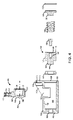
図1~図4に関して、軸のカシメ工具100の実施形態が示される。軸のカシメ工具100は、チャンバ106を形成する内部表面104を有するハウジング102を含む。チャンバ106は、長手方向軸108(チャンバ軸とも呼ばれる)を有することができる。ハウジング102は、固定ジョーユニット110(カシメ係合部材とも呼ばれる)を含む。いくつかの実施形態では、ジョーユニット110は、ハウジング102に形成されることができる。カシメ工具100はまた、第1の部分151(チャンバ部分とも呼ばれる)および第2の部分160(可動ジョーユニットまたはカシメ係合部材とも呼ばれる)を有する可動ジョー150を含む。固定ジョーユニット110および可動ジョーユニット160は、可動ジョーユニット160が固定ジョーユニット110に向けて移動するように、チャンバ部分151がチャンバ106の中を摺動するときに、部品を軸方向にカシメるように構成されるヨークを含む。ジョーユニットのヨークは、(図5Aおよび図5Bに示すように)部品を軸方向にカシメるために、部品200および部品のスリーブ(部品のボディ210とも呼ばれる)を保持するように構成される。工具100は、シール130、ピストン140、締着具132、ばね134、ストッパプレート136、および保持リング138をさらに備えることができる。
With respect to FIGS. 1 to 4, embodiments of the
ハウジング
ハウジング102は、外部表面118を有し、チャンバ106を形成する内部表面104を有する。内部表面104およびチャンバ106は、実質的に円筒状でありえる。いくつかの実施形態では、チャンバ106は、異なる断面形状(例えば長方形)でありえる。ハウジング102の第1の端部120は、好ましくはチャンバ106と同一のサイズおよび形状である(またはほぼそうである)チャンバ開口を定める。例えば、第1の端部120は、内部表面104と同じ直径を有することができる。第1の端部に向けて、環状のスロットまたは溝122は、内部表面104に形成されることができる。環状溝は、内部表面よりも大きな直径を有することができて、保持リング138を受容するためにサイズ決めされることができて、形状決めされることができる。ハウジングの第2の端部124は、流体源(例えば作動流体源)を取り付けるために構成されるポート126を除いて、閉じられる。いくつかの実施形態では、ねじハウジング接続を有する管は、ポート126に結合されることができる。そして流体源は、他端部上の流体源接続に結合(例えば迅速解放接続)されることができる。
ハウジング102の第1の端部120は、固定ジョーユニット110を含むことができる。そしてそれは、構造補強フランジ112、ヨーク114、およびボール戻り止め116を含むことができる。ハウジングジョーユニット110は、(例えばチャンバ軸に平行な)長手方向に面しているヨーク面を有する実質的にU字形状でありえて、そして、カシメプロセスの間、ボディ210またはカシメリング200のためのサポートを提供するように構成されることができる。例えば、ボディ210は、ヨーク114に配置されることができる。そしてカシメリング200は、ボディ210に向けて軸方向に移動することができる。ボール戻り止め116は、ヨーク114の両側に配置されることができる。ボール戻り止め116は、ヨーク114のボディ210の適切な適合の徴候を提供することができる。例えば、ボール戻り止め116は、ボディ210がヨーク114の範囲内で適切に配置されることを確実にするために配置されることができる。ボディ210の適切な配置は、不正使用を防止することができて、動作の間、工具への損傷(例えばフランジョーク、ボディ、カシメリング、または工具の他の部分への損傷)を防止することができる。
The
ハウジング102は、内部チャンバ106への放射状のアクセスを許容するハウジング102の中央部分にほぼ矩形のカットアウト128(図3に示すように)を有することができる。好ましくは、カットアウト128の幅は、チャンバ106の中に可動ジョー150を配置するのに必要な幅だけであり、そしてカットアウトの長さは、完全なカシメ動作を許容するのに必要な長さだけである。例えば、カットアウトは、可動ジョー150がそのリラックスした工具位置から完全に作動した位置まで移動することができるのに十分長い。そしてそれは、完全なカシメ動作を完了する。いくつかの実施形態では、カットアウト128の幅は、可動ジョー150が回転なしで軸方向に移動するように、可動ジョー150の幅と一致するように構成されることができる。例えば、一実施形態では、可動ジョー150とカットアウト128との間の幅の違いは、0.005インチ以下、0.002インチ以下、0.001インチ以下、0.001インチと0.005インチとの間、0.002インチと0.005インチとの間、または寸法の他の変化でありえる。
The
可動ジョー
可動ジョー150は、第1の部分151(チャンバ部分とも呼ばれる)、および第2の部分160(可動ジョーユニットまたはカシメ係合部材とも呼ばれる)を有する。チャンバ部分151は、ハウジング102のチャンバ106の中に配置されるように構成される。チャンバ部分151は、外部表面152を有する。外部表面152の曲率は、チャンバ106の内部表面104の曲率と一致するように構成される。いくつかの実施形態では、外部表面152の少なくとも一部は、円筒状でもよい。いくつかの実施形態では、外部表面は、異なる形状(例えば、平坦部分を有する円筒状、長方形、または他の形状)でもよい。外部表面152は、チャンバ106の中で並進運動可能である形状に構成される。工具の動作の間、可動ジョーが望ましくない角度運動なしにチャンバの中で並進運動可能であるように、外部表面152は、内部表面104の定義済み公差の範囲内でサイズ決めされることができる。寸法(例えば、直径)の違いは、外部表面152と内部表面104との間の隙間109(図において認知可能でない)を形成することができる。隙間は、外部表面152と内部表面104との間の寸法(例えば、半径方向寸法、直径、長さ寸法、など)によって定義されることができる。例えば、一実施形態では、外部表面152と内部表面104との間の寸法(例えば、直径)の違いは、0.005インチ以下、0.002インチ以下、0.001インチ以下、0.001インチと0.005インチとの間、0.002インチと0.005インチとの間、または寸法の他の変化でありえる。チャンバ部分151は、第1の内部表面154および、開口またはスルーホールを形成する第2の内部表面156を有する。第1および第2の内部表面は、同心的でありえる。ばね係合面157は、第1および第2の内部表面に対して実質的に垂直でありえる。ばね係合面157は、第1および第2の内部表面154、156間に延びることができる。第1および第2の内部表面は、可動ジョー150がハウジング102の中を軸方向に移動するにつれて、チャンバ軸108と整列するように構成されるチャンバ部分軸158を定めることができる。ピストン係合面153は、チャンバ部分151の第1の面155から突出する。ピストン係合面153は、ばね係合面157と平行でありえる。ピストン係合面153は、ピストン140の凹所146の中に適合するようにサイズ決めされることができて、形状決めされることができる。
Movable Jaw
可動ジョーのジョーユニット部分160は、構造補強フランジ162、ヨーク164、およびボール戻り止め166を含むことができる。可動ジョーユニット160は、(例えばチャンバ軸に平行な)長手方向に面しているヨーク面を有する実質的にU字形状でありえて、そして、カシメプロセスの間、ボディ210またはカシメリング200のためのサポートを提供するように構成されることができる。例えば、部品のボディ210は、ヨーク164に配置されることができる。そしてカシメリング200は、部品のボディ210に向けて軸方向に移動することができる。ボール戻り止め166は、ヨーク164の両側に配置されることができる。ボール戻り止め166は、ヨーク164のカシメボディの適切な適合の徴候を提供することができる。例えば、ボール戻り止め166は、カシメボディがヨーク164の範囲内で適切に配置されることを確実にするために配置されることができる。カシメリングの適切な配置は、不正使用を防止することができて、動作の間、工具への損傷(例えばフランジョーク、スリーブ、カシメリング、または工具の他の部分への損傷)を防止することができる。
The
ハウジングジョーユニット110は、ハウジングジョー軸を定める。そして可動ジョーユニット160は、可動ジョー軸を定める。可動ジョー軸158がチャンバ軸108と整列されるときに、これらの軸は、カシメ軸170を形成するために整列される。ハウジング102上に設けられる固定ジョーユニット110および可動ジョーユニット160は、管または他のアイテムに部品をカシメるために、カシメ軸170に沿って部品のボディ210の上をカシメリング200を動かすように構成される。
The
ピストン
ピストン140は、ハウジング102の第2の端部124に配置されるように構成されることができる。ピストン140の外部表面142は、チャンバ106と同じ形状(例えば円筒状)でありえる。ピストン140の外部表面142は、ピストン140がハウジングチャンバ106の中を軸方向に移動することができるようにサイズ決めされることができて、形状決めされることができて、またはさもなければそのようにピストン140がハウジングチャンバ106の中を軸方向に移動することができるように構成される(例えば、チャンバ軸108に沿って摺動するように構成される)ことができる。ピストン140は、ハウジング102の第2の端部124に面するヘッド143を形成する第1の閉鎖端部144を有する。ヘッド143の直径は、外部表面142の直径よりも小さくありえる。ピストン140はまた、第1の端部144の反対側に第2の端部145を有する。第2の端部145は、カウンタ穴または凹んだ案内面146を有する軸穴147(例えば、円筒状穴)を有する。穴147は、可動ジョー150をピストン140に固定するための締着具132(例えばねじ)を受容するように構成されることができる。凹んだ案内面146は、ピストン係合面153を受容するためにサイズ決めされることができて、形状決めされることができる。可動ジョー150のチャンバ部分151は、凹んだ案内面146に隣接して配置されているピストン係合面153とともに、ピストン140に直接載置するように構成されることができる。チャンバ部分151の表面155は、ピストン140の第2の端部145の表面に隣接して配置されることができる。可動ジョー150をピストンに直接載置することによって、工具100上の可動部品の数は、減少されることができる。加えて、チャンバ軸108とカシメ軸170との間の距離は、減少されることができる。これにより、カシメ動作の間、可動ジョー150上に発生するモーメント力を低下させる。
Piston The
工具の動作の間、ピストン140が望ましくない角度運動なしにチャンバの中で並進運動可能であるように、外部表面142は、内部表面104の定義済み公差の範囲内でサイズ決めされることができる。外部表面152と内部表面104との間のサイズの違いは、隙間109(図において認知可能でない)を形成することができる。隙間は、外部表面152と内部表面104との間の寸法値(例えば、半径方向寸法、直径、長さ寸法、など)によって定義されることができる。例えば、一実施形態では、外部表面152と内部表面104との間の直径の違いは、0.005インチ以下、0.002インチ以下、0.001インチ以下、0.001インチと0.005インチとの間、0.002インチと0.005インチとの間、または寸法の他の変化でありえる。外部表面142のサイズおよび形状は、ベアリングまたはチャンバ106を通って軸方向に延びるピストンロッドなしに工具が作動することができるように構成される。このサイズおよび形状は、チャンバ内でのピストン140および/または可動ジョー150の詰まりを結果として引き起こすことが可能な、ピストン140および可動ジョー150上の回転を減らす。ピストンの長さは、動作の間、角度回転を防止して、安定度を増加させるのを助けることもできる。いくつかの実施形態では、ピストン140の長さの大部分は、チャンバ106内に残って、開口128に達しない。
The
加圧流体がポート126を通って導入されるときに、それは、ピストン140のヘッド144に対して作用して、ピストン140を押圧して、これにより、ハウジング102の第1の端部120に向けて可動ジョー150を直接押圧する。ピストン140は、それがハウジング102の第2の端部でチャンバ106を通って、ハウジングの第1の端部120に向けて軸方向に並進することができるように、そしてそれが移動するにつれて可動ジョー150およびばね134の一端部を押し込むように、このように構成される。ハウジング102の第1の端部120に向けたこの並進運動は、チャンバ106の深さ、可動ジョーの軸方向の移動の自由度(例えば、完全に圧縮されたばね長さ、カットアウト長さ、または可動ジョー150の移動に対する制限からの)によって制限されることができる。
As the pressurized fluid is introduced through the
シール
シール130は、ピストン140のヘッド143上に配置されるように構成されることができる。シール130は、永続的な材料で作られることができる。流体がハウジング102の第2の端部124上のポート126を介してハウジングチャンバに供給されるときに、流体は、シール130によってピストン外部表面142とハウジング内部表面104との間に流れることを防止される。このように、ピストン140は、シール130によって助けられ、そしてハウジング102の第2の端部124は、油圧チャンバを形成することができて、工具100のためのアクチュエータとして作用することができる。いくつかの実施形態では、シールは、ポリウレタンシールでありえる。
Seal The
ばねアセンブリ
ピストン140および可動ジョー150は、ばね134、ストッパプレート136、および保持リング138によって、ハウジング102の中の適所において保持されることができる。保持リング138は、ハウジング102の第1の端部120に向けて形成される環状のスロット122において着座することができる。ストッパプレート136は、保持リングに隣接して配置されることができる。ストッパプレート136は、チャンバ106の内部表面104と実質的に同じ形状(例えば、直径)でありえる。突起137は、保持リング138の反対側の表面上のストッパプレートから延びることができる。ばね134が突起の周辺に、そして保持リング138の反対側のストッパプレート136の表面に隣接して配置されることができるように、突起137は、サイズ決めされることができて、形状決めされることができる。工具100の範囲内で組立てられるときに、ばね134は、ストッパプレート136と可動ジョー150のばね係合面157との間に延びる。ストッパプレート136およびばね係合面157は、ばねの反対側の端部134を受容するように構成されることができる。ばね134が横方向の動きなしで軸方向に圧縮するように、突起137および可動ジョー150のチャンバ部分151(例えば、内部表面154の深さ)は、工具100の動作の間、ばね134に付加的なサポートを提供するように構成されることができる。工具がリラックスした位置にあるときに、ピストン140、可動ジョー150、およびストッパプレート136は、ばねによって保持リング138に対して静止状態に保持されることができる。
The
リラックスした(例えば、作動されない)位置(図1に示すように)の工具によって、ばね134は、比較的拡張された位置にあり、そして可動ジョー150をピストン140に対してハウジング102の第2の端部124に向けて押す。いくつかの実施形態では、工具100がリラックスした(例えば、作動されない)位置にあるときに、ばね134は、ばね用のストッパとして作用する各表面とともに、ストッパプレート136と可動ジョー150との間で絶えず圧縮されることができる。ピストン140は、ハウジングの第2の端部に対して押す。ばねの圧縮力は、ストッパプレート136に対して押しつけられる。そしてそれは、保持リング138に対して保持される。チャンバ106の中の可動ジョー150の回転は、カットアウト128のサイズおよび形状によって制限されることができる。
By a tool in a relaxed (eg, inactive) position (as shown in FIG. 1), the
軸のカシメ工具アセンブリ
一実施形態では、軸のカシメ工具100を組立てるために、シール130、およびピストン140は、チャンバ106内に挿入される。シール130は、ピストンヘッド153上に載置される。ピストンヘッド153およびシールは、ハウジング102の第2の端部124に面して配置される。シールおよび/またはピストンは、ハウジングカットアウト128を通って挿入されることができる。可動ジョー150のチャンバ部分151は、カットアウト128を介してチャンバ106の中に配置される。可動ジョー150のピストン係合面153は、ピストン140の凹んだ案内面146に隣接して配置される。チャンバ部分151の表面155は、ピストン140の第2の端部145の表面に隣接して配置されることができる。可動ジョー150は、締着具132を用いてピストン140に固着される。次いで、ばね134は、ハウジングの第1の端部を通って挿入される。そしてストッパプレート136は、ばねに対して挿入される。次いで、保持リング287は、チャンバの内部表面104における環状のスロット122にステップインされる。圧縮ばねは、可動ジョーおよびピストンをハウジングの第1の端部から離れて付勢する。
Shaft Caulking Tool Assembly In one embodiment, a
カシメ動作
図5Aおよび図5Bの特定の参照については、部品ボディ210を第1の係合部材と係合することによって、オペレータは、部品の一側をカシメることができる。例えば、カシメの間、ボディ210の運動を抑制するために、静止している固定ジョー110のヨーク114の範囲内で部品ボディ210を係合する。ボール戻り止め116は、第1の係合部材の範囲内で正しい位置にボディ210を固定するために用いることができる。次いで、第2の係合部材(例えば、可動ジョーヨーク164)は、カシメリング200の外部表面と係合する。カシメリング200が他の係合部材に適している限り、部品ボディ210は、係合部材(例えば、固定または可動ジョー)のどちらかを係合するように調整されることができる。好ましくは、両方の係合部材は、部品ボディ210およびカシメリング200を受容することができる。
Caulking Operation For certain references in FIGS. 5A and 5B, engaging the
圧力がポート126を通して供給されるときに、ピストン140、シール130、および可動ジョー150は、ハウジング102の第1の端部120に向けて移動する。そして、ばね134を圧縮し、カシメリング200をボディ210の上に移動させる。これにより、ボディ210を管220に対してカシメる。より詳しくは、圧力を掛けられた流体源(例えば、10,000psiのオイル源)からチャンバ106への加圧流体の供給は、ピストン140上に軸方向に力を適用する。そして、ハウジング102の第1の端部120に向けてそれを押す。ピストン140は、可動ジョー150に軸方向の力を適用する。そしてそれは、それをばね134に適用する。流体の力は、軸のばね圧縮力に打ち勝つ。そして、ピストン140、シール130、および可動ジョー150は、ハウジングの第1の端部120に向けてハウジングチャンバ106を通して軸方向に並進運動する。そして、ばね134を圧縮する。工具がリラックスした状態にある間、ピストンのチャンバ106内にある空気は、カットアウト128を介して、作動の間、工具100から排気される。可動ジョーユニット160は、固定ジョーユニット110に向けて移動する。この並進運動の間、部品210およびカシメリング200がジョーユニットのヨーク内に置かれるときに、カシメリング200は、部品210を通じて押し込まれる。したがって、(図5Bに示すように)工具が完全に作動した構成に達するまでに、カシメられた部品を管220上に形成する。カシメリング200がボディ210に接触するときに、カシメ動作は終了している。カシメ動作の完了の前に可動ジョーが止まらないように、工具は構成される。見ることができるように、可動ジョー150とハウジング102の表面との間に隙間180がある。可動ジョー150とストッパプレート136との間に隙間182がある。ばね134は、完全には圧縮されない。このように、カシメ動作が不完全なカシメに結果としてなるのを早期に止める停止に遭遇せずに、カシメ動作は、完了することができる。
When pressure is supplied through the
カシメ動作の終端で、圧力源は軽減される。そして、ばね力は、可動ジョー150およびピストン140をハウジングの第2の端部124に向けて戻す。これにより、可動ジョーユニット160をハウジングジョーユニット110から離隔する。圧縮ばね134が拡大するときに、ばね136は、可動ジョー150に力を適用する。可動ジョーは、これらの力をピストン140に伝える。そしてそれは、チャンバ106から流体を排出させて、管への力を取り除く。空気は、カットアウト128を介してチャンバ106に戻ることができる。そして、工具100は、次のカシメ動作のためのリラックスした位置(図5A)に戻る。
At the end of the caulking operation, the pressure source is reduced. The spring force then returns the
図6および図7は、カシメ工具100’の別の実施形態を示す。カシメ工具100’は、構造補強フランジ112’を修正した。図示の実施形態では、修正したフランジ112’は、実質的に可動ジョー150および固定ジョー110の高さまで延びる。フランジ112’は、可動ジョー150の操作上の移動の長さを延長する。フランジ112’は、カシメ工具の動作の間、オペレータに保護を提供することができる。工具100’は、本明細書に記載されている工具100の説明にしたがって作動する。動作の間、フランジ112’は、オペレータが可動ジョー150と固定ヨーク110との間に器材の付加物(例えば、指)または部分を不注意に配置するのを防止することができる。これにより、オペレータを傷害から保護して、カシメ工具100’を破損から保護する。
6 and 7 show another embodiment of the
図8は、平行な管210および220を適切にカシメるためのポート分離を示す。平行な管の間の最小限の違いは、「アルミニウムの軸方向カシメ部品の設置および検査手順」用のAS6124標準の下の要件である。適切なカシメのための干渉のない2つの平行な部品の上にカシメ工具200を係合するために、最小限のポート分離距離「M」が部品間に必要なことを、標準は義務づける。
FIG. 8 shows port separation for proper caulking of
アルミニウムの軸カシメ部品シリーズ(すなわち-10部品の次の-04部品)のさまざまなサイズの組合せのための推奨された最小限のポート分離距離「M」は、AS標準において与えられる。コンパクトなカシメ工具のいくらかの実施形態において、「M」値は、AS標準の推奨値よりも小さくなることができる。望ましくは、管を互いにより近くするときには、「M」値を低下させることは、航空機の配管設計において所与のスペースにより多くの管を適合することを助ける。 The recommended minimum port separation distance "M" for various size combinations of the aluminum shaft caulking component series (ie, the -04 component following the -10 component) is given in the AS standard. In some embodiments of the compact caulking tool, the "M" value can be smaller than the recommended value of the AS standard. Desirably, lowering the "M" value when the pipes are closer to each other helps fit more pipes into a given space in aircraft piping design.
下の表は、適合するための値の範囲および同一サイズの組合せの工具を示す。いくらかの例示的実施形態のために、AS値と比較して減少した「M」値は、テーブルに示される。

例示の実施形態において、ピストン140および可動ジョー150は、保持リング138およびばね134によってハウジング102の中で実質的に固定されて静止している状態に保たれる。そして、ばねは、ストッパプレート136と可動ジョー150との間を延びる。ピストン140および可動ジョー150は、流体がハウジングの第2の端部124上のポート126を介してハウジングチャンバに供給されるときに、軸108に沿って軸方向に並進運動するように構成される。ピストン140および可動ジョー150がハウジング102の中で自由に並進運動するために、ベアリングは必要とされない。シール130は、保持リングの反対側のハウジング102の軸端部に密封チャンバを形成するように構成される。ピストン140、密封チャンバ106、および加圧流体源は、チャンバ106の中で可動ジョーを軸方向に作動させるようにこのように構成される。
In an exemplary embodiment, the
整列部材を有するカシメ工具
図9~図12は、軸のカシメ工具300の別の実施形態を例示する。軸のカシメ工具300は、ハウジング302、固定したジョーユニット310、可動ジョーユニット350、ピストンおよびばねアセンブリを含む。
Caulking Tools with Alignment Members FIGS. 9-12 exemplify another embodiment of the
ハウジング302は、外部表面318を有し、チャンバ306を形成する第1の内部表面303および第2の内部表面304を有する。第1の内部表面303は、チャンバ306のピストン部を形成する。第2の内部表面304は、チャンバ306の可動ジョー部分を形成する。チャンバ306は、実質的に円筒状でありえる。いくつかの実施形態では、チャンバ306は、異なる断面形状(例えば長方形)でありえる。ピストン部は、第1のサイズまたは寸法を(例えば、第1の直径)有することができて、可動ジョー部分は、第2のサイズまたは寸法を(例えば、第2の直径)有することができる。ピストン部は、ピストン340に適合するためにサイズ決めされることができて、形状決めされることができる。可動ジョー部分は、可動ジョー350に適合するためにサイズ決めされることができて、形状決めされることができる。ピストン部と可動ジョー部分との間のサイズの違いは、ピストン340および可動ジョー350の位置決めおよび配列を制御することができる。部分の異なるサイズは、チャンバの中での構成要素の組立を支援することもできる。
The
ハウジング302の第1の端部320は、好ましくはチャンバ306の可動ジョー部分と同一のサイズおよび形状である(かまたはほぼそうである)チャンバ開口を定める。例えば、第1の端部320は、内部表面304と同じ直径を有することができる。第1の端部に向けて、環状のスロットまたは溝322が内部表面304に形成されることができる。環状溝は、内部表面304よりも大きな直径を有することができて、保持リング338を受容するためにサイズ決めされることができて、形状決めされることができる。ハウジングの第2の端部324は、流体源(例えば油圧流体源)を取り付けるために構成されるポートインターフェース326を除いて、閉じられる。いくつかの実施形態では、ねじハウジング接続を有する管は、インターフェース326に結合されることができる。そして流体源は、他端部上の流体源接続に結合(例えば迅速解放接続)されることができる。
The
ハウジング302の第1の端部320は、固定ジョーユニット310を含むことができる。そしてそれは、構造補強フランジ312、ヨーク314を含むことができる。ハウジングジョーユニット310のヨーク314は、(例えばチャンバ軸に平行な)長手方向に面しているヨーク面を有する実質的にU字形状でありえて、そして、カシメプロセスの間、ボディ210またはカシメリング200のためのサポートを提供するように構成されることができる。例えば、ボディ210はヨーク314に配置されることができる。そしてカシメリング200は、ボディ210に向けて軸方向に移動することができる。
The
ハウジング302は、内部チャンバ306への放射状のアクセスを許容するハウジング302の中央部分にほぼ矩形のカットアウト328を有することができる。好ましくは、カットアウト328の幅は、チャンバ306の中に可動ジョー350を配置するのに必要な幅だけであり、そしてカットアウトの長さは、完全なカシメ動作を許容するのに必要な長さだけである。例えば、カットアウトは、可動ジョー350がそのリラックスした工具位置から完全に作動した位置まで移動することができるのに十分長くありえる。そしてそれは、完全なカシメ動作を完了する。いくつかの実施形態では、カットアウト328の幅は、可動ジョー350が回転なしで軸方向に移動するように、可動ジョー350の幅と一致するように構成されることができる。例えば、一実施形態では、可動ジョー350とカットアウト328との間の幅の違いは、0.005インチ以下、0.002インチ以下、0.001インチ以下、0.001インチと0.005インチとの間、0.002インチと0.005インチ間、または寸法の他の変化でありえる。
The
可動ジョー350は、チャンバ部分351(第1の部分とも呼ばれる)、カシメ係合部材部360、および整列部材部380を有する。チャンバ部分351は、ハウジング102のチャンバ306の中に配置されるように構成される。チャンバ部分351は、外部表面352を有する。外部表面352の形状および/または曲率は、チャンバ306の第2の内部表面304の形状および/または曲率と一致するように構成される。いくつかの実施形態では、外部表面352の少なくとも一部は、円筒状でもよい。いくつかの実施形態では、外部表面は、異なる形状(例えば、平坦部分を有する円筒状、長方形、または他の形状)でもよい。外部表面352は、チャンバ306の中で並進運動可能である形状に構成される。工具の動作の間、可動ジョー350が望ましくない角度運動なしにチャンバの中で並進運動可能であるように、外部表面352は、内部表面304の定義済み公差の範囲内でサイズ決めされることができる。寸法(例えば、直径)の違いは、外部表面352と内部表面304との間の隙間307(図において認知可能でない)を形成することができる。隙間は、外部表面352と内部表面304との間の寸法(例えば、半径方向寸法、直径、長さ寸法、など)によって定義されることができる。例えば、一実施形態では、外部表面352および内部表面304との間の寸法(例えば、直径)の違いは、0.005インチ以下、0.002インチ以下、0.001インチ以下、0.001インチと0.005インチとの間、0.002インチと0.005インチとの間、または寸法の他の変化でありえる。チャンバ部分351は、第1の内部表面354および、開口またはスルーホールを形成する第2の内部表面356を有する。第1および第2の内部表面は、同心的でありえる。第1および第2の内部表面は、可動ジョー350がハウジング302の中を軸方向に移動するにつれて、チャンバ軸308と整列するように構成されるチャンバ部分軸を定めることができる。可動ジョーユニット部360およびハウジングジョーは、カシメ軸370を定める。カシメ軸は、チャンバ軸308と平行であるかまたは実質的に平行である。
The
可動ジョー350は、可動ジョー350のヨークから外へ遠位に延びることができる整列部材380を含む。整列部材380は、ハウジングに沿って軸方向に延びることができる。1つ以上の補強フランジ386は、整列部材380にサポート、剛性、安定化を提供することができる。整列部材380は、実質的に可動ジョー350の幅でありえる。いくつかの実施形態では、整列部材380は幅の一部でありえて、それは可動ジョー350の幅よりも小さい。いくつかの実施形態では、整列部材380は、可動ジョー350の幅よりも大きくありえる。
The
整列部材380は、可動ジョー360が軸のカシメ工具300の中に取り付けられるときに、整列部材380とハウジング302との間の隙間を形成する整列部材380の底面上の曲げられた表面382を含む。曲げられた表面382は、整列部材380とハウジングの外部表面302との間に位置する位置決め構成要素390(例えば楔)を収納するように構成される。曲げられた表面382は、整列部材380の幅を延長することができる。曲げられた表面382は、整列部材380の幅の少なくとも一部を延ばすリップまたは他の突起384を有することができる。リップ384は、位置決め構成要素390が整列部材380の下からすべり出るのを防止することができる。いくつかの実施形態では、リップ384は、整列部材380の裏側の少なくとも一部に沿って、そして整列部材380の両側面の一方または両方に沿って延びる伸びてよい。
The
整列部材380は、ハウジング302の外部表面318の曲率に一致するように構成されることができる。曲げられた表面382および位置決め構成要素390は、同じ曲率に一致することができる。整列部材380は、締着具394を用いて整列部材380とハウジング302との間に位置決め構成要素390を固定するための取付孔388を含むことができる。位置決め構成要素は、締着具394用の対応する開口部392を有することができる。取付孔388は、位置決め構成要素390が位置の範囲に固定されるのを許容するために長方形の形状であることができる。取付孔388は、位置決め構成要素390の横方向および長手方向位置決めを許容するように構成されてよく、位置決めされてよい。
The
整列部材380の長さは、可動ジョー350の構造的完全性を増加させるように構成されることができる。カシメ動作の間、可動ジョーが作動位置にあるときに、整列部材380の少なくとも半分がハウジング302の上に位置しかつ開口328に位置しないように、整列部材380の長さおよび形状は構成されることができる。いくつかの実施形態では、整列部材380の長さは、整列部材の後端および可動ジョーのヨークの上部から測定される角度に基づくことができる。このような実施形態では、測定角度は、約45~60°の間でありえる。
The length of the
カシメ工具の動作の間、カシメ軸370およびチャンバ軸308が平行であるように、位置決め構成要素390は、整列部材380とハウジング302との間に配置されることができて、固定されることができる。位置決め構成要素は、楔、ジョー位置決め構成要素、または整列部材位置決め構成要素と呼ばれることもできる。カシメ工具300の動作の間、位置決め構成要素390が整列部材380と関連して移動しないように、位置決め構成要素390は固定されることができる。動作中に、整列部材380は、可動ジョーがカシメ動作の間、後方に曲がるのを防止するのを助けることができる。加えて、整列部材380は、カシメ動作の間、それがハウジングと接触する可動ジョー上の早すぎる摩耗を防止するのを助けることができる。いくつかの実施形態では、位置決め構成要素が大部分の負荷または、カシメ動作の間、整列部材および/または可動ジョーによって経験される負荷の少なくとも実質部分を受けることができて、吸収することができるように、整列部材380および位置決め構成要素390は、形状決めされることができて、構成されることができる。位置決め構成要素の位置決めは、カシメ動作の間、可動ジョーによって経験される力を吸収して、分配するために、増加した表面積を提供することができる。動作の間の力の分配は、カシメ工具300上の摩耗を減らすのを助けることができる。時間とともに、位置決め構成要素は、摩耗して、より容易に置き換えられやすくなることができる。位置決め構成要素は、カシメ工具(例えばAISI-A2鋼、AISI-O6鋼または他の材料)として同一材料から製造されることができる。カシメ工具300は、位置決め構成要素とハウジングとの間の注油なしに動作することができる。いくつかの実施形態では、セラミックコーティング(例えば窒化チタン)が、注油および/または摩耗を減らす代わりに位置決め構成要素390および/またはハウジング302に使われることができる。いくつかの実施形態では、整列部材380は位置決め構成要素390を含まなくてもよくて、整列部材380の底面はハウジング302の外部表面318に隣接するように構成される。
The
ピストン340は、ハウジング302の第2の端部324に配置されるように構成されることができる。ピストン340の外部表面342は、チャンバ306と同じ形状(例えば円筒状)でありえる。ピストン340の外部表面342は、ピストン340がハウジングチャンバ306の中を軸方向に移動することができるようにサイズ決めされることができて、形状決めされることができて、またはさもなければそのようにピストン340がハウジングチャンバ306の中を軸方向に移動することができるように構成される(例えば、チャンバ軸308に沿って摺動するように構成される)ことができる。ピストン340は、ハウジング302の第2の端部324に面する六角形のポケット346を有するヘッドを形成する第1の閉鎖端部344を有する。ヘッド344の直径は、外部表面342の直径よりも小さくありえる。六角形のポケット346は、六角形タイプの工具を係合するように構成されることができて、チャンバ306の中にピストン340を組立、位置決め、および/または固定する際の援助に使われることができる。ピストン340はまた、第1の端部344の反対側に第2の端部345を有する。第2の端部345は、開口347(例えば、円筒状穴)を有する。開口347は、可動ジョー350をピストン340に固定するための締着具332(例えばねじ)を受容するように構成されることができる。開口347は、さら穴部およびねじ部を有することができる。いくつかの実施形態では、開口347は、ねじ部を有するだけであってよい。可動ジョー350のチャンバ部分351は、ピストン340の第2の端部345の表面に隣接して配置されている表面355を有するピストン340に直接載置するように構成されることができる。
The
工具の動作の間、ピストン340が望ましくない角度運動なしにチャンバの中で並進運動可能であるように、外部表面342は、内部表面303の定義済み公差の範囲内でサイズ決めされることができる。外部表面342と内部表面303との間のサイズの違いは、隙間309(図において認知可能でない)を形成することができる。隙間は、外部表面352と内部表面303との間の寸法値(例えば、半径方向寸法、直径、長さ寸法、など)によって定義されることができる。例えば、一実施形態では、外部表面342と内部表面303との間の直径の違いは、0.005インチ以下、0.002インチ以下、0.001インチ以下、0.001インチと0.005インチとの間、0.002インチと0.005インチとの間、または寸法の他の変化でありえる。外部表面342のサイズおよび形状は、ベアリングまたはチャンバ306を通って軸方向に延びるピストンロッドなしに工具が作動することができるように構成される。このサイズおよび形状は、チャンバ内でのピストン340および/または可動ジョー350の詰まりを結果として引き起こすことが可能な、ピストン340および可動ジョー350上の回転を減らす。ピストンの長さは、動作の間、角度回転を防止して、安定度を増加させるのを助けることもできる。いくつかの実施形態では、ピストン340の長さの大部分は、チャンバ306のピストン部に残って、チャンバ306の可動ジョー部分に達しない。シール330は、ピストン340のヘッド343上に配置されるように構成されることができる。シールは、本明細書において述べられるシール130と実質的に同じでありえる。
The
ピストン340および可動ジョー350は、ばね334、ストッパプレート336、および保持リング338によって、ハウジング302の中の適所において保持されることができる。ばね334、ストッパプレート336、および保持リング338は、それぞれ、本明細書において開示されるばね134、ストッパプレート136、および保持リング138と実質的に同じでありえる。
The
軸のカシメ工具300は、軸のカシメ工具100に関して本明細書において開示される同じカシメ動作を実行するために実行することができて、作動することができる。
The
本開示の実施形態は、先に述べた工具よりも実質的に少ないパーツ、より詳しくは、より少ない移動パーツによって特徴づけられる。パーツのより少ない数は、許容度増強をおそらく減らす。そしてそれは、さもなければ、ハウジングヨークに関して好ましい角度よりも小さい可動ジョーヨーク回転に結果としてなりえる。さらに、安定化ピン上の従来技術のベアリングが一様でないサポート(すなわち、完全な周長よりも少ない周辺のサポート)を提供する葉(lobe)を有するハウジングの部分を通らなければならなかったので、そのベアリングは、他のパーツよりも大きい率で摩耗しやすかった。安定化ピンの除去および、安定化部材および位置決め構成要素の取り込みは、カシメ動作の間、負荷を吸収するためにより大きい表面を提供するのを助ける。位置決め構成要素のより大きい表面積および安定化部材のサポートは、好ましい全体の耐久性を有するツールを提供する傾向がある。 The embodiments of the present disclosure are characterized by substantially fewer parts than the tools described above, more specifically, fewer moving parts. A smaller number of parts will probably reduce the tolerance increase. And it can result in a movable jaw yoke rotation that is otherwise smaller than the preferred angle with respect to the housing yoke. In addition, the prior art bearings on the stabilizing pins had to go through a portion of the housing with lobes that provided non-uniform support (ie, less peripheral support than full circumference). , The bearing was more prone to wear than other parts. The removal of stabilizing pins and the incorporation of stabilizing members and positioning components help provide a larger surface to absorb the load during the caulking operation. The larger surface area of the positioning components and the support of the stabilizing members tend to provide tools with favorable overall durability.
上記のことから、本発明のカシメ工具が非常に減少したサイズ、重量および複雑さのカシメ工具を好ましくは提供することはいうまでもない。そしてそれは、より信頼性の高いおよびより高価でないカシメ工具に概して結果としてなる。工具には、保守要件がほとんどない。これらのそしてまた他の利点は、本発明のカシメ工具に固有の利点を与える。 From the above, it goes without saying that the caulking tool of the present invention preferably provides a caulking tool of significantly reduced size, weight and complexity. And it generally results in more reliable and less expensive caulking tools. Tools have few maintenance requirements. These and also other advantages provide the inherent advantages of the caulking tools of the present invention.
本開示の特定の特徴、態様および利点が特定の実施形態に関して記載されたが、他の実施形態もまた本発明の範囲内であることは当業者にとって明らかである。このように、さまざまな改変と変更態様は、本発明の精神と範囲から逸脱することなくなされてよい。例えば、各種の構成要素は、所望のように再位置付けされてよい。さらに、特徴、態様、および利点の全てが、本発明を実施することを必ずしも必要とするわけではない。したがって、本発明の範囲は、以下の請求項によってのみ定義されることが意図される。
Although certain features, embodiments and advantages of the present disclosure have been described for a particular embodiment, it will be apparent to those skilled in the art that other embodiments are also within the scope of the invention. Thus, various modifications and modifications may be made without departing from the spirit and scope of the invention. For example, the various components may be repositioned as desired. Moreover, not all features, embodiments, and advantages necessarily require that the invention be practiced. Therefore, the scope of the invention is intended to be defined only by the following claims.
Claims (18)
ハウジングであって、
第1の端部、第2の端部、内壁、およびチャンバを通って延びる軸、を有するチャンバ、および、固定カシメ係合部材、
を含む、ハウジングと、
可動カシメ係合部材であって、前記可動カシメ係合部材から遠位に延びる整列部材、および位置決め構成要素を含み、前記整列部材は、前記整列部材の幅を延長する表面であって前記軸の方向に対して曲げられた表面、および前記整列部材の幅の少なくとも一部を延ばすリップを有し、前記リップは、前記位置決め構成要素が前記整列部材の下からすべり出るのを防止するように構成され、前記整列部材の一部は、前記位置決め構成要素と結合され、前記位置決め構成要素は、底面および、前記整列部材の前記曲げられた表面の曲げの程度に対応する表面を含み、前記位置決め構成要素の前記底面は、前記ハウジングの外部表面に隣接するように構成され、前記位置決め構成要素の前記表面は、前記整列部材の前記曲げられた表面に隣接するように構成され、前記可動カシメ係合部材のチャンバ部分は、前記チャンバ内に配置されて、前記軸に沿って並進運動可能である、可動カシメ係合部材と、
前記第2の端部で前記チャンバ内に配置されるピストンであって、前記ピストンは、前記可動カシメ係合部材の前記チャンバ部分に固定され、前記ピストンは、前記軸に沿って並進運動可能であり、前記ピストンの外壁と前記チャンバの前記内壁との間に隙間が形成される、ピストンと、
前記可動カシメ係合部材が前記固定カシメ係合部材に向けて移動するように、前記ピストンを前記第2の端部から前記第1の端部へ前記ハウジングの前記チャンバを通って前記軸に沿って押し込むためにアクチュエータから入力を受けるように構成されるアクチュエータインターフェースと、
を含む、カシメ工具。 A caulking tool for caulking
It ’s a housing.
A chamber having a first end, a second end, an inner wall, and a shaft extending through the chamber, and a fixed caulking engaging member,
Including the housing and,
A movable caulking engaging member comprising an alignment member extending distally from the movable caulking engaging member and a positioning component, wherein the alignment member is a surface extending the width of the alignment member and is of the axis. It has a surface bent in a direction and a lip that extends at least a portion of the width of the alignment member, the lip being configured to prevent the positioning component from slipping under the alignment member. And a portion of the alignment member is coupled to the positioning component, the positioning component comprising a bottom surface and a surface corresponding to the degree of bending of the bent surface of the alignment member. The bottom surface of the positioning component is configured to be adjacent to the outer surface of the housing, and the surface of the positioning component is configured to be adjacent to the bent surface of the alignment member. The chamber portion of the movable caulking engaging member is a movable caulking engaging member that is arranged in the chamber and is capable of translational movement along the axis.
A piston disposed in the chamber at the second end, the piston being fixed to the chamber portion of the movable caulking engaging member, the piston being able to translate along the axis. With the piston, there is a gap formed between the outer wall of the piston and the inner wall of the chamber.
The piston is moved from the second end to the first end along the axis through the chamber of the housing so that the movable caulking engaging member moves towards the fixed caulking engaging member. An actuator interface configured to receive input from the actuator for pushing in,
Including caulking tools.
請求項1のカシメ工具と、
第1の部材を受容するために構成される第1のボディを有する部品と、
前記部材に前記第1のボディをカシメるために前記第1のボディの上に軸方向移動するために構成されるリングと、
を含み、
各カシメ係合部材は、前記部品または前記リングの少なくとも1つを係合するように構成される、
カシメシステム。 A caulking system for connecting members, the caulking system is
The caulking tool of claim 1 and
A component having a first body configured to receive the first member, and
A ring configured to axially move over the first body to crimp the first body onto the member.
Including
Each caulking engaging member is configured to engage at least one of said parts or said rings.
Caulking system.
The caulking tool of claim 2, wherein the alignment member comprises a mounting hole for one or more fasteners that allows lateral and longitudinal positioning of the positioning component.
Applications Claiming Priority (3)
| Application Number | Priority Date | Filing Date | Title |
|---|---|---|---|
| US201662419918P | 2016-11-09 | 2016-11-09 | |
| US62/419,918 | 2016-11-09 | ||
| PCT/US2017/060699 WO2018089538A1 (en) | 2016-11-09 | 2017-11-08 | Axial swage tool |
Publications (3)
| Publication Number | Publication Date |
|---|---|
| JP2019537518A JP2019537518A (en) | 2019-12-26 |
| JP2019537518A5 JP2019537518A5 (en) | 2020-12-24 |
| JP7071352B2 true JP7071352B2 (en) | 2022-05-18 |
Family
ID=60570208
Family Applications (1)
| Application Number | Title | Priority Date | Filing Date |
|---|---|---|---|
| JP2019524019A Active JP7071352B2 (en) | 2016-11-09 | 2017-11-08 | Shaft caulking tool |
Country Status (5)
| Country | Link |
|---|---|
| US (1) | US10828757B2 (en) |
| EP (1) | EP3538323B1 (en) |
| JP (1) | JP7071352B2 (en) |
| CA (1) | CA3042682C (en) |
| WO (1) | WO2018089538A1 (en) |
Families Citing this family (2)
| Publication number | Priority date | Publication date | Assignee | Title |
|---|---|---|---|---|
| US10400921B2 (en) * | 2015-05-05 | 2019-09-03 | Aerofit, Llc | Axial swage tool |
| US12049765B2 (en) * | 2021-07-20 | 2024-07-30 | Life Coded, Llc | Portable hot swaged coupling device for connecting articles |
Family Cites Families (20)
| Publication number | Priority date | Publication date | Assignee | Title |
|---|---|---|---|---|
| US4189817A (en) * | 1978-03-03 | 1980-02-26 | Moebius Kurt Otto | Hydraulic assembly tool for tube fittings |
| JP3086703B2 (en) * | 1990-04-06 | 2000-09-11 | ロックリング コーポレイション | Hydraulic assembly tool with improved load-bearing device for fittings |
| US5277089A (en) | 1991-08-01 | 1994-01-11 | Mcgushion Kevin D | Tubing union and tool |
| JP2599913Y2 (en) * | 1991-09-27 | 1999-09-27 | 新日本ツール株式会社 | Socket wrenches for L-type and T-type elbows |
| JP2875889B2 (en) | 1992-01-31 | 1999-03-31 | ザ ドイチュ カンパニー | Swaging tool for pipe fittings swaged in the axial direction |
| US5297325A (en) * | 1993-03-11 | 1994-03-29 | Aeroquip Corporation | Hydraulic tool |
| US5592726A (en) | 1995-01-06 | 1997-01-14 | The Deutsch Company | Axial swage tool having a stabilizing pin |
| US5694670A (en) | 1995-05-26 | 1997-12-09 | Hosseinian; Amir P. | Secure swaging tool |
| EP0833707B1 (en) * | 1995-05-26 | 2000-04-19 | Sierracin Corporation | Interchangeable and secure swaging tool |
| US6430792B1 (en) * | 2000-06-09 | 2002-08-13 | Eaton Aeroquip Inc. | Hydraulic tool |
| US6434808B1 (en) * | 2000-11-02 | 2002-08-20 | Westinghouse Air Brake Technologies Corporation | Compact installation tool |
| US6823573B2 (en) * | 2002-01-25 | 2004-11-30 | Eaton Corporation | Swaging tool including system to determine when connector is in a proper position for assembly |
| US7155790B2 (en) * | 2003-10-20 | 2007-01-02 | Designed Metal Connections | Axial swage tool |
| US7337514B2 (en) | 2004-02-24 | 2008-03-04 | Lokring Technology, Llc | Hydraulic hand tool |
| US8256079B2 (en) * | 2008-06-05 | 2012-09-04 | The Boeing Company | Apparatus for swaging components |
| US8458876B2 (en) * | 2010-08-09 | 2013-06-11 | Designed Metal Connections, Inc. | Axial swage tool |
| US10093000B2 (en) | 2012-08-06 | 2018-10-09 | Mcelroy Manufacturing, Inc. | Socket fusion jig |
| EP2969299B8 (en) * | 2013-03-15 | 2020-08-12 | Howmet Aerospace Inc. | Extreme offset nose assembly with secondary bearing |
| US9604273B1 (en) * | 2014-05-06 | 2017-03-28 | Veigh Hogan | Axial swage tool |
| US10400921B2 (en) | 2015-05-05 | 2019-09-03 | Aerofit, Llc | Axial swage tool |
-
2017
- 2017-11-08 EP EP17808663.3A patent/EP3538323B1/en active Active
- 2017-11-08 US US15/807,422 patent/US10828757B2/en active Active
- 2017-11-08 CA CA3042682A patent/CA3042682C/en active Active
- 2017-11-08 WO PCT/US2017/060699 patent/WO2018089538A1/en unknown
- 2017-11-08 JP JP2019524019A patent/JP7071352B2/en active Active
Also Published As
| Publication number | Publication date |
|---|---|
| EP3538323A1 (en) | 2019-09-18 |
| CA3042682A1 (en) | 2018-05-17 |
| US20180126526A1 (en) | 2018-05-10 |
| JP2019537518A (en) | 2019-12-26 |
| CA3042682C (en) | 2023-09-26 |
| WO2018089538A1 (en) | 2018-05-17 |
| US10828757B2 (en) | 2020-11-10 |
| EP3538323B1 (en) | 2022-07-13 |
Similar Documents
| Publication | Publication Date | Title |
|---|---|---|
| US11384871B2 (en) | Axial swage tool | |
| TWI659161B (en) | Fluid pressure cylinder | |
| GB2062799A (en) | Assembly comprising a shaft removably held axially in a bore of a housing and a clutch release mechanism including such an assembly | |
| US10821564B2 (en) | Cylinder device, press machine, workpiece clamping apparatus, cylinder device actuating method, method for clamping workpiece, and method for pressing workpiece | |
| JP6103384B2 (en) | Piston connection structure used in fluid pressure cylinder and connection method thereof | |
| EP3308037B1 (en) | Fluid pressure cylinder | |
| CA2811914C (en) | Axial swage tool | |
| US11167428B2 (en) | Suction-type gripping device | |
| JP7071352B2 (en) | Shaft caulking tool | |
| KR20190126856A (en) | Shaft connection structure and fluid pressure device | |
| US10316983B2 (en) | Valve | |
| EP2796715A2 (en) | Reciprocating compressor | |
| TWI605201B (en) | Fluid pressure cylinder | |
| US7155790B2 (en) | Axial swage tool | |
| US20210285544A1 (en) | Method for producing piston assembly and hydraulic fluid device | |
| US10941790B2 (en) | Cylinder device, press machine, workpiece clamping apparatus, cylinder device actuating method, method for clamping workpiece, and method for pressing workpiece | |
| KR102079672B1 (en) | Hydraulic cylinder | |
| US10683955B2 (en) | Hose clamp | |
| EP3308034B1 (en) | Fluid pressure cylinder | |
| US20120210568A1 (en) | Uninstaller for taking out brake caliper piston |
Legal Events
| Date | Code | Title | Description |
|---|---|---|---|
| A521 | Request for written amendment filed |
Free format text: JAPANESE INTERMEDIATE CODE: A523 Effective date: 20201109 |
|
| A621 | Written request for application examination |
Free format text: JAPANESE INTERMEDIATE CODE: A621 Effective date: 20201109 |
|
| A871 | Explanation of circumstances concerning accelerated examination |
Free format text: JAPANESE INTERMEDIATE CODE: A871 Effective date: 20201109 |
|
| A975 | Report on accelerated examination |
Free format text: JAPANESE INTERMEDIATE CODE: A971005 Effective date: 20210106 |
|
| A131 | Notification of reasons for refusal |
Free format text: JAPANESE INTERMEDIATE CODE: A131 Effective date: 20210112 |
|
| A601 | Written request for extension of time |
Free format text: JAPANESE INTERMEDIATE CODE: A601 Effective date: 20210409 |
|
| A521 | Request for written amendment filed |
Free format text: JAPANESE INTERMEDIATE CODE: A523 Effective date: 20210610 |
|
| A131 | Notification of reasons for refusal |
Free format text: JAPANESE INTERMEDIATE CODE: A131 Effective date: 20210810 |
|
| A601 | Written request for extension of time |
Free format text: JAPANESE INTERMEDIATE CODE: A601 Effective date: 20211110 |
|
| A521 | Request for written amendment filed |
Free format text: JAPANESE INTERMEDIATE CODE: A523 Effective date: 20220209 |
|
| TRDD | Decision of grant or rejection written | ||
| A01 | Written decision to grant a patent or to grant a registration (utility model) |
Free format text: JAPANESE INTERMEDIATE CODE: A01 Effective date: 20220405 |
|
| A61 | First payment of annual fees (during grant procedure) |
Free format text: JAPANESE INTERMEDIATE CODE: A61 Effective date: 20220506 |
|
| R150 | Certificate of patent or registration of utility model |
Ref document number: 7071352 Country of ref document: JP Free format text: JAPANESE INTERMEDIATE CODE: R150 |