JP7071289B2 - Electrochemical battery with solid ion conductive polymer material - Google Patents
Electrochemical battery with solid ion conductive polymer material Download PDFInfo
- Publication number
- JP7071289B2 JP7071289B2 JP2018562254A JP2018562254A JP7071289B2 JP 7071289 B2 JP7071289 B2 JP 7071289B2 JP 2018562254 A JP2018562254 A JP 2018562254A JP 2018562254 A JP2018562254 A JP 2018562254A JP 7071289 B2 JP7071289 B2 JP 7071289B2
- Authority
- JP
- Japan
- Prior art keywords
- positive electrode
- ion conductive
- conductive polymer
- polymer material
- solid ion
- Prior art date
- Legal status (The legal status is an assumption and is not a legal conclusion. Google has not performed a legal analysis and makes no representation as to the accuracy of the status listed.)
- Active
Links
Images


Classifications
-
- H—ELECTRICITY
- H01—ELECTRIC ELEMENTS
- H01M—PROCESSES OR MEANS, e.g. BATTERIES, FOR THE DIRECT CONVERSION OF CHEMICAL ENERGY INTO ELECTRICAL ENERGY
- H01M12/00—Hybrid cells; Manufacture thereof
- H01M12/04—Hybrid cells; Manufacture thereof composed of a half-cell of the fuel-cell type and of a half-cell of the primary-cell type
- H01M12/06—Hybrid cells; Manufacture thereof composed of a half-cell of the fuel-cell type and of a half-cell of the primary-cell type with one metallic and one gaseous electrode
-
- H—ELECTRICITY
- H01—ELECTRIC ELEMENTS
- H01M—PROCESSES OR MEANS, e.g. BATTERIES, FOR THE DIRECT CONVERSION OF CHEMICAL ENERGY INTO ELECTRICAL ENERGY
- H01M6/00—Primary cells; Manufacture thereof
- H01M6/04—Cells with aqueous electrolyte
- H01M6/045—Cells with aqueous electrolyte characterised by aqueous electrolyte
-
- H—ELECTRICITY
- H01—ELECTRIC ELEMENTS
- H01M—PROCESSES OR MEANS, e.g. BATTERIES, FOR THE DIRECT CONVERSION OF CHEMICAL ENERGY INTO ELECTRICAL ENERGY
- H01M10/00—Secondary cells; Manufacture thereof
- H01M10/24—Alkaline accumulators
- H01M10/26—Selection of materials as electrolytes
-
- H—ELECTRICITY
- H01—ELECTRIC ELEMENTS
- H01M—PROCESSES OR MEANS, e.g. BATTERIES, FOR THE DIRECT CONVERSION OF CHEMICAL ENERGY INTO ELECTRICAL ENERGY
- H01M4/00—Electrodes
- H01M4/02—Electrodes composed of, or comprising, active material
- H01M4/06—Electrodes for primary cells
-
- H—ELECTRICITY
- H01—ELECTRIC ELEMENTS
- H01M—PROCESSES OR MEANS, e.g. BATTERIES, FOR THE DIRECT CONVERSION OF CHEMICAL ENERGY INTO ELECTRICAL ENERGY
- H01M4/00—Electrodes
- H01M4/02—Electrodes composed of, or comprising, active material
- H01M4/24—Electrodes for alkaline accumulators
-
- H—ELECTRICITY
- H01—ELECTRIC ELEMENTS
- H01M—PROCESSES OR MEANS, e.g. BATTERIES, FOR THE DIRECT CONVERSION OF CHEMICAL ENERGY INTO ELECTRICAL ENERGY
- H01M4/00—Electrodes
- H01M4/02—Electrodes composed of, or comprising, active material
- H01M4/36—Selection of substances as active materials, active masses, active liquids
- H01M4/38—Selection of substances as active materials, active masses, active liquids of elements or alloys
-
- H—ELECTRICITY
- H01—ELECTRIC ELEMENTS
- H01M—PROCESSES OR MEANS, e.g. BATTERIES, FOR THE DIRECT CONVERSION OF CHEMICAL ENERGY INTO ELECTRICAL ENERGY
- H01M4/00—Electrodes
- H01M4/02—Electrodes composed of, or comprising, active material
- H01M4/36—Selection of substances as active materials, active masses, active liquids
- H01M4/48—Selection of substances as active materials, active masses, active liquids of inorganic oxides or hydroxides
- H01M4/50—Selection of substances as active materials, active masses, active liquids of inorganic oxides or hydroxides of manganese
-
- H—ELECTRICITY
- H01—ELECTRIC ELEMENTS
- H01M—PROCESSES OR MEANS, e.g. BATTERIES, FOR THE DIRECT CONVERSION OF CHEMICAL ENERGY INTO ELECTRICAL ENERGY
- H01M4/00—Electrodes
- H01M4/02—Electrodes composed of, or comprising, active material
- H01M4/62—Selection of inactive substances as ingredients for active masses, e.g. binders, fillers
- H01M4/621—Binders
- H01M4/622—Binders being polymers
-
- H—ELECTRICITY
- H01—ELECTRIC ELEMENTS
- H01M—PROCESSES OR MEANS, e.g. BATTERIES, FOR THE DIRECT CONVERSION OF CHEMICAL ENERGY INTO ELECTRICAL ENERGY
- H01M6/00—Primary cells; Manufacture thereof
- H01M6/04—Cells with aqueous electrolyte
- H01M6/06—Dry cells, i.e. cells wherein the electrolyte is rendered non-fluid
-
- H—ELECTRICITY
- H01—ELECTRIC ELEMENTS
- H01M—PROCESSES OR MEANS, e.g. BATTERIES, FOR THE DIRECT CONVERSION OF CHEMICAL ENERGY INTO ELECTRICAL ENERGY
- H01M2300/00—Electrolytes
- H01M2300/0017—Non-aqueous electrolytes
- H01M2300/0065—Solid electrolytes
- H01M2300/0082—Organic polymers
-
- H—ELECTRICITY
- H01—ELECTRIC ELEMENTS
- H01M—PROCESSES OR MEANS, e.g. BATTERIES, FOR THE DIRECT CONVERSION OF CHEMICAL ENERGY INTO ELECTRICAL ENERGY
- H01M4/00—Electrodes
- H01M4/02—Electrodes composed of, or comprising, active material
- H01M4/36—Selection of substances as active materials, active masses, active liquids
- H01M4/38—Selection of substances as active materials, active masses, active liquids of elements or alloys
- H01M4/42—Alloys based on zinc
-
- H—ELECTRICITY
- H01—ELECTRIC ELEMENTS
- H01M—PROCESSES OR MEANS, e.g. BATTERIES, FOR THE DIRECT CONVERSION OF CHEMICAL ENERGY INTO ELECTRICAL ENERGY
- H01M50/00—Constructional details or processes of manufacture of the non-active parts of electrochemical cells other than fuel cells, e.g. hybrid cells
- H01M50/40—Separators; Membranes; Diaphragms; Spacing elements inside cells
- H01M50/409—Separators, membranes or diaphragms characterised by the material
- H01M50/411—Organic material
- H01M50/414—Synthetic resins, e.g. thermoplastics or thermosetting resins
- H01M50/417—Polyolefins
-
- Y—GENERAL TAGGING OF NEW TECHNOLOGICAL DEVELOPMENTS; GENERAL TAGGING OF CROSS-SECTIONAL TECHNOLOGIES SPANNING OVER SEVERAL SECTIONS OF THE IPC; TECHNICAL SUBJECTS COVERED BY FORMER USPC CROSS-REFERENCE ART COLLECTIONS [XRACs] AND DIGESTS
- Y02—TECHNOLOGIES OR APPLICATIONS FOR MITIGATION OR ADAPTATION AGAINST CLIMATE CHANGE
- Y02E—REDUCTION OF GREENHOUSE GAS [GHG] EMISSIONS, RELATED TO ENERGY GENERATION, TRANSMISSION OR DISTRIBUTION
- Y02E60/00—Enabling technologies; Technologies with a potential or indirect contribution to GHG emissions mitigation
- Y02E60/10—Energy storage using batteries
Description
本発明は、負極および正極を有し、該負極および正極の少なくとも1つはヒドロキシルイオンをイオン的に伝導することができる固体イオン伝導性高分子材料を含む、電気化学電池に関する。 The present invention relates to an electrochemical cell comprising a solid ion conductive polymeric material having a negative electrode and a positive electrode, wherein at least one of the negative electrode and the positive electrode is capable of ionicly conducting hydroxyl ions.
連邦政府資金による研究開発の説明
(適用なし)
Federally funded R & D description (not applicable)
発明の背景
現代社会で電池は、多数の携帯電子装置への電力供給ならびに新しい環境保全技術における重要部品であることの両方においてますます重要になってきている。これらの新しい技術は副産物である温室効果ガスの発生に寄与する石炭、石油製品および天然ガスのような現在のエネルギー源への依存を取り除くことを約束する。さらに、固定および移動用途の両方におけるエネルギー貯蔵の能力は新しいエネルギー源の成功のために決定的であり、すべての寸法の高度な電池に対する要求を急速に増すようである。特に大型の用途のための電池の場合、電池の低い基準原価はこれらの用途の導入および全体的な成功のために重要になるであろう。
Background of the Invention In modern society, batteries are becoming more and more important both in supplying power to a large number of portable electronic devices and as an important component in new environmental protection technologies. These new technologies promise to remove reliance on current energy sources such as coal, petroleum products and natural gas, which contribute to the generation of by-products greenhouse gases. In addition, the capacity of energy storage in both fixed and mobile applications is critical to the success of new energy sources, and the demand for advanced batteries of all dimensions appears to increase rapidly. Especially for batteries for large applications, the low baseline cost of the battery will be important for the introduction and overall success of these applications.
しかしながら通常の電池は限界を有する。例えばリチウムイオンおよび他の電池は一般に液体電解質を用い、それは人間および環境に危険であり、かつ、火事または爆発の原因であり得る。液体電解質電池はスチールまたは他の強い包装材料中に密封され、それは包装された電池の重量および嵩を増す。通常の液体電解質は電極/電解質界面における固体界面層の堆積に悩まされ、それは結果として電池を破損させる。通常のリチウムイオン電池も遅い充電時間を示し、かつ、限られた再充電の回数に悩まされ、それは、電池内の化学反応が完了に達し、かつ、腐食および樹状晶生成の故に再充電可能性を制限するからである。液体電解質は最大エネルギー密度を制限もし、それは約4.2ボルトで衰え始めるが、新しい工業的用途において多くの場合に4.8ボルトおよびそれより高い電圧が必要である。通常のリチウムイオン電池は、イオン流を許すが電子流を遮断するための液体電解質セパレーター、ハウジング内の圧力を軽減するための通気孔およびさらに危険な可能性のある過電流および過剰温度を最小にするための安全回路部品を必要とする。 However, ordinary batteries have limitations. For example, lithium ions and other batteries generally use liquid electrolytes, which are dangerous to humans and the environment and can cause fires or explosions. The liquid electrolyte battery is sealed in steel or other strong packaging material, which increases the weight and bulk of the packaged battery. Normal liquid electrolytes suffer from the deposition of solid interface layers at the electrode / electrolyte interface, which results in damage to the battery. Normal lithium-ion batteries also show slow charge times and suffer from a limited number of recharges, which are that the chemical reaction in the battery has reached completion and can be recharged due to corrosion and dendritic formation. This is because it limits sex. Liquid electrolytes also limit the maximum energy density, which begins to decline at about 4.2 volts, but new industrial applications often require 4.8 volts and higher voltages. Normal lithium-ion batteries minimize liquid electrolyte separators that allow ion flow but block electron flow, vents to relieve pressure in the housing, and even more dangerous overcurrents and excess temperatures. Requires safety circuit components to do so.
電気伝導のためにOH-イオンの輸送に頼っているアルカリ電池に関し、ある時点に電解質はイオン(例えばZn/MnO2電池の放電の間に亜鉛酸塩イオン)で飽和し、結果として負極は水が枯渇する。再充電可能なアルカリ電池において、反応は充電の間に逆転する。しかしながら電解質を飽和させた同じイオンの生成は放電を妨げ得る。正極反応はOH-イオンの放出を生ずる。しかしながら可溶性低原子価種(例えばZn/MnO2電池の放電の間のMn種)の生成は活性材料の利用率に不利に影響し得る。MnO2は理論的に2電子還元を経験し、616mAh/gの理論的容量を有し得るが、実際には理論的な2電子放電に近い比容量は示されなかった。不活性相の形成および可溶性生成物の外方拡散を伴う結晶構造再配列は、正極容量を制限する。 For alkaline batteries that rely on the transport of OH - ions for electrical conduction, at some point the electrolyte is saturated with ions (eg, zincate ions during the discharge of the Zn / MnO 2 battery), resulting in a negative electrode of water. Is exhausted. In rechargeable alkaline batteries, the reaction reverses during charging. However, the production of the same ions that saturate the electrolyte can interfere with the discharge. The positive electrode reaction results in the release of OH - ions. However, the formation of soluble low valence species (eg Mn species during discharge of a Zn / MnO 2 battery) can adversely affect the utilization of the active material. MnO 2 theoretically experienced two-electron reduction and could have a theoretical capacity of 616 mAh / g, but in practice did not show a specific capacity close to the theoretical two-electron discharge. Crystal structure rearrangement with the formation of the inert phase and the outward diffusion of soluble products limits the positive electrode capacity.
特許文献1は、アルカリ電池の全体的な放電性能を強化するための5価ビスマス金属酸化物の使用を説明している。10%のAgBiO3および90%の電解質MnO2を含有する正極は、100%MnO2の場合の287mAh/gおよび100%AgBiO3の場合の200mAh/gと比較して、10mA/gの放電レートにおいて0.8Vのカット-オフ電圧まで351mAh/gを送達することが示された。351mAh/gの比容量は
MnO2の1.13電子放電に相当し、実際に有用な放電レートおよび電圧範囲において送達される最高の比容量に該当する。特許文献2および特許文献3に開示されているビスマス-もしくは鉛-改質MnO2材料は多くのサイクルに関して理論的な2電子放電容量の約80%を送達することができると主張された。文献[非特許文献1、非特許文献2、非特許文献3]において、ビスマスまたは鉛カチオンは放電の間のMnO2の結晶構造を安定化させることができ、かつ、/あるいは可溶性Mn2+種を含む不均一な機構を介して2電子還元が進行することを可能にすると理論づけられた。該Mn2+種を含有することは高いMnO2利用率および可逆性を得るために重要であると思われる。特許文献2および特許文献3による高い炭素含有率(30~70%)正極において、得られる高度に多孔質の構造は可溶性種を吸収することができた。しかしながら、これらの正極を利用する完全な電池が構成されたかあるいはこれがZn負極を用いて作用したことを示唆するためのデータはない。
従って、1)溶解しなければ電解質を飽和させるであろうイオンの溶解および2)低原子価種の溶解および輸送を妨げる高分子電解質は、アルカリ電池の利用率および再充電可能性を向上させるであろう。さらに、Liの挿入(insertion)は還元の際にMnO2構造を安定化し、再充電可能性を可能とすることが示唆された[非特許文献4]。Li+およびOH-イオンを伝導するように設計された(engineered)高分子は、プロトンまたはリチウム挿入に有利なようにMnO2放電機構を調整する可能性を開き、それはライフサイクルを向上させるための追加のツールとして作動することができる。 Therefore, 1) the dissolution of ions that would saturate the electrolyte if not dissolved and 2) the high molecular weight electrolyte that interferes with the dissolution and transport of low valence species can improve the utilization and rechargeability of alkaline batteries. There will be. Furthermore, it has been suggested that insertion of Li stabilizes the MnO 2 structure during reduction and enables rechargeability [Non-Patent Document 4]. Polymers designed to conduct Li + and OH - ions open the possibility of adjusting the MnO 2 discharge mechanism in favor of proton or lithium insertion, which is to improve the life cycle. It can act as an additional tool.
さらに、多くの高度な用途のための電池技術はリチウムイオン(Li-イオン)であるが、携帯装置のための容積あたりのエネルギー密度(Wh/L)および電気自動車およびその他の大きな用途のための重量あたりのエネルギー密度(Wh/kg)の両方の点におけるより高いエネルギー密度に対する向上した要求は、Li-イオン電池の現在の可能性を十分に超えた技術に近づくことに対する必要性を示した。1つのそのような有望な技術はLi/硫黄電池である。硫黄に基づく正極は高い理論的なエネルギー密度(1672mAh/g)の故に魅力的であり、それは現在のLi-イオン金属酸化物正極活物質より約10倍優れている。硫黄は多くの現在のLi-イオン電池材料、例えばLiCoO2と異なってそれが非常に豊富であり、低原価であり、環境に優しい材料である故にも魅力的である。 In addition, battery technology for many advanced applications is lithium ion (Li - ion), but energy density per volume (Wh / L) for portable devices and for electric vehicles and other large applications. The increased demand for higher energy densities, both in terms of energy density per weight (Wh / kg), has indicated the need to approach technologies well beyond the current potential of Li - ion batteries. One such promising technique is Li / sulfur batteries. Sulfur-based positive electrodes are attractive due to their high theoretical energy density (1672 mAh / g), which is about 10 times better than current Li - ion metal oxide positive electrode active materials. Sulfur is attractive because it is very rich, low cost and environmentally friendly, unlike many current Li - ion battery materials such as LiCoO 2 .
近年、Li/硫黄電池研究における多くの活動があり、再充電可能なLi/硫黄電池の容量およびサイクル寿命における進歩があった。活動には正極、負極、電解質およびセパレーターへの修正が含まれ、すべてがポリスルフィド往復(shuttle)を減少させ、それにより電池性能を向上させることを目的とした。硫黄正極へのこの研究の適用は2つの主な領域:1)硫黄および可溶性リチウム化生成物を囲み、含有するように設計される材料の使用、例えば:特許文献4を参照されたい、ならびに2)硫黄と反応して「硫化」複合正極材料を与える伝導性高分子の使用に集中した。「硫化高分子」の例にはポリアクリロニトリル(PAN)と一緒の硫黄の高温暴露からの反応生成物が含まれる[非特許文献5および非特許文献6を参照されたい]。硫黄正極において用いられる他の伝導性高分子系はポリビニルピロリドン(PVP)[非特許文献7を参照されたい」およびポリピロール(PPY)[非特許文献8を参照されたい]を含む。これらの方法はポリスルフィドシャトル機構の制限において種々の程度の成功を経験したが、それらはすべて大規模製造に十分には適していない高価な材料の使用に頼っている。
In recent years, there has been much activity in Li / Sulfur battery research, with advances in the capacity and cycle life of rechargeable Li / Sulfur batteries. Activities included modifications to the positive, negative, electrolytes and separators, all aimed at reducing polysulfide round trips, thereby improving battery performance. The application of this study to sulfur positives has two main areas: 1) Use of materials designed to enclose and contain sulfur and soluble lithium products, eg: See
室温でおよび広い温度範囲に及んで非常に高いイオン拡散率および伝導率を有する固体イオン伝導性高分子材料を提供する。固体イオン性高分子材料はアルカリ電池のための固体電解質として有用であり、かつ、アルカリ電池のための電極の製造のための部品としても有用である。材料は電池用途に限られず、アルカリ燃料電池、電気二重層コンデンサ(supercapacitors)、エレクトロクロミック装置、センサーなどのような他の目的のためにより広く適用可能である。高分子材料は難燃性であり、自己消炎性であり、それはそうでないと易燃性であり得る用途のために特に魅力的である。さらに材料は機械的に強く、それら自身が当該技術分野において既知である大量高分子処理方法および装置を用いて製造される場合がある。 Provided are solid ion conductive polymer materials having very high ion diffusivity and conductivity at room temperature and over a wide temperature range. The solid ionic polymer material is useful as a solid electrolyte for alkaline batteries and also as a component for manufacturing electrodes for alkaline batteries. The material is not limited to battery applications and is more widely applicable for other purposes such as alkaline fuel cells, electric double layer capacitors, electrochromic devices, sensors and the like. Polymeric materials are flame-retardant and self-extinguishing, which makes them particularly attractive for applications that could otherwise be flammable. In addition, the materials are mechanically strong and may themselves be manufactured using high molecular weight polymer treatment methods and equipment known in the art.
本発明の1つの側面において、固体イオン伝導性高分子材料は、アルカリ電池中でOH-イオンを伝送するための電解質として作動する。アルカリ電池は、Zn/MnO2、Zn/Ni、FE/NI、Zn/空気、Ni/金属水素化物、酸化銀、金属/空気および当該技術分野において既知の他を含むがこれらに限られない種々の電池の化学(battery chemistries)を含むことができる。亜鉛/酸化マンガン(Zn/MnNO2)の化学は、家庭用アルカリ電池のために最も広く用いられる。 In one aspect of the invention, the solid ion conductive polymer material acts as an electrolyte for transmitting OH - ions in alkaline batteries. Alkaline batteries include, but are not limited to, Zn / MnO 2 , Zn / Ni, FE / NI, Zn / air, Ni / metal hydrides, silver oxide, metals / air and others known in the art. Battery chemistry can be included. Zinc / manganese oxide (Zn / MnNO 2 ) chemistry is most widely used for household alkaline batteries.
固体イオン伝導性高分子材料を含むリチウムイオン電池のための固体イオン性高分子電解質は、2013年4月11日に出願された同時係属米国特許出願第13/861,170号明細書に開示され、本発明と同じ譲受人に譲渡された。 Solid ionic polymer electrolytes for lithium ion batteries containing solid ionic conductive polymeric materials are disclosed in Co-pending US Patent Application No. 13 / 861,170, filed April 11, 2013. , Transferred to the same transferee as the present invention.
本発明の別の側面において、アルカリ電池の正極、電解質および負極の形成のために固体イオン伝導性高分子材料を用いる。電池の3つの層は固体であり、電池構造を有効に形成するために同時押出される場合がある。個々の層を個別に押出すかあるいは他の方法で形成し、一緒に層にして電池構造を形成することもできるか、あるいは代わりにそうすることができる。 In another aspect of the invention, solid ion conductive polymeric materials are used for the formation of positive electrodes, electrolytes and negative electrodes in alkaline batteries. The three layers of the battery are solid and may be extruded simultaneously to effectively form the battery structure. The individual layers can be individually extruded or otherwise formed and layered together to form a battery structure, or can be done instead.
固体イオン伝導性高分子材料は基本高分子、ドーパントおよびイオン源を含む少なくとも1種の化合物を含む。ドーパントには電子供与体、電子受容体または酸化体(oxidant)が含まれる。OH-の化学を用いる電池のための1つの態様において、基本高分子はポリフェニレンスルフィド、PEEKとしても既知のポリエーテルエーテルケトンまたは液晶高分子の場合がある。この態様において、ドーパントは非制限的な例として2,3,ジクロロ-5,6-ジシアノ-1,4-ベンゾキノン、TCNE、三酸化硫黄またはクロラニルのような電子受容体である。電子受容体として作用するかまたは電子を受容することができる官能基を含有する他のドーパントを用いる場合がある。イオン源を含む化合物には、ヒドロキシルイオンを含有する化合物、または、ヒドロキシルイオンを含有する化合物に化学的に転換可能な、ヒドロキシド、オキシド、塩またはそれらの混合物を含むが、それらに限られない材料、そしてさらに特定的にLi2O、Na2O、MgO、CaO、ZnO、LiOH、KOH、NaOH、CaCl2、AlCl3、MgCl2、LiTFSI(リチウムビストリフルオロメタンスルホンイミド)、LiBOB(リチウムビス(オキサレート)ボレート)あるいは前記の2つの成分の混合物が含まれる。 The solid ion conductive polymer material comprises at least one compound including a basic polymer, a dopant and an ion source. Dopants include electron donors, electron acceptors or oxidants. In one embodiment for batteries using OH - chemistry, the basic polymer may be polyphenylene sulfide, a polyetheretherketone, also known as PEEK, or a liquid crystal polymer. In this embodiment, the dopant is, as a non-limiting example, an electron acceptor such as 2,3,dichloro-5,6-dicyano-1,4-benzoquinone, TCNE, sulfur trioxide or chloranil. Other dopants containing functional groups that can act as electron acceptors or accept electrons may be used. Compounds containing an ion source include, but are not limited to, compounds containing hydroxyl ions or compounds that are chemically convertible to compounds containing hydroxyl ions, such as hydroxides, oxides, salts or mixtures thereof. Materials, and more specifically Li 2 O, Na 2 O, MgO, CaO, ZnO, LiOH, KOH, NaOH, CaCl 2 , AlCl 3 , MgCl 2 , LiTFSI (lithium bistrifluoromethanesulfonimide), LiBOB (lithium bis). (Oxalate) borate) or a mixture of the above two components.
固体イオン伝導性高分子材料は、約172.5ppm、143.6ppm、127.7ppmおよび115.3ppmにおいて13C NMR(500MHzにおいて検出)化学シフトピークを示す。電子受容体の同様の13C NMR走査は、約172.5ppm、143.6ppm、127.7ppmおよび115.3ppmにおける化学シフトピークの他に約195ppmおよび107.6ppmにおける化学シフトピークを示す。言い換えると、基本高分子および電子受容体の間の反応は約195ppmおよび107.6ppmにおける化学シフトピークを除去すると思われる。さらに、基本高分子から固体イオン伝導性高分子への移動における固体イオン伝導性高分子の13C NMRスペクトルの主ピーク(芳香族炭素により支配される)の動きがある。固体イオン伝導性高分子における支配的なピークの化学シフトは、基本高分子における支配的なピークの化学シフトより大きい。 Solid ion conductive polymer materials show 13 C NMR (detected at 500 MHz) chemical shift peaks at about 172.5 ppm, 143.6 ppm, 127.7 ppm and 115.3 ppm. Similar 13 C NMR scans of electron acceptors show chemical shift peaks at about 195 ppm and 107.6 ppm in addition to chemical shift peaks at about 172.5 ppm, 143.6 ppm, 127.7 ppm and 115.3 ppm. In other words, the reaction between the basic macromolecule and the electron acceptor appears to eliminate the chemical shift peaks at about 195 ppm and 107.6 ppm. In addition, there is a movement of the main peak (dominated by aromatic carbon) of the 13 C NMR spectrum of the solid ion conductive polymer in the transfer from the basic polymer to the solid ion conductive polymer. The chemical shift of the dominant peak in the solid ion conductive polymer is larger than the chemical shift of the dominant peak in the basic polymer.
材料は少なくとも約30%かもしくはそれより高い結晶化度を有する。 The material has a crystallinity of at least about 30% or higher.
イオン源を含む化合物は10重量%~60重量%の範囲内で存在する。 The compound containing an ion source exists in the range of 10% by weight to 60% by weight.
ドーパントモル比は約1~16の範囲内にある。 The dopant molar ratio is in the range of about 1-16.
材料は20℃~26℃の室温において少なくとも1x10⁻⁴S/cmのイオン伝導率を有する。 The material has an ionic conductivity of at least 1x10 -4 S / cm at room temperature of 20 ° C to 26 ° C.
材料は5~100MPaの範囲内の引張強さ、0.5~3.0GPaの範囲内の弾性率および0.5~30%の範囲内の伸び率を有する。 The material has a tensile strength in the range of 5-100 MPa, an elastic modulus in the range of 0.5-3.0 GPa and an elongation in the range of 0.5-30%.
材料は20℃~26℃の室温において10-11cm2/Sより大きいOH-拡散率を有する。 The material has an OH - diffusion rate greater than 10-11 cm 2 / S at room temperature of 20 ° C to 26 ° C.
OH-の化学を有する電池は再充電可能な場合、または、再充電可能でない場合がある。 Batteries with OH - chemistry may or may not be rechargeable.
別の側面において本発明は、負極;正極;および電解質を含み;ここで負極、正極および電解質の少なくとも1つは固体イオン伝導性高分子材料を含む再充電可能なアルカリ電池を提供する。 In another aspect, the invention comprises a negative electrode; a positive electrode; and an electrolyte; where at least one of the negative electrode, the positive electrode and the electrolyte provides a rechargeable alkaline battery comprising a solid ion conductive polymer material.
該電池の1つの態様において、電池は負極;正極を含み;そしてここで負極および正極
の少なくとも1つは固体イオン伝導性高分子材料を含む。電池は再充電可能な電池または一次電池の場合がある。電池はさらに電解質を含み、電解質は固体イオン伝導性高分子材料を含むことができる。電池は代わりに、または追加してさらに電解質を含む場合があり、かつ、該電解質はアルカリ性の場合がある。固体イオン伝導性高分子は20℃~26℃の範囲内の温度において複数のOH-イオンを伝導する場合があり、10-11cm2/秒より大きいOH-拡散率を有するので、それはアルカリ電池電極上における使用に特に十分に適している。
In one embodiment of the battery, the battery comprises a negative electrode; a positive electrode; and where at least one of the negative electrode and the positive electrode comprises a solid ion conductive polymeric material. The battery may be a rechargeable battery or a primary battery. The battery further comprises an electrolyte, which can include a solid ion conductive polymeric material. Batteries may contain additional electrolytes instead or in addition, and the electrolytes may be alkaline. It is an alkaline battery because solid ion conductive polymers can conduct multiple OH - ions at temperatures in the range of 20 ° C to 26 ° C and have an OH - diffusion rate greater than 10-11 cm 2 / sec. Especially well suited for use on electrodes.
固体イオン伝導性高分子材料は基本高分子、電子受容体およびイオン源を含む化合物を含んでなる反応物生成物(reactant product)から形成される。固体イオン伝導性高分子材料を負極または正極において電解質として用いる場合がある。電池において用いられる場合、該電池の正極は鉄酸塩、酸化鉄、酸化第一銅、ヨウ素酸塩、酸化第二銅、酸化水銀(II)、酸化第二コバルト、酸化マンガン、二酸化鉛、酸化銀、酸素、オキシ水酸化ニッケル、二酸化ニッケル、過酸化銀、過マンガン酸塩、臭素酸塩、酸化銀バナジウム、一フッ化炭素、二硫化鉄、ヨウ素、酸化バナジウム、硫化銅、硫黄または炭素およびそれらの組み合わせを含んでなる群から選ばれる活性材料を含む場合がある。該電池の負極は、リチウム、マグネシウム、アルミニウム、亜鉛、クロム、鉄、ニッケル、錫、鉛、水素、銅、銀、パラジウム、水銀、白金または金およびそれらの組み合わせおよびそれらの合金化材料を含んでなる群から選ばれる活性材料を含む場合がある。 The solid ion conductive polymer material is formed from a reactant product comprising a compound comprising a basic polymer, an electron acceptor and an ion source. A solid ion conductive polymer material may be used as an electrolyte in the negative electrode or the positive electrode. When used in a battery, the positive electrode of the battery is iron salt, iron oxide, cuprous oxide, iodine salt, cupric oxide, mercury (II) oxide, cobalt oxide, manganese oxide, lead dioxide, oxidation. Silver, oxygen, nickel oxyhydroxide, nickel dioxide, silver peroxide, permanganate, bromine salt, silver vanadium oxide, carbon monofluoride, iron disulfide, iodine, vanadium oxide, copper sulfide, sulfur or carbon and It may contain active materials selected from the group comprising combinations thereof. The negative electrode of the battery contains lithium, magnesium, aluminum, zinc, chromium, iron, nickel, tin, lead, hydrogen, copper, silver, palladium, mercury, platinum or gold and combinations thereof and alloying materials thereof. May contain active materials selected from the group.
正極が二酸化マンガンを含み、負極が亜鉛を含むアルカリ電池において。二酸化マンガンはβ-MnO2(パイロルーサイト)、ラムスデライト、γ-MnO2、ε-MnO2、λ-MnO2、電解二酸化マンガン(electrolytic manganese dioxide)(EMD)および化学二酸化マンガン(chemical manganese dioxide)(CMD)の形態ならびに前記の形態の組み合わせをとる場合がある。さらに、負極および正極の少なくとも1つは活性材料の粒子を含む場合があり、固体イオン伝導性高分子材料は少なくとも1つの活性材料の粒子または活性材料のすべてを封入している場合がある。そのような正極は400mAh/g、450mAh/gおよび500mAh/gより大きい比容量を示した。 In alkaline batteries where the positive electrode contains manganese dioxide and the negative electrode contains zinc. Manganese dioxide is β-MnO 2 (pyrolucite), rams delite, γ-MnO 2 , ε-MnO 2 , λ-MnO 2 , electrolytic manganese dioxide (EMD) and chemical manganese dioxide. ) (CMD) and may be a combination of the above forms. Further, at least one of the negative electrode and the positive electrode may contain particles of the active material, and the solid ion conductive polymer material may enclose all of the particles of the at least one active material or the active material. Such positive electrodes showed specific volumes greater than 400 mAh / g, 450 mAh / g and 500 mAh / g.
あるいはまた、電池は電気伝導性添加物および/または機能性添加物を負極または正極中に含む場合がある。電気伝導性添加物は、カーボンブラック、天然グラファイト、合成グラファイト、グラフェン、導電性高分子、金属粒子および前記の成分の少なくとも2つの組み合わせを含んでなる群から選ばれる場合がある。機能性添加物は、ビスマス、ZnO、MgO、CaO、SnO2、Na2SnO3およびZnSO4を含んでなる群から選ばれる場合がある。 Alternatively, the battery may contain an electrically conductive additive and / or a functional additive in the negative or positive electrode. The electrically conductive additive may be selected from the group comprising carbon black, natural graphite, synthetic graphite, graphene, conductive polymers, metal particles and at least two combinations of the above components. The functional additive may be selected from the group comprising bismuth, ZnO, MgO, CaO, SnO 2 , Na 2 SnO 3 and ZnSO 4 .
電池電極(負極または正極)は、射出成形、チューブ押出および圧縮成形のような方法により成形される場合がある複合構造を有する場合がある。固体イオン伝導性高分子材料の製造の1つの態様において、基本ポリマーをイオン源の存在下で酸化的にドーピングする。イオン源は少なくとも1つのヒドロキシル基を含む化合物または少なくとも1つのヒドロキシル基を含有する化合物に転換可能な化合物であるか、あるいはまたLiOH、Li2Oまたは前記の2つの成分の混合物より成る群から選ばれる化合物である。基本高分子は、液晶高分子、ポリエーテルエーテルケトン(PEEK)およびポリフェニレンスルフィド(PPS)または30%より高い結晶化度を有する半結晶性高分子ならびにそれらの組み合わせを含んでなる群から選ばれる。イオン源の存在下で基本高分子と反応する電子受容体は、2,3,ジクロロ-5,6-ジシアノ-1,4-ベンゾキノン、TCNE、三酸化硫黄またはクロラニルおよびそれらの組み合わせを含んでなる群から選ばれる場合がある。方法はさらに反応を促進するための加熱段階を含む場合がある。電気化学的に活性な材料を混合段階に加えることができ、そのように加えられる場合、それは反応したイ
オン伝導性高分子により封入される。アルカリ電池が1Vより高い平らな放電曲線および5~95%放電深度における0.3Vより小さい電圧降下を有することを特徴とするMnO2正極、亜鉛負極およびアルカリ性電解質を有するそのような電池。
The battery electrode (negative or positive) may have a composite structure that may be molded by methods such as injection molding, tube extrusion and compression molding. In one embodiment of the production of a solid ion conductive polymer material, the basic polymer is oxidatively doped in the presence of an ion source. The ion source is a compound that contains at least one hydroxyl group or a compound that can be converted to a compound that contains at least one hydroxyl group, or is also selected from the group consisting of LiOH, Li 2 O or a mixture of the above two components. It is a compound. The basic polymer is selected from the group comprising liquid crystal polymers, polyetheretherketone (PEEK) and polyphenylene sulfide (PPS) or semi-crystalline polymers with a crystallinity greater than 30% and combinations thereof. Electroreceptors that react with the basic macromolecule in the presence of an ion source consist of 2,3, dichloro-5,6-dicyano-1,4-benzoquinone, TCNE, sulfur trioxide or chloranil and combinations thereof. May be selected from the group. The method may further include a heating step to facilitate the reaction. An electrochemically active material can be added to the mixing step, and if so added, it is encapsulated by the reacted ionic conductive polymer. Such batteries having an MnO 2 positive electrode, a zinc negative electrode and an alkaline electrolyte, characterized in that the alkaline battery has a flat discharge curve higher than 1 V and a voltage drop of less than 0.3 V at a depth of 5 to 95%.
固体イオン伝導性高分子材料は電気的に非伝導性であり、イオン的に伝導性であるので、それはセパレーターフィルムとしても有用であり得る。従って流延されるか(cast)または他の方法でフィルムとして与えられる(rendered)固体イオン伝導性高分子材料を、負極および正極の間に置かれるセパレーターとして用いる場合がある。さらに、セパレーターとして機能するため、あるいはまた電極または電極部品を水性電解質のような他の電池部品から隔離するために、固体イオン伝導性高分子材料を電極上にコーティングする場合がある。固体イオン伝導性高分子材料は、そのような隔離された部品が残りの電池部品から物理的に隔てられ、かつ、電気的に区分されているのにかかわらず、その間のイオン的コミュニケーションを可能にする。材料は固体イオン伝導性高分子材料の小粒子の凝集した、または流延された凝集物も含む場合がある。そのような凝集物はいずれの形をとることもできるが、設計された表面積を保持しながら設計され多孔度を含む場合がある。疎水性材料のような充填剤を材料中に混合し、低い有効水性多孔度(effective aqueous porosity)のような望ましい物理的性質を与える場合がある。固体イオン伝導性高分子材料に触媒を加え、金属/空気電池のための空気電極において必要とされるような触媒作用とイオン伝導性の組み合わせを可能にする場合がある。かくして固体イオン伝導性高分子材料は低いかまたは非常に高い表面積および低いかまたは非常に高い多孔度を含む場合がある。固体イオン伝導性高分子材料のイオン伝導率を有する望ましい物理的性質を有する環形または他の鋳造可能な形のような形を設計することができ、それは本発明により可能になる。 Since the solid ion conductive polymer material is electrically non-conductive and ionic conductive, it can also be useful as a separator film. Thus, a solid ion conductive polymer material cast or otherwise given as a film may be used as a separator placed between the negative and positive electrodes. In addition, solid ion conductive polymeric materials may be coated on the electrodes to act as separators or to isolate the electrodes or electrode components from other battery components such as aqueous electrolytes. Solid ionic conductive polymer materials allow ionic communication between such isolated components, even though they are physically separated from the remaining battery components and electrically separated. do. The material may also include agglomerated or cast agglomerates of small particles of solid ion conductive polymer material. Such agglomerates can take any form, but may be designed to contain porosity while preserving the designed surface area. Fillers such as hydrophobic materials may be mixed into the material to provide desirable physical properties such as low effective acute porosity. Catalysis may be added to solid ion conductive polymeric materials to allow for a combination of catalysis and ionic conductivity as required in air electrodes for metal / air batteries. Thus, solid ion conductive polymer materials may contain low or very high surface area and low or very high porosity. Shapes such as rings or other castable shapes with desirable physical properties with ionic conductivity of solid ionic conductive polymeric materials can be designed, which is made possible by the present invention.
1つの側面に従うと、電気化学電池は固体イオン伝導性高分子材料を含み、それはその負極または正極または両方において用いられる。 According to one aspect, the electrochemical cell comprises a solid ion conductive polymer material, which is used in its negative electrode and / or positive electrode.
1つの側面において、電気化学電池は負極および正極を含む電気化学反応を介して電気エネルギーを生み;ここで固体イオン伝導性高分子材料はヒドロキシルイオンをイオン的に伝導することができ、それにより固体イオン伝導性高分子材料は前記電気化学反応の間にヒドロキシルイオンを伝導することができる。 In one aspect, an electrochemical battery produces electrical energy through an electrochemical reaction involving a negative and a positive; where the solid ion conductive polymer material is capable of ionicly conducting hydroxyl ions, thereby solid. Ion-conducting polymer materials can conduct hydroxyl ions during the electrochemical reaction.
電気化学電池のさらなる側面は以下の1つ以上を個別にまたは組み合わせて含む場合がある;
正極は電気化学反応の間にヒドロキシルイオンを与える場合がある。
Further aspects of electrochemical cells may include one or more of the following individually or in combination;
The positive electrode may give hydroxyl ions during the electrochemical reaction.
固体イオン伝導性高分子材料は少なくとも約30%かもしくはそれより高い結晶化度を有する。 Solid ion conductive polymer materials have a crystallinity of at least about 30% or higher.
固体イオン伝導性高分子材料は少なくとも1つのヒドロキシルイオンを含み、20℃~26℃の範囲内の温度において10-11より大きいOH-拡散率を有する。
The solid ion conductive polymer material contains at least one hydroxyl ion and has an OH - diffusion rate greater than 10-11 at temperatures in the
正極は電気化学反応の間にヒドロキシルイオンを生成する活性材料を含む。 The positive electrode contains an active material that produces hydroxyl ions during the electrochemical reaction.
負極は固体イオン伝導性高分子材料を含み、さらに負極電気化学的活性材料を含み、ここで固体イオン伝導性高分子材料および負極電気化学的活性材料は混合され、それにより固体イオン伝導性高分子材料は負極電気化学的活性材料にヒドロキシルイオンをイオン的に伝導することができる。 The negative electrode comprises a solid ion conductive polymer material, further comprising a negative electrode electrochemically active material, wherein the solid ion conductive polymer material and the negative electrode electrochemically active material are mixed, whereby the solid ion conductive polymer material is mixed. The material can ionicly conduct hydroxyl ions to the negative electrochemically active material.
正極は固体イオン伝導性高分子材料を含み、さらに正極電気化学的活性材料を含み、こ
こで固体イオン伝導性高分子材料および正極電気化学的活性材料は混合され、それにより固体イオン伝導性高分子材料は正極電気化学的活性材料にヒドロキシルイオンをイオン的に伝導することができる。
The positive electrode comprises a solid ion conductive polymer material, further comprising a positive electrode electrochemically active material, wherein the solid ion conductive polymer material and the positive electrode electrochemically active material are mixed, whereby the solid ion conductive polymer material is mixed. The material can ionicly conduct hydroxyl ions to the positive electrochemically active material.
ここで固体イオン伝導性高分子材料の少なくとも一部は負極電気化学的活性材料と接触している。 Here, at least a part of the solid ion conductive polymer material is in contact with the negative electrode electrochemically active material.
ここで固体イオン伝導性高分子材料の少なくとも一部は正極電気化学的活性材料と接触している。 Here, at least a part of the solid ion conductive polymer material is in contact with the positive electrode electrochemically active material.
正極は二酸化マンガンを含み、ここで電池は二酸化マンガンのg当たり308mAhより大きい比容量を有する。 The positive electrode contains manganese dioxide, where the battery has a specific capacity greater than 308 mAh per gram of manganese dioxide.
固体イオン伝導性高分子材料は負極および正極の間に挟まれて位置し、それにより固体イオン伝導性高分子材料は負極および正極の間でヒドロキシルイオンを伝導する。 The solid ion conductive polymer material is located sandwiched between the negative electrode and the positive electrode, whereby the solid ion conductive polymer material conducts hydroxyl ions between the negative electrode and the positive electrode.
正極は固体イオン伝導性高分子材料を含み、ここで固体イオン伝導性高分子材料の量は正極の1~40重量パーセントの範囲である。 The positive electrode comprises a solid ion conductive polymer material, wherein the amount of the solid ion conductive polymer material is in the range of 1-40 weight percent of the positive electrode.
電池は再充電可能であり、ここで正極は二酸化マンガンを含み、かつ、ここで二酸化マンガンの量は正極の20~90重量パーセントの範囲である。 The battery is rechargeable, where the positive electrode contains manganese dioxide, where the amount of manganese dioxide is in the range of 20-90 weight percent of the positive electrode.
電池は一次電池であり、ここで正極は二酸化マンガンを含み、かつ、ここで二酸化マンガンの量は正極の50~95重量パーセントの範囲である。 The battery is a primary cell, wherein the positive electrode contains manganese dioxide, wherein the amount of manganese dioxide is in the range of 50-95 weight percent of the positive electrode.
電池はさらに液体電解質を含み、ここで液体電解質はヒドロキシルイオンを含む。 The battery also contains a liquid electrolyte, where the liquid electrolyte contains hydroxyl ions.
負極および正極の両方は固体イオン伝導性高分子材料を含み、ここで電池は固体状態であり、いずれの液体電解質も含有せず、それにより電池のイオン伝導性は固体イオン伝導性高分子材料を介して可能になる。 Both the negative and positive sides contain a solid ionic conductive polymer material, where the battery is in a solid state and does not contain any liquid electrolyte, whereby the ionic conductivity of the battery is a solid ionic conductive polymer material. It will be possible through.
負極は亜鉛を含み、正極は二酸化マンガンを含み、ここで電池は一次電池である。 The negative electrode contains zinc and the positive electrode contains manganese dioxide, where the battery is a primary cell.
負極は亜鉛を含み、正極は二酸化マンガンを含み、ここで電池は二次電池である。 The negative electrode contains zinc and the positive electrode contains manganese dioxide, where the battery is a secondary battery.
負極はアルミニウムを含み、正極は二酸化マンガンを含み、ここで電池は一次電池である。 The negative electrode contains aluminum and the positive electrode contains manganese dioxide, where the battery is a primary cell.
負極は亜鉛を含み、正極は酸素と流体的に連結されるかまたは単に酸素に暴露され、ここで酸素は正極電気化学的活性材料として作動する。 The negative electrode contains zinc and the positive electrode is fluidly coupled with or simply exposed to oxygen, where oxygen acts as the positive electrochemically active material.
本出願は2014年12月3日に出願された米国特許出願第14/559,430号明細書の一部継続出願である。2016年5月27日に出願された米国暫定特許出願第62/342,432号明細書は、すべての目的のために引用することにより本明細書の内容となる。 This application is a partial continuation of US Patent Application No. 14 / 559,430, filed December 3, 2014. US Provisional Patent Application No. 62 / 342,432, filed May 27, 2016, is incorporated herein by reference for all purposes.
本発明は、基本高分子、ドーパントおよびイオン源を含む少なくとも1種の化合物を含む固体イオン伝導性高分子材料を含む。高分子材料は室温を含む広い温度範囲に及んでイオン伝導に関する容量を有する。イオン「ホッピング」は高密度の原子部位から起こると思われる。かくして高分子材料はイオンの供給のための手段として機能することができ、有意な材料強度(material strength)を有する。 The present invention includes a solid ion conductive polymer material containing at least one compound including a basic polymer, a dopant and an ion source. Polymeric materials have capacity for ionic conduction over a wide temperature range, including room temperature. Ion "hopping" appears to occur from dense atomic sites. Thus, the polymeric material can function as a means for the supply of ions and has significant material strength.
本出願の目的のために、「高分子」という用語は結晶性または半結晶性構造を有する高分子を指す。いくつかの用途において、固体イオン伝導性高分子材料を自身の上に折り重ね得る(can be folded back)形に成形する場合があり、用途に依存する新しい物理的型(physical formats)を可能にする。基本高分子は所望の用途に関連する組成物の所望の性質に依存して選ばれる。 For the purposes of this application, the term "macromolecule" refers to a polymer having a crystalline or semi-crystalline structure. In some applications, solid ion conductive polymer materials may be molded into a can be folded back shape, allowing for new application-dependent physical forms. do. The basic polymer is selected depending on the desired properties of the composition associated with the desired application.
本出願の目的のために、「ドーパント」という用語は電子受容体または酸化体または電子供与体を指す。ドーパントは所望の用途に関連する組成物の所望の性質に依存して選ばれる。 For the purposes of this application, the term "dopant" refers to an electron acceptor or oxidant or electron donor. Dopants are selected depending on the desired properties of the composition associated with the desired application.
同様に、イオン源を含む化合物は、所望の用途に関連する組成物の所望の性質に依存して選ばれる。 Similarly, compounds containing an ion source are selected depending on the desired properties of the composition associated with the desired application.
I.Li
+
の化学
1つの側面において、本発明はリチウムイオン電池における固体イオン伝導性高分子材料を含む固体高分子電解質に関する。
I. Li + chemistry
In one aspect, the invention relates to solid polyelectrolytes, including solid ion conductive polymeric materials in lithium ion batteries.
この側面において、基本高分子は30%~100%、そして好ましくは50%~100%の結晶化度の値を有するとして特徴付けられる。基本高分子は80℃より高い、好ましくは120℃より高い、より好ましくは150℃より高い、最も好ましくは200℃より高いガラス転移温度を有する。基本高分子は250℃より高い、好ましくは280℃より高い、より好ましくは320℃より高い融解温度を有する。本発明の基本高分子のモノマー単位の分子量は100~200gm/モルの範囲内にあり、200gm/モルより大き
い場合がある。図1は代表的な基本高分子の分子構造を示し、ここで基本高分子のモノマー単位は108.16g/モルの分子量を有する。図2は代表的な半結晶性基本高分子の動的走査熱量計曲線を例示的に示す。図3は、DDQがドーパントである本発明のこの側面における固体イオン伝導性高分子材料のための代表的な配合を示す。基本高分子として用いられ得る典型的な材料には液晶高分子およびPPSとしても既知のポリフェニレンスルフィドまたは30%より高い、好ましくは50%より高い結晶化度を有する半結晶性高分子が含まれる。1つの態様において、本発明は図4に例示的に示される「結晶性または半結晶性高分子」を用い、それらは典型的に30%より高い結晶化度の値であり、200℃より高いガラス転移温度および250℃より高い融解温度を有する。
In this aspect, the basic polymer is characterized as having a crystallinity value of 30% to 100%, preferably 50% to 100%. The basic polymer has a glass transition temperature higher than 80 ° C., preferably higher than 120 ° C., more preferably higher than 150 ° C., and most preferably higher than 200 ° C. The basic polymer has a melting temperature higher than 250 ° C., preferably higher than 280 ° C., more preferably higher than 320 ° C. The molecular weight of the monomer unit of the basic polymer of the present invention is in the range of 100 to 200 gm / mol and may be larger than 200 gm / mol. FIG. 1 shows the molecular structure of a typical basic polymer, wherein the monomer unit of the basic polymer has a molecular weight of 108.16 g / mol. FIG. 2 schematically shows a dynamic scanning calorimeter curve of a typical semi-crystalline basic polymer. FIG. 3 shows a representative formulation for solid ion conductive polymeric materials in this aspect of the invention in which DDQ is a dopant. Typical materials that can be used as the basic polymer include liquid crystal polymers and polyphenylene sulfides, also known as PPS, or semi-crystalline polymers with a crystallinity higher than 30%, preferably higher than 50%. In one embodiment, the invention uses "crystalline or semi-crystalline polymers" exemplified in FIG. 4, which typically have a crystallinity value of greater than 30% and higher than 200 ° C. It has a glass transition temperature and a melting temperature higher than 250 ° C.
この側面においてドーパントは、非制限的な例としてDDQとしても既知の2,3-ジシアノ-5,6-ジクロロジシアノキノン(C8Cl2N2O2)、TCNEとして既知のテトラシアノエチレン(C6N4)および三酸化硫黄(SO3)のような電子受容体である。好ましいドーパントはDDQである。図5は、この好ましいドーパントの構造式を与える。電子受容体の目的は二重:輸送移動性のためにイオンを放出することおよびイオン伝導性を可能にするために高分子内に極性高密度部位を作ることであると思われる。電子受容体を初期成分と「予備混合」し、後処理なしで押出す場合か、あるいはまた蒸気ドーピングのようなドーピング法を用いて材料が作られた後に組成物に電子受容体を加える場合がある。 In this aspect, the dopants are 2,3-dicyano-5,6-dichlorodicyanoquinone (C 8 Cl 2 N 2 O 2 ), also known as DDQ, and tetracyanoethylene (C) known as TCNE, as non-limiting examples. It is an electron acceptor such as 6 N 4 ) and sulfur trioxide (SO 3 ). The preferred dopant is DDQ. FIG. 5 gives the structural formula of this preferred dopant. The purpose of the electron acceptor appears to be dual: releasing ions for transport mobility and creating polar high density sites in the polymer to allow ionic conductivity. The electron acceptor may be "premixed" with the initial component and extruded without post-treatment, or the electron acceptor may be added to the composition after the material has been made using a doping method such as vapor doping. be.
本発明のこの側面における使用のためのイオン源を含む典型的な化合物にはLi2O、LiOH、ZnO、TiO2、Al2O3などが含まれるがこれらに限られない。安定な形態にある適したイオンを含有する化合物を、固体高分子電解質フィルムの作製後に改変する(modified)場合がある。 Typical compounds containing an ion source for use in this aspect of the invention include, but are not limited to, Li 2 O, LiOH, ZnO, TiO 2 , Al 2 O 3 and the like. Compounds containing suitable ions in stable form may be modified after the solid polyelectrolyte film is made.
炭素粒子ナノチューブなどのような他の添加物を、固体イオン伝導性材料を含む固体高分子電解質に加え、電気伝導率または電流密度をさらに強化することができる。 Other additives, such as carbon particle nanotubes, can be added to solid polymer electrolytes, including solid ion conductive materials, to further enhance electrical conductivity or current density.
新規な固体高分子電解質は、重く且つ嵩高い金属密閉包装および保護回路部品の必要性を取り除くことにより、より軽い重量およびよりずっと安全な構造を可能にする。固体高分子電解質を含む新規な固体高分子電池は、同じ容量の液体電解質電池より小さい寸法、より軽い重さおよびより高いエネルギー密度のものの場合がある。新規な固体高分子電池は、より複雑でない製造方法、より低い原価および電解質材料が難燃性であるのでより少ない安全上の問題からも利益を得る。新規な固体高分子電池は4.2ボルトより高い電池電圧が可能であり、より高いおよびより低い電圧に対して安定である。新規な固体高分子電解質を、押出(および共押出)、成形および他の方法により種々の形に成形し、種々の形態因子(form factors)を電池に与える場合がある。電力供給されている装置または設備中の種々に形作られた囲いの中に収まるように特定の形を作る場合がある。さらに新規な固体高分子電池は、電解質および電極の間に液体電解質電池の場合のようなセパレーターを必要としない。新規な固体高分子電池の重量は、類似の容量を有する通常の構造の電池より実質的に軽い。いくつかの態様において、新規な固体高分子電池の重量は通常の電池の重量の半分より軽い場合がある。 The new solid polyelectrolytes allow for lighter weight and much safer construction by eliminating the need for heavy and bulky metal sealed packaging and protective circuit components. New solid polymer batteries containing solid polymer electrolytes may be smaller in size, lighter weight and higher energy density than liquid electrolyte batteries of the same capacity. New polymer electrolyte batteries also benefit from less complex manufacturing methods, lower costs and less safety issues due to the flame retardancy of the electrolyte material. The new polymer electrolyte batteries are capable of battery voltages higher than 4.2 volts and are stable to higher and lower voltages. The novel solid polyelectrolyte may be formed into various shapes by extrusion (and coextrusion), molding and other methods to give the battery various form factorors. It may be shaped specifically to fit within various shaped enclosures in powered equipment or equipment. Moreover, new polymer electrolyte batteries do not require a separator between the electrolyte and the electrodes as in the case of liquid electrolyte batteries. The weight of the new polymer electrolyte battery is substantially lighter than that of a conventional structure battery having a similar capacity. In some embodiments, the weight of the new polymer electrolyte battery may be less than half the weight of a normal battery.
本発明の別の側面において、固体イオン伝導性高分子材料を含む固体高分子電解質は、イオン性高分子フィルムの形態にある。電極材料がイオン性高分子フィルムの各表面に直接適用され、各電極表面上に箔電荷収集体(collector)または端子が適用される。端子上に軽重量の保護高分子カバー(protective polymer covering)を適用してフィルムに基づく構造を完成させる場合がある。フィルムに基づく構造は、柔軟性であり、かつ、設置の要件に合った意図される形に巻かれるかまたは折りたたまれ得る薄フィルム電池を形成する。 In another aspect of the invention, the solid polymer electrolyte containing the solid ionic conductive polymer material is in the form of an ionic polymer film. The electrode material is applied directly to each surface of the ionic polymer film and a foil collector or terminal is applied on each electrode surface. A light weight protective polymer covering may be applied on the terminals to complete the film-based structure. The film-based structure is flexible and forms a thin film battery that can be rolled or folded into the intended shape to meet the installation requirements.
本発明のさらに別の側面において、固体イオン伝導性高分子材料を含む固体高分子電解質は、イオン性高分子中空モノフィラメントの形態にある。固体イオン伝導性高分子材料の各表面に電極材料および電荷収集体を直接適用し(共押出)、各電極表面に端子を適用する。端子上に軽重量の保護高分子カバーを適用し、構造を完成させる場合がある。構造は、薄く、柔軟性であり、かつ、非常に小さい用途を含む設置の要件に合った意図される形にぐるぐる巻くことができる電池を形成する。 In yet another aspect of the invention, the solid polymer electrolyte containing the solid ionic conductive polymer material is in the form of an ionic polymer hollow monofilament. The electrode material and charge collector are applied directly to each surface of the solid ion conductive polymer material (coextrusion), and the terminals are applied to each electrode surface. A light weight protective polymer cover may be applied on the terminals to complete the structure. The structure is thin, flexible, and forms a battery that can be rolled into the intended shape to meet installation requirements, including very small applications.
本発明のさらに別の側面において、固体イオン伝導性高分子材料を含む固体高分子電解質は、所望の成形された形を有する。負極および正極の電極材料を固体高分子電解質の向かい合うそれぞれの表面上に配置し、電池単位(cell unit)を形成する。マルチセル電池(multi cell batery)を与えるための他の電池単位との相互連結のため、あるいは利用装置への連結のために、各電池単位の負極および正極電極上に電気端子を設けることができる。 In yet another aspect of the invention, the solid polyelectrolyte containing the solid ion conductive polymer material has the desired molded shape. Electrode materials for the negative and positive electrodes are placed on the opposite surfaces of the solid polyelectrolyte to form a cell unit. Electrical terminals can be provided on the negative and positive electrodes of each battery unit for interconnection with other battery units to provide a multi-cell battery or for connection to a utilization device.
電池に関連する本発明の側面において、電極材料(正極および負極)をある形態の新規な固体イオン伝導性高分子材料と組み合わせ、2つの電極間のイオンの動きをさらに助長することができる。これは、通常のリチウムイオン電池において各電極材料中に浸み込む通常の液体電解質に類似している。 In aspects of the invention related to batteries, electrode materials (positive and negative electrodes) can be combined with a novel solid ion conductive polymer material of some form to further facilitate the movement of ions between the two electrodes. This is similar to a normal liquid electrolyte that penetrates into each electrode material in a normal lithium-ion battery.
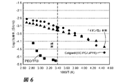
本発明の固体イオン伝導性高分子材料のフィルムを0.0003インチより大きい範囲の厚さ(thickness ranging upward from .0003 inches)で押出した。フィルムのイオン表面伝導率を、当業者に既知のAC-Electrochemical Impedance Spectroscopy(EIS)の標準的な試験を用いて測定した。固体イオン伝導性高分子材料フィルムの試料をステンレススチール遮断(blocking)電極の間に挟み、試験固定具内に置いた。電解質伝導率を決定するためにBiologic VSP試験システムを用いて800KHz~100KHzの範囲内でAC-インピーダンスを記録した。表面伝導率測定の結果を図6に示す。本発明に従う固体イオン伝導性高分子材料フィルムの伝導率(Δ)をトリフルオロメタンスルホネートPEOの伝導率(□)ならびにCelgardセパレーターを用いてLi塩溶質およびEC:PC組み合わせ溶媒から構成される液体電解質の伝導率(O)と比較する。本発明に従う固体イオン伝導性高分子材料フィルムの伝導率は、液体電解質の伝導率を追跡しており、比較的低温においてトリフルオロメタンスルホネートPEOの伝導率をはるかにしのいでいる。さらにPEO電解質と異なり、本発明の高分子材料に関する伝導率の温度依存性は、温度により活性化されるVogel-Tamman-Fulcher行動により記述される鎖運動性(chain mobility)と関連するそのガラス転移温度より高温での鋭い向上を示さない。従って本発明の高分子材料におけるイオン伝導機構としてのセグメント的な動きはありそうもない。さらに、これは本発明の高分子材料が液体電解質に類似のイオン伝導率を有することを示している。 A film of the solid ion conductive polymer material of the present invention was extruded to a thickness in the range greater than 0.0003 inches (thickness ranking upward from .0003 inches). The ionic surface conductivity of the film was measured using standard testing of AC-Electrochemical Impedance Spectroscopy (EIS) known to those of skill in the art. A sample of solid ion conductive polymer material film was sandwiched between stainless steel blocking electrodes and placed in a test fixture. AC-impedance was recorded in the range of 800 KHz to 100 KHz using a Biological VSS test system to determine the electrolyte conductivity. The result of the surface conductivity measurement is shown in FIG. The conductivity (Δ) of the solid ion conductive polymer material film according to the present invention is the conductivity of trifluoromethanesulfonate PEO (□) and the liquid electrolyte composed of Li salt solute and EC: PC combination solvent using the Celgard separator. Compare with conductivity (O). The conductivity of solid ion conductive polymer material films according to the present invention tracks the conductivity of liquid electrolytes, far surpassing that of trifluoromethanesulfonated PEO at relatively low temperatures. Further, unlike the PEO electrolyte, the temperature dependence of the conductivity for the polymeric material of the present invention is its glass transition associated with chain mobility described by the temperature-activated Vogel-Tamman-Fulcher behavior. Does not show a sharp improvement at temperatures above temperature. Therefore, it is unlikely that the polymer material of the present invention will have a segmental movement as an ion conduction mechanism. Furthermore, this indicates that the polymer material of the present invention has an ionic conductivity similar to that of a liquid electrolyte.
図7は、本発明の固体イオン伝導性高分子材料フィルムの機械的性質を示す。Institute for Interconnecting and Packaging Electronic Circuits IPC-TM-650 Test Methods Manual 2.4.18.3を用いて機械的性質を評価した。図7の引張強さ対伸び率曲線において、「延性破壊」の様相は材料が非常に堅牢であり得ることを示す。 FIG. 7 shows the mechanical properties of the solid ion conductive polymer material film of the present invention. Mechanical properties were evaluated using the Institute for Interconnecting and Packaging Electrical Circuits IPC-TM-650 Test Methods Manual 2.4.18.3. In the tensile strength vs. elongation curve of FIG. 7, the aspect of "ductile fracture" indicates that the material can be very robust.
本発明の固体イオン伝導性高分子材料は、その高分子性能特性において3つの重要な利点を与える:(1)それは広大な温度範囲を有する。実験室規模の試験において、結晶性高分子は室温および広い温度範囲に及ぶ両方において、高いイオン伝導率を示した。(2
)それは難燃性である。高分子は自己消炎し、UL-V0燃焼試験に合格する。室温で作動する能力および難燃特性は変革的な(transformative)安全性の向上を示し、それは高価な熱処理システムを取り除く。(3)それは低原価の大量生産を与える。電極上に高分子を噴霧するのではなく、プラスチック製造のための工業標準であるロールツウロール法を介して高分子材料を薄フィルムに押出すことができる。フィルムを押出した後、それに電極および電荷収集体材料をコーティングして「完全に(from the inside out)」電池を構築する。これは密閉包装の必要のない薄い柔軟性の形態因子を可能にし、低い原価における車両および貯蔵用途(storage applications)への容易な組み込みに至る。
The solid ion conductive polymeric materials of the present invention offer three important advantages in their polymeric performance properties: (1) It has a vast temperature range. In laboratory-scale tests, crystalline polymers showed high ionic conductivity both at room temperature and over a wide temperature range. (2
) It is flame retardant. The polymer self-extinguishes and passes the UL-V0 combustion test. The ability to operate at room temperature and flame retardant properties show a transformative safety improvement, which eliminates expensive heat treatment systems. (3) It provides low cost mass production. Rather than spraying the polymer onto the electrodes, the polymer material can be extruded into a thin film via the roll-to-roll method, which is an industrial standard for plastic production. After extruding the film, it is coated with electrodes and charge collector material to build a "from inside out" battery. This allows for a morphological factor of thin flexibility that does not require airtight packaging, leading to easy integration into vehicle and storage applications at low cost.
本発明の固体イオン伝導性高分子材料は新しいイオン伝導機構を生み、それはイオン輸送のための部位のより高い密度を与え、熱暴走または例えばリチウム化からのイオン輸送部位への損傷の危険なくして伝導性材料がより高い電圧を保持するのを可能にすると思われる。この特性は、固体イオン伝導性高分子材料が負極材料およびより高い電圧の正極の薄フィルム用途に耐久性であることを可能にし、車両および固定貯蔵用途に用いられ得る電池のためのより高いエネルギー密度を生ずる。室温のみでなく広範囲の温度に及んで機械的に堅牢であり、化学品および湿度に抵抗性であり、難燃性である固体イオン伝導性高分子材料内に高電圧を保持する能力は、今日工業が用いている高価な熱および安全機構なくして高性能電極との統合(integration)を可能にする。 The solid ion conductive polymer material of the present invention creates a new ion conduction mechanism, which gives a higher density of sites for ion transport, without the risk of thermal runaway or damage to the ion transport sites from, for example, lithium formation. It seems that conductive materials will be able to hold higher voltages. This property allows solid ion conductive polymer materials to be durable for negative electrode materials and thin film applications for higher voltage positive electrodes, resulting in higher energy for batteries that can be used in vehicles and fixed storage applications. Produces density. The ability to hold high voltages in solid ion conductive polymer materials that are mechanically robust, resistant to chemicals and humidity, and flame retardant over a wide range of temperatures, not just room temperature, is today. Allows integration with high performance electrodes without the expensive heat and safety mechanisms used by the industry.
本発明の固体イオン伝導性高分子材料を含む固体高分子電解質を用いる電池は、現在の商業的に入手可能な電解質を超えるエネルギー密度の向上ならびに最小の伝導率低下での-40℃~150℃の動作範囲(performance range)により特徴付けられる。6ミクロンの厚さの高分子を製造する方法により固体高分子電解質を押出すことができ、それはバッチスケールにおける商業的製造条件下で薄フィルムの型(formats)を可能にする。さらに、そのような押出法は固体高分子電解質の製造のための高い処理量、低原価製造ラインを可能にし、方法をリチウムおよび亜鉛電池製造を含む多様な製造ライン中に組み込むことができる。電池原価を最高で50%低下させることができる。 Batteries using solid polymer electrolytes containing the solid ion conductive polymer materials of the present invention have higher energy densities than currently commercially available electrolytes and -40 ° C to 150 ° C with minimal reduced conductivity. It is characterized by the performance range of. A solid polyelectrolyte can be extruded by a method of making a polymer with a thickness of 6 microns, which allows thin film forms under commercial manufacturing conditions on a batch scale. In addition, such extrusion methods enable high throughput, low cost production lines for the production of solid polyelectrolytes, and the methods can be incorporated into a variety of production lines, including lithium and zinc battery production. Battery costs can be reduced by up to 50%.
さらに、固体イオン伝導性高分子材料は電池における使用に限られず、電解質材料を含むいずれの装置または組成物中でも用いられ得る。例えば新規な固体イオン伝導性高分子材料をエレクトロクロミック装置、電気化学センサー、電気二重層コンデンサーおよび燃料電池において用いることができる。図8は、本発明の固体高分子電解質の側面における固体イオン伝導性高分子材料の伝導の可能な機構を示す。ドーピングプロセスの結果として電荷キャリヤー複合体が高分子中に作られる(set up)。 Furthermore, solid ion conductive polymer materials are not limited to use in batteries and can be used in any device or composition comprising an electrolyte material. For example, novel solid ion conductive polymer materials can be used in electrochromic devices, electrochemical sensors, electric double layer capacitors and fuel cells. FIG. 8 shows a possible mechanism of conduction of a solid ion conductive polymer material on the side of the solid polymer electrolyte of the present invention. A charge carrier complex is formed in the polymer as a result of the doping process (set up).
本発明の固体イオン伝導性高分子材料を含む固体高分子電解質の燃焼性を、UL94燃焼試験を用いて試験した。UL94-V0と評価されるべき高分子のために、それは10秒以内に「自己消炎」しなければならず、「ドリップしてはならない(not drip)」。この性質に関して固体高分子電解質を試験し、それが2秒を以て自己消炎し、ドリップしないことが決定され、従って容易にV0評価に合格した。図9は結果の写真を示す。 The combustibility of the solid polyelectrolyte containing the solid ion conductive polymer material of the present invention was tested using the UL94 combustion test. Due to the polymer to be evaluated as UL94-V0, it must be "self-extinguishing" within 10 seconds and "not drip". A solid polyelectrolyte was tested for this property and it was determined that it self-extinguished in 2 seconds and did not drip, thus easily passing the V0 rating. FIG. 9 shows a photograph of the result.
イオン伝導性、耐燃性、高温挙動および優れた機械的性質の他に、本発明の固体イオン伝導性高分子材料を含む固体高分子電解質は低および高電位において電気化学的に安定であるのが好ましい。電気化学的安定性に関する通常の試験は、作用電極電位を時間に対して直線的に傾斜させる時のサイクリックボルタムメトリーである。この試験においては、リチウム金属負極と遮断ステンレススチール電極の間に高分子を挟む。電圧を適用し、酸化に対する安定性のためにそれを高い値(Liに対して4ボルトより高い)に正に掃引し
、還元に対する安定性のためにそれを低い値(Liに対して0Vかもしくはそれより低い)に負に掃引する。電流出力を測定して、電極界面において有意な反応が起こるか否かを決定する。高い正の電位における高い電流出力は酸化反応が起こっていることを示し、これらのまたはもっと正の電位で作動する正極材料(例えば多くの金属酸化物)を用いる場合の不安定性を示唆している。低い電位における高い電流出力は還元反応が起こることを示し、これらのまたはもっと負の電位において作動する負極(例えば金属Liまたはリチウム化炭素)を用いる場合の不安定性を示唆している。図10は、リチウム金属に対する本発明に従う固体イオン伝導性高分子材料を含む固体高分子電解質に関する電圧対電流のプロットを示す。研究は、固体高分子電解質が約4.4ボルトまで安定であることを示す。これらの結果は、固体高分子電解質が低電圧正極、例えば非制限的な例としてリン酸鉄および硫黄正極と共にLCO、LMO、NMCを含む正極および類似の正極を用いる場合に安定であり得ることを示す。
In addition to ionic conductivity, flame resistance, high temperature behavior and excellent mechanical properties, solid polymer electrolytes, including the solid ionic conductive polymer materials of the invention, are electrochemically stable at low and high potentials. preferable. The usual test for electrochemical stability is cyclic voltammetry when the working electrode potential is tilted linearly with time. In this test, a polymer is sandwiched between the lithium metal negative electrode and the blocking stainless steel electrode. Apply a voltage and sweep it positively to a high value (greater than 4 volts for Li) for stability against oxidation and a low value (0V for Li) for stability against reduction. Or lower) to sweep negatively. The current output is measured to determine if a significant reaction occurs at the electrode interface. High current outputs at high positive potentials indicate that an oxidation reaction is taking place, suggesting instability when using positive electrode materials (eg, many metal oxides) that operate at these or more positive potentials. .. High current outputs at low potentials indicate that a reduction reaction occurs, suggesting instability when using negative electrodes operating at these or more negative potentials (eg, metallic Li or carbon lithiumized). FIG. 10 shows a voltage vs. current plot for a solid polyelectrolyte containing a solid ion conductive polymer material according to the present invention for lithium metal. Studies show that solid polyelectrolytes are stable up to about 4.4 volts. These results indicate that the solid polymer electrolyte can be stable when using low voltage positive electrodes, eg, positive electrodes containing LCO, LMO, NMC and similar positives with iron phosphate and sulfur positives as a non-limiting example. show.
本発明の固体イオン伝導性高分子材料を含む固体高分子電解質は、以下の性質を達成することができる:A)室温および広い温度範囲に及ぶ(少なくとも-10℃~+60℃)高いイオン伝導率;B)難燃性;C)リール-リール処理(reel-reel processing)および新しい製造方法を許す薄フィルムへの押出適性;D)リチウム金属および他の活性材料との適合性。従って本発明は真のソリッドステート電池の製作(fabrication)を可能にする。本発明は以下の性質を有する新しい世代の電池を可能にする:
-安全性の問題なし;
-新しい形態因子;
-エネルギー密度における大きな向上;および
-エネルギー貯蔵の原価における大きな改善。
The solid polyelectrolyte containing the solid ion conductive polymer material of the present invention can achieve the following properties: A) High ionic conductivity over room temperature and a wide temperature range (at least −10 ° C. to + 60 ° C.). B) Flame retardant; C) Reel-reel processing and extrusion suitability for thin films allowing new manufacturing methods; D) Compatibility with lithium metals and other active materials. Therefore, the present invention enables the fabrication of a true solid state battery. The present invention enables a new generation of batteries with the following properties:
-No safety issues;
-New morphological factor;
-Major improvements in energy density; and-Major improvements in the cost of energy storage.
図11、12および13は本発明の固体イオン伝導性高分子材料を含むソリッドステート電池のいくつかの要素(elements)を示し、それらはそれぞれ:A)押出された電解質;B)押出された負極および正極;ならびにC)新しい形態因子および柔軟性を可能にする最終的なソリッドステート電池である。 FIGS. 11, 12 and 13 show some elements of a solid state battery containing the solid ion conductive polymeric material of the invention, which are: A) extruded electrolyte; B) extruded negative electrode, respectively. And positive electrodes; and C) the final solid-state battery that enables new morphological factors and flexibility.
他の側面において、本発明は本発明の固体イオン伝導性高分子材料を含むLi電池の製造方法を提供する。図14は、押出された本発明に従う固体イオン伝導性高分子材料を用いるソリッドステートリチウムイオン電池の製造方法を示す。材料を配合してペレットとし、次いでダイを介して押出し、可変の厚さのフィルムを作る。スパッタリングまたはスラリにおける通常の流延のようないくつかの方法を用いてフィルムに電極を適用することができる。 In another aspect, the present invention provides a method for producing a Li battery containing the solid ion conductive polymer material of the present invention. FIG. 14 shows a method for manufacturing a solid state lithium ion battery using an extruded solid ion conductive polymer material according to the present invention. The materials are blended into pellets and then extruded through a die to make a film of variable thickness. Electrodes can be applied to the film using several methods such as sputtering or normal casting in slurry.
さらに別の側面において、本発明は本発明の固体イオン伝導性高分子材料を含むイオン性高分子フィルムの製造方法を提供し、それはフィルムを約295℃の温度に加熱し、次いでプラスチックを固化させるチルロール上にフィルムを流延することを含む。この押出法を図15に示す。得られるフィルムは非常に薄く、10ミクロンの厚さかもしくはそれより薄い範囲内の場合がある。図16は、本発明に従う態様の構造の略図を示す。 In yet another aspect, the invention provides a method of making an ionic polymer film comprising the solid ion conductive polymeric material of the invention, which heats the film to a temperature of about 295 ° C. and then solidifies the plastic. Includes casting the film on a chill roll. This extrusion method is shown in FIG. The resulting film is very thin and may be in the range of 10 microns thick or thinner. FIG. 16 shows a schematic diagram of a structure according to the present invention.
II.OH-の化学
本発明は、OH-イオンを伝送するように設計され、それによりアルカリ電池のためにそれを適用可能にしている固体イオン伝導性高分子材料にも関する。本発明の目的のために、「アルカリ電池(alkaline battery or alkaline batteries)」という用語はアルカリ性(OH-含有)電解質を用いる電池を指す。そのような電池の化学はZn/MnO2、Zn/Ni、Fe/Ni、Zn/空気、Al/空気、Ni/金属水素化物、酸化銀および他を含むがこれらに限られない。Zn/Mn
O2の化学はおそらく最も広く用いられ、家庭用電池のために主に選ばれるものである。本明細書に説明される多くの態様はZn/MnO2の化学に関するが、当業者は同じ原理が他のアルカリ系に広く適用可能であることを理解するであろう。
II. Chemistry of OH - The invention also relates to solid ion conductive polymeric materials designed to carry OH - ions, thereby making them applicable for alkaline batteries. For the purposes of the present invention, the term "alkaline battery or alkaline batteries" refers to a battery that uses an alkaline (OH - containing) electrolyte. Chemistries for such batteries include, but are not limited to, Zn / MnO 2 , Zn / Ni, Fe / Ni, Zn / air, Al / air, Ni / metal hydrides, silver oxide and others. Zn / Mn
O 2 chemistry is probably the most widely used and is the predominant choice for household batteries. Although many aspects described herein relate to Zn / MnO 2 chemistry, one of ordinary skill in the art will appreciate that the same principles are widely applicable to other alkaline systems.
アルカリ電池は、電気の伝導のためにOH-イオンの輸送に頼っている。ほとんどの場合、OH-イオンは電気化学的プロセスにおける関係者でもある。例えばZn/MnO2電池の放電の間に亜鉛負極は2個の電子を放出し、OH-イオンを消費する:
(1)Zn + 4OH- → Zn(OH)4
2- + 2e-
(2)Zn + 2OH- → Zn(OH)2 + 2e- → ZnO + H2O
(3)Zn(OH)2 → ZnO + H2O
Alkaline batteries rely on the transport of OH - ions for the conduction of electricity. In most cases, OH - ions are also involved in electrochemical processes. For example, during the discharge of a Zn / MnO 2 battery, the zinc negative electrode emits two electrons and consumes OH - ions:
(1) Zn + 4OH- → Zn (OH) 4 2- + 2e-
(2) Zn + 2OH- → Zn (OH) 2 + 2e- → ZnO + H 2O
(3) Zn (OH) 2 → ZnO + H 2 O
電池の放電の初期の段階の間に、反応(1)は可溶性の亜鉛酸塩イオンを生じ、それはセパレーターおよび正極中に見出される場合がある[Linden’s Handbook of Batteries,Fourth Edition]。ある時点に電解質は亜鉛酸塩イオンで飽和し、反応生成物は不溶性のZn(OH)2に変わるであろう(2)。最終的に負極は水が枯渇し、水酸化亜鉛は式(3)により脱水される。再充電可能な電池において、電池の充電の間に反応は逆転する。Zn放電の初期段階の間の可溶性亜鉛酸塩イオンの生成は、再充電を妨げ得る。 During the early stages of battery discharge, reaction (1) produces soluble zincate ions, which may be found in the separator and the positive electrode [Linden's Handbook of Batteries, Fourth Edition]. At some point the electrolyte will saturate with the zincate ion and the reaction product will turn into insoluble Zn (OH) 2. (2). Finally, the negative electrode is depleted of water, and zinc hydroxide is dehydrated by the formula (3). In a rechargeable battery, the reaction reverses during battery charging. The production of soluble zincate ions during the initial stages of Zn discharge can prevent recharging.
正極反応はプロトン挿入機構によるMn3+へのMn4+の還元を含み、OH-イオンの放出を生ずる(4)。そのような1電子還元に関する理論的な比MnO2容量は308mAh/gである。より低い電圧への低速放電は式(5)により描かれる通りMnOOHのさらなる放電に導き、それは410mAh/gの合計比容量(1.33e)を生ずる。ほとんどの先行技術の用途において、MnO2放電は1電子プロセスに限られている。活性(active)の利用は可溶性低原子価Mn種の生成によりさらに不利に影響される。
(4)MnO2 + e- + H2O → MnOOH + OH-
(5)3MnOOH + e- → Mn3O4 + H2O + OH-
(6)MnO2 + 2e- + 2H2O → Mn(OH)2 + 2OH-
The positive electrode reaction involves the reduction of Mn 4+ to Mn 3+ by a proton insertion mechanism, resulting in the release of OH - ions (4). The theoretical ratio MnO 2 volume for such one-electron reduction is 308 mAh / g. A slow discharge to a lower voltage leads to a further discharge of MnOOH as depicted by equation (5), which yields a total specific volume (1.33e) of 410 mAh / g. In most prior art applications, MnO 2 discharge is limited to a one-electron process. Utilization of activity is further adversely affected by the production of soluble low valence Mn species.
(4) MnO 2 + e-+ H 2 O → MnOOH + OH-
(5) 3MnOOH + e-→ Mn 3O 4 + H 2 O + OH-
(6) MnO 2 + 2e- + 2H 2 O → Mn (OH) 2 + 2OH-
MnO2は理論的に式(6)に従って2電子還元を経験し得、616mAh/gの理論的な比容量を有するが、先行技術の電池を用いる実施においてそれは示されていない。黒マンガン鉱(Hausmanite)Mn3O4のような不活性な相の生成を伴う結晶構造再配列および可溶性生成物の外方拡散は、正極容量を制限する因子に含まれる。 MnO 2 can theoretically experience two-electron reduction according to equation (6) and has a theoretical specific volume of 616 mAh / g, which has not been shown in the prior art battery practice. Crystal structure rearrangement with the formation of an inert phase such as Hausmanite Mn 3 O 4 and outward diffusion of soluble products are included in the factors limiting the positive cell volume.
米国特許第7,972,726号明細書は、アルカリ電池の全体的な放電性能を強化するための5価ビスマス金属酸化物の使用を説明している。10%のAgBiO3および90%の電解質MnO2を含有する正極は、100%MnO2の場合の287mAh/gおよび100%AgBiO3の場合の200mAh/gと比較して、10mA/gの放電レートにおいて0.8Vカット-オフまで351mAh/gを送達することが示された。351mAh/gの比容量はMnO2の1.13電子放電に相当し、実際に有用な放電レートおよび電圧範囲において送達される最高の比容量に該当する。 US Pat. No. 7,972,726 describes the use of pentavalent bismuth metal oxides to enhance the overall discharge performance of alkaline batteries. A positive electrode containing 10% AgBio 3 and 90% electrolyte MnO 2 has a discharge rate of 10 mA / g compared to 287 mAh / g for 100% MnO 2 and 200 mAh / g for 100% AgBio 3 . Was shown to deliver 351 mAh / g up to 0.8 V cut-off. The specific volume of 351 mAh / g corresponds to the 1.13 electron discharge of MnO 2 , which corresponds to the highest specific volume delivered in a practically useful discharge rate and voltage range.
原則的に反応(4)は可逆的であり得、再充電可能なZn/MnO2電池に関する可能性を開く。実際は、結晶構造崩壊および可溶性生成物の生成は少ないサイクリング回数(shallow cycling)を許すのみである。 In principle, reaction (4) can be reversible, opening up possibilities for rechargeable Zn / MnO 2 batteries. In practice, crystal structure collapse and the formation of soluble products only allow a small number of cycling.
米国特許第5,156,934号明細書および米国特許第5,660,953号明細書に開示されているビスマス-または鉛-改質MnO2材料は多くのサイクルに関して理論的な2電子放電容量の約80%を送達することができると主張された。文献[Y.F.Yao,N.Gupta,H.S.Wroblowa著,J.Electroanal.C
hem.,223,107,1987年;H.S.Wroblowa,N.Gupta著,J.Electroanal.Chem.,238,93,1987年;D.Y.Qu,L.Bai,C.G.Castledine,B.E.Conway著,J.Electroanal.Chem.,365,247,1994年]において、ビスマスまたは鉛カチオンは放電の間のMnO2の結晶構造を安定化させることができ、および/またはは可溶性Mn2+種を含む不均一な機構を介して反応(6)が進行することを可能にすると理論づけられた。前記Mn2+種を含有することは高いMnO2利用率および可逆性を得るために重要であると思われる。米国特許第5,156,934号明細書および米国特許第5,660,953号明細書による高い炭素含有率(30~70%)正極において、得られる高度に多孔質の構造は可溶性種を吸収することができた。しかしながら、これらの正極を利用する完全な電池が構成されたかあるいはこれがZn負極を用いて作用したことを示唆するためのデータはない。
The bismuth-or lead-modified MnO 2 material disclosed in US Pat. Nos. 5,156,934 and US Pat. No. 5,660,953 has a theoretical two-electron discharge capacity for many cycles. It was claimed to be able to deliver about 80% of. Reference [Y. F. Yao, N.M. Gupta, H. et al. S. Wróblowa, J. Mol. Electrical. C
hem. , 223, 107, 1987; H. S. Wroblowa, N. et al. By Gupta, J. Mol. Electrical. Chem. , 238, 93, 1987; D. Y. Qu, L. Bai, C.I. G. Castledine, B.I. E. By Conway, J. Mol. Electrical. Chem. , 365, 247, 1994], bismuth or lead cations can stabilize the crystal structure of MnO 2 during discharge and / or through a non-uniform mechanism containing soluble Mn 2+ species. It was theorized to allow reaction (6) to proceed. The inclusion of the Mn 2+ species appears to be important for obtaining high MnO 2 utilization and reversibility. In the high carbon content (30-70%) positive electrode according to US Pat. No. 5,156,934 and US Pat. No. 5,660,953, the highly porous structure obtained absorbs soluble species. We were able to. However, there is no data to suggest that a complete battery utilizing these positive electrodes was constructed or that it worked with a Zn negative electrode.
かくして低原子価マンガン種および亜鉛酸塩イオンの溶解および輸送を妨げる高分子電解質は、MnO2利用率を向上させ、Zn/MnO2電池の再充電可能性を達成するために非常に有益である。 Thus, polyelectrolytes that interfere with the dissolution and transport of low valence manganese species and zincate ions are very beneficial for improving MnO 2 utilization and achieving rechargeability of Zn / MnO 2 batteries. ..
MnO2は、プロトン挿入の他にLiインターカレーションによる還元を経ることができる。Li挿入は還元の際にMnO2構造を安定化することができ、再充電可能性を許すことが示唆されている[M.Minakshi,P.Singh著,J.Solid State Elecrochem.16,1487,2012年]。 MnO 2 can undergo reduction by Li intercalation in addition to proton insertion. It has been suggested that Li insertion can stabilize the MnO 2 structure during reduction, allowing rechargeability [M. Minakshi, P.M. By Singh, J. Mol. Solid State Elecrochem. 16, 1487, 2012].
Li+およびOH-イオンを伝導するように設計された本発明の固体イオン伝導性高分子材料は、プロトンまたはリチウム挿入を支持して、MnO2放電機構を調整する可能性を開き、それはサイクル寿命を向上させるための追加の道具として作動することができる。 The solid ion conductive polymeric materials of the invention designed to conduct Li + and OH - ions open the possibility of adjusting the MnO 2 discharge mechanism by supporting proton or lithium insertion, which has a cycle lifetime. Can act as an additional tool to improve.
従って1つの側面において本発明は、基本高分子、ドーパントおよびイオン源を含む少なくとも1種の化合物を含む高分子材料を提供し、ここで該高分子材料はOH-イオンに関する移動性を有する固体イオン伝導性高分子材料である。本出願の目的のために、「OH-イオンに関する移動性」という用語は、20℃~26℃の室温における10-11cm2/秒より大きい拡散率または10-4S/cmの伝導率を指す。固体イオン伝導性高分子材料はアルカリ電池における使用に適している。 Accordingly, in one aspect, the invention provides a polymeric material comprising at least one compound including a basic polymer, a dopant and an ion source, wherein the polymeric material is a solid ion having mobility with respect to OH - ions. It is a conductive polymer material. For the purposes of this application, the term "mobility for OH - ions" refers to a diffusion rate greater than 10 -11 cm 2 / sec or a conductivity of 10 -4 S / cm at room temperature between 20 ° C and 26 ° C. Point to. Solid ion conductive polymer materials are suitable for use in alkaline batteries.
種々の側面において、本発明はOH-イオンに関する移動性を有する固体イオン伝導性高分子材料を含み、アルカリ電池における使用のための固体高分子電解質である電解質;該固体高分子電解質を含む1つ以上の電極;および/または該電極を含む1つ以上の電池(cell or cells)を提供する。 In various aspects, the present invention comprises a solid ion conductive polymer material having mobility with respect to OH - ions and is an electrolyte that is a solid polymer electrolyte for use in alkaline batteries; one comprising said solid polymer electrolyte. The above electrodes; and / or one or more batteries (cell or cells) containing the electrodes are provided.
別の側面において、本発明はアルカリ電池における使用のための固体高分子電解質を含む電極、正極および負極を提供し、ここで固体高分子電解質はOH-イオンに関する移動性を有する固体イオン伝導性高分子材料を含む。さらに別の側面において、本発明は正極および負極の間に挟まれた電解質を提供し、ここで電解質、正極および負極の少なくとも1つはOH-イオンに関する移動性を有する固体イオン伝導性高分子材料を含む。別の側面において、本発明は正極層、電解質層および負極層を含むアルカリ電池を提供し、ここで層の少なくとも1つはOH-イオンに関する移動性を有する固体イオン伝導性高分子材料を含む。後者の側面を図17に例示的に示す。 In another aspect, the invention provides electrodes, positive and negative electrodes containing solid polymer electrolytes for use in alkaline batteries, where the solid polymer electrolytes have high solid ion conductivity with OH - ion mobility. Contains molecular materials. In yet another aspect, the invention provides an electrolyte sandwiched between a positive electrode and a negative electrode, where at least one of the electrolyte, the positive electrode and the negative electrode is a solid ion conductive polymeric material having mobility for OH - ions. including. In another aspect, the invention provides an alkaline battery comprising a positive electrode layer, an electrolyte layer and a negative electrode layer, wherein at least one of the layers comprises a solid ion conductive polymeric material having mobility with respect to OH - ions. The latter aspect is exemplified in FIG.
OH-イオンに関する移動性を有する固体イオン伝導性高分子材料の基本高分子は結晶性または半結晶性高分子であり、それは典型的には30%~100%、好ましくは50%~100%の結晶化度の値を有する。本発明のこの側面の基本高分子は、80℃より高い
、好ましくは120℃より高い、より好ましくは150℃より高い、最も好ましくは200℃より高いガラス転移温度を有する。基本高分子は250℃より高い、好ましくは280℃より高い、より好ましくは280℃より高い、最も好ましくは300℃より高い融解温度を有する。
The basic polymer of the solid ion conductive polymer material with OH - ion mobility is a crystalline or semi-crystalline polymer, which is typically 30% to 100%, preferably 50% to 100%. It has a crystallinity value. The basic polymer of this aspect of the invention has a glass transition temperature higher than 80 ° C, preferably higher than 120 ° C, more preferably higher than 150 ° C, and most preferably higher than 200 ° C. The basic polymer has a melting temperature higher than 250 ° C., preferably higher than 280 ° C., more preferably higher than 280 ° C., and most preferably higher than 300 ° C.
OH-イオンに関する移動性を有する固体イオン伝導性高分子材料のドーパントは電子受容体または酸化体である。本発明のこの側面における使用のための典型的なドーパントはDDQ、TCNE、SO3などである。 Dopants of solid ion conductive polymeric materials with OH - ion mobility are electron acceptors or oxides. Typical dopants for use in this aspect of the invention are DDQ, TCNE, SO 3 and the like.
OH-イオンに関する移動性を有する固体イオン伝導性高分子材料のイオン源を含む化合物には、塩、水酸化物、酸化物あるいはヒドロキシルイオンを含有する他の材料またはそのような材料に転換可能な材料が含まれ、LiOH、NaOH、KOH、Li2O、LiNO3などを含むがこれらに限られない。 Compounds containing the ion source of solid ion conductive polymer materials with OH - ion mobility can be converted to salts, hydroxides, oxides or other materials containing hydroxyl ions or such materials. Materials include, but are not limited to, LiOH, NaOH, KOH, Li 2 O, LiNO 3 and the like.
OH-イオンに関する移動性を有する固体イオン伝導性材料は室温における1x10⁻⁴S/cmの最小の伝導率および/または室温における10-11cm2/秒より大きいOH-イオンの拡散率により特徴付けられる。 Solid ion conductive materials with OH - ion mobility are characterized by a minimum conductivity of 1 x 10 -4 S / cm at room temperature and / or a diffusion rate of OH - ions greater than 10-11 cm 2 / sec at room temperature. Be done.
OH-の化学に関連する本発明の正極にはMnO2、NiOOH、AgO、空気(O2)または類似の活性材料が含まれる。MnO2は好ましい材料であり、β-MnO2(パイロルーサイト)、ラムスデライト、γ-MnO2、ε-MnO2、λ-MnO2ならびにEMDおよびCMDを含むがこれらに限られない他のMnO2相またはそれらの混合物の形態の場合がある。 The positive electrodes of the invention associated with OH - chemistry include MnO 2 , NiOOH, AgO, air (O 2 ) or similar active materials. MnO 2 is a preferred material, including but not limited to β-MnO 2 (pyrolucite), rams delite, γ-MnO 2 , ε-MnO 2 , λ-MnO 2 and EMD and CMD. It may be in the form of two phases or a mixture thereof.
OH-の化学に関連する本発明の正極は、基本高分子、ドーパントおよびイオン源を含む化合物を含む本発明の固体イオン伝導性高分子材料の成分に、当該固体イオン伝導性高分子材料の生成の前に正極活物質を混合して混合物を形成することにより製造される。あるいはまた、正極活物質をすでに形成された固体イオン伝導性高分子材料と混合する。 The positive electrode of the present invention related to the chemistry of OH - is a component of the solid ion conductive polymer material of the present invention containing a compound containing a basic polymer, a dopant and an ion source, and the solid ion conductive polymer material is produced. It is produced by mixing a positive electrode active material before forming a mixture. Alternatively, the positive electrode active material is mixed with the already formed solid ion conductive polymer material.
混合物を180℃~350℃、好ましくは190℃~350℃、より好ましくは280℃~350℃、最も好ましくは290℃~325℃の温度で成形するおよび/または押出す。正極活物質には非制限的な例として粉末形態、粒子形態、繊維形態および/またはシート形態のような種々の形態が含まれ得る。本発明の正極は合計正極重量に対して10重量%~90重量%の量で、好ましくは25重量%~90重量%の量で、より好ましくは50重量%~90重量%の量で活性材料を含む。正極はさらに電気伝導性添加物、例えばカーボンブラック成分、天然グラファイト成分、合成グラファイト成分、グラフェン成分、導電性高分子成分、金属粒子成分および/または他の類似の電気伝導性添加物を含む場合がある。正極は合計正極重量に対して0重量%~25重量%の量で、好ましくは10重量%~15重量%の量で電気伝導性添加物を含む場合がある。OH-の化学に関連する本発明の正極は、性能を向上させるために1種もしくはそれより多い機能性添加物をさらに含む場合がある。正極活物質を本発明の固体イオン伝導性高分子材料により封入する場合がある。 The mixture is molded and / or extruded at a temperature of 180 ° C. to 350 ° C., preferably 190 ° C. to 350 ° C., more preferably 280 ° C. to 350 ° C., most preferably 290 ° C. to 325 ° C. The positive electrode active material may include various forms such as powder form, particle form, fiber form and / or sheet form as non-limiting examples. The positive electrode of the present invention is an active material in an amount of 10% by weight to 90% by weight, preferably 25% by weight to 90% by weight, more preferably 50% by weight to 90% by weight, based on the total positive electrode weight. including. The positive electrode may further contain an electrically conductive additive such as a carbon black component, a natural graphite component, a synthetic graphite component, a graphene component, a conductive polymer component, a metal particle component and / or other similar electrically conductive additives. be. The positive electrode may contain an electrically conductive additive in an amount of 0% by weight to 25% by weight, preferably 10% by weight to 15% by weight, based on the total weight of the positive electrode. The positive electrodes of the invention associated with OH - chemistry may further contain one or more functional additives to improve performance. The positive electrode active material may be encapsulated with the solid ion conductive polymer material of the present invention.
OH-の化学に関連する本発明の負極は、亜鉛粉末、亜鉛フレークおよび他の形、亜鉛シートおよび他の形の形態におけるZnの活性材料を含む場合がある。すべてのそのような形態の亜鉛を合金化して亜鉛腐食を最小にする場合がある。 Negative electrodes of the invention related to the chemistry of OH - may include zinc powder, zinc flakes and other forms, zinc sheets and Zn active materials in other forms. All such forms of zinc may be alloyed to minimize zinc corrosion.
OH-の化学に関連する本発明の負極は、基本高分子、ドーパントおよびイオン源を含む化合物を含む本発明の固体イオン伝導性高分子材料の成分に、当該固体イオン伝導性高分子材料の生成の前に負極活物質を混合して混合物を形成することにより製造される。あ
るいはまた、負極活物質をすでに形成された固体イオン伝導性高分子材料と混合する。混合物を180℃~350℃の温度で成形するおよび/または押出す。本発明の負極は合計負極重量に対して10重量%~90重量%の量で、好ましくは25重量%~90重量%の量で、より好ましくは50重量%~90重量%の量で活性材料を含む。負極はさらに電気伝導性添加物、例えばカーボンブラック成分、天然グラファイト成分、合成グラファイト成分、グラフェン成分、導電性高分子成分、金属粒子成分および/または他の類似の電気伝導性添加物を含む場合がある。負極は合計負極重量に対して0重量%~25重量%の量で、好ましくは10重量%~15重量%の量で電気伝導性添加物を含む場合がある。OH-の化学に関連する本発明の負極は、性能を向上させるために1種以上の機能性添加物をさらに含む場合がある。負極活物質を本発明の固体イオン伝導性高分子材料により封入する場合がある。
The negative electrode of the present invention related to the chemistry of OH - is a component of the solid ion conductive polymer material of the present invention containing a compound containing a basic polymer, a dopant and an ion source, and the solid ion conductive polymer material is produced. It is produced by mixing a negative polymer with a negative polymer before forming a mixture. Alternatively, the negative electrode active material is mixed with the already formed solid ion conductive polymer material. The mixture is molded and / or extruded at a temperature of 180 ° C to 350 ° C. The negative electrode of the present invention is an active material in an amount of 10% by weight to 90% by weight, preferably 25% by weight to 90% by weight, more preferably 50% by weight to 90% by weight, based on the total negative electrode weight. including. The negative electrode may further contain an electrically conductive additive such as a carbon black component, a natural graphite component, a synthetic graphite component, a graphene component, a conductive polymer component, a metal particle component and / or other similar electrically conductive additives. be. The negative electrode may contain an electrically conductive additive in an amount of 0% by weight to 25% by weight, preferably 10% by weight to 15% by weight, based on the total weight of the negative electrode. The negative electrodes of the present invention associated with OH - chemistry may further contain one or more functional additives to improve performance. The negative electrode active material may be encapsulated with the solid ion conductive polymer material of the present invention.
別の側面において、本発明はMnO2正極およびZn負極の間に挟まれた電解質を含むZn/MnO2電池を提供する。この側面における電解質は、OH-イオンに関する移動性を有する本発明の固体イオン伝導性材料を含む場合か、あるいは液体電解質で満たされた通常のセパレーターを含む場合がある。正極は本発明のOH-イオンに関する移動性を有する固体イオン伝導性材料を含む場合か、あるいは市販のMnO2正極を含む場合がある。この側面における負極はOH-イオンに関する移動性を有する本発明の固体イオン伝導性材料を含む場合か、あるいはZn箔、Znメッシュまたは他の方法により製造されるZn負極を含む場合がある。本発明のZn/MnO2電池において、OH-イオンに関する移動性を有する本発明の固体電子伝導性高分子材料は正極、負極および電解質の少なくとも1つの中に含まれる。 In another aspect, the invention provides a Zn / MnO 2 battery containing an electrolyte sandwiched between a MnO 2 positive electrode and a Zn negative electrode. The electrolyte in this aspect may include the solid ion conductive material of the present invention having OH - ion mobility, or may include a conventional separator filled with a liquid electrolyte. The positive electrode may contain a solid ion conductive material having mobility with respect to the OH - ion of the present invention, or may contain a commercially available MnO 2 positive electrode. Negatives in this aspect may include solid ion conductive materials of the invention that are mobile with respect to OH - ions, or may include Zn negatives made by Zn foil, Zn mesh or other methods. In the Zn / MnO 2 battery of the present invention, the solid electron conductive polymer material of the present invention having mobility with respect to OH - ions is contained in at least one of a positive electrode, a negative electrode and an electrolyte.
III.高分子-MnO2複合正極
本発明はさらに、高い比容量を有する高分子-MnO2複合正極および正極を含む一次アルカリ電池に関する。さらに特定的に、本発明はさらに理論的な2電子放電に近い比容量を有する高分子-MnO2複合正極および正極を含んでなる一次アルカリ電池に関する。アルカリ電池を、典型的な0.8Vの電圧カットオフまで有用な容量を送達しながら市販のアルカリ電池の電流密度に匹敵する電流密度で放電させる場合がある。
III. Polymer-MnO 2 Composite Positive The present invention further relates to a primary alkaline battery including a polymer-MnO 2 composite positive electrode and a positive electrode having a high specific capacity. More specifically, the present invention relates to a primary alkaline battery comprising a polymer-MnO 2 composite positive electrode and a positive electrode having a specific capacity close to the theoretical two-electron discharge. Alkaline batteries may be discharged at current densities comparable to those of commercially available alkaline batteries while delivering useful capacity up to a typical 0.8V voltage cutoff.
種々の側面において本発明は、基本高分子、ドーパントおよびイオン源を含む化合物を含む固体イオン伝導性高分子材料と混合された多数の活性MnO2粒子を含むMnO2活性材料で作られる正極ならびに該正極の製造方法に関する(features)。他の側面において本発明は、正極、負極および正極と負極の間に配置されるセパレーターを含む電気化学電池(electrochemical cell)および該正極の製造方法に関する。正極は基本高分子、ドーパントおよびイオン源を含む化合物を含む固体イオン伝導性高分子材料と混合された多数の活性MnO2粒子を含むMnO2活性材料で作られる。本発明の正極および電気化学電池は平らな放電曲線により特徴付けられる。 In various aspects, the invention comprises a positive electrode made of a MnO 2 active material containing a large number of active MnO 2 particles mixed with a solid ion conductive polymer material containing a basic polymer, a dopant and a compound containing an ion source, and the like. The present invention relates to a method for producing a positive electrode. In another aspect, the present invention relates to an electrochemical cell including a positive electrode, a negative electrode and a separator disposed between the positive electrode and the negative electrode, and a method for manufacturing the positive electrode. The positive electrode is made of a MnO 2 active material containing a large number of active MnO 2 particles mixed with a solid ion conductive polymer material containing a basic polymer, a dopant and a compound containing an ion source. The positive electrode and electrochemical cell of the present invention are characterized by a flat discharge curve.
高分子-MnO2複合正極に関連する本発明の側面において、基本高分子は半結晶性高分子の場合がある。共役高分子または容易に酸化される場合がある高分子より成る群から基本高分子を選ぶ場合がある。本発明のこの側面において用いられる基本高分子の非制限的な例にはPPS、PPO、PEEK、PPAなどが含まれる。 Polymer-In aspects of the invention relating to the MnO 2 composite positive electrode, the basic polymer may be a semi-crystalline polymer. Basic polymers may be selected from the group consisting of conjugated polymers or polymers that may be easily oxidized. Non-limiting examples of basic polymers used in this aspect of the invention include PPS, PPO, PEEK, PPA and the like.
高分子-MnO2複合正極に関連する本発明の側面において、ドーパントは電子受容体または酸化体である。ドーパントの非制限的な例はDDQ、TCNEとしても既知のテトラシアノエチレン、SO3、オゾン、MnO2を含む遷移金属酸化物あるいはいずれかの適した電子受容体などである。 In aspects of the invention relating to the polymer-MnO 2 composite positive electrode, the dopant is an electron acceptor or an oxidant. Non-limiting examples of dopants are DDQ, a transition metal oxide containing tetracyanoethylene, SO 3 , ozone, MnO 2 , also known as TCNE, or any suitable electron acceptor.
高分子-MnO2複合正極に関連する本発明の側面において、イオン源を含む化合物は
塩、水酸化物、酸化物またはヒドロキシルイオンを含有する他の材料もしくはそのような材料に転換可能な材料であり、LiOH、NaOH、KOH、Li2O、LiNO3などを含むがこれらに限られない。
In aspects of the invention relating to the polymer-MnO 2 composite positive, the compound containing the ion source is any other material containing salts, hydroxides, oxides or hydroxyl ions or any material convertible to such materials. Yes, including, but not limited to, LiOH, NaOH, KOH, Li 2 O, Li NO 3 .
高分子-MnO2複合正極に関連する本発明の側面において、MnO2活性材料はβ-MnO2(パイロルーサイト)、ラムスデライト、γ-MnO2、ε-MnO2、λ-MnO2ならびにEMDおよびCMDを含むがこれらに限られない他のMnO2相またはそれらの混合物の形態の場合がある。 In aspects of the invention relating to the polymer-MnO 2 composite positive, the MnO 2 active materials are β-MnO 2 (pyrolucite), rams delite, γ-MnO 2 , ε-MnO 2 , λ-MnO 2 and EMD. And other MnO 2 phases, including but not limited to CMD, or mixtures thereof.
多数の活性MnO2粒子ならびに基本高分子、ドーパントおよびイオン源を含む化合物を含む固体イオン伝導性高分子材料を混合し、混合物を所定の温度に所定の時間加熱することにより、高分子-MnO2複合正極に関連する正極を製造することができる。場合により圧力を適用しながら該加熱を行うことができる。 A polymer-MnO 2 is obtained by mixing a large number of active MnO 2 particles and a solid ion conductive polymer material containing a compound containing a basic polymer, a dopant and an ion source and heating the mixture to a predetermined temperature for a predetermined time. A positive electrode related to a composite positive electrode can be manufactured. The heating can be carried out while applying pressure as the case may be.
1つの態様において、本発明の高分子-MnO2複合正極を温度における圧縮成形により製造する場合がある。混合物を180~350℃、好ましくは190℃~350℃、より好ましくは280℃~350℃、最も好ましくは290℃~325℃の温度で成形するおよび/または押出す。他の態様において、加熱は場合により150~2000PSI、好ましくは150~1000PSI、より好ましくは150~500PSI、最も好ましくは150~250PSIの圧力において行われる。MnO2活性材料は、複合正極の合計重量に対して5重量%~95重量%、好ましくは50重量%~90重量%の量で存在する場合がある。複合正極は、複合正極の合計重量に対して5重量%~50重量%、好ましくは10重量%~50重量%、より好ましくは20重量%~40重量%、最も好ましくは25重量%~35重量%の量で充填剤を含む場合がある。ドーパントを2~10、好ましくは2~8、より好ましくは2~6、最も好ましくは3~5の基本高分子/ドーパントモル比に相当する量で加える場合がある。複合正極は電気伝導性添加物、例えばカーボンブラック成分、天然および/または合成グラファイト成分、グラフェン成分、電気伝導性高分子成分、金属粒子成分および他の成分を含む場合があり、ここで電気伝導性成分は複合正極の合計重量に対して5重量%~25重量%、好ましくは15重量%~25重量%、より好ましくは18重量%~22重量%の量で存在する。複合正極中のMnO2活性材料を本発明の固体イオン伝導性高分子材料により封入する場合がある。 In one embodiment, the polymer-MnO 2 composite positive electrode of the present invention may be manufactured by compression molding at temperature. The mixture is molded and / or extruded at a temperature of 180-350 ° C, preferably 190 ° C-350 ° C, more preferably 280 ° C-350 ° C, most preferably 290 ° C-325 ° C. In another embodiment, heating is optionally performed at a pressure of 150-2000 PSI, preferably 150-1000 PSI, more preferably 150-500 PSI, most preferably 150-250 PSI. The MnO 2 active material may be present in an amount of 5% by weight to 95% by weight, preferably 50% by weight to 90% by weight, based on the total weight of the composite positive electrode. The composite positive electrode is 5% by weight to 50% by weight, preferably 10% by weight to 50% by weight, more preferably 20% by weight to 40% by weight, and most preferably 25% by weight to 35% by weight with respect to the total weight of the composite positive electrode. May contain filler in%. The dopant may be added in an amount corresponding to the basic polymer / dopant molar ratio of 2-10, preferably 2-8, more preferably 2-6, most preferably 3-5. The composite positive electrode may contain an electrically conductive additive such as a carbon black component, a natural and / or synthetic graphite component, a graphene component, an electrically conductive polymer component, a metal particle component and other components, wherein the composite positive electrode is electrically conductive. The components are present in an amount of 5% by weight to 25% by weight, preferably 15% by weight to 25% by weight, and more preferably 18% by weight to 22% by weight based on the total weight of the composite positive electrode. The MnO 2 active material in the composite positive electrode may be encapsulated with the solid ion conductive polymer material of the present invention.
好ましい態様において、本発明は該高分子-MnO2複合正極およびZn負極を含むアルカリ電池に関する。Zn負極はZnまたはZn合金粉末、KOH、ゲル化剤および場合により他の添加物を含むスラリの形態にある場合がある。Zn負極はさらに複合正極に類似の電気伝導性添加物を含む場合がある。 In a preferred embodiment, the present invention relates to an alkaline battery comprising the polymer-MnO 2 composite positive electrode and a Zn negative electrode. The Zn negative electrode may be in the form of a slurry containing Zn or Zn alloy powder, KOH, a gelling agent and optionally other additives. The Zn negative electrode may further contain an electrically conductive additive similar to the composite positive electrode.
本発明の高分子-MnO2複合材料に関連する負極は、Zn、Al、Fe、金属水素化物合金または類似の材料を含む場合がある。ZnおよびAlは好ましい材料であり、純粋な金属または特別に設計される合金の形態の場合がある。セパレーターはアルカリ電池において用いられる通常の不織セパレーターの場合がある。電解質は水中のKOH、NaOH、LiOHなどの溶液である。アルカリ濃度は4~9Mの場合がある。電解質はさらに電子伝導性添加物および/または機能性添加物を含有する場合がある。 Negatives associated with the polymer-MnO 2 composites of the present invention may contain Zn, Al, Fe, metal hydride alloys or similar materials. Zn and Al are preferred materials and may be in the form of pure metals or specially designed alloys. The separator may be a normal non-woven separator used in alkaline batteries. The electrolyte is a solution of KOH, NaOH, LiOH, etc. in water. The alkali concentration may be 4-9M. The electrolyte may further contain electronically conductive and / or functional additives.
IV.高分子-硫黄正極
さらに、本発明は複合高分子-硫黄正極に関する。複合高分子-硫黄正極は硫黄成分ならびに基本高分子、ドーパントおよびイオン源を含む化合物を含む固体イオン伝導性高分子材料を含む。複合高分子-硫黄正極は、二次リチウムまたはLiイオン硫黄電池において用いられる場合、高い比容量および高い容量維持率を有するとして特徴付けられる。複合正極は200ミリアンペア-時/グラムより大きい、好ましくは500ミリアンペア-
時/グラムより大きい、より好ましくは750ミリアンペア-時/グラムより大きい、最も好ましくは1000ミリアンペア-時/グラムより大きい比容量を有するとして特徴付けられる。複合正極は500回を超える再充電/放電サイクルに及んで少なくとも50%、好ましくは少なくとも80%の維持率(retention)を有するとして特徴付けられる。本発明の複合高分子-硫黄正極は、この複合電極において用いられる独特の高分子により可能にされる低原価大規模製造への直接の用途を有する。本発明の複合高分子-硫黄正極は高性能を与えながら同時に低原価の電池の製造のための要件を満たすことができる。
IV. Polymer-sulfur positive electrode
Furthermore, the present invention relates to a composite polymer-sulfur positive electrode. The composite polymer-sulfur positive electrode comprises a solid ion conductive polymer material containing a sulfur component as well as a compound containing a basic polymer, a dopant and an ion source. Composite polymer-sulfur positives are characterized as having high specific capacity and high capacity retention when used in secondary lithium or Li ion sulfur batteries. Composite positives are 200mA-greater than hour / gram, preferably 500mA-
It is characterized as having a specific volume greater than hour / gram, more preferably 750 milliamp-hours-greater than hour / gram, most preferably 1000 milliamp-hours / gram. The composite positive electrode is characterized as having a retention of at least 50%, preferably at least 80%, over 500 recharge / discharge cycles. The composite polymer-sulfur positive electrode of the present invention has a direct application to low cost large scale manufacturing enabled by the unique polymer used in this composite electrode. The composite polymer-sulfur positive electrode of the present invention can provide high performance and at the same time meet the requirements for manufacturing low cost batteries.
注目するべきことに、硫黄正極は放電の間に還元され、次式に示される順を介して次々とより低次のポリスルフィドを生ずる:
S8 → Li2S8 → Li2S4 → Li2S2 → Li2S
It should be noted that the sulfur positive electrode is reduced during the discharge, producing one after another lower order polysulfides in the order represented by the following equation:
S 8 → Li 2 S 8 → Li 2 S 4 → Li 2 S 2 → Li 2 S
Li2S8およびLi2S4の間の中間的なポリスルフィドは液体電解質中で可溶性である。かくして溶解されたポリスルフィド粒子は多孔質のセパレーターを横切って移動(migrate)(または「往復(shuttle)」)し、サイクリングの間に負極および正極と直接反応することができる。ポリスルフィド往復はリチウム負極との寄生反応(parasitic reactions)および正極における再酸化を生じ、すべて容量の損失を引き起こす。さらに、この往復反応の側面は不可逆的であり、自己放電および低いサイクル寿命に導き、それは今日までリチウム硫黄電池を悩ませてきた。 The intermediate polysulfide between Li 2 S 8 and Li 2 S 4 is soluble in the liquid electrolyte. The thus dissolved polysulfide particles can migrate (or "shuttle") across the porous separator and react directly with the negative and positive electrodes during cycling. The polysulfide round trip causes parasitic reactions with the lithium negative electrode and reoxidation at the positive electrode, all of which cause a loss of capacity. Moreover, this round-trip aspect is irreversible, leading to self-discharge and low cycle life, which has plagued lithium-sulfur batteries to this day.
本発明は、硫黄成分および固体イオン伝導性高分子材料を含む複合高分子-硫黄正極を示す。ロールツウロール法を介してこの正極を柔軟性薄フィルムに押出すことができる。そのような薄フィルムは、新規な柔軟性電池の設計に導入される場合がある薄い柔軟性の形態因子を可能にする。続く実施例中に示される通り、この複合高分子-硫黄正極は、例えば安価なカーボンブラック成分、例えばすでに多くの市販の電池製品中で使用されているTimcal C45のような電気伝導性添加物を含む場合がある。複合高分子-硫黄正極は、代表的なカーボンブラック成分の他に、他の電気伝導性添加物、例えば非制限的な例として炭素繊維、グラフェン成分、グラファイト成分を含むがこれらに限られない炭素成分、金属粒子または他の金属添加物および電気伝導性高分子を含む場合がある。 The present invention presents a composite polymer-sulfur positive electrode containing a sulfur component and a solid ion conductive polymer material. This positive electrode can be extruded into a flexible thin film via a roll-to-roll method. Such thin films allow for thin flexibility morphological factors that may be introduced in the design of new flexible batteries. As shown in subsequent examples, this composite polymer-sulfur positive electrode contains, for example, an inexpensive carbon black component, eg, an electrically conductive additive such as Timcal C45, which is already used in many commercially available battery products. May include. In addition to the typical carbon black component, the composite polymer-sulfur positive electrode contains, but is not limited to, other electrically conductive additives such as carbon fiber, graphene component, and graphite component as non-limiting examples. May contain components, metal particles or other metal additives and electrically conductive polymers.
複合高分子-硫黄正極の工学的性質は広範囲の可能な厚さに正極を押出すことを可能にし、それは今度は大規模正極製造での設計における柔軟性の点で重要な利点を与える。複合高分子-硫黄正極を5ミクロンのように薄く、ならびに最高で数百ミクロンより大きい厚さに押出す場合がある。 The engineering properties of the composite polymer-sulfur positive electrode allow the positive electrode to be extruded to a wide range of possible thicknesses, which in turn provides an important advantage in terms of design flexibility in large-scale positive electrode production. Composite polymer-sulfur positive electrodes may be extruded as thin as 5 microns, as well as thicker than a few hundred microns.
標準的なリチウムイオン正極の製造に必要なプロセス段階と本発明の複合高分子-硫黄正極の製造に必要なプロセス段階との比較は、複合高分子-硫黄正極製造の固有のより低い原価に関して教訓的である。図18は、本発明の押出される複合高分子-硫黄正極のよりずっと簡単な製造と比較される、標準的なリチウムイオン正極の製造に必要なプロセス段階を示す。複合高分子-硫黄正極のための押出法は容易に大量生産に大規模化され、それは現存するリチウムイオン電池を超える有意な利点ならびに工場設備のためのよりずっと少ない資本支出を与える。 A comparison of the process steps required to manufacture a standard lithium-ion positive electrode with the process steps required to manufacture a composite polymer-sulfur positive electrode of the present invention is a lesson regarding the inherent lower cost of composite polymer-sulfur positive electrode production. It is a target. FIG. 18 shows the process steps required to produce a standard lithium ion positive electrode compared to the much simpler production of the extruded composite polymer-sulfur positive electrode of the present invention. Extrusion methods for composite polymer-sulfur positives are easily scaled up to mass production, which offers significant advantages over existing lithium-ion batteries as well as much less capital spending on factory equipment.
押出の他に射出成形、圧縮成形または熱を含む他の方法あるいはエンジニアリングプラスチックに関する技術分野における熟練者に既知の他の方法により、複合高分子-硫黄正極を形成する場合がある。 In addition to extrusion, other methods including injection molding, compression molding or heat or other methods known to those skilled in the art of engineering plastics may form the composite polymer-sulfur positive electrode.
上記で議論した通り、複合高分子-硫黄正極は硫黄成分ならびに基本高分子、ドーパント、イオン源を含む化合物を含む固体イオン伝導性高分子材料を含む。 As discussed above, the composite polymer-sulfur positive electrode comprises a solid ion conductive polymer material containing a sulfur component as well as a compound containing a basic polymer, a dopant and an ion source.
基本高分子には液晶高分子およびポリフェニレンスルフィド(PPS)あるいは30%より高い結晶化度を有する半結晶性高分子あるいは他の典型的な酸素受容体が含まれる。 Basic polymers include liquid crystal polymers and polyphenylene sulfide (PPS) or semi-crystalline polymers with crystallinity greater than 30% or other typical oxygen receptors.
ドーパントはイオン伝導機構を活性化する電子受容体を含む。これらの電子受容体を他の成分と一緒に予備混合する場合か、あるいはポストドーピング法として蒸気相において供給する場合がある。使用に適した典型的な電子受容体ドーパントには;2,3-ジクロロ-5,6-ジシアノ-1,4-ベンゾキノン(DDQ)(C8Cl2N2O2)、テトラシアノエチレン(TCNE)(C6N4)および三酸化硫黄(SO3)が含まれるがこれらに限られない。 Dopants include electron acceptors that activate the ion conduction mechanism. These electron acceptors may be premixed with other components or supplied in the vapor phase as a post-doping method. Typical electron acceptor dopants suitable for use are; 2,3-dichloro-5,6-dicyano-1,4-benzoquinone (DDQ) (C 8 Cl 2 N 2 O 2 ), tetracyanoethylene (TCNE). ) (C 6 N 4 ) and sulfur trioxide (SO 3 ), but not limited to these.
イオン源を含む化合物にはLi2OおよびLiOHが含まれるがこれらに限られない。Li/硫黄試験電池における複合高分子-硫黄正極の使用は、複合高分子-硫黄正極がリチウム、硫黄およびリチウム/硫黄電池において典型的に用いられる有機電解質に安定であることを示した。 Compounds containing an ion source include, but are not limited to, Li 2 O and Li OH. The use of the composite polymer-sulfur positive electrode in Li / sulfur test batteries has shown that the composite polymer-sulfur positive electrode is stable to lithium, sulfur and the organic electrolytes typically used in lithium / sulfur batteries.
基本高分子は、自己消炎し、かつ、UL-VO燃焼試験に合格することが示された難燃性高分子である。基本高分子の難燃性は、複合高分子-硫黄正極を用いる電池への安全性の利益である。難燃性電解質を有する電池中への難燃性複合高分子-硫黄正極の導入は、高エネルギー密度の電池に関する重要な属性である電池の安全性をさらに向上させるであろう。 The basic polymer is a flame-retardant polymer that is self-extinguishing and has been shown to pass the UL-VO combustion test. The flame retardancy of the basic polymer is a safety benefit to the battery using the composite polymer-sulfur positive electrode. The introduction of a flame-retardant composite polymer-sulfur positive electrode into a battery with a flame-retardant electrolyte will further improve the safety of the battery, which is an important attribute for high energy density batteries.
硫黄成分は、元素硫黄を含む硫黄の非還元および/または還元形態を含む場合がある。特に複合高分子-硫黄正極は、完全にリチウム化された形態の硫黄(Li2S)を含む硫黄成分を含み、ここでLi2Sは固体である。複合高分子-硫黄正極は炭素成分も含む場合がある。完全にリチウム化された形態の硫黄を用いる利点は、金属Liと異なって初期充電の間にリチウム化されねばならないLiイオン負極を有する硫黄電池のためのリチウム源をそれが与えることである。Liイオン負極との硫黄正極の組み合わせは、リチウム負極のサイクリングの後に形成される場合があるリチウム樹状晶の生成の予防において利益を与える。樹状晶は、充電の間のリチウム金属負極上へのリチウムの不均一なメッキにより引き起こされる。これらの樹状晶はセパレーター材料を介して成長し得、正極および負極の間の内部短絡を引き起こし、多くの場合に高温および電池の危うい安全性に導く。インターカレーションまたは合金化を介してリチウムが可逆的に導入された材料は、樹状晶生成の機会を減らし、高い安全性のリチウム/硫黄電池における使用に関して提案された。複合高分子-硫黄正極は、例えば炭素に基づく(石油コークス、非晶質炭素、グラファイト、炭素ナノチューブ、グラフェンなど)材料、Sn、SnO、SnO2およびCo、Cu、Fe、Mn、Niなどのような遷移金属との複合材料を含むSnに基づく複合酸化物のような負極材料と一緒に用いられ得る。さらにケイ素は、元素の形態でまたは酸化物もしくは錫に関して説明したような複合材料として、リチウムイオン負極材料としての有望性を示した。他のリチウム合金化材料(例えばGe、Pb、Bなど)もこの目的のために用いることができるはずである。Fe2O3またはFe3O4のような鉄の酸化物および種々の酸化バナジウム材料もLiイオン負極材料として可逆的にリチウムを導入させる(incorporate)ことが示された。負極材料は、非晶質および結晶性およびナノ寸法の粒子ならびにナノチューブを含む種々の形態において考えられ得る。 The sulfur component may include non-reducing and / or reduced forms of sulfur, including elemental sulfur. In particular, the composite polymer-sulfur positive electrode contains a sulfur component containing sulfur (Li 2 S) in a completely lithium form, where Li 2 S is a solid. The composite polymer-sulfur positive electrode may also contain a carbon component. The advantage of using a fully lithium-ized form of sulfur is that it provides a lithium source for lithium batteries with a Li-ion negative electrode that must be lithium-ionized during the initial charge, unlike metallic Li. The combination of a sulfur positive electrode with a Li ion negative electrode benefits in preventing the formation of lithium dendritic crystals that may form after cycling the lithium negative electrode. The dendritic crystals are caused by the non-uniform plating of lithium onto the lithium metal negative electrode during charging. These dendritic crystals can grow through the separator material, causing an internal short circuit between the positive and negative electrodes, often leading to high temperatures and dangerous safety of the battery. Materials in which lithium is reversibly introduced via intercalation or alloying have been proposed for use in highly safe lithium / sulfur batteries, reducing the chances of dendritic crystal formation. Composite polymer-sulfur positives are, for example, carbon-based (petroleum coke, amorphous carbon, graphite, carbon nanotubes, graphene, etc.) materials, such as Sn, SnO, SnO 2 and Co, Cu, Fe, Mn, Ni, etc. Can be used with negative material such as Sn-based composite oxides, including composites with transition metals. Furthermore, silicon has shown promise as a lithium ion negative electrode material in the form of elements or as a composite material as described for oxides or tin. Other lithium alloying materials (eg Ge, Pb, B, etc.) could also be used for this purpose. It has been shown that iron oxides such as Fe 2 O 3 or Fe 3 O 4 and various vanadium oxide materials are also incorporated reversibly as Li ion negative electrode materials. Negative electrode materials can be considered in various forms including amorphous and crystalline and nano-sized particles as well as nanotubes.
複合高分子-硫黄正極を標準的な液体電解質、標準的な不織セパレーターおよび/または液体電解質なしの固体イオン伝導性高分子材料を含む電解質と組み合わせる場合がある。標準的な有機電解質溶液の例には1,3-ジオキソラン(DOL)と1,2-ジメトキシエタン(DME)の混合物中に溶解されたリチウム塩、例えばリチウムビス(トリフルオロメタンスルホニル)イミド(LiTFSI)が含まれる。LiNO3のような添加物
を電解質に加え、電池性能を向上させることができる。有機液体電解質中で:中でもLiPF6、LiBF4、LiAsF6、リチウムトリフレートを含む他のリチウム塩を使用することができる。さらに、いくつかの例としてプロピレンカーボネート(PC)、エチレンカーボネート(EC)、ジエチルカーボネート(DEC)、ジメチルカーボネート(DMC)、エチルメチルカーボネート(EMC)、フルオロエチレンカーボネート(FEC)のような他の有機溶媒を単独で、あるいは混合物としてあるいはDOLおよびDMEと一緒に用いることができる。標準的な不織セパレーターの例にはポリプロピレン(PP)、ポリエチレン(PE)およびPP/PEフィルムの組み合わせが含まれる。他のセパレーター材料にはポリイミド、PTFE、セラミック被覆フィルムおよびガラスマットセパレーターが含まれる。上記の材料のすべてを複合高分子-硫黄正極と一緒に用いることができる。さらに、複合高分子-硫黄正極を、例えばPVDFに基づく高分子を有機電解質で膨潤させるゲル高分子系において使用することもできる。
Composite Polymer-Sulfur positives may be combined with electrolytes containing standard liquid electrolytes, standard non-woven separators and / or solid ion conductive polymer materials without liquid electrolytes. An example of a standard organic electrolyte solution is a lithium salt dissolved in a mixture of 1,3-dioxolane (DOL) and 1,2-dimethoxyethane (DME), such as lithium bis (trifluoromethanesulfonyl) imide (LiTFSI). Is included. Additives such as LiNO 3 can be added to the electrolyte to improve battery performance. In organic liquid electrolytes: Among them, other lithium salts including LiPF 6 , LiBF 4 , LiAsF 6 , and lithium triflate can be used. In addition, other organics such as propylene carbonate (PC), ethylene carbonate (EC), diethyl carbonate (DEC), dimethyl carbonate (DMC), ethylmethyl carbonate (EMC), fluoroethylene carbonate (FEC), as some examples. The solvent can be used alone or as a mixture or with DOL and DME. Examples of standard non-woven separators include polypropylene (PP), polyethylene (PE) and PP / PE film combinations. Other separator materials include polyimide, PTFE, ceramic coating films and glass mat separators. All of the above materials can be used with composite polymer-sulfur positive electrodes. Further, the composite polymer-sulfur positive electrode can also be used in, for example, a gel polymer system in which a polymer based on PVDF is swollen with an organic electrolyte.
複合高分子-硫黄正極の、リチウムイオン伝導性を与える能力は、ポリスルフィド往復機構を制限することにより電池の性能を向上させながら、同時に硫黄正極に高い電圧を与えると思われる。さらに、この独特の工学的(engineering)複合高分子-硫黄正極は、正極の商業的生存力のために必要な大規模、低原価製造を可能にする。 The ability of the composite polymer-sulfur positive electrode to confer lithium ion conductivity is believed to improve battery performance by limiting the polysulfide reciprocating mechanism while at the same time applying a high voltage to the sulfur positive electrode. In addition, this unique engineering composite polymer-sulfur positive electrode enables the large scale, low cost manufacturing required for the commercial viability of the positive electrode.
かくして独特の複合高分子-硫黄正極は:
●正常なおよび酷使(abuse)条件下における向上した安全性
●新しい電池形態因子を可能にすること
●現存するLiイオン電池を超えるエネルギー密度における大きな向上
●ポリスルフィド往復機構を妨げてより大きな充電/放電可逆性に導くこと
●製造原価(原料、プロセスおよび資本的設備)を大きく低下させてエネルギー貯蔵の原価における改善に導くこと
を含む電池への多数の潜在的な利益を有する。
Thus, the unique composite polymer-sulfur positive electrode is:
● Improved safety under normal and abuse conditions ● Enable new battery morphology factors ● Significant improvement in energy density over existing Li-ion batteries ● Greater charge / discharge by interfering with polysulfide reciprocating mechanism Leading to reversibility ● Has numerous potential benefits to batteries, including significantly reducing manufacturing costs (raw materials, processes and capital equipment) and leading to improvements in the cost of energy storage.
V.アルカリ電池
1つの側面において、向上した安定性、堅牢性およびより低い原価を提供する一方でリチウム-イオン性能に匹敵するかまたはそれを超えることができる低レート用途のための再充電可能なZn/MnO2電池を説明する。
V. Alkaline battery
In one aspect, rechargeable Zn / MnO 2 for low-rate applications that can match or exceed lithium-ion performance while offering improved stability, robustness and lower cost. Explain the battery.
固体イオン伝導性高分子材料を含むある種の正極配合物は、放電レートが向上するとより急勾配の低下を示しながら、低レートにおいてずっと高い活性材料利用率を示し得ることが観察された。これは図38により示され、それは高エネルギー電池におそらく有用な正極配合物を有するボタン電池のレート分布を描いている。そのような配合物のほとんどは約300mAh/gの比C/2容量を示し、それはMnO2の1-電子放電に関して理論的に予測されるものに近い(図38中の配合物1により示される)。いくつかの場合、電池は理論的な1-電子放電を超える比容量を示す。例えば配合物2はC/2放電においてほとんど400mAh/gを示し、二酸化マンガンのより深い放電を示している。
It has been observed that certain positive electrode formulations containing solid ion conductive polymeric materials can exhibit much higher active material utilization at lower rates, while exhibiting a steeper decrease as the discharge rate increases. This is shown by FIG. 38, which depicts the rate distribution of button cells with positive electrode formulations that are probably useful for high energy batteries. Most such formulations exhibit a ratio C / 2 volume of about 300 mAh / g, which is close to what is theoretically predicted for the 1-electron discharge of MnO 2 (indicated by
負極中の亜鉛および高分子含有率を最適化し、特に:所望の負極性能のための亜鉛の型および粒度、固体高分子電解質の組成および作製方法を最適化し、亜鉛不動態化を減らすためにZnOおよび他の機能性添加物を導入した。より大きい亜鉛表面積および向上した安定性の合わされた効果は性能の向上およびサイクル寿命の延長を生ずる。高分子マトリックス中にZn粒子を埋め込むことは、形の変化、凝集および樹状晶の成長を妨げる。 Optimizing the zinc and polymer content in the negative electrode, especially: ZnO to optimize the zinc type and particle size for the desired negative electrode performance, the composition and fabrication method of the solid polymer electrolyte, and reduce zinc passivation. And other functional additives were introduced. The combined effect of greater zinc surface area and improved stability results in improved performance and extended cycle life. Embedding Zn particles in a polymer matrix interferes with shape changes, aggregation and dendritic growth.
容量を300mAh/gより高く向上させるために最適化された正極は比MnO2容量の向上を示し、それは図39により示される通りにパウチ型電池(pouch cell)の電池エネルギー密度に大きな影響を有する。 The positive electrode optimized to increase the capacity above 300 mAh / g shows an increase in the specific MnO 2 capacity, which has a significant effect on the battery energy density of the pouch cell as shown by FIG. ..
1つの側面において、高レートおよび高温用途用の固体イオン伝導性高分子材料が導入された再充電可能なZn/MnO2電池を説明する。 In one aspect, a rechargeable Zn / MnO 2 battery introduced with a solid ion conductive polymeric material for high rate and high temperature applications will be described.
二酸化マンガン含有率を80重量%以上に向上させると、ボタン電池の優れた活性材料利用率および高レート性能が保持される。高い活性材料負荷は高いエネルギー密度の達成に必須であるので、この発見の有意性は誇張し難い。二酸化マンガン含有率の最適化から生ずる放電容量における向上を図40に示す。わかる通り、最適化された電池は、負極およびボタン電池ハードウェアの限界が役割を果たし始める場合があるレベルの50mA(ボタン電池に関して極端に高い)のような高い電流においてさえ十分に作動した。 When the manganese dioxide content is increased to 80% by weight or more, the excellent active material utilization rate and high rate performance of the button battery are maintained. The significance of this finding cannot be exaggerated, as high active material loads are essential for achieving high energy densities. The improvement in discharge capacity resulting from the optimization of manganese dioxide content is shown in FIG. As you can see, the optimized battery worked well even at high currents such as 50mA (extremely high for coin cell batteries), where the limits of the negative electrode and coin cell hardware may begin to play a role.
高エネルギー密度を得るために2.5-3.0g/ccの正極密度が十分である。これらの条件下における高レート性能は、正極ではなくて亜鉛箔負極により制限される場合がある。亜鉛箔に置き換わるための表面積が向上した亜鉛負極は向上した性能を示す。 A positive electrode density of 2.5-3.0 g / cc is sufficient to obtain a high energy density. High rate performance under these conditions may be limited by the zinc foil negative electrode rather than the positive electrode. A zinc negative electrode with an increased surface area to replace the zinc foil exhibits improved performance.
負極レート容量を向上させるためおよびサイクル寿命を延長するために、亜鉛および負極高分子含有率を最適化し、亜鉛の型および粒度を最適化し、そしてZnOおよび他の機能性添加物(マンガン塩のような)を導入して亜鉛の不動態化および腐食を減らすことにより負極を改良する。より大きい亜鉛表面積および向上した安定性の合わされた効果は、高い放電レートにおける性能の向上およびサイクル寿命の延長を生ずる。さらに、高分子マトリックス中に亜鉛粒子を埋め込むことは、形の変化、凝集および樹状晶の成長を妨げることが見出された。 To improve the negative electrode rate capacity and extend the cycle life, optimize the zinc and negative electrode polymer content, optimize the zinc type and particle size, and ZnO and other functional additives (like manganese salts). ) Is introduced to improve the negative electrode by reducing the passivation and corrosion of zinc. The combined effect of greater zinc surface area and improved stability results in improved performance and extended cycle life at high discharge rates. In addition, embedding zinc particles in the polymer matrix has been found to impede morphological changes, aggregation and dendritic growth.
エネルギー/電力密度において現在の最先端のLi-イオンシステムに匹敵するかまたはそれを超え、15C放電において>85%の容量維持率を示し;80-100℃において作動するのに安全であり;そして500サイクルの最小寿命を有する電池を製造した。これらのZn/MnO2電池のパック(packs)は複雑な電池管理および電荷制御回路を必要とせず、パックのレベルで追加のエネルギー密度の利益および原価の低下が期待される。 Comparing or surpassing current state-of-the-art Li-ion systems in energy / power density, showing> 85% capacity retention at 15C discharge; safe to operate at 80-100 ° C; and A battery with a minimum life of 500 cycles was manufactured. These Zn / MnO 2 battery packs do not require complex battery management and charge control circuits, and additional energy density benefits and cost reductions are expected at the pack level.
実施例1
PPS基本高分子およびイオン源化合物LiOH一水和物をそれぞれ67%対33%(重量による)の割合で混ぜ、ジェットミリング(jet milling)を用いて混合することにより固体高分子電解質を調製した。得られる混合物にDDQドーパントを4.2モルのPPS当たりに1モルのDDQの量で加えた。混合物を穏やかな圧力(500~1000PSI)下で325/250℃において30分間熱処理した。冷却後、得られる材料を微粉砕し、NMR固定具中に置いた。
Example 1
A solid polyelectrolyte was prepared by mixing the PPS basic polymer and the ion source compound LiOH monohydrate at a ratio of 67% to 33% (by weight), respectively, and mixing them using jet milling. DDQ dopant was added to the resulting mixture in an amount of 1 mol DDQ per 4.2 mol of PPS. The mixture was heat treated at 325/250 ° C. for 30 minutes under mild pressure (500-1000 PSI). After cooling, the resulting material was finely ground and placed in an NMR fixative.
パルス磁場勾配固体NMR法(pulsed field gradient solid state NMR technique)の使用により、自己拡散係数を決定した。図19および20に示される結果は、固体高分子電解質中におけるそれぞれLi+およびOH-拡散率がいずれの既知の固体の中でも最高であり、もっとずっと高い温度(140℃)における最近開発されたLi10GeP2S12セラミックまたは90℃における最も優れたPEO配合物と比較して室温において1桁を超えて高いことを示す。 The self-diffusion coefficient was determined by using a pulsed field gradient solid state NMR technique technique. The results shown in FIGS. 19 and 20 show that the Li + and OH - diffusion rates in the solid polyelectrolyte are the highest of any known solids, respectively, and the recently developed Li at much higher temperatures (140 ° C.). It shows that it is more than an order of magnitude higher at room temperature compared to 10 GeP 2S 12 ceramics or the best PEO formulations at 90 ° C.
実施例2
PPS基本高分子およびイオン源化合物LiOH一水和物をそれぞれ67重量%対33重量%の割合で一緒に加え、ジェットミリングを用いて混合した。さらに50%のAlfa Aesarからのβ-MnO2、5%のBi2O3および15%のC45カーボンブラ
ックを混合することにより正極を製造した。得られる混合物にDDQドーパントを4.2モルのPPS当たりに1モルのDDQの量で加えた。
Example 2
The PPS basic polymer and the ion source compound LiOH monohydrate were added together at a ratio of 67% by weight to 33% by weight, respectively, and mixed using jet milling. A positive electrode was further prepared by mixing β-MnO 2 , 5% Bi 2 O 3 from 50% Alfa Aesar and 15% C45 carbon black. DDQ dopant was added to the resulting mixture in an amount of 1 mol DDQ per 4.2 mol of PPS.
混合物を穏やかな圧力(500~1000PSI)下で325/250℃において30分間、ステンレススチールメッシュ(Dexmet)上に圧縮成形し、直径が1インチであり、厚さが約0.15mmの正極円板を与えた。得られる円板を19mmの直径に打ち抜き、正極として用いて、市販の不織セパレーター(NKK)およびZn箔負極を含有する試験電池を組み立てた。電解質として6M LiOHを加えた。 The mixture was compression molded onto a stainless steel mesh (Dexmet) at 325/250 ° C. under mild pressure (500-1000 PSI) for 30 minutes, a 1 inch diameter positive electrode disc with a thickness of approximately 0.15 mm. Gave. The obtained disk was punched to a diameter of 19 mm and used as a positive electrode to assemble a test battery containing a commercially available non-woven separator (NKK) and a Zn foil negative electrode. 6M LiOH was added as an electrolyte.
Biologic VSP試験システムを用い、0.5mA/cm2の一定の電流条件下で電池を放電させた。MnO2の比容量は303mAh/gであったか、または理論的な1e-放電に近かった。図21は、0.5mA/cm2の放電レートにおけるMnO2の比容量の関数としての実施例2による電池の電圧分布を示す。 A Biological VSS test system was used to discharge the batteries under constant current conditions of 0.5 mA / cm 2 . The specific volume of MnO 2 was 303 mAh / g or was close to the theoretical 1e - discharge. FIG. 21 shows the voltage distribution of the battery according to Example 2 as a function of the specific volume of MnO 2 at a discharge rate of 0.5 mA / cm 2 .
実施例3
PPS基本高分子およびイオン源化合物LiOH一水和物をそれぞれ67%対33%(重量による)の割合で一緒に加え、ジェットミリングを用いて混合した。さらに50%のAlfa Aesarからのβ-MnO2、5%のBi2O3および15%のC45カーボンブラックを混合することにより正極を製造した。得られる混合物にDDQドーパントを4.2モルのPPS当たりに1モルのDDQの量で加えた。
Example 3
The PPS basic polymer and the ion source compound LiOH monohydrate were added together at a ratio of 67% to 33% (by weight), respectively, and mixed using jet milling. A positive electrode was further prepared by mixing β-MnO 2 , 5% Bi 2 O 3 from 50% Alfa Aesar and 15% C45 carbon black. DDQ dopant was added to the resulting mixture in an amount of 1 mol DDQ per 4.2 mol of PPS.
混合物を穏やかな圧力(500~1000psi)下で325/250℃において30分間、ステンレススチールメッシュ(Dexmet)上に圧縮成形し、直径が1インチであり、厚さが1.6~1.8mmの正極円板を与えた。 The mixture was compression molded onto a stainless steel mesh (Dexmet) at 325/250 ° C. under mild pressure (500-1000 psi) for 30 minutes, 1 inch in diameter and 1.6-1.8 mm thick. A positive electrode disk was given.
得られる正極を用いて、市販の不織セパレーター(NKK)および市販のアルカリ電池から抽出されたZn負極スラリを含有する試験電池を組み立てた。電解質として水中の6M KOH溶液を用いた。 Using the obtained positive electrode, a test battery containing a commercially available non-woven separator (NKK) and a Zn negative electrode slurry extracted from a commercially available alkaline battery was assembled. A 6M KOH solution in water was used as the electrolyte.
Biologic VSP試験システムを用い、一定の電流条件下で電池を放電させた。MnO2の比容量はC/9放電レート(35mA/g)において600mAh/gに近かったか、または理論的な2e-放電に近かった。 Batteries were discharged under constant current conditions using a Biological VSS test system. The specific volume of MnO 2 was close to 600 mAh / g at the C / 9 discharge rate (35 mA / g) or close to the theoretical 2e - discharge.
図22は、C/9レート(35mA/g)におけるMnO2の比容量の関数としての実施例3による電池の電圧分布を示す。 FIG. 22 shows the voltage distribution of the battery according to Example 3 as a function of the specific volume of MnO 2 at the C / 9 rate (35 mA / g).
実施例4
PPS基本高分子およびイオン源化合物LiOH一水和物をそれぞれ67%対33%(重量による)の割合で一緒に加え、ジェットミリングを用いて混合した。さらに50%のAlfa Aesarからのβ-MnO2、5%のBi2O3および15%のC45カーボンブラックを混合することにより正極を製造した。得られる混合物にDDQドーパントを4.2モルのPPS当たりに1モルのDDQの量で加えた。
Example 4
The PPS basic polymer and the ion source compound LiOH monohydrate were added together at a ratio of 67% to 33% (by weight), respectively, and mixed using jet milling. A positive electrode was further prepared by mixing β-MnO 2 , 5% Bi 2 O 3 from 50% Alfa Aesar and 15% C45 carbon black. DDQ dopant was added to the resulting mixture in an amount of 1 mol DDQ per 4.2 mol of PPS.
混合物を穏やかな圧力(500~1000PSI)下で325/250℃において30分間、ステンレススチールメッシュ(Dexmet)上に圧縮成形し、直径が1インチであり、厚さが約0.15mmの正極円板を与えた。 The mixture was compression molded onto a stainless steel mesh (Dexmet) at 325/250 ° C. under mild pressure (500-1000 PSI) for 30 minutes, a 1 inch diameter positive electrode disc with a thickness of approximately 0.15 mm. Gave.
得られる円板を19mmの直径に打ち抜き、正極として用いて、市販の不織セパレーター(NKK)およびZn箔負極を含有する試験電池を組み立てた。電解質として6M LiOHを加えた。 The obtained disk was punched to a diameter of 19 mm and used as a positive electrode to assemble a test battery containing a commercially available non-woven separator (NKK) and a Zn foil negative electrode. 6M LiOH was added as an electrolyte.
Biologic VSP試験システムを用いて電池を放電させ、充電した。0.5mA/cm2の電流において0.8Vのカット-オフまで放電を行った。0.25mA/cm2において1.65Vまで充電を行い、次いで1.65Vに3時間、あるいは電流が0.02mA/cm2に減退するまで保持した。数サイクル毎に不動態化した(passivated)Zn負極およびセパレーターを新しいもので置き換えた。実施例4による電池におけるサイクル数の関数としてのMnO2の比容量を図23においてプロットする。各柱は別々の電池を示す。新しいZn負極を用いる放電のみを示す。本発明のMnO2正極が再充電可能であるのを見るのは容易である。新しいZn負極を用いる放電のみを示す。 Batteries were discharged and charged using a Biological VSS test system. Discharging was performed to a cut-off of 0.8 V at a current of 0.5 mA / cm 2 . It was charged to 1.65 V at 0.25 mA / cm 2 and then held at 1.65 V for 3 hours or until the current diminished to 0.02 mA / cm 2 . Passivated Zn negative electrodes and separators were replaced with new ones every few cycles. The specific capacity of MnO 2 as a function of the number of cycles in the battery according to Example 4 is plotted in FIG. Each pillar shows a separate battery. Only discharges using the new Zn negative electrode are shown. It is easy to see that the MnO 2 positive electrode of the present invention is rechargeable. Only discharges using the new Zn negative electrode are shown.
実施例5
実施例1の固体高分子電解質、実施例2の正極および負極としてのZn箔を用いて2035ボタン電池を組み立てた。Biologic VSP試験システムを用いて電池を放電させ、充電した。0.25mA/cm2の電流において0.8Vのカット-オフまで放電を行った。0.25mA/cm2において1.65Vまで充電を行い、次いで1.65Vに3時間、あるいは電流が0.02mA/cm2に減退するまで保持した。電池はそのようなサイクリングの間、可逆的な行動を示した。図24は、試験時間の関数としての実施例5によるボタン電池の放電曲線を示す。
Example 5
A 2035 button cell was assembled using the solid polyelectrolyte of Example 1 and the Zn foil as the positive and negative electrodes of Example 2. Batteries were discharged and charged using a Biological VSS test system. Discharging was performed to a cut-off of 0.8 V at a current of 0.25 mA / cm 2 . It was charged to 1.65 V at 0.25 mA / cm 2 and then held at 1.65 V for 3 hours or until the current diminished to 0.02 mA / cm 2 . Batteries showed reversible behavior during such cycling. FIG. 24 shows the discharge curve of the button cell according to Example 5 as a function of the test time.
実施例6
PPS基本高分子およびイオン源化合物LiOH一水和物をそれぞれ67%対33%(重量による)の割合で一緒に加え、ジェットミリングを用いて混合した。さらに55%のAlfa Aesarからのβ-MnO2および15%のC45カーボンブラックを混合することにより正極を製造した。得られる混合物にDDQドーパントを4.2モルのPPS当たりに1モルのDDQの量で加えた。
Example 6
The PPS basic polymer and the ion source compound LiOH monohydrate were added together at a ratio of 67% to 33% (by weight), respectively, and mixed using jet milling. A positive electrode was further prepared by mixing β-MnO 2 from 55% Alfa Aesar and 15% C45 carbon black. DDQ dopant was added to the resulting mixture in an amount of 1 mol DDQ per 4.2 mol of PPS.
混合物を穏やかな圧力(500~1000psi)下で325/250℃において30分間、ステンレススチールメッシュ(Dexmet)上に圧縮成形し、直径が1インチであり、厚さが約0.15mmの正極円板を与えた。 The mixture was compression molded onto a stainless steel mesh (Dexmet) at 325/250 ° C. under mild pressure (500-1000 psi) for 30 minutes, a 1 inch diameter positive electrode disc with a thickness of approximately 0.15 mm. Gave.
得られる正極、実施例1による電解質およびZn粉末で作られる負極を用い、試験電池を組み立てた。Biologic VSP試験システムを用い、0.5mA/cm2の電流密度において0.8Vカット-オフまで電池を放電させた。MnO2の比容量は401mAh/gまたは理論的な1-電子放電より高い比容量であった。図25は試験時間の関数としての実施例6による電池の電圧分布を示す。 A test battery was assembled using the obtained positive electrode, the electrolyte according to Example 1, and the negative electrode made of Zn powder. Batteries were discharged to 0.8 V cut-off at a current density of 0.5 mA / cm 2 using a Biological VSS test system. The specific volume of MnO 2 was 401 mAh / g or higher than the theoretical 1-electron discharge. FIG. 25 shows the voltage distribution of the battery according to Example 6 as a function of the test time.
実施例7
PPS基本高分子およびイオン源化合物LiOH一水和物をそれぞれ67%対33%(重量による)の割合で一緒に加え、ジェットミリングを用いて混合した。さらに60%のZn粉末および10%のC45カーボンブラックを混合することにより負極を製造した。得られる混合物にDDQドーパントを4.2モルのPPS当たりに1モルのDDQの量で加えた。
Example 7
The PPS basic polymer and the ion source compound LiOH monohydrate were added together at a ratio of 67% to 33% (by weight), respectively, and mixed using jet milling. Further, a negative electrode was manufactured by mixing 60% Zn powder and 10% C45 carbon black. DDQ dopant was added to the resulting mixture in an amount of 1 mol DDQ per 4.2 mol of PPS.
混合物を穏やかな圧力(500~1000psi)下で325/250℃において30分間、ステンレススチールメッシュ(Dexmet)上に圧縮成形し、直径が1インチであり、厚さが約0.15mmの正極円板を与えた。 The mixture was compression molded onto a stainless steel mesh (Dexmet) at 325/250 ° C. under mild pressure (500-1000 psi) for 30 minutes, a 1 inch diameter positive electrode disc with a thickness of approximately 0.15 mm. Gave.
得られる負極、実施例2による正極および電解質として飽和LiOHを含有する市販のNKKセパレーターを用い、2035ボタン電池を組み立てた。 A 2035 button battery was assembled using the obtained negative electrode, the positive electrode according to Example 2, and a commercially available NKK separator containing saturated LiOH as the electrolyte.
負極としてのZn箔、実施例2による正極および電解質として飽和LiOHを含有する市販のNKKセパレーターを用い、対照標準のボタン電池を作った。 A control standard button cell was made using a Zn foil as a negative electrode, a positive electrode according to Example 2, and a commercially available NKK separator containing saturated LiOH as an electrolyte.
Biologic VSP試験システムを用い、0.5mA/cm2の電流密度において電池を放電させた。本発明の負極を用いる放電分布は、わずかにより高い電圧におけるより高い容量を示し、それはZn負極の増加した表面積および負極構造内における可溶性亜鉛酸塩の保持に関連付けられ得る。図26は、放電容量の関数としての実施例7によるボタン電池の放電曲線を示す。0.25mA/cm2の電流において0.7Vカット-オフまで放電を行った。曲線A-本発明の負極を用いる電池。曲線B-Zn箔負極を用いる電池。図26は、放電容量の関数としての実施例7によるボタン電池の放電曲線を示す。0.25mA/cm2の電流において0.7Vカット-オフまで放電を行った。曲線A-本発明の負極を用いる電池。曲線B-Zn箔負極を用いる電池。 Batteries were discharged at a current density of 0.5 mA / cm 2 using a Biological VSS test system. The discharge distribution with the negative electrode of the present invention shows higher capacity at slightly higher voltage, which can be associated with the increased surface area of the Zn negative electrode and the retention of soluble zincate in the negative electrode structure. FIG. 26 shows the discharge curve of the button cell according to Example 7 as a function of the discharge capacity. Discharging was performed to 0.7 V cut-off at a current of 0.25 mA / cm 2 . Curve A-Battery using the negative electrode of the present invention. A battery using a curved B-Zn foil negative electrode. FIG. 26 shows the discharge curve of the button cell according to Example 7 as a function of the discharge capacity. Discharging was performed to 0.7 V cut-off at a current of 0.25 mA / cm 2 . Curve A-Battery using the negative electrode of the present invention. A battery using a curved B-Zn foil negative electrode.
実施例8
PPS基本高分子およびイオン源化合物LiOH一水和物をそれぞれ67%対33%(重量による)の割合で一緒に加え、ジェットミリングを用いて混合した。さらに60%のAl粉末および10%のC45カーボンブラックを混合することにより負極を製造した。得られる混合物にDDQドーパントを4.2モルのPPS当たりに1モルのDDQの量で加えた。混合物を穏やかな圧力(500~1000psi)下で325/250℃において30分間、ステンレススチールメッシュ(Dexmet)上に圧縮成形し、直径が1インチであり、厚さが約0.15mmの正極円板を与えた。
Example 8
The PPS basic polymer and the ion source compound LiOH monohydrate were added together at a ratio of 67% to 33% (by weight), respectively, and mixed using jet milling. Further, a negative electrode was manufactured by mixing 60% Al powder and 10% C45 carbon black. DDQ dopant was added to the resulting mixture in an amount of 1 mol DDQ per 4.2 mol of PPS. The mixture was compression molded onto a stainless steel mesh (Dexmet) at 325/250 ° C. under mild pressure (500-1000 psi) for 30 minutes, a 1 inch diameter positive electrode disc with a thickness of approximately 0.15 mm. Gave.
得られる負極を、Zn対極およびZnSO4電解質を含有する市販のセパレーターを含有する試験電池において試験した。対照標準としてAl箔で作られた負極を試験した。 The resulting negative electrode was tested in a test battery containing a commercially available separator containing a Zn counter electrode and a ZnSO 4 electrolyte. A negative electrode made of Al foil was tested as a control standard.
Biologic VSP試験システムを用い、1mV/秒の掃引速度において負極を動電位的に分極させた。図27は、ZnSO4電解質中の本発明の負極(曲線A)および対照標準Al箔(曲線B)の1mV/秒における動電位走査を示す。本発明の負極は、Al箔と比較して0.5V向上した腐食安定性を示した。 The negative electrode was electropotentially polarized at a sweep rate of 1 mV / sec using a Biological VSP test system. FIG. 27 shows a dynamic potential scan at 1 mV / sec of the negative electrode (curve A) and control standard Al foil (curve B) of the present invention in a ZnSO 4 electrolyte. The negative electrode of the present invention showed a corrosion stability improved by 0.5 V as compared with the Al foil.
比較実施例9
Duracell Coppertop AA電池の250mA放電における放電分布をデータシートから得た。公開された規格書(published specification)とMSDSの比較により、電池中のMnO2の量を計算し、8.4~9.6gを与えた。単純な変換(conversion)は26~30mA/gの電流密度を生ずる。実用時間(データシートによる)と放電電流の積は合計容量を与え、それをMnO2の重量で割ることにより、それを比容量に変換することができる。そのような方法で計算された比MnO2容量の関数としてのCoppertop AA電池の電圧分布を図28に示す。曲線Aは最大量MnO2(9.6g)に相当し、そこでDuracell Coppertop AA電池の比容量は26mA/gレートにおける一定電流放電下にある。曲線BはMnO2の最小量(8.4g)に相当し、そこでDuracell Coppertop AA電池の比容量は30mA/gレートにおける一定電流放電下にある。曲線Cは2.2mA/gの一定電流放電レートの下のDuracell Coppertop AA電池の比容量を示す。0.9Vカット-オフまで計算されるMnO2の比容量が235~270mAh/gであることを理解するのは容易である。0.8Vカット-オフへの外挿は245~275mAh/gのわずかにもっと高い比容量を生ずるであろう。放電曲線は、Zn/MnO2電池に特徴的な典型的な勾配のある形を有する。5%放電深度における電圧と95%放電深度における電圧との間の差は0.5Vまたは初期(5%DOD)の30%に近い[2.1-2.4V/Ah/g]。2.2mA/g(電池中のMnO
2の平均量を仮定して)の極度に低いレートで放電しているCoppertop電池は、追加のプラトーの出現を生ずる(曲線C)。合計比容量は347mA/gであり、1.13-電子放電に相当した。それでも放電曲線は5%放電深度と95%放電深度との間の0.5Vに近い電圧差を有する典型的な勾配のある形を有する。
Comparative Example 9
The discharge distribution of the Duracell Coppertop AA battery at 250 mA discharge was obtained from the data sheet. The amount of MnO 2 in the battery was calculated by comparing the published specification and MSDS, and 8.4 to 9.6 g was given. A simple conversion produces a current density of 26-30 mA / g. The product of working time (according to the data sheet) and discharge current gives the total capacity, which can be converted to specific capacity by dividing by the weight of MnO 2 . The voltage distribution of the Coppertop AA battery as a function of the ratio MnO 2 capacitance calculated in such a way is shown in FIG. Curve A corresponds to the maximum amount of MnO 2 (9.6 g), where the specific capacity of the Duracell Coppertop AA battery is under constant current discharge at a 26 mA / g rate. Curve B corresponds to the minimum amount of MnO 2 (8.4 g), where the specific capacity of the Duracell Coppertop AA battery is under constant current discharge at a 30 mA / g rate. Curve C shows the specific capacity of the Duracell Coppertop AA battery under a constant current discharge rate of 2.2 mA / g. It is easy to understand that the specific volume of MnO 2 calculated up to 0.9V cut-off is 235 to 270 mAh / g. Extrapolation to 0.8 V cut-off will result in a slightly higher specific volume of 245-275 mAh / g. The discharge curve has a gradient shape typical of Zn / MnO 2 batteries. The difference between the voltage at 5% discharge depth and the voltage at 95% discharge depth is 0.5V or close to 30% of the initial (5% DOD) [2.1-2.4V / Ah / g]. 2.2mA / g (MnO in battery)
A Coppertop battery discharging at an extremely low rate (assuming an average amount of 2 ) results in the appearance of an additional plateau (Curve C). The total specific volume was 347 mA / g, which corresponded to 1.13-electron discharge. Nevertheless, the discharge curve has a typical gradient shape with a voltage difference close to 0.5V between the 5% discharge depth and the 95% discharge depth.
比較実施例10
小売店でAA電池を購入し、Maccor 4300システムを用いて中間-レート試験に相当する250mA放電に供した。表10.1は250mAの継続的放電下における市販のAA電池の性能を示す。0.9Vカット-オフまでに送達される合計容量を表10.1に示す。電池中のMnO2の量を比較実施例9と同じと仮定して、電池の合計容量をMnO2の比容量に変換することができる。わかる通り、これらの放電条件下で市販のAA電池は200~280mAh/gを送達する。断続的な放電の正の効果および0.8Vへの電圧カット-オフの延長を考慮してさえ、市販のアルカリ電池が式(1)により記述され、308mAh/gに制限されるMnO2の1-電子還元内で作動するというのは正当な説である。
Comparative Example 10
AA batteries were purchased from retail stores and subjected to a 250 mA discharge equivalent to an intermediate-rate test using the Maccor 4300 system. Table 10.1 shows the performance of commercially available AA batteries under continuous discharge of 250 mA. The total volume delivered up to the 0.9V cut-off is shown in Table 10.1. Assuming that the amount of MnO 2 in the battery is the same as in Comparative Example 9, the total capacity of the battery can be converted to the specific capacity of MnO 2 . As can be seen, under these discharge conditions, commercially available AA batteries deliver 200-280 mAh / g. A commercially available alkaline battery is described by equation (1), even considering the positive effect of intermittent discharge and the extension of voltage cut-off to 0.8V, 1 of MnO 2 limited to 308mAh / g. -It is a valid theory that it works within electron reduction.

比較実施例11(米国特許第7,972,726号明細書による)
図29は、AgBiO3正極(曲線(a))、EMD(MnO2)正極(曲線(b))および米国特許第7,972,726号明細書から再現される1:9 AgBiO3:EMD混合物(曲線(c))に基づく正極を有するアリカリボタン電池に関する10mA/gの放電レートにおける放電曲線を示す。これらの条件下で、EMDに関する放電分布(b)は、5%DODにおける電圧と95%DODにおける電圧との間の0.5Vの差を有する比較実施例9で説明された市販のアルカリ電池に類似している。約290mAh/gのMnO2容量は1-電子放電と一致する。AgBiO3:EMD混合物を用いて製造される正極は、約0.9Vにおいて追加のプラトーを現し、MnO2容量を増強している(boosting)。1:9 AgBiO3:EMD混合物を用いて最高の性能が報告され、それは0.8Vカット-オフまでに351mAh/gを送達した。これはMnO2の1.13-電子放電に相当する。
Comparative Example 11 (according to US Pat. No. 7,972,726)
FIG. 29 shows an AgBio 3 positive electrode (curve (a)), an EMD (MnO 2 ) positive electrode (curve (b)) and a 1: 9 AgBio 3 : EMD mixture reproduced from US Pat. No. 7,972,726. (Curve (c)) shows a discharge curve at a discharge rate of 10 mA / g for an Alikari button battery with a positive electrode. Under these conditions, the discharge distribution (b) for EMD is the commercially available alkaline battery described in Comparative Example 9 having a 0.5 V difference between the voltage at 5% DOD and the voltage at 95% DOD. It is similar. The MnO 2 capacity of about 290 mAh / g is consistent with 1-electron discharge. Positive electrodes made with the AgBio 3 : EMD mixture show an additional plateau at about 0.9V, boosting the MnO 2 capacity. Best performance was reported with a 1: 9 AgBio 3 : EMD mixture, which delivered 351 mAh / g by 0.8 V cut-off. This corresponds to 1.13-electron discharge of MnO 2 .
実施例12
PPS基本高分子およびイオン源化合物LiOH一水和物をそれぞれ67%対33%(重量による)の割合で一緒に加え、ジェットミリングを用いて混合した。さらに50%のAlfa Aesarからのβ-MnO2、5%のBi2O3および15%のC45カーボンブラックを混合することにより正極を製造した。得られる混合物にDDQドーパントを4.2モルのPPS当たりに1モルのDDQの量で加えた。
Example 12
The PPS basic polymer and the ion source compound LiOH monohydrate were added together at a ratio of 67% to 33% (by weight), respectively, and mixed using jet milling. A positive electrode was further prepared by mixing β-MnO 2 , 5% Bi 2 O 3 from 50% Alfa Aesar and 15% C45 carbon black. DDQ dopant was added to the resulting mixture in an amount of 1 mol DDQ per 4.2 mol of PPS.
混合物を穏やかな圧力(500~1000psi)下で325/250℃において30分間、ステンレススチールメッシュ(Dexmet)上に圧縮成形し、直径が1インチであり、厚さが1.6~1.8mmの正極円板を与えた。 The mixture was compression molded onto a stainless steel mesh (Dexmet) at 325/250 ° C. under mild pressure (500-1000 psi) for 30 minutes, 1 inch in diameter and 1.6-1.8 mm thick. A positive electrode disk was given.
得られる正極を用いて、市販の不織セパレーター(NKK)および市販のアルカリ電池から抽出されたZn負極スラリを含有する試験電池を組み立てた。電解質として水中の6M KOH溶液を用いた。 Using the obtained positive electrode, a test battery containing a commercially available non-woven separator (NKK) and a Zn negative electrode slurry extracted from a commercially available alkaline battery was assembled. A 6M KOH solution in water was used as the electrolyte.
Biologic VSP試験システムを用い、一定の電流条件下で電池を放電させた。図30は、MnO2の比容量の関数としての実施例12による電池の35mA/gの一定の電流放電における電圧分布を示す。図30に示される放電分布は通常のZn/MnO2電池と比較して有意により平らに見える。5%DODと95%DODとの間の電圧差は約0.1Vであるか、または初期の10%より小さい。MnO2の比容量は600mAh/gまたは理論的な2-電子放電(616mAh/g)の97%に近かった。 Batteries were discharged under constant current conditions using a Biological VSS test system. FIG. 30 shows the voltage distribution of the battery at a constant current discharge of 35 mA / g according to Example 12 as a function of the specific capacity of MnO 2 . The discharge distribution shown in FIG. 30 looks significantly flatter than that of a normal Zn / MnO 2 battery. The voltage difference between 5% DOD and 95% DOD is about 0.1V or less than the initial 10%. The specific volume of MnO 2 was close to 600 mAh / g or 97% of the theoretical 2-electron discharge (616 mAh / g).
実施例13
PPS基本高分子およびイオン源化合物LiOH一水和物をそれぞれ67%対33%(重量による)の割合で一緒に加え、ジェットミリングを用いて混合した。さらに50%のTronoxからのEMD(γ-およびε-MnO2の混合物)、5%のBi2O3および15%のC45カーボンブラックを混合することにより正極を製造した。得られる混合物にDDQドーパントを4.2モルのPPS当たりに1モルのDDQの量で加えた。
Example 13
The PPS basic polymer and the ion source compound LiOH monohydrate were added together at a ratio of 67% to 33% (by weight), respectively, and mixed using jet milling. A positive electrode was made by further mixing EMD (a mixture of γ- and ε-MnO 2 ) from 50% Tronox, 5% Bi 2 O 3 and 15% C45 carbon black. DDQ dopant was added to the resulting mixture in an amount of 1 mol DDQ per 4.2 mol of PPS.
混合物を穏やかな圧力(500~1000psi)下で325/250℃において30分間、ステンレススチールメッシュ(Dexmet)上に圧縮成形し、直径が[欠文]インチであり、厚さが1.6~1.8mmの正極円板を与えた。 The mixture was compression molded onto a stainless steel mesh (Dexmet) at 325/250 ° C. under mild pressure (500-1000 psi) for 30 minutes, with a diameter of [missing] inches and a thickness of 1.6-1. A 0.8 mm positive electrode disc was given.
得られる正極を用いて、市販の不織セパレーター(NKK)および市販のアルカリ電池から抽出されたZn負極スラリを含有する試験電池を組み立てた。電解質として水中の6M KOH溶液を用いた。 Using the obtained positive electrode, a test battery containing a commercially available non-woven separator (NKK) and a Zn negative electrode slurry extracted from a commercially available alkaline battery was assembled. A 6M KOH solution in water was used as the electrolyte.
Biologic VSP試験システムを用い、一定の電流条件下で電池を放電させた。図31は、29mA/g(曲線A)および59mA/g(曲線B)におけるMnO2の比容量の関数としての実施例13による電池の電圧分布を示す。MnO2の比容量は29mA/gのレートにおいて600mAh/gに近く、59mA/gのレートにおいて560mAh/gに近かった。 Batteries were discharged under constant current conditions using a Biological VSS test system. FIG. 31 shows the voltage distribution of the battery according to Example 13 as a function of the specific volume of MnO 2 at 29 mA / g (curve A) and 59 mA / g (curve B). The specific volume of MnO 2 was close to 600 mAh / g at a rate of 29 mA / g and close to 560 mAh / g at a rate of 59 mA / g.
実施例14
PPS基本高分子およびイオン源化合物LiOH一水和物をそれぞれ67%対33%(重量による)の割合で一緒に加え、ジェットミリングを用いて混合した。さらに80%のTronoxからのEMD(γ-およびε-MnO2の混合物)、5%のC45カーボンブラックを混合することにより正極を製造した。得られる混合物にDDQドーパントを4.2モルのPPS当たりに1モルのDDQの量で加えた。
Example 14
The PPS basic polymer and the ion source compound LiOH monohydrate were added together at a ratio of 67% to 33% (by weight), respectively, and mixed using jet milling. A positive electrode was further prepared by mixing 80% EMD (mixture of γ- and ε-MnO 2 ) from Tronox and 5% C45 carbon black. DDQ dopant was added to the resulting mixture in an amount of 1 mol DDQ per 4.2 mol of PPS.
混合物を穏やかな圧力(500~1000psi)下で325/250℃において30分間、ステンレススチールメッシュ(Dexmet)上に圧縮成形し、直径が1インチであり、厚さが1.6~1.8mmの正極円板を与えた。 The mixture was compression molded onto a stainless steel mesh (Dexmet) at 325/250 ° C. under mild pressure (500-1000 psi) for 30 minutes, 1 inch in diameter and 1.6-1.8 mm thick. A positive electrode disk was given.
得られる正極を用いて、市販の不織セパレーター(NKK)および市販のアルカリ電池から抽出されたZn負極スラリを含有する試験電池を組み立てた。電解質として水中の7M KOH溶液を用いた。 Using the obtained positive electrode, a test battery containing a commercially available non-woven separator (NKK) and a Zn negative electrode slurry extracted from a commercially available alkaline battery was assembled. A 7M KOH solution in water was used as the electrolyte.
Biologic VSP試験システムを用い、9mA/gのレートにおける一定の電流条件下で電池を放電させた。MnO2の比容量は590mAh/gであった。図32は、MnO2の比容量の関数としての実施例14による電池の9mA/gの放電レートにおける電圧分布(曲線A)およびDuracell Coppertop電池の2.2mA/gにおける電圧分布(曲線B)を示す。5%DODと95%DODとの間の電圧差は0.163Vまたは13.6%であった(曲線A)。比較のために2.2mA/gにおけるDuracell Coppertop電池に関する放電分布を示す(曲線B)。 A Biological VSS test system was used to discharge the batteries under constant current conditions at a rate of 9 mA / g. The specific volume of MnO 2 was 590 mAh / g. FIG. 32 shows the voltage distribution (curve A) at a discharge rate of 9 mA / g for the battery and the voltage distribution (curve B) at 2.2 mA / g for the Duracell Coppertop battery according to Example 14 as a function of the specific capacitance of MnO 2 . show. The voltage difference between 5% DOD and 95% DOD was 0.163V or 13.6% (Curve A). For comparison, the discharge distribution for the Duracell Coppertop battery at 2.2 mA / g is shown (Curve B).
実施例15
PPS基本高分子およびイオン源化合物LiOH一水和物をそれぞれ67%対33%(重量による)の割合で一緒に加え、ジェットミリングを用いて混合した。さらに80%のErachemからのEMD(γ-およびε-MnO2の混合物)、5%のC45カーボンブラックを混合することにより正極を製造した。得られる混合物にDDQドーパントを4.2モルのPPS当たりに1モルのDDQの量で加えた。
Example 15
The PPS basic polymer and the ion source compound LiOH monohydrate were added together at a ratio of 67% to 33% (by weight), respectively, and mixed using jet milling. A positive electrode was further prepared by mixing 80% EMD (mixture of γ- and ε-MnO 2 ) from Erachem and 5% C45 carbon black. DDQ dopant was added to the resulting mixture in an amount of 1 mol DDQ per 4.2 mol of PPS.
混合物を穏やかな圧力(500~1000psi)下で325/250℃において30分間、ステンレススチールメッシュ(Dexmet)上に圧縮成形し、直径が1インチであり、厚さが1.6~1.8mmの正極円板を与えた。 The mixture was compression molded onto a stainless steel mesh (Dexmet) at 325/250 ° C. under mild pressure (500-1000 psi) for 30 minutes, 1 inch in diameter and 1.6-1.8 mm thick. A positive electrode disk was given.
得られる正極を用いて、市販の不織セパレーター(NKK)および市販のアルカリ電池から抽出されたZn負極スラリを含有する試験電池を組み立てた。電解質として水中の7M KOH溶液を用いた。 Using the obtained positive electrode, a test battery containing a commercially available non-woven separator (NKK) and a Zn negative electrode slurry extracted from a commercially available alkaline battery was assembled. A 7M KOH solution in water was used as the electrolyte.
Biologic VSP試験システムを用い、9.5mA/gのレートにおける一定の電流条件下で電池を放電させた。MnO2の比容量は541mAh/gであった。図33は、5%DODと95%DODとの間の電圧差が0.180Vまたは14.1%であったことを示す(曲線A)。比較のために2.2mA/gにおけるDuracell Coppertop電池に関する放電分布を示す(曲線B)。 A Biological VSS test system was used to discharge the batteries under constant current conditions at a rate of 9.5 mA / g. The specific volume of MnO 2 was 541 mAh / g. FIG. 33 shows that the voltage difference between 5% DOD and 95% DOD was 0.180V or 14.1% (Curve A). For comparison, the discharge distribution for the Duracell Coppertop battery at 2.2 mA / g is shown (Curve B).
実施例16
PPS基本高分子およびイオン源化合物LiOH一水和物をそれぞれ67%対33%(重量/重量)の割合で一緒に加え、ジェットミリングを用いて混合した。混合物を低圧下で325℃/250℃において30分間圧縮成形した。さらに25%~50%の硫黄粉末、5%~15%のC45カーボンブラックおよび0%~10%のLiNO3を固体イオン伝導性高分子材料と一緒に混合することにより、高分子-硫黄複合正極を製造した。材料を120℃において30分間ステンレススチールメッシュ(Dexmet)上に圧縮成形し、直径が15mmであり、厚さが0.3~0.4mmの正極円板を与えた。
Example 16
The PPS basic polymer and the ion source compound LiOH monohydrate were added together at a ratio of 67% to 33% (weight / weight), respectively, and mixed using jet milling. The mixture was compression molded at 325 ° C / 250 ° C for 30 minutes under low pressure. Further, by mixing 25% to 50% sulfur powder, 5% to 15% C45 carbon black and 0% to 10% LiNO 3 together with a solid ion conductive polymer material, a polymer-sulfur composite positive electrode is added. Manufactured. The material was compression molded onto a stainless steel mesh (Dexmet) at 120 ° C. for 30 minutes to give a positive electrode disc with a diameter of 15 mm and a thickness of 0.3-0.4 mm.
得られる正極を用いて、2035ボタン電池ハードウェアにおいて試験電池を組み立てた。厚さが25ミクロンであり、直径が19mmのポリプロピレンセパレーター(Celgard)を、直径が15mmのリチウム箔負極材料と一緒に用いた。DOL/DMEの50/50(容積/容積)混合物中に溶解された1M LiTFSI塩の液体電解質を0
.5MのLiNO3添加物と一緒に用いた。酸素および水のレベルが低い、アルゴンガスで満たされたグローブボックス中で電池を組み立てた。Maccor 4600電池試験システムを用い、一定の電流条件下(1mA)で電池を放電させた。1.75Vの電圧において放電を止めた。
The resulting positive electrode was used to assemble a test battery in 2035 button cell hardware. A polypropylene separator (Celgard) with a thickness of 25 microns and a diameter of 19 mm was used with a lithium foil negative electrode material having a diameter of 15 mm. 0 liquid electrolyte of 1M LiTFSI salt dissolved in 50/50 (volume / volume) mixture of DOL / DME
.. Used with 5M LiNO 3 additive. Batteries were assembled in a glove box filled with argon gas with low oxygen and water levels. A Maccor 4600 battery test system was used to discharge the batteries under constant current conditions (1 mA). The discharge was stopped at a voltage of 1.75V.
図34は、本発明の電池におけるLi/複合高分子-硫黄正極に関する第1放電電圧曲線を示す。第1サイクルに関する放電電圧分布を図34に示す。複合高分子-硫黄正極は正極中の硫黄の量に基づいて>1300mAh/gの高い初期容量を与えることがわかる。図34における電池は、~2.3Vおよび~2.1Vにおいて2つのプラトーを有する放電電圧曲線も示す。これは、複合高分子-硫黄系が安定な電気化学的対と矛盾しないリチウム/硫黄系に関して予測される電圧曲線を与えながら、高い容量を可能にすることを示す。 FIG. 34 shows the first discharge voltage curve for the Li / composite polymer-sulfur positive electrode in the battery of the present invention. The discharge voltage distribution for the first cycle is shown in FIG. 34. It can be seen that the composite polymer-sulfur positive electrode provides a high initial capacity of> 1300 mAh / g based on the amount of sulfur in the positive electrode. The battery in FIG. 34 also shows a discharge voltage curve with two plateaus at ~ 2.3 V and ~ 2.1 V. This indicates that the composite polymer-sulfur system allows for high capacitance while giving the expected voltage curve for the lithium / sulfur system consistent with the stable electrochemical pair.
実施例17
実施例16に説明した通りに複合高分子-硫黄正極を製造した。リチウム金属負極、ポリプロピレンセパレーターおよび0.5MのLiNO3添加物を有するDOL/DME電解質中の1M LiTFSIを用いてこれらの正極をボタン電池に組み立てた。Maccor 4600電池試験システムを用い、一定の電流条件下(1mA)で電池を放電させた。1.75Vの電圧において放電を止めた。2.3Vの最大電圧までの0.2mA電流の比較的低い充電レートにおける第1段階および2.45Vの最大電圧までの1mA電流の比較的高いレートにおける第2充電段階の2段階で充電を行った。全体的な充電容量はこれらの試験電池に関して制限された。これらの電池を室温で数回サイクリングさせた。
Example 17
A composite polymer-sulfur positive electrode was produced as described in Example 16. These positive electrodes were assembled into a coin cell cell using 1M LiTFSI in a DOL / DME electrolyte with a lithium metal negative electrode, a polypropylene separator and a 0.5M LiNO 3 additive. A Maccor 4600 battery test system was used to discharge the batteries under constant current conditions (1 mA). The discharge was stopped at a voltage of 1.75V. Charging is performed in two stages, the first stage at a relatively low charge rate of 0.2 mA current up to a maximum voltage of 2.3 V and the second charge stage at a relatively high rate of 1 mA current up to a maximum voltage of 2.45 V. rice field. The overall charge capacity was limited for these test batteries. These batteries were cycled several times at room temperature.
図35は、本発明のLi/複合高分子-硫黄電池に関するサイクル数の関数としてプロットされる放電容量曲線を示す。このグラフは、複合高分子-硫黄正極が正極中の硫黄の量に基づいて少なくとも1000mAh/gの高い可逆的容量を以て可逆的充電/放電を支持するであろうことを示す。 FIG. 35 shows a discharge capacity curve plotted as a function of the number of cycles for the Li / composite polymer-sulfur battery of the present invention. This graph shows that the composite polymer-sulfur positive electrode will support reversible charge / discharge with a high reversible capacity of at least 1000 mAh / g based on the amount of sulfur in the positive electrode.
比較実施例18
高度に秩序のある編成複合電極の注目すべき実施例が文献に示されている[Ji,X.;Lee,K.T.;Nazar,L.F.Nature Materials 8,500-506,2009年]。この複合正極は、155℃における熱処理を介して孔中に定着した(entrenched)硫黄を有するCMK-3メソ多孔質炭素を使用している。図36は、文献の実施例のLi/硫黄-CMK-3に関する第1放電を本発明のLi/複合高分子-硫黄に関する第1放電と比較している。
Comparative Example 18
Notable examples of highly ordered knitted composite electrodes are presented in the literature [Ji, X. et al. Lee, K. et al. T. Nazar, L. et al. F. Nature Materials 8,500-506, 2009]. This composite positive electrode uses CMK-3 mesoporous carbon having sulfur anchored in the pores through heat treatment at 155 ° C. FIG. 36 compares the first discharge for Li / Sulfur-CMK-3 of Examples in the literature with the first discharge for Li / composite polymer-sulfur of the present invention.
この実施例における複合正極は、シクロペンタノンから炭素被覆アルミニウム集電体上にスラリ-流延された(slurry-casted)。正極は84重量%のCMK-3/S複合材料、8重量%のSuper-S炭素および8重量%のPVDF結合剤を使用した。電解質はエチルメチルスルホン中の1.2MのLiPF6から成り、負極としてLi金属を用いた。実施例16に説明した本発明の複合高分子-硫黄正極に関する結果を比較において同じグラフ上にプロットした。本発明の複合高分子-硫黄正極が優れた、または複合硫黄正極の文献の実施例より優れた結果を与えることが明らかである。 The composite positive electrode in this example was slurry-casted from cyclopentanone onto a carbon-coated aluminum current collector. The positive electrode used was 84% by weight CMK-3 / S composite, 8% by weight Super-S carbon and 8% by weight PVDF binder. The electrolyte consisted of 1.2 M LiPF 6 in ethylmethyl sulfone and a Li metal was used as the negative electrode. The results for the composite polymer-sulfur positive electrode of the invention described in Example 16 were plotted on the same graph for comparison. It is clear that the composite polymer-sulfur positive electrode of the present invention gives superior or better results than the examples of the composite sulfur positive electrode in the literature.
比較実施例19
リチウム電池のための正極としての硫黄-伝導性高分子複合材料使用が示されている。1つの事例において、ポリアクリロニトリル(PAN)を硫化して伝導性且つ化学的に活性な正極材料を形成する。高分子の硫化は~300℃の比較的高い温度で起こる。米国特許出願第2014/0045059号明細書[He,X.-M.,et al.]に示されたこの材料に関する放電曲線の例を図37に示す。図37は、Li/硫黄-ポリアクリ
ロニトリル(S/PAN)電池に関して見られる典型的な電圧の特徴的痕跡(signature)を示す。これらの電池は1つの勾配のある電圧プラトーにより特徴付けられ、2.0Vより低い平均電圧を有する。本発明の電池におけるLi/複合高分子-硫黄正極に関する図4において観察される電圧曲線との比較において、S/PAN電池は放電の間ずっと有意にそれより低い電圧を示すことがわかり、それはワット-時に基づいてより低いエネルギー密度を生ずる。かくして本発明の複合高分子-硫黄正極が示す電圧行動は硫化PANに基づく正極のそれより優れている。
Comparative Example 19
The use of sulfur-conductive polymer composites as positive electrodes for lithium batteries has been demonstrated. In one case, polyacrylonitrile (PAN) is sulfurized to form a conductive and chemically active positive electrode material. Sulfation of macromolecules occurs at relatively high temperatures of ~ 300 ° C. US Patent Application No. 2014/0045059 [He, X. -M. , Et al. ] Is shown in FIG. 37 as an example of a discharge curve for this material. FIG. 37 shows a characteristic voltage signature found for Li / sulfur-polyacrylonitrile (S / PAN) batteries. These batteries are characterized by a single gradient voltage plateau and have an average voltage below 2.0V. In comparison with the voltage curve observed in FIG. 4 for the Li / composite polymer-sulfur positive electrode in the battery of the present invention, it was found that the S / PAN battery showed a significantly lower voltage during discharge, which is watts. -Produces lower energy densities based on time. Thus, the voltage behavior exhibited by the composite polymer-sulfur positive electrode of the present invention is superior to that of the sulfurized PAN-based positive electrode.
実施例20
SRT802(液晶高分子(Liquid Crystal Polymer))高分子を、イオン源を含んでなる化合物としての水酸化リチウム一水和物とそれぞれ2:1(重量による)の割合で混合することにより、固体高分子電解質試料を作製した。ドーパントとしてDDQを用いた。高分子対ドーパントの重量比は2:1であった。混合物を穏やかな圧力(500-1000PSI)下に325/250℃で30分間熱処理した。標準的なAC-EISを用いて試料のイオン表面伝導率を測定した。試料をステンレススチール遮断電極の間に挟み、試験固定具内に置いた。Bioligic VSP試験システムを用いて800KHzから100Hzの範囲内でAC-インピーダンスを記録し、電解質伝導率を決定した。6個の試料を調製し、試験した。平均伝導率は3.7x10⁻⁴S/cmであり、標準偏差は約19%であった。結果を以下の表20.1に示す。
Example 20
SRT802 (Liquid Crystal Polymer) polymer is mixed with lithium hydroxide monohydrate as a compound containing an ion source at a ratio of 2: 1 (by weight) to a solid height. A molecular electrolyte sample was prepared. DDQ was used as the dopant. The polymer to dopant weight ratio was 2: 1. The mixture was heat treated under mild pressure (500-1000 PSI) at 325/250 ° C. for 30 minutes. The ionic surface conductivity of the sample was measured using standard AC-EIS. The sample was sandwiched between stainless steel blocking electrodes and placed in a test fixture. The AC-impedance was recorded in the range of 800 KHz to 100 Hz using the Biologic VSS test system to determine the electrolyte conductivity. Six samples were prepared and tested. The average conductivity was 3.7 x 10 -4 S / cm and the standard deviation was about 19%. The results are shown in Table 20.1.

実施例21
SRT900(液晶高分子(Liquid Crystal Polymer))高分子を、イオン源を含んでなる化合物としての水酸化リチウム一水和物とそれぞれ2:1(重量による)の割合で混合することにより、固体高分子電解質試料を作製した。ドーパントとしてDDQを用いた。高分子対ドーパントの重量比は2:1であった。混合物を穏やかな圧力(500-1000psi)下に325/250℃で30分間熱処理した。試料をステンレススチール電極の間に挟み、試験固定具内に置いた。Bioligic VSP試験システムを用いて800KHzから100Hzの範囲内でAC-インピーダンスを記録し、電解質伝導率を決定した。6個の試料を調製し、試験した。平均伝導率は1.5x10⁻³S/cmであり、標準偏差は約25%であった。結果を以下の表21.1に示す。
Example 21
SRT900 (Liquid Crystal Polymer) polymer is mixed with lithium hydroxide monohydrate as a compound containing an ion source at a ratio of 2: 1 (by weight) to a solid height. A molecular electrolyte sample was prepared. DDQ was used as the dopant. The polymer to dopant weight ratio was 2: 1. The mixture was heat treated under mild pressure (500-1000 psi) at 325/250 ° C. for 30 minutes. The sample was sandwiched between stainless steel electrodes and placed in a test fixture. The AC-impedance was recorded in the range of 800 KHz to 100 Hz using the Biologic VSS test system to determine the electrolyte conductivity. Six samples were prepared and tested. The average conductivity was 1.5 x 10 -3 S / cm and the standard deviation was about 25%. The results are shown in Table 21.1 below.

実施例22
高分子とイオン源を含んでなる化合物を種々の割合で混合することにより、高分子電解質電解質試料を作製した。ドーパントとしてDDQを用いた。高分子対ドーパントのモル比は4.2であった。混合物を穏やかな圧力(500-1000psi)下に325/250℃で30分間熱処理した。試料をステンレススチール電極の間に挟み、試験固定具内に置いた。Bioligic VSP試験システムを用いて800KHzから100Hzの範囲内でAC-インピーダンスを記録し、電解質伝導率を決定した。
Example 22
A polyelectrolyte electrolyte sample was prepared by mixing a compound containing a polymer and an ion source in various ratios. DDQ was used as the dopant. The polymer-to-dopant molar ratio was 4.2. The mixture was heat treated under mild pressure (500-1000 psi) at 325/250 ° C. for 30 minutes. The sample was sandwiched between stainless steel electrodes and placed in a test fixture. The AC-impedance was recorded in the range of 800 KHz to 100 Hz using the Biologic VSS test system to determine the electrolyte conductivity.
結果を下記の表に示す。観察される高い伝導率は、高分子電解質がLi+、K+、Na+、Ca2+、Mg2+、Al3+、OH-およびCl-を含む多数のイオンを伝導することができることを示唆している。 The results are shown in the table below. The high conductivity observed is that the polyelectrolyte can conduct a large number of ions including Li + , K + , Na + , Ca 2+ , Mg 2+ , Al 3+ , OH - and Cl- . Suggests.

Li+以外のイオンを伝導する能力は、高分子電解質に関する新しい用途を開く。ナトリウムおよびカリウムに基づくエネルギー貯蔵システムは、主に原料の低原価および比較的豊富なことにより推進されるLi-イオンへの代替物として期待されている。 The ability to conduct ions other than Li + opens up new applications for polyelectrolytes. Energy storage systems based on sodium and potassium are expected as alternatives to Li-ions, driven primarily by the low cost and relatively abundance of raw materials.
カルシウム、マグネシウムおよびアルミニウム伝導率は、おそらくLi-イオン電池の能力を超えてエネルギー密度を向上させることができる多価インターカレーション系の開発において重要である。リチウムより安定且つ安価な金属負極を用いる電力源を作るためにそのような材料を用いる可能性もある。 Calcium, magnesium and aluminum conductivity are important in the development of multivalent intercalation systems that can increase energy density, perhaps beyond the capabilities of Li-ion batteries. It is also possible to use such materials to create power sources that use metal negatives that are more stable and cheaper than lithium.
ヒドロキシル伝導率は、Zn/MnO2、Ni/Zn、Ni-Cd、Ni-MH、Zn-空気、Al-空気を含む多数のアルカリの化学にとって決定的である。ヒドロキシルイオンを伝導する高分子電解質をアルカリ燃料電池およびスーパーキャパシタにおいて用いることもできる。 The hydroxyl conductivity is decisive for the chemistry of many alkalis including Zn / MnO 2 , Ni / Zn, Ni-Cd, Ni-MH, Zn-air, Al-air. Polyelectrolytes that conduct hydroxyl ions can also be used in alkaline fuel cells and supercapacitors.
実施例23
固体イオン伝導性高分子材料:
ポリフェニレンスルフィド“PPS”(基本高分子)およびテトラクロロ-1,4-ベンゾキノン“クロラニル”を混合し、加熱して固体中間高分子材料を生成し、それはイオン源を含む化合物と混合すると固体イオン伝導性高分子材料を生成する。化合物は10-50重量%の基本高分子を含む。加熱段階は反応物の温度を250-350℃に上昇させ、約10分から8時間から終夜かかる。1つの側面において、固体イオン伝導性高分子材料またはその中間体またはその反応物を添加物(例えば電気伝導性炭素)と混合して、イオン伝導性でもあり且つ添加物の機能的属性(例えば電気伝導性)を与えもする複合材料を形成することができる。
Example 23
Solid Ionic Conductive Polymer Material:
The polyphenylene sulfide "PPS" (basic polymer) and the tetrachloro-1,4-benzoquinone "chloranil" are mixed and heated to form a solid intermediate polymer material, which is solid ion conduction when mixed with a compound containing an ion source. Produces sex polymer materials. The compound contains 10-50% by weight of the basic polymer. The heating step raises the temperature of the reactants to 250-350 ° C. and takes about 10 minutes to 8 hours to overnight. In one aspect, a solid ionic conductive polymer material or an intermediate thereof or a reactant thereof is mixed with an additive (eg, electrically conductive carbon) to be ionic and also functional attributes of the additive (eg, electrical). It is possible to form a composite material that also provides conductivity).
Zn負極:
亜鉛粉末(純粋な粉末またはビスマス、インジウム、カルシウム、アルミニウムおよび当該技術分野で既知の他の合金化剤を用いて合金化された亜鉛粉末)を固体中間高分子材料、水酸化リチウム、導電性炭素添加物(例えばTincalによるC45またはKS6Lグラファイト、AkzoNobelからのEC600-高表面積炭素など)、添加物酸化亜鉛および/または他の耐腐食性添加物と混合する。PVDFまたはKynar PVDFを結合剤として用い、NMPを溶媒として用いる。ミキサー(例えばThinky)を用いることができ、混合に用いられる場合、均一なスラリが得られるまで(例えば2000rpmにおいて10-30分)混合物を混合する。次いでグラファイトプライマーの薄層が予備コーティングされた集電体(ステンレススチール、チタンまたはニッケル箔)上にスラリをドクターブレード法により流延する。次いで電極を80-120℃で2-12時間乾燥し、圧延し、ボタン電池またはパウチ型電池に望ましい寸法にスライスする。
Zn negative electrode:
Zinc powder (pure powder or zinc powder alloyed with bismuth, indium, calcium, aluminum and other alloying agents known in the art) is a solid intermediate polymer material, lithium hydroxide, conductive carbon. Mix with additives (eg C45 or KS6L graphite by Tincal, EC600-high surface carbon from AkzoNobel), additives zinc oxide and / or other corrosion resistant additives. PVDF or Kynar PVDF is used as a binder and NMP is used as a solvent. A mixer (eg, Thinky) can be used and when used for mixing the mixture is mixed until a uniform slurry is obtained (eg at 2000 rpm for 10-30 minutes). The slurry is then cast by the doctor blade method onto a pre-coated current collector (stainless steel, titanium or nickel foil) with a thin layer of graphite primer. The electrodes are then dried at 80-120 ° C. for 2-12 hours, rolled and sliced to the desired dimensions for coin cell or pouch batteries.
MnO2正極:
EMD MnO2粉末を導電性添加物(例えばC45、KS6Lグラファイト、EC600高表面積炭素など)、固体中間高分子材料およびイオン性化合物水酸化リチウムと混合する。PVDF(ポリビニリデンフルオリド)またはKynar PVDFを結合剤として用い、NMP(N-メチル-2-ピロリドン)を溶媒として用いる。Thinkyブランドのミキサーを用いて2000rpmで10-30分間、均一なスラリが得られるまで混合物を混合する。次いでグラファイトプライマーの薄層が予備コーティングされた集電体(ステンレススチール、チタンまたはニッケル箔)上にスラリをドクターブレード法により流延する。次いで電極を80-120℃で2-12時間乾燥し、圧延し、ボタン電池またはパウチ型電池に望ましい寸法にスライスする。全体として固体イオン伝導性高分子材料は合計正極重量の約2-30重量%を構成し、活性(この場合はEMD)は20-80重量%であり、炭素は約3-30重量%であり、そして液体電解質
MnO 2 positive electrode:
The EMD MnO 2 powder is mixed with a conductive additive (eg C45, KS6L graphite, EC600 high surface carbon, etc.), a solid intermediate polymer material and an ionic compound lithium hydroxide. PVDF (polyvinylidene fluoride) or Kynar PVDF is used as a binder, and NMP (N-methyl-2-pyrrolidone) is used as a solvent. Mix the mixture using a Thinky brand mixer at 2000 rpm for 10-30 minutes until a uniform slurry is obtained. The slurry is then cast by the doctor blade method onto a pre-coated current collector (stainless steel, titanium or nickel foil) with a thin layer of graphite primer. The electrodes are then dried at 80-120 ° C. for 2-12 hours, rolled and sliced to the desired dimensions for coin cell or pouch batteries. Overall, the solid ion conductive polymer material constitutes about 2-30% by weight of the total positive electrode weight, the activity (EMD in this case) is 20-80% by weight, and the carbon is about 3-30% by weight. , And liquid electrolyte
電解質:
種々の電解質を用いることができる。1つの側面において、電解質配合物は添加物とし
ての酸化亜鉛と共に36重量%の水酸化カリウムを含有する水溶液である。1つの側面において、添加物0.5-4重量%の硫酸マンガン(または他のMn(ii)塩)が加えられた1-3モル濃度の硫酸亜鉛塩が用いられる。これらの水性電解質を0.5-2重量%のゲル化剤、例えばポリ(エチレングリコール)二-酸(または当該技術分野で既知の他のゲル化剤)に加えることができる。1つの側面において、固体イオン伝導性高分子材料を電解質として用い、セパレーターは必要でなく、少量のKOH溶液または他の液体電解質溶液を場合により負極または正極に加えることができる。
Electrolytes:
Various electrolytes can be used. In one aspect, the electrolyte formulation is an aqueous solution containing 36% by weight potassium hydroxide with zinc oxide as an additive. In one aspect, a 1-3 molar concentration zinc sulphate salt with 0.5-4 wt% manganese sulphate (or other Mn (ii) salt) added is used. These aqueous electrolytes can be added to 0.5-2 wt% gelling agents such as poly (ethylene glycol) di-acids (or other gelling agents known in the art). In one aspect, a solid ion conductive polymer material is used as the electrolyte, no separator is required, and a small amount of KOH solution or other liquid electrolyte solution can optionally be added to the negative or positive electrode.
電池構造:
CR2032ボタン電池、ボビン型円筒形電池ならびに単層および多層パウチ型電池はすべて同じ正極および負極の組み合わせを用いて製造されてきた。電池の組み立て段階は電極スラリ、クロージング(closing)、クリンピング(crimping)を含んで工業において通常用いられると同じである。例としてボタン電池を用いると、上記の通りに上記の硫酸亜鉛液体電解質を浸み込ませた不織セパレーターの層の間に正極および負極を挟む。図41はCR2032ボタン電池の型における再充電可能なZn-MnO2電池の典型的な充電-放電プロフィールを示す。
Battery structure:
CR2032 button batteries, bobbin cylindrical batteries and single-layer and multi-layer pouch batteries have all been manufactured using the same combination of positive and negative electrodes. The battery assembly steps are the same as those commonly used in the industry, including electrode slurry, closing, and crimping. When a button battery is used as an example, the positive electrode and the negative electrode are sandwiched between the layers of the non-woven separator impregnated with the zinc sulfate liquid electrolyte as described above. FIG. 41 shows a typical charge-discharge profile of a rechargeable Zn-MnO 2 battery in the form of a CR2032 button cell battery.
この構造は二次電池として説明されているが、一次電池としても有用であることが見出された。 Although this structure has been described as a secondary battery, it has also been found to be useful as a primary battery.
表23.1に言及すると、固体イオン伝導性高分子材料を用いる多数の構造が示されている。一次構造、固体-状態配合物を含む3つの(1-3)二次アルカリ構造および亜鉛空気構造が挙げられている。 Reference to Table 23.1 shows a number of structures using solid ion conductive polymeric materials. Three (1-3) secondary alkaline and zinc air structures are mentioned, including the primary structure, solid-state formulation.
二次配合物(1)は図41および関連する議論に対応する。 The secondary formulation (1) corresponds to FIG. 41 and related discussions.
二次配合物(2)は図38-40および関連する議論に対応する。液体水酸化カリウム電解質を加えた。正極および負極作製法は機械的ミキサーまたはスラリ流延の使用を含まない。負極および正極は結合剤を含有せず(PVDFなし)、MNP溶媒を必要としない。 The secondary formulation (2) corresponds to FIGS. 38-40 and related discussions. Liquid potassium hydroxide electrolyte was added. The positive and negative electrode fabrication methods do not include the use of mechanical mixers or slurry casting. The negative and positive electrodes are binder-free (without PVDF) and do not require an MNP solvent.
本発明を好ましい態様と結び付けて説明してきたが、当業者は、前記の明細書を読んだ後、本明細書に示されるものへの種々の変更、同等事項の置き換えおよび他の改変を成し得るであろう。従って特許証により本明細書に付与される保護は、添付の特許請求の範囲およびそれらの同等事項内に含有される定義のみによって制限されることが意図されている。 Although the present invention has been described in connection with preferred embodiments, those skilled in the art will make various modifications, replacements of equivalents and other modifications to those set forth herein after reading the specification. Will get. Accordingly, the protection provided herein by letter is intended to be limited solely by the appended claims and the definitions contained within their equivalents.
Claims (12)
前記負極および正極の少なくとも1つが、基本高分子、電子受容体およびイオン源を含む化合物から形成される固体イオン伝導性高分子材料を含み、前記基本高分子は室温において80℃より高いガラス転移温度を有するポリフェニレンスルフィドを含み、前記電子受容体はテトラクロロ-1,4-ベンゾキノンを含み、そして前記化合物はLiOH、NaOH、KOH、Li2O、及びLiNO 3 のいずれかを含み;
前記高分子材料は、室温において1x10⁻⁴S/cmより大きいイオン伝導率を有し;
前記固体イオン伝導性高分子材料がヒドロキシルイオンをイオン的に伝導することができ、それにより前記固体イオン伝導性高分子材料は前記電気化学反応の間にヒドロキシルイオンを伝導することができ;
前記固体イオン伝導性高分子材料が少なくとも30%かまたはそれより高い結晶化度を有し;および、
前記負極は亜鉛を含み、前記正極は二酸化マンガンを含む、
電池。 An electrochemical cell for generating electrical energy through an electrochemical reaction, including a negative electrode and a positive electrode.
At least one of the negative and positive polymers contains a solid ion conductive polymer material formed from a compound containing a basic polymer, an electron acceptor and an ion source, the basic polymer having a glass transition temperature higher than 80 ° C. at room temperature. The electron acceptor contains tetrachloro-1,4-benzoquinone, and the compound contains any of LiOH, NaOH, KOH, Li 2 O , and LiNO 3 ;
The polymeric material has an ionic conductivity greater than 1x10 -4 S / cm at room temperature;
The solid ion conductive polymer material can conduct hydroxyl ions ionicly, whereby the solid ion conductive polymer material can conduct hydroxyl ions during the electrochemical reaction;
The solid ion conductive polymer material has a crystallinity of at least 30% or higher; and
The negative electrode contains zinc and the positive electrode contains manganese dioxide.
battery.
前記負極および正極の少なくとも1つが、基本高分子、電子受容体およびイオン源を含む化合物から形成される固体イオン伝導性高分子材料を含み、前記基本高分子は室温において80℃より高いガラス転移温度を有するポリフェニレンスルフィドを含み、前記電子受容体はテトラクロロ-1,4-ベンゾキノンを含み、そして前記化合物はLiOH、NaOH、KOH、Li2O、及びLiNO 3 のいずれかを含み;
前記高分子材料は、室温において1x10⁻⁴S/cmより大きいイオン伝導率を有し;
前記固体イオン伝導性高分子材料がヒドロキシルイオンをイオン的に伝導することができ、それにより前記固体イオン伝導性高分子材料は前記電気化学反応の間にヒドロキシルイオンを伝導することができ;
前記負極が固体イオン伝導性高分子材料を含み、さらに負極電気化学的活性材料を含み;
前記固体イオン伝導性高分子材料および前記負極電気化学的活性材料は混合され、それにより前記固体イオン伝導性高分子材料はヒドロキシルイオンを負極電気化学的活性材料にイオン的に伝導することができ;および、
前記負極は亜鉛を含み、前記正極は二酸化マンガンを含む、
電池。 An electrochemical cell for generating electrical energy through an electrochemical reaction, including a negative electrode and a positive electrode.
At least one of the negative and positive polymers contains a solid ion conductive polymer material formed from a compound containing a basic polymer, an electron acceptor and an ion source, the basic polymer having a glass transition temperature higher than 80 ° C. at room temperature. The electron acceptor contains tetrachloro-1,4-benzoquinone, and the compound contains any of LiOH, NaOH, KOH, Li 2 O , and LiNO 3 ;
The polymeric material has an ionic conductivity greater than 1x10 -4 S / cm at room temperature;
The solid ion conductive polymer material can conduct hydroxyl ions ionicly, whereby the solid ion conductive polymer material can conduct hydroxyl ions during the electrochemical reaction;
The negative electrode contains a solid ion conductive polymer material and further contains a negative electrode electrochemically active material;
The solid ion conductive polymer material and the negative electrode electrochemically active material are mixed so that the solid ion conductive polymer material can ionicly conduct hydroxyl ions to the negative electrode electrochemically active material; and,
The negative electrode contains zinc and the positive electrode contains manganese dioxide.
battery.
前記負極および正極の少なくとも1つが、基本高分子、電子受容体およびイオン源を含む化合物から形成される固体イオン伝導性高分子材料を含み、前記基本高分子は室温において80℃より高いガラス転移温度を有するポリフェニレンスルフィドを含み、前記電子受容体はテトラクロロ-1,4-ベンゾキノンを含み、そして前記化合物はLiOH、NaOH、KOH、Li2O、及びLiNO 3 のいずれかを含み;
前記高分子材料は、室温において1x10⁻⁴S/cmより大きいイオン伝導率を有し;
前記固体イオン伝導性高分子材料がヒドロキシルイオンをイオン的に伝導することができ、それにより前記固体イオン伝導性高分子材料は前記電気化学反応の間にヒドロキシルイオンを伝導することができ;前記正極が固体イオン伝導性高分子材料を含み、さらに正極電気化学的活性材料を含み;
ここで前記固体イオン伝導性高分子材料および正極電気化学的活性材料は混合され、それにより該固体イオン伝導性高分子材料はヒドロキシルイオンを前記正極電気化学的活性材料にイオン的に伝導することができ;および、
前記負極は亜鉛を含み、前記正極は二酸化マンガンを含む、
電池。 An electrochemical cell for generating electrical energy through an electrochemical reaction, including a negative electrode and a positive electrode.
At least one of the negative and positive polymers contains a solid ion conductive polymer material formed from a compound containing a basic polymer, an electron acceptor and an ion source, the basic polymer having a glass transition temperature higher than 80 ° C. at room temperature. The electron acceptor contains tetrachloro-1,4-benzoquinone, and the compound contains any of LiOH, NaOH, KOH, Li 2 O , and LiNO 3 ;
The polymeric material has an ionic conductivity greater than 1x10 -4 S / cm at room temperature;
The solid ion conductive polymer material can conduct hydroxyl ions ionically, whereby the solid ion conductive polymer material can conduct hydroxyl ions during the electrochemical reaction; the positive electrode. Includes solid ion conductive polymer material and further contains positive electrode electrochemically active material;
Here, the solid ion conductive polymer material and the positive electrode electrochemically active material are mixed, whereby the solid ion conductive polymer material can ionicly conduct hydroxyl ions to the positive electrode electrochemically active material. Yes; and
The negative electrode contains zinc and the positive electrode contains manganese dioxide.
battery.
前記負極および正極の少なくとも1つが、基本高分子、電子受容体およびイオン源を含む化合物から形成される固体イオン伝導性高分子材料を含み、前記基本高分子は室温において80℃より高いガラス転移温度を有するポリフェニレンスルフィドを含み、前記電子受容体はテトラクロロ-1,4-ベンゾキノンを含み、そして前記化合物はLiOH、NaOH、KOH、Li2O、及びLiNO 3 のいずれかを含み;
前記高分子材料は、室温において1x10⁻⁴S/cmより大きいイオン伝導率を有し;
前記固体イオン伝導性高分子材料がヒドロキシルイオンをイオン的に伝導することができ、それにより前記固体イオン伝導性高分子材料は前記電気化学反応の間にヒドロキシルイオンを伝導することができ;
前記正極が固体イオン伝導性高分子材料を含み;
該固体イオン伝導性高分子材料の量は正極の1~40重量パーセントの範囲であり;および、
前記負極は亜鉛を含み、前記正極は二酸化マンガンを含む、
電池。 An electrochemical cell for generating electrical energy through an electrochemical reaction, including a negative electrode and a positive electrode.
At least one of the negative and positive polymers contains a solid ion conductive polymer material formed from a compound containing a basic polymer, an electron acceptor and an ion source, the basic polymer having a glass transition temperature higher than 80 ° C. at room temperature. The electron acceptor contains tetrachloro-1,4-benzoquinone, and the compound contains any of LiOH, NaOH, KOH, Li 2 O , and LiNO 3 ;
The polymeric material has an ionic conductivity greater than 1x10 -4 S / cm at room temperature;
The solid ion conductive polymer material can conduct hydroxyl ions ionicly, whereby the solid ion conductive polymer material can conduct hydroxyl ions during the electrochemical reaction;
The positive electrode contains a solid ion conductive polymer material;
The amount of the solid ion conductive polymer material ranges from 1 to 40 weight percent of the positive electrode; and
The negative electrode contains zinc and the positive electrode contains manganese dioxide.
battery.
Priority Applications (1)
| Application Number | Priority Date | Filing Date | Title |
|---|---|---|---|
| JP2022076724A JP2022105177A (en) | 2016-05-27 | 2022-05-06 | Electrochemical battery with solid ion conductive polymer material |
Applications Claiming Priority (3)
| Application Number | Priority Date | Filing Date | Title |
|---|---|---|---|
| US201662342432P | 2016-05-27 | 2016-05-27 | |
| US62/342,432 | 2016-05-27 | ||
| PCT/US2017/034495 WO2017205634A1 (en) | 2016-05-27 | 2017-05-25 | ELECTROCHEMICAL CELL HAVING SOLID lONICALLY CONDUCTING POLYMER MATERIAL |
Related Child Applications (1)
| Application Number | Title | Priority Date | Filing Date |
|---|---|---|---|
| JP2022076724A Division JP2022105177A (en) | 2016-05-27 | 2022-05-06 | Electrochemical battery with solid ion conductive polymer material |
Publications (3)
| Publication Number | Publication Date |
|---|---|
| JP2019517712A JP2019517712A (en) | 2019-06-24 |
| JP2019517712A5 JP2019517712A5 (en) | 2020-07-09 |
| JP7071289B2 true JP7071289B2 (en) | 2022-05-18 |
Family
ID=60411601
Family Applications (2)
| Application Number | Title | Priority Date | Filing Date |
|---|---|---|---|
| JP2018562254A Active JP7071289B2 (en) | 2016-05-27 | 2017-05-25 | Electrochemical battery with solid ion conductive polymer material |
| JP2022076724A Withdrawn JP2022105177A (en) | 2016-05-27 | 2022-05-06 | Electrochemical battery with solid ion conductive polymer material |
Family Applications After (1)
| Application Number | Title | Priority Date | Filing Date |
|---|---|---|---|
| JP2022076724A Withdrawn JP2022105177A (en) | 2016-05-27 | 2022-05-06 | Electrochemical battery with solid ion conductive polymer material |
Country Status (6)
| Country | Link |
|---|---|
| EP (1) | EP3465804A4 (en) |
| JP (2) | JP7071289B2 (en) |
| KR (3) | KR102255457B1 (en) |
| CN (1) | CN109661738A (en) |
| SG (1) | SG11201810603RA (en) |
| WO (1) | WO2017205634A1 (en) |
Families Citing this family (6)
| Publication number | Priority date | Publication date | Assignee | Title |
|---|---|---|---|---|
| GB2559450B (en) * | 2016-11-01 | 2022-04-27 | Ffi Ionix Ip Inc | Anionic electrochemical compressor and refrigeration system employing same |
| JP7128303B2 (en) * | 2018-10-31 | 2022-08-30 | エルジー エナジー ソリューション リミテッド | Sulfur-carbon composite, method for producing the same, and lithium secondary battery containing the same |
| CN110534696B (en) * | 2019-07-29 | 2022-08-16 | 深圳大学 | Flexible battery and preparation method thereof |
| CN112086678A (en) * | 2020-09-30 | 2020-12-15 | 合肥国轩高科动力能源有限公司 | Solid electrolyte, preparation method thereof and solid battery |
| CN113343589B (en) * | 2021-06-30 | 2022-07-26 | 西南石油大学 | Genetic-random constant-based acidic natural gas hydrate generation condition prediction method adopting genetic expression programming |
| CN113608391A (en) * | 2021-07-28 | 2021-11-05 | 海南大学 | Electrochromic device based on transparent metal mesh electrode |
Citations (5)
| Publication number | Priority date | Publication date | Assignee | Title |
|---|---|---|---|---|
| JP2002538585A (en) | 1999-02-26 | 2002-11-12 | レヴェオ,インコーポレーティッド | Solid gel membrane |
| JP2005535076A (en) | 2002-07-31 | 2005-11-17 | ザ ジレット カンパニー | Alkaline battery with polymer electrolyte |
| JP2012522336A (en) | 2009-03-27 | 2012-09-20 | ゼットパワー, エルエルシー | Improved cathode |
| JP2015005493A (en) | 2013-05-23 | 2015-01-08 | 株式会社日本触媒 | Electrode precursor, electrode, and battery |
| WO2015084940A1 (en) | 2013-12-03 | 2015-06-11 | Zimmerman Michael A | Solid, ionically conducting polymer material, and applications |
Family Cites Families (5)
| Publication number | Priority date | Publication date | Assignee | Title |
|---|---|---|---|---|
| US20030069343A1 (en) * | 1998-08-06 | 2003-04-10 | Paul Smith | Melt-processible poly(tetrafluoroethylene) |
| US20110274990A1 (en) * | 2010-05-07 | 2011-11-10 | Yang G Xu | Methanol and Hydrogen Peroxide Fuel Cell with Hydroxyl Ion Exchange Membrane |
| MX343838B (en) * | 2011-06-17 | 2016-11-24 | Fluidic Inc | Metal-air cell with ion exchange material. |
| EP3127177B1 (en) * | 2014-04-01 | 2021-01-06 | Ionic Materials, Inc. | High capacity polymer cathode and high energy density rechargeable cell comprising the cathode |
| CN107980185B (en) * | 2015-06-02 | 2021-11-09 | 离子材料公司 | Alkali metal-air battery cathode |
-
2017
- 2017-05-25 EP EP17803591.1A patent/EP3465804A4/en active Pending
- 2017-05-25 KR KR1020187037728A patent/KR102255457B1/en active IP Right Grant
- 2017-05-25 WO PCT/US2017/034495 patent/WO2017205634A1/en unknown
- 2017-05-25 CN CN201780044030.4A patent/CN109661738A/en active Pending
- 2017-05-25 JP JP2018562254A patent/JP7071289B2/en active Active
- 2017-05-25 KR KR1020227031595A patent/KR20220129678A/en not_active Application Discontinuation
- 2017-05-25 SG SG11201810603RA patent/SG11201810603RA/en unknown
- 2017-05-25 KR KR1020217014528A patent/KR20210059795A/en active Application Filing
-
2022
- 2022-05-06 JP JP2022076724A patent/JP2022105177A/en not_active Withdrawn
Patent Citations (5)
| Publication number | Priority date | Publication date | Assignee | Title |
|---|---|---|---|---|
| JP2002538585A (en) | 1999-02-26 | 2002-11-12 | レヴェオ,インコーポレーティッド | Solid gel membrane |
| JP2005535076A (en) | 2002-07-31 | 2005-11-17 | ザ ジレット カンパニー | Alkaline battery with polymer electrolyte |
| JP2012522336A (en) | 2009-03-27 | 2012-09-20 | ゼットパワー, エルエルシー | Improved cathode |
| JP2015005493A (en) | 2013-05-23 | 2015-01-08 | 株式会社日本触媒 | Electrode precursor, electrode, and battery |
| WO2015084940A1 (en) | 2013-12-03 | 2015-06-11 | Zimmerman Michael A | Solid, ionically conducting polymer material, and applications |
Also Published As
| Publication number | Publication date |
|---|---|
| KR20190025850A (en) | 2019-03-12 |
| JP2022105177A (en) | 2022-07-12 |
| WO2017205634A1 (en) | 2017-11-30 |
| JP2019517712A (en) | 2019-06-24 |
| EP3465804A1 (en) | 2019-04-10 |
| KR102255457B1 (en) | 2021-05-25 |
| CN109661738A (en) | 2019-04-19 |
| EP3465804A4 (en) | 2019-10-23 |
| KR20220129678A (en) | 2022-09-23 |
| WO2017205634A8 (en) | 2018-05-31 |
| SG11201810603RA (en) | 2018-12-28 |
| KR20210059795A (en) | 2021-05-25 |
Similar Documents
| Publication | Publication Date | Title |
|---|---|---|
| JP7139264B2 (en) | Solid ion-conducting polymer materials and applications | |
| US11949105B2 (en) | Electrochemical cell having solid ionically conducting polymer material | |
| US20210288313A1 (en) | High capacity polymer cathode and high energy density rechargeable cell comprising the cathode | |
| JP7071289B2 (en) | Electrochemical battery with solid ion conductive polymer material |
Legal Events
| Date | Code | Title | Description |
|---|---|---|---|
| A521 | Request for written amendment filed |
Free format text: JAPANESE INTERMEDIATE CODE: A523 Effective date: 20200521 |
|
| A621 | Written request for application examination |
Free format text: JAPANESE INTERMEDIATE CODE: A621 Effective date: 20200521 |
|
| A871 | Explanation of circumstances concerning accelerated examination |
Free format text: JAPANESE INTERMEDIATE CODE: A871 Effective date: 20200521 |
|
| A975 | Report on accelerated examination |
Free format text: JAPANESE INTERMEDIATE CODE: A971005 Effective date: 20200619 |
|
| A977 | Report on retrieval |
Free format text: JAPANESE INTERMEDIATE CODE: A971007 Effective date: 20201016 |
|
| A131 | Notification of reasons for refusal |
Free format text: JAPANESE INTERMEDIATE CODE: A131 Effective date: 20201104 |
|
| A601 | Written request for extension of time |
Free format text: JAPANESE INTERMEDIATE CODE: A601 Effective date: 20210201 |
|
| A521 | Request for written amendment filed |
Free format text: JAPANESE INTERMEDIATE CODE: A523 Effective date: 20210405 |
|
| A131 | Notification of reasons for refusal |
Free format text: JAPANESE INTERMEDIATE CODE: A131 Effective date: 20210609 |
|
| A601 | Written request for extension of time |
Free format text: JAPANESE INTERMEDIATE CODE: A601 Effective date: 20210909 |
|
| A521 | Request for written amendment filed |
Free format text: JAPANESE INTERMEDIATE CODE: A523 Effective date: 20211022 |
|
| A131 | Notification of reasons for refusal |
Free format text: JAPANESE INTERMEDIATE CODE: A131 Effective date: 20211201 |
|
| A521 | Request for written amendment filed |
Free format text: JAPANESE INTERMEDIATE CODE: A523 Effective date: 20220228 |
|
| TRDD | Decision of grant or rejection written | ||
| A01 | Written decision to grant a patent or to grant a registration (utility model) |
Free format text: JAPANESE INTERMEDIATE CODE: A01 Effective date: 20220406 |
|
| A61 | First payment of annual fees (during grant procedure) |
Free format text: JAPANESE INTERMEDIATE CODE: A61 Effective date: 20220506 |
|
| R150 | Certificate of patent or registration of utility model |
Ref document number: 7071289 Country of ref document: JP Free format text: JAPANESE INTERMEDIATE CODE: R150 |