JP7069590B2 - Applied product - Google Patents
Applied product Download PDFInfo
- Publication number
- JP7069590B2 JP7069590B2 JP2017151935A JP2017151935A JP7069590B2 JP 7069590 B2 JP7069590 B2 JP 7069590B2 JP 2017151935 A JP2017151935 A JP 2017151935A JP 2017151935 A JP2017151935 A JP 2017151935A JP 7069590 B2 JP7069590 B2 JP 7069590B2
- Authority
- JP
- Japan
- Prior art keywords
- operation unit
- rear end
- coated product
- container
- main body
- Prior art date
- Legal status (The legal status is an assumption and is not a legal conclusion. Google has not performed a legal analysis and makes no representation as to the accuracy of the status listed.)
- Active
Links
Images


Landscapes
- Containers And Packaging Bodies Having A Special Means To Remove Contents (AREA)
- Coating Apparatus (AREA)
Description
本発明は、塗布物を内部に収容する容器の後端側に、前記塗布物を前方に押し出すための押出機構の操作部が設けられた塗布製品に関する。 The present invention relates to a coated product in which an operating portion of an extrusion mechanism for pushing the coated material forward is provided on the rear end side of a container for accommodating the coated material.
従来、スティック糊等と称される塗布製品においては、一般に、後端側に押出機構の操作部が備えられた容器本体を有する容器に、固形糊が押出可能に収容されている(例えば、非特許文献1を参照)。 Conventionally, in a coated product called a glue stick or the like, the solid glue is generally extrudably housed in a container having a container body provided with an operating portion of an extrusion mechanism on the rear end side (for example, non-stick glue). See Patent Document 1).
このような塗布製品を天板上等に載置する際には、後端側を下にする態様が採用されることが通例であるが、このような載置態様が採用された場合、天板等への載置時の姿勢と使用時の姿勢とが逆向きであるため、使用状態を直感的に認識しがたく、また、載置状態から使用状態に速やかに移行できないといった不具合が存在する。 When such a coated product is placed on a top plate or the like, it is customary to adopt a mode in which the rear end side is facing down, but when such a mounting mode is adopted, the ceiling is used. Since the posture when placed on a board and the posture when used are opposite to each other, it is difficult to intuitively recognize the used state, and there is a problem that the state of use cannot be quickly changed from the state of being placed. do.
そこで、上述した不具合を解消すべく、前端側を下にして天板上等に載置態様を採用することが考えられるが、その場合、以下に述べるような別の不具合が生じることがある。すなわち、このような塗布製品の押出機構においては、操作部の前端側にネジ棒等が一体に形成されているので、操作性を高めるために操作部を比較的大きなものにする場合、前記操作部は後方に開放されたカップ状のものとならざるを得ない。そのため、前端側を下にする載置姿勢をとると、空洞となっている操作部の後端側が露出し、見栄えが悪いだけでなく、操作部の後端側にごみが溜まりやすい、といった不具合が生じる。 Therefore, in order to solve the above-mentioned problem, it is conceivable to adopt a mounting mode on the top plate or the like with the front end side facing down, but in that case, another problem as described below may occur. That is, in such an extrusion mechanism for coated products, a screw rod or the like is integrally formed on the front end side of the operation portion. Therefore, when the operation portion is made relatively large in order to improve operability, the operation is described. The part has to be a cup-shaped one that is open to the rear. Therefore, when the mounting posture is taken with the front end side facing down, the rear end side of the hollow operation part is exposed, which not only looks bad, but also tends to collect dust on the rear end side of the operation part. Occurs.
このような不具合は、スティック糊に限らず、塗布物が糊以外のものである塗布製品においても同様に存在する。 Such a defect is not limited to the glue stick, but also exists in the coated product in which the coated material is something other than the glue.
本発明は以上の点に着目してなされたもので、塗布製品の後端側を下にして天板上等に載置する場合に生じやすい前述した課題を解消することを目的とする。 The present invention has been made with the above points in mind, and an object of the present invention is to solve the above-mentioned problems that are likely to occur when the coated product is placed on a top plate or the like with the rear end side facing down.
請求項1記載の発明に係る塗布製品は、塗布物と、押出機構を備えた容器本体に前記塗布物を押出可能に収容した容器とを備えた塗布製品であって、前記容器が、後端側に前記押出機構の操作部が設けられた容器本体と、この容器本体の前端部に装着されるキャップとを具備し、前記容器本体が、この容器本体の主要部をなすボディと、このボディの後端に隣設された前記操作部を有する押出機構とを備え、前記操作部が、後端に開口を有する操作部本体と、この操作部本体の開口を覆う操作部カバーとを備えたものであるとともに、前記操作部の全体が、前記ボディの後端よりも後方に位置し、前記操作部本体の外周面が塗布製品の後端部の外周面を形成しているものである。
The coated product according to the invention according to
請求項2記載の発明に係る塗布製品は、請求項1記載の構成のものにおいて、前記キャップの前端を載置面としているものである。
The coated product according to the invention according to
請求項3記載の発明に係る塗布製品は、請求項2記載の構成のものにおいて、前記キャップの前端にフランジ部を有するものである。
The coated product according to the invention according to
請求項4記載の発明に係る塗布製品は、請求項1、2又は3記載の構成のものにおいて、前記容器が、その後端側から前端側に向かって徐々にその形状が変化し、前端の断面積が後端の断面積よりも大きくなっているものである。
The coated product according to the invention according to
請求項5記載の発明に係る塗布製品は、請求項1、2、3又は4記載の構成のものにおいて、前記操作部カバーが、カバー板と、このカバー板の外周縁に形成された周壁とを備えたものであり、前記周壁を前記操作部本体の内周に嵌合させた状態で前記カバー板が前記操作部本体の開口を塞ぐように構成されているものである。
The coated product according to the invention according to
なお、本発明において、「形状が徐々に変化する」とは、形状が連続的に変化するものに限らず、形状が段階的に変化するものも含む概念である。 In the present invention, "the shape gradually changes" is a concept that includes not only a shape that changes continuously but also a shape that changes stepwise.
本発明によれば、使用状態を直感的に認識しやすく、また、載置状態から使用状態に速やかに移行できるようにすべく後端側を下にして天板上等に載置する載置態様を採用した場合であっても、見栄えが良く、操作部の後端側にごみが溜まりにくい塗布製品を提供することができる。 According to the present invention, the mounting state is placed on a top plate or the like with the rear end side facing down so that the usage state can be easily recognized intuitively and the mounting state can be quickly changed to the usage state. Even when the embodiment is adopted, it is possible to provide a coated product that looks good and does not easily collect dust on the rear end side of the operation unit.
本発明の一実施形態を、図1~図11を参照しつつ以下に述べる。 An embodiment of the present invention will be described below with reference to FIGS. 1 to 11.
本実施形態は、本発明をスティック糊等と称される塗布製品1に適用した場合のものである。
The present embodiment is a case where the present invention is applied to a coated
この塗布製品1は、図6~図9に示すように、断面多角形状の塗布物2と、押出機構7を備えた容器本体4に前記塗布物2を押出可能に収容した容器3とを備えている。
As shown in FIGS. 6 to 9, the coated
前記塗布物2は、図6~図9に示すように、断面多角形状、具体的には断面四角形状をなす固形の糊であり、前記容器本体4内に前方に押出可能に収容されている。
As shown in FIGS. 6 to 9, the
前記容器3は、図1、図2及び図7~図9に示すように、後端側に前記押出機構7の操作部8が設けられた容器本体4と、この容器本体4の前端部に装着されるキャップ5とを具備する。
As shown in FIGS. 1, 2 and 7 to 9, the
前記容器本体4は、図1、図2及び図7~図9に示すように、この容器本体4の主要部をなし合成樹脂により一体に形成されたボディ6と、このボディ6の後端に隣設された前記操作部8を有する前記押出機構7とを備えてなる。
As shown in FIGS. 1, 2 and 7 to 9, the container
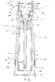
前記容器本体4のボディ6は、図1~図3及び図6~図9に示すように、その前端側6aに、断面円形状をなし、使用者により保持される保持領域9が設けられている。一方、その後端側6bは、図1~図3、図5及び図9に示すように、前記塗布物2に対応した断面形状すなわち断面四角形状をなす。ここで、このボディ6の断面形状は、図1、図2及び図7~図9に示すように、後端側6bから前記保持領域9に向かって漸次なめらかに変化するように設定してある。なお、前記ボディ6の前端側6aは、図6~図8に示すように、外周に前記保持領域9が形成されている断面円形状の外壁11と、この外壁11の内側に配された断面四角形状の内壁13とを備えた二重壁構造をなしており、前記内壁13の内周は、前記容器本体4の後端側6bの内周と連続させてある。すなわち、これらの内周は、前記塗布物2に対応する断面四角形状をなしている。前記内壁13は、前記外壁11よりも前方に延出させてあり、この内壁13の先端から塗布物2が順次前方に押し出されるようになっている。前記外壁11の先端部外周には、図7及び図8に示すように、前記キャップ5が嵌合するキャップ装着用段部15が形成されている。また、前記ボディ6の後端には、図7及び図8に示すように、前記押出機構7を保持する軸受部17が設けられている。
As shown in FIGS. 1 to 3 and 6 to 9, the
前記押出機構7は、図7~図9に示すように、前記軸受部17に保持された主軸19と、この主軸19の中心部前端からボディ6内に延出させたネジ棒21と、前記主軸19の後端に設けられた前記操作部8と、前記ボディ6内に位置させてネジ棒21に螺着されそのネジ棒21の回転に伴って螺合進退する進退部材23とを具備してなるもので、前記塗布物2の後端は、前記進退部材23に保持されている。
As shown in FIGS. 7 to 9, the
前記操作部8は、図7~図9に示すように、後端に開口25aを有する操作部本体25と、この操作部本体25の開口25aを覆う操作部カバー27とを備えたものである。前記操作部本体25は、前記ボディ6の後端部外周に連続する形態をなすものであり、主軸19と一体化された底板29と、この底板29の外周縁から後方に向けて延出させた周壁31とを備えている。なお、この操作部本体25と、前記主軸19と、前記ネジ棒21とは、合成樹脂により一体に成形されている。一方、前記操作部カバー27は、前記操作部本体25と別体をなすもので、カバー板33と、このカバー板33の外周縁に形成された周壁35とを備えている。そして、前記周壁35を前記操作部本体25の前記周壁31の内周に嵌合させた状態で前記カバー板33が前記操作部本体25の開口25aを塞ぐように構成されている。前記操作部本体25の周壁31の内面には係合凹部37が形成されているとともに、前記操作部カバー27の周壁35の外面には、係合凸部39が設けられており、前記操作部カバー27を前記操作部本体25内に押し込むことにより前記係合凸部39が前記係合凹部37に係合してこの操作部カバー27が操作部本体25に固定されるようになっている。この実施形態では、以上説明した操作部8の外周面8a及び前記ボディ6の後端側6bの部位の外周面6b1は、それぞれ断面正方形状のものであり、操作部8を90度回転操作するごとにこの操作部8の外周面8aと前記ボディ6の前記外周面6b1とが連続するようにしてある。すなわち、前記容器本体4の断面形状は、その後端側6bから前記保持領域9に向かって漸次なめらかに変化している。なお、前記ボディ6の軸受部17と前記主軸19との間に、操作部8の外周面8aとボディ6の前記外周面6b1とが連続するごとに当該操作部8を節度停止させるための図示しない節度用の凹凸部を設けてもよい。
As shown in FIGS. 7 to 9, the
以上説明した容器本体4の前端部には、前記キャップ5が着脱可能に装着されている。
The
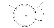
前記キャップ5は、前記塗布物2の前端部が露出している容器本体4の前端部分を覆うためのもので、図1、図2、図7及び図8に示すように、前記容器本体4の保持領域9と同一の断面形状を有している。すなわち、このキャップ5は、図1、図2、図4、図7及び図8に示すように、前端を載置面5aとしたカップ状のもので、前記載置面5aを形成する前壁41と、この前壁41の外周近傍部から後方に延出させた円筒状の周壁43とを備えており、この周壁43の外周面43aが前記保持領域9の外周面9aと連続するように形成されている。一方、この周壁43の外周面43aには、前記容器本体4のボディ6に設けた前記キャップ装着用段部15と係合可能な装着段部45が形成されている。なお、円板状をなす前記前壁41の直径は、前記周壁43の外径よりも大きく設定してあり、この前壁41の外周部分がフランジ部47をなしている。すなわち、このキャップ5は、前端に最も外径が大きなフランジ部47を有しており、このフランジ部47の前端面すなわち前記載置面5aを下にして当該塗布製品1を起立状態で安定して載置しておくことができるようにしてある。換言すれば、前記容器3は、その後端側から前端側に向かって徐々にその形状が変化し、前端側の断面積が後端側の断面積よりも大きくなるように設定されており、これによって当該容器3を安定して起立させておくことができるようにしてある。
このような構成のものであれば、操作部本体25の開口25aを操作部カバー27により覆っているので、いかなる姿勢で使用する場合においても、見栄えが良く、操作部8に埃等がたまりにくい塗布製品を提供することができる。すなわち、成形上の都合により操作部本体25を後方に開口するカップ状のものにした場合であっても、操作部本体25の開口25aが操作部カバー27により覆われているので、操作部本体25の内部が外部に露出するのを防止することができる。そのため、どのような姿勢であっても、見栄えが良い上に、操作部本体25の内部に埃等がたまりにくい。この効果は、特に、使用状態を直感的に認識しやすく、また、載置状態から使用状態に速やかに移行できるようにすべく、前端側、具体的にはキャップの前面を下にして天板上などに載置する場合において顕著に得ることができる。また、操作部カバー27を操作部本体25と別体にしているので、操作部カバー27を操作部本体25と異なった色彩にすることが可能となり、操作部カバー27の色彩により、塗布物2の特性がそれぞれ異なる複数種の塗布製品1をわかりやすく区別して示すことができる。例えば、塗布物2が通常の固形糊である場合の操作部カバー27の色彩と、塗布物2が塗布後に色が変化する特殊な固形糊である場合の操作部カバー27の色彩とを異ならせる等、種々の製品展開が可能となる。さらに、前記操作カバー27に文字や図形を刻印することも可能になる。そのため、操作カバー27を成形するための比較的小さな金型を複数種類用意することにより、外観が異なった複数種類の塗布製品1を製造することも可能になる。
The
With such a configuration, since the
また本実施形態によれば、操作部8を回転させる事により、容器本体4内に収納されている塗布物2の先端部を容器本体4の前端から所望量突出させることができる。そのため、キャップ5を外した状態で、容器本体4の保持領域9を例えば親指と人差し指とで両側からつまんで保持し、その塗布物2の先端部を用紙等の塗布対象物に押し当てて移動させることにより、その塗布対象物の所望個所に塗布物2を塗布することができる。この実施形態の塗布物2は角柱状をなしているため、図10に示すように、塗布物2の先端角部2aを塗布対象物に押し付けて細い線状領域に塗布物2を塗布したり、図11に示すように、塗布物2の先端辺部2bを塗布対象物に押し付けて幅の広い帯状領域に塗布物2を塗布したりすることができる。その際、使用者が親指T、人差し指Fで摘まむ保持領域9が断面円形状をなす円筒面により構成されているため、いずれの使用形態により塗布作業を行う場合でも違和感なく保持することができる。しかも、図10に示す第一の使用形態から図11に示す第二の使用形態に切り替える場合でも、親指T、人差し指Fを容器本体4から離すことなく微動操作して容器本体4を軸心L周りに回転させるだけで済むため、多様な塗布作用を効率よく行うことができる。また、図10に示す使用形態と図11に示す使用形態との中間の使用形態をとることも容易であり、塗布幅を微妙に調整しつつ塗布作業を進めることも可能になる。さらに、塗布物2の断面形状を工夫すれば、塗布幅を複数段階に変更することや、連続的に変更できるようにすることもできる。しかも、容器本体4の後端側、より具体的には前記ボディ6の後端側6bは塗布物2の断面形状に対応した断面多角形状にしてあるため、キャップ5を装着した状態でも塗布物2の形状を使用者に示唆することができるだけでなく、その内部に塗布物2を隙間なく収容することが可能となり、デッドスペースを極小にして塗布製品1全体のコンパクト化を図ることができる。
Further, according to the present embodiment, by rotating the
なお、前記塗布製品は、キャップを装着した状態で起立させて載置させるものに限られないが、前記実施形態のように、キャップの前端面を載置面としておけば、安定した状態で机上面に起立させておくことができる。特に、キャップの前端にフランジ部を有するものであれば、その安定性を高めることができる上に、キャップの着脱も容易になる。 The coated product is not limited to the one in which the cap is placed upright with the cap attached, but if the front end surface of the cap is used as the mounting surface as in the above embodiment, the desk is in a stable state. It can be erected on the upper surface. In particular, if the cap has a flange portion at the front end, the stability can be improved and the cap can be easily attached and detached.
また、容器も、前記実施形態のものに限られないのはもちろんであるが、前述したようなものにしておけば、見た目も実質上もともに安定した起立姿勢を実現することができる。 Further, the container is not limited to that of the above-described embodiment, but if the container is as described above, it is possible to realize a stable standing posture both in appearance and in substance.
そして、操作部カバーの態様も、前記実施形態のものに限られないのはもちろんであり、例えば、容易に着脱することができ、使用者が自由に交換できるようなものにしてもよい。 Of course, the mode of the operation unit cover is not limited to that of the above-described embodiment, and may be, for example, one that can be easily attached and detached and can be freely replaced by the user.
その他、本発明の趣旨を損ねない範囲で種々変更してよい。 In addition, various changes may be made as long as the gist of the present invention is not impaired.
1…塗布製品
2…塗布物
3…容器
4…容器本体
5…キャップ
5a…載置面
7…押出機構
8…操作部
25…操作部本体
25a…開口
27…操作部カバー
33…カバー板
35…周壁
47…フランジ部
1 ...
Claims (5)
前記容器が、後端側に前記押出機構の操作部が設けられた容器本体と、この容器本体の前端部に装着されるキャップとを具備し、
前記容器本体が、この容器本体の主要部をなすボディと、このボディの後端に隣設された前記操作部を有する押出機構とを備え、
前記操作部が、後端に開口を有する操作部本体と、この操作部本体の開口を覆う操作部カバーとを備えたものであるとともに、
前記操作部の全体が、前記ボディの後端よりも後方に位置し、
前記操作部本体の外周面が塗布製品の後端部の外周面を形成している塗布製品。 A coated product comprising a coated material and a container in which the coated material is extrudably housed in a container body provided with an extrusion mechanism.
The container comprises a container body provided with an operation portion of the extrusion mechanism on the rear end side, and a cap attached to the front end portion of the container body.
The container body includes a body forming a main part of the container body and an extrusion mechanism having the operation part adjacent to the rear end of the body.
The operation unit includes an operation unit main body having an opening at the rear end and an operation unit cover that covers the opening of the operation unit main body.
The entire operation unit is located behind the rear end of the body .
A coated product in which the outer peripheral surface of the main body of the operation unit forms the outer peripheral surface of the rear end portion of the coated product.
Priority Applications (1)
| Application Number | Priority Date | Filing Date | Title |
|---|---|---|---|
| JP2017151935A JP7069590B2 (en) | 2017-08-04 | 2017-08-04 | Applied product |
Applications Claiming Priority (1)
| Application Number | Priority Date | Filing Date | Title |
|---|---|---|---|
| JP2017151935A JP7069590B2 (en) | 2017-08-04 | 2017-08-04 | Applied product |
Publications (2)
| Publication Number | Publication Date |
|---|---|
| JP2019031294A JP2019031294A (en) | 2019-02-28 |
| JP7069590B2 true JP7069590B2 (en) | 2022-05-18 |
Family
ID=65523115
Family Applications (1)
| Application Number | Title | Priority Date | Filing Date |
|---|---|---|---|
| JP2017151935A Active JP7069590B2 (en) | 2017-08-04 | 2017-08-04 | Applied product |
Country Status (1)
| Country | Link |
|---|---|
| JP (1) | JP7069590B2 (en) |
Citations (2)
| Publication number | Priority date | Publication date | Assignee | Title |
|---|---|---|---|---|
| JP2009001283A (en) | 2007-06-19 | 2009-01-08 | Koa Glass Kk | Decorative container and method for manufacturing decorative container |
| JP2012130617A (en) | 2010-12-24 | 2012-07-12 | Yoshino Kogyosho Co Ltd | Container including inner tray lifting mechanism |
Family Cites Families (1)
| Publication number | Priority date | Publication date | Assignee | Title |
|---|---|---|---|---|
| JPS5999953U (en) * | 1982-12-22 | 1984-07-06 | ホ−ライ糊工業株式会社 | Inverted glue container |
-
2017
- 2017-08-04 JP JP2017151935A patent/JP7069590B2/en active Active
Patent Citations (2)
| Publication number | Priority date | Publication date | Assignee | Title |
|---|---|---|---|---|
| JP2009001283A (en) | 2007-06-19 | 2009-01-08 | Koa Glass Kk | Decorative container and method for manufacturing decorative container |
| JP2012130617A (en) | 2010-12-24 | 2012-07-12 | Yoshino Kogyosho Co Ltd | Container including inner tray lifting mechanism |
Also Published As
| Publication number | Publication date |
|---|---|
| JP2019031294A (en) | 2019-02-28 |
Similar Documents
| Publication | Publication Date | Title |
|---|---|---|
| US7052198B2 (en) | Stick-shaped cosmetic material feeding container | |
| JPS5825941Y2 (en) | Retractable cosmetic container | |
| KR20060045676A (en) | Reel unit for dual-bearing reel | |
| USD971026S1 (en) | Egg container | |
| JP2006506287A (en) | Pill dispenser | |
| KR100496245B1 (en) | Bar-like paint delivering container | |
| USD945527S1 (en) | Writing instrument | |
| JP7005108B2 (en) | Refill container | |
| JP7069590B2 (en) | Applied product | |
| US20090080963A1 (en) | Propel/repel dispensers | |
| US20080107469A1 (en) | Safety Knock-Type Writing Instrument | |
| EP3415035B1 (en) | Baked powder pencil | |
| JP2001299445A (en) | Container capable of extruding cream | |
| JP6926799B2 (en) | Applied product | |
| JP4035362B2 (en) | Feeding container | |
| JP5460216B2 (en) | Feeding container | |
| JP5223142B2 (en) | Solid material supply container for coating | |
| JP6684196B2 (en) | Pouring cap | |
| KR200390640Y1 (en) | Lipstick case with rotary cutting dispenser | |
| JP2021097994A (en) | Cosmetic stick container | |
| JP3186606U (en) | Cap for feeding container | |
| KR200319255Y1 (en) | puff for a makeup | |
| JP2005168745A (en) | Viscous cosmetic material container | |
| JP2022085137A (en) | Portable soap | |
| JP3113830U (en) | Viscous cosmetic container |
Legal Events
| Date | Code | Title | Description |
|---|---|---|---|
| A621 | Written request for application examination |
Free format text: JAPANESE INTERMEDIATE CODE: A621 Effective date: 20200731 |
|
| A977 | Report on retrieval |
Free format text: JAPANESE INTERMEDIATE CODE: A971007 Effective date: 20210618 |
|
| A131 | Notification of reasons for refusal |
Free format text: JAPANESE INTERMEDIATE CODE: A131 Effective date: 20210706 |
|
| A521 | Request for written amendment filed |
Free format text: JAPANESE INTERMEDIATE CODE: A523 Effective date: 20210830 |
|
| A02 | Decision of refusal |
Free format text: JAPANESE INTERMEDIATE CODE: A02 Effective date: 20211102 |
|
| A521 | Request for written amendment filed |
Free format text: JAPANESE INTERMEDIATE CODE: A523 Effective date: 20220125 |
|
| C60 | Trial request (containing other claim documents, opposition documents) |
Free format text: JAPANESE INTERMEDIATE CODE: C60 Effective date: 20220125 |
|
| A911 | Transfer to examiner for re-examination before appeal (zenchi) |
Free format text: JAPANESE INTERMEDIATE CODE: A911 Effective date: 20220203 |
|
| C21 | Notice of transfer of a case for reconsideration by examiners before appeal proceedings |
Free format text: JAPANESE INTERMEDIATE CODE: C21 Effective date: 20220208 |
|
| TRDD | Decision of grant or rejection written | ||
| A01 | Written decision to grant a patent or to grant a registration (utility model) |
Free format text: JAPANESE INTERMEDIATE CODE: A01 Effective date: 20220405 |
|
| A61 | First payment of annual fees (during grant procedure) |
Free format text: JAPANESE INTERMEDIATE CODE: A61 Effective date: 20220418 |
|
| R150 | Certificate of patent or registration of utility model |
Ref document number: 7069590 Country of ref document: JP Free format text: JAPANESE INTERMEDIATE CODE: R150 |