JP7068898B2 - Nanotubes decorated with metal nanoparticles for gas detection - Google Patents
Nanotubes decorated with metal nanoparticles for gas detection Download PDFInfo
- Publication number
- JP7068898B2 JP7068898B2 JP2018071787A JP2018071787A JP7068898B2 JP 7068898 B2 JP7068898 B2 JP 7068898B2 JP 2018071787 A JP2018071787 A JP 2018071787A JP 2018071787 A JP2018071787 A JP 2018071787A JP 7068898 B2 JP7068898 B2 JP 7068898B2
- Authority
- JP
- Japan
- Prior art keywords
- carbon nanotubes
- metal nanoparticles
- polymer
- sensor
- gas
- Prior art date
- Legal status (The legal status is an assumption and is not a legal conclusion. Google has not performed a legal analysis and makes no representation as to the accuracy of the status listed.)
- Expired - Fee Related
Links
Images


Classifications
-
- B—PERFORMING OPERATIONS; TRANSPORTING
- B01—PHYSICAL OR CHEMICAL PROCESSES OR APPARATUS IN GENERAL
- B01J—CHEMICAL OR PHYSICAL PROCESSES, e.g. CATALYSIS OR COLLOID CHEMISTRY; THEIR RELEVANT APPARATUS
- B01J20/00—Solid sorbent compositions or filter aid compositions; Sorbents for chromatography; Processes for preparing, regenerating or reactivating thereof
- B01J20/02—Solid sorbent compositions or filter aid compositions; Sorbents for chromatography; Processes for preparing, regenerating or reactivating thereof comprising inorganic material
- B01J20/20—Solid sorbent compositions or filter aid compositions; Sorbents for chromatography; Processes for preparing, regenerating or reactivating thereof comprising inorganic material comprising free carbon; comprising carbon obtained by carbonising processes
- B01J20/205—Carbon nanostructures, e.g. nanotubes, nanohorns, nanocones, nanoballs
-
- B—PERFORMING OPERATIONS; TRANSPORTING
- B01—PHYSICAL OR CHEMICAL PROCESSES OR APPARATUS IN GENERAL
- B01J—CHEMICAL OR PHYSICAL PROCESSES, e.g. CATALYSIS OR COLLOID CHEMISTRY; THEIR RELEVANT APPARATUS
- B01J20/00—Solid sorbent compositions or filter aid compositions; Sorbents for chromatography; Processes for preparing, regenerating or reactivating thereof
- B01J20/02—Solid sorbent compositions or filter aid compositions; Sorbents for chromatography; Processes for preparing, regenerating or reactivating thereof comprising inorganic material
- B01J20/0203—Solid sorbent compositions or filter aid compositions; Sorbents for chromatography; Processes for preparing, regenerating or reactivating thereof comprising inorganic material comprising compounds of metals not provided for in B01J20/04
- B01J20/0225—Compounds of Fe, Ru, Os, Co, Rh, Ir, Ni, Pd, Pt
-
- B—PERFORMING OPERATIONS; TRANSPORTING
- B01—PHYSICAL OR CHEMICAL PROCESSES OR APPARATUS IN GENERAL
- B01J—CHEMICAL OR PHYSICAL PROCESSES, e.g. CATALYSIS OR COLLOID CHEMISTRY; THEIR RELEVANT APPARATUS
- B01J20/00—Solid sorbent compositions or filter aid compositions; Sorbents for chromatography; Processes for preparing, regenerating or reactivating thereof
- B01J20/30—Processes for preparing, regenerating, or reactivating
- B01J20/32—Impregnating or coating ; Solid sorbent compositions obtained from processes involving impregnating or coating
- B01J20/3202—Impregnating or coating ; Solid sorbent compositions obtained from processes involving impregnating or coating characterised by the carrier, support or substrate used for impregnation or coating
- B01J20/3204—Inorganic carriers, supports or substrates
-
- B—PERFORMING OPERATIONS; TRANSPORTING
- B01—PHYSICAL OR CHEMICAL PROCESSES OR APPARATUS IN GENERAL
- B01J—CHEMICAL OR PHYSICAL PROCESSES, e.g. CATALYSIS OR COLLOID CHEMISTRY; THEIR RELEVANT APPARATUS
- B01J20/00—Solid sorbent compositions or filter aid compositions; Sorbents for chromatography; Processes for preparing, regenerating or reactivating thereof
- B01J20/30—Processes for preparing, regenerating, or reactivating
- B01J20/32—Impregnating or coating ; Solid sorbent compositions obtained from processes involving impregnating or coating
- B01J20/3231—Impregnating or coating ; Solid sorbent compositions obtained from processes involving impregnating or coating characterised by the coating or impregnating layer
- B01J20/3242—Layers with a functional group, e.g. an affinity material, a ligand, a reactant or a complexing group
- B01J20/3268—Macromolecular compounds
- B01J20/327—Polymers obtained by reactions involving only carbon to carbon unsaturated bonds
-
- G—PHYSICS
- G01—MEASURING; TESTING
- G01N—INVESTIGATING OR ANALYSING MATERIALS BY DETERMINING THEIR CHEMICAL OR PHYSICAL PROPERTIES
- G01N27/00—Investigating or analysing materials by the use of electric, electrochemical, or magnetic means
- G01N27/02—Investigating or analysing materials by the use of electric, electrochemical, or magnetic means by investigating impedance
- G01N27/04—Investigating or analysing materials by the use of electric, electrochemical, or magnetic means by investigating impedance by investigating resistance
- G01N27/12—Investigating or analysing materials by the use of electric, electrochemical, or magnetic means by investigating impedance by investigating resistance of a solid body in dependence upon absorption of a fluid; of a solid body in dependence upon reaction with a fluid, for detecting components in the fluid
- G01N27/125—Composition of the body, e.g. the composition of its sensitive layer
- G01N27/126—Composition of the body, e.g. the composition of its sensitive layer comprising organic polymers
-
- G—PHYSICS
- G01—MEASURING; TESTING
- G01N—INVESTIGATING OR ANALYSING MATERIALS BY DETERMINING THEIR CHEMICAL OR PHYSICAL PROPERTIES
- G01N27/00—Investigating or analysing materials by the use of electric, electrochemical, or magnetic means
- G01N27/02—Investigating or analysing materials by the use of electric, electrochemical, or magnetic means by investigating impedance
- G01N27/04—Investigating or analysing materials by the use of electric, electrochemical, or magnetic means by investigating impedance by investigating resistance
- G01N27/12—Investigating or analysing materials by the use of electric, electrochemical, or magnetic means by investigating impedance by investigating resistance of a solid body in dependence upon absorption of a fluid; of a solid body in dependence upon reaction with a fluid, for detecting components in the fluid
- G01N27/125—Composition of the body, e.g. the composition of its sensitive layer
- G01N27/127—Composition of the body, e.g. the composition of its sensitive layer comprising nanoparticles
-
- G—PHYSICS
- G01—MEASURING; TESTING
- G01N—INVESTIGATING OR ANALYSING MATERIALS BY DETERMINING THEIR CHEMICAL OR PHYSICAL PROPERTIES
- G01N33/00—Investigating or analysing materials by specific methods not covered by groups G01N1/00 - G01N31/00
- G01N33/0004—Gaseous mixtures, e.g. polluted air
- G01N33/0009—General constructional details of gas analysers, e.g. portable test equipment
-
- B—PERFORMING OPERATIONS; TRANSPORTING
- B22—CASTING; POWDER METALLURGY
- B22F—WORKING METALLIC POWDER; MANUFACTURE OF ARTICLES FROM METALLIC POWDER; MAKING METALLIC POWDER; APPARATUS OR DEVICES SPECIALLY ADAPTED FOR METALLIC POWDER
- B22F1/00—Metallic powder; Treatment of metallic powder, e.g. to facilitate working or to improve properties
- B22F1/10—Metallic powder containing lubricating or binding agents; Metallic powder containing organic material
- B22F1/102—Metallic powder coated with organic material
-
- B—PERFORMING OPERATIONS; TRANSPORTING
- B22—CASTING; POWDER METALLURGY
- B22F—WORKING METALLIC POWDER; MANUFACTURE OF ARTICLES FROM METALLIC POWDER; MAKING METALLIC POWDER; APPARATUS OR DEVICES SPECIALLY ADAPTED FOR METALLIC POWDER
- B22F2999/00—Aspects linked to processes or compositions used in powder metallurgy
-
- B—PERFORMING OPERATIONS; TRANSPORTING
- B82—NANOTECHNOLOGY
- B82Y—SPECIFIC USES OR APPLICATIONS OF NANOSTRUCTURES; MEASUREMENT OR ANALYSIS OF NANOSTRUCTURES; MANUFACTURE OR TREATMENT OF NANOSTRUCTURES
- B82Y15/00—Nanotechnology for interacting, sensing or actuating, e.g. quantum dots as markers in protein assays or molecular motors
-
- B—PERFORMING OPERATIONS; TRANSPORTING
- B82—NANOTECHNOLOGY
- B82Y—SPECIFIC USES OR APPLICATIONS OF NANOSTRUCTURES; MEASUREMENT OR ANALYSIS OF NANOSTRUCTURES; MANUFACTURE OR TREATMENT OF NANOSTRUCTURES
- B82Y30/00—Nanotechnology for materials or surface science, e.g. nanocomposites
-
- B—PERFORMING OPERATIONS; TRANSPORTING
- B82—NANOTECHNOLOGY
- B82Y—SPECIFIC USES OR APPLICATIONS OF NANOSTRUCTURES; MEASUREMENT OR ANALYSIS OF NANOSTRUCTURES; MANUFACTURE OR TREATMENT OF NANOSTRUCTURES
- B82Y40/00—Manufacture or treatment of nanostructures
-
- C—CHEMISTRY; METALLURGY
- C22—METALLURGY; FERROUS OR NON-FERROUS ALLOYS; TREATMENT OF ALLOYS OR NON-FERROUS METALS
- C22C—ALLOYS
- C22C26/00—Alloys containing diamond or cubic or wurtzitic boron nitride, fullerenes or carbon nanotubes
- C22C2026/002—Carbon nanotubes
Landscapes
- Chemical & Material Sciences (AREA)
- Analytical Chemistry (AREA)
- Chemical Kinetics & Catalysis (AREA)
- Life Sciences & Earth Sciences (AREA)
- Health & Medical Sciences (AREA)
- Organic Chemistry (AREA)
- Engineering & Computer Science (AREA)
- General Physics & Mathematics (AREA)
- Pathology (AREA)
- Immunology (AREA)
- Physics & Mathematics (AREA)
- General Health & Medical Sciences (AREA)
- Biochemistry (AREA)
- Inorganic Chemistry (AREA)
- Electrochemistry (AREA)
- Nanotechnology (AREA)
- Materials Engineering (AREA)
- Crystallography & Structural Chemistry (AREA)
- Combustion & Propulsion (AREA)
- Food Science & Technology (AREA)
- Medicinal Chemistry (AREA)
- Carbon And Carbon Compounds (AREA)
- Investigating Or Analyzing Materials By The Use Of Fluid Adsorption Or Reactions (AREA)
Description
ここに開示されている実施形態は、ガスセンサ、より詳細には、ガスセンサ用のナノ粒子系材料に関する。 The embodiments disclosed herein relate to gas sensors, and more particularly to nanoparticle materials for gas sensors.
様々な技術がガス漏れ検出のために利用されており、それぞれの手法は、利点とのかねあいで決まる。このような技術としては、例えば、触媒ビーズセンサ、金属酸化物半導体(MOS)センサ、非分散型赤外線センサ、赤外線レーザベースセンサが挙げられる。 Various techniques are used to detect gas leaks, each of which is determined by its advantages. Examples of such a technique include a catalyst bead sensor, a metal oxide semiconductor (MOS) sensor, a non-dispersive infrared sensor, and an infrared laser-based sensor.
触媒ビーズとMOSセンサは、小型であり、プリント基板に簡単に組み込むことができる。これらの技術は、メタンの検出限界も高く、安全性を向上させるには十分であるが、検出されない場合には積み重なると環境に悪影響を及ぼし得る低濃度の漏れを検出するには、不十分である。さらに、これらのセンサは、長期間のバッテリ駆動の動作に適合しないほど十分な電力を消費し、化学的相互作用を利用して測定を行うため、同様の気体からの干渉を受ける。 The catalyst beads and MOS sensor are small and can be easily incorporated into a printed circuit board. These techniques also have high detection limits for methane and are sufficient to improve safety, but are insufficient to detect low concentrations of leaks that, if not detected, could adversely affect the environment if stacked. be. In addition, these sensors consume enough power to be incompatible with long-term battery-powered operation and utilize chemical interactions to make measurements and are therefore subject to interference from similar gases.
赤外線系のセンサは、非常に感度が高く、一般に干渉の影響を受けないが、高価でかさばり、高出力が要求されることが多い。 Infrared sensors are extremely sensitive and generally unaffected by interference, but are often expensive, bulky, and require high output.
以下は、このような態様の基本を理解するために、本開示の様々な態様の簡略化された概要を提示する。この概要は、開示内容を広範囲にわたってとらえたものではない。本開示の鍵となる要素または重要な要素を特定することも、本開示の特定の実施形態の任意の範囲または特許請求の範囲の境界を示すことも意図していない。その唯一の目的は、後で提示されるより詳細な説明の前置きとして、開示のいくつかの概念を簡略化した形で提示することである。 The following is a simplified overview of the various aspects of the present disclosure to understand the basics of such aspects. This summary does not capture the content of the disclosure extensively. It is not intended to identify key or important elements of this disclosure or to demarcate any scope or claims of a particular embodiment of this disclosure. Its sole purpose is to present some of the concepts of the disclosure in a simplified form as a prelude to a more detailed explanation presented later.
本開示の1つの態様において、組成物は、カルボン酸基および/またはヒドロキシル基での平均官能化度が、カーボンナノチューブの総重量に基づいて3重量パーセント(重量%)未満のカーボンナノチューブと;カーボンナノチューブに結合したポリマーコーティングされた金属ナノ粒子とを含む。 In one aspect of the present disclosure, the composition comprises carbon nanotubes having an average functionality of carboxylic acid groups and / or hydroxyl groups of less than 3% by weight based on the total weight of the carbon nanotubes; carbon. Includes polymer-coated metal nanoparticles bound to nanotubes.
一実施形態では、ポリマーコーティングされた金属ナノ粒子は、カーボンナノチューブに非共有結合している。 In one embodiment, the polymer coated metal nanoparticles are non-covalently attached to the carbon nanotubes.
一実施形態では、カーボンナノチューブは、カルボン酸官能基およびヒドロキシル官能基を実質的に含まない。 In one embodiment, the carbon nanotubes are substantially free of carboxylic acid and hydroxyl functional groups.
一実施形態では、カーボンナノチューブは、単層カーボンナノチューブまたは多層カーボンナノチューブを含む。 In one embodiment, the carbon nanotubes include single-walled carbon nanotubes or multi-walled carbon nanotubes.
一実施形態では、ポリマーコーティングされた金属ナノ粒子は、それぞれ、金属コアと、金属コアに共有結合したポリマー層とを含む。一実施形態では、ポリマー層は、疎水性ポリマーを含む。一実施形態では、金属コアは、パラジウム、イリジウム、ロジウム、白金および金からなる群から選択される金属を含む。一実施形態では、ポリマー層はポリ(ビニルピロリジノン)を含み、金属コアはパラジウムを含む。 In one embodiment, the polymer coated metal nanoparticles contain a metal core and a polymer layer covalently bonded to the metal core, respectively. In one embodiment, the polymer layer comprises a hydrophobic polymer. In one embodiment, the metal core comprises a metal selected from the group consisting of palladium, iridium, rhodium, platinum and gold. In one embodiment, the polymer layer comprises poly (vinylpyrrolidinone) and the metal core comprises palladium.
一実施形態では、組成物は有機溶媒に分散される。 In one embodiment, the composition is dispersed in an organic solvent.
本開示の別の態様において、ガスを検出するためのセンサは、電極を含む電極アセンブリと、電極アセンブリの電極の間に配置されたガス吸着材料とを含む。一実施形態では、ガス吸着材料は、カーボンナノチューブと、カーボンナノチューブに結合したポリマーコーティングされた金属ナノ粒子とを含む。 In another aspect of the present disclosure, a sensor for detecting gas comprises an electrode assembly comprising electrodes and a gas adsorbing material disposed between the electrodes of the electrode assembly. In one embodiment, the gas adsorbing material comprises carbon nanotubes and polymer coated metal nanoparticles bound to the carbon nanotubes.
一実施形態では、電極アセンブリは、処理装置に動作可能に連結され、処理装置は、ガス吸着材料に吸着された気体分子から生じる、ガス吸着材料の抵抗率の変化を測定する。一実施形態では、センサは、0%~80%の相対湿度を有する周囲環境での動作中、100ppmの検出限界を有する。一実施形態では、センサはメタンを選択的に検出するように改変される。 In one embodiment, the electrode assembly is operably coupled to the processing device, which measures the change in resistance of the gas adsorbing material resulting from the gas molecules adsorbed on the gas adsorbing material. In one embodiment, the sensor has a detection limit of 100 ppm during operation in an ambient environment with a relative humidity of 0% to 80%. In one embodiment, the sensor is modified to selectively detect methane.
一実施形態では、ポリマーコーティングされた金属ナノ粒子は、カーボンナノチューブに非共有結合している。 In one embodiment, the polymer coated metal nanoparticles are non-covalently attached to the carbon nanotubes.
一実施形態では、カルボン酸基および/またはヒドロキシル基でのカーボンナノチューブの平均官能化度は、カーボンナノチューブの総重量に基づいて3重量%未満である。 In one embodiment, the average degree of functionalization of carbon nanotubes with carboxylic acid and / or hydroxyl groups is less than 3% by weight based on the total weight of the carbon nanotubes.
本開示の別の態様において、金属ナノ粒子で装飾されたカーボンナノチューブを製造する方法は、第1の溶液と第2の溶液を合わせることによって反応混合物を作成し、第1の溶液が、ポリマーでコーティングされた金属ナノ粒子を含む、ポリマーコーティングされた金属ナノ粒子を含み、第2の溶液が、カーボンナノチューブを含むことと;ポリマーのガラス転移点より高い温度まで、ポリマーコーティングされた金属ナノ粒子がカーボンナノチューブと結合し、金属ナノ粒子で装飾されたカーボンナノチューブを生成するのに十分な時間、反応混合物を加熱することとを含む。 In another aspect of the present disclosure, a method of making carbon nanotubes decorated with metal nanoparticles creates a reaction mixture by combining a first solution and a second solution, where the first solution is a polymer. Containing polymer-coated metal nanoparticles, including coated metal nanoparticles, the second solution contains carbon nanotubes; polymer-coated metal nanoparticles up to a temperature above the glass transition point of the polymer. It involves heating the reaction mixture for a time sufficient to bind to the carbon nanotubes and produce carbon nanotubes decorated with metal nanoparticles.
一実施形態では、ポリマーコーティングされた金属ナノ粒子は、反応混合物を作成する前に完全に作成されている。 In one embodiment, the polymer coated metal nanoparticles are fully prepared prior to making the reaction mixture.
一実施形態では、ポリマーコーティングされた金属ナノ粒子は、カーボンナノチューブに非共有結合している。 In one embodiment, the polymer coated metal nanoparticles are non-covalently attached to the carbon nanotubes.
一実施形態では、カルボン酸基および/またはヒドロキシル基でのカーボンナノチューブの平均官能化度は、カーボンナノチューブの総重量に基づいて3重量%未満である。 In one embodiment, the average degree of functionalization of carbon nanotubes with carboxylic acid and / or hydroxyl groups is less than 3% by weight based on the total weight of the carbon nanotubes.
一実施形態では、本方法は、金属ナノ粒子で装飾されたカーボンナノチューブを非水性溶媒系インクに分散させる工程をさらに含む。 In one embodiment, the method further comprises the step of dispersing carbon nanotubes decorated with metal nanoparticles in a non-aqueous solvent-based ink.
本開示は、限定ではなく例として、添付図面の図に示されている。 The present disclosure is shown in the illustrations of the accompanying drawings as an example, but not a limitation.
本明細書には、金属ナノ粒子で装飾されたナノチューブ、その製造方法、およびそれを組み込んだセンサの実施形態が記載されている。特定の実施形態は、検知材料として金属ナノ粒子で装飾されたカーボンナノチューブ(例えば、単層カーボンナノチューブまたは「SWCNT」)を含む疎水性組成物を使用するガス(例えば、メタン)センサに関する。検知材料(本明細書では「ガス吸着材料」とも呼ばれる)は、センサの互いに組み合わせられた電極の間に配置されてもよい。メタンガスが検知材料に吸着すると、その電子状態が変化し、その結果、吸着したメタンの量に比例して抵抗率が変化する。この抵抗率の変化は、多数の抵抗率測定技術(例えば、ボルタンメトリー)を介して測定することができる。センサは、メタン検知に合うように改変される場合、メタンを含まない気体を流すことによって、再生することができる。 This specification describes nanotubes decorated with metal nanoparticles, a method for producing the same, and embodiments of a sensor incorporating the same. A particular embodiment relates to a gas (eg, methane) sensor that uses a hydrophobic composition comprising carbon nanotubes (eg, single-walled carbon nanotubes or "SWCNTs") decorated with metal nanoparticles as a detection material. The detection material (also referred to herein as a "gas adsorbent material") may be placed between the electrodes combined with each other in the sensor. When methane gas is adsorbed on the detection material, its electronic state changes, and as a result, the resistivity changes in proportion to the amount of adsorbed methane. This change in resistivity can be measured via a number of resistivity measurement techniques (eg, voltammetry). If the sensor is modified to meet methane detection, it can be regenerated by flowing a methane-free gas.
メタンを検出するための現行の手法は、非常に小型であり、消費電力が低いデバイスを作成することに集中している。これらの手法は、異なる種類の材料の吸着効果に注目している。これらには、触媒金属で装飾されたカーボンナノチューブ、触媒金属を利用した薄膜、および化学修飾されたグラフェンまたはカーボンナノチューブが含まれる。しかしながら、このような物理吸着に基づくメタンセンサは、水蒸気の存在下で検出能力を失うので、純粋なメタンと水蒸気が混合した場合であっても、多くは検出することができない。大気中のどこにでも湿気は存在するため、実際の状況では、吸着効果に基づく現行のメタンセンサは、信頼性良く機能することができない。 Current methods for detecting methane are focused on creating devices that are very small and consume low power. These methods focus on the adsorptive effect of different types of materials. These include carbon nanotubes decorated with catalytic metal, thin films utilizing catalytic metal, and chemically modified graphene or carbon nanotubes. However, since such a methane sensor based on physical adsorption loses its detection ability in the presence of water vapor, even when pure methane and water vapor are mixed, many cannot be detected. Due to the presence of moisture everywhere in the atmosphere, in practice, current methane sensors based on adsorption effects cannot function reliably.
理論に拘束されるものではないが、この性能低下の理由は、水素結合による表面カルボン酸基またはヒドロキシル基との相互作用によって、吸着表面に水が蓄積することによるものであることを、ここに提案しておく。メタンと金属ナノ粒子との相互作用は疎水性であり、親水性官能基の存在が減らされるか、または完全に抑えられれば、水蒸気の濃度とは無関係であるとの仮説がなりたつ。本明細書に記載されるように、水蒸気の影響を抑える手法は、水蒸気が吸着するのに利用可能なカルボン酸(「-COOH」)部位を抑えることを含む。これには、例えば、-COOH基を疎水性金属ナノ粒子で保護すること、また、ポリマーを用い、(例えば、非共有相互作用によって)疎水性金属ナノ粒子をナノチューブに結合することを含む。 Without being bound by theory, it is here that the reason for this performance degradation is the accumulation of water on the adsorption surface due to the interaction with surface carboxylic acid or hydroxyl groups by hydrogen bonds. I'll make a suggestion. It has been hypothesized that the interaction of methane with metal nanoparticles is hydrophobic and is independent of water vapor concentration if the presence of hydrophilic functional groups is reduced or completely suppressed. As described herein, techniques for suppressing the effects of water vapor include suppressing the carboxylic acid (“—COOH”) sites available for water vapor adsorption. This includes, for example, protecting the -COOH group with hydrophobic metal nanoparticles and using a polymer to attach the hydrophobic metal nanoparticles (eg, by non-covalent interaction) to the nanotubes.
一実施形態では、有機ポリマーコーティングされたパラジウムナノ粒子(SWCNTとは別に製造される)をSWCNTと混合し、ポリマーのガラス転移点より高い温度まで加熱する。冷却すると、-COOHで高度に官能化されたSWCNT、少量の-COOHで官能化されたSWCNT、さらには-COOH官能化されていないSWCNTであっても、パラジウムで装飾されたSWCNTが得られることがわかった。この結果は、SWCNT上でPdナノ粒子を成長させるためには高度に官能化された-COOHが必要であることを示唆する従来の手法の観点からは予想外である。理論に拘束されるものではないが、Pd粒子がSWCNTの表面に結合するさらなる機構は、Pdナノ粒子上に存在するコーティングポリマーが熱によって軟化し、Pdナノ粒子がSWCNTに非特異的に非共有結合することによるものであるという仮説がなりたつ。 In one embodiment, organic polymer coated palladium nanoparticles (manufactured separately from SWCNT) are mixed with SWCNT and heated to a temperature above the glass transition point of the polymer. Cooling yields a highly functionalized SWCNT with -COOH, a small amount of -COOH-functionalized SWCNT, and even a non-COOH-functionalized SWCNT with palladium-decorated SWCNTs. I understood. This result is unexpected from the point of view of conventional methods suggesting that highly functionalized -COOH is required to grow Pd nanoparticles on SWCNTs. Without being bound by theory, a further mechanism by which Pd particles bind to the surface of SWCNTs is that the coating polymer present on the Pd nanoparticles is thermally softened and the Pd nanoparticles are non-specifically non-covalent to SWCNTs. The hypothesis is that it is due to the combination.
本開示の実施形態は、実質的にあらゆる環境で、たとえ湿度の高い環境または湿度が変動する環境であっても漏れを検出することができる、従来のメタン検出技術に代わる消費電力が低く低コストの代替物を提供する。さらに、本開示の実施形態は、従来のガス検知手法に勝るいくつかの利点を提供する。印刷可能な金属ナノ粒子で装飾されたナノチューブを利用する実施形態は、湿度水準が変動する状態で低濃度のメタンの漏れを信頼性良く検出することができる。これらの実施形態は、ポータブルデバイスまたは携帯用デバイスでの使用、または天然ガス抽出分野におけるセンサネットワークの一部としての使用に適応可能である。この実施形態は、例えば、パラジウムを、他の金属(例えば、限定されないが、イリジウム、ロジウム、白金または金)で置き換えることによって、他の気体を検出するために使用することもできる。加えて、開示された方法は、モジュール化され、大量生産のために容易に拡張可能である。 Embodiments of the present disclosure are low power consumption and low cost alternatives to conventional methane detection techniques that can detect leaks in virtually any environment, even in humid or variable humidity environments. Provide an alternative to. Moreover, embodiments of the present disclosure provide some advantages over conventional gas detection techniques. Embodiments that utilize nanotubes decorated with printable metal nanoparticles can reliably detect low-concentration methane leaks in varying humidity levels. These embodiments are adaptable for use in portable or portable devices, or as part of a sensor network in the field of natural gas extraction. This embodiment can also be used to detect other gases, for example by substituting palladium with another metal (eg, but not limited to, iridium, rhodium, platinum or gold). In addition, the disclosed methods are modular and easily expandable for mass production.
図1は、ポリマーコーティングされた金属ナノ粒子100の一実施形態の図である。ポリマーコーティングされた金属ナノ粒子100は、金属コア102と、金属コア102をコーティングするポリマー層104とを含む。いくつかの実施形態では、金属コア102は、結晶、多結晶、非晶質、またはそれらの組み合わせであってもよい。いくつかの実施形態では、金属コア102は、単一の金属種(例えば、遷移金属)、または異なる金属種の合金を含んでいてもよい。いくつかの実施形態では、金属は、パラジウム、イリジウム、ロジウム、白金および金から選択される。例えば、メタンを検出する特定の実施形態では、金属コア102はパラジウムコアであってもよい。特定の実施形態では、金属コア102の直径は、例えば、1nm~100nm、1nm~50nm、1nm~20nm、1nm~10nm、または1nm~5nmの範囲であってもよい。
FIG. 1 is a diagram of an embodiment of polymer coated
ポリマー層104は、図示されているように、金属コア102の表面に結合した複数の直鎖ポリマーを含む。いくつかの実施形態では、分枝鎖ポリマーを使用してもよい。いくつかの実施形態では、ポリマーは、金属コア102に共有結合していてもよい。他の実施形態では、ポリマーは、金属コア102に物理的に吸着されてもよく、吸着は、例えば、疎水性相互作用によって起こる。ポリマーは、ポリマー間の立体斥力によってポリマーが表面から延びるように、金属コア102の表面上に密に充填されてもよい。ポリマー層の剛性は、ポリマーの化学構造、充填密度、表面の曲率、ポリマー分子量および多分散性、および溶媒条件の関数であり得る。ポリマー層104は、ポリマーでコーティングされた金属ナノ粒子100と、ポリマーでコーティングされた他の金属ナノ粒子との間の粒子間力を軽減して、溶媒中に分散している間の凝集を防ぐ働きをするだろう。いくつかの実施形態では、ポリマー層104は、1種類のポリマーまたは異なる種類のポリマーを含む。いくつかの実施形態では、ポリマー層104は、疎水性ポリマーを含む。いくつかの実施形態では、ポリマー層104は、ポリビニルピロリドン(PVP)を含む。
The
図2は、本開示の一実施形態のポリマーコーティングされた金属ナノ粒子を製造するための反応プロセスを示す。具体的には、図2は、PVPでコーティングされたパラジウムナノ粒子を製造する反応プロセスを示し、ここで、まず、不溶性PdCl2をHClと反応させて可溶性H2PdCl4を生成し、その後、PVP存在下でエチレングリコールと反応させ、Pd(0)金属ナノ粒子を製造する。 FIG. 2 shows a reaction process for producing polymer coated metal nanoparticles of one embodiment of the present disclosure. Specifically, FIG. 2 shows a reaction process for producing PVP-coated palladium nanoparticles, where insoluble PdCl 2 is first reacted with HCl to produce soluble H 2 PdCl 4 and then. Pd (0) metal nanoparticles are produced by reacting with ethylene glycol in the presence of PVP.
特定の実施形態では、金属ナノ粒子で装飾されたナノチューブは、金属ナノ粒子を合成するための別個の工程と、ナノチューブを合成するための別個の工程を利用したプロセスによって製造され、ナノチューブ表面の官能化された位置で直接的にナノ粒子を成長させる方法よりも、最終生成物の制御がしやすい。 In certain embodiments, the nanotubes decorated with metal nanoparticles are produced by a process utilizing a separate step for synthesizing the metal nanoparticles and a separate step for synthesizing the nanotubes, and the functionalities of the nanotube surface. It is easier to control the final product than the method of growing nanoparticles directly in the converted position.
本明細書で使用される場合、「ナノチューブ」は、少なくとも2つの軸に沿ってナノスケールの寸法を有する中空構造を指す。ナノチューブは、円筒形であってもよく、高いアスペクト比を有していてもよく、例えば、直径が5ナノメートル(nm)~100nmであり、長さが一般的に20nm~1マイクロメートル(μm)、またはもっと大きくてもよい。単層カーボンナノチューブは、本明細書中の例示的な実施形態で説明されるが、本実施形態は、多層カーボンナノチューブなどの他の種類のカーボンナノチューブにも及ぶ。カーボンナノチューブの電子特性は、直径およびキラリティ(ナノチューブの長さに沿った原子の位置における「ねじれ」の程度を表す)の関数として、金属性から半導体性まで様々であり得る。 As used herein, "nanotube" refers to a hollow structure with nanoscale dimensions along at least two axes. The nanotubes may be cylindrical or may have a high aspect ratio, eg, 5 nanometers (nm) to 100 nm in diameter and generally 20 nm to 1 micrometer (μm) in length. ), Or may be larger. Single-walled carbon nanotubes are described in the exemplary embodiments herein, but this embodiment also extends to other types of carbon nanotubes, such as multi-walled carbon nanotubes. The electronic properties of carbon nanotubes can vary from metallic to semiconducting as a function of diameter and chirality (representing the degree of "twist" at the position of atoms along the length of the nanotube).
図3は、カルボン酸官能基の量を増加させていくカーボンナノチューブの図である。カーボンナノチューブ300は、-COOHまたは他の親水性官能基によって官能化されていないか、または最小限官能化されたカーボンナノチューブを表す。カーボンナノチューブ310は、-COOH官能化度が低いか、または中程度のカーボンナノチューブを表し、カーボンナノチューブ320は、-COOH官能化度が高いカーボンナノチューブを表す。-COOHは、カーボンナノチューブの端部だけではなく、カーボンナノチューブの表面に沿って存在していてもよい。
FIG. 3 is a diagram of carbon nanotubes in which the amount of carboxylic acid functional groups is increased. The
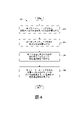
図4は、本開示の実施形態によって金属ナノ粒子で装飾されたナノチューブを製造する方法400を示すフロー図である。方法400は、ブロック402で開始し、ポリマーコーティングされた金属ナノ粒子を含む第1の溶液が提供される。ポリマーコーティングされた金属ナノ粒子は、図1について記載したポリマーコーティングされた金属ナノ粒子100によって表される構造を有していてもよい。ポリマーコーティングされた金属ナノ粒子は、本明細書に記載されるように(例えば、以下の実施例4)、または当業者によって認識されるような任意の改変または他の適切な合成方法を用いて合成されてもよい。いくつかの実施形態では、各ポリマーコーティングされた金属ナノ粒子は、パラジウムコアと、PVPを含むポリマー層とを含む。いくつかの実施形態では、ポリマーコーティングされた金属ナノ粒子は、有機溶媒に分散される。
FIG. 4 is a flow chart showing a
ブロック404において、カーボンナノチューブを含む第2の溶液が提供される。カーボンナノチューブは官能化されていなくてもよく、実質的にカルボン酸(-COOH)および/またはヒドロキシル(-OH)官能化されていなくてもよく(例えば、検出限界以下)、または-COOHおよび/または-OHでの平均官能化度が、カーボンナノチューブの総重量(すなわち、任意のこのような官能化を含む)に基づいて3重量パーセント(重量%)未満であってもよい。いくつかの実施形態では、カーボンナノチューブは、-COOHおよび/または-OHでの平均官能化度が3重量%以上であってもよい。-COOHおよび/または-OHでの平均官能化の重量%は、本明細書で記載されるように、測定が超高純度(UHP)グレードの不活性気体中で行われる場合には、300℃を超えない温度での熱重量分析(TGA)における重量損失によって測定される。カーボンナノチューブは、本明細書に記載されるように(例えば、以下の実施例1~3)、または当業者によって認識されるような任意の改変または他の適切な合成方法を用いて合成されてもよい。いくつかの実施形態では、カーボンナノチューブは、SWCNTである。いくつかの実施形態では、カーボンナノチューブは、水性溶媒に分散される。
At
ブロック406において、第1の溶液と第2の溶液とを合わせることによって反応混合物が作成される。ブロック408において、反応混合物は、ポリマーコーティングされた金属ナノ粒子のポリマーのガラス転移点よりも高い温度まで加熱される(例えば、PVPのガラス転移点は、分子量に応じて、100℃~180℃で変動し得る)。いくつかの実施形態では、この温度は、ガラス転移点よりも高いが50℃以内である。いくつかの実施形態では、この温度は、ガラス転移点よりも高いが25℃以内である。いくつかの実施形態では、この温度は、ガラス転移点よりも高いが10℃以内である。いくつかの実施形態では、この温度は、120℃~180℃である。いくつかの実施形態では、この温度は、120℃~140℃である。いくつかの実施形態では、この温度は、150℃~180℃である。いくつかの実施形態では、この温度を30分~4時間維持する。いくつかの実施形態では、この温度は、ある温度(例えば120℃~140℃)で第1の時間(例えば、30分~4時間)から、第2の温度(150℃~180℃)で第2の時間(例えば、30分~4時間)まで、様々であってもよい。いくつかの実施形態では、ナノ粒子コーティングされた金属ナノ粒子を溶媒で処理し、ナノ粒子の表面から、溶媒が接触可能なPVPを除去する。図5は、カーボンナノチューブ502に結合したポリマーコーティングされた金属ナノ粒子504を含む、例示的な金属ナノ粒子で装飾されたナノチューブ500を示す。ポリマーコーティングされた金属ナノ粒子504は、ポリマーの接着性によって非共有結合的にカーボンナノチューブ502の表面に結合している。
In
いくつかの実施形態では、メタンガスを検知するためのセンサ材料は、全く-COOHで官能化されていないか、またはほとんど官能化されていないSWCNTの表面に、コーティングされたパラジウムナノ粒子を固定し、得られた金属ナノ粒子で装飾されたナノチューブを非水性溶媒系インクに分散させ、このインクをセンサチップ上に印刷することによって製造されてもよい(例えば、方法400に従って)。 In some embodiments, the sensor material for detecting methane gas immobilizes coated palladium nanoparticles on the surface of SWCNTs that are completely or barely functionalized with -COOH. It may be produced by dispersing the obtained nanotubes decorated with metal nanoparticles in a non-aqueous solvent-based ink and printing the ink on a sensor chip (for example, according to the method 400).
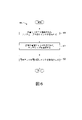
図6は、本開示の実施形態によってセンサを製造する方法600を示すフロー図である。方法600は、ブロック602で開始し、金属ナノ粒子で装飾されたナノチューブを含むインクが提供される。金属ナノ粒子で装飾されたナノチューブは、本明細書に記載されている任意の金属ナノ粒子で装飾されたナノチューブ(例えば、SWCNTに結合したPVPコーティングされたパラジウムナノ粒子)に対応していてもよい。
FIG. 6 is a flow chart showing a
ブロック604において、表面に電極アレイが形成されたセンサチップまたは基板が提供される。
In
次に、本開示の実施形態の例示的なセンサチップ700の上面図および断面図をそれぞれ示す模式図である図7Aおよび図7Bを参照する。センサチップ700は、表面にセンサ704A~704Dが形成された基板702を含む。4つのセンサが示されているが、任意の適切な数のセンサを使用してもよいことに留意されたい。基板702は、非導電性材料、例えば、ポリエチレンナフタレート(PEN)、ポリイミド、または任意の他の適切な非導電性材料などを含む。いくつかの実施形態では、基板の厚さは、一種のゼロ挿入力(ZIF)コネクタへの確実な接続を容易にするように選択することができる(例えば、基板厚さ250μm)。
Next, reference is made to FIGS. 7A and 7B, which are schematic views showing a top view and a cross-sectional view of an
センサ704A~704Dは、銅、グラファイト、チタン、銀、金、白金、またはそれらの組み合わせなどの任意の適切な電極材料を含んでいてもよい。センサ704A~704Dは、センサ読み出しのための外部構成要素との電気的接触を容易にするような形状にすることができる。センサチップ700上の電極の総数を減らすために、センサ704A~704Dの各々によって共有され得る単一の対向電極706を基板702上に形成してもよい。
センサ704A~704Dおよび共通電極706は、互いに組み合わせられた電極708を有する領域を共に規定してもよい。図7Bは、センサ704Cの互いに組み合わせられた電極708の断面図を示し(図7Aに点線で示す)、互いに組み合わせられた電極708間に規定された活性領域710を示し、ここにガス検知材料が堆積され得る。特定の実施形態では、互いに組み合わせられた電極708の厚さは、100nm~1μmの範囲であってもよい。隣接する互いに組み合わせられた電極708の間のピッチ710は、例えば、50μm~5mmの範囲であってもよい。
The
センサチップ700は、抵抗測定のためにセンサチップ700の一部を電気コネクタに直接挿入できるように設計されていてもよい。印刷された物質の所望の抵抗レベルを達成するために、センサチップ700は、互いに組み合わせられた電極708の数、デューティサイクル、および寸法(厚さを含む)ならびに隣接する電極間のギャップ距離を変えるように設計することができる。センサ704A~704Dの印刷されたリード線の寸法は、共通電極の経路およびセンサ経路のリード抵抗が、抵抗測定におけるそれらの影響をほぼ相殺するように選択することができる。基板702は、レシオメトリック3線抵抗測定用に設計されてもよいが、従来の3線抵抗測定および2線抵抗測定と互換性があってもよい。
The
再び図6を参照すると、ブロック606において、インクが電極アレイの電極間に堆積し、インクの溶媒が蒸発して、金属ナノ粒子で装飾されたナノチューブを含むガス検知材料が残る。特定の実施形態では、インクは、センサ上に直接(例えば、インクジェット印刷を使用して)印刷することによって堆積する。いくつかの実施形態では、インクは、ピペット操作、スピンコーティング布または浸漬コーティングなどの他の適切な方法を使用して堆積する。図7Cは、例示的なセンサの互いに組み合わせられた電極の上に印刷されたインクを示す顕微鏡写真である。
Referring again to FIG. 6, in
図7Dは、(例えば、複数のZIFピン754を介して)処理装置750に動作可能に連結されているものとして示されているセンサチップ700の動作を示す。処理装置は、様々なオンチップセンサを使用してガス検知材料の抵抗率を測定するように構成されていてもよい1つ以上の電子部品、例えばMUX752を備えていてもよい。いくつかの実施形態では、処理装置750は、マイクロプロセッサ、中央処理装置などのような1つ以上の汎用処理装置を表す。例えば、処理装置750は、CISC(Complex Instruction Set Computing)マイクロプロセッサ、RISC(Reduced Instruction Set Computing)マイクロプロセッサ、VLIW(Very Long Instruction Word)マイクロプロセッサ、または他の命令セットを実装するプロセッサ、または命令セットの組み合わせを実装するプロセッサであってもよい。処理装置750は、特定用途向け集積回路(ASIC)、フィールドプログラマブルゲートアレイ(FPGA)、デジタル信号プロセッサ(DSP)、ネットワークプロセッサなどのような1つ以上の専用処理装置であってもよい。処理装置750は、電気信号を適用し、電気信号を測定し、測定された電気信号に基づいてデータを計算するなどの様々な動作を実行するように構成することができる。特定の実施形態では、処理装置750は、単一の装置または他の装置を制御する装置であってもよい。例えば、処理装置750は、抵抗率測定を実行するように構成されてもよく、または抵抗率測定を実行する1つ以上の他のデバイスを制御してもよい。
FIG. 7D shows the operation of the
いくつかの実施形態では、方法600に従って製造されたセンサは、周囲条件で広い相対湿度範囲にわたって動作することができる。本明細書で使用される場合、「周囲条件」とは、20±5℃の温度および1±0.1気圧(ATM)の典型的な実験室環境の条件を指す。特定の実施形態では、0%~80%の相対湿度を有する周囲環境での動作中、センサは、100ppmのメタン検出限界を有する。いくつかの実施形態では、センサは、より低い検出限界、例えば、50ppmまたは10ppmを有していてもよい。センサは、周囲条件からはずれた温度範囲(例えば、-5℃から50℃)にわたってこのような性能を達成してもよい。
In some embodiments, the sensor manufactured according to
以下の実施例は、本発明の理解を助けるために記載されたものであり、もちろん、本明細書に記載され、特許請求される発明を具体的に限定するものとして解釈されるべきではない。当業者の知識の範囲内にある、現在知られているかまたは後に開発される全ての均等物の置換を含む本発明のそのような変形、および実験設計の処方または軽微な変化は、本明細書に組み込まれる本発明の範囲に含まれると考えるべきである。 The following examples have been described to aid in the understanding of the invention and, of course, should not be construed as specifically limiting the claimed invention described herein. Such variations of the invention, including substitutions of all currently known or later developed equivalents, within the knowledge of one of ordinary skill in the art, and prescriptions or minor changes in experimental design are herein. It should be considered to be included in the scope of the present invention incorporated in.
実施例1:-COOHでの官能化度が高いSWCNTの製造
200mgのSWCNT(NanoAmor)を50mLの脱イオン水に分散させ、2時間(20W)超音波処理することにより懸濁液を製造した。次に懸濁液を丸底フラスコに入れ、50mLの濃HNO3(16M)を加えた。反応ボリュームを120℃で5日間磁気撹拌しながら還流し、次いで室温まで冷却した。反応ボリュームを脱イオン(DI)水で洗浄し、遠心分離して粒子を分離した。中性pHに達するまで洗浄および遠心分離プロセスを繰り返した。
Example 1: Production of SWCNTs Highly Functionalized with -COOH A suspension was prepared by dispersing 200 mg of SWCNT (NanoAmor) in 50 mL of deionized water and sonicating for 2 hours (20 W). The suspension was then placed in a round bottom flask and 50 mL of concentrated HNO 3 (16M) was added. The reaction volume was refluxed at 120 ° C. with magnetic stirring for 5 days and then cooled to room temperature. The reaction volume was washed with deionized (DI) water and centrifuged to separate the particles. The washing and centrifugation process was repeated until a neutral pH was reached.
実施例2:-COOHでの官能化度が低いSWCNTの製造
反応ボリュームを加熱した後に、5日間ではなく2時間撹拌する以外は、実施例1のプロセスを繰り返した。
Example 2: Production of SWCNTs with low degree of functionality at -COOH The process of Example 1 was repeated except that the reaction volume was heated and then stirred for 2 hours instead of 5 days.
実施例3:無視できる程度の-COOH官能基を有するSWCNTの製造
200mgのSWCNT(NanoAmor)を100mLの濃塩酸に分散させ、室温で30分間超音波処理して懸濁液を製造した。懸濁液を2Lの水(0.2μmポリテトラフルオロエチレン膜を使用して減圧下で濾過した脱イオン水)で希釈し、中性pHに達するまで脱イオン水で洗浄した。次いで、濾過した物質を後の使用のために40mLの脱イオン水に分散させた。
Example 3: Preparation of SWCNTs having a negligible —COOH functional group 200 mg of SWCNT (NanoAmor) was dispersed in 100 mL of concentrated hydrochloric acid and sonicated at room temperature for 30 minutes to prepare a suspension. The suspension was diluted with 2 L of water (deionized water filtered under reduced pressure using a 0.2 μm polytetrafluoroethylene membrane) and washed with deionized water until a neutral pH was reached. The filtered material was then dispersed in 40 mL of deionized water for later use.
実施例4:ポリマーコーティングされた金属ナノ粒子の製造
ポリオール還元法を使用し、ポリマーコーティングされたパラジウム(Pd)ナノ粒子を合成した。1.5mLの65mM H2PdCl4を5mLの5重量%ポリビニルピロリドン(PVP)のエチレングリコール(EG)溶液と混合し、100mLのEGを加えることによって、反応ボリュームをシュレンク管で調製した。反応ボリュームをアルゴンで飽和させ、その後、減圧下で5回脱気し、溶存酸素を除去した。次いで、500rpmで撹拌しつつ、この脱気した溶液を130℃で3時間加熱し、その後、160℃で1時間加熱することによって、PVPコーティングされたPdナノ粒子を製造した。図7Aは、得られたPVPコーティングされたPdナノ粒子を示す電子顕微鏡写真である。
Example 4: Preparation of Polymer-Coated Metal Nanoparticles Polymer-coated palladium (Pd) nanoparticles were synthesized using the polyol reduction method. Reaction volumes were prepared in Schlenk tubes by mixing 1.5 mL of 65 mM H 2 PdCl 4 with 5 mL of 5 wt% polyvinylpyrrolidone (PVP) in ethylene glycol (EG) and adding 100 mL of EG. The reaction volume was saturated with argon and then degassed 5 times under reduced pressure to remove dissolved oxygen. The degassed solution was then heated at 130 ° C. for 3 hours with stirring at 500 rpm and then at 160 ° C. for 1 hour to produce PVP-coated Pd nanoparticles. FIG. 7A is an electron micrograph showing the resulting PVP-coated Pd nanoparticles.
実施例5:ポリマーコーティングされた金属ナノ粒子で装飾されたSWCNTの製造
実施例4のPdナノ粒子溶液を室温まで冷却した後、SWCNTを水に分散させたもの20mLをPdナノ粒子溶液に加えて脱気した後、撹拌しつつ、脱気した溶液を130℃で3時間加熱し、160℃で1時間加熱した。過剰のアセトンをPd-SWCNT溶液に添加し、4000rpmで10分間遠心分離処理し、上澄み溶液を捨て、Pdで装飾されたSWCNT(Pd-SWNT)を取り出した。この粒子をさらに15分間撹拌しながら過剰のエタノールで洗浄し、続いて4000rpmで10分間遠心分離処理し、PVPをPd-SWCNT粒子から除去した。洗浄手順を5回繰り返した。
Example 5: Production of SWCNTs Decorative with Polymer-Coated Metal Nanoparticles After cooling the Pd nanoparticles solution of Example 4 to room temperature, 20 mL of SWCNTs dispersed in water was added to the Pd nanoparticles solution. After degassing, the degassed solution was heated at 130 ° C. for 3 hours and then at 160 ° C. for 1 hour with stirring. Excess acetone was added to the Pd-SWCNT solution, centrifuged at 4000 rpm for 10 minutes, the supernatant solution was discarded, and SWCNTs (Pd-SWNT) decorated with Pd were taken out. The particles were washed with excess ethanol with stirring for an additional 15 minutes and then centrifuged at 4000 rpm for 10 minutes to remove PVP from the Pd-SWCNT particles. The washing procedure was repeated 5 times.
図8は、Pd-SWCNT粒子のエネルギー分散型X線(EDX)スペクトルである。 FIG. 8 is an energy dispersive X-ray (EDX) spectrum of Pd-SWCNT particles.
説明を簡単にするために、本開示の方法は、一連の作業として示され、説明される。しかし、本開示による作業は、様々な順序で、および/または並行して、および本明細書に提示され、記載されていない他の作業で行うことができる。さらに、開示された主題に従ってこの方法を実施するために、図示された全ての作業が必要とされない場合もある。 For the sake of brevity, the methods of the present disclosure are presented and described as a series of operations. However, the work according to the present disclosure may be performed in various orders and / or in parallel, and in other work presented and not described herein. In addition, not all of the work illustrated may be required to carry out this method in accordance with the disclosed subject matter.
本開示の実施形態は、複合材料(例えば、ナノ粒子-ナノチューブ複合材料)およびこれを気体検知に利用するデバイスに関して説明されているが、本明細書に記載される1つ以上の構成要素は、他のデバイスおよびシステムで使用するように改変されてもよい。したがって、本開示の実施形態は、ガスセンサおよび記載される特定の構成要素に限定されない。 Although embodiments of the present disclosure describe composite materials (eg, nanoparticle-nanotube composites) and devices that utilize them for gas detection, one or more components described herein are described. It may be modified for use with other devices and systems. Accordingly, embodiments of the present disclosure are not limited to gas sensors and the particular components described.
前述の説明では、多くの詳細が述べられている。しかしながら、本開示の恩恵を受ける当業者には、本開示の実施形態を、これらの特定の詳細を用いずに実施し得ることは明らかであろう。いくつかの例では、本開示を不明瞭にすることを避けるために、特定の構造およびデバイスが詳細ではなくブロック図の形態で示されている。そのような構造およびデバイスの詳細、ならびにそれらを製造するための様々なプロセスは、当業者の知識の範囲内にあると理解されるべきである。
Many details are given in the above description. However, it will be apparent to those skilled in the art who will benefit from the present disclosure that embodiments of the present disclosure may be implemented without these particular details. In some examples, specific structures and devices are shown in the form of block diagrams rather than details to avoid obscuring the disclosure. Details of such structures and devices, as well as the various processes for manufacturing them, should be understood to be within the knowledge of those skilled in the art.
Claims (3)
電極を含む電極アセンブリと、
前記電極アセンブリの電極間に配置されたガス吸着材料とを備え、前記ガス吸着材料は、
カーボンナノチューブと、
前記カーボンナノチューブに結合したポリマーコーティングされた金属ナノ粒子と
を含み、前記カーボンナノチューブは、カルボン酸官能基およびヒドロキシル官能基の平均官能化度が、カーボンナノチューブの総重量に基づいて3重量パーセント未満であり、前記ポリマーコーティングされた金属ナノ粒子が、前記カーボンナノチューブに非共有結合している、センサ。 It is a sensor for detecting gas,
Electrode assembly including electrodes and
The gas adsorbent material comprises a gas adsorbent material disposed between the electrodes of the electrode assembly.
With carbon nanotubes
Including polymer-coated metal nanoparticles bonded to the carbon nanotubes, the carbon nanotubes have an average degree of functionalization of carboxylic acid and hydroxyl functional groups of less than 3 weight percent based on the total weight of the carbon nanotubes. A sensor in which the polymer-coated metal nanoparticles are non-covalently bonded to the carbon nanotubes .
Applications Claiming Priority (2)
| Application Number | Priority Date | Filing Date | Title |
|---|---|---|---|
| US15/582,172 US10830721B2 (en) | 2017-04-28 | 2017-04-28 | Metal nanoparticle-decorated nanotubes for gas sensing |
| US15/582,172 | 2017-04-28 |
Publications (3)
| Publication Number | Publication Date |
|---|---|
| JP2018189632A JP2018189632A (en) | 2018-11-29 |
| JP2018189632A5 JP2018189632A5 (en) | 2021-11-04 |
| JP7068898B2 true JP7068898B2 (en) | 2022-05-17 |
Family
ID=62067334
Family Applications (1)
| Application Number | Title | Priority Date | Filing Date |
|---|---|---|---|
| JP2018071787A Expired - Fee Related JP7068898B2 (en) | 2017-04-28 | 2018-04-03 | Nanotubes decorated with metal nanoparticles for gas detection |
Country Status (3)
| Country | Link |
|---|---|
| US (3) | US10830721B2 (en) |
| EP (1) | EP3396365B1 (en) |
| JP (1) | JP7068898B2 (en) |
Families Citing this family (10)
| Publication number | Priority date | Publication date | Assignee | Title |
|---|---|---|---|---|
| US10836639B1 (en) * | 2016-10-26 | 2020-11-17 | Air Stations Llc/Elevated Analytics Llc Joint Venture | Air quality measurement system |
| KR101922187B1 (en) * | 2017-03-13 | 2018-11-26 | 한국과학기술연구원 | Sensing materials for gas sensor, method for fabricating the sensing materials, gas sensor including the sensing materials and method for fabricating the gas sensor |
| US11072531B2 (en) * | 2017-12-22 | 2021-07-27 | Palo Alto Research Center Incorporated | Annealed metal nano-particle decorated nanotubes |
| JP7470419B2 (en) * | 2018-07-26 | 2024-04-18 | 国立大学法人東海国立大学機構 | Non-covalently bonded nanocarbon-polymer hybrid compositions |
| CN109444299A (en) * | 2018-12-12 | 2019-03-08 | 江苏师范大学 | The solid phase microextraction material and the preparation method and application thereof of polycyclic aromatic hydrocarbon in a kind of extracting and enriching water body |
| JP7255612B2 (en) * | 2019-01-29 | 2023-04-11 | 日本電気株式会社 | Infrared sensor using carbon nanotube and manufacturing method thereof |
| EP3819260A1 (en) * | 2019-11-07 | 2021-05-12 | Infineon Technologies AG | A composite material, a chemoresistive gas sensor, a chemoresistive gas sensor system and a method for making and using same |
| CA3246988A1 (en) * | 2021-03-29 | 2022-10-06 | Olivier Smiljanic | Methods and materials for additive manufacturing |
| CN116399908A (en) * | 2023-02-24 | 2023-07-07 | 上海交通大学 | Sensitive structure and preparation method of a single-walled carbon nanotube methane sensor |
| CN121495406B (en) * | 2026-01-13 | 2026-04-10 | 武汉工程大学 | A Highly Selective Gas-Sensitive Coating Composition for Electronic Nose Chips in Humanoid Robots |
Citations (4)
| Publication number | Priority date | Publication date | Assignee | Title |
|---|---|---|---|---|
| JP2005285511A (en) | 2004-03-29 | 2005-10-13 | Nissan Motor Co Ltd | ELECTRODE CATALYST INK FOR FUEL CELL AND METHOD FOR PRODUCING ELECTRODE CATALYST INK FOR FUEL CELL |
| JP2012021996A (en) | 2005-04-06 | 2012-02-02 | President And Fellows Of Harvard College | Molecular property analysis using carbon nano-tube control |
| WO2013175241A1 (en) | 2012-05-25 | 2013-11-28 | Nexeon Limited | Composite particle |
| US20140314624A1 (en) | 2013-04-23 | 2014-10-23 | Hewlett-Packard Development Company, L.P. | Structure and method of manufacture |
Family Cites Families (25)
| Publication number | Priority date | Publication date | Assignee | Title |
|---|---|---|---|---|
| US5618493A (en) * | 1994-08-29 | 1997-04-08 | Quantum Group, Inc. | Photon absorbing bioderived organometallic carbon monoxide sensors |
| US20160195488A1 (en) * | 2004-04-08 | 2016-07-07 | Research Triangle Institute | An encased polymer nanofiber-based electronic nose |
| US8052932B2 (en) * | 2006-12-22 | 2011-11-08 | Research Triangle Institute | Polymer nanofiber-based electronic nose |
| US20060188723A1 (en) * | 2005-02-22 | 2006-08-24 | Eastman Kodak Company | Coating compositions containing single wall carbon nanotubes |
| US8409863B2 (en) * | 2005-12-14 | 2013-04-02 | Becton, Dickinson And Company | Nanoparticulate chemical sensors using SERS |
| US9389260B2 (en) * | 2012-09-28 | 2016-07-12 | General Electric Company | Systems and methods for monitoring sensors |
| US9261474B2 (en) * | 2012-12-28 | 2016-02-16 | General Electric Company | Methods for analysis of fluids |
| US9080942B2 (en) * | 2007-04-18 | 2015-07-14 | The Research Foundation for State University of New York | Flexible multi-moduled nanoparticle-structured sensor array on polymer substrate and methods for manufacture |
| US9714941B2 (en) * | 2007-07-31 | 2017-07-25 | Massachusetts Institute Of Technology | Bio-sensing nanodevice |
| CN101857217B (en) | 2009-04-07 | 2013-03-20 | 清华大学 | Carbon nano tube metal composite and preparation method thereof |
| WO2011079296A2 (en) * | 2009-12-23 | 2011-06-30 | University Of Utah | Photoconductive sensor materials for detection of explosive vapor |
| WO2011140239A2 (en) * | 2010-05-05 | 2011-11-10 | The Arizona Board Of Regents For And On Behalf Of Arizona State University | Sensing materials for selective and sensitive detection of hydrocarbons and acids |
| WO2012050646A2 (en) * | 2010-06-29 | 2012-04-19 | The Trustees Of The University Of Pennsylvania | Biomimetic chemical sensors using nanoelectronic readout of olfactory receptors |
| US8542024B2 (en) * | 2010-12-23 | 2013-09-24 | General Electric Company | Temperature-independent chemical and biological sensors |
| KR101043273B1 (en) * | 2011-01-19 | 2011-06-21 | 주식회사 한나노텍 | A conductive polymer filler comprising carbon nanotube microcapsules surrounded by a thermoplastic resin layer and a method of manufacturing the same |
| US8865019B2 (en) * | 2011-05-03 | 2014-10-21 | King Fahd University Of Petroleum And Minerals | Method of inhibiting free radical polymerization of styrene |
| CN103649739B (en) * | 2011-05-05 | 2015-07-08 | 格拉芬斯克公司 | Field effect transistor for chemical sensing using graphene, chemical sensor using the transistor and method for producing the transistor |
| WO2013134089A1 (en) * | 2012-03-06 | 2013-09-12 | The Regents Of The University Of Michigan | Nanoparticles coated with amphiphilic block copolymers |
| US9513555B2 (en) * | 2013-03-29 | 2016-12-06 | Sk Innovation Co., Ltd. | Method for manufacturing a suspended single carbon nanowire and piled nano-electrode pairs |
| KR101772575B1 (en) * | 2013-07-19 | 2017-08-30 | 한국전자통신연구원 | Micro Semiconducting Gas Sensors for Low power operation and its fabrication method |
| CA2957918A1 (en) * | 2014-08-11 | 2016-02-18 | The Arizona Board Of Regents On Behalf Of The University Of Arizona | Aligned graphene-carbon nanotube porous carbon composite |
| US9995719B2 (en) * | 2014-08-20 | 2018-06-12 | Massachusetts Institute Of Technology | Methods and devices for selective deposition of materials including mechanical abrasion |
| US20160202225A1 (en) * | 2015-01-09 | 2016-07-14 | Case Western Reserve University | System for Detecting a Gas and Method Therefor |
| KR20170036558A (en) * | 2015-09-24 | 2017-04-03 | 삼성전자주식회사 | Conductive composites and compositions for producing the same and production methods thereof |
| JP6668827B2 (en) * | 2016-03-03 | 2020-03-18 | 富士通株式会社 | Gas sensor device |
-
2017
- 2017-04-28 US US15/582,172 patent/US10830721B2/en not_active Expired - Fee Related
-
2018
- 2018-04-03 JP JP2018071787A patent/JP7068898B2/en not_active Expired - Fee Related
- 2018-04-11 EP EP18166837.7A patent/EP3396365B1/en not_active Not-in-force
-
2020
- 2020-08-18 US US16/996,239 patent/US11327036B2/en active Active
-
2022
- 2022-02-22 US US17/677,716 patent/US11585771B2/en active Active
Patent Citations (4)
| Publication number | Priority date | Publication date | Assignee | Title |
|---|---|---|---|---|
| JP2005285511A (en) | 2004-03-29 | 2005-10-13 | Nissan Motor Co Ltd | ELECTRODE CATALYST INK FOR FUEL CELL AND METHOD FOR PRODUCING ELECTRODE CATALYST INK FOR FUEL CELL |
| JP2012021996A (en) | 2005-04-06 | 2012-02-02 | President And Fellows Of Harvard College | Molecular property analysis using carbon nano-tube control |
| WO2013175241A1 (en) | 2012-05-25 | 2013-11-28 | Nexeon Limited | Composite particle |
| US20140314624A1 (en) | 2013-04-23 | 2014-10-23 | Hewlett-Packard Development Company, L.P. | Structure and method of manufacture |
Non-Patent Citations (2)
| Title |
|---|
| CHOI, H. H. et al.,Noxious gas detection using carbon nanotubes with Pd nanoparticles,Nanoscale Research Letters,2011年,Vol.6, No.605,p.1-6 |
| PATOLE, A. et al.,Carbon nanotubes with silver nanoparticle decoration and conductive polymer coating for improving the electrical conductivity of polycarbonate composites,Carbon,2015年,Vol.81,p.720-730 |
Also Published As
| Publication number | Publication date |
|---|---|
| US20200378914A1 (en) | 2020-12-03 |
| EP3396365A1 (en) | 2018-10-31 |
| US11585771B2 (en) | 2023-02-21 |
| US20180313775A1 (en) | 2018-11-01 |
| EP3396365B1 (en) | 2020-08-19 |
| US10830721B2 (en) | 2020-11-10 |
| US20220178859A1 (en) | 2022-06-09 |
| US11327036B2 (en) | 2022-05-10 |
| JP2018189632A (en) | 2018-11-29 |
Similar Documents
| Publication | Publication Date | Title |
|---|---|---|
| JP7068898B2 (en) | Nanotubes decorated with metal nanoparticles for gas detection | |
| Maity et al. | Polyaniline anchored MWCNTs on fabric for high performance wearable ammonia sensor | |
| Islam et al. | Graphene and carbon nanotube‐based electrochemical sensing platforms for dopamine | |
| JP7487104B2 (en) | Annealed metal nanoparticle decorated nanotubes | |
| Zhao et al. | Drawn on paper: a reproducible humidity sensitive device by handwriting | |
| Liang et al. | Enhanced NH3-sensing behavior of 2, 9, 16, 23-tetrakis (2, 2, 3, 3-tetrafluoropropoxy) metal (II) phthalocyanine/multi-walled carbon nanotube hybrids: An investigation of the effects of central metals | |
| Yoo et al. | Effects of O2 plasma treatment on NH3 sensing characteristics of multiwall carbon nanotube/polyaniline composite films | |
| Balasubramanian et al. | Electrochemically functionalized carbon nanotubes for device applications | |
| Toda et al. | Recent progress in applications of graphene oxide for gas sensing: A review | |
| Bhardwaj et al. | A three-phase copper MOF-graphene-polyaniline composite for effective sensing of ammonia | |
| Afrin et al. | Room temperature gas sensors based on carboxyl and thiol functionalized carbon nanotubes buckypapers | |
| Jiang et al. | Preparation and characterization of silver nanoparticles immobilized on multi-walled carbon nanotubes by poly (dopamine) functionalization | |
| Ramachandran et al. | Physiological level and selective electrochemical sensing of dopamine by a solution processable graphene and its enhanced sensing property in general | |
| Lee et al. | Highly conductive and flexible dopamine–Graphene hybrid electronic textile yarn for sensitive and selective NO2 detection | |
| Aroutiounian | Metal oxide gas sensors decorated with carbon nanotubes | |
| Du et al. | Highly sensitive single-walled carbon nanotube/polypyrrole/phenylalanine core–shell nanorods for ammonia gas sensing | |
| Zhao et al. | A carbon monoxide gas sensor using oxygen plasma modified carbon nanotubes | |
| Jannat et al. | Recent advances in flexible and wearable gas sensors harnessing the potential of 2D materials | |
| Shobin et al. | Silver nanowires-single walled carbon nanotubes heterostructure chemiresistors | |
| Aroutiounian | Gas sensors based on functionalized carbon nanotubes | |
| Wu et al. | Manipulating polyaniline fibrous networks by doping tetra-β-carboxyphthalocyanine cobalt (II) for remarkably enhanced ammonia sensing | |
| Hannon et al. | Functionalized-carbon nanotube sensor for room temperature ammonia detection | |
| Adhikari et al. | Improved Ethanol Sensing Performance of α-MnO2 Nanorods at Room Temperature Enabled through PPy Embedding | |
| Shanmugam et al. | Iron (III) oxide adsorbed multiwalled carbon nanotube modified glassy carbon electrode as a precursor for enhanced Prussian blue formation and selective hydrogen peroxide sensing | |
| WO2022031782A1 (en) | Carbogenic nanoparticle-conducting polymer materials and inks for voc and moisture sensing, and methods of making and using the same |
Legal Events
| Date | Code | Title | Description |
|---|---|---|---|
| RD03 | Notification of appointment of power of attorney |
Free format text: JAPANESE INTERMEDIATE CODE: A7423 Effective date: 20180411 |
|
| RD04 | Notification of resignation of power of attorney |
Free format text: JAPANESE INTERMEDIATE CODE: A7424 Effective date: 20180413 |
|
| A521 | Request for written amendment filed |
Free format text: JAPANESE INTERMEDIATE CODE: A523 Effective date: 20210402 |
|
| A621 | Written request for application examination |
Free format text: JAPANESE INTERMEDIATE CODE: A621 Effective date: 20210402 |
|
| A521 | Request for written amendment filed |
Free format text: JAPANESE INTERMEDIATE CODE: A523 Effective date: 20210924 |
|
| A871 | Explanation of circumstances concerning accelerated examination |
Free format text: JAPANESE INTERMEDIATE CODE: A871 Effective date: 20210924 |
|
| A131 | Notification of reasons for refusal |
Free format text: JAPANESE INTERMEDIATE CODE: A131 Effective date: 20211027 |
|
| A521 | Request for written amendment filed |
Free format text: JAPANESE INTERMEDIATE CODE: A523 Effective date: 20220126 |
|
| TRDD | Decision of grant or rejection written | ||
| A01 | Written decision to grant a patent or to grant a registration (utility model) |
Free format text: JAPANESE INTERMEDIATE CODE: A01 Effective date: 20220330 |
|
| A61 | First payment of annual fees (during grant procedure) |
Free format text: JAPANESE INTERMEDIATE CODE: A61 Effective date: 20220502 |
|
| R150 | Certificate of patent or registration of utility model |
Ref document number: 7068898 Country of ref document: JP Free format text: JAPANESE INTERMEDIATE CODE: R150 |
|
| LAPS | Cancellation because of no payment of annual fees |