JP7068384B2 - Microfluidic device for assaying biological activity - Google Patents
Microfluidic device for assaying biological activity Download PDFInfo
- Publication number
- JP7068384B2 JP7068384B2 JP2020089306A JP2020089306A JP7068384B2 JP 7068384 B2 JP7068384 B2 JP 7068384B2 JP 2020089306 A JP2020089306 A JP 2020089306A JP 2020089306 A JP2020089306 A JP 2020089306A JP 7068384 B2 JP7068384 B2 JP 7068384B2
- Authority
- JP
- Japan
- Prior art keywords
- enclosure
- micro
- objects
- captured
- microfluidic device
- Prior art date
- Legal status (The legal status is an assumption and is not a legal conclusion. Google has not performed a legal analysis and makes no representation as to the accuracy of the status listed.)
- Active
Links
Images


Classifications
-
- B—PERFORMING OPERATIONS; TRANSPORTING
- B01—PHYSICAL OR CHEMICAL PROCESSES OR APPARATUS IN GENERAL
- B01L—CHEMICAL OR PHYSICAL LABORATORY APPARATUS FOR GENERAL USE
- B01L3/00—Containers or dishes for laboratory use, e.g. laboratory glassware; Droppers
- B01L3/50—Containers for the purpose of retaining a material to be analysed, e.g. test tubes
- B01L3/502—Containers for the purpose of retaining a material to be analysed, e.g. test tubes with fluid transport, e.g. in multi-compartment structures
- B01L3/5027—Containers for the purpose of retaining a material to be analysed, e.g. test tubes with fluid transport, e.g. in multi-compartment structures by integrated microfluidic structures, i.e. dimensions of channels and chambers are such that surface tension forces are important, e.g. lab-on-a-chip
- B01L3/502761—Containers for the purpose of retaining a material to be analysed, e.g. test tubes with fluid transport, e.g. in multi-compartment structures by integrated microfluidic structures, i.e. dimensions of channels and chambers are such that surface tension forces are important, e.g. lab-on-a-chip specially adapted for handling suspended solids or molecules independently from the bulk fluid flow, e.g. for trapping or sorting beads, for physically stretching molecules
-
- B—PERFORMING OPERATIONS; TRANSPORTING
- B03—SEPARATION OF SOLID MATERIALS USING LIQUIDS OR USING PNEUMATIC TABLES OR JIGS; MAGNETIC OR ELECTROSTATIC SEPARATION OF SOLID MATERIALS FROM SOLID MATERIALS OR FLUIDS; SEPARATION BY HIGH-VOLTAGE ELECTRIC FIELDS
- B03C—MAGNETIC OR ELECTROSTATIC SEPARATION OF SOLID MATERIALS FROM SOLID MATERIALS OR FLUIDS; SEPARATION BY HIGH-VOLTAGE ELECTRIC FIELDS
- B03C5/00—Separating dispersed particles from liquids by electrostatic effect
- B03C5/005—Dielectrophoresis, i.e. dielectric particles migrating towards the region of highest field strength
-
- B—PERFORMING OPERATIONS; TRANSPORTING
- B03—SEPARATION OF SOLID MATERIALS USING LIQUIDS OR USING PNEUMATIC TABLES OR JIGS; MAGNETIC OR ELECTROSTATIC SEPARATION OF SOLID MATERIALS FROM SOLID MATERIALS OR FLUIDS; SEPARATION BY HIGH-VOLTAGE ELECTRIC FIELDS
- B03C—MAGNETIC OR ELECTROSTATIC SEPARATION OF SOLID MATERIALS FROM SOLID MATERIALS OR FLUIDS; SEPARATION BY HIGH-VOLTAGE ELECTRIC FIELDS
- B03C5/00—Separating dispersed particles from liquids by electrostatic effect
- B03C5/02—Separators
- B03C5/022—Non-uniform field separators
- B03C5/026—Non-uniform field separators using open-gradient differential dielectric separation, i.e. using electrodes of special shapes for non-uniform field creation, e.g. Fluid Integrated Circuit [FIC]
-
- B—PERFORMING OPERATIONS; TRANSPORTING
- B03—SEPARATION OF SOLID MATERIALS USING LIQUIDS OR USING PNEUMATIC TABLES OR JIGS; MAGNETIC OR ELECTROSTATIC SEPARATION OF SOLID MATERIALS FROM SOLID MATERIALS OR FLUIDS; SEPARATION BY HIGH-VOLTAGE ELECTRIC FIELDS
- B03C—MAGNETIC OR ELECTROSTATIC SEPARATION OF SOLID MATERIALS FROM SOLID MATERIALS OR FLUIDS; SEPARATION BY HIGH-VOLTAGE ELECTRIC FIELDS
- B03C7/00—Separating solids from solids by electrostatic effect
- B03C7/02—Separators
- B03C7/023—Non-uniform field separators
-
- B—PERFORMING OPERATIONS; TRANSPORTING
- B81—MICROSTRUCTURAL TECHNOLOGY
- B81B—MICROSTRUCTURAL DEVICES OR SYSTEMS, e.g. MICROMECHANICAL DEVICES
- B81B7/00—Microstructural systems; Auxiliary parts of microstructural devices or systems
- B81B7/02—Microstructural systems; Auxiliary parts of microstructural devices or systems containing distinct electrical or optical devices of particular relevance for their function, e.g. microelectro-mechanical systems [MEMS]
-
- C—CHEMISTRY; METALLURGY
- C12—BIOCHEMISTRY; BEER; SPIRITS; WINE; VINEGAR; MICROBIOLOGY; ENZYMOLOGY; MUTATION OR GENETIC ENGINEERING
- C12M—APPARATUS FOR ENZYMOLOGY OR MICROBIOLOGY; APPARATUS FOR CULTURING MICROORGANISMS FOR PRODUCING BIOMASS, FOR GROWING CELLS OR FOR OBTAINING FERMENTATION OR METABOLIC PRODUCTS, i.e. BIOREACTORS OR FERMENTERS
- C12M23/00—Constructional details, e.g. recesses, hinges
- C12M23/02—Form or structure of the vessel
- C12M23/16—Microfluidic devices; Capillary tubes
-
- C—CHEMISTRY; METALLURGY
- C12—BIOCHEMISTRY; BEER; SPIRITS; WINE; VINEGAR; MICROBIOLOGY; ENZYMOLOGY; MUTATION OR GENETIC ENGINEERING
- C12M—APPARATUS FOR ENZYMOLOGY OR MICROBIOLOGY; APPARATUS FOR CULTURING MICROORGANISMS FOR PRODUCING BIOMASS, FOR GROWING CELLS OR FOR OBTAINING FERMENTATION OR METABOLIC PRODUCTS, i.e. BIOREACTORS OR FERMENTERS
- C12M47/00—Means for after-treatment of the produced biomass or of the fermentation or metabolic products, e.g. storage of biomass
- C12M47/02—Separating microorganisms from the culture medium; Concentration of biomass
-
- G—PHYSICS
- G01—MEASURING; TESTING
- G01N—INVESTIGATING OR ANALYSING MATERIALS BY DETERMINING THEIR CHEMICAL OR PHYSICAL PROPERTIES
- G01N27/00—Investigating or analysing materials by the use of electric, electrochemical, or magnetic means
- G01N27/26—Investigating or analysing materials by the use of electric, electrochemical, or magnetic means by investigating electrochemical variables; by using electrolysis or electrophoresis
- G01N27/416—Systems
- G01N27/447—Systems using electrophoresis
- G01N27/44756—Apparatus specially adapted therefor
- G01N27/44791—Microapparatus
-
- G—PHYSICS
- G01—MEASURING; TESTING
- G01N—INVESTIGATING OR ANALYSING MATERIALS BY DETERMINING THEIR CHEMICAL OR PHYSICAL PROPERTIES
- G01N33/00—Investigating or analysing materials by specific methods not covered by groups G01N1/00 - G01N31/00
- G01N33/48—Biological material, e.g. blood, urine; Haemocytometers
- G01N33/50—Chemical analysis of biological material, e.g. blood, urine; Testing involving biospecific ligand binding methods; Immunological testing
- G01N33/53—Immunoassay; Biospecific binding assay; Materials therefor
- G01N33/543—Immunoassay; Biospecific binding assay; Materials therefor with an insoluble carrier for immobilising immunochemicals
- G01N33/54313—Immunoassay; Biospecific binding assay; Materials therefor with an insoluble carrier for immobilising immunochemicals the carrier being characterised by its particulate form
- G01N33/54326—Magnetic particles
-
- G—PHYSICS
- G01—MEASURING; TESTING
- G01N—INVESTIGATING OR ANALYSING MATERIALS BY DETERMINING THEIR CHEMICAL OR PHYSICAL PROPERTIES
- G01N35/00—Automatic analysis not limited to methods or materials provided for in any single one of groups G01N1/00 - G01N33/00; Handling materials therefor
- G01N35/10—Devices for transferring samples or any liquids to, in, or from, the analysis apparatus, e.g. suction devices, injection devices
-
- B—PERFORMING OPERATIONS; TRANSPORTING
- B01—PHYSICAL OR CHEMICAL PROCESSES OR APPARATUS IN GENERAL
- B01L—CHEMICAL OR PHYSICAL LABORATORY APPARATUS FOR GENERAL USE
- B01L2200/00—Solutions for specific problems relating to chemical or physical laboratory apparatus
- B01L2200/02—Adapting objects or devices to another
- B01L2200/026—Fluid interfacing between devices or objects, e.g. connectors, inlet details
- B01L2200/027—Fluid interfacing between devices or objects, e.g. connectors, inlet details for microfluidic devices
-
- B—PERFORMING OPERATIONS; TRANSPORTING
- B01—PHYSICAL OR CHEMICAL PROCESSES OR APPARATUS IN GENERAL
- B01L—CHEMICAL OR PHYSICAL LABORATORY APPARATUS FOR GENERAL USE
- B01L2200/00—Solutions for specific problems relating to chemical or physical laboratory apparatus
- B01L2200/06—Fluid handling related problems
- B01L2200/0647—Handling flowable solids, e.g. microscopic beads, cells, particles
- B01L2200/0652—Sorting or classification of particles or molecules
-
- B—PERFORMING OPERATIONS; TRANSPORTING
- B01—PHYSICAL OR CHEMICAL PROCESSES OR APPARATUS IN GENERAL
- B01L—CHEMICAL OR PHYSICAL LABORATORY APPARATUS FOR GENERAL USE
- B01L2200/00—Solutions for specific problems relating to chemical or physical laboratory apparatus
- B01L2200/06—Fluid handling related problems
- B01L2200/0647—Handling flowable solids, e.g. microscopic beads, cells, particles
- B01L2200/0668—Trapping microscopic beads
-
- B—PERFORMING OPERATIONS; TRANSPORTING
- B01—PHYSICAL OR CHEMICAL PROCESSES OR APPARATUS IN GENERAL
- B01L—CHEMICAL OR PHYSICAL LABORATORY APPARATUS FOR GENERAL USE
- B01L2300/00—Additional constructional details
- B01L2300/04—Closures and closing means
- B01L2300/041—Connecting closures to device or container
- B01L2300/044—Connecting closures to device or container pierceable, e.g. films, membranes
-
- B—PERFORMING OPERATIONS; TRANSPORTING
- B01—PHYSICAL OR CHEMICAL PROCESSES OR APPARATUS IN GENERAL
- B01L—CHEMICAL OR PHYSICAL LABORATORY APPARATUS FOR GENERAL USE
- B01L2300/00—Additional constructional details
- B01L2300/06—Auxiliary integrated devices, integrated components
- B01L2300/0627—Sensor or part of a sensor is integrated
- B01L2300/0636—Integrated biosensor, microarrays
-
- B—PERFORMING OPERATIONS; TRANSPORTING
- B01—PHYSICAL OR CHEMICAL PROCESSES OR APPARATUS IN GENERAL
- B01L—CHEMICAL OR PHYSICAL LABORATORY APPARATUS FOR GENERAL USE
- B01L2300/00—Additional constructional details
- B01L2300/06—Auxiliary integrated devices, integrated components
- B01L2300/0627—Sensor or part of a sensor is integrated
- B01L2300/0645—Electrodes
-
- B—PERFORMING OPERATIONS; TRANSPORTING
- B01—PHYSICAL OR CHEMICAL PROCESSES OR APPARATUS IN GENERAL
- B01L—CHEMICAL OR PHYSICAL LABORATORY APPARATUS FOR GENERAL USE
- B01L2300/00—Additional constructional details
- B01L2300/08—Geometry, shape and general structure
- B01L2300/0809—Geometry, shape and general structure rectangular shaped
- B01L2300/0816—Cards, e.g. flat sample carriers usually with flow in two horizontal directions
-
- B—PERFORMING OPERATIONS; TRANSPORTING
- B01—PHYSICAL OR CHEMICAL PROCESSES OR APPARATUS IN GENERAL
- B01L—CHEMICAL OR PHYSICAL LABORATORY APPARATUS FOR GENERAL USE
- B01L2300/00—Additional constructional details
- B01L2300/08—Geometry, shape and general structure
- B01L2300/0809—Geometry, shape and general structure rectangular shaped
- B01L2300/0819—Microarrays; Biochips
-
- B—PERFORMING OPERATIONS; TRANSPORTING
- B01—PHYSICAL OR CHEMICAL PROCESSES OR APPARATUS IN GENERAL
- B01L—CHEMICAL OR PHYSICAL LABORATORY APPARATUS FOR GENERAL USE
- B01L2300/00—Additional constructional details
- B01L2300/08—Geometry, shape and general structure
- B01L2300/0809—Geometry, shape and general structure rectangular shaped
- B01L2300/0829—Multi-well plates; Microtitration plates
-
- B—PERFORMING OPERATIONS; TRANSPORTING
- B01—PHYSICAL OR CHEMICAL PROCESSES OR APPARATUS IN GENERAL
- B01L—CHEMICAL OR PHYSICAL LABORATORY APPARATUS FOR GENERAL USE
- B01L2300/00—Additional constructional details
- B01L2300/08—Geometry, shape and general structure
- B01L2300/0848—Specific forms of parts of containers
- B01L2300/0851—Bottom walls
-
- B—PERFORMING OPERATIONS; TRANSPORTING
- B01—PHYSICAL OR CHEMICAL PROCESSES OR APPARATUS IN GENERAL
- B01L—CHEMICAL OR PHYSICAL LABORATORY APPARATUS FOR GENERAL USE
- B01L2300/00—Additional constructional details
- B01L2300/08—Geometry, shape and general structure
- B01L2300/0861—Configuration of multiple channels and/or chambers in a single devices
- B01L2300/0864—Configuration of multiple channels and/or chambers in a single devices comprising only one inlet and multiple receiving wells, e.g. for separation, splitting
-
- B—PERFORMING OPERATIONS; TRANSPORTING
- B01—PHYSICAL OR CHEMICAL PROCESSES OR APPARATUS IN GENERAL
- B01L—CHEMICAL OR PHYSICAL LABORATORY APPARATUS FOR GENERAL USE
- B01L2300/00—Additional constructional details
- B01L2300/08—Geometry, shape and general structure
- B01L2300/0861—Configuration of multiple channels and/or chambers in a single devices
- B01L2300/087—Multiple sequential chambers
-
- B—PERFORMING OPERATIONS; TRANSPORTING
- B01—PHYSICAL OR CHEMICAL PROCESSES OR APPARATUS IN GENERAL
- B01L—CHEMICAL OR PHYSICAL LABORATORY APPARATUS FOR GENERAL USE
- B01L2300/00—Additional constructional details
- B01L2300/08—Geometry, shape and general structure
- B01L2300/0861—Configuration of multiple channels and/or chambers in a single devices
- B01L2300/0877—Flow chambers
-
- B—PERFORMING OPERATIONS; TRANSPORTING
- B01—PHYSICAL OR CHEMICAL PROCESSES OR APPARATUS IN GENERAL
- B01L—CHEMICAL OR PHYSICAL LABORATORY APPARATUS FOR GENERAL USE
- B01L2400/00—Moving or stopping fluids
- B01L2400/04—Moving fluids with specific forces or mechanical means
- B01L2400/0403—Moving fluids with specific forces or mechanical means specific forces
- B01L2400/0415—Moving fluids with specific forces or mechanical means specific forces electrical forces, e.g. electrokinetic
- B01L2400/0424—Dielectrophoretic forces
-
- B—PERFORMING OPERATIONS; TRANSPORTING
- B01—PHYSICAL OR CHEMICAL PROCESSES OR APPARATUS IN GENERAL
- B01L—CHEMICAL OR PHYSICAL LABORATORY APPARATUS FOR GENERAL USE
- B01L2400/00—Moving or stopping fluids
- B01L2400/04—Moving fluids with specific forces or mechanical means
- B01L2400/0403—Moving fluids with specific forces or mechanical means specific forces
- B01L2400/0433—Moving fluids with specific forces or mechanical means specific forces vibrational forces
-
- B—PERFORMING OPERATIONS; TRANSPORTING
- B01—PHYSICAL OR CHEMICAL PROCESSES OR APPARATUS IN GENERAL
- B01L—CHEMICAL OR PHYSICAL LABORATORY APPARATUS FOR GENERAL USE
- B01L2400/00—Moving or stopping fluids
- B01L2400/04—Moving fluids with specific forces or mechanical means
- B01L2400/0403—Moving fluids with specific forces or mechanical means specific forces
- B01L2400/0454—Moving fluids with specific forces or mechanical means specific forces radiation pressure, optical tweezers
-
- B—PERFORMING OPERATIONS; TRANSPORTING
- B01—PHYSICAL OR CHEMICAL PROCESSES OR APPARATUS IN GENERAL
- B01L—CHEMICAL OR PHYSICAL LABORATORY APPARATUS FOR GENERAL USE
- B01L2400/00—Moving or stopping fluids
- B01L2400/08—Regulating or influencing the flow resistance
- B01L2400/084—Passive control of flow resistance
- B01L2400/086—Passive control of flow resistance using baffles or other fixed flow obstructions
-
- B—PERFORMING OPERATIONS; TRANSPORTING
- B03—SEPARATION OF SOLID MATERIALS USING LIQUIDS OR USING PNEUMATIC TABLES OR JIGS; MAGNETIC OR ELECTROSTATIC SEPARATION OF SOLID MATERIALS FROM SOLID MATERIALS OR FLUIDS; SEPARATION BY HIGH-VOLTAGE ELECTRIC FIELDS
- B03C—MAGNETIC OR ELECTROSTATIC SEPARATION OF SOLID MATERIALS FROM SOLID MATERIALS OR FLUIDS; SEPARATION BY HIGH-VOLTAGE ELECTRIC FIELDS
- B03C2201/00—Details of magnetic or electrostatic separation
- B03C2201/26—Details of magnetic or electrostatic separation for use in medical applications
-
- C—CHEMISTRY; METALLURGY
- C12—BIOCHEMISTRY; BEER; SPIRITS; WINE; VINEGAR; MICROBIOLOGY; ENZYMOLOGY; MUTATION OR GENETIC ENGINEERING
- C12M—APPARATUS FOR ENZYMOLOGY OR MICROBIOLOGY; APPARATUS FOR CULTURING MICROORGANISMS FOR PRODUCING BIOMASS, FOR GROWING CELLS OR FOR OBTAINING FERMENTATION OR METABOLIC PRODUCTS, i.e. BIOREACTORS OR FERMENTERS
- C12M41/00—Means for regulation, monitoring, measurement or control, e.g. flow regulation
- C12M41/46—Means for regulation, monitoring, measurement or control, e.g. flow regulation of cellular or enzymatic activity or functionality, e.g. cell viability
-
- G—PHYSICS
- G01—MEASURING; TESTING
- G01N—INVESTIGATING OR ANALYSING MATERIALS BY DETERMINING THEIR CHEMICAL OR PHYSICAL PROPERTIES
- G01N27/00—Investigating or analysing materials by the use of electric, electrochemical, or magnetic means
- G01N27/26—Investigating or analysing materials by the use of electric, electrochemical, or magnetic means by investigating electrochemical variables; by using electrolysis or electrophoresis
- G01N27/416—Systems
- G01N27/447—Systems using electrophoresis
-
- G—PHYSICS
- G01—MEASURING; TESTING
- G01N—INVESTIGATING OR ANALYSING MATERIALS BY DETERMINING THEIR CHEMICAL OR PHYSICAL PROPERTIES
- G01N33/00—Investigating or analysing materials by specific methods not covered by groups G01N1/00 - G01N31/00
- G01N33/48—Biological material, e.g. blood, urine; Haemocytometers
- G01N33/50—Chemical analysis of biological material, e.g. blood, urine; Testing involving biospecific ligand binding methods; Immunological testing
- G01N33/5005—Chemical analysis of biological material, e.g. blood, urine; Testing involving biospecific ligand binding methods; Immunological testing involving human or animal cells
- G01N33/5008—Chemical analysis of biological material, e.g. blood, urine; Testing involving biospecific ligand binding methods; Immunological testing involving human or animal cells for testing or evaluating the effect of chemical or biological compounds, e.g. drugs, cosmetics
- G01N33/502—Chemical analysis of biological material, e.g. blood, urine; Testing involving biospecific ligand binding methods; Immunological testing involving human or animal cells for testing or evaluating the effect of chemical or biological compounds, e.g. drugs, cosmetics for testing non-proliferative effects
- G01N33/5023—Chemical analysis of biological material, e.g. blood, urine; Testing involving biospecific ligand binding methods; Immunological testing involving human or animal cells for testing or evaluating the effect of chemical or biological compounds, e.g. drugs, cosmetics for testing non-proliferative effects on expression patterns
Landscapes
- Health & Medical Sciences (AREA)
- Life Sciences & Earth Sciences (AREA)
- Chemical & Material Sciences (AREA)
- Engineering & Computer Science (AREA)
- Immunology (AREA)
- General Health & Medical Sciences (AREA)
- Biomedical Technology (AREA)
- Molecular Biology (AREA)
- Hematology (AREA)
- Biochemistry (AREA)
- Biotechnology (AREA)
- Analytical Chemistry (AREA)
- Urology & Nephrology (AREA)
- Bioinformatics & Cheminformatics (AREA)
- Microbiology (AREA)
- Physics & Mathematics (AREA)
- Wood Science & Technology (AREA)
- Organic Chemistry (AREA)
- Zoology (AREA)
- General Physics & Mathematics (AREA)
- Pathology (AREA)
- Cell Biology (AREA)
- Chemical Kinetics & Catalysis (AREA)
- Food Science & Technology (AREA)
- Medicinal Chemistry (AREA)
- Dispersion Chemistry (AREA)
- General Engineering & Computer Science (AREA)
- Genetics & Genomics (AREA)
- Sustainable Development (AREA)
- Clinical Laboratory Science (AREA)
- Electrochemistry (AREA)
- Microelectronics & Electronic Packaging (AREA)
- Fluid Mechanics (AREA)
- Computer Hardware Design (AREA)
- Toxicology (AREA)
- Tropical Medicine & Parasitology (AREA)
- Preparation Of Compounds By Using Micro-Organisms (AREA)
- Apparatus Associated With Microorganisms And Enzymes (AREA)
- Measuring Or Testing Involving Enzymes Or Micro-Organisms (AREA)
- Automatic Analysis And Handling Materials Therefor (AREA)
Description
関連出願(単数または複数)への相互参照
本願は、U.S.変更仮特許出願第14/060,423号の仮ではない(したがって、その利益および/またはそれに対する優先権を主張する)。
Cross-reference to related applications (s) This application is not provisional of US Modified Provisional Patent Application No. 14 / 060,423 (thus claiming its benefits and / or priority over it).
背景
生物科学および関連分野において、細胞などの微小物体の生物学的アクティビティ(biological activity)をアッセイすることは、有用であり得る。本発明のいくつかの態様は、微少流体デバイスの保持用囲い(holding pens)中の生物学的アクティビティをアッセイするための装置および処理を含む。
Background In biological sciences and related disciplines, assaying the biological activity of microscopic objects such as cells can be useful. Some aspects of the invention include devices and treatments for assaying biological activity in holding pens of microfluidic devices.
概要
いくつかの態様において、本発明は、微少流体デバイス中の生物学的アクティビティをアッセイするための処理を提供する。生物学的アクティビティは、生体細胞などによる、目的の生体材料の生産であり得る。したがって、処理は、微少流体デバイスの保持用囲い中の目的の生体材料を生産する1以上の生体細胞の培養を含み得る。処理は、さらに、保持用囲いの中に1以上の捕捉微小物体(capture micro-objects)を導入すること、および、1以上の生体細胞によって生産される目的の生体材料が、1以上の捕捉微小物体に結合することを可能にすることを含み得る。捕捉微小物体は、例えば、前目的の生体材料を特異的に結合する結合物質を含み得る。処理はまた、結合された目的の生体材料のために捕捉微小物体を評価することを含み得る。
Overview In some embodiments, the invention provides a process for assaying biological activity in microfluidic devices. Biological activity can be the production of a biomaterial of interest, such as by living cells. Thus, the treatment may include culturing one or more living cells that produce the desired biomaterial in the holding enclosure of the microfluidic device. The treatment further introduces one or more capture micro-objects into the holding enclosure and the target biomaterial produced by one or more living cells is one or more captured micros. It may include making it possible to bond to an object. Capturing microobjects may include, for example, a binding substance that specifically binds the biomaterial of interest. The treatment may also include evaluating captured microobjects for the bound biomaterial of interest.
ある態様において、1以上の捕捉微小物体は、目的の生体材料が、1以上の捕捉微小物体に結合させるようにすることの後であるが、結合されている目的の生体材料のために捕捉微小物体を評価することの前に、保持用囲いから除去される。1以上の捕捉微小物体を除去することは、微少流体デバイス内に位置づけられるアッセイ領域に、1以上の捕捉微小物体を移動させることを含み得る。ある態様において、アッセイ領域は、微少流体デバイス中のチャネル内に位置づけられる停留部、微少流体デバイス内に位置づけられるチャンバーまたは同種のものである。それとは関係なく、アッセイ領域は、そこから1以上の捕捉微小物体が除去される保持用囲いに隣接して位置づけられ得る。代わりに、または加えて、1以上の捕捉微小物体を除去することは、前記微少流体デバイス中のチャネルに1以上の捕捉微小物体を移動させ、その後、前記微少流体デバイスから1以上の捕捉微小物体を搬出することを含み得る。 In some embodiments, one or more captured micro-objects are after the biomaterial of interest is made to bind to one or more captured micro-objects, but for the biomaterial of interest that is bound. Before evaluating the object, it is removed from the holding enclosure. Removing one or more captured micro-objects may include moving one or more captured micro-objects into an assay region located within the microfluidic device. In some embodiments, the assay region is a stop located within a channel in the microfluidic device, a chamber located within the microfluidic device, or the like. Regardless, the assay region may be positioned adjacent to a retention enclosure from which one or more trapped microobjects are removed. Alternatively or additionally, removing one or more captured micro-objects moves one or more captured micro-objects to a channel in the micro-fluid device and then one or more captured micro-objects from the micro-fluid device. May include carrying out.
ある態様において、1以上の捕捉微小物体を除去することは、それが保持用囲いにある間、捕捉微小物体の少なくとも1つを捕らえる光トラップを作り出すことを含む。光トラップは、微少流体デバイスの内表面上に投影され、少なくとも1つの捕捉微小物体を取り囲み、および、微少流体デバイス内で誘電泳動(DEP)電極などの電極を起動させる光パターンを含み得る。微少流体デバイスのチャネルおよび/またはアッセイ領域に保持用囲いから光トラップを移動させることは、捕らえられる捕捉微小物体が、それに応じて移動することを引き起こし得る。 In some embodiments, removing one or more captured micro-objects comprises creating an optical trap that captures at least one of the captured micro-objects while it is in the holding enclosure. The optical trap may include a light pattern that is projected onto the inner surface of the microfluidic device, surrounds at least one captured microobject, and activates an electrode such as a dielectrophoresis (DEP) electrode within the microfluidic device. Moving the optical trap from the holding enclosure to the channel and / or assay region of the microfluidic device can cause the captured micro-object to move accordingly.
ある態様において、1以上の捕捉微小物体は、磁気を帯びている。関連する態様において、1以上の捕捉微小物体を除去することは、微少流体デバイスに磁場を与えることを伴い得る。 In some embodiments, the one or more captured microobjects are magnetic. In a related embodiment, removing one or more captured microobjects may involve applying a magnetic field to the microfluidic device.
ある態様において、保持用囲いから除去された捕捉微小物体は、保持用囲いと関連したままであり得る。例えば、相互関係は、捕捉微小物体およびそこから除去される保持用囲いの間で維持され得る。この仕方において、微少流体デバイスが複数の保持用囲いを収容するとき、その保持用囲いから除去された捕捉微小物体から入手されるデータは、適切な保持用囲いまで遡り得る。 In some embodiments, the captured micro-object removed from the holding enclosure may remain associated with the retaining enclosure. For example, the interrelationship can be maintained between the captured micro-object and the retaining enclosure removed from it. In this way, when the microfluidic device houses a plurality of holding enclosures, the data obtained from the captured micro-objects removed from the holding enclosure can be traced back to the appropriate holding enclosure.
ある態様において、結合される目的の生体材料のために捕捉微小物体を評価することは、捕捉微小物体が保持用囲いにある間に実施される。 In some embodiments, the evaluation of the captured micro-object for the biomaterial of interest to be bound is performed while the captured micro-object is in the holding enclosure.
ある態様において、結合される目的の生体材料のために捕捉微小物体を評価することは、捕捉微小物体に結合される目的の生体材料の種類を決定することを伴い得る。ある態様において、結合される目的の生体材料のために捕捉微小物体を評価することは、捕捉微小物体に結合される目的の生体材料の活性を決定することを伴い得る。ある態様において、結合される目的の生体材料のために捕捉微小物体を評価することは、捕捉微小物体に結合される前記目的の生体材料の量を決定することを伴い得る。かかるいかなる決定も、捕捉微小物体に結合される目的の生体材料とアッセイ材料とを混合すること(および/または結合すること)、および、捕捉微小物体とアッセイ材料との間の関連を検知することを含み得る。例えば、アッセイ材料が、検知可能な放射を生産することが可能である場合、決定は、捕捉微小物体とアッセイ材料から生じる放射との間の関連を検知することを伴い得る。決定は、微小物体とアッセイ材料から生じる放射との間の関連を検知する前に、捕捉微小物体から、結合されないおよび/または反応しないアッセイ材料を洗い流すことをさらに伴い得る。代わりに、または加えて、決定は、捕捉微小物体と関連した放射が所定の特徴に対応するかどうかを決定することをさらに伴い得る。例えば放射は、特徴的な波長を有してもよい。 In some embodiments, evaluating a captured microobject for the biomaterial of interest to be bound may involve determining the type of biomaterial of interest to be bound to the captured microobject. In some embodiments, assessing a captured microobject for the biomaterial of interest to be bound may involve determining the activity of the biomaterial of interest to be bound to the captured microobject. In some embodiments, evaluating a captured microobject for the biomaterial of interest to be bound may involve determining the amount of the biomaterial of interest to be bound to the captured microobject. Any such determination is to mix (and / or bind) the biomaterial of interest to the assay material to be bound to the capture micro-object and to detect the association between the capture micro-object and the assay material. May include. For example, if the assay material is capable of producing detectable radiation, the determination may involve detecting the association between the captured micro-object and the radiation originating from the assay material. The determination may further involve flushing the unbound and / or unreacted assay material from the captured micro-object before detecting the association between the micro-object and the radiation generated from the assay material. Alternatively, or in addition, the determination may further accompany determining whether the radiation associated with the captured micro-object corresponds to a given feature. For example, radiation may have a characteristic wavelength.
ある態様において、目的の生体材料は、治療用タンパク質、抗体、成長因子、サイトカイン、がん抗原、ウイルスまたは他の病原体に関連した感染性抗原、分泌タンパク質、または、生体細胞によって生産され、および/または、放出される他のあらゆるタンパク質などのタンパク質である。ある態様において、目的の生体材料は、タンパク質、核酸、炭水化物、脂質、ホルモン、代謝物質、小分子、ポリマーまたはそのあらゆる組み合わせである。ある態様において、捕捉微小物体の結合物質は、目的の生体材料のために、少なくとも1μM、100nM、50nM、25nM、10nM、5nM、1nMまたはより強い結合親和性を有する。 In some embodiments, the biological material of interest is produced by an infectious antigen, secretory protein, or living cell associated with a therapeutic protein, antibody, growth factor, cytokine, cancer antigen, virus or other pathogen, and /. Or a protein, such as any other protein that is released. In some embodiments, the biomaterial of interest is a protein, nucleic acid, carbohydrate, lipid, hormone, metabolite, small molecule, polymer or any combination thereof. In some embodiments, the binding material of the captured microobject has at least 1 μM, 100 nM, 50 nM, 25 nM, 10 nM, 5 nM, 1 nM or stronger binding affinity for the biomaterial of interest.
ある態様において、保持用囲い中に単一の生体細胞がある。他の態様において、保持用囲い中に2以上の生体細胞がある。ある態様において、保持用囲い中の生体細胞は、クローンコロニーである。ある態様において、単一の捕捉微小物体は、保持用囲いの中へ導入される。他の態様において、2以上の(例えば、複数の)捕捉微小物体は、保持用囲いの中へ導入される。これらの後者の態様において、複数の捕捉微小物体の各々は、その複数において他の捕捉微小物体の結合物質とは異なる結合物質を有し得る。 In some embodiments, there is a single living cell in the retention enclosure. In another embodiment, there are two or more living cells in the retaining enclosure. In some embodiments, the living cell in the retention enclosure is a clonal colony. In some embodiments, a single trapped micro-object is introduced into the holding enclosure. In another embodiment, two or more (eg, a plurality) captured micro-objects are introduced into the holding enclosure. In these latter aspects, each of the plurality of captured micro-objects may have a binding material that is different from the binding material of the other captured micro-objects in the plurality.
ある態様において、目的の生体材料は、候補治療用抗体などの抗体である。関連する態様において、処理は、その各々が異なる抗体アイソタイプに結合する結合物質を有する、複数の捕捉微小物体を含み得る。他の関連する態様において、処理は、その各々が抗体によって認識される抗原の異なるエピトープに対応する結合物質を有する、複数の捕捉微小物体を含み得る。さらに他の関連する態様において、処理は、その1つが前記抗体によって認識される抗原またはそのエピトープに対応する結合物質を有する、複数の捕捉微小物体を含み得る。複数における残りの捕捉微小物体は、抗原の相同体またはそのエピトープに対応する結合物質を有し得る。相同抗原またはそのエピトープは、異なる種由来であり得る。 In some embodiments, the biomaterial of interest is an antibody, such as a candidate therapeutic antibody. In a related embodiment, the treatment may include multiple capture micro-objects, each of which has a binding agent that binds to a different antibody isotype. In other related embodiments, the treatment may include multiple capture micro-objects, each of which has a binding agent corresponding to a different epitope of the antigen recognized by the antibody. In yet another related embodiment, the treatment may comprise a plurality of captive micro-objects, one of which has a binding agent corresponding to the antigen or epitope thereof recognized by the antibody. The remaining captive microobjects in the plurality may have a binding agent corresponding to the homologue of the antigen or its epitope. Homological antigens or epitopes thereof can be of different species.
いくつかの態様において、本発明は、微少流体デバイス中のn個の異なる目的の生体材料の生産のアッセイのための処理を提供する。処理は、微少流体デバイスの保持用囲い中の1以上の生体細胞を培養することを含み得、ここで、1以上の細胞は、n個の異なる目的の生体材料を生産する。処理は、保持用囲いの中へ捕捉微小物体のn個の異なる種類を導入することであって、各々の種類は、前記n個の異なる目的の生体材料の1つに特異的に結合する結合物質を有すること、および、生体細胞によって生産されるn個の異なる目的の生体材料が捕捉微小物体のn個の異なる種類に結合することを可能にすることをさらに含む。処理はまた、結合される目的の生体材料のために捕捉微小物体のn個の異なる種類を評価することを含み得る。ある態様において、n個の異なる目的の生体材料の少なくとも1つが捕捉微小物体のn個の異なる種類の1つに特異的に結合する場合、かかる評価の結果は、陽性である。他の態様において、n個の異なる目的の生体材料の少なくとも2つの各々が、捕捉微小物体のn個の異なる種類の1つに特異的に結合する場合、かかる評価の結果は、陽性である。さらに他の態様において、n個の異なる目的の生体材料のすべての各々が、捕捉微小物体のn個の異なる種類の1つに特異的に結合する場合、かかる評価の結果は、陽性である。 In some embodiments, the invention provides a process for an assay for the production of n different biomaterials of interest in a microfluidic device. The treatment may comprise culturing one or more living cells in a holding enclosure of the microfluidic device, where the one or more cells produce n different biomaterials of interest. The treatment is to introduce n different types of trapped micro-objects into the holding enclosure, each type of binding specifically binding to one of the n different types of biomaterial of different purpose. It further comprises having the substance and allowing the n different biomaterials of interest produced by the living cell to bind to n different types of captured microobjects. The treatment may also include evaluating n different types of captured microobjects for the biomaterial of interest to be bound. In some embodiments, the result of such an assessment is positive if at least one of the n different biomaterials of interest specifically binds to one of the n different types of captured microobjects. In another embodiment, the result of such an assessment is positive if at least two of each of the n different target biomaterials specifically bind to one of the n different types of captured microobjects. In yet another embodiment, the result of such an assessment is positive if each of the n different types of biomaterials of different purpose specifically binds to one of the n different types of captured microobjects.
ある態様において、捕捉微小物体のn個の異なる種類は、同時に保持用囲いの中へ導入される。他の態様において、捕捉微小物体のn個の異なる種類は、連続して保持用囲いの中へ導入される。 In some embodiments, n different types of captured microobjects are simultaneously introduced into the holding enclosure. In another embodiment, n different types of captured microobjects are continuously introduced into the holding enclosure.
いくつかの態様において、微少流体デバイス中のn個の異なる目的の生体材料の生産のアッセイのための処理は、保持用囲いへ1以上のy-材料捕捉微小物体を導入することを含み、各y-材料捕捉微小物体は、y個の異なる結合物質を有し、その各々は、1以上の生体細胞によって生産されるn個の異なる目的の生体材料の1つに特異的に結合する。処理は、1以上の生体細胞によって生産されるn個の異なる目的の生体材料が、前記y-材料捕捉微小物体に結合することを可能にすることをさらに含み得る。加えて、処理は、結合される目的の生体材料のためにy-材料捕捉微小物体を評価することを含み得る。 In some embodiments, processing for an assay for the production of n different biomaterials in a microfluidic device comprises introducing one or more y-material capture microobjects into a holding enclosure, respectively. The y-material capture microobject has y different binding substances, each of which specifically binds to one of n different biomaterials of interest produced by one or more living cells. The treatment may further comprise allowing n different biomaterials of interest produced by one or more living cells to bind to the y-material trapping microobject. In addition, the treatment may include evaluating y-material capture microobjects for the biomaterial of interest to be bound.
前述のあらゆる処理のために、微少流体デバイスは、複数の保持用囲いを含み得、その各々は、1以上の生体細胞を収容し、連続してまたは並行してアッセイされ得る。 For all of the aforementioned processes, the microfluidic device may include multiple retention enclosures, each containing one or more living cells and assayed sequentially or in parallel.
いくつかの態様において、本発明は、微少流体デバイスを提供する。微少流体デバイスは、チャネル、保持用囲いおよびアッセイ領域を有する包囲体(enclosure)を含み得る。保持用囲いは、チャネルへの近位開口および分離領域への遠位開口を有する接続領域を備えた、分離領域および接続領域を含み得る。アッセイ領域は、保持用囲いに隣接して位置づけられ得る。例えば、アッセイ領域は、チャネル内に位置づけられる停留部を含み得る。停留部は、接続領域の近位開口からまたはちょうどその外側のチャネルを横切って、直接位置づけられ得る。代わりに、アッセイ領域は、アッセイチャンバーを含み得る。アッセイチャンバーは、保持用囲いに並んで、または、保持用囲いの接続領域の近位開口からのチャネルを横切って、直接位置づけられ得る。いくつかの態様において、アッセイチャンバーは、実質的に分離領域を欠く(例えばアッセイチャンバーの体積の50%未満は、チャネルを経て流れている媒体のバルク流れから分離される)。ある態様において、微少流体デバイスは、包囲体内で磁力を発生させるための手段も含み得る。かかる手段は、例えば磁石であり得る。 In some embodiments, the invention provides a microfluidic device. Microfluidic devices can include enclosures with channels, retention enclosures and assay regions. The retaining enclosure may include a separation area and a connection area with a connection area having a proximal opening to the channel and a distal opening to the separation area. The assay region may be located adjacent to the holding enclosure. For example, the assay region may include a stop located within the channel. The anchorage can be located directly from the proximal opening of the connection area or across the channel just outside it. Alternatively, the assay region may include an assay chamber. The assay chamber can be positioned side by side with the holding enclosure or directly across the channel from the proximal opening of the connecting area of the holding enclosure. In some embodiments, the assay chamber substantially lacks a separation region (eg, less than 50% of the volume of the assay chamber is separated from the bulk flow of medium flowing through the channel). In some embodiments, the microfluidic device may also include means for generating a magnetic force within the enclosure. Such means can be, for example, a magnet.
図面の簡単な説明
例示態様の詳細な記載
本明細書は、本発明の例示態様および適用を記載する。しかしながら、本発明は、これらの例示態様および適用に、あるいは、例示態様および適用が動作するかまたは本明細書に記載されるやり方に限定されない。また、図は、簡略化されたかまたは部分的な図を示してもよく、図中の要素の寸法は、明確化のため、大きく見せてもよいし、またはそうでなければ、釣り合いが取れていなくてもよい。加えて、用語「の上にある(on)」、「に付着されている(attached to)」または「とカップリングされている(coupled to)」が本明細書に使用されるとき、1つの要素(例えば材料、層、基板など)は、1つの要素が直接、他の要素の上に、それに付着されているか、または、それとカップリングされているか否かにかかわらず、あるいは、1以上の介在要素が一方の要素と他方の要素との間にあるか否かにかかわらず、別の要素「の上にある」か、それ「に付着されている」か、または、それ「とカップリングされてい」てもよい。提供される場合、方向(例えば、上へ(above)、下へ(below)、上端(top)、下端(bottom)、横へ(side)、上方へ(up)、下方へ(down)、下へ(under)、上へ(over)、上方へ(upper)、下方へ(lower)、水平の(horizontal)、垂直の(vertical)、「x」、「y」、「z」など)もまた相対的なものであって、説明および検討を容易にするため例を用いて単に提供されるものであり、限定する目的はない。加えて、要素の一覧(例えば要素a、b、c)を参照する場合、かかる参照は、載せられた要素のいずれか1つそれ自体、載せられた要素の全部より少ないものからなるいずれかの組み合わせ、および/または、載せられた要素の全部からなる組み合わせを含むことを意図する。
Detailed Description of Illustrated Embodiments This specification describes exemplary embodiments and applications of the present invention. However, the invention is not limited to these exemplary embodiments and applications, or to the manner in which the exemplary embodiments and applications work or are described herein. The figure may also show a simplified or partial view, the dimensions of the elements in the figure may appear larger for clarity, or otherwise balanced. It does not have to be. In addition, when the terms "on", "attached to" or "coupled to" are used herein, one. An element (eg, material, layer, substrate, etc.) is one or more elements, whether or not one element is directly attached to or coupled to it on top of another. Whether the intervening element is between one element and the other, it is "on", "attached to", or "coupled" with another element. It may be ". If provided, directions (eg above, below, top, bottom, side, up, down, down) Also (under), up (over), up (upper), down (lower), horizontal (horizontal), vertical (vertical), "x", "y", "z", etc.) It is relative and is provided merely with examples for ease of explanation and review and has no purpose of limitation. In addition, when referring to a list of elements (eg, elements a, b, c), such reference consists of any one of the loaded elements itself, less than all of the loaded elements. It is intended to include combinations and / or combinations consisting of all of the mounted elements.
本明細書に使用される「実質的に」は、本来の目的どおりに働くのに充分であることを意味する。よって、用語「実質的に」は、完全なまたは完璧な状態、寸法、大きさ、結果からの有意でない小さな変動量、あるいは、例えば当該技術分野における当業者に予期されるであろうが、全体的な性能に感知できるほどに影響を及ぼさない同種のものを可能にする。数値もしくはパラメータまたは数値として表現され得る特徴に関して使用されるとき、「実質的に」という用語は、10パーセント内を意味する。用語「1つ(複数)(ones)」は1つより多いことを意味する。 As used herein, "substantially" means sufficient to work as intended. Thus, the term "substantially" may be expected to be in perfect or perfect condition, size, size, insignificant small variation from the results, or, for example, those skilled in the art, but overall. It enables the same kind of things that do not affect the performance in a perceptible manner. When used with respect to numbers or features that can be expressed as parameters or numbers, the term "substantially" means within 10 percent. The term "one" means more than one.
本明細書に使用される用語「捕捉物体」および「捕捉微小物体」は互換的に使用され、以下の1以上を包含し得る:微小粒子、マイクロビーズ(例としてポリスチレンビーズ、Luminex(商標)ビーズまたは同種のもの)、磁性ビーズ、マイクロロッド(microrod)、マイクロワイヤ(microwire)、量子ドットなどの無生物の微小物体;細胞(例として組織または流体サンプル、血液細胞、ハイブリドーマ、培養細胞、細胞株からの細胞、がん細胞、感染した細胞、形質移入および/または形質転換された細胞、レポーター細胞など)等の生物学的な微小物体、リポソーム(例として合成のまたは膜調製物由来の)、脂質ナノラフト(lipid nanoraft)など;または、無生物の微小物体と生物学的な微小物体との組み合わせ(例として細胞に付着されているマイクロビーズ、リポソームで被覆されたマイクロビーズ、リポソームで被覆された磁性ビーズまたは同種のもの)。脂質ナノラフトは、例としてRitchie et al. (2009) "Reconstitution of Membrane Proteins in Phospholipid Bilayer Nanodiscs," Methods Enzymol., 464:211-231に記載されている。 The terms "captured object" and "captured microobject" used herein are used interchangeably and may include one or more of the following: microparticles, microbeads (eg, polystyrene beads, Luminex ™ beads). Or similar), inanimate microobjects such as magnetic beads, microrods, microwires, quantum dots; from cells (eg tissue or fluid samples, blood cells, hybridomas, cultured cells, cell lines) Biological microscopic objects such as cells, cancer cells, infected cells, transgenic and / or transformed cells, reporter cells, etc., liposomes (eg from synthetic or membrane preparations), lipids. For example, lipid nanoraft; or a combination of inanimate microobjects and biological microobjects (eg, microbeads attached to cells, microbeads coated with liposomes, magnetic beads coated with liposomes). Or the same kind). Lipid nanorafts are described, for example, in Ritchie et al. (2009) "Reconstitution of Membrane Proteins in Phospholipid Bilayer Nanodiscs," Methods Enzymol., 464: 211-231.
本明細書において使用される用語「特異的な結合をすること」および「特異的に結合する」は、イオン結合、水素結合および/またはファンデルワールス力が、特異的な配座(conformation)において一緒にリガンドおよびレセプタを保持するように、それにおいてリガンドの特異的な表面が、レセプタ上の特異的な表面へ結合する、リガンドとレセプタとの間の相互作用を指す。リガンドは、タンパク質(例えば、治療用タンパク質、抗体、成長因子、サイトカイン、がん抗原、ウイルスまたは他の病原体と関連した感染性抗原、分泌タンパク質、または、生体細胞によって生産され、および/または、放出されるあらゆる他のタンパク質)、核酸、炭水化物、脂質、ホルモン、代謝物質またはそのあらゆる組み合わせなどの、目的の生体材料であり得る。レセプタは、結合物質、例えば、タンパク質(例えば、治療用タンパク質、抗体、成長因子、サイトカイン、がん抗原、ウイルスまたは他の病原体と関連した感染性抗原、分泌タンパク質、または生体細胞によって生産され、および/または、放出されるあらゆる他のタンパク質)、核酸、炭水化物、脂質、ホルモン、代謝物質、小分子、ポリマー、またはそのあらゆる組み合わせなどの生物学もしくは化学分子であり得る。レセプタへのリガンドの特異的な結合は、定量化できる結合親和性と関連する。結合親和性は、例えば、解離定数Kdとして表され得る。 As used herein, the terms "specifically binding" and "specifically binding" mean that ionic bonds, hydrogen bonds and / or van der Waals forces are in a specific conformation. It refers to the interaction between the ligand and the receptacle, in which the specific surface of the ligand binds to the specific surface on the receptacle, as it holds the ligand and the receptacle together. Ligands are produced and / or released by proteins (eg, therapeutic proteins, antibodies, growth factors, cytokines, cancer antigens, infectious antigens associated with viruses or other pathogens, secretory proteins, or living cells. It can be the biological material of interest, such as any other protein), nucleic acids, carbohydrates, lipids, hormones, metabolites or any combination thereof. Receptors are produced and produced by binding agents, such as proteins (eg, therapeutic proteins, antibodies, growth factors, cytokines, cancer antigens, infectious antigens associated with viruses or other pathogens, secreted proteins, or living cells. / Or any other protein released), a biological or chemical molecule such as a nucleic acid, carbohydrate, lipid, hormone, metabolite, small molecule, polymer, or any combination thereof. The specific binding of the ligand to the receptor is associated with a quantifiable binding affinity. The binding affinity can be expressed, for example, as the dissociation constant Kd.
液体に準拠して本明細書において使用される用語「流れ」は、主として、拡散以外いずれのメカニズムにも起因する、液体のバルク移動を指す。例えば媒体の流れは、地点間の圧力差に起因する、ある地点から別の地点への流動性媒体の移動を伴い得る。かかる流れは、液体の、一続きの、パルス状の、周期的な、ランダムの、断続的な、または、往復の流れ、あるいは、それらの組み合わせを含み得る。ある流動性媒体が他の流動性媒体に流入するとき、培地の乱流および混合が起こり得る。 The term "flow" as used herein in accordance with a liquid refers primarily to the bulk movement of a liquid due to any mechanism other than diffusion. For example, the flow of the medium can be accompanied by the movement of the fluid medium from one point to another due to the pressure difference between the points. Such flows may include a continuous, pulsed, periodic, random, intermittent, or reciprocating flow of liquid, or a combination thereof. Turbulence and mixing of media can occur when one fluid medium flows into another.
語句「実質的に流れがない」は、液体の中へのまたは液体内での材料の成分(例として目的のアナライト)の拡散の速度より小さい液体の流れの速度を指す。かかる材料の成分の拡散の速度は、例えば温度、成分の大きさ、および、成分と流動性媒体との間の相互作用の強さに依存し得る。 The phrase "substantially no flow" refers to the rate of flow of a liquid that is less than the rate of diffusion of a component of the material (eg, the analyst of interest) into or within the liquid. The rate of diffusion of the components of such a material may depend, for example, on the temperature, the size of the components, and the strength of the interaction between the components and the fluid medium.
流動性媒体に準拠して本明細書に使用される「拡散する」および「拡散」は、濃度勾配を下回る、流動性媒体の成分の熱力学的な移動を指す。 As used herein in accordance with a fluid medium, "diffuse" and "diffuse" refer to the thermodynamic movement of components of a fluid medium below a concentration gradient.
微少流体デバイス内の異なる領域に準拠して本明細書に使用される語句「流体的に接続されている」は、異なる領域が実質的に流体培地などの流体で満たされているとき、領域の各々における流体が、流体の単体(single body)を形成するように接続されていることを意味する。これは、異なる領域中の流体(または流体培地)の組成が必ずしも同一であることを意味しない。むしろ、微少流体デバイスの、流体的に接続されている異なる領域中の流体は、溶質がそれら夫々の濃度勾配を下る(move down)ようにおよび/または流体がデバイスを経て流れるように流動的である異なる組成物(例として異なる濃度のタンパク質、炭水化物、イオンまたは他の分子などの溶質)を有し得る。 The phrase "fluidically connected" as used herein in accordance with different regions within a microfluidic device is a region of the region when the different regions are substantially filled with a fluid such as a fluid medium. It means that the fluids in each are connected so as to form a single body of the fluid. This does not mean that the composition of the fluid (or fluid medium) in the different regions is necessarily the same. Rather, the fluids in the different regions of the microfluidic device that are fluidly connected are fluid so that the solute moves down and / or the fluid flows through the device. It may have different compositions (eg, solutes such as different concentrations of proteins, carbohydrates, ions or other molecules).
本発明の微少流体デバイスまたは装置は、「掃引」領域および「非掃引」領域を含み得る。流体接続が、拡散を可能にするが、掃引領域と非掃引領域との間に実質的に培地の流れがないように構築されるという条件で、非掃引領域は掃引領域と流体的に接続され得る。よって、微少流体装置は、掃引領域中の媒体の流れから、非掃引領域を実質的に分離するが、実質的に唯一、掃引領域と非掃引領域との間の拡散性の流体連絡(fluid communication)を可能にするように構築され得る。 The microfluidic device or device of the present invention may include a "sweep" region and a "non-sweep" region. The non-swept area is fluidly connected to the swept area, provided that the fluid connection allows diffusion, but is constructed with virtually no media flow between the swept area and the non-swept area. obtain. Thus, the microfluidic device substantially separates the non-sweep region from the flow of media in the sweep region, but is substantially the only fluid communication between the sweep region and the non-sweep region. ) Can be constructed to enable.
生体細胞のコロニーは、複製が可能であるコロニー中の生細胞の全てが、単一の親細胞に由来する娘細胞である場合、「クローン(clonal)」である。用語「クローン細胞」は、同じクローンコロニーの細胞を指す。 A colony of living cells is a "clonal" if all of the living cells in the colony that are capable of replication are daughter cells derived from a single parent cell. The term "cloned cell" refers to a cell in the same cloned colony.
本発明のいくつかの態様において、微少流体デバイス中の保持用囲い中の生物学的アクティビティは、生物学的アクティビティによって生産される特定の目的の材料を結合させる捕捉物体を、保持用囲い中に置くことによって、アッセイされ得る。その後各捕捉物体に結合された目的の材料は、微少流体デバイスにおいて評価され得る。したがって、本発明の態様は、微少流体デバイス中の保持用囲い中で生じる生物学的アクティビティを効率的にアッセイし得る。また、生物学的アクティビティが、保持用囲いの1つにおいて特定の目的の生体材料を生産する各クローン細胞コロニーを含む場合、いくつかの本発明の態様は、各コロニーのクローンを保ちながら(例として、いずれの1つのコロニーからも複製し得る細胞をいずれの別のコロニーとも混合せずに)、微少流体デバイスにおいて目的の材料を生産する各コロニーの能力を評価し得る。 In some embodiments of the invention, biological activity in a retention enclosure in a microfluidic device holds a trapping object in the retention enclosure that binds a particular material of interest produced by the biological activity. By placing, it can be assayed. The material of interest then coupled to each trapped object can then be evaluated in a microfluidic device. Accordingly, aspects of the invention can efficiently assay biological activity that occurs in a retention enclosure in a microfluidic device. Also, if biological activity involves each cloned cell colony that produces a particular biomaterial in one of the retention enclosures, some embodiments of the invention retain the clone of each colony (eg,). (Without mixing cells capable of replicating from any one colony with any other colony), the ability of each colony to produce the material of interest in a microfluidic device can be assessed.
図1は、アッセイ処理100の例を説明する。図2A~2Cは、処理100を実施するための微少流体デバイス200の例を説明し、図3Aおよび3Bは、微少流体デバイス200の一部であり得る誘電泳動(DEP)デバイスの例を説明する。
FIG. 1 illustrates an example of
図1に示されるとおり、処理100は、ステップ102で、微少流体デバイス中の保持用囲いの中へ捕捉物体を移動し得、処理100は、ステップ104で、特定の目的の生体材料を生産する保持用囲いの各々中に生物学的アクティビティを培養し得る。保持用囲いは、非掃引領域を含み得、生物学的アクティビティは、かかる非掃引領域において位置づけられ得、またはそこへ置かれ得る。生物学的アクティビティは、卵母細胞、精子、組織から解離された細胞、血液細胞(例としてB細胞、T細胞、マクロファージおよび同種のもの)、ハイブリドーマ、培養される細胞、細胞株からの細胞、がん細胞、感染した細胞、形質移入および/または形質転換された細胞、レポーター細胞および同種のものなどの1以上の細胞の一部であり得、またはそれらからなり得る。捕捉物体は、1以上の結合物質を含み得、その各々は、特定の目的の生体材料に特異的に結合する。例えば、捕捉物体の結合物質は、少なくとも約1mMまたはより強い(例として、約100μM、10μM、1μM、500nM、400nM、300nM、200nM、100nM、75nM、50nM、25nM、15nM、10nM、5nM、2.5nM、1nMまたはより強い)、特定の目的の生体材料のための親和性(例としてKd)を有し得る。かかる親和性は、特定の目的の生体材料(または保持用囲いおよび/または微少流体デバイス中に存在する、少なくともいずれの他の目的の生体材料)以外の他のいずれの材料のための親和性よりも、例えば2倍、3倍、4倍、5倍、10倍またはそれ以上の倍数で、より強くあり得る。したがって、各捕捉物体は、1以上の特定の目的の生体材料を結合させるが、保持用囲い中の他の生体材料を実質的に結合させないと言われ得る。しばらくして、捕捉物体は、ステップ106で、保持用囲いから除去され得、および、除去される捕捉物体とそこから除去される各捕捉物体が取られた囲いとの間の相互関係は、ステップ108で維持され得る。各保持用囲い中の生物学的アクティビティは、ステップ110で、保持用囲いから除去される捕捉物体に結合した生体材料を分析することによって評価され得る。例えば、処理100は、ステップ110で、保持用囲いから除去される捕捉物体によって結合された生体材料の量を決定することによって、各保持用囲い中の生物学的アクティビティを見積もり(rate)得る。見積もりは、例えば、各保持用囲い中のコロニーがしきい率で、または、それよりも上で、目的の材料を生産するかどうかの決定を含み得る。別の例として、見積もりは、各保持用囲い中のコロニーによって生産される目的の材料の量を定量化し得る。
As shown in FIG. 1,
図1は例であり、処理100の多くの変動が考慮される。例えば、処理100は、捕捉物体が保持用囲い中にある間にステップ110で生物学的アクティビティを評価し得、および、したがって処理100は、いくらかの変動において、ステップ106、108を含む必要がなく、または、ステップ106、108は、スキップされ得る。別の例として、ステップ102~110は、図1に示される順序において実施される必要がない。例えば、ステップ102および104は、逆にされ得る。
FIG. 1 is an example, and many variations of the
図2A~2Cは、処理100がその上で実施され得る微少流体デバイス200の例を説明する。示されるとおり、微少流体デバイス200は、ハウジング202、セレクタ222、ディテクタ224、流れコントローラ226および制御モジュール230を含み得る。
2A-2C illustrate an example of a
示されるとおり、ハウジング202は、液状媒体244を保持するための1以上の流れ領域240を含み得る。図2Bは、媒体244が配置され得る流れ領域240の内表面242を、平ら(例として平面)であって特色のないものとして説明する。しかしながら、内表面242は代わりに、平らでないもの(例として非平面)であってもよく、電気端子などの特長(示されず)を含んでいてもよい。
As shown, the
ハウジング202は、1以上の入口208を含み得、それを経て媒体244が流れ領域240の中へ投入され得る。入口208は、例えば、投入口、開口、バルブ、別のチャネル、流体コネクタまたは同種のものであり得る。ハウジング202は、1以上の出口210をも含み得、それを経て媒体244は、除去され得る。出口210は、例えば、排出口、開口、バルブ、チャネル、流体コネクタまたは同種のものであり得る。別の例として、出口210は、2013年4月4日に出願されたU.S.特許出願第13/856,781号(attorney docket no. BL1-US)に開示されているいずれの排出メカニズムなどの液滴排出メカニズムをも含み得る。ハウジング202の全部または一部は、ガス(例として、周囲空気)が流れ領域240に出入りするのを可能にするようにガス透過性であり得る。
The
ハウジング202は、基部(例として基板)206上に配置されている微少流体構造物204をも含み得る。微少流体構造物204は、ガス透過性である、ゴム、プラスチック、エラストマー、シリコーン(例としてパターン化可能なシリコーン)、ポリジメチルシロキサン(「PDMS」)または同種のものなどの可撓性がある材料を含み得る。代わりに、微少流体構造物204は、硬質な(rigid)材料を含む他の材料を含み得る。基部206は、1以上の基板を含み得る。単一の構造物として説明されているが、基部206は、多数の基板などの多数の相互接続された構造物を含み得る。微少流体構造物204は、同様にして、相互接続され得る多数の構造物を含み得る。例えば微少流体構造物204は加えて、構造物中の他の材料と同じかまたは異なる材料から作られるカバー(示されず)を含み得る。
The
微少流体構造物204および基部206は、流れ領域240を規定し得る。1つの流れ領域240が図2A~2Cに示されているが、微少流体構造物204および基部206は、媒体244のための多数の流れ領域を規定し得る。流れ領域240は、微少流体回路を形成するように相互接続され得るチャネル(図2C中の252、253)およびチャンバーを含み得る。1つより多い流れ領域240を含む包囲体において、各流れ領域240は、媒体244を投入することとそれを流れ領域240から除去することとの夫々のために、1以上の入口208および1以上の出口210と関連し得る。
The
図2Bおよび2Cに示されるとおり、保持用囲い256は、流れ領域240において配置され得る。例えば、各保持用囲い256は、部分的な包囲体を形成する障壁254を含み得る。部分的な包囲体は、流れのないスペース(または分離領域)を規定し得る。したがって、各保持用囲い256の内部の一部は、空の流れ領域240が最初に媒体244で満たされているときを除き、その中へチャネル252からの媒体244が直接流れない、流れのないスペースであり得る。例えば、各保持用囲い256は、その内側が流れのないスペースを含み得る、部分的な包囲体を形成する1以上の障壁254を含み得る。したがって、保持用囲い256を規定する障壁254は、流れ領域240が媒体244で満たされる間、媒体244がチャネル252からいずれの保持用囲い256の保護された内部の中へも直接、流れることを妨げ得る。例えば囲い256の障壁254は、流れ領域240が媒体244で満たされる間、チャネル252から囲い256の流れのないスペースへの、媒体244のバルク流れを実質的に防ぎ得、代わりに、囲い256中の流れのないスペース中の媒体と、チャネル252からの媒体との拡散性混合のみを実質的に可能にする。それに応じて、保持用囲い256中の流れのないスペースとチャネル252との間の栄養物と廃棄物の交換が、実質的に唯一、拡散によって生じ得る。
As shown in FIGS. 2B and 2C, the holding
前述のことは、囲い256の中へのいずれの開口も、チャネル252において媒体244の流れの中へ直接面しないように、囲い256を方向付けることによって達成され得る。例えば、図2C中のチャネル252において媒体の流れが入口208から出口210(したがって左から右)である場合、囲い256の各々は、囲い256の各々の開口が図2Cにおいて左に面しないため、それはかかる流れの中へ直接であったであろう、チャネル252から囲い256の中への媒体244の直接の流れを実質的に妨げる。
The above can be achieved by orienting the
いずれのパターンでも配置される流れ領域240中に、多くのかかる保持用囲い256はあり得、保持用囲い256は、多くの異なる大きさおよび形状のうちのいずれでもよい。図2Cに示されるとおり、保持用囲い256の開口は、チャネル252、253に隣接して配置され得、該チャネル252、253は、1つより多い囲い256の開口に隣接したスペースであり得る。各保持用囲い256の開口は、チャネル252、253に流れる液状媒体244の自然な交換を可能にし得るが、そうでなければ、各保持用囲い256は、いずれか1つの囲い256中の生体細胞などの微小物体(示されず)が、別の1つの囲い256中の微小物体と混合することを妨げるために充分に閉鎖され得る。8つの囲い256および2つのチャネル252、253が示されているが、より多くてもより少なくてもよい。媒体244は、保持用囲い256中の開口を通り過ぎて、チャネル252、253に流され得る。チャネル252、253中の媒体の流れ244は、例えば、保持用囲い256中の生物学的な物体(示されず)に栄養物を提供し得る。別の例として、共通の流れスペース252、253中の媒体の流れ252、253は、保持用囲い256からの廃棄物の除去をも提供し得る。
Within the
図2Cに示されるとおり、停留部258はまた、流れ領域240中の、例えばチャネル252、253において配置され得る。停留部258の各々は、チャネル252、253中の媒体244の流れに対して微小物体(示されず)を適所に保つように構成され得る。囲い256の停留部258および障壁254は、微少流体構造物204に関して上で検討された材料のいずれの種類をも含み得る。停留部258および障壁254は、微少流体構造物204と同じかまたは異なる材料を含み得る。障壁254は、図2Bに示されるとおり、基部206の表面242から流れ領域240の全体を超えて微少流体構造物204の上壁(表面242の反対)に延び得る。代わりに、1以上の障壁254は、流れ領域240を超えて部分的にのみ延び得、したがって、全体的には表面242または微少流体構造物204の上壁へ延びない。示されないが、停留部258および/または障壁254は、それを通して媒体244が通り得る、1以上の相対的に小さな開口などの追加の特長を含み得る。かかる開口(示されず)は、微小物体が通り過ぎることを妨げるために、微小物体(示されず)よりも小さくてもよい。
As shown in FIG. 2C, the
セレクタ222は、媒体244中の微小物体(示されず)上に動電学的な力(electrokinetic force)を選択的に生じさせるように構成され得る。例えば、セレクタ222は、流れ領域240の内表面242での電極を選択的に起動させる(例えばオンにする)および起動停止させる(例えばオフにする)ように構成され得る。電極は、媒体244中の微小物体(示されず)を引き寄せるかまたは遠ざける力を媒体244中に生じさせ得、よってセレクタ222は、媒体244中の1以上の微小物体を選択し得、移動させ得る。電極は、例えば誘電泳動(DEP)電極であり得る。
The
例えば、セレクタ222は、1以上の光(例としてレーザー)ピンセットデバイス、および/または、1以上の光電ピンセット(OET)デバイス(例としてU.S.特許第7,612,355号(これは参照によりその全体が本明細書に組み込まれる)またはU.S.特許出願第14/051,004号(attorney docket no. BL9-US)(これもまた、参照によりその全体が本明細書に組み込まれる)に開示されるとおり)を含み得る。さらに別の例として、セレクタ222は、微小物体の1以上が懸濁されている媒体244の液滴を移動させるための1以上のデバイス(示されず)を含み得る。かかるデバイス(示されず)は、光電ウェッティング(OEW)デバイス(例えばU.S.特許第6,958,132号に開示されるとおり)などのエレクトロウェッティングデバイスまたは他のエレクトロウェッティングデバイスを含み得る。よってセレクタ222は、いくつかの態様において、DEPデバイスとして特徴づけられ得る。
For example, the
図3Aおよび3Bは、セレクタ222がOET DEPデバイス300を含む例を説明する。示されるとおり、DEPデバイス300は、第1電極304、第2電極310、電極起動基板308、電源312(例として交流電流(AC)電源)および光源320を含み得る。流れ領域240中の媒体244および電極起動基板308は、電極304、310を分離し得る。光源320からの光のパターン322を変化させることは、流れ領域240の内表面242の領域314でのDEP電極の変化するパターンを、選択的に起動および起動停止し得る。(以下、領域314は、「電極領域」ともいう。)
3A and 3B illustrate an example in which the
図3Bに説明される例において、内表面242上へ向けられる光パターン322’は、示される四角いパターン中の斜光平行の電極領域314aに光を当てる。他の電極領域314には光が当てられず、それを以下「暗」電極領域314というときもある。電極起動基板308を超えて各暗電極領域314から第2電極310への相対電気インピーダンスは、第1電極304から、流れ領域240中の媒体244を超えて、暗電極領域314への相対インピーダンスより大きい。しかしながら、電極領域314aに光を当てることは、電極起動基板308を超えて、光が当てられた電極領域314aから第2電極310への相対インピーダンスを、第1電極304から、流れ領域240中の媒体244を超えて、光が当てられる電極領域314aへの相対インピーダンス未満まで、低減させる。
In the example illustrated in FIG. 3B, the light pattern 322'directed onto the
電源312が起動されると、前述のものは、光が当てられた電極領域314aと、隣接した暗電極領域314との間の媒体244に、電場勾配を引き起こし、これが順に、媒体244中の近くの微小物体(示されず)を引き寄せるかまたは遠ざける局所的なDEP力を生じさせる。よって、媒体244中の微小物体を引き寄せるかまたは遠ざけるDEP電極は、光源320(例としてレーザー源、高輝度放電ランプまたは他のタイプの光源)から微少流体デバイス300の中へ投影される光パターン322を変化させることによって、流れ領域240の内表面242での多くの異なるかかる電極領域314で、選択的に起動および起動停止され得る。DEP力が近くの微小物体を引き寄せるかまたは遠ざけるかは、電源312の周波数ならびに媒体244および/または微小物体(示されず)の誘電特性といったパラメータに依存し得る。
Upon activation of the power supply 312, the aforementioned causes an electric field gradient in the medium 244 between the lighted
図3Bに説明される、光が当てられた電極領域314aの四角いパターン322’は、例でしかない。電極領域314のいずれのパターンも、デバイス300の中へ投影される光のパターン322によって光が当てられ得、光が当てられた電極領域322’のパターンは、光パターン322を変化させることによって繰り返し変化され得る。
The square pattern 322'of the illuminated
いくつかの態様において、電極起動基板308は、光伝導材料であってもよく、内表面242は、特色のないものであってもよい。かかる態様において、DEP電極314は、光パターン322に従い(図3Aを参照)、流れ領域240の内表面242上、どこでも、いずれのパターンにおいても、生じさせられ得る。よって、電極領域314の数およびパターンは、確定されるものではないが、光パターン322に対応する。例は、上記U.S.特許第7,612,355号中に説明される。ここで、前述した特許の図面中に示されている非ドープの非晶質ケイ素材料24が、電極起動基板308を構成し得る光伝導材料の例であり得る。
In some embodiments, the
他の態様において、電極起動基板308は、半導体分野などにおいて知られている半導体集積回路を形成する複数のドープ層、電気絶縁層および導電層を含む半導体材料などの回路基板を含み得る。かかる態様において、電気回路要素は、流れ領域240の内表面242での電極領域314と、光パターン322によって選択的に起動および起動停止され得る第2電極310との間の電気的接続を形成し得る。起動されないとき、対応する電極領域314から第2電極310への相対インピーダンスが、第1電極304から媒体244を経て対応する電極領域314への相対インピーダンスより大きくなるように、各電気的接続は高インピーダンスを有し得る。しかしながら、光パターン322中の光によって起動されるとき、対応する電極領域314から第2電極310への相対インピーダンスが、第1電極304から媒体244を経て対応する電極領域314への相対インピーダンスより小さくなるように、各電気的接続は低インピーダンスを有し得、これは、上述のとおり、対応する電極領域314でのDEP電極を起動する。よって、媒体244中の微小物体(示されず)を引き寄せるかまたは遠ざけるDEP電極は、流れ領域240の内表面242での多くの異なる電極領域314にて、光パターン322によって選択的に起動および起動停止され得る。電極起動基板308のかかる構成の非限定例は、U.S.特許第7,956,339号の図21および22に説明される光トランジスタをベースとしたOETデバイス300ならびに上記U.S.特許出願14/051,004号中の図面にわたって説明されるOETデバイスを含む。
In another embodiment, the
いくつかの態様において、一般に図3Aに説明されるとおり、第1電極304は、ハウジング202の第1壁302(またはカバー)の一部であり得、電極起動基板308および第2電極310は、ハウジング202の第2壁306(または基部)の一部であり得る。示されるとおり、流れ領域240は、第1壁302と第2壁306との間にあり得る。しかしながら、前述のものは、例に他ならない。他の態様において、第1電極304は、第2壁306の一部であり得、電極起動基板308および/または第2電極310の一方または両方は、第1壁302の一部であり得る。別の例として、第1電極304は、電極起動基板308および第2電極310と同じ壁302または306の一部であり得る。例えば、電極起動基板308は、第1電極304および/または第2電極310を含み得る。また、光源320は代わりに、ハウジング202の下に位置づけられる。
In some embodiments, the
よって、図3Aおよび3BのDEPデバイス300として構成されると、流れ領域240の内表面242の電極領域314で1以上のDEP電極を起動するため、光パターン322を、微小物体を囲み捕捉するパターンでデバイス300の中へ投影することによって、セレクタ222は、流れ領域240中の媒体244中の微小物体(示されず)を選択し得る。その後、セレクタ222は、デバイス300に対して相対的に光パターン322を移動させることによって、捕捉された微小物体を移動させ得る。代わりに、デバイス300は、光パターン322に対して相対的に、移動させられ得る。
Therefore, when configured as the DEP device 300 of FIGS. 3A and 3B, the
保持用囲い256を規定する障壁254が図2Bおよび2Cに説明され、物理的障壁として上述されているが、障壁254は代わりに、光パターン322によって起動されるDEP力を含む仮想の障壁であり得る。同様に、停留部258は、光パターン322によって起動されるDEP力を含む物理的障壁および/または仮想の障壁を含み得る。
The
図2A~2Cを再び参照して、ディテクタ224は、流れ領域240中の事象を検知するためのメカニズムであり得る。例えば、ディテクタ224は、媒体中の微小物体(示されず)の1以上の放射特徴(例として、蛍光または冷光による)を検知することが可能である光ディテクタを含み得る。例えば、かかるディテクタ224は、媒体244中の1以上の微小物体(示されず)が電磁放射線および/または近似する波長、輝度、明度または同種のものの放射を放射していることを検知するように構成され得る。好適な光ディテクタの例は、限定されることなく、光電子増倍管ディテクタおよびアバランチ光ディテクタを含む。
With reference to FIGS. 2A-2C again, the
ディテクタ224は、代わりに、または加えて、媒体244中の微小物体(示されず)を含む流れ領域240のデジタル画像を捕捉するためのイメージングデバイスを含み得る。ディテクタ224が含み得る好適なイメージングデバイスの例は、デジタルカメラ、または、電荷結合素子および相補型金属酸化膜半導体撮像装置などの光センサを含む。画像は、(例として制御モジュール230および/またはヒトのオペレータによって)かかるデバイスにより捕捉され得、分析され得る。
The
流れコントローラ226は、流れ領域240中の媒体244の流れを制御するように構成され得る。例えば、流れコントローラ226は、流れの方向および/または速さを制御し得る。流れコントローラ226の非限定例は、1以上のポンプまたは流体アクチュエータ(actuator)を含む。いくつかの態様において、流れコントローラ226は、例えば流れ領域240中の媒体244の流れの速さを感知するための1以上のセンサ(示されず)などの追加の要素を含み得る。
The
制御モジュール230は、セレクタ222、ディテクタ224および/または流れコントローラ226からの信号を受け入れ、ならびにそれらを制御するように構成され得る。示されるとおり、制御モジュール230は、コントローラ232およびメモリ234を含み得る。いくつかの態様において、コントローラ232は、デジタル電子的な、光学的なまたは磁気的なメモリデバイスであり得るメモリ234に非一過性の信号として保存された機械読取り可能な命令(例としてソフトウェア、ファームウェア、マイクロコードまたは同種のもの)に従って動作するように構成されたデジタル電子コントローラ(例としてマイクロプロセッサ、マイクロコントローラ、コンピュータまたは同種のもの)であり得る。代わりに、コントローラ232は、実配線のデジタル回路網および/またはアナログ回路網あるいは機械読取り可能な命令に従って動作するデジタル電子コントローラと、実配線のデジタル回路網および/またはアナログ回路網との組み合わせを含み得る。
The
検討されるとおり、微少流体デバイス200は、処理100を実施するために使用され得るデバイスの例である。例えば、ステップ102で、(例として図3Aおよび2Bに示されるとおり構成される)セレクタ222は、流れ領域240中の媒体244中の捕捉物体(示されず)を選択し得、保持用囲い256の中へ選択された捕捉物体を移動させ得る。ステップ104で、栄養物は、チャネル252、253中の媒体244の流れ中の囲い256中の生物学的な微小物体(示されず)に提供され得る。ステップ106で、セレクタ222は、囲い256から捕捉物体(示されず)を選択および除去し得、ステップ108で、ディテクタ224およびコントローラ232は、そこから捕捉物体が取られた囲い256と、除去される各捕捉物体(示されず)とを互いに関係づけ得る。例えば、ディテクタ224は、捕捉物体(示されず)および囲い256の画像を捕捉し得、コントローラ232は、相互関係をメモリ234にデジタルデータとして保存し得る。ステップ110で、生体材料は、微少流体デバイス200中で評価され得る除去される各捕捉物体(示されず)に結合される。例えば、ディテクタ224は、除去される捕捉物体に結合される生体材料を評価するために、画像を捕捉し得、または、除去される捕捉物体(示されず)の特徴を検知し得る。
As discussed, the
図4は、微少流体デバイスの保持用囲い中の生物学的アクティビティをアッセイするための処理400の別の例を説明する。処理400は、より一般の処理100のより狭い例であり得、保持用囲い中の生物学的アクティビティは、図4の処理400において、細胞のクローンコロニーによる目的の生体材料の生産である。説明および検討がし易いように、処理400は、図2A~2Cの微少流体デバイス200に関して以下で検討され、それにおいてセレクタ222は、図3Aおよび3Bに説明されるとおりに構成され得る。しかしながら、処理400はそのように限定されず、したがって、他の微少流体デバイス上で実施され得る。
FIG. 4 illustrates another example of processing 400 for assaying biological activity in a holding enclosure of a microfluidic device.
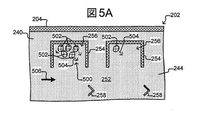
図4に示されるとおり、処理400は、ステップ402で、微少流体デバイス200の保持用囲い256中にクローン細胞のコロニーの生産物を培養し得る。図5A(図6、7A、8~11Bおよび12~14のように、図2A~2Cの微少流体デバイス200の流れ領域240の一部の水平断面図を示す)および図5Bは、例を説明する。
As shown in FIG. 4,
図5Aおよび5Bに示されるとおり、生体細胞502は、囲い256の少なくともいくつかの開口に隣接したチャネル252中に流れる液状媒体244によって、1以上の保持用囲い256中に培養され得る。流れ506中の栄養物は、保持用囲い256中の生物学的アクティビティを培養し得る。流れ506はまた、囲い256からの廃棄物の除去を提供し得る。類似の流れは、デバイス200の他の囲い256の開口に隣接した他のチャネル(例として図2Cに示される253)中に提供され得る。
As shown in FIGS. 5A and 5B, living
図5Bは、分離領域508および接続領域510を有する囲いを示す。知られているとおり、囲い256の近位開口を通る微少流体チャネル252中の流動性媒体244の流れ506は、囲いの中へおよび/またはその外への媒体244の第2の流れを引き起こし得る。第2の流れから囲い256の分離領域508中の微小物体502を分離するために、遠位開口への近位開口からの隔離囲い256の接続領域510の長さは、チャネル252中の流れ506の速さが最大(Vmax)であるとき、接続領域510の中への第2の流れの最大浸透深さDpよりも大きくてもよい。よって、チャネル252中の流れ506が最大の速さVmaxを超えない限り、流れ506および結果として生じる第2の流れは、チャネル252および接続領域510に限定され得、分離領域508の外にあり続け得る。よって、チャネル252中の流れ506は、分離領域508の外に生物学的な微小物体502(またはいずれの他の微小物体)を引き出さないだろう。よって、分離領域508中の生物学的な微小物体502は、チャネル252中の流れ506とは関係なく、分離領域508中にとどまるだろう。
FIG. 5B shows an enclosure having a
ステップ402で培養することは、細胞の繁殖または各囲い256中の細胞502が各囲い256中の細胞502のコロニー500を生産することを容易にし得る。各囲い256は、いずれの1つの囲い256中の細胞502も、いずれの別の囲い256中の細胞502と混合することを十分に妨げるために、他の囲い256のすべてにおける細胞502からその細胞502を分離し得る。また、各保持用囲い256中に生産されるコロニー500は、囲い256中の単一の細胞502を備えて始まり得る。よって、各囲い256中の細胞502のコロニー500は、クローンであり得る。
Culturing in
ステップ402で培養することはまた、アッセイされることになる特定の目的の材料504の生産を容易にし得る。目的の材料504の非限定例は、タンパク質、核酸、炭水化物、脂質、ホルモン、代謝物質またはそのあらゆる組み合わせを含む。目的のタンパク質は、例えば、治療用タンパク質、抗体、成長因子、サイトカイン、がん抗原、ウイルスもしくは他の病原体に関連した感染性抗原、分泌タンパク質または生体細胞によって生産され、および/または、放出される他のあらゆるタンパク質などのタンパク質を含んでもよい。よって、例えば、細胞502は、細胞を生産するタンパク質(例として抗体)であり得、目的の材料504は、特定のタンパク質(例として特定の抗体)であり得る。例えば、目的の材料は、免疫グロブリンG(IgG)アイソタイプの抗体であり得る。目的の材料504以外の生体材料を含む材料は、囲い中にあり得る。例えば、細胞502は、目的の材料504に加えて、他の材料を生産し得る。
Culturing in
いくつかの態様において、ステップ402で培養することは、多数の種類の培養することを伴い得る。例えば、媒体244の第1の種類の第1の流れ506は、各囲い256中の細胞502の成長および分裂を培養し得る。その後、媒体244の第2の種類の第2の流れは、各囲い256中の細胞502によって目的の材料504の生産を培養し得る。
In some embodiments, culturing in
処理400は、図4のステップ404で、保持用囲い256の中へ捕捉物体602を移動させ得る(図6を参照)。捕捉物体602は、例えば、微小粒子、マイクロビーズ(例としてポリスチレンビーズ、Luminex(商標)ビーズまたは同種のもの)、磁性ビーズ、マイクロロッド、マイクロワイヤ、量子ドットまたは同種のものなどの無生物の微小物体であり得る。いくつかの場合において、捕捉物体602は、無生物の微小物体および生物学的な微小物体(例としてリポソームで被覆されたマイクロビーズ、リポソームで被覆された磁性ビーズ、細胞に付着されているマイクロビーズまたは同種のもの)の組み合わせであり得る。さらに他の場合において、捕捉物体602は、細胞、リポソーム、脂質ナノラフトまたは同種のものなどの生物学的な微小物体であり得る。また、各捕捉物体602は、特定の目的の生体材料に特異的に結合する特定の結合物質を含み得る。捕捉物体602は、例として、少なくとも約1mMまたはより強い(例として約100μM、10μM、1μM、500nM、400nM、300nM、200nM、100nM、75nM、50nM、25nM、15nM、10nM、5nM、2.5nM、1nMまたはより強い)、特定の目的の生体材料のための親和性(例としてKd)を有する特定の結合物質を含み得る。かかる親和性は、特定の目的の生体材料(または保持用囲いおよび/または微少流体デバイス中に存在する、少なくともいずれの他の目的の生体材料)以外の他のいずれの材料のための親和性よりも、例えば2倍、3倍、4倍、5倍、10倍またはそれ以上の倍数で、より強くあり得る。例えば、目的の材料504が特定の抗体である場合、捕捉物体602は、保持用囲い256および/または微少流体デバイス中のいずれの他の材料のためよりも、その特定の抗体のためにより大きな親和性を有する結合物質(例として抗原またはそのエピトープ)を含み得る。言及したとおり、目的の材料504は、IgG抗体であり得、その場合において捕捉物体602の結合物質は、IgG抗体を結合するためのIgG Fcレセプタを伴う材料を含み得る。図6~8は、ステップ404の例を説明する。
図6に示されるとおり、捕捉物体602は、囲い256への開口に隣接したチャネル252中に配置され得る。図7A~7Bおよび8に示されるとおり、個別の捕捉物体602は、特定の囲い256の中へ移動させられ得る。
As shown in FIG. 6, the
捕捉物体602は、入口208を通じて微少流体デバイス200の中へ導入され得(図2A~2Cを参照)、図6に示されるとおり、流れ506とともにチャネル252へ移動させられ得る。図7Aは、光トラップ702を発生させる例を説明し、それにおいて、図3Aおよび3BのDEPデバイス300のように構成されたセレクタ222(図2A~2Cを参照)は、個別の捕捉物体602を捕らえ得る。その後DEPデバイス300は、囲い256の1つの中へ光トラップ702を移動させ得、それは、捕らえられた捕捉物体602を囲い256の中へ移動させる。光トラップ702は、図3Aおよび3Bに関して上述のとおり、微少流体デバイス300の流れ領域240の内表面242上へ投影される光のパターン322を変化させることの一部であり得る。捕捉物体602が囲い256中にある場合、捕捉物体602に対応する光トラップ602は、図8に説明されるとおりオフにされ得る。ディテクタ224は、流れ領域240の全部または一部の画像を捕捉し得、それらの画像は、特定の囲い256の中へ個別の捕捉物体602を捕らえ、移動させることを容易にし得る。よって、特定の数(例として1以上)の捕捉物体602は、同定され、選択され、および、各囲い256の中へ移動させられ得る。
The
図7Aに示されるとおり、媒体244の流れ506は、流れ506がチャネル252の中へ捕捉物体602をもたらす後に、停留され得る。流れ506を停留させることは、個別の捕捉物体602を同定し、選択することを容易にし得る。図8に示されるとおり、捕捉物体602が囲い256中にある場合、流れ506は、再開され得る。代わりに、流れ506を停留させるよりもむしろ、流れ506は、ディテクタ224がチャネル252中の個別の捕捉物体602を検知し、セレクタ222がそれを捕らえ、移動させるのに十分に遅い速さまで、単に遅くされ得る。さらに別の代わりとして、流れ506は、ディテクタ224が個別の捕捉物体602を検知し、セレクタ222がそれを捕らえ、移動させるのに十分に遅い、一般に安定した比率で始められ、維持され得る。かかる場合において、流れ506は、図6、7Aおよび8の各々において一般に一定の速さで維持され得る。
As shown in FIG. 7A, the
図7Aは、トラップ702ごとに1つの捕捉物体602を捕らえることを説明するが、トラップ702は、1つより多い捕捉物体602を捕捉し得る。同様に、図8は、各囲い256中の1つの捕捉物体602を示すが、1つより多い捕捉物体602が、囲い256の中へ移動させられ得る。それとは関係なく、特定の、知られている数の捕捉物体602(例として1以上)は、各囲い256の中へ移動させられ得る。一般的に言えば、処理100および400中のステップの順序は重大ではなく、よって、例えば、ステップ404および402の順序は、逆にされ得る。例えば、捕捉物体602は、第1の細胞502が囲い256中に置かれる前でさえ、保持用囲い256中に置かれ得る。かかる場合において、処理は、保持用囲い256の中へ生物学的アクティビティ(例として生体細胞502)を移動させるためのステップを含み得る。
Although FIG. 7A illustrates capturing one
図7Bは、捕捉物体602を能動的に選択し、保持用囲い256の中へ移動させることの代わりとして、保持用囲い256の中へ捕捉物体602を積み入れることに対するより受動的なアプローチを説明する。図7Bの微少流体デバイスは、保持用囲い256のちょうど外側のチャネル252中に位置づけられるデフレクタ754があることを除き、図7Aに示される微少流体デバイスに類似する。ごく一部の捕捉物体602は、捕捉物体602が微少流体デバイスの中へ、および、チャネル252を通じて流されるとき、チャネル252の周辺へ運ばれるだろう。チャネル252の周辺で流れ506によって運ばれる捕捉物体602は、デフレクタ754によって捕まえられ得、保持用囲い256の中へそらされ得る。デフレクタの使用は、特定の捕捉物体602を選択し、特定の保持用囲い256の中へ移動させるために光トラップを使用するアプローチとは異なり、図7Bに示されるとおり、正確にどの捕捉物体602が、または、いくつの捕捉物体602が各保持用囲い256の中へ移動させられるかの綿密な制御を可能にしない。しかしながら、デフレクタ754の使用は、同時に多数の保持用囲いの積み入れを容易にし得る。
FIG. 7B illustrates a more passive approach to loading
図7Bに示されるデフレクタ754は、障壁254または本明細書中に検討されるいずれの他の好適な材料と同じ材料で作られ得る。加えて、デフレクタ754は、障壁254(示されるとおり)から分離し得、または、付着され得る。デフレクタ754は、チャネル252の高さいっぱいに延び得、または、それは、チャネルを通じて上に部分的にのみ延び得、それによって、保持用囲い256の中へそらされる捕捉物体602(または細胞などの生物学的な微小物体)の数を潜在的に低減させる。また、デフレクタ754は、チャネル252の表面242上に焦点を合わせた光によって生じる仮想の障壁であり得る。かかる光は、電極(例としてDEP電極)を起動させ得、それによって、上述のとおり光トラップのやり方において捕捉物体602(または細胞502)への障壁を作り出す。かかる仮想のデフレクタは、捕捉物体602のしきい数が保持用囲い256の中へそらされた場合にオフにされ得るため、有利であり得る。例えば、ヒトのユーザまたはコントローラ232は、いずれの特定の保持用囲い256の中へそらされる捕捉物体602の数をも監視し得、その後、捕捉物体602のしきい数に達すると、電極を活性化している(および、それによってデフレクタを発生させている)光をオフにし得る。
The
チャネル252中の媒体244の流れ506の高い比率は、捕捉物体602を能動的に選択し、保持用囲い256の中へ移動させることのさらに別の代わりとして、保持用囲い256に入る第2の流れの浸透深さDpを増加させるために使用され得る。よって、捕捉物体602は、チャネル252中の媒体244の流れ506の比率を増加させることによって、保持用囲い256の中へ押し込まれ得る。いくつかの態様において、微少流体デバイスは、約3,000から6,000平方ミクロンまたは約2,500から4,000平方ミクロンの断面エリアを有するチャネル252を有する。かかる微少流体デバイス中の保持用囲い256の中へ捕捉物体602を積み入れるために好適な媒体244の流れ506の比率は、例として約0.05~5.0μE/秒(例として約0.1~2.0、0.2~1.5、0.5~1.0μE/秒または約1.0~2.0μE/秒)であり得る。
A high proportion of the
図4のステップ406で囲い256中の細胞502を培養することは、その間に細胞502が目的の材料504を繁殖させ、および/または、生産するために継続し得る期間、継続し得る。図9に説明されるとおり、特定の囲い256中の捕捉物体602は、その囲い256中の細胞502によって生産される目的の材料504を結合し得る。よって図9は、囲い256中の捕捉物体602に結合される目的の材料504を示す。
Culturing the
いくつかの態様において、図4のアッセイ処理400の目的は、最小のしきい率で目的の材料504を生産する、囲い256中の細胞コロニー500を同定するためであり得る。かかる態様において、いずれの1つの囲い256中の1以上の捕捉物体602も結合し得る目的の材料504の量、および、ステップ406の期間は、最小のしきい率以上で目的の材料504を生産するコロニー500が、囲い256中の捕捉物体(単数または複数)602を浸すのに十分な目的の材料504などを生産する量および期間であり得る。
In some embodiments, the purpose of
他の態様において、アッセイ処理400の目的は、各囲い256中で生産される目的の材料504の数量を決定するためであり得る。かかる態様において、囲い256中の1以上の捕捉物体602が結合し得る目的の材料504の量、および、ステップ406の期間は、可能な限り最も高い比率で目的の材料504を生産するコロニー500でさえ、囲い256中の捕捉物体(単数または複数)602などを浸さない量および期間であり得る。
In another aspect, the purpose of
処理400は、図5~14中のページの右の保持用囲い256中に説明されるとおり、保持用囲い256中の単一の生物学的物体502(例として単一の生体細胞)をアッセイし得る。保持用囲い256中の単一の生物学的物体502をアッセイする能力は、例えば、生体細胞のアッセイのための既知の技術が、例えば単一の細胞によって生産される材料をアッセイするのに十分な感度がないと信じられているため意義深い。
処理400は、図4に説明されるとおり、上述のステップ406の期間の後に、ステップ408で、特定の囲い256から個別の捕捉物体602を選択し得、囲い256から選択された捕捉物体602を除去し得る。いくつかの態様において、除去される捕捉物体602は、チャネル252の中へ移動させられ得る。図10および11Aは、ステップ408の例を示す。
図10に示されるとおり、個別の捕捉物体602は、上述のとおり光トラップ702のようにあり得る光トラップ1002を備えて、特定の囲い256中に選択され得る。図11Aに示されるとおり、捕らえられた捕捉物体602は、囲い256から除去され得、囲い256の開口に隣接したチャネル252中に置かれ得る。例えば、光トラップ1002は、囲い256からチャネル252の中へ移動させられ得る。また図11Aに示されるとおり、捕捉物体602は、検討されるとおり、流れ領域240中の媒体244の流れ506に対して適所に捕捉物体602を保ち得るチャネル252中の、停留部258へ移動させられ得る。除去された捕捉物体602が停留部258へ移動させられる場合、光トラップ1002は、オフにされ得る。代わりに、光トラップ1002は、例えば媒体244の流れ506に対して適所に、除去された捕捉物体602を保ち続けられ得る。かかる場合において、停留部258は、デバイス200の流れ領域240中に含まれる必要はない。それとは関係なく、流れ506は、ステップ408の間、遅くされ得、または停留さえされ得る。さらに別の代わりとして、捕捉物体602は、チャネル252の中へ移動させられた場合、後続の分析のためのデバイスから搬出され得る。捕捉物体を搬出するための好適な方法は、例えば、2014年10月22日に出願されたU.S.特許出願第14/520,150号中に開示されており、参照によりその全体の内容が本明細書に組み込まれる。捕捉物体602は、同じ保持用囲い256から捕捉物体の群を備えて、または、複数の保持用囲い256からの捕捉物体602を含む群を備えて、個別に搬出され得る。後者の場合において、捕捉物体602は、それらの識別およびそこから除去される保持用囲い256との関連を容易にする識別子(identifier)を有し得る。例えば、Luminex(商標)ビーズは、捕捉物体602として使用され得、それによって、特定の保持用囲い256からの捕捉物体602を、他の保持用囲い256からの捕捉物体から区別することが可能となる。
As shown in FIG. 10, the
図11Bに示されるとおり、チャネル252中の停留部258へ捕捉物体602を移動させることの代わりは、アッセイ領域1156へ捕捉物体602を移動させることを伴う。アッセイ領域1156は、保持用囲い256に隣接し得、それによって、捕捉物体602を移動させるために必要とされる時間を低減させ、捕捉物体602と、そこから除去される保持用囲い256との間の相互関係の維持を容易にする。アッセイ領域は、障壁254または本明細書において検討されるいずれの他の好適な材料とも同じ材料で作られ得る障壁1154によって、規定され得る。アッセイ領域1156は、保持用囲い256と同じ大きさおよび形状を有するものとして示されるが、より小さくてもよく、および/または、異なる形状を有してもよい。例えば、アッセイ領域1156は、より小さくてもよく、および、分離領域を含んでも含まなくてもよい。よって、例えば、アッセイ領域1156は、分離領域を実質的に欠き得る(例としてアッセイ領域の体積の50%未満が、チャネル252中の媒体244の流れ506の第2の流れから分離され得る)。ある態様において、分離領域の実質的な欠如は、捕捉物体602からアッセイ材料を洗い流すことを容易にし得る(さらに以下で検討される)。
As shown in FIG. 11B, instead of moving the
保持用囲い256の外に捕捉物体602を移動させるために光トラップ1002を使用することの代わりとして、磁性捕捉物体602は、磁石などの磁力を使用して囲い256の外に強いられ得る。図11Cに示されるとおり、微少流体デバイス1100は、開口から保持用囲い256へチャネル252を超えて位置づけられるアッセイ領域1156を含み得る。磁性捕捉物体602を保持用囲い256の外に、および、アッセイ領域1156の中へ移動させるために、磁力は、磁性捕捉物体602がアッセイ領域1156の中へ引かれるか、または押されるように、微少流体デバイスへ与えられ得る。かかるステップの間、チャネル252中の媒体244の流れ506は、遅くされ得、または、停留され得る。
Instead of using the
図10および11A~11C中に、1つの捕捉物体602が各囲い256から除去されながら示されるが、上で検討されたとおり、1つより多い捕捉物体602が、ステップ404で囲い256へ置かれ得、かかる場合において、1つより多い捕捉物体602は、それに応じてステップ408で囲い256から除去され得る。
In FIGS. 10 and 11A-11C, one
図4に再び戻ると、ステップ410で、処理400は、ステップ408で囲い256から除去される各捕捉物体602と、そこから捕捉物体602が除去される囲い256との間の相互関係を維持し得る。例えば、コントローラ232は、ディテクタ224によって提供される画像から捕捉物体602および囲い256の位置を同定し得、その跡を付け得、および、コントローラ232は、チャネル252中の個別の除去された捕捉物体602と、そこから各捕捉物体602が取られた囲い256との間の相互関係をメモリ234中に保存し得る。表1は、メモリ234中に保存され得るデジタル表の例であり、捕捉物体602と、そこから捕捉物体602が除去された囲い256とのチャネル252中の位置を互いに関係づける。表1の例において、停留部Aとして同定される停留部258での捕捉物体602は、3の番号を付けられた囲い256から取られた。同様に、停留部258Bでの捕捉物体602は、1の番号を付けられた囲い256から取られ、および、停留部258Cでの捕捉物体602は、2の番号を付けられた囲い256から取られた。対応する表は、アッセイ領域1156中の捕捉物体602、および、そこから捕捉物体602が除去された保持用囲い256の位置に関するデータを保存するために使用され得る。同様に、分析のために微少流体デバイスから搬出される捕捉物体602のための表は、特定の捕捉物体602、および、そこから捕捉物体602が除去された保持用囲い256と関連した、識別子に関するデータを保存するために使用され得る。

図4のステップ412で、処理400は、チャネル252中の除去された捕捉物体602に結合される目的の材料504を評価し得る。例えば、処理400は、ステップ412で、細胞のコロニー500または囲い256中の単一の細胞502によって生産される目的の材料504の数量および/または質を決定することによって、目的の材料504を評価し得る。別の例として、処理400は、ステップ412で、細胞502のコロニー500または囲い256中の単一の細胞502によって生産される材料504の種類を評価し得る。さらに別の例として、処理400は、ステップ412で、細胞502のコロニー500または囲い256中の単一の細胞502によって生産される材料504の活性を評価し得る。ステップ408で、捕捉物体602に結合される目的の材料504が、そこから捕捉物体602が除去された囲い256中の生物学的アクティビティによって生産されたため、ステップ412で、除去された捕捉物体602に結合される目的の材料504の評価は、それから囲い256中の生物学的アクティビティが評価され得る情報を提供し得る。図12~14は、ステップ412の例を説明する。
In
図12に示されるとおり、ステップ412で、アッセイ材料1202は、チャネル252を通じて流され得る。アッセイ材料1202は、除去された捕捉物体602上の目的の材料504に結合すること、および、別個の、検知可能なふるまいを提示することの両方をし得る。例えば、アッセイ材料1202は、目的の生体材料504に特異的に(例として、捕捉物体602によって結合される位置と異なる目的の材料504上の位置で)結合する結合物質を含むラベルを収容し得る。目的の生体材料504が抗体である場合において、ラベルは、Fcレセプタを含み得、捕捉物体602は、抗体によって結合される抗原を含み得、その逆もまた同様である。図12~14に示される例において、アッセイ材料1202は、図14に示されるとおり、捕捉物体上で目的の材料504に結合し、エネルギー1402を放射するラベルを含み得る。よって、例えば、アッセイ材料1202は、目的の生体材料504に特異的に結合し、発色団に連結する結合物質を含み得る。他の態様において、アッセイ材料1202は、例として、目的の生体材料504に特異的に結合する、ルシフェラーゼが連結した(luciferase-linked)結合物質を含み得る。後者の場合において、アッセイ材料1202は、加えて、適切なルシフェラーゼ基板(例としてルシフェリン基板)を含み得る。よって、アッセイ材料1202は、蛍光または冷光を発し得る。それとは関係なく、アッセイ材料1202は、アッセイ材料1202が実質的に、除去された捕捉物体602に結合される目的の材料504のすべてに結合するのに充分な数量において、および、それに充分な時間の間、除去された捕捉物体602に提供され得る。
As shown in FIG. 12, in
図13に示されるとおり、その後、除去された捕捉物体602の1つに結合されなかったアッセイ材料1202は、チャネル252の外にフラッシュされ得る。例えば、アッセイ材料1202の流れ506は、チャネル252中の媒体の流れ244(またはいずれの洗浄材)が続き得、それは、除去された捕捉物体602上の目的の材料504に結合しなかったアッセイ材料1202のすべてを、実質的にチャネル252の外に洗い出し得る。図13に示されるとおり、チャネル252中の捕捉物体602は、いま、捕捉物体602に結合される目的の材料504、および、目的の材料504に結合されるアッセイ材料1202を含み得る。
As shown in FIG. 13,
図14に示されるとおり、アッセイ材料1202は、ディテクタ224によって検知され得るエネルギー1402を放射し得る。いくつかの態様において、アッセイ材料1202は、エネルギー1402の放射を誘発するために、(例として光もしくは他の放射、または、(チャネル252を通じて流され得る)化学的触媒もしくは基板を備えて)刺激されることを必要としてもよい。除去された捕捉物体602から放射されるエネルギー1402のレベル、輝度、色(例として特異的な波長)または同種のものなどの検知可能な特徴は、除去された捕捉物体602に結合されるアッセイ材料1202の量に対応し得、それは、除去された捕捉物体602に結合される生体材料の量に対応し得、これが順に、目的の材料504を生産するためにそこから捕捉物体602が除去された囲い256中の細胞コロニー500の性能に対応し得る。いくつかの態様において、アッセイ材料は、繰り返し刺激されてもよい。例えば、光刺激は、各刺激に続いて、結果として生じるいずれの放射をも検知しながら周期的に与えられ得る。代わりに、化学的触媒または基板(例としてルシフェリン)は、チャネル252の中へ流され得、その際、検知可能な放射が検知され得る。チャネル252は、適切な期間の後、化学的触媒を取り除き得、処理はその後に、繰り返され得る。
As shown in FIG. 14,
ステップ412は、ステップ408で囲い256から除去される各個別の捕捉物体602から放射する、エネルギー1402のレベルを検知することを含み得る。例えば、ディテクタ224は、チャネル252中に除去された各捕捉物体602からのエネルギー1402のレベルを検知し得る。ステップ410に関して言及したとおり、除去された各捕捉物体602と、そこから捕捉物体602が取られた囲い256との間の相互関係は、例えば、上の表1などのデジタル表において維持され得る。ステップ412の部分として検知される、除去された各捕捉物体602から放射されるエネルギー1402のレベルは、かかる表中に保存され得、それは、下の表2に示されるとおり、検知されるエネルギーレベルのための列を含み得る。

図4のステップ414で、処理400は、所望の細胞コロニー500を備える保持用囲い256を同定し得、および、少なくともデフォルト設定によって、それはまた所望でない細胞コロニー500を備える保持用囲い256をも同定し得る。例えば、ステップ414で、処理400は、どの除去された捕捉物体602がしきいレベルよりも上(または下)のエネルギーを放射したかを決定し得、および、それらの除去された捕捉物体602の、互いに関係づけられた保持用囲い256は、所望の細胞コロニー500を有するものとして同定され得る。しきいレベル未満で1402を放射する、除去された捕捉物体602に互いに関係する保持用囲い256は、所望でない細胞コロニー500を収容するものとして同定され得る。
In step 414 of FIG. 4,
ステップ414で、所望のおよび所望でない細胞コロニー500を備えて単に保持用囲い256を同定するよりもむしろ、処理400は、他の態様において、除去された捕捉物体602に対応する各保持用囲い256中の細胞コロニー500を定量的に見積り得る。例えば、処理400は、除去された各捕捉物体602によって放射されるエネルギー1402を検知および定量化し得、それによって、目的の材料504を生産するために、そこから除去される捕捉物体602が取られた保持用囲い256の各々中の、細胞コロニー500の性能を見積もり得る。
Rather than simply identifying the
いくつかの態様において、ディテクタ224は、画像を捕捉し得、その画像から、ヒトのオペレータまたはコントローラ232は、そこから除去される捕捉物体602の1つが取られた保持用囲い256の各々中の細胞502の数を数えるかまたは近似し得る。かかる態様において、処理400は、細胞502ごとの比率として、目的の材料504を生産するための特定の保持用囲い256中の細胞502のコロニー500の性能を決定するために、ステップ412の部分として検知される放射されたエネルギー1402のレベル(または色、輝度または同種のものなどの他の特徴)および保持用囲い256中の細胞の数を利用し得る。その後、処理400は、ステップ414で所望の細胞コロニー500を備える保持用囲い256を同定するために、前述のものを利用し得る。
In some embodiments, the
それとは関係なく、ステップ414の後、所望の細胞コロニー500は、それらの夫々の保持用囲い256からデバイス200中の他の位置へ、または、さらなる処理、分析、試験または使用のための他のデバイス(示されず)へ除去され得る。例えば、所望の細胞コロニー500は、2014年10月22日に出願されたU.S.特許出願第14/520,150号に示されるとおり、選択され得、および、移動させられ得、それは、本出願と同じ譲受人に譲渡される。
Regardless, after step 414, the desired
図4は例であり、処理400の多くの変動が考慮される。例えば、処理400は、ステップ412で、捕捉物体602が保持用囲い256中にある間、生物学的アクティビティを評価し得る。よって、処理400は、いくらかの変動において、ステップ408、410を含む必要がなく、または、ステップ408、410は、スキップされ得る。別の例として、ステップ402~414のすべては、図4に示される順序において実施される必要がない。
FIG. 4 is an example, and many variations of the
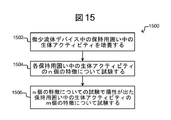
図15は、微少流体デバイスの保持用囲い中の生物学的アクティビティのアッセイのための処理1500のさらに別の例を説明する。処理1500は、より一般の処理100のより狭い例であり得、それにおいて、図15の処理1500中の生物学的アクティビティは、特徴の第1数nについて試験され、その後特徴の第2数mについて試験され、ここでnおよびm(それらは同じ数かまたは異なる数であり得る)は、各々1以上のいずれの整数値でもあり得る。説明および検討をし易いように、処理1500は、図2A~2Cの微少流体デバイス200に関して以下で検討され、それにおいてセレクタ222は、図3Aおよび3Bに説明されるとおり構成され得る。しかしながら、処理1500は、そのように限定されず、よって他の微少流体デバイス上で実施され得る。
FIG. 15 illustrates yet another example of
図15に示されるとおり、ステップ1502で、処理1502は、微少流体デバイス中の保持用囲い中の生物学的アクティビティを培養し得る。ステップ1502は、図1のステップ104または図4のステップ402のように実施され得る。例えば、一般に図4の上の検討に従って、生物学的アクティビティは、図2A~2Cの微少流体デバイス200の各囲い256中の1以上の生体細胞による、1以上の異なる目的の材料の生産であり得る。ステップ1502の培養することは、処理1500の実行全体を通じて一続きに実施され得、よって、ステップ1502の培養することは、ステップ1504および/または1506の間、継続され得る。
As shown in FIG. 15, at step 1502, treatment 1502 may culture biological activity in the retention enclosure in the microfluidic device. Step 1502 may be performed as in
ステップ1504で、処理1500は、その各々が異なる特徴であり得るn個の特徴について各保持用囲い256中の生物学的アクティビティを試験し得る。n個の特徴は、上述のとおり図1および4の処理100または処理400中に試験されるいずれの特徴または生物学的アクティビティの他の特徴でもあり得る。この仕方において多数の特徴を評価することは、抗体の特徴づけを含む多くの適用のために所望される。よって、例えば、多数の評価は、以下に続くいずれをも助け得る:配座特異的な抗体を同定すること(例として異なる特徴が、特定の抗原の異なる立体配座に結合するための抗体アナライトの能力であり得る);抗体アナライトのエピトープマッピング(例として異なる特徴が、抗原の様々な遺伝的または化学的に変更された形態に結合するための能力であり得る);抗体アナライトの種間交差反応性を評価すること(例として異なる特徴が、ヒト、マウス、ラットおよび/または他の動物(例として実験動物)などの、異なる種から生じる相同抗原に結合するための、抗体アナライトの能力であり得る);および、抗体アナライトのIgGアイソタイピング(例として異なる特徴が、IgG1、IgG2、IgG3、IgG4、IgM、IgA、IgEおよび/またはIgDに結合するための能力であり得る)。抗体のエピトープマッピングのための化学的に組み換えられた抗原の発生は、例えば、Dhungana et al. (2009), Methods Mol. Biol. 524:119-34に記載されている。多数の特徴を評価することから利益を得られ得る他の適用は、例えば、細胞の健康、がん、感染(例としてウイルス、バクテリア、寄生虫など)、炎症、治療用剤への反応および同種のものと互いに関係づけるマーカーを検知することを含む。
At step 1504, processing 1500 may test the biological activity in each
ステップ1504で、処理1500は、各囲い256中の生物学的アクティビティがn個の特徴のいずれか1以上を有するかを示唆する試験を実施し得る。よって、いくつかの態様において、囲い256中の生物学的アクティビティは、生物学的アクティビティがn個の特徴のうち1つしか有さない場合、ステップ1504にて試験で陽性が出ると思われる。他の態様において、囲い256中の生物学的アクティビティは、生物学的アクティビティがn個の特徴のうちすべてを有する場合にのみ、ステップ1504にて試験で陽性が出ると思われ、さらに他の態様において、囲い256中の生物学的アクティビティは、生物学的アクティビティがn個の特徴のうちq個の数を有する場合、ステップ1504にて試験で陽性が出ると思われ、ここでqは、1より大きくnより小さい。
At step 1504,
ステップ1506で、処理1500は、異なるm個の特徴についてステップ1504にて試験で陽性が出た各保持用囲い256中の生物学的アクティビティを試験し得、その各々は、異なる特徴であり得る。ステップ1506で試験されたm個の特徴は、ステップ1504で試験されたn個の特徴とは異なり得る。m個の特徴は、上述のとおり図1および4の処理100または処理400中に試験された特徴または生物学的アクティビティの他の特徴のいずれをも含み得る。代わりに、ステップ1506で試験されたm個の特徴と、ステップ1504で試験されたn個の特徴との間に重複があり得る。
At
ステップ1506はステップ1504を実施するための上述のいずれの仕方においても実施され得る。例えばステップ1506で、処理1500は、ステップ1504にて試験で陽性が出た囲い256中の生物学的アクティビティが、いずれの1以上のm個の特徴をも有するかどうかを示唆する試験を実施し得る。よって、いくつかの態様において、囲い256中の生物学的アクティビティは、生物学的アクティビティがm個の特徴のうち1つしか有さない場合、ステップ1506にて試験で陽性が出たと思われる。他の態様において、囲い256中の生物学的アクティビティは、生物学的アクティビティがm個の特徴のうちすべてを有する場合にのみ、ステップ1506にて試験で陽性が出ると思われ、さらに他の態様において、囲い256中の生物学的アクティビティは、生物学的アクティビティがm個の特徴のうちp個の数を有する場合、ステップ1506にて試験で陽性が出ると思われ、ここでpは、1より大きくmより小さい。
図16および17は、図15のステップ1504および/またはステップ1506を実施し得る処理1600、1700の例を説明する。
16 and 17 illustrate examples of
まず図16を見ると、処理1602は、ステップ1602で、微少流体デバイス200の各囲い256の中の数xの捕捉物体を移動させ得る。例えば、数xは、1とnを含めたそれらの間であり得る。図18(図2A~2Cの微少流体デバイス200の流れ領域240の一部の水平断面図を示す)は、例を説明する。示されるとおり、x個の捕捉物体1812は、囲い256の中へ移動させられ得る。捕捉物体1812は、連続して、並行してまたは連続および並行の組み合わせにおいて、囲い256の中へ移動させられ得る。さらに示されるように、生物学的な微小物体1802は、囲い256中にあり得る。3つの生物学的な微小物体1802が囲い256中に示されるが、1、2または3以上があり得る。生物学的な微小物体1802は、例えば、1以上の目的の材料を生産する生体細胞であり得る。
First, looking at FIG. 16,
各捕捉物体1812は、特定の目的の生体材料に特異的に結合する結合物質を含み得る。例えば、結合物質は、少なくとも約1mMまたはより強い(例として約100μM、10μM、1μM、500nM、400nM、300nM、200nM、100nM、75nM、50nM、25nM、15nM、10nM、5nM、2.5nM、1nMまたはより強い)特定の目的の生体材料のための親和性(例としてKd)を有し得る。かかる親和性は、特定の目的の生体材料(または保持用囲いおよび/または微少流体デバイス中に存在する、少なくともいずれの他の目的の生体材料)以外の他のいずれの材料のための親和性よりも、例えば、2倍、3倍、4倍、5倍、10倍またはそれ以上の倍数で、より強くあり得る。よって、例えば各捕捉物体1812は、図15のステップ1502によって囲い256中で培養されている生物学的アクティビティによって存在し、または生産されてもよい、異なる目的の材料のためのかかる優勢な親和性を有する異なる結合物質を含み得る。さもなければ、捕捉物体1812は、捕捉物体602に一般に類似し得、捕捉物体1812は、捕捉物体602を選択し、移動させるための上述のいずれの仕方においても選択され得、移動させられ得る。
Each trapped
ステップ1604で、処理は、ステップ1602で囲い256の中へ移動させられたx個の捕捉物体の各々によって捕捉された生体材料を評価し得る。ステップ1604は同様であり得、図1のステップ110または図4のステップ414に関する上述のいずれのやり方においても実施され得る。
At step 1604, the process may evaluate the biomaterial captured by each of the x capture objects moved into the
図16に説明されるとおり、処理1600は、いずれの回数でも任意に繰り返され得る。数xは、ステップ1602の繰り返される各性能のために同じかまたは異なり得る。よって、例えば処理1600は、n個の捕捉物体(その各々が異なる結合物質を有し得る)が、ステップ1602で囲いの中へ移動させられ、ステップ1604で評価されるまでずっと、1以上の回数で実施され得る。よって、処理1600を1以上の回数で実施することは、ステップ1602を1以上の回数で実施し、ステップ1604を1以上の回数で実施することによってn個の捕捉物体によって捕捉された生体材料を評価することすることにより、各囲いの中へn個の捕捉物体の合計を移動させるという結果になり得る。例えば、ステップ1602の繰り返される各性能で、xの値は、1以上n-1以下のいずれの数でもあり得、処理1600は、ステップ1602の繰り返される各性能でのxの値が少なくともnまで合計されるまでずっと繰り返され得る。
As described in FIG. 16,
言及したとおり、図15のステップ1504および/またはステップ1506は、図16の処理1600によって実施され得る。ステップ1506が実施される場合、数mは、図16の上の検討においてnに代用される。
As mentioned, step 1504 and / or
いま図17を参照すると、ステップ1702で、処理1700は、微少流体デバイス200の囲い256の中へy-材料捕捉物体を移動させ得、そこで各y-材料捕捉物体は、y個の異なる結合物質を含み得る。数yは、2以上n以下であり得る。図19(図2A~2Cの微少流体デバイス200の流れ領域240の一部の水平断面図を示す)は、例を説明する。示されるとおり、y-材料捕捉物体1912は、1以上の生物学的な微小物体1802を備えて囲い256の中へ移動させられ得、それは上述のとおりであり得る。
Now referring to FIG. 17, in
y-材料捕捉物体1912は、y個の異なる結合物質を含み得、それらの各々は、特定の目的の生体材料に特異的に結合する。例えば、各結合物質は、少なくとも約1mMまたはより強い(例として約100μM、10μM、1μM、500nM、400nM、300nM、200nM、100nM、75nM、50nM、25nM、15nM、10nM、5nM、2.5nM、1nMまたはより強い)特定の目的の生体材料のための親和性(例としてKd)を有し得る。かかる親和性は、特定の目的の生体材料(または保持用囲いおよび/または微少流体デバイス中に存在する、少なくともいずれの他の目的の生体材料)以外の他のいずれの材料のための親和性よりも、例えば、2倍、3倍、4倍、5倍、10倍またはそれ以上の倍数で、より強くあり得る。さもなければ、y-材料捕捉物体1912は、捕捉物体602に一般に類似し得、捕捉物体1912は、捕捉物体602を選択し、移動させるための上述のいずれの仕方においても選択され得、移動させられ得る。
The y-
ステップ1704で、処理1700は、各囲い256中のy-材料捕捉物体1912によって捕捉された生体材料を評価し得る。ステップ1704は同様であり得、図1のステップ110または図4のステップ414に関する上述のいずれのやり方においても実施され得る。
At
図17に説明されるとおり、処理1700は、いずれの回数でも任意に繰り返され得る。数yは、ステップ1702の繰り返される各性能のために同じかまたは異なり得る。よって、例えば処理1700は、ステップ1702の各性能でのyの値が少なくともnに加わるまでずっと、1以上の回数で実施され得る。例えば、ステップ1702の繰り返される各性能で、yの値は、2以上n-2以下のいずれの数でもあり得、処理1700は、ステップ1702の繰り返される各性能でのyの値が少なくともnまで合計されるまでずっと繰り返され得る。
As described in FIG. 17,
言及したとおり、図15のステップ1504および/またはステップ1506は、図17の処理1700によって実施され得る。ステップ1506が実施される場合、数mは、図17の上の検討においてnに代用される。
As mentioned, step 1504 and / or
図20A~20Cは、微少流体デバイス中に使用され得る保持用囲いの形状上の変動および本発明の方法を示す。各場合において、保持用囲いは、生物学的アクティビティ(例として1以上の生体細胞)を収容するために使用され得る領域、および、捕捉物体602を収容するために使用され得る別の領域を含む。例えば、図20Aにおいて、保持用囲い256は、生体細胞502を収容し得る左部および捕捉物体602を収容し得る右部を含む、分離領域508を有する。保持用囲い256は、チャネル252への近位開口および分離領域508への遠位開口を有する、接続領域510をさらに含む。図20B中に類似する配列があるが、保持用囲い256は、(接続領域510の深さの観点から)より長く、より浅い。図20Cにおいて、保持用囲い256は、捕捉物体602を収容し得る右部から、生体細胞502を収容し得る左部を分離する薄い壁を含む。薄い壁は漏れやすく、したがって、保持用囲い256の左部と右部との間の目的の生体材料の拡散を可能にし、それによって生物学的アクティビティ(例として生体細胞502)が捕捉物体602に接触することを妨げる。
20A-20C show the shape variations of the retaining enclosure and the methods of the invention that can be used in microfluidic devices. In each case, the retention enclosure comprises an area that can be used to contain biological activity (eg, one or more living cells) and another area that can be used to contain the
本発明の具体的な態様および適用が本明細書中に記載されているが、これらの態様および適用は、例示する目的しかなく、多くの変動があり得る。 Specific embodiments and applications of the invention are described herein, but these embodiments and applications are for illustration purposes only and may vary in many ways.
Claims (30)
前記保持用囲いが、第1部分、第2部分、及び当該保持用囲いの前記第2部分から当該保持用囲いの前記第1部分を分離する壁を備え、
前記第1部分が前記流れ領域に開いており、
前記第2部分が前記流れ領域に開いており、
前記壁が、前記保持用囲いの前記第1部分に配置された生体細胞が、前記保持用囲いの前記第2部分に配置された捕捉物体と接触することを妨げ、かつ、前記保持用囲いの前記第1部分と前記保持用囲いの前記第2部分の間で拡散が生じることを可能にするよう構成されている、
微少流体デバイス。 A microfluidic device comprising a flow region and a housing with an enclosure having a holding enclosure open in the flow region.
The holding enclosure comprises a wall that separates the first portion, the second portion, and the first portion of the holding enclosure from the second portion of the holding enclosure.
The first portion is open to the flow area and
The second part is open to the flow area and
The wall prevents the living cells placed in the first portion of the holding enclosure from coming into contact with the capture object placed in the second portion of the holding enclosure, and the retaining enclosure. It is configured to allow diffusion to occur between the first portion and the second portion of the holding enclosure.
Micro fluid device.
基部と、
前記基部上に配置された微少流体構造物と、
を備え、
前記微少流体構造物と前記基部が、前記流れ領域と前記保持用囲いを規定し、
前記保持用囲いが前記基部上に配置されている、
請求項1に記載の微少流体デバイス。 The housing is
At the base,
The microfluidic structure placed on the base and
Equipped with
The microfluidic structure and the base define the flow region and the holding enclosure.
The holding enclosure is located on the base,
The microfluidic device according to claim 1.
前記接続領域が、前記チャネルへの近位開口と、前記単離領域への遠位開口を有し、
前記保持用囲いの前記単離領域が、微少流体デバイスの非掃引領域である、
請求項3に記載の微少流体デバイス。 The holding enclosure comprises an isolated area and a connecting area.
The connecting region has a proximal opening to the channel and a distal opening to the isolated region.
The isolated region of the retaining enclosure is the non-swept region of the microfluidic device.
The microfluidic device according to claim 3.
前記流れ領域及び前記電極起動基板が、前記第1電極及び前記第2電極の間に配置され、
前記光源からの光のパターンを変化させることが、前記流れ領域の前記内表面上の前記DEP電極の変化するパターンを選択的に起動及び起動停止させる、請求項12に記載の微少流体デバイス。 Further equipped with a first electrode, a second electrode, an electrode starting board, a power supply, and a light source,
The flow region and the electrode activation substrate are arranged between the first electrode and the second electrode.
12. The microfluidic device of claim 12, wherein changing the pattern of light from the light source selectively activates and stops the changing pattern of the DEP electrode on the inner surface of the flow region.
前記生物学的アクティビティが、目的の生体材料の産生を含み、
前記微少流体デバイスの前記保持用囲いの前記第1部分で、前記目的の生体材料を産生する一又は複数の生体細胞を培養することと、
前記微少流体デバイスの前記保持用囲いの前記第2部分に、一又は複数の捕捉微小物体であって、それぞれが前記目的の生体材料に特異的に結合する結合物質を備える一又は複数の捕捉微小物体を導入することと、
前記保持用囲いの前記第1部分の前記一又は複数の生体細胞によって産生された前記目的の生体材料を、前記保持用囲いの前記第2部分の前記一又は複数の捕捉微小物体に結合させることと、
前記捕捉微小物体に結合された前記目的の生体材料を評価することと、
を含む、生物学的アクティビティをアッセイする処理。 A process of assaying biological activity in the microfluidic device according to any one of claims 1 to 15.
The biological activity involves the production of the desired biomaterial.
Culturing one or more living cells that produce the biomaterial of interest in the first portion of the holding enclosure of the microfluidic device.
In the second portion of the holding enclosure of the microfluidic device, one or more capture microobjects, each comprising a binding substance that specifically binds to the biomaterial of interest. Introducing an object and
Binding the biomaterial of interest produced by the one or more living cells in the first part of the holding enclosure to the one or more captive microobjects in the second part of the holding enclosure. When,
To evaluate the biomaterial of interest bound to the captured micro-object,
Processing to assay biological activity, including.
前記微少流体デバイス内に配置されたアッセイ領域に移動させることを含み、
前記アッセイ領域が、停留部及びチャンバーから選択される少なくとも一つであり、
前記停留部が、前記微少流体デバイスのチャネル内に位置し、
前記停留部が、前記チャネル内の媒体の流れに対して、微小物体を所定の場所に保持するよう、構成されており、
前記チャンバーが、前記微少流体デバイス内に配置されている、
請求項18に記載の処理。 Removing the one or more captured micro-objects removes the one or more captured micro-objects.
Including moving to an assay region located within the microfluidic device.
The assay region is at least one selected from the anchorage and chamber.
The stop is located within the channel of the microfluidic device.
The anchor is configured to hold a small object in place against the flow of media in the channel.
The chamber is located within the microfluidic device.
The process according to claim 18.
前記一又は複数の捕捉微小物体を前記微少流体デバイス内のチャネルに移動させることと、
前記微少流体デバイスから前記一又は複数の捕捉微小物体を搬出することと、
を含む、請求項18に記載の処理。 Removing the one or more captured micro-objects
Moving the one or more captured microobjects to a channel within the microfluidic device,
Carrying out the one or more captured micro-objects from the micro-fluid device
18. The process of claim 18.
(i)少なくとも一つの前記捕捉微小物体を取り囲む光パターンを前記微少流体デバイスの内表面上に投影することにより、前記保持用囲いの前記第2部分の前記捕捉微小物体の少なくとも一つを捕らえる光トラップを生成し、前記光トラップを前記保持用囲いの前記第2部分から前記微少流体デバイスのチャネルに移動させること;
(ii)前記少なくとも一つの捕捉微小物体に隣接する前記微少流体デバイスの内表面上に光パターンを投影することにより、前記保持用囲いの前記第2部分の前記捕捉微小物体の少なくとも一つに隣接する光誘起DEP電極を起動させ、前記光パターンを前記保持用囲いの前記第2部分から前記微少流体デバイスの前記チャネルに移動させることによって、前記起動されたDEP電極が、前記少なくとも一つの捕捉微小物体を前記チャネルに遠ざけること;及び
(iii)前記一又は複数の捕捉微小物体が磁気を帯びており、前記微少流体デバイスに磁場を与えること;
からなる群から選択される一つである、請求項18から20のいずれか1項に記載の処理。 Removing the one or more captured micro-objects
(I) Light that captures at least one of the captured micro-objects in the second portion of the holding enclosure by projecting a light pattern surrounding the at least one captured micro-object onto the inner surface of the micro-fluid device. Creating a trap and moving the optical trap from the second portion of the holding enclosure to the channel of the microfluidic device;
(Ii) Adjacent to at least one of the captured micro-objects in the second portion of the holding enclosure by projecting a light pattern onto the inner surface of the micro-fluid device adjacent to the at least one captured micro-object. By activating the photoinduced DEP electrode to move the optical pattern from the second portion of the holding enclosure to the channel of the microfluidic device, the activated DEP electrode is subjected to the at least one capture micro. Moving an object away from the channel; and (iii) the one or more captured microobjects being magnetic and applying a magnetic field to the microfluidic device;
The process according to any one of claims 18 to 20, which is one selected from the group consisting of.
前記一又は複数の捕捉微小物体に結合された前記目的の生体材料の種類を決定すること;
前記一又は複数の捕捉微小物体に結合された前記目的の生体材料の活性を決定すること;及び
前記一又は複数の捕捉微小物体に結合された前記目的の生体材料の量を決定すること;
からなる群から選択される一又は複数である、請求項16から21のいずれか1項に記載の処理。 Evaluating the biomaterial of interest bound to the trapped micro-object can be
Determining the type of biomaterial of interest bound to the one or more capture micro-objects;
Determining the activity of the biomaterial of interest bound to the one or more capture micro-objects; and determining the amount of the biomaterial of interest bound to the one or more capture micro-objects;
The process according to any one of claims 16 to 21, which is one or more selected from the group consisting of.
前記一又は複数の捕捉微小物体に結合された前記目的の生体材料に、検知可能な放射をすることができるアッセイ材料を結合することと、
前記一又は複数の捕捉微小物体と前記アッセイ材料から生じた放射との間の関連を検知することと、
を含む、請求項22に記載の処理。 The above decision can be made
Binding an assay material capable of detectable radiation to the biomaterial of interest bound to the one or more capture micro-objects.
To detect the association between the one or more captured micro-objects and the radiation generated from the assay material.
22. The process of claim 22.
(i)前記複数の捕捉微小物体のそれぞれが、前記複数における他の捕捉微小物体の結合物質により結合される抗体アイソタイプとは異なる抗体アイソタイプに結合する結合物質を備える;
(ii)前記複数の捕捉微小物体のそれぞれが、前記抗体により認識される抗原のエピトープに対応する結合物質を備える;及び
(iii)前記複数の捕捉微小物体の一つの捕捉微小物体が、前記抗体により認識される抗原又は前記抗原のエピトープに対応する結合物質を備え、前記複数の捕捉微小物体の他の捕捉微小物体が、それぞれ、異なる種由来の前記抗原の相同体又は前記抗原の相同体のエピトープに対応する結合物質を備える;
からなる群から選択される一つである、
請求項27に記載の処理。 The target biomaterial is an antibody.
(I) Each of the plurality of captured micro-objects comprises a binding substance that binds to an antibody isotype different from the antibody isotype bound by the binding substance of the other captured micro-objects in the plurality of objects;
(Iii) Each of the plurality of captured micro-objects comprises a binding substance corresponding to an epitope of an antigen recognized by the antibody; and (iii) one of the plurality of captured micro-objects is the antibody. The other captive micro-objects of the plurality of capture micro-objects are the homologues of the antigen or homologues of the antigen, respectively, which are provided with a binding substance corresponding to the antigen recognized by the above-mentioned antigen or an epitope of the antigen. Equipped with a binding substance corresponding to the epitope;
It is one selected from the group consisting of
The process of claim 27.
前記一又は複数の捕捉微小物体が、異なるn種の捕捉微小物体を備え、前記捕捉微小物体のそれぞれの種が、前記異なるn種の目的の生体材料の一つに特異的に結合する結合物質を備え、
前記一又は複数の生体細胞によって産生された前記異なるn種の目的の生体材料を、前記異なるn種の捕捉微小物体に結合させることを含み、
前記捕捉微小物体に結合した前記目的の生体材料を評価することが、前記異なるn種の目的の生体材料と、前記異なるn種の捕捉微小物体と、の間の結合を検出することを含む、
請求項16から28のいずれか1項に記載の処理。 The one or more cells produce n different biomaterials of interest,
The one or more captured micro-objects comprises different n types of captured micro-objects, and each species of the captured micro-objects specifically binds to one of the different n species of biomaterial of interest. Equipped with
It comprises binding the different n species of biomaterial of interest produced by the one or more biological cells to the different n species of captured microobjects.
Evaluating the biomaterial of interest bound to the captured micro-object comprises detecting the bond between the different n species of biomaterial of interest and the different n species of captured micro-object.
The process according to any one of claims 16 to 28.
前記複数の保持用囲いのそれぞれに一又は複数の生体細胞があり、
前記複数の保持用囲いのそれぞれの前記一又は複数の生体細胞を評価する、
請求項16から29のいずれか1項に記載の処理。 The microfluidic device comprises a plurality of holding enclosures.
Each of the plurality of retention enclosures has one or more living cells.
Evaluate the one or more living cells in each of the plurality of retention enclosures.
The process according to any one of claims 16 to 29.
Priority Applications (1)
| Application Number | Priority Date | Filing Date | Title |
|---|---|---|---|
| JP2022075037A JP2022093581A (en) | 2013-10-22 | 2022-04-28 | Micro-fluidic devices for assaying biological activity |
Applications Claiming Priority (10)
| Application Number | Priority Date | Filing Date | Title |
|---|---|---|---|
| US201361996962P | 2013-10-22 | 2013-10-22 | |
| US201361996969P | 2013-10-22 | 2013-10-22 | |
| US201361996973P | 2013-10-22 | 2013-10-22 | |
| US61/996,969 | 2013-10-22 | ||
| US61/996,962 | 2013-10-22 | ||
| US61/996,973 | 2013-10-22 | ||
| US201462058658P | 2014-10-01 | 2014-10-01 | |
| US62/058,658 | 2014-10-01 | ||
| US14/520,510 | 2014-10-22 | ||
| US14/520,510 US9617145B2 (en) | 2013-10-22 | 2014-10-22 | Exporting a selected group of micro-objects from a micro-fluidic device |
Related Parent Applications (1)
| Application Number | Title | Priority Date | Filing Date |
|---|---|---|---|
| JP2019001195A Division JP6709299B2 (en) | 2013-10-22 | 2019-01-08 | Microfluidic device for assaying biological activity |
Related Child Applications (1)
| Application Number | Title | Priority Date | Filing Date |
|---|---|---|---|
| JP2022075037A Division JP2022093581A (en) | 2013-10-22 | 2022-04-28 | Micro-fluidic devices for assaying biological activity |
Publications (3)
| Publication Number | Publication Date |
|---|---|
| JP2020122804A JP2020122804A (en) | 2020-08-13 |
| JP2020122804A5 JP2020122804A5 (en) | 2021-11-25 |
| JP7068384B2 true JP7068384B2 (en) | 2022-05-16 |
Family
ID=72614748
Family Applications (2)
| Application Number | Title | Priority Date | Filing Date |
|---|---|---|---|
| JP2020089306A Active JP7068384B2 (en) | 2013-10-22 | 2020-05-22 | Microfluidic device for assaying biological activity |
| JP2022075037A Pending JP2022093581A (en) | 2013-10-22 | 2022-04-28 | Micro-fluidic devices for assaying biological activity |
Family Applications After (1)
| Application Number | Title | Priority Date | Filing Date |
|---|---|---|---|
| JP2022075037A Pending JP2022093581A (en) | 2013-10-22 | 2022-04-28 | Micro-fluidic devices for assaying biological activity |
Country Status (2)
| Country | Link |
|---|---|
| JP (2) | JP7068384B2 (en) |
| DK (1) | DK3060912T3 (en) |
Citations (8)
| Publication number | Priority date | Publication date | Assignee | Title |
|---|---|---|---|---|
| US20060154361A1 (en) | 2002-08-27 | 2006-07-13 | Wikswo John P | Bioreactors with substance injection capacity |
| JP2008136475A (en) | 2006-11-10 | 2008-06-19 | Univ Waseda | Cell catching device and cell catching method using the same |
| US20080274493A1 (en) | 2000-11-16 | 2008-11-06 | California Institute Of Technology | Apparatus and methods for conducting assays and high throughput screening |
| US20090170186A1 (en) | 2004-04-12 | 2009-07-02 | Ming Chiang Wu | Optoelectronic tweezers for microparticle and cell manipulation |
| WO2009130694A2 (en) | 2008-04-21 | 2009-10-29 | Cell Kinetics Ltd. | Flat cell carriers with cell traps |
| JP2010060567A (en) | 2004-12-03 | 2010-03-18 | Orion Diagnostica Oy | Particle based binding assay |
| US20110262906A1 (en) | 2008-10-10 | 2011-10-27 | Dublin City University | Microfluidic multiplexed cellular and molecular analysis device and method |
| WO2012037030A2 (en) | 2010-09-14 | 2012-03-22 | The Regents Of The University Of California | Method and device for isolating cells from heterogeneous solution using microfluidic trapping vortices |
-
2014
- 2014-10-22 DK DK14854978.5T patent/DK3060912T3/en active
-
2020
- 2020-05-22 JP JP2020089306A patent/JP7068384B2/en active Active
-
2022
- 2022-04-28 JP JP2022075037A patent/JP2022093581A/en active Pending
Patent Citations (8)
| Publication number | Priority date | Publication date | Assignee | Title |
|---|---|---|---|---|
| US20080274493A1 (en) | 2000-11-16 | 2008-11-06 | California Institute Of Technology | Apparatus and methods for conducting assays and high throughput screening |
| US20060154361A1 (en) | 2002-08-27 | 2006-07-13 | Wikswo John P | Bioreactors with substance injection capacity |
| US20090170186A1 (en) | 2004-04-12 | 2009-07-02 | Ming Chiang Wu | Optoelectronic tweezers for microparticle and cell manipulation |
| JP2010060567A (en) | 2004-12-03 | 2010-03-18 | Orion Diagnostica Oy | Particle based binding assay |
| JP2008136475A (en) | 2006-11-10 | 2008-06-19 | Univ Waseda | Cell catching device and cell catching method using the same |
| WO2009130694A2 (en) | 2008-04-21 | 2009-10-29 | Cell Kinetics Ltd. | Flat cell carriers with cell traps |
| US20110262906A1 (en) | 2008-10-10 | 2011-10-27 | Dublin City University | Microfluidic multiplexed cellular and molecular analysis device and method |
| WO2012037030A2 (en) | 2010-09-14 | 2012-03-22 | The Regents Of The University Of California | Method and device for isolating cells from heterogeneous solution using microfluidic trapping vortices |
Non-Patent Citations (1)
| Title |
|---|
| Jian Chen et al,Microfluidic approaches for cancer cell detection, characterization, and separation,Lab on a Chip,2012年,12,1753-1767 |
Also Published As
| Publication number | Publication date |
|---|---|
| JP2020122804A (en) | 2020-08-13 |
| JP2022093581A (en) | 2022-06-23 |
| DK3060912T3 (en) | 2020-09-28 |
Similar Documents
| Publication | Publication Date | Title |
|---|---|---|
| JP6709299B2 (en) | Microfluidic device for assaying biological activity | |
| US20220388003A1 (en) | Micro-Fluidic Devices for Assaying Biological Activity | |
| JP7333365B2 (en) | Microfluidic device with isolation enclosure and method for testing biological microobjects therewith | |
| CN109142717B (en) | Microfluidic device for determining biological activity | |
| EP3060926B1 (en) | Exporting a selected group of micro-objects from a micro-fluidic device | |
| CN105658781B (en) | Microfluidic device with isolation rail and the micro- mesh calibration method of biology is tested with it | |
| JP7068384B2 (en) | Microfluidic device for assaying biological activity |
Legal Events
| Date | Code | Title | Description |
|---|---|---|---|
| A521 | Request for written amendment filed |
Free format text: JAPANESE INTERMEDIATE CODE: A523 Effective date: 20200522 |
|
| A621 | Written request for application examination |
Free format text: JAPANESE INTERMEDIATE CODE: A621 Effective date: 20200522 |
|
| A977 | Report on retrieval |
Free format text: JAPANESE INTERMEDIATE CODE: A971007 Effective date: 20210426 |
|
| A131 | Notification of reasons for refusal |
Free format text: JAPANESE INTERMEDIATE CODE: A131 Effective date: 20210510 |
|
| A601 | Written request for extension of time |
Free format text: JAPANESE INTERMEDIATE CODE: A601 Effective date: 20210802 |
|
| A524 | Written submission of copy of amendment under article 19 pct |
Free format text: JAPANESE INTERMEDIATE CODE: A524 Effective date: 20211008 |
|
| TRDD | Decision of grant or rejection written | ||
| A01 | Written decision to grant a patent or to grant a registration (utility model) |
Free format text: JAPANESE INTERMEDIATE CODE: A01 Effective date: 20220302 |
|
| A601 | Written request for extension of time |
Free format text: JAPANESE INTERMEDIATE CODE: A601 Effective date: 20220329 |
|
| A61 | First payment of annual fees (during grant procedure) |
Free format text: JAPANESE INTERMEDIATE CODE: A61 Effective date: 20220428 |
|
| R150 | Certificate of patent or registration of utility model |
Ref document number: 7068384 Country of ref document: JP Free format text: JAPANESE INTERMEDIATE CODE: R150 |