JP7068232B2 - Electrical junction box - Google Patents
Electrical junction box Download PDFInfo
- Publication number
- JP7068232B2 JP7068232B2 JP2019108141A JP2019108141A JP7068232B2 JP 7068232 B2 JP7068232 B2 JP 7068232B2 JP 2019108141 A JP2019108141 A JP 2019108141A JP 2019108141 A JP2019108141 A JP 2019108141A JP 7068232 B2 JP7068232 B2 JP 7068232B2
- Authority
- JP
- Japan
- Prior art keywords
- recess
- hole
- fastening member
- mounting surface
- protrusion
- Prior art date
- Legal status (The legal status is an assumption and is not a legal conclusion. Google has not performed a legal analysis and makes no representation as to the accuracy of the status listed.)
- Active
Links
Images

Classifications
-
- H—ELECTRICITY
- H05—ELECTRIC TECHNIQUES NOT OTHERWISE PROVIDED FOR
- H05K—PRINTED CIRCUITS; CASINGS OR CONSTRUCTIONAL DETAILS OF ELECTRIC APPARATUS; MANUFACTURE OF ASSEMBLAGES OF ELECTRICAL COMPONENTS
- H05K5/00—Casings, cabinets or drawers for electric apparatus
- H05K5/0026—Casings, cabinets or drawers for electric apparatus provided with connectors and printed circuit boards [PCB], e.g. automotive electronic control units
- H05K5/0047—Casings, cabinets or drawers for electric apparatus provided with connectors and printed circuit boards [PCB], e.g. automotive electronic control units having a two-part housing enclosing a PCB
- H05K5/0052—Casings, cabinets or drawers for electric apparatus provided with connectors and printed circuit boards [PCB], e.g. automotive electronic control units having a two-part housing enclosing a PCB characterized by joining features of the housing parts
-
- B—PERFORMING OPERATIONS; TRANSPORTING
- B60—VEHICLES IN GENERAL
- B60R—VEHICLES, VEHICLE FITTINGS, OR VEHICLE PARTS, NOT OTHERWISE PROVIDED FOR
- B60R16/00—Electric or fluid circuits specially adapted for vehicles and not otherwise provided for; Arrangement of elements of electric or fluid circuits specially adapted for vehicles and not otherwise provided for
- B60R16/02—Electric or fluid circuits specially adapted for vehicles and not otherwise provided for; Arrangement of elements of electric or fluid circuits specially adapted for vehicles and not otherwise provided for electric constitutive elements
- B60R16/023—Electric or fluid circuits specially adapted for vehicles and not otherwise provided for; Arrangement of elements of electric or fluid circuits specially adapted for vehicles and not otherwise provided for electric constitutive elements for transmission of signals between vehicle parts or subsystems
- B60R16/0238—Electrical distribution centers
-
- H—ELECTRICITY
- H02—GENERATION; CONVERSION OR DISTRIBUTION OF ELECTRIC POWER
- H02G—INSTALLATION OF ELECTRIC CABLES OR LINES, OR OF COMBINED OPTICAL AND ELECTRIC CABLES OR LINES
- H02G3/00—Installations of electric cables or lines or protective tubing therefor in or on buildings, equivalent structures or vehicles
- H02G3/02—Details
- H02G3/08—Distribution boxes; Connection or junction boxes
- H02G3/081—Bases, casings or covers
-
- B—PERFORMING OPERATIONS; TRANSPORTING
- B60—VEHICLES IN GENERAL
- B60R—VEHICLES, VEHICLE FITTINGS, OR VEHICLE PARTS, NOT OTHERWISE PROVIDED FOR
- B60R16/00—Electric or fluid circuits specially adapted for vehicles and not otherwise provided for; Arrangement of elements of electric or fluid circuits specially adapted for vehicles and not otherwise provided for
- B60R16/02—Electric or fluid circuits specially adapted for vehicles and not otherwise provided for; Arrangement of elements of electric or fluid circuits specially adapted for vehicles and not otherwise provided for electric constitutive elements
-
- H—ELECTRICITY
- H05—ELECTRIC TECHNIQUES NOT OTHERWISE PROVIDED FOR
- H05K—PRINTED CIRCUITS; CASINGS OR CONSTRUCTIONAL DETAILS OF ELECTRIC APPARATUS; MANUFACTURE OF ASSEMBLAGES OF ELECTRICAL COMPONENTS
- H05K5/00—Casings, cabinets or drawers for electric apparatus
- H05K5/0026—Casings, cabinets or drawers for electric apparatus provided with connectors and printed circuit boards [PCB], e.g. automotive electronic control units
- H05K5/0073—Casings, cabinets or drawers for electric apparatus provided with connectors and printed circuit boards [PCB], e.g. automotive electronic control units having specific features for mounting the housing on an external structure
-
- H—ELECTRICITY
- H02—GENERATION; CONVERSION OR DISTRIBUTION OF ELECTRIC POWER
- H02G—INSTALLATION OF ELECTRIC CABLES OR LINES, OR OF COMBINED OPTICAL AND ELECTRIC CABLES OR LINES
- H02G3/00—Installations of electric cables or lines or protective tubing therefor in or on buildings, equivalent structures or vehicles
- H02G3/02—Details
- H02G3/08—Distribution boxes; Connection or junction boxes
- H02G3/10—Distribution boxes; Connection or junction boxes for surface mounting on a wall
Description
本発明は、電気接続箱に関する。 The present invention relates to an electrical junction box.
従来から、車両に搭載され、リレー等の電子部品を収容するリレーボックス等の電気接続箱が広く知られている(例えば、特許文献1を参照)。電気接続箱の筐体には、通常、電気接続箱を車両の一部に固定するためのブラケットが一体に設けられている。ブラケットには、スタッドボルト等の締結部材を挿通させる貫通孔が形成され且つ車両の一部に取り付けられる取付面が設けられており、ブラケットは、貫通孔に挿通された締結部材により車両の一部に固定されるようになっている。 Conventionally, an electric connection box such as a relay box mounted on a vehicle and accommodating an electronic component such as a relay is widely known (see, for example, Patent Document 1). The housing of the electrical junction box is usually integrally provided with a bracket for fixing the electrical junction box to a part of the vehicle. The bracket is provided with a through hole through which a fastening member such as a stud bolt is inserted and a mounting surface is provided to be attached to a part of the vehicle. The bracket is a part of the vehicle by the fastening member inserted through the through hole. It is designed to be fixed to.
一般に、電気接続箱の筐体及びブラケットは、樹脂成形体である。このため、樹脂成形時に発生し得るヒケを抑制するため、ブラケット(取付部)の取付面には、複数の凹部が設けられる場合が多い。このことに起因して、電気接続箱の車両への取り付け作業時、スタッドボルト等の締結部材が誤って、貫通孔の縁部の周囲に位置する凹部に挿入され、これにより、電気接続箱の車両への取り付けが困難になる場合が発生し得る。 Generally, the housing and bracket of the electrical junction box are resin molded bodies. Therefore, in order to suppress sink marks that may occur during resin molding, a plurality of recesses are often provided on the mounting surface of the bracket (mounting portion). Due to this, when the electrical junction box is attached to the vehicle, a fastening member such as a stud bolt is mistakenly inserted into a recess located around the edge of the through hole, thereby causing the electrical junction box to be inserted. It may be difficult to install it on the vehicle.
本発明は、上述した事情に鑑みてなされたものであり、その目的は、取付部の取付面における貫通孔の縁部の周囲に位置する凹部に誤って締結部材が挿入されることを抑制可能な電気接続箱を提供することにある。 The present invention has been made in view of the above circumstances, and an object thereof is to prevent the fastening member from being erroneously inserted into a recess located around the edge of the through hole on the mounting surface of the mounting portion. To provide a good electrical junction box.
前述した目的を達成するために、本発明に係る電気接続箱は、下記[1]を特徴としている。
[1]
少なくとも1つの電子部品を収容する筐体と、前記筐体に設けられる取付部であって、締結部材を挿通させる貫通孔が形成され被取付対象に取り付けられる取付面を有し、前記締結部材により前記被取付対象に固定される取付部と、を備えた電気接続箱において、
前記取付面における前記貫通孔の縁部の周囲には、複数の凹部が形成され、
前記複数の凹部の少なくとも1つには、前記締結部材の前記凹部内への進入を防止するための進入防止部であって、進入防止部がなければ前記締結部材が前記凹部内へ進入可能となる進入防止部が設けられ、
前記取付面には、前記貫通孔の縁部から前記貫通孔の径方向の外側に放射状に延びる複数の放射状リブが形成され、
隣接する前記放射状リブの間に、前記進入防止部が設けられた前記凹部が位置し、
隣接する前記放射状リブの間に位置する前記凹部に設けられた前記進入防止部は、前記凹部における前記径方向の外側の側壁から前記凹部の内部に向けて前記径方向の内側に延びる突起部である、
電気接続箱であること。
In order to achieve the above-mentioned object, the electric connection box according to the present invention is characterized by the following [1].
[1]
It has a housing that accommodates at least one electronic component, and a mounting portion that is provided in the housing and has a through hole through which a fastening member is inserted and is mounted on the object to be mounted. In an electrical junction box provided with a mounting portion fixed to the mounted object.
A plurality of recesses are formed around the edge of the through hole on the mounting surface.
At least one of the plurality of recesses is an entry prevention portion for preventing the fastening member from entering the recess, and if there is no entry prevention portion, the fastening member can enter the recess. Is provided with an entry prevention part
A plurality of radial ribs extending radially outward of the through hole from the edge of the through hole are formed on the mounting surface.
The recess provided with the intrusion prevention portion is located between the adjacent radial ribs.
The intrusion prevention portion provided in the recess located between the adjacent radial ribs is a protrusion extending inward in the radial direction from the outer side wall in the radial direction of the recess toward the inside of the recess. be,
Must be an electrical junction box .
上記[1]の構成の電気接続箱によれば、取付部の取付面における貫通孔の縁部の周囲に位置する複数の凹部の少なくとも1つには、締結部材の凹部内への進入を防止するための進入防止部が設けられる。従って、進入防止部の存在により、締結部材が誤って貫通孔の縁部の周囲に位置する凹部に挿入されること抑制され得る。 According to the electrical connection box having the configuration of [1] above, at least one of the plurality of recesses located around the edge of the through hole on the mounting surface of the mounting portion prevents the fastening member from entering the recess. An entry prevention unit is provided to prevent the entry. Therefore, the presence of the entry prevention portion can prevent the fastening member from being erroneously inserted into a recess located around the edge of the through hole.
更に、上記[1]の構成の電気接続箱によれば、貫通孔の縁部から放射状に延びる複数の放射状リブのうち隣接する放射状リブの間に位置する凹部に進入防止部が設けられる。このため、貫通孔の縁部の周囲に位置する凹部に進入防止部を容易に設けることができる。 Further, according to the electrical connection box having the configuration of [ 1 ] above, an intrusion prevention portion is provided in a recess located between adjacent radial ribs among a plurality of radial ribs extending radially from the edge of the through hole. Therefore, an intrusion prevention portion can be easily provided in the recess located around the edge portion of the through hole.
更に、上記[1]の構成の電気接続箱によれば、隣接する放射状リブの間に位置する凹部では、凹部の径方向外側に位置する側壁における凹部の周方向の長さは、凹部の径方向内側に位置する側壁における凹部の周方向の長さより長くなる。このため、凹部における径方向外側の側壁から凹部の内部に向けて径方向内側に延びる突起部を設けることにより、凹部における径方向内側の側壁から凹部の内部に向けて径方向外側に延びる突起部を設ける態様と比べて、突起部を設けるスペースを確保し易くなる。この結果、進入防止部を、隣接する放射状リブの間に位置する凹部に、より一層容易に設けることができる。 Further, according to the electrical junction box having the configuration of [ 1 ] above, in the recess located between the adjacent radial ribs, the circumferential length of the recess in the side wall located on the radial outer side of the recess is the diameter of the recess. It is longer than the circumferential length of the recess in the side wall located on the inner side of the direction. Therefore, by providing a protrusion extending radially inward from the radial outer side wall of the recess toward the inside of the recess, the protrusion extending radially outward from the radially inner side wall of the recess toward the inside of the recess. It becomes easier to secure a space for providing the protrusion as compared with the mode of providing the protrusion. As a result, the entry prevention portion can be more easily provided in the recess located between the adjacent radial ribs.
このように、本発明によれば、取付部の取付面における貫通孔の縁部の周囲に位置する凹部に誤って締結部材が挿入されることを抑制可能な電気接続箱を提供できる。 As described above, according to the present invention, it is possible to provide an electric junction box capable of suppressing erroneous insertion of a fastening member into a recess located around an edge portion of a through hole on a mounting surface of a mounting portion.
以上、本発明について簡潔に説明した。更に、以下に説明される発明を実施するための形態を添付の図面を参照して通読することにより、本発明の詳細は更に明確化されるであろう。 The present invention has been briefly described above. Further, the details of the present invention will be further clarified by reading through the embodiments described below with reference to the accompanying drawings.
<実施形態>
以下、図面を参照しながら、図1に示す本発明の実施形態に係る電気接続箱1について説明する。電気接続箱1は、典型的には、車両に搭載され、リレー等の電子部品を収容するリレーボックスである。以下、説明の便宜上、図1における「上下方向」、「上」及び「下」を、それぞれ、「上下方向」、「上」及び「下」と定義する。電気接続箱1の車両搭載時において、「上下方向」は、車両の上下方向に対応している。
<Embodiment>
Hereinafter, the
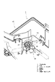
図1に示すように、樹脂製の電気接続箱1は、複数の電子部品(図示省略)を収容する筐体10を備える。筐体10は、本例では、複数の電子部品を収容する略矩形枠状のフレーム11と、フレーム11の上側開口を塞ぐようにフレーム11の上方に組み付けられる上カバー12と、フレーム11の下側開口を塞ぐようにフレーム11の下方に組み付けられる下カバー13と、から構成される。電気接続箱1を構成する上記3つの部品は全て、樹脂成形体である。
As shown in FIG. 1, the resin
筐体10には、電気接続箱1を車両の一部(被取付対象)に固定するための複数のブラケット20が、筐体10の複数箇所からそれぞれ外側に延びるように、筐体10に一体に設けられている。従って、ブラケット20も、樹脂成形体である。
In the
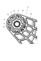
各ブラケット20の先端部の下面は、車両の一部に取り付けられる取付面22として機能する。本例では、図2に示すように、取付面22は、円形状の平面である。円形状の取付面22の中心位置には、取付面22と直交する方向に延びる貫通孔21が形成されている。この貫通孔21に、車両の一部に固定されたスタッドボルト及びウエルドボルト等(以下、「締結部材30」と呼ぶ)(図3参照)が取付面22側から挿通され、締結部材30に係合されるナット等を利用して各ブラケット20を車両の一部に締結固定することで、電気接続箱1が車両の一部に固定される。
The lower surface of the tip of each
上述したように、ブラケット20は、樹脂成形体である。このため、樹脂成形時に発生し得るヒケを抑制するため、ブラケット20の取付面22には、複数の凹部26が設けられている。本例では、図2に示すように、取付面22に、貫通孔21の縁部に位置する円形の内側リブ23と、ブラケット20の先端部の円弧状部分と共通の円弧部分を有する円形の外側リブ24と、内側リブ23及び外側リブ24の間において、貫通孔21の径方向に放射状に延びる複数の放射状リブ25と、が形成されている。この結果、取付面22には、内側リブ23、外側リブ24、及び、隣接する放射状リブ25により画成される凹部26が、貫通孔21の周方向の複数箇所に形成されている。
As described above, the
なお、本例では、ブラケット20における取付面22以外の下面(取付面22よりもブラケット20の根元側に位置する下面)にも、樹脂成形時に発生し得るヒケを抑制するため、図2に示すように、複数の凹部28が形成されている。
In this example, the lower surface of the
取付面22に設けられた全ての凹部26には、凹部26における径方向の外側の側壁から凹部26の内部に向けて径方向の内側に延びる突起部27が一体で設けられている。本例では、貫通孔21の周方向の長さが比較的長い凹部26には、2つの突起部27が周方向に並ぶように設けられ、貫通孔21の周方向の長さが比較的短い凹部26には、1つの突起部27が設けられている。
All the
この突起部27は、図3に示すように、締結部材30の凹部26内への進入を防止する機能を果たす。即ち、突起部27がなければ締結部材30が凹部26内へ進入可能となるが、突起部27が存在することに起因して、締結部材30が突起部27に干渉することで、締結部材30が凹部26内へ進入できなくなる。
As shown in FIG. 3, the
具体的には、締結部材30としては、図3に示すように、先端部が根元部より小径の段付き円柱状の足部(棒状部)を有するスタッドボルト及びウエルドボルト等、並びに、長手方向全域に亘って一定の径を有する円柱状の足部(棒状部)を有するスタッドボルト及びウエルドボルト等が想定される。このような締結部材30の足部の先端が、突起部27がなければ凹部26内へ進入可能となるが、突起部27が存在することに起因して突起部27に干渉することで、凹部26内へ進入できなくなる。このように、突起部27の存在により、締結部材30が誤って貫通孔21の縁部の周囲に位置する凹部26に挿入されること抑制され得る。
Specifically, as the
<作用・効果>
以上、本発明の実施形態に係る電気接続箱1によれば、ブラケット20の取付面22における貫通孔21の縁部の周囲に位置する複数の凹部26には、締結部材30の凹部26内への進入を防止するための突起部27が設けられている。従って、突起部27の存在により、締結部材30が誤って貫通孔21の縁部の周囲に位置する凹部26に挿入されること抑制され得る。
<Action / effect>
As described above, according to the
更に、本発明の実施形態に係る電気接続箱1によれば、貫通孔21の縁部から放射状に延びる複数の放射状リブ25のうち隣接する放射状リブ25の間に位置する凹部26に突起部27が設けられる。このため、貫通孔21の縁部の周囲に位置する凹部26に突起部27を容易に設けることができる。
Further, according to the
更に、本発明の実施形態に係る電気接続箱1によれば、隣接する放射状リブ25の間に位置する凹部26では、凹部26の径方向外側に位置する側壁における凹部26の周方向の長さは、凹部26の径方向内側に位置する側壁における凹部26の周方向の長さより長くなる。このため、凹部26における径方向外側の側壁から凹部26の内部に向けて径方向内側に延びる突起部27を設けることにより、凹部26における径方向内側の側壁から凹部26の内部に向けて径方向外側に延びる突起部を設ける態様と比べて、突起部27を設けるスペースを確保し易くなる。この結果、突起部27を、隣接する放射状リブ25の間に位置する凹部26に、より一層容易に設けることができる。
Further, according to the
<他の形態>
なお、本発明は上記各実施形態に限定されることはなく、本発明の範囲内において種々の変形例を採用することができる。例えば、本発明は、上述した実施形態に限定されるものではなく、適宜、変形、改良、等が可能である。その他、上述した実施形態における各構成要素の材質、形状、寸法、数、配置箇所、等は本発明を達成できるものであれば任意であり、限定されない。
<Other forms>
The present invention is not limited to each of the above embodiments, and various modifications can be adopted within the scope of the present invention. For example, the present invention is not limited to the above-described embodiment, and can be appropriately modified, improved, and the like. In addition, the material, shape, size, number, arrangement location, etc. of each component in the above-described embodiment are arbitrary as long as the present invention can be achieved, and are not limited.
上記実施形態では、本発明の「進入防止部」として、凹部26における径方向外側の側壁から凹部26の内部に向けて径方向内側に延びる突起部27が設けられている。これに対し、本発明の「進入防止部」として、凹部26における径方向内側の側壁から凹部26の内部に向けて径方向外側に延びる突起部が設けられてもよい。更に、本発明の「進入防止部」として、凹部26の底壁の中央部から凹部26の側壁とは独立して凹部26の内部に向けて突出する島状の突起部が設けられていてもよい。
In the above embodiment, as the "entry prevention portion" of the present invention, a
更に、上記実施形態では、貫通孔21の縁部の周囲に位置する全ての凹部26に突起部27が設けられている。これに対し、貫通孔21の縁部の周囲に位置する複数の凹部26のうち、電気接続箱1の車両への取り付け作業時において締結部材30が特に誤って挿入され易い傾向にある1つ又は複数の凹部26にのみ突起部27が設けられていてもよい。
Further, in the above embodiment, the
更に、上記実施形態では、本発明の「進入防止部」として設けられる突起部27は、樹脂成形体であるブラケット20の一部(即ち、樹脂成形体の一部)となっている。これに対し、本発明の「進入防止部」として、樹脂成形体であるブラケット20の凹部26に後付けされる部品が採用されてもよい。
Further, in the above embodiment, the
ここで、上述した本発明に係る電気接続箱1の実施形態の特徴をそれぞれ以下[1]~[3]に簡潔に纏めて列記する。
[1]
少なくとも1つの電子部品を収容する筐体(10)と、前記筐体(10)に設けられる取付部(20)であって、締結部材(30)を挿通させる貫通孔(21)が形成され被取付対象に取り付けられる取付面(22)を有し、前記締結部材(30)により前記被取付対象に固定される取付部(20)と、を備えた電気接続箱(1)において、
前記取付面(22)における前記貫通孔(21)の縁部の周囲には、複数の凹部(26)が形成され、
前記複数の凹部(26)の少なくとも1つには、前記締結部材(30)の前記凹部(26)内への進入を防止するための進入防止部(27)であって、進入防止部(27)がなければ前記締結部材(30)が前記凹部(26)内へ進入可能となる進入防止部(27)が設けられた、
電気接続箱(1)。
[2]
上記[1]に記載の電気接続箱(1)において、
前記取付面(22)には、前記貫通孔(21)の縁部から前記貫通孔(21)の径方向の外側に放射状に延びる複数の放射状リブ(25)が形成され、
隣接する前記放射状リブ(25)の間に、前記進入防止部(27)が設けられた前記凹部(26)が位置する、
電気接続箱(1)。
[3]
上記[2]に記載の電気接続箱(1)において、
隣接する前記放射状リブ(25)の間に位置する前記凹部(26)に設けられた前記進入防止部(27)は、前記凹部(26)における前記径方向の外側の側壁から前記凹部(26)の内部に向けて前記径方向の内側に延びる突起部(27)である、
電気接続箱(1)。
Here, the features of the embodiment of the
[1]
A housing (10) for accommodating at least one electronic component and a mounting portion (20) provided in the housing (10), through which a through hole (21) through which the fastening member (30) is inserted are formed and covered. In the electrical junction box (1) having a mounting surface (22) to be mounted on the mounting target and having a mounting portion (20) fixed to the mounted target by the fastening member (30).
A plurality of recesses (26) are formed around the edge of the through hole (21) on the mounting surface (22).
At least one of the plurality of recesses (26) is an entry prevention portion (27) for preventing the fastening member (30) from entering the recess (26), and is an entry prevention portion (27). ), An entry prevention portion (27) is provided so that the fastening member (30) can enter the recess (26).
Electrical junction box (1).
[2]
In the electrical connection box (1) described in the above [1],
A plurality of radial ribs (25) extending radially outside the through hole (21) from the edge of the through hole (21) are formed on the mounting surface (22).
The recess (26) provided with the entry prevention portion (27) is located between the adjacent radial ribs (25).
Electrical junction box (1).
[3]
In the electrical connection box (1) described in the above [2],
The intrusion prevention portion (27) provided in the recess (26) located between the adjacent radial ribs (25) is from the radial outer side wall of the recess (26) to the recess (26). A protrusion (27) extending inward in the radial direction toward the inside of the.
Electrical junction box (1).
1 電気接続箱
10 筐体
20 ブラケット(取付部)
21 貫通孔
22 取付面
25 放射状リブ
26 凹部
27 突起部(進入防止部)
1
21 Through
Claims (1)
前記取付面における前記貫通孔の縁部の周囲には、複数の凹部が形成され、
前記複数の凹部の少なくとも1つには、前記締結部材の前記凹部内への進入を防止するための進入防止部であって、進入防止部がなければ前記締結部材が前記凹部内へ進入可能となる進入防止部が設けられ、
前記取付面には、前記貫通孔の縁部から前記貫通孔の径方向の外側に放射状に延びる複数の放射状リブが形成され、
隣接する前記放射状リブの間に、前記進入防止部が設けられた前記凹部が位置し、
隣接する前記放射状リブの間に位置する前記凹部に設けられた前記進入防止部は、前記凹部における前記径方向の外側の側壁から前記凹部の内部に向けて前記径方向の内側に延びる突起部である、
電気接続箱。 It has a housing that accommodates at least one electronic component, and a mounting portion that is provided in the housing and has a through hole through which a fastening member is inserted and is mounted on the object to be mounted. In an electrical junction box provided with a mounting portion fixed to the mounted object.
A plurality of recesses are formed around the edge of the through hole on the mounting surface.
At least one of the plurality of recesses is an entry prevention portion for preventing the fastening member from entering the recess, and if there is no entry prevention portion, the fastening member can enter the recess. Is provided with an entry prevention part
A plurality of radial ribs extending radially outward of the through hole from the edge of the through hole are formed on the mounting surface.
The recess provided with the intrusion prevention portion is located between the adjacent radial ribs.
The intrusion prevention portion provided in the recess located between the adjacent radial ribs is a protrusion extending inward in the radial direction from the outer side wall in the radial direction of the recess toward the inside of the recess. be,
Electrical junction box.
Priority Applications (4)
| Application Number | Priority Date | Filing Date | Title |
|---|---|---|---|
| JP2019108141A JP7068232B2 (en) | 2019-06-10 | 2019-06-10 | Electrical junction box |
| DE102020205624.2A DE102020205624A1 (en) | 2019-06-10 | 2020-05-05 | ELECTRICAL CONNECTION BOX |
| US16/869,054 US11171471B2 (en) | 2019-06-10 | 2020-05-07 | Electric connection box |
| CN202010378575.2A CN112074107B (en) | 2019-06-10 | 2020-05-07 | Electric connection box |
Applications Claiming Priority (1)
| Application Number | Priority Date | Filing Date | Title |
|---|---|---|---|
| JP2019108141A JP7068232B2 (en) | 2019-06-10 | 2019-06-10 | Electrical junction box |
Publications (2)
| Publication Number | Publication Date |
|---|---|
| JP2020202665A JP2020202665A (en) | 2020-12-17 |
| JP7068232B2 true JP7068232B2 (en) | 2022-05-16 |
Family
ID=73459782
Family Applications (1)
| Application Number | Title | Priority Date | Filing Date |
|---|---|---|---|
| JP2019108141A Active JP7068232B2 (en) | 2019-06-10 | 2019-06-10 | Electrical junction box |
Country Status (4)
| Country | Link |
|---|---|
| US (1) | US11171471B2 (en) |
| JP (1) | JP7068232B2 (en) |
| CN (1) | CN112074107B (en) |
| DE (1) | DE102020205624A1 (en) |
Citations (3)
| Publication number | Priority date | Publication date | Assignee | Title |
|---|---|---|---|---|
| JP2005119331A (en) | 2003-10-14 | 2005-05-12 | Yazaki Corp | Electric junction box |
| JP2010233357A (en) | 2009-03-27 | 2010-10-14 | Yazaki Corp | Electrical junction box |
| JP2019068634A (en) | 2017-10-02 | 2019-04-25 | 矢崎総業株式会社 | Electric connection box and wire harness |
Family Cites Families (31)
| Publication number | Priority date | Publication date | Assignee | Title |
|---|---|---|---|---|
| US6310291B1 (en) * | 2000-02-10 | 2001-10-30 | Emett Clough | Utility lock-out apparatus |
| JP2005051880A (en) * | 2003-07-31 | 2005-02-24 | Yazaki Corp | Mounting structure of electrical junction box |
| JP4177215B2 (en) * | 2003-09-11 | 2008-11-05 | 矢崎総業株式会社 | Easy disassembly mounting structure and electric junction box provided with the same |
| JP4651512B2 (en) * | 2005-11-17 | 2011-03-16 | モレックス インコーポレイテド | connector |
| JP4315986B2 (en) * | 2007-02-08 | 2009-08-19 | 富士通株式会社 | Electronic device with light emitting diode |
| JP5067175B2 (en) * | 2008-01-23 | 2012-11-07 | 住友電装株式会社 | In-vehicle electrical junction box |
| JP5292016B2 (en) * | 2008-08-19 | 2013-09-18 | 矢崎総業株式会社 | Protector and wire harness |
| CN201611714U (en) * | 2009-11-16 | 2010-10-20 | 北京铁路信号工厂 | Device for preventing circuit connector from misplug |
| CN201699816U (en) * | 2010-01-20 | 2011-01-05 | 煜森五金电子(深圳)有限公司 | Shell with integrated backing plate and base for set top box |
| JP5707060B2 (en) * | 2010-06-02 | 2015-04-22 | 矢崎総業株式会社 | Plastic molded product |
| JP5630089B2 (en) * | 2010-06-17 | 2014-11-26 | 住友電装株式会社 | Electrical junction box |
| JP5625972B2 (en) * | 2011-02-08 | 2014-11-19 | 住友電装株式会社 | Electrical junction box |
| JP5798777B2 (en) * | 2011-04-04 | 2015-10-21 | 矢崎総業株式会社 | Washer holding bracket structure |
| JP5645081B2 (en) * | 2011-05-10 | 2014-12-24 | 住友電装株式会社 | Automotive electrical equipment seal cover |
| US9882361B2 (en) * | 2011-08-01 | 2018-01-30 | Snaprays Llc | Active cover plates |
| JP5828290B2 (en) * | 2012-02-27 | 2015-12-02 | 株式会社オートネットワーク技術研究所 | Electrical junction box |
| JP5880973B2 (en) * | 2013-01-08 | 2016-03-09 | 住友電装株式会社 | Electrical junction box |
| JP6215580B2 (en) * | 2013-06-05 | 2017-10-18 | 矢崎総業株式会社 | Electrical junction box |
| JP6115916B2 (en) * | 2013-07-16 | 2017-04-19 | 矢崎総業株式会社 | Electrical junction box |
| JP6045074B2 (en) * | 2013-09-17 | 2016-12-14 | 矢崎総業株式会社 | Electrical junction box |
| JP6433692B2 (en) * | 2014-06-17 | 2018-12-05 | 株式会社日本クライメイトシステムズ | Member mounting structure |
| JP6325396B2 (en) * | 2014-08-29 | 2018-05-16 | 株式会社東芝 | Electronic equipment |
| JP6110428B2 (en) * | 2015-04-14 | 2017-04-05 | 矢崎総業株式会社 | Electrical junction box and wire harness |
| JP6144297B2 (en) * | 2015-04-27 | 2017-06-07 | 矢崎総業株式会社 | Electrical junction box and wire harness |
| CN204923389U (en) * | 2015-07-31 | 2015-12-30 | 株式会社电装 | Automobile -used condenser support |
| CN105186220B (en) * | 2015-09-10 | 2018-07-06 | 北京动力源科技股份有限公司 | A kind of mistake proofing plug device and the rectification module with the mistake proofing plug device |
| CN205520593U (en) * | 2016-04-29 | 2016-08-31 | 湖南江滨机器(集团)有限责任公司 | A boring grab for pivort fixation's work piece |
| KR101818662B1 (en) * | 2017-05-29 | 2018-01-15 | 인지컨트롤스 주식회사 | support bracket for vehicle transmission |
| CN109210238A (en) * | 2017-06-30 | 2019-01-15 | 杭州三花研究院有限公司 | Volume control device |
| JP6966263B2 (en) * | 2017-08-31 | 2021-11-10 | 矢崎総業株式会社 | Protector |
| CN207773058U (en) * | 2017-12-25 | 2018-08-28 | 苏州睿艾迪汽车科技有限公司 | Vehicle electric tailgate ECU controllers |
-
2019
- 2019-06-10 JP JP2019108141A patent/JP7068232B2/en active Active
-
2020
- 2020-05-05 DE DE102020205624.2A patent/DE102020205624A1/en active Pending
- 2020-05-07 CN CN202010378575.2A patent/CN112074107B/en active Active
- 2020-05-07 US US16/869,054 patent/US11171471B2/en active Active
Patent Citations (3)
| Publication number | Priority date | Publication date | Assignee | Title |
|---|---|---|---|---|
| JP2005119331A (en) | 2003-10-14 | 2005-05-12 | Yazaki Corp | Electric junction box |
| JP2010233357A (en) | 2009-03-27 | 2010-10-14 | Yazaki Corp | Electrical junction box |
| JP2019068634A (en) | 2017-10-02 | 2019-04-25 | 矢崎総業株式会社 | Electric connection box and wire harness |
Also Published As
| Publication number | Publication date |
|---|---|
| DE102020205624A1 (en) | 2020-12-10 |
| CN112074107B (en) | 2021-09-07 |
| JP2020202665A (en) | 2020-12-17 |
| US20200389001A1 (en) | 2020-12-10 |
| US11171471B2 (en) | 2021-11-09 |
| CN112074107A (en) | 2020-12-11 |
Similar Documents
| Publication | Publication Date | Title |
|---|---|---|
| JP6198183B2 (en) | Electric wire housing protector | |
| CN111688603B (en) | Resin structure | |
| JP2010259228A (en) | Clamp and electronic device accommodating unit | |
| US8764419B2 (en) | Fuel pump module for damping vibration | |
| US20180186314A1 (en) | Wire housing protector | |
| JP6644829B2 (en) | Electrical junction box and wire harness | |
| JP7068232B2 (en) | Electrical junction box | |
| US11114829B2 (en) | Electric connection box | |
| US11380508B2 (en) | Electric connection box | |
| JP5884137B2 (en) | Electrical junction box | |
| JP5821682B2 (en) | Anti-rattle structure for electrical parts | |
| CN111698852B (en) | Resin structure | |
| JP6270034B2 (en) | Exterior member | |
| JP7360713B2 (en) | Wiper arm cover mounting structure | |
| JP7473588B2 (en) | Electrical Junction Box | |
| JP6128615B1 (en) | Motor mounting structure | |
| JP5841814B2 (en) | Battery cover | |
| JP6996986B2 (en) | Housing and electrical junction box | |
| JP7222338B2 (en) | electric junction box | |
| JP2023007791A (en) | housing | |
| JP2023168999A (en) | Electric connection box | |
| JP2018207711A (en) | Electric connection box | |
| JP2019132400A (en) | Fixing structure | |
| JP6066838B2 (en) | Electrical junction box | |
| JP2011160627A (en) | Electrical part equipped with hinge-type cover |
Legal Events
| Date | Code | Title | Description |
|---|---|---|---|
| A621 | Written request for application examination |
Free format text: JAPANESE INTERMEDIATE CODE: A621 Effective date: 20210119 |
|
| A977 | Report on retrieval |
Free format text: JAPANESE INTERMEDIATE CODE: A971007 Effective date: 20220209 |
|
| A131 | Notification of reasons for refusal |
Free format text: JAPANESE INTERMEDIATE CODE: A131 Effective date: 20220222 |
|
| A521 | Request for written amendment filed |
Free format text: JAPANESE INTERMEDIATE CODE: A523 Effective date: 20220323 |
|
| TRDD | Decision of grant or rejection written | ||
| A01 | Written decision to grant a patent or to grant a registration (utility model) |
Free format text: JAPANESE INTERMEDIATE CODE: A01 Effective date: 20220426 |
|
| A61 | First payment of annual fees (during grant procedure) |
Free format text: JAPANESE INTERMEDIATE CODE: A61 Effective date: 20220428 |
|
| R150 | Certificate of patent or registration of utility model |
Ref document number: 7068232 Country of ref document: JP Free format text: JAPANESE INTERMEDIATE CODE: R150 |
|
| S531 | Written request for registration of change of domicile |
Free format text: JAPANESE INTERMEDIATE CODE: R313531 |
|
| R350 | Written notification of registration of transfer |
Free format text: JAPANESE INTERMEDIATE CODE: R350 |