JP7063993B2 - Communication method, network device, and terminal device - Google Patents
Communication method, network device, and terminal device Download PDFInfo
- Publication number
- JP7063993B2 JP7063993B2 JP2020527089A JP2020527089A JP7063993B2 JP 7063993 B2 JP7063993 B2 JP 7063993B2 JP 2020527089 A JP2020527089 A JP 2020527089A JP 2020527089 A JP2020527089 A JP 2020527089A JP 7063993 B2 JP7063993 B2 JP 7063993B2
- Authority
- JP
- Japan
- Prior art keywords
- channel
- mhz
- channels
- scs
- bandwidth
- Prior art date
- Legal status (The legal status is an assumption and is not a legal conclusion. Google has not performed a legal analysis and makes no representation as to the accuracy of the status listed.)
- Active
Links
Images


Classifications
-
- H—ELECTRICITY
- H04—ELECTRIC COMMUNICATION TECHNIQUE
- H04L—TRANSMISSION OF DIGITAL INFORMATION, e.g. TELEGRAPHIC COMMUNICATION
- H04L5/00—Arrangements affording multiple use of the transmission path
- H04L5/0091—Signaling for the administration of the divided path
- H04L5/0094—Indication of how sub-channels of the path are allocated
-
- H—ELECTRICITY
- H04—ELECTRIC COMMUNICATION TECHNIQUE
- H04L—TRANSMISSION OF DIGITAL INFORMATION, e.g. TELEGRAPHIC COMMUNICATION
- H04L5/00—Arrangements affording multiple use of the transmission path
- H04L5/003—Arrangements for allocating sub-channels of the transmission path
- H04L5/0032—Distributed allocation, i.e. involving a plurality of allocating devices, each making partial allocation
-
- H—ELECTRICITY
- H04—ELECTRIC COMMUNICATION TECHNIQUE
- H04L—TRANSMISSION OF DIGITAL INFORMATION, e.g. TELEGRAPHIC COMMUNICATION
- H04L27/00—Modulated-carrier systems
- H04L27/26—Systems using multi-frequency codes
- H04L27/2601—Multicarrier modulation systems
- H04L27/2602—Signal structure
- H04L27/26025—Numerology, i.e. varying one or more of symbol duration, subcarrier spacing, Fourier transform size, sampling rate or down-clocking
-
- H—ELECTRICITY
- H04—ELECTRIC COMMUNICATION TECHNIQUE
- H04L—TRANSMISSION OF DIGITAL INFORMATION, e.g. TELEGRAPHIC COMMUNICATION
- H04L5/00—Arrangements affording multiple use of the transmission path
- H04L5/003—Arrangements for allocating sub-channels of the transmission path
- H04L5/0037—Inter-user or inter-terminal allocation
-
- H—ELECTRICITY
- H04—ELECTRIC COMMUNICATION TECHNIQUE
- H04L—TRANSMISSION OF DIGITAL INFORMATION, e.g. TELEGRAPHIC COMMUNICATION
- H04L5/00—Arrangements affording multiple use of the transmission path
- H04L5/003—Arrangements for allocating sub-channels of the transmission path
- H04L5/0044—Arrangements for allocating sub-channels of the transmission path allocation of payload
-
- H—ELECTRICITY
- H04—ELECTRIC COMMUNICATION TECHNIQUE
- H04L—TRANSMISSION OF DIGITAL INFORMATION, e.g. TELEGRAPHIC COMMUNICATION
- H04L5/00—Arrangements affording multiple use of the transmission path
- H04L5/003—Arrangements for allocating sub-channels of the transmission path
- H04L5/0058—Allocation criteria
- H04L5/0064—Rate requirement of the data, e.g. scalable bandwidth, data priority
-
- H—ELECTRICITY
- H04—ELECTRIC COMMUNICATION TECHNIQUE
- H04L—TRANSMISSION OF DIGITAL INFORMATION, e.g. TELEGRAPHIC COMMUNICATION
- H04L5/00—Arrangements affording multiple use of the transmission path
- H04L5/0091—Signaling for the administration of the divided path
- H04L5/0092—Indication of how the channel is divided
-
- H—ELECTRICITY
- H04—ELECTRIC COMMUNICATION TECHNIQUE
- H04L—TRANSMISSION OF DIGITAL INFORMATION, e.g. TELEGRAPHIC COMMUNICATION
- H04L5/00—Arrangements affording multiple use of the transmission path
- H04L5/0091—Signaling for the administration of the divided path
- H04L5/0096—Indication of changes in allocation
-
- H—ELECTRICITY
- H04—ELECTRIC COMMUNICATION TECHNIQUE
- H04W—WIRELESS COMMUNICATION NETWORKS
- H04W56/00—Synchronisation arrangements
- H04W56/001—Synchronization between nodes
-
- H—ELECTRICITY
- H04—ELECTRIC COMMUNICATION TECHNIQUE
- H04L—TRANSMISSION OF DIGITAL INFORMATION, e.g. TELEGRAPHIC COMMUNICATION
- H04L5/00—Arrangements affording multiple use of the transmission path
- H04L5/0001—Arrangements for dividing the transmission path
- H04L5/0028—Variable division
-
- H—ELECTRICITY
- H04—ELECTRIC COMMUNICATION TECHNIQUE
- H04L—TRANSMISSION OF DIGITAL INFORMATION, e.g. TELEGRAPHIC COMMUNICATION
- H04L5/00—Arrangements affording multiple use of the transmission path
- H04L5/003—Arrangements for allocating sub-channels of the transmission path
- H04L5/0048—Allocation of pilot signals, i.e. of signals known to the receiver
Description
この出願は、無線通信技術の分野に関する。そして、特には、無線通信システムにおける通信方法、ネットワーク装置、および端末装置に関する。 This application relates to the field of wireless communication technology. In particular, the present invention relates to communication methods, network devices, and terminal devices in wireless communication systems.
無線通信技術の急速な発展は、周波数リソース(frequency resource)にひずみをもたらし、アンライセンス(unlicensed)周波数帯域の探究を推進している。3GPPはそれぞれ、ライセンススペクトル(licensed spectrum)の助けを借りてアンライセンススペクトルリソースが最大限に使用されるように、ライセンス・アシスト・アクセス(License Assisted Access、LAA)技術と、リリース-13(Release-13、R-13)およびリリース-14(Release-14、R-14)におけるエンハンスト・ライセンス・アシスト・アクセス(enhanced LAA、eLAA)技術とを導入している。将来の第5世代(5th-generation、5G)新たな無線(New Radio、NR)においては、アンライセンススペクトルおよびフレキシブル帯域幅の利用も、また、サービス要件を満たし、かつ、ユーザ体験を向上させるために不可欠な技術的手段である。この観点で、帯域幅分割(bandwidth division)方法が導入される必要がある。 The rapid development of wireless communication technology has distorted frequency resources and is driving the quest for unlicensed frequency bands. Each of the 3GPPs has License Assisted Access (LAA) technology and Release-13 (Release-) to maximize the use of unlicensed spectrum resources with the help of licensed spectrum. Introduced enhanced license assist access (enhanced LAA, eLAA) technology in 13, R-13) and Release-14 (Release-14, R-14). In the future 5th-generation (5G) new radio (NR), the use of unlicensed spectra and flexible bandwidth will also meet service requirements and improve the user experience. Is an indispensable technical means. From this point of view, a bandwidth division method needs to be introduced.
この出願の実施形態は、通信方法、ネットワーク装置、および端末装置を提供し、そして、その中で帯域幅がフレキシブルであるアプリケーションシナリオに適応するために、チャネルリソース分割方法を提案する。 Embodiments of this application provide communication methods, network devices, and terminal devices, and propose channel resource partitioning methods to adapt to application scenarios in which bandwidth is flexible.
上記の目的を達成するために、この出願の実施形態は、以下の技術的ソリューションを提供する。 To achieve the above objectives, embodiments of this application provide the following technical solutions.
第1態様に従って、この出願は、ネットワーク装置ベースの通信方法を提供する。ここでは、特定の規則に従ってチャネルリソースが分割される。本方法は、ネットワーク装置によって、少なくとも2つのチャネルを決定するステップであり、少なくとも2つのチャネルにおける2つの隣接するチャネルの中心周波数間の間隔は、サブキャリア間隔の正の整数倍またはリソースブロック(resource block、RB)間隔の正の整数倍であるステップ、および、ネットワーク装置によって、少なくとも2つのチャネルのうち1つを使用することにより、通信するステップ、を含む。 According to the first aspect, this application provides a network device-based communication method. Here, channel resources are divided according to specific rules. The method is a step of determining at least two channels by a network device, where the spacing between the center frequencies of two adjacent channels in at least two channels is a positive integer multiple of the subcarrier spacing or a resource block. block, RB) includes a step that is a positive integer multiple of the interval and a step of communicating by using at least one of two channels by the network appliance.
既定の規則は、2つの隣接するチャネルの中心周波数間の間隔が、チャネル帯域幅およびサブキャリア間隔に基づいて決定されるか、または、2つの隣接するチャネルの中心周波数間の間隔が、チャネル帯域幅およびリソースブロックRB間隔に基づいて決定される、というものである。 The default rule is that the spacing between the center frequencies of two adjacent channels is determined based on the channel bandwidth and subcarrier spacing, or the spacing between the center frequencies of two adjacent channels is the channel bandwidth. It is determined based on the width and the resource block RB interval.
前述の規定の規則は、チャネル帯域幅およびサブキャリア間隔、または、チャネル帯域幅およびRB間隔が動的に変化するシナリオに適用可能であり、その結果、よりフレキシブルなリソース構成が実装され得る。 The rules of the above provisions are applicable to scenarios where channel bandwidth and subcarrier spacing, or channel bandwidth and RB spacing change dynamically, so that more flexible resource configurations can be implemented.
第2態様に従って、この出願は、端末装置ベースの通信方法を提供する。本方法は、ランダムアクセスを実行するために、端末装置によって、ネットワーク装置からの同期信号を探索するステップ、および、ネットワーク装置にアクセスするときに、端末装置によって、少なくとも1つのチャネル上で通信するステップ、を含む。ここで、少なくとも1つのチャネルおよびネットワーク装置によって構成されている別の隣接するチャネルそれぞれの中心周波数間の間隔は、サブキャリア間隔の正の整数倍またはリソースブロックRBの正の整数倍である。 According to the second aspect, this application provides a terminal device-based communication method. In this method, a step of searching for a synchronization signal from a network device by a terminal device in order to perform random access, and a step of communicating on at least one channel by the terminal device when accessing the network device. ,including. Here, the interval between the center frequencies of at least one channel and another adjacent channel configured by the network device is a positive integer multiple of the subcarrier interval or a positive integer multiple of the resource block RB.
可能な設計において、少なくとも2つのチャネルにおける2つの隣接するチャネルの中心周波数間の間隔は、以下の等式


ノミナルチャネル間隔(Nominal channel spacing)は2つのチャネルの中心周波数間の間隔を表し、BWchannel(1)およびBWchannel(2)は2つのキャリアの帯域幅を別々に表し、BWCRは、チャネルラスタを表し、SCSはサブキャリア間隔を表し、かつ、LCM(BWCR,SCS)は、BWCRとSCSの最小公倍数を表している。 Nominal channel spacing represents the spacing between the center frequencies of the two channels, BW channel (1) and BW channel (2) represent the bandwidths of the two carriers separately, and BW CR represents the channel raster. , SCS represents the subcarrier spacing, and LCM (BW CR, SCS) represents the least common multiple of BW CR and SCS.
別の可能な設計において、2つの隣接するチャネルの中心周波数間の間隔は、以下の式のいずれかを満たしている。


さらに別の可能な設計において、少なくとも2つのチャネルにおける2つの隣接するチャネルの中心周波数間の間隔は、以下の等式を満たしている。


ノミナルチャネル間隔は2つのチャネルの中心周波数間の間隔を表し、BWchannel(1)およびBWchannel(2)は2つのキャリアの帯域幅を別々に表し、BWCRはチャネルラスタを表し、BWRBはRB間隔を表し、かつ、LCM(BWCR,BWRB)はBWCRとBWRBの最小公倍数を表している。 Nominal channel spacing represents the spacing between the center frequencies of the two channels, BW channel (1) and BW channel (2) represent the bandwidths of the two carriers separately, BW CR represents the channel raster, and BW RB represents the channel raster. It represents the RB interval, and LCM (BW CR, BW RB ) represents the least common multiple of BW CR and BW RB .
可能な設計において、2つの隣接するチャネルの中心周波数間の間隔は、以下の式のいずれかを満たしている。


第3態様に従って、この出願は、ネットワーク装置を提供する。ネットワーク装置は、プロセッサ、および、バスを使用することによりプロセッサに接続されているトランシーバを含む。ここでは、少なくとも2つのチャネルが決定される。そして、少なくとも2つのチャネルにおける2つの隣接するチャネルの中心周波数間の間隔は、サブキャリア間隔の正の整数倍またはリソースブロックRB間隔の正の整数倍である。そして、トランシーバは、少なくとも2つのチャネルのうち少なくとも1つを使用することにより、通信するように構成されている。 According to a third aspect, this application provides a network device. Networking equipment includes a processor and a transceiver connected to the processor by using a bus. Here, at least two channels are determined. The spacing between the center frequencies of two adjacent channels in at least two channels is a positive integer multiple of the subcarrier spacing or a positive integer multiple of the resource block RB spacing. The transceiver is then configured to communicate by using at least one of at least two channels.
第4態様に従って、この出願の実施形態は、通信装置を提供する。通信装置は、前述の方法の実施形態において、ネットワーク装置を実装する機能を有している。本機能は、ハードウェアによって実装されてよく、または、対応するソフトウェアを実行するハードウェアによって実装されてよい。ハードウェアまたはソフトウェアは、前述の機能に対応する1つまたはそれ以上のモジュールを含んでいる。 According to a fourth aspect, embodiments of this application provide communication equipment. The communication device has a function of mounting the network device in the embodiment of the above-mentioned method. This feature may be implemented by hardware or by hardware running the corresponding software. The hardware or software includes one or more modules corresponding to the above-mentioned functions.
第5態様に従って、この出願の実施形態は、端末装置を提供する。端末装置は、トランシーバおよびプロセッサを含む。ここで、トランシーバは、ランダムアクセスを実行するためにネットワーク装置からの同期信号を探索するように構成されている。プロセッサは、ネットワーク装置にアクセスするときに少なくとも1つのチャネルにおいて通信するためにトランシーバを制御するように構成されている。ここで、少なくとも1つのチャネルおよびネットワーク装置によって構成されている別の隣接するチャネルそれぞれの中心周波数間の間隔は、サブキャリア間隔の正の整数倍またはリソースブロックRBの正の整数倍である。 According to a fifth aspect, embodiments of this application provide a terminal device. Terminal devices include transceivers and processors. Here, the transceiver is configured to search for synchronization signals from network devices to perform random access. The processor is configured to control the transceiver to communicate on at least one channel when accessing the network device. Here, the interval between the center frequencies of at least one channel and another adjacent channel configured by the network device is a positive integer multiple of the subcarrier interval or a positive integer multiple of the resource block RB.
第6態様に従って、この出願の実施形態は、通信装置を提供する。同期信号送信装置は、前述の方法の実施形態においてネットワーク装置を実装する機能を有している。本機能は、ハードウェアによって実装されてよく、または、対応するソフトウェアを実行するハードウェアによって実装されてよい。ハードウェアまたはソフトウェアは、前述の機能に対応する1つまたはそれ以上のモジュールを含んでいる。 According to a sixth aspect, embodiments of this application provide communication equipment. The synchronous signal transmitting device has a function of mounting the network device in the embodiment of the above-mentioned method. This feature may be implemented by hardware or by hardware running the corresponding software. The hardware or software includes one or more modules corresponding to the above-mentioned functions.
第7態様に従って、この出願の実施形態は、命令を含むコンピュータで読取り可能な記憶媒体を提供する。命令がコンピュータ上で実行されるときに、コンピュータは、第1態様または第2態様に従って、方法を実行することを可能にする。 According to a seventh aspect, embodiments of this application provide a computer-readable storage medium containing instructions. When the instruction is executed on the computer, the computer allows the method to be performed according to the first or second aspect.
第8態様に従って、命令を含むコンピュータプログラム製品が提供される。コンピュータプログラム製品がコンピュータ上で実行されるときに、コンピュータは、第1態様または第2態様に従って、方法を実行することが可能である。 According to the eighth aspect, a computer program product including instructions is provided. When the computer program product is run on the computer, the computer is capable of performing the method according to the first or second aspect.
加えて、第2態様の任意の設計方法によってもたらされる第8態様に対する技術的効果については、第1態様の異なる設計方法によってもたらされる技術的効果を参照のこと。詳細は、ここにおいて再度説明されない。 In addition, for the technical effect on the eighth aspect brought about by any design method of the second aspect, see the technical effect brought about by the different design method of the first aspect. Details are not described here again.
本発明のこれらの態様または他の態様は、以下の実施形態の説明において、より明確であり、かつ、より理解可能である。 These or other aspects of the invention are clearer and more comprehensible in the description of the embodiments below.
以下に、添付の図面を参照して、この出願において提供されるリソース表示方法を説明する。 The resource display method provided in this application will be described below with reference to the accompanying drawings.
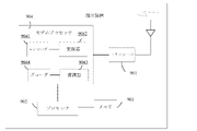
図1は、この出願の実施形態が適用されるネットワークアーキテクチャの簡略化された模式図である。ネットワークアーキテクチャは、無線通信システムのネットワークアーキテクチャであってよく、そして、ネットワーク装置および端末装置を含んでよい。ネットワーク装置および端末装置は、無線通信技術を使用することにより接続されている。図1に示される端末装置およびネットワーク装置の数量および形態は、この出願の実施形態に対して限定を構成するものではないことが留意されるべきである。異なる実施形態においては、1つのネットワーク装置が、1つまたはそれ以上の端末装置に接続され得る。ネットワーク装置は、さらに、コアネットワーク装置に接続されてよい。そして、コアネットワーク装置は、図1において示されていない。 FIG. 1 is a simplified schematic diagram of the network architecture to which the embodiments of this application apply. The network architecture may be the network architecture of a wireless communication system and may include network devices and terminal devices. Network devices and terminal devices are connected by using wireless communication technology. It should be noted that the quantities and embodiments of the terminal and network devices shown in FIG. 1 do not constitute a limitation for the embodiments of this application. In different embodiments, one network device may be connected to one or more terminal devices. The network device may also be connected to the core network device. And the core network device is not shown in FIG.
この出願の実施形態において言及されている無線通信システムは、これらに限定されるわけではないが、ナローバンド・インターネットオブシングス(narrow band-internet of things、NB-IoT)、移動通信用グローバルシステム(global system for mobile system、GSM)、GSMエボリューションのための拡張データレート(enhanced data rate for GSM evolution、EDGE)システム、広帯域符号分割多重アクセス(wideband code division multiple access、WCDMA)システム、符号分割多重アクセス2000(code division multiple access、CDMA2000)システム、時分割同期符号分割多重アクセス(time division-synchronization code division multiple access、TD-SCDMA)システム、ロングタームエボリューション(long term evolution、LTE)システム、第5世代移動通信システム、および将来の移動通信システムを含む。 The wireless communication systems referred to in embodiments of this application are, but are not limited to, narrow band-internet of things (NB-IoT), global systems for mobile communications (global). system for mobile system (GSM), enhanced data rate for GSM evolution (EDGE) system, wideband code division multiple access (WCDMA) system, code division multiple access 2000 ( code division multiple access (CDMA2000) system, time division-synchronization code division multiple access (TD-SCDMA) system, long term evolution (LTE) system, 5th generation mobile communication system , And future mobile communication systems.
この出願の実施形態において、前述のネットワーク装置は、端末装置に対して無線通信機能を提供するために無線アクセスネットワークにおいて展開されている装置である。ネットワーク装置は、これらに限定されるわけではないが、基地局(Base Station、BS)、ネットワークコントローラ、送受信ポイント(transmission and reception point、TRP)、モバイル・スイッチングセンタ(mobile switching center)、Wi-Fiにおける無線アクセスポイント、等を含む。例えば、無線チャネルを通じて端末装置と直接的に通信する装置は、一般的に基地局である。基地局は、マクロ基地局、マイクロ基地局、中継局(relay point)、アクセスポイント、リモート無線装置(Remote Radio Unit、RRU)等を種々の形態で含み得る。確かに、端末装置との無線通信は、代替的に、無線通信機能を有する別のネットワーク装置によって実行されてよい。このこと、この出願において一意に限定されるものではない。異なるシステムにおいて、基地局機能を持つデバイスは、異なる名前を有し得ることに留意すべきである。例えば、LTEネットワークにおいて、デバイスは、LTE無線基地局(evolved NodeB、eNB、または、eNodeB)として参照され、第3世代(第3世代、3G)ネットワークにおいて、デバイスは、NodeB
(NodeB)などと呼ばれ、そして、5Gネットワークにおいて、デバイスは、5G gNB(NR NodeB、gNB)として参照される。
In an embodiment of this application, the network device described above is a device deployed in a radio access network to provide a radio communication function to a terminal device. Network devices are not limited to these, but are limited to base stations (Base Stations, BSs), network controllers, transmission and reception points (TRPs), mobile switching centers, and Wi-Fi. Including wireless access points, etc. For example, a device that communicates directly with a terminal device through a wireless channel is generally a base station. The base station may include a macro base station, a micro base station, a relay point, an access point, a remote radio unit (RRU), and the like in various forms. Indeed, wireless communication with the terminal device may instead be performed by another network device having a wireless communication function. This is not uniquely limited in this application. It should be noted that in different systems, devices with base station functionality may have different names. For example, in an LTE network, the device is referred to as an LTE radio base station (evolved NodeB, eNB, or eNodeB), and in a 3rd generation (3rd generation, 3G) network, the device is NodeB.
Called (NodeB) etc., and in 5G networks, the device is referred to as 5G gNB (NR NodeB, gNB).
端末装置は、また、ユーザ装置(user equipment、UE)、移動局(mobile station、MS)、移動端末(mobile terminal、MT)、等としても参照される。そして、ユーザに音声及び/又はデータ通信を提供する装置、例えば、ハンドヘルド装置、車載装置、ウェアラブル装置、または無線接続機能を有しているコンピューティング装置、もしくは無線モデムに接続された別の処理装置である。現在、例えば、端末装置は、移動電話(mobile phone)、タブレット、ノートブックコンピュータ、パームトップコンピュータ、モバイルインターネット装置(mobile internet device、MID)、ウェアラブル装置、仮想現実(virtual reality、VR)装置、拡張現実(augmented reality)装置、産業用制御無線端末(industrial control)、セルフドライブにおける無線端末(self-driving)、遠隔医療手術のための無線端末(remote medical surgery)、スマートグリッドにおける無線端末(smart grid)、輸送安全における無線端末(transportation safety)、スマートシティにおける無線端末(smart city)、スマートホームにおける無線端末(smart home)、等である。 The terminal device is also referred to as a user device (user equipment, UE), a mobile station (mobile station, MS), a mobile terminal (mobile terminal, MT), and the like. Then, a device that provides voice and / or data communication to the user, for example, a handheld device, an in-vehicle device, a wearable device, or a computing device having a wireless connection function, or another processing device connected to a wireless modem. Is. Currently, for example, terminal devices include mobile phones, tablets, notebook computers, palmtop computers, mobile internet devices (MIDs), wearable devices, virtual reality (VR) devices, and extensions. Augmented reality equipment, industrial control, self-driving, remote medical surgery, smart grid ), Transportation safety, smart city, smart home, etc.
この出願において、名詞「ネットワーク(“network”)」および「システム(“system”)」は互換的に使用されてよく、そして、名詞「チャネル(“channel”)」および「キャリア(“carrier”)」は互換的に使用されてよい。当業者であれば、これらの名詞の意味を理解し得る。加えて、この明細書における英語の略語についてLTEシステムが参照され、そして、ネットワークの進化と伴に英語の略語は変化し得る。具体的な進化については、進化標準の定義を参照のこと。 In this application, the nouns "network" and "system" may be used interchangeably, and the nouns "channel" and "carrier". May be used interchangeably. Those skilled in the art can understand the meaning of these nouns. In addition, the LTE system is referenced for English abbreviations herein, and English abbreviations can change with the evolution of networks. See the definition of evolutionary standards for specific evolution.
図2は、無線通信プロセスにおける、ネットワーク装置によってチャネルリソースを構成するための方法の簡略化された模式的フローチャートである。 FIG. 2 is a simplified schematic flow chart of a method for configuring channel resources by network devices in a wireless communication process.
ネットワーク装置は、チャネルを分割し、そして、少なくとも2つのチャネルを決定する。ここで、決定された少なくとも2つのチャネルにおける2つの隣接する(adjacent)中心周波数間の間隔(spacing)は、サブキャリア間隔の正の整数倍またはRB間隔の正の整数倍である。次に、ネットワーク装置は、セルの確立または再構成プロセスを実行する。ネットワーク装置は、決定された少なくとも2つのチャネルに基づいて対応する周波数帯域を選択し、そして、ネットワーク装置によってカバーされるセルを構成するために、同期信号、ブロードキャスト信号、システムメッセージ、等を決定する。セルの確立または再構成が完了した後で、ネットワーク装置は、同期信号を送信し得る。端末装置は、同期信号を探索し、そして、受信した後で、同期を実行し、そして、次いで、ネットワーク装置と通信する。 The network appliance divides the channel and determines at least two channels. Here, the spacing between two adjacent center frequencies in at least two determined channels is a positive integer multiple of the subcarrier spacing or a positive integer multiple of the RB spacing. The network appliance then performs the cell establishment or reconstruction process. The network appliance selects the corresponding frequency band based on at least two determined channels and determines the sync signal, broadcast signal, system message, etc. to configure the cells covered by the network appliance. .. After the cell has been established or reconfigured, the network appliance may send a sync signal. The terminal device searches for the synchronization signal, and after receiving it, performs synchronization and then communicates with the network device.
次いで、図3は、この出願の一つの実施形態に従った、チャネルリソース構成方法の模式的なフローチャートである。 Next, FIG. 3 is a schematic flowchart of a channel resource configuration method according to one embodiment of this application.
ステップ301:ネットワーク装置は、少なくとも2つのチャネルを決定する。ここで、少なくとも2つのチャネルにおける2つの隣接するチャネルの中心周波数間の間隔は、サブキャリア間隔の正の整数倍またはリソースブロックRB間隔の正の整数倍である。 Step 301: The network appliance determines at least two channels. Here, the spacing between the center frequencies of two adjacent channels in at least two channels is a positive integer multiple of the subcarrier spacing or a positive integer multiple of the resource block RB spacing.
中心周波数(center frequency)は、チャネルに対応するスペクトルリソース(spectrum resource)の中心であり、そして、また、中心周波数としても参照される。チャネルの中心周波数は、チャネルラスタ(channel raster)の整数倍であり、そして、チャネルラスタは、チャネル分割の最小粒度(minimum granularity)である。異なる例において、チャネルの中心周波数の値は異なっている。一つの実施形態において、2つの隣接するチャネルの中心周波数間の間隔は、サブキャリア間隔の整数倍である。別の例において、2つの隣接するチャネルの中心周波数間の間隔は、リソースブロック(resource block、RB)間隔の整数倍である。 The center frequency is the center of the spectral resource corresponding to the channel, and is also referred to as the center frequency. The center frequency of the channel is an integral multiple of the channel raster, and the channel raster is the minimum granularity of the channel division. In different examples, the center frequency values of the channels are different. In one embodiment, the spacing between the center frequencies of two adjacent channels is an integral multiple of the subcarrier spacing. In another example, the spacing between the center frequencies of two adjacent channels is an integral multiple of the resource block (RB) spacing.
この実施形態において、チャネルの中心周波数は、標準プロトコルにおいて既に定義されており、または、チャネルの構成が、標準において直接的に定義されている。ネットワーク装置が少なくとも2つのチャネルを決定する方法は、セルの初期化または再構成の最中に標準プロトコルにおける定義に基づいて、ネットワーク装置がチャネル分割を決定し得ること、または、標準において定義されたチャネル構成を直接的に使用し得ることである。加えて、チャネル構成は、少なくとも2つのチャネルにおける2つの隣接するチャネルの中心周波数間の間隔が、サブキャリア間隔の正の整数倍またはRB間隔の正の整数倍であることに従う。例えば、チャネルの中心周波数は、セット(set)の形態で表現されてよく、そして、詳細が以下で説明される。 In this embodiment, the center frequency of the channel is already defined in the standard protocol, or the configuration of the channel is directly defined in the standard. The method by which the network appliance determines at least two channels is that the network appliance can determine the channel split based on the definition in the standard protocol during cell initialization or reconstruction, or is defined in the standard. The channel configuration can be used directly. In addition, the channel configuration follows that the spacing between the center frequencies of two adjacent channels in at least two channels is a positive integer multiple of the subcarrier spacing or a positive integer multiple of the RB spacing. For example, the center frequency of a channel may be expressed in the form of a set, the details of which are described below.
別の実施形態において、ネットワーク装置が少なくとも2つのチャネルを決定する方法は、各チャネルによって占有される周波数帯域、中心周波数、等を動的に割り当てるように、ネットワーク装置がチャネルを分割し得ることである。ネットワーク装置は、既定の中心周波数、例えば、以下で説明されるように設定された中心周波数、から中心周波数を選択し、そして、チャネル分割を実行し得る。チャネル分割は、少なくとも2つのチャネルにおける2つの隣接するチャネルの中心周波数間の間隔がサブキャリア間隔の正の整数倍またはRB間隔の正の整数倍である、という原理に従う。 In another embodiment, the method by which the network device determines at least two channels is that the network device can divide the channels so as to dynamically allocate the frequency band, center frequency, etc. occupied by each channel. be. The network device may select a center frequency from a predetermined center frequency, eg, a center frequency set as described below, and perform channel splitting. Channel division follows the principle that the spacing between the center frequencies of two adjacent channels in at least two channels is a positive integer multiple of the subcarrier spacing or a positive integer multiple of the RB spacing.
ステップ302:ネットワーク装置は、決定された少なくとも2つのチャネルのうち少なくとも1つを使用することによって通信し、そして、信号を送信する。 Step 302: The network appliance communicates by using at least one of the determined at least two channels and transmits a signal.
このプロセスにおいて、ネットワーク装置は、決定された少なくとも2つのチャネルのうち少なくとも1つを選択し得る。別の言葉で言えば、ネットワーク装置は、決定された少なくとも2つのチャネルから1つのチャネルを選択してよく、または、ネットワーク装置は、決定された少なくとも2つのチャネルから複数のチャネルを選択してよい。前述の構成が完了した後で、ネットワーク装置は、信号、例えば、同期信号を送信する。 In this process, the network appliance may select at least one of at least two determined channels. In other words, the network appliance may select one channel from at least two determined channels, or the network appliance may select multiple channels from at least two determined channels. .. After completing the above configuration, the network appliance transmits a signal, eg, a sync signal.
ネットワーク装置は、1つの端末装置について1つまたはそれ以上のチャネルを決定してよく、または、複数の端末について1つまたはそれ以上のチャネルを別々に決定してよい。 The network device may determine one or more channels for one terminal device, or may determine one or more channels separately for a plurality of terminals.
ステップ303:端末装置は、ランダムアクセスを実行するために、ネットワーク装置からの同期信号を探索する。 Step 303: The terminal device searches for a sync signal from the network device to perform random access.
ステップ304:端末装置は、ネットワーク装置にアクセスするときに、少なくとも1つのチャネルにおいてネットワーク装置と通信する。ここで、少なくとも1つのチャネルおよびネットワーク装置によって構成される別の隣接するチャネルそれぞれの中心周波数間の間隔は、サブキャリア間隔の正の整数倍またはリソースブロックRBの正の整数倍である。 Step 304: The terminal device communicates with the network device on at least one channel when accessing the network device. Here, the spacing between the center frequencies of at least one channel and another adjacent channel configured by the network device is a positive integer multiple of the subcarrier spacing or a positive integer multiple of the resource block RB.
一つの実施形態においては、2つの隣接するチャネルの中心周波数間のものであり、かつ、ネットワーク装置によって決定される、間隔が、サブキャリア間隔の整数倍である例が、説明のために使用される。2つの隣接するチャネルの中心周波数間のものであり、かつ、ネットワーク装置により決定される、間隔(ノミナルチャネル間隔(Nominal channel spacing))は、以下の等式を満たしている。

BWchannel(1)およびBWchannel(2)は2つの隣接するチャネルの帯域幅を別々に表し、SCSはサブチャネル間隔を表し、BWCRはチャネルラスタを表し、そして、LCM(BWCR,SCS)はBWCRとSCSの最小公倍数を表している。 BW channel (1) and BW channel (2) separately represent the bandwidth of two adjacent channels, SCS represents the subchannel spacing, BW CR represents the channel raster, and LCM (BW CR, SCS). Represents the least common multiple of BW CR and SCS.
別の実施形態において、2つの隣接するチャネルの中心周波数間の間隔は、さらに以下の等式を満たしている。

2つの隣接するチャネルの中心周波数間のものであり、かつ、ネットワーク装置によって決定される、間隔が、等式1を満たしている例が、さらなる説明のために以下で使用されている。2つの隣接するチャネルの中心周波数間のものであり、かつ、ネットワーク装置によって決定される、間隔が、等式2を満たしている適用方法は、等式1の場合と類似していることが理解されよう、そして、詳細は、再度説明されない。この実施形態においては、リソース構成において、システムによって中心として(as a center)サポートされる最大帯域幅に対応する中心周波数を使用することにより分割が実行される。別のチャネルについては、別のチャネルに対応する伝送帯域幅(transmission bandwidth)が、別のチャネルの中心周波数によって決定される。
An example, which is between the center frequencies of two adjacent channels and whose spacing is determined by the network device and the spacing satisfies
チャネルラスタが100KHz(BWCR=100KHz)であり、かつ、サブキャリア間隔が15KHz、30KHz、または60KHzのいずれかである場合に、2つの隣接するチャネルの中心周波数間のものであり、かつ、ネットワーク装置によって決定される、間隔は、以下の等式を満たしている。

システムサブキャリア間隔が15kHzであり、かつ、20MHzまたは40MHzのフレキシブル帯域幅伝送がサポートされている例が、説明のために使用される。システムによってサポートされる最大帯域幅は40MHzであることが学習され得る。いくつかの実施形態において、RB分割は、システムによってサポートされる最大システム帯域幅に基づいて実行される。図4を参照すると、一つの例において、40MHzの帯域幅を有するチャネルは、約222のRBに対応し得る。ガード間隔(guard spacing)が構成された後で、40MHzの帯域幅に対応する伝送帯域幅は216のRBである。216のRBは、チャネル中心周波数Mの2つの側において対称的に分布しており、そして、ガード間隔が、システム帯域幅の2つの端に分布している。説明を容易にするために、以下の、かつ、添付の図面においては、RBの量(quantity)がN_RBで表わされ、そして、前述の216のRBは、RB 0からRB 215まで番号が付けられている。この出願において提供される実施態様において、RB分割および番号付けは、全て、説明のための例であることが理解されるだろう。必要なガード間隔が構成されるときに、伝送帯域幅のために使用されるRBの位置は、例に対してオフセットされてよく、そして、例における構成方法に限定されるものではない。
An example is used for illustration where the system subcarrier spacing is 15 kHz and flexible bandwidth transmission of 20 MHz or 40 MHz is supported. It can be learned that the maximum bandwidth supported by the system is 40 MHz. In some embodiments, the RB partitioning is performed based on the maximum system bandwidth supported by the system. Referring to FIG. 4, in one example, a channel with a bandwidth of 40 MHz may correspond to about 222 RBs. After the guard spacing is configured, the transmission bandwidth corresponding to the 40MHz bandwidth is 216 RBs. The 216 RBs are symmetrically distributed on the two sides of the channel center frequency M, and the guard spacing is distributed at the two ends of the system bandwidth. For ease of explanation, in the following and in the accompanying drawings, the quantity of RB is represented by N_RB, and the 216 RBs mentioned above are numbered from
ネットワーク装置が、40MHzのシステム帯域幅を20MHzの帯域幅を有する2つの隣接するチャネルに分割することを決定する場合に、2つの隣接するチャネルの中心周波数間の間隔は19.8MHzであり、等式3を満たしている。図4に示されるように、各チャネルに対応する伝送帯域幅は106のRBであり、RB#0からRB#105まで、および、RB#110からRB#215までである。従って、1つのチャネルの中心周波数位置が決定された後で、別の隣接するチャネルの中心周波数位置が決定されてよい。
If the network appliance decides to divide the system bandwidth of 40 MHz into two adjacent channels with a bandwidth of 20 MHz, the spacing between the center frequencies of the two adjacent channels is 19.8 MHz and the equation. 3 is satisfied. As shown in FIG. 4, the transmission bandwidth corresponding to each channel is 106 RBs, from
次に、システムサブキャリア間隔が30kHzであり、かつ、20MHz、40MHz、60MHz、80MHz、100MHzのフレキシブル帯域幅において伝送をサポートするシステムについて、システムによってサポートされる最大帯域幅は100MHzである。必要なガード間隔が構成された後で、100MHzの帯域幅に対応する伝送帯域幅は、273のRBであり得る。273のRBは、チャネル中心周波数の両側に対称的に分布し、ガード間隔はシステム帯域幅の両側に分布し、そして、中心周波数はRB#136に配置される。
Second, for systems with a system subcarrier spacing of 30 kHz and support for transmission over flexible bandwidths of 20 MHz, 40 MHz, 60 MHz, 80 MHz, and 100 MHz, the maximum bandwidth supported by the system is 100 MHz. After the required guard spacing is configured, the transmission bandwidth corresponding to the 100MHz bandwidth can be 273 RBs. The 273 RBs are symmetrically distributed on both sides of the channel center frequency, the guard spacing is distributed on both sides of the system bandwidth, and the center frequency is located at
本システムは、20MHz、40MHz、60MHz、80MHz、または100MHzのフレキシブル帯域幅の伝送をサポートし得る。図5は、異なる帯域幅を有するチャネルが結合される場合のリソース構成、または、異なる帯域幅を有する複数のチャネルへとシステム帯域幅が分割される場合のリソース構成を示している。 The system may support transmission with a flexible bandwidth of 20MHz, 40MHz, 60MHz, 80MHz, or 100MHz. FIG. 5 shows a resource configuration when channels with different bandwidths are combined, or a resource configuration when the system bandwidth is divided into multiple channels with different bandwidths.
(1)ネットワーク装置は、20MHzの帯域幅を有する5つのチャネルを決定し得る。図5を参照すると、20MHzの帯域幅を有する5つのチャネルに対して必要なガード間隔が構成された後で、各チャネルの伝送帯域幅は52のRBであり、中央のチャネル3の中心周波数は、100MHzの最大システム帯域幅の中心周波数とオーバーラップしている。2つの隣接するチャネルの中心周波数間の間隔は19.8MHzであり、前述の等式3の要件を満たしている。例えば、中心周波数は中心にあり、チャネル1の伝送帯域幅がRB#0からRB#51までであり、チャネル2の伝送帯域幅がRB#55からRB#106までであり、チャネル3の伝送帯域幅がRB#110からRB#161までであり、チャネル4の伝送帯域幅がRB#165からRB#216までであり、そして、チャネル5の伝送帯域幅がRB#220からRB#271までである。RB#52からRB#54まで、RB#107からRB#109まで、RB#161からRB#164まで、および、RB#217からRB#219までは、ガード間隔である。
(1) The network device may determine five channels with a bandwidth of 20 MHz. Referring to FIG. 5, after the required guard spacing is configured for 5 channels with a bandwidth of 20 MHz, the transmission bandwidth of each channel is 52 RB and the center frequency of central channel 3 is. , Overlaps the center frequency of the maximum system bandwidth of 100MHz. The distance between the center frequencies of two adjacent channels is 19.8 MHz, which satisfies the requirement of equation 3 above. For example, the center frequency is at the center, the transmission bandwidth of
(2)ネットワーク装置は、20MHzの帯域幅を有する1つのチャネルおよび40MHzの帯域幅を有する2つのチャネルを決定し得る。この実施形態においては、20MHzの帯域幅を有するチャネルの前述の中心周波数を参照し得る。40MHzの帯域幅を有するチャネル6と20MHzの帯域幅を有する隣接チャネル1との中心周波数間の間隔が30MHzであり、そして、40MHzの帯域幅を有するチャネル6と40MHzの帯域幅を有するチャネル7との間隔が39.3MHzであり、これは、前述の等式3の要件を満たしている。例えば、中心周波数は中心にある。必要なガード間隔が構成された後で、チャネル1の伝送帯域幅はRB#0からRB#51までであり、チャネル6の伝送帯域幅はRB#56からRB#161までであり、そして、チャネル7の伝送帯域幅はRB#166からRB#271までである。
(2) The network device may determine one channel with a bandwidth of 20 MHz and two channels with a bandwidth of 40 MHz. In this embodiment, the aforementioned center frequency of a channel having a bandwidth of 20 MHz can be referred to. The distance between the center frequencies of channel 6 with a bandwidth of 40 MHz and
(3)ネットワーク装置は、20MHzの帯域幅を有するチャネルおよび80MHzの帯域幅を有するチャネルを決定し得る。この実施形態においては、20MHzの帯域幅を有するチャネルの前述の中心周波数を参照し得る。80MHzの帯域幅を有するチャネル8と20MHzの帯域幅を有する隣接チャネル1との中心周波数間の間隔は49.8MHzであり、これは、前述の等式3の要件を満たしている。例えば、中心周波数は中心にある。必要なガード間隔が構成された後で、チャネル1の伝送帯域幅はRB#0からRB#51までであり、そして、チャネル8の伝送帯域幅はRB#56からB#272である。
(3) The network device can determine a channel having a bandwidth of 20 MHz and a channel having a bandwidth of 80 MHz. In this embodiment, the aforementioned center frequency of a channel having a bandwidth of 20 MHz can be referred to. The distance between the center frequencies of channel 8 with a bandwidth of 80 MHz and
別の実施形態において、システムは、さらに、他の帯域幅のチャネルの組み合わせを決定し得ることが理解されよう。例えば、システムは、40MHzの帯域幅を有するチャネルおよび60MHzの帯域幅を有するチャネルをサポートし得る。種々のチャネルの組み合わせにおいて、2つの隣接するチャネルの中心周波数間の間隔は、等式3を満たしている。加えて、別の実施形態においては、必要なガード間隔の要件が満たされた後で、前述のチャネルそれぞれの中心周波数が、中心周波数に対してオフセットされてよい。これに応じて、伝送帯域幅の位置も、また、オフセットされ得る。 It will be appreciated that in another embodiment the system may further determine the combination of channels of other bandwidths. For example, the system may support channels with a bandwidth of 40 MHz and channels with a bandwidth of 60 MHz. In various channel combinations, the spacing between the center frequencies of two adjacent channels satisfies equation 3. In addition, in another embodiment, the center frequency of each of the aforementioned channels may be offset relative to the center frequency after the required guard spacing requirements have been met. Accordingly, the position of the transmission bandwidth can also be offset.
この出願は、前述のチャネルの組み合わせにおいて異なる帯域幅を有するチャネルの相対的な位置について限定を課すものではなく、そして、前述の組み合わせに限定されるものではないことに留意すべきである。他の構成方法は、ここにおいて、一つずつ説明されない。 It should be noted that this application does not impose limits on the relative positions of channels with different bandwidths in the aforementioned combinations of channels, and is not limited to the aforementioned combinations. Other configuration methods are not described here one by one.
チャネルラスタが180KHz(BWCR=180KHz)であり、かつ、サブキャリア間隔が15KHz、30KHz、60KHzのいずれかである場合に、2つの隣接するチャネルの中心周波数間のものであり、かつ、ネットワーク装置によって決定される、間隔は、以下の等式を満たしている。

システムが20MHz、40MHz、60MHz、80MHz、または100MHzのフレキシブル帯域幅における伝送をサポートする一つの例が、説明のために使用される。リソース構成においては、中心としてシステムによってサポートされる最大キャリア帯域幅に対応する中心周波数を使用して、分割が実行される。より小さいキャリアについては、各中心周波数が決定された後で、より小さいキャリアに対応する伝送帯域幅が決定される。 One example in which the system supports transmission over a flexible bandwidth of 20MHz, 40MHz, 60MHz, 80MHz, or 100MHz is used for illustration. In the resource configuration, the division is performed using the center frequency corresponding to the maximum carrier bandwidth supported by the system as the center. For smaller carriers, the transmission bandwidth corresponding to the smaller carrier is determined after each center frequency is determined.
(1)ネットワーク装置は、20MHzの帯域幅を有する5つのチャネルを決定し得る。そして、2つの隣接するチャネルの中心周波数間の間隔は19.98MHzであり、等式4の要件を満たしている。20MHzの帯域幅を有する5つのチャネルに対して必要なガード間隔が構成された後で、各チャネルの伝送帯域幅に対応するRBが決定され得る。例えば、等式2を満たしているシステムにおいて、2つの隣接するチャネルの中心周波数間の間隔は20.16MHzである。 (1) The network device may determine five channels with a bandwidth of 20 MHz. The distance between the center frequencies of the two adjacent channels is 19.98 MHz, which satisfies the requirement of equation 4. After the required guard spacing has been configured for the five channels with a bandwidth of 20 MHz, the RB corresponding to the transmission bandwidth of each channel can be determined. For example, in a system satisfying equation 2, the distance between the center frequencies of two adjacent channels is 20.16 MHz.
(2)ネットワーク装置は、20MHzの帯域幅を有する1つのチャネルおよび40MHzの帯域幅を有する2つのチャネルを決定し得る。ここで、20MHzの帯域幅を有するチャネルの中心周波数と40MHzの帯域幅を有する隣接チャネルとの間の間隔は29.88MHzである。40MHzの帯域幅を有する2つの隣接するチャネルの中心周波数間の間隔は39.96MHzであり、これは等式4の要件を満たしている。例えば、等式2を満たしているシステムにおいて、20MHzの帯域幅を有するチャネルと40MHzの帯域幅を有する隣接チャネルの中心周波数間の間隔は30.06MHzであり、そして、40MHzの帯域幅を有する2つの隣接チャネルの中心周波数間の間隔は40.14MHzである。 (2) The network device may determine one channel with a bandwidth of 20 MHz and two channels with a bandwidth of 40 MHz. Here, the distance between the center frequency of a channel with a bandwidth of 20 MHz and an adjacent channel with a bandwidth of 40 MHz is 29.88 MHz. The distance between the center frequencies of two adjacent channels with a bandwidth of 40 MHz is 39.96 MHz, which meets the requirement of equation 4. For example, in a system satisfying equation 2, the distance between the center frequencies of a channel with a bandwidth of 20 MHz and an adjacent channel with a bandwidth of 40 MHz is 30.06 MHz, and two with a bandwidth of 40 MHz. The spacing between the center frequencies of adjacent channels is 40.14MHz.
(3)ネットワーク装置は、20MHzの帯域幅を有するチャネルおよび80MHzの帯域幅を有するチャネルを決定し得る。ここで、2つのチャネルの中心周波数間の間隔は49.86MHzであり、そして、等式4の要件を満たしている。例えば、等式2の要件を満たしているシステムにおいて、20MHzの帯域幅を有するチャネルおよび80MHzの帯域幅を有する隣接チャネルの中心周波数間の間隔は50.04MHzである。 (3) The network device can determine a channel having a bandwidth of 20 MHz and a channel having a bandwidth of 80 MHz. Here, the distance between the center frequencies of the two channels is 49.86 MHz, which meets the requirements of equation 4. For example, in a system that meets the requirements of Equality 2, the spacing between the center frequencies of a channel with a bandwidth of 20 MHz and an adjacent channel with a bandwidth of 80 MHz is 50.04 MHz.
(4)100MHzのシステム帯域幅はさらに、別の方法で分割され得る。表4を参照すると、フレキシブル帯域幅における別の分割方法が、一つの例として説明されている。

前述のチャネル分割方法は、単なる説明のための一つの例にすぎないことが理解されよう。前述の方法が適用される場合には、別の分割方法が、さらに決定され得る。このことは、この出願において限定されるものではない。 It will be appreciated that the channel splitting method described above is just one example for illustration purposes. If the method described above applies, another method of division may be further determined. This is not limited in this application.
さらに別の実施形態においては、この出願において提供されるリソース構成方法が、高周波シナリオに対してさらに適用され得る。チャネルラスタが720KHz(BWCR=720KHz)である場合に、2つの隣接するチャネルのキャリアの中心周波数間の間隔は、前述の等式2または等式3の要件を満たしている。以下では、異なるサブキャリア間隔を説明するための一つの例として、等式2を使用する。 In yet another embodiment, the resource configuration method provided in this application may be further applied to high frequency scenarios. When the channel raster is 720 KHz (BW CR = 720 KHz), the spacing between the center frequencies of the carriers of two adjacent channels meets the requirements of Equality 2 or Equality 3 above. In the following, equation 2 will be used as an example to illustrate the different subcarrier spacing.
システムサブキャリア間隔が240KHzの場合に、2つの隣接するチャネルの中心周波数間のものであり、かつ、ネットワーク装置によって決定される、間隔は、以下の等式を満たしている。

システムサブキャリア間隔が480KHzの場合に、隣接する2つのチャネルの中心周波数間のものであり、かつ、ネットワーク装置によって決定される、間隔は、以下の等式を満たしている。

システムサブキャリア間隔が960KHzの場合、に隣接する2つのチャネルの中心周波数間のものであり、かつ、ネットワーク装置によって決定される、間隔は、以下の等式を満たしている。

例えば、システム帯域幅は2.16GHzであり、帯域幅利用率は88%であり、そして、伝送帯域幅は1.9008GHzである。 For example, the system bandwidth is 2.16GHz, the bandwidth utilization is 88%, and the transmission bandwidth is 1.9008GHz.
例えば、サブキャリア間隔は480KHzであり、そして、ネットワーク装置は400MHzの帯域幅を有する5つのチャネルを決定する。例えば、図6を参照すると、1.9008GHzの伝送帯域幅は、330のRBに対応している。ガード間隔が構成されていない場合に、400MHzの帯域幅を有する各チャネルは、66のRBに対応している。ガード間隔が構成される場合に、400MHzの帯域幅を有する各チャネルに対応する伝送帯域幅は66のRBより小さく、そして、構成されたガード間隔のサイズに依存している。データ伝送に使用される伝送帯域幅は、例えば、65のRB、64のRB、または60のRBであり得る。400MHzの帯域幅を有する5つのチャネルが決定される場合に、2つの隣接するチャネルの中心周波数間のものであり、かつ、ネットワーク装置によって決定される、間隔は、380.16MHzであり、これは、等式6の要件を満たしている。例えば、等式2を満たしているシステムにおいて、2つの隣接するチャネルの中心周波数間の間隔は381.6MHzである。 For example, the subcarrier spacing is 480 KHz, and the network appliance determines five channels with a bandwidth of 400 MHz. For example, referring to FIG. 6, the transmission bandwidth of 1.9008 GHz corresponds to 330 RBs. Each channel with a bandwidth of 400 MHz corresponds to 66 RBs when the guard interval is not configured. When guard spacing is configured, the transmission bandwidth corresponding to each channel with a bandwidth of 400MHz is less than 66 RBs and depends on the size of the configured guard spacing. The transmission bandwidth used for data transmission can be, for example, 65 RBs, 64 RBs, or 60 RBs. When five channels with a bandwidth of 400 MHz are determined, the interval between the center frequencies of two adjacent channels and determined by the network appliance is 380.16 MHz, which is It meets the requirements of equation 6. For example, in a system satisfying equation 2, the distance between the center frequencies of two adjacent channels is 381.6 MHz.
次に、2つのチャネルの中心周波数間のものであり、かつ、ネットワーク装置によって決定される、間隔が、RB間隔(または、RB帯域幅として理解され得るもの)の整数倍である、一つの例が説明のために使用される。2つのチャネルの中心周波数間のものであり、かつ、ネットワーク装置によって決定される、間隔は、以下の等式を満たしている。

BWchannel(1)およびBWchannel(2)は2つのキャリアの帯域幅を別々に表し、BWCRはチャネルラスタを表し、BWRBはRB間隔を表し、そして、LCM(BWCR,BWRB)はBWCRとBWRBの最小公倍数を表している。 BW channel (1) and BW channel (2) represent the bandwidths of the two carriers separately, BW CR represents the channel raster, BW RB represents the RB spacing, and LCM (BW CR, BW RB ). It represents the least common multiple of BW CR and BW RB .
代替的に、2つの隣接するチャネルの中心周波数間の間隔は、以下の等式を満たしている。

2つの隣接するチャネルの中心周波数間のものであり、かつ、ネットワーク装置によって決定される、間隔が、等式1を満たしている、一つの例が、さらなる説明のために以下で使用される。2つの隣接するチャネルの中心周波数間のものであり、かつ、ネットワーク装置によって決定される、間隔が、等式2を満たしている適用方法は、等式1における方法と類似しており、そして、詳細は再度説明されていないことが、理解されよう。
One example, which is between the center frequencies of two adjacent channels and whose spacing is determined by the network device and the spacing satisfies
チャネルラスタが100KHz(BWCR=100KHz)であり、かつ、サブキャリア間隔が15KHzの場合に、RB間隔は、BWRB=15KHz*12=180KHzである。そして、2つの隣接するチャネルの中心周波数間のものであり、かつ、ネットワーク装置によって決定される、間隔は、以下の等式を満たしている。

チャネルラスタが100KHz(BWCR=100KHz)であり、かつ、サブキャリア間隔が30KHzの場合に、RB間隔は、BWRB=30KHz*12=360KHzである。そして、2つの隣接するチャネルの中心周波数間のものであり、かつ、ネットワーク装置によって決定される、間隔は、以下の等式を満たしている。

チャネルラスタが100KHz(BWCR=100KHz)であり、かつ、サブキャリア間隔が60KHzの場合に、RB間隔は、BWRB=60KHz*12=720KHzである。そして、2つの隣接するチャネルの中心周波数間のものであり、かつ、ネットワーク装置によって決定される、間隔は、以下の等式を満たしている。

サブキャリア間隔が30KHzであり、そして、20MHz、40MHz、60MHz、80MHz、または100MHzのフレキシブル帯域幅の伝送がサポートされている一つの例が、説明のために使用される。図7を参照すると、ガード間隔が構成された後で、20MHzの帯域幅を有するチャネルは52のRBに対応し、40MHzの帯域幅を有するチャネルは106のRBに対応し、60MHzの帯域幅を有するチャネルは162のRBに対応し、80MHzの帯域幅を有するチャネルは217のRBに対応し、そして、100MHzの帯域幅を有するチャネルは273のRBに対応している。説明を容易にするために、273のRBには、RB#0からRB#272までの番号が付けられ、そして、100MHzの帯域幅を有するチャネルの中心周波数がRB#136に配置されている。
One example is used for illustration, where the subcarrier spacing is 30 KHz and transmission with a flexible bandwidth of 20 MHz, 40 MHz, 60 MHz, 80 MHz, or 100 MHz is supported. Referring to FIG. 7, after the guard interval is configured, a channel with a bandwidth of 20 MHz corresponds to 52 RBs, a channel with a bandwidth of 40 MHz corresponds to 106 RBs, and a bandwidth of 60 MHz. The channel with has 162 RBs, the channel with 80 MHz bandwidth corresponds to 217 RBs, and the channel with 100 MHz bandwidth corresponds to 273 RBs. For ease of explanation, the RBs of 273 are numbered from
(1)ネットワーク装置は、20MHzの帯域幅を有する5つのチャネルを決定し得る。図7を参照すると、20MHzの帯域幅を有する5つのチャネルに対して必要なガード間隔が構成された後で、各チャネルの伝送帯域幅は52のRBであり、中間のチャネルの中心周波数は、100MHzの最大システム帯域幅の中心周波数とオーバーラップしている。2つの隣接するチャネルの中心周波数間の間隔は19.8MHzであり、これは、前述の等式10の要件を満たしている。例えば、中心周波数は中心にある。ガード間隔が構成された後で、5つのチャネルの伝送帯域幅は、それぞれに、RB#0からRB#51まで、RB#55からRB#106まで、RB#110からRB#161まで、RB#165からRB#216まで、および、RB#220からB#271まで、である。別の実施形態においては、等式8を満たしているシステムにおいて、2つの隣接するチャネルの中心周波数間の間隔は21.6MHzである。
(1) The network device may determine five channels with a bandwidth of 20 MHz. Referring to FIG. 7, after the required guard spacing is configured for 5 channels with a bandwidth of 20 MHz, the transmission bandwidth of each channel is 52 RB and the center frequency of the intermediate channels is It overlaps with the center frequency of the maximum system bandwidth of 100MHz. The distance between the center frequencies of two adjacent channels is 19.8 MHz, which meets the requirement of
(2)ネットワーク装置は、20MHzの帯域幅を有する1つのチャネルおよび40MHzの帯域幅を有する2つのチャネルを決定し得る。ここで、20MHzの帯域幅を有するチャネルの中心周波数と40MHzの帯域幅を有する隣接チャネルとの間の間隔は29.7MHzである。40MHzの帯域幅を有する2つの隣接するチャネルの中心周波数間の間隔は39.6MHzであり、これは等式10の要件を満たしている。例えば、中心周波数は中心にある。ガード間隔が構成された後で、3つのチャネルの伝送帯域幅は、それぞれに、RB#0からRB#51まで、RB#55からRB#160まで、および、RB#165からRB#270まで、である。別の実施形態においては、等式8を満たしているシステムにおいて、20MHzの帯域幅を有するチャネルと40MHzの帯域幅を有する隣接チャネルの中心周波数間の間隔は31.5MHzであり、かつ、2つの隣接40MHzチャネルの中心周波数間の間隔は41.4MHzである。
(2) The network device may determine one channel with a bandwidth of 20 MHz and two channels with a bandwidth of 40 MHz. Here, the distance between the center frequency of the channel having a bandwidth of 20 MHz and the adjacent channel having a bandwidth of 40 MHz is 29.7 MHz. The distance between the center frequencies of two adjacent channels with a bandwidth of 40 MHz is 39.6 MHz, which meets the requirement of
(3)ネットワーク装置は、20MHzの帯域幅を有するチャネルおよび80MHzの帯域幅を有するチャネルを決定し得る。ここで、2つのチャネルの中心周波数間の間隔は49.5MHzであり、等式10の要件を満たしている。例えば、中心周波数は中心にある。ガード間隔が構成された後で、2つのチャネルの伝送帯域幅は、それぞれに、RB#0からRB#51まで、および、RB#55からRB#271まで、である。別の実施形態においては、等式8を満たしているシステムにおいて、20MHzの帯域幅を有するチャネルと80MHzの帯域幅を有する隣接チャネルとの間の間隔は51.3MHzである。
(3) The network device can determine a channel having a bandwidth of 20 MHz and a channel having a bandwidth of 80 MHz. Here, the distance between the center frequencies of the two channels is 49.5 MHz, which satisfies the requirement of
(4)100MHzは、さらに、複数の方法で分割され得ることが理解されよう。表2を参照すると、フレキシブル帯域幅におけるチャネル組み合わせに係る別の形態の一つの例が記載されている。各チャネル組み合わせにおけるRB構成については、前述の方法を参照のこと。詳細は、ここにおいて再度説明されない。

以下は、一つの例を使用することにより、チャネル帯域幅について任意的な中心周波数のセットにおける値の相対的位置が、前述の等式を満たしていることを、別々に説明している。以下の中心周波数セットは、標準プロトコルにおいて事前に定義されており、そして、ネットワーク装置は、セット内の中心周波数を使用することによって通信することができる。アップリンクチャネルおよびダウンリンクチャネルの中心周波数は、以下の要件を満たしている。
FDL=FDL_low+0.1(NDL―Noffs_DL)
FUL=FUL_low+0.1(NUL―Noffs_UL)
The following separately explains, by using one example, that the relative positions of the values in any set of center frequencies for the channel bandwidth satisfy the above equation. The following center frequency sets are predefined in the standard protocol, and network appliances can communicate by using the center frequencies within the set. The center frequencies of the uplink and downlink channels meet the following requirements.
F DL = F DL_low +0.1 (N DL ― N offs_DL )
F UL = F UL_low +0.1 (N UL -N offs_UL )
FDLはダウンリンクキャリア周波数を表し、FULはアップリンクキャリア周波数を表し、NDLはダウンリンク・エボルブ・ユニバーサル地上無線アクセスネットワーク(evolved universal terrestrial radio access network、E-UTRA)の絶対無線周波数チャネル番号(E-UTRA absolute radio frequency channel number、EARFCN)を表し、そして、NULはアップリンクEARFCNを表している。例えば、前述の等式におけるパラメータの値の範囲は以下のとおりである。

チャネル中心周波数は、以下のセットのうち任意の1つまたは組み合わせから選択される。 The channel center frequency is selected from any one or combination of the following sets.
5GHz周波数帯域において、サブキャリア間隔は、15kHz、30kHz、または60kHzのうちいずれかである。例えば、チャネル帯域幅(channel band width)が40MHzの場合に、任意的なチャネル中心周波数セットは、少なくとも以下を含んでいる。 In the 5 GHz frequency band, the subcarrier spacing is either 15 kHz, 30 kHz, or 60 kHz. For example, if the channel band width is 40 MHz, then any channel center frequency set includes at least:
セット1:
NDL=NUL={n-2,n-1,n,n+1,n+2|n=47190(FDL=FUL=5190MHz),47590(FDL=FUL=5230MHz),47990(FDL=FUL=5270MHz),48390(FDL=FUL=5310MHz),50390(FDL=FUL=5510MHz),50790(FDL=FUL=5550MHz),51190(FDL=FUL=5590MHz),51590(FDL=FUL=5630MHz),51990(FDL=FUL=5670MHz),52390(FDL=FUL=5710MHz)}
Set 1:
N DL = N UL = {n-2, n-1, n, n + 1, n + 2 | n = 47190 (F DL = F UL = 5190MHz), 47590 (F DL = F UL = 5230MHz), 47990 (F DL = F UL = 5270MHz), 48390 (F DL = F UL = 5310MHz), 50390 (F DL = F UL = 5510MHz), 50790 (F DL = F UL = 5550MHz), 51190 (F DL = F UL ) = 5590MHz), 51590 (F DL = F UL = 5630MHz), 51990 (F DL = F UL = 5670MHz), 52390 (F DL = F UL = 5710MHz)}
一つの例としてn=47190を使用すると、nの値は、±2だけオフセットされてよく、例えば、n-2、n-1、n+1、またはn+2であってよい。nの値が、n-2=47188の場合、FDL=FUL=5189.8MHzである。nの値が、n-1=47189の場合、FDL=FUL=5189.9MHzである。nの値が、n+1=47191の場合、FDL=FUL=5190.1MHzである。nの値が、n+2=47192の場合、FDL=FUL=5190.2MHzである。同様にして、セット1から、より多くの値の範囲を獲得することができる。40MHzのチャネル帯域幅を有する中心周波数セット、および、以下の他のチャネル帯域幅を有する中心周波数セットである。
Using n = 47190 as an example, the value of n may be offset by ± 2, for example n-2, n-1, n + 1, or n + 2. If the value of n is n-2 = 47188, then F DL = F UL = 5189.8 MHz. If the value of n is n-1 = 47189, then F DL = F UL = 5189.9 MHz. If the value of n is n + 1 = 47191, then F DL = F UL = 5190.1MHz. If the value of n is n + 2 = 47192, then F DL = F UL = 5190.2MHz. Similarly, a range of more values can be obtained from
加えて、キャリア中心周波数の値が5190MHzである一つの例、すなわち、前述のセット1において、n=47190に対応する中心周波数の値が5190MHzであり、かつ、2つの隣接するチャネルが40MHzの帯域幅を有するものが、説明のために使用される。すなわち、BWchannel(1)=40MHz、BWchannel(2)=40MHz、および、BWCR=100KHzである。SCSが15KHz、30KHz、または60KHzのいずれかである場合には、等式3に従って、2つの隣接するチャネル間のキャリア間隔が以下であることが学習され得る。

従って、別の40MHzチャネルの中心周波数は5229.9MHzである。チャネル構成は、以下のセットにおいて、同様の方法および異なる値を使用することによって獲得することができる。 Therefore, the center frequency of another 40MHz channel is 5229.9MHz. Channel configurations can be obtained by using similar methods and different values in the following sets.
セット2:
NDL=NUL={n-2,n-1,n,n+1,n+2|n=46990(FDL=FUL=5170MHz),47390(FDL=FUL=5210MHz),47790(FDL=FUL=5250MHz),48190(FDL=FUL=5290MHz),48590(FDL=FUL=5330MHz),50190(FDL=FUL=5490MHz),50590(FDL=FUL=5530MHz),50990(FDL=FUL=5570MHz),51390(FDL=FUL=5610MHz),51790(FDL=FUL=5650MHz),52190(FDL=FUL=5690MHz)}
Set 2:
N DL = N UL = {n-2, n-1, n, n + 1, n + 2 | n = 46990 (F DL = F UL = 5170MHz), 47390 (F DL = F UL = 5210MHz), 47790 (F DL = F UL = 5250MHz), 48190 (F DL = F UL = 5290MHz), 48590 (F DL = F UL = 5330MHz), 50190 (F DL = F UL = 5490MHz), 50590 (F DL = F UL = F UL) = 5530MHz), 50990 (F DL = F UL = 5570MHz), 51390 (F DL = F UL = 5610MHz), 51790 (F DL = F UL = 5650MHz), 52190 (F DL = F UL = 5690MHz)}
セット3:
NDL=NUL={n-2,n-1,n,n+1,n+2|n=52840(FDL=FUL=5755MHz),53240(FDL=FUL=5795MHz),53640(FDL=FUL=5835MHz),54040(FDL=FUL=5875MHz)}
Set 3:
N DL = N UL = {n-2, n-1, n, n + 1, n + 2 | n = 52840 (F DL = F UL = 5755MHz), 53240 (F DL = F UL = 5795MHz), 53640 (F DL = F UL = 5835MHz), 54040 (F DL = F UL = 5875MHz)}
セット4:
NDL=NUL={n-2,n-1,n,n+1,n+2|n=53040(FDL=FUL=5775MHz),53440(FDL=FUL=5815MHz),53840(FDL=FUL=5855MHz),54240(FDL=FUL=5895MHz)}
Set 4:
N DL = N UL = {n-2, n-1, n, n + 1, n + 2 | n = 53040 (F DL = F UL = 5775MHz), 53440 (F DL = F UL = 5815MHz), 53840 (F DL = F UL = 5855MHz), 54240 (F DL = F UL = 5895MHz)}
チャネル帯域幅が40MHzである場合、チャネル中心周波数セットは、前述のセット1から4のうち少なくとも1つであってよく、または、前述のセット1から4のうち複数であってよいことが理解されよう。
It is understood that if the channel bandwidth is 40 MHz, the channel center frequency set may be at least one of the
例えば、チャネル帯域幅が60MHzの場合に、任意的なキャリア中心周波数セットは、少なくとも以下を含んでいる。 For example, if the channel bandwidth is 60 MHz, any carrier center frequency set includes at least:
セット5:
NDL=NUL={n-2,n-1,n,n+1,n+2|n=47090(FDL=FUL=5180MHz),47690(FDL=FUL=5240MHz),48290(FDL=FUL=5300MHz),50290(FDL=FUL=5500MHz),50890(FDL=FUL=5560MHz),51490(FDL=FUL=5620MHz),52090(FDL=FUL=5680MHz)}
Set 5:
N DL = N UL = {n-2, n-1, n, n + 1, n + 2 | n = 47090 (F DL = F UL = 5180MHz), 47690 (F DL = F UL = 5240MHz), 48290 (F DL = F UL = 5300MHz), 50290 (F DL = F UL = 5500MHz), 50890 (F DL = F UL = 5560MHz), 51490 (F DL = F UL = 5620MHz), 52090 (F DL = F UL ) = 5680MHz)}
セット6:
NDL=NUL={n-2,n-1,n,n+1,n+2|n=47290(FDL=FUL=5200MHz),47890(FDL=FUL=5260MHz),48490(FDL=FUL=5320MHz),50490(FDL=FUL=5520MHz),51090(FDL=FUL=5580MHz),51690(FDL=FUL=5640MHz),52290(FDL=FUL=5700MHz)}
Set 6:
N DL = N UL = {n-2, n-1, n, n + 1, n + 2 | n = 47290 (F DL = F UL = 5200MHz), 47890 (F DL = F UL = 5260MHz), 48490 (F DL = F UL = 5320MHz), 50490 (F DL = F UL = 5520MHz), 51090 (F DL = F UL = 5580MHz), 51690 (F DL = F UL = 5640MHz), 52290 (F DL = F UL ) = 5700MHz)}
セット7:
NDL=NUL={n-2,n-1,n,n+1,n+2|n=47490(FDL=FUL=5220MHz),48090(FDL=FUL=5280MHz),50690(FDL=FUL=5540MHz),51290(FDL=FUL=5600MHz),51890(FDL=FUL=5660MHz)}
Set 7:
N DL = N UL = {n-2, n-1, n, n + 1, n + 2 | n = 47490 (F DL = F UL = 5220MHz), 48090 (F DL = F UL = 5280MHz), 50690 (F DL = F UL = 5540MHz), 51290 (F DL = F UL = 5600MHz), 51890 (F DL = F UL = 5660MHz)}
セット8:
NDL=NUL={n-2,n-1,n,n+1,n+2|n=52940(FDL=FUL=5765MHz),53540(FDL=FUL=5825MHz),54140(FDL=FUL=5885MHz)}
Set 8:
N DL = N UL = {n-2, n-1, n, n + 1, n + 2 | n = 52940 (F DL = F UL = 5765MHz), 53540 (F DL = F UL = 5825MHz), 54140 (F DL = F UL = 5885MHz)}
セット9:
NDL=NUL={n-2,n-1,n,n+1,n+2|n=53140(FDL=FUL=5785MHz),53740(FDL=FUL=5845MHz)}
Set 9:
N DL = N UL = {n-2, n-1, n, n + 1, n + 2 | n = 53140 (F DL = F UL = 5785MHz), 53740 (F DL = F UL = 5845MHz)}
セット10:
NDL=NUL={n-2,n-1,n,n+1,n+2|n=53340(FDL=FUL=5805MHz),53940(FDL=FUL=5865MHz)}
Set 10:
N DL = N UL = {n-2, n-1, n, n + 1, n + 2 | n = 53340 (F DL = F UL = 5805MHz), 53940 (F DL = F UL = 5865MHz)}
チャネル帯域幅が60MHzである場合に、チャネル中心周波数セットは、前述のセット5から10のうち少なくとも1つであってよく、または、前述のセット5から10のうち複数であってよいことが理解されよう。 It is understood that if the channel bandwidth is 60 MHz, the channel center frequency set may be at least one of the above sets 5 to 10 or may be more than one of the above sets 5 to 10. Will be done.
キャリア帯域幅が80MHzである場合に、任意的なキャリア中心周波数セットは、少なくとも以下を含んでいる。 If the carrier bandwidth is 80 MHz, any carrier center frequency set includes at least:
セット11:
NDL=NUL={n-2,n-1,n,n+1,n+2|n=47390(FDL=FUL=5210MHz),48190(FDL=FUL=5290MHz),50590(FDL=FUL=5530MHz),51390(FDL=FUL=5610MHz),52190(FDL=FUL=5690MHz)}
Set 11:
N DL = N UL = {n-2, n-1, n, n + 1, n + 2 | n = 47390 (F DL = F UL = 5210MHz), 48190 (F DL = F UL = 5290MHz), 50590 (F DL = F UL = 5530MHz), 51390 (F DL = F UL = 5610MHz), 52190 (F DL = F UL = 5690MHz)}
セット12:
NDL=NUL={n-2,n-1,n,n+1,n+2|n=47190(FDL=FUL=5690MHz),47990(FDL=FUL=5270MHz),50390(FDL=FUL=5510MHz),51190(FDL=FUL=5590MHz),51990(FDL=FUL=5670MHz)}
Set 12:
N DL = N UL = {n-2, n-1, n, n + 1, n + 2 | n = 47190 (F DL = F UL = 5690MHz), 47990 (F DL = F UL = 5270MHz), 50390 (F DL = F UL = 5510MHz), 51190 (F DL = F UL = 5590MHz), 51990 (F DL = F UL = 5670MHz)}
セット13:
NDL=NUL={n-2,n-1,n,n+1,n+2|n=47590(FDL=FUL=5230MHz),48390(FDL=FUL=5310MHz),50790(FDL=FUL=5550MHz),51590(FDL=FUL=5630MHz)}
Set 13:
N DL = N UL = {n-2, n-1, n, n + 1, n + 2 | n = 47590 (F DL = F UL = 5230MHz), 48390 (F DL = F UL = 5310MHz), 50790 (F DL = F UL = 5550MHz), 51590 (F DL = F UL = 5630MHz)}
セット14:
NDL=NUL={n-2,n-1,n,n+1,n+2|n=47790(FDL=FUL=5250MHz),50790(FDL=FUL=5570MHz),51790(FDL=FUL=5650MHz)}
Set 14:
N DL = N UL = {n-2, n-1, n, n + 1, n + 2 | n = 47790 (F DL = F UL = 5250MHz), 50790 (F DL = F UL = 5570MHz), 51790 (F DL = F UL = 5650MHz)}
セット15:
NDL=NUL={n-2,n-1,n,n+1,n+2|n=53040(FDL=FUL=5775MHz),53840(FDL=FUL=5855MHz)}
Set 15:
N DL = N UL = {n-2, n-1, n, n + 1, n + 2 | n = 53040 (F DL = F UL = 5775MHz), 53840 (F DL = F UL = 5855MHz)}
セット16:
NDL=NUL={n-2,n-1,n,n+1,n+2|n=53240(FDL=FUL=5795MHz),54040(FDL=FUL=5875MHz)}
Set 16:
N DL = N UL = {n-2, n-1, n, n + 1, n + 2 | n = 53240 (F DL = F UL = 5795MHz), 54040 (F DL = F UL = 5875MHz)}
セット17:
NDL=NUL={n-2,n-1,n,n+1,n+2|n=53440(FDL=FUL=5815MHz)}
Set 17:
N DL = N UL = {n-2, n-1, n, n + 1, n + 2 | n = 53440 (F DL = F UL = 5815MHz)}
セット18:
NDL=NUL={n-2,n-1,n,n+1,n+2|n=53640(FDL=FUL=5835MHz)}
Set 18:
N DL = N UL = {n-2, n-1, n, n + 1, n + 2 | n = 53640 (F DL = F UL = 5835MHz)}
チャネル帯域幅が80MHzである場合に、チャネル中心周波数セットは、前述のセット11から18のうちの少なくとも1つであってよく、または、前述のセット11から18の複数であってよいことが理解されよう。 It is understood that if the channel bandwidth is 80 MHz, the channel center frequency set may be at least one of the aforementioned sets 11-18, or may be a plurality of the aforementioned sets 11-18. Will be done.
キャリア帯域幅が100MHzの場合に、オプションのキャリア中心周波数セットは、少なくとも以下を含んでいる。 If the carrier bandwidth is 100 MHz, the optional carrier center frequency set includes at least:
セット19:
NDL=NUL={n-2,n-1,n,n+1,n+2|n=47290(FDL=FUL=5200MHz),48290(FDL=FUL=5300MHz),50490(FDL=FUL=5520MHz),51490(FDL=FUL=5620MHz)}
Set 19:
N DL = N UL = {n-2, n-1, n, n + 1, n + 2 | n = 47290 (F DL = F UL = 5200MHz), 48290 (F DL = F UL = 5300MHz), 50490 (F DL = F UL = 5520MHz), 51490 (F DL = F UL = 5620MHz)}
セット20:
NDL=NUL={n-2,n-1,n,n+1,n+2|n=47490(FDL=FUL=5220MHz),50690(FDL=FUL=5540MHz),51690(FDL=FUL=5640MHz)}
Set 20:
N DL = N UL = {n-2, n-1, n, n + 1, n + 2 | n = 47490 (F DL = F UL = 5220MHz), 50690 (F DL = F UL = 5540MHz), 51690 (F DL = F UL = 5640MHz)}
セット12:
NDL=NUL={n-2,n-1,n,n+1,n+2|n=47690(FDL=FUL=5240MHz),50890(FDL=FUL=5560MHz),51890(FDL=FUL=5660MHz)}
Set 12:
N DL = N UL = {n-2, n-1, n, n + 1, n + 2 | n = 47690 (F DL = F UL = 5240MHz), 50890 (F DL = F UL = 5560MHz), 51890 (F DL = F UL = 5660MHz)}
セット22:
NDL=NUL={n-2,n-1,n,n+1,n+2|n=47890(FDL=FUL=5260MHz),51090(FDL=FUL=5580MHz),52090(FDL=FUL=5680MHz)}
Set 22:
N DL = N UL = {n-2, n-1, n, n + 1, n + 2 | n = 47890 (F DL = F UL = 5260MHz), 51090 (F DL = F UL = 5580MHz), 52090 (F DL = F UL = 5680MHz)}
セット23:
NDL=NUL={n-2,n-1,n,n+1,n+2|n=48090(FDL=FUL=5280MHz),51290(FDL=FUL=5600MHz)}
Set 23:
N DL = N UL = {n-2, n-1, n, n + 1, n + 2 | n = 48090 (F DL = F UL = 5280MHz), 51290 (F DL = F UL = 5600MHz)}
セット24:
NDL=NUL={n-2,n-1,n,n+1,n+2|n=53140(FDL=FUL=5785MHz)}
Set 24:
N DL = N UL = {n-2, n-1, n, n + 1, n + 2 | n = 53140 (F DL = F UL = 5785MHz)}
セット25:
NDL=NUL={n-2,n-1,n,n+1,n+2|n=53340(FDL=FUL=5805MHz)}
Set 25:
N DL = N UL = {n-2, n-1, n, n + 1, n + 2 | n = 53340 (F DL = F UL = 5805MHz)}
セット26:
NDL=NUL={n-2,n-1,n,n+1,n+2|n=53540(FDL=FUL=5825MHz)}
Set 26:
N DL = N UL = {n-2, n-1, n, n + 1, n + 2 | n = 53540 (F DL = F UL = 5825MHz)}
セット27:
NDL=NUL={n-2,n-1,n,n+1,n+2|n=53740(FDL=FUL=5845MHz)}
Set 27:
N DL = N UL = {n-2, n-1, n, n + 1, n + 2 | n = 53740 (F DL = F UL = 5845MHz)}
セット28:
NDL=NUL={n-2,n-1,n,n+1,n+2|n=53940(FDL=FUL=5865MHz)}
Set 28:
N DL = N UL = {n-2, n-1, n, n + 1, n + 2 | n = 53940 (F DL = F UL = 5865MHz)}
チャネル帯域幅が100MHzである場合に、チャネル中心周波数セットは、前述のセット19から28のうち少なくとも1つであってよく、または、前述のセット19から28の複数であってもよいことが理解されよう。 It is understood that if the channel bandwidth is 100 MHz, the channel center frequency set may be at least one of the aforementioned sets 19 to 28, or may be a plurality of the aforementioned sets 19 to 28. Will be done.
キャリア帯域幅が160MHzである場合に、任意的なキャリア中心周波数セットは、以下のセットの少なくとも1つ、または、以下のセットの複数の組み合わせである: If the carrier bandwidth is 160 MHz, then any carrier center frequency set is at least one of the following sets, or a combination of the following sets:
セット1:
NDL=NUL={n-2,n-1,n,n+1,n+2|n=47790
(5250MHz),50990 (5570MHz)}
Set 1:
N DL = N UL = {n-2, n-1, n, n + 1, n + 2 | n = 47790
(5250MHz), 50990 (5570MHz)}
セット2:
NDL=NUL={n-2,n-1,n,n+1,n+2|n=47590(5230MHz),47990(5270MHz),50790(5550MHz),51190(5590MHz),51390(5610MHz),51590(5630MHz),51790(5650MHz)}
Set 2:
N DL = N UL = {n-2, n-1, n, n + 1, n + 2 | n = 47590 (5230MHz), 47990 (5270MHz), 50790 (5550MHz), 51190 (5590MHz), 51390 (5610MHz) ), 51590 (5630MHz), 51790 (5650MHz)}
セット3:
NDL=NUL={n-2,n-1,n,n+1,n+2|n=53640
(5835MHz)}
Set 3:
N DL = N UL = {n-2, n-1, n, n + 1, n + 2 | n = 53640
(5835MHz)}
セット4:
NDL=NUL={n-2,n-1,n,n+1,n+2|n=53440
(5815MHz)}
Set 4:
N DL = N UL = {n-2, n-1, n, n + 1, n + 2 | n = 53440
(5815MHz)}
アンライセンス周波数帯域のアプリケーションシナリオにおいては、いくつかの実装において、帯域幅利用が、占有チャネル帯域幅(occupancied channel bandwidth、OCB)の要件を満たす必要がある。アップリンク伝送のために、非均一インターレース(non-even interlace)に基づく構造が使用され得る。具体的には、リソース・インターレース(interlace)における2つの隣接するRB間の間隔(インターレース間隔として参照されるもの)は、固定されており、しかし、異なるインターレース内に含まれるRBの量は異なることがある。1つのリソース・インターレースは、システム帯域幅内で間隔をおいて分配された複数のリソースブロックを含んでいる。例えば、システム帯域幅が106のRBであり、かつ、インターレース間隔が10のRBであるインターレース構造が使用されるものと仮定すると、6つのインターレースは11のRBを含み、そして、残りの4つのインターレースは10のRBを含んでいる。具体的には、異なるサブキャリア間隔および異なるシステム帯域幅シナリオにおいて、インターレース間隔の値は、以下の表に従って選択され得る。表において、[a、b]は、aからbまでの閉じた区間における全ての正の整数を示しており、そして、N/Aは、シナリオがサポートされていないことを示している。表における値は、次のように計算される。 In some implementations of unlicensed frequency band application scenarios, bandwidth utilization must meet the requirements of occupancied channel bandwidth (OCB). Structures based on non-even interlace can be used for uplink transmission. Specifically, the spacing between two adjacent RBs in a resource interlace (referred to as the interlacing spacing) is fixed, but the amount of RB contained within different interlaces is different. There is. One resource interlace contains multiple resource blocks spaced apart within the system bandwidth. For example, assuming an interlaced structure is used with a system bandwidth of 106 RBs and an interlace interval of 10 RBs, 6 interlaces contain 11 RBs, and the remaining 4 interlaces. Contains 10 RBs. Specifically, for different subcarrier intervals and different system bandwidth scenarios, the interlace interval values can be selected according to the table below. In the table, [a, b] indicates all positive integers in the closed interval from a to b, and N / A indicates that the scenario is not supported. The values in the table are calculated as follows:
![]()
![]()
別のシステム帯域幅については、サブキャリア間隔シナリオにおいて、対応するインターレース間隔値の範囲が前述の表から獲得され、そして、次いで、1つまたはそれ以上の値が値の範囲から選択され得る。一つの実装においては、低周波シナリオにおいて、15kHzサブキャリア間隔のシナリオについて、インターレース間隔が10であるインターレース構造が、異なるシステム帯域幅(例えば、20MHz、40MHz、60MHz、80MHz、100MHz、および160MHz)に対して使用される。30kHzサブキャリア間隔のシナリオについて、インターレース間隔が5であるインターレース構造が、異なるシステム帯域幅(例えば、20MHz、40MHz、60MHz、80MHz、100MHz、および160MHz)に対して使用される。60kHzサブキャリア間隔のシナリオにおいて、インターレース間隔が2であるインターレース構造が、異なるシステム帯域幅(例えば、20MHz、40MHz、60MHz、80MHz、100MHz、および160MHz)に対して使用される。高周波シナリオにおいて、60kHzサブキャリア間隔のシナリオについて、インターレース間隔が20であるインターレース構造が、異なるシステム帯域幅(例えば、100MHz、200MHz、および400MHz)に対して使用される。120kHzサブキャリア間隔のシナリオにおいて、インターレース間隔が10であるインターレース構造が、異なるシステム帯域幅(例えば、100MHz、200MHz、および400MHz)に対して使用される。別の可能な実装において、低周波シナリオにおいては、20MHzのシステム帯域幅に対して、インターレース間隔が、10、5、および2であるインターレース構造が、15kHz、30kHz、および60kHzのサブキャリア間隔についてそれぞれに使用される。40MHzシステム帯域幅の場合、インターレース間隔が20、10、および5であるインターレース構造が、15kHz、30kHz、および60kHzのサブキャリア間隔についてそれぞれに使用される。60MHzのシステム帯域幅に対して、インターレース間隔が15および7であるインターレース構造が、30kHzおよび60kHzのサブキャリア間隔についてそれぞれに使用される。80MHzシステム帯域幅の場合、インターレース間隔が20および10であるインターレース構造が、30kHzおよび60kHzのサブキャリア間隔についてそれぞれに使用される。高周波シナリオにおいては、100MHzのシステム帯域幅に対して、インターレース間隔が20および10であるインターレース構造が、60kHzおよび120kHzのサブキャリア間隔についてそれぞれに使用される。200MHzのシステム帯域幅に対して、インターレース間隔が40および20であるインターレース構造が、60kHzおよび120kHzのサブキャリア間隔についてそれぞれに使用される。400MHzのシステム帯域幅に対して、インターレース間隔が40であるインターレース構造が、120kHzのサブキャリア間隔について使用される。 For another system bandwidth, in a subcarrier spacing scenario, a range of corresponding interlaced spacing values can be obtained from the table above, and then one or more values can be selected from the range of values. In one implementation, in a low frequency scenario, for a 15kHz subcarrier spacing scenario, an interlaced structure with an interlacing spacing of 10 will have different system bandwidths (eg, 20MHz, 40MHz, 60MHz, 80MHz, 100MHz, and 160MHz). Used against. For the 30kHz subcarrier spacing scenario, an interlacing structure with an interlacing spacing of 5 is used for different system bandwidths (eg, 20MHz, 40MHz, 60MHz, 80MHz, 100MHz, and 160MHz). In the 60kHz subcarrier spacing scenario, an interlaced structure with an interlacing spacing of 2 is used for different system bandwidths (eg, 20MHz, 40MHz, 60MHz, 80MHz, 100MHz, and 160MHz). In high frequency scenarios, for 60kHz subcarrier spacing scenarios, an interlaced structure with an interlacing spacing of 20 is used for different system bandwidths (eg, 100MHz, 200MHz, and 400MHz). In the 120kHz subcarrier spacing scenario, an interlaced structure with an interlacing spacing of 10 is used for different system bandwidths (eg, 100MHz, 200MHz, and 400MHz). In another possible implementation, in a low frequency scenario, the interlaced structure with interlaced intervals of 10, 5, and 2 for a system bandwidth of 20 MHz has subcarrier intervals of 15 kHz, 30 kHz, and 60 kHz . Used for each. For 40MHz system bandwidth, interlaced structures with interlacing intervals of 20, 10, and 5 are used for 15kHz, 30kHz, and 60kHz subcarrier intervals, respectively. Interlaced structures with interlaced intervals of 15 and 7 for a system bandwidth of 60 MHz are used for 30 kHz and 60 kHz subcarrier intervals, respectively. For 80MHz system bandwidth, interlaced structures with interlacing intervals of 20 and 10 are used for 30kHz and 60kHz subcarrier intervals, respectively. In high frequency scenarios, interlaced structures with interlaced intervals of 20 and 10 for a system bandwidth of 100 MHz are used for subcarrier intervals of 60 kHz and 120 kHz, respectively. Interlaced structures with interlaced intervals of 40 and 20 for a system bandwidth of 200 MHz are used for subcarrier intervals of 60 kHz and 120 kHz, respectively. An interlaced structure with an interlaced interval of 40 for a system bandwidth of 400 MHz is used for a subcarrier interval of 120 kHz.
いくつかの他の実装が、システムの帯域幅、対応するサブキャリア間隔、および、以下の表において提供される値に基づいて、選択され得る。詳細は、ここにおいて再度説明されない。


上記は、この出願における通信方式の実装を詳細に説明している。以下は、この出願におけるネットワーク装置および端末装置の実装を説明するように続いている。 The above describes in detail the implementation of the communication scheme in this application. The following continues to illustrate the implementation of network and terminal devices in this application.
ネットワーク装置の実装が、最初に説明される。特定の例において、ネットワーク装置の構造は、プロセッサ(または、コントローラとして参照されるもの)およびトランシーバを含んでいる。可能な例において、ネットワーク装置の構造は、さらに、通信ユニットを含み得る。通信ユニットは、コアネットワーク・ノード(core network node)との通信といった、別のネットワーク・サイド・デバイス(network-side device)との通信をサポートするように構成されている。可能な例において、ネットワーク装置の構造は、さらに、メモリを含み得る。メモリは、プロセッサに対して結合されており、そして、ネットワーク装置のために必要なプログラム命令およびデータを保管するように構成されている。 The implementation of network equipment is described first. In certain examples, the structure of a network device includes a processor (or what is referred to as a controller) and a transceiver. In a possible example, the structure of the network device may further include a communication unit. The communication unit is configured to support communication with another network-side device, such as communication with a core network node. In a possible example, the structure of the network device may further include memory. The memory is coupled to the processor and is configured to store the program instructions and data needed for the network device.
図8は、前述の実装におけるネットワーク装置の可能な簡略化された模式的な構造図である。図8に対応する例において、この出願におけるネットワーク装置の構造は、トランシーバ801、プロセッサ802、メモリ803、および通信ユニット804を含んでいる。トランシーバ801、プロセッサ802、メモリ803、および通信ユニット804は、バスを使用することにより接続されている。
FIG. 8 is a possible simplified schematic structural diagram of the network device in the implementation described above. In the example corresponding to FIG. 8, the structure of the network device in this application includes a
ダウンリンクにおいて、送信されるべき(to-be-sent)データまたは信号(前述のダウンリンク制御情報を含んでいる)は、サンプルを出力し、かつ、ダウンリンク信号を生成するために、トランシーバ801によって調整されている。ダウンリンク信号は、アンテナを使用することにより、前述の実施形態における端末装置に対して送信される。アップリンクにおいて、アンテナは、前述の実施形態における端末装置によって送信されたアップリンク信号を受信する。トランシーバ801は、アンテナから受信した信号を調整し、そして、入力サンプルを提供する。プロセッサ802においては、サービスデータおよび信号メッセージ(signaling message)が処理され、例えば、送信されるべきデータを変調し、そして、SC-FDMAシンボルを生成している。これらのユニットは、無線アクセスネットワークによって使用される無線アクセス技術(例えば、LTE、5G、および他の進化システム(evolved system)におけるアクセス技術)に基づいて、処理を実行する。図7に示される実装において、トランシーバ802は、送信機および受信機によって統合されている。別の実装において、送信機と受信機は、代替的に、相互に独立していてよい。
In the downlink, the to-be-sent data or signal (including the downlink control information described above) is a
プロセッサ802は、さらに、ネットワーク装置の動作を制御および管理し、前述の実施形態におけるネットワーク装置によって実行される処理を実行し、例えば、チャネル構成を処理するためにネットワーク装置を制御すること、かつ/あるいは、この出願において説明される技術の別のプロセスを実行する、ように構成されている。一つの例において、プロセッサ802は、図2から図7のネットワーク装置に関連する処理プロセス、例えば、ステップ301および302、を実行することにおいて、ネットワーク装置をサポートするように構成されている。プロセッサ802がアンライセンスシナリオに適用されるとき、プロセッサ802は、チャネルリスニング(channel listening)を実行し、そして、競合(contention)を通じてチャネル占有時間を獲得する。例えば、プロセッサ802は、アンテナからトランシーバ802によって受信された信号に基づいてチャネルリスニングを実行し、そして、チャネルを占有するためにアンテナを使用することによって信号を送信するようにトランシーバを制御する。異なる実装において、プロセッサ802は、1つまたはそれ以上のプロセッサを含み、例えば、1つまたはそれ以上の中央処理装置(Central Processing Unit、CPU)を含み得る。プロセッサ802は、チップの中へ集積されてよく、または、チップであってよい。
メモリ803は、関連する命令およびデータ、並びに、ネットワーク装置のものであるプログラムコードおよびデータを保管するように構成されている。異なる実装において、メモリ803は、これらに限定されるわけではないが、ランダムアクセスメモリ(Random Access Memory、RAM)、読出し専用メモリ(Read Only Memory、ROM)、消去可能プログラマブル読出し専用メモリ(Erasable Programmable Read Only Memory、EPROM)、または、ポータブル読出し専用メモリ(Compact Disc Read-Only Memory、CD-ROM)を含む。
The
図8は、単にネットワーク装置の簡略化された設計を示しただけのものであることが理解され得る。実際のアプリケーションにおいて、ネットワーク装置は、任意の量の送信機、受信機、プロセッサ、メモリ、等を含み得る。この出願を実装することができる全てのネットワーク装置は、この出願の保護範囲の中にある。 It can be understood that FIG. 8 merely shows a simplified design of the network appliance. In a real application, the network device may include any amount of transmitter, receiver, processor, memory, etc. All network devices that can implement this application are within the scope of protection of this application.
以下は、端末装置の実装を説明している。特定的な例において、端末装置の構造は、プロセッサ(または、コントローラとしても参照されるもの)、トランシーバ、およびモデムプロセッサを含んでいる。可能な例において、ネットワーク装置の構造は、さらに、メモリを含み得る。メモリは、プロセッサに結合されており、そして、ネットワーク装置のために必要なプログラム命令およびデータを保管するように構成されている。 The following describes the implementation of the terminal device. In a particular example, the structure of a terminal device includes a processor (or also referred to as a controller), a transceiver, and a modem processor. In a possible example, the structure of the network device may further include memory. The memory is coupled to the processor and is configured to store the program instructions and data needed for the network equipment.
図9は、前述の実施形態における端末装置の可能な設計構造の簡略化された模式図である。端末装置は、トランシーバ901、プロセッサ902、メモリ903、およびモデムプロセッサ904を含んでいる。トランシーバ901、プロセッサ902、メモリ903、およびモデムプロセッサ904は、バスを使用することにより接続されている。
FIG. 9 is a simplified schematic diagram of the possible design structure of the terminal device in the above-described embodiment. The terminal device includes a
トランシーバ901は、出力サンプルを調整(例えば、アナログ変換、フィルタリング、増幅、およびアップコンバージョン(up-conversion)を実行)し、そして、アップリンク信号を生成する。アップリンク信号は、アンテナを使用することにより、前述の実施形態におけるネットワーク装置に対して送信される。ダウンリンクにおいて、アンテナは、前述の実施形態における基地局によって送信されたダウンリンク信号を受信する。トランシーバ901は、アンテナから受信した信号を調整(例えば、フィルタリング、増幅、ダウンコンバージョン(down-conversion)、およびデジタル化を実行)し、そして、入力サンプルを提供する。例えば、モデムプロセッサ904において、エンコーダ9041は、アップリンク上で送信されるべきサービスデータおよび信号メッセージを受信し、そして、サービスデータおよび信号メッセージを処理(例えば、フォーマッティング、エンコード、およびインタリーブ(interleaving on))する。変調器9042は、さらに、符号化されたサービスデータおよび信号メッセージを処理(例えば、シンボルマッピングおよび変調を実行)し、そして、出力サンプルを提供する。復調器9043は、入力サンプルを処理(例えば、復調)し、そして、シンボル推定(symbol estimation)を提供する。デコーダ9044は、シンボル推定を処理(例えば、デインターリーブ(de-interleave)、かつ、復号)し、そして、端末装置に送信されるべき復号化されたデータおよび復号化された信号メッセージを提供する。エンコーダ9041、変調器9042、復調器9043、およびデコーダ9044は、結合モデム(combined modem)プロセッサ904によって実装されてよい。これらのユニットは、無線アクセスネットワークによって使用される無線アクセス技術(例えば、LTE、5G、および、他の進化システムにおけるアクセス技術)に基づいて処理を実行する。図9に示される実装において、トランシーバ901は、送信機および受信機によって統合されている。別の実装において、送信機と受信機は、代替的に、相互に独立していてよい。
プロセッサ902は、端末装置の動作を制御および管理し、前述の実施形態における端末装置によって実行される処理を実行する。例えば、プロセッサ902は、受信したページング表示情報に基づいて、本発明で説明される技術の処理及び/又は別のプロセスを実行するために端末装置を制御するように構成されている。一つの例において、プロセッサ902は、図2から図7における端末装置に関連する処理プロセスを実行することにおいて、端末装置をサポートするように構成されている。例えば、トランシーバ901は、アンテナを使用することにより、ネットワーク装置によって送信されたダウンリンク制御情報を受信するように構成されており、そして、プロセッサ902は、ダウンリンク制御情報に基づいて、アンテナを使用することにより同期信号を探索し、かつ、受信するために、トランシーバを制御するように構成されている。異なる実装において、プロセッサ902は、1つまたはそれ以上のプロセッサを含んでよく、例えば、1つまたはそれ以上のCPUを含んでよい。プロセッサ902は、チップの中に集積されてよく、または、チップであってよい。
The
メモリ903は、関連する命令およびデータ、並びに、端末装置のものであるプログラムコードおよびデータを保管するように構成されている。異なる実装において、メモリ903は、これらに限定されるわけではないが、ランダムアクセスメモリ(Random Access Memory、RAM)、読出し専用メモリ(Read Only Memory、ROM)、消去可能プログラマブル読出し専用メモリ(Erasable Programmable Read Only Memory、EPROM)、または、ポータブル読出し専用メモリ(Compact Disc Read-Only Memory、CD-ROM)を含む。
The
図9は、単に端末装置の簡略化された設計を示しただけのものであることが理解され得る。実際のアプリケーションにおいて、端末装置は、任意の量の送信機、受信機、プロセッサ、メモリ、等を含み得る。この出願を実装することができる全ての端末装置は、この出願の保護範囲の中にある。 It can be understood that FIG. 9 merely shows a simplified design of the terminal device. In a real application, the terminal device may include any amount of transmitter, receiver, processor, memory, etc. All terminal devices capable of implementing this application are within the scope of protection of this application.
前述の実施形態の全て又はいくつかは、ソフトウェア、ハードウェア、ファームウェア、またはそれらの任意の組み合わせを使用することによって実施され得る。実施形態を実装するためにソフトウェアが使用される場合、実施形態は、コンピュータプログラム製品の形態において完全に又は部分的に実施され得る。コンピュータプログラム製品は、1つまたはそれ以上のコンピュータ命令を含んでいる。コンピュータプログラム命令がロードされ、コンピュータ上で実行される場合、本発明の実施形態に従ったプロシージャまたは機能が、全て又は部分的に生成される。コンピュータは、汎用コンピュータ、専用コンピュータ、コンピュータネットワーク、または他のプログラム可能な装置であってよい。コンピュータ命令は、コンピュータで読取り可能な記憶媒体に保管されてよく、または、コンピュータで読取り可能な記憶媒体から別のコンピュータで読取り可能な記憶媒体へ送信されてよい。例えば、コンピュータ命令は、ウェブサイト、コンピュータ、サーバ、またはデータセンタから、有線(例えば、同軸ケーブル、光ファイバ、またはデジタル加入者線(DSL))または無線(例えば、赤外線、無線、またはマイクロ波)方式で、別のウェブサイト、コンピュータ、サーバ、またはデータセンタへ送信され得る。コンピュータで読取り可能記憶媒体は、コンピュータによってアクセス可能な任意の使用可能媒体、または、1つまたはそれ以上の使用可能媒体を統合する、サーバまたはデータセンタといった、データ記憶装置であってよい。使用可能な媒体は、磁気媒体(例えば、フロッピー(登録商標)ディスク、ハードディスク、または磁気テープ)、光媒体(例えば、DVD)、半導体媒体(例えば、ソリッドステートドライブ(Solid State drive、SSD))、等である。 All or some of the aforementioned embodiments may be performed by using software, hardware, firmware, or any combination thereof. When software is used to implement an embodiment, the embodiment may be fully or partially implemented in the form of a computer program product. Computer program products include one or more computer instructions. When a computer program instruction is loaded and executed on a computer, a procedure or function according to an embodiment of the invention is generated in whole or in part. The computer may be a general purpose computer, a dedicated computer, a computer network, or other programmable device. Computer instructions may be stored on a computer-readable storage medium, or may be transmitted from a computer-readable storage medium to another computer-readable storage medium. For example, computer instructions can be wired (eg, coaxial cable, fiber optic, or digital subscriber line (DSL)) or wireless (eg, infrared, wireless, or microwave) from a website, computer, server, or data center. In a manner, it can be sent to another website, computer, server, or data center. The computer-readable storage medium may be any usable medium accessible by the computer, or a data storage device such as a server or data center that integrates one or more usable media. Possible media are magnetic media (eg, floppy® disks, hard disks, or magnetic tapes), optical media (eg, DVDs), semiconductor media (eg, Solid State drives , SSDs), And so on.
当業者であれば、前述の1つまたはそれ以上の例において、この出願で説明される機能が、ハードウェア、ソフトウェア、ファームウェア、または、それらの任意の組み合わせによって実現され得ることを認識すべきである。この出願がソフトウェアによって実装される場合、機能は、コンピュータで読取り可能媒体において保管されるか、または、コンピュータで読取り可能媒体における1つまたはそれ以上の命令またはコードとして送信されてよい。コンピュータで読取り可能媒体は、コンピュータ記憶媒体および通信媒体を含み、ここで、通信媒体は、コンピュータプログラムが1つの場所から別の場所へ送信されることを可能にする任意の媒体を含む。記憶媒体は、汎用コンピュータまたは専用コンピュータにアクセス可能な任意の利用可能な媒体であってよい。 Those skilled in the art should be aware that in one or more of the above examples, the functionality described in this application may be achieved by hardware, software, firmware, or any combination thereof. be. If this application is implemented by software, the function may be stored on a computer-readable medium or transmitted as one or more instructions or codes on a computer-readable medium. Computer-readable media include computer storage media and communication media, where the communication media includes any medium that allows a computer program to be transmitted from one location to another. The storage medium may be a general purpose computer or any available medium accessible to a dedicated computer.
Claims (13)
ネットワーク装置によって、少なくとも2つのチャネルを決定するステップであり、前記少なくとも2つのチャネルにおける2つの隣接するチャネルの中心周波数間の間隔は、サブキャリア間隔の正の整数倍またはリソースブロック(RB)間隔の正の整数倍であり、前記少なくとも2つのチャネルのうち少なくとも1つにおけるアップリンクリソースは、インターレース構造に基づいており、かつ、異なるインターレース内に含まれるRBの量は異なっている、ステップと、
前記ネットワーク装置によって、前記少なくとも2つのチャネルのうち1つを使用することにより、通信するステップと、
を含み、
前記少なくとも2つのチャネルは、前記間隔が19.98MHzである2つの隣接するチャネルを含み、かつ、前記2つの隣接するチャネルの帯域幅は20MHzであるか、もしくは、
前記少なくとも2つのチャネルは、前記間隔が39.96MHzである2つの隣接するチャネルを含み、かつ、前記2つの隣接するチャネルの帯域幅は40MHzである、
通信方法。 It ’s a communication method.
The step of determining at least two channels by the network appliance is that the spacing between the center frequencies of the two adjacent channels in the at least two channels is a positive integer multiple of the subcarrier spacing or the resource block (RB) spacing. The step and the step, which are multiples of a positive integer, the uplink resources in at least one of the at least two channels are based on an interlaced structure, and the amount of RB contained in different interlaces is different.
A step of communicating by the network device by using one of the at least two channels.
Including
The at least two channels include two adjacent channels with an interval of 19.98 MHz, and the bandwidth of the two adjacent channels is 20 MHz, or.
The at least two channels include two adjacent channels with an interval of 39.96 MHz, and the bandwidth of the two adjacent channels is 40 MHz.
Communication method.
floor((BWchannel(1)+BWchannel(2))÷(2×LCM(BWCR,SCS)))×LCM(BWCR,SCS)、または、
ceil((BWchannel(1)+BWchannel(2))÷(2×LCM(BWCR,SCS)))×LCM(BWCR,SCS)であり(単位は[MHz])、
ここで、
BWchannel(1)およびBWchannel(2)は、それぞれに、2つのキャリアの帯域幅を表し、
BWCRは、チャネルラスタを表し、
SCSは、サブキャリア間隔を表し、かつ、
LCM(BWCR,SCS)は、BWCRとSCSの最小公倍数を表している、
請求項1に記載の通信方法。 The spacing between the center frequencies of two adjacent channels in at least the two channels is
floor ((BW channel (1) + BW channel (2) ) ÷ (2 x LCM (BW CR , SCS))) x LCM (BW CR , SCS), or
ceil ((BW channel (1) + BW channel (2) ) ÷ (2 × LCM (BW CR , SCS))) × LCM (BW CR , SCS) (unit is [MHz]),
here,
BW channel (1) and BW channel (2) each represent the bandwidth of two carriers.
BW CR represents a channel raster
SCS represents a subcarrier interval and
LCM (BW CR , SCS) represents the least common multiple of BW CR and SCS.
The communication method according to claim 1.
floor((BWchannel(1)+BWchannel(2))÷0.6)×0.3、
floor((BWchannel(1)+BWchannel(2))÷0.36)×0.18、
floor((BWchannel(1)+BWchannel(2))÷1.44)×0.72、
floor((BWchannel(1)+BWchannel(2))÷2.88)×1.44、または、
floor((BWchannel(1)+BWchannel(2))÷5.76)×2.88、
のいずれか1つである(単位は[MHz])、
請求項2に記載の通信方法。 The distance between the center frequencies of the two adjacent channels is
floor ((BW channel (1) + BW channel (2) ) ÷ 0.6) × 0.3,
floor ((BW channel (1) + BW channel (2) ) ÷ 0.36) × 0.18,
floor ((BW channel (1) + BW channel (2) ) ÷ 1.44) × 0.72,
floor ((BW channel (1) + BW channel (2) ) ÷ 2.88) × 1.44, or
floor ((BW channel (1) + BW channel (2) ) ÷ 5.76) × 2.88,
(Unit is [MHz]),
The communication method according to claim 2.
ランダムアクセスを実行するために、端末装置によって、ネットワーク装置からの同期信号を探索するステップと、
前記ネットワーク装置にアクセスするときに、前記端末装置によって、少なくとも1つのチャネル上で通信するステップであり、前記少なくとも1つのチャネルおよび前記ネットワーク装置によって構成されている別の隣接するチャネルそれぞれの中心周波数間の間隔は、サブキャリア間隔の正の整数倍またはリソースブロック(RB)の正の整数倍であり、前記少なくとも1つのチャネルにおけるアップリンクリソースは、インターレース構造に基づいており、かつ、異なるインターレース内に含まれるRBの量は異なっている、ステップと、
を含み、
前記少なくとも2つのチャネルは、前記間隔が19.98MHzである2つの隣接するチャネルを含み、かつ、前記2つの隣接するチャネルの帯域幅は20MHzであるか、もしくは、
前記少なくとも2つのチャネルは、前記間隔が39.96MHzである2つの隣接するチャネルを含み、かつ、前記2つの隣接するチャネルの帯域幅は40MHzである、
通信方法。 It ’s a communication method.
In order to perform random access, the terminal device searches for a synchronization signal from the network device, and
A step of communicating on at least one channel by the terminal device when accessing the network device, between the center frequencies of the at least one channel and another adjacent channel configured by the network device. The interval is a positive integer multiple of the subcarrier interval or a positive integer multiple of the resource block (RB), and the uplink resources in at least one channel are based on an interlaced structure and within different interlaces. The amount of RB contained is different, step and
Including
The at least two channels include two adjacent channels with an interval of 19.98 MHz, and the bandwidth of the two adjacent channels is 20 MHz, or.
The at least two channels include two adjacent channels with an interval of 39.96 MHz, and the bandwidth of the two adjacent channels is 40 MHz.
Communication method.
floor((BWchannel(1)+BWchannel(2))÷(2×LCM(BWCR,SCS)))×LCM(BWCR,SCS)、または、
ceil((BWchannel(1)+BWchannel(2))÷(2×LCM(BWCR,SCS)))×LCM(BWCR,SCS)であり(単位は[MHz])、
ここで、
BWchannel(1)およびBWchannel(2)は、それぞれに、2つのキャリアの帯域幅を表し、
BWCRは、チャネルラスタを表し、
SCSは、サブキャリア間隔を表し、かつ、
LCM(BWCR,SCS)は、BWCRとSCSの最小公倍数を表している、
請求項4に記載の通信方法。 The spacing between the center frequencies of each of the at least one channel and another adjacent channel is
floor ((BW channel (1) + BW channel (2) ) ÷ (2 x LCM (BW CR , SCS))) x LCM (BW CR , SCS), or
ceil ((BW channel (1) + BW channel (2) ) ÷ (2 × LCM (BW CR , SCS))) × LCM (BW CR , SCS) (unit is [MHz]),
here,
BW channel (1) and BW channel (2) each represent the bandwidth of two carriers.
BW CR represents a channel raster
SCS represents a subcarrier interval and
LCM (BW CR, SCS) represents the least common multiple of BW CR and SCS.
The communication method according to claim 4 .
floor((BWchannel(1)+BWchannel(2))÷0.6)×0.3、
floor((BWchannel(1)+BWchannel(2))÷0.36)×0.18、
floor((BWchannel(1)+BWchannel(2))÷1.44)×0.72、
floor((BWchannel(1)+BWchannel(2))÷2.88)×1.44、または、
floor((BWchannel(1)+BWchannel(2))÷5.76)×2.88、
のいずれか1つである(単位は[MHz])、
請求項5に記載の通信方法。 The spacing between the center frequencies of two adjacent channels is
floor ((BW channel (1) + BW channel (2) ) ÷ 0.6) × 0.3,
floor ((BW channel (1) + BW channel (2) ) ÷ 0.36) × 0.18,
floor ((BW channel (1) + BW channel (2) ) ÷ 1.44) × 0.72,
floor ((BW channel (1) + BW channel (2) ) ÷ 2.88) × 1.44, or
floor ((BW channel (1) + BW channel (2) ) ÷ 5.76) × 2.88,
(Unit is [MHz]),
The communication method according to claim 5 .
少なくとも2つのチャネルを決定するように構成された、プロセッサであり、前記少なくとも2つのチャネルにおける2つの隣接するチャネルの中心周波数間の間隔は、サブキャリア間隔の正の整数倍またはリソースブロックRB間隔の正の整数倍である、プロセッサと、
少なくとも2つのチャネルのうち少なくとも1つを使用することにより、通信するように構成されている、トランシーバと、
を含み、
前記少なくとも2つのチャネルのうち少なくとも1つにおけるアップリンクリソースは、インターレース構造に基づいており、かつ、異なるインターレース内に含まれるRBの量は異なっており、
前記少なくとも2つのチャネルは、前記間隔が19.98MHzである2つの隣接するチャネルを含み、かつ、前記2つの隣接するチャネルの帯域幅は20MHzであるか、もしくは、
前記少なくとも2つのチャネルは、前記間隔が39.96MHzである2つの隣接するチャネルを含み、かつ、前記2つの隣接するチャネルの帯域幅は40MHzである、
ネットワーク装置。 It ’s a network device,
A processor configured to determine at least two channels, the spacing between the center frequencies of two adjacent channels in the at least two channels is a positive integer multiple of the subcarrier spacing or the resource block RB spacing. A processor that is an integral multiple of a positive number,
A transceiver that is configured to communicate by using at least one of at least two channels.
Including
The uplink resources in at least one of the at least two channels are based on an interlaced structure, and the amount of RB contained in different interlaces is different .
The at least two channels include two adjacent channels with an interval of 19.98 MHz, and the bandwidth of the two adjacent channels is 20 MHz, or.
The at least two channels include two adjacent channels with an interval of 39.96 MHz, and the bandwidth of the two adjacent channels is 40 MHz.
Network device.
floor((BWchannel(1)+BWchannel(2))÷(2×LCM(BWCR,SCS)))×LCM(BWCR,SCS)、または、
ceil((BWchannel(1)+BWchannel(2))÷(2×LCM(BWCR,SCS)))×LCM(BWCR,SCS)であり(単位は[MHz])、
ここで、
BWchannel(1)およびBWchannel(2)は、それぞれに、2つのキャリアの帯域幅を表し、
BWCRは、チャネルラスタを表し、
SCSは、サブキャリア間隔を表し、かつ、
LCM(BWCR,SCS)は、BWCRとSCSの最小公倍数を表している、
請求項7に記載のネットワーク装置。 The spacing between the center frequencies of two adjacent channels in at least the two channels is
floor ((BW channel (1) + BW channel (2) ) ÷ (2 x LCM (BW CR , SCS))) x LCM (BW CR , SCS), or
ceil ((BW channel (1) + BW channel (2) ) ÷ (2 × LCM (BW CR , SCS))) × LCM (BW CR , SCS) (unit is [MHz]),
here,
BW channel (1) and BW channel (2) each represent the bandwidth of two carriers.
BW CR represents a channel raster
SCS represents a subcarrier interval and
LCM (BW CR, SCS) represents the least common multiple of BW CR and SCS.
The network device according to claim 7 .
floor((BWchannel(1)+BWchannel(2))÷0.6)×0.3、
floor((BWchannel(1)+BWchannel(2))÷0.36)×0.18、
floor((BWchannel(1)+BWchannel(2))÷1.44)×0.72、
floor((BWchannel(1)+BWchannel(2))÷2.88)×1.44、または、
floor((BWchannel(1)+BWchannel(2))÷5.76)×2.88、
のいずれか1つである(単位は[MHz])、
請求項8に記載のネットワーク装置。 The distance between the center frequencies of the two adjacent channels is
floor ((BW channel (1) + BW channel (2) ) ÷ 0.6) × 0.3,
floor ((BW channel (1) + BW channel (2) ) ÷ 0.36) × 0.18,
floor ((BW channel (1) + BW channel (2) ) ÷ 1.44) × 0.72,
floor ((BW channel (1) + BW channel (2) ) ÷ 2.88) × 1.44, or
floor ((BW channel (1) + BW channel (2) ) ÷ 5.76) × 2.88,
(Unit is [MHz]),
The network device according to claim 8 .
前記トランシーバは、ランダムアクセスを実行するために、ネットワーク装置からの同期信号を探索するように構成されており、かつ、
前記プロセッサは、前記ネットワーク装置にアクセスするときに、少なくとも1つのチャネル上で通信するために前記トランシーバを制御するように構成されており、前記少なくとも1つのチャネルおよび前記ネットワーク装置によって構成されている別の隣接するチャネルそれぞれの中心周波数間の間隔は、サブキャリア間隔の正の整数倍またはリソースブロック(RB)の正の整数倍であり、
前記少なくとも1つのチャネルにおけるアップリンクリソースは、インターレース構造に基づいており、かつ、異なるインターレース内に含まれるRBの量は異なっており、
前記少なくとも2つのチャネルは、前記間隔が19.98MHzである2つの隣接するチャネルを含み、かつ、前記2つの隣接するチャネルの帯域幅は20MHzであるか、もしくは、
前記少なくとも2つのチャネルは、前記間隔が39.96MHzである2つの隣接するチャネルを含み、かつ、前記2つの隣接するチャネルの帯域幅は40MHzである、
端末装置。 A terminal device that includes a transceiver and a processor.
The transceiver is configured to search for synchronization signals from network devices to perform random access.
The processor is configured to control the transceiver to communicate on at least one channel when accessing the network device, the at least one channel and another configured by the network device. The spacing between the center frequencies of each of the adjacent channels of is a positive integer multiple of the subcarrier spacing or a positive integer multiple of the resource block (RB).
The uplink resources in at least one channel are based on an interlaced structure, and the amount of RB contained in different interlaces is different .
The at least two channels include two adjacent channels with an interval of 19.98 MHz, and the bandwidth of the two adjacent channels is 20 MHz, or.
The at least two channels include two adjacent channels with an interval of 39.96 MHz, and the bandwidth of the two adjacent channels is 40 MHz.
Terminal device.
floor((BWchannel(1)+BWchannel(2))÷(2×LCM(BWCR,SCS)))×LCM(BWCR,SCS)、または、
ceil((BWchannel(1)+BWchannel(2))÷(2×LCM(BWCR,SCS)))×LCM(BWCR,SCS)であり(単位は[MHz])、
ここで、
BWchannel(1)およびBWchannel(2)は、それぞれに、2つのキャリアの帯域幅を表し、
BWCRは、チャネルラスタを表し、
SCSは、サブキャリア間隔を表し、かつ、
LCM(BWCR,SCS)は、BWCRとSCSの最小公倍数を表している、
請求項10に記載の端末装置。 The spacing between the center frequencies of each of the at least one channel and another adjacent channel is
floor ((BW channel (1) + BW channel (2) ) ÷ (2 x LCM (BW CR , SCS))) x LCM (BW CR , SCS), or
ceil ((BW channel (1) + BW channel (2) ) ÷ (2 × LCM (BW CR , SCS))) × LCM (BW CR , SCS) (unit is [MHz]),
here,
BW channel (1) and BW channel (2) each represent the bandwidth of two carriers.
BW CR represents a channel raster
SCS represents a subcarrier interval and
LCM (BW CR, SCS) represents the least common multiple of BW CR and SCS.
The terminal device according to claim 10 .
floor((BWchannel(1)+BWchannel(2))÷0.6)×0.3、
floor((BWchannel(1)+BWchannel(2))÷0.36)×0.18、
floor((BWchannel(1)+BWchannel(2))÷1.44)×0.72、
floor((BWchannel(1)+BWchannel(2))÷2.88)×1.44、または、
floor((BWchannel(1)+BWchannel(2))÷5.76)×2.88、
のいずれか1つである(単位は[MHz])、
請求項11に記載の端末装置。 The spacing between the center frequencies of two adjacent channels is
floor ((BW channel (1) + BW channel (2) ) ÷ 0.6) × 0.3,
floor ((BW channel (1) + BW channel (2) ) ÷ 0.36) × 0.18,
floor ((BW channel (1) + BW channel (2) ) ÷ 1.44) × 0.72,
floor ((BW channel (1) + BW channel (2) ) ÷ 2.88) × 1.44, or
floor ((BW channel (1) + BW channel (2) ) ÷ 5.76) × 2.88,
(Unit is [MHz]),
The terminal device according to claim 11 .
Applications Claiming Priority (3)
| Application Number | Priority Date | Filing Date | Title |
|---|---|---|---|
| CN201711148367.8 | 2017-11-17 | ||
| CN201711148367.8A CN109803267B (en) | 2017-11-17 | 2017-11-17 | Communication method, network equipment and terminal equipment |
| PCT/CN2018/110797 WO2019095925A1 (en) | 2017-11-17 | 2018-10-18 | Communication method, network device, and terminal device |
Publications (2)
| Publication Number | Publication Date |
|---|---|
| JP2021503833A JP2021503833A (en) | 2021-02-12 |
| JP7063993B2 true JP7063993B2 (en) | 2022-05-09 |
Family
ID=66540093
Family Applications (1)
| Application Number | Title | Priority Date | Filing Date |
|---|---|---|---|
| JP2020527089A Active JP7063993B2 (en) | 2017-11-17 | 2018-10-18 | Communication method, network device, and terminal device |
Country Status (6)
| Country | Link |
|---|---|
| US (1) | US11405168B2 (en) |
| EP (1) | EP3694277A4 (en) |
| JP (1) | JP7063993B2 (en) |
| CN (1) | CN109803267B (en) |
| BR (1) | BR112020009385A2 (en) |
| WO (1) | WO2019095925A1 (en) |
Families Citing this family (3)
| Publication number | Priority date | Publication date | Assignee | Title |
|---|---|---|---|---|
| EP3618328B1 (en) * | 2018-02-14 | 2022-09-07 | LG Electronics Inc. | Method for transmitting and receiving uplink signal between terminal and base station in wireless communication system for supporting unlicensed band, and apparatus for supporting same |
| US11018929B2 (en) * | 2018-07-20 | 2021-05-25 | Kt Corporation | Method and apparatus for transmitting uplink channel in unlicensed band |
| CN117714016A (en) * | 2022-09-02 | 2024-03-15 | 华为技术有限公司 | Communication method and communication device |
Citations (1)
| Publication number | Priority date | Publication date | Assignee | Title |
|---|---|---|---|---|
| JP2010522500A (en) | 2007-03-23 | 2010-07-01 | ゼットティーイー(ユーエスエー)インコーポレーテッド | Scalable OFDM and OFDMA bandwidth allocation in communication systems |
Family Cites Families (12)
| Publication number | Priority date | Publication date | Assignee | Title |
|---|---|---|---|---|
| US8625568B2 (en) * | 2007-09-21 | 2014-01-07 | Lg Electronics Inc. | Method of mapping physical resource to logical resource in wireless communication system |
| US8259664B2 (en) * | 2008-11-14 | 2012-09-04 | Samsung Electronics Co., Ltd. | Method and apparatus for resource allocation in a communication system |
| EP2777207B1 (en) * | 2011-11-07 | 2018-05-09 | Telefonaktiebolaget LM Ericsson (publ) | Channel spacing determination for carrier aggregation |
| WO2014113975A1 (en) * | 2013-01-25 | 2014-07-31 | 华为技术有限公司 | Method for carrier aggregation transmission and apparatus for realizing carrier aggregation transmission |
| EP3043610B1 (en) * | 2013-09-27 | 2019-09-04 | Huawei Technologies Co., Ltd. | Communication method, user equipment and base station |
| CN106162913B (en) * | 2015-04-21 | 2020-09-22 | 索尼公司 | Spectrum coordination device and method, and device and method in wireless communication system |
| CN106961734B (en) * | 2016-01-11 | 2023-05-30 | 中兴通讯股份有限公司 | Information transmission method and device |
| EP3430728B1 (en) * | 2016-03-18 | 2023-09-20 | Telefonaktiebolaget LM Ericsson (PUBL) | Communication circuit for multi-antenna apparatus |
| WO2017171847A1 (en) * | 2016-04-01 | 2017-10-05 | Nokia Solutions And Networks Oy | Rach preamble transmission and multiplexing with data and/or control signals |
| US10419199B2 (en) * | 2016-05-11 | 2019-09-17 | Qualcomm Incorporated | Synchronization in wireless communications |
| CA3038172C (en) * | 2016-09-26 | 2023-10-10 | Fraunhofer-Gesellschaft Zur Foerderung Der Angewandten Forschung E.V. | Physically separated channels for narrowband, low complexity receivers |
| EP3602900A1 (en) * | 2017-03-24 | 2020-02-05 | Nokia Technologies Oy | Spectrum utilization for standalone nb-iot carriers |
-
2017
- 2017-11-17 CN CN201711148367.8A patent/CN109803267B/en active Active
-
2018
- 2018-10-18 EP EP18879049.7A patent/EP3694277A4/en active Pending
- 2018-10-18 BR BR112020009385-8A patent/BR112020009385A2/en unknown
- 2018-10-18 JP JP2020527089A patent/JP7063993B2/en active Active
- 2018-10-18 WO PCT/CN2018/110797 patent/WO2019095925A1/en unknown
-
2020
- 2020-05-15 US US16/875,810 patent/US11405168B2/en active Active
Patent Citations (1)
| Publication number | Priority date | Publication date | Assignee | Title |
|---|---|---|---|---|
| JP2010522500A (en) | 2007-03-23 | 2010-07-01 | ゼットティーイー(ユーエスエー)インコーポレーテッド | Scalable OFDM and OFDMA bandwidth allocation in communication systems |
Non-Patent Citations (3)
| Title |
|---|
| Huawei,Consideration on channel arrangement for LAA,3GPP TSG-RAN WG4#76 R4-154695,フランス,3GPP,2015年08月17日 |
| LG Electronics,PUSCH resource allocation in LAA,3GPP TSG-RAN WG1#85 R1-164495,フランス,3GPP,2016年05月14日 |
| Samsung,Wider Bandwidth Operations,3GPP TSG RAN WG1 #89 R1-1708060,フランス,3GPP,2017年05月06日 |
Also Published As
| Publication number | Publication date |
|---|---|
| CN109803267B (en) | 2022-12-27 |
| EP3694277A4 (en) | 2021-03-17 |
| BR112020009385A2 (en) | 2020-10-13 |
| JP2021503833A (en) | 2021-02-12 |
| US20200280426A1 (en) | 2020-09-03 |
| US11405168B2 (en) | 2022-08-02 |
| CN109803267A (en) | 2019-05-24 |
| EP3694277A1 (en) | 2020-08-12 |
| WO2019095925A1 (en) | 2019-05-23 |
Similar Documents
| Publication | Publication Date | Title |
|---|---|---|
| US20200163128A1 (en) | Random access configuration method, network device, and terminal device | |
| AU2019248309B2 (en) | Communications method and apparatus | |
| CN110958098B (en) | Method and device for configuring sidelink resources | |
| CN108366424B (en) | Resource allocation method, related equipment and system | |
| US20210288852A1 (en) | Guard band indication method and apparatus | |
| RU2730967C1 (en) | Device and method for configuring frequency and time resource transmission direction | |
| JP7058262B2 (en) | Signal transmission method and equipment | |
| JP7063993B2 (en) | Communication method, network device, and terminal device | |
| JP7282182B2 (en) | RA-RNTI processing method and apparatus | |
| CN110972265B (en) | Resource determination method and device | |
| US11051300B2 (en) | Method and apparatus for transmitting control channel information in an OFDM system | |
| WO2019214740A1 (en) | Signal transmission method and related apparatus and system | |
| US20210218525A1 (en) | Communication method and communications apparatus | |
| EP3648518A1 (en) | Communication method and apparatus | |
| WO2017146987A1 (en) | Interlaces allocation and indication | |
| WO2020030253A1 (en) | Reducing dci payload | |
| KR102333042B1 (en) | Synchronization block and paging - method, indication method and apparatus for associating scheduling signaling messages | |
| US11564220B2 (en) | Resource assignment method, related device, and apparatus | |
| KR20220079297A (en) | Method and apparatus for scheduling in wireless communication system supporting muti-connectivity | |
| WO2023124718A1 (en) | Communication method and apparatus | |
| EP4120715A1 (en) | User equipment and base station supporting dynamic spectrum sharing, and communication system including the same | |
| CN111656843B (en) | Data transmission method and equipment | |
| WO2020063684A1 (en) | Communication method and apparatus | |
| KR20160058691A (en) | Method and apparatus for allocating resource in low latency mobile communication system | |
| CN116437476A (en) | User equipment, serving cell and operation method thereof |
Legal Events
| Date | Code | Title | Description |
|---|---|---|---|
| A521 | Request for written amendment filed |
Free format text: JAPANESE INTERMEDIATE CODE: A523 Effective date: 20200608 |
|
| A621 | Written request for application examination |
Free format text: JAPANESE INTERMEDIATE CODE: A621 Effective date: 20200608 |
|
| A977 | Report on retrieval |
Free format text: JAPANESE INTERMEDIATE CODE: A971007 Effective date: 20210531 |
|
| A131 | Notification of reasons for refusal |
Free format text: JAPANESE INTERMEDIATE CODE: A131 Effective date: 20210615 |
|
| A521 | Request for written amendment filed |
Free format text: JAPANESE INTERMEDIATE CODE: A523 Effective date: 20210910 |
|
| A131 | Notification of reasons for refusal |
Free format text: JAPANESE INTERMEDIATE CODE: A131 Effective date: 20211116 |
|
| A521 | Request for written amendment filed |
Free format text: JAPANESE INTERMEDIATE CODE: A523 Effective date: 20220207 |
|
| TRDD | Decision of grant or rejection written | ||
| A01 | Written decision to grant a patent or to grant a registration (utility model) |
Free format text: JAPANESE INTERMEDIATE CODE: A01 Effective date: 20220322 |
|
| A61 | First payment of annual fees (during grant procedure) |
Free format text: JAPANESE INTERMEDIATE CODE: A61 Effective date: 20220421 |
|
| R150 | Certificate of patent or registration of utility model |
Ref document number: 7063993 Country of ref document: JP Free format text: JAPANESE INTERMEDIATE CODE: R150 |