JP7062192B2 - Battery module - Google Patents
Battery module Download PDFInfo
- Publication number
- JP7062192B2 JP7062192B2 JP2020524702A JP2020524702A JP7062192B2 JP 7062192 B2 JP7062192 B2 JP 7062192B2 JP 2020524702 A JP2020524702 A JP 2020524702A JP 2020524702 A JP2020524702 A JP 2020524702A JP 7062192 B2 JP7062192 B2 JP 7062192B2
- Authority
- JP
- Japan
- Prior art keywords
- battery
- battery cells
- cell
- stacking direction
- module
- Prior art date
- Legal status (The legal status is an assumption and is not a legal conclusion. Google has not performed a legal analysis and makes no representation as to the accuracy of the status listed.)
- Active
Links
Images


Classifications
-
- H—ELECTRICITY
- H01—ELECTRIC ELEMENTS
- H01M—PROCESSES OR MEANS, e.g. BATTERIES, FOR THE DIRECT CONVERSION OF CHEMICAL ENERGY INTO ELECTRICAL ENERGY
- H01M50/00—Constructional details or processes of manufacture of the non-active parts of electrochemical cells other than fuel cells, e.g. hybrid cells
- H01M50/20—Mountings; Secondary casings or frames; Racks, modules or packs; Suspension devices; Shock absorbers; Transport or carrying devices; Holders
-
- H—ELECTRICITY
- H01—ELECTRIC ELEMENTS
- H01M—PROCESSES OR MEANS, e.g. BATTERIES, FOR THE DIRECT CONVERSION OF CHEMICAL ENERGY INTO ELECTRICAL ENERGY
- H01M10/00—Secondary cells; Manufacture thereof
- H01M10/60—Heating or cooling; Temperature control
- H01M10/65—Means for temperature control structurally associated with the cells
- H01M10/655—Solid structures for heat exchange or heat conduction
- H01M10/6551—Surfaces specially adapted for heat dissipation or radiation, e.g. fins or coatings
-
- H—ELECTRICITY
- H01—ELECTRIC ELEMENTS
- H01M—PROCESSES OR MEANS, e.g. BATTERIES, FOR THE DIRECT CONVERSION OF CHEMICAL ENERGY INTO ELECTRICAL ENERGY
- H01M10/00—Secondary cells; Manufacture thereof
- H01M10/42—Methods or arrangements for servicing or maintenance of secondary cells or secondary half-cells
- H01M10/48—Accumulators combined with arrangements for measuring, testing or indicating the condition of cells, e.g. the level or density of the electrolyte
- H01M10/482—Accumulators combined with arrangements for measuring, testing or indicating the condition of cells, e.g. the level or density of the electrolyte for several batteries or cells simultaneously or sequentially
-
- H—ELECTRICITY
- H01—ELECTRIC ELEMENTS
- H01M—PROCESSES OR MEANS, e.g. BATTERIES, FOR THE DIRECT CONVERSION OF CHEMICAL ENERGY INTO ELECTRICAL ENERGY
- H01M10/00—Secondary cells; Manufacture thereof
- H01M10/60—Heating or cooling; Temperature control
- H01M10/61—Types of temperature control
- H01M10/617—Types of temperature control for achieving uniformity or desired distribution of temperature
-
- H—ELECTRICITY
- H01—ELECTRIC ELEMENTS
- H01M—PROCESSES OR MEANS, e.g. BATTERIES, FOR THE DIRECT CONVERSION OF CHEMICAL ENERGY INTO ELECTRICAL ENERGY
- H01M10/00—Secondary cells; Manufacture thereof
- H01M10/60—Heating or cooling; Temperature control
- H01M10/62—Heating or cooling; Temperature control specially adapted for specific applications
- H01M10/625—Vehicles
-
- H—ELECTRICITY
- H01—ELECTRIC ELEMENTS
- H01M—PROCESSES OR MEANS, e.g. BATTERIES, FOR THE DIRECT CONVERSION OF CHEMICAL ENERGY INTO ELECTRICAL ENERGY
- H01M50/00—Constructional details or processes of manufacture of the non-active parts of electrochemical cells other than fuel cells, e.g. hybrid cells
- H01M50/50—Current conducting connections for cells or batteries
- H01M50/528—Fixed electrical connections, i.e. not intended for disconnection
- H01M50/529—Intercell connections through partitions, e.g. in a battery casing
-
- H—ELECTRICITY
- H01—ELECTRIC ELEMENTS
- H01M—PROCESSES OR MEANS, e.g. BATTERIES, FOR THE DIRECT CONVERSION OF CHEMICAL ENERGY INTO ELECTRICAL ENERGY
- H01M2220/00—Batteries for particular applications
- H01M2220/20—Batteries in motive systems, e.g. vehicle, ship, plane
-
- H—ELECTRICITY
- H01—ELECTRIC ELEMENTS
- H01M—PROCESSES OR MEANS, e.g. BATTERIES, FOR THE DIRECT CONVERSION OF CHEMICAL ENERGY INTO ELECTRICAL ENERGY
- H01M50/00—Constructional details or processes of manufacture of the non-active parts of electrochemical cells other than fuel cells, e.g. hybrid cells
- H01M50/20—Mountings; Secondary casings or frames; Racks, modules or packs; Suspension devices; Shock absorbers; Transport or carrying devices; Holders
- H01M50/204—Racks, modules or packs for multiple batteries or multiple cells
- H01M50/207—Racks, modules or packs for multiple batteries or multiple cells characterised by their shape
- H01M50/211—Racks, modules or packs for multiple batteries or multiple cells characterised by their shape adapted for pouch cells
-
- H—ELECTRICITY
- H01—ELECTRIC ELEMENTS
- H01M—PROCESSES OR MEANS, e.g. BATTERIES, FOR THE DIRECT CONVERSION OF CHEMICAL ENERGY INTO ELECTRICAL ENERGY
- H01M50/00—Constructional details or processes of manufacture of the non-active parts of electrochemical cells other than fuel cells, e.g. hybrid cells
- H01M50/20—Mountings; Secondary casings or frames; Racks, modules or packs; Suspension devices; Shock absorbers; Transport or carrying devices; Holders
- H01M50/218—Mountings; Secondary casings or frames; Racks, modules or packs; Suspension devices; Shock absorbers; Transport or carrying devices; Holders characterised by the material
- H01M50/22—Mountings; Secondary casings or frames; Racks, modules or packs; Suspension devices; Shock absorbers; Transport or carrying devices; Holders characterised by the material of the casings or racks
- H01M50/222—Inorganic material
- H01M50/224—Metals
-
- H—ELECTRICITY
- H01—ELECTRIC ELEMENTS
- H01M—PROCESSES OR MEANS, e.g. BATTERIES, FOR THE DIRECT CONVERSION OF CHEMICAL ENERGY INTO ELECTRICAL ENERGY
- H01M50/00—Constructional details or processes of manufacture of the non-active parts of electrochemical cells other than fuel cells, e.g. hybrid cells
- H01M50/50—Current conducting connections for cells or batteries
- H01M50/531—Electrode connections inside a battery casing
- H01M50/536—Electrode connections inside a battery casing characterised by the method of fixing the leads to the electrodes, e.g. by welding
-
- Y—GENERAL TAGGING OF NEW TECHNOLOGICAL DEVELOPMENTS; GENERAL TAGGING OF CROSS-SECTIONAL TECHNOLOGIES SPANNING OVER SEVERAL SECTIONS OF THE IPC; TECHNICAL SUBJECTS COVERED BY FORMER USPC CROSS-REFERENCE ART COLLECTIONS [XRACs] AND DIGESTS
- Y02—TECHNOLOGIES OR APPLICATIONS FOR MITIGATION OR ADAPTATION AGAINST CLIMATE CHANGE
- Y02E—REDUCTION OF GREENHOUSE GAS [GHG] EMISSIONS, RELATED TO ENERGY GENERATION, TRANSMISSION OR DISTRIBUTION
- Y02E60/00—Enabling technologies; Technologies with a potential or indirect contribution to GHG emissions mitigation
- Y02E60/10—Energy storage using batteries
Description
本発明は、多様な大きさの複数のバッテリーセルが備えられたバッテリーモジュール及びそれを含むバッテリーパックに関し、より詳しくは、バッテリーモジュールに備えられたセルアセンブリーの熱バランスを向上させたバッテリーモジュールに関する。 The present invention relates to a battery module including a plurality of battery cells of various sizes and a battery pack containing the same, and more particularly to a battery module having an improved thermal balance of a cell assembly provided in the battery module. ..
本出願は、2018年4月4日出願の韓国特許出願第10-2018-0039232号に基づく優先権を主張し、該当出願の明細書及び図面に開示された内容は、すべて本出願に組み込まれる。 This application claims priority based on Korean Patent Application No. 10-2018-0039232 filed on April 4, 2018, and all the contents disclosed in the specification and drawings of the relevant application are incorporated into this application. ..
現在、商用化した二次電池としては、ニッケルカドミウム電池、ニッケル水素電池、ニッケル亜鉛電池、リチウム二次電池などがあり、このうち、リチウム二次電池は、ニッケル系の二次電池に比べてメモリ効果がほとんど起こらず、充放電が自由で、自己放電率が非常に低くてエネルギー密度が高いという長所から脚光を浴びている。 Currently, commercialized secondary batteries include nickel cadmium batteries, nickel hydrogen batteries, nickel zinc batteries, lithium secondary batteries, etc. Among them, lithium secondary batteries have more memory than nickel-based secondary batteries. It is in the limelight because it has almost no effect, it can be charged and discharged freely, its self-discharge rate is very low, and its energy density is high.
このような二次電池は、多様な製品への適用が容易であり、高いエネルギー密度を有する電気的特性を有している。このような二次電池は、携帯用器機のみならず電気的駆動源によって駆動する電気自動車またはハイブリッド自動車、電力貯蔵装置などに適用されている。 Such a secondary battery is easy to apply to various products and has electrical characteristics having a high energy density. Such a secondary battery is applied not only to a portable device but also to an electric vehicle or a hybrid vehicle driven by an electric drive source, a power storage device, and the like.
二次電池は化石燃料の使用を画期的に減少させることができるという一次的な長所のみならず、エネルギーの使用による副産物が全く発生しないという点で環境にやさしく、エネルギー効率性の向上のための新しいエネルギー源として注目を浴びている。 Rechargeable batteries have the primary advantage of being able to dramatically reduce the use of fossil fuels, as well as being environmentally friendly and improving energy efficiency in that no by-products are generated from the use of energy. It is attracting attention as a new energy source for.
電気自動車などに適用されるバッテリーパックは、高出力を得るために複数のバッテリーセルを含む複数のバッテリーモジュールを連結した構造を有する。そして、個々のバッテリーセルは電極組立体であって、正極及び負極集電体、セパレーター、活物質、電解液などを含み、構成要素間の電気化学的反応によって反復的な充放電が可能である。 A battery pack applied to an electric vehicle or the like has a structure in which a plurality of battery modules including a plurality of battery cells are connected in order to obtain high output. Each battery cell is an electrode assembly, which includes a positive and negative current collector, a separator, an active material, an electrolytic solution, and the like, and can be repeatedly charged and discharged by an electrochemical reaction between the components. ..
一方、近来、エネルギー貯蔵源としての活用を含めて大容量構造に対する必要性が高まるにつれ、複数の二次電池が直列及び/または並列に接続した複数のバッテリーモジュールに対する需要が増加しつつある。 On the other hand, in recent years, as the need for a large-capacity structure including utilization as an energy storage source has increased, the demand for a plurality of battery modules in which a plurality of secondary batteries are connected in series and / or in parallel is increasing.
このようなバッテリーモジュールは、複数の二次電池が狭い空間に密集する形態で製造されるため、各バッテリーセルで発生する熱を外部へ容易に放出することが重要となる。 Since such a battery module is manufactured in a form in which a plurality of secondary batteries are densely packed in a narrow space, it is important to easily release the heat generated in each battery cell to the outside.
即ち、二次電池バッテリーの充電または放電の過程は、電気化学的反応によって熱を発生させる。したがって、充放電過程で発生したバッテリーモジュールの熱が効果的に除去されなければ、熱蓄積が起こり得る。また、バッテリーモジュールの劣化が促進され、場合によっては発火または爆発につながることがある。 That is, the process of charging or discharging a secondary battery battery generates heat by an electrochemical reaction. Therefore, if the heat of the battery module generated in the charge / discharge process is not effectively removed, heat accumulation may occur. It also accelerates the deterioration of the battery module, which in some cases can lead to ignition or explosion.
また、一つのバッテリーモジュールの内部に複数のバッテリーセルが収納された場合、空間的な制約によってバッテリーセルの密集度が非常に高かった。また、バッテリーセルの発熱量は電流の二乗に比例するため、高率放電時、バッタリーセルの温度が急激に上昇する現象が発生しやすかった。特に、バッテリーモジュールの内部に収納されたバッテリーセルの配列構造における内側部位(中心部位)に熱が集中するヒートアイランド現象が発生しやすかった。 In addition, when a plurality of battery cells are housed inside one battery module, the density of the battery cells is very high due to space restrictions. Further, since the calorific value of the battery cell is proportional to the square of the current, the phenomenon that the temperature of the battery cell rises sharply at the time of high rate discharge is likely to occur. In particular, the heat island phenomenon in which heat is concentrated in the inner part (central part) in the arrangement structure of the battery cells housed inside the battery module is likely to occur.
このようなヒートアイランド現象が長期的に発生するようになれば、内側部位に位置したバッテリーセルの電池性能が劣り、電気的に並列構造で接続しているバッテリーセルの出力電圧が不均一になる所謂セルインバランス(cell imbalance)現象が発生した。これによって、従来技術では高率放電のバッテリーモジュールが長期間高性能を発揮しにくかった。そこで、バッテリーモジュールの性能及び寿命特性を高めるために熱バランスを向上させることができる技術が必要な状況である。 If such a heat island phenomenon occurs for a long period of time, the battery performance of the battery cells located in the inner part will be inferior, and the output voltage of the battery cells electrically connected in parallel structure will be non-uniform. A cell imbalance phenomenon has occurred. As a result, it has been difficult for the high-rate discharge battery module to exhibit high performance for a long period of time in the conventional technique. Therefore, there is a need for a technique capable of improving the thermal balance in order to improve the performance and life characteristics of the battery module.
本発明は、上記問題点に鑑みてなされたものであり、セルアセンブリーの熱バランスを向上させたバッテリーモジュールを提供することを目的にする。 The present invention has been made in view of the above problems, and an object of the present invention is to provide a battery module having an improved thermal balance of a cell assembly.
本発明の他の目的及び長所は、下記する説明によって理解でき、本発明の実施例によってより明らかに分かるであろう。また、本発明の目的及び長所は、特許請求の範囲に示される手段及びその組合せによって実現することができる。 Other objects and advantages of the invention can be understood by the description below and will be more apparent by the examples of the invention. In addition, the objects and advantages of the present invention can be realized by means and combinations thereof shown in the claims.
上記の課題を達成するための本発明によるバッテリーモジュールは、
少なくとも三つ以上のバッテリーセルが一方向へ積層されて備えられたセルアセンブリーであって、前記バッテリーセルのうち、前記バッテリーセルの積層方向において、内側に位置した一つ以上のバッテリーセルが、外側に位置したバッテリーセルよりも厚い、積層方向の厚さを有する、セルアセンブリーと、
一つ以上の側壁を備えるモジュールハウジングであって、前記側壁によって限定される内部空間に前記セルアセンブリーを収納するように構成されたモジュールハウジングと、を含み得る。
The battery module according to the present invention for achieving the above problems is
A cell assembly in which at least three or more battery cells are stacked in one direction, and one or more battery cells located inside in the stacking direction of the battery cells among the battery cells. With a cell assembly, which is thicker than the battery cell located on the outside and has a thickness in the stacking direction,
A module housing having one or more side walls, which may include a module housing configured to house the cell assembly in an internal space limited by the side walls.
また、前記バッテリーセルは、前記積層方向において、最外側に位置したバッテリーセルから最内側に位置したバッテリーセルへ進むにつれてバッテリーセルの積層方向の厚さが順次に厚くなり得る。 Further, in the stacking direction, the thickness of the battery cells in the stacking direction may be sequentially increased from the outermost battery cell to the innermost battery cell.
さらに、前記バッテリーセルのうち、前記積層方向において、内側に位置した一つ以上のバッテリーセルが、外側に位置したバッテリーセルよりも大きい、バッテリー容量を有し得る。 Further, among the battery cells, one or more battery cells located inside in the stacking direction may have a larger battery capacity than the battery cells located outside.
そして、前記モジュールハウジングの側壁は、前記バッテリーセル同士の間に間隙が発生しないように、前記バッテリーセルを積層方向から内側へ押圧するように構成され得る。 Then, the side wall of the module housing may be configured to press the battery cells inward from the stacking direction so that no gap is generated between the battery cells.
さらに、前記バッテリーセル同士の間に間隙が発生しないように、前記バッテリーセル同士の接触外面が相互接合され得る。 Further, the contact outer surfaces of the battery cells may be joined to each other so that no gap is generated between the battery cells.
また、前記バッテリーセル各々の外装ケースが、一体化して相互連結され得る。 Further, the outer cases of each of the battery cells can be integrated and interconnected.
また、前記バッテリーセルの積層方向において、内側に位置した一つ以上のバッテリーセルの電極リードは、外側に位置したバッテリーセルの電極リードよりも広い、外面積を有し得る。 Further, in the stacking direction of the battery cells, the electrode leads of one or more battery cells located inside may have an outer area wider than the electrode leads of the battery cells located outside.
そして、前記バッテリーセルの積層方向において、内側に位置した一つ以上のバッテリーセルの電極リードは、外側に位置したバッテリーセルの電極リードよりも厚い、バッテリーセルの積層方向の厚さを有し得る。 Then, in the stacking direction of the battery cells, the electrode leads of one or more battery cells located inside may have a thickness in the stacking direction of the battery cells, which is thicker than the electrode leads of the battery cells located outside. ..
さらに、前記の課題を達成するための本発明によるバッテリーパックは、前記バッテリーモジュールを少なくとも一つ含み得る。 Further, the battery pack according to the present invention for achieving the above-mentioned problems may include at least one said battery module.
そして、前記の課題を達成するための本発明による自動車は、前記バッテリーパックを含み得る。 An automobile according to the present invention for achieving the above-mentioned problems may include the above-mentioned battery pack.
本発明の一面によれば、バッテリーセルの積層方向において、内側に位置したバッテリーセルが、外側に位置したバッテリーセルよりも厚い積層方向の厚さを有するように形成することで、セルアセンブリーの内側にバッテリーセル同士の境界面が形成される頻度を減らすことができる。 According to one aspect of the present invention, the cell assembly is formed by forming the battery cell located inside so as to have a thickness in the stacking direction thicker than that of the battery cell located outside in the stacking direction of the battery cell. It is possible to reduce the frequency with which the interface between battery cells is formed inside.
これによって、セルアセンブリーの中心に位置したバッテリーセルに過度な熱蓄積を防止し、全体バッテリーセルの熱バランスを適切に維持することができ、バッテリーモジュールの性能及び寿命特性を効果的に向上させることができる。 This prevents excessive heat accumulation in the battery cell located in the center of the cell assembly, maintains an appropriate heat balance of the entire battery cell, and effectively improves the performance and life characteristics of the battery module. be able to.
また、本発明の他面によれば、セルアセンブリーの内側に位置したバッテリーセルの上下方向の高さを残りのバッテリーセルよりも相対的に高く形成することで、内側に位置したバッテリーセルの外面積を効果的に増やすことができ、特に、バッテリーセル同士の接合面ではなく外部に露出した外面の面積を増加させることができることから、積層方向において相対的に外側に位置したバッテリーセルよりも放熱量を増やすことができる。これによって、セルアセンブリーの熱バランスを向上させることができる。 Further, according to another aspect of the present invention, the vertical height of the battery cell located inside the cell assembly is formed to be relatively higher than the remaining battery cells, so that the battery cell located inside is formed. Since the outer area can be effectively increased, and in particular, the area of the outer surface exposed to the outside rather than the joint surface between the battery cells can be increased, the area of the outer surface exposed to the outside can be increased, so that the battery cells located relatively outside in the stacking direction can be increased. The amount of heat dissipation can be increased. This can improve the thermal balance of the cell assembly.
さらに、本発明の他面によれば、モジュールハウジングの内部に弾性部材を備えることで、前記弾性部材が弾力的にセルアセンブリーを押圧でき、これによって、バッテリーセル同士の間における間隙が減り、境界面における熱抵抗を大幅に減少させることができる。これによって、セルアセンブリーの放熱特性を向上させることができ、セル厚さによる熱バランスを向上させることとシナジー効果を発揮できる。 Further, according to another aspect of the present invention, by providing an elastic member inside the module housing, the elastic member can elastically press the cell assembly, thereby reducing the gap between the battery cells. The thermal resistance at the interface can be significantly reduced. As a result, the heat dissipation characteristics of the cell assembly can be improved, and the heat balance due to the cell thickness can be improved and a synergistic effect can be exhibited.
そして、本発明の他面によれば、バッテリーセルの間に接着層を形成することで、バッテリーセル同士の間に間隙が発生せず、境界面の熱抵抗を大幅に減少させることができるだけでなく、バッテリーセルが相互拘束されることで、積層配列が崩れず、外部衝撃によるバッテリーセルの動きを防止することができるので、セルアセンブリーの安定性及び耐久性を向上させることができる。 Further, according to the other aspect of the present invention, by forming the adhesive layer between the battery cells, no gap is generated between the battery cells, and the thermal resistance of the boundary surface can be significantly reduced. By mutually restraining the battery cells, the laminated arrangement does not collapse and the movement of the battery cells due to an external impact can be prevented, so that the stability and durability of the cell assembly can be improved.
さらに、本発明の他面によれば、一体型に形成された外装ケースを備えたセルアセンブリーは、バッテリーセル同士の間に間隙が発生しないことで、境界面で発生する熱抵抗を最小化することができる。また、セルアセンブリーの外装ケースの大きさを減らすことができるという利点がある。 Further, according to another aspect of the invention, the cell assembly with the integrally formed exterior case minimizes the thermal resistance generated at the interface by eliminating gaps between the battery cells. can do. It also has the advantage that the size of the outer case of the cell assembly can be reduced.
また、本発明の他面によれば、セルアセンブリーの内側に位置したバッテリーセルの電極リードの外面を相対的に広く形成することで、内側に位置したバッテリーセルの放熱量を効果的に増加させることができると共に、内側に相対的に厚く形成されたバッテリーセルの放熱効果とシナジー効果とを発揮できる。 Further, according to another aspect of the present invention, by forming the outer surface of the electrode lead of the battery cell located inside the cell assembly relatively wide, the heat dissipation amount of the battery cell located inside is effectively increased. At the same time, it is possible to exert the heat dissipation effect and the synergistic effect of the battery cell formed relatively thick inside.
本明細書に添付される次の図面は、本発明の望ましい実施例を例示するものであり、発明の詳細な説明とともに本発明の技術的な思想をさらに理解させる役割をするため、本発明は図面に記載された事項だけに限定されて解釈されてはならない。 The following drawings, which are attached herein, illustrate desirable embodiments of the invention and serve to further understand the technical ideas of the invention as well as a detailed description of the invention. It should not be construed as being limited to the matters described in the drawings.
以下、添付された図面を参照して本発明の望ましい実施例を詳しく説明する。これに先立ち、本明細書及び本特許請求の範囲に使われた用語や単語は通常的や辞書的な意味に限定して解釈されてはならず、発明者自らは発明を最善の方法で説明するために用語の概念を適切に定義できるという原則に則して本発明の技術的な思想に応ずる意味及び概念で解釈されねばならない。 Hereinafter, desirable embodiments of the present invention will be described in detail with reference to the accompanying drawings. Prior to this, the terms and words used in this specification and the scope of this patent claim shall not be construed in a general or lexical sense, and the inventor himself describes the invention in the best possible way. In order to do so, it must be interpreted in the meaning and concept corresponding to the technical idea of the present invention in accordance with the principle that the concept of terms can be appropriately defined.
したがって、本明細書に記載された実施例及び図面に示された構成は、本発明のもっとも望ましい一実施例に過ぎず、本発明の技術的な思想のすべてを代弁するものではないため、本出願の時点においてこれらに代替できる多様な均等物及び変形例があり得ることを理解せねばならない。 Therefore, the embodiments described herein and the configurations shown in the drawings are merely one of the most desirable embodiments of the present invention and do not represent all of the technical ideas of the present invention. It must be understood that at the time of filing, there may be a variety of equivalents and variants that can replace them.
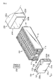
図1は、本発明の一実施例によるバッテリーモジュールを概略的に示した斜視図である。図2は、本発明の一実施例によるバッテリーモジュールの構成を分離して概略的に示した分離斜視図である。そして、図3は、本発明の一実施例によるバッテリーモジュールの一部構成を概略的に示した正面図である。 FIG. 1 is a perspective view schematically showing a battery module according to an embodiment of the present invention. FIG. 2 is a separated perspective view schematically showing the configuration of the battery module according to the embodiment of the present invention. FIG. 3 is a front view schematically showing a partial configuration of the battery module according to the embodiment of the present invention.
図1~図3を参照すれば、本発明の一実施例によるバッテリーモジュール200は、セルアセンブリー100、モジュールハウジング220、及びエンドフレーム230を含む。
Referring to FIGS. 1 to 3, the
ここで、前記セルアセンブリー100は、少なくとも三つ以上のバッテリーセル110を備え得る。また、前記バッテリーセル110は、パウチ型バッテリーセル110であり得る。特に、このようなパウチ型バッテリーセル110は、電極組立体、電解質及びパウチ外装ケース115を備え得る。
Here, the
ここで、電極組立体は、一つ以上の正極板及び一つ以上の負極板がセパレーターを挟んで配置された形態で構成され得る。より具体的に、電極組立体は、一つの正極板と一つの負極板とがセパレーターと共に巻き取られた巻取型、及び複数の正極板と複数の負極板とがセパレーターを挟んで相互積層されたスタック型などに分けられる。 Here, the electrode assembly may be configured in a form in which one or more positive electrode plates and one or more negative electrode plates are arranged with the separator interposed therebetween. More specifically, the electrode assembly is a winding type in which one positive electrode plate and one negative electrode plate are wound together with a separator, and a plurality of positive electrode plates and a plurality of negative electrode plates are laminated with each other sandwiching a separator. It can be divided into stack type and so on.
また、パウチ外装ケース115は、外部絶縁層、金属層及び内部接着層を備える形態で構成され得る。このようなパウチ外装ケース115は、電極組立体と電解液などの内部構成要素を保護し、電極組立体と電解液による電気化学的性質に対する補完及び放熱性などを向上するために金属薄膜、例えば、アルミニウム薄膜が含まれた形態で構成され得る。そして、このようなアルミニウム薄膜は、電極組立体及び電解液のようなバッテリーセル110の内部の構成要素やバッテリーセル110の外部の他の構成要素との電気的絶縁性を確保するために、絶縁物質から形成された絶縁層の間に挟まれ得る。
Further, the
特に、パウチ外装ケース115は、二つのパウチで構成され得、そのうち少なくとも一つには、凹んだ形態の内部空間が形成され得る。そして、このようなパウチの内部空間には、電極組立体が収納できる。この際、二つのパウチの外周面には封止部が備えられ、このような封止部が相互溶着することで、電極組立体が収容された内部空間を密閉できる。即ち、前記パウチ外装ケース115には、電極組立体及び電解液が収容された収容部115cが形成され得る。
In particular, the
各々のパウチ型バッテリーセル110は、電極リード111を備え、このような電極リード111には、正極リード及び負極リードが含まれ得る。
Each pouch-
より具体的に、電極リード111は、パウチ外装ケース115の前方または後方の外周縁に位置した封止部から前方または後方へ突出するように構成され得る。そして、このような電極リード111は、バッテリーセル110の電極端子として機能できる。例えば、図2に示したように、一つの電極リード111がバッテリーセル110から前方へ突出するように構成され得、他の一つの電極リード111がバッテリーセル110から後方へ突出するように構成され得る。
More specifically, the electrode leads 111 may be configured to project forward or backward from a sealing portion located on the outer peripheral edge of the front or rear of the
したがって、本発明のこのような構成によれば、一つのバッテリーセル110において、正極リードと負極リードとの干渉がなくなり、電極リード111の面積を広げることができ、複数の電極リード111同士の溶接、または電極リード111とバスバー(図示せず)との溶接などをより容易に行うことができる。
Therefore, according to such a configuration of the present invention, in one
また、パウチ型バッテリーセル110は、バッテリーモジュール200に複数個が含まれ、少なくとも一方向へ積層されるように配列され得る。例えば、図2に示したように、複数のパウチ型バッテリーセル110が左右方向へ平行に積層されるように構成され得る。この際、各々のパウチ型バッテリーセル110は、F方向から見たとき、二つの広い面が左右側に各々位置し、上部及び下部、前方及び後方には、封止部が位置するように地面にほぼ垂直に立てられるように配置され得る。即ち、各バッテリーセル110は、上下方向へ立てられて構成され得る。
Further, a plurality of pouch-
一方、本明細書において、前、後、左、右、上、下のように方向を示す用語は、観測者の位置や対象が置かれた形態によって変わり得る。但し、本明細書においては、説明の便宜のために、F方向から見ることを基準にして、前、後、左、右、上、下などの方向に区分して示す。 On the other hand, in the present specification, terms indicating directions such as front, back, left, right, top, and bottom may change depending on the position of the observer and the form in which the object is placed. However, in the present specification, for convenience of explanation, the front, rear, left, right, top, bottom, and the like are shown separately based on the view from the F direction.
さらに、前記バッテリーセル110のうち、バッテリーセル110の積層方向Wにおいて、内側に位置した一つ以上のバッテリーセル110が、外側に位置したバッテリーセル110よりも積層方向(左右方向)の厚さZがさらに厚い。ここで、前記厚さZの部位は、前記バッテリーセル110の電極組立体及び電解液が収容されるバッテリーセル110の収容部(図2、115c)の左右方向の厚さZを意味する。
Further, among the
具体的に、前記バッテリーセル110のうち、最内側に位置するバッテリーセル110となるにつれて、最外側に位置したバッテリーセル110よりも左右方向の厚さZがさらに厚くなっている。そして、前記バッテリーセル110のうち、最内側に位置したバッテリーセル110の左右方向の厚さZが最も厚くなっている。
Specifically, among the
さらに、前記バッテリーセル110は、積層方向Wを基準として、最外側に位置したバッテリーセル110から最内側に位置したバッテリーセル110へ進むにつれてバッテリーセル110の積層方向Wの厚さZが順次に厚くなり得る。
Further, in the
例えば、図3に示したように、セルアセンブリー100は、12個のバッテリーセル110を備えている。前記12個のバッテリーセル110のうち、最内側に位置した二つのバッテリーセル110aが、残りのバッテリーセル110よりも左右方向の厚さZがさらに厚く形成されている。
For example, as shown in FIG. 3, the
一方、複数のバッテリーセル110を備えたバッテリーモジュール200は、バッテリーセル110同士が接触した境界面Pで間隙が発生するので、このような境界面Pで熱抵抗が発生し得る。
On the other hand, in the
したがって、本発明のこのような構成によれば、本発明のバッテリーモジュール200は、バッテリーセル110の積層方向において、内側に位置したバッテリーセル110を、外側に位置したバッテリーセル110よりも積層方向における厚さZを厚く形成することで、セルアセンブリー100の内側にバッテリーセル110同士の境界面Pが形成される頻度を減らすことができる。即ち、セルアセンブリー100の外側から内側へ進むにつれて、バッテリーセル110同士の境界面Pの形成頻度が減少する。
Therefore, according to such a configuration of the present invention, in the
これによって、セルアセンブリー100の中心に位置したバッテリーセル110に過度な熱蓄積を防止し、全体バッテリーセル110の熱バランスを適切に維持することができ、バッテリーモジュール200の性能及び寿命特性を効果的に高めることができる。
As a result, excessive heat accumulation can be prevented in the
さらに、多様な厚さZの複数のバッテリーセル110を備えたセルアセンブリー100の場合、一つの大きいバッテリーセル110で構成されたセルアセンブリー100と比較して、バッテリーモジュール200の設計容量の変更時、必要なバッテリーセル110を追加するか、不要なバッテリーセル110を除去することで容易に設計変更が可能であるという利点がある。
Further, in the case of the
また、多様な厚さZの複数のバッテリーセル110を備えたセルアセンブリー100の場合、複数のバッテリーセル110のうち、不良が発生したバッテリーセル110のみを新しいものに入れ替えることで正常化させることができるので、バッテリーモジュール200のメインテナンスが容易となり、費用を節減することができる。
Further, in the case of the
図2及び図3をさらに参照すれば、前記バッテリーセル110のうち、積層方向において、内側に位置した一つ以上のバッテリーセル110が、外側に位置したバッテリーセル110よりもバッテリー容量がさらに大きい。即ち、内側に位置した一つ以上のバッテリーセル110は、外側に位置したバッテリーセル110よりも電極組立体及び電解質を収容可能な外装ケース115の容量がさらに大きい。言い換えれば、内側に位置したバッテリーセル110は、前記外装ケース115に収容された電極組立体及び電解質の量も、外側に位置したバッテリーセル110よりも多い。
Further referring to FIGS. 2 and 3, among the
これによって、セルアセンブリー100の体積当たりのエネルギー容量が、内側部位及び外側部位の両方とも同程度に形成される。
As a result, the energy capacity per volume of the
前述したパウチ型バッテリーセル110の構成については、本願発明が属する技術分野における当業者にとって自明な事項であるので、より詳細な説明を省略する。そして、本発明によるセルアセンブリー100には、本願発明の出願時点における公知の多様なバッテリーセル(二次電池)が採用可能である。
The configuration of the pouch-
また、図1及び図2を参照すれば、前記モジュールハウジング220は、バッテリーモジュール200において、外部衝撃から内部構成要素を保護するか、外部の異物が流れ込むことを防止する役割を果たすことができる。これによって、前記モジュールハウジング220は、バッテリーモジュール200に構造的安定性を付与し、衝撃や異物などのような外部の物理的な要素からセルアセンブリー100のように内部に収納された構成要素を保護する役割を果たす。このために、前記モジュールハウジング220は、スチールまたはアルミニウムのような金属材質からなり得る。
Further, referring to FIGS. 1 and 2, the
特に、アルミニウムを含む金属材質でモジュールハウジング220を構成する場合、アルミニウムの高い熱伝導性を用いてセルアセンブリー100で発生した熱をモジュールハウジング220の外部へ効果的に放出できる。
In particular, when the
また、前記モジュールハウジング220は、一つ以上の側壁220a、220b、220c、220dを備え得る。
Further, the
具体的に、前記側壁220a、220b、220c、220dは、複数個で構成される場合、相互連結されている構造であり得る。例えば、前記側壁220a、220b、220c、220dは、F方向から見たとき、セルアセンブリー100を基準として、上側壁220a、下側壁220b、左側壁220c及び右側壁220dを備え得、また、前記側壁220a、220b、220c、220dは、相互連結された構造であり得る。
Specifically, the
そして、前記モジュールハウジング220には、前記セルアセンブリー100を収納するように前記側壁220a、220b、220c、220dによって限定された内部空間が形成され得る。具体的に、前記内部空間は、セルアセンブリー100の外観形状と対応する内部構造を有し得る。
Then, the
例えば、図2に示したように、前記モジュールハウジング220は、概略全体形状が直方体であるセルアセンブリー100を内部に収容できるように、前記モジュールハウジング220の上側壁220a及び下側壁220bが、左側壁220c及び右側壁220dと相互直角をなすように連結された構造であり得る。
For example, as shown in FIG. 2, in the
さらに、前記モジュールハウジング220の上側壁220a、下側壁220b、左側壁220c及び右側壁220dのうち、一つ以上がセルアセンブリー100の少なくとも一つ以上の側面と接するように内部空間が備えられ得る。即ち、前記モジュールハウジング220の側壁220a、220b、220c、220dとセルアセンブリー100の外面とが直接接触する面積が大きくなるにつれて、セルアセンブリー100に生成された熱が効果的にモジュールハウジング220へ伝導される。
Further, an internal space may be provided such that one or more of the
例えば、図2に示したように、前記モジュールハウジング220は、セルアセンブリー100の上面、下面、左側面及び右側面と接するように、上側壁220a、下側壁220b、左側壁220c及び右側壁220dが形成され得る。
For example, as shown in FIG. 2, the
より具体的に、前記モジュールハウジング220は、上側壁220a、下側壁220b、左側壁220c及び右側壁220dが一体化した形態に形成されたモノフレームで構成され得る。
More specifically, the
ここで、一体化した形態とは、鋳造方法などを用いて、一つの本体で構成された形態を意味する。具体的に、前記モジュールハウジング220は、上側壁220a、下側壁220b、左側壁220c及び右側壁220dの各端部が相互連結された構造であり得る。
Here, the integrated form means a form composed of one main body by using a casting method or the like. Specifically, the
例えば、図2に示したように、モジュールハウジング220は、前後方向が開放され、上側壁220a、下側壁220b、左側壁220c及び右側壁220dの両端部が相互連結された四角の管状で構成され得る。
For example, as shown in FIG. 2, the
したがって、本発明のこのような構成によれば、前記モジュールハウジング220は、前記セルアセンブリー100の側面を囲むように形成されることで、バッテリーモジュール200の充放電時、前記セルアセンブリー100で生成された熱を効果的に外部へ放熱させることができる。
Therefore, according to such a configuration of the present invention, the
また、図1及び図2を参照すれば、前記エンドフレーム230は、本体フレーム232及び接合プレート236を備え得る。
Further, referring to FIGS. 1 and 2, the
ここで、前記本体フレーム232は、主壁232aを含み得る。即ち、前記主壁232aは、上下方向へ直立したプレート形状であり得る。また、前記主壁232aには、前記セルアセンブリー100と外部デバイスとの電気的接続をなすようにモジュール端子(図示せず)が備えられ得る。
Here, the
そして、前記本体フレーム232は、前記主壁232aの外周から前記モジュールハウジング220が位置した方向へ延びた一つ以上の側壁233を備え得る。
The
具体的に、前記本体フレーム232は、F方向から見たとき、前記主壁232aの中央を基準として、上側壁233a、下側壁233b、左側壁233c、及び右側壁233dを備え得る。さらに、前記側壁233a、233b、233c、233dは、相互連結された構造であり得る。
Specifically, the
さらに、前記本体フレーム232は、バッテリーモジュール200において、外部の衝撃から保護する役割を果たすことができる。これによって、前記本体フレーム232は、バッテリーモジュール200に構造的安定性を付与し、衝撃や異物などの外部の他の物理的な要素からセルアセンブリー100のような内部に収納された構成要素を保護する役割を果たす。このために、前記本体フレーム232は、スチールまたはアルミニウムのような金属材質からなり得る。
Further, the
さらに、前記接合プレート236は、一側部が前記本体フレーム232の側壁233に結合固定され得る。即ち、前記接合プレート236の上で所定位置の左右方向の線を基準として、前方部位と後方部位とに分けられ、前記接合プレート236の前方部または後方部は、前記本体フレーム232の側壁233の外面に結合固定され得る。
Further, one side of the
また、前記接合プレート236は、前記接合プレート236の前方部が前記本体フレーム232の側壁233の外面に結合固定される場合、後方部は、前記モジュールハウジング220の前端部に結合するように構成され得る。逆に、前記接合プレート236の後方部が前記本体フレーム232の側壁233の外面に結合固定される場合、前方部は、前記モジュールハウジング220の後端部に結合するように構成され得る。
Further, the
さらに、前記接合プレート236は、スチールまたはアルミニウムのような金属材質からなり得る。
Further, the
図4は、本発明の他の一実施例によるバッテリーモジュールの一部構成を概略的に示した正面図である。 FIG. 4 is a front view schematically showing a partial configuration of a battery module according to another embodiment of the present invention.
図4を参照すれば、他の一実施例によるバッテリーモジュール200Bは、セルアセンブリー100Bに備えられた少なくとも三つ以上のバッテリーセル110のうち、内側に位置したバッテリーセル110の上下方向Hの高さが、外側に位置したバッテリーセル110よりも大きくなるように形成され得る。
Referring to FIG. 4, the
例えば、図4に示したように、12個のバッテリーセル110のうち、最内側に位置した二つのバッテリーセル110aが、上下方向Hの高さが最も高く形成され得、前記二つのバッテリーセル110aに隣接して位置した4個のバッテリーセル110bが、二番目に大きい高さに形成され得、外側に位置した6個のバッテリーセル110cは、上下方向Hの高さが最も低く形成され得る。
For example, as shown in FIG. 4, of the 12
したがって、本発明のこのような構成によれば、他の一実施例によるバッテリーモジュール200Bは、セルアセンブリー100Bの内側に位置したバッテリーセル110の上下方向Hの高さを、残りのバッテリーセル110よりも相対的に高く形成することで、内側に位置したバッテリーセル110の外面積を効果的に増やすことができ、バッテリーセル110同士の接合面ではなく、外部に露出した外面の面積を増やすことができるので、積層方向において相対的に外側に位置したバッテリーセル110よりも放熱量を増やすことができる。
Therefore, according to such a configuration of the present invention, the
これによって、セルアセンブリー100Bの中心に位置したバッテリーセル110に過度な熱が蓄積されることを防止し、全体バッテリーセル110の熱バランスを適切に維持でき、バッテリーモジュール200Bの性能及び寿命特性を効果的に高めることができる。
As a result, excessive heat can be prevented from being accumulated in the
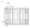
図5は、本発明のさらに他の一実施例によるバッテリーモジュールの一部構成を概略的に示した正面図である。 FIG. 5 is a front view schematically showing a partial configuration of a battery module according to still another embodiment of the present invention.
図5を参照すれば、前記モジュールハウジング220の側壁220a、220b、220c、220dは、前記バッテリーセル110同士の間に間隙が発生しないように前記バッテリーセル110を積層方向から内側へ押圧するように構成され得る。この際、図5のバッテリーモジュール200Cは、図3のバッテリーモジュール200と比較して、前記モジュールハウジング220のセルアセンブリー100Cを収容する内部空間に弾性部材130をさらに備え得る。
Referring to FIG. 5, the
具体的に、前記弾性部材130は、放熱性に優れており、外圧によって体積が減少または増加する弾性素材を備え得る。例えば、前記弾性部材130は、シリコーンパッドであり得る。また、前記弾性部材130は、前記複数のバッテリーセル110の積層方向における両側端の各々に位置し得る。例えば、図5に示したように、二つの弾性部材130が複数のバッテリーセル110の左右方向の両側に位置した左側壁220c及び右側壁220dの各々の内面に位置し得る。
Specifically, the
したがって、本発明のこのような構成によれば、モジュールハウジング220の内部に弾性部材130を備えることで、前記弾性部材130が弾力的に前記セルアセンブリー100Cを押圧でき、これによって、前記バッテリーセル110同士の間における間隙が減り、境界面における熱抵抗を大幅に減少させることができる。
Therefore, according to such a configuration of the present invention, by providing the
図6は、本発明のさらに他の実施例によるバッテリーモジュールの一部構成を概略的に示した正面図である。 FIG. 6 is a front view schematically showing a partial configuration of a battery module according to still another embodiment of the present invention.
図6を参照すれば、さらに他の一実施例によるバッテリーモジュール200Dのセルアセンブリー100Dは、図3のセルアセンブリー100と比較して、前記バッテリーセル110同士の接触外面が相互接合され得る。具体的に、図6のセルアセンブリー100Dの複数のバッテリーセル110の間には、前記バッテリーセル110同士の間に間隙が発生しないように接着層117が形成され得る。
Referring to FIG. 6, in the cell assembly 100D of the battery module 200D according to still another embodiment, the contact outer surfaces of the
さらに、このような接着層117は、放熱性に優れた素材であることが望ましく、例えば、硬化性グリース(grease)またはグルー(glue)であり得る。しかし、このような接着素材に限定されず、公知の放熱性接着素材を使って接着層117を形成してもよい。
Further, such an
したがって、本発明のこのような構成によれば、バッテリーセル110の間に接着層117を形成することで、バッテリーセル110の間に間隙が発生せず、バッテリーセル110同士の境界面における熱抵抗を大幅に減少させることができるだけでなく、バッテリーセル110が相互拘束されることで積層配列が崩れず、外部衝撃によるバッテリーセル110の動きを防止することができるので、セルアセンブリー100Dの安定性及び耐久性を向上させることができる。
Therefore, according to such a configuration of the present invention, by forming the
図7は、本発明のさらに他の実施例によるバッテリーモジュールの一部構成を概略的に示した正面図である。 FIG. 7 is a front view schematically showing a partial configuration of a battery module according to still another embodiment of the present invention.
図7を参照すれば、図7のバッテリーモジュール200Eのセルアセンブリー100Eは、図3のセルアセンブリー100と比較して、前記バッテリーセル110の各々の外装ケース115が一体化して相互連結された形態であり得る。また、前記バッテリーセル110の外装ケース115は、相互接触している部位115aが相互連結された形態であり得る。即ち、前記セルアセンブリー100Eに備えられた少なくとも三つ以上のバッテリーセル110の外装ケース115は、電極組立体及び電解液を収容できる複数の収容部が形成された一体型の外装ケース115であり得る。
Referring to FIG. 7, the
例えば、図7に示したように、12個のバッテリーセル110の外装ケース115は、一体型に形成され得る。即ち、12個のバッテリーセル110は、外装ケース115が一体型に形成され得る。
For example, as shown in FIG. 7, the
したがって、本発明のこのような構成によれば、一体型に形成された外装ケース115を備えたセルアセンブリー100Eは、バッテリーセル110同士の間に間隙が存在しないため、境界面で発生する熱抵抗を最小化することができる。また、前記セルアセンブリー100Eの外装ケース115の大きさを効果的に減らすことができるという利点がある。
Therefore, according to such a configuration of the present invention, in the
図8は、さらに他の実施例によるバッテリーモジュールの一部構成を概略的に示した正面図である。 FIG. 8 is a front view schematically showing a partial configuration of the battery module according to still another embodiment.
図8を参照すれば、図8のさらに他の実施例によるバッテリーモジュール200Fのセルアセンブリー100Fは、図3のセルアセンブリー100と比較して、冷却フィン119をさらに備え得る。具体的に、前記冷却フィン119は、少なくとも三つ以上のバッテリーセル110のうち、内側に位置したバッテリーセル110と接するように設けられ得る。
Referring to FIG. 8, the
また、前記冷却フィン119は、多様な大きさを有し得る。例えば、前記バッテリーセル110のうち、内側に位置したバッテリーセル110と接して位置した冷却フィン119aは、外側に位置したバッテリーセル110と接して位置した冷却フィン119bよりも外面の大きさがさらに大きくてもよい。即ち、内側に位置したバッテリーセル110と接して位置した冷却フィン119aは、外側に位置したバッテリーセル110と接して位置した冷却フィン119bよりも放熱量がさらに大きく設定され得る。
Further, the cooling
さらに、冷却フィン119を全てのバッテリーセル110に接するように構成するよりは、積層方向における内側に位置したバッテリーセル110と接するように構成し得る。これは、冷却フィン119の適用個数を減らすことで、バッテリーモジュール200Fの製造コストを節減できるだけではなく、バッテリーモジュール200Fの軽量化を図るのにさらに適合する。
Further, the cooling
例えば、図8に示したように、セルアセンブリー100Fには、三つの冷却フィン119が内側に位置したバッテリーセル110の間に設けられ得る。また、前記三つの冷却フィン119のうち、中央に位置した冷却フィン119aは、残りの冷却フィン119bよりも上下方向の長さが長く形成され得る。
For example, as shown in FIG. 8, in the
したがって、本発明のこのような構成によれば、冷却フィン119を内側に位置したバッテリーセル110と接するように設ける場合、ヒートアイランド現象が発生しやすい内側に位置したバッテリーセル110の放熱量を効果的に増大させることができる。これによって、全体バッテリーセル110の熱バランスを適切に維持でき、バッテリーモジュール200Fの性能及び寿命特性を効果的に高めることができる。
Therefore, according to such a configuration of the present invention, when the cooling
図9は、本発明のさらに他の実施例によるバッテリーモジュールの一部構成を概略的に示した正面図である。 FIG. 9 is a front view schematically showing a partial configuration of a battery module according to still another embodiment of the present invention.
図9を参照すれば、さらに他の実施例によるバッテリーモジュール200Gのセルアセンブリー100Gは、前記バッテリーセル110Gの積層方向において、内側に位置した一つ以上のバッテリーセル110Gの電極リード111aが、外側に位置したバッテリーセル110Gの電極リード111cよりも外面積が広く形成され得る。
Referring to FIG. 9, in the
また、前記バッテリーセル110Gの積層方向において、内側に位置した一つ以上のバッテリーセル110Gの電極リード111aは、外側に位置したバッテリーセル110Gの電極リード111cよりも上下方向が長く形成され得る。
Further, in the stacking direction of the
例えば、図9に示したように、12個のバッテリーセル110Gのうち、最内側に位置したバッテリーセル110aの電極リード111aは、外面積が最も広く形成され得る。さらに、前記12個のバッテリーセル110Gは、積層方向において、最外側に位置したバッテリーセル110cから最内側に位置したバッテリーセル110aへ進むにつれて、電極リード111の上下方向の長さが順次に長くなり得る。
For example, as shown in FIG. 9, of the 12
具体的に、図9に示したように、12個のバッテリーセル110Gのうち、最内側に位置した二つのバッテリーセル110aの電極リード111aの上下方向の長さが最も長く形成され得、前記二つのバッテリーセル110aに隣接して位置した4個のバッテリーセル110bの電極リード111bが二番目に長く形成され得、外側に位置した6個のバッテリーセル110cの電極リード111cは、上下方向の長さが最も短く形成され得る。
Specifically, as shown in FIG. 9, among the 12
即ち、電極リード111の外面が大きくなるにつれて、バッテリーセル110Gの放熱量を増やすことができるので、内側に位置したバッテリーセル110Gで熱蓄積が最も発生しやすいことから、内側に位置したバッテリーセル110aの電極リード111aの外面をさらに広く形成し、発熱量がさらに大きくなるように形成することができる。
That is, as the outer surface of the
したがって、本発明のこのような構成によれば、セルアセンブリー100Gの内側に位置したバッテリーセル110Gの電極リード111の外面を相対的に広く形成することで、内側に位置したバッテリーセル110Gの放熱量を効果的に増加させることができるだけでなく、内側に相対的に厚く形成されたバッテリーセル110Gの放熱効果と共にさらに大きいシナジー効果を発揮できる。
Therefore, according to such a configuration of the present invention, by forming the outer surface of the
図10は、本発明のさらに他の実施例によるバッテリーモジュールのバッテリーセルを概略的に示した一部平面図である。 FIG. 10 is a partial plan view schematically showing a battery cell of a battery module according to still another embodiment of the present invention.
図10を参照すれば、本発明のさらに他の実施例によるバッテリーモジュール200Hのセルアセンブリー100Hの前記バッテリーセル110Hの積層方向において、内側(中央)に位置した一つ以上のバッテリーセル110Hの電極リード111aの厚さT1が、外側に位置したバッテリーセル110Hの電極リード111cよりも厚く形成され得る。
Referring to FIG. 10, the electrodes of one or
例えば、図10に示したように、12個のバッテリーセル110Hの電極リード111の積層方向の厚さT1が相違し得る。即ち、12個のバッテリーセル110Hのうち、最内側に位置した二つのバッテリーセル110aは、0.8mmの厚さT1を有し得、残りの内側に隣接した4個のバッテリーセル110Hの電極リード111bは、0.6mmの厚さT2を有し得、外側に位置した6個のバッテリーセル110Hの電極リード111cは、0.4mmの厚さT3を有し得る。
For example, as shown in FIG. 10, the thickness T1 of the electrode leads 111 of the 12
したがって、本発明のこのような構成によれば、内側に位置したバッテリーセル110aの電極リード111を、外側に位置したバッテリーセル110cよりも厚く形成することで、電極リード111による放熱量を増大させ、電極リード111に発生する電気抵抗熱を減らすことができるので、内側に位置したバッテリーセル110Hの熱蓄積を効果的に減らすことができる。
Therefore, according to such a configuration of the present invention, the
また、本発明によるバッテリーパック(図示せず)は、前記バッテリーモジュール200を少なくとも一つ以上含み得る。さらに、本発明によるバッテリーパックは、このようなバッテリーモジュール200に加え、バッテリーモジュール200を収納するためのパックケース、バッテリーモジュール200の充放電を制御するための各種装置、例えば、BMS、電流センサー、ヒューズなどをさらに含み得る。
Further, the battery pack (not shown) according to the present invention may include at least one
そして、本発明によるバッテリーパックは、電気自動車やハイブリッド自動車のような自動車に適用することができる。即ち、本発明による自動車は、本発明によるバッテリーパックを含み得る。 The battery pack according to the present invention can be applied to automobiles such as electric vehicles and hybrid vehicles. That is, the vehicle according to the present invention may include a battery pack according to the present invention.
なお、本明細書において、上、下、左、右、前、後のような方向を示す用語が使用されたが、このような用語は相対的な位置を示し、説明の便宜のためのものであるだけで、対象となる事物の位置や観測者の位置などによって変わり得ることは、当業者にとって自明である。 In the present specification, terms indicating directions such as up, down, left, right, front, and back are used, but such terms indicate relative positions and are for convenience of explanation. It is obvious to those skilled in the art that it can change depending on the position of the object or the position of the observer.
以上のように、本発明を限定された実施例と図面によって説明したが、本発明はこれに限定されるものではなく、本発明の属する技術分野で通常の知識を持つ者によって本発明の技術思想と特許請求の範囲の均等範囲内で多様な修正及び変形が可能であることは言うまでもない。 As described above, the present invention has been described with reference to limited examples and drawings, but the present invention is not limited thereto, and the technique of the present invention is used by a person having ordinary knowledge in the technical field to which the present invention belongs. It goes without saying that various modifications and modifications are possible within the same range of ideas and claims.
本発明は、多様な大きさの複数のバッテリーセルが備えられたバッテリーモジュール及びバッテリーパックに関する。また、本発明は、前記バッテリーパックが備えられた電子デバイスまたは自動車関連産業に利用可能である。 The present invention relates to a battery module and a battery pack provided with a plurality of battery cells of various sizes. The present invention can also be used in electronic devices equipped with the battery pack or in the automobile-related industry.
100 セルアセンブリー
110 バッテリーセル、パウチ型バッテリーセル
111 電極リード
115 外装ケース、パウチ外装ケース
117 接着層
119 冷却フィン
130 弾性部材
200 バッテリーモジュール
220 モジュールハウジング
230 エンドフレーム
232 本体フレーム
233 側壁
236 接合プレート
100
Claims (8)
一つ以上の側壁を備えるモジュールハウジングであって、前記側壁によって限定される内部空間に前記セルアセンブリーを収納するように構成されたモジュールハウジングと、を含み、
前記バッテリーセル各々の外装ケースが直接的に接触した状態で相互連結されている一体型であり、
前記バッテリーセルの積層方向において、内側に位置した一つ以上のバッテリーセルの高さが、外側に位置したバッテリーセルの高さよりも大きいことを特徴とするバッテリーモジュール。 A cell assembly in which at least three or more battery cells are stacked in one direction, and one or more battery cells located inside in the stacking direction of the battery cells among the battery cells. With a cell assembly, which is thicker than the battery cell located on the outside and has a thickness in the stacking direction,
A module housing comprising one or more sidewalls, comprising a module housing configured to house the cell assembly in an internal space confined by the sidewalls.
It is an integrated type in which the outer cases of each of the battery cells are interconnected in a state of direct contact .
A battery module characterized in that the height of one or more battery cells located inside is larger than the height of the battery cells located outside in the stacking direction of the battery cells .
Applications Claiming Priority (3)
| Application Number | Priority Date | Filing Date | Title |
|---|---|---|---|
| KR10-2018-0039232 | 2018-04-04 | ||
| KR1020180039232A KR102312416B1 (en) | 2018-04-04 | 2018-04-04 | Battery Module |
| PCT/KR2019/001994 WO2019194413A1 (en) | 2018-04-04 | 2019-02-19 | Battery module |
Publications (2)
| Publication Number | Publication Date |
|---|---|
| JP2020527848A JP2020527848A (en) | 2020-09-10 |
| JP7062192B2 true JP7062192B2 (en) | 2022-05-06 |
Family
ID=68101060
Family Applications (1)
| Application Number | Title | Priority Date | Filing Date |
|---|---|---|---|
| JP2020524702A Active JP7062192B2 (en) | 2018-04-04 | 2019-02-19 | Battery module |
Country Status (6)
| Country | Link |
|---|---|
| US (1) | US11923523B2 (en) |
| EP (1) | EP3686954A4 (en) |
| JP (1) | JP7062192B2 (en) |
| KR (1) | KR102312416B1 (en) |
| CN (1) | CN111418085B (en) |
| WO (1) | WO2019194413A1 (en) |
Families Citing this family (4)
| Publication number | Priority date | Publication date | Assignee | Title |
|---|---|---|---|---|
| DE102019207356A1 (en) * | 2019-05-20 | 2020-11-26 | Audi Ag | Module housing, battery module, high-voltage battery, motor vehicle and method for introducing a heat-conducting medium between a battery module and a cooling floor |
| CN115152080A (en) | 2020-09-30 | 2022-10-04 | 宁德时代新能源科技股份有限公司 | Battery, device, preparation method of battery and preparation device |
| CN113363673B (en) * | 2021-06-28 | 2024-03-12 | 东莞新能安科技有限公司 | Battery module and electronic device using same |
| KR20230058870A (en) * | 2021-10-25 | 2023-05-03 | 주식회사 엘지에너지솔루션 | A lithium secondary battery having a fire suppression structure |
Citations (5)
| Publication number | Priority date | Publication date | Assignee | Title |
|---|---|---|---|---|
| JP2009182001A (en) | 2008-01-29 | 2009-08-13 | Nisshin Steel Co Ltd | Cell stack structure |
| JP2011044275A (en) | 2009-08-20 | 2011-03-03 | Sanyo Electric Co Ltd | Power supply device, and vehicle using the same |
| JP2011222369A (en) | 2010-04-12 | 2011-11-04 | Toyota Motor Corp | Power storage device and manufacturing method of the same |
| JP2013157112A (en) | 2012-01-27 | 2013-08-15 | Toshiba Corp | Battery pack |
| WO2017209388A1 (en) | 2016-05-31 | 2017-12-07 | 주식회사 엘지화학 | Battery module, battery pack comprising same, and automobile |
Family Cites Families (27)
| Publication number | Priority date | Publication date | Assignee | Title |
|---|---|---|---|---|
| KR980006597A (en) * | 1996-06-29 | 1998-03-30 | 김광호 | Nickel-zinc module battery |
| US6255015B1 (en) * | 1998-08-23 | 2001-07-03 | Ovonic Battery Company, Inc. | Monoblock battery assembly |
| JP3793908B2 (en) | 1998-11-24 | 2006-07-05 | 本田技研工業株式会社 | Rechargeable battery |
| KR100958647B1 (en) * | 2002-12-18 | 2010-05-20 | 삼성에스디아이 주식회사 | Pouch type secondary battery |
| JP4738730B2 (en) | 2003-04-21 | 2011-08-03 | 株式会社マキタ | Battery pack and battery pack |
| KR100560158B1 (en) * | 2003-09-29 | 2006-03-16 | 주식회사 코캄 | Lithium secondary battery with high safety and manufacturing method thereof |
| US7041408B1 (en) | 2004-12-28 | 2006-05-09 | Utc Fuel Cells, Llc | Varied fuel cell oxidant flow channel depth resulting in fewer cooler plates |
| KR101431278B1 (en) | 2008-12-19 | 2014-08-20 | 주식회사 엘지화학 | Secondary battery having enhanced uniformity of temperature distribution |
| WO2011099793A2 (en) * | 2010-02-10 | 2011-08-18 | 주식회사 엘지화학 | Rechargeable lithium battery in pouch form |
| US9040187B2 (en) * | 2010-07-13 | 2015-05-26 | Apple, Inc. | Battery pack with cells of different capacities electrically coupled in parallel |
| DE102010047453A1 (en) * | 2010-10-04 | 2012-04-05 | Li-Tec Battery Gmbh | Housing for receiving a flat electrochemical cell |
| US9548476B2 (en) | 2010-12-20 | 2017-01-17 | Samsung Sdi Co., Ltd. | Multi-cell battery module with integral cooling and assembly aids |
| US9431686B2 (en) | 2011-02-28 | 2016-08-30 | Sanyo Electric Co., Ltd. | Cell module and manufacturing method for cell module |
| JP2013143185A (en) | 2012-01-06 | 2013-07-22 | Hitachi Ltd | Battery module and battery pack |
| KR101178152B1 (en) | 2012-02-23 | 2012-08-29 | 주식회사 엘지화학 | Battery pack of novel structure |
| US20130236768A1 (en) | 2012-03-08 | 2013-09-12 | Lg Chem, Ltd. | Battery pack of stair-like structure |
| KR20130118716A (en) * | 2012-04-20 | 2013-10-30 | 주식회사 엘지화학 | Electrode assembly, battery cell and device comprising the same |
| DE102012207162A1 (en) | 2012-04-30 | 2013-10-31 | Robert Bosch Gmbh | Process for the production of Li-ion battery modules and a corresponding Li-ion battery module |
| KR20140100032A (en) * | 2013-02-05 | 2014-08-14 | 주식회사 엘지화학 | Battery Cell Having Structure of Steps-Formed |
| KR101783914B1 (en) * | 2013-10-22 | 2017-10-10 | 주식회사 엘지화학 | Pouch type secondary battery and battery pack including the same |
| JP6168167B2 (en) * | 2014-02-12 | 2017-07-26 | 日産自動車株式会社 | Battery module |
| EP3340365B1 (en) | 2015-09-21 | 2020-04-22 | LG Chem, Ltd. | Battery module including array of cooling fins having different thicknesses |
| KR102051109B1 (en) | 2015-10-08 | 2019-12-02 | 주식회사 엘지화학 | Battery Module |
| KR20170072698A (en) * | 2015-12-17 | 2017-06-27 | 주식회사 엘지화학 | Battery module, battery pack comprising the battery module and plug in hybrid electric vehicle comprising the battery pack |
| CN107799799A (en) | 2016-09-05 | 2018-03-13 | 宁德新能源科技有限公司 | Battery bag |
| KR102556084B1 (en) | 2016-10-07 | 2023-07-17 | 삼성디스플레이 주식회사 | Display device capable of changing frame rate and operating method thereof |
| DE102016225184A1 (en) * | 2016-12-15 | 2018-06-21 | Robert Bosch Gmbh | Battery module with battery cell system and enclosure |
-
2018
- 2018-04-04 KR KR1020180039232A patent/KR102312416B1/en active IP Right Grant
-
2019
- 2019-02-19 CN CN201980006045.0A patent/CN111418085B/en active Active
- 2019-02-19 JP JP2020524702A patent/JP7062192B2/en active Active
- 2019-02-19 US US16/650,211 patent/US11923523B2/en active Active
- 2019-02-19 EP EP19780914.8A patent/EP3686954A4/en active Pending
- 2019-02-19 WO PCT/KR2019/001994 patent/WO2019194413A1/en unknown
Patent Citations (5)
| Publication number | Priority date | Publication date | Assignee | Title |
|---|---|---|---|---|
| JP2009182001A (en) | 2008-01-29 | 2009-08-13 | Nisshin Steel Co Ltd | Cell stack structure |
| JP2011044275A (en) | 2009-08-20 | 2011-03-03 | Sanyo Electric Co Ltd | Power supply device, and vehicle using the same |
| JP2011222369A (en) | 2010-04-12 | 2011-11-04 | Toyota Motor Corp | Power storage device and manufacturing method of the same |
| JP2013157112A (en) | 2012-01-27 | 2013-08-15 | Toshiba Corp | Battery pack |
| WO2017209388A1 (en) | 2016-05-31 | 2017-12-07 | 주식회사 엘지화학 | Battery module, battery pack comprising same, and automobile |
Also Published As
| Publication number | Publication date |
|---|---|
| EP3686954A4 (en) | 2021-02-17 |
| WO2019194413A1 (en) | 2019-10-10 |
| US20200266398A1 (en) | 2020-08-20 |
| KR20190115940A (en) | 2019-10-14 |
| EP3686954A1 (en) | 2020-07-29 |
| CN111418085A (en) | 2020-07-14 |
| US11923523B2 (en) | 2024-03-05 |
| CN111418085B (en) | 2023-01-17 |
| JP2020527848A (en) | 2020-09-10 |
| KR102312416B1 (en) | 2021-10-12 |
Similar Documents
| Publication | Publication Date | Title |
|---|---|---|
| JP7062192B2 (en) | Battery module | |
| JP5621111B2 (en) | Battery cell with improved thermal stability and medium- or large-sized battery module using the same | |
| EP3276739B1 (en) | Battery module | |
| KR102119183B1 (en) | Battery module | |
| JP6719562B2 (en) | Battery module | |
| KR102112716B1 (en) | Battery module, battery pack the battery module and vehicle comprising the battery pack | |
| JP7047208B2 (en) | Battery module with heat shrinkable tube | |
| JP5242697B2 (en) | Battery cell with excellent heat dissipation characteristics and medium or large battery module using it | |
| KR102088477B1 (en) | Battery module | |
| KR101960922B1 (en) | Battery module | |
| KR102176697B1 (en) | Battery Module Having Unit Body | |
| KR101098196B1 (en) | Battery Cell Having Improved Thermal Stability and Middle or Large-sized Battery Module Employed with the Same | |
| JP2022521945A (en) | Battery pack and devices containing it | |
| KR102057620B1 (en) | Battery module | |
| JP2018518025A (en) | Battery pack including edge cooling member | |
| KR101560563B1 (en) | Secondary Battery Of Improved Cooling Efficiency | |
| KR20130001970A (en) | Battery module assembly and battery pack including the same | |
| JP2021524136A (en) | A battery module with improved safety, a battery pack containing the battery module, and a vehicle containing the battery pack. | |
| CN220121952U (en) | Battery module and battery pack including the same | |
| JP2023538292A (en) | Battery packs and devices containing them | |
| KR20240012299A (en) | Battery pack and device including the same | |
| JP2023531641A (en) | Battery packs and devices containing them | |
| KR20230146306A (en) | Battery pack and vehicle including the same | |
| JP2023552124A (en) | Battery module and battery pack containing it | |
| KR20240012303A (en) | Battery cell assembly and battery pack including the same |
Legal Events
| Date | Code | Title | Description |
|---|---|---|---|
| A621 | Written request for application examination |
Free format text: JAPANESE INTERMEDIATE CODE: A621 Effective date: 20200122 |
|
| A977 | Report on retrieval |
Free format text: JAPANESE INTERMEDIATE CODE: A971007 Effective date: 20210112 |
|
| A131 | Notification of reasons for refusal |
Free format text: JAPANESE INTERMEDIATE CODE: A131 Effective date: 20210201 |
|
| A521 | Request for written amendment filed |
Free format text: JAPANESE INTERMEDIATE CODE: A523 Effective date: 20210409 |
|
| A02 | Decision of refusal |
Free format text: JAPANESE INTERMEDIATE CODE: A02 Effective date: 20210628 |
|
| A521 | Request for written amendment filed |
Free format text: JAPANESE INTERMEDIATE CODE: A523 Effective date: 20211028 |
|
| C60 | Trial request (containing other claim documents, opposition documents) |
Free format text: JAPANESE INTERMEDIATE CODE: C60 Effective date: 20211028 |
|
| A911 | Transfer to examiner for re-examination before appeal (zenchi) |
Free format text: JAPANESE INTERMEDIATE CODE: A911 Effective date: 20211108 |
|
| C21 | Notice of transfer of a case for reconsideration by examiners before appeal proceedings |
Free format text: JAPANESE INTERMEDIATE CODE: C21 Effective date: 20211115 |
|
| TRDD | Decision of grant or rejection written | ||
| A01 | Written decision to grant a patent or to grant a registration (utility model) |
Free format text: JAPANESE INTERMEDIATE CODE: A01 Effective date: 20211129 |
|
| A711 | Notification of change in applicant |
Free format text: JAPANESE INTERMEDIATE CODE: A712 Effective date: 20211227 |
|
| A61 | First payment of annual fees (during grant procedure) |
Free format text: JAPANESE INTERMEDIATE CODE: A61 Effective date: 20211228 |
|
| R150 | Certificate of patent or registration of utility model |
Ref document number: 7062192 Country of ref document: JP Free format text: JAPANESE INTERMEDIATE CODE: R150 |