JP7061882B2 - Measuring equipment, methods, programs, recording media - Google Patents
Measuring equipment, methods, programs, recording media Download PDFInfo
- Publication number
- JP7061882B2 JP7061882B2 JP2018007258A JP2018007258A JP7061882B2 JP 7061882 B2 JP7061882 B2 JP 7061882B2 JP 2018007258 A JP2018007258 A JP 2018007258A JP 2018007258 A JP2018007258 A JP 2018007258A JP 7061882 B2 JP7061882 B2 JP 7061882B2
- Authority
- JP
- Japan
- Prior art keywords
- sensor
- amount
- measuring device
- measurement
- pulse
- Prior art date
- Legal status (The legal status is an assumption and is not a legal conclusion. Google has not performed a legal analysis and makes no representation as to the accuracy of the status listed.)
- Active
Links
Images


Classifications
-
- G—PHYSICS
- G01—MEASURING; TESTING
- G01R—MEASURING ELECTRIC VARIABLES; MEASURING MAGNETIC VARIABLES
- G01R33/00—Arrangements or instruments for measuring magnetic variables
- G01R33/0023—Electronic aspects, e.g. circuits for stimulation, evaluation, control; Treating the measured signals; calibration
- G01R33/0029—Treating the measured signals, e.g. removing offset or noise
-
- G—PHYSICS
- G01—MEASURING; TESTING
- G01R—MEASURING ELECTRIC VARIABLES; MEASURING MAGNETIC VARIABLES
- G01R33/00—Arrangements or instruments for measuring magnetic variables
- G01R33/0017—Means for compensating offset magnetic fields or the magnetic flux to be measured; Means for generating calibration magnetic fields
-
- G—PHYSICS
- G01—MEASURING; TESTING
- G01R—MEASURING ELECTRIC VARIABLES; MEASURING MAGNETIC VARIABLES
- G01R33/00—Arrangements or instruments for measuring magnetic variables
- G01R33/0023—Electronic aspects, e.g. circuits for stimulation, evaluation, control; Treating the measured signals; calibration
- G01R33/0041—Electronic aspects, e.g. circuits for stimulation, evaluation, control; Treating the measured signals; calibration using feed-back or modulation techniques
-
- G—PHYSICS
- G01—MEASURING; TESTING
- G01R—MEASURING ELECTRIC VARIABLES; MEASURING MAGNETIC VARIABLES
- G01R33/00—Arrangements or instruments for measuring magnetic variables
- G01R33/0094—Sensor arrays
-
- G—PHYSICS
- G01—MEASURING; TESTING
- G01R—MEASURING ELECTRIC VARIABLES; MEASURING MAGNETIC VARIABLES
- G01R33/00—Arrangements or instruments for measuring magnetic variables
- G01R33/02—Measuring direction or magnitude of magnetic fields or magnetic flux
Description
本発明は、センサにおいて発生する1/fノイズの除去に関する。 The present invention relates to removing 1 / f noise generated in a sensor.
従来より、微弱な磁界を測定するセンサが知られている(例えば、特許文献1の要約を参照)。また、耐ノイズ性を向上し、磁界強度の計測を用いた位置検出法が知られている(例えば、特許文献2の要約を参照)。さらに、磁気センサとしてはMIセンサが知られている(例えば、特許文献3の要約を参照)。 Conventionally, a sensor for measuring a weak magnetic field has been known (see, for example, a summary of Patent Document 1). Further, a position detection method that improves noise resistance and uses measurement of magnetic field strength is known (see, for example, a summary of Patent Document 2). Further, an MI sensor is known as a magnetic sensor (see, for example, the abstract of Patent Document 3).
本発明は、磁気センサなどのセンサにおいて発生する1/fノイズによる測定結果の誤差を軽減することを課題とする。 An object of the present invention is to reduce an error in measurement results due to 1 / f noise generated in a sensor such as a magnetic sensor.
本発明にかかる測定装置は、測定対象が発生する測定対象量を測定する測定装置であって、前記測定対象量に加算する加算量を発生する加算量発生部と、前記測定対象量に前記加算量が加算された合成量を測定するセンサと、前記センサの出力から前記測定対象量を導出する導出部とを備え、前記センサによる測定の際に、1/fノイズが発生し、前記合成量が0未満の場合の前記センサの出力値は、前記合成量が0の場合の前記センサの出力値と同じ値であり、前記加算量は、パルスであり、該パルスは、前記測定対象量の最大値の絶対値よりも大きな振幅を有し、該パルスの最大値が0であり、該パルスは、前記1/fノイズを無視できる程度に高い周波数を有し、前記導出部は、前記センサの出力値を検波することにより、前記測定対象量を導出するように構成される。 The measuring device according to the present invention is a measuring device that measures a measurement target amount generated by a measurement target, and includes an additional amount generating unit that generates an additional amount to be added to the measurement target amount and the addition to the measurement target amount. A sensor for measuring the combined amount to which the amount is added and a derivation unit for deriving the measurement target amount from the output of the sensor are provided, and 1 / f noise is generated during the measurement by the sensor, and the combined amount is generated. The output value of the sensor when is less than 0 is the same as the output value of the sensor when the combined amount is 0, the addition amount is a pulse, and the pulse is the measurement target amount. It has an amplitude larger than the absolute value of the maximum value, the maximum value of the pulse is 0, the pulse has a frequency high enough to ignore the 1 / f noise, and the derivation unit is the sensor. It is configured to derive the measurement target amount by detecting the output value of.
上記のように構成された測定装置は、測定対象が発生する測定対象量を測定する。加算量発生部は、前記測定対象量に加算する加算量を発生する。センサは、前記測定対象量に前記加算量が加算された合成量を測定する。導出部は、前記センサの出力から前記測定対象量を導出する。前記センサによる測定の際に、1/fノイズが発生する。前記合成量が0未満の場合の前記センサの出力値は、前記合成量が0の場合の前記センサの出力値と同じ値である。前記加算量は、パルスである。該パルスは、前記測定対象量の最大値の絶対値よりも大きな振幅を有する。該パルスの最大値が0である。該パルスは、前記1/fノイズを無視できる程度に高い周波数を有する。前記導出部は、前記センサの出力値を検波することにより、前記測定対象量を導出する。 The measuring device configured as described above measures the amount of the measurement target generated by the measurement target. The addition amount generation unit generates an addition amount to be added to the measurement target amount. The sensor measures the combined amount obtained by adding the additional amount to the measurement target amount. The derivation unit derives the measure target amount from the output of the sensor. 1 / f noise is generated during measurement by the sensor. The output value of the sensor when the combined amount is less than 0 is the same as the output value of the sensor when the combined amount is 0. The addition amount is a pulse. The pulse has an amplitude larger than the absolute value of the maximum value of the measure target amount. The maximum value of the pulse is 0. The pulse has a frequency high enough to ignore the 1 / f noise. The derivation unit derives the measure target amount by detecting the output value of the sensor.
なお、本発明にかかる測定装置は、前記測定対象量は磁場であるようにしてもよい。 In the measuring device according to the present invention, the measure target amount may be a magnetic field.
なお、本発明にかかる測定装置は、前記センサの出力を受けて、前記1/fノイズを、前記パルスの周波数と同じ周波数の成分よりも減衰させて、前記導出部に与えるハイパスフィルタを備えるようにしてもよい。 The measuring device according to the present invention is provided with a high-pass filter that receives the output of the sensor, attenuates the 1 / f noise from a component having the same frequency as the frequency of the pulse, and gives it to the derivation unit. You may do it.
なお、本発明にかかる測定装置は、複数の前記センサの出力を合計して一つの前記導出部に与える合計部を備えるようにしてもよい。 The measuring device according to the present invention may include a totaling unit that totals the outputs of the plurality of sensors and gives them to one out-licensing unit.
なお、本発明にかかる測定装置は、複数の前記センサの出力を、それぞれ別々の前記導出部に与えるようにしてもよい。 The measuring device according to the present invention may supply the outputs of the plurality of sensors to the separate derivation units.
なお、本発明にかかる測定装置は、前記合成量に、誤差補正量を加えて、前記センサに与える前置誤差補正部を備えるようにしてもよい。 The measuring device according to the present invention may be provided with a pre-error correction unit that is applied to the sensor by adding an error correction amount to the combined amount.
なお、本発明にかかる測定装置は、アナログである前記センサの出力を、デジタルに変換して、前記導出部に与えるようにしてもよい。 The measuring device according to the present invention may convert the output of the analog sensor into digital and give it to the derivation unit.
なお、本発明にかかる測定装置は、前記導出部の出力を受けて、外部環境に起因する誤差を補正する外部誤差補正部を備えるようにしてもよい。 The measuring device according to the present invention may be provided with an external error correction unit that receives the output of the derivation unit and corrects an error caused by the external environment.
なお、本発明にかかる測定装置は、ある一つの前記センサと、その出力を受けるある一つの前記導出部とを有するチャネルを複数備え、さらに前記チャネル間の誤差を補正するチャネル間誤差補正部を備えるようにしてもよい。 The measuring device according to the present invention includes a plurality of channels having one sensor and one derivation unit that receives the output thereof, and further includes an inter-channel error correction unit that corrects an error between the channels. You may be prepared.
なお、本発明にかかる測定装置は、前記1/fノイズを無視できる程度に高い周波数帯域における前記導出部の出力の誤差を測定する高周波帯域誤差測定部と、前記高周波帯域誤差測定部の測定結果に基づき、前記パルスの周波数を決定する周波数決定部とを備えるようにしてもよい。 The measuring device according to the present invention has a high frequency band error measuring unit for measuring an output error of the derivation unit in a frequency band so high that the 1 / f noise can be ignored, and a measurement result of the high frequency band error measuring unit. A frequency determination unit that determines the frequency of the pulse may be provided based on the above.
本発明は、測定対象が発生する測定対象量を測定する測定方法であって、前記測定対象量に加算する加算量を発生する加算量発生工程と、センサにより、前記測定対象量に前記加算量が加算された合成量を測定する測定工程と、前記センサの出力から前記測定対象量を導出する導出工程とを備え、前記センサによる測定の際に、1/fノイズが発生し、前記合成量が0未満の場合の前記センサの出力値は、前記合成量が0の場合の前記センサの出力値と同じ値であり、前記加算量は、パルスであり、該パルスは、前記測定対象量の最大値の絶対値よりも大きな振幅を有し、該パルスの最大値が0であり、該パルスは、前記1/fノイズを無視できる程度に高い周波数を有し、前記導出工程は、前記センサの出力値を検波することにより、前記測定対象量を導出する測定方法である。 The present invention is a measurement method for measuring a measurement target amount generated by a measurement target, and the addition amount is added to the measurement target amount by a sensor and an additional amount generation step of generating an additional amount to be added to the measurement target amount. It is provided with a measurement step of measuring the combined amount to which is added and a derivation step of deriving the measurement target amount from the output of the sensor, and 1 / f noise is generated during the measurement by the sensor, and the combined amount is generated. The output value of the sensor when is less than 0 is the same as the output value of the sensor when the combined amount is 0, the addition amount is a pulse, and the pulse is the measurement target amount. It has an amplitude larger than the absolute value of the maximum value, the maximum value of the pulse is 0, the pulse has a frequency high enough to ignore the 1 / f noise, and the derivation step is the sensor. This is a measurement method for deriving the measurement target amount by detecting the output value of.
本発明は、測定対象が発生する測定対象量を測定する測定装置であって、前記測定対象量に加算する加算量を発生する加算量発生部と、前記測定対象量に前記加算量が加算された合成量を測定するセンサとを有する測定装置における測定処理をコンピュータに実行させるためのプログラムであって、前記測定処理は、前記センサの出力から前記測定対象量を導出する導出工程を備え、前記センサによる測定の際に、1/fノイズが発生し、前記合成量が0未満の場合の前記センサの出力値は、前記合成量が0の場合の前記センサの出力値と同じ値であり、前記加算量は、パルスであり、該パルスは、前記測定対象量の最大値の絶対値よりも大きな振幅を有し、該パルスの最大値が0であり、該パルスは、前記1/fノイズを無視できる程度に高い周波数を有し、前記導出工程は、前記センサの出力値を検波することにより、前記測定対象量を導出するプログラムである。 The present invention is a measuring device that measures a measurement target amount generated by a measurement target, and is a measurement device that generates an additional amount to be added to the measurement target amount, and the additional amount is added to the measurement target amount. It is a program for causing a computer to execute a measurement process in a measuring device having a sensor for measuring the combined amount, and the measurement process includes a derivation step of deriving the measurement target amount from the output of the sensor. When 1 / f noise is generated during measurement by the sensor and the combined amount is less than 0, the output value of the sensor is the same as the output value of the sensor when the combined amount is 0. The addition amount is a pulse, the pulse has an amplitude larger than the absolute value of the maximum value of the measurement target amount, the maximum value of the pulse is 0, and the pulse is the 1 / f noise. The derivation step is a program for deriving the amount to be measured by detecting the output value of the sensor.
本発明は、測定対象が発生する測定対象量を測定する測定装置であって、前記測定対象量に加算する加算量を発生する加算量発生部と、前記測定対象量に前記加算量が加算された合成量を測定するセンサとを有する測定装置における測定処理をコンピュータに実行させるためのプログラムを記録したコンピュータによって読み取り可能な記録媒体であって、前記測定処理は、前記センサの出力から前記測定対象量を導出する導出工程を備え、前記センサによる測定の際に、1/fノイズが発生し、前記合成量が0未満の場合の前記センサの出力値は、前記合成量が0の場合の前記センサの出力値と同じ値であり、前記加算量は、パルスであり、該パルスは、前記測定対象量の最大値の絶対値よりも大きな振幅を有し、該パルスの最大値が0であり、該パルスは、前記1/fノイズを無視できる程度に高い周波数を有し、前記導出工程は、前記センサの出力値を検波することにより、前記測定対象量を導出する記録媒体である。 The present invention is a measuring device that measures a measurement target amount generated by a measurement target, and is a measurement device that generates an additional amount to be added to the measurement target amount, and the additional amount is added to the measurement target amount. It is a recording medium readable by a computer that records a program for causing a computer to execute a measurement process in a measuring device having a sensor for measuring the combined amount, and the measurement process is the measurement target from the output of the sensor. The derivation process for deriving the amount is provided, and the output value of the sensor when 1 / f noise is generated during the measurement by the sensor and the combined amount is less than 0 is the said when the combined amount is 0. It is the same value as the output value of the sensor, the addition amount is a pulse, the pulse has an amplitude larger than the absolute value of the maximum value of the measurement target amount, and the maximum value of the pulse is 0. The pulse has a frequency high enough to ignore the 1 / f noise, and the derivation step is a recording medium for deriving the amount to be measured by detecting the output value of the sensor.
以下、本発明の実施形態を図面を参照しながら説明する。 Hereinafter, embodiments of the present invention will be described with reference to the drawings.
第一の実施形態
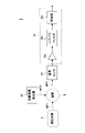
図1は、本発明の第一の実施形態にかかる測定装置1の構成を示す機能ブロック図である。
First Embodiment FIG. 1 is a functional block diagram showing a configuration of a
第一の実施形態にかかる測定装置1は、測定対象2(例えば、心臓)が発生する測定対象量(例えば、測定対象磁場MF1)を測定するものであり、加算磁場発生部(加算量発生部)12、磁気センサ14、センサ出力処理部16を備える。
The measuring
加算磁場発生部(加算量発生部)12は、測定対象量(例えば、測定対象磁場MF1(図3(a)参照))に加算する加算量(例えば、加算磁場MF0(図3(b)参照))を発生する。 The additional magnetic field generation unit (addition amount generation unit) 12 is an addition amount to be added to the measurement target amount (for example, the measurement target magnetic field MF1 (see FIG. 3A)) (for example, the addition magnetic field MF0 (see FIG. 3B). )) Occurs.
磁気センサ14は、測定対象量に加算量が加算された合成量(例えば、合成磁場MF2(図3(c)および図4参照))を測定する。この加算は、空間Sにおいて行われる。磁気センサ14による測定の際に、1/fノイズが発生する(図7参照)。
The
なお、本発明の実施形態においては、測定装置1が磁気センサ14を備えることとなっているが、1/fノイズが問題となる(すなわち、測定対象量の周波数が、1/fノイズを無視できない程度に低い周波数である)ようなセンサであれば、磁気センサに限定されるものではない。
In the embodiment of the present invention, the measuring
図2は、加算磁場発生部12の構成の一例を示す図である。加算磁場発生部12は、加算磁場発生用電源12a、加算磁場発生用コイル12bを有する。磁気センサ14は、例えばMIセンサである。磁気センサ14は、加算磁場発生用コイル12b内に挿入されている。
FIG. 2 is a diagram showing an example of the configuration of the additive magnetic
加算磁場発生用電源12aが加算磁場発生用コイル12bに電流を流すと、加算磁場発生用コイル12b内に加算磁場MF0が発生する。また、加算磁場発生用コイル12b内には、測定対象2より、測定対象磁場MF1が与えられている。
When the
よって、磁気センサ14には、合成磁場MF2=MF0+MF1が与えられる。
Therefore, the
センサ出力処理部16は、アンプ16a、ハイパスフィルタ16b、検波部(導出部)16cを有する。
The sensor
アンプ16aは、磁気センサ14の出力を増幅する。ハイパスフィルタ16bは、磁気センサ14の出力を、アンプ16aを介して受け、磁気センサ14において発生する1/fノイズを、加算磁場MF0(パルスである)の周波数f0(図4参照)と同じ周波数の成分よりも減衰させて、検波部(導出部)16cに与える。検波部(導出部)16cは、磁気センサ14の出力を、アンプ16aおよびハイパスフィルタ16bを介して受け、受けた磁気センサ14の出力から測定対象量(測定対象磁場MF1)を導出する。なお、検波部(導出部)16cは、磁気センサ14の出力値を検波することにより、測定対象量(測定対象磁場MF1)を導出する。なお、検波は、ダイオードを用いて行ってもよいし、サンプルホールド、包絡線検波、同期検波または遅延検波を用いて行ってもよい。
The
次に、第一の実施形態の動作を説明する。 Next, the operation of the first embodiment will be described.
測定対象2が発生する測定対象磁場MF1が、加算磁場発生部12が発生する加算磁場MF0と加算され合成磁場MF2(=MF0+MF1)となり、磁気センサ14に与えられる。
The measurement target magnetic field MF1 generated by the measurement target 2 is added to the addition magnetic field MF0 generated by the addition magnetic
図3は、測定対象磁場MF1(図3(a))、加算磁場MF0(図3(b))、合成磁場MF2(図3(c))の波形を示す図である。図4は、加算磁場MF0および測定対象磁場MF1のスペクトルを示す図である。ただし、図3および図4においては、磁場を磁束密度[μT]に変換して図示している。 FIG. 3 is a diagram showing waveforms of the measurement target magnetic field MF1 (FIG. 3 (a)), the additive magnetic field MF0 (FIG. 3 (b)), and the synthetic magnetic field MF2 (FIG. 3 (c)). FIG. 4 is a diagram showing spectra of the additive magnetic field MF0 and the measurement target magnetic field MF1. However, in FIGS. 3 and 4, the magnetic flux is converted into a magnetic flux density [μT] and shown in the figure.
図3(a)を参照して、測定対象磁場MF1は、非常に微弱な磁場であり(例えば、心臓が発生する磁場)、例えば、時間を横軸に、磁束密度[μT]を縦軸にとると、最大値が3[μT]よりやや小さい値であり、しかも最小値が0[μT]よりやや大きい値の正弦波を描く。この正弦波の周波数は、磁気センサ14において発生する1/fノイズが無視できない程度に低い周波数f1である(図7参照)。
With reference to FIG. 3A, the magnetic field to be measured MF1 is a very weak magnetic field (for example, a magnetic field generated by the heart), for example, time is on the horizontal axis and magnetic flux density [μT] is on the vertical axis. Then, a sine wave having a maximum value slightly smaller than 3 [μT] and a minimum value slightly larger than 0 [μT] is drawn. The frequency of this sine wave is a frequency f1 so low that the 1 / f noise generated in the
図3(b)においては、0[μT]から-50[μT]までの間で、縦軸を一部省略している。図3(b)を参照して、加算磁場MF0は、パルスである。このパルスは、測定対象量の最大値(3[μT]よりやや小さい値)の絶対値よりも大きな振幅(例えば、50[μT])を有する。しかも、このパルスの最大値は0である。さらに、このパルスは、磁気センサ14において発生する1/fノイズを無視できる程度に高い周波数f0を有する(図4および図7参照)。加算磁場MF0は、0[μT]または-50[μT]の値をとるパルスである。例えば、周波数f0は、1/fノイズの1/fコーナー周波数よりも高い値(例えば、2[kHz])である。 In FIG. 3B, a part of the vertical axis is omitted between 0 [μT] and −50 [μT]. With reference to FIG. 3 (b), the additive magnetic field MF0 is a pulse. This pulse has an amplitude (for example, 50 [μT]) larger than the absolute value of the maximum value (value slightly smaller than 3 [μT]) of the amount to be measured. Moreover, the maximum value of this pulse is 0. Further, this pulse has a frequency f0 high enough to ignore the 1 / f noise generated in the magnetic sensor 14 (see FIGS. 4 and 7). The additive magnetic field MF0 is a pulse having a value of 0 [μT] or −50 [μT]. For example, the frequency f0 is a value higher than the 1 / f corner frequency of 1 / f noise (for example, 2 [kHz]).
図3(c)および図4を参照して、合成磁場MF2=MF0+MF1である。 With reference to FIGS. 3 (c) and 4, the combined magnetic field MF2 = MF0 + MF1.
図3(c)を参照して、合成磁場MF2は、加算磁場MF0が0[μT]のときは測定対象磁場MF1と同じ値をとるが、加算磁場MF0が-50[μT]のときは-47[μT]未満の値をとる。ただし、図3(c)においては、およそ-3[μT]未満のグラフを図示省略している。 With reference to FIG. 3 (c), the combined magnetic field MF2 takes the same value as the measurement target magnetic field MF1 when the added magnetic field MF0 is 0 [μT], but-when the added magnetic field MF0 is -50 [μT]. It takes a value less than 47 [μT]. However, in FIG. 3C, graphs of less than about -3 [μT] are omitted.
図4を参照して、合成磁場MF2は、周波数f1の成分(測定対象磁場MF1)と、周波数f0の成分(加算磁場MF0)とを有する。ただし、図4においては、加算磁場MF0の高調波成分(2f0、3f0、…)を図示省略している(図7および図8も同様)。また、図4においては、周波数f1と周波数f0との間で、横軸を一部省略している。 With reference to FIG. 4, the synthetic magnetic field MF2 has a component of frequency f1 (measurement target magnetic field MF1) and a component of frequency f0 (additional magnetic field MF0). However, in FIG. 4, the harmonic components (2f0, 3f0, ...) Of the additive magnetic field MF0 are not shown (the same applies to FIGS. 7 and 8). Further, in FIG. 4, a part of the horizontal axis is omitted between the frequency f1 and the frequency f0.
磁気センサ14は、合成磁場MF2を電圧に変換して出力する。
The
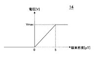
図5は、磁気センサ14の入出力特性を示す図である。ただし、図5においては、横軸に入力である磁束密度[μT]を、縦軸に出力である電圧[V]をとっている。
FIG. 5 is a diagram showing input / output characteristics of the
磁気センサ14の出力の下限は、合成磁場MF2が0[μT]において飽和している。すなわち、合成磁場MF2が0未満の場合の磁気センサ14の出力値0[V]は、合成磁場MF2が0の場合の磁気センサ14の出力値0[V]と同じ値である。
The lower limit of the output of the
なお、磁気センサ14の出力の上限も、合成磁場MF2の最大値(3[μT]よりやや小さい値)よりも大きな値(例えば、5[μT])において飽和している。
The upper limit of the output of the
図6は、磁気センサ14の出力(図6(a))、測定対象磁場MF1(図6(b))、加算磁場MF0と同じ周波数のパルス(図6(c))の波形を示す図である。ただし、図6(a)および図6(b)においては、磁場を磁束密度[μT]に換算している。 FIG. 6 is a diagram showing waveforms of an output of the magnetic sensor 14 (FIG. 6 (a)), a magnetic field to be measured MF1 (FIG. 6 (b)), and a pulse having the same frequency as the additive magnetic field MF0 (FIG. 6 (c)). be. However, in FIGS. 6 (a) and 6 (b), the magnetic flux is converted into the magnetic flux density [μT].
上述のとおり、合成磁場MF2が0[μT]において、磁気センサ14の出力は飽和している(図5参照)。よって、磁気センサ14の出力波形は、合成磁場MF2の波形(図3(c)参照)において0[μT]未満の磁束密度を0[μT]に置き換えたものとなる(図6(a)参照)。ただし、図6(a)において、磁気センサ14から発生する1/fノイズおよび熱雑音は図示省略している。
As described above, when the combined magnetic field MF2 is 0 [μT], the output of the
図6(b)は、図3(a)と同じグラフである。 FIG. 6 (b) is the same graph as in FIG. 3 (a).
図6(c)は、加算磁場MF0と同じ周波数のパルスであるが、縦軸は無次元であり、1または0の値をとる。 FIG. 6 (c) shows a pulse having the same frequency as the additive magnetic field MF0, but the vertical axis is dimensionless and takes a value of 1 or 0.
図6(a)、図6(b)および図6(c)を参照して、磁気センサ14の出力(図6(a)参照)は、測定対象磁場MF1(図6(b)参照)に、加算磁場MF0と同じ周波数のパルス(図6(c)参照)を乗じたものとなる。 With reference to FIGS. 6 (a), 6 (b) and 6 (c), the output of the magnetic sensor 14 (see FIG. 6 (a)) is directed to the magnetic field MF1 to be measured (see FIG. 6 (b)). , A pulse having the same frequency as the added magnetic field MF0 (see FIG. 6C) is multiplied.
図7は、磁気センサ14の出力のスペクトルを示す図である。ただし、図7においては、磁気センサ14の出力を磁束密度[μT]に換算している。また、図7においては、周波数f1と周波数f0との間で、横軸を一部省略している。
FIG. 7 is a diagram showing an output spectrum of the
磁気センサ14の出力は、測定対象磁場MF1(周波数f0)に、加算磁場MF0と同じ周波数f0のパルスを乗じたものとなるので、周波数f0+f1の成分と、周波数f0-f1の成分を有する。これらの二つの成分は、加算磁場MF0と同じ周波数f0のパルス(図6(c)参照)を搬送波として、測定対象磁場MF1により、この搬送波を変調したものといえる。
Since the output of the
しかも、磁気センサ14の出力は、搬送波の成分(周波数f0)と、測定対象磁場MF1(周波数f1)と、1/fノイズと、熱雑音とを有する。磁気センサ14の出力の成分のうち、1/fノイズと測定対象磁場MF1とは低周波であり、周波数f0+f1の成分と、周波数f0-f1の成分と、加算磁場MF0の成分と、熱雑音とは高周波である。ただし、熱雑音は、周波数f0+f1の成分と、周波数f0-f1の成分と、加算磁場MF0の成分とに比べると無視できる程に小さい。
Moreover, the output of the
磁気センサ14の出力はアンプ16aにより増幅され、ハイパスフィルタ16bに与えられる。ハイパスフィルタ16bの出力は、検波部(導出部)16cに与えられる。
The output of the
図8は、ハイパスフィルタ16bの出力(図8(a))、検波部(導出部)16cの出力(図8(b))のスペクトルを示す図である。ただし、図8においては、周波数f1と周波数f0との間で、横軸を一部省略している。
FIG. 8 is a diagram showing spectra of the output of the high-
図8(a)を参照して、磁気センサ14の出力を、ハイパスフィルタ16bに与えると、1/fノイズと測定対象磁場MF1とが著しく減衰し、無視できる程度の大きさとなる。周波数f0+f1の成分と、周波数f0-f1の成分と、加算磁場MF0の成分とは、ほとんど減衰しない。
When the output of the
図8(b)を参照して、ハイパスフィルタ16bの出力を、検波部(導出部)16cに与えると、検波により、測定対象磁場MF1(周波数f1)の成分を得ることができる。ただし、検波部16cの出力には熱雑音も含まれるが、測定対象磁場MF1の成分に比べると無視できる程に小さい。
When the output of the high-
第一の実施形態によれば、磁気センサ14において発生する1/fノイズによる測定装置1による測定対象磁場MF1の測定結果の誤差を軽減することができる。
According to the first embodiment, it is possible to reduce an error in the measurement result of the magnetic field MF1 to be measured by the measuring
すなわち、磁気センサ14の出力は、加算磁場MF0と同じ周波数f0のパルス(図6(c)参照)を搬送波として、測定対象磁場MF1により、この搬送波を変調したもの(周波数f0+f1の成分および周波数f0-f1の成分)を有する。ここで、磁気センサ14において1/fノイズが発生しても、磁気センサ14の出力する周波数f0+f1の成分および周波数f0-f1の成分には、1/fノイズが無視できる程度にしか含まれていない(図7参照)。このため、周波数f0+f1の成分および周波数f0-f1の成分を復調して、測定対象磁場MF1(周波数f1)の成分を得れば、この成分には、1/fノイズが無視できる程度にしか含まれていないことになる。
That is, the output of the
第二の実施形態
第二の実施形態にかかる測定装置1は、複数の磁気センサ14の出力を合計して一つの導出部16cに与える合計部15を備えた点が、第一の実施形態にかかる測定装置1と異なる。
Second Embodiment The point that the measuring
図9は、本発明の第二の実施形態にかかる測定装置1の構成を示す機能ブロック図である。第二の実施形態にかかる測定装置1は、測定対象2(例えば、心臓)が発生する測定対象量(例えば、測定対象磁場MF1)を測定するものであり、加算磁場発生部(加算量発生部)12、磁気センサ14、合計部15、センサ出力処理部16を備える。
FIG. 9 is a functional block diagram showing the configuration of the measuring
加算磁場発生部12は、第一の実施形態と同様であり、説明を省略する。
The additive magnetic
磁気センサ14は複数(図9の例では、3個)設けられており、いずれも、空間S内のほぼ同一地点の合成磁場MF2を測定する。合計部15は、複数の磁気センサ14の出力を合計して、一つの検波部(導出部)16cに、アンプ16aおよびハイパスフィルタ16bを介して与える。
A plurality of magnetic sensors 14 (three in the example of FIG. 9) are provided, and all of them measure the combined magnetic field MF2 at substantially the same point in the space S. The totaling
アンプ16aは、合計部15の出力を増幅して、ハイパスフィルタ16bに与える。ハイパスフィルタ16bおよび検波部16cは、第一の実施形態と同様であり、説明を省略する。
The
次に、第二の実施形態の動作を説明する。 Next, the operation of the second embodiment will be described.
測定対象2が発生する測定対象磁場MF1が、加算磁場発生部12が発生する加算磁場MF0と加算され合成磁場MF2(=MF0+MF1)となり、複数の磁気センサ14に与えられる。
The measurement target magnetic field MF1 generated by the measurement target 2 is added to the addition magnetic field MF0 generated by the addition magnetic
複数の磁気センサ14の出力は、合計部15により合計されて、アンプ16aに与えられる。以後の動作は、第一の実施形態と同様であり、説明を省略する。
The outputs of the plurality of
第二の実施形態によれば、第一の実施形態と同様な効果を奏する。 According to the second embodiment, the same effect as that of the first embodiment is obtained.
しかも、第二の実施形態によれば、以下のような効果を奏する。すなわち、磁気センサ14の出力には1/fノイズに限らず、色々なノイズが混入するので、S/N比が低下してしまう。ここで、複数(例えば、3個)の磁気センサ14の出力を合計すれば、磁気センサ14の信号(本来の出力)は単純に3倍になるが、ノイズは磁気センサ14ごとにランダムなので単純に3倍とはならない。複数(例えば、3個)の磁気センサ14の出力を合計した場合、ノイズはおおむね、各磁気センサ14のノイズの2乗の総和の平方根にしかならず、3倍未満となる。よって、複数(例えば、3個)の磁気センサ14の出力の合計を、センサ出力処理部16によって処理するようにすれば、S/N比が向上する。
Moreover, according to the second embodiment, the following effects are obtained. That is, not only 1 / f noise but also various noises are mixed in the output of the
第三の実施形態
第三の実施形態にかかる測定装置1は、複数の磁気センサ142、144、146の出力を、それぞれ別々の導出部16cに与える点が、第一の実施形態にかかる測定装置1と異なる。
Third Embodiment The measuring
図10は、本発明の第三の実施形態にかかる測定装置1の構成を示す機能ブロック図である。第三の実施形態にかかる測定装置1は、測定対象2(例えば、心臓)が発生する測定対象量(例えば、測定対象磁場MF1)を測定するものであり、加算磁場発生部(加算量発生部)12、磁気センサ142、144、146、センサ出力処理部162、164、166を備える。
FIG. 10 is a functional block diagram showing the configuration of the measuring
加算磁場発生部12は、第一の実施形態と同様であり、説明を省略する。
The additive magnetic
磁気センサ142、144、146は複数(図10の例では、3個)設けられている。複数の磁気センサ142、144、146は、それぞれ、空間S内の別々の地点の合成磁場MF2a、MF2b、MF2cを測定する。
A plurality of
複数の磁気センサ142、144、146の出力は、それぞれ別々のセンサ出力処理部162、164、166内のアンプ16aおよびハイパスフィルタ16bを介して、別々の導出部16cに与えられる。
The outputs of the plurality of
センサ出力処理部162、164、166内のアンプ16aは、それぞれ、複数の磁気センサ142、144、146の出力を増幅する。センサ出力処理部162、164、166内のハイパスフィルタ16bおよび検波部16cは、第一の実施形態と同様であり、説明を省略する。
The
次に、第三の実施形態の動作を説明する。 Next, the operation of the third embodiment will be described.
測定対象2が発生する測定対象磁場MF1が、加算磁場発生部12が発生する加算磁場MF0と加算される。合成磁場MF2は、空間S内の別々の地点において、別々の合成磁場MF2a、MF2b、MF2cとなり、複数の磁気センサ142、144、146に与えられる。
The measurement target magnetic field MF1 generated by the measurement target 2 is added to the addition magnetic field MF0 generated by the addition magnetic
複数の磁気センサ142、144、146の出力は、それぞれ、別々のセンサ出力処理部162、164、166内のアンプ16aに与えられる。以後の動作は、第一の実施形態と同様であり、説明を省略する。
The outputs of the plurality of
第三の実施形態によれば、第一の実施形態と同様な効果を奏する。 According to the third embodiment, the same effect as that of the first embodiment is obtained.
しかも、第三の実施形態によれば、空間S内の別々の地点において磁場が異なる場合、空間S内の磁場の分布を測定することができる。例えば、測定対象2が心臓である場合、心臓の磁場の分布を広範囲に測定することができる。 Moreover, according to the third embodiment, when the magnetic fields are different at different points in the space S, the distribution of the magnetic fields in the space S can be measured. For example, when the measurement target 2 is the heart, the distribution of the magnetic field of the heart can be measured over a wide range.
第四の実施形態
第四の実施形態にかかる測定装置1は、複数の磁気センサ142、144、146に与えられる別々の合成磁場MF2a、MF2b、MF2cに、誤差補正量を加えて、複数の磁気センサ142、144、146に与えるキャンセルコイル(前置誤差補正部)132、134、136を備えた点が、第三の実施形態にかかる測定装置1と異なる。
Fourth Embodiment In the
図11は、本発明の第四の実施形態にかかる測定装置1の構成を示す機能ブロック図である。第四の実施形態にかかる測定装置1は、測定対象2(例えば、心臓)が発生する測定対象量(例えば、測定対象磁場MF1)を測定するものであり、加算磁場発生部(加算量発生部)12、キャンセルコイル(前置誤差補正部)132、134、136、磁気センサ142、144、146、センサ出力処理部162、164、166を備える。
FIG. 11 is a functional block diagram showing the configuration of the measuring
加算磁場発生部12、磁気センサ142、144、146、センサ出力処理部162、164、166は、第三の実施形態と同様であり、説明を省略する。
The additive magnetic
キャンセルコイル(前置誤差補正部)132、134、136は、磁気センサ142、144、146より前に(すなわち、磁気センサ142、144、146と空間Sとの間に)配置される。キャンセルコイル(前置誤差補正部)132、134、136は、それぞれ、合成磁場MF2a、MF2b、MF2cに、誤差補正量を加えて、複数の磁気センサ142、144、146のそれぞれに与える。例えば、キャンセルコイル132、134、136に所定の電流を流すことで、誤差補正のための磁場(誤差補正量)を、合成磁場MF2a、MF2b、MF2cに加えることができる。
The cancel coils (preliminary error correction units) 132, 134, 136 are arranged before the
ここで、誤差補正量は、例えば、特開2017-133993号公報の[0030]~[0033]に記載の方法により決定する。すなわち、センサ出力処理部162、164、166の出力の総和は、測定装置1外部のノイズが無ければ、ほぼ0となる。よって、センサ出力処理部162、164、166の出力の総和が、測定装置1外部のノイズとなる。そこで、センサ出力処理部162、164、166の出力の総和が0となるように誤差補正量を決定する。
Here, the error correction amount is determined by, for example, the method described in [0030] to [0033] of JP-A-2017-133993. That is, the total output of the sensor
次に、第四の実施形態の動作を説明する。 Next, the operation of the fourth embodiment will be described.
測定対象2が発生する測定対象磁場MF1が、加算磁場発生部12が発生する加算磁場MF0と加算される。合成磁場MF2は、空間S内の別々の地点において、別々の合成磁場MF2a、MF2b、MF2cとなる。キャンセルコイル132、134、136には、所定の電流が流れており、誤差補正のための磁場(誤差補正量)が、合成磁場MF2a、MF2b、MF2cに加えられる。合成磁場MF2a、MF2b、MF2cに、誤差補正のための磁場が加えられたものは、それぞれ、複数の磁気センサ142、144、146に与えられる。
The measurement target magnetic field MF1 generated by the measurement target 2 is added to the addition magnetic field MF0 generated by the addition magnetic
以後の動作は、第三の実施形態と同様であり、説明を省略する。 Subsequent operations are the same as those in the third embodiment, and the description thereof will be omitted.
第四の実施形態によれば、第一の実施形態と同様な効果を奏する。 According to the fourth embodiment, the same effect as that of the first embodiment is obtained.
しかも、第四の実施形態によれば、測定装置1外部のノイズにより測定に誤差が生ずることを抑制することができる。
Moreover, according to the fourth embodiment, it is possible to suppress the occurrence of an error in the measurement due to noise outside the measuring
例えば、測定装置1外部のノイズとして、1/fノイズよりも大きい環境雑音(例えば、50Hz商用電源やエアコンなどの磁気ノイズ)がある場合が考えられる。このような環境雑音を放置しておくと、測定に誤差が生ずることとなる。ここで、第四の実施形態によれば、このような環境雑音により測定に誤差が生ずることを抑制することができる。
For example, as noise outside the measuring
第五の実施形態
第五の実施形態にかかる測定装置1は、複数の磁気センサ142、144、146の出力をデジタルに変換して、それぞれ、センサ出力処理部162、164、166の検波部(導出部)16cに与える点が、第四の実施形態にかかる測定装置1と異なる。
Fifth Embodiment The measuring
図12は、本発明の第五の実施形態にかかる測定装置1の構成を示す機能ブロック図である。第五の実施形態にかかる測定装置1は、測定対象2(例えば、心臓)が発生する測定対象量(例えば、測定対象磁場MF1)を測定するものであり、加算磁場発生部(加算量発生部)12、キャンセルコイル(前置誤差補正部)132、134、136、磁気センサ142、144、146、ADC152、154、156、センサ出力処理部162、164、166を備える。
FIG. 12 is a functional block diagram showing the configuration of the measuring
加算磁場発生部12、キャンセルコイル(前置誤差補正部)132、134、136、磁気センサ142、144、146は、第四の実施形態と同様であり、説明を省略する。ただし、キャンセルコイル132、134、136に与える電流をPWM方式で供給してよい。
The additive magnetic
ADC152、154、156は、それぞれ、複数の磁気センサ142、144、146の出力をデジタルに変換して、センサ出力処理部162、164、166の検波部(導出部)16cに、アンプ16aおよびハイパスフィルタ16bを介して与える。
The
センサ出力処理部162、164、166は、第四の実施形態と同様であるが、デジタル信号を処理できるようなもの(例えば、波形等価器、FIRフィルタおよび適応フィルタなど)により実装する。
The sensor
次に、第五の実施形態の動作を説明する。 Next, the operation of the fifth embodiment will be described.
測定対象2が発生する測定対象磁場MF1が、加算磁場発生部12が発生する加算磁場MF0と加算される。合成磁場MF2は、空間S内の別々の地点において、別々の合成磁場MF2a、MF2b、MF2cとなる。キャンセルコイル132、134、136には、所定の電流が流れており、誤差補正のための磁場(誤差補正量)が、合成磁場MF2a、MF2b、MF2cに加えられる。合成磁場MF2a、MF2b、MF2cに、誤差補正のための磁場が加えられたものは、それぞれ、複数の磁気センサ142、144、146に与えられる。
The measurement target magnetic field MF1 generated by the measurement target 2 is added to the addition magnetic field MF0 generated by the addition magnetic
磁気センサ142、144、146の出力は、それぞれ、ADC152、154、156に与えられ、デジタルに変換して、センサ出力処理部162、164、166に与えられる。
The outputs of the
以後の動作は、第四の実施形態と同様であり、説明を省略する。 Subsequent operations are the same as those in the fourth embodiment, and the description thereof will be omitted.
第五の実施形態によれば、第一の実施形態と同様な効果を奏する。 According to the fifth embodiment, the same effect as that of the first embodiment is obtained.
しかも、第五の実施形態によれば、測定装置1の回路規模削減、制御電子化およびケーブルレス化を行うことができる。
Moreover, according to the fifth embodiment, the circuit scale of the measuring
なお、第五の実施形態の変形例として、キャンセルコイル132、134、136にかえて、同じ機能のアナログ信号処理部またはデジタル信号処理部を設けてもよい。また、測定装置1の各部を接続するためにバス配線を用いてもよいが、バス配線にかえて、光ファイバを用いてもよいし(高速シリアル通信が可能となる)、無線(Wi-Fiやブルートゥース(登録商標)など)を用いてもよい。
As a modification of the fifth embodiment, an analog signal processing unit or a digital signal processing unit having the same function may be provided instead of the cancel
第六の実施形態
第六の実施形態にかかる測定装置1は、検波部(導出部)16cの出力を受けて、外部環境に起因する誤差を補正する外部誤差補正部182を備えた点が、第五の実施形態にかかる測定装置1と異なる。
Sixth Embodiment The measuring
図13は、本発明の第六の実施形態にかかる測定装置1の構成を示す機能ブロック図である。第六の実施形態にかかる測定装置1は、測定対象2(例えば、心臓)が発生する測定対象量(例えば、測定対象磁場MF1)を測定するものであり、加算磁場発生部(加算量発生部)12、キャンセルコイル(前置誤差補正部)132、134、136、磁気センサ142、144、146、ADC152、154、156、センサ出力処理部162、164、166、外部誤差補正部182を備える。
FIG. 13 is a functional block diagram showing the configuration of the measuring
加算磁場発生部(加算量発生部)12、キャンセルコイル(前置誤差補正部)132、134、136、磁気センサ142、144、146、ADC152、154、156およびセンサ出力処理部162、164、166は、第五の実施形態と同様であり説明を省略する。
Addition magnetic field generation unit (addition amount generation unit) 12, cancel coil (preliminary error correction unit) 132, 134, 136,
外部誤差補正部182は、センサ出力処理部162、164、166の検波部(導出部)16cの出力を受けて、測定装置1の外部環境に起因する誤差を補正する。測定装置1の外部環境に起因する誤差は、以下の様にして求められる。
The external
すなわち、センサ出力処理部162、164、166の出力の総和は、測定装置1外部のノイズが無ければ、ほぼ0となる。よって、センサ出力処理部162、164、166の出力の総和の加算平均値が、測定装置1の外部環境に起因する誤差となる。
That is, the total output of the sensor
または、磁気センサ142、144、146の配置されている領域が、測定対象2に比べて非常に広い場合は、測定対象2から離れて配置された磁気センサの出力は、測定対象磁場MF1を含まず、測定装置1の外部環境に起因する誤差となる。
Alternatively, when the area where the
このように外部環境に起因する誤差を求めると、外部誤差補正部182は、この外部環境に起因する誤差を補正する。
When the error caused by the external environment is obtained in this way, the external
次に、第六の実施形態の動作を説明する。 Next, the operation of the sixth embodiment will be described.
センサ出力処理部162、164、166の出力までは、第五の実施形態の動作と同じなので説明を省略する。
Since the operations up to the outputs of the sensor
外部誤差補正部182は、求めておいた外部環境に起因する誤差に基づき、センサ出力処理部162、164、166の出力における測定装置1の外部環境に起因する誤差を補正する。
The external
第六の実施形態によれば、第一の実施形態と同様な効果を奏する。 According to the sixth embodiment, the same effect as that of the first embodiment is obtained.
しかも、第六の実施形態によれば、測定装置1の外部環境に起因する誤差を補正できる。
Moreover, according to the sixth embodiment, the error caused by the external environment of the measuring
第七の実施形態
第七の実施形態にかかる測定装置1は、チャネル間の誤差を補正するチャネル間誤差補正部184を備えた点が、第五の実施形態にかかる測定装置1と異なる。ただし、各チャネルは、ある一つの磁気センサと、その出力を受けるある一つの検波部(導出部)16cとを有する。
Seventh Embodiment The measuring
図14は、本発明の第七の実施形態にかかる測定装置1の構成を示す機能ブロック図である。第七の実施形態にかかる測定装置1は、測定対象2(例えば、心臓)が発生する測定対象量(例えば、測定対象磁場MF1)を測定するものであり、加算磁場発生部(加算量発生部)12、キャンセルコイル(前置誤差補正部)132、134、136、磁気センサ142、144、146、ADC152、154、156、センサ出力処理部162、164、166、チャネル間誤差補正部184を備える。
FIG. 14 is a functional block diagram showing the configuration of the measuring
加算磁場発生部(加算量発生部)12、キャンセルコイル(前置誤差補正部)132、134、136、磁気センサ142、144、146、ADC152、154、156およびセンサ出力処理部162、164、166は、第五の実施形態と同様であり説明を省略する。
Addition magnetic field generation unit (addition amount generation unit) 12, cancel coil (preliminary error correction unit) 132, 134, 136,
ここで、キャンセルコイル132、磁気センサ142、ADC152、およびセンサ出力処理部162をチャネル1とする。磁気センサ142の出力を、センサ出力処理部162の(導出部)16cが、ADC152と、センサ出力処理部162のアンプ16aおよびハイパスフィルタ16bとを介して受ける。
Here, the cancel
また、キャンセルコイル134、磁気センサ144、ADC154、およびセンサ出力処理部164をチャネル2とする。磁気センサ144の出力を、センサ出力処理部164の(導出部)16cが、ADC154と、センサ出力処理部164のアンプ16aおよびハイパスフィルタ16bとを介して受ける。
Further, the cancel
さらに、キャンセルコイル136、磁気センサ146、ADC156、およびセンサ出力処理部166をチャネル3とする。磁気センサ146の出力を、センサ出力処理部166の(導出部)16cが、ADC156と、センサ出力処理部166のアンプ16aおよびハイパスフィルタ16bとを介して受ける。
Further, the cancel
チャネル間誤差補正部184は、チャネル1、2および3の間の誤差を補正する。
The interchannel
チャネル1、2および3の間の誤差について説明する。チャネル1、2および3のキャンセルコイル132、134、136に、それぞれ同じ磁場を与えた場合、本来ならば、チャネル1、2および3の各々の検波部(導出部)16cの出力は同じ値となる。しかし、チャネル1、2および3の特性(例えば、変復調特性)の相違により、チャネル1、2および3の入力が同じであるにもかかわらず、チャネル1、2および3の出力が異なった値となることがある。これが、チャネル1、2および3の間の誤差である。
The error between
測定装置1による測定対象2の測定を行う前に、加算磁場MF0を空間Sに与え(測定対象磁場MF1は空間Sに与えない)、チャネル1、2および3により測定することにより、チャネル1、2および3の間の誤差を求めることができる。本来、同じ加算磁場MF0を、チャネル1、2および3により測定しているので、同じ測定結果となるはずである。そこで、チャネル1、2および3の測定結果が異なれば、チャネル1、2および3の測定結果の差異が、チャネル1、2および3の間の誤差となる。
Before measuring the measurement target 2 by the measuring
次に、第七の実施形態の動作を説明する。 Next, the operation of the seventh embodiment will be described.
センサ出力処理部162、164、166の出力までは、第五の実施形態の動作と同じなので説明を省略する。
Since the operations up to the outputs of the sensor
チャネル間誤差補正部184は、求めておいたチャネル1、2および3の間の誤差に基づき、センサ出力処理部162、164、166の出力におけるチャネル1、2および3の間の誤差を補正する。
The inter-channel
第七の実施形態によれば、第一の実施形態と同様な効果を奏する。 According to the seventh embodiment, the same effect as that of the first embodiment is obtained.
しかも、第七の実施形態によれば、チャネル1、2および3の間の誤差を補正できる。
Moreover, according to the seventh embodiment, the error between
第八の実施形態
第八の実施形態にかかる測定装置1は、1/fノイズを無視できる程度に高い周波数帯域における導出部16cの出力の誤差を測定し、その測定結果に基づきパルスの周波数f0を決定する点が、第五の実施形態にかかる測定装置1と異なる。
Eighth Embodiment The measuring
図15は、本発明の第八の実施形態にかかる測定装置1の構成を示す機能ブロック図である。第八の実施形態にかかる測定装置1は、測定対象2(例えば、心臓)が発生する測定対象量(例えば、測定対象磁場MF1)を測定するものであり、加算磁場発生部(加算量発生部)12、キャンセルコイル(前置誤差補正部)132、134、136、磁気センサ142、144、146、ADC152、154、156、センサ出力処理部162、164、166、高周波帯域誤差測定部186、周波数決定部188を備える。
FIG. 15 is a functional block diagram showing the configuration of the measuring
加算磁場発生部(加算量発生部)12、キャンセルコイル(前置誤差補正部)132、134、136、磁気センサ142、144、146、ADC152、154、156およびセンサ出力処理部162、164、166は、第五の実施形態と同様であり説明を省略する。
Addition magnetic field generation unit (addition amount generation unit) 12, cancel coil (preliminary error correction unit) 132, 134, 136,
高周波帯域誤差測定部186は、1/fノイズを無視できる程度に高い周波数帯域(例えば、1/fノイズの1/fコーナー周波数よりも高い周波数の帯域)における検波部(導出部)16cの出力の誤差を測定する。図7を参照すると、1/fノイズを無視できる程度に高い周波数帯域には、周波数f0+f1の成分および周波数f0-f1の成分に比べれば無視できる程度に小さい熱雑音しかない。しかし、1/fノイズを無視できる程度に高い周波数帯域に、周波数f0+f1の成分および周波数f0-f1の成分に比べても無視できないようなノイズ(例えば、環境雑音)がある場合も考えられる。
The high frequency band
周波数決定部188は、高周波帯域誤差測定部186の測定結果に基づき、パルスの周波数f0を決定する。決定結果は、加算磁場発生部12に与えられ、加算磁場MF0(パルスである)の周波数が決定された値f0となるようにする。
The
例えば、周波数決定部188は、高周波帯域誤差測定部186の測定結果に基づき、周波数f0+f1の成分および周波数f0-f1の成分に比べれば無視できる程度に小さいノイズしかない周波数帯域を決定し、その周波数帯域から任意の周波数を加算磁場MF0(パルス)の周波数f0とする決定を行う。
For example, the
次に、第八の実施形態の動作を説明する。 Next, the operation of the eighth embodiment will be described.
センサ出力処理部162、164、166の出力までは、第五の実施形態の動作と同じなので説明を省略する。
Since the operations up to the outputs of the sensor
測定装置1による測定対象2の測定を行う前に、高周波帯域誤差測定部186は1/fノイズを無視できる程度に高い周波数帯域における検波部(導出部)16cの出力の誤差を測定する。周波数決定部188は、高周波帯域誤差測定部186の測定した誤差に基づき、加算磁場MF0(パルス)の周波数f0を決定し、加算磁場発生部12に与える。この後、測定装置1による測定対象2の測定を行う。
Before measuring the measurement target 2 by the measuring
第八の実施形態によれば、第一の実施形態と同様な効果を奏する。 According to the eighth embodiment, the same effect as that of the first embodiment is obtained.
しかも、第八の実施形態によれば、周波数f0+f1の成分および周波数f0-f1の成分に比べて無視できる程度に小さいノイズしかないように周波数f0を決定できる。 Moreover, according to the eighth embodiment, the frequency f0 can be determined so that the noise is negligibly smaller than that of the frequency f0 + f1 component and the frequency f0−f1 component.
また、上記の実施形態は、以下のようにして実現できる。CPU、ハードディスク、メディア(フロッピー(登録商標)ディスク、CD-ROMなど)読み取り装置を備えたコンピュータに、上記の各部分、例えばセンサ出力処理部16、162、164、166を実現するプログラムを記録したメディアを読み取らせて、ハードディスクにインストールする。このような方法でも、上記の機能を実現できる。
Further, the above embodiment can be realized as follows. A program for realizing each of the above parts, for example, sensor
MF0 加算磁場
MF1 測定対象磁場
MF2、MF2a、MF2b、MF2c 合成磁場
f0 加算磁場MF0の周波数
f1 測定対象磁場MF1の周波数
1 測定装置
2 測定対象
12 加算磁場発生部(加算量発生部)
132、134、136 キャンセルコイル(前置誤差補正部)
14 磁気センサ
15 合計部
152、154、156 ADC
16、162、164、166 センサ出力処理部
16a アンプ
16b ハイパスフィルタ
16c 検波部(導出部)
182 外部誤差補正部
184 チャネル間誤差補正部
186 高周波帯域誤差測定部
188 周波数決定部
MF0 Additional magnetic field MF1 Measurement target magnetic field MF2, MF2a, MF2b, MF2c Synthetic magnetic field f0 Additional magnetic field MF0 frequency f1 Measurement target magnetic
132, 134, 136 Cancel coil (preliminary error correction unit)
14
16, 162, 164, 166 Sensor
182 External
Claims (12)
前記測定対象量に加算する加算量を発生する加算量発生部と、
前記測定対象量に前記加算量が加算された合成量を測定するセンサと、
前記センサの出力を受けて、1/fノイズを、パルスの周波数と同じ周波数の成分よりも減衰させるハイパスフィルタと、
前記ハイパスフィルタの出力から前記測定対象量を導出する導出部と、
を備え、
前記センサによる測定の際に、前記1/fノイズが発生し、
前記合成量が0未満の場合の前記センサの出力値は、前記合成量が0の場合の前記センサの出力値と同じ値であり、
前記加算量は、前記パルスであり、
該パルスは、前記測定対象量の最大値の絶対値よりも大きな振幅を有し、
該パルスの最大値が0であり、
該パルスは、前記1/fノイズを無視できる程度に高い周波数を有し、
前記導出部は、前記センサの出力値を検波することにより、前記測定対象量を導出する、
測定装置。 It is a measuring device that measures the amount of measurement target generated by the measurement target.
An addition amount generating unit that generates an addition amount to be added to the measurement target amount,
A sensor that measures the combined amount obtained by adding the added amount to the measured amount,
A high-pass filter that receives the output of the sensor and attenuates 1 / f noise more than a component having the same frequency as the pulse frequency.
A derivation unit that derives the measure target quantity from the output of the high-pass filter , and
Equipped with
During the measurement by the sensor, the 1 / f noise is generated.
The output value of the sensor when the combined amount is less than 0 is the same as the output value of the sensor when the combined amount is 0.
The addition amount is the pulse.
The pulse has an amplitude larger than the absolute value of the maximum value of the measureable quantity.
The maximum value of the pulse is 0,
The pulse has a frequency high enough to ignore the 1 / f noise.
The derivation unit derives the measure target amount by detecting the output value of the sensor.
measuring device.
前記測定対象量は磁場である、
測定装置。 The measuring device according to claim 1.
The measure target is a magnetic field.
measuring device.
複数の前記センサの出力を合計して前記ハイパスフィルタを介して一つの前記導出部に与える合計部を備えた測定装置。 The measuring device according to claim 1 or 2.
A measuring device including a totaling unit that sums up the outputs of a plurality of the sensors and gives them to one of the out-licensing units via the high-pass filter .
複数の前記センサの出力を、前記ハイパスフィルタを介してそれぞれ別々の前記導出部に与える測定装置。 The measuring device according to claim 1 or 2.
A measuring device that supplies the outputs of a plurality of the sensors to the separate derivation units via the high-pass filter .
前記合成量に、誤差補正量を加えて、前記センサに与える前置誤差補正部を備えた測定装置。 The measuring device according to claim 1 or 2.
A measuring device provided with a pre-error correction unit that adds an error correction amount to the combined amount and gives it to the sensor.
アナログである前記センサの出力を、デジタルに変換して、前記導出部に与える測定装置。 The measuring device according to claim 1 or 2.
A measuring device that converts the output of the sensor, which is analog, into digital and gives it to the derivation unit.
前記導出部の出力を受けて、外部環境に起因する誤差を補正する外部誤差補正部を備えた測定装置。 The measuring device according to claim 6 .
A measuring device provided with an external error correction unit that receives the output of the derivation unit and corrects an error caused by the external environment.
ある一つの前記センサと、その出力を受けるある一つの前記導出部とを有するチャネルを複数備え、
さらに前記チャネル間の誤差を補正するチャネル間誤差補正部を備えた測定装置。 The measuring device according to claim 6 .
A plurality of channels having one said sensor and one said derivation unit receiving the output thereof are provided.
Further, a measuring device provided with an inter-channel error correction unit that corrects the error between the channels.
前記1/fノイズを無視できる程度に高い周波数帯域における前記導出部の出力の誤差を測定する高周波帯域誤差測定部と、
前記高周波帯域誤差測定部の測定結果に基づき、前記パルスの周波数を決定する周波数決定部と、
を備えた測定装置。 The measuring device according to claim 6 .
A high-frequency band error measuring unit that measures an output error of the derivation unit in a frequency band that is high enough to ignore the 1 / f noise, and a high-frequency band error measuring unit.
A frequency determination unit that determines the frequency of the pulse based on the measurement results of the high frequency band error measurement unit, and
A measuring device equipped with.
前記測定対象量に加算する加算量を発生する加算量発生工程と、
センサにより、前記測定対象量に前記加算量が加算された合成量を測定する測定工程と、
ハイパスフィルタにより、前記測定工程の測定結果を受けて、1/fノイズを、パルスの周波数と同じ周波数の成分よりも減衰させる減衰工程と、
前記減衰工程の出力から前記測定対象量を導出する導出工程と、
を備え、
前記センサによる測定の際に、前記1/fノイズが発生し、
前記合成量が0未満の場合の前記センサの出力値は、前記合成量が0の場合の前記センサの出力値と同じ値であり、
前記加算量は、前記パルスであり、
該パルスは、前記測定対象量の最大値の絶対値よりも大きな振幅を有し、
該パルスの最大値が0であり、
該パルスは、前記1/fノイズを無視できる程度に高い周波数を有し、
前記導出工程は、前記センサの出力値を検波することにより、前記測定対象量を導出する、
測定方法。 It is a measurement method that measures the amount of measurement target generated by the measurement target.
A step of generating an additional amount to generate an additional amount to be added to the amount to be measured, and a step of generating an additional amount.
A measurement step of measuring a synthetic amount obtained by adding the additional amount to the measurement target amount by a sensor, and a measurement step.
An attenuation step in which 1 / f noise is attenuated more than a component having the same frequency as the pulse frequency in response to the measurement result of the measurement step by the high-pass filter.
A derivation step of deriving the measure target amount from the output of the attenuation step , and a derivation step.
Equipped with
During the measurement by the sensor, the 1 / f noise is generated.
The output value of the sensor when the combined amount is less than 0 is the same as the output value of the sensor when the combined amount is 0.
The addition amount is the pulse.
The pulse has an amplitude larger than the absolute value of the maximum value of the measureable quantity.
The maximum value of the pulse is 0,
The pulse has a frequency high enough to ignore the 1 / f noise.
In the derivation step, the measure target amount is derived by detecting the output value of the sensor.
Measuring method.
前記測定処理は、
前記ハイパスフィルタの出力から前記測定対象量を導出する導出工程を備え、
前記センサによる測定の際に、前記1/fノイズが発生し、
前記合成量が0未満の場合の前記センサの出力値は、前記合成量が0の場合の前記センサの出力値と同じ値であり、
前記加算量は、前記パルスであり、
該パルスは、前記測定対象量の最大値の絶対値よりも大きな振幅を有し、
該パルスの最大値が0であり、
該パルスは、前記1/fノイズを無視できる程度に高い周波数を有し、
前記導出工程は、前記センサの出力値を検波することにより、前記測定対象量を導出する、
プログラム。 A measuring device that measures the amount of measurement target generated by the measurement target, the addition amount generating unit that generates the addition amount to be added to the measurement target amount, and the combined amount obtained by adding the addition amount to the measurement target amount. A program for causing a computer to perform measurement processing in a measuring device having a sensor for measurement and a high-pass filter that receives the output of the sensor and attenuates 1 / f noise more than a component having the same frequency as the pulse frequency . There,
The measurement process is
A derivation step for deriving the measure target quantity from the output of the high-pass filter is provided.
During the measurement by the sensor, the 1 / f noise is generated.
The output value of the sensor when the combined amount is less than 0 is the same as the output value of the sensor when the combined amount is 0.
The addition amount is the pulse.
The pulse has an amplitude larger than the absolute value of the maximum value of the measureable quantity.
The maximum value of the pulse is 0,
The pulse has a frequency high enough to ignore the 1 / f noise.
In the derivation step, the measure target amount is derived by detecting the output value of the sensor.
program.
前記測定処理は、
前記ハイパスフィルタの出力から前記測定対象量を導出する導出工程を備え、
前記センサによる測定の際に、前記1/fノイズが発生し、
前記合成量が0未満の場合の前記センサの出力値は、前記合成量が0の場合の前記センサの出力値と同じ値であり、
前記加算量は、前記パルスであり、
該パルスは、前記測定対象量の最大値の絶対値よりも大きな振幅を有し、
該パルスの最大値が0であり、
該パルスは、前記1/fノイズを無視できる程度に高い周波数を有し、
前記導出工程は、前記センサの出力値を検波することにより、前記測定対象量を導出する、
記録媒体。
A measuring device that measures the amount of measurement target generated by the measurement target, and the addition amount generation unit that generates the addition amount to be added to the measurement target amount, and the combined amount obtained by adding the addition amount to the measurement target amount. A program for causing a computer to perform measurement processing in a measuring device having a sensor for measurement and a high-pass filter that receives the output of the sensor and attenuates 1 / f noise more than a component having the same frequency as the pulse frequency . A recording medium that can be read by the computer that recorded it.
The measurement process is
A derivation step for deriving the measure target quantity from the output of the high-pass filter is provided.
During the measurement by the sensor, the 1 / f noise is generated.
The output value of the sensor when the combined amount is less than 0 is the same as the output value of the sensor when the combined amount is 0.
The addition amount is the pulse.
The pulse has an amplitude larger than the absolute value of the maximum value of the measureable quantity.
The maximum value of the pulse is 0,
The pulse has a frequency high enough to ignore the 1 / f noise.
In the derivation step, the measure target amount is derived by detecting the output value of the sensor.
recoding media.
Priority Applications (3)
| Application Number | Priority Date | Filing Date | Title |
|---|---|---|---|
| JP2018007258A JP7061882B2 (en) | 2018-01-19 | 2018-01-19 | Measuring equipment, methods, programs, recording media |
| DE102019200192.0A DE102019200192A1 (en) | 2018-01-19 | 2019-01-09 | Measuring device, method and program |
| US16/249,213 US10914794B2 (en) | 2018-01-19 | 2019-01-16 | Measuring apparatus, method, and storage medium |
Applications Claiming Priority (1)
| Application Number | Priority Date | Filing Date | Title |
|---|---|---|---|
| JP2018007258A JP7061882B2 (en) | 2018-01-19 | 2018-01-19 | Measuring equipment, methods, programs, recording media |
Publications (2)
| Publication Number | Publication Date |
|---|---|
| JP2019124661A JP2019124661A (en) | 2019-07-25 |
| JP7061882B2 true JP7061882B2 (en) | 2022-05-02 |
Family
ID=67145083
Family Applications (1)
| Application Number | Title | Priority Date | Filing Date |
|---|---|---|---|
| JP2018007258A Active JP7061882B2 (en) | 2018-01-19 | 2018-01-19 | Measuring equipment, methods, programs, recording media |
Country Status (3)
| Country | Link |
|---|---|
| US (1) | US10914794B2 (en) |
| JP (1) | JP7061882B2 (en) |
| DE (1) | DE102019200192A1 (en) |
Citations (7)
| Publication number | Priority date | Publication date | Assignee | Title |
|---|---|---|---|---|
| JP2007322125A (en) | 2006-05-30 | 2007-12-13 | Uchihashi Estec Co Ltd | Magnetic impedance effect sensor and method for detecting external magnetic field |
| JP2008513762A (en) | 2004-09-16 | 2008-05-01 | リエゾン、エレクトロニク−メカニク、エルウエム、ソシエテ、アノニム | Continuous calibration magnetic field sensor |
| WO2010052664A2 (en) | 2008-11-06 | 2010-05-14 | Nxp B.V. | Modulation of input signals for a sensor apparatus |
| US20150331065A1 (en) | 2014-05-15 | 2015-11-19 | Maxim Integrated Products, Inc. | Bipolar chopping for 1/f noise and offset reduction in magnetic field sensors |
| JP2016183944A (en) | 2015-03-27 | 2016-10-20 | 旭化成エレクトロニクス株式会社 | Magnetic field detection method, magnetic sensor, and biomagnetic sensor |
| JP2017133993A (en) | 2016-01-29 | 2017-08-03 | 株式会社アドバンテスト | Magnetic noise cancelling device and magnetic field measurement device |
| JP2018500146A (en) | 2014-12-19 | 2018-01-11 | ティ・オ・ドォッブルビィ・エンジニアリング・アー/エス | Active electrode with closed-loop unit gain amplifier using chopper modulation |
Family Cites Families (5)
| Publication number | Priority date | Publication date | Assignee | Title |
|---|---|---|---|---|
| CA2008009C (en) * | 1989-01-20 | 1994-05-03 | Hajime Hayashi | Apparatus for measuring magnetic field |
| JPH09325003A (en) | 1996-06-04 | 1997-12-16 | Sekisui Chem Co Ltd | Detection of position |
| US7046002B1 (en) * | 2004-11-26 | 2006-05-16 | The United States Of America As Represented By The Secretary Of The Army | Magnetic sensor with variable sensitivity |
| US8222898B1 (en) * | 2011-04-15 | 2012-07-17 | The United States Of America As Represented By The Secretary Of The Army | Method and apparatus for utilizing magnetic field modulation to increase the operating frequency of sensors |
| JP2014190774A (en) | 2013-03-26 | 2014-10-06 | Nagoya Univ | Magnetic measuring device |
-
2018
- 2018-01-19 JP JP2018007258A patent/JP7061882B2/en active Active
-
2019
- 2019-01-09 DE DE102019200192.0A patent/DE102019200192A1/en active Pending
- 2019-01-16 US US16/249,213 patent/US10914794B2/en active Active
Patent Citations (7)
| Publication number | Priority date | Publication date | Assignee | Title |
|---|---|---|---|---|
| JP2008513762A (en) | 2004-09-16 | 2008-05-01 | リエゾン、エレクトロニク−メカニク、エルウエム、ソシエテ、アノニム | Continuous calibration magnetic field sensor |
| JP2007322125A (en) | 2006-05-30 | 2007-12-13 | Uchihashi Estec Co Ltd | Magnetic impedance effect sensor and method for detecting external magnetic field |
| WO2010052664A2 (en) | 2008-11-06 | 2010-05-14 | Nxp B.V. | Modulation of input signals for a sensor apparatus |
| US20150331065A1 (en) | 2014-05-15 | 2015-11-19 | Maxim Integrated Products, Inc. | Bipolar chopping for 1/f noise and offset reduction in magnetic field sensors |
| JP2018500146A (en) | 2014-12-19 | 2018-01-11 | ティ・オ・ドォッブルビィ・エンジニアリング・アー/エス | Active electrode with closed-loop unit gain amplifier using chopper modulation |
| JP2016183944A (en) | 2015-03-27 | 2016-10-20 | 旭化成エレクトロニクス株式会社 | Magnetic field detection method, magnetic sensor, and biomagnetic sensor |
| JP2017133993A (en) | 2016-01-29 | 2017-08-03 | 株式会社アドバンテスト | Magnetic noise cancelling device and magnetic field measurement device |
Also Published As
| Publication number | Publication date |
|---|---|
| JP2019124661A (en) | 2019-07-25 |
| US10914794B2 (en) | 2021-02-09 |
| US20190227128A1 (en) | 2019-07-25 |
| DE102019200192A1 (en) | 2019-07-25 |
Similar Documents
| Publication | Publication Date | Title |
|---|---|---|
| KR101056003B1 (en) | Extended Range RMS-DC Converters | |
| US8878139B2 (en) | Neutron measurement apparatus and neutron measurement method | |
| WO2017077870A1 (en) | Magnetic field detection device and magnetic field detection method | |
| JP6257188B2 (en) | measuring device | |
| KR101279581B1 (en) | Earthquake Sensor Verification system using Earthquake Recorder and method. | |
| JP7061882B2 (en) | Measuring equipment, methods, programs, recording media | |
| JP6153387B2 (en) | Current sensor | |
| US9971913B1 (en) | Adaptively combining waveforms | |
| US7898243B2 (en) | Device for determining the strength of the magnetic field of an electromagnet | |
| KR101483041B1 (en) | Constant fraction discriminator time pickoff apparatus and method thereof | |
| CN108872669B (en) | PID control error compensation system for inductive shunt and method thereof | |
| CN113092577B (en) | Rail defect detection system based on multifrequency excitation vortex and detection method thereof | |
| JP2011033491A (en) | Electromagnetic flowmeter | |
| US7038605B2 (en) | Apparatus and method for measuring noise, and recording medium | |
| US20030210040A1 (en) | Permeability detection system of ferrite core using magnetic field induction method | |
| CA2582560A1 (en) | Method and system for vibration signal processing | |
| Szary et al. | Signal conditioning perspectives on pyroshock measurement systems | |
| TWI779965B (en) | Measuring system and associated method | |
| JP7128128B2 (en) | protection controller | |
| CN110244105B (en) | All-digital vector demodulation method of magnetic modulator | |
| JP2016023941A (en) | Amplitude automatic adjustment method of resolver signal | |
| RU2720712C1 (en) | Magnetic-inductive flow meter control method and magnetic-inductive flow meter | |
| JP4576285B2 (en) | Exposure meter | |
| JP6631915B2 (en) | Power measurement system | |
| Bonisch et al. | Low-frequency noise of resistively coupled charge amplifiers |
Legal Events
| Date | Code | Title | Description |
|---|---|---|---|
| A621 | Written request for application examination |
Free format text: JAPANESE INTERMEDIATE CODE: A621 Effective date: 20201210 |
|
| A977 | Report on retrieval |
Free format text: JAPANESE INTERMEDIATE CODE: A971007 Effective date: 20211129 |
|
| A131 | Notification of reasons for refusal |
Free format text: JAPANESE INTERMEDIATE CODE: A131 Effective date: 20211209 |
|
| A521 | Request for written amendment filed |
Free format text: JAPANESE INTERMEDIATE CODE: A523 Effective date: 20220112 |
|
| TRDD | Decision of grant or rejection written | ||
| A01 | Written decision to grant a patent or to grant a registration (utility model) |
Free format text: JAPANESE INTERMEDIATE CODE: A01 Effective date: 20220414 |
|
| A61 | First payment of annual fees (during grant procedure) |
Free format text: JAPANESE INTERMEDIATE CODE: A61 Effective date: 20220419 |
|
| R150 | Certificate of patent or registration of utility model |
Ref document number: 7061882 Country of ref document: JP Free format text: JAPANESE INTERMEDIATE CODE: R150 |