JP7055782B2 - Pachinko machine - Google Patents
Pachinko machine Download PDFInfo
- Publication number
- JP7055782B2 JP7055782B2 JP2019165905A JP2019165905A JP7055782B2 JP 7055782 B2 JP7055782 B2 JP 7055782B2 JP 2019165905 A JP2019165905 A JP 2019165905A JP 2019165905 A JP2019165905 A JP 2019165905A JP 7055782 B2 JP7055782 B2 JP 7055782B2
- Authority
- JP
- Japan
- Prior art keywords
- display
- text
- image
- effect
- data
- Prior art date
- Legal status (The legal status is an assumption and is not a legal conclusion. Google has not performed a legal analysis and makes no representation as to the accuracy of the status listed.)
- Active
Links
Images


Landscapes
- Pinball Game Machines (AREA)
Description
本発明は、遊技が可能な遊技機に関する。 The present invention relates to a gaming machine capable of playing a game.
遊技機の一例であるパチンコ遊技機において、遊技場に設置された遊技島から供給される遊技媒体を貯留可能な貯留部と、遊技媒体を払出すことが可能な払出装置(払出部)と、貯留部に供給された遊技媒体を払出部に誘導する誘導通路を形成する誘導通路形成部と、を備え、これら貯留部や誘導通路形成部がねじ部材により遊技枠に取付けられたもの等があった(例えば、特許文献1参照)。 In a pachinko gaming machine, which is an example of a gaming machine, a storage unit capable of storing a game medium supplied from a game island installed in a game field, a payout device (payout unit) capable of paying out the game medium, and a payout unit. Some have a guide passage forming portion for forming a guide passage for guiding the game medium supplied to the storage portion to the payout portion, and these storage portions and the guide passage forming portion are attached to the game frame by a screw member. (See, for example, Patent Document 1).
上記特許文献1に記載の遊技機では、これら貯留部や誘導通路形成部を遊技枠に取付けるためのねじ部材や遊技島の内部に取付けられたねじ部材等が外れて、貯留部や誘導通路形成部に落下した場合、遊技媒体とともにねじ部材が払出装置に混入してしまい、遊技媒体を正常に払出しすることができなくなったり、払出装置が故障したり、あるいは、遊技媒体とともにねじ部材が遊技者に払出されたりすることがあるという問題があった。 In the gaming machine described in
本発明は、このような問題点に着目してなされたもので、払出部にねじ部材が混入することを防止することができる遊技機を提供することを目的とする。 The present invention has been made focusing on such a problem, and an object of the present invention is to provide a gaming machine capable of preventing a screw member from being mixed in a payout portion.
手段1の遊技機は、
遊技が可能な遊技機であって、
遊技媒体を貯留可能な貯留部と、
遊技媒体を払出すことが可能な払出部と、
上面が開口し、前記貯留部の遊技媒体を前記払出部に誘導する誘導通路を形成する誘導通路形成部と、
前記誘導通路形成部の上面を覆うように設けられたカバー部と、
遊技枠と、
を備え、
前記貯留部は、前記遊技枠の所定部の上面側に配置され、かつ該所定部の上面との間にねじ部材が進入しないように該所定部の上面に近接または当接して配置されており、
前記カバー部に、該カバー部上に落下したねじ部材の前記誘導通路形成部への落下を制限するための第1所定制限部および第2所定制限部が設けられ、
前記第1所定制限部および前記第2所定制限部は、前記カバー部上に落下した遊技媒体が滞留せずに、かつ前記カバー部上に落下したねじ部材が前記誘導通路形成部へ落下せずに該カバー部上に滞留可能に構成される、(図8、図9、図19、図20参照)
ことを特徴としている。
この特徴によれば、カバー部上に落下したねじ部材が誘導通路形成部内に落下することを防止することができる。また、誘導通路形成部内に混入したねじ部材が払出部に混入することを防止することができる。
The gaming machine of
It is a gaming machine that can play games,
A storage unit that can store game media,
A payout unit that can pay out game media,
A guide passage forming portion having an open upper surface and forming a guide passage for guiding the game medium of the storage portion to the payout portion.
A cover portion provided so as to cover the upper surface of the guide passage forming portion, and a cover portion.
Game frame and
Equipped with
The storage portion is arranged on the upper surface side of the predetermined portion of the game frame, and is arranged in close proximity to or in contact with the upper surface of the predetermined portion so that the screw member does not enter between the storage portion and the upper surface of the predetermined portion. ,
The cover portion is provided with a first predetermined limiting portion and a second predetermined limiting portion for restricting the falling of the screw member that has fallen on the cover portion into the guide passage forming portion.
In the first predetermined limiting portion and the second predetermined limiting portion, the game medium dropped on the cover portion does not stay, and the screw member dropped on the cover portion does not fall to the guide passage forming portion. It is configured to be able to stay on the cover portion (see FIGS. 8, 9, 19, and 20).
It is characterized by that.
According to this feature, it is possible to prevent the screw member that has fallen on the cover portion from falling into the guide passage forming portion. Further, it is possible to prevent the screw member mixed in the guide passage forming portion from being mixed in the payout portion.
尚、本発明は、本発明の請求項に記載された発明特定事項のみを有するものであっても良いし、本発明の請求項に記載された発明特定事項とともに該発明特定事項以外の構成を有するものであっても良い。 The present invention may have only the invention-specific matters described in the claims of the present invention, or may have a configuration other than the invention-specific matters together with the invention-specific matters described in the claims of the present invention. It may have.
本発明に係る遊技機を実施するための形態を図面に基づいて以下に説明する。 A mode for carrying out the gaming machine according to the present invention will be described below with reference to the drawings.
(形態)
形態1の遊技機は、
遊技が可能な遊技機(例えば、パチンコ遊技機75SG001)であって、
遊技者から視認可能に設けられた電子部品(例えば、LED基板303,403,603,803)と、
前記電子部品の周辺に設けられ、該電子部品と同系色に形成された特定部材(例えば、ベース部材301,401,601,801)と、
透光性を有する部材であって遊技者が該部材を透して前記電子部品及び前記特定部材を視認可能に設けられた透光部材(例えば、カバー部材302,402,602,802)と、
を備える
ことを特徴としている。
この特徴によれば、遊技者から視認可能に電子部品を配置しても、同系色の特定部材によって電子部品が目立ちにくくなるため、設計の自由度を高めることができる。
(form)
The gaming machine of
A gaming machine capable of playing (for example, a pachinko gaming machine 75SG001).
Electronic components (for example,
Specific members (for example,
A translucent member (for example, a
It is characterized by having.
According to this feature, even if the electronic components are arranged so as to be visible to the player, the electronic components are inconspicuous due to the specific members of similar colors, so that the degree of freedom in design can be increased.
形態2の遊技機は、形態1に記載の遊技機であって、
遊技者から視認困難または視認不能に設けられた所定電子部品(例えば、第1始動口スイッチ22A、第2始動口スイッチ22B、ソレノイド81,82など)と、
前記所定電子部品の周辺に設けられた所定部材(例えば、第1始動口スイッチ22A、第2始動口スイッチ22B、ソレノイド81,82などを固定する部材など)と、
を備え、
前記所定部材は、前記所定電子部品と非同系色である
ことを特徴としている。
この特徴によれば、遊技者から視認困難または視認不能な所定電子部品については、所定部材との兼ね合いを考慮せずに汎用品を使用できるため、製造コストを削減することができる。
The gaming machine of the second embodiment is the gaming machine according to the first embodiment.
Predetermined electronic components (for example, first start port switch 22A, second
Predetermined members provided around the predetermined electronic components (for example, members for fixing the first start port switch 22A, the second
Equipped with
The predetermined member is characterized in that it has a non-similar color to the predetermined electronic component.
According to this feature, for a predetermined electronic component that is difficult or invisible to the player, a general-purpose product can be used without considering the balance with the predetermined member, so that the manufacturing cost can be reduced.
形態3の遊技機は、形態1または2に記載の遊技機であって、
表示手段(例えば、画像表示装置5)を備え、
前記電子部品(例えば、LED基板303)は、前記特定部材(例えば、ベース部材301の上部)よりも前記表示手段から離間した位置に設けられる
ことを特徴としている。
この特徴によれば、電子部品は、遊技者が注目する表示手段から離れた位置にあるので目立ちにくくなる。
The gaming machine of the third embodiment is the gaming machine according to the first or second aspect.
A display means (for example, an image display device 5) is provided.
The electronic component (for example, the LED substrate 303) is characterized in that it is provided at a position farther from the display means than the specific member (for example, the upper part of the base member 301).
According to this feature, the electronic component is inconspicuous because it is located away from the display means that the player pays attention to.
形態4の遊技機は、形態1~3のいずれかに記載の遊技機であって、
前記電子部品(例えば、LED基板603,803)の上方に設けられ、該電子部品よりも遊技者側に突出する突出部(例えば、突出部3A)を備え、
前記突出部は、前記電子部品よりも大きい
ことを特徴としている。
この特徴によれば、電子部品が突出部の影になり目立ちにくくなる。
The gaming machine of the fourth embodiment is the gaming machine according to any one of the first to third embodiments.
A protrusion (for example, a
The protrusion is characterized by being larger than the electronic component.
According to this feature, the electronic component becomes a shadow of the protruding portion and becomes inconspicuous.
形態5の遊技機は、形態4に記載の遊技機であって、
前記電子部品(例えば、LED基板603,803)及び前記特定部材(例えば、ベース部材601,801)は暗色(例えば、黒色)である(変形例)
ことを特徴としている。
この特徴によれば、電子部品が突出部の影に紛れやすくなるのでより目立ちにくくなる。
The gaming machine of the fifth embodiment is the gaming machine according to the fourth embodiment.
The electronic component (for example, LED substrate 603,803) and the specific member (for example, base member 601,801) are dark (for example, black) (variation example).
It is characterized by that.
According to this feature, the electronic component is easily distracted by the shadow of the protruding portion, so that it becomes less noticeable.
形態6の遊技機は、形態1~5のいずれかに記載の遊技機であって、
前記電子部品よりも前記特定部材の方が色の明度または彩度が高い
ことを特徴としている。
この特徴によれば、特定部材の方が電子部品よりも視認性が高くなるので、相対的に電子部品を目立ちにくくすることができる。
The gaming machine of the sixth embodiment is the gaming machine according to any one of the first to fifth embodiments.
The specific member is characterized in that the color brightness or saturation is higher than that of the electronic component.
According to this feature, the specific member has higher visibility than the electronic component, so that the electronic component can be made relatively inconspicuous.
形態7の遊技機は、形態1~6のいずれかに記載の遊技機であって、
前記透光部材(例えば、カバー部材302)は、前記電子部品(例えば、LED基板303)と前記特定部材(例えば、ベース部材301)とに跨るように形成された装飾パターン(例えば、装飾パターン331)を有する(図10-12参照)
ことを特徴としている。
この特徴によれば、遊技者から視認可能に電子部品を配置しても、装飾パターンによって電子部品が目立ちにくくなるため、設計の自由度を高めることができる。
The gaming machine of the seventh embodiment is the gaming machine according to any one of the first to sixth embodiments.
The translucent member (for example, cover member 302) has a decorative pattern (for example, decorative pattern 331) formed so as to straddle the electronic component (for example, LED substrate 303) and the specific member (for example,
It is characterized by that.
According to this feature, even if the electronic components are arranged so as to be visible to the player, the decorative patterns make the electronic components inconspicuous, so that the degree of freedom in design can be increased.
形態8の遊技機は、形態1~7のいずれかに記載の遊技機であって、
前記電子部品(例えば、LED基板303)は回路基板であり、
前記特定部材(例えば、ベース部材301)には、前記回路基板に形成される回路パターン(例えば、プリント配線320)の態様と少なくとも一部の態様が共通する装飾パターン(例えば、装飾パターン341)が設けられている(図10-12参照)
ことを特徴としている。
この特徴によれば、回路基板に形成される回路パターンが目立ちにくくなる。
The gaming machine of the eighth embodiment is the gaming machine according to any one of the first to seventh embodiments.
The electronic component (for example, LED board 303) is a circuit board.
The specific member (for example, the base member 301) has a decorative pattern (for example, decorative pattern 341) that has at least a part in common with the aspect of the circuit pattern (for example, the printed wiring 320) formed on the circuit board. It is provided (see Fig. 10-12).
It is characterized by that.
According to this feature, the circuit pattern formed on the circuit board becomes inconspicuous.
形態9の遊技機は、形態7または8に記載の遊技機であって、
前記特定部材(例えば、ベース部材301)は、遊技者側から前記透光部材(例えば、カバー部材302)を透すことなく視認可能な所定領域(例えば、後壁部313A~313D)を有し、
前記所定領域には、前記透光部材の装飾パターン(例えば、装飾パターン331)と態様が同一または類似の所定装飾パターン(例えば、装飾パターン341)が設けられている(図10-12参照)
ことを特徴としている。
この特徴によれば、特定部材と透光部材とが異なる部材であることが分かりにくくなる。
The gaming machine of the ninth embodiment is the gaming machine according to the seventh or eighth aspect.
The specific member (for example, the base member 301) has a predetermined region (for example,
In the predetermined area, a predetermined decorative pattern (for example, decorative pattern 341) having the same or similar aspect as the decorative pattern (for example, decorative pattern 331) of the translucent member is provided (see FIG. 10-12).
It is characterized by that.
According to this feature, it becomes difficult to understand that the specific member and the translucent member are different members.
形態10の遊技機は、形態1~9のいずれかに記載の遊技機であって、
前記電子部品(例えば、LED基板403)と前記特定部材(例えば、ベース部材401)との境界(例えば、境界部BD)に対応する位置に設けられた装飾部(例えば、装飾部420)を備える(図10-19参照)
ことを特徴としている。
この特徴によれば、遊技者から視認可能に電子部品を配置しても、電子部品と特定部材との境界が装飾部によって見えにくくなることで電子部品が目立ちにくくなるため、設計の自由度を高めることができる。
The gaming machine of the tenth embodiment is the gaming machine according to any one of the first to ninth embodiments.
A decorative portion (for example, a decorative portion 420) provided at a position corresponding to a boundary (for example, the boundary portion BD) between the electronic component (for example, the LED substrate 403) and the specific member (for example, the base member 401) is provided. (See Fig. 10-19)
It is characterized by that.
According to this feature, even if the electronic component is arranged so as to be visible to the player, the boundary between the electronic component and the specific member is obscured by the decorative portion, so that the electronic component is inconspicuous, so that the degree of freedom in design is increased. Can be enhanced.
形態11の遊技機は、形態10に記載の遊技機であって、
前記装飾部は複数の装飾部を含み、
前記電子部品と前記特定部材との境界に対応しない位置に複数の所定装飾部が設けられ、
前記複数の装飾部は、前記複数の所定装飾部よりも数が多い
ことを特徴としている。
この特徴によれば、電子部品と特定部材との境界が複数の装飾部によって見えにくくなるため、電子部品が目立ちにくくなる。
The gaming machine of the eleventh embodiment is the gaming machine according to the tenth aspect.
The decorative part includes a plurality of decorative parts.
A plurality of predetermined decorative portions are provided at positions that do not correspond to the boundary between the electronic component and the specific member.
The plurality of decorative portions are characterized in that the number is larger than that of the plurality of predetermined decorative portions.
According to this feature, the boundary between the electronic component and the specific member is obscured by the plurality of decorative portions, so that the electronic component is inconspicuous.
形態12の遊技機は、形態1~11のいずれかに記載の遊技機であって、
前記透光部材(例えば、カバー部材402)は、前記電子部品(例えば、LED基板403)と前記特定部材(例えば、ベース部材401)との境界(例えば、境界部BD)に対応する境界対応領域(例えば、凸部410)と前記電子部品と前記特定部材との境界に対応しない境界非対応領域(例えば、凸部410以外の領域)とを有し、
前記境界対応領域の透光性は、前記境界非対応領域の透光性よりも低い
ことを特徴としている。
この特徴によれば、電子部品と特定部材との境界を遊技者から境界対応領域を透して視認しにくくなるため、電子部品が目立ちにくくなる。
The gaming machine of the
The translucent member (for example, the cover member 402) corresponds to a boundary corresponding region (for example, the boundary portion BD) between the electronic component (for example, the LED substrate 403) and the specific member (for example, the base member 401). It has (for example, a convex portion 410) and a boundary non-corresponding region (for example, a region other than the convex portion 410) that does not correspond to the boundary between the electronic component and the specific member.
The translucency of the boundary-corresponding region is characterized by being lower than the translucency of the non-boundary-corresponding region.
According to this feature, it becomes difficult for the player to visually recognize the boundary between the electronic component and the specific member through the boundary corresponding area, so that the electronic component becomes inconspicuous.
形態13の遊技機は、形態11または12に記載の遊技機であって、
前記装飾部(例えば、装飾部420)には、ロゴタイプ(例えば、「V」の文字)が表示されている(図10-19参照)
ことを特徴としている。
この特徴によれば、遊技者がロゴタイプに注目して電子部品と特定部材との境界を意識しにくくなるため、電子部品が目立ちにくくなる。
The gaming machine of the thirteenth aspect is the gaming machine according to the eleventh or the twelfth aspect.
A logotype (for example, the letter "V") is displayed on the decorative portion (for example, the decorative portion 420) (see FIG. 10-19).
It is characterized by that.
According to this feature, it becomes difficult for the player to pay attention to the logotype and be aware of the boundary between the electronic component and the specific member, so that the electronic component becomes inconspicuous.
形態14の遊技機は、形態11~13のいずれかに記載の遊技機であって、
前記電子部品(例えば、LED基板403)は、前記装飾部(例えば、装飾部420)を発光させることが可能な発光手段(例えば、第2演出用LED404A)を含む(図10-18参照)
ことを特徴としている。
この特徴によれば、装飾部が発光により目立つことで遊技者が電子部品と特定部材との境界を意識しにくくなるので、電子部品が目立ちにくくなる。
The gaming machine of the 14th embodiment is the gaming machine according to any one of the 11th to 13th embodiments.
The electronic component (for example, LED substrate 403) includes a light emitting means (for example, a
It is characterized by that.
According to this feature, since the decorative portion is conspicuous due to light emission, the player is less likely to be aware of the boundary between the electronic component and the specific member, so that the electronic component is less conspicuous.
形態15の遊技機は、形態14に記載の遊技機であって、
前記発光手段(例えば、第2演出用LED404A)は、前記装飾部(例えば、装飾部420)を面発光させることが可能に設けられている(例えば、第2演出用LED404Aからの光がインナーレンズ405の前面全域から略均等に前方に出射されて凸部410に対応する領域に入射されることで、装飾部420を含む凸部410の前面全域が面発光する。)
ことを特徴としている。
この特徴によれば、装飾部が面発光により目立つことで遊技者が電子部品と特定部材との境界を意識しにくくなるので、電子部品が目立ちにくくなる。
The gaming machine of the
The light emitting means (for example, the
It is characterized by that.
According to this feature, since the decorative portion is conspicuous due to surface emission, the player is less likely to be aware of the boundary between the electronic component and the specific member, so that the electronic component is less conspicuous.
形態16の遊技機は、形態1~15のいずれかに記載の遊技機であって、
前記電子部品(例えば、LED基板803)及び前記特定部材(例えば、ベース部材801)の周辺に、前記電子部品及び前記特定部材よりも視認性が高い演出手段(例えば、第3演出ユニット600)が設けられる(図10-20参照)
ことを特徴としている。
この特徴によれば、遊技者から視認可能に電子部品を配置しても、演出手段の視認性が電子部品の視認性よりも高いことで電子部品が目立ちにくくなるため、設計の自由度を高めることができる。
The gaming machine of the 16th embodiment is the gaming machine according to any one of the 1st to 15th embodiments.
Around the electronic component (for example, LED substrate 803) and the specific member (for example, base member 801), an effect means (for example, a third effect unit 600) having higher visibility than the electronic component and the specific member is provided. Provided (see Fig. 10-20)
It is characterized by that.
According to this feature, even if the electronic components are arranged so as to be visible to the player, the visibility of the effect means is higher than the visibility of the electronic components, so that the electronic components are less noticeable, which increases the degree of freedom in design. be able to.
形態17の遊技機は、形態16に記載の遊技機であって、
前記演出手段(例えば、第3演出ユニット600)は、前記電子部品(例えば、LED基板803)よりも遊技者側(前面側)に設けられている(図10-22参照)
ことを特徴としている。
この特徴によれば、演出手段の視認性を容易に高めることができる。
The gaming machine of the
The effect means (for example, the third effect unit 600) is provided on the player side (front side) of the electronic component (for example, the LED substrate 803) (see FIG. 10-22).
It is characterized by that.
According to this feature, the visibility of the effect means can be easily improved.
形態18の遊技機は、形態16または17に記載の遊技機であって、
前記演出手段(例えば、第3演出ユニット600)において遊技者から視認可能に設けられた演出部(例えば、発光演出部630)は、前記電子部品(例えば、LED基板803)よりも大きい(図10-20参照)
ことを特徴としている。
この特徴によれば、演出手段の視認性を容易に高めることができる。
The gaming machine of the 18th form is the gaming machine according to the 16th or 17th form.
The effect unit (for example, the light emitting effect unit 630) provided so as to be visible to the player in the effect means (for example, the third effect unit 600) is larger than the electronic component (for example, the LED substrate 803) (FIG. 10). -20)
It is characterized by that.
According to this feature, the visibility of the effect means can be easily improved.
形態19の遊技機は、形態16~18のいずれかに記載の遊技機であって、
前記演出手段(例えば、第3演出ユニット600)において遊技者から視認可能に設けられた演出部(例えば、発光演出部630)は、前記電子部品(例えば、LED基板803)の色よりも視認性が高い色とされている
ことを特徴としている。
この特徴によれば、演出手段の視認性を容易に高めることができる。
The gaming machine of the form 19 is the gaming machine according to any one of the forms 16 to 18.
The effect unit (for example, the light emitting effect unit 630) provided so as to be visible to the player in the effect means (for example, the third effect unit 600) is more visible than the color of the electronic component (for example, the LED substrate 803). Is characterized by its high color.
According to this feature, the visibility of the effect means can be easily improved.
形態20の遊技機は、形態16~19のいずれかに記載の遊技機であって、
前記演出手段(例えば、第3演出ユニット600)は、遊技者側に向けて光を照射可能な発光手段(例えば、第3演出用LED604A,604B)を有する(図10-21(A)参照)
ことを特徴としている。
この特徴によれば、演出手段の視認性を容易に高めることができる。
The gaming machine of the
The effect means (for example, the third effect unit 600) has light emitting means (for example,
It is characterized by that.
According to this feature, the visibility of the effect means can be easily improved.
形態21の遊技機は、形態1~20のいずれかに記載の遊技機であって、
透光性を有する部材であって前記透光部材とは異なる位置に設けられた特定透光部材(例えば、可変入賞球ユニット700のカバー板702A)をさらに備え、
前記透光部材(例えば、カバー部材302)に進入した光を所定方向(例えば、T方向)へ透過する透過率(例えば、XA%、XB%)の方が、前記特定透光部材に進入した光を前記所定方向へ透過する透過率(例えば、Y%)よりも低い(図10-14参照)
ことを特徴としている。
この特徴によれば、遊技者から視認可能に電子部品を配置しても、透光部材の透光性が特定透光部材の透光性よりも低いことで電子部品が目立ちにくくなるため、設計の自由度を高めることができる。
The gaming machine of the 21st embodiment is the gaming machine according to any one of the 1st to 20th aspects.
Further, a specific translucent member (for example, a
The transmittance (for example, XA%, XB%) that transmits the light that has entered the translucent member (for example, the cover member 302) in a predetermined direction (for example, the T direction) has entered the specific translucent member. It is lower than the transmittance (for example, Y%) that transmits light in the predetermined direction (see FIG. 10-14).
It is characterized by that.
According to this feature, even if the electronic components are arranged so as to be visible to the player, the translucency of the translucent member is lower than the translucency of the specific translucent member, so that the electronic components are inconspicuous. The degree of freedom can be increased.
形態22の遊技機は、形態21に記載の遊技機であって、
前記透光部材の板厚(例えば、カバー部材302の前後寸法L1A,L1B)は、前記特定透光部材の板厚(例えば、カバー板702Aの前後寸法L2)よりも厚い(図10-14参照)
ことを特徴としている。
この特徴によれば、透光部材の透光性が低くなるので、電子部品が目立ちにくくなる。
The gaming machine of the
The plate thickness of the translucent member (for example, the front-rear dimension L1A and L1B of the cover member 302) is thicker than the plate thickness of the specific translucent member (for example, the front-rear dimension L2 of the
It is characterized by that.
According to this feature, the translucency of the translucent member is lowered, so that the electronic component becomes inconspicuous.
形態23の遊技機は、形態1~22のいずれかに記載の遊技機であって、
前記透光部材(例えば、カバー部材302)は所定色に着色され、
前記所定色は、前記電子部品(例えば、LED基板303)及び前記特定部材(例えば、ベース部材301)と同系色である
ことを特徴としている。
この特徴によれば、透光部材が電子部品や特定部材と同化するので、電子部品が目立ちにくくなる。
The gaming machine of the
The translucent member (for example, the cover member 302) is colored in a predetermined color.
The predetermined color is characterized in that it is a similar color to the electronic component (for example, LED substrate 303) and the specific member (for example, base member 301).
According to this feature, the translucent member is assimilated with the electronic component or the specific member, so that the electronic component becomes inconspicuous.
(基本説明)
まず、パチンコ遊技機1の基本的な構成及び制御(一般的なパチンコ遊技機の構成及び制御でもある。)について説明する。
(Basic explanation)
First, the basic configuration and control of the pachinko gaming machine 1 (also the configuration and control of a general pachinko gaming machine) will be described.
(パチンコ遊技機1の構成等)
図1は、パチンコ遊技機1の正面図であり、主要部材の配置レイアウトを示す。パチンコ遊技機(遊技機)1は、大別して、遊技盤面を構成する遊技盤(ゲージ盤)2と、遊技盤2を支持固定する遊技機用枠(台枠)3とから構成されている。遊技盤2には、遊技領域が形成され、この遊技領域には、遊技媒体としての遊技球が、所定の打球発射装置から発射されて打ち込まれる。
(Configuration of
FIG. 1 is a front view of the
遊技盤2の所定位置(図1に示す例では、遊技領域の左下)には、複数種類の特別識別情報としての特別図柄(特図ともいう)の可変表示(特図ゲームともいう)を行う第1特別図柄表示装置4A及び第2特別図柄表示装置4Bが設けられている。これらは、それぞれ、7セグメントのLEDなどからなる。特別図柄は、「0」~「9」を示す数字や「-」などの点灯パターンなどにより表される。特別図柄には、LEDを全て消灯したパターンが含まれてもよい。
A variable display (also referred to as a special figure game) of a special symbol (also referred to as a special figure) as a plurality of types of special identification information is performed at a predetermined position of the game board 2 (in the example shown in FIG. 1, the lower left of the game area). A first special
なお、特別図柄の「可変表示」とは、例えば、複数種類の特別図柄を変動可能に表示することである(後述の他の図柄についても同じ)。変動としては、複数の図柄の更新表示、複数の図柄のスクロール表示、1以上の図柄の変形、1以上の図柄の拡大/縮小などがある。特別図柄や後述の普通図柄の変動では、複数種類の特別図柄又は普通図柄が更新表示される。後述の飾り図柄の変動では、複数種類の飾り図柄がスクロール表示又は更新表示されたり、1以上の飾り図柄が変形や拡大/縮小されたりする。なお、変動には、ある図柄を点滅表示する態様も含まれる。可変表示の最後には、表示結果として所定の特別図柄が停止表示(導出または導出表示などともいう)される(後述の他の図柄の可変表示についても同じ)。なお、可変表示を変動表示、変動と表現する場合がある。 The "variable display" of the special symbol is, for example, to display a plurality of types of special symbols in a variable manner (the same applies to other symbols described later). Variations include update display of a plurality of symbols, scroll display of a plurality of symbols, deformation of one or more symbols, enlargement / reduction of one or more symbols, and the like. In the variation of the special symbol or the ordinary symbol described later, a plurality of types of special symbols or ordinary symbols are updated and displayed. In the variation of the decorative symbol described later, a plurality of types of decorative symbols are scrolled or updated, and one or more decorative symbols are deformed or enlarged / reduced. It should be noted that the fluctuation includes a mode in which a certain symbol is blinking and displayed. At the end of the variable display, a predetermined special symbol is stopped and displayed (also referred to as derivation or derivation display) as a display result (the same applies to the variable display of other symbols described later). The variable display may be expressed as variable display or variable.
なお、第1特別図柄表示装置4Aにおいて可変表示される特別図柄を「第1特図」ともいい、第2特別図柄表示装置4Bにおいて可変表示される特別図柄を「第2特図」ともいう。また、第1特図を用いた特図ゲームを「第1特図ゲーム」といい、第2特図を用いた特図ゲームを「第2特図ゲーム」ともいう。なお、特別図柄の可変表示を行う特別図柄表示装置は1種類であってもよい。
The special symbol variably displayed on the first special
遊技盤2における遊技領域の中央付近には画像表示装置5が設けられている。画像表示装置5は、例えばLCD(液晶表示装置)や有機EL(Electro Luminescence)等から構成され、各種の演出画像を表示する。画像表示装置5は、プロジェクタおよびスクリーンから構成されていてもよい。画像表示装置5には、各種の演出画像が表示される。
An
例えば、画像表示装置5の画面上では、第1特図ゲームや第2特図ゲームと同期して、特別図柄とは異なる複数種類の装飾識別情報としての飾り図柄(数字などを示す図柄など)の可変表示が行われる。ここでは、第1特図ゲームまたは第2特図ゲームに同期して、「左」、「中」、「右」の各飾り図柄表示エリア5L、5C、5Rにおいて飾り図柄が可変表示(例えば上下方向のスクロール表示や更新表示)される。なお、同期して実行される特図ゲームおよび飾り図柄の可変表示を総称して単に可変表示ともいう。
For example, on the screen of the
画像表示装置5の画面上には、実行が保留されている可変表示に対応する保留表示や、実行中の可変表示に対応するアクティブ表示を表示するための表示エリアが設けられていてもよい。保留表示およびアクティブ表示を総称して可変表示に対応する可変表示対応表示ともいう。
On the screen of the
保留されている可変表示の数は保留記憶数ともいう。第1特図ゲームに対応する保留記憶数を第1保留記憶数、第2特図ゲームに対応する保留記憶数を第2保留記憶数ともいう。また、第1保留記憶数と第2保留記憶数との合計を合計保留記憶数ともいう。 The number of variable displays on hold is also called the number of hold storages. The number of reserved storage corresponding to the first special figure game is also referred to as the first reserved storage number, and the number of reserved storage corresponding to the second special figure game is also referred to as the second reserved storage number. Further, the total of the first reserved storage number and the second reserved storage number is also referred to as a total reserved storage number.
また、遊技盤2の所定位置(図1に示す例では、遊技領域の左下)には、複数のLEDを含んで構成された第1保留表示器25Aと第2保留表示器25Bとが設けられ、第1保留表示器25Aは、LEDの点灯個数によって、第1保留記憶数を表示し、第2保留表示器25Bは、LEDの点灯個数によって、第2保留記憶数を表示する。
Further, at a predetermined position of the game board 2 (in the example shown in FIG. 1, the lower left of the game area), a
画像表示装置5の下方には、入賞球装置6Aと、可変入賞球装置6Bとが設けられている。
Below the
入賞球装置6Aは、例えば所定の玉受部材によって常に遊技球が進入可能な一定の開放状態に保たれる第1始動入賞口を形成する。第1始動入賞口に遊技球が進入したときには、所定個(例えば3個)の賞球が払い出されるとともに、第1特図ゲームが開始され得る。
The winning
可変入賞球装置6B(普通電動役物)は、ソレノイド81(図2参照)によって閉鎖状態と開放状態とに変化する第2始動入賞口を形成する。可変入賞球装置6Bは、例えば、ソレノイド81によって開閉駆動される始動入賞口扉を備え、ソレノイド81がオフ状態であるときに始動入賞口扉が閉鎖位置となることにより、第2始動入賞口に遊技球が進入しない閉鎖状態になる(第2始動入賞口が閉鎖状態になるともいう。)。その一方で、可変入賞球装置6Bは、ソレノイド81がオン状態であるときに始動入賞口扉が開放位置となることにより、第2始動入賞口に遊技球が進入できる開放状態になる(第2始動入賞口が開放状態になるともいう。)。第2始動入賞口に遊技球が進入したときには、所定個(例えば3個)の賞球が払い出されるとともに、第2特図ゲームが開始され得る。なお、可変入賞球装置6Bは、閉鎖状態と開放状態とに変化するものであればよく、一対の可動翼片を有する電動チューリップ型役物を備えるものに限定されない。
The variable winning
遊技盤2の所定位置(図1に示す例では、遊技領域の左右下方4箇所)には、所定の玉受部材によって常に一定の開放状態に保たれる一般入賞口10が設けられる。この場合には、一般入賞口10のいずれかに進入したときには、所定個数(例えば10個)の遊技球が賞球として払い出される。
At a predetermined position of the game board 2 (in the example shown in FIG. 1, four locations on the lower left and right sides of the game area), a general winning
入賞球装置6Aと可変入賞球装置6Bの下方には、大入賞口を有する特別可変入賞球装置7が設けられている。特別可変入賞球装置7は、ソレノイド82(図2参照)によって開閉駆動される大入賞口扉を備え、その大入賞口扉によって開放状態と閉鎖状態とに変化する特定領域としての大入賞口を形成する。
Below the winning
一例として、特別可変入賞球装置7では、大入賞口扉用(特別電動役物用)のソレノイド82がオフ状態であるときに大入賞口扉が大入賞口を閉鎖状態として、遊技球が大入賞口に進入(通過)できなくなる。その一方で、特別可変入賞球装置7では、大入賞口扉用のソレノイド82がオン状態であるときに大入賞口扉が大入賞口を開放状態として、遊技球が大入賞口に進入しやすくなる。
As an example, in the special variable winning
大入賞口に遊技球が進入したときには、所定個数(例えば14個)の遊技球が賞球として払い出される。大入賞口に遊技球が進入したときには、例えば第1始動入賞口や第2始動入賞口および一般入賞口10に遊技球が進入したときよりも多くの賞球が払い出される。
When a game ball enters the large prize opening, a predetermined number (for example, 14) of game balls are paid out as prize balls. When a game ball enters the large winning opening, more prize balls are paid out than when the game ball enters, for example, the first starting winning opening, the second starting winning opening, and the general winning
一般入賞口10を含む各入賞口に遊技球が進入することを「入賞」ともいう。特に、始動口(第1始動入賞口、第2始動入賞口)への入賞を始動入賞ともいう。
The entry of a game ball into each winning opening including the general winning
遊技盤2の所定位置(図1に示す例では、遊技領域の左下)には、普通図柄表示器20が設けられている。一例として、普通図柄表示器20は、7セグメントのLEDなどからなり、特別図柄とは異なる複数種類の普通識別情報としての普通図柄の可変表示を行う。普通図柄は、「0」~「9」を示す数字や「-」などの点灯パターンなどにより表される。普通図柄には、LEDを全て消灯したパターンが含まれてもよい。このような普通図柄の可変表示は、普図ゲームともいう。
A
画像表示装置5の右方には、遊技球が通過可能な通過ゲート41が設けられている。遊技球が通過ゲート41を通過したことに基づき、普図ゲームが実行される。
A passing
普通図柄表示器20の下方には、普図保留表示器25Cが設けられている。普図保留表示器25Cは、例えば4個のLEDを含んで構成され、実行が保留されている普図ゲームの数である普図保留記憶数をLEDの点灯個数により表示する。
Below the
遊技盤2の表面には、上記の構成以外にも、遊技球の流下方向や速度を変化させる風車および多数の障害釘が設けられている。遊技領域の最下方には、いずれの入賞口にも進入しなかった遊技球が取り込まれるアウト口が設けられている。
In addition to the above configuration, the surface of the
遊技機用枠3の左右上部位置には、効果音等を再生出力するためのスピーカ8L、8Rが設けられており、さらに遊技領域周辺部には、遊技効果用の遊技効果ランプ9が設けられている。遊技効果ランプ9は、LEDを含んで構成されている。
遊技盤2の所定位置(図1では図示略)には、演出に応じて動作する可動体32が設けられている。
At a predetermined position of the game board 2 (not shown in FIG. 1), a
遊技機用枠3の右下部位置には、遊技球を打球発射装置により遊技領域に向けて発射するために遊技者等によって操作される打球操作ハンドル(操作ノブ)30が設けられている。
At the lower right position of the
遊技領域の下方における遊技機用枠3の所定位置には、賞球として払い出された遊技球や所定の球貸機により貸し出された遊技球を、打球発射装置へと供給可能に保持(貯留)する打球供給皿(上皿)が設けられている。上皿の下方には、上皿満タン時に賞球が払い出される打球供給皿(下皿)が設けられている。
At a predetermined position of the
遊技領域の下方における遊技機用枠3の所定位置には、遊技者が把持して傾倒操作が可能なスティックコントローラ31Aが取付けられている。スティックコントローラ31Aには、遊技者が押下操作可能なトリガボタンが設けられている。スティックコントローラ31Aに対する操作は、コントローラセンサユニット35A(図2参照)により検出される。
A
遊技領域の下方における遊技機用枠3の所定位置には、遊技者が押下操作などにより所定の指示操作を可能なプッシュボタン31Bが設けられている。プッシュボタン31Bに対する操作は、プッシュセンサ35B(図2参照)により検出される。
A
パチンコ遊技機1では、遊技者の動作(操作等)を検出する検出手段として、スティックコントローラ31Aやプッシュボタン31Bが設けられるが、これら以外の検出手段が設けられていてもよい。
The
(遊技の進行の概略)
パチンコ遊技機1が備える打球操作ハンドル30への遊技者による回転操作により、遊技球が遊技領域に向けて発射される。遊技球が通過ゲート41を通過すると、普通図柄表示器20による普図ゲームが開始される。なお、前回の普図ゲームの実行中の期間等に遊技球が通過ゲート41を通過した場合(遊技球が通過ゲート41を通過したが当該通過に基づく普図ゲームを直ちに実行できない場合)には、当該通過に基づく普図ゲームは所定の上限数(例えば4)まで保留される。
(Outline of the progress of the game)
The game ball is launched toward the game area by the rotation operation of the
この普図ゲームでは、特定の普通図柄(普図当り図柄)が停止表示されれば、普通図柄の表示結果が「普図当り」となる。その一方、確定普通図柄として、普図当り図柄以外の普通図柄(普図ハズレ図柄)が停止表示されれば、普通図柄の表示結果が「普図ハズレ」となる。「普図当り」となると、可変入賞球装置6Bを所定期間開放状態とする開放制御が行われる(第2始動入賞口が開放状態になる)。
In this normal symbol game, if a specific normal symbol (design per normal symbol) is stopped and displayed, the display result of the normal symbol becomes "per normal symbol". On the other hand, if a normal symbol other than a normal symbol (a normal symbol lost symbol) is stopped and displayed as a confirmed normal symbol, the display result of the normal symbol becomes "normal symbol lost". When it becomes "per-normal", the opening control is performed so that the variable winning
入賞球装置6Aに形成された第1始動入賞口に遊技球が進入すると、第1特別図柄表示装置4Aによる第1特図ゲームが開始される。
When the game ball enters the first starting winning opening formed in the winning
可変入賞球装置6Bに形成された第2始動入賞口に遊技球が進入すると、第2特別図柄表示装置4Bによる第2特図ゲームが開始される。
When the game ball enters the second starting winning opening formed in the variable winning
なお、特図ゲームの実行中の期間や、後述する大当り遊技状態や小当り遊技状態に制御されている期間に、遊技球が始動入賞口へ進入(入賞)した場合(始動入賞が発生したが当該始動入賞に基づく特図ゲームを直ちに実行できない場合)には、当該進入に基づく特図ゲームは所定の上限数(例えば4)までその実行が保留される。 In addition, when the game ball enters (wins) the start winning opening during the period during which the special figure game is being executed, or during the period controlled by the big hit game state or the small hit game state described later (starting prize has occurred). If the special figure game based on the start prize cannot be executed immediately), the execution of the special figure game based on the approach is suspended up to a predetermined upper limit number (for example, 4).
特図ゲームにおいて、確定特別図柄として特定の特別図柄(大当り図柄、例えば「7」、後述の大当り種別に応じて実際の図柄は異なる。)が停止表示されれば、「大当り」となり、大当り図柄とは異なる所定の特別図柄(小当り図柄、例えば「2」)が停止表示されれば、「小当り」となる。また、大当り図柄や小当り図柄とは異なる特別図柄(ハズレ図柄、例えば「-」)が停止表示されれば「ハズレ」となる。 In the special symbol game, if a specific special symbol (big hit symbol, for example, "7", the actual symbol differs depending on the jackpot type described later) is stopped and displayed as a confirmed special symbol, it becomes "big hit" and the jackpot symbol. If a predetermined special symbol (small hit symbol, for example, "2") different from the above is stopped and displayed, it becomes "small hit". Further, if a special symbol (missing symbol, for example, "-") different from the big hit symbol or the small hit symbol is stopped and displayed, it becomes "missing".
特図ゲームでの表示結果が「大当り」になった後には、遊技者にとって有利な有利状態として大当り遊技状態に制御される。特図ゲームでの表示結果が「小当り」になった後には、小当り遊技状態に制御される。 After the display result in the special figure game becomes "big hit", it is controlled to the big hit game state as an advantageous state advantageous for the player. After the display result in the special figure game becomes "small hit", it is controlled to the small hit game state.
大当り遊技状態では、特別可変入賞球装置7により形成される大入賞口が所定の態様で開放状態となる。当該開放状態は、所定期間(例えば29秒間や1.8秒間)の経過タイミングと、大入賞口に進入した遊技球の数が所定個数(例えば9個)に達するまでのタイミングと、のうちのいずれか早いタイミングまで継続される。前記所定期間は、1ラウンドにおいて大入賞口を開放することができる上限期間であり、以下、開放上限期間ともいう。このように大入賞口が開放状態となる1のサイクルをラウンド(ラウンド遊技)という。大当り遊技状態では、当該ラウンドが所定の上限回数(15回や2回)に達するまで繰り返し実行可能となっている。
In the big hit game state, the big winning opening formed by the special variable winning
大当り遊技状態においては、遊技者は、遊技球を大入賞口に進入させることで、賞球を得ることができる。従って、大当り遊技状態は、遊技者にとって有利な状態である。大当り遊技状態におけるラウンド数が多い程、また、開放上限期間が長い程遊技者にとって有利となる。 In the big hit game state, the player can obtain the prize ball by letting the game ball enter the big prize opening. Therefore, the jackpot gaming state is an advantageous state for the player. The larger the number of rounds in the jackpot game state and the longer the open upper limit period, the more advantageous it is for the player.
なお、「大当り」には、大当り種別が設定されている。例えば、大入賞口の開放態様(ラウンド数や開放上限期間)や、大当り遊技状態後の遊技状態(後述の、通常状態、時短状態、確変状態など)を複数種類用意し、これらに応じて大当り種別が設定されている。大当り種別として、多くの賞球を得ることができる大当り種別や、賞球の少ない大当り種別、または、ほとんど賞球を得ることができない大当り種別が設けられていてもよい。 A big hit type is set for "big hit". For example, multiple types of open modes (number of rounds and open upper limit period) of the big winning opening and game states after the big hit game state (normal state, time saving state, probability change state, etc., which will be described later) are prepared, and the big hit is made according to these. The type is set. As the jackpot type, a jackpot type in which a large number of prize balls can be obtained, a jackpot type in which a small number of prize balls can be obtained, or a jackpot type in which almost no prize balls can be obtained may be provided.
小当り遊技状態では、特別可変入賞球装置7により形成される大入賞口が所定の開放態様で開放状態となる。例えば、小当り遊技状態では、一部の大当り種別のときの大当り遊技状態と同様の開放態様(大入賞口の開放回数が上記ラウンド数と同じであり、かつ、大入賞口の閉鎖タイミングも同じ等)で大入賞口が開放状態となる。なお、大当り種別と同様に、「小当り」にも小当り種別を設けてもよい。
In the small hit game state, the large winning opening formed by the special variable winning
大当り遊技状態が終了した後は、上記大当り種別に応じて、時短状態や確変状態に制御されることがある。 After the jackpot game state is completed, it may be controlled to a time saving state or a probability change state according to the jackpot type.
時短状態では、平均的な特図変動時間(特図を変動させる期間)を通常状態よりも短縮させる制御(時短制御)が実行される。時短状態では、平均的な普図変動時間(普図を変動させる期間)を通常状態よりも短縮させたり、普図ゲームで「普図当り」となる確率を通常状態よりも向上させる等により、第2始動入賞口に遊技球が進入しやすくなる制御(高開放制御、高ベース制御)も実行される。時短状態は、特別図柄(特に第2特別図柄)の変動効率が向上する状態であるので、遊技者にとって有利な状態である。 In the time saving state, control (time saving control) is executed in which the average special figure fluctuation time (period in which the special figure is changed) is shortened from the normal state. In the time-saving state, the average fluctuation time of the normal map (the period during which the normal map is changed) is shortened from the normal state, and the probability of becoming a "normal map hit" in the normal map game is improved from the normal state. Control (high opening control, high base control) that makes it easier for the game ball to enter the second start winning opening is also executed. The time saving state is a state in which the variation efficiency of the special symbol (particularly the second special symbol) is improved, which is advantageous for the player.
確変状態(確率変動状態)では、時短制御に加えて、表示結果が「大当り」となる確率が通常状態よりも高くなる確変制御が実行される。確変状態は、特別図柄の変動効率が向上することに加えて「大当り」となりやすい状態であるので、遊技者にとってさらに有利な状態である。 In the probabilistic state (probability fluctuation state), in addition to the time saving control, the probability change control in which the probability that the display result becomes a "big hit" is higher than in the normal state is executed. The probabilistic state is a state in which the fluctuation efficiency of the special symbol is improved and the “big hit” is likely to occur, which is a more advantageous state for the player.
時短状態や確変状態は、所定回数の特図ゲームが実行されたことと、次回の大当り遊技状態が開始されたこと等といった、いずれか1つの終了条件が先に成立するまで継続する。所定回数の特図ゲームが実行されたことが終了条件となるものを、回数切り(回数切り時短、回数切り確変等)ともいう。 The time saving state and the probabilistic change state continue until any one of the end conditions such as the execution of the special figure game a predetermined number of times and the start of the next big hit game state are satisfied first. A game whose end condition is that the special figure game has been executed a predetermined number of times is also referred to as a number-cutting (time-cutting time reduction, number-cutting probability change, etc.).
通常状態とは、遊技者にとって有利な大当り遊技状態等の有利状態、時短状態、確変状態等の特別状態以外の遊技状態のことであり、普図ゲームにおける表示結果が「普図当り」となる確率および特図ゲームにおける表示結果が「大当り」となる確率などのパチンコ遊技機1が、パチンコ遊技機1の初期設定状態(例えばシステムリセットが行われた場合のように、電源投入後に所定の復帰処理を実行しなかったとき)と同一に制御される状態である。
The normal state is a gaming state other than a special state such as an advantageous state such as a big hit gaming state, a time saving state, and a probability change state, which is advantageous for the player, and the display result in the normal drawing game is "normal drawing hit". The
確変制御が実行されている状態を高確状態、確変制御が実行されていない状態を低確状態ともいう。時短制御が実行されている状態を高ベース状態、時短制御が実行されていない状態を低ベース状態ともいう。これらを組み合わせて、時短状態は低確高ベース状態、確変状態は高確高ベース状態、通常状態は低確低ベース状態などともいわれる。高確状態かつ低ベース状態は高確低ベース状態ともいう。 The state in which the probability change control is executed is also called a high probability state, and the state in which the probability change control is not executed is also called a low probability state. The state in which the time reduction control is executed is also called a high base state, and the state in which the time reduction control is not executed is also called a low base state. By combining these, it is also called a low-accuracy high-base state in a time-saving state, a high-accuracy high-base state in a probabilistic state, and a low-accuracy low-base state in a normal state. The high-accuracy state and low-base state are also called the high-accuracy low-base state.
小当り遊技状態が終了した後は、遊技状態の変更が行われず、特図ゲームの表示結果が「小当り」となる以前の遊技状態に継続して制御される(但し、「小当り」発生時の特図ゲームが、上記回数切りにおける上記所定回数目の特図ゲームである場合には、当然遊技状態が変更される)。なお、特図ゲームの表示結果として「小当り」がなくてもよい。 After the small hit game state ends, the game state is not changed, and the game state is continuously controlled to the game state before the display result of the special figure game becomes "small hit" (however, "small hit" occurs. If the special figure game at the time is the special figure game of the predetermined number of times in the above number of times cut, the game state is naturally changed). In addition, it is not necessary that there is no "small hit" as the display result of the special figure game.
なお、遊技状態は、大当り遊技状態中に遊技球が特定領域(例えば、大入賞口内の特定領域)を通過したことに基づいて、変化してもよい。例えば、遊技球が特定領域を通過したとき、その大当り遊技状態後に確変状態に制御してもよい。 The gaming state may change based on the fact that the gaming ball has passed through a specific area (for example, a specific area in the big winning opening) during the big hit game state. For example, when the game ball passes through a specific area, it may be controlled to a probable change state after the big hit game state.
(演出の進行など)
パチンコ遊技機1では、遊技の進行に応じて種々の演出(遊技の進行状況を報知したり、遊技を盛り上げたりする演出)が実行される。当該演出について以下説明する。なお、当該演出は、画像表示装置5に各種の演出画像を表示することによって行われるが、当該表示に加えて、または当該表示に代えて、スピーカ8L、8Rからの音声出力、遊技効果ランプ9の点灯や消灯、可動体32の動作、あるいは、これらの一部または全部を含む任意の演出装置を用いた演出として行われてもよい。
(Progress of production, etc.)
In the
遊技の進行に応じて実行される演出として、画像表示装置5に設けられた「左」、「中」、「右」の飾り図柄表示エリア5L、5C、5Rでは、第1特図ゲームまたは第2特図ゲームが開始されることに対応して、飾り図柄の可変表示が開始される。第1特図ゲームや第2特図ゲームにおいて表示結果(確定特別図柄ともいう。)が停止表示されるタイミングでは、飾り図柄の可変表示の表示結果となる確定飾り図柄(3つの飾り図柄の組合せ)も停止表示(導出)される。
As an effect executed according to the progress of the game, in the decorative
飾り図柄の可変表示が開始されてから終了するまでの期間では、飾り図柄の可変表示の態様が所定のリーチ態様となる(リーチが成立する)ことがある。ここで、リーチ態様とは、画像表示装置5の画面上にて停止表示された飾り図柄が後述の大当り組合せの一部を構成しているときに未だ停止表示されていない飾り図柄については可変表示が継続している態様などのことである。
In the period from the start to the end of the variable display of the decorative symbol, the variable display mode of the decorative symbol may become a predetermined reach mode (reach is established). Here, the reach mode is a variable display for a decorative symbol that has not yet been stopped and displayed when the decorative symbol that has been stopped and displayed on the screen of the
また、飾り図柄の可変表示中に上記リーチ態様となったことに対応してリーチ演出が実行される。パチンコ遊技機1では、演出態様に応じて表示結果(特図ゲームの表示結果や飾り図柄の可変表示の表示結果)が「大当り」となる割合(大当り信頼度、大当り期待度とも呼ばれる。)が異なる複数種類のリーチ演出が実行される。リーチ演出には、例えば、ノーマルリーチと、ノーマルリーチよりも大当り信頼度の高いスーパーリーチと、がある。
In addition, the reach effect is executed in response to the above-mentioned reach mode during the variable display of the decorative pattern. In the
特図ゲームの表示結果が「大当り」となるときには、画像表示装置5の画面上において、飾り図柄の可変表示の表示結果として、予め定められた大当り組合せとなる確定飾り図柄が導出される(飾り図柄の可変表示の表示結果が「大当り」となる)。一例として、「左」、「中」、「右」の飾り図柄表示エリア5L、5C、5Rにおける所定の有効ライン上に同一の飾り図柄(例えば、「7」等)が揃って停止表示される。
When the display result of the special figure game is "big hit", a definite decorative symbol that is a predetermined jackpot combination is derived as a display result of the variable display of the decorative symbol on the screen of the image display device 5 (decoration). The display result of the variable display of the symbol is "big hit"). As an example, the same decorative symbols (for example, "7") are all stopped and displayed on predetermined effective lines in the decorative
大当り遊技状態の終了後に確変状態に制御される「確変大当り」である場合には、奇数の飾り図柄(例えば、「7」等)が揃って停止表示され、大当り遊技状態の終了後に確変状態に制御されない「非確変大当り(通常大当り)」である場合には、偶数の飾り図柄(例えば、「6」等)が揃って停止表示されるようにしてもよい。この場合、奇数の飾り図柄を確変図柄、偶数の飾り図柄を非確変図柄(通常図柄)ともいう。非確変図柄でリーチ態様となった後に、最終的に「確変大当り」となる昇格演出を実行するようにしてもよい。 In the case of "probability change jackpot" which is controlled to the probability change state after the end of the jackpot game state, an odd number of decorative symbols (for example, "7" etc.) are all stopped and displayed, and the probability change state is changed after the end of the jackpot game state. In the case of an uncontrolled "non-probability variable jackpot (normal jackpot)", an even number of decorative symbols (for example, "6") may be stopped and displayed. In this case, the odd-numbered decorative symbol is also referred to as a probabilistic symbol, and the even-numbered decorative symbol is also referred to as a non-probable variable symbol (normal symbol). After the non-probability pattern becomes the reach mode, the promotion effect that finally becomes the "probability change jackpot" may be executed.
特図ゲームの表示結果が「小当り」となるときには、画像表示装置5の画面上において、飾り図柄の可変表示の表示結果として、予め定められた小当り組合せとなる確定飾り図柄(例えば、「1 3 5」等)が導出される(飾り図柄の可変表示の表示結果が「小当り」となる)。一例として、「左」、「中」、「右」の飾り図柄表示エリア5L、5C、5Rにおける所定の有効ライン上にチャンス目を構成する飾り図柄が停止表示される。なお、特図ゲームの表示結果が、一部の大当り種別(小当り遊技状態と同様の態様の大当り遊技状態の大当り種別)の「大当り」となるときと、「小当り」となるときとで、共通の確定飾り図柄が導出表示されてもよい。
When the display result of the special figure game is "small hit", the fixed decorative symbol (for example, "for example,") which is a predetermined small hit combination as the display result of the variable display of the decorative symbol on the screen of the
特図ゲームの表示結果が「ハズレ」となる場合には、飾り図柄の可変表示の態様がリーチ態様とならずに、飾り図柄の可変表示の表示結果として、非リーチ組合せの確定飾り図柄(「非リーチハズレ」ともいう。)が停止表示される(飾り図柄の可変表示の表示結果が「非リーチハズレ」となる)ことがある。また、表示結果が「ハズレ」となる場合には、飾り図柄の可変表示の態様がリーチ態様となった後に、飾り図柄の可変表示の表示結果として、大当り組合せでない所定のリーチ組合せ(「リーチハズレ」ともいう)の確定飾り図柄が停止表示される(飾り図柄の可変表示の表示結果が「リーチハズレ」となる)こともある。 When the display result of the special figure game is "missing", the variable display mode of the decorative symbol is not the reach mode, and the display result of the variable display of the decorative symbol is a definite decorative symbol of a non-reach combination ("" (Also referred to as "non-reach loss") may be stopped and displayed (the display result of the variable display of the decorative pattern may be "non-reach loss"). In addition, when the display result is "missing", after the variable display mode of the decorative symbol becomes the reach mode, the display result of the variable display of the decorative symbol is a predetermined reach combination ("reach loss") that is not a big hit combination. The confirmed decorative symbol (also referred to as) may be stopped and displayed (the display result of the variable display of the decorative symbol may be "reach loss").
パチンコ遊技機1が実行可能な演出には、上記の可変表示対応表示(保留表示やアクティブ表示)を表示することも含まれる。また、他の演出として、例えば、大当り信頼度を予告する予告演出等が飾り図柄の可変表示中に実行される。予告演出には、実行中の可変表示における大当り信頼度を予告する予告演出や、実行前の可変表示(実行が保留されている可変表示)における大当り信頼度を予告する先読予告演出がある。先読予告演出として、可変表示対応表示(保留表示やアクティブ表示)の表示態様を通常とは異なる態様に変化させる演出が実行されるようにしてもよい。
The effect that the
また、画像表示装置5において、飾り図柄の可変表示中に飾り図柄を一旦仮停止させた後に可変表示を再開させることで、1回の可変表示を擬似的に複数回の可変表示のように見せる擬似連演出を実行するようにしてもよい。
Further, in the
大当り遊技状態中にも、大当り遊技状態を報知する大当り中演出が実行される。大当り中演出としては、ラウンド数を報知する演出や、大当り遊技状態の価値が向上することを示す昇格演出が実行されてもよい。また、小当り遊技状態中にも、小当り遊技状態を報知する小当り中演出が実行される。なお、小当り遊技状態中と、一部の大当り種別(小当り遊技状態と同様の態様の大当り遊技状態の大当り種別で、例えばその後の遊技状態を高確状態とする大当り種別)での大当り遊技状態とで、共通の演出を実行することで、現在が小当り遊技状態中であるか、大当り遊技状態中であるかを遊技者に分からないようにしてもよい。そのような場合であれば、小当り遊技状態の終了後と大当り遊技状態の終了後とで共通の演出を実行することで、高確状態であるか低確状態であるかを識別できないようにしてもよい。 Even during the big hit game state, the big hit middle effect that notifies the big hit game state is executed. As the big hit middle effect, an effect of notifying the number of rounds and a promotion effect indicating that the value of the big hit gaming state is improved may be executed. Further, even during the small hit game state, the small hit medium effect for notifying the small hit game state is executed. It should be noted that the big hit game during the small hit game state and in some big hit types (the big hit type of the big hit game state having the same aspect as the small hit game state, for example, the big hit type in which the subsequent game state is a highly accurate state). By executing a common effect depending on the state, the player may not know whether the current state is in the small hit game state or the big hit game state. In such a case, by executing a common effect after the end of the small hit game state and after the end of the big hit game state, it is not possible to distinguish between the high probability state and the low probability state. You may.
また、例えば特図ゲーム等が実行されていないときには、画像表示装置5にデモ(デモンストレーション)画像が表示される(客待ちデモ演出が実行される)。 Further, for example, when a special figure game or the like is not executed, a demo (demonstration) image is displayed on the image display device 5 (a customer waiting demo effect is executed).
(基板構成)
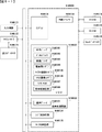
パチンコ遊技機1には、例えば図2に示すような主基板11、演出制御基板12、音声制御基板13、ランプ制御基板14、中継基板15などが搭載されている。その他にも、パチンコ遊技機1の背面には、例えば払出制御基板、情報端子基板、発射制御基板、電源基板などといった、各種の基板が配置されている。
(Board configuration)
For example, the
主基板11は、メイン側の制御基板であり、パチンコ遊技機1における上記遊技の進行(特図ゲームの実行(保留の管理を含む)、普図ゲームの実行(保留の管理を含む)、大当り遊技状態、小当り遊技状態、遊技状態など)を制御する機能を有する。主基板11は、遊技制御用マイクロコンピュータ100、スイッチ回路110、ソレノイド回路111などを有する。
The
主基板11に搭載された遊技制御用マイクロコンピュータ100は、例えば1チップのマイクロコンピュータであり、ROM(Read Only Memory)101と、RAM(Random Access Memory)102と、CPU(Central Processing Unit)103と、乱数回路104と、I/O(Input/Output port)105とを備える。
The
CPU103は、ROM101に記憶されたプログラムを実行することにより、遊技の進行を制御する処理(主基板11の機能を実現する処理)を行う。このとき、ROM101が記憶する各種データ(後述の変動パターン、後述の演出制御コマンド、後述の各種決定を行う際に参照される各種テーブルなどのデータ)が用いられ、RAM102がメインメモリとして使用される。RAM102は、その一部または全部がパチンコ遊技機1に対する電力供給が停止しても、所定期間記憶内容が保存されるバックアップRAMとなっている。なお、ROM101に記憶されたプログラムの全部または一部をRAM102に展開して、RAM102上で実行するようにしてもよい。
The
乱数回路104は、遊技の進行を制御するときに使用される各種の乱数値(遊技用乱数)を示す数値データを更新可能にカウントする。遊技用乱数は、CPU103が所定のコンピュータプログラムを実行することで更新されるもの(ソフトウェアで更新されるもの)であってもよい。
The
I/O105は、例えば各種信号(後述の検出信号)が入力される入力ポートと、各種信号(第1特別図柄表示装置4A、第2特別図柄表示装置4B、普通図柄表示器20、第1保留表示器25A、第2保留表示器25B、普図保留表示器25Cなどを制御(駆動)する信号、ソレノイド駆動信号)を伝送するための出力ポートとを含んで構成される。
The I /
スイッチ回路110は、遊技球検出用の各種スイッチ(ゲートスイッチ21、始動口スイッチ(第1始動口スイッチ22Aおよび第2始動口スイッチ22B)、カウントスイッチ23)からの検出信号(遊技球が通過または進入してスイッチがオンになったことを示す検出信号など)を取り込んで遊技制御用マイクロコンピュータ100に伝送する。検出信号の伝送により、遊技球の通過または進入が検出されたことになる。
The
ソレノイド回路111は、遊技制御用マイクロコンピュータ100からのソレノイド駆動信号(例えば、ソレノイド81やソレノイド82をオンする信号など)を、普通電動役物用のソレノイド81や大入賞口扉用のソレノイド82に伝送する。
The
主基板11(遊技制御用マイクロコンピュータ100)は、遊技の進行の制御の一部として、遊技の進行に応じて演出制御コマンド(遊技の進行状況等を指定(通知)するコマンド)を演出制御基板12に供給する。主基板11から出力された演出制御コマンドは、中継基板15により中継され、演出制御基板12に供給される。当該演出制御コマンドには、例えば主基板11における各種の決定結果(例えば、特図ゲームの表示結果(大当り種別を含む。)、特図ゲームを実行する際に使用される変動パターン(詳しくは後述))、遊技の状況(例えば、可変表示の開始や終了、大入賞口の開放状況、入賞の発生、保留記憶数、遊技状態)、エラーの発生等を指定するコマンド等が含まれる。
The main board 11 (
演出制御基板12は、主基板11とは独立したサブ側の制御基板であり、演出制御コマンドを受信し、受信した演出制御コマンドに基づいて演出(遊技の進行に応じた種々の演出であり、可動体32の駆動、エラー報知、電断復旧の報知等の各種報知を含む)を実行する機能を有する。
The
演出制御基板12には、演出制御用CPU120と、ROM121と、RAM122と、表示制御部123と、乱数回路124と、I/O125とが搭載されている。
The
演出制御用CPU120は、ROM121に記憶されたプログラムを実行することにより、表示制御部123とともに演出を実行するための処理(演出制御基板12の上記機能を実現するための処理であり、実行する演出の決定等を含む)を行う。このとき、ROM121が記憶する各種データ(各種テーブルなどのデータ)が用いられ、RAM122がメインメモリとして使用される。
The
演出制御用CPU120は、コントローラセンサユニット35Aやプッシュセンサ35Bからの検出信号(遊技者による操作を検出したときに出力される信号であり、操作内容を適宜示す信号)に基づいて演出の実行を表示制御部123に指示することもある。
The
表示制御部123は、VDP(Video Display Processor)、CGROM(Character Generator ROM)、VRAM(Video RAM)などを備え、演出制御用CPU120からの演出の実行指示に基づき、演出を実行する。
The
表示制御部123は、演出制御用CPU120からの演出の実行指示に基づき、実行する演出に応じた映像信号を画像表示装置5に供給することで、演出画像を画像表示装置5に表示させる。表示制御部123は、さらに、演出画像の表示に同期した音声出力や、遊技効果ランプ9の点灯/消灯を行うため、音指定信号(出力する音声を指定する信号)を音声制御基板13に供給したり、ランプ信号(ランプの点灯/消灯態様を指定する信号)をランプ制御基板14に供給したりする。また、表示制御部123は、可動体32を動作させる信号を当該可動体32または当該可動体32を駆動する駆動回路に供給する。
The
音声制御基板13は、スピーカ8L、8Rを駆動する各種回路を搭載しており、当該音指定信号に基づきスピーカ8L、8Rを駆動し、当該音指定信号が指定する音声をスピーカ8L、8Rから出力させる。
The
ランプ制御基板14は、遊技効果ランプ9を駆動する各種回路を搭載しており、当該ランプ信号に基づき遊技効果ランプ9を駆動し、当該ランプ信号が指定する態様で遊技効果ランプ9を点灯/消灯する。このようにして、表示制御部123は、音声出力、ランプの点灯/消灯を制御する。
The
なお、音声出力、ランプの点灯/消灯の制御(音指定信号やランプ信号の供給等)、可動体32の制御(可動体32を動作させる信号の供給等)は、演出制御用CPU120が実行するようにしてもよい。
The
乱数回路124は、各種演出を実行するために使用される各種の乱数値(演出用乱数)を示す数値データを更新可能にカウントする。演出用乱数は、演出制御用CPU120が所定のコンピュータプログラムを実行することで更新されるもの(ソフトウェアで更新されるもの)であってもよい。
The
演出制御基板12に搭載されたI/O125は、例えば主基板11などから伝送された演出制御コマンドを取り込むための入力ポートと、各種信号(映像信号、音指定信号、ランプ信号)を伝送するための出力ポートとを含んで構成される。
The I /
演出制御基板12、音声制御基板13、ランプ制御基板14といった、主基板11以外の基板をサブ基板ともいう。パチンコ遊技機1のようにサブ基板が機能別に複数設けられていてもよいし、1のサブ基板が複数の機能を有するように構成してもよい。
Boards other than the
(動作)
次に、パチンコ遊技機1の動作(作用)を説明する。
(motion)
Next, the operation (action) of the
(主基板11の主要な動作)
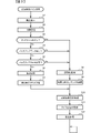
まず、主基板11における主要な動作を説明する。パチンコ遊技機1に対して電力供給が開始されると、遊技制御用マイクロコンピュータ100が起動し、CPU103によって遊技制御メイン処理が実行される。図3は、主基板11におけるCPU103が実行する遊技制御メイン処理を示すフローチャートである。
(Main operation of main board 11)
First, the main operation of the
図3に示す遊技制御メイン処理では、CPU103は、まず、割込禁止に設定する(ステップS1)。続いて、必要な初期設定を行う(ステップS2)。初期設定には、スタックポインタの設定、内蔵デバイス(CTC(カウンタ/タイマ回路)、パラレル入出力ポート等)のレジスタ設定、RAM102をアクセス可能状態にする設定等が含まれる。
In the game control main process shown in FIG. 3, the
次いで、クリアスイッチからの出力信号がオンであるか否かを判定する(ステップS3)。クリアスイッチは、例えば電源基板に搭載されている。クリアスイッチがオンの状態で電源が投入されると、出力信号(クリア信号)が入力ポートを介して遊技制御用マイクロコンピュータ100に入力される。クリアスイッチからの出力信号がオンである場合(ステップS3;Yes)、初期化処理(ステップS8)を実行する。初期化処理では、CPU103は、RAM102に記憶されるフラグ、カウンタ、バッファをクリアするRAMクリア処理を行い、作業領域に初期値を設定する。
Next, it is determined whether or not the output signal from the clear switch is ON (step S3). The clear switch is mounted on, for example, a power supply board. When the power is turned on with the clear switch turned on, an output signal (clear signal) is input to the
また、CPU103は、初期化を指示する演出制御コマンドを演出制御基板12に送信する(ステップS9)。演出制御用CPU120は、当該演出制御コマンドを受信すると、例えば画像表示装置5において、遊技機の制御の初期化がなされたことを報知するための画面表示を行う。
Further, the
クリアスイッチからの出力信号がオンでない場合には(ステップS3;No)、RAM102(バックアップRAM)にバックアップデータが保存されているか否かを判定する(ステップS4)。不測の停電等(電断)によりパチンコ遊技機1への電力供給が停止したときには、CPU103は、当該電力供給の停止によって動作できなくなる直前に、電源供給停止時処理を実行する。この電源供給停止時処理では、RAM102にデータをバックアップすることを示すバックアップフラグをオンする処理、RAM102のデータ保護処理等が実行される。データ保護処理には、誤り検出符号(チェックサム、パリティビット等)の付加、各種データをバックアップする処理が含まれる。バックアップされるデータには、遊技を進行するための各種データ(各種フラグ、各種タイマの状態等を含む)の他、前記バックアップフラグの状態や誤り検出符号も含まれる。ステップS4では、バックアップフラグがオンであるか否かを判定する。バックアップフラグがオフでRAM102にバックアップデータが記憶されていない場合(ステップS4;No)、初期化処理(ステップS8)を実行する。
If the output signal from the clear switch is not on (step S3; No), it is determined whether or not the backup data is stored in the RAM 102 (backup RAM) (step S4). When the power supply to the
RAM102にバックアップデータが記憶されている場合(ステップS4;Yes)、CPU103は、バックアップしたデータのデータチェックを行い(誤り検出符号を用いて行われる)、データが正常か否かを判定する(ステップS5)。ステップS5では、例えば、パリティビットやチェックサムにより、RAM102のデータが、電力供給停止時のデータと一致するか否かを判定する。これらが一致すると判定された場合、RAM102のデータが正常であると判定する。
When the backup data is stored in the RAM 102 (step S4; Yes), the
RAM102のデータが正常でないと判定された場合(ステップS5;No)、内部状態を電力供給停止時の状態に戻すことができないので、初期化処理(ステップS8)を実行する。
When it is determined that the data in the
RAM102のデータが正常であると判定された場合(ステップS5;Yes)、CPU103は、主基板11の内部状態を電力供給停止時の状態に戻すための復旧処理(ステップS6)を行う。復旧処理では、CPU103は、RAM102の記憶内容(バックアップしたデータの内容)に基づいて作業領域の設定を行う。これにより、電力供給停止時の遊技状態に復旧し、特別図柄の変動中であった場合には、後述の遊技制御用タイマ割込み処理の実行によって、復旧前の状態から特別図柄の変動が再開されることになる。
When it is determined that the data in the
そして、CPU103は、電断からの復旧を指示する演出制御コマンドを演出制御基板12に送信する(ステップS7)。これに合わせて、バックアップされている電断前の遊技状態を指定する演出制御コマンドや、特図ゲームの実行中であった場合には当該実行中の特図ゲームの表示結果を指定する演出制御コマンドを送信するようにしてもよい。これらコマンドは、後述の特別図柄プロセス処理で送信設定されるコマンドと同じコマンドを使用できる。演出制御用CPU120は、電断からの復旧時を特定する演出制御コマンドを受信すると、例えば画像表示装置5において、電断からの復旧がなされたこと、または電断からの復旧中であることを、報知するための画面表示を行う。演出制御用CPU120は、前記演出制御コマンドに基づいて、適宜の画面表示を行うようにしてもよい。
Then, the
復旧処理または初期化処理を終了して演出制御基板12に演出制御コマンドを送信した後には、CPU103は、乱数回路104を初期設定する乱数回路設定処理を実行する(ステップS10)。そして、所定時間(例えば2ms)毎に定期的にタイマ割込がかかるように遊技制御用マイクロコンピュータ100に内蔵されているCTCのレジスタの設定を行い(ステップS11)、割込みを許可する(ステップS12)。その後、ループ処理に入る。以後、所定時間(例えば2ms)ごとにCTCから割込み要求信号がCPU103へ送出され、CPU103は定期的にタイマ割込み処理を実行することができる。
After the restoration process or the initialization process is completed and the effect control command is transmitted to the
こうした遊技制御メイン処理を実行したCPU103は、CTCからの割込み要求信号を受信して割込み要求を受け付けると、図4のフローチャートに示す遊技制御用タイマ割込み処理を実行する。図4に示す遊技制御用タイマ割込み処理を開始すると、CPU103は、まず、所定のスイッチ処理を実行することにより、スイッチ回路110を介してゲートスイッチ21、第1始動口スイッチ22A、第2始動口スイッチ22B、カウントスイッチ23といった各種スイッチからの検出信号の受信の有無を判定する(ステップS21)。続いて、所定のメイン側エラー処理を実行することにより、パチンコ遊技機1の異常診断を行い、その診断結果に応じて必要ならば警告を発生可能とする(ステップS22)。この後、所定の情報出力処理を実行することにより、例えばパチンコ遊技機1の外部に設置されたホール管理用コンピュータに供給される大当り情報(大当りの発生回数等を示す情報)、始動情報(始動入賞の回数等を示す情報)、確率変動情報(確変状態となった回数等を示す情報)などのデータを出力する(ステップS23)。
When the
情報出力処理に続いて、主基板11の側で用いられる遊技用乱数の少なくとも一部をソフトウェアにより更新するための遊技用乱数更新処理を実行する(ステップS24)。この後、CPU103は、特別図柄プロセス処理を実行する(ステップS25)。CPU103がタイマ割込み毎に特別図柄プロセス処理を実行することにより、特図ゲームの実行および保留の管理や、大当り遊技状態や小当り遊技状態の制御、遊技状態の制御などが実現される(詳しくは後述)。
Following the information output process, a game random number update process for updating at least a part of the game random numbers used on the
特別図柄プロセス処理に続いて、普通図柄プロセス処理が実行される(ステップS26)。CPU103がタイマ割込み毎に普通図柄プロセス処理を実行することにより、ゲートスイッチ21からの検出信号に基づく(通過ゲート41に遊技球が通過したことに基づく)普図ゲームの実行および保留の管理や、「普図当り」に基づく可変入賞球装置6Bの開放制御などを可能にする。普図ゲームの実行は、普通図柄表示器20を駆動することにより行われ、普図保留表示器25Cを点灯させることにより普図保留数を表示する。
Following the special symbol process process, the normal symbol process process is executed (step S26). By executing the normal symbol process processing for each timer interrupt, the
普通図柄プロセス処理を実行した後、遊技制御用タイマ割込み処理の一部として、電断が発生したときの処理、賞球を払い出すための処理等などが行われてもよい。その後、CPU103は、コマンド制御処理を実行する(ステップS27)。CPU103は、上記各処理にて演出制御コマンドを送信設定することがある。ステップS27のコマンド制御処理では、送信設定された演出制御コマンドを演出制御基板12などのサブ側の制御基板に対して伝送させる処理が行われる。コマンド制御処理を実行した後には、割込みを許可してから、遊技制御用タイマ割込み処理を終了する。
After executing the normal symbol process process, as a part of the game control timer interrupt process, a process when a power failure occurs, a process for paying out a prize ball, and the like may be performed. After that, the
図5は、特別図柄プロセス処理として、図4に示すステップS25にて実行される処理の一例を示すフローチャートである。この特別図柄プロセス処理において、CPU103は、まず、始動入賞判定処理を実行する(ステップS101)。
FIG. 5 is a flowchart showing an example of the process executed in step S25 shown in FIG. 4 as the special symbol process process. In this special symbol process process, the
始動入賞判定処理では、始動入賞の発生を検出し、RAM102の所定領域に保留情報を格納し保留記憶数を更新する処理が実行される。始動入賞が発生すると、表示結果(大当り種別を含む)や変動パターンを決定するための乱数値が抽出され、保留情報として記憶される。また、抽出した乱数値に基づいて、表示結果や変動パターンを先読判定する処理が実行されてもよい。保留情報や保留記憶数を記憶した後には、演出制御基板12に始動入賞の発生、保留記憶数、先読判定等の判定結果を指定するための演出制御コマンドを送信するための送信設定が行われる。こうして送信設定された始動入賞時の演出制御コマンドは、例えば特別図柄プロセス処理が終了した後、図4に示すステップS27のコマンド制御処理が実行されることなどにより、主基板11から演出制御基板12に対して伝送される。
In the start winning determination process, a process of detecting the occurrence of a start winning, storing the hold information in a predetermined area of the
ステップS101にて始動入賞判定処理を実行した後、CPU103は、RAM102に設けられた特図プロセスフラグの値に応じて、ステップS110~S120の処理のいずれかを選択して実行する。なお、特別図柄プロセス処理の各処理(ステップS110~S120)では、各処理に対応した演出制御コマンドを演出制御基板12に送信するための送信設定が行われる。
After executing the start winning determination process in step S101, the
ステップS110の特別図柄通常処理は、特図プロセスフラグの値が“0”(初期値)のときに実行される。この特別図柄通常処理では、保留情報の有無などに基づいて、第1特図ゲームまたは第2特図ゲームを開始するか否かの判定が行われる。また、特別図柄通常処理では、表示結果決定用の乱数値に基づき、特別図柄や飾り図柄の表示結果を「大当り」または「小当り」とするか否かや「大当り」とする場合の大当り種別を、その表示結果が導出表示される以前に決定(事前決定)する。さらに、特別図柄通常処理では、決定された表示結果に対応して、特図ゲームにおいて停止表示させる確定特別図柄(大当り図柄や小当り図柄、ハズレ図柄のいずれか)が設定される。その後、特図プロセスフラグの値が“1”に更新され、特別図柄通常処理は終了する。なお、第2特図を用いた特図ゲームが第1特図を用いた特図ゲームよりも優先して実行されるようにしてもよい(特図2優先消化ともいう)。また、第1始動入賞口および第2始動入賞口への遊技球の入賞順序を記憶し、入賞順に特図ゲームの開始条件を成立させるようにしてもよい(入賞順消化ともいう)。 The special symbol normal processing in step S110 is executed when the value of the special symbol process flag is “0” (initial value). In this special symbol normal processing, it is determined whether or not to start the first special figure game or the second special figure game based on the presence or absence of the reserved information. In addition, in the special symbol normal processing, whether or not the display result of the special symbol or decorative symbol is set to "big hit" or "small hit" based on the random number value for determining the display result, and the big hit type when the display result is set to "big hit". Is determined (predetermined) before the display result is derived and displayed. Further, in the special symbol normal processing, a definite special symbol (either a big hit symbol, a small hit symbol, or a lost symbol) to be stopped and displayed in the special symbol game is set according to the determined display result. After that, the value of the special symbol process flag is updated to "1", and the special symbol normal processing ends. It should be noted that the special figure game using the second special figure may be executed with priority over the special figure game using the first special figure (also referred to as special figure 2 priority digestion). Further, the winning order of the game balls to the first starting winning opening and the second starting winning opening may be stored, and the starting condition of the special figure game may be satisfied in the winning order (also referred to as winning order digestion).
乱数値に基づき各種の決定を行う場合には、ROM101に格納されている各種のテーブル(乱数値と比較される決定値が決定結果に割り当てられているテーブル)が参照される。主基板11における他の決定、演出制御基板12における各種の決定についても同じである。演出制御基板12においては、各種のテーブルがROM121に格納されている。
When making various decisions based on the random number value, various tables stored in the ROM 101 (a table in which the decision value to be compared with the random number value is assigned to the decision result) are referred to. The same applies to other decisions on the
ステップS111の変動パターン設定処理は、特図プロセスフラグの値が“1”のときに実行される。この変動パターン設定処理には、表示結果を「大当り」または「小当り」とするか否かの事前決定結果等に基づき、変動パターン決定用の乱数値を用いて変動パターンを複数種類のいずれかに決定する処理などが含まれている。変動パターン設定処理では、変動パターンを決定したときに、特図プロセスフラグの値が“2”に更新され、変動パターン設定処理は終了する。 The variation pattern setting process in step S111 is executed when the value of the special figure process flag is “1”. In this fluctuation pattern setting process, one of a plurality of types of fluctuation patterns is used by using a random value for determining the fluctuation pattern based on the pre-determination result of whether or not the display result is "big hit" or "small hit". It includes the process of determining. In the variation pattern setting process, when the variation pattern is determined, the value of the special figure process flag is updated to "2", and the variation pattern setting process ends.
変動パターンは、特図ゲームの実行時間(特図変動時間)(飾り図柄の可変表示の実行時間でもある)や、飾り図柄の可変表示の態様(リーチの有無等)、飾り図柄の可変表示中の演出内容(リーチ演出の種類等)を指定するものであり、可変表示パターンとも呼ばれる。 The fluctuation pattern includes the execution time of the special figure game (special figure fluctuation time) (which is also the execution time of the variable display of the decorative symbol), the variable display mode of the decorative symbol (presence or absence of reach, etc.), and the variable display of the decorative symbol. It specifies the content of the effect (type of reach effect, etc.), and is also called a variable display pattern.
ステップS112の特別図柄変動処理は、特図プロセスフラグの値が“2”のときに実行される。この特別図柄変動処理には、第1特別図柄表示装置4Aや第2特別図柄表示装置4Bにおいて特別図柄を変動させるための設定を行う処理や、その特別図柄が変動を開始してからの経過時間を計測する処理などが含まれている。また、計測された経過時間が変動パターンに対応する特図変動時間に達したか否かの判定も行われる。そして、特別図柄の変動を開始してからの経過時間が特図変動時間に達したときには、特図プロセスフラグの値が“3”に更新され、特別図柄変動処理は終了する。
The special symbol variation process in step S112 is executed when the value of the special symbol process flag is “2”. In this special symbol variation processing, the processing for setting the special symbol to be varied in the first special
ステップS113の特別図柄停止処理は、特図プロセスフラグの値が“3”のときに実行される。この特別図柄停止処理には、第1特別図柄表示装置4Aや第2特別図柄表示装置4Bにて特別図柄の変動を停止させ、特別図柄の表示結果となる確定特別図柄を停止表示(導出)させるための設定を行う処理が含まれている。そして、表示結果が「大当り」である場合には特図プロセスフラグの値が“4”に更新される。その一方で、大当りフラグがオフであり、表示結果が「小当り」である場合には、特図プロセスフラグの値が“8”に更新される。また、表示結果が「ハズレ」である場合には、特図プロセスフラグの値が“0”に更新される。表示結果が「小当り」または「ハズレ」である場合、時短状態や確変状態に制御されているときであって、回数切りの終了成立する場合には、遊技状態も更新される。特図プロセスフラグの値が更新されると、特別図柄停止処理は終了する。
The special symbol stop processing in step S113 is executed when the value of the special symbol process flag is “3”. In this special symbol stop process, the first special
ステップS114の大当り開放前処理は、特図プロセスフラグの値が“4”のときに実行される。この大当り開放前処理には、表示結果が「大当り」となったことなどに基づき、大当り遊技状態においてラウンドの実行を開始して大入賞口を開放状態とするための設定を行う処理などが含まれている。大入賞口を開放状態とするときには、大入賞口扉用のソレノイド82に対してソレノイド駆動信号を供給する処理が実行される。このときには、例えば大当り種別がいずれであるかに対応して、大入賞口を開放状態とする開放上限期間や、ラウンドの上限実行回数を設定する。これらの設定が終了すると、特図プロセスフラグの値が“5”に更新され、大当り開放前処理は終了する。
The jackpot opening preprocessing in step S114 is executed when the value of the special figure process flag is “4”. This big hit pre-opening process includes a process of setting to open the big winning opening by starting the execution of the round in the big hit game state based on the display result being "big hit". It has been. When the large winning opening is opened, a process of supplying a solenoid drive signal to the
ステップS115の大当り開放中処理は、特図プロセスフラグの値が“5”のときに実行される。この大当り開放中処理には、大入賞口を開放状態としてからの経過時間を計測する処理や、その計測した経過時間やカウントスイッチ23によって検出された遊技球の個数などに基づいて、大入賞口を開放状態から閉鎖状態に戻すタイミングとなったか否かを判定する処理などが含まれている。そして、大入賞口を閉鎖状態に戻すときには、大入賞口扉用のソレノイド82に対するソレノイド駆動信号の供給を停止させる処理などを実行した後、特図プロセスフラグの値が“6”に更新し、大当り開放中処理を終了する。
The process of opening the jackpot in step S115 is executed when the value of the special figure process flag is “5”. In this big hit opening process, the big winning opening is based on the process of measuring the elapsed time since the big winning opening is opened, the measured elapsed time, the number of game balls detected by the
ステップS116の大当り開放後処理は、特図プロセスフラグの値が“6”のときに実行される。この大当り開放後処理には、大入賞口を開放状態とするラウンドの実行回数が設定された上限実行回数に達したか否かを判定する処理や、上限実行回数に達した場合に大当り遊技状態を終了させるための設定を行う処理などが含まれている。そして、ラウンドの実行回数が上限実行回数に達していないときには、特図プロセスフラグの値が“5”に更新される一方、ラウンドの実行回数が上限実行回数に達したときには、特図プロセスフラグの値が“7”に更新される。特図プロセスフラグの値が更新されると、大当り解放後処理は終了する。 The post-processing after opening the jackpot in step S116 is executed when the value of the special figure process flag is “6”. In this big hit post-opening process, there is a process of determining whether or not the number of rounds to be executed with the big winning opening open has reached the set maximum number of executions, and a big hit game state when the maximum number of executions has been reached. It includes the process of making settings to terminate. Then, when the number of round executions has not reached the upper limit, the value of the special figure process flag is updated to "5", while when the number of round executions reaches the upper limit, the special figure process flag is set. The value is updated to "7". When the value of the special figure process flag is updated, the jackpot release post-processing ends.
ステップS117の大当り終了処理は、特図プロセスフラグの値が“7”のときに実行される。この大当り終了処理には、大当り遊技状態の終了を報知する演出動作としてのエンディング演出が実行される期間に対応した待ち時間が経過するまで待機する処理や、大当り遊技状態の終了に対応して確変制御や時短制御を開始するための各種の設定を行う処理などが含まれている。こうした設定が行われたときには、特図プロセスフラグの値が“0”に更新され、大当り終了処理は終了する。 The jackpot end process of step S117 is executed when the value of the special figure process flag is “7”. In this jackpot end process, there is a process of waiting until the waiting time corresponding to the period corresponding to the period in which the ending effect as an effect effect for notifying the end of the jackpot game state is executed, and a probable change corresponding to the end of the jackpot game state. It includes processing to make various settings for starting control and time reduction control. When such a setting is made, the value of the special figure process flag is updated to "0", and the jackpot end process ends.
ステップS118の小当り開放前処理は、特図プロセスフラグの値が“8”のときに実行される。この小当り開放前処理には、表示結果が「小当り」となったことに基づき、小当り遊技状態において大入賞口を開放状態とするための設定を行う処理などが含まれている。このときには、特図プロセスフラグの値が“9”に更新され、小当り開放前処理は終了する。 The small hit release preprocessing in step S118 is executed when the value of the special figure process flag is “8”. This small hit pre-opening process includes a process of setting the large winning opening to be in the open state in the small hit game state based on the display result being "small hit". At this time, the value of the special figure process flag is updated to "9", and the small hit opening preprocessing ends.
ステップS119の小当り開放中処理は、特図プロセスフラグの値が“9”のときに実行される。この小当り開放中処理には、大入賞口を開放状態としてからの経過時間を計測する処理や、その計測した経過時間などに基づいて、大入賞口を開放状態から閉鎖状態に戻すタイミングとなったか否かを判定する処理などが含まれている。大入賞口を閉鎖状態に戻して小当り遊技状態の終了タイミングとなったときには、特図プロセスフラグの値が“10”に更新され、小当り開放中処理は終了する。 The small hit opening process in step S119 is executed when the value of the special figure process flag is “9”. In this small hit opening process, it is the timing to return the big prize opening from the open state to the closed state based on the process of measuring the elapsed time from the opening state of the big winning opening and the measured elapsed time. It includes a process to determine whether or not it is. When the large winning opening is returned to the closed state and the end timing of the small hit game state is reached, the value of the special figure process flag is updated to "10", and the processing during the small hit opening process ends.
ステップS120の小当り終了処理は、特図プロセスフラグの値が“10”のときに実行される。この小当り終了処理には、小当り遊技状態の終了を報知する演出動作が実行される期間に対応した待ち時間が経過するまで待機する処理などが含まれている。ここで、小当り遊技状態が終了するときには、小当り遊技状態となる以前のパチンコ遊技機1における遊技状態を継続させる。小当り遊技状態の終了時における待ち時間が経過したときには、特図プロセスフラグの値が“0”に更新され、小当り終了処理は終了する。
The small hit end process of step S120 is executed when the value of the special figure process flag is “10”. The small hit end process includes a process of waiting until a waiting time corresponding to a period in which the effect operation for notifying the end of the small hit game state is executed has elapsed. Here, when the small hit gaming state ends, the gaming state in the
(演出制御基板12の主要な動作)
次に、演出制御基板12における主要な動作を説明する。演出制御基板12では、電源基板等から電源電圧の供給を受けると、演出制御用CPU120が起動して、図6のフローチャートに示すような演出制御メイン処理を実行する。図6に示す演出制御メイン処理を開始すると、演出制御用CPU120は、まず、所定の初期化処理を実行して(ステップS71)、RAM122のクリアや各種初期値の設定、また演出制御基板12に搭載されたCTC(カウンタ/タイマ回路)のレジスタ設定等を行う。また、初期動作制御処理を実行する(ステップS72)。初期動作制御処理では、可動体32を駆動して初期位置に戻す制御、所定の動作確認を行う制御といった可動体32の初期動作を行う制御が実行される。
(Main operation of the effect control board 12)
Next, the main operation of the
その後、タイマ割込みフラグがオンとなっているか否かの判定を行う(ステップS73)。タイマ割込みフラグは、例えばCTCのレジスタ設定に基づき、所定時間(例えば2ミリ秒)が経過するごとにオン状態にセットされる。このとき、タイマ割込みフラグがオフであれば(ステップS73;No)、ステップS73の処理を繰り返し実行して待機する。 After that, it is determined whether or not the timer interrupt flag is turned on (step S73). The timer interrupt flag is set to the ON state every time a predetermined time (for example, 2 milliseconds) elapses, based on the register setting of the CTC, for example. At this time, if the timer interrupt flag is off (step S73; No), the process of step S73 is repeatedly executed and waits.
また、演出制御基板12の側では、所定時間が経過するごとに発生するタイマ割込みとは別に、主基板11からの演出制御コマンドを受信するための割込みが発生する。この割込みは、例えば主基板11からの演出制御INT信号がオン状態となることにより発生する割込みである。演出制御INT信号がオン状態となることによる割込みが発生すると、演出制御用CPU120は、自動的に割込み禁止に設定するが、自動的に割込み禁止状態にならないCPUを用いている場合には、割込み禁止命令(DI命令)を発行することが望ましい。演出制御用CPU120は、演出制御INT信号がオン状態となることによる割込みに対応して、例えば所定のコマンド受信割込み処理を実行する。このコマンド受信割込み処理では、I/O125に含まれる入力ポートのうちで、中継基板15を介して主基板11から送信された制御信号を受信する所定の入力ポートより、演出制御コマンドを取り込む。このとき取り込まれた演出制御コマンドは、例えばRAM122に設けられた演出制御コマンド受信用バッファに格納する。その後、演出制御用CPU120は、割込み許可に設定してから、コマンド受信割込み処理を終了する。
Further, on the side of the
ステップS73にてタイマ割込みフラグがオンである場合には(ステップS73;Yes)、タイマ割込みフラグをクリアしてオフ状態にするとともに(ステップS74)、コマンド解析処理を実行する(ステップS75)。コマンド解析処理では、例えば主基板11の遊技制御用マイクロコンピュータ100から送信されて演出制御コマンド受信用バッファに格納されている各種の演出制御コマンドを読み出した後に、その読み出された演出制御コマンドに対応した設定や制御などが行われる。例えば、どの演出制御コマンドを受信したかや演出制御コマンドが特定する内容等を演出制御プロセス処理等で確認できるように、読み出された演出制御コマンドをRAM122の所定領域に格納したり、RAM122に設けられた受信フラグをオンしたりする。また、演出制御コマンドが遊技状態を特定する場合、遊技状態に応じた背景の表示を表示制御部123に指示してもよい。
If the timer interrupt flag is on in step S73 (step S73; Yes), the timer interrupt flag is cleared and turned off (step S74), and the command analysis process is executed (step S75). In the command analysis process, for example, after reading various effect control commands transmitted from the
ステップS75にてコマンド解析処理を実行した後には、演出制御プロセス処理を実行する(ステップS76)。演出制御プロセス処理では、例えば画像表示装置5の表示領域における演出画像の表示動作、スピーカ8L、8Rからの音声出力動作、遊技効果ランプ9および装飾用LEDといった装飾発光体における点灯動作、可動体32の駆動動作といった、各種の演出装置を動作させる制御が行われる。また、各種の演出装置を用いた演出動作の制御内容について、主基板11から送信された演出制御コマンド等に応じた判定や決定、設定などが行われる。
After executing the command analysis process in step S75, the effect control process process is executed (step S76). In the effect control process processing, for example, an effect image display operation in the display area of the
ステップS76の演出制御プロセス処理に続いて、演出用乱数更新処理が実行され(ステップS77)、演出制御基板12の側で用いられる演出用乱数の少なくとも一部がソフトウェアにより更新される。その後、ステップS73の処理に戻る。ステップS73の処理に戻る前に、他の処理が実行されてもよい。
Following the effect control process process in step S76, the effect random number update process is executed (step S77), and at least a part of the effect random numbers used on the
図7は、演出制御プロセス処理として、図6のステップS76にて実行される処理の一例を示すフローチャートである。図7に示す演出制御プロセス処理において、演出制御用CPU120は、まず、先読予告設定処理を実行する(ステップS161)。先読予告設定処理では、例えば、主基板11から送信された始動入賞時の演出制御コマンドに基づいて、先読予告演出を実行するための判定や決定、設定などが行われる。また、当該演出制御コマンドから特定される保留記憶数に基づき保留表示を表示するための処理が実行される。
FIG. 7 is a flowchart showing an example of the process executed in step S76 of FIG. 6 as the effect control process process. In the effect control process process shown in FIG. 7, the
ステップS161の処理を実行した後、演出制御用CPU120は、例えばRAM122に設けられた演出プロセスフラグの値に応じて、以下のようなステップS170~S177の処理のいずれかを選択して実行する。
After executing the process of step S161, the
ステップS170の可変表示開始待ち処理は、演出プロセスフラグの値が“0”(初期値)のときに実行される処理である。この可変表示開始待ち処理は、主基板11から可変表示の開始を指定するコマンドなどを受信したか否かに基づき、画像表示装置5における飾り図柄の可変表示を開始するか否かを判定する処理などを含んでいる。画像表示装置5における飾り図柄の可変表示を開始すると判定された場合、演出プロセスフラグの値を“1”に更新し、可変表示開始待ち処理を終了する。
The variable display start waiting process in step S170 is a process executed when the value of the effect process flag is “0” (initial value). This variable display start waiting process is a process of determining whether or not to start variable display of the decorative symbol on the
ステップS171の可変表示開始設定処理は、演出プロセスフラグの値が“1”のときに実行される処理である。この可変表示開始設定処理では、演出制御コマンドにより特定される表示結果や変動パターンに基づいて、飾り図柄の可変表示の表示結果(確定飾り図柄)、飾り図柄の可変表示の態様、リーチ演出や各種予告演出などの各種演出の実行の有無やその態様や実行開始タイミングなどを決定する。そして、その決定結果等を反映した演出制御パターン(表示制御部123に演出の実行を指示するための制御データの集まり)を設定する。その後、設定した演出制御パターンに基づいて、飾り図柄の可変表示の実行開始を表示制御部123に指示し、演出プロセスフラグの値を“2”に更新し、可変表示開始設定処理を終了する。表示制御部123は、飾り図柄の可変表示の実行開始の指示により、画像表示装置5において、飾り図柄の可変表示を開始させる。
The variable display start setting process in step S171 is a process executed when the value of the effect process flag is “1”. In this variable display start setting process, the display result of the variable display of the decorative symbol (fixed decorative symbol), the mode of the variable display of the decorative symbol, the reach effect, and various types are based on the display result and the variation pattern specified by the effect control command. It is determined whether or not various effects such as a notice effect are executed, the mode thereof, and the execution start timing. Then, an effect control pattern (a collection of control data for instructing the
ステップS172の可変表示中演出処理は、演出プロセスフラグの値が“2”のときに実行される処理である。この可変表示中演出処理において、演出制御用CPU120は、表示制御部123を指示することで、ステップS171にて設定された演出制御パターンに基づく演出画像を画像表示装置5の表示画面に表示させることや、可動体32を駆動させること、音声制御基板13に対する指令(効果音信号)の出力によりスピーカ8L、8Rから音声や効果音を出力させること、ランプ制御基板14に対する指令(電飾信号)の出力により遊技効果ランプ9や装飾用LEDを点灯/消灯/点滅させることといった、飾り図柄の可変表示中における各種の演出制御を実行する。こうした演出制御を行った後、例えば演出制御パターンから飾り図柄の可変表示終了を示す終了コードが読み出されたこと、あるいは、主基板11から確定飾り図柄を停止表示させることを指定するコマンドを受信したことなどに対応して、飾り図柄の表示結果となる確定飾り図柄を停止表示させる。確定飾り図柄を停止表示したときには、演出プロセスフラグの値が“3”に更新され、可変表示中演出処理は終了する。
The variable display effect process in step S172 is a process executed when the value of the effect process flag is “2”. In this variable display effect processing, the
ステップS173の特図当り待ち処理は、演出プロセスフラグの値が“3”のときに実行される処理である。この特図当り待ち処理において、演出制御用CPU120は、主基板11から大当り遊技状態または小当り遊技状態を開始することを指定する演出制御コマンドの受信があったか否かを判定する。そして、大当り遊技状態または小当り遊技状態を開始することを指定する演出制御コマンドを受信したきに、そのコマンドが大当り遊技状態の開始を指定するものであれば、演出プロセスフラグの値を“6”に更新する。これに対して、そのコマンドが小当り遊技状態の開始を指定するものであれば、演出プロセスフラグの値を小当り中演出処理に対応した値である“4”に更新する。また、大当り遊技状態または小当り遊技状態を開始することを指定するコマンドを受信せずに、当該コマンドの受信待ち時間が経過したときには、特図ゲームにおける表示結果が「ハズレ」であったと判定して、演出プロセスフラグの値を初期値である“0”に更新する。演出プロセスフラグの値を更新すると、特図当り待ち処理を終了する。
The special figure hit waiting process in step S173 is a process executed when the value of the effect process flag is “3”. In this special figure hit waiting process, the
ステップS174の小当り中演出処理は、演出プロセスフラグの値が“4”のときに実行される処理である。この小当り中演出処理において、演出制御用CPU120は、例えば小当り遊技状態における演出内容に対応した演出制御パターン等を設定し、その設定内容に基づく小当り遊技状態における各種の演出制御を実行する。また、小当り中演出処理では、例えば主基板11から小当り遊技状態を終了することを指定するコマンドを受信したことに対応して、演出プロセスフラグの値を小当り終了演出に対応した値である“5”に更新し、小当り中演出処理を終了する。
The small hit medium effect process in step S174 is a process executed when the value of the effect process flag is “4”. In this small hit medium effect process, the
ステップS175の小当り終了演出処理は、演出プロセスフラグの値が“5”のときに実行される処理である。この小当り終了演出処理において、演出制御用CPU120は、例えば小当り遊技状態の終了などに対応した演出制御パターン等を設定し、その設定内容に基づく小当り遊技状態の終了時における各種の演出制御を実行する。その後、演出プロセスフラグの値を初期値である“0”に更新し、小当り終了演出処理を終了する。
The small hit end effect process in step S175 is a process executed when the value of the effect process flag is “5”. In this small hit end effect process, the
ステップS176の大当り中演出処理は、演出プロセスフラグの値が“6”のときに実行される処理である。この大当り中演出処理において、演出制御用CPU120は、例えば大当り遊技状態における演出内容に対応した演出制御パターン等を設定し、その設定内容に基づく大当り遊技状態における各種の演出制御を実行する。また、大当り中演出処理では、例えば主基板11から大当り遊技状態を終了することを指定するコマンドを受信したことに対応して、演出プロセスフラグの値をエンディング演出処理に対応した値である“7”に更新し、大当り中演出処理を終了する。
The jackpot effect process in step S176 is a process executed when the value of the effect process flag is “6”. In this big hit middle effect processing, the
ステップS177のエンディング演出処理は、演出プロセスフラグの値が“7”のときに実行される処理である。このエンディング演出処理において、演出制御用CPU120は、例えば大当り遊技状態の終了などに対応した演出制御パターン等を設定し、その設定内容に基づく大当り遊技状態の終了時におけるエンディング演出の各種の演出制御を実行する。その後、演出プロセスフラグの値を初期値である“0”に更新し、エンディング演出処理を終了する。
The ending effect process of step S177 is a process executed when the value of the effect process flag is “7”. In this ending effect processing, the
(基本説明の変形例)
この発明は、上記基本説明で説明したパチンコ遊技機1に限定されず、本発明の趣旨を逸脱しない範囲で、様々な変形および応用が可能である。
(Modified example of basic explanation)
The present invention is not limited to the
上記基本説明のパチンコ遊技機1は、入賞の発生に基づいて所定数の遊技媒体を景品として払い出す払出式遊技機であったが、遊技媒体を封入し入賞の発生に基づいて得点を付与する封入式遊技機であってもよい。
The
特別図柄の可変表示中に表示されるものは1種類の図柄(例えば、「-」を示す記号)だけで、当該図柄の表示と消灯とを繰り返すことによって可変表示を行うようにしてもよい。さらに可変表示中に当該図柄が表示されるものも、可変表示の停止時には、当該図柄が表示されなくてもよい(表示結果としては「-」を示す記号が表示されなくてもよい)。 Only one type of symbol (for example, a symbol indicating "-") is displayed during the variable display of the special symbol, and the variable display may be performed by repeating the display and extinguishing of the symbol. Further, even if the symbol is displayed during the variable display, the symbol may not be displayed when the variable display is stopped (the symbol indicating "-" may not be displayed as the display result).
上記基本説明では、遊技機としてパチンコ遊技機1を示したが、メダルが投入されて所定の賭け数が設定され、遊技者による操作レバーの操作に応じて複数種類の図柄を回転させ、遊技者によるストップボタンの操作に応じて図柄を停止させたときに停止図柄の組合せが特定の図柄の組合せになると、所定数のメダルが遊技者に払い出されるゲームを実行可能なスロット機(例えば、ビッグボーナス、レギュラーボーナス、RT、AT、ART、CZ(以下、ボーナス等)のうち1以上を搭載するスロット機)にも本発明を適用可能である。
In the above basic explanation, the
本発明を実現するためのプログラムおよびデータは、パチンコ遊技機1に含まれるコンピュータ装置などに対して、着脱自在の記録媒体により配布・提供される形態に限定されるものではなく、予めコンピュータ装置などの有する記憶装置にインストールしておくことで配布される形態を採っても構わない。さらに、本発明を実現するためのプログラムおよびデータは、通信処理部を設けておくことにより、通信回線等を介して接続されたネットワーク上の、他の機器からダウンロードすることによって配布する形態を採っても構わない。
The program and data for realizing the present invention are not limited to the form of being distributed and provided by a detachable recording medium to the computer device included in the
そして、ゲームの実行形態も、着脱自在の記録媒体を装着することにより実行するものだけではなく、通信回線等を介してダウンロードしたプログラムおよびデータを、内部メモリ等に一旦格納することにより実行可能とする形態、通信回線等を介して接続されたネットワーク上における、他の機器側のハードウェア資源を用いて直接実行する形態としてもよい。さらには、他のコンピュータ装置等とネットワークを介してデータの交換を行うことによりゲームを実行するような形態とすることもできる。 The game can be executed not only by attaching a detachable recording medium, but also by temporarily storing the program and data downloaded via a communication line or the like in an internal memory or the like. It may be executed directly by using the hardware resources of other devices on the network connected via a communication line or the like. Furthermore, the game can be executed by exchanging data with another computer device or the like via a network.
なお、本明細書において、演出の実行割合などの各種割合の比較の表現(「高い」、「低い」、「異ならせる」などの表現)は、一方が「0%」の割合であることを含んでもよい。例えば、一方が「0%」の割合で、他方が「100%」の割合または「100%」未満の割合であることも含む。 In this specification, one of the expressions for comparison of various ratios such as the execution ratio of the production (expressions such as "high", "low", and "differentiate") is "0%". It may be included. For example, one may have a percentage of "0%" and the other a percentage of "100%" or less than "100%".
(設定値に関する特徴部の説明)
以下、パチンコ遊技機1における設定値に関する特徴部について説明する。
(Explanation of the feature part regarding the set value)
Hereinafter, the feature portion related to the set value in the
パチンコ遊技機1の主基板11は、図示は省略しているが、第1部材と第2部材とにより開放可能に構成された基板ケースに収納された状態でパチンコ遊技機1の背面に搭載されている。また、主基板11には、何れも図示は省略しているが、パチンコ遊技機1の設定値を変更可能な設定値変更状態に切り替えるための錠スイッチと、設定値変更状態において後述する大当りの当選確率(出玉率)等の設定値を変更するための設定スイッチとして機能する設定切替スイッチと、遊技機用枠の開放を検知する開放センサと、が設けられている。なお、本実施の形態における設定値変更状態は、遊技場の係員等がパチンコ遊技機1に設定されている設定値を確認可能な状態(設定値確認状態)でもある。
Although not shown, the
これら錠スイッチ及び設定切替スイッチといった、遊技場の係員等が操作可能な操作部は、設定切替本体部に設けられ、主基板11とともに基板ケース内に収容されている。錠スイッチ及び設定切替スイッチは、基板ケースを開放しなくても操作可能となるように、基板ケースの背面に形成された開口を介して背面側に露出している。
The operation unit, such as the lock switch and the setting changeover switch, which can be operated by the staff of the game hall or the like, is provided in the setting changeover main body part and is housed in the board case together with the
錠スイッチ及び設定切替スイッチを収容した基板ケースはパチンコ遊技機1の背面に設けられている。したがって、錠スイッチ及び設定切替スイッチは、遊技機用枠を閉鎖した状態では操作が極めて困難あるいは不可能であり、所定の扉キーを用いて遊技機用枠を開放することで操作が可能となる。また、錠スイッチは、遊技場の係員等が所持する設定キーの操作を要することから、設定キーを所持する管理者のみ操作が可能とされている。錠スイッチは、設定キーによって、ONとOFFの切替操作を実行可能なスイッチでもある。本実施の形態では、扉キーと設定キーとが別個のキーである形態を例示しているが、これらは1のキーにて兼用されていてもよい。
A board case containing a lock switch and a setting changeover switch is provided on the back surface of the
基板ケースには、設定値やベース値を表示可能な表示モニタが配置されている。表示モニタは、主基板11に接続されているとともに、基板ケースの上部に配置されている。つまり、表示モニタは、基板ケースにおける主基板11を視認する際の正面に配置されている。主基板11は、遊技機用枠を開放していない状態では視認できないので、主基板11を視認する際の正面とは、遊技機用枠を開放した状態における遊技盤2の裏面側を視認する際の正面であり、パチンコ遊技機1の正面とは異なる。このように、表示モニタは、遊技機用枠を開放した状態における遊技盤2の裏面側を視認する際の正面に配置されている。ただし、主基板11を視認する際の正面とパチンコ遊技機1の正面とが共通するようにしてもよい。
A display monitor capable of displaying set values and base values is arranged on the board case. The display monitor is connected to the
表示モニタは、第1表示部、第2表示部、第3表示部、第4表示部を備えている。表示モニタの第1表示部~第4表示部は、いずれも「8」の字を描く7つのセグメントによって構成される7セグメントと、7セグメントの右側方下部に配置されたドットによって構成されている。表示モニタの第1表示部~第4表示部は、それぞれ種々の色、例えば赤色、青色、緑色、黄色、白色等で点灯や点滅が可能とされている。また、これらの色を極短周期で変化させながら異なる色やいわゆるレインボーで表示させることも可能である。 The display monitor includes a first display unit, a second display unit, a third display unit, and a fourth display unit. The first display unit to the fourth display unit of the display monitor are each composed of seven segments composed of seven segments drawing the character "8" and dots arranged at the lower right side of the seven segments. .. The first display unit to the fourth display unit of the display monitor can be lit or blinked in various colors such as red, blue, green, yellow, and white. It is also possible to display these colors in different colors or so-called rainbows while changing them in a very short cycle.
パチンコ遊技機1の遊技盤2の所定位置として、例えば遊技領域の左下方位置には、遊技情報表示部が設けられていてもよい。遊技情報表示部には、ラウンド表示器、右打ちランプ、確変ランプ、時短ランプが、まとめて配置されている。ラウンド表示器は、大当り遊技中に、大当り遊技のラウンド数や大当り種別を表示可能である。右打ちランプは、時短状態としての低確高ベース状態や大当り遊技状態といった、遊技球を右遊技領域に向けて打ち出す遊技状態において点灯する。確変ランプは、確変状態であるとき点灯する。時短ランプは、時短状態であるときに点灯する。ラウンド表示器は5個のセグメント(LED)から構成されている。
As a predetermined position of the
パチンコ遊技機1は、設定値に応じて大当りの当選確率(出玉率)が変わる構成とされている。例えば、特別図柄プロセス処理の特別図柄通常処理において、設定値に応じた表示結果判定テーブル(当選確率)を用いることにより、大当りの当選確率(出玉率)が変わるようになっている。設定値は1~6の6段階からなり、6が最も出玉率が高く、6、5、4、3、2、1の順に値が小さくなるほど出玉率が低くなる。すなわち、設定値として6が設定されている場合には遊技者にとって最も有利度が高く、5、4、3、2、1の順に値が小さくなるほど有利度が段階的に低くなる。また、設定値は、最も大きい値である6が最も遊技場側にとって不利な値であり、5、4、3、2、1の順に値が小さくなるほど遊技場側にとって有利な値となる。なお、設定値に応じて出玉率が変われば、例えば、大当りの確率が設定値によって変わっていてもよいし、大当り確率は一定であるものの大当り遊技状態におけるラウンド数が設定値によって変わっていてもよい。このように、パチンコ遊技機1は、遊技者にとっての有利度が異なる複数の設定値のうちいずれかを設定可能に構成されている。パチンコ遊技機1において設定されている設定値は、主基板11の側から演出制御基板12の側へ設定値指定コマンドが送信されることにより通知される。
The
(特徴部91AK、92AKに関する説明)
図8-1は、特徴部91AK、92AKに関し、演出制御基板12に搭載された各種回路の構成例を示している。図8-1に示す構成例では、演出制御用マイクロプロセッサ91AK100、入力回路91AK121、メモリコントローラ91AK122、演出データメモリ91AK123、ROM91AK124、RAM91AK125、ウォッチドッグタイマ91AK126といった、各種回路が演出制御基板12に搭載されている。演出制御用マイクロプロセッサ91AK100は、CPU91AK131、VDP91AK132、音声処理回路91AK133、ランプ制御回路91AK134、モータ制御回路135、内蔵メモリ91AK136を備えている。VDP91AK132は、命令デコーダ91AK141、デマルチプレクサ91AK142、映像デコーダ91AK143、動画像レンダラ91AK144、キャラクタ画像レンダラ91AK145、テキスト画像レンダラ91AK146、VRAM91AK147、表示駆動回路91AK148を含んでいる。音声処理回路91AK133は、音声デコーダ91AK151を含んでいる。
(Explanation of feature units 91AK and 92AK)
FIG. 8-1 shows configuration examples of various circuits mounted on the
演出制御用マイクロプロセッサ91AK100は、主基板11から受信した演出制御コマンドに基づいて、データ処理や信号処理を実行することなどにより、画像表示装置5、スピーカ8L、8R、遊技効果ランプ9その他の装飾用LED、可動体32などの演出用可動部材といった、複数の演出装置のうち、一部または全部を用いた演出の実行を制御可能な回路が1チップに集積された統合型プロセッサであればよい。なお、演出制御用マイクロプロセッサ91AK100は、CPU91AK131、VDP91AK132や内蔵メモリ91AK136を備える一方で、音声処理回路91AK133、ランプ制御回路91AK134、モータ制御回路91AK135のうち、一部または全部は、演出制御用マイクロプロセッサ91AK100の外部に設けられてもよい。
The effect control microprocessor 91AK100 executes data processing and signal processing based on the effect control command received from the
入力回路91AK121は、バッファ回路などを備えていればよい。入力回路91AK121のバッファ回路は、中継基板15を介して主基板11から伝送された演出制御コマンドを受信するために用いられる。メモリコントローラ91AK122は、演出制御用マイクロプロセッサ91AK100から供給される要求信号に応じて、演出データメモリ91AK123の記憶データに対する各種処理を実行する。演出データメモリ91AK123は、例えば画像表示装置5における表示画像を示す各種の画像データといった、演出装置を用いた演出の実行に使用可能な演出データを予め記憶している。演出データメモリ91AK123が記憶する画像データには、動画像データと静止画像データとが含まれていればよい。静止画像データとして、例えば画像表示装置5の画面上において可変表示される複数種類の飾り図柄といった、複数種類の演出画像に対応した複数種類の画像要素データとなるスプライト画像データであるキャラクタ画像データが用意されていればよい。飾り図柄に対応する演出画像は、キャラクタ画像に含まれてもよい。その他、画像表示装置5の画面上に表示される任意のキャラクタ画像、具体的には、人物、図形、記号などを示す演出画像、および背景画像の画像データが、予め演出データメモリ91AK123に記憶されていればよい。静止画像データとして、例えば画像表示装置5の画面上において文字を表示可能にするテキスト画像データが用意されていればよい。画像データの他にも、演出データメモリ91AK123には、スピーカ8L、8Rによる音声出力に用いられる音声データの一部または全部が記憶されていればよい。演出データメモリ91AK123には、遊技効果ランプ9や装飾用LEDといった発光部材に対する点灯駆動に用いられるランプ駆動データの一部または全部が記憶されてもよい。演出データメモリ91AK123には、可動体32などの可動部材を動作させる駆動モータの回転駆動に用いられるモータ駆動データの一部または全部が記憶されてもよい。演出データメモリ91AK123は、例えばNAND型フラッシュメモリといった、電気的に消去や書込あるいは書換などが可能な不揮発性の半導体メモリであればよい。ただし、パチンコ遊技機1における演出の進行が制御される通常使用の状態であるときに、演出データメモリ91AK123は、読出専用の記憶装置として使用される。
The input circuit 91AK121 may include a buffer circuit or the like. The buffer circuit of the input circuit 91AK121 is used to receive an effect control command transmitted from the
ROM91AK124は、演出制御用のコンピュータプログラムや固定データなどを記憶する。RAM91AK125は、演出制御用マイクロプロセッサ91AK100のCPU91AK131にワークエリアを提供する。ウォッチドッグタイマ91AK126は、内蔵レジスタの設定に基づいてカウントアップまたはカウントダウンするカウンタ回路を有し、計測時間が開始時間(タイムアウト時間)を経過してタイムアウトが発生したときに、時間経過信号となるタイムアウト信号を発生させる。タイムアウト信号は、演出制御用マイクロプロセッサ91AK100のCPU91AK131に入力される。タイムアウト信号の発生により、CPU91AK131はリセット状態になり、演出制御用マイクロプロセッサ91AK100を再起動させる。
The
ROM91AK124には、演出制御用のプログラムの他にも、演出動作を制御するために用いられる各種のテーブルデータなどが格納されている。例えば、ROM91AK124には、演出制御用マイクロプロセッサ91AK100のCPU91AK131が各種の判定や決定、設定を行うために用意された複数の判定テーブルや決定テーブルを構成するテーブルデータ、各種の演出制御パターンを構成するパターンデータなどが記憶されている。演出制御パターンは、例えば演出制御プロセスタイマ判定値と対応付けられた演出制御実行データ(表示制御データ、音声制御データ、ランプ制御データ、モータ制御データ、操作検出制御データなど)や終了コードなどを含んだプロセスデータから構成されている。演出制御パターンや演出制御実行データの一部または全部は、ディスプレイリストとして構成されていてもよい。ディスプレイリストは、VDP91AK132に実行させる一連の転送命令などを画像処理の順番などにあわせて記述した命令群のデータである。ディスプレイリストには、表示制御用の命令群、音声制御用の命令群、ランプ制御用の命令群、モータ制御用の命令群が、混在して含まれていてもよい。このようなディスプレイリストを用いて演出の進行を制御することにより、演出用の電気部品を連携して制御できればよい。RAM91AK125には、演出用の電気部品を制御するために用いられるプログラムや各種データが記憶される。CPU91AK131は、ROM91AK124に格納されているプログラムやデータの読出時間よりも短い読出時間にて、RAM91AK125に記憶されたプログラムやデータを読み出すことができればよい。
In addition to the effect control program, the ROM 91AK124 stores various table data and the like used for controlling the effect operation. For example, in the
CPU91AK131は、演出制御用のコンピュータプログラムに従って制御処理を実行する。このとき、CPU91AK131は、ROM91AK124から読み出したプログラムに従って、演出用の電気部品による演出の進行を制御するための演出制御処理を実行する。演出制御処理は、例えばCPU91AK131がROM91AK124から固定データを読み出す固定データ読出処理や、CPU91AK131がRAM91AK125に各種の変動データを書き込んで一時記憶させる変動データ書込処理、CPU91AK131がRAM91AK125に一時記憶されている各種の変動データを読み出す変動データ読出処理、CPU91AK131が外部から各種信号の入力を受け付ける受信処理、CPU91AK131が外部へと各種信号を出力する送信処理、あるいは、これらの処理の一部または全部を含んでいてもよい。 The CPU 91AK131 executes control processing according to a computer program for effect control. At this time, the CPU 91AK131 executes an effect control process for controlling the progress of the effect by the electric component for effect according to the program read from the ROM 91AK124. The effect control processing includes, for example, a fixed data reading process in which the CPU 91AK131 reads fixed data from the ROM 91AK124, a variable data writing process in which the CPU91AK131 writes various variable data to the RAM91AK125 and temporarily stores them, and various types in which the CPU91AK131 is temporarily stored in the RAM91AK125. Variable data read processing for reading variable data, reception processing for CPU91AK131 to receive input of various signals from the outside, transmission processing for CPU91AK131 to output various signals to the outside, or a part or all of these processes. May be good.
VDP91AK132は、CPU91AK131からの表示制御指令やレジスタ設定などに基づいて、画像表示装置5における画像表示の制御内容を決定する。例えばVDP91AK132は、画像表示装置5の画面上に表示させる演出画像の切替タイミングを決定することなどにより、飾り図柄の可変表示や各種の演出表示を実行させるための制御を行う。VDP91AK132は、高速描画機能や動画像データ分離機能、映像デコード機能といった画像データ処理機能を有する画像プロセッサである。なお、VDP91AK132は、GPU(Graphics Processing Unit)、GCL(Graphics Controller LSI)、あるいは、より一般的にDSP(Digital Signal Processor)と称される画像処理用のマイクロプロセッサであってもよい。
The VDP91AK132 determines the control content of the image display in the
命令デコーダ91AK141は、CPU91AK131からの表示制御指令に含まれる命令部(命令コード)を解読して、解読結果に応じた画像処理などを指示する。例えば解読結果に含まれる表示制御用の命令群は、VDP91AK132の内部回路に供給される。命令デコーダ91AK141は、解読結果に応じた制御信号を生成し、VDP91AK132の内部回路に供給してもよい。解読結果に含まれる音声制御用の命令群は、音声処理回路91AK133に供給されてもよい。解読結果に含まれるランプ制御用の命令群は、ランプ制御回路91AK134に供給されてもよい。解読結果に含まれるモータ制御用の命令群は、モータ制御回路91AK135に供給されてもよい。 The instruction decoder 91AK141 decodes the instruction unit (instruction code) included in the display control command from the CPU 91AK131, and instructs image processing or the like according to the decoding result. For example, the instruction group for display control included in the decoding result is supplied to the internal circuit of VDP91AK132. The instruction decoder 91AK141 may generate a control signal according to the decoding result and supply it to the internal circuit of the VDP91AK132. The voice control instruction group included in the decoding result may be supplied to the voice processing circuit 91AK133. The instruction group for lamp control included in the decoding result may be supplied to the lamp control circuit 91AK134. The instruction group for motor control included in the decoding result may be supplied to the motor control circuit 91AK135.
デマルチプレクサ91AK142は、演出データメモリ91AK123などから読み出された動画像データが入力され、映像データと音声データとに分離して出力する。デマルチプレクサ91AK142から出力された映像データは、映像デコーダ91AK143に入力される。デマルチプレクサ91AK142から出力された音声データは、音声処理回路91AK133の音声デコーダ91AK151に入力される。映像デコーダ91AK143は、圧縮符号化された映像データを伸張復号化して出力する。映像デコーダ91AK143から出力された映像データは、動画像レンダラ91AK144に供給される。映像デコーダ91AK143は、演出データメモリ91AK123などから圧縮符号化されたキャラクタ画像データやテキスト画像データを読み出し、伸張復号化した後に、キャラクタ画像レンダラ91AK145やテキスト画像レンダラ91AK146に供給してもよい。 The demultiplexer 91AK142 inputs the moving image data read from the effect data memory 91AK123 or the like, and outputs the video data and the audio data separately. The video data output from the demultiplexer 91AK142 is input to the video decoder 91AK143. The audio data output from the demultiplexer 91AK142 is input to the audio decoder 91AK151 of the audio processing circuit 91AK133. The video decoder 91AK143 decompresses and decodes the compressed and encoded video data and outputs the data. The video data output from the video decoder 91AK143 is supplied to the moving image renderer 91AK144. The video decoder 91AK143 may read compression-encoded character image data or text image data from the effect data memory 91AK123 or the like, perform decompression decoding, and then supply the character image renderer 91AK145 or the text image renderer 91AK146.
動画像レンダラ91AK144は、映像デコーダ91AK143から供給された映像データを、VRAM91AK147の所定領域に書き込んで記憶させる。動画像レンダラ91AK144は、映像データに示される映像の色相、彩度、明度、あるいは、これらの一部または全部を調整可能な画像処理を実行して、調整後の映像データをVRAM91AK147に一時記憶させてもよい。キャラクタ画像レンダラ91AK145は、演出データメモリ91AK123などから読み出されたキャラクタ画像データや映像デコーダ91AK143から供給されたキャラクタ画像データが入力され、VRAM91AK147の所定領域に書き込んで記憶させる。キャラクタ画像レンダラ91AK145は、ベクター形式のキャラクタ画像データをビットマップ形式に変換して、VRAM91AK147に一時記憶させてもよい。キャラクタ画像レンダラ91AK145は、キャラクタ画像指定情報により指定されたキャラクタ画像を、キャラクタ表示設定情報により設定された表示スタイルや表示レイアウトを含めた表示態様で表示するための画像変換処理などを実行してもよい。テキスト画像レンダラ91AK146は、演出データメモリ91AK123などから読み出されたテキスト画像データや映像デコーダ91AK143から供給されたテキスト画像データが入力され、VRAM91AK147の所定領域に書き込んで記憶させる。テキスト画像レンダラ91AK146は、ベクター形式のテキスト画像データをビットマップ形式に変換して、VRAM91AK147に一時記憶させてもよい。テキスト画像レンダラ91AK146は、テキスト画像指定情報により指定されたテキスト画像を、テキスト表示設定情報により設定された表示スタイルや表示レイアウトを含めた表示態様で表示するための画像変換処理などを実行してもよい。 The moving image renderer 91AK144 writes and stores the video data supplied from the video decoder 91AK143 in a predetermined area of the VRAM 91AK147. The moving image renderer 91AK144 executes image processing that can adjust the hue, saturation, brightness, or a part or all of the hue, saturation, and brightness of the video shown in the video data, and temporarily stores the adjusted video data in the VRAM 91AK147. You may. The character image renderer 91AK145 receives character image data read from the effect data memory 91AK123 or the like and character image data supplied from the video decoder 91AK143, and writes and stores the character image data in a predetermined area of the VRAM 91AK147. The character image renderer 91AK145 may convert the character image data in vector format into a bitmap format and temporarily store the character image data in VRAM 91AK147. Even if the character image renderer 91AK145 executes an image conversion process for displaying the character image specified by the character image designation information in a display mode including the display style and display layout set by the character display setting information. good. The text image renderer 91AK146 is input with text image data read from the effect data memory 91AK123 or the like and text image data supplied from the video decoder 91AK143, and is written and stored in a predetermined area of the VRAM 91AK147. The text image renderer 91AK146 may convert text image data in vector format into a bitmap format and temporarily store it in VRAM 91AK147. Even if the text image renderer 91AK146 executes an image conversion process for displaying the text image specified by the text image designation information in a display mode including the display style and display layout set by the text display setting information. good.
VRAM91AK147は、画像データを一時記憶して、VDP91AK132による画像データ処理のワークエリアを提供する。VRAM91AK147には、例えばパレットデータが配置されるパレット領域、キャラクタ画像データが格納されるキャラクタ用バッファ、テキスト画像データが格納されるテキスト用バッファ、CG用バッファなどの各領域を提供できればよい。CG用バッファは、VDP91AK132による描画処理が実行されるときにキャラクタやテキストの表示色が定義されたパレットデータを一時的に保存したり、描画処理により作成される演出画像の表示データを一時的に保存したりするために用いられる。表示駆動回路91AK148は、画像表示装置5の画面上に各種画像を表示させる信号を出力するための回路である。表示駆動回路91AK148は、VDP91AK132において作成された表示データに応じた色信号(階調制御信号)とともに、所定のクロック信号(ドットクロック信号)や走査信号(駆動制御信号)を画像表示装置5に出力すればよい。
The VRAM91AK147 temporarily stores image data and provides a work area for image data processing by the VDP91AK132. The VRAM 91AK147 may be provided with, for example, a palette area in which palette data is arranged, a character buffer in which character image data is stored, a text buffer in which text image data is stored, a CG buffer, and the like. The CG buffer temporarily stores palette data in which the display colors of characters and texts are defined when the drawing process by VDP91AK132 is executed, and temporarily stores the display data of the effect image created by the drawing process. It is used for storage. The display drive circuit 91AK148 is a circuit for outputting signals for displaying various images on the screen of the
VRAM91AK147の内部、または内蔵メモリ91AK136といったVRAM91AK147とは別個のメモリモジュールには、フレームバッファが設けられてもよい。フレームバッファは、VDP91AK132による描画処理で作成される演出画像の表示データなどが展開記憶される仮想表示領域を提供する。フレームバッファに記憶される表示データは、例えばポイント、ライン、ポリゴンといった、ベクター形式の画像データ(ベクターデータ、ベクトルデータ)などに基づいて、VDP91AK132が作成したビットマップ形式の画像データ(ピクセルデータ、ラスターデータ)などであればよい。なお、フレームバッファには、例えば画像表示装置5の画面上に表示される各種画像の表示データを記憶する実表示領域と、画像表示装置5の画面上には表示されない各種画像の表示データを記憶する仮想表示領域とが含まれていてもよい。あるいは、フレームバッファの仮想表示領域にて画像表示装置5の表示画面と同じ大きさの画面表示を行うための表示データが作成され、仮想表示領域の表示データが表示駆動回路91AK148へと供給されることで、画像表示装置5の側に出力されるようにしてもよい。
A frame buffer may be provided inside the VRAM 91AK 147 or in a memory module separate from the VRAM 91AK 147, such as the built-in memory 91AK 136. The frame buffer provides a virtual display area in which display data of the effect image created by the drawing process by VDP91AK132 is expanded and stored. The display data stored in the frame buffer is bitmap format image data (pixel data, raster) created by VDP91AK132 based on vector format image data (vector data, vector data) such as points, lines, and polygons. Data) etc. In the frame buffer, for example, an actual display area for storing display data of various images displayed on the screen of the
例えばフレームバッファの記憶領域には、画像表示領域と、画像描画領域とが割り当てられる。画像表示領域には、画像表示装置5の画面上に演出画像を表示させるための表示データが格納される。画像描画領域には、描画処理により作成された各演出画像の表示データが格納される。画像表示領域と画像描画領域は、Vブランクが発生するごとに互いに切り替わるようにしてもよい。Vブランクは、画像表示装置5の画面上に表示される画像を更新する周期で発生する。Vブランクが開始されるごとに、VDP91AK132からCPU91AK131に対してVブランク割込信号が出力されるとともに、各種割込信号が、VDP91AK132からCPU91AK131に対して出力されてもよい。Vブランクが発生するごとに画像表示領域と画像描画領域とを切り替えることで、あるVブランク周期(第1描画表示期間)において画像描画領域として割り当てられた記憶領域では各演出画像の表示データを作成する描画処理が行われるとともに、次のVブランク周期(第2描画表示期間)おいては、この記憶領域が画像表示領域に切り替わる。したがって、第1描画表示期間における描画処理で作成された表示データは、第2描画表示期間にて画像表示装置5に向けて出力され、また、第2描画表示期間にて画像描画領域が割り当てられた記憶領域では、描画処理で作成された表示データの格納が行われる。
For example, an image display area and an image drawing area are allocated to the storage area of the frame buffer. In the image display area, display data for displaying the effect image on the screen of the
音声処理回路91AK133は、CPU91AK131やVDP91AK132からの命令やレジスタ設定に基づいて、スピーカ8L、8Rを用いた音声出力を可能にする音声信号を生成する。音声処理回路91AK133の音声デコーダ91AK151には、VDP91AK132のデマルチプレクサ91AK142から出力された音声データが供給される。音声デコーダ91AK151は、圧縮符号化された音声データを伸張復号化して、音声信号を生成する。また、音声処理回路91AK133は、動画像データに含まれない音声データを予め記憶可能な音声データメモリを含んでいてもよい。音声データメモリは、例えば演出データメモリ91AK123やROM91AK124などに含まれることで、音声処理回路91AK133の外部に設けられてもよい。音声処理回路91AK133は、CPU91AK131やVDP91AK132からの命令やレジスタ設定に基づいて、音声データメモリから読み出した音声データを伸張復号化するなどして、音声信号を生成してもよい。
The voice processing circuit 91AK133 generates a voice signal that enables voice output using the
ランプ制御回路91AK134は、遊技効果ランプ9や装飾用LEDといった発光部材の点灯、消灯、点滅などの点灯態様(発光態様)を制御する。ランプ制御回路91AK134は、CPU91AK131やVDP91AK132からの命令やレジスタ設定に基づいて、ランプ制御データを生成し、ランプ制御基板14やランプドライバ基板へと出力する。モータ制御回路91AK135は、可動体32などの演出用可動部材を動作可能に駆動する駆動モータに対し、回転、停止、回転速度、回転角度(位相)などの作動状態を制御する。モータ制御回路91AK135は、CPU91AK131やVDP132からの命令やレジスタ設定に基づいて、モータ制御データを生成し、モータドライバ基板へと出力する。内蔵メモリ91AK136は、演出制御用マイクロプロセッサ91AK100に内蔵されたメモリ回路であり、演出の進行を制御するために用いられる各種データを記憶可能である。
The lamp control circuit 91AK134 controls a lighting mode (light emitting mode) such as lighting, extinguishing, and blinking of a light emitting member such as a
図8-2は、演出制御用の記憶エリアについて、記憶内容に応じた構成例を示している。この実施の形態では、複数の記憶エリアとして、記憶エリア91AKM01、91AKM02、91AKM11~91AKM14が設けられている。各記憶エリアは、例えば演出データメモリ91AK123、ROM91AKM124、内蔵メモリ91AK136、あるいは、これらの一部または全部に含まれるように、設けられていればよい。複数の記憶エリアには、動画像に関するデータを記憶する記憶エリア91AKM11と、テキスト画像に関するデータを記憶する記憶エリア91AKM13とが、含まれている。 FIG. 8-2 shows a configuration example of the storage area for effect control according to the storage content. In this embodiment, storage areas 91AKM01, 91AKM02, and 91AKM11 to 91AKM14 are provided as a plurality of storage areas. Each storage area may be provided so as to be included in, for example, the effect data memory 91AK123, ROM91AKM124, the built-in memory 91AK136, or a part or all of them. The plurality of storage areas include a storage area 91AKM11 for storing data related to moving images and a storage area 91AKM13 for storing data related to text images.
記憶エリア91AKM01は、演出制御用プログラムや演出制御管理データが記憶され、演出制御用のプログラム等管理エリアとして機能する。例えば演出制御用マイクロプロセッサ91AK100のCPU91AK131が各種の判定や決定、設定を行うために用意された各種テーブルの構成データであるテーブルデータ、演出制御パターンを構成するパターンデータなどは、管理データとして記憶エリア91AKM01に記憶されていればよい。 The storage area 91AKM01 stores the effect control program and the effect control management data, and functions as a management area such as a program for effect control. For example, table data, which is configuration data of various tables prepared for CPU 91AK131 of the microprocessor 91AK100 for effect control to perform various determinations, decisions, and settings, pattern data constituting the effect control pattern, and the like are stored as management data in a storage area. It suffices if it is stored in 91AKM01.
記憶エリア91AKM02は、表示制御用プログラムや表示制御管理データが記憶され、表示制御用のプログラム等管理エリアとして機能する。例えば演出制御用マイクロプロセッサ91AK100のVDP91AK132が各種の画像処理を行うために用意された画像処理プログラム、演出画像を表示する手順などが定められた表示用のプロセステーブルなどは、記憶エリア91AKM02に記憶されていればよい。画像処理プログラムは、ベクター形式の画像データを、ビットマップ形式の画像データに変換するプログラムを含んでいてもよい。画像処理プログラムは、文字コードを用いて記述されたテキストとフォントデータとに基づいて、ビットマップ形式のテキスト画像を生成するプログラムを含んでいてもよい。 The storage area 91AKM02 stores display control programs and display control management data, and functions as a management area for display control programs and the like. For example, an image processing program prepared for VDP91AK132 of the effect control microprocessor 91AK100 to perform various image processing, a display process table in which a procedure for displaying an effect image, etc. are defined are stored in the storage area 91AKM02. You just have to. The image processing program may include a program for converting image data in vector format into image data in bitmap format. The image processing program may include a program that generates a text image in bitmap format based on the text described using the character code and the font data.
記憶エリア91AKM11は、動画像データと、その関連データとを含めた動画像関連データが記憶される。動画像データは、元画像となる複数フレームの画像を用いて、例えば動き補償予測符号化といった圧縮符号化処理により、参照画像や予測画像などを含む画像圧縮情報が生成され、音声データと多重化された多重符号化ストリームであればよい。記憶エリア91AKM11に記憶される動画像関連データは、動画像表示プロセステーブルを構成するテーブルデータやデータファイルを含んでいてもよい。動画像表示プロセステーブルは、パチンコ遊技機1における演出の進行に伴い、画像表示装置5の画面上に表示する動画像の表示内容や表示態様を、経過時間に応じて変更可能な表示制御処理に用いられる。動画像の表示内容は、動画像データに対応して再生表示される動画像の内容である。動画像の表示態様は、動画像の表示スタイルや表示レイアウトを含めた、動画像を再生表示するときの態様や形態である。なお、動画像表示プロセステーブルを構成するテーブルデータやデータファイルは、表示制御管理データとして、記憶エリア91AKM02に記憶されてもよい。
The storage area 91AKM11 stores moving image-related data including moving image data and related data. For the moving image data, image compression information including a reference image and a predicted image is generated by compression coding processing such as motion compensation prediction coding using a multi-frame image as an original image, and is multiplexed with audio data. It may be a multi-encoded stream. The moving image-related data stored in the
記憶エリア91AKM12は、キャラクタ画像データと、その関連データとを含めたキャラクタ画像関連データが記憶される。キャラクタ画像データは、複数種類の飾り図柄、人物、図形、記号などを示す任意のキャラクタ画像を、ベクター形式あるいはビットマップ形式で記述した静止画像データであればよい。記憶エリア91AKM12に記憶されるキャラクタ画像関連データは、キャラクタ表示プロセステーブルを構成するテーブルデータやデータファイルを含んでいてもよい。キャラクタ表示プロセステーブルは、パチンコ遊技機1における演出の進行に伴い、画像表示装置5の画面上に表示するキャラクタ画像の表示内容や表示態様を、経過時間に応じて変更可能な表示制御処理に用いられる。キャラクタ画像の表示内容は、キャラクタ画像データに対応して表示されるキャラクタ画像の内容である。キャラクタ画像の表示態様は、キャラクタ画像の表示スタイルや表示レイアウトを含めた、キャラクタ画像を表示するときの態様や形態である。なお、キャラクタ表示プロセステーブルを構成するテーブルデータやデータファイルは、表示制御管理データとして、記憶エリア91AKM02に記憶されてもよい。
The storage area 91AKM12 stores character image-related data including character image data and its related data. The character image data may be any still image data in which an arbitrary character image showing a plurality of types of decorative patterns, people, figures, symbols, etc. is described in a vector format or a bitmap format. The character image-related data stored in the storage area 91AKM12 may include table data and data files constituting the character display process table. The character display process table is used for display control processing in which the display content and display mode of the character image displayed on the screen of the
記憶エリア91AKM13は、テキスト画像データと、その関連データとを含めたテキスト画像関連データが記憶される。テキスト画像関連データは、アウトラインフォントデータを含んでいてもよい。アウトラインフォントデータは、テキスト画像の表示に使用される文字ごとに、輪郭を結ぶ複数の頂点座標などを組み合わせて指定することにより、ビットマップ形式の画像データにおける各文字の字形に変換可能なデータである。テキスト画像関連データは、アウトラインフォントデータに代えて、あるいはアウトラインフォントデータとともに、ベクターフォントデータあるいはストロークフォントデータを含んでいてもよい。ベクターフォントデータやストロークフォントデータは、テキスト画像の表示に使用される文字ごとに、直線や曲線のパラメータを指定することにより、ビットマップ形式の画像データにおける各文字の字形に変換可能なデータである。アウトラインフォントやベクターフォントは、フォントの拡大縮小によっても品質が劣化しにくいスケーラブルフォントに含まれる。テキスト画像データは、複数の文字画像を組み合わせた文字列を構成するテキスト画像を示し、文章、段落、文、文節、単語、あるいは、これらの一部または全部の組合せといった、任意に設定された言葉の単位を認識可能に示すものであればよい。また、テキスト画像データは、単一の文字画像のみによるテキスト画像を示すものであってもよい。テキスト画像データを用いて画像表示装置5の画面上に表示されるテキスト画像は、テロップ文字を示すものであってもよいし、字幕を示すものであってもよいし、その他の情報伝達文字や装飾文字を示すものであってもよい。テキスト画像データは、テキスト画像を表示するための演出データに含まれるので、演出データメモリ91AK123に記憶されてもよい。これに対し、アウトラインフォントデータなどのフォントデータは、VDP91AK132が画像処理プログラムを実行するときに用いられるので、ROM91AK124や内蔵メモリ91AK136のいずれかに記憶されてもよい。このように、記憶エリア91AKM13は、演出データメモリ91AK123と、ROM91AK124または内蔵メモリ91AK136とに、設けられてもよい。他の記憶エリアについても同様に、演出データメモリ91AK123、ROM91AKM124、内蔵メモリ91AK136といった、複数のメモリ装置の一部または全部に設けられてもよい。
The storage area 91AKM13 stores text image-related data including text image data and its related data. The text image-related data may include outline font data. Outline font data is data that can be converted into the glyph of each character in bitmap format image data by specifying a combination of multiple vertex coordinates that connect contours for each character used to display a text image. be. The text image-related data may include vector font data or stroke font data in place of the outline font data or together with the outline font data. Vector font data and stroke font data are data that can be converted into glyphs of each character in bitmap format image data by specifying straight line or curve parameters for each character used to display a text image. .. Outline fonts and vector fonts are included in scalable fonts whose quality does not easily deteriorate even when the font is scaled up or down. The text image data indicates a text image that constitutes a character string in which a plurality of character images are combined, and is an arbitrarily set word such as a sentence, a paragraph, a sentence, a phrase, a word, or a combination of a part or all of them. Any unit may be used as long as it can be recognized. Further, the text image data may indicate a text image consisting of only a single character image. The text image displayed on the screen of the
記憶エリア91AKM13に記憶されるテキスト画像関連データは、テキスト表示プロセステーブルを構成するテーブルデータやデータファイルを含んでいてもよい。テキスト表示プロセステーブルは、パチンコ遊技機1における演出の進行に伴い、画像表示装置5の画面上に表示するテキスト画像の表示内容や表示態様を、経過時間に応じて変更可能な表示制御処理に用いられる。テキスト画像の表示内容は、テキスト画像データに対応して表示されるテキスト画像の内容である。テキスト画像の表示態様は、テキスト画像の表示スタイルや表示レイアウトを含めた、キャラクタ画像を表示するときの態様や形態である。なお、テキスト表示プロセステーブルを構成するテーブルデータやデータファイルは、表示制御管理データとして、記憶エリア91AKM02に記憶されてもよい。
The text image-related data stored in the
記憶エリア91AKM14は、音声データと、その関連データとを含めた音声関連データが記憶される。記憶エリア91AKM14に記憶される音声データは、動画像表示による演出において画像と同期して再生出力される音声とは異なり、パチンコ遊技機1における演出の進行に伴い、任意の音声を再生出力可能にするものであればよい。記憶エリア91AKM14に記憶される音声関連データは、音声出力プロセステーブルを構成するテーブルデータやデータファイルを含んでいてもよい。音声出力プロセステーブルは、パチンコ遊技機1における演出の進行に伴い、スピーカ8L、8Rから出力する効果音や楽曲などの音声を、経過時間に応じて変更可能な音声制御処理に用いられる。なお、音声出力プロセステーブルを構成するテーブルデータやデータファイルは、演出制御管理データとして、記憶エリア91AKM01に記憶されてもよい。
The storage area 91AKM14 stores voice-related data including voice data and related data. The audio data stored in the storage area 91AKM14 can be reproduced and output as the
演出制御用マイクロプロセッサ91AK100のVDP91AK132では、デマルチプレクサ91AK142に、記憶エリア91AKM11から読み出された動画像データが入力され、映像データと音声データとに分離される。映像データは映像デコーダ91AK143に入力され、音声データは音声処理回路91AK133の音声デコーダ91AK151に入力される。映像デコーダ91AK143は、圧縮符号化された映像データを伸張復号化して、動画像レンダラ91AK144に供給する。動画像レンダラ91AK144は、例えば動画像の表示スタイルや表示レイアウトを含めた表示態様に応じた映像データの変換処理などを実行し、変換後のデータをVRAM91AK147の所定領域に書き込んで記憶させる。こうして、記憶エリア91AKM11の記憶データである動画像データを用いて、動画像の表示が制御される。 In the VDP91AK132 of the effect control microprocessor 91AK100, the moving image data read from the storage area 91AKM11 is input to the demultiplexer 91AK142, and is separated into video data and audio data. The video data is input to the video decoder 91AK143, and the audio data is input to the audio decoder 91AK151 of the audio processing circuit 91AK133. The video decoder 91AK143 decompresses and decodes the compressed and encoded video data and supplies it to the moving image renderer 91AK144. The moving image renderer 91AK144 executes, for example, conversion processing of video data according to a display mode including a moving image display style and a display layout, and writes and stores the converted data in a predetermined area of the VRAM 91AK147. In this way, the display of the moving image is controlled by using the moving image data which is the stored data of the storage area 91AKM11.
演出制御用マイクロプロセッサ91AK100のVDP91AK132では、テキスト画像レンダラ91AK146に、記憶エリア91AKM13から読み出されたテキスト画像データが入力される。テキスト画像データが圧縮符号化されている場合には、映像デコーダ91AK143により伸張復号化してから、テキスト画像レンダラ91AK146に入力されてもよい。テキスト画像レンダラ91AK146は、例えばテキスト画像の表示スタイルや表示レイアウトを含めた表示態様に応じたテキスト画像データの変換処理などを実行し、変換後のデータをVRAM91AK147の所定領域に書き込んで記憶させる。こうして、記憶エリア91AKM13の記憶データであるテキスト画像データを用いて、テキスト画像の表示が制御される。 In the VDP91AK132 of the effect control microprocessor 91AK100, the text image data read from the storage area 91AKM13 is input to the text image renderer 91AK146. When the text image data is compressed and encoded, it may be decompressed and decoded by the video decoder 91AK143 and then input to the text image renderer 91AK146. The text image renderer 91AK146 executes, for example, a text image data conversion process according to a display mode including a text image display style and a display layout, and writes and stores the converted data in a predetermined area of the VRAM 91AK147. In this way, the display of the text image is controlled by using the text image data which is the storage data of the storage area 91AKM13.
図8-3は、リーチ演出内容に応じた動画像データとテキスト表示プロセステーブルの決定例を示している。SPリーチAやSPリーチBといった、スーパーリーチのリーチ演出では、動画像データを用いた動画像表示による演出と、テキスト画像データを用いたテキスト画像表示による演出とを、実行可能である。動画像表示による演出が実行される期間と、テキスト画像表示による演出が実行される期間は、一部または全部が同一期間であってもよいし異なる期間を含んでいてもよい。テキスト表示プロセステーブルは、例えば複数の文字画像を組み合わせたテキスト画像を表示する場合に、表示の制御に用いられるプロセスデータが設定されたテーブルである。 FIG. 8-3 shows an example of determining the moving image data and the text display process table according to the reach effect content. In the reach effect of super reach such as SP reach A and SP reach B, it is possible to execute an effect by displaying a moving image using moving image data and an effect by displaying a text image using text image data. The period in which the effect by displaying the moving image is executed and the period in which the effect by displaying the text image is executed may be partially or wholly the same period or may include different periods. The text display process table is a table in which process data used for display control is set when displaying a text image in which a plurality of character images are combined, for example.
図8-3に示す決定例では、リーチ演出内容に応じて、動画像データ91AKD01、91AKD02、91AKD11、91AKD12のいずれかに決定され、テキスト表示プロセステーブル91AKT01、91AKT02、91AKT11、91AKT12のいずれかに決定される。このうち、動画像データは、リーチ演出内容と一対一に対応して決定される。例えばリーチ演出内容が「SPリーチA(大当り)」である場合には、動画像データ91AKD01に決定される。リーチ演出内容が「SPリーチB(大当り)」である場合には、動画像データ91AKD02に決定される。リーチ演出内容が「SPリーチA(ハズレ)」である場合には、動画像データ91AKD11に決定される。リーチ演出内容が「SPリーチB(ハズレ)」である場合には、動画像データ91AKD12に決定される。これに対して、テキスト表示プロセステーブルは、異なるリーチ演出内容でも共通して決定可能な場合と、決定不可となる場合とがある。例えばリーチ演出内容が「SPリーチA(大当り)」である場合には、テキスト表示プロセステーブル91AKT01の決定割合が30/100であり、テキスト表示プロセステーブル91AKT02の決定割合が70/100である。リーチ演出内容が「SPリーチB(大当り)」である場合には、テキスト表示プロセステーブル91AKT11の決定割合が20/100であり、テキスト表示プロセステーブル91AKT12の決定割合が80/100である。リーチ演出内容が「SPリーチA(ハズレ)」である場合には、テキスト表示プロセステーブル91AKT01の決定割合が80/100であり、テキスト表示プロセステーブル91AKT02の決定割合が20/100である。リーチ演出内容が「SPリーチB(ハズレ)」である場合には、テキスト表示プロセステーブル91AKT11の決定割合が70/100であり、テキスト表示プロセステーブル91AKT12の決定割合が30/100である。 In the determination example shown in FIG. 8-3, the moving image data is determined to be one of 91AKD01, 91AKD02, 91AKD11, and 91AKD12 according to the reach effect content, and is determined to be one of the text display process tables 91AKT01, 91AKT02, 91AKT11, and 91AKT12. Will be done. Of these, the moving image data is determined in a one-to-one correspondence with the reach effect content. For example, when the reach effect content is "SP reach A (big hit)", the moving image data 91AKD01 is determined. When the reach effect content is "SP reach B (big hit)", the moving image data 91AKD02 is determined. When the reach effect content is "SP reach A (loss)", the moving image data 91AKD11 is determined. When the reach effect content is "SP reach B (loss)", the moving image data 91AKD12 is determined. On the other hand, in the text display process table, there are cases where it can be determined in common even with different reach effect contents, and there are cases where it cannot be determined. For example, when the reach effect content is "SP reach A (big hit)", the determination ratio of the text display process table 91AKT01 is 30/100, and the determination ratio of the text display process table 91AKT02 is 70/100. When the reach effect content is "SP reach B (big hit)", the determination ratio of the text display process table 91AKT11 is 20/100, and the determination ratio of the text display process table 91AKT12 is 80/100. When the reach effect content is "SP reach A (loss)", the determination ratio of the text display process table 91AKT01 is 80/100, and the determination ratio of the text display process table 91AKT02 is 20/100. When the reach effect content is "SP reach B (loss)", the determination ratio of the text display process table 91AKT11 is 70/100, and the determination ratio of the text display process table 91AKT12 is 30/100.
テキスト表示プロセステーブル91AKT01、91AKT02は、リーチ演出内容が「SPリーチA(大当り)」または「SPリーチA(ハズレ)」の場合に決定可能となり、リーチ演出内容が「SPリーチB(大当り)」または「SPリーチB(ハズレ)」の場合には決定不可となる。テキスト表示プロセステーブル91AKT11、91AKT12は、リーチ演出内容が「SPリーチB(大当り)」または「SPリーチB(ハズレ)」の場合に決定可能となり、リーチ演出内容が「SPリーチA(大当り)」または「SPリーチA(ハズレ)」の場合には決定不可となる。このように、テキスト表示プロセステーブル91AKT01、91AKT02は、SPリーチAのリーチ演出が実行される場合に、テキスト画像の表示を制御するために用いられる。テキスト表示プロセステーブル91AKT11、91AKT12は、SPリーチBのリーチ演出が実行される場合に、テキスト画像の表示を制御するために用いられる。 The text display process tables 91AKT01 and 91AKT02 can be determined when the reach effect content is "SP reach A (big hit)" or "SP reach A (loss)", and the reach effect content is "SP reach B (big hit)" or. In the case of "SP reach B (loss)", it cannot be determined. The text display process tables 91AKT11 and 91AKT12 can be determined when the reach effect content is "SP reach B (big hit)" or "SP reach B (loss)", and the reach effect content is "SP reach A (big hit)" or. In the case of "SP reach A (loss)", it cannot be determined. As described above, the text display process tables 91AKT01 and 91AKT02 are used to control the display of the text image when the reach effect of the SP reach A is executed. The text display process tables 91AKT11 and 91AKT12 are used to control the display of the text image when the reach effect of the SP reach B is executed.
リーチ演出内容が「SPリーチA(大当り)」の場合には動画像データ91AKD01を用いた動画像表示による演出が実行され、リーチ演出内容が「SPリーチA(ハズレ)」の場合には動画像データ91AKD11を用いた動画像表示による演出が実行される。動画像データ91AKD01を用いて表示される動画像と、動画像データ91AKD11を用いて表示される動画像とに対して、テキスト表示プロセステーブル91AKT01、91AKT02のいずれかを用いたテキスト画像を付加して表示可能である。リーチ演出内容が「SPリーチB(大当り)」の場合には動画像データ91AKD02を用いた動画像表示による演出が実行され、リーチ演出内容が「SPリーチB(ハズレ)」の場合には動画像データ91AKD12を用いた動画像表示による演出が実行される。動画像データ91AKD02を用いて表示される動画像と、動画像データ91AKD12を用いて表示される動画像とに対して、テキスト表示プロセステーブル91AKT11、91AKT12のいずれかを用いたテキスト画像を付加して表示可能である。したがって、異なる動画像データを用いて表示される複数の動画像に対して、共通のテキスト表示プロセステーブルを用いたテキスト画像を付加して表示可能である。 When the reach effect content is "SP reach A (big hit)", the effect by moving image display using the moving image data 91AKD01 is executed, and when the reach effect content is "SP reach A (missing)", the moving image is executed. An effect by displaying a moving image using the data 91AKD11 is executed. A text image using either the text display process table 91AKT01 or 91AKT02 is added to the moving image displayed using the moving image data 91AKD01 and the moving image displayed using the moving image data 91AKD11. It can be displayed. When the reach effect content is "SP reach B (big hit)", the effect by moving image display using the moving image data 91AKD02 is executed, and when the reach effect content is "SP reach B (missing)", the moving image is executed. An effect by displaying a moving image using the data 91AKD12 is executed. A text image using either the text display process table 91AKT11 or 91AKT12 is added to the moving image displayed using the moving image data 91AKD02 and the moving image displayed using the moving image data 91AKD12. It can be displayed. Therefore, it is possible to add and display a text image using a common text display process table to a plurality of moving images displayed using different moving image data.
図8-4は、テキスト表示プロセステーブルの構成例を示している。このうち、図8-4(A1)は、SPリーチAのリーチ演出に対応して使用可能なテキスト表示プロセステーブル91AKT01の構成例を示し、図8-4(A2)は、SPリーチAのリーチ演出に対応して使用可能なテキスト表示プロセステーブル91AKT02の構成例を示している。図8-4(B)は、SPリーチBのリーチ演出に対応して使用可能なテキスト表示プロセステーブル91AKT11の構成例を示している。 FIG. 8-4 shows a configuration example of the text display process table. Of these, FIG. 8-4 (A1) shows a configuration example of the text display process table 91AKT01 that can be used corresponding to the reach effect of SP reach A, and FIG. 8-4 (A2) shows the reach of SP reach A. A configuration example of the text display process table 91AKT02 that can be used in response to the effect is shown. FIG. 8-4 (B) shows a configuration example of the text display process table 91AKT11 that can be used corresponding to the reach effect of SP reach B.
それぞれのテキスト表示プロセステーブルでは、複数のテキスト表示期間に、テキスト画像指定情報およびテキスト表示設定情報が、それぞれ対応付けて設定されている。なお、テキスト表示プロセステーブルは、単一のテキスト表示期間に、テキスト画像指定情報およびテキスト表示設定情報が対応付けて設定されたものを含んでもよい。テキスト表示期間は、表示対象となるテキスト画像ごとに、その表示を開始する開始時間と、その表示を終了する終了時間とを指定する。テキスト表示期間における開始時間と終了時間は、リーチ演出における動画像の表示が開始されてからの経過時間を用いて指定されてもよし、可変表示が開始されてからの経過時間を用いて指定されてもよい。ただし、テキスト画像の表示内容が動画像の表示内容と関連性の高いものである場合には、動画像の表示が開始されてからの経過時間を用いて、テキスト表示期間における開始時間と終了時間を指定することが望ましい。可変表示が開始されてからの経過時間は、例えば可変表示がリーチ態様となる以前の経過時間も含むので、リーチ態様となる以前の可変表示演出などにより、共通のリーチ演出であっても動画像の表示が開始されるタイミングは異なる場合がある。このような場合でも、動画像の表示が開始されてからの経過時間を用いて、テキスト表示期間における開始時間と終了時間が指定されていれば、動画像における特定画像が表示されるタイミングと、特定のテキスト画像が表示されるタイミングとを容易に同期させることができ、動画像の表示とテキスト画像の表示との連動性を高めることができる。テキスト画像指定情報は、テキスト画像の表示に用いるテキスト画像データを特定可能に指定する。例えばテキスト画像指定情報は、記憶エリア91AKM13におけるテキスト画像データの記憶アドレスや読出アドレス、データサイズなどを指定する情報であればよい。あるいは、テキスト画像指定情報は、例えばASCIIコードやUNICODE(UTF-16またはUTF-8など)、JISコード(Shift_JISコードなど)といった、任意の文字コードを使用して、表示対象となるテキスト画像の内容が特定される情報であってもよい。テキスト表示設定情報は、表示対象となるテキスト画像の表示スタイル情報や表示レイアウト情報、その他のメタデータなどにより、テキスト画像の表示態様を設定可能に指定する情報である。テキスト表示プロセステーブルは、例えばTTML(Timed Text Markup Language)といった、所定のマークアップ言語を用いて記述されてもよい。その他、テキスト表示プロセステーブルは、任意のテーブルデータを用いることにより、テキスト表示期間に、テキスト画像指定情報およびテキスト表示設定情報を、対応付けて設定可能であればよい。 In each text display process table, text image designation information and text display setting information are set in association with each other in a plurality of text display periods. The text display process table may include a text image designation information and a text display setting information set in association with each other in a single text display period. The text display period specifies a start time for starting the display and an end time for ending the display for each text image to be displayed. The start time and end time in the text display period may be specified by using the elapsed time from the start of the display of the moving image in the reach effect, or by using the elapsed time from the start of the variable display. You may. However, if the display content of the text image is highly related to the display content of the moving image, the start time and end time in the text display period are used using the elapsed time from the start of the display of the moving image. It is desirable to specify. Since the elapsed time from the start of the variable display includes, for example, the elapsed time before the variable display becomes the reach mode, the moving image even if it is a common reach effect due to the variable display effect before the variable display becomes the reach mode. The timing at which the display of is started may differ. Even in such a case, if the start time and end time in the text display period are specified using the elapsed time from the start of displaying the moving image, the timing at which the specific image in the moving image is displayed and the timing. The timing at which a specific text image is displayed can be easily synchronized, and the interlocking between the display of the moving image and the display of the text image can be enhanced. The text image designation information specifies the text image data used for displaying the text image so as to be identifiable. For example, the text image designation information may be any information that specifies the storage address, read address, data size, etc. of the text image data in the storage area 91AKM13. Alternatively, the text image specification information uses an arbitrary character code such as ASCII code, UNICODE (UTF-16 or UTF-8, etc.), JIS code (Shift_JIS code, etc.), and the content of the text image to be displayed. May be the specified information. The text display setting information is information that specifies that the display mode of the text image can be set by the display style information, the display layout information, other metadata, and the like of the text image to be displayed. The text display process table may be described using a predetermined markup language such as TTML (Timed Text Markup Language). In addition, the text display process table may be set as long as the text image designation information and the text display setting information can be set in association with each other during the text display period by using arbitrary table data.
図8-5は、テキスト表示プロセステーブルを用いたテキスト画像の表示制御例を示している。このうち、図8-5(A1)は、テキスト表示プロセステーブル91AKT01の場合における表示制御例を示し、図8-5(A2)は、テキスト表示プロセステーブル91AKT02の場合における表示制御例を示している。図8-5(B)は、テキスト表示プロセステーブル91AKT11の場合における表示制御例を示している。これらの表示制御例では、SPリーチAのリーチ演出が実行される場合に、タイミングT00であるときに動画像の表示が開始され、SPリーチBのリーチ演出が実行される場合に、タイミングT10であるときに動画像の表示が開始される。 FIG. 8-5 shows an example of display control of a text image using a text display process table. Of these, FIG. 8-5 (A1) shows a display control example in the case of the text display process table 91AKT01, and FIG. 8-5 (A2) shows a display control example in the case of the text display process table 91AKT02. .. FIG. 8-5 (B) shows a display control example in the case of the text display process table 91AKT11. In these display control examples, when the reach effect of SP reach A is executed, the display of the moving image is started at the timing T00, and when the reach effect of SP reach B is executed, the timing T10 is used. At some point, the display of the moving image starts.
図8-4(A1)に示されたテキスト表示プロセステーブル91AKT01の場合には、図8-5(A1)に示すように、タイミングT01からタイミングT05までのテキスト表示期間において、テキスト画像指定情報91AKA01により指定されたテキスト画像を表示させる。また、タイミングT02からタイミングT03までのテキスト表示期間ではテキスト画像指定情報91AKA02により指定されたテキスト画像を表示させ、タイミングT04からタイミングT05までのテキスト表示期間ではテキスト画像指定情報91AKA03により指定されたテキスト画像を表示させる。なお、タイミングT02~T04は、いずれもタイミングT01からタイミングT05までの期間に含まれている。タイミングT05が経過した後には、タイミングT06からタイミングT08までのテキスト表示期間ではテキスト画像指定情報91AKA04により指定されたテキスト画像を表示させ、タイミングT07からタイミングT09までのテキスト表示期間ではテキスト画像指定情報91AKA05により指定されたテキスト画像を表示させる。なお、タイミングT08はタイミングT07よりも後に到来するタイミングである。 In the case of the text display process table 91AKT01 shown in FIG. 8-4 (A1), as shown in FIG. 8-5 (A1), the text image designation information 91AKA01 in the text display period from the timing T01 to the timing T05. Display the text image specified by. Further, the text image specified by the text image designation information 91AKA02 is displayed in the text display period from the timing T02 to the timing T03, and the text image designated by the text image designation information 91AKA03 in the text display period from the timing T04 to the timing T05. Is displayed. All of the timings T02 to T04 are included in the period from the timing T01 to the timing T05. After the timing T05 has elapsed, the text image specified by the text image designation information 91AKA04 is displayed in the text display period from the timing T06 to the timing T08, and the text image designation information 91AKA05 is displayed in the text display period from the timing T07 to the timing T09. Display the text image specified by. The timing T08 is a timing that arrives after the timing T07.
図8-4(A2)に示されたテキスト表示プロセステーブル91AKT02の場合には、図8-5(A2)に示すように、タイミングT01からタイミングT05までのテキスト表示期間において、テキスト画像指定情報91AKA01により指定されたテキスト画像を表示させる。また、タイミングT02からタイミングT03までのテキスト表示期間ではテキスト画像指定情報91AKA02により指定されたテキスト画像を表示させ、タイミングT04からタイミングT05までのテキスト表示期間ではテキスト画像指定情報91AKA13により指定されたテキスト画像を表示させる。タイミングT05が経過した後には、タイミングT06からタイミングT08までのテキスト表示期間ではテキスト画像指定情報91AKA14により指定されたテキスト画像を表示させ、タイミングT07からタイミングT09までのテキスト表示期間ではテキスト画像指定情報91AKA05により指定されたテキスト画像を表示させる。 In the case of the text display process table 91AKT02 shown in FIG. 8-4 (A2), as shown in FIG. 8-5 (A2), the text image designation information 91AKA01 during the text display period from timing T01 to timing T05. Display the text image specified by. Further, the text image designated by the text image designation information 91AKA02 is displayed in the text display period from the timing T02 to the timing T03, and the text image designated by the text image designation information 91AKA13 in the text display period from the timing T04 to the timing T05. Is displayed. After the timing T05 has elapsed, the text image specified by the text image designation information 91AKA14 is displayed in the text display period from the timing T06 to the timing T08, and the text image designation information 91AKA05 is displayed in the text display period from the timing T07 to the timing T09. Display the text image specified by.
このように、テキスト表示プロセステーブルにより設定された複数のテキスト表示期間に対応して、テキスト画像指定情報により指定されたテキスト画像を、画像表示装置5の画面上に表示させることができる。複数のテキスト表示期間に含まれる第1テキスト表示期間は、第1テキスト表示期間とは異なる第2テキスト表示期間と、一部または全部が共通する期間を含んでいてもよい。例えばテキスト表示プロセステーブル91AKT01やテキスト表示プロセステーブル91AKT02では、タイミングT01からタイミングT05までの第1テキスト表示期間に、タイミングT02からタイミングT03までの第2テキスト表示期間や、タイミングT04からタイミングT05までの第3テキスト表示期間が含まれるように設定されている。この場合に、第1テキスト表示期間は、一部の期間が第2テキスト表示期間と共通しており、他の一部の期間が第3テキスト表示期間と共通している。このように、第1テキスト表示期間は、第2テキスト表示期間と一部が共通する期間を含み、第3テキスト表示期間と一部が共通する期間を含んでいる。これに対して、第2テキスト表示期間は全部の期間が第1テキスト表示期間と共通しており、第3テキスト表示期間は全部の期間が第1テキスト表示期間と共通している。このように、第2テキスト表示期間は第1テキスト表示期間に全部の期間が含まれ、第3テキスト表示期間は第1テキスト表示期間に全部の期間が含まれている。また、タイミングT06からタイミングT08までのテキスト表示期間と、タイミングT07からタイミングT09までのテキスト表示期間とは、互いに一部が共通する期間を含んでいる。このように、第1テキスト表示期間は第2テキスト表示期間に一部の期間が含まれ、第2テキスト表示期間は第1テキスト表示期間に一部の期間が含まれてもよい。あるいは、第1テキスト表示期間は第2テキスト表示期間に全部の期間が含まれ、第2テキスト表示期間は第1テキスト表示期間に全部の期間が含まれてもよい。
In this way, the text image designated by the text image designation information can be displayed on the screen of the
テキスト表示プロセステーブルにおける設定により、複数のテキスト表示期間に応じて、テキスト画像指定情報により指定された異なるテキスト画像を表示させることができる。これにより、動画像に付加されたテキスト画像の表示期間において、テキスト画像の表示における複数の構成要素のうち、テキスト画像の表示内容に関する第1構成要素を、経過時間に応じて変更することが可能になる。例えばテキスト表示プロセステーブル91AKT01やテキスト表示プロセステーブル91AKT02における設定により、タイミングT01からタイミングT05までの第1テキスト表示期間では、テキスト画像指定情報91AKA01により指定されたテキスト画像が表示される。この第1テキスト表示期間に含まれる第2テキスト表示期間として、タイミングT02からタイミングT03までのテキスト表示期間では、テキスト画像指定情報91AKA02により指定されたテキスト画像が表示される。タイミングT03にて第2テキスト表示期間が終了した後には、さらに第1テキスト表示期間に含まれる第3テキスト表示期間として、タイミングT04からタイミングT05までのテキスト表示期間では、テキスト画像指定情報91AKA03またはテキスト画像指定情報91AKA13により指定されたテキスト画像が表示される。このような設定により、第1テキスト表示期間のうち、タイミングT01からタイミングT02までの期間と、タイミングT03からタイミングT04までの期間では、テキスト画像指定情報91AKA01により指定されたテキスト画像のみが表示される。その一方で、第1テキスト表示期間のうち、第2テキスト表示期間と共通するタイミングT02からタイミングT03までの期間では、テキスト画像指定情報91AKA01により指定された第1テキスト画像の表示に、テキスト画像指定情報91AKA02により指定された第2テキスト画像の表示が、付加されるようにテキスト画像の表示が変更される。他方では、第1テキスト表示期間のうち、第3テキスト表示期間と共通するタイミングT04からタイミングT05までの期間において、テキスト画像指定情報91AKA01により指定された第1テキスト画像の表示に、テキスト画像指定情報91AKA03により指定された第3テキスト画像の表示が、または、テキスト画像指定情報91AKA13により指定された第4テキスト画像の表示が、付加されるようにテキスト画像の表示が変更される。この場合には、第1テキスト画像の表示に付加されるテキスト画像の表示を、テキスト表示プロセステーブルの決定結果に応じて、第3テキスト画像または第4テキスト画像のいずれかが表示されるように変更することが可能になる。 By setting in the text display process table, different text images specified by the text image designation information can be displayed according to a plurality of text display periods. This makes it possible to change the first component related to the display content of the text image among the plurality of components in the display of the text image during the display period of the text image added to the moving image according to the elapsed time. become. For example, according to the settings in the text display process table 91AKT01 and the text display process table 91AKT02, the text image designated by the text image designation information 91AKA01 is displayed in the first text display period from the timing T01 to the timing T05. As the second text display period included in the first text display period, the text image designated by the text image designation information 91AKA02 is displayed in the text display period from the timing T02 to the timing T03. After the second text display period ends at the timing T03, as the third text display period included in the first text display period, in the text display period from the timing T04 to the timing T05, the text image designation information 91AKA03 or the text The text image designated by the image designation information 91AKA13 is displayed. With such a setting, only the text image specified by the text image designation information 91AKA01 is displayed in the period from timing T01 to timing T02 and the period from timing T03 to timing T04 in the first text display period. .. On the other hand, in the period from the timing T02 to the timing T03, which is common to the second text display period in the first text display period, the text image is designated for the display of the first text image designated by the text image designation information 91AKA01. The display of the text image is changed so that the display of the second text image specified by the information 91AKA02 is added. On the other hand, in the period from the timing T04 to the timing T05, which is common to the third text display period, in the first text display period, the text image designation information is displayed on the display of the first text image designated by the text image designation information 91AKA01. The display of the text image is changed so that the display of the third text image designated by 91AKA03 or the display of the fourth text image designated by the text image designation information 91AKA13 is added. In this case, the display of the text image added to the display of the first text image is such that either the third text image or the fourth text image is displayed depending on the determination result of the text display process table. It will be possible to change.
テキスト表示プロセステーブル91AKT01とテキスト表示プロセステーブル91AKT02とでは、タイミングT01からタイミングT05までのテキスト表示期間において共通のテキスト画像指定情報91AKA01により指定されたテキスト画像を表示させ、タイミングT02からタイミングT03までのテキスト表示期間において共通のテキスト画像指定情報91AKA02により指定されたテキスト画像を表示させる。これに対し、タイミングT04からタイミングT05までのテキスト表示期間において、テキスト表示プロセステーブル91AKT01の場合にはテキスト画像指定情報91AKA03により指定されたテキスト画像を表示させ、テキスト表示プロセステーブル91AKT02の場合にはテキスト画像指定情報91AKA13により指定されたテキスト画像を表示させる。テキスト表示プロセステーブル91AKT01とテキスト表示プロセステーブル91AKT02は、共通の動画像データ91AKD01、91AKD11に対応して決定可能である。したがって、共通の動画像データを用いた動画像が表示される場合であっても、複数のテキスト表示期間の少なくとも一部では、表示対象となるテキスト画像を異ならせることで、テキスト画像の表示における構成要素を変更可能である。なお、共通の動画像データを用いた動画像が表示される場合に、テキスト表示プロセステーブルの決定結果に応じて、複数のテキスト表示期間の全部において、表示態様となるテキスト画像を異ならせてもよい。共通の動画像データを用いた動画像が表示される場合に、テキスト表示プロセステーブルの決定結果に応じて、複数のテキスト表示期間について、開始時間、終了時間、期間長の一部または全部を異ならせてもよい。このように、1の動画像に付加されたテキスト画像を表示する表示期間の一部または全部を変更可能としてもよいし、1の動画像に付加されたテキスト画像の一部または全部を変更可能としてもよい。
In the text display process table 91AKT01 and the text display process table 91AKT02, the text image specified by the common text image designation information 91AKA01 is displayed in the text display period from the timing T01 to the timing T05, and the text from the timing T02 to the timing T03 is displayed. The text image designated by the common text image designation information 91AKA02 is displayed in the display period. On the other hand, in the text display period from timing T04 to timing T05, the text image specified by the text image designation information 91AKA03 is displayed in the case of the text display process table 91AKT01, and the text is displayed in the case of the text display process table 91AKT02.
図8-4(B)に示されたテキスト表示プロセステーブル91AKT11の場合には、図8-5(B)に示すように、タイミングT11からタイミングT15までのテキスト表示期間において、テキスト画像指定情報91AKA21により指定されたテキスト画像を表示させる。また、タイミングT11からタイミングT12までのテキスト表示期間ではテキスト画像指定情報91AKA22により指定されたテキスト画像を表示させ、タイミングT13からタイミングT14までのテキスト表示期間ではテキスト画像指定情報91AKA23により指定されたテキスト画像を表示させる。なお、タイミングT12~T14は、いずれもタイミングT11からタイミングT15までの期間に含まれている。タイミングT15が経過した後には、タイミングT16からタイミングT17までのテキスト表示期間ではテキスト画像指定情報91AKA24により指定されたテキスト画像を表示させ、タイミングT18からタイミングT19までのテキスト表示期間ではテキスト画像指定情報91AKA25により指定されたテキスト画像を表示させる。 In the case of the text display process table 91AKT11 shown in FIG. 8-4 (B), as shown in FIG. 8-5 (B), the text image designation information 91AKA21 is in the text display period from the timing T11 to the timing T15. Display the text image specified by. Further, the text image designated by the text image designation information 91AKA22 is displayed in the text display period from the timing T11 to the timing T12, and the text image designated by the text image designation information 91AKA23 in the text display period from the timing T13 to the timing T14. Is displayed. The timings T12 to T14 are all included in the period from the timing T11 to the timing T15. After the timing T15 has elapsed, the text image specified by the text image designation information 91AKA24 is displayed in the text display period from the timing T16 to the timing T17, and the text image designation information 91AKA25 is displayed in the text display period from the timing T18 to the timing T19. Display the text image specified by.
図8-6は、テキスト表示設定情報の具体例を示している。テキスト表示設定情報は、例えばorigin、fontFamily、fontSize、fontWeight、color、backgroundColor、fontStyle、textAlign、textDecorationといった、複数フィールドに対応するデータを含んで構成されている。originフィールドは、テキスト画像を表示する場合の原点座標を設定可能である。fontFamilyフィールドは、テキスト画像に含まれる文字のフォントについて、フォントの種類となるフォントファミリーを設定可能である。fontSizeフィールドは、テキスト画像を表示する大きさとなるフォントサイズを設定可能である。fontWeightフィールドは、テキスト画像に含まれる文字の太さを設定可能である。colorフィールドは、テキスト画像に含まれる文字の表示色を設定可能である。backgroundColorフィールドは、テキスト画像における背景の表示色を設定可能である。fontStyleフィールドは、標準体やイタリック体または斜体といったテキスト画像における文字のスタイルを設定可能である。textAlignフィールドは、右詰め、中央、左詰めといった、テキスト画像に含まれる文字の配置を設定可能である。textDecorationフィールドは、例えばアンダーライン、オーバーライン、取消し線、その他のエフェクト画像といった、テキスト画像に付加される装飾表示を設定可能である。このように、テキスト表示設定情報は、テキスト画像の表示スタイルや表示レイアウトといった、テキスト画像の表示態様を設定可能にする。 FIG. 8-6 shows a specific example of the text display setting information. The text display setting information is configured to include data corresponding to a plurality of fields such as origin, fontFamily, fontSize, fontWeight, color, backgroundColor, fontStyle, textAlign, and textDecoration. The origin field can set the origin coordinates when displaying a text image. In the fontFamily field, the font family that is the font type can be set for the font of the characters included in the text image. In the fontSize field, you can set the font size that is the size to display the text image. The fontWeight field allows you to set the thickness of the characters contained in the text image. In the color field, the display color of the characters included in the text image can be set. The backgroundColor field can set the display color of the background in the text image. The fontStyle field allows you to set the style of characters in text images such as standard, italic, or italic. The textAlign field can set the alignment of characters included in the text image, such as right-justified, center-justified, and left-justified. The textDecoration field can be set to display decorations added to the text image, such as underlines, overlines, strikethroughs, and other effect images. In this way, the text display setting information makes it possible to set the display mode of the text image, such as the display style and display layout of the text image.
図8-6(A)は、テキスト表示設定情報91AKB01の構成例を示している。図8-6(B)は、テキスト表示設定情報91AKB02の構成例を示している。図8-6(C1)は、テキスト表示設定情報91AKB03の構成例を示している。図8-6(C2)は、テキスト表示設定情報91AKB13の構成例を示している。テキスト表示設定情報91AKB01は、テキスト表示プロセステーブル91AKT01、91AKT02、91AKT11に含まれている。テキスト表示設定情報91AKB02は、テキスト表示プロセステーブル91AKT01、91AKT02、91AKT11に含まれている。テキスト表示設定情報91AKB03は、テキスト表示プロセステーブル91AKT01、91AKT11に含まれているが、テキスト表示プロセステーブル91AKT02には含まれていない。テキスト表示設定情報91AKB13は、テキスト表示プロセステーブル91AKT02に含まれているが、テキスト表示プロセステーブル91AKT01、91AKT11には含まれていない。 FIG. 8-6 (A) shows a configuration example of the text display setting information 91AKB01. FIG. 8-6 (B) shows a configuration example of the text display setting information 91AKB02. FIG. 8-6 (C1) shows a configuration example of the text display setting information 91AKB03. FIG. 8-6 (C2) shows a configuration example of the text display setting information 91AKB13. The text display setting information 91AKB01 is included in the text display process tables 91AKT01, 91AKT02, 91AKT11. The text display setting information 91AKB02 is included in the text display process tables 91AKT01, 91AKT02, 91AKT11. The text display setting information 91AKB03 is included in the text display process tables 91AKT01 and 91AKT11, but is not included in the text display process table 91AKT02. The text display setting information 91AKB13 is included in the text display process table 91AKT02, but is not included in the text display process tables 91AKT01 and 91AKT11.
テキスト表示プロセステーブルにより設定された複数のテキスト表示期間では、テキスト画像指定情報により指定されたテキスト画像を、テキスト表示設定情報により設定された表示スタイルや表示レイアウトにて、画像表示装置5の画面上に表示させることができる。これにより、動画像に付加されたテキスト画像の表示期間において、テキスト画像の表示における複数の構成要素のうち、テキスト画像の表示態様に関する第2構成要素を、経過時間に応じて変更することが可能になる。例えばテキスト表示プロセステーブル91AKT01やテキスト表示プロセステーブル91AKT02における設定により、タイミングT01からタイミングT05までの第1テキスト表示期間では、テキスト画像指定情報91AKA01により指定されたテキスト画像が、テキスト表示設定情報91AKB01により設定された表示スタイルや表示レイアウトにて表示される。この第1テキスト表示期間に含まれる第2テキスト表示期間として、タイミングT02からタイミングT03までのテキスト表示期間では、テキスト画像指定情報91AKA02により指定されたテキスト画像が、テキスト表示設定情報91AKB02により設定された表示スタイルや表示レイアウトにて表示される。タイミングT03にて第2テキスト表示期間が終了した後には、さらに第1テキスト表示期間に含まれる第3テキスト表示期間として、タイミングT04からタイミングT05までのテキスト表示期間では、テキスト画像指定情報91AKA03により指定されたテキスト画像がテキスト表示設定情報91AKB03により設定された表示スタイルや表示レイアウトにて表示される場合と、テキスト画像指定情報91AKA13により指定されたテキスト画像がテキスト表示設定情報91AKB13により設定された表示スタイルや表示レイアウトにて表示される場合とがある。このような設定により、第1テキスト表示期間のうち、タイミングT01からタイミングT02までの期間と、タイミングT03からタイミングT04までの期間では、テキスト画像指定情報91AKA01により指定されたテキスト画像のみが、テキスト表示設定情報91AKB01により設定された表示スタイルや表示レイアウトにて表示される。その一方で、第1テキスト表示期間のうち、第2テキスト表示期間と共通するタイミングT02からタイミングT03までの期間では、テキスト画像指定情報91AKA01により指定されたテキスト画像の表示に付加されて、テキスト画像指定情報91AKA02により指定されたテキスト画像が、テキスト表示設定情報91AKB02により設定された表示スタイルや表示レイアウトにて表示されるように、テキスト画像の表示が変更される。他方では、第1テキスト表示期間のうち、第3テキスト表示期間と共通するタイミングT04からタイミングT05までの期間において、テキスト画像指定情報91AKA01により指定されたテキスト画像の表示に付加されて、テキスト画像指定情報91AKA03により指定されたテキスト画像がテキスト表示設定情報91AKB03により設定された表示スタイルや表示レイアウトにて表示される場合と、テキスト画像指定情報91AKA13により指定されたテキスト画像がテキスト表示設定情報91AKB13により表示された表示スタイルや表示レイアウトにて表示される場合とがあるように、テキスト画像の表示が変更される。
In the plurality of text display periods set by the text display process table, the text image specified by the text image designation information is displayed on the screen of the
タイミングT02からタイミングT03までの第2テキスト表示期間では、テキスト画像指定情報91AKA02により指定されたテキスト画像を、テキスト表示設定情報91AKB01により設定された表示スタイルや表示レイアウトとは異なり、テキスト表示設定情報91AKB02により設定された表示スタイルや表示レイアウトにて、表示することができる。タイミングT04からタイミングT05までの第3テキスト表示期間では、テキスト画像指定情報91AKA03により指定されたテキスト画像を、テキスト表示設定情報91AKB01により設定された表示スタイルや表示レイアウトとは異なり、テキスト表示設定情報91AKB03により設定された表示スタイルや表示レイアウトにて、表示する場合がある。あるいは、タイミングT04からタイミングT05までの第3テキスト表示期間では、テキスト画像指定情報91AKA13により指定されたテキスト画像を、テキスト表示設定情報91AKB01により設定された表示スタイルや表示レイアウトとは異なり、テキスト表示設定情報91AKB13により設定された表示スタイルや表示レイアウトにて、表示する場合がある。このように、タイミングT01からタイミングT05までの第1テキスト表示期間のうち、タイミングT02からタイミングT03までの第2テキスト表示期間と共通する期間では、テキスト画像指定情報91AKA01により指定されたテキスト画像を第1表示態様で表示するとともに、テキスト画像指定情報91AKA02により指定されたテキスト画像を第1表示態様とは異なる第2表示態様に変更して表示することができる。タイミングT01からタイミングT05までの第1テキスト表示期間のうち、タイミングT04からタイミングT05までの第3テキスト表示期間と共通する期間では、テキスト画像指定情報91AKA01により指定されたテキスト画像を第1表示態様で表示するとともに、テキスト画像指定情報91AKA03により指定されたテキスト画像を第1表示態様および第2表示態様とは異なる第3表示態様に変更して表示する場合がある。あるいは、タイミングT01からタイミングT05までの第1テキスト表示期間のうち、タイミングT04からタイミングT05までの第3テキスト表示期間と共通する期間では、テキスト画像指定情報91AKA01により指定されたテキスト画像を第1表示態様で表示するとともに、テキスト画像指定情報91AKA13により指定されたテキスト画像を第1~第3表示態様とは異なる第4表示態様に変更して表示する場合がある。したがって、動画像に付加されるテキスト画像の表示期間では、一部のテキスト画像を他のテキスト画像とは異なる表示態様に変更して表示することができる。また、第1表示態様のテキスト画像とともに第2表示態様のテキスト画像を表示した後には、第2表示態様のテキスト画像を第3表示態様のテキスト画像に変更して表示する場合と、第2表示態様のテキスト画像を第4表示態様のテキスト画像に変更して表示する場合とがあるように、テキスト画像の表示態様を変更して表示することができる。
In the second text display period from timing T02 to timing T03, the text image specified by the text image designation information 91AKA02 is different from the display style and display layout set by the text display setting information 91AKAB01, and the text display setting information 91AKAB02 It can be displayed with the display style and display layout set by. In the third text display period from timing T04 to timing T05, the text image specified by the text image designation information 91AKA03 is different from the display style and display layout set by the text display setting information 91AKAB01, and the text display setting information 91AKAB03. It may be displayed with the display style and display layout set by. Alternatively, in the third text display period from the timing T04 to the timing T05, the text image specified by the text image designation information 91AKA13 is set to display the text, unlike the display style and display layout set by the text display setting information 91AKAB01.
図8-4(A1)に示されたテキスト表示プロセステーブル91AKT01と図8-4(A2)に示されたテキスト表示プロセステーブル91AKT02とでは、タイミングT01からタイミングT05までのテキスト表示期間において、テキスト画像指定情報91AKA01により指定されたテキスト画像を、テキスト表示設定情報91AKB01により設定された表示態様で表示させる。また、タイミングT02からタイミングT03までのテキスト表示期間において、テキスト画像指定情報91AKA02により指定されたテキスト画像を、テキスト表示設定情報91AKB02により設定された表示態様で表示させる。これにより、共通のテキスト画像を、共通の表示態様で表示させることができる。一方において、テキスト表示プロセステーブル91AKT01では、タイミングT04からタイミングT05までのテキスト表示期間に対応して、テキスト画像指定情報91AKA03により指定されたテキスト画像を、テキスト表示設定情報91AKB03により設定された表示態様で表示させる。テキスト表示プロセステーブル91AKT02では、タイミングT04からタイミングT05までのテキスト表示期間に対応して、テキスト画像指定情報91AKA13により指定されたテキスト画像を、テキスト表示設定情報91AKB13により設定された表示態様で表示させる。これにより、異なるテキスト画像を、異なる表示態様で表示させることができる。他方において、テキスト表示プロセステーブル91AKT11では、タイミングT11からタイミングT15までのテキスト表示期間に対応して、テキスト画像指定情報91AKA21により指定されたテキスト画像を、テキスト表示設定情報91AKB01により設定された表示態様で表示させる。また、タイミングT11からタイミングT12までのテキスト表示期間に対応して、テキスト画像指定情報91AKA22により指定されたテキスト画像を、テキスト表示設定情報91AKB02により設定された表示態様で表示させる。この場合には、テキスト画像指定情報91AKA21により指定されたテキスト画像を、テキスト画像指定情報91AKA01により指定されたテキスト画像と、共通の表示態様で表示させることができる。また、テキスト画像指定情報91AKA22により指定されたテキスト画像を、テキスト画像指定情報91AKA02により指定されたテキスト画像と、共通の表示態様で表示させることができる。このように、異なる動画像に付加される異なるテキスト画像であっても、共通のテキスト表示設定情報による設定データに応じて、共通の表示態様で表示させることができるようにしてもよい。あるいは、テキスト表示プロセステーブル91AKT01では、タイミングT07からタイミングT09までのテキスト表示期間に対応して、テキスト画像指定情報91AKA05により指定されたテキスト画像を、テキスト表示設定情報91AKB05により設定された表示態様で表示させる。テキスト表示プロセステーブル91AKT02では、タイミングT07からタイミングT09までのテキスト表示期間に対応して、テキスト画像指定情報91AKA05により指定されたテキスト画像を、テキスト表示設定情報91AKB15により設定された表示態様で表示させる。このように、共通のテキスト画像であっても、テキスト表示設定情報に応じて、異なる表示態様で表示させることができるようにしてもよい。 In the text display process table 91AKT01 shown in FIG. 8-4 (A1) and the text display process table 91AKT02 shown in FIG. 8-4 (A2), a text image is displayed in the text display period from timing T01 to timing T05. The text image designated by the designated information 91AKA01 is displayed in the display mode set by the text display setting information 91AKAB01. Further, in the text display period from the timing T02 to the timing T03, the text image designated by the text image designation information 91AKA02 is displayed in the display mode set by the text display setting information 91AKAB02. This makes it possible to display a common text image in a common display mode. On the other hand, in the text display process table 91AKT01, the text image designated by the text image designation information 91AKA03 is displayed in the display mode set by the text display setting information 91AKB03 corresponding to the text display period from the timing T04 to the timing T05. Display. In the text display process table 91AKT02, the text image designated by the text image designation information 91AKA13 is displayed in the display mode set by the text display setting information 91AKB13 corresponding to the text display period from the timing T04 to the timing T05. This makes it possible to display different text images in different display modes. On the other hand, in the text display process table 91AKT11, the text image designated by the text image designation information 91AKA21 is displayed in the display mode set by the text display setting information 91AKB01 corresponding to the text display period from the timing T11 to the timing T15. Display. Further, the text image designated by the text image designation information 91AKA22 is displayed in the display mode set by the text display setting information 91AKAB02 corresponding to the text display period from the timing T11 to the timing T12. In this case, the text image designated by the text image designation information 91AKA21 can be displayed in the same display mode as the text image designated by the text image designation information 91AKA01. Further, the text image designated by the text image designation information 91AKA22 can be displayed in the same display mode as the text image designated by the text image designation information 91AKA02. As described above, even different text images added to different moving images may be displayed in a common display mode according to the setting data based on the common text display setting information. Alternatively, in the text display process table 91AKT01, the text image specified by the text image designation information 91AKA05 is displayed in the display mode set by the text display setting information 91AKB05 corresponding to the text display period from the timing T07 to the timing T09. Let me. In the text display process table 91AKT02, the text image designated by the text image designation information 91AKA05 is displayed in the display mode set by the text display setting information 91AKB15 corresponding to the text display period from the timing T07 to the timing T09. In this way, even a common text image may be displayed in a different display mode depending on the text display setting information.
テキスト表示プロセステーブルでは、複数のテキスト表示期間に、テキスト画像指定情報およびテキスト表示設定情報が、それぞれ対応付けて設定されている。また、複数のテキスト表示プロセステーブルにおいて、複数のテキスト表示期間に対応付けて設定されたテキスト画像指定情報およびテキスト表示設定情報のうち、少なくとも一部の情報を共通の情報として設定可能であり、また、一部または全部の情報を異なる情報として設定可能である。これらの設定により、テキスト画像の表示内容や表示態様といった、テキスト画像に関する第1構成要素や第2構成要素を、個別に変更して表示することができる。 In the text display process table, the text image designation information and the text display setting information are set in association with each other in a plurality of text display periods. Further, in a plurality of text display process tables, at least a part of the text image specification information and the text display setting information set in association with the plurality of text display periods can be set as common information. , Part or all information can be set as different information. With these settings, the first component and the second component related to the text image, such as the display content and display mode of the text image, can be individually changed and displayed.
図8-6(A)に示されたテキスト表示設定情報91AKB01では、colorフィールドにより、テキスト画像の表示色が#FF0040から#4000FFへと段階的に変化するように設定される。図8-4(A1)に示されたテキスト表示プロセステーブル91AKT01と図8-4(A2)に示されたテキスト表示プロセステーブル91AKT02とでは、タイミングT01からタイミングT05までのテキスト表示期間において、テキスト表示設定情報91AKB01により設定された表示態様のテキスト画像を表示させる。図8-4(B)に示されたテキスト表示プロセステーブル91AKT11では、タイミングT11からタイミングT15までのテキスト表示期間において、テキスト表示設定情報91AKB01により設定された表示態様のテキスト画像を表示させる。これらの場合に、テキスト表示設定情報91AKB01により設定された表示態様のテキスト画像は、対応するテキスト表示期間において、共通の第1構成要素となる表示内容に対応するテキスト画像として表示されるときに、そのテキスト画像の表示色といった、テキスト画像に関する第2構成要素となる表示態様を、経過時間に応じて変更することができる。なお、例えばcolorフィールドにより設定されるテキスト画像の表示色は、テキスト画像指定情報により同一のテキスト画像が指定される場合であっても、リーチ演出内容などに応じて、変更可能であってもよい。この場合には、例えば可変表示の表示結果が「大当り」であるか否かといった、有利状態に制御されるか否かに応じて異なる割合で、テキスト画像の表示色を変更するか否かが決定されてもよいし、複数の表示色のいずれかに決定されてもよい。また、例えばcolorフィールドにより設定されるテキスト画像の表示色は、テキスト画像指定情報により同一のテキスト画像が指定される場合であっても、CPU91AK131による演出制御用プログラムの実行結果などに応じて、変更可能であってもよい。この場合に、VDP91AK132は、CPU91AK131からの表示制御指令やレジスタ設定などに基づいて、colorフィールドにより設定されるテキスト画像の表示色を、異なる表示色に変更できればよい。このように、テキスト表示プロセステーブルに含まれるテキスト画像に関するデータの一部を変更するだけで、テキスト画像の表示スタイルといった表示態様を変更できるので、データ容量の増大や処理負担の増大を防止しつつ、多様なテキスト画像の表示が可能になる。テキスト画像の表示色を変更する場合には、他の表示スタイルも対応して変更可能であってもよい。例えばテキスト画像の表示色が白色である場合に、テキスト画像の表示は遊技者が視認しやすくなり、テキスト画像の表示色が赤色である場合に、テキスト画像の表示は遊技者が認識しにくくなる傾向がある。そこで、テキスト画像の表示色が赤色に変更された場合には、テキスト画像の表示色が白色である場合よりも、フォントサイズが大きくなるように、例えばfontSizeフィールドにより設定されるテキスト画像を表示する大きさが変更されてもよい。具体的な一例として、表示色が白色である場合にフォントサイズが10.5pxで表示されるテキスト画像は、その表示色が赤色に変更されて表示される場合に、フォントサイズが11pxで表示されるように変更できればよい。これにより、テキスト画像の表示における遊技者の違和感を抑制しつつ、遊技者が視認しやすいテキスト画像の表示が可能になる。 In the text display setting information 91AKB01 shown in FIG. 8-6 (A), the display color of the text image is set to change stepwise from # FF0040 to # 4000FF by the color field. In the text display process table 91AKT01 shown in FIG. 8-4 (A1) and the text display process table 91AKT02 shown in FIG. 8-4 (A2), text is displayed in the text display period from timing T01 to timing T05. The text image of the display mode set by the setting information 91AKB01 is displayed. In the text display process table 91AKT11 shown in FIG. 8-4 (B), the text image of the display mode set by the text display setting information 91AKB01 is displayed in the text display period from the timing T11 to the timing T15. In these cases, when the text image of the display mode set by the text display setting information 91AKB01 is displayed as a text image corresponding to the display content which is the common first component in the corresponding text display period, The display mode, which is the second component of the text image, such as the display color of the text image, can be changed according to the elapsed time. For example, the display color of the text image set by the color field may be changed even when the same text image is specified by the text image designation information, depending on the reach effect content and the like. .. In this case, whether or not to change the display color of the text image at a different rate depending on whether or not it is controlled to an advantageous state, for example, whether or not the display result of the variable display is a "big hit". It may be determined, or it may be determined to be one of a plurality of display colors. Further, for example, the display color of the text image set by the color field is changed according to the execution result of the effect control program by the CPU 91AK131 even when the same text image is specified by the text image designation information. It may be possible. In this case, the VDP91AK132 may change the display color of the text image set by the color field to a different display color based on the display control command from the CPU91AK131, the register setting, and the like. In this way, the display mode such as the display style of the text image can be changed by simply changing a part of the data related to the text image included in the text display process table, so that the increase in the data capacity and the processing load can be prevented. , Various text images can be displayed. When changing the display color of the text image, other display styles may be changed accordingly. For example, when the display color of the text image is white, the display of the text image is easy for the player to see, and when the display color of the text image is red, the display of the text image is difficult for the player to recognize. Tend. Therefore, when the display color of the text image is changed to red, the text image set by the fontSize field is displayed so that the font size is larger than that when the display color of the text image is white. The size may be changed. As a specific example, a text image displayed with a font size of 10.5px when the display color is white is displayed with a font size of 11px when the display color is changed to red. It would be nice if it could be changed to. This makes it possible to display a text image that is easy for the player to see while suppressing the player's discomfort in displaying the text image.
図8-7は、テキスト表示プロセステーブルを用いてテキスト画像が表示される演出の実行例を示している。この実行例では、SPリーチAのリーチ演出が実行される場合の動画像表示に伴い、複数のテキスト表示期間に応じたテキスト画像の表示が行われる。SPリーチAのリーチ演出は、可変表示の表示結果が「大当り」となる場合に動画像データ91AKD01を用いた動画像表示が行われ、可変表示の表示結果が「ハズレ」となる場合に動画像データ91AKD11を用いた動画像表示が行われる。動画像データ91AKD01を用いた動画像表示と、動画像データ91AKD11を用いた動画像表示とでは、共通する味方キャラクタと敵方キャラクタが対戦するバトル演出となる演出表示が行われ、例えば対戦結果が報知されるタイミングまでは、共通する演出表示の内容となっていればよい。また、可変表示の表示結果が「大当り」となる場合にはテキスト表示プロセステーブル91AKT02の決定割合が高くなり、可変表示の表示結果が「ハズレ」となる場合にはテキスト表示プロセステーブル91AKT01の決定割合が高くなる。したがって、SPリーチAのリーチ演出では、共通する演出表示の内容となる動画像表示期間であっても、テキスト表示プロセステーブルに応じたテキスト画像の表示内容に応じて、大当り期待度を異ならせることができる。 FIG. 8-7 shows an execution example of an effect in which a text image is displayed using a text display process table. In this execution example, along with the moving image display when the reach effect of SP reach A is executed, the text image is displayed according to a plurality of text display periods. In the reach effect of SP reach A, when the display result of the variable display is "big hit", the moving image is displayed using the moving image data 91AKD01, and when the display result of the variable display is "missing", the moving image is displayed. A moving image is displayed using the data 91AKD11. In the moving image display using the moving image data 91AKD01 and the moving image display using the moving image data 91AKD11, a production display that is a battle effect in which a common ally character and an enemy character compete with each other is performed, for example, the battle result is Until the timing of notification, the contents of the common effect display may be used. Further, when the display result of the variable display is "big hit", the determination ratio of the text display process table 91AKT02 is high, and when the display result of the variable display is "missing", the determination ratio of the text display process table 91AKT01 is high. Will be higher. Therefore, in the reach effect of SP reach A, even during the moving image display period, which is the content of the common effect display, the jackpot expectation is different depending on the display content of the text image according to the text display process table. Can be done.
図8-7(A)に示す演出実行例91AKD11は、テキスト表示プロセステーブル91AKT01、91AKT02で共通する演出内容であり、タイミングT01からタイミングT05までのテキスト表示期間に対応して、テキスト画像指定情報91AKA01により指定されたテキスト画像が、テキスト表示設定情報91AKB01により設定された表示態様で表示される。この場合に、テキスト画像指定情報91AKA01により指定された「SPリーチA」というリーチ名を示すテキスト画像は、テキスト表示設定情報91AKB01により設定された表示態様として、例えば原点座標が(300,30)、フォントファミリーがAA_gothicというゴシック体に分類される書体、フォントサイズが48px、文字の太さがboldに対応する太字の線幅、テキスト画像の表示色が#FF0040から#4000FFへと段階的に変化、背景表示色が#CCF0F0、文字スタイルがitalicに対応するイタリック体または斜体、文字配置が中央、文字装飾が無設定となるように、テキスト画像の表示における構成要素が制御される。演出制御用マイクロプロセッサ91AK100では、VDP91AK132のテキスト画像レンダラ91AK146が、テキスト表示指定情報により指定された表示スタイルや表示レイアウトを含めた表示態様でテキスト画像を表示するための画像変換処理などを実行すればよい。 The effect execution example 91AKD11 shown in FIG. 8-7 (A) is an effect content common to the text display process tables 91AKT01 and 91AKT02, and corresponds to the text display period from the timing T01 to the timing T05, and the text image designation information 91AKA01. The text image specified by is displayed in the display mode set by the text display setting information 91AKB01. In this case, the text image indicating the reach name "SP reach A" designated by the text image designation information 91AKA01 has, for example, the origin coordinates (300,30) as the display mode set by the text display setting information 91AKAB01. The font family is classified as AA_gothic in Gothic typeface, the font size is 48px, the font thickness is bold corresponding to bold, the display color of the text image changes gradually from # FF0040 to # 4000FF, The components in the text image display are controlled so that the background display color is # CCF0F0, the font style is italic or italic corresponding to italic, the font alignment is centered, and the font decoration is unset. In the effect control microprocessor 91AK100, if the text image renderer 91AK146 of the VDP91AK132 executes an image conversion process for displaying a text image in a display mode including a display style and a display layout specified by the text display designation information. good.
また、図8-7(A)に示す演出実行例91AKD11では、タイミングT02からタイミングT03までのテキスト表示期間に対応して、テキスト画像指定情報91AKA02により指定されたテキスト画像が、テキスト表示設定情報91AKB02により設定された表示態様で表示される。この場合に、テキスト画像指定情報91AKA02により指定された「このキャラが勝てば・・・」というセリフを示すテキスト画像は、テキスト表示設定情報91AKB02により設定された表示態様として、例えば原点座標が(250,600)、フォントファミリーがBB_minchoという明朝体に分類される書体、フォントサイズが36px、文字の太さがnormalに対応する通常の線幅、テキスト画像の表示色が#FFFFFF、背景表示色が#220C0C、文字スタイルがnormalに対応する通常体、文字配置が左詰め、文字装飾が無設定となるように、テキスト画像の表示における構成要素が制御される。 Further, in the effect execution example 91AKD11 shown in FIG. 8-7 (A), the text image designated by the text image designation information 91AKA02 corresponds to the text display period from the timing T02 to the timing T03, and the text image is the text display setting information 91AKAB02. It is displayed in the display mode set by. In this case, the text image indicating the line "If this character wins ..." specified by the text image designation information 91AKA02 has, for example, the origin coordinate (250,600) as the display mode set by the text display setting information 91AKAB02. ), Font family is BB_mincho, a typeface classified into Mincho typeface, font size is 36px, normal line width corresponding to normal character thickness, text image display color is #FFFFFF, background display color is # 220C0C , The components in the display of the text image are controlled so that the normal font corresponding to the normal character style, the character arrangement is left-justified, and the character decoration is not set.
図8-7(B1)に示す演出実行例91AKD21は、テキスト表示プロセステーブル91AKT01を用いた場合において、テキスト表示プロセステーブル91AKT02とは異なる演出内容を含み、タイミングT04からタイミングT05までのテキスト表示期間に対応して、テキスト画像指定情報91AKA03により指定されたテキスト画像が、テキスト表示設定情報91AKB03により設定された表示態様で表示される。この場合に、テキスト画像指定情報91AKA03により指定された「チャンス!!」というセリフを示すテキスト画像は、テキスト表示設定情報91AKB03により設定された表示態様として、例えば原点座標が(250,600)、フォントファミリーがCC_gothicというゴシック体に分類される書体、フォントサイズが60px、文字の太さがnormalに対応する通常の線幅、テキスト画像の表示色が#000000、背景表示色が#FFFFFF、文字スタイルがnormalに対応する通常体、文字配置が中央、文字装飾が無設定となるように、テキスト画像における構成要素が制御される。このテキスト画像は、テキスト画像指定情報91AKA02により指定されたテキスト画像と比較して、原点座標や文字装飾が共通であり、フォントファミリー、フォントサイズ、文字の太さ、テキスト画像の表示色、背景表示色、文字スタイル、文字配置が変更されている。このように、テキスト画像指定情報により指定されたテキスト画像を表示する場合に、テキスト表示設定情報に含まれる複数のフィールドに対応するデータのうち、一部を変更して表示可能であってもよい。 The effect execution example 91AKD21 shown in FIG. 8-7 (B1) includes an effect content different from that of the text display process table 91AKT02 when the text display process table 91AKT01 is used, and during the text display period from timing T04 to timing T05. Correspondingly, the text image designated by the text image designation information 91AKA03 is displayed in the display mode set by the text display setting information 91AKA3. In this case, the text image indicating the line "chance !!" specified by the text image designation information 91AKA03 has, for example, the origin coordinate (250,600) and the font family as the display mode set by the text display setting information 91AKAB03. Typeface classified into Gothic typeface called CC_gothic, font size is 60px, normal line width corresponding to normal character thickness, text image display color is # 000000, background display color is #FFFFFF, character style is normal The components in the text image are controlled so that the corresponding normal typeface, the character arrangement is centered, and the character decoration is unset. This text image has the same origin coordinates and character decoration as the text image specified by the text image designation information 91AKA02, and has a font family, font size, character thickness, text image display color, and background display. The color, character style, and character arrangement have been changed. In this way, when displaying the text image specified by the text image designation information, some of the data corresponding to the plurality of fields included in the text display setting information may be changed and displayed. ..
図8-7(B2)に示す演出実行例91AKD22は、テキスト表示プロセステーブル91AKT02を用いた場合において、テキスト表示プロセステーブル91AKT01とは異なる演出内容を含み、タイミングT04からタイミングT05までのテキスト表示期間に対応して、テキスト画像指定情報91AKA13により指定されたテキスト画像が、テキスト表示設定情報91AKB13により設定された表示態様で表示される。この場合に、テキスト画像指定情報91AKA13により指定された「激アツ」というセリフを示すテキスト画像は、テキスト表示設定情報91AKB13により設定された表示態様として、例えば原点座標が(250,600)、フォントファミリーがDD_minchoという明朝体に分類される書体、フォントサイズが72px、文字の太さがboldに対応する太字の線幅、テキスト画像の表示色が"gold"に対応する金色、背景表示色が#000000、文字スタイルがnormalに対応する通常体、文字配置が中央、文字装飾がeffect_goldによる金色表示用のエフェクト表示設定となるように、テキスト画像における構成要素が制御される。このテキスト画像は、テキスト画像指定情報91AKA02により指定されたテキスト画像と比較して、原点座標のみが共通であり、フォントファミリー、フォントサイズ、文字の太さ、テキスト画像の表示色、背景表示色、文字スタイル、文字配置、文字装飾が変更されている。このように、テキスト画像指定情報により指定されたテキスト画像を表示する場合に、テキスト表示設定情報に含まれる複数のフィールドに対応するデータのうち、変更するデータと変更しないデータとを、個別に設定可能であってもよい。このテキスト画像は、テキスト画像指定情報91AKA01により指定されたテキスト画像と比較すると、原点座標も含めて、全部の設定が変更されている。このように、テキスト画像指定情報により指定されたテキスト画像を表示する場合に、テキスト表示設定情報に含まれる複数のフィールドに対応するデータのうち、全部を変更して表示可能であってもよい。テキスト画像指定情報により指定されたテキスト画像を表示する場合に、テキスト表示設定情報に含まれる複数のフィールドに対応するデータのうち、1のデータを変更して表示する場合には、1のデータと予め対応付けられた他のデータも変更して表示可能であってもよい。例えばテキスト画像の表示色を"gold"に対応する金色に変更して表示する場合には、文字装飾をeffect_goldによる金色表示用のエフェクト表示設定に変更して表示することができればよい。 The effect execution example 91AKD22 shown in FIG. 8-7 (B2) includes an effect content different from that of the text display process table 91AKT01 when the text display process table 91AKT02 is used, and during the text display period from timing T04 to timing T05. Correspondingly, the text image designated by the text image designation information 91AKA13 is displayed in the display mode set by the text display setting information 91AKAB13. In this case, the text image indicating the line "Gekiatsu" specified by the text image designation information 91AKA13 has, for example, the origin coordinate (250,600) and the font family DD_mincho as the display mode set by the text display setting information 91AKAB13. Typeface classified as Mincho typeface, font size is 72px, character thickness is bold corresponding to bold, text image display color is gold corresponding to "gold", background display color is # 000000, The components in the text image are controlled so that the character style is a normal typeface corresponding to normal, the character arrangement is in the center, and the character decoration is the effect display setting for golden display by effect_gold. This text image has only the origin coordinates in common as compared with the text image designated by the text image designation information 91AKA02, and has a font family, a font size, a character thickness, a text image display color, and a background display color. The character style, character arrangement, and character decoration have been changed. In this way, when displaying the text image specified by the text image specification information, the data to be changed and the data not to be changed are individually set among the data corresponding to the plurality of fields included in the text display setting information. It may be possible. When this text image is compared with the text image designated by the text image designation information 91AKA01, all the settings including the origin coordinates are changed. In this way, when the text image designated by the text image designation information is displayed, all of the data corresponding to the plurality of fields included in the text display setting information may be changed and displayed. When displaying the text image specified by the text image specification information, if 1 data is changed and displayed among the data corresponding to multiple fields included in the text display setting information, 1 data is displayed. Other data associated in advance may be changed and displayed. For example, when the display color of the text image is changed to the gold color corresponding to "gold" and displayed, it is sufficient that the character decoration can be changed to the effect display setting for the gold color display by effect_gold and displayed.
テキスト画像の表示色や背景表示色は、R(赤)、G(緑)、B(青)の各表示色について、例えば輝度(階調)が「0」~「255」のうちいずれかのレベルとなるように、256段階で設定可能である。テキスト表示設定情報において、colorフィールドやbackgroundColorフィールドを構成するフィールドデータは、例えばキャラクタ画像の表示に用いられるキャラクタ表示設定情報において、colorフィールドやbackgroundColorフィールドを構成するフィールドデータと共通のデータフォーマットを有していればよい。また、テキスト画像を表示する場合の原点座標は、画像表示装置5の画面上における水平方向のx座標と垂直方向のy座標との組合せにより設定可能である。テキスト表示設定情報において、originフィールドを構成するフィールドデータは、例えばキャラクタ表示設定情報において、originフィールドを構成するフィールドデータと共通のデータフォーマットを有していればよい。このように、テキスト表示設定情報に含まれる一部または全部のフィールドデータは、キャラクタ表示設定情報といった、テキスト画像とは異なる演出画像の表示に用いられる設定情報に含まれるフィールドデータと、共通のデータフォーマットを有していてもよい。このようなテキスト表示設定情報により、テキスト画像とは異なる演出画像と共通の情報を用いて、テキスト画像の表示スタイルや表示レイアウトといった、テキスト画像に関する第2構成要素を変更可能であればよい。これにより、テキスト画像の表示スタイルや表示レイアウトといった、テキスト画像に関する第2構成要素を変更する処理負担を軽減することができる。
As for the display color and background display color of the text image, for each display color of R (red), G (green), and B (blue), for example, the brightness (gradation) is any one of "0" to "255". It can be set in 256 steps so that it becomes a level. In the text display setting information, the field data constituting the color field and the backgroundColor field has a data format common to the field data constituting the color field and the backgroundColor field in the character display setting information used for displaying the character image, for example. You just have to. Further, the origin coordinates when displaying a text image can be set by a combination of the x-coordinate in the horizontal direction and the y-coordinate in the vertical direction on the screen of the
テキスト画像を表示する場合に設定可能なフォントファミリーは、キャラクタ画像を表示する場合には設定されない。テキスト表示設定情報において、fontFamilyフィールドを構成するフィールドデータは、キャラクタ表示設定情報には含まれない特有のフィールドデータであればよい。また、テキスト画像を表示する場合に設定可能なフォントサイズに代えて、キャラクタ画像を表示する場合にはキャラクタサイズを設定可能であればよい。テキスト表示設定情報において、fontSizeフィールドを構成するフィールドデータは、キャラクタ表示設定情報において、characterSizeフィールドを構成するフィールドデータに相当するものの、特有のフィールドフォーマットを有していてもよい。このように、テキスト表示設定情報に含まれる一部または全部のフィールドデータは、キャラクタ表示設定情報といった、テキスト画像とは異なる演出画像の表示に用いられる設定情報に含まれるフィールドデータとは異なる特有のデータフォーマットを有していてもよい。このようなテキスト表示設定情報により、テキスト画像とは異なる演出画像では用いられない特有の情報を用いて、テキスト画像の表示スタイルや表示レイアウトといった、テキスト画像に関する第2構成要素を変更可能であってもよい。これにより、テキスト画像の表示スタイルや表示レイアウトといった、テキスト画像に関する第2構成要素を、柔軟に変更して多様なテキスト画像を表示することができる。 The font family that can be set when displaying a text image is not set when displaying a character image. In the text display setting information, the field data constituting the fontFamily field may be any unique field data not included in the character display setting information. Further, instead of the font size that can be set when displaying a text image, it is sufficient that the character size can be set when displaying a character image. In the text display setting information, the field data constituting the fontSize field corresponds to the field data constituting the characterSize field in the character display setting information, but may have a unique field format. In this way, some or all of the field data included in the text display setting information is different from the field data included in the setting information used for displaying the effect image different from the text image, such as the character display setting information. It may have a data format. With such text display setting information, it is possible to change the second component related to the text image, such as the display style and display layout of the text image, by using unique information that is not used in the effect image different from the text image. May be good. This makes it possible to flexibly change the second component related to the text image, such as the display style and display layout of the text image, to display various text images.
テキスト画像の表示色として、例えば"gold"に対応する金色が設定された場合には、文字装飾がeffect_goldによる金色表示用のエフェクト表示設定となる。テキスト表示設定情報において、colorフィールドにより"gold"が設定される場合には、textDecorationフィールドによりeffect_goldが設定されることで、光沢性を有するテキスト画像を表示するとともに、そのテキスト画像の周囲に金色表示用のエフェクト画像を付加して表示可能である。図8-7(B2)に示された演出実行例91AKD22では、テキスト画像指定情報91A13により「激アツ」というセリフを示す特定テキスト画像が指定された場合に、テキスト表示設定情報91AKB13により金色表示用の表示スタイルなどが設定されることで、「激アツ」というセリフを示す特定テキスト画像が光沢性を有して表示されるとともに、特定テキスト画像の周囲に金色表示用のエフェクト画像が表示される。これにより、テキスト画像の表示に対する遊技者の印象を高めて、テキスト画像表示による演出の興趣を向上させるように、適切な表示の制御が可能になる。 When, for example, a gold color corresponding to "gold" is set as the display color of the text image, the character decoration is the effect display setting for the gold color display by effect_gold. When "gold" is set by the color field in the text display setting information, effect_gold is set by the textDecoration field to display a glossy text image and display gold around the text image. It is possible to add an effect image for display. In the effect execution example 91AKD22 shown in FIG. 8-7 (B2), when a specific text image indicating a line of "super hot" is designated by the text image designation information 91A13, the text display setting information 91AKB13 is used for gold display. By setting the display style of, the specific text image showing the line "super hot" is displayed with gloss, and the effect image for gold display is displayed around the specific text image. .. This makes it possible to appropriately control the display so as to enhance the impression of the player on the display of the text image and to improve the interest of the effect by the text image display.
パチンコ遊技機1では、動画像データを用いた動画像表示による演出が実行される場合に、テキスト画像データを用いたテキスト画像表示による演出を付加することで、演出内容を遊技者が認識しやすくなり、演出内容とは異なる情報の提供も容易になる。この場合に、動画像データに含まれる映像データとして、テキスト画像データを圧縮符号化して多重化するなどしたデータ構成では、伸張復号化して再生されたテキスト画像データを用いたテキスト画像表示において、輪郭が滲んで表示品質が劣化するなどの問題が生じるおそれがある。また、動画像表示に付加されるテキスト画像表示の表示内容に応じて、異なる動画像データを用意した場合には、動画像データのデータ容量が増大しやすくなり、画像データの処理負担も増大しやすくなる。テキスト画像表示における表示品質の劣化を防止するために、特別な圧縮符号化処理や伸張復号化処理を実行する場合には、さらに画像データの処理負担が増大するおそれがある。
In the
特徴部91AK、92AKでは、記憶エリア91AKM11から読み出した動画像データを用いた動画像表示による演出が実行される場合に、記憶エリア91AKM13から読み出したテキスト画像データを用いたテキスト画像表示による演出を付加することで、多様なテキスト画像表示が容易かつ高品質で実行可能になり、演出内容などを遊技者が認識しやすくなる。また、動画像データとは別個に記憶されたテキスト画像データを用いたテキスト画像表示による演出を付加するので、動画像データのデータ容量が増大することや、画像データの処理負担が増大することを、可及的に防止できる適切な表示の制御が可能になる。 In the feature units 91AK and 92AK, when the effect of moving image display using the moving image data read from the storage area 91AKM11 is executed, the effect of displaying the text image using the text image data read from the storage area 91AKM13 is added. By doing so, it becomes possible to easily display various text images with high quality, and it becomes easy for the player to recognize the contents of the production. In addition, since the effect of displaying the text image using the text image data stored separately from the moving image data is added, the data capacity of the moving image data increases and the processing load of the image data increases. , Appropriate display control that can be prevented as much as possible becomes possible.
動画像データを用いた動画像表示に付加されるテキスト画像表示は、テキスト表示プロセステーブルを用いて制御される。同様に、動画像表示は動画像表示プロセステーブルを用いて制御され、キャラクタ画像表示はキャラクタ表示プロセステーブルを用いて制御され、音声出力は音声出力プロセスデータを用いて制御される。テキスト表示プロセステーブルでは、複数のテキスト表示期間に、テキスト画像指定情報およびテキスト表示設定情報が、それぞれ対応付けて設定されている。テキスト画像指定情報は、テキスト画像に関する第1構成要素として、テキスト画像データに応じたテキスト画像の表示内容を指定する。テキスト表示設定情報は、テキスト画像に関する第2構成要素として、テキスト画像の表示スタイルや表示レイアウトといった、テキスト画像の表示態様を設定する。演出制御用マイクロプロセッサ91AK100のVDP91AK132では、例えばテキスト画像レンダラ91AK146が、テキスト画像指定情報により指定されたテキスト画像を、テキスト表示設定情報により設定された表示スタイルや表示レイアウトを含めた表示態様で表示するための画像変換処理などを実行可能である。これにより、1の動画像に付加されたテキスト画像の表示期間において、第1構成要素となるテキスト画像の表示内容や、第2構成要素となるテキスト画像の表示態様を、経過時間などに応じて変更可能にする。1の動画像に付加されたテキスト画像に関する第1構成要素や第2構成要素を変更可能にすることで、多様なテキスト画像表示が容易かつ高品質で実行されるとともに、データ容量や処理負担の増大が防止されるように、適切な表示の制御が可能になる。
The text image display added to the moving image display using the moving image data is controlled by using the text display process table. Similarly, the moving image display is controlled using the moving image display process table, the character image display is controlled using the character display process table, and the audio output is controlled using the audio output process data. In the text display process table, the text image designation information and the text display setting information are set in association with each other in a plurality of text display periods. The text image designation information specifies the display content of the text image according to the text image data as the first component related to the text image. The text display setting information sets the display mode of the text image, such as the display style and display layout of the text image, as the second component related to the text image. In the VDP91AK132 of the effect control microprocessor 91AK100, for example, the text image renderer 91AK146 displays the text image specified by the text image designation information in a display mode including the display style and display layout set by the text display setting information. It is possible to execute image conversion processing for this purpose. As a result, in the display period of the text image added to the moving
リーチ演出内容が「SPリーチA(大当り)」である場合には、動画像データ91AKD01を用いた動画像表示による演出が実行されるときに、テキスト表示プロセステーブル91AKT01、91AKT02のいずれかを用いたテキスト画像を付加して表示可能である。リーチ演出内容が「SPリーチA(ハズレ)」である場合には、動画像データ91AKD11を用いた動画像表示による演出が実行されるときに、テキスト表示プロセステーブル91AKT01、91AKT02のいずれかを用いたテキスト画像を付加して表示可能である。また、リーチ演出内容が「SPリーチB(大当り)」である場合には、動画像データ91AKD02を用いた動画像表示による演出が実行されるときに、テキスト表示プロセステーブル91AKT11、91AKT12のいずれかを用いたテキスト画像を付加して表示可能である。リーチ演出内容が「SPリーチB(ハズレ)」である場合には、動画像データ91AKD12を用いた動画像表示による演出が実行されるときに、テキスト表示プロセステーブル91AKT11、91AKT12のいずれかを用いたテキスト画像を付加して表示可能である。このように、互いに異なる複数の動画像に対して、例えば共通のテキスト表示プロセステーブルといった、共通のテキスト画像に関するデータを用いたテキスト画像を付加して表示可能である。複数の動画像に対して共通データを用いたテキスト画像を付加して表示可能にすることで、多様なテキスト画像表示が容易かつ高品質で実行されるとともに、データ容量や処理負担の増大が防止されるように、適切な表示の制御が可能になる。 When the reach effect content is "SP reach A (big hit)", one of the text display process tables 91AKT01 and 91AKT02 was used when the effect by moving image display using the moving image data 91AKD01 was executed. It is possible to add a text image and display it. When the reach effect content is "SP reach A (loss)", one of the text display process tables 91AKT01 and 91AKT02 is used when the effect by moving image display using the moving image data 91AKD11 is executed. It is possible to add a text image and display it. Further, when the reach effect content is "SP reach B (big hit)", one of the text display process tables 91AKT11 and 91AKT12 is displayed when the effect by moving image display using the moving image data 91AKD02 is executed. It is possible to add and display the used text image. When the reach effect content is "SP reach B (loss)", one of the text display process tables 91AKT11 and 91AKT12 is used when the effect by moving image display using the moving image data 91AKD12 is executed. It is possible to add a text image and display it. In this way, it is possible to add and display a text image using data related to a common text image, such as a common text display process table, to a plurality of moving images that are different from each other. By adding a text image using common data to multiple moving images and making it displayable, various text images can be displayed easily and with high quality, and the increase in data capacity and processing load is prevented. Appropriate display control is possible.
テキスト表示プロセステーブル91AKT02では、タイミングT04からタイミングT05までのテキスト表示期間に対応付けて設定されたテキスト画像指定情報91AKA13およびテキスト表示設定情報91AKB13により、「激アツ」というセリフを示すテキスト画像を、複数のタイミングにて表示スタイルなどを変更可能に表示させてもよい。「激アツ」というセリフを示すテキスト画像は、例えば可変表示の表示結果が「大当り」になる割合が高いことを示唆する表示内容となるテキスト画像といった、特定の第1構成要素グループに対応する特定テキスト画像であればよい。このように、特定の第1構成要素グループに対応する特定テキスト画像を表示する場合には、特定テキスト画像に関する表示態様といった第2構成要素を、複数のタイミングにて変更可能であってもよい。 In the text display process table 91AKT02, a plurality of text images indicating the line "super hot" are provided by the text image designation information 91AKA13 and the text display setting information 91AKB13 set in association with the text display period from timing T04 to timing T05. The display style and the like may be changed and displayed at the timing of. A text image showing the line "super hot" corresponds to a specific first component group, for example, a text image whose display content suggests that the display result of variable display has a high rate of "big hit". It may be a text image. In this way, when displaying the specific text image corresponding to the specific first component group, the second component such as the display mode related to the specific text image may be changed at a plurality of timings.
図8-8は、「激アツ」というセリフを示すテキスト画像を、複数のタイミングにて表示スタイルを変更可能にした場合の表示制御例を示している。この表示制御例では、タイミングT04からタイミングT05までのテキスト表示期間のうち、タイミングT04からタイミングT041までのテキスト表示期間では表示色が黒色で文字装飾が無設定となり、タイミングT041からタイミングT042までのテキスト表示期間では表示色が金色で文字装飾が無設定となり、タイミングT042からタイミングT05までのテキスト表示期間では表示色が金色で文字装飾が金色表示用のエフェクト表示設定となる。なお、タイミングT04かたタイミングT05までのテキスト表示期間に共通するテキスト画像の表示スタイルとして、fontFamilyフィールドによりフォントファミリーがDD_minchoという明朝体に分類される書体、fontSizeフィールドによりフォントサイズが72pxに、それぞれ設定されている。 FIG. 8-8 shows an example of display control when the display style of a text image showing a line of "super hot" can be changed at a plurality of timings. In this display control example, in the text display period from timing T04 to timing T05, the display color is black and the character decoration is not set in the text display period from timing T04 to timing T041, and the text from timing T041 to timing T042 is set. In the display period, the display color is gold and the character decoration is not set, and in the text display period from timing T042 to timing T05, the display color is gold and the character decoration is the effect display setting for gold display. As a display style of text images common to the text display period up to timing T04 and timing T05, the font family is classified into the Mincho typeface called DD_mincho by the fontFamily field, and the font size is 72px by the fontSize field. It is set.
図8-8(A)は、タイミングT04からタイミングT041までのテキスト表示期間において、「激アツ」というセリフのテキスト画像が表示される場合を示している。このテキスト表示期間におけるテキスト画像の表示スタイルとして、colorフィールドによりテキスト画像の表示色が#000000に対応する黒色、textDecorationフィールドにより文字装飾がnoneに対応する無設定に、それぞれ設定される。これにより、「激アツ」というセリフを示すテキスト画像は、表示色が黒色で文字装飾が無設定となるように、表示スタイルを含めた表示態様が制御される。 FIG. 8-8 (A) shows a case where a text image of a line of "super hot" is displayed in the text display period from timing T04 to timing T041. As the display style of the text image in this text display period, the display color of the text image is set to black corresponding to # 000000 by the color field, and the character decoration is set to no setting corresponding to none by the text Decoration field. As a result, the display mode including the display style of the text image showing the line "super hot" is controlled so that the display color is black and the character decoration is not set.
図8-8(B)は、タイミングT041からタイミングT042までのテキスト表示期間において、「激アツ」というセリフのテキスト画像が表示される場合を示している。このテキスト表示期間におけるテキスト画像の表示スタイルとして、colorフィールドによりテキスト画像の表示色が"gold"に対応する金色、textDecorationフィールドにより文字装飾がnoneに対応する無設定に、それぞれ設定される。これにより、「激アツ」というセリフを示すテキスト画像は、表示色が金色で文字装飾が無設定となるように、表示スタイルを含めた表示態様が制御される。テキスト画像の表示色を金色に設定した場合には、例えばテキスト画像のグラデーション表示などにより、光沢性を有するテキスト画像を表示させることができる。しかしながら、テキスト画像の表示が光沢性を有するだけでは、遊技者が金色表示を認識することが困難になるおそれがある。 FIG. 8-8 (B) shows a case where a text image with a line of "super hot" is displayed in the text display period from timing T041 to timing T042. As the display style of the text image in this text display period, the display color of the text image is set to gold corresponding to "gold" by the color field, and the character decoration is set to no setting corresponding to none by the text Decoration field. As a result, the display mode including the display style of the text image showing the line "super hot" is controlled so that the display color is gold and the character decoration is not set. When the display color of the text image is set to gold, it is possible to display a glossy text image by, for example, displaying a gradation of the text image. However, if the display of the text image is only glossy, it may be difficult for the player to recognize the golden display.
図8-8(C)は、タイミングT042からタイミングT05までのテキスト表示期間において、「激アツ」というセリフのテキスト画像が表示される場合を示している。このテキスト表示期間におけるテキスト画像の表示スタイルとして、colorフィールドによりテキスト画像の表示色が"gold"に対応する金色、textDecorationフィールドにより文字装飾がeffect_goldに対応する金色表示用のエフェクト表示設定に、それぞれ設定される。これにより、「激アツ」というセリフを示すテキスト画像は、表示色が金色で文字装飾が金色表示用のエフェクト表示設定となるように、表示スタイルを含めた表示態様が制御される。テキスト画像の表示色を金色に設定したことに加えて、テキスト画像の文字装飾を金色表示用のエフェクト表示設定とした場合には、テキスト画像のグラデーション表示に加えて、例えばテキスト画像における輪郭の縁取りや陰影の表示色、ベベルやエンボスによる境界表示、光彩を付加するレイヤースタイル、これらの一部または全部の組合せなどにより、テキスト画像の周囲にエフェクト画像を付加して表示させることができる。これにより、テキスト画像の表示が光沢性を有することに加えて、テキスト画像の周囲にエフェクト画像を付加して表示することで、遊技者が金色表示を認識しやすくなり、テキスト画像の表示に対する遊技者の印象を高めることができる。 FIG. 8-8 (C) shows a case where a text image of a line of "super hot" is displayed in the text display period from timing T042 to timing T05. As the display style of the text image in this text display period, the color field sets the display color of the text image to gold corresponding to "gold", and the text Decoration field sets the effect display setting for gold display corresponding to effect_gold. Will be done. As a result, the display mode including the display style of the text image showing the line "super hot" is controlled so that the display color is gold and the character decoration is the effect display setting for gold display. In addition to setting the display color of the text image to gold, if the text decoration of the text image is set to the effect display setting for gold display, in addition to the gradation display of the text image, for example, the border of the outline in the text image It is possible to add an effect image around a text image and display it by displaying colors such as and shadows, border display by bevel and embossing, layer styles that add brilliance, and some or all combinations of these. As a result, in addition to the display of the text image having glossiness, by adding an effect image around the text image and displaying it, it becomes easier for the player to recognize the golden display, and the game for displaying the text image. It can enhance the impression of the person.
テキスト表示プロセステーブル91AKT01、91AKT02では、タイミングT02からタイミングT03までのテキスト表示期間に対応付けて設定されたテキスト画像指定情報91AKA02およびテキスト表示設定情報91AKB02により、テキスト画像の一部分を、他の部分とは異なる表示スタイルで表示させてもよい。テキスト画像指定情報91AKA02は、「このキャラが勝てば・・・」というセリフのテキスト画像を指定する。テキスト表示設定情報91AKB02は、「このキャラが勝てば・・・」というセリフを示すテキスト情報のうち、「キャラ」というテキスト画像の一部分を、他の部分とは異なるテキスト画像の表示色と背景表示色と文字スタイルとなるように設定すればよい。 In the text display process tables 91AKT01 and 91AKT02, a part of the text image is separated from the other part by the text image designation information 91AKA02 and the text display setting information 91AKB02 set in association with the text display period from the timing T02 to the timing T03. It may be displayed in a different display style. The text image designation information 91AKA02 designates a text image of the line "If this character wins ...". The text display setting information 91AKB02 displays a part of the text image "character" in the text information indicating the line "If this character wins ..." with a display color and background display of the text image different from the other parts. You can set the color and character style.
図8-9は、テキスト画像の一部分を、他の部分とは異なる表示スタイルとした場合の表示例を示している。この表示例では、「キャラ」というテキスト画像の一部分を、表示色が白色で背景表示色が黒色で文字スタイルが斜体となるように表示させ、テキスト画像の他の部分を、表示色が黒色で背景表示色が白色で文字スタイルが通常体となるように表示させる。テキスト表示設定情報91AKB02は、「キャラ」というテキスト画像の一部分に対応して、colorフィールドによりテキスト画像の表示色が#FFFFFFに対応する白色、backgroundColorフィールドにより背景表示色が#000000に対応する黒色、fontStyleフィールドにより文字スタイルがitalicに対応する斜体を、それぞれ設定する。また、テキスト表示設定情報91AKB02は、テキスト画像の他の部分に対応して、colorフィールドによりテキスト画像の表示色が#000000に対応する黒色、背景表示色が#FFFFFFに対応する白色、fontStyleフィールドにより文字スタイルがnormalに対応する通常体を、それぞれ設定する。これにより、テキスト画像の一部分を、他の部分とは異なる表示スタイルで表示させることで、テキスト画像の表示に対する遊技者の印象を高めることができる。 FIG. 8-9 shows a display example in which a part of the text image has a display style different from that of the other parts. In this display example, a part of the text image "Character" is displayed so that the display color is white, the background display color is black, and the character style is oblique, and the other part of the text image is displayed in black. Display so that the background display color is white and the character style is normal. In the text display setting information 91AKB02, the display color of the text image corresponds to #FFFFFF by the color field, and the background display color corresponds to black by the backgroundColor field, corresponding to a part of the text image called "character". The fontStyle field sets the italics whose character style corresponds to italic. Further, the text display setting information 91AKB02 corresponds to other parts of the text image, the display color of the text image is black corresponding to # 000000 by the color field, the background display color is white corresponding to #FFFFFF, and the fontStyle field is used. Set the normal body whose character style corresponds to normal. As a result, by displaying a part of the text image in a display style different from that of the other parts, the player's impression of the display of the text image can be enhanced.
複数の文字画像を組み合わせた文字列を構成するテキスト画像の表示において、他の部分とは異なる表示スタイルで表示させる一部分は、動画像表示による演出の進行に応じて変更可能であってもよい。例えば動画像表示に伴い楽曲の演奏やセリフの音声再生が進行する場合に、進行状況に対応するテキスト画像の一部分を、特定色表示またはハイライト表示といった、他の部分とは異なる表示スタイルで表示させてもよい。楽曲の演奏やセリフの音声再生が進行する状況に対応して、テキスト画像の一部分を、フェードイン表示またはフェードアウト表示するように、表示スタイルを変更可能であってもよい。動画像表示に伴う楽曲の演奏やセリフの音声再生が進行する状況に限定されず、他の部分とは異なる表示スタイルで表示させるテキスト画像の一部分を、任意の演出実行における経過時間に応じて変更可能であってもよい。これにより、テキスト画像の表示において、他の部分とは異なる表示スタイルで表示させる一部分が、演出の進行に応じて変更されることで、テキスト画像の表示に対する遊技者の印象を高めることができる。 In the display of a text image constituting a character string in which a plurality of character images are combined, a part to be displayed in a display style different from other parts may be changed according to the progress of the effect by the moving image display. For example, when a musical piece is played or a dialogue is played back along with a moving image display, a part of the text image corresponding to the progress is displayed in a display style different from other parts such as a specific color display or a highlight display. You may let me. The display style may be changed so that a part of the text image is faded in or faded out according to the situation in which the performance of the music or the voice reproduction of the dialogue progresses. A part of the text image to be displayed in a display style different from other parts is changed according to the elapsed time in any production execution, not limited to the situation where the music performance or the voice reproduction of the dialogue progresses with the moving image display. It may be possible. As a result, in the display of the text image, the part to be displayed in a display style different from the other parts is changed according to the progress of the effect, so that the impression of the player on the display of the text image can be enhanced.
この発明は、上記実施の形態に限定されず、様々な変形および応用が可能である。例えばパチンコ遊技機1は、上記実施の形態で示された全ての技術的特徴を備えるものでなくてもよく、従来技術における少なくとも1つの課題を解決できるように、上記実施の形態で示された構成の一部を備えたものであってもよい。
The present invention is not limited to the above embodiment, and various modifications and applications are possible. For example, the
具体的な一例として、1の動画像に付加されたテキスト画像の表示期間において、第1構成要素となるテキスト画像の表示内容や、第2構成要素となるテキスト画像の表示態様を、経過時間などに応じて変更可能にする表示の制御と、複数の動画像に対して共通のテキスト画像に関するデータを用いたテキスト画像を付加して表示可能にする表示の制御とのうち、いずれか一方を実行して他方を実行しないものであってもよい。テキスト画像に関する第1構成要素と第2構成要素は、例えばテキスト画像の表示内容と表示態様について、任意の構成要素を変更可能であってもよい。テキスト画像の表示内容と表示態様の一部または全部に代えて、あるいは、テキスト画像の表示内容と表示態様の一部または全部に加えて、テキスト画像の表示に関する任意の構成要素を変更可能であってもよい。例えばテキスト画像を移動表示する場合に表示位置を更新する時間間隔や移動幅、テキスト画像を拡大または縮小して表示する場合の拡大率や縮小率、これらの拡大率や縮小率を経過時間に応じて変化させる場合に拡大率や縮小率を更新する時間間隔や変化量といった、テキスト画像の表示に関して設定可能な任意の構成要素を変更可能であればよい。
As a specific example, in the display period of the text image added to the moving
共通の表示内容に対応するテキスト画像を表示するときに、そのテキスト画像の表示態様を変更するものは、図8-6(A)に示されたテキスト表示設定情報91AKB01により設定されたテキスト画像の表示色を変更するものに限定されず、任意の表示スタイルや表示レイアウトといった表示態様を変更可能であればよい。例えばテキスト表示設定情報91AKB01により設定された表示態様のテキスト画像は、対応するテキスト表示期間において、テキスト画像の表示色に代えて、あるいは、テキスト画像の表示色に加えて、原点座標、フォントファミリー、フォントサイズ、文字の太さ、背景表示色、文字のスタイル、文字の配置、装飾表示、これらの一部または全部の組合せといった、任意の表示態様を変更可能であればよい。テキスト表示設定情報91AKB01とは異なるテキスト表示設定情報により設定された表示態様のテキスト画像は、テキスト表示設定情報91AKB01により設定された表示態様のテキスト画像とは異なる表示態様を変更可能であってもよい。 When displaying a text image corresponding to a common display content, the one that changes the display mode of the text image is the text image set by the text display setting information 91AKB01 shown in FIG. 8-6 (A). It is not limited to those that change the display color, and any display style, display layout, and other display modes may be changed. For example, in the corresponding text display period, the text image of the display mode set by the text display setting information 91AKB01 is replaced with the display color of the text image, or in addition to the display color of the text image, the origin coordinates, the font family, and the like. Any display mode such as font size, character thickness, background display color, character style, character arrangement, decorative display, and a combination of some or all of these may be changed. The text image of the display mode set by the text display setting information different from the text display setting information 91AKB01 may be capable of changing the display mode different from the text image of the display mode set by the text display setting information 91AKB01. ..
テキスト画像データは、動画像データとは異なるデータとして、記憶エリア91AKM13に記憶されるものに限定されず、少なくとも一部のテキスト画像データが動画像データに含まれてもよい。例えば草書体や筆記体といった、デザイン性の高い文字を表示するためのテキスト画像データは、動画像データの一部として多重化や圧縮符号化され、この動画像データから分離された映像データを伸張復号化することなどにより、特定態様のテキスト画像を表示可能であってもよい。この場合に、特定態様のテキスト画像に関するデータは、動画像データに含められて記憶エリア91AKM11に記憶される。このように、テキスト画像に関するデータは、動画像データに含められて記憶エリア91AKM11に記憶される特定テキスト画像関連データと、記憶エリア91AKM13に記憶される通常テキスト画像関連データとを、含むものであってもよい。 The text image data is not limited to the data stored in the storage area 91AKM13 as data different from the moving image data, and at least a part of the text image data may be included in the moving image data. Text image data for displaying highly designed characters, such as grass type and writing style, is multiplexed or compressed as part of the moving image data, and the video data separated from this moving image data is decompressed. It may be possible to display a text image of a specific aspect by decoding or the like. In this case, the data relating to the text image of the specific aspect is included in the moving image data and stored in the storage area 91AKM11. As described above, the data related to the text image includes the specific text image-related data included in the moving image data and stored in the storage area 91AKM11 and the normal text image-related data stored in the storage area 91AKM13. You may.
テキスト表示プロセステーブルに含まれるテキスト表示設定情報は、複数フィールドに対応するデータとして、origin、fontFamily、fontSize、fontWeight、color、backgroundColor、fontStyle、textAlign、textDecorationの一部に対応するフィールドデータにより構成されてもよいし、これらとは異なるフィールドデータを含んで構成されてもよい。例えばテキスト画像指定情報により記憶エリア91AKM13におけるテキスト画像データの記憶アドレスや読出アドレス、データサイズなどを指定する場合には、フォントデータを用いることなく、記憶エリア91AKM13に記憶されたテキスト画像データを読み出して、対応するテキスト画像を表示させることができる。この場合に、テキスト表示設定情報は、フォントの設定に関するフィールドデータが不要なので、例えばfontFamily、fontSize、fontWeight、fontStyleといった、フォントの設定に関するフィールドデータを含まずに構成されてもよい。その一方で、この場合には、テキスト画像の表示サイズを設定するために、テキスト表示設定情報は、例えばtextSizeといった、テキスト表示の設定に関する別個のフィールドデータを含んで構成されてもよい。 The text display setting information included in the text display process table is composed of field data corresponding to a part of origin, fontFamily, fontSize, fontWeight, color, backgroundColor, fontStyle, textAlign, and textDecoration as data corresponding to multiple fields. It may be configured to include field data different from these. For example, when the storage address, read address, data size, etc. of the text image data in the storage area 91AKM13 are specified by the text image designation information, the text image data stored in the storage area 91AKM13 is read out without using the font data. , The corresponding text image can be displayed. In this case, since the text display setting information does not require field data related to font settings, it may be configured without including field data related to font settings such as fontFamily, fontSize, fontWeight, and fontStyle. On the other hand, in this case, in order to set the display size of the text image, the text display setting information may be configured to include separate field data regarding the text display setting, for example, textSize.
記憶エリア91AKM13に記憶されるアウトラインフォントデータやベクターフォントデータなどのスケーラブルフォントデータは、パチンコ遊技機1における表示演出で用いられるテキスト画像に対応するデータのみが用意されてもよいし、例えば汎用の日本語フォントデータといった、パチンコ遊技機1における表示演出で用いられるテキスト画像に限定されないテキスト画像に対応するデータが用意されてもよい。表示演出で用いられるテキスト画像に対応するフォントデータのみが記憶エリア91AKM13に記憶される場合には、表示演出で用いられるテキスト画像が少量である場合に、データ容量の増大を防止することができる。表示演出で用いられるテキスト画像に限定されないテキスト画像に対応する汎用のフォントデータが記憶エリア91AKM13に記憶される場合には、フォントデータの再利用が容易になるので、テキスト画像を表示させる演出の設計負担を軽減することができ、また、表示演出で用いられるテキスト画像が大量になる場合に、データ容量の増大を防止することができる。
As the scalable font data such as outline font data and vector font data stored in the storage area 91AKM13, only the data corresponding to the text image used in the display effect in the
テキスト画像に関する第2構成要素として、テキスト画像の表示スタイルや表示レイアウトを含めた表示態様を複数のタイミングにて変更可能な特定テキスト画像は、「激アツ」というセリフを示すテキスト画像に限定されず、特定の第1構成要素グループに対応する特定テキスト画像として予め設定された任意のテキスト画像であればよい。例えば複数種類のテキスト画像のうちで、楽曲の歌詞表示用として予め用意されたテキスト画像や、動画像の字幕表示用として予め用意されたテキスト画像を、特定テキスト画像としてもよい。このように、楽曲の再生出力や動画像の再生表示といった、経過時間に応じて演出内容が変化する音声演出や表示演出に対応する特定テキスト画像について、表示態様などの第2構成要素を複数のタイミングにて変更可能であってもよい。あるいは、テキスト画像の表示色が虹色となるレインボー表示用のテキスト画像や、テキスト画像の模様や文字装飾がサクラ柄となるモチーフ表示用のテキスト画像といった、特定の表示態様が設定されるテキスト画像を、特定テキスト画像としてもよい。あるいは、可変表示の表示結果が「大当り」である割合が高いことを示唆する表示内容のテキスト画像に限定されず、任意の有利状態に制御される割合が高いことを示唆する表示内容のテキスト画像を、特定テキスト画像としてもよい。有利状態は大当り遊技状態に限定されず、時短状態や確変状態といった特別遊技状態が含まれてもよい。その他、大当り遊技状態にて実行可能なラウンド遊技の上限回数が第2ラウンド数(例えば「7」)よりも多い第1ラウンド数(例えば「15」)となること、時短状態にて実行可能な可変表示の上限回数が第2回数(例えば「50」)よりも多い第1回数(例えば「100」)となること、確変状態における大当り確率が第2確率(例えば1/50)よりも高い第1確率(例えば1/20)となること、通常状態に制御されることなく大当り遊技状態に繰り返し制御される回数である連チャン回数が第2連チャン数(例えば「5」)よりも多い第1連チャン数(例えば「10」)となることの一部または全部といった、遊技者にとってより有利な遊技状況となることが含まれていてもよい。 As the second component of the text image, the specific text image whose display mode including the display style and display layout of the text image can be changed at multiple timings is not limited to the text image showing the line "super hot". , Any text image preset as a specific text image corresponding to the specific first component group may be used. For example, among a plurality of types of text images, a text image prepared in advance for displaying the lyrics of a musical piece or a text image prepared in advance for displaying subtitles of a moving image may be used as a specific text image. In this way, a plurality of second components such as a display mode are provided for a specific text image corresponding to an audio effect or a display effect in which the effect content changes according to the elapsed time, such as a reproduction output of a music or a reproduction display of a moving image. It may be possible to change at the timing. Alternatively, a text image for which a specific display mode is set, such as a text image for rainbow display in which the display color of the text image is rainbow, or a text image for motif display in which the pattern or character decoration of the text image is a cherry blossom pattern. May be used as a specific text image. Alternatively, the text image of the display content suggesting that the display result of the variable display is not limited to the text image of the display content suggesting that the ratio of "big hit" is high, and the ratio of being controlled to an arbitrary advantageous state is high. May be used as a specific text image. The advantageous state is not limited to the big hit game state, and may include a special game state such as a time saving state or a probability change state. In addition, the maximum number of round games that can be executed in the jackpot game state is the number of first rounds (for example, "15") that is larger than the number of second rounds (for example, "7"), and it can be executed in a time-saving state. The upper limit of the variable display is the first number (for example, "100") which is larger than the second number (for example, "50"), and the jackpot probability in the probabilistic state is higher than the second probability (for example, 1/50). The number of consecutive chans, which is one probability (for example, 1/20) and the number of times that the jackpot game state is repeatedly controlled without being controlled by the normal state, is larger than the number of consecutive chans (for example, "5"). It may include a more favorable gaming situation for the player, such as part or all of the number of consecutive chans (eg, "10").
光沢性を有するテキスト画像は、テキスト画像の表示色として"gold"に対応する金色が設定された場合に限定されず、例えば銀色や銅色、その他の金属色、あるいは、金属色とは異なる任意の表示色が設定された場合を含んでいてもよい。テキスト画像の表示色に限定されず、予め設定された特定テキスト画像を表示する場合に、その特定テキスト画像が光沢性を有する表示態様で表示されてもよい。光沢性を有する任意のテキスト画像を表示する場合には、そのテキスト画像の周囲にエフェクト画像を付加して表示可能となるように、テキスト表示設定情報におけるtextDecorationフィールドなどによる設定が行われるようにすればよい。 The glossy text image is not limited to the case where the display color of the text image is set to gold corresponding to "gold", for example, silver, copper, other metallic colors, or any color different from metallic colors. It may include the case where the display color of is set. The display color of the text image is not limited, and when displaying a preset specific text image, the specific text image may be displayed in a glossy display mode. When displaying an arbitrary text image with gloss, the textDecoration field etc. in the text display setting information should be set so that an effect image can be added around the text image and displayed. Just do it.
テキスト画像をレインボー表示する場合には、テキスト画像の表示における文字内座標や表示時間といった所定範囲にて、複数の表示色を順次に変更して表示させてもよい。例えばテキスト表示設定情報におけるcolorフィールドによりテキスト画像の表示色が"rainbow"に対応した虹色に設定された場合には、テキスト画像の文字内座標ごとに、異なる表示色を遷移させていくことで、レインボー表示が可能になればよい。例えば1の文字内座標では、経過時間に応じて、表示色を赤色とした後に橙色から黄色とし、続いて緑色としてから水色とし、その後には青色とし、続いて青紫色から赤紫色とするように、複数の表示色を順次に変更すればよい。このときに、赤色は人間の目に強く印象を与える色であることや、青色の変化が暗くなってしまうことなどを考慮して、レインボー表示における各表示色に対応した輝度を調整し、各文字内座標における表示色を、赤、橙、黄、緑、水、青、青紫、赤紫の順に変更すればよい。赤紫の後には、再び赤に戻って表示色を変更すればよい。これにより、遊技者は、表示色の変化を滑らかに、かつ明確に認識することができる。こうして、テキスト表示設定情報におけるcolorフィールドによりテキスト画像の表示色が"rainbow"に対応した虹色に設定された場合のように、文字画像構成要素として特殊要素が設定された場合に、テキスト表示プロセステーブルに含まれるテキスト表示期間に対応したテキスト画像指定情報により指定されたテキスト画像の文字内座標や表示時間の範囲において、複数の表示色が順次に変更されるテキスト画像を表示可能であってもよい。これにより、テキスト画像の表示に対する遊技者の印象を高めて、テキスト画像表示による演出の興趣を向上させるように、適切な表示の制御が可能になる。なお、テキスト画像の文字内座標に応じて異なる表示色を順次に変更することで、テキスト画像の表示が、全体においてレインボー表示されてもよい。あるいは、全部の文字内座標について共通の表示色を順次に変更することで、テキスト画像の表示が、経過時間に応じてレインボー表示となるように変更されてもよい。このように、文字内座標と表示時間とのうち、いずれか一方の所定範囲にて、複数の表示色が順次に変更されるテキスト画像を表示させてもよい。 When the text image is displayed in rainbow, a plurality of display colors may be sequentially changed and displayed within a predetermined range such as the coordinates in characters and the display time in the display of the text image. For example, if the display color of the text image is set to the rainbow color corresponding to "rainbow" by the color field in the text display setting information, a different display color can be changed for each in-character coordinate of the text image. , Rainbow display should be possible. For example, in the in-character coordinates of 1, the display color is red, then orange to yellow, then green, then light blue, then blue, and then bluish-purple to magenta, depending on the elapsed time. In addition, a plurality of display colors may be changed in sequence. At this time, considering that red is a color that gives a strong impression to the human eye and that the change in blue becomes dark, the brightness corresponding to each display color in the rainbow display is adjusted for each. The display color in the in-character coordinates may be changed in the order of red, orange, yellow, green, water, blue, bluish purple, and magenta. After reddish purple, it may return to red again and change the display color. As a result, the player can smoothly and clearly recognize the change in the display color. In this way, when a special element is set as a character image component, such as when the display color of the text image is set to the rainbow color corresponding to "rainbow" by the color field in the text display setting information, the text display process Even if it is possible to display a text image in which multiple display colors are sequentially changed within the range of the in-character coordinates and display time of the text image specified by the text image specification information corresponding to the text display period included in the table. good. This makes it possible to appropriately control the display so as to enhance the impression of the player on the display of the text image and to improve the interest of the effect by the text image display. The display of the text image may be displayed as a rainbow as a whole by sequentially changing different display colors according to the coordinates in the characters of the text image. Alternatively, the display of the text image may be changed to a rainbow display according to the elapsed time by sequentially changing the common display color for all the in-character coordinates. In this way, a text image in which a plurality of display colors are sequentially changed may be displayed within a predetermined range of either the in-character coordinates or the display time.
テキスト画像に関する第1構成要素や第2構成要素は、遊技者の特定動作が検出されたか否かに応じて、異なる構成要素に変更可能であってもよいし、異なる割合で複数の構成要素のいずれかに変更可能であってもよい。テキスト画像に関する第1構成要素や第2構成要素を変更可能にする遊技者の特定動作は、例えばVコントローラとなるスティックコントローラ31Aの操作桿に対する押し操作や引き操作、その他、スティックコントローラ31Aの操作桿を傾倒操作する任意の動作であってもよいし、プッシュボタン31bを押下操作する動作であってもよい。遊技者の動作を検出可能なものに限定されず、例えば検出対象における処理や制御の実行状態、検出対象の形状、模様、色彩の変化といった、検出対象における任意の変化や差異の検出結果に基づいて、テキスト画像に関する第1構成要素や第2構成要素を変更可能であってもよい。検出対象における動作や変化、差異などを検出可能な検出装置は、例えば赤外線センサや超音波センサ、CCDセンサ、CMOSセンサのように、検出対象の状態を、機械的、電気的、電磁的に、検出できる任意の構成であればよい。あるいは、所定のカメラを用いて検出対象を撮影した結果を解析(ビデオ式モーションキャプチャ)して、検出対象の状態を検出できるようにしてもよい。カメラを用いて検出対象の状態を検出する一例として、携帯端末の画面表示状態を検出して、検出結果に基づいてテキスト画像の表示内容や表示態様を変更可能にしてもよい。
The first component and the second component related to the text image may be changed to different components depending on whether or not the player's specific motion is detected, or the plurality of components may be changed to different components at different ratios. It may be possible to change to either. The player's specific operation that makes it possible to change the first component and the second component related to the text image is, for example, a push operation or a pull operation on the operation rod of the
テキスト画像データを用いたテキスト画像表示による演出は、一部または全部の演出が、パチンコ遊技機1における設定値を示唆可能な設定示唆演出として実行されてもよい。例えばリーチ演出内容が「SPリーチA(大当り)」である場合には、パチンコ遊技機1における設定値に応じて異なる割合で、テキスト表示プロセステーブル91AKT01、91AKT02が決定されてもよい。このような場合において、テキスト表示プロセステーブル91AKT01の決定割合は、設定値が1であれば35/100(=35%)であり、設定値が2であれば30/100(=30%)であり、設定値が3であれば25/100(=25%)であり、設定値が4であれば20/100(=20%)であり、設定値が5であれば15/100(=15%)であり、設定値が6であれば10/100(=10%)であるように、設定されてもよい。これに対応して、テキスト表示プロセステーブル91AKT02の決定割合は、設定値が1であれば65/100(=65%)であり、設定値が2であれば70/100(=70%)であり、設定値が3であれば75/100(=75%)であり、設定値が4であれば80/100(=80%)であり、設定値が5であれば85/100(=85%)であり、設定値が6であれば90/100(=90%)であるように、設定されてもよい。こうした決定割合の設定によれば、リーチ演出内容が「SPリーチA(大当り)」である場合には、テキスト表示プロセスパターン91AKT01、91AKT02のいずれかに応じたテキスト画像表示による演出が実行される比率を、パチンコ遊技機1における設定値に応じて異ならせている。例えばパチンコ遊技機1における設定値が1である場合には、テキスト表示プロセステーブル91AKT01に応じたテキスト画像表示による演出が実行されやすく、設定値が増加するに従って、テキスト表示プロセステーブル91AKT02に応じたテキスト画像表示による演出が実行される比率が高くなる。したがって、リーチ演出内容が「SPリーチA(大当り)」である場合に、テキスト表示プロセステーブル91AKT02に応じたテキスト画像表示による演出が実行されると、パチンコ遊技機1における設定値が遊技者にとって有利な設定値である期待度が高くなる。
In the effect of displaying a text image using text image data, a part or all of the effect may be executed as a setting suggestion effect that can suggest a set value in the
その他、パチンコ遊技機1における設定値に応じて、異なる割合で任意の設定示唆演出を実行可能としたものであってもよい。例えば、特定設定値である場合には、特定設定値以外の設定値である場合よりも高い割合で設定示唆演出を実行可能にしてもよい。この場合に、設定値が特定設定値以外である範囲では、設定値が特定設定値である範囲よりも、設定示唆演出の実行割合が低くなるという限界としての制限が設けられる。特定設定値である場合には所定割合で実行可能となり、特定設定値以外の設定値である場合には実行されない設定示唆演出を設けてもよい。このように、設定値が特定設定値である範囲では、所定割合で設定示唆演出を実行可能となる。その一方で、設定値が特定設定値以外である範囲では、設定示唆演出が実行されないという限界としての制限が設けられる。
In addition, it may be possible to execute an arbitrary setting suggestion effect at different ratios according to the set value in the
特別期間であるか否かに応じて、異なる割合で任意の設定示唆演出を実行可能としたものであってもよい。例えば、特別期間である場合には、特別期間以外の期間である場合よりも高い割合で設定示唆演出を実行可能にしてもよい。この場合に、特別期間以外の期間である範囲では、特別期間である範囲よりも、設定示唆演出の実行割合が低くなるという限界としての制限が設けられる。特別期間である場合には所定割合で実行可能となり、特別期間以外の期間である場合には実行されない設定示唆演出を設けてもよい。このように、特別期間である範囲では、所定割合で設定示唆演出を実行可能となる。その一方で、特別期間以外の期間である範囲では、設定示唆演出が実行されないという限界としての制限が設けられる。 It may be possible to execute an arbitrary setting suggestion effect at different ratios depending on whether or not it is a special period. For example, in the case of a special period, the setting suggestion effect may be executed at a higher rate than in the case of a period other than the special period. In this case, in the range other than the special period, there is a limit as a limit that the execution rate of the setting suggestion effect is lower than in the range of the special period. If it is a special period, it can be executed at a predetermined ratio, and if it is a period other than the special period, a setting suggestion effect that is not executed may be provided. In this way, within the range of the special period, the setting suggestion effect can be executed at a predetermined ratio. On the other hand, in the range other than the special period, there is a limit as a limit that the setting suggestion effect is not executed.
特別期間であるか否かに限定されず、任意の特別条件が成立したか否かに応じて、異なる割合で任意の設定示唆演出を実行可能としたものであってもよい。例えば、特別条件が成立した場合には、特別条件が成立しない場合よりも高い割合で設定示唆演出を実行可能にしてもよい。この場合に、特別条件が成立していない範囲では、特別条件が成立した範囲よりも、設定示唆演出の実行割合が低くなるという限界としての制限が設けられる。特別条件が成立した場合には所定割合で実行可能となり、特別条件が成立していない場合には実行されない設定示唆演出を設けてもよい。このように、特別条件が成立した範囲では、所定割合で設定示唆演出を実行可能となる。その一方で、特別条件が成立していない範囲では、設定示唆演出が実行されないという限界としての制限が設けられる。特別条件は、パチンコ遊技機1における遊技の進行または履歴あるいは遊技の判定や決定の結果に応じて成立可能な任意の条件であってもよいし、パチンコ遊技機1における演出の進行または履歴あるいは演出の判定や決定に応じて成立可能な任意の条件であってもよい。設定示唆演出に限定されず、任意の演出は、予め設定された条件が成立したか否かに応じて異なる割合で実行可能としたものであってもよいし、そのような条件が成立したか否かに応じて異なる割合で演出態様が決定されるものであってもよいし、そのような条件が成立したか否かに応じて異なる割合で実行タイミングが決定されるものであってもよい。また、任意の演出は、予め設定された制限条件が成立した範囲では、特定の演出が実行されないという限界としての制限が設けられてもよく、あるいは制限条件が成立していない範囲と比較して実行割合が低下し実行されにくいという限界としての制限が設けられてもよい。
It is not limited to whether or not it is a special period, and it may be possible to execute an arbitrary setting suggestion effect at a different ratio depending on whether or not an arbitrary special condition is satisfied. For example, when the special condition is satisfied, the setting suggestion effect may be executed at a higher rate than when the special condition is not satisfied. In this case, in the range where the special condition is not satisfied, there is a limit as a limit that the execution rate of the setting suggestion effect is lower than the range where the special condition is satisfied. If the special condition is satisfied, it can be executed at a predetermined ratio, and if the special condition is not satisfied, a setting suggestion effect that is not executed may be provided. In this way, within the range where the special condition is satisfied, the setting suggestion effect can be executed at a predetermined ratio. On the other hand, as long as the special condition is not satisfied, there is a limit as a limit that the setting suggestion effect is not executed. The special condition may be any condition that can be satisfied according to the progress or history of the game in the
(特徴部91AKの課題解決手段および効果)
遊技を実行可能な、例えばパチンコ遊技機1などの遊技機であって、例えばSPリーチAやSPリーチBのリーチ演出などの文字画像が付加された動画像を表示する特定演出を実行可能な、例えば演出制御用マイクロプロセッサ91AK100などの演出実行手段と、例えば記憶エリア91AKM11など、動画像に関するデータを記憶する第1記憶領域と、例えば記憶エリア91AKM13など、文字画像に関するデータを記憶する第2記憶領域と、第1記憶領域の記憶データを用いて動画像の表示を制御する、例えば映像デコーダ91AK143、動画像レンダラ91AK144などの動画像制御手段と、第2記憶領域の記憶データを用いて文字画像の表示を制御する、例えば映像デコーダ91AK143、テキスト画像レンダラ91AK146などの文字画像制御手段とを備え、第2記憶領域の記憶データは、例えばテキスト画像指定情報により指定されるテキスト画像などの第1構成要素と、例えばテキスト表示設定情報により設定される表示スタイルなどの第2構成要素とを含む複数の文字画像構成要素に関するデータを含み、文字画像制御手段は、1の動画像に付加された文字画像の表示期間において、例えば図8-7に示すように、第1構成要素と第2構成要素とを変更可能である。これにより、多様な文字画像表示が容易かつ高品質で実行されるとともに、データ容量や処理負担の増大が防止されるように、適切な表示の制御が可能になる。
(Problem-solving means and effects of feature unit 91AK)
A game machine capable of executing a game, for example, a
文字画像制御手段は、例えば図8-8に示すように、表示期間において、共通の第1構成要素に対応する文字画像を表示するときに、文字画像に関する第2構成要素を変更可能であってもよい。これにより、多様な文字画像表示が実行されるように、適切な表示の制御が可能になる。 As shown in FIG. 8-8, for example, the character image control means can change the second component related to the character image when displaying the character image corresponding to the common first component during the display period. May be good. This makes it possible to appropriately control the display so that various character image displays are executed.
文字画像制御手段は、例えばcolorフィールドを構成するフィールドデータなど、文字画像とは異なる特定画像と共通の情報を用いて、例えば図8-6に示すように、文字画像に関する第2構成要素を変更可能であってもよい。これにより、処理負担を軽減するように、適切な表示の制御が可能になる。 The character image control means uses information common to a specific image different from the character image, such as field data constituting the color field, and modifies the second component related to the character image, for example, as shown in FIG. 8-6. It may be possible. This makes it possible to appropriately control the display so as to reduce the processing load.
文字画像制御手段は、例えば「激アツ」を示すテキスト画像など、特定の第1構成要素グループに対応する特定文字画像を表示可能であり、例えば図8-8に示すように、特定文字画像に関する第2構成要素を、複数のタイミングにて変更可能であってもよい。これにより、多様な文字画像表示が実行されるように、適切な表示の制御が可能になる。 The character image control means can display a specific character image corresponding to a specific first component group, for example, a text image showing "super hot", and is related to the specific character image, for example, as shown in FIGS. 8-8. The second component may be changeable at a plurality of timings. This makes it possible to appropriately control the display so that various character image displays are executed.
文字画像制御手段は、例えば図8-4に示すように、文字画像に関する第1構成要素と第2構成要素とを、個別に変更して表示可能であってもよい。これにより、多様な文字画像表示が実行されるように、適切な表示の制御が可能になる。 As shown in FIG. 8-4, for example, the character image control means may be able to individually change and display the first component and the second component related to the character image. This makes it possible to appropriately control the display so that various character image displays are executed.
第2記憶領域の記憶データは、例えばアウトラインフォントデータなど、文字画像の表示に使用可能なアウトラインデータを含んでもよい。これにより、多様な文字画像表示が容易かつ高品質で実行されるとともに、データ容量や処理負担の増大が防止されるように、適切な表示の制御が可能になる。 The storage data in the second storage area may include outline data that can be used for displaying a character image, such as outline font data. This makes it possible to display various character images easily and with high quality, and to appropriately control the display so as to prevent an increase in data capacity and processing load.
文字画像構成要素として、例えばcolorフィールドが"gold"の場合などの特定要素が設定された場合に、例えば図8-8に示すように、光沢性を有する文字画像を表示するとともに、文字画像の周囲にエフェクト画像を付加して表示可能であってもよい。これにより、文字画像表示に対する遊技者の印象を高めて、文字画像表示による演出の興趣を向上させるように、適切な表示の制御が可能になる。 When a specific element such as when the color field is "gold" is set as the character image component, for example, as shown in FIG. 8-8, a glossy character image is displayed and the character image is displayed. It may be possible to add an effect image to the surroundings and display it. This makes it possible to appropriately control the display so as to enhance the player's impression of the character image display and improve the interest of the effect by the character image display.
文字画像構成要素として、例えばcolorフィールドが"rainbow"の場合などの特殊要素が設定された場合に、例えば文字内座標や表示時間の範囲などの所定範囲で、例えば赤、橙、黄、緑、水、青、青紫、赤紫の順に変更など、複数の表示色が順次に変更される文字画像を表示可能であってもよい。これにより、文字画像表示に対する遊技者の印象を高めて、文字画像表示による演出の興趣を向上させるように、適切な表示の制御が可能になる。 When a special element such as when the color field is "rainbow" is set as the character image component, for example, in a predetermined range such as the intra-character coordinates or the display time range, for example, red, orange, yellow, green, It may be possible to display a character image in which a plurality of display colors are sequentially changed, such as changing in the order of water, blue, bluish purple, and reddish purple. This makes it possible to appropriately control the display so as to enhance the player's impression of the character image display and improve the interest of the effect by the character image display.
(特徴部92AKの課題解決手段および効果)
遊技を実行可能な、例えばパチンコ遊技機1などの遊技機であって、例えばSPリーチAやSPリーチBのリーチ演出などの文字画像が付加された動画像を表示する特定演出を実行可能な、例えば演出制御用マイクロプロセッサ91AK100などの演出実行手段と、例えば記憶エリア91AKM11など、動画像に関するデータを記憶する第1記憶領域と、例えば記憶エリア91AKM13など、文字画像に関するデータを記憶する第2記憶領域と、第1記憶領域の記憶データを用いて動画像の表示を制御する、例えば映像デコーダ91AK143、動画像レンダラ91AK144などの動画像制御手段と、第2記憶領域の記憶データを用いて文字画像の表示を制御する、例えば映像デコーダ91AK143、テキスト画像レンダラ91AK146などの文字画像制御手段とを備え、第2記憶領域の記憶データは、例えばテキスト画像指定情報により指定されるテキスト画像などの第1構成要素と、例えばテキスト表示設定情報により設定される表示スタイルなどの第2構成要素とを含む複数の文字画像構成要素に関するデータを含み、文字画像制御手段は、例えば動画像データ91AKD01を用いた動画像などの第1動画像と、第1動画像とは異なる、例えば動画像データ91AKD11を用いた動画像などの第2動画像とに対して、例えばテキスト表示プロセステーブル91AKT01、91AKT02に応じたテキスト画像など、共通の文字画像に関するデータを用いた文字画像を付加して表示可能である。これにより、多様な文字画像表示が容易かつ高品質で実行されるとともに、データ容量や処理負担の増大が防止されるように、適切な表示の制御が可能になる。
(Problem-solving means and effects of feature unit 92AK)
A game machine capable of executing a game, for example, a
文字画像制御手段は、例えば図8-8に示すように、1の動画像に付加された文字画像の表示期間において、共通の第1構成要素に対応する文字画像を表示するときに、文字画像に関する第2構成要素を変更可能であってもよい。これにより、多様な文字画像表示が実行されるように、適切な表示の制御が可能になる。
As shown in FIG. 8-8, for example, when the character image control means displays the character image corresponding to the common first component in the display period of the character image added to the moving
文字画像制御手段は、例えばcolorフィールドを構成するフィールドデータなど、文字画像とは異なる特定画像と共通の情報を用いて、例えば図8-6に示すように、文字画像に関する第2構成要素を変更可能であってもよい。これにより、処理負担を軽減するように、適切な表示の制御が可能になる。 The character image control means uses information common to a specific image different from the character image, such as field data constituting the color field, and modifies the second component related to the character image, for example, as shown in FIG. 8-6. It may be possible. This makes it possible to appropriately control the display so as to reduce the processing load.
文字画像制御手段は、例えば「激アツ」を示すテキスト画像など、特定の第1構成要素グループに対応する特定文字画像を表示可能であり、例えば図8-8に示すように、特定文字画像に関する第2構成要素を、複数のタイミングにて変更可能であってもよい。これにより、多様な文字画像表示が実行されるように、適切な表示の制御が可能になる。 The character image control means can display a specific character image corresponding to a specific first component group, for example, a text image showing "super hot", and is related to the specific character image, for example, as shown in FIGS. 8-8. The second component may be changeable at a plurality of timings. This makes it possible to appropriately control the display so that various character image displays are executed.
文字画像制御手段は、例えば図8-4に示すように、文字画像に関する第1構成要素と第2構成要素とを、個別に変更して表示可能であってもよい。これにより、多様な文字画像表示が実行されるように、適切な表示の制御が可能になる。 As shown in FIG. 8-4, for example, the character image control means may be able to individually change and display the first component and the second component related to the character image. This makes it possible to appropriately control the display so that various character image displays are executed.
第2記憶領域の記憶データは、例えばアウトラインフォントデータなど、文字画像の表示に使用可能なアウトラインデータを含んでもよい。これにより、多様な文字画像表示が容易かつ高品質で実行されるとともに、データ容量や処理負担の増大が防止されるように、適切な表示の制御が可能になる。 The storage data in the second storage area may include outline data that can be used for displaying a character image, such as outline font data. This makes it possible to display various character images easily and with high quality, and to appropriately control the display so as to prevent an increase in data capacity and processing load.
文字画像構成要素として、例えばcolorフィールドが"gold"の場合などの特定要素が設定された場合に、例えば図8-8に示すように、光沢性を有する文字画像を表示するとともに、文字画像の周囲にエフェクト画像を付加して表示可能であってもよい。これにより、文字画像表示に対する遊技者の印象を高めて、文字画像表示による演出の興趣を向上させるように、適切な表示の制御が可能になる。 When a specific element such as when the color field is "gold" is set as the character image component, for example, as shown in FIG. 8-8, a glossy character image is displayed and the character image is displayed. It may be possible to add an effect image to the surroundings and display it. This makes it possible to appropriately control the display so as to enhance the player's impression of the character image display and improve the interest of the effect by the character image display.
文字画像構成要素として、例えばcolorフィールドが"rainbow"の場合などの特殊要素が設定された場合に、例えば文字内座標や表示時間の範囲などの所定範囲で、例えば赤、橙、黄、緑、水、青、青紫、赤紫の順に変更など、複数の表示色が順次に変更される文字画像を表示可能であってもよい。これにより、文字画像表示に対する遊技者の印象を高めて、文字画像表示による演出の興趣を向上させるように、適切な表示の制御が可能になる。 When a special element such as when the color field is "rainbow" is set as the character image component, for example, in a predetermined range such as the intra-character coordinates or the display time range, for example, red, orange, yellow, green, It may be possible to display a character image in which a plurality of display colors are sequentially changed, such as changing in the order of water, blue, bluish purple, and reddish purple. This makes it possible to appropriately control the display so as to enhance the player's impression of the character image display and improve the interest of the effect by the character image display.
(特徴部の関連付けに係る説明)
特徴部91AK、92AKに関する構成は、特徴部60AKに関する構成などの一部または全部と、適宜、組み合わせられてもよい。例えば、所定期間の経過後に実行する操作演出を、示唆演出態様の操作演出である設定示唆演出として実行可能であるとともに、1の動画像に付加された文字画像の表示期間において、第1構成要素と第2構成要素とを変更可能であってもよいし、第1動画像と、第1動画像とは異なる第2動画像とに対して、共通の文字画像に関するデータを用いた文字画像を付加して表示可能であってもよい。
(Explanation related to the association of feature parts)
The configuration relating to the feature portions 91AK and 92AK may be appropriately combined with a part or all of the configuration relating to the feature portion 60AK and the like. For example, the operation effect to be executed after the lapse of a predetermined period can be executed as the setting suggestion effect which is the operation effect of the suggestion effect mode, and the first component element in the display period of the character image added to the moving image of 1. And the second component may be changeable, and for the first moving image and the second moving image different from the first moving image, a character image using data related to a common character image is used. It may be additionally displayable.
(特徴部01AK、02AKに関する説明)
図9-1は、特徴部01AK、02AKに関し、画像表示装置5における画面表示の構成例01AKP0を示している。構成例01AKP0において、画像表示装置5の画面上には、アクティブ表示エリア01AKA1、第1保留表示エリア01AKB1、第2保留表示エリア01AKB2、小図柄表示エリア01AKC1が設けられている。
(Explanation of feature units 01AK and 02AK)
FIG. 9-1 shows a configuration example 01AKP0 of the screen display in the
アクティブ表示エリア01AKA1では、実行中の可変表示に対応した演出画像の表示によるアクティブ表示が行われる。第1保留表示エリア01AKB1では、第1保留記憶数に応じて、実行が保留されている可変表示に対応した演出画像の表示による保留表示が行われる。第2保留表示エリア01AKB2では、第2保留記憶数に応じて、実行が保留されている可変表示に対応した演出画像の表示による保留表示が行われる。このように、アクティブ表示エリア01AKA1、第1保留表示エリア01AKB1、第2保留表示エリア01AKB2では、可変表示に関する情報に基づいて特定表示となるアクティブ表示や保留表示が可能である。第1保留表示エリア01AKB1における保留表示は「第1保留表示」とも称され、第2保留表示エリア01AKB2における保留表示は「第2保留表示」とも称される。 In the active display area 01AKA1, active display is performed by displaying an effect image corresponding to the variable display during execution. In the first hold display area 01AKB1, the hold display is performed by displaying the effect image corresponding to the variable display in which the execution is held, according to the first hold storage number. In the second hold display area 01AKB2, the hold display is performed by displaying the effect image corresponding to the variable display in which the execution is held, according to the second hold storage number. As described above, in the active display area 01AKA1, the first hold display area 01AKAB1, and the second hold display area 01AKAB2, active display or hold display that becomes a specific display based on the information related to the variable display is possible. The hold display in the first hold display area 01AKB1 is also referred to as "first hold display", and the hold display in the second hold display area 01AKB2 is also referred to as "second hold display".
第1保留表示エリア01AKB1は、例えば右端から順に保留番号の「1」、「2」、「3」、「4」と対応付けられた保留表示が可能であり、右詰めで第1保留表示が行われるように表示領域が構成されていればよい。第2保留表示エリア01AKB2は、例えば左端から順に保留番号の「1」、「2」、「3」、「4」と対応付けられた保留表示が可能であり、左詰めで第2保留表示が行われるように表示領域が構成されていればよい。アクティブ表示エリア01AKA1では、第1特図ゲームの開始に対応して第1保留表示エリア01AKB1にて消去(消化)された第1保留表示に応じたアクティブ表示が開始され、第2特図ゲームの開始に対応して第2保留表示エリア01AKB2にて消去(消化)された第2保留表示に応じたアクティブ表示が開始される。アクティブ表示エリア01AKA1にて表示可能なアクティブ表示は、第1保留表示や第2保留表示と色彩や模様が共通するものであればよく、例えばアクティブ表示は第1保留表示や第2保留表示と共通の演出画像が各保留表示よりも大きく表示されるものであってもよい。アクティブ表示の表示態様は、アクティブ表示変化演出が実行されることにより、第1保留表示や第2保留表示のときとは異なる表示態様に変化する場合があってもよい。また、アクティブ表示エリア01AKA1では、例えばアクティブ表示の下方に台座を示す演出画像が表示されることにより、アクティブ表示を第1保留表示や第2保留表示とは区別して認識可能にしてもよい。 In the first hold display area 01AKB1, for example, hold display associated with hold numbers "1", "2", "3", and "4" can be performed in order from the right end, and the first hold display is right-justified. It suffices if the display area is configured to be done. In the second hold display area 01AKB2, for example, hold display associated with hold numbers "1", "2", "3", and "4" can be performed in order from the left end, and the second hold display is left-justified. It suffices if the display area is configured to be done. In the active display area 01AKA1, the active display corresponding to the first hold display erased (digested) in the first hold display area 01AKAB1 is started in response to the start of the first special figure game, and the second special figure game is started. Corresponding to the start, the active display corresponding to the second hold display erased (digested) in the second hold display area 01AKB2 is started. The active display that can be displayed in the active display area 01AKA1 may be any one that has the same color and pattern as the first hold display and the second hold display. For example, the active display is the same as the first hold display and the second hold display. The effect image of may be displayed larger than each hold display. The display mode of the active display may change to a display mode different from that of the first hold display or the second hold display by executing the active display change effect. Further, in the active display area 01AKA1, for example, an effect image showing a pedestal may be displayed below the active display so that the active display can be recognized separately from the first hold display and the second hold display.
画像表示装置5の画面上における所定位置には、小図柄表示エリア01AKC1が配置されている。小図柄表示エリア01AKC1は、「左」、「中」、「右」の飾り図柄表示エリア5L、5C、5Rよりも小さく、例えば画像表示装置5の画面上における右側端部といった所定位置に設けられている。小図柄表示エリア01AKC1では、特別図柄や飾り図柄の可変表示に対応して、小図柄の可変表示が実行される。小図柄を示す演出画像は、飾り図柄を示す演出画像である識別情報画像よりも縮小され、飾り図柄を示す識別情報画像のそれぞれと一部または全部が共通する態様で、可変表示を実行可能な縮小識別情報画像であればよい。例えば飾り図柄を示す識別情報画像が数字を示す部位とキャラクタを示す部位とを含んでいる場合に、小図柄を示す演出画像は、飾り図柄に含まれる数字を示す部位と同様の図柄番号に対応した数字を示す画像であり、キャラクタを示す部位を含んでいないため、飾り図柄を示す演出画像よりも簡素な態様により小図柄を表示可能であればよい。小図柄表示エリア01AKC1では簡素な態様により小図柄を表示することにより、小図柄の表示内容や表示結果が遊技者に誤認されることを防止できればよい。画像表示装置5の画面上に設けられた小図柄表示エリア01AKC1では、縮小識別情報となる小図柄の可変表示が行われ、表示結果となる確定小図柄が導出される。小図柄を示す演出画像は、常時視認可能な位置に表示してもよい。
A small symbol display area 01AKC1 is arranged at a predetermined position on the screen of the
図9-2は、エフェクト用描画コマンドの構成例を示している。この実施例では、複数のエフェクト用描画コマンドとして、コマンド01AKG01~01AKG06が予め用意されている。コマンド01AKG01は、バイリニアサンプリングによるぼかし用のカラーブレンドが命令される描画コマンドである。コマンド01AKG02は、色情報を反転させるカラーブレンドが命令される描画コマンドである。コマンド01AKG03は、倍率変更によるぼかし用のカラーブレンドが命令される描画コマンドである。コマンド01AKG04は、モノクロ変換させるカラーブレンドが命令される描画コマンドである。コマンド01AKG05は、回転によるぼかし用のカラーブレンドが命令される描画コマンドである。コマンド01AKG06は、画像位置のオフセット量を変更することが命令される描画コマンドである。 FIG. 9-2 shows a configuration example of a drawing command for an effect. In this embodiment, commands 01AKG01 to 01AKG06 are prepared in advance as drawing commands for a plurality of effects. The command 01AKG01 is a drawing command in which a color blend for blurring by bilinear sampling is instructed. Command 01AKG02 is a drawing command in which a color blend that inverts color information is instructed. The command 01AKG03 is a drawing command in which a color blend for blurring by changing the magnification is instructed. The command 01AKG04 is a drawing command in which a color blend for monochrome conversion is instructed. The command 01AKG05 is a drawing command in which a color blend for blurring by rotation is instructed. Command 01AKG06 is a drawing command instructed to change the offset amount of the image position.
エフェクト用描画コマンドは、1の描画コマンドとして用意されたものであってもよいし、ディスプレイリストとして用意されたものであってもよい。ディスプレイリストは、描画制御を行うコマンド群であり、VDP91AK132に対する複数のコマンドを組み合わせたコマンド列として、CPU91AK131により作成可能である。VDP91AK132では、ディスプレイリストの記述順に描画処理を実行可能である。エフェクト用描画コマンドは、複数種類の画素間演算設定を行うコマンド群の組合せにより構成されてもよい。例えばカラーブレンドが命令される描画コマンドにおいて、適用するエフェクトに応じたパラメータを設定することにより、それぞれのエフェクト用描画コマンドとして機能できるものであってもよい。例えばVDP91AK132の内部レジスタには、ディスプレイリストに含まれる演算対象を指定する制御データやパラメータを指定する数値データ、その他のレジスタ値が格納され、実行コマンドに応じたレジスタ値が格納されることにより、ディスプレイリストに従った描画が開始される。 The drawing command for the effect may be prepared as one drawing command or may be prepared as a display list. The display list is a command group for performing drawing control, and can be created by the CPU91AK131 as a command sequence in which a plurality of commands for the VDP91AK132 are combined. In VDP91AK132, the drawing process can be executed in the order described in the display list. The drawing command for an effect may be composed of a combination of commands for setting a plurality of types of inter-pixel operations. For example, in a drawing command in which color blending is instructed, it may be possible to function as a drawing command for each effect by setting parameters according to the effect to be applied. For example, in the internal register of VDP91AK132, control data that specifies the calculation target included in the display list, numerical data that specifies parameters, and other register values are stored, and register values corresponding to execution commands are stored. Drawing according to the display list starts.
コマンド01AKG01に対応して、バイリニアサンプリングによるぼかし用のカラーブレンドを実行する場合には、例えば画像データに対するバイリニア補間方式のテクスチャマッピングにより縮小画像を生成する。この縮小画像を生成するときには、サンプリング点グループが異なる複数の縮小画像を生成してもよい。こうして生成された複数の縮小画像を用いて、例えばアルファブレンディングといった、カラーブレンドによる合成処理を実行することで、合成された縮小画像を生成する。その後、合成された縮小画像の拡大処理を実行することで、ぼかし処理が施された画像となるように、画像データに含まれる色情報を変更して生成された画像を描画することができる。 When color blending for blurring by bilinear sampling is executed in response to the command 01AKG01, a reduced image is generated by, for example, texture mapping of a bilinear interpolation method for image data. When generating this reduced image, a plurality of reduced images with different sampling point groups may be generated. Using the plurality of reduced images generated in this way, a composite reduced image is generated by performing a compositing process by color blending, for example, alpha blending. After that, by executing the enlargement processing of the combined reduced image, it is possible to draw the generated image by changing the color information included in the image data so that the image is blurred.
コマンド01AKG02に対応して、色情報を反転させるカラーブレンドを実行する場合には、例えば画像データにて示される各画素(1ピクセル)の色情報であるRGB値について、最大値(例えば255)との差分演算処理を実行する。例えば「赤」に対応するR値が「80」である場合には、255-80=175が得られることで、色情報を反転させることができる。「緑」に対応するG値、「青」に対応するB値についても、同様の差分演算処理を実行することで、色情報を反転させた画像となるように、画像データに含まれる色情報を変更して生成された画像を描画することができる。 When executing a color blend that inverts the color information in response to the command 01AKG02, for example, the RGB value, which is the color information of each pixel (1 pixel) shown in the image data, is set to the maximum value (for example, 255). Executes the difference calculation process of. For example, when the R value corresponding to "red" is "80", the color information can be inverted by obtaining 255-80 = 175. For the G value corresponding to "green" and the B value corresponding to "blue", the color information included in the image data is included in the image data so that the image becomes an inverted image by executing the same difference calculation process. You can change to draw the generated image.
コマンド01AKG03に対応して、倍率変更によるぼかし用のカラーブレンドを実行する場合には、例えば画像データに対するスケーリング処理により複数の拡大画像または縮小画像を生成する。このときには、画像の拡大率や縮小率といった倍率が異なる複数の拡大画像または縮小画像を生成する。例えば表示倍率100%の画像に対し、表示倍率102%の画像、表示倍率104%の画像といった、2種類の拡大画像を生成する。こうして生成された複数の拡大画像または縮小画像と、オリジナルの画像データに対応する画像(原画像)とを用いて、例えばアルファブレンディングといった、カラーブレンドによる合成処理を実行することで、ぼかし処理が施された画像となるように、画像データに含まれる色情報を変更して生成された画像を描画することができる。 When executing a color blend for blurring by changing the magnification in response to the command 01AKG03, for example, a plurality of enlarged images or reduced images are generated by scaling processing on the image data. At this time, a plurality of enlarged images or reduced images having different magnifications such as an enlargement ratio and a reduction ratio of the image are generated. For example, for an image having a display magnification of 100%, two types of enlarged images such as an image having a display magnification of 102% and an image having a display magnification of 104% are generated. Blurring is performed by performing a color blending composition process such as alpha blending using the plurality of enlarged or reduced images generated in this way and the image (original image) corresponding to the original image data. It is possible to draw the generated image by changing the color information included in the image data so as to obtain the resulting image.
コマンド01AKG04に対応して、モノクロ変換させるカラーブレンドを実行する場合には、例えば画像データにて示される各画素(1ピクセル)の色情報であるRGB値について、画素ごとにモノクロ変換演算処理を実行する。モノクロ変換演算処理では、色調変換用の演算式にRGB値を代入することで、画像がモノクロ化するように色情報を変更することができる。このように、モノクロ変換演算処理を実行することで、モノクロ変換が施された画像となるように、画像データに含まれる色情報を変更して生成された画像を描画することができる。 When executing a color blend for monochrome conversion corresponding to the command 01AKG04, for example, the monochrome conversion calculation process is executed for each pixel for the RGB value which is the color information of each pixel (1 pixel) shown in the image data. do. In the monochrome conversion calculation process, the color information can be changed so that the image becomes monochrome by substituting the RGB value into the calculation formula for color tone conversion. By executing the monochrome conversion calculation process in this way, it is possible to draw the generated image by changing the color information included in the image data so that the image is monochrome-converted.
コマンド01AKG05に対応して、回転によるぼかし用のカラーブレンドを実行する場合には、例えば画像データに対する回転演算処理により複数の回転画像を生成する。このときには、画像の回転角度が異なる複数の回転画像を生成する。例えば回転角度0°の画像に対し、回転角度2°の画像、回転角度4°の画像といった、2種類の回転画像を生成する。こうして生成された複数の回転画像と、オリジナルの画像データに対応する画像(原画像)とを用いて、例えばアルファブレンディングといった、カラーブレンドによる合成処理を実行することで、ぼかし処理が施された画像となるように、画像データに含まれる色情報を変更して生成された画像を描画することができる。 When executing color blending for blurring by rotation corresponding to the command 01AKG05, for example, a plurality of rotated images are generated by rotation calculation processing on the image data. At this time, a plurality of rotated images having different rotation angles of the images are generated. For example, for an image with a rotation angle of 0 °, two types of rotation images, such as an image with a rotation angle of 2 ° and an image with a rotation angle of 4 °, are generated. An image that has been blurred by performing a color blending composition process such as alpha blending using the plurality of rotated images generated in this way and the image (original image) corresponding to the original image data. It is possible to draw the generated image by changing the color information included in the image data so as to be.
コマンド01AKG06に対応して、画像位置のオフセット量を変更する場合には、例えば画像データに対する座標値変換処理により画像の位置情報を変更する。座標値変換処理は、パラメータとして設定されたオフセット量に応じて、例えばUV座標値といった、画像を描画する場合の位置情報が変更する。UV座標値は、テクスチャをオブジェクトにマッピングする場合のテクスチャ座標属性値として与えられる。座標値変換処理を実行することで、テクスチャの配置が異なる画像となるように、画像データに対応する位置情報を変更して生成された画像を描画することができる。 When changing the offset amount of the image position corresponding to the command 01AKG06, the position information of the image is changed by, for example, the coordinate value conversion process for the image data. In the coordinate value conversion process, the position information when drawing an image, such as a UV coordinate value, is changed according to the offset amount set as a parameter. The UV coordinate value is given as a texture coordinate attribute value when mapping a texture to an object. By executing the coordinate value conversion process, it is possible to draw the generated image by changing the position information corresponding to the image data so that the image has a different texture arrangement.
このように、エフェクト用描画コマンドは、コマンド01AKG01~01AKG05のように、画像データに含まれる色情報を変更して生成された画像を描画可能にするコマンドを含んでいてもよい。また、エフェクト用描画コマンドは、コマンド01AKG06のように、画像データに対応する位置情報を変更して生成された画像を描画可能にするコマンドを含んでいてもよい。その他、エフェクト用描画コマンドは、画像データに関する任意の属性情報を変更して生成された画像を描画可能にするコマンドを含んでいてもよい。 As described above, the drawing command for the effect may include a command such as commands 01AKG01 to 01AKG05 that can draw the generated image by changing the color information included in the image data. Further, the drawing command for the effect may include a command such as command 01AKG06 that makes it possible to draw the generated image by changing the position information corresponding to the image data. In addition, the drawing command for the effect may include a command that makes it possible to draw the generated image by changing arbitrary attribute information regarding the image data.
これらのエフェクト用描画コマンドとは異なり、CPU91AK131は、通常表示用描画コマンドも生成可能である。通常表示用描画コマンドは、カラーブレンドによる合成処理などを実行しないことで、画像データに含まれる色情報などを変更せずに、画像データに対応する画像を描画する処理を実行させる。 Unlike these effect drawing commands, the CPU 91AK131 can also generate normal display drawing commands. The normal display drawing command executes a process of drawing an image corresponding to the image data without changing the color information included in the image data by not executing the composition process by color blending.
図9-3は、画像表示装置5の画面上に表示可能な各種の演出画像を含む画面表示の構成例を示している。画像表示装置5に表示される複数の演出画像は、複数の表示レイヤに分けて描画される。複数の表示レイヤは、演出画像の表示層として、予め異なる表示優先度が設定されている。図9-3に示す構成例では、複数の表示レイヤとして、レイヤ01AKL1~01AKL5が設けられている。このうち、レイヤ01AKL1は、表示優先度が最も高い表示レイヤであり、小図柄表示エリア01AKC1における小図柄を示す演出画像などを表示可能に描画する。レイヤ01AKL2は、表示優先度がレイヤ01AKL1の次に高い表示レイヤであり、保留表示やアクティブ表示に対応する演出画像を表示可能に描画する。また、レイヤ01AKL2は、アクティブ表示の下方に台座を示す演出画像を表示可能に描画してもよい。レイヤ01AKL3は、表示優先度がレイヤ01AKL2の次に高い表示レイヤであり、リーチ中チャンスアップとなるチャンスアップ演出に用いられる演出画像などを表示可能に描画する。レイヤ01AKL4は、表示優先度がレイヤ01AKL3の次に高い表示レイヤであり、「左」、「中」、「右」の飾り図柄表示エリア5L、5C、5Rにおける飾り図柄を示す演出画像などを表示可能に描画する。レイヤ01AKL5は、表示優先度が最も低い表示レイヤであり、背景画像となる演出画像などを表示可能に描画する。
FIG. 9-3 shows a configuration example of a screen display including various effect images that can be displayed on the screen of the
複数の演出画像が配置される表示レイヤは、例えばディスプレイリストに含まれる表示優先度情報などにより指定される。ディスプレイリストでは、レイヤ01AKL5に配置される演出画像が最初の描画対象に指定され、その後、レイヤ01AKL4、01AKL3、01AKL2、01AKL1の順に、各表示レイヤに配置される演出画像が描画対象に指定されてもよい。また、例えば各レイヤ01AKL1~01AKL5に描画される演出画像の画像データには、それぞれの演出画像を重畳して描画するときに用いられる奥行き値となるZ値が設定されてもよい。Z値設定テーブルによるZ値の設定により、各レイヤ01AKL1~01AKL5に描画される演出画像のZ値は、描画先のレイヤに応じて異なる値となればよい。例えばZ値として小さい値が割り当てられた表示レイヤは、Z値として大きい値が割り当てられた表示レイヤよりも、Z軸方向の手前側(前方側)に配置され、画像の表示優先度が高くなるようにすればよい。 A display layer in which a plurality of effect images are arranged is designated by, for example, display priority information included in a display list. In the display list, the effect image arranged on the layer 01AKL5 is designated as the first drawing target, and then the effect image arranged on each display layer is designated as the drawing target in the order of layers 01AKL4, 01AKL3, 01AKL2, 01AKL1. May be good. Further, for example, the image data of the effect images drawn on each layer 01AKL1 to 01AKL5 may be set with a Z value which is a depth value used when each effect image is superimposed and drawn. By setting the Z value in the Z value setting table, the Z value of the effect image drawn on each layer 01AKL1 to 01AKL5 may be different depending on the drawing destination layer. For example, a display layer to which a small value is assigned as a Z value is arranged on the front side (front side) in the Z-axis direction as compared with a display layer to which a large value is assigned as a Z value, and the display priority of an image is higher. You can do it.
VDP91AK132は、演出データメモリ91AK123などから読み出した画像データをVRAM91AK147などに設けられたフレームバッファに書き込むときに、Z値の比較演算を行うことで、表示優先度の判定を行えばよい。このときに、例えばZ値が小さい値である演出画像の画像データは、Z値が大きい値である演出画像の画像データよりも優先してフレームバッファに書き込まれる。これにより、Z値として小さい値が割り当てられた表示レイヤに描画する演出画像は、Z値として大きい値が割り当てられた表示レイヤに描画する演出画像よりも表示優先度が高くなり、遊技者からみて手前側(前方側)に配置することができる。その一方で、Z値として大きい値が割り当てられた表示レイヤに描画する演出画像は、Z値として小さい値が割り当てられた表示レイヤに描画する演出画像よりも表示優先度が低くなり、遊技者からみて奥側(後方側)に配置することができる。なお、Z値と表示優先度との関係は、逆の関係であってもよく、Z値として大きい値が割り当てられた表示レイヤは、Z値として小さい値が割り当てられた表示レイヤよりも、Z軸方向の手前側(前方側)に配置され、画像の表示優先度が高くなるようにしてもよい。 The VDP91AK132 may determine the display priority by performing a Z value comparison operation when writing the image data read from the effect data memory 91AK123 or the like to the frame buffer provided in the VRAM91AK147 or the like. At this time, for example, the image data of the effect image having a small Z value is written in the frame buffer with priority over the image data of the effect image having a large Z value. As a result, the effect image drawn on the display layer to which a small value as the Z value is assigned has a higher display priority than the effect image drawn on the display layer to which the large value as the Z value is assigned, and is seen by the player. It can be placed on the front side (front side). On the other hand, the effect image drawn on the display layer to which a large value as the Z value is assigned has a lower display priority than the effect image drawn on the display layer to which the small value as the Z value is assigned. It can be placed on the back side (rear side). The relationship between the Z value and the display priority may be the opposite, and the display layer to which a large value is assigned as the Z value is Z more than the display layer to which the small value is assigned as the Z value. It may be arranged on the front side (front side) in the axial direction so that the display priority of the image is high.
こうして、表示レイヤに応じた演出画像の描画処理を実行して、複数の演出画像を含んだ表示画像01AKD1が生成される。表示画像01AKD1は、表示優先度が異なる複数の表示レイヤとして、レイヤ01AKL1~01AKL5に描画される画像を重畳可能に合成した後、画像表示装置5の画面上にて表示される。
In this way, the drawing process of the effect image corresponding to the display layer is executed, and the display image 01AKD1 including the plurality of effect images is generated. The display image 01AKD1 is displayed on the screen of the
レイヤ01AKL1~01AKL5のうち、レイヤ01AKL1、01AKL2は特別レイヤとなり、レイヤ01AKL3~01AKL5は特定レイヤとなる。特定レイヤに含まれるレイヤ01AKL3~01AKL5では、特別レイヤに含まれるレイヤ01AKL1、01AKL2に描画される演出画像とは異なる描画処理により、演出画像を描画して表示可能である。 Of the layers 01AKL1 to 01AKL5, the layers 01AKL1 and 01AKL2 are special layers, and the layers 01AKL3 to 01AKL5 are specific layers. In the layers 01AKL3 to 01AKL5 included in the specific layer, the effect image can be drawn and displayed by a drawing process different from the effect images drawn on the layers 01AKL1 and 01AKL2 included in the special layer.
図9-4は、VDP91AK132が実行するエフェクト描画合成処理の一例を示すフローチャートである。エフェクト描画合成処理は、例えばVDP91AK132の命令デコーダ91AK141による命令コードの解読結果に基づいて、エフェクト用描画コマンドを含むディスプレイリストが転送されたときに実行される。エフェクト描画合成処理が開始されると、エフェクト処理の対象となる画像データが読み出される(ステップ01AKS01)。例えばVDP91AK132では、演出データメモリ91AK123などから処理対象の画像データを読み出し、VRAM91AK147のワークエリアなどに格納して一時記憶させる。VDP91AK132のデータ転送回路は、描画コマンドにより指定された画像データのアドレスにアクセスすることで、演出データメモリ91AK123やVRAM91AK147のバッファエリアなどから処理対象の画像データを読み出し、VRAM91AK147のワークエリアなどに転送して記憶させればよい。エフェクト処理の対象となる画像データは、描画コマンドにより、複数の表示レイヤのうち、特定レイヤとなるレイヤ01AKL3~01AKL5のいずれかに描画される画像を示す画像データが指定される。 FIG. 9-4 is a flowchart showing an example of the effect drawing composition processing executed by VDP91AK132. The effect drawing synthesis process is executed when, for example, a display list including an effect drawing command is transferred based on the decoding result of the instruction code by the instruction decoder 91AK141 of VDP91AK132. When the effect drawing composition processing is started, the image data to be the target of the effect processing is read out (step 01AKS01). For example, in the VDP91AK132, the image data to be processed is read from the effect data memory 91AK123 or the like, stored in the work area of the VRAM91AK147 or the like, and temporarily stored. The data transfer circuit of VDP91AK132 reads the image data to be processed from the buffer area of the effect data memory 91AK123 or VRAM91AK147 by accessing the address of the image data specified by the drawing command, and transfers the image data to the work area of VRAM91AK147. And memorize it. As the image data to be the target of the effect processing, the image data indicating the image to be drawn on any one of the layers 01AKL3 to 01AKL5 which is a specific layer is specified by the drawing command among the plurality of display layers.
その後、描画コマンドに応じて、エフェクト用カラーブレンドを実行する(ステップ01AKS02)。例えばVDP91AK132は、動画像レンダラ91AK144、キャラクタ画像レンダラ91AK145、テキスト画像レンダラ91AK146の一部または全部により、描画コマンドで指定された画素間演算処理などを実行することで、例えばコマンド01AKG01~01AKG05のいずれかに応じたカラーブレンドを実行すればよい。コマンド01AKG06の場合には、テクスチャマッピングにおける画像位置のオフセット量を変更する座標値変換処理が実行されてもよい。 After that, the color blend for the effect is executed according to the drawing command (step 01AKS02). For example, the VDP91AK132 may execute, for example, any of the commands 01AKG01 to 01AKG05 by executing the inter-pixel arithmetic processing specified by the drawing command by a part or all of the moving image renderer 91AK144, the character image renderer 91AK145, and the text image renderer 91AK146. Color blending may be performed according to the above. In the case of the command 01AKG06, the coordinate value conversion process for changing the offset amount of the image position in the texture mapping may be executed.
ステップ01AKS02の次には、低優先度の表示レイヤに対応して、画像を合成して描画する(ステップ01AKS03)。このときには、ステップ01AKS02にてエフェクト用カラーブレンドを実行した画像について、VRAM91AK147のスクリーン表示用となるフレームバッファに描画する。例えばVDP91AK132は、動画像レンダラ91AK144、キャラクタ画像レンダラ91AK145、テキスト画像レンダラ91AK146の一部または全部により、描画コマンドで指定された画素間演算処理などを実行することで、レイヤ01AKL3~01AKL5にそれぞれ描画される画像を、表示優先度に応じて合成しながらスクリーン表示用のフレームバッファに記憶させればよい。これにより、特定レイヤとなるレイヤ01AKL3~01AKL5のいずれかに描画される画像は、エフェクト用カラーブレンドを実行することで、画像データの色情報などを変更した後に、スクリーン表示用として描画することができる。 Following step 01AKS02, images are combined and drawn corresponding to the low priority display layer (step 01AKS03). At this time, the image obtained by performing the effect color blending in step 01AKS02 is drawn in the frame buffer for screen display of VRAM91AK147. For example, the VDP91AK132 is drawn on the layers 01AKL3 to 01AKL5 by executing the inter-pixel arithmetic processing specified by the drawing command by a part or all of the moving image renderer 91AK144, the character image renderer 91AK145, and the text image renderer 91AK146. Images may be stored in the frame buffer for screen display while being combined according to the display priority. As a result, the image drawn on any of layers 01AKL3 to 01AKL5, which is a specific layer, can be drawn for screen display after changing the color information of the image data by executing the effect color blend. can.
ステップ01AKS03の後には、高優先度の表示レイヤに対応して、画像を合成して描画する(ステップ01AKS04)。例えばVDP91AK132では、演出データメモリ91AK123などから描画対象の画像データを読み出し、VRAM91AK147のスクリーン表示用となるフレームバッファに描画する。このフレームバッファには、ステップ01AKS03により、既に低優先度の表示レイヤにおける画像が描画されている。VDP91AK132のデータ転送回路は、描画コマンドにより指定された画像データのアドレスにアクセスすることで、演出データメモリ91AK123やVRAM91AK147のバッファエリアなどから描画対象の画像データを読み出し、VRAM91AK147にてスクリーン表示用となるフレームバッファに転送して記憶させればよい。このときには、動画像レンダラ91AK144、キャラクタ画像レンダラ91AK145、テキスト画像レンダラ91AK146の一部または全部により、描画コマンドで指定された画素間演算処理などを実行することで、レイヤ01AKL1、01AKL2にそれぞれ描画される画像を、表示優先度に応じて合成しながらスクリーン表示用のフレームバッファに記憶させればよい。ステップ01AKS04にて描画対象となる画像データは、描画コマンドにより、複数の表示レイヤのうち、特別レイヤとなるレイヤ01AKL1、01AKL2のいずれかに描画される画像を示す画像データが指定される。これにより、特別レイヤとなるレイヤ01AKL1、01AKL2のいずれかに描画される画像は、エフェクト用カラーブレンドを実行することなく、画像データの色情報などが変更されずに、スクリーン表示用として描画することができる。 After step 01AKS03, images are combined and drawn corresponding to the high priority display layer (step 01AKS04). For example, in the VDP91AK132, the image data to be drawn is read from the effect data memory 91AK123 or the like and drawn in the frame buffer for screen display of the VRAM91AK147. An image in the low priority display layer has already been drawn in this frame buffer by step 01AKS03. The data transfer circuit of VDP91AK132 reads the image data to be drawn from the effect data memory 91AK123, the buffer area of VRAM91AK147, etc. by accessing the address of the image data specified by the drawing command, and uses the VRAM91AK147 for screen display. It may be transferred to the frame buffer and stored. At this time, a part or all of the moving image renderer 91AK144, the character image renderer 91AK145, and the text image renderer 91AK146 draws on the layers 01AKL1 and 01AKL2 by executing the inter-pixel arithmetic processing specified by the drawing command, respectively. The images may be stored in the frame buffer for screen display while being combined according to the display priority. As the image data to be drawn in step 01AKS04, image data indicating an image to be drawn on any of layers 01AKL1 and 01AKL2, which are special layers, is specified by a drawing command among a plurality of display layers. As a result, the image drawn on either layer 01AKL1 or 01AKL2, which is a special layer, is drawn for screen display without executing the effect color blend and without changing the color information of the image data. Can be done.
このように、VDP91AK132は、演出データメモリ91AK123やVRAM91AK147の所定領域に記憶された画像データを用いて、画像表示装置5の画面上に各種画像を表示するための描画処理を実行可能である。また、エフェクト描画合成処理を実行することで、一方では、特定レイヤとなるレイヤ01AKL3~01AKL5のいずれかに描画される画像に関して、画像データに含まれる色情報を変更して描画することができ、他方では、特別レイヤとなるレイヤ01AKL1、01AKL2のいずれかに描画される画像に関して、画像データに対応して描画することができる。
As described above, the VDP91AK132 can execute the drawing process for displaying various images on the screen of the
エフェクト用描画コマンドを含まず通常表示用描画コマンドを含むディスプレイリストが転送された場合に、VDP91AK132は、エフェクト描画合成処理とは異なる通常描画合成処理を実行可能である。通常描画合成処理において、VDP91AK132のデータ転送回路は、描画コマンドにより指定された画像データのアドレスにアクセスすることで、演出データメモリ91AK123やVRAM91AK147のバッファエリアなどから描画対象の画像データを読み出し、VRAM91AK147にてスクリーン表示用となるフレームバッファに転送して記憶させればよい。このときには、動画像レンダラ91AK144、キャラクタ画像レンダラ91AK145、テキスト画像レンダラ91AK146の一部または全部により、描画コマンドで指定された画素間演算処理などを実行することで、レイヤ01AKL1、01AKL2にそれぞれ描画される画像を、表示優先度に応じて合成しながらスクリーン表示用のフレームバッファに記憶させればよい。この場合に、特別レイヤとなるレイヤ01AKL1、01AKL2および特定レイヤとなるレイヤ01AKL3~01AKL5のいずれかに描画される画像は、エフェクト用カラーブレンドを実行することなく、画像データの色情報などが変更されずに、スクリーン表示用として描画することができる。 When the display list including the normal display drawing command is transferred without including the effect drawing command, the VDP91AK132 can execute the normal drawing composition process different from the effect drawing composition process. In the normal drawing composition process, the data transfer circuit of the VDP91AK132 reads the image data to be drawn from the effect data memory 91AK123, the buffer area of the VRAM91AK147, etc. by accessing the address of the image data specified by the drawing command, and causes the VRAM91AK147 to read the image data to be drawn. Then, it may be transferred to a frame buffer for screen display and stored. At this time, a part or all of the moving image renderer 91AK144, the character image renderer 91AK145, and the text image renderer 91AK146 draws on the layers 01AKL1 and 01AKL2 by executing the inter-pixel arithmetic processing specified by the drawing command, respectively. The images may be stored in the frame buffer for screen display while being combined according to the display priority. In this case, the color information of the image data and the like of the image drawn on any of the layers 01AKL1 and 01AKL2 as special layers and the layers 01AKL3 to 01AKL5 as specific layers are changed without executing the effect color blend. It can be drawn for screen display without.
図9-5は、エフェクト描画合成処理による画像処理の実行例を示している。この場合に、エフェクト用描画コマンドを含むディスプレイリストでは、エフェクト処理の対象となる画像データとして、特定レイヤに含まれるレイヤ01AKL3~01AKL5のうち、レイヤ01AKL3に配置される演出画像の画像データ01AKD03、レイヤ01AKL4に配置される演出画像の画像データ01AKD04、レイヤ01AKL5に配置される演出画像の画像データ01AKD05が、それぞれ指定される。VDP91AK132は、エフェクト描画合成処理のステップ91AKS01にて、これらの画像データを読み出すと、VRAM91AK147のワークエリアなどに設けられたサブフレームバッファ01AKF01に格納して一時記憶させる。これにより、図9-5(A1)に示すように、レイヤ01AKL3に配置される演出画像の画像データ01AKD03と、レイヤ01AKL4に配置される演出画像の画像データ01AKD04と、レイヤ01AKL5に配置される演出画像の画像データ01AKD05は、サブフレームバッファ01AKF01に記憶される。 FIG. 9-5 shows an execution example of image processing by the effect drawing composition processing. In this case, in the display list including the drawing command for the effect, as the image data to be processed by the effect, the image data 01AKD03 and the layer of the effect image arranged in the layer 01AKL3 among the layers 01AKL3 to 01AKL5 included in the specific layer. The image data 01AKD04 of the effect image arranged on the 01AKL4 and the image data 01AKD05 of the effect image arranged on the layer 01AKL5 are designated, respectively. When the VDP91AK132 reads out these image data in step 91AKS01 of the effect drawing / compositing process, the VDP91AK132 stores them in the subframe buffer 01AKF01 provided in the work area of the VRAM91AK147 or the like and temporarily stores them. As a result, as shown in FIG. 9-5 (A1), the image data 01AKD03 of the effect image arranged on the layer 01AKL3, the image data 01AKD04 of the effect image arranged on the layer 01AKL4, and the effect arranged on the layer 01AKL5. The image data 01AKD05 of the image is stored in the subframe buffer 01AKF01.
続いて、VDP91AK132は、エフェクト描画合成処理のステップ91AKS02により、サブフレームバッファ01AKF01に記憶されている画像データに対して、エフェクト用カラーブレンドを実行する。例えばエフェクト用描画コマンドとして、コマンド01AKG04によりモノクロ変換させるカラーブレンドが指定された場合には、モノクロ変換演算処理を実行することで、画像データに含まれる色情報を変更する。これにより、レイヤ01AKL3に配置される演出画像の画像データ01AKD03は、図9-5(A2)に示すようなモノクロ変換された画像データ01AKD13となるように色情報が変更される。レイヤ01AKL4に配置される演出画像の画像データ01AKD04は、図9-5(A2)に示すようなモノクロ変換された画像データ01AKD14となるように色情報が変更される。レイヤ01AKL5に配置される演出画像の画像データ01AKD05は、図9-5(A2)に示すようなモノクロ変換された画像データ01AKD15となるように色情報が変更される。 Subsequently, the VDP91AK132 executes the effect color blending on the image data stored in the subframe buffer 01AKF01 by the effect drawing composition processing step 91AKS02. For example, when a color blend to be converted into monochrome is specified by the command 01AKG04 as a drawing command for an effect, the color information included in the image data is changed by executing the monochrome conversion calculation process. As a result, the color information of the image data 01AKD03 of the effect image arranged on the layer 01AKL3 is changed so as to be the monochrome-converted image data 01AKD13 as shown in FIG. 9-5 (A2). The color information of the image data 01AKD04 of the effect image arranged on the layer 01AKL4 is changed so as to be the monochrome-converted image data 01AKD14 as shown in FIG. 9-5 (A2). The color information of the image data 01AKD05 of the effect image arranged on the layer 01AKL5 is changed so as to be the monochrome-converted image data 01AKD15 as shown in FIG. 9-5 (A2).
その後、VDP91AK132は、エフェクト描画合成処理のステップ91AKS03により、低優先度の表示レイヤに対応した画像を合成する。例えば表示優先度が低い表示レイヤから順番に、サブフレームバッファ01AKF01から読み出した画像データを、メインフレームバッファ01AKF02に書き込んで記憶させる。このときには、表示優先度に応じて、画像データの上書きや隠面消去を実行すればよい。図9-5(A2)に示すサブフレームバッファ01AKF01に記憶されている画像データ01AKD13~01AKD15のうち、レイヤ01AKL5に配置される演出画像の画像データ01AKD15を1番目に読み出し、メインフレームバッファ01AKF02に書き込んで記憶させる。レイヤ01AKL4に配置される演出画像の画像データ01AKD14を2番目に読み出し、メインフレームバッファ01AKF02に記憶されている画像データ01AKD15に重畳して書き込んで合成する。レイヤ01AKL3に配置される演出画像の画像データ01AKD13を3番目に読み出し、メインフレームバッファ01AKF02に記憶されている画像データ01AKD14、01AKD15に重畳して書き込んで合成する。 After that, the VDP91AK132 synthesizes an image corresponding to the low priority display layer by the effect drawing composition processing step 91AKS03. For example, the image data read from the subframe buffer 01AKF01 is written and stored in the mainframe buffer 01AKF02 in order from the display layer having the lowest display priority. At this time, the image data may be overwritten or the hidden surface may be erased according to the display priority. Of the image data 01AKD13 to 01AKD15 stored in the subframe buffer 01AKF01 shown in FIG. 9-5 (A2), the image data 01AKD15 of the effect image arranged in the layer 01AKL5 is read first and written in the main frame buffer 01AKF02. Remember with. The image data 01AKD14 of the effect image arranged on the layer 01AKL4 is read out second, superimposed on the image data 01AKD15 stored in the mainframe buffer 01AKF02, written and synthesized. The image data 01AKD13 of the effect image arranged on the layer 01AKL3 is read out third, superimposed on the image data 01AKD14 and 01AKD15 stored in the mainframe buffer 01AKF02, written and synthesized.
そして、VDP91AKD132は、エフェクト描画合成処理のステップ91AKS04により、高優先度の表示レイヤに対応した画像を合成する。このときには、例えばディスプレイリストに含まれる描画コマンドにより、描画対象となる画像データとして、特別レイヤに含まれるレイヤ01AKL1、01AKL2のうち、レイヤ01AKL2に配置される演出画像の画像データ01AKD02が最初に指定され、レイヤ01AKL1に配置される演出画像の画像データ01AKD01が次に指定される。VDP91AK132は、これらの画像データを読み出すごとに、メインフレームバッファ01AKF02に書き込んで記憶させる。すなわち、描画対象となる画像データ01AKD01、01AKD02のうち、レイヤ01AKL2に配置される演出画像の画像データ01AKD02を1番目に読み出し、メインフレームバッファ01AKF02に記憶されている画像データ01AKD13~01AKD15に重畳して書き込んで合成する。レイヤ01AKL1に配置される演出画像の画像データ01AKD01を最後に読み出し、メインフレームバッファ01AKF02に記憶されている画像データ01AKD02、01AKD13~01AKD15に重畳して書き込んで合成する。 Then, the VDP91AKD132 synthesizes an image corresponding to the high priority display layer by the effect drawing synthesis processing step 91AKS04. At this time, for example, by a drawing command included in the display list, the image data 01AKD02 of the effect image arranged in the layer 01AKL2 is first designated as the image data to be drawn among the layers 01AKL1 and 01AKL2 included in the special layer. , The image data 01AKD01 of the effect image arranged on the layer 01AKL1 is designated next. Each time the VDP91AK132 reads out these image data, the VDP91AK132 writes and stores the image data in the mainframe buffer 01AKF02. That is, among the image data 01AKD01 and 01AKD02 to be drawn, the image data 01AKD02 of the effect image arranged in the layer 01AKL2 is read first and superimposed on the image data 01AKD13 to 01AKD15 stored in the mainframe buffer 01AKF02. Write and synthesize. The image data 01AKD01 of the effect image arranged on the layer 01AKL1 is finally read out, superimposed on the image data 01AKD02 and 01AKD13 to 01AKD15 stored in the mainframe buffer 01AKF02, and written and synthesized.
このように、サブフレームバッファ01AKF01に一時記憶させた画像データ01AKD03~01AKD05は、エフェクト用カラーブレンドにより色情報を変更した画像データ01AKD13~01AKD15に変換され、変換後の画像データ01AKD13~01AKD15が表示優先度に応じた順番でメインフレームバッファ01AKF02に書き込まれる。その後、画像データ01AKD01、01AKD02は、エフェクト用カラーブレンドを実行しないことで色情報を変更せず、表示優先度に応じた順番でメインフレームバッファ01AKF02に書き込まれる。したがって、特定レイヤとなる01AKL3~01AKL5では、エフェクト用カラーブレンドといった特定描画処理により描画して、背景画像、飾り図柄を示す演出画像、リーチ中チャンスアップの演出画像といった、各種の演出用画像を表示可能である。これに対し、特別レイヤとなる01AKL1、01AKL2では、エフェクト用カラーブレンドを行わない通常描画処理により描画して、保留表示やアクティブ表示を示す演出画像、小図柄を示す演出画像といった、遊技の進行に関連する所定画像を表示可能である。 In this way, the image data 01AKD03 to 01AKD05 temporarily stored in the subframe buffer 01AKF01 is converted into image data 01AKD13 to 01AKD15 whose color information is changed by the effect color blend, and the converted image data 01AKD13 to 01AKD15 has priority for display. It is written to the main frame buffer 01AKF02 in the order according to the degree. After that, the image data 01AKD01 and 01AKD02 are written to the mainframe buffer 01AKF02 in the order according to the display priority without changing the color information by not executing the effect color blend. Therefore, in 01AKL3 to 01AKL5, which are specific layers, various production images such as a background image, a production image showing a decorative pattern, and a production image for increasing the chance during reach are displayed by drawing by a specific drawing process such as a color blend for effects. It is possible. On the other hand, in 01AKL1 and 01AKL2, which are special layers, the images are drawn by the normal drawing process without color blending for effects, and the effect image showing the hold display or the active display, the effect image showing the small pattern, and the like are used for the progress of the game. It is possible to display a related predetermined image.
図9-6は、エフェクト描画合成処理の実行による画像表示例を示している。VDP91AK132は、エフェクト用描画コマンドを含むディスプレイリストが転送された場合に、エフェクト描画合成処理を実行することにより、画像データに含まれる色情報などを変更して描画した演出用画像を表示可能である。 FIG. 9-6 shows an image display example by executing the effect drawing composition process. The VDP91AK132 can display an effect image drawn by changing the color information included in the image data by executing the effect drawing composition process when the display list including the effect drawing command is transferred. ..
図9-6(A)は、モノクロ変換の場合における画像表示例01AKM01を示している。エフェクト用描画コマンドとして、コマンド01AKG04を含むディスプレイリストが転送された場合には、特定レイヤとなるレイヤ01AKL3~01AKL5において、エフェクト用カラーブレンドのうちでモノクロ変換演算処理などにより描画した演出用画像を表示可能である。モノクロ変換演算処理は、画像データに含まれる色情報よりも色数を少なくして描画するための処理である。これにより、画像表示例01AKM01の特定レイヤとなるレイヤ01AKL3~01AKL5では、特定描画処理として、画像データに含まれる色情報よりも色数を少なくして描画するモノクロ変換演算処理などにより描画して、演出用画像を表示可能である。画像表示例01AKM01の特別レイヤとなるレイヤ01AKL1、01AKL2では、通常描画処理により画像データに含まれる色情報などを変更せずに描画して、遊技の進行に関する所定画像を表示可能である。 FIG. 9-6 (A) shows an image display example 01AKM01 in the case of monochrome conversion. When the display list including the command 01AKG04 is transferred as the effect drawing command, the effect image drawn by the monochrome conversion calculation process among the effect color blends is displayed on the layers 01AKL3 to 01AKL5 which are the specific layers. It is possible. The monochrome conversion calculation process is a process for drawing with a smaller number of colors than the color information included in the image data. As a result, in the layers 01AKL3 to 01AKL5, which are the specific layers of the image display example 01AKM01, the specific drawing process is drawn by a monochrome conversion calculation process for drawing with a smaller number of colors than the color information included in the image data. It is possible to display a production image. In the layers 01AKL1 and 01AKL2, which are special layers of the image display example 01AKM01, it is possible to draw a predetermined image related to the progress of the game by drawing without changing the color information and the like included in the image data by the normal drawing process.
図9-6(B)は、色情報反転の場合における画像表示例01AKM02を示している。エフェクト用描画コマンドとして、コマンド01AKG02を含むディスプレイリストが転送された場合には、特定レイヤとなるレイヤ01AKL3~01AKL5において、エフェクト用カラーブレンドのうちで差分演算処理などにより描画した演出用画像を表示可能である。差分演算処理は、画像データに含まれる色情報の値を、最大値との差分により反転するように変換して描画するための処理である。これにより、画像表示例01AKM02の特定レイヤとなるレイヤ01AKL3~01AKL5では、特定描画処理として、画像データに含まれる色情報の値を変換して描画する差分演算処理などにより描画して、演出用画像を表示可能である。画像表示例01AKM02の特別レイヤとなるレイヤ01AKL1、01AKL2では、通常描画処理により画像データに含まれる色情報の値などを変換せずに描画して、遊技の進行に関する所定画像を表示可能である。 FIG. 9-6 (B) shows an image display example 01AKM02 in the case of color information inversion. When the display list including the command 01AKG02 is transferred as the effect drawing command, the effect image drawn by the difference calculation process among the effect color blends can be displayed on the layers 01AKL3 to 01AKL5 which are the specific layers. Is. The difference calculation process is a process for converting and drawing the value of the color information included in the image data so as to be inverted by the difference from the maximum value. As a result, in the layers 01AKL3 to 01AKL5, which are the specific layers of the image display example 01AKM02, as the specific drawing process, the value of the color information included in the image data is converted and drawn by a difference calculation process or the like, and the image for production is drawn. Can be displayed. In the layers 01AKL1 and 01AKL2, which are special layers of the image display example 01AKM02, a predetermined image related to the progress of the game can be displayed by drawing without converting the value of the color information included in the image data by the normal drawing process.
その他、エフェクト用描画コマンドとして、コマンド01AKG01を含むディスプレイリストが転送された場合に、特定レイヤとなるレイヤ01AKL3~01AKL5では、特定描画処理として、バイリニアサンプリングによるぼかし用のカラーブレンドを行う合成処理により、画像データに含まれる色情報を変更して描画した演出用画像を表示可能である。この場合に、特別レイヤとなるレイヤ01AKL1、01AKL2では、通常描画処理により画像データに含まれる色情報などを変更せずに描画して、遊技の進行に関する所定画像を表示可能であればよい。 In addition, when the display list including the command 01AKG01 is transferred as the drawing command for the effect, the layers 01AKL3 to 01AKL5, which are the specific layers, perform the color blending process for blurring by bilinear sampling as the specific drawing process. It is possible to display an effect image drawn by changing the color information included in the image data. In this case, the layers 01AKL1 and 01AKL2, which are special layers, may be drawn without changing the color information and the like included in the image data by the normal drawing process, and may be able to display a predetermined image relating to the progress of the game.
エフェクト用描画コマンドとして、コマンド01AKG03を含むディスプレイリストが転送された場合に、特定レイヤとなるレイヤ01AKL3~01AKL5では、特定描画処理として、倍率変更によるぼかし用のカラーブレンドを行う合成処理により、画像データに含まれる色情報を変更して描画した演出用画像を表示可能である。この場合に、特別レイヤとなるレイヤ01AKL1、01AKL2では、通常描画処理により画像データに含まれる色情報などを変更せずに描画して、遊技の進行に関する所定画像を表示可能であればよい。 When the display list including the command 01AKG03 is transferred as the drawing command for the effect, the layers 01AKL3 to 01AKL5, which are the specific layers, perform the image data by the composition process of performing the color blending for blurring by changing the magnification as the specific drawing process. It is possible to display an effect image drawn by changing the color information included in. In this case, the layers 01AKL1 and 01AKL2, which are special layers, may be drawn without changing the color information and the like included in the image data by the normal drawing process, and may be able to display a predetermined image relating to the progress of the game.
エフェクト用描画コマンドとして、コマンド01AKG05を含むディスプレイリストが転送された場合に、特定レイヤとなるレイヤ01AKL3~01AKL5では、特定描画処理として、回転によるぼかし用のカラーブレンドを行う合成処理により、画像データに含まれる色情報を変更して描画した演出用画像を表示可能である。この場合に、特別レイヤとなるレイヤ01AKL1、01AKL2では、通常描画処理により画像データに含まれる色情報などを変更せずに描画して、遊技の進行に関する所定画像を表示可能であればよい。 When the display list including the command 01AKG05 is transferred as the drawing command for the effect, the layers 01AKL3 to 01AKL5, which are the specific layers, perform the color blending for blurring by rotation as the specific drawing process to the image data. It is possible to display an effect image drawn by changing the included color information. In this case, the layers 01AKL1 and 01AKL2, which are special layers, may be drawn without changing the color information and the like included in the image data by the normal drawing process, and may be able to display a predetermined image relating to the progress of the game.
エフェクト用描画コマンドとして、コマンド01AKG06を含むディスプレイリストが転送された場合に、特定レイヤとなるレイヤ01AKL3~01AKL5では、特定描画処理として、画像位置のオフセット量を変更する座標値変換処理により、画像データに対応する位置情報を変更して描画した演出用画像を表示可能である。この場合に、特別レイヤとなるレイヤ01AKL1、01AKL2では、通常描画処理により画像データに対応する位置情報などを変更せずに描画して、遊技の進行に関する所定画像を表示可能であればよい。 When the display list including the command 01AKG06 is transferred as the drawing command for the effect, the layers 01AKL3 to 01AKL5, which are the specific layers, perform the image data by the coordinate value conversion process for changing the offset amount of the image position as the specific drawing process. It is possible to display an effect image drawn by changing the position information corresponding to. In this case, the layers 01AKL1 and 01AKL2, which are special layers, may be drawn without changing the position information corresponding to the image data by the normal drawing process, and may be able to display a predetermined image related to the progress of the game.
これらのエフェクト用描画コマンドを用いることで、画像データに含まれる色情報を変更して描画した演出用画像や、画像データに対応する位置情報を変更して描画した演出用画像を、特定レイヤにて表示することができる。これにより、共通の画像データを用いて描画される演出用画像であっても、エフェクト用描画コマンドに応じて異なる画像処理を実行可能にすることで、色情報または位置情報を変更して描画することができるので、画像データのデータ量が増大することを防止しつつ、多様な表示演出を実行して、遊技興趣を向上させることができる。 By using these drawing commands for effects, the effect image drawn by changing the color information contained in the image data and the effect image drawn by changing the position information corresponding to the image data can be displayed on a specific layer. Can be displayed. As a result, even if the image is drawn using common image data, the color information or the position information is changed and drawn by enabling different image processing to be executed according to the effect drawing command. Therefore, it is possible to improve the game entertainment by executing various display effects while preventing the amount of image data from increasing.
図9-7(A)は、リーチ演出内容に応じた大当り信頼度の設定例を示している。リーチ演出ごとの大当り信頼度は、それぞれのリーチ演出が実行された場合のうちで、可変表示結果が「大当り」となり大当り遊技状態に制御される場合の割合である。この設定例では、SPリーチA1~A3あるいはSPリーチBといった、複数種類のスーパーリーチとなるリーチ演出に応じて、大当り信頼度が異なるように設定されている。例えば可変表示パターン決定テーブルにおいて、可変表示パターン決定用の乱数値と比較される決定値の割当てにより、複数種類のリーチ演出に応じて可変表示結果が「大当り」となる割合が異なるように設定されていればよい。 FIG. 9-7 (A) shows an example of setting the jackpot reliability according to the reach effect content. The jackpot reliability for each reach effect is the ratio when the variable display result becomes a "big hit" and is controlled to the jackpot gaming state among the cases where each reach effect is executed. In this setting example, the jackpot reliability is set to be different depending on the reach effects of a plurality of types of super reach such as SP reach A1 to A3 or SP reach B. For example, in the variable display pattern determination table, by assigning a determination value to be compared with a random value for determining a variable display pattern, the ratio of the variable display result to be a "big hit" is set to be different according to a plurality of types of reach effects. You just have to.
SPリーチA1~A3は、SPリーチBよりも大当り信頼度が低いスーパーリーチのリーチ演出であり、「弱SPリーチ」とも称される。SPリーチBは、SPリーチA1~A3よりも大当り信頼度が高いスーパーリーチのリーチ演出であり、「強SPリーチ」とも称される。例えばSPリーチA1の大当り信頼度は20%であり、SPリーチA2の大当り信頼度は25%であり、SPリーチA3の大当り信頼度は30%であり、SPリーチBの大当り信頼度は80%である。したがって、SPリーチA1のリーチ演出が実行された場合に可変表示結果が「大当り」になるのは、5回中の1回程度である。これに対し、SPリーチBのリーチ演出が実行された場合に可変表示結果が「大当り」になるのは、5回中の4回程度である。リーチ演出内容は、SPリーチA1~A3の場合に、一部が共通性を認識できる演出態様を含んでいてもよい。例えばSPリーチA1~A3は、背景画像として、互いに共通の動画像が再生表示されてもよい。あるいは、SPリーチA1~A3は、共通のキャラクタ画像がアニメーション表示されてもよい。リーチ演出内容は、SPリーチBの場合に、SPリーチA1~A3の場合との相違性を認識できる演出態様を含んでいてもよい。例えばSPリーチBは、背景画像として、SPリーチA1~A3とは異なる動画像が再生表示されてもよい。あるいは、SPリーチBは、SPリーチA1~A3とは異なるキャラクタ画像がアニメーション表示されてもよい。リーチ演出内容は、SPリーチA1~A3のいずれかの場合に、他の場合との相違性を認識できる演出態様を含んでいてもよい。例えばSPリーチA1~A3は、背景画像として、互いに異なる動画像が再生表示されてもよい。あるいは、SPリーチA1~A3は、互いに異なるキャラクタ画像がアニメーション表示されてもよい。その他、相違性を認識できる演出態様は、画像表示装置5の画面上における任意の表示、スピーカ8L、8Rから出力される任意の音声、遊技効果ランプ9や装飾用LEDといった発光部材を用いた任意の発光、演出用可動部材を用いた任意の動作、あるいは、これらの一部または全部の組合せによるものであればよい。
SP reach A1 to A3 are reach productions of super reach with lower jackpot reliability than SP reach B, and are also referred to as "weak SP reach". SP reach B is a reach production of super reach with higher jackpot reliability than SP reach A1 to A3, and is also called "strong SP reach". For example, the jackpot reliability of SP reach A1 is 20%, the jackpot reliability of SP reach A2 is 25%, the jackpot reliability of SP reach A3 is 30%, and the jackpot reliability of SP reach B is 80%. Is. Therefore, when the reach effect of the SP reach A1 is executed, the variable display result becomes a "big hit" only once out of five times. On the other hand, when the reach effect of SP reach B is executed, the variable display result becomes a "big hit" about 4 times out of 5 times. In the case of SP reach A1 to A3, the reach effect content may include an effect mode in which a part of the reach can recognize the commonality. For example, in the SP reach A1 to A3, a moving image common to each other may be reproduced and displayed as a background image. Alternatively, in SP reach A1 to A3, a common character image may be displayed as an animation. The reach effect content may include an effect mode in which the difference between the SP reach B and the SP reach A1 to A3 can be recognized. For example, in SP reach B, a moving image different from SP reach A1 to A3 may be reproduced and displayed as a background image. Alternatively, in SP reach B, a character image different from SP reach A1 to A3 may be displayed as an animation. The reach effect content may include an effect mode in which the difference from the other cases can be recognized in any one of the SP reach A1 to A3. For example, in SP reach A1 to A3, moving images different from each other may be reproduced and displayed as background images. Alternatively, the SP reach A1 to A3 may display character images different from each other in animation. In addition, the effect mode in which the difference can be recognized is an arbitrary display on the screen of the
SPリーチA1~A3といった、スーパーリーチとなるリーチ演出が実行される場合には、エフェクト用描画コマンドに応じて描画した画像の表示による描画演出を実行する場合が含まれている。描画演出として、エフェクト用描画コマンドに応じて異なる描画処理により描画した画像を表示可能な複数種類の表示演出のうち、いずれかの表示演出を選択して実行可能であってもよい。描画演出として、エフェクト用描画コマンドに応じて描画した画像の表示は行われないが、エフェクト用描画コマンドとは異なる描画コマンドに応じて描画した画像を表示可能な表示演出を実行可能であってもよい。スーパーリーチとなるリーチ演出が実行される場合には、特定の描画演出を実行せずに、通常表示用描画コマンドのみに応じて描画した画像の表示による演出を実行する場合が含まれていてもよい。 When a reach effect that becomes a super reach such as SP reach A1 to A3 is executed, a drawing effect by displaying an image drawn in response to an effect drawing command is included. As the drawing effect, one of a plurality of types of display effects capable of displaying an image drawn by different drawing processes according to the effect drawing command may be selected and executed. As a drawing effect, the image drawn according to the drawing command for the effect is not displayed, but even if it is possible to execute the display effect that can display the image drawn according to the drawing command different from the drawing command for the effect. good. When a reach effect that becomes a super reach is executed, even if a case is included in which an effect by displaying an image drawn according to only a normal display drawing command is executed without executing a specific drawing effect. good.
図9-7(B)は、描画演出パターンに応じた描画演出内容の設定例を示している。この設定例では、複数の描画演出パターンとして、描画演出パターン02AKA01、02AKA02、02AKB01、02AKB02、02AKB11、02AKB12が予め用意されている。これら複数の描画演出パターンに応じて、描画演出内容の一部または全部が異なっている。描画演出内容には、エフェクト表示による描画演出の有無や種類と、ストロボ表示による描画演出の有無とが含まれている。エフェクト表示やストロボ表示を含まない描画演出は、通常描画演出ともいう。エフェクト表示やストロボ表示による描画演出は、特定描画演出ともいう。 FIG. 9-7 (B) shows a setting example of the drawing effect content according to the drawing effect pattern. In this setting example, as a plurality of drawing effect patterns, drawing effect patterns 02AKA01, 02AKA02, 02AKB01, 02AKB02, 02AKB11, 02AKB12 are prepared in advance. A part or all of the drawing effect contents is different depending on these plurality of drawing effect patterns. The contents of the drawing effect include the presence / absence and type of the drawing effect by the effect display and the presence / absence of the drawing effect by the strobe display. A drawing effect that does not include an effect display or strobe display is also called a normal drawing effect. The drawing effect by effect display or strobe display is also called specific drawing effect.
エフェクト表示は、エフェクト用描画コマンドが生成されて転送された場合に、画像データに含まれる色情報を変更して描画する演出表示である。エフェクト表示の種類には、モノクロ変換エフェクトと、色情報反転エフェクトとが含まれている。モノクロ変換エフェクトは、エフェクト用描画コマンドのうちでコマンド01AKG04を用いて、モノクロ変換が施された演出画像を描画して表示する。色情報反転エフェクトは、エフェクト用描画コマンドのうちでコマンド02を用いて、色情報を反転させた演出画像を描画して表示する。このように、エフェクト表示は、画像データに含まれる色情報を変更して描画した演出画像を表示可能であればよい。なお、エフェクト表示は、例えばエフェクト用描画コマンドのうちでコマンド01AKG06を用いて、画像データに対応する位置情報を変更して描画した演出画像を表示可能であってもよい。 The effect display is an effect display in which the color information included in the image data is changed and drawn when the drawing command for the effect is generated and transferred. The types of effect display include monochrome conversion effect and color information inversion effect. The monochrome conversion effect uses the command 01AKG04 among the drawing commands for the effect to draw and display the effect image to which the monochrome conversion has been performed. The color information inversion effect uses command 02 among the effect drawing commands to draw and display an effect image in which the color information is inverted. As described above, the effect display may be any effect as long as it can display the effect image drawn by changing the color information included in the image data. As the effect display, for example, the effect image drawn by changing the position information corresponding to the image data may be displayed by using the command 01AKG06 among the drawing commands for the effect.
ストロボ表示は、所定数のフレームごとに、画像データを用いて描画した画像と、画像データとは異なる設定による単一色(例えば黒色または白色)の画像とを、交互に繰り返し切り替えて表示する演出表示である。ストロボ表示は、エフェクト用描画コマンドとは異なる描画コマンドが生成されて転送された場合に、特定レイヤとなるレイヤ01AKL3~01AKL5に描画される画像に対して実行可能であればよい。これに対し、ストロボ表示は、特別レイヤとなるレイヤ01AKL1、01AKL2にお描画される画像に対して実行されないようにしてもよい。このように、ストロボ表示は、特定レイヤに描画される画像の範囲で実行可能となる一方で、特別レイヤに描画される画像の範囲では実行されないという限界としての制限が設けられてもよい。ストロボ表示とともに、一時停止表示を行う場合があってもよい。一時停止表示は、所定数の連続するフレームにわたり同じ画像を継続して表示することで、画像の表示による演出の進行が一時停止した印象を与える演出表示である。なお、ストロボ表示が実行されない場合に、一時停止表示を行う場合があってもよい。 The strobe display is an effect display in which an image drawn using image data and a single color (for example, black or white) image with a setting different from the image data are alternately and repeatedly displayed for each predetermined number of frames. Is. The strobe display may be executed for an image drawn on layers 01AKL3 to 01AKL5, which are specific layers, when a drawing command different from the effect drawing command is generated and transferred. On the other hand, the strobe display may not be executed for the images drawn on the layers 01AKL1 and 01AKL2 which are special layers. As described above, while the strobe display can be executed in the range of the image drawn on the specific layer, there may be a limitation as a limit that the strobe display is not executed in the range of the image drawn on the special layer. Along with the strobe display, a pause display may be displayed. The pause display is an effect display that gives the impression that the progress of the effect by displaying the image is paused by continuously displaying the same image over a predetermined number of consecutive frames. In addition, when the strobe display is not executed, the pause display may be performed.
図9-8は、描画演出パターンの決定例を示している。例えばステップS76の演出制御プロセス処理では、ステップS171にて可変表示開始設定処理が実行されたときに、図9-8に示すような可変表示結果やリーチ演出内容に応じた割合で、複数の描画演出パターンのいずれかに決定できればよい。CPU91AK131は、スーパーリーチのリーチ演出に対応する可変表示パターンが指定された場合に、描画演出パターン決定用の乱数値を抽出し、その乱数値に基づき、可変表示結果やリーチ演出内容に応じて、描画演出パターン決定テーブルを参照することで、描画演出パターンを決定すればよい。 FIG. 9-8 shows an example of determining a drawing effect pattern. For example, in the effect control process process of step S76, when the variable display start setting process is executed in step S171, a plurality of drawings are drawn at a ratio corresponding to the variable display result and the reach effect content as shown in FIG. 9-8. It suffices if one of the production patterns can be determined. When a variable display pattern corresponding to the reach effect of super reach is specified, the CPU 91AK131 extracts a random number value for determining a drawing effect pattern, and based on the random number value, according to the variable display result and the reach effect content, The drawing effect pattern may be determined by referring to the drawing effect pattern determination table.
図9-8に示す決定例では、可変表示結果が「ハズレ」である場合に、リーチ演出内容がSPリーチA1~A3のいずれかであれば、60%(=60/100)の割合で描画演出パターン02AKA01に決定され、10%(=10/100)の割合で描画演出パターン02AKA02に決定され、10%(=10/100)の割合で描画演出パターン02AKB01に決定され、5%(=5/100)の割合で描画演出パターン02AKB02に決定され、10%(=10/100)の割合で描画演出パターン02AKB11に決定され、5%=(5/100)の割合で描画演出パターン02AKB12に決定される。これに対し、可変表示結果が「大当り」である場合に、リーチ演出内容がSPリーチA1~A3のいずれかであれば、5%(=5/100)の割合で描画演出パターン02AKA01に決定され、10%(=10/100)の割合で描画演出パターン02AKA02に決定され、15%(=15/100)の割合で描画演出パターン02AKB01に決定され、20%(=20/100)の割合で描画演出パターン02AKB02に決定され、20%(=20/100)の割合で描画演出パターン02AKB11に決定され、30%(=30/100)の割合で描画演出パターン02AKB12に決定される。このような決定割合により、描画演出パターン02AKA01と、描画演出パターン02AKA01以外の描画演出パターンとでは、可変表示結果が「大当り」となり大当り遊技状態に制御される割合が異なっている。 In the determination example shown in FIG. 9-8, when the variable display result is "missing" and the reach effect content is any of SP reach A1 to A3, the drawing is performed at a ratio of 60% (= 60/100). The effect pattern 02AKA01 is determined, the drawing effect pattern 02AKA02 is determined at a rate of 10% (= 10/100), and the drawing effect pattern 02AKAB01 is determined at a rate of 10% (= 10/100), and 5% (= 5). The drawing effect pattern 02AKB02 is determined at the ratio of / 100), the drawing effect pattern 02AKB11 is determined at the ratio of 10% (= 10/100), and the drawing effect pattern 02AKB12 is determined at the ratio of 5% = (5/100). Will be done. On the other hand, when the variable display result is "big hit" and the reach effect content is any of SP reach A1 to A3, the drawing effect pattern 02AKA01 is determined at a rate of 5% (= 5/100). The drawing effect pattern 02AKA02 is determined at a rate of 10% (= 10/100), the drawing effect pattern 02AKAB01 is determined at a rate of 15% (= 15/100), and the drawing effect pattern 02AKA02 is determined at a rate of 20% (= 20/100). The drawing effect pattern 02AKB02 is determined, the drawing effect pattern 02AKB11 is determined at a rate of 20% (= 20/100), and the drawing effect pattern 02AKB12 is determined at a rate of 30% (= 30/100). Due to such a determination ratio, the variable display result becomes a "big hit" between the drawing effect pattern 02AKA01 and the drawing effect pattern other than the drawing effect pattern 02AKA01, and the ratio controlled to the big hit gaming state is different.
描画演出パターン02AKA01は、エフェクト表示やストロボ表示による描画演出である特定描画演出を実行しないパターンである。これに対し、描画演出パターン02AKA02、02AKB01、02AKB02、02AKB11、02AKB12は、エフェクト表示やストロボ表示の一方または双方による特定描画演出を実行するパターンである。そして、リーチ演出内容がSPリーチA1~A3のいずれかである場合のうち、可変表示結果が「大当り」である場合には、可変表示結果が「ハズレ」である場合よりも、描画演出パターン02AKA01以外の描画演出パターンに決定される割合が高くなる。したがって、リーチ演出内容がSPリーチA1~A3のいずれかである場合のうち、エフェクト表示やストロボ表示による描画演出である特定描画演出が実行された場合には、特定描画演出が実行されない場合よりも、可変表示結果が「大当り」となり大当り遊技状態に制御される割合が高くなる。また、描画演出パターン02AKA01以外の描画演出パターンは、描画演出パターン02AKA01よりも大当り遊技状態に制御される割合が高くなるように、決定割合が可変表示結果に応じて設定されている。 The drawing effect pattern 02AKA01 is a pattern that does not execute a specific drawing effect, which is a drawing effect by effect display or strobe display. On the other hand, the drawing effect patterns 02AKA02, 02AKAB01, 02AKB02, 02AKB11, 02AKB12 are patterns for executing a specific drawing effect by one or both of the effect display and the strobe display. When the variable display result is "big hit" among the cases where the reach effect content is any of SP reach A1 to A3, the drawing effect pattern 02AKA01 is higher than the case where the variable display result is "missing". The ratio of drawing effect patterns other than the above is increased. Therefore, when the reach effect content is any of SP reach A1 to A3, when the specific drawing effect which is the drawing effect by the effect display or the strobe display is executed, the specific drawing effect is not executed as compared with the case where the specific drawing effect is not executed. , The variable display result becomes "big hit", and the ratio of being controlled to the big hit game state increases. Further, in the drawing effect patterns other than the drawing effect pattern 02AKA01, the determination ratio is set according to the variable display result so that the ratio controlled to the jackpot gaming state is higher than that of the drawing effect pattern 02AKA01.
リーチ演出内容がSPリーチBである場合には、描画演出パターン02AKA01のみに決定可能であり、描画演出パターン02AKA01以外には決定されないように制限が設けられる。リーチ演出内容がSPリーチBである場合には、SPリーチA1~A3である場合よりも大当り信頼度が高い「強SPリーチ」となるスーパーリーチのリーチ演出が実行される。このような場合に、エフェクト表示やストロボ表示による特定描画演出が実行されると、遊技者は大当り信頼度が高いスーパーリーチのリーチ演出を視認することが困難になり、遊技興趣を低下させるおそれがある。そこで、リーチ演出内容がSPリーチBである範囲では、エフェクト表示やストロボ表示による特定描画演出を実行しないという限界としての制限が設けられる。これにより、大当り信頼度が高いスーパーリーチのリーチ演出に対する遊技者の注目が妨げられることを防止して、遊技興趣を適切に向上させることができる。 When the reach effect content is SP reach B, it is possible to determine only the drawing effect pattern 02AKA01, and a restriction is provided so that it is not determined other than the drawing effect pattern 02AKA01. When the content of the reach effect is SP reach B, the reach effect of super reach, which is a "strong SP reach" with higher reliability than the case of SP reach A1 to A3, is executed. In such a case, if the specific drawing effect by the effect display or the strobe display is executed, it becomes difficult for the player to visually recognize the reach effect of the super reach with high jackpot reliability, which may reduce the game interest. be. Therefore, in the range where the reach effect content is SP reach B, there is a limitation as a limit that the specific drawing effect by the effect display or the strobe display is not executed. As a result, it is possible to prevent the player's attention from being hindered by the reach effect of the super reach having high jackpot reliability, and to appropriately improve the game entertainment.
リーチ演出内容がSPリーチA1~A3のいずれかである場合には、可変表示結果に応じて異なる割合で、描画演出パターン02AKA01、02AKA02、02AKB01、02AKB02、02AKB11、02AKB12のいずれかに決定可能である。リーチ演出内容がSPリーチA1~A3のいずれかである場合には、SPリーチBである場合よりも大当り信頼度が低い「弱SPリーチ」となるスーパーリーチのリーチ演出が実行される。このような場合に、エフェクト表示やストロボ表示による特定描画演出が実行されると、可変表示結果が「大当り」となり大当り遊技状態に制御される割合が高くなる。こうして、リーチ演出内容がSPリーチA1~A3のいずれかである場合には、特定描画演出が実行されることで、大当り遊技状態に制御される割合が高くなるので、大当り信頼度が低いスーパーリーチのリーチ演出であっても、特定描画演出の実行により遊技者の期待感を高めて、遊技興趣を適切に向上させることができる。 When the reach effect content is any of SP reach A1 to A3, it is possible to determine the drawing effect pattern 02AKA01, 02AKA02, 02AKAB01, 02AKAB02, 02AKB11, 02AKB12 at a different ratio depending on the variable display result. .. When the content of the reach effect is any one of SP reach A1 to A3, the reach effect of super reach, which is a "weak SP reach" with a lower jackpot reliability than the case of SP reach B, is executed. In such a case, when a specific drawing effect by effect display or strobe display is executed, the variable display result becomes "big hit" and the ratio of being controlled to the big hit game state increases. In this way, when the reach effect content is any one of SP reach A1 to A3, the ratio of being controlled to the jackpot gaming state is increased by executing the specific drawing effect, so that the jackpot reliability is low. Even in the case of the reach effect of, the player's expectation can be raised by executing the specific drawing effect, and the game entertainment can be appropriately improved.
なお、リーチ演出内容がSPリーチBである場合にも、所定割合で描画演出パターン02AKA01以外に決定可能としてもよい。ただし、リーチ演出内容がSPリーチBである場合には、リーチ演出内容がSPリーチA1~A3である場合よりも低い割合で、描画演出パターン02AKA01以外に決定可能とすればよい。このように、リーチ演出内容がSPリーチBである範囲では、リーチ演出内容がSPリーチA1~A3である範囲よりも、エフェクト表示やストロボ表示による特定描画演出が低い割合で実行可能になるという限界としての制限が設けられてもよい。 Even when the reach effect content is SP reach B, it may be possible to determine the drawing effect pattern other than the drawing effect pattern 02AKA01 at a predetermined ratio. However, when the reach effect content is SP reach B, it may be possible to determine other than the drawing effect pattern 02AKA01 at a lower rate than when the reach effect content is SP reach A1 to A3. In this way, in the range where the reach effect content is SP reach B, the limit that the specific drawing effect by effect display or strobe display can be executed at a lower rate than the range where the reach effect content is SP reach A1 to A3. May be limited as.
図9-9(A)は、スーパーリーチの可変表示における演出実行期間を示している。スーパーリーチの可変表示が実行される場合には、可変表示開始から可変表示終了までの期間を、演出実行期間D0~D4といった複数の演出実行期間に分けることができる。演出実行期間D0は、可変表示開始からリーチ成立後にリーチ演出の実行が開始されるまでの期間である。演出実行期間D1は、スーパーリーチとなるリーチ演出が実行されるリーチ演出実行期間が開始されてから、チャンスアップ演出を実行可能なチャンスアップ演出実行期間が開始されるまでの期間である。演出実行期間D2は、チャンスアップ演出実行期間が開始されてから、そのチャンスアップ演出実行期間が終了した後に、結果報知演出を実行可能な結果報知演出実行期間が開始されるまでの期間である。結果報知演出は、スーパーリーチとなるリーチ演出において可変表示の表示結果と対応した演出結果を報知する演出であればよい。演出実行期間D3は、結果報知演出実行期間が開始されてから終了するまでの期間である。演出実行期間D4は、結果報知演出実行期間が終了してから可変表示終了までの期間である。 FIG. 9-9 (A) shows the effect execution period in the variable display of the super reach. When the variable display of super reach is executed, the period from the start of the variable display to the end of the variable display can be divided into a plurality of effect execution periods such as the effect execution period D0 to D4. The effect execution period D0 is a period from the start of the variable display to the start of the execution of the reach effect after the reach is established. The effect execution period D1 is a period from the start of the reach effect execution period in which the reach effect to be super reach is executed to the start of the chance up effect execution period in which the chance up effect can be executed. The effect execution period D2 is a period from the start of the chance-up effect execution period to the start of the result notification effect execution period in which the result notification effect can be executed after the chance-up effect execution period ends. The result notification effect may be any effect that notifies the effect result corresponding to the display result of the variable display in the reach effect that becomes the super reach. The effect execution period D3 is a period from the start to the end of the result notification effect execution period. The effect execution period D4 is a period from the end of the result notification effect execution period to the end of the variable display.
図9-9(B)は、それぞれの演出実行期間における演出制御例02AKC01を示している。複数の演出実行期間D0~D4のうち、チャンスアップ演出実行期間の開始から結果報知演出実行期間の開始までとなる演出実行期間D2では、描画演出パターン02AKA01以外である場合に、特定描画演出SPEを実行可能になる。描画演出パターン02AKA01である場合は、特定描画演出SPEを実行しないので、演出実行期間D2であっても特定描画演出SPEは実行されず通常描画演出NORが実行可能になる。 FIG. 9-9 (B) shows an effect control example 02AKC01 in each effect execution period. Of the plurality of effect execution periods D0 to D4, in the effect execution period D2 from the start of the chance-up effect execution period to the start of the result notification effect execution period, the specific drawing effect SPE is performed when the drawing effect pattern is other than 02AKA01. Become feasible. In the case of the drawing effect pattern 02AKA01, since the specific drawing effect SPE is not executed, the specific drawing effect SPE is not executed even during the effect execution period D2, and the normal drawing effect NOR can be executed.
複数の演出実行期間D0~D4のうち、可変表示開始からスーパーリーチのリーチ演出が開始されるまでの演出実行期間D0では、描画演出パターン02AKA01であるか描画演出パターン02AKA01以外であるかにかかわらず、特定描画演出SPEは実行されず通常描画演出NORが実行可能になる。例えば演出実行期間D0では、飾り図柄の可変表示が開始されるときに、BGMや効果音出力に対応して、遊技効果ランプ9その他の装飾用LEDなどを用いた発光演出を実行可能であればよい。また、演出実行期間D0では、「左」、「右」の飾り図柄表示エリア5L、5Rにて飾り図柄が停止表示(仮停止表示)される場合や、「左」、「中」、「右」の飾り図柄表示エリア5L、5C、5Rにて擬似連チャンス目を構成する飾り図柄が停止表示される場合に、BGMや効果音出力に対応して、遊技効果ランプ9その他の装飾用LEDなどを用いた発光演出を実行可能であってもよい。その他、演出実行期間D0の全体において、通常描画演出NORが実行されるとともに、可変表示の実行中におけるBGMや効果音出力に対応して、遊技効果ランプ9その他の装飾用LEDなどを用いた発光演出を実行可能であってもよい。
Of the plurality of effect execution periods D0 to D4, in the effect execution period D0 from the start of the variable display to the start of the reach effect of the super reach, regardless of whether the drawing effect pattern 02AKA01 or other than the drawing effect pattern 02AKA01. , The specific drawing effect SPE is not executed, and the normal drawing effect NOR can be executed. For example, in the effect execution period D0, when the variable display of the decorative pattern is started, if it is possible to execute a light emission effect using the
可変表示の実行中にスーパーリーチのリーチ演出などが実行される演出実行期間D1~D4のうちでは、演出実行期間D0に続く演出実行期間D1において、描画演出パターン02AKA01であるか描画演出パターン02AKA01以外であるかにかかわらず、特定描画演出SPEは実行されず通常描画演出NORが実行可能になる。こうした演出実行期間D1よりも後の演出実行期間D2では、描画演出パターン02AKA01である場合に通常描画演出NORを実行可能であり、描画演出パターン02AKA01以外である場合に特定描画演出SPEを実行可能である。描画演出パターン02AKA01による通常描画演出NORでは、通常描画処理により描画した画像を表示可能である。描画演出パターン02AKA01以外による特定描画演出SPEでは、例えば特定レイヤとなる01AKL3~01AKL5にて、特定描画処理により描画した画像を表示可能である。なお、描画演出パターン02AKA01以外による特定描画演出SPEが実行される場合でも、例えば特別レイヤとなるレイヤ01AKL1、01AKL2では、通常描画処理により描画した画像を表示可能であればよい。 Among the effect execution periods D1 to D4 in which the reach effect of super reach is executed during the execution of the variable display, in the effect execution period D1 following the effect execution period D0, the drawing effect pattern 02AKA01 or other than the drawing effect pattern 02AKA01. Regardless of whether or not, the specific drawing effect SPE is not executed and the normal drawing effect NOR can be executed. In the effect execution period D2 after the effect execution period D1, the normal drawing effect NOR can be executed when the drawing effect pattern 02AKA01 is used, and the specific drawing effect SPE can be executed when the drawing effect pattern 02AKA01 is not used. be. In the normal drawing effect NOR by the drawing effect pattern 02AKA01, the image drawn by the normal drawing process can be displayed. In the specific drawing effect SPE other than the drawing effect pattern 02AKA01, for example, the image drawn by the specific drawing process can be displayed on 01AKL3 to 01AKL5 which are the specific layers. Even when the specific drawing effect SPE other than the drawing effect pattern 02AKA01 is executed, for example, the layers 01AKL1 and 01AKL2, which are special layers, may display an image drawn by the normal drawing process.
演出実行期間D2よりも後の演出実行期間D3や演出実行期間D4では、描画演出パターン02AKA01であるか描画演出パターン02AKA01以外であるかにかかわらず、特定描画演出SPEは実行されず通常描画演出NORが実行可能になる。なお、演出実行期間D3では、演出実行期間D2と同様に、描画演出パターン02AKA01である場合に通常描画演出NORを実行可能であり、描画演出パターン02AKA01以外である場合に特定描画演出SPEを実行可能であってもよい。演出実行期間D3にて特定描画演出SPEを実行可能とした場合には、可変表示結果となる確定飾り図柄などを確定報知するための演出実行期間D4にて、特定描画演出SPEの実行を通常描画演出NORの実行へと戻すようにすればよい。また、複数の演出実行期間D1~D4の全部において、特定描画演出SPEを実行可能にしてもよい。スーパーリーチのリーチ演出が実行される可変表示よりも前に、始動入賞時の判定結果として、スーパーリーチのリーチ演出が実行されるとの判定結果に基づいて、特定描画演出SPEの実行を開始できるようにしてもよい。こうした演出実行期間D2以外の期間で特定描画演出SPEを実行可能となる場合でも、演出実行期間D2にて特定描画演出SPEを実行する場合と同様に、例えば特定レイヤとなる01AKL3~01AKL5にて、特定描画処理により描画した画像を表示可能であり、例えば特別レイヤとなるレイヤ01AKL1、01AKL2では、通常描画処理により描画した画像を表示可能であればよい。 In the effect execution period D3 and the effect execution period D4 after the effect execution period D2, the specific drawing effect SPE is not executed and the normal drawing effect NOR is not executed regardless of whether the drawing effect pattern 02AKA01 or other than the drawing effect pattern 02AKA01. Becomes feasible. In the effect execution period D3, as in the effect execution period D2, the normal drawing effect NOR can be executed when the drawing effect pattern 02AKA01 is used, and the specific drawing effect SPE can be executed when the drawing effect pattern 02AKA01 is not used. May be. When the specific drawing effect SPE can be executed in the effect execution period D3, the execution of the specific drawing effect SPE is normally drawn in the effect execution period D4 for confirming and notifying the fixed decorative symbol that is the variable display result. It suffices to return to the execution of the production NOR. Further, the specific drawing effect SPE may be executed in all of the plurality of effect execution periods D1 to D4. Prior to the variable display in which the reach effect of the super reach is executed, the execution of the specific drawing effect SPE can be started based on the determination result that the reach effect of the super reach is executed as the determination result at the time of starting winning. You may do so. Even when the specific drawing effect SPE can be executed in a period other than the effect execution period D2, for example, in 01AKL3 to 01AKL5 which are specific layers, as in the case of executing the specific drawing effect SPE in the effect execution period D2. An image drawn by a specific drawing process can be displayed. For example, in layers 01AKL1 and 01AKL2, which are special layers, an image drawn by a normal drawing process may be displayed.
複数の演出実行期間D0~D4のうち、演出実行期間D0以外の期間でも、通常描画演出NORが実行される場合には、遊技効果ランプ9その他の装飾用LEDといった発光部材を用いた発光演出を実行可能である。これに対し、演出実行期間D2などにて特定描画演出SPEが実行される場合には、発光演出が実行されないように制御される。例えば特定描画演出SPEが実行されるときには、遊技効果ランプ9その他の装飾用LEDといった発光部材を消灯状態とすることで、発光演出が実行されないようにすればよい。このように、通常描画処理により描画した画像を表示可能な通常描画演出NORが実行される場合には、遊技効果ランプ9などの発光部材による発光演出を実行可能である。その一方で、特定描画処理により描画した画像を表示可能な特定描画演出SPEが実行される場合には、遊技効果ランプ9などの発光部材による発光演出を実行しない。したがって、通常描画処理により描画した画像を表示可能な通常描画演出NORが実行される演出実行期間の範囲では、発光部材の発光による発光演出を実行可能にする一方で、特定描画処理により描画した画像を表示可能な特定描画演出SPEが実行される演出実行期間の範囲では、発光部材の発光による発光演出を実行しないという限界としての制限が設けられる。エフェクト表示やストロボ表示による特定描画演出SPEが実行される場合には、発光演出を実行しないようにすることで、特定描画処理により描画した画像を遊技者が容易に認識することができる適切な画像表示により、遊技興趣を向上させることができる。
When the normal drawing effect NOR is executed even in a period other than the effect execution period D0 among the plurality of effect execution periods D0 to D4, a light emission effect using a light emitting member such as a
なお、演出実行期間D2などにて特定描画演出SPEが実行される場合には、発光部材の発光による発光演出を実行しないという制限が設けられるものに限定されず、例えば通常描画演出NORが実行される場合よりも発光演出の演出量を減少させるといった、発光演出の演出態様に制限が設けられてもよい。特定描画演出SPEが実行される場合には、通常描画演出NORが実行される場合よりも、発光演出における発光部材の発光量(輝度)を低下させることで、演出量を減少させるように制限が設けられてもよい。あるいは、特定描画演出SPEが実行される場合には、通常描画演出NORが実行される場合よりも、発光演出において発光可能な発光部材の個数を減少させることで、演出量を減少させるように制限が設けられてもよい。あるいは、特定描画演出SPEが実行される場合には、通常描画処理NORが実行される場合よりも、発光演出において使用する発光色を減少(例えば単色発光など)させることで、演出量を減少させるように制限が設けられてもよい。 When the specific drawing effect SPE is executed during the effect execution period D2 or the like, it is not limited to the one provided with the restriction that the light emission effect by the light emission of the light emitting member is not executed, and for example, the normal drawing effect NOR is executed. There may be restrictions on the mode of effect of the light emission effect, such as reducing the amount of effect of the light emission effect. When the specific drawing effect SPE is executed, the emission amount (luminance) of the light emitting member in the light emission effect is reduced as compared with the case where the normal drawing effect NOR is executed, so that the effect amount is limited to be reduced. It may be provided. Alternatively, when the specific drawing effect SPE is executed, the amount of effect is limited to be reduced by reducing the number of light emitting members capable of emitting light in the light emission effect as compared with the case where the normal drawing effect NOR is executed. May be provided. Alternatively, when the specific drawing effect SPE is executed, the amount of effect is reduced by reducing the emission color used in the light emission effect (for example, single color emission) as compared with the case where the normal drawing process NOR is executed. Restrictions may be set as such.
図9-10~図9-13は、リーチ演出や描画演出の実行例を示している。図9-10は、スーパーリーチとなるリーチ演出が実行される場合のうち、描画演出パターン02AKA01に決定された場合の演出実行例を示している。図9-11は、描画演出パターン02AKA02に決定された場合の演出実行期間D2における演出実行例を示している。図9-12は、描画演出パターン02AKB02に決定された場合の演出実行期間D2における演出実行例を示している。図9-13は、描画演出パターン02AKB12に決定された場合の演出実行期間D2における演出実行例を示している。 9-10 to 9-13 show execution examples of reach effect and drawing effect. FIG. 9-10 shows an example of effect execution when the drawing effect pattern 02AKA01 is determined among the cases where the reach effect that becomes the super reach is executed. FIG. 9-11 shows an effect execution example in the effect execution period D2 when the drawing effect pattern 02AKA02 is determined. FIG. 9-12 shows an effect execution example in the effect execution period D2 when the drawing effect pattern 02AKB02 is determined. FIG. 9-13 shows an effect execution example in the effect execution period D2 when the drawing effect pattern 02AKB12 is determined.
図9-10(A)は、飾り図柄の可変表示の態様がリーチ態様でリーチ成立となる場合の演出実行例02AKM01を示している。このときには、「左」と「右」の飾り図柄表示エリア5L、5Rにて、「7」の数字に対応する共通の飾り図柄が揃って停止表示(仮停止表示)されることによりリーチ成立となり、ノーマルリーチのリーチ演出が実行される。演出実行例02AKM01の場合には、演出実行期間D0であることに対応して、適宜、発光演出を伴う通常描画演出NORを実行可能である。例えばリーチ成立からスーパーリーチに発展するまでのBGMや効果音出力に対応して、遊技効果ランプ9その他の装飾用LEDといった発光部材を用いた発光演出を実行可能であればよい。
FIG. 9-10 (A) shows an effect execution example 02AKM01 in the case where the variable display mode of the decorative symbol is the reach mode and the reach is established. At this time, in the decorative
図9-10(B)は、演出実行期間D1の開始に対応して、ノーマルリーチのリーチ演出がスーパーリーチのリーチ演出に移行するリーチ発展となる場合の演出実行例02AKM02を示している。図9-10(C)および図9-10(D)は、演出実行期間D1においてスーパーリーチのリーチ演出が進行するときの演出実行例02AKM03、02AKM04を示している。演出実行例02AKM02~02AKM04の場合には、演出実行期間D1であることに対応して、描画演出パターンの決定結果にかかわらず、発光演出を伴う通常描画演出NORを実行可能であり、特定描画演出SPEを実行しない。 FIG. 9-10 (B) shows an effect execution example 02AKM02 in the case where the reach effect of the normal reach shifts to the reach effect of the super reach in response to the start of the effect execution period D1. 9-10 (C) and 9-10 (D) show the effect execution examples 02AKM03 and 02AKM04 when the reach effect of the super reach progresses in the effect execution period D1. In the case of the effect execution example 02AKM02 to 02AKM04, the normal drawing effect NOR accompanied by the light emission effect can be executed regardless of the determination result of the drawing effect pattern corresponding to the effect execution period D1, and the specific drawing effect can be executed. Do not execute SPE.
図9-10(E)は、演出実行期間D2においてリーチ中チャンスアップ演出が実行される場合の演出実行例02AKM05を示している。図9-10(F)は、演出実行期間D2におけるチャンスアップ演出後のリーチ演出が実行される場合の演出実行例02AKM06を示している。演出実行例02AKM05、02AKM06の場合には、演出実行期間D2であることに対応して、描画演出パターン02AKA01による発光演出を伴う通常描画演出NORが実行される。このときには、描画演出パターン02AKA01であることから、エフェクト表示やストロボ表示による特定描画演出SPEを実行しない。 FIG. 9-10 (E) shows an effect execution example 02AKM05 when the chance-up effect during reach is executed in the effect execution period D2. FIG. 9-10 (F) shows an effect execution example 02AKM06 in the case where the reach effect after the chance-up effect is executed in the effect execution period D2. In the case of the effect execution example 02AKAM05 and 02AKAM06, the normal drawing effect NOR accompanied by the light emission effect by the drawing effect pattern 02AKA01 is executed corresponding to the effect execution period D2. At this time, since the drawing effect pattern 02AKA01, the specific drawing effect SPE by effect display or strobe display is not executed.
図9-10(G)は、演出実行期間D3において結果報知演出が実行される場合の演出実行例02AKM07を示している。このときには、スーパーリーチのリーチ演出として、可変表示結果に応じて演出内容が異なるリーチ演出が実行され、また、「左」、「中」、「右」の飾り図柄表示エリア5L、5C、5Rにて、確定飾り図柄が揺れ表示などにより仮停止表示される。演出実行例02AKM07の場合には、演出実行期間D3であることに対応して、描画演出パターンの決定結果にかかわらず、発光演出を伴う通常描画演出NORを実行可能であり、特定描画演出SPEを実行しない。
FIG. 9-10 (G) shows an effect execution example 02AKM07 when the result notification effect is executed in the effect execution period D3. At this time, as the reach effect of the super reach, a reach effect in which the effect content differs depending on the variable display result is executed, and the decorative
図9-10(H)は、演出実行期間D4において可変表示結果の確定報知が実行される場合の演出実行例02AKM08を示している。このときには、スーパーリーチのリーチ演出が終了することに伴い、確定飾り図柄が完全停止表示により停止表示される。演出実行例02AKM08の場合には、演出実行期間D4であることに対応して、描画演出パターンの決定結果にかかわらず、発光演出を伴う通常描画演出NORを実行可能であり、特定描画演出SPEを実行しない。 FIG. 9-10 (H) shows an effect execution example 02AKM08 in the case where the final notification of the variable display result is executed in the effect execution period D4. At this time, as the reach effect of the super reach ends, the fixed decorative symbol is stopped and displayed by the complete stop display. In the case of the effect execution example 02AKM08, the normal drawing effect NOR accompanied by the light emission effect can be executed regardless of the determination result of the drawing effect pattern, corresponding to the effect execution period D4, and the specific drawing effect SPE can be executed. Do not execute.
図9-11(A)は、演出実行期間D2の開始に対応して、リーチ中チャンスアップ演出が実行されるときの演出実行例02AKM11を示している。このときの演出表示は、演出実行例02AKM05における演出表示と同様であればよい。ただし、描画演出パターン02AKA02であることに対応して、一時停止表示が開始されてもよい。例えば、特定レイヤとなるレイヤ01AKL3~01AKL5にて描画した画像は、VRAM91AK147に設けられたコピー領域に複写して、再利用可能に記憶させればよい。また、ストロボ表示による特定描画演出SPEが実行されることに対応して、発光演出を実行しないように制御される。
FIG. 9-11 (A) shows an effect execution example 02
図9-11(B)は、演出実行例02AKM11に続いて、ストロボ表示を実行する場合の演出実行例02AKM12を示している。演出実行例02AKM12の場合には、特定レイヤとなるレイヤ01AKL3~01AKL5にて、単一色の画像として、全体が黒色の画像を描画して表示する。このとき、特別レイヤとなるレイヤ01AKL1、01AKL2では、通常描画処理により描画した画像を表示可能であればよい。
FIG. 9-11 (B) shows an effect execution example 02
図9-11(C)は、演出実行例02AKM12に続いて、ストロボ表示中に一時停止表示となる演出表示を実行する場合の演出実行例02AKM13を示している。演出実行例02AKM13の場合には、演出実行例02AKM11にて開始された一時停止表示を繰り返すことで、ストロボ表示中に一時停止表示を実行できればよい。例えば、特定レイヤとなるレイヤ01AKL3~レイヤ01AKL5では、VRAM91AK147のコピー領域から読み出した画像を描画することで、演出実行例02AKM11と同様の画像一時停止してを繰り返し表示すればよい。
FIG. 9-11 (C) shows an effect
図9-11(D)は、演出実行例02AKM13に続いて、演出実行例02AKM12と同様の画像を繰り返して表示する演出実行例02AKM14を示している。図9-11(E)は、演出実行例02AKM14に続いて、演出実行例02AKM11、02AKM13と同様の画像を繰り返して表示する演出実行例02AKM15を示している。図9-11(F)は、演出実行例02AKM15に続いて、演出実行例02AKM12、02AKM14と同様の画像を繰り返して表示する演出実行例02AKM16を示している。図9-11(G)は、演出実行例02AKM16に続いて、演出実行例02AKM11、02AKM13、02AKM15と同様の画像を繰り返して表示する演出実行例02AKM17を示している。図9-11(H)は、演出実行例02AKM17に続いて、演出実行例02AKM12、02AKM14、02AKM16と同様の画像を繰り返して表示する演出実行例02AKM18を示している。このように、画像データを用いて描画した画像と、画像データとは異なる設定による単一色の画像とを、交互に繰り返し切り替えて表示することにより、ストロボ表示とともに、一時停止表示を行うことができる。演出実行例02AKM18のストロボ表示が終了した後には、通常描画演出NORの実行に戻るとともに、発光演出を実行するように制御される。
FIG. 9-11 (D) shows an effect
このようなストロボ表示は、CPU91AK131からVDP91AK132へと転送された描画コマンドに応じて、画像データとは異なる設定による画像を用いて、専用の画像データによらず実行可能である。これにより、共通の画像データを用いて描画される演出用画像であっても、描画コマンドに応じてストロボ表示による特定描画演出SPEを実行可能にすることで、通常描画演出NORとは遊技者に異なる印象を与えることができるので、画像データのデータ量が増大することを防止しつつ、多様な表示演出を実行して、遊技興趣を向上させることができる。 Such a strobe display can be executed without using dedicated image data by using an image with settings different from the image data according to the drawing command transferred from the CPU 91AK131 to the VDP91AK132. As a result, even if the image is drawn using common image data, the specific drawing effect SPE by strobe display can be executed according to the drawing command, so that the normal drawing effect NOR can be used by the player. Since different impressions can be given, it is possible to improve the enjoyment of the game by executing various display effects while preventing the amount of image data from increasing.
図9-12(A)は、演出実行期間D2の開始に対応して、リーチ中チャンスアップ演出が実行されるときに、描画演出パターン02AKB02に応じたモノクロ変換エフェクトによる特定描画演出SPEが実行される演出実行例02AKM21を示している。このときの演出表示は、演出実行例02AKM05における演出表示と比較して、特定レイヤとなるレイヤ01AKL3~01AKL5では、特定描画処理となるモノクロ変換演算処理などにより描画した画像が表示される点で相違している。 In FIG. 9-12 (A), when the chance-up effect during reach is executed corresponding to the start of the effect execution period D2, the specific drawing effect SPE by the monochrome conversion effect corresponding to the drawing effect pattern 02AKB02 is executed. The production execution example 02AKM21 is shown. The effect display at this time is different from the effect display in the effect execution example 02AKM05 in that the images drawn by the monochrome conversion calculation process, which is the specific drawing process, are displayed in the layers 01AKL3 to 01AKL5, which are the specific layers. are doing.
図9-12(B)は、演出実行例02AKM21に続いて、ストロボ表示を実行する場合の演出実行例02AKM22を示している。演出実行例02AKM22の場合には、演出実行例02AKM12などと同様に、特定レイヤとなるレイヤ01AKL3~01AKL5にて、単一色の画像として、全体が黒色の画像を描画して表示する。このとき、特別レイヤとなるレイヤ01AKL1、01AKL2では、通常描画処理により描画した画像を表示可能であればよい。 FIG. 9-12 (B) shows the effect execution example 02AKM22 in the case of executing the strobe display following the effect execution example 02AKM21. In the case of the effect execution example 02AKM22, similarly to the effect execution example 02AKM12 and the like, the layers 01AKL3 to 01AKL5, which are specific layers, draw and display an entirely black image as a single color image. At this time, the layers 01AKL1 and 01AKL2, which are special layers, may be sufficient as long as the image drawn by the normal drawing process can be displayed.
図9-12(C)は、演出実行例02AKM22に続いて、リーチ中チャンスアップ演出の実行中に、描画演出パターン02AKB02に応じたモノクロ変換エフェクトによる特定描画演出SPEが実行される演出実行例02AKM23を示している。演出実行例02AKM23の場合には、演出実行例02AKM21にて開始されたリーチ中チャンスアップ演出を継続して実行できればよい。なお、ストロボ表示中のチャンスアップ演出として、一時停止表示を実行できるようにしてもよい。あるいは、モノクロ変換エフェクトによる特定描画演出SPEでは、ストロボ表示が実行される場合でも、演出実行例02AKM05の場合と同様に、経過時間に従って読み出した画像データを用いて描画した画像を表示することにより、チャンスアップ演出の一時停止表示を実行しないようにしてもよい。
FIG. 9-12 (C) shows an effect execution example 02AKM23 in which a specific drawing effect SPE by a monochrome conversion effect corresponding to the drawing effect pattern 02AKB02 is executed during the execution of the chance-up effect during reach, following the effect execution example 02AKM22. Is shown. In the case of the effect execution example 02 AKM23, it suffices if the chance-up effect during reach started in the effect execution example 02
図9-12(D)は、演出実行例02AKM23に続いて、演出実行例02AKM22と同様の画像を繰り返して表示する演出実行例02AKM24を示している。図9-12(E)は、演出実行例02AKM24に続いて、演出実行期間D2におけるチャンスアップ演出後のリーチ演出が実行される場合の演出実行例02AKM25を示している。このときの演出表示は、演出実行例02AKM06における演出表示と比較して、特定レイヤとなるレイヤ01AKL3~01AKL5では、特定描画処理となるモノクロ変換演算処理などにより描画した画像が表示される点で相違している。
FIG. 9-12 (D) shows an effect execution example 02AKM 24 that repeatedly displays an image similar to the effect execution example 02
図9-12(F)は、演出実行例02AKM25に続いて、演出実行例02AKM22、02AKM24と同様の画像を繰り返して表示する演出実行例02AKM26を示している。図9-12(G)は、演出実行例02AKM26に続いて、演出実行期間D2における演出実行例02AKM25より後のリーチ演出が実行される場合の演出実行例02AKM27を示している。演出実行例02AKM27の場合には、演出実行例02AKM25にて実行されたリーチ演出を継続して実行できればよい。なお、ストロボ表示中のリーチ演出として、一時停止表示を実行できるようにしてもよいし、色情報変換エフェクトによる特定描画演出SPEとして一時停止表示を実行しないようにしてもよい。図9-12(H)は、演出実行例02AKM27に続いて、演出実行例02AKM22、02AKM24、02AKM26と同様の画像を繰り返して表示する演出実行例02AKM28を示している。このように、画像データを用いたモノクロ変換演算処理などにより色情報の色数を少なくして描画したモノクロ変換による画像と、画像データとは異なる設定による単一色の画像とを、交互に繰り返し切り替えて表示することにより、ストロボ表示とともに、モノクロ変換エフェクトによる特定描画演出SPEを実行することができる。
FIG. 9-12 (F) shows an effect execution example 02AKM26 that repeatedly displays the same images as the effect execution examples 02AKM22 and 02AKM24, following the effect execution example 02AKM25. FIG. 9-12 (G) shows an effect execution example 02AKM 27 when a reach effect after the effect execution example 02
モノクロ変換エフェクトとなるエフェクト表示は、CPU91AK131からVDP91AK132へと転送されたエフェクト用描画コマンドに応じて、画像データに含まれる色情報よりも色数を少なくして描画した画像を用いて、専用の画像データによらず実行可能である。これにより、共通の画像データを用いて描画される演出用画像であっても、エフェクト用描画コマンドに応じてモノクロ変換エフェクトによる特定描画演出SPEを実行可能にすることで、通常描画演出NORとは遊技者に与える印象を異ならせることができるので、画像データのデータ量が増大することを防止しつつ、多様な表示演出を実行して、遊技興趣を向上させることができる。また、モノクロ変換エフェクトとなるエフェクト表示と、ストロボ表示とを組み合わせることにより、表示画像の色変化を遊技者が容易に認識可能となり、画像データのデータ量が増大することを防止しつつ、表示演出の印象を高めて、遊技興趣を向上させることができる。 The effect display, which is a monochrome conversion effect, is a dedicated image using an image drawn with a smaller number of colors than the color information included in the image data in response to the effect drawing command transferred from the CPU 91AK131 to the VDP91AK132. It can be executed regardless of the data. As a result, even if the image is drawn using common image data, the specific drawing effect SPE by the monochrome conversion effect can be executed according to the effect drawing command. Since the impression given to the player can be different, it is possible to improve the interest of the game by executing various display effects while preventing the amount of image data from increasing. In addition, by combining the effect display, which is a monochrome conversion effect, with the strobe display, the player can easily recognize the color change of the displayed image, and the display effect is prevented while preventing the amount of image data from increasing. It is possible to enhance the impression of the game and improve the game entertainment.
図9-13(A)は、演出実行期間D2の開始に対応して、リーチ中チャンスアップ演出が実行されるときに、描画演出パターン02AKB12に応じた色情報反転エフェクトによる特定描画演出SPEが実行される演出実行例02AKM31を示している。このときの演出表示は、演出実行例02AKM05における演出表示と比較して、特定レイヤとなるレイヤ01AKL3~01AKL5では、特定描画処理となる差分演算処理などにより色情報の値を変換して描画した画像が表示される点で相違している。 In FIG. 9-13 (A), when the chance-up effect during reach is executed corresponding to the start of the effect execution period D2, the specific drawing effect SPE by the color information inversion effect corresponding to the drawing effect pattern 02AKB12 is executed. The production execution example 02AKM31 to be performed is shown. The effect display at this time is an image drawn by converting the value of the color information by the difference calculation process which is the specific drawing process in the layers 01AKL3 to 01AKL5 which are the specific layers as compared with the effect display in the effect execution example 02AKM05. Is different in that is displayed.
図9-13(B)は、演出実行例02AKM31に続いて、ストロボ表示を実行する場合の演出実行例02AKM32を示している 。演出実行例02AKM32の場合には、演出実行例02AKM12、02AKM22などと同様に、特定レイヤとなるレイヤ01AKL3~01AKL5にて、単一色の画像として、全体が黒色の画像を描画して表示する。このとき、特別レイヤとなるレイヤ01AKL1、01AKL2では、通常描画処理により描画した画像を表示可能であればよい。 FIG. 9-13 (B) shows the effect execution example 02AKM32 in the case of executing the strobe display following the effect execution example 02AKM31. In the case of the effect execution example 02AKM32, similarly to the effect execution examples 02AKM12, 02AKM22, etc., the entire black image is drawn and displayed as a single color image on the layers 01AKL3 to 01AKL5 which are specific layers. At this time, the layers 01AKL1 and 01AKL2, which are special layers, may be sufficient as long as the image drawn by the normal drawing process can be displayed.
図9-13(C)は、演出実行例02AKM32に続いて、リーチ中チャンスアップ演出の実行中に、描画演出パターン02AKB12に応じた色情報反転エフェクトによる特定描画演出SPEが実行される演出実行例02AKM33を示している。演出実行例02AKM33の場合には、演出実行例02AKM31にて開始されたリーチ中チャンスアップ演出を継続して実行できればよい。なお、ストロボ表示中のチャンスアップ演出として、一時停止表示を実行できるようにしてもよい。あるいは、色情報反転エフェクトによる特定描画演出SPEでは、ストロボ表示が実行される場合でも、演出実行例02AKM05の場合と同様に、経過時間に従って読み出した画像データを用いて描画した画像を表示することにより、チャンスアップ演出の一時停止表示を実行しないようにしてもよい。 FIG. 9-13 (C) shows an effect execution example in which, following the effect execution example 02AKM32, a specific drawing effect SPE by the color information inversion effect corresponding to the drawing effect pattern 02AKB12 is executed during the execution of the chance-up effect during reach. 02AKM33 is shown. In the case of the effect execution example 02AKM33, it suffices if the chance-up effect during reach started in the effect execution example 02AKM31 can be continuously executed. It should be noted that the pause display may be executed as a chance-up effect during the strobe display. Alternatively, in the specific drawing effect SPE by the color information inversion effect, even when the strobe display is executed, the image drawn using the image data read according to the elapsed time is displayed as in the case of the effect execution example 02AKM05. , The pause display of the chance-up effect may not be executed.
図9-13(D)は、演出実行例02AKM33に続いて、演出実行例02AKM32と同様の画像を繰り返して表示する演出実行例02AKM34を示している。図9-13(E)は、演出実行例02AKM34に続いて、演出実行期間D2におけるチャンスアップ演出後のリーチ演出が実行される場合の演出実行例02AKM35を示している。このときの演出表示は、演出実行例02AKM06における演出表示と比較して、特定レイヤとなるレイヤ01AKL3~01AKL5では、特定描画処理となる差分演算処理などにより色情報の値を変換して描画した画像が表示される点で相違している。
FIG. 9-13 (D) shows an effect
図9-13(F)は、演出実行例02AKM35に続いて、演出実行例02AKM32、02AKM034と同様の画像を繰り返して表示する演出実行例02AKM36を示している。図9-13(G)は、演出実行例02AKM36に続いて、演出実行期間D2における演出実行例02AKM35より後のリーチ演出が実行される場合の演出実行例02AKM37を示している。演出実行例02AKM37の場合には、演出実行例02AKM35にて実行されたリーチ演出を継続して実行できればよい。なお、ストロボ表示中のリーチ演出として一時停止表示を実行できるようにしてもよいし、色情報変換エフェクトによる特定描画演出SPEとして一時停止表示を実行しないようにしてもよい。図9-13(H)は、演出実行例02AKM37に続いて、演出実行例02AKM32、02AKM34、02AKM36と同様の画像を繰り返して表示する演出実行例02AKM38を示している。このように、画像データを用いた差分演算処理などにより色情報の値を変換して描画した色情報反転による画像と、画像データとは異なる設定による単一色の画像とを、交互に繰り返し切り替えて表示することにより、ストロボ表示とともに、色情報反転エフェクトによる特定描画演出SPEを実行することができる。
FIG. 9-13 (F) shows an effect execution example 02AKM36 that repeatedly displays the same images as the effect execution examples 02AKM32 and 02AKM034, following the effect execution example 02AKM35. FIG. 9-13 (G) shows an effect
色情報反転エフェクトとなるエフェクト表示は、CPU91AK131からVDP91AK132へと転送されたエフェクト用描画コマンドに応じて、画像データに含まれる色情報の値を変換して描画した画像を用いて、専用の画像データによらず実行可能である。これにより、共通の画像データを用いて描画される演出用画像であっても、エフェクト用描画コマンドに応じて色情報反転エフェクトによる特定描画演出SPEを実行可能にすることで、通常描画演出NORとは遊技者に与える印象を異ならせることができるので、画像データのデータ量が増大することを防止しつつ、多様な表示演出を実行して、遊技興趣を向上させることができる。また、色情報反転エフェクトとなるエフェクト表示と、ストロボ表示とを組み合わせることにより、表示画像の色変化を遊技者が容易に認識可能となり、画像データのデータ量が増大することを防止しつつ、表示演出の印象を高めて、遊技興趣を向上させることができる。 The effect display, which is the color information inversion effect, is dedicated image data using an image drawn by converting the value of the color information included in the image data according to the drawing command for the effect transferred from the CPU 91AK131 to the VDP91AK132. It is feasible regardless. As a result, even if the image is drawn using common image data, the specific drawing effect SPE by the color information inversion effect can be executed according to the effect drawing command, so that the normal drawing effect NOR can be executed. Can give different impressions to the player, so that it is possible to improve the game interest by executing various display effects while preventing the amount of image data from increasing. In addition, by combining the effect display, which is a color information inversion effect, with the strobe display, the player can easily recognize the color change of the displayed image, and the display is displayed while preventing the amount of image data from increasing. It is possible to enhance the impression of the production and improve the entertainment of the game.
エフェクト表示やストロボ表示による特定描画演出SPEを実行することで、通常描画演出NORにはない表示演出の違和感を遊技者に与えることができる。リーチ演出内容がSPリーチA1~A3のいずれかである場合には、SPリーチBである場合よりも大当り信頼度が低い「弱SPリーチ」となるスーパーリーチのリーチ演出が実行される一方で、通常描画演出NORにはない表示演出の違和感を与える特定描画演出SPEを実行可能である。そして、特定描画演出SPEが実行された場合には、大当り遊技状態に制御される割合が高くなるので、遊技者の期待感を高めて、遊技興趣を適切に向上させることができる。 By executing the specific drawing effect SPE by the effect display or the strobe display, it is possible to give the player a sense of discomfort in the display effect that is not normally found in the drawing effect NOR. When the reach effect content is any of SP reach A1 to A3, the reach effect of super reach, which is a "weak SP reach" with a lower jackpot reliability than the case of SP reach B, is executed, while the reach effect is executed. It is possible to execute a specific drawing effect SPE that gives a sense of discomfort in the display effect that is not found in the normal drawing effect NOR. Then, when the specific drawing effect SPE is executed, the ratio of being controlled to the big hit game state becomes high, so that the player's expectation can be raised and the game entertainment can be appropriately improved.
特徴部01AK、02AKに関する発明は、上記実施の形態に限定されず、様々な変形および応用が可能である。例えばパチンコ遊技機1は、特徴部01AK、02AKに関する全ての技術的特徴を備えるものでなくてもよく、従来技術における少なくとも1つの課題を解決できるように、上記実施の形態で示された構成の一部を備えたものであってもよい。
The invention relating to the feature portions 01AK and 02AK is not limited to the above-described embodiment, and various modifications and applications are possible. For example, the
ストロボ表示は、画像データを用いて描画した画像と、画像データとは異なる設定による単一色の画像とを、交互に繰り返し切り替えて表示することにより実行するものとして説明した。このようなストロボ表示において、単一色の画像について一部または全部を、予め用意された特定画像に差し替えて表示する場合があってもよい。例えば特定画像として、キャラクタ画像となる演出画像を差し込んで表示する場合には、単一色の画像を繰り返して表示する場合よりも、可変表示の表示結果が「大当り」となり大当り遊技状態に制御される割合が高くなるように、描画演出パターンの描画演出内容や決定割合が設定されてもよい。 The strobe display has been described as being executed by alternately and repeatedly switching and displaying an image drawn using image data and a single-color image having a setting different from the image data. In such a strobe display, a part or all of a single color image may be replaced with a specific image prepared in advance and displayed. For example, when an effect image to be a character image is inserted and displayed as a specific image, the display result of the variable display becomes a "big hit" and is controlled to a big hit game state, as compared with the case where a single color image is repeatedly displayed. The drawing effect content and the determination ratio of the drawing effect pattern may be set so that the ratio becomes high.
特定描画演出SPEが実行される場合には、発光部材を用いた発光演出が実行されないものとして説明した。このような発光部材を用いた発光演出には、導光板の表示部を発光させることによる発光表示演出が含まれてもよい。例えば画像表示装置5の表示画面における一部または全部よりも手前側(前方側)に、光透過性を有する透明導光部材としての導光板を設ける。また、導光板の近傍には導光板LEDといった発光部材を設け、発光部材からの光が導光板の端面を介して導入され、導光板の内部にて予め形成された反射部により反射されることで、所定の絵柄などを表示させる発光表示演出が実行されるものであってもよい。そして、描画演出パターンなどに対応して、通常描画演出NORが実行される演出実行期間では、発光表示演出パターンの決定結果などに基づいて、発光表示演出を実行可能であればよい。これに対し、描画演出パターンなどに対応して、特定描画演出SPEが実行される演出実行期間では、発光表示演出を実行しないように制御すればよい。
It has been described that when the specific drawing effect SPE is executed, the light emission effect using the light emitting member is not executed. The light emitting effect using such a light emitting member may include a light emitting display effect by causing the display unit of the light guide plate to emit light. For example, a light guide plate as a transparent light guide member having light transmission is provided on the front side (front side) of a part or all of the display screen of the
また、このような発光部材を用いた発光演出には、プッシュボタン31Bの内部に装着されたボタン発光部を発光させることによるボタン発光演出が含まれてもよい。この場合には、描画演出パターンなどに対応して、通常描画演出NORが実行される演出実行期間では、ボタン発光演出パターンの決定結果などに基づいて、ボタン発光演出を実行可能であればよい。これに対し、描画演出パターンなどに対応して、特定描画演出SPEが実行される演出実行期間では、ボタン発光演出を実行しないように制御すればよい。
Further, the light emitting effect using such a light emitting member may include a button light emitting effect by causing the button light emitting unit mounted inside the
複数の表示レイヤが設けられる場合に、各表示レイヤを特別レイヤとするか特定レイヤとするかの設定は、パチンコ遊技機1の仕様などに基づいて任意に変更可能である。例えば保留表示やアクティブ表示に対応する演出画像を表示可能に描画するレイヤ01AKL2は、特別レイヤではなく特定レイヤに含まれてもよい。レイヤ01AKL2が特定レイヤに含まれる設定では、特定描画演出SPEが実行された場合に、保留表示やアクティブ表示に対応する演出画像は、特定描画処理により描画して表示されることで、色情報などが変更されてもよい。そして、モノクロ変換エフェクトによる特定描画演出SPEが実行される場合には、保留表示やアクティブ表示に対応する演出画像を色数の少ないモノクロ画像に変更して表示可能であればよい。このような保留表示やアクティブ表示のモノクロ表示を可能にする一方で、保留表示やアクティブ表示といった、可変表示に関する特定表示の表示色を変化させる変化演出を実行可能である場合に、特定描画演出SPEの実行中に変化演出を実行した場合には、特定表示の表示色を変化させたときに特定描画演出SPEの実行を終了して、通常描画演出NORの実行を開始または再開してもよい。特定表示の表示色は、大当り遊技状態に制御される期待度に応じて異なっていればよい。変化演出には、特定表示の表示色を変化させる成功パターンと、特定表示の表示色を変化させない失敗パターンとがある場合に、特定描画演出SPEの実行中に成功パターンの変化演出が実行され、特定表示の表示色が特定色に変化したときに特定描画演出SPEの実行を終了して、通常描画演出NORの実行を開始または再開してもよい。保留表示が表示されたタイミングで特定描画演出SPEの実行を開始し、その保留表示に対応する可変表示とアクティブ表示が行われた後、成功パターンの変化演出が実行され、アクティブ表示の表示色が特定色に変化したときに特定描画演出SPEの実行を終了して、通常描画演出NORの実行を開始または再開してもよい。
When a plurality of display layers are provided, the setting of whether each display layer is a special layer or a specific layer can be arbitrarily changed based on the specifications of the
特別レイヤに含まれる表示レイヤとして、遊技球の発射方向を示す演出画像などを表示可能に描画する方向表示レイヤが含まれてもよい。例えば方向表示レイヤでは、左打ち演出や右打ち演出となる操作促進演出として、発射促進演出が実行される場合に、遊技球を左側遊技領域または右側遊技領域に向けて発射するよう促す演出画像を描画して表示可能であればよい。パチンコ遊技機1では、遊技媒体として、遊技球を発射することにより遊技が可能であり、遊技球が流下可能な移動経路として、第1経路と第2経路とが設けられている。第1経路は遊技領域において右側遊技領域となる右打ち経路であり、第2経路は遊技領域において左側遊技領域となる左打ち領域であればよい。そして、第1経路に遊技球を流下させることが有利な第1状態であるときに、第1経路に向けた遊技媒体の発射を促す第1促進画像を、方向表示レイヤに描画して表示可能であればよい。また、第2経路に遊技球を流下させることが有利な第2状態であるときに、予め定めた条件成立に基づいて、第2経路に向けた遊技媒体の発射を促す第2促進画像を、方向表示レイヤに描画して表示可能であってもよい。このように、方向表示レイヤが特別レイヤに含まれることにより、特定描画演出SPEが実行される演出実行期間にて、特定レイヤでは特定描画処理により描画した画像を表示可能であるのに対し、方向表示レイヤでは通常描画処理により描画した画像を表示可能であればよい。したがって、遊技球を左側遊技領域または右側遊技領域に向けて発射するよう促す演出画像は、遊技に関連する所定画像として、通常描画処理により特別レイヤにて描画して表示可能であればよい。遊技媒体の発射を促す画像を特定描画処理ではなく通常描画処理により描画して表示可能であることにより、遊技媒体の発射を促す画像の視認性を適切に確保しつつ、多様な表示演出を実行して、遊技興趣を向上させることができる。
As the display layer included in the special layer, a direction display layer for drawing an effect image showing the launch direction of the game ball so as to be displayable may be included. For example, in the direction display layer, as an operation promotion effect that is a left-handed effect or a right-handed effect, when a launch promotion effect is executed, an effect image that prompts the game ball to be fired toward the left game area or the right game area is displayed. It suffices if it can be drawn and displayed. In the
操作促進演出として、音量、画面輝度、発光量の一部または全部といった、演出出力量を変更可能に示す演出画像を描画して表示可能であってもよい。特別レイヤに含まれる表示レイヤとして、このような操作促進演出における演出画像などを表示可能に描画する操作表示レイヤが含まれてもよい。 As the operation promotion effect, an effect image indicating that the effect output amount can be changed, such as volume, screen brightness, and a part or all of the light emission amount, may be drawn and displayed. As the display layer included in the special layer, an operation display layer for drawing an effect image or the like in such an operation promotion effect so as to be displayable may be included.
特別レイヤに含まれる表示レイヤとして、パチンコ遊技機1における異常の発生を報知する警告画像などを表示可能に描画する警告表示レイヤが含まれてもよい。例えば警告表示レイヤでは、パチンコ遊技機1において主基板11に接続されている磁気センサ、電波センサ、振動センサ、扉開放センサ、大入賞口扉センサ、満タンセンサ、球切れセンサといった、各種センサによる検出状態や、払出基板の状態、始動口スイッチ、カウントスイッチによる遊技球の検知状態などに基づいて、各種エラーが発生したと判定された場合に、発生したエラーに応じた警告画像を描画して表示可能であればよい。警告表示レイヤは、複数の表示レイヤのうちで表示優先度が最も高い表示レイヤに設定されてもよい。このように、警告表示レイヤが特別レイヤに含まれることにより、特定描画演出SPEが実行される演出実行期間にて、特定レイヤでは特定描画処理により描画した画像を表示可能であるのに対し、警告表示レイヤでは通常描画処理により描画した画像を表示可能であればよい。したがって、異常の発生を報知する警告画像は、遊技に関連する所定画像として、通常描画処理により特別レイヤにて描画して表示可能であればよい。異常の発生を報知する警告画像を特定描画処理ではなく通常描画処理により描画して表示可能であることにより、異常の発生を報知する画像の視認性を適切に確保しつつ、多様な表示演出を実行して、遊技興趣を向上させることができる。異常の発生を報知する場合には、たとえ発光演出が実行されない特定描画演出SPEの実行中であっても、発光部材を発光させることによる異常時発光報知を実行してもよい。このように、異常の発生に関する報知は、他の演出よりも高い優先度で実行されてもよい。
As the display layer included in the special layer, a warning display layer for drawing a warning image or the like for notifying the occurrence of an abnormality in the
特別レイヤに含まれる表示レイヤとして、設定示唆演出における演出画像を表示可能に描画する示唆表示レイヤが含まれてもよい。例えば示唆表示レイヤでは、パチンコ遊技機1における設定値に応じて、異なる割合で決定された設定示唆画像を描画して表示可能であればよい。パチンコ遊技機1では、遊技者にとっての有利度が異なる複数の設定値のうちいずれかの設定値に設定可能であり、設定値の設定に関する示唆として、設定値に応じて実行有無や演出態様の決定割合が異なる設定示唆演出を実行可能であればよい。例えば設定値に応じて異なる割合で、複数の設定示唆画像のうちいずれかを選択し、選択された設定示唆画像を示唆表示レイヤに描画して表示可能であってもよい。このように、示唆表示レイヤが特別レイヤに含まれることにより、特定描画演出SPEが実行される演出実行期間にて、特定レイヤでは特定描画処理により描画した画像を表示可能であるのに対し、示唆表示レイヤでは通常描画処理により描画した画像を表示可能であればよい。パチンコ遊技機1における設定値を示唆する画像を特定描画処理ではなく通常描画処理により特別レイヤにて描画して表示可能であることにより、遊技者にとっての有利度が異なる設定値を示唆する画像の視認性を適切に確保しつつ、多様な表示演出を実行して、遊技興趣を向上させることができる。あるいは、示唆表示レイヤは、特別レイヤではなく特定レイヤに含まれてもよい。このように、示唆表示レイヤが特定レイヤに含まれることにより、特定描画演出SPEが実行される演出実行期間にて、特別レイヤでは通常描画処理により描画した画像を表示可能であるのに対し、示唆表示レイヤでは特定描画処理により描画した画像を表示可能であればよい。パチンコ遊技機1における設定値を示唆する画像を特定描画処理により特定レイヤにて描画して表示可能であることにより、遊技者にとっての有利度が異なる設定値を示唆する画像の表示を多様化して、遊技興趣を向上させることができる。
As the display layer included in the special layer, a suggestion display layer for drawing the effect image in the setting suggestion effect so as to be displayable may be included. For example, in the suggestion display layer, it is sufficient that the setting suggestion images determined at different ratios can be drawn and displayed according to the setting values in the
パチンコ遊技機1が有する特徴の少なくとも一部は、パチンコ遊技機1に限らずスロットマシンなどにも適用できる。このスロットマシンに適用する例として、内部抽選結果に応じて遊技者にとって有利となる停止順を報知するナビ報知を実行可能な報知期間となるアシストタイム(ATともいう)に制御可能である場合に、ナビ報知として、画像表示装置の画面上に停止順を識別可能に報知する演出画像が表示されてもよい。この場合に、特別レイヤに含まれる表示レイヤとして、ナビ報知に用いられる演出画像を表示可能に描画する報知表示レイヤが含まれていてもよい。例えば報知表示レイヤでは、左中右の各リールによる可変表示を停止させる順番を報知する場合に、ストップスイッチによる停止操作の順番を示す停止順画像を報知表示レイヤに描画して表示可能であればよい。このように、報知表示レイヤが特別レイヤに含まれることにより、特定描画演出SPEが実行される演出実行期間にて、特定レイヤでは特定描画処理により描画した画像を表示可能であるのに対し、報知表示レイヤでは通常描画処理により描画した画像を表示可能であればよい。スロットマシンにおける可変表示を停止させる場合の操作態様を報知する画像を、特定描画処理ではなく通常描画処理により特別レイヤにて描画して表示可能であることにより、操作態様を報知する画像の視認性を適切に確保しつつ、多様な表示演出を実行して、遊技興趣を向上させることができる。
At least some of the features of the
(特徴部01AKの課題解決手段および効果)
本実施の形態には、以下に示す発明が含まれている。つまり、パチンコ遊技機等の遊技を実行可能な遊技機において、例えば、特開2018-171129号公報等に記載されたもののように、パチンコ遊技機等の遊技機において、ディスプレイリストの指示により演出画像を傾斜変形して表示可能とする技術や、特開2012-29947号公報等に記載されたもののように、反転画像を用いて生成した変形画像を複数配置した処理画像を描画する遊技機の技術も提案されていた。上記特許公報に記載の遊技機では、画像の全体が変更されてしまうことにより、重要な画像の視認性が低下するおそれがあった。そこで、画像の視認性を適切に確保しつつ、遊技興趣を向上させる遊技機を提供することを目的として、
特徴部01AKに関する遊技機は、遊技を実行可能な、例えばパチンコ遊技機1などの遊技機であって、例えば演出データメモリ91AK123、VRAM91AK147など、画像データを記憶する記憶手段と、画像データを用いた描画処理を実行可能な、例えばVDP91AK132などの画像処理手段とを備え、画像処理手段は、画像データに対応して描画する、例えば通常表示用描画コマンドに応じた描画処理などの通常描画処理と、少なくとも画像データに含まれる色情報を変更して描画する、例えばエフェクト用描画コマンドに応じた描画処理などの特定描画処理とを実行可能であり、例えばレイヤ01AKL1~01AKL5など、優先度が異なる複数のレイヤそれぞれにおける画像を表示可能であり、複数のレイヤは、例えばレイヤAKL03~AKL05などの特定レイヤと、該特定レイヤよりも優先度が高い、例えばレイヤAKL01、AKL02などの特別レイヤとを含み、例えばステップ01AKS01~01AKS03により、特定レイヤでは、特定描画処理により描画して、演出用画像を表示可能であり、例えばステップ01AKS04により、特別レイヤでは、通常描画処理により描画して、遊技の進行に関連する所定画像を表示可能である。これにより、データ容量の増大を防止するとともに、画像の視認性を適切に確保しつつ、多様な表示による演出を実行可能にして、遊技興趣を向上させることができる。
(Problem-solving means and effects of feature unit 01AK)
The present embodiment includes the following inventions. That is, in a gaming machine capable of performing a game such as a pachinko gaming machine, for example, as described in Japanese Patent Application Laid-Open No. 2018-171129, in a gaming machine such as a pachinko gaming machine, an effect image is produced according to an instruction of a display list. A technique for slanting and deforming a slingshot to display a slingshot image, or a pachinko machine for drawing a processed image in which a plurality of deformed images generated by using an inverted image are arranged, as described in Japanese Patent Application Laid-Open No. 2012-29947. Was also proposed. In the gaming machine described in the above patent gazette, the visibility of an important image may be deteriorated because the entire image is changed. Therefore, for the purpose of providing a gaming machine that improves the interest of gaming while appropriately ensuring the visibility of images.
The gaming machine related to the feature unit 01AK is a gaming machine capable of executing a game, for example, a
特定描画処理は、例えばモノクロ変換などのように、画像データに含まれる色情報よりも色数を少なくして描画(例えばモノクロ変換など)してもよい。これにより、データ容量の増大を防止しつつ、多様な表示による演出を実行可能にして、遊技興趣を向上させることができる。 The specific drawing process may draw with a smaller number of colors than the color information included in the image data (for example, monochrome conversion), for example, monochrome conversion. As a result, while preventing an increase in the amount of data, it is possible to execute an effect with various displays, and it is possible to improve the entertainment of the game.
特定描画処理は、例えば色情報反転などのように、画像データに含まれる色情報の値を変換して描画(例えば色情報反転など)してもよい。これにより、データ容量の増大を防止しつつ、多様な表示による演出を実行可能にして、遊技興趣を向上させることができる。 In the specific drawing process, the value of the color information included in the image data may be converted and drawn (for example, color information inversion), for example, such as color information inversion. As a result, it is possible to improve the entertainment of the game by making it possible to perform various display effects while preventing an increase in the data capacity.
例えば演出制御例02AKC01のように、例えば演出実行期間D1などの特定描画処理を実行しない第1期間(例えば演出実行期間D1など)と、例えば演出実行期間D2などの特定描画処理を実行する第2期間(例えば演出実行期間D2など)とを含む複数の期間のうち、第1期間では発光手段を発光させることが可能であり、第2期間では発光手段を発光させないようにしてもよい。これにより、画像の視認性を適切に確保しつつ、遊技興趣を向上させることができる。 For example, as in the effect control example 02AKC01, the first period (for example, the effect execution period D1) in which the specific drawing process such as the effect execution period D1 is not executed, and the second period in which the specific drawing process such as the effect execution period D2 is executed are executed. Of a plurality of periods including a period (for example, the effect execution period D2), the light emitting means can be made to emit light in the first period, and the light emitting means may not be made to emit light in the second period. As a result, it is possible to improve the entertainment of the game while appropriately ensuring the visibility of the image.
あるいは、例えば演出実行期間D1などの特定描画処理を実行しない第1期間(例えば演出実行期間D1など)と、例えば演出実行期間D2などの特定描画処理を実行する第2期間(例えば演出実行期間D2など)とを含む複数の期間のうち、第1期間では発光手段を通常態様で発光させることが可能であり、第2期間では発光手段の発光を通常態様よりも制限してもよい。これにより、画像の視認性を適切に確保しつつ、遊技興趣を向上させることができる。 Alternatively, for example, a first period (for example, the effect execution period D1) in which the specific drawing process such as the effect execution period D1 is not executed, and a second period (for example, the effect execution period D2) in which the specific drawing process such as the effect execution period D2 is executed. In the first period, the light emitting means can be made to emit light in the normal mode, and in the second period, the light emission of the light emitting means may be restricted more than in the normal mode. As a result, it is possible to improve the entertainment of the game while appropriately ensuring the visibility of the image.
遊技者にとっての有利度が異なる、例えば1から6までの値など複数の設定値のうちいずれかの設定値(例えば1から6までの値など)に設定可能な、例えば設定値変更処理S6Aを実行するCPU103などの設定手段(例えば設定値変更処理S6Aを実行するCPU103など)を備え、設定手段の設定に関する示唆を、特定態様の表示により行う、例えば演出実行例60AKD8~60AKD12による演出などの設定示唆演出(例えば演出実行例60AKD8~60AKD12による演出など)を実行可能であり、設定示唆演出により表示される画像として、特定描画処理により描画した画像を表示しないようにしてもよい。これにより、画像の視認性を適切に確保しつつ、遊技興趣を向上させることができる。
For example, the setting value change process S6A that can be set to any setting value (for example, a value from 1 to 6) among a plurality of setting values having different advantages for the player, for example, a value from 1 to 6. A setting means such as a
遊技者にとっての有利度が異なる、例えば1から6までの値など複数の設定値のうちいずれかの設定値(例えば1から6までの値など)に設定可能な、例えば設定値変更処理S6Aを実行するCPU103など設定手段(例えば設定値変更処理S6Aを実行するCPU103など)を備え、設定手段の設定に関する示唆を、特定態様の表示により行う、例えば演出実行例60AKD8~60AKD12による演出などの設定示唆演出(例えば演出実行例60AKD8~60AKD12による演出など)を実行可能であり、設定示唆演出により表示される画像として、特定描画処理により描画した画像を表示可能であってもよい。これにより、画像の視認性を適切に確保しつつ、多様な表示による演出を実行可能にして、遊技興趣を向上させることができる。
For example, the setting value change process S6A that can be set to any setting value (for example, a value from 1 to 6) among a plurality of setting values having different advantages for the player, for example, a value from 1 to 6. A setting means such as a
例えば描画演出パターン02AKA02による特定描画演出など、画像を一時停止して表示させる特定演出(例えば描画演出パターン02AKA02による特定描画演出など)を実行可能であってもよい。これにより、データ容量の増大を防止しつつ、多様な表示による演出を実行可能にして、遊技興趣を向上させることができる。 For example, it may be possible to execute a specific effect (for example, a specific drawing effect by the drawing effect pattern 02AKA02) for suspending and displaying an image, such as a specific drawing effect by the drawing effect pattern 02AKA02. As a result, it is possible to improve the entertainment of the game by making it possible to perform various display effects while preventing an increase in the data capacity.
例えば演出実行例02AKM21~02AKM28のように、特定レイヤでは、画像データを用いて描画した画像と単色画像とを交互に表示可能(例えば演出実行例02AKM21~02AKM28を参照)であってもよい。これにより、データ容量の増大を防止しつつ、多様な表示による演出を実行可能にして、遊技興趣を向上させることができる。 For example, as in the production execution examples 02AKM21 to 02AKM28, the image drawn using the image data and the monochromatic image may be alternately displayed on the specific layer (see, for example, the production execution examples 02AKM21 to 02AKM28). As a result, while preventing the increase in the data capacity, it is possible to execute the production by various displays, and it is possible to improve the game entertainment.
例えば「左」、「中」、「右」の飾り図柄表示エリア5L、5C、5Rにおける飾り図柄の可変表示(例えば「左」、「中」、「右」の飾り図柄表示エリア5L、5C、5Rにおける飾り図柄の可変表示など)などのように、識別情報画像の可変表示と、例えば小図柄表示エリア01AKC1における小図柄の可変表示などのように、識別情報画像よりも縮小された態様による縮小識別情報画像の可変表示(例えば小図柄表示エリア01AKC1における小図柄の可変表示など)とを実行可能であり、例えば図9-5に示すように、識別情報画像は特定描画処理により描画して表示可能であり、縮小識別情報画像は通常描画処理により描画して表示可能であってもよい。これにより、画像の視認性を適切に確保しつつ、多様な表示による演出を実行可能にして、遊技興趣を向上させることができる。
For example, variable display of decorative symbols in "left", "middle", and "right" decorative
(特徴部02AKの課題解決手段および効果)
特徴部02AKに関する遊技機は、遊技を実行可能な、例えばパチンコ遊技機1などの遊技機であって、例えば演出データメモリ91AK123、VRAM91AK147など、画像データを記憶する記憶手段と、画像データを用いた描画処理を実行可能な、例えばVDP91AK132などの画像処理手段とを備え、例えば大当り遊技状態などの遊技者にとって有利な有利状態に制御されることを示唆する、例えばスーパーリーチのリーチ演出などの特定演出を、可変表示中に実行可能であり、特定演出の演出パターンは、有利状態に制御される割合が異なる、例えば描画演出パターン02AKA01などの第1パターンと、例えば描画演出パターン02AKA02などの第2パターンとを含み、 特定演出が実行される演出期間のうち、少なくとも、例えば演出実行期間D1などの第1期間では、第1パターンと第2パターンのいずれであるかにかかわらず、例えば通常描画演出時の描画コマンドに応じた描画処理などの通常描画処理により描画した画像を表示可能であり、 特定演出が実行される演出期間のうち、第1期間よりも後の、例えば演出実行期間D2などの第2期間では、第1パターンである場合に通常描画処理により描画した画像を表示可能であり、第2パターンである場合に、例えば特定描画演出時の描画コマンドに応じた描画処理などの特定描画処理により描画した画像を表示可能である。これにより、データ容量の増大を防止するとともに、多様な表示による演出を実行可能にしつつ、遊技者の期待感を適切に高めて、遊技興趣を向上させることができる。
(Problem-solving means and effects of feature unit 02AK)
The gaming machine related to the feature unit 02AK is a gaming machine capable of executing a game, for example, a
特定描画処理は、例えばモノクロ変換などのように、画像データに含まれる色情報よりも色数を少なくして描画してもよい。これにより、データ容量の増大を防止しつつ、多様な表示による演出を実行可能にして、遊技興趣を向上させることができる。 The specific drawing process may draw with a smaller number of colors than the color information included in the image data, for example, such as monochrome conversion. As a result, it is possible to improve the entertainment of the game by making it possible to perform various display effects while preventing an increase in the data capacity.
特定描画処理は、例えば色情報反転などのように、画像データに含まれる色情報の値を変換して描画してもよい。これにより、データ容量の増大を防止しつつ、多様な表示による演出を実行可能にして、遊技興趣を向上させることができる。 In the specific drawing process, the value of the color information included in the image data may be converted and drawn, for example, color information inversion. As a result, it is possible to improve the entertainment of the game by making it possible to perform various display effects while preventing an increase in the data capacity.
例えば演出制御例02AKC01のように、特定演出において通常描画処理により描画した画像の表示に対応して、発光手段による発光演出を実行可能であり、特定演出において特定描画処理により描画した画像の表示に対応して、発光演出を実行しないようにしてもよい。これにより、画像の視認性を適切に確保しつつ、遊技興趣を向上させることができる。 For example, as in the effect control example 02AKC01, it is possible to execute a light emitting effect by the light emitting means in response to the display of the image drawn by the normal drawing process in the specific effect, and to display the image drawn by the specific drawing process in the specific effect. Correspondingly, the light emission effect may not be executed. As a result, it is possible to improve the entertainment of the game while appropriately ensuring the visibility of the image.
あるいは、特定演出において通常描画処理により描画した画像の表示に対応して、発光手段による発光演出を通常態様で実行可能であり、特定演出において特定描画処理により描画した画像の表示に対応して、発光演出を通常態様よりも制限してもよい。これにより、画像の視認性を適切に確保しつつ、遊技興趣を向上させることができる。 Alternatively, the light emitting effect by the light emitting means can be executed in the normal mode in response to the display of the image drawn by the normal drawing process in the specific effect, and the image drawn by the specific drawing process in the specific effect can be displayed. The light emission effect may be limited more than in the normal mode. As a result, it is possible to improve the entertainment of the game while appropriately ensuring the visibility of the image.
遊技者にとっての有利度が異なる、例えば1から6までの値など複数の設定値のうちいずれかの設定値に設定可能な、例えば設定値変更処理S6Aを実行するCPU103などの設定手段を備え、設定手段の設定に関する示唆を、特定態様の表示により行う、例えば演出実行例60AKD8~60AKD12による演出などの設定示唆演出を実行可能であり、設定示唆演出により表示される画像として、特定描画処理により描画した画像を表示しないようにしてもよい。これにより、画像の視認性を適切に確保しつつ、遊技興趣を向上させることができる。
It is provided with a setting means such as a
遊技者にとっての有利度が異なる、例えば1から6までの値など複数の設定値のうちいずれかの設定値に設定可能な、例えば設定値変更処理S6Aを実行するCPU103など設定手段を備え、設定手段の設定に関する示唆を、特定態様の表示により行う、例えば演出実行例60AKD8~60AKD12による演出などの設定示唆演出を実行可能であり、設定示唆演出により表示される画像として、特定描画処理により描画した画像を表示可能であってもよい。これにより、画像の視認性を適切に確保しつつ、多様な表示による演出を実行可能にして、遊技興趣を向上させることができる。
A setting means such as a
第2期間では、例えば描画演出パターン02AKA02による特定描画演出などのように、第2パターンである場合に画像を一時停止して表示させる演出を実行可能であってもよい。これにより、データ容量の増大を防止しつつ、多様な表示による演出を実行可能にして、遊技興趣を向上させることができる。 In the second period, it may be possible to execute an effect of pausing and displaying an image in the case of the second pattern, for example, a specific drawing effect by the drawing effect pattern 02AKA02. As a result, while preventing an increase in the amount of data, it is possible to execute an effect with various displays, and it is possible to improve the entertainment of the game.
第2期間では、例えば演出実行例02AKM21~02AKM28などのように、第2パターンである場合に画像データを用いて描画した画像と単色画像とを交互に表示可能であってもよい。これにより、データ容量の増大を防止しつつ、多様な表示による演出を実行可能にして、遊技興趣を向上させることができる。 In the second period, an image drawn using the image data and a monochromatic image may be alternately displayed in the case of the second pattern, for example, as in the production execution examples 02AKM21 to 02AKM28. As a result, while preventing the increase in the data capacity, it is possible to execute the production by various displays, and it is possible to improve the game entertainment.
例えば「左」、「中」、「右」の飾り図柄表示エリア5L、5C、5Rにおける飾り図柄の可変表示などのように、識別情報画像の可変表示と、例えば小図柄表示エリア01AKC1における小図柄の可変表示などのように、識別情報画像よりも縮小された態様による縮小識別情報画像の可変表示とを実行可能であり、例えば図9-5に示すように、識別情報画像は特定描画処理により描画して表示可能であり、縮小識別情報画像は通常描画処理により描画して表示可能であってもよい。これにより、画像の視認性を適切に確保しつつ、多様な表示による演出を実行可能にして、遊技興趣を向上させることができる。
For example, variable display of the identification information image such as variable display of decorative symbols in the decorative
特徴部01AK、02AKに関する構成は、特徴部91AK、92AKに関する構成や、特徴部60AKに関する構成などのうち、一部または全部の構成と、適宜、組み合わせられてもよい。例えば、所定期間の経過後に実行する操作演出を、示唆演出態様の操作演出である設定示唆演出として実行可能である構成、1の動画像に付加された文字画像の表示期間において、第1構成要素と第2構成要素とを変更可能である構成、または、第1動画像と、第1動画像とは異なる第2動画像とに対して、共通の文字画像に関するデータを用いた文字画像を付加して表示可能である構成において、特定レイヤでは、特定描画処理により描画して、演出用画像を表示可能であり、特定レイヤよりも優先度が高い特別レイヤでは、通常描画処理により描画して、遊技の進行に関連する所定画像を表示可能であってもよいし、第1期間よりも後の第2期間では、第1パターンである場合に通常描画処理により描画した画像を表示可能であり、第1パターンとは有利状態に制御される割合が異なる第2パターンである場合に特定描画処理により描画した画像を表示可能であってもよい。 The configurations relating to the feature portions 01AK and 02AK may be appropriately combined with some or all of the configurations relating to the feature portions 91AK and 92AK and the configurations relating to the feature portion 60AK. For example, in the configuration in which the operation effect to be executed after the lapse of a predetermined period can be executed as the setting suggestion effect which is the operation effect of the suggestion effect mode, the first component element in the display period of the character image added to the moving image of 1. And the second component can be changed, or a character image using data related to a common character image is added to the first moving image and the second moving image different from the first moving image. In the configuration that can be displayed, the specific layer can be drawn by the specific drawing process and the effect image can be displayed, and the special layer having a higher priority than the specific layer is drawn by the normal drawing process. A predetermined image related to the progress of the game may be displayed, or in the second period after the first period, the image drawn by the normal drawing process can be displayed in the case of the first pattern. It may be possible to display an image drawn by a specific drawing process when the second pattern has a different ratio of being controlled to an advantageous state from the first pattern.
(特徴部75SGに関する説明)
次に、本実施の形態における特徴部75SGのパチンコ遊技機75SG001について、図10-1~図10-26に基づいて説明する。図10-1は、特徴部75SGとしてのパチンコ遊技機を示す正面図である。図10-2は、特徴部75SGとしてのパチンコ遊技機に搭載された各種の制御基板などを示す構成図である。図10-3は、特徴部75SGとしてのパチンコ遊技機の遊技盤を示す正面図である。図10-4は、図10-3のA-A断面図である。尚、以下の説明においては、遊技者が位置する方向をパチンコ遊技機75SG001の前方とし、その反対の方向を後方とする。また、パチンコ遊技機75SG001の前方に位置する遊技者からみて上下左右の方向を基準として説明する。また、前記実施の形態と同様の部位に関しては、同じ符号を付すことで詳細な説明は省略する。
(Explanation of feature 75SG)
Next, the pachinko gaming machine 75SG001 of the feature portion 75SG in the present embodiment will be described with reference to FIGS. 10-1 to 10-26. FIG. 10-1 is a front view showing a pachinko gaming machine as a feature portion 75SG. FIG. 10-2 is a configuration diagram showing various control boards mounted on the pachinko gaming machine as the feature portion 75SG. FIG. 10-3 is a front view showing a gaming board of a pachinko gaming machine as a feature portion 75SG. 10-4 is a cross-sectional view taken along the line AA of FIG. 10-3. In the following description, the direction in which the player is located is the front of the pachinko gaming machine 75SG001, and the opposite direction is the rear. Further, the description will be given with reference to the up, down, left, and right directions when viewed from the player located in front of the pachinko gaming machine 75SG001. Further, the same parts as those in the above embodiment are designated by the same reference numerals, and detailed description thereof will be omitted.
図10-1~図10-4に示すように、パチンコ遊技機75SG001は、遊技盤面を構成する遊技盤2(ゲージ盤2とも言う)と、遊技盤2を支持固定する遊技機用枠3(台枠3とも言う)とから構成されている。遊技盤2には、遊技領域Yが形成され、この遊技領域Yには、遊技媒体としての遊技球が、所定の打球発射装置から発射されて打ち込まれる。また、遊技機用枠3には、ガラス窓50aを有するガラス扉枠50が左側辺を中心として回動可能に設けられ、該ガラス扉枠50により遊技領域Yを開閉できるようになっており、ガラス扉枠50を閉鎖したときにガラス窓50aを通して遊技領域Yを透視できるようになっている。
As shown in FIGS. 10-1 to 10-4, the pachinko gaming machine 75SG001 has a gaming board 2 (also referred to as a gauge board 2) constituting the gaming board surface and a gaming machine frame 3 (also referred to as a gauge board 2) for supporting and fixing the
遊技盤2は、アクリル樹脂、ポリカーボネート樹脂、メタクリル樹脂等の透光性を有する(透明な)合成樹脂材にて正面視略四角形状に形成され、前面である遊技盤面に障害釘(図示略)、ガイドレール211、外レール飾り212等が設けられた盤面板200と、該盤面板200の背面側に一体的に取付けられるスペーサ部材201と、から構成されている。尚、遊技盤2は、ベニヤ板等の非透光性部材にて正面視略四角形状に構成され、前面である遊技盤面に障害釘(図示略)やガイドレール211等が設けられた盤面板にて構成されていてもよい。
The
遊技盤2の盤面板200及びスペーサ部材201には開口2cが形成されており、遊技盤2から背面側に離れた位置に設けられた画像表示装置5の表示領域を、開口2cを通して遊技者側(前面側)から視認することができるようになっている。また、画像表示装置5の表示領域において盤面板200に重複する領域は、盤面板200を通して視認可能とされている。
An opening 2c is formed in the
また、盤面板200の開口2cにはセンター飾り枠51が取付けられており、このセンター飾り枠51とガイドレール211及び外レール飾り212とに囲まれる領域が遊技領域Yにおける遊技球の流下領域とされている。また、このセンター飾り枠51に囲まれた開口2cに対応する位置には、後述する導光板装置500が設けられている。
Further, a center
盤面板200の背面側下部位置、つまり、画像表示装置5の下方位置には、第1演出ユニット300が設けられている。センター飾り枠51に囲まれた領域の右側、つまり、画像表示装置5の表示領域右側に対応する位置には、第2演出ユニット400が設けられている。センター飾り枠51に囲まれた領域の上部、つまり、画像表示装置5の表示領域の上部に対応する位置には、第3演出ユニット600が設けられている。盤面板200の背面側左上部位置、つまり、画像表示装置5の上方左側の位置には、第4演出ユニット800が設けられている。また、盤面板200の右側下部位置には、遊技領域Yを流下する遊技球が入賞可能な可変入賞球ユニット700が設けられている。
The
第1演出ユニット300と第4演出ユニット800は、盤面板200の背面側に設けられていることで、盤面板200を透して遊技者側(パチンコ遊技機75SG001の前側)から視認可能とされている。一方、第2演出ユニット400と第3演出ユニット600は、少なくとも前面が盤面板200の前面である遊技盤面よりも前方に位置しており、開口2c内に配置されていることで、導光板装置500の導光板501を透して遊技者側から視認可能とされている。
Since the
(導光板装置500)
次に、導光板装置500について、図10-5及び図10-6に基づいて説明する。図10-5は、導光板装置を示す正面図である。図10-6は、(A)は導光板装置の要部を示す拡大正面図、(B)は(A)のB-B断面図、(C)は(B)の要部を示す拡大図である。尚、ここでは、理解を助けるために発光領域506をドット(網点)で示し、ドット(網点)がない非発光領域507を白色で示す。
(Light guide plate device 500)
Next, the light
図10-5及び図10-6に示すように、導光板装置500は、センター飾り枠51に囲まれた領域のうち右側及び下部領域を除いて閉鎖するように設けられる導光板501と、該導光板501の右端面501aに光を入射するための導光板LED502が複数搭載されたLED基板503と、導光板LED502からの光を導光板501の右端面501aに向けて集光するための集光レンズ504と、を主に有する。尚、導光板装置500は、遊技盤2の背面やセンター飾り枠51に固定されたベース部材(図示略)に支持されている。
As shown in FIGS. 10-5 and 10-6, the light
導光板501は、所定の前後幅寸法(板厚=約5mm)を有するアクリルやポリカーボネートなどの透明な合成樹脂等の材質で形成された板部材であって、図10-4に示すように、第3演出ユニット600よりも前方であって、ガラス窓50aに近接するように配置されている。
The
また、導光板501は、右端面501aから内部に入射された導光板LED502からの光を前方へ反射して前面から出射させる所定の導光パターンを形成する第1領域としての発光領域506、つまり、導光板501の右端面501aから内部に入射された光により発光する発光領域(図10-5及び図10-6(A)における網点領域を参照)と、右端面501aから内部に入射された導光板LED502からの光を前方へ反射して前面から出射させる所定の導光パターンを形成しない第2領域としての非発光領域507、つまり、導光板501の内部に入射された光により発光しない非発光領域(図10-5及び図10-6(A)における白色領域を参照)と、を有する。
Further, the
発光領域506は、導光板501の略中央位置に周縁が放射状の図形が表れるように形成されており、導光板501の内部に光が入射したときには、発光領域506が光を反射して前方へ出射することで、導光板501に所定の画像が発光表示されるようになっている。
The
図10-6(B)(C)に示すように、発光領域506は、右端面501aから内部に入射された導光板LED502からの入射光を誘導して前面から出射させるように微細な凹凸状態(粗面)に背面側に形成されている。具体的には、発光領域506は、光の進行方向を側方から見たときの断面視で一定ピッチの略半円形状をなす凹凸状態(粗面)に形成されている。図10-6(C)では、理解を助けるために、凹凸状態(粗面)を拡大して図示しているが、実際の発光領域506は、肉眼で確認することが困難な大きさの微細な凹凸状態となっている。
As shown in FIGS. 10-6 (B) and 10-6 (C), the
導光板501の右端面501aから内部に光が入射されると、発光領域506に形成された複数の凹部510からなるドットパターンによって導光板501に所定の画像(静止画像)が表示される(図10-5における網点領域を参照)。つまり、右端面501aから内部に入射された導光板LED502からの光を前方へ反射して前面から出射させる所定の導光パターンを形成する第1領域としての発光領域506は、複数の凹部510からなるドットパターンが形成された領域であり、右端面501aから内部に入射された導光板LED502からの光を前方へ反射して前面から出射させる所定の導光パターンを形成しない第2領域としての非発光領域507は、複数の凹部510からなるドットパターンが形成されていない領域である。また、特徴部75SGでは、導光板501により表示可能とする表示情報として所定の画像(図形)が例示されているが、これら以外にも、絵柄、文字、記号、図柄、あるいは模様等の装飾も含む他の表示情報を表示可能としても良い。
When light is incident inside from the
尚、導光板501は、右端面501aから光が入射されていない状態では、発光領域506の部分を含む導光板501全体は無色透明の状態となり、後方の画像表示装置5の表示画像や、第2演出ユニット400や第3演出ユニット600を導光板501の前方から視認(透視)可能である。また、右端面501aから光が入射された状態では、発光領域506の部分は発光するが、発光領域506以外の部分は無色透明の状態が維持される。
In the
尚、特徴部75SGでは、発光領域506が略半円形状をなす凹凸状態に形成されているが、本発明はこれに限定されるものではなく、例えば、発光領域506をスタンパーやインジェクションにより導光板501の背面(後面)に凹凸部をつける成型方式にて構成しても良い。また、アクリル板に白色インクで反射ドットを印刷したシルク印刷方式や、アクリル板と反射板とをドット状の粘着材で貼り付けた貼着ドット方式や、溝加工方式等により反射部を構成しても良い。
In the feature portion 75SG, the
尚、特徴部75SGでは、導光板501の背面(後面)における発光領域506の各凹凸の形状が断面視で略半円形状となっているが、本発明はこれに限定されるものではなく、これら発光領域506の各凹凸の断面形状を略三角形状等、光を正面(前面)に向けて反射可能な反射面を構成するものであれば種々に変形可能である。
In the feature portion 75SG, the shape of each unevenness of the
集光レンズ504は、アクリルまたはポリカーボネート等の透光性を有する部材によって上下方向に延びる長尺板状に形成される。集光レンズ504の導光板501側の面には、正面視で導光板501側に膨出する半円形状の複数の凸部504Aが上下方向に連続して形成されている。集光レンズ504は、複数の凸部504Aが一体に設けられた単一の部材で構成されている。各凸部504Aは、導光板LED502のそれぞれに対応して1つずつ形成されている。
The
尚、凸部504Aは導光板LED502に一対一に対応することに限らず、例えば1つの凸部504Aが2以上の導光板LED502に対応していてもよい。また、集光レンズ504は、複数の凸部504Aが一体に設けられた単一の部材で構成されることに限らず、導光板LED502に対応して別個に形成された複数の集光レンズを用いてもよい。
The
図10-6(C)に示すように、集光レンズ504の導光板501側の前後幅は、集光レンズ504の導光板LED502側の前後幅よりも小さくなっている。また、集光レンズ504の導光板501側の前後幅は、導光板501の受光面の前後幅と略同じとなっていることで、集光レンズ504からの出射光は前後方向に拡散されることなく(光の漏れなく)導光板501に入射される。
As shown in FIG. 10-6 (C), the front-rear width of the
集光レンズ504の前面は、導光板LED502側から導光板501側に向けて漸次後側に傾斜する平坦な傾斜面となっており、集光レンズ504の後面は、導光板LED502側から導光板501側に向けて漸次前側に傾斜する平坦な傾斜面となっている。つまり、集光レンズ504は、導光板LED502側から導光板501側に向けて漸次板厚が薄くなるテーパ状に形成されている。
The front surface of the
また、集光レンズ504と導光板501との間に僅かな隙間が設けられる。例えば、この隙間の間隔は、パチンコ遊技機75SG001の輸送や使用の際に振動が生じた場合であっても、集光レンズ504と導光板501とが接触しない程度の大きさとなっている。これにより、パチンコ遊技機75SG001の輸送や使用の際に生じる振動によって、集光レンズ504や導光板501に傷が付くことを防止することができる。
Further, a slight gap is provided between the
次に、導光板LED502からの出射光の導光状態について説明する。各導光板LED502から出射された出射光は、集光レンズ504に入射される。ここで、集光レンズ504の入射面はレンズ面をなすように湾曲状に形成されているので、導光板LED502からの出射光の指向性が高い場合であっても、集光レンズ504に入射する光は、集光レンズ504内で左右方向に放射状に拡散される。そして、集光レンズ504に入射する光は、内側の湾曲状のレンズ面を通過する際に、右方向に向けて屈折して出射される。
Next, the light guide state of the light emitted from the light
これにより、導光板LED502からの出射光の指向性が高い場合であっても、導光板LED502からの出射光を、集光レンズ504によってある程度放射状に拡散させることができ、導光板501における発光領域を広げることが可能となる。また、集光レンズ504からの出射光は、水平方向に向けて誘導されるため(放射状に拡がることが抑制されるため)、各導光板LED502に対応する部分のみを発光させることができる。また、導光板LED502から集光レンズ504に入射された光は、前後方向に全反射を繰り返しつつ、前後方向の略中央位置に向けて集光され、最終的に集光レンズ504のうち導光板501側の端面(前後幅が最も小さい部分)から出射される。
As a result, even when the directivity of the light emitted from the light
このような構成により、導光板LED502からの光を前後方向に拡散させることなく集光して導光板501に導くことができる。特に、導光板LED502の発光面の前後幅が、集光レンズ504の導光板LED502側の前後幅よりも大きい場合であっても、導光板LED502からの光を前後方向に拡散させることなく導光板501に導くことができるので、導光板LED502からの光が周囲に拡散されることを防止することができる。
With such a configuration, the light from the light
集光レンズ504からの光が導光板501内に導かれ、発光領域506に到達すると、発光領域506にて光が前面側(遊技者の側)に向けて反射される。これにより、遊技者から見て、導光板501のうち発光領域506が反射光により発光することで、導光板501の前面に、図10-5において網点で表された領域が面発光することで図形が表示されるようになる。
When the light from the
図10-4に示すように、遊技者から見て(前後方向で)、画像表示装置5は奥、導光板装置500は手前に配置される。遊技者から見て、画像表示装置5は横長長方形状をなす。例えば、画像表示装置5は、液晶パネルを備える液晶表示装置を用いる。尚、画像表示装置5は、液晶表示装置に限らず、有機EL表示装置、無機EL表示装置等のEL表示装置を用いてもよい。
As shown in FIG. 10-4, the
(第1演出ユニット300)
次に、第1演出ユニット300について、図10-7~図10-12に基づいて説明する。図10-7は、(A)は第1演出ユニットを示す正面図、(B)は背面図である。図10-8は、第1演出ユニットの構成を斜め前から見た状態を示す分解斜視図である。図10-9は、(A)は図10-7(A)のC-C断面図、(B)は図10-7(A)のD-D断面図、(C)は図10-7(A)のE-E断面図である。図10-10は、(A)はベース部材を示す正面図、(B)はLED基板を示す正面図、(C)はカバー部材を示す正面図である。図10-11は、(A)はカバー部材を取外した状態の第1演出ユニットを示す正面図、(B)はカバー部材を取付けた状態の第1演出ユニットを示す正面図である。図10-12は、図10-11(B)の要部を示す拡大図である。
(1st production unit 300)
Next, the
図10-7~図10-9に示すように、第1演出ユニット300は、ベース部材301と、ベース部材301の前面側を被覆するように配置され、複数のネジN1によりベース部材301に取付けられるカバー部材302と、複数のネジN2によりベース部材301の前面に取付けられるLED基板303と、から主に構成され、パチンコ遊技機75SG001の前方、つまり、パチンコ遊技機75SG001に対峙する遊技者側からガラス窓50a及び盤面板200を透して視認可能に設けられている。
As shown in FIGS. 10-7 to 10-9, the
ベース部材301は、非透光性を有する合成樹脂材により正面視横長形状に形成され、表面(前後面及び周面)は黒色とされている。ベース部材301の前面は、平坦面からなる平坦部311と、平坦部311の下部に形成される正面視横長長方形状の凹部312と、平坦部311のやや後側に位置する後壁部313A~313Dと、を有する。
The
平坦部311の上部は、後述する装飾パターン331の一部を構成する台形状の凸部314A~314Eが長手方向に向けて複数形成されており、これら各凸部314A~314Eの間から後壁部313A~313Dを視認できるようになっている。尚、後壁部313A~313Dは、上方に向けて後側に傾斜するように形成されている(図10-9(B)参照)。また、後壁部313A~313Dの前面には、所定の装飾パターン341が刻設されている。
A plurality of trapezoidal
図10-9に示すように、凹部312は、正面視で横長長方形状をなし、LED基板303を収容可能な深さを有し、正面視において周囲が平坦部311により囲まれるように形成されている。そして、LED基板303が取付けられた状態において、LED基板303の前面と平坦部311とが略面一をなし、後述する第1演出用LED304のみが平坦部311より前方に位置するようになっている。また、凹部312には縦長状の複数の放熱孔315やLED基板303に接続されるケーブル(図示略)を背面側に引き回すための開口316が形成されている。
As shown in FIG. 10-9, the
図10-8~図10-9に示すように、LED基板303の前面には、前方に向けて光を照射可能な複数の第1演出用LED304や他の電子部品(図示略)が複数搭載されているとともに、複数本のプリント配線320が形成されている(図10-10(B)の拡大図参照)。一方、LED基板303の背面には、該LED基板303にケーブル(図示略)を接続するための基板側コネクタCNや電子部品(図示略)が搭載されている。また、LED基板303の表面(前面及び背面におけるプリント配線320を除く絶縁部)は黒色とされている。
As shown in FIGS. 10-8 to 10-9, a plurality of first effect LED 304s capable of irradiating light toward the front and a plurality of other electronic components (not shown) are mounted on the front surface of the
カバー部材302は、透光性を有する(透明な)合成樹脂材により正面視横長形状に形成され、ベース部材301の平坦部311及び凹部312の一部に対応する第1透光部321と、主に第1演出用LED304に対応する第2透光部322A,322Bと、を有している。また、ベース部材301の凸部314A~314Eに対応する位置には、台形状の凸部324A~324Eが長手方向に向けて複数形成されている。
The
図10-9に示すように、第2透光部322A,322Bは、前面が第1透光部321の前面より前方に突出しているとともに、背面には凹部322Dが形成されていることで、第1演出用LED304を収容可能としている。また、第2透光部322A,322Bの背面には微細な凹凸部からなる光拡散部322Cが形成されており、後方の第1演出用LED304からの光を拡散して前方へ出射可能とされている。尚、凹凸部は、例えば、サンドブラスト加工により形成されてもよいし、ダイヤカット加工などにより形成されてもよく、形成方法や形状等は種々に変更可能である。
As shown in FIG. 10-9, the front surface of the second
また、図10-10(C)に示すように、第1透光部321には、正面視六角形状をなす装飾パターン331が複数設けられている。詳しくは、一の装飾パターン331は、左右方向に延びる複数の横ラインからなる装飾部331A及び左斜め及び右斜め方向に延びる傾斜ラインからなる装飾部331B,331Cと、正面視横長長方形状をなす装飾部331Dと、正面視三角形状をなす装飾部331Eと、を有し、装飾部331A~331Cを隣り合う装飾パターン331と共用することで、複数の装飾パターン331が連続的に設けられている。
Further, as shown in FIG. 10-10 (C), the first
また、これら各装飾部331A~331Eは、例えば、カバー部材302の背面(または前面)にサンドブラスト加工を施して微細な凹凸部を形成したり、半透明のシール等を貼着したりすること等により、遊技者側から視認したときに各装飾部331A~331Eが乳白色または半透明に見えるようになっている。
Further, in each of these
図10-11(A)に示すように、第1演出用LED304を有する電子部品としてのLED基板303は、ベース部材301の前面側に配置されており、その前面側はカバー部材302により被覆されている。しかし、カバー部材302は透光性を有する合成樹脂材にて形成されていることで、遊技者側からカバー部材302を透してベース部材301やLED基板303の前面を視認することは可能である。
As shown in FIG. 10-11 (A), the
ここで、黒色のLED基板303の周囲(周辺)に、同じ黒色のベース部材301が配置されることにより、LED基板303がその周囲のベース部材301と同化して、LED基板303とカバー部材302との境界部BDが分かりにくくなっている。つまり、ベース部材301の前面の一部にLED基板303が設けられていることが分かりにくくなるため、電子部品であるLED基板303が目立ちにくくなる。
Here, by arranging the same
次いで、図10-11(B)に示すように、ベース部材301の凹部312にLED基板303を配置した状態で、ベース部材301の前面側にカバー部材302を取付けると、ベース部材301やLED基板303の前面を被覆するようにカバー部材302がハイ位置され、ベース部材301やLED基板303の前面を遊技者側から第1透光部321を透して視認することが容易である一方で、第1演出用LED304については、遊技者側から第2透光部322A,322Bを透して視認することが困難となっている。また、カバー部材302に施された乳白色または半透明の各装飾部331A~331Eがベース部材301及びLED基板303の前面側に配置されることで、黒色の背景の前面側に乳白色または半透明の装飾パターン331を視認できる。
Next, as shown in FIG. 10-11 (B), when the
図10-12に示すように、ベース部材301の前面側にカバー部材302を配置した状態において、複数の装飾パターン331のうち所定の装飾パターン331(例えば、図10-12における装飾パターン331J~331Mなど)は、遊技者側から視認したときにLED基板303とカバー部材302とに跨るように形成され(設けられ)ている。詳しくは、傾斜ラインからなる装飾部331B,331Cが、左右方向を向くLED基板303とカバー部材302との境界部BDに対し交差するように配置され、一の装飾パターン331が2つの部材(LED基板303とカバー部材302)に跨って設けられていることで、一の装飾パターン331があたかも一の部材に設けられているように見えるため、その背面側にあるLED基板303とカバー部材302とが別部材であることを認識し難くなる。
As shown in FIG. 10-12, in a state where the
また、LED基板303とカバー部材302との境界部BDの一部が、前面側に重複する装飾部331B,331Cにより遊技者側から視認し難くなるため、LED基板303が目立ちにくくなる。尚、装飾部331B,331Cは線状であるため、境界部BDの前面側に重複するように配置されても、境界部BDと重複する領域は小さいが、装飾パターン331がLED基板303とカバー部材302の前面ほぼ全域にわたり形成されていることで、LED基板303とカバー部材302とが別部材であることを認識し難くなる。
Further, since a part of the boundary portion BD between the
また、各装飾パターン331の装飾部331Aは、境界部BDと略平行に配置されることで、境界部BDと態様が類似するので見分けがつきにくくなり、また、境界部BDより前面側に配置され、かつ、黒色よりも明度が高い乳白色の場合は目立つため、LED基板303が目立ちにくくなる。尚、装飾部331Aを境界部BDに沿って重複するように配置することで、境界部BDの一部を装飾部331Aにより遊技者側から視認し難くしてもよい。
Further, since the
また、これら装飾部331A~331Cは、LED基板303に設けられたプリント配線320と同じように線状に形成され、かつ、プリント配線320の一部と略平行に配置されることで、プリント配線320の配線パターンと態様が類似(または共通)するので見分けがつきにくくなるため、LED基板303が目立ちにくくなる。
Further, these
さらに、装飾部331D,331Eは、プリント配線320や境界部BDと態様は異なるが、プリント配線320や境界部BDよりも太く面積が大きいことで、プリント配線320や境界部BDよりも目立つ。また、一部はプリント配線320の前面側に重複して配置されることでプリント配線320が視認し難くなるため、LED基板303が目立ちにくくなる。
Further, although the
また、ベース部材301の各後壁部313A~313Dの前面には、上下に偏平した六角形状をなす線状の凸部からなる装飾パターン341が遊技者側から視認可能に設けられており、この装飾パターン341は、プリント配線320の配線パターンに態様が類似(または共通)することで、ベース部材301においてカバー部材302に被覆されていない領域においても、プリント配線320の配線パターンに態様が類似する装飾パターン341を形成することができるため、LED基板303が目立ちにくくなる。
Further, on the front surface of each of the
また、ベース部材301は、遊技者側からカバー部材302を透すことなく視認可能な所定領域としての後壁部313A~313Dを有し、後壁部313A~313Dには、カバー部材302に設けられた装飾パターン331と態様が同一または類似の所定装飾パターンとしての装飾パターン341が設けられていることで、ベース部材301とカバー部材302とが異なる部材であることが分かりにくくなるため、LED基板303が目立ちにくくなる。
Further, the
また、LED基板303は、ベース部材301の下部に形成された凹部312に配置されていることで、ベース部材301における凹部312の上部領域よりも下方、つまり、画像表示装置5から離間した位置に設けられていることで、遊技者が注目する画像表示装置5から離れた位置にあるので目立ちにくくなる。
Further, since the
このように、複数の装飾パターン331のうち所定の装飾パターン331(例えば、図10-12における装飾パターン331J~331Mなど)は、遊技者側から視認したときにLED基板303とカバー部材302とに跨るように設けられていることで、電子部品であるLED基板303が目立ちにくくなる。よって、見栄えやデザイン性の観点から本来であれば遊技者に見せたくないLED基板303などの電子部品でも、遊技者側から視認可能な前面側などに設けることが可能となるため、設計自由度を高めることができる。
As described above, among the plurality of
(可変入賞球ユニット700)
次に、可変入賞球ユニット700について、図10-13に基づいて簡単に説明する。図10-13は、(A)は可変入賞球ユニットを示す正面図、(B)は(A)のF-F断面図である。
(Variable winning ball unit 700)
Next, the variable winning
図10-13に示すように、可変入賞球ユニット700は、盤面板200に前面側から取付けられるベース部材701と、ベース部材701の前面側に設けられるカバー部材702とを有し、可変入賞球装置6Bと特別可変入賞球装置7とが一体に設けられたユニットとして構成されている。
As shown in FIG. 10-13, the variable winning
可変入賞球ユニット700の右上には特別可変入賞球装置7が設けられ、左下には可変入賞球装置6Bが設けられており、ベース部材701のベース板701Aと、カバー部材702のカバー板702Aとの間には、特別可変入賞球装置7の大入賞口に遊技球(遊技球P)が進入可能な遊技球経路705Aや、可変入賞球装置6Bの第2始動入賞口に遊技球(遊技球P)が進入可能な遊技球経路705Bが設けられている。また、特別可変入賞球装置7の下方には、前方に向けて光を照射可能な複数の演出用LED704が設けられたLED基板703が設けられている。
A special variable winning
ベース部材701及びカバー部材702は、透光性を有する合成樹脂材により形成されている。よって、遊技者側からカバー板702Aを透して遊技球経路705A,705Bを通過する遊技球を視認可能とされている。
The
(第1演出ユニット300と可変入賞球ユニット700)
次に、第1演出ユニット300と可変入賞球ユニット700とについて、図10-14~図10-16に基づいて説明する。図10-14は、(A)(B)は第1演出ユニットの要部を示す断面図、(C)(D)は可変入賞球ユニットの要部を示す断面図である。図10-15は、第1演出ユニットと可変入賞球ユニットとを比較するための図である。図10-16は、同系色を説明するための図である。
(
Next, the
まず、図10-3に示すように、第1演出ユニット300と可変入賞球ユニット700とは、画像表示装置5の下方位置に左右に並設されており、遊技者側から視認したときに第1演出ユニット300の右端部が可変入賞球ユニット700の左端部に重複または近接するように設けられている。また、図10-4及び図10-13(B)に示すように、可変入賞球ユニット700の前部は盤面板200の前面側に配置される一方で、第1演出ユニット300は盤面板200の背面側に配置されている。
First, as shown in FIG. 10-3, the
図10-14(A)(B)に示すように、第1演出ユニット300の第1透光部321におけるカバー部材302の板厚寸法である前後寸法L1Aは、第2透光部322A,322Bにおけるカバー部材302の板厚寸法である前後寸法L1Bよりも長寸とされている(L1A>L1B)。
As shown in FIGS. 10-14 (A) and 10-14 (B), the front-rear dimension L1A, which is the plate thickness dimension of the
カバー部材302の第1透光部321において、該第1透光部321の前面に対し直交する方向(T方向)に前方から進入した光のうち、T方向に透過する光の透過率はXA%である。また、カバー部材302の第2透光部322A,322Bにおいて、該第2透光部322A,322Bの前面に対し直交する方向(T方向)に前方から進入した光のうち、T方向に透過する光の透過率はXB%である。つまり、第1透光部321や第2透光部322A,322Bに前方から進入した光の全て(100%)がT方向に透過するわけではなく、一部の光は前面にて反射したり、後方にてT方向とは異なる方向に(周囲に広がるように)出射される。特に第2透光部322A,322Bは、背面に凹凸部からなる光拡散部322Cが形成されていることで、第1透光部321よりもT方向とは異なる方向に光を透過しやすいため、T方向の光の透過率は第1透光部321の透過率よりも低い(透光性が低い。XA%>XB%)。
In the first
図10-14(C)(D)に示すように、カバー板702Aにおいて、前面に対し直交する方向(T方向)に前方から進入した光のうち、T方向に透過する光の透過率はY%である。ここで、カバー板702Aの前後寸法L2は、カバー部材302の第1透光部321や第2透光部322A,322Bの前後寸法L1A,L1Bよりも短寸であることで(L2<L1A、L2<L1B)、前面から入射された光が内部においてT方向に誘導され背面から出射されるまでに周囲に拡散されにくく、また、第2透光部322A,322Bのように光拡散部がない平板であるため、カバー板702AのT方向への光の透過率は、カバー部材302のT方向への光の透過率よりも高い(Y%>XA%、Y%>XB%)。
As shown in FIGS. 10-14 (C) and 10-14 (D), in the
言い換えると、カバー部材302の透光性は、カバー板702Aの透光性よりも低いため、遊技者側からカバー板702Aを透して該カバー板702Aの背面側のある所定部(例えば、遊技球P)を視認する場合よりも、遊技者側からカバー部材302を透して該カバー部材302の背面側の所定部(例えば、第1演出用LED304やLED基板303)を視認する場合の方が視認性が低いため、電子部品である第1演出用LED304を含むLED基板303が目立ちにくくなる。
In other words, since the translucency of the
図10-15に示すように、第1演出ユニット300は、電子部品である第1演出用LED304を含むLED基板303とその周囲に配置されるベース部材301とが同色(黒色)であることで、LED基板303が目立ちにくくなっている。また、第1演出ユニット300のカバー部材302の前後寸法L1A,L1Bは、可変入賞球ユニット700のカバー板702Aの前後寸法L2よりも長寸であり(L1A,L1B>L2)、第1演出ユニット300のカバー部材302のT方向への光の透過率(XA%、XA%)は、可変入賞球ユニット700のカバー部材702のT方向への光の透過率(Y%)よりも低いことで(Y%>XA%、Y%>XB%)、LED基板303が目立ちにくくなっている。
As shown in FIGS. 10-15, in the
よって、第1演出ユニット300と、該第1演出ユニット300とは異なる位置(右側方)に設けられた可変入賞球ユニット700とを遊技者側から視認したときに、カバー部材702を透して遊技球Pを視認したときの視認性よりも、カバー部材302を透してLED基板303を視認したときの視認性の方が低いため、第1演出ユニット300の近傍にある可変入賞球ユニット700と比較して、透光部材であるカバー部材302の背面側に配置されているLED基板303がより見えにくく感じるようになる。また、カバー板702Aよりもカバー部材302の方が背面側に配置されているとともに、ベース部材301とLED基板303とは暗色である黒色であることで、LED基板303がより目立たなくなる。
Therefore, when the
また、本実施の形態の特徴部75SGでは、電子部品であるLED基板303とその周囲に配置される特定部材であるベース部材301とが同色(黒色)である形態を例示したが、本発明はこれに限定されるものではなく、電子部品と特定部材とは同色でなくてもよく、例えば、同系色や類似色であってもよい。
Further, in the feature portion 75SG of the present embodiment, an embodiment in which the
色には、色相(色味)、明度(明るさ)、彩度(鮮やかさ)の3つの属性があり、「同系色」とは、1.トーン(明度(明るさ)と彩度(鮮やかさ)が同じ色相グループ)は同じで色相上隣り合う色(隣接色)の組合せ、2.トーンは異なるが同じ色相の組合せ、3.明度もしくは彩度だけが異なる色の組合せ、が含まれる。 Color has three attributes: hue (hue), lightness (brightness), and saturation (vividness). 2. A combination of colors (adjacent colors) that have the same tone (hue group with the same brightness (brightness) and saturation (vividness)) but are adjacent to each other on the hue. 3. A combination of different tones but the same hue. Includes color combinations, which differ only in lightness or saturation.
ここで、上記「1.トーン(明度(明るさ)と彩度(鮮やかさ)が同じ色相グループ)は同じで色相上隣り合う色(隣接色)の組合せ」の例を、図10-16に基づいて説明すると、所定数(ここでは24色)の色相環において、色料の3原色であるシアン(C)、マゼンタ(M)、イエロー(Y)を120度の角度間隔で配置した場合、各3色は互いに非同系色となる。この色相環の角度で30~60度の範囲において色相差がある色は「同系色」となり、色相環上で隣り合う隣接色同士の組合せに限定されるものではない。 Here, an example of the above "1. Combination of colors having the same tone (hue group having the same brightness (brightness) and saturation (vividness)) but adjacent colors on the hue (adjacent colors)" is shown in FIGS. 10-16. To explain based on this, when cyan (C), magenta (M), and yellow (Y), which are the three primary colors of the colorants, are arranged at an angle interval of 120 degrees in a predetermined number of hue circles (24 colors in this case). Each of the three colors is a non-similar color to each other. Colors having a hue difference in the range of 30 to 60 degrees in the angle of the color wheel are "similar colors" and are not limited to combinations of adjacent colors adjacent to each other on the color wheel.
例えば、シアン(C)を基準色とした場合、マゼンタ(M)側に30度、イエロー(Y)側に30度(計60度)の範囲に属する色がシアン(C)と同系色となり、マゼンタ(M)を基準色とした場合、シアン(C)側に30度、イエロー(Y)側に30度(計60度)の範囲に属する色がマゼンタ(M)の同系色となり、イエロー(Y)を基準色とした場合、シアン(C)側に30度、マゼンタ(M)側に30度(計60度)の範囲に属する色がイエロー(Y)の同系色となる。よって、色相環の色数が24色未満あるいは24色以上であった場合でも、色相環の角度で30~60度の範囲において色相差がある色の組合せを「同系色」とすればよい。 For example, when cyan (C) is used as the reference color, the color belonging to the range of 30 degrees on the magenta (M) side and 30 degrees on the yellow (Y) side (60 degrees in total) becomes a similar color to cyan (C). When magenta (M) is used as the reference color, colors belonging to the range of 30 degrees on the cyan (C) side and 30 degrees on the yellow (Y) side (60 degrees in total) become similar colors to magenta (M), and yellow (M). When Y) is used as the reference color, the color belonging to the range of 30 degrees on the cyan (C) side and 30 degrees on the magenta (M) side (60 degrees in total) is a similar color of yellow (Y). Therefore, even when the number of colors in the color wheel is less than 24 colors or 24 colors or more, a combination of colors having a hue difference in the range of 30 to 60 degrees in the angle of the color wheel may be referred to as "similar colors".
また、同系色は、赤色や黄色などの暖みを感じさせる有彩色である暖色や、青色や紫色など、冷たさを感じさせる有彩色である寒色に含まれる色の組合せや、緑色や紫色など暖色と寒色の中間に位置する有彩色である中性色に含まれる色の組合せを含むことが好ましい。 Similar colors include warm colors such as red and yellow, which are chromatic colors that make you feel warm, cool colors such as blue and purple, which are chromatic colors that make you feel cold, and combinations of colors such as green and purple. It is preferable to include a combination of colors contained in a neutral color which is a chromatic color located between warm colors and cool colors.
(第2演出ユニット400)
次に、第2演出ユニット400について、図10-17~図10-19に基づいて説明する。図10-17は、(A)は第2演出ユニットを示す正面図、(B)はカバー部材を取外した状態の第2演出ユニットを示す正面図である。図10-18は、(A)は図10-17(A)のG-G断面図、(B)は図10-17(A)のH-H断面図である。図10-19は、(A)はベース部材とLED基板の境界を説明する図、(B)は第2演出ユニットの構成を示す図である。
(2nd production unit 400)
Next, the
図10-17及び図10-18に示すように、第2演出ユニット400は、ベース部材401と、ベース部材401の前面側を被覆するように配置されるカバー部材402と、ベース部材401の前面に取付けられるLED基板403と、LED基板403の前面側に配置されるインナーレンズ405と、から主に構成され、図10-3に示すように、導光板501の右側方において、パチンコ遊技機75SG001の前方、つまり、パチンコ遊技機75SG001に対峙する遊技者側からガラス窓50a及び導光板501を透して視認可能に設けられている。
As shown in FIGS. 10-17 and 10-18, the
ベース部材401は、非透光性を有する合成樹脂材により正面視略半月状に形成され、表面(前後面及び周面)は白色とされている。
The
LED基板403は、正面視略四角形状をなし、ベース部材401の前面に突設されたボスの前端に取付けられている。LED基板403の前面には、複数の第2演出用LED404A,404Bや他の電子部品(図示略)が前面に複数搭載されている。また、LED基板403の背面には、上方に向けて光を照射可能な複数の第2演出用LED404C及び下方に向けて光を照射可能な複数の第2演出用LED404Dや他の電子部品(図示略)が複数搭載されている。第2演出用LED404A~404Dは、LED基板403の実装面に対し平行または略平行に光を照射可能なアングル型LEDとされている。また、LED基板403の表面(前面及び背面におけるプリント配線を除く絶縁部)は白色とされている。
The
インナーレンズ405は、透光性を有する合成樹脂材にて構成され、LED基板403とほぼ同形に形成され、LED基板403の前面における上辺に沿って配置された複数の第2演出用LED404Aと、LED基板403の前面における下辺に沿って配置された複数の第2演出用LED404Bとの間に配置されており、第2演出用LED404Aからの光が前端面に入射され、第2演出用LED404Bからの光が後端面に入射されるようになっている。
The
図10-18(A)に示すように、インナーレンズ405の背面には、第2演出用LED404A,404Bから入射された光を前方に向けて反射させるための反射部406により前方に向けて反射され、インナーレンズ405の前面全域から略均等に前方に出射される。インナーレンズ405の前面は平坦面であるため導光板のように面発光する。
As shown in FIG. 10-18 (A), the back surface of the
反射部406は、インナーレンズ405の内部を導光される光の進行方向の断面視が一定ピッチの略三角波形状をなす凹凸状態(粗面)に形成されている。具体的には、スタンパーやインジェクションによりインナーレンズ405の背面に凹凸部をつける成型方式にて構成されているが、例えばアクリル板に白色インクで反射ドットを印刷したシルク印刷方式や、アクリル板と反射板とをドット状の粘着材で貼り付けた貼着ドット方式や、溝加工方式等により反射部を構成してもよい。
The reflecting
カバー部材402は、透光性を有する(透明な)合成樹脂材により背面が開口する箱状をなし、ベース部材401及びLED基板403の前面側を被覆可能に形成されている。カバー部材402の前面におけるLED基板403に対応する位置には、正面視でLED基板403をやや拡大した形状をなす凸部410が前方に向けて突設されている。
The
凸部410の前面には、「V」の文字(ロゴタイプ)からなる装飾部420が、透光性を有する有色の塗料により印刷または文字が印刷された透光性を有するシートを貼着すること等により、光を透過可能に設けられている。また、凸部410の背面には凹凸部からなる光拡散部402Aが形成されており、インナーレンズ405からの光を拡散して前方へ出射可能とされている。
On the front surface of the
カバー部材402の背面における凸部410の上方領域には、背面側に突出する複数の凸条部421Aが、各第2演出用LED404Cに対応する位置において上下方向に延設されている。また、カバー部材402の背面における凸部410の下方領域には、背面側に突出する複数の凸条部421Bが、各第2演出用LED404Dに対応する位置において上下方向に延設されている。尚、カバー部材402の背面における凸条部421A,421Bが形成されていない部分にも、凹凸部からなる光拡散部が形成されていてもよい。また、カバー部材402は、凸部410から上方及び下方に向けて後側に傾斜するように形成されている。
In the upper region of the
複数の凸条部421A,421Bは、後端面に凹凸部が連続的に形成されているとともに、長手方向の途中位置には段部421Cが形成されており、凸部410から上方及び下方に向けて後側に傾斜するように延設されていることで、第2演出用LED404C,404Dから上方及び下方に出射された光をこれら凹凸部と段部421Cとから入光可能としているとともに、入光された光が凹凸部により拡散されて前方に出射されるようになっている。
The plurality of
このように第2演出ユニット400は、第2演出用LED404A,404Bが発光することで、第2演出用LED404A,404Bからの光がインナーレンズ405により前方に出射された光がカバー部材402の凸部410に対応する領域に入射されることで、装飾部420を含む凸部410の前面全域が面発光する。
In this way, in the
図10-19(A)に示すように、第2演出用LED404A~404Dを有する電子部品としてのLED基板403は、ベース部材401の前面側に配置されており、その前面側はカバー部材402により被覆されている。しかし、カバー部材402は透光性を有する合成樹脂材にて形成されていることで、遊技者側からカバー部材402における凸条部421A,421B以外の部分に光拡散部が形成されているとしても、該凸条部421A,421B以外の部分を透してベース部材401やLED基板403の前面を視認することは可能である。
As shown in FIG. 10-19 (A), the
ここで、図10-19(B)に示すように、白色のLED基板403の周囲(周辺)に同じ白色のベース部材401が配置されることにより、LED基板403がその周囲のベース部材401と同化して、LED基板403とカバー部材402との境界部BDが分かりにくくなっている。つまり、ベース部材401の前面の一部にLED基板403が設けられていることが分かりにくくなるため、電子部品であるLED基板403が目立ちにくくなる。
Here, as shown in FIG. 10-19 (B), by arranging the same
また、図10-19(A)に示すように、凸部410の前面に設けられた装飾部420は、遊技者側から視認したときに電子部品であるLED基板403とベース部材401との境界部BDにおける上辺及び下辺の一部に対応する位置に設けられている。つまり、装飾部420の一部が、境界部BDの前面側において該境界部BDの一部に掛かる(重複する)ように配置されていることで、境界部BDの一部が装飾部420によって見えにくくなることでLED基板403が目立ちにくくなる。よって、見栄えやデザイン性の観点から本来であれば遊技者に見せたくないLED基板403などの電子部品でも、遊技者側から視認可能な前面側などに設けることが可能となるため、設計自由度を高めることができる。
Further, as shown in FIG. 10-19 (A), the
また、装飾部420は、前述した装飾パターン331に比べて境界部BDの前面側を被覆する(重複する)領域が大きくなるように設けられ、境界部BDを視認し難くすることによりLED基板403を目立たなくしている。
Further, the
尚、本実施の形態では、装飾部420が、遊技者側から視認したときに境界部BDにおける上辺及び下辺の一部に対応する位置に部分的に掛かる(重複する)形態を例示したが、本発明はこれに限定されるものではなく、境界部BDの全ての部位に対応する位置に装飾部420が配置されるようにしてもよい。尚、境界部BDの約1/3以上に重複するように設けられることが好ましい。
In this embodiment, the
また、装飾部420には、ロゴタイプとして「V」の文字が表示されていることで、遊技者がロゴタイプに注目してLED基板403とベース部材401との境界部BDを意識しにくくなるため、LED基板403が目立ちにくくなる。
Further, since the character "V" is displayed as the logotype on the
尚、本実施の形態では、ロゴタイプとして大当りを示す「V」の文字を適用した形態を例示したが、本発明はこれに限定されるものではなく、「大当り」、「BONUS」、「RUSH」など可変表示結果を示す文字や、「熱」、「激熱」、「!!」といった大当りを示唆する文字や、遊技機の機種名、タイトル、登場するキャラクタの名前などの文字でもよい。さらに、文字だけでなく、キャラクタ、記号、図柄、絵柄、模様などの装飾などを装飾部として表示してもよい。 In the present embodiment, a form in which the letter "V" indicating a big hit is applied as a logotype is exemplified, but the present invention is not limited to this, and "big hit", "BONUS", and "RUSH" are used. , A character indicating a variable display result, a character suggesting a big hit such as "heat", "extreme heat", "!!", or a character such as a game machine model name, a title, or a character name appearing. Further, not only characters but also decorations such as characters, symbols, patterns, patterns, and patterns may be displayed as decorations.
また、LED基板403は、装飾部420を発光させることが可能な発光手段としての第2演出用LED404Aを有することで、装飾部420が発光により目立つことで遊技者がLED基板403とベース部材401との境界部BDを意識しにくくなるので、LED基板403が目立ちにくくなる。
Further, the
また、第2演出用LED404Aは、装飾部420が、インナーレンズ405を介して面発光させることが可能に設けられていることで、装飾部420が面発光により目立つことで遊技者がLED基板403とベース部材401との境界部BDを意識しにくくなるので、LED基板403が目立ちにくくなる。
Further, the
また、本実施の形態では、装飾部420を「V」の文字からなる一の装飾部とした形態を例示したが、本発明はこれに限定されるものではなく、カバー部材402の凸部410の領域に複数の装飾部420を設けるとともに、カバー部材402の凸部410以外の領域に、装飾部420とは態様が異なる複数の所定装飾部(例えば、絵柄など)を設ける場合、複数の装飾部は、複数の所定装飾部よりも数が多いことが好ましい。このようにすることで、LED基板403とベース部材401との境界部BDが複数の装飾部によって見えにくくなるとともに、他の領域に設けられた複数の所定装飾部よりも数が多く目立ちやすくなるため、LED基板403が目立ちにくくなる。
Further, in the present embodiment, an embodiment in which the
尚、この場合、複数の装飾部と複数の所定装飾部とは態様が異なっていれば良く、例えば、所定装飾部は装飾部の拡大態様または縮小態様であってもよいし、外形、形態、色、大きさなどのうちいずれか1つが異なるものであってもよい。 In this case, it is sufficient that the plurality of decorative portions and the plurality of predetermined decorative portions have different modes. For example, the predetermined decorative portion may be an enlarged or reduced mode of the decorative portion, and the outer shape, the form, and the like. Any one of the colors, sizes, etc. may be different.
また、カバー部材402は、LED基板403とベース部材401との境界部BDに対応する境界対応領域である凸部410と、LED基板403とベース部材401との境界部BDに対応しない凸部410以外の領域とを有し、凸部410の透光性は、凸部410以外の領域の透光性よりも低くしてもよい。このようにすることで、LED基板403とベース部材401との境界部BDを遊技者から凸部410を透して視認しにくくなるため、LED基板403が目立ちにくくなる。
Further, the
(第3演出ユニット600と第4演出ユニット800)
次に、第3演出ユニット600と第4演出ユニット800について、図10-20~図10-26に基づいて説明する。図10-20は、(A)は第3演出ユニット及び第4演出ユニットを示す正面図である。図10-21は、(A)は図10-20のI-I断面図、(B)は図10-20のJ-J断面図である。図10-22は、図10-20のK-K断面図である。図10-23は、第3演出ユニット及び第4演出ユニットの視認状況を示す説明図である。図10-24は、第3演出ユニット及び第4演出ユニットの構成を示す図である。図10-25は、第3演出ユニット及び第4演出ユニットが発光したときの演出態様を示す図である。図10-26は、(A)は第3演出ユニットが原点位置に位置している状態、(B)は第3演出ユニットが演出位置に位置している状態を示す概略正面図である。
(
Next, the
(第3演出ユニット600)
図10-20、図10-21(A)及び図10-26に示すように、第3演出ユニット600は、ベース部材601と、ベース部材601の前面側を被覆するように配置されるカバー部材602と、ベース部材601の前面に取付けられるLED基板603と、LED基板603の前面側に配置されるインナーレンズ605と、からなる発光演出部630と、発光演出部630を図10-26(A)に示す原点位置と図10-26(B)に示す演出位置との間で上下方向に移動可能とする駆動源である演出用モータ631(図10-2参照)と、演出用モータ631の動力を発光演出部630に伝達するための動力伝達部材632と、を有し、図10-20に示すように、センター飾り枠51に囲まれた領域の上部において、パチンコ遊技機75SG001の前方、つまり、パチンコ遊技機75SG001に対峙する遊技者側からガラス窓50a及び導光板501を透して視認可能に設けられている。
(Third production unit 600)
As shown in FIGS. 10-20, 10-21 (A) and 10-26, the
ベース部材601は、非透光性を有する合成樹脂材により正面視略台形状に形成され、表面(前後面及び周面)は白色とされている。
The
LED基板603は、正面視略台形状をなし、ベース部材601の前面周縁に突設された立壁の前端に取付けられている。LED基板603の前面には、複数の第3演出用LED604A,604Bや他の電子部品(図示略)が複数搭載されている。第3演出用LED604A,604Bは、前方に向けて光を照射可能とされている。また、LED基板603の表面(前面及び背面におけるプリント配線を除く絶縁部)は白色とされている。尚、LED基板603と演出制御基板12とを接続するケーブルCは、動力伝達部材632に沿うように配線されている(図10-26参照)。
The
インナーレンズ605は、透光性を有する合成樹脂材にて構成され、LED基板603とほぼ同形に形成され、LED基板603の前面に配置された複数の第3演出用LED604A,604Bを前面側から被覆するように配置されている。
The
図10-21(A)に示すように、インナーレンズ605の前面及び背面には、背面側に配置された第3演出用LED604A,604Bからの光を前方に向けて拡散して出射するための凹凸部からなる光拡散部605Aが設けられていることで面発光するようになっている。
As shown in FIG. 10-21 (A), on the front surface and the back surface of the
カバー部材602は、透光性を有する(透明な)合成樹脂材により背面が開口する箱状をなし、ベース部材601及びLED基板603の前面側を被覆可能に形成されている。
The
カバー部材602の前面には、「XXX」の文字(ロゴタイプ)からなる装飾部620が、透光性を有する有色の塗料により印刷または文字が印刷された透光性を有するシートを貼着すること等により、光を透過可能に設けられている。また、カバー部材602の背面には凹凸部からなる光拡散部602Aが形成されており、インナーレンズ605からの光を拡散して前方へ出射可能とされている。
On the front surface of the
尚、本実施の形態では、ロゴタイプとして大当りを示す「XXX」の文字を適用した形態を例示したが、本発明はこれに限定されるものではなく、遊技機の機種名、タイトル、登場するキャラクタの名前などの文字や、「大当り」、「BONUS」、「RUSH」など可変表示結果を示す文字、「熱」、「激熱」、「!!」といった大当りを示唆する文字などでもよい。さらに、文字だけでなく、キャラクタ、記号、図柄、絵柄、模様などの装飾などを装飾部として表示してもよい。 In addition, in this embodiment, an embodiment in which the character "XXX" indicating a big hit is applied as a logotype is exemplified, but the present invention is not limited to this, and the model name, title, and appearance of the gaming machine appear. Characters such as the name of a character, characters indicating a variable display result such as "big hit", "BONUS", and "RUSH", and characters suggesting a big hit such as "heat", "super heat", and "!!" may be used. Further, not only characters but also decorations such as characters, symbols, patterns, patterns, and patterns may be displayed as decorations.
このように第3演出ユニット600は、第3演出用LED604A,604Bが発光することで、第3演出用LED604A,604Bからインナーレンズ605を透して前方に出射された光が、さらにカバー部材602を透して拡散され前方に出射されることで、装飾部620を含むカバー部材602の前面全域が発光する。
In this way, in the
また、図10-20に示すように、複数の第3演出用LED604Aは、装飾部620を構成する「XXX」の文字の周縁に沿うように配置され、複数の第3演出用LED604Bは、装飾部620に対応しない位置に配置されている。このように複数の第3演出用LED604Aが装飾部620を構成する「XXX」の文字の周縁に沿うように配置されていることで、第3演出用LED604Aが発光したときに、「XXX」の文字の周縁が点光りするため、装飾部620の形状を認識しやすくなる。
Further, as shown in FIG. 10-20, the plurality of
また、発光演出部630に動力を伝達する動力伝達部材の一部を構成する動力伝達部材632は、一端が前後方向を向く回動軸を中心として回動可能に軸支され、他端に発光演出部630が設けられたアーム部材であるが、動力伝達部材は種々に変更可能であり、発光演出部630を上下方向に移動可能に動力を伝達可能なものであれば、ラックギヤとピニオンギヤなどであってもよい。
Further, the
(第4演出ユニット800)
図10-20及び図10-21(B)に示すように、第4演出ユニット800は、ベース部材801と、ベース部材801の前面側を被覆するように配置されるカバー部材802と、ベース部材801の前面に取付けられるLED基板803と、LED基板803の前面側に配置されるインナーレンズ805と、から主に構成され、図10-20に示すように、ガイドレール211に囲まれた領域の左上部において、パチンコ遊技機75SG001の前方、つまり、パチンコ遊技機75SG001に対峙する遊技者側からガラス窓50a及び盤面板200を透して視認可能に設けられている。
(4th production unit 800)
As shown in FIGS. 10-20 and 10-21 (B), the
ベース部材801は、非透光性を有する合成樹脂材により前面が開口する箱状に形成され、周縁の一部がガイドレール211に沿うように円弧状に形成されている。また、表面(前後面及び周面)は白色とされている。
The
LED基板803は、ベース部材801より正面視形状が小さくなるように形成され、ベース部材801の前面に立設されたボス(図示略)の前端に取付けられている。LED基板803の前面には、複数の第4演出用LED804や他の電子部品(図示略)が複数搭載されている。第4演出用LED804は、LED基板803の実装面に対し平行または略平行に光を照射可能なアングル型LEDとされ、LED基板803の前面における周縁部に沿って複数配置されている。また、LED基板803の表面(前面及び背面におけるプリント配線を除く絶縁部)は白色とされている。
The
インナーレンズ805は、透光性を有する合成樹脂材にて構成され、LED基板803の前面における複数の第4演出用LED804に囲まれた領域に載置されている。
The
図10-21(B)に示すように、インナーレンズ805の背面には、第4演出用LED804から入射された光を前方に向けて反射させるための反射部806により前方に向けて反射され、インナーレンズ805の前面全域から略均等に前方に出射される。インナーレンズ805の前面は平坦面であるため導光板のように面発光する。
As shown in FIG. 10-21 (B), the back surface of the
カバー部材802は、透光性を有する(透明な)合成樹脂材により形成され、ベース部材801及びLED基板803の前面側を被覆可能に形成されている。詳しくは、カバー部材802は、ベース部材801の前面周縁に立設された立壁のうち、ガイドレール211に沿う部分の立壁801Aの前端を被覆せず、ガイドレール211に沿う部分以外の立壁801Bの前端を被覆している。また、カバー部材802の背面には凹凸部からなる光拡散部802Aが形成されており、インナーレンズ805からの光を拡散して前方へ出射可能とされている。
The
このように第4演出ユニット800は、第4演出用LED804が発光することで、第4演出用LED804からインナーレンズ805を透して前方に出射された光が、さらにカバー部材802を透して拡散され前方に出射されることで、カバー部材802の前面全域が面発光する。
In this way, in the
次に、第3演出ユニット600と第4演出ユニット800とについて説明する。図10-24に示すように、第3演出ユニット600と第4演出ユニット800は、それぞれのベース部材601,801とLED基板603,803の表面が同色である白色とされ、これらベース部材601,801とLED基板603,803の前面側が透光性を有するカバー部材602,802により被覆され、第3演出用LED604A,604B及び第4演出用LED804が点灯することにより前面が発光する発光演出体とされている。
Next, the
図10-20及び図10-21(A)に示すように、第3演出用LED604A,604Bを有する電子部品としてのLED基板603は、ベース部材601の前面側に配置され、その前面側はカバー部材602により被覆されている。しかし、カバー部材602は透光性を有する合成樹脂材にて形成されていることで、カバー部材602に光拡散部602Aが形成されているとしても、遊技者側からカバー部材602を透して背面側を視認することは可能であるが、その背面側には、前後面に光拡散部605Aが形成されたインナーレンズ605がLED基板603を前面側から被覆するように設けられていることで、LED基板603の前面を視認することは可能であるものの、視認することは極めて困難とされている。
As shown in FIGS. 10-20 and 10-21 (A), the
ここで、図10-21(A)に示すように、白色のLED基板603の周囲(周辺)に同じ白色のベース部材601の立壁が配置されることにより、LED基板603がその周囲のベース部材601と同化して、LED基板603とカバー部材602との境界部BDが分かりにくくなっている。つまり、ベース部材601にLED基板603が設けられていることが分かりにくくなるため、電子部品であるLED基板603が目立ちにくくなる。
Here, as shown in FIG. 10-21 (A), the vertical wall of the same
一方、図10-20及び図10-21(B)に示すように、第4演出用LED804を有する電子部品としてのLED基板803は、ベース部材801の前面側に配置されており、その前面側はカバー部材802により被覆されている。しかし、カバー部材802は透光性を有する合成樹脂材にて形成されていることで、カバー部材802に光拡散部802Aが形成されているとしても、遊技者側からカバー部材802を透してベース部材801やLED基板803の前面を視認することは可能である。
On the other hand, as shown in FIGS. 10-20 and 10-21 (B), the
ここで、図10-21(B)に示すように、白色のLED基板803の周囲(周辺)に同じ白色のベース部材801が配置されることにより、LED基板803がその周囲のベース部材801と同化して、LED基板803とカバー部材802との境界部BDが分かりにくくなっている。つまり、ベース部材801の前面の一部にLED基板803が設けられていることが分かりにくくなるため、電子部品であるLED基板803が目立ちにくくなる。
Here, as shown in FIG. 10-21 (B), by arranging the same
しかし、第4演出用LED804は、インナーレンズ805の側端面から光を入射するアングル型LEDであり、LED基板803の周縁部に沿って配置されていることで、第4演出用LED804を含むLED基板803の前面周縁部の前面側がインナーレンズ805により被覆されておらず、また、インナーレンズ805は、インナーレンズ605に比べて反射部や光拡散部が形成されている面積が小さいため、遊技者側からインナーレンズ805を透して第4演出用LED804を含むLED基板803を視認したときの視認性が、遊技者側からインナーレンズ605を透して第3演出用LED604A,604Bを含むLED基板603を視認したときの視認性より高い。つまり、LED基板803の方がLED基板603よりも目立ちやすい。
However, the
ここで、図10-24に示すように、第3演出ユニット600の発光演出部630は、遊技者側から視認したときに第4演出ユニット800のLED基板803よりも大きく(図10-20参照)、また、前面の前後方向の配置位置が、第4演出ユニット800の前面の配置位置よりも前方(遊技者側)であり(図10-22、図10-23参照)、さらに、第4演出ユニット800の第4演出用LED804による発光態様が面発光であるのに対し、第3演出ユニット600の第3演出用LED604A,604Bによる発光態様が点光りである(図10-25参照)。尚、図10-25においては、発光態様を説明する便宜上、第3演出ユニット600と第4演出ユニット800の背景を黒色で表している。
Here, as shown in FIG. 10-24, the light emitting
このように第3演出ユニット600の発光演出部630は、遊技者側から視認したときに第4演出ユニット800のLED基板803よりも大きく、遊技者に近い位置にあり、かつ、強い光で発光するため、遊技者側から視認したときの視認性が第4演出ユニット800よりも高い演出手段とされている。すなわち、第4演出ユニット800の近傍位置には、第4演出ユニット800よりも遊技者側から視認したときの視認性が高い演出手段である第3演出ユニット600が設けられていることで、第4演出ユニット800よりも第3演出ユニット600の方が目立って遊技者の注目度が高いことから、第4演出ユニット800の電子部品であるLED基板803が目立ちにくくなる。
As described above, the light emitting
尚、本実施の形態では、第3演出ユニット600の発光演出部630は、遊技者側から視認したときに第4演出ユニット800のLED基板803よりも大きく、遊技者に近い位置にあり、かつ、強い光で発光することで、LED基板803及びベース部材801よりも視認性が高い演出手段として構成されている形態を例示したが、本発明はこれに限定されるものではなく、第3演出ユニット600の発光演出部630は、遊技者側から視認したときの大きさ、遊技者に対する位置、発光態様のうち少なくともいずれかの態様が第4演出ユニット800のLED基板803と異なることで視認性が高くなっていればよい。
In the present embodiment, the light emitting
また、演出手段としての第3演出ユニット600の発光演出部630の前面を、LED基板803の表面色よりも視認性が高い色にて着色したり、視認性が高い色の装飾部を設けたり、視認性が高い色にて成形されたカバー部材602とすることで、発光演出部630の視認性を容易に高めるようにしてもよい。さらに、第3演出用LED604A,604Bの発光態様(例えば、点灯色、点灯態様、輝度など)により発光演出部630の視認性を容易に高めるようにしてもよい。
Further, the front surface of the light emitting
また、演出手段として、発光手段により発光可能であり、かつ、演出用モータ631により動作可能な第3演出ユニット600の発光演出部630を適用した形態を例示したが、本発明はこれに限定されるものではなく、遊技機用枠3における第4演出ユニット800の周辺に設けられた発光手段(ランプ部など)や、発光手段により発光しない演出手段であってもよいし、所定の駆動源により動作せず所定位置に固定された演出部であってもよい。
Further, as the effect means, an embodiment in which the light
また、図10-23に示すように、遊技機用枠3の前面上部には、遊技盤2やガラス窓50aよりも前方に突出する突出部3A(庇部)が形成されている。突出部3Aは、遊技領域Yの上部を通過する遊技球を、視認を妨げることがないように遊技領域Yよりも上方に形成されているが、前方に大きく突出していることで、例えば、パチンコ遊技機75SG001が遊技場の遊技島に設置された状態において、突出部3Aの下方の領域E1(図中網点で示す領域)は、遊技場の外光が突出部3Aにより遮断され影となることで暗くなる。
Further, as shown in FIG. 10-23, a protruding
よって、第3演出ユニット600や第4演出ユニット800は、遊技領域Yの上部において領域E1に対応する位置に設けられていることで、LED基板603,803が突出部3Aの影に紛れやすくなるのでより目立たなくなる。
Therefore, since the
また、LED基板603,803の上方には、LED基板603,803よりも遊技者側に突出する突出部3Aが設けられており、突出部3Aは、LED基板603,803よりも大きいことで(図10-23参照)、LED基板603,803が突出部3Aの影になり目立ちにくくなる。
Further, above the
また、LED基板603,803及びベース部材601,801は白色である形態を例示したが、本発明はこれに限定されるものではなく、これらを暗色(例えば、黒色)としてもよく、このようにすることで、LED基板603,803及びベース部材601,801が突出部3Aの影に紛れやすくなるのでより目立ちにくくなる。
Further, the LED substrate 603,803 and the base members 601,801 are exemplified in the form of being white, but the present invention is not limited to this, and these may be dark colors (for example, black), as described above. By doing so, the
尚、本実施の形態では、電子部品及び特定部材よりも上方で遊技者側に突出する突出部として、LED基板603,803よりも上方で遊技者側に突出する突出部3Aを適用した形態を例示したが、本発明はこれに限定されるものではなく、突出部は、遊技機用枠3の一部に突設される突出部に限定されるものではなく、例えば、遊技盤2や遊技領域Yに設けられた他の遊技用装置(例えば、入賞球装置など)や演出装置により構成されるものであってもよい。また、突出部3Aは、遊技機用枠3の前面に固設されたものだけでなく、所定タイミングにて原点位置から突出位置まで動作することにより、電子部品及び特定部材よりも上方で遊技者側に突出する突出部であってもよい。
In the present embodiment, as a protrusion protruding toward the player above the electronic component and the specific member, a
次に、図10-26に示すように、導光板501の発光領域506は、導光板501の背面側で動作する第3演出ユニット600の発光演出部630及び動力伝達部材632が移動する際の移動領域E2(図10-26において1点鎖線で囲まれた領域)の大部分に対して前後に重畳するように形成されている。
Next, as shown in FIGS. 10-26, the
詳しくは、発光演出部630及び動力伝達部材632の移動領域E2は、発光演出部630が原点位置から演出位置に移動する領域であり、原点位置と演出位置を含む領域である。導光板501は、右端面501aから光が入射されると発光領域506が発光した状態となり、後方の画像表示装置5の表示画像や発光演出部630及び動力伝達部材632が遊技者側から導光板501を透して視認困難または視認不能となる。すなわち、演出制御用CPU120は、発光演出部630及び動力伝達部材632を少なくとも原点位置から演出位置へ移動させる移動期間や演出位置に位置している演出期間において、導光板LED502を点灯させて発光領域506を発光させる発光演出を実行することで、発光演出部630及び動力伝達部材632が遊技者側から導光板501を透して視認困難または視認不能となるため、移動期間や演出期間において動力伝達部材632に沿って設けられるケーブルC(電子部品)等が目立つことを抑制することができる。
Specifically, the moving region E2 of the light emitting
また、発光演出部630が演出位置まで移動した後、導光板LED502が消灯して発光領域506の発光演出が終了した場合、動力伝達部材632やケーブルC等が視認可能となるが、発光演出部630の第3演出用LED604A,604Bを点灯して発光演出部630を目立たせることで、動力伝達部材632やケーブルCを目立ちにくくすることができる。
Further, when the light
また、このように動作可能に設けられた電子部品(例えば、LED基板603やケーブルC)については、原点位置に待機している待期期間や移動期間においては遊技者側から視認可能とされていてもよいが、少なくとも演出位置に位置する演出期間においては、遊技者側から視認困難または視認不能となるようにすることが好ましい。このようにすることで、遊技者が注目する演出期間において電子部品が目立つことを抑制できる。
Further, the electronic components (for example, the
また、本実施の形態の特徴部75SGのパチンコ遊技機75SG001は、
遊技者から視認可能に設けられた電子部品(例えば、LED基板303,403,603,803)と、
前記電子部品の周辺に設けられ、該電子部品と同系色に形成された特定部材(例えば、ベース部材301,401,601,801)と、
透光性を有する部材であって遊技者が該部材を透して前記電子部品及び前記特定部材を視認可能に設けられた透光部材(例えば、カバー部材302,402,602,802)と、
を備える
ことを特徴としている。
このようにすることで、遊技者から視認可能に電子部品を配置しても、同系色の特定部材によって電子部品が目立ちにくくなるため、設計の自由度を高めることができる。
尚、電子部品と特定部材とは、同系色であれば任意の色に変更可能である。また、上記実施例のように電子部品と特定部材とが同色(例えば、黒色と黒色、白色と白色など)であるものを含む。
Further, the pachinko gaming machine 75SG001 of the feature portion 75SG of the present embodiment is
Electronic components (for example,
Specific members (for example,
A translucent member (for example, a
It is characterized by having.
By doing so, even if the electronic components are arranged so as to be visible to the player, the electronic components are less noticeable due to the specific members of the same color, so that the degree of freedom in design can be increased.
The electronic component and the specific member can be changed to any color as long as they have similar colors. Further, as in the above embodiment, the electronic component and the specific member have the same color (for example, black and black, white and white, etc.).
(特徴部75SGの変形および応用に関する説明)
この発明は、上記で説明したパチンコ遊技機75SG001に限定されず、本発明の趣旨を逸脱しない範囲で、様々な変形および応用が可能である。
(Explanation of deformation and application of feature 75SG)
The present invention is not limited to the pachinko gaming machine 75SG001 described above, and various modifications and applications are possible without departing from the spirit of the present invention.
例えば、前記実施の形態の特徴部75SGでは、電子部品として、第1演出用LED304、第2演出用LED404A~404D、第3演出用LED604A,604B、第4演出用LED804といった発光ダイオードが設けられたLED基板303,403,603,803を適用した形態を例示したが、本発明はこれに限定されるものではなく、発光ダイオードが設けられていない回路基板(演出用ではない主基板11や、演出制御基板12や中継基板等を含む)や、センサ、ソレノイド、モータ、コネクタ、ケーブル(配線)などの電子部品及びこれらを固定する基板や部材等を含む。
For example, in the feature unit 75SG of the above-described embodiment, light emitting diodes such as the
また、前記実施の形態の特徴部75SGでは、特定部材として、電子部品としてのLED基板303,403,603,803を配置するためのベース部材301,401,601,801を適用した形態を例示したが、本発明はこれに限定されるものではなく、上記のように電子部品を配置または収容するユニット(装置)の一部を構成する部材でなくても、電子部品の周辺に設けられる部材であれば、該電子部品を配置または収容するユニット(装置)とは別個に設けられた異なる部材(例えば、他のユニットの一部を構成する部材や、遊技盤2や遊技機用枠3の一部を構成する部材など)であってもよい。
Further, in the feature portion 75SG of the above-described embodiment, an embodiment in which the
また、前記実施の形態の特徴部75SGでは、透光部材として、電子部品を配置または収容するユニット(装置)の一部を構成するカバー部材302,402,602,802を適用した形態を例示したが、本発明はこれに限定されるものではなく、上記のように電子部品を配置または収容するユニット(装置)の一部を構成する部材でなくても、透光性を有する部材であって遊技者が該部材を透して電子部品及び特定部材を視認可能に設けられた部材であれば、該電子部品を配置または収容するユニット(装置)とは別個に設けられた異なる部材(例えば、他のユニットの一部を構成する部材や、遊技盤2や遊技機用枠3の一部を構成する部材など)であってもよい。
Further, in the feature portion 75SG of the above-described embodiment, a mode in which cover
また、前記実施の形態の特徴部75SGでは、電子部品と該電子部品の周辺に設けられる特定部材とが同色(同一色)である形態を例示したが、本発明はこれに限定されるものではなく、電子部品と該電子部品の周辺に設けられる特定部材とが前述した同系色であれば、電子部品と特定部材とが同色であるものに限定されるものではない。 Further, in the feature portion 75SG of the embodiment, the embodiment in which the electronic component and the specific member provided around the electronic component have the same color (same color) is exemplified, but the present invention is not limited thereto. However, as long as the electronic component and the specific member provided around the electronic component have the same color as described above, the electronic component and the specific member are not limited to the same color.
また、前記実施の形態の特徴部75SGでは、特定部材としてのベース部材301,401,601,801は、電子部品としてのLED基板303,403,603,803の背面側において一部が重複するとともに、重複しない部分がLED基板303,403,603,803の周囲に配置される形態を例示したが、本発明はこれに限定されるものではなく、電子部品と特定部材とは、遊技者側から視認したときに一部が重複することなく上側、下側、左側、右側の少なくともいずれかに並んで配置されていてもよい。また、遊技者側から視認したときに電子部品の周辺に特定部材が配置されて見えるようになっていれば、電子部品と特定部材とは、上下方向、左右方向、前後方向などに離れて配置されていてもよい。
Further, in the feature portion 75SG of the above-described embodiment, the
尚、電子部品の周辺に設けられる特定部材とは、遊技者側から電子部品とともに視認可能な位置に設けられる特定部材を含み、例えば、電子部品から約5cmの範囲内に離れて配置されている特定部材を含んでもよい。 The specific member provided around the electronic component includes a specific member provided at a position visible from the player side together with the electronic component, and is arranged, for example, within a range of about 5 cm from the electronic component. Specific members may be included.
また、前記実施の形態の特徴部75SGでは、透光部材として、透光性を有する合成樹脂材からなるカバー部材302,402,602,802を適用した形態を例示したが、本発明はこれに限定されるものではなく、透光性を有する部材であれば材質は任意であり、ガラス材などであってもよい。また、遊技者が当該部材を透して電子部品及び特定部材を視認可能であれば、透明または半透明であってもよいし、所定の色に着色されていてもよい。また、光の透過率は100%または100%に近似する値でなくてもよい。
Further, in the feature portion 75SG of the above-described embodiment, a mode in which a
また、前記実施の形態の特徴部75SGでは、透光部材としてのカバー部材302,402,602,802は、遊技者が該部材を透して電子部品としてのLED基板303,403,603,803及び特定部材としてのベース部材301,401,601,801の一部または全域を視認可能な形態を例示したが、本発明はこれに限定されるものではなく、少なくとも電子部品の一部が該部材を透して視認可能に設けられていれば、特定部材の少なくとも一部が該部材を透して視認可能とされていなくても、電子部品と特定部材とを一緒に視認できるように設けられていればよい。
Further, in the feature portion 75SG of the above-described embodiment, the
また、前記実施の形態の特徴部75SGでは、透光部材としてのカバー部材302,402,602,802は、電子部品としてのLED基板303,403,603,803及び特定部材としてのベース部材301,401,601,801の前面側において電子部品及び特定部材に沿うように配置される形態を例示したが、本発明はこれに限定されるものではなく、必ずしも電子部品及び特定部材に沿うように配置されていなくてもよい。つまり、透光部材に対し電子部品や特定部材が斜めに傾斜した状態で配置されていてもよい。
Further, in the feature portion 75SG of the above-described embodiment, the
また、前記実施の形態の特徴部75SGでは、LED基板303,403,603,803やベース部材301,401,601,801の表面全域が所定の色(黒色または白色)とされた形態を例示したが、本発明はこれに限定されるものではなく、電子部品及び特定部材において透光部材を透して視認可能な部分の色(例えば、電子部品及び特定部材の前面色)が同系色とされていれば、必ずしも表面全域が同系色とされていなくてもよい。また、これら電子部品と特定部材の色は、部材の成型時に着色されてもよいし、成型後に塗装または印刷により着色されてもよいし、シール等が貼着されることで所定の色になっていてもよい。
Further, in the feature portion 75SG of the above-described embodiment, an embodiment in which the entire surface of the
また、前記実施の形態の特徴部75SGでは、電子部品と該電子部品の周辺に設けられる特定部材とが同色(同一色)である形態を例示したが、本発明はこれに限定されるものではなく、例えば、電子部品としてのLED基板303,403,603,803や特定部材としてのベース部材301,401,601,801とは別個に、遊技者から視認困難または視認不能に設けられた所定電子部品(例えば、第1始動口スイッチ22A、第2始動口スイッチ22B、ソレノイド81,82など)と、該所定電子部品の周辺に設けられた所定部材(例えば、第1始動口スイッチ22A、第2始動口スイッチ22B、ソレノイド81,82などを固定する部材など)と、を備えるものにおいて、所定電子部品(例えば、第1始動口スイッチ22A、第2始動口スイッチ22B、ソレノイド81,82など)は、所定部材(例えば、第1始動口スイッチ22A、第2始動口スイッチ22B、ソレノイド81,82などを固定する部材など)と非同系色であることが好ましい。
Further, in the feature portion 75SG of the embodiment, the embodiment in which the electronic component and the specific member provided around the electronic component have the same color (same color) is exemplified, but the present invention is not limited thereto. Not, for example, a predetermined electron provided so as to be difficult or invisible to the player, separately from the
このように、遊技者から視認困難または視認不能に設けられる第1始動口スイッチ22A、第2始動口スイッチ22B、ソレノイド81,82などの所定電子部品については、これらを固定する所定部材との兼ね合いを考慮せずに汎用品を使用できるため、製造コストを削減することができる。
As described above, the predetermined electronic components such as the first start port switch 22A, the second
また、特定部材の色を、色相が同じであって電子部品の色の明度または彩度のいずれかが高い色とすることで、特定部材の方が電子部品よりも視認性が高くなるので、相対的に電子部品を目立ちにくくすることができる。 Further, by setting the color of the specific member to have the same hue and higher brightness or saturation of the color of the electronic component, the specific member has higher visibility than the electronic component. Electronic components can be made relatively inconspicuous.
また、透光部材を、電子部品及び特定部材と同系色にて着色することで、透光部材が電子部品や特定部材と同化するので、電子部品がより目立ちにくくすることができる。 Further, by coloring the translucent member with a color similar to that of the electronic component and the specific member, the translucent member is assimilated with the electronic component and the specific member, so that the electronic component can be made less noticeable.
また、例えば、遊技盤2の右側に黒色のLED基板などの電子部品が配置されている場合において、画像表示装置5を挟んで反対側の遊技盤2の左側に、電子部品の周辺に設けられる特定部材とは別個に、該電子部品と同色または同系色の外レール飾り212を遊技者から視認可能に設けることで、画像表示装置5の左右側に黒色の部材がバランス良く配置されることになり、遊技者に違和感を与えにくくなるため、電子部品をより目立ちにくくすることができる。このように、特定部材とは別個に、電子部品と同色または同系色の部材を離れた位置に対象に配置することによって、電子部品をより目立ちにくくすることができる。
Further, for example, when an electronic component such as a black LED board is arranged on the right side of the
また、特徴部75SGに関する構成は、特徴部91AK、92AK、01AK、02AKに関する構成などのうち、一部または全部の構成と、適宜、組み合わせられてもよい。例えば、特徴部91AK、92AK、01AK、02AKにて説明した演出を画像表示装置5において実行可能とする場合、画像表示装置5の周りに設けられた特徴部75SGにて説明した第1演出ユニット300、第2演出ユニット400、第3演出ユニット600、第4演出ユニット800の電子部品が目立ちにくくなるので、上記演出を好適に見せることが可能である。
Further, the configuration related to the feature unit 75SG may be appropriately combined with a part or all of the configurations related to the feature unit 91AK, 92AK, 01AK, 02AK and the like. For example, when the effect described by the feature units 91AK, 92AK, 01AK, and 02AK can be executed by the
具体的には、例えば、図9-9~図9-11にて説明したように、複数の演出実行期間D0~D4のうち演出実行期間D0以外の期間でも、通常描画演出NORが実行される場合には、遊技効果ランプ9その他の装飾用LEDといった第1発光部材を用いた発光演出を実行可能であり、演出実行期間D2などにて特定描画演出SPEを実行するときに、発光演出が実行されないように制御する場合等においては、電子部品(例えば、LED基板303,403,603,803)及び特定部材(例えば、ベース部材301,401,601,801)の周辺(例えば、遊技効果ランプ9などよりも近い位置)に設けられる第2発光部材を用いた発光演出についても実行しない(または遊技効果ランプ9などの光量よりも光量を低くする)ように制御してもよい。このようにすることで、第1発光部材を用いた発光演出を制限したときに第2発光部材を用いた発光演出が実行されることにより、かえって電子部品や特定部材が目立ってしまうことを防止できる。
Specifically, for example, as described with reference to FIGS. 9-9 to 9-11, the normal drawing effect NOR is executed even in a period other than the effect execution period D0 among the plurality of effect execution periods D0 to D4. In this case, it is possible to execute a light emitting effect using the first light emitting member such as the
また、電子部品及び特定部材の周辺に設けられる第2発光部材のうち、電子部品及び特定部材の前面側に配置される透光部材の装飾部420を面発光させることが可能な第2演出用LED404Aなど、発光を継続しても目立たない発光部材については、第1発光部材を用いた発光演出を実行しないように制御する場合でも、光量を維持する(実行を制限しない)ようにしてもよい。このようにすることで、演出効果を下げすぎることなく、電子部品や特定部材が目立たないようにすることができる。
Further, among the second light emitting members provided around the electronic component and the specific member, the
また、前記実施の形態では、遊技機の一例としてパチンコ遊技機1,75SG001を例示しているが、本発明はこれに限定されるものではなく、例えば、予め定められた球数の遊技球が遊技機内部に循環可能に内封され、遊技者による貸出要求に応じて貸し出された貸出球や、入賞に応じて付与された賞球数が加算される一方、遊技に使用された遊技球数が減算されて記憶される、所謂、封入式遊技機にも本発明を適用可能である。これら封入式遊技機においては遊技球ではなく得点やポイントが遊技者に付与されるので、これら付与される得点やポイントが遊技価値に該当する。
Further, in the above-described embodiment, the
また、前記実施の形態では、遊技媒体の一例として、球状の遊技球(パチンコ球)が適用されていたが、球状の遊技媒体に限定されるものではなく、例えば、メダル等の非球状の遊技媒体であってもよい。 Further, in the above-described embodiment, a spherical game ball (pachinko ball) has been applied as an example of the game medium, but the present invention is not limited to the spherical game medium, and for example, a non-spherical game such as a medal. It may be a medium.
また、前記実施の形態では、遊技機の一例としてパチンコ遊技機が適用されていたが、例えば遊技用価値を用いて1ゲームに対して所定数の賭数を設定することによりゲームが開始可能となるとともに、各々が識別可能な複数種類の図柄を変動表示可能な変動表示装置に変動表示結果が導出されることにより1ゲームが終了し、該変動表示装置に導出された変動表示結果に応じて入賞が発生可能とされたスロットマシンにも適用可能である。 Further, in the above-described embodiment, the pachinko gaming machine is applied as an example of the gaming machine, but for example, the game can be started by setting a predetermined number of bets for one game using the gaming value. At the same time, one game is completed by deriving the variable display result to the variable display device capable of variable display of a plurality of types of symbols, each of which can be identified, and the variable display result is derived from the variable display device. It can also be applied to slot machines that can generate prizes.
本発明の遊技機は、遊技媒体を封入し入賞の発生に基づいて得点を付与する封入式遊技機やスロットマシンなどにも適用することができる。また、遊技が可能な遊技機とは、少なくとも遊技を行うものであれば良く、パチンコ遊技機やスロットマシンに限らず、一般ゲーム機であっても良い。 The gaming machine of the present invention can also be applied to an enclosed gaming machine, a slot machine, or the like in which a gaming medium is enclosed and a score is given based on the occurrence of a prize. Further, the game machine capable of playing a game may be at least a machine that plays a game, and may be a general game machine as well as a pachinko game machine or a slot machine.
本発明は、以上に説明したものに限られるものではない。また、その具体的な構成は、上述の実施形態や後述の他の形態例に加えて、本発明の要旨を逸脱しない範囲における変更や追加があってもこの発明に含まれる。 The present invention is not limited to those described above. Further, the specific configuration is included in the present invention even if there are changes or additions within a range that does not deviate from the gist of the present invention, in addition to the above-described embodiment and other embodiments described later.
また、上述した実施の形態及び各変形例に示した構成、後述の形態例及び各変形例に示した構成のうち、全部又は一部の構成を任意に組み合わせることとしてもよい。 Further, all or a part of the configurations shown in the above-described embodiment and each modification, and the configurations shown in the following embodiment and each modification may be arbitrarily combined.
なお、今回開示された上述の実施形態及び後述の形態はすべての点で例示であって制限的なものではないと考えられるべきである。この発明の範囲は上述の説明及び後述の説明ではなく特許請求の範囲によって示され、特許請求の範囲と均等な意味および範囲内でのすべての変更が含まれることが意図される。 It should be considered that the above-described embodiment and the following-described embodiment disclosed this time are exemplary in all respects and are not restrictive. The scope of the present invention is shown by the scope of claims rather than the above description and the description below, and is intended to include all modifications within the meaning and scope equivalent to the scope of claims.
本発明の遊技機としては、他にも、遊技が可能な遊技機(例えば、パチンコ遊技機75SG001)であって、遊技者から視認可能に設けられた電子部品(例えば、LED基板303,403,603,803)と、前記電子部品の周辺に設けられ、該電子部品と同系色に形成された特定部材(例えば、ベース部材301,401,601,801)と、透光性を有する部材であって遊技者が該部材を透して前記電子部品及び前記特定部材を視認可能に設けられた透光部材(例えば、カバー部材302,402,602,802)と、を備え、前記透光部材(例えば、カバー部材302)は、前記電子部品(例えば、LED基板303)と前記特定部材(例えば、ベース部材301)とに跨るように形成された装飾パターン(例えば、装飾パターン331)を有し(図10-12参照)、さらに、遊技媒体(例えば、遊技球P)を貯留可能な貯留部(例えば、球タンク形成部201)と、遊技媒体を払出すことが可能な払出部(例えば、払出装置200)と、上面が開口し、前記貯留部の遊技媒体を前記払出部に誘導する誘導通路(例えば、第1誘導通路や第2誘導通路)を形成する誘導通路形成部(例えば、第1誘導通路形成部202や第2誘導通路形成部204)と、前記誘導通路形成部の上面の一部を覆うように設けられたカバー部(例えば、第1カバー体310、第2カバー体320、第3カバー体330)と、を備え、前記カバー部に、該カバー部上に落下したねじ部材(例えば、ねじ部材N1~N6、N11~N16)の前記誘導通路形成部への落下を制限するための所定制限部(例えば、長孔316A~316C、凹溝326A~326C、凹部336)が設けられ(図30、図32参照)、前記誘導通路形成部に、該誘導通路形成部に落下したねじ部材の前記払出部への移動を制限するための特定制限部(例えば、孔部271A~271H)が複数設けられている(図19、図20、図35参照)遊技機が挙げられる。
The gaming machine of the present invention is also a gaming machine capable of playing a game (for example, a pachinko gaming machine 75SG001), which is an electronic component (for example,
このような構成によれば、遊技者から視認可能に電子部品を配置しても、装飾パターンによって電子部品が目立ちにくくなるため、設計の自由度を高めることができる。また、カバー部上に落下したねじ部材が誘導通路形成部内に落下することを防止することができる。また、誘導通路形成部内に混入したねじ部材が払出部に混入することを防止することができる。 According to such a configuration, even if the electronic components are arranged so as to be visible to the player, the electronic components are inconspicuous due to the decorative pattern, so that the degree of freedom in design can be increased. Further, it is possible to prevent the screw member that has fallen on the cover portion from falling into the guide passage forming portion. Further, it is possible to prevent the screw member mixed in the guide passage forming portion from being mixed in the payout portion.
つまり、設計の自由度が高まることにより見栄えのよい遊技機とすることができるとともに、誘導通路形成部内や払出部にねじ部材が落下、混入することを防止することにより故障しにくい遊技機とすることができる。すなわち、遊技場に設置したときに見栄えがよく故障しにくい遊技機を提供することができる。 In other words, it is possible to make a gaming machine that looks good by increasing the degree of freedom in design, and it is also possible to make a gaming machine that is less likely to break down by preventing screw members from falling and mixing in the guide passage forming portion and the payout portion. be able to. That is, it is possible to provide a gaming machine that looks good and does not easily break down when installed in a gaming field.
さらに、設計の自由度を高めることができ、また、ねじ部材が誘導通路形成部内や払出部に混入することを防止できる遊技機の形態の一例として、遊技が可能な遊技機(例えば、パチンコ遊技機1)であって、遊技媒体(例えば、遊技球P)を貯留可能な貯留部(例えば、球タンク形成部201)と、遊技媒体を払出すことが可能な払出部(例えば、払出装置200)と、上面が開口し、前記貯留部の遊技媒体を前記払出部に誘導する誘導通路(例えば、第1誘導通路や第2誘導通路)を形成する誘導通路形成部(例えば、第1誘導通路形成部202や第2誘導通路形成部204)と、前記誘導通路形成部の上面の一部を覆うように設けられたカバー部(例えば、第1カバー体310、第2カバー体320、第3カバー体330)と、を備え、前記カバー部に、該カバー部上に落下したねじ部材(例えば、ねじ部材N1~N6、N11~N16)の前記誘導通路形成部への落下を制限するための所定制限部(例えば、長孔316A~316C、凹溝326A~326C、凹部336)が設けられ(図30、図32参照)、前記誘導通路形成部に、該誘導通路形成部に落下したねじ部材の前記払出部への移動を制限するための特定制限部(例えば、孔部271A~271H)が複数設けられている(図19、図20、図35参照)遊技機が挙げられる。以下に、これらの遊技機の形態例の一例を他の形態例として説明する。
Further, as an example of the form of the gaming machine that can increase the degree of freedom in design and prevent the screw member from being mixed in the guide passage forming portion or the payout portion, a gaming machine capable of playing a game (for example, a pachinko game). Machine 1), a storage unit (for example, a ball tank forming unit 201) capable of storing a game medium (for example, a game ball P) and a payout unit (for example, a payout device 200) capable of paying out the game medium. ) And a guide passage forming portion (for example, a first guide passage) having an open upper surface and forming a guide passage (for example, a first guide passage and a second guide passage) for guiding the game medium of the storage portion to the discharge portion. The forming
(形態)
形態A1の遊技機は、
遊技媒体(例えば、遊技球P)を貯留可能な貯留部(例えば、球タンク形成部201)と、
遊技媒体を払出すことが可能な払出部(例えば、払出装置200)と、
上面が開口し、前記貯留部の遊技媒体を前記払出部に誘導する誘導通路(例えば、第1誘導通路や第2誘導通路)を形成する誘導通路形成部(例えば、第1誘導通路形成部202や第2誘導通路形成部204)と、
を備える
ことを特徴としている。
(form)
The gaming machine of form A1 is
A storage unit (for example, a ball tank forming unit 201) capable of storing a game medium (for example, a game ball P),
A payout unit (for example, a payout device 200) capable of paying out a game medium, and
A guide passage forming portion (for example, a first guide passage forming portion 202) having an open upper surface and forming a guide passage (for example, a first guide passage or a second guide passage) for guiding the game medium of the storage portion to the payout portion. And the second guide passage forming part 204),
It is characterized by having.
形態A2の遊技機は、形態A1に記載の遊技機であって、
前記誘導通路形成部の上面の一部を覆うように設けられたカバー部(例えば、第1カバー体310のカバー部314、第2カバー体320のカバー部324、第3カバー体330のカバー部334)を備え、
前記カバー部に、該カバー部上に落下したねじ部材(例えば、ねじ部材N1~N6、N11~N16)の前記誘導通路形成部(例えば、第1誘導通路形成部202)への落下を制限するための所定制限部(例えば、長孔316A~316C、凹溝326A~326C、凹部336)が設けられている(図30、図32参照)
ことを特徴としている。
この特徴によれば、カバー部上に落下したねじ部材が誘導通路形成部内に落下することを防止することができる。
The gaming machine of the form A2 is the gaming machine according to the form A1.
A cover portion provided so as to cover a part of the upper surface of the guide passage forming portion (for example, a
The cover portion limits the falling of the screw members (for example, screw members N1 to N6 and N11 to N16) that have fallen on the cover portion to the guide passage forming portion (for example, the first guide passage forming portion 202). (For example,
It is characterized by that.
According to this feature, it is possible to prevent the screw member that has fallen on the cover portion from falling into the guide passage forming portion.
形態A3の遊技機は、形態A2に記載の遊技機であって、
前記所定制限部(例えば、長孔316A~316C、凹溝326A~326C、凹部336)は、前記カバー部上に落下した遊技媒体を滞留させることなく該カバー部上から落下可能に設けられている
ことを特徴としている。
この特徴によれば、所定制限部に遊技媒体が滞留することがなく、常にねじ部材を滞留させることが可能な状態を維持できるため、カバー部上に落下したねじ部材が誘導通路形成部内に落下することを防止することができる。
The gaming machine of the form A3 is the gaming machine according to the form A2.
The predetermined limiting portion (for example,
According to this feature, the game medium does not stay in the predetermined limiting portion, and the screw member can always be kept in a state where the screw member can stay. Therefore, the screw member dropped on the cover portion falls into the guide passage forming portion. Can be prevented from doing so.
形態A4の遊技機は、形態A2またはA3に記載の遊技機であって、
前記所定制限部は、前記カバー部上に落下したねじ部材(例えば、ねじ部材N1~N6、N11~N16)を該カバー部上に滞留させることが可能な第1滞留部(例えば、長孔316A~316C)と第2滞留部(例えば、凹溝326A~326C)とを含み、
前記第2滞留部は、前記第1滞留部よりも前記払出部(例えば、払出装置200)に近い位置に設けられ、該第1滞留部よりも大きい(L22B>L21)
ことを特徴としている。
この特徴によれば、払出部に近づくにつれてねじ部材が滞留部に滞留されやすくなるため、カバー部上に落下したねじ部材が移動して誘導通路形成部内に落下することを防止することができる。
The gaming machine of the form A4 is the gaming machine according to the form A2 or A3.
The predetermined limiting portion is a first retaining portion (for example, an
The second stagnant portion is provided at a position closer to the payout portion (for example, the payout device 200) than the first stagnant portion, and is larger than the first stagnant portion (L22B> L21).
It is characterized by that.
According to this feature, since the screw member tends to stay in the retention portion as it approaches the payout portion, it is possible to prevent the screw member that has fallen on the cover portion from moving and falling into the guide passage forming portion.
形態A5の遊技機は、形態A1~A4のいずれかに記載の遊技機であって、
前記誘導通路形成部(例えば、第1誘導通路形成部202)に、該誘導通路形成部に落下したねじ部材(例えば、ねじ部材N1~N6、N11~N16)の前記払出部(例えば、払出装置200)への移動を制限するための特定制限部(例えば、孔部271A~271H)が複数設けられている(図20、図35参照)
ことを特徴としている。
この特徴によれば、誘導通路形成部内に混入したねじ部材が払出部に混入することを防止することができる。
The gaming machine of the form A5 is the gaming machine according to any one of the forms A1 to A4.
The payout portion (for example, a payout device) of a screw member (for example, screw members N1 to N6, N11 to N16) that has fallen into the guide passage forming portion in the guide passage forming portion (for example, the first guide passage forming portion 202). A plurality of specific restriction portions (for example,
It is characterized by that.
According to this feature, it is possible to prevent the screw member mixed in the guide passage forming portion from being mixed in the payout portion.
形態A6の遊技機は、形態A5に記載の遊技機であって、
前記特定制限部は、複数の孔部(例えば、孔部271A~271H)であり、
前記複数の孔部のうち少なくとも2以上の孔部は、前記誘導通路形成部に混入したねじ部材を前記払出部に到達する前に前記誘導通路形成部外に落下させることが可能な大きさを有する(L11>L2、図19参照)
ことを特徴としている。
この特徴によれば、誘導通路形成部にねじ部材が混入しても孔部から誘導通路形成部外に落下させることができるため、誘導通路形成部内に混入したねじ部材が払出部に混入することを防止することができる。また、誘導通路形成部内に混入したねじ部材により遊技媒体の流下が阻害されることを防止することができる。
The gaming machine of the form A6 is the gaming machine according to the embodiment A5.
The specific restriction portion is a plurality of holes (for example,
At least two or more of the plurality of holes have a size capable of dropping the screw member mixed in the guide passage forming portion to the outside of the guide passage forming portion before reaching the payout portion. Has (L11> L2, see FIG. 19)
It is characterized by that.
According to this feature, even if a screw member is mixed in the guide passage forming portion, it can be dropped from the hole portion to the outside of the guide passage forming portion, so that the screw member mixed in the guide passage forming portion is mixed in the discharge portion. Can be prevented. In addition, it is possible to prevent the flow of the game medium from being hindered by the screw member mixed in the guide passage forming portion.
形態A7の遊技機は、形態A6に記載の遊技機であって、
前記複数の孔部は、それぞれ大きさが異なり、
前記複数の孔部のうち最も大きい所定孔部は、前記払出部に最も近い位置に設けられている(例えば、孔部271Hの左右寸法L12は他の孔部271A~271Gの左右寸法より大きい。図20参照)
ことを特徴としている。
この特徴によれば、所定孔部からねじ部材を好適に誘導通路形成部外に落下させることができるため、誘導通路形成部内に落下したねじ部材が払出部に混入することを防止することができる。
The gaming machine of the form A7 is the gaming machine according to the embodiment A6.
The plurality of holes have different sizes.
The largest predetermined hole among the plurality of holes is provided at a position closest to the payout portion (for example, the left-right dimension L12 of the
It is characterized by that.
According to this feature, since the screw member can be suitably dropped from the predetermined hole portion to the outside of the guide passage forming portion, it is possible to prevent the screw member dropped into the guide passage forming portion from being mixed in the discharge portion. ..
形態A8の遊技機は、形態A6またはA7に記載の遊技機であって、
前記誘導通路形成部(例えば、第1誘導通路形成部202)の上面において前記カバー部(例えば、第1カバー体310のカバー部314、第2カバー体320のカバー部324、第3カバー体330のカバー部334)により覆われていない非被覆領域(例えば、非被覆領域350)があり、
複数の前記特定制限部のうち少なくとも一部(例えば、孔部271B~271H)は、前記誘導通路形成部における前記非被覆領域に対応する位置に設けられている(図35参照)
ことを特徴としている。
この特徴によれば、ねじ部材が非被覆領域から誘導通路形成部に混入しても、孔部から誘導通路形成部外に落下させることができる。
The gaming machine of the form A8 is the gaming machine according to the form A6 or A7.
On the upper surface of the guide passage forming portion (for example, the first guide passage forming portion 202), the cover portion (for example, the
At least a part (for example, holes 271B to 271H) of the plurality of specific restriction portions is provided at a position corresponding to the uncovered region in the guide passage forming portion (see FIG. 35).
It is characterized by that.
According to this feature, even if the screw member is mixed into the guide passage forming portion from the uncovered region, it can be dropped from the hole portion to the outside of the guide passage forming portion.
形態A9の遊技機は、形態A1~A8のいずれかに記載の遊技機であって、
前記貯留部(例えば、球タンク形成部201)が設けられた遊技枠(例えば、遊技機用枠3)を備え、
前記貯留部は、
前記遊技枠の所定部(例えば、第1突出部224)の上面側に配置され、
前記所定部の上面との間にねじ部材が進入しないように該所定部の上面に近接または当接している(L30<L1、図27(B)参照)
ことを特徴としている。
この特徴によれば、ねじ部材が遊技枠の所定部と貯留部との間に入り込んで部材が破損してしまうことを防止することができる。
The gaming machine of the form A9 is the gaming machine according to any one of the embodiments A1 to A8.
A gaming frame (for example, a gaming machine frame 3) provided with the storage portion (for example, a ball tank forming portion 201) is provided.
The reservoir is
It is arranged on the upper surface side of a predetermined portion (for example, the first protruding portion 224) of the game frame.
It is close to or in contact with the upper surface of the predetermined portion so that the screw member does not enter between the upper surface of the predetermined portion (L30 <L1, see FIG. 27 (B)).
It is characterized by that.
According to this feature, it is possible to prevent the screw member from entering between the predetermined portion of the game frame and the storage portion and damaging the member.
形態A10の遊技機は、形態A1~A9のいずれかに記載の遊技機であって、
前記誘導通路形成部(例えば、第1誘導通路形成部202)よりも下方位置に取付けられる第1基板(例えば、主基板11、演出制御基板12など)と、
前記誘導通路形成部よりも上方位置に取付けられる第2基板(例えば、ターミナル基板210)と、
を備え、
前記第1基板はねじ部材を用いた取付方法により取付けられる一方で、前記第2基板はねじ部材を用いた取付方法とは異なる取付方法により取付けられる(例えば、基板ケース11A,12Aなどはねじ部材により遊技盤2に取付けられる一方で、ターミナル基板210は、ねじ部材とは異なる取付手段としての複数の規制部235及び係止部236からなる係止手段を用いて基板取付枠211に取付けられる。図25参照)
ことを特徴としている。
この特徴によれば、誘導通路形成部内に落下したねじ部材が払出部に混入することを防止することができる。
The gaming machine of the form A10 is the gaming machine according to any one of the forms A1 to A9.
A first substrate (for example, a
A second substrate (for example, a terminal substrate 210) attached at a position above the guide passage forming portion,
Equipped with
The first board is mounted by a mounting method using a screw member, while the second board is mounted by a mounting method different from the mounting method using a screw member (for example, the
It is characterized by that.
According to this feature, it is possible to prevent the screw member that has fallen into the guide passage forming portion from being mixed in the payout portion.
形態A11の遊技機は、形態A10に記載の遊技機であって、
前記第2基板は、所定の信号を前記遊技機の外部に出力するための配線(例えば、ケーブルC)が接続される外部出力用基板(例えば、ターミナル基板210)であり、
前記第1基板は、前記外部出力用基板よりも接続される配線数が少ない(例えば、第1誘導通路形成部202の上方に設けられる第1基板としてのターミナル基板210の複数の接続孔部231に接続可能なケーブルCの接続本数は第1本数(例えば、20本)とされている一方で、第1誘導通路形成部202の下方に設けられる主基板11や演出制御基板12などの第2基板にも各々の信号線が接続されるが、第1本数より少ない本数である第2本数(例えば、10本)とされている。)
ことを特徴としている。
この特徴によれば、接続する配線数が多く配線接続作業の際に外力が加わりやすい第2基板がねじ部材で取付けられないことで、外部出力用基板に外力が加わることによりねじ部材が外れて誘導通路形成部内に落下することを防止することができる。
The gaming machine of the embodiment A11 is the gaming machine according to the embodiment A10.
The second board is an external output board (for example, terminal board 210) to which wiring (for example, cable C) for outputting a predetermined signal to the outside of the gaming machine is connected.
The first board has a smaller number of wires connected than the external output board (for example, a plurality of
It is characterized by that.
According to this feature, the second board, which has a large number of wires to be connected and is easily subjected to external force during wiring connection work, cannot be attached by the screw member, and the screw member is disengaged due to the external force applied to the external output board. It is possible to prevent the vehicle from falling into the guide passage forming portion.
形態A12の遊技機は、形態A10またはA11に記載の遊技機であって、
前記貯留部(例えば、球タンク形成部201)が設けられた遊技枠(例えば、遊技機用枠3)と、
前記外部出力用基板を前記遊技枠に取付けるための取付枠(例えば、基板取付枠211)と、
を備え、
前記取付枠は、該取付枠に落下したねじ部材の前記誘導通路形成部への移動を制限するための取付枠制限部(例えば、凹部242)を有する
ことを特徴としている。
この特徴によれば、外部出力用基板の取付枠を利用して、誘導通路形成部内に落下したねじ部材が払出部に混入することを防止することができる。
The gaming machine of the form A12 is the gaming machine according to the form A10 or A11.
A gaming frame (for example, a gaming machine frame 3) provided with the storage portion (for example, a ball tank forming portion 201) and a gaming frame (for example, a gaming machine frame 3).
A mounting frame (for example, a board mounting frame 211) for mounting the external output board on the game frame,
Equipped with
The mounting frame is characterized by having a mounting frame limiting portion (for example, a recess 242) for restricting the movement of a screw member that has fallen into the mounting frame to the guide passage forming portion.
According to this feature, it is possible to prevent the screw member that has fallen into the guide passage forming portion from being mixed in the payout portion by utilizing the mounting frame of the external output board.
形態A13の遊技機は、形態A1~A12のいずれかに記載の遊技機であって、
前記誘導通路形成部(例えば、第1誘導通路形成部202)の周辺に、該誘導通路形成部に向けて移動してきたねじ部材(例えば、ねじ部材N1~N6、N11~N16)の前記誘導通路形成部への落下を制限するための特別制限部(例えば、凹部280,290,214,242,243)が設けられている(図30(C)、図31(A)(B)、図32参照)
ことを特徴としている。
この特徴によれば、ねじ部材が誘導通路形成部内に落下することを防止することができる。
The gaming machine of the form A13 is the gaming machine according to any one of the embodiments A1 to A12.
The guide passage of a screw member (for example, screw members N1 to N6, N11 to N16) that has moved toward the guide passage forming portion around the guide passage forming portion (for example, the first guide passage forming portion 202). A special limiting portion (for example, recesses 280, 290, 214, 242, 243) for limiting the fall to the forming portion is provided (FIGS. 30 (C), 31 (A) (B), 32. reference)
It is characterized by that.
According to this feature, it is possible to prevent the screw member from falling into the guide passage forming portion.
形態A14の遊技機は、形態A13に記載の遊技機であって、
前記特別制限部は、前記誘導通路形成部(例えば、第1誘導通路形成部202)に向けて移動してきたねじ部材(例えば、ねじ部材N1~N6、N11~N16)を該誘導通路形成部に到達する前に滞留させることが可能な特別滞留部(例えば、凹部280,290,214,242,243)であり、被取付部に取付けられたねじ部材の下方に設けられ、
前記被取付部から外れたが前記特別滞留部に滞留しなかったねじ部材が前記カバー部に向けて移動可能である(図30(C)、図31(A)(B)、図32参照)
ことを特徴としている。
この特徴によれば、被取付部から外れたねじ部材が誘導通路形成部内に落下することを防止することができる。
The gaming machine of the embodiment A14 is the gaming machine according to the embodiment A13.
The special restriction portion attaches a screw member (for example, screw members N1 to N6 and N11 to N16) that has moved toward the guide passage forming portion (for example, the first guide passage forming portion 202) to the guide passage forming portion. It is a special retaining portion (for example, recesses 280, 290, 214, 242, 243) that can be retained before reaching, and is provided below the screw member attached to the attached portion.
The screw member that has come off from the attached portion but has not retained in the special retaining portion can move toward the cover portion (see FIGS. 30 (C), 31 (A), (B), and 32).
It is characterized by that.
According to this feature, it is possible to prevent the screw member detached from the attached portion from falling into the guide passage forming portion.
形態A15の遊技機は、形態A13またはA14に記載の遊技機であって、
前記特別滞留部は、ねじ部材の少なくとも一部を収容可能な凹部(例えば、凹部280,290,214,242,243)であり、
前記凹部の深さは、ねじ部材が収容された状態において該ねじ部材の一部が突出する深さである(図30(C)、図31(A)(B)、図32参照)
ことを特徴としている。
この特徴によれば、凹部に滞留したねじ部材を容易に取出すことができる。
The gaming machine of the form A15 is the gaming machine according to the form A13 or A14.
The special retaining portion is a recess (for example,
The depth of the recess is a depth at which a part of the screw member protrudes when the screw member is housed (see FIGS. 30 (C), 31 (A), (B), and 32).
It is characterized by that.
According to this feature, the screw member staying in the recess can be easily taken out.
形態A16の遊技機は、形態A1~A15のいずれかに記載の遊技機であって、
前記誘導通路形成部(例えば、第1誘導通路形成部202)の上面の一部を覆うように設けられたカバー部(例えば、第3カバー体330のカバー部334)を備え、
前記カバー部は、前記払出部側に向けて下方に傾斜するように設けられ、
前記カバー部における傾斜方向の前記払出部側に、該カバー部上に落下したねじ部材を該カバー部に滞留させることが可能な特定部(例えば、球止め部材340)が設けられている(図23、図34、図35参照)
ことを特徴としている。
この特徴によれば、誘導通路形成部内に落下したねじ部材が払出部に混入することを防止することができる。
The gaming machine of the form A16 is the gaming machine according to any one of the forms A1 to A15.
A cover portion (for example, a
The cover portion is provided so as to incline downward toward the payout portion side.
A specific portion (for example, a ball stopper member 340) capable of retaining a screw member dropped on the cover portion in the cover portion is provided on the payout portion side in the inclined direction of the cover portion (FIG. 23, see FIGS. 34 and 35)
It is characterized by that.
According to this feature, it is possible to prevent the screw member that has fallen into the guide passage forming portion from being mixed in the payout portion.
形態A17の遊技機は、形態A16に記載の遊技機であって、
前記特定部(例えば、球止め部材340)は、前記誘導通路形成部(例えば、第1誘導通路形成部202)の遊技媒体(例えば、遊技球P)を流下可能とする第1状態と、前記誘導通路形成部の遊技媒体を流下困難または流下不能とする第2状態と、に変化可能であり(例えば、回動部341が起立位置に位置し、前壁部341Aがスリット344から上方に逸脱して第1誘導通路形成部202の遊技球を第2誘導通路形成部204に流下可能とする第1状態と、回動部341が傾倒位置に位置し、前壁部341Aがスリット344に挿入され遊技球に接触可能となり、第1誘導通路形成部202の遊技球を第2誘導通路形成部204に流下不能(または流下困難)とする第2状態と、に変化可能とされている。)、
前記特定部が前記第2状態のときの方が、前記第1状態のときよりもねじ部材が滞留しやすい(図34参照)
ことを特徴としている。
この特徴によれば、誘導通路形成部内に落下したねじ部材が払出部に混入することを防止することができる。
The gaming machine of the form A17 is the gaming machine according to the embodiment A16.
The specific portion (for example, the ball stop member 340) has a first state that allows the game medium (for example, the game ball P) of the guide passage forming portion (for example, the first guide passage forming portion 202) to flow down. It is possible to change to a second state in which the game medium of the guide passage forming portion is difficult to flow down or cannot flow down (for example, the rotating
When the specific portion is in the second state, the screw member is more likely to stay than in the first state (see FIG. 34).
It is characterized by that.
According to this feature, it is possible to prevent the screw member that has fallen into the guide passage forming portion from being mixed in the payout portion.
形態A18の遊技機は、形態A16またはA17に記載の遊技機であって、
前記カバー部は、
前記カバー部上に落下したねじ部材を該カバー部上に滞留させることが可能な滞留部(例えば、長孔316A~316C、凹溝326A~326C、凹部336)が設けられた第1カバー部(例えば、第1カバー体310のカバー部324、第2カバー体320のカバー部324)と、
前記第1カバー部とは異なり前記特定部が設けられた第2カバー部(例えば、第3カバー体330のカバー部334)と、
を含む
ことを特徴としている。
この特徴によれば、誘導通路形成部内に落下したねじ部材が払出部に混入することを防止することができる。
The gaming machine of the form A18 is the gaming machine according to the form A16 or A17.
The cover portion is
A first cover portion (for example,
A second cover portion (for example, a
It is characterized by including.
According to this feature, it is possible to prevent the screw member that has fallen into the guide passage forming portion from being mixed in the payout portion.
形態A19の遊技機は、形態A18に記載の遊技機であって、
前記第2カバー部(例えば、第3カバー体330のカバー部334)は、緩み止め部(例えば、フランジ部F)を有するねじ部材(例えば、ねじ部材N16)にて取付けられている(図16参照)
ことを特徴としている。
この特徴によれば、誘導通路形成部内に落下したねじ部材が払出部に混入することを防止することができる。
The gaming machine of the form A19 is the gaming machine according to the embodiment A18.
The second cover portion (for example, the
It is characterized by that.
According to this feature, it is possible to prevent the screw member that has fallen into the guide passage forming portion from being mixed in the payout portion.
形態A20の遊技機は、形態A1~A19のいずれかに記載の遊技機であって、
前記貯留部(例えば、球タンク形成部201)が設けられた遊技枠(例えば、遊技機用枠3)を備え、
前記貯留部は、緩み止め部を有するねじ部材(例えば、ねじ部材N11~N14)によって複数個所で前記遊技枠に取付けられ、
前記貯留部及び前記誘導通路形成部(例えば、第1誘導通路形成部202)を前記遊技枠に取付けるためのねじ部材は、該遊技枠から外れても前記誘導通路形成部外に落下するように取付けられている(図16参照)
ことを特徴としている。
この特徴によれば、貯留部を取付けるねじ部材を遊技枠から外れにくくする一方で、貯留部と誘導通路形成部を取付けるねじ部材は、外れたとしても誘導通路形成部外に落下するため、誘導通路形成部内に落下したねじ部材が払出部に混入することを防止することができる。
The gaming machine of the form A20 is the gaming machine according to any one of the forms A1 to A19.
A gaming frame (for example, a gaming machine frame 3) provided with the storage portion (for example, a ball tank forming portion 201) is provided.
The storage portion is attached to the game frame at a plurality of locations by a screw member having a locking portion (for example, screw members N11 to N14).
The screw member for attaching the storage portion and the guide passage forming portion (for example, the first guide passage forming portion 202) to the game frame is such that the screw member falls out of the guide passage forming portion even if it comes off the game frame. Installed (see Figure 16)
It is characterized by that.
According to this feature, the screw member that attaches the storage portion is made difficult to come off from the game frame, while the screw member that attaches the storage portion and the guide passage forming portion falls out of the guide passage forming portion even if it comes off. It is possible to prevent the screw member that has fallen into the passage forming portion from being mixed into the payout portion.
形態A21の遊技機は、形態A20に記載の遊技機であって、
前記貯留部(例えば、球タンク形成部201)及び前記誘導通路形成部(例えば、第1誘導通路形成部202)を前記遊技枠(例えば、遊技機用枠3)に取付けるための複数のねじ部材のうち、前記遊技機の周縁部近傍の所定ねじ部材(例えば、ねじ部材N12)は、アース線(例えば、アース線226)を取付けるためのねじ部材と兼用されている(図16参照)
ことを特徴としている。
この特徴によれば、ねじ部材を減らすことができるため、誘導通路形成部内に落下したねじ部材が払出部に混入することを防止することができる。
The gaming machine of the form A21 is the gaming machine according to the form A20.
A plurality of screw members for attaching the storage portion (for example, the ball tank forming portion 201) and the guiding passage forming portion (for example, the first guiding passage forming portion 202) to the gaming frame (for example, the gaming machine frame 3). Of these, the predetermined screw member (for example, the screw member N12) near the peripheral edge of the gaming machine is also used as the screw member for attaching the ground wire (for example, the ground wire 226) (see FIG. 16).
It is characterized by that.
According to this feature, since the number of screw members can be reduced, it is possible to prevent the screw members that have fallen into the guide passage forming portion from being mixed into the payout portion.
形態A22の遊技機は、形態A20またはA21に記載の遊技機であって、
前記貯留部(例えば、球タンク形成部201)を前記遊技枠(例えば、遊技機用枠3)に取付けるためのねじ部材(例えば、ねじ部材N11~N14)は、該遊技枠を補強するための金属部材(例えば、金属板222)に取付けられている(図16参照)
ことを特徴としている。
この特徴によれば、貯留部を強固に取付けることができる。
The gaming machine of the form A22 is the gaming machine according to the form A20 or A21.
The screw member (for example, screw members N11 to N14) for attaching the storage portion (for example, the ball tank forming portion 201) to the game frame (for example, the game machine frame 3) is for reinforcing the game frame. It is attached to a metal member (for example, a metal plate 222) (see FIG. 16).
It is characterized by that.
According to this feature, the reservoir can be firmly attached.
形態A23の遊技機は、形態A20~A22のいずれかに記載の遊技機であって、
前記遊技枠(例えば、遊技機用枠3)における前記誘導通路形成部(例えば、第1誘導通路形成部202)の上方位置に取付けられているねじ部材(例えば、ねじ部材N3~N6)は、前記緩み止め部を有するねじ部材とは異なるねじ部材である
ことを特徴としている。
この特徴によれば、誘導通路形成部内に落下したねじ部材が払出部に混入することを防止することができる。
The gaming machine of the form A23 is the gaming machine according to any one of the forms A20 to A22.
The screw member (for example, screw members N3 to N6) attached to the upper position of the guide passage forming portion (for example, the first guide passage forming portion 202) in the game frame (for example, the game machine frame 3) has a screw member (for example, screw members N3 to N6). It is characterized in that it is a screw member different from the screw member having the locking portion.
According to this feature, it is possible to prevent the screw member that has fallen into the guide passage forming portion from being mixed in the payout portion.
形態A24の遊技機は、形態A20~A23のいずれかに記載の遊技機であって、
前記遊技枠(例えば、遊技機用枠3)に着脱可能な遊技盤(例えば、遊技盤2)を備え、
前記遊技盤における前記誘導通路形成部(例えば、第1誘導通路形成部202)よりも下方の領域には、落下してきたねじ部材を流下させることが可能な傾斜面(例えば、カバー体220の上壁部220H)が設けられている(図26~図28、図35参照)
ことを特徴としている。
この特徴によれば、誘導通路形成部から遊技盤に落下したねじ部材が跳ねて再び誘導通路形成部に混入されることを防止することができる。
The gaming machine of the form A24 is the gaming machine according to any one of the forms A20 to A23.
The gaming frame (for example, a gaming machine frame 3) is provided with a detachable gaming board (for example, a gaming board 2).
In the region below the guide passage forming portion (for example, the first guide passage forming portion 202) in the game board, the upper surface of the inclined surface (for example, the cover body 220) on which the falling screw member can flow down. The
It is characterized by that.
According to this feature, it is possible to prevent the screw member that has fallen from the guide passage forming portion onto the game board from bouncing and being mixed into the guide passage forming portion again.
形態A25の遊技機は、形態A1~A24のいずれかに記載の遊技機であって、
前記誘導通路形成部(例えば、第1誘導通路形成部202)の上面の一部を覆うように設けられたカバー部(例えば、変形例1のカバー部360)を備え、
前記誘導通路形成部は、
一側方(例えば、左側方)に向けて下側に傾斜するように延設される第1通路形成部(例えば、第1誘導通路形成部202)と、
前記第1通路形成部の下側の端部から下方に向けて延設される第2通路形成部(例えば、第2誘導通路形成部204)と、
を有し、
前記カバー部は、該カバー部上に落下したねじ部材が移動して下側の端部から前記誘導通路形成部外に落下するように前記第1通路形成部に沿って設けられる(図37(A)参照)
ことを特徴としている。
この特徴によれば、誘導通路形成部内に落下したねじ部材が払出部に混入することを防止することができる。
The gaming machine of the form A25 is the gaming machine according to any one of the forms A1 to A24.
A cover portion (for example, the
The guide passage forming portion is
A first passage forming portion (for example, a first guide passage forming portion 202) extending downward so as to incline toward one side (for example, the left side), and
A second passage forming portion (for example, a second guide passage forming portion 204) extending downward from the lower end of the first passage forming portion, and a second passage forming portion.
Have,
The cover portion is provided along the first passage forming portion so that the screw member dropped on the cover portion moves and falls from the lower end portion to the outside of the guide passage forming portion (FIG. 37 (FIG. 37). A) See)
It is characterized by that.
According to this feature, it is possible to prevent the screw member that has fallen into the guide passage forming portion from being mixed in the payout portion.
形態A26の遊技機は、形態A2~A25のいずれかに記載の遊技機であって、
前記カバー部(例えば、変形例1のカバー部360)における前記所定制限部(例えば、凹部361)の近傍位置に、前記誘導通路形成部に対し交差するように配線(例えば、ケーブルCH)が設けられている(図37(B)参照)
ことを特徴としている。
この特徴によれば、ねじ部材が配線に引っ掛かり所定制限部に滞留しやすくなる。
The gaming machine of the form A26 is the gaming machine according to any one of the forms A2 to A25.
Wiring (for example, a cable CH) is provided at a position near the predetermined limiting portion (for example, the recess 361) in the cover portion (for example, the
It is characterized by that.
According to this feature, the screw member is easily caught in the wiring and stays in the predetermined limiting portion.
(パチンコ遊技機の背面構造)
次に、図11~図15に基づいて、パチンコ遊技機1の背面構造について説明する。図11は、パチンコ遊技機を示す背面図である。図12は、パチンコ遊技機を示す左側面図である。図13は、遊技盤が取付けられた遊技機用枠を示す平面図である。図14は、パチンコ遊技機を斜め後ろから見た状態を示す斜視図である。図15は、遊技機枠から遊技盤が取外された状態を示す斜視図である。尚、図13~図15においてガラス扉枠50の図示は省略している。
(Back structure of pachinko machine)
Next, the back structure of the
図11~図15に示すように、パチンコ遊技機1は、遊技盤2と、遊技盤2が着脱可能に設けられる遊技機用枠3と、遊技機用枠3の左側辺を中心として該遊技機用枠3の前面を開閉可能に設けられたガラス扉枠50と、遊技機用枠3を左側辺を中心として開閉可能に支持する四角枠状の外枠60と、を有し、遊技場に設置された遊技島(図示略)に外枠60を固定することにより遊技島に設置できるようになっている。
As shown in FIGS. 11 to 15, the
遊技機用枠3の背面上部には、遊技島(図示略)の内部に設けられた遊技球(以下、遊技球Pと言うこともある)の循環経路から補給装置150(図11、図12参照)を介して供給される遊技球を貯留可能な貯留部を形成する球タンク形成部201と、球タンク形成部201に貯留された遊技球を左側に向けて誘導する第1誘導通路を形成する第1誘導通路形成部202と、からなる第1通路形成体203が、遊技機用枠3の上辺部3Aに沿うように左右方向に延設されている。また、第1誘導通路形成部202の上方位置には、後述するターミナル基板210が設けられている。
At the upper part of the back surface of the
補給装置150は、遊技島の循環経路の遊技球を誘導可能なノズル等からなる誘導部材150Aと、該誘導部材150Aにより導かれた遊技球を所定数(例えば、10個など)ずつ送出することが可能なスプロケット(図示略)、該スプロケットを駆動する駆動源(図示略)、外枠60の開口が遊技機用枠3により閉鎖される閉鎖状態であるときに該遊技機用枠3に押圧されるレバースイッチ(図示略)と、を有し、閉鎖状態においてレバースイッチ(図示略)が遊技機用枠3にて押圧されているときにはスプロケットにて送出された遊技球が球タンク形成部201に落下可能となり、開放状態においてレバースイッチ(図示略)が遊技機用枠3にて押圧されていないときにはスプロケットにて送出された遊技球が落下不能に保持される。そして、外枠60が閉鎖状態であるときに球タンク形成部201に貯留されている遊技球数が減少すると、駆動源によりスプロケットが回転して遊技球が所定個数ずつ送出され球タンク形成部201に供給されるようになっている。また、補給装置150は、複数の部材を複数のねじ部材(図示略)により組付けることによりケース体150Bが構成され、該ケース体150Bが複数のねじ部材(図示略)を用いて遊技島の所定個所に固設されている。
The
また、第1誘導通路形成部202により左側に誘導された遊技球を下方に誘導する第2誘導通路を形成する第2誘導通路形成部204と、第2誘導通路形成部204により誘導された遊技球を払出すことが可能な払出部を構成する払出装置200と、払出装置200により払出された遊技球を上皿に誘導する、つまり、遊技者に遊技球を払出すための払出通路を形成する払出通路形成部205と、第2誘導通路形成部204により誘導された遊技球を払出装置200から払出通路形成部205に払出すことなく、パチンコ遊技機1の外部に排出するためにパチンコ遊技機1の背面側下部に設けられた図示しない排出部(図示略)に誘導する球抜き通路を形成する球抜き通路形成部206と、からなる第2通路形成体207が、遊技機用枠3の背面左側辺部に沿うように上下方向に延設されている。
Further, a second guide
払出装置200は、略直方体状に形成されるケース体からなり、内部には遊技球を所定球数(例えば、1球)ずつ払い出すためのスプロケット、該スプロケットを回転させるための払出モータ、遊技球の流路を払出通路と球抜き通路とに切り替え可能な切替弁、該切替弁の切り替え操作を行うための操作レバー等が設けられている。また、遊技機用枠3の背面下部には、電源基板91が収納された基板ケース91Aや払出制御基板37が収納された基板ケース37A等が設けられている。
The
尚、本実施の形態では、第2誘導通路の所定個所に遊技球を検出可能な球切れスイッチ(図示略)が設けられており、CPU103は、球切れスイッチ(図示略)からの検出信号の入力状態に基づいて、払出装置200の上流側の第2誘導通路に払出すための遊技球があるか否かを常時監視している。そして、球切れスイッチ(図示略)のオフ状態が所定時間以上継続した場合、球詰まりなど何らかの理由で遊技球が払出装置200に供給されていない、つまり、補給エラーが発生したと判定し、払出装置200による払出動作を中止する。また、主基板11に接続される所定の表示器(図示略)にて補給エラー表示を行うとともに、補給エラーコマンドを演出制御基板12に出力することで、演出制御用CPU120にガラス扉枠50の前面所定個所に設けられた遊技効果ランプ9をエラー態様にて発光させるなどして、補給エラーが生じている旨の報知処理を実行可能である。
In the present embodiment, a ball-out switch (not shown) capable of detecting a game ball is provided at a predetermined position in the second guide passage, and the
図15に示すように、遊技機用枠3の略中央部に形成された開口部221には、遊技機用枠3の前面側から遊技盤2が着脱可能に配置される。遊技盤2は、前述した盤面板及びスペーサ部材からなる板状体2aと、板状体2aの前面側に設けられる各種遊技用部品(例えば、障害釘や入賞装置など)や、板状体2aの背面側に設けられる画像表示装置5、可動体32を有する演出装置や、演出制御基板12が収納された基板ケース12A、主基板11が収納された基板ケース11A等の電子部品や、板状部及び演出装置や電子部品等を保護するカバー体220と、を含む構造体とされている。
As shown in FIG. 15, the
尚、基板ケース11A,12A,91A,37Aは、透明な合成樹脂材からなるベース部材とカバー部材とにより各基板を内部に収納可能に構成され、これらのうち基板ケース11A,12Aにあっては、各々1個または複数のねじ部材N20,N21(図11参照)により遊技機用枠3または遊技盤2に取付けられ、基板ケース91A,37Aは係止手段(図示略)により遊技機用枠3または遊技盤2に取付けられている。また、カバー体220は、透明な合成樹脂材により前面が開口する箱状に形成され、背面の一部は右側辺を中心として回動可能な開閉部220Aとされ、遊技盤2の背面の一部を開閉可能とされている。
The
図12~図14に示すように、遊技機用枠3の背面に設けられた第1通路形成体203、第2通路形成体207と、遊技盤2の背面を構成するカバー体220は、遊技機用枠3により外枠60を閉鎖した状態において、外枠60よりも後方に突出する。特に第1通路形成体203は、球タンク形成部201の上面開口が遊技機用枠3の背面上部における外枠60の上板の後方位置に配置されるように設けられていることで、パチンコ遊技機1の外枠60を遊技島(図示略)に固定した状態において、遊技島の上方の循環経路から補給装置150を介して球タンク形成部201に遊技球を供給できるようになっている。
As shown in FIGS. 12 to 14, the first
(第1通路形成体203の取付構造)
次に、第1通路形成体203の遊技機用枠3への取付構造について、図16及び図17に基づいて説明する。図16は、通路形成体の遊技機用枠への取付構造を示す分解斜視図である。図17は、遊技機用枠の背面上部を示す拡大背面図である。
(Mounting structure of the first passage forming body 203)
Next, the structure for attaching the first
図16及び図17に示すように、遊技機用枠3は、正面視略長方形状をなす枠体であり、遊技盤2を取付けるための開口部221が形成されており、開口部221の上方の上辺部3Aの背面には、補強用の金属板222が左右方向に向けて設けられている。また、金属板222の背面には、第1通路形成体203を遊技機用枠3に取付けるための取付部材223が取付けられている。
As shown in FIGS. 16 and 17, the
取付部材223は、合成樹脂材により金属板222を背面側から被覆可能に形成され、前後方向を向く複数の取付孔H1~H5に背面側から取付けたねじ部材N1~N5を、金属板222に形成された複数のねじ孔に各々螺入することで金属板222に取付けられている。取付部材223の右側には、板状の第1突出部224が後方に向けて突設され、取付部材223の左側には、上壁部225A、後壁部225B及び左右の側壁部225Cからなる立体状の第2突出部225が後方に向けて突設されている。
The mounting
第1突出部224は、第2突出部225の上壁部225Aより下方位置から後方に向けて突出しており、その上側には球タンク形成部201が配置される。また、第2突出部225の後壁部225Bの後側には、第1誘導通路形成部202が配置されるとともに、その上側には、ターミナル基板210を取付けるための基板取付枠211が取付けられている。基板取付枠211は、下辺から下方に突設された係止片212を後壁部225Bに形成された係止孔213に挿入した状態で、上部に形成された取付孔H6に背面側から取付けたねじ部材N6を、取付部材223に形成されたねじ孔に螺入することで取付部材223に取付けられる。
The first protruding
このように取付部材223は、後方に突出する第1突出部224と第2突出部225とを有することで、遊技盤2の上方を覆うように形成されている。よって、遊技島の上部から球タンク形成部201に供給される遊技球などが遊技盤2内に進入することが防止されている。つまり、取付部材223は遊技盤2の保護カバーとして機能している。
As described above, the mounting
第1通路形成体203は、複数の取付孔H11~H14に背面側から取付けたねじ部材N11~N14、及び取付孔H15に上側から取付けたねじ部材N15を、取付部材223に形成された複数のねじ孔に各々螺入することで取付部材223に取付けられている。尚、取付孔H12に取付けるねじ部材N12は、第1通路形成体203に帯電した電気を除去するためのアース線226を第1通路形成体203に取付けるためのねじ部材と兼用されている。また、第1通路形成体203の上部には、後述する第1カバー体310、第2カバー体320、第3カバー体330が取付けられている。第3カバー体330は、取付孔H16に上方から取付けたねじ部材N16を第1通路形成体203の後壁に形成されたねじ孔に螺入することで第1通路形成体203に取付けられている。
The first
上記したねじ部材N1~N6、N11~N16は、図16中拡大図に示すように、雄ねじ部NSと頭部NHとからなり、このうち、ねじ部材N1、N2、N11~N16は、頭部の座面に緩み止め部としてのフランジ部Fが一体に形成されたフランジ付きねじとされ、座面の接地面積を広くして摩擦力を高めることで、ねじ部材N3~N6に比べて緩みにくいねじ部材とされている。 As shown in the enlarged view in FIG. 16, the above-mentioned screw members N1 to N6 and N11 to N16 are composed of a male screw portion NS and a head NH, of which the screw members N1, N2 and N11 to N16 are heads. A flanged screw in which a flange portion F as a locking portion is integrally formed on the seat surface of the seat surface. By widening the contact area of the seat surface and increasing the frictional force, it is harder to loosen than the screw members N3 to N6. It is a screw member.
例えば、各ねじ部材N1~N6、N11~N16の雄ねじ部NSの直径L1は約1~3mm、頭部NHの直径L2は約4~7mmとされ、フランジ部Fの直径L3は、頭部NHの直径L2よりも長寸で約8~10mmとされている。 For example, the diameter L1 of the male threaded portion NS of the threaded members N1 to N6 and N11 to N16 is about 1 to 3 mm, the diameter L2 of the head NH is about 4 to 7 mm, and the diameter L3 of the flange portion F is the head NH. It is said that the diameter is about 8 to 10 mm longer than the diameter L2.
尚、ねじ部材N1~N6、N11~N16の大きさ、種類などは任意であり、直径L1~L3の寸法も上記した寸法に限定されるものではない。また、フランジ付きねじからなるねじ部材N1、N2、N11~N16は、フランジ部F(座金)が一体に形成されたねじ部材であるが、フランジ部Fの替わりに、ねじ部材とは別個のワッシャをねじ部材に装着して取付けてもよく、フランジ部Fやワッシャが本発明の緩み止め部を構成する。また、ねじ部材は、ビスやボルト等、緩むと被取付部から離脱してしまう部材を含むものとする。また、緩み止め部は、頭部NHやフランジ部F(座金)の裏面に凹凸状に形成された頭部NHの回止め部や接着剤等も含まれる。 The sizes and types of the screw members N1 to N6 and N11 to N16 are arbitrary, and the dimensions of the diameters L1 to L3 are not limited to the above-mentioned dimensions. Further, the screw members N1, N2, N11 to N16 made of a flanged screw are screw members integrally formed with a flange portion F (washer), but instead of the flange portion F, a washer separate from the screw member. May be attached to the screw member, and the flange portion F and the washer constitute the locking portion of the present invention. Further, the screw member includes a member such as a screw or a bolt that is separated from the attached portion when loosened. Further, the loosening prevention portion also includes a rotation stopper portion of the head NH and an adhesive and the like formed in an uneven shape on the back surface of the head NH and the flange portion F (washer).
図16及び図17に示すように、第1通路形成体203は、遊技島の上方から供給される遊技球を球タンク形成部201にて受止めて貯留する必要があるとともに、第1誘導通路において球詰まりなどが発生しにくいように、また、球詰まりが発生した場合にこれを容易に解消することができるように上面が開放する凹状に形成されている。
As shown in FIGS. 16 and 17, the first
また、球タンク形成部201にて上下方向に重なって滞留する遊技球が第1誘導通路形成部202に流入していく箇所には第1カバー体310や第2カバー体320が上面を被覆するように配置され、また、第1誘導通路形成部202から第2誘導通路形成部204に流入していく箇所には第3カバー体330が上面を被覆するように配置されることで、遊技球が整流されるようになっている。しかし、第1通路形成体203の上面開口の一部はこれら第1カバー体310、第2カバー体320及び第3カバー体330により被覆されるが、球タンク形成部201及び非被覆領域350(図35参照)の上面開口は開放されている。
Further, the
一方、第1通路形成体203の周辺近傍には、遊技機用枠3や取付部材223に取付けられる複数のねじ部材N1~N6、N11~N16が配置されている。また、遊技島に固定されるパチンコ遊技機1の上方には、遊技島を構成する躯体などを組付けるためのねじ部材(図示略)や、遊技島の内部に配置される各種装置(例えば、補給装置150など)等を躯体などに取付けるためのねじ部材(図示略)や、各種装置のケース体を構成する複数の部材を組付けるための複数のねじ部材などが多数配置されている。
On the other hand, a plurality of screw members N1 to N6 and N11 to N16 to be attached to the
これらねじ部材は、遊技島やパチンコ遊技機1に生じる振動や衝撃などにより緩んで抜け落ちてしまうと、振動や衝撃あるいは遊技機用枠3の開閉などにより転がって、球タンク形成部201や第1誘導通路形成部202の非被覆領域350から内部に落下して遊技球の誘導通路に混入する可能性がある。特に補給装置150などは、図11及び図12に示すように球タンク形成部201の直上近傍に配置されており、また、所定個数の遊技球を球タンク形成部201に送出することで遊技島の循環経路から新たな遊技球が供給される際や、遊技機用枠3が開閉する際に振動が生じやすい装置であるため、補給装置150を遊技島の躯体などに取付けるためのねじ部材(図示略)や、補給装置150のケース体150Bを構成する複数の部材を組付けるための複数のねじ部材が振動により緩んで抜け落ちた場合、球タンク形成部201や第1誘導通路形成部202内に落下する可能性が極めて高い。
When these screw members loosen and fall off due to vibration or impact generated in the gaming island or
そして、球タンク形成部201や第1誘導通路形成部202にねじ部材が落下すると、遊技球の流下とともに払出装置200側に向けて移動し、最終的に払出装置200に混入する可能がある。このように払出装置200にねじ部材が進入すると、スプロケットや切換え弁がねじ部材により損傷したり、球詰まりが生じて払出モータに負荷がかかり故障したり、あるいは、遊技球とともにねじ部材が遊技者に払出されてしまい、遊技者に違和感や不信感を与えてしまう虞があった。
Then, when the screw member falls on the ball
そこで本実施の形態では、以下に説明するように、第1誘導通路形成部202に落下したねじ部材が払出装置200に混入して払出装置200が破損、故障したり、遊技球とともにねじ部材が遊技者に払出されることを抑制するために様々な対策が施されている。
Therefore, in the present embodiment, as described below, the screw member that has fallen into the first guide
(第1通路形成体203)
次に、第1通路形成体203について、図18~図24に基づいて説明する。図18は、(A)は第1通路形成体を示す平面図、(B)は第1通路形成体を示す背面図である。図19は、(A)は図18(A)のA-A断面図、(B)は図18(A)のB-B断面図、(C)は図18(A)のC-C断面図である。図20は、(A)は第1誘導通路形成部を示す平面図、(B)は(A)のD-D断面図である。図21は、(A)は第1カバー体を示す平面図、(B)は(A)のE-E断面図、(C)は(A)のF-F断面図である。図22は、(A)は第2カバー体を示す平面図、(B)は(A)のG-G断面図、(C)は(A)のH-H断面図である。図23は、(A)は第3カバー体を示す平面図、(B)は(A)のI-I断面図、(C)は(A)のJ-J断面図、(D)は第3カバー体を示す斜視図、(E)は球止め部材を示す斜視図である。図24は、(A)は球止め部材が第1状態である状態を示す第1誘導通路形成部を示す縦断面図、(B)は球止め部材が第2状態である状態を示す第1誘導通路形成部を示す縦断面図である。
(First passage forming body 203)
Next, the first
図18~図20に示すように、第1通路形成体203は、導電性を有する合成樹脂材により、底壁部203Aと該底壁部203Aの周縁に立設される立壁部203Bとにより上面が開口する凹状または凹溝状に形成され、右側に配置される球タンク形成部201と、左側に配置される第1誘導通路形成部202とを有する。球タンク形成部201は、平面視横長長方形状に形成され、第1誘導通路形成部202は、球タンク形成部201の左側から斜め後方に向けて延びる上流部と左右方向に延びる下流部とからなる。球タンク形成部201の前後方向の寸法は、第1誘導通路形成部202の前後方向の寸法よりも長寸とされており、第1誘導通路形成部202よりも多くの遊技球を貯留可能とされている。また、底壁部203Aは、球タンク形成部201の左側から第1誘導通路形成部202の右側に向けて漸次下方に傾斜するように形成されているため、球タンク形成部201に供給された遊技球は、球タンク形成部201及び第1誘導通路形成部202を左側に向けて自然流下するようになっている。
As shown in FIGS. 18 to 20, the first
球タンク形成部201の右側の立壁部203Bの外面には上下方向を向く取付片261が突設されており、取付片261には前後方向を向く取付孔H11,H12が上下に形成されている。また、取付片261の後側には取付片265が突設されており、取付片265には上下方向を向く取付孔H15が形成されている。第1誘導通路形成部202の左側の立壁部203Bの外面には上下方向を向く取付片262が突設されており、取付片262には前後方向を向く取付孔H14が形成されている。第1誘導通路形成部202の上流部の前側の立壁部203Bの外面には水平壁部264が前方に向けて突設されている。水平壁部264の前辺には取付片263が立設されており、取付片263には前後方向を向く取付孔H13が形成されている。
A mounting
そして第1通路形成体203は、これら取付孔H11~H15に取付けた複数のねじ部材N11~N15を取付部材223に形成されたねじ孔に螺入することで遊技機用枠3に取付けられる。また、水平壁部264の上面における取付片263の後方近傍位置には、平面視略四角形状をなす凹部280が形成されている。
The first
図19及び図20に示すように、第1誘導通路形成部202の上流部における底壁部203Aと後側の立壁部203Bとの角部には、孔部270A,270Bが形成されている(図19(A)参照)。孔部271A,271Bの下流側(左側)における底壁部203Aの前後方向の略中央位置には、孔部271A~271Hが下流側に向けて複数形成されている。また、第1誘導通路形成部202の下流側端部の底壁部203Aには、下方の第2誘導通路形成部204に遊技球を落下させるための連絡孔272が貫通して形成されている。
As shown in FIGS. 19 and 20,
第1誘導通路形成部202の途中には、遊技球を前後方向に蛇行させながら左側に向けて流下させる蛇行部273が形成されており、複数の孔部271A~271Hのうち孔部271B~271Fが蛇行部273に対応する位置に形成されている。このような蛇行部273を設けることで後続球による球圧が増大しないようにしている。
In the middle of the first guide
また、第1誘導通路形成部202の前後の立壁部203B,203B下部の離間寸法L10は、遊技球の直径2R(約11mm)よりも長寸で、直径2Rの2倍の寸法(約22mm)よりも短寸とされている(11mm<L10<22mm)。つまり、第1誘導通路形成部202は、遊技球を下流側に向けて1列で誘導可能に形成されている。
Further, the separation dimension L10 of the lower portions of the standing
孔部271A,271Bを除く孔部271A~271Hの前後寸法L11は、前述したねじ部材N3~N6の頭部NHの直径L2より若干長いため(L11>L2)、後述するようにねじ部材N3~N6が第1誘導通路形成部202に混入した場合でも孔部271A~271Hからねじ部材N3~N6が落下可能とされている。また、最下流側に形成された孔部271Hは、他の孔部271A~271Gと比べて左右寸法L12(遊技球の流下方向の寸法)が最も長いため、ねじ部材N3~N6が連絡孔272に到達する前に確実に第1誘導通路形成部202外へ落下させることができる。
Since the front-rear dimensions L11 of the
つまり、これら孔部271A~271Hは、第1誘導通路形成部202に落下したねじ部材N3~N6の払出装置200への移動を制限するための特定制限部を構成している。尚、これら複数の孔部271A~271Hからは、ねじ部材以外のゴミや埃、あるいは何らかの部材等も落下可能であるため、これらにより球詰まりが生じることが防止される。
That is, these
(第1カバー体310)
図21(A)~図21(C)に示すように、第1カバー体310は、球タンク形成部201の前側の立壁部203Bの上端縁に沿うように延設され、立壁部203Bの上端に上方から嵌合可能な断面視下向きコ字形をなす取付部311と、取付部311の右側から後側に向けて延設される立壁部312と、立壁部312の下部から右側(球タンク形成部201側)に向けて下方に傾斜するように延びる板状の球押え部313と、立壁部312の下部から左側(第1誘導通路形成部202側)に向けて延びるカバー部314と、取付部311の前側及びカバー部314の前後側に弾性変形可能に形成された複数の係止部315A~315Dと、から主に構成される。
(First cover body 310)
As shown in FIGS. 21 (A) to 21 (C), the
このように構成された第1カバー体310は、立壁部312を球タンク形成部201と第1誘導通路形成部202との境目付近に配置した状態で、取付部311を球タンク形成部201の前側の立壁部203Bの上端に上方から嵌合させることで、複数の係止部315A~315Dが立壁部203Bの外面に形成された被係止部317(図26参照)に弾性的に係止することで第1通路形成体203に取付けられる。取付けられた状態において、球押え部313が球タンク形成部201の下流側の一部を上方から被覆するように配置されるとともに、カバー部314が第1誘導通路形成部202の上流側の一部を上方から被覆するとともに、カバー部314の上面が第1誘導通路形成部202側に向けて僅かに下方に傾斜するように配置される(図17参照)。
In the
第1カバー体310が第1通路形成体203に取付けられた状態において、球押え部313が球タンク形成部201側に配置されることで、遊技島(図示略)から球タンク形成部201に供給された遊技球が上下方向に積み重なるように貯留した場合でも、遊技球が第1誘導通路形成部202側に流下していく際に球押え部313により下側に向けて押えられることで整流されるようになっている。
In a state where the
カバー部314には、平面視横長長方形状をなす左右方向に延びる長孔316A~316Cが、互いに平行をなすように列状に配置された状態で上下に貫通して形成されている。各長孔316A~316Cは、前後寸法L21が全て同一とされ、前後寸法L21は、遊技球の直径2Rよりも短寸であり、かつ、前述したねじ部材N1~N6,N11~N16の頭部NHの直径L2よりも短寸となっている(L21<2R、L21<L2)。つまり、長孔316A~316Cは、遊技球及びねじ部材N1~N6,N11~N16を落下不能な大きさに形成されている。尚、カバー部314の下面における各長孔316A~316Cの周縁からは補強用のリブが垂下されている。
In the
また、長孔316A~316Cは遊技球の流下方向に沿うように延設されているため、図21(B)(C)に示すように、長孔316A~316Cの上部に遊技球Pが落下した場合、遊技球Pは流下方向(左側)に向けて移動可能である。
Further, since the
(第2カバー体320)
図22(A)~図22(C)に示すように、第2カバー体320は、第1誘導通路形成部202の上流部に沿うように形成された板状のカバー部324と、カバー部324の前後側に弾性変形可能に形成された複数の係止部325A,325Bと、から主に構成され、カバー部324の右側端部を第1カバー体310のカバー部314の左側端部に近接させた状態で、複数の係止部325A,325Bが立壁部302Bの外面に形成された被係止部317(図28参照)に弾性的に係止することで、第1通路形成体203に取付けられる。取付けられた状態において、カバー部324が第1誘導通路形成部202の上流側の一部を上方から被覆するとともに、遊技球の流下方向に向けて下方に傾斜するように配置される(図17参照)。
(Second cover body 320)
As shown in FIGS. 22 (A) to 22 (C), the
カバー部324の上面には、左右方向に延びる凹溝326A~326Cが、互いに列状に配置された状態で形成されている。各凹溝326A~326Cは、前後寸法L22A~L22Cが各々異なるが、各々遊技球の直径2Rよりも短寸とされている(L22A~L22C<2R)。尚、前後寸法が最も長い中央の凹溝326Bの前後寸法L22Bは、前述したねじ部材N1~N6,N11~N16の頭部NHの直径L2よりも長寸となっている(L22B>L2)。つまり、凹溝326Bは、遊技球を収容不能、かつ、ねじ部材N1~N6,N11~N16を収容可能な大きさに形成されている。また、凹溝326Bの前後寸法L22Bは、カバー部314の長孔316A~316Cの前後寸法L21よりも長寸とされている(L22B>L21)。
Recessed
また、凹溝326Aの前後寸法L22Aと凹溝326Cの前後寸法L22Cは、ねじ部材N1~N6,N11~N16の雄ねじ部NSの直径L1よりも長寸であるため(L22B>L1、L22C>L1)、少なくとも雄ねじ部NSを収容可能な大きさとされている。
Further, since the front-rear dimension L22A of the
また、凹溝326A~326Cは遊技球の流下方向に沿うように延設され、かつ、遊技球の流下方向に向けて下方に傾斜するように配置されるため、図22(B)(C)に示すように、凹溝326A~326Cの上部に遊技球Pが落下した場合、遊技球Pが流下方向(左側)に向けて誘導される。
Further, since the
(第3カバー体330)
図23(A)~図23(C)及び図24に示すように、第3カバー体330は、第1誘導通路形成部202の下流部に沿うように形成された板状のカバー部334と、カバー部334の左端の前後側に弾性変形可能に形成された複数の係止部335A~335Dと、背面における係止部335C,335Dの間に突設されねじ部材N15が上方から取付けられる取付孔H15が形成された取付部331と、カバー部334の上面左端部に設けられた球止め部材340と、から主に構成され、カバー部324の左端の複数の係止部335A~335Dを立壁部302Bの外面に形成された被係止部317(図28参照)に弾性的に係止するとともに、取付孔H15に取付けたねじ部材N15を立壁部203Bの外面に設けられたねじ孔に螺入することで第1通路形成体203に取付けられる。取付けられた状態において、カバー部334が第1誘導通路形成部202の下流部を上方から被覆するとともに、遊技球の流下方向に向けて下方に傾斜するように配置される(図17参照)。
(Third cover body 330)
As shown in FIGS. 23 (A) to 23 (C) and FIG. 24, the
カバー部334は、左側から右側に向けて斜め上方に延びるように延設されており、上面における右端部から左側に向けて所定深さの凹部336が延設されている。右側の一部は蛇行部273に差し掛かるため、蛇行部273の形状に対応して形成されている。また、凹部336に対応する位置には、平面視横長コ字形をなすスリット337が形成されることで、左端側が上下方向に揺動するように弾性変形可能な整流板338が形成されているとともに、右端部には、右側に向けて下方に傾斜する傾斜板部339が形成されていることで、上下に積み重なった遊技球Pを底壁部203Aに向けて押し付けるように誘導しながら均すことができるようになっている(図24参照)。
The
凹部336の前後寸法L23は、遊技球の直径2Rよりも長寸とされ、また、前述したねじ部材N1~N6,N11~N16の頭部NHの直径L2よりも長寸となっている(L23>2R、L23>L2)。つまり、凹部336は、遊技球P及びねじ部材N1~N6,N11~N16の頭部NHを収容可能な大きさに形成されている。また、凹部336の前後寸法L23は、カバー部324の凹溝326Bの前後寸法L22Bよりも長寸とされている(L23>L22B)。
The front-rear dimension L23 of the
また、凹部336は遊技球の流下方向に沿うように延設され、かつ、遊技球の流下方向に向けて下方に傾斜するように配置されるため、図23(D)に示すように、凹部336の上部に遊技球Pが落下した場合、遊技球Pが流下方向(左側)に向けて誘導される。
Further, since the
また、スリット337の前後寸法L24は、前述したねじ部材N1~N6,N11~N16の頭部NHの直径L2よりも短寸となっているため(L24<L2)、ねじ部材N1~N6,N11~N16がスリット337から落下することはない。
Further, since the front-rear dimension L24 of the
球止め部材340は、背面視略三角形状をなす板状の前壁部341Aと、前壁部341Aの背面側に配置される後壁部341Bと、前壁部341Aと後壁部341Bとを接続する左壁部341Cと、左壁部341Cの上端に突設される突壁部341Dと、を有する回動部341と、前後方向を向く円筒状の軸部342と、から構成される。カバー部334の上面左側には、軸部342の前後端を回動可能に支持する軸受部343A,343Bが立設されている。また、カバー部334における軸受部343Aの右側には、前壁部341Aを挿入可能なスリット344が貫通して形成されている。
The
図24に示すように、第3カバー体330は、第1通路形成体203に取付けた状態において、カバー部324により第1誘導通路形成部202の下流部の上方が被覆される。カバー部324は、下流側(左側)に向けて底壁部203Aに近づくように下方に傾斜するように配置されるため、第1誘導通路形成部202内で上下に積み重なっている遊技球Pを流下させながら均していき、最終的に連絡孔272から1個ずつ流出させることができるようにする。特に、整流板338は、遊技球が接触したときに弾性変形可能であることで、球詰まりが生じない程度に遊技球を下方に押し付けるように均していく(整流していく)。
As shown in FIG. 24, when the
(球止め部材340)
球止め部材340は、図24(A)に示すように、回動部341が上方に起立する起立位置と右側に傾倒する傾倒位置との間で回動可能とされており、回動部341が起立位置に位置し、前壁部341Aがスリット344から上方に逸脱して第1誘導通路形成部202の遊技球を第2誘導通路形成部204に流下可能とする第1状態と、回動部341が傾倒位置に位置し、前壁部341Aがスリット344に挿入され遊技球に接触可能となり、第1誘導通路形成部202の遊技球を第2誘導通路形成部204に流下不能(または流下困難)とする第2状態、つまり、球止め状態と、に変化可能とされている。
(Ball stop member 340)
As shown in FIG. 24A, the
このように球止め部材340を第2状態とすることで、第2誘導通路形成部204への遊技球の進入を規制することができるため、この状態で第2誘導通路形成部204内の遊技球を抜き取り、払出装置200を取外して点検または交換したりすることが可能となる。
By setting the
また、図24(A)に示すように、球止め部材340が第1状態にあるときには、回動部341の右側が開放し、前壁部341A、後壁部341B、左壁部341Cからなる平面視略コ字形の壁部により囲まれた空間部が、後述するようにねじ部材N1~N6,N11~N16が滞留可能な滞留部として機能する。一方、図24(B)に示すように、球止め部材340が第2状態にあるときには、回動部341が傾倒してしまうが、突壁部341Dが通路を横切るように起立状態で位置するため、後述するようにねじ部材N1~N6,N11~N16を突壁部341Dの右側に滞留させることが可能となる。
Further, as shown in FIG. 24A, when the
(ターミナル基板210)
次に、ターミナル基板210について、図25に基づいて図16を参照しながら説明する。図25は、(A)はターミナル基板が取付けられた基板取付枠を示す斜視図、(B)は(A)のK-K断面、(C)は(B)のL-L断面図である。
(Terminal board 210)
Next, the
図16及び図25に示すように、ターミナル基板210は、背面視横長長方形状をなし、背面には、主基板11等と繋がる信号線ケーブル(図示略)が着脱されるケーブル接続部(図示略)と、ホールコンピュータ等の外部装置に繋がる複数本のケーブルC(図11参照)を接続するための複数の接続孔部231が設けられた実装部材232と、が実装されている。実装部材232の内部における各接続孔部231に対応する位置には、各ケーブルCの先端を挟持するための接続ピンチ(図示略)が設けられている。この接続ピンチを閉じる方向、即ちケーブルCの先端を挟持する方向に付勢するためのバネ(図示略)が設けられている。そして、実装部材232には、バネ(図示略)の付勢力に抗して各接続ピンチ(図示略)を開放させるための操作部233が複数設けられている。
As shown in FIGS. 16 and 25, the
第1誘導通路形成部202の上方に設けられる第1基板としてのターミナル基板210の複数の接続孔部231に接続可能なケーブルCの接続本数は第1本数(例えば、20本)とされている一方で、第1誘導通路形成部202の下方に設けられる主基板11や演出制御基板12などの第2基板にも各々の信号線が接続されるが、第1本数より少ない本数である第2本数(例えば、10本)とされている。
The number of cables C that can be connected to the plurality of connection holes 231 of the
この操作部233は、各接続孔部231に対応して複数設けられ、側面視で略鉤状をなし、その基端側を揺動軸として前後方向に揺動される。前述の接続ピンチ(図示略)を開放させる際には、操作部233を上方または下方に押圧操作をして操作部233を揺動させることで接続ピンチ(図示略)を開放される。そして、接続ピンチが開放された状態で接続孔部231にケーブルCの先端を挿入し、操作部233の押圧操作をやめると、バネ(図示略)の付勢力によって接続ピンチが閉じるようになり、ケーブルCが保持されるようになる。尚、左右方向に並んだ各操作部233は、所定の操作部233を押圧操作する際に、隣り合う操作部233が押圧操作の邪魔にならないように、左右方向に交互に異なる形状となっている。
A plurality of the
基板取付枠211は、下辺から下方に突設された係止片212を後壁部225Bに形成された係止孔213に挿入した状態で、上部に形成された取付孔H6に背面側から取付けたねじ部材N6を、取付部材223に形成されたねじ孔に螺入することで取付部材223に取付けられる。また、基板取付枠211には、横長長方形状の開口部234が形成されている。
The
基板取付枠211の内面には、前面側から挿入したターミナル基板210の周縁に係止することで、ターミナル基板210の前方への移動を規制する複数の規制部235と、規制部235により前方への移動が規制されたターミナル基板210の周縁に前面側から弾性的に係止可能な複数の係止部236と、ターミナル基板210の周縁に当接して配置位置を決定する位置決め片237と、を有する。よって、ターミナル基板210は、基板取付枠211の前面側から挿入し、複数の規制部235にて前方への移動が規制された状態で係止部236が弾性的に係止することで基板取付枠211に取付けられる。つまり、ターミナル基板210は、ねじ部材とは異なる取付手段としての複数の規制部235及び係止部236を用いて(ねじ部材を用いた取付方法とは異なる取付方法にて)基板取付枠211に取付けられる。
On the inner surface of the
ターミナル基板210は、ケーブルCを接続可能な接続孔部231が複数形成されているため、複数本のケーブルCを接続孔部231に接続する配線作業時において、各ケーブルCに対応する操作部233を操作する必要がある。また、パチンコ遊技機1が遊技島に固定されている状態において、遊技場の店員等が点検等のために遊技機用枠3を開放すると、遊技島の上部から垂下されるケーブルCが外枠60の前方に引き回されて接続部に張力がかかることがある。つまり、ターミナル基板210は取付部に負荷がかかりやすいことで、ねじ部材により基板取付枠211や取付部材223に取付けるとねじ部材が緩んで外れやすくなるため、ねじ部材を用いない取付方法にて取付けている。
Since the
また、ターミナル基板210が基板取付枠211に取付けられた状態において、ターミナル基板210の接続孔部231や操作部233が開口部234から背面側に臨むようになっている(図25(A)参照)。また、複数の操作部233が後方に向けて略水平に突出するため、後述するようにこれら左右に並設される複数の操作部233によりねじ部材N3~N6を保持することができる。また、ターミナル基板210の下部と基板取付枠211の前部との間に、ねじ部材N3~N6を収容可能な凹部242が形成される。
Further, in a state where the
(ねじ部材N1~N16の取付状態)
次に、ねじ部材N1~N16の取付状態について、図26~図29に基づいて説明する。図26は、遊技枠の背面における球タンク部の周辺を斜め後ろから見た状態を示す斜視図である。図27は、(A)は遊技枠の背面における球タンク部の周辺を示す平面図、(B)は(A)のM-M断面図である。図28は、遊技枠の背面における第1誘導通路形成部の周辺を斜め後ろから見た状態を示す斜視図である。図29は、遊技枠の背面における第1誘導通路形成部の周辺を示す平面図である。図30は、(A)は図29のN-N断面図、(B)はねじ部材の回転状態を示す図、(C)は図29のO-O断面図である。図31は、(A)は図29のP-P断面図、(B)は図29のQ-Q断面図である。図32は、図29のR-R断面図である。図33は、図29のS-S断面図である。図34は、(A)は球止め部材が第1状態であるときのねじ部材の滞留状態、(B)は(A)のT-T断面図、(C)は球止め部材が第2状態であるときのねじ部材の滞留状態、(D)は(C)のU-U断面図である。図35は、ねじ部材の移動状況を示す第1誘導通路形成部の縦断面図である。図36は、カバー部上の遊技球の移動状態を示す第1誘導通路形成部の縦断面図である。
(Mounted state of screw members N1 to N16)
Next, the mounting state of the screw members N1 to N16 will be described with reference to FIGS. 26 to 29. FIG. 26 is a perspective view showing a state in which the periphery of the ball tank portion on the back surface of the game frame is viewed from diagonally behind. 27A is a plan view showing the periphery of the ball tank portion on the back surface of the game frame, and FIG. 27B is a sectional view taken along the line MM of FIG. 27A. FIG. 28 is a perspective view showing a state in which the periphery of the first guide passage forming portion on the back surface of the game frame is viewed from diagonally behind. FIG. 29 is a plan view showing the periphery of the first guide passage forming portion on the back surface of the game frame. 30A is a sectional view taken along the line NN of FIG. 29, FIG. 30B is a sectional view showing a rotational state of the screw member, and FIG. 30C is a sectional view taken along the line OO of FIG. 29. 31 is a cross-sectional view taken along the line PP of FIG. 29, and FIG. 31B is a cross-sectional view taken along the line QQ of FIG. 29. FIG. 32 is a cross-sectional view taken along the line RR of FIG. 29. FIG. 33 is a cross-sectional view taken along the line SS of FIG. 29. In FIG. 34, (A) is a staying state of the screw member when the ball fixing member is in the first state, (B) is a TT cross-sectional view of (A), and (C) is a second state of the ball fixing member. The stagnant state of the screw member at the time of (D) is a cross-sectional view taken along the line UU of (C). FIG. 35 is a vertical cross-sectional view of the first guide passage forming portion showing the movement state of the screw member. FIG. 36 is a vertical cross-sectional view of the first guide passage forming portion showing the moving state of the game ball on the cover portion.
図17、図26及び図27(A)に示すように、遊技機用枠3の背面における球タンク形成部201及びその周辺には、取付部材223を金属板222に取付けるためのねじ部材N1~N2や、第1通路形成体203を取付部材223に取付けるためのねじ部材N11,N12,N15が取付けられている。
As shown in FIGS. 17, 26 and 27 (A), the ball
詳しくは、ねじ部材N1,N2は、球タンク形成部201から右側に離れ、かつ、球タンク形成部201における立壁部203Bの上端縁よりも下方位置において、背面側から前方に向けて取付けられているため、パチンコ遊技機1に生じた振動や衝撃などによりねじ部材N1,N2が緩んで後方に抜け落ちたとしても、図26に示すように球タンク形成部201内に落下する可能性は極めて低い。
Specifically, the screw members N1 and N2 are attached to the right side from the ball
ねじ部材N11,N12は、球タンク形成部201の右側の立壁部203Bの外面で、かつ、球タンク形成部201の上端縁よりも下方位置において、背面側から前方に向けて取付けられているため、パチンコ遊技機1に生じた振動や衝撃などによりねじ部材N11,N12が緩んで後方に抜け落ちたとしても、図26に示すように球タンク形成部201内に落下する可能性は極めて低い。
Because the screw members N11 and N12 are attached from the back side to the front on the outer surface of the standing
ねじ部材N15は、球タンク形成部201の右側の立壁部203Bの外面で、かつ、球タンク形成部201の上端縁よりも下方位置において、上側から下方に向けて取付けられているため、パチンコ遊技機1に生じた振動や衝撃などによりねじ部材N15が緩んで上方に抜け落ちたとしても、図26に示すように球タンク形成部201内に落下する可能性は極めて低い。
Since the screw member N15 is attached from the upper side to the lower side on the outer surface of the
また、ねじ部材N1,N2,N11,N12,N15は、遊技島の上方の循環経路から補給装置150により供給される遊技球を受止めて貯留するとともに多数の遊技球の荷重がかかる球タンク形成部201の周辺に配置されていることで、振動や衝撃が生じやすいので、被取付部との接地面積が大きく緩みが生じにくいフランジ付きねじ部材が使用されている。
Further, the screw members N1, N2, N11, N12, and N15 form a ball tank in which the game balls supplied by the
また、球タンク形成部201の周辺のねじ部材N1,N2,N11,N12,N15は、緩んで抜け落ちても球タンク形成部201内に落下しにくい位置、つまり、球タンク形成部201の上面開口よりも下方に配置されているので、遊技島の上方の循環経路から補給装置150により供給される遊技球を受止めて貯留するために上方が開口する球タンク形成部201内に混入することが抑制されている。
Further, the screw members N1, N2, N11, N12, and N15 around the ball
また、図27(B)に示すように、球タンク形成部201は、取付部材223において後方に向けて突出する板状の第1突出部224の上面側に近接(または当接でもよい)して配置されており、底壁部203Aと第1突出部224との間の隙間L30は、ねじ部材の雄ねじ部NSの直径L1よりも短寸とされていることで(L30<L1)、底壁部203Aと第1突出部224との間にねじ部材が挟まって球タンク形成部201の近傍に保持されてしまうことはほぼない。
Further, as shown in FIG. 27 (B), the ball
また、球タンク形成部201の底壁部203Aの後部とカバー体220の上壁部220Hとの間に形成された隙間L31は、フランジ付きねじ部材の頭部L2やフランジ部Fの直径L3よりも長寸とされていることで(L3>L2)、隙間L31にフランジ付きねじ部材が挟まって球タンク形成部201の近傍に保持されてしまうことはほぼない。
Further, the gap L31 formed between the rear portion of the
また、図26及び図27(B)に示すように、仮にねじ部材N15が被取付部としての取付孔H15から抜け落ちてカバー体220の上壁部220H上に落下した場合、上壁部220Hは、背面側に向けて下方に傾斜していることで、落下したねじ部材N15は後方または左方のいずれかに流下するため、球タンク形成部201の近傍に保持されてしまうことはほぼない。よって、落下したねじ部材N15が球タンク形成部201の下方に設けられた各基板ケース11A,12A,37A,91A内に混入し、基板の配線に接触して断線等を生じさせることを抑制できる。
Further, as shown in FIGS. 26 and 27 (B), if the screw member N15 falls out of the mounting hole H15 as the mounted portion and falls on the
一方、図17、図28及び図29(A)に示すように、第1誘導通路形成部202及びその周辺には、取付部材223を金属板222に取付けるためのねじ部材N3~N5と、基板取付枠211を取付部材223に取付けるためのねじ部材N6と、第1通路形成体203を取付部材223に取付けるためのねじ部材N13,N14と、第3カバー体330を第1誘導通路形成部202に取付けるためのねじ部材N16と、が取付けられている。
On the other hand, as shown in FIGS. 17, 28 and 29 (A), in and around the first guide
詳しくは、ねじ部材N3~N6は、第1誘導通路形成部202から前側に離れ、かつ、第1誘導通路形成部202における立壁部203Bの上端縁よりも上方位置において、背面側から前方に向けて取付けられており、また、ねじ部材N3~N6各々の取付位置と第1誘導通路形成部202との間には、取付部材223の第2突出部225が配置されていることで、ねじ部材N3~N6各々の取付位置から第1誘導通路形成部202まではある程度離れているが、第2突出部225の上壁部225Aは背面側に向けて下方に傾斜しているため、パチンコ遊技機1に生じた振動や衝撃などによりねじ部材N3~N6が緩んで後方に抜け落ちた場合、図28に示すように第2突出部225の上壁部225A上を後方に向けて移動して第1誘導通路形成部202内に落下する可能性が高い。
Specifically, the screw members N3 to N6 are separated from the first guide
図28~図30に示すように、ねじ部材N3は、取付部材223において、第1誘導通路形成部202の上流部から前方に離れ、かつ、立壁部203Bの上端縁よりも上方位置に形成された取付孔H3に取付けられている。また、上壁部225Aの上面における取付孔H3に対応する位置には、ねじ部材N3を取付孔H3に取付ける際に頭部NHとの干渉を避けるための凹溝227が後方に向けて直線状に延設されている。尚、凹溝227は、後側に向けて左右幅が先細りとなり浅くなるように形成されているが、上壁部225Aの上面が背面側に向けて下方に傾斜していることで、凹溝227の底面は略水平(または背面側に向けて僅かに下方に傾斜している)となっている。
As shown in FIGS. 28 to 30, the screw member N3 is formed in the mounting
よって、パチンコ遊技機1に生じた振動や衝撃などによりねじ部材N3が緩んで後方に抜け落ちた場合、第2突出部225の上壁部225A上における凹溝227に落下する可能性が高い(図30(A)参照)。また、凹溝227に落下したねじ部材N3は、振動や衝撃が生じたときに後方に向けて直線状に移動するように案内されやすいが、凹溝227は後方に向けて略水平であるため、凹溝227以外の領域に比べてねじ部材N3が後方に移動しにくい。つまり、凹溝227は、第1誘導通路形成部202に向けて移動するねじ部材N3の第1誘導通路形成部202への落下を制限するための特別制限部を構成している。
Therefore, if the screw member N3 loosens due to vibration or impact generated in the
ここで、ねじ部材N3を含む全てのねじ部材は、頭部NHと雄ねじ部NSとからなることで、平坦面状の上壁部225Aの上面に落下すると頭部NHの周縁と雄ねじ部NSの先端との2点が接した状態(図30(A)参照)で傾倒する姿勢になることが多いため、図30(B)に示すように傾倒したねじ部材N3は、振動や衝撃が生じたときに、雄ねじ部NSの先端を中心として頭部NHが首を振るように回転して向きが変わることがある。よって、上壁部225Aの上面における凹溝227以外の平坦面に落下した場合や、凹溝227の後端から逸脱した場合は、後方に向けて直線的に移動することもあれば、頭部NHが首を振るように回転することで左側または右側に曲がるように移動することもある。すなわち、図28において矢印で示すように、後方に向けて右側に曲がるように移動した場合は第1カバー体310上に落下する可能性が高く、後方に向けて直線的に移動した場合は第2カバー体320上に落下する可能性が高く、後方に向けて左側に曲がるように移動した場合は第1誘導通路の手前の水平壁部264上に落下する可能性が高い。
Here, all the screw members including the screw member N3 are composed of the head NH and the male screw portion NS, and when they fall on the upper surface of the flat
図28及び図29に示すように、取付孔H3から抜け落ちたねじ部材N3は、凹溝227の後端まで案内された後、後方に向けて右側に曲がるように移動した場合、第1カバー体310のカバー部314上に落下する可能性が高い。図30(A)に示すように、カバー部314上にねじ部材N3が落下すると、ねじ部材N3は、長孔316A~316Cに対し雄ねじ部NSが交差するように傾倒したり、雄ねじ部NSが長孔316A~316Cのいずれかに挿入されるが頭部NHが抜け落ちずに係止されることで、カバー部314から第1誘導通路形成部202内に落下せずにカバー部314上に滞留することになる。つまり、長孔316A~316Cは、第1誘導通路形成部202の上面の一部を覆うように設けられたカバー部314上に落下したねじ部材N3の第1誘導通路形成部202への落下を制限するための所定制限部を構成している。
As shown in FIGS. 28 and 29, when the screw member N3 that has fallen out of the mounting hole H3 is guided to the rear end of the
また、図28及び図29に示すように、凹溝227の後端まで案内された後、後方に向けて直線的に移動した場合、第2カバー体320のカバー部324上または第1通路形成体203の水平壁部264上に落下する可能性が高い。図30(C)に示すように、カバー部324上にねじ部材N3が落下すると、ねじ部材N3は、凹溝326A~326Cに対し雄ねじ部NSが交差するように傾倒したり、雄ねじ部NSや頭部NHの一部が凹溝326A~326C内に収容されることで、カバー部324から第1誘導通路形成部202内に落下せずにカバー部324上に滞留することになる。つまり、凹溝326A~326Cは、第1誘導通路形成部202の上面の一部を覆うように設けられたカバー部324上に落下したねじ部材N3の第1誘導通路形成部202への落下を制限するための所定制限部を構成している。
Further, as shown in FIGS. 28 and 29, when the
また、第2突出部225の後壁部225Bと第1誘導通路形成部202との間に設けられた第1通路形成体203の水平壁部264上に落下した場合は、水平壁部264上に傾倒した状態で滞留する。つまり、水平壁部264側が、後壁部225Bと第1誘導通路形成部202との間において、上壁部225A及び立壁部203Bの上端縁よりも下方に配置されていることで、上壁部225A、立壁部203B及び水平壁部264により上方が開放する凹部290が形成されているため、この凹部290内に収容され滞留することになる。つまり、凹部290は、第1誘導通路形成部202の周辺である取付孔H3と第1誘導通路形成部202との間に設けられ、第1誘導通路形成部202に向けて移動してきたねじ部材N3の第1誘導通路形成部202への落下を制限するための特別制限部を構成している。
Further, when the vehicle falls on the
図28及び図29に示すように、ねじ部材N13は、第1通路形成体203において、第1誘導通路形成部202の上流部から前方に離れ、かつ、立壁部203Bの上端縁よりもやや上方位置である取付片263に形成された取付孔H13に取付けられている。よって、パチンコ遊技機1に生じた振動や衝撃などによりねじ部材N13が緩んで後方に抜け落ちた場合、水平壁部264における取付孔H13の後側近傍に形成された凹部280に落下する可能性が高い(図31(A)参照)。詳しくは、水平壁部264が、取付片263と第1誘導通路形成部202との間において、上壁部225A及び立壁部203Bの上端縁よりも下方に配置されていることで、上壁部225A、立壁部203B及び水平壁部264により上方が開放する凹部290内における取付孔H13の近傍に、凹部290より小さい凹部280が形成されているため、この凹部280内に収容され滞留することになる。
As shown in FIGS. 28 and 29, the screw member N13 is separated forward from the upstream portion of the first guide
また、図28及び図31(B)に示すように、パチンコ遊技機1に生じた振動や衝撃などによりねじ部材N13が緩んで後方に抜け落ちた場合、水平壁部264の左側下方に配置された基板取付枠211の右側付近に設けられた凹部214に落下して滞留することもある。つまり、凹部214は、第1誘導通路形成部202の周辺である取付孔H13と第1誘導通路形成部202との間に設けられ、第1誘導通路形成部202に向けて移動してきたねじ部材N13の第1誘導通路形成部202への落下を制限するための特別制限部を構成している。
Further, as shown in FIGS. 28 and 31 (B), when the screw member N13 loosens due to vibration or impact generated in the
図28及び図29に示すように、ねじ部材N4は、取付部材223において、第1誘導通路形成部202の下流部から前方に離れ、かつ、立壁部203Bの上端縁よりも上方位置に形成された取付孔H4に取付けられている。よって、パチンコ遊技機1に生じた振動や衝撃などによりねじ部材N4が緩んで後方に抜け落ちた場合、第2突出部225の上壁部225A上に落下する可能性が高い(図32参照)。
As shown in FIGS. 28 and 29, the screw member N4 is formed in the mounting
図28、図29及び図32に示すように、取付孔H4から抜け落ちたねじ部材N4は、後方に向けて右側に曲がるように移動した場合、後方に向けて直線的に移動した場合、後方に向けて右側に曲がるように移動した場合のいずれにおいても、図32に示すように、上壁部225A上から基板取付枠211の上壁部211Hの後端から落下する。上壁部211Hの後端から落下したねじ部材N4は、開口部234から内部に進入して、基板取付枠211とターミナル基板210とにより形成される凹部242に収容され滞留するか、基板取付枠211と立壁部203Bとの間に形成される凹部243に雄ねじ部NSが挿入されるが頭部NHが抜け落ちずに係止されることで滞留する可能性がある。つまり、凹部242や凹部243は、第1誘導通路形成部202の周辺である取付孔H4と第1誘導通路形成部202との間に設けられ、第1誘導通路形成部202に向けて移動してきたねじ部材N4の第1誘導通路形成部202への落下を制限するための特別制限部を構成している。
As shown in FIGS. 28, 29, and 32, the screw member N4 that has fallen out of the mounting hole H4 moves rearward so as to bend to the right, or linearly moves rearward. In any case of moving so as to turn to the right, as shown in FIG. 32, the
尚、図32に示すように、ねじ部材N4が上壁部211Hの後端から落下したときに、複数の操作部233上にねじ部材N4が保持されることもある。また、パチンコ遊技機1が遊技島に固定された状態では、複数の接続孔部231に接続された複数本のケーブルCが遊技島の上部から垂下されているため(図11参照)、これらケーブルCによりねじ部材N4の上壁部211Hの後端からの落下が防止されることもある。つまり、操作部233やケーブルCは、第1誘導通路形成部202の周辺である取付孔H4と第1誘導通路形成部202との間に設けられ、第1誘導通路形成部202に向けて移動してきたねじ部材N4の第1誘導通路形成部202への落下を制限するための特別制限部を構成している。
As shown in FIG. 32, when the screw member N4 falls from the rear end of the
また、ねじ部材N4が、取付孔H4から抜け落ちて後方に向けて右側に曲がるように移動した後、立壁部203Bを越えた場合は、第1誘導通路形成部202の上面開口において第1カバー体310、第2カバー体320及び第3カバー体330のいずれにも被覆されない、第2カバー体320と第3カバー体330との間に設けられた非被覆領域350から第1誘導通路形成部202に落下する。第1誘導通路形成部202に落下したねじ部材N4は、遊技球Pの流下に応じて下流側に向けて移動しながら遊技球の間から抜け落ちて底壁部203Aに近づいていくので、第1誘導通路形成部202における非被覆領域350に対応する位置に形成された孔部271B~271Dのいずれかから落下して第1誘導通路形成部202外へ排出される。
Further, when the screw member N4 slips out of the mounting hole H4 and moves so as to bend to the right toward the rear and then crosses the
また、これら孔部271B~271Dのいずれかから落下しなかった場合でも、最終的には、孔部271A~271Hのいずれかから落下して第1誘導通路形成部202外へ排出される。つまり、孔部271A~271Hは、球タンク形成部201または第1誘導通路形成部202に落下したねじ部材N4の払出装置200への移動を制限するための特定制限部を構成している。
Further, even if it does not fall from any of the
一方、ねじ部材N4が、取付孔H4から抜け落ちて後方に向けて左側に曲がるように移動した後、立壁部203Bを越えた場合は、第3カバー体330のカバー部334上の凹部336上に落下することで、カバー部334から第1誘導通路形成部202内に落下せずに凹部336に収容され滞留することになる。つまり、凹部336は、第1誘導通路形成部202の上面の一部を覆うように設けられたカバー部334上に落下したねじ部材N4の第1誘導通路形成部202への落下を制限するための所定制限部を構成している。
On the other hand, when the screw member N4 slips out of the mounting hole H4 and moves so as to bend to the left toward the rear and then crosses the
図28及び図29に示すように、ねじ部材N6は、基板取付枠211において、第1誘導通路形成部202の下流部から前方に離れ、かつ、立壁部203Bの上端縁よりも上方位置に形成された取付孔H6に取付けられている。よって、パチンコ遊技機1に生じた振動や衝撃などによりねじ部材N6が緩んで後方に抜け落ちた場合、基板取付枠211の上壁部211H上に落下する可能性が高い(図33参照)。
As shown in FIGS. 28 and 29, the screw member N6 is formed in the
図28、図29及び図33に示すように、取付孔H6から抜け落ちたねじ部材N6は、後方に向けて延設された複数のリブ211Aにより後方に向けて直線的に移動するように案内された後、右側に曲がるように移動した場合、図33に示すように、第3カバー体330のカバー部334上における球止め部材340の上流側近傍位置に落下する。図24にて説明したように、カバー部334は、下流側(払出装置200側)に向けて下方に傾斜するように第1誘導通路形成部202の上面開口を被覆するため、カバー部334上における球止め部材340の上流側近傍位置に落下したねじ部材N6は、下流側に向けて移動する可能性が高い。
As shown in FIGS. 28, 29 and 33, the screw member N6 that has fallen out of the mounting hole H6 is guided to move linearly toward the rear by a plurality of
下流側に移動したねじ部材N6は、図34に示すように、カバー部334における傾斜下位側である下流側端部(左側端部)に設けられた球止め部材340に当接し、下流側(左側)への移動が規制されることでカバー部334上に滞留する。
As shown in FIG. 34, the screw member N6 that has moved to the downstream side abuts on the
具体的には、図34(A)(B)に示すように、球止め部材340が第1状態である場合は、回動部341の右側が開放し、前壁部341A、後壁部341B、左壁部341Cからなる平面視略コ字形の壁部により囲まれた空間部にねじ部材N6を滞留させることができるため、ねじ部材N6をカバー部334上から落下させることなく保持しておくことができる。一方、図34(C)(D)に示すように、球止め部材340が第2状態にあるときには、突壁部341Dが通路を横切るように起立状態で位置するため、ねじ部材N6を突壁部341Dの右側に滞留させることができるため、ねじ部材N6をカバー部334上から落下させることなく保持しておくことができる。
Specifically, as shown in FIGS. 34 (A) and 34 (B), when the
尚、第2状態では、突壁部341Dが傾斜方向に対し交差するように配置されるだけで、前後側が開放されているため移動が規制されたねじ部材N6が後方または前方に落下する可能があるのに対し、第1状態では、移動を規制したねじ部材N6の前後左側が前壁部341A、後壁部341B、左壁部341Cにより覆われているため、移動を規制したねじ部材N6の左側にのみ左壁部341Cが位置する第2状態よりも確実に滞留させておくことができる。つまり、球止め部材340は、カバー部334における傾斜方向の払出装置200側に設けられ、該カバー部334上に落下したねじ部材N6を該カバー部334に滞留させることが可能な特定部を構成している。
In the second state, the screw member N6 whose movement is restricted may fall backward or forward because the front and rear sides are open only when the
図28及び図29に示すように、ねじ部材N5は、取付部材223において、第1誘導通路形成部202の下流部から前右側方に離れ、かつ、立壁部203Bの上端縁よりも上方位置に形成された取付孔H5に取付けられているが、取付孔H5の真後ろには第1誘導通路形成部202が配置されておらず、また、第2突出部225の上壁部225Aも途中で切りかかれてしまっているので、振動や衝撃などによりねじ部材N5が緩んで後方に抜け落ちた場合、第2突出部225の上壁部225Aに落下するが、第1誘導通路形成部202に到達する前に上壁部225Aから第1誘導通路形成部202外へ落下してしまう可能性が高い。
As shown in FIGS. 28 and 29, the screw member N5 is separated from the downstream portion of the first guide
また、ねじ部材N16は、第3カバー体330において、第1誘導通路形成部202の後側で、かつ、立壁部203Bの上端縁よりも下方位置に形成された取付孔H16に取付けられているため、振動や衝撃などによりねじ部材N5が緩んで後方に抜け落ちた場合、第1誘導通路形成部202内に落下することなく、第1誘導通路形成部202外へ落下してしまう可能性が高い。
Further, the screw member N16 is attached to the mounting hole H16 formed in the
(作用・効果)
以上説明したように、本実施の形態におけるパチンコ遊技機1にあっては、図35に示すように、遊技機用枠3における第1誘導通路形成部202よりも上方位置に設けられたねじ部材N3~N6等が、パチンコ遊技機1に生じた振動や衝撃などにより緩みが生じて抜け落ち、振動や衝撃あるいは遊技機用枠3の開閉などにより上壁部225A上を後方へ移動した後、カバー部314,324,334上に落下したときには、長孔316A~316C、凹溝326A~326C、凹部336や球止め部材340により、第1誘導通路形成部202への落下が制限されることで、カバー部314,324,334から第1誘導通路形成部202内に落下することなくカバー部314,324,334上に滞留する可能性が高いため、第1誘導通路形成部202内に落下したねじ部材が移動して払出装置200に混入することを抑制できる。また、長孔316A~316Cや凹溝326A~326Cの左側(下流側)端部には立壁部が形成されているため、ねじ部材が左側に移動してきても第1誘導通路形成部202内への落下を好適に防止できる。
(Action / effect)
As described above, in the
また、図36に示すように、第1誘導通路形成部202の上面において、非被覆領域350を除く領域については、カバー部314,324,334により被覆されているが、球タンク形成部201に補給された遊技球がこぼれるなどして上流部側のカバー部314,324上に乗ってしまった場合でも、長孔316A~316Cや凹溝326A~326Cの前後寸法は遊技球Pの直径2Rよりも狭いことで、遊技球Pは左側に向けて転動した後、カバー部324の左端部から非被覆領域350に落下して第1誘導通路形成部202内に戻されるようになっている。
Further, as shown in FIG. 36, on the upper surface of the first guide
よって、カバー部314,324上に乗ってしまった遊技球を第1誘導通路形成部202内に戻すことができるだけでなく、長孔316A~316Cや凹溝326A~326Cに遊技球Pが滞留していることで、落下してきたねじ部材Nが滞留するスペースが制限されてしまったり、滞留している遊技球に接触して非被覆領域350から第1誘導通路形成部202内に落下してしまうことを防止することができる。
Therefore, not only can the game ball that has been placed on the
また、遊技球がカバー部334上に落下した場合は、カバー部334上を左側に向けて流下して球止め部材340により流下が規制されるか、あるいは第1誘導通路形成部202外へ落下する。
When the game ball falls on the
また、第1滞留部としての長孔316A~316Cと第2滞留部としての凹溝326A~326Cとにおいて、凹溝326Bは、長孔316A~316Cよりも払出装置200に近い位置に設けられ、該長孔316Bの前後寸法L22よりも前後寸法L22Bが大きい(L22B>L21)。このようにすることで、払出装置200に近づくにつれてねじ部材が滞留部に滞留されやすくなるため、カバー部314,324上に落下したねじ部材が移動して第1誘導通路形成部202内に落下することを防止することができる。
Further, in the
一方、カバー部314,324,334上に落下して滞留しているねじ部材N3~N6が、振動や衝撃などにより移動して、カバー部324とカバー部334との間に設けられた非被覆領域350から第1誘導通路形成部202内に落下した場合や、あるいは、ねじ部材N4のように、上壁部225A上を後方へ移動した後、非被覆領域350から第1誘導通路形成部202内にダイレクトに落下した場合でも、第1誘導通路形成部202内の遊技球Pの流下に応じて、下流側に向けて移動しながら遊技球の間から抜け落ちて底壁部203Aに近づいていくことで、孔部271A~271Hのいずれかから落下して第1誘導通路形成部202外へ排出されるため、第1誘導通路形成部202内に落下したねじ部材が移動して払出装置200に混入することを抑制できる。
On the other hand, the screw members N3 to N6 that have fallen and stayed on the
また、底壁部203Aに形成された複数の孔部271A~271Hは、第1誘導通路形成部202における中流部(蛇行部273付近)から下流部にかけて形成されており、球タンク形成部201に近い位置に形成された孔部270A,270Bと孔部271A~271Hのうち最も上流側の孔部271Aと間には、孔部が形成されていない領域がある。このように、第1誘導通路形成部202における上流部に複数の孔部が形成されていない領域が形成されていることで、球タンク形成部201からの遊技球が上下に積み重なった状態で流下することで球圧がかかる第1誘導通路形成部202における上流部付近の底壁部203Aの強度低下を好適に防止できる。
Further, the plurality of
また、このように第1誘導通路形成部202に孔部が形成されていない領域が形成されることで、第1誘導通路形成部202から落下したねじ部材がカバー体220の後壁部に形成された放熱孔220B(図14参照)などからカバー体220の内部に進入することを適度に抑えることができる。
Further, by forming the region in which the hole is not formed in the first guide
また、第1誘導通路形成部202において孔部が形成されていない領域に対応する位置に第1カバー体310や第2カバー体320が設けられることで、第1誘導通路形成部202にねじ部材が落下することを抑制することができるとともに、第1誘導通路形成部202に落下したねじ部材が第1誘導通路形成部202外へ落下せずに払出装置200に混入してしまうことを抑制することができる。
Further, by providing the
また、複数の孔部271A~271Hのうち最も大きい孔部271Hは、払出装置200に最も近い位置に設けられていることで、孔部271Hからねじ部材を好適に第1誘導通路形成部202外に落下させることができるため、第1誘導通路形成部202内に落下したねじ部材が払出装置200に混入することを防止することができる。
Further, since the
詳しくは、図35に示すように、球タンク形成部201や非被覆領域350から第1誘導通路形成部202内にねじ部材が落下した場合、球タンク形成部201や非被覆領域350では遊技球が上下に積み重なっている状態であるため、ねじ部材は遊技球の上部に位置していることが多いが、孔部271Hは、カバー部334の整流板338の下流側に配置されている、つまり、遊技球が上下1段に整流される位置に配置されているため、ねじ部材が孔部271Hに落下しやすい。よって、第1誘導通路形成部202内に落下したねじ部材が払出装置200に混入することを防止することができる。
Specifically, as shown in FIG. 35, when a screw member falls from the ball
また、複数の孔部271B~271Hのうち少なくとも一部の孔部271B~271Dは、第1誘導通路形成部202における非被覆領域350に対応する位置に設けられているため、ねじ部材が非被覆領域350から第1誘導通路形成部202に混入しても、孔部271B~271Dから第1誘導通路形成部202外に落下させることができる。
Further, since at least a part of the
さらに、複数の孔部271B~271Hのうち少なくとも一部の孔部271E~271Hは、第1誘導通路形成部202における非被覆領域350よりも払出装置200側に設けられていることで、上記のように非被覆領域350から第1誘導通路形成部202に落下した遊技球が孔部271B~271Dに到達しない場合でも、遊技球の流下とともに移動しながら下方に近づいて孔部271E~271Hから落下する確率が高くなるため、第1誘導通路形成部202内に落下したねじ部材が払出装置200に混入することを防止することができる。
Further, at least some of the
また、図30(C)、図31(A)(B)、図32に示すように、第1誘導通路形成部202に向けて移動してきたねじ部材N3~N6を該第1誘導通路形成部202に到達する前に滞留させることが可能な特別滞留部としての凹部280,290,214,242,243は、被取付部としての取付孔H3~H6に取付けられたねじ部材N3~N6の下方に設けられ、取付孔H3~H6から外れたが凹部280,290,214,242,243に滞留しなかったねじ部材N3~N6がカバー部314,324,334に向けて移動可能であることで、取付孔H3~H6から外れたねじ部材N3~N6が第1誘導通路形成部202内に落下することを防止することができる。
Further, as shown in FIGS. 30 (C), 31 (A), (B), and 32, the screw members N3 to N6 that have moved toward the first guide
また、凹部280,290,214,242,243の深さは、ねじ部材N3~N6が収容された状態においてねじ部材N3~N6の一部が突出する深さであるため、凹部280,290,214,242,243に滞留したねじ部材N3~N6を容易に取出すことができる。
Further, since the depths of the
また、凹部280,290,214,242,243や、上記した長孔316A~316C、凹溝326A~326C、凹部336は、落下してきたねじ部材の第1誘導通路形成部202への落下を規制(または阻害)するだけでなく、第1誘導通路形成部202外に滞留させておくことが可能な滞留部であることで、遊技場の店員等が点検等を行う際にねじ部材を発見することが可能となるため、いずれのねじ部材が外れてしまったのかを特定しやすくなるので、ねじ部材の払出装置200への混入に対する対処策を講じやすくなる。
Further, the
また、特定部としての球止め部材340は、回動部341が起立位置に位置し、前壁部341Aがスリット344から上方に逸脱して第1誘導通路形成部202の遊技球を第2誘導通路形成部204に流下可能とする第1状態と、回動部341が傾倒位置に位置し、前壁部341Aがスリット344に挿入され遊技球に接触可能となり、第1誘導通路形成部202の遊技球を第2誘導通路形成部204に流下不能(または流下困難)とする第2状態と、に変化可能とされており、球止め部材340が第2状態のときの方が、第1状態のときよりもねじ部材が滞留しやすい形態となっていることで、第1誘導通路形成部202内に落下したねじ部材が払出装置200に混入することを防止することができる。
Further, in the
より詳しくは、球止め部材340を第2状態とするのは、前述したように、第1誘導通路や第2誘導通路内の遊技球を抜き出すとき、つまり、遊技場の店員等がパチンコ遊技機1の点検やメンテナンス作業を行うときであるのに対し、球止め部材340を第1状態とするのはパチンコ遊技機1が稼働状態であるとき、つまり、遊技場の店員等が監視できないときであるため、このような状態においてねじ部材が第1誘導通路形成部202内に混入することを好適に防止することができる。
More specifically, as described above, the
また、球タンク形成部201は、緩み止め部としてのフランジ部Fを有するねじ部材N11~N14によって複数個所で遊技機用枠3に取付けられ、球タンク形成部201及び第1誘導通路形成部202を遊技機用枠3に取付けるためのねじ部材N11~N14は、該遊技機用枠3から外れても第1誘導通路形成部202外に落下するように、第1誘導通路形成部202や球タンク形成部201の立壁部203Bの上端縁よりも下方位置に取付けられている。よって、球タンク形成部201を取付けるねじ部材N11~N14は振動や遊技球の重量がかかり緩みやすいので、フランジ付きねじ部材として遊技機用枠3から外れにくくする一方で、球タンク形成部201及び第1誘導通路形成部202を取付けるねじ部材N11~N14は、外れたとしても第1誘導通路形成部202外に落下するため、第1誘導通路形成部202内に落下したねじ部材が払出装置200に混入することを防止することができる。
Further, the ball
また、球タンク形成部201及び第1誘導通路形成部202を遊技機用枠3に取付けるための複数のねじ部材のうち、パチンコ遊技機1の周縁部近傍の所定ねじ部材(例えば、ねじ部材N12)は、アース線(例えば、アース線226)を取付けるためのねじ部材と兼用されていることで、ねじ部材(部品点数)を減らすことができるため、第1誘導通路形成部202内に落下したねじ部材が払出装置200に混入することを防止することができる。尚、アース線ではなく、球タンク形成部201及び第1誘導通路形成部202以外の所定部材を取付けるねじ部材と兼用してもよい。
Further, among a plurality of screw members for attaching the ball
また、球タンク形成部201を遊技機用枠3に取付けるためのねじ部材N11~N14は、該遊技機用枠3を補強するための金属板222に取付けられていることで、球タンク形成部201を強固に取付けることができるとともに、振動が発生しにくくなるのでねじ部材の緩みを好適に抑制することができる。
Further, the screw members N11 to N14 for attaching the ball
また、遊技機用枠3における第1誘導通路形成部202の上方位置に取付けられているねじ部材N3~N6は、フランジ部Fを有しない頭部NHの直径が小さいねじ部材であることで、第1誘導通路形成部202内に落下した場合でも、孔部271A~271Hから落下させやすいため、ねじ部材が払出装置200に混入することを防止することができる。
Further, the screw members N3 to N6 attached to the upper position of the first guide
また、図27(B)、図35に示すように、遊技機用枠3に着脱可能な遊技盤2における第1誘導通路形成部202よりも下方の領域には、落下してきたねじ部材を後方または払出装置200側に流下させることが可能な傾斜面(例えば、カバー体220の上壁部220H)が第1誘導通路形成部202に対し隙間を隔てて設けられていることで、カバー体220の上壁部220Hに落下したねじ部材が跳ねて再び第1誘導通路形成部202に混入されることを防止することができる。
Further, as shown in FIGS. 27 (B) and 35, a screw member that has fallen is rearwardly placed in a region below the first guide
また、特に図示はしないが、基板ケース11A,12A,37A,91Aは、カバー体220の後壁部よりも後方に突出しないように設けられており、カバー体220の上壁部220Hに落下したねじ部材は後方または払出装置200側に流下するように案内されることで、上壁部220Hに落下したねじ部材が下方に配置された基板ケース11A,12A,37A,91A内に落下することを防止できる。
Further, although not particularly shown, the
また、カバー体220は、遊技盤2の背面側に設けられた画像表示装置5、可動体を有する演出用装置、演出制御基板12を被覆するように設けられることで、これらの駆動源から生じる熱を放出する複数の放熱孔220Bが後壁部の上部に形成されているが(図14参照)、これら放熱孔220Bは、ねじ部材の雄ねじ部NSは挿入可能であっても、少なくとも頭部NHを挿入不能な大きさであることが好ましい。また、第1誘導通路形成部202の直下に配置される上壁部220Hは、上方の孔部270A,270B、271A~271Hからねじ部材が落下してくる可能性が高いため、放熱孔220Bは、少なくとも上壁部220Hにおいて孔部270A,270B、271A~271Hに対応しない位置に形成するか、上壁部220H以外の部位(例えば、後壁部など)に形成することが好ましい。このようにすることで、落下してきたねじ部材がカバー体220内に落下して画像表示装置5、可動体を有する演出用装置、演出制御基板12などに悪影響を及ぼすことを抑制できる。
Further, the
(変形例1)
次に、本発明の変形例1について、図37に基づいて説明する。図37は、(A)は変形例としてのカバー部を示す概略背面図、(B)はケーブルがカバー部に交差するように配線された状態を示す概略背面図である。
(Modification 1)
Next, a
前記実施の形態では、球タンク形成部201の遊技球を払出装置200に誘導する誘導通路を形成する誘導通路形成部は、左側方に向けて下側に傾斜するように延設される第1誘導通路形成部202と、第1誘導通路形成部202の下側の左端部から下方に向けて延設される第2誘導通路形成部204と、を有し、第1誘導通路形成部202の上面の一部を覆うように設けられた第3カバー体330のカバー部334は、図24に示すように、左端部の上面に球止め部材340が上方に突出するように設けられていることで、カバー部334上を左側に移動するねじ部材Nを受止めて滞留可能に構成されている形態を例示したが、本発明はこれに限定されるものではなく、本変形例1のカバー部360のように、カバー部360の左端部360Rが、下方の第2誘導通路形成部204に向けて湾曲するR形状に形成されていてもよい。
In the above embodiment, the guide passage forming portion forming the guide passage for guiding the game ball of the ball
このようにすることで、カバー部360上に落下した遊技球Pやねじ部材Nは、左端部側に向けて移動した場合、カバー部360上に滞留することなく、第1誘導通路形成部202の左端部からダイレクトに第1誘導通路形成部202外に落下するため、ねじ部材Nが払出装置200に混入することを防止することができる。
By doing so, when the game ball P and the screw member N that have fallen on the
また、図37(B)に示すように、カバー部360の上面に、ねじ部材Nを滞留させることが可能な凹部361が形成されたものにおいて、カバー部360における凹部361の近傍位置に、第1誘導通路形成部202における遊技球の流下方向に対し交差するようにケーブルCHが設けられていてもよい。
Further, as shown in FIG. 37 (B), in the case where the
このようにすることで、凹部361に滞留したが傾斜により移動する可能性があるねじ部材Nや遊技球Pを、ケーブルCにより移動を規制することで滞留させておくことができる。
By doing so, the screw member N and the game ball P that have accumulated in the
(変形および応用に関する説明)
例えば、前記実施の形態では、ねじ部材として、パチンコ遊技機1の遊技機用枠3に取付部材223や第1通路形成体203等を取付けるためのねじ部材N1~6、N11~16や、パチンコ遊技機1の他の個所に取付けられるねじ部材(図示略)や、遊技島を構成する躯体などを組付けるためのねじ部材(図示略)や、遊技島の内部に配置される各種装置(例えば、補給装置150など)等を躯体などに取付けるためのねじ部材(図示略)等を対象とした形態を例示したが、本発明はこれに限定されるものではなく、遊技機の製造時や遊技場でのメンテナンス時などにおいて取付けを忘れるなど何らかの理由でパチンコ遊技機1に残留してしまったねじ部材等の全てのねじ部材が対象可能であるが、少なくともパチンコ遊技機1に予め取付けられているねじ部材が払出装置200へ混入することを防止できるようになっていることが好ましい。
(Explanation of deformation and application)
For example, in the above-described embodiment, as the screw members, the screw members N1 to 6, N11 to 16 for mounting the mounting
また、前記実施の形態では、遊技媒体を貯留可能な貯留部として、底壁部203Aと立壁部Bとにより上面が開口する箱状に形成された球タンク形成部201を適用した形態を例示したが、本発明はこれに限定されるものではなく、貯留部は遊技球を貯留可能であれば、上記球タンク形成部201のように第1誘導通路形成部202の前後寸法よりも前後寸法が長いものでなくてもよく、第1誘導通路形成部202と前後寸法がほぼ同一または短いものであってもよい。また、補給装置150から供給される遊技球を受止め可能であれば、必ずしも上面は開放されていなくてもよい。
Further, in the above-described embodiment, as a storage portion capable of storing the game medium, a mode in which a box-shaped ball
また、前記実施の形態では、遊技媒体を払出すことが可能な払出部として、回転可能なスプロケットにより遊技球を払出し可能な払出装置200を適用した形態を例示したが、本発明はこれに限定されるものではなく、スプロケット以外の部材により遊技球を払出し可能な払出装置であってもよい。
Further, in the above-described embodiment, a mode in which a
また、前記実施の形態では、上面が開口し、貯留部の遊技媒体を払出部に誘導する誘導通路を形成する誘導通路形成部として、底壁部203Aと立壁部203Bとにより上面が開口する凹溝状に形成された第1誘導通路形成部202を適用した形態を例示したが、本発明はこれに限定されるものではなく、上面の一部に開口が形成された筒状部材からなる誘導通路形成部であってもよく、形状や大きさ等は種々に変更可能である。尚、球タンク形成部201と幅寸法(前後寸法)が略同一または大きくてもよく、遊技球を複数列で流下可能に誘導するものでもよい。
Further, in the above-described embodiment, the upper surface is opened, and the upper surface is opened by the
また、前記実施の形態では、遊技球を貯留可能な貯留部としての球タンク形成部201と、上面が開口し、球タンク形成部201の遊技球を払出装置200に誘導する第1誘導通路を形成する第1誘導通路形成部202とが一体成型されている形態を例示したが、本発明はこれに限定されるものではなく、球タンク形成部201と第1誘導通路形成部202とが別個の部材をねじ部材などにより組付けることにより一体に形成されていてもよい。この場合、球タンク形成部201と第1誘導通路形成部202とを組付けるねじ部材についても本発明のねじ部材の対象となる。
Further, in the above-described embodiment, a ball
また、前記実施の形態では、第1誘導通路形成部202の上面開口からねじ部材が混入しうる形態を例示したが、本発明はこれに限定されるものではなく、第1誘導通路形成部202の立壁側に形成された孔部や切欠部等からねじ部材が混入しうるものであってもよい。また、第2誘導通路形成部204についてもねじ部材が混入しうる場合、ねじ部材の第2誘導通路形成部204への落下を制限するための所定制限部や、第2誘導通路形成部204に落下したねじ部材の払出装置200への移動を制限するための特定制限部等を設けてもよい。
Further, in the above-described embodiment, the embodiment in which the screw member can be mixed from the upper surface opening of the first guide
また、前記実施の形態では、第1誘導通路形成部202の上面の一部を覆うように設けられたカバー部として、第1カバー体310、第2カバー体320、第3カバー体330を適用した形態を例示したが、本発明はこれに限定されるものではなく、第1誘導通路形成部202の上面の全領域がカバー部により被覆されていてもよい。
Further, in the above-described embodiment, the
また、前記実施の形態では、第1誘導通路形成部202の上面の一部の領域を覆うカバー部は、第1誘導通路形成部202とは別個の部材にて構成されていてもよいし、第1誘導通路形成部202と予め一体に形成されていてもよい。つまり、第1誘導通路形成部202が予め四角筒状に形成されているものであってもよい。
Further, in the above-described embodiment, the cover portion covering a part of the upper surface of the first guide
また、前記実施の形態では、カバー部314,324,334上に落下したねじ部材の第1誘導通路形成部202への落下を制限するための所定制限部として、ねじ部材をカバー部上に滞留させることが可能な孔部としての長孔316A~316Cや、凹部としての凹溝326A~326Cや凹部336を適用した形態を例示したが、本発明はこれに限定されるものではなく、ねじ部材のカバー部上からの落下を規制(または阻害)可能な落下規制部(落下阻害部)や、カバー部上でのねじ部材の移動を規制(または阻害)可能な移動規制部(移動阻害部)や、ねじ部材をカバー部上から第1誘導通路形成部202外へ落下可能に誘導する傾斜面などの落下誘導部等であってもよい。尚、落下や移動を規制または阻害可能な手段としては、凸部や凹部だけでなく、金属製のねじ部材を吸着可能な磁石や、ねじ部材を粘着可能な粘着部などであってもよい。
Further, in the above-described embodiment, the screw member stays on the cover portion as a predetermined limiting portion for limiting the fall of the screw member dropped on the
つまり、カバー部314,324,334上に落下したねじ部材の第1誘導通路形成部202への落下を制限するための所定制限部とは、ねじ部材の第1誘導通路形成部202への落下を不能とするものだけでなく、落下を困難とすることができるものであればよい。
That is, the predetermined limiting portion for limiting the fall of the screw member that has fallen on the
また、前記実施の形態では、第1誘導通路形成部202に設けられ、該第1誘導通路形成部202に落下したねじ部材の払出装置200への移動を制限するための特定制限部として、複数の孔部271A~271Hを適用した形態を例示したが、本発明はこれに限定されるものではなく、第1誘導通路形成部202に落下したねじ部材の払出装置200側への移動を規制(または阻害)可能な移動規制部(移動阻害部)であってもよい。尚、払出装置200側への移動を規制または阻害可能な手段としては、凸部や凹部だけでなく、金属製のねじ部材を吸着可能な磁石や、ねじ部材を粘着可能な粘着部などであってもよく、これらは遊技球の流下に影響しない位置(例えば、底壁部203Aと立壁部203Bとの間の角部など、遊技球が接触しない部分)に設けることが好ましい。
Further, in the above-described embodiment, a plurality of specific restriction units are provided in the first guide
つまり、第1誘導通路形成部202に設けられ、該第1誘導通路形成部202に落下したねじ部材の払出装置200への移動を制限するための特定制限部とは、ねじ部材の払出装置200側への移動を制限できるものであれば、必ずしも第1誘導通路形成部202に混入したねじ部材の払出装置200側への移動を不能とするものだけでなく、移動を困難とすることができるものであればよい。
That is, the specific restriction unit provided in the first guide
また、第1誘導通路形成部202に設けられた特定制限部により、第1誘導通路形成部202に落下したねじ部材の払出装置200への移動が制限(規制、阻害)された場合、移動が制限され第1誘導通路内に滞留しているねじ部材により遊技球の流下も制限されてしまい球詰まりが生じる可能性が高い。球詰まりが生じた場合、前述したように補給エラー報知が実行されることで、遊技場の店員等が遊技機用枠3を開放して背面にある球タンク形成部201や第1誘導通路形成部202における遊技球の状況を目視により点検する可能性が高い。このとき、ねじ部材が払出装置200まで移動せずに第1誘導通路形成部202に滞留していることで、球詰まりの原因がねじ部材であったことを店員等が特定しやすくなるので、適切な対処を行うことが可能となる。
Further, when the movement of the screw member dropped on the first guide
また、前記実施の形態では、複数の孔部271A~271Hが全てねじ部材を落下可能な大きさを有する形態を例示したが、本発明はこれに限定されるものではなく、複数の孔部271A~271Hのうち少なくとも2以上の孔部がねじ部材を落下可能に形成されていれば、他の孔部はねじ部材を落下可能でなくてもよい。また、複数の孔部271A~271Hの形状、大きさは任意であり、上記した形態に限らず種々に変更可能である。
Further, in the above-described embodiment, the embodiment in which the plurality of
また、前記実施の形態では、第1誘導通路形成部202よりも下方位置に取付けられる第1基板として、主基板11、演出制御基板12を適用した形態を例示したが、本発明はこれに限定されるものではなく、中継基板など他の基板も対象としてもよい。
Further, in the above-described embodiment, the
また、前記実施の形態では、第1誘導通路形成部202よりも上方位置に取付けられる第2基板として、ターミナル基板210を適用した形態を例示したが、本発明はこれに限定されるものではなく、第2基板として、中継基板など他の基板も対象としてもよい。
Further, in the above-described embodiment, a mode in which the
また、前記実施の形態では、第1基板としての主基板11、演出制御基板12は、これら基板が収納される基板ケース11A,12Aがねじ部材N20,N21により遊技盤2に取付けられる形態を例示したが、本発明はこれに限定されるものではなく、第1基板としての上記各種基板が基板ケースを介すことなく直接遊技盤2や遊技機用枠3に取付けられていてもよい。
Further, in the above-described embodiment, the
また、前記実施の形態では、第1基板としての主基板11、演出制御基板12は、各基板が収納される基板ケース11A,12Aがねじ部材N20,N21にて、つまり、ねじ部材を用いた取付方法により遊技盤2に取付けられ、第2基板としてのターミナル基板210は、ねじ部材とは異なる取付手段としての複数の規制部235及び係止部236からなる係止手段を用いて、つまり、ねじ部材を用いた取付方法とは異なる取付方法により基板取付枠211に取付けられる形態を例示したが、本発明はこれに限定されるものではなく、ラッチ部材などによる係止手段や、カシメピンなどによる取付手段や、接着剤などによる接着手段等を含むものであってもよい。
Further, in the above-described embodiment, in the
また、前記実施の形態では、第1誘導通路形成部202の周辺に設けられ、該第1誘導通路形成部202に向けて移動してきたねじ部材の第1誘導通路形成部202への落下を制限するための特別制限部として、凹部280,290,214,242,243を適用した形態を例示したが、本発明はこれに限定されるものではなく、ねじ部材の第1誘導通路形成部202への落下を規制(または阻害)可能な落下規制部(落下阻害部)や、第1誘導通路形成部202へのねじ部材の移動を規制(または阻害)可能な移動規制部(移動阻害部)や、ねじ部材を第1誘導通路形成部202外へ落下可能に誘導する傾斜面などの落下誘導部等であってもよい。尚、第1誘導通路形成部202への落下や移動を規制または阻害可能な手段としては、凸部や凹部だけでなく、金属製のねじ部材を吸着可能な磁石や、ねじ部材を粘着可能な粘着部などであってもよい。
Further, in the above embodiment, the screw member provided around the first guide
つまり、外れたねじ部材の第1誘導通路形成部202への落下を制限するための特別制限部とは、ねじ部材の第1誘導通路形成部202への落下を不能とするものだけでなく、落下を困難とすることができるものであればよい。例えば、落下規制部(落下阻害部)としての凸部や、移動規制部(移動阻害部)としての凹部や孔部などが、上壁部225Aなどの所定位置に設けられていればよい。
That is, the special restriction portion for restricting the fall of the detached screw member to the first guide
また、前記実施の形態では、特別制限部としての凹部280,290,214,242,243などが設けられる第1誘導通路形成部202の周辺が、前側の立壁部203Bの近傍位置である形態を例示したが、本発明はこれに限定されるものではなく、少なくともねじ部材が取付けられる被取付部(取付孔)と誘導通路形成部との間であれば、必ずしも立壁部203Bの近傍位置に設けられていなくてもよく、例えば、ねじ部材の被取付部と誘導通路形成部との間において誘導通路形成部よりも被取付部に近い位置に設けられていてもよい。
Further, in the above-described embodiment, the periphery of the first guide
また、前記実施の形態では、カバー部334における傾斜方向の払出装置200側に、該カバー部334上に落下したねじ部材N6を該カバー部334に滞留させることが可能な特定部として、第1誘導通路形成部202の遊技球を流下可能とする第1状態と、流下困難または流下不能とする第2状態と、に変化可能な球止め部材340を適用した形態を例示したが、本発明はこれに限定されるものではなく、カバー部334における傾斜方向の払出装置200側(傾斜下位側)に設けられる部材であれば、球止め機能を有していなくても、ねじ部材の移動を規制(または阻害)可能な凸部や立壁部、配線押えなどであってもよい。
Further, in the above-described embodiment, the first is a specific portion capable of retaining the screw member N6 dropped on the
また、前記実施の形態では、特定部としての球止め部材340が、カバー部334における傾斜方向の払出装置200側に設けられている形態を例示したが、本発明はこれに限定されるものではなく、特定部は、一のカバー部における払出装置200側の端部に設けられていれば、カバー部314,324の払出装置200側の端部に設けられていてもよい。
Further, in the above-described embodiment, the ball-stopping
また、前記実施の形態では、特定部としての球止め部材340が、カバー部334とは別個の部材にて構成されている形態を例示したが、本発明はこれに限定されるものではなく、カバー部334を構成する部材の一部に特定部(球止め部)が一体的に形成されていてもよい。
Further, in the above-described embodiment, the embodiment in which the ball-stopping
また、前記実施の形態では、緩み止め部の一例として、ねじ部材N1、N2、N11~N16の頭部NHよりも大径であり該頭部NHに一体に形成されたフランジ部F(座金)を適用した形態を例示したが、本発明はこれに限定されるものではなく、フランジ部Fの替わりに、ねじ部材とは別個に形成されねじ部材に装着可能なワッシャなどでもよいし、頭部NHやフランジ部F(座金)の裏面に凹凸状に形成された頭部NHの回止め部や接着剤等も含まれる。また、ねじ部材は、ドライバなどの工具により取付け可能なものだけでなく、蝶ねじであってもよいし、ビスやボルト等、緩むと被取付部から離脱してしまう部材を含む。 Further, in the above embodiment, as an example of the locking portion, the flange portion F (washer) having a larger diameter than the head NH of the screw members N1, N2, N11 to N16 and integrally formed with the head NH. However, the present invention is not limited to this, and instead of the flange portion F, a washer or the like that is formed separately from the screw member and can be attached to the screw member may be used, or the head may be used. It also includes a detent portion of the head NH formed in an uneven shape on the back surface of the NH and the flange portion F (washer), an adhesive, and the like. Further, the screw member is not limited to a member that can be attached by a tool such as a screwdriver, but may be a thumbscrew, and includes a member such as a screw or a bolt that is detached from the attached portion when loosened.
また、前記実施の形態では、貯留部としての球タンク形成部201は、緩み止め部であるフランジ部Fを有するねじ部材N11~N14によって複数個所で遊技機用枠3に取付けられ、球タンク形成部201及び第1誘導通路形成部202を遊技機用枠3に取付けるためのねじ部材N11~N14は、該遊技機用枠3から外れても第1誘導通路形成部202外に落下するように、第1誘導通路形成部202や球タンク形成部201の立壁部203Bの上端縁よりも下方位置に取付けられている形態を例示したが、本発明はこれに限定されるものではなく、第1誘導通路形成部202や球タンク形成部201の立壁部203Bの上端縁よりも上方位置であっても、例えば、第1誘導通路形成部202や球タンク形成部201の直上位置から水平方向にずれた非直上位置に取付けられていれば、ねじ部材が第1誘導通路形成部202にダイレクトに落下することを防止できる。また、落下したねじ部材が所定の誘導部(例えば、上壁部225Aに形成された凹溝など)などにより、第1誘導通路形成部202外に落下するように誘導されるようになっていてもよい。
Further, in the above-described embodiment, the ball
また、前記実施の形態における所定制限部、特定制限部、特別制限部、特定部は、パチンコ遊技機1に取付けられているねじ部材N1~N6、N11~N16だけでなく、遊技島などパチンコ遊技機1以外のねじ部材についての払出装置200への移動を制限または規制(阻害)する形態を例示したが、本発明はこれに限定されるものではなく、少なくともパチンコ遊技機1に取付けられているねじ部材N1~N6、N11~N16、さらには第1誘導通路形成部202や球タンク形成部201の上方位置に取付けられているねじ部材N3~N6についての払出装置200への移動を制限または規制(阻害)可能な大きさや形態にて形成されていることが好ましい。
Further, the predetermined limiting portion, the specific limiting portion, the special limiting portion, and the specific portion in the above embodiment are not only the screw members N1 to N6 and N11 to N16 attached to the
(特徴部053SG)
次に、本発明に係る特徴部053SGにおける遊技機を実施するための形態について、図38-1~図38-24に基づいて説明する。
(Characteristic part 053SG)
Next, a mode for carrying out the gaming machine in the feature unit 053SG according to the present invention will be described with reference to FIGS. 38-1 to 38-24.
特徴部053SGにおける遊技機は、遊技場等に設置されるパチンコ遊技機や、スロットマシンなどであり、特に、図38-1に示すように、遊技の制御を行う遊技制御用マイクロコンピュータが搭載された遊技制御基板を備える。尚、以下に説明する遊技機として、上記実施の形態のパチンコ遊技機1が適用可能であり、遊技制御基板は、上記実施の形態の主基板11、演出制御基板は演出制御基板12が適用可能である。
The gaming machine in the feature unit 053SG is a pachinko gaming machine installed in a game hall or the like, a slot machine, or the like, and in particular, as shown in FIG. 38-1, a gaming control microcomputer for controlling the game is mounted. It is equipped with a game control board. As the game machine described below, the
遊技制御基板には、図38-1に示すように、各種スイッチやセンサ等の遊技の進行に応じた入力状況を検出する複数の入力部品が接続されている。入力部品は、例えば、遊技者による操作を検出する検出スイッチ、遊技球やメダル等の遊技媒体の通過を検出する検出スイッチ、リールなどの遊技に用いられる可動物の位置を特定するセンサ、遊技者の有利度等の各種設定に用いられる検出スイッチ、ドアの開放や異常等を検出する検出スイッチなどである。 As shown in FIG. 38-1, a plurality of input components such as various switches and sensors for detecting the input status according to the progress of the game are connected to the game control board. The input parts include, for example, a detection switch for detecting an operation by a player, a detection switch for detecting the passage of a game medium such as a game ball or a medal, a sensor for specifying the position of a movable object used for a game such as a reel, and a player. It is a detection switch used for various settings such as the advantage of the reel, and a detection switch for detecting the opening of a door or an abnormality.
また、遊技制御基板には、図38-1に示すように、これら入力部品からの入力信号を検出する入力回路が搭載されており、入力回路による入力部品からの入力信号の検出状況が特定される入力データが遊技制御用マイクロコンピュータに伝送されることで遊技制御用マイクロコンピュータによる遊技の制御に用いられる。 Further, as shown in FIG. 38-1, the game control board is equipped with an input circuit for detecting input signals from these input components, and the detection status of the input signal from the input components by the input circuit is specified. The input data is transmitted to the game control microcomputer and is used for game control by the game control microcomputer.
また、遊技制御基板には、図38-1に示すように、表示器やLED、モータ、ソレノイド等の遊技の進行に応じた出力制御を行う複数の出力部品が接続されている。出力部品は、例えば、抽選結果に応じた表示を行う表示器、遊技の進行状況や遊技機の状態を表示する表示器、遊技者に対して操作態様を指示する表示器、遊技者所有の価値を表示する表示器、遊技状態を示すLED、異常の発生を報知するLED、リールや可変入賞装置などの遊技に用いられる可動部を動作させるモータ、ソレノイドなどである。 Further, as shown in FIG. 38-1, a plurality of output components such as a display, an LED, a motor, a solenoid, and the like that perform output control according to the progress of the game are connected to the game control board. The output parts are, for example, a display that displays according to the lottery result, a display that displays the progress of the game and the state of the game machine, a display that instructs the player in the operation mode, and a value owned by the player. A display that displays the game status, an LED that indicates the game status, an LED that notifies the occurrence of an abnormality, a motor that operates a moving part used for a game such as a reel or a variable winning device, a solenoid, and the like.
また、遊技制御基板には、図38-1に示すように、遊技制御用マイクロコンピュータから伝送される出力データに基づいて対応する出力部品に対して出力信号を出力する出力回路が設けられており、遊技制御用マイクロコンピュータは、出力回路に出力データを伝送することにより、遊技の進行に応じた出力部品の制御を行う。 Further, as shown in FIG. 38-1, the game control board is provided with an output circuit that outputs an output signal to the corresponding output component based on the output data transmitted from the game control microcomputer. The game control microcomputer controls output components according to the progress of the game by transmitting output data to the output circuit.
また、遊技制御用マイクロコンピュータと、入力回路及び出力回路は、データバスを介して接続されており、入力回路から遊技制御用マイクロコンピュータへの入力データの伝送及び遊技制御用マイクロコンピュータから出力回路への出力データの伝送は、共用のデータバスを介して行われる。 Further, the game control microcomputer and the input circuit and the output circuit are connected via a data bus, and the input data is transmitted from the input circuit to the game control microcomputer and the game control microcomputer is connected to the output circuit. The output data of is transmitted via a shared data bus.
また、全ての入力回路が共用のデータバスを介して接続されているのではなく、一部の入力回路は、データバスを介すことなく直接遊技制御用マイクロコンピュータに接続され、共用のデータバスを介することなく入力回路から遊技制御用マイクロコンピュータへの入力データが伝送されるようになっている。 Also, not all input circuits are connected via a shared data bus, but some input circuits are directly connected to the game control microcomputer without going through the data bus, and the shared data bus is used. The input data is transmitted from the input circuit to the game control microcomputer without going through.
尚、出力回路については、いずれも共用のデータバスを介して接続される構成であるが、一部の出力回路が、データバスを介すことなく直接遊技制御用マイクロコンピュータに接続され、共用のデータバスを介することなく遊技制御用マイクロコンピュータから出力回路へ出力データが伝送される構成でも良い。 All of the output circuits are configured to be connected via a shared data bus, but some output circuits are directly connected to the game control microcomputer without going through the data bus and are shared. The output data may be transmitted from the game control microcomputer to the output circuit without going through the data bus.
また、データバスは、外部出力端子に接続されており、遊技制御用マイクロコンピュータからの出力データが外部出力信号として外部機器に対して出力されるようになっており、外部機器では、外部出力信号として出力された出力データを用いて遊技機の性能等を検査することが可能とされている。 In addition, the data bus is connected to the external output terminal, and the output data from the game control microcomputer is output to the external device as an external output signal. It is possible to inspect the performance of the gaming machine using the output data output as.
次に、本発明の遊技機が備える遊技制御基板について以下の実施例1~3を用いて説明する。 Next, the game control board included in the game machine of the present invention will be described with reference to the following Examples 1 to 3.
実施例1における遊技制御基板の構造について説明する。遊技制御基板は、一方の面に電子部品が実装され、他方の面には電子部品が実装されず、電子部品が備える端子がハンダ付けされる構成であり、以下では、電子部品が実装される面を実装面と呼び、電子部品が実装されず、電子部品が備える端子がハンダ付けされる面をハンダ面と呼ぶ。 The structure of the game control board in the first embodiment will be described. The game control board has a configuration in which electronic components are mounted on one surface, electronic components are not mounted on the other surface, and terminals provided by the electronic components are soldered. In the following, electronic components are mounted. The surface is called a mounting surface, and the surface on which electronic components are not mounted and the terminals of the electronic components are soldered is called a soldering surface.
図38-2は、本実施例における遊技制御基板の実装面を示す図であり、図38-3は、本実施例における遊技制御基板のハンダ面を示す図である。図38-2及び図38-3に示すように、遊技制御基板は、縦方向に延びる一対の短辺と横方向に延びる一対の長辺とからなる長方形状であり、絶縁性を有するプリント板によって構成される。また、遊技制御基板には、実装面とハンダ面を貫通するスルーホールが複数形成されているとともに、遊技制御基板の実装面及びハンダ面には、スルーホールを適宜連結するように導電体で構成された複数の配線パターンが形成されている。また、遊技制御基板の実装面及びハンダ面の配線パターンが形成されていない領域には、絶縁体で構成された絶縁領域及び導電体で形成され、グランドを構成するグランド領域が形成されている。グランド領域は、遊技制御基板の実装面及びハンダ面において配線パターン及び絶縁領域が形成された領域以外のほぼ全域にわたって形成されたベタグランドである。 FIG. 38-2 is a diagram showing a mounting surface of the game control board in this embodiment, and FIG. 38-3 is a diagram showing a solder surface of the game control board in this embodiment. As shown in FIGS. 38-2 and 38-3, the game control board is a rectangular printed circuit board composed of a pair of short sides extending in the vertical direction and a pair of long sides extending in the horizontal direction, and has an insulating property. Consists of. Further, the game control board is formed with a plurality of through holes penetrating the mounting surface and the solder surface, and the mounting surface and the solder surface of the game control board are composed of conductors so as to appropriately connect the through holes. A plurality of soldering patterns are formed. Further, in the region where the wiring pattern of the mounting surface and the solder surface of the game control board is not formed, an insulating region made of an insulator and a conductor are formed, and a ground region forming a ground is formed. The ground region is a betta land formed over almost the entire area other than the region where the wiring pattern and the insulating region are formed on the mounting surface and the solder surface of the game control board.
図38-2に示すように、実装面には、縦方向に延びる配線パターンが横方向に延びる配線パターンの割合よりも多く配置されており、一方、図38-3に示すように、ハンダ面には、横方向に延びる配線パターンが縦方向に延びる配線パターンの割合よりも多く配置されている。このため、縦方向に延びる配線パターンが実装面に集約され、横方向に延びる配線パターンがハンダ面に集約されることとなり、縦方向に延びる配線パターンと横方向に延びる配線パターンが交差する場合に配線パターンを迂回する等の設計を極力減らせるようになっている。 As shown in FIG. 38-2, the wiring pattern extending in the vertical direction is arranged more than the ratio of the wiring pattern extending in the horizontal direction on the mounting surface, while the solder surface is arranged as shown in FIG. 38-3. There are more wiring patterns extending in the horizontal direction than the ratio of wiring patterns extending in the vertical direction. Therefore, the wiring pattern extending in the vertical direction is aggregated on the mounting surface, and the wiring pattern extending in the horizontal direction is aggregated on the solder surface, and when the wiring pattern extending in the vertical direction and the wiring pattern extending in the horizontal direction intersect. Designs such as bypassing wiring patterns can be reduced as much as possible.
また、図38-3に示すように、ハンダ面に配置された配線パターンは、長辺と同じ横方向に延びる配線が多いため、実装面に配置された配線パターンよりも配線パターンの距離が長くなるものが多いが、前述のように、電子部品は実装面にのみ実装され、ハンダ面には実装されることがなく、ハンダ面に配置された比較的距離の長い配線パターンが電子部品によって阻害されることが回避されている。 Further, as shown in FIG. 38-3, since many wiring patterns arranged on the solder surface extend in the same lateral direction as the long side, the distance of the wiring pattern is longer than that of the wiring pattern arranged on the mounting surface. However, as mentioned above, the electronic components are mounted only on the mounting surface, not on the soldering surface, and the wiring pattern with a relatively long distance arranged on the soldering surface is obstructed by the electronic components. Is avoided.
また、ハンダ面に形成された配線パターンを分岐させる際に、分岐先の配線パターンのうち一方はハンダ面に形成され、他方はスルーホールを通じて実装面に形成されるようになっており、分岐先の一方の配線パターンを迂回させたり、分岐先の一方の配線パターンと他方の配線パターンとを同一面で交差させたりすることなく分岐されるようになっている。 Further, when the wiring pattern formed on the solder surface is branched, one of the wiring patterns of the branch destination is formed on the solder surface and the other is formed on the mounting surface through the through hole. Branching is performed without bypassing one wiring pattern or crossing one wiring pattern and the other wiring pattern at the branch destination on the same surface.
図38-4は、本実施例における遊技制御基板に入力回路及び出力回路が実装された状態の実装面を示す図である。 FIG. 38-4 is a diagram showing a mounting surface in a state where the input circuit and the output circuit are mounted on the game control board in this embodiment.
図38-4に示すように、遊技制御基板の実装面には、前述した遊技制御用マイクロコンピュータや入力回路、出力回路等の電子部品が実装されている。これらの電子部品は、一の方向に並ぶ複数の端子からなる端子列が一列または複数列を備える電子部品を含む。そして、これらの端子列を備える電子部品は、その多くが、遊技制御基板の長辺に沿って、すなわち横方向に並ぶように配置されている。前述のように、実装面では、縦方向に延びる配線パターンの割合が多く、端子列を備える電子部品は、多くの場合、遊技制御基板の長辺にそって、すなわち横方向に並ぶように配置されることで、縦方向に延びる配線パターンの方向を変えることなく、そのまま横方向に並ぶ端子列に接続させることができるようになっている。 As shown in FIG. 38-4, electronic components such as the above-mentioned game control microcomputer, input circuit, and output circuit are mounted on the mounting surface of the game control board. These electronic components include electronic components in which a terminal row consisting of a plurality of terminals arranged in one direction has one row or a plurality of rows. Most of the electronic components including these terminal rows are arranged along the long side of the game control board, that is, arranged in the horizontal direction. As described above, on the mounting surface, the proportion of wiring patterns extending in the vertical direction is large, and the electronic components provided with the terminal rows are often arranged along the long side of the game control board, that is, arranged in the horizontal direction. By doing so, it is possible to connect to a terminal row arranged in the horizontal direction as it is without changing the direction of the wiring pattern extending in the vertical direction.
また、端子列を備える電子部品のうち入力回路及び出力回路は、図38-4に示すように、長方形状に形成されるとともに、短辺側の一方に凹状の切欠が設けられるとともに、表面に型番が印字されており、切欠の向きと型番の印字方向により部品の向きが特定できるようになっている。そして、図38-4に示すように、入力回路は、図38-4中において切欠が左側となり、かつ型番の印字方向が左から右に向かう方向となるように配置される一方、出力回路は、図38-4中において切欠が右向きとなり、かつ型番の印字方向が右から左に向かう方向となるように配置されており、これらの電子部品が切欠の位置及び型番の印字方向によって入力回路であるか、出力回路であるか、が特定可能とされている。 Further, among the electronic components provided with the terminal train, the input circuit and the output circuit are formed in a rectangular shape as shown in FIG. 38-4, have a concave notch on one of the short sides, and have a concave notch on the surface. The model number is printed, and the orientation of the component can be specified by the orientation of the notch and the printing direction of the model number. Then, as shown in FIG. 38-4, the input circuit is arranged so that the notch is on the left side and the printing direction of the model number is from left to right in FIG. 38-4, while the output circuit is arranged. , In Fig. 38-4, the notch is arranged to the right and the printing direction of the model number is from right to left, and these electronic components are arranged in the input circuit depending on the position of the notch and the printing direction of the model number. It is possible to specify whether it is an output circuit or not.
図38-5は、本実施例における遊技制御基板のハンダ面に形成されたデータバスの構成を示す図であり、図38-6は、本実施例における遊技制御基板の実装面においてデータバスから分岐した配線パターンを示す図である。 FIG. 38-5 is a diagram showing the configuration of a data bus formed on the solder surface of the game control board in this embodiment, and FIG. 38-6 is a diagram from the data bus on the mounting surface of the game control board in this embodiment. It is a figure which shows the branched wiring pattern.
遊技制御基板には、前述のように入力回路から遊技制御用マイクロコンピュータへの入力データの伝送及び遊技制御用マイクロコンピュータから出力回路への出力データの伝送に共用されるデータバスが形成されている。本実施例の遊技制御基板に形成されたデータバスは、ハンダ面に形成された横方向に延びる8本の配線パターンにて構成されており、図38-5に示すように、遊技制御基板の左側に実装された遊技制御用マイクロコンピュータの端子が接続されるスルーホールから右側に向けて横方向に延びるように形成された8本の配線パターンからなる。データバスと入力回路、出力回路等の電子部品とは、図38-6に示すように、スルーホールを通して実装面側に分岐し、上下方向に向けて縦方向に延びるように形成された配線パターンにより接続される。 As described above, the game control board is formed with a data bus shared for transmission of input data from the input circuit to the game control microcomputer and transmission of output data from the game control microcomputer to the output circuit. .. The data bus formed on the game control board of this embodiment is composed of eight wiring patterns formed on the solder surface extending in the lateral direction, and as shown in FIGS. 38-5, the game control board of the game control board. It consists of eight wiring patterns formed so as to extend laterally toward the right side from the through hole to which the terminal of the game control microcomputer mounted on the left side is connected. As shown in FIG. 38-6, the data bus and the electronic components such as the input circuit and the output circuit are branched to the mounting surface side through the through hole, and the wiring pattern is formed so as to extend in the vertical direction. Connected by.
このように遊技制御用マイクロコンピュータと横方向に離れた入力回路、出力回路等の電子部品とをデータバスを介して接続する場合に、まず、遊技制御用マイクロコンピュータの端子が横方向に延びるハンダ面のデータバスに接続され、電子部品が実装される位置でスルーホールを通して電子部品に向けて縦方向に延びる実装面側の配線パターンに分岐し、電子部品と接続されることとなる。このため、データバスから分岐した配線パターンを迂回する必要がなく、遊技制御用マイクロコンピュータと横方向に離れた電子部品とを効率良く接続することができる。また、データバスを構成する配線パターンが、電子部品が実装されないハンダ面に形成されるので、データバスへの電子部品からのノイズの影響を受け難く、さらに、データバスと電子部品とは、スルーホールを通して実装面側に分岐した配線パターンにより接続されるので、実装面側の配線パターンが短くなり、この間の電子部品からのノイズの影響も受け難いようになっている。 When connecting a game control microcomputer and electronic components such as input circuits and output circuits separated in the lateral direction via a data bus, first, the terminals of the game control microcomputer extend in the lateral direction. It is connected to the data bus of the surface, branches to the wiring pattern on the mounting surface side extending in the vertical direction toward the electronic component through the through hole at the position where the electronic component is mounted, and is connected to the electronic component. Therefore, it is not necessary to bypass the wiring pattern branched from the data bus, and the game control microcomputer can be efficiently connected to the electronic components separated in the lateral direction. Further, since the wiring pattern constituting the data bus is formed on the solder surface on which the electronic components are not mounted, it is not easily affected by the noise from the electronic components on the data bus, and the data bus and the electronic components are through. Since they are connected by a wiring pattern branched to the mounting surface side through the hole, the wiring pattern on the mounting surface side is shortened, and the influence of noise from electronic components during this period is not easily affected.
図38-5に示すように、データバスを構成する横方向に延びる配線パターンは、一直線上に形成されるのではなく、横方向に延びる複数の配線パターンに分割して形成されている。分割されたそれぞれの配線パターンの長さ(L1~L8)は、データバスにおいてデータを伝送する際のバスクロック(データバスでデータを伝送する際に用いる周波数)に応じて共振が最大となるアンテナ長(λ(バスクロック)/2)よりも短く形成されている。このため、データバスを構成する配線パターンがバスクロックに対応するアンテナ長となって、共振により意図しない電波を発してしまうことが防止されるようになっている。さらに、バスクロックに対応するアンテナ長の1/2の長さとなった場合にも、基板の表面に反射して強い共振が発生してしまうことがあるため、分割されたそれぞれの配線パターンの長さ(L1~L8)は、バスクロックに応じて共振が最大となるアンテナ長の1/2とならない長さに形成されており、基板の表面に反射することにより強い共振が発生してしまい、電波を発してしまうことも防止されるようになっている。 As shown in FIG. 38-5, the wiring pattern extending in the lateral direction constituting the data bus is not formed in a straight line, but is divided into a plurality of wiring patterns extending in the lateral direction. The length of each divided wiring pattern (L1 to L8) is the antenna whose resonance is maximized according to the bus clock (frequency used when transmitting data on the data bus) when transmitting data on the data bus. It is formed shorter than the length (λ (bus clock) / 2). Therefore, the wiring pattern constituting the data bus has an antenna length corresponding to the bus clock, and it is possible to prevent unintended radio waves from being emitted due to resonance. Furthermore, even if the length is halved of the antenna length corresponding to the bus clock, strong resonance may occur due to reflection on the surface of the substrate, so the length of each divided wiring pattern (L1 to L8) are formed to have a length that is not half of the antenna length at which resonance is maximized according to the bus clock, and strong resonance occurs due to reflection on the surface of the substrate. It is also prevented from emitting radio waves.
また、バスクロックは、実装される遊技制御用マイクロコンピュータや発振器によって異なるが、分割されたそれぞれの配線パターンの長さ(L1~L8)は、そのうち想定される最大周波数となるバスクロックに応じて共振が最大となるアンテナ長よりも短く、さらに最大周波数となるバスクロックに応じて共振が最大となるアンテナ長の1/2とならない長さとなるように形成されている。このため、想定される最大周波数未満のバスクロックでデータが伝送される場合でも、意図しない電波を発生してしまうことが防止されるようになっている。 The bus clock differs depending on the game control microcomputer and the oscillator to be mounted, but the length (L1 to L8) of each divided wiring pattern depends on the bus clock which is the maximum frequency expected. It is formed so as to be shorter than the antenna length at which the resonance is maximum, and not half the antenna length at which the resonance is maximum according to the bus clock at the maximum frequency. Therefore, even when data is transmitted with a bus clock having a bus clock lower than the expected maximum frequency, it is possible to prevent unintended radio waves from being generated.
図38-5に示すように、データバスを構成する複数に分割された横方向の配線パターン同士は、斜め右方向または斜め左方向、すなわち複数に分割された横方向の配線パターンの方向とは異なる方向に延びる配線パターンを挟んで接続されている。また、複数に分割された横方向の配線パターンと斜め右方向または斜め左方向の配線パターンとは、鈍角に屈曲して接続されている。このため、配線パターンの屈曲部分から意図しない電波を発してしまうことが防止される。 As shown in FIG. 38-5, the plurality of lateral wiring patterns constituting the data bus are diagonally right or diagonally left, that is, the direction of the plurality of lateral wiring patterns. They are connected across a wiring pattern that extends in different directions. Further, the wiring pattern in the horizontal direction divided into a plurality of parts and the wiring pattern in the diagonally right direction or the diagonally left direction are bent at an obtuse angle and connected. Therefore, it is possible to prevent unintended radio waves from being emitted from the bent portion of the wiring pattern.
また、図38-5に示すように、複数に分割された横方向の配線パターン同士を接続する斜め方向の配線パターン上に設けられたスルーホール(図38-5に示すA~F)を通して実装面側の配線パターン(図38-6に示すA~Fに接続される配線パターン)に分岐するようになっており、複数に分割された横方向の配線パターン同士を接続する斜め方向の配線パターンを利用してデータバスを構成する配線パターンが分岐されるようになっている。 Further, as shown in FIG. 38-5, it is mounted through a through hole (A to F shown in FIGS. 38-5) provided on the diagonal wiring pattern connecting the plurality of lateral wiring patterns. It is designed to branch into a wiring pattern on the surface side (wiring pattern connected to A to F shown in FIGS. 38-6), and is a diagonal wiring pattern connecting a plurality of horizontal wiring patterns divided into each other. The wiring patterns that make up the data bus are branched using.
尚、実施例1における遊技制御基板では、横方向の配線パターンの長さを共振が最大となるアンテナ長よりも短くするために、横方向の配線パターンを複数の配線パターンに分割するとともに、複数に分割された横方向の配線パターン同士を同じハンダ面上に形成された斜め方向の配線パターンにより接続する構成であるが、複数に分割された横方向の配線パターン同士を実装面側に形成された配線パターンにより接続する構成、すなわち横方向の配線パターンの長さを共振が最大となるアンテナ長よりも短くなるように、横方向の配線パターンをハンダ面と実装面に交互に形成する構成としても良い。このような構成においては、横方向の配線パターンがハンダ面または実装面から他方の面に切り替わる箇所で分岐させることが好ましく、このような構成とすることで、分岐後の配線パターンを迂回したり、同一面上で交差させることなくデータバスを構成する配線パターンを分岐させることが可能となる。 In the game control board according to the first embodiment, in order to make the length of the horizontal wiring pattern shorter than the antenna length at which the resonance is maximized, the horizontal wiring pattern is divided into a plurality of wiring patterns and a plurality of wiring patterns. The horizontal wiring patterns divided into two are connected by the diagonal wiring patterns formed on the same solder surface, but the horizontal wiring patterns divided into a plurality of are formed on the mounting surface side. As a configuration in which the wiring pattern is connected by the wiring pattern, that is, the wiring pattern in the lateral direction is alternately formed on the solder surface and the mounting surface so that the length of the wiring pattern in the lateral direction is shorter than the antenna length at which the resonance is maximized. Is also good. In such a configuration, it is preferable to branch at a point where the horizontal wiring pattern switches from the solder surface or the mounting surface to the other surface, and such a configuration bypasses the wiring pattern after branching. , It is possible to branch the wiring pattern constituting the data bus without intersecting on the same surface.
図38-7は、本実施例における遊技制御基板の実装面に形成されたグランド領域の構成を示す図であり、図38-8は、本実施例における遊技制御基板のハンダ面に形成されたグランド領域の構成を示す図である。 FIG. 38-7 is a diagram showing the configuration of a ground region formed on the mounting surface of the game control board in this embodiment, and FIG. 38-8 is a diagram formed on the solder surface of the game control board in this embodiment. It is a figure which shows the structure of the ground area.
図38-7及び図38-8に示すように、遊技制御基板の実装面及びハンダ面において配線パターン及び絶縁領域が形成された領域以外のほぼ全域にわたってグランド領域が形成されている。遊技制御基板に形成されたグランド領域は、絶縁領域を介して電気的に隔てられた第1グランド領域と第2グランド領域とから構成される。実装面及びハンダ面のいずれにおいても、第1グランド領域は遊技制御基板の左側の領域に形成され、第2グランド領域は遊技制御基板の右側の領域に形成される。 As shown in FIGS. 38-7 and 38-8, a ground region is formed over almost the entire area other than the region where the wiring pattern and the insulating region are formed on the mounting surface and the solder surface of the game control board. The ground region formed on the game control board is composed of a first ground region and a second ground region electrically separated by an insulating region. On both the mounting surface and the solder surface, the first ground region is formed in the region on the left side of the game control board, and the second ground region is formed in the region on the right side of the game control board.
また、図38-7に示すように、遊技制御用マイクロコンピュータや入力回路、出力回路等、低電圧(本実施例では、Vcc(+5V))の信号が伝達される配線パターンが接続される電子部品(低電圧部品)は第1グランド領域が形成された左側の領域に実装され、低電圧部品のグランド端子は第1グランド領域に接続される。一方、モータやソレノイド等を動作させるための駆動回路等、高電圧(本実施例では、VLD(+24V))の信号が伝達される配線パターンが接続される電子部品(高電圧部品)は第2グランド領域が形成された右側の領域に実装され、高電圧部品のグランド端子は、第2グランド領域に接続される。このため、グランド領域を介して高電圧部品から低電圧部品に意図しない電流が逆流してしまうことが防止される。また、第1グランド領域と第2グランド領域が遊技制御基板の対向する辺側にそれぞれ形成されているので、一時的に電位差が生じても互いに干渉することが防止される。 Further, as shown in FIG. 38-7, wiring patterns for transmitting low voltage (Vcc (+ 5V) in this embodiment) signals such as a game control microcomputer, an input circuit, and an output circuit are connected. The electronic component (low voltage component) is mounted in the left region where the first ground region is formed, and the ground terminal of the low voltage component is connected to the first ground region. On the other hand, electronic components (high voltage components) to which wiring patterns for transmitting high voltage (VLD (+ 24V) in this embodiment) signals, such as drive circuits for operating motors and solenoids, are connected are the first. It is mounted in the area on the right side where the two ground areas are formed, and the ground terminal of the high voltage component is connected to the second ground area. Therefore, it is possible to prevent an unintended current from flowing back from the high voltage component to the low voltage component through the ground region. Further, since the first ground region and the second ground region are formed on the opposite sides of the game control board, even if a potential difference temporarily occurs, they are prevented from interfering with each other.
また、図38-9に示すように、第1グランド領域と第2グランド領域との間には、コンデンサが設けられているため、このコンデンサによって第1グランド領域と第2グランド領域との間に一時的に電位差が生じても一方のグランド領域から他方のグランド領域に電流が流れてしまうことが防止される。 Further, as shown in FIG. 38-9, since a capacitor is provided between the first ground region and the second ground region, the capacitor is used between the first ground region and the second ground region. Even if a potential difference occurs temporarily, it is possible to prevent current from flowing from one ground region to the other ground region.
また、図38-7及び図38-8に示すように、実装面及びハンダ面には、第1グランド領域と第2グランド領域との間に配線パターンが形成されない絶縁領域が形成され、第1グランド領域と第2グランド領域が電気的に隔てられるようになっている。さらに、実装面における第1グランド領域及び第2グランド領域と、ハンダ面における第1グランド領域及び第2グランド領域と、が重なるように形成されているとともに、実装面において第1グランド領域と第2グランド領域を隔てる絶縁領域と、ハンダ面において第1グランド領域と第2グランド領域を隔てる絶縁領域も重なるように形成されているため、実装面及びハンダ面の一方の面から他方の面に対して一時的に電位差が生じても互いに干渉することが防止されるようになっている。 Further, as shown in FIGS. 38-7 and 38-8, an insulating region in which a wiring pattern is not formed is formed between the first ground region and the second ground region on the mounting surface and the solder surface, and the first The ground region and the second ground region are electrically separated from each other. Further, the first ground region and the second ground region on the mounting surface and the first ground region and the second ground region on the soldering surface are formed so as to overlap each other, and the first ground region and the second ground region are formed on the mounting surface. Since the insulating region that separates the ground region and the insulating region that separates the first ground region and the second ground region on the solder surface are also formed so as to overlap each other, one surface of the mounting surface and the solder surface is formed with respect to the other surface. Even if a potential difference occurs temporarily, it is prevented from interfering with each other.
図38-10は、本実施例における遊技制御基板の実装面に実装されたコネクタの構成を示す図であり、図38-11は、本実施例における遊技制御基板のハンダ面に形成されたコネクタ周辺の配線パターンを示す図であり、図38-12は、本実施例における遊技制御基板が基板ケースに収納された状態を示す図である。 FIG. 38-10 is a diagram showing a configuration of a connector mounted on the mounting surface of the game control board in this embodiment, and FIG. 38-11 is a diagram showing a connector formed on the solder surface of the game control board in this embodiment. It is a figure which shows the wiring pattern of the periphery, and FIG. 38-12 is a figure which shows the state which the game control board in this Example is housed in a board case.
図38-10に示すように、遊技制御基板には、実装面の下辺寄りに、遊技制御基板外部からの配線を接続するための複数のコネクタCN1~CN7が実装されている。遊技制御基板からの配線には、抽選の契機となる信号、抽選確率等の遊技者にとっての有利度を規定する設定値を変更可能な状態へ移行させるための信号、設定値を変更するための信号、遊技者にとって有利な情報を外部の表示器に表示させる信号等、遊技の有利度に関連する信号が入力または出力される配線、エラーの解除操作の検出信号が入力される配線、バックアップ電源の供給ラインとしての配線が含まれる。 As shown in FIGS. 38-10, a plurality of connectors CN1 to CN7 for connecting wiring from the outside of the game control board are mounted on the game control board near the lower side of the mounting surface. In the wiring from the game control board, the signal that triggers the lottery, the signal for shifting the set value that defines the advantage for the player such as the lottery probability to the changeable state, and the setting value for changing the set value. Wiring that inputs or outputs signals related to the advantage of the game, such as signals and signals that display information that is advantageous to the player on an external display, wiring that inputs the detection signal of the error cancellation operation, backup power supply Wiring as a supply line is included.
図38-10に示すように、コネクタCN1~CN7に設けられた端子は、実装面、すなわちコネクタCN1~CN7が実装された側の面に形成された配線パターンには直接接続されず、図38-11に示すように、ハンダ面、すなわちコネクタCN1~CN7が実装された面とは反対側の面に形成された配線パターンに接続される。一方、図38-10に示すように、実装面におけるコネクタCN1~CN7の実装部分の周辺には、配線パターンは形成されておらず、その周辺には、コネクタナンバ等のコネクタに関する情報が印字されている。尚、コネクタCN1~CN7の実装部分の周辺に印字される情報は、コネクタナンバに限らず、端子の数やコネクタの方向、接続先に関する情報等が印字される構成でも良い。 As shown in FIGS. 38-10, the terminals provided on the connectors CN1 to CN7 are not directly connected to the wiring pattern formed on the mounting surface, that is, the surface on the side on which the connectors CN1 to CN7 are mounted, and is not directly connected to FIG. 38. As shown in -11, it is connected to a wiring pattern formed on a solder surface, that is, a surface opposite to the surface on which the connectors CN1 to CN7 are mounted. On the other hand, as shown in FIGS. 38-10, no wiring pattern is formed around the mounting portion of the connectors CN1 to CN7 on the mounting surface, and information about the connector such as the connector number is printed around the wiring pattern. ing. The information printed around the mounting portions of the connectors CN1 to CN7 is not limited to the connector number, and may be configured to print information on the number of terminals, the direction of the connector, the connection destination, and the like.
図38-11に示すように、ハンダ面においてコネクタCN1~CN7に設けられた端子と接続された配線パターンは、端子と接続された側とは反対側の端部においてスルーホールを通して実装面の配線パターンに接続される。特に、図38-10及び図38-11に示すa~hのスルーホールは、電子部品の端子が接続されるスルーホールであり、コネクタCN1~CN7に設けられた端子と接続された配線パターンが最初に電子部品に接続される箇所に設けられている。このため、電子部品へ接続するためのスルーホールを利用してハンダ面から実装面の配線パターンに接続させることができる。 As shown in FIG. 38-11, the wiring pattern connected to the terminals provided on the connectors CN1 to CN7 on the solder surface is the wiring on the mounting surface through the through hole at the end on the side opposite to the side connected to the terminal. Connected to the pattern. In particular, the through holes a to h shown in FIGS. 38-10 and 38-11 are through holes to which the terminals of electronic components are connected, and the wiring pattern connected to the terminals provided in the connectors CN1 to CN7 It is provided at the place where it is first connected to the electronic component. Therefore, it is possible to connect to the wiring pattern from the solder surface to the mounting surface by using the through hole for connecting to the electronic component.
図38-12(A)(B)に示すように、遊技制御基板は、基板ケースに収納された状態で遊技機に取付けられる。基板ケースは、ワンウェイネジ、封印シールまたは溶着等により封止可能とされており、一度封止されると、痕跡を残すことなく開放することが困難な構成である。このため、遊技制御基板を基板ケースに収納した状態で遊技機に取り付けることで、遊技制御基板に対する不正が防止される構造となっている。 As shown in FIGS. 38-12 (A) and 38-12 (B), the game control board is attached to the game machine in a state of being housed in the board case. The substrate case can be sealed by a one-way screw, a sealing seal, welding, or the like, and once sealed, it is difficult to open it without leaving a trace. Therefore, by attaching the game control board to the game machine in a state of being housed in the board case, the structure is such that fraud against the game control board is prevented.
また、図38-12(A)(B)に示すように、基板ケースには、遊技制御基板を収納した状態においてコネクタCN1~CN7周辺の領域を被覆する被覆部が設けられている。一方、図38-10に示すように、遊技制御基板の実装面のうち基板ケースの被覆部によって被覆される領域には、配線パターンが形成されず、当該領域を避けて配線パターンが形成されている。被覆部には、コネクタCN1~CN7とほぼ同形の挿通孔が設けられており、これら挿通孔を通してコネクタCN1~CN7が外部に露呈し、外部からの配線を接続可能とされている。 Further, as shown in FIGS. 38-12 (A) and 38-12 (B), the substrate case is provided with a covering portion that covers the region around the connectors CN1 to CN7 in a state where the game control substrate is housed. On the other hand, as shown in FIG. 38-10, the wiring pattern is not formed in the region of the mounting surface of the game control board that is covered by the covering portion of the substrate case, and the wiring pattern is formed avoiding the region. There is. The covering portion is provided with insertion holes having substantially the same shape as the connectors CN1 to CN7, and the connectors CN1 to CN7 are exposed to the outside through these insertion holes so that wiring from the outside can be connected.
このように基板ケースに遊技制御基板を収納した場合でも、コネクタCN1~CN7を外部からの配線と接続するため、コネクタCN1~CN7の周囲に若干の隙間が生じることとなるが、コネクタCN1~CN7に設けられた端子は、実装面、すなわちコネクタCN1~CN7が実装された側の面に形成された配線パターンには直接接続されず、ハンダ面、すなわちコネクタCN1~CN7が実装された面とは反対側の面に形成された配線パターンに接続されるようになっており、基板ケースよりコネクタCN1~CN7が露呈する部分の周囲からコネクタCN1~CN7の端子に接続される配線パターンを短絡させたり断線されたりする不正行為が防止されるようになっている。 Even when the game control board is housed in the board case in this way, since the connectors CN1 to CN7 are connected to the wiring from the outside, a slight gap is generated around the connectors CN1 to CN7, but the connectors CN1 to CN7 The terminals provided in the above are not directly connected to the wiring pattern formed on the mounting surface, that is, the surface on the side on which the connectors CN1 to CN7 are mounted, and the solder surface, that is, the surface on which the connectors CN1 to CN7 are mounted. It is designed to be connected to the wiring pattern formed on the opposite surface, and the wiring pattern connected to the terminals of connectors CN1 to CN7 can be short-circuited from around the part where the connectors CN1 to CN7 are exposed from the board case. It is designed to prevent fraudulent activities such as disconnection.
また、実装面におけるコネクタCN1~CN7の実装部分の周辺は基板ケースの被覆部によって被覆されるとともに、被覆部により被覆される領域には、コネクタCN1~CN7に設けられた端子に接続される配線パターンを含むいずれの配線パターンも形成されず、コネクタCN1~CN7に設けられた端子に接続された配線パターンは、被覆部以外の領域で実装面の配線パターンに接続されるようになっており、基板ケースよりコネクタCN1~CN7が露呈する部分の周囲からコネクタCN1~CN7の端子に接続される配線パターンを短絡させたり断線されたりする不正行為が確実に防止されるようになっている。 Further, the periphery of the mounting portion of the connectors CN1 to CN7 on the mounting surface is covered by the covering portion of the substrate case, and the area covered by the covering portion is the wiring connected to the terminals provided on the connectors CN1 to CN7. None of the wiring patterns including the pattern is formed, and the wiring pattern connected to the terminals provided on the connectors CN1 to CN7 is connected to the wiring pattern on the mounting surface in the area other than the covering portion. The wiring pattern connected to the terminals of the connectors CN1 to CN7 is surely prevented from being short-circuited or broken from the periphery of the portion where the connectors CN1 to CN7 are exposed from the board case.
図38-13は、本実施例における遊技制御基板に実装された遊技制御用マイクロコンピュータへのバックアップ電源の供給に係る回路図である。 FIG. 38-13 is a circuit diagram relating to the supply of backup power to the game control microcomputer mounted on the game control board in this embodiment.
図38-13に示すように、Vcc(+5V)は、電源基板にて生成されるとともに、遊技制御基板に搭載された遊技制御用マイクロコンピュータの電源入力端子Vccに接続される。また、Vcc(+5V)は、電源基板において遊技制御用マイクロコンピュータに供給されるラインと分岐し、逆流防止用ダイオードを介して充電用コンデンサに接続されており、逆流防止用ダイオードと充電用コンデンサとの間で分岐したラインが遊技制御用マイクロコンピュータのバックアップ電源入力端子VBBに接続される。 As shown in FIGS. 38-13, Vcc (+ 5V) is generated on the power supply board and is connected to the power input terminal Vcc of the game control microcomputer mounted on the game control board. Further, Vcc (+ 5V) is branched from the line supplied to the game control microcomputer in the power supply board and connected to the charging capacitor via the backflow prevention diode, and the backflow prevention diode and the charging capacitor are connected. The line branched between them is connected to the backup power input terminal VBB of the game control microcomputer.
電力が供給されている間は、Vcc(+5V)が遊技制御用マイクロコンピュータの駆動用電源として供給されるとともに、充電用コンデンサに充電される。一方、電力の供給が停止した場合には、Vcc(+5V)の供給が停止することで、充電用コンデンサに充電されたバックアップ電源VBBが遊技制御用マイクロコンピュータに供給されるようになっており、遊技制御用マイクロコンピュータは、バックアップ電源VBBの供給を受けることで、遊技制御用マイクロコンピュータが備えるRAMに格納されたデータが保持されるようになっている。尚、本実施例では、バックアップ電源が、遊技制御基板外の電源基板から供給される構成であるが、遊技制御基板内に設けられた回路から供給される構成でも良い。 While the electric power is being supplied, Vcc (+ 5V) is supplied as a power source for driving the game control microcomputer, and the charging capacitor is charged. On the other hand, when the power supply is stopped, the supply of Vcc (+ 5V) is stopped, so that the backup power supply VBB charged in the charging capacitor is supplied to the game control microcomputer. By receiving the supply of the backup power supply VBB, the game control microcomputer holds the data stored in the RAM included in the game control microcomputer. In this embodiment, the backup power supply is supplied from the power supply board outside the game control board, but it may be supplied from the circuit provided in the game control board.
図38-14は、本実施例における遊技制御基板のハンダ面に形成された電源供給用の配線パターンを示す図であり、図38-15は、本実施例における遊技制御基板の実装面に形成された配線パターンとハンダ面に形成された電源供給用の配線パターンとの関係を示す図である。 38-14 is a diagram showing a wiring pattern for power supply formed on the solder surface of the game control board in this embodiment, and FIGS. 38-15 are formed on the mounting surface of the game control board in this embodiment. It is a figure which shows the relationship between the wiring pattern which was made, and the wiring pattern for power supply formed on the solder surface.
図38-14に示すように、遊技制御基板のハンダ面には、電源供給用ラインを構成する配線パターンとして、通常電源を供給する配線パターンVcc1~3と、バックアップ電源を供給する配線パターンVBBと、が形成されている。配線パターンVcc1~3は、図38-14及び図38-15に示すように、ハンダ面に形成された配線パターンと実装面に形成された配線パターンとによって構成され、遊技制御基板に実装された電子部品に接続される。一方、配線パターンVBBは、図38-14に示すように、ハンダ面に形成された配線パターンのみから構成される。すなわち配線パターンVBBは、実装面に形成された配線パターンと接続されることなく、ハンダ面に形成された配線パターンのみを通って遊技制御用マイクロコンピュータのバックアップ電源入力端子VBBに接続される。すなわち、電源基板からのバックアップ電源VBBが供給される配線パターンVBBはハンダ面のみに形成されている。このため、バックアップ電源VBBが供給される配線パターンVBBは、実装面に実装された電子部品を迂回する必要がなく、遊技制御用マイクロコンピュータまでの配線パターンの距離を短くできるため、外部からのノイズを受けにくく、ノイズによってRAMに記憶されているデータが破損してしまうことが防止されるようになっている。 As shown in FIGS. 38-14, on the solder surface of the game control board, wiring patterns Vcc1 to 3 for supplying normal power and wiring patterns VBB for supplying backup power are used as wiring patterns constituting the power supply line. , Are formed. As shown in FIGS. 38-14 and 38-15, the wiring patterns Vcc1 to 33 are composed of a wiring pattern formed on the solder surface and a wiring pattern formed on the mounting surface, and are mounted on the game control board. Connected to electronic components. On the other hand, the wiring pattern VBB is composed of only the wiring pattern formed on the solder surface, as shown in FIGS. 38-14. That is, the wiring pattern VBB is connected to the backup power input terminal VBB of the game control microcomputer only through the wiring pattern formed on the solder surface without being connected to the wiring pattern formed on the mounting surface. That is, the wiring pattern VBB to which the backup power supply VBB from the power supply board is supplied is formed only on the solder surface. Therefore, the wiring pattern VBB to which the backup power supply VBB is supplied does not need to bypass the electronic components mounted on the mounting surface, and the distance of the wiring pattern to the game control microcomputer can be shortened, so that noise from the outside is generated. It is less susceptible to damage and prevents the data stored in the RAM from being damaged by noise.
また、図38-15に示すように、実装面において、ハンダ面側に配線パターンVBBが形成された部分には、ベタグランドが形成されている。このため、実装面に形成されたベタグランドによってノイズが遮断されることで、ハンダ面側の配線パターンVBBがノイズの影響を受けにくいようになっている。また、図38-15に示すように、ハンダ面に形成された配線パターンのうち、バックアップ電源を供給する配線パターンVBBの方が、通常電源を供給する配線パターンVcc1~3よりも、実装面側の対応する領域において実装面側に形成された配線パターン、特に信号の伝送に用いられる配線パターンと交差する箇所が少なくなる位置に形成されている。このため、実装面側に形成された信号の伝送に用いられる配線パターンからのバックアップ電源が供給される配線パターンVBBに対するノイズの影響が極力抑えられるようになっている。 Further, as shown in FIGS. 38-15, a beta land is formed on the mounting surface where the wiring pattern VBB is formed on the solder surface side. Therefore, the noise is blocked by the beta land formed on the mounting surface, so that the wiring pattern VBB on the solder surface side is less affected by the noise. Further, as shown in FIGS. 38-15, among the wiring patterns formed on the solder surface, the wiring pattern VBB that supplies backup power is on the mounting surface side rather than the wiring patterns Vcc1 to Vcc1 to 3 that supply normal power. In the corresponding region of the above, it is formed at a position where the wiring pattern formed on the mounting surface side, particularly the wiring pattern used for signal transmission, is less likely to intersect. Therefore, the influence of noise on the wiring pattern VBB to which the backup power supply is supplied from the wiring pattern used for transmitting the signal formed on the mounting surface side is suppressed as much as possible.
尚、本実施例では、ハンダ面に形成された配線パターンのうち、バックアップ電源を供給する配線パターンVBBの方が、通常電源を供給する配線パターンVcc1~3よりも、実装面側の対応する領域において実装面側に形成された信号の伝送に用いられる配線パターンと交差する箇所が少なくなる位置に形成される構成であるが、ハンダ面に形成された配線パターンのうち、抽選の契機となる信号等、遊技者の利益に関わる信号が伝送される配線パターンの方が、出力部品の制御を行う信号等、直接遊技者の履歴に関わらない信号が伝送される配線パターンよりも、実装面側の対応する領域において実装面側に形成された信号の伝送に用いられる配線パターンと交差する箇所が少なくなる位置に形成される構成とすることで、実装面側に形成された信号の伝送に用いられる配線パターンからの遊技者の利益に関わる信号が伝送される配線パターンに対するノイズの影響が極力抑えられる。 In this embodiment, among the wiring patterns formed on the solder surface, the wiring pattern VBB that supplies backup power is the corresponding area on the mounting surface side than the wiring patterns Vcc1 to 3 that supply normal power. In the configuration, the wiring pattern formed on the mounting surface side is formed at a position where there are few intersections with the wiring pattern used for transmission. However, among the wiring patterns formed on the solder surface, the signal that triggers the lottery. The wiring pattern in which signals related to the interests of the player are transmitted, such as, is closer to the mounting surface than the wiring pattern in which signals not directly related to the player's history, such as signals for controlling output components, are transmitted. It is used for the transmission of the signal formed on the mounting surface side by being formed at a position where there are few intersections with the wiring pattern used for transmitting the signal formed on the mounting surface side in the corresponding region. The influence of noise on the wiring pattern in which the signal related to the interest of the player from the wiring pattern is transmitted is suppressed as much as possible.
また、ハンダ面に形成された配線パターンのうち、遊技制御用マイクロコンピュータに対するリセット信号が伝送される配線パターンや遊技制御用マイクロコンピュータに対して動作クロックを与える配線パターン等の比較的重要度の高い信号が伝送される配線パターンの方が、その他の信号が伝送される配線パターンよりも、実装面側の対応する領域において実装面側に形成された信号の伝送に用いられる配線パターンと交差する箇所が少なくなる位置に形成される構成とすることで、実装面側に形成された信号の伝送に用いられる配線パターンからの比較的重要度の高い信号が伝送される配線パターンに対するノイズの影響が極力抑えられる。 Further, among the wiring patterns formed on the solder surface, the wiring pattern in which the reset signal is transmitted to the game control microcomputer and the wiring pattern in which the operation clock is given to the game control microcomputer are relatively important. Where the wiring pattern in which the signal is transmitted intersects with the wiring pattern used for transmitting the signal formed on the mounting surface side in the corresponding region on the mounting surface side, rather than the wiring pattern in which other signals are transmitted. By making the configuration formed at a position where the number of signals is reduced, the influence of noise on the wiring pattern in which a relatively important signal is transmitted from the wiring pattern used for transmitting the signal formed on the mounting surface side is as much as possible. It can be suppressed.
図38-16は、遊技制御基板をスロットマシンに取付けた状況の一例を示す図である。スロットマシンには、液晶表示器や演出の制御を行う演出制御基板、複数のリールからなるリールユニット、メダルの払出を行うホッパーユニット等の遊技に関連する遊技部品が搭載されている。そして、遊技制御基板をスロットマシンに取り付ける場合には、遊技制御基板は、実装面側、すなわちバックアップ電源が供給される配線パターンVBBが形成されたハンダ面とは反対側の面が遊技部品側に配置されるように取り付けられる。このような構成とすることで、バックアップ電源が供給される配線パターンVBBに対する遊技部品から発せられるノイズの影響が抑えられる。 FIG. 38-16 is a diagram showing an example of a situation in which the game control board is attached to the slot machine. The slot machine is equipped with game-related game parts such as a liquid crystal display, an effect control board for controlling the effect, a reel unit composed of a plurality of reels, and a hopper unit for paying out medals. When the game control board is attached to the slot machine, the surface of the game control board on the mounting surface side, that is, the surface opposite to the solder surface on which the wiring pattern VBB to which the backup power is supplied is formed, is on the game component side. Installed to be placed. With such a configuration, the influence of noise generated from the game component on the wiring pattern VBB to which the backup power supply is supplied can be suppressed.
図38-17は、遊技制御基板をパチンコ遊技機に取付けた状況の一例を示す図である。パチンコ遊技機は、遊技場に設置される際に、他のパチンコ遊技機等の他の遊技装置と、背面同士が向き合う態様で設置されることが多い。そして、遊技制御基板をパチンコ遊技機に取り付ける場合には、遊技制御基板は、実装面側、すなわちバックアップ電源が供給される配線パターンVBBが形成されたハンダ面とは反対側の面が他の遊技装置側に配置されるように取り付けられる。このような構成とすることで、バックアップ電源が供給される配線パターンVBBに対する他の遊技装置から発せられるノイズの影響が抑えられる。 FIG. 38-17 is a diagram showing an example of a situation in which a game control board is attached to a pachinko gaming machine. When the pachinko gaming machine is installed in the game hall, it is often installed so that the back surfaces of the pachinko gaming machines face each other with other gaming devices such as other pachinko gaming machines. When the game control board is attached to the pachinko gaming machine, the surface of the game control board on the mounting surface side, that is, the surface opposite to the solder surface on which the wiring pattern VBB to which the backup power is supplied is formed, is another game. It is installed so that it is placed on the device side. With such a configuration, the influence of noise emitted from other gaming devices on the wiring pattern VBB to which the backup power supply is supplied can be suppressed.
(作用効果1)
本実施例の遊技制御基板は、実装面とハンダ面の双方に配線パターンが形成されるとともに、実装面に形成される配線パターンは、第1方向(上下方向)に延びる配線パターンの割合が第1方向と異なる第2方向(左右方向)に延びる配線パターンの割合よりも多く、ハンダ面に形成される配線パターンは、第2方向(左右方向)に延びる配線パターンの割合が第1方向(上下方向)に延びる配線パターンの割合よりも多いことを特徴としている。このような構成によれば、第1方向(上下方向)に延びる配線パターンが実装面に集約され、第2方向(左右方向)に延びる配線パターンがハンダ面に集約されることで、第1方向(上下方向)に延びる配線パターンと第2方向(左右方向)に延びる配線パターンが交差する場合に配線パターンを迂回する等の設計を極力減らすことができる。
(Action effect 1)
In the game control board of this embodiment, wiring patterns are formed on both the mounting surface and the solder surface, and the wiring pattern formed on the mounting surface has a ratio of wiring patterns extending in the first direction (vertical direction). The ratio of the wiring pattern extending in the second direction (left-right direction) different from the one direction is larger than the ratio of the wiring pattern extending in the second direction (left-right direction), and the wiring pattern formed on the solder surface has the ratio of the wiring pattern extending in the second direction (left-right direction) in the first direction (up and down). It is characterized by having more wiring patterns extending in the direction). According to such a configuration, the wiring pattern extending in the first direction (vertical direction) is aggregated on the mounting surface, and the wiring pattern extending in the second direction (horizontal direction) is aggregated on the solder surface, so that the wiring pattern extends in the first direction. When the wiring pattern extending in the (vertical direction) and the wiring pattern extending in the second direction (left-right direction) intersect, the design such as bypassing the wiring pattern can be reduced as much as possible.
本実施例の遊技制御基板は、第1方向(上下方向)に延びる1対の辺(左辺及び右辺)と第2方向(左右方向)に延びる1対の辺(上辺及び下辺)とからなる四角形状であることを特徴としている。このような構成によれば、遊技制御基板の形状に沿って配線パターンを無駄なく形成することができる。 The game control board of this embodiment is a square composed of a pair of sides (left side and right side) extending in the first direction (vertical direction) and a pair of sides (upper side and lower side) extending in the second direction (horizontal direction). It is characterized by its shape. According to such a configuration, the wiring pattern can be formed without waste along the shape of the game control board.
本実施例の遊技制御基板は、複数の端子からなる端子列を備える電子部品が、端子列が第2方向(左右方向)に並ぶように配置されることを特徴としている。このような構成によれば、第1方向(左右方向)に延びる配線パターンをそのまま電子部品に接続することができる。 The game control board of the present embodiment is characterized in that electronic components including a terminal row composed of a plurality of terminals are arranged so that the terminal rows are arranged in a second direction (left-right direction). According to such a configuration, the wiring pattern extending in the first direction (left-right direction) can be directly connected to the electronic component.
本実施例の遊技制御基板は、第1方向(上下方向)に延びる1対の短辺(左辺及び右辺)と前記第2方向(左右方向)に延びる1対の長辺(上辺及び下辺)とからなる長方形状であり、実装面のみに電子部品が実装され、ハンダ面には電子部品が実装されないことを特徴としている。このような構成によれば、ハンダ面において距離が長くなり得る第2方向(左右方向)の配線パターンを電子部品によって阻害されることなく形成することができる。 The game control board of this embodiment has a pair of short sides (left side and right side) extending in the first direction (vertical direction) and a pair of long sides (upper side and lower side) extending in the second direction (left and right direction). It has a rectangular shape consisting of, and is characterized in that electronic components are mounted only on the mounting surface and electronic components are not mounted on the solder surface. According to such a configuration, it is possible to form a wiring pattern in the second direction (left-right direction) in which the distance can be long on the solder surface without being hindered by the electronic components.
本実施例の遊技制御基板は、配線パターンが、1の配線パターンから2の配線パターンに分岐する配線パターンを含み、分岐先の2の配線パターンのうち一方の配線パターンは実装面に形成され、他方の配線パターンはハンダ面に形成されることを特徴としている。このような構成によれば、分岐先の一方の配線パターンを迂回させたり、分岐先の一方の配線パターンと他方の配線パターンとを同一面で交差させたりする必要がなく、好適に配線パターンを形成することができる。 The game control board of the present embodiment includes a wiring pattern in which the wiring pattern branches from one wiring pattern to two wiring patterns, and one of the two wiring patterns of the branch destination is formed on the mounting surface. The other wiring pattern is characterized in that it is formed on the solder surface. According to such a configuration, it is not necessary to bypass one wiring pattern of the branch destination or to intersect one wiring pattern of the branch destination and the other wiring pattern on the same surface, and the wiring pattern can be preferably used. Can be formed.
(作用効果2)
本実施例の遊技制御基板は、特定方向(左右方向)に離れた第1端子(遊技制御用マイクロコンピュータの端子)と第2端子(入力回路、出力回路の端子)を接続し、特定信号(入力データ、出力データ)の送信に用いられる特定配線パターン(データバス)が形成され、特定配線パターン(データバス)は、特定方向(左右方向)に延びる直線の配線パターンからなる複数の配線パターンに分割して形成され、特定方向(左右方向)に延びる直線の配線パターンが各々特定信号(入力データ、出力データ)の周波数(バスクロック)に応じたアンテナ長である特定長さ(λ/2)よりも短く形成されることを特徴としている。このような構成によれば、特定配線パターン(データバス)が特定方向(左右方向)に延びる直線の配線パターンからなる複数の配線パターンに分割して形成され、特定方向(左右方向)に延びる直線の配線パターンは各々特定信号(入力データ、出力データ)の周波数(バスクロック)に応じたアンテナ長である特定長さ(λ/2)よりも短く形成されることで、特定配線パターン(データバス)が特定信号(入力データ、出力データ)の周波数(バスクロック)に応じたアンテナ長となることを防止し、意図しない電波を発してしまうことを防止できる。
(Action effect 2)
The game control board of this embodiment connects a first terminal (terminal of a game control microcomputer) and a second terminal (terminals of an input circuit and an output circuit) separated from each other in a specific direction (left-right direction), and a specific signal (terminal of an input circuit and an output circuit) is connected. A specific wiring pattern (data bus) used for transmission of input data and output data is formed, and the specific wiring pattern (data bus) is divided into a plurality of wiring patterns consisting of straight wiring patterns extending in a specific direction (left-right direction). A specific length (λ / 2) in which the wiring pattern of a straight line that is divided and formed and extends in a specific direction (left-right direction) is the antenna length corresponding to the frequency (bus clock) of each specific signal (input data, output data). It is characterized by being formed shorter than. According to such a configuration, a specific wiring pattern (data bus) is formed by being divided into a plurality of wiring patterns consisting of linear wiring patterns extending in a specific direction (left-right direction), and a straight line extending in a specific direction (left-right direction). The wiring pattern is formed shorter than the specific length (λ / 2), which is the antenna length corresponding to the frequency (bus clock) of each specific signal (input data, output data), so that the specific wiring pattern (data bus) is formed. ) Can be prevented from becoming an antenna length corresponding to the frequency (bus clock) of a specific signal (input data, output data), and unintended radio waves can be prevented from being emitted.
本実施例の遊技制御基板は、特定方向(左右方向)に延びる直線の配線パターン同士が、特定方向(左右方向)と異なる方向(斜め方向)に延びる配線パターンにより接続されることを特徴としている。このような構成によれば、特定配線パターン(データバス)を簡単な構造で特定方向(左右方向)に延びる直線の配線パターンに分割することができる。 The game control board of the present embodiment is characterized in that linear wiring patterns extending in a specific direction (horizontal direction) are connected by wiring patterns extending in a direction different from the specific direction (horizontal direction) (diagonal direction). .. According to such a configuration, the specific wiring pattern (data bus) can be divided into straight wiring patterns extending in a specific direction (left-right direction) with a simple structure.
尚、本実施例の遊技制御基板は、特定方向(左右方向)に延びる直線の配線パターン同士が、特定方向(左右方向)と異なる方向(斜め方向)に延びる配線パターンにより接続される構成であるが、実装面とハンダ面に配線パターンが形成され、特定方向(左右方向)に延びる直線の配線パターンが、実装面とハンダ面に交互に形成される構成としても良い。このような構成においても、特定配線パターン(データバス)を簡単な構造で特定方向(左右方向)に延びる直線の配線パターンに分割することができる。 The game control board of the present embodiment has a configuration in which linear wiring patterns extending in a specific direction (left-right direction) are connected by wiring patterns extending in a direction (diagonal direction) different from the specific direction (left-right direction). However, a wiring pattern may be formed on the mounting surface and the soldering surface, and linear wiring patterns extending in a specific direction (left-right direction) may be alternately formed on the mounting surface and the soldering surface. Even in such a configuration, the specific wiring pattern (data bus) can be divided into straight wiring patterns extending in a specific direction (left-right direction) with a simple structure.
本実施例の遊技制御基板は、特定配線パターン(データバス)が、特定方向(左右方向)に延びる一の配線パターンと他の配線パターンの間で特定配線パターン(データバス)とは異なる配線パターンに分岐することを特徴としている。このような構成によれば、特定方向に延びる一の配線パターンと他の配線パターンとの間を利用して特定配線パターン(データバス)を好適に分岐させることができる。 In the game control board of this embodiment, the specific wiring pattern (data bus) is different from the specific wiring pattern (data bus) between one wiring pattern extending in a specific direction (left-right direction) and another wiring pattern. It is characterized by branching to. According to such a configuration, a specific wiring pattern (data bus) can be suitably branched by utilizing between one wiring pattern extending in a specific direction and another wiring pattern.
本実施例の遊技制御基板は、特定方向(左右方向)に延びる直線の配線パターンが各々特定信号(入力データ、出力データ)の最大周波数(バスクロックとして想定される最大周波数)に応じたアンテナ長である特定長さ(λ/2)よりも短く形成されることを特徴としている。このような構成によれば、特定方向(左右方向)に延びる直線の配線パターンの長さが、特定信号(入力データ、出力データ)の最大周波数に対応するアンテナ長よりも短いので、最大周波数以下で信号が送信されても意図しない電波を発してしまうことを防止できる。 In the game control board of this embodiment, the linear wiring pattern extending in a specific direction (left-right direction) has an antenna length corresponding to the maximum frequency (maximum frequency assumed as a bus clock) of each specific signal (input data, output data). It is characterized in that it is formed shorter than a specific length (λ / 2). According to such a configuration, the length of the linear wiring pattern extending in the specific direction (left-right direction) is shorter than the antenna length corresponding to the maximum frequency of the specific signal (input data, output data), and therefore is equal to or less than the maximum frequency. It is possible to prevent unintended radio waves from being emitted even if a signal is transmitted.
本実施例の遊技制御基板は、特定方向に延びる直線の配線パターンが、特定信号(入力データ、出力データ)の周波数(バスクロック)に応じたアンテナ長である特定長さ(λ/2)の1/2(λ/4)とならない長さであることを特徴としている。このような構成によれば、特定方向(左右方向)に延びる直線の配線パターンが特定長さ(λ/2)の1/2となり、基板の表面からの反射によって強い共振が発生してしまうことがないので、意図しない電波を発してしまうことを防止できる。 The game control board of the present embodiment has a specific length (λ / 2) in which the linear wiring pattern extending in a specific direction is the antenna length corresponding to the frequency (bus clock) of the specific signal (input data, output data). It is characterized by having a length that does not become 1/2 (λ / 4). According to such a configuration, the wiring pattern of a straight line extending in a specific direction (horizontal direction) becomes 1/2 of the specific length (λ / 2), and strong resonance occurs due to reflection from the surface of the substrate. Since there is no such thing, it is possible to prevent unintended radio waves from being emitted.
(作用効果3)
本実施例の遊技制御基板は、第1電圧(Vcc(+5V))の信号が伝達される配線パターンが接続される第1電子部品(低電圧部品)と、第2電圧(VDL(+24V))の信号が伝達される配線パターンが接続される第2電子部品(高電圧部品)と、が実装され、第1電子部品(低電圧部品)は第1グランド領域に接続され、第2電子部品(高電圧部品)は第1グランド領域と絶縁部によって隔てられた第2グランド領域に接続されることを特徴としている。このような構成によれば、第1電圧(Vcc(+5V))の信号が伝達される配線パターンが接続される第1電子部品(低電圧部品)は第1グランド領域に接続され、第2電圧(VDL(+24V))の信号が伝達される配線パターンが接続される第2電子部品(高電圧部品)は第1グランド領域と絶縁部(絶縁領域)によって隔てられた第2グランド領域に接続されるので、グランドを介して意図しない電流が逆流してしまうことを防止できる。
(Action effect 3)
The game control board of this embodiment has a first electronic component (low voltage component) to which a wiring pattern to which a signal of the first voltage (Vcc (+ 5V)) is transmitted is connected, and a second voltage (VDL (+ 24V)). The second electronic component (high voltage component) to which the wiring pattern to which the signal is transmitted is connected, and the first electronic component (low voltage component) is connected to the first ground region, and the second electronic component (second electronic component) The high voltage component) is characterized in that it is connected to a first ground region and a second ground region separated by an insulating portion. According to such a configuration, the first electronic component (low voltage component) to which the wiring pattern through which the signal of the first voltage (Vcc (+ 5V)) is transmitted is connected is connected to the first ground region and the second voltage. The second electronic component (high voltage component) to which the wiring pattern through which the (VDL (+ 24V)) signal is transmitted is connected is connected to the first ground region and the second ground region separated by the insulating portion (insulating region). Therefore, it is possible to prevent an unintended current from flowing back through the ground.
尚、本実施例の遊技制御基板は、第1電圧(Vcc(+5V))の信号が伝達される配線パターンが接続される第1電子部品(低電圧部品)が第1グランド領域に接続され、第2電圧(VDL(+24V))の信号が伝達される配線パターンが接続される第2電子部品(高電圧部品)が第1グランド領域と絶縁部によって隔てられた第2グランド領域に接続される構成であるが、第1電子部品と、第2電子部品と、で接続される配線パターンを流れる電流差が大きい構成において、第1電子部品が第1グランド領域に接続され、第2電子部品が第1グランド領域と絶縁部によって隔てられた第2グランド領域に接続される構成としても良く、このような構成とすることで、第1電子部品と、第2電子部品と、で接続される配線パターンを流れる電流差が大きい場合でも、第1電子部品は第1グランド領域に接続され、第2電子部品は第2グランド領域に接続されるので、グランドを介して意図しない電流が逆流してしまうことを防止できる。 In the game control board of the present embodiment, the first electronic component (low voltage component) to which the wiring pattern through which the signal of the first voltage (Vcc (+ 5V)) is transmitted is connected to the first ground region. The second electronic component (high voltage component) to which the wiring pattern to which the signal of the second voltage (VDL (+ 24V)) is transmitted is connected is connected to the first ground region and the second ground region separated by the insulating portion. Regarding the configuration, in a configuration in which the current difference flowing through the wiring pattern connected by the first electronic component and the second electronic component is large, the first electronic component is connected to the first ground region and the second electronic component is It may be configured to be connected to the first ground region and the second ground region separated by the insulating portion, and with such a configuration, the wiring connected by the first electronic component and the second electronic component. Even when the current difference flowing through the pattern is large, the first electronic component is connected to the first ground region and the second electronic component is connected to the second ground region, so that an unintended current flows back through the ground. Can be prevented.
本実施例の遊技制御基板は、第1グランド領域と第2グランド領域の間にコンデンサが設けられていることを特徴としている。このような構成によれば、コンデンサによって第1グランド領域と第2グランド領域との間に一時的に電位差が生じても一方のグランド領域から他方のグランド領域に電流が流れてしまうことを防止できる。 The game control board of the present embodiment is characterized in that a capacitor is provided between the first ground region and the second ground region. According to such a configuration, even if a potential difference is temporarily generated between the first ground region and the second ground region by the capacitor, it is possible to prevent the current from flowing from one ground region to the other ground region. ..
本実施例の遊技制御基板は、一辺側(左側)に第1グランド領域が形成され、一辺に対向する他辺側(右側)に第2グランド領域が形成され、第1電子部品(低電圧部品)は第1グランド領域に実装され、第2電子部品(高電圧部品)は第2グランド領域に実装されることを特徴としている。このような構成によれば、第1グランド領域と第2グランド領域が遊技制御基板の対向する辺側にそれぞれ形成されているので、一時的に電位差が生じても互いに干渉することを防止できる。 In the game control board of this embodiment, a first ground region is formed on one side (left side), a second ground region is formed on the other side (right side) facing one side, and a first electronic component (low voltage component) is formed. ) Is mounted in the first ground region, and the second electronic component (high voltage component) is mounted in the second ground region. According to such a configuration, since the first ground region and the second ground region are formed on the opposite sides of the game control board, it is possible to prevent them from interfering with each other even if a temporary potential difference occurs.
本実施例の遊技制御基板は、実装面及びハンダ面の双方に、第1グランド領域と第2グランド領域との間に配線パターンが形成されない非配線パターン領域(絶縁領域)が形成されていることを特徴としている。このような構成によれば、第1グランド領域と第2グランド領域の間の絶縁性を高めることができる。 In the game control board of this embodiment, a non-wiring pattern region (insulation region) in which a wiring pattern is not formed is formed between the first ground region and the second ground region on both the mounting surface and the soldering surface. It is characterized by. According to such a configuration, the insulating property between the first ground region and the second ground region can be enhanced.
尚、本実施例の遊技制御基板は、実装面及びハンダ面の双方に、第1グランド領域と第2グランド領域との間に非配線パターン領域(絶縁領域)が形成される構成であるが、少なくとも実装面及びハンダ面のうち少なくとも一方の面に、第1グランド領域と第2グランド領域との間に非配線パターン領域(絶縁領域)が形成される構成であっても、第1グランド領域と第2グランド領域の間の絶縁性を高めることができる。 The game control board of the present embodiment has a configuration in which a non-wiring pattern region (insulation region) is formed between the first ground region and the second ground region on both the mounting surface and the soldering surface. Even if a non-wiring pattern region (insulation region) is formed between the first ground region and the second ground region on at least one of the mounting surface and the solder surface, the first ground region and the first ground region are formed. The insulation between the second ground regions can be enhanced.
本実施例の遊技制御基板は、実装面における第1グランド領域及び第2グランド領域と、ハンダ面における第1グランド領域及び第2グランド領域と、はそれぞれ対応する領域に形成されており、実装面の非配線パターン領域(絶縁領域)とハンダ面の非配線パターン領域(絶縁領域)も対応する領域に形成されていることを特徴としている。このような構成によれば、実装面及びハンダ面の一方の面から他方の面に対して一時的に電位差が生じても互いに干渉することを防止できる。 In the game control board of this embodiment, the first ground region and the second ground region on the mounting surface and the first ground region and the second ground region on the soldering surface are formed in corresponding regions, respectively, and the mounting surface is formed. The non-wiring pattern region (insulation region) of the solder surface and the non-wiring pattern region (insulation region) of the solder surface are also formed in the corresponding regions. According to such a configuration, even if a potential difference is temporarily generated from one surface of the mounting surface and the solder surface to the other surface, it is possible to prevent them from interfering with each other.
(作用効果4)
本実施例の遊技制御基板は、基板ケースに収納された状態で遊技機に取付けられ、実装面には遊技制御基板外部からの配線を取付けるためのコネクタ(コネクタCN1~CN7)が実装され、コネクタ(コネクタCN1~CN7)の端子はハンダ面に形成された配線パターンと接続されることを特徴としている。このような構成によれば、コネクタ(コネクタCN1~CN7)の端子がコネクタ(コネクタCN1~CN7)が実装された実装面ではなく、反対側のハンダ面に形成された配線パターンと接続されるので、基板ケースよりコネクタ(コネクタCN1~CN7)が露呈する部分の周囲からコネクタ(コネクタCN1~CN7)の端子に接続される配線パターンを短絡させたり断線されたりする不正行為を防止することができる。
(Action effect 4)
The game control board of this embodiment is attached to the game machine in a state of being housed in the board case, and connectors (connectors CN1 to CN7) for attaching wiring from the outside of the game control board are mounted on the mounting surface, and the connectors are connected. The terminals (connectors CN1 to CN7) are characterized in that they are connected to a wiring pattern formed on a solder surface. According to such a configuration, the terminals of the connectors (connectors CN1 to CN7) are connected to the wiring pattern formed on the solder surface on the opposite side, not the mounting surface on which the connectors (connectors CN1 to CN7) are mounted. It is possible to prevent fraudulent acts such as short-circuiting or disconnecting the wiring pattern connected to the terminals of the connectors (connectors CN1 to CN7) from around the portion where the connectors (connectors CN1 to CN7) are exposed from the board case.
本実施例の遊技制御基板は、コネクタ(コネクタCN1~CN7)に接続される配線が、遊技の有利度に関連する配線(設定値を変更可能な状態へ移行させるための信号、設定値を変更するための信号、遊技者にとって有利な情報を外部の表示器に表示させる信号等が入力または出力される配線)を含むことを特徴としている。このような構成によれば、遊技の有利度に関連する不正行為を防止できる。 In the game control board of this embodiment, the wiring connected to the connectors (connectors CN1 to CN7) is the wiring related to the advantage of the game (the signal for shifting the set value to a state where the set value can be changed, and the set value is changed. It is characterized by including a signal for inputting or outputting a signal for displaying information advantageous to the player on an external display (wiring for inputting or outputting). With such a configuration, it is possible to prevent cheating related to the advantage of the game.
本実施例の遊技制御基板は、実装面におけるコネクタ(コネクタCN1~CN7)の実装部分の周辺には当該コネクタ(コネクタCN1~CN7)に関する情報(コネクタナンバ)が表示されることを特徴としている。このような構成によれば、コネクタ(コネクタCN1~CN7)の端子はハンダ面に形成された配線パターンに接続され、実装面においてコネクタ(コネクタCN1~CN7)の実装部分の周辺には配線パターンが形成されないため、この部分にコネクタ(コネクタCN1~CN7)に関する情報(コネクタナンバ)を表示することで、実装面における配線パターンが形成されない部分を有効に利用することができる。 The game control board of the present embodiment is characterized in that information (connector number) regarding the connector (connector CN1 to CN7) is displayed around the mounting portion of the connector (connector CN1 to CN7) on the mounting surface. According to such a configuration, the terminals of the connectors (connectors CN1 to CN7) are connected to the wiring pattern formed on the solder surface, and the wiring pattern is formed around the mounting portion of the connectors (connectors CN1 to CN7) on the mounting surface. Since it is not formed, by displaying the information (connector number) regarding the connectors (connectors CN1 to CN7) in this portion, the portion where the wiring pattern is not formed on the mounting surface can be effectively used.
本実施例の遊技制御基板は、基板ケースが、コネクタ(コネクタCN1~CN7)周辺の領域を被覆する被覆部を備えており、コネクタ(コネクタCN1~CN7)の端子に接続される配線パターンは、被覆部に被覆されている領域においてハンダ面に形成されることを特徴としている。このような構成によれば、コネクタ(コネクタCN1~CN7)周辺部においてもコネクタ(コネクタCN1~CN7)の端子に接続される配線パターンが実装面に形成されることがないので、基板ケースよりコネクタ(コネクタCN1~CN7)が露呈する部分の周囲からコネクタ(コネクタCN1~CN7)の端子に接続される配線パターンを短絡させたり断線されたりする不正行為を確実に防止することができる。 The game control board of this embodiment has a covering portion in which the board case covers the area around the connector (connectors CN1 to CN7), and the wiring pattern connected to the terminals of the connectors (connectors CN1 to CN7) is as follows. It is characterized in that it is formed on a solder surface in a region covered with a covering portion. According to such a configuration, the wiring pattern connected to the terminals of the connectors (connectors CN1 to CN7) is not formed on the mounting surface even in the peripheral portion of the connector (connectors CN1 to CN7), so that the connector is formed from the board case. It is possible to reliably prevent fraudulent acts such as short-circuiting or disconnecting the wiring pattern connected to the terminals of the connectors (connectors CN1 to CN7) from the periphery of the portion where the (connectors CN1 to CN7) are exposed.
本実施例の遊技制御基板は、コネクタ(コネクタCN1~CN7)の端子に接続される配線パターンが、最初に電子部品に接続される箇所で実装面の配線パターンに接続されることを特徴としている。このような構成によれば、電子部品へ接続するためのスルーホールを利用して実装面の配線パターンに接続させることができる。 The game control board of the present embodiment is characterized in that the wiring pattern connected to the terminals of the connectors (connectors CN1 to CN7) is connected to the wiring pattern on the mounting surface at the place where it is first connected to the electronic component. .. According to such a configuration, it is possible to connect to the wiring pattern on the mounting surface by using a through hole for connecting to an electronic component.
(作用効果5)
本実施例の遊技制御基板は、実装面には、記憶手段(RAM)を有する遊技制御用マイクロコンピュータを含む複数の電子部品が搭載され、ハンダ面には、電子部品が搭載されず、遊技制御用マイクロコンピュータは、配線パターンにより供給される特定電源(バックアップ電源(VBB))により記憶手段(RAM)の記憶内容を保持可能であり、特定電源(バックアップ電源(VBB))を遊技制御用マイクロコンピュータへ供給する配線パターン(VBB)は、ハンダ面のみに形成されていることを特徴としている。このような構成によれば、特定電源(バックアップ電源(VBB))を遊技制御用マイクロコンピュータへ供給する配線パターンは、電子部品が搭載されないハンダ面のみに形成されているので、電子部品を迂回して形成する必要がなく、配線パターンの距離を短くできるため、外部からのノイズを受けにくく、ノイズによって記憶手段(RAM)に記憶されているデータが破損してしまうことを防止できる。
(Action effect 5)
In the game control board of the present embodiment, a plurality of electronic components including a game control microcomputer having a storage means (RAM) are mounted on the mounting surface, and no electronic components are mounted on the solder surface, so that the game control is performed. The microcomputer for games can hold the stored contents of the storage means (RAM) by the specific power supply (backup power supply (VBB)) supplied by the wiring pattern, and the specific power supply (backup power supply (VBB)) can be used as the game control microcomputer. The wiring pattern (VBB) supplied to is characterized in that it is formed only on the solder surface. According to such a configuration, the wiring pattern for supplying the specific power supply (backup power supply (VBB)) to the game control microcomputer is formed only on the solder surface on which the electronic parts are not mounted, so that the electronic parts are bypassed. Since it is not necessary to form the wiring pattern and the distance of the wiring pattern can be shortened, it is difficult to receive external noise, and it is possible to prevent the data stored in the storage means (RAM) from being damaged by the noise.
本実施例の遊技制御基板は、実装面側が遊技に関連する遊技部品(液晶表示器や演出の制御を行う演出制御基板等)側に配置されるように取付けられることを特徴としている。このような構成によれば、特定電源(バックアップ電源(VBB))を遊技制御用マイクロコンピュータへ供給する配線パターン(VBB)に対する遊技部品から発せられるノイズの影響を防ぐことができる。 The game control board of the present embodiment is characterized in that it is mounted so that the mounting surface side is arranged on the game component (liquid crystal display, effect control board that controls the effect, etc.) side related to the game. According to such a configuration, it is possible to prevent the influence of noise generated from the game component on the wiring pattern (VBB) for supplying the specific power source (backup power source (VBB)) to the game control microcomputer.
本実施例の遊技制御基板は、実装面側が他の遊技装置(他の遊技機)側に配置されるように取付けられることを特徴としている。このような構成によれば、特定電源(バックアップ電源(VBB))を遊技制御用マイクロコンピュータへ供給する配線パターン(VBB)に対する他の遊技装置から発せられるノイズの影響を防ぐことができる。 The game control board of the present embodiment is characterized in that it is mounted so that the mounting surface side is arranged on the other game device (other game machine) side. According to such a configuration, it is possible to prevent the influence of noise emitted from other gaming devices on the wiring pattern (VBB) for supplying the specific power supply (backup power supply (VBB)) to the game control microcomputer.
本実施例の遊技制御基板は、ハンダ面において特定電源(バックアップ電源(VBB))を遊技制御用マイクロコンピュータに供給する配線パターン(VBB)が設けられる領域に対応する実装面側の領域にはベタグランドが形成されていることを特徴としている。このような構成によれば、実装面に形成されたベタグランドにより実装面側からのノイズを遮断することができる。 The game control board of this embodiment is solid in the area on the mounting surface side corresponding to the area where the wiring pattern (VBB) for supplying the specific power supply (backup power source (VBB)) to the game control microcomputer is provided on the solder surface. It is characterized by the formation of a ground. According to such a configuration, noise from the mounting surface side can be blocked by the beta land formed on the mounting surface.
本実施例の遊技制御基板は、特定電源(バックアップ電源(VBB))を遊技制御用マイクロコンピュータに供給する配線パターン(VBB)は、他の電源を供給する配線パターン(Vcc1~3)よりも、実装面側の対応する領域で信号を送信する配線パターンと交差する箇所が少ないことを特徴としている。このような構成によれば、実装面側で信号を送信する配線パターンからのノイズの影響を極力防ぐことができる。 In the game control board of this embodiment, the wiring pattern (VBB) for supplying a specific power source (backup power source (VBB)) to the game control microcomputer is higher than the wiring pattern (Vcc1 to 3) for supplying other power sources. It is characterized in that there are few points that intersect with the wiring pattern for transmitting signals in the corresponding area on the mounting surface side. With such a configuration, it is possible to prevent the influence of noise from the wiring pattern for transmitting signals on the mounting surface side as much as possible.
以上、本発明の実施例1を図面により説明してきたが、本発明はこの実施例に限定されるものではなく、本発明の主旨を逸脱しない範囲における変更や追加があっても本発明に含まれることは言うまでもない。 Although the first embodiment of the present invention has been described above with reference to the drawings, the present invention is not limited to this embodiment and is included in the present invention even if there are changes or additions within the range not deviating from the gist of the present invention. Needless to say.
例えば、本実施例では、本発明に係る構成を遊技の制御を行う遊技制御基板に適用した例について説明しているが、遊技機に搭載される他の基板、例えば、演出の制御を行う基板、遊技媒体や遊技用価値の付与に関する制御を行う基板、さらには、基板同士を中継する基板等に対して本発明に係る構成を適用しても良い。 For example, in the present embodiment, an example in which the configuration according to the present invention is applied to a game control board that controls a game is described, but another board mounted on the game machine, for example, a board that controls an effect. The configuration according to the present invention may be applied to a gaming medium, a substrate that controls the addition of gaming value, a substrate that relays between the substrates, and the like.
実施例2における遊技制御基板の構造について説明する。遊技制御基板は、実施例1と同様に、一方の面に電子部品が実装され、他方の面には電子部品が実装されず、電子部品が備える端子がハンダ付けされる構成である。尚、実施例2における遊技制御基板の構成は、実施例1における遊技制御基板の構成と基本的な構成は同じであり、ここでは、主に実施例1の遊技制御基板と異なる構成について説明する。 The structure of the game control board in the second embodiment will be described. Similar to the first embodiment, the game control board has a configuration in which electronic components are mounted on one surface, electronic components are not mounted on the other surface, and terminals included in the electronic components are soldered. The configuration of the game control board in the second embodiment is basically the same as the configuration of the game control board in the first embodiment, and here, a configuration different from the game control board of the first embodiment will be mainly described. ..
図38-18は、実施例1における遊技制御基板の実装面を示す図であり、図38-19は、本実施例における遊技制御基板のハンダ面を示す図である。 FIG. 38-18 is a diagram showing a mounting surface of the game control board in the first embodiment, and FIG. 38-19 is a diagram showing a solder surface of the game control board in the present embodiment.
図38-18及び図38-19に示すように、遊技制御基板は、縦方向に延びる一対の短辺と横方向に延びる一対の長辺とからなる長方形状であり、絶縁性を有するプリント板によって構成される。また、遊技制御基板には、スルーホールが複数形成されているとともに、遊技制御基板の実装面及びハンダ面には、スルーホールを適宜連結するように複数の配線パターンが形成されている。また、遊技制御基板の実装面及びハンダ面の配線パターンが形成されていない領域には、絶縁領域及びグランド領域が形成されている。 As shown in FIGS. 38-18 and 38-19, the game control board is a rectangular printed circuit board composed of a pair of short sides extending in the vertical direction and a pair of long sides extending in the horizontal direction, and has an insulating property. Consists of. Further, a plurality of through holes are formed on the game control board, and a plurality of wiring patterns are formed on the mounting surface and the solder surface of the game control board so as to appropriately connect the through holes. Further, an insulating region and a ground region are formed in a region where the wiring pattern of the mounting surface and the solder surface of the game control board is not formed.
実施例2における遊技制御基板においても、実施例1の遊技制御基板と同様に、入力回路及び出力回路が実装されており、これら入力回路及び出力回路は、長方形状に形成されるとともに、短辺側の一方に凹状の切欠が設けられるとともに、表面に型番が印字されており、切欠の向きと型番の印字方向により部品の向きが特定できるようになっている。そして、入力回路は、図中において切欠が左側となり、かつ型番の印字方向が左から右に向かう方向となるように配置される一方、出力回路は、図中において切欠が右向きとなり、かつ型番の印字方向が右から左に向かう方向となるように配置されており、これらの電子部品が切欠の位置及び型番の印字方向によって入力回路であるか、出力回路であるか、が特定可能とされている。 Similar to the game control board of the first embodiment, the game control board of the second embodiment also has an input circuit and an output circuit mounted therein. The input circuit and the output circuit are formed in a rectangular shape and have short sides. A concave notch is provided on one side, and a model number is printed on the surface, so that the orientation of the component can be specified by the direction of the notch and the printing direction of the model number. The input circuit is arranged so that the notch is on the left side in the drawing and the printing direction of the model number is from left to right, while the output circuit is arranged so that the notch is facing right in the drawing and the model number is printed. It is arranged so that the printing direction is from right to left, and it is possible to specify whether these electronic components are an input circuit or an output circuit depending on the position of the notch and the printing direction of the model number. There is.
図38-20は、本実施例における遊技制御基板のハンダ面に形成されたデータバスの構成を示す図であり、図38-21は、本実施例における遊技制御基板の実装面においてデータバスから分岐した配線パターンを示す図である。 FIG. 38-20 is a diagram showing the configuration of a data bus formed on the solder surface of the game control board in this embodiment, and FIG. 38-21 is a diagram from the data bus on the mounting surface of the game control board in this embodiment. It is a figure which shows the branched wiring pattern.
遊技制御基板には、入力回路から遊技制御用マイクロコンピュータへの入力データの伝送及び遊技制御用マイクロコンピュータから出力回路への出力データの伝送に共用されるデータバスが形成されている。本実施例の遊技制御基板に形成されたデータバスは、ハンダ面に形成された横方向に延びる8本の配線パターンにて構成されており、図38-20に示すように、遊技制御基板の左側に実装された遊技制御用マイクロコンピュータの端子が接続されるスルーホールから右側に向けて横方向に延びるように形成された8本の配線パターンからなる。データバスと入力回路及び出力回路とは、図38-21に示すように、スルーホールを通して実装面側に分岐し、上下方向に向けて縦方向に延びるように形成された配線パターンにより接続される。 The game control board is formed with a data bus shared for transmission of input data from the input circuit to the game control microcomputer and transmission of output data from the game control microcomputer to the output circuit. The data bus formed on the game control board of this embodiment is composed of eight wiring patterns formed on the solder surface extending in the lateral direction, and as shown in FIGS. 38-20, the game control board of the game control board. It consists of eight wiring patterns formed so as to extend laterally toward the right side from the through hole to which the terminal of the game control microcomputer mounted on the left side is connected. As shown in FIG. 38-21, the data bus and the input circuit and the output circuit are connected by a wiring pattern formed so as to branch to the mounting surface side through a through hole and extend in the vertical direction. ..
このように遊技制御用マイクロコンピュータと横方向に離れた入力回路及び出力回路とをデータバスを介して接続する場合に、まず、遊技制御用マイクロコンピュータの端子が横方向に延びるハンダ面のデータバスに接続され、入力回路または出力回路が実装される位置でスルーホールを通して入力回路または出力回路に向けて縦方向に延びる実装面側の配線パターンに分岐し、入力回路または出力回路と接続されることとなる。このため、データバスから分岐した配線パターンを迂回する必要がなく、遊技制御用マイクロコンピュータと横方向に離れた入力回路及び出力回路とを効率良く接続することができる。また、データバスを構成する配線パターンが、電子部品が実装されないハンダ面に形成されるので、データバスへの電子部品からのノイズの影響を受け難く、さらに、データバスと入力回路及び出力回路とは、スルーホールを通して実装面側に分岐した配線パターンにより接続されるので、実装面側の配線パターンが短くなり、この間の電子部品からのノイズの影響も受け難いようになっている。 When the game control microcomputer and the input circuit and the output circuit separated in the lateral direction are connected via the data bus, first, the terminal of the game control microcomputer extends in the lateral direction on the data bus on the solder surface. Branch to the mounting surface side wiring pattern that extends vertically toward the input circuit or output circuit through the through hole at the position where the input circuit or output circuit is mounted, and is connected to the input circuit or output circuit. It becomes. Therefore, it is not necessary to bypass the wiring pattern branched from the data bus, and the game control microcomputer can be efficiently connected to the input circuit and the output circuit separated in the lateral direction. Further, since the wiring pattern constituting the data bus is formed on the solder surface on which the electronic components are not mounted, it is not easily affected by the noise from the electronic components on the data bus, and further, the data bus, the input circuit, and the output circuit Is connected by a wiring pattern branched to the mounting surface side through a through hole, so that the wiring pattern on the mounting surface side is shortened and is less susceptible to the influence of noise from electronic components during this period.
また、図38-22に示すように、データバスには、データバスに接続されるいずれの入力回路及び出力回路よりも遊技制御用マイクロコンピュータに近い位置においてノイズ除去回路と接続されるようになっており、遊技制御用マイクロコンピュータに対してデータバスに乗ったノイズが影響し難いようになっている。 Further, as shown in FIGS. 38-22, the data bus is connected to the noise reduction circuit at a position closer to the game control microcomputer than any input circuit and output circuit connected to the data bus. Therefore, the noise on the data bus is less likely to affect the game control microcomputer.
また、遊技制御基板には、図38-20に示すように、図中上辺側の近傍に遊技制御基板の外部からの配線を接続するためのコネクタCN10~CN17が実装されるとともに、データバスを構成する配線パターンは、遊技制御基板の図中下辺寄りの領域、すなわちコネクタCN10~CN17が実装される一辺側と対向する他辺側寄りの領域に形成されている。このため、遊技制御基板の外部の電子部品と信号の入出力が行われるコネクタCN10~CN17とデータバスとの間に入力回路や出力回路等の電子部品を実装する領域が広く担保されるようになっている。 Further, as shown in FIG. 38-20, connectors CN10 to CN17 for connecting wiring from the outside of the game control board are mounted on the game control board in the vicinity of the upper side in the figure, and a data bus is provided. The constituent wiring pattern is formed in a region near the lower side in the drawing of the game control board, that is, a region near the other side facing the one side on which the connectors CN10 to CN17 are mounted. For this reason, the area for mounting electronic components such as input circuits and output circuits is widely secured between the connectors CN10 to CN17 where signals are input and output from the electronic components outside the game control board and the data bus. It has become.
図38-20及び図38-21に示すように、遊技制御基板には、遊技の制御に用いられる入力部品のうち比較的重要度の低い第1入力部品からの入力信号(抽選の契機とならないセンサやスイッチの検出信号など)の入力を検出する第1入力回路、第1入力部品よりも重要度の高い第2入力部品からの入力信号(抽選の契機となるセンサやスイッチの検出信号、有利度を規定する設定値を変更する検出信号など)の入力を検出する第2入力回路、遊技制御用マイクロコンピュータからの出力データに基づき、ソレノイドやモータ等、遊技の進行に応じて可動部の動作を行う第1出力部品に対して出力信号を出力する第1出力回路、遊技制御用マイクロコンピュータからの出力データに基づき、各種表示器やLED等、遊技の進行に応じた表示を行う第2出力部品に対して出力信号を出力する第2出力回路、遊技制御用マイクロコンピュータからの出力データに基づき、遊技制御基板に実装され、一定期間において遊技を行った際の払出率等、当該遊技機の性能を表示する性能表示器に対して出力信号を出力する第3出力回路が実装されている。 As shown in FIGS. 38-20 and 38-21, the game control board has an input signal from the first input component, which is relatively less important among the input components used for controlling the game (does not trigger a lottery). Input signals from the first input circuit that detects the input of sensors and switches (detection signals of sensors and switches, etc.) and the second input components that are more important than the first input components (detection signals of sensors and switches that trigger lottery, advantageous. The operation of moving parts such as solenoids and motors according to the progress of the game, based on the output data from the second input circuit that detects the input of the second input circuit (such as the detection signal that changes the set value that defines the degree) and the game control computer. The first output circuit that outputs an output signal to the first output component, and the second output that displays various indicators, LEDs, etc. according to the progress of the game based on the output data from the game control microcomputer. The second output circuit that outputs an output signal to the parts, based on the output data from the game control microcomputer, is mounted on the game control board, and the payout rate when the game is played for a certain period of time, etc. A third output circuit that outputs an output signal to a performance indicator that displays performance is mounted.
これらの入力回路及び出力回路のうち第1出力回路、第1出力回路、第2出力回路及び第3出力回路は、データバスに接続され、入力データの伝送及び出力データの伝送がデータバスを介して行われる。 Of these input circuits and output circuits, the first output circuit, the first output circuit, the second output circuit, and the third output circuit are connected to the data bus, and the transmission of input data and the transmission of output data are performed via the data bus. Is done.
図38-20に示すように、ハンダ面において遊技制御用マイクロコンピュータの端子に接続されたデータバスを構成する配線パターンは、複数の箇所でスルーホールを通して実装面側に分岐し、実装面において縦方向に形成された配線パターンに接続される。図38-21に示すように、図中Mの位置でスルーホールを通して実装面側に分岐した配線パターンは第1入力回路の端子と接続される。また、図中Nの位置でスルーホールを通して実装面側に分岐した配線パターンは第3出力回路の端子と接続される。また、図中O、Pの位置でスルーホールを通して実装面側に分岐した配線パターンは第1出力回路の端子と接続される。また、図中Qの位置でスルーホールを通して接続された実装面側の配線パターンは、第2出力回路の端子と接続されるとともに、実装面上で分岐し、一部の配線パターンは、そのまま外部出力端子に接続され、残りの配線パターンは、図中Rの位置で一度スルーホールを通してハンダ面側の配線パターンに接続され、図中Sの位置で再度スルーホールを通して実装面側の配線パターンに接続されて外部出力端子に接続される。 As shown in FIGS. 38-20, the wiring pattern constituting the data bus connected to the terminal of the game control microcomputer on the solder surface branches to the mounting surface side through through holes at a plurality of points, and is vertically formed on the mounting surface. It is connected to a wiring pattern formed in the direction. As shown in FIG. 38-21, the wiring pattern branched to the mounting surface side through the through hole at the position M in the figure is connected to the terminal of the first input circuit. Further, the wiring pattern branched to the mounting surface side through the through hole at the position N in the figure is connected to the terminal of the third output circuit. Further, the wiring pattern branched to the mounting surface side through the through holes at the positions O and P in the figure is connected to the terminal of the first output circuit. Further, the wiring pattern on the mounting surface side connected through the through hole at the position Q in the figure is connected to the terminal of the second output circuit and branches on the mounting surface, and some wiring patterns are external as they are. It is connected to the output terminal, and the remaining wiring pattern is once connected to the wiring pattern on the solder surface side through the through hole at the position R in the figure, and is connected to the wiring pattern on the mounting surface side again through the through hole at the position S in the figure. It is connected to the external output terminal.
図38-20及び図38-21に示すように、共用のデータバスによって接続される入力回路及び出力回路のうち入力回路は、出力回路よりも遊技制御用マイクロコンピュータまでの配線パターンの長さが短くなるようにデータバスに接続されている。このため、遊技の制御に用いられる入力データがノイズ等の影響を受け難いようになっている。 As shown in FIGS. 38-20 and 38-21, among the input circuits and output circuits connected by the shared data bus, the input circuit has a wiring pattern length to the game control microcomputer rather than the output circuit. It is connected to the data bus so that it is short. Therefore, the input data used for controlling the game is less likely to be affected by noise or the like.
また、図38-20及び図38-21に示すように、共用のデータバスによって接続される複数の出力回路うち遊技の進行に応じて可動部の動作を行う第1出力部品に対して出力信号を出力する第1出力回路は、遊技の進行に応じた表示を行う第2出力部品に対して出力信号を出力する第2出力回路よりも遊技制御用マイクロコンピュータまでの配線パターンの長さが短くなるようにデータバスに接続されている。このため、出力データがノイズ等の影響を受けることで遊技の進行に応じた可動部の動作に影響を与えてしまうことが防止されるようになっている。 Further, as shown in FIGS. 38-20 and 38-21, an output signal is output to the first output component that operates the movable portion according to the progress of the game among the plurality of output circuits connected by the shared data bus. The length of the wiring pattern to the game control microcomputer is shorter in the first output circuit that outputs the game than in the second output circuit that outputs the output signal to the second output component that displays according to the progress of the game. It is connected to the data bus so that it becomes. Therefore, it is possible to prevent the output data from being affected by noise or the like and affecting the operation of the movable portion according to the progress of the game.
また、図38-20及び図38-21に示すように、共用のデータバスによって接続される複数の出力回路うち性能表示器に対して出力信号を出力する第3出力回路は、性能表示器以外の遊技の進行に応じた表示を行う表示器(第2出力部品)に対して出力信号を出力する第2出力回路よりも遊技制御用マイクロコンピュータまでの配線パターンの長さが短くなるようにデータバスに接続されている。このため、不正部品の配置等による性能表示の内容改変の不正がされ難いようになっている。 Further, as shown in FIGS. 38-20 and 38-21, among a plurality of output circuits connected by a shared data bus, the third output circuit that outputs an output signal to the performance indicator is other than the performance indicator. Data so that the length of the wiring pattern to the game control microcomputer is shorter than the second output circuit that outputs the output signal to the display (second output component) that displays according to the progress of the game. It is connected to the bus. For this reason, it is difficult for the contents of the performance display to be illegally modified due to the placement of unauthorized parts.
また、図38-21に示すように、ハンダ面側のデータバスを構成する配線パターンから、図中Qの位置でスルーホールを通して接続された実装面側の配線パターンが、遊技の進行に応じた出力を行う第2出力部品に対して出力信号を出力する第2出力回路の端子に接続されるとともに、実装面状で分岐し、分岐した配線パターンが遊技の進行に応じた出力信号を外部機器に対して出力するための外部出力端子に接続される。このように、ハンダ面に形成されたデータバスからスルーホールを通して接続された実装面の配線パターンを利用して実装面側で遊技の進行に応じた出力を行うために第2出力回路に接続される配線パターンと遊技の進行に応じた出力信号を外部機器に対して出力するための外部出力端子に接続される配線パターンに分岐させるので、第2出力回路に接続される配線パターン、外部出力端子に接続される配線パターンそれぞれに分岐させるために実装面に形成されたデータバスからハンダ面側に分岐させる必要がないので、配線パターンが簡素に形成される。 Further, as shown in FIG. 38-21, from the wiring pattern constituting the data bus on the solder surface side, the wiring pattern on the mounting surface side connected through the through hole at the position Q in the figure corresponds to the progress of the game. It is connected to the terminal of the second output circuit that outputs the output signal to the second output component that outputs, and branches on the mounting surface, and the branched wiring pattern outputs the output signal according to the progress of the game. It is connected to the external output terminal for outputting to. In this way, it is connected to the second output circuit in order to output according to the progress of the game on the mounting surface side by using the wiring pattern of the mounting surface connected from the data bus formed on the solder surface through the through hole. Since the wiring pattern and the output signal according to the progress of the game are branched into the wiring pattern connected to the external output terminal for outputting to the external device, the wiring pattern connected to the second output circuit and the external output terminal Since it is not necessary to branch from the data bus formed on the mounting surface to the solder surface side in order to branch to each of the wiring patterns connected to the wiring pattern, the wiring pattern is simply formed.
尚、ハンダ面側のデータバスを構成する配線パターンからスルーホールを通して接続された実装面側の配線パターンが、遊技の進行に応じた出力を行う第2出力部品に対して出力信号を出力する第2出力回路の端子に接続されるとともに、実装面状で分岐し、分岐した配線パターンが遊技の進行に応じた出力信号を外部機器に対して出力するための出力回路に接続される構成としても良く、このような構成であっても、ハンダ面に形成されたデータバスからスルーホールを通して接続された実装面の配線パターンを利用して実装面側で遊技の進行に応じた出力を行うために第2出力回路に接続される配線パターンと遊技の進行に応じた出力信号を外部機器に対して出力するための出力回路に接続される配線パターンに分岐させることで、複数の出力回路に接続される配線パターンそれぞれに分岐させるために実装面に形成されたデータバスからハンダ面側に分岐させる必要がないので、配線パターンが簡素に形成される。 The wiring pattern on the mounting surface side connected through the through hole from the wiring pattern constituting the data bus on the solder surface side outputs an output signal to the second output component that outputs according to the progress of the game. In addition to being connected to the terminals of the two output circuits, the wiring pattern is branched on the mounting surface, and the branched wiring pattern is connected to the output circuit for outputting the output signal to the external device according to the progress of the game. Well, even with such a configuration, in order to output according to the progress of the game on the mounting surface side by utilizing the wiring pattern of the mounting surface connected from the data bus formed on the solder surface through the through hole. By branching the wiring pattern connected to the second output circuit and the wiring pattern connected to the output circuit for outputting the output signal according to the progress of the game to the external device, it is connected to multiple output circuits. Since it is not necessary to branch from the data bus formed on the mounting surface to the solder surface side in order to branch to each wiring pattern, the wiring pattern is simply formed.
入力回路のうち第2入力回路は、データバスに接続されず、データバスを介することなく、直接遊技制御用マイクロコンピュータに対して入力データの伝送が行われる。図38-21に示すように、実装面において遊技制御用マイクロコンピュータの端子と接続された配線パターンは、図中Tの位置で一度スルーホールを通してハンダ面側の配線パターンに接続され、図中Uの位置で再度スルーホールを通して実装面側の配線パターンに接続され、第2入力回路の端子に接続される。 The second input circuit of the input circuits is not connected to the data bus, and the input data is directly transmitted to the game control microcomputer without going through the data bus. As shown in FIG. 38-21, the wiring pattern connected to the terminal of the game control microcomputer on the mounting surface is once connected to the wiring pattern on the solder surface side through the through hole at the position T in the figure, and is connected to the wiring pattern on the solder surface side. It is connected to the wiring pattern on the mounting surface side again through the through hole at the position of, and is connected to the terminal of the second input circuit.
このように、遊技の制御に用いられる入力部品のうち比較的重要度の低い第1入力部品からの入力信号の入力を検出する第1入力回路は、データバスを介して遊技制御用マイクロコンピュータと接続される一方で、第1入力部品よりも重要度の高い第2入力部品からの入力信号の入力を検出する第2入力回路は、データバスに接続されず、データバスを介することなく、直接遊技制御用マイクロコンピュータと接続されるようになっており、第2入力部品からの入力信号に基づく入力データは、他の入力回路から入力データや出力回路への出力データが伝送されるデータバスを介さずに遊技制御用マイクロコンピュータに伝送されるので、重要な入力信号に基づく入力データが他の入力回路から入力データや出力回路への出力データの影響を受けることなく、遊技制御用マイクロコンピュータに伝送されることとなる。 In this way, the first input circuit that detects the input of the input signal from the first input component, which is relatively less important among the input components used for controlling the game, is the game control microcomputer via the data bus. On the other hand, the second input circuit that detects the input of the input signal from the second input component, which is more important than the first input component, is not connected to the data bus and is directly connected without going through the data bus. It is connected to a game control microcomputer, and the input data based on the input signal from the second input component is a data bus on which input data from other input circuits and output data to the output circuit are transmitted. Since it is transmitted to the game control microcomputer without going through it, the input data based on the important input signal is not affected by the input data from other input circuits or the output data to the output circuit, and it is sent to the game control microcomputer. It will be transmitted.
(作用効果6)
本実施例の遊技制御基板は、入力回路からの入力データの遊技制御用マイクロコンピュータへの伝送及び遊技制御用マイクロコンピュータからの出力データの出力回路への伝送に共用されるデータバスが形成されており、入力回路は、出力回路よりも遊技制御用マイクロコンピュータまでの配線パターンが短くなるようにデータバスに接続されることを特徴としている。このような構成によれば、遊技制御用マイクロコンピュータの制御に用いられる電子部品(入力部品)からの入力信号に基づく入力データを遊技制御用マイクロコンピュータに伝送する入力回路が、遊技制御用マイクロコンピュータから伝送された出力データに基づいて電子部品(出力部品)に対して出力信号を出力する出力回路よりも遊技制御用マイクロコンピュータまでの配線パターンが短くなるようにデータバスに接続されるので、入力データがノイズ等の影響を受けることを防止できる。
(Action effect 6)
In the game control board of this embodiment, a data bus shared for transmission of input data from the input circuit to the game control microcomputer and transmission of output data from the game control microcomputer to the output circuit is formed. The input circuit is characterized in that it is connected to the data bus so that the wiring pattern to the game control microcomputer is shorter than that of the output circuit. According to such a configuration, the input circuit that transmits the input data based on the input signal from the electronic component (input component) used for controlling the game control microcomputer to the game control microcomputer is the game control microcomputer. Since it is connected to the data bus so that the wiring pattern to the game control microcomputer is shorter than the output circuit that outputs the output signal to the electronic component (output component) based on the output data transmitted from It is possible to prevent the data from being affected by noise or the like.
尚、本実施例の遊技制御基板は、入力回路が、出力回路よりも遊技制御用マイクロコンピュータまでの配線パターンが短くなるようにデータバスに接続される構成であるが、出力回路が、入力回路よりも遊技制御用マイクロコンピュータまでの配線パターンが短くなるようにデータバスに接続される構成としても良く、このような構成とすることで、遊技制御用マイクロコンピュータから伝送された出力データに基づいて電子部品(出力部品)に対して出力信号を出力する出力回路が、遊技制御用マイクロコンピュータの制御に用いられる電子部品(入力部品)からの入力信号に基づく入力データを遊技制御用マイクロコンピュータに伝送する入力回路よりも遊技制御用マイクロコンピュータまでの配線パターンが短くなるようにデータバスに接続されるので、出力データがノイズ等の影響を受けることを防止できる。 The game control board of this embodiment has a configuration in which the input circuit is connected to the data bus so that the wiring pattern to the game control microcomputer is shorter than that of the output circuit. However, the output circuit is an input circuit. It may be configured to be connected to the data bus so that the wiring pattern to the game control computer is shorter than that of the game control computer. With such a configuration, the output data transmitted from the game control microcomputer may be used. An output circuit that outputs an output signal to an electronic component (output component) transmits input data based on an input signal from the electronic component (input component) used for controlling the game control computer to the game control computer. Since the output data is connected to the data bus so that the wiring pattern to the game control microcomputer is shorter than that of the input circuit, it is possible to prevent the output data from being affected by noise or the like.
本実施例の遊技制御基板は、入力回路からの入力データの遊技制御用マイクロコンピュータへの伝送及び遊技制御用マイクロコンピュータからの出力データの出力回路への伝送に共用されるデータバスが形成されており、出力回路は、遊技制御用マイクロコンピュータから伝送された出力データに基づいて遊技の進行に応じた可動部の動作を行う第1出力部品に対して出力信号を出力する第1出力回路と、遊技制御用マイクロコンピュータから伝送された出力データに基づいて遊技の進行に応じた表示を行う第2出力部品に対して出力信号を出力する第2出力回路と、を含み、第1出力回路は、第2出力回路よりも遊技制御用マイクロコンピュータまでの配線パターンが短くなるようにデータバスに接続されることを特徴としている。このような構成によれば、遊技の進行に応じた可動部の動作を行う第1出力部品に対して出力信号を出力する第1出力回路が、遊技の進行に応じた表示を行う第2出力部品に対して出力信号を出力する第2出力回路よりも遊技制御用マイクロコンピュータまでの配線パターンが短くなるようにデータバスに接続されるので、出力データがノイズ等の影響を受けることで遊技の進行に応じた可動部の動作に影響を与えてしまうことを防止できる。 In the game control board of this embodiment, a data bus shared for transmission of input data from the input circuit to the game control computer and transmission of output data from the game control microcomputer to the output circuit is formed. The output circuit is a first output circuit that outputs an output signal to the first output component that operates the movable part according to the progress of the game based on the output data transmitted from the game control microcomputer. The first output circuit includes a second output circuit that outputs an output signal to a second output component that displays according to the progress of the game based on the output data transmitted from the game control microcomputer. It is characterized in that it is connected to the data bus so that the wiring pattern to the game control microcomputer is shorter than that of the second output circuit. According to such a configuration, the first output circuit that outputs an output signal to the first output component that operates the movable part according to the progress of the game has the second output that displays according to the progress of the game. Since it is connected to the data bus so that the wiring pattern to the game control microcomputer is shorter than the second output circuit that outputs the output signal to the parts, the output data is affected by noise etc. It is possible to prevent the movement of the movable part from being affected according to the progress.
尚、本実施例の遊技制御基板は、第1出力回路が、第2出力回路よりも遊技制御用マイクロコンピュータまでの配線パターンが短くなるようにデータバスに接続される構成であるが、第2出力回路が、第1出力回路よりも遊技制御用マイクロコンピュータまでの配線パターンが短くなるようにデータバスに接続される構成としても良く、このような構成とすることで、遊技の進行に応じた表示を行う第2出力部品に対して出力信号を出力する第2出力回路が、遊技の進行に応じた可動部の動作を行う第1出力部品に対して出力信号を出力する第1出力回路よりも遊技制御用マイクロコンピュータまでの配線パターンが短くなるようにデータバスに接続されるので、出力データがノイズ等の影響を受けることで遊技の進行に応じた表示に影響を与えてしまうことを防止できる。 The game control board of the present embodiment has a configuration in which the first output circuit is connected to the data bus so that the wiring pattern to the game control microcomputer is shorter than that of the second output circuit. The output circuit may be connected to the data bus so that the wiring pattern to the game control microcomputer is shorter than that of the first output circuit. With such a configuration, the game progresses. The second output circuit that outputs the output signal to the second output component that displays is from the first output circuit that outputs the output signal to the first output component that operates the movable part according to the progress of the game. However, since the wiring pattern to the game control microcomputer is connected to the data bus so that it is shortened, it is possible to prevent the output data from being affected by noise, etc., and affecting the display according to the progress of the game. can.
また、実施例1の遊技制御基板のように、遊技制御用マイクロコンピュータが配置される左側に、低電圧部品が実装される第1グランド領域が形成され、右側に高電圧部品が実装される第2グランド領域が形成される場合に、遊技の進行に応じた可動部の動作を行う第1出力部品に対して出力信号を出力する第1出力回路は高電圧部品に属することが多いことから第2グランド領域に実装され、遊技の進行に応じた表示を行う第2出力部品に対して出力信号を出力する第2出力回路は低電圧部品に属することが多いことから第1グランド領域に実装されることとなる。このような構成においては、第2出力回路が、第1出力回路よりも遊技制御用マイクロコンピュータまでの配線パターンが短くなるようにデータバスに接続される構成とし、第2出力回路を第1グランド領域に実装させることで、低電圧部品である第2出力回路を、高電圧部品である第1出力回路とともに第2グランド領域に実装させる必要がなく、第2出力回路に負荷がかかることを防止できる。 Further, as in the game control board of the first embodiment, the first ground region on which the low voltage component is mounted is formed on the left side where the game control microcomputer is arranged, and the high voltage component is mounted on the right side. When the two ground regions are formed, the first output circuit that outputs an output signal to the first output component that operates the movable portion according to the progress of the game often belongs to the high voltage component. The second output circuit, which is mounted in the two ground regions and outputs an output signal to the second output component that displays according to the progress of the game, is often mounted in the first ground region because it belongs to the low voltage component. The Rukoto. In such a configuration, the second output circuit is connected to the data bus so that the wiring pattern to the game control microcomputer is shorter than that of the first output circuit, and the second output circuit is connected to the first ground. By mounting it in the region, it is not necessary to mount the second output circuit, which is a low-voltage component, together with the first output circuit, which is a high-voltage component, in the second ground region, preventing the load from being applied to the second output circuit. can.
本実施例の遊技制御基板は、入力回路からの入力データの遊技制御用マイクロコンピュータへの伝送及び遊技制御用マイクロコンピュータからの出力データの出力回路への伝送に共用されるデータバスが形成されており、実装面のみに電子部品が実装されるとともに、ハンダ面にデータバスが形成され、データバスからスルーホールを通して接続された実装面の配線パターンを、実装面において遊技の進行に応じた出力を行うための第2出力回路に接続される配線パターンと遊技の進行に応じた出力信号を外部機器に対して出力する外部出力端子に接続される配線パターンに分岐することを特徴としている。このような構成によれば、ハンダ面に形成されたデータバスからスルーホールを通して接続された実装面の配線パターンを利用して実装面側で遊技の進行に応じた出力を行うための第2出力回路に接続される配線パターンと遊技の進行に応じた出力信号を外部機器に対して出力するための外部出力端子に接続される配線パターンに分岐させるので、これらの配線パターンそれぞれに分岐させるためにハンダ面に形成されたデータバスから実装面側に分岐させる必要がないので、配線パターンを簡素に形成することができる。 In the game control board of this embodiment, a data bus shared for transmission of input data from the input circuit to the game control microcomputer and transmission of output data from the game control microcomputer to the output circuit is formed. An electronic component is mounted only on the mounting surface, a data bus is formed on the solder surface, and the wiring pattern of the mounting surface connected from the data bus through the through hole is output according to the progress of the game on the mounting surface. It is characterized in that it branches into a wiring pattern connected to a second output circuit for performing and a wiring pattern connected to an external output terminal that outputs an output signal according to the progress of the game to an external device. According to such a configuration, the second output for outputting according to the progress of the game on the mounting surface side by utilizing the wiring pattern of the mounting surface connected from the data bus formed on the solder surface through the through hole. Since the wiring pattern connected to the circuit and the output signal according to the progress of the game are branched into the wiring pattern connected to the external output terminal for outputting to the external device, in order to branch to each of these wiring patterns. Since it is not necessary to branch from the data bus formed on the solder surface to the mounting surface side, the wiring pattern can be simply formed.
本実施例の遊技制御基板は、入力回路からの入力データの遊技制御用マイクロコンピュータへの伝送及び遊技制御用マイクロコンピュータからの出力データの出力回路への伝送に共用されるデータバスが形成されており、遊技制御用マイクロコンピュータの制御に用いられる第1入力部品からの入力信号に基づく入力データを遊技制御用マイクロコンピュータに伝送する第1入力回路と、遊技制御用マイクロコンピュータの制御に用いられる第2入力部品からの入力信号に基づく入力データを遊技制御用マイクロコンピュータに伝送する第2入力回路と、遊技制御用マイクロコンピュータから伝送された出力データに基づいて第1出力部品、第2出力部品に対して出力信号を出力する第1出力回路、第2出力回路と、を含み、第1入力回路、第1出力回路及び第2出力回路は、データバスを介して遊技制御用マイクロコンピュータに接続され、第2入力回路は、データバスを介さずに遊技制御用マイクロコンピュータに接続されることを特徴としている。このような構成によれば、第2入力部品からの入力信号に基づく入力データは、他の入力回路からの入力データや出力回路への出力データが伝送されるデータバスを介さずに遊技制御用マイクロコンピュータに伝送されるので、重要な入力信号に基づく入力データを他の入力回路からの入力データや出力回路への出力データの影響を受けることなく、遊技制御用マイクロコンピュータに伝送することができる。 In the game control board of this embodiment, a data bus shared for transmission of input data from the input circuit to the game control computer and transmission of output data from the game control microcomputer to the output circuit is formed. The first input circuit that transmits the input data based on the input signal from the first input component used for controlling the game control microcomputer to the game control microcomputer, and the first input circuit used for controlling the game control microcomputer. 2 The second input circuit that transmits the input data based on the input signal from the input component to the game control computer, and the first output component and the second output component based on the output data transmitted from the game control computer. The first output circuit, the second output circuit, and the first input circuit, the first output circuit, and the second output circuit are connected to the game control microcomputer via the data bus. The second input circuit is characterized in that it is connected to a game control microcomputer without going through a data bus. According to such a configuration, the input data based on the input signal from the second input component is for game control without going through the data bus in which the input data from other input circuits and the output data to the output circuit are transmitted. Since it is transmitted to the microcomputer, the input data based on the important input signal can be transmitted to the game control microcomputer without being affected by the input data from other input circuits and the output data to the output circuit. ..
本実施例の遊技制御基板は、実装面のみに電子部品が実装されるとともに、ハンダ面にデータバスが形成されることを特徴としている。このような構成によれば、データバスへの電子部品からのノイズの影響を防ぐことができる。 The game control board of the present embodiment is characterized in that electronic components are mounted only on the mounting surface and a data bus is formed on the solder surface. With such a configuration, it is possible to prevent the influence of noise from electronic components on the data bus.
本実施例の遊技制御基板は、データバスと入力回路及び出力回路とは、スルーホールを通してデータバスが形成されたハンダ面とは反対側の実装面に分岐した配線パターンにより接続されることを特徴としている。このような構成によれば、データバスから入力回路及び出力回路までの配線パターンの距離が短くなるため、ノイズの影響を軽減することができる。 The game control board of the present embodiment is characterized in that the data bus, the input circuit, and the output circuit are connected by a wiring pattern branched to the mounting surface opposite to the solder surface on which the data bus is formed through the through hole. It is supposed to be. According to such a configuration, the distance of the wiring pattern from the data bus to the input circuit and the output circuit is shortened, so that the influence of noise can be reduced.
本実施例の遊技制御基板は、一辺側(上辺側)の近傍に基板外部からの配線を取付けるためのコネクタ(コネクタCN10~CN17)が実装されるとともに、データバスは遊技制御基板における一辺と対向する他辺(下辺)寄りの領域に形成されていることを特徴としている。このような構成によれば、コネクタ(コネクタCN10~CN17)とデータバスとの間に入力回路や出力回路等の電子部品を実装する領域を担保できるので、基板領域を有効に活用することができる。 In the game control board of this embodiment, connectors (connectors CN10 to CN17) for attaching wiring from the outside of the board are mounted in the vicinity of one side (upper side), and the data bus faces one side of the game control board. It is characterized in that it is formed in a region closer to the other side (lower side). With such a configuration, it is possible to secure an area for mounting electronic components such as an input circuit and an output circuit between the connector (connectors CN10 to CN17) and the data bus, so that the board area can be effectively utilized. ..
本実施例の遊技制御基板は、遊技機の性能を表示する性能表示器が実装され、性能表示器に対して出力信号を出力する第3出力回路は、他の表示器に対して出力信号を出力する第2出力回路よりも遊技制御用マイクロコンピュータまでの配線パターンが短くなるようにデータバスに接続されることを特徴としている。このような構成によれば、性能表示器に対して出力信号を出力する第3出力回路が、他の表示器に対して出力信号を出力する第2出力回路よりも遊技制御用マイクロコンピュータまでの配線パターンが短いことで、不正部品の配置等による表示内容改変の不正等を困難にできる。 The game control board of this embodiment is equipped with a performance indicator that displays the performance of the gaming machine, and the third output circuit that outputs an output signal to the performance indicator outputs an output signal to other indicators. It is characterized in that it is connected to the data bus so that the wiring pattern to the game control microcomputer is shorter than that of the second output circuit that outputs. According to such a configuration, the third output circuit that outputs the output signal to the performance display is more up to the microcomputer for game control than the second output circuit that outputs the output signal to the other display. Since the wiring pattern is short, it is possible to make it difficult to modify the display contents due to the placement of unauthorized parts.
本実施例の遊技制御基板は、入力回路と出力回路とが、部品の向きが異なるように実装されることを特徴としている。このような構成によれば、入力回路と出力回路の違いを容易に把握することができる。 The game control board of the present embodiment is characterized in that the input circuit and the output circuit are mounted so that the orientations of the components are different. With such a configuration, the difference between the input circuit and the output circuit can be easily grasped.
本実施例の遊技制御基板は、データバスは、入力回路及び出力回路よりも遊技制御用マイクロコンピュータに近い位置でノイズ除去回路と接続されることを特徴としている。このような構成によれば、遊技制御用マイクロコンピュータに対するノイズの影響を防止することができる。 The game control board of the present embodiment is characterized in that the data bus is connected to the noise reduction circuit at a position closer to the game control microcomputer than the input circuit and the output circuit. With such a configuration, it is possible to prevent the influence of noise on the game control microcomputer.
以上、本発明の実施例2を説明してきたが、本発明はこの実施例2に限定されるものではなく、本発明の主旨を逸脱しない範囲における変更や追加があっても本発明に含まれることは言うまでもない。また、実施例1と同一もしくは類似する構成については、実施例1で説明したものと同様の効果を有するものである。また、実施例1について例示した変形例についても実施例2に適用可能である。 Although the second embodiment of the present invention has been described above, the present invention is not limited to the second embodiment and is included in the present invention even if there are changes or additions within the range not deviating from the gist of the present invention. Needless to say. Further, the same or similar configuration as that of Example 1 has the same effect as that described in Example 1. Further, the modified example exemplified for Example 1 can also be applied to Example 2.
実施例3における遊技制御基板の構造について説明する。遊技制御基板は、実施例1、2と同様に、一方の面に電子部品が実装され、他方の面には電子部品が実装されず、電子部品が備える端子がハンダ付けされる構成である。尚、実施例3における遊技制御基板は、実装される電子部品及びスルーホールの構造に特徴を有するものであり、ここでは、電子部品及びスルーホールの構造について説明する。 The structure of the game control board in the third embodiment will be described. Similar to the first and second embodiments, the game control board has a configuration in which electronic components are mounted on one surface, electronic components are not mounted on the other surface, and terminals included in the electronic components are soldered. The game control board in the third embodiment is characterized by the structure of the electronic component and the through hole to be mounted, and here, the structure of the electronic component and the through hole will be described.
図38-23は、実施例3における遊技制御基板に実装される特定電子部品の構造を示す斜視図であり、(A)は、特定電子部品の上方からの斜視図であり、(B)は、特定電子部品の下方からの斜視図である。 38-23 are perspective views showing the structure of the specific electronic component mounted on the game control board in the third embodiment, (A) is a perspective view from above of the specific electronic component, and (B) is a perspective view. , Is a perspective view from below of a specific electronic component.
特定電子部品は、キースイッチ等の比較的大型の電子部品であり、特定電子部品の下部には、図38-23(A)(B)に示すように、特定電子部品の基板への固定を目的とし、特定電子部品の信号や電力の伝搬には用いられない固定用端子1、2と、基板の配線パターンと接続され、特定電子部品の信号や電力の伝搬に用いられる接続用端子と、が設けられる。また、特定電子部品の側面における固定用端子1、2の上方には、当該特定電子部品の型番が刻印または印字されている。
The specific electronic component is a relatively large electronic component such as a key switch, and as shown in FIGS. 38-23 (A) and 38-23 (B), the specific electronic component is fixed to the substrate at the bottom of the specific electronic component. For the purpose, fixing
尚、本実施例では、特定電子部品として固定用端子と、接続用端子の双方を備えるキースイッチを例示しているが、他の電子部品を特定電子部品として適用しても良いし、また、固定用端子を備えず、接続用端子のみ備える電子部品を特定電子部品として適用しても良い。 In this embodiment, a key switch having both a fixing terminal and a connecting terminal is illustrated as a specific electronic component, but other electronic components may be applied as the specific electronic component, and the key switch may be applied. An electronic component having only a connection terminal without a fixing terminal may be applied as a specific electronic component.
遊技制御基板に設けられたスルーホールは、通常スルーホールと、特定スルーホールと、からなる。通常スルーホールは、図38-24(A)に示すように、ハンダ面からスルーホールの内周面にかけて導電体である銅メッキ処理が施されることで、スルーホールが実装面とハンダ面とで導通するスルーホールである。一方、特定スルーホールは、図38-24(B)に示すように、スルーホールの内周面には銅メッキ処理が施されず、スルーホールが実装面とハンダ面とで導通しないスルーホールである。 The through-holes provided on the game control board are usually composed of through-holes and specific through-holes. Normally, as shown in FIG. 38-24 (A), the through hole is subjected to copper plating, which is a conductor, from the solder surface to the inner peripheral surface of the through hole, so that the through hole becomes a mounting surface and a solder surface. It is a through hole that conducts with. On the other hand, as shown in FIG. 38-24 (B), the specific through hole is a through hole in which the inner peripheral surface of the through hole is not copper-plated and the through hole does not conduct with the mounting surface and the solder surface. be.
通常スルーホールにハンダ面側からハンダ付けする場合には、図38-24(A)に示すように、スルーホール内に銅メッキ処理が施されているため、スルーホール内のハンダが実装面までフローアップするが、特定スルーホールにハンダ面側からハンダ付けする場合には、図38-24(B)に示すように、スルーホール内に銅メッキ処理が施されていないため、スルーホール内をハンダがフローアップせず、ハンダが実装面まで到達しないようになっている。 Normally, when soldering to the through hole from the solder surface side, as shown in FIG. 38-24 (A), the through hole is copper-plated, so that the solder in the through hole reaches the mounting surface. Although it flows up, when soldering to a specific through hole from the solder surface side, as shown in FIG. 38-24 (B), the inside of the through hole is not copper-plated, so that the inside of the through hole is filled. The solder does not flow up and the solder does not reach the mounting surface.
本実施例において特定電子部品は、固定用端子1、2が特定スルーホールに挿通され、接続用端子が通常スルーホールに挿通され、ハンダ面側からハンダ付けすることにより固定される。
In this embodiment, the specific electronic component is fixed by inserting the
このように、固定用端子1、2は、特定スルーホールに挿通され、ハンダ面側からハンダ付けにより固定されるので、ハンダが実装面に到達しないので、ハンダ付けした際に、ハンダが特定電子部品の実装される実装面側に上がりすぎて、固定用端子1、2の上方に印字または刻印された型番がハンダによって隠れてしまう等の不具合を防止できる。
In this way, the
特に、型番がハンダによって隠れてしまうことにより部品が不正に交換されても発見できない虞があり、また、型式試験において型番が隠れていると、部品構成の特定ができず試験を通らず、認可を受けることができなくなる虞や、遊技店への設置時において型番が確認できないことで遊技店への設置が認められない虞があるが、上部に型番が印字または刻印された端子を特定スルーホールにて固定することで、このような不具合を防止することができる。 In particular, if the model number is hidden by solder, it may not be found even if the part is replaced illegally, and if the model number is hidden in the type test, the component configuration cannot be specified and the test cannot be passed. There is a risk that you will not be able to receive the solder, or you may not be allowed to install it in the game store because you cannot confirm the model number when installing it in the game store. By fixing with, such a problem can be prevented.
一方、固定用端子1、2は、特定電子部品の信号や電力の伝搬には用いられない端子であるため、特定スルーホールでハンダ付けした際に、電気的接続が弱くなっても問題が生じることがない。一方で、接続用端子は、通常スルーホールに挿通され、ハンダ面側からハンダ付けにより固定されるので、ハンダが実装面まで到達することで電気的接続を確実にすることができる。
On the other hand, since the
(作用効果7)
本実施例の遊技制御基板は、実装面とハンダ面のうち実装面に複数の電子部品が実装されるとともに、実装面とハンダ面に配線パターンが形成されており、複数の電子部品は、実装面とハンダ面を貫通するスルーホールに端子を挿通させ、スルーホールと端子をハンダ付けすることで固定され、複数の電子部品のうち特定電子部品が固定される特定スルーホールが形成されており、特定スルーホールは、実装面ハンダ面が導通せず、特定電子部品の端子がハンダ面からハンダ付けされたときにハンダが実装面に到達しないことを特徴としている。このような構成によれば、特定スルーホールは、実装面とハンダ面が導通せず、特定電子部品の端子がハンダ面からハンダ付けされたときにハンダが実装面に到達しないので、ハンダ付けした際に、ハンダが電子部品の実装される実装面側に上がりすぎて不具合の原因となることを防止できる。
(Action effect 7)
In the game control board of this embodiment, a plurality of electronic components are mounted on the mounting surface of the mounting surface and the soldering surface, and wiring patterns are formed on the mounting surface and the soldering surface, and the plurality of electronic components are mounted. A terminal is inserted through a through hole that penetrates the surface and the solder surface, and the through hole and the terminal are fixed by soldering, and a specific through hole is formed in which a specific electronic component is fixed among a plurality of electronic components. The specific through hole is characterized in that the solder surface of the mounting surface does not conduct, and the solder does not reach the mounting surface when the terminals of the specific electronic component are soldered from the solder surface. According to such a configuration, the specific through hole is soldered because the mounting surface and the solder surface do not conduct with each other and the solder does not reach the mounting surface when the terminals of the specific electronic component are soldered from the solder surface. At that time, it is possible to prevent the solder from rising too much toward the mounting surface on which the electronic component is mounted and causing a malfunction.
本実施例の遊技制御基板は、特定スルーホールに特定電子部品の固定用の端子(固定用端子1、2)が挿通されてハンダ付けされることを特徴としている。このような構成によれば、特定スルーホールは、特定スルーホールにハンダ付けされるのは、特定電子部品の固定用の端子(固定用端子1、2)であるため、ハンダが実装面に到達しないことで電気的接続が弱くなっても問題が生じることがない。
The game control board of the present embodiment is characterized in that terminals for fixing specific electronic components (fixing
尚、本実施例の遊技制御基板は、特定スルーホールに特定電子部品の固定用の端子(固定用端子1、2)が挿通されてハンダ付けされる構成であるが、特定スルーホールに特定電子部品の信号や電力を伝搬する端子(接続用端子)が挿通されてハンダ付けされる構成としても良く、このような構成によれば、ハンダが電子部品の実装される実装面側に上がりすぎて特定電子部品の信号や電力を伝搬する端子が他の端子とショートしてしまうことなどによる不具合を防止できる。
The game control board of this embodiment has a configuration in which terminals for fixing specific electronic components (fixing
本実施例の遊技制御基板は、特定電子部品の型番が、端子(固定用端子1、2)の上方に表示(印字または刻印)されていることを特徴としている。このような構成によれば、ハンダが電子部品の実装される実装面側に上がりすぎて特定電子部の型番が隠れてしまうことを防止できる。
The game control board of the present embodiment is characterized in that the model number of the specific electronic component is displayed (printed or engraved) above the terminals (fixing
以上、本発明の実施例3を説明してきたが、本発明はこの実施例3に限定されるものではなく、本発明の主旨を逸脱しない範囲における変更や追加があっても本発明に含まれることは言うまでもない。また、実施例1、2と同一もしくは類似する構成については、実施例1、2で説明したものと同様の効果を有するものである。また、実施例1、2について例示した変形例についても実施例3に適用可能である。 Although the third embodiment of the present invention has been described above, the present invention is not limited to the third embodiment, and is included in the present invention even if there are changes or additions within the range not deviating from the gist of the present invention. Needless to say. Further, the same or similar configurations as those of Examples 1 and 2 have the same effects as those described in Examples 1 and 2. Further, the modified examples exemplified for Examples 1 and 2 can also be applied to Example 3.
(特徴部053SGの発明)
以上説明したように、特徴部053SGには、以下に示す発明が含まれている。つまり、従来、例えば、特開2016-93428号公報等に記載されたもののように、パチンコ遊技機やスロットマシン等の遊技機は、電子機器が実装された基板を備えるものが一般的であり、この種の基板には、CPU等の制御手段と他の電子機器との間で一のデータバスを用いてデータの入出力を行うものが提案されている。この種の基板においては、配線パターンの設計に関して種々の課題が存在している。そこで、基板の配線パターンが好適に形成された遊技機を提供することを目的として、特徴部053SGの(1)の遊技機は、
遊技が可能な遊技機であって、
制御手段(遊技制御用マイクロコンピュータ)と、前記制御手段(遊技制御用マイクロコンピュータ)の制御に用いられる電子部品(入力部品)からの入力信号に基づく入力データを前記制御手段(遊技制御用マイクロコンピュータ)に伝送する入力回路と、前記制御手段(遊技制御用マイクロコンピュータ)から伝送された出力データに基づいて電子部品(出力部品)に対して出力信号を出力する出力回路と、が実装されるとともに、配線パターンが形成された基板(遊技制御基板)を備え、
前記配線パターンは、前記入力回路からの入力データの前記制御手段(遊技制御用マイクロコンピュータ)への伝送及び前記制御手段(遊技制御用マイクロコンピュータ)からの出力データの前記出力回路への伝送に共用されるデータバスを含み、
前記入力回路は、前記出力回路よりも前記制御手段(遊技制御用マイクロコンピュータ)までの配線パターンが短くなるように前記データバスに接続される
ことを特徴としている。
この特徴によれば、制御手段の制御に用いられる電子部品からの入力信号に基づく入力データを制御手段に伝送する入力回路が、制御手段から伝送された出力データに基づいて電子部品に対して出力信号を出力する出力回路よりも制御手段までの配線パターンが短くなるようにデータバスに接続されるので、入力データがノイズ等の影響を受けることを防止できる。
(Invention of Feature 053SG)
As described above, the feature unit 053SG includes the inventions shown below. That is, conventionally, as described in JP-A-2016-93428, for example, a gaming machine such as a pachinko gaming machine or a slot machine is generally provided with a substrate on which an electronic device is mounted. A board of this type has been proposed in which data is input / output between a control means such as a CPU and another electronic device using one data bus. In this type of substrate, there are various problems regarding the design of the wiring pattern. Therefore, for the purpose of providing a gaming machine in which the wiring pattern of the substrate is suitably formed, the gaming machine of (1) of the feature unit 053SG is
It is a gaming machine that can play games,
The control means (microcomputer for game control) inputs input data based on input signals from the control means (microcomputer for game control) and electronic parts (input parts) used for controlling the control means (microcomputer for game control). ), And an output circuit that outputs an output signal to an electronic component (output component) based on the output data transmitted from the control means (microcomputer for game control) are mounted. , Equipped with a board (game control board) on which a wiring pattern is formed,
The wiring pattern is shared for transmission of input data from the input circuit to the control means (game control microcomputer) and transmission of output data from the control means (game control microcomputer) to the output circuit. Including the data bus to be
The input circuit is characterized in that it is connected to the data bus so that the wiring pattern to the control means (microcomputer for game control) is shorter than that of the output circuit.
According to this feature, an input circuit that transmits input data based on an input signal from an electronic component used for controlling the control means to the control means outputs to the electronic component based on the output data transmitted from the control means. Since the input data is connected to the data bus so that the wiring pattern to the control means is shorter than that of the output circuit that outputs the signal, it is possible to prevent the input data from being affected by noise or the like.
特徴部053SGの(2)の遊技機は、(1)に記載の遊技機であって、
前記基板(遊技制御基板)は、第1面(実装面)のみに電子部品が実装されるとともに、第2面(ハンダ面)に前記データバスが形成される
ことを特徴としている。
この特徴によれば、データバスへの電子部品からのノイズの影響を防ぐことができる。
The gaming machine of (2) of the feature unit 053SG is the gaming machine according to (1).
The board (game control board) is characterized in that electronic components are mounted only on the first surface (mounting surface) and the data bus is formed on the second surface (solder surface).
According to this feature, it is possible to prevent the influence of noise from electronic components on the data bus.
特徴部053SGの(3)の遊技機は、(1)または(2)に記載の遊技機であって、
前記データバスと前記入力回路及び前記出力回路とは、スルーホールを通して前記データバスが形成された面(ハンダ面)とは反対側の面(実装面)に分岐した配線パターンにより接続される
ことを特徴としている。
この特徴によれば、データバスから入力回路及び出力回路までの配線パターンの距離が短くなるため、ノイズの影響を軽減することができる。
特徴部053SGの(4)の遊技機は、(1)~(3)のいずれかに記載の遊技機であって、
前記基板(遊技制御基板)には、一辺側(上辺側)の近傍に前記基板外部からの配線を取付けるためのコネクタ(コネクタCN10~CN17)が実装されるとともに、前記データバスは前記基板(遊技制御基板)における前記一辺と対向する他辺(下辺)寄りの領域に形成されている
ことを特徴としている。
この特徴によれば、コネクタとデータバスとの間に入力回路や出力回路等の電子部品を実装する領域を担保できるので、基板領域を有効に活用することができる。
The gaming machine of (3) of the feature unit 053SG is the gaming machine according to (1) or (2).
The data bus, the input circuit, and the output circuit are connected by a wiring pattern branched to a surface (mounting surface) opposite to the surface (solder surface) on which the data bus is formed through a through hole. It is a feature.
According to this feature, the distance of the wiring pattern from the data bus to the input circuit and the output circuit is shortened, so that the influence of noise can be reduced.
The gaming machine of (4) of the feature unit 053SG is the gaming machine according to any one of (1) to (3).
On the board (game control board), connectors (connectors CN10 to CN17) for attaching wiring from the outside of the board are mounted in the vicinity of one side (upper side), and the data bus is the board (game). The control board) is characterized in that it is formed in a region closer to the other side (lower side) facing the one side.
According to this feature, an area for mounting electronic components such as an input circuit and an output circuit can be secured between the connector and the data bus, so that the board area can be effectively utilized.
特徴部053SGの(5)の遊技機は、(1)~(4)のいずれかに記載の遊技機であって、
前記基板(遊技制御基板)には、前記遊技機の性能を表示する性能表示器が実装され、
前記性能表示器に対して出力信号を出力する出力回路(第3出力回路)は、他の表示器に対して出力信号を出力する出力回路(第2出力回路)よりも前記制御手段(遊技制御用マイクロコンピュータ)までの配線パターンが短くなるように前記データバスに接続される
ことを特徴としている。
この特徴によれば、性能表示器に対して出力信号を出力する出力回路が、他の表示器に対して出力信号を出力する出力回路よりも制御手段までの配線パターンが短いことで、不正部品の配置等による表示内容改変の不正等を困難にできる。
The gaming machine of (5) of the feature unit 053SG is the gaming machine according to any one of (1) to (4).
A performance indicator that displays the performance of the gaming machine is mounted on the substrate (game control board).
The output circuit (third output circuit) that outputs an output signal to the performance indicator is a control means (game control) rather than an output circuit (second output circuit) that outputs an output signal to another display. It is characterized by being connected to the data bus so that the wiring pattern to the (microcomputer) is shortened.
According to this feature, the output circuit that outputs the output signal to the performance indicator has a shorter wiring pattern to the control means than the output circuit that outputs the output signal to other indicators, which is an illegal component. It is possible to make it difficult to improperly modify the display contents due to the arrangement of the above.
特徴部053SGの(6)の遊技機は、(1)~(5)のいずれかに記載の遊技機であって、
前記入力回路と前記出力回路とは、部品の向きが異なるように前記基板に実装される
ことを特徴としている。
この特徴によれば、入力回路と出力回路の違いを容易に把握することができる。
The gaming machine of (6) of the feature unit 053SG is the gaming machine according to any one of (1) to (5).
The input circuit and the output circuit are characterized in that they are mounted on the board so that the orientations of the components are different.
According to this feature, the difference between the input circuit and the output circuit can be easily grasped.
特徴部053SGの(7)の遊技機は、(1)~(6)のいずれかに記載の遊技機であって、
前記データバスは、前記入力回路及び前記出力回路よりも前記制御手段(遊技制御用マイクロコンピュータ)に近い位置でノイズ除去回路と接続される
ことを特徴としている。
この特徴によれば、制御手段に対するノイズの影響を防止することができる。
The gaming machine of (7) of the feature unit 053SG is the gaming machine according to any one of (1) to (6).
The data bus is characterized in that it is connected to a noise reduction circuit at a position closer to the control means (game control microcomputer) than the input circuit and the output circuit.
According to this feature, it is possible to prevent the influence of noise on the control means.
特徴部053SGの(8)の遊技機は、
遊技が可能な遊技機であって、
制御手段(遊技制御用マイクロコンピュータ)と、前記制御手段(遊技制御用マイクロコンピュータ)の制御に用いられる電子部品(入力部品)からの入力信号に基づく入力データを前記制御手段(遊技制御用マイクロコンピュータ)に伝送する入力回路と、前記制御手段(遊技制御用マイクロコンピュータ)から伝送された出力データに基づいて電子部品(出力部品)に対して出力信号を出力する出力回路と、が実装されるとともに、配線パターンが形成された基板(遊技制御基板)を備え、
前記配線パターンは、前記入力回路からの入力データの前記制御手段(遊技制御用マイクロコンピュータ)への伝送及び前記制御手段(遊技制御用マイクロコンピュータ)からの出力データの前記出力回路への伝送に共用されるデータバスを含み、
前記出力回路は、前記制御手段(遊技制御用マイクロコンピュータ)から伝送された出力データに基づいて遊技の進行に応じた可動部の動作を行う第1電子部品(第1出力部品)に対して出力信号を出力する第1出力回路(第1出力回路)と、前記制御手段(遊技制御用マイクロコンピュータ)から伝送された出力データに基づいて遊技の進行に応じた表示を行う第2電子部品(第2出力部品)に対して出力信号を出力する第2出力回路(第2出力回路)と、を含み、
前記第1出力回路(第1出力回路)は、前記第2出力回路(第2出力回路)よりも前記制御手段(遊技制御用マイクロコンピュータ)までの配線パターンが短くなるように前記データバスに接続される
ことを特徴としている。
この特徴によれば、遊技の進行に応じた可動部の動作を行う第1電子部品に対して出力信号を出力する第1出力回路が、遊技の進行に応じた表示を行う第2電子部品に対して出力信号を出力する第2出力回路よりも制御手段までの配線パターンが短くなるようにデータバスに接続されるので、出力データがノイズ等の影響を受けることで遊技の進行に応じた可動部の動作に影響を与えてしまうことを防止できる。
The gaming machine of (8) of the feature unit 053SG is
It is a gaming machine that can play games,
The control means (microcomputer for game control) inputs input data based on input signals from the control means (microcomputer for game control) and electronic parts (input parts) used for controlling the control means (microcomputer for game control). ), And an output circuit that outputs an output signal to an electronic component (output component) based on the output data transmitted from the control means (microcomputer for game control) are mounted. , Equipped with a board (game control board) on which a wiring pattern is formed,
The wiring pattern is shared for transmission of input data from the input circuit to the control means (game control microcomputer) and transmission of output data from the control means (game control microcomputer) to the output circuit. Including the data bus to be
The output circuit outputs to a first electronic component (first output component) that operates a movable portion according to the progress of the game based on output data transmitted from the control means (game control microcomputer). A second electronic component (second electronic component) that displays according to the progress of the game based on the output data transmitted from the first output circuit (first output circuit) that outputs a signal and the control means (game control microcomputer). Includes a second output circuit (second output circuit) that outputs an output signal to (2 output components).
The first output circuit (first output circuit) is connected to the data bus so that the wiring pattern to the control means (microcomputer for game control) is shorter than that of the second output circuit (second output circuit). It is characterized by being done.
According to this feature, the first output circuit that outputs an output signal to the first electronic component that operates the movable part according to the progress of the game becomes the second electronic component that displays according to the progress of the game. On the other hand, since it is connected to the data bus so that the wiring pattern to the control means is shorter than the second output circuit that outputs the output signal, the output data is affected by noise etc. and can move according to the progress of the game. It is possible to prevent the operation of the part from being affected.
特徴部053SGの(9)の遊技機は、
遊技が可能な遊技機であって、
制御手段(遊技制御用マイクロコンピュータ)と、前記制御手段(遊技制御用マイクロコンピュータ)の制御に用いられる電子部品(入力部品)からの入力信号に基づく入力データを前記制御手段(遊技制御用マイクロコンピュータ)に伝送する入力回路と、前記制御手段(遊技制御用マイクロコンピュータ)から伝送された出力データに基づいて電子部品(出力部品)に対して出力信号を出力する出力回路と、が実装されるとともに、配線パターンが形成された基板(遊技制御基板)を備え、
前記配線パターンは、前記入力回路からの入力データの前記制御手段(遊技制御用マイクロコンピュータ)への伝送及び前記制御手段(遊技制御用マイクロコンピュータ)からの出力データの前記出力回路への伝送に共用されるデータバスを含み、
前記基板(遊技制御基板)は、第1面(実装面)のみに電子部品が実装されるとともに、第2面(ハンダ面)に前記データバスが形成され、前記データバスからスルーホールを通して接続された前記第1面(実装面)の配線パターンを、前記第1面(実装面)において遊技の進行に応じた出力を行うための第1配線パターン(第2出力回路に接続される配線パターン)と遊技の進行に応じた出力信号を外部機器に対して出力するための第2配線パターン(外部出力端子に接続される配線パターン)に分岐する
ことを特徴としている。
この特徴によれば、第2面に形成されたデータバスからスルーホールを通して接続された第1面の配線パターンを利用して第1面側で遊技の進行に応じた出力を行うための第1配線パターンと遊技の進行に応じた出力信号を外部機器に対して出力するための第2配線パターンに分岐させるので、第1配線パターン、第2配線パターンそれぞれに分岐させるために第2面に形成されたデータバスから第1面側に分岐させる必要がないので、配線パターンを簡素に形成することができる。
The gaming machine of (9) of the feature unit 053SG is
It is a gaming machine that can play games,
The control means (microcomputer for game control) inputs input data based on input signals from the control means (microcomputer for game control) and electronic parts (input parts) used for controlling the control means (microcomputer for game control). ), And an output circuit that outputs an output signal to an electronic component (output component) based on the output data transmitted from the control means (microcomputer for game control) are mounted. , Equipped with a board (game control board) on which a wiring pattern is formed,
The wiring pattern is shared for transmission of input data from the input circuit to the control means (game control microcomputer) and transmission of output data from the control means (game control microcomputer) to the output circuit. Including the data bus to be
In the board (game control board), electronic components are mounted only on the first surface (mounting surface), and the data bus is formed on the second surface (solder surface), and the data bus is connected from the data bus through a through hole. The first wiring pattern (wiring pattern connected to the second output circuit) for outputting the wiring pattern of the first surface (mounting surface) on the first surface (mounting surface) according to the progress of the game. It is characterized by branching into a second wiring pattern (wiring pattern connected to an external output terminal) for outputting an output signal according to the progress of the game to an external device.
According to this feature, the first surface side is used to output according to the progress of the game by using the wiring pattern of the first surface connected from the data bus formed on the second surface through the through hole. Since the wiring pattern and the output signal according to the progress of the game are branched into the second wiring pattern for outputting to the external device, they are formed on the second surface to be branched into the first wiring pattern and the second wiring pattern respectively. Since it is not necessary to branch from the generated data bus to the first surface side, the wiring pattern can be simply formed.
特徴部053SGの(10)の遊技機は、
遊技が可能な遊技機であって、
制御手段(遊技制御用マイクロコンピュータ)と、前記制御手段(遊技制御用マイクロコンピュータ)の制御に用いられる電子部品(入力部品)からの入力信号に基づく入力データを前記制御手段(遊技制御用マイクロコンピュータ)に伝送する入力回路と、前記制御手段(遊技制御用マイクロコンピュータ)から伝送された出力データに基づいて電子部品(出力部品)に対して出力信号を出力する出力回路と、が実装されるとともに、配線パターンが形成された基板(遊技制御基板)を備え、
前記配線パターンは、前記入力回路からの入力データの前記制御手段(遊技制御用マイクロコンピュータ)への伝送及び前記制御手段(遊技制御用マイクロコンピュータ)からの出力データの前記出力回路への伝送に共用されるデータバスを含み、
前記制御手段(遊技制御用マイクロコンピュータ)の制御に用いられる第1電子部品(第1入力部品)からの入力信号に基づく入力データを前記制御手段(遊技制御用マイクロコンピュータ)に伝送する第1入力回路(第1入力回路)と、前記制御手段(遊技制御用マイクロコンピュータ)の制御に用いられる第2電子部品(第2入力部品)からの入力信号に基づく入力データを前記制御手段(遊技制御用マイクロコンピュータ)に伝送する第2入力回路(第2入力回路)と、前記制御手段(遊技制御用マイクロコンピュータ)から伝送された出力データに基づいて第3電子部品(第1出力部品、第2出力部品)に対して出力信号を出力する出力回路(第1出力回路、第2出力回路)と、を含み、
前記第1入力回路(第1入力回路)及び前記出力回路(第1出力回路、第2出力回路)は、前記データバスを介して前記制御手段(遊技制御用マイクロコンピュータ)に接続され、
前記第2入力回路(第2入力回路)は、前記データバスを介さずに前記制御手段(遊技制御用マイクロコンピュータ)に接続される
ことを特徴としている。
この特徴によれば、第2電子部品からの入力信号に基づく入力データは、他の入力回路からの入力データや出力回路への出力データが伝送されるデータバスを介さずに制御手段に伝送されるので、重要な入力信号に基づく入力データを他の入力回路からの入力データや出力回路への出力データの影響を受けることなく、制御手段に伝送することができる。
The gaming machine of (10) of the feature unit 053SG is
It is a gaming machine that can play games,
The control means (microcomputer for game control) inputs input data based on input signals from the control means (microcomputer for game control) and electronic parts (input parts) used for controlling the control means (microcomputer for game control). ), And an output circuit that outputs an output signal to an electronic component (output component) based on the output data transmitted from the control means (microcomputer for game control) are mounted. , Equipped with a board (game control board) on which a wiring pattern is formed,
The wiring pattern is shared for transmission of input data from the input circuit to the control means (game control microcomputer) and transmission of output data from the control means (game control microcomputer) to the output circuit. Including the data bus to be
A first input for transmitting input data based on an input signal from a first electronic component (first input component) used for controlling the control means (game control microcomputer) to the control means (game control microcomputer). Input data based on input signals from the circuit (first input circuit) and the second electronic component (second input component) used for controlling the control means (game control microcomputer) is used for the control means (game control). A third electronic component (first output component, second output) based on the second input circuit (second input circuit) transmitted to the (microcomputer) and the output data transmitted from the control means (game control microcomputer). Includes an output circuit (first output circuit, second output circuit) that outputs an output signal to a component).
The first input circuit (first input circuit) and the output circuit (first output circuit, second output circuit) are connected to the control means (game control microcomputer) via the data bus.
The second input circuit (second input circuit) is characterized in that it is connected to the control means (microcomputer for game control) without going through the data bus.
According to this feature, the input data based on the input signal from the second electronic component is transmitted to the control means without going through the data bus to which the input data from other input circuits and the output data to the output circuit are transmitted. Therefore, the input data based on the important input signal can be transmitted to the control means without being affected by the input data from other input circuits and the output data to the output circuit.
特徴部053SGの(11)の遊技機は、
遊技が可能な遊技機であって、
制御手段(遊技制御用マイクロコンピュータ)と、前記制御手段(遊技制御用マイクロコンピュータ)の制御に用いられる電子部品(入力部品)からの入力信号に基づく入力データを前記制御手段(遊技制御用マイクロコンピュータ)に伝送する入力回路と、前記制御手段(遊技制御用マイクロコンピュータ)から伝送された出力データに基づいて電子部品(出力部品)に対して出力信号を出力する出力回路と、が実装されるとともに、配線パターンが形成された基板(遊技制御基板)を備え、
前記配線パターンは、前記入力回路からの入力データの前記制御手段(遊技制御用マイクロコンピュータ)への伝送及び前記制御手段(遊技制御用マイクロコンピュータ)からの出力データの前記出力回路への伝送に共用されるデータバスを含み、
前記出力回路は、前記入力回路よりも前記制御手段(遊技制御用マイクロコンピュータ)までの配線パターンが短くなるように前記データバスに接続される
ことを特徴としている。
この特徴によれば、制御手段から伝送された出力データに基づいて電子部品に対して出力信号を出力する出力回路が、制御手段の制御に用いられる電子部品からの入力信号に基づく入力データを前記制御手段に伝送する入力回路よりも制御手段までの配線パターンが短くなるようにデータバスに接続されるので、出力データがノイズ等の影響を受けることを防止できる。
The gaming machine of (11) of the feature unit 053SG is
It is a gaming machine that can play games,
The control means (microcomputer for game control) inputs input data based on input signals from the control means (microcomputer for game control) and electronic parts (input parts) used for controlling the control means (microcomputer for game control). ), And an output circuit that outputs an output signal to an electronic component (output component) based on the output data transmitted from the control means (microcomputer for game control) are mounted. , Equipped with a board (game control board) on which a wiring pattern is formed,
The wiring pattern is shared for transmission of input data from the input circuit to the control means (game control microcomputer) and transmission of output data from the control means (game control microcomputer) to the output circuit. Including the data bus to be
The output circuit is characterized in that it is connected to the data bus so that the wiring pattern to the control means (microcomputer for game control) is shorter than that of the input circuit.
According to this feature, an output circuit that outputs an output signal to an electronic component based on the output data transmitted from the control means outputs input data based on the input signal from the electronic component used for controlling the control means. Since the data bus is connected so that the wiring pattern to the control means is shorter than that of the input circuit transmitted to the control means, it is possible to prevent the output data from being affected by noise or the like.
特徴部053SGの(12)の遊技機は、
遊技が可能な遊技機であって、
制御手段(遊技制御用マイクロコンピュータ)と、前記制御手段(遊技制御用マイクロコンピュータ)の制御に用いられる電子部品(入力部品)からの入力信号に基づく入力データを前記制御手段(遊技制御用マイクロコンピュータ)に伝送する入力回路と、前記制御手段(遊技制御用マイクロコンピュータ)から伝送された出力データに基づいて電子部品(出力部品)に対して出力信号を出力する出力回路と、が実装されるとともに、配線パターンが形成された基板(遊技制御基板)を備え、
前記配線パターンは、前記入力回路からの入力データの前記制御手段(遊技制御用マイクロコンピュータ)への伝送及び前記制御手段(遊技制御用マイクロコンピュータ)からの出力データの前記出力回路への伝送に共用されるデータバスを含み、
前記出力回路は、前記制御手段(遊技制御用マイクロコンピュータ)から伝送された出力データに基づいて遊技の進行に応じた可動部の動作を行う第1電子部品(第1出力部品)に対して出力信号を出力する第1出力回路(第1出力回路)と、前記制御手段(遊技制御用マイクロコンピュータ)から伝送された出力データに基づいて遊技の進行に応じた表示を行う第2電子部品(第2出力部品)に対して出力信号を出力する第2出力回路(第2出力回路)と、を含み、
前記第2出力回路(第2出力回路)は、前記第1出力回路(第1出力回路)よりも前記制御手段(遊技制御用マイクロコンピュータ)までの配線パターンが短くなるように前記データバスに接続される
ことを特徴としている。
この特徴によれば、遊技の進行に応じた表示を行う第2電子部品に対して出力信号を出力する第2出力回路が、遊技の進行に応じた可動部の動作を行う第1電子部品に対して出力信号を出力する第1出力回路よりも制御手段までの配線パターンが短くなるようにデータバスに接続されるので、出力データがノイズ等の影響を受けることで遊技の進行に応じた表示に影響を与えてしまうことを防止できる。
The gaming machine of (12) of the feature unit 053SG is
It is a gaming machine that can play games,
The control means (microcomputer for game control) inputs input data based on input signals from the control means (microcomputer for game control) and electronic parts (input parts) used for controlling the control means (microcomputer for game control). ), And an output circuit that outputs an output signal to an electronic component (output component) based on the output data transmitted from the control means (microcomputer for game control) are mounted. , Equipped with a board (game control board) on which a wiring pattern is formed,
The wiring pattern is shared for transmission of input data from the input circuit to the control means (game control microcomputer) and transmission of output data from the control means (game control microcomputer) to the output circuit. Including the data bus to be
The output circuit outputs to a first electronic component (first output component) that operates a movable portion according to the progress of the game based on output data transmitted from the control means (game control microcomputer). A second electronic component (second electronic component) that displays according to the progress of the game based on the output data transmitted from the first output circuit (first output circuit) that outputs a signal and the control means (game control microcomputer). Includes a second output circuit (second output circuit) that outputs an output signal to (2 output components).
The second output circuit (second output circuit) is connected to the data bus so that the wiring pattern to the control means (microcomputer for game control) is shorter than that of the first output circuit (first output circuit). It is characterized by being done.
According to this feature, the second output circuit that outputs an output signal to the second electronic component that displays according to the progress of the game becomes the first electronic component that operates the movable part according to the progress of the game. On the other hand, since it is connected to the data bus so that the wiring pattern to the control means is shorter than the first output circuit that outputs the output signal, the output data is affected by noise etc. and is displayed according to the progress of the game. Can be prevented from affecting the.
前記実施の形態では、遊技機の一例としてパチンコ遊技機1を例示しているが、本発明はこれに限定されるものではなく、例えば、予め定められた球数の遊技球が遊技機内部に循環可能に内封され、遊技者による貸出要求に応じて貸し出された貸出球や、入賞に応じて付与された賞球数が加算される一方、遊技に使用された遊技球数が減算されて記憶される、所謂、封入式遊技機にも本発明を適用可能である。これら封入式遊技機においては遊技球ではなく得点やポイントが遊技者に付与されるので、これら付与される得点やポイントが遊技価値に該当する。
In the above-described embodiment, the
また、前記実施の形態では、遊技媒体の一例として、球状の遊技球(パチンコ球)が適用されていたが、球状の遊技媒体に限定されるものではなく、例えば、メダル等の非球状の遊技媒体であってもよい。 Further, in the above-described embodiment, a spherical game ball (pachinko ball) has been applied as an example of the game medium, but the present invention is not limited to the spherical game medium, and for example, a non-spherical game such as a medal. It may be a medium.
また、前記実施の形態では、遊技機の一例としてパチンコ遊技機が適用されていたが、例えば遊技用価値を用いて1ゲームに対して所定数の賭数を設定することによりゲームが開始可能となるとともに、各々が識別可能な複数種類の図柄を変動表示可能な変動表示装置に変動表示結果が導出されることにより1ゲームが終了し、該変動表示装置に導出された変動表示結果に応じて入賞が発生可能とされたスロットマシンにも適用可能である。 Further, in the above-described embodiment, the pachinko gaming machine is applied as an example of the gaming machine, but for example, the game can be started by setting a predetermined number of bets for one game using the gaming value. At the same time, one game is completed by deriving the variable display result to the variable display device capable of variable display of a plurality of types of symbols, each of which can be identified, and the variable display result is derived from the variable display device. It can also be applied to slot machines that can generate prizes.
本発明の遊技機は、遊技媒体を封入し入賞の発生に基づいて得点を付与する封入式遊技機やスロットマシンなどにも適用することができる。また、遊技が可能な遊技機とは、少なくとも遊技を行うものであれば良く、パチンコ遊技機やスロットマシンに限らず、一般ゲーム機であっても良い。 The gaming machine of the present invention can also be applied to an enclosed gaming machine, a slot machine, or the like in which a gaming medium is enclosed and a score is given based on the occurrence of a prize. Further, the game machine capable of playing a game may be at least a machine that plays a game, and may be a general game machine as well as a pachinko game machine or a slot machine.
1 パチンコ遊技機
2 遊技盤
3 遊技機用枠
11 主基板
12 演出制御基板
200 払出装置
202 第1誘導通路形成部
201 球タンク形成部
203 第1通路形成体
210 ターミナル基板
220 カバー体
271A~271H 孔部
314,324,334 カバー部
340 球止め部材
N1~6,11~16 ねじ部材
75SG001 パチンコ遊技機
300 第1演出ユニット
301 ベース部材
302 カバー部材
303 LED基板
331 装飾パターン
400 第2演出ユニット
401 ベース部材
402 カバー部材
403 LED基板
420 装飾部
600 第3演出ユニット
800 第4演出ユニット
801 ベース部材
802 カバー部材
803 LED基板
1
Claims (1)
遊技媒体を貯留可能な貯留部と、
遊技媒体を払出すことが可能な払出部と、
上面が開口し、前記貯留部の遊技媒体を前記払出部に誘導する誘導通路を形成する誘導通路形成部と、
前記誘導通路形成部の上側に設けられた第1ねじ落下制限部と、
前記誘導通路形成部の上側に設けられた第2ねじ落下制限部と、
遊技枠と、
を備え、
前記貯留部は、前記遊技枠の所定部の上面側に配置され、かつ該所定部の上面との間にねじ部材が進入しないように該所定部の上面に近接または当接して配置されており、
前記第1ねじ落下制限部は、該第1ねじ落下制限部上に落下した遊技媒体が滞留せずに、かつ該第1ねじ落下制限部上に落下したねじ部材が前記誘導通路形成部へ落下せずに該第1ねじ落下制限部上に滞留可能に構成され、
前記第2ねじ落下制限部は、該第2ねじ落下制限部上に落下した遊技媒体が滞留せずに、かつ該第2ねじ落下制限部上に落下したねじ部材が前記誘導通路形成部へ落下せずに該第2ねじ落下制限部上に滞留可能に構成される、
ことを特徴とする遊技機。 It is a gaming machine that can play games,
A storage unit that can store game media,
A payout unit that can pay out game media,
A guide passage forming portion having an open upper surface and forming a guide passage for guiding the game medium of the storage portion to the payout portion.
The first screw drop limiting portion provided on the upper side of the guide passage forming portion,
A second screw drop limiting portion provided on the upper side of the guide passage forming portion,
Game frame and
Equipped with
The storage portion is arranged on the upper surface side of the predetermined portion of the game frame, and is arranged in close proximity to or in contact with the upper surface of the predetermined portion so that the screw member does not enter between the storage portion and the upper surface of the predetermined portion. ,
In the first screw drop limiting portion, the game medium dropped on the first screw drop limiting portion does not stay, and the screw member dropped on the first screw drop limiting portion falls to the induction passage forming portion. It is configured so that it can stay on the first screw drop limiting part without
In the second screw drop limiting portion, the game medium dropped on the second screw drop limiting portion does not stay, and the screw member dropped on the second screw drop limiting portion falls to the induction passage forming portion. It is configured so that it can stay on the second screw drop limiting part without
A gaming machine characterized by that.
Priority Applications (1)
| Application Number | Priority Date | Filing Date | Title |
|---|---|---|---|
| JP2019165905A JP7055782B2 (en) | 2019-09-12 | 2019-09-12 | Pachinko machine |
Applications Claiming Priority (1)
| Application Number | Priority Date | Filing Date | Title |
|---|---|---|---|
| JP2019165905A JP7055782B2 (en) | 2019-09-12 | 2019-09-12 | Pachinko machine |
Publications (3)
| Publication Number | Publication Date |
|---|---|
| JP2021040998A JP2021040998A (en) | 2021-03-18 |
| JP2021040998A5 JP2021040998A5 (en) | 2022-01-06 |
| JP7055782B2 true JP7055782B2 (en) | 2022-04-18 |
Family
ID=74863258
Family Applications (1)
| Application Number | Title | Priority Date | Filing Date |
|---|---|---|---|
| JP2019165905A Active JP7055782B2 (en) | 2019-09-12 | 2019-09-12 | Pachinko machine |
Country Status (1)
| Country | Link |
|---|---|
| JP (1) | JP7055782B2 (en) |
Citations (6)
| Publication number | Priority date | Publication date | Assignee | Title |
|---|---|---|---|---|
| JP2001218939A (en) | 2000-02-10 | 2001-08-14 | Takao:Kk | Pinball game machine |
| JP2006158707A (en) | 2004-12-08 | 2006-06-22 | Fujimoto Kogeisha:Kk | Game ball recovery device |
| JP2011234939A (en) | 2010-05-11 | 2011-11-24 | Sankyo Co Ltd | Foreign body-removing structure in game ball flow passage, and game machine installation island having foreign body removing structure in the game ball flow passage |
| JP5844074B2 (en) | 2011-06-16 | 2016-01-13 | 株式会社小糸製作所 | Vehicle headlight control device |
| JP6190122B2 (en) | 2013-02-18 | 2017-08-30 | Kddi株式会社 | Problem selection server, learning support system, problem selection method, and problem selection program |
| JP2018164698A (en) | 2017-03-28 | 2018-10-25 | 株式会社大一商会 | Game machine |
Family Cites Families (4)
| Publication number | Priority date | Publication date | Assignee | Title |
|---|---|---|---|---|
| JPS5844074A (en) * | 1981-10-12 | 1983-03-14 | 株式会社大一商会 | Pinball game machine |
| JP2811395B2 (en) * | 1992-12-24 | 1998-10-15 | 株式会社エース電研 | Cover device for tank members of pachinko machines |
| JP2000093629A (en) * | 1998-09-28 | 2000-04-04 | Asama Engineering:Kk | Entrance gate member on pachinko ball returning device |
| JP5371006B2 (en) * | 2009-09-25 | 2013-12-18 | 株式会社エース電研 | Amusement machine island |
-
2019
- 2019-09-12 JP JP2019165905A patent/JP7055782B2/en active Active
Patent Citations (6)
| Publication number | Priority date | Publication date | Assignee | Title |
|---|---|---|---|---|
| JP2001218939A (en) | 2000-02-10 | 2001-08-14 | Takao:Kk | Pinball game machine |
| JP2006158707A (en) | 2004-12-08 | 2006-06-22 | Fujimoto Kogeisha:Kk | Game ball recovery device |
| JP2011234939A (en) | 2010-05-11 | 2011-11-24 | Sankyo Co Ltd | Foreign body-removing structure in game ball flow passage, and game machine installation island having foreign body removing structure in the game ball flow passage |
| JP5844074B2 (en) | 2011-06-16 | 2016-01-13 | 株式会社小糸製作所 | Vehicle headlight control device |
| JP6190122B2 (en) | 2013-02-18 | 2017-08-30 | Kddi株式会社 | Problem selection server, learning support system, problem selection method, and problem selection program |
| JP2018164698A (en) | 2017-03-28 | 2018-10-25 | 株式会社大一商会 | Game machine |
Also Published As
| Publication number | Publication date |
|---|---|
| JP2021040998A (en) | 2021-03-18 |
Similar Documents
| Publication | Publication Date | Title |
|---|---|---|
| JP7128785B2 (en) | game machine | |
| JP6997741B2 (en) | Pachinko machine | |
| JP7143266B2 (en) | game machine | |
| JP7128784B2 (en) | game machine | |
| JP7055782B2 (en) | Pachinko machine | |
| JP7143267B2 (en) | game machine | |
| JP2021061872A (en) | Game machine | |
| JP2020199059A (en) | Game machine | |
| JP7346317B2 (en) | gaming machine | |
| JP7346316B2 (en) | gaming machine | |
| JP7399689B2 (en) | gaming machine | |
| JP7391581B2 (en) | gaming machine | |
| JP7150682B2 (en) | game machine | |
| JP7399687B2 (en) | gaming machine | |
| JP7399688B2 (en) | gaming machine | |
| JP2021061873A (en) | Game machine | |
| JP2021061874A (en) | Game machine | |
| JP2022047582A (en) | Game machine | |
| JP2022047583A (en) | Game machine | |
| JP2022047584A (en) | Game machine | |
| JP2021122691A (en) | Game machine | |
| JP2021061886A (en) | Game machine | |
| JP2021061883A (en) | Game machine | |
| JP2021061887A (en) | Game machine | |
| JP2021061884A (en) | Game machine |
Legal Events
| Date | Code | Title | Description |
|---|---|---|---|
| A521 | Request for written amendment filed |
Free format text: JAPANESE INTERMEDIATE CODE: A523 Effective date: 20211129 |
|
| A621 | Written request for application examination |
Free format text: JAPANESE INTERMEDIATE CODE: A621 Effective date: 20211129 |
|
| A871 | Explanation of circumstances concerning accelerated examination |
Free format text: JAPANESE INTERMEDIATE CODE: A871 Effective date: 20211129 |
|
| A977 | Report on retrieval |
Free format text: JAPANESE INTERMEDIATE CODE: A971007 Effective date: 20220318 |
|
| TRDD | Decision of grant or rejection written | ||
| A01 | Written decision to grant a patent or to grant a registration (utility model) |
Free format text: JAPANESE INTERMEDIATE CODE: A01 Effective date: 20220405 |
|
| A61 | First payment of annual fees (during grant procedure) |
Free format text: JAPANESE INTERMEDIATE CODE: A61 Effective date: 20220406 |
|
| R150 | Certificate of patent or registration of utility model |
Ref document number: 7055782 Country of ref document: JP Free format text: JAPANESE INTERMEDIATE CODE: R150 |