JP7053103B2 - Projection system and method - Google Patents
Projection system and method Download PDFInfo
- Publication number
- JP7053103B2 JP7053103B2 JP2018513480A JP2018513480A JP7053103B2 JP 7053103 B2 JP7053103 B2 JP 7053103B2 JP 2018513480 A JP2018513480 A JP 2018513480A JP 2018513480 A JP2018513480 A JP 2018513480A JP 7053103 B2 JP7053103 B2 JP 7053103B2
- Authority
- JP
- Japan
- Prior art keywords
- light
- phase modulator
- color
- phase
- modulator
- Prior art date
- Legal status (The legal status is an assumption and is not a legal conclusion. Google has not performed a legal analysis and makes no representation as to the accuracy of the status listed.)
- Active
Links
Images


Classifications
-
- H—ELECTRICITY
- H04—ELECTRIC COMMUNICATION TECHNIQUE
- H04N—PICTORIAL COMMUNICATION, e.g. TELEVISION
- H04N9/00—Details of colour television systems
- H04N9/12—Picture reproducers
- H04N9/31—Projection devices for colour picture display, e.g. using electronic spatial light modulators [ESLM]
- H04N9/3102—Projection devices for colour picture display, e.g. using electronic spatial light modulators [ESLM] using two-dimensional electronic spatial light modulators
- H04N9/3105—Projection devices for colour picture display, e.g. using electronic spatial light modulators [ESLM] using two-dimensional electronic spatial light modulators for displaying all colours simultaneously, e.g. by using two or more electronic spatial light modulators
-
- H—ELECTRICITY
- H04—ELECTRIC COMMUNICATION TECHNIQUE
- H04N—PICTORIAL COMMUNICATION, e.g. TELEVISION
- H04N9/00—Details of colour television systems
- H04N9/12—Picture reproducers
- H04N9/31—Projection devices for colour picture display, e.g. using electronic spatial light modulators [ESLM]
- H04N9/3102—Projection devices for colour picture display, e.g. using electronic spatial light modulators [ESLM] using two-dimensional electronic spatial light modulators
- H04N9/3111—Projection devices for colour picture display, e.g. using electronic spatial light modulators [ESLM] using two-dimensional electronic spatial light modulators for displaying the colours sequentially, e.g. by using sequentially activated light sources
-
- H—ELECTRICITY
- H04—ELECTRIC COMMUNICATION TECHNIQUE
- H04N—PICTORIAL COMMUNICATION, e.g. TELEVISION
- H04N9/00—Details of colour television systems
- H04N9/12—Picture reproducers
- H04N9/31—Projection devices for colour picture display, e.g. using electronic spatial light modulators [ESLM]
- H04N9/3102—Projection devices for colour picture display, e.g. using electronic spatial light modulators [ESLM] using two-dimensional electronic spatial light modulators
- H04N9/312—Driving therefor
- H04N9/3126—Driving therefor for spatial light modulators in series
-
- H—ELECTRICITY
- H04—ELECTRIC COMMUNICATION TECHNIQUE
- H04N—PICTORIAL COMMUNICATION, e.g. TELEVISION
- H04N9/00—Details of colour television systems
- H04N9/12—Picture reproducers
- H04N9/31—Projection devices for colour picture display, e.g. using electronic spatial light modulators [ESLM]
- H04N9/3138—Projection devices for colour picture display, e.g. using electronic spatial light modulators [ESLM] using arrays of modulated light sources
-
- H—ELECTRICITY
- H04—ELECTRIC COMMUNICATION TECHNIQUE
- H04N—PICTORIAL COMMUNICATION, e.g. TELEVISION
- H04N9/00—Details of colour television systems
- H04N9/12—Picture reproducers
- H04N9/31—Projection devices for colour picture display, e.g. using electronic spatial light modulators [ESLM]
- H04N9/3141—Constructional details thereof
- H04N9/315—Modulator illumination systems
- H04N9/3155—Modulator illumination systems for controlling the light source
-
- H—ELECTRICITY
- H04—ELECTRIC COMMUNICATION TECHNIQUE
- H04N—PICTORIAL COMMUNICATION, e.g. TELEVISION
- H04N9/00—Details of colour television systems
- H04N9/12—Picture reproducers
- H04N9/31—Projection devices for colour picture display, e.g. using electronic spatial light modulators [ESLM]
- H04N9/3141—Constructional details thereof
- H04N9/315—Modulator illumination systems
- H04N9/3164—Modulator illumination systems using multiple light sources
-
- H—ELECTRICITY
- H04—ELECTRIC COMMUNICATION TECHNIQUE
- H04N—PICTORIAL COMMUNICATION, e.g. TELEVISION
- H04N9/00—Details of colour television systems
- H04N9/12—Picture reproducers
- H04N9/31—Projection devices for colour picture display, e.g. using electronic spatial light modulators [ESLM]
- H04N9/3141—Constructional details thereof
- H04N9/315—Modulator illumination systems
- H04N9/3167—Modulator illumination systems for polarizing the light beam
-
- H—ELECTRICITY
- H04—ELECTRIC COMMUNICATION TECHNIQUE
- H04N—PICTORIAL COMMUNICATION, e.g. TELEVISION
- H04N9/00—Details of colour television systems
- H04N9/12—Picture reproducers
- H04N9/31—Projection devices for colour picture display, e.g. using electronic spatial light modulators [ESLM]
- H04N9/3179—Video signal processing therefor
- H04N9/3182—Colour adjustment, e.g. white balance, shading or gamut
Description
関連出願の相互参照 本願は、2015年10月6日に出願された、投影システムおよび方法という発明の名称の米国出願第62/237989号明細書の米国特許法第119条に基づく利益を主張する。当該明細書は、ここに、参照により、あらゆる目的で、本明細書に組み込まれている。 Cross-reference to related applications This application claims the benefit under US Patent Act Article 119 of US Application No. 62/237989, filed October 6, 2015, entitled Projection Systems and Methods. .. This specification is incorporated herein by reference in its entirety for all purposes.
本発明の一態様は、フィールドシーケンシャル投影システムにおける所望のパターンの光の生成に関する。本発明の別の態様は、結像素子の複数の段を有する投影システムにおける所望のパターンの光の生成に関する。これらの態様は、個別に、または組み合わせて適用され得る。本発明の実施形態は、プロジェクタ、プロジェクタ用のコンポーネント、および関連する方法を提供する。 One aspect of the invention relates to the generation of a desired pattern of light in a field sequential projection system. Another aspect of the invention relates to the generation of a desired pattern of light in a projection system having multiple stages of imaging elements. These embodiments may be applied individually or in combination. Embodiments of the invention provide projectors, components for projectors, and related methods.
本発明は複数の態様を有する。これらは、個別に、または様々な組み合わせで実施され得る。これらの態様は、画像投影装置と、画像投影方法と、位相変調器により、撮像素子上へとステアリングされた光を追加の光と混合するための装置および方法とを含むが、それらに限定されない。 The present invention has a plurality of aspects. These can be performed individually or in various combinations. These embodiments include, but are not limited to, an image projection device, an image projection method, and a device and method for mixing light steered onto the image sensor with additional light by a phase modulator. ..
本発明の態様の一例は、カラー画像を投影するための方法を提供する。上記方法は、対応する色に関連付けられた一連のフィールドの各々について、上記色に対応パターンに従って光を空間変調するよう撮像素子を設定する段階と、前記撮像素子を前記対応する色の光で照射する段階とを備える。上記撮像素子を上記対応する色の光で照射する段階は、上記撮像素子上の所望の位置へ上記対応する色の光をステアリングする働きをする位相パターンを提供するよう制御される位相変調器上へと上記対応する色の上記光を向ける段階を有する。上記位相変調器は、上記フィールドが示される周波数未満の周波数でリフレッシュされる。いくつかの実施形態において、(1フレームが異なる色のフィールドの1つの完全なサイクルを含む場合)上記位相変調器は、1フレーム当たり1回リフレッシュされる。 An example of an aspect of the present invention provides a method for projecting a color image. The method comprises setting the image sensor to spatially modulate the light according to the pattern corresponding to the color for each of the series of fields associated with the corresponding color, and illuminating the image sensor with the light of the corresponding color. Prepare for the stage to do. The step of irradiating the image sensor with the light of the corresponding color is on a phase modulator controlled to provide a phase pattern that serves to steer the light of the corresponding color to a desired position on the image sensor. It has a step of directing the light of the corresponding color to. The phase modulator is refreshed at a frequency below the frequency indicated by the field. In some embodiments, the phase modulator is refreshed once per frame (when one frame contains one complete cycle of fields of different colors).
いくつかの実施形態において、別々の位相変調器が、複数の上記色の各々について設けられ、上記方法は、複数の上記色のうちの1つに対応する、複数の上記位相変調器のうちの1つを、複数の上記色のうちの異なる1つに対応するフィールド中にリフレッシュする段階を備える。 In some embodiments, separate phase modulators are provided for each of the plurality of colors, the method of which is one of the plurality of phase modulators corresponding to one of the plurality of colors. One is provided with a step of refreshing into a field corresponding to a different one of the plurality of colors.
いくつかの実施形態において、上記位相変調器の別個の領域が、複数の上記色の各々に関連付けられ、上記撮像素子を上記対応する色の光で照射する段階は、上記対応する色に関連付けられた上記位相変調器の上記領域が、上記撮像素子上の所望の位置へ上記対応する色の光をステアリングする働きをする上記位相パターンを提供するよう制御されている間、上記対応する色に関連付けられた上記位相変調器の上記領域を照射するように上記対応する色の上記光を向ける段階を有する。いくつかの実施形態において、上記方法は、複数の上記色のうちの1つに対応する、上記位相変調器の上記領域のうちの1つを、複数の上記色のうちの異なる1つに対応するフィールド中にリフレッシュする段階を備える。 In some embodiments, a separate area of the phase modulator is associated with each of the plurality of colors, and the step of illuminating the image pickup element with light of the corresponding color is associated with the corresponding color. While the region of the phase modulator is controlled to provide the phase pattern that serves to steer the light of the corresponding color to a desired position on the image pickup element, it is associated with the corresponding color. It has a step of directing the light of the corresponding color so as to illuminate the region of the phase modulator. In some embodiments, the method corresponds to one of the regions of the phase modulator, corresponding to one of the plurality of colors, to a different one of the plurality of colors. Have a refreshing step in the field.
上記領域は異なるサイズを有し得る。例えば、複数の上記色は青色を含み得、青色に関連付けられた、上記領域のうちの1つは、上記領域のうちの他の少なくとも1つよりも大きい可能性があるか、または、複数の上記色は緑色を含み得、緑色に関連付けられた、上記領域のうちの1つは、上記領域のうちの他の少なくとも1つよりも大きい可能性があるか、または、表示されている画像における複数の上記色についての相対的な出力レベルに基づいて、上記領域の相対的なサイズが制御され得る。いくつかの実施形態において、上記方法は、複数の上記色のうちのいくつかまたは全てを、上記位相変調器の複数の上記領域のうちの異なるものに周期的に再び割り当てる段階を備える。例えば、上記一連のフィールドは、一連のフレームの各々において1回繰り返し得、上記方法は、上記フレームの各々において、複数の上記色のうちのいくつかまたは全てを、上記位相変調器の複数の上記領域のうちの異なるものに再び割り当てる段階を備え得る。 The regions may have different sizes. For example, a plurality of the above colors may include blue, and one of the above regions associated with blue may be larger than at least one of the above regions, or may be more than one. The color may include green, one of the areas associated with green may be larger than at least one of the other areas, or in the image being displayed. The relative size of the area can be controlled based on the relative output levels for the plurality of colors. In some embodiments, the method comprises periodically reassigning some or all of the plurality of colors to different ones of the plurality of regions of the phase modulator. For example, the series of fields may be repeated once in each of the series of frames, and the method may include some or all of the plurality of colors in each of the frames, the plurality of the phase modulators. It may be equipped with a stage of reallocating to different ones of the area.
いくつかの実施形態において、複数の上記色の各々について同じ位相パターンが用いられる。 In some embodiments, the same phase pattern is used for each of the plurality of colors.
いくつかの実施形態において、複数の上記色は、赤色、緑色および青色を含む。 In some embodiments, the plurality of colors include red, green and blue.
いくつかの実施形態において、上記撮像素子は、DMDを備える。 In some embodiments, the image sensor comprises a DMD.
いくつかの実施形態において、上記位相変調器は、LCOSを備える。 In some embodiments, the phase modulator comprises LCOS.
いくつかの実施形態において、上記撮像素子を上記対応する色の光で照射する段階は、上記対応する色の追加の光を上記位相変調器によりステアリングされた光と合成する段階、または上記位相変調器によりステアリングされた上記光を、上記位相変調器を迂回した光で置き換える段階をさらに有する。上記追加の光を上記位相変調器によりステアリングされた上記光と合成する段階により、上記撮像素子を共通の方向から照射する光ビームが生成され得る。いくつかの実施形態において、上記追加の光は、上記位相変調器により生成されたDCスポットから集められた光を含む。いくつかの実施形態において、上記追加の光は、追加の光源からの光を含む。いくつかの実施形態において、上記位相変調器によりステアリングされた上記光は第1偏光を有し、上記追加の光は上記第1偏光とは異なる第2偏光を有し、上記位相変調器によりステアリングされた上記光は、偏光ビームスプリッタにおいて上記追加の光と合成される。いくつかの実施形態において、上記位相変調器によりステアリングされた上記光は第1波長を有し、上記追加の光は上記第1波長とは異なる第2波長を有し、上記位相変調器によりステアリングされた上記光は、ダイクロイック素子において上記追加の光と合成される。いくつかの実施形態において、上記光源は、2つの偏光状態の成分を有する光を発し、上記方法は、発せられた上記光の上記成分を分離する段階を備え、上記追加の光は、発せられた上記光の上記成分の一方を含み、上記位相変調器によりステアリングされた上記光は、発せられた上記光の上記成分の他方で構成される。いくつかのそのような実施形態において、上記方法は、発せられた上記光に偏光シフト素子を通過させることにより上記2つの偏光状態の上記成分の相対的な強度を変える段階と、分離された上記成分の各々における上記光の割合を投影されている画像の明度に基づいて変化させるよう上記偏光シフト素子を制御する段階とを備える。 In some embodiments, the step of irradiating the image pickup element with light of the corresponding color is a step of synthesizing additional light of the corresponding color with light steered by the phase modulator, or phase modulation. It further comprises a step of replacing the light steered by the instrument with light bypassing the phase modulator. The step of synthesizing the additional light with the light steered by the phase modulator can generate a light beam that illuminates the image pickup element from a common direction. In some embodiments, the additional light includes light collected from a DC spot generated by the phase modulator. In some embodiments, the additional light includes light from an additional light source. In some embodiments, the light steered by the phase modulator has a first polarization and the additional light has a second polarization different from the first polarization and is steered by the phase modulator. The resulting light is combined with the additional light in the polarization beam splitter. In some embodiments, the light steered by the phase modulator has a first wavelength and the additional light has a second wavelength different from the first wavelength and is steered by the phase modulator. The resulting light is combined with the additional light in the dichroic element. In some embodiments, the light source emits light having two polarized light components, the method comprising separating the emitted components of the light, and the additional light emitted. The light including one of the components of the light and steered by the phase modulator is composed of the other of the components of the emitted light. In some such embodiments, the method is separated from the step of changing the relative intensity of the components of the two polarization states by passing the emitted light through a polarization shift element. It comprises a step of controlling the polarization shift element to change the proportion of light in each of the components based on the brightness of the projected image.
別の例示的な態様が、撮像素子をある色の光で照射する段階を備える、カラー画像を投影するための方法を提供する。上記段階は、上記画像の明度または出力レベルに基づいて、第1モードで動作する段階であって、上記撮像素子上の所望の位置へ上記色の光をステアリングする働きをする位相パターンを提供するよう制御される位相変調器上へと上記色の上記光が向けられる、段階と、第2モードで動作する段階であって、上記色の光が、上記位相変調器と相互作用することなく、光源から撮像素子上へと向けられるか、または、上記色の光が、上記撮像素子上の所望の位置へ上記色の上記光をステアリングする働きをする位相パターンを提供するよう制御される位相変調器上へと向けられ、上記色の追加の光と合成され、合成された上記光が上記撮像素子上へと向けられるかのいずれかである、段階とを選択的に有する。 Another exemplary embodiment provides a method for projecting a color image, comprising illuminating the image sensor with light of a certain color. The step is a step of operating in the first mode based on the brightness or output level of the image, and provides a phase pattern that serves to steer the light of the color to a desired position on the image pickup element. A step in which the light of the above color is directed onto the phase modulator controlled in such a manner, and a step of operating in the second mode, in which the light of the above color does not interact with the phase modulator. Phase modulation directed from a light source onto the image pickup element or controlled to provide a phase pattern in which the light of the color is directed to steer the light of the color to a desired position on the image pickup element. It selectively has a stage in which the light is directed onto the instrument, combined with additional light of the color, and the combined light is directed onto the imaging element.
別の例示的な態様が、画像を投影するための装置を提供する。上記装置は、本明細書において説明される方法のいずれかを実装するように構成される。 Another exemplary embodiment provides a device for projecting an image. The device is configured to implement any of the methods described herein.
本発明の追加の態様および本発明の実施形態の例が、図面に示され、および/または以下の説明において説明される。 Additional embodiments of the invention and examples of embodiments of the invention are shown in the drawings and / or described in the following description.
添付の図面は、本発明の実施形態の非限定的な例を示す。これらの図面は、例字的なプロジェクタを示し、例示的な方法も示す。 The accompanying drawings show non-limiting examples of embodiments of the present invention. These drawings show an exemplary projector and also show exemplary methods.
図1から9は、フィールドシーケンシャル方式で画像を表示する方法および装置に関する。また、等和色または白色をフィールドとして使用するフィールドシーケンシャルプロジェクタが、1つよりも多くの光源を一度にオンにし、振幅画像をデジタルマイクロミラーデバイス(「DMD」)上で調整することにより、これらの図を用いて表され得る。 1 to 9 relate to a method and an apparatus for displaying an image in a field sequential manner. Also, a field sequential projector that uses isoharmonious or white as a field can turn on more than one light source at a time and adjust the amplitude image on a digital micromirror device (“DMD”). Can be represented using the figure in.
図10から13は、複数の光路を用いて画像を表示する方法および装置に関する。 10 to 13 relate to a method and an apparatus for displaying an image using a plurality of optical paths.
以下の説明の全体を通じて、本発明のより完全な理解を提供すべく、具体的な詳細が記載される。しかしながら、本発明は、これらの詳細なしに実施され得る。他の例においては、本発明を不必要に不明瞭にすることを回避すべく、周知の要素は詳細には示されていないか、または説明されていない。従って、本明細書および図面は、限定的な意味ではなく、例示的な意味で考えられるべきである。 Specific details are provided throughout the description below to provide a more complete understanding of the invention. However, the present invention can be practiced without these details. In other examples, well-known elements are not shown or described in detail in order to avoid unnecessarily obscuring the invention. Therefore, the specification and drawings should be considered in an exemplary sense, not in a limiting sense.
本開示は、フィールドシーケンシャル色投影を実行するための複数の手法、およびまた、DMDまたは他の撮像素子を照射するための複数の手法の両方を説明する。本技術のこれらの態様は、個別に、または任意の組み合わせで適用され得る。フィールドシーケンシャル表示 The present disclosure describes both a plurality of techniques for performing field sequential color projection and also a plurality of techniques for illuminating a DMD or other image sensor. These aspects of the art may be applied individually or in any combination. Field sequential display
赤色光、緑色光および青色光の各々について別々の結像素子を用い、次にこれらの画像をスクリーン上で合成することにより、画像が投影システムにおいて形成され得る。しかしながら、プロジェクタ製造業者は通常、プロジェクタを可能な限り安価に製造することを望む。高画質、高解像度DMDなどの結像素子は高価であり得る。 Images can be formed in the projection system by using separate imaging elements for each of the red, green and blue light and then synthesizing these images on the screen. However, projector manufacturers usually want to make projectors as cheaply as possible. Imaging elements such as high image quality, high resolution DMDs can be expensive.
高ダイナミックレンジの投影システムは、撮像素子の複数の段を有し得る。これらの素子は、システムのコントラストを上げるべく、および/または黒レベルを低減すべく連携し得る。 A high dynamic range projection system may have multiple stages of image sensors. These elements may work together to increase the contrast of the system and / or reduce the black level.
いくつかの高ダイナミックレンジ(「HDR」)投影システムにおいて、位相変調器(例えば、LCOS位相変調器)がDMD振幅変調器と組み合わされ得る。このタイプの投影システムの例は、例えば、国際公開第2015/054797号において説明されている。当該明細書は、ここに、参照により、あらゆる目的で本明細書に組み込まれる。本明細書において説明される実施形態は、国際公開第2015/054797号において説明される特徴のいずれも実装し得る。 In some high dynamic range ("HDR") projection systems, a phase modulator (eg, an LCOS phase modulator) can be combined with a DMD amplitude modulator. An example of this type of projection system is described, for example, in WO 2015/054797. The specification is hereby incorporated herein by reference for all purposes. The embodiments described herein may implement any of the features described in WO 2015/054797.
コンポーネントのコストを低減すべく、HDRプロジェクタが、要求されるDMDが1つのみで済むようにフィールドシーケンシャル技術を用い得る。本明細書において説明されるように、いくつかの実施形態において、3つの位相変調器ではなく、1つの位相変調器が用いられ得る。 To reduce the cost of components, HDR projectors may use field sequential technology so that only one DMD is required. As described herein, in some embodiments, one phase modulator may be used instead of three phase modulators.
DMDは通常、応答時間が速い。具体的には、DMDは、それらが表示するパターンを、人間が認識し得るよりもはるかに速く変え得る。各色について別々のDMDを有する(およびそれにより3つのDMDを用いる)のではなく、単一のDMDを設け、その単一のDMDを通じてフィールドを急速に時分割多重化し得る。それらの色は1つずつ表示されるが、画像における全ての色が人間の目により一体化される。なぜなら、時分割多重化は、人間が個々のフィールドを認識し得るよりも速く生じるからである。これは業界内で、「フィールドシーケンシャル投影」として知られている。 DMDs usually have a fast response time. Specifically, DMDs can change the patterns they display much faster than humans can perceive. Rather than having a separate DMD for each color (and thereby using three DMDs), a single DMD can be provided and the field can be rapidly time-division-multiplexed through that single DMD. The colors are displayed one by one, but all the colors in the image are united by the human eye. This is because time division multiplexing occurs faster than humans can perceive individual fields. This is known within the industry as "field sequential projection".
多くの位相変調器は、応答時間が比較的遅い。例えば、位相変調器はLCOSベースのものであり得る。人間の観察者は、単一のLCOSがフィールド間で次の色について再構成されるフィールドシーケンシャル適用例において、個々の色フィールドを容易に認識し得る。 Many phase modulators have relatively slow response times. For example, the phase modulator can be LCOS based. A human observer can easily recognize individual color fields in a field sequential application in which a single LCOS is reconstructed for the next color between fields.
個々のLCOSパネルは通常、単一のDMDと同じ程度多くの光を損傷または劣化なしに処理し得ない。光出力が非常に高いシステムにおいては、単一のDMDを照射するのに2つまたはそれより多くのLCOSパネルが要求され得る。青色光は、波長がより長い光(例えば、赤色光)よりも多くのLCOSパネルの劣化を生じさせ得る。例示的なフィールドシーケンシャル実施形態 Individual LCOS panels are usually unable to handle as much light as a single DMD without damage or degradation. In a system with very high light output, two or more LCOS panels may be required to irradiate a single DMD. Blue light can cause more deterioration of the LCOS panel than light with a longer wavelength (eg, red light). Illustrative Field Sequential Embodiment
LCOS位相変調器およびDMD振幅変調器を用いるプロジェクタにおいてフィールドシーケンシャル投影を実行するための3つの例示的な方法が、以下に説明される。これらの方法の各々は、単一のDMDを用いて実施され得る。以下の説明では、赤色、緑色および青色を3つのシーケンシャルフィールドとして用いるフィールドシーケンシャルプロジェクタを想定している。以下に説明される方法の変形例は、フィールドとしての異なる色、より多いかまたは少ない原色、1または複数の等和色(例えば、原色の組み合わせ)、および/または白色を用い得る。第1アプローチ―3つの位相変調器および1つの撮像素子 Three exemplary methods for performing field sequential projection in a projector with an LCOS phase modulator and a DMD amplitude modulator are described below. Each of these methods can be performed using a single DMD. In the following description, a field sequential projector that uses red, green, and blue as three sequential fields is assumed. Variations on the methods described below may use different colors as fields, more or less primary colors, one or more isobaric colors (eg, combinations of primary colors), and / or white. First approach-three phase modulators and one image sensor
「第1アプローチ」は、赤色光の向け直し用に1つ、緑色光の向け直し用に1つ、青色光の向け直し用に1つ、という3つのLCOS位相変調器を用いる。第1アプローチは、高い光スループットを提供し得、高コントラストおよび広色域を提供し得る。 The "first approach" uses three LCOS phase modulators, one for red light redirection, one for green light redirection, and one for blue light redirection. The first approach can provide high optical throughput, high contrast and wide color gamut.
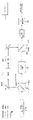
第1アプローチに従って動作し得る装置10が、図1から3に概略的に示される。装置10は複数の光源11(11R、11Gおよび11Bが示される)を備える。光源11は、例えばレーザを備え得る。図示される実施形態において、光源11Rは赤色光を発し、光源11Gは緑色光を発し、光源11Bは青色光を発する。
光源11の各々は、対応する位相変調器12(12R、12Gおよび12Bが示される)に関連付けられる。これらの位相変調器は、例えばLCOSを各々備え得る。複数の位相変調器12のいずれかにより変調された光が撮像素子14を照射する。撮像素子14は、例えばDMDを備え得る。撮像素子14が当該光を変調し、次に、当該光はスクリーン15上へと投影される。
Each of the
コントローラ16が、光源11、位相変調器12および撮像素子14の動作を調整して、画像データに従った画像を表示する。複数のシーケンシャルフィールドの各々(各フィールドはある期間である)において、1つの光源が作動中である。例示的な実施形態において、フレームレートが毎秒20から100フレームの範囲内であり、各フレームは3つのフィールドに分割される。
The
図1に示されるように、第1フィールドにおいて、赤色光源11Rが作動中であり得る。赤色光源11Rからの赤色光は、位相変調器12Rに適用される位相パターンにより、所望の位置(例えば、より高い赤色強度を画像データが指定する領域に対応する位置)へとステアリングされ、および/または望ましくない位置(例えば、低い赤色強度を画像データが指定する領域に対応する位置)から離れるようにステアリングされる。位相変調器12Rにより変調された赤色光は次に、画像データにより赤色光用に指定されたパターンに入射光を変調するよう制御される撮像素子14上へと向けられる。
As shown in FIG. 1, in the first field, the
第2フィールドおよび第3フィールドにおいて、上述の処理が、図2および3に示されるように、緑色光および青色光のそれぞれについて繰り返される。 In the second and third fields, the above process is repeated for green light and blue light, respectively, as shown in FIGS. 2 and 3.
この例示的な実施形態において、位相変調器12は、当該フレームレート(本例ではフィールドが示されるレートの1/3)よりも一切速くリフレッシュされる必要がない。撮像素子14は、全てのフィールドについてリフレッシュされる。
In this exemplary embodiment, the
各フィールドについて、コントローラ16は、対応する色に対応するパターンに撮像素子を設定する段階と、異なる色に対応する位相変調器をリフレッシュする(現在の色に対応する位相変調器は、前のフィールドにおいてリフレッシュされている可能性がある)段階と、現在の色の光源をオンにし、これにより、当該光源からの光が、位相変調器によりステアリングされ、撮像素子により変調され、スクリーン15上へと投影される段階とを含む複数の段階を実行し得る。
For each field, the
各フィールドの期間は、各フィールドに表示される異なる色が観察者の目により一体化されてカラー画像として感知される程度に十分短い。 The duration of each field is short enough that the different colors displayed in each field are integrated by the observer's eyes and perceived as a color image.
例示的な実施形態において、3つの(1色当たり1つの)位相変調器が、変調された光源(通常はレーザ光源)により順次照射される。各位相変調器は、入射ビームの波長およびプロファイルについてカスタマイズされた位相パターンを提供するよう制御され、これにより、ステアリングされた画像が、当該位相変調器から既知の距離だけ離れた位置のステアリング像面に生成される。ステアリングされた画像は、画像データがその色についてより高い輝度を指定した場合、より高い強度を伝達し得、画像データがその色についてより低い輝度を指定した場合、より低い強度を伝達し得る。3つの色チャネル全てのステアリングされた画像を共通の経路に沿って撮像素子に(例えば、DMDを備えるヘッドに)リレーするために、光学素子が設けられる。各々のステアリングされた画像により、DMDまたは他の撮像素子に対する所望のステアリングされた照射がもたらされる。ステアリングされた画像を撮像素子にリレーする当該光学素子は、画像の質の向上およびDMDヘッドとの互換性の改善につながり得る拡大、テレセントリシティの向上およびエタンデュの増加のうちの1または複数をオプションでもたらし得る。 In an exemplary embodiment, three (one per color) phase modulators are sequentially illuminated by a modulated light source (usually a laser light source). Each phase modulator is controlled to provide a customized phase pattern for the wavelength and profile of the incident beam, whereby the steering image plane is located at a known distance from the phase modulator. Is generated in. The steered image may convey a higher intensity if the image data specifies a higher intensity for that color, and a lower intensity if the image data specifies a lower intensity for that color. Optical elements are provided to relay the steered images of all three color channels to the image sensor (eg, to a head with a DMD) along a common path. Each steered image provides the desired steered irradiation of the DMD or other image sensor. The optics that relay the steered image to the image sensor may have one or more of the expansion, increased telecentricity and increased ethandue that can lead to improved image quality and improved compatibility with the DMD head. Can be brought as an option.
ステアリングされた画像の各々を撮像素子にガイドする当該光学素子は、3つの別々のステアリングされた画像ビームがテレセントリックにされた後、またはステアリング像面の前のいずれかで、光路に位置し得る。これは容易になされる。なぜなら、ステアリングされた画像は、単色(レーザの原色)であり、F値が高い(発散が小さい)からである。 The optical element that guides each of the steered images to the image sensor may be located in the optical path either after the three separate steered image beams have been telecentricized or in front of the steering image plane. This is easily done. This is because the steered image is monochromatic (primary color of the laser) and has a high F-number (small divergence).
位相変調器は、カスタマイズ済みのパターンを色チャネル毎に表示するよう設定され得る。これにより、各々のステアリングされた画像は、他の色チャネルのステアリングされた画像と一貫したフレーミング(画像のサイズおよび形状)のみならず、当該色チャネルの所望の輝度プロファイルを特徴とする。一貫したフレーミングを実現すべく、各位相変調器とその対応するステアリング像面との間の距離は、波長、ビーム発散およびビームプロファイルなどの基準に基づいて選択され得る。 The phase modulator may be configured to display a customized pattern for each color channel. Thereby, each steered image is characterized by framing (image size and shape) consistent with the steered image of the other color channel, as well as the desired brightness profile of the color channel. To achieve consistent framing, the distance between each phase modulator and its corresponding steering image plane can be selected based on criteria such as wavelength, beam divergence and beam profile.
第1アプローチに従って動作する実施形態において、各光源が作動されている期間(R光源、G光源、B光源のオン時間)は、所望のステアリング輝度レベルおよび色に基づいて変えられ得る。例えば、ステアリングされた全画面白色をD65白色点で生じさせる期間、R光源、G光源、B光源を作動し得る。各光源による光出力の強度が変調され得る場合、表示画像の所望の輝度および色は、対応するフィールドにおける各光源のオン時間、各光源の出力、各光源のデューティサイクルのうちの1または複数を制御することにより設定され得る。変調された光源のいくつかの利点には、より低出力のレーザを用いることができ、より短いデューティサイクルでより高い要求出力(例えば、通常の最大出力の2倍での30%赤色)でそれらを駆動できることが含まれる。第2アプローチ―1つの空間分割位相変調器および1つの撮像素子 In embodiments that operate according to the first approach, the duration of each light source being activated (R light source, G light source, B light source on time) can be varied based on the desired steering brightness level and color. For example, the R light source, the G light source, and the B light source may be operated during the period in which the steered full screen white is generated at the D65 white point. If the intensity of the light output by each light source can be modulated, the desired brightness and color of the displayed image can be one or more of the on-time of each light source in the corresponding field, the output of each light source, the duty cycle of each light source. It can be set by controlling. For some advantages of modulated light sources, lower power lasers can be used and they with higher required power (eg, 30% red at twice the normal maximum power) with shorter duty cycles. Includes being able to drive. Second approach-one spatially split phase modulator and one image sensor
「第2アプローチ」は、複数の領域へと空間分割された単一の位相変調器を使用する。当該位相変調器は、各領域が1色につき1つの位相パターン(すなわち、対応する色について光を適切にステアリングする位相パターン)を提供するように制御される。例示的な実施形態に従ったプロジェクタ40が図4、5および6に示される。
The "second approach" uses a single phase modulator spatially divided into multiple regions. The phase modulator is controlled so that each region provides one phase pattern per color (ie, a phase pattern that properly steers light for the corresponding color). A
例示的な実施形態において、光源11(再びであるが、例えば、11R、11Gおよび11Bが設けられる)がそれぞれ、赤色光、緑色光および青色光を発する。赤色光、緑色光および青色光はそれぞれ、(例えばLCOSであり得る)位相変調器42の対応する領域43R、43Gおよび43Bを照射するように向けられる。領域43R、43Gおよび43Bはそれぞれ、赤色光用、緑色光用および青色光用の位相パターンを提供するよう制御される。これらの位相パターンは、当該光を撮像素子14上へと向ける。撮像素子14は、各フィールドにおいて、現在の色の光を変調するよう設定される。撮像素子14により変調された光は、スクリーン15上へと投影される。
In an exemplary embodiment, the light source 11 (again, for example, 11R, 11G and 11B are provided) emits red light, green light and blue light, respectively. Red light, green light and blue light are directed to illuminate the
単一の位相変調器のみが要求されるので、第2アプローチは、第1アプローチと比較してコストの節約を提供し得る。第2アプローチはコントラストを損ない得る。なぜなら、個々の色の光が、当該光をステアリングするのに位相変調器の一部分のみが用いられる場合、当該光をステアリングするのに位相変調器全体が用いられる場合に可能であるのと同程度に正確にはステアリングされ得ないからである。第2アプローチは、レーザの原色であり得る原色により可能になる、全色域の使用も可能にする。 Since only a single phase modulator is required, the second approach may provide cost savings compared to the first approach. The second approach can compromise contrast. This is because light of individual colors is as good as possible if only a portion of the phase modulator is used to steer the light, or if the entire phase modulator is used to steer the light. This is because it cannot be steered accurately. The second approach also allows the use of the entire color gamut, which is made possible by the primary colors that can be the primary colors of the laser.
いくつかの実施形態において、異なる色に対応する領域43の、LCOS上の物理的位置は、ウェアレベリングのために時々変えられ得る。青色領域43Bは、赤色領域43Rよりも速く経時的に劣化し得る。
In some embodiments, the physical position of the
領域43への位相変調器42の分割は、等分である必要はない。領域43のうちのいくつかまたは全てのサイズは異なり得る。例えば、領域43のサイズは、異なる色についての出力要件に比例し得る。オプションで、領域43は、異なる色の光についての出力要件が変わる時にリアルタイムでサイズ変更され得る。領域43Gが、緑色光の精度に対する人間の視覚系の感度が増していることに起因して、他の領域43よりも大きくされ得るか、または青色用の領域43Bが、出力密度の低下および劣化の低減をもたらすために増大され得る。
The division of the
第2アプローチにおいて、位相変調器42の各領域43は、多くても1フレーム当たり1回リフレッシュされる必要がある。位相変調器42の全ての領域43は、1回の動作でリフレッシュされ得る。位相変調器42の異なる領域43が個別にリフレッシュされ得る場合、別の領域43により光がステアリングされている間に、1つの領域43がリフレッシュされ得る。
In the second approach, each
単一の位相変調器が空間分割される場合、LCOSの地理的部分が個々の色の各々について用いられる。各部分が、対応する位相画像で駆動される。3つの位相画像の全てが計算され、スケーリングされ、LCOS位相変調器に適用される単一の位相画像へと合成される。 When a single phase modulator is spatially partitioned, the geographic part of the LCOS is used for each of the individual colors. Each part is driven by the corresponding phase image. All three phase images are calculated, scaled and combined into a single phase image applied to the LCOS phase modulator.
各光源11(例えば、各レーザ)は、LCOS変調器42上の対応する色領域のみを照射するように向けられる。LCOSのいずれの部分も、1つよりも多くのレーザ色により照射されるべきではない。
Each light source 11 (eg, each laser) is directed to illuminate only the corresponding color region on the
ウェアレベリングのために、レーザは時々、青色光の位置を変えるようにLCOSの異なる領域に向け直され得る。青色光は、赤色光または緑色光よりも速くLCOSデバイスを劣化させる。 Due to wear leveling, the laser can sometimes be redirected to different regions of the LCOS to reposition the blue light. Blue light degrades LCOS devices faster than red or green light.
第2アプローチを実装する例示的な実施形態において、単一の位相変調器が複数の変調された光源の各々により順次照射されるが、各光源は、その単一の位相変調器の対応する部分のみを照射する。各色に対して割り当てられる位相変調器の当該部分のサイズは、所望のステアリングされた画像の質により決定され得る(一般的に、他の全てが等しく、1つの色に対して割り当てられる画素が多ければ多いほど、ステアリングされた画像の質は、その色についてより良好になる)。位相デバイスの色別の部分の各々は、その色の光の波長、入射ビームのプロファイル/性質等についてカスタマイズされた位相パターンを提供するよう制御され得る。これにより、当該部分により形成されるステアリングされた画像は、他のチャネルのステアリングされた画像と重なる(すなわち、フレーミングは一貫しているはずである)。 In an exemplary embodiment that implements the second approach, a single phase modulator is sequentially illuminated by each of the plurality of modulated light sources, where each light source is the corresponding portion of that single phase modulator. Irradiate only. The size of that part of the phase modulator assigned to each color can be determined by the desired quality of the steered image (generally everything else is equal and more pixels are assigned to one color. The more, the better the quality of the steered image will be for that color). Each of the color distinct parts of a phase device can be controlled to provide a customized phase pattern for the wavelength of light of that color, the profile / properties of the incident beam, and the like. This causes the steered image formed by the portion to overlap the steered image of the other channel (ie, the framing should be consistent).
位相変調器から共通の距離のステアリング像面にRGBステアリングされた画像を形成するためのいくつかの実施形態において、各色部分の位相パターンは、異なる幾何学的形状を有するターゲット画像を用いて計算され得る(すなわち、異なる色についてのターゲット画像は、ステアリングに対する波長の影響を補償すべく、異なるようにスケーリングされ得る)。第1アプローチを適用するいくつかの実施形態においてのように、ステアリングされた画像を撮像素子にリレーする光学素子は、画像の質の向上およびDMDヘッドとの互換性の改善につながり得る拡大、テレセントリシティの向上およびエタンデュの増加のうちの1または複数をオプションでもたらし得る。 In some embodiments for forming an RGB-steered image on a steering image plane at a common distance from the phase modulator, the phase pattern of each color portion is calculated using target images with different geometric shapes. Obtain (ie, target images for different colors can be scaled differently to compensate for the effect of wavelength on steering). As in some embodiments to which the first approach is applied, the optics that relay the steered image to the image sensor can lead to improved image quality and improved compatibility with the DMD head. It may optionally result in one or more of the increased centricity and increased etandu.
色合成光学素子がオプションで存在するが、通常、位相変調器の後には必要ない。なぜなら、各色についてのステアリングされた画像は、フィールドシーケンシャル方式で共通のステアリング像面に提供され得るからである。色合成光学素子は、位相変調器のそれら3つの部分からの入射光を集約するように設けられ得る。これにより、Rビーム、Gビーム、Bビームが撮像素子に入射する時に取る経路は、間隔が近くなり、平行またはほぼ平行になる。入射ビームが完全に平行ではない場合、対応する色別の位相パターンにより、傾き補正がもたらされ得る。第3アプローチ―1つの共通位相変調器および1つの撮像素子 Color compositing optics are available as an option, but are usually not needed after the phase modulator. This is because the steering image for each color can be provided on a common steering image plane in a field sequential manner. The color compositing optics may be provided to aggregate the incident light from those three parts of the phase modulator. As a result, the paths taken when the R beam, G beam, and B beam are incident on the image sensor become close to each other and become parallel or substantially parallel. If the incident beams are not perfectly parallel, the corresponding color-coded phase patterns can result in tilt correction. Third approach-one common phase modulator and one image sensor
「第3アプローチ」は、各フレームについて単一の位相パターンを表示する単一のLCOS位相変調器を使用する。このアプローチは、最も費用対効果が高い方法である。その理由は、このアプローチが単一の位相変調器を用いること、およびより安価な計算ハードウェアが用いられ得るように、(3つではなく)1つの位相パターンのみが計算される必要があることである。第3アプローチは色域を損ない得る。なぜなら、このアプローチは、(不要な色成分をステアリングしないことに起因して)不要な色がシステムを通じてより多く漏れることを可能にしてしまい得るからである。第3アプローチは、第1アプローチとほぼ同等のコントラストをもたらし得る。 The "third approach" uses a single LCOS phase modulator that displays a single phase pattern for each frame. This approach is the most cost-effective method. The reason is that this approach uses a single phase modulator, and only one phase pattern (rather than three) needs to be calculated so that cheaper computational hardware can be used. Is. The third approach can compromise the color gamut. This approach can allow more unwanted colors to leak through the system (due to not steering the unwanted color components). The third approach can provide much the same contrast as the first approach.
図7、8および9は、第3アプローチに従った動作用に構成される装置70を概略的に示す。装置70は、赤色光、緑色光および青色光をそれぞれ発する光源11(再びであるが、例えば、11R、11Gおよび11Bが設けられる)を含む。赤色光、緑色光および青色光はそれぞれ、(例えばLCOSを備え得る)位相変調器72を照射するように向けられる。位相変調器72は、光を光源11のうちのいずれか1つから撮像素子14上へとステアリングするよう選択される位相パターンで設定される。同じ位相パターンが2つまたはそれより多くの、光の異なる色について用いられ得る。
FIGS. 7, 8 and 9 schematically show a
撮像素子14は、各フィールドにおいて、現在の色の光を変調するよう設定される。撮像素子14により変調された光は、スクリーン15上へと投影される。
The
連続する複数のフレームの強度分布が同じであるか、または類似している場合、位相変調器72は、1フレーム当たり1回、またはそれよりも少なく、新しいパターンで更新され得る。輝度位相変調画像
If the intensity distributions of a plurality of consecutive frames are the same or similar, the
光を全ての色について向けるために単一の位相画像が用いられる場合(例えば、上述の第3アプローチを適用する場合)、その単一の位相画像は、全ての画像特徴部を照射するために、あらゆる色が存在するあらゆる領域において十分な光をDMDに向けるべきである。 If a single phase image is used to direct light for all colors (eg, when applying the third approach described above), the single phase image is to illuminate all image features. , Sufficient light should be directed at the DMD in every area where every color is present.
DMDは、各画像特徴部についてスクリーンからあらゆる不要な色を遮断するよう制御される。光を遮断するというDMDの機能により、最終的な色域のサイズが決定される(なぜなら、純粋な赤色の物体上には、少量の緑色光および青色光が漏れるからである)。 The DMD is controlled to block all unwanted colors from the screen for each image feature. The DMD's ability to block light determines the size of the final color gamut (because a small amount of green and blue light leaks onto a pure red object).
RGB画像(すなわち、個々の画素についてR値、G値およびB値を指定する画像データ)から輝度画像を生成する1つの手法が、RGB画像をXYZ色空間に変換し、Yチャネルを輝度画像として用いることである。 One method of generating a luminance image from an RGB image (ie, image data that specifies R, G, and B values for each pixel) is to convert the RGB image into an XYZ color space and use the Y channel as the luminance image. Is to use.
第3アプローチを実装する特定の実施形態において、単一の位相変調器が、異なる色の変調された光源により順次照射される。各光源は、位相変調器の作動領域の実質的に全てを照射し得る。3つの色チャネルの全てについて光をステアリングするために、共通の位相パターンが用いられる。これにより、ステアリングされた画像は、所望の輝度プロファイルを有し、ステアリングされた画像の組み合わせは、同じ色点をもたらす。 In certain embodiments that implement the third approach, a single phase modulator is sequentially illuminated by modulated light sources of different colors. Each light source may illuminate substantially the entire working area of the phase modulator. A common phase pattern is used to steer the light for all three color channels. Thereby, the steered image has the desired luminance profile and the combination of the steered images results in the same color point.
当該位相パターンが全ての色について共通なので、ビームを異なる色の光源から位相変調器に異なる角度で入射するように向け得る。これにより、3つのステアリングされた画像が、位相変調器に対して、異なる距離の所に、かつ、異なる向きに沿って、生成される。次に、別々のステアリングされた画像を再合成し、整形し、撮像素子上へとリレーするために、別々の色合成光学素子およびリレー光学素子が用いられ得る。この構造は、異なる色のフレーミングを一致させるために用いられ得る。 Since the phase pattern is common to all colors, the beam can be directed from different colored sources to the phase modulator at different angles. This produces three steered images at different distances and along different orientations with respect to the phase modulator. Separate color optics and relay optics can then be used to resynthesize, shape, and relay the separate steered images onto the image sensor. This structure can be used to match the framing of different colors.
異なる色チャネルのフレーミングを一致させるための別の手法が、異なる色の光ビームを位相変調器に平行に入射させはするが、当該ビームのうちのいくつかまたは全てがわずかに発散または収束するように当該ビームのうちのいくつかまたは全てのコリメーションを修正することである。各ビームの発散または収束の量は、そうでない場合にステアリングされた画像が異なる色について形成されるであろう異なる距離を補償するように選択され得る。次に、ステアリングされた画像は、撮像素子上へとリレーされ得る。他のアプローチでのように、第3アプローチを適用するプロジェクタは、拡大力があり、テレセントリシティを改善し、および/またはエタンデュを増加させる光学素子をオプションで含み得る。撮像素子を照射するためのアプローチ Another technique for matching the framing of different color channels is to make light beams of different colors enter parallel to the phase modulator, but some or all of the beams diverge or converge slightly. To modify some or all of the beams of the beam. The amount of divergence or convergence of each beam may be selected to compensate for the different distances that would otherwise be formed for the steered image for different colors. The steered image can then be relayed onto the image sensor. As with other approaches, projectors that apply the third approach may optionally include optics that are magnifying, improve telecentricity, and / or increase etandu. Approach for irradiating the image sensor
本発明の別の態様は、何らかのやり方で予め変調された光で、および/または光源から振幅変調器へより直接的に届けられた光で、DMDをより直接的に照射するための、および/またはDMDまたは他の振幅変調器を選択的に照射するための方法および装置を提供する。そのような方法および装置は、光の一部分を、位相変調器または他の上流側の光減衰コンポーネントを迂回して光源からDMDに向け得、および/またはDMDのみを照射するように向けられた1または複数の第2光源を追加し得る。DMDを直接照射することは、明るいシーンを表示する場合に効率を高める一助となり得る。 Another aspect of the invention is to irradiate the DMD more directly with light somehow pre-modulated and / or with light delivered more directly from the light source to the amplitude modulator, and /. Alternatively, methods and devices for selectively irradiating a DMD or other amplitude modulator are provided. Such methods and devices are directed to direct a portion of the light from the light source to the DMD, bypassing the phase modulator or other upstream light attenuation component, and / or irradiating only the DMD. Alternatively, a plurality of second light sources may be added. Direct irradiation of DMD can help increase efficiency when displaying bright scenes.
この態様の方法および装置は、個別に適用され得るか、または上述の第1アプローチから第3アプローチのいずれかに記載の方法および装置と組み合わされ得る。そのような方法および装置は、LCOSおよびDMDの3つの完全なセットを含む色投影システムにおいても適用され得る。 The methods and devices of this embodiment can be applied individually or combined with the methods and devices described in any of the first to third approaches described above. Such methods and devices may also be applied in color projection systems that include three complete sets of LCOS and DMD.
高ダイナミックレンジの投影システムにおいて、LCOS位相変調器は、必要な場合にLCOS位相変調器が振幅変調器上の位置へとステアリングするように、振幅変調器(例えば、DMD)と組み合わされ得る。 In high dynamic range projection systems, the LCOS phase modulator can be combined with an amplitude modulator (eg, DMD) such that the LCOS phase modulator steers to a position on the amplitude modulator if necessary.
全画面白色または非常に明るい画像の場合、位相変調器を用いて光をDMD上へとステアリングするのとは対照的に、DMDを直接照射するのがより効率的である。LCOSパネルは通常、DMDと同じ程度多くの光エネルギーを処理し得ない。その結果、システムの光スループットキャパシティの合計は、少なくとも、明るい画像が投影されている場合に、少なくともいくつかの光がLCOS変調器を迂回するのを可能にすることにより、増やされ得る。 For full-screen white or very bright images, it is more efficient to irradiate the DMD directly, as opposed to steering the light onto the DMD using a phase modulator. LCOS panels are usually unable to handle as much light energy as DMDs. As a result, the total optical throughput capacity of the system can be increased by allowing at least some light to bypass the LCOS modulator, at least when a bright image is projected.
いくつかの実施形態は、合成された光が均一の入射角でDMDに到達するように、位相変調器によりステアリングされている光を、位相変調器を迂回している光と合成する。これにより、光が接近する角度にDMDがしばしば非常に影響を受けるという問題に対処する。LCOSを迂回する光と、LCOSによりステアリングされた光とは、その全てが同じ角度で(すなわち、DMDが対応し得る狭い入射角範囲内で)DMDに入射するように合成され得る。いくつかの実施形態において、これは、2つの異なる方向から合成器に入射した光を、共通の方向に合成器を離れる合成光ビームへと合成する合成器を用いることにより、実現される。合成器は、例えば、偏光ビームスプリッタまたはダイクロイック素子を備え得る。 In some embodiments, the light steered by the phase modulator is combined with the light bypassing the phase modulator so that the combined light reaches the DMD at a uniform angle of incidence. This addresses the problem that the DMD is often very sensitive to the angle at which the light approaches. The light that bypasses the LCOS and the light that is steered by the LCOS can all be combined to enter the DMD at the same angle (ie, within the narrow angle of incidence that the DMD can accommodate). In some embodiments, this is accomplished by using a synthesizer that combines light incident on the synthesizer from two different directions into a synthetic light beam that leaves the synthesizer in a common direction. The synthesizer may include, for example, a polarization beam splitter or a dichroic element.
図10から13は例示的な装置を示す。当該装置は、位相変調器によりステアリングされた(および/またはいくつかの他の上流側の光減衰光学素子により処理された)光、位相変調器によりステアリングされることなく撮像素子を照射するように向けられた光、または上記の2つの光を混合したものでDMDなどの撮像素子を照射するよう動作させられ得る。位相変調器によりステアリングされた光と、位相変調器によりステアリングされていない光とは、同じ光源または異なる光源から来得る。 10 to 13 show exemplary devices. The device is to illuminate the light steered by the phase modulator (and / or processed by some other upstream photoattenuation optics), the image sensor without being steered by the phase modulator. It can be operated to illuminate an image sensor such as a DMD with directed light or a mixture of the above two lights. The light steered by the phase modulator and the light not steered by the phase modulator can come from the same or different light sources.
光は選択的に、偏光を用いて異なる経路で伝搬させられ得る。例えば、光は、P偏光され得るか、S偏光され得るか、またはそれらの両方(ランダム偏光)をされ得る。S偏光およびP偏光は、互いに直角に偏光される。S偏光およびP偏光は、偏光ビームスプリッタで互いに分離され得る。P偏光およびS偏光はランダム偏光へと合成され得、ランダム偏光は偏光ビームスプリッタを用いてP偏光およびS偏光に分割され得る。 Light can selectively be propagated in different paths using polarization. For example, light can be P-polarized, S-polarized, or both (randomly polarized). The S-polarization and the P-polarization are polarized at right angles to each other. S-polarization and P-polarization can be split from each other by a polarization beam splitter. P-polarization and S-polarization can be combined into random polarization, and random polarization can be split into P-polarization and S-polarization using a polarization beam splitter.
ランダム偏光を伴うレーザ光源は、S偏光およびP偏光の両方の大型のコンポーネントを有する。自由空間レーザは、当該レーザの物理的な向きに応じてS偏光またはP偏光を生成するに過ぎない傾向がある。当該レーザを物理的に回転させることにより、発せられた光がS偏光であるかまたはP偏光であるかが変わり得る。 Laser sources with random polarization have large components of both S and P polarization. Free space lasers tend to only generate S or P polarization depending on the physical orientation of the laser. By physically rotating the laser, it is possible to change whether the emitted light is S-polarized or P-polarized.
LCOS位相変調器は、(向きに応じて)単一のタイプの偏光でしか良好に機能しない傾向がある。例えば、LCOSパネルがP偏光に対して向けられる場合、当該LCOSパネルは、S偏光が通過することを可能にするのではなく、S偏光を当該光源に向かって戻るように直接反射する傾向があるだろう。 LCOS phase modulators tend to work well with only a single type of polarization (depending on the orientation). For example, when an LCOS panel is directed against P-polarization, the LCOS panel tends to reflect the S-polarization directly back towards the light source rather than allowing the S-polarization to pass through. right.
LCOS変調器を用いて光をP偏光光源からステアリングすると、ステアリングされたP偏光をステアリングされていないS偏光と合成することが、結果として生じる合成ランダム偏光をDMD振幅変調器へと向ける前に可能になる。固定偏光アプローチ Steering light from a P-polarized light source using an LCOS modulator allows the steered P-polarized light to be combined with the unsteered S-polarized light before the resulting synthetic random polarization is directed to the DMD amplitude modulator. become. Fixed polarization approach
いくつかの実施形態において、1つはS偏光の生成用、もう1つはP偏光の生成用という2つの別々の光源、例えば、一群のレーザが用いられ得る(「固定偏光」アプローチ)。それら光源の一方からの光(例えば、P偏光)が、ステアリング素子(例えば、LCOS)により撮像素子(例えば、DMD)を照射するように向けられる。他方の光源(例えば、S偏光光源)からの光が、ステアリング素子と相互作用することなく(すなわち、ステアリング素子を迂回して)撮像素子を照射するように向けられる。表示されるシーンが非常に暗いといった理由で、迂回光(例えば、S偏光)が撮像素子において所望されない場合、迂回光の光源(例えば、S偏光光源)が、出力を下げられ得るか、またはオフにされ得、および/または、迂回光が、撮像素子から離れるように向けられ得、および/または撮像素子への到達を阻止され得る。 In some embodiments, two separate light sources, one for the generation of S polarization and the other for the generation of P polarization, may be used, eg, a group of lasers ("fixed polarization" approach). Light from one of these light sources (eg, P-polarized light) is directed by the steering element (eg, LCOS) to illuminate the image sensor (eg, DMD). Light from the other light source (eg, an S-polarized light source) is directed to illuminate the image pickup element without interacting with the steering element (ie, bypassing the steering element). If diversion light (eg, S-polarization) is not desired in the image sensor because the displayed scene is very dark, the diversion light source (eg, S-polarization light source) can be reduced or turned off. And / or the diversion light can be directed away from the image sensor and / or can be blocked from reaching the image sensor.
図10は、2つの別々のレーザ光源11Sおよび11Pで「固定偏光」アプローチを実装するプロジェクタ100を示す。光源11Pは、P偏光で位相変調器12を照射する。位相変調器12は、偏光ビームスプリッタを本実施形態において備える合成器108によりP偏光をDMDなどの撮像素子14上へとステアリングする位相パターンで設定される。
FIG. 10 shows a
光源11SはS偏光を発する。S偏光は、光学システム109を通過することにより均質化され、合成器108上へと向けられる。光学システム109は、それ自体を通過する光を均一に分散させる(または別の所望の手法で撮像素子において分散させる)。光学システム109は、例えば、フライアイアレイおよび/または他のホモジナイザを備え得る。
The
光源11Sからの任意の光が、合成器108において光源11Pからの光と合成され、撮像素子14を照射するように向けられる。
Arbitrary light from the
デスペックル素子107が、撮像素子14から上流光路にオプションで設けられる。デスペックル素子は、合成ビームをデスペックルする。オプションのデスペックル素子は、例えば、DMD振幅変調器の直前に設けられ得る。
A
DMDおよび他の振幅変調器は光を完全には遮断しないので、多くの暗い箇所があるシーンにおいては、位相変調器から生じたのではない光がDMDに当たるのを阻止することが望ましい。 Since DMDs and other amplitude modulators do not completely block light, it is desirable to prevent light that does not come from the phase modulator from hitting the DMD in scenes with many dark areas.
制御システム101が、光源11Pおよび11Sを制御するために接続され得る。いくつかの実施形態において、光源11Pおよび11Sは、個別に制御可能な出力を有する。いくつかの実施形態において、制御システム101は、光源11Sからの光の出力を制御し得る。いくつかの実施形態において、制御システム101は、追加の光が要求されるかどうかに応じて、光源11Sのオンまたはオフを切り替え得る。また、制御システム101は、位相変調器12および撮像素子14に対するデータの適用と、装置100の動作のタイミング全体とを制御し得る。ランダム偏光(または非偏光アプローチ)
A
S偏光およびP偏光の両方を発する単一の光源(おそらくはファイバ結合LED)が用いられ得る(「ランダム偏光」アプローチ)。この場合、2つの別々の経路への入射光のS成分およびP成分を分離するために、偏光ビームスプリッタが使用され得る。開口および/またはシャッタなどの減衰器、および/または可動ミラーまたは可動レンズなどの制御可能な向け直し素子が、暗い黒色が要求される場合に位相変調器を迂回する光を減衰させるために、S(迂回)光路に設けられ得る。P成分は、振幅変調器に入射する前に変調され(例えば、位相変調器によりステアリングされ)得る。 A single light source (possibly a fiber-coupled LED) that emits both S and P polarization can be used (a "randomly polarized" approach). In this case, a polarizing beam splitter can be used to split the S and P components of the incident light into two separate paths. Attenuators such as apertures and / or shutters, and / or controllable redirection elements such as movable mirrors or movable lenses, are used to attenuate light that bypasses the phase modulator when dark black color is required. (Detour) Can be installed in the optical path. The P component can be modulated (eg, steered by a phase modulator) prior to incident on the amplitude modulator.
図11は、ランダム偏光アプローチに従って動作するように構成される装置110の例の概略図である。装置110は、複数の分離可能な偏光成分(例えば、S偏光成分およびP偏光成分)を含む光を発する光源11SPを備える。光源11SPは、有益にだが、オプションで、ファイバ結合レーザ源を備え得る。
FIG. 11 is a schematic representation of an
光源11SPにより発せられた光が、ビームとして良好な質を有し(すなわち、エタンデュが小さく)、それにより、発散が少ないようにコリメートされるのが可能になることが好ましい。次に、これにより、ビームスプリッタ112においてS偏光成分およびP偏光成分を経路111Aおよび111Bへとより良好に分離すること(例えば、より良好な均一性およびより高いスループットを有するようにすること)が可能になる。
It is preferred that the light emitted by the light source 11SP has good quality as a beam (ie, small etandu), which allows it to be collimated for less divergence. This in turn causes the beam splitter 112 to better separate the S and P polarization components into
ホモジナイザ115は、当該光のエタンデュが経路111Bに沿って著しく増加しないように選択されることが好ましい。これにより、合成器114において光ビームを合成することが容易になる。ホモジナイザ115のための好適な選択の1つが、フライアイレンズアレイを含む、レンズの組み合わせである。これが当てはまるのは、そのような組み合わせにより、最小限のエタンデュの増加で均質化をもたらし得る場合である。
The
図10から13のいずれに示される実施形態も、エタンデュが小さい光を用いることから利益を享受し得る。エタンデュが小さいことにより、異なる光ビームが合成される場合に、効率、均一性等が促進される。 The embodiments shown in any of FIGS. 10 to 13 can also benefit from the use of small light by Etandu. The small etandu promotes efficiency, uniformity, etc. when different light beams are combined.
光源11SPにより発せられた光は、ビームスプリッタ112による、2つの経路111Aおよび111Bへの偏光に基づいて分割される。経路111Aは、位相変調器12により撮像素子14を照射するように光を伝達する。経路111Bは位相変調器12を迂回する。経路111Aおよび111Bは、撮像素子14からの上流へと合成器114において合流する。
The light emitted by the light source 11SP is split based on the polarization into the two
経路111Bはホモジナイザ115および開口116を含む。開口116は、迂回経路111Bにより届けられて撮像素子14に入射する光の量を調整するよう制御され得る。
制御システム115が、撮像素子14への到達が可能になる経路111Bからの光の量を選択的に調節するよう、開口116を制御し得る。また、制御システム115は、位相変調器12および撮像素子14に対するデータの適用と、装置110の動作のタイミング全体とを制御し得る。可変偏光アプローチ
The
「可変偏光」アプローチは、ランダム偏光アプローチに類似しているが、光源により発せられた光の分離可能な偏光成分の相対的な強度を変化させるための手法を提供する。例えば、可変偏光アプローチを実装する装置は、90度以内で迅速に回転させられ得る半波長板を備え得る。半波長板の回転をフレーム単位で設定することにより、偏光ビームスプリッタに送られるS偏光およびP偏光を混合したものを調整し得る。結果として生じるビームは、上述のランダム偏光装置への入力として用いられ得、より多くの光(例えば、より多くのS偏光)が明るいシーン用にDMDに直接送られることを可能にし、より多くの光(例えば、より多くのP偏光)が暗いシーン用にLCOSに直接送られることを可能にする。 The "variable polarization" approach is similar to the random polarization approach, but provides a method for varying the relative intensity of the separable polarization components of the light emitted by a light source. For example, a device that implements a variable polarization approach may include a half-wave plate that can be rapidly rotated within 90 degrees. By setting the rotation of the half-wave plate on a frame-by-frame basis, a mixture of S-polarity and P-polarization sent to the polarization beam splitter can be adjusted. The resulting beam can be used as an input to the random polarization device described above, allowing more light (eg, more S-polarization) to be sent directly to the DMD for bright scenes, and more. Allows light (eg, more P-polarization) to be sent directly to the LCOS for dark scenes.
図12は、「可変偏光」アプローチを実装する装置120を示す概略図である。図12の実施形態は通常、図10および11の実施形態よりも実行が複雑かつ高価であるが、レーザの最も効率的な使用を可能にする。
FIG. 12 is a schematic diagram showing a
ボックス121の内側に示される、装置120の部分は、上述の装置110と共通している。装置120は、偏光を発する光源11を備える。光の偏光は、偏光シフト素子122により変化させられ得る。偏光シフト素子は、ビームスプリッタ112により分離可能な光における2つの偏光状態の相対的な量を変化させるよう制御され得る。例えば、偏光シフト素子122は、半波長板と、モータまたは他の半波長板の回転角を設定するために接続されたアクチュエータとを備え得る。
The portion of the
制御システム125が、経路111Bに入射する光の量を選択的に調節するよう、偏光シフト素子122を制御し得る。また、制御システム125は、位相変調器12および撮像素子14へのデータの適用と、装置120の動作のタイミング全体とを制御し得る。波長ベースの分離アプローチ
The
光が取る経路を制御するための他のアプローチは、波長に基づいて光を分離する。異なる波長の光が、例えば、ダイクロイック素子または多層薄膜で分離され得る。故に、赤色、緑色および青色の2つのセットを有するシステムが形成され得る。赤色、緑色および青色は、いずれかのセットで大きな色域が生成され得、一方の不存在が目立たないように、選択され得る。 Another approach to controlling the path taken by light is to separate the light based on its wavelength. Light of different wavelengths can be separated, for example, by a dichroic device or a multilayer thin film. Therefore, a system with two sets of red, green and blue can be formed. Red, green and blue can produce a large color gamut in any set and can be selected so that the absence of one is inconspicuous.
上記のものに類似する方式で、類似の波長を有する2つの光源、例えば、2つのレーザが用いられ得る。この場合、カラービームスプリッタを用いて、一方の波長がLCOSまたは他の位相変調器に送られ、他方の波長がDMDまたは他の振幅変調器に直接(例えば、著しい減衰なしに)提供される(「固定波長」アプローチ)。それら2つの波長は、同じ原色に対応し得る(例えば、それら2つの波長は、異なる赤色、緑色または青色であり得る)。 Two light sources with similar wavelengths, eg, two lasers, may be used in a manner similar to that described above. In this case, using a color beam splitter, one wavelength is delivered to the LCOS or other phase modulator and the other wavelength is provided directly (eg, without significant attenuation) to the DMD or other amplitude modulator (eg, without significant attenuation). "Fixed wavelength" approach). The two wavelengths may correspond to the same primary color (eg, the two wavelengths may be different red, green or blue).
図13は、異なる波長の光を発する2つの別々のレーザ光源11R1および11R2で「固定波長」アプローチを実装する装置130を概略的に示す。それら波長は間隔が近くなり得る。例えば、5nmまたは10nmの差異だけ離れる。他の実施形態において、それら2つの波長は、より広く離れ得る。それらの波長は、同じ色の2つのシェイド、例えば、赤色、緑色または青色の2つのシェイド/トーンであり得る。
FIG. 13 schematically illustrates
光源11R1は、位相変調器12により撮像素子14を照射する。光源11R2は、位相変調器12を迂回する光路により撮像素子14を照射する。光源11R1および11R2からの光は、合成器132において合成される。光学素子139が、光路11R2において光を均質化する。
The light source 11R1 irradiates the
制御システム135が、光源11R1および11R2を制御するために接続され得る。いくつかの実施形態において、光源11R1および11R2は、個別に制御可能な出力を有する。いくつかの実施形態において、制御システム135は、光源11R2からの光の出力を制御し得る。いくつかの実施形態において、制御システム135は、追加の光が要求されるかどうかに応じて、光源11R2のオンまたはオフを切り替え得る。また、制御システム135は、位相変調器12および撮像素子14へのデータの適用と、装置130の動作のタイミング全体とを制御し得る。DCスポットの再利用
A
位相変調器は、画像特徴部に対応しないDCスポットを生成し得る。通常、DCスポットを画像の外側へステアリングすることが望ましい。このスポットからの光は、復元され、例えば拡散光として、DMDまたは他の撮像デバイスに送られ得る。DCスポットからの光が撮像デバイスに向けられるか否か、および/またはDCスポットから撮像デバイスに向けられる光の量は、いくつかの実施形態において、フレーム単位またはフィールド単位で制御される。当該制御は、フィールドまたはフレームについて計算される出力レベルに基づき得る。より高い出力レベル(より明るい画像)では、DCスポットから光が撮像デバイスに向けられ得、一方で、より低い出力レベルでは、DCスポットから、より少ない光が撮像デバイスに向けられ得るか、または光が撮像デバイスに向けられない可能性がある。広範囲の光学システムが、光をDCスポットから撮像デバイスに伝達するために用いられ得る。いくつかの実施形態において、図10に示されるものに類似する配置が、DCスポットから光を集め、当該光を撮像デバイスから上流へと位相変調器により変調された光と合成するために用いられ得る。DCスポットからの光のための光路は、DCスポットからの光によりもたらされた追加の照射を撮像デバイスにおいて拡散させるための1または複数のホモジナイザまたは光拡散器などの光学素子を含み得る。必要な場合、DCスポットからの光の偏光を変えて、DCスポットからの光と位相変調器によりステアリングされた光の合成を容易にするための偏光シフト素子が設けられ得る。この技術は、上記技術のいずれとも組み合わされ得るか、または単独で用いられ得る。
The phase modulator may generate a DC spot that does not correspond to the image feature. It is usually desirable to steer the DC spot out of the image. The light from this spot can be restored and sent to the DMD or other imaging device, for example as diffuse light. Whether or not the light from the DC spot is directed at the imaging device and / or the amount of light directed from the DC spot to the imaging device is controlled on a frame-by-frame or field-by-field basis in some embodiments. The control may be based on the output level calculated for the field or frame. At higher output levels (brighter images), light can be directed from the DC spot to the imaging device, while at lower output levels, less light can be directed from the DC spot to the imaging device, or light. May not be aimed at the imaging device. A wide range of optical systems can be used to transfer light from the DC spot to the imaging device. In some embodiments, an arrangement similar to that shown in FIG. 10 is used to collect light from the DC spot and combine the light upstream from the imaging device with light modulated by a phase modulator. obtain. The optical path for light from the DC spot may include an optical element such as one or more homogenizers or light diffusers for diffusing the additional irradiation provided by the light from the DC spot in the imaging device. If necessary, a polarization shift element may be provided to change the polarization of the light from the DC spot to facilitate the synthesis of the light from the DC spot and the light steered by the phase modulator. This technique can be combined with any of the above techniques or used alone.
本明細書において説明される様々なアプローチは、これらのアプローチを実装するように構成されるプロジェクタにおいて具現化され得る。さらに、フィールドシーケンシャル撮像のための説明される方法のいずれもが、光変調器の直接照射をもたらすための説明される方法のいずれとも、オプションで組み合わされ得る。LCOSは位相変調器の一例である。他の実施形態は、他のタイプの位相変調器を用い得る。DMDは振幅変調器の一例である。他の実施形態は、DMDの代わりに他のタイプの振幅変調器を用い得る。 The various approaches described herein can be embodied in projectors configured to implement these approaches. In addition, any of the described methods for field sequential imaging can optionally be combined with any of the described methods for resulting in direct irradiation of the light modulator. LCOS is an example of a phase modulator. Other embodiments may use other types of phase modulators. DMD is an example of an amplitude modulator. Other embodiments may use other types of amplitude modulators instead of DMDs.
例示的な実施形態において、フレームの明度を識別するために動画データが処理される。当該フレームが暗い場合、位相変調器は、光源からの光を振幅変調器上へとステアリングするよう、かつ、ステアリング済みの光を変調するよう振幅変調器を制御することで、当該フレーム用に指定された画像を表示するよう、制御され得る。フレームシーケンシャル画像において、これは、各色サブフレームについて別々になされ得る。当該フレームが明るい場合、振幅変調器は、位相変調器によりステアリングされた光に加えて、または当該光の代わりに、のいずれかで位相変調器により最初にステアリングされていない光により照射され得る。振幅変調器は、(明るい)画像を表示するよう制御され得る。 In an exemplary embodiment, moving image data is processed to identify the brightness of the frame. When the frame is dark, the phase modulator is designated for the frame by steering the light from the light source onto the amplitude modulator and by controlling the amplitude modulator to modulate the steered light. It can be controlled to display the image. In frame sequential images, this can be done separately for each color subframe. If the frame is bright, the amplitude modulator may be illuminated by light that is not initially steered by the phase modulator, either in addition to or in place of the light steered by the phase modulator. The amplitude modulator can be controlled to display a (bright) image.
いくつかの例示的な実施形態において、図11、12、13のうちのいずれか1つに示される装置は、複数の(例えば、いくつかの実施形態において、3つから6つの)色チャネルのうちの1つを提供するために用いられ得る。いくつかの実施形態において、それら色チャネルのうち、2つまたはそれより多く、または全ては、それぞれの色の光を並行して(すなわち、同時に)変調する。他の実施形態において、それら色チャネルのうちのいくつかまたは全ては、フィールドシーケンシャル方式またはタイムインターリーブ方式で動作し得る。いくつかの場合において、フィールドシーケンシャル動作は、それら色チャネルのうちのいくつかまたは全てについて上述されたアプローチ1、2または3のうちの1つを用いて実現される。 In some exemplary embodiments, the device shown in any one of FIGS. 11, 12, and 13 has a plurality of (eg, 3 to 6 in some embodiments) color channels. Can be used to provide one of them. In some embodiments, two or more, or all of those color channels modulate the light of each color in parallel (ie, simultaneously). In other embodiments, some or all of those color channels may operate in a field sequential or time interleaved fashion. In some cases, field sequential operation is achieved using one of approaches 1, 2 or 3 described above for some or all of those color channels.
いくつかの実施形態において、図11、12または13により示される全体的アーキテクチャを有する別々の色チャネルからの複数の色が、同時に発せられ、白色光を提供するために合成される。 In some embodiments, multiple colors from different color channels with the overall architecture shown by FIGS. 11, 12 or 13 are simultaneously emitted and combined to provide white light.
本明細書において説明されるディスプレイは、画像または他の光パターンを表示するよう1または複数の位相変調器および1または複数の振幅変調器を制御するように構成されるコントローラ、それにより画像データが供給される入力またはデータストア、(レーザ、他のソリッドステート光源、または他の光源を全体的に備え得る)光源、プロジェクションレンズ、ディスプレイスクリーン(前方または後方投影)、光路における他の光学素子(例えば、レンズ、ミラー、コリメータ、拡散器等)、電源、合焦システム、熱管理システム等、明確性のために示されていない他の素子を含み得る。用語の解釈 The display described herein is a controller configured to control one or more phase modulators and one or more amplitude modulators to display an image or other optical pattern, thereby the image data. A fed input or data store, a light source (which may be entirely equipped with a laser, other solid state light source, or other light source), a projection lens, a display screen (forward or backward projection), and other optics in the optical path (eg,). , Lenses, mirrors, collimators, diffusers, etc.), power supplies, focusing systems, thermal management systems, etc., which may include other elements not shown for clarity. Interpretation of terms
文脈上他の解釈を明らかに要求していない限り、本明細書および請求項の全体を通じて、「備え」、「備える」および同様のものは、排他的または網羅的な意味とは対照的に、包括的な意味で、つまり、「を含むがそれらに限定されない」という意味で解釈されるべきである。「接続され」、「結合され」またはそれらのあらゆる変形は、直接または間接いずれであれ、2つまたはそれより多くの素子の間のあらゆる接続または結合を意味し、当該素子間の結合または接続は、物理的、論理的またはそれらの組み合わせであり得る。「本明細書に」、「上記」、「以下」および類似の趣旨の語は、本明細書を説明するために用いられている場合、本明細書全体を指すものとし、本明細書のいかなる特定の部分も指さないものとする。2つまたはそれより多くの項目のリストを参照する際、「または」は、この語の以下の解釈、つまり、当該リストにおける当該項目のいずれか、当該リストにおける当該項目の全て、および当該リストにおける当該項目のあらゆる組み合わせの全てを包含する。「1つ」、「一」および「その」という単数形は、あらゆる適切な複数形の意味も含む。 Throughout this specification and claims, "preparation," "preparation," and the like, as opposed to exclusive or exhaustive meaning, unless the context explicitly requires other interpretations. It should be interpreted in a comprehensive sense, that is, "including but not limited to". "Connected," "coupled," or any variation thereof, either directly or indirectly, means any connection or connection between two or more elements, and the connection or connection between the elements. , Physically, logically or a combination thereof. The terms "in the present specification", "above", "below" and the like to the same effect shall refer to the entire specification and any of the present specification as used to describe the present specification. It does not refer to any specific part. When referring to a list of two or more items, "or" means the following interpretation of the term, that is, any of the items in the list, all of the items in the list, and in the list. Includes all combinations of such items. The singular forms "one," "one," and "that" also include the meaning of any suitable plural.
本明細書およびあらゆる添付の請求項において用いられる「鉛直」、「横」、「水平」、「上方」、「下方」、「前方」、「後方」、「内側」、「外側」、「鉛直」、「横」、「左」、「右」、「前」、「後」、「上部」、「下部」、「下の方」、「上の方」、「下」および同様のものなどの方向を示す語(存在する場合)は、説明され、示される装置の具体的な向きに依存する。本明細書において説明される主題は、様々な代替的な向きを想定し得る。従って、これら方向についての用語は、厳密には定義されず、狭義に解釈されるべきではない。 "Vertical," "horizontal," "horizontal," "upper," "lower," "front," "rear," "inside," "outside," and "vertical," as used herein and in all accompanying claims. , "Horizontal", "Left", "Right", "Front", "Back", "Top", "Bottom", "Bottom", "Top", "Bottom" and similar The word indicating the direction of, if any, depends on the specific orientation of the device being described and indicated. The subjects described herein can envision a variety of alternative orientations. Therefore, terms in these directions are not strictly defined and should not be construed in a narrow sense.
本発明の実施形態は、特定的に設計されたハードウェア、構成可能なハードウェア、データプロセッサ上で実行可能なソフトウェア(オプションで「ファームウェア」を備え得る)の提供により構成されるプログラマブルデータプロセッサ、本明細書において詳細に説明される方法における1または複数の段階を実行するように特定的にプログラミングされるか、構成されるか、または構築される専用コンピュータまたはデータプロセッサおよび/またはこれらのうちの2つまたはそれより多くの組み合わせを含む制御システムを用いて実装され得る。特定的に設計されたハードウェアの例は、論理回路、特定用途向け集積回路(「ASIC」)、大規模集積回路(「LSI」)、超大規模集積回路(「VLSI」)および同様のものである。構成可能なハードウェアの例は、プログラマブルアレイロジック(「PAL」)、プログラマブルロジックアレイ(「PLA」)およびフィールドプログラマブルゲートアレイ(「FPGA」)などの1または複数のプログラマブルロジックデバイスである。プログラマブルデータプロセッサの例は、マイクロプロセッサ、デジタル信号プロセッサ(「DSP」)、組み込みプロセッサ、グラフィックスプロセッサ、数値演算コプロセッサ、汎用コンピュータ、サーバコンピュータ、クラウドコンピュータ、メインフレームコンピュータ、コンピュータワークステーションおよび同様のものである。例えば、デバイス用の制御回路における1または複数のデータプロセッサが、それらプロセッサがアクセス可能なプログラムメモリにおけるソフトウェア命令を実行することにより、本明細書において説明される方法を実装し得る。 Embodiments of the invention are programmable data processors configured by providing specifically designed hardware, configurable hardware, software that can be run on a data processor (which may optionally include "firmware"). Dedicated computers or data processors and / or of which are specifically programmed, configured, or constructed to perform one or more steps in the methods described in detail herein. It can be implemented using a control system that includes two or more combinations. Examples of specifically designed hardware include logic circuits, application-specific integrated circuits (“ASIC”), large scale integration circuits (“LSI”), very large scale integration circuits (“VLSI”) and the like. be. Examples of configurable hardware are one or more programmable logic devices such as Programmable Array Logic (“PAL”), Programmable Logic Array (“PLA”) and Field Programmable Gate Array (“FPGA”). Examples of programmable data processors are microprocessors, digital signal processors (“DSP”), embedded processors, graphics processors, math coprocessors, general purpose computers, server computers, cloud computers, mainframe computers, computer workstations and similar. It is a thing. For example, one or more data processors in a control circuit for a device may implement the methods described herein by executing software instructions in program memory accessible to those processors.
処理は集中化または分散され得る。処理が分散される場合、ソフトウェアおよび/またはデータを含む情報は、集中化または分散されたままであり得る。そのような情報は、ローカルエリアネットワーク(LAN)、ワイドエリアネットワーク(WAN)またはインターネット、有線データリンクまたは無線データリンク、電磁信号または他のデータ通信チャネルなどの通信ネットワークにより、異なる機能ユニット間で交換され得る。 Processing can be centralized or distributed. If the processing is distributed, the information, including software and / or data, can remain centralized or distributed. Such information is exchanged between different functional units by communication networks such as local area networks (LANs), wide area networks (WANs) or the Internet, wired or wireless data links, electromagnetic signals or other data communication channels. Can be done.
例えば、処理またはブロックが所与の順序で示されているが、代替的な例が、異なる順序で、段階を有するルーチンを実行し得、またはブロックを有するシステムを使用し得る。また、いくつかの処理またはブロックが、代替物または部分的組み合わせを提供するために、削除され、移動され、追加され、細分化され、組み合わされ、および/または修正され得る。これらの処理またはブロックの各々は、様々な異なる手法で実装され得る。また、処理またはブロックが、連続して実行されるものとして時々示されているが、これらの処理またはブロックは、代わりに、並行して実行され得るか、または異なる時点で実行され得る。 For example, processes or blocks are shown in a given order, but alternative examples may execute routines with steps in different orders, or use systems with blocks. Also, some processes or blocks may be deleted, moved, added, subdivided, combined, and / or modified to provide alternatives or partial combinations. Each of these processes or blocks can be implemented in a variety of different ways. Also, although operations or blocks are sometimes shown as being executed consecutively, these operations or blocks may instead be executed in parallel or at different times.
加えて、要素が連続して実行されるものとして時々示されているが、それらは、代わりに、同時に、または異なる順序で実行され得る。従って、以下の請求項が、そのような変形例の全てを、意図される範囲内に含むものと解釈されることが意図されている。 In addition, although the elements are sometimes shown as being executed consecutively, they can instead be executed simultaneously or in a different order. Therefore, the following claims are intended to be construed as including all such variations within the intended range.
ソフトウェアおよび他のモジュールは、サーバ、ワークステーション、パーソナルコンピュータ、タブレットコンピュータ、画像データエンコーダ、画像データデコーダ、PDA、動画プロジェクタ、AVレシーバ、ディスプレイ(テレビなど)、デジタルシネマプロジェクタ、メディアプレーヤおよび本明細書において説明される目的に好適な他のデバイス上に存在し得る。当業者であれば、本システムの態様が、民生用電子機器(例えば、動画プロジェクタ、AVレシーバ、テレビなどのディスプレイ、および同様のもの)、セットトップボックス、ネットワークPC、小型コンピュータ、メインフレームコンピュータおよび同様のものを含む、他の通信、データ処理またはコンピュータシステム構成で実施され得ることを理解するであろう。 Software and other modules include servers, workstations, personal computers, tablet computers, image data encoders, image data decoders, PDA, video projectors, AV receivers, displays (such as televisions), digital cinema projectors, media players and herein. It may be on other devices suitable for the purposes described in. For those of us, the aspects of this system include consumer electronic devices (eg, video projectors, AV receivers, displays such as televisions, and the like), set-top boxes, network PCs, small computers, mainframe computers and the like. You will understand that it can be performed in other communications, data processing or computer system configurations, including similar ones.
本発明は、プログラム製品の形態でも提供され得る。プログラム製品は、データプロセッサにより実行された場合に当該データプロセッサに本発明の方法を実行させるコンピュータ可読命令のセットを保持する任意の非一時的媒体を備え得る。本発明に従ったプログラム製品は、多種多様な形態のいずれでもあり得る。プログラム製品は、例えば、フロッピー(登録商標)ディスクを含む磁気データ記憶媒体、ハードディスクドライブ、CD-ROM、DVDを含む光学データ記憶媒体、ROM、フラッシュRAM、EPROMを含む電子データ記憶媒体、ハードウェアに組み込まれているかまたは予めプログラミングされているチップ(例えば、EEPROM半導体チップ)、ナノ技術メモリまたは同様のものなどの非一時的媒体を備え得る。プログラム製品上のコンピュータ可読信号は、オプションで圧縮または暗号化され得る。 The present invention may also be provided in the form of a program product. The program product may include any non-temporary medium holding a set of computer-readable instructions that, when executed by a data processor, causes the data processor to perform the methods of the invention. Program products according to the present invention can be in any of a wide variety of forms. Program products include, for example, magnetic data storage media including floppy (registered trademark) disks, optical data storage media including hard disk drives, CD-ROMs, and DVDs, electronic data storage media including ROMs, flash RAMs, and EPROMs, and hardware. It may include non-temporary media such as embedded or pre-programmed chips (eg EEPROM semiconductor chips), nanotechnology memory or the like. Computer-readable signals on program products can optionally be compressed or encrypted.
いくつかの実施形態において、本発明は、ソフトウェアにおいて実装され得る。より明確にするために、「ソフトウェア」は、プロセッサ上で実行されるあらゆる命令を含み、ファームウェア、常駐ソフトウェア、マイクロコードおよび同様のものを含み得る(が、それらに限定されない)。当業者に知られているように、処理ハードウェアおよび処理ソフトウェアの両方は、その全部または一部が、集中化または分散され得る(またはそれらの組み合わせであり得る)。例えば、ソフトウェアおよび他のモジュールは、ローカルメモリを介して、ネットワークを介して、分散型コンピューティング環境におけるブラウザまたは他のアプリケーションを介して、または上述の目的に好適な他の手段を介してアクセス可能であり得る。いくつかの実施形態において、画像データは、位相変調器用の制御信号を生じさせるために、ソフトウェア命令を実行するプロセッサにより処理される。当該ソフトウェアは、いくつかの実施形態(他の実施形態でも可能)において、リアルタイムで動作し得る。 In some embodiments, the invention may be implemented in software. For better clarity, "software" may include, but is not limited to, firmware, resident software, microcode and the like, including any instructions executed on the processor. As is known to those of skill in the art, both processing hardware and processing software can be centralized or distributed (or a combination thereof) in whole or in part. For example, software and other modules can be accessed via local memory, over a network, through a browser or other application in a distributed computing environment, or through other means suitable for the purposes described above. Can be. In some embodiments, the image data is processed by a processor executing software instructions to generate a control signal for the phase modulator. The software may operate in real time in some embodiments (other embodiments are possible).
コンポーネント(例えば、ソフトウェアモジュール、プロセッサ、アセンブリ、デバイス、回路等)が上記で言及される場合、別段の記載がない限り、当該コンポーネントについての言及(「手段」についての言及を含む)は、本発明の実施形態の例示的な実施形態に示される機能を実行する開示されている構造物と構造的に等価ではないコンポーネントを含む、説明されるコンポーネントの機能を実行する(すなわち、機能的に等価である)あらゆるコンポーネントを、当該コンポーネントの等価物として含むものと解釈されるべきである。 Where a component (eg, software module, processor, assembly, device, circuit, etc.) is referred to above, reference to that component (including reference to "means") is the present invention unless otherwise stated. Performs the functions of the described components (ie, functionally equivalent), including components that are not structurally equivalent to the disclosed structures that perform the functions shown in the exemplary embodiments of. Any component (which is) should be construed as including as an equivalent of that component.
システム、方法および装置の具体的な例が、例示の目的で、本明細書において説明されてきた。これらは例に過ぎない。本明細書において提供される技術は、上述の例示的なシステム以外のシステムに適用され得る。多くの変更、修正、追加、省略および置換が、本発明の実施の範囲内で可能である。本発明は、当業者には明らかであろう、説明される実施形態の変形例を含む。当該変形例は、特徴、要素および/または動作を等価の特徴、要素および/または動作と置き換えること、異なる実施形態からの特徴、要素および/または動作を混合し一致させること、本明細書において説明される実施形態からの特徴、要素および/または動作を他の技術の特徴、要素および/または動作と組み合わせること、および/または説明される実施形態からの特徴、要素および/または動作を組み合わせることを省略することにより得られる変形例を含む。 Specific examples of systems, methods and devices have been described herein for illustrative purposes. These are just examples. The techniques provided herein may apply to systems other than the exemplary systems described above. Many changes, modifications, additions, omissions and replacements are possible within the scope of the present invention. The invention includes variations of the embodiments described that will be apparent to those of skill in the art. The variations are described herein in replacing features, elements and / or behaviors with equivalent features, elements and / or behaviors, mixing and matching features, elements and / or behaviors from different embodiments. Combining features, elements and / or behaviors from embodiments that are made with features, elements and / or behaviors of other techniques, and / or combining features, elements and / or behaviors from the embodiments described. A modification obtained by omitting it is included.
従って、以下の添付の請求項および今後導入される請求項は、合理的に推定され得るそのような全ての修正、置換、追加、省略および部分的組み合わせを含むものとして解釈されることが意図されている。特許請求の範囲は、例に記載されている好ましい実施形態により限定されるべきではなく、全体として説明と一貫した最も広い解釈が与えられるべきである。 Therefore, the following appended claims and future claims are intended to be construed as including all such modifications, substitutions, additions, omissions and partial combinations that can be reasonably presumed. ing. The scope of the claims should not be limited by the preferred embodiments described in the examples, but should be given the broadest interpretation consistent with the description as a whole.
Claims (16)
前記光変調素子を前記対応する色の光で照射する段階は、前記光変調素子上の所望の位置へ前記対応する色の光をステアリングする働きをする位相パターンを提供するよう制御される位相変調器上へと前記対応する色の前記光を向ける段階を有し、
前記位相変調器は、前記一連のフィールドが示される周波数未満の周波数でリフレッシュされ、
前記位相変調器の別個の領域が、複数の前記対応する色の各々に関連付けられ、
前記光変調素子を前記対応する色の光で照射する段階は、前記対応する色に関連付けられた前記位相変調器の前記別個の領域が、前記光変調素子上の所望の位置へ前記対応する色の光をステアリングする働きをする前記位相パターンを提供するよう制御されている間、前記対応する色に関連付けられた前記位相変調器の前記別個の領域を照射するように前記対応する色の前記光を向ける段階を有し、
複数の前記別個の領域は異なるサイズを有する、
カラー画像を投影するための方法。 For each of the series of fields associated with the corresponding color, a step of setting the light modulation element to spatially modulate the light according to the pattern corresponding to the corresponding color, and the light modulation element with the light of the corresponding color. With a stage of irradiation,
The step of irradiating the light modulation element with the light of the corresponding color is phase modulation controlled to provide a phase pattern that serves to steer the light of the corresponding color to a desired position on the light modulation element. It has a step of directing the light of the corresponding color onto the vessel,
The phase modulator is refreshed at a frequency below the frequency indicated by the sequence of fields.
A separate area of the phase modulator is associated with each of the plurality of corresponding colors.
In the step of irradiating the light modulator with light of the corresponding color, the separate region of the phase modulator associated with the corresponding color has the corresponding color at a desired position on the light modulator. While controlled to provide the phase pattern that serves to steer the light of the corresponding color, the light of the corresponding color so as to illuminate the separate area of the phase modulator associated with the corresponding color. Have a stage to turn
The plurality of separate areas have different sizes,
A method for projecting color images.
請求項1に記載の方法。 One of the plurality of separate regions of the phase modulator corresponding to one of the plurality of corresponding colors in the field corresponding to a different one of the plurality of corresponding colors. Prepare to refresh
The method according to claim 1 .
請求項1に記載の方法。 The plurality of corresponding colors include blue, and one of the plurality of distinct areas associated with blue is greater than at least one of the plurality of distinct areas.
The method according to claim 1 .
請求項1に記載の方法。 The plurality of corresponding colors include green, and one of the plurality of distinct areas associated with green is greater than at least one of the plurality of separate areas.
The method according to claim 1 .
請求項1に記載の方法。 A step of controlling the relative size of the plurality of separate regions based on the relative output level of the plurality of corresponding colors in the displayed image.
The method according to claim 1 .
請求項1に記載の方法。 It comprises a step of periodically reallocating some or all of the plurality of corresponding colors to different ones of the plurality of the distinct regions of the phase modulator.
The method according to claim 1 .
前記方法は、前記一連のフレームの各々において、前記複数の対応する色のうちのいくつかまたは全てを、前記位相変調器の複数の前記複数の別個の領域のうちの異なるものに再び割り当てる段階を備える、
請求項6に記載の方法。 The series of fields is repeated once in each of the series of frames.
The method reassigns some or all of the plurality of corresponding colors in each of the series of frames to different ones of the plurality of distinct regions of the phase modulator. Prepare, prepare
The method according to claim 6 .
請求項1に記載の方法。 The same phase pattern is used for each of the plurality of corresponding colors.
The method according to claim 1.
請求項8に記載の方法。 Each of the plurality of corresponding colors is provided with a step of directing light at different angles incident on the phase modulator.
The method according to claim 8 .
当該方法は、前記複数の対応する色の各々の前記光により形成される複数の前記画像を合成する段階を備える、
請求項9に記載の方法。 The light of each of the plurality of corresponding colors forms an image at different distances from the phase modulator or in different orientations with respect to the phase modulator.
The method comprises synthesizing a plurality of the images formed by the light of each of the plurality of corresponding colors.
The method according to claim 9 .
請求項8に記載の方法。 It comprises a step of directing the light of each of the plurality of corresponding colors in parallel to the phase modulator.
The method according to claim 8 .
請求項11に記載の方法。 A step of modifying the collimation of the light of each of the plurality of corresponding colors to form an image at the same point with respect to the light modulation element.
The method according to claim 11 .
請求項1から12のいずれか一項に記載の方法。 The step of irradiating the light modulator with the light of the corresponding color further comprises a step of synthesizing the additional light of the corresponding color with the light steered by the phase modulator.
The method according to any one of claims 1 to 12 .
請求項13に記載の方法。 The step of synthesizing the additional light with the light steered by the phase modulator produces a light beam that illuminates the light modulator from a common direction.
13. The method of claim 13 .
請求項13または14に記載の方法。 The light steered by the phase modulator has a first polarization, the additional light has a second polarization different from the first polarization, and the light steered by the phase modulator has. Combined with the additional light in the polarization beam splitter,
13. The method of claim 13 .
各々が、対応する色に関連付けられ、かつ、前記対応する色の光源を有する複数の色チャネルと、
少なくとも1つの位相変調器と、
光変調素子と、
前記少なくとも1つの位相変調器による位相変調を含む経路により前記光変調素子を照射するように、前記複数の色チャネルの各々の前記光源からの光を向けるよう配置された光学素子と、
各々が前記複数の色チャネルのうちの1つの前記対応する色に関連付けられた一連のフィールド内で画像を投影するよう前記光源と、前記少なくとも1つの位相変調器と、前記光変調素子とを制御するために接続された制御システムであって、前記フィールドにおいて、前記対応する色に対応するパターンに従って光を空間変調するよう前記光変調素子を設定する働きをし、かつ、前記少なくとも1つの位相変調器により位相変調され、前記光変調素子上へと向けられる光を発するよう前記対応する色の前記光源を制御する働きをする制御システムと
を備え、
前記制御システムはさらに、前記一連のフィールドが示される周波数未満の周波数で前記少なくとも1つの位相変調器が前記光を前記複数の色チャネルの各々に変調する位相パターンをリセットするように構成され、
前記少なくとも1つの位相変調器の別個の領域が、複数の前記対応する色の各々に関連付けられ、
前記光変調素子を前記対応する色の光で照射することは、前記対応する色に関連付けられた前記少なくとも1つの位相変調器の前記別個の領域が、前記光変調素子上の所望の位置へ前記対応する色の光をステアリングする働きをする前記位相パターンを提供するよう制御されている間、前記対応する色に関連付けられた前記少なくとも1つの位相変調器の前記別個の領域を照射するように前記対応する色の前記光を向けることを含み、
複数の前記別個の領域は異なるサイズを有する、
装置。 A device for projecting color images
With a plurality of color channels, each associated with a corresponding color and having a light source of said corresponding color,
With at least one phase modulator,
Light modulation elements and
An optical element arranged to direct light from the light source of each of the plurality of color channels so as to irradiate the light modulation element by a path including phase modulation by the at least one phase modulator.
The light source, the at least one phase modulator, and the light modulator are controlled so that each projects an image within a series of fields associated with the corresponding color in one of the plurality of color channels. A control system connected to the above, which serves to set the light modulation element to spatially modulate the light according to the pattern corresponding to the corresponding color in the field, and at least one phase modulation. It is equipped with a control system that functions to control the light source of the corresponding color so as to emit light that is phase-modulated by a device and directed onto the light modulation element.
The control system is further configured such that the at least one phase modulator resets the phase pattern that modulates the light into each of the plurality of color channels at frequencies below the frequency indicated by the series of fields.
A separate area of the at least one phase modulator is associated with each of the plurality of corresponding colors.
Irradiating the light modulator with light of the corresponding color causes the separate region of the at least one phase modulator associated with the corresponding color to move to a desired position on the light modulator. While being controlled to provide the phase pattern that serves to steer the light of the corresponding color, the said so as to illuminate the separate area of the at least one phase modulator associated with the corresponding color. Including directing the light of the corresponding color
The plurality of separate areas have different sizes,
Device.
Priority Applications (1)
| Application Number | Priority Date | Filing Date | Title |
|---|---|---|---|
| JP2022054246A JP7460677B2 (en) | 2015-10-06 | 2022-03-29 | Method and apparatus for projecting color images |
Applications Claiming Priority (3)
| Application Number | Priority Date | Filing Date | Title |
|---|---|---|---|
| US201562237989P | 2015-10-06 | 2015-10-06 | |
| US62/237,989 | 2015-10-06 | ||
| PCT/CA2016/051165 WO2017059537A1 (en) | 2015-10-06 | 2016-10-06 | Projection systems and methods |
Related Child Applications (1)
| Application Number | Title | Priority Date | Filing Date |
|---|---|---|---|
| JP2022054246A Division JP7460677B2 (en) | 2015-10-06 | 2022-03-29 | Method and apparatus for projecting color images |
Publications (4)
| Publication Number | Publication Date |
|---|---|
| JP2018532152A JP2018532152A (en) | 2018-11-01 |
| JP2018532152A5 JP2018532152A5 (en) | 2019-11-14 |
| JPWO2017059537A5 JPWO2017059537A5 (en) | 2022-02-18 |
| JP7053103B2 true JP7053103B2 (en) | 2022-04-12 |
Family
ID=58447833
Family Applications (2)
| Application Number | Title | Priority Date | Filing Date |
|---|---|---|---|
| JP2018513480A Active JP7053103B2 (en) | 2015-10-06 | 2016-10-06 | Projection system and method |
| JP2022054246A Active JP7460677B2 (en) | 2015-10-06 | 2022-03-29 | Method and apparatus for projecting color images |
Family Applications After (1)
| Application Number | Title | Priority Date | Filing Date |
|---|---|---|---|
| JP2022054246A Active JP7460677B2 (en) | 2015-10-06 | 2022-03-29 | Method and apparatus for projecting color images |
Country Status (6)
| Country | Link |
|---|---|
| US (7) | US9848176B2 (en) |
| EP (1) | EP3360320B8 (en) |
| JP (2) | JP7053103B2 (en) |
| CN (2) | CN113411552B (en) |
| CA (1) | CA2999353A1 (en) |
| WO (1) | WO2017059537A1 (en) |
Families Citing this family (22)
| Publication number | Priority date | Publication date | Assignee | Title |
|---|---|---|---|---|
| WO2017059537A1 (en) | 2015-10-06 | 2017-04-13 | Mtt Innovation Incorporated | Projection systems and methods |
| CN109564379B (en) * | 2016-08-02 | 2021-12-14 | 索尼公司 | Projection display device |
| EP3840370B1 (en) | 2016-09-30 | 2022-08-10 | Dolby Laboratories Licensing Corporation | Beam combining for highlight projection |
| WO2018205036A1 (en) | 2017-05-12 | 2018-11-15 | Mtt Innovation Incorporated | High brightness projection systems and methods |
| CN114679577B (en) | 2017-09-25 | 2024-03-26 | 杜比实验室特许公司 | System and method for displaying high quality images in a dual modulation projection system |
| CN107993429A (en) * | 2017-11-08 | 2018-05-04 | 国家电网公司 | A kind of passive pollution flashover monitoring system |
| US10488746B2 (en) | 2017-11-14 | 2019-11-26 | Dolby Laboratories Licensing Corporation | Aperture sharing for highlight projection |
| CN111492652B (en) | 2017-12-22 | 2022-05-24 | 杜比实验室特许公司 | Method and medium for generating light field simulation, projection system, and controller thereof |
| CN112005547B (en) * | 2018-04-26 | 2022-09-13 | 索尼半导体解决方案公司 | Optical phase control device and display device |
| CN110941133B (en) * | 2018-09-21 | 2022-04-22 | 深圳光峰科技股份有限公司 | Image display method and device and projection equipment |
| US20220191440A1 (en) * | 2019-03-15 | 2022-06-16 | Dolby Laboratories Licensing Corporation | Dual-modulation laser projection systems and methods |
| US11662597B2 (en) | 2019-07-03 | 2023-05-30 | Texas Instruments Incorporated | Homogenizing lens array for display imaging |
| US10880528B1 (en) * | 2019-10-31 | 2020-12-29 | Christie Digital Systems Usa, Inc. | Device, system and method for modulating light using a phase light modulator and a spatial light modulator |
| JPWO2021132059A1 (en) | 2019-12-25 | 2021-07-01 | ||
| TW202141074A (en) * | 2020-04-07 | 2021-11-01 | 日商索尼股份有限公司 | Illumination optical system and projection display device |
| US11880124B2 (en) * | 2020-12-17 | 2024-01-23 | Texas Instruments Incorporated | Scrolling laser illumination with a phase light modulator |
| CN116868563A (en) * | 2021-02-16 | 2023-10-10 | Mtt创新公司 | Patch correction for light steering projector |
| CN113180029A (en) * | 2021-05-24 | 2021-07-30 | 中国人民解放军93114部队 | Multifunctional laser scanning bird repelling system and method |
| US11962945B2 (en) * | 2021-05-31 | 2024-04-16 | Himax Display, Inc. | Projection apparatus |
| CN117651908A (en) | 2021-07-21 | 2024-03-05 | 索尼集团公司 | Lighting device |
| WO2023161237A1 (en) | 2022-02-22 | 2023-08-31 | Barco N.V. | Apparatus and methods for adjusting digital images |
| WO2023162637A1 (en) * | 2022-02-24 | 2023-08-31 | ソニーグループ株式会社 | Lighting device and projector device |
Citations (1)
| Publication number | Priority date | Publication date | Assignee | Title |
|---|---|---|---|---|
| JP2011514546A (en) | 2008-01-28 | 2011-05-06 | ドルビー・ラボラトリーズ・ライセンシング・コーポレーション | Display with two binary spatial light modulators |
Family Cites Families (39)
| Publication number | Priority date | Publication date | Assignee | Title |
|---|---|---|---|---|
| US5424863A (en) | 1993-09-23 | 1995-06-13 | Ael Industries, Inc. | Dual-polarization fiber optic communications link |
| US5832009A (en) * | 1995-08-18 | 1998-11-03 | Sony Corporation | Laser light emitting device, laser beacon device and laser imager display device |
| JP2879003B2 (en) | 1995-11-16 | 1999-04-05 | 株式会社生体光情報研究所 | Image measurement device |
| JP3594384B2 (en) * | 1995-12-08 | 2004-11-24 | ソニー株式会社 | Semiconductor exposure apparatus, projection exposure apparatus, and circuit pattern manufacturing method |
| US6406148B1 (en) * | 1998-12-31 | 2002-06-18 | Texas Instruments Incorporated | Electronic color switching in field sequential video displays |
| ATE478523T1 (en) * | 1999-11-05 | 2010-09-15 | Texas Instruments Inc | SEQUENTIAL COLOR RECOVERY FOR PROJECTION SYSTEMS |
| US6817717B2 (en) * | 2002-09-19 | 2004-11-16 | Hewlett-Packard Development Company, L.P. | Display system with low and high resolution modulators |
| DE10248376A1 (en) * | 2002-10-17 | 2004-04-29 | Philips Intellectual Property & Standards Gmbh | projection system |
| JP4289269B2 (en) * | 2004-03-01 | 2009-07-01 | セイコーエプソン株式会社 | Optical display device, optical display device control program, and optical display device control method |
| WO2006105259A2 (en) * | 2004-07-30 | 2006-10-05 | Novalux, Inc. | System and method for driving semiconductor laser sources for displays |
| EP1650736A1 (en) * | 2004-10-25 | 2006-04-26 | Barco NV | Backlight modulation for display |
| US7193765B2 (en) * | 2005-03-31 | 2007-03-20 | Evans & Sutherland Computer Corporation | Reduction of speckle and interference patterns for laser projectors |
| GB0512179D0 (en) | 2005-06-15 | 2005-07-20 | Light Blue Optics Ltd | Holographic dispaly devices |
| JP2007192919A (en) * | 2006-01-17 | 2007-08-02 | Olympus Corp | Image display device |
| CN101421661B (en) * | 2006-04-12 | 2010-08-11 | 松下电器产业株式会社 | Image display apparatus |
| JP2008015064A (en) | 2006-07-04 | 2008-01-24 | Seiko Epson Corp | Illuminator and projector |
| JP4961917B2 (en) | 2006-09-12 | 2012-06-27 | コニカミノルタホールディングス株式会社 | Information recording device |
| US20080158263A1 (en) * | 2006-12-28 | 2008-07-03 | Texas Instruments Incorporated | System and method for increasing bit-depth in a display system |
| JP5104205B2 (en) * | 2007-10-24 | 2012-12-19 | セイコーエプソン株式会社 | Image display device |
| GB2461894B (en) | 2008-07-16 | 2010-06-23 | Light Blue Optics Ltd | Holographic image display systems |
| US20100232005A1 (en) * | 2009-03-12 | 2010-09-16 | Microvision, Inc. | Speckle Reduction in Display Systems Using Transverse Phase Modulation in A Non-Image Plane |
| GB0907297D0 (en) | 2009-04-29 | 2009-06-10 | Light Blue Optics Ltd | Dynamic backlighting |
| US8235532B2 (en) | 2009-04-30 | 2012-08-07 | Texas Instruments Incorporated | Color splitting method for light sources |
| JP5876635B2 (en) | 2009-07-22 | 2016-03-02 | セイコーエプソン株式会社 | Electro-optical device drive device, electro-optical device, and electronic apparatus |
| WO2011012168A1 (en) | 2009-07-31 | 2011-02-03 | Lemoptix Sa | Optical micro-projection system and projection method |
| WO2012002207A1 (en) * | 2010-06-29 | 2012-01-05 | 国立大学法人京都工芸繊維大学 | Method and apparatus for polarization imaging |
| EP3364651B1 (en) | 2011-04-19 | 2020-03-04 | Dolby Laboratories Licensing Corporation | High luminance projection displays and associated methods |
| US20130042534A1 (en) * | 2011-08-16 | 2013-02-21 | Doron Polus | Modular sliding door system |
| US9262995B2 (en) | 2011-12-20 | 2016-02-16 | Nec Display Solutions, Ltd. | Image projection apparatus and control method therefor |
| KR101946031B1 (en) | 2012-02-15 | 2019-02-11 | 한국전자통신연구원 | Holographic display apparatus capable of steering view window |
| US8872985B2 (en) * | 2012-04-13 | 2014-10-28 | Red.Com, Inc. | Video projector system |
| US8976318B2 (en) * | 2013-03-14 | 2015-03-10 | Christie Digital Systems Usa Inc. | System and method for zonal switching for light steering to produce an image having high dynamic range |
| US9110294B2 (en) * | 2013-03-15 | 2015-08-18 | Christie Digital Systems Usa, Inc. | Imaging with shaped highlight beam |
| JP6176439B2 (en) | 2013-03-19 | 2017-08-09 | セイコーエプソン株式会社 | projector |
| ES2768699T3 (en) | 2013-07-30 | 2020-06-23 | Dolby Laboratories Licensing Corp | Projector screen systems that have non-mechanical mirror beam direction |
| US9049413B2 (en) * | 2013-07-30 | 2015-06-02 | Dolby Laboratories Licensing Corporation | Multiple stage modulation projector display systems having efficient light utilization |
| WO2015054797A1 (en) * | 2013-10-20 | 2015-04-23 | Mtt Innovation Incorporated | Light field projectors and methods |
| JP2015099323A (en) | 2013-11-20 | 2015-05-28 | セイコーエプソン株式会社 | Projector |
| WO2017059537A1 (en) * | 2015-10-06 | 2017-04-13 | Mtt Innovation Incorporated | Projection systems and methods |
-
2016
- 2016-10-06 WO PCT/CA2016/051165 patent/WO2017059537A1/en active Application Filing
- 2016-10-06 CA CA2999353A patent/CA2999353A1/en active Pending
- 2016-10-06 CN CN202110769620.1A patent/CN113411552B/en active Active
- 2016-10-06 CN CN201680059105.1A patent/CN108141574B/en active Active
- 2016-10-06 EP EP16852940.2A patent/EP3360320B8/en active Active
- 2016-10-06 US US15/287,390 patent/US9848176B2/en active Active
- 2016-10-06 JP JP2018513480A patent/JP7053103B2/en active Active
-
2017
- 2017-10-03 US US15/724,141 patent/US10469808B2/en active Active
-
2018
- 2018-08-21 US US16/107,860 patent/US10602100B2/en active Active
-
2019
- 2019-09-27 US US16/586,290 patent/US11032525B2/en active Active
-
2020
- 2020-02-24 US US16/799,518 patent/US11019311B2/en active Active
-
2021
- 2021-04-30 US US17/246,417 patent/US11558588B2/en active Active
-
2022
- 2022-03-29 JP JP2022054246A patent/JP7460677B2/en active Active
- 2022-12-15 US US18/066,855 patent/US20230188684A1/en active Pending
Patent Citations (1)
| Publication number | Priority date | Publication date | Assignee | Title |
|---|---|---|---|---|
| JP2011514546A (en) | 2008-01-28 | 2011-05-06 | ドルビー・ラボラトリーズ・ライセンシング・コーポレーション | Display with two binary spatial light modulators |
Also Published As
| Publication number | Publication date |
|---|---|
| WO2017059537A1 (en) | 2017-04-13 |
| JP2022091901A (en) | 2022-06-21 |
| EP3360320A4 (en) | 2019-06-12 |
| US11558588B2 (en) | 2023-01-17 |
| EP3360320B8 (en) | 2024-04-24 |
| CA2999353A1 (en) | 2017-04-13 |
| CN113411552A (en) | 2021-09-17 |
| CN113411552B (en) | 2024-04-09 |
| US10602100B2 (en) | 2020-03-24 |
| US20230188684A1 (en) | 2023-06-15 |
| JP7460677B2 (en) | 2024-04-02 |
| US20170099466A1 (en) | 2017-04-06 |
| US20210258546A1 (en) | 2021-08-19 |
| US11019311B2 (en) | 2021-05-25 |
| EP3360320B1 (en) | 2024-03-13 |
| US20200195896A1 (en) | 2020-06-18 |
| US11032525B2 (en) | 2021-06-08 |
| JP2018532152A (en) | 2018-11-01 |
| US20200106997A1 (en) | 2020-04-02 |
| US20190007660A1 (en) | 2019-01-03 |
| US9848176B2 (en) | 2017-12-19 |
| US20180048873A1 (en) | 2018-02-15 |
| US10469808B2 (en) | 2019-11-05 |
| EP3360320A1 (en) | 2018-08-15 |
| CN108141574B (en) | 2021-07-27 |
| CN108141574A (en) | 2018-06-08 |
Similar Documents
| Publication | Publication Date | Title |
|---|---|---|
| JP7053103B2 (en) | Projection system and method | |
| JP6556880B2 (en) | Local dimming of laser light sources for projectors and other light emitting devices including cinema, entertainment systems, displays | |
| US20230216995A1 (en) | High luminance projection displays and associated methods | |
| US10477170B2 (en) | Phase modulator redirecting incident light from darker areas to lighter areas of images | |
| JP5512798B2 (en) | High dynamic range projection system | |
| JP7203758B2 (en) | Image projection system and image projection method for projecting light to form an image | |
| JP2017518695A (en) | Drive scheme optimization for multiple projector systems | |
| US11399164B2 (en) | System and method for increased spatial resolution | |
| CN110830785B (en) | Beam combining for highlight projection |
Legal Events
| Date | Code | Title | Description |
|---|---|---|---|
| A521 | Request for written amendment filed |
Free format text: JAPANESE INTERMEDIATE CODE: A523 Effective date: 20191004 |
|
| A621 | Written request for application examination |
Free format text: JAPANESE INTERMEDIATE CODE: A621 Effective date: 20191004 |
|
| A977 | Report on retrieval |
Free format text: JAPANESE INTERMEDIATE CODE: A971007 Effective date: 20200930 |
|
| A131 | Notification of reasons for refusal |
Free format text: JAPANESE INTERMEDIATE CODE: A131 Effective date: 20201027 |
|
| A601 | Written request for extension of time |
Free format text: JAPANESE INTERMEDIATE CODE: A601 Effective date: 20210126 |
|
| A521 | Request for written amendment filed |
Free format text: JAPANESE INTERMEDIATE CODE: A523 Effective date: 20210329 |
|
| A131 | Notification of reasons for refusal |
Free format text: JAPANESE INTERMEDIATE CODE: A131 Effective date: 20210914 |
|
| A601 | Written request for extension of time |
Free format text: JAPANESE INTERMEDIATE CODE: A601 Effective date: 20211214 |
|
| A524 | Written submission of copy of amendment under article 19 pct |
Free format text: JAPANESE INTERMEDIATE CODE: A524 Effective date: 20220209 |
|
| TRDD | Decision of grant or rejection written | ||
| A01 | Written decision to grant a patent or to grant a registration (utility model) |
Free format text: JAPANESE INTERMEDIATE CODE: A01 Effective date: 20220301 |
|
| A61 | First payment of annual fees (during grant procedure) |
Free format text: JAPANESE INTERMEDIATE CODE: A61 Effective date: 20220329 |
|
| R150 | Certificate of patent or registration of utility model |
Ref document number: 7053103 Country of ref document: JP Free format text: JAPANESE INTERMEDIATE CODE: R150 |