JP7049786B2 - Bed system - Google Patents
Bed system Download PDFInfo
- Publication number
- JP7049786B2 JP7049786B2 JP2017165536A JP2017165536A JP7049786B2 JP 7049786 B2 JP7049786 B2 JP 7049786B2 JP 2017165536 A JP2017165536 A JP 2017165536A JP 2017165536 A JP2017165536 A JP 2017165536A JP 7049786 B2 JP7049786 B2 JP 7049786B2
- Authority
- JP
- Japan
- Prior art keywords
- bed
- terminal device
- information
- user
- unit
- Prior art date
- Legal status (The legal status is an assumption and is not a legal conclusion. Google has not performed a legal analysis and makes no representation as to the accuracy of the status listed.)
- Active
Links
Images


Classifications
-
- G—PHYSICS
- G16—INFORMATION AND COMMUNICATION TECHNOLOGY [ICT] SPECIALLY ADAPTED FOR SPECIFIC APPLICATION FIELDS
- G16H—HEALTHCARE INFORMATICS, i.e. INFORMATION AND COMMUNICATION TECHNOLOGY [ICT] SPECIALLY ADAPTED FOR THE HANDLING OR PROCESSING OF MEDICAL OR HEALTHCARE DATA
- G16H40/00—ICT specially adapted for the management or administration of healthcare resources or facilities; ICT specially adapted for the management or operation of medical equipment or devices
- G16H40/60—ICT specially adapted for the management or administration of healthcare resources or facilities; ICT specially adapted for the management or operation of medical equipment or devices for the operation of medical equipment or devices
- G16H40/63—ICT specially adapted for the management or administration of healthcare resources or facilities; ICT specially adapted for the management or operation of medical equipment or devices for the operation of medical equipment or devices for local operation
-
- A—HUMAN NECESSITIES
- A61—MEDICAL OR VETERINARY SCIENCE; HYGIENE
- A61G—TRANSPORT, PERSONAL CONVEYANCES, OR ACCOMMODATION SPECIALLY ADAPTED FOR PATIENTS OR DISABLED PERSONS; OPERATING TABLES OR CHAIRS; CHAIRS FOR DENTISTRY; FUNERAL DEVICES
- A61G7/00—Beds specially adapted for nursing; Devices for lifting patients or disabled persons
- A61G7/002—Beds specially adapted for nursing; Devices for lifting patients or disabled persons having adjustable mattress frame
- A61G7/018—Control or drive mechanisms
-
- A—HUMAN NECESSITIES
- A47—FURNITURE; DOMESTIC ARTICLES OR APPLIANCES; COFFEE MILLS; SPICE MILLS; SUCTION CLEANERS IN GENERAL
- A47C—CHAIRS; SOFAS; BEDS
- A47C21/00—Attachments for beds, e.g. sheet holders, bed-cover holders; Ventilating, cooling or heating means in connection with bedsteads or mattresses
-
- A—HUMAN NECESSITIES
- A61—MEDICAL OR VETERINARY SCIENCE; HYGIENE
- A61G—TRANSPORT, PERSONAL CONVEYANCES, OR ACCOMMODATION SPECIALLY ADAPTED FOR PATIENTS OR DISABLED PERSONS; OPERATING TABLES OR CHAIRS; CHAIRS FOR DENTISTRY; FUNERAL DEVICES
- A61G5/00—Chairs or personal conveyances specially adapted for patients or disabled persons, e.g. wheelchairs
- A61G5/10—Parts, details or accessories
- A61G5/1056—Arrangements for adjusting the seat
- A61G5/1059—Arrangements for adjusting the seat adjusting the height of the seat
-
- A—HUMAN NECESSITIES
- A61—MEDICAL OR VETERINARY SCIENCE; HYGIENE
- A61G—TRANSPORT, PERSONAL CONVEYANCES, OR ACCOMMODATION SPECIALLY ADAPTED FOR PATIENTS OR DISABLED PERSONS; OPERATING TABLES OR CHAIRS; CHAIRS FOR DENTISTRY; FUNERAL DEVICES
- A61G5/00—Chairs or personal conveyances specially adapted for patients or disabled persons, e.g. wheelchairs
- A61G5/10—Parts, details or accessories
- A61G5/1056—Arrangements for adjusting the seat
- A61G5/1067—Arrangements for adjusting the seat adjusting the backrest relative to the seat portion
-
- G—PHYSICS
- G06—COMPUTING; CALCULATING OR COUNTING
- G06F—ELECTRIC DIGITAL DATA PROCESSING
- G06F3/00—Input arrangements for transferring data to be processed into a form capable of being handled by the computer; Output arrangements for transferring data from processing unit to output unit, e.g. interface arrangements
- G06F3/01—Input arrangements or combined input and output arrangements for interaction between user and computer
- G06F3/048—Interaction techniques based on graphical user interfaces [GUI]
- G06F3/0481—Interaction techniques based on graphical user interfaces [GUI] based on specific properties of the displayed interaction object or a metaphor-based environment, e.g. interaction with desktop elements like windows or icons, or assisted by a cursor's changing behaviour or appearance
- G06F3/0482—Interaction with lists of selectable items, e.g. menus
-
- G—PHYSICS
- G06—COMPUTING; CALCULATING OR COUNTING
- G06F—ELECTRIC DIGITAL DATA PROCESSING
- G06F3/00—Input arrangements for transferring data to be processed into a form capable of being handled by the computer; Output arrangements for transferring data from processing unit to output unit, e.g. interface arrangements
- G06F3/14—Digital output to display device ; Cooperation and interconnection of the display device with other functional units
- G06F3/147—Digital output to display device ; Cooperation and interconnection of the display device with other functional units using display panels
-
- H—ELECTRICITY
- H04—ELECTRIC COMMUNICATION TECHNIQUE
- H04M—TELEPHONIC COMMUNICATION
- H04M1/00—Substation equipment, e.g. for use by subscribers
-
- H—ELECTRICITY
- H04—ELECTRIC COMMUNICATION TECHNIQUE
- H04Q—SELECTING
- H04Q9/00—Arrangements in telecontrol or telemetry systems for selectively calling a substation from a main station, in which substation desired apparatus is selected for applying a control signal thereto or for obtaining measured values therefrom
-
- A—HUMAN NECESSITIES
- A47—FURNITURE; DOMESTIC ARTICLES OR APPLIANCES; COFFEE MILLS; SPICE MILLS; SUCTION CLEANERS IN GENERAL
- A47C—CHAIRS; SOFAS; BEDS
- A47C20/00—Head -, foot -, or like rests for beds, sofas or the like
- A47C20/08—Head -, foot -, or like rests for beds, sofas or the like with means for adjusting two or more rests simultaneously
-
- A—HUMAN NECESSITIES
- A61—MEDICAL OR VETERINARY SCIENCE; HYGIENE
- A61G—TRANSPORT, PERSONAL CONVEYANCES, OR ACCOMMODATION SPECIALLY ADAPTED FOR PATIENTS OR DISABLED PERSONS; OPERATING TABLES OR CHAIRS; CHAIRS FOR DENTISTRY; FUNERAL DEVICES
- A61G2203/00—General characteristics of devices
- A61G2203/10—General characteristics of devices characterised by specific control means, e.g. for adjustment or steering
- A61G2203/12—Remote controls
-
- G—PHYSICS
- G06—COMPUTING; CALCULATING OR COUNTING
- G06F—ELECTRIC DIGITAL DATA PROCESSING
- G06F3/00—Input arrangements for transferring data to be processed into a form capable of being handled by the computer; Output arrangements for transferring data from processing unit to output unit, e.g. interface arrangements
- G06F3/01—Input arrangements or combined input and output arrangements for interaction between user and computer
- G06F3/048—Interaction techniques based on graphical user interfaces [GUI]
- G06F3/0484—Interaction techniques based on graphical user interfaces [GUI] for the control of specific functions or operations, e.g. selecting or manipulating an object, an image or a displayed text element, setting a parameter value or selecting a range
- G06F3/04847—Interaction techniques to control parameter settings, e.g. interaction with sliders or dials
Description
本発明は、端末装置及びプログラムに関する。 The present invention relates to terminal devices and programs.
従来、身体の不自由な患者が行動しやすくなるように、患者の身体を支持し、患者の動作を支援する装置が開発されている。例えば背ボトムと、膝ボトムと、足ボトムとを駆動部により回動してチェアポジションをとる電動ベッドが知られている(例えば、特許文献1)。 Conventionally, devices have been developed that support a patient's body and support the patient's movement so that the physically handicapped patient can easily move. For example, there is known an electric bed in which a back bottom, a knee bottom, and a foot bottom are rotated by a drive unit to take a chair position (for example, Patent Document 1).
ところで、従来の身体支持装置のコントローラは、機械式ボタンを備えるものであった。しかしながら、身体支持装置のユーザが主に身体の不自由な患者であることに鑑みると、身体支持装置のコントローラは、ユーザの身体状況に合せ、操作しやすいものであることが望ましい。この点、コントローラの機械式ボタンを、ユーザに応じて置き換えることは現実的ではない。また、複数種類のコントローラを用意することも考えられるが、この場合は、製造コストが増大してしまうし、コントローラの取違いを生じる可能性もある。 By the way, the controller of the conventional body support device is provided with a mechanical button. However, considering that the user of the body support device is mainly a physically handicapped patient, it is desirable that the controller of the body support device is easy to operate according to the physical condition of the user. In this respect, it is not realistic to replace the mechanical buttons of the controller according to the user. It is also conceivable to prepare a plurality of types of controllers, but in this case, the manufacturing cost increases and there is a possibility that the controllers may be misunderstood.
本発明のいくつかの態様は、身体支持装置の操作性を向上させることができる端末装置及びプログラムを提供することを目的の一つとする。 It is one of the objects of the present invention to provide a terminal device and a program capable of improving the operability of the body support device.
また、本発明の他の態様は、後述する実施形態に記載した作用効果を奏することを可能にする端末装置及びプログラムを提供することを目的の一つとする。 Another object of the present invention is to provide a terminal device and a program capable of exerting the effects described in the embodiments described later.
本発明の一態様は、第1動作および第2動作が可能な身体支持装置を制御する端末装置であって、前記身体支持装置の動作を制御する操作子を表示する表示部と、外部からの指示に基づいて、前記第1動作を制御する第1操作子および前記第2動作を制御する第2操作子を前記表示部に表示する第1表示形式と、前記第1操作子および前記第2操作子のいずれか一方を前記表示部に表示する第2表示形式とを切り替える制御部と、を備える端末装置である。 One aspect of the present invention is a terminal device that controls a body support device capable of performing a first operation and a second operation, and has a display unit that displays an operator that controls the operation of the body support device, and an external device. Based on the instruction, the first display format for displaying the first operator for controlling the first operation and the second operator for controlling the second operation on the display unit, the first operator, and the second operation. It is a terminal device including a control unit for switching between a second display format for displaying any one of the operators on the display unit.
また、本発明の一態様は、第1動作および第2動作が可能な身体支持装置を制御する端末装置のコンピュータに、前記身体支持装置の動作を制御する操作子を表示するステップと、外部からの指示に基づいて、前記第1動作を制御する第1操作子および前記第2動作を制御する第2操作子を表示する第1表示形式と、前記第1操作子および前記第2操作子のいずれか一方を表示する第2表示形式とを切り替えるステップと、を実行させるためのプログラム。 Further, one aspect of the present invention includes a step of displaying an operator for controlling the operation of the body support device on the computer of the terminal device for controlling the body support device capable of the first operation and the second operation, and a step from the outside. The first display format for displaying the first operator for controlling the first operation and the second operator for controlling the second operation, and the first and second operators based on the instruction of the above. A program for executing the step of switching between the second display format that displays either one.
本発明の一態様によれば、身体支持装置の操作性を向上させることができる。 According to one aspect of the present invention, the operability of the body support device can be improved.
以下、図を参照して本発明の実施形態について説明する。
[第1の実施形態]
図1は、本実施形態の概要を示す模式図である。
本実施形態に係るベッドシステム1は、ベッド10と、手元スイッチ21と、コントロールボックス22と、端末装置30と、を備えるシステムである。
コントロールボックス22はベッド10に設置され、手元スイッチ21とは有線または無線で接続される。
ベッド10は、駆動部を備える。ベッド10は、ユーザが手元スイッチ21を操作して入力した操作指示に基づいて、コントロールボックス22が駆動部を動作させることにより、高さやボトムの昇降を制御することができる。
端末装置30は、コンピュータシステムを備える電子機器である。端末装置30は、例えば、スマートフォン、タブレット端末装置、パーソナルコンピュータ等のタッチパネルを備えた装置である。タッチパネルとは、表示部と、入力部と、が一体に構成された電子部品である。この入力部は、表示部に対する指やスタイラスペンの接触(タッチ)の位置を検出する。
Hereinafter, embodiments of the present invention will be described with reference to the drawings.
[First Embodiment]
FIG. 1 is a schematic diagram showing an outline of the present embodiment.
The
The
The
The
タッチパネルは、タップ、ダブルタップ、長押し、フリック、ピンチイン、ピンチアウト等の操作を受け付け可能である。タップとは、短時間タッチする操作である。ダブルタップとは、タップを所定時間内に2回行う操作である。長押しとは、長時間タッチする操作である。フリックとは、タッチしたままタッチの位置を移動させる操作である。フリックは、タッチの位置の移動方向により区別されてもよい。ピンチインとは、複数の位置をタッチした後、タッチの位置を互いに近づける操作である。ピンチアウトとは、複数の位置をタッチした後、タッチの位置を互いに遠ざける操作である。 The touch panel can accept operations such as tap, double tap, long press, flick, pinch in, and pinch out. Tap is an operation of touching for a short time. Double tap is an operation of tapping twice within a predetermined time. A long press is an operation of touching for a long time. Flick is an operation to move the touch position while touching. Flicks may be distinguished by the moving direction of the touch position. Pinch-in is an operation of touching a plurality of positions and then bringing the touch positions closer to each other. Pinch-out is an operation of touching a plurality of positions and then moving the touched positions away from each other.
また、端末装置30には、ベッド10の動作を制御するためのプログラムがインストールされている。これにより、端末装置30は、ベッド10のリモートコントローラとして動作する。
リモートコントローラとして動作する場合、端末装置30は、ユーザから指示を受け付けるための制御用画面を、タッチパネルに表示する。制御用画面には、操作ボタンが配置される。操作ボタンは、ベッド10の動作に対応付けられている。つまり、操作ボタンとは、ベッド10を動作させるための操作子の一例である。例えば、ある操作ボタンは、ベッド10の高さを上昇させる制御命令に対応付けられており、別の操作ボタンは、足ボトムの位置を下降させる制御命令に対応付けられている。端末装置30のユーザは、操作ボタンが表示された位置にタッチすることで、その操作ボタンに対応付けられた動作をベッド10に行わせることができる。以下では、端末装置30のユーザを、端末ユーザと称する。また、以下では、ベッド10のユーザを、ベッドユーザと称する。本実施形態では、一例として、端末ユーザとベッドユーザとが同一である場合について説明する。以下では、端末ユーザとベッドユーザとを特に区別しない場合には、単にユーザと呼称する。
Further, a program for controlling the operation of the
When operating as a remote controller, the
ここで、制御用画面は、ユーザごと、ベッド10ごと等で設定可能な設定情報に基づいて表示される。設定情報とは、操作ボタンの表示態様、表示する操作ボタン、非表示とする操作ボタン、操作可能な操作ボタン、操作不能な操作ボタン、操作ボタンに対応する制御命令のセット、操作ボタンに対応する制御命令の目標値等を定める情報である。表示態様とは、大きさ、形状、模様、色彩、配置を含む。
Here, the control screen is displayed based on the setting information that can be set for each user, each
これにより、端末装置30は、ユーザに応じて、又は、制御対象のベッド10に応じて異なる制御用画面を表示することができる。例えば右手が不自由なユーザに対しては、左側に操作ボタンが配置された制御用画面が表示される。これにより、操作ボタンがユーザの左手の親指が届く範囲に配置されるため、左手のみでも操作しやすくなる。また、端末装置30は、例えば細かい動作が苦手なユーザに対しては、操作ボタンを大きく表示することにより、操作ボタンにタッチしやすくする。また、端末装置30は、例えば足を骨折中のユーザに対しては、足ボトムの位置を昇降させる操作ボタンを表示しないようにしたり、操作できないようにしたりする。これにより、ユーザは、足が動く操作を行わないように意識する必要がない。このように、端末装置30は、操作子の表示を多様化できるため、ベッド10の操作性を向上させることができる。
As a result, the
例えば、端末装置30は、足ボトムの位置を昇降させる表示ボタンと他の操作ボタン(背ボトム、腰ボトム等)を同時に表示する形式(第1表示形式とも称する)と、足ボトムの位置を昇降させる操作ボタンを表示せず、他の表示ボタンのみを表示する形式(第2表示形式とも称する)をユーザに応じて、又は、制御対象のベッド10に応じて切り替える。これにより、端末装置30は、ユーザごと、又はベッドごとに適した操作ボタンを表示し、ベッド10の操作性を向上させることができる。
For example, the
〔ベッド10の動作〕
次に、ベッド10の動作について説明する。
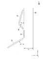
図2は、ベッド10の動作を説明する図である。
ベッド10のフレームには、背ボトム22、腰ボトム24、膝ボトム26、足ボトム28が頭側から足側に順に分割して設けられている。腰ボトム24はフレームに固定されている。ベッド10の高さ(以下、「ベッド高」と称する。)は、駆動部により制御可能である。ベッド高とは、例えば鉛直方向(図2のZ軸方向)におけるベッド10の接地面(図2に示すXY平面)からベッド10の所定の部材までの高さである。以下では一例として、腰ボトム24までの高さhを、ベッド高として説明する。背ボトム22は、腰ボトム24側を中心として回動可能にフレームに設けられている。膝ボトム26は、腰ボトム24側を中心として回動可能にベッドフレームに設けられている。また、足ボトム28は、膝ボトム26に連結されている。背ボトム22の水平状態からの持ち上がり角度α(以下、「第1回動角度」と称する。)と、膝ボトム26の水平状態からの持ち上がり角度β(以下、「第2回動角度」と称する。)は、それぞれ、駆動部により制御可能である。以下では一例として、駆動部は、ベッド高hと、第1回動角度α、第2回動角度βを制御可能であるとして説明するが、ベッド10は、任意の部材を回動可能としてよいし、任意の部材を伸縮可能としてもよい。なお、通常は、背ボトム22、腰ボトム24、膝ボトム26、足ボトム28の上には、マットレスMTが載置される。なお、駆動部は、ユーザが、手元スイッチ21を操作して入力した操作指示に基づいて、コントロールボックス22が制御する。
[Operation of bed 10]
Next, the operation of the
FIG. 2 is a diagram illustrating the operation of the
The frame of the
〔ベッド10の構成〕
次に、ベッド10の構成について説明する。
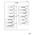
図3は、ベッド10の構成を示すブロック図である。
ベッド10は、高さ検出部12と、角度検出部13と、駆動部11と、ベッド側通信部14と、ベッド側記憶部15と、ベッド側制御部16と、を備える。
[Composition of bed 10]
Next, the configuration of the
FIG. 3 is a block diagram showing the configuration of the
The
駆動部11は、電動アクチュエータを備え、ベッド10の各部材の位置や角度を変更する。
高さ検出部12は、センサを備え、ベッド高を検出する。高さ検出部12は、例えばベッド高を変更可能な電動アクチュエータのピストンロッドの位置を検出する。このピストンロッドの位置とベッド高との間には相関があり、相関を示すデータが予めベッド側記憶部15に記憶されている。そして、高さ検出部12は、このデータを参照することにより、ピストンロッドの位置に基づいてベッド高を検出することができる。高さ検出部12は、検出したベッド高を、ベッド側制御部16に通知する。
The
The
角度検出部13は、センサを備え、第1回動角度と第2回動角度とを検出する。角度検出部13は、例えば第1回動角度、第2回動角度を変更可能な電動アクチュエータのピストンロッドの位置を検出する。このピストンロッドの位置と、第1回動角度及び第2回動角度との間には相関があり、相関を示すデータが予めベッド側記憶部15に記憶されている。そして、角度検出部13は、このデータを参照することにより、ピストンロッドの位置に基づいて第1回動角度と第2回動角度とを検出することができる。角度検出部13は、検出した第1回動角度と第2回動角度とを、ベッド側制御部16に通知する。
The
ベッド側通信部14は、例えば通信用IC(Integrated Circuit)を備え、端末装置30等の他の装置と通信する。ベッド側通信部14は、端末装置30から制御命令を受信する。ベッド側通信部14は、受信した制御命令を、ベッド側制御部16に出力する。ここで、制御命令とは、駆動部11の動作内容を指示する命令である。例えば制御命令には、動作種別(伸長、収縮、停止等)、動作量、動作速度等が含まれてよい。また、制御命令は、動作種別(伸長、収縮、停止等)、動作量、動作速度等を直接的に示すものであってもよいし、これらの制御値と予め対応付けられたコードであってもよい。また、制御命令は、複数の動作を同時に指示したり、順序付けられた複数の動作を指示したりするものであってもよい。この場合、複数の動作は、1つの電動アクチュエータを制御により行われるものであってもよいし、複数の電動アクチュエータを連動させた制御により行われるものであってもよい。なお、ベッド側通信部14は、手元スイッチ21またはコントロールボックス22に備えられる。ただし、その他の箇所に備えられてもよい。
The bed-
ベッド側記憶部15は、例えばHDD(Hard Disk Drive)やSSD(Solid State Drive)、EEPROM(Electrically Erasable Programmable Read-Only Memory)、ROM(Read-Only Memory)、RAM(Random Access Memory)等を含み、ベッド10が処理する各種情報やプログラム等を記憶する。なお、ベッド側記憶部15は、ベッド10に内蔵されるものに限らず、USB(Universal Serial Bus)(登録商標)等のデジタル入出力ポート等によって接続された外付け型の記憶装置でもよい。ベッド側記憶部15は、ベッドID記憶部151を備える。
The bed-
ベッドID記憶部151は、ベッドID(IDentifier)を記憶する。ベッドIDとは、ベッド10に割当てられた識別情報である。ベッドIDには、個々のベッド10に固有の識別情報であってもよいし、同じ機種のベッド10に共通の識別情報であってもよい。
The bed
ベッド側制御部16は、ベッド10の各構成を制御する。ベッド側制御部16は、例えばベッド10が備える演算装置(例えばCPU(Central Processing Unit))が、ベッドID記憶部151に記憶されたプログラムを実行することにより実現されてよい。また、ベッド側制御部16は、例えばASIC(Application Programmable Integrated Circuit)等の集積回路として実現されてもよい。ベッド側制御部16は、現在のベッド高、第1回動角度、第2回動角度等を示す状態を、ベッド側通信部14を介して、端末装置30に通知する。また、ベッド側制御部16は、端末装置30から受信した制御命令に従って、駆動部11を動作、停止させる。
The bed-
端末装置30からの制御命令に従って駆動部11を制御するに際し、ベッド10と端末装置30との間では、通信接続が確立される。通信接続の確立とは、通信相手を互いに認証するプロセスであり、例えばBluetooth(登録商標)通信におけるペアリングである。また、ベッド10と端末装置30とは、Wi-Fi(登録商標)、LTE(Long Term Evolution)等の無線通信や、各種の接続ケーブルを介した有線通信により通信接続を確立してもよい。ベッド側制御部16は、通信接続を確立した端末装置30のみを、自装置の制御端末とする。つまり、ベッド側制御部16は、通信接続を確立した端末装置30から送信された制御命令は受け付け、他の端末装置30から送信された制御命令は受け付けない。
When the
本実施形態では、一例として、通信接続を確立するベッド10と端末装置30との組み合わせは、端末装置30により選択される。通信接続の確立では、ベッド側制御部16は、ベッドID記憶部151に記憶された自装置のベッドIDを、端末装置30に送信する。端末装置30は、ベッドIDを受信すると、ベッドIDが示すベッド10のうち、通信接続を確立するベッド10に対して、端末IDを送信する。端末IDとは、端末装置30を固有に識別する情報である。端末IDは、端末装置30の端末ユーザを識別する情報であってもよい。そして、ベッド側制御部16は、端末IDを受信すると、この端末IDが示す端末装置30を、通信接続の確立相手として認証する。以降、ベッド側制御部16は、認証した端末装置30からの制御命令のみを受け付ける。これにより、ベッドシステム1は、特定の端末装置30のみにより、ベッド10を操作可能とするため、ベッド10の安全性を向上させることができる。
In the present embodiment, as an example, the combination of the
〔端末装置30の構成〕
次に、端末装置30の構成について説明する。
図4は、端末装置30の構成を示すブロック図である。
端末装置30は、入力部31と、表示部32と、音声出力部33と、端末側通信部34と、端末側記憶部35と、端末側制御部36と、を備える。
入力部31は、例えばタッチパネルのタッチセンサを備え、ユーザからの操作入力を受け付ける。
表示部32は、例えばタッチパネルの液晶ディスプレイパネルや有機EL(ElectroLuminescence)ディスプレイパネル等を備え、ベッド10の状態を表示したり、ベッド10の動作を制御するための操作ボタンを表示したりする。
音声出力部33は、例えばスピーカ等を備え、操作案内用の音声や警告音を出力する。
[Configuration of terminal device 30]
Next, the configuration of the
FIG. 4 is a block diagram showing the configuration of the
The
The
The
The
端末側通信部34は、例えば通信用ICを備え、ベッド10等の他の装置と通信する。
端末側記憶部35は、例えばHDDやSSD、ROM、RAM等を含み、端末装置30が処理する各種情報やプログラム等を記憶する。なお、端末側記憶部35は、端末装置30に内蔵されるものに限らず、外付け型の記憶装置でもよい。端末側記憶部35は、端末ID記憶部351と、設定情報記憶部352を備える。
The terminal-
The terminal-
端末ID記憶部351は、端末IDを記憶する。端末IDは、例えばMACアドレス、IPアドレス等であってもよい。
設定情報記憶部352は、設定情報を記憶する。操作ボタン設定情報は、端末IDごと、ユーザIDごと、ベッドIDごとに記憶されてもよい。つまり、設定情報は、端末装置30ごと、ベッドユーザごと、端末ユーザごと、ベッド10ごとの操作ボタンの表示設定を示す情報であってよい。また、設定情報は、端末装置30ごと、ベッドユーザごと、端末ユーザごと、ベッド10ごとに複数記憶されてもよい。この場合、各設定情報には、優先順位が設定されていてもよい。また、設定情報は、端末ID、ユーザID、ベッドID等と、明示的又は暗黙的に対応付けられていてよい。明示的な対応付けとは、データ上で互いに紐付けられていることをいう。暗黙的な対応付けとは、データ上で明確な対応付けはされていないが、端末装置30に管理されている等、所定の関係にあることをいう。以下では、一例として、設定情報が、ユーザIDごとに記憶される場合について説明する。
The terminal
The setting
ここで、本実施形態では、動作設定情報と、表示設定情報との2種類の設定情報が存在する。動作設定情報とは、操作ボタンとベッド10の動作との対応関係を示す情報である。動作設定情報のデータ構成については、後述する。動作設定情報を参照することで、端末装置30は、端末ユーザが所望する動作と、その動作を行わせるための制御命令と、を特定することができる。また、動作設定情報を参照することで、端末装置30は、操作ボタンの有効化、無効化を制御することができる。例えば端末装置30は、動作設定情報において、操作ボタンに対応する動作が許可されている場合にのみ、その操作ボタンに対する操作を受け付ける。端末装置30は、無効化されている操作ボタンを非表示としてもよいし、明るさを低下させる等して、有効化されている操作ボタンと区別してよい。なお、無効化されている操作ボタンと有効化されている操作ボタンを区別せずに、いずれも表示する形式を第1表示形式、有効化されている操作ボタンのみを表示する形式を第2表示形式とも称する。第1表示形式、第2形式は端末側制御部36によって切り替えられてもよい。
Here, in the present embodiment, there are two types of setting information, operation setting information and display setting information. The operation setting information is information indicating the correspondence between the operation buttons and the operation of the
表示設定情報とは、制御用画面における操作ボタンの表示態様を示す情報である。表示設定情報のデータ構成については、後述する。表示設定情報を参照することで、端末装置30は、制御用画面における操作ボタンの表示態様を、端末ユーザごとに異ならせることができる。なお、各操作ボタンの形状、模様、色彩、配置は、個別に端末ユーザが設定可能としてもよい。なお、ユーザごとに表示する操作ボタンを異ならせる表示形式を第1表示形式、全ユーザに同じ操作ボタンを表示する表示形式を第1表示形式とも称する。第1表示形式、第2形式は端末側制御部36によって切り替えられてもよい。
The display setting information is information indicating the display mode of the operation buttons on the control screen. The data structure of the display setting information will be described later. By referring to the display setting information, the
端末側制御部36は、端末装置30の各構成を制御する。端末側制御部36は、例えば端末装置30が備える演算装置(例えばCPU)が、端末側記憶部35に記憶されたプログラムを実行することにより実現されてよい。また、端末側制御部36は、例えばASIC等の集積回路として実現されてもよい。端末側制御部36は、ユーザ認証部361と、ベッドID取得部362と、操作受付部363と、設定部364と、出力処理部365と、を備える。
The terminal
ユーザ認証部361は、ユーザを認証する。ユーザ認証部361は、例えば入力部31を介して入力されたユーザID、パスワード等に基づいてユーザを認証してよい。また、ユーザ認証部361は、指紋認証等の生体認証を行ってもよいし、ユーザに固有のICカードを用いて認証を行ってもよい。ユーザ認証部361は、認証結果を出力処理部365に通知する。
ベッドID取得部362は、端末側通信部34を介して、ベッド10からベッドIDを取得する。ベッド10は、取得したベッドIDを、出力処理部365に通知する。
The
The bed
操作受付部363は、入力部31を介して、端末ユーザによる操作を受け付ける。操作受付部363が受け付ける操作には、例えばベッド選択操作、設定操作、制御操作がある。ベッド選択操作とは、通信接続を確立するベッド10を選択する操作である。設定操作とは、設定情報に記述される設定値を入力する操作である。制御操作とは、ベッド10に送信する制御命令を指定する操作である。操作受付部363は、受け付けた操作の内容を、出力処理部365に通知する。
The
設定部364は、設定情報を編集する。ここで、編集とは、情報を新規に生成すること、情報の内容を更新すること、情報を消去することを含む。設定部364は、編集後の設定情報を、設定情報記憶部352に記憶させる。
The
出力処理部365は、各種画面を表示部32に表示させる。例えば、出力処理部365は、表示部32にベッド選択画面、設定画面、制御用画面等を表示させる。制御用画面の表示において、出力処理部365は、設定情報を参照し、制御用画面に配置する操作ボタンの種類や操作ボタンの表示態様を決定する。これにより、表示される操作ボタンの種類や操作ボタンの表示態様が、端末装置30ごと、ベッドユーザごと、端末ユーザごと、ベッド10ごと、或いは、これらの組み合わせごとに切り替わる。
The
また、出力処理部365は、操作受付部363が受け付けた操作内容に基づく処理を行う。例えば出力処理部365は、操作がベッド選択操作である場合には、選択されたベッド10に端末IDを送信する。例えば出力処理部365は、操作が設定操作である場合には、入力された設定値の設定情報を設定情報記憶部352に記憶させる。例えば出力処理部365は、操作が制御操作である場合には、指定された制御命令をベッド10に送信する。
Further, the
〔設定情報のデータ構成〕
まず、動作設定情報のデータ構成について説明する。
図5は、設定情報のデータ構成を示す図である。
図5に示す例において、動作設定情報は、ユーザIDと、頭速度情報と、高さ速度情報と、連動可否情報と、頭動作可否情報と、足動作可否情報と、高さ動作可否情報と、メモリ可否情報と、頭メモリ情報と、足メモリ情報と、高さメモリ情報と、離床通知可否情報と、を互いに対応付けた情報である。
[Data structure of setting information]
First, the data structure of the operation setting information will be described.
FIG. 5 is a diagram showing a data structure of setting information.
In the example shown in FIG. 5, the operation setting information includes the user ID, the head speed information, the height speed information, the interlocking possibility information, the head movement possibility information, the foot movement possibility information, and the height movement possibility information. , Memory availability information, head memory information, foot memory information, height memory information, and bed leaving notification availability information are associated with each other.
頭速度情報とは、第1回動角度を変更する速度を示す情報である。高さ速度情報とは、ベッド高を変更する速度を示す情報である。連動可否情報とは、複数の電動アクチュエータを連動させた動作の可否を示す情報である。頭動作可否情報とは、第1回動角度を変更する動作の可否を示す情報である。足動作可否情報とは、第2回動角度を変更する動作の可否を示す情報である。高さ動作可否情報とは、ベッド高を変更する動作の可否を示す情報である。メモリ可否情報とは、予め定められたベッド高、第1回動角度、第2回動角度の目標値に、ベッド10の状態を変更する動作(以下、「メモリ動作」と称する。)の可否を示す情報である。頭メモリ情報とは、メモリ動作における第1回動角度の目標値を示す情報である。足メモリ情報とは、メモリ動作における第2回動角度の目標値を示す情報である。高さメモリ情報とは、メモリ動作におけるベッド高の目標値を示す情報である。離床通知可否情報とは、ベッド10からベッドユーザが離床したことを通知するか否かを示す情報である。
The head speed information is information indicating the speed at which the first rotation angle is changed. The height speed information is information indicating the speed at which the bed height is changed. The interlocking possibility information is information indicating whether or not the operation in which a plurality of electric actuators are interlocked is possible. The head movement availability information is information indicating whether or not the movement for changing the first rotation angle is possible. The foot movement availability information is information indicating whether or not the movement for changing the second rotation angle is possible. The height operation availability information is information indicating whether or not the operation of changing the bed height is possible. The memory availability information is the availability of an operation of changing the state of the bed 10 (hereinafter referred to as "memory operation") to the target values of the bed height, the first rotation angle, and the second rotation angle set in advance. This is information indicating. The head memory information is information indicating a target value of the first rotation angle in the memory operation. The foot memory information is information indicating a target value of the second rotation angle in the memory operation. The height memory information is information indicating a target value of the bed height in the memory operation. The bed leaving notification availability information is information indicating whether or not to notify the bed user that the bed user has left the bed from the
次に、表示設定情報のデータ構成について説明する。
図6は、表示設定情報のデータ構成を示す図である。
図6に示す例において、表示設定情報は、ユーザIDと、表示パターン情報と、を互いに対応付けた情報である。
表示パターン情報とは、制御用画面の表示パターンを示す情報である。本実施形態では、複数の表示パターンが用意されている。そして、各表示パターンでは、各操作ボタンの表示態様が異なっていたり、表示される操作ボタンの種類が異なっていたりする。
Next, the data structure of the display setting information will be described.
FIG. 6 is a diagram showing a data structure of display setting information.
In the example shown in FIG. 6, the display setting information is information in which the user ID and the display pattern information are associated with each other.
The display pattern information is information indicating a display pattern of the control screen. In this embodiment, a plurality of display patterns are prepared. Then, in each display pattern, the display mode of each operation button is different, or the type of the displayed operation button is different.
〔ベッドシステム1の動作〕
次に、ベッドシステム1の動作について説明する。
図7は、ベッドシステム1による処理の流れを示すシーケンスチャートである。
(ステップS300)端末装置30は、ユーザ認証を行う。その後、ベッドシステム1は、ステップS100に処理を進める。
(ステップS100)ベッド10は、ベッドIDを端末装置30に送信する。その後、ベッドシステム1は、ステップS310に処理を進める。
[Operation of bed system 1]
Next, the operation of the
FIG. 7 is a sequence chart showing the flow of processing by the
(Step S300) The
(Step S100) The
(ステップS310)端末装置30は、ベッド10からベッドIDを取得し、ベッド選択画面を表示する。ベッド選択画面の具体例については後述する。ベッドIDを取得することで、端末装置30は、ベッド10の機種やベッド10が受け付け可能な制御命令等を特定することができる。その後、ベッドシステム1は、ステップS320に処理を進める。
(ステップS320)端末装置30は、端末ユーザからベッド選択操作を受け付ける。その後、ベッドシステム1は、ステップS330に処理を進める。
(Step S310) The
(Step S320) The
(ステップS330)端末装置30は、ベッド選択操作で指定されたベッド10に対して、通信接続の確立を要求する。その後、ベッドシステム1は、ステップS110、S340に処理を進める。
(ステップS110、S340)ベッド10と端末装置30とは、通信接続を確立する。これにより、ベッド10は、端末装置30から送信された制御命令に従った動作を行えるようになる。換言すると、端末装置30は、ベッド10を制御可能になる。その後、ベッドシステム1は、ステップS120に処理を進める。
(Step S330) The
(Steps S110 and S340) The
(ステップS120)ベッド10は、自装置のベッド高、第1回動角度、第2回動角度等の状態を示す状態情報を端末装置30に送信する。その後、ベッドシステム1は、ステップS350に処理を進める。
(ステップS350)端末装置30は、設定情報を読み出す。ここでは処理の図示を省略するが、設定情報は、設定画面を介した設定操作により編集することができる。設定画面の具体例については後述する。その後、ベッドシステム1は、ステップS360に処理を進める。
(Step S120) The
(Step S350) The
(ステップS360)端末装置30は、設定情報に基づいて制御用画面を表示する。制御用画面の具体例については後述する。その後、ベッドシステム1は、ステップS370に処理を進める。
(ステップS370)端末装置30は、制御操作を受け付ける。その後、ベッドシステム1は、ステップS380に処理を進める。
(Step S360) The
(Step S370) The
(ステップS380)端末装置30は、制御操作に対応する制御命令を特定する。端末装置30は、制御命令を示す制御情報を、ベッド10に送信する。ここで、同じ動作を行わせる場合であっても、ベッド10の機種間で異なる制御命令が割当てられている場合がある。この場合、ベッド10の機種に依らず画一的な制御命令を送信すると、ベッド10が誤動作してしまう可能性がある。そこで、端末装置30は、ベッド10の機種ごとに、動作と制御命令との対応関係を示すデータを予め記憶しておく。そして、端末装置30は、このデータを、制御対象のベッド10について参照して、制御操作に対応する制御命令を特定する。これにより、端末装置30は、多様な機種のベッド10を適切に制御することができる。その後、ベッドシステム1は、ステップS130に処理を進める。
(Step S380) The
(ステップS130)ベッド10は、制御情報が示す制御命令に従って駆動部11を動作させる。その後、ベッドシステム1は、ステップS140に処理を進める。
(ステップS140)ベッド10は、駆動部11の制御結果を示す情報を端末装置30に送信する。制御結果には、例えばベッド高、第1回動角度、第2回動角度の値等が含まれてもよい。制御結果の受信に応じて、端末装置30は、次の制御操作を受け付け可能とする。その後、ベッドシステム1は、制御操作が行われる場合には、ステップS370に処理を進め、ベッド10の操作が必要なくなった場合には、図7に示す処理を終了する。
(Step S130) The
(Step S140) The
なお、図7に示した任意の処理は、適宜、一部省略されてもよいし、順序を入れ替えて実行されてもよい。例えば、ステップS300の処理は、省略されてもよいし、ステップS110、S340の処理の後等に実行されてもよい。 It should be noted that the arbitrary processing shown in FIG. 7 may be partially omitted or may be executed in a different order. For example, the process of step S300 may be omitted, or may be executed after the process of steps S110 and S340.
〔画面例〕
次に、端末装置30が表示する画面例について説明する。
まず、ベッド選択画面の例について説明する。
図8は、ベッド選択画面を示す図である。
図8に示すベッド選択画面G1には、端末装置30がベッドIDを取得した2つのベッド10を選択するための操作子として、選択ボタンG11、G12が設けられている。この選択ボタンG11、G12には、ベッドIDや各ベッド10との通信強度等の情報が表示されてよい。
[Screen example]
Next, an example of a screen displayed by the
First, an example of the bed selection screen will be described.
FIG. 8 is a diagram showing a bed selection screen.
The bed selection screen G1 shown in FIG. 8 is provided with selection buttons G11 and G12 as controls for the
次に、設定画面の例について説明する。
図9は、設定画面を示す図である。
図9に示す設定画面G2には、設定情報の各項目の設定値を指定するための操作子として、設定ボタンG211、G212、G221~G225、G23、G231~G233、G24が設けられている。設定ボタンG211は、頭速度情報を設定するための操作子である。設定ボタンG212は、高さ速度情報を設定するための操作子である。設定ボタンG221は、連動可否情報を設定するための操作子である。設定ボタンG222は、頭動作可否情報を設定するための操作子である。設定ボタンG223は、足動作可否情報を設定するための操作子である。設定ボタンG224は、高さ動作可否情報を設定するための操作子である。設定ボタンG225は、メモリ可否情報を設定するための操作子である。設定ボタンG23は、現在のベッド10の第1回動角度、第2回動角度、ベッド高を、頭メモリ情報、足メモリ情報、高さメモリ情報に設定するための操作子である。設定ボタンG231は、頭メモリ情報の設定値を調整するための操作子である。設定ボタンG232は、足メモリ情報の設定値を調整するための操作子である。設定ボタンG233は、高さメモリ情報の設定値を調整するための操作子である。設定ボタンG24は、離床通知可否情報を設定するための操作子である。設定画面では、図9に示す以外にも、操作子の表示態様を設定可能としてよい。
Next, an example of the setting screen will be described.
FIG. 9 is a diagram showing a setting screen.
The setting screen G2 shown in FIG. 9 is provided with setting buttons G211 and G212, G221 to G225, G23, G231 to G233, and G24 as controls for designating the setting values of each item of the setting information. The setting button G211 is an operator for setting the head speed information. The setting button G212 is an operator for setting height / velocity information. The setting button G221 is an operator for setting interlocking possibility information. The setting button G222 is an operator for setting head movement availability information. The setting button G223 is an operator for setting foot movement availability information. The setting button G224 is an operator for setting height operation enable / disable information. The setting button G225 is an operator for setting memory availability information. The setting button G23 is an operator for setting the first rotation angle, the second rotation angle, and the bed height of the
次に、制御用画面について説明する。
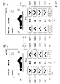
図10~図12は、制御用画面を示す図である。
図10に示す制御用画面G31には、ベッド10の状態(第1回動角度、第2回動角度、ベッド高等)を示すベッド状態表示欄BSが設けられている。また、制御用画面G31には、制御命令を指定するための操作子として、操作ボタンG311、G312、G321、G322、G331、G332、G341、G342、FB、MBが設けられている。操作ボタンG311、G312は、第1回動角度と第2回動角度との両方を変更する動作に対応する操作子である。操作ボタンG321、G322は、第1回動角度を変更する動作に対応する操作子である。操作ボタンG331、G332は、第2回動角度を変更する動作に対応する操作子である。操作ボタンG341、G342は、ベッド高を変更する動作に対応する操作子である。また、操作ボタンG311、G321、G331、G341は、第1回動角度と第2回動角度との両方、第1回動角度、第2回動角度、ベッド高を小さくする動作に対応する。また、操作ボタンG321、G322、G332、G342は、第1回動角度と第2回動角度との両方、第1回動角度、第2回動角度、ベッド高を大きくする動作に対応する。操作ボタンFBは、第1回動角度と第2回動角度との両方をゼロにして、各ボトムを水平状態にする動作に対応する操作子である。操作ボタンMBは、メモリ動作に対応する操作子である。
Next, the control screen will be described.
10 to 12 are diagrams showing control screens.
The control screen G31 shown in FIG. 10 is provided with a bed state display column BS indicating the state of the bed 10 (first rotation angle, second rotation angle, bed height, etc.). Further, the control screen G31 is provided with operation buttons G311, G312, G321, G322, G331, G332, G341, G342, FB, and MB as controls for designating control commands. The operation buttons G311 and G312 are operators corresponding to the operation of changing both the first rotation angle and the second rotation angle. The operation buttons G321 and G322 are operators corresponding to the operation of changing the first rotation angle. The operation buttons G331 and G332 are operators corresponding to the operation of changing the second rotation angle. The operation buttons G341 and G342 are operators corresponding to the operation of changing the bed height. Further, the operation buttons G311, G321, G331, and G341 correspond to both the first rotation angle and the second rotation angle, the first rotation angle, the second rotation angle, and the operation of reducing the bed height. Further, the operation buttons G321, G322, G332, and G342 correspond to both the first rotation angle and the second rotation angle, the first rotation angle, the second rotation angle, and the operation of increasing the bed height. The operation button FB is an operator corresponding to an operation in which both the first rotation angle and the second rotation angle are set to zero to bring each bottom into a horizontal state. The operation button MB is an operator corresponding to the memory operation.
ここで、制御用画面G31には、パターン切替ボタンCBが配置されている。パターン切替ボタンCBとは、制御用画面の表示パターンを切り替えるための操作子である。つまり、パターン切替ボタンCBとは、操作ボタンの表示態様を変更する表示態様変更指示を受け付けるための操作子の一例である。端末装置30は、制御用画面G31において、パターン切替ボタンCBが操作されると、制御用画面G32に表示を切り替える。また、端末装置30は、制御用画面G32において、パターン切替ボタンCBが操作されると、制御用画面G31に表示を切り替える。制御用画面G32には、制御用画面G31と同様の操作ボタンが配置されている。ただし、各操作ボタンの配置が、左右を反転するように変更されている。これにより、例えば片手が不自由な端末ユーザであっても、自由が利く手の親指が届く範囲に、所望の操作ボタンを移動させることができる。よって、ベッドシステム1は、ベッド10の操作性を向上させることができる。
Here, the pattern switching button CB is arranged on the control screen G31. The pattern switching button CB is an operator for switching the display pattern of the control screen. That is, the pattern switching button CB is an example of an operator for receiving a display mode change instruction for changing the display mode of the operation button. When the pattern switching button CB is operated on the control screen G31, the
なお、制御用画面の表示パターンは、2つに限らず3つ以上用意されてもよい。また、各表示パターンは、操作ボタンの配置の他にも大きさ、形状、模様、色彩が異なっていてもよい。また、各表示パターンにおいて、個々の操作ボタンの大きさ、形状、模様、色彩が異なっていてもよい。また、操作ボタンの大きさ、形状、模様、色彩、配置等は個別に変更可能としてもよい。また、個々の操作ボタンの操作方法は異なっていてもよい。例えば長押しされた場合に操作を受け付ける操作ボタンやダブルタップされた場合に操作を受け付ける操作ボタンが設けられてもよい。このように特定の操作方法のみ受け付けるようにすることで、操作ボタンの誤操作に応じてベッド10が動作してしまうことを予防することができる。
The display pattern of the control screen is not limited to two, and three or more may be prepared. Further, each display pattern may have a different size, shape, pattern, and color in addition to the arrangement of the operation buttons. Further, in each display pattern, the size, shape, pattern, and color of each operation button may be different. Further, the size, shape, pattern, color, arrangement, etc. of the operation buttons may be individually changed. Moreover, the operation method of each operation button may be different. For example, an operation button that accepts an operation when it is long-pressed or an operation button that accepts an operation when it is double-tapped may be provided. By accepting only a specific operation method in this way, it is possible to prevent the
図11に示す制御用画面G41には、操作ボタンG410、G420、G430、G440が設けられている。操作ボタンG410、G420、G430、G440は、制御対象の電動アクチュエータを選択するための操作子である。操作ボタンG410は、第1回動角度と第2回動角度との両方を変更する動作に対応する操作子である。操作ボタンG420は、第1回動角度を変更する動作に対応する操作子である。操作ボタンG430は、第2回動角度を変更する動作に対応する操作子である。操作ボタンG440は、ベッド高を変更する動作に対応する操作子である。なお、各動作を第1動作、第2動作、・・・、と称してもよい。 The control screen G41 shown in FIG. 11 is provided with operation buttons G410, G420, G430, and G440. The operation buttons G410, G420, G430, and G440 are controls for selecting an electric actuator to be controlled. The operation button G410 is an operator corresponding to an operation of changing both the first rotation angle and the second rotation angle. The operation button G420 is an operator corresponding to the operation of changing the first rotation angle. The operation button G430 is an operator corresponding to the operation of changing the second rotation angle. The operation button G440 is an operator corresponding to the operation of changing the bed height. In addition, each operation may be referred to as a first operation, a second operation, ....
制御対象が選択されると、端末装置30は、動作量と動作方向との入力を受け付けるための制御用画面に表示を遷移させる。例えば操作ボタンG430が操作されると、端末装置30は、制御用画面G42に表示を表示する。制御用画面G42には、操作ボタンG431、G432が設けられている。操作ボタンG431は、第2回動角度を大きくする動作に対応する。操作ボタンG432は、第2回動角度を小さくする動作に対応する。このように、図11に示す例では、端末装置30は、ベッド10に1つの動作を行わせるために、複数の操作ボタンを順に操作することを要求する。そのため、1つの操作ボタンが誤って操作されてしまった場合であっても、直ちにベッド10が動作することはない。よって、ベッドシステム1は、ベッド10の安全性を向上させることができる。
When the control target is selected, the
なお、端末装置30は、ベッド10に1つの動作を行わせるために、複数の操作ボタンを同時に操作することを要求してもよい。この場合、例えば2つの操作ボタンが同時にタッチされていない場合には、ベッド10は動作しない。そのため、1つの操作ボタンが誤って操作されてしまった場合であっても、直ちにベッド10が動作することはない。よって、ベッドシステム1は、ベッド10の安全性を向上させることができる。
The
なお、制御用画面G41において、操作ボタンG410、G420、G430、G440のそれぞれに対応して、動作量と動作方向との入力を受け付ける操作ボタンを表示してもよい。つまり、表示画面G42における操作ボタンG431、G432を、操作ボタンG410、G420、G430、G440と対応付けて表示してもよい。これにより、端末装置30は、制御用画面G41において、ユーザから制御対象の動作量と動作方向との入力を受け付けることができる。ここで、制御用画面G41の表示形式を第1表示形式、制御用画面G42の表示形式を第2表示形式とも称する。第1表示形式とは、例えば足の位置を制御するための操作ボタンG420と、他の動作を制御するための制御ボタン(G410、G420等)を同時に表示する形式である。第2表示形式とは、例えば、足の位置を制御するための操作ボタンG420のみを表示し、他の動作を制御するための操作ボタン(G410、G420等)を表示しない形式である。第1表示形式、第2形式は端末側制御部36によって切り替えられてもよい。
In the control screen G41, an operation button that accepts inputs of an operation amount and an operation direction may be displayed corresponding to each of the operation buttons G410, G420, G430, and G440. That is, the operation buttons G431 and G432 on the display screen G42 may be displayed in association with the operation buttons G410, G420, G430 and G440. As a result, the
図12に示す制御用画面G51には、操作ボタンG510、G520、G530、G540が設けられている。操作ボタンG510、G520、G530、G540は、ベッドユーザの行動を選択するための操作子である。操作ボタンG510は、ベッドユーザが食事するのに適した状態になるようベッド10を動作させるための操作子である。操作ボタンG520は、ベッドユーザがベッド10から立ち上がるのに適した状態になるように、ベッド10を動作させるための操作子である。操作ボタンG530は、ベッドユーザがベッドから起き上がるのに適した状態になるように、ベッド10を動作させるための操作子である。操作ボタンG540は、ベッドユーザが寝るのに適した状態になるように、ベッド10を動作させるための操作子である。
The control screen G51 shown in FIG. 12 is provided with operation buttons G510, G520, G530, and G540. The operation buttons G510, G520, G530, and G540 are controls for selecting the action of the bed user. The operation button G510 is an operator for operating the
ベッドユーザの行動が選択されると、端末装置30は、選択された行動を行うためのベッドユーザの動作手順とベッド10の動作手順とを表示する。例えば操作ボタンG520が操作されると、端末装置30は、制御用画面G53を表示する。制御用画面G53には、操作ボタンG521、G522が設けられている。操作ボタンG521、G522は、行動の各手順に応じた動作を、ベッド10に行わせるための操作子である。ベッドユーザは、各手順の説明文に対して並べられた操作ボタンを操作することで、各手順を行うのに適した状態になるようベッド10を動作させることができる。これにより、ベッドユーザは、自身がどのように動作して、ベッド10をどのように動作させれば、所望の行動を行うのに最適であるかを、容易に理解することができる。そのため、ベッドユーザは、ベッド10の適切な利用方法を知らなくても、ベッド10を適切に利用することができる。よって、ベッドシステム1は、ベッド10の操作性を向上させることができる。
When the bed user's action is selected, the
なお、制御用画面G52に示す例では、ベッドユーザの動作手順の各々に対して、1つの操作ボタンG521又は操作ボタンG522を並べて表示しているが、複数の動作手順に対して1つの操作ボタンを対応付けて表示してもよい。この場合、操作ボタンに対応する制御命令は、順次切り替わるようにしてもよい。この操作ボタンは、例えば最初に操作されたときには、操作ボタンG521として機能し、次に操作されたときには、操作ボタンG522として機能する。このように、端末装置30は、1つの操作ボタンに対応する制御命令を、操作回数や操作タイミングに応じて変更してもよい。これにより、端末ユーザは、同じ操作ボタンを操作することで、ベッド10に異なる動作を行わせることができる。なお、端末装置30は、この操作ボタンを、対応する動作手順の近傍に随時移動させてもよいし、表示を変更していずれの動作手順に対応しているかを識別可能としてもよい。
In the example shown on the control screen G52, one operation button G521 or operation button G522 is displayed side by side for each operation procedure of the bed user, but one operation button is displayed for a plurality of operation procedures. May be associated and displayed. In this case, the control commands corresponding to the operation buttons may be sequentially switched. This operation button functions as an operation button G521 when it is first operated, and functions as an operation button G522 when it is operated next time. As described above, the
なお、制御用画面G51において、操作ボタンG510、G520、G530、G540のそれぞれに対応して、動作量と動作方向との入力を受け付ける操作ボタンを表示してもよい。つまり、表示画面G52における操作ボタンG521、G522を、操作ボタンG510、G520、G530、G540と対応付けて表示してもよい。これにより、端末装置30は、制御用画面G51において、ユーザから制御対象の動作量と動作方向との入力を受け付けることができる。ここで、制御用画面G51の表示形式を第1表示形式、制御用画面G52の表示形式を第2表示形式とも称する。第1表示形式とは、例えばベッドユーザがベッド10から立ち上がるのに適した状態になるように、ベッド10を動作させるための操作ボタンG520と、他の動作に適した状態になるように、ベッド10を動作させるための操作ボタン(G510、G530等)を同時に表示する形式である。第2表示形式とは、例えば、操作ボタンG520のみを表示し、他の操作ボタン(G510、G530等)を表示しない形式である。第1表示形式、第2形式は端末側制御部36によって切り替えられてもよい。
In the control screen G51, an operation button that accepts inputs of an operation amount and an operation direction may be displayed corresponding to each of the operation buttons G510, G520, G530, and G540. That is, the operation buttons G521 and G522 on the display screen G52 may be displayed in association with the operation buttons G510, G520, G530, and G540. As a result, the
〔第1の実施形態のまとめ〕
以上説明したように、ベッドシステム1(情報処理システムの一例)は、ベッド10(身体支持装置の一例)と、端末装置30(端末装置の一例)とを備える。端末装置30は、ベッド10の各種動作(第1動作および第2動作)を制御する操作ボタン(操作子)を表示する表示部32と、外部からの指示に基づいて、第1動作を制御する第1操作子および第2動作を制御する第2操作子を表示部32に表示する第1表示形式と、第1操作子および第2操作子のいずれか一方を表示部32に表示する第2表示形式とを切り替える制御部と、を備える。
[Summary of the first embodiment]
As described above, the bed system 1 (an example of an information processing system) includes a bed 10 (an example of a body support device) and a terminal device 30 (an example of a terminal device). The
これにより、ベッドシステム1は、ユーザやベッド10に応じて表示形式を切り替え、ユーザやベッド10に適した表示をし、ベッド10の操作性を向上させることができる。例えば、ユーザごとに、操作させない操作ボタンを非表示にしたり、ベッドごとに、対応していない動作の操作ボタンを非表示にすることで、ベッド10の操作性を向上させることができる。
As a result, the
また、端末装置30は、操作受付部363(選択受付部の一例)と、出力処理部365(制御命令送信部、表示処理部の一例)と、を備える。操作受付部363は、ベッド10の選択を受け付ける。出力処理部365は、選択されたベッド10に対応する操作ボタン(操作子の一例)を表示部32に表示する。操作受付部363は、ベッド10に対する制御命令の入力を、操作ボタンに対する操作に基づいて受け付ける。出力処理部365は、操作ボタンに対する操作に応じて、選択されたベッド10に対し、入力された制御命令を送信する。
Further, the
これにより、ベッドシステム1は、ベッド10の選択やベッド10に応じた設定情報に基づいて操作ボタンを表示する。そのため、ベッドシステム1は、操作ボタンの表示を、制御対象のベッド10ごとにカスタマイズすることができる。つまり、ベッドシステム1は、操作ボタンの表示をベッドユーザごとにカスタマイズすることができる。よって、ベッドシステム1は、ベッド10の操作性を向上させることができる。
As a result, the
また、端末装置30は、ベッドID取得部362(識別情報取得部の一例)をさらに備える。ベッドID取得部362は、ベッド10に対応付けられたベッドID(識別情報の一例)を取得する。操作受付部363は、ベッドIDの選択を受け付ける。出力処理部365は、ベッドIDに基づいて(ベッドIDの選択に基づいて、或いは、ベッドIDに応じた設定情報に基づいて)、操作ボタンを表示部32に表示する。操作受付部363は、ベッド10に対する制御命令の入力を、操作ボタンに対する操作に基づいて受け付ける。出力処理部365は、操作ボタンに対する操作に応じて、選択されたベッドIDに対応付けられたベッド10に、入力された制御命令を送信する。
Further, the
これにより、ベッドシステム1は、ベッドIDの選択やベッドIDに応じた設定情報に基づいて操作ボタンを表示する。そのため、ベッドシステム1は、操作ボタンの表示を、制御対象のベッド10ごとにカスタマイズすることができる。つまり、ベッドシステム1は、操作ボタンの表示をベッドIDに基づいてベッドユーザごとにカスタマイズすることができる。よって、ベッドシステム1は、ベッド10の操作性を向上させることができる。
As a result, the
また、端末装置30は、設定部364(設定部の一例)を備える。設定部364は、操作ボタンの表示態様を示す設定情報を生成する。出力処理部365は、操作ボタンを、設定情報が示す表示態様で、表示部32に表示する。
これにより、ベッドシステム1は、設定情報に示される表示態様(大きさ、形状、模様、色彩、配置)で操作ボタンを表示する。そのため、ベッドシステム1は、制御対象のベッド10ごとに、操作ボタンの表示態様をカスタマイズすることができる。つまり、ベッドシステム1は、ベッドユーザごとに操作ボタンの表示態様をカスタマイズすることができる。よって、ベッドシステム1は、ベッド10の操作性を向上させることができる。
Further, the
As a result, the
また、端末装置30において、設定情報は、操作ボタンを表示の可否を示す情報であり、出力処理部365は、設定情報において表示が許可されている操作ボタンを、表示部32に表示する。
これにより、ベッドシステム1において、表示が許可された操作ボタンが表示され、表示が禁止された操作ボタンは表示されない。換言すると、ベッドシステム1は、制御対象のベッド10に応じて、表示する操作ボタンを変更する。そのため、ベッドシステム1は、受け付け可能とする制御命令をベッド10ごとに適切に管理することができる。つまり、ベッドシステム1は、ベッドユーザごとに、受け付ける制御命令を適切に制限したり、提案したりすることができる。よって、ベッドシステム1は、ベッド10の操作性や安全性を向上させることができる。
Further, in the
As a result, in the
操作受付部363(変更指示受付部の一例)は、操作ボタンの表示態様を変更する表示態様変更指示の入力を受け付け、出力処理部365は、表示態様変更指示が入力された場合、操作ボタンの表示態様を変更する。
これにより、ベッドシステム1は、ユーザの指示に応じて、操作ボタンの表示態様を変更する。そのため、ベッドシステム1は、例えば画像において、所望の操作ボタンが操作しにくい位置に配置されている場合であっても、その操作ボタンを操作しやすい位置に移動させたり、所望の操作ボタンを大きくしたりする。よって、ベッドシステム1は、ベッド10の操作性を向上させることができる。
The operation reception unit 363 (an example of the change instruction reception unit) accepts the input of the display mode change instruction for changing the display mode of the operation button, and the
As a result, the
操作受付部363は、複数の操作ボタンに対する操作に基づいて、1つの制御命令の入力を受け付け、出力処理部365は、複数の操作ボタンに対する操作に応じて、入力された1つの制御命令を送信する。
これにより、ベッドシステム1は、1つの動作を指示するのに、複数の操作ボタンに対する操作を要求する。この場合、ベッドシステム1は、1つの操作ボタンが操作された場合であっても、ベッド10を動作させない。そのため、例えば、端末ユーザが意図せずに1つの操作ボタンを誤操作した場合であっても、ベッド10が動作してしまうことがない。よって、ベッドシステム1は、ベッド10の安全性を向上させることができる。
The
As a result, the
出力処理部365は、1つの操作ボタンに対する操作に応じて、複数の制御命令を、選択されたベッドIDに対応付けられたベッド10に対して所定の順序で送信する。
これにより、ベッドシステム1は、1つの操作ボタンの操作に応じて、複雑な動作をベッド10に行わせることができる。つまり、端末ユーザは、同じ動作を行わせるのに、複数回、端末装置30を操作する必要がない。よって、ベッドシステム1は、ベッド10の安全性を向上させることができる。
The
As a result, the
出力処理部365は、自装置のユーザに応じた設定情報に基づいて、操作ボタンを表示部32に表示する。
これにより、ベッドシステム1は、端末ユーザごとの設定情報に基づいて操作ボタンを表示する。そのため、ベッドシステム1は、操作ボタンの表示を、端末ユーザごとにカスタマイズすることができる。よって、ベッドシステム1は、ベッド10の操作性や安全性を向上させることができる。
The
As a result, the
[第2の実施形態]
第2の実施形態について説明する。以下では、上述した実施形態と同様の構成については、同一の符号を付し、説明を援用する。
図13は、本実施形態の概要を示す模式図である。
本実施形態に係るベッドシステム1Aは、第1の実施形態に係るベッドシステム1と同様に、ベッド10と端末装置30とを備える。ただし、第1の実施形態では、ベッドユーザと端末ユーザとが同一であったのに対して、本実施形態では、ベッドユーザと端末ユーザとが同一ではない点が異なる。例えばベッドユーザは患者であり、端末ユーザは医者や看護師である。この場合、ベッドユーザと端末ユーザとでは立場が異なるため、端末装置30は、端末ユーザの立場に応じて異なる制御用画面を表示する。具体的には、端末装置30は、設定情報に対して権限情報を対応付けて管理する。権限情報とは、端末ユーザの権限を示す情報である。設定情報は、権限情報に応じてその項目が異なっている。これにより、端末装置30は、端末ユーザの権限に応じて、操作子の表示、非表示や、操作子の表示態様を制御することができる。
[Second Embodiment]
The second embodiment will be described. In the following, the same reference numerals will be given to the same configurations as those of the above-described embodiments, and the description will be incorporated.
FIG. 13 is a schematic diagram showing an outline of the present embodiment.
The
図14は、制御用画面を示す図である。
図14に示す制御用画面G6には、図10に示す制御用画面G31と同様の操作ボタンが配置されている。ただし、制御用画面G6には、操作ボタンFBに代えて操作ボタンNBが配置されている。操作ボタンNBは、夜間用に、ベッド高を最も低い位置まで下げるとともに、第1回動角度と第2回動角度とをゼロにして各ボトムを水平状態にするための操作子である。このように、端末装置30は、端末ユーザの権限に応じて、専用の操作ボタンを追加したり、変更したり、無効化したりしてもよい。
FIG. 14 is a diagram showing a control screen.
The control screen G6 shown in FIG. 14 has the same operation buttons as the control screen G31 shown in FIG. 10. However, on the control screen G6, an operation button NB is arranged instead of the operation button FB. The operation button NB is an operator for lowering the bed height to the lowest position and setting the first rotation angle and the second rotation angle to zero to make each bottom horizontal for nighttime use. As described above, the
以上説明したように、ベッドシステム1Aにおいて、出力処理部365は、自装置のユーザの権限に応じた設定情報に基づいて、操作ボタンを表示部32に表示する。
これにより、ベッドシステム1Aは、端末ユーザの権限に応じた操作ボタンを表示する。そのため、ベッドシステム1Aは、操作ボタンの利用を端末ユーザの権限に応じて制限できる。よって、ベッドシステム1Aは、操作性を向上させるだけでなく、ベッド10の安全性を向上させることができる。
As described above, in the
As a result, the
なお、権限は、端末ユーザの立場だけでなく、端末ユーザの身体状況に応じて定められてよい。例えば権限は、要介助度に対応するものであってもよい。 The authority may be determined not only according to the position of the terminal user but also according to the physical condition of the terminal user. For example, the authority may correspond to the degree of caregiving.
[第3の実施形態]
第3の実施形態について説明する。以下では、上述した実施形態と同様の構成については、同一の符号を付し、説明を援用する。
図15は、本実施形態の概要を示す模式図である。
本実施形態に係るベッドシステム1Bは、第2の実施形態に係るベッドシステム1Aと同様に、ベッド10と端末装置30とを備える。ただし、第2の実施形態では、1つの端末装置30により1つのベッド10を制御可能としていたのに対して、本実施形態では、1つの端末装置30により複数のベッド10(ベッド10-1、10-2、…)を制御可能とする点が異なる。これにより、複数のベッド10を同じ状態にしたい場合に、個々のベッド10に対して操作を入力する必要がないため、効率よくベッド10を動作させることができる。
[Third Embodiment]
A third embodiment will be described. In the following, the same reference numerals will be given to the same configurations as those of the above-described embodiments, and the description will be incorporated.
FIG. 15 is a schematic diagram showing an outline of the present embodiment.
The
ただし、1つの端末装置30により複数のベッド10を制限なく制御可能としてしまうと、一部のベッドユーザにとって、適切でない動作が行われてしまう可能性もある。そこで、端末装置30は、制御対象の複数のベッド10のいずれにおいても許可されている動作について、操作を受け付ける。これにより、ベッドシステム1Bは、複数のベッド10の操作性を向上させるだけでなく、安全性をも向上させることができる。
However, if a plurality of
図16は、制御用画面を示す図である。
図16に示す制御用画面G7には、図14に示す制御用画面G6と同様の操作ボタンが配置されている。ただし、制御対象の複数のベッド10のベッドユーザに、第1回動角度の変更を禁止しているユーザが存在する。そこで、制御用画面G7では、操作ボタンG321、G322、MBが無効化されている。これにより、ベッド10の安全性を向上させることができる。また、端末装置30は、操作ボタンを無効化する代わりに、動作を禁止しているベッドユーザが利用するベッド10には、制御命令を送信しないようにしてもよい。各ベッド10又は各ベッドユーザの禁止動作の情報は、端末装置30に記憶されていてもよいし、ベッド10に記憶されていてもよい。
FIG. 16 is a diagram showing a control screen.
The control screen G7 shown in FIG. 16 has the same operation buttons as the control screen G6 shown in FIG. However, among the bed users of the plurality of
なお、図14に示す制御用画面G6の表示形式を第1表示形式、図16に示す制御用画面G7の表示形式を第2表示形式とも称する。第1表示形式、第2形式は端末側制御部36によって切り替えられてもよい。
The display format of the control screen G6 shown in FIG. 14 is also referred to as a first display format, and the display format of the control screen G7 shown in FIG. 16 is also referred to as a second display format. The first display format and the second format may be switched by the terminal
以上説明したように、ベッドシステム1Bにおいて、端末装置30の出力処理部365は、表示部32に表示する操作ボタンを、制御命令を送信するベッド10の数に応じて異ならせる。
これにより、ベッドシステム1において、制御対象のベッド10の台数が異なる場合には、表示される操作ボタンが異なることになる。換言すると、ベッドシステム1は、制御対象のベッド10の台数に応じて、表示する操作ボタンを変更する。例えば、ベッドシステム1は、制御対象のベッド10が1台である場合に比して、複数台である場合には、表示する操作ボタンを制限する。つまり、ベッド10の動作を制限する。そのため、各ベッドユーザの身体状況等が異なる場合であっても、安全性を保ちつつ、複数のベッド10を動作させることができる。よって、ベッドシステム1は、ベッド10の操作性を向上させるだけでなく、安全性をも向上させることができる。
As described above, in the
As a result, in the
[第4の実施形態]
第4の実施形態について説明する。以下では、上述した実施形態と同様の構成については、同一の符号を付し、説明を援用する。
図17は、本実施形態の概要を示す模式図である。
本実施形態に係るベッドシステム1Cは、上述したベッドシステム1、1A、1Bが備えるベッド10に代えて、ベッド10Cを備える。上述した各実施形態では、ベッド10を制御する端末装置30が1つであったのに対して、本実施形態では、ベッド10Cを制御する端末装置30が複数存在する点が異なる。これにより、複数の端末装置30からベッド10Cが操作可能になるため、操作性を向上させることができる。図17に示す例では、ベッドユーザである患者と、他のユーザである看護師とが、それぞれ端末装置30を有している。以下では、患者が有する端末装置30を端末装置30Pと称し、看護師が有する端末装置30を端末装置30Nと称する。ベッド10Cの操作において、患者と看護師には、それぞれ異なる権限を有している。ここでは、一例として、看護師の方がより強い権限を有する場合について説明する。
[Fourth Embodiment]
A fourth embodiment will be described. In the following, the same reference numerals will be given to the same configurations as those of the above-described embodiments, and the description will be incorporated.
FIG. 17 is a schematic diagram showing an outline of the present embodiment.
The
ここで、ベッド10Cを制御する端末装置30が複数存在する場合、ベッド10Cが複数の端末装置30からの制御命令を平等に受け付けてしまうと、ベッド10Cが意図しない動作を行ってしまう可能性もある。そこで、ベッド10Cは、通信接続を確立する相手を、常に1つの端末装置30とする。例えば端末装置30Nから接続要求があった場合には、端末装置30Pと通信接続を確立していた場合であっても、端末装置30Nと通信接続を確立する。つまり、ベッド10Cは、より強い権限を有する端末ユーザとの通信接続を優先する。これにより、ベッド10Cの操作性を向上させるだけでなく、ベッド10Cの安全性も向上させることができる。
Here, when there are a plurality of
次に、ベッド10Cの構成について説明する。
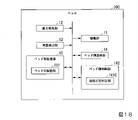
図18は、ベッド10Cの構成を示すブロック図である。
ベッド10Cは、ベッド10が備えるベッド側制御部16に代えて、ベッド側制御部16Cを備える。ベッド側制御部16Cは、接続可否判定部161Cを備える。
接続可否判定部161Cは、端末装置30から通信接続の確立を要求された場合に、その端末装置30と通信接続を確立してよいか否かを判定する。接続可否判定部161Cは、端末装置30と通信接続を確立していない場合には、要求元の端末装置30と通信接続を確立してよいと判定する。また、接続可否判定部161Cは、端末装置30と通信接続を確立している場合には、要求元の端末装置30と、現在通信接続を確立している相手の端末装置30と、の間で、端末ユーザの権限を比較する。権限情報は、例えば通信確立の要求時に、端末装置30から送信されるようにしてよい。接続可否判定部161Cは、より強い権限を有する端末ユーザの端末装置30と、通信接続を確立又は維持する。これにより、接続可否判定部161Cは、制御命令を受け付ける端末装置30を、端末ユーザの権限や通信接続の状況に応じて制限することができる。
Next, the configuration of the
FIG. 18 is a block diagram showing the configuration of the
The
When the
次に、ベッドシステム1Cの動作について説明する。
図19は、ベッドシステム1の動作を示すシーケンスチャートである。
ここでは一例として、ベッド10Cと、端末装置30P、30Nとの間での通信接続の確立に係る処理について、抜粋して説明する。また、ここでは説明を容易にするため場面を特定してあるが、端末装置30Pと、端末装置30Nとは、端末ユーザの権限に応じて適宜置換されてよい。なお、図19に示す処理において、P1の符号は端末装置30Pからの1回目の通信接続要求に係る処理であることを示す。同様にN1の符号は端末装置30Nからの1回目の通信接続要求に係る処理であることを示し、P2の符号は端末装置30Pからの2回目の通信接続要求に係る処理であることを示す。
Next, the operation of the
FIG. 19 is a sequence chart showing the operation of the
Here, as an example, the process related to the establishment of the communication connection between the
また、図19に示す一部処理は、図7に示す処理と同様である。例えばステップS330-P1、S330-N1、S330-P2の処理は、ステップS330の処理と同様である。また、ステップS110-N1、S110-P1の処理は、ステップS110の処理と同様である。また、ステップS380-N1、S380-P1の処理は、ステップS380の処理と同様である。
また、ステップS101-P1、S101-N1、S101-P2は、いずれも同様の処理であるが、一部判定結果が異なる。また、ステップS112-P1、S112-N1は、同様の処理である。また、S382-P1、S382-N1は、同様の処理である。
Further, the partial processing shown in FIG. 19 is the same as the processing shown in FIG. 7. For example, the processing of steps S330-P1, S330-N1, and S330-P2 is the same as the processing of step S330. Further, the processing of steps S110-N1 and S110-P1 is the same as the processing of step S110. Further, the processing of steps S380-N1 and S380-P1 is the same as the processing of step S380.
Further, steps S101-P1, S101-N1 and S101-P2 are all the same processes, but some determination results are different. Further, steps S112-P1 and S112-N1 are the same processes. Further, S382-P1 and S382-N1 are the same processes.
(ステップS330-P1)端末装置30Pは、通信接続の確立をベッド10Cに要求する。その後、ベッドシステム1Cは、ステップS101-P1に処理を進める。
(ステップS101-P1)ベッド10Cは、端末装置30Pからの要求に対して、通信接続の可否を判定する。具体的には、ベッド10Cは、他の端末装置30と通信接続を確立しているか否かを判定する。ここでは、他の端末装置30と通信接続を確立していないため、ベッド10Cは、通信接続の確立が可能と判定する。その後、ベッドシステム1Cは、ステップS110-P1、S380-P1に処理を進める。
(ステップS110-P1、S380-P1)ベッド10Cと端末装置30Pは、通信接続を確立する。その後、ベッドシステム1Cは、ステップS330-N1に処理を進める。
(Step S330-P1) The
(Step S101-P1) The
(Steps S110-P1, S380-P1) The
(ステップS330-N1)端末装置30Nは、通信接続の確立をベッド10Cに要求する。その後、ベッドシステム1Cは、ステップS101-N1に処理を進める。
(ステップS101-N1)ベッド10Cは、端末装置30Pからの要求に対して、通信接続の可否を判定する。ここで、ベッド10Cは、既に端末装置30Pと通信接続を確立しているが、端末装置30Nの方が端末ユーザの権限が強いため、ベッド10Cは、端末装置30Nとの通信接続を確立すると判定する。その後、ベッドシステム1Cは、ステップS112-P1、S382-P1に処理を進める。
(Step S330-N1) The
(Step S101-N1) The
(ステップS112-P1、S382-P1)ベッド10Cと端末装置30Pとは、通信接続を解除する。その後、ベッドシステム1Cは、ステップS110-N1、S380-N1に処理を進める。
(ステップS110-N1、S380-N1)ベッド10Cと端末装置30Pは、通信接続を確立する。その後、ベッドシステム1Cは、ステップS330-P2に処理を進める。
(Steps S112-P1, S382-P1) The
(Steps S110-N1, S380-N1) The
(ステップS330-P2)端末装置30Pは、通信接続の確立をベッド10Cに要求する。その後、ベッドシステム1Cは、ステップS101-P2に処理を進める。
(ステップS101-P2)ベッド10Cは、端末装置30Pからの要求に対して、通信接続の可否を判定する。ここで、ベッド10Cは、既に端末装置30Nと通信接続を確立しているが、端末装置30Nの方が端末ユーザの権限が強いため、ベッド10Cは、端末装置30Pとの通信接続を確立しないと判定する。その後、ベッドシステム1Cは、ステップS102-P2に処理を進める。
(Step S330-P2) The
(Step S101-P2) The
(ステップS102-P2)ベッド10Cは、端末装置30Pに対して通信接続を拒否する旨を通知する。その後、ベッドシステム1Cは、ステップS381-N1に処理を進める。
(ステップS381-N1)端末装置30Nは、端末ユーザから通信接続を解除する操作を受け付ける。通信接続の解除は、このように、明示的に端末ユーザから指示された場合に行われるようにしてもよい。これにより、ベッドシステム1において、端末装置30Nのユーザは、ベッド10Cの制御権の移動を制限することができるため、ベッド10Cの安全性を向上させることができる。その後、ベッドシステム1Cは、ステップS112-N1、S382-N1に処理を進める。
(ステップS112-N1、S382-N1)ベッド10Cと端末装置30Pとは、通信接続を解除する。その後、ベッドシステム1Cは、図19に示す処理を終了する。
(Step S102-P2) The
(Step S381-N1) The
(Steps S112-N1, S382-N1) The
以上説明したように、ベッドシステム1Cにおいて、ベッド10Cは、端末装置30の制御命令を受け付けるか否かを判定する接続可否判定部161C(判定部の一例)を備える。
これにより、ベッドシステム1Cは、ベッド10が制御命令を受け付ける端末装置30を制限する。つまり、ベッド10を制御可能な端末装置30を制限する。そのため、端末装置30が複数存在する場合であっても、複数の端末装置30からの制御命令により、ベッド10が意図しない動作を行ってしまうことがない。よって、ベッドシステム1は操作性を向上させるだけでなく、ベッド10の安全性も向上させることができる。
As described above, in the
As a result, the
[第5の実施形態]
第5の実施形態について説明する。以下では、上述した実施形態と同様の構成については、同一の符号を付し、説明を援用する。
図20は、本実施形態の概要を示す模式図である。
本実施形態に係るベッドシステム1Dは、上述した各実施形態に係るベッドシステム1、1A~1Cと同様に、ベッド10、10Cと端末装置30とを備えるシステムである。ただし、ベッドシステム1Dは、端末装置30によるベッド10、10Cの制御履歴を集積し、解析する履歴解析装置50をさらに備える点が異なる。以下では一例として、ベッドシステム1Dがベッド10を備える場合について説明するが、ベッド10Cを備える場合も同様である。
[Fifth Embodiment]
A fifth embodiment will be described. In the following, the same reference numerals will be given to the same configurations as those of the above-described embodiments, and the description will be incorporated.
FIG. 20 is a schematic diagram showing an outline of the present embodiment.
The
履歴解析装置50は、コンピュータシステムを備える電子機器であり、例えばサーバ装置である。履歴解析装置50は、複数のベッド10や端末装置30から制御履歴を収集してよい。履歴解析装置50は、収集した制御履歴に基づいてベッドの利用状況、端末ユーザの嗜好、ベッドユーザの嗜好等を解析する。例えば履歴解析装置50は、ベッド10、10Cのどの電動アクチュエータが、どの程度利用されているかを解析することができる。また、例えば履歴解析装置50は、各ベッドユーザがどのようなベッド10、10Cを好むかを推定することができる。また、例えば履歴解析装置50は、各端末ユーザがどの操作を好んで行っているかを解析することができる。よって、ベッドシステム1Dは、ベッド10の保守を容易にしたり、ベッド10、10Cをお勧めしたり、操作の制御設定を改善したりすることができる。
The
次に、履歴解析装置50の構成について説明する。
図21は、履歴解析装置50の構成を示すブロック図である。
履歴解析装置50は、解析装置側通信部51と、解析装置側記憶部52と、解析装置側制御部53と、を備える。
解析装置側通信部51は、例えば通信用ICを備え、端末装置30やベッド10、10C等の他の装置と通信する。解析装置側通信部51は、端末装置30やベッド10、10Cから履歴情報を受信する。
Next, the configuration of the
FIG. 21 is a block diagram showing the configuration of the
The
The
解析装置側記憶部52は、例えばHDDやSSD、ROM、RAM等を含み、履歴解析装置50が処理する各種情報やプログラム等を記憶する。なお、履歴情報記憶部521は、履歴解析装置50に内蔵されるものに限らず、外付け型の記憶装置を備えてもよい。解析装置側記憶部52は、履歴情報記憶部521を備える。
The analysis device
履歴情報記憶部521は、解析装置側通信部51が受信した履歴情報を記憶する。履歴情報とは、ベッド10の制御履歴を示す情報である。履歴情報のデータ構成については、後述する。履歴情報を参照することで、履歴解析装置50は、いつ、誰により、誰が利用しているベッド10に対して、どのような操作が入力され、どのような制御が行われた結果、ベッド10がどのような状態になったかを特定することができる。
The history
解析装置側制御部53は、履歴解析装置50の各構成を制御する。解析装置側制御部53は、例えば履歴解析装置50が備える演算装置(例えばCPU)が、解析装置側記憶部52に記憶されたプログラムを実行することにより実現されてよい。また、解析装置側制御部53は、例えばASIC等の集積回路として実現されてもよい。解析装置側制御部53は、解析部531を備える。
The analysis device
解析部531は、履歴情報を解析する。解析部531は、例えばベッドIDごと、端末ユーザIDごと、ベッドユーザIDごとに履歴情報を解析する。
例えば解析部531は、ベッドIDに基づいて履歴情報を抽出する。次に、解析部531は、抽出した履歴情報の制御命令情報を参照し、例えば駆動量、駆動回数等、これまでの電動アクチュエータの駆動実績を演算する。これにより、解析部531は、ベッド10の故障の可能性を解析することができる。この解析結果に基づき、例えば解析部531は、駆動実績が所定の閾値を超える場合には、保守点検が必要である旨を、端末装置30に通知してよい。
The
For example, the
また、例えば解析部531は、端末ユーザIDに基づいて履歴情報を抽出する。次に、解析部531は、抽出した履歴情報の操作ボタン情報を参照し、各操作ボタンの利用回数を演算する。これにより、解析部531は、端末ユーザごとの操作ボタンの嗜好を特定することができる。この解析結果に基づき、例えば解析部531は、頻繁に利用されている操作ボタンが利用しやすい制御用画面を、端末ユーザに提案してよい。
また、例えば解析部531は、ベッドユーザIDに基づいて履歴情報を抽出する。次に、解析部531は抽出した履歴情報の制御結果情報を参照し、ベッドの状態ごとに、その状態を取っていた時間の長さを演算する。これにより、解析部531は、ベッドユーザごとのベッド10の嗜好を特定することができる。この解析結果に基づき、例えば解析部531は、ベッドユーザに他のベッドの利用を提案してもよい。例えばベッド高が低い状態を好むベッドユーザに対しては、高さの低いベッドの利用を提案してもよい。
Further, for example, the
Further, for example, the
次に、履歴情報のデータ構成について説明する。
図22は、履歴情報のデータ構成を示す図である。
図22に示す例において、履歴情報は、日時情報と、端末ユーザIDと、ベッドユーザIDと、ベッドIDと、操作ボタン情報と、制御命令情報と、制御結果情報と、を互いに対応付けた情報である。
日時情報とは、端末装置30が操作を受け付けた日時、又は、ベッド10に制御命令が送信された日時を示す情報である。端末ユーザIDとは、端末装置30の端末ユーザを示すユーザIDである。ベッドユーザIDとは、ベッド10のベッドユーザを示すユーザIDである。操作ボタン情報とは、端末ユーザにより操作された操作ボタンを示す情報である。制御命令情報とは、ベッド10が受け付けた制御命令を示す情報である。制御結果情報とは、端末装置30による制御結果として、ベッド10の状態を示す情報である。
Next, the data structure of the history information will be described.
FIG. 22 is a diagram showing a data structure of history information.
In the example shown in FIG. 22, the history information is information in which date and time information, terminal user ID, bed user ID, bed ID, operation button information, control command information, and control result information are associated with each other. Is.
The date and time information is information indicating the date and time when the
以上説明したように、ベッドシステム1Dは、履歴解析装置50を備える。履歴解析装置50は、入力された制御命令の履歴を記憶する解析装置側記憶部52を備える。
これにより、ベッドシステム1Dは、ベッド10に対する制御内容を追跡可能にする。そのため、例えば、ベッド10の駆動部11に加えられた負荷やベッドユーザごとのベッド10の利用傾向等を解析可能になる。そして、これらの解析結果は、ベッド10の保守やベッドユーザへの提案に利用することができる。
As described above, the
Thereby, the
[変形例]
以上、この発明の実施形態について図面を参照して詳述してきたが、具体的な構成は上述の実施形態に限られるものではなく、この発明の要旨を逸脱しない範囲の設計等も含まれる。例えば、上述の第1~5の実施形態において説明した各構成は、任意に組み合わせることができる。また、例えば、上述の第1~5の実施形態において説明した各構成は、特定の機能を発揮するのに不要である場合には、省略することができる。また、上述の第1~5の実施形態において説明した各構成は、別体の装置に分離して備えることができる。
[Modification example]
Although the embodiments of the present invention have been described in detail with reference to the drawings, the specific configuration is not limited to the above-described embodiments, and includes designs and the like within a range that does not deviate from the gist of the present invention. For example, the configurations described in the first to fifth embodiments described above can be arbitrarily combined. Further, for example, each configuration described in the above-described first to fifth embodiments can be omitted if it is not necessary to exert a specific function. In addition, each of the configurations described in the above-described first to fifth embodiments can be separately provided in a separate device.
なお、上述した実施形態において、ベッド10、10Cの状態や制御命令の内容等が音声により通知されてもよい。例えば緊急停止の警告音を、ベッド10、10Cや端末装置30から出力してもよい。
また、上述した実施形態では、ベッド10、10Cを制御対象とする場合について説明したが、これには限られない。例えば車椅子や保育器等の電動アクチュエータを備える身体支持装置を制御対象としてよい。
また、上述した実施形態では、タッチパネルを介した操作を前提に説明したが、これには限られない。例えばマウス、キーボード等の入力装置を操作入力に用いてもよい。
In the above-described embodiment, the state of the
Further, in the above-described embodiment, the case where the
Further, in the above-described embodiment, the description is based on the premise that the operation is performed via the touch panel, but the present invention is not limited to this. For example, an input device such as a mouse or a keyboard may be used for operation input.
また、上述した実施形態において、端末装置30は、ベッド10、10Cの属性情報を、取得してもよい。ベッド10、10Cの属性情報には、機種、設置場所等が含まれてよい。端末装置30は、これら属性情報に応じて制御用画面の生成時に参照する設定情報を変更してもよい。例えばベッド10、10Cの設置場所に応じて設定情報を変更することにより、例えば病室ごとに異なる制御用画面を表示することができる。
Further, in the above-described embodiment, the
また、上述した実施形態において、ベッド10、10Cは、ベッドユーザの生体情報を取得するセンサを備えてよい。生体情報としては、例えば体動、脈拍、血圧等を取得してよい。また、ベッド10、10Cは、取得した生体情報を、端末装置30に通知してよい。そして、端末装置30は、生体情報に基づいて、ベッド10、10Cに送信する制御命令を制限してもよい。
Further, in the above-described embodiment, the
また、上述した実施形態では、設定情報が端末装置30に記憶される場合について説明したが、これには限られない。設定情報は、例えばネットワーク上のサーバ装置に記憶され、任意の装置から参照可能としてもよい。これにより、1つのユーザIDに応じた設定情報を、任意の端末装置30において利用可能になる。
Further, in the above-described embodiment, the case where the setting information is stored in the
また、上述した実施形態において、端末装置30の機能の一部または全部をサイドレールやボードにおいて実施してもよい。図23は、サイドレールの一例を示す図である。サイドレール60は、結合部61を有し、結合部61をベッド10、10Cの側面に結合(装着)して使用する。サイドレール60の内側(ベッド側)には、端末装置30の入力部31および出力部32が埋め込まれている。また、サイドレール60は、端末機能30の他の機能を内蔵し、ユーザから操作を受け付ける。これにより、ユーザ(患者)はスマートフォン等の独立した端末装置30を保持しなくても、ベッド上でベッド10、10Cに対する操作を行うことができる。
Further, in the above-described embodiment, a part or all of the functions of the
また、上述のベッド10、10C、端末装置30、履歴解析装置50の機能を実現するためのプログラムをコンピュータ読み取り可能な記録媒体に記録して、この記録媒体に記録されたプログラムをコンピュータシステムに読み込ませ、実行することによりベッド10、10C、端末装置30、履歴解析装置50としての処理を行ってもよい。ここで、「記録媒体に記録されたプログラムをコンピュータシステムに読み込ませ、実行する」とは、コンピュータシステムにプログラムをインストールすることを含む。ここでいう「コンピュータシステム」とは、OSや周辺機器等のハードウェアを含むものとする。また、「コンピュータシステム」は、インターネットやWAN、LAN、専用回線等の通信回線を含むネットワークを介して接続された複数のコンピュータ装置を含んでもよい。また、「コンピュータ読み取り可能な記録媒体」とは、フレキシブルディスク、光磁気ディスク、ROM、CD-ROM等の可搬媒体、コンピュータシステムに内蔵されるハードディスク等の記憶装置のことをいう。このように、プログラムを記憶した記録媒体は、CD-ROM等の非一過性の記録媒体であってもよい。また、記録媒体には、当該プログラムを配信するために配信サーバからアクセス可能な内部または外部に設けられた記録媒体も含まれる。配信サーバの記録媒体に記憶されるプログラムのコードは、端末装置で実行可能な形式のプログラムのコードと異なるものでもよい。すなわち、配信サーバからダウンロードされて端末装置で実行可能な形でインストールができるものであれば、配信サーバで記憶される形式は問わない。なお、プログラムを複数に分割し、それぞれ異なるタイミングでダウンロードした後に端末装置で合体される構成や、分割されたプログラムのそれぞれを配信する配信サーバが異なっていてもよい。さらに「コンピュータ読み取り可能な記録媒体」とは、ネットワークを介してプログラムが送信された場合のサーバやクライアントとなるコンピュータシステム内部の揮発性メモリ(RAM)のように、一定時間プログラムを保持しているものも含むものとする。また、上記プログラムは、上述した機能の一部を実現するためのものであってもよい。さらに、上述した機能をコンピュータシステムに既に記録されているプログラムとの組み合わせで実現できるもの、いわゆる差分ファイル(差分プログラム)であってもよい。
Further, a program for realizing the functions of the
また、上述したベッド10、10A、端末装置30、履歴解析装置50の機能の一部または全部を、LSI(Large Scale Integration)等の集積回路として実現してもよい。上述した各機能は個別にプロセッサ化してもよいし、一部、または全部を集積してプロセッサ化してもよい。また、集積回路化の手法はLSIに限らず専用回路、または汎用プロセッサで実現してもよい。また、半導体技術の進歩によりLSIに代替する集積回路化の技術が出現した場合、当該技術による集積回路を用いてもよい。
Further, a part or all of the functions of the
1、1A~1D…ベッドシステム、10、10C…ベッド、21…手元スイッチ、22…コントロールボックス、50…履歴解析装置、11…駆動部、12…高さ検出部、13…角度検出部、14…ベッド側通信部、15…ベッド側記憶部、151…ベッドID記憶部、16…ベッド側制御部、161C…接続可否判定部、31…入力部、32…表示部、33…音声出力部、34…端末側通信部、35…端末側記憶部、351…端末ID記憶部、352…設定情報記憶部、36…端末側制御部、361…ユーザ認証部、362…ベッドID取得部、363…操作受付部、364…設定部、365…出力処理部、51…解析装置側通信部、52…解析装置側記憶部、521…履歴情報記憶部、53…解析装置側制御部、531…解析部、60…サイドレール、61…結合部 1, 1A-1D ... Bed system, 10, 10C ... Bed, 21 ... Hand switch, 22 ... Control box, 50 ... History analysis device, 11 ... Drive unit, 12 ... Height detection unit, 13 ... Angle detection unit, 14 ... Bed side communication unit, 15 ... Bed side storage unit, 151 ... Bed ID storage unit, 16 ... Bed side control unit, 161C ... Connection availability determination unit, 31 ... Input unit, 32 ... Display unit, 33 ... Audio output unit, 34 ... Terminal side communication unit, 35 ... Terminal side storage unit, 351 ... Terminal ID storage unit, 352 ... Setting information storage unit, 36 ... Terminal side control unit, 361 ... User authentication unit, 362 ... Bed ID acquisition unit, 363 ... Operation reception unit, 364 ... Setting unit, 365 ... Output processing unit, 51 ... Analysis device side communication unit, 52 ... Analysis device side storage unit, 521 ... History information storage unit, 53 ... Analysis device side control unit, 513 ... Analysis unit , 60 ... Side rail, 61 ... Joint
Claims (3)
前記ベッドと有線で接続され、前記ベッドの動作を制御する第1端末装置と、
前記第1端末装置とは別の装置であって、前記ベッドと無線接続され、前記ベッドの動作を制御する第2端末装置と、
を備え、
前記第2端末装置は、
前記ベッドの前記複数の動作を制御する複数の操作ボタンを表示可能な表示部を含み、
ユーザの操作に応じて、表示する前記操作ボタンの種類および表示態様を切り替え可能であり、
前記ユーザが前記表示部に表示された前記操作ボタンをタッチすることにより、前記ベッドを動作させ、
前記複数の動作のうちの一つは第1動作であり、
前記複数の動作のうちの他の一つは第2動作であり、
前記複数の操作ボタンのうちの1つは、前記第1動作を制御する第1操作ボタンであり、
前記複数の操作ボタンのうちの他の1つは、前記第2動作を制御する第2操作ボタンであり、
前記第2端末装置は、前記ユーザの操作に基づいて、前記第1操作ボタンおよび前記第2操作ボタンを前記表示部に表示する第1表示形式と、前記第1操作ボタンおよび前記第2操作ボタンのいずれか一方を前記表示部に表示する第2表示形式とを切り替えるベッドシステム。 A bed that can perform multiple movements and
A first terminal device that is connected to the bed by wire and controls the operation of the bed .
A second terminal device that is different from the first terminal device and is wirelessly connected to the bed to control the operation of the bed .
Equipped with
The second terminal device is
A display unit capable of displaying a plurality of operation buttons for controlling the plurality of operations of the bed is included.
The type and display mode of the operation button to be displayed can be switched according to the operation of the user .
When the user touches the operation button displayed on the display unit, the bed is operated .
One of the plurality of operations is the first operation,
The other one of the plurality of operations is the second operation.
One of the plurality of operation buttons is a first operation button that controls the first operation.
The other one of the plurality of operation buttons is a second operation button that controls the second operation.
The second terminal device has a first display format for displaying the first operation button and the second operation button on the display unit, the first operation button, and the second operation button based on the operation of the user. A bed system that switches between a second display format in which one of the above is displayed on the display unit .
前記ベッドと前記第2端末装置が通信を確立したのち、前記ベッドの状態に関する情報を前記ベッドは、前記第2端末装置に送信する、請求項1記載のベッドシステム。 The bed includes a detector capable of detecting the state of the bed .
The bed system according to claim 1, wherein after the bed and the second terminal device establish communication, the bed transmits information regarding the state of the bed to the second terminal device.
前記設定情報は、頭速度情報、高さ速度情報、連動可否情報、頭動作可否情報、足動作可否情報、高さ動作可否情報、及び、離床通知可否情報の少なくとも1つを含む、請求項1または請求項2記載のベッドシステム。
The second terminal device holds the setting information about the bed and holds the setting information.
The setting information includes at least one of head speed information, height speed information, interlocking possibility information, head movement possibility information, foot movement possibility information, height movement possibility information, and bed leaving notification possibility information, claim 1. Or the bed system according to claim 2.
Priority Applications (8)
| Application Number | Priority Date | Filing Date | Title |
|---|---|---|---|
| JP2017165536A JP7049786B2 (en) | 2017-08-30 | 2017-08-30 | Bed system |
| US16/485,269 US11289191B2 (en) | 2017-08-30 | 2018-04-06 | Terminal device and program |
| PCT/JP2018/014709 WO2019044022A1 (en) | 2017-08-30 | 2018-04-06 | Terminal device and program |
| CN202310052514.0A CN116019647A (en) | 2017-08-30 | 2018-04-06 | Terminal device |
| CN201880014408.0A CN110958868B (en) | 2017-08-30 | 2018-04-06 | Body support system |
| JP2022012246A JP7323661B2 (en) | 2017-08-30 | 2022-01-28 | terminal equipment |
| US17/674,179 US11776685B2 (en) | 2017-08-30 | 2022-02-17 | Terminal device and program |
| JP2023122266A JP2023133436A (en) | 2017-08-30 | 2023-07-27 | terminal device |
Applications Claiming Priority (1)
| Application Number | Priority Date | Filing Date | Title |
|---|---|---|---|
| JP2017165536A JP7049786B2 (en) | 2017-08-30 | 2017-08-30 | Bed system |
Related Child Applications (1)
| Application Number | Title | Priority Date | Filing Date |
|---|---|---|---|
| JP2022012246A Division JP7323661B2 (en) | 2017-08-30 | 2022-01-28 | terminal equipment |
Publications (3)
| Publication Number | Publication Date |
|---|---|
| JP2019041842A JP2019041842A (en) | 2019-03-22 |
| JP2019041842A5 JP2019041842A5 (en) | 2020-03-19 |
| JP7049786B2 true JP7049786B2 (en) | 2022-04-07 |
Family
ID=65525300
Family Applications (1)
| Application Number | Title | Priority Date | Filing Date |
|---|---|---|---|
| JP2017165536A Active JP7049786B2 (en) | 2017-08-30 | 2017-08-30 | Bed system |
Country Status (4)
| Country | Link |
|---|---|
| US (2) | US11289191B2 (en) |
| JP (1) | JP7049786B2 (en) |
| CN (2) | CN110958868B (en) |
| WO (1) | WO2019044022A1 (en) |
Families Citing this family (3)
| Publication number | Priority date | Publication date | Assignee | Title |
|---|---|---|---|---|
| JP7323661B2 (en) * | 2017-08-30 | 2023-08-08 | パラマウントベッド株式会社 | terminal equipment |
| JP7049786B2 (en) | 2017-08-30 | 2022-04-07 | パラマウントベッド株式会社 | Bed system |
| TWI803397B (en) * | 2022-07-21 | 2023-05-21 | 施權航 | electric bed |
Citations (7)
| Publication number | Priority date | Publication date | Assignee | Title |
|---|---|---|---|---|
| JP2004141484A (en) | 2002-10-25 | 2004-05-20 | Gac Corp | Remote control system and its control method |
| JP2011162007A (en) | 2010-02-08 | 2011-08-25 | Tokai Rika Co Ltd | Vehicle seat adjusting device |
| JP2013062694A (en) | 2011-09-14 | 2013-04-04 | Aisin Seiki Co Ltd | Seat layout controller and computer program for personal digital assistant |
| JP2016076038A (en) | 2014-10-03 | 2016-05-12 | 株式会社サルカン | Display processing device, display processing program and display processing method |
| JP2016167385A (en) | 2015-03-09 | 2016-09-15 | パナソニックIpマネジメント株式会社 | Portable terminal and equipment control system |
| JP2016193371A (en) | 2016-08-25 | 2016-11-17 | パナソニックIpマネジメント株式会社 | Electric Bed |
| JP2017070352A (en) | 2015-10-05 | 2017-04-13 | 株式会社ミツバ | Movement support device |
Family Cites Families (20)
| Publication number | Priority date | Publication date | Assignee | Title |
|---|---|---|---|---|
| JP3818502B2 (en) * | 2002-03-18 | 2006-09-06 | パラマウントベッド株式会社 | Back knee bottom interlocking control method in bed etc. |
| US8065024B2 (en) * | 2002-03-18 | 2011-11-22 | Paramount Bed Co., Ltd. | Coordinative control system for adjusting the back and knee bottom sections of an adjustable bed |
| US7805784B2 (en) * | 2005-12-19 | 2010-10-05 | Stryker Corporation | Hospital bed |
| US7472439B2 (en) * | 2005-02-23 | 2009-01-06 | Stryker Canadian Management, Inc. | Hospital patient support |
| US8926535B2 (en) * | 2006-09-14 | 2015-01-06 | Martin B. Rawls-Meehan | Adjustable bed position control |
| US10864137B2 (en) * | 2006-09-14 | 2020-12-15 | Ascion, Llc | System and method of an adjustable bed with a vibration motor |
| US8572778B2 (en) * | 2007-03-30 | 2013-11-05 | Hill-Rom Services, Inc. | User interface for hospital bed |
| JP2010191722A (en) * | 2009-02-18 | 2010-09-02 | Kyocera Mita Corp | Computer program |
| JP2011050446A (en) * | 2009-08-31 | 2011-03-17 | Carecom Co Ltd | Electric bed control system |
| JP5640023B2 (en) * | 2012-01-16 | 2014-12-10 | フランスベッド株式会社 | Hand control device for bed equipment |
| JP2014204846A (en) | 2013-04-12 | 2014-10-30 | パラマウントベッド株式会社 | Bed operation device and program |
| KR20160003749A (en) * | 2013-04-25 | 2016-01-11 | 파라마운트 베드 가부시키가이샤 | Bed apparatus and bed apparatus control method |
| CN105208992B (en) * | 2013-05-15 | 2017-11-03 | 八乐梦床业有限公司 | Bed apparatus |
| US9463126B2 (en) * | 2014-03-11 | 2016-10-11 | Hill-Rom Services, Inc. | Caregiver universal remote cart for patient bed control |
| US10420687B2 (en) * | 2015-05-12 | 2019-09-24 | Stryker Corporation | Battery management for patient support apparatuses |
| WO2016204837A1 (en) * | 2015-06-19 | 2016-12-22 | Tempur-Pedic Management, Llc | Adjustable base assemblies, systems and related methods |
| US10905609B2 (en) * | 2015-11-20 | 2021-02-02 | Stryker Corporation | Patient support systems and methods for assisting caregivers with patient care |
| US11020295B2 (en) * | 2015-12-22 | 2021-06-01 | Stryker Corporation | Patient support systems and methods for assisting caregivers with patient care |
| JP6262194B2 (en) | 2015-12-25 | 2018-01-17 | パラマウントベッド株式会社 | Electric bed |
| JP7049786B2 (en) | 2017-08-30 | 2022-04-07 | パラマウントベッド株式会社 | Bed system |
-
2017
- 2017-08-30 JP JP2017165536A patent/JP7049786B2/en active Active
-
2018
- 2018-04-06 US US16/485,269 patent/US11289191B2/en active Active
- 2018-04-06 WO PCT/JP2018/014709 patent/WO2019044022A1/en active Application Filing
- 2018-04-06 CN CN201880014408.0A patent/CN110958868B/en active Active
- 2018-04-06 CN CN202310052514.0A patent/CN116019647A/en active Pending
-
2022
- 2022-02-17 US US17/674,179 patent/US11776685B2/en active Active
Patent Citations (7)
| Publication number | Priority date | Publication date | Assignee | Title |
|---|---|---|---|---|
| JP2004141484A (en) | 2002-10-25 | 2004-05-20 | Gac Corp | Remote control system and its control method |
| JP2011162007A (en) | 2010-02-08 | 2011-08-25 | Tokai Rika Co Ltd | Vehicle seat adjusting device |
| JP2013062694A (en) | 2011-09-14 | 2013-04-04 | Aisin Seiki Co Ltd | Seat layout controller and computer program for personal digital assistant |
| JP2016076038A (en) | 2014-10-03 | 2016-05-12 | 株式会社サルカン | Display processing device, display processing program and display processing method |
| JP2016167385A (en) | 2015-03-09 | 2016-09-15 | パナソニックIpマネジメント株式会社 | Portable terminal and equipment control system |
| JP2017070352A (en) | 2015-10-05 | 2017-04-13 | 株式会社ミツバ | Movement support device |
| JP2016193371A (en) | 2016-08-25 | 2016-11-17 | パナソニックIpマネジメント株式会社 | Electric Bed |
Also Published As
| Publication number | Publication date |
|---|---|
| CN110958868A (en) | 2020-04-03 |
| US11776685B2 (en) | 2023-10-03 |
| US20220172834A1 (en) | 2022-06-02 |
| JP2019041842A (en) | 2019-03-22 |
| US11289191B2 (en) | 2022-03-29 |
| WO2019044022A1 (en) | 2019-03-07 |
| CN116019647A (en) | 2023-04-28 |
| CN110958868B (en) | 2023-02-28 |
| US20190378612A1 (en) | 2019-12-12 |
Similar Documents
| Publication | Publication Date | Title |
|---|---|---|
| US11776685B2 (en) | Terminal device and program | |
| KR101600134B1 (en) | Device controller with connectable touch user interface | |
| JP2007130476A (en) | Apparatus for adjusting bed of operating table | |
| CN103294337A (en) | Electronic apparatus and control method | |
| WO2013099580A1 (en) | Medical endoscope system | |
| US10270961B2 (en) | Information processing apparatus, information processing method, program, and system | |
| US10929083B2 (en) | Resource sharing device and control method thereof | |
| KR101102242B1 (en) | Patient information display device | |
| CN110636812A (en) | Control device, control method and surgical system | |
| WO2014155885A1 (en) | Input device | |
| JP2014109723A (en) | Image processing apparatus, electronic apparatus, control method of image processing apparatus, control method of electronic apparatus, and program | |
| JP7323661B2 (en) | terminal equipment | |
| JP2010017558A (en) | Ultrasonic system and method for providing pictorial keyboard | |
| JP2009176129A (en) | Remote control system | |
| CN102150118B (en) | Touch panel device | |
| JP2014174507A (en) | Augmented reality display device, information terminal, multi display system, and program | |
| WO2013153707A1 (en) | Cursor movement control method, computer program, cursor movement control device and image display system | |
| US20210008709A1 (en) | Control apparatus, control method, and master-slave system | |
| JP6129458B1 (en) | Endoscope processor | |
| JP2018010691A (en) | Display device and display method | |
| JP7130953B2 (en) | Medical image display system and medical image display device | |
| WO2022239109A1 (en) | Host device and input/output system | |
| JP6880869B2 (en) | Image processing system, image processing device and program | |
| EP3744281A1 (en) | Microscope system and method for operating a surgical microscope | |
| JP6246523B2 (en) | KVM switch and KVM system |
Legal Events
| Date | Code | Title | Description |
|---|---|---|---|
| RD01 | Notification of change of attorney |
Free format text: JAPANESE INTERMEDIATE CODE: A7421 Effective date: 20190424 |
|
| A521 | Request for written amendment filed |
Free format text: JAPANESE INTERMEDIATE CODE: A523 Effective date: 20200205 |
|
| A621 | Written request for application examination |
Free format text: JAPANESE INTERMEDIATE CODE: A621 Effective date: 20200205 |
|
| A131 | Notification of reasons for refusal |
Free format text: JAPANESE INTERMEDIATE CODE: A131 Effective date: 20210409 |
|
| A521 | Request for written amendment filed |
Free format text: JAPANESE INTERMEDIATE CODE: A523 Effective date: 20210602 |
|
| A02 | Decision of refusal |
Free format text: JAPANESE INTERMEDIATE CODE: A02 Effective date: 20211029 |
|
| A521 | Request for written amendment filed |
Free format text: JAPANESE INTERMEDIATE CODE: A523 Effective date: 20220128 |
|
| C60 | Trial request (containing other claim documents, opposition documents) |
Free format text: JAPANESE INTERMEDIATE CODE: C60 Effective date: 20220128 |
|
| A911 | Transfer to examiner for re-examination before appeal (zenchi) |
Free format text: JAPANESE INTERMEDIATE CODE: A911 Effective date: 20220204 |
|
| C21 | Notice of transfer of a case for reconsideration by examiners before appeal proceedings |
Free format text: JAPANESE INTERMEDIATE CODE: C21 Effective date: 20220208 |
|
| TRDD | Decision of grant or rejection written | ||
| A01 | Written decision to grant a patent or to grant a registration (utility model) |
Free format text: JAPANESE INTERMEDIATE CODE: A01 Effective date: 20220304 |
|
| A61 | First payment of annual fees (during grant procedure) |
Free format text: JAPANESE INTERMEDIATE CODE: A61 Effective date: 20220328 |
|
| R150 | Certificate of patent or registration of utility model |
Ref document number: 7049786 Country of ref document: JP Free format text: JAPANESE INTERMEDIATE CODE: R150 |