JP7049037B2 - Pachinko machine - Google Patents
Pachinko machine Download PDFInfo
- Publication number
- JP7049037B2 JP7049037B2 JP2020049633A JP2020049633A JP7049037B2 JP 7049037 B2 JP7049037 B2 JP 7049037B2 JP 2020049633 A JP2020049633 A JP 2020049633A JP 2020049633 A JP2020049633 A JP 2020049633A JP 7049037 B2 JP7049037 B2 JP 7049037B2
- Authority
- JP
- Japan
- Prior art keywords
- game
- data
- display
- game medal
- error
- Prior art date
- Legal status (The legal status is an assumption and is not a legal conclusion. Google has not performed a legal analysis and makes no representation as to the accuracy of the status listed.)
- Active
Links
Images


Description
本発明は、遊技媒体を投入し、リールを回転させた後に停止させ、そのときに表示されているリールに描かれた図柄の組合せによって遊技結果を定めるスロットマシンやぱちんこ遊技機等の遊技機に関する。 The present invention relates to a gaming machine such as a slot machine or a pachinko gaming machine, in which a gaming medium is input, a reel is rotated and then stopped, and a gaming result is determined by a combination of symbols drawn on the reel displayed at that time. ..
従来から、遊技機の1つとしてスロットマシン(回胴式遊技機)が知られている。このスロットマシンにおいては、遊技者が遊技メダル等の遊技媒体を投入し、スタートレバーの操作により、図柄が描かれた複数の回胴(リール)を回転させる。その後、遊技者が停止ボタンを操作して各回胴を停止させ、停止した図柄の組合せ(表示結果)によっては、所定数の遊技メダル等の払出しを受けることが可能となっている。また、スロットマシンにおいては、このような基本的な遊技に加えて各種の演出を行うことにより、全体としての趣向性の向上が図られている。
ところで、この種のスロットマシンにおいては、遊技媒体(遊技メダル等)の投入受付、回胴(リール)の回転、演出制御、回胴の停止、遊技メダル等の払出し、といった個々の基本動作が一連の動作として繰り返される。そして、いかなる場合もこれらの動作が適正に行われることが望ましいが、様々な状況が複合して発生した場合には想定外の動作を行ってしまうことも考えられる。したがって、可能な限り多くの複合的な状況を想定し、そのときにどのような動作を行うこととするのかを予め決めておくことが有効である。また、近年は、ゲーム性に工夫を重ね、適度な時間をかけて緩やかに獲得枚数を増やせるようにしたタイプのスロットマシンが知られているが、このようなスロットマシンについても、可能な限り適正化することが望ましい。 By the way, in this type of slot machine, individual basic operations such as acceptance of input of game media (game medals, etc.), rotation of reels, production control, stop of rotation, and withdrawal of game medals, etc. are performed in a series. Is repeated as the operation of. It is desirable that these operations be performed properly in any case, but it is conceivable that unexpected operations may be performed when various situations occur in combination. Therefore, it is effective to assume as many complex situations as possible and decide in advance what kind of operation should be performed at that time. Also, in recent years, there have been known types of slot machines that have been devised in terms of gameplay so that the number of acquired cards can be gradually increased over a reasonable period of time. Such slot machines are also as appropriate as possible. It is desirable to make it.
本発明はこうした課題に鑑みてなされたものであり、その目的とするところは、より最適化された機能を有する遊技機を提供することにある。 The present invention has been made in view of these problems, and an object of the present invention is to provide a gaming machine having more optimized functions.
上記課題を解決するために本発明は、複数のリールと、
スタートレバーと、
複数のストップボタンと、を備え、
所定の賭け数に応じた役抽せんが実行可能であり、
前記所定の賭け数には、第1賭け数(2枚など)と、当該第1賭け数よりも多い第2賭け数(3枚など)と、が含まれ、
前記第1賭け数が設定された第1賭け数遊技(2枚賭け遊技など)が実行可能であり、
前記第2賭け数が設定された第2賭け数遊技(3枚賭け遊技など)が実行可能であり、
前記第1賭け数遊技での役抽せんで第1特定役に当せんして、当該第1賭け数遊技で前記第1特定役に係る所定図柄組み合わせの停止表示がなかったときの次の遊技では、第1内部当せん状態での遊技(「2枚賭けBB内部中」の遊技など)が実行可能となり、
前記第2賭け数遊技での役抽せんで第2特定役に当せんして、当該第2賭け数遊技で前記第2特定役に係る特定図柄組み合わせの停止表示がなかったときの次の遊技では、第2内部当せん状態での遊技(「3枚賭けBB内部中」の遊技など)が実行可能となり、
前記第1特定役に係る所定図柄組み合わせの停止表示があると第1ボーナス状態での遊技(「2枚賭けBB中」の遊技など)が実行可能となり、
前記第2特定役に係る特定図柄組み合わせの停止表示があると第2ボーナス状態での遊技(「3枚賭けBB中」の遊技など)が実行可能となり、
前記第1内部当せん状態、前記第1ボーナス状態、前記第2内部当せん状態、及び、前記第2ボーナス状態のいずれとも異なる所定の遊技状態(「非内部中」など)での遊技が実行可能であり、
前記第1内部当せん状態において設定変更した場合であっても前記第1内部当せん状態を維持可能であり、
前記第2ボーナス状態における前記第2賭け数遊技での所定特典の付与率<前記所定の遊技状態における前記第2賭け数遊技での所定特典の付与率となっており、
前記第2ボーナス状態における前記第2賭け数遊技での所定特典の付与率<前記第2内部当せん状態における前記第2賭け数遊技での所定特典の付与率となっており、
前記第1内部当せん状態における前記第1賭け数が設定されて実行された前記第1賭け数遊技での表示画面に表示されている演出表示は、前記第1内部当せん状態における前記第2賭け数が設定されて実行された前記第2賭け数遊技での表示画面に表示されている演出表示よりも薄暗くなっており、
前記第1ボーナス状態における前記第2賭け数が設定されて実行された前記第2賭け数遊技での表示画面に表示されている演出表示も薄暗くなっているが、前記第1ボーナス状態の終了条件に関する情報は薄暗くなっていない
ことを特徴とする遊技機である。
In order to solve the above problems, the present invention has a plurality of reels and
With the start lever,
With multiple stop buttons,
It is possible to execute a lottery according to a predetermined number of bets,
The predetermined number of bets includes a first bet number (such as two) and a second bet number (such as three) that is larger than the first bet number.
The first bet number game (two-card bet game, etc.) in which the first bet number is set can be executed.
The second bet number game (three-card bet game, etc.) in which the second bet number is set can be executed.
In the next game when the first specific combination is won in the combination lottery in the first bet number game and there is no stop display of the predetermined symbol combination related to the first bet number game in the first bet number game. A game in the first internal winning state (such as a game of "two bets inside BB") can be executed.
In the next game when the second specific combination is won in the combination lottery in the second bet number game and there is no stop display of the specific symbol combination related to the second bet number game in the second bet number game. A game in the second internal winning state (such as a game of "3 bets inside BB") can be executed.
If there is a stop display of the predetermined symbol combination related to the first specific combination, the game in the first bonus state (such as the game of "during two bets BB") can be executed.
If there is a stop display of the specific symbol combination related to the second specific combination, the game in the second bonus state (such as the game of "during 3 bets BB") can be executed.
It is possible to execute a game in a predetermined gaming state (such as "non-internal middle") different from any of the first internal winning state, the first bonus state, the second internal winning state, and the second bonus state. can be,
Even when the setting is changed in the first internal winning state, the first internal winning state can be maintained.
The grant rate of the predetermined privilege in the second bet number game in the second bonus state <the grant rate of the predetermined privilege in the second bet number game in the predetermined game state.
The grant rate of the predetermined privilege in the second bet number game in the second bonus state <the grant rate of the predetermined privilege in the second bet number game in the second internal winning state.
The effect display displayed on the display screen in the first bet number game in which the first bet number is set and executed in the first internal winning state is the second betting number in the first internal winning state. Is set and executed, and it is dimr than the effect display displayed on the display screen in the second bet number game.
The effect display displayed on the display screen in the second bet number game in which the second bet number is set and executed in the first bonus state is also dim, but the end condition of the first bonus state is also dim. Information about is not dim
It is a gaming machine characterized by this.
本発明によれば、より最適化された機能を有する遊技機を提供できる。 According to the present invention, it is possible to provide a gaming machine having more optimized functions.
<本実施例に係るスロットマシンの概要> <Outline of the slot machine according to this embodiment>
以下、図面を参照しながら、本発明の実施例に係るスロットマシンについて説明する。図1は、本実施例に係るスロットマシン10の外観を正面から示している。スロットマシン10は、図1~図3に示す前面ドア部11と、図4に示す筐体部12とを、前面ドア部11を前にして前後に組み合わせて構成されている。そして、前面ドア部11は、ヒンジ装置を介して筐体部12により支持され、筐体部12に対して閉じた状態で施錠が可能となっている。
Hereinafter, the slot machine according to the embodiment of the present invention will be described with reference to the drawings. FIG. 1 shows the appearance of the
前面ドア部11の表側(正面側)には、図1中に示すように、上下方向の中段に操作部14が配置され、この操作部14の上部に回胴表示部15が配置されている。さらに、前面ドア部11の下部には、矩形に開口した遊技メダル払出口16、及び、遊技メダル払出口16から放出された遊技メダルを受け入れる受け皿17が配置されており、更に回胴表示部15の上方には演出部18が配置されている。また、操作部14の下方には、機種に固有の名称やデザイン画などが描かれた透光性の下部パネル19が設けられている。
On the front side (front side) of the
これらのうち操作部14には、遊技メダル投入口21、遊技メダル返却ボタン22、錠前部23(施錠部ともいう)、停止ボタン部(ストップボタン部)24、スタートレバー25などが設けられている。さらに、操作部14の上部には、メイン入力部26とサブ入力部27が設けられており、メイン入力部26には、清算ボタン74、1枚投入ボタン(所謂1BETボタン)75、3枚投入ボタン(所謂MAXBET(マックスベット)ボタン)76が設けられている。さらに、サブ入力部27には、十字キー77や、サブ入力スイッチ78などが設けられている。
Of these, the
遊技メダル投入口21は、遊技媒体としての遊技メダルを、ガイドを介して投入するためのものであり、遊技メダル返却ボタン22は、遊技メダルセレクター(後述する)に滞留した遊技メダルを返却させるときに使用されるものである。また、錠前部23は、前面ドア部11の開錠の際に所定の鍵を挿し込んで使用されるものであり、停止ボタン部24は、後述する3つの回胴(第1回胴51L、第2回胴51C、第3回胴51R)の回転を停止させるときに使用されるものである。
The game
停止ボタン部24には、3つの停止ボタン(3つのストップボタンである第1停止ボタン24L、第2停止ボタン24C、第3停止ボタン24R)が設けられている。これらの停止ボタン24L、24C、24Rは、各回胴51L、51C、51Rに対応付けられており、停止ボタン24L、24C、24Rを個々に押圧操作することで、対応する回胴51L、51C、51Rが停止するようになっている。なお、本実施例では、第1回胴51L~第3回胴51Rの並びは、スロットマシン10の正面から見て左から第1回胴51L、第2回胴51C、第3回胴51Rの順となっており、停止ボタン24L、24C、24Rの並びも左から第1停止ボタン24L、第2停止ボタン24C、第3停止ボタン24Rの順になっている。また、スタートレバー25は、回胴の回転及び設定値の確定(後述する)を行うときにも使用される。
The
メイン入力部26における清算ボタン74は、投入された遊技メダルの払戻し及び貯留装置(後述する)に貯留されている遊技メダルを清算するときに使用される。1枚投入ボタン75は、貯留されている遊技メダルを1枚ずつ投入するときに使用され、3枚投入ボタン76は、貯留されている遊技メダルの枚数及び投入に係る規定数(後述する)を超えない範囲で、貯留されている遊技メダルを最大3枚投入するときに使用される。サブ入力部27におけるサブ入力スイッチ78は、演出に係る操作を行うためのものであり、演出部18に設けられた液晶画面などの表示内容の切り替えや、演出に係る入力のために使用される。
The
さらに、操作部14には、図示は省略するが、LEDの発光の有無や、7セグメント(7セグ)表示器の表示態様などによって遊技内容を示す各種の表示部が設けられている。この遊技の状況を示す各種の表示部としては、獲得枚数表示部、貯留枚数表示部、再遊技表示部、投入表示部、打止表示部、遊技開始表示部、投入枚数表示部などがある。これらの各種の表示部の近傍には、各表示部がどのような情報の表示機能を担ったものかが判るよう、文字の印刷などが行われている。さらに、これらの表示部のうち、獲得枚数表示部及び貯留枚数表示部は、7セグ表示器を用いて数字や文字等を表示する機能を有するものであり、その他の表示部はLEDの点灯の有無や点灯の態様により所定の情報を表示するものである。そして、各表示部に光源として用いられているLEDについて、以下では、獲得枚数表示LED、貯留枚数表示LED、再遊技表示LED、投入表示LED、打止表示LED、遊技開始表示LED、投入枚数表示LEDと称する場合がある。
Further, although not shown, the
また、各種の表示部のうち、獲得枚数表示部は、状況に応じて、獲得枚数に応じた遊技メダルの枚数の表示、設定の切り替え時の表示、及びエラーコードの表示の何れかの用途に用いられる。貯留枚数表示部は、貯留装置に貯留されている遊技メダルの枚数を表示するものであり、再遊技表示部は、再遊技の作動の有無を表示するものである。さらに、投入表示部は、遊技メダルの投入受付けが可能である旨の表示を行い、打止表示部は、貯留されている遊技メダルの清算時である旨の表示を行う。遊技開始表示部は、遊技の開始が可能な状態において、スタートレバー25の操作受付が可能である旨の表示を行う。さらに、投入枚数表示部は、投入された遊技メダルの枚数の表示を行い、再遊技作動時には、前回遊技と同数の遊技メダル枚数を表示する。
In addition, among various display units, the acquired number display unit is used for any of the purposes of displaying the number of game medals according to the acquired number, displaying when switching settings, and displaying an error code, depending on the situation. Used. The stored number display unit displays the number of game medals stored in the storage device, and the re-game display unit displays whether or not the re-game is activated. Further, the insertion display unit displays that the game medals can be inserted and accepted, and the stop display unit displays that the stored game medals are being settled. The game start display unit displays that the operation of the
前述の停止ボタン部24には、第1停止ボタン24L、第2停止ボタン24C、第3停止ボタン24Rの3つの停止ボタンが設けられている。また、回胴表示部15には、矩形に開口した表示窓を透明パネルで塞いだ回胴表示パネル28が備えられており、この回胴表示パネル28を透して、図2及び図4中に示すように、筐体部12に収納された第1回胴51L~第3回胴51Rの3つの回胴(リール)を視認できるようになっている。また、演出部18には、液晶表示装置などが設けられており、遊技に伴う演出などの表示が演出部18で行われる。ここで、本実施例では、回胴表示パネル28も表示装置の機能を備えたものとなっており、演出部18と同様に各種の動画表示を行うことが可能である。なお、これに限らず、例えば、演出部18と回胴表示パネル28とを連続した画面を有する一つの演出表示装置として形成することも可能である。
The above-mentioned
また、前面ドア部11には、演出に用いられる各種の光源(LED)が設けられている。これらの演出用の光源としては、図示は省略するが、3枚投入表示LED、停止ボタンLED、サブ入力表示LEDなどを挙げることができる。これらのうち、3枚投入表示LEDは、前述のメイン入力部26に配置された3枚投入ボタン76を内側から照らすものであり、3枚投入ボタン76を用いた演出内容の表示に利用される。また、停止ボタンLEDは、停止ボタン24L、24C、24Rを内側から照らすものであり、停止ボタン24L、24C、24Rを用いた演出内容の表示に利用される。さらに、サブ入力表示LEDは、前述のサブ入力部27に配置されたサブ入力スイッチ78を内側から照らすものであり、サブ入力スイッチ78を用いた演出内容の表示に利用される。
Further, the
これら以外にも、演出用の光源としては、図示略は省略するが、回胴上部LED、回胴下部LED、サイドLED、チャンスLED、左ウイングLED、左下サークルLED、右ウイングLED、右下サークルLED、左上サークルLED、上部LED、右上サークルLED、ARランプLED、下部パネル照明LED、左ミニLED、右ミニLED、V字LEDなどがある。何れの光源も、その配置や機能に応じて、演出内容の表示に用いられるものである。 In addition to these, as the light source for the production, although not shown, the upper part LED, the lower part LED, the side LED, the chance LED, the left wing LED, the lower left circle LED, the right wing LED, and the lower right circle There are LEDs, upper left circle LEDs, upper LEDs, upper right circle LEDs, AR lamp LEDs, lower panel lighting LEDs, left mini LEDs, right mini LEDs, V-shaped LEDs, and the like. Each light source is used to display the content of the effect according to its arrangement and function.
図3は、前面ドア部11の背面側を示している。前面ドア部11の背面側には、各種基板、遊技メダルを取扱う機器、各種センサ等が配置されている。これらのうち、各種基板としては、サブ制御基板31、画像制御基板32、画像表示接続基板33、音声基板34、演出ロム(ROM)基板35、スイッチセンサ基板36、表示基板37、ドア中継端子板38、回胴照明基板39、及び下パネル照明基板40などが設けられている。
FIG. 3 shows the back side of the
これらのうち、サブ制御基板31は、演出用の画像、各種ソレノイド、各種LED及び効果音を制御するための基板である。そして、サブ制御基板31は、専用基板ケースに収納され、当該基板ケースを前面ドア部11にねじ止めすることにより、前面ドア部11に装着されている。
Of these, the
画像制御基板32は、後述する音声基板34及び演出ロム基板35を搭載し、サブ制御基板31と画像表示接続基板33との間を中継し、演出用の画像及び効果音を制御するための基板である。そして、画像制御基板32は、専用基板ケースに収納され、当該基板ケースを前面ドア部11にねじ止めすることにより、前面ドア部11に装着されている。
The
画像表示接続基板33は、画像制御基板32と演出部18の液晶表示器との間を中継している基板であり、前面ドア部11に設けられたねじ穴にねじ止めして固定されている。音声基板34は、演出用の音声データが保存されたロムを取り付けた基板であり、画像制御基板32に設けられたねじ穴にねじ止めして固定されている。演出ロム基板35は、演出用の画像データが保存されたロムを取り付けた基板であり、画像制御基板32に設けられたねじ穴にねじ止めして固定されている。尚、各種ロムは、搭載される基板に設けられたソケットにロムに設けられたピンを指し込むことで固定するようにしても良い。さらに、各種基板はねじ止め固定されるだけでなく、各種基板に設けられたコネクタを、相手方のドア、ケース、基板等に設けられたコネクタに嵌め合わせることで固定するようにしても良い。このような基板の固定手法は、以下に説明する各種の基板についても同様に採用が可能なものである。また、画像制御接続基板は必ずしも設ける必要はなく、画像制御基板32を演出部18に直接接続して搭載しても良い。
The image display connection board 33 is a board that relays between the
スイッチセンサ基板36は、サブ制御基板31と、後述する2つのソレノイド(第1ソレノイド、第2ソレノイド)との間を中継し、LEDによる演出内容を表示、又は液晶画面の切り替え及び入力をするための基板である。そして、スイッチセンサ基板36は、専用基板ケースに設けたねじ穴にねじ止めして固定されている。
The
表示基板37は、前述の獲得枚数表示LED、貯留枚数表示LED、再遊技表示LED、投入表示LED、打止表示LED、遊技開始表示LED及び投入枚数表示LEDを取り付けた基板であり、前面ドア部11に設けられたフックにはめ込んで固定されている。ドア中継端子板38は、主制御基板(後述する)と、前面ドア部11の各所に配置された各種センサ、ブロッカ47(後述する)及び表示基板37との間を中継している基板である。そして、ドア中継端子板38は、専用基板ケースに収納し、当該基板ケースを前面ドア部11にねじ止めすることにより、前面ドア部11に装着されている
The
回胴照明基板39は、第1回胴51L~第3回胴51Rを照らすためのLEDを取り付けた基板であり、前面ドア部11に設けられたフックにはめ込んで固定されている。下パネル照明基板40は、下部パネル19を照らすためのLEDを取り付けた上下2分割構造の基板であり、前面ドア部11に設けられたフックにはめ込んで固定されている。下パネル照明基板40は、下部パネルを照らすためにLEDを取り付けた基板であり、前面ドア部11に設けられたフックにはめ込んで固定されている。
The rotating
続いて、前面ドア部11に設けられた各種センサ等の機器としては、スタートレバーセンサ41、3枚投入ボタンセンサ42、1枚投入/清算ボタンスイッチ43、遊技メダルセレクター44、投入センサ45、セレクタ通路センサ46、ブロッカ47、遊技メダル返却通路48、停止ボタンセンサ49、スピーカ50などがある。このうちスタートレバーセンサ41は、スタートレバー25の操作を検知するためのものであり、3枚投入ボタンセンサ42は、3枚投入ボタン76の操作を検知するためのものである。
Next, as devices such as various sensors provided on the
また、1枚投入/清算ボタンスイッチ43は、1枚投入ボタン及び清算ボタンスイッチを搭載した装置である。遊技メダルセレクター44は、後述する投入センサ45、セレクタ通路センサ46及びブロッカ47を取り付けた装置であり、また、投入された遊技メダルが受付可能範囲のものか否かの選別を行う装置でもある。上述の投入センサ45は、遊技メダルの投入を検知するためのセンサであり、セレクタ通路センサ46は遊技メダルの通過を検知するためのセンサである。さらに、ブロッカ47は、遊技状態に応じ遊技メダルを返却するための装置であり、遊技メダル返却通路48は、遊技メダルが返却されるときの通路となるものである。そして、停止ボタンセンサ49は、停止ボタン24L~24Rの操作を検知するためのセンサであり、スピーカ50は効果音を出力ために複数設けられているものである。
Further, the one-sheet insertion /
また、図示は省略するが、前面ドア部11には、ソレノイド1及びソレノイド2、十字キー基板が設けられている。このうち、ソレノイド1及びソレノイド2は、サブ入力スイッチ78を振動させるための装置である。また、十字キー基板は、液晶画面の切り替え及び入力をするための基板であり、専用基板ケースに基板を収納し、当該専用ケースをねじ止めして固定されている。
Although not shown, the
図4は、筐体部12の正面側を示している。筐体部12には、主制御基板61、設定ユニット62、遊技メダル払出装置(ホッパ)63、電源ユニット64等が配置されている。これらのうち、主制御基板61は、スロットマシン10に対する入出力を総括して遊技を司る制御を行うとともに、符号は省略するが、後述する打止スイッチ、設定表示LED及びモニタLED等を取り付けた基板である。この主制御基板61は、専用基板ケースである主基板ケース65に基板を収納し、当該主基板ケース65を専用止め具で固定して、筐体部12に装着している。設定表示LED66は、理論上の当り易さ(遊技者の有利度合い)を規定する設定値を表示するものである。打止スイッチは、上側又は下側の何れかに設定して打ち止め機能及び自動清算機能のいずれかを選択するものであるが、本実施例では打ち止め機能及び自動清算機能を搭載していないため、この打止スイッチは使用されていない。したがって、打止スイッチが遊技の結果に影響を与えることはない。なお、主基板ケース65にはICタグ封印シール(図示略)が貼付されており、このICタグ封印シールは、内部にICタグが埋め込まれた封印紙である。
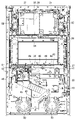
FIG. 4 shows the front side of the
また、筐体部12には、ドアスイッチ60が設けられており、このドアスイッチ60は、前面ドア部11の開閉を検知するためのスイッチである。また、前述の設定ユニット62は、後述する設定ドアスイッチ67、設定キースイッチ68及び設定/リセットボタン69(「/」は「又は」の意味)を収納した箱である。これらのうち、設定ドアスイッチ67は、設定ユニット62の筐体の一部を構成し設定ユニット62を閉じる設定ドアについて、その開閉を検知するためのスイッチである。設定キースイッチ68は、スロットマシンにおける設定の切り替え及び設定の確認を行うためのスイッチであり、設定/リセットボタン69は、前述の設定値の選択又はエラーの解除を行うためのボタンである。尚、設定ドアスイッチ67は必ずしも設ける必要はない。また、本実施例では設定ボタンとリセットボタンを兼用した設定/リセットボタン69を用いているが、それぞれ別で設けても良い。さらにまた、前述の錠前部23に設定及びリセットの機能をもたせ、例えば、錠前部23に挿し込んだ鍵を右方向に回転させた場合に施錠を解除し、左方向に回転させた場合には設定/リセットスイッチとして機能するようにしても良い。また、図4中に示す設定キースイッチ68及び設定/リセットボタン69のうちのいずれか一方を、設定ユニット62から分離して設けても良い。このようなものとしては、例えば、設定キースイッチ68を備えた設定キーシリンダ(図示略)を電源ユニット64に設け、設定/リセットボタン69を設定ユニット62に設けたものなどを例示できる。
Further, the
さらに、筐体部12には、外部集中端子板70が設けられており、この外部集中端子板70は、メダル投入信号出力、メダル払出信号出力、外部信号出力1~外部信号出力5を外部に出力するとともに、モニタLED(7個)が取り付けられた基板である。そして、この外部集中端子板70は、筐体部12に設けたフックにはめ込んで、筐体部12に固定されている。
Further, the
前述の遊技メダル払出装置63には、払出センサ(図示略。「払出センサ」と称する場合もある。)が備えられており、この払出センサは、払い出された遊技メダルを検知するためのセンサである。
The game
さらに、筐体部12には、遊技メダル補助収納庫71が設けられており、この遊技メダル補助収納庫71は、遊技メダル払出装置63の貯留容量を超えた遊技メダルを収納するための収納庫である。遊技メダル補助収納庫71には、満杯検知電極(図示略)が備えられており、この満杯検知電極は、遊技メダル補助収納庫の満杯状態を検知するための電極である。
Further, the
前述の電源ユニット64は、電源スイッチ72を収納した箱であり、電源スイッチ72は、主電源のON・OFFを行うためのスイッチである。そして、この電源スイッチ72をOFFからONすることにより、電源ユニット64を介して、制御基板等を含む各種機器に所定の電力が供給される。
The
また、筐体部12には、前述の第1回胴51L~第3回胴51Rが設けられている。この回胴51L~51Rは、外周面に描かれた図柄を回転させるための装置である。各回胴51L~51Rの内側には、回胴センサ(図示略)が設けられており、この回胴センサは回転中の回胴の基準位置を、回胴に設けられインデックスとなる部分(以下ではこの部分を「インデックス」と称する場合がある)に基づいて検知するためのセンサである。
Further, the
さらに、筐体部12には、図示は省略するが、BL(バックライト)中継基板、回胴装置基板、バックライトLED、LEDバックライト基板等が設けられている。これらのうち、BL中継基板は、サブ制御基板31と後述するLEDバックライト基板や回胴センサ等との間を中継している基板である。このBL中継基板は、専用基板ケースに基板を収納し、当該基板ケースを専用止め具で固定することで、筐体部12に装着されている。
Further, although not shown, the
また、回胴装置基板は、各回胴51L~51Rを回転又は停止させるために、主制御基板61と回胴ステッピングモータ(後述する)及び回胴センサとの間を中継している基板であるとともに、また、主制御基板61と前述の満杯検知電極、ドアスイッチ60、遊技メダル払出装置63、外部集中端子板70及び電源ユニット64との間を中継している基板でもある。この回胴装置基板は、専用基板ケースに基板を収納し、当該基板ケースを専用止め具で固定することで、筐体部12に装着されている。バックライトLEDは、各回胴51L~51Rの内側に配置され、回胴51L~51R上の図柄を背面から照らすためのLEDである。LEDバックライト基板は、上述バックライトLEDを搭載した基板である。
<各種制御基板の電気的基本構成>
Further, the rotating cylinder device substrate is a substrate that relays between the
<Electrical basic configuration of various control boards>
次に、前述した主制御基板61、サブ制御基板31、画像制御基板32の電気的な基本構成について説明する。図5(a)に示すように、主制御基板61には、遊技の進行に係る制御を行うメインCPU81、メインCPU81の遊技制御に用いられるプログラム(遊技制御プログラム)や各種のデータが記憶されたメインROM82、遊技の進行に係る制御のためのデータ等を一時的に記憶する読み書き可能なRWM83、及び、インタフェース部(図示略)等といった種々の電子部品が備えられている。なお、本実施例では、遊技制御プログラムとして、大きく分けて、第1制御プログラムと第2制御プログラムの2つの制御プログラムが備えられている。そして、第1制御プログラムに基づき実行される制御を第1制御と称し、第2制御プログラムに基づき実行される制御を第2制御と称することができる。また、第1制御を「遊技の用に供する制御」と称し、第2制御を「遊技の用に供さない制御」などと称することも可能であるが、これらの詳細については後述する。
Next, the electrical basic configuration of the
また、サブ制御基板31には、主制御基板61からのコマンドに基づき演出用の制御を行うサブメインCPU86、サブメインCPU86の演出制御に用いられるプログラム(演出制御プログラム)や各種のデータが記憶されたサブメインROM87、演出制御のためのデータ等を一時的に記憶する読み書き可能なRWM88、及び、インタフェース部(図示略)等といった種々の電子部品が備えられている。そして、サブ制御基板31は、主制御基板61から送信されるコマンド(メインコマンド)を受信し、このメインコマンドに基づく制御を行う。そして、サブ制御基板31は、画像表示や音声(サウンド)出力のためコマンド(サブメインコマンド)を、画像制御基板32に送信する。
Further, the
画像制御基板32には、サブ制御基板31からのサブメインコマンドに基づき画像制御を行うサブサブCPU91、サブサブCPU91の画像制御に用いられるプログラム(画像制御プログラム)や各種のデータが記憶された演出ROM92、サブサブCPU91からのコマンドに基づき、キャラクタROM93に記憶された画像データを用いて画像表示を制御するVDP94、音声ROM95に記憶された音声データを用いて音声出力を制御する音声チップ96、画像表示や音声出力のためのデータ等を一時的に記憶する読み書き可能なRWM97、及び、インタフェース部(図示略)等といった種々の電子部品が備えられている。ここで、演出ROM92は前述の演出ロム基板35に搭載されており、音声ROM95は前述の音声基板34に搭載されている。但しこの態様に限られるものではなく、サブ制御基板31で画像制御基板32の一部の機能、及び、全ての機能を補っても良い。例えば、サブ制御基板31に音声ROM95を備え、画像制御基板32を介することなく音声データの選択や出力制御を行っても良いし、サブ制御基板31がキャラクタROM93、VDP94を備えていても良い。なお、主制御基板61、サブ制御基板31、及び、画像制御基板32のより具体的な動作については後述する。
<<主制御基板に係る部品構成>>
The
<< Parts configuration related to the main control board >>
続いて、前述の主制御基板61の部品構成の概要について説明する。主制御基板61は、プリント配線を有する矩形板状の配線基板であり、本実施例では、複数層(ここでは2層)構造のものが用いられている。さらに、主制御基板61の所定の部位には、リードタイプの電子部品を実装するためのスルーホールが設けられており、このスルーホールにリードを差し込んだ状態でフロー式等のはんだ付けを行うことで、リードタイプの電子備品が、主制御基板61に実装される。また、主制御基板61には、リードタイプの電子部品のみでなく、表面実装タイプの電子部品等も実装が可能となっている。
Subsequently, an outline of the component configuration of the
図5(b)は、主制御基板61の表面側である実装面を概略的に示している。主制御基板61には、リードタイプのパッケージ化デバイスであるメインCPU81が装着されている。このメインCPU81の装着は、主制御基板61にはんだ付けされたリードタイプのソケットに、メインCPU81のリードを差し込んで嵌合させることにより行われている。さらに、主制御基板61上には、一部を図示するように、各種の電子部品181や各種コネクタ182がはんだ付けされている。
FIG. 5B schematically shows a mounting surface on the surface side of the
このうち、各種コネクタ182は、主制御基板61の周縁部(外縁部)に沿って配置されており、前述の主基板ケース65から、接続口を外部に露出させている。そして、各種コネクタ182には、例えば、前述のサブ制御基板31、回胴装置基板、各種LED基板等といった外部機器に係る基板からのハーネスに設けられたコネクタが嵌着され、主制御基板61と、各種外部機器との電気的な接続に用いられる。
Of these, the
また、図5(b)中に符号183で示すのは、コネクタが設けられていない非搭載領域である。この非搭載領域183は、製品開発の段階において試験機接続用である非常設コネクタの実装のために確保されていた領域であり、本実施例に係るスロットマシン10の、開発段階から製品化への移行にあたり、非常設コネクタが除去された領域である。そして、非搭載領域183においては、主制御基板61の板面が露出しており、非常設コネクタのリードを挿入するための複数のスルーホール184を目視することが可能となっている。また、非常設コネクタの搭載位置は、前述のように主制御基板61の周縁部であるため、この非搭載領域183も、メインCPU81よりも基板外側にあたる基板周縁部に位置している。なお、図5(b)では、図面が煩雑になるのを避けるため、非常設コネクタの一部のスルーホールのみを示している。
Further, what is indicated by
非常設コネクタは、主制御基板61に、開発段階の、特に公的な認可を受ける段階で用いられる性能試験機(図示略)を接続するために用いられるものである。より具体的には、非常設コネクタに、試験用中継基板(図示略)が接続され、この試験用中継基板に、性能試験機が接続される。そして、性能試験機には、試験用中継基板を経由して取り出された試験用データ信号が入力され、性能試験機は、入力された試験用データ信号に基づいて、スロットマシン10の性能データを取得する。
The emergency connector is used to connect a performance tester (not shown) used in the development stage, particularly in the stage of receiving official approval, to the
試験用中継基板は、製品化の段階では利用されないものであり、製品化されたスロットマシン10には備えられていない。また、試験用データ信号の出力にあたり、試験用駆動回路(試験用ドライバ)が用いられるが、この試験用ドライバは試験用中継基板に搭載されており、製品化されたスロットマシン10においては、試験用ドライバを搭載する領域は、主制御基板61には設けられていない。さらに、非常設コネクタの形状、各部寸法、ピン数、及び、色といった構成要素は、他の各種のコネクタ182の何れとも異なっており、他のコネクタに接続される相手側コネクタとの構造上の接続が不可能となっている。
The test relay board is not used at the stage of commercialization, and is not provided in the commercialized
これに対し、製品化段階においては、性能試験機が接続されることがないため、主制御基板61の製造時には、非常設コネクタは搭載されない。しかし、非常設コネクタを搭載しないことに合わせて、主制御基板61のプリント配線や、遊技機制御プログラムに変更を加えたのでは、製品化されたスロットマシン10と、試験時のスロットマシンとの条件を一致させることができない。また、条件を変更しないように、製品化されたスロットマシン10に非常設コネクタをも残したのでは、不正のための機器に非常設コネクタと嵌合可能なコネクタが使用されて、不正が容易になってしまうことも考えられる。
On the other hand, in the commercialization stage, the performance tester is not connected, so that the emergency connector is not mounted at the time of manufacturing the
このため、非常設コネクタを削除して不正対策を施すとともに、条件の変化を最小限に抑えるために、非常設コネクタのためのプリント配線は、非常設コネクタ搭載時と同じ形態で残されている。また、非常設コネクタのためのスルーホール184には、はんだが供給されており、はんだによって、非常設コネクタのためのスルーホール184は、全長に亘り塞がれている。スルーホール184をはんだにより塞ぐことにより、スルーホール184を利用するような不正行為を防止することができる。また、はんだにより、非常設コネクタ用の配線を、他の配線(例えば接地用配線など)と導通させることが可能である。
For this reason, in order to remove the emergency connector and take measures against fraud and to minimize the change in conditions, the printed wiring for the emergency connector is left in the same form as when the emergency connector is installed. .. Further, solder is supplied to the through
さらに、はんだ付けの際、溶融はんだの表面張力により、凝固後のはんだが、基板面からある程度(例えば0.1mm程度)隆起して突出することも考えられる。しかし、前述のように、製品化の際には非常設コネクタは搭載されないため、隆起したはんだが、非常設コネクタや他の電子部品と接触するということはない。なお、スルーホール184を、はんだ以外の素材(例えばソルダレジストなど)で塞ぐことも可能であるが、この場合は、スルーホール184を塞ぐためのはんだが不要である。また、スルーホール184を塞がずに、開放したままとすることも可能である。この場合は、スルーホール184を塞ぐための素材が不要となる。
Further, during soldering, it is conceivable that the surface tension of the molten solder causes the solidified solder to rise to some extent (for example, about 0.1 mm) and protrude from the substrate surface. However, as described above, since the emergency connector is not mounted at the time of commercialization, the raised solder does not come into contact with the emergency connector or other electronic components. It is possible to close the through
また、図示は省略するが、前述の主基板ケース65は、透明樹脂製で略直方体形状のボックスベースと、同じく透明樹脂製で、上述のボックスベースの開口部を覆うボックスカバーとを組み合わせて構成されている。そして、ボックスカバーのうち、製品化後も使用される各種の常設コネクタ182の搭載領域と対応する位置には、常設コネクタ182を露出させる孔部が設けられているが、非常設コネクタの非搭載領域183と対応する位置には、非常設コネクタを露出させる孔部は残されておらず、非搭載領域183は封入された状態となっている。
<回胴の回転に係る機構>
Although not shown, the above-mentioned
<Mechanism related to rotation of the rotating cylinder>
次に、前述した第1回胴51L~第3回胴51Rを回転させるための機構について説明する。各回胴51L~51Rの外周面にはリールテープが装着されており、リールテープには所定数の図柄が描かれている。本実施例では、図柄の数は各々21個である。全ての回胴の大きさは同一に設定されており、回転軸は同一直線状に位置している。さらに、各回胴51L~51Rは、図4中に示す回胴回転装置54に連結されて回胴回転装置54と一体化されており、この回胴回転装置54により、回転軸をスロットマシン10の左右方向に向けた状態で回転駆動される。ここで、第1回胴51L~第3回胴51Rにおける図柄の配列や、図柄表示に係る制御態様については後述する。尚、図柄の数は、21個に限られるものではなく、例えば20個や14個などであってもよい。
Next, the mechanism for rotating the
回胴回転装置54は、第1回胴51L~第3回胴51Rを回転させるための装置であり、スタートレバー25を操作することにより作動し、第1回胴51L~第3回胴51Rを回転させる機能を有している。
The rotating cylinder
回胴回転装置54は、図示は省略するが、回胴ステッピングモータ、リールブッシュ、回胴センサ及び回胴装置基板等により構成され、後述するように、第1制御プログラムと第2制御プログラムを含むコンピュータプログラム(遊技制御プログラム)により制御される。第1回胴51L~第3回胴51Rの各回胴は、円筒状のリールブッシュを介して、回胴ステッピングモータのステンレス製の軸に凹凸組込みされ、ねじ及び樹脂ワッシャーを介して回胴ステッピングモータの軸に固定されている。そして、回胴ステッピングモータの軸を第1回胴51L~第3回胴51Rの軸として使用し、回胴ステッピングモータを金属製などのモータフレームにねじにより固定し、また、回胴回転装置54の骨格となる金属製などのリールフレームに、上記モータフレームを挿入してラッチ(ここではプランジャやグロメットを備えた所謂スナップラッチ)により固定しているため、回胴回転装置54が作動しても、第1回胴51L~第3回胴51Rが動揺しない(回転方向や軸方向などに揺れ動くことがない)ようになっている。
Although not shown, the rotating cylinder
第1回胴51L~第3回胴51Rを停止させる際には、回胴回転装置54が回転停止装置として機能する。すなわち、回転停止装置は、回胴を停止させる機能と図柄の組合せを表示する機能とを有している。このうち回胴を停止させる機能は、前述の停止ボタン24L、24C、24Rの個々の押圧操作があると、押圧操作された停止ボタンに対応する回胴を停止させる機能である。また、図柄の組合せを表示する機能は、上述の回胴を停止させる機能により3個の第1回胴51L~第3回胴51Rをすべて停止させ、第1回胴51L~第3回胴51Rによる図柄の組合せを表示する機能である。
When stopping the
さらに、回転停止装置は、停止ボタン24L、24C、24R、停止ボタンセンサ、ドア中継端子板、回胴ステッピングモータ、回胴センサ及び回胴装置基板で構成され、前述の遊技制御プログラムの制御により、遊技者が停止ボタンを操作すると作動し、それ以外では作動しない構成となっている。ここで、各回胴51L~51Rには、回転角度の指標となるインデックスが形成されており、このインデックスと、各回胴51L~51Rに描かれた各図柄のとの位置関係に基づいて、回胴回転停止時の図柄の位置が制御される。
<回胴の回転に係る機構の制御>
Further, the rotation stop device is composed of a
<Control of the mechanism related to the rotation of the rotating cylinder>
各回胴51L~51Rは、以下に説明する各種のデータ、即ち、回胴駆動状態番号、回胴駆動パルス出力カウンタ、加速時の回胴駆動パルス切り替え回数、1図柄のステップ番号、図柄番号(通過位置用)、図柄番号(停止位置用)、回胴回転不良検出カウンタ、回胴駆動パルスデータ検索用カウンタ、回胴回転開始待機カウンタ、などを用いて管理されている。各回胴の駆動状態は、割込み(2.235ms)ごとに回胴駆動管理モジュールでチェックを行い、条件に応じて励磁データを出力する。
Each of the
上述の各種のデータのうち、回胴駆動状態番号は、0~5の値を持っており、0は停止中又は揺れ変動中、1は回転開始待機、2は減速中、3は減速開始、4は定速中、5は加速中をそれぞれ表している。また、回胴駆動パルス出力カウンタは、励磁を切り替える割込み回数を表しており、加速時の回胴駆動パルス切り替え回数は、回胴の立ち上がりパターン(割込み回数)テーブルのオフセットを表しており、1図柄のステップ番号は、1図柄のステップ数を表している。 Of the various data described above, the rotating cylinder drive state number has a value of 0 to 5, where 0 is stopped or swaying, 1 is waiting for rotation start, 2 is decelerating, and 3 is deceleration start. 4 represents constant speed and 5 represents acceleration. Further, the rotating cylinder drive pulse output counter represents the number of interrupts for switching excitation, and the number of rotating cylinder drive pulse switching during acceleration represents the offset of the rotating cylinder rising pattern (number of interrupts) table. The step number of 1 represents the number of steps of one symbol.
さらに、図柄番号(通過位置用)は、中段を通過している図柄番号(0~20)を表しており、その値がFFH(Hは16進数表記であることを表す)である場合は、回胴センサ未通過であることを表している。図柄番号(停止位置用)は、中段に表示させる図柄番号(0~20)を表しており、その値がFFHである場合は、図柄番未設定であることを表している。回胴回転不良検出カウンタは、回胴の回転不良を検出するカウンタであり、センサ通過後のステップ数/2の値を出力する。また、各回胴51L~51Rが、回胴センサを通過すると、回胴駆動状態番号は「定速中」の「4」となる。
<遊技メダルセレクター>
<<遊技メダルセレクターの構成>>
Further, the symbol number (for passing position) represents a symbol number (0 to 20) passing through the middle row, and when the value is FFH (H represents hexadecimal notation), the symbol number (for passing position) represents the symbol number (0 to 20). It indicates that the rotation sensor has not passed. The symbol number (for the stop position) represents the symbol number (0 to 20) to be displayed in the middle row, and when the value is FFH, it indicates that the symbol number has not been set. The rotating cylinder rotation defect detection counter is a counter that detects rotation defects of the rotating cylinder, and outputs a value of the number of steps / 2 after passing through the sensor. Further, when each of the
<Game medal selector>
<< Configuration of game medal selector >>
次に、前述の遊技メダルセレクター44について説明する。遊技メダルセレクター44は、図2中及び図3中に示すように、前面ドア部11の背面において、前面ドア部11の開放端側(図2中及び図3中の左端側)で、且つ、上下方向の略中段の部位に装着されている。さらに、遊技メダルセレクター44は、回胴表示部15の直ぐ下の部位に位置しており、前面ドア部11の前面の遊技メダル投入口21(図1参照)に投入(所謂手入れ)された遊技メダルを、前面ドア部11の背後で受け入れるようになっている。
Next, the above-mentioned
遊技メダルセレクター44は、図6に示すように矩形な箱状の外形を有しており、本体部101、開閉部102、ヒンジ機構部103を備えている。このうち本体部101は、前面ドア部11に固定されており、この本体部101には、図7に示すように開閉部102が、ヒンジ機構部103を介して開閉可能に装着されている。さらに、ヒンジ機構部103の配置は、前面ドア部11の背面側から見て右側の部位であり、開閉部102は、上下方向に延びるヒンジ機構部103の軸を中心として、ヒンジ機構部103に設けられたコイルばね104等の弾性復元力に抗しながら、水平方向に開放可能となっている。
As shown in FIG. 6, the
開閉部102が閉じられた際には、本体部101との間に、1枚の遊技メダルの厚さよりも幾分大きい程度の幅のメダル通路105が形成される。すなわち、このメダル通路105は、上向きにスリット状に開口するとともに、途中の部位で屈曲及び分岐し、遊技メダルセレクター44の側方(前面ドア部11の背面から見て右側)や、下方に向かって伸びている。メダル通路105の上端は遊技メダルの入口(遊技メダル入口)106となり、この遊技メダル入口106となる開口部は、前述の遊技メダル投入口21に連通している。また、遊技メダルセレクター44の側方の出口(以下「第1出口」と称する)107は、前述の遊技メダル払出装置63に向けて遊技メダルを排出できるようになっており、下方の出口(以下「第2出口」と称する)108は、前述の遊技メダル払出口16に向けて遊技メダルを排出できるようになっている。
When the opening /
さらに、メダル通路105の途中の部位に位置する屈曲部110には、図7中に示すように、異形板状の減速部111が設けられている。この減速部111は、上端側を基端として前後方向(前面ドア部11の前後方向)に回動可能となっており、遊技メダルの通過がない場合は、メダル通路105内に弾性的に突出している。そして、遊技メダル投入口21に遊技メダルが投入され、投入された遊技メダルが屈曲部110を通りながら減速部111に接触すると、減速部111は、遊技メダルにより押されて本体部101内に没入する。さらに、減速部111は、遊技メダルが通過し、遊技メダルの押圧力から開放されると、再びメダル通路105内に突出する。そして、屈曲部110を通過する遊技メダルは、この減速部111との接触により減速されながら進路を変えて、屈曲部110の下流側へ向かう。
Further, as shown in FIG. 7, the
屈曲部110の下流側には、前述のセレクタ通路センサ46が設けられている。このセレクタ通路センサ46は、矩形板状の第1可動部112を備えており、この第1可動部112は、メダル通路105の分岐部113に、長手方向を、メダル通路105の幅方向(通過する遊技メダルの径方向)に向けた状態で配置されている。第1可動部112は、メダル通路105の上流側の一辺を基端として前後方向(前面ドア部11の前後方向)に回動可能となっており、遊技メダルの通過がない場合は、メダル通路105内に突出している。しかし、前述の減速部111を通過した遊技メダルが第1可動部112に接触すると、第1可動部112は、遊技メダルにより押されて本体部101内に没入する。そして、第1可動部112は、遊技メダルが通過して押圧力から開放されると、再びメダル通路105内に突出する。
The
また、本体部101には、セレクタ通路センサ46用のマイクロセンサ(図示略)が内蔵されており、第1可動部112の没入動作の有無が、マイクロセンサにより検出されるようになっている。つまり、メダル通路105に進入して流下する遊技メダルにより、第1可動部112が押されて没入動作を行うと、この第1可動部112の動作が検出されて、マイクロセンサの出力信号が変化する。そして、前述の主制御基板61においては、このセレクタ通路センサ用のマイクロセンサからの出力を利用して、後述するような、遊技メダルの投入に係る制御(図22~図29など)が実行される。ここで、セレクタ通路センサ46用のマイクロセンサとしては、接触式や非接触式等の種々のマイクロセンサを適用できる。また、第1可動部112は逆流した異物等が引っ掛かる(第1可動部112の下流から上流に異物が移動できない)ように構成されている。これにより、ゴト機(所謂ゴト行為に用いられる機械器具)が挿入された場合にゴト機が容易に抜けないようにすることもできる。
Further, the
また、第1可動部112の上流側の上部には第2可動部114が設けられており、この第2可動部114も、通常はメダル通路105に弾性的に突出し、遊技メダルに押された場合には、本体部101に没入するようになっている。そして、本実施例では、第1可動部112や第2可動部114等の可動部と、セレクタ通路センサ46用のマイクロセンサ等の検出部とにより、セレクタ通路センサ46が構成されている。尚、本実施形態では、セレクタ通路センサ46を第1可動部112、及び、第2可動部114により形成しているが、これに限られるものではなく、例えば、何れか一方のみ備えていても良いし、上記のような形状でなくても良い。
Further, a second
メダル通路105における、セレクタ通路センサ46から前述の第1出口107に向かう途中の部位には、前述の投入センサ45が設けられている。投入センサ45は、符号115で示す投入センサ1と、符号116で示す投入センサ2の2つのセンサにより構成されており、各投入センサは、本体部101に内蔵されている。なお、以下では、投入センサ1や投入センサ2に図中の符号を付して説明を行う場合には、投入センサ1(115)、投入センサ2(116)のように記載する。
The above-mentioned
投入センサ1(115)及び投入センサ2(116)は、何れも本体部101に内蔵された非接触式のマイクロセンサ(図示略)を用いたものである。さらに、投入センサ1(115)及び投入センサ2(116)は、遊技メダルの流下方向に関して、遊技メダルの直径(ここでは25mm)よりも小さい所定距離(例えば5~10mm程度)を置いて配置されており、これらのうち投入センサ1(115)は、投入センサ2(116)よりもメダル通路105の上流側に位置している。
Both the closing sensor 1 (115) and the closing sensor 2 (116) use a non-contact type microsensor (not shown) built in the
また、投入センサ1(115)及び投入センサ2(116)に用いられるマイクロセンサとしては、受光式のものが用いられており、黒色の矩形な窓部117の斜め上方に配置された投光部118から照射された光(検出光)を、受光できるようになっている。つまり、投光部118の内部にはLED等を用いた発光器(図示略)が内蔵されており、この投光器と、投入センサ1(115)及び投入センサ2(116)との位置関係は、発光器から出力された検出光が、窓部117を透過して投入センサ1(115)及び投入センサ2(116)に入射するよう設定されている。
Further, as the microsensor used for the input sensor 1 (115) and the input sensor 2 (116), a light receiving type sensor is used, and a light projecting unit arranged diagonally above the black
そして、メダル通路105を流下してきた遊技メダルが検出光を遮ると、投入センサ1(115)及び投入センサ2(116)に検出光が入射しなくなり、遊技メダルが検出されて、投入センサ1(115)及び投入センサ2(116)に用いられているマイクロセンサの出力信号が変化する。そして、前述の主制御基板61においては、この投入センサ1(115)及び投入センサ2(116)からの出力を利用して、後述するような、遊技メダルの投入に係る制御(図22~図29など)が実行される。
Then, when the game medal flowing down the
また、本実施では、投入センサ1(115)及び投入センサ2(116)は、メダル通路105の上方寄りの部位に配置されており、例えば、複数枚の遊技メダルが連続して通過しても、遊技メダル同士の上部の間隙が、投入センサ1(115)及び投入センサ2(116)を通過するようになっている。そして、このことによって遊技メダルが1枚毎に確実に検出できるようになっている。
Further, in this implementation, the insertion sensor 1 (115) and the insertion sensor 2 (116) are arranged at a portion closer to the upper side of the
また、図7中に示すように、開閉部102には前述のブロッカ47が設けられている。このブロッカ47は、断面L字状に成形された板状の可動ブロック部119やソレノイド(図示略)等により構成されており、可動ブロック部119には水平方向に突出した遮蔽板部120が設けられている。さらに、ブロッカ47の配置は、開閉部102が閉鎖状態となった場合に、可動ブロック部119の大部分が、セレクタ通路センサ46における第1可動部112の真下よりも、第1出口107に向かう遊技メダルを基準として、下流側に位置するよう設定されている。そして、ブロッカ47は、ソレノイド(図示略)のON/OFF駆動に伴い、可動ブロック部119を前後方向(前面ドア部11の前後方向)に進退させる。
Further, as shown in FIG. 7, the opening /
本実施例においては、ソレノイドのOFF時は、ブロッカOFF時であり、このブロッカOFF時には、可動ブロック部119が開閉部102の内部に後退し、遮蔽板部120が開閉部102の内に引き込まれた状態にある。そして、このブロッカOFF時には、下方の第2出口108が開放されており、遊技メダルが、第1出口107に向かえずに、第2出口108の側に落下して第2出口108に導かれ、受け皿17に返却される。
In this embodiment, when the solenoid is turned off, the blocker is turned off. When the blocker is turned off, the
一方、ソレノイドのON時は、ブロッカON時であり、このブロッカON時には、可動ブロック部119が、図7中に示すように、本体部101の側に前進して、遮蔽板部120がメダル通路105中に突出した状態にある。そして、このブロッカON時には、下方の第2出口108が遮蔽板部120により閉塞されており、遮蔽板部120を伝って、側方の第1出口107の側に導かれる。そして、遊技メダルが、セレクタ通路センサ46や投入センサ45を通って第1出口107に向かい、第1出口107から遊技メダル払出口16に向けて排出される。
On the other hand, when the solenoid is turned on, the blocker is turned on. When the blocker is turned on, the
ここで、図7中に符号121で示すのは、本体部101に設けられてリジェクト機構を構成するリジェクトスイッチであり、符号122で示すのは、開閉部102の閉鎖時にリジェクトスイッチ121に対向するよう配置されたリジェクト用受け部である。そして、リジェクトスイッチ121の機能については後述する。
<<遊技メダルセレクターの機能>>
Here,
<< Function of game medal selector >>
続いて、遊技メダルセレクター44の機能について説明する。遊技メダルセレクター44には、遊技メダル選別機能、遊技メダル受付不可機能、遊技メダル検出機能がある。このうち、遊技メダル選別機能は、投入された遊技メダルが受付可能な寸法の範囲内か否かを選別する機能である。また、遊技メダル受付不可機能は、遊技状態に応じて前述のブロッカ47により、遊技メダルを受け付けずに返却する機能であり、遊技メダル検出機能は、前述の投入センサ45を通過した遊技メダルを検出する機能である。
Subsequently, the function of the
上述の遊技メダル受付不可機能について、遊技メダルを受け付けずに返却する遊技状態としては、貯留装置(後述する)に遊技メダルが50枚貯留されていて、且つ、規定数(後述する)の遊技メダルが投入されているとき、規定数の遊技メダル投入後のスタートレバー25の操作受付からそのときの遊技である当該遊技が終了するまでの間、投入された遊技メダル及び貯留されている遊技メダルの払い戻しのとき、エラー発生の場合、設定の切り替え時及び設定の確認時、を挙げることができる。 Regarding the above-mentioned non-acceptable function of game medals, as a game state in which game medals are returned without being accepted, 50 game medals are stored in a storage device (described later), and a specified number of game medals (described later) are stored. When the inserted game medal and the stored game medal When refunding, when an error occurs, when switching the setting and when confirming the setting, it can be mentioned.
受付可能な遊技メダル寸法の範囲内の遊技メダルが遊技メダル投入口21より投入されると、遊技メダルセレクター44の遊技メダル入口106からメダル通路105を通過して、遊技メダル出口(第1出口107)から遊技メダル払出装置63へ落下する。なお、遊技メダルがセレクタ通路センサ46、投入センサ45を通過すると、各センサ45、46から主制御基板61に検出信号を送る。セレクタ通路センサ46の検出信号は、遊技メダルがセレクタ通路センサ46を通過した遊技メダルの枚数を前述の遊技制御プログラムで確認するために利用される。
When a game medal within the range of acceptable game medal dimensions is inserted from the game
投入センサ45の検出信号は、遊技メダルがセレクタ通路センサ46を通過した時間及び順序を前述の遊技制御プログラムで判断するのに利用される。このセレクタ通路センサ46、投入センサ45の検出信号が規定時間内、かつ、規定順序及び規定枚数の場合は、正常に遊技メダル検出が行われたこととなる。規定時間以上又は規定順序以外及び規定枚数以外の場合はエラーとなり、投入された遊技メダルは無効になる。ただし、検出信号が投入センサ1の出力信号(投入センサ1信号)のみで投入センサ2の検出信号(投入センサ2信号)による検出がない場合は、エラーにならない。
The detection signal of the
ここで、投入センサ1信号のみが検出され、投入センサ2信号が検出されない場合としては、遊技メダルが投入センサ1から逆方向に戻った場合等を挙げることができる。また、このような遊技メダル検出の具体的態様については後述する。
Here, as a case where only the
変形した遊技メダルが遊技メダル投入口21から投入されると、遊技メダル入口106で滞留する。滞留した遊技メダルは、遊技メダル返却ボタン22(図1参照)を操作することにより、前述のリジェクトスイッチ121が押され、遊技メダルセレクター44の開閉部102が僅かに開き、遊技メダル払出口16から受け皿17へ返却される。受付可能な遊技メダル寸法より小さい遊技メダルが遊技メダル投入口21より投入されると、遊技メダル入口106を通過したした後、遊技メダル払出口16から受け皿17へ返却される。
When the deformed game medal is inserted from the game
また、前述の遊技メダル受付不可機能により、遊技状態に応じて前述のブロッカ47がOFFになり、可動ブロック部119がメダル通路105から退避する。そのときに受付可能な範囲内の遊技メダルが遊技メダル投入口21より投入されると、前述のように、遊技メダル入口106を通過してメダル通路105の屈曲部110に達し、更に自由落下により、第2出口108を通過して、遊技メダル払出口16から受け皿17へ返却される。
<設定変更の手順>
Further, the above-mentioned
<Procedure for changing settings>
本実施例のスロットマシン10において、前述の設定ユニット62(図4参照)に対する設定変更のための正規な操作は、以下のように行われる。先ず、例えば遊技場店員等が、電源OFFの状態にあるスロットマシン10の前面ドア部11を開放する(図1及び図2参照)。この前面ドア部11の開放にあたっては、閉鎖状態で施錠された前面ドア部11の錠前部23(図1参照)に、前述のように、所定の鍵を挿し込んで、この鍵を開錠方向(例えば反時計回り)に回転させる。
In the
さらに、図4中に示す設定ユニット62に設けられた設定ドアを開放し、図示は省略するが、設定キーが差し込まれる設定キーシリンダへのアクセスが可能な状態とする。また、設定キーシリンダに設定キーを差し込み、設定キーをON方向(例えば時計回り方向)に回転操作(ON操作)する。そして、前述の電源スイッチ72をONして、スロットマシン10に電力供給する。このように、設定キーをON操作したまま電源スイッチ72をONすることで、後述する設定変更装置処理(図13参照)が行われる「設定変更装置作動」の状況(設定変更モードに移行した状況)となる。
Further, the setting door provided in the
スロットマシン10に電力供給がされると、前述の主制御基板61(図4参照)に搭載された前述の設定表示LED66に設定値が表示される。設定表示LED66には、所謂7セグ表示器が使用されている。さらに、本実施例では、設定表示LED66には、所定範囲の整数値である設定値(ここでは「1」から「6」の6つ)のうちのいずれかが表示され、この表示された設定値が透明な主基板ケース65を通して視認可能となる。
When power is supplied to the
このように設定変更装置が作動した状況において、前述の設定/リセットボタン69(図4参照)を押圧操作すると、設定値の表示が変化する。本実施例では、設定/リセットボタン69を押すごとに、設定値の表示が1段階ずつインクリメントされる。例えば、設定1(設定値が1の状態)でスロットマシン10の電源が立ち上がり、設定/リセットボタン69を1回操作すると設定2となる。その後、設定/リセットボタン69を押すごとに、設定値の表示が「2」、「3」、…と昇順に変化する。
When the setting / reset button 69 (see FIG. 4) described above is pressed in the situation where the setting change device is operated in this way, the display of the set value changes. In this embodiment, each time the setting /
さらに、本実施例では、遊技者にとって最も有利度合が高いのは、最高設定値である設定値6であり、設定値の値が小さくなるほど有利度合は低くなる。そして、上述の最高設定値である設定値6で設定/リセットボタン69を1回操作すると、最低設定値である設定1となる。さらに、設定表示LED66に表示された値が、選択目的としている設定値になっている状況で、遊技店員等が前述のスタートレバー25(図1参照)を操作してスタートスイッチ(スタートレバー25やスタートレバーセンサ41を有する機器、図示略)をONすることにより、設定値が確定する。
Further, in the present embodiment, the player has the highest degree of advantage in the
なお、前述のように設定/リセットボタン69を押した際における、設定値の表示に係る変化の態様は、設定値の表示が1段階ずつインクリメントされるものに限らず、例えば、設定値の表示が1段階ずつデクリメントされて、降順に変化するものであってもよい。さらに、後述する設定変更装置処理(図13参照)により変更可能な設定値の範囲は、「1」~「6」の6段階に限らず、例えば、「1」~「4」の4段階などであってもよい。
As described above, the mode of change related to the display of the set value when the setting /
続いて、設定キーをOFF方向(例えば反時計回り方向)に回転操作(OFF操作)し、設定ユニット62に設けられた設定ドアを閉じて、正規な設定変更の操作が完了し、遊技が可能な状態(通常状態)となる。
Subsequently, the setting key is rotated in the OFF direction (for example, counterclockwise direction) (OFF operation), the setting door provided in the
ここで、前述の「設定変更装置作動」の状況となった後、設定/リセットボタン69の操作が有効になった後の状況を「設定値変更可能中」の状況であると称することができる。この「設定値変更可能中」は、設定/リセットボタン69の操作による設定値の変更(選択)が可能な状況である。
Here, the situation after the above-mentioned "setting change device operation" status and the setting /
また、「設定値変更可能中」の後、スタートレバー25の操作(レバー操作)により設定値を確定させた状態を「設定値確定」の状況と称することができる。そして、設定値の変更がされる場合には、「設定値変更可能中」で、前述のように設定/リセットボタン69が操作され、目的の設定値に達した状態でスタートレバー25が操作されて「設定値確定」の状況になる。そして、「設定値確定」の状況では、設定/リセットボタン69を操作しても、設定値の表示は変化しない。
Further, the state in which the set value is confirmed by the operation of the start lever 25 (lever operation) after "the set value can be changed" can be referred to as the "set value confirmed" situation. Then, when the set value is changed, the setting /
また、上述の「設定値確定」の後、設定キーがOFFされるのを待っている状態を、「設定値決定待ち」の状況と称することができる。この「設定値決定待ち」の状況においても、設定/リセットボタン69の操作により設定値を変化させることは不可能である。さらに、本実施例では、設定変更作業における状態を第1状態と第2状態とに分けることが可能である。そして、設定キーがONされた状況で電源投入がされると、設定変更に係る第1状態に移行し、その後にスタートレバー25が操作されると、第1状態から第2状態へ移行する。さらに、この設定変更に係る第2状態において設定キーがOFFされると、第2状態が終了する。
<遊技を行う手順及び遊技メダル投入時の処理>
Further, the state of waiting for the setting key to be turned off after the above-mentioned "setting value confirmation" can be referred to as a "setting value determination waiting" situation. Even in this "waiting for setting value determination" situation, it is impossible to change the set value by operating the setting /
<Procedure for playing games and processing when inserting game medals>
次に、遊技を行う手順及び遊技メダル投入時の処理について説明する。遊技メダル投入時の処理においては、遊技メダルセレクター44(図6参照)が遊技メダル受付状態(遊技メダル通過可能状態)になっている場合は、遊技メダル投入口21(図1参照)より遊技メダルを投入することができる。ここで、「遊技メダルの投入」とは、「賭数の設定」と同義であり、「賭数の設定」は、「ベットする」と同義である。遊技メダルを投入すると、投入枚数に応じて前述の投入枚数表示LEDが点灯し、規定数の遊技メダルを投入することによりスタートレバー25が有効に操作可能となる。そして、スタートレバー25が有効に操作可能となることにより、スタートレバー25の操作に基づく役抽せん、フリーズ抽選(後述するフリーズ演出のための抽選)、回胴駆動状態の更新等の処理が実行できるようになる。なお、遊技メダルは遊技媒体として用いられているものであり、遊技媒体としては、遊技メダルに限らず、遊技球や電子データなどを用いることも可能である。
Next, a procedure for performing a game and a process for inserting a game medal will be described. In the process when inserting a game medal, if the game medal selector 44 (see FIG. 6) is in the game medal acceptance state (game medal passable state), the game medal is inserted from the game medal insertion slot 21 (see FIG. 1). Can be thrown in. Here, "inserting a game medal" is synonymous with "setting the number of bets", and "setting the number of bets" is synonymous with "betting". When the game medals are inserted, the above-mentioned insertion number display LED lights up according to the number of inserted medals, and the
なお、遊技状態ごとの最大規定数を超えて投入すると、以降の遊技メダルは貯留装置に貯留される。貯留装置は、スロットマシン10の制御上、遊技メダルを所定枚数(ここでは50枚)まで貯留可能とする機能を果たすものである。ただし、貯留されている遊技メダルの枚数が最大枚数である50枚を超える場合は、遊技メダルセレクター44が遊技メダル返却状態になり、遊技メダル投入口21より投入された遊技メダルは、遊技メダル払出口16(図1参照)から受け皿17へ返却される。貯留装置は「クレジット」とも呼ばれ、具体的には遊技メダルを電気的に記憶(RWMに記憶)するものを指す。
If the maximum number of medals for each game state is exceeded, subsequent game medals are stored in the storage device. The storage device fulfills a function of storing up to a predetermined number of game medals (here, 50 medals) under the control of the
回胴回転については、規定数の遊技メダルを投入後、スタートレバー25を操作し、回胴回転装置54を作動させることにより回胴を回転させることができる。ただし、清算ボタン74、停止ボタン24L~24R、1枚投入ボタン75又は3枚投入ボタン76のいずれかを操作している状態では、スタートレバー25を操作しても回胴51L~51Rを回転させることはできない。
Regarding the rotation of the rotating cylinder, the rotating cylinder can be rotated by operating the
スタートレバー25を操作すると、回胴51L~51Rが加速回転を始め、所定の回転数に(ここでは79.90回転/分)に達すると定速状態となる。スタートレバー25が操作されると、遊技メダルセレクター44は遊技メダル返却状態となる。前回の遊技で回胴51L~51Rが回転し始めてから最小遊技時間(最短遊技時間)である所定時間(ここでは4.1秒)が経過していない場合に、スタートレバー25を操作しても、回胴51L~51Rは回転しない。前回の遊技で回胴が回転し始めてから4.1秒経過に回胴51L~51Rが回転を始める。ただし、後述するような遊技演出(フリーズ演出など)による遊技待機中の場合は、遊技待機終了後に回胴が回転を始めるように制御することも可能である。
When the
回胴51L~51Rが回転を始め、回胴51L~51Rのすべてが正常回転(ここでは定速かつ脱調していない状態の回転)していることを検知すると、停止ボタン24L~24Rの操作が受付可能な状態になる。ただし、回胴51L~51Rのすべてが正常回転していることが検出されない場合は、正常回転するまで停止ボタン24L~24Rの操作が受付可能な状態にならない。スタートレバー25を操作した後から、回胴51L~51Rがすべて停止するまでの間に遊技メダル投入口21より投入された遊技メダルは、遊技メダル払出口16から受け皿17へ返却される。
When it is detected that the
回胴回転の停止においては、回転している回胴51L~51Rを任意に選択し、それに対応した停止ボタン24L~24Rを操作することにより、回胴51L~51Rを停止させることができる。ただし、清算ボタン74、スタートレバー25、すでに停止している回胴に対応する停止ボタン、1枚投入ボタン75又は3枚投入ボタン76のいずれかを操作している状態では、停止ボタンを操作しても回転中の回胴を停止させることはできない。なお、これらの主制御基板61で管理されるボタン(メイン系ボタン)に関し、組合せによっては一部のボタンが操作可能(操作が有効)となるようにすることも可能である。そして、操作できる(操作が有効になる)ボタンやスイッチと、操作できない(操作が無効になる)ボタンやスイッチとの組合せは任意に決めることができる。例えば、いずれか1つの停止ボタンの操作中は他の停止ボタンの操作ができないが、スタートレバー25の操作中(操作後)であればいずれも停止ボタンを操作できる、などといった組合せ態様を例示することができる。
When stopping the rotation of the rotating cylinder, the rotating
停止ボタン24L~24Rが操作されると、それに対応した回胴が所定時間(ここでは190ms)以内に停止する。残りの回転しているいずれかの回胴も同様に、任意に選択した回胴に対応した停止ボタンを操作して停止させる。停止ボタンを操作し続けた場合は、残りの停止ボタンを操作しても、それに対応した回胴は停止しない。スタートレバー25を操作した後、停止ボタン24L~24Rを操作しない限り回転中の回胴51L~51Rは停止しない。但し、フリーズ演出中の場合には、停止ボタン24L~24Rの操作を介さずに回転中の回胴を停止させるように構成することも可能である。
When the
図柄の組合せの表示判定においては、回胴51L~51Rがすべて停止したとき、投入に係る規定数に応じた有効ライン上で入賞又は役物作動に係る図柄の組合せの表示判定を行う。ただし、3番目の停止である第3停止時にスタートレバー25又はいずれかの停止ボタン24L~24Rを操作し続けた場合は、操作解除後に、規定数に応じた有効ライン上で入賞又は作動に係る図柄の組合せの表示判定を行う。なお、「図柄組合せの表示判定」や「表示判定」は、メインCPU81が、停止した図柄を検出して停止図柄が何であるかを直接的に判定するといったようなこと(所謂出目をみること)ではなく、例えば、回胴51L~51Rの制御に異常が生じなかったか否かを判定し、異常がなければ図柄表示が適正に行われている旨の判定を行い、正常に図柄停止が行われたものとして以降の処理を進める、といったようなことを意味している。ここで、図示は省略するが、本実施例のスロットマシン10において投入可能な規定数は、役物作動時の遊技においては2枚、それ以外の遊技においては3枚であり、有効ラインは、回胴表示部15(図1参照)の上段、中段、及び、下段の3ラインである。なお、これに限らず、有効ラインを、中段のみの1ラインとしたり、斜め右上がり、及び、斜め左上りを加えた5ラインとしたものなどの採用も可能である。そして、規定数に応じた有効ライン上に、入賞に係る図柄の組合せが表示された場合は、該当する場合の制御を実行し、役物作動又は役物連続作動装置に係る図柄の組合せが表示された場合は、役物作動又は役物連続作動装置に係る図柄の組合せが表示された場合の制御が実行される。
In the display determination of the combination of symbols, when all the
入賞に係る図柄の組合せが表示された場合、規定数ごとの当該入賞に係る図柄の組合せに対応した枚数分の遊技メダルが払い出され、遊技者によって獲得される。なお、獲得される遊技メダルは、前述の貯留装置に貯留される。ただし、貯留されている遊技メダルの枚数が50枚を超える場合は、超える獲得枚数分を遊技メダル払出口16から受け皿17へ払い出す。遊技メダルの獲得中に遊技メダル投入口21より投入された遊技メダルは、遊技メダル払出口16から受け皿17へ返却される。規定数ごとの当該入賞に係る図柄の組合せに対応した枚数分の遊技メダルがすべて獲得されると、遊技メダルセレクター44は、所定の条件を満たした場合には遊技メダル受付状態になる。そして、前述の遊技メダル投入時の処理が実行される。本実施例においては、1回の入賞により獲得することができる遊技メダルの枚数の上限は15枚を超えることはないようになっている。
When the combination of symbols related to the prize is displayed, the number of game medals corresponding to the combination of the symbols related to the prize for each specified number is paid out and acquired by the player. The acquired game medals are stored in the above-mentioned storage device. However, if the number of stored game medals exceeds 50, the excess number of acquired medals is paid out from the game
役物の作動に係る図柄の組合せが表示された場合においては、該当する役物に応じた処理が実行される。本実施例では、役物として(抽せんされる役として)、所謂、普通役物、第一種特別電動役物、第二種特別電動役物、第一種特別電動役物に係る役物連続作動装置、の各々が作動することとなる図柄の組合せに該当するものは設けられていないが、再遊技が作動することとなる図柄の組合せ、及び、第一種特別役物に係る役物連続作動装置が作動することとなる図柄の組合せは設けられている。そして、これらに該当する図柄の組合せが表示された場合は、該当する処理を実行する。 When the combination of symbols related to the operation of the accessory is displayed, the process corresponding to the corresponding accessory is executed. In this embodiment, as a character (as a lottery character), a so-called ordinary character, a first-class special electric character, a second-class special electric character, and a continuous character related to the first-class special electric character There is no combination of symbols that each of the actuating devices will operate, but the combination of symbols that activates the replay, and the series of characters related to the first-class special bonus. A combination of symbols that causes the actuating device to operate is provided. Then, when the combination of the symbols corresponding to these is displayed, the corresponding process is executed.
一方、入賞及び作動に係る図柄が表示されなかった場合においては、遊技メダルセレクター44は遊技メダル受付状態になる。そして、前述の遊技メダル投入時の処理が実行される。
On the other hand, when the symbol related to the winning and the operation is not displayed, the
続いて、規定数ごとの入賞に係る図柄の組合せ及び当該図柄の組合せが表示された場合に獲得することができる遊技メダルの枚数について説明する。入賞に係る図柄の組合せ、及び、対応して獲得することができる遊技メダルの枚数は、規定数ごとにあらかじめ定められている。入賞に係る図柄の組合せを表示することなく、遊技メダルを獲得することはできないようになっている。また、入賞に係る条件装置が作動することなく、入賞に係る図柄の組合せが表示されることはないようになっている。 Next, the combination of symbols related to the winning for each specified number and the number of game medals that can be obtained when the combination of the symbols is displayed will be described. The combination of symbols related to winning and the number of game medals that can be obtained correspondingly are predetermined for each specified number. It is not possible to win a game medal without displaying the combination of symbols related to the winning. In addition, the combination of symbols related to the prize is not displayed without the condition device related to the prize being activated.
そして、役物及び役物連続作動装置未作動時における入賞に係る図柄の組合せ及び遊技メダル獲得枚数は、規定数3枚時についてのみが定められており、入賞に係る図柄の組合せ(1図柄又は2図柄のみ規定されたものを含む)の数としては、獲得枚数毎に所定数が規定されている。さらに、第一種特別役物作動時における入賞に係る図柄の組合せ及び遊技メダル獲得枚数は、規定数2枚時についてのみが定められており、入賞に係る図柄の組合せ(1図柄又は2図柄のみ規定されたものを含む)の数としては、獲得枚数毎に所定数が規定されている。 The combination of the symbols related to the prize and the number of game medals won when the accessory and the continuous operation device of the accessory are not activated are defined only for the specified number of 3 cards, and the combination of the symbols related to the prize (1 symbol or As the number of (including those specified only for 2 symbols), a predetermined number is specified for each acquired number. Furthermore, the combination of symbols related to winning and the number of game medals won when the first-class special accessory is activated are defined only for the specified number of 2 cards, and the combination of symbols related to winning (only 1 symbol or 2 symbols). As the number (including the specified number), a predetermined number is specified for each acquired number.
続いて、規定数ごとの作動に係る図柄の組合せについて説明する。再遊技、役物及び役物連続作動装置の作動に係る図柄の組合せは、規定数ごとにあらかじめ定められている。再遊技、役物及び役物連続作動装置等の作動に係る条件装置が作動せず(未作動時)に、再遊技、役物及び役物連続作動装置の作動に係る図柄の組合せが表示されることはないようになっている。 Next, the combination of symbols related to the operation for each specified number will be described. The combination of symbols related to the re-game, the accessory, and the operation of the accessory continuous operation device is predetermined for each specified number. When the condition device related to the operation of the re-game, the accessory and the accessory continuous actuating device does not operate (when not activated), the combination of the symbols related to the operation of the re-game, the accessory and the accessory continuous actuating device is displayed. It is designed to never happen.
そして、役物及び役物連続作動装置未作動時における作動に係る図柄の組合せ及び作動名称は、規定数3枚時についてのみが定められており、作動に係る図柄の組合せ(1図柄のみ又は2図柄のみ規定されたものを含む)の数としては、本実施例では8種類が設けられている。なお、これらの作動名称と図柄の組合せとの具体的な関係については後述する。そして、作動に係る図柄の組合せが表示された場合には、その後に作動名称に応じた遊技制御が実行されることになる。 The combination of symbols and the operation name related to the operation when the accessory and the continuous actuation device of the accessory are not operated are defined only for the specified number of 3 sheets, and the combination of the symbols related to the operation (1 symbol only or 2). In this embodiment, eight types are provided as the number of (including those in which only the symbols are specified). The specific relationship between these operation names and the combination of symbols will be described later. Then, when the combination of the symbols related to the operation is displayed, the game control according to the operation name is executed thereafter.
続いて、再遊技を行うことができることとなる図柄の組合せ、当該図柄の組合せが表示されたときの効果及び当該図柄の組合せが表示された場合の処理について説明する。回胴51L~51Rがすべて停止したときに、有効ライン上に表示した図柄の組合せが再遊技に係る図柄の組合せであれば、再遊技が作動する。また、本実施例のスロットマシン10には、再遊技に係る条件装置が作動する確率が変動する遊技が設けられている。
Subsequently, a combination of symbols that can be replayed, an effect when the combination of the symbols is displayed, and a process when the combination of the symbols is displayed will be described. When all the
再遊技に係る条件装置の作動する確率の変動契機は、第一種特別役物に係る役物連続作動装置の作動に係る条件装置が作動したとき、第一種特別役物に係る役物連続作動装置が作動することとなる図柄の組合せが有効ライン上に表示されたとき、及び、第一種特別役物に係る役物連続作動装置の作動が終了したとき、である。再遊技を行うことができることとなる図柄の組合せが表示された場合の処理としては、自動的に前回の遊技と同数の遊技メダルが投入された状態となり、スタートレバー25が操作可能になる。再遊技に係る図柄の組合せが表示されてから遊技メダル投入口21より投入された遊技メダルは、所定の条件を満たした場合には貯留装置に貯留される。そして、その後は、前述した通常時(ここでは再遊技以外の場合)と同様に、回胴回転についての制御、回胴回転の停止についての制御、及び、回胴の組合せの表示判定についての制御が実行される。
The change in the probability that the condition device related to the replay is activated is that when the condition device related to the operation of the continuous operation device for the first-class special bonus is activated, the continuous bonus related to the first-class special bonus is activated. When the combination of symbols to be activated by the actuating device is displayed on the effective line, and when the operation of the accessory continuous actuating device related to the first-class special accessory is completed. As a process when a combination of symbols that can be replayed is displayed, the same number of game medals as the previous game are automatically inserted, and the
続いて、第一種特別役物について説明する。第一種特別役物に係る役物連続作動装置が作動すると、同時に第一種特別役物に係る役物連続作動装置作動時の第一種特別役物が作動する。また、第一種特別役物に係る役物連続作動装置の作動時において、第一種特別役物の作動が終了すると、ただちに第一種特別役物に係る役物連続作動装置作動時の第一種特別役物が再度動作する。以上のように第一種特別役物が作動すると、前述した通常時(ここでは第一種特別役物に係る遊技以外の場合)と同様に、遊技メダル投入時の処理、及び、回胴回転についての制御による遊技を行う。 Next, the first-class special character will be described. When the bonus continuous actuating device related to the first-class special bonus is activated, the first-class special bonus when the bonus continuous actuation device related to the first-class special bonus is activated is activated at the same time. In addition, when the operation of the first-class special bonus is completed during the operation of the first-class special bonus continuous operation device, the first one at the time of the first-class special bonus continuous activation device is immediately activated. A kind of special character works again. When the first-class special bonus is activated as described above, the processing at the time of inserting the game medal and the rotation of the torso are the same as in the normal time (here, in the case other than the game related to the first-class special bonus). Play a game by controlling about.
さらに、回胴回転の停止の制御に際しては、遊技者が、回転している回胴を任意に選択し、それに対応した停止ボタンを操作することにより、回胴を停止させることができる。ただし、清算ボタン74、スタートレバー、すでに停止している回胴に対応する停止ボタン、1枚投入75ボタン又は3枚投入ボタン76のいずれかを操作している状態では、停止ボタンを操作しても回転中の回胴を停止させることはできない。第1回胴51L~第3回胴51Rに対応した停止ボタン24L、24C、24Rを操作した場合、対応する回胴の回転は、前述の場合と同様に、所定時間(ここでは190ms)以内に停止する。
Further, in controlling the stop of the rotation of the rotating cylinder, the player can arbitrarily select the rotating rotating cylinder and operate the corresponding stop button to stop the rotating cylinder. However, when the
いずれかの停止ボタンを操作し続けた場合は、残りの停止ボタンを操作してもそれに対応した回胴は停止しないようになっている。スタートレバー25を操作した後は、停止ボタンを操作しない限り回転中の回胴は停止しない。そして、図柄の組合せの表示判定については、前述した通常時と同様に、回胴の組合せの表示判定についての制御が実行される。尚、本実施形態では、停止ボタンの操作を有効的に受け付けた後に、次の停止ボタンが有効的に受け付けられるまでに約200msの待機時間(回胴停止受付待機時間ともいう。)を設けている。つまり、全リール(51L~51R)が回転している場合に、例えば左停止ボタン(第1停止ボタン24L)が操作された後は200ms後に中又は右の停止ボタン(第2停止ボタン24C又は第3停止ボタン24R)が受付可能となる。
If one of the stop buttons is continuously operated, the corresponding rotation is not stopped even if the remaining stop buttons are operated. After operating the
第一種特別役物の作動終了については、第一種特別役物は、規定の回数の遊技が終了したこと、又は、入賞回数が規定数に達したことを作動終了条件としており、これらの作動終了条件のうちの少なくとも一方が成立すると、その作動を終了するようになっている。 Regarding the end of operation of the first-class special bonus, the first-class special bonus is subject to the completion of the specified number of games or the number of winnings reaching the specified number, and these When at least one of the operation termination conditions is satisfied, the operation is terminated.
続いて、第一種特別役物に係る役物連続作動装置について説明する。第一種特別役物に係る役物連続作動装置未作動時の遊技において、回胴がすべて停止したときに、有効ライン上に表示した図柄の組合せが第一種特別役物に係る役物連続作動装置の作動に係る図柄の組合せであれば、前述の第一種特別役物に係る遊技を実行する。第一種特別役物に係る役物連続作動装置の作動終了の契機は、遊技メダル獲得枚数が所定枚数(例えば465枚)を超えた場合である。そして、その後は、前述した通常時と同様に、遊技メダル投入時の処理に移る場合がある。
<遊技演出>
Subsequently, the accessory continuous operation device related to the first-class special accessory will be described. In the game when the continuous operating device for the first-class special bonus is not activated, the combination of the symbols displayed on the effective line when all the rotating cylinders are stopped is the continuous bonus for the first-class special bonus. If it is a combination of symbols related to the operation of the operating device, the game related to the above-mentioned first-class special accessory is executed. The trigger for the end of operation of the bonus continuous operation device related to the first-class special bonus is when the number of game medals acquired exceeds a predetermined number (for example, 465). Then, after that, the process may be started when the game medal is inserted, as in the normal case described above.
<Game production>
前述の遊技演出としては、代表的にはフリーズ演出がある。このフリーズ演出は、遊技の進行を所定期間一時停止状態にして遅延させるものであり、この意味で遅延演出ということもできる。さらに、フリーズ演出に関しては以下のように分類して捉えることができる。すなわち、フリーズ演出は、遊技者がフリーズ演出の実行を容易に認識できるものと、認識できない(又は認識し難い)ものとに分けることができる。このうち、フリーズ演出の実行を容易に認識できるものには、スタートレバー25の操作に回胴を応答させないものや、応答はさせるが通常の遊技時の回胴の動作態様とは異なる態様で回胴を作動させるリール演出(回胴演出)を行うもの、などがある。スタートレバー25の操作に回胴を応答させないものとしては、スタートレバー25を操作しても回胴が作動開始しないものや、作動開始までに所定期間(例えば10秒間)を要するもの、などがある。
<主制御基板における主要動作>
As the above-mentioned game production, there is typically a freeze production. This freeze effect delays the progress of the game by suspending it for a predetermined period of time, and in this sense, it can also be called a delayed effect. Furthermore, the freeze effect can be classified and understood as follows. That is, the freeze effect can be divided into those that the player can easily recognize the execution of the freeze effect and those that cannot (or are difficult to recognize) the execution of the freeze effect. Of these, those that can easily recognize the execution of the freeze effect include those that do not respond to the operation of the
<Main operation on the main control board>
次に、本実施例に係るスロットマシン10の主制御手段として機能する主制御基板61について、主要動作を図11以降の図面に基づき説明する。先ず、主制御基板61は、前述のメインCPU81が、例えばメインCPU81の内蔵ROMや、主制御基板61上に実装された外付けのROM(メインROM82)に記憶された前述の第1制御プログラムや第2制御プログラム(後述する)に基づき、メインCPU81の内蔵RWMや、主制御基板61上に実装された外付けのRWM(メインRWM83)等を用いて、乱数抽せんや、各種機器の制御などを実行するものである。
Next, the main operation of the
さらに、主制御基板61は、画像等を用いた演出に係る制御を行うサブ制御基板31に対し、遊技状態や抽せん結果に応じたコマンド(「メインコマンド」、「サブ制御コマンド」、「サブメインコマンド」などともいう)を送信する機能を有している。そして、主制御基板61に対しては、前述の電源ユニット64から電力が供給される。なお、ここでは図示の便宜上、外付けのROMやRWMに符号82、83を付して説明を行ったが、以下では、特に記載がない場合は、ROM82やRWM83は、メインCPU81の内蔵のものと外付けのものの総称として用いる。
Further, the
ここで、前述の乱数抽せんとしては、先述した再遊技、役物、役物連続作動装置等の役抽せんや、フリーズ抽選等の演出抽選、AT(アシストタイム)等の実行に関するAT抽選などを例示できる。また、主制御手段は、主制御基板61のほか、メインCPU81や、メインCPU81と協働して主制御基板61の各種機能を実現するメインROM82やRWM83等の周辺機器等を包含する概念のものである。さらに、場合に応じて「抽せん」と「抽選」の用語を使い分けているが、これらは同じ意味を有する用語である。
<第1制御と第2制御との関係>
Here, examples of the above-mentioned random number lottery include the above-mentioned replay, a character, a character lottery for a continuous character actuating device, a production lottery such as a freeze lottery, and an AT lottery related to the execution of AT (assist time). can. Further, the main control means is a concept that includes not only the
<Relationship between the first control and the second control>
次に、前述した第1制御と第1制御プログラム、及び、第2制御と第2制御プログラムについて説明する。図11は、メインCPU81のメモリマップの一例を示している。図11中のメモリマップは、「0000H」から「FFFFH」までのアドレス空間を示している。このうち、内蔵ROMには「0000H」から「2FFFH」までの空間が割り当てられており、内蔵RWMには「F000H」から「F3FFH」までの空間が割り当てられている。
Next, the above-mentioned first control and the first control program, and the second control and the second control program will be described. FIG. 11 shows an example of the memory map of the
さらに、「FE00H」から「FEBFH」までの空間には、メインCPU81内の各回路に内蔵されているレジスタのための、レジスタ領域(内蔵レジスタエリア)が割り当てられている。そして、メインCPU81に、これらの番地に対してアクセスする命令を実行させることにより、対応するハードウェアに対するアクセスを実行させることが可能となっている。
Further, a register area (built-in register area) for a register built in each circuit in the
前述の内蔵ROM(0000H~2FFFH)の構成は、第1ROM領域と第2ROM領域に分けることができる。これらのうち、第1ROM領域は、主として遊技の進行を制御する領域となっている。また、第2ROM領域は、主としてエラー関連等の、遊技の正常な進行とは異なる状況に係る処理を制御する領域となっている。 The configuration of the built-in ROM (0000H to 2FFFH) described above can be divided into a first ROM area and a second ROM area. Of these, the first ROM area is mainly an area for controlling the progress of the game. Further, the second ROM area is an area for controlling processing related to a situation different from the normal progress of the game, such as mainly related to errors.
第1ROM領域は、図中の右側に示す第1制御領域(「0000H」から「11FAH」まで)と第1データ領域(「1200H」から「1D9EH」まで)を有するものとなっている。また、第2ROM領域は、同じく図中の右側に示す第2制御領域(「2000H」から「22E4H」まで)と第2データ領域(「22E5H」から「2346H」まで)を有するものとなっている。 The first ROM area has a first control area (from "0000H" to "11FAH") and a first data area (from "1200H" to "1D9EH") shown on the right side in the drawing. Further, the second ROM area has a second control area (from "2000H" to "22E4H") and a second data area (from "22E5H" to "2346H") also shown on the right side in the figure. ..
さらに、第2制御領域は、前述した第1データ領域との間に未使用領域(1D9FH~1FFFH)を介在させている。また、第2制御領域の最終アドレス(22E4H)と第2データ領域の先頭アドレス(22E5H)は連続しており、第2データ領域の最終アドレス(2346H)の後には、未使用領域(2347H~2FBFH)と、管理エリア(2FC0H~2FFFH)が設けられている。 Further, the second control region has an unused region (1D9FH to 1FFFH) interposed between the second control region and the first data region described above. Further, the final address (22E4H) of the second control area and the start address (22E5H) of the second data area are continuous, and the unused area (2347H to 2FBFH) follows the final address (2346H) of the second data area. ) And a management area (2FC0H to 2FFFH) are provided.
本実施例においては、第1ROM領域は、第2ROM領域よりも容量が大きくなるように構成されている。例えば、第1ROM領域に関して、未使用領域を含めず、第1制御領域と第1データ領域のみからなるものとし、第2ROM領域に関しても、同様に未使用領域を含めず、第2制御領域と第2データ領域のみからなるものとした場合にも、この関係が成立するようになっている。なお、図11中に示すメモリマップは一例であり、各領域のバイト数や未使用領域の有無については、種々に変更が可能である。 In this embodiment, the first ROM area is configured to have a larger capacity than the second ROM area. For example, the first ROM area does not include the unused area and consists only of the first control area and the first data area. Similarly, the second ROM area does not include the unused area and includes the second control area and the first data area. This relationship is established even when the data area consists of only two data areas. The memory map shown in FIG. 11 is an example, and the number of bytes in each area and the presence / absence of an unused area can be changed in various ways.
前述の内蔵RWM(F000H~F3FFH)の構成は、第1RWM領域と第2RWM領域に分けることができる。これらのうち、第1RWM領域は、主に遊技の進行に基づく情報(遊技データ)を必要に応じて書き込んで格納したり、書き込んだ情報を更に更新したりする領域(使用領域と称することがある)となっている。また、第2RWM領域は、主にエラー関連等の遊技の正常な進行とは異なる処理に基づく情報を格納する領域(使用領域外と称することがある)となっている。なお、第1RWM領域は、第1制御において用いられるRWM領域であり、第2RWM領域は第2制御において用いられるRWM領域であるということもいえる。 The configuration of the built-in RWM (F000H to F3FFH) described above can be divided into a first RWM region and a second RWM region. Of these, the first RWM area may be referred to as an area (used area) in which information mainly based on the progress of the game (game data) is written and stored as needed, and the written information is further updated. ). Further, the second RWM area is an area (sometimes referred to as outside the used area) for storing information based on processing different from the normal progress of the game, such as error-related. It can also be said that the first RWM region is the RWM region used in the first control, and the second RWM region is the RWM region used in the second control.
第1RWM領域は、図中の右側に示す第1作業領域(「F000H」から「F14AH」まで)と第1スタックエリア(「F1D7H」から「F1FFH」まで)を有するものとなっている。また、第2RWM領域は、同じく図中の右側に示す第2作業領域(「F210H」から「F21EH」まで)と第2スタックエリア(「F3F3H」から「F3FFH」まで)を有するものとなっている。ここで、第2RWM領域を、F200Hから始まるように定めることも可能である。 The first RWM area has a first working area (from "F000H" to "F14AH") and a first stack area (from "F1D7H" to "F1FFH") shown on the right side in the drawing. Further, the second RWM area also has a second work area (from "F210H" to "F21EH") and a second stack area (from "F3F3H" to "F3FFH") shown on the right side in the figure. .. Here, it is also possible to define the second RWM region to start from F200H.
また、第1スタックエリアは、第1制御に係るプログラムが内部的にデータを保存しておく必要がある場合に使用される領域となっており、第2スタックエリアは、第2制御に係るプログラムが内部的にデータを保存しておく必要がある場合に使用される領域となっている。そして、第1スタックエリアや第2スタックエリアは、例えば、サブルーチンへの移行時に記憶される戻り番地の情報(戻り番地データ)が、遊技の状況に応じて随時書き込まれるようになっている。なお、図11中に示すメモリマップは一例であり、各領域のバイト数等については、種々に変更が可能である。 Further, the first stack area is an area used when the program related to the first control needs to store data internally, and the second stack area is the program related to the second control. Is an area used when it is necessary to store data internally. Then, in the first stack area and the second stack area, for example, the information of the return address (return address data) stored at the time of transition to the subroutine is written at any time according to the situation of the game. The memory map shown in FIG. 11 is an example, and the number of bytes in each area and the like can be changed in various ways.
第1スタックエリアと第2作業領域の間には、所定の大きさの未使用領域(F200H~F20FHの16バイト)が設けられている。この未使用領域は必須のものとすることが考えられる。さらに、第1作業領域と第1スタックエリアの間、及び、第2作業領域と第2スタックエリアの間にも、所定の大きさの未使用領域(F14BH~F1D6H、F21FH~F3F2H)が設けられている。これらの未使用領域については、必須のものとはしないことが考えられる。 An unused area (16 bytes of F200H to F20FH) having a predetermined size is provided between the first stack area and the second work area. It is conceivable that this unused area is essential. Further, unused areas (F14BH to F1D6H, F21FH to F3F2H) having a predetermined size are provided between the first work area and the first stack area, and also between the second work area and the second stack area. ing. It is conceivable that these unused areas are not essential.
第1RWM領域は、第2RWM領域よりも容量が大きいものとなっている。また、本実施例では、第1作業領域と第1スタックエリアの組を第1RWM領域としており、第2作業領域と第2スタックエリアの組を第2RWM領域としている。しかし、これに限定されず、第1スタックエリアが第1RWM領域に含まれず、第2スタックエリアが第2RWM領域に含まれないといったような構成を採用することも可能である。この場合は、例えば、「F000H」から「F14AH」までの空間には第1RWM領域が割り当てられ、「F210H」から「F21EH」までの空間には第2RWM領域が割り当てられたものとすることが可能である。 The first RWM region has a larger capacity than the second RWM region. Further, in this embodiment, the set of the first work area and the first stack area is set as the first RWM area, and the set of the second work area and the second stack area is set as the second RWM area. However, the present invention is not limited to this, and it is also possible to adopt a configuration in which the first stack area is not included in the first RWM area and the second stack area is not included in the second RWM area. In this case, for example, it is possible that the space from "F000H" to "F14AH" is assigned the first RWM area, and the space from "F210H" to "F21EH" is assigned the second RWM area. Is.
ここで、主制御基板が搭載するROMに関しては、不正行為によって改造されたプログラム等を書き込まれることを防止するため、未使用の領域(充填されていない領域)を設けないよう構成することが好適である。このようにするために、例えば、未使用領域を全て0によって充填し、使用している領域を若い(数値の小さい)番地に詰めて書き込む、等のことが考えられる。本実施例における、未使用領域は、すべてのビットが「0」となっており、当該未使用領域以外の領域は、いずれかのビットが「1」となっている(「0」ではなくなっている)。
<RWMの初期化の契機と範囲>
Here, it is preferable to configure the ROM mounted on the main control board so that an unused area (unfilled area) is not provided in order to prevent a program or the like modified by fraudulent activity from being written. Is. In order to do so, for example, it is conceivable that all the unused areas are filled with 0, and the used areas are packed in the young (small numerical value) address and written. In the unused area in this embodiment, all the bits are "0", and in the area other than the unused area, any bit is "1" (not "0"). Yes).
<Initiation and scope of RWM initialization>
次に、第1RWM領域及び第2RWM領域の初期化の契機と範囲について説明する。まず、第1RWM領域の初期化の契機と範囲については、本実施例では電断復帰の状況に応じて、以下の(1)~(3)のように定められている。
(1)設定変更装置作動時において、電源断復帰が正常に実行できない場合
第1RWM領域(「F000H」~「F1FFH」)にデータ0をセットする。
(2)設定変更装置作動時において、電源断復帰が正常に実行できない場合以外の場合
第1RWM領域(「F000H」~「F1FFH」)のうち、設定値データ、割込みカウンタ、内蔵乱数加工用乱数、ソフト乱数初期値及びRT状態番号、を除く範囲(「F008H」~「F1FFH」)にデータ0をセットする。
(3)電源断復帰時である場合
第1RWM領域(「F000H」~「F1FFH」)の作業領域(第1作業領域)及び第1スタックエリアの最大使用量を除く領域(「F14BH」~「F1D6H」)にデータ0をセットする。
Next, the trigger and range of initialization of the first RWM region and the second RWM region will be described. First, the trigger and range of initialization of the first RWM region are defined as follows (1) to (3) in this embodiment according to the situation of recovery from power failure.
(1) When the power supply / disconnection / recovery cannot be normally executed when the setting change device is operating,
(2) When the setting change device is operating, except when the power supply cutoff / recovery cannot be executed normally. In the first RWM area ("F000H" to "F1FFH"), the setting value data, the interrupt counter, the random number for built-in random number processing,
(3) When the power is turned off and restored The work area (first work area) of the first RWM area ("F000H" to "F1FFH") and the area excluding the maximum usage amount of the first stack area ("F14BH" to "F1D6H") ") Is set to
続いて、第2RWM領域の初期化の契機と範囲について説明する。
(1)設定変更装置作動時である場合
設定変更装置作動時のスタック使用量を除く第2RWM領域(例えば「F200H」~「F3F5H」)にデータ0をセットする。
(2)電源断復帰時である場合
第2RWM領域(例えば「F200H」~「F3FFH」)の作業領域(第2作業領域)及び第2スタックエリアの最大使用量を除く領域(例えば「F200H」~「F20FH」及び「F21FH」~「F3F2H」)にデータ0をセットする。
Next, the trigger and range of initialization of the second RWM region will be described.
(1) When the setting change device is operating
(2) When the power is turned off and restored. The work area (second work area) of the second RWM area (for example, "F200H" to "F3FFH") and the area excluding the maximum usage amount of the second stack area (for example, "F200H" to "F200H").
なお、第1作業領域を、例えば、「使用領域の作業領域」と称することが可能である。さらに、第1RWM領域には、第1作業領域が含まれていればよく、例えば、第1作業領域の先頭アドレスから第1スタックエリアの最終アドレスまで(図11の例ではF14BH~F1D6Hの未使用領域を含む)を第1RWM領域としてもよい。さらに、第2RWM領域についても同様であり、例えば、第2作業領域の先頭アドレスから第2スタックエリアの最終アドレスまで(図11の例ではF21FH~E3F2Hの未使用領域を含む)を第2RWM領域としてもよい。 The first work area can be referred to as, for example, a "work area of a used area". Further, the first RWM area may include the first work area, for example, from the start address of the first work area to the final address of the first stack area (F14BH to F1D6H are not used in the example of FIG. 11). The region is included) may be used as the first RWM region. Further, the same applies to the second RWM area, for example, from the start address of the second work area to the final address of the second stack area (including the unused area of F21FH to E3F2H in the example of FIG. 11) as the second RWM area. May be good.
ここで、ROMデータについての使用領域である第1制御領域、第1データ領域、第2制御領域、及び、第2データ領域については、その用途に基づき、例えば「遊技中に書き込みが行われない領域」などと称することができる。また、第1作業領域、第1スタック領域、第2作業領域、及び、第2スタック領域については、その用途に基づき、例えば「遊技中に書き込みが行われ得る領域」などと称することができる。 Here, with respect to the first control area, the first data area, the second control area, and the second data area, which are the areas used for the ROM data, for example, "writing is not performed during the game" based on the intended use. It can be called "area" or the like. Further, the first work area, the first stack area, the second work area, and the second stack area can be referred to as, for example, "an area where writing can be performed during the game" based on the intended use.
そして、前述のように内蔵ROMの領域と内蔵RWMの領域を、未使用領域(3000H~EFFFH)を介して配置することにより、用途の異なる「遊技中に書き込みが行われない領域」と「遊技中に書き込みが行われ得る領域」とを、RWMにおいて、構造上(及びアドレス上)明確に区分けすることができる。 Then, as described above, by arranging the built-in ROM area and the built-in RWM area via the unused area (3000H to EFFFH), the "area where writing is not performed during the game" and the "game" for different purposes are performed. In the RWM, the "area in which writing can be performed" can be clearly separated structurally (and on the address).
また、本実施例では、第1制御領域1よりも後に第1データ領域が配置され、その後に、未使用領域(1D9FH~1FFFH)を挟んで、第2制御領域2と第2データ領域が続けて配置されている。また、第1作業領域、第1スタックエリア、第2作業領域、及び、第2スタックエリアが、それぞれ間に未使用領域を挟んで配置されている。したがって、「遊技中に書き込みが行われない領域」、及び、「遊技中に書き込みが行われ得る領域」のいずれについても、第1制御と第2制御の区別に応じて、混合することなく区分けした状態で配置することができる。
Further, in this embodiment, the first data area is arranged after the
なお、第1制御と第2制御の区別について、例えば、「制御区別」、「制御区分」、「制御種別」、或いは、「制御分類」などと称することが可能である。また、第1制御領域と不第2制御領域、第1データ領域と第2データ領域、第1作業領域と第2作業領域2、或いは、第1スタックエリアと第2スタックエリアの組を、それぞれ、異なる制御区分間における同一種別の情報(データ)として捉え、これらの各組について、データ種別が同一であると称することが可能である。
The distinction between the first control and the second control can be referred to as, for example, "control distinction", "control classification", "control type", or "control classification". Further, the first control area and the non-second control area, the first data area and the second data area, the first work area and the
そして、本実施例では、上述のような異なる制御区分間の同一のデータ種別(第1制御領域と第2制御領域、或いは、第1作業領域と第2作業領域など)については、互いに隣接することなく領域配置が行われている、ということができる。 Then, in this embodiment, the same data types (first control area and second control area, first work area and second work area, etc.) between different control categories as described above are adjacent to each other. It can be said that the area is arranged without any problem.
また、本実施例においては、「遊技中に書き込みが行われ得る領域」である内蔵RWMの領域において、未使用領域が、第1スタックエリアと第2作業領域の間に設けられている。そして、内蔵RWMの領域において、異なる制御区分(第1制御と第2制御)の領域が、未使用領域を介して、互いに隣り合うことなく、且つ、混合されることなく配置されている。 Further, in the present embodiment, an unused area is provided between the first stack area and the second work area in the built-in RWM area which is the “area where writing can be performed during the game”. Then, in the region of the built-in RWM, regions of different control categories (first control and second control) are arranged via unused regions without being adjacent to each other and without being mixed.
さらに、本実施例では、例えば、第1制御プログラムに従って制御が行われている場合には、第2RWM領域への書込み(更新など)は行われないようになっており、第2制御プログラムに従って制御が行われている場合には、第1RWM領域への書込み(更新など)は行われないようになっている。しかし、例えば、第1制御プログラムに従って制御が行われている場合に、第2RWM領域のデータを参照すること(確認することなど)は行われる場合があり、第2制御プログラムに従って制御が行われている場合に、第1RWM領域のデータを参照すること(確認することなど)は行われる場合がある。 Further, in this embodiment, for example, when the control is performed according to the first control program, the writing (update, etc.) to the second RWM area is not performed, and the control is performed according to the second control program. When is performed, writing (update, etc.) to the first RWM area is not performed. However, for example, when the control is performed according to the first control program, the data in the second RWM area may be referred to (confirmed, etc.), and the control is performed according to the second control program. If so, referencing (confirming, etc.) the data in the first RWM area may be performed.
また、後述するように、第1制御から第2制御へ移行した後に第1制御に戻る場合や、第2制御から第1制御へ移行した後に第2制御に戻る場合には、移行の際と戻った際とで、レジスタの内容を同一に保つようにしている。 Further, as will be described later, when returning to the first control after shifting from the first control to the second control, or when returning to the second control after shifting from the second control to the first control, it is the case of the transition. The contents of the register are kept the same when returning.
以上説明したようなRWMの領域配置や取扱いによれば、例えば、第1制御に係る第1作業領域と、第2制御に係る第2作業領域のように、異なる制御区分間の同一データ種別に該当するデータが、隣り合った領域やアドレスに記憶されている、といったような状況が生じるのを防ぐことができる。このため、例えば、不正を行う第三者が、遊技中に発生した所定のデータを探そうと、RWMのアドレスを昇順や降順に辿って記憶されているデータを確認したとしても、必要なデータを効率よく探知することができない。 According to the area arrangement and handling of the RWM as described above, for example, the same data type between different control categories such as the first work area related to the first control and the second work area related to the second control. It is possible to prevent a situation in which the corresponding data is stored in an adjacent area or address. Therefore, for example, even if a fraudulent third party tries to find predetermined data generated during the game by tracing the RWM address in ascending or descending order and confirming the stored data, the necessary data is required. Cannot be detected efficiently.
つまり、遊技における各種の役抽せん結果やエラー情報などが記憶されるのは、第1作業領域や第2作業領域である。このため第三者が、例えば、アドレスを昇順或いは降順に辿り、第1作業領域や第2作業領域を探し当てようとしても、前後に未使用領域や、戻り番地を記憶する各スタックエリアが存在するため、第1作業領域や第2作業領域に直ぐには到達することができない。 That is, it is the first work area and the second work area that store various lottery results and error information in the game. Therefore, even if a third party tries to find the first work area or the second work area by tracing the addresses in ascending or descending order, there are unused areas and stack areas for storing the return address before and after. Therefore, it is not possible to reach the first work area or the second work area immediately.
また、第1作業領域から第2作業領域(或いは第2作業領域から第1作業領域)へ探知先を移行しようとしても、未使用領域や第1スタックエリアの存在により、直ぐには目的の作業領域へ到達することができない。そして、これらの結果、不正行為に必要な情報へのアクセスを遅らせることが可能になり、不正の防止や抑止を図ることが可能となる。 Further, even if an attempt is made to move the detection destination from the first work area to the second work area (or from the second work area to the first work area), the target work area is immediately obtained due to the existence of the unused area or the first stack area. Cannot reach. As a result, it becomes possible to delay access to information necessary for fraudulent activity, and it is possible to prevent or deter fraudulent activity.
さらに、本実施例においては、第1制御領域内に存在しメインCPU81からアクセスされるプログラムコードと、第2制御領域内に存在しメインCPU81からアクセスされるプログラムコードとを、メモリマップ上において離隔して(アドレスが連続しない配置で)配置することができる。さらに、第1制御領域と第2制御領域の間に、未使用領域(1D9FH~1FFFH)を挟んでいるため、プログラムソースコード上又はダンプリスト上において、双方のプログラムコードの配置を、視覚上明確に切り分けることが可能である。そして、このような切り分けによっても、不正の防止を図ることが可能である。
Further, in the present embodiment, the program code existing in the first control area and accessed from the
また、本実施例では、RWMへのデータの書き込みは、実行中の制御区分について定められたRWM領域のみのとなっている。つまり、第1制御と第2制御との間では、所定の場合に、制御区分の移行が行われ、第1制御が行われている状況では、第2作業領域と第2スタックエリアについてのデータ書き込みやデータ更新は行われず、第2制御が行われている状況では、第1作業領域と第1スタックエリアについてのデータ書き込みやデータ更新は行われないようになっている。 Further, in this embodiment, the writing of data to the RWM is limited to the RWM area defined for the control category being executed. That is, between the first control and the second control, the control division is transferred in a predetermined case, and in the situation where the first control is performed, the data about the second work area and the second stack area are performed. No writing or data update is performed, and in a situation where the second control is performed, data writing or data update for the first work area and the first stack area is not performed.
そして、各々の制御区分におけるデータの書込みは、他の制御区分への移行を行わずに、当該制御区分内で、当該制御区分に対応した作業領域やスタックエリアのみに対して行われる。したがって、第1制御と第2制御を、メインCPU81の処理上も明確に分けることができ、このことによって不正の抑止や早期発見が可能となる。
Then, the data is written in each control category only to the work area or stack area corresponding to the control category within the control category without shifting to another control category. Therefore, the first control and the second control can be clearly separated in terms of processing of the
また、内蔵ROMの領域(0000H~2FFFH)は、第1制御に係る領域(0000H~1D9EH)と、第2制御に係る領域(2000H~22E4H)とに分かれている。そして、第1制御プログラムと第2制御プログラムの間を移行して制御処理を行うことにより、第1制御と第2制御を明確に分離しつつ、遊技制御を行うことが可能となる。
<主制御基板における電源投入時の処理>
Further, the area (0000H to 2FFFH) of the built-in ROM is divided into an area related to the first control (0000H to 1D9EH) and an area related to the second control (2000H to 22E4H). Then, by shifting between the first control program and the second control program and performing the control process, it becomes possible to perform the game control while clearly separating the first control and the second control.
<Processing when the power is turned on on the main control board>
次に、主制御基板における電源投入時の処理について説明する。電源ユニット64を介して主制御基板61のメインCPU81に電源投入があると、前述した内蔵ROM(図11参照)の「0000H」となるアドレス(第1制御領域)に配置されているプログラムコードから順番に実行されていく。メインCPU81は、第1制御に係るROM領域及びRWM領域内のデータに基づき、Qレジスタを「F000H」に設定する。
Next, the processing at the time of turning on the power in the main control board will be described. When the
次に、メインCPU81は、第1制御に係るROM領域及びRWM領域内のデータに基づき、主制御の機能設定を実行する。さらに、メインCPU81は、第1制御に係るROM領域及びRWM領域内のデータに基づき、チェックサムを算出し、第1RWM及び第2RWMをチェックし(例えば、当該算出したチェックサムとチェックサム領域に保持されているチェックサムデータとに基づき、電源断・電源断復帰により内蔵RWMに格納されているデータが正しく保持されているか否かをチェックし)、電源断復帰データを生成する。
Next, the
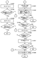
図12に基づき説明すると、主制御基板61のメインCPU81への電源投入により、図12に示す電源投入時の処理(「プログラム開始処理」、「電源ON時処理」、又は、「電源オン時処理」などともいう。)が実行される。この電源投入時の処理においては、所定のレジスタに対する初期値の設定が行われ(S1)、このレジスタ初期化の処理においては、メインCPU81に内蔵されているレジスタに初期値を設定する。設定の内容としては、メインCPU81に備えられているシリアル通信回路の通信速度の設定、割込み種類(モード)の設定、及び、送信するコマンドに付与するパリティの設定、等がある。さらに、本実施例では、割込み種類として、使用可能な各種割込み種類のうち、マスカブル割込みを1種類のみ使用している。また、パリティの設定においては、偶数パリティを使用している。
Explaining with reference to FIG. 12, when the power is turned on to the
続いて、マスカブル割込みがセットされ(S2)、RWMへのアクセスが許可される(S3)。さらに、内蔵乱数の設定が行われ(S4)、RWMチェックが行われる。このRWMチェックにおいては、チェックサムの算出(S5)と、電源断処理が済んでいることを示す電源断処理済フラグとによって、前回の電源断時のバックアップが正常か否かを判断するための電源断復帰データの生成が行われる。上述のチェックサムの算出(S5)においては、電源断処理(後述する)におけるRWMチェックサムと同じ記憶領域範囲(ここでは図11中の内蔵RWMの「F000H」から「F3FFH」)について、チェックサムを実行する。 Subsequently, a masqueradable interrupt is set (S2), and access to the RWM is permitted (S3). Further, the built-in random number is set (S4), and the RWM check is performed. In this RWM check, the checksum calculation (S5) and the power-off processing flag indicating that the power-off processing has been completed are used to determine whether or not the backup at the time of the previous power-off processing is normal. Power on / off recovery data is generated. In the above-mentioned checksum calculation (S5), the checksum is the same storage area range as the RWM checksum in the power supply cutoff process (described later) (here, “F000H” to “F3FFH” of the built-in RWM in FIG. 11). To execute.
また、チェックサムの算出(S5)においては、算出の処理の後に、対象となる全範囲について算出が終了したか否かを判定し(S6)、全範囲についての算出が終了していなければ(S6:NO)、算出の処理(S5)に戻る。そして、対象となる全範囲についての算出が終了するまで、チェックサムの算出が繰り返される。ここで、対象となる全範囲についての算出が終了したか否かの判定は、1番地毎の演算の後に行ってもよく、また、所定範囲毎の演算の後に行ってもよい。 Further, in the checksum calculation (S5), after the calculation process, it is determined whether or not the calculation for the entire target range is completed (S6), and if the calculation for the entire range is not completed (S6). S6: NO), the process returns to the calculation process (S5). Then, the checksum calculation is repeated until the calculation for the entire target range is completed. Here, the determination as to whether or not the calculation for the entire target range is completed may be performed after the calculation for each address, or may be performed after the calculation for each predetermined range.
対象となる全範囲についてのチェックサムの算出が終了した後(S6:YES)、電源断復帰データをレジスタに記憶する(S7)。ここでは、電源断実行処理フラグ、RWMチェックサムの何れかが異常であった場合と、両方がともに正常であった場合とで、電源断復帰データが異なるようになっている。さらに、入力ポート1のデータをレジスタに記憶する(S8)。ここでは、次のステップ(S9)の指定スイッチ信号が入力されるポート(入力ポート1)のデータを取得する。
After the checksum calculation for the entire target range is completed (S6: YES), the power supply cutoff / recovery data is stored in the register (S7). Here, the power-off / recovery data is different depending on whether one of the power-off execution processing flag and the RWM checksum is abnormal and the case where both are normal. Further, the data of the
続いて、指定スイッチがONとなっているか否かの判定を行う(S9)。指定スイッチは、ドアスイッチ、設定ドアスイッチ、設定キースイッチの3つのスイッチを指す。そして、ドアスイッチ信号、設定ドアスイッチ信号及び設定キースイッチ信号の状態をチェックし(S9)、すべてのスイッチ信号がONの場合は(S9:YES)、後述する設定変更装置処理(図13参照)を行う。ここで、本実施形態においては、すべてのスイッチ信号がONの場合とは、前述の扉(前面ドア部11)が開放、設定ユニット62(図4参照)の設定ドアが開放、設定キースイッチ68がON方向に回転となっている場合であり、これらの3つの条件を満たした場合にS9の判定結果が「YES」となる。なお、指定スイッチから設定ドアスイッチを除外し、ドアスイッチと設定キースイッチの2つのスイッチがON状態であれば設定変更装置が作動状態となるようにしてもよい。
Subsequently, it is determined whether or not the designated switch is ON (S9). The designated switch refers to three switches: a door switch, a setting door switch, and a setting key switch. Then, the states of the door switch signal, the setting door switch signal, and the setting key switch signal are checked (S9), and if all the switch signals are ON (S9: YES), the setting change device processing described later (see FIG. 13). I do. Here, in the present embodiment, when all the switch signals are ON, the above-mentioned door (front door portion 11) is opened, the setting door of the setting unit 62 (see FIG. 4) is opened, and the setting
例えば、扉(前面ドア部11)が閉じているときに(ドアスイッチが閉鎖状態にあるときに)、設定ユニット62(図4参照)の設定ドアが開放状態にあり、設定キースイッチ68がON方向に回転となっていても、S9の判定は「YES」とはならない。このような場合には、不正が行われている可能性もあるため、判定結果を「YES」としないことにより、後述する設定変更装置処理(「設定変更処理」ともいう)へ移行しないようになっている。尚、設定ドアスイッチ67(図4参照)を備えていない場合には、すべてのスイッチ信号がONの場合とは、S9の判定処理において、ドアスイッチ信号、設定キースイッチ信号の状態をチェックした結果がONとなっていることを指す。
For example, when the door (front door portion 11) is closed (when the door switch is in the closed state), the setting door of the setting unit 62 (see FIG. 4) is in the open state, and the setting
上述の指定スイッチがONとなっているか否かの判定(S9)で条件が満たされて「YES」となった場合には、電源断復帰データが異常であるか否かの判定を行う(S10)。この電源断復帰データに係る判定(S10)において肯定判断がされ、「YES」となった場合(電源断復帰データが異常であった場合)には、後述する設定変更装置処理(図13参照)へ移行する。また、否定判断がされて「NO」となった場合(電源断復帰データが異常でなかった場合)には、設定変更不可フラグがONか否かの判定が行われ(S11)、否定判断がされて「NO」となった場合(設定変更不可フラグがONでなかった場合)にも、設定変更装置処理(図13参照)へ移行する。 If the condition is satisfied and "YES" is satisfied in the determination (S9) of whether or not the above-mentioned designated switch is ON, it is determined whether or not the power supply cutoff / recovery data is abnormal (S10). ). If an affirmative judgment is made in the determination (S10) relating to the power supply cutoff / recovery data and the result is "YES" (when the power supply cutoff / recovery data is abnormal), the setting change device processing described later (see FIG. 13). Move to. Further, when a negative judgment is made and the result is "NO" (when the power supply cutoff / recovery data is not abnormal), it is judged whether or not the setting change impossibility flag is ON (S11), and the negative judgment is made. Even when the result is "NO" (when the setting change impossibility flag is not ON), the process proceeds to the setting change device process (see FIG. 13).
さらに、設定変更不可フラグに係る判定(S11)において、肯定判断がされて「YES」となった場合(設定変更不可フラグがONであった場合)には、後述する電源断復帰データの確認の処理(S12)に移行する。設定変更不可フラグは、RWMに記憶されるデータの1つであって、後述する遊技進行メイン処理(図14参照)において、役抽せん処理(S60)から遊技終了時のチェック(S68)までの間は、設定変更ができないことを示すデータである。 Further, in the determination (S11) relating to the setting change impossibility flag, if an affirmative determination is made and the result is "YES" (when the setting change impossibility flag is ON), the confirmation of the power supply cutoff / recovery data described later is performed. The process proceeds to (S12). The setting non-changeable flag is one of the data stored in the RWM, and is between the combination lottery process (S60) and the check at the end of the game (S68) in the game progress main process (see FIG. 14) described later. Is data indicating that the setting cannot be changed.
前述の指定スイッチがONとなっているか否かの判定(S9)で、少なくとも何れかのスイッチ信号がONではなかった場合(S9:NO)、又は、前述の設定変更不可フラグがONであった場合は(S11:YES)、電源断復帰データの確認の処理(S12)に移行する。この電源断復帰データの確認の処理(S12)においては、前回の電源断の際に電源断処理(後述する)が行われており、かつ、前回の電源断の際に所定のRWMエリアについて演算されたチェックサムの値が、正常であれば、正常と判定し、その他の場合は異常と判定する。 In the determination (S9) of whether or not the above-mentioned designated switch is ON, at least one of the switch signals is not ON (S9: NO), or the above-mentioned setting change impossible flag is ON. In that case (S11: YES), the process proceeds to the process of confirming the power-off / recovery data (S12). In the process of confirming the power-off / recovery data (S12), the power-off process (described later) is performed at the time of the previous power-off, and the predetermined RWM area is calculated at the time of the previous power-off. If the value of the checked checksum is normal, it is determined to be normal, and in other cases, it is determined to be abnormal.
この電源断復帰データの確認の処理(S12)において、電源断復帰データが異常と判定した場合は(S12:NO)、エラー表示を実行し(S13)、獲得枚数表示LEDに対応するエラーコード(E1)を表示し、遊技機の動作を停止する。この時のエラーであるE1エラーは、設定変更装置処理(図13参照)が実行されないと解除されないエラーであり、後述するような、復帰が不可能なエラー(復帰不可能エラー)の1つでもある。上述の電源断復帰データの確認の処理(S12)において、電源断復帰データが正常と判定した場合は(S12:YES)、電源復帰処理(図21参照)へ移行する。電源復帰処理(図21参照)については後述する。
<設定変更装置処理>
In the process of confirming the power-off / recovery data (S12), if it is determined that the power-off / recovery data is abnormal (S12: NO), an error display is executed (S13), and an error code corresponding to the acquired number display LED (S12: NO) is executed. E1) is displayed and the operation of the gaming machine is stopped. The E1 error, which is an error at this time, is an error that cannot be cleared unless the setting change device process (see FIG. 13) is executed, and even one of the unrecoverable errors (unrecoverable error) as described later. be. In the process of confirming the power supply / disconnection / recovery data (S12), if it is determined that the power supply / disconnection / recovery data is normal (S12: YES), the process proceeds to the power supply recovery process (see FIG. 21). The power restoration process (see FIG. 21) will be described later.
<Setting change device processing>
図13は、前述の設定変更装置処理を示すものである。この設定変更装置処理においては、スタックポインタをセットし、設定変更装置の作動を開始する。そして、図中に示すように、RWM初期化の所定範囲をレジスタに記憶する(S21)が、ここではRWM初期化に係る「所定範囲」として、電源断処理が正常に実行されたと判断した場合の、前述の記憶領域範囲(ここでは図11中のF000H番地からF3FFH番地)をセットする。さらに、ここでは、前述の設定値に係る設定値データ、リプレイタイム(RT)に係るRT状態番号、前述の条件装置に係る条件装置フラグについては、初期化の対象としての記憶は行わない。ここで、RT(リプレイタイム)は、再遊技の当せん確率が通常よりも向上する遊技状態であり、RT状態番号は、再遊技の当せん傾向が異なる複数のRT状態を区別するための番号である。また、設定値は、前述のように理論上の当り易さ(遊技者の有利度合い)を規定するものと説明することができるが、より具体的には、設定値とは、例えば、その違いによって、役の当選確率が異なるものである、と説明することができる。また、これ以外にも、設定値は、役の当選確率は同じだが、役の当選に基づく他の抽選(AT抽選など)の当せん確率が異なるものである、といった態様で用いられることもある。 FIG. 13 shows the above-mentioned setting change device processing. In this setting change device processing, the stack pointer is set and the operation of the setting change device is started. Then, as shown in the figure, the predetermined range of RWM initialization is stored in the register (S21), but here, it is determined that the power cutoff process is normally executed as the "predetermined range" related to RWM initialization. The above-mentioned storage area range (here, from address F000H to address F3FFH in FIG. 11) is set. Further, here, the set value data related to the above-mentioned set value, the RT state number related to the replay time (RT), and the condition device flag related to the above-mentioned condition device are not stored as initialization targets. Here, the RT (replay time) is a gaming state in which the winning probability of the re-game is higher than usual, and the RT state number is a number for distinguishing a plurality of RT states having different winning tendencies of the re-game. .. Further, the set value can be explained as defining the theoretical ease of hitting (the degree of advantage of the player) as described above, but more specifically, the set value is different from the set value, for example. It can be explained that the winning probability of the winning combination is different. In addition to this, the set value may be used in such a manner that the winning probability of the winning combination is the same, but the winning probability of another lottery (AT lottery or the like) based on the winning of the winning combination is different.
続いて、電源断復帰データが正常であるか否かの判定を行い(S22)、電源断処理(後述する)が正常に行われたか否かを判断する。この電源断復帰データは、前述の電源投入時の処理において、チェックサムの算出が終了した後に所定のレジスタに記憶されたものである。そして、電源断が正常に行われなかったと判定した場合には(S22:NO)、前述の設定値データ、RT状態番号、条件装置フラグを含めて、初期化の対象となる「特定範囲」とし、これらを含めた記憶領域範囲を、所定のレジスタに記憶する(S23)。ここで、「特定範囲」は、設定値データ、RT状態番号、条件装置フラグを含めた範囲である点で、上述の「所定範囲」と区別されるものである。 Subsequently, it is determined whether or not the power supply cutoff / recovery data is normal (S22), and it is determined whether or not the power supply cutoff process (described later) is normally performed. This power-off / recovery data is stored in a predetermined register after the checksum calculation is completed in the above-mentioned power-on processing. If it is determined that the power is not turned off normally (S22: NO), the "specific range" to be initialized is set to include the above-mentioned set value data, RT status number, and condition device flag. , The storage area range including these is stored in a predetermined register (S23). Here, the "specific range" is distinguished from the above-mentioned "predetermined range" in that it is a range including the set value data, the RT state number, and the condition device flag.
一方、上述の電源断復帰データが正常であるか否かの判定(S22)において、電源断が正常に行われたと判定した場合には(S22:YES)、所定のレジスタ(ここではAFレジスタ)の退避(S24)を行い、レジスタの内容(戻り番地)が前述の第1スタック領域に記憶される。そして、第1制御から第2制御への移行を行い、前述した第2制御に係る制御モジュールであるRWM初期化3(S25)を実行する。このRWM初期化3(S25)は、前述の第2制御領域に展開された第2制御プログラムの一部である。そして、RWM初期化3(S25)においては、第2制御に係るRWM領域(ここではF200H~F3FFH)のうち、設定変更装置作動時のスタック使用量(設定変更装置作動時に必要なスタック領域)を除くRWMエリア(F200H~F3F5H)がクリアされる。このRWM初期化3の詳細については後述する。
On the other hand, in the determination (S22) of whether or not the power-off / recovery data described above is normal, if it is determined that the power-off has been performed normally (S22: YES), a predetermined register (here, the AF register). Is saved (S24), and the contents of the register (return address) are stored in the above-mentioned first stack area. Then, the transition from the first control to the second control is performed, and the RWM initialization 3 (S25), which is the control module related to the second control described above, is executed. This RWM initialization 3 (S25) is a part of the second control program developed in the above-mentioned second control region. Then, in the RWM initialization 3 (S25), of the RWM area (here, F200H to F3FFH) related to the second control, the stack usage amount when the setting change device is operated (the stack area required when the setting change device is operated) is set. The excluded RWM area (F200H to F3F5H) is cleared. The details of this
このRWM初期化3(S25)の後には、AFレジスタの復帰(S26)があり、第2制御から第1制御への移行(復帰)を行う。そして、割込みの起動設定の処理(S27)により、タイマ割込みを起動する。この割込みの起動設定の処理(S27)においては、割込みの種類や、タイマ割込みの周期を設定する。この処理の後、タイマ割込み処理であるタイマ割込み処理(図18参照)が実行可能となる。本実施例では、前述のように、タイマ割込みの周期は、2.235msとなっている。 After this RWM initialization 3 (S25), there is a return (S26) of the AF register, and a transition (return) from the second control to the first control is performed. Then, the timer interrupt is activated by the interrupt activation setting process (S27). In the interrupt activation setting process (S27), the interrupt type and the timer interrupt cycle are set. After this processing, the timer interrupt processing (see FIG. 18), which is the timer interrupt processing, can be executed. In this embodiment, as described above, the timer interrupt cycle is 2.235 ms.
続いて、「設定変更開始」を示すデータをレジスタに記憶する(S28)。この「設定変更開始」を示すデータは、設定変更装置処理が開始され、実行されていることを前述のサブ制御基板31に知らせるためのコマンドとなるものである。さらに、制御コマンドセット1の処理(S29)が行われるが、本実施例において制御コマンドセット1の処理(S29)は、制御コマンドセット2の処理を行うものとなっている。制御コマンドセット2の処理は、前述のサブ制御コマンドを、送信前に一旦記憶するリングバッファ(送信バッファ)に保存するための処理を行うものとなっている。ここでは、制御コマンドセット1の処理(S29)により、「設定変更開始」を示すサブ制御コマンドがリングバッファにセットされることとなる。なお、制御コマンドセット2の処理の詳細については後述する。
Subsequently, the data indicating "setting change start" is stored in the register (S28). The data indicating "setting change start" is a command for notifying the above-mentioned
続いて、設定値が所定の範囲内であるかのチェックが行われ(S30)、設定値が正常な範囲(ここでは「1」から「6」の6つのうちの何れか)にない場合(S30:NO)は、設定値に1をセットし(S31)、設定変更装置作動中表示の処理(S31)に移行する。一方、設定値が正常な範囲にある場合(S30:YES)は、設定値(=1)のセット(S31)を行わずに、設定変更装置作動中表示の処理(S32)へ移行する。ここで、本実施例では、設定値の正常な範囲を「1」から「6」としており、「0」を正常範囲の値に使用していない。これは、何らかの事情で制御に異常が生じた場合に、値が偶然に「0」となってしまうことも考えられ、このような場合を的確に異常と判定できるようにするためである。 Subsequently, a check is made to see if the set value is within a predetermined range (S30), and if the set value is not within the normal range (here, any of the six "1" to "6") ( S30: NO) sets 1 to the set value (S31), and shifts to the process of displaying the setting change device in operation (S31). On the other hand, when the set value is in the normal range (S30: YES), the process shifts to the process of displaying the setting change device in operation (S32) without performing the setting (S31) of the set value (= 1). Here, in this embodiment, the normal range of the set value is set to "1" to "6", and "0" is not used as the value in the normal range. This is because it is possible that the value accidentally becomes "0" when an abnormality occurs in the control for some reason, and such a case can be accurately determined as an abnormality.
上述の設定変更装置作動中表示の処理(S32)においては、設定変更装置処理中のランプ(LED)点灯と、設定値の表示とを行う。ここで行う「点灯」や「表示」は、「点灯」や「表示」のためのデータ(フラグ)をセットする処理であり、具体的には、ここでセットされたデータが、この後のタイマ割込み処理(図18参照)中の所定の処理(ここでは図18中のLED表示の処理(S549))により、設定表示LED(66)や、得枚数表示LEDの駆動のために出力される。そして、本実施例では、設定表示LED(66)に設定値を表示し、得枚数表示LEDに設定変更装置作動中であることを示す「--」を表示することとなる。 In the above-mentioned processing of the setting changing device operating display (S32), the lamp (LED) during the setting changing device processing is turned on and the set value is displayed. The "lighting" and "display" performed here are processes for setting data (flags) for "lighting" and "display". Specifically, the data set here is the timer after that. By a predetermined process (here, the LED display process (S549) in FIG. 18) during the interrupt process (see FIG. 18), the data is output for driving the setting display LED (66) and the number-of-number display LED. Then, in this embodiment, the set value is displayed on the setting display LED (66), and "---" indicating that the setting change device is operating is displayed on the number-of-sale display LED.
さらに、設定/リセットボタン信号(設定/リセットスイッチ信号)に係る判定の処理(S33)を行い、ドアスイッチ信号及び設定ドアスイッチ信号がONの状態で、設定/リセットボタン信号がOFFからONになった場合は(S33:YES)、設定値の更新の処理(S34)に移行し、その他の場合はスタートレバー25に係る判定の処理(S35)へ移行する。ここで、上述の設定/リセットボタン信号に係る設定/リセットボタン(69)は、前述のように、設定ボタン(設定スイッチ)とリセットボタン(リセットスイッチ)として、1つのボタン装置を兼用しているものである。さらに、設定/リセットボタン信号の立ち上がりデータに基づき、設定/リセットボタン信号に係る判定(S33)が行われている。 Further, the determination process (S33) related to the setting / reset button signal (setting / reset switch signal) is performed, and the setting / reset button signal is changed from OFF to ON while the door switch signal and the setting door switch signal are ON. If (S33: YES), the process proceeds to the process of updating the set value (S34), and in other cases, the process proceeds to the process of determination related to the start lever 25 (S35). Here, the setting / reset button (69) related to the above-mentioned setting / reset button signal also serves as one button device as a setting button (setting switch) and a reset button (reset switch) as described above. It is a thing. Further, the determination (S33) relating to the setting / reset button signal is performed based on the rising data of the setting / reset button signal.
設定値の更新の処理(S34)においては、設定値を1加算する。ただし、加算した結果、値が最大設定値(ここでは6)を超えた場合は、設定値は1に戻る。スタートレバー25に係る判定の処理(S35)においては、スタートレバーセンサ信号(スタートセンサ信号)がOFFからONになった場合は(S35:YES)、設定キースイッチ68に係る判定の処理(S36)へ移行し、その他の場合は(S35:NO)、設定/リセットボタン信号に係る判定の処理(S33)へ移行する。
In the process of updating the set value (S34), the set value is added by 1. However, if the value exceeds the maximum set value (6 in this case) as a result of addition, the set value returns to 1. In the determination process (S35) relating to the
設定キースイッチ68に係る判定の処理(S36)においては、ドアスイッチ信号及び設定ドアスイッチ信号がONの状態で、設定キースイッチ信号がONからOFFになった場合は(S36:YES)、設定変更装置作動中表示クリアの処理(S37)へ移行し、その他の場合(S36:NO)はS36の処理を繰り返す。設定変更装置作動中表示クリアの処理(S37)においては、設定変更装処理中のランプ消灯と、設定値の表示終了とを行う。より具体的には、設定表示LEDを消灯し、獲得枚数表示LEDに「00」を表示する。ここで行う「消灯」や「表示終了」は、前述したのと同様に、「消灯」や「表示終了」のためのデータ(フラグ)をセットする処理であり、具体的には、ここでセットされたデータが、この後のタイマ割込み処理(図18参照)中の所定の処理(ここでは図18中のLEDの処理(S549))により、設定表示LEDや、得枚数表示LEDの駆動のために用いられる。
In the determination process (S36) relating to the setting
続いて、「設定変更終了」を示すデータをレジスタにセットする(S38)。この「設定変更終了」を示すデータは、設定変更装置処理が終了したことを前述のサブ制御基板31に知らせるためのコマンドとなるものである。さらに、制御コマンドセット1の処理(S39)が行われるが、この制御コマンドセット1(S39)は、前述の制御コマンドセット1(S29)と同じ制御モジュールを用いたものである。そして、制御コマンドセット1の処理(S39)により、「設定変更終了」を示すサブ制御コマンドがリングバッファにセットされることとなる。そして、この後、後述する遊技進行メイン処理(図14参照)へ移行する。
Subsequently, the data indicating "setting change completion" is set in the register (S38). The data indicating "setting change end" is a command for notifying the above-mentioned
なお、設定変更装置を作動状態とする際には複数のスイッチがON状態となることを必要としていたが(図12のS9)、設定変更装置を非作動状態とする際には設定キースイッチのみが確認されるようになっている(図13のS36)。つまり、設定変更装置の作動終了の条件は、開始の条件に比べて緩和されているということができる。
<<制御コマンドセット2>>
It was necessary to turn on a plurality of switches when the setting change device was put into the operating state (S9 in FIG. 12), but when the setting changing device was put into the non-operating state, only the setting key switch was used. Is confirmed (S36 in FIG. 13). That is, it can be said that the condition for ending the operation of the setting changing device is relaxed as compared with the condition for starting the operation.
<< Control command set 2 >>
次に、前述した制御コマンドセット1(S29、S39)において行われる制御コマンドセット2の処理について説明する。この制御コマンドセット2においては、制御コマンドバッファアドレスのセットを行い、制御コマンド書込ポインタのデータを取得する。さらに、指定アドレスをセットし、指定アドレスデータを取得し、制御コマンドが「64」よりも小さいか否かの判定を行う。 Next, the processing of the control command set 2 performed in the control command set 1 (S29, S39) described above will be described. In this control command set 2, the control command buffer address is set and the control command write pointer data is acquired. Further, the designated address is set, the designated address data is acquired, and it is determined whether or not the control command is smaller than "64".
そして、制御コマンドが「64」よりも小さい場合には、制御コマンドをセットし、制御コマンド書込ポインタの更新を行って、処理を終える。上記制御コマンドが「64」よりも小さいか否かの判定処理で、制御コマンドが「64」よりも小さくなかった場合には、制御コマンドのセットや、制御コマンド書込ポインタの更新を行わずに処理を終える。
<遊技進行メイン処理>
Then, when the control command is smaller than "64", the control command is set, the control command write pointer is updated, and the process is completed. If the control command is not smaller than "64" in the determination process of whether or not the control command is smaller than "64", the control command is not set or the control command write pointer is not updated. Finish the process.
<Game progress main processing>
次に、遊技進行メイン処理について、図14に基づき説明する。なお、ここでは遊技進行メイン処理の概要を説明し、遊技進行メイン処理で用いられる各種の制御モジュールのうち、本実施例において主要なものについては後述する。遊技進行メイン処理においては、スタックポインタをセットし(S51)、遊技開始セットの処理(S52)において、以下の処理を行う。すなわち、この遊技開始セットの処理(S52)においては、遊技状態をセットする。 Next, the game progress main process will be described with reference to FIG. Here, the outline of the game progress main process will be described, and among the various control modules used in the game progress main process, the main ones in this embodiment will be described later. In the game progress main process, the stack pointer is set (S51), and in the game start set process (S52), the following processes are performed. That is, in the process (S52) of this game start set, the game state is set.
つまり、遊技開始セットの処理(S52)においては、遊技開始時のセットを行う。さらに、図示は省略するが、遊技待機表示開始時間をセットし、引込み図柄データをクリアし、作動状態セットに移行する。 That is, in the processing of the game start set (S52), the set at the start of the game is performed. Further, although not shown, the game standby display start time is set, the retracted symbol data is cleared, and the operation state set is entered.
より具体的には、前回の遊技で停止表示された図柄組合せに基づいて、今回の遊技が、再遊技であるのか、前述の第一種特別役物に係る役物連続作動装置が作動する遊技(1種BB遊技)であるのかを示すデータをセットする。さらに、サブボーナス後のウエイト待機を行う。ここで、サブボーナスは、前述のサブ制御基板31の側で管理しているボーナスであり、例えば、特定の再遊技(特定リプレイ)に当せんした場合に、その後の所定数のゲームに亘り継続される、といったような遊技状態を意味している。
More specifically, based on the symbol combination stopped and displayed in the previous game, whether this game is a re-game or a game in which the character continuous operation device related to the above-mentioned first-class special character is operated. Set the data indicating whether it is (
具体的な例としては、演出上「7」の図柄が入賞ライン上に揃って表示され、特定リプレイの入賞状態となり、更に、この特定リプレイの入賞から30ゲーム間に亘り、AT(アシストタイム)状態とすることで利益を付与する、といったような遊技状態を挙げることができる。そして、サブボーナス後のウエイト待機とは、AT状態が終了する際に、主制御基板61で管理するボーナス(メインボーナス)と同じように、ボーナス終了デモを行うための待機時間を意味している。そして、待機時間の開始契機は、主制御基板61側で特定リプレイに入賞してから30ゲーム経過時のように設定することが可能である。
As a specific example, the symbols "7" are displayed together on the winning line for the production, and the winning state of the specific replay is set. Furthermore, AT (assist time) is performed for 30 games from the winning of the specific replay. It is possible to mention a game state such as giving a profit by making it a state. The weight wait after the sub-bonus means the waiting time for performing the bonus end demo in the same way as the bonus (main bonus) managed by the
続いて、この遊技開始セットの処理(S52)においては、図示は省略するが、各種遊技情報を示すコマンドを、それぞれコマンドバッファに書き込む。さらに、満杯検知信号をチェックし、遊技メダル補助収納庫71が満杯の場合は獲得枚数表示LEDにその旨を表すエラーコード(FE)を表示し、遊技を停止する。
Subsequently, in the process (S52) of this game start set, although not shown, commands indicating various game information are written in the command buffer. Further, the fullness detection signal is checked, and if the game medal
遊技メダル補助収納庫71が満杯でない場合又はエラーが解除された場合は、遊技メダル投入の受け付けを行う。この遊技メダル投入の受け付けにおいては、再遊技未作動時の場合は、ブロッカ信号をON(通過可能状態)にして遊技メダル投入の受付を開始する。再遊技作動時の場合は、貯留装置へ遊技メダルの投入が可能であれば(クレジット数が最大数である50に達していなければ)ブロッカ信号をON(メダル流路形成)にし、貯留装置へ遊技メダルの投入が可能でない場合はブロッカ信号のONは行わず、前回の遊技における賭数の遊技メダルの自動投入動作を行う。再遊技作動時のブロッカ処理については後述する。
If the game medal
遊技進行メイン処理においては、続いて、図14中に示すように、遊技メダルの読み込みの処理(S53)を実行する。この遊技メダルの読み込みの処理(S53)においては、遊技メダル枚数データを読み込み、遊技メダル枚数の有無をチェックする。遊技メダルの読み込みの処理(S53)の後、遊技メダルの有無をチェックし(S54)、遊技メダルがない場合には(S54:NO)、遊技メダル投入待ち時の表示(メダルが投入可能なことの報知)の処理(S55)に移行し、遊技メダルがある場合は(S54:YES)、遊技メダル管理の処理(S56)へ移行する。ここで、遊技メダルがあるとは、遊技を行うための規定数を満たすために、遊技メダルが賭け設定(ベット)されている状態を示す。 In the game progress main process, subsequently, as shown in FIG. 14, the game medal reading process (S53) is executed. In this game medal reading process (S53), the game medal number data is read and the presence or absence of the game medal number is checked. After the process of reading the game medal (S53), the presence or absence of the game medal is checked (S54), and if there is no game medal (S54: NO), the display when waiting for the game medal to be inserted (the medal can be inserted). (S55), and if there is a game medal (S54: YES), the process proceeds to the game medal management process (S56). Here, the presence of a game medal indicates a state in which a game medal is set (bet) in order to satisfy a specified number for playing a game.
遊技メダル投入待ち時の表示の処理(S55)においては、設定キースイッチ信号がOFFからONになった場合に、ブロッカOFFを行い、設置値表示開始時の制御コマンドをセットする。さらに、設定キースイッチ信号がONからOFFになるまで、設定表示LEDに設定値を表示する。そして、設定値表示終了時の制御コマンドをセットし、ブロッカONを行う。そして、遊技待機表示開始時間が経過している場合は、獲得枚数表示クリアの処理に移行し、その他の場合は処理を終了する。 In the display processing (S55) when waiting for the game medal to be inserted, when the setting key switch signal is changed from OFF to ON, the blocker is turned off and the control command at the start of the installation value display is set. Further, the set value is displayed on the setting display LED until the setting key switch signal is turned from ON to OFF. Then, the control command at the end of the set value display is set, and the blocker is turned on. Then, when the game standby display start time has elapsed, the process proceeds to the process of clearing the acquired number display, and in other cases, the process ends.
遊技メダル管理(S56)においては、ブロッカの状態確認の処理を行い、このブロッカの状態確認の処理においては、投入された遊技メダルに基づいた投入処理、清算ボタン74やMAXベットボタン(3枚投入ボタン76)の操作に基づいた処理を行う。この遊技メダル管理(S56)については後述する(図26参照)。さらに、遊技メダル管理の処理(S56)の後に、ソフト乱数更新のための処理であるソフト乱数更新1(S57)が行われる。このソフト乱数更新1(S57)においては、ソフト乱数更新2を行うが、ソフト乱数更新2は、内蔵乱数加工用乱数の更新を行うものとなっている。
In the game medal management (S56), the blocker status confirmation process is performed, and in the blocker status confirmation process, the insertion process based on the inserted game medals, the
続いて、スタートレバーチェックの処理(S58)においては、スタートレバーの受付チェックを行う。つまり、図示は省略するが、投入・払出センサ異常表示を行い、投入枚数が規定数と一致していない場合は、処理を終了する。さらに、ブロッカON時の監視時間(ブロッカON時監視時間)が経過していない場合は、遊技開始表示LED信号をOFFにし、処理を終了する。続いて、遊技開始表示LED信号をONにする。そして、スタートレバーセンサ信号がOFFからONになった場合はスタートレバー受付に移行し、その他の場合は処理を終了する。 Subsequently, in the start lever check process (S58), the reception check of the start lever is performed. That is, although not shown, the insertion / withdrawal sensor abnormality display is performed, and if the number of insertions does not match the specified number, the process is terminated. Further, when the monitoring time when the blocker is ON (the monitoring time when the blocker is ON) has not elapsed, the game start display LED signal is turned off and the process is terminated. Then, the game start display LED signal is turned on. Then, when the start lever sensor signal changes from OFF to ON, the process shifts to the start lever reception, and in other cases, the process ends.
より具体的には、スタートレバー25の受付チェックとして、以下の処理を順に行う。すなわち、セレクタ通路に遊技メダルが滞留しているか否かを表すセレクタ通路センサ滞留フラグをチェックし、遊技メダルが滞留している場合は、獲得枚数表示LEDに対応するエラーコード(CH)を表示し遊技を停止する。その他の場合又はエラーが解除された場合は、投入センサ異常検出データをチェックし、異常入力を検出している場合は、獲得枚数表示LEDに対応するエラーコード(C0)を表示し、遊技を停止する。これらについての具体的な処理は、後述する。
More specifically, as a reception check of the
さらに、その他の場合(異常入力を検出してない場合)又はエラーが解除された場合は、払出センサ異常検出データをチェックし、異常入力を検出している場合は、獲得枚数表示LEDにH0を表示し遊技を停止する。さらに、その他の場合(異常入力を検出していない場合)又はエラーが解除された場合は、オーバーフロー検出データをチェックし、遊技メダル補助収納庫が満杯の場合は、獲得枚数表示LEDにFEを表示し遊技を停止する。その他の場合(遊技メダル補助収納庫が満杯でない場合)又はエラーが解除された場合は、更に以下の処理に移行する。 Furthermore, in other cases (when no abnormal input is detected) or when the error is cleared, the payout sensor abnormality detection data is checked, and when an abnormal input is detected, H0 is set on the acquired number display LED. Display and stop the game. Furthermore, in other cases (when no abnormal input is detected) or when the error is cleared, the overflow detection data is checked, and when the game medal auxiliary storage is full, FE is displayed on the acquired number display LED. Stop the game. In other cases (when the game medal auxiliary storage is not full) or when the error is cleared, the process further proceeds to the following processing.
すなわち、投入された遊技メダル枚数と規定数を比較し、規定数と一致した場合には次の処理(スタートレバー受付とするか否かを決める処理(S59))へ移行し、その他の場合はスタートレバー受付不可として、遊技メダル読み込みの処理(53)へ戻る。さらに、上述のスタートレバー受付とするか否かを決める処理(S59)では、停止ボタン24L~24R、清算ボタン74及び各投入ボタンの操作がない状態で、かつスタートレバーセンサ信号がOFFからONに変化した場合は、スタートレバー受付となり、その他の場合はスタートレバー非受付となる。そして、遊技メダルセレクター44のブロッカ47をOFF(ソレノイドOFF)し、遊技メダルセレクター44を、遊技メダルの通過が不可能な返却状態とする。
That is, the number of inserted game medals is compared with the specified number, and if the number matches the specified number, the process proceeds to the next process (process for deciding whether or not to accept the start lever (S59)), and in other cases, the process proceeds to the next process. As the start lever cannot be accepted, the process returns to the game medal reading process (53). Further, in the process (S59) for deciding whether or not to accept the start lever described above, the
スタートレバー受付に係る判定の処理(S59)において、スタートレバー受付でないと判定した場合は(S59:NO)、遊技メダル読込みの処理(S53)へ戻り、スタートレバー受付の場合は(S59:YES)、内蔵乱数(ハードウェア乱数)の取り込みを行い、役抽せん処理である内部抽せん開始の処理(S60)へ移行する。ここで、スタートレバー受付でないと判定した場合(S59:NO)におけるループ処理(S53~S59)は、スタックポインタのセット(S51)の後に配置されており、このため、スタックポインタのセット(S51)は、常にループ処理(S53~S59)の前に実行されるようになっている。 In the determination process related to the start lever reception (S59), if it is determined that the start lever is not accepted (S59: NO), the process returns to the game medal reading process (S53), and in the case of the start lever reception (S59: YES). , The built-in random number (hardware random number) is taken in, and the process proceeds to the internal lottery start process (S60), which is the winning combination lottery process. Here, the loop processing (S53 to S59) in the case where it is determined that the start lever is not received (S59: NO) is arranged after the stack pointer set (S51), and therefore, the stack pointer set (S51). Is always executed before the loop processing (S53 to S59).
内部抽せん開始の処理(S60)においては、条件装置(再遊技、入賞役、役物、役物連続作動装置)に係る役抽せんや、図柄制御番号等の決定のための内部抽せん処理を行う。内部抽せん処理においては、遊技状態に応じて異なる役抽せんテーブルが用いられており、各種の遊技状態やRT状態に応じて当せん番号(当せん役)の種類や当選確率が異なっている。また、内部抽せんのための乱数として、上述の内蔵乱数に、加工用乱数(ここではソフトウェア乱数)を加算して得られたものを使用している。さらに、各種の役に係る抽せんについては、役の種類に基づき抽せんの順番が決められている。なお、内部抽せん開始の処理(S60)の詳細については後述する(図15参照)。 In the process of starting the internal lottery (S60), the combination lottery related to the conditional device (replay, winning combination, bonus, continuous motion of the bonus) and the internal lottery process for determining the symbol control number and the like are performed. In the internal lottery process, different winning combination lottery tables are used according to the game state, and the type of winning number (winning combination) and the winning probability are different according to various game states and RT states. Further, as a random number for internal lottery, a random number obtained by adding a processing random number (here, a software random number) to the above-mentioned built-in random number is used. Further, for lottery related to various roles, the order of lottery is determined based on the type of role. The details of the internal lottery start process (S60) will be described later (see FIG. 15).
回胴回転開始処理(S61)を含む回胴管理の処理(S61~S65)においては、回胴の加速から停止の管理が行われる。また、回胴管理の処理(S61~S65)は、図示は省略するが、前述の擬似遊技を行うための処理である擬似遊技開始処理内でも実行されるものである。そして、回胴管理の処理(S61~S65)においては、回胴の回転に係る機構の制御が行われるが、これについては後述する。 In the rotation cylinder management processing (S61 to S65) including the rotation cylinder rotation start processing (S61), the rotation management is performed from the acceleration of the rotation cylinder to the stop. Further, although the illustration is omitted, the rotation body management processes (S61 to S65) are also executed in the pseudo game start process, which is the process for performing the above-mentioned pseudo game. Then, in the rotation cylinder management processing (S61 to S65), the mechanism related to the rotation of the rotation cylinder is controlled, which will be described later.
回胴回転開始の処理(S61)においては、回胴の回転を開始するためのデータセット及び回転不良の検査を行う。より具体的には、データセット要求がある回胴(データセット要求回胴)の有無を判定し、データセット要求回胴がある場合は、要求のある回胴にデータをセットする。さらに、定速中の回胴において回転不良を検出した場合は、当該回胴に対して加速状態セットの要求データをセットして、上述したデータセット要求回胴の有無の判定に戻る。そして、データセット要求回胴がない場合には、前述した制御モジュールであるソフト乱数更新処理1に移行する。
In the process of starting the rotation of the rotating cylinder (S61), the data set for starting the rotation of the rotating cylinder and the inspection of the rotation defect are performed. More specifically, it is determined whether or not there is a round cylinder with a data set request (data set request round cylinder), and if there is a data set request round cylinder, data is set in the requested round cylinder. Further, when a rotation failure is detected in the rotating cylinder during constant speed, the required data of the acceleration state set is set for the rotating cylinder, and the process returns to the determination of the presence / absence of the above-mentioned data set required rotating cylinder. Then, when there is no data set request rotation cylinder, the process proceeds to the soft random
回胴回転開始処理(S61)に続いては、ずらしコマ数(引込みポイント)の作成を行う(S62)。このずらしコマ数作成の処理(S52)においては、停止済みでないすべての回胴について、ずらしコマ数を示すデータを作成する。より具体的には、図示は省略するが、ずらしコマ数作成要求がない場合は、処理を終了する。さらに、第3回胴(51R)、第2回胴(51C)、第1回胴(51L)の順にずらしコマ数作成要求があるすべての回胴に対して、以下の処理を行う。 Following the rotation start processing (S61), the number of shifted frames (pull-in point) is created (S62). In this process of creating the number of shifted frames (S52), data indicating the number of shifted frames is created for all the rotating cylinders that have not been stopped. More specifically, although not shown, if there is no request for creating the number of shifted frames, the process ends. Further, the following processing is performed for all the rotating cylinders for which there is a request for creating the number of frames shifted in the order of the third cylinder (51R), the second cylinder (51C), and the first cylinder (51L).
先ず、ずらしコマ数作成に用いるテーブル検索番号を保存するRWMアドレスを保存すする。続いて、制御回胴番号をRWMに保存し、図柄配列コマ数分の引込みポイント初期化の処理を行う。さらに、コントロール制御実行の処理を行い、テーブルセット制御の処理を行う。さらに、制御図柄番号の初期化の処理を行い、各制御図柄番号に対して以下の処理を行う。 First, the RWM address for storing the table search number used for creating the number of shifted frames is saved. Subsequently, the control rotation cylinder number is saved in the RWM, and the process of initializing the pull-in point for the number of symbol arrangement frames is performed. Further, the control control execution process is performed, and the table set control process is performed. Further, the process of initializing the control symbol number is performed, and the following process is performed for each control symbol number.
先ず、停止可能位置作成の処理を行う。続いて、ずらしコマ数を、制御回胴及び制御図柄番号に応じたRWMに保存する。さらに、ずらしコマ数作成要求をクリアし、割込み待ちの処理に移行する。 First, the process of creating a stoptable position is performed. Subsequently, the number of shifted frames is stored in the RWM corresponding to the control rotation cylinder and the control symbol number. Furthermore, the request for creating the number of shifted frames is cleared, and the process shifts to the interrupt waiting process.
このようなずらしコマ数作成の処理(S62)の後には、回転停止受付チェックの処理(S63)へ移行する。この回転停止受付チェックの処理(S63)においては、停止操作に係るチェックのため、先ず、全回胴のセンサのチェックを行い、停止受付不可の場合は処理を終了する。さらに、回転中の回胴に対応する停止ボタンセンサの出力信号(停止ボタンセンサ信号)のいずれかがONになった場合は、停止ボタン受付の処理に移行する。さらに、全回胴の回転又は停止状態に合わせて、停止受付情報データをセットし、停止位置を決定して、全回胴停止チェックの処理(S64)へ移行する。 After the process of creating the number of shifted frames (S62), the process proceeds to the process of checking the rotation stop acceptance (S63). In this rotation stop acceptance check process (S63), for the check related to the stop operation, first, the sensor of the whole rotation cylinder is checked, and if the stop acceptance is not possible, the process is terminated. Further, when any of the output signals (stop button sensor signals) of the stop button sensor corresponding to the rotating cylinder is turned on, the process proceeds to the process of accepting the stop button. Further, the stop reception information data is set according to the rotation or stop state of the full rotation cylinder, the stop position is determined, and the process proceeds to the all rotation cylinder stop check process (S64).
全回胴停止チェックの処理(S64)においては、すべての回胴が停止中の状態であり、かつ停止ボタン(24L、24C、24R)及びスタートレバー25の操作が終了しているかチェックする。この全回胴停止チェックの処理(S64)では、すべての回胴51L~51Rが停止し、かつ、スタートレバー25及び停止ボタン24L~24Rの操作が、例えば、前述のように第3停止時にスタートレバー25又はいずれかの停止ボタン24L~24Rを操作し続けた状態等になく、適正に終了しているかのチェックが行われる。
In the process of checking the stop of all rotations (S64), it is checked whether all rotations are stopped and whether the operation of the stop buttons (24L, 24C, 24R) and the
続く全回胴停止の判定の処理(S65)において、肯定の判定がされた場合は(S65:YES)、表示判定の処理(S66)へ移行し、その他の場合はずらしコマ数作成の処理(S62)に戻る。 In the subsequent processing of determining the total rotation stop (S65), if an affirmative determination is made (S65: YES), the process proceeds to the display determination processing (S66), and in other cases, the processing of creating the number of staggered frames (S65). Return to S62).
表示判定処理(S66)においては、以下の処理を順に行う。すなわち、表示判定を行った結果、図柄の組合せ表示が異常の場合は、獲得枚数表示LEDに対応するエラーコード(E5)を表示し、遊技の動作を停止する。 In the display determination process (S66), the following processes are performed in order. That is, if the combination display of the symbols is abnormal as a result of the display determination, the error code (E5) corresponding to the acquired number display LED is displayed and the operation of the game is stopped.
続いて、入賞による遊技メダル払出しの処理(S67)に移行する。入賞による遊技メダル払出しの処理(S67)においては、入賞による遊技メダル払出がある場合は、遊技メダルを払出す。また、図示は省略するが、この遊技メダルの払出しの際には、払出された遊技メダルの枚数を表示するための表示処理を行う。この遊技メダル枚数の表示処理においては、遊技メダルが1枚払出される毎に、表示装置(ここでは貯留枚数表示部)に表示する値を更新する。 Subsequently, the process proceeds to the process of paying out the game medals by winning (S67). In the process of paying out the game medal by winning (S67), if there is a game medal paying out by winning, the game medal is paid out. Further, although not shown, when paying out the game medals, a display process for displaying the number of paid out game medals is performed. In this game medal display process, the value displayed on the display device (here, the stored number display unit) is updated every time one game medal is paid out.
より具体的には、入賞による遊技メダルの払い出し及びBB作動時の払出し枚数の管理のため、先ず、遊技メダル払出開始時の制御コマンドをセットする。続いて、メダル払出信号出力回数をセットし、遊技メダル払出し枚数がない場合は、処理を終了する。さらに、BB作動時の獲得可能枚数を更新し、払出し枚数分、後述する処理を行って、遊技メダル払出終了時の制御コマンドをセットする。 More specifically, in order to pay out the game medals by winning and manage the number of payouts when the BB is operated, first, a control command at the start of paying out the game medals is set. Subsequently, the number of times the medal payout signal is output is set, and if there is no game medal payout number, the process ends. Further, the number of sheets that can be acquired when the BB is operated is updated, the process described later is performed for the number of payouts, and the control command at the end of payout of the game medal is set.
上述の払出し枚数分に係る処理としては、先ず、遊技メダルの払い出し先に応じて以下の処理を行う。すなわち、貯留装置への払い出しが可能な場合には、加算時間待機後に、貯留枚数1枚加算を行い、貯留装置への払い出しが不可能な場合には、遊技メダル1枚払出しを行う。続いて、払出し枚数分に応じた処理として、獲得枚数データを1加算する。 As the above-mentioned processing for the number of payouts, first, the following processing is performed according to the payout destination of the game medal. That is, if the payout to the storage device is possible, one stored number is added after waiting for the addition time, and if the payout to the storage device is not possible, one game medal is paid out. Subsequently, the acquired number of sheets data is added by 1 as a process according to the number of payouts.
次に、遊技終了時の処理(S68)を行う。この遊技終了時の処理(S68)においては、先ず、再遊技表示LEDを消灯する。続いて、再遊技作動状態フラグ並びに入賞及び再遊技条件装置番号をクリアする。さらに、BB作動時の場合には、BB作動管理の処理を行い、RB作動時の場合には、RB作動管理の処理を行う。また、ボーナス作動中でない場合には、RT状態管理の処理に移行する。 Next, the process (S68) at the end of the game is performed. In the process (S68) at the end of the game, first, the re-game display LED is turned off. Subsequently, the re-game operation status flag and the winning and re-game condition device numbers are cleared. Further, in the case of BB operation, BB operation management processing is performed, and in the case of RB operation, RB operation management processing is performed. If the bonus is not in operation, the process shifts to RT status management.
この後、遊技終了時の出力要求をセットし(S69)、前述した制御コマンドセット1を行って(S70)、遊技進行メインの処理を再度実行する。なお、役物や連続作動装置に入賞が発生していても、対応する図柄の組合せが揃っていない場合は、これらの入賞に係るフラグは持ち越す。また、再遊技や小役の条件装置に係るフラグはクリアする。すなわち、上述の遊技状態に応じた終了処理としては、持越し役以外の条件装置番号のRWMクリア処理、RT番号の生成処理、及び、フリーズ状態の移行処理、外部信号データの生成処理、等が行われる。 After that, the output request at the end of the game is set (S69), the control command set 1 described above is performed (S70), and the game progress main process is executed again. Even if a prize is generated in the accessory or the continuous operation device, if the corresponding combinations of symbols are not prepared, the flags related to these prizes are carried over. In addition, the flags related to the replay and small role condition devices are cleared. That is, as the end processing according to the above-mentioned game state, RWM clear processing of the condition device number other than the carry-over combination, RT number generation processing, freeze state transition processing, external signal data generation processing, and the like are performed. Will be.
続いて、遊技進行メイン処理(S51~S70)における各種の処理のうち、内部抽せん開始処理(S60)について、更に詳細に説明する。前述のように、内部抽せん開始処理(S60)は、遊技を開始できる状況において、スタートレバー操作の受付が検出されると移行する処理である。図15に示すように、内部抽せん開始処理(S60)においては、条件装置番号セット(S81)、図柄制御番号セット(S82)、引込み図柄データセット(S83)、制御図柄セット(S84)、出玉抽せん管理(S85)、条件装置コマンドセット(S86)、回胴回転開始待機(S87)、回胴回転開始準備(S88)の各処理が順に実行される。 Subsequently, among the various processes in the game progress main process (S51 to S70), the internal lottery start process (S60) will be described in more detail. As described above, the internal lottery start process (S60) is a process of shifting when the reception of the start lever operation is detected in the situation where the game can be started. As shown in FIG. 15, in the internal lottery start process (S60), the condition device number set (S81), the symbol control number set (S82), the pull-in symbol data set (S83), the control symbol set (S84), and the ball ejection Each process of lottery management (S85), condition device command set (S86), rotation cylinder rotation start standby (S87), and rotation cylinder rotation start preparation (S88) is executed in order.
これらのうち、条件装置番号セット(S81)においては、先ず、ボーナス条件装置作動時であるか否かの判定を行う。そして、ボーナス条件装置作動時でなければ、ボーナス条件装置番号を示すデータの保存を行い(S502)、入賞及び再遊技条件装置番号を示すデータの保存を行う。 Of these, in the condition device number set (S81), first, it is determined whether or not the bonus condition device is operating. Then, if the bonus condition device is not in operation, the data indicating the bonus condition device number is saved (S502), and the data indicating the winning and replay condition device numbers is saved.
前述の出玉抽せん管理の処理(図15のS85)においては、演出グループ番号に係るデータをセットし、指定番号をセットし、メイン遊技状態管理の処理を行って条件装置コマンドセットの処理(図15のS86)へ移行する。 In the above-mentioned ball-out lottery management process (S85 in FIG. 15), the data related to the effect group number is set, the designated number is set, the main game state management process is performed, and the condition device command set process (FIG. 15). Move to S86) of 15.
条件装置コマンドセットの処理(図15のS86)においては、図16に示すように、割込みを禁止し(S511)、AFレジスタの退避(S512)を行って、第2制御に移行して、図柄停止信号出力の処理(S513)を実行する。第2制御として行われる図柄停止信号出力の処理(S513)は、試射試験用の図柄停止信号データを出力するための処理であるが、その詳細については後述する(図33参照)。 In the processing of the condition device command set (S86 in FIG. 15), as shown in FIG. 16, interrupts are prohibited (S511), the AF register is saved (S512), the process shifts to the second control, and the symbol is displayed. The processing of the stop signal output (S513) is executed. The symbol stop signal output process (S513) performed as the second control is a process for outputting the symbol stop signal data for the test firing test, and the details thereof will be described later (see FIG. 33).
図柄停止信号出力の処理(S513)が終わると、第1制御に係る条件装置コマンドセットの処理(図16)に戻り、AFレジスタの復帰を行う(S514)。さらに、割込みを許可し(S515)、スタートレバー受付時コマンドテーブルをセットし(S516)、呼び出し元へ復帰する。 When the processing of the symbol stop signal output (S513) is completed, the process returns to the processing of the condition device command set related to the first control (FIG. 16), and the AF register is restored (S514). Further, the interrupt is permitted (S515), the command table at the time of receiving the start lever is set (S516), and the caller is returned.
回胴回転開始待機の処理(図15のS87)においては、前述の最小遊技時間が経過したか否かを判定し、最小遊技時間が経過すると、最小遊技時間のデータを保存する。続いて、条件装置出力時間の保存を行い、コマンド送信待ちの処理を行う。 In the process of waiting for the start of rotation of the rotating body (S87 in FIG. 15), it is determined whether or not the above-mentioned minimum game time has elapsed, and when the minimum game time has elapsed, the data of the minimum game time is saved. Subsequently, the condition device output time is saved and the process of waiting for command transmission is performed.
回胴回転開始準備の処理(図15のS88)においては、回胴停止順番データ及び押し順データを初期化し、回胴停止フラグ及びずらしコマ数の作成要求に係るデータを初期化する。さらに、初期化図柄群数のデータをセットし、図柄制御データテーブル1のセットを行う。また、初期化開始RWMアドレスのセットを行い、停止図柄データの初期化を行う。 In the process of preparing for the start of rotation of the rotating cylinder (S88 in FIG. 15), the rotation rotation stop order data and the pushing order data are initialized, and the data related to the rotation cylinder stop flag and the request for creating the number of shifted frames are initialized. Further, the data of the number of initialized symbol groups is set, and the symbol control data table 1 is set. In addition, the initialization start RWM address is set, and the stop symbol data is initialized.
続いて、全回胴回転開始時の出力要求に係るデータをセットし、前述したのと同じ制御コマンドセット1を実行する。そして、全回胴回転開始ビット及び回転開始準備状態に係るデータをセットし、回転開始回胴ありを示すデータをセットする。 Subsequently, the data related to the output request at the start of full rotation of the cylinder is set, and the same control command set 1 as described above is executed. Then, the data related to the rotation start rotation start bit and the rotation start preparation state are set, and the data indicating the presence of the rotation start rotation cylinder is set.
次に、前述の遊技進行メイン処理(図14参照)における表示判定処理(S66)について説明する。図17は、表示判定(S66)の処理の内容を示している。この表示判定処理においては、獲得枚数表示クリア処理(S401)が実行され、その後に各種データのセット処理(S402、S403)や、E5エラーのセット処理(S404)が実行される。 Next, the display determination process (S66) in the above-mentioned game progress main process (see FIG. 14) will be described. FIG. 17 shows the contents of the processing of the display determination (S66). In this display determination process, the acquired number display clear process (S401) is executed, and then various data set processes (S402, S403) and E5 error set process (S404) are executed.
上述の獲得枚数表示クリア処理(S401)は、獲得枚数表示のデータをクリアするためのものであり、前述した貯留投入処理(図27参照)における獲得枚数表示クリアの処理(S339)と同様な処理である。さらに、上述の各種データのセット処理(S402、S403)は、所定の停止図柄データに係るRWMアドレスのセット(S402)、及び、制御図柄群数や蹴飛ばし図柄データに係るRWMアドレスのセット(S404)である。 The above-mentioned acquired number display clear process (S401) is for clearing the acquired number display data, and is the same process as the acquired number display clear process (S339) in the above-mentioned storage input process (see FIG. 27). Is. Further, the above-mentioned various data set processing (S402, S403) is a set of RWM addresses related to predetermined stop symbol data (S402), and a set of RWM addresses related to the number of control symbol groups and kicking symbol data (S404). Is.
ここで、蹴飛ばし図柄データは、役抽せんの結果に対応しない図柄組合せを構成する図柄データである。そして、この蹴飛ばし図柄データには、例えば、前述のBB(ビッグボーナス)に当せんしていない場合における、BBの図柄組合せを構成する一部の図柄に係る図柄データなどが該当する。 Here, the kick-off symbol data is symbol data constituting a symbol combination that does not correspond to the result of the winning combination lottery. Then, the kicking symbol data corresponds to, for example, symbol data related to some symbols constituting the symbol combination of BB in the case where the above-mentioned BB (big bonus) is not applied.
さらに、蹴飛ばし図柄に係る集合演算を行い(S405)、蹴飛ばし図柄データと、このときの遊技で表示された図柄の相関を演算する。そして、表示された図柄が蹴飛ばし図柄に該当するか否かの判定を行い(S406)、蹴飛ばし図柄が表示されている場合には(S406:YES)、復帰不可能エラー処理(図29参照)へ移行する。この復帰不可能エラー処理については後述する。 Further, a set operation related to the kick-off symbol is performed (S405), and the correlation between the kick-off symbol data and the symbol displayed in the game at this time is calculated. Then, it is determined whether or not the displayed symbol corresponds to the kicking symbol (S406), and if the kicking symbol is displayed (S406: YES), the process goes to the non-recoverable error process (see FIG. 29). Transition. This non-recoverable error processing will be described later.
一方、蹴飛ばし図柄が表示されていない場合には(S406:NO)、次の停止図柄データアドレスのセット(S407)、次の蹴飛ばし図柄データアドレスのセット(S408)を行う。そして、制御図柄群数に応じた分の判定が終了したか否かを判定し(S409)、終了している場合には(S409:YES)、1ライン表示判定処理(S421)へ移行する。また、制御図柄群数に応じた分の判定が終了していない場合には(S409:NO)、蹴飛ばし図柄に係る演算処理(S405)の直前に戻る。 On the other hand, when the kick-off symbol is not displayed (S406: NO), the next stop symbol data address is set (S407) and the next kick-off symbol data address is set (S408). Then, it is determined whether or not the determination according to the number of control symbol groups is completed (S409), and if it is completed, (S409: YES), the process proceeds to the one-line display determination process (S421). If the determination for the number of control symbol groups has not been completed (S409: NO), the process returns immediately before the calculation process (S405) related to the kicking symbol.
上記S409で、制御図柄群数に応じた分の判定が終了している場合には(S409:YES)、S421へ移行し、1ライン表示判定処理を実行する。この1ライン表示判定処理(S421)では、有効ライン1ラインの表示判定及び表示時のデータセットを行う。具体的には、有効ライン上に停止するよう決められた図柄組合せに応じて、作動種別、図柄組合せ表示フラグ、遊技メダル払出枚数データ、払出し枚数バッファ及び入賞図柄グループを保存する。 If the determination for the amount corresponding to the number of control symbol groups is completed in S409 (S409: YES), the process proceeds to S421 and the one-line display determination process is executed. In this one-line display determination process (S421), the display determination of one effective line and the data set at the time of display are performed. Specifically, the operation type, the symbol combination display flag, the game medal payout number data, the payout number buffer, and the winning symbol group are stored according to the symbol combination determined to stop on the valid line.
続いて、全回胴回転停止時の演出表示の処理(S422)により、全回胴停止時の演出表示のための処理を行う。この全回胴回転停止時の演出表示処理(S422)では、3番目の停止操作に係る第3停止時待機時間が通過するまで待機し、メイン遊技状態管理の処理を行い、全回胴回転停止時における制御コマンドをセットし、全回胴回転停止時におけるRWM初期化を行う。 Subsequently, by the effect display process (S422) when the full rotation of the body is stopped, the process for displaying the effect when the full body is stopped is performed. In this effect display process (S422) at the time of stopping the rotation of the whole body, the player waits until the waiting time at the time of the third stop related to the third stop operation has passed, performs the process of managing the main game state, and stops the rotation of the body all times. The control command at the time is set, and the RWM is initialized when the body rotation is stopped all times.
さらに、投入・払出センサ異常表示の処理(S423)に進み、詳細は後述するが、投入・払出センサ異常セットの処理を行う。そして、エラー表示要求の有無をチェックし、エラー表示要求がある場合は、該当するエラーのエラー表示を行い、その他の場合は処理を終了する。また、エラーが解除された場合は、投入・払出センサ異常クリアを行う。 Further, the process proceeds to the process of displaying the input / payout sensor abnormality (S423), and although the details will be described later, the process of the input / payout sensor abnormality set is performed. Then, the presence / absence of an error display request is checked, and if there is an error display request, an error display of the corresponding error is performed, and in other cases, the process is terminated. If the error is cleared, the input / payout sensor abnormality is cleared.
図50は、上述の投入・払出センサ異常表示処理(図17のS423)をより具体的に示している。この投入・払出センサ異常表示処理では、図50に示すように、割込みを禁止し(S431)、AFレジスタの退避を行って(S432)、第2制御に係る投入・払出センサ異常セットの処理を行う(S433)。この投入・払出センサ異常セット処理(S433)の詳細については後述する(図36参照)。 FIG. 50 more specifically shows the above-mentioned input / withdrawal sensor abnormality display process (S423 in FIG. 17). In this input / payout sensor abnormality display process, as shown in FIG. 50, interrupts are prohibited (S431), the AF register is saved (S432), and the input / payout sensor abnormality set processing related to the second control is performed. Do (S433). The details of this input / payout sensor abnormality set process (S433) will be described later (see FIG. 36).
投入・払出センサ異常セット処理(S433)の後、AFレジスタの復帰を行い(S434)、割込み許可を行い(S435)、エラー表示要求データ取得の処理を行う(S436)。このエラー表示要求データ取得処理(S436)においては、エラー表示要求データを取得する。そして、エラー表示要求データがあるか否かの判定を行い(S437)、エラー表示要求データがない場合には(S437:NO)、処理を終了する。上記S437で、エラー表示要求データがある場合には(S437:YES)、エラー表示の処理(S438)を行う。このエラー表示処理(S438)の詳細については後述する(図24参照)。 After the input / payout sensor abnormality set processing (S433), the AF register is restored (S434), interrupt permission is performed (S435), and error display request data acquisition processing is performed (S436). In this error display request data acquisition process (S436), error display request data is acquired. Then, it is determined whether or not there is error display request data (S437), and if there is no error display request data (S437: NO), the process is terminated. If there is error display request data in S437 (S437: YES), the error display process (S438) is performed. The details of this error display process (S438) will be described later (see FIG. 24).
この後、割込みを禁止し(S439)、AFレジスタの退避を行って(S440)、第2制御に係る投入・払出センサ異常クリアの処理(S441)を行う。この投入・払出センサ異常クリア処理の詳細については後述する(図37参照)。投入・払出センサ異常クリア処理(S441)の後、AFレジスタの復帰を行い(S442)、割込みを許可し(S443)、先頭の割込み禁止の処理(S431)へ戻る。
<主制御基板におけるタイマ割込み処理>
After that, the interrupt is prohibited (S439), the AF register is saved (S440), and the input / payout sensor abnormality clear process (S441) related to the second control is performed. The details of this input / payout sensor abnormality clearing process will be described later (see FIG. 37). After the input / payout sensor abnormality clear processing (S441), the AF register is restored (S442), interrupts are permitted (S443), and the process returns to the first interrupt prohibition process (S431).
<Timer interrupt processing on the main control board>
次に、タイマ割込み処理について、図18に基づき説明する。なお、ここではタイマ割込み処理の概要を説明し、タイマ割込み処理で用いられる各種の制御モジュールのうち、本実施例において主要なものについては後述する。タイマ割込み処理は、図12に示す電源投入時の処理や、図13に示す設定変更装置処理(S27参照)での起動に基づき、所定周期(ここでは2.235ms)ごとに繰り返し実行されるものである。 Next, the timer interrupt processing will be described with reference to FIG. An outline of the timer interrupt processing will be described here, and among various control modules used in the timer interrupt processing, the main ones in this embodiment will be described later. The timer interrupt process is repeatedly executed every predetermined cycle (here, 2.235 ms) based on the process at power-on shown in FIG. 12 and the start-up in the setting change device process (see S27) shown in FIG. Is.
このタイマ割込み処理においては、割込み開始時の初期化処理として、レジスタの値を退避し(S541)、重複割込の禁止のための割込みフラグのクリアを行う(S542)。そして、この初期化処理におけるレジスタの退避の処理(S541)は、前述の遊技進行メイン処理(図14参照)で使用されているレジスタを、このタイマ割込み処理で使用できるようにするためのものである。 In this timer interrupt process, as the initialization process at the start of the interrupt, the register value is saved (S541) and the interrupt flag for prohibiting duplicate interrupts is cleared (S542). The register save process (S541) in this initialization process is for enabling the register used in the above-mentioned game progress main process (see FIG. 14) to be used in this timer interrupt process. be.
続いて、電源断処理(S543)を実行する。この電源断処理(S543)においては、電源断検知信号の有無の判定の後に各種の処理を行うが、その詳細について後述する。さらに、割込みカウンタを更新し(S544)、入力ポートデータ生成(S545)、回胴駆動管理(S546)、ポート出力(S547)、制御コマンド送信(S548)、LED表示(S549)、サブ報知データ出力(S550)、タイマ計測(S551)の各処理を順次実行する。 Subsequently, the power cutoff process (S543) is executed. In this power cutoff process (S543), various processes are performed after determining the presence or absence of the power supply cutoff detection signal, and the details thereof will be described later. Further, the interrupt counter is updated (S544), input port data generation (S545), rotation cylinder drive management (S546), port output (S547), control command transmission (S548), LED display (S549), sub-notification data output. (S550) and timer measurement (S551) are sequentially executed.
そして、これらを実行した後に、図中に示すように、エラー管理の処理(S552、図20参照)へ移行する。続いて、外部信号出力データ管理の処理(S759)、外部信号出力の処理(S760)を順に行う。これらの各処理(S759、S760)については後述する。 Then, after executing these, as shown in the figure, the process proceeds to the error management process (S552, see FIG. 20). Subsequently, the external signal output data management process (S759) and the external signal output process (S760) are sequentially performed. Each of these processes (S759, S760) will be described later.
さらに、AFレジスタの退避を行い(S761)、第2制御に移行して、試験信号出力の処理(762)を行う。この試験信号出力の処理(S762)については後述する(図35参照)。試験信号出力の処理(S762)が終わると、第1制御に戻り、AFレジスタの復帰を行う(S763)。そして、ソフト乱数管理の処理(S764)を行い、レジスタ復帰(S765)の後に割込み許可を行い、処理を終える。 Further, the AF register is saved (S761), the process shifts to the second control, and the test signal output process (762) is performed. The processing of this test signal output (S762) will be described later (see FIG. 35). When the processing of the test signal output (S762) is completed, the control returns to the first control and the AF register is restored (S763). Then, the soft random number management process (S764) is performed, interrupt permission is performed after the register return (S765), and the process is completed.
なお、以下では、タイマ割込み処理における各処理(S543、S545~551等)について説明するが、ここでは先ず、上述した各処理のうちの電源断処理(S543)について説明する。
<<電源断処理>>
In the following, each process (S543, S545 to 551, etc.) in the timer interrupt process will be described, but first, the power cutoff process (S543) among the above-mentioned processes will be described.
<< Power off processing >>
電源断処理(S543)においては、図19に示すように、前回電源断検知信号がONであるか否かの判定を行い(S561)、ONである場合には(S561:YES)、今回の入力ポート0データの入力を行う(S562)。さらに、電源断検知信号がONであるか否かの判定を行い(S563)、ONである場合には(S563:YES)、クリア出力ポートアドレス及び出力ポート数のデータをセットする(S564)。
In the power cutoff process (S543), as shown in FIG. 19, it is determined whether or not the previous power cutoff detection signal is ON (S561), and if it is ON (S561: YES), this time.
続いて、出力ポート(0~6)をOFFし(S565)、次の出力ポートアドレスのデータをセットする(S566)。さらに、出力が終了したか否かの判定を行い(S567)、終了していれば(S567:YES)、スタックポインタの保存を行う(S568)。上記S567で、出力が終了していなければ(S567:NO)、上記S565の、出力ポート(0~6)をOFFする処理(S565)へ戻る。 Subsequently, the output ports (0 to 6) are turned off (S565), and the data of the next output port address is set (S566). Further, it is determined whether or not the output is finished (S567), and if it is finished (S567: YES), the stack pointer is saved (S568). If the output is not completed in S567 (S567: NO), the process returns to the process of turning off the output ports (0 to 6) in S565 (S565).
上記S568の後、電源断処理済みフラグのセットを行い(S569)、RWMチェックサムデータのクリアを行い(S570)、RWMチェックサム算出用の初期データをクリアする(S571)。また、RWMチェックサムの算出を行い(S572)、全バイトについての算出が終了したか否かの判定を行う(S573)。さらに、全バイトについての算出が終了していれば(S573:YES)、RWMチェックサムデータのセットを行う(S574)。そして、RWMのアクセスを禁止し(S575)、処理をループさせてリセット待ちの状態となる(S576)。 After the above S568, the power cutoff processing flag is set (S569), the RWM checksum data is cleared (S570), and the initial data for calculating the RWM checksum is cleared (S571). Further, the RWM checksum is calculated (S572), and it is determined whether or not the calculation for all bytes is completed (S573). Further, if the calculation for all bytes is completed (S573: YES), the RWM checksum data is set (S574). Then, the access of the RWM is prohibited (S575), the process is looped, and the state of waiting for reset is entered (S576).
なお、上記S561で、前回電源断検知信号がONでなかった場合(S561:NO)や、上記S563で、電源断検知信号がONでなかった場合(S563:NO)には、処理を終了する。 If the power failure detection signal was not ON last time in S561 (S561: NO), or if the power failure detection signal was not ON in S563 (S563: NO), the process ends. ..
電源断処理の実行の契機としては、メインCPU81のNMI端子(図示略)に電圧低下を示す電源断信号が入力されたことに基づきノンマスカブル割込み(NMI)を発生させるハードウェア的なものと、割込み処理で、電圧低下が検知された際に立てた電源断フラグを確認して行うソフトウェア的なものなどがある。また、NMI端子に入力される電源断信号に基づき、電源断フラグを設定し、電源断処理の実行契機としても良い。
<<入力ポートデータ生成>>
The trigger for executing the power cutoff process is a hardware-like interrupt that generates a non-maskable interrupt (NMI) based on the input of a power cutoff signal indicating a voltage drop to the NMI terminal (not shown) of the
<< Input port data generation >>
続いて、入力ポートデータ生成処理においては、入力ポート0~2の読み込みの処理を行う。
<<回胴駆動管理>>
Subsequently, in the input port data generation process, the process of reading the
<< Rotating cylinder drive management >>
上述の回胴駆動管理(S546)の処理においては、各回胴の駆動制御を行う。より具体的には、回胴数をセットし、回胴データアドレスセットの処理を行う。さらに、回胴駆動制御を行い、全回胴について終了すれば、ポート出力の処理(図18のS547)へ移行する。上記処理で、回胴駆動制御が全回胴について終了していない場合には、回胴データアドレスセットの処理へ戻る。
<<<回胴駆動制御>>>
In the above-mentioned processing of the rotating cylinder drive management (S546), the driving control of each rotating cylinder is performed. More specifically, the number of rotations is set and the rotation data address set is processed. Further, when the rotation cylinder drive control is performed and all rotation cylinders are completed, the process proceeds to the port output process (S547 in FIG. 18). If the rotation cylinder drive control is not completed for all rotation cylinders in the above processing, the process returns to the rotation cylinder data address set processing.
<<< Rotating cylinder drive control >>>
続いて、上述の回胴駆動制御の処理について説明する。回胴駆動制御の処理においては、回胴の停止中であるか否かの判定を行い、停止中でなければ、回転開始準備の状況であるか否かの判定を行う。さらに、回転開始準備の状況であれば、回胴駆動パルスデータ検索用カウンタの補正を行い、加速状態のデータのセットを行って、更新用アドレスに回胴駆動状態のデータをセットする。 Subsequently, the above-mentioned processing of the rotating cylinder drive control will be described. In the processing of the rotation cylinder drive control, it is determined whether or not the rotation cylinder is stopped, and if it is not stopped, it is determined whether or not the rotation start preparation is in progress. Further, if the rotation start preparation is in progress, the rotation cylinder drive pulse data search counter is corrected, the acceleration state data is set, and the rotation cylinder drive state data is set in the update address.
ここで、上記回胴の停止中であるか否かの判定処理で、回胴停止中の状況でなければ、処理を終了する。また、上記回転開始準備の状況であるか否かの判定処理で、回転開始準備の状況でなければ、間の処理を行わずに、前述の更新用アドレスに回胴駆動状態のデータをセットする処理を行う。 Here, in the determination process of whether or not the rotating cylinder is stopped, the processing is terminated if the rotating cylinder is not stopped. Further, in the determination process of whether or not the rotation start preparation is in progress, if the rotation start preparation is not in progress, the rotation cylinder drive state data is set in the above-mentioned update address without performing the interim processing. Perform processing.
上記更新用アドレスに回胴駆動状態のデータをセットする処理の後に、回胴駆動パルス出力カウンタを-1し、出力カウンタが0であるか否かの判定を行う。さらに、出力カウンタが0である場合には、駆動パルスクリアデータ及び停止状態のデータをセットし、モータ(回胴ステッピングモータ)の4相をOFFする。ここで、上記出力カウンタが0であるか否かの判定処理で、出力カウンタが0でない場合には、処理を終了する。 After the process of setting the data of the rotating cylinder drive state to the update address, the rotating cylinder drive pulse output counter is set to -1 and it is determined whether or not the output counter is 0. Further, when the output counter is 0, the drive pulse clear data and the stop state data are set, and the four phases of the motor (rotary cylinder stepping motor) are turned off. Here, in the determination process of whether or not the output counter is 0, if the output counter is not 0, the process ends.
続いて、減速中であるか否かの判定を行い、減速中でなければ、回胴駆動パルス出力カウンタを+1する。さらに、回胴が定速中の状況にあるか否かの判定を行い、定速中であれば、回胴駆動パルスデータ検索用カウンタが偶数であるか否かの判定を行う。 Subsequently, it is determined whether or not deceleration is in progress, and if deceleration is not in progress, the rotating cylinder drive pulse output counter is incremented by 1. Further, it is determined whether or not the rotating cylinder is in a constant speed state, and if it is in a constant speed, it is determined whether or not the rotating cylinder drive pulse data search counter is an even number.
そして、上記回胴駆動パルスデータ検索用カウンタが偶数であるか否かの判定処理で、回胴駆動パルスデータ検索用カウンタが偶数であれば、回胴回転不良検出カウンタを+1し、回胴駆動パルス更新の処理を行う。また、上記回胴が定速中の状況にあるか否かの判定処理で、定速中でない場合や、上記回胴駆動パルスデータ検索用カウンタが偶数であるか否かの判定処理で、回胴駆動パルスデータ検索用カウンタが偶数でない場合には、間の処理を行わず、回胴駆動パルス更新の処理を行う。 Then, in the determination process of whether or not the counter for rotating the cylinder drive pulse data is even, if the counter for searching the cylinder drive pulse data is even, the rotation failure detection counter is incremented by 1 and the rotation is driven. Performs pulse update processing. In addition, in the determination process of whether or not the rotating cylinder is in the constant speed state, in the determination processing of whether or not the rotating cylinder drive pulse data search counter is even, the rotation is performed. If the body drive pulse data search counter is not an even number, the body drive pulse update process is performed without performing the interim processing.
続いて、定速状態セットの処理を行い、加速中であるか否かの判定を行う。さらに、加速中であれば、パルス切り替え回数を-1し、切り替え回数が0であるか否かの判定を行う。そして、切り替え回数が0でない場合には、更新用アドレスに回胴駆動パルス出力カウンタのデータをセットする。 Subsequently, the constant speed state set is processed to determine whether or not acceleration is in progress. Further, if the vehicle is accelerating, the number of pulse switching is reduced by -1 and it is determined whether or not the number of switching is 0. Then, when the number of switchings is not 0, the data of the rotating cylinder drive pulse output counter is set in the update address.
さらに、パルス切り替え回数のデータを取得し、回胴立ち上がりパターンテーブルをセットする。そして、指定アドレスデータセットの処理を行い、更新用アドレスの回胴制御データセットを更新して、処理を終了する。上記切り替え回数が0であるか否かの判定処理で、切り替え回数が0であった場合には、間の処理を行わず、処理を終了する。 Furthermore, the data of the number of times of pulse switching is acquired, and the rotation cylinder rise pattern table is set. Then, the designated address data set is processed, the rotation control data set of the update address is updated, and the processing is terminated. In the process of determining whether or not the number of switchings is 0, if the number of switchings is 0, the processing is not performed and the processing is terminated.
上記加速中であるか否かの判定処理で、回胴が加速中の状況でなかった場合には、1図柄のステップ番号RWMアドレスのセットを行い、定速中か否かの判定を行う。さらに、低速中であった場合には、回胴センサ信号を取得し、取得した回胴センサ信号が制御対象となっている回胴の回胴センサのものであるか否かの判定を行う。 In the determination process of whether or not the vehicle is accelerating, if the rotating cylinder is not in the accelerating state, the step number RWM address of one symbol is set, and it is determined whether or not the speed is constant. Further, when the speed is low, the rotation body sensor signal is acquired, and it is determined whether or not the acquired rotation body sensor signal belongs to the rotation body sensor of the rotation body to be controlled.
上記取得した回胴センサ信号が制御対象となっている回胴の回胴センサのものであるか否かの判定処理で、制御回胴の回胴センサのものであると判定した場合には、回胴センサ信号の立ち上がりを検出したか否かの判定を行う。さらに、回胴センサの立ち上がりであった場合には、回胴センサ通過時基準図柄番号を保存し、回胴回転不良検出カウンタを初期化する。 If it is determined in the determination process of whether or not the acquired rotation sensor signal belongs to the rotation sensor of the rotation body to be controlled, it is determined that the signal belongs to the rotation sensor of the control rotation body. It is determined whether or not the rise of the rotation sensor signal is detected. Further, when the rotating cylinder sensor starts up, the reference symbol number when passing through the rotating cylinder sensor is saved, and the rotating cylinder rotation failure detection counter is initialized.
続いて、基準ステップ数補正値をセットし、回胴センサ通過時基準ステップ数を生成し、回胴センサ通過時基準ステップ数を保存し、処理を終了する。上記取得した回胴センサ信号が制御対象となっている回胴の回胴センサのものであるか否かの判定処理で、取得した回胴センサ信号が制御対象回胴のものでなかった場合には、前述の、回胴センサ信号取得の処理へ移行する。また、上記回胴センサ信号の立ち上がりを検出したか否かの判定処理で、回胴センサ信号の立ち上がりであった場合には、回胴センサ通過済みであるか否かの判定を行う。また、上記定速中か否かの判定処理で、低速中でなかった場合にも、回胴センサ通過済みであるか否かの判定を行う。 Subsequently, the reference step number correction value is set, the reference step number when passing through the rotating cylinder sensor is generated, the reference step number when passing through the rotating cylinder sensor is saved, and the process ends. When the acquired rotation sensor signal is not that of the control target rotation in the determination process of whether or not the acquired rotation sensor signal is that of the rotation sensor of the control target. Moves to the above-mentioned processing of rotating body sensor signal acquisition. Further, in the determination process of whether or not the rise of the cylinder sensor signal is detected, if the rise of the cylinder sensor signal is found, it is determined whether or not the rotation sensor has passed. Further, in the above-mentioned constant speed determination process, even if the vehicle is not at low speed, it is determined whether or not the rotation sensor has passed.
上記回胴センサ通過済みであるか否かの判定処理で、回胴センサ通過済みであった場合には、1図柄のステップ数を-1し、1図柄分動いたか否かの判定を行う。上記回胴センサ通過済みであるか否かの判定処理で、回胴センサ通過済みでなかった場合には、処理を終える。さらに、1図柄分動いた場合には、1図柄のステップ数である16を保存し、図柄番号の更新を行う。 In the determination process of whether or not the rotating cylinder sensor has passed, if the rotating cylinder sensor has passed, the number of steps of one symbol is decremented by -1, and it is determined whether or not the movement is performed by one symbol. In the determination process of whether or not the rotation sensor has passed, if the rotation sensor has not passed, the process ends. Further, when the movement is performed by one symbol, 16 which is the number of steps of one symbol is saved and the symbol number is updated.
さらに、1図柄のステップ番号RWMアドレスをセットし、図柄番号を+3し、所定の除算((図柄番号+3)÷5)を行う。また、図柄番号+3の値が5の倍数であるか否かの判定を行い、判定結果が5の倍数でなかった場合には、図柄ステップ数を補正し、減速開始図柄位置に達したか否かの判定を行う。 Further, the step number RWM address of one symbol is set, the symbol number is +3, and a predetermined division ((symbol number +3) ÷ 5) is performed. Further, it is determined whether or not the value of the symbol number +3 is a multiple of 5, and if the determination result is not a multiple of 5, the number of symbol steps is corrected and whether or not the deceleration start symbol position is reached. Judgment is made.
上記図柄番号+3の値が5の倍数であるか否かの判定処理で、判定結果が5の倍数であった場合には、前述の、図柄ステップ数の補正を行わずに、上記減速開始図柄位置に達したか否かの判定の処理を行う。上記1図柄分動いたか否かの判定処理で、回胴が1図柄分動いていなかった場合には、間の処理を行わずに、前述の、減速開始図柄位置に達したか否かの判定の処理を行う。 In the determination process of whether or not the value of the symbol number +3 is a multiple of 5, if the determination result is a multiple of 5, the deceleration start symbol is not performed without the above-mentioned correction of the number of symbol steps. Performs the process of determining whether or not the position has been reached. If the rotating cylinder has not moved by one symbol in the above-mentioned determination process of whether or not it has moved by one symbol, it is determined whether or not the deceleration start symbol position has been reached without performing the interim processing. Is processed.
上記減速開始図柄位置に達したか否かの判定処理で、減速開始図柄位置に達した場合には、減速パルスカウンタのセットを行い、減速開始図柄位置に達していない場合には、処理を終える。さらに、上記減速パルスカウンタのセットの後、減速状態のセットを行い、減速パルスデータのセットを行い、モータの4相をONして、回胴状態のセットを行う。ここで、前述の、減速中であるか否かの判定処理で、減速中でなかった場合には、間の処理を行わずに、上記回胴状態のセットの処理を行う。 In the deceleration start symbol position determination process, if the deceleration start symbol position is reached, the deceleration pulse counter is set, and if the deceleration start symbol position is not reached, the process ends. .. Further, after setting the deceleration pulse counter, the deceleration state is set, the deceleration pulse data is set, the four phases of the motor are turned on, and the rotating state is set. Here, in the above-mentioned determination process of whether or not deceleration is in progress, if deceleration is not in progress, the process of setting the rotating cylinder state is performed without performing the intervening process.
上記回胴状態のセットの処理の後、回胴状態が減速開始から減速中に変化したか否かの判定を行い、回胴状態が減速中に変化した場合には、回胴回転停止時の出力要求のセットを行う。そして、前述の制御コマンドセット2の処理(参照)を行い(S649)、処理を終える。上記回胴状態が減速開始から減速中に変化したか否かの判定処理で、回胴状態の変化がなかった場合には、間の処理を行わず、処理を終える。
<<ポート出力>>
After processing the set of the rotating cylinder state, it is determined whether or not the rotating cylinder state has changed from the start of deceleration to the deceleration, and if the rotating cylinder state changes during deceleration, the rotation of the rotating cylinder is stopped. Set output requests. Then, the processing (reference) of the above-mentioned control command set 2 is performed (S649), and the processing is completed. In the determination process of whether or not the rotation state has changed from the start of deceleration to the deceleration, if there is no change in the rotation state, the process is completed without performing the interim processing.
<< Port output >>
前述のポート出力の処理(図18のS547)においては、出力ポート0及び1の出力を行う。より具体的には、出力ポート0のデータを生成し、出力ポート0のデータを出力する。さらに、出力ポート1のデータを生成し(S663)、出力ポート1のデータを出力して、制御コマンド送信の処理(図18のS548)に移行する。
<<制御コマンド送信>>
In the above-mentioned port output processing (S547 in FIG. 18),
<< Send control command >>
上述の制御コマンド送信の処理(図18のS548)においては、周辺基板に送信する制御コマンドを出力する。より具体的には、制御コマンドバッファアドレスをセットし、制御コマンド読み込みポインタのデータを取得する。さらに、指定アドレスをセットし、送信対象制御コマンドアドレスのセットを行う。そして、制御コマンドの有無を判定し、未送信の制御コマンドがある場合は、制御コマンド出力の処理を行い、出力ポート7及び8に制御コマンドを出力する。
In the above-mentioned control command transmission process (S548 in FIG. 18), the control command to be transmitted to the peripheral board is output. More specifically, the control command buffer address is set and the control command read pointer data is acquired. Furthermore, the specified address is set, and the transmission target control command address is set. Then, the presence / absence of the control command is determined, and if there is an untransmitted control command, the control command output process is performed and the control command is output to the
続いて、サブ制御データストローブ信号をONにした状態で、出力ポート2に出力データを出力し、送信済みの制御コマンド保存バッファをクリアし、制御コマンド読込ポインタを更新する。さらに、サブ制御データストローブ信号をOFFにした状態で、出力ポート2に出力データを出力する。そして、出力ポート7及び8にクリアデータ(制御コマンドクリアデータ)を出力して、LED表示の処理(図18のS549)に移行する。上記で、未送信の制御コマンドがなかった場合は(S675:NO)、間の処理を行わず、上記の、サブ制御データストローブ信号をOFFにした状態での、出力ポート2に出力データを出力する処理を行う。
<<LED表示>>
Subsequently, with the sub-control data strobe signal turned ON, the output data is output to the
<< LED display >>
上述のLED表示の処理(図18のS549)においては、LED表示カウンタを更新し、カウンタ値をもとに、出力するLEDデジット1~5信号を決定し、出力するLEDデジット1~5信号に対応したLEDの表示要求があれば、出力するデータに対応したLEDセグメントA~G信号をセットする。表示要求がない場合には、LEDセグメントA~G信号をすべてOFFにする。そして、出力するLEDデジット1~5信号及びLEDセグメントP信号により表示されるLEDの表示要求がある場合は、LEDセグメントP信号をONにし、LEDデジット及びLEDセグメントの出力を行って、LEDデジット及びLEDセグメントの出力を更新する。
In the above-mentioned LED display processing (S549 in FIG. 18), the LED display counter is updated, the
より具体的には、LEDデジット・セグメントに対応した出力ポート3及び4をOFFし、LED表示カウンタを更新する。さらに、LED表示カウンタが0であるか否かの判定を行い、LED表示カウンタが0であれば、LED表示カウンタを初期化して、LED表示カウンタのデータ及びLED表示要求フラグを取得する。
More specifically, the
上記LED表示カウンタが0であるか否かの判定処理で、LED表示カウンタが0でなければ、LED表示カウンタの初期化を行わずに、LED表示カウンタのデータ及びLED表示要求フラグを取得する。さらに、今回表示するデジットのセグメント表示要求の確認に係るデータをセットし、表示要求があるか否かの判定を行う。そして、表示要求がある場合には、エラー表示データの取得を行い、エラー表示データのセットを行う。 If the LED display counter is not 0 in the determination process of whether or not the LED display counter is 0, the data of the LED display counter and the LED display request flag are acquired without initializing the LED display counter. Further, the data related to the confirmation of the segment display request of the digit to be displayed this time is set, and it is determined whether or not there is a display request. Then, when there is a display request, the error display data is acquired and the error display data is set.
続いて、7セグLEDセグメントテーブル2をセットし、設定データを取得する。さらに、設定値表示データの生成を行い、設定値表示要求があるか否かの判定を行う。そして、設定値表示要求がない場合には、貯留枚数データを取得し、上位桁用オフセットのデータを取得する。 Subsequently, the 7-segment LED segment table 2 is set and the setting data is acquired. Further, the set value display data is generated, and it is determined whether or not there is a set value display request. Then, when there is no request for displaying the set value, the stored number data is acquired and the offset data for the upper digit is acquired.
さらに、貯留枚数(上位桁)表示要求があるか否かの判定を行い、貯留枚数(上位桁)表示要求がない場合には、貯留枚数(下位桁)表示要求があるか否かの判定を行う。このS707で貯留枚数(下位桁)表示要求がなかった場合には、設定変更装置作動中表示データ、獲得枚数データ、及び、表示データの取得を行い、エラー表示時であるか否かの判定を行う。 Further, it is determined whether or not there is a storage number (upper digit) display request, and if there is no storage number (upper digit) display request, it is determined whether or not there is a storage number (lower digit) display request. conduct. If there is no request to display the number of stored sheets (lower digit) in S707, the display data during operation of the setting change device, the acquired number of sheets data, and the display data are acquired, and it is determined whether or not an error is displayed. conduct.
続いて、上記エラー表示時であるか否かの判定処理でエラー表示時であった場合には、7セグLEDセグメントテーブル1をセットし、上位桁用オフセットのデータを取得する。さらに、獲得枚数(上位桁)表示要求があるか否かの判定を行い、ない場合には、下位桁用オフセットのデータを取得する。また、セグメント出力データの取得を行い、所定のセグメントPに係る表示要求があるか否かの判定を行う。 Subsequently, if an error is displayed in the above error display determination process, the 7-segment LED segment table 1 is set and the offset data for the upper digit is acquired. Further, it is determined whether or not there is a request for displaying the number of acquired sheets (upper digit), and if not, the offset data for the lower digit is acquired. In addition, segment output data is acquired, and it is determined whether or not there is a display request related to a predetermined segment P.
そして、セグメントP表示要求があった場合(S715:YES)には、セグメントP出力データをセットし(S716)、LEDデジット・セグメントに対応した出力ポート3及び4への出力を行う。
Then, when there is a segment P display request (S715: YES), the segment P output data is set (S716), and output to the
前述した表示要求があるか否かの判定処理で表示要求がなかった場合には、間の処理を行わずに、前述のセグメントPに係る表示要求を確認する処理へ移行する。また、前述の設定値表示要求があるか否かの判定処理で設定値表示要求があった場合には、セグメント出力データ取得の処理へ移行する。 If there is no display request in the above-mentioned display request determination process, the process proceeds to the process of confirming the display request related to the above-mentioned segment P without performing the interim process. Further, if there is a set value display request in the above-mentioned determination process of whether or not there is a set value display request, the process proceeds to the segment output data acquisition process.
さらに、前述した貯留枚数(上位桁)表示要求があるか否かの判定処理で、貯留枚数(上位桁)表示要求があった場合には、前述の、下位桁用オフセットのデータを取得する処理を移行し、前述の、貯留枚数(下位桁)表示要求があるか否かの判定処理で、貯留枚数(下位桁)表示要求があった場合には、前述の、セグメント出力データの取得の処理へ移行する。また、前述したエラー表示時であるか否かの判定処理において、エラー表示時でなかった場合には、7セグLEDセグメントテーブル1のセットを行わずに、上位桁用オフセットのデータを取得する。 Further, in the above-mentioned processing for determining whether or not there is a storage number (upper digit) display request, if there is a storage number (upper digit) display request, the above-mentioned processing for acquiring the offset data for the lower digit. If there is a storage number (lower digit) display request in the above-mentioned determination process of whether or not there is a storage number (lower digit) display request, the above-mentioned segment output data acquisition process is performed. Move to. Further, in the above-mentioned error display determination process, if the error is not displayed, the offset data for the upper digit is acquired without setting the 7-segment LED segment table 1.
さらに、前述した獲得枚数(上位桁)表示要求があるか否かの判定処理で、獲得枚数(上位桁)表示要求があった場合には、前述の、セグメント出力データの取得の処理へ移行する。また、前述したセグメントP表示要求がなかった場合には、前述の、LEDデジット・セグメントに対応した出力ポート3及び4への出力の処理へ移行する。
<<サブ報知データ出力>>
Further, in the determination process of whether or not there is an acquisition number (upper digit) display request described above, if there is an acquisition number (upper digit) display request, the process proceeds to the above-mentioned segment output data acquisition process. .. If there is no segment P display request described above, the process proceeds to the process of outputting to the
<< Sub notification data output >>
前述のサブ報知データ出力の処理(図18のS550)においては、周辺基板に送信する報知データを出力するため、停止受付情報データにより、停止ボタン1~3報知データをセットする。さらに、遊技メダル限界(貯留限界枚数ともいい、ここでは50枚。)に達したか否か等に係る所定条件をすべて満たした場合は、3枚投入ボタン報知データをセットする。そして、入力ポート0レベルデータにより、設定/リセットボタン報知データ、設定キースイッチ報知データ、ドアスイッチ報知データ及び設定ドアスイッチ報知データをセットする。また、出力ポート6にセットした報知データを出力する。
In the above-mentioned sub-notification data output process (S550 in FIG. 18), in order to output the notification data to be transmitted to the peripheral board, the
より具体的には、停止受付情報データをセットし、遊技メダル限界チェックの処理を行う。さらに、遊技メダル限界に達しているか否かの判定を行い、達していなければ、ブロッカ信号がOFFか否かの判定を行う。 More specifically, the stop reception information data is set and the game medal limit check process is performed. Further, it is determined whether or not the game medal limit has been reached, and if not, it is determined whether or not the blocker signal is OFF.
また、ブロッカOFFでなければ、貯留枚数の確認のための判定を行い、貯留枚数があれば、遊技メダルの通過があったか否かを判定する。そして、上記遊技メダルの通過があったか否かの判定処理で、遊技メダルの通過がなければ、3枚投入ボタン報知データをセットする。そして、設定/リセットボタン報知データ、設定キースイッチ報知データ、ドアスイッチ報知データ及び設定ドアスイッチ報知データをセットする。続いて、出力ポート6にセットした報知データを出力する。
If the blocker is not OFF, a determination is made to confirm the number of stored sheets, and if there is a stored number, it is determined whether or not the game medal has passed. Then, in the determination process of whether or not the game medal has passed, if the game medal has not passed, the three-card insertion button notification data is set. Then, the setting / reset button notification data, the setting key switch notification data, the door switch notification data, and the setting door switch notification data are set. Subsequently, the broadcast data set in the
上記遊技メダル限界に達しているか否かの判定処理で遊技メダル限界に達していた場合、上記ブロッカ信号がOFFか否かの判定処理でブロッカ信号がOFFだった場合、上記貯留枚数の確認のための判定処理で貯留枚数がなかった場合、或いは、上記遊技メダルの通過があったか否かの判定処理で遊技メダル通過が検出されていた場合には、3枚投入ボタン報知データをセットする処理を行わず、設定/リセットボタン報知データ等のセットを行う。
<<タイマ計測>>
If the game medal limit has been reached in the game medal limit determination process, or if the blocker signal is OFF in the blocker signal OFF determination process, the storage number is confirmed. If there is no stored number in the determination process of, or if the passage of the game medal is detected in the determination process of whether or not the game medal has passed, a process of setting the three-card insertion button notification data is performed. First, set the setting / reset button notification data, etc.
<< Timer measurement >>
前述のタイマ計測の処理(図18のS551)においては、タイマの更新処理を行い、すべてのタイマ用RWMについて1減算をする(0未満の場合は0をセットする)。より具体的には、計測開始タイマアドレスをセットし、1バイトタイマ数をセットする。さらに、カウントダウンの処理を行い、次のタイマアドレスをセットする。続いて、1バイトタイマ計測が終了したか否かの判定を行い、終了していれば、2バイトタイマ数をセットする。上記1バイトタイマ計測が終了したか否かの判定処理で、1バイトタイマ計測が終了していない場合には、カウントダウンの処理へ戻る。 In the above-mentioned timer measurement process (S551 in FIG. 18), the timer is updated and 1 is subtracted from all the timer RWMs (0 is set if it is less than 0). More specifically, the measurement start timer address is set, and the number of 1-byte timers is set. Furthermore, the countdown process is performed and the next timer address is set. Subsequently, it is determined whether or not the 1-byte timer measurement is completed, and if it is completed, the number of 2-byte timers is set. In the determination process of whether or not the 1-byte timer measurement is completed, if the 1-byte timer measurement is not completed, the process returns to the countdown process.
上記2バイトタイマ数をセットする処理で2バイトタイマ数をセットした後には、2バイトタイマ値の更新を行い、次のタイマアドレスをセットする。そして、2バイトタイマ計測が終了したか否かの判定を行い、2バイトタイマ計測が終了していなければ、上述の2バイトタイマ値を更新する処理に戻る。
<<エラー管理>>
After setting the number of 2-byte timers in the process of setting the number of 2-byte timers, the 2-byte timer value is updated and the next timer address is set. Then, it is determined whether or not the 2-byte timer measurement is completed, and if the 2-byte timer measurement is not completed, the process returns to the above-mentioned process of updating the 2-byte timer value.
<< Error management >>
前述したエラー管理(図18及び図20参照)においては、図20に示すように、セレクタ通路センサの出力信号(セレクタ通路センサ信号)の立ち上がりが検出されているか否かの判定を行う(S751)。そして、セレクタ通路センサ信号の立ち上がりが検出されている場合には(S751:YES)、ブロッカOFF時監視時間(本実施例では約100.57ms)及びブロッカON時監視時間をセットする(S752)。さらに、AFレジスタの退避を行い(S753)、第2制御に移行して、エラーチェックの処理(S754)を行う。このエラーチェックの処理(S754)については後述する(図38参照)。 In the above-mentioned error management (see FIGS. 18 and 20), as shown in FIG. 20, it is determined whether or not the rise of the output signal (selector passage sensor signal) of the selector passage sensor is detected (S751). .. Then, when the rise of the selector passage sensor signal is detected (S751: YES), the blocker OFF monitoring time (about 100.57 ms in this embodiment) and the blocker ON monitoring time are set (S752). Further, the AF register is saved (S753), the process shifts to the second control, and the error check process (S754) is performed. This error check process (S754) will be described later (see FIG. 38).
エラーチェックの処理(S754)が終わると、第1制御に戻り、AFレジスタの復帰を行う(S755)。さらに、エラー検出時であるか否かの判定(S756)を行い、エラー検出時であれば(S756:YES)、エラー検出時の出力要求をセットする(S757)。上記S751で、セレクタ通路センサ信号の立ち上がりが検出されていなかった場合には(S751:NO)、間の処理を行わず、上記S753の、AFレジスタ退避の処理を行う。 When the error check process (S754) is completed, the process returns to the first control and the AF register is restored (S755). Further, it is determined whether or not an error is detected (S756), and if an error is detected (S756: YES), an output request at the time of error detection is set (S757). If the rise of the selector passage sensor signal is not detected in S751 (S751: NO), the processing during the interval is not performed, and the AF register save processing in S753 is performed.
上記S757でエラー検出時の出力要求をセットした後には、前述した制御コマンドセット2の処理を行い(S758)、処理を終了する。
<<外部信号出力データ管理>>
After setting the output request at the time of error detection in S757, the process of the control command set 2 described above is performed (S758), and the process is terminated.
<< External signal output data management >>
前述の外部信号出力データ管理の処理(S759)においては、外部信号1~5の出力データ生成処理を行うため、外部信号フラグ及び外部信号1管理時間の値に応じて、外部信号1~3の出力データをセットする。さらに、ドアスイッチ信号又は設定ドアスイッチ信号がONの場合は、外部信号5の出力データをセットする。また、設定キースイッチ信号がONで、且つ、電源断復帰時外部信号4出力時間未経過又はエラー検出フラグの出力がある場合は、外部信号4の出力データをセットする。
In the above-mentioned external signal output data management process (S759), in order to perform the output data generation process of the
より具体的には、外部信号フラグを取得し、外部信号1管理時間が経過したか否かの判定を行う。外部信号1管理時間が経過していなければ、外部信号1出力データをセットし、ドアスイッチ信号又は設定ドアスイッチ信号がONとなったか否かの判定を行う。そして、ONとなっていれば、外部信号5の出力データをセットし、設定キースイッチ信号がONとなったか否かの判定を行う。
More specifically, the external signal flag is acquired, and it is determined whether or not the
設定キースイッチ信号がONとなっていなければ、エラー検出フラグ及び電源断復帰時外部信号4出力時間のデータチェックを行い、全データが無くなったか否かの判定を行う。そして、全データが無くなっていなければ、外部信号4出力データセットを行い、外部信号出力の処理(図18のS760)へ移行する。
If the setting key switch signal is not ON, the error detection flag and the data of the
前述の外部信号1管理時間が経過したか否かの判定処理において、外部信号1管理時間が経過していれば、外部信号1出力データセットを行わずに、ドアスイッチ信号又は設定ドアスイッチ信号がONとなったか否かの判定を行う。また、ドアスイッチ信号又は設定ドアスイッチ信号がONとなっていなければ、外部信号5の出力データセットを行わずに、設定キースイッチ信号がONとなったか否かの判定を行う。
In the above-mentioned determination process of determining whether or not the
さらに、設定キースイッチ信号がONとなっていれば、間の処理を行わずに、外部信号4出力データセットを行う。また、上記S778で、全データが無くなっていれば、前述の外部信号4出力データセットを行わずに、外部信号出力の処理(図18のS760)へ移行する。
<<外部信号出力>>
Further, if the setting key switch signal is ON, the
<< External signal output >>
前述の外部信号出力の処理(図18のS760)においては、外部信号1~5、メダル投入信号及びメダル払出信号の出力データを出力する。
<<ソフト乱数管理>>
In the above-mentioned external signal output processing (S760 in FIG. 18), the output data of the
<< Soft random number management >>
前述のソフト乱数管理の処理(図18のS764参照)においては、ソフト乱数更新2の処理を行う。
<電源復帰処理>
In the above-mentioned soft random number management process (see S764 in FIG. 18), the soft
<Power recovery processing>
続いて、前述の電源投入時処理(図12参照)において説明した電源復帰処理について、図21に基づき説明する。この電源復帰処理は、主制御基板61における前述の電源投入時の処理(図12参照)において、電源断復帰データが正常と判定した場合(S12:YES)に移行する処理である。
Subsequently, the power restoration process described in the above-mentioned power-on processing (see FIG. 12) will be described with reference to FIG. 21. This power supply recovery process is a process of shifting to the case where the power supply cutoff / recovery data is determined to be normal (S12: YES) in the above-mentioned power-on operation process (see FIG. 12) on the
図21に示す電源復帰処理においては、スタックポインタ内の値を電源断時の状態に復帰させ(S311)、電源断復帰時初期化開始アドレス及び初期化バイト数のデータをセットする(S312)。さらに、RWM初期化の対象として定められた範囲を初期化し(RWM初期化1(S313))、AFレジスタの退避を行う(S314)。そして、第2制御に移行し、後述するRWM初期化2(図30参照)を行った後、第1制御に戻って、AFレジスタの復帰を行う(S316)。 In the power recovery process shown in FIG. 21, the value in the stack pointer is returned to the state at the time of power off (S311), and the data of the initialization start address and the number of initialization bytes at the time of power off / recovery are set (S312). Further, the range defined as the target of RWM initialization is initialized (RWM initialization 1 (S313)), and the AF register is saved (S314). Then, after shifting to the second control and performing RWM initialization 2 (see FIG. 30) described later, the process returns to the first control and the AF register is restored (S316).
また、その後の入力ポート読込処理(S317)において、所定の入力ポート(0~2)を読み込み、入力データを、電源断前のものから最新のものに更新する。さらに、タイマ割込みを起動し(S318)、電源断処理済みフラグ(電源断実行処理フラグ)を示すデータをRWMからクリアした後(S319)、電源断時に発生したタイマ割込みの処理へ復帰する。上述の割込みの起動設定の処理(S318)においては、割込みの種類や、タイマ割込みの周期を設定する。この処理の後、タイマ割込み処理が実行可能となる。本実施例では、タイマ割込みの周期は、2.235msとなっている。 Further, in the subsequent input port reading process (S317), a predetermined input port (0 to 2) is read, and the input data is updated from the one before the power is turned off to the latest one. Further, the timer interrupt is activated (S318), the data indicating the power cutoff processing completed flag (power cutoff execution processing flag) is cleared from the RWM (S319), and then the process returns to the processing of the timer interrupt generated when the power supply is cut off. In the above-mentioned interrupt activation setting process (S318), the interrupt type and the timer interrupt cycle are set. After this processing, timer interrupt processing can be executed. In this embodiment, the timer interrupt cycle is 2.235 ms.
ここで、入力ポート読込処理(S317)において入力ポートを読み込んだ後にタイマ割込みを起動するのは(S318)、上述のように入力ポート読込処理(S317)で入力データを最新のデータに書き換えることを考慮したものである。例えば、電源断時に設定キースイッチ68がONであり、電源復帰前に設定キースイッチ68がOFFとなっていた場合、入力ポート読込処理(S317)の処理がなかった場合には、タイマ割込み処理の入力ポートデータ生成処理(図18中のS545参照)により設定キースイッチ68の立下りデータが生成されてしまう。具体的には、前述の「遊技メダル投入待ち時の表示」(図14中のS55参照)のときに、電源断が行なわれて上記のような設定キースイッチ68の変更があったら、電源断復帰時に、立下りデータをもとに設定値確認状態から通常状態に移行するという意図しない処理が実行される。したがって、上述のように入力ポートの読み込み(S317)の後に、タイマ割込みの起動(S318)が実行されるようになっている。
<エラーの種類>
Here, the timer interrupt is activated after reading the input port in the input port reading process (S317) (S318), and the input data is rewritten to the latest data in the input port reading process (S317) as described above. It is a consideration. For example, if the setting
<Type of error>
次に、本実施例のスロットマシン10における各種のエラーのうち、遊技メダルの取扱いに係るエラーについて説明する。この遊技メダルの取扱いに係るエラーとしては、エラーの解除後に復帰が可能なエラーと、復帰が不可能なエラーとがある。これらのうち、復帰が可能なエラーには、遊技メダルの払出しに係るエラーである、HEエラー、HPエラー、HQエラー、及び、FEエラーと、遊技メダルの投入に係るエラーである、CPエラー、C0エラー、C1エラー、CHエラー、及び、CEエラーがある。
Next, among various errors in the
上述の各種のエラーのうち、HEエラーは、遊技メダル払出装置63内の遊技メダルが空と判断した場合のエラーであり、HPエラーは、遊技メダル払出装置63内の遊技メダル出口に遊技メダルが詰まったと判断した場合のエラー(ホッパエラー)である。さらに、HQエラーは、払出センサ(図示略)に異常入力があったと判断した場合のエラーであり、FEエラーは、前述のように遊技メダル補助収納庫71が満杯と判断した場合のエラーである。
Among the various errors described above, the HE error is an error when it is determined that the game medal in the game
また、CPエラーは、投入された遊技メダルが不正通過したと判断した場合のエラーであり、C0エラーは、前述のように投入センサ(ここでは投入センサ2)に異常入力があったと判断した場合のエラーである。さらに、C1エラーは、メダル通路105における投入センサ45及びセレクタ通路センサ46が設けられた部位に異常があったと判断した場合のエラーであり、CHエラーは、前述のようにセレクタ通路センサ46に遊技メダルが滞留したと判断した場合のエラーである。また、CEエラーは、投入センサ1(115)又は投入センサ2(116)が設けられた部位に遊技メダルが滞留したと判断した場合のエラーである。
Further, the CP error is an error when it is determined that the inserted game medal has passed illegally, and the C0 error is when it is determined that the insertion sensor (here, the insertion sensor 2) has an abnormal input as described above. Error. Further, the C1 error is an error when it is determined that there is an abnormality in the portion of the
これらのエラーに係るエラー解除条件は、要因を除去した状態で設定/リセットボタン69の信号(設定/リセットボタン信号)をOFFからONに変化させる解除操作が行われることである。さらに、ドアスイッチ60に係るドアスイッチ信号、及び、設定ドアスイッチ67に係る設定ドアスイッチ信号がONの場合に、上述の解除操作が有効となる。
The error release condition related to these errors is that the release operation for changing the signal of the setting / reset button 69 (setting / reset button signal) from OFF to ON is performed with the cause removed. Further, when the door switch signal related to the
一方、復帰が不可能なエラーとしては、E1エラー、E5エラー、E6エラー、E7エラーがある。これらのうち、E1エラーは、電源断復帰が正常に行えない場合のエラーであり、E5エラーは、全回胴停止時の図柄の組合せ表示が異常の場合のエラーである。さらに、E6エラーは、設定値が範囲外の場合のエラーであり、E7エラーは、メインCPU81における乱数更新用のRCK端子(図示略)に入力されたクロックの周波数異常、又は内蔵乱数(16ビット乱数)の更新状態異常を検知した場合のエラーである。
<<CPエラー(遊技メダル不正通過)>>
On the other hand, errors that cannot be recovered include E1 error, E5 error, E6 error, and E7 error. Of these, the E1 error is an error when the power supply is cut off and restored normally, and the E5 error is an error when the combination display of the symbols at the time of stopping the whole rotation is abnormal. Further, the E6 error is an error when the set value is out of the range, and the E7 error is a frequency abnormality of the clock input to the RCK terminal (not shown) for random number update in the
<< CP error (illegal passage of game medals) >>
続いて、遊技メダルの投入に係るエラーである、CPエラー、C0エラー、C1エラー、CHエラー、及び、CEエラーの検出態様について説明する。先ず、CPエラーについては、前述の遊技メダル投入時の処理(より具体的には、後述する遊技メダル投入チェックの処理)において、図8(a)のような投入センサのON/OFF順序を正常通過と判断し、遊技メダル1枚受付の状態となる。すなわち、図8(a)においては、左端に投入センサON/OFF順序が5段階で示されている。さらに、その右側には、各順序1~5の段階における、投入センサ1信号及び投入センサ2信号のON/OFFの状態が示されている。そして、投入センサ1信号及び投入センサ2信号は、通常時はOFFの状態にあり、遊技メダルを検出した場合にONとなる。
Subsequently, the detection modes of CP error, C0 error, C1 error, CH error, and CE error, which are errors related to the insertion of the game medal, will be described. First, regarding the CP error, in the above-mentioned processing at the time of inserting the game medal (more specifically, the processing of the game medal insertion check described later), the ON / OFF order of the insertion sensor as shown in FIG. 8A is normal. It is judged that the game has passed, and one game medal is accepted. That is, in FIG. 8A, the closing sensor ON / OFF order is shown in five stages at the left end. Further, on the right side thereof, the ON / OFF state of the
遊技メダルの検出がない場合には、順序1に示すように、投入センサ1信号及び投入センサ2信号がともにOFFとなっている。そして、正規の遊技メダルが遊技メダルセレクター44の遊技メダル入口106に進入し、メダル通路105を流下すると、順序2に示すように、メダル通路105の上流側に位置する投入センサ1信号が先にONとなり、続いて、投入センサ1信号がON状態にあるうちに、順序3に示すように、投入センサ2信号もONとなる。さらに、遊技メダルの流下に伴って、順序4に示すように、投入センサ1信号が先にOFFとなり、その後に、順序5に示すように、投入センサ1信号及び投入センサ2信号がともにOFFとなる。そして、このような順序で投入センサ1信号及び投入センサ2信号のON/OFFが検出された場合には、メインCPU81(図5参照)は、1枚の遊技メダルが正常に通過したと判断する。なお、より具体的には、後述するセレクタ通路センサ配置部位滞留のエラー(CHエラー)の判定結果も併せて参照し、双方のエラーが検出されていない場合に、メインCPU81は、1枚の遊技メダルが正常に通過したと判断する。
When no game medal is detected, both the
また、その他の場合は遊技メダル不正通過と判断し、エラーとなる。ただし、図8(b)中の順序1~3に示すように、投入センサ1信号のみがONとなって検出され、投入センサ2信号が検出されない場合には、遊技メダルが上流側に戻ったものとしての取扱いがされ、エラーとならず、投入センサ1信号の入力を無効とする。このように図8(b)のような場合にエラーとしない理由としては、ブロッカOFF時においても遊技メダルが投入センサ1のみは検出する場合があるからである。そして、このような場合においてもエラーの報知や遊技の停止処理がなされると遊技者の遊技のリズムを崩すこととなるため、エラーと判定しないように制御している。
<<C0エラー(投入センサ異常入力)>>
In other cases, it is judged that the game medal has passed illegally, and an error occurs. However, as shown in the
<< C0 error (input sensor error) >>
次に、C0エラーにおいては、図8(c)に示すように、ブロッカ(47)を制御するためのデータであるブロッカ信号を、ON(遊技メダルの通過状態)からOFF(遊技メダルの返却状態)に変化させた後、所定時間(ここでは約500.60ms)が経過してから、ブロッカがOFF(返却状態)の間に、投入センサ2信号に入力があったか否かが判定される。この所定時間は、後述する投入センサ異常入力検出開始時間であり、投入センサに係る異常入力の検出を開始するまでの時間となっている。
Next, in the C0 error, as shown in FIG. 8C, the blocker signal, which is the data for controlling the blocker (47), is changed from ON (passing state of the game medal) to OFF (returning state of the game medal). ), After a predetermined time (here, about 500.60 ms) has elapsed, it is determined whether or not there is an input to the
そして、所定時間(投入センサ異常入力検出開始時間)の経過後に、ブロッカ信号がOFF(遊技メダルの返却状態)のままであるにも関わらず投入センサ2信号に入力があった場合(ONとなった場合)には、投入センサ(45)に異常入力があったと判断し、図中の中段に示すように、エラー監視が有効(ON)となる。そして、このようにエラーを検出すると、投入センサ2信号が、エラー要因が除去されるまでONとなり、C0エラーに対応したエラー表示の出力要求が行われ、その後の所定タイミングでC0エラーの表示が実行される。エラー表示が行われるタイミングとしては、遊技メダル投入待ちの間、スタートレバー受付待ちの間、又は、全回胴回転停止後がある。
Then, after the lapse of a predetermined time (input sensor abnormality input detection start time), there is an input to the
ただし、本実施例では、CEエラー、CPエラー、CHエラー、C0エラー、又は、C1エラーが既に起こっている間には、図8(c)に示すようなC0エラーの検出要因を改めて満たしても、異常入力とは判断しない。
<<C1エラー(メダル通路異常)>>
However, in this embodiment, while the CE error, CP error, CH error, C0 error, or C1 error has already occurred, the detection factor of the C0 error as shown in FIG. 8C is satisfied again. However, it is not judged to be an abnormal input.
<< C1 error (medal passage abnormality) >>
次に、C1エラーにおいては、図9(a)の中段に示すように、セレクタ通路センサ46がOFFからONになると、図中の上部に示すように、投入監視カウンタを1加算する。さらに、図中の下段に示すように、遊技メダルが投入センサ45を正常に通過した場合の投入センサ2信号がONからOFFになったときに投入監視カウンタを1減算する。そして、正常投入があった場合の投入センサ2信号がONからOFFに切り替わる度に、投入監視カウンタを1減算し、投入監視カウンタが所定範囲(例えば0~3の範囲)外となった場合にはエラーになる。
Next, in the C1 error, as shown in the middle stage of FIG. 9A, when the
つまり、投入監視カウンタが所定範囲内の値である場合には正常と判断し、所定範囲から外れると異常と判断する。この投入監視カウンタに係る所定範囲の最大値(ここでは3)は、セレクタ通路センサ46から投入センサ2(105)までの距離と、遊技メダルのサイズとの関係により定めることが可能である。例えば、セレクタ通路センサ46から投入センサ2(116)までの距離が、遊技メダルの直径を超え、遊技メダルを2枚並べた寸法(ここでは50(=25×2)mm)以下である場合には、セレクタ通路センサ46から投入センサ2(116)までの間に、1枚の遊技メダルの全体と、2枚の遊技メダルの1部ずつとで、最大3枚の遊技メダルが並ぶ場合が想定される。このため、投入監視カウンタに係る所定範囲の最大値を3とすることができる。
That is, if the input monitoring counter has a value within the predetermined range, it is determined to be normal, and if it deviates from the predetermined range, it is determined to be abnormal. The maximum value (here, 3) in the predetermined range related to the throwing monitoring counter can be determined by the relationship between the distance from the
また、このような考え方に限らず、例えば、エラー検出に一層の確実性を持たせるために、投入監視カウンタに係る所定範囲の最大値を「2」としたり、エラー検出精度を敢えて緩和して、上記最大値を「4」としたりすることも可能である。さらに、セレクタ通路センサ46から投入センサ2(116)までの距離に応じて、上記最大値を「3」や「4」以外の値とすることも可能である。さらに、セレクタ通路センサ46から投入センサ2(116)までの距離としては、セレクタ通路センサ46の最上流部位から投入センサ2(116)のマイクロセンサの中央部位(光軸部位)としたり、セレクタ通路センサ46の中央部位から投入センサ2(116)の最上流部位とするなど、種々に設定することが可能である。なお、投入監視カウンタは、後述するように、ブロッカ信号をOFFからONにするときに0にクリアされる。
<<CHエラー(セレクタ通路センサ配置部位滞留)>>
Further, not limited to such an idea, for example, in order to have more certainty in error detection, the maximum value in a predetermined range related to the input monitoring counter is set to "2", or the error detection accuracy is intentionally relaxed. , It is also possible to set the above maximum value to "4". Further, the maximum value may be set to a value other than "3" or "4" according to the distance from the
<< CH error (selector passage sensor placement site retention) >>
次に、CHエラーにおいては、図9(b)に示すように、セレクタ通路センサ46がONになったまま所定時間(ここではセレクタ通路センサ滞留時間である446.97ms)経過すると、遊技メダルが滞留したと判断し、エラーとなる。この所定時間は、セレクタ通路センサに係る滞留判定通過時間である。そして、エラーを検出すると、CHエラーに対応したエラー表示の出力要求を行い、その後の所定タイミングでCHエラーの表示が実行される。エラー表示が行われるタイミングとしては、遊技メダル投入待ちの間、スタートレバー受付待ちの間、又は、全回胴回転停止後がある。ただし、本実施例では、CEエラー、CPエラー、CHエラー、C0エラー、又は、C1エラーが既に起こっている場合には、図9(b)に示すようなCHエラーの検出要因を改めて満たしても、異常入力とは判断しない。
<<CEエラー(投入センサ配置部位滞留)>>
Next, in the CH error, as shown in FIG. 9B, when a predetermined time (here, the selector passage sensor residence time of 446.97 ms) elapses while the
<< CE error (retention of input sensor placement site) >>
次に、CEエラーにおいては、図10に示すように、遊技メダル投入時に、投入センサに係る滞留判定通過時間が図10中のA~Cの範囲外の場合は、遊技メダルが滞留したと判断し、エラーとなる。ここで、図中の時間Aは、投入センサ1のONからOFFまでの滞留判定通過時間であり、時間Bは、投入センサ2のONから投入センサ1のOFFまでの滞留判定通過時間である。さらに、時間Cは、投入センサ2のONからOFFまでの滞留判定通過時間である。そして、本実施例では、各滞留判定通過時間A~Cは、4.47ms≦A<143.03ms、2.23ms≦B<98.33ms、4.47ms≦C<143.03msとなっている。
Next, in the CE error, as shown in FIG. 10, when the retention determination passage time related to the insertion sensor is out of the range of A to C in FIG. 10 at the time of inserting the game medal, it is determined that the game medal has accumulated. However, an error occurs. Here, the time A in the figure is the residence determination passing time from ON to OFF of the
なお、エラー表示時の処理として、エラーの表示開始時、又は、エラー検出時には、検出したエラー表示出力要求を行う。また、各エラーに対応したエラーコードを前述の獲得枚数表示LEDに表示し、遊技を停止する。ここで、遊技の停止については後述する。さらに、エラー解除時の処理として、獲得枚数表示LEDをエラー前の状態に復帰させ、エラー表示終了時の出力要求を行い、その後、遊技を再開する。
<遊技メダルの投入に係る制御処理>
As a process at the time of error display, the detected error display output request is performed at the start of error display or at the time of error detection. In addition, the error code corresponding to each error is displayed on the above-mentioned acquired number display LED, and the game is stopped. Here, the stop of the game will be described later. Further, as a process at the time of canceling the error, the acquired number display LED is returned to the state before the error, an output request is made at the end of the error display, and then the game is restarted.
<Control processing related to the insertion of game medals>
次に、前述の遊技メダルの投入に係る制御処理について、図22~図29などに基づき、より具体的に説明する。ここで説明する処理は、前述の遊技進行メイン処理(図14参照)やタイマ割込み処理(図18参照)における各処理で、状況に応じて実行される制御モジュール(プログラムモジュール)の一部である。つまり、ここで説明するのは、遊技メダルの投入に係る制御処理のうち、第1制御に係るものであり、第2制御に係るものについては後述する。 Next, the control process related to the insertion of the game medal described above will be described more specifically with reference to FIGS. 22 to 29 and the like. The processing described here is a part of the control module (program module) executed according to the situation in each processing in the above-mentioned game progress main processing (see FIG. 14) and timer interrupt processing (see FIG. 18). .. That is, what is described here is the control process related to the insertion of the game medal, which is related to the first control, and the one related to the second control will be described later.
遊技メダルの投入に係る制御処理のうち、第1制御に係るものとしては、遊技メダル受付開始の処理(図22参照)、ブロッカONの処理(図23(a)参照)、ブロッカOFFの処理(図23(b)参照)、エラー表示の処理(図24参照)、及び、入力エラーセットの処理(図25参照)がある。 Among the control processes related to the insertion of game medals, the process related to the first control includes the process of starting the reception of game medals (see FIG. 22), the process of turning on the blocker (see FIG. 23 (a)), and the process of turning off the blocker (see FIG. 23 (a)). 23 (b)), error display processing (see FIG. 24), and input error set processing (see FIG. 25).
これらの制御モジュールのうち、図22~図24に示す、遊技メダル受付開始の処理、ブロッカONの処理、ブロッカOFFの処理、及び、エラー表示の処理は、遊技進行メイン処理(図14参照)における各種の処理で、必要に応じて実行されるものである。より具体的には、遊技メダル受付開始の処理は、図14中の遊技開始セットの処理(S52)において実行されものであり、遊技メダル投入待ち時の表示の処理は、同じく図14中の遊技メダル投入待ち時の表示の処理(S55)において実行されるものである。そして、遊技メダル受付開始の処理を経てブロッカONの処理(後述する)が行われ、前述のブロッカ47がON状態(通過可能状態)となって、遊技メダルの投入が可能な状態となる。
Among these control modules, the game medal acceptance start process, the blocker ON process, the blocker OFF process, and the error display process shown in FIGS. 22 to 24 are in the game progress main process (see FIG. 14). It is executed as needed in various processes. More specifically, the process of starting the reception of the game medal is executed in the process of the game start set (S52) in FIG. 14, and the process of displaying the game while waiting for the game medal to be inserted is the process of displaying the game in FIG. This is executed in the display process (S55) when waiting for the medal to be inserted. Then, the blocker ON process (described later) is performed after the game medal acceptance start process is performed, the
さらに、ブロッカONの処理、ブロッカOFFの処理、及び、エラー表示の処理は、汎用性のある処理であり、これらのうちブロッカONの処理は、例えば、上述の遊技メダル受付開始の処理(図22参照)、遊技メダル投入待ち時の表示の処理(図14のS55参照)、遊技メダル清算の処理(図28参照)などにおいて、状況に応じて実行される場合がある。 Further, the blocker ON process, the blocker OFF process, and the error display process are versatile processes, and among these, the blocker ON process is, for example, the above-mentioned game medal acceptance start process (FIG. 22). (See), processing of display when waiting for a game medal to be inserted (see S55 in FIG. 14), processing of game medal clearing (see FIG. 28), and the like may be executed depending on the situation.
また、ブロッカOFFの処理は、遊技メダル投入待ち時の表示の処理(図14のS55参照)、上記遊技メダル清算の処理(具体的には、遊技メダルが清算される前にブロッカOFFの処理が実行される)、スタートレバーチェックの処理(図14のS58)、スタートレバー受付の処理(図14のS59)などにおいて、状況に応じて実行される場合がある。 Further, the blocker OFF process includes a display process when waiting for the game medal to be inserted (see S55 in FIG. 14) and a game medal clearing process (specifically, a blocker OFF process before the game medal is cleared). It may be executed depending on the situation in the process of checking the start lever (S58 in FIG. 14), the process of accepting the start lever (S59 in FIG. 14), and the like.
さらに、エラー表示の処理は、上記遊技メダル清算の処理、スタートレバーチェックの処理(図14のS58)、入賞による遊技メダル払出しの処理(図14のS67)などにおいて、状況に応じて実行される場合がある。 Further, the error display process is executed depending on the situation in the game medal clearing process, the start lever check process (S58 in FIG. 14), the game medal payout process by winning (S67 in FIG. 14), and the like. In some cases.
なお、タイマ割込み処理で実行される制御モジュールについては、その時の周期のタイマ割込み処理の発生以前に、遊技進行メイン処理(図14参照)でセットされたデータ(例えば異常検出を示すフラグなど)が取扱われることとなる。以下に、遊技メダルの投入に係る制御処理として挙げた個々の処理について説明し、その後に、これらの処理同士の相互関係について説明する。
<遊技メダル受付開始>
For the control module executed by the timer interrupt process, the data set in the game progress main process (see FIG. 14) (for example, a flag indicating abnormality detection) before the timer interrupt process of the cycle at that time occurs. It will be handled. Hereinafter, the individual processes listed as the control processes related to the insertion of the game medal will be described, and then the mutual relationship between these processes will be described.
<Start accepting game medals>
前述の遊技メダル受付開始の処理(図22参照)は、遊技メダル受付開始時の処理を行うものであり、遊技メダルセレクター44(図2、図6、図7参照)が遊技メダルの返却状態(通過不可能状態)となっている状態から、所定の条件を満たしている場合に遊技メダル受付状態(通過可能状態)に制御し、遊技メダル投入口21(図1参照)から遊技メダルを投入できるようにするための処理を行っている。遊技メダル受付開始の処理は、図22に示すように、最初に遊技メダル枚数データをクリアし(S101)、続いて投入枚数表示LEDを消灯する(S102)。さらに、遊技メダル管理フラグを初期化し(S103)、動作フラグチェックの処理(S104)を実行する。この動作フラグチェックの処理(S104)は、役物、役物連続作動装置、及び、再遊技等の作動の有無を確認するための処理である。 The above-mentioned processing for starting the reception of game medals (see FIG. 22) is the processing for starting the reception of game medals, and the game medal selector 44 (see FIGS. 2, 6, and 7) is in the state of returning the game medals (see FIG. 2, FIG. 7). The game medal can be inserted from the game medal insertion slot 21 (see FIG. 1) by controlling the game medal acceptance state (passable state) when the predetermined conditions are satisfied from the state of being unable to pass. We are doing the processing to make it. In the process of starting the acceptance of game medals, as shown in FIG. 22, the game medal number data is first cleared (S101), and then the inserted number display LED is turned off (S102). Further, the game medal management flag is initialized (S103), and the operation flag check process (S104) is executed. This operation flag check process (S104) is a process for confirming the presence / absence of operation of the accessory, the accessory continuous actuating device, the replay, and the like.
そして、再遊技作動時であるか否かの判定を行い(S105)、再遊技作動時でなければ(S105:NO)、前述のブロッカ47(図7参照)を遊技メダルが通過可能な状態とする後述するブロッカONの処理(図23(a)参照)へ移行し、再遊技作動時であれば(S105:YES)、自動投入待機時間1(237割込み:約529.65ms)をセットする(S106)。さらに、表示種類データが0であるか否かの判定を行い(S107)、表示種類データが0であった場合には(S107:YES)、2バイト時間待ちの処理(S111)へ移行する。この2バイト時間待ちの処理(S111)は、指定された待ち時間(自動投入待機時間1)が0になるまで待機する処理である。ここで、表示種類データとは、停止表示された再遊技役の種別を示すデータである。具体的には、有効ライン上、又は、無効ライン上に「リプレイ-リプレイ-リプレイ」が停止表示される所定の再遊技役が停止表示された場合には、表示種類データ0となる。一方、有効ライン上、又は、無効ライン上に「リプレイ-リプレイ-リプレイ」が停止表示されない特定の再遊技役(例:「ベル-ベル-ベル」、「赤7-赤7-赤7」)が停止表示された場合には、表示種類データ1となる。この表示種類データは、入賞判定時にRWM83に記憶され、停止表示された図柄組合せに基づいて自動投入処理が開始されるまでの時間を変化させることを目的としている。例えば、表示種類データ1に相当する図柄組合せが停止したときを例とすると、自動投入待機時間2(後述する)をセットし、セットした2バイト時間待ち時に、小役やボーナス役に対応する効果音を出力したりして、遊技者に、成立した役を小役やボーナス役として認識させることができるようにしている。
Then, it is determined whether or not it is in the re-game operation (S105), and if it is not in the re-game operation (S105: NO), the above-mentioned blocker 47 (see FIG. 7) is in a state where the game medal can pass. If the process shifts to the blocker ON process (see FIG. 23 (a)) described later and the re-game is activated (S105: YES), the automatic input standby time 1 (237 interrupts: about 529.65 ms) is set (. S106). Further, it is determined whether or not the display type data is 0 (S107), and if the display type data is 0 (S107: YES), the process proceeds to the process of waiting for 2 bytes (S111). This 2-byte time wait process (S111) is a process of waiting until the designated waiting time (automatic input standby time 1) becomes 0. Here, the display type data is data indicating the type of the re-game combination that has been stopped and displayed. Specifically, when a predetermined replay combination in which "replay-replay-replay" is stopped and displayed is stopped and displayed on the valid line or the invalid line, the display type data is 0. On the other hand, a specific replay role in which "Replay-Replay-Replay" is not stopped and displayed on the valid line or the invalid line (example: "Bell-Bell-Bell", "Red 7-Red 7-
また、表示種類データの判定(S107)において、表示種類データが0でなかった場合には(S107:NO)、自動投入待機時間2(500割込み:約1119.50ms)をセットし(S108)、前述の2バイト時間待ちの処理(S111)へ移行する。 Further, in the determination of the display type data (S107), if the display type data is not 0 (S107: NO), the automatic input standby time 2 (500 interrupts: about 1119.50 ms) is set (S108). The process proceeds to the above-mentioned 2-byte time wait process (S111).
2バイト時間待ちの処理(S111)の後には、貯留枚数読み込みの処理を実行する(S112)。この貯留枚数読み込みの処理(S112)は、貯留枚数データを読み込み、貯留の有無や、貯留枚数のチェックを行うものである。この後、貯留枚数が貯留限界枚数(ここでは50枚)に達しているか否かの判定が行われ(S113)、貯留枚数が貯留限界枚数に達していなければ(S113:NO)、ブロッカONの処理(S114)が実行される。このブロッカONの処理(S114)については後述する。一方、貯留枚数が貯留限界枚数に達していれば(S113:YES)、ブロッカONの処理(S114)を行わずに、表示種類データの取得の処理(S116)へ移行する。 After the process of waiting for 2 bytes (S111), the process of reading the number of stored sheets is executed (S112). In this process of reading the number of stored sheets (S112), the data on the number of stored sheets is read, and the presence or absence of storage and the number of stored sheets are checked. After that, it is determined whether or not the number of stored sheets has reached the storage limit number (here, 50 sheets) (S113), and if the number of stored sheets has not reached the storage limit number (S113: NO), the blocker is turned on. The process (S114) is executed. The process of turning on the blocker (S114) will be described later. On the other hand, if the number of stored sheets reaches the storage limit number (S113: YES), the process proceeds to the process of acquiring the display type data (S116) without performing the blocker ON process (S114).
このような構成により、再遊技が作動していない場合(S105:NO)には貯留枚数に関わらずブロッカONの処理を実行することができ、再遊技が作動している場合(S105:YES)には貯留枚数に応じてブロッカONの処理を行うことができる。よって、(1)停止表示された図柄組合せが再遊技とは一見分からない図柄組合せであっても、一律メダルが投入できること、(2)少ないプログラム処理でブロッカON処理が実現できること、(3)メダルを検知してからブロッカON処理を行う場合と比較してメダルの飲み込み(取り込み)を低減できること、(4)再遊技の確率が高い遊技であっても一定のリズムで遊技者はメダルの投入ができること、等の効果を奏する。 With such a configuration, when the re-game is not operating (S105: NO), the blocker ON process can be executed regardless of the number of stored sheets, and when the re-game is operating (S105: YES). The blocker can be turned on according to the number of stored sheets. Therefore, (1) even if the symbol combination displayed as stopped is a symbol combination that does not seem to be a replay, a uniform medal can be inserted, (2) blocker ON processing can be realized with less program processing, and (3) medals. It is possible to reduce the swallowing (capture) of medals compared to the case where the blocker is turned on after detecting the above. It has the effect of being able to do things.
上述の貯留枚数に係る判定処理(S113)、又は、ブロッカONの処理(S114)の後、表示種類データを取得し(S116)、表示種類データが1であるか否かを判定する(S117)。表示種類データが1であった場合には(S117:YES)、3枚投入表示LED-R(赤色)を点灯し(S118)、自動投入待機時間3(8949割込み:約19999.49ms)をセットし(S119)、入力検知待機時間を保存する(S120)。さらに、セレクタ通路センサ信号、1枚投入スイッチ信号、3枚投入センサ信号、及び、清算スイッチ信号の入力をチェックし(S121)、これらの入力があったか否かを判定する(S122)。ここで、3枚投入表示LED-R(赤色)の点灯(S118)は、遊技者にBET(ベット)ボタンを操作させることを促す報知として機能する。そして、何れか1つでも入力があった場合には(S122:YES)、入力検知待機時間をクリアし(S123)、入力情報コマンドをセットする(S124)。ここで、入力情報コマンドとは、「セレクタ通路センサ信号、1枚投入スイッチ信号、3枚投入センサ信号、3枚投入スイッチ信号」の状態を示すコマンドを指す。上述のS122において、何れの入力もなかった場合には(S122:NO)、入力検知待機時間のクリア(S123)を行わずに、入力情報コマンドをセットする(S124)。換言すると、自動投入待機時間3は時間の経過又は上記の入力情報(セレクタ通路センサ信号、1枚投入スイッチ信号、3枚投入センサ信号、3枚投入スイッチ信号の何れかの信号)に基づいて解除されるものであり、このような制御態様の採用により、表示種類データ1に属する再遊技役が表示された場合に、小役やボーナス役に見せかけることができるという効果を奏する。
After the determination process (S113) relating to the number of stored sheets or the blocker ON process (S114), the display type data is acquired (S116), and it is determined whether or not the display type data is 1 (S117). .. When the display type data is 1, (S117: YES), the three-sheet input display LED-R (red) is turned on (S118), and the automatic input standby time 3 (8949 interrupt: about 19999.49 ms) is set. (S119), and save the input detection standby time (S120). Further, the inputs of the selector passage sensor signal, the one-sheet input switch signal, the three-sheet input sensor signal, and the clearing switch signal are checked (S121), and it is determined whether or not these inputs are present (S122). Here, the lighting (S118) of the three-sheet insertion display LED-R (red) functions as a notification for urging the player to operate the BET button. Then, when any one of the inputs is input (S122: YES), the input detection standby time is cleared (S123), and the input information command is set (S124). Here, the input information command refers to a command indicating the state of "selector passage sensor signal, 1-sheet input switch signal, 3-sheet input sensor signal, 3-sheet input switch signal". In the above-mentioned S122, when there is no input (S122: NO), the input information command is set without clearing the input detection standby time (S123) (S124). In other words, the automatic
続いて、入力検知待機時間が経過したか否かの判定を行い(S125)、経過していない場合には(S125:NO)、S121に戻り、各種信号の入力チェックを行う。また、S125で入力検知待機時間が経過している場合には(S125:YES)、3枚投入表示LEDを消灯し(S126)、入力情報の出力要求をセットする(S127)。前述のS117で、表示種類データが1ではなかった場合には(S117:NO)、S118~S126の処理を行わずに、入力情報の出力要求をセットする(S127)。そして、制御コマンドセット1の処理が実行されるが(S128)、本実施例において制御コマンドセット1の処理(S128)は、制御コマンドセット2の処理を行うものとなっている。制御コマンドセット2の処理は、前述のサブ制御コマンドを、送信前に一旦記憶するリングバッファ(送信バッファ)に保存するための処理を行うものとなっている。なお、以降のステップにおいても「出力要求をセットする」との処理ステップがあるが、これはサブ制御手段(ここではサブ制御基板31)に送信するための情報(コマンド)をレジスタに記憶する処理を指す。 Subsequently, it is determined whether or not the input detection standby time has elapsed (S125), and if not (S125: NO), the process returns to S121 to check the input of various signals. When the input detection standby time has elapsed in S125 (S125: YES), the three-sheet input display LED is turned off (S126), and the input information output request is set (S127). If the display type data is not 1 in S117 described above (S117: NO), the input information output request is set without performing the processes of S118 to S126 (S127). Then, the processing of the control command set 1 is executed (S128), but in the present embodiment, the processing of the control command set 1 (S128) is the processing of the control command set 2. The process of the control command set 2 is to store the above-mentioned sub-control command in a ring buffer (transmission buffer) that is temporarily stored before transmission. In the subsequent steps, there is also a process step of "setting an output request", which is a process of storing information (command) to be transmitted to the sub control means (here, the sub control board 31) in a register. Point to.
この後、再遊技表示LEDを点灯し(S129)、自動投入時の出力要求をセットし(S130)、上述のS128と同じである制御コマンドセット1の処理(S131)を実行する。そして、遊技メダル1枚加算の処理(S132)を実行し、遊技メダル1枚加算の処理(S132)においては、遊技メダル枚数の1枚加算、投入枚数表示LEDの表示処理を行う。より具体的には、遊技メダル1枚加算の処理(S132)は、図示は省略するが、遊技メダル枚数データを1加算し、獲得枚数表示データをクリアする。さらに、遊技メダル枚数データに対応した投入枚数表示LED信号データを保存し、遊技メダル限界セットの処理を行い、遊技メダル読み込みの処理を行う。そして、遊技メダル枚数データが遊技メダル限界枚数(前述の規定数)と一致する場合は、遊技メダル限界フラグをセットする。 After that, the re-game display LED is turned on (S129), the output request at the time of automatic closing is set (S130), and the process of the control command set 1 which is the same as the above-mentioned S128 (S131) is executed. Then, the process of adding one game medal (S132) is executed, and in the process of adding one game medal (S132), one of the number of game medals is added and the display process of the inserted number display LED is performed. More specifically, in the process of adding one game medal (S132), although not shown, one is added to the game medal number data and the acquired number display data is cleared. Further, the input number display LED signal data corresponding to the game medal number data is saved, the game medal limit set is processed, and the game medal reading process is performed. Then, when the game medal number data matches the game medal limit number (the above-mentioned specified number), the game medal limit flag is set.
この遊技メダル1枚加算の処理(S132)の後、上述の遊技メダル限界フラグを確認し(S133)、遊技メダル枚数が遊技メダル限界に達していなければ(S133:NO)、遊技メダル1枚加算の処理(S132)に戻る。そして、S133において、遊技メダル枚数が遊技メダル限界に達していれば(S133:YES)、リターンし、サブルーチンである遊技メダル受付開始の処理の開始前に実行されていた処理に戻る。
<ブロッカON>
After the process of adding one game medal (S132), the above-mentioned game medal limit flag is confirmed (S133), and if the number of game medals does not reach the game medal limit (S133: NO), one game medal is added. The process returns to (S132). Then, in S133, if the number of game medals has reached the game medal limit (S133: YES), the process returns and returns to the process executed before the start of the process of starting the reception of the game medal, which is a subroutine.
<Blocker ON>
次に、ブロッカONの処理について、図23(a)に基づき説明する。図23(a)に示すように、このブロッカONの処理は、ブロッカOFF時監視時間(本実施例では約100.57ms)が経過したか否かを判定し(S211)、経過していなければ(S211:NO)、経過するまでS211を繰り返す。また、ブロッカOFF時監視時間が経過していれば(S211:YES)、割込みを禁止し(S212)、ブロッカ信号をONし(S213)、投入監視カウンタをクリアする(S214)。さらに、ブロッカ信号状態をONし(S215)、割込みを許可して(S216)、ブロッカONの処理の開始前の処理に戻る。ここで、S213の「ブロッカ信号_ON」とは、本実施形態ではブロッカ47をONにするためのRWM領域に「1」を記憶する処理を指す。なお、図中では「_」の記載を省略している(以下同様)。このS213の処理によって、当該処理以降に実行されるタイマ割込み処理(図18参照)内のポート出力処理(S547)によりブロッカ47がONになる。尚、S213の処理を、直接ブロッカ信号を出力するための出力ポートに「1」を記憶する処理とすることが可能である。
Next, the process of turning on the blocker will be described with reference to FIG. 23 (a). As shown in FIG. 23A, this blocker ON process determines whether or not the blocker OFF monitoring time (about 100.57 ms in this embodiment) has elapsed (S211), and if not. (S211: NO), S211 is repeated until it elapses. If the monitoring time when the blocker is OFF has elapsed (S211: YES), interrupts are prohibited (S212), the blocker signal is turned ON (S213), and the input monitoring counter is cleared (S214). Further, the blocker signal state is turned ON (S215), interrupts are permitted (S216), and the process returns to the process before the start of the blocker ON process. Here, the "blocker signal_ON" of S213 refers to a process of storing "1" in the RWM area for turning on the
また、S214の「投入監視カウンタ_クリア」とは、本実施形態では、セレクタ通路センサ46の入力があったときに更新される投入監視カウンタのRWM83におけるデータを0にする処理を指す。この処理により、例えばセレクタ通路センサ46を通過したと判定した2値データが「10B」であった後に、後述する遊技メダル投入チェック(図42、図43参照)が実行されたときにエラーと判定されるのを防止することができる。さらに、S215の「ブロッカ信号状態_ON」とは、本実施形態では、メダルが投入可能であることを示す情報をRWM83に記憶することを指す。このS215の処理によって、当該処理以降に実行される割込み処理のLED表示の処理(S75)により、遊技メダルが投入可能であることを示すランプ(遊技開始表示LED)を点灯させることができる。尚、S213~S215の処理順序はこれに限られるものではない。
Further, the “input monitoring counter_clear” in S214 refers to the process of setting the data in the RWM83 of the input monitoring counter, which is updated when the
上述のブロッカ信号ONの処理は(S213)、ブロッカOFF時監視時間が経過(S211:YES)してから行われる。このようにしているのは、遊技メダルが通過中である可能性がある場合には、ブロッカ47をONしないことによって、メダルの挟み込みを防止するためである。つまり、本実施例のように、ブロッカOFF時監視時間が経過したか否かの判定(S211)を行ってからブロッカ信号のONを行うことにより(S213)、ブロッカ47のON動作を所定期間留保でき、主制御基板61からのブロッカ信号の出力や、ブロッカ47が機械的動作を行うまでの間に、遊技メダルの通過を待つ時間を確保することが可能となる。
The process of turning on the blocker signal described above is performed after the monitoring time when the blocker is turned off has elapsed (S211: YES) (S213). This is done in order to prevent the medals from being pinched by not turning on the
また、上述の割込み禁止(S212)は、ブロッカOFF時監視時間の経過を待ってから(S211)実行される。本実施例では、投入センサやセレクタ通路センサに係るC1エラー(図9(a)参照)について前述したように、セレクタ通路センサ信号と投入センサ2信号の検出に基づき、投入監視カウンタの値が増減され、投入監視カウンタの値が所定範囲(例えば0~3の範囲)を超えた場合に、ブロッカ47をOFFするようになっている。そして、ブロッカONの処理(図23(a)参照)において、ブロッカ信号に係る処理(S213、S215)と、投入監視カウンタに係る処理(S214)とが一連の処理として実行し、ブロッカ47の動作と、セレクタ通路センサ信号と投入センサ2信号の検出結果との整合を図っている。
Further, the above-mentioned interrupt prohibition (S212) is executed after waiting for the elapse of the monitoring time when the blocker is turned off (S211). In this embodiment, as described above for the C1 error related to the input sensor and the selector passage sensor (see FIG. 9A), the value of the input monitoring counter increases / decreases based on the detection of the selector passage sensor signal and the
また、ブロッカ信号ONの処理(S213)からブロッカ信号状態ONの処理(S215)の間に、タイマ割込み処理(図18参照)が発生したような場合には、このときのタイマ割込み処理(当該割込み)における所定の処理(ここでは入力データ作成を行うS545やポート出力を行うS547など)を介して、前述のように、ブロッカ47がON状態(通過可能状態)となり得る。しかし、遊技進行メイン処理(図14参照)においては、ブロッカ信号ONの処理(S213)に続くブロッカ信号状態ONの処理(S215)が行われていないことから、当該割込みの所定の処理(ここではLED表示の処理であるS549)において、遊技メダルが投入可能であることを示すランプ(遊技開始表示LED)を点灯させることができない。つまり、ブロッカ47がONとなっているにも関わらず遊技開始表示LEDの表示が行われない、といった事態が生じ得る。
If a timer interrupt process (see FIG. 18) occurs between the blocker signal ON process (S213) and the blocker signal state ON process (S215), the timer interrupt process (the interrupt) at this time occurs. ), The
しかし、本実施例のように、割込み禁止(S212)を行い、ブロッカ信号に係る処理(S213、S215)と、投入監視カウンタに係る処理(S214)とを、タイマ割込み処理(図18参照)を介在させない一連の処理として実行することにより、ブロッカ47の動作と、LED表示との整合を図ることができ、遊技メダルの投入に係る適切な制御が可能となる。
<<ブロッカOFF>>
However, as in this embodiment, interrupt disabling (S212) is performed, and the processing related to the blocker signal (S213, S215) and the processing related to the input monitoring counter (S214) are performed by the timer interrupt processing (see FIG. 18). By executing the process as a series of processes without intervention, the operation of the
<< Blocker OFF >>
次に、ブロッカOFFの処理について、図23(b)に基づき説明する。図23(b)に示すように、このブロッカOFFの処理は、ブロッカ信号がOFFであるか否かを判定し(S221)、ブロッカ信号がOFFでなければ(S221:NO)、割込みを禁止し(S222)、ブロッカ信号をOFFし(S223)、ブロッカ信号状態をOFFする(S224)。さらに、C0エラーについて前述した投入センサ異常入力検出開始時間(本実施例では約500.60ms)をセットし(S225)、割込みを許可して(S226)、ブロッカOFFの処理の開始前の処理に戻る。ここで、S223の「ブロッカ信号_OFF」とは、本実施形態ではブロッカ47をONにするためのRWM領域に「0」を記憶する処理を指す。この処理によって、当該処理以降に実行されるタイマ割込み処理(図18参照)内のポート出力処理(S547)によりブロッカ47がOFFになる。尚、S223の処理を、直接ブロッカ信号を出力するための出力ポートに「1」を記憶する処理とすることが可能である。
Next, the blocker OFF process will be described with reference to FIG. 23 (b). As shown in FIG. 23B, this blocker OFF process determines whether or not the blocker signal is OFF (S221), and if the blocker signal is not OFF (S221: NO), interrupts are prohibited. (S222), the blocker signal is turned off (S223), and the blocker signal state is turned off (S224). Further, for the C0 error, the input sensor abnormality input detection start time (about 500.60 ms in this embodiment) described above is set (S225), interrupts are permitted (S226), and the process before the start of the blocker OFF process is performed. return. Here, "blocker signal_OFF" in S223 refers to a process of storing "0" in the RWM area for turning on the
さらに、S224の「ブロッカ信号状態_OFF」とは、本実施形態では、メダルが投入できないことを示す情報をRWM83に記憶することを指す。この処理によって、遊技メダルが投入可能であることを示すランプ(遊技開始表示LED)の消灯が維持される。さらに、S225の投入センサ異常入力検出開始時間セットでは、C0エラーに係る所定時間(本実施例では約500.60ms)をセットする。 Further, the “blocker signal state_OFF” of S224 means that in the present embodiment, information indicating that a medal cannot be inserted is stored in the RWM83. By this process, the lamp (game start display LED) indicating that the game medal can be inserted is kept off. Further, in the input sensor abnormality input detection start time set of S225, a predetermined time related to the C0 error (about 500.60 ms in this embodiment) is set.
また、ブロッカOFFの処理(図23(b)参照)においても、投入センサ異常入力検出開始時間のセット(S225)は、割込みを禁止したうえで(S222)、ブロッカ信号OFF(S223)、ブロッカ信号状態OFF(S224)の各処理に続き行われている。つまり、ブロッカOFFの処理においては、ブロッカ信号に係る処理(S223、S224)と、入力エラーチェックに係る処理である投入センサ異常入力検出開始時間セット(S225)とが一連の処理として実行される。 Further, also in the blocker OFF process (see FIG. 23B), the setting of the input sensor abnormality input detection start time (S225) is set by disabling interrupts (S222), the blocker signal OFF (S223), and the blocker signal. It is performed following each process of the state OFF (S224). That is, in the blocker OFF process, the process related to the blocker signal (S223, S224) and the process related to the input error check, the input sensor abnormality input detection start time set (S225), are executed as a series of processes.
また、ブロッカ信号OFF(S223)と、ブロッカ信号状態OFF(S224)との間にタイマ割込み(図18参照)が発生したような場合には、このときのタイマ割込み処理(当該割込み)における所定の処理(ここでは入力データ作成を行うS79やポート出力を行うS82など)を介して、前述のように、ブロッカ47がOFF状態(返却状態)となり得る。しかし、遊技進行メイン処理(図14参照)においては、ブロッカ信号OFFの処理(S223)に続くブロッカ信号状態OFFの処理(S224)が行われていないことから、当該割込みの所定の処理(ここではLED表示の処理であるS75)において、遊技メダルが投入可能であることを示すランプ(遊技開始表示LED)を確実に消灯させておくことができない。つまり、ブロッカ47がOFFとなっているにも関わらず遊技開始表示LEDが点灯している、といった事態が生じ得る。
If a timer interrupt (see FIG. 18) occurs between the blocker signal OFF (S223) and the blocker signal state OFF (S224), a predetermined timer interrupt process (corresponding interrupt) at this time occurs. As described above, the
しかし、本実施例のように、割込み禁止(S222)を行い、ブロッカ信号OFF(S223)と、ブロッカ信号状態OFF(S224)とを、タイマ割込み処理(図18参照)を介在させない一連の処理として実行することにより、ブロッカ47の動作と、LED表示との整合を図ることができ、遊技メダルの投入に係る適切な制御が可能となる。
<<エラー表示>>
However, as in this embodiment, interrupt is disabled (S222), and the blocker signal OFF (S223) and the blocker signal state OFF (S224) are set as a series of processes without intervening timer interrupt processing (see FIG. 18). By executing this, the operation of the
<< Error display >>
次に、エラー表示の処理について、図24に基づき説明する。図24に示すように、このエラー表示の処理は、エラー番号を保存し(S231)、エラー前ブロッカ信号及びホッパモータ駆動信号に係る状態情報の退避を行う(S232)。この状態情報の退避の際には、RWM83における状態情報記憶領域(ブロッカ信号データ記憶領域、ホッパモータ駆動信号データ記憶領域)から所定の記憶領域(状態情報退避領域となるCレジスタ)へのデータ退避が実行される。さらに、状態情報記憶領域のうちホッパモータ駆動信号データ記憶領域の情報をクリアし(S233)、ブロッカOFFの処理(S234)を実行する。このブロッカOFFの処理(S234)は、前述のブロッカOFFの処理(図23(b)参照)を行うものである。そして、スタートレバー受付許可フラグをクリアし(S235)、獲得枚数表示の情報を退避させ(S236)、エラー表示のセットを行う(S237)。この獲得枚数表示情報の退避の際には、RWM83における獲得枚数表示情報記憶領域から所定の記憶領域(獲得枚数表示情報退避領域となるBレジスタ)へのデータ退避が実行される。
Next, the error display process will be described with reference to FIG. 24. As shown in FIG. 24, in this error display process, the error number is saved (S231), and the state information related to the pre-error blocker signal and the hopper motor drive signal is saved (S232). When this state information is saved, data is saved from the state information storage area (blocker signal data storage area, hopper motor drive signal data storage area) in the RWM83 to a predetermined storage area (C register which is the state information save area). Will be executed. Further, the information in the hopper motor drive signal data storage area in the state information storage area is cleared (S233), and the blocker OFF process (S234) is executed. The blocker OFF process (S234) is the blocker OFF process described above (see FIG. 23B). Then, the start lever acceptance permission flag is cleared (S235), the information of the acquired number display is saved (S236), and the error display is set (S237). When the acquired number of sheets display information is saved, data is saved from the acquired number of sheets display information storage area in the
さらに、エラー表示開始時の出力要求をセットし(S238)、制御コマンドセット1の処理を実行し(S239)、設定/リセットボタン信号(設定ボタンの信号又はリセットボタンの信号)の立ち上がりが検出されたか否かを判定する(S240)。上述のS240において、設定/リセットボタン信号の立ち上がりが検出されなかった場合には(S240:NO)、検出されるまでS240を繰り返すが、設定/リセットボタン信号の立ち上がりが検出された場合には(S240:YES)、設定/リセットボタン信号立ち上がりデータをクリアする(S241)。 Further, the output request at the start of the error display is set (S238), the processing of the control command set 1 is executed (S239), and the rise of the setting / reset button signal (setting button signal or reset button signal) is detected. It is determined whether or not the signal is present (S240). In the above-mentioned S240, if the rising edge of the setting / reset button signal is not detected (S240: NO), S240 is repeated until it is detected, but if the rising edge of the setting / reset button signal is detected (S240: NO). S240: YES), clear the setting / reset button signal rise data (S241).
続いて、満杯検知信号検査データをセットし(S242)、遊技メダルの払出しに係る前述のFEエラー時であるか否かを判定する(S243)。このS243において、FEエラー時でないと判定した場合には(S243:NO)、払出し検査データをセットし(S244)、払出関連エラー時であるか否かを判定する(S245)。そして、払出関連エラー時でないと判定した場合には(S245:NO)、投入センサ及びセレクタ通路センサの検査データをセットし(S246)、検査データによる各エラー毎の入力状態をチェックする(S247)。具体的には、投入センサ45(投入センサ1及び2)のレベルデータ、セレクタ通路センサ46のレベルデータ、払出センサ(図示略)のレベルデータを確認する処理に相当する。前述のS243でFEエラー時であると判定した場合(S243:YES)、及び、S245で払出関連エラー時であると判定した場合には(S245:YES)、間の処理を行わずに、上述のS247に移行する。
Subsequently, the fullness detection signal inspection data is set (S242), and it is determined whether or not it is the above-mentioned FE error related to the payout of the game medal (S243). In this S243, when it is determined that the FE error has not occurred (S243: NO), the payout inspection data is set (S244), and it is determined whether or not the payout-related error has occurred (S245). Then, when it is determined that it is not a payout-related error (S245: NO), the inspection data of the input sensor and the selector passage sensor are set (S246), and the input state for each error based on the inspection data is checked (S247). .. Specifically, it corresponds to the process of confirming the level data of the input sensor 45 (
上述のS247の後、エラー要因が除去されたか否かを判定し(S248)、エラー要因が除去されていない場合には(S248:NO)、前述のS240に戻り、設定/リセットボタン信号の立ち上がりが検出されたか否かを判定する。本実施形態における「エラー要因の除去」は、上述した各種センサのレベルデータが「0」であることを指す。エラー要因が除去されている場合には(S248:YES)、エラー番号をクリアし(S249)、獲得枚数表示を復帰させ(S250)、エラー表示終了時の出力要求をセットする(S250)。さらに、制御コマンドセット1の処理を実行し(S252)、エラー前のブロッカ信号及びホッパモータ駆動信号の状態情報を復帰させ(S253)、ホッパモータ駆動信号を復帰させる(S254)。そして、エラー前のブロッカ信号がONであったか否かを判定し(S255)、ONであった場合には(S255:YES)、ブロッカONの処理(S256)を実行し、エラー表示の処理の開始前の処理にリターンする。一方、エラー前のブロッカ信号がONでなかった場合には(S255:NO)、ブロッカONの処理(S256)を実行せずにリターンする。
<<入力エラーセット>>
After the above-mentioned S247, it is determined whether or not the error factor has been removed (S248), and if the error factor has not been removed (S248: NO), the process returns to the above-mentioned S240 and the setting / reset button signal rises. Is detected. "Removal of error factor" in the present embodiment means that the level data of the various sensors described above is "0". When the error factor is removed (S248: YES), the error number is cleared (S249), the acquired number display is restored (S250), and the output request at the end of the error display is set (S250). Further, the processing of the control command set 1 is executed (S252), the state information of the blocker signal and the hopper motor drive signal before the error is restored (S253), and the hopper motor drive signal is restored (S254). Then, it is determined whether or not the blocker signal before the error was ON (S255), and if it is ON (S255: YES), the blocker ON process (S256) is executed, and the error display process is started. Return to the previous process. On the other hand, if the blocker signal before the error is not ON (S255: NO), the process returns without executing the blocker ON process (S256).
<< Input error set >>
次に、入力エラーセットの処理について、図25に基づき説明する。図25に示すように、この入力エラーセットの処理は、異常入力フラグ(「異常発生フラグ」、「エラーフラグ」などとも称する)を更新する(S301)。このS301においては、図示は省略するが、Aレジスタに記憶されているデータをDレジスタに退避する。さらに、Aレジスタに記憶されているデータと、Eレジスタに記憶されているデータの論理演算(OR)を実行し、演算結果をAレジスタに記憶する。そして、Aレジスタの値を、RWM83の所定番地に設けられた異常入力データ記憶領域に記憶(更新)する。 Next, the processing of the input error set will be described with reference to FIG. As shown in FIG. 25, the processing of this input error set updates the abnormal input flag (also referred to as “abnormal occurrence flag”, “error flag”, etc.) (S301). In this S301, although not shown, the data stored in the A register is saved in the D register. Further, a logical operation (OR) of the data stored in the A register and the data stored in the E register is executed, and the operation result is stored in the A register. Then, the value of the A register is stored (updated) in the abnormal input data storage area provided at the predetermined address of the RWM83.
つまり、S301は、RWM83の異常入力データ記憶領域に記憶されている異常入力フラグのデータを、Aレジスタに記憶する処理を実行する。ここで本実施形態における異常入力フラグは1バイトデータで構成され、D0~D3ビットは未使用、D4ビットはセレクタ通路センサ滞留、D5ビットは投入センサ2異常入力、D6ビットは払出センサ異常入力を表しており、D7ビットは未使用となっている。例えば、セレクタ通路センサ滞留のみを検出した場合には、異常入力フラグは「00010000B」となる。また、セレクタ通路センサ滞留を検出した後に払出センサの異常を検出した場合には、異常入力フラグは「01010000B」となる。
That is, S301 executes a process of storing the data of the abnormal input flag stored in the abnormal input data storage area of the
また、上述のS301においては、前述の異常入力フラグのデータを用いて、送信するか否かのデータ(出力要求を行うか否かを判定するためのデータ)の作成と、送信する場合のコマンド(制御コマンド)の作成とを行うようになっている。すなわち、送信するか否かのデータ作成においては、Dレジスタの値をAレジスタに記憶する。そして、AレジスタとEレジスタの論理演算(AND)を実行し、演算結果をAレジスタに記憶する。例えば、Aレジスタの値が「01000000B」であり、Eレジスタの値が「00010000B」であった場合は、論理演算(AND)後のAレジスタの値は「00000000」となる(例1)。また、例えば、Aレジスタの値が「01010000B」であり、Eレジスタの値が「00010000B」であった場合は、論理演算(AND)後のAレジスタの値は「00010000B」となる(例2)。 Further, in the above-mentioned S301, the command for creating and transmitting the data (data for determining whether or not to make an output request) of whether or not to transmit is used by using the data of the above-mentioned abnormal input flag. (Control command) is created. That is, the value of the D register is stored in the A register when creating data as to whether or not to transmit. Then, the logical operation (AND) of the A register and the E register is executed, and the operation result is stored in the A register. For example, when the value of the A register is "01000000B" and the value of the E register is "00010000B", the value of the A register after the logical operation (AND) is "0000000000" (Example 1). Further, for example, when the value of the A register is "01010000B" and the value of the E register is "00010000B", the value of the A register after the logical operation (AND) is "00010000B" (Example 2). ..
一方、送信する場合のコマンドの作成においては、AレジスタとEレジスタの論理演算(XOR)を実行し、演算結果をAレジスタに記憶する。例えば、Aレジスタの値が上述の例1のように「00000000B」となり、Eレジスタの値が「01000000B」であった場合は、論理演算(XOR)後のAレジスタの値は「01000000B」となる。また、例えば、Aレジスタの値が上述の例2のように「00010000B」であり、Eレジスタの値が「00010000B」であった場合は、論理演算(XOR)後のAレジスタの値は「00000000B」となる。 On the other hand, in creating a command for transmission, a logical operation (XOR) of the A register and the E register is executed, and the operation result is stored in the A register. For example, if the value of the A register is "0000000000B" as in Example 1 above and the value of the E register is "01000000B", the value of the A register after the logical operation (XOR) is "01000000B". .. Further, for example, when the value of the A register is "00010000B" and the value of the E register is "00010000B" as in Example 2 above, the value of the A register after the logical operation (XOR) is "0000000000B". ".
続いて、異常入力エラー検出時であるか否かを判定する(S302)。このS302で行う判定は、S301で更新された異常入力フラグが、新たなものであるか否か(重複したものでないか否か)を検査するものである。このような検査は、RWM83の対象となる記憶領域(異常入力フラグ記憶領域)に記憶されたデータが、更新前後で同じものであるか否かを判定することにより行われている。より具体的には、Aレジスタの値が「0」、即ち前述のZ(ゼロフラグ)が「=1」のときNOと判定し、Aレジスタの値が「0」以外、即ち前述のZ(ゼロフラグ)が「≠1」のときYESと判定する。
Subsequently, it is determined whether or not an abnormal input error is detected (S302). The determination performed in S302 checks whether or not the abnormal input flag updated in S301 is new (whether or not it is duplicated). Such an inspection is performed by determining whether or not the data stored in the target storage area (abnormal input flag storage area) of the
そして、新たな異常入力エラーが検出されたのであれば(S302:YES)、エラー表示開始時の出力要求をセットする(S303)。このS303においては、Dレジスタに所定値(=01H)を記憶する。そして、制御コマンドセット1の処理へ移行するが、この入力エラーチェックの移行先となっている制御コマンドセット1は、前述のように、制御コマンドセット2の処理を行うものとなっている。ここで、制御コマンドセット2の処理は、前述のサブ制御コマンドを送信バッファに保存するための処理を行うものとなっている。この制御コマンドセット1(制御コマンドセット2)により、エラーの種類等の情報をサブ制御基板31に伝えることが可能となる。また、上述のS302において、異常入力エラーが既に検出済みのものであれば(S302:NO)、リターンし、元の処理に戻る。
<ブロッカの動作制御と他の処理との関係>
<<再遊技との関係>>
Then, if a new abnormal input error is detected (S302: YES), the output request at the start of error display is set (S303). In this S303, a predetermined value (= 01H) is stored in the D register. Then, the process proceeds to the control command set 1, but the control command set 1 which is the transfer destination of the input error check performs the process of the control command set 2 as described above. Here, the processing of the control command set 2 is for storing the above-mentioned sub-control command in the transmission buffer. This control command set 1 (control command set 2) makes it possible to convey information such as an error type to the
<Relationship between blocker operation control and other processing>
<< Relationship with replay >>
次に、前述のブロッカ47を動作させるための処理と、他の処理との関係について説明する。先ず、ここでは、前述のブロッカONの処理(図23(a)参照)と再遊技との関係について説明する。先ず、ブロッカ47(図7参照)は、前述のように、ON時には遊技メダルの通過可能状態となり、OFF時には遊技メダルの返却状態となるものであり、ブロッカ47をONするための制御は、遊技進行メイン処理(図14参照)においては、図23(a)に示すブロッカONの処理を用いて実行される。
Next, the relationship between the process for operating the
また、上述のブロッカONの処理を経てブロッカ47に駆動信号が入力され、ブロッカ47が機械的動作を行うまでには、前述のタイマ割込み処理(図18参照)におけるポート出力の処理(S547)や、制御コマンド送信の処理(S548)が必要である。そして、タイマ割込み処理は所定周期(ここでは2.235ms)毎に発生するものである。このため、ブロッカONの処理(図23(a)参照)でブロッカ信号のONデータをセットしても(S213)、それ以降にタイマ割込みが発生して、実際にブロッカ47が遊技メダルを通過可能とするまでには、制御上や機械的動作上の遅延を伴うこととなる。そして、ブロッカ信号のONデータをセットしてから、ブロッカ47が実際に第2出口108(図7参照)を閉じるまでは、遊技進行メイン処理においてはブロッカON状態であるが、ブロッカ47はOFF状態となっている状況であるといえる。
Further, until the drive signal is input to the
さらに、セレクタ通路センサ46(図7参照)は、前述のように、遊技メダルの通過を検出可能なものであり、投入センサ45やブロッカ47よりも前段(メダル通路105の上流側)に配置されている。そして、セレクタ通路センサ46を用いた遊技メダルの通過の有無に係る判断は、遊技メダルが、投入センサ45やブロッカ47に到達するよりも先に行えるようになっている。さらに、セレクタ通路センサ46の第1可動部112及び第2可動部114は、メダル通路105内に突出することにより、遊技メダルの逆流を防止する機能をも有している。
Further, as described above, the selector passage sensor 46 (see FIG. 7) can detect the passage of the game medal, and is arranged in front of the
そして、前述のスタートレバー25の操作があると、ブロッカ47がOFFされてメダル返却状態となるが、この際には、図23(b)に示すブロッカOFFの処理が実行され、RWM83における所定の領域(ブロッカ信号データ記憶領域)に、ブロッカ信号をOFFとするためのデータが格納される。ここで、スタートレバー25の操作の有無は、遊技進行メイン処理(図14参照)のS59で行われているが、図14や遊技進行メイン処理の主要動作の説明においては、ブロッカ47の制御に係る処理の(図示略)や説明を省略している。
Then, when the above-mentioned
本実施例では、図22の遊技メダル受付開始の処理中に示すように、S105で再遊技作動時であるか否かの判定が行われる。さらに、再遊技作動時であれば(S105:YES)、貯留枚数読込みの処理(S112)や、貯留枚数が貯留限界枚数に達しているか否かの判定(S113)等が行われる。そして、貯留枚数が貯留限界枚数である特定値(ここでは50)に達していれば、ブロッカONの処理(S114)が実行される。 In this embodiment, as shown in the process of starting the reception of the game medal in FIG. 22, it is determined in S105 whether or not the re-game is in operation. Further, if the re-game is in operation (S105: YES), a process of reading the number of stored sheets (S112), a determination of whether or not the number of stored sheets has reached the storage limit number (S113), and the like are performed. Then, if the number of stored sheets reaches a specific value (here, 50) which is the storage limit number, the blocker ON process (S114) is executed.
ブロッカONの処理(S114)においては、図23(a)に示すように、ブロッカOFF時監視時間が経過したか否かの判定(S211)を行うが、このブロッカOFF時監視時間は、前述のように本実施例では約100.57msに設定されており、RWM83のブロッカOFF時監視時間記憶領域に記憶されたタイマデータに基づき計時される。そして、このブロッカOFF時監視時間は、前述のタイマ割込みの周期(ここでは2.235ms)を所定回数(ここでは50回)実行するのに要する時間にほぼ一致している。
In the blocker ON process (S114), as shown in FIG. 23 (a), it is determined whether or not the blocker OFF monitoring time has elapsed (S211), and the blocker OFF monitoring time is described above. As described above, in this embodiment, the time is set to about 100.57 ms, and the time is measured based on the timer data stored in the monitor time storage area when the blocker of the
そして、ブロッカOFF時監視時間が経過していれば(S211:YES)、割込みの禁止(S212)を経て、RWM83のブロッカ信号データ記憶領域に、ブロッカ信号をONとするためのデータを格納する(S213)。さらに、前述の投入監視カウンタのクリア(S214)、ブロッカ信号ONフラグのセット(S215)を経て、割込みを許可し(S216)、ブロッカONの処理の開始前の処理に戻る。そして、この割込み許可(S216)以降のタイミングで発生したタイマ割込み(図18参照)において、ポート出力(S82)等の処理を経てブロッカ47が機械的に駆動され、遊技メダルの投入の受付けが可能となる。
Then, if the monitoring time when the blocker is OFF has elapsed (S211: YES), the interrupt is disabled (S212), and the data for turning on the blocker signal is stored in the blocker signal data storage area of the RWM83 (S21: YES). S213). Further, after clearing the input monitoring counter (S214) and setting the blocker signal ON flag (S215), the interrupt is permitted (S216), and the process returns to the process before the start of the blocker ON process. Then, in the timer interrupt (see FIG. 18) generated at the timing after the interrupt enable (S216), the
一方、再遊技作動時でなければ(図22のS105:NO)、前述の貯留枚数に係る判定(S113)等を経ずに、図23(a)に示すブロッカONの処理が実行され、ブロッカOFF時監視時間の監視(S211)から割込み許可(S216)までの一連の処理が実行される。このように、再遊技時にS113等の処理を行うことにより、再遊技時にも、貯留枚数の状況に応じて、遊技メダルの投入の受付けが可能となっている。 On the other hand, if it is not during the re-game operation (S105: NO in FIG. 22), the blocker ON process shown in FIG. A series of processes from monitoring the OFF monitoring time (S211) to enabling interrupts (S216) are executed. In this way, by performing the processing of S113 or the like at the time of re-game, it is possible to accept the insertion of the game medal even at the time of re-game, depending on the situation of the number of stored medals.
また、本実施例では、タイマ割込み処理(図18参照)において、セレクタ通路センサ46に係る入力検知処理や、ブロッカON信号データやブロッカOFF信号データに基づきブロッカ47を動作させるための動作情報出力処理が行われている。つまり、セレクタ通路センサ信号に基づく入力検知処理は、タイマ割込み処理の入力ポートデータ生成の処理(S545)や、後述する第2制御のエラーチェック処理(図38参照)により行われており、ブロッカ47を動作させるための駆動データ出力処理は、タイマ割込み処理の制御コマンド送信処理(S548)等において行われている。そして、これらの入力検知処理や動作情報出力処理は、遊技進行メイン処理においてセットされたデータに基づき、タイマ割込み処理内のそのときの制御状況に応じたタイミングで実行される。
Further, in the present embodiment, in the timer interrupt processing (see FIG. 18), the input detection processing related to the
なお、ブロッカ47をOFF状態(返却状態)とするためのブロッカOFFの処理(図23(b)参照)においては、前述のように投入センサ異常入力検出開始時間のセット(S225)を行うが、この投入センサ異常入力検出開始時間は、本実施例では、約500.60msに設定されている。この投入センサ異常入力検出開始時間は、前述のタイマ割込みの周期(ここでは2.235ms)を所定回数(ここでは224回)実行するのに要する時間(224割込みに要する時間)にほぼ一致している。そして、投入センサ異常入力検出開始時間の経過を待ってから投入センサに係る異常入力が検出されるようになっている。
In the blocker OFF process (see FIG. 23B) for turning the
以上説明したような再遊技に係る制御態様によれば、遊技メダルが通過中である可能性がある場合には、ブロッカ47をONしないことによって、メダルの挟み込みを防止することが可能となる。つまり、メダル通路105における、セレクタ通路センサ46やブロッカ47の近辺の部位においては、屈曲部110(図7参照)の存在や、隣り合った遊技メダル間の偏心、及び、ブロッカ47がON動作を行うタイミング等の影響により、遊技メダル同士が噛合って、遊技メダルの挟み込みが生じる可能性がある。
According to the control mode related to the re-game as described above, when there is a possibility that the game medal is passing, it is possible to prevent the medal from being pinched by not turning on the
特に、例えば遊技者が、1回の遊技の終了から次の遊技の開始にかけて、遊技メダル投入口21(図1参照)に遊技メダルを絶え間なく続けて投入したような場合には、メダル通路105の遊技メダル間に隙間が確保され難く、ブロッカ47がON動作を行った場合に、複数の遊技メダルの位置関係や、ブロッカ47から遊技メダルに加わる力などの要素のバランスによって、遊技メダルの噛合いが生じることが考えられる。
In particular, for example, when a player continuously inserts a game medal into the game medal insertion slot 21 (see FIG. 1) from the end of one game to the start of the next game, the
しかし、本実施例のように、ブロッカOFF時監視時間が経過したか否かの判定(S211)を行ってからブロッカ信号のONを行うことにより(S213)、ブロッカ47のON動作を所定期間留保でき、主制御基板61からのブロッカ信号の出力や、ブロッカ47が機械的動作を行うまでの間に、遊技メダルの通過を待つ時間を確保することが可能になる。そして、遊技メダルの挟み込みが生じるのを防止できる。
However, as in the present embodiment, by turning on the blocker signal after determining whether or not the monitoring time when the blocker is turned off (S211) is performed (S213), the ON operation of the
また、スタートレバー25を操作した場合のように、ブロッカ47をOFF状態(返却状態)とする際には、前述のように投入センサ異常入力検出開始時間(500.60ms)の経過を待ってから投入センサに係る異常入力が検出される。したがって、遊技メダルが投入センサ45等により正常に検出されるのとほぼ同時にブロッカ47がOFF動作を行ってしまい、正常にカウントされた遊技メダルが遊技メダル払出口16から返却される、といった事態が生じるのを防止できる。
Further, when the
また、ブロッカ47をOFF状態(返却状態)とする際には、前述のように、ブロッカ信号OFFのデータをRWM83にセットし、出力要求を行うことにより、そのとき以降に発生するタイマ割込み処理(図18参照)によって、ブロッカ47は、返却状態となるための機械的動作を行う。しかし、ブロッカ信号OFFのデータがセットされてから直ぐに、投入センサ2による異常入力検査を開始すると、ブロッカ47が未だON状態(通過可能状態)を保っているうちに、投入センサ2の直前に到達していた遊技メダルを、その後に投入センサ2が検出する場合も生じ得る。そして、このような遊技メダルの通過は正常なものであるにも関わらず、投入センサ2に係る異常発生の判断が行われてしまう。
Further, when the
このような事情に対し、本実施例のように、ブロッカOFFのデータセットのタイミングから約500msの投入センサ異常入力検出開始時間が有効となってから投入センサ45に係る異常入力の判定を行うことにより、正常な遊技メダルの通過が異常と判断されてしまうことを防止でき、エラー発生の判断を、より正確に行うことが可能となる。
<<ブロッカON/OFFの処理における割込み禁止の処理>>
In response to such a situation, as in the present embodiment, the abnormality input related to the
<< Interrupt prohibition processing in blocker ON / OFF processing >>
上述のように、ブロッカONの処理(図23(a)参照)においては、ブロッカOFF時監視時間の経過を待ってから(S211)、割込みを禁止する(S212)。本実施例では、投入センサやセレクタ通路センサに係るC1エラー(図9(a)参照)について前述したように、セレクタ通路センサ信号と投入センサ2信号の検出に基づき、投入監視カウンタの値が増減され、投入監視カウンタの値が所定範囲(例えば0~3の範囲)を超えた場合に、ブロッカ47をOFFするようになっている。そして、ブロッカONの処理(図23(a)参照)において、ブロッカ信号に係る処理(S213、S215)と、投入監視カウンタに係る処理(S214)とが一連の処理として実行され、このことによって、ブロッカ47の動作と、セレクタ通路センサ信号と投入センサ2信号の検出結果との整合を図るようにしている。
As described above, in the blocker ON process (see FIG. 23 (a)), interrupts are prohibited (S212) after waiting for the elapse of the blocker OFF monitoring time (S211). In this embodiment, as described above for the C1 error related to the input sensor and the selector passage sensor (see FIG. 9A), the value of the input monitoring counter increases / decreases based on the detection of the selector passage sensor signal and the
また、ブロッカOFFの処理(図23(b)参照)においても、投入センサ異常入力検出開始時間のセット(S225)は、割込みを禁止したうえで(S222)、ブロッカ信号OFF(S223)、ブロッカ信号状態OFF(S224)の各処理に続き行われている。つまり、ブロッカOFFの処理においては、ブロッカ信号に係る処理(S223、S224)と、入力エラーチェックに係る処理である投入センサ異常入力検出開始時間セット(S225)とが一連の処理として実行され、このことによって、返却状態となるブロッカ47の動作と、エラーチェックとの一体性を確保している。
Further, also in the blocker OFF process (see FIG. 23B), the setting of the input sensor abnormality input detection start time (S225) is set by disabling interrupts (S222), the blocker signal OFF (S223), and the blocker signal. It is performed following each process of the state OFF (S224). That is, in the blocker OFF process, the process related to the blocker signal (S223, S224) and the input sensor error input detection start time set (S225), which is the process related to the input error check, are executed as a series of processes. As a result, the operation of the
また、本実施例では、タイマ割込み処理(図18参照)において、セレクタ通路センサ46に係る入力検知処理や、投入監視カウンタの計数値の加算処理、及び、ブロッカON信号データやブロッカOFF信号データに基づきブロッカ47を動作させるための動作情報出力処理が行われている。つまり、セレクタ通路センサ信号に基づく入力検知処理は、タイマ割込み処理の入力ポートデータ生成の処理(S545)や、後述する第2制御のエラーチェック処理(図38参照)により行われており、投入監視カウンタの計数値を加算する処理は、タイマ割込み処理におけるエラー管理(図20参照)の、エラーチェックの処理(図38参照)で行われており、更に、ブロッカ47を動作させるための駆動データ出力処理は、タイマ割込み処理の制御コマンド送信処理(S548)において行われている。そして、これらの入力検知処理や、投入監視カウンタ更新処理、及び、動作情報出力処理は、遊技進行メイン処理においてセットされたデータに基づき、タイマ割込み処理内のそのときの制御状況に応じたタイミングで実行される。
Further, in this embodiment, in the timer interrupt processing (see FIG. 18), the input detection processing related to the
ここで、遊技進行メイン処理における投入監視カウンタの計数値の更新処理と、タイマ割込み処理における投入監視カウンタの計数値の更新処理との関係は、上述の加算及び減算の対応関係に限定されるものではない。例えば、遊技進行メイン処理において投入監視カウンタの計数値の加算を行い、タイマ割込み処理において投入監視カウンタの計数値の減算を行うようにしてもよい。この場合は、例えば、投入監視カウンタの計数値の初期値を「3」以上に設定し、この初期値に対してタイマ割込み処理により減算を行い、遊技進行メイン処理において、投入監視カウンタの計数値に対する加算を行って、上記計数値が正常範囲内にあるか否かの判定処理を実行する、といった制御態様が考えられる。
<<設定キースイッチ操作との関係>>
Here, the relationship between the input monitoring counter count value update process in the game progress main process and the input monitor counter count value update process in the timer interrupt process is limited to the above-mentioned addition and subtraction correspondence. is not. For example, the count value of the input monitoring counter may be added in the game progress main process, and the count value of the input monitor counter may be subtracted in the timer interrupt process. In this case, for example, the initial value of the count value of the input monitoring counter is set to "3" or more, the initial value is subtracted by the timer interrupt process, and the count value of the input monitor counter is performed in the game progress main process. It is conceivable that a control mode such as performing an addition to the above-mentioned count value and executing a determination process of whether or not the count value is within the normal range is executed.
<< Relationship with setting key switch operation >>
次に、ブロッカ47を動作させるための処理と設定キースイッチ操作との関係について説明する。先ず、前述の遊技メダル投入待ち時の処理において、設定キースイッチ信号がONの場合、即ち、RWM83の所定領域(設定キースイッチ信号データ記憶領域)の設定キースイッチ信号のデータがONを示しているものである場合に、図23(b)に示すブロッカOFFの処理が実行される。そして、RWM83における所定の領域(ブロッカ信号データ記憶領域)に、ブロッカ信号をOFFとするためのデータが格納される。
Next, the relationship between the process for operating the
続いて、設定値を表示する設定表示LED66(図4参照)を有効とする。この際、遊技メダル投入待ち時の処理(図14のS55)において、設定値表示開始時出力要求のセットから設定表示LEDの点灯の各処理が実行される。さらに、RWM83の設定キースイッチ信号データ記憶領域に記憶されているデータがOFFを示している場合、ブロッカONの処理が実行される。なお、設定キースイッチ信号データ記憶領域に記憶されているデータがOFFの場合とは、ここでは、設定キースイッチ信号の立が下りデータが記憶されている場合を意味している。
Subsequently, the setting display LED 66 (see FIG. 4) for displaying the set value is enabled. At this time, in the process of waiting for the game medal to be inserted (S55 in FIG. 14), each process of lighting the setting display LED is executed from the set of the output request at the start of setting value display. Further, when the data stored in the setting key switch signal data storage area of the
そして、前述のように、ブロッカOFF時監視時間が経過している場合に(S211:YES)、その後の一連の処理(S212~S216)を行い、S213において、ブロッカ信号をONにするためのデータをセットする。なお、設定キースイッチに係る入カデータや、立下りデータの生成処理は、タイマ割込み(図18参照)の入力ポートデータ生成の処理(S545)にて行われている。したがって、この場合にも、遊技メダルが通過中である可能性があるうちは、ブロッカ信号のONデータをセットしないことによって、メダルの挟み込みを防止することが可能となる。 Then, as described above, when the monitoring time when the blocker is turned off has elapsed (S211: YES), a series of subsequent processes (S212 to S216) are performed, and data for turning on the blocker signal in S213. To set. The input data generation process (S545) of the timer interrupt (see FIG. 18) is used to generate the input data and the downlink data related to the setting key switch. Therefore, even in this case, it is possible to prevent the medals from being pinched by not setting the ON data of the blocker signal while the game medal may be passing.
また、本実施例では、タイマ割込み処理(図18参照)において、セレクタ通路センサ46に係る入力検知処理や、スタートレバー25に係る入力検知処理、及び、ブロッカON信号データやブロッカOFF信号データに基づきブロッカ47を動作させるための動作情報出力処理が行われている。つまり、セレクタ通路センサ信号に基づく入力検知処理や、スタートレバーセンサ信号に基づく入力検知処理は、タイマ割込み処理の入力ポートデータ生成の処理(S545)や入力エラーチェック処理(S83)により行われており、ブロッカ47を動作させるための駆動データ出力処理は、タイマ割込み処理の制御コマンド送信処理(S548)において行われている。そして、これらの入力検知処理や動作情報出力処理は、遊技進行メイン処理においてセットされたデータに基づき、タイマ割込み処理内のそのときの制御状況に応じたタイミングで実行される。
Further, in this embodiment, in the timer interrupt processing (see FIG. 18), based on the input detection processing related to the
以上説明したような制御態様によれば、設定キースイッチ操作とブロッカ動作とに係る連携を正確に行うことができ、設定キースイッチ操作時におけるブロッカ動作制御を適正に行うことが可能となる。
<<エラー処理との関係>>
According to the control mode as described above, the cooperation between the setting key switch operation and the blocker operation can be accurately performed, and the blocker operation control at the time of setting key switch operation can be appropriately performed.
<< Relationship with error handling >>
次に、ブロッカ47を動作させるための処理とエラー処理との関係について説明する。ここで説明するのは、前述のCEエラー(図10参照)が発生した場合の処理例であり、CEエラーは、投入センサ1(115)又は投入センサ2(116)が設けられた部位(図7参照)に遊技メダルが滞留したと判断した場合のエラーである。
Next, the relationship between the processing for operating the
先ず、遊技進行メイン処理(図14参照)において、投入センサ1信号又は投入センサ2(116)が所定時間以上継続して検知された場合に、遊技メダル滞留(CEエラー)と判定する。ここで、遊技メダル滞留の判定に係る所定時間は、前述の滞留判定通過時間A及びCの上限値である約143.03msである。そして、図24に示すエラー表示の処理に移行し、エラー番号の保存(S231)、エラー前ブロッカ信号及びホッパモータ駆動信号に係る状態情報の退避を行う(S232)。さらに、ホッパモータ駆動信号をOFFにした後(S233)、ブロッカOFFの処理(S234)が実行され、図23(b)に示すように、S223においてブロッカ信号をOFFにするためのデータがセットされる。
First, in the game progress main process (see FIG. 14), when the
続いて、エラー要因が除去された場合(S248:YES)には、エラー番号のクリアや(S249)、各種情報の復帰(S250、S253、S254)等の処理を経て、エラー前のブロッカ信号がONであったか否かを判定する(S255)。そして、エラー前のブロッカ信号がONであった場合には(S255:YES)、ブロッカONの処理(S256)を実行し、ブロッカOFF時監視時間の経過を待ってから(S211)、ブロッカ信号をONとするためのデータを格納する(S213)。したがって、この場合にも、遊技メダルが通過中である可能性があるうちは、ブロッカ信号のONデータをセットしないことによって、メダルの挟み込みを防止することが可能となる。 Subsequently, when the error factor is removed (S248: YES), the blocker signal before the error is transmitted through processing such as clearing the error number (S249) and returning various information (S250, S253, S254). It is determined whether or not it was ON (S255). Then, if the blocker signal before the error is ON (S255: YES), the blocker ON process (S256) is executed, and after waiting for the elapse of the blocker OFF monitoring time (S211), the blocker signal is output. The data for turning on is stored (S213). Therefore, even in this case, it is possible to prevent the medals from being pinched by not setting the ON data of the blocker signal while the game medal may be passing.
また、本実施例では、タイマ割込み処理(図18参照)において、セレクタ通路センサ46に係る入力検知処理や、ブロッカON信号データやブロッカOFF信号データに基づきブロッカ47を動作させるための動作情報出力処理は、タイマ割込み処理(図18参照)により行われている。つまり、セレクタ通路センサ信号に基づく入力検知処理は、タイマ割込み処理の入力ポートデータ生成の処理(S545)や、後述する第2制御のエラーチェック処理(図38参照)により行われており、ブロッカ47を動作させるための駆動データ出力処理は、タイマ割込み処理の制御コマンド送信処理(S548)において行われている。そして、これらの入力検知処理や動作情報出力処理は、遊技進行メイン処理においてセットされたデータに基づき、タイマ割込み処理内のそのときの制御状況に応じたタイミングで実行される。
Further, in this embodiment, in the timer interrupt processing (see FIG. 18), the input detection processing related to the
以上説明したような制御態様によれば、エラー処理とブロッカ動作とに係る連携を正確に行うことができ、エラー発生時におけるブロッカ動作制御を適正に行うことが可能となる。
<<遊技メダル管理処理>>
According to the control mode as described above, the cooperation between the error processing and the blocker operation can be accurately performed, and the blocker operation control at the time of error occurrence can be appropriately performed.
<< Game medal management process >>
続いて、前述の遊技メダル管理の処理(図14のS56参照)について、図26に基づき説明する。この遊技メダル管理処理は、前述の遊技進行メイン処理(図14参照)において、遊技メダルの有無のチェック(S54)により、遊技メダルがある場合(S54:YES)に移行する処理である。 Subsequently, the above-mentioned game medal management process (see S56 in FIG. 14) will be described with reference to FIG. 26. This game medal management process is a process of shifting to the case where there is a game medal (S54: YES) by checking the presence or absence of the game medal (S54) in the above-mentioned game progress main process (see FIG. 14).
図26に示す遊技メダル管理処理においては、遊技メダルの投入及び清算処理の管理を行う。より具体的には、前述のブロッカ47をONの状態(遊技メダル通過可能状態)にするためのデータセットがされているか否かの判定を行う(S321)。ここでは、手動投入した遊技メダルの受付又は排出を行う遊技メダルセレクター44の流路切替部であるブロッカ47が、受付状態(メダル流路形成状態)となっているか否かの確認を行う。
In the game medal management process shown in FIG. 26, the game medal insertion and the clearing process are managed. More specifically, it is determined whether or not a data set for turning the above-mentioned
そして、ブロッカ47をONにするためのデータセットがされていれば(S321:YES)、投入センサ信号がONとなっているか否かを確認し(S322)、遊技メダルの投入の有無を判定する。この遊技メダルの投入が検知されたか否かの判定は、前述の投入センサ115、116により実物の遊技メダルが検出されたか否かの判定を行うものであり、賭け設定(ベット)の有無を判定する前述のS54(図14の遊技進行メイン処理参照)とは異なる処理である。
Then, if the data set for turning on the
ここでは、投入センサ1(115)と投入センサ2(116)のうち、メダル通路105の下流側に位置する投入センサ2(116)のみが遊技メダルを検出しているのみの場合でも、遊技メダルの投入があった(S322:YES)と判定される。そして、遊技メダルの投入が検知されれば(S322:YES)、遊技メダルの投入が適正であるか否かの判定等の投入処理を行う第2制御の遊技メダル投入チェックの処理(図42、図43参照)を実行する。つまり、ブロッカ信号及び投入センサ信号がともにONの場合に(S321:YES、S322:YES)、遊技メダル投入チェック(図42、図43)に移行する。
Here, of the insertion sensor 1 (115) and the insertion sensor 2 (116), even if only the insertion sensor 2 (116) located on the downstream side of the
一方、ブロッカの状態確認の処理(S321)でブロッカONのデータがセットされていないことが判定された場合(S321:NO)や、遊技メダルの投入が検知されない場合(S322:NO)は、遊技メダル投入チェックの処理(図42、図43参照)を行わずに、メイン入力部26(図1参照)におけるベットボタンや清算ボタン74の操作を受付け可能であるか否かを判定する(S323)。このボタン操作が受付可能であるか否かの判定(S323)は、各種ベットボタン、又は、清算ボタン74が受付可能状態にあるか否かを判定するものである。そして、受付可能でないと判定するのは、スタートレバー25が操作されている場合、又は、別のボタンである何れかの停止ボタン(24L~24R)が操作されている場合である。
On the other hand, when it is determined in the blocker status confirmation process (S321) that the blocker ON data is not set (S321: NO), or when the insertion of the game medal is not detected (S322: NO), the game is played. It is determined whether or not the operation of the bet button or the
上述の各種ベットボタン、又は、清算ボタン74が受付け可能でなければ(S323:NO)、遊技メダル管理を抜けて、元の処理へ戻る。また、操作を受付け可能であれば(S323:YES)、操作を受付けたか否かの判定(S324)を実行する。このボタン操作を受付けたか否かの判定(S324)は、ボタン操作に応じて投入を行う場合の処理である。具体的には、既に賭数が上限に達していないか否かを判定し、操作された投入ボタンが前述の1BETボタン(1枚投入ボタン75)であるか否かを判定する。そして、1BETボタン(1枚投入ボタン75)であれば、1枚のデータをセットし、1BETボタン(1枚投入ボタン75)でなければ、前述のMAXBETと判定し、次遊技の規定数を賭数設定予定枚数にセットする。そして、賭数設定予定枚数は貯留された枚数を示す貯留枚数(貯留メダル数)よりも多いか否かを判定し、貯留枚数の方が少なければ、賭数設定予定枚数を貯留枚数にセットする。さらに、投入ボタンが押された旨の制御コマンドをセットし、賭数1枚設定、貯留数1枚減算を、賭数設定予定枚数に相当する回数に亘り繰り返す。
If the above-mentioned various bet buttons or the
上述のボタン操作を受付けたか否かの判定の処理(S324)において、操作を受付けていない場合には(S324:NO)、遊技メダル管理を抜けて、元の処理へ戻る。一方、操作を受付けていれば(S324:YES)、清算ボタン74がONか否かの判定を実行し(S325)、清算ボタン74がONでなければ(S325:NO)、後述する貯留投入処理(図27参照)へ移行する。また、清算ボタン74がONであれば(S325:YES)、ボタンの操作に応じて清算を行う遊技メダル清算処理(S326)を実行し、元の処理へ戻る。
In the process of determining whether or not the button operation is accepted (S324), if the operation is not accepted (S324: NO), the game medal management is exited and the process returns to the original process. On the other hand, if the operation is accepted (S324: YES), the determination as to whether or not the
より具体的には、清算ボタン74の信号(清算スイッチ信号)がOFFからONになった場合には、前述した遊技開始表示LEDへの信号(遊技開始表示LED信号)をOFFにし、遊技メダル清算処理(S326)に移行する。また、前述の1枚投入スイッチ信号又は3枚投入センサ信号がOFFからONになった場合には、遊技開始表示LED信号をOFFにし、貯留投入に移行する。なお、S321及びS322のうちの少なくともいずれかで否定判断(NO)となり、且つ、S323又はS324でも否定判断(NO)となった場合には、遊技メダル管理処理を終了する。 More specifically, when the signal of the clearing button 74 (clearing switch signal) is turned from OFF to ON, the signal to the game start display LED (game start display LED signal) described above is turned off to clear the game medal. The process proceeds to (S326). Further, when the above-mentioned 1-sheet insertion switch signal or 3-sheet insertion sensor signal is changed from OFF to ON, the game start display LED signal is turned OFF and the storage input is started. If at least one of S321 and S322 gives a negative judgment (NO), and S323 or S324 also gives a negative judgment (NO), the game medal management process ends.
図28は、上述の遊技メダル清算処理(S326)の内容をより具体的に示している。この遊技メダル清算処理においては、作動フラグのチェックを行い(S371)、再遊技作動中か否かを判定し(S372)、作動中であれば(S372:YES)、賭数設定されている遊技メダルの有無を確認し(S373)、賭数設定されている遊技メダルがあれば(S373:YES)、ブロッカOFFのデータをセットし(S374)、遊技メダルセレクター44のメダル通路105(図6参照)を、投入不可状態とする。そして、制御コマンドとして、清算開始コマンドをセットする(S375)。
FIG. 28 shows more specifically the contents of the above-mentioned game medal clearing process (S326). In this game medal clearing process, the operation flag is checked (S371), it is determined whether or not the re-game is in operation (S372), and if it is in operation (S372: YES), the bet number is set. Check the presence or absence of medals (S373), if there is a game medal for which the number of bets is set (S373: YES), set the blocker OFF data (S374), and set the
さらに、賭数設定されている遊技メダル枚数を読み込み(S376)、賭数設定されている枚数分まで、1枚ずつ清算処理を行う。ここでは、遊技メダルを1枚払出す毎に、賭数(賭け枚数)を1減算し(S377)、更に賭数設定されている遊技メダル枚数を読み込み(S378)、賭枚数分の清算が終了したか否かの判定を行う(S379)。そして、賭枚数分の清算が終了していれば(S379:YES)、遊技メダル限界フラグをクリアし(S380)する。この遊技メダル限界フラグは、投入ボタン受付を禁止するために用いられるフラグである。 Further, the number of game medals for which the number of bets is set is read (S376), and the settlement process is performed one by one up to the number of medals for which the number of bets is set. Here, every time one game medal is paid out, the number of bets (number of bets) is subtracted by 1 (S377), the number of game medals for which the number of bets is set is read (S378), and the settlement for the number of bets is completed. It is determined whether or not it has been done (S379). Then, if the settlement for the number of bets is completed (S379: YES), the game medal limit flag is cleared (S380). This game medal limit flag is a flag used to prohibit the acceptance of the input button.
続いて、制御コマンドとして、清算終了コマンドをセットし(S381)、ブロッカONのデータをセットし(S382)、遊技メダルセレクター44のメダル通路105(図6参照)を、投入可能状態に戻す。そして、遊技メダル清算処理を終了し、元の処理へ戻る。上述の賭枚数分の清算が終了したか否かの判定(S379)において、賭枚数分の清算が終了していなければ(S379:NO)、賭枚数の読み込み(S376)に戻り、ベット分の清算が終了するまで、S376~S379の処理を繰り返す。
Subsequently, as a control command, a clearing end command is set (S381), blocker ON data is set (S382), and the medal passage 105 (see FIG. 6) of the
一方、前述の再遊技作動中か否かの判定(S372)において、再遊技が作動中でないと判定した場合(S372:NO)、又は、賭数設定されている遊技メダルの有無の確認(S373)において、賭数設定されている遊技メダルがない場合(S373:NO)には、貯留枚数を読み出す処理(S383)が実行される。そして、貯留枚数の有無を判定し(S384)、貯留枚数がなければ(S384:NO)、遊技メダル清算処理を終了して、元の処理へ戻る。 On the other hand, in the above-mentioned determination of whether or not the re-game is in operation (S372), when it is determined that the re-game is not in operation (S372: NO), or the presence or absence of a game medal for which the bet number is set is confirmed (S373). ), When there is no game medal for which the number of bets is set (S373: NO), the process of reading the number of stored medals (S383) is executed. Then, it is determined whether or not there is a stored number (S384), and if there is no stored number (S384: NO), the game medal clearing process is terminated and the process returns to the original process.
上述の貯留されている遊技メダルの有無の確認(S384)において、貯留されている遊技メダルがある場合(S384:YES)には、ブロッカOFFのデータをセットし(S385)、遊技メダルセレクター44のメダル通路105(図6参照)を、投入不可状態とする。そして、制御コマンドとして、清算開始コマンドをセットする(S386)。これらのブロッカOFFデータのセット(S385)、清算開始コマンドのセット(S386)は、前述のS374、S375と同じ処理とすることができる。
In the above-mentioned confirmation of the presence or absence of stored game medals (S384), if there are stored game medals (S384: YES), the blocker OFF data is set (S385), and the
さらに、貯留されている遊技メダル枚数を読み込み(S387)、貯留されている枚数分まで、1枚ずつ清算処理を行う。ここでは、遊技メダルを1枚払出す毎に、貯留枚数を1減算し(S388)、更に残っている貯留枚数を読み込み(S389)、貯留数分の清算が終了したか否かの判定を行う(S390)。そして、貯留枚数分の清算が終了していれば(S390:YES)、前述の清算終了コマンドのセットし(S381)、ブロッカONのデータセット(S382)を行い、遊技メダル清算処理を終了し、元の処理へ戻る。 Further, the number of stored game medals is read (S387), and the settlement process is performed one by one up to the number of stored medals. Here, every time one game medal is paid out, the number of stored medals is subtracted by 1 (S388), the remaining number of stored medals is read (S389), and it is determined whether or not the settlement for the number of stored medals is completed. (S390). Then, if the clearing for the number of stored sheets is completed (S390: YES), the above-mentioned clearing end command is set (S381), the blocker ON data set (S382) is performed, and the game medal clearing process is completed. Return to the original process.
上述の貯留数分の清算が終了したか否かの判定(S390)において、貯留数分の清算が終了していなければ(S390:NO)、貯留枚数の読み込み(S387)に戻り、貯留分の清算が終了するまで、S387~S390の処理を繰り返す。
<<貯留投入処理>>
In the above-mentioned determination of whether or not the settlement for the number of stored items has been completed (S390), if the settlement for the number of stored items has not been completed (S390: NO), the process returns to reading the number of stored items (S387) and the stored amount. The processing of S387 to S390 is repeated until the settlement is completed.
<< Storage input processing >>
続いて、前述の貯留投入処理について、図27に基づき説明する。この貯留投入処理は、前述の遊技メダル管理の処理(図26参照)にて、清算ボタン74がONか否かの判定(S325)により、清算ボタン74がONでない場合(S325:NO)に移行する処理である。
Subsequently, the above-mentioned storage input processing will be described with reference to FIG. 27. This storage input processing shifts to the case where the
図27に示す貯留投入処理においては、遊技メダル限界フラグがセットされているか否かの判定(S331)を行い、遊技メダル限界フラグがセットされている場合には(S331:YES)、貯留投入処理を終えて、遊技進行メイン処理における元の処理へ戻る。遊技メダル限界フラグがセットされていない場合には(S331:NO)、投入要求枚数セットの処理(S332)を実行する。この投入要求枚数セット(S332)においては、投入要求枚数として「1」をセットし、MAXBETスイッチ信号の立ち上がりを検出している場合は、賭数の上限と、現在設定されている賭数との差分を、投入要求枚数としてセットする。 In the storage loading process shown in FIG. 27, it is determined whether or not the game medal limit flag is set (S331), and if the game medal limit flag is set (S331: YES), the storage loading process is performed. Is finished, and the process returns to the original process in the game progress main process. If the game medal limit flag is not set (S331: NO), the processing of the input request number set (S332) is executed. In this input request number set (S332), when "1" is set as the input request number and the rising edge of the MAXBET switch signal is detected, the upper limit of the bet number and the currently set bet number are used. The difference is set as the number of input requests.
続いて、貯留枚数読込みの処理(S333)を行い、遊技メダルの貯留枚数があるか否かの判定を行う(S334)。そして、貯留枚数がある場合には(S334:YES)、貯留投入処理を終えて、遊技進行メイン処理における元の処理へ戻る。また、貯留枚数がない場合には(S334:NO)、投入スイッチ信号の立ち上がりデータをクリアし(S335)、遊技メダル貯留枚数と投入要求枚数との関係の判定(S336)を実行する。そして、遊技メダル貯留枚数が投入要求枚数以上でなければ(S336:NO)、投入要求枚数に遊技メダル貯留枚数の値をセットし(S337)、遊技メダル1枚加算の処理(S338)へ移行する。上述のS336において、遊技メダル貯留枚数が投入要求枚数以上であれば(S336:YES)、遊技メダル貯留枚数の値のセット(S337)を行わずに、遊技メダル1枚加算の処理(S338)へ移行する。 Subsequently, a process of reading the stored number of medals (S333) is performed, and it is determined whether or not there is a stored number of game medals (S334). Then, if there is a number of stored sheets (S334: YES), the storage input process is completed, and the process returns to the original process in the game progress main process. If there is no stored number (S334: NO), the rising data of the input switch signal is cleared (S335), and the relationship between the stored number of game medals and the requested number of input is determined (S336). If the number of stored game medals is not equal to or greater than the required number of inserted medals (S336: NO), the value of the number of stored game medals is set in the requested number of inserted medals (S337), and the process proceeds to the process of adding one game medal (S338). .. In S336 described above, if the number of stored game medals is equal to or greater than the required number of inserted medals (S336: YES), the process of adding one game medal (S338) is performed without setting the value of the stored number of game medals (S337). Transition.
遊技メダル1枚加算の処理(S338)においては、賭数に「1」を加算する。その後、獲得枚数表示クリアの処理(S339)を実行し、賭数の表示処理(S340)を実行し、規定数と遊技メダル枚数の読み込み(S341)を実行する。さらに、遊技メダル枚数限界に係る判定の処理(S342)を実行し、賭数が上限に達しているか否かを判定する。そして、賭数が上限に達していれば(S342:YES)、遊技メダル限界フラグをセットし(S343)、貯留枚数読込みの処理(S345)へ移行する。賭数が上限に達していなければ(S342:NO)、遊技メダル限界フラグセットの処理(S343)を行わずに、貯留枚数読込みの処理(S345)へ移行する。 In the process of adding one game medal (S338), "1" is added to the number of bets. After that, the process of clearing the display of the number of acquired medals (S339) is executed, the process of displaying the number of bets (S340) is executed, and the specified number and the number of game medals are read (S341). Further, a determination process (S342) relating to the limit on the number of game medals is executed, and it is determined whether or not the number of bets has reached the upper limit. Then, if the number of bets has reached the upper limit (S342: YES), the game medal limit flag is set (S343), and the process proceeds to the process of reading the stored number (S345). If the number of bets has not reached the upper limit (S342: NO), the process of reading the stored number of sheets (S345) is performed without performing the game medal limit flag set process (S343).
貯留枚数読込みの処理(S345)の後には、貯留枚数1枚減算の処理(S345)を実行し、投入要求枚数に係る一連の処理が、投入要求枚数分について実行されたか否かの判定(S346)が実行される。そして、投入要求枚数分の処理が終わっていれば(S346:YES)、貯留投入処理を終えて、遊技進行メイン処理における元の処理へ戻る。投入要求枚数分の処理が終わっていなければ(S346:NO)、遊技メダル1枚加算の処理(S338)以降の処理を再度実行する。
<第2制御に係る各種の処理>
After the process of reading the number of stored sheets (S345), the process of subtracting one sheet of stored sheets (S345) is executed, and it is determined whether or not a series of processes related to the requested number of sheets has been executed for the requested number of sheets (S346). ) Is executed. Then, if the processing for the requested number of charging is completed (S346: YES), the storage charging processing is completed, and the process returns to the original processing in the game progress main processing. If the processing for the requested number of insertions is not completed (S346: NO), the processing after the processing for adding one game medal (S338) is executed again.
<Various processes related to the second control>
次に、前述した第2制御における各種の処理について説明する。
<RWM初期化2>
Next, various processes in the above-mentioned second control will be described.
<
図30は、前述した電源復帰処理(図21参照)等で用いられるRWM初期化2の処理を示している。このRWM初期化2の処理においては、所定のRWMエリア(F200H~F3FFH)に設けられた第2作業領域、及び、第2スタックエリアの最大使用量(F210H~F21EH、F3F3H~F3FFH)を除く未使用領域をクリアする。
FIG. 30 shows the process of
より具体的には、スタックポインタの退避を行い(S871)、スタックポインタの使用領域外の領域のセットを行い(S872)、所定のレジスタの退避を行う(S873)。さらに、RWM初期化開始アドレスのセットを行い(S874)、RWM初期化バイト数のセットを行い(S875)、RWMの初期化を行う(S876)。そして、次のRWMアドレスのセットを行い(S877)、RWMの初期化が終了したか否かの判定を行う(S878)。 More specifically, the stack pointer is saved (S871), the area outside the used area of the stack pointer is set (S872), and the predetermined register is saved (S873). Further, the RWM initialization start address is set (S874), the number of RWM initialization bytes is set (S875), and the RWM is initialized (S876). Then, the next RWM address is set (S877), and it is determined whether or not the initialization of the RWM is completed (S878).
上記S878で、RWMの初期化が終了していれば(S878:YES)、RWM初期化開始アドレスのセットを行い(S879)、終了していなければ(S878:NO)、上記S876の、RWMの初期化の処理へ戻る。上記S879の後、RWM初期化バイト数のセットを行い(S880)、RWMの初期化を行う(S881)。 In the above S878, if the initialization of the RWM is completed (S878: YES), the RWM initialization start address is set (S879), and if it is not completed (S878: NO), the RWM of the above S876 Return to the initialization process. After the above S879, the number of RWM initialization bytes is set (S880), and the RWM is initialized (S881).
さらに、次のRWMアドレスのセットを行い(S882)、RWMの初期化が終了したか否かの判定を行う(S883)。上記S883で、RWMの初期化が終了していれば(S883:YES)、レジスタの復帰を行い(S884)、終了していなければ(S883:NO)、上記S881の、RWMの初期化の処理へ戻る。上記S884の後、スタックポインタの復帰(S885)を行い、処理を終了する。
<RWM初期化3>
Further, the next RWM address is set (S882), and it is determined whether or not the initialization of the RWM is completed (S883). If the initialization of the RWM is completed in S883 (S883: YES), the register is restored (S884), and if it is not completed (S883: NO), the RWM initialization process of S881 is performed. Return to. After the above S884, the stack pointer is returned (S885), and the process is terminated.
<
次に、前述した設定変更装置処理(図13参照)等で用いられるRWM初期化3の処理について説明する。図31に示すように、RWM初期化3の処理においては、スタックポインタの退避を行い(S891)、スタックポインタの使用領域外の領域のセットを行い(S892)、所定のレジスタの退避を行う(S893)。さらに、RWM初期化開始アドレスのセットを行い(S894)、RWM初期化バイト数のセットを行い(S895)、RWMの初期化を行う(S896)。
Next, the process of
続いて、次のRWMアドレスのセットを行い(S897)、RWMの初期化が終了したか否かの判定を行う(S898)。上記S898で、RWMの初期化が終了していれば(S898:YES)、レジスタの復帰を行い(S899)、終了していなければ(S898:NO)、上記S896の、RWMの初期化の処理へ戻る。上記S899の後、スタックポインタの復帰(S900)を行い、処理を終了する。 Subsequently, the next RWM address is set (S897), and it is determined whether or not the initialization of the RWM is completed (S898). In the above S898, if the initialization of the RWM is completed (S898: YES), the register is restored (S899), and if it is not completed (S898: NO), the RWM initialization process of the above S896 is performed. Return to. After the above S899, the stack pointer is returned (S900), and the process is terminated.
なお、RWM初期化に係る制御モジュールとして、前述のRWM初期化2やRWM初期化3以外にも、例えば、第1制御に係るRWM初期化1が設けられている。このRWM初期化1は、第1制御に係る電源投入時処理(図12参照)の遊技開始セットの処理(S52)で使用される制御モジュールから移行するようになっているが、RWM初期化1の処理についての説明は省略している。
<シリアル通信設定>
As a control module related to RWM initialization, for example,
<Serial communication settings>
次に、シリアル通信のために用いられるシリアル通信設定の処理について説明する。このシリアル通信設定においては、試射試験用出力で使用するSCU1の送信機能設定を行う。より具体的には、図32に示すように、スタックポインタの退避を行い(S911)、スタックポインタの使用領域外の領域のセットを行い(S912)、所定のレジスタの退避を行う(S913)。 Next, the processing of the serial communication setting used for serial communication will be described. In this serial communication setting, the transmission function setting of SCU1 used in the test firing test output is set. More specifically, as shown in FIG. 32, the stack pointer is saved (S911), the area outside the used area of the stack pointer is set (S912), and the predetermined register is saved (S913).
さらに、SCU1ボーレートレジスタアドレス(下位)のセットを行い(S914)、SCU1ボーレートレジスタのセットを行う(S915)。続いて、SCUチャンネル1送機能使用、FIFOモード、データ長9ビット、パリティ使用及び偶数パリティのセットを行い(S916)、レジスタの復帰を行い(S917)、スタックポインタの復帰を行って(S918)、処理を終了する。
<図柄停止信号出力>
Further, the SCU1 baud rate register address (lower) is set (S914), and the SCU1 baud rate register is set (S915). Subsequently, the
<Sign stop signal output>
次に、前述した条件装置コマンドセットの処理(図16参照)等で用いられる図柄停止信号出力の処理について説明する。この条件装置コマンドセットの処理においては、試射試験用の図柄停止信号データを出力する。より具体的には、図33に示すように、スタックポインタの退避を行い(S921)、スタックポインタの使用領域外の領域のセットを行い(S922)、所定のレジスタの退避を行う(S923)。 Next, the processing of the symbol stop signal output used in the processing of the above-mentioned condition device command set (see FIG. 16) and the like will be described. In the processing of this conditional device command set, the symbol stop signal data for the test firing test is output. More specifically, as shown in FIG. 33, the stack pointer is saved (S921), the area outside the used area of the stack pointer is set (S922), and the predetermined register is saved (S923).
さらに、SCU1データレジスタのセットを行い(S924)、第1コマンド(回胴情報指定)のライトを行う(S925)。続いて、第2コマンド(回胴情報指定)のライトを行い(S926)、図柄停止信号セットの処理を行う(S927)。この図柄停止信号セットの処理(S927)については後述する。 Further, the SCU1 data register is set (S924), and the first command (rotational information designation) is written (S925). Subsequently, the second command (designation of rotating cylinder information) is lighted (S926), and the symbol stop signal set is processed (S927). The processing (S927) of this symbol stop signal set will be described later.
また、送信回数及び第1コマンド(押し順指定)データのセットを行い(S928)、第1コマンドのライトを行う(S929)。さらに、停止受付指定テーブルから第2コマンドデータの取得を行い(S930)、第2コマンドのライトを行う(S931)。また、次の第1コマンドデータのセットを行い(S932)、次のテーブルアドレスのセットを行う(S933)。 In addition, the number of transmissions and the first command (push order designation) data are set (S928), and the first command is written (S929). Further, the second command data is acquired from the stop reception designation table (S930), and the second command is written (S931). Further, the next first command data is set (S932), and the next table address is set (S933).
続いて、送信終了か否かの判定を行い(S934)、送信終了であれば(S934:YES)、レジスタの復帰を行い(S935)、スタックポインタの復帰を行って(S936)、処理を終了する。上記S934で、送信が終了していなければ(S934:NO)、上記S929の、第1コマンドライトの処理へ戻る。
<図柄停止信号セット>
Subsequently, it is determined whether or not the transmission is completed (S934), if the transmission is completed (S934: YES), the register is restored (S935), the stack pointer is restored (S936), and the process is terminated. do. If the transmission is not completed in S934 (S934: NO), the process returns to the process of the first command light in S929.
<Symbol stop signal set>
次に、前述した図柄停止信号出力の処理(図33参照)で用いられる図柄停止信号セットの処理(S927)について説明する。この条件装置コマンドセットの処理においては、指示番号、作動状態フラグ及びボーナス条件装置番号に応じて、試射試験用の図柄停止信号データテーブルをセットする。 Next, the processing (S927) of the symbol stop signal set used in the above-mentioned processing of the symbol stop signal output (see FIG. 33) will be described. In the processing of this condition device command set, the symbol stop signal data table for the test firing test is set according to the instruction number, the operation state flag, and the bonus condition device number.
より具体的には、図34に示すように、停止受付指定テーブル2のセットを行い(S941)、オフセットのセットを行う(S942)。さらに、指示番号が0であるか否かの判定を行い(S943)、指示番号が0である場合には(S943:YES)、停止受付指定テーブル1のセットを行う(S944)。また、ボーナス作動時であるか否かの判定を行い(S945)、ボーナス作動時でなければ(S945:NO)、停止受付指定テーブル2のセットを行う(S946)。 More specifically, as shown in FIG. 34, the stop reception designation table 2 is set (S941), and the offset is set (S942). Further, it is determined whether or not the instruction number is 0 (S943), and if the instruction number is 0 (S943: YES), the stop reception designation table 1 is set (S944). Further, it is determined whether or not the bonus is activated (S945), and if the bonus is not activated (S945: NO), the stop reception designation table 2 is set (S946).
続いて、オフセットのセットを行い(S947)、ボーナス条件装置の未作動時であるか否かの判定を行う(S948)。ボーナス条件装置の未作動時でなければ(S948:NO)、オフセットの生成を行い(S949)、オフセットに応じた停止受付指定テーブルのセットを行って(S950)、処理を終了する。 Subsequently, the offset is set (S947), and it is determined whether or not the bonus condition device is not operating (S948). If the bonus condition device is not inactive (S948: NO), an offset is generated (S949), a stop reception designation table is set according to the offset (S950), and the process ends.
上記S943で、指示番号が0でない場合には(S943:NO)、間の処理を行わずに、オフセットに応じた停止受付指定テーブルセットの処理(S850)を行う。上記S945で、ボーナス作動時である場合(S945:YES)や、上記S948で、ボーナス条件装置の未作動時であった場合(S948:YES)には、以降の処理を行わず、処理を終了する。
<試験信号出力>
In the above S943, when the instruction number is not 0 (S943: NO), the processing of the stop reception designation table set according to the offset is performed (S850) without performing the processing between them. If the bonus is activated in S945 (S945: YES) or if the bonus condition device is not activated in S948 (S948: YES), the subsequent processing is not performed and the processing is terminated. do.
<Test signal output>
次に、前述したエラー管理の処理(図20参照)等で用いられる試験信号出力の処理について説明する。この試験信号出力の処理においては、シミュレーション試験用の試験信号、条件装置情報及び再遊技状態識別情報を出力する。そして、ボーナス作動情報及び再遊技作動情報を出力ポート10に出力し、条件装置出力時間及び再遊技状態識別情報フラグに応じて出力データをポート9に出力する。そして、役物条件差動装置情報出力時には役物条件装置情報を出力し、入賞及び再遊技条件装置情報出力時には入賞及び再遊技条件装置情報を出力し、再遊技状態識別情報フラグON時には再遊技状態識別情報を出力し、これら以外の場合にはクリアデータを出力する。
Next, the processing of the test signal output used in the above-mentioned error management processing (see FIG. 20) and the like will be described. In the processing of this test signal output, the test signal for the simulation test, the condition device information, and the replay state identification information are output. Then, the bonus operation information and the re-game operation information are output to the
より具体的には、図35に示すように、スタックポインタの退避を行い(S961)、スタックポインタ(使用領域外)のセットを行う(S962)。続いて、レジスタの退避を行い(S963)、試験信号出力データの生成を行う(S964)。さらに、試験信号の出力を行い(S965)、RT状態番号の取得を行う(S966)。 More specifically, as shown in FIG. 35, the stack pointer is saved (S961), and the stack pointer (outside the used area) is set (S962). Subsequently, the register is saved (S963), and the test signal output data is generated (S964). Further, the test signal is output (S965), and the RT status number is acquired (S966).
続いて、ボーナス作動時であるか否かの判定を行い(S967)、ボーナス作動時であれば(S967:YES)、所定のボーナス(ここでは1種BB-A)の作動時を除く再遊技状態識別信号をセットする(S968)。さらに、上述の所定のボーナス(1種BB-A)の作動時であるか否かの判定を行い(S969)、作動時であれば(S969:YES)、上記所定のボーナス(1種BB-A)時に係る再遊技状態識別信号のセットを行う(S970)。
Subsequently, it is determined whether or not the bonus is activated (S967), if the bonus is activated (S967: YES), and the replay is performed except when the predetermined bonus (here,
続いて、再遊技状態識別信号の生成を行い(S971)、再遊技状態識別情報フラグがONであるか否かの判定を行う(S972)。ここで、再遊技状態識別情報は、RT状態番号及び作動種別により生成される情報である。上記S967で、ボーナス作動時でなかった場合には(S967:NO)、間の処理を行わず、上記S972の、再遊技状態識別情報フラグがONであるか否かの判定を行う。また、上記S969で、上述の所定のボーナス(1種BB-A)の作動時でなかった場合には(S969:NO)、上記S970を行わず、上記S972の、再遊技状態識別情報フラグがONであるか否かの判定を行う。
Subsequently, a re-game state identification signal is generated (S971), and it is determined whether or not the re-game state identification information flag is ON (S972). Here, the replay state identification information is information generated by the RT state number and the operation type. In S967, if the bonus is not activated (S967: NO), no processing is performed, and it is determined whether or not the replay state identification information flag in S972 is ON. Further, in the above S969, when the above-mentioned predetermined bonus (
上記S972で、再遊技状態識別情報フラグがONでなかった場合には(S972:NO)、条件装置情報クリアデータのセットを行い(S973)、条件装置情報の出力時であるか否かの判定を行う(S974)。条件装置情報の出力時であった場合には、(S974:YES)、役物条件装置情報出力時データのセットを行い(S975)、ボーナス条件装置番号RWMアドレスのセットを行う(S976)。 In the above S972, if the replay state identification information flag is not ON (S972: NO), the condition device information clear data is set (S973), and it is determined whether or not it is time to output the condition device information. (S974). When the condition device information is output, (S974: YES), the accessory condition device information output data is set (S975), and the bonus condition device number RWM address is set (S976).
さらに、役物条件装置情報の出力時であるか否かの判定を行い(S977)、役物条件装置情報の出力時でなかった場合には(S977:NO)、入賞及び再遊技条件装置情報データのセット(S978)、入賞及び再遊技条件装置番号RWMアドレスのセット(S979)を行って、条件装置番号の取得を行う(S980)。上記S977で、役物条件装置情報の出力時であった場合には(S977:YES)、間の処理を行わず、上記S980の、条件装置番号の取得を行う(S980)。 Further, it is determined whether or not the bonus condition device information is output (S977), and if it is not the bonus condition device information output (S977: NO), the winning and replay condition device information is obtained. The data set (S978), the winning and replay condition device number RWM address set (S979) are performed, and the condition device number is acquired (S980). In S977, when it is time to output the accessory condition device information (S977: YES), the condition device number of S980 is acquired without performing the intervening process (S980).
続いて、条件装置下位情報(下位桁の情報)のセットを行い(S981)、条件装置下位情報の出力時であるか否かの判定を行う(S982)。さらに、条件装置下位情報の出力時でなければ(S982:NO)、条件装置上位情報(上位桁の情報)のセットを行い(S983)、条件装置情報の生成を行う(S984)。そして、条件装置情報の出力を行い(S985)、レジスタの復帰を行い(S986)、スタックポインタの復帰を行って(S987)、処理を終了する。 Subsequently, the condition device lower information (lower digit information) is set (S981), and it is determined whether or not the condition device lower information is being output (S982). Further, if the condition device lower information is not output (S982: NO), the condition device upper information (upper digit information) is set (S983), and the condition device information is generated (S984). Then, the condition device information is output (S985), the register is restored (S986), the stack pointer is restored (S987), and the process is terminated.
上記S972で、再遊技状態識別情報フラグがONであった場合(S972:YES)、及び、上記S974で、条件装置情報の出力時でなかった場合(S974:NO)には、間の処理を行わず、上記S985の、条件装置情報の出力を行う(S985)。また、上記S982で、条件装置下位情報の出力時であった場合には(S982:YES)、上記983を行わず、上記S984の、条件装置情報生成の処理を行う(S984)。
<投入・払出センサ異常セット>
In the above S972, when the replay state identification information flag is ON (S972: YES), and in the above S974, when the condition device information is not output (S974: NO), the interim processing is performed. Instead, the condition device information of S985 is output (S985). Further, in S982, when the condition device lower information is output (S982: YES), the condition device information generation process of S984 is performed without performing the 983 (S984).
<Insert / payout sensor error set>
次に、遊技メダルの投入や払出しのエラー検出等に係る前述した投入・払出センサ異常セットの処理について説明する。この投入・払出センサ異常セットの処理においては、エラー検出フラグに応じて、該当するエラーの表示要求を行う。 Next, the above-mentioned processing of the insertion / withdrawal sensor abnormality set related to error detection of insertion / withdrawal of game medals will be described. In the processing of this input / payout sensor abnormality set, a display request for the corresponding error is made according to the error detection flag.
より具体的には、図36に示すように、スタックポインタの退避を行い(S991)、スタックポインタ(使用領域外)のセットを行う(S992)。さらに、レジスタの退避を行い(S993)、CHエラーの表示要求をセットする(S994)。また、CHエラーが検出されたか否かの判定を行い(S995)、検出されていない場合には(S995:NO)、エラー表示要求のクリアを行う(S996)。 More specifically, as shown in FIG. 36, the stack pointer is saved (S991), and the stack pointer (outside the used area) is set (S992). Further, the register is saved (S993), and a CH error display request is set (S994). Further, it is determined whether or not a CH error is detected (S995), and if it is not detected (S995: NO), the error display request is cleared (S996).
続いて、エラー表示要求データの保存を行い(S997)、レジスタの復帰(S998)、スタックポインタの復帰(S999)を行って処理を終了する。また、上記S995で、CHエラーが検出された場合には(S995:YES)、上記S996の、エラー表示要求クリアの処理を行わず、上記S997の、エラー表示要求データの保存を行う。
<投入・払出センサ異常クリア>
Subsequently, the error display request data is saved (S997), the register is returned (S998), the stack pointer is returned (S999), and the process is terminated. If a CH error is detected in S995 (S995: YES), the error display request clearing process of S996 is not performed, and the error display request data of S997 is saved.
<Clearing input / payout sensor abnormality>
次に、遊技メダルの投入・払出のエラー表示時の処理に係る投入・払出センサ異常クリアの処理について説明する。この投入・払出センサ異常クリアの処理においては、エラー表示要求があった場合、該当するエラーの検出フラグ及び関連データをクリアする。より具体的には、図37に示すように、スタックポインタの退避を行い(S1011)、スタックポインタ(使用領域外)のセットを行う(S1012)。 Next, the process of clearing the insertion / withdrawal sensor abnormality related to the process of displaying the error of the insertion / withdrawal of the game medal will be described. In the process of clearing the input / payout sensor abnormality, when an error display request is made, the detection flag of the corresponding error and the related data are cleared. More specifically, as shown in FIG. 37, the stack pointer is evacuated (S1011), and the stack pointer (outside the used area) is set (S1012).
さらに、レジスタの退避を行い(S1013)、エラー検出フラグのセットを行う(S1014)。また、CHエラー表示の要求があるか否かの判定を行い(S1015)、表示要求がある場合には(S1015:YES)、CHエラー検出フラグのクリアを行う(S1016)。そして、レジスタの復帰(S1017)、スタックポインタの復帰(S1018)を行って処理を終了する。上記S1015で、表示要求がなかった場合には(S1015:NO)、上記S1016を行わず、上記S1017の、レジスタ復帰の処理を行う。
<エラーチェック>
Further, the register is saved (S1013) and the error detection flag is set (S1014). Further, it is determined whether or not there is a CH error display request (S1015), and if there is a display request (S1015: YES), the CH error detection flag is cleared (S1016). Then, the register is returned (S1017) and the stack pointer is returned (S1018) to end the process. If there is no display request in S1015 (S1015: NO), the register return process of S1017 is performed without performing S1016.
<Error check>
次に、前述のエラー管理の処理(図20参照)等で用いられるエラーチェックの処理について説明する。このエラーチェックの処理においては、各種のエラーチェック処理を行う。より具体的には、図38に示すように、スタックポインタの退避を行い(S1021)、スタックポインタの使用領域外の領域のセットを行い(S1022)、所定のレジスタの退避を行う(S1023)。 Next, the error check process used in the above-mentioned error management process (see FIG. 20) and the like will be described. In this error check process, various error check processes are performed. More specifically, as shown in FIG. 38, the stack pointer is saved (S1021), the area outside the used area of the stack pointer is set (S1022), and the predetermined register is saved (S1023).
さらに、エラーチェックの処理においては、設定値エラーチェックの処理(S1024)、内蔵乱数チェックの処理(S1025)、タイマ計測2の処理(S1026)、遊技メダル投入チェックの処理(S1027)、遊技メダル通過状態更新の処理(S1028)投入・払出センサ異常チェックの処理(S1029)エラー表示要求データクリアの処理(S1030)を順に行うが、これらの処理については後述する。そして、エラー表示要求データクリアの処理(S1030)の後、レジスタの復帰を行い(S1031)、スタックポインタの復帰を行って(S1032)、処理を終える。
<設定値エラーチェック>
Further, in the error check processing, the set value error check processing (S1024), the built-in random number check processing (S1025), the
<Set value error check>
次に、上述のエラーチェックの処理(図38参照)で用いられる設定値エラーチェックの処理(S1024)について説明する。この設定値エラーチェックの処理においては、設定の段階が正常範囲であるかチェックし、正常範囲でない場合は、復帰不可能エラー処理2に移行する。
Next, the set value error check process (S1024) used in the above error check process (see FIG. 38) will be described. In this set value error check process, it is checked whether the setting stage is within the normal range, and if it is not within the normal range, the process proceeds to the
より具体的には、図39に示すように、復帰不可能エラーの1つであるE6エラーのセットを行い(S1036)、設定値が最大値(ここでは6)未満であるか否かの判定を行う(S1037)。さらに、上記S1037において、設定値が最大値未満であれば(S1037:YES)、処理を終え、設定値が最大値未満でなければ(S1037:NO)、復帰不可能エラー処理2に移行する。この復帰不可能エラー処理2については後述する(図49参照)。
<内蔵乱数チェック>
More specifically, as shown in FIG. 39, an E6 error, which is one of the unrecoverable errors, is set (S1036), and it is determined whether or not the set value is less than the maximum value (6 in this case). (S1037). Further, in S1037, if the set value is less than the maximum value (S1037: YES), the process is completed, and if the set value is not less than the maximum value (S1037: NO), the process proceeds to the
<Built-in random number check>
次に、前述のエラーチェックの処理(図38参照)で用いられる内蔵乱数チェックの処理(S1025)について説明する。この内蔵乱数チェックの処理においては、内蔵乱数更新関連異常発生を検出した場合は、復帰不可能エラー処理2に移行し、検出しなかった場合には、8ビット乱数の検査を行う。
Next, the built-in random number check process (S1025) used in the above-mentioned error check process (see FIG. 38) will be described. In this built-in random number check process, if the occurrence of a built-in random number update-related abnormality is detected, the process proceeds to the
より具体的には、図40に示すように、復帰不可能エラーの1つであるE7エラーのセットを行い(S1041)、内蔵情報レジスタデータを取得する(S1042)。さらに、内蔵乱数更新関連異常が発生したか否かの判定を行い(S1043)、発生していない場合には(S1043:NO)、8ビット乱数最大値検査テーブルをセットする(S1044)。そして、RS0ソフトラッチ乱数値レジスタアドレスをセットし(S1045)、8ビット乱数検査の処理を4回行って(S1046~S1049)、処理を終える。 More specifically, as shown in FIG. 40, an E7 error, which is one of the unrecoverable errors, is set (S1041), and the built-in information register data is acquired (S1042). Further, it is determined whether or not an abnormality related to the built-in random number update has occurred (S1043), and if it has not occurred (S1043: NO), an 8-bit random number maximum value inspection table is set (S1044). Then, the RS0 soft latch random number value register address is set (S1045), the 8-bit random number inspection process is performed four times (S1046 to S1049), and the process is completed.
また、上記S1043の、内蔵乱数更新関連異常が発生したか否かの判定の処理において、異常が発生していた場合には(S1043:YES)、復帰不可能エラー処理2に移行する。この復帰不可能エラー処理2については後述する(図49参照)。ここで、上記S1046~S1049において8ビット乱数検査の処理を4回行うのは、対応するレジスタが4つあり、この4つのレジスタのチェックを順に行うためである。
<タイマ計測2>
Further, in the process of determining whether or not the built-in random number update-related error has occurred in S1043, if an error has occurred (S1043: YES), the process proceeds to the
<
次に、前述のエラーチェックの処理(図38参照)で用いられるタイマ計測2の処理(S1026)について説明する。このタイマ計測2の処理においては、エラーチェックで使用するタイマ用RWM1の減算をする(0未満の場合は0をセットする)。
Next, the
より具体的には、図41に示すように、計測開始タイマアドレスのセットを行い(S1051)、1バイトタイマ数2のセットを行う(S1052)。さらに、1バイトタイマ値の更新を行い(S1053)、次のタイマアドレスのセットを行う(S1054)。また、1バイトタイマの計測が終了したか否かの判定を行い(S1055)、終了していれば(S1055:YES)、処理を終える。上記S1055で、1バイトタイマの計測が終了していない場合には(S1055:NO)、上記S1053の1バイトタイマ値更新の処理に戻る。
<遊技メダル投入チェック>
More specifically, as shown in FIG. 41, the measurement start timer address is set (S1051), and the number of 1-byte timers is set to 2 (S1052). Further, the 1-byte timer value is updated (S1053), and the next timer address is set (S1054). Further, it is determined whether or not the measurement of the 1-byte timer is completed (S1055), and if it is completed (S1055: YES), the process is terminated. If the measurement of the 1-byte timer is not completed in S1055 (S1055: NO), the process returns to the process of updating the 1-byte timer value in S1053.
<Check for inserting game medals>
次に、前述のエラーチェックの処理(図38参照)で用いられる遊技メダル投入チェック(S1027)について説明する。この遊技メダル投入チェックの処理においては、メダル投入検査フラグON、又はブロッカ信号ON時に、投入センサ1及び2信号の検査を行い、通過異常を検出した場合は、各エラーの表示要求を行う。そして、投入センサ1通過チェック時間又は投入センサ2通過チェック時間が超過した場合、CEエラーの表示要求を行い、遊技メダルが不正通過した場合、CPエラーの表示要求を行う。さらに、投入監視カウンタが正常範囲内でなければ、C1エラーの表示要求を行う。
Next, the game medal insertion check (S1027) used in the above-mentioned error check process (see FIG. 38) will be described. In this game medal insertion check process, when the medal insertion inspection flag is ON or the blocker signal is ON, the
より具体的には、図42に示すように、前回ブロッカ信号データをセットし(S1061)、ブロッカ信号データの生成を行う(S1062)。さらに、今回ブロッカ信号データの生成を行い(S1063)、ブロッカ信号データの生成を行う(S1064)。また、ブロッカ信号の立ち上がりが検出されたか否かの判定を行い(S1065)、検出された場合には(S1065:YES)、投入監視カウンタのクリアを行う(S1066)。 More specifically, as shown in FIG. 42, the previous blocker signal data is set (S1061), and the blocker signal data is generated (S1062). Further, the blocker signal data is generated this time (S1063), and the blocker signal data is generated (S1064). Further, it is determined whether or not the riser of the blocker signal is detected (S1065), and if it is detected (S1065: YES), the input monitoring counter is cleared (S1066).
また、メダル投入検査フラグがONか否かの判定を行い(S1067)、ONでなかった場合には(S1067:NO)、ブロッカ信号がONか否かの判定を行う(S1068)。さらに、ブロッカ信号がONであった場合には(S1068:YES)、前回遊技メダル通過状態のデータを取得する(S1069)。そして、投入センサ信号がONか否かの判定を行い(S1070)、ONであった場合には(S1070:YES)、メダル投入検査フラグのセットを行う(S1071)。 Further, it is determined whether or not the medal insertion inspection flag is ON (S1067), and if it is not ON (S1067: NO), it is determined whether or not the blocker signal is ON (S1068). Further, when the blocker signal is ON (S1068: YES), the data of the previous game medal passing state is acquired (S1069). Then, it is determined whether or not the insertion sensor signal is ON (S1070), and if it is ON (S1070: YES), the medal insertion inspection flag is set (S1071).
上記S1065で、ブロッカ信号の立ち上がりが検出されなければ(S1065:NO)、S1066を行わず、メダル投入検査フラグがONか否かの判定を行う(S1067)。また、上記S1067で、メダル投入検査フラグがONであった場合には(S1067:YES)、間の処理を行わず、S1070の、投入センサ信号がONか否かの判定を行う。上記S1068で、ブロッカ信号がONでなかった場合には(S1068:NO)、処理を終了する。 If the rising edge of the blocker signal is not detected in S1065 (S1065: NO), S1066 is not performed and it is determined whether or not the medal insertion inspection flag is ON (S1067). Further, in S1067, when the medal insertion inspection flag is ON (S1067: YES), the interim processing is not performed, and it is determined whether or not the insertion sensor signal of S1070 is ON. If the blocker signal is not ON in S1068 (S1068: NO), the process ends.
上記S1071の後、投入センサ1信号がONであるか否かの判定を行い(S1072)、ONであった場合には(S1072:YES)、CPエラーのセットを行う(S1073)。さらに、前回遊技メダル通過状態1又は3の状況であったか否かを判定し(S1074)、否定判断がされた場合には(S1074:NO)、前回遊技メダル通過状態0の状況であったか否かの判定を行う(S1075)。
After the above S1071, it is determined whether or not the
上記S1075で肯定判断がされた場合には(S1075:YES)、投入センサ1通過チェック時間のセットを行い(S1076)、CEエラーのセットを行う(1077)。そして、投入センサ1の通過時間を超過したか否かの判定が行われ(S1078)、超過していない場合には(S1078:NO)、処理を終了する。上記S1075で否定判断がされた場合には(S1075:NO)、上記S1076を行わず、上記S1077の、CEエラーのセットを行う(1077)。
If an affirmative judgment is made in S1075 (S1075: YES), the
上記S1072で、投入センサ1信号がONでなかった場合には(S1072:NO)、図42中にS1079で示すように、投入センサ1及び2の信号がONであるか否かの判定を行う。さらに、投入センサ1及び2信号がONであった場合には(S1079:YES)、CPエラーのセットを行い(S1080)、前回遊技メダル通過状態0又は1の状況であったか否かの判定を行う(S1081)。
In the above S1072, when the
そして、前回遊技メダル通過状態0又は1の状況でなかった場合には、前回遊技メダル通過状態2の状況であるか否かの判定を行い(S1082)、肯定判断の場合には(S1082:YES)、投入センサ2通過チェック時間のセットを行う(S1083)。また、CEエラーのセットを行い(S1084)、投入センサ2通過時間が超過したか否かの判定を行う(S1085)。
Then, if it is not the situation of the previous game
上記S1085で、投入センサ2通過時間が超過していなかった場合には(S1085:NO)、投入センサ1通過時間が超過したか否かの判定を行い(S1085)、超過していなかった場合には(S1086:NO)、処理を終了する。上記S1082で、前回遊技メダル通過状態2の状況でなかった場合には(S1082:NO)、S1083を行わず、上記S1084の、CEエラーのセットを行う(S1084)。
In the above S1085, when the
上記S1079で、投入センサ1及び2信号がONでなかった場合には(S1079:NO)、図43に示すように、S1087の、CPエラーのセットを行う。さらに、前回遊技メダル通過状態が0又は2であったか否かの判定を行い(S1088)、否定判断の場合には(S1088:NO)、CEエラーのセットを行い(S1089)、投入センサ2の通過時間が超過したか否かの判定を行う(S1090)。そして、投入センサ2の通過時間が超過した場合には(S1090:NO)、処理を終える。
If the
図42に示す上記1070で、投入センサ信号がONでなかった場合(S1070:NO)には、図43に示すS1091に移行し、メダル投入検査フラグのクリアを行う。さらに、投入センサ1通過チェック時間及び投入センサ2通過チェック時間のデータのクリアを行い(S1092)、前回遊技メダル通過状態0の状況であるか否かの判定を行う(S1093)。
In the above 1070 shown in FIG. 42, when the insertion sensor signal is not ON (S1070: NO), the process proceeds to S1091 shown in FIG. 43, and the medal insertion inspection flag is cleared. Further, the data of the
そして、前回遊技メダル通過状態0の状況でなければ(S1093:NO)、前回遊技メダル通過状態2の状況であるか否かの判定を行い(S1094)、否定判断が行われれば(S1094:NO)、CPエラーのセットを行う(S1095)。上記S1093で、前回遊技メダル通過状態0の状況であった場合(S1093:YES)や、上記S1094で、前回遊技メダル通過状態2の状況であった場合(S1094:YES)には、処理を終了する。
Then, if it is not the situation of the previous game medal passing state 0 (S1093: NO), it is determined whether or not it is the situation of the previous game medal passing state 2 (S1094), and if a negative judgment is made (S1094: NO). ), Set the CP error (S1095). If the previous game medal passing state is 0 in S1093 (S1093: YES), or if the previous game
上記S1095の後、前回遊技メダル通過状態1の状況であるか否かの判定を行い(S1096)、肯定判断がされれば(S1096:YES)、投入監視カウンタを-1し(S1097)、投入監視カウンタの値が正常範囲にあるか否かの判定を行う(S1098)。さらに、投入監視カウンタが正常範囲になければ(S1098:NO)、エラー表示要求データの保存を行い(S1099)、処理を終了する。 After the above S1095, it is determined whether or not the status is the state of passing the game medal last time (S1096), and if a positive judgment is made (S1096: YES), the input monitoring counter is set to -1 (S1097) and the input is performed. It is determined whether or not the value of the monitoring counter is within the normal range (S1098). Further, if the input monitoring counter is not in the normal range (S1098: NO), the error display request data is saved (S1099), and the process is terminated.
上記S1096で、前回遊技メダル通過状態1の状況でない場合(S1096:NO)や、図42に示す上記S1074、S1078、S1081、S1086、図43に示す上記S1088、S1090の各処理で、肯定判断(YESの判断)がされた場合には、上記S1099に移行し、エラー表示要求データの保存を行う(S1099)。また、上記S1098で、投入監視カウンタが正常範囲にあれば(S1098:YES)、処理を終了する。
<遊技メダル通過状態更新>
In the case of the above S1096, when it is not the situation of the previous game medal passing state 1 (S1096: NO), or in each of the above S1074, S1078, S1081, S1086, and the above S1088, S1090 shown in FIG. If YES is determined), the process proceeds to S1099 and the error display request data is saved (S1099). Further, in S1098, if the input monitoring counter is within the normal range (S1098: YES), the process is terminated.
<Updated game medal passing status>
次に、前述のエラーチェックの処理(図38参照)で用いられる遊技メダル通過状態更新の処理(S1028)について説明する。この遊技メダル投入チェックの処理においては、図44に示すように、投入センサ信号に応じて遊技メダル通過状態を更新する。より具体的には、図44に示すように、投入センサ信号情報を取得し(S1106)、遊技メダル通過状態の更新を行って(S1107)、処理を終える。
<投入・払出センサ異常チェック>
Next, a game medal passing state update process (S1028) used in the above-mentioned error check process (see FIG. 38) will be described. In this game medal insertion check process, as shown in FIG. 44, the game medal passing state is updated according to the insertion sensor signal. More specifically, as shown in FIG. 44, the input sensor signal information is acquired (S1106), the game medal passing state is updated (S1107), and the process is completed.
<Check for abnormalities in the input / payout sensor>
次に、前述のエラーチェックの処理(図38参照)で用いられる投入・払出センサ異常チェックの処理(S1029)について説明する。この遊技メダル投入チェックの処理においては、投入センサの入力異常、払出しセンサの入力異常、及び、セレクタ通路センサの通過異常を監視する。 Next, the input / payout sensor abnormality check process (S1029) used in the above-mentioned error check process (see FIG. 38) will be described. In this game medal insertion check process, an input abnormality of the insertion sensor, an input abnormality of the payout sensor, and a passage abnormality of the selector passage sensor are monitored.
より具体的には、図45に示すように、前回のエラー検出フラグを更新し(S1111)、ブロッカ信号の立ち下がりが検出されたか否か(ここではOFFになったか否か)の判定を行う(S1112)。さらに、ブロッカ信号の立ち下がりが検出された場合には(S1112:YES)、投入センサ異常入力検出開始時間をセットし(S1113)、投入関連エラー時であるか否かの判定を行う(S1114)。 More specifically, as shown in FIG. 45, the previous error detection flag is updated (S1111), and it is determined whether or not the fall of the blocker signal is detected (here, whether or not it is turned off). (S1112). Further, when the fall of the blocker signal is detected (S1112: YES), the input sensor abnormality input detection start time is set (S1113), and it is determined whether or not it is an input-related error (S1114). ..
上記S1112で、ブロッカ信号の立ち下がりが検出されなかった場合には(S1112:NO)、投入センサ異常入力検出開始時間のセット(S1113)を行わずに、投入関連エラー時であるか否かの判定を行う(S1114)。また、上記S1114で、投入関連エラー時でないと判定された場合には(S1114:NO)、ブロッカ信号ONの検査を行い(S1115)、投入センサ異常入力検出開始時間の有効検査を行う(S1116)。 If the fall of the blocker signal is not detected in S1112 (S1112: NO), whether or not it is an input-related error without setting the input sensor abnormality input detection start time (S1113). A determination is made (S1114). Further, when it is determined in S1114 that it is not the time of the input-related error (S1114: NO), the blocker signal ON is inspected (S1115), and the effective inspection of the input sensor abnormality input detection start time is performed (S1116). ..
さらに、投入センサ異常検出検査があったか否かの判定を行い(S1117)、結果が肯定判定であった場合には(S1117:YES)、投入センサ2の異常検出があったか否かを判定する(S1118)。そして、投入センサ2の異常検出があった場合には(S1118:YES)、C0エラー検出フラグのセットを行い(S1119)、セレクタ通路センサ信号の立ち上がりが検出されたか否かの判定を行う(S1120)。 Further, it is determined whether or not there is an abnormality detection inspection of the closing sensor (S1117), and if the result is a positive judgment (S1117: YES), it is determined whether or not there is an abnormality detection of the closing sensor 2 (S1118). ). Then, when an abnormality is detected in the closing sensor 2 (S1118: YES), the C0 error detection flag is set (S1119), and it is determined whether or not the rise of the selector passage sensor signal is detected (S1120). ).
上記S1117で、投入センサ異常検出検査がなかったと判定された場合(S1117:NO)や、上記S1118で、投入センサ2に係る異常検出がなかったと判定された場合(S1118:NO)には、C0エラー検出フラグのセット(S1119)を行わずに、セレクタ通路センサ信号の立ち上がりが検出されたか否か(ここではONになったか否か)の判定を行う(S1120)。 In S1117, when it is determined that there is no input sensor abnormality detection inspection (S1117: NO), or in S1118, it is determined that there is no abnormality detection related to the input sensor 2 (S1118: NO), C0. Without setting the error detection flag (S1119), it is determined whether or not the rise of the selector passage sensor signal is detected (here, whether or not it is turned ON) (S1120).
上記S1120で、セレクタ通路センサ信号の立ち上がりが検出されると(S1120:YES)、投入監視カウンタを+1し(S1121)、セレクタ通路センサ滞留時間をセットする(S1122)。そして、セレクタ通路センサがONか否か(滞貨があるか否か)の判定を行い(S1123)、ONである場合(滞貨がある場合)には(S1123:YES)、セレクタ通路滞留時間が経過したか否かの判定を行う(S1124)。 When the rising edge of the selector passage sensor signal is detected in S1120 (S1120: YES), the input monitoring counter is incremented by 1 (S1121), and the selector passage sensor residence time is set (S1122). Then, it is determined whether or not the selector passage sensor is ON (whether or not there is a arrears) (S1123), and if it is ON (if there is a arrears) (S1123: YES), the selector passage residence time. Is determined (S1124).
上記S1124で、セレクタ通路滞留時間が経過していれば(S1124:YES)、CHエラー検出フラグをセットし(S1125)、HPエラー時であるか否かの判定を行う(S1126)。さらに、上記S1124で、セレクタ通路滞留時間が経過していなければ(S1124:NO)、CHエラー検出フラグのセット(S1125)を行わずに、HPエラー時であるか否かの判定を行う(S1126)。 If the selector passage residence time has elapsed in S1124 (S1124: YES), the CH error detection flag is set (S1125), and it is determined whether or not an HP error has occurred (S1126). Further, in the above S1124, if the selector passage residence time has not elapsed (S1124: NO), it is determined whether or not it is an HP error without setting the CH error detection flag (S1125) (S1126). ).
上記S1126で、HPエラー時でない場合は(S1126:NO)、払出センサ異常検出1データのRWMアドレスをセットし(S1127)、払出センサ異常検出2データのRWMアドレスをセットする(S1128)。上記S1126で、HPエラー時であった場合には(S1126:YES)、処理を終える。
In the above S1126, if it is not the time of HP error (S1126: NO), the RWM address of the payout
上記S1128に続いて、払出センサ1及び2マスクデータ並びに払出センサ2ビットのデータをセットする(S1129)。さらに、ホッパモータ駆動信号がONか否かの判定を行い(S1130)、ONでない場合には(S1130:NO)、払出センサチェック用データの生成を行う(S1131)。また、払出センサ2のみONであるか否かの判定を行い(S1132)、払出センサ2のみONであった場合には(S1132:YES)、払出センサ異常検出1データ及び払出センサ異常検出2データをクリアし(S1133)、処理を終える。
Following the above S1128, the
上記S1114で、投入関連エラーであることが判定された場合(S1114:YES)、S1120で、セレクタ通路センサ信号の立ち上がりが検出されなかった場合(S1120:NO)、S1123でセレクタ通路センサがONでなかった場合(S1123:NO)には、それぞれ間の処理を行わずに前述のS1126へ移行し、HPエラー時であるか否かの判定を行う。 In the above S1114, when it is determined that the error is related to the input (S1114: YES), in S1120, when the rising edge of the selector passage sensor signal is not detected (S1120: NO), the selector passage sensor is turned on in S1123. If not (S1123: NO), the process proceeds to S1126 described above without performing processing between the two, and it is determined whether or not an HP error has occurred.
上記S1132で、払出センサ2のみのONが検出されなかった場合には(S1132:NO)、図46に示すように、払出センサ1マスクデータ及び払出センサ1ビットをセットする(S1134)。さらに、払出センサチェック用データの生成を行い(S1135)、異常検出データクリア用データのセットを行う(S1136)。
When the ON of only the
上記S1130(図45参照)で、ホッパモータ駆動信号がONであった場合には(S1130:YES)、間の処理を行わずに、図46に示す払出センサチェック用データの生成処理(S1135)を行う。 In the above S1130 (see FIG. 45), when the hopper motor drive signal is ON (S1130: YES), the payout sensor check data generation process (S1135) shown in FIG. 46 is performed without performing the intervening process. conduct.
続いて、払出センサ異常検出3データのクリアを行い(S1137)、チェックを行わない払出センサ異常検出データのクリアを行う(S1138)。さらに、払出センサ1又は2の異常を検出したか否かの判定を行い(S1139)、異常を検出した場合には(S1139:YES)、払出センサ異常検出時間の計測を行い(S1140)、処理を終了する。上記S1139で、払出センサ1又は2の異常を検出しなかった場合には(S1139:NO)、払出センサ異常検出時間の計測(S1140)を行わずに、処理を終了する。
<エラー表示要求データクリア>
Subsequently, the payout
<Clear error display request data>
次に、前述のエラーチェックの処理(図38参照)で用いられるエラー表示要求データクリアの処理(S1030)について説明する。このエラー表示要求データクリアの処理においては、エラー表示時にエラー表示要求データをクリアする。 Next, the error display request data clearing process (S1030) used in the above-mentioned error checking process (see FIG. 38) will be described. In the process of clearing the error display request data, the error display request data is cleared when the error is displayed.
より具体的には、図47に示すように、エラー表示時であるか否かの判定を行い(S1146)、エラー表示時である場合には(S1146:YES)、エラー表示要求データをクリアして(S1147)、処理を終了する。上記S1146でエラー表示時でなければ(S1146:NO)、エラー表示要求データのクリア(S1147)を行わずに、処理を終了する。
<<8ビット乱数検査>>
More specifically, as shown in FIG. 47, it is determined whether or not an error is displayed (S1146), and if an error is displayed (S1146: YES), the error display request data is cleared. (S1147), the process is terminated. If the error is not displayed in S1146 (S1146: NO), the process ends without clearing the error display request data (S1147).
<< 8-bit random number inspection >>
次に、前述の内蔵乱数チェックの処理(図40参照)で用いられる8ビット乱数検査の処理(S1046~S1049)について説明する。この8ビット乱数検査の処理においては、8ビット乱数の検査を行い、8ビット乱数値が乱数最大検査データ以上かつ乱数最大値設定ありの場合や、取得した最大3個の8ビット乱数値がすべて一致した場合には、復帰不可能エラー処理2に移行する。
Next, the 8-bit random number check processing (S1046 to S1049) used in the above-mentioned built-in random number check processing (see FIG. 40) will be described. In this 8-bit random number inspection process, 8-bit random number inspection is performed, and when the 8-bit random number value is equal to or greater than the maximum random number inspection data and the maximum random value is set, or when the acquired maximum 3 8-bit random number values are all. If they match, the process proceeds to the
より具体的には、図48に示すように、8ビット乱数値の取得を行い(S1151)、乱数値が乱数最大検査データよりも小さいか否かの判定を行う(S1152)。さらに、乱数値が乱数最大検査データよりも小さくない場合には(S1152:NO)、乱数最大値の設定があるか否かの判定を行い(S1153)、乱数最大値の設定がない場合には(S1153:NO)、8ビット乱数値の再取得を行う(S1154)。 More specifically, as shown in FIG. 48, an 8-bit random number value is acquired (S1151), and it is determined whether or not the random number value is smaller than the random number maximum inspection data (S1152). Further, when the random number value is not smaller than the random number maximum inspection data (S1152: NO), it is determined whether or not the random number maximum value is set (S1153), and when the random number maximum value is not set, it is determined. (S1153: NO), the 8-bit random number value is reacquired (S1154).
上記S1152で、乱数値が乱数最大検査データよりも小さい場合には(S1152:YES)、乱数最大値設定に係る判定の処理(S1153)を行わずに、8ビット乱数値の再取得を行う(S1154)。上記S1153で、乱数最大値の設定がある場合には(S1153:YES)、後述する復帰不可能エラー処理2(図49参照)へ移行する。 In the above S1152, when the random number value is smaller than the random number maximum inspection data (S1152: YES), the 8-bit random number value is reacquired without performing the determination process (S1153) related to the random number maximum value setting (S1152). S1154). If the maximum random number is set in S1153 (S1153: YES), the process proceeds to the non-recoverable error processing 2 (see FIG. 49) described later.
上記S1154の後、乱数値が一致するか否かの判定を行い(S1155)、一致する場合には(S1155:YES)、8ビット乱数値の再取得を行う(S1156)。さらに、取得した3個の乱数値が全て一致するか否かの判定を行い(S1157)、一致しない場合には(S1157:NO)、8ビット乱数最大値検査テーブルの更新を行う(S1158)。そして、8ビット乱数ソフトラッチ乱数値レジスタアドレスの更新を行い(S1159)、処理を終了する。 After the above S1154, it is determined whether or not the random number values match (S1155), and if they match (S1155: YES), the 8-bit random number values are reacquired (S1156). Further, it is determined whether or not all the acquired three random number values match (S1157), and if they do not match (S1157: NO), the 8-bit random number maximum value inspection table is updated (S1158). Then, the 8-bit random number soft latch random number value register address is updated (S1159), and the process is terminated.
上記S1155で、乱数値が一致しない場合には(S1155:N)、間の処理を行わずに、上記S1158の、8ビット乱数最大値検査テーブルの更新を行う。また、上記S1157で、取得した3個の乱数値が全て一致した場合には(S1157:YES)、後述する復帰不可能エラー処理2(図49参照)へ移行する。
<<復帰不可能エラー処理2>>
If the random numbers do not match in S1155 (S1155: N), the 8-bit random number maximum value inspection table in S1158 is updated without performing the processing between them. Further, when all the three acquired random number values match in S1157 (S1157: YES), the process proceeds to the non-recoverable error processing 2 (see FIG. 49) described later.
<<
次に、前述の設定値エラーチェックの処理(図39参照)、内蔵乱数チェックの処理(図40参照)、8ビット乱数検査の処理(図48参照)等で用いられる復帰不可能エラー処理2について説明する。この復帰不可能エラー処理2においては、復帰不可能エラー検出時の処理を行う。
Next, regarding the
より具体的には、図49に示すように、下位桁のエラー表示データをセットし(S1171)、上位桁のエラー表示データをセットする(S1172)。さらに、クリア出力ポートアドレス及びポート数のセットを行い(S1173)、出力ポート(0~6)をOFFにする(S1174)。 More specifically, as shown in FIG. 49, the error display data of the lower digit is set (S1171), and the error display data of the upper digit is set (S1172). Further, the clear output port address and the number of ports are set (S1173), and the output ports (0 to 6) are turned off (S1174).
また、次の出力ポートアドレスをセットし(S1175)、出力が終了したか否かの判定を行い(S1176)、出力が終了していれば(S1176:YES)、出力ポート3及び4に対するエラー表示出力を行う(S1177)。そして、上位桁と下位桁の切り替えを行い(S1178)、上記S1173の、クリア出力ポートアドレス及びポート数セットの処理に戻る。また、上記S1176で、出力が終了していなければ(S1176:NO)、上記S1174の、出力ポート(0~6)OFFの処理に戻る。
<メダル投入に係る発明の作用効果>
Further, the next output port address is set (S1175), it is determined whether or not the output is completed (S1176), and if the output is completed (S1176: YES), an error is displayed for the
<Effects of the invention relating to medal insertion>
以上説明したように、本実施例のスロットマシン10によれば、遊技メダルセレクター44に、投入センサ45とセレクタ通路センサ46が設けられているので、投入センサ45とセレクタ通路センサ46の両方の検出結果を用い、遊技メダルの状態を判断することができる。したがって、例えば投入センサ45のみを用いた場合に比べて、より強固に不正対策を行うことが可能である。さらに、投入センサ45とセレクタ通路センサ46を用いて、遊技メダルの投入に係る動作状態を監視できることから、前述したような各種の制御態様に基づき、エラー監視やブロッカ47の動作制御を適正に実行することが可能となる。そして、セレクタ通路センサ46に、不正の有無の検出以外の種々の機能を与えることができ、セレクタ通路センサ46を有効に活用することが可能となる。また、異常の検出を経て実行される遊技の停止に関しても、他の処理との関係において適正なタイミングで実行することが可能となる。
As described above, according to the
また、本実施例によれば、タイマ割込み処理(図18参照)に係るエラー管理の処理(図18、図20参照)において、試験信号出力処理(S762)が実行され、タイマ割込み処理毎に試験信号の出力処理を実行する。そして、試験信号出力処理(S762)により、役決定結果(役抽せん結果)に対応した試験信号がセットされ、役決定結果を試験信号として出力が可能となる。さらに、演算処理手段であるメインCPU81を有する主制御基板61には、製品開発段階において試験装置との接続に用いられる非常設コネクタは設けられていないが、非常設コネクタを配設するための非搭載領域183は残されたままとなっている。このため、試験時と同じ条件での製品の提供が可能であるとともに、試験信号から内部情報を不正に取得されるリスクを低減することが可能となっている。
Further, according to this embodiment, the test signal output process (S762) is executed in the error management process (see FIGS. 18 and 20) related to the timer interrupt process (see FIG. 18), and the test is performed for each timer interrupt process. Executes signal output processing. Then, the test signal output process (S762) sets a test signal corresponding to the combination determination result (combination lottery result), and the combination determination result can be output as a test signal. Further, the
さらに、電源投入時の処理(図12参照)において、電源が投入されたことに基づき、初めに、初期設定処理を実行する。そして、この初期設定処理として、レジスタを初期化(S1)した後、図示は省略しているが、レジスタに初期値を設定し、割込みの種類の設定など行う。さらに、このような初期設定処理が終わると、RWMのチェックサムの算出を行い(S3)、指定スイッチ(ここではドアスイッチ、設定ドアスイッチ、設定キースイッチ)が操作されているか否かを判定し(S9)、操作されていない場合には(S9:NO)、電断復帰処理(図21参照)を実行する。 Further, in the process at the time of turning on the power (see FIG. 12), the initial setting process is first executed based on the fact that the power is turned on. Then, as this initial setting process, after the register is initialized (S1), although not shown, the initial value is set in the register, and the interrupt type is set. Further, when such an initial setting process is completed, the RWM checksum is calculated (S3), and it is determined whether or not the designated switch (here, the door switch, the setting door switch, and the setting key switch) is operated. (S9), if not operated (S9: NO), the power failure recovery process (see FIG. 21) is executed.
したがって、電源投入したときに、早い段階でレジスタに初期値を設定でき、前回の電源断時にレジスタに残っていたデータに影響されることなく、常に同じ状態で、電源投入時の処理(図12参照)の大部分の処理(S2~S13)を実行することが可能となる。 Therefore, when the power is turned on, the initial value can be set in the register at an early stage, and the process at the time of power-on (FIG. 12) is always in the same state without being affected by the data remaining in the register when the power was turned off last time. It is possible to execute most of the processes (S2 to S13) of (see).
また、電源投入時の処理において、レジスタに初期値設定を行った後に、設定変更装置処理へ移行し(図13参照)、設定変更装置処理において、設定値が所定範囲(ここでは「1」から「6」)にあるか否かのチェックを行い(図13のS30)、設定値が所定範囲にない場合には(S30:NO)、設定値の補正を行ったうえで(S31)、設定値を遊技情報表示手段に表示するための設定値表示処理を行う(S32)。さらに、表示処理では、設定変更中を示す情報と記憶されている設定値を、表示装置(ここでは設定表示LED66(図4参照))に出力し(S32)、設定スイッチの操作に応じて設定値を更新する(S33~S34)。 Further, in the process at the time of turning on the power, after the initial value is set in the register, the process shifts to the setting change device process (see FIG. 13), and in the setting change device process, the set value is within a predetermined range (here, from "1"). Check whether it is in "6") (S30 in FIG. 13), if the set value is not within the predetermined range (S30: NO), correct the set value (S31), and then set. A set value display process for displaying the value on the game information display means is performed (S32). Further, in the display process, the information indicating that the setting is being changed and the stored setting value are output to the display device (here, the setting display LED 66 (see FIG. 4)) (S32), and the setting is set according to the operation of the setting switch. The value is updated (S33 to S34).
したがって、電源投入から設定値の表示のための処理を適正に規定でき、設定値の表示を的確に行うことが可能である。そして、電源投入から設定値表示のための処理までの一連の処理を適正に行うことが可能となる。また、設定値を表示するための表示装置である設定表示LED66(図4参照)に異常な表示がされてしまうことを防ぐことができる。 Therefore, the process for displaying the set value can be appropriately specified from the power-on, and the set value can be displayed accurately. Then, a series of processes from turning on the power to displaying the set value can be appropriately performed. Further, it is possible to prevent an abnormal display from being displayed on the setting display LED 66 (see FIG. 4), which is a display device for displaying the set value.
なお、設定変更装置処理(図13)への移行条件としては、例えば、内蔵RWM(図11参照)の状態に基づく条件を採用することが考えられる。より具体的には、内蔵RWMの対象と成る範囲の全領域についてチェックサムを行い、チェックサムの値(チェックサムデータ)が正常であることを、設定変更装置処理への移行条件とすることを例示できる。また、チェックサムを行うが、チェックサムの結果は何らの判定条件に用いず、チェックサム値に異常があっても、そのことによる特段の処理を行わない、といった制御態様も採用が可能である。 As the transition condition to the setting change device process (FIG. 13), for example, it is conceivable to adopt a condition based on the state of the built-in RWM (see FIG. 11). More specifically, a checksum is performed for the entire area of the range covered by the built-in RWM, and it is a condition for shifting to the setting change device process that the checksum value (checksum data) is normal. It can be exemplified. It is also possible to adopt a control mode in which a checksum is performed, but the checksum result is not used for any judgment condition, and even if there is an abnormality in the checksum value, no special processing is performed due to the checksum. ..
さらに、複数の条件の成立を設定変更装置処理への移行条件としてもよく、その場合には、電源断実行処理フラグが正常であること、及び、チェックサムの結果が正常であること、の両方を、設定変更装置処理への移行条件とすることが考えられる。 Further, the satisfaction of a plurality of conditions may be used as a transition condition to the setting change device processing, in which case both the power off execution processing flag is normal and the checksum result is normal. Can be considered as a transition condition to the setting change device processing.
また、本実施例によれば、設定変更スイッチ(図4中の設定キースイッチ68)が操作された際に、スイッチ信号(設定/リセットボタン信号)の変化を、信号の立ち上がりによって検出する(図13のS33)。さらに、本実施例によれば、遊技進行メイン処理(図14参照)において、遊技開始にあたり遊技メダルの有無が判定され(S54)、遊技メダルがない場合(賭数がない場合)には(S54:NO)、前述のように、現在設定されている設定値を表示装置(設定表示LED66)に可視可能に表示する設定値確認可能状態となる。また、遊技メダルがある場合(賭数がある場合)には(S54:YES)、現在設定されている設定値が表示装置(設定表示LED66)に表示されない設定値確認不可能状態となる。
Further, according to the present embodiment, when the setting change switch (setting
そして、設定値確認可能状態となる場合に実行される遊技メダル投入待ち時の表示の処理(S55)においては、設定変更スイッチ(設定キースイッチ68)を操作することで、設定値の確認が可能となる。さらに、この設定値確認可能状態では、遊技メダルが投入できないようにブロッカOFFデータをセットし、記憶されている設定値の表示処理を行い、スイッチ信号の変化を検出(立下りの検出)すると、設定値の表示処理を終了し、ブロッカONデータをセットするための処理を実行する。 Then, in the display process (S55) when waiting for the game medal to be inserted, which is executed when the set value can be confirmed, the set value can be confirmed by operating the setting change switch (setting key switch 68). Will be. Furthermore, in the state where the set value can be confirmed, the blocker OFF data is set so that the game medal cannot be inserted, the stored set value is displayed, and the change of the switch signal is detected (falling detection). The process of displaying the set value is terminated, and the process for setting the blocker ON data is executed.
また、この設定値確認可能状態においては、遊技メダル管理(図14中のS56)から遊技終了チェック(図14中のS68)までのような、遊技を進行させる処理は行われない。さらに、図示は省略するが、設定値確認可能状態においては、乱数に関するエラーは検出するが他のエラー監視は行わない。また、設定値確認可能状態へは、スイッチ信号の変化を検出することで移行する一方で、賭数が設定されている場合に(S54:YES)、賭数に係るスイッチ信号の変化を検出しても設定確認状態へ移行しないが、遊技の進行は可能となっている(S56以降参照)。 Further, in the state where the set value can be confirmed, the process of advancing the game, such as from the game medal management (S56 in FIG. 14) to the game end check (S68 in FIG. 14), is not performed. Further, although not shown, in the state where the set value can be confirmed, an error related to a random number is detected, but other error monitoring is not performed. Further, while shifting to the state where the set value can be confirmed by detecting the change in the switch signal, when the bet number is set (S54: YES), the change in the switch signal related to the bet number is detected. However, the game does not move to the setting confirmation state, but the game can proceed (see S56 and later).
このように設定値確認不可能状態とするための処理を実行し、設定値の確認に制限を設けることで、予め定められた手順を経なければ設定値の確認ができないようにすることが可能となる。そして、適正な手法以外で設定値を確認しようとする不正行為を予防できるようになる。 By executing the process to make the setting value unconfirmable in this way and setting a limit on the confirmation of the setting value, it is possible to prevent the setting value from being confirmed without following a predetermined procedure. Will be. Then, it becomes possible to prevent fraudulent acts that try to confirm the set value by a method other than an appropriate method.
さらに、本実施例によれば、遊技進行メイン処理(図14参照)の表示判定(S66)に基づいて遊技メダルが払出される場合、払出された遊技メダルの枚数に係る表示処理を行い、遊技メダルが1枚払出されるごとに表示装置(ここでは獲得枚数表示部)に表示する値を更新する。そして、最終的に払出された枚数に対応する値が、次回の遊技メダル投入時、又は、前述の遊技待機表示開始時(遊技終了から一定時間経過しても遊技メダルが投入されない場合)まで表示される。また、払出された遊技メダルの枚数に係る情報の表示中であっても、エラー発生時は、表示されている枚数に対応する値に変えて、発生したエラーに対応する表示を行う。 Further, according to the present embodiment, when the game medals are paid out based on the display determination (S66) of the game progress main process (see FIG. 14), the display process related to the number of paid out game medals is performed and the game is played. Every time one medal is paid out, the value displayed on the display device (here, the acquired number display unit) is updated. Then, the value corresponding to the number of sheets finally paid out is displayed until the next game medal is inserted or the above-mentioned game standby display start (when the game medal is not inserted even after a certain period of time has passed from the end of the game). Will be done. Further, even when the information related to the number of paid out game medals is being displayed, when an error occurs, the value corresponding to the displayed number of medals is changed and the display corresponding to the generated error is performed.
そして、以上説明したような本実施例によれば、上述の獲得枚数の表示を消灯する条件を定めることで、遊技メダル枚数に係る表示を適正なタイミングで他の表示態様に変更でき、表示の切り替えが行われない場合や、切り替えのタイミングが遅過ぎたり、早過ぎたりした場合に比べて、遊技の結果を誤認してしまうこと防止できる。 Then, according to the present embodiment as described above, by setting the condition for turning off the display of the number of acquired medals, the display related to the number of game medals can be changed to another display mode at an appropriate timing. It is possible to prevent the result of the game from being misidentified as compared with the case where the switching is not performed or the timing of the switching is too late or too early.
また、本実施例によれば、遊技進行メイン処理(図14参照)において、スタックポインタに所定値(開始アドレス)を設定する(S51)。そして、遊技メダルの管理処理(S56)、スタートスイッチの入力確認処理(S58)を行う。さらに、スタートスイッチが有効に受け付けられるまで遊技メダルの管理処理(S56)、スタートスイッチの入力確認処理を繰り返す(S58)。したがって、スタックポインタを、遊技進行メイン処理(図14参照)において、開始初期の段階で毎回クリアすることができ、何らかの異常が発生した場合に、異常状態のまま処理がループすることを予防できる。 Further, according to this embodiment, in the game progress main process (see FIG. 14), a predetermined value (start address) is set in the stack pointer (S51). Then, the game medal management process (S56) and the start switch input confirmation process (S58) are performed. Further, the game medal management process (S56) and the start switch input confirmation process are repeated until the start switch is effectively accepted (S58). Therefore, the stack pointer can be cleared every time in the game progress main process (see FIG. 14) at the initial stage of the start, and if any abnormality occurs, it is possible to prevent the process from looping in the abnormal state.
さらに、本実施例によれば、遊技進行メイン処理(図14参照)において、表示判定(S66)を行い、遊技メダルの払出しがある場合は遊技メダルの払出しのための処理(S67)を行う。そして、遊技メダルの払出しが終了した場合や、遊技メダルの払出しがない場合は、遊技終了チェック(S68等)により、遊技状態に応じた処理を行う。 Further, according to the present embodiment, in the game progress main process (see FIG. 14), the display determination (S66) is performed, and if the game medal is paid out, the process for paying out the game medal (S67) is performed. Then, when the payout of the game medals is completed or when the payout of the game medals is not completed, the processing according to the game state is performed by the game end check (S68 or the like).
そして、遊技終了チェックの処理(S68等)においては、持越し役以外の条件装置番号のRWMクリア処理(非持ち越し役の条件装置のクリア)、再遊技表示LEDの消灯、再遊技作動フラグのクリア、ボーナス(ここではBB)やRTなどの遊技状態の設定を行う。さらに、遊技終了チェック(S68等)を終えると、遊技進行メイン処理(図14参照)の先頭にて、スタックポインタに所定値(開始アドレス)を設定する(S51)。したがって、遊技終了チェック(S68等)の後に、スタックポインタを毎回クリアすることができ、何らかの異常が発生した場合に、異常状態のまま処理がループすることを予防できる。 Then, in the game end check process (S68, etc.), the RWM clear process of the condition device number other than the carry-over combination (clearing the condition device of the non-carry-over combination), turning off the re-game display LED, clearing the re-game operation flag, Set the game status such as bonus (here, BB) and RT. Further, when the game end check (S68 or the like) is completed, a predetermined value (start address) is set in the stack pointer at the beginning of the game progress main process (see FIG. 14) (S51). Therefore, the stack pointer can be cleared every time after the game end check (S68 or the like), and if any abnormality occurs, it is possible to prevent the process from looping in the abnormal state.
また、本実施例によれば、電源断時に、電源断処理(図19参照)において、スタックポインタの値を、図11に示す内蔵RWM領域(F000H~F14AH)内に設定された第1所定記憶領域に保存し(S568)、この作業領域を含むRWMの記憶領域範囲(F000H~F3FFH)についてチェックサムデータを演算し、演算して得られたチェックサム値を、同じ作業領域内の第1所定記憶領域とは第2所定記憶領域に記憶する(S574)。さらに、上述の第1所定記憶領域と第2所定記憶領域とは、作業領域の最初と最後以外の領域に設定されている。したがって、スタックポインタの値や、チェックサムデータの値を、位置を特定し易い作業領域の先頭や最後尾を避けて保存でき、これらの値の保存場所を第三者が特定し難くなり、このことによって不正を防止することが可能となる。 Further, according to the present embodiment, when the power is turned off, the value of the stack pointer is set in the built-in RWM area (F000H to F14AH) shown in FIG. 11 in the power off processing (see FIG. 19). Saved in an area (S568), check sum data is calculated for the storage area range (F000H to F3FFH) of the RWM including this work area, and the check sum value obtained by the calculation is the first predetermined value in the same work area. The storage area is stored in a second predetermined storage area (S574). Further, the above-mentioned first predetermined storage area and second predetermined storage area are set in areas other than the beginning and the end of the work area. Therefore, the value of the stack pointer and the value of the checksum data can be saved avoiding the beginning and the end of the work area where the position can be easily specified, and it becomes difficult for a third party to identify the storage location of these values. This makes it possible to prevent fraud.
なお、本発明は上述した各制御態様に適宜加えて、或いは、適宜置き換えて、以下に説明するような種々の制御態様を採用することが可能である。
<エラー報知に係る制御態様>
It should be noted that the present invention can appropriately add to or replace each of the above-mentioned control modes to adopt various control modes as described below.
<Control mode related to error notification>
先ず、エラー報知に係る制御態様について説明する。エラー報知に係る制御態様としては、タイマ割込み処理(図18参照)に続くエラー管理処理(図20参照)において、第2制御に係るエラーチェック(S754)等によりセレクタ通路センサ46や投入センサ45の監視を行い(図38参照)、エラーが発生した場合に、サブ制御基板31へメインコマンドを送信し、このメインコマンドに基づいて、サブ制御基板31により、例えば演出部18(図1参照)を用いてエラー報知を行うことが考えられる。換言すると、遊技の進行を停止する前(各状況におけるエラー表示処理の前)にエラー報知を行うことができる。
First, a control mode related to error notification will be described. As a control mode related to error notification, in the error management process (see FIG. 20) following the timer interrupt process (see FIG. 18), the
また、スタートレバー25の操作後、即ちブロッカ47がOFFの状態(返却可能状態)において、例えば演出部18(図1参照)での演出が実行されている状況でエラーが発生した場合に、当該演出をキャンセル(中止)して、演出部18等によりエラーである旨の報知を実行することが考えられる。さらに、他の態様として、同様にブロッカ47がOFFの状態(返却可能状態)において、例えば演出部18(図1参照)での演出が実行されている場合に、当該演出を継続しながら、例えばエラー報知が可能な表示装置(例えば獲得枚数表示LEDなど)にエラー表示を行うことや、スピーカ50を用いた音声によるエラー報知を実行することが考えられる。また、他の態様として、同様にブロッカ47がOFFの状態(返却可能状態)において、例えば演出部18(図1参照)で、何らかの役に当せんしている期待度が高いことを示す高期待度演出、複数回の遊技を跨いで継続性をもって行われる連続演出等といった特定の演出を実行しているときにエラーが発生した場合に、全回胴の停止後に、エラーである旨の報知を実行することが考えられる。例えば、サブ制御手段(ここではサブ制御基板31)は、入力エラーセット処理(図25参照)に基づいたメインコマンドを受信した場合に、所定の報知態様A(液晶、第1のランプ、及び、アンプ(スピーカ)を用いた報知態様)でエラーを報知し、エラー表示処理(図24参照)に基づいたメインコマンドを受信した場合に、他の報知態様B(液晶、第1のランプ、第2のランプ、及び、アンプ(スピーカ)を用いた報知態様)で報知しても良い。このとき、第2のランプはAT遊技(報知遊技)中に操作順序をナビ(ナビゲーション)することが可能なランプであって、エラーが発生した場合にも当該遊技では遊技者に不利益が出ないように第2のランプを制御する、といったことが可能である。
<遊技停止に係る制御態様>
Further, when an error occurs after the operation of the
<Control mode related to game stop>
また、遊技停止に係る制御態様として、例えば、タイマ割込み処理において、エラー管理(図20参照)等によりセレクタ通路センサ46や投入センサ45の監視を行い(図38参照)、エラーが検出された場合に、エラー表示の処理(図24)に進んでから、図24中のS240やS248によるループ処理を行って遊技を停止するのではなく、エラーチェック(図38)内で直ぐに遊技を停止する(例えばブロッカOFFの処理を行う)ことが考えられる。さらに、遊技停止のタイミングに同期して、サブ制御基板31の制御による、演出部18やスピーカ50等を用いたエラー報知を実行することが考えられる。
<エラー検知に係る他の制御態様>
Further, as a control mode related to the game stop, for example, in the timer interrupt processing, the
<Other control modes related to error detection>
また、ブロッカ47がON状態(通過可能状態)にあり、タイマ割込み処理(図18参照)からのエラー管理処理(図20)で、エラーチェック(図38)により、投入センサ45に基づくエラーが検知された場合には、エラー表示の処理(図24)へ進むのを待たずに、例えばエラーチェック(図38)内で即座に遊技を停止する処理(例えばブロッカOFFの処理)に移行することが考えられる。
Further, the
さらに、遊技進行メイン処理(図14参照)における各種の処理により投入センサ45等に基づくエラーが検知された場合には、タイマ割込み処理による、セレクタ通路センサ46の監視や、投入センサ45の監視のための処理は実行しないことが可能である。さらに、上述のように、タイマ割込み処理による、セレクタ通路センサ46の監視や、投入センサ45の監視のための処理は実行しない一方で、遊技メダル払出装置63(図2参照)に備えられた払出センサ(図示略)の監視は、タイマ割込みの周期に基づいて行い、払出センサによって遊技メダルの滞留や逆流などの異常検出をした場合には、当該異常に伴うエラーコマンドをサブに送信するコマンドセットのための処理を実行することが考えられる。
Further, when an error based on the
また、前述の扉(前面ドア部11)が開いているとき(ドアスイッチが開放状態にあるとき)には、扉開放に係るエラー報知が、LEDやスピーカ50を用いて行われる。しかし、主制御基板61では、この扉開放に係るエラー発生は認識しているものの、遊技を停止するのに該当するエラーとしては認識せず、このエラー発生に係るコマンドをサブ制御基板31に送信する。そして、扉開放のエラー報知は、サブ制御基板31が実行する。このため、前面ドア部11を開放しても、リール制御を伴う遊技を行うことは可能である。さらに、扉開放のエラー報知が行われている状況で、前面ドア部11を閉じると、サブ制御基板31が、扉開放のエラー解除条件が満たされたと判断し、LEDやスピーカ50による扉開放のエラー報知を終了させる。なお、サブ制御基板31が、前面ドア部11を閉じてから所定時間(例えば数秒程度)の経過を待って、扉開放のエラー報知を終了させるようにしてもよい。
<スロットマシンにおける演出状態>
Further, when the above-mentioned door (front door portion 11) is open (when the door switch is in the open state), error notification related to door opening is performed using the LED or the
<Direction state in slot machine>
次に、スロットマシン10で行われる演出状態について、概略的に説明する。スロットマシン10における演出状態は、演出部18や回胴表示パネル28等の画像表示手段に表示される動画や静止画、スピーカ50からの音出力、各種LED等からの光などを単独、或いは、組み合わせにより用いて創り出される状態である。そして、このような演出状態は、基本となる通常状態時の演出状態(通常演出状態)と、通常とは異なる特別状態時の演出状態(特別演出状態)とに分けることが可能である。
Next, the effect state performed by the
これらのうち、通常演出状態は、例えば、いずれの役にも当せんしておらず、また、当せんした期待を煽るような内容の演出(示唆演出)も行われない演出状態とすることが可能である。そして、この通常演出状態は、1回の遊技のスタート前の状況から、賭け設定(ベット)、スタート、回胴回転(図柄変動)、図柄組合せの停止表示、次ゲームの賭け設定(ベット)、といった一連の遊技状態の間に継続され得るものである。そして、演出部18や回胴表示パネル28等の画像表示手段に表示される動画(特別状態表示)などを例示することができる。
Of these, the normal production state can be, for example, a production state in which no role is applied, and no production (suggestion production) with contents that arouse the expected expectations is performed. be. Then, in this normal production state, from the situation before the start of one game, bet setting (bet), start, rotation of the body (symbol change), stop display of symbol combination, bet setting (bet) of the next game, It can be continued during a series of gaming states such as. Then, a moving image (special state display) displayed on an image display means such as an
これに対し特別演出状態は、通常状態とは異なる特別状態となった場合や、特別状態となることへの期待を煽り得るよう実行される演出であるということができる。そして、特別状態としては、前述したBBやRBなどのボーナス(メインボーナス)、RT(リプレイタイム)、AT(アシストタイム)、及び、リプレイやベルが通常よりも高確率で成立するART(アシストリプレイタイム)の状態などを例示できる。 On the other hand, it can be said that the special effect state is an effect that is executed so as to be in a special state different from the normal state or to arouse the expectation of the special state. And, as a special state, the above-mentioned bonus (main bonus) such as BB and RB, RT (replay time), AT (assist time), and ART (assist replay) in which replay or bell is established with a higher probability than usual. The state of time) can be exemplified.
これらの特別状態のうち、BBやRBなどのボーナスやRTは、主制御基板61で管理されている。これ以外の特別状態であるATやARTについては、サブ制御基板31で管理されるもの(サブボーナス)であってもよく、或いは、主制御基板61で管理されるものであってもよい。また、ATやARTなどの遊技状態においては、回胴表示パネル28(或いは演出部18)において、例えば「3」、「1」、「2」や、「2」、「1」、「3」、或いは「1」、「3」、「2」などといったように、停止ボタン(24L~24R)の操作順序をナビ(ナビゲーション)する所謂押し順ナビの表示を行うことが可能である。
Of these special states, bonuses such as BB and RB and RT are managed by the
また、特別状態として、遊技者にとって有利な遊技状態を行うことが可能となる有利区間(有利遊技状態)なども例示できる。この有利区間としては、主制御基板61の管理によりATやART等の遊技を行うことが可能となる遊技状態を例示できる。この有利区間においては、AT等の遊技を行っても行わなくてもよく、例えば、所定の抽せんに当せんした場合や、更に所定の図柄組合せを表示するための制御が行われた場合に、AT等の遊技のための制御が行われるようにすることができる。また、有利区間は、所定の期間(1500ゲームの期間など)で終了するようにすることが可能である。また、この有利区間の期間は、複数種類あってもよい。
Further, as a special state, an advantageous section (advantageous gaming state) in which a gaming state advantageous to the player can be performed can be exemplified. As this advantageous section, a gaming state in which a game such as AT or ART can be played by managing the
さらに、特別状態として、所謂上乗せ特化ゾーンの遊技状態を例示することもできる。この上乗せ特化ゾーンは、先に決まったATやART等のゲームについてゲーム数の上乗せが行われ易くなる(上乗せの確率が高まる)遊技状態の期間となっている。そして、この上乗せ特化ゾーンの期間は、1種類であっても、複数種類であってもよい。 Further, as a special state, a gaming state of a so-called additional special zone can be exemplified. This addition special zone is a period of the gaming state in which the number of games is easily added (the probability of addition is increased) for the previously determined games such as AT and ART. The period of this additional special zone may be one type or a plurality of types.
このような特別状態に係る特別状態表示としては、一連の表示を、時系列に並ぶ複数の区分に分けて考えることができる。そして、特別状態表示の表示区分としては、特別状態の開始の表示(特別状態開始表示)、特別状態中の表示(特別状態中表示)、特別状態に係る終了の表示(特別状態終了表示)を例示することができる。これらの表示としては、いずれも、複数の表示データを時系列に使用して一連の表示内容を構成するものを例示することができる。さらに、これらのうちの特別状態開始表示としては、映像表示や演出音出力を、例えば数秒~数十秒程度の導入演出として行うものを例示できる。映像表示は、動画表示、静止画表示、或いはこれらの組合せを含むものとすることができる。例えば、所定の動画の表示の後に所定の静止画や他の所定の動画の表示を行って、後述する特別状態中表示へ移行する、といった表示態様を特別状態開始表示として採用することも可能である。 As the special state display related to such a special state, a series of displays can be considered by dividing them into a plurality of divisions arranged in chronological order. The display categories of the special state display include the start display of the special state (special state start display), the display during the special state (display during the special state), and the display of the end related to the special state (special state end display). It can be exemplified. As any of these displays, it is possible to exemplify a display in which a plurality of display data are used in a time series to form a series of display contents. Further, as the special state start display among these, those in which the video display and the effect sound output are performed as an introduction effect of, for example, several seconds to several tens of seconds can be exemplified. The video display may include a moving image display, a still image display, or a combination thereof. For example, it is also possible to adopt a display mode as a special state start display, such as displaying a predetermined still image or another predetermined video after displaying a predetermined moving image and shifting to the display during the special state described later. be.
また、特別状態開始表示時の演出としては、これ以外にも、例えば、主制御基板61の管理により回胴51L~51Rを用いて前述のように種々の態様で行い得るフリーズ(開始フリーズ)演出と、サブ制御基板31の管理(サブメインCPU86の管理)による映像表示や演出音の出力とを併せて実行するものを例示することができる。
In addition to this, as the effect at the time of displaying the start of the special state, for example, a freeze (start freeze) effect that can be performed in various modes as described above by using the
ここで、主制御基板61の管理による演出であるフリーズ演出と、サブ制御基板31の管理による映像表示等の演出(フリーズ演出に関連する表示演出)との関係は、種々に決定することが可能である。例えば、フリーズ演出と映像表示等の演出とを同じタイミングで開始したり、映像表示等の演出をフリーズ演出よりも先に開始したり、或いは、映像表示等の演出をフリーズ演出よりも後に開始したりすることが可能である。
Here, it is possible to variously determine the relationship between the freeze effect, which is the effect managed by the
より具体的には、主制御基板61の管理によりフリーズ演出が開始される際に、サブ制御基板31が主制御基板61からのコマンドに基づき、フリーズ演出に係わる演出を開始することが可能である。また、フリーズ演出の開始前に、主制御基板61からサブ制御基板31へフリーズ演出に関するコマンドを送信してサブ制御基板31の管理による演出を開始し、その後にフリーズ演出を開始することが可能である。さらに、フリーズ演出の開始後に、主制御基板61からサブ制御基板31へフリーズ演出に関するコマンドを送信してサブ制御基板31の管理による演出を開始することも可能である。
More specifically, when the freeze effect is started by the management of the
さらに、上述の特別状態中表示としては、例えば、特別状態中において順次増加するゲーム数(経過ゲーム数)や遊技メダルの獲得枚数などの進行状況を、主制御基板61からのコマンドに基づくサブ制御基板31の管理により演出と共に表示するようなものを例示できる。この特別状態中表示については、例えば、「特別状態における通常表示」や、「特別状態における通常画面」であるということもできる。
Further, as the above-mentioned special state display, for example, the progress status such as the number of games (number of elapsed games) and the number of game medals acquired in the special state is sub-controlled based on the command from the
また、前述の特別状態終了表示としては、サブ制御基板31の管理により、例えば、演出の登場人物(主人公キャラクタや味方キャラクタなど)が、バトル演出において敵キャラクタに勝利する様子や敗北する内容のものなどを、特別状態中の演出に続けて実行するものを例示できる。さらに、この特別状態終了表示としては、特別状態中に実行されたゲーム数や、獲得された遊技メダルの枚数、及び、継続セット数などの遊技結果のうちのいずれか一部、或いは全てを、主制御基板61からのコマンドに基づき表示する、所謂エンディング演出を例示できる。上述の「継続セット数」は、特別状態の積み重ねの程度を、複数のゲーム数(40ゲーム、70ゲーム、100ゲームなど)を1セットとするセット数で表すものである。
In addition, as the above-mentioned special state end display, for example, by managing the
エンディング演出における、ゲーム数、獲得枚数、継続セット数などの、特別状態中での遊技結果の表示は、例えば、ゲーム数、獲得枚数、継続セット数を順に1つずつ追加表示したり、1つずつ入れ替え表示したりすることが可能である。さらに、エンディング演出を、ゲーム数、獲得枚数、継続セット数などの複数種類の遊技結果を全て表示(一括結果表示)する態様で行うことも可能である。 The display of the game result in the special state such as the number of games, the number of acquired sheets, the number of continuous sets, etc. in the ending effect is, for example, the number of games, the number of acquired sheets, and the number of continuous sets are additionally displayed one by one in order. It is possible to switch and display them one by one. Further, it is also possible to perform the ending effect in a manner of displaying all the game results of a plurality of types such as the number of games, the number of acquired cards, and the number of continuous sets (collective result display).
さらに、エンディング演出の際に、主制御基板61の管理による前述のようなフリーズ演出を、終了フリーズ演出として併せて実行することも可能である。また、主人公キャラクタや味方キャラクタなどが、敵キャラクタに敗北するストーリーの演出を実行してから、上述のようなエンディング演出を実行する演出態様も例示できる。
Further, at the time of the ending effect, it is also possible to execute the freeze effect as described above by managing the
さらに、例えばARTからボーナスに移行する場合のように特別状態が連続する場合には、主制御基板61からのコマンドに基づくサブ制御基板31の管理により、先の特別状態に係る特別状態終了表示に続けて、後の特別状態に係る特別状態開始表示が実行される、といったこともある。
Further, when the special state is continuous, for example, when shifting from ART to bonus, the special state end display related to the previous special state is displayed by managing the
また、各種の演出の態様は、内部抽せんの結果や、演出の進行状況などに応じて決定される。さらに、演出部18等の表示装置において行われる演出の態様としては、演出ステージごとに異なる背景画像や登場人物による演出、競争や戦闘などの場面と遊技の結果とを関連付けて行われる前述のバトル演出、与えられた任務や、使命、課題などの場面と遊技の結果とを関連付けて行われるミッション演出等のように、種々の演出を行うことが可能である。
In addition, various modes of production are determined according to the result of the internal lottery, the progress of the production, and the like. Further, as a mode of the production performed in the display device such as the
そして、演出の選択にあたっては、例えば、サブ制御基板31において、主制御基板61から送信されるコマンド(メインコマンド)を受信する。そして、サブ制御基板31が、メインコマンドに基づき、複数の選択対象からいずれかの演出態様を選択し、画像制御基板32へ、画像表示(音声(サウンド)出力も含む)のためコマンド(サブメインコマンド)を送信し、画像制御基板32の制御の下で、各種の演出が実行される。
Then, in selecting the effect, for example, the
また、サブ制御基板31における演出態様の決定が、乱数抽せんにより行われる場合、各種の演出の選択割合は、所定の乱数範囲(乱数個数)予め決められた置数によって決まる。例えば、0~999の乱数範囲(乱数個数が1000個)のうち、所定の演出Aに対応した置数が0~799であり、他の所定の演出Bに対応した置数が800~949であり、更に他の所定の演出Cに対応した置数が950~999である場合、演出Aの選択割合は80%、演出Bの選択割合は15%、演出Bの選択割合は5%となる。
Further, when the effect mode on the
この場合、演出Aが演出B及びCよりも実行され易くなり(出現しやすくなり)、演出Bが演出Cよりも実行され易くなる。また、演出Cが演出A及びBよりも実行され難くなり(出現し難くなり)、演出Bが演出Aよりも実行され難くなる。 In this case, the effect A is more likely to be executed (more likely to appear) than the effects B and C, and the effect B is more likely to be executed than the effect C. Further, the effect C is less likely to be executed (more difficult to appear) than the effects A and B, and the effect B is less likely to be executed than the effect A.
さらに、所定の役に当せんしている場合に、例えば、前述の演出A~Cについて、演出Aは、或る役に当せんしている場合に80%の割合で選択され(当選していない場合に20%の割合で選択され)、演出Bは、当該役に当せんしている場合に15%の割合で選択され(当選していない場合に85%の割合で選択され)、演出Cは、当該役に当せんしている場合に5%の割合で選択され(当選していない場合に95%の割合で選択され)るものとする。 Further, when a predetermined combination is won, for example, with respect to the above-mentioned effects A to C, the effect A is selected at a rate of 80% when the combination is won (when not won). (Selected at a rate of 20%), effect B is selected at a rate of 15% if the role is won (selected at a rate of 85% if not won), and effect C is selected at a rate of 85%. If you win the role, you will be selected at a rate of 5% (if you have not won, you will be selected at a rate of 95%).
この場合、当該役に当せんしている期待度は、演出Aが80%、演出Bが15%、演出Cが5%であるといえる。そして、当該役の当せんに係る期待度は、演出Aが最も高く、演出Bが演出Aの次に期待度が高く、演出Cの期待度が最も低いということができる。
<規定数変更機能に係る制御態様>
In this case, it can be said that the degree of expectation for the role is 80% for the effect A, 15% for the effect B, and 5% for the effect C. It can be said that the degree of expectation related to the winning of the role is highest in the effect A, the expectation level in the effect B is the second highest after the effect A, and the expectation level in the effect C is the lowest.
<Control mode related to the specified number change function>
また、賭け数に係る規定数についての前述したような制御態様を、以下のように変更することが可能である。例えば、賭け数に係る規定数を2枚或いは3枚とし、賭け数の違いに応じて役抽せんや演出抽せんの傾向が異なり得るようにする。そして、2枚賭けでの遊技を前提とした状況や、3枚賭けでの遊技を前提とした状況が生じ得るようにし、これらの状況を使い分けることで、趣向性の高い遊技を提供できるようにする。このような機能は、例えば「規定数変更機能」などと称することが可能なものである。 In addition, the control mode as described above for the specified number of bets can be changed as follows. For example, the specified number of bets is set to 2 or 3, so that the tendency of the winning combination lottery or the production lottery can be different depending on the difference in the number of bets. Then, a situation premised on a game with two bets and a situation premised on a game with three bets can occur, and by properly using these situations, it is possible to provide a highly palatable game. do. Such a function can be referred to as, for example, a "specified number changing function".
<<規定数変更機能を備えた場合におけるゲーム性の一例>>
以下に、このような規定数変更機能を備えたスロットマシンのゲーム性について概略的に説明する。先ず、規定数変更機能を備えたスロットマシンにおいては、種々の図柄を採用することが可能であるが、ここでは、回胴(リール)に装着されたリールテープの図柄を、例えば図51に示すようなものとする。
<< An example of gameplay when equipped with a specified number change function >>
The game characteristics of a slot machine having such a specified number change function will be described below. First, in a slot machine equipped with a specified number changing function, various symbols can be adopted, but here, the symbols of the reel tape attached to the reel are shown in FIG. 51, for example. It shall be something like.
図51は、各リール51L~51Rに描かれた図柄と図柄番号との対応関係を示している。図51において、1つのリール(51L~51R)に描かれた図柄の数は、20個(図柄番号0~19)となっている。また、各リール51L~51R(図1)の図柄の種類数は10種類となっている。
FIG. 51 shows the correspondence between the symbols drawn on the
さらに、個々の図柄としては種々のものを採用可能であるが、ここでは、数字の「7」を赤色で表した「赤7」、黒色の棒状の塊をモチーフとした「黒BAR」、白色の棒状の塊をモチーフとした「白BAR」、白色のベルをモチーフとした「ベルA」、黒色のベルをモチーフとした「ベルB」、果物のプラムをモチーフとした「リプレイ」、サクランボをモチーフとした「チェリー」、スイカをモチーフとした「スイカ」、ブドウをモチーフとした「ブドウ」、所定のキャラクタ(星など)をモチーフとし空白を意味する「ブランク」が用いられている。 Furthermore, various patterns can be adopted as individual patterns, but here, "red 7", which represents the number "7" in red, "black BAR", which has a black rod-shaped mass as a motif, and white. "White BAR" with a stick-shaped mass as a motif, "Bell A" with a white bell as a motif, "Bell B" with a black bell as a motif, "Replay" with a fruit plum as a motif, Sakuranbo "Cherry" as a motif, "watermelon" with a watermelon motif, "grape" with a grape motif, and "blank" with a predetermined character (star, etc.) as a motif, which means blank, are used.
続いて、役抽せんの一例について説明する。役抽せんの態様は以下のようなものとすることができる。例えば、遊技者によるスタートレバー25の操作があると、前述したようにメインCPU81においてハードウェア乱数の取り込みが行われ、内部抽せん開始の処理(S60)へ処理が移行する。内部抽せん開始の処理(S60)では、予め定められた条件装置(再遊技、入賞役、役物、役物連続作動装置)に係る役抽せんが行われる。
Next, an example of a winning combination lottery will be described. The mode of the winning combination can be as follows. For example, when the player operates the
ここで説明する例では、条件装置には複数のもの(例えば条件装置番号0~12のもの)があり、各条件装置には、役や図柄組合せが対応付けられている(図52(a)~図56)。そして、前述したような有効ラインに沿って停止表示された図柄組合せが、役抽せんによって当選役に定められた役の図柄組合せと一致すると、その役が入賞したことになる。
In the example described here, there are a plurality of condition devices (for example, those with
図52(a)~図56は、条件装置と対応する役との関係を概略的に例示している。図52(a)は、規定数の違い(3枚賭け又は2枚賭け)の下における、条件装置番号0、1の条件装置と対応する役との関係を示している。また、図52(b)は、3枚賭けにおける条件装置番号2~4の条件装置と対応する役との関係を示している。
52 (a) to 56 are schematically illustrating the relationship between the condition device and the corresponding combination. FIG. 52A shows the relationship between the conditional device of the
図52(a)の条件装置番号0に対応するビッグボーナス役(BBA)は、入賞すると次の単位遊技からBBA遊技が開始される役である。また、条件装置番号1に対応するビッグボーナス役(BBB)は、入賞すると次の単位遊技からBBB遊技が開始される役である。これらのBB遊技中(BBA中、BBB中)は、図56に示すように、条件装置番号2、11、12の条件装置の中から条件装置が抽せんされる。そして、BBA中に合計で45枚以上のメダルが払い出されると、BBA遊技が終了し、BBB中に合計で10枚以上のメダルが払い出されると、BBB遊技が終了する。
The big bonus combination (BBA) corresponding to the
また、前述したスロットマシン10も同様であるが、役抽せんの結果、何らかの役が当せんした場合は、その状態は当せんした役が入賞するか否かを問わず、単位遊技が終了するとクリアされる。しかし、BB役(BBA、又はBBB)が当せんしたときは、その単位遊技でBB役を入賞させることができない場合でも、次の単位遊技以降、BB役に入賞するまで、BBに当せんした状態が維持される(持ち越される)ようになっている。すなわち、BB役が入賞するまで、BB役を入賞させることができる状態が継続する。
Further, the same applies to the
そして、以下では、BB役の当せん状態が維持されている期間を、「内部中」や「ボーナス持越中」などと称する。なお、「内部中」における役抽せんではBB役が抽せん対象とはされず、BB役が当せん役になっているときに重ねてBB役が当せん役と定められることはないようになっている。 In the following, the period during which the winning state of the BB role is maintained is referred to as "internal" or "bonus carry-over". In the "internal middle" combination lottery, the BB combination is not the target of the lottery, and when the BB combination is the winning combination, the BB combination is not repeatedly determined as the winning combination.
また、以下では、BB役が当せんしていない状態を「非内部中」と称し、上述の「内部中」と区別する。この「非内部中」は、他の遊技状態と区別するために、例えば、「所定の遊技状態」や「第n遊技状態」(nは自然数)などと称することが可能である。 Further, in the following, the state in which the BB combination is not won is referred to as “non-internal inside” and is distinguished from the above-mentioned “internal inside”. This "non-internal middle" can be referred to as, for example, a "predetermined gaming state" or a "nth gaming state" (n is a natural number) in order to distinguish it from other gaming states.
図52(b)~図55は、3枚賭け時における条件装置と払い出しとの関係を示している。これらのうち、図52(b)に示すように、条件装置番号2に対応するハズレでは、いずれの役の組合せも構成しないはずれの図柄組合せを表示する。
FIGS. 52 (b) to 55 show the relationship between the conditional device and the payout at the time of betting three cards. Of these, as shown in FIG. 52 (b), in the loss corresponding to the
さらに、条件装置番号3に対応する再遊技役は、前述した表示種類データ1に対応するものであり、入賞すると次の単位遊技に限ってメダルを新たに投入することなく再び遊技(再遊技又はリプレイともいう)を行うことができる。なお、上述したBB役も、この再遊技役も、それぞれの役が入賞したことによるメダルの払い出しは無い。これに対して、小役は、入賞すると予め定められていた枚数のメダルが払い出されることになる。
Further, the re-game combination corresponding to the
条件装置名が左中右ベルである条件装置番号4の条件装置の役には、ベル1、1枚役1~14が対応している。各役に対応する図柄組合せは、図示された図柄組合せになっており、例えば、ベル1に対応する図柄組合せは、リール(回胴)51C、51R、51Lの順で示すと、「ブドウ-ブドウ-白BAR」となっている。また、1枚役1~14に関しても、「黒BAR-ブランク-白BAR」、「黒BAR-ベルA-白BAR」、「リプレイ-ベルA-白BAR」などの図柄組合せが定められている。
さらに、図52(b)中の「備考」欄に示すように、「BBB内部中」に条件装置番号4の条件装置が当せんすると、所定の停止操作順序で遊技メダルの払い出しが行われ得るようになる。例えば、停止ボタン(24L~24R)が左中右の順番で操作されると、操作順序に正解となり、ベル1(払い出し枚数が8枚)が100%の確率で入賞する。
Further, as shown in the "Remarks" column in FIG. 52 (b), when the condition device of the
また、停止ボタン(24L~24R)が左右中の順番で操作されると、操作順序に不正解となり、1枚役(1枚)のいずれかが100%の確率で入賞する。さらに、停止ボタン(24L~24R)が中第一(中停止ボタンである第2停止ボタン24Cが最初)の順番で操作されると、1枚役1~14(払い出し枚数が1枚)のいずれかが1/2の確率で入賞する。さらに、停止ボタン(24L~24R)が右第一(右停止ボタンである第3停止ボタン24Rが最初)の順番で操作されると、1枚役1~14(払い出し枚数が1枚)のいずれかが1/4の確率で入賞する。
Further, if the stop buttons (24L to 24R) are operated in the order of left and right, the operation order becomes incorrect and one of the one-card combination (one-card) wins with a 100% probability. Further, when the stop buttons (24L to 24R) are operated in the order of the middle first (the
図53~図55に示す条件装置5~12についても、押し順と払い出しとの関係が定められており、図示略された押し順での停止ボタン操作や、第1停止操作を行うことにより、予め定められた確率とメダル枚数で、払い出しが行われる。
The relationship between the push order and the payout is also defined for the
図56は、3枚賭けにおける条件装置番号2、11、12と対応する役との関係を説明するための図である。条件装置番号2に対応するハズレでは、いずれの役の組合せも構成しない図柄組合せを表示する。条件装置名が全小役ALLである条件装置番号11の条件装置の役には、ベル1~5、スイカが対応しており、ベル1~5、スイカが入賞すると8枚の払い出しがある。条件装置名が1枚小役ALLである条件装置番号12の条件装置の役には、1枚役1~60が対応しており、1枚役が入賞すると1枚の払い出しがある。
FIG. 56 is a diagram for explaining the relationship between the
次に、図57に示す役抽せんテーブルを参照して、役抽せんにおける各抽せん対象の当選確率について説明する。図57に示す役抽せんテーブルは、「非内部中」、「BBA内部中」及び「BBB内部中」における各抽せん対象について、当選と見なされる数値(当せん値)の数(置数)を示している。なお、乱数値「0」も数値に含まれ、乱数値の総数は65536個となっている。よって、各抽せん対象の当選確率は、対応する置数を65536で割った値となる。また、図57に示す役抽せんテーブルは、説明を簡略化するため、「設定1」~「設定6」共通の役抽せんテーブルであるものとする。
Next, with reference to the winning combination lottery table shown in FIG. 57, the winning probability of each lottery target in the winning combination lottery will be described. The winning combination lottery table shown in FIG. 57 shows the number (number of places) of the numerical values (winning values) considered to be winning for each lottery target in "non-internal inside", "BBA internal inside", and "BBB internal inside". There is. The random number value "0" is also included in the numerical value, and the total number of random number values is 65536. Therefore, the winning probability of each lottery target is a value obtained by dividing the corresponding number by 65536. Further, the winning combination lottery table shown in FIG. 57 is assumed to be a winning combination lottery table common to "
この図57に示す役抽せんテーブルでは、条件装置名がBBAである条件装置番号0の置数は、「非内部中」の3枚賭けにおいて4300、「非内部中」の2枚賭けにおいて1となっている。条件装置名がBBBである条件装置番号1の置数は、「非内部中」の3枚賭けにおいて1、「非内部中」の2枚賭けにおいて10000となっている。
In the winning combination lottery table shown in FIG. 57, the number of the
なお、条件装置名がBBAである条件装置番号0の置数は、「非内部中」の2枚賭けにおいて0、条件装置名がBBBである条件装置番号1の置数は、「非内部中」の3枚賭けにおいて0としてもよい。なお、条件装置名がBBAである条件装置番号0の置数を、「非内部中」の2枚賭けにおいて0とすることにより、2枚賭け遊技においてBBAの入賞に係る図柄が揃ってしまうことを確実に防止でき、後述する「事前準備」の作業をより円滑に行うことが可能になる。また、条件装置名がBBBである条件装置番号1の置数を、「非内部中」の3枚賭けにおいて0とすることにより、3枚賭け遊技においてBBBの入賞に係る図柄が揃ってしまうことを確実に防止でき、後述する「事前準備」が完了した後の遊技で誤ってBBBが入賞されてしまうことを防ぐことが可能になる。
The number of the
また、「BBA内部中」及び「BBB内部中」は、BBA及びBBBの抽せんは行われないようになっている。 In addition, BBA and BBB are not drawn for "inside BBA" and "inside BBB".
続いて、条件装置名がハズレである条件装置番号2の置数は、「非内部中」の3枚賭けにおいて30737、「非内部中」の2枚賭けにおいて25037、「BBA内部中」の3枚賭けにおいて30737、「BBA内部中」の2枚賭けにおいて30737、「BBB内部中」の3枚賭けにおいて30737、「BBB内部中」の2枚賭けにおいて30737となっている。
Subsequently, the number of the
条件装置名が再遊技である条件装置番号3の置数は、「非内部中」の3枚賭けにおいて8978、「非内部中」の2枚賭けにおいて8978、「BBA内部中」の3枚賭けにおいて13279、「BBA内部中」の2枚賭けにおいて13279、「BBB内部中」の3枚賭けにおいて13279、「BBB内部中」の2枚賭けにおいて13279となっている。
The number of the
条件装置名が左中右ベルである条件装置番号4の置数は、「非内部中」、「BBA内部中」及び「BBB内部中」の3枚賭けにおいて3420、「非内部中」、「BBA内部中」及び「BBB内部中」の2枚賭けにおいて3420となっている。また、条件装置番号5~9の置数は、条件装置番号4の置数と同様に「非内部中」、「BBA内部中」及び「BBB内部中」の3枚賭けにおいて3420、「非内部中」、「BBA内部中」及び「BBB内部中」の2枚賭けにおいて3420となっている。
The number of the
条件装置名がスイカである条件装置番号10の置数は、「非内部中」、「BBA内部中」及び「BBB内部中」の3枚賭けにおいて1000、「非内部中」、「BBA内部中」及び「BBB内部中」の2枚賭けにおいて1000となっている。
The number of the
図58(a)に示す役抽せんテーブルは、BBA中及びBBB中における各抽せん対象について、当せんと見なされる数値の数を示している。条件装置名がハズレである条件装置番号2の置数は、3枚賭けにおいて100となっている。条件装置名が全小役ALLである条件装置番号11の置数は、3枚賭けにおいて16384、条件装置名が1枚役ALLである条件装置番号12の置数は、3枚賭けにおいて49052となっている。なお、BBA中及びBBB中は、2枚賭け遊技は行われない(3枚賭け専用となる制御が行われるようになっている)。全小役ALLではベル1~ベル5のいずれかが入賞可能となるが、ベル1~ベル5については、任意の位置で停止操作をしても入賞可能となる図柄組合せで構成されている。本実施例では、全小役ALLが当選した場合はベル1が入賞するように設計されているものとするが、これに限らず、停止位置に応じて任意の図柄組合せが表示されるようにしてもよい。また、BBA中及びBBB中は3枚賭け専用となるゲーム性を採用しているが、これに限定されず、3枚賭け遊技が行われず(行えず)、2枚賭け専用となる制御を採用することも可能である。
The winning combination lottery table shown in FIG. 58 (a) shows the number of numerical values considered to be winning for each lottery target in BBA and BBB. The number of the
また、「非内部中」、「BBA内部中」、「BBB内部中」では、ベル1が当選する確率は、条件装置番号4、5の条件装置が当選したとき、6840/65536となる(図57参照)。一方、「BBA中」又は「BBB中」では、ベル1が当選する確率は、条件装置番号11の条件装置が当選したとき、16384/65536となる(図58(a)参照)。このように、「BBA中」又は「BBB中」に、ベル1が当選する確率は、「非内部中」、「BBA内部中」、「BBB内部中」にベル1が当選する確率よりも高く設定されている。さらに、「非内部中」、「BBA内部中」、「BBB内部中」では、操作順序に正解しないとベル1が入賞せず、「BBA中」、「BBB中」では任意の操作順序でベル1を入賞させることができるため、「BBA中」、「BBB中」の方がベル1に対応する8枚払い出しの配当を獲得できる可能性が高くなる。
Further, in "non-internal", "BBA internal", and "BBB internal", the probability that the
しかし、ベル1等の図柄組合せの観点からみると、BB中が有利(当選確率に関して)であるが、8枚役の払い出しの機会が多いのは非BB中である。AT中に操作順序を正解すると、ベル1~5とスイカを獲得できる確率は21520/65536となるため、非BB中の方がBB中よりも8枚払い出しの配当を獲得できる回数が多くなる。このように、AT等の遊技状態に応じて、有利度が異なる遊技性(ゲーム性)を提供できる。
However, from the viewpoint of the combination of symbols such as
また、「BBA中」又は「BBB中」に、条件装置番号11の条件装置が当選したとき、操作順序を設定し、停止ボタン(24L~24R)が左第一の順番で操作されるとベル1(8枚)が100%の確率で入賞し、中第一の順番で操作されるとベル1(8枚)が100%の確率で入賞し、右第一の順番で操作されるとベル1以外のベル(8枚)のいずれかが100%の確率で入賞するようにしてもよい。このとき、ベル1が有効ライン上に停止表示される確率は、条件装置番号11の条件装置が当選したとき、左第一又は中第一の操作順序によりベル1を入賞させると、置数16384は2/3となるため、10923/655366となる(図58(a)参照)。このように、条件装置番号11の条件装置が当選したときベル1が入賞する操作順序を設定してもBBA中又はBBB中に、ベル1が有効ライン上に停止表示される確率は、「非内部中」、「BBA内部中」、又は、「BBB内部中」にベル1が有効ライン上に停止表示される確率(6840/65536)よりも高くなるように設定できる。また、BBA中とBBB中はAT抽せんを実行しないため、内部中よりもメダルは獲得できる可能性はある(8枚払い出しの条件装置が連続当選する等)が、それ以上にメダルが増えることはないため、内部中と比較して不利な状態であるといえる。
Further, when the condition device of the
なお、この規定数変更機能を備えたスロットマシンにおいて、クレジットの残数が2枚の状況でMAXベットしても(3枚投入ボタン76を押下しても)、2枚賭けのベットは行われないようになっている。そして、この状況で有効なベットを行うには、1枚投入ボタン75の押下操作を2回繰り返したり、遊技者が遊技メダル投入口21に遊技メダルを投入(所謂手入れ)したりする必要がある。
In a slot machine equipped with this specified number change function, even if a MAX bet is made when the remaining number of credits is two (even if the three-
<遊技状態の遷移図の説明>
図58(b)は、遊技状態の遷移を、BBBを例に説明するための図である。BBAの場合は図58(b)のBBBをそのままBBAに置き換えることで説明が可能である。ここで、「BBB内部中」となって再遊技役の当選確率(「再遊技役当選確率」、「再遊技当選確率」などともいう)が上昇した状態又は「BBA内部中」となったときのRT状態を「RT」中といい、内部中になる前(非内部中)の再遊技役の当選確率が「BBB内部中」よりも低い状態となったときのRT状態を「非RT」中という。なお、ここではRTの開始条件をBBAまたはBBBの作動に係る条件装置が作動したこととしており、RTの終了条件はBBAまたはBBBが作動することとなる図柄組合せが表示されたとき(BBAまたはBBBの図柄組合せが表示されたとき)としている。
<Explanation of transition diagram of game state>
FIG. 58 (b) is a diagram for explaining the transition of the gaming state by taking BBB as an example. In the case of BBA, it can be explained by replacing the BBB in FIG. 58 (b) with the BBA as it is. Here, when the winning probability of the re-game combination (also referred to as "re-game winning probability", "re-game winning probability", etc.) has increased due to "inside the BBB" or "inside the BBA". The RT state of is called "RT", and the RT state when the winning probability of the replaying combination before becoming inside (inside inside) is lower than "inside BBB" is "non-RT". It is called medium. Here, the start condition of RT is that the condition device related to the operation of BBA or BBB is activated, and the end condition of RT is when the symbol combination that BBA or BBB is to operate is displayed (BBA or BBB). When the symbol combination of is displayed).
なお、再遊技役の当選確率に関して、「非RT」における再遊技当選確率が、他に比べて最も高くなるように当選確率の関係を定めてもよい。また、再遊技当選確率が異なっていればよく(再遊技当選確率に相違があればよく)、全体として当選確率(合成した当選確率)が同じ場合であっても、個々の再遊技当選確率に係る選択割合(振り分け)が互いに異なっているようにすることが考えられる。 Regarding the winning probability of the re-game combination, the relationship of the winning probability may be determined so that the re-game winning probability in "non-RT" is the highest as compared with the others. In addition, it suffices if the re-game winning probabilities are different (if there is a difference in the re-game winning probabilities), and even if the winning probabilities (combined winning probabilities) are the same as a whole, the individual re-game winning probabilities will be determined. It is conceivable that the selection ratios (distribution) are different from each other.
例えば、「非RT」における第1再遊技Aの当選確率を1/4とし、第2再遊技Bの当選確率1/4とし、「RT1」の第1再遊技Aの当選確率を1/2とし、第2再遊技Bの当選確率0とすると、「非RT」の合成確率と「RT1」の合成確率はともに同じ(1/2)となる。 For example, the winning probability of the first re-game A in "non-RT" is 1/4, the winning probability of the second re-game B is 1/4, and the winning probability of the first re-game A of "RT1" is 1/2. Assuming that the winning probability of the second replay B is 0, the combined probability of "non-RT" and the combined probability of "RT1" are both the same (1/2).
図58(b)を参照して、役抽せんの観点から見た遊技状態(換言すると、メインCPU81が直接的に認識し得る遊技状態)の遷移について説明すると、スロットマシン10が工場から出荷された直後又は所定の遊技状態における設定変更後(3枚賭け遊技により当せんして移行した「BB内部中」である「3枚賭けBB内部中(BBA内部中)」での設定変更後、3枚賭け遊技により当せんして移行した「BB中」である「3枚賭けBB中(BBA中)」での設定変更後、2枚賭け遊技により当せんして移行した「BB中」である「2枚賭けBB中(BBB中)」での設定変更後)は、「非内部中」且つ「非RT」中になっており、再遊技役の当選確率は、ここでは約1/7.29になっている。そして、この遊技状態でBBA又はBBBが当選してBBA内部中、又はBBB内部中に移行すると、再遊技役の当選確率が1/4.93となる「RT」中に移行する。また、2枚賭け遊技により当せんして移行した「BB内部中」である「2枚賭けBB内部中(BBB内部中)」での設定変更後はBB内部中状態、及びRT状態が初期化されずに維持される。
Referring to FIG. 58 (b), the transition of the gaming state (in other words, the gaming state that can be directly recognized by the main CPU 81) from the viewpoint of winning combination lottery will be described. The
「RT」中の状態はBBA又はBBBが入賞するまで継続し、所定の有効ライン上に「ブランク-白BAR-チェリー」の図柄組合せが揃ってBBAが入賞又は所定の有効ライン上に「ブランク-ブランク-チェリー」の図柄組合せが揃ってBBBが入賞すると、次の単位遊技から「BBA遊技(BBA中)」又は「BBB遊技(BBB中)」が開始される。そして、「BBA遊技」中に払い出されたメダルの枚数が合計45枚以上となると、又は、「BBB遊技」中に払い出されたメダルの枚数が合計10枚以上となると、遊技状態は再び「非RT」中となる。 The state during "RT" continues until BBA or BBB wins, and the symbol combination of "Blank-White BAR-Cherry" is aligned on the predetermined valid line, and BBA wins or "Blank-" on the predetermined valid line. When the BBB wins with all the symbol combinations of "Blank-Cherry", the "BBA game (during BBA)" or "BBB game (during BBB)" is started from the next unit game. Then, when the total number of medals paid out during the "BBA game" is 45 or more, or when the total number of medals paid out during the "BBB game" is 10 or more, the game state is restored. It will be in "non-RT".
このように、ここで説明しているタイプのスロットマシンでは、「非RT」中、「RT」中、「BB遊技」中という3つの遊技状態を循環的に遷移している。また、何れの遊技状態であっても、電源をオフにしてからオンにしても電源をオフにする前の遊技状態が維持されるので、一旦RT状態に移行すると電源のオンまたはオフでは非RTに移行することは困難になる。また、「BBA内部中」にあるときは、設定変更すると「BBA内部中」のRT状態はクリアされ非RT状態となるが、設定変更してもBBA内部中のRT状態が維持されるようにしてもよい。 As described above, in the slot machine of the type described here, the three gaming states of "non-RT", "RT", and "BB game" are cyclically transitioned. In addition, regardless of the gaming state, even if the power is turned off and then turned on, the gaming state before the power is turned off is maintained. It will be difficult to move to. Also, when it is in "BBA inside", if the setting is changed, the RT state of "BBA inside" is cleared and it becomes a non-RT state, but even if the setting is changed, the RT state inside BBA is maintained. You may.
なお、上述したようなゲーム性に限らず、例えば、2枚賭けでのみ当せんする(又は当せんし易い)BBBの内部中で「RT」に移行(RT移行)するが、3枚賭けでのみ当せんする(又は当選し易い)BBAの内部中ではRT移行しない、といったゲーム性を採用することも可能である。このようにすることで、「BBA内部中」であることを移行の契機の必須条件としないゲーム性を提供できる。この場合、「BBA内部中」にRT移行しない場合の内部抽せんの確率は「非RT」と同様(或いは同じ)とし、「非RT」のBBAの当せん置数分をはずれに割り振ることが可能である。
<遊技機の更なる適正化のための各種の対策>
In addition, it is not limited to the above-mentioned game characteristics, for example, it shifts to "RT" (RT shift) inside the BBB that wins (or is easy to win) only by betting two cards, but wins only by betting three cards. It is also possible to adopt a game property such as not shifting to RT inside the BBA (or easy to win). By doing so, it is possible to provide a game property in which "inside the BBA" is not a prerequisite for the transition. In this case, the probability of internal lottery when RT does not shift to "inside BBA" is the same as (or the same) as "non-RT", and it is possible to allocate the number of winning BBAs of "non-RT" to the outlier. be.
<Various measures for further optimization of gaming machines>
次に、これまでに説明したような各タイプのスロットマシンを、より最適化するための各種の対策について説明する。具体的には、前述した規定数変更機能を備えたタイプのスロットマシンに関しては、規定数変更機能の向上に係る対策について説明する。また、規定数変更機能を備えたタイプを含めた、より広い範囲のスロットマシンに関しては、電源投入の際における各種操作機器の機能の向上に係る対策などについて説明する。
<規定数変更の機能向上に係る対策>
<<各対策に係る発明の背景>>
Next, various measures for further optimizing each type of slot machine as described above will be described. Specifically, regarding the type of slot machine having the above-mentioned specified number changing function, measures for improving the specified number changing function will be described. In addition, for a wider range of slot machines, including types equipped with a specified number change function, measures related to improving the functions of various operating devices when the power is turned on will be explained.
<Measures for improving the function of changing the specified number>
<< Background of the invention relating to each measure >>
先ず、規定数変更機能を備えたタイプのスロットマシンの、当該規定数変更機能の向上に係る対策について説明するが、ここでは先に、規定数変更機能が果たしている基本的な役割について技術的背景を含めて説明し、その後に、各向上策について項分けしながら説明する。 First, we will explain the measures for improving the specified number change function of the slot machine of the type equipped with the specified number change function. Here, first, the technical background of the basic role played by the specified number change function. After that, each improvement measure will be explained by dividing it into sections.
先ず、図51~図58(b)に例示したようなスロットマシンにおける規定数変更機能は、近年の多くの機種に備えられているものである。また、規定数変更機能は、2枚賭け(「2枚掛け」ともいう)での遊技と、3枚賭け(「3枚掛け」ともいう)での遊技を行えるようにしている。さらに、図51~図58(b)に示したタイプのスロットマシンにおいては、2枚賭け遊技の状態(2枚賭け遊技状態)と、3枚賭け遊技の状態(3枚賭け遊技状態)とで、役当せんの確率やAT当せんの確率や演出態様などを異ならせることが行われている。 First, the specified number changing function in the slot machine as illustrated in FIGS. 51 to 58 (b) is provided in many models in recent years. In addition, the specified number change function enables a game with a two-card bet (also referred to as "two-card bet") and a game with a three-card bet (also referred to as "three-card bet"). Further, in the slot machines of the types shown in FIGS. 51 to 58 (b), the state of the two-card betting game (two-card betting game state) and the state of the three-card betting game (three-card betting game state) are , The probability of winning a role, the probability of winning an AT, the mode of production, and the like are different.
このようなタイプのスロットマシンが市場に登場した要因の1つとして、以下のようなことを説明できる。例えば、遊技者にとってより好ましい状況は、できるだけ多くの遊技メダルの獲得を期待できる遊技状態の下で遊技を行うことであるといえる。しかし、例えば、1回のBBで数百枚の遊技メダルを獲得できるようにしたり、BBが連続し易くなるようにしたりしたのでは、一時的には射幸性が過大となることもあり得る。 The following can be explained as one of the factors that led to the appearance of this type of slot machine on the market. For example, it can be said that a more preferable situation for a player is to play a game under a gaming state in which as many game medals as possible can be expected to be obtained. However, for example, if it is possible to obtain hundreds of game medals in one BB, or if the BBs are made easy to be continuous, the gambling may be temporarily excessive.
このため、短時間で多くの遊技メダルを獲得できるようにするのではなく、適度な時間をかけて緩やかに獲得枚数を増やせるようにしたものが、昨今の主流となっている。そして、このようなゲーム性としては、例えば、役抽せんにおいてBBに当せんし、且つ、未だBBの入賞はしていない状況において、適度な払い出し枚数の小役(8枚の払い出しのベルなど)に複数回(数十回~数百回など)当せんし得るようにし、ゲーム数を重ねるにしたがって、遊技メダルの獲得枚数が少しずつ緩やかに増加するものなどが知られている。 For this reason, instead of making it possible to acquire many game medals in a short period of time, it has become the mainstream these days to make it possible to gradually increase the number of acquired medals over an appropriate amount of time. And, as such a game property, for example, in a situation where the BB is won in the winning combination lottery and the BB has not been won yet, a small winning combination with an appropriate number of payouts (eight payout bells, etc.) can be used. It is known that the number of game medals won gradually increases as the number of games increases, so that the player can win multiple times (tens to hundreds of times, etc.).
例えば、図51~図58(b)に示したスロットマシンを例に用いれば、BB(ここではBBAやBBB)は、BB中(BB遊技中)に、所定の限られた枚数(ここでは45枚や10枚)の遊技メダルが払い出されると終了するようになっている。そして、BBの終了後には、遊技状態が「非内部中」の状態に戻る。つまり、BBに当せんしても、BB中に多くの遊技メダルを獲得することはできない。 For example, using the slot machines shown in FIGS. 51 to 58 (b) as an example, the number of BBs (here, BBA and BBB) is limited to a predetermined number during BB (during BB game) (here, 45). It ends when the game medals (1 or 10) are paid out. Then, after the end of BB, the gaming state returns to the "non-internal middle" state. In other words, even if you win the BB, you cannot win many game medals during the BB.
しかし、「BB内部中」の期間には、ほとんどの場合に、押し順役(8枚役など)、リプレイ、1枚役のうちのいずれかの役が成立するようになっている。そして、「BB内部中」の期間には、これらの小役やリプレイ役(再遊技役)への引込み(ずらし)を行い、可能な限りはずれの図柄組合せが成立しないよう図柄制御(回胴制御)が行われるようになっている。 However, during the period of "inside the BB", in most cases, one of the push order combination (8-card combination, etc.), replay, and 1-card combination is established. Then, during the period of "inside the BB", these small roles and replay roles (replaying roles) are pulled in (shifted), and the symbol control (rotating body control) is performed so that the symbol combination that is out of the range is not established as much as possible. ) Is to be performed.
さらに、「BB内部中」の期間には、はずれの置数を極少なく(例えば1/65536)したり、置数をゼロ(零)としてはずれが全く発生しないようにしたりすることが行われている。図51~図58(b)に示したスロットマシンでは、図57に示すように、BBB内部中におけるはずれの置数は、0(2枚賭け3枚賭け共に)となっている。 Further, during the period of "inside the BB", the number of outliers is extremely small (for example, 1/65536), and the number of outliers is set to zero (zero) so that no outliers occur at all. There is. In the slot machines shown in FIGS. 51 to 58 (b), as shown in FIG. 57, the number of outliers in the inside of the BBB is 0 (both for two bets and three bets).
また、「BB内部中」にBB入賞すると、「BB内部中」が即座に終わり、遊技状態がBB遊技に移行するため、遊技者は獲得メダル数の増加をあまり期待できなくなる。したがって、「BB内部中」には、停止ボタン(24L~24R)に係る操作順序のナビゲーション(押し順ナビ)を行い、押し順ナビの通りに停止ボタン(24L~24R)の操作が行われれば、BB入賞を避けられるようになっている。 Further, when the BB prize is won in "BB inside", "BB inside" ends immediately and the game state shifts to BB game, so that the player cannot expect much increase in the number of medals won. Therefore, if the operation order navigation (push order navigation) related to the stop button (24L to 24R) is performed and the stop button (24L to 24R) is operated according to the push order navigation in "BB inside". , BB prizes can be avoided.
そして、図51~図58(b)に示したスロットマシンでは、「BB内部中」には、押し順役(8枚役など)、リプレイ、1枚役などの遊技が多く(数十~数百ゲーム)繰り返されることで、遊技者は、賭数の分を差し引いても、BB中を超える枚数の遊技メダルを獲得できるようになっている。 In the slot machines shown in FIGS. 51 to 58 (b), there are many games such as push order (8-card role, etc.), replay, and 1-card role (several tens to several) in "inside the BB". (Hundred games) By repeating the game, the player can obtain more game medals than in the BB even if the number of bets is deducted.
ところが、このように「BB内部中」を活用した場合、「BB内部中」には、遊技者が所有する遊技メダル数が減り難くなるため、所謂ベースが高くなり易い。また、1枚役を多用することによっても、遊技メダル数が減り難くなり、ベースが高くなり易い。 However, when the "inside the BB" is utilized in this way, the number of game medals owned by the player is difficult to decrease in the "inside the BB", so that the so-called base tends to be high. In addition, the number of game medals is difficult to decrease and the base tends to be high by using a lot of single-card roles.
つまり、「BB内部中」に、遊技者が、緩やかなペースで遊技メダルの払い出しを受ける期間を設けることで、結果的に獲得メダル数が投入枚数以上となる場合も、投入枚数未満となる場合も、いずれも遊技のスピード感を醸し出すことは難しくなる。 In other words, if the player receives the payout of the game medals at a slow pace in "inside the BB", the number of medals won will be more than the number of medals to be inserted, but less than the number of medals to be inserted. However, it is difficult to create a sense of speed in the game.
さらに、「BB内部中」に1枚役を多用した場合には、3枚賭け遊技のはずれであれば遊技者のメダル数が3枚減るが、1枚役が成立した場合に、2枚しか減らないこととなる。このため、1枚役を多用した場合には、遊技メダルの消費のペースが遅くなり、より一層ベースが低下し難くなる。 Furthermore, if one card is frequently used in "inside the BB", the number of medals of the player will be reduced by three if the three-card bet game is missed, but if the one-card combination is established, only two cards will be used. It will not decrease. For this reason, when one card is used a lot, the pace of consumption of game medals slows down, and the base is less likely to be lowered.
そして、これらのことから、比較的短い時間に集中して遊技者のメダル数を増やすというゲーム性を提供することが困難であり、時間的な出玉の多寡(「波」などともいわれる)を発生させ難いという側面があった。そして、所謂「波」が生じにくいことを要因として、スロットマシンの趣向性が不十分となる場合があった。 And, from these things, it is difficult to provide the game nature of increasing the number of medals of the player by concentrating on a relatively short time, and it is difficult to provide the amount of time to play (also called "wave"). There was an aspect that it was difficult to generate. Then, due to the fact that so-called "waves" are unlikely to occur, the slot machine may have insufficient taste.
このような事情の下、前述のような規定数変更機能を備え、2枚賭け遊技と3枚賭け遊技の用途を工夫することで、趣向性を向上することが可能となった。 Under such circumstances, it is possible to improve the taste by providing the above-mentioned specified number changing function and devising the use of the two-card betting game and the three-card betting game.
例えば、2枚賭け遊技状態では3枚賭け遊技状態の一部の役に当せんせず、3枚賭け遊技状態では2枚賭け遊技状態の一部の役に当せんしない、といったゲーム性を提供することが可能となった。そして、この結果、それぞれの遊技状態について当せんしない役が設けられることとなり、それまでとは異なる新たな態様で、「BB内部中」のはずれを設けることが可能となった。 For example, to provide a game property in which a two-card betting game state does not win a part of the three-card betting game state, and a three-card betting game state does not win a part of the two-card betting game state. Is now possible. As a result, a winning combination is provided for each game state, and it is possible to provide an outlier "inside the BB" in a new mode different from the previous ones.
そして、遊技者の遊技メダルが増加する期間と、遊技メダルが減少する期間との遊技状態の相違が明確に表れ得るようになり、このような遊技状態の相違を利用して趣向性を向上することが可能となった。 Then, the difference in the gaming state between the period in which the player's game medals increase and the period in which the game medals decrease can be clearly shown, and the difference in the game state is utilized to improve the taste. It became possible.
このように、規定数変更機能を有するタイプのスロットマシンは、2枚賭け遊技と3枚賭け遊技とを遊技者に対して提供可能であるが、遊技機メーカーの製造工場から遊技場(遊技店)に向けて出荷される際には、「非内部中」で電源が立ち上がるようになっているのが一般的である。 In this way, the type of slot machine having the specified number change function can provide the player with a two-card betting game and a three-card betting game, but the game hall (game shop) from the manufacturing factory of the game machine manufacturer. ), The power is generally turned on in "non-internal".
また、規定数変更機能を有するタイプのスロットマシンにおいては、2枚賭け遊技により当せんして移行した「BB内部中」(以下「2枚賭けBB内部中」と称する)は、電源をOFFしてから電源ONしたり、電源ONの際に設定変更を行ったりしても、制御状態の情報が維持され、遊技状態が「2枚賭けBB内部中」のまま保たれるものがある。そして、これに対し、3枚賭け遊技により当せんして移行した「BB内部中」(以下「3枚賭けBB内部中」と称する)は、電源をOFFしてから電源ONする際に設定変更を行うと、制御状態の情報が初期化(クリア)が行われ、遊技状態が、最低設定値、且つ、「非内部中」の状態に戻るものがある。 Further, in a slot machine of a type having a specified number change function, the power is turned off during the "inside the BB" (hereinafter referred to as "inside the two-card bet BB") that has been won and transferred by the two-card betting game. Even if the power is turned on from, or the setting is changed when the power is turned on, the information on the control state is maintained, and the game state is kept as "inside the two-card bet BB". On the other hand, the "inside the BB" (hereinafter referred to as "inside the three-card bet BB"), which was won and transferred by the three-card betting game, changes the setting when the power is turned off and then turned on. When this is done, the control state information is initialized (cleared), and the gaming state may return to the minimum set value and the "non-internal middle" state.
つまり、「2枚賭けBB内部中」から電源OFFした後に電源ONした後、設定変更装置が作動しても「非内部中」に戻らず「2枚賭けBB内部中」が維持されるが、「3枚賭けBB内部中」から電源OFFした後に電源ONした後、設定変更装置が作動すると「非内部中」に戻るものがある。また、「2枚賭けBB中」や「3枚賭けBB中」に、電源OFFした後に電源ONした後、設定変更装置が作動すると「非内部中」に戻るものがある。 That is, after the power is turned off after the power is turned off from "inside the two-card bet BB", even if the setting change device is activated, it does not return to "not inside" and "inside the two-card bet BB" is maintained. Some of them return to "non-internal" when the setting change device is activated after the power is turned on after the power is turned off from "three-card bet BB internal". In addition, some of the "two-card betting BB" and "three-card betting BB" return to "non-internal" when the setting change device is activated after the power is turned off and then turned on.
このように「2枚賭けBB内部中」と「3枚賭けBB内部中」等との処理の違いが設けられている理由としては、以下のような説明を行うことができる。例えば、スロットマシンの開発者には、基本的には、1度「2枚賭けBB内部中」となれば、当該スロットマシンが遊技場で使用されなくなるまで(撤去されるまで等)、「2枚賭けBB内部中」を維持したいという考えがあるといえる。 The reason why there is a difference in processing between "inside the two-card bet BB" and "inside the three-card bet BB" can be explained as follows. For example, for a slot machine developer, basically, once "two bets are inside the BB", "2" until the slot machine is no longer used in the playground (until it is removed, etc.). It can be said that there is an idea to maintain "inside the BB betting".
しかし、「2枚賭けBB内部中」における電源OFF後の電源ONの際に、設定変更に伴い「非内部中」に戻るような設計を行ったのでは、設定変更を行う毎に、毎回「事前準備」を行わなければ「2枚賭けBB内部中」とすることができない。このため、遊技状態が「2枚賭けBB内部中」であった場合には、電源ON時に設定変更装置が作動しても、「非内部中」に戻らないようにしている。 However, if the design is such that when the power is turned on after the power is turned off in the "two-card bet BB internal", it returns to the "non-internal" due to the setting change, every time the setting is changed, " If you do not do "preparation", you cannot make "two bets inside BB". Therefore, when the game state is "inside the two-card bet BB", even if the setting change device is activated when the power is turned on, it does not return to "not inside".
一方、「3枚賭けBB内部中」の場合は、電源ON時に設定変更装置が作動したときに「非内部中」とならずに遊技状態としてRT状態が維持されるようにすると、設定変更を伴う電源投入後、遊技状態は「3枚賭けBB内部中」となる。この状態から「2枚賭けBB内部中」とするには、1度3枚賭けBBの図柄を揃えて入賞させ、3枚賭けBBの終了条件を満たすまで遊技を実行(消化)して「非内部中」とし、その後2枚賭け遊技を行って「2枚賭けBB内部中」に移行させる必要がある。 On the other hand, in the case of "3 bets inside BB", if the RT state is maintained as a game state without becoming "non-inside" when the setting change device is activated when the power is turned on, the setting can be changed. After turning on the power, the game state becomes "3 cards bet inside BB". In order to change from this state to "inside the 2-card bet BB", the symbols of the 3-card bet BB are aligned once to win a prize, and the game is executed (digested) until the end condition of the 3-card bet BB is satisfied. It is necessary to set "inside inside" and then perform a two-card betting game to shift to "two-card betting BB inside".
さらに、3枚賭けBBを入賞させることができるのは、押し順役(8枚役など)、リプレイ、1枚役などの役に当せんしていない場合(はずれた場合)に限られるため、3枚賭けBBの当せん後に、必ずしも直ぐに3枚賭けBBに入賞させることができるとは限らない。また、「3枚賭けBB中」も、1ゲームあたりの払い出し枚数は8枚や1枚などであり、BBの終了基準となる遊技メダル枚数(図51~図58(b)に示したスロットマシンの場合は45枚や10枚)の払い出しを終えてBBを消化するまでに、数十~数百ゲームを要し、相当の時間が必要になる場合がある。 Furthermore, since the 3-card bet BB can be won only when the role such as push order (8-card role, etc.), replay, 1-card role, etc. is not won (when it is off), 3 It is not always possible to win a 3-card bet BB immediately after winning a 3-card bet BB. Further, in "3 betting BB", the number of payouts per game is 8 or 1, and the number of game medals which is the end standard of BB (slot machines shown in FIGS. 51 to 58 (b)). In the case of, it takes tens to hundreds of games to finish paying out 45 or 10 cards and digest the BB, which may take a considerable amount of time.
これらのような事情から、「3枚賭けBB内部中」等の電源OFF後に、設定変更を伴う電源ONがあった場合には、初期化を行うことで、迅速に「非内部中」に移行することができる。そして、結果として、可能な限り迅速に、「3枚賭けBB内部中」から「2枚賭けBB内部中」に移行させ得ることとなる。 Due to these circumstances, if the power is turned on with a setting change after the power is turned off, such as "3 bets inside the BB", it will be initialized to quickly shift to "non-inside". can do. Then, as a result, it is possible to shift from "inside the 3-card bet BB" to "inside the 2-card bet BB" as quickly as possible.
さらに、上述のようなタイプと異なり、設定変更しても「2枚賭けBB内部中」や「3枚賭けBB内部中」の情報は初期化(クリア)されないが、「2枚賭けBB中」や「3枚賭けBB中」の情報は初期化(クリア)されるスロットマシンもある。 Furthermore, unlike the types described above, the information of "inside the 2-card bet BB" and "inside the 3-card bet BB" is not initialized (cleared) even if the setting is changed, but "inside the 2-card bet BB". And there is also a slot machine where the information of "3 bets in BB" is initialized (cleared).
また、遊技者によく見られる行動態様の1つとして、「非内部中」に3枚賭け遊技を行うことが挙げられる。このため、上述のように工場から出荷されて遊技場に設置されたスロットマシンが、そのままの遊技状態で遊技者の遊技に提供された場合には、2枚賭け遊技を行うべき状況で3枚賭けの遊技が行われることとなる。 In addition, one of the behavioral modes often seen by the player is to play a three-card betting game "inside the non-internal". For this reason, if the slot machine shipped from the factory and installed in the playground as described above is provided to the player's game in the same game state, two cards should be bet and three cards should be played. A betting game will be played.
そして、このような場合には、前述したような、2枚賭け遊技のみに割り当てられ、3枚賭け遊技に割り当てられていない役には当せんし得ないこととなる。このような状況は、例えば、遊技者が行う遊技に対応した役抽せんが行われ得ない状況であるということもできる。 Then, in such a case, the winning combination that is assigned only to the two-card betting game and is not assigned to the three-card betting game as described above cannot be won. In such a situation, for example, it can be said that the winning combination lottery corresponding to the game played by the player cannot be performed.
さらに、前述したように、2枚賭け遊技と3枚賭け遊技とでは、演出の内容や選択割合などにも違いがある。このため、遊技者の行動と開発者の意図との齟齬が生じ、遊技者が、開発者が意図したような趣向性の高い演出を体験することができないこととなる。 Further, as described above, there are differences in the content of the production and the selection ratio between the two-card betting game and the three-card betting game. For this reason, there is a discrepancy between the behavior of the player and the intention of the developer, and the player cannot experience the highly tasteful production as intended by the developer.
具体的には、遊技者が、他の機種のゲーム性や、それまでの経験などに基づき、普段通りの遊技(3枚賭け遊技)を行っているにも関わらず、演出に変化が表れず、趣向性を高めるような特別な演出は全く出現しない、といった状況が生じ得る。このような状況は、例えば、遊技者が行う遊技に対応した演出が行われ得ない状況であるということもできる。 Specifically, even though the player is playing the usual game (three-card betting game) based on the game characteristics of other models and the experience so far, there is no change in the production. , There may be situations where no special production that enhances the taste appears. In such a situation, for example, it can be said that the production corresponding to the game performed by the player cannot be performed.
また、前述したように、スロットマシンのタイプによっては、「2枚賭けBB内部中」は、電源をOFF後に電源ONしても「非内部中」に戻らないようになっている。さらに、「2枚賭けBB内部中」や「3枚賭けBB内部中」のゲーム性は、「非内部中」と比べれば、演出に多くの変化がある(演出が変化に富んでいる)のが通常である。 Further, as described above, depending on the type of slot machine, "two-card bet BB internal" does not return to "non-internal" even if the power is turned on after the power is turned off. Furthermore, the game characteristics of "two-card bet BB inside" and "three-card bet BB inside" have many changes in the production (the production is rich in variety) compared to "non-inside". Is normal.
このため、遊技場が、スロットマシンを「2枚賭けBB内部中」で運用すれば、比較的趣向性の高いゲーム性で遊技者に遊技機を提供できるとともに、設定変更に係る作業を可能な限り簡便なものとすることができる。 For this reason, if the amusement park operates the slot machine "inside the two-card bet BB", it is possible to provide the player with a game machine with a relatively high taste, and it is possible to perform work related to setting changes. It can be as simple as possible.
このような事情もあり、遊技機メーカーは遊技場に対し、スロットマシンが、「2枚賭けBB内部中」の状態で運用されることを促している。例えば、遊技機メーカーは、2枚賭け遊技状態でのBB内部中(2枚賭けBB内部中)としてから営業を行うよう、遊技場に対して情報提供を行っている。 Due to such circumstances, the game machine maker is urging the game hall to operate the slot machine in the state of "inside the two-card bet BB". For example, the gaming machine maker provides information to the game hall so that the business can be performed after the inside of the BB in the two-card betting game state (inside the two-card betting BB).
より具体的には、遊技機メーカーは遊技場に対し、設置後最初に遊技者の用に供する前に、ある程度のゲーム数に亘り、2枚賭け遊技状態での非営利な遊技を行うよう情報提供している。そして、遊技場においては、店員が、2枚賭けで数ゲーム~数十ゲーム程度の遊技を行い、2枚賭け遊技状態におけるBBを自らの力で(自力で)引き当てることが行われている。 More specifically, the game machine maker informs the game hall to play a non-profit game in a two-card betting state for a certain number of games before it is first used for the player after installation. providing. Then, in the amusement park, a clerk plays a game of several games to several tens of games with a two-card bet, and the BB in the two-card bet game state is assigned by himself / herself (by himself / herself).
このように、工場出荷後に遊技場店員が「2枚賭けBB内部中」とするまでの状況を、「事前準備中」などと称することもある。以下では、この「事前準備中」の用語を用いるとともに、基本的には、遊技場店員が非営利に「2枚賭けBB内部中」とする作業を「事前準備」と称することとする。 In this way, the situation until the game hall clerk makes a "two-card bet inside the BB" after shipping from the factory is sometimes referred to as "preparing in advance". In the following, the term "preparation in progress" will be used, and basically, the work in which the game hall clerk makes a non-profit "inside the two-card bet BB" will be referred to as "preparation".
このような「事前準備」が済んだスロットマシンが「2枚賭けBB内部中」の遊技状態で運用されることで、遊技者と遊技場の双方に利点が得られる。このため、遊技場の営業中には、可能な限り「2枚賭けBB内部中」の状態を維持し、「2枚賭けBB内部中」の3枚賭けにより、遊技場の営業中の遊技が行われる状況が、遊技者と遊技場の双方にとっての目標(目的)になっているともいえる。 By operating the slot machine for which such "preparation" has been completed in the game state of "inside the two-card bet BB", advantages can be obtained for both the player and the game field. For this reason, during the operation of the amusement park, the state of "inside the two-card bet BB" is maintained as much as possible, and the three-card bet of "inside the two-card bet BB" allows the game in the amusement park to be open. It can be said that the situation is the goal (purpose) for both the player and the playground.
しかし、すべての遊技場が、確実に、推奨されている対応を採るとは限らない。そして、遊技場への情報提供が不十分であったり、遊技場が「事前準備」の作業をし損ねていたり、といったような場合には、遊技者と遊技場の双方が利点を享受できなくなる。また、予期しないような何らかの状況(事情)によりRWMが初期化されてしまい、遊技状態が「非内部中」になってしまうことも考えられる。さらに、これらの結果として、スロットマシンが市場から不当な評価を受ける可能性もある。 However, not all amusement parks will certainly take the recommended response. If the information provided to the amusement park is insufficient, or if the amusement park fails to perform "preparation" work, neither the player nor the amusement park can enjoy the benefits. .. It is also conceivable that the RWM will be initialized due to some unexpected situation (circumstances), and the gaming state will be "non-internal". Moreover, as a result of these, slot machines may be unfairly evaluated by the market.
このような背景の下、発明者は、規定数変更機能が正当に利用され、より確実に本来の働きを発揮できるよう、各種の対策を検討した。例えば、遊技場の店員が「事前準備中」の作業を円滑に行えるようにすることや、遊技者が遊技機の状態を認識し得るようにすることなどを対策の目的として抽出し、これらの目的のための具体策について種々に検討を行った。 Against this background, the inventor examined various measures so that the specified number change function can be used properly and the original function can be more reliably exerted. For example, the purpose of the measures is to enable the clerk of the pachinko parlor to smoothly perform the work "in preparation" and to enable the player to recognize the state of the pachinko machine. Various studies were conducted on specific measures for the purpose.
以下に、発明者が検討した各種の対策(規定数変更機能適正化対策)について、項分けしながら順に説明する。なお、以下に説明する各種の対策は、特に支障のない限りは併用することが可能なものである。 The various measures (measures for optimizing the specified number change function) examined by the inventor will be described below in order, dividing them into sections. The various measures described below can be used together as long as there is no particular problem.
また、適正に「事前準備」が行われず、例えば、遊技場の店員が「非内部中」に3枚賭け遊技を行っている状況や、遊技者が「非内部中」のままの状態で遊技を行うこととなっている状況などについても、「2枚賭けBB内部中」になっていない遊技状態であるという意味で、「事前準備」が行われている「事前準備中」であるものとして説明を行う。
<<規定数変更機能適正化対策1(払出音の選択的出力)>>
In addition, "preparation" is not properly performed, for example, a situation where a clerk at a game hall is betting three cards in "non-internal", or a game in which a player remains "non-internal". Even in the situation where you are supposed to perform "preparation", it is assumed that "preparation is in progress" in the sense that it is a game state that is not "inside the two-card bet BB". Give an explanation.
<< Measures for optimizing the specified number change function 1 (selective output of payout sound) >>
先ず、規定数変更機能適正化に係る1つ目の対策として、「事前準備中」の払出音の出力態様を工夫することにより、遊技状態を容易に認識し得るようにすることを検討した。さらには、「事前準備中」には、遊技者にとって有利な遊技状態では払出音が出力され、不利な遊技状態では払出音が出力されないようにすることを検討した。 First, as the first measure related to the optimization of the specified number change function, it was examined to make it possible to easily recognize the game state by devising the output mode of the payout sound of "preparing in advance". Furthermore, it was examined to prevent the payout sound from being output in a game state that is advantageous to the player and not to be output in a game state that is unfavorable to the player during "preparation".
具体的には、「事前準備中」において、3枚賭けの遊技が行われ、未だ「2枚賭けBB内部中」にはなっていない状況を想定した。この場合、本来であれば、遊技場の店員により、「2枚賭けBB内部中」とするために2枚賭けでの遊技が行われるべき状況である。しかし、本対策で想定しているのは、遊技場の店員に「事前準備」の情報が正確に伝わらなかった場合や、2枚賭け遊技を行う意思を持ちながらも身につけた癖や習慣によりMAXベットボタン(3枚投入ボタン76)を押下してしまった等の事情により、「非内部中」に3枚賭けでの遊技が行われている状況である。 Specifically, it is assumed that the game of three-card bet is played in "preparation in advance" and the situation is not yet "inside the two-card bet BB". In this case, normally, the clerk of the amusement park should play a game with a two-card bet in order to make it "inside the two-card bet BB". However, this measure assumes that the information on "preparation" is not accurately transmitted to the clerk at the amusement park, or due to the habits and habits that he has acquired while having the intention of playing a two-card betting game. Due to circumstances such as pressing the MAX bet button (three-card insertion button 76), a game is being played with a three-card bet "in the non-internal".
このような状況は、例えば「3枚賭け非内部中」や、「非内部中3枚賭け」の状況などと称することが可能である。そして、「事前準備」が適正に行われなかった場合でも、遊技者が、そのことを認識していなければ、前述の図57に示したように遊技者にとって有利な3枚賭け遊技を行うのが通常である。 Such a situation can be referred to as, for example, a situation of "three-card bet non-internal" or "non-internal three-card bet". Then, even if the "preparation" is not properly performed, if the player is not aware of this, the three-card betting game that is advantageous to the player is performed as shown in FIG. 57 above. Is normal.
また、「3枚賭け非内部中」から3枚賭けBBに当せんして移行する「3枚賭けBB内部中」は、「3枚賭けBB中」に比べれば、前述した「2枚賭けBB内部中」と同様に、遊技メダルを多く獲得し易く、遊技者に有利である。 In addition, the "inside the three-card bet BB", which shifts from the "three-card bet non-internal" to the three-card bet BB, is compared to the "three-card bet BB inside" described above. Similar to "Medium", it is easy to get many game medals, which is advantageous for players.
これらのことを踏まえ、「非内部中」や「3枚賭けBB内部中」に3枚賭け遊技がされた場合(遊技者にとって相対的に有利な場合)には、払出音が出力されるようにする。つまり、「非内部中」や「3枚賭けBB内部中」の3枚賭け遊技において、遊技メダルの払い出しの対象となっている役(ここでは8枚役、図51~58(b)のスロットマシンの例であればベル1~5、スイカ1~4が相当する)に当せんし、停止ボタン(24L~24R)の操作により当せん役に対応した図柄(或いは図柄組み合わせ)が停止表示された場合に、成立した役に対応する枚数の遊技メダルが払い出される(或いはクレジットされる)。この際、遊技メダルの払い出しに係る演出として、払出音の出力が行われるようにする。そして、この払出音の出力には、前述したスピーカ50を用いることとする。
Based on these facts, when a 3-card bet game is played in "non-internal" or "3-card bet BB internal" (when it is relatively advantageous for the player), a payout sound is output. To. That is, in the three-card betting game of "non-internal middle" and "three-card bet BB internal middle", the winning combination (here, eight-card winning combination, slots in FIGS. 51 to 58 (b)) for which the game medal is paid out. In the case of a machine example, it hits
これに対し、「3枚賭けBB中」に3枚賭け遊技がされた場合(遊技者にとって相対的に不利な場合)は、上述のような払出音の出力が行わないようにする。ここで「遊技者にとって相対的に不利」は、「BB内部中」に比べて「BB中」が遊技者にとって不利であるという意味である。具体的には、「3枚賭けBB中」の3枚賭け遊技において8枚の払い出しがある役(図51~58(b)のスロットマシンの例であればベル1~5、スイカ1~4)が成立した場合などを挙げることができる。また、この他にも、BB中に1枚賭けで遊技を行えるようになっている場合には、3枚賭けではBB中に使用する遊技メダルの数が増えてしまうという意味で、BB中の3枚賭けを「不利」と表現することが可能である。
On the other hand, when a three-card betting game is played during "three-card betting BB" (when it is relatively disadvantageous to the player), the payout sound as described above is not output. Here, "relatively disadvantageous to the player" means that "inside the BB" is more disadvantageous to the player than "inside the BB". Specifically, in the three-card betting game of "three-card betting BB", there are eight payouts (in the case of the slot machine shown in FIGS. 51 to 58 (b),
このような規定数変更機能適正化対策1によれば、払出音の出力が、遊技者にとって相対的に有利な状態と不利な状態とで選択的に行われる。そして、遊技者にとって相対的に有利な「非内部中」や「3枚賭けBB内部中」に3枚賭け遊技がされた場合には、払出音を出力する一方、遊技者にとって相対的に不利な「3枚賭けBB中」に3枚賭け遊技がされた場合には払出音を出力しないことによって、「事前準備中」に、遊技中の不慮の事故により遊技状態が不利なものに移行してしまったとしても、遊技者が気付き易くなる。
According to the
ここで、「事前準備中」に遊技を行う遊技者としては、遊技場の営業時間外に遊技を行うことが想定される遊技場店員や、遊技場の営業時間内に遊技を行うことが想定される来場客を挙げることができる。また、BB中にリプレイ(再遊技)の図柄組み合わせが成立した場合には、遊技状態が遊技者に有利なものであるとして、リプレイの成立に伴う音声の演出(リプレイ音)が出力されるようにすることが考えられる。 Here, as a player who plays a game during "preparation", it is assumed that a game hall clerk who is expected to play a game outside the business hours of the game hall or a game player who plays a game during the business hours of the game hall. It is possible to list the visitors who will be. Further, when the symbol combination of the replay (replay) is established during the BB, the sound effect (replay sound) accompanying the establishment of the replay is output, assuming that the game state is advantageous to the player. It is conceivable to make it.
また、「事前準備中」に遊技者が遊技を行っている状況は、本来遊技者が楽しむことができた条件で演出や役抽せんが行えなくなっている状況である。しかし、払出音の出力の有無により、そのときの遊技状態が有利なものであるか不利なものであるかを知らせることで、遊技者に対し、当該スロットマシンで遊技を継続すべきか否かの判断材料を提供することができる。そして、不利な状況に置かれた遊技者が、その状況を脱するのを手助けすることが可能となる。 In addition, the situation in which the player is playing the game during "preparation" is a situation in which the production and the lottery cannot be performed under the conditions that the player can originally enjoy. However, by notifying the player whether the gaming state at that time is advantageous or disadvantageous depending on whether or not the payout sound is output, whether or not the player should continue the game with the slot machine. Judgment material can be provided. Then, it becomes possible to help the player who is placed in a disadvantageous situation to get out of the situation.
なお、これ以外にも、例えば、「非内部中」に1枚役に当せんし、当せん役に係る払い出しを行う際には、2枚賭けで当該1枚役に当せんした場合も、3枚賭けで当該1枚役に当せんした場合も、いずれも払出音を出力しないようにすることが考えられる。また、「非内部中」を除く全ての遊技状態についても、1枚役に当せんし、当せん役に係る払い出しを行う際には、払出音を出力しないようにすることが考えられる。 In addition to this, for example, when winning a 1-card combination in "non-internal" and paying out the winning combination, even if the 1-card combination is won by a 2-card bet, a 3-card bet is made. Even if the player wins the winning combination, it is conceivable that the payout sound is not output. In addition, it is conceivable that the payout sound is not output when paying out the winning combination by winning the winning combination for all the gaming states except "non-internal middle".
また、電源投入後に「2枚賭けBB内部中」となるまでの「事前準備中」に、状況に応じた演出を行うことも考えられる。また、演出の出力手段としては、演出部18、下部パネル19、スピーカ50、その他の各種LEDなどを用いることが可能である。
In addition, it is conceivable to perform an effect according to the situation during "preparation in progress" until "inside the two-card bet BB" after the power is turned on. Further, as the effect output means, it is possible to use the
そして、具体的な演出態様としては、例えば、「非内部中」に、演出部18において「2枚賭け」等のような文字表示を行うことや、下部パネル19を消灯すること(或いは点滅させること)、前面ドア部11の電飾用のLEDに状況に応じた色での点滅を行わせること、等を例示できる。また、前面ドア部11の点滅を、賭け設定(ベット)から1ゲームの完了(第3停止ボタンなど)までは行わないようにすることなども考えられる。
Then, as a specific effect mode, for example, in the "non-internal", the
さらに、リール(回胴)回転中に、演出部18でその旨の演出(所定のマーク表示や、所定の映像の表示など)を行うことや、下部パネル19の点滅を開始させることなども考えられる。また、スタートレバー25の操作を契機に、それ以前の演出から他の演出への演出の切り替えを行うことなども考えられる。
Further, it is also conceivable to perform an effect (such as displaying a predetermined mark or displaying a predetermined image) on the
また、スタートレバー25の操作時から演出部18に所定の演出表示を行い、1ゲームの完了(第3停止ボタンなど)まで当該演出表示を継続することなども考えられる。さらに、「事前準備」の開始から「2枚賭けBB内部中」となるまで(或いは「3枚賭けBB内部中」)となるまでのゲーム数を、演出部18に加算表示(累積表示)することなども考えられる。さらに、特に支障がない限り、ここで例示した各種の具体的態様を適宜組み合わせることも可能である。
Further, it is also conceivable to display a predetermined effect on the
なお、「事前準備」から「2枚賭けBB内部中」へ移行した後、「2枚賭けBB中」となり、その後に再度「非内部中」に移行したような場合や、このようなサイクルが繰り返されたような場合、及び、「事前準備」から他の遊技状態(「2枚賭けBB内部中」など)を経て再度「事前準備」へ移行した場合などについて、それぞれの「非内部中」は「事前準備中」に該当し得るものである。さらに、状況に関係なく、遊技状態と払出音の態様との組み合わせが互いに対応するようにすることが可能である。 In addition, when the transition from "preparation" to "inside the two-card bet BB" is followed by "during the two-card bet BB" and then to the "non-internal" again, such a cycle occurs. In the case of repeated cases, and in the case of shifting from "preparation" to "preparation" again after another game state (such as "two-card bet inside BB"), each "non-internal" Can correspond to "preparing in advance". Further, regardless of the situation, it is possible to make the combination of the gaming state and the payout sound mode correspond to each other.
また、前述のような払出音、前面ドア部11や下部パネル19の電飾、及び、演出部18などの出力制御は、主制御基板61から送信されるコマンド(メインコマンド)に基づく処理が可能なサブ制御基板31により、画像制御基板32を介して、或いは、介さずに行うことが可能である。そして、この点は、以下に説明する各種の変更機能適正化対策や、操作機器の機能向上に係る対策についても同様である。
Further, the output control of the payout sound, the illumination of the
また、このような規定数変更機能適正化対策1(払出音の選択的出力)を施した遊技機については、その基本的な構成を、例えば、以下のように表現することが可能である。
複数のリールと、
スタートレバーと、
複数のストップボタンと、を備え、
前記リールには複数の図柄が付され、
所定の賭け数が設定されたことを条件に役抽せんを伴う遊技が実行可能となり、
前記役抽せんで所定役に当せんした遊技にて、前記複数のリールにより前記所定役に係る図柄組み合わせの停止表示があると、前記所定役について予め定められた数の遊技媒体(遊技メダルなど)の払い出しが可能となり、
遊技媒体の払い出しの際には予め定められた払出音の出力が可能であり、
前記所定の賭け数には、第1賭け数(2枚など)と、当該第1賭け数とは異なる第2賭け数(3枚など)とが含まれ、
前記第1賭け数が設定されたことを条件とする第1賭け数遊技(2枚賭け遊技など)と、前記第2賭け数が設定されたことを条件とする第2賭け数遊技(3枚賭け遊技など)とが可能であり、
前記第1賭け数遊技での役抽せんの当せんにより第1内部当せん状態の遊技(「2枚賭けBB内部中」の遊技など)が可能となり、
前記第2賭け数遊技での役抽せんの当せんにより第2内部当せん状態の遊技(「3枚賭けBB内部中」の遊技など)が可能となり、
前記第1内部当せん状態の遊技での前記複数のリールによる所定の図柄組み合わせの停止表示により第1入賞状態での遊技(「2枚賭けBB中」の遊技など)が可能となり、
前記第2内部当せん状態の遊技での前記複数のリールによる所定の図柄組み合わせの停止表示により第2入賞状態での遊技(「3枚賭けBB中」の遊技など)が可能となり、
前記第1内部当せん状態、前記第1入賞状態、前記第2内部当せん状態、及び、前記第2入賞状態のいずれとも異なる所定の遊技状態(「非内部中」など)での前記第1賭け数遊技により前記第1内部当せん状態に移行して前記第2賭け数遊技を行う遊技の流れを、想定された1つの遊技の流れである想定遊技フロー(適正な遊技フローなど)とし、
前記所定の遊技状態にて前記第1内部当せん状態に移行するまでの状況で遊技が行われる事前準備中において、
前記所定の遊技状態での前記第2賭け数遊技については前記払出音の出力を実行し、
前記第2入賞状態における前記第2賭け数遊技については前記払出音の出力を実行せず、
前記第2内部当せん状態における前記第2賭け数遊技については前記払出音の出力を実行する
ことを特徴とする遊技機。
<<規定数変更機能適正化対策2(非内部中への移行報知)>>
Further, the basic configuration of the gaming machine to which the specified number changing function optimization measure 1 (selective output of the payout sound) is applied can be expressed as follows, for example.
With multiple reels
With the start lever,
With multiple stop buttons,
A plurality of symbols are attached to the reel.
A game with a lottery can be executed on condition that a predetermined number of bets has been set.
In the game in which the predetermined combination is won by the combination lottery, if there is a stop display of the symbol combination related to the predetermined combination by the plurality of reels, a predetermined number of game media (game medals, etc.) for the predetermined combination are displayed. It is possible to pay out,
When paying out the game medium, it is possible to output a predetermined payout sound.
The predetermined number of bets includes a first bet number (2 cards, etc.) and a second bet number (3 cards, etc.) different from the first bet number.
A first bet number game (such as a two-card bet game) subject to the condition that the first bet number is set, and a second bet number game (three cards) subject to the condition that the second bet number is set. (Bet games, etc.) is possible,
By winning the winning combination in the first bet number game, the game in the first internal winning state (such as the game of "inside the two-card bet BB") becomes possible.
By winning the winning combination in the second bet number game, the game in the second internal winning state (such as the game of "inside the three-card bet BB") becomes possible.
In the game in the first internal winning state, the stop display of the predetermined symbol combination by the plurality of reels enables the game in the first winning state (such as the game in "two betting BB").
In the game in the second internal winning state, the stop display of the predetermined symbol combination by the plurality of reels enables the game in the second winning state (such as the game in "3 betting BB").
The first bet number in a predetermined gaming state (such as "non-internal middle") different from any of the first internal winning state, the first winning state, the second internal winning state, and the second winning state. The flow of the game in which the game shifts to the first internal winning state and the second bet number game is performed is defined as the assumed game flow (appropriate game flow, etc.) which is the assumed one game flow.
In the preparatory preparation for the game to be performed in the situation until the state shifts to the first internal winning state in the predetermined gaming state.
For the second bet number game in the predetermined game state, the payout sound is output.
For the second bet number game in the second winning state, the payout sound is not output.
A gaming machine characterized in that the payout sound is output for the second bet number game in the second internal winning state.
<< Measures for optimizing the function to change the specified number 2 (notification of transition to non-internal) >>
続いて、他の対策として、「事前準備中」において、「3枚賭けBB中」の最終遊技(最終ゲーム)に係る払出終了時に、演出状態を、「非内部中」に対応した演出状態とすることを検討した。言い換えれば、BB遊技が終了して遊技状態が「非内部中」に移行する際、「非内部中」に対応した演出の開始タイミングを、BB遊技に係る最終遊技についての遊技メダルの払い出しが完了した後のタイミングとすることを検討した。 Then, as another measure, in "preparation in progress", at the end of payout for the final game (final game) of "three-card betting BB", the production state is changed to the production state corresponding to "non-internal". I considered doing it. In other words, when the BB game ends and the game state shifts to "non-internal middle", the start timing of the production corresponding to "non-internal middle" is set, and the payout of the game medal for the final game related to the BB game is completed. We considered setting the timing after this.
例えば、遊技者が、最後に回転している回胴(51L~51Rのいずれか)を停止させるための停止ボタン(24L~24Rのうち対応するもの)を押下し、当該停止ボタン(第3停止ボタン)から手指を離し、停止した図柄組み合わせに対応して遊技メダルを1枚ずつ払い出し、停止した図柄組み合わせに対応する数の遊技メダルの払い出しが払出センサ(図示略)により検出され、払い出しが完了すると、演出状態を、「非内部中」に対応した演出状態とする。 For example, the player presses a stop button (corresponding one of 24L to 24R) for stopping the last rotating cylinder (any of 51L to 51R), and the stop button (third stop) is pressed. Release your finger from the button), pay out one game medal corresponding to the stopped symbol combination, and the payout sensor (not shown) detects the number of game medals corresponding to the stopped symbol combination, and the payout is completed. Then, the effect state is set to the effect state corresponding to "non-internal inside".
ここでの「「非内部中」に対応した演出状態とする」については、「非内部中」に実行され得る演出を実行するといった意味であるが、例えば、「非内部中」に実行され得る演出の一部と同じ態様のものを実行することや、「非内部中」に実行され得る演出の一部と細部において異なるが、遊技者に同じものとして認識され得る程度に類似している態様のものを実行すること、などを例示できる。 Here, "making the effect state corresponding to" non-internal inside "" means executing an effect that can be executed in "non-internal medium", but for example, it can be executed in "non-internal medium". Aspects that perform the same aspects as part of the rendition, or are similar in detail to some of the renditions that can be performed "non-internally", but to the extent that they can be perceived by the player as the same. You can exemplify things like doing things.
さらに、「3枚賭けBB中」から「「非内部中」に対応した演出状態」に移行する態様としては、例えば、図59(a)に示すように、BBの最終段階の表示が黒を基調とした背景中に遊技メダルの獲得枚数などを表示した画面(エンディング演出の画面)であったとすると、当該画面から、図59(b)に示すように、明転して所定の風景場面(ここでは浜辺の場面)に移行する、といった態様を例示することができる。 Further, as a mode of shifting from "during 3 bets BB" to "a production state corresponding to" non-internal middle "", for example, as shown in FIG. 59 (a), the display at the final stage of BB is black. Assuming that the screen (ending effect screen) displays the number of game medals won in the background as the keynote, the screen turns bright and a predetermined landscape scene (as shown in FIG. 59 (b)). Here, it is possible to exemplify a mode such as shifting to a beach scene).
また、ここでの「「非内部中」に対応した演出状態」として、音の出力を行わない演出、通常は遊技者に聞こえない程度の小さな音の出力を行う演出などを例示できる。そして、ここでいう演出としての「音」は、例えば、遊技者のベット操作に伴う音などのように遊技者の操作に伴って出力されるものではなく、遊技者の操作に連動せず自動的に進行するBGM(背景音楽、バックグラウンドミュージック)などのような音を例示できる。 Further, as the "effect state corresponding to" non-internal middle "" here, an effect that does not output sound, an effect that outputs a small sound that is normally inaudible to the player, and the like can be exemplified. The "sound" as an effect here is not output according to the player's operation, such as the sound associated with the player's bet operation, and is automatically not linked to the player's operation. It is possible to exemplify a sound such as BGM (background music, background music) that progresses in a targeted manner.
また、前述のように前面ドア部11に備えられた各種の演出用の光源の発光態様(発光対象や発光パターンなど)を「非内部中」と同様のものとすることも例示できる。
Further, as described above, it is also possible to exemplify that the light emitting mode (light emitting target, light emitting pattern, etc.) of various light sources for effect provided in the
このような規定数変更機能適正化対策2によれば、「非内部中」の演出状態に戻るタイミングを、払い出しの完了後としていることから、「非内部中」への移行を遊技者が気づかないような事態を減少させることができる。
According to the regulation number change
つまり、BB中において遊技者は、遊技価値となる遊技メダルの獲得に注目し、意識を向けているのが通常である。このため、「非内部中」への移行の報知を適正に行わなければ、遊技者が正確に遊技状態を把握することができず、遊技者が、当該スロットマシンで遊技を継続すべきか否かの判断材料を得る機会を逸してしまうことが考えられる。 That is, in the BB, the player usually pays attention to the acquisition of the game medal, which is the game value, and pays attention to it. For this reason, if the notification of the transition to "non-internal middle" is not properly performed, the player cannot accurately grasp the game state, and whether or not the player should continue the game with the slot machine. It is conceivable that you will miss the opportunity to obtain the judgment material of.
しかし、規定数変更機能適正化対策2のように、「非内部中」の演出状態に戻るタイミングを、払い出しの完了後とすることで、遊技者が遊技に気を取られ、遊技状態の変化に気付かない事態が生じるのを未然に防止でき、遊技者が、その後の採るべき遊技方法の選択を間違え難くし得るようになる。
However, by setting the timing to return to the "non-internal" production state after the completion of the payout, as in the specified number change
なお、払い出しが完了した状況としては、例えば、3枚賭けBBの終了条件が、BB中に45枚以上の遊技メダルが払い出されたことである場合に、45枚丁度の数の遊技メダルの払い出しが完了した状況を例示できる。また、これに限らず、そのときの払い出し済み枚数が40枚である場合に、払い出し枚数が8枚の小役に当せんして、BB中の合計で45枚を超える48枚の払い出しが完了した状況なども例示できる。 As for the situation in which the payout is completed, for example, when the end condition of the 3-card bet BB is that 45 or more game medals have been paid out during the BB, the number of game medals is exactly 45. An example is the situation where the payout is completed. Further, not limited to this, when the number of paid-out sheets at that time is 40, the number of paid-out sheets is equivalent to a small role of 8 sheets, and the total of 48 sheets in the BB, which exceeds 45 sheets, has been paid out. The situation can also be illustrated.
また、このような規定数変更機能適正化対策2(非内部中への移行報知)を施した遊技機については、その基本的な構成を、例えば、以下のように表現することが可能である。
複数のリールと、
スタートレバーと、
複数のストップボタンと、
演出の出力が可能な演出出力手段(演出部、電飾、スピーカなど)と、を備え、
前記リールには複数の図柄が付され、
所定の賭け数が設定されたことを条件に役抽せんを伴う遊技が実行可能となり、
前記役抽せんで所定役に当せんした遊技にて、前記複数のリールにより前記所定役に係る図柄組み合わせの停止表示があると、前記所定役について予め定められた数の遊技媒体(遊技メダルなど)の払い出しが可能となり、
遊技媒体の払い出しの際には予め定められた払出音の出力が可能であり、
前記所定の賭け数には、第1賭け数(2枚など)と、当該第1賭け数とは異なる第2賭け数(3枚など)とが含まれ、
前記第1賭け数が設定されたことを条件とする第1賭け数遊技(2枚賭け遊技など)と、前記第2賭け数が設定されたことを条件とする第2賭け数遊技(3枚賭け遊技など)とが可能であり、
前記第1賭け数遊技での役抽せんの当せんにより第1内部当せん状態の遊技(「2枚賭けBB内部中」の遊技など)が可能となり、
前記第2賭け数遊技での役抽せんの当せんにより第2内部当せん状態の遊技(「3枚賭けBB内部中」の遊技など)が可能となり、
前記第1内部当せん状態の遊技での前記複数のリールによる所定の図柄組み合わせの停止表示により第1入賞状態での複数回の遊技(「2枚賭けBB中」の遊技など)が可能となり、
前記第2内部当せん状態の遊技での前記複数のリールによる所定の図柄組み合わせの停止表示により第2入賞状態での複数回の遊技(「3枚賭けBB中」の遊技など)が可能となり、
前記第1内部当せん状態、前記第1入賞状態、前記第2内部当せん状態、及び、前記第2入賞状態のいずれとも異なる所定の遊技状態(「非内部中」など)での前記第1賭け数遊技により前記第1内部当せん状態に移行して前記第2賭け数遊技を行う遊技の流れを、想定された1つの遊技の流れである想定遊技フロー(適正な遊技フローなど)とし、
前記所定の遊技状態にて前記第1内部当せん状態に移行するまでの状況で遊技が行われる事前準備中において、
前記第2入賞状態での最終の遊技に対する払い出しの終了時に、前記所定の遊技状態に係る演出(「非内部中」の演出など)に移行する
ことを特徴とする遊技機。
<<規定数変更機能適正化対策3(不適正状態の即時報知(その1))>>
In addition, the basic configuration of a gaming machine that has undergone such a specified number change function optimization measure 2 (notification of transition to non-internal) can be expressed as follows, for example. ..
With multiple reels
With the start lever,
With multiple stop buttons,
Equipped with production output means (production unit, illuminations, speakers, etc.) that can output production,
A plurality of symbols are attached to the reel.
A game with a lottery can be executed on condition that a predetermined number of bets has been set.
In the game in which the predetermined combination is won by the combination lottery, if there is a stop display of the symbol combination related to the predetermined combination by the plurality of reels, a predetermined number of game media (game medals, etc.) for the predetermined combination are displayed. It is possible to pay out,
When paying out the game medium, it is possible to output a predetermined payout sound.
The predetermined number of bets includes a first bet number (2 cards, etc.) and a second bet number (3 cards, etc.) different from the first bet number.
A first bet number game (such as a two-card bet game) subject to the condition that the first bet number is set, and a second bet number game (three cards) subject to the condition that the second bet number is set. (Bet games, etc.) is possible,
By winning the winning combination in the first bet number game, the game in the first internal winning state (such as the game of "inside the two-card bet BB") becomes possible.
By winning the winning combination in the second bet number game, the game in the second internal winning state (such as the game of "inside the three-card bet BB") becomes possible.
In the game in the first internal winning state, the stop display of the predetermined symbol combination by the plurality of reels enables multiple games in the first winning state (such as a game of "during two bets BB").
In the game in the second internal winning state, the stop display of the predetermined symbol combination by the plurality of reels enables multiple games in the second winning state (such as a game in "3 betting BB").
The first bet number in a predetermined gaming state (such as "non-internal middle") different from any of the first internal winning state, the first winning state, the second internal winning state, and the second winning state. The flow of the game in which the game shifts to the first internal winning state and the second bet number game is performed is defined as the assumed game flow (appropriate game flow, etc.) which is the assumed one game flow.
In the preparatory preparation for the game to be performed in the situation until the state shifts to the first internal winning state in the predetermined gaming state.
A gaming machine characterized in that, at the end of payout for the final game in the second winning state, the effect shifts to the effect related to the predetermined game state (such as the effect of "non-internal middle").
<< Measures for optimizing the function to change the specified number 3 (immediate notification of improper status (1)) >>
続いて、他の対策として、「事前準備中」において、「非内部中」に2枚賭けBBに当せんした正規の場合と、その他の場合(不正規な場合)とで、異なる演出を実行することを検討した。 Then, as another measure, in "preparation in progress", different productions are executed depending on whether the regular case where the two bets are won on the "non-internal" BB and the other cases (irregular case). I considered that.
例えば、「非内部中」に2枚賭けBBが当せんしたときに所定の演出(ここでは「第1演出」と称する)を実行し、「非内部中」に3枚賭けBBが当せんしたときには他の所定の演出(「特定の演出」や「第2演出」などともいえるがここでは「第2演出」と称する)を実行するようにする。 For example, when a two-card bet BB wins in "non-internal middle", a predetermined effect (referred to as "first effect" here) is executed, and when a three-card bet BB wins in "non-internal middle", the others. (Although it can be said to be a "specific effect" or a "second effect", it is referred to as a "second effect" here).
ここで、上述の「当せんしたとき」は、2枚賭けBBや3枚賭けBBに係る主制御基板61から条件装置コマンド(図15や図16の条件装置コマンドセットの処理)をサブ制御基板31が受信した後の状況としている。しかし、これに限らず、「当せんしたとき」を、例えば、「非内部中」における2枚賭けBBに当せんした当該遊技中の状況と定めることも可能である。
Here, in the above-mentioned "when winning", the condition device command (processing of the condition device command set of FIGS. 15 and 16) is transmitted from the
また、各種LEDの制御(ランプ制御)は、必ずしもサブ制御基板31(サブメインCPU86)で行う必要はなく、例えば、主制御基板61(メインCPU81)や、画像制御基板32(サブサブCPU91)等でも行うことが可能である。そして、主制御基板61(メインCPU81)において、該当するLEDの制御を行って第1演出や第2演出を実行する場合は、上述の「当せんしたとき」は、主制御基板61において、役抽せんにより2枚賭けBBや3枚賭けBBの条件装置が当せんした以降の所定の時期(タイミング)とすることが可能である。
Further, control of various LEDs (lamp control) does not necessarily have to be performed by the sub control board 31 (sub-main CPU 86), and for example, the main control board 61 (main CPU 81), the image control board 32 (sub-sub CPU 91), or the like. It is possible to do. Then, when the main control board 61 (main CPU 81) controls the corresponding LED to execute the first effect or the second effect, the above-mentioned "when winning" is a winning combination on the
さらに、「非内部中」に2枚賭けBBが当せんして第1演出が実行されても、その後に続いて2枚賭けBBに入賞すると、「非内部中」に3枚賭けBBが当せんしたときと同様に第2演出を実行するようにする。ここで、「入賞」のタイミングとしては、例えば、2枚賭けBBの入賞に係る組み合せで図柄が停止して入賞判定(表示判定(S66))が行われた以降の時期(タイミング)や、入賞判定が終わって遊技終了処理(遊技終了時の処理(S68))を実行した以降の時期(タイミング)などを例示できる。そして、これらの時期を包括的に、例えば、当せん役に係る所定の図柄組み合わせが停止した以降の所定の時期(タイミング)、などと称することが可能である。 Furthermore, even if the first effect is executed by winning a 2-card bet BB in "non-internal middle", if a 2-card bet BB is subsequently won, a 3-card bet BB wins in "non-internal middle". The second effect is executed as in the case. Here, as the timing of "winning", for example, the time (timing) after the symbol is stopped and the winning judgment (display judgment (S66)) is made in the combination related to the winning of the two-card bet BB, or the winning. For example, the time (timing) after the determination is completed and the game end process (process at the end of the game (S68)) is executed can be exemplified. Then, these periods can be comprehensively referred to as, for example, a predetermined period (timing) after the predetermined symbol combination related to the winning combination is stopped.
このようにすることで、「事前準備」に関して適正な遊技状態の移行態様(適正な遊技フロー)である「非内部中」から2枚賭けBBの当せんへの移行(想定遊技フローに該当する移行)があった状況と、不適正な遊技フローである「非内部中」から3枚賭けBBの当せんへの移行(想定遊技フローに該当しない移行)があった状況や、2枚賭けBBの入賞への移行(想定遊技フローに該当しない移行)があった状況とで、異なる演出を実行することができる。 By doing so, the transition mode (appropriate game flow) of the appropriate game state regarding "preparation" from "non-internal middle" to the winning of the two-card bet BB (transition corresponding to the assumed game flow). ), The improper game flow "non-internal middle" to the winning of the 3-card bet BB (transition that does not correspond to the assumed game flow), and the winning of the 2-card bet BB. It is possible to execute different effects depending on the situation where there is a transition to (a transition that does not correspond to the assumed game flow).
そして、不適正な遊技フローで遊技が進行した場合には、第2演出によって即時にその旨を報知することができる。さらに、遊技者が、その時点でどのように遊技を進めるべきか混乱したり、不明となったりすることを防止できる。 Then, when the game progresses in an improper game flow, it is possible to immediately notify that fact by the second effect. Furthermore, it is possible to prevent the player from being confused or uncertain about how to proceed with the game at that time.
また、遊技者は、遊技状態を把握していないと、そのときの遊技状態を抜け出すための行動をとることが困難であるが、第2演出により不利な状況であることを報知することで、遊技者が状況を改善するのを促すことが可能となる。 Further, if the player does not know the game state, it is difficult to take an action to get out of the game state at that time, but by notifying that the situation is disadvantageous by the second production, the player can be notified. It is possible to encourage the player to improve the situation.
そして、このようにして実行される第2演出は、「事前準備」が終わっていないことを対外的に知らせるものであるということができる。第2演出としては、種々のものを採用することが可能である。例えば、「狙って!」の文字表示や音声出力のように、遊技者が、遊技場店員であっても、或いは来場客であったとしても兼用できるような内容で、不適正な状況である旨の報知ができる態様のものとすることが考えられる。 Then, it can be said that the second effect executed in this way externally informs that the "preparation" has not been completed. As the second effect, various things can be adopted. For example, it is an inappropriate situation because the content can be used by both the player, whether it is a game hall clerk or a visitor, such as the character display and voice output of "Aim!". It is conceivable that the mode can be notified to that effect.
ここで、第2演出の種類を多くすると、第2演出であることが遊技者に伝わり難くなり、演出状況の把握が困難になることも考えられる。このため、例えば、3枚賭けBB当せん時や、2枚賭けBB入賞時に係る第2演出は同じ内容(態様)の演出とする(演出態様の共通化を図る)ことが考えられる。特に、LEDによる第2演出を行う場合は、LEDにより遊技者が識別可能なように行える演出の種類(情報量)が、静止画や動画による演出に比べて少なくなると考えられるため、演出態様の共通化は有効である。 Here, if the number of types of the second production is increased, it may be difficult for the player to know that the second production is performed, and it may be difficult to grasp the production status. Therefore, for example, it is conceivable that the second production related to the time of winning the 3-card bet BB or the time of winning the 2-card bet BB has the same content (mode) (to make the production mode common). In particular, when the second effect is performed by the LED, it is considered that the type (information amount) of the effect that can be identified by the player by the LED is smaller than that of the effect by the still image or the moving image. Commonization is effective.
また、第2演出としては、前面ドア部11の電飾用のLEDを所定の彩色で点滅させることや、下部パネル19を消灯させること、などであってもよい。さらに、特に支障がない限り、ここで例示した各種の具体的態様を適宜組み合わせることも可能である。
Further, as the second effect, the lighting LED of the
また、「事前準備中」は、遊技場の営業前の遊技状態として想定されているものであり、「事前準備中」のための演出は、遊技場の営業中に実行される演出の全体と比べて、使用頻度(出現頻度や実行時間など)が少なくなると考えられる。そして、使用頻度が少ない演出に対して、演出部18で表示し得る静止画データや動画データを作成して記憶しておくことで、その分のコスト増や、データ容量制約の問題が生じ得る。したがって、第2演出として、静止画データや動画データの表示による演出は行わず(或いは少なく抑制して)、LEDの電飾や音声による演出を行う(或いは多用する)ことが考えられる。
In addition, "preparing in advance" is assumed to be the game state before the opening of the amusement park, and the production for "preparing in advance" is the entire production performed during the opening of the amusement park. In comparison, it is considered that the frequency of use (frequency of appearance, execution time, etc.) will be lower. Then, by creating and storing still image data and moving image data that can be displayed by the
なお、「非内部中」に3枚賭けBBに当せんした場合と、「非内部中」に2枚賭けBBに当せんした場合とで、共通の第2演出を同じタイミングで行うことが可能である。しかし、「非内部中」に3枚賭けBBに当せんした場合と、「非内部中」に2枚賭けBBに当せんした場合とで、第2演出への切り替え時期(第2演出の開始時期)を異ならせることも考えられる。 It is possible to perform a common second effect at the same timing depending on whether the player wins a 3-card bet BB in "non-internal middle" or a 2-card bet BB in "non-internal middle". .. However, the time to switch to the second production (the start time of the second production) depending on whether the player wins the 3-card bet BB in the "non-internal middle" or the 2-card bet BB in the "non-internal middle". It is also possible to make them different.
例えば、「非内部中」に3枚賭けBBに当せんした場合には、そのまま即座に第2演出へ移行するわけではなく、最終停止操作(第3停止ボタンの押下操作、或いは、第3停止ボタンから手指を離す操作)後の所定の操作(例えば、スタートレバー25の操作)を契機として第2演出が実行されるようにする。これに対して「非内部中」に2枚賭けBBに当せんした場合には、最終停止操作を契機として、上述の「所定の操作」よりも前(最終停止操作のタイミングなど)に、第2演出が実行されるようにする。 For example, when a three-card bet BB is won in "non-internal", the second production is not immediately performed, and the final stop operation (pressing operation of the third stop button or third stop button) is not performed. The second effect is executed triggered by a predetermined operation (for example, the operation of the start lever 25) after the operation of releasing the finger from the body. On the other hand, when a two-card bet BB is won in "non-internal", the second stop operation is triggered before the above-mentioned "predetermined operation" (timing of the final stop operation, etc.). Allow the production to be performed.
また、第2演出を複数態様設け、例えば、第2演出1、第2演出2、第2演出3などのように区別し、これらを第2演出群などと称することも可能である。ただし、これらの第2演出が、第1演出にはない共通の表示要素(背景や登場人物など)を含むようにするなどして、遊技者が第1演出と第2演出(群)とを識別できるようにすることが望ましい。
Further, it is also possible to provide a plurality of modes of the second effect, for example, distinguish them as the
さらに、例えば、第1演出として所定の音の出力を行い、第2演出として当該「所定の音」の出力を行わない演出(「所定の演出」に関しては無音となる演出)を行うことが可能である。具体的には、第1演出として「完了です」などの音声(ボイス)の出力を伴う演出を行い、第2演出としては、「完了です」の音声の出力を伴わない演出を行う、といったことが可能である。 Further, for example, it is possible to perform an effect of outputting a predetermined sound as the first effect and not outputting the "predetermined sound" as the second effect (an effect of silence for the "predetermined effect"). Is. Specifically, as the first effect, an effect accompanied by the output of a voice (voice) such as "completed" is performed, and as the second effect, an effect without the output of the voice "completed" is performed. Is possible.
なお、このような規定数変更機能適正化対策3(不適正状態の即時報知(その1))を施した遊技機については、その基本的な構成を、例えば、以下のように表現することが可能である。
複数のリールと、
スタートレバーと、
複数のストップボタンと、を備え、
前記リールには複数の図柄が付され、
所定の賭け数が設定されたことを条件に役抽せんを伴う遊技が実行可能となり、
前記所定の賭け数には、第1賭け数(2枚など)と、当該第1賭け数とは異なる第2賭け数(3枚など)とが含まれ、
前記第1賭け数が設定されたことを条件とする第1賭け数遊技(2枚賭け遊技など)と、前記第2賭け数が設定されたことを条件とする第2賭け数遊技(3枚賭け遊技など)とが可能であり、
前記第1賭け数遊技での役抽せんの当せんにより第1内部当せん状態の遊技(「2枚賭けBB内部中」の遊技など)が可能となり、
前記第2賭け数遊技での役抽せんの当せんにより第2内部当せん状態の遊技(「3枚賭けBB内部中」の遊技など)が可能となり、
前記第1内部当せん状態の遊技での前記複数のリールによる所定の図柄組み合わせの停止表示により第1入賞状態での遊技(「2枚賭けBB中」の遊技など)が可能となり、
前記第2内部当せん状態の遊技での前記複数のリールによる所定の図柄組み合わせの停止表示により第2入賞状態での遊技(「3枚賭けBB中」の遊技など)が可能となり、
前記第1内部当せん状態、前記第1入賞状態、前記第2内部当せん状態、及び、前記第2入賞状態のいずれとも異なる所定の遊技状態(「非内部中」など)での前記第1賭け数遊技により前記第1内部当せん状態に移行して前記第2賭け数遊技を行う遊技の流れを、想定された1つの遊技の流れである想定遊技フロー(適正な遊技フローなど)とし、
前記所定の遊技状態にて前記第1内部当せん状態に移行するまでの状況で遊技が行われる事前準備中において、
前記所定の遊技状態中に前記第1賭け数遊技での当せんがあった状況(適正な遊技フローで遊技が行われた状況など)では第1演出を実行し、
前記所定の遊技状態中に前記第2賭け数遊技での当せんがあった状況(不適正な遊技フローで遊技が行われた状況など)では、前記第1演出と異なる第2演出を実行し、
前記所定の遊技状態中に前記第1賭け数遊技での当せんがあり、前記第1内部当せん状態の遊技で前記第1入賞状態に係る図柄組み合わせの停止表示があると前記第2演出を実行する
ことを特徴とする遊技機。
<<規定数変更機能適正化対策4(不適正時の救済)>>
The basic configuration of a gaming machine that has undergone such a specified number change function optimization measure 3 (immediate notification of improper state (No. 1)) can be expressed as follows, for example. It is possible.
With multiple reels
With the start lever,
With multiple stop buttons,
A plurality of symbols are attached to the reel.
A game with a lottery can be executed on condition that a predetermined number of bets has been set.
The predetermined number of bets includes a first bet number (2 cards, etc.) and a second bet number (3 cards, etc.) different from the first bet number.
A first bet number game (such as a two-card bet game) subject to the condition that the first bet number is set, and a second bet number game (three cards) subject to the condition that the second bet number is set. (Bet games, etc.) is possible,
By winning the winning combination in the first bet number game, the game in the first internal winning state (such as the game of "inside the two-card bet BB") becomes possible.
By winning the winning combination in the second bet number game, the game in the second internal winning state (such as the game of "inside the three-card bet BB") becomes possible.
In the game in the first internal winning state, the stop display of the predetermined symbol combination by the plurality of reels enables the game in the first winning state (such as the game in "two betting BB").
In the game in the second internal winning state, the stop display of the predetermined symbol combination by the plurality of reels enables the game in the second winning state (such as the game in "3 betting BB").
The first bet number in a predetermined gaming state (such as "non-internal middle") different from any of the first internal winning state, the first winning state, the second internal winning state, and the second winning state. The flow of the game in which the game shifts to the first internal winning state and the second bet number game is performed is defined as the assumed game flow (appropriate game flow, etc.) which is the assumed one game flow.
In the preparatory preparation for the game to be performed in the situation until the state shifts to the first internal winning state in the predetermined gaming state.
In a situation where there is a win in the first bet number game during the predetermined game state (such as a situation where the game is played in an appropriate game flow), the first effect is executed.
In a situation where there is a win in the second bet number game during the predetermined game state (such as a situation in which the game is played with an improper game flow), a second effect different from the first effect is executed.
If there is a win in the first bet number game during the predetermined game state, and there is a stop display of the symbol combination related to the first winning state in the game in the first internal winning state, the second effect is executed. A game machine characterized by that.
<< Measures for optimizing the function to change the specified number 4 (relief when inappropriate) >>
続いて、他の対策として、「事前準備中」において、「3枚賭けBB内部中」における3枚賭け遊技が行われた際には、ATやART等の機能(前述の所謂指示機能)に係る処理(抽せんや演出など)を実行可能とすることを検討した。そして、「2枚賭けBB内部中」における所定の状況や、「2枚賭けBB内部中」を除いた状況における2枚賭け遊技時には、指示機能に係る処理を実行しないようにすることを検討した。上述の「2枚賭けBB内部中」における「所定の状況」としては、2枚賭け遊技を行っている状況を挙げることがきる。 Subsequently, as another measure, when a 3-card bet game is performed in the "3-card bet BB internal" in "preparation", the function such as AT or ART (the above-mentioned so-called instruction function) is used. We considered making it possible to execute such processing (lottery, production, etc.). Then, it was considered not to execute the process related to the instruction function at the time of the two-card betting game in the predetermined situation in "inside the two-card bet BB" or in the situation excluding "inside the two-card bet BB". .. As the "predetermined situation" in the above-mentioned "inside the two-card bet BB", a situation in which a two-card bet game is performed can be mentioned.
このようにすることで、「2枚賭けBB内部中」の3枚賭け遊技時には指示機能に係る処理を実行するが、「2枚賭けBB内部中」の2枚賭け遊技時や、「2枚賭けBB内部中」以外の状況では指示機能に係る処理を実行しないスロットマシンを提供することができる。そして、「事前準備中」において、本来遊技を進行すべき遊技状態でなかった場合にも、できる限り遊技者に損をさせない(著しく不利とはならない)、ユーザーフレンドリーなスロットマシンを提供することが可能となる。 By doing so, the process related to the instruction function is executed during the 3-card betting game of "2-card betting inside the BB", but during the 2-card betting game of "2-card betting inside the BB" or "2 cards". It is possible to provide a slot machine that does not execute the process related to the instruction function in situations other than "inside the bet BB". And, in "preparing in advance", it is possible to provide a user-friendly slot machine that does not cause any loss to the player as much as possible (it does not become a significant disadvantage) even if the game is not in the game state where the game should originally proceed. It will be possible.
また、前述したように、遊技場店員以外に来場客も「事前準備中」に遊技を行う遊技者になり得る。このため、上述のように「2枚賭けBB内部中」の3枚賭け遊技時には指示機能に係る処理を実行し、「2枚賭けBB内部中」の2枚賭け遊技時や、「2枚賭けBB内部中」以外の場合のみに指示機能に係る処理を実行しないようにすることで、指示機能に係る演出や抽選を行わない状況を、可能な限り少なく抑えることができ、来場客に対する趣向性の低下を防止できる。 Further, as described above, visitors other than the game hall clerk can also be players who play the game "in preparation". Therefore, as described above, the process related to the instruction function is executed during the 3-card betting game of "2-card betting inside the BB", and during the 2-card betting game of "2-card betting inside the BB" or "2-card betting". By not executing the processing related to the instruction function only in cases other than "inside the BB", it is possible to suppress the situation where the production and lottery related to the instruction function are not performed as much as possible, and it is a taste for visitors. Can be prevented from decreasing.
なお、本対策4のようにすることで、指示機能に係る処理が有効になるのは「3枚賭け」のように1つ(1種類)の規定数に限られることとなる。ただし、2枚賭け専用となるBBを備えたスロットマシンの場合には、当該BB中に限り、2枚賭け遊技が行われる状況でも指示機能に係る処理を実行するようにしてもよい。
In addition, by implementing this
また、このような規定数変更機能適正化対策4(不適正時の救済)を施した遊技機については、その基本的な構成を、例えば、以下のように表現することが可能である。
複数のリールと、
スタートレバーと、
複数のストップボタンと、
演出の出力が可能な演出出力手段(演出部、電飾、スピーカなど)と、を備え、
前記リールには複数の図柄が付され、
所定の賭け数が設定されたことを条件に役抽せんを伴う遊技が実行可能となり、
前記演出にて前記ストップボタンの操作順序を指示する指示機能(押し順ナビの機能など)を有し、
前記所定の賭け数には、第1賭け数(2枚など)と、当該第1賭け数とは異なる第2賭け数(3枚など)とが含まれ、
前記第1賭け数が設定されたことを条件とする第1賭け数遊技(2枚賭け遊技など)と、前記第2賭け数が設定されたことを条件とする第2賭け数遊技(3枚賭け遊技など)とが可能であり、
前記第1賭け数遊技での役抽せんの当せんにより第1内部当せん状態の遊技(「2枚賭けBB内部中」の遊技など)が可能となり、
前記第2賭け数遊技での役抽せんの当せんにより第2内部当せん状態の遊技(「3枚賭けBB内部中」の遊技など)が可能となり、
前記第1内部当せん状態の遊技での前記複数のリールによる所定の図柄組み合わせの停止表示により第1入賞状態での遊技(「2枚賭けBB中」の遊技など)が可能となり、
前記第2内部当せん状態の遊技での前記複数のリールによる所定の図柄組み合わせの停止表示により第2入賞状態での遊技(「3枚賭けBB中」の遊技など)が可能となり、
前記第1内部当せん状態、前記第1入賞状態、前記第2内部当せん状態、及び、前記第2入賞状態のいずれとも異なる所定の遊技状態(「非内部中」など)での前記第1賭け数遊技により前記第1内部当せん状態に移行して前記第2賭け数遊技を行う遊技の流れを、想定された1つの遊技の流れである想定遊技フロー(適正な遊技フローなど)とし、
前記所定の遊技状態にて前記第1内部当せん状態に移行するまでの状況で遊技が行われる事前準備中において、
前記第2内部当せん状態における第2賭け数遊技では前記指示機能に係る演出を実行可能である
ことを特徴とする遊技機。
<<規定数変更機能適正化対策5(不適正状態の即時報知(その2))>>
Further, the basic configuration of the gaming machine to which the specified number change function optimization measure 4 (relief at the time of improperness) is applied can be expressed as follows, for example.
With multiple reels
With the start lever,
With multiple stop buttons,
Equipped with production output means (production unit, illuminations, speakers, etc.) that can output production,
A plurality of symbols are attached to the reel.
A game with a lottery can be executed on condition that a predetermined number of bets has been set.
It has an instruction function (such as a push order navigation function) that indicates the operation order of the stop button in the effect.
The predetermined number of bets includes a first bet number (2 cards, etc.) and a second bet number (3 cards, etc.) different from the first bet number.
A first bet number game (such as a two-card bet game) subject to the condition that the first bet number is set, and a second bet number game (three cards) subject to the condition that the second bet number is set. (Bet games, etc.) is possible,
By winning the winning combination in the first bet number game, the game in the first internal winning state (such as the game of "inside the two-card bet BB") becomes possible.
By winning the winning combination in the second bet number game, the game in the second internal winning state (such as the game of "inside the three-card bet BB") becomes possible.
In the game in the first internal winning state, the stop display of the predetermined symbol combination by the plurality of reels enables the game in the first winning state (such as the game in "two betting BB").
In the game in the second internal winning state, the stop display of the predetermined symbol combination by the plurality of reels enables the game in the second winning state (such as the game in "3 betting BB").
The first bet number in a predetermined gaming state (such as "non-internal middle") different from any of the first internal winning state, the first winning state, the second internal winning state, and the second winning state. The flow of the game in which the game shifts to the first internal winning state and the second bet number game is performed is defined as the assumed game flow (appropriate game flow, etc.) which is the assumed one game flow.
In the preparatory preparation for the game to be performed in the situation until the state shifts to the first internal winning state in the predetermined gaming state.
A gaming machine characterized in that an effect related to the instruction function can be executed in the second bet number game in the second internal winning state.
<< Measures for optimizing the function to change the specified number 5 (immediate notification of improper status (2)) >>
続いて、他の対策として、「事前準備中」において、「非内部中」に2枚賭けBBに当せんした正規の場合と、その他の場合(不正規な場合)とで、異なる演出を実行することを検討した。さらに、事前準備が完了した際に、完了した旨を混乱なく報知することを検討した。そして、本対策では、BBの当せん後、BBを入賞させずに「BB内部中」としている状況を想定している。 Then, as another measure, in "preparation in progress", different productions are executed depending on whether the regular case where the two bets are won on the "non-internal" BB and the other cases (irregular case). I considered that. Furthermore, when the advance preparations were completed, we considered notifying them of the completion without confusion. And, in this measure, it is assumed that after winning the BB, the BB is not awarded and the situation is "inside the BB".
例えば、「事前準備中」において、2枚賭けBBに当せんした遊技における第3停止の状況で、第3停止ボタンから遊技者が手指を離すと、遊技状態が「2枚賭けBB内部中」に移行するが、そのときに前述したような第1演出(遊技フローが適正な場合の演出)を実行する。 For example, in "preparing in advance", when the player releases the finger from the third stop button in the situation of the third stop in the game in which the two-card bet BB is won, the game state becomes "inside the two-card bet BB". At that time, the first effect (effect when the game flow is appropriate) as described above is executed.
これに対して、「事前準備中」において、3枚賭けBBに当せんした遊技における第3停止の状況で、第3停止ボタンから遊技者が手指を離すと、遊技状態が「3枚賭けBB内部中」に移行するが、そのときに前述したような第2演出(遊技フローが不適正な場合の演出)を実行する。 On the other hand, in the "preparing in advance", when the player releases the finger from the third stop button in the situation of the third stop in the game in which the three-card bet BB is won, the game state is "inside the three-card bet BB". At that time, the second effect (effect when the game flow is inappropriate) as described above is executed.
このようにすることで、遊技者に対し、遊技の終了時に、演出の種類や態様の違いによって、事前準備が問題なく完了したかどうかの判断材料を提供することができる。 By doing so, it is possible to provide the player with a material for determining whether or not the advance preparation has been completed without any problem at the end of the game, depending on the type and mode of the effect.
つまり、遊技フローが適正な場合の第1演出の実行タイミングや、不適正な場合の第2演出の実行タイミングを適正に定めておかない場合には、事前準備が問題なく完了したかどうかの判断材料を、遊技者が誤解のないように認識できるか否かが不明となる。 That is, if the execution timing of the first effect when the game flow is appropriate and the execution timing of the second effect when the game flow is inappropriate are not properly determined, it is determined whether or not the advance preparation is completed without any problem. It is unclear whether the material can be recognized by the player without misunderstanding.
さらに、上述の第1演出及び第2演出の開始タイミングが一致していない場合には、遊技者が、事前準備が問題なく完了したかどうかの判断時期を誤って認識することも考えられる。 Further, when the start timings of the first and second effects described above do not match, it is possible that the player erroneously recognizes the timing of determining whether or not the advance preparation has been completed without any problem.
しかし、本対策のように、第1演出や第2演出を、いずれも第3停止ボタンの解放のタイミングで実行開始されるものとすることで、遊技の途中ではなく、遊技の終了時に確実に、事前準備が問題なく完了したかどうかの判断材料を提供することができる。さらに、第1演出及び第2演出の開始時期を共通とすることで、遊技者が、事前準備が問題なく完了したかどうかの判断時期を誤って認識するのを防止できる。 However, as in this measure, by assuming that both the first effect and the second effect are started at the timing of releasing the third stop button, the execution is surely started at the end of the game, not in the middle of the game. , It is possible to provide a judgment material as to whether or not the advance preparation is completed without any problem. Further, by making the start time of the first effect and the second effect common, it is possible to prevent the player from erroneously recognizing the determination time of whether or not the advance preparation is completed without any problem.
そして、停止操作完了後に第1演出や第2演出を実行することにより、遊技終了後の状況と、遊技フローの適否を表す演出とを、1対1で対応付けることができる。また、1回の遊技の終了時に演出を開始することから、遊技者が、1回の遊技の途中で実行された第1演出や第2演出に驚いてその後の停止操作をミスする、といったことを未然に防止することができる。 Then, by executing the first effect and the second effect after the stop operation is completed, the situation after the game is completed and the effect indicating the suitability of the game flow can be associated with each other on a one-to-one basis. In addition, since the effect is started at the end of one game, the player is surprised at the first effect and the second effect executed in the middle of one game and makes a mistake in the subsequent stop operation. Can be prevented in advance.
また、本対策5は、例えば、事前準備を行った際に、遊技者が所望しない遊技状態に移行したか否か(及び移行していないか否か)を即時に報知できるようにしたものであるということができる。さらに、本対策5は、2枚賭けBBと3枚賭けBBとで同じタイミングで演出が開始されることとなるので、第1演出及び第2演出による報知タイミング(報知開始のタイミングや実行時期など)を、遊技者に誤認され難くしているものであるということができる。
Further, in the
なお、このような規定数変更機能適正化対策5(不適正状態の即時報知(その2))を施した遊技機については、その基本的な構成を、例えば、以下のように表現することが可能である。
複数のリールと、
スタートレバーと、
複数のストップボタンと、
演出の出力が可能な演出出力手段(演出部、電飾、スピーカなど)と、を備え、
前記リールには複数の図柄が付され、
所定の賭け数が設定されたことを条件に役抽せんを伴う遊技が実行可能となり、
前記所定の賭け数には、第1賭け数(2枚など)と、当該第1賭け数とは異なる第2賭け数(3枚など)とが含まれ、
前記第1賭け数が設定されたことを条件とする第1賭け数遊技(2枚賭け遊技など)と、前記第2賭け数が設定されたことを条件とする第2賭け数遊技(3枚賭け遊技など)とが可能であり、
前記第1賭け数遊技での役抽せんの当せんにより第1内部当せん状態の遊技(「2枚賭けBB内部中」の遊技など)が可能となり、
前記第2賭け数遊技での役抽せんの当せんにより第2内部当せん状態の遊技(「3枚賭けBB内部中」の遊技など)が可能となり、
前記第1内部当せん状態の遊技での前記複数のリールによる所定の図柄組み合わせの停止表示により第1入賞状態での遊技(「2枚賭けBB中」の遊技など)が可能となり、
前記第2内部当せん状態の遊技での前記複数のリールによる所定の図柄組み合わせの停止表示により第2入賞状態での遊技(「3枚賭けBB中」の遊技など)が可能となり、
前記第1内部当せん状態、前記第1入賞状態、前記第2内部当せん状態、及び、前記第2入賞状態のいずれとも異なる所定の遊技状態(「非内部中」など)での前記第1賭け数遊技により前記第1内部当せん状態に移行して前記第2賭け数遊技を行う遊技の流れを、想定された1つの遊技の流れである想定遊技フロー(適正な遊技フローなど)とし、
前記所定の遊技状態にて前記第1内部当せん状態に移行するまでの状況で遊技が行われる事前準備中において、
前記第1賭け数遊技(適正な遊技フローで遊技が行われた遊技など)にて最後に操作されたストップボタンの操作が終わると第1演出を実行し、
前記第2賭け数遊技(不適正な遊技フローで遊技が行われた遊技など)にて最後に操作されたストップボタンの操作が終わると、前記第1演出と異なる第2演出を実行する
ことを特徴とする遊技機。
<<規定数変更機能適正化対策6(演出の連続性を利用した規定数の報知(その1))>>
It should be noted that the basic configuration of a gaming machine provided with such a specified number change function optimization measure 5 (immediate notification of improper state (No. 2)) can be expressed as follows, for example. It is possible.
With multiple reels
With the start lever,
With multiple stop buttons,
Equipped with production output means (production unit, illuminations, speakers, etc.) that can output production,
A plurality of symbols are attached to the reel.
A game with a lottery can be executed on condition that a predetermined number of bets has been set.
The predetermined number of bets includes a first bet number (2 cards, etc.) and a second bet number (3 cards, etc.) different from the first bet number.
A first bet number game (such as a two-card bet game) subject to the condition that the first bet number is set, and a second bet number game (three cards) subject to the condition that the second bet number is set. (Bet games, etc.) is possible,
By winning the winning combination in the first bet number game, the game in the first internal winning state (such as the game of "inside the two-card bet BB") becomes possible.
By winning the winning combination in the second bet number game, the game in the second internal winning state (such as the game of "inside the three-card bet BB") becomes possible.
In the game in the first internal winning state, the stop display of the predetermined symbol combination by the plurality of reels enables the game in the first winning state (such as the game in "two betting BB").
In the game in the second internal winning state, the stop display of the predetermined symbol combination by the plurality of reels enables the game in the second winning state (such as the game in "3 betting BB").
The first bet number in a predetermined gaming state (such as "non-internal middle") different from any of the first internal winning state, the first winning state, the second internal winning state, and the second winning state. The flow of the game in which the game shifts to the first internal winning state and the second bet number game is performed is defined as the assumed game flow (appropriate game flow, etc.) which is the assumed one game flow.
In the preparatory preparation for the game to be performed in the situation until the state shifts to the first internal winning state in the predetermined gaming state.
When the operation of the stop button last operated in the first bet number game (a game in which the game is played in an appropriate game flow, etc.) is completed, the first effect is executed.
When the operation of the stop button last operated in the second bet number game (such as a game in which the game is played in an improper game flow) is completed, the second effect different from the first effect is executed. A featured gaming machine.
<< Measures for optimizing the function to change the specified number 6 (Notification of the specified number using the continuity of the production (1)) >>
続いて、他の対策として、「事前準備中」において、遊技者が、直感的に適正な規定数(2枚賭けか3枚賭けか)を把握し得るようにすることを検討した。例えば、「事前準備中」において、「非内部中」の3枚賭け遊技で3枚賭けBBに当せんしておらず、且つ、実行される演出として、BGM(背景音楽、バックグラウンドミュージック)がループする演出(以下では「BGMループ演出」と称する)の演出パターンに当せんした場合を想定する。 Subsequently, as another measure, it was examined to allow the player to intuitively grasp an appropriate specified number (whether to bet 2 or 3) in "preparation". For example, in "preparing in advance", BGM (background music, background music) loops as a production that does not hit the 3-card bet BB in the "non-internal medium" 3-card bet game and is executed. It is assumed that the effect pattern of the effect (hereinafter referred to as "BGM loop effect") is applied.
ここで、「BGMループ演出」としては、例えば、所定の楽曲の旋律を先頭から最後尾まで再生(出力)すると、自動的に再び先頭に戻って当該旋律を繰り返すようなものを例示できる。そして、この「BGMループ演出」は、演出の場面や展開、或いは、遊技状態の移行などがあるまで繰り返されるものとすることが可能である。さらに、「BGMループ演出」における上述の旋律は、限られた期間内でもループしていることが遊技者に認識され易いよう、例えば数秒(3秒~10秒)程度の比較的短いものとすることが考えられる。また「BGMループ演出」は、「BGMループ演出」が実行された遊技の終了後(最終停止操作を離した以降)にも継続してBGMがループするものであり、次遊技のためのスタートスイッチの操作により、継続されているBGMが終了し得るものである。換言すると次遊技のためのスタートスイッチの操作により、別の演出状態に切り替わるときに継続されているBGMが終了し、演出状態が切り替わらないときはそのままBGMが継続するようになっている。また、「BGMループ演出」が実行された遊技の終了後(最終停止操作を離した以降の所定のタイミング)から所定期間経過により「BGMループ演出」が終了する場合も考えられる。所定期間の経過した場合には、デモ画面に移行することでBGMが終了する態様であってもよいし、BGMの音量が低下して0になることでBGMが終了する態様であってもよい。 Here, as the "BGM loop effect", for example, when a tune of a predetermined musical piece is reproduced (output) from the beginning to the end, it automatically returns to the beginning and repeats the tune. Then, this "BGM loop effect" can be repeated until there is a scene or development of the effect, or a transition of the gaming state. Further, the above-mentioned melody in the "BGM loop effect" is set to be relatively short, for example, about several seconds (3 seconds to 10 seconds) so that the player can easily recognize that the loop is performed even within a limited period. Is possible. In addition, the "BGM loop effect" is a start switch for the next game in which the BGM continues to loop even after the game in which the "BGM loop effect" is executed ends (after the final stop operation is released). By the operation of, the continued BGM can be terminated. In other words, by operating the start switch for the next game, the BGM that is being continued when the production state is switched to another is terminated, and when the production state is not switched, the BGM is continued as it is. Further, it is also conceivable that the "BGM loop effect" ends after a predetermined period elapses after the end of the game in which the "BGM loop effect" is executed (a predetermined timing after the final stop operation is released). When a predetermined period has passed, the BGM may be terminated by moving to the demo screen, or the BGM may be terminated by reducing the volume of the BGM to 0. ..
そして、前述のように「非内部中」の3枚賭け遊技で3枚賭けBBに当せんしておらず、且つ、「BGMループ演出」が当せんし、「BGMループ演出」が出力されている状況で、次の遊技を3枚賭けで開始した場合は、遊技者に相対的に有利な3枚賭け遊技の状況であるものとして、BGMが、出力されていた「BGMループ演出」から他の演出に、所定の割合で、切り替わる場合があるようにする。 Then, as described above, the situation where the "non-internal medium" 3-card bet game does not win the 3-card bet BB, the "BGM loop effect" is won, and the "BGM loop effect" is output. Then, when the next game is started with a 3-card bet, the BGM considers that the situation is a 3-card bet game that is relatively advantageous to the player, and the BGM outputs another production from the output "BGM loop production". In addition, it may switch at a predetermined rate.
しかし、同様に「非内部中」の3枚賭け遊技で3枚賭けBBに当せんしておらず、且つ、「BGMループ演出」が当せんし、「BGMループ演出」が出力されている状況で、次の遊技を2枚賭けで開始した場合は、遊技者に相対的に不利な2枚賭けの遊技の状況であるものとして、そのまま当該「BGMループ演出」が連続して出力され続け、BGMに係る演出が連続性を持って継続するものとする。ここで、3枚賭け遊技時は、新たな演出の決定のための抽選(演出抽選)を行うが、2枚賭け遊技時には演出抽選を行わないようにすることで、2枚賭け遊技時には、BGMの出力が行われない「BGMなし」の状況から、BGMの出力が行われる「BGMあり」の状況への変化がないようにすることも可能である。そして、この場合は、演出の切り替えが行われず、演出表示(演出部18での表示)も変化(背景や場面、登場人物の変化など)しないようにすることが可能である。 However, similarly, in the situation where the "non-internal medium" 3-card bet game does not win the 3-card bet BB, the "BGM loop effect" is won, and the "BGM loop effect" is output. When the next game is started with a two-card bet, the "BGM loop effect" is continuously output to the BGM as it is, assuming that the situation is a two-card bet game that is relatively disadvantageous to the player. Such production shall be continued with continuity. Here, during the 3-card betting game, a lottery (directing lottery) is performed to determine a new production, but by not performing the production lottery during the 2-card betting game, the BGM is performed during the 2-card betting game. It is also possible to prevent a change from the situation of "without BGM" in which the output of BGM is performed to the situation of "with BGM" in which the output of BGM is performed. In this case, the effect is not switched, and the effect display (display in the effect unit 18) can be prevented from changing (change in background, scene, characters, etc.).
このようにすることで、「事前準備」が完了し、遊技者に不利な規定数の遊技である2枚賭け遊技では演出が連続し、遊技者に有利な規定数の遊技である3枚賭け遊技では演出が連続しない場合があるようにすることができる。そして、このような演出の連続性の有無により、遊技者が、直感的に遊技を進行する際の規定数を把握することが可能となる。また、2枚賭けの遊技の場合はBGMは連続するが演出表示は変化しないといったような通常起こりえない状況になるため遊技者が、直感的に遊技を進行する際の規定数を把握することが可能となる。 By doing so, the "preparation" is completed, and in the two-card betting game, which is a predetermined number of games that are disadvantageous to the player, the production is continuous, and the three-card betting, which is a predetermined number of games that is advantageous to the player. In the game, it is possible to prevent the production from being continuous. Then, depending on the presence or absence of the continuity of such an effect, the player can intuitively grasp the specified number when the game progresses. Also, in the case of a two-card betting game, the BGM is continuous, but the effect display does not change, which is a situation that cannot normally occur. Therefore, the player intuitively grasps the specified number when proceeding with the game. Is possible.
ここで、上述の「遊技者に有利」は、1回の払い出し枚数が多いベル役に当せんし易い、演出に変化が表れ易い、AT抽せんを実行可能、などといった意味で有利であると表現している。これとは逆に「遊技者に不利」は、相対的に、ベル役に当せんし難い、演出に変化が表れ難い、AT抽せんを実行できない、などといった意味で不利であると表現している。 Here, the above-mentioned "advantageous to the player" is expressed as being advantageous in the sense that it is easy to win the role of a bell with a large number of payouts at one time, the production is likely to change, and the AT lottery can be executed. ing. On the contrary, "disadvantageous to the player" is expressed as being relatively disadvantageous in the sense that it is difficult to win the role of bell, it is difficult for changes to appear in the production, and the AT lottery cannot be executed.
なお、連続性のある演出としては、「BGMループ演出」に限らず、例えば、前述したように複数回の遊技を跨いで継続性をもって行われる連続演出なども適用が可能である。この場合は連続演出の最初の遊技を3枚賭けで実行し、次の遊技を2枚賭けで実行した場合に、最初の遊技の演出が切り替わらないため、遊技者が、直感的に遊技を進行する際の規定数を把握することが可能となる。 The continuous effect is not limited to the "BGM loop effect", and for example, as described above, a continuous effect that is continuously performed over a plurality of games can be applied. In this case, if the first game of the continuous production is executed with a bet of 3 cards and the next game is executed with a bet of 2 cards, the production of the first game is not switched, so that the player intuitively proceeds with the game. It is possible to grasp the specified number when doing so.
さらに、連続演出の1つの態様として、3枚賭けで実行された先の遊技で「BGMループ演出」が実行され、3枚賭けで実行された次回の遊技でも「BGMループ演出」が実行される場合も考えることが可能である。この場合、上記先の遊技で「BGMループ演出」が実行され、上記次回の遊技で3枚賭け遊技が行われた場合には、新たに「BGMループ演出」を実行する(BGMが初めから出力される)、といったことも可能である。 Further, as one aspect of the continuous effect, the "BGM loop effect" is executed in the previous game executed by the three-card bet, and the "BGM loop effect" is executed in the next game executed by the three-card bet. It is possible to think about the case. In this case, when the "BGM loop effect" is executed in the above-mentioned game and the three-card bet game is performed in the above-mentioned next game, the "BGM loop effect" is newly executed (BGM outputs from the beginning). It is also possible.
なお、このような規定数変更機能適正化対策6(演出の連続性を利用した規定数の報知(その1))を施した遊技機については、その基本的な構成を、例えば、以下のように表現することが可能である。
複数のリールと、
スタートレバーと、
複数のストップボタンと、
演出の出力が可能な演出出力手段(スピーカなど)と、を備え、
前記リールには複数の図柄が付され、
所定の賭け数が設定されたことを条件に役抽せんを伴う遊技が実行可能となり、
前記演出には、所定の背景音楽(BGMなど)を含み、
前記所定の賭け数には、第1賭け数(2枚など)と、当該第1賭け数とは異なる第2賭け数(3枚など)とが含まれ、
前記第1賭け数が設定されたことを条件とする第1賭け数遊技(2枚賭け遊技など)と、前記第2賭け数が設定されたことを条件とする第2賭け数遊技(3枚賭け遊技など)とが可能であり、
前記第1賭け数遊技での役抽せんの当せんにより第1内部当せん状態の遊技(「2枚賭けBB内部中」の遊技など)が可能となり、
前記第2賭け数遊技での役抽せんの当せんにより第2内部当せん状態の遊技(「3枚賭けBB内部中」の遊技など)が可能となり、
前記第1内部当せん状態の遊技での前記複数のリールによる所定の図柄組み合わせの停止表示により第1入賞状態での遊技(「2枚賭けBB中」の遊技など)が可能となり、
前記第2内部当せん状態の遊技での前記複数のリールによる所定の図柄組み合わせの停止表示により第2入賞状態での遊技(「3枚賭けBB中」の遊技など)が可能となり、
前記第1内部当せん状態、前記第1入賞状態、前記第2内部当せん状態、及び、前記第2入賞状態のいずれとも異なる所定の遊技状態(「非内部中」など)での前記第1賭け数遊技により前記第1内部当せん状態に移行して前記第2賭け数遊技を行う遊技の流れを、想定された1つの遊技の流れである想定遊技フロー(適正な遊技フローなど)とし、
前記所定の遊技状態にて前記第1内部当せん状態に移行するまでの状況で遊技が行われる事前準備中において、
前記所定の遊技状態中に前記第2賭け数遊技での当せんは無いが、前記背景音楽が繰り返し出力される演出が選択されている状況で、次の遊技を前記第2賭け数で開始すると(遊技者に相対的に有利な遊技が行われている場合など)、前記背景音楽が繰り返し出力される演出が他の演出に切り替わる場合があるが、前記第1賭け数で開始すると(遊技者に相対的に不利な遊技が行われている場合など)、前記背景音楽が繰り返し出力される演出が他の演出に切り替わらない
ことを特徴とする遊技機。
<<規定数変更機能適正化対策7(演出の連続性を利用した規定数の報知(その2))>>
The basic configuration of the gaming machine to which the specified number change function optimization measure 6 (notification of the specified number using the continuity of the production (No. 1)) is applied is, for example, as follows. It is possible to express it in.
With multiple reels
With the start lever,
With multiple stop buttons,
Equipped with a production output means (speaker, etc.) that can output production,
A plurality of symbols are attached to the reel.
A game with a lottery can be executed on condition that a predetermined number of bets has been set.
The production includes predetermined background music (BGM, etc.).
The predetermined number of bets includes a first bet number (2 cards, etc.) and a second bet number (3 cards, etc.) different from the first bet number.
A first bet number game (such as a two-card bet game) subject to the condition that the first bet number is set, and a second bet number game (three cards) subject to the condition that the second bet number is set. (Bet games, etc.) is possible,
By winning the winning combination in the first bet number game, the game in the first internal winning state (such as the game of "inside the two-card bet BB") becomes possible.
By winning the winning combination in the second bet number game, the game in the second internal winning state (such as the game of "inside the three-card bet BB") becomes possible.
In the game in the first internal winning state, the stop display of the predetermined symbol combination by the plurality of reels enables the game in the first winning state (such as the game in "two betting BB").
In the game in the second internal winning state, the stop display of the predetermined symbol combination by the plurality of reels enables the game in the second winning state (such as the game in "3 betting BB").
The first bet number in a predetermined gaming state (such as "non-internal middle") different from any of the first internal winning state, the first winning state, the second internal winning state, and the second winning state. The flow of the game in which the game shifts to the first internal winning state and the second bet number game is performed is defined as the assumed game flow (appropriate game flow, etc.) which is the assumed one game flow.
In the preparatory preparation for the game to be performed in the situation until the state shifts to the first internal winning state in the predetermined gaming state.
If there is no win in the second bet number game during the predetermined game state, but the effect of repeatedly outputting the background music is selected, when the next game is started with the second bet number ( When a game that is relatively advantageous to the player is performed, the effect in which the background music is repeatedly output may be switched to another effect, but when the effect is started with the first bet number (to the player). A gaming machine characterized in that the effect of repeatedly outputting the background music does not switch to another effect (for example, when a relatively disadvantageous game is performed).
<< Measures for optimizing the function to change the specified number 7 (Notification of the specified number using the continuity of the production (Part 2)) >>
続いて、他の対策として、上述した規定数変更機能適正化対策6(演出の連続性を利用した規定数の報知(その1))を更に発展させることを検討した。例えば、「事前準備中」において、「非内部中」の3枚賭け遊技で3枚賭けBBに当せんしておらず、且つ、「BGMループ演出」が当せんし、「BGMループ演出」が出力されている状況で、次の遊技を2枚賭けで開始した場合は、そのまま当該「BGMループ演出」が連続して出力され続けるようにする。この点は、上述した規定数変更機能適正化対策6(演出の連続性を利用した規定数の報知(その1))と同様である。 Subsequently, as another measure, it was examined to further develop the above-mentioned measures for optimizing the specified number change function 6 (notification of the specified number using the continuity of the production (No. 1)). For example, in "preparing in advance", the "non-internal medium" 3-card bet game does not win the 3-card bet BB, and the "BGM loop effect" wins, and the "BGM loop effect" is output. In this situation, if the next game is started by betting two cards, the "BGM loop effect" is continuously output as it is. This point is the same as the above-mentioned specified number change function optimization measure 6 (notification of the specified number using the continuity of the production (No. 1)).
さらに、この開始した2枚賭け遊技で2枚賭けBBが入賞し、その次の遊技となる2枚賭けBB遊技中において、3枚賭け遊技を行った場合には、3枚賭け遊技は本来遊技者に有利なものであるが、ここでは「BGMループ演出」がそのまま継続される。そして、「BGMループ演出」がループし、2枚賭けBBが終了した直後の遊技(「非内部中」の遊技)で3枚賭けした場合は、本来の遊技者に有利な遊技であるものとして、BGMが切り替わり得る(切り替わりの条件が成立している場合には切り替わる)ようにする。 Furthermore, if a 2-card bet BB wins a prize in the started 2-card bet game and a 3-card bet game is performed during the 2-card bet BB game that is the next game, the 3-card bet game is originally a game. Although it is advantageous to the person, the "BGM loop production" is continued here as it is. Then, when the "BGM loop production" loops and three cards are bet in the game immediately after the two-card bet BB is completed (the "non-internal middle" game), the game is considered to be advantageous to the original player. , BGM can be switched (switched if the switching condition is satisfied).
このようにすることで、「2枚賭けBB内部中」よりも遊技者に不利な2枚賭けBB遊技が終了するまで、演出が進行しない(切り替わらない)よう構成することが可能となる。そして、演出の進行の相違により、遊技者が、「2枚賭けBB内部中」から「2枚賭けBB中」まで継続して、遊技者に不利な状況であることを認識でき、本来滞在するべきでない遊技状態に居る状況を直感的に把握することができるようになる。さらに、「2枚賭けBB中」に演出の切り替えのための演出抽選を実行しないことで、演出の切り替わりが起きないようにすることが可能である。 By doing so, it is possible to configure the production so that the production does not proceed (does not switch) until the two-card bet BB game, which is more disadvantageous to the player than "inside the two-card bet BB", is completed. Then, due to the difference in the progress of the production, the player can continue from "inside the two-card bet BB" to "during the two-card bet BB", can recognize that the situation is disadvantageous to the player, and stays originally. You will be able to intuitively grasp the situation in which you should not be playing. Further, by not executing the effect lottery for switching the effect during "during the two-card bet BB", it is possible to prevent the effect from being switched.
なお、このような規定数変更機能適正化対策7(演出の連続性を利用した規定数の報知(その2))を施した遊技機については、その基本的な構成を、例えば、以下のように表現することが可能である。
複数のリールと、
スタートレバーと、
複数のストップボタンと、
演出の出力が可能な演出出力手段(スピーカなど)と、を備え、
前記リールには複数の図柄が付され、
所定の賭け数が設定されたことを条件に役抽せんを伴う遊技が実行可能となり、
前記演出には、所定の背景音楽(BGMなど)を含み、
前記所定の賭け数には、第1賭け数(2枚など)と、当該第1賭け数とは異なる第2賭け数(3枚など)とが含まれ、
前記第1賭け数が設定されたことを条件とする第1賭け数遊技(2枚賭け遊技など)と、前記第2賭け数が設定されたことを条件とする第2賭け数遊技(3枚賭け遊技など)とが可能であり、
前記第1賭け数遊技での役抽せんの当せんにより第1内部当せん状態の遊技(「2枚賭けBB内部中」の遊技など)が可能となり、
前記第2賭け数遊技での役抽せんの当せんにより第2内部当せん状態の遊技(「3枚賭けBB内部中」の遊技など)が可能となり、
前記第1内部当せん状態の遊技での前記複数のリールによる所定の図柄組み合わせの停止表示により第1入賞状態での遊技(「2枚賭けBB中」の遊技など)が可能となり、
前記第2内部当せん状態の遊技での前記複数のリールによる所定の図柄組み合わせの停止表示により第2入賞状態での遊技(「3枚賭けBB中」の遊技など)が可能となり、
前記第1内部当せん状態、前記第1入賞状態、前記第2内部当せん状態、及び、前記第2入賞状態のいずれとも異なる所定の遊技状態(「非内部中」など)での前記第1賭け数遊技により前記第1内部当せん状態に移行して前記第2賭け数遊技を行う遊技の流れを、想定された1つの遊技の流れである想定遊技フロー(適正な遊技フローなど)とし、
前記所定の遊技状態にて前記第1内部当せん状態に移行するまでの状況で遊技が行われる事前準備中において、
前記所定の遊技状態中に前記第2賭け数遊技での当せんは無いが、前記背景音楽が繰り返し出力される演出が選択されている状況で、次の遊技を前記第2賭け数で開始すると(不適正な遊技フローで遊技が繰り返されている場合など)、前記背景音楽が繰り返し出力される演出が他の演出に切り替わる場合があるが、前記第1賭け数で開始すると(適正な遊技フローでの遊技に戻った場合など)、前記背景音楽が繰り返し出力される演出が他の演出に切り替わらず、
前記次の遊技を前記第1賭け数で開始し、前記第1内部当せん状態を経て前記第1入賞状態に移行した次の遊技で前記第1入賞状態における前記第2賭け数遊技が行われた場合(適正な遊技フローでのBB遊技が行われた場合など)には、前記背景音楽が繰り返し出力される演出が他の演出に切り替わらず、前記第1入賞状態での遊技が終了した次の遊技で前記第2賭け数遊技が行われた場合(不適正な遊技フローで遊技が行われるようになった場合など)、には、前記背景音楽が繰り返し出力される演出が他の演出に切り替わり得る
ことを特徴とする遊技機である。
<<規定数変更機能適正化対策8(2枚賭けBB入賞の容易化)>>
The basic configuration of the gaming machine to which the specified number change function optimization measure 7 (notification of the specified number using the continuity of the production (No. 2)) is applied is as follows, for example. It is possible to express it in.
With multiple reels
With the start lever,
With multiple stop buttons,
Equipped with a production output means (speaker, etc.) that can output production,
A plurality of symbols are attached to the reel.
A game with a lottery can be executed on condition that a predetermined number of bets has been set.
The production includes predetermined background music (BGM, etc.).
The predetermined number of bets includes a first bet number (2 cards, etc.) and a second bet number (3 cards, etc.) different from the first bet number.
A first bet number game (such as a two-card bet game) subject to the condition that the first bet number is set, and a second bet number game (three cards) subject to the condition that the second bet number is set. (Bet games, etc.) is possible,
By winning the winning combination in the first bet number game, the game in the first internal winning state (such as the game of "inside the two-card bet BB") becomes possible.
By winning the winning combination in the second bet number game, the game in the second internal winning state (such as the game of "inside the three-card bet BB") becomes possible.
In the game in the first internal winning state, the stop display of the predetermined symbol combination by the plurality of reels enables the game in the first winning state (such as the game in "two betting BB").
In the game in the second internal winning state, the stop display of the predetermined symbol combination by the plurality of reels enables the game in the second winning state (such as the game in "3 betting BB").
The first bet number in a predetermined gaming state (such as "non-internal middle") different from any of the first internal winning state, the first winning state, the second internal winning state, and the second winning state. The flow of the game in which the game shifts to the first internal winning state and the second bet number game is performed is defined as the assumed game flow (appropriate game flow, etc.) which is the assumed one game flow.
In the preparatory preparation for the game to be performed in the situation until the state shifts to the first internal winning state in the predetermined gaming state.
If there is no win in the second bet number game during the predetermined game state, but the effect of repeatedly outputting the background music is selected, when the next game is started with the second bet number ( If the game is repeated with an improper game flow, the effect in which the background music is repeatedly output may be switched to another effect, but if the game is started with the first bet number (with an appropriate game flow). (For example, when returning to the game of), the effect that the background music is repeatedly output does not switch to another effect.
The second bet number game in the first winning state was performed in the next game in which the next game was started with the first betting number and the game shifted to the first winning state through the first internal winning state. In the case (for example, when a BB game is performed in an appropriate game flow), the effect in which the background music is repeatedly output is not switched to another effect, and the next game in the first winning state is completed. When the second bet number game is played in the game (for example, when the game is played with an improper game flow), the effect in which the background music is repeatedly output is switched to another effect. It is a gaming machine characterized by obtaining.
<< Measures for optimizing the function to change the specified number 8 (facilitating BB winning with two bets) >>
続いて、他の対策として、2枚賭けBBの入賞(図柄組み合わせの成立)を、3枚賭けBBの入賞(図柄組み合わせの成立)に比べて容易なものとすることを検討した。例えば、2枚賭けBBの入賞のための図柄組合せと、3枚賭けBBの入賞のための図柄組合せとについて、互い1リールの図柄のみ異なり、更に2枚賭けBBの方が、入賞に係る図柄を引き込み易くなっている。 Subsequently, as another measure, it was examined to make the winning of the two-card bet BB (establishment of the symbol combination) easier than the winning of the three-card bet BB (establishment of the symbol combination). For example, regarding the symbol combination for winning a 2-card bet BB and the symbol combination for winning a 3-card bet BB, only the symbol of one reel is different from each other, and the symbol of the 2-card bet BB is the symbol related to the winning. It is easy to pull in.
ここで、入賞に係る図柄を引き込み易くするための態様としては、入賞に必要な図柄を、前述の引込み(ずらし)が可能な最大(ここでは4個)の図柄数(所謂コマ数)内、或いは、当該図柄数(ここでは4コマ)に近い図柄数(5コマや6コマなど)内に多く(2つ或いは2つ以上)配置したものなどを例示できる。 Here, as an aspect for facilitating the drawing of the symbols related to the winning, the symbols required for the winning are within the maximum number of symbols (so-called number of frames) that can be drawn (shifted) as described above. Alternatively, it is possible to exemplify a large number (two or two or more) arranged within a number of symbols (5 frames, 6 frames, etc.) close to the number of symbols (4 frames in this case).
より具体的には、例えば、2枚賭けBBの入賞に関しては、「ベルA、スイカ、白BAR」と「ベルA、スイカ、黒BAR」で成立するものとし、3枚賭けBBの入賞に関しては、「ベルA、黒BAR、白BAR」と「ベルA、黒BAR、黒BAR」で成立するものとする。 More specifically, for example, regarding the winning of the two-card bet BB, it is assumed that "Bell A, watermelon, white BAR" and "Bell A, watermelon, black BAR" are established, and the winning of the three-card betting BB is established. , "Bell A, black BAR, white BAR" and "bell A, black BAR, black BAR".
ここでの2枚賭けBBの入賞と、3枚賭けBBの入賞との関係は、互いに1リール(ここでは中リール)の図柄(「スイカ」と「黒BAR」)のみ異なっている。さらに、2枚賭けBBの入賞に係る「スイカ」の方が、3枚賭けBBの入賞に係る「黒BAR」よりも引き込みが容易となるよう、両図柄(ここでは「黒BAR」と「スイカ」)の図柄数や図柄配置を決定する。例えば、図51の例に当てはめれば、2枚賭けBBを構成する中リールの「スイカ」は2個(図柄番号14、18)であり、3枚賭けBBを構成する中リールの「黒BAR」は1個(図柄番号19)であるので、2枚賭けBBのほうが3枚賭けBBよりも入賞させ易くなっている。
The relationship between the winning of the two-card betting BB and the winning of the three-card betting BB here is different only in the design (“watermelon” and “black BAR”) of one reel (here, the middle reel). Furthermore, both symbols (here, "black BAR" and "watermelon") are easier to pull in than the "black BAR" related to the winning of the 3-card betting BB. ”) Determine the number of symbols and the arrangement of symbols. For example, if the example of FIG. 51 is applied, the number of "watermelons" on the middle reels constituting the two-card bet BB is two (
このようにすることで、3枚賭けBBを入賞させるのに比べて、2枚賭けBBを入賞させる方が簡単にBB中に移行できる、といったゲーム性を実現することが可能となる。また、2枚賭けBBと3枚賭けBBの入賞に係る図柄組合せを1リールのみ(上述の例では中リールのみ)異なるようにしており、さらに中リールの「黒BAR」と「スイカ」が隣り合っているため、2枚賭け遊技中の2枚賭けBBの当せん時、及び、3枚賭け遊技中の3枚賭けBB当せん時の何れの場合も、中リールに4番の「ブランク」を狙うといった同じ手順で内部中にすることが可能となる。このため内部中にするための手順を共通化することができる。
<<規定数変更機能適正化対策9(不適正報知に係る対策の組み合わせ例)>>
By doing so, it is possible to realize a game property in which it is easier to move to the BB by winning a two-card bet BB than by winning a three-card bet BB. In addition, the symbol combination related to the winning of the 2-card bet BB and the 3-card bet BB is different only for one reel (only the middle reel in the above example), and the middle reels "black BAR" and "watermelon" are adjacent to each other. Because it matches, aim for the 4th "blank" on the middle reel in both cases of winning the 2-card BB during the 2-card betting game and when winning the 3-card betting BB during the 3-card betting game. It is possible to do it inside by the same procedure such as. Therefore, it is possible to standardize the procedure for making it inside.
<< Measures for optimizing the function to change the specified number 9 (example of combination of measures related to improper notification) >>
続いて、「事前準備中」や「BB内部中」等において不適正な遊技フローで遊技が進められた場合の対策の組み合わせについて一例を説明する。例えば、「非内部中」に2枚賭け遊技が行われた次の遊技で3枚賭け遊技が行われたような場合に、前述した「狙って!」のような第2演出を実行し、更に演出部18の画面の暗転を行う。
Next, an example of a combination of countermeasures when the game is advanced with an inappropriate game flow in "preparation in progress" or "inside the BB" will be described. For example, when a 3-card bet game is played in the next game in which a 2-card bet game is played in "non-internal", a second effect such as "Aim!" Is executed. Further, the screen of the
ここでの暗転は、例えば、画面が薄暗くなるような表示を行い、「狙って!」の文字やその他の表示内容(背景や登場人物、記号(ユーザーインタフェースを含む)など)が薄暗い中にも視認できるようにすることが考えられる。ここで、上述のユーザーインタフェースとしては、メニュー画面(図60(a))における各種の選択ボタンや、遊技者に遊技機の状態を知らせる記号などを例示できる。また、暗転としては、文字や記号等が視認できない黒一色の表示のような態様も例示できる。 The blackout here is, for example, a display that makes the screen dim, even when the characters "Aim!" And other display contents (background, characters, symbols (including the user interface), etc.) are dim. It is conceivable to make it visible. Here, as the above-mentioned user interface, various selection buttons on the menu screen (FIG. 60A), symbols for notifying the player of the state of the gaming machine, and the like can be exemplified. Further, as the darkening, an embodiment such as a solid black display in which characters, symbols, and the like cannot be visually recognized can be exemplified.
さらに、「2枚賭けBB内部中」に3枚賭け遊技が行われる遊技フローを適正な遊技フローとしていることから、「2枚賭けBB内部中」に2枚賭けが行われた場合には、不適正である旨を演出により報知することが可能である。この場合の演出としては、暗転を例示することが可能である。 Furthermore, since the game flow in which the 3-card bet game is performed in the "2-card bet BB internal" is set as the appropriate game flow, if the 2-card bet is made in the "2-card bet BB internal", the game flow is set to be appropriate. It is possible to notify that it is inappropriate by directing. As an effect in this case, it is possible to exemplify darkening.
なお、暗転させる際の演出態様として、以下のようなものも考えることができる。例えば、不適正な遊技フローに該当するものとして「2枚賭けBB中」や「3枚賭けBB中」が行われ、演出部18にBB遊技終了条件に係る残り枚数(残りの遊技メダル数)が表示されている場合(「残り_3枚」の文字表示がされている場合など)に、この残り枚数のような所定の表示のみについては暗転させずに明示状態を選択的に維持し、画面中のそれ以外の部分を暗転させる。
In addition, the following can be considered as an effect mode when darkening. For example, "during 2 bets BB" or "during 3 bets BB" is performed as an improper game flow, and the remaining number of cards related to the BB game end condition (remaining number of game medals) is given to the
また、「非内部中」に3枚賭け遊技が行われた場合に「2枚賭けしてください」のような音声(ボイス)出力を行い、「2枚賭けBB内部中」に2枚賭けが行われた場合には、「3枚賭けしてください」のような音声(ボイス)出力を行うことが可能である。そして、これらのボイスの出力タイミングとしては、例えば、スタートレバー25の操作タイミングを例示できる。さらに、スタートレバー25の操作が、最小遊技時間(最短遊技時間)である所定時間(ここでは4.1秒)が経過していない状況で行われた場合であっても、スタートレバー25の操作タイミングで、これらのボイスの出力を行うことが考えられる。これにより、リール(回胴)の回転を待たずに直ぐに報知でき、操作者に、誤った操作であったことが迅速に伝わり得るようになる。
In addition, when a 3-card bet game is played in "non-internal", a voice output such as "Please bet 2" is output, and a 2-card bet is placed in "2-card BB internal". If so, it is possible to output a voice such as "Please bet 3 cards". As the output timing of these voices, for example, the operation timing of the
さらに、「2枚賭けBB内部中」や「3枚賭けBB内部中」における、映像、電飾、音声(ここではBGMを含む)の関係を定めておくことが考えられる。例えば、「2枚賭けBB内部中」や「3枚賭けBB内部中」には、一部の演出(ここでは映像及び電飾)は、進行しない(変化がない)ようにする。しかし、その他の演出(ここでは音声)は、進行するようにすることが考えられる。例えば、「2枚賭けBB内部中」に2枚賭け遊技が行われた場合や、「3枚賭けBB内部中」に2枚賭け遊技が行われた場合などに、背景映像の移動速度や、電飾の点滅周期は、それ以前と同じであるが、BGMが変化するようにする、といたことが考えられる。 Further, it is conceivable to determine the relationship between video, illumination, and audio (including BGM here) in "inside the two-card bet BB" and "inside the three-card bet BB". For example, in "inside the two-card bet BB" and "inside the three-card bet BB", some of the effects (here, the image and the illumination) do not progress (there is no change). However, it is conceivable that other productions (here, audio) will proceed. For example, when a two-card bet game is played in "inside a two-card bet BB" or when a two-card bet game is played in "inside a three-card bet BB", the movement speed of the background image and It is probable that the blinking cycle of the illumination was the same as before, but the BGM was changed.
また、規定数、払出音、及び、再遊技の図柄組み合わせの成立に伴う音声の演出(リプレイ音)の3項目の関係を定めておくことも考えられる。例えば、3枚賭け遊技時には払出音もリプレイ音も出力し、2枚賭け遊技時には、払出音は出力せず、リプレイ音は出力する、といったことも考えられる。
<電源投入の際における各種操作機器の機能向上に係る対策>
It is also conceivable to determine the relationship between the three items of the specified number, the payout sound, and the sound production (replay sound) that accompanies the establishment of the symbol combination of the replay. For example, it is conceivable that both the payout sound and the replay sound are output during the three-card betting game, and the payout sound is not output and the replay sound is output during the two-card betting game.
<Measures for improving the functions of various operating devices when the power is turned on>
次に、電源投入の際における各種操作機器の機能向上に係る対策について以下に説明する。ここで説明する電源投入の際における各種操作機器の機能向上に係る対策は、前述のような規定数変更機能を備えたタイプのスロットマシンや、規定数変更機能を備えていないタイプのスロットマシン10などに適用が可能なものである。
Next, measures related to improving the functions of various operating devices when the power is turned on will be described below. The measures for improving the functions of various operating devices when the power is turned on described here are the slot machine of the type having the specified number changing function as described above and the
また、電源投入の態様としては、例えば、スロットマシンが設置された島設備(複数の場合も単数の場合もあり得る)において、複数のスロットマシンに一斉に電力が供給開始される態様や、1台について電源スイッチ72の操作により電力が供給開始される態様などを挙げることができる。
Further, as a mode of turning on the power, for example, in an island facility in which slot machines are installed (there may be a plurality or a single number), power is started to be supplied to a plurality of slot machines all at once, or 1 Examples thereof include a mode in which power is started to be supplied to the table by operating the
さらに、別な観点からの電源投入の態様としては、扉(前面ドア部11)が開いている状況での電源投入や、扉(前面ドア部11)が閉じている状況での電源投入なども挙げることができる。また、遊技メダルのベットが行われていない状況での電源断及び電源投入や、遊技メダルのベットが行われている状況での電源断及び電源投入を挙げることもできる。また、ベット数に係る規定数(3枚、2枚、1枚など)を超える数のクレジットがある状況での電源断及び電源投入を挙げることもできる。 Further, as a mode of power-on from another viewpoint, power-on may be performed when the door (front door portion 11) is open, or when the door (front door portion 11) is closed. Can be mentioned. Further, the power is turned off and turned on when the game medal is not bet, and the power is turned off and turned on when the game medal is bet. It is also possible to turn off the power and turn on the power when there are more credits than the specified number (3, 2, 1, etc.) related to the number of bets.
さらに、1人の遊技場店員が前述の島設備の電源を投入する一方で、他の遊技場店員が、3枚投入ボタン76や、1BETボタン75、サブ入力スイッチ78、清算ボタン74、及び、停止ボタン24L~24Rといった各種操作機器を操作している状況を考えることもできる。また、遊技場店員による1台のスロットマシンの電源投入の際に、来場客である遊技者が、上述の各種操作機器を操作している状況を考えることもできる。
<<操作機器の機能向上に係る対策1(MAXベットボタン)>>
Further, while one game hall clerk turns on the power of the above-mentioned island equipment, the other game hall clerk has a three-
<< Measures 1 (MAX bet button) for improving the functions of operating equipment >>
先ず、操作機器の機能向上に係る1つ目の対策として、3枚投入ボタン(以下では「MAXベットボタン」と称する)76についての対策を検討した、前述したように、MAXベットボタン76は、貯留されている遊技メダルの枚数及び投入に係る規定数(ここでは貯留限界枚数である50枚)を超えない範囲で、貯留されている遊技メダルを最大3枚投入するときに使用される。
First, as the first measure for improving the function of the operating device, the measure for the three-sheet insertion button (hereinafter referred to as "MAX bet button") 76 was examined. As described above, the
例えば、MAXベット操作が可能な状態(1遊技終了後からベット操作されるまでの間)であり、電源断時(電源断前)にはMAXベットボタン76が押下されていなかった(非押下の)状況で電源断が発生し、その後電源が落ちきった状況でMAXベットボタン76が押下され、MAXベットボタン76の押下中に電源投入があり、当該電源投入後の状態であって、クレジットされている数が3枚以上あり、且つ、先のMAXベットボタン76の押下が継続している状況においては、MAXベットランプ(前述の3枚投入表示LED)が点灯するが、電源投入後の新たなMAXベット(3枚投入処理)は、そのまま自動的には行われないようにする。ここで、「3枚投入処理」としては、例えば、図27に示す貯留投入処理などを挙げることができる。図1~図50に示すスロットマシン10の例では、図27に示す貯留投入処理は、図26に示す遊技メダル管理の処理におけるS324(各種ベットボタンの操作を受付けたか否かの判定の処理)の後に移行し得るものとなっている。
For example, the MAX bet operation is possible (from the end of one game until the bet operation is performed), and the
また、電源投入後の新たなMAXベットは、そのまま自動的には行われないが、遊技者の手指により、遊技メダル投入口21への3枚の遊技メダルの投入があれば、MAXベットが行われるようにする。さらに、4枚を超える投入があれば、4枚目以降は返却されずにクレジット(貯留)されるようにする。ここで、図1~図50に示すスロットマシン10の例に当てはめれば、遊技メダル投入口21への遊技メダルの投入が検出された場合に(図26のS322:YES)、遊技メダル投入チェックの処理(図42、図43)へ移行し、投入された遊技メダルに係る処理を実行することや、貯留投入処理を実行することが可能である。
In addition, a new MAX bet after the power is turned on is not automatically placed as it is, but if the player's finger inserts three game medals into the
このようにすることで、ベットの処理が有効であることを、MAXベットランプ(前述の3枚投入表示LED)を用いて正確に報知することができる。さらに、自動的な3枚ベットはされないことから、電源投入時に、遊技者が誤操作(MAXベットボタン76に手指を置き続けていることなど)があっても、意図しないベットが行われるのを防止することができる。さらに、MAXベットランプ(前述の3枚投入表示LED)が点灯することから、制御上は、MAXベットが可能な状態となっていることを報知できる。 By doing so, it is possible to accurately notify that the bet processing is effective by using the MAX bet lamp (the above-mentioned three-sheet insertion display LED). Furthermore, since automatic 3-card betting is not performed, it is possible to prevent unintended betting even if the player makes an erroneous operation (such as keeping his / her finger on the MAX bet button 76) when the power is turned on. can do. Further, since the MAX bet lamp (the above-mentioned three-sheet insertion display LED) is lit, it is possible to notify that the MAX bet is possible in terms of control.
なお、このような操作機器の機能向上に係る対策1(MAXベットボタン)を施した遊技機については、その基本的な構成を、例えば、以下のように表現することが可能である。
電源と、
リールと、
スタートレバーと、
複数のストップボタンと、
最大数の賭け設定(MAXベットなど)の際に遊技者により押下され、所定の場合に光源(MAXベットランプなど)の点灯により照らされる最大数賭け設定ボタン(MAXベットボタンなど)と、
前記最大数賭け設定ボタンが押下されると最大数の賭け設定を実行可能な制御手段(メインCPUなど)と、を備え、
前記最大数賭け設定ボタンの押下中の電源投入後において、前記最大数賭け設定ボタンの押下が継続している状況では、前記光源が点灯し、賭け設定は行われない
ことを特徴とする遊技機。
<<操作機器の機能向上に係る対策2(MAXベットボタン)>>
It should be noted that the basic configuration of the gaming machine provided with the measure 1 (MAX bet button) related to the improvement of the function of the operating device can be expressed as follows, for example.
Power supply and
With reel
With the start lever,
With multiple stop buttons,
The maximum number bet setting button (MAX bet button, etc.) that is pressed by the player when setting the maximum number of bets (MAX bet, etc.) and illuminated by the lighting of the light source (MAX bet lamp, etc.) in a predetermined case,
A control means (main CPU, etc.) capable of executing the maximum number of bets when the maximum number of bets setting button is pressed is provided.
A gaming machine characterized in that, after the power is turned on while the maximum number bet setting button is pressed, the light source is turned on and the bet setting is not performed in a situation where the maximum number bet setting button is continuously pressed. ..
<< Measure 2 for improving the functions of operating equipment (MAX bet button) >>
続いて、他の対策として、3枚投入ボタン(以下では「MAXベットボタン」と称する)76について別の対策を検討した。例えば、MAXベット操作が可能な状態(1遊技終了後からベット操作されるまでの間)であり、電源断時(電源断前)にはMAXベットボタン76が押下されていなかった(非押下の)状況で電源断が発生し、その後電源が落ちきった状況でMAXベットボタン76が押下され、MAXベットボタン76の押下中に電源投入があり、当該電源投入後の状態であって、クレジットされている数が3枚以上あり、且つ、先のMAXベットボタン76の押下が継続している状況においては、MAXベットランプ(前述の3枚投入表示LED)が点灯するが、上述の対策1と異なり、電源投入後の新たな1枚ベット(1枚の賭け設定)は行えるようにする。つまり、1枚ベットの操作が有効とされ、1BETボタン(以下では「1枚投入ボタン」と称する)75が操作されると1枚ベットの処理が行われるようにする。この場合、前述の対策1と同様に、自動的なMAXベットは行われないようにする。
Subsequently, as another measure, another measure was examined for the three-sheet insertion button (hereinafter referred to as "MAX bet button") 76. For example, the MAX bet operation is possible (from the end of one game until the bet operation is performed), and the
そして、本対策においても、遊技者の手指により、遊技メダル投入口21への3枚の遊技メダルの投入があれば、MAXベットが行われるようにする。
Further, also in this measure, if the player inserts three game medals into the game
このようにすることで、ベットの処理が有効であることを、MAXベットランプ(前述の3枚投入表示LED)を用いて正確に報知することができる。さらに、1枚ベットを無効としないことから、MAXベットに比べて少ない限られた枚数(賭け数)であっても、可能な限り遊技の進行を妨げないようにすることができる。さらに、MAXベットランプ(前述の3枚投入表示LED)が点灯することから、制御上は、MAXベットが可能な状態となっていることを報知できる。また、MAXベットボタン76が故障中であったとしても、1枚投入ボタン75を使用して遊技を進行させることが可能となる。
By doing so, it is possible to accurately notify that the bet processing is effective by using the MAX bet lamp (the above-mentioned three-sheet insertion display LED). Further, since the one-card bet is not invalidated, even a limited number of bets (number of bets) smaller than that of the MAX bet can be prevented from hindering the progress of the game as much as possible. Further, since the MAX bet lamp (the above-mentioned three-sheet insertion display LED) is lit, it is possible to notify that the MAX bet is possible in terms of control. Further, even if the
なお、このような操作機器の機能向上に係る対策2(MAXベットボタン)を施した遊技機については、その基本的な構成を、例えば、以下のように表現することが可能である。
電源と、
リールと、
スタートレバーと、
複数のストップボタンと、
第1賭け数(1枚など)の賭け設定の際に遊技者により押下される第1賭け設定ボタン(1枚投入ボタンなど)と、
前記第1賭け数と異なる第2賭け数(3枚など)の賭け設定の際に遊技者により押下され、所定の場合に光源(MAXベットランプなど)の点灯により照らされる第2賭け設定ボタン(MAXベットボタンなど)と、
前記第1賭け設定ボタンが押下されると前記第1賭け数の賭け設定を実行可能であり、前記第2賭け設定ボタンが押下されると前記第2賭け数の賭け設定を実行可能である制御手段(メインCPUなど)と、を備え、
前記第2賭け設定ボタンの押下中の電源投入後において、前記第2賭け設定ボタンの押下が継続している状況では、前記光源が点灯し、前記第1賭け設定ボタンによる賭け設定が可能である
ことを特徴とする遊技機。
<<操作機器の機能向上に係る対策3(1ベットボタン)>>
It should be noted that the basic configuration of the gaming machine provided with the measure 2 (MAX bet button) related to the improvement of the function of the operating device can be expressed as follows, for example.
Power supply and
With reel
With the start lever,
With multiple stop buttons,
The first bet setting button (one-card insertion button, etc.) pressed by the player when setting the bet for the first bet number (one-card, etc.),
A second bet setting button (3) that is pressed by the player when setting a bet of a second bet number (3 cards, etc.) different from the first bet number, and is illuminated by lighting a light source (MAX bet lamp, etc.) in a predetermined case. MAX bet button, etc.) and
A control that can execute the bet setting of the first bet number when the first bet setting button is pressed, and can execute the bet setting of the second bet number when the second bet setting button is pressed. With means (main CPU, etc.)
In a situation where the second bet setting button is continuously pressed after the power is turned on while the second bet setting button is being pressed, the light source is turned on and the bet setting by the first bet setting button is possible. A gaming machine characterized by that.
<< Measures 3 (1 bet button) for improving the functions of operating equipment >>
続いて、他の対策として、1枚投入ボタン75についての対策を検討した。例えば、1枚投入ボタン75の操作が可能な状態(1遊技終了後からベット操作されるまでの間)であり、電源断時(電源断前)には1枚投入ボタン75が押下されていなかった(非押下の)状況で電源断が発生し、その後電源が落ちきった状況で1枚投入ボタン75が押下され、1枚投入ボタン75の押下中に電源投入があり、当該電源投入後の状態であって、クレジットされている数が3枚以上あり、且つ、先の1枚投入ボタン75の押下が継続している状況においては、MAXベットランプ(前述の3枚投入表示LED)が点灯するが、電源投入後の新たな1枚ベット(1枚の賭け設定)は行われないようにする。また、前述の対策1、2と同様に、遊技者の手指により、遊技メダル投入口21への3枚の遊技メダルの投入があれば、MAXベットが行われるようにする。
Subsequently, as another measure, a measure for the one-
このようにすることで、ベットの処理が有効であることをMAXベットランプ(前述の3枚投入表示LED)を用いて正確に報知することができる。さらに、1枚ベットはされないことから、電源投入時に、遊技者が誤操作(1枚投入ボタン75に手指を置き続けていることなど)があっても、意図しないベットが行われるのを防止することができる。さらに、MAXベットランプ(前述の3枚投入表示LED)が点灯することから、制御上は、MAXベットが可能な状態となっていることを報知できる。 By doing so, it is possible to accurately notify that the bet processing is effective by using the MAX bet lamp (the above-mentioned three-sheet insertion display LED). Furthermore, since one bet is not placed, it is possible to prevent an unintended bet from being placed even if the player makes an erroneous operation (such as keeping a finger on the one-sheet insertion button 75) when the power is turned on. Can be done. Further, since the MAX bet lamp (the above-mentioned three-sheet insertion display LED) is lit, it is possible to notify that the MAX bet is possible in terms of control.
なお、このような操作機器の機能向上に係る対策3(1ベットボタン)を施した遊技機については、その基本的な構成を、例えば、以下のように表現することが可能である。
電源と、
リールと、
スタートレバーと、
複数のストップボタンと、
第1賭け数(1枚など)の賭け設定の際に遊技者により押下される第1賭け設定ボタン(1枚投入ボタンなど)と、
前記第1賭け数と異なる第2賭け数(3枚など)の賭け設定の際に遊技者により押下され、所定の場合に光源(MAXベットランプなど)の点灯により照らされる第2賭け設定ボタン(MAXベットボタンなど)と、
前記第1賭け設定ボタンが押下されると前記第1賭け数の賭け設定を実行可能であり、前記第2賭け設定ボタンが押下されると前記第2賭け数の賭け設定を実行可能である制御手段(メインCPUなど)と、を備え、
前記第2賭け設定ボタンの押下中の電源投入後において、前記第2賭け設定ボタンの押下が継続している状況では、前記光源が点灯し、前記第1賭け設定ボタンによる賭け設定がされない
ことを特徴とする遊技機。
<<操作機器の機能向上に係る対策4(1ベットボタン)>>
It should be noted that the basic configuration of the gaming machine provided with the measure 3 (1 bet button) related to the improvement of the function of the operating device can be expressed as follows, for example.
Power supply and
With reel
With the start lever,
With multiple stop buttons,
The first bet setting button (one-card insertion button, etc.) pressed by the player when setting the bet for the first bet number (one-card, etc.),
A second bet setting button (3) that is pressed by the player when setting a bet of a second bet number (3 cards, etc.) different from the first bet number, and is illuminated by lighting a light source (MAX bet lamp, etc.) in a predetermined case. MAX bet button, etc.) and
A control that can execute the bet setting of the first bet number when the first bet setting button is pressed, and can execute the bet setting of the second bet number when the second bet setting button is pressed. With means (main CPU, etc.)
After the power is turned on while the second bet setting button is being pressed, if the second bet setting button is continuously pressed, the light source is turned on and the bet setting by the first bet setting button is not performed. A featured gaming machine.
<< Measures for improving the functions of operating equipment 4 (1 bet button) >>
続いて、他の対策として、1BETボタン(以下では「1枚投入ボタン」と称する)75についての他の対策を検討した。例えば、1枚投入ボタン75の操作が可能な状態(1遊技終了後からベット操作されるまでの間)であり、電源断時(電源断前)には1枚投入ボタン75が押下されていなかった(非押下の)状況で電源断が発生し、その後電源が落ちきった状況で1枚投入ボタン75が押下され、1枚投入ボタン75の押下中に電源投入があり、当該電源投入後の状態であって、クレジットされている数が3枚以上あり、且つ、先の1枚投入ボタン75の押下が継続している状況においては、MAXベットランプ(前述の3枚投入表示LED)が点灯し、電源投入後の新たなMAXベットを行えるようにする。
Subsequently, as another measure, another measure for the 1BET button (hereinafter referred to as "one-sheet insertion button") 75 was examined. For example, the one-
このようにすることで、ベットの処理が有効であることを、MAXベットランプ(前述の3枚投入表示LED)を用いて正確に報知することができる。さらに、MAXベットを無効としないことから、可能な限り遊技の進行を妨げないようにすることができる。さらに、MAXベットランプ(前述の3枚投入表示LED)が点灯することから、制御上は、MAXベットが可能な状態となっていることを報知できる。 By doing so, it is possible to accurately notify that the bet processing is effective by using the MAX bet lamp (the above-mentioned three-sheet insertion display LED). Furthermore, since the MAX bet is not invalidated, it is possible to prevent the progress of the game from being hindered as much as possible. Further, since the MAX bet lamp (the above-mentioned three-sheet insertion display LED) is lit, it is possible to notify that the MAX bet is possible in terms of control.
なお、このような操作機器の機能向上に係る対策4(1ベットボタン)を施した遊技機については、その基本的な構成を、例えば、以下のように表現することが可能である。
電源と、
リールと、
スタートレバーと、
複数のストップボタンと、
第1賭け数(1枚など)の賭け設定の際に遊技者により押下される第1賭け設定ボタン(1枚投入ボタンなど)と、
前記第1賭け数と異なる第2賭け数(3枚など)の賭け設定の際に遊技者により押下され、所定の場合に光源(MAXベットランプなど)の点灯により照らされる第2賭け設定ボタン(MAXベットボタンなど)と、
前記第1賭け設定ボタンが押下されると前記第1賭け数の賭け設定を実行可能であり、前記第2賭け設定ボタンが押下されると前記第2賭け数の賭け設定を実行可能である制御手段(メインCPUなど)と、を備え、
前記第1賭け設定ボタンの押下中の電源投入後において、前記第1賭け設定ボタンの押下が継続している状況では、前記光源が点灯し、前記第2賭け設定ボタンによる賭け設定が可能である
ことを特徴とする遊技機。
<<操作機器の機能向上に係る対策5(メニューボタン)>>
It should be noted that the basic configuration of the gaming machine provided with the measure 4 (1 bet button) related to the improvement of the function of the operating device can be expressed as follows, for example.
Power supply and
With reel
With the start lever,
With multiple stop buttons,
The first bet setting button (one-card insertion button, etc.) pressed by the player when setting the bet for the first bet number (one-card, etc.),
A second bet setting button (3) that is pressed by the player when setting a bet of a second bet number (3 cards, etc.) different from the first bet number, and is illuminated by lighting a light source (MAX bet lamp, etc.) in a predetermined case. MAX bet button, etc.) and
A control that can execute the bet setting of the first bet number when the first bet setting button is pressed, and can execute the bet setting of the second bet number when the second bet setting button is pressed. With means (main CPU, etc.)
In a situation where the first bet setting button is continuously pressed after the power is turned on while the first bet setting button is being pressed, the light source is turned on and the bet setting by the second bet setting button is possible. A gaming machine characterized by that.
<< Measures 5 (menu button) for improving the functions of operating equipment >>
続いて、他の対策として、サブ入力スイッチ(以下では「メニューボタン」と称する)78についての対策を検討した。例えば、メニューボタン78の操作が可能な状態(1遊技終了後からベット操作されるまでの間)であり、電源断時(電源断前)にはメニュー画面(図60(a)に一例を示す)が表示されておらず非表示であり、メニューボタン78が押下されていなかった(非押下の)状況で電源断が発生し、その後電源が落ちきった状況でメニューボタン78が押下され、メニューボタン78の押下中に電源投入があり、当該電源投入後の状態であって、且つ、先のメニューボタン78の押下が継続している状況においては、メニューボタンランプが点灯し、メニュー画面(図60(a)に一例を示す)の表示は行われないようにする。さらに、メニューボタン78の押下以外の操作を行っても、メニュー画面が表示されることはないようになっている。
Subsequently, as another measure, a measure for the sub input switch (hereinafter referred to as "menu button") 78 was examined. For example, the
このようにすることで、メニューボタン78の操作が有効であることを、メニューボタンランプを用いて正確に報知することができる。さらに、メニュー画面の表示は行われないことから、電源投入時に、遊技者が誤操作(メニューボタン78に手指を置き続けていることなど)があっても、意図しないメニュー画面の表示が行われるのを防止することができる。さらに、メニューボタンランプが点灯することから、制御上は、メニューボタン78の操作が可能な状態となっていることを報知できる。また、メニューボタンランプの点灯により、サブメイン基板1301などによるサブ制御機能が電気的には作動していることを遊技者に把握させ得ることとなる。
By doing so, it is possible to accurately notify that the operation of the
ここで、本対策のように、メニューボタンランプが点灯し、メニュー画面の表示は行われないようにしながらも、メニュー画面以外の表示を行うため操作機器の操作があれば、対応する表示を行うことが可能である。例えば、十字キー77の操作により、音量調整が可能であることを示す画像(図60(b)に音量設定画面の一例を示す)の表示や、画面の輝度調整が可能であることを示す画像(図60(c)に光量設定画面の一例を示す)の表示を行うことなどを例示できる。 Here, as in this measure, the menu button lamp lights up and the menu screen is not displayed, but since the display is other than the menu screen, if there is an operation of the operating device, the corresponding display is performed. It is possible. For example, an image showing that the volume can be adjusted by operating the cross key 77 (an example of the volume setting screen is shown in FIG. 60 (b)) and an image showing that the brightness of the screen can be adjusted. (Fig. 60 (c) shows an example of the light amount setting screen) can be illustrated.
なお、このような操作機器の機能向上に係る対策5(メニューボタン)を施した遊技機については、その基本的な構成を、例えば、以下のように表現することが可能である。
電源と、
リールと、
スタートレバーと、
複数のストップボタンと、
メニュー画面の表示が可能な画像表示手段(演出部など)と、
前記メニュー画面の表示の際に遊技者により押下され、所定の場合に光源(メニューボタンランプなど)の点灯により照らされるメニューボタンと、を備え、
前記メニューボタンの押下中の電源投入後において、前記メニューボタンの押下が継続している状況では、前記光源が点灯し、前記メニュー画面は表示されない
ことを特徴とする遊技機。
<<操作機器の機能向上に係る対策6(清算ボタン)>>
It should be noted that the basic configuration of the gaming machine provided with the measure 5 (menu button) related to the improvement of the function of the operating device can be expressed as follows, for example.
Power supply and
With reel
With the start lever,
With multiple stop buttons,
Image display means (such as the production section) that can display the menu screen,
It is provided with a menu button that is pressed by the player when the menu screen is displayed and is illuminated by lighting a light source (menu button lamp, etc.) in a predetermined case.
A gaming machine characterized in that, in a situation where the menu button is continuously pressed after the power is turned on while the menu button is being pressed, the light source is turned on and the menu screen is not displayed.
<< Measures for improving the functions of operating equipment 6 (clearing button) >>
続いて、他の対策として、清算ボタン74についての対策を検討した。例えば、清算ボタン74の操作が可能な状態(1遊技終了後からスタート操作されるまでの間)であり、電源断時(電源断前)には清算ボタン74が押下されていなかった(非押下の)状況で、且つ、クレジットされている遊技メダル枚数があり、何れの枚数のベットも行われていない状況で電源断が発生し、その後電源が落ちきった状況で清算ボタン74が押下され、清算ボタン74の押下中に電源投入があり、当該電源投入後の状態であって、且つ、先の清算ボタン74の押下が継続している状況においては、貯留されている遊技メダルの清算(投入された遊技メダルの払戻しを含む)は行われないようにする。
Subsequently, as another measure, a measure for the
さらに、MAXベットランプ(前述の3枚投入表示LED)が点灯するが、先の清算ボタン74の押下が継続している状況においては、MAXベットボタン76の押下が行われても、電源投入後の新たなMAXベットは行われないようにする。また、1枚投入ボタン75についても、押下が行われても、電源投入後の新たな1枚ベット(1枚の賭け設定)が行われないようにする。
Further, although the MAX bet lamp (the above-mentioned three-sheet insertion display LED) is lit, in the situation where the
さらに、遊技メダル投入口21へ遊技メダルの投入についても、無効なものとして制御処理を行うことが可能である。ただし、これに限らず、遊技メダル投入口21へ遊技メダルの投入については、有効なものとして制御処理を行うことも可能である。
Further, it is possible to control the insertion of the game medal into the game
このようにすることで、電源投入時に誤操作(清算ボタン74に手指を置き続けていることなど)で清算(払戻しを含む)が行われてしまうことを防止できる。さらに、MAXベットボタン76でベットできない状況においても、MAXベットランプの点灯により、MAXベットが可能な程度のクレジット数の遊技メダルが貯留されていることが報知されるので、遊技者が貯留を残したまま離席することを防止できる。
By doing so, it is possible to prevent clearing (including refund) due to an erroneous operation (such as keeping a finger on the clearing button 74) when the power is turned on. Furthermore, even in a situation where betting cannot be made with the
ここで、本体対策の前提条件として、何れの枚数のベットも行われていない状況を例としたが、これに限定されず、ベットに関しては行われている状況を前提としてもよい。そして、この場合は、清算ボタン74の押下中に電源投入があり、当該電源投入後の状態であって、且つ、先の清算ボタン74の押下が継続している状況においては、貯留されている遊技メダルの清算(投入された遊技メダルの払戻しを含む)は行われないが、ベットされている遊技メダル枚数は清算されるようにすることが考えられる。また、これ以外にも、同様の電源投入時の状況において、ベットされている遊技メダル枚数と、クレジットされた数とを、いずれも(一括で)清算されるようにすることや、同様の電源投入時の状況において、ベットされている遊技メダル枚数と、クレジットされた数とを、いずれも(一括で)清算されないようにすることが考えられる。
Here, as a precondition for the main body measures, an example is taken in which no number of bets have been placed, but the present invention is not limited to this, and a situation in which bets have been placed may be assumed. In this case, the power is turned on while the
なお、このような操作機器の機能向上に係る対策6(清算ボタン)を施した遊技機については、その基本的な構成を、例えば、以下のように表現することが可能である。
電源と、
リールと、
スタートレバーと、
複数のストップボタンと、
第1賭け数(1枚など)の賭け設定の際に遊技者により押下される第1賭け設定ボタン(1枚投入ボタンなど)と、
前記第1賭け数と異なる第2賭け数(3枚など)の賭け設定の際に遊技者により押下され、所定の場合に光源(MAXベットランプなど)の点灯により照らされる第2賭け設定ボタン(MAXベットボタンなど)と、
清算の際に遊技者により押下される清算ボタンと、
前記第1賭け設定ボタンが押下されると前記第1賭け数の賭け設定を実行可能であり、前記第2賭け設定ボタンが押下されると前記第2賭け数の賭け設定を実行可能であり、前記清算ボタンが押下されると遊技価値の清算が可能な制御手段(メインCPUなど)と、を備え、
前記清算ボタンの押下中の電源投入後において、前記清算ボタンの押下が継続している状況では、清算が行われず、前記光源が点灯し、前記第2賭け設定ボタンによる賭け設定が行われない
ことを特徴とする遊技機。
<<操作機器の機能向上に係る対策7(清算ボタン)>>
It should be noted that the basic configuration of the gaming machine provided with the measure 6 (clearing button) related to the improvement of the function of the operating device can be expressed as follows, for example.
Power supply and
With reel
With the start lever,
With multiple stop buttons,
The first bet setting button (one-card insertion button, etc.) pressed by the player when setting the bet for the first bet number (one-card, etc.),
A second bet setting button (3) that is pressed by the player when setting a bet of a second bet number (3 cards, etc.) different from the first bet number, and is illuminated by lighting a light source (MAX bet lamp, etc.) in a predetermined case. MAX bet button, etc.) and
The clearing button pressed by the player at the time of clearing,
When the first bet setting button is pressed, the bet setting of the first bet number can be executed, and when the second bet setting button is pressed, the bet setting of the second bet number can be executed. It is equipped with a control means (main CPU, etc.) capable of clearing the game value when the clearing button is pressed.
In a situation where the clearing button is continuously pressed after the power is turned on while the clearing button is being pressed, the clearing is not performed, the light source is turned on, and the bet setting by the second bet setting button is not performed. A gaming machine featuring.
<< Measures for improving the functions of operating equipment 7 (clearing button) >>
続いて、他の対策として、清算ボタン74についての対策を検討した。例えば、前述の対策6と同様に、清算ボタン74の操作が可能な状態(1遊技終了後からスタート操作されるまでの間)であり、電源断時(電源断前)には清算ボタン74が押下されていなかった(非押下の)状況で、且つ、クレジットされている遊技メダル枚数があり、何れの枚数のベットも行われていない状況で電源断が発生し、その後電源が落ちきった状況で清算ボタン74が押下され、清算ボタン74の押下中に電源投入があり、当該電源投入後の状態であって、且つ、先の清算ボタン74の押下が継続している状況においては、貯留されている遊技メダルの清算(投入された遊技メダルの払戻しを含む)は行われないようにする。さらに、MAXベットランプ(前述の3枚投入表示LED)が点灯し、電源投入後の新たなMAXベットを行えるようにする。
Subsequently, as another measure, a measure for the
このようにすることで、電源投入時に誤操作(清算ボタン74に手指を置き続けていることなど)で清算(払戻しを含む)が行われてしまうことを防止できる。さらに、MAXベットを無効としないことから、可能な限り遊技の進行を妨げないようにすることができる。さらに、MAXベットランプが点灯することから、制御上は、MAXベットが可能な状態となっていることを報知できる。 By doing so, it is possible to prevent clearing (including refund) due to an erroneous operation (such as keeping a finger on the clearing button 74) when the power is turned on. Furthermore, since the MAX bet is not invalidated, it is possible to prevent the progress of the game from being hindered as much as possible. Further, since the MAX bet lamp is turned on, it is possible to notify that the MAX bet is possible in terms of control.
なお、このような操作機器の機能向上に係る対策7(清算ボタン)を施した遊技機については、その基本的な構成を、例えば、以下のように表現することが可能である。
電源と、
リールと、
スタートレバーと、
複数のストップボタンと、
第1賭け数(1枚など)の賭け設定の際に遊技者により押下される第1賭け設定ボタン(1枚投入ボタンなど)と、
前記第1賭け数と異なる第2賭け数(3枚など)の賭け設定の際に遊技者により押下され、所定の場合に光源(MAXベットランプなど)の点灯により照らされる第2賭け設定ボタン(MAXベットボタンなど)と、
清算の際に遊技者により押下される清算ボタンと、
前記第1賭け設定ボタンが押下されると前記第1賭け数の賭け設定を実行可能であり、前記第2賭け設定ボタンが押下されると前記第2賭け数の賭け設定を実行可能であり、前記清算ボタンが押下されると遊技価値の清算が可能な制御手段(メインCPUなど)と、を備え、
前記清算ボタンの押下中の電源投入後において、前記清算ボタンの押下が継続している状況では、清算が行われず、前記光源が点灯し、前記第2賭け設定ボタンによる賭け設定が可能である
ことを特徴とする遊技機である。
<<操作機器の機能向上に係る対策8(停止ボタン)>>
It should be noted that the basic configuration of the gaming machine provided with the measure 7 (clearing button) related to the improvement of the function of the operating device can be expressed as follows, for example.
Power supply and
With reel
With the start lever,
With multiple stop buttons,
The first bet setting button (one-card insertion button, etc.) pressed by the player when setting the bet for the first bet number (one-card, etc.),
A second bet setting button (3) that is pressed by the player when setting a bet of a second bet number (3 cards, etc.) different from the first bet number, and is illuminated by lighting a light source (MAX bet lamp, etc.) in a predetermined case. MAX bet button, etc.) and
The clearing button pressed by the player at the time of clearing,
When the first bet setting button is pressed, the bet setting of the first bet number can be executed, and when the second bet setting button is pressed, the bet setting of the second bet number can be executed. It is equipped with a control means (main CPU, etc.) capable of clearing the game value when the clearing button is pressed.
In a situation where the clearing button is continuously pressed after the power is turned on while the clearing button is being pressed, the clearing is not performed, the light source is turned on, and the bet setting by the second bet setting button is possible. It is a gaming machine characterized by.
<< Measures for improving the functions of operating equipment 8 (stop button) >>
続いて、他の対策として、停止ボタン24L~24Rについての対策を検討した。例えば、電源断時(電源断前)には回胴(リール、51L~51R)は3つとも回転しており、停止ボタン24L~24Rが有効である状況で電源断が発生し、その後電源が落ちきった状況で停止ボタン24L~24Rのうちのいずれか1つが押下され、停止ボタン24L~24Rのうちのいずれか1つの押下中に電源投入があり、当該電源投入後の状態であって、且つ、先の停止ボタン(24L~24Rのいずれか1つ)の押下が継続している状況においては、電源投入後に実行される加速処理により回胴(リール、51L~51R)は3つとも回転するが、押下が継続している停止ボタン(24L~24Rのいずれか1つ)に対応する回胴を含めて、いずれの回胴(51L~51R)も停止されない。さらに、停止ボタンLEDは無効態様であり、他の停止ボタンでのリールの回転の停止はできない。そして、その後、押下継続していた手指が離され、改めて停止ボタン(24L~24Rのいずれか1つ)の押下操作がされれば、対応した回胴(リール、51L~51R)が停止する。
Subsequently, as another measure, measures for the
停止ボタンLEDの無効態様としては、例えば、有効な場合の発光態様(有効態様)が白色光や橙色(オレンジ色)光である場合に、青色光とする、消灯する、などといったことを例示できる。 Examples of the invalid mode of the stop button LED include, for example, when the light emitting mode (effective mode) when it is valid is white light or orange (orange) light, it is turned into blue light or turned off. ..
このようにすることで、電源投入時に、遊技者が誤操作(いずれかの停止ボタン24L~24Rに手指を置き続けていることなど)があっても、意図せず回胴(51L~51R)が停止してしまい、例えば小役を取りこぼすことなどのような、遊技者に対する不利益を与えないようにすることができる。また、例えば、停止ボタン24L~24Rに何らかの不具合が生じて、遊技者の操作にしたがった回胴停止が行われず、意図しない遊技の結果が出て遊技者に不測の不利益を与えてしまう、といったことを防止できる。
By doing so, even if the player makes an erroneous operation (such as keeping his / her finger on any of the
ここで、このような操作機器の機能向上に係る対策8(停止ボタン)を施した遊技機については、その基本的な構成を、例えば、以下のように表現することが可能である。
電源と、
リールと、
スタートレバーと、
各リールの回転停止の際に遊技者により順に押下される複数のストップボタンと、
各ストップボタンを個々に照らすことが可能であり、少なくとも、対応するストップボタンの押下の操作が有効である旨の態様と、対応するストップボタンの押下の操作が無効である旨の態様で発光可能な光源(停止ボタンLEDなど)と、を備え、
いずれかのストップボタンの押下中の電源投入後において、当該ストップボタンの押下が継続している状況では、対応するリールの回転停止は行われず、当該ストップボタンに対応した光源は当該ストップボタンの押下の操作が無効である旨の態様で発光し、当該ストップボタン以外のストップボタンを押下しても対応するリールの回転停止が行われない
ことを特徴とする遊技機である。
Here, the basic configuration of a gaming machine provided with the measure 8 (stop button) for improving the functions of such operating devices can be expressed as follows, for example.
Power supply and
With reel
With the start lever,
Multiple stop buttons that are pressed in sequence by the player when the rotation of each reel is stopped,
It is possible to illuminate each stop button individually, and at least it is possible to emit light in a mode that the operation of pressing the corresponding stop button is valid and that the operation of pressing the corresponding stop button is invalid. Equipped with various light sources (stop button LED, etc.)
If the stop button continues to be pressed after the power is turned on while one of the stop buttons is being pressed, the rotation of the corresponding reel is not stopped, and the light source corresponding to the stop button presses the stop button. It is a gaming machine characterized in that it emits light in a manner that the operation of the above is invalid, and the rotation of the corresponding reel is not stopped even if a stop button other than the stop button is pressed.
また、電源断時(電源断前)には回胴(リール、51L~51R)は3つとも回転しており、停止ボタン24L~24Rが有効である状況で電源断が発生し、その後電源が落ちきった状況で停止ボタン24L~24Rのうちのいずれか1つが押下され、停止ボタン24L~24Rのうちのいずれか1つの押下中に電源投入があり、当該電源投入後の状態であって、且つ、先の停止ボタン(24L~24Rのいずれか1つ)の押下が継続している状況においては、電源投入後に先の停止ボタンの押下を検知することで、先の停止ボタンに対応する回胴(リール、51L~51R)が停止する態様も考えられる。
In addition, when the power is turned off (before the power is turned off), all three reels (reels, 51L to 51R) are rotating, and the power is cut off when the
この場合は、電源投入後に加速処理が実行されるが、当該加速処理中であっても先の停止ボタンに対応する回胴が停止する。換言すると、リールのインデックスを検知することなく停止制御が実行される。このため、先の停止ボタンに対応する回胴においては予定しているものではない図柄が停止する可能性があるが、停止制御は正常に行われているため入賞判定時に異なる図柄組合せの停止とは判断しない(小役当選時には小役の払出が行われる)。 In this case, the acceleration process is executed after the power is turned on, but the rotating cylinder corresponding to the previous stop button is stopped even during the acceleration process. In other words, stop control is executed without detecting the reel index. For this reason, there is a possibility that unplanned symbols will stop in the rotating cylinder corresponding to the previous stop button, but since the stop control is performed normally, it will be stopped with a different symbol combination at the time of winning judgment. Does not judge (small winnings are paid out when a small winning combination is won).
このようにすることで、遊技者の停止操作順番が停止操作間で電源断を挟んでも遊技者の停止操作順番と実際の回胴の停止順番がずれにくくなるようにでき、遊技者の停止操作順番のミスによる小役の払出が少なくなる(押し順に失敗する)という不利益を抑制することが可能となる。 By doing so, even if the stop operation order of the player is such that the stop operation order of the player and the actual stop order of the rotating cylinder are not different from each other even if the power is cut off between the stop operations, the stop operation of the player can be prevented. It is possible to suppress the disadvantage that the payout of small wins due to a mistake in the order is reduced (the push order fails).
なお、電源断時(電源断前)には回胴(リール、51L~51R)は3つとも回転しており、停止ボタン24L~24Rが有効である状況で電源断が発生し、その後電源が落ちきった状況で停止ボタン24L~24Rのうちのいずれか2つが押下され、停止ボタン24L~24Rのうちのいずれか2つの押下中に電源投入があり、当該電源投入後の状態であって、且つ、先の停止ボタン(24L~24Rのいずれか2つ)の押下が継続している状況においては、電源投入後に先の停止ボタン(24L~24Rのいずれか2つ)の押下を検知しても、いずれの回胴(リール、51L~51R)も停止しない態様も考えられる。
When the power is turned off (before the power is turned off), all three reels (reels, 51L to 51R) are rotating, and the power is cut off when the
このようにすることで、想定以上に有利な制御を行うことを防ぐことが可能となる。例えば、2個同時に停止ボタンが操作されることは通常想定していないため、これによる不具合を利用した攻略法等を抑制することが可能となる。 By doing so, it is possible to prevent more advantageous control than expected. For example, since it is not normally assumed that two stop buttons are operated at the same time, it is possible to suppress a strategy or the like using a defect due to this.
続いて、他の対策として、スタートレバー25についての対策を検討した。例えば、電源断時(電源断前)には3ベットされており、スタートレバー25が有効である状況で電源断が発生し、その後電源が落ちきった状況でスタートレバー25が押下され、スタートレバー25の押下中に電源投入があり、当該電源投入後の状態であって、且つ、先のスタートレバー25の押下が継続している状況においては、電源投入後に先のスタートレバー25の押下を検知しても、回胴(リール、51L~51R)は回転されないようにする。
Subsequently, as another measure, a measure for the
このようにすることで、電源投入時に、遊技者が誤操作(スタートレバー25に手指を置き続けていることなど)があっても、意図せず回胴(51L~51R)が回転してしまうような、遊技者に対する不利益を与えないようにすることができる。 By doing so, even if the player makes an erroneous operation (such as keeping the finger on the start lever 25) when the power is turned on, the rotating cylinder (51L to 51R) will rotate unintentionally. It is possible not to give a disadvantage to the player.
なお、要旨を逸脱しない範囲で種々に変形することが可能である。例えば、他のタイプのスロットマシンや、ぱちんこ遊技機、スロットマシンと同様に遊技者がリール停止や図柄停止の機能を備えたぱちんこ遊技機などといった他のタイプの遊技機にも、特に支障がない限りは適用することが可能である。 It is possible to make various modifications within the range that does not deviate from the gist. For example, there is no particular problem with other types of slot machines, pachinko gaming machines, and other types of gaming machines such as pachinko gaming machines that have the functions of reel stop and symbol stop by the player as well as slot machines. As long as it is applicable.
10 スロットマシン、11 前面ドア部、12 筐体部、15 回胴表示部、
16 遊技メダル払出口、17 受け皿、18 演出部、21 遊技メダル投入口、
24L~24R 第1停止ボタン~第3停止ボタン、25 スタートレバー、
31 サブ制御基板、51L~51R 第1回胴~第3回胴、61 主制御基板、
62 設定ユニット、68 設定キースイッチ、74 清算ボタン、
75 1BETボタン(1枚投入ボタン)、
76 3枚投入ボタン(MAXベットボタン)、
78 サブ入力スイッチ(メニューボタン)、81 メインCPU。
10 slot machine, 11 front door part, 12 housing part, 15 times body display part,
16 game medal payout exit, 17 saucer, 18 production department, 21 game medal slot,
24L-24R 1st stop button-3rd stop button, 25 start lever,
31 Sub control board, 51L-51R 1st to 3rd body, 61 Main control board,
62 setting unit, 68 setting key switch, 74 clearing button,
75 1BET button (1 sheet insertion button),
76 Three-sheet insertion button (MAX bet button),
78 Sub input switch (menu button), 81 Main CPU.
Claims (1)
スタートレバーと、
複数のストップボタンと、を備え、
所定の賭け数に応じた役抽せんが実行可能であり、
前記所定の賭け数には、第1賭け数と、当該第1賭け数よりも多い第2賭け数と、が含まれ、
前記第1賭け数が設定された第1賭け数遊技が実行可能であり、
前記第2賭け数が設定された第2賭け数遊技が実行可能であり、
前記第1賭け数遊技での役抽せんで第1特定役に当せんして、当該第1賭け数遊技で前記第1特定役に係る所定図柄組み合わせの停止表示がなかったときの次の遊技では、第1内部当せん状態での遊技が実行可能となり、
前記第2賭け数遊技での役抽せんで第2特定役に当せんして、当該第2賭け数遊技で前記第2特定役に係る特定図柄組み合わせの停止表示がなかったときの次の遊技では、第2内部当せん状態での遊技が実行可能となり、
前記第1特定役に係る所定図柄組み合わせの停止表示があると第1ボーナス状態での遊技が実行可能となり、
前記第2特定役に係る特定図柄組み合わせの停止表示があると第2ボーナス状態での遊技が実行可能となり、
前記第1内部当せん状態、前記第1ボーナス状態、前記第2内部当せん状態、及び、前記第2ボーナス状態のいずれとも異なる所定の遊技状態での遊技が実行可能であり、
前記第1内部当せん状態において設定変更した場合であっても前記第1内部当せん状態を維持可能であり、
前記第2ボーナス状態における前記第2賭け数遊技での所定特典の付与率<前記所定の遊技状態における前記第2賭け数遊技での所定特典の付与率となっており、
前記第2ボーナス状態における前記第2賭け数遊技での所定特典の付与率<前記第2内部当せん状態における前記第2賭け数遊技での所定特典の付与率となっており、
前記第1内部当せん状態における前記第1賭け数が設定されて実行された前記第1賭け数遊技での表示画面に表示されている演出表示は、前記第1内部当せん状態における前記第2賭け数が設定されて実行された前記第2賭け数遊技での表示画面に表示されている演出表示よりも薄暗くなっており、
前記第1ボーナス状態における前記第2賭け数が設定されて実行された前記第2賭け数遊技での表示画面に表示されている演出表示も薄暗くなっているが、前記第1ボーナス状態の終了条件に関する情報は薄暗くなっていない
ことを特徴とする遊技機。 With multiple reels
With the start lever,
With multiple stop buttons,
It is possible to execute a lottery according to a predetermined number of bets,
The predetermined number of bets includes a first bet number and a second bet number larger than the first bet number.
The first bet number game in which the first bet number is set can be executed.
The second bet number game in which the second bet number is set can be executed.
In the next game when the first specific combination is won in the combination lottery in the first bet number game and there is no stop display of the predetermined symbol combination related to the first bet number game in the first bet number game. The game in the first internal winning state can be executed,
In the next game when the second specific combination is won in the combination lottery in the second bet number game and there is no stop display of the specific symbol combination related to the second bet number game in the second bet number game. The game in the second internal winning state can be executed,
If there is a stop display of the predetermined symbol combination related to the first specific combination, the game in the first bonus state can be executed.
If there is a stop display of the specific symbol combination related to the second specific combination, the game in the second bonus state can be executed.
It is possible to execute a game in a predetermined gaming state different from any of the first internal winning state, the first bonus state, the second internal winning state, and the second bonus state.
Even when the setting is changed in the first internal winning state, the first internal winning state can be maintained.
The grant rate of the predetermined privilege in the second bet number game in the second bonus state <the grant rate of the predetermined privilege in the second bet number game in the predetermined game state.
The grant rate of the predetermined privilege in the second bet number game in the second bonus state <the grant rate of the predetermined privilege in the second bet number game in the second internal winning state.
The effect display displayed on the display screen in the first bet number game in which the first bet number is set and executed in the first internal winning state is the second betting number in the first internal winning state. Is set and executed, and it is dimr than the effect display displayed on the display screen in the second bet number game.
The effect display displayed on the display screen in the second bet number game in which the second bet number is set and executed in the first bonus state is also dim, but the end condition of the first bonus state is also dim. Information about is not dim
A gaming machine characterized by that.
Priority Applications (1)
| Application Number | Priority Date | Filing Date | Title |
|---|---|---|---|
| JP2020049633A JP7049037B2 (en) | 2020-03-19 | 2020-03-19 | Pachinko machine |
Applications Claiming Priority (1)
| Application Number | Priority Date | Filing Date | Title |
|---|---|---|---|
| JP2020049633A JP7049037B2 (en) | 2020-03-19 | 2020-03-19 | Pachinko machine |
Publications (3)
| Publication Number | Publication Date |
|---|---|
| JP2021145955A JP2021145955A (en) | 2021-09-27 |
| JP2021145955A5 JP2021145955A5 (en) | 2022-01-06 |
| JP7049037B2 true JP7049037B2 (en) | 2022-04-06 |
Family
ID=77849970
Family Applications (1)
| Application Number | Title | Priority Date | Filing Date |
|---|---|---|---|
| JP2020049633A Active JP7049037B2 (en) | 2020-03-19 | 2020-03-19 | Pachinko machine |
Country Status (1)
| Country | Link |
|---|---|
| JP (1) | JP7049037B2 (en) |
Citations (2)
| Publication number | Priority date | Publication date | Assignee | Title |
|---|---|---|---|---|
| JP2016150120A (en) | 2015-02-17 | 2016-08-22 | 株式会社オリンピア | Game machine |
| JP2017169905A (en) | 2016-03-24 | 2017-09-28 | 株式会社三共 | Slot machine |
-
2020
- 2020-03-19 JP JP2020049633A patent/JP7049037B2/en active Active
Patent Citations (2)
| Publication number | Priority date | Publication date | Assignee | Title |
|---|---|---|---|---|
| JP2016150120A (en) | 2015-02-17 | 2016-08-22 | 株式会社オリンピア | Game machine |
| JP2017169905A (en) | 2016-03-24 | 2017-09-28 | 株式会社三共 | Slot machine |
Also Published As
| Publication number | Publication date |
|---|---|
| JP2021145955A (en) | 2021-09-27 |
Similar Documents
| Publication | Publication Date | Title |
|---|---|---|
| JP2021145960A (en) | Game machine | |
| JP6785436B2 (en) | Game machine | |
| JP6860798B1 (en) | Game machine | |
| JP2021145961A (en) | Game machine | |
| JP6860799B1 (en) | Game machine | |
| JP2021069459A (en) | Game machine | |
| JP2021069456A (en) | Game machine | |
| JP6802507B1 (en) | Game machine | |
| JP6773994B2 (en) | Game machine | |
| JP6829408B1 (en) | Game machine | |
| JP7049037B2 (en) | Pachinko machine | |
| JP7049038B2 (en) | Pachinko machine | |
| JP7049036B2 (en) | Pachinko machine | |
| JP7033822B2 (en) | Pachinko machine | |
| JP7027000B2 (en) | Pachinko machine | |
| JP2021069946A (en) | Game machine | |
| JP7125622B2 (en) | game machine | |
| JP7265178B2 (en) | game machine | |
| JP7125619B2 (en) | game machine | |
| JP7125623B2 (en) | game machine | |
| JP7125620B2 (en) | game machine | |
| JP7125621B2 (en) | game machine | |
| JP2021069460A (en) | Game machine | |
| JP2021145958A (en) | Game machine | |
| JP2021145957A (en) | Game machine |
Legal Events
| Date | Code | Title | Description |
|---|---|---|---|
| A521 | Request for written amendment filed |
Free format text: JAPANESE INTERMEDIATE CODE: A523 Effective date: 20211125 |
|
| A621 | Written request for application examination |
Free format text: JAPANESE INTERMEDIATE CODE: A621 Effective date: 20211202 |
|
| A871 | Explanation of circumstances concerning accelerated examination |
Free format text: JAPANESE INTERMEDIATE CODE: A871 Effective date: 20211206 |
|
| A131 | Notification of reasons for refusal |
Free format text: JAPANESE INTERMEDIATE CODE: A131 Effective date: 20220201 |
|
| A521 | Request for written amendment filed |
Free format text: JAPANESE INTERMEDIATE CODE: A523 Effective date: 20220222 |
|
| TRDD | Decision of grant or rejection written | ||
| A01 | Written decision to grant a patent or to grant a registration (utility model) |
Free format text: JAPANESE INTERMEDIATE CODE: A01 Effective date: 20220322 |
|
| A61 | First payment of annual fees (during grant procedure) |
Free format text: JAPANESE INTERMEDIATE CODE: A61 Effective date: 20220323 |
|
| R150 | Certificate of patent or registration of utility model |
Ref document number: 7049037 Country of ref document: JP Free format text: JAPANESE INTERMEDIATE CODE: R150 |