JP7048592B2 - Balloon catheter system - Google Patents
Balloon catheter system Download PDFInfo
- Publication number
- JP7048592B2 JP7048592B2 JP2019518537A JP2019518537A JP7048592B2 JP 7048592 B2 JP7048592 B2 JP 7048592B2 JP 2019518537 A JP2019518537 A JP 2019518537A JP 2019518537 A JP2019518537 A JP 2019518537A JP 7048592 B2 JP7048592 B2 JP 7048592B2
- Authority
- JP
- Japan
- Prior art keywords
- balloon
- protective sleeve
- drug
- balloon catheter
- area
- Prior art date
- Legal status (The legal status is an assumption and is not a legal conclusion. Google has not performed a legal analysis and makes no representation as to the accuracy of the status listed.)
- Active
Links
Images


Classifications
-
- A—HUMAN NECESSITIES
- A61—MEDICAL OR VETERINARY SCIENCE; HYGIENE
- A61M—DEVICES FOR INTRODUCING MEDIA INTO, OR ONTO, THE BODY; DEVICES FOR TRANSDUCING BODY MEDIA OR FOR TAKING MEDIA FROM THE BODY; DEVICES FOR PRODUCING OR ENDING SLEEP OR STUPOR
- A61M25/00—Catheters; Hollow probes
- A61M25/0021—Catheters; Hollow probes characterised by the form of the tubing
-
- A—HUMAN NECESSITIES
- A61—MEDICAL OR VETERINARY SCIENCE; HYGIENE
- A61M—DEVICES FOR INTRODUCING MEDIA INTO, OR ONTO, THE BODY; DEVICES FOR TRANSDUCING BODY MEDIA OR FOR TAKING MEDIA FROM THE BODY; DEVICES FOR PRODUCING OR ENDING SLEEP OR STUPOR
- A61M25/00—Catheters; Hollow probes
- A61M25/10—Balloon catheters
- A61M25/104—Balloon catheters used for angioplasty
-
- A—HUMAN NECESSITIES
- A61—MEDICAL OR VETERINARY SCIENCE; HYGIENE
- A61M—DEVICES FOR INTRODUCING MEDIA INTO, OR ONTO, THE BODY; DEVICES FOR TRANSDUCING BODY MEDIA OR FOR TAKING MEDIA FROM THE BODY; DEVICES FOR PRODUCING OR ENDING SLEEP OR STUPOR
- A61M25/00—Catheters; Hollow probes
- A61M25/10—Balloon catheters
- A61M25/1018—Balloon inflating or inflation-control devices
- A61M25/10184—Means for controlling or monitoring inflation or deflation
- A61M25/10185—Valves
-
- A—HUMAN NECESSITIES
- A61—MEDICAL OR VETERINARY SCIENCE; HYGIENE
- A61F—FILTERS IMPLANTABLE INTO BLOOD VESSELS; PROSTHESES; DEVICES PROVIDING PATENCY TO, OR PREVENTING COLLAPSING OF, TUBULAR STRUCTURES OF THE BODY, e.g. STENTS; ORTHOPAEDIC, NURSING OR CONTRACEPTIVE DEVICES; FOMENTATION; TREATMENT OR PROTECTION OF EYES OR EARS; BANDAGES, DRESSINGS OR ABSORBENT PADS; FIRST-AID KITS
- A61F2250/00—Special features of prostheses classified in groups A61F2/00 - A61F2/26 or A61F2/82 or A61F9/00 or A61F11/00 or subgroups thereof
- A61F2250/0058—Additional features; Implant or prostheses properties not otherwise provided for
- A61F2250/0067—Means for introducing or releasing pharmaceutical products into the body
-
- A—HUMAN NECESSITIES
- A61—MEDICAL OR VETERINARY SCIENCE; HYGIENE
- A61M—DEVICES FOR INTRODUCING MEDIA INTO, OR ONTO, THE BODY; DEVICES FOR TRANSDUCING BODY MEDIA OR FOR TAKING MEDIA FROM THE BODY; DEVICES FOR PRODUCING OR ENDING SLEEP OR STUPOR
- A61M25/00—Catheters; Hollow probes
- A61M2025/0098—Catheters; Hollow probes having a strain relief at the proximal end, e.g. sleeve
-
- A—HUMAN NECESSITIES
- A61—MEDICAL OR VETERINARY SCIENCE; HYGIENE
- A61M—DEVICES FOR INTRODUCING MEDIA INTO, OR ONTO, THE BODY; DEVICES FOR TRANSDUCING BODY MEDIA OR FOR TAKING MEDIA FROM THE BODY; DEVICES FOR PRODUCING OR ENDING SLEEP OR STUPOR
- A61M25/00—Catheters; Hollow probes
- A61M25/10—Balloon catheters
- A61M25/1002—Balloon catheters characterised by balloon shape
- A61M2025/1004—Balloons with folds, e.g. folded or multifolded
-
- A—HUMAN NECESSITIES
- A61—MEDICAL OR VETERINARY SCIENCE; HYGIENE
- A61M—DEVICES FOR INTRODUCING MEDIA INTO, OR ONTO, THE BODY; DEVICES FOR TRANSDUCING BODY MEDIA OR FOR TAKING MEDIA FROM THE BODY; DEVICES FOR PRODUCING OR ENDING SLEEP OR STUPOR
- A61M25/00—Catheters; Hollow probes
- A61M25/10—Balloon catheters
- A61M2025/1043—Balloon catheters with special features or adapted for special applications
- A61M2025/105—Balloon catheters with special features or adapted for special applications having a balloon suitable for drug delivery, e.g. by using holes for delivery, drug coating or membranes
-
- A—HUMAN NECESSITIES
- A61—MEDICAL OR VETERINARY SCIENCE; HYGIENE
- A61M—DEVICES FOR INTRODUCING MEDIA INTO, OR ONTO, THE BODY; DEVICES FOR TRANSDUCING BODY MEDIA OR FOR TAKING MEDIA FROM THE BODY; DEVICES FOR PRODUCING OR ENDING SLEEP OR STUPOR
- A61M25/00—Catheters; Hollow probes
- A61M25/10—Balloon catheters
- A61M2025/1043—Balloon catheters with special features or adapted for special applications
- A61M2025/107—Balloon catheters with special features or adapted for special applications having a longitudinal slit in the balloon
-
- A—HUMAN NECESSITIES
- A61—MEDICAL OR VETERINARY SCIENCE; HYGIENE
- A61M—DEVICES FOR INTRODUCING MEDIA INTO, OR ONTO, THE BODY; DEVICES FOR TRANSDUCING BODY MEDIA OR FOR TAKING MEDIA FROM THE BODY; DEVICES FOR PRODUCING OR ENDING SLEEP OR STUPOR
- A61M25/00—Catheters; Hollow probes
- A61M25/10—Balloon catheters
- A61M2025/1043—Balloon catheters with special features or adapted for special applications
- A61M2025/1081—Balloon catheters with special features or adapted for special applications having sheaths or the like for covering the balloon but not forming a permanent part of the balloon, e.g. retractable, dissolvable or tearable sheaths
Description
[関連出願]
この出願は、2016年10月5日出願の「Balloon Catheter Systems」と題された米国仮特許出願第62/404,647号および10月28日出願の「Balloon Catheter Systems」と題された米国仮特許出願第62/414,520号の優先権を主張するものであり、上記の両出願は、ここで参照によりその全体を本明細書に組み込まれる。
[Related application]
This application is a US provisional patent application No. 62 / 404,647 entitled "Balloon Catherer Systems" filed October 5, 2016 and a US provisional patent application entitled "Balloon Catherer Systems" filed October 28, 2016. It claims the priority of patent application No. 62 / 414,520, both of which are incorporated herein by reference in their entirety.
狭窄または再狭窄とは、硬化性物質の蓄積に起因する血管の狭小化である。狭窄は、血流の低減に伴う種々の血管状態を引き起こすことがあり、そのようなものとしては、脳卒中、心臓病、または四肢欠損が上げられる。種々の抗硬化薬、例えばパクリタキセル、シロリムス、および/またはゾタロリムスなどを利用する薬剤コーティングバルーンは、狭窄を治療する1つの方法である。すなわち、バルーンを膨ませて硬化を圧縮し、薬剤を血管壁にデリバリしてその領域の治療を支援する。多くの場合、ガイディングシースを通して装填され進められる間に、かなりの量の薬剤がバルーンから失われる可能性がある。さらに、十分な薬剤コーティングが標的部位にデリバリされるとしても、その円筒状バルーンが異常な血管のプロファイル(例えば非円形)に合致できないために、または血管上の石灰化が特に濃い場合には、デリバリがさらに妨げられることがある。 Stenosis or restenosis is the narrowing of blood vessels due to the accumulation of sclerosing substances. Stenosis can cause a variety of vascular conditions associated with reduced blood flow, such as stroke, heart disease, or limb defects. Drug-coated balloons that utilize various anti-hardening agents such as paclitaxel, sirolimus, and / or zotarolimus are one method of treating stenosis. That is, it inflates the balloon to compress the hardening and deliver the drug to the vessel wall to support treatment in that area. In many cases, significant amounts of drug can be lost from the balloon while being loaded and advanced through the guiding sheath. In addition, even if sufficient drug coating is delivered to the target site, if the cylindrical balloon is unable to match the profile of the abnormal vessel (eg, non-circular), or if the calcification on the vessel is particularly strong. Delivery may be further hindered.
この点で、バルーンからの薬剤のロスを改善し、それによって患者の血管にデリバリする間の薬剤を改善することのできるバルーンカテーテルシステムが求められている。また、標準的なバルーンが標的領域の形状に合致しない場合がある硬化領域、石灰化硬化、または比較的濃い硬化に治療の改善をもたらすことのできる、バルーンカテーテルも求められている。 In this regard, there is a need for a balloon catheter system that can improve drug loss from the balloon, thereby improving the drug during delivery to the patient's blood vessels. There is also a need for balloon catheters capable of providing therapeutic improvements to hardened areas, calcified hardened, or relatively dark hardened areas where standard balloons may not fit the shape of the target area.
実施形態によっては、薬剤コーティングバルーンに用いる保護スリーブが記載される。保護スリーブは、標的治療部位に対しガイディングシースを通して挿入され進められる際に、薬剤コーティングがバルーンから擦れ落ちるのを防止するのに有用である。 In some embodiments, protective sleeves used for drug coated balloons are described. The protective sleeve is useful to prevent the drug coating from rubbing off the balloon as it is inserted and advanced through the guiding sheath against the target treatment site.
一実施形態では、保護スリーブは、薬剤コーティングバルーンを保護スリーブの管区域内に配することができるように構成され、保護スリーブおよび包囲された薬剤コーティングバルーンは、ガイディングシースを通して押し出される。一実施形態では、保護スリーブは、遠位ノーズコーンを含み、血液がバルーンから薬剤コーティングを擦り落とすのを防止し易くする。一実施形態では、薬剤コーティングバルーンを格納する保護スリーブの管区域を、血液へのバルーンの曝露を制限するように狭めることができる。 In one embodiment, the protective sleeve is configured to allow the drug-coated balloon to be placed within the tube area of the protective sleeve, and the protective sleeve and the enclosed drug-coated balloon are extruded through a guiding sheath. In one embodiment, the protective sleeve comprises a distal nose cone to help prevent blood from scraping the drug coating from the balloon. In one embodiment, the tube area of the protective sleeve that houses the drug-coated balloon can be narrowed to limit the balloon's exposure to blood.
一実施形態では、保護スリーブは、長さが比較的小さく、その長さは、ガイディングシースの止血弁内に挿入される際に薬剤コーティングバルーン自体のみを覆うようなサイズである。一実施形態では、保護スリーブは、バルーンカテーテルのアセンブリの一部であり、バルーンカテーテルから除去され、次いで止血弁内に配されて、ガイディングシース内に薬剤コーティングバルーンを配置する助けとなる。 In one embodiment, the protective sleeve is relatively small in length, sized to cover only the drug-coated balloon itself when inserted into the hemostatic valve of the guiding sheath. In one embodiment, the protective sleeve is part of the balloon catheter assembly and is removed from the balloon catheter and then placed within the hemostatic valve to help place the drug coated balloon within the guiding sheath.
実施形態によっては、保護スリーブを利用するバルーンカテーテルおよびバルーンカテーテルシステムが記載される。保護スリーブは、標的治療部位に対しガイディングシースを通して進められる際に、薬剤コーティングがバルーンから擦れ落ちるのを防止するのに有用である。 In some embodiments, balloon catheters and balloon catheter systems that utilize protective sleeves are described. The protective sleeve is useful to prevent the drug coating from rubbing off the balloon as it is advanced through the guiding sheath to the target treatment site.
一実施形態では、バルーンカテーテル含めたバルーンカテーテルシステムは、ガイディングシースを通してバルーンカテーテルを装填する前に中にバルーンカテーテルが配置される、保護スリーブを利用する。バルーン保護スリーブおよび包囲されているバルーンは、ガイディングシースを通して進められる。一実施形態では、バルーンカテーテル/バルーンカテーテルシステムは、遠位ノーズコーンを利用し、このノーズコーンは、デリバリ中に早期に血液に曝露されることでバルーンから薬剤を押し出してしまうというような場合に、バルーンのデリバリ中に血液からバルーンを保護する助けとなる。一実施形態では、薬剤コーティングバルーンを格納する保護スリーブの管区域を、血液へのバルーンの曝露を制限するように狭めることができる。 In one embodiment, the balloon catheter system, including the balloon catheter, utilizes a protective sleeve into which the balloon catheter is placed prior to loading the balloon catheter through the guiding sheath. The balloon protective sleeve and the surrounding balloon are advanced through the guiding sheath. In one embodiment, the balloon catheter / balloon catheter system utilizes a distal nose cone, which may push the drug out of the balloon due to early exposure to blood during delivery. Helps protect the balloon from blood during delivery of the balloon. In one embodiment, the tube area of the protective sleeve that houses the drug-coated balloon can be narrowed to limit the balloon's exposure to blood.
一実施形態では、バルーンカテーテル/バルーンカテーテルシステムは、長さの比較的短い保護スリーブを利用し、このスリーブは、ガイディングシースの止血弁内に薬剤コーティングバルーンを配する際の助けとなるサイズである。実施形態によっては、保護スリーブは、バルーンカテーテルに予め取り付けられることができ、その場合、保護スリーブは、バルーンカテーテルから除去され、止血弁内に配置されて、ガイディングシース内に薬剤コーティングバルーンを配する助けとなる。 In one embodiment, the balloon catheter / balloon catheter system utilizes a relatively short protective sleeve, which is sized to aid in placing the drug-coated balloon within the hemostatic valve of the guiding sheath. be. In some embodiments, the protective sleeve can be pre-attached to the balloon catheter, in which case the protective sleeve is removed from the balloon catheter and placed in a hemostatic valve to place a drug-coated balloon within the guiding sheath. Helps to do.
実施形態によっては、バルーンカテーテルが記載される。バルーンカテーテルは、不規則な形状の硬化の蓄積を有することがある脈管構造の狭窄領域、または特に厚いもしくは稠密な硬化を伴う狭窄領域を治療する際に、特に有用性がある。 In some embodiments, a balloon catheter is described. Balloon catheters are particularly useful in treating constricted areas of vascular structures that may have an accumulation of irregularly shaped stiffening, or particularly constricted areas with thick or dense hardening.
一実施形態では、バルーンカテーテルは、内側バルーンと外側バルーンとを含む二重バルーンを利用する。内側バルーンは、高圧バルーンであり、外側バルーンは、薬剤コーティングされており、狭窄した血管の形状に合致するように極めて自在に適合する。 In one embodiment, the balloon catheter utilizes a double balloon that includes an inner balloon and an outer balloon. The inner balloon is a high pressure balloon and the outer balloon is drug coated and fits very freely to match the shape of the narrowed blood vessel.
一実施形態では、高圧の内側バルーンと薬剤コーティングされた適合自在な外側バルーンとを含むバルーンカテーテルを使用する方法が記載される。外側バルーンがまず、狭窄した血管の形状に合致するように膨らみ、外側バルーンは、硬化を含む血管に薬剤をデリバリする。次いで、外側バルーンが萎む。次いで、高圧の内側バルーンが膨らみ、血管内に比較的均一な管腔が形成されるように硬化を圧縮する。 In one embodiment, a method of using a balloon catheter comprising a high pressure inner balloon and a drug coated flexible outer balloon is described. The outer balloon first inflates to match the shape of the narrowed blood vessel, which delivers the drug to the blood vessel containing hardening. The outer balloon then withers. The high pressure inner balloon then inflates and compresses the hardening so that a relatively uniform lumen is formed within the blood vessel.
本発明の実施形態が可能とするこれらのまたは他の態様、特長、および利点は、以下の本願発明の実施形態の記載、添付の図面に対しなされている言及から、明らかとされ、説明されるものとなる。 These or other aspects, features, and advantages made possible by embodiments of the present invention are clarified and described from the following description of embodiments of the present invention, references made to the accompanying drawings. It becomes a thing.
本発明の具体的な実施形態を以下、添付の図面を参照した記載する。しかし、この発明は、数多くの異なる形態で具現化されていることがあり、本明細書に記載の実施形態に限定するものと解釈されるべきではなく、むしろ、これらの実施形態は、この開示が徹底的かつ完全なものとなるように、ならびに当業者に本発明の範囲を充分伝えるように、示される。添付の図面に説明される実施形態の詳細な記載に使用される用語は、本発明を限定することを意図するものではない。図面中、類似の番号は類似の構成要素を指す。 Specific embodiments of the present invention will be described below with reference to the accompanying drawings. However, the invention may be embodied in a number of different forms and should not be construed as limiting to the embodiments described herein, rather these embodiments are in this disclosure. Is shown to be thorough and complete, and to fully convey the scope of the invention to those skilled in the art. The terms used in the detailed description of the embodiments described in the accompanying drawings are not intended to limit the invention. In the drawings, similar numbers refer to similar components.
薬剤コーティングバルーンは、狭窄を含めた種々の血管状態―硬化性物質が血管に蓄積し、脈管構造を通した正常な血液の循環に影響を及ぼす状態―のために使用される。再狭窄とは、狭窄の継続的な発生であり、そこでは、硬化を治療するための治療が成功せず、結果として、脈管構造内に硬化性物質が継続的に存在し蓄積する。 Drug-coated balloons are used for a variety of vascular conditions, including stenosis, where sclerosing substances accumulate in the blood vessels and affect normal blood circulation through the vasculature. Restenosis is the continuous occurrence of stenosis, where treatment for treating sclerosis is unsuccessful, resulting in the continuous presence and accumulation of curable material in the vasculature.
狭窄を治療する方法の1つは、薬剤コーティングバルーンの使用である。これらの薬剤コーティングバルーンは、脚部の比較的大きな動脈である表層の大腿部または膝窩の動脈中にある狭窄の治療に用いることを含めて、いくつかの標的範囲に使用することができる。典型的には、この手順は、その遠位端に薬剤コーティングバルーンを有するバルーンカテーテルを伴う。様々な抗硬化薬をバルーン上にコーティングすることができ、そのようなものとしては、パクリタキセル、シロリムス、および/またはゾタロリムスが挙げられる。バルーンは、さらに大きなガイディングシースを通して標的治療部位に進められる。次いで、このバルーンはデリバリされ、狭窄部位で膨らんで硬化性物質を圧縮し、血管壁に薬剤をデリバリして、硬化性物質の将来的な蓄積を防止する。 One method of treating stenosis is the use of drug-coated balloons. These drug-coated balloons can be used in several target areas, including for the treatment of stenosis in the superficial thigh or knee fossa arteries, which are relatively large arteries in the legs. .. Typically, this procedure involves a balloon catheter with a drug-coated balloon at its distal end. Various anti-hardening agents can be coated on the balloon, such as paclitaxel, sirolimus, and / or zotarolimus. The balloon is advanced to the target treatment site through a larger guiding sheath. The balloon is then delivered and inflates at the site of the stenosis to compress the sclerosing substance and deliver the drug to the vessel wall to prevent future accumulation of the sclerosing substance.
薬剤コーティングバルーンのデリバリに伴う厄介な問題の1つは、薬剤コーティングがバルーンから擦れ落ちることである。これは主に2つのシナリオで起こる可能性がある。第1に、ガイディングシース内に進入させるために、まずガイディングシースの止血弁を通して薬剤コーティングバルーンを配する時である(ここで典型的には大部分の薬剤のロスが起こる)。第2に、ガイディングシースを通して薬剤コーティングバルーンが押されている時である。この薬剤のロスは、バルーンと、止血弁およびガイディングシース内面それぞれとの間の、接触摩擦に起因する。配置および進める間の薬剤のロスは、狭窄の治療に利用可能な薬剤の量を限定的なものとする可能性があり、問題のある領域の治療に利用可能な薬剤が少ないために、狭窄または再狭窄が継続する機会を増やす可能性がある。 One of the complications associated with the delivery of drug coated balloons is that the drug coating rubs off the balloon. This can happen in two main scenarios. First, it is time to place a drug-coated balloon through the hemostatic valve of the guiding sheath to allow it to enter the guiding sheath (where typically most drug loss occurs). Second, when the drug-coated balloon is pushed through the guiding sheath. The loss of this agent is due to the contact friction between the balloon and each of the hemostatic valve and the inner surface of the guiding sheath. Drug loss during placement and advancement can limit the amount of drug available to treat the stenosis, and the stenosis or due to the limited amount of drug available to treat the problem area. May increase the chances of continued restenosis.
このことは、表層の大腿部および膝窩の動脈などのより大きな動脈で特に問題となるが、これは、その比較的大きな血管サイズのゆえに、狭窄領域が特に大きくなり石灰化してゆく可能性があり、したがって標的領域の治療のためにさらに多くの薬剤用量を要することがあるためである。薬剤のロスは、それゆえ、薬剤コーティングバルーンの使用に付随する重大な問題である。 This is especially problematic for larger arteries, such as the superficial thigh and patellar arteries, which, due to their relatively large vessel size, can lead to particularly large and calcified stenotic areas. Therefore, higher drug doses may be required to treat the target area. Drug loss is therefore a serious problem associated with the use of drug coated balloons.
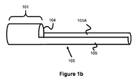
本明細書の実施形態は、ガイディングシースを止血弁内に配する間に、ならびにさらに大きなガイディングシースを通して進める間に、薬剤コーティングバルーンを保護する助けとなるように設計された、保護スリーブを含む。本記載中に議論される図に係わる目的で、別段に述べない限り、左側にあるあらゆるものが、「遠位」または患者の身体/脈管構造の方向にあるものとみなされるのに対し、右側にあるあらゆるものが、近位または患者の身体/脈管構造の外部の方向にあるものとみなされる。 Embodiments herein provide a protective sleeve designed to help protect the drug-coated balloon while placing the guiding sheath in the hemostatic valve and while advancing through a larger guiding sheath. include. For the purposes of the figures discussed herein, anything on the left is considered to be "distal" or in the direction of the patient's body / vessel structure, unless otherwise stated. Anything on the right side is considered to be proximal or outward of the patient's body / vessel structure.
図1aは、典型的な薬剤コーティングバルーンカテーテル103を示し、このカテーテルでは、膨らませることのできる薬剤コーティングバルーン102がカテーテル103の遠位端に装着され、このバルーンの一部は薬剤コーティング102Aを含む。好ましくは、バルーン102の長さおよび周囲の実質的に全てが、薬剤コーティング102Aを含む。多くの場合、バルーン102の近位テーパ端および遠位テーパ端は血管に接触する可能性が低いため、これらの部分は薬剤コーティングを含まない。
FIG. 1a shows a typical drug coated
薬剤コーティングバルーンカテーテル103は、延びた本体部分106を含み、この本体部分では、第1の管腔106Aが本体部分106の長さの全てまたは一部に沿って位置し、それを通してガイドワイヤー108を前進させることができる(および/または造影剤もしくは治療材を患者内にデリバリすることができる)。第2の膨張管腔106Bは、本体部分106の近位端からバルーン102内の開口まで延び、手順の間、膨張媒体のデリバリを可能にする。
The drug coated
また、バルーンカテーテルは多くの場合、図1aに示されるように、本体部分106および管腔106Aに沿ったいくらか遠位の場所に独立した迅速交換ポート106Cを含み、これによりガイドワイヤー108の速やかな配置および除去が可能になる。バルーンカテーテル103は、典型的にはガイディングシースの止血弁内に配され、次いで、標的治療範囲へのデリバリに用いるためにガイディングシースを通してデリバリされる。しかし、上に議論されたように、これらのステップに付随して著しい薬剤のロスがある。
Also, balloon catheters often include an independent
図1bは、ガイディングシースの止血弁を通して配置する間に、ならびにガイディングシースを通して通過させる間に、薬剤コーティングバルーンカテーテル103の薬剤コーティングバルーン102を保護するための、一実施形態による保護スリーブ100を図説する。保護スリーブ100は、遠位管区域101と近位本体部分105とを含み、近位本体部分105は、円弧状のチャネルすなわち「パイプの半片」の形状の領域105Aを有し、領域105Aは、遠位管区域101への開口104を形成する本体部分の近位端105にわたって延びている。
FIG. 1b shows the
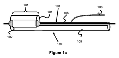
図1cに最も良く見られるように、近位開口部104と区域101の内径の両方がバルーン102の収縮径よりも大きいことから、バルーン102を遠位管区域101内に前進させる。カテーテル103の本体部分106は、管状でない円弧状の領域105A内に配置することができる。好ましくは、図2に示されるように、バルーンを予め遠位管区域101の内部に配して、保護スリーブ100を、カテーテル103に被せて配置した後にガイディングシース110の止血弁112内に配し、次いで、ガイディングシース110を通して押す。
As most often seen in FIG. 1c, both the
保護スリーブ100は、薬剤コーティングバルーン102がガイディングシース110に入る際に止血弁112との直接的な接触からバルーンを保護するための中間面を提供するとともに、前記ガイディングシース110を通して進める際にガイディングシースの内径との直接的な接触から薬剤コーティングバルーン102を保護するための中間面を提供する。薬剤のロスは、第1に、止血弁112を貫いて配置する間に起こり(止血弁の径が減少するだけでなく止血弁の触感がざらついているために)、第2に、ガイディングシース110を通して進める間に起こる。保護スリーブ100は、薬剤コーティングバルーン102を止血弁112に入れる際におよびガイディングシース110を通して進める際に保護することによって、これらの問題を低減または除外する。保護スリーブ100は、ガイディングシース110を通して前進することができるように、ガイディングシース110の内径内にフィットするようサイズ調整されるべきである。バルーン保護スリーブ100の外部表面は、外部ガイディングシース110との摩擦を低減するために、親水性のまたは他の摩擦低減型のコーティングを利用することができる。バルーン保護スリーブ100はまた、上に被せたガイディングシース110と下張りした保護スリーブ100との間の摩擦を低減するために、滑らかなポリマーから作製されることがある。
The
保護スリーブ100は、同封されているバルーンカテーテル103がガイディングシース110を通して前進するように、その近位端で医師により前に進められる。既に議論されたように、保護スリーブ100の近位区域105は、遠位区域101のように完全に同封されているチューブではなく、むしろ円弧状または「パイプの半片」形状の領域105Aである。この構成配置は、薬剤コーティングバルーン102の装填をさらに容易にする。なぜなら、バルーン102は、バルーン保護スリーブ100の全長が完全に同封された管状形状を有する場合にそうであるようにバルーン保護スリーブ100の全長を通して押される代わりに、切り抜き開口部104を通して押されるだけで遠位管区域101に近付かなければならないためである。本体部分106が保護スリーブ100の円弧状部分105Aに存在するため、医師は、近位本体部分105(または任意選択で近位本体部分105の近位端とカテーテル103との両方)の近位端のみを操作することによって、スリーブ100とカテーテル103との両方を共に前進させることができる。このようにして、近位本体部分105をナビゲーション区域と考えることができるが、それは、ユーザが、近位本体部分105の近位部を握って、同封されているバルーンカテーテル102および薬剤コーティングバルーン102と併せて保護スリーブ100を動かすためである。
The
ガイディングシース110を通して通過し標的治療部位に配された後、薬剤コーティングバルーン102は、僅かな方法のうちの1つで曝露される。まず、保護スリーブ110をガイディングシース110から押し出すか、またはガイディングシース110を近位で引き出して保護スリーブ100の遠位管区域101を曝露する。次いで、保護スリーブ100を引き込んで薬剤コーティングバルーン102を曝露し、バルーンカテーテルを保護スリーブ100から押し出すか、または両方の手法を併せて実施することができる(二重押し出し/引き込み法)。薬剤コーティングバルーン102が保護スリーブ100内に位置することから、薬剤コーティングバルーン102と保護スリーブ100との間の摩擦に起因して少量の薬剤のロスが生じ得るが、この薬剤のロスは、スリーブ100のない際に起こるような量よりもはるかに少ない。バルーン102からの薬剤のロスをさらに軽減するために、保護スリーブ100の内部表面は、親水性のまたはその他摩擦低減型のコーティングを含むか、または滑らかなポリマーから作製されることがある。
After passing through the guiding
遠位管区域101の遠位端は、図3aに見られるように、放射線不透過性(例えばタンタル)マーカー帯114をさらに含むことがある。ガイディングシース110は、多くの場合、遠位先端から約3cmにマーカー帯を含み、その結果、ガイディングシースを通してデリバリされるデバイスは、遠位先端に合致して、ガイディングシース110に対し確実に適正に配置される。この点、マーカー帯114は、ガイディングシース110のマーカー帯に合致した際に、保護スリーブがガイディングシースの遠位端にあることを、ユーザが確かめる助けとなる。
The distal end of the
遠位の管状領域101とチャネル105Aとの間に作製される開口部104は、図1bに見られるように、概ね垂直の壁の切り口(すなわちスリーブ100の伸びた軸に垂直な切り口から形成することができるか、または、図3b(例えば45度かまたは90度未満の角度)に見られるように近位の方向に減少してゆく角度で切断して、2つの領域101と105Aとの間に遷移部を作製することができる。一例では、保護スリーブ100は、開口部104と近位区域105の近位端との間のチューブの一部を切断し、それによって、円弧状部分またはチャネル部分105Aを形成することによって製造することができる。別の例では、遠位管区域101を、長手方向に切断されたチューブ全体に接続して、近位部分105を形成することができる。
The
薬剤コーティングバルーンは、多くの場合、失う可能性のある薬剤の量を低減するために、図4に示されるようにプリーツが付いている。プリーツ116は、バルーン102に被せた面と接触する可能性がある外部領域116Aと、その被せた面から保護される内部領域116Bとを含む。このプリーツの付いたデザインは、バルーン全面を確実に曝露しないものとし、それによって、配置および進行の間に失われる薬剤の量を制限する助けとなる。
Drug-coated balloons are often pleated as shown in FIG. 4 to reduce the amount of drug that can be lost. The
薬剤コーティングバルーン102は、先に議論されたように、図1Aに示されるようなガイドワイヤー108を収容できる管腔106Aを含み、続いて導入される任意の治療材のための通路を提供し、この治療材は、治療範囲でさらに使用されることがある。バルーン102の近位端は、膨張管腔106Bに接続されており、脈管構造の標的治療部位に配置されると、カテーテル本体106のポートを通して膨張媒体(例えば液体造影剤)が注入されて、バルーン102を膨らませることを可能にする。
The drug coated
図5は、バルーンおよびバルーン保護スリーブ100が、前記ガイディングシース110を通して進むために、ガイディングシース110の止血弁112内に配されているところを示す。様々な実施形態が、保護スリーブ100内にバルーンを配することについて想定される。一実施形態では、バルーン102は、保護スリーブ100の遠位管区域101内に予め配され、パッケージとしてエンドユーザに販売される。別の実施形態では、エンドユーザは、保護スリーブ100の遠位管区域101内に、例えば保護スリーブ100の開口部104を通してバルーン102を押すことによって、バルーン102を物理的に配する。バルーンが保護スリーブ100内にあれば、保護スリーブ100を止血弁112内に物理的に配し、左記に記載された方法でガイディングシース110を通して押す。エンドユーザが保護スリーブ100の遠位管区域101内にバルーンを配する場合の実施形態では、貯蔵および運送の過程の間の薬剤のロスを防ぐために、バルーン102を一時的な保護構造内に配する必要があることがあること―この一時的な保護構造は、エンドユーザが保護スリーブ100の遠位管区域101内にバルーンを配した際に、次いで、前記ユーザによって除去されることになることに留意されたい。
FIG. 5 shows that the balloon and the balloon
保護スリーブ100の他の実施形態は、切り抜き領域105Aのないものとすることができ、むしろ全体的に管状である。この実施形態の場合、完全に管状の保護構造を通してバルーンを進めるのに必要な労力を最小にするために、薬剤コーティングバルーン102を予め装填して保護スリーブ100をエンドユーザに販売/分配することが有用となる。
Another embodiment of the
先の議論は、薬剤のロスの起こる可能性のある主要なシナリオとして、ガイディングシース110内に薬剤コーティングバルーン102を配置すること、ならびにガイディングシース110を通してバルーン102を進めることについて強調した。しかし、血液への曝露もまた、薬剤コーティングバルーン102からの薬剤のロスを引き起こす可能性がある。一般に、薬剤コーティングバルーン102をガイディングシース110の遠位端に進めると、バルーン102を展開する前であっても、薬剤コーティングバルーン102の遠位部分が血液に接触することがあり、加圧された血流によって、薬剤コーティング102Aがバルーン102から取り除かれることがある。保護スリーブ100は、保護スリーブ100の表面積に起因して血液の接触可能なバルーン表面の量を制限することによって、これらの問題のいくつかに対処することができる。しかし保護スリーブ100のみでは、血液の接触に起因する薬剤のロスを完全には防止しないことがある。図6~8は、血液の接触/血流に起因するこの薬剤のロスを低減するための、様々な実施形態を記載する。
The previous discussion emphasized placing the drug coated
図6では、ノーズコーン118が、バルーン102との直接的な血流の接触を遮断するかまたはその向きを変える助けとなるバルーン102の遠位端を越えて、カテーテル本体106の遠位端に取り付けられ、それによって、さらに薬剤コーティング102Aのロスをさらに低減する。ノーズコーン118は、カテーテル本体106の周りに配置されるか、またはそれを貫いて管腔106Aに合致する経路を含むかのどちらかであり、それゆえに、ノーズコーン118は、管腔106Aを通して前に進められるガイドワイヤーまたは他の剤のための出口を提供する。好ましくは、ノーズコーン118は、描図されたような近位に向けて増えてゆく円錐状の形状か、または同様の傾斜した形状とすることができ、それゆえに、円錐の近位端は、デリバリ中に血液が早期にバルーンに接触するのを防止するために、最大の厚みを有するのに対し、遠位端は、バルーンが脈管構造内に配された際に血流を実質的に妨げないように、より小さなプロファイルを有する。しかし,種々の形状が想定され、そのようなものとしては、円錐、円柱、長円、卵形、および/または弾丸様の形状が挙げられる。
In FIG. 6, the
一実施形態では、ノーズコーン118が、バルーン保護スリーブ100内に位置し、ノーズコーン118の近位端が、バルーン保護スリーブ100の内径と同様の径を有し、それによって、血液が薬剤コーティングバルーン102に接触するのを防止する。別の実施形態では、ノーズコーン118が、バルーン保護スリーブ110に対し遠位に位置し、ノーズコーン118の近位端が、ガイディングシース110の内径と同様の径を有する。
In one embodiment, the
血液によって誘発される薬剤コーティングのロスはまた、血液が薬剤コーティングバルーン102に接触できる空間が少なくなるように、バルーン保護スリーブの遠位端を狭めることによって、対処することができる。図7~8は、そのような実施形態の1つを説明するものであり、そこでは、バルーン保護スリーブ200は、遠位管区域201の近位部分に比べてはるかに狭まった遠位区域220を有する。この狭まった遠位区域220は、バルーン102がガイディングシース110を通して進みながら保護スリーブ内に格納されるのに伴って、バルーン102の全体またはバルーンの遠位部分のみを収容できる。狭まった遠位区域220は、保護スリーブ200の遠位管区域201の残り部分(バルーン102を収容可能)に比べて小さな径を有し、それゆえにバルーンに比べて緊密に収まり、血液が入り込む空間を制限する。これによって、血液が入り込んでバルーン102から薬剤コーティング102Aを取り除く機会が軽減される。
Blood-induced loss of drug coating can also be addressed by narrowing the distal end of the balloon protective sleeve so that there is less space for blood to contact the drug coated
図7~8に示される狭まった遠位区域220は、血液により薬剤コーティング102Aがバルーンから押し出されるかもしくは洗い出されるのを防止し易くするよう複数のレベルで保護することができるように、図6に示されるノーズコーン118の代わりに使用することができるか、またはノーズコーン118と共に使用することができる。
The narrowed
狭まった遠位区域220の実施形態の様々な実施形態が想定される。例として、内部に薬剤コーティングバルーン102が位置している区域全体を、比較的狭いものとすることができる。あるいは、遠位部分のみを狭めて、拡大された近位区域にバルーン102の近位区域を位置させるとともに、狭まった区域220内にバルーンの遠位区域を位置させる。
Various embodiments of the narrowed
上記の狭まった遠位区域220を利用する実施形態は、内部にバルーンが収まるさらに詰まった遠位区域(図1~2の管状区域101と同様のサイズ)と、次いでこのバルーンを越えてさらに小さな狭まった遠位区域220とを利用することができ、その場合、この狭まった区域は、保護スリーブに入り込んで薬剤コーティングバルーン102に接触し得る血液の量を制限することになる。
The embodiment utilizing the narrowed
先の記載では、どのように保護スリーブ100の近位端を押す/引くことによってバルーンカテーテル103(薬剤コーティングバルーン102はその一部である)がガイディングシース110を通して進められるかを議論したが、この場合、バルーンカテーテルが保護スリーブ100内に収められているために、上記の押し引きによってバルーンカテーテル100(および薬剤コーティングバルーン102)が順次移送される。保護スリーブ100の近位区域105は、実施形態のいくつかでは管状ではなく、保護スリーブ100内に薬剤コーティングバルーン102を配置させ易いものとする。しかし、この構成の短所の1つは、保護スリーブ100の近位部105がチャネル105Aから切り出されているために、断面積がさらに小さなものであることに起因して、軸方向強度または保護スリーブ100に対するねじれ抵抗性がさらに少ないことである。
In the previous description, we discussed how the balloon catheter 103 (where the drug coated
図7~8において、保護スリーブの近位区域205は、そのチャネル205Aの円弧が図1~3bの実施形態に示されるチャネル105Aに比べて大きく湾曲しており、この湾曲は、よりホタテ貝状をとる切り口(すなわち周囲/幅の増えた切り口)を領域204に形成して薬剤コーティングバルーンのための入口部を画定することによって、実現される。このホタテ貝状の切り口は、ディボットのまたは内側にテーパ状をとる切り口領域204aによって画定されるが、この切り口領域204aは、本来ならばチャネル105Aの開口が比較的狭いゆえにフィットしない薬剤コーティングバルーン102を遠位にある管状区域201内に収容することのできる十分なギャップ、入口、空間、またはポートを作り上げる。この近位区域105が、さらに小さな開口のあるチャネル205Aを有して、保護スリーブの押す力を増大するように任意の保護スリーブの実施形態に使用されることがある。
In FIGS. 7-8, the
先に議論したように、ガイディングシースを通して薬剤コーティングバルーンを進める際に薬剤コーティングのロスが起こる可能性がある主な場所は、ガイディングシース110の止血弁112内に配置する間、ならびにガイディングシース110を通して進める間である―その場合、止血弁112は、最も多量の薬剤コーティング102Aが失われる場所である。薬剤コーティング102Aのロスは、数少ない理由により、止血弁112を貫いて配置する間のために起こる。第1に、ガイディングシースの径に比べて止血弁112の径が小さいために、止血弁112を貫いてバルーン102を配置する際にバルーン102との接触摩擦が増加する。第2に、止血弁ポートが滑らかでないために、摩擦による薬剤コーティング102Aのロスが促進される可能性がある。第3に、薬剤コーティングバルーン102はいくらか柔らかいが、このことは、医師が一般に、止血弁112を貫いて押し進めるためにバルーン102を握り締めなければならないことを意味し、それゆえに接触による薬剤コーティングのロスが引き起こされる。最後に、止血弁112を通じた血液の逆流もまた、血液との接触による薬剤のロスを引き起こす可能性がある。以下の実施形態は、比較的短い保護スリーブに対するものであり、このスリーブは、止血弁112内への挿入時に―すなわち血液のロスが生じる主要なシナリオにおいて、薬剤コーティングバルーン102を保護するようにのみ機能するが、ガイディングシース110を通して進める際には必ずしもバルーン102を保護する訳ではない。
As discussed earlier, the main locations where drug coating loss can occur when advancing the drug coated balloon through the guiding sheath are during placement within the
図9は、短縮保護スリーブ300を説明するが、このスリーブの機能が、ガイディングシース110の止血弁112を貫いて挿入するの間にのみ薬剤コーティングバルーン102を保護するためのものであることから、このスリーブは、挿入スリーブ300であるとも考えられる。保護スリーブ300は、止血弁112内への挿入の間にバルーンを保護するに過ぎないため、ガイディングシース110の全長にわたって広がっている必要のある図1~8の保護スリーブの実施形態100および200よりもはるかに短いものとすることができる。
FIG. 9 illustrates a shortened
バルーン102をガイディングシース110の止血弁112の内側に配置する際に、バルーン102を覆って保護スリーブ300を配置して、前記止血弁112内に配置する際の薬剤のロスから薬剤コーティングバルーンを保護することができる。保護スリーブ300では、その全長に沿って薄い切り口301(例えば、0.002インチ以下の開口を画定する切り口301a)が延びており、完全な長円形/円形の形状の代わりに断面でのc形状を形成している。保護スリーブ300の一端は、好ましくはフレア状であるかまたは径方向に開いて、フレア端305を形成する(すなわち、切り口301Aは近位方向に幅が増加する)。一例では、保護スリーブ300は、円柱として形成されるが、区域305の切り口301Aが、スリーブの残り部分の切り口301よりも大きく、それによってフレア端305はフレア形状を採るものとなる―このことは、領域305で用いられる切り口が大きいほど、フレア端の形状が大きくなることを意味する。図9に示されるように、末端区域301Cでの切り口のサイズが区域301Bでの切り口のサイズよりも大きくなるように、切り口301Aはテーパ状をとる。一例では、末端区域301Cでの切り口サイズは、約0.17インチから約0.23インチの開口を画定する。保護スリーブ300は、約2.75-3.25インチの長さであり、フレア端は、約0.5から1インチの長さである。別の例では、保護スリーブ300は、約3インチ、約7.62センチメートル、または約8センチメートルの長さであり、フレア端305は、約0.75インチの長さである。保護スリーブ300は、Pebax7233 SA01などのポリマー材を含めた種々の材料から形成することができる。一例では、保護スリーブ300は、約0.1インチの内径と約0.115インチの外径とを有する。保護スリーブ300は一般に円筒から形成され、その円筒は、先述したようなフレア端305をとるように比較的大きな切り口を領域301Cにもたらすことから、保護スリーブの径は、スリーブの外径と切り口のサイズとを足し合わせたものと考えることができる。このアプローチを用いると、保護スリーブのフレア端305の径は、約0.285インチから0.345インチ、または約0.315インチとなる―その一方で、保護スリーブのフレア状でない部分のスリーブ径は、約0.115インチから0.12インチ、または約0.117インチである。
When the
図10は、保護スリーブ300が、予めバルーンカテーテル103の近位部分に配置されている実施形態を示し、この場合、バルーンカテーテル100は、保護スリーブ300が既に前記バルーンカテーテル100の近位部分を覆って位置している状態で、エンドユーザに販売される。保護スリーブ300の近位端(フレア端305に合致)は、バルーンカテーテル103の拡張された張力緩和部303を覆って位置するものとなる。
FIG. 10 shows an embodiment in which the
近位のフレア305は、2つの目的のために有用である。第1に、このフレアは、僅かに拡張された領域を提供して、より良好に張力緩和部303を覆ってフィットする。第2に、薬剤コーティングバルーンが前記保護スリーブ300を通して装填される際に、この近位のフレア305は、前記バルーンの進入をより滑らかなものとする。図9と図10とを比較すると、切り口301は、図10に示される保護スリーブ300の下部に位置することになる。ユーザは、ただ単に保護スリーブ300をバルーンカテーテル1から取り除き、次いで、ガイディングシースの止血弁内に保護スリーブ300を配置することができる―下記にさらに詳細に説明する方法で行う。
保護スリーブ300を用いる方法を図11~13に示す。これらの図にあるように、左側のあらゆるものが遠位にあるものと考えられ、右側のあらゆるものが近位もあるものと考えられることに留意されたい。保護スリーブ300をまずバルーンカテーテル103の近位区域から取り除いて、後に前記バルーンカテーテル103の遠位区域が前記保護スリーブ300を通して配置されるようにした。切り口301があるため、この除去は、切り口301に向かって力を加えることによって起こすことができる(図10を参照すると、切り口301がスリーブ300の下部に位置することから、上向きに引いてスリーブ300を除去する)。
The method using the
一般に、薬剤コーティングバルーンは、製造後に薬剤を保護するために、運送および操作の間は保護チューブ307中に搭載されて届く。薬剤コーティングバルーン/バルーンカテーテルを使用する前に、ガイディングシースの止血弁内に配置する前に、この保護チューブ307を取り除かねばならない。バルーンカテーテル管腔103を囲んでバルーンカテーテル103の遠位端に配置された薬剤コーティングバルーンを含む、バルーンカテーテルの遠位部分を図11に示す。周囲に保護チューブ307を含むバルーンカテーテルの遠位部分を、保護スリーブ300を通して挿入し、バルーンカテーテルの遠位部分および保護チューブ307の遠位部分が、保護スリーブ300の遠位端を通り越えて位置するようにする。次いで、保護チューブ307を図12に示されるように遠位に(左方へ)引いて、保護チューブ300をバルーン102から取り除く。この後、図13に示されるように、次いで、保護スリーブ300をガイディングシース110の止血弁112内に配置して、保護スリーブ300が、止血弁112全体を貫いて配置されるようにする。次いで、バルーンカテーテルを遠位に(左方向に)押し込み、バルーン102を、止血弁112に貫通させてガイディングシース110内に前進させる。バルーン102全体が止血弁112を通り越えてガイディングシース内に装填されれば、保護スリーブ300を近位に引き込んで(右に引いて)取り除き(例えば、切り口に向かって引き、そして図13中での上方に引いてスリーブ300全体を取り除くことによって)、バルーンカテーテル103の残り部分を、止血弁112に貫通させてガイディングシース110内に押し込む。
Generally, the drug coated balloon arrives mounted in a
代替の実施形態は、短縮保護スリーブ300を、バルーンカテーテル103に接続されていない独立した部品として有する。しかし、バルーンカテーテル103を覆って予め配置しておくことによって、バルーンカテーテルシステムまたはキットの一部として短縮保護スリーブ300を配置するためのさらに便利なフォーマットがもたらされることになる。また、代替の実施形態は、予め切り口のあるまたは予め弱められた領域を、切り口301の代わりに利用することもあり、その場合、ユーザは、開口領域301を引き裂くのに十分な圧力を加える。
An alternative embodiment has a shortened
スリーブ/保護スリーブ300を挿入させる主なメリットは、止血弁112の持つ低減された径と粗い面との接触から薬剤コーティングバルーン102を保護し、それによって、前記止血弁112を貫いて配置させる間の薬剤のロスの問題を軽減することである。保護スリーブ300の切り口区域301のさらに別の利点の1つは、スリーブが径の小さなチューブ内に配置された際に、チューブ端が重なって、より小さなプロファイルにフィットできることである。止血弁112が、ガイディングシースの残り部分に比べて径が低減されていることから、保護スリーブ300は、それ自体を覆って丸まり、この低減された径にフィットすることができる(このことは、保護スリーブ300が、さらに小さな径の止血弁にフィットするように合致できる―それに対し、切り口のないチューブは、明白な理由で、そのチューブよりも径の小さな止血弁内にフィットできないものとなることを意味する)。先の記載では、薬剤のロスの原因の1つが血液への曝露であることを議論した。保護スリーブ300が接触して止血弁300にフィットするする能力とは、血液に曝露され得る薬剤コーティングバルーンの曝露表面積が少なく、配置させる間に薬剤がバルーンから脱落する機会をさらに最小限にすることを意味する。
The main advantage of inserting the sleeve /
保護スリーブがガイディングシースの長さに延びており、かつ薬剤コーティングバルーンを支持するための遠位管区域を含む、図1~8の保護スリーブの実施形態では、スリーブは、ガイディングシース110内に配置されることから、相対的に長いものでなければならない。遠位管区域101、201もまた、薬剤コーティングバルーンの長さと同様のサイズとしなければならない。薬剤コーティングバルーン102は、治療される血管面積のサイズに応じて40-200ミリメートルの長さの範囲とすることができ、それゆえに、遠位管区域101、201は、バルーンを収容できるように少なくともこのサイズとしなければならない。スリーブ/保護スリーブ300を挿入させる利点の1つは、それが、ガイディングシースの止血弁112に広がるのに十分な大きさでさえあればよいことから、比較的短いことである。いくつかの例では、先述されたように、保護スリーブ300は、約3インチ、7.62センチメートル、または約8センチメートルの長さである。
In embodiments of the protective sleeve of FIGS. 1-8, where the protective sleeve extends to the length of the guiding sheath and includes a distal tube area to support the drug coated balloon, the sleeve is within the guiding
硬化性物質は、血管に蓄積する際に、多くの場合不格好な形状をとる―図14に示される血管断面に示される通り、血管400では、硬化性物質402が、小さくなった血管断面404を血流に対し残す。この硬化性の蓄積は、血液が血管を通って流れることのできる空間を狭め、狭窄と呼ばれる現象において、血管を通る血流を減少させる―狭窄は、種々の合併症を引き起こし得る。典型的な治療手順は、いくらかの方法で進めることができる。治療選択肢の1つは、高圧バルーンを使用して、膨らませて硬化を圧縮し、規則正しい血流を血管に復活させようと試みることである。しかし、硬化が特に稠密である場合、または狭窄が繰り返し発生し続ける場合(再狭窄として知られる現象)、この方法は有用ではない。
The curable material often takes an awkward shape when accumulating in the blood vessel-in the
第2の治療選択肢の1つは、薬剤コーティングバルーンを使用して、薬剤を血管壁および硬化性物質に適用し、狭窄を治療しようと試みることである。しかし、硬化性物質の不規則なプロファイルにより、薬剤を血管周囲に均等に、効果的に適用することが難しいものとなることがあり、これは、バルーンに血管断面404に合致するよう不格好な形状をとらせることが難しくなるためである―実際に、薬剤コーティングバルーンを自然に挿入する結果、薬剤コーティングバルーンは、硬化性領域の「最も狭い」部分に接触するに過ぎないものとなり、これは、薬剤をデリバリするには極めて効率の悪い方法である。さらに、厚い硬化性層が存在することにより、薬剤が血管の壁に到達するのが難しいものとなる。医師は多くの場合、この問題に対処するために前拡張ステップを使用するが、そのステップでは、第1の高圧バルーンを硬化性領域内に挿入し、広げて硬化を圧縮し均一な環状の管腔を生じる―均一な環状の管腔があれば、その領域を治療するために薬剤コーティングバルーンが環形状を採ることははるかに容易である。前拡張ステップが完了すれば、第2のバルーン―パクリタキセル、シロリムス、および/またはゾタロリムスなどの抗硬化薬でコーティングすることの可能な薬剤コーティングバルーンを、次いで挿入し、膨らませて硬化および血管壁に接触させ、薬剤を前記硬化および組織にデリバリする。この手順は、かなりの時間をとることがあるが、これは、第1のバルーンを、ガイディングシースを通して進め、標的部位にデリバリして前拡張ステップとして膨らませ、次いで、萎ませてガイディングシースを通して引き出さねばならないためである。次いで、薬剤コーティングバルーンを、ガイディングシースを通して進め、標的部位に配置し、広げて薬剤をデリバリし、次いで除去して引き出さねばならない。前拡張以外のステップは、硬化に起因して血管が著しく狭まっている状況下では、余分な時間を取り、脳卒中などの合併症のリスクを増加させる可能性がある。以下の実施形態は、二元式バルーンマイクロカテーテルシステムに対処するが、このシステムは、拡張と薬剤デリバリとを同時に行うことができるように、拡張バルーンと適合自在な薬剤コーティングバルーンとの両方を含む。
One of the second treatment options is to use a drug-coated balloon to apply the drug to the vessel wall and sclerosing material to attempt to treat the stenosis. However, the irregular profile of the sclerosing substance can make it difficult to apply the drug evenly and effectively around the vessel, which is an awkward shape to match the
図15は、2つのバルーンを有するバルーンカテーテルシステム405を説明する。この2バルーンシステムは、外側の第1の極めて適合自在な薬剤コーティングバルーン406と内側の第2の高圧バルーン408とを利用する。1つのバルーンカテーテル上に2つのバルーンを含むことにより、別の前拡張ステップの必要はないが、これは、内側バルーンが、血管を拡張することができるとともに、次いで、外側バルーンが、拡張後に狭窄に合致することができ、それゆえに、狭窄を治療するための2つの別々のバルーンカテーテルと、脈管構造を通して2つの別々のバルーンカテーテルを進めるのに伴う時間とが必要ないためである。
FIG. 15 illustrates a
一実施形態では、この2つのバルーンは、図15に示されるように同心である。バルーンカテーテルは2つの膨張管腔を含有し、一方(408a)は内側バルーンを膨らませ、他方(408b)は外側バルーンを膨らませる―その一方で、第3の管腔410は、ガイドワイヤーまたは追加の治療材のための進入路を提供する。液体造影剤などの典型的な膨張媒体を使用して、バルーンを膨らませることができる。内側バルーンは、高圧バルーンであり、硬化を圧縮しそれによって血管を拡張するために強度の高いものとすべきである。ナイロンなどの従来の高圧バルーン材は、この内側の/第2のバルーン408に使用することができる。外側バルーン406は、硬化性領域全体にわたって均一な薬剤デリバリを確実に行うために、適合性が高く、硬化性領域の形状に合致することを意図されている。そのため、柔らかく適合自在な材料が、内部/第1のバルーンに理想的であり、Polyblend 18-45が内部/第1のバルーンに使用されることがある。
In one embodiment, the two balloons are concentric as shown in FIG. The balloon catheter contains two inflatable lumens, one (408a) inflating the inner balloon and the other (408b) inflating the outer balloon-while the
図14に示されるもののような硬化性領域を治療するための、二元式バルーンカテーテルシステム406の使用方法を以下に記載する。第1の適合自在な外側の薬剤コーティングバルーン406をまず膨らませると、バルーンの適合自在な性質に起因して、このバルーンは、硬化性領域の形状に概ね合致して、その領域に薬剤をデリバリすることができる―しかし、狭窄の形状の性質に応じて、形状が特に複雑または不規則である場合に、その形状に完全には適合しないことがある。医師は、蛍光透視法を介して治療部位を観察し、どのようにして適合自在な薬剤コーティングバルーンを血管の形状にうまく合致させるかを決定することができる。均一な環形状を得るかまたは硬化を圧縮するために拡張が必要である場合には、第1の外側バルーン406を萎ませて、次いで、第2の内側の高圧バルーン408を膨らませる。外側バルーン406が内側バルーン408を覆って位置することから、外側バルーン406は硬化との接触を維持するが、内側の高圧バルーンからの力は、硬化をさらに圧縮し、血管を通る血流のための均一な開いた管腔を生じる。留意すべきは、外側の薬剤コーティングバルーン406が狭窄の形状に適合している場合であっても、拡張の手順を使用して、狭窄の蓄積の量を減少させ、血流のために血管を「開放する」ことが依然として望ましいことがある―高圧の内側バルーン408を含むことによって、同じバルーンカテーテルを利用しながらこれを行うことが可能になることである。
The use of the dual
他の二重バルーンシステムがさらに想定される。例として、2つのバルーンを用いる二元式の管腔膨張システムを使用することができ、その場合、バルーンは、長手方向に互いに隣接して(すなわち互いの近位/遠位に)配置される。一方のバルーンは、適合自在な薬剤コーティングバルーンであり、第2の線形に転置されるバルーンは、高圧バルーンである。このシステムを用いると、バルーンを、どちらの順番でも使用することができる(例えば、適合自在な薬剤コーティングバルーンと高圧バルーンのどちらかを膨らませて最初に使用することができる)。カテーテルは、第1のバルーンと第2のバルーンのどちらかが硬化性領域と一直線となるように、線形に動かすことができる。 Other double balloon systems are further envisioned. As an example, a dual luminal inflatable system with two balloons can be used, in which the balloons are placed adjacent to each other in the longitudinal direction (ie, proximal / distal to each other). .. One balloon is a adaptable drug coated balloon and the second linearly transposed balloon is a high pressure balloon. With this system, the balloons can be used in either order (eg, either the adaptable drug coated balloon or the high pressure balloon can be inflated and used first). The catheter can be moved linearly so that either the first balloon or the second balloon is aligned with the curable region.
本発明は、具体的な実施形態および適用に関して記載されているが、当業者は、この教示に照らして、特許請求の範囲に記載される発明の趣旨を逸脱することなく、またその範囲を超えることなく、追加の実施形態および改変を作り出すことがある。したがって、本明細書の図面および記載は、本発明の把握を促すために例として提供されるのであって、その範囲を限定するものと解釈されるべきではないことを理解されたい。
Although the present invention has been described with respect to specific embodiments and applications, those skilled in the art will, in the light of this teaching, without and beyond the gist of the invention described in the claims. It may produce additional embodiments and modifications without. Therefore, it should be understood that the drawings and descriptions herein are provided as examples to facilitate understanding of the invention and should not be construed as limiting their scope.
Claims (14)
前記バルーンカテーテル(103)の近位端の近くの張力緩和部(303)と、
保護スリーブ(300)であって、その全長に沿って延びた一の長手方向の開口(301)を有し及びc字形状の断面を形成する、保護スリーブと、を含み、
前記保護スリーブ(300)は、概ね管状の形状を形成し、第1の非フレア状区域であって、前記保護スリーブ(300)が前記薬剤コーティングバルーン(102)を覆って配置されたときに、前記第1の非フレア状区域における前記開口は第一の幅を有する、第1の非フレア状区域と、
第2のフレア端区域であって、前記保護スリーブ(300)が前記薬剤コーティングバルーン(102)を覆って配置されたときに、前記第2のフレア端区域における前記開口は前記第一の幅より大きく且つ前記第1の非フレア状区域から離れる方向に増していく第二の幅を有し、前記第2のフレア端区域は、前記張力緩和部の一部を覆って配置されるようなサイズを有する、第2のフレア端区域と、を有し、
前記保護スリーブ(300)は、前記薬剤コーティングバルーン(102)が前記止血弁(112)の内側に配置される際に前記薬剤コーティングバルーン(102)を覆って配置され、次いで、前記薬剤コーティングバルーン(102)が前記止血弁を貫いて挿入されるのに伴って前記ガイディングシース(110)の止血弁(112)を貫いて挿入され、前記薬剤コーティングバルーン(102)を保護するように構成されている、
バルーンカテーテル。 A balloon catheter (103) suitable for inserting a drug-coated balloon (102) through a hemostatic valve (112) of a guiding sheath (110).
A tension relief section (303) near the proximal end of the balloon catheter (103),
A protective sleeve (300) comprising a protective sleeve having one longitudinal opening (301) extending along its entire length and forming a c-shaped cross section .
The protective sleeve (300) forms a generally tubular shape and is a first non-flared area when the protective sleeve (300) is placed over the drug coated balloon (102). The opening in the first non-flared area has a first width, the first non-flared area and
In the second flare end area, when the protective sleeve (300) is placed over the drug coated balloon (102), the opening in the second flare end area is from the first width. It has a large second width that increases away from the first non-flared area, and the second flared end area is sized so as to cover a part of the tension relief portion. With a second flare end area , and with,
The protective sleeve (300) is placed over the drug coated balloon (102) when the drug coated balloon (102) is placed inside the hemostatic valve (112), and then the drug coated balloon (102). 102) is inserted through the hemostatic valve (112) of the guiding sheath (110) as it is inserted through the hemostatic valve, and is configured to protect the drug coated balloon (102). Yes,
Balloon catheter.
The balloon catheter according to claim 12, wherein the protective sleeve has a larger diameter than the protective tube.
Applications Claiming Priority (5)
| Application Number | Priority Date | Filing Date | Title |
|---|---|---|---|
| US201662404647P | 2016-10-05 | 2016-10-05 | |
| US62/404,647 | 2016-10-05 | ||
| US201662414520P | 2016-10-28 | 2016-10-28 | |
| US62/414,520 | 2016-10-28 | ||
| PCT/US2017/055422 WO2018067875A1 (en) | 2016-10-05 | 2017-10-05 | Balloon catheter systems |
Publications (3)
| Publication Number | Publication Date |
|---|---|
| JP2019528995A JP2019528995A (en) | 2019-10-17 |
| JP2019528995A5 JP2019528995A5 (en) | 2021-09-09 |
| JP7048592B2 true JP7048592B2 (en) | 2022-04-05 |
Family
ID=61757531
Family Applications (1)
| Application Number | Title | Priority Date | Filing Date |
|---|---|---|---|
| JP2019518537A Active JP7048592B2 (en) | 2016-10-05 | 2017-10-05 | Balloon catheter system |
Country Status (5)
| Country | Link |
|---|---|
| US (2) | US10874826B2 (en) |
| EP (2) | EP3522824B1 (en) |
| JP (1) | JP7048592B2 (en) |
| CN (1) | CN110177522B (en) |
| WO (1) | WO2018067875A1 (en) |
Families Citing this family (1)
| Publication number | Priority date | Publication date | Assignee | Title |
|---|---|---|---|---|
| CN113195033A (en) * | 2019-03-22 | 2021-07-30 | 泰尔茂株式会社 | Balloon catheter and balloon deployment method |
Citations (3)
| Publication number | Priority date | Publication date | Assignee | Title |
|---|---|---|---|---|
| JP2014516691A (en) | 2011-05-20 | 2014-07-17 | アボット カーディオバスキュラー システムズ インコーポレイテッド | Method for inserting drug-coated balloon hemostasis valve and balloon sheath |
| US20140221831A1 (en) | 2010-08-03 | 2014-08-07 | Cook Medical Technologies | Method of introducing a catheter |
| JP2016516552A (en) | 2013-05-03 | 2016-06-09 | シー・アール・バード・インコーポレーテッドC R Bard Incorporated | Protective sheath that can be peeled off |
Family Cites Families (22)
| Publication number | Priority date | Publication date | Assignee | Title |
|---|---|---|---|---|
| US5147302A (en) * | 1989-04-21 | 1992-09-15 | Scimed Life Systems, Inc. | Method of shaping a balloon of a balloon catheter |
| US5242399A (en) | 1990-04-25 | 1993-09-07 | Advanced Cardiovascular Systems, Inc. | Method and system for stent delivery |
| US5634901A (en) * | 1992-11-02 | 1997-06-03 | Localmed, Inc. | Method of using a catheter sleeve |
| US5800517A (en) * | 1996-08-19 | 1998-09-01 | Scimed Life Systems, Inc. | Stent delivery system with storage sleeve |
| US5843027A (en) | 1996-12-04 | 1998-12-01 | Cardiovascular Dynamics, Inc. | Balloon sheath |
| US6152944A (en) * | 1997-03-05 | 2000-11-28 | Scimed Life Systems, Inc. | Catheter with removable balloon protector and stent delivery system with removable stent protector |
| US5893868A (en) | 1997-03-05 | 1999-04-13 | Scimed Life Systems, Inc. | Catheter with removable balloon protector and stent delivery system with removable stent protector |
| US6093173A (en) | 1998-09-09 | 2000-07-25 | Embol-X, Inc. | Introducer/dilator with balloon protection and methods of use |
| US6110146A (en) * | 1998-09-30 | 2000-08-29 | Medtronic Ave, Inc. | Protector for catheter balloon with guidewire backloading system |
| US6783542B2 (en) * | 2001-02-22 | 2004-08-31 | Scimed Life Systems, Inc | Crimpable balloon/stent protector |
| US7105013B2 (en) * | 2002-09-30 | 2006-09-12 | Advanced Cardiovascular Systems, Inc. | Protective sleeve assembly for a balloon catheter |
| US8652198B2 (en) * | 2006-03-20 | 2014-02-18 | J.W. Medical Systems Ltd. | Apparatus and methods for deployment of linked prosthetic segments |
| CA2716985A1 (en) | 2008-03-06 | 2009-09-11 | Boston Scientific Scimed, Inc. | Balloon catheter devices with sheath covering |
| WO2009135125A2 (en) * | 2008-05-01 | 2009-11-05 | Bayer Schering Pharma Ag | Catheter balloon drug adherence techniques and methods |
| US8460168B2 (en) * | 2009-03-27 | 2013-06-11 | Circulite, Inc. | Transseptal cannula device, coaxial balloon delivery device, and methods of using the same |
| US9421346B2 (en) * | 2009-04-16 | 2016-08-23 | Covidien Lp | IUPC introducer |
| GB0921240D0 (en) | 2009-12-03 | 2010-01-20 | Angiomed Ag | Stent device delivery system and method of making such |
| EP2361651B1 (en) * | 2010-02-25 | 2016-04-27 | Biotronik AG | System comprising a protective sleeve and a medical device, and method for the production thereof |
| US20140074022A1 (en) * | 2012-09-11 | 2014-03-13 | Boston Scientific Scimed, Inc. | Loading tools for use with balloon catheters |
| WO2015061801A2 (en) * | 2013-10-26 | 2015-04-30 | Accumed Radial Systems Llc | System, apparatus, and method for creating a lumen |
| EP3000446B1 (en) * | 2014-09-15 | 2020-02-12 | Biotronik AG | Catheter system and method for producing same |
| US9375336B1 (en) * | 2015-01-29 | 2016-06-28 | Intact Vascular, Inc. | Delivery device and method of delivery |
-
2017
- 2017-10-05 US US15/726,264 patent/US10874826B2/en active Active
- 2017-10-05 CN CN201780075276.8A patent/CN110177522B/en active Active
- 2017-10-05 WO PCT/US2017/055422 patent/WO2018067875A1/en unknown
- 2017-10-05 JP JP2019518537A patent/JP7048592B2/en active Active
- 2017-10-05 EP EP17859220.0A patent/EP3522824B1/en active Active
- 2017-10-05 EP EP23192287.3A patent/EP4282385A3/en active Pending
-
2020
- 2020-06-26 US US16/914,178 patent/US20200368501A1/en active Pending
Patent Citations (3)
| Publication number | Priority date | Publication date | Assignee | Title |
|---|---|---|---|---|
| US20140221831A1 (en) | 2010-08-03 | 2014-08-07 | Cook Medical Technologies | Method of introducing a catheter |
| JP2014516691A (en) | 2011-05-20 | 2014-07-17 | アボット カーディオバスキュラー システムズ インコーポレイテッド | Method for inserting drug-coated balloon hemostasis valve and balloon sheath |
| JP2016516552A (en) | 2013-05-03 | 2016-06-09 | シー・アール・バード・インコーポレーテッドC R Bard Incorporated | Protective sheath that can be peeled off |
Also Published As
| Publication number | Publication date |
|---|---|
| EP4282385A3 (en) | 2024-02-28 |
| WO2018067875A1 (en) | 2018-04-12 |
| US20200368501A1 (en) | 2020-11-26 |
| CN110177522A (en) | 2019-08-27 |
| JP2019528995A (en) | 2019-10-17 |
| EP4282385A2 (en) | 2023-11-29 |
| EP3522824A1 (en) | 2019-08-14 |
| CN110177522B (en) | 2021-07-30 |
| US20180093071A1 (en) | 2018-04-05 |
| US10874826B2 (en) | 2020-12-29 |
| EP3522824B1 (en) | 2023-08-30 |
| EP3522824A4 (en) | 2020-07-15 |
Similar Documents
| Publication | Publication Date | Title |
|---|---|---|
| EP3245985B1 (en) | Implantable medical device delivery system | |
| US5976155A (en) | System for removably securing a stent on a catheter assembly and method of use | |
| US5108416A (en) | Stent introducer system | |
| EP4321200A2 (en) | Expandable sheath with longitudinally extending reinforcing members | |
| US20170028170A1 (en) | Guide catheter extension device and methods of use for cardiology procedures | |
| JP6410743B2 (en) | Delivery device and delivery method | |
| US20030105508A1 (en) | Everting balloon stent delivery system having tapered leading edge | |
| CA2934664A1 (en) | Balloon catheters and systems and methods for delivering stents using such catheters | |
| CN109414571A (en) | A kind of medicament elution sacculus | |
| JP7048592B2 (en) | Balloon catheter system | |
| EP2982346B1 (en) | Indwelling object delivery system | |
| JP2007202614A (en) | Catheter |
Legal Events
| Date | Code | Title | Description |
|---|---|---|---|
| A521 | Request for written amendment filed |
Free format text: JAPANESE INTERMEDIATE CODE: A523 Effective date: 20190605 |
|
| A521 | Request for written amendment filed |
Free format text: JAPANESE INTERMEDIATE CODE: A523 Effective date: 20191031 |
|
| A621 | Written request for application examination |
Free format text: JAPANESE INTERMEDIATE CODE: A621 Effective date: 20201001 |
|
| A521 | Request for written amendment filed |
Free format text: JAPANESE INTERMEDIATE CODE: A523 Effective date: 20210729 |
|
| A977 | Report on retrieval |
Free format text: JAPANESE INTERMEDIATE CODE: A971007 Effective date: 20210928 |
|
| A131 | Notification of reasons for refusal |
Free format text: JAPANESE INTERMEDIATE CODE: A131 Effective date: 20211012 |
|
| A601 | Written request for extension of time |
Free format text: JAPANESE INTERMEDIATE CODE: A601 Effective date: 20211209 |
|
| A521 | Request for written amendment filed |
Free format text: JAPANESE INTERMEDIATE CODE: A523 Effective date: 20211227 |
|
| TRDD | Decision of grant or rejection written | ||
| A01 | Written decision to grant a patent or to grant a registration (utility model) |
Free format text: JAPANESE INTERMEDIATE CODE: A01 Effective date: 20220222 |
|
| A61 | First payment of annual fees (during grant procedure) |
Free format text: JAPANESE INTERMEDIATE CODE: A61 Effective date: 20220324 |
|
| R150 | Certificate of patent or registration of utility model |
Ref document number: 7048592 Country of ref document: JP Free format text: JAPANESE INTERMEDIATE CODE: R150 |