JP7043164B2 - Methods and Devices for Encoding Both High Dynamic Range Frames and Impose Low Dynamic Range Frames - Google Patents
Methods and Devices for Encoding Both High Dynamic Range Frames and Impose Low Dynamic Range Frames Download PDFInfo
- Publication number
- JP7043164B2 JP7043164B2 JP2016119120A JP2016119120A JP7043164B2 JP 7043164 B2 JP7043164 B2 JP 7043164B2 JP 2016119120 A JP2016119120 A JP 2016119120A JP 2016119120 A JP2016119120 A JP 2016119120A JP 7043164 B2 JP7043164 B2 JP 7043164B2
- Authority
- JP
- Japan
- Prior art keywords
- frame
- residual
- decoded
- decoding
- backlight
- Prior art date
- Legal status (The legal status is an assumption and is not a legal conclusion. Google has not performed a legal analysis and makes no representation as to the accuracy of the status listed.)
- Active
Links
Images


Classifications
-
- H—ELECTRICITY
- H04—ELECTRIC COMMUNICATION TECHNIQUE
- H04N—PICTORIAL COMMUNICATION, e.g. TELEVISION
- H04N19/00—Methods or arrangements for coding, decoding, compressing or decompressing digital video signals
- H04N19/50—Methods or arrangements for coding, decoding, compressing or decompressing digital video signals using predictive coding
-
- H—ELECTRICITY
- H04—ELECTRIC COMMUNICATION TECHNIQUE
- H04N—PICTORIAL COMMUNICATION, e.g. TELEVISION
- H04N19/00—Methods or arrangements for coding, decoding, compressing or decompressing digital video signals
- H04N19/30—Methods or arrangements for coding, decoding, compressing or decompressing digital video signals using hierarchical techniques, e.g. scalability
-
- G—PHYSICS
- G09—EDUCATION; CRYPTOGRAPHY; DISPLAY; ADVERTISING; SEALS
- G09G—ARRANGEMENTS OR CIRCUITS FOR CONTROL OF INDICATING DEVICES USING STATIC MEANS TO PRESENT VARIABLE INFORMATION
- G09G3/00—Control arrangements or circuits, of interest only in connection with visual indicators other than cathode-ray tubes
- G09G3/20—Control arrangements or circuits, of interest only in connection with visual indicators other than cathode-ray tubes for presentation of an assembly of a number of characters, e.g. a page, by composing the assembly by combination of individual elements arranged in a matrix no fixed position being assigned to or needed to be assigned to the individual characters or partial characters
- G09G3/34—Control arrangements or circuits, of interest only in connection with visual indicators other than cathode-ray tubes for presentation of an assembly of a number of characters, e.g. a page, by composing the assembly by combination of individual elements arranged in a matrix no fixed position being assigned to or needed to be assigned to the individual characters or partial characters by control of light from an independent source
- G09G3/3406—Control of illumination source
-
- H—ELECTRICITY
- H04—ELECTRIC COMMUNICATION TECHNIQUE
- H04N—PICTORIAL COMMUNICATION, e.g. TELEVISION
- H04N19/00—Methods or arrangements for coding, decoding, compressing or decompressing digital video signals
- H04N19/10—Methods or arrangements for coding, decoding, compressing or decompressing digital video signals using adaptive coding
- H04N19/169—Methods or arrangements for coding, decoding, compressing or decompressing digital video signals using adaptive coding characterised by the coding unit, i.e. the structural portion or semantic portion of the video signal being the object or the subject of the adaptive coding
- H04N19/17—Methods or arrangements for coding, decoding, compressing or decompressing digital video signals using adaptive coding characterised by the coding unit, i.e. the structural portion or semantic portion of the video signal being the object or the subject of the adaptive coding the unit being an image region, e.g. an object
- H04N19/172—Methods or arrangements for coding, decoding, compressing or decompressing digital video signals using adaptive coding characterised by the coding unit, i.e. the structural portion or semantic portion of the video signal being the object or the subject of the adaptive coding the unit being an image region, e.g. an object the region being a picture, frame or field
-
- H—ELECTRICITY
- H04—ELECTRIC COMMUNICATION TECHNIQUE
- H04N—PICTORIAL COMMUNICATION, e.g. TELEVISION
- H04N19/00—Methods or arrangements for coding, decoding, compressing or decompressing digital video signals
- H04N19/10—Methods or arrangements for coding, decoding, compressing or decompressing digital video signals using adaptive coding
- H04N19/169—Methods or arrangements for coding, decoding, compressing or decompressing digital video signals using adaptive coding characterised by the coding unit, i.e. the structural portion or semantic portion of the video signal being the object or the subject of the adaptive coding
- H04N19/179—Methods or arrangements for coding, decoding, compressing or decompressing digital video signals using adaptive coding characterised by the coding unit, i.e. the structural portion or semantic portion of the video signal being the object or the subject of the adaptive coding the unit being a scene or a shot
-
- H—ELECTRICITY
- H04—ELECTRIC COMMUNICATION TECHNIQUE
- H04N—PICTORIAL COMMUNICATION, e.g. TELEVISION
- H04N19/00—Methods or arrangements for coding, decoding, compressing or decompressing digital video signals
- H04N19/10—Methods or arrangements for coding, decoding, compressing or decompressing digital video signals using adaptive coding
- H04N19/169—Methods or arrangements for coding, decoding, compressing or decompressing digital video signals using adaptive coding characterised by the coding unit, i.e. the structural portion or semantic portion of the video signal being the object or the subject of the adaptive coding
- H04N19/186—Methods or arrangements for coding, decoding, compressing or decompressing digital video signals using adaptive coding characterised by the coding unit, i.e. the structural portion or semantic portion of the video signal being the object or the subject of the adaptive coding the unit being a colour or a chrominance component
-
- H—ELECTRICITY
- H04—ELECTRIC COMMUNICATION TECHNIQUE
- H04N—PICTORIAL COMMUNICATION, e.g. TELEVISION
- H04N19/00—Methods or arrangements for coding, decoding, compressing or decompressing digital video signals
- H04N19/50—Methods or arrangements for coding, decoding, compressing or decompressing digital video signals using predictive coding
- H04N19/503—Methods or arrangements for coding, decoding, compressing or decompressing digital video signals using predictive coding involving temporal prediction
- H04N19/51—Motion estimation or motion compensation
- H04N19/513—Processing of motion vectors
- H04N19/517—Processing of motion vectors by encoding
- H04N19/52—Processing of motion vectors by encoding by predictive encoding
-
- H—ELECTRICITY
- H04—ELECTRIC COMMUNICATION TECHNIQUE
- H04N—PICTORIAL COMMUNICATION, e.g. TELEVISION
- H04N19/00—Methods or arrangements for coding, decoding, compressing or decompressing digital video signals
- H04N19/90—Methods or arrangements for coding, decoding, compressing or decompressing digital video signals using coding techniques not provided for in groups H04N19/10-H04N19/85, e.g. fractals
- H04N19/98—Adaptive-dynamic-range coding [ADRC]
-
- G—PHYSICS
- G09—EDUCATION; CRYPTOGRAPHY; DISPLAY; ADVERTISING; SEALS
- G09G—ARRANGEMENTS OR CIRCUITS FOR CONTROL OF INDICATING DEVICES USING STATIC MEANS TO PRESENT VARIABLE INFORMATION
- G09G2320/00—Control of display operating conditions
- G09G2320/06—Adjustment of display parameters
- G09G2320/0626—Adjustment of display parameters for control of overall brightness
- G09G2320/0646—Modulation of illumination source brightness and image signal correlated to each other
-
- G—PHYSICS
- G09—EDUCATION; CRYPTOGRAPHY; DISPLAY; ADVERTISING; SEALS
- G09G—ARRANGEMENTS OR CIRCUITS FOR CONTROL OF INDICATING DEVICES USING STATIC MEANS TO PRESENT VARIABLE INFORMATION
- G09G2340/00—Aspects of display data processing
- G09G2340/02—Handling of images in compressed format, e.g. JPEG, MPEG
-
- G—PHYSICS
- G09—EDUCATION; CRYPTOGRAPHY; DISPLAY; ADVERTISING; SEALS
- G09G—ARRANGEMENTS OR CIRCUITS FOR CONTROL OF INDICATING DEVICES USING STATIC MEANS TO PRESENT VARIABLE INFORMATION
- G09G2350/00—Solving problems of bandwidth in display systems
-
- G—PHYSICS
- G09—EDUCATION; CRYPTOGRAPHY; DISPLAY; ADVERTISING; SEALS
- G09G—ARRANGEMENTS OR CIRCUITS FOR CONTROL OF INDICATING DEVICES USING STATIC MEANS TO PRESENT VARIABLE INFORMATION
- G09G3/00—Control arrangements or circuits, of interest only in connection with visual indicators other than cathode-ray tubes
- G09G3/20—Control arrangements or circuits, of interest only in connection with visual indicators other than cathode-ray tubes for presentation of an assembly of a number of characters, e.g. a page, by composing the assembly by combination of individual elements arranged in a matrix no fixed position being assigned to or needed to be assigned to the individual characters or partial characters
- G09G3/34—Control arrangements or circuits, of interest only in connection with visual indicators other than cathode-ray tubes for presentation of an assembly of a number of characters, e.g. a page, by composing the assembly by combination of individual elements arranged in a matrix no fixed position being assigned to or needed to be assigned to the individual characters or partial characters by control of light from an independent source
- G09G3/3406—Control of illumination source
- G09G3/342—Control of illumination source using several illumination sources separately controlled corresponding to different display panel areas, e.g. along one dimension such as lines
- G09G3/3426—Control of illumination source using several illumination sources separately controlled corresponding to different display panel areas, e.g. along one dimension such as lines the different display panel areas being distributed in two dimensions, e.g. matrix
Description
本開示は一般的には、フレーム/ビデオ符号化および復号に関する。特に本開示の技術分野は、フレームであって、その画素値が高ダイナミックレンジに属するフレームの、および、フレームであって、その画素値がより低いダイナミックレンジに属するフレームの符号化/復号に関係付けられるものである。 The present disclosure relates generally to frame / video coding and decoding. In particular, the technical field of the present disclosure relates to coding / decoding of a frame whose pixel value belongs to a high dynamic range and a frame whose pixel value belongs to a lower dynamic range. It is something that can be attached.
本セクションは、読者に、下記で説明および/または特許請求される本開示の様々な態様に関係付けられ得る、技術の様々な態様を紹介することを意図している。この議論は、読者に背景情報を提供して、本開示の様々な態様を容易により良く理解することに役立つと確信する。したがって、これらの説明は、この観点から読むべきであり、従来技術の自白として読むべきでないことを理解すべきである。 This section is intended to introduce to the reader various aspects of the technology that may be relevant to the various aspects of the disclosure described and / or claimed below. We believe that this discussion provides background information to our readers and helps us to better understand the various aspects of this disclosure. Therefore, it should be understood that these explanations should be read from this point of view and not as a confession of the prior art.
標準ダイナミックレンジフレーム(SDRフレーム)はフレームであるが、その輝度値が、制限される数のビット(8または10であることが最も多い)によって表される。この限定的な表現は、特に、暗い、および明るい輝度範囲での小さな信号変動の正しいレンダリングを可能としない。高ダイナミックレンジフレーム(HDRフレーム)では信号表現は、信号の高い正確度をその全部の範囲にわたって維持するために拡張される。HDRフレームでは画素値は通常、最も普及したフォーマットがopenEXR半精度浮動小数点(half-float)フォーマット(RGB成分当たり16ビット、すなわち、画素当たり48ビット)である、浮動小数点フォーマット(各々の成分に対して32ビットまたは16ビット、すなわち、浮動小数点または半精度浮動小数点のいずれか)で、または、long型の表現、典型的には少なくとも16ビットによる整数で表される。 A standard dynamic range frame (SDR frame) is a frame, but its luminance value is represented by a limited number of bits (most often 8 or 10). This limited representation does not allow correct rendering of small signal variations, especially in the dark and bright luminance ranges. In high dynamic range frames (HDR frames), the signal representation is extended to maintain the high accuracy of the signal over its entire range. In HDR frames, pixel values are usually in a floating point format (for each component, where the most popular format is the openEXR half-float format (16 bits per RGB component, i.e. 48 bits per pixel). It is represented by 32 bits or 16 bits, that is, either floating point or half precision floating point), or as a long representation, typically an integer with at least 16 bits.
HDRフレームを符号化するための典型的な手法は、レガシーな符号化方式(SDRフレームを符号化するように初期に構成される)によりフレームを符号化するために、フレームのダイナミックレンジを低減することである。 A typical technique for encoding HDR frames is to reduce the dynamic range of the frame in order to encode the frame by a legacy coding method (initially configured to encode the SDR frame). That is.
よく知られている手法によると、バックライトフレームが、入力HDRフレームの輝度成分から決定される。次いで、残差フレームが、入力HDRフレームをバックライトフレームで除算することにより取得され、バックライトフレームおよび残差フレームの両方が、H.264/AVC((「Advanced video coding for generic audiovisual Services」, SERIES H: AUDIOVISUAL AND MULTIMEDIA SYSTEMS, Recommendation ITU-T H.264, Telecommunication Standardization Sector of ITU, January 2012).)またはHEVC、SHVC(「High Efficiency Video Coding」, SERIES H: AUDIOVISUAL AND MULTIMEDIA SYSTEMS, Recommendation ITU-T H.265, Telecommunication Standardization Sector of ITU, October 2014)などのレガシーな符号化器により符号化される。 According to a well-known technique, the backlight frame is determined from the luminance component of the input HDR frame. The residual frame is then obtained by dividing the input HDR frame by the backlight frame, and both the backlight frame and the residual frame are H.I. 264 / AVC (( "Advanced video coding for generic audiovisual Services", SERIES H:. AUDIOVISUAL AND MULTIMEDIA SYSTEMS, Recommendation ITU-T H.264, Telecommunication Standardization Sector of ITU, January 2012)), or HEVC, SHVC ( "High Efficiency Video Coding ”, SERIES H: AUDIOVISUMAL AND MULTIMEDIA SYSTEMS, Recognition ITU-T H.265, Telecommunication Standard video Coding, etc. Legacy Coded 20.
そのような符号化手法は、HDRフレームを、HDRフレームの輝度成分から取得されたバックライトフレームで除算することにより、SDRフレームを自動的に生成する。 Such a coding technique automatically generates an SDR frame by dividing the HDR frame by a backlight frame obtained from the luminance component of the HDR frame.
結果的に、SDRフレームがインポーズされるとき、すなわち、SDRフレームが符号化の入力であり、さらに符号化されるとき、そのような符号化手法は適応されない。なぜなら、インポーズされるSDRフレームに(視覚コンテンツの点で)十分に近いHDRフレームから自動的な低ダイナミックレンジフレームを得る見込みが実際上ないためである。 As a result, such coding techniques are not applicable when the SDR frame is implanted, i.e., when the SDR frame is an input for coding and is further coded. This is because there is virtually no chance of getting an automatic low dynamic range frame from an HDR frame that is close enough (in terms of visual content) to the SDR frame to be imposed.
これは例えば、2つの異なるカラーグレーディング:HDRフレームから取得されたSDRフレームに対するもの、および、HDRフレームそれ自体に対するものをスタジオから取得することが期待される、映画向けの使用例で起こる。その場合、HDRフレームを符号化するための通常のバックライトベースの方法から、芸術的にグレーディングされるSDRフレームに(視覚コンテンツの点で)十分に近い、(SDRフレームをバックライトフレームで除算することで)自動的なSDRフレームを得ることは、実際上不可能である。 This happens, for example, in two different color grading: for SDR frames taken from HDR frames, and for movies where it is expected to get one for the HDR frame itself from the studio. In that case, the SDR frame is divided by the backlight frame, which is close enough (in terms of visual content) to the artistically graded SDR frame from the usual backlight-based method for encoding HDR frames. Therefore, it is practically impossible to obtain an automatic SDR frame.
本開示は、フレームを符号化するための方法であって、
- バックライトフレームをそのフレームから決定するステップと、
- そのフレームおよびそのバックライトフレームに対応する残差フレームを算出するステップと、
- その残差フレームを、インポーズされるフレームから算出されたその残差フレームの予測子を使用して予測符号化するステップであって、上記インポーズされるフレームは、符号化されるそのフレームの低ダイナミックバージョンである、予測符号化するステップと、
を含む、その方法によって、従来技術の欠点の一部を改善することを企図している。
The present disclosure is a method for encoding a frame.
-The steps to determine the backlight frame from that frame,
-The step of calculating the residual frame corresponding to the frame and its backlight frame, and
-The step of predicting and coding the residual frame using the predictor of the residual frame calculated from the frame to be impose, and the frame to be impose is the frame to be encoded. A low dynamic version of, with predictive coding steps,
It is intended to remedy some of the shortcomings of the prior art by means of such methods, including.
これは、HDRフレームおよびインポーズされるSDRフレームの両方を符号化するための高い効率的な方法を提供するものである。なぜなら、その残差フレームは、その残差フレームに視覚コンテンツの点で類似する、そのインポーズされるSDRフレームから取得された予測子を使用して予測符号化されるためである。これは、符号化されるその残差フレームのそのダイナミックを低減し、したがって、そのインポーズされるSDRフレームおよびそのHDRフレームを独立して符号化する符号化方法と比較して、符号化効率を増大する。 It provides a highly efficient way to encode both HDR frames and impose SDR frames. This is because the residual frame is predictively encoded using a predictor obtained from the impose SDR frame that is similar in visual content to the residual frame. This reduces the dynamics of the encoded residual frame and therefore the coding efficiency compared to the coding method that independently encodes the imposed SDR frame and the HDR frame. Increase.
さらに、上記の映画向けの使用例では、芸術的な意図(カラーグレード、その他…)は、そのHDRフレームおよびそのインポーズされるSDRフレームの両方に対して維持される。 Moreover, in the cinematic use case described above, the artistic intent (color grade, etc ...) is maintained for both the HDR frame and the imposed SDR frame.
次に、その方法は、典型的には8~12ビットの、低から中間のビット深度符号化器を使用するのみであり、そのことは、通常のインフラストラクチャとの後方互換性を確実にする。 Second, the method only uses a low to medium bit depth encoder, typically 8-12 bits, which ensures backwards compatibility with normal infrastructure. ..
実施形態によると、その残差フレームのその予測子は、そのインポーズされるフレームの復号されたバージョンから算出される。 According to embodiments, the predictor of the residual frame is calculated from the decoded version of the imposed frame.
実施形態によると、その残差フレームのその予測子を算出するステップは、そのインポーズされるフレームのその復号されたバージョンを、その残差フレームに、カラーマッピング関数によりマッピングするステップを備える。 According to embodiments, the step of calculating the predictor of the residual frame comprises mapping the decrypted version of the implanted frame to the residual frame by a color mapping function.
実施形態によると、そのカラーマッピング関数は、3Dカラールックアップテーブルを使用する。 According to embodiments, the color mapping function uses a 3D color look-up table.
実施形態によると、そのバックライトフレームは、そのインポーズされるフレームからさらに決定される。 According to the embodiment, the backlight frame is further determined from the frame to be imposed.
実施形態によると、そのバックライトフレームを決定するステップは、そのフレームの各々の成分を、そのフレームIMFの成分で除算するステップを備える。 According to embodiments, the step of determining the backlight frame comprises dividing each component of the frame by the component of the frame IMF.
実施形態によると、その方法は、予測符号化する前に、その残差フレームをマッピングし、そのバックライトフレームを決定する前に、そのインポーズされるフレームの各々の成分を逆マッピングするステップをさらに備える。 According to embodiments, the method maps the residual frame prior to predictive coding and backmaps each component of the imposed frame before determining the backlight frame. Further prepare.
実施形態によると、その残差フレームを予測符号化するステップは、SHVC標準に準拠する。 According to the embodiment, the step of predictively coding the residual frame conforms to the SHVC standard.
本開示は、フレームを少なくとも1つのビットストリームから復号するための方法にさらに関する。その方法は、
- バックライトフレームを、ビットストリームを少なくとも部分的に復号することにより取得するステップと、
- 復号されたインポーズされるフレームを、ビットストリームを少なくとも部分的に復号することにより取得するステップであって、上記復号されたインポーズされるフレームは、復号されるそのフレームの低ダイナミックバージョンである、取得するステップと、
- 予測子を、その復号されたインポーズされるフレームから取得するステップと、
- 復号された残差フレームを、ビットストリームを少なくとも部分的に復号することにより、および、その復号されたインポーズされるフレームから取得されたその予測子を使用することにより予測復号するステップと、
- その復号された残差フレーム、およびその復号されたバックライトフレームに対応するそのフレームを復号するステップと、
を備える。
The present disclosure further relates to a method for decoding a frame from at least one bitstream. The method is
-The step of getting the backlight frame by at least partially decoding the bitstream, and
-The step of acquiring the decoded impose frame by at least partially decoding the bitstream, wherein the decoded impose frame is a low dynamic version of the decoded frame. There are steps to get and
-The step of getting the predictor from its decrypted imposed frame,
-A step of predictively decoding a decoded residual frame by at least partially decoding the bitstream and by using its predictor obtained from the decoded impose frame.
-The step of decoding the decoded residual frame and the frame corresponding to the decoded backlight frame, and
To prepare for.
実施形態によると、その方法は、
- 3DカラーLUTに関係付けられるパラメータを、ビットストリームを少なくとも部分的に復号することにより取得するステップと、
- その予測子を、その復号されたインポーズされるフレーム、およびその取得されたパラメータから取得するステップと、
をさらに備える。
According to the embodiment, the method is
-A step to obtain the parameters associated with the 3D color LUT by at least partially decoding the bitstream, and
-The steps to get the predictor from the decrypted imposed frame and the retrieved parameters,
Further prepare.
実施形態によると、その予測子は、3DカラーLUTの各々の領域に対する特定の予測子を備える。 According to embodiments, the predictor comprises a particular predictor for each region of the 3D color LUT.
実施形態によると、復号された残差フレームを予測復号するステップは、SHVC標準に準拠する。 According to the embodiment, the step of predictively decoding the decoded residual frame conforms to the SHVC standard.
その態様の他のものによると、本開示は、その上記の方法を実装するように構成されたプロセッサーを備えるデバイスと、コンピュータプログラム製品であって、このプログラムがコンピュータ上で実行されるときに、その上記の方法のそのステップを実行するためのプログラムコードの命令を備える、そのコンピュータプログラム製品と、プロセッサー可読媒体であって、そのプロセッサー可読媒体内に、プロセッサーが、その上記の方法の少なくともそのステップを実行することを引き起こすための命令が記憶される、そのプロセッサー可読媒体と、プログラムコードの命令であって、上記プログラムがコンピューティングデバイス上で実行されるときに、その上記の方法のステップを実行するための、そのプログラムコードの命令を搬送する、非一時的ストレージ媒体と、に関する。 According to others of that aspect, the present disclosure is a device comprising a processor configured to implement the above method and a computer program product, when the program is run on a computer. The computer program product and the processor-readable medium, wherein the processor comprises at least that step of the above-mentioned method, comprising instructions of a program code for performing the step of the above-mentioned method. The instructions for causing the execution of the processor-readable medium and the instructions of the program code, which are the instructions of the program code, perform the steps of the above method when the above program is executed on a computing device. With respect to a non-temporary storage medium, which carries the instructions of its program code.
本開示の特定の性質、ならびに、本開示の他の対象、利点、特徴、および使用は、付随する図面との連関で取り上げられる好ましい実施形態の、以下の説明から明らかになろう。 The particular nature of this disclosure, as well as other objects, advantages, features, and uses of this disclosure will be apparent from the following description of the preferred embodiments taken up in connection with the accompanying drawings.
実施形態は、以下の図への参照によって説明される。
本開示は、本明細書で以降、本開示の実施形態が示される、添付の図を参照することによってより完全に説明される。しかしながら本開示は、多くの代替の形式で実施され得るものであり、本明細書で説明される実施形態に制限されると解釈されるべきではない。したがって、本開示は様々な変更および代替形式が可能であるが、その特定の実施形態が、図面で例として示され、本明細書で詳細に説明される。しかしながら、本開示を、開示される個別の形式に制限する意図はなく、反対に本開示は、特許請求の範囲により定義されるような、本開示の趣旨および範囲の内部に在る、すべての変更、等価物、および代替物を包含するためのものであることが理解されるべきである。類似の番号は、図の説明の全体を通して類似の要素を指す。 The present disclosure is described more fully herein by reference to the accompanying figures, wherein embodiments of the present disclosure are shown. However, this disclosure can be implemented in many alternative forms and should not be construed as limited to the embodiments described herein. Accordingly, various modifications and alternative forms of the present disclosure are possible, but a particular embodiment thereof is illustrated in the drawings as an example and is described in detail herein. However, we do not intend to limit this disclosure to the individual form in which it is disclosed, and conversely, this disclosure is within the spirit and scope of this disclosure, as defined by the claims. It should be understood that it is intended to include modifications, equivalents, and alternatives. Similar numbers refer to similar elements throughout the description of the figure.
本明細書で使用される専門用語は、個別の実施形態を説明することの目的のみのためのものであり、本開示に関して制限的であることは意図されない。単数形式「a」、「an」、および「the」は、本明細書で使用される際に、文脈でそうでないことを明確に示さない限り複数形式も含むことを意図する。用語「備える(comprises)」、「備える(comprising)」、「含む(includes)」、および/または「含む(including)」は、本明細書で使用されるときに、説明される特徴、整数、ステップ、動作、要素、および/または構成要素の存在を指定するが、1つまたは複数の、他の特徴、整数、ステップ、動作、要素、構成要素、および/またはそれらの群の、存在または追加を排除しないことがさらに理解されよう。さらに、ある要素が別の要素に「対応する(responsive to)」または「接続される」と言うとき、それは、その別の要素に直接対応する、もしくは接続される場合があり、または、介在要素が存在する場合がある。対照的に、要素が他の要素に「直接対応する」または「直接接続される」と言うとき、介在要素は存在しない。本明細書で使用される際に、用語「および/または」は、関連付けられる列挙される項目の1つまたは複数の任意の、およびすべての組み合わせを含み、「/」と略す場合がある。 The technical terms used herein are for the purpose of describing individual embodiments only and are not intended to be restrictive with respect to the present disclosure. The singular forms "a", "an", and "the" are intended to include multiple forms as used herein, unless the context explicitly indicates otherwise. The terms "comprises", "comprising", "includes", and / or "includes" are the features, integers, as used herein. Specifies the existence of steps, actions, elements, and / or components, but the presence or addition of one or more other features, integers, steps, actions, elements, components, and / or groups of them. It will be further understood not to exclude. Furthermore, when one element says "responsive to" or "connected" to another element, it may directly correspond to or be connected to that other element, or an intervening element. May exist. In contrast, when an element says "directly corresponds" or "directly connected" to another element, there are no intervening elements. As used herein, the term "and / or" includes any and all combinations of one or more of the listed items associated and may be abbreviated as "/".
第1の、第2の、等の用語が、様々な要素を説明するために本明細書で使用され得るが、これらの用語によりこれらの要素が制限されるべきではないことが理解されよう。これらの用語は、1つの要素を別のものから区別するためにのみ使用される。例えば、本開示の教示から逸脱することなく、第1の要素は第2の要素と名付けられ得るものであり、同様に、第2の要素は第1の要素と名付けられ得る。 It will be appreciated that terms such as first, second, etc. may be used herein to describe various elements, but these terms should not limit these elements. These terms are used only to distinguish one element from another. For example, without departing from the teachings of the present disclosure, the first element may be named the second element, and similarly, the second element may be named the first element.
図の一部は、通信の主方向を示すために、通信経路上に矢印を含むが、通信は、描写される矢印に対して反対方向で行われ得ることが理解されるべきである。 Although some of the figures include arrows on the communication path to indicate the main direction of communication, it should be understood that communication can occur in the opposite direction to the arrow depicted.
一部の実施形態は、各々のブロックが、指定の論理関数を実装するための、回路要素、モジュール、または、1つもしくは複数の実行可能命令を含むコードの部分を表す、ブロック図および動作フローチャートに関して説明される。他の実装では、ブロックで記される機能は、記される順序から外れて行われ得ることがさらには留意されるべきである。例えば、連続で示される2つのブロックは、現実には、実質的に同時的に実行され得るものであり、またはブロックは時には、必然的に含まれる機能性に応じて逆順序で実行され得る。 In some embodiments, block diagrams and operating flow charts, where each block represents a portion of the code that contains a circuit element, module, or one or more executable instructions for implementing a given logical function. Will be explained. It should be further noted that in other implementations, the functions described in blocks may be performed out of the order in which they are described. For example, two blocks shown in succession can, in reality, be executed substantially simultaneously, or the blocks can sometimes be executed in reverse order, depending on the functionality that is necessarily included.
本明細書での「1つの実施形態」または「実施形態」への言及は、実施形態との関連で説明される個別の特徴、構造、または特性が、本開示の少なくとも1つの実装に含まれ得ることを意味する。本明細書の様々な所での語句「1つの実施形態で」または「実施形態によると」の出現は、必ずしもすべてが同じ実施形態を指してはおらず、別々の、または代替的実施形態は、必ずしも他の実施形態に関して相互に排他的ではない。 References to "one embodiment" or "embodiments" herein include individual features, structures, or properties described in the context of embodiments in at least one implementation of the present disclosure. Means to get. The appearance of the phrase "in one embodiment" or "according to an embodiment" in various places herein does not necessarily refer to the same embodiment, but separate or alternative embodiments may. Not necessarily mutually exclusive with respect to other embodiments.
特許請求の範囲に出現する参照番号は、例としてのみのものであり、特許請求の範囲の範囲への制限的な影響を有さないものとする。 The reference numbers appearing in the claims are for example only and shall not have a limiting effect on the claims.
明示的に説明されないが、本実施形態および変形形態は、任意の組み合わせまたはサブコンビネーションで用いられ得る。 Although not explicitly described, the present embodiments and variants may be used in any combination or sub-combination.
本開示は、フレームを符号化/復号することに対して説明されるが、フレームのシーケンス(ビデオ)の符号化/復号への拡張となる。なぜなら、シーケンスの各々のフレームは、下記で説明されるように順次的に符号化/復号されるためである。 The present disclosure describes the coding / decoding of frames, but is an extension to the coding / decoding of sequence (video) of frames. This is because each frame of the sequence is sequentially encoded / decoded as described below.
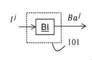
図1は、本原理の例によるフレームIを符号化するための方法のステップのブロック図を示す。 FIG. 1 shows a block diagram of the steps of a method for encoding frame I according to an example of this principle.
ステップ100でモジュールICは、符号化されるフレームIの少なくとも1つの成分Ijを取得する。
In
以下では、成分Ij=1は、フレームIの輝度成分であり、成分Ij≠1は、符号化されるフレームIの色成分である。 In the following, the component I j = 1 is the luminance component of the frame I, and the component I j ≠ 1 is the color component of the encoded frame I.
例えば、フレームIが色空間(X,Y,Z)に属するとき、輝度成分I1は、成分Yの変換f(.)により取得され、例えばI1=f(Y)である。 For example, when the frame I belongs to the color space (X, Y, Z), the luminance component I 1 is acquired by the conversion f (.) Of the component Y, for example, I 1 = f (Y).
フレームIが色空間(R,G,B)に属するとき、輝度成分I1は、例えば、
I1=g(0.2127.R+0.7152.G+0.0722.B)
により与えられる線形結合の関数により、709色域で取得される。
When the frame I belongs to the color space (R, G, B), the luminance component I 1 is, for example,
I 1 = g (0.2127.R + 0.7152.G + 0.0722.B)
Obtained in the 709 color gamut by the function of the linear combination given by.
ステップ101でモジュールBAMは、バックライトフレームBaの成分Bajを、フレームIの各々の成分Ijから決定する。
In
図3で例示されるステップ101の実施形態によると、モジュールBIは、バックライトフレームBaの成分Bajを、
According to the embodiment of
![]()
![]()
により与えられる、形状関数 Given by the shape function
![]()
![]()
の重み付けされる線形結合であるとして決定するものであり、ここで It is determined as a weighted linear combination of, and here
![]()
![]()
は、成分Bajに対する重み付け係数である。 Is a weighting coefficient for the component Ba j .
したがって、バックライトフレームBaの成分Bajを成分Ijから決定することは、バックライトフレームBaの成分Bajが成分Ijに適合するために、最適な重み付け係数(および可能性として、さらには、前もって知られていないならば、最適な形状関数)を見出すことにある。 Therefore, determining the component Ba j of the backlight frame Ba from the component I j is an optimal weighting factor (and possibly even more) for the component Ba j of the backlight frame Ba to match the component I j . , If not known in advance, is to find the optimal shape function).
成分Bajに対する重み付け係数 Weighting factor for component Ba j
![]()
![]()
を見出すための多くのよく知られている方法が存する。例えば、最小平均二乗誤差方法を使用して、成分Bajと成分Ijとの間の平均二乗誤差を最小化することが可能である。 There are many well-known ways to find out. For example, the least mean squared error method can be used to minimize the mean square error between component Ba j and component I j .
本開示は、バックライトフレームBaを取得するための任意の特定の方法に制限されない。 The present disclosure is not limited to any particular method for obtaining a backlight frame Ba.
形状関数は、(例えばLEDでなされ、したがって各々の形状関数は1つのLEDの応答に対応する)ディスプレイバックライトの真の物理的応答であってもよく、または、輝度成分に最も良好に適合するための純粋な数学的構造であってもよいことに留意すべきである。 The shape function may be the true physical response of the display backlight (eg, made with LEDs, so each shape function corresponds to the response of one LED) or best fits the luminance component. It should be noted that it may be a pure mathematical structure for.
この実施形態によると、ステップ101から出力されるバックライトフレームBaは、式(1)により与えられる少なくとも1つの成分を備えるバックライトフレームBaである。
According to this embodiment, the backlight frame Ba output from
図4で例示されるステップ101の実施形態によると、モジュールBMは、(式(1)により与えられる)バックライトフレームBaの少なくとも1つの成分Bajを、モジュールHLにより取得された平均値Lmeanによって調節(modulate)する。
According to the embodiment of
バックライトフレームの少なくとも1つの成分を、フレームの成分の平均値によって調節することは、フレームの成分と残差フレームの成分との間の大域的な輝度コヒーレンスを改善し、例えば、フレーム内の明るい領域は残差フレーム内で明るく見え、フレーム内の暗い領域は残差フレーム内で暗く見える。 Adjusting at least one component of the backlight frame by the mean of the components of the frame improves the global luminance coherence between the components of the frame and the components of the residual frame, eg, bright in the frame. Areas appear bright within the residual frame, and dark areas within the frame appear dark within the residual frame.
複数の成分が、これらの成分のダイナミックレンジを、それらのトーンを変更することなく低減するために、同じ平均値によって調節される。 Multiple components are adjusted by the same average value to reduce the dynamic range of these components without changing their tone.
この実施形態によると、ステップ101から出力されるバックライトフレームBaは、調節されるバックライトフレームである。
According to this embodiment, the backlight frame Ba output from
実施形態によると、モジュールHLは、平均値Lmeanを、全体のルミナンス成分I1にわたって算出するように構成される。 According to embodiments, the module HL is configured to calculate an average value L mean over the entire luminance component I 1 .
この実施形態の変形形態によると、モジュールHLは、 According to a variant of this embodiment, the module HL is

により平均値Lmeanを算出するように構成され、ここでβは、1より小さい係数であり、E(X)は、成分I1の数学的期待値(平均)である。 Is configured to calculate the mean value L mean , where β is a coefficient less than 1 and E (X) is the mathematically expected value (mean) of component I 1 .
この最後の変形形態は、フレームIがフレームのシーケンスに属するときに、通常非常に迷惑な一時的な平均明るさの不安定性の原因となる極めて高い値の数個の画素により、平均値Lmeanが影響を受けることを防止するものであるため、有利である。 This final variant, when frame I belongs to a sequence of frames, has an average value of L mean due to a few pixels with extremely high values that usually cause very annoying temporary average brightness instability. It is advantageous because it prevents the influence of.
本開示は、平均値Lmeanを算出するための特定の実施形態に制限されない。 The present disclosure is not limited to a particular embodiment for calculating the mean value L mean .
図5で例示される変形形態によると、モジュールNは、フレームに対して(または、フレームIがフレームのシーケンスに属するならば、すべてのフレームに対して)、1での中間灰色成分 According to the variants exemplified in FIG. 5, module N is an intermediate gray component at 1 with respect to the frame (or for all frames if frame I belongs to the sequence of frames).
![]()
![]()
を得るように、(式(1)により与えられる)バックライトフレームBaの少なくとも1つの成分Bajを、ルミナンス平均値E(Ba1)により正規化する。 At least one component Ba j of the backlight frame Ba (given by equation (1)) is normalized by the luminance average value E (Ba 1 ) so as to obtain.

次いでモジュールBMは、1での中間灰色成分 The module BM then has an intermediate gray component at 1.
![]()
![]()
を、成分Ijの平均値Lmeanによって、以下の関係 The following relationship is determined by the mean value L mean of the component I j .
![]()
![]()
を使用することにより調節するように構成され、ここでcstmodは調節係数であり、αは、1より小さい、典型的には0.3から0.5の間の、別の調節係数である。 Is configured to be adjusted by using, where the cst mod is the adjustment factor and α is another adjustment factor, less than 1, typically between 0.3 and 0.5. ..
この変形形態によると、ステップ101から出力されるバックライトフレームBalは、式(2)により与えられる少なくとも1つの成分
According to this modified form, the backlight frame Bal output from
![]()
![]()
を備えるバックライトフレームである。 It is a backlight frame equipped with.
調節係数cstmodは、残差フレームに対する良好なルックとなる明るさを得るために調節され、バックライトフレームを取得することのプロセスに高度に依存することに留意すべきである。例えば、最小平均二乗により取得されたすべての成分に対して、 It should be noted that the adjustment factor cst mod is adjusted to obtain brightness that gives a good look to the residual frame and is highly dependent on the process of acquiring the backlight frame. For example, for all components obtained by the least mean square
![]()
![]()
である。 Is.
実際には、線形性により、バックライトフレームの成分Bajを調節するためのすべての演算は、バックライト係数 In fact, due to linearity, all operations to adjust the component Baj of the backlight frame are backlit coefficients.
![]()
![]()
に、補正因子(correcting factor)として供給され、その因子は、係数 Is supplied as a correcting factor, which is a coefficient.
![]()
![]()
を新しい係数 The new coefficient
![]()
![]()
に変換し、結果として And as a result

を得る。 To get.
ステップ102(図1)で、ステップ101から出力されるバックライトフレームBaを決定するために必要とされるデータが、符号化器ENC1により符号化され、ビットストリームF1内に追加され、そのビットストリームF1は、記憶され、および/または、通信ネットワークを介して送信され得る。
In step 102 (FIG. 1), the data required to determine the backlight frame Ba output from
例えば、符号化されるデータは、既知の非適応的形状関数が使用されるときは、重み付け係数 For example, the coded data is a weighting factor when known non-adaptive shape functions are used.
![]()
![]()
または or
![]()
![]()
に制限されるが、形状関数Ψiは、例えば、より良好な適合のためのいくらか最適な数学的構造の例では、事前に知られておらず、したがってビットストリームF1内で符号化される場合もある。そのため、すべての重み付け係数 Although limited to, the shape function Ψ i is not known in advance, for example, in some optimal mathematical structure examples for better fitting, and is therefore encoded in the bitstream F1. There is also. Therefore, all weighting factors
![]()
![]()
または or
![]()
![]()
(および可能性として、形状関数 (And possibly the shape function
![]()
![]()
)が、ビットストリームF1内で符号化される。 ) Is encoded in the bitstream F1.
有利には、重み付け係数 Advantageously, the weighting factor
![]()
![]()
または or
![]()
![]()
は、ビットストリームF1のサイズを低減するために、符号化される前に量子化される。 Is quantized before being encoded in order to reduce the size of the bitstream F1.
別の例によると、バックライトフレームBaの各々の成分Bajは、符号化器ENC1によりビットストリームF1内で符号化される画像であると考えられる。 According to another example, each component Baj of the backlight frame Ba is considered to be an image encoded in the bitstream F1 by the encoder ENC1 .
ステップ103で残差フレームResは、フレームIを、復号されたバージョンのバックライトフレームで除算することにより算出される。
The residual frame Res in
バックライトフレームの復号されたバージョンを使用して、符号化器側および復号器側の両方での同じバックライトフレームを確実にすることが有利であり、したがってこれは、最終的な復号されたフレーム It is advantageous to use the decoded version of the backlight frame to ensure the same backlight frame on both the encoder side and the decoder side, so this is the final decoded frame.
![]()
![]()
のより良好な精密度につながる。 Leads to better precision.
より精密には、モジュールICから取得されたフレームIの各々の成分Ijは、バックライトフレームの成分の復号されたバージョン More precisely, each component I j of the frame I obtained from the module IC is a decoded version of the component of the backlight frame.
![]()
![]()
で除算される。この除算は画素ごとに行われる。 Is divided by. This division is done pixel by pixel.
例えば、フレームIの成分R、G、またはBが色空間(R,G,B)で表現されるとき、成分Res1、Res2、およびRes3が、以下のように取得される。 For example, when the component R, G, or B of the frame I is represented in the color space (R, G, B), the components Res 1 , Res 2 , and Res 3 are acquired as follows.
![]()
![]()
![]()
![]()
![]()
![]()
例えば、フレームIの成分X、Y、またはZが色空間(X,Y,Z)で表現されるとき、成分Res1、Res2、およびRes3が、以下のように取得される。 For example, when the components X, Y, or Z of the frame I are represented in the color space (X, Y, Z), the components Res 1 , Res 2 , and Res 3 are acquired as follows.
![]()
![]()
![]()
![]()
![]()
![]()
一実施形態によると、ステップ104で、バックライトフレームの少なくとも1つの成分の復号されたバージョン
According to one embodiment, in
![]()
![]()
が、復号器DEC1によりビットストリームF1を少なくとも部分的に復号することにより取得される。 Is obtained by at least partially decoding the bitstream F1 with the decoder DEC1.
上述したように、バックライトフレームの成分を取得するために必要とされる一部のデータ、ステップ101の出力が、符号化され(ステップ102)、次いで、ビットストリームF1を少なくとも部分的に復号することにより取得されている。
As mentioned above, some data required to obtain the components of the backlight frame, the output of
上記で与えられる例の後に続いて、重み付け係数 Following the example given above, the weighting factor
![]()
![]()
(および可能性として、形状関数 (And possibly the shape function
![]()
![]()
)が次いで、ステップ104の出力として取得される。
) Is then acquired as the output of
次いでステップ105でモジュールBAGは、バックライトフレームの成分の復号されたバージョン
Then, in
![]()
![]()
を、重み付け係数 , Weighting factor
![]()
![]()
、および、一部の知られている非適応的形状関数、または形状関数 , And some known non-adaptive shape functions, or shape functions
![]()
![]()
のいずれかから、 From any of

により生成する。 Generated by.
別の例によると、バックライトフレームの成分の復号されたバージョン According to another example, the decrypted version of the component of the backlight frame
![]()
![]()
は、ビットストリームF1を復号することにより直接取得される。 Is directly obtained by decoding the bitstream F1.
ステップ106でモジュールMAPは、少なくとも1つのトーンマッピングされる成分Resj
vを、残差フレームResの少なくとも1つの成分Resjをトーンマッピングすることにより取得するものであり、そのことは、その少なくとも1つのトーンマッピングされる成分Resj
vから築造される、視認可能な残差フレームResvを得るためのものである。
In
残差フレームResは、そのダイナミックレンジが高すぎるために、および、この残差フレームResの復号されたバージョンが高い可視アーチファクトを示すために、視認可能でない場合があるように思われるかもしれない。残差フレームの少なくとも1つの成分をトーンマッピングすることは、トーンマッピングされる残差フレームが、符号化されるフレーム内の元のシーンと比較して、シーンの、適度に良好な堅実にトーンマッピングされるバージョンを芸術的にレンダリングするという意味で、視認可能な残差フレームを提供する。したがって、この方法は、視認可能な残差フレームが、高ダイナミックレンジを扱うことができない従前の装置により復号および/または表示され得るため、後方互換性を有する。 It may seem that the residual frame Res may not be visible because its dynamic range is too high and because the decoded version of this residual frame Res shows high visible artifacts. Tone-mapping at least one component of a residual frame means that the tone-mapped residual frame is a reasonably good and solid tone mapping of the scene compared to the original scene in the encoded frame. It provides a visible residual frame in the sense that it renders the version to be done artistically. Therefore, this method is backwards compatible as visible residual frames can be decoded and / or displayed by conventional devices that cannot handle high dynamic range.
視認可能なSDRフレームを、符号化される残差フレームから自動的に提供する能力は重要な利点である。なぜならそれは、バックライトフレームおよび残差フレームの両方を後処理して、HDRフレーム(ビデオ)を復号することに専用化されていない、標準SDR TVセットおよび受信デバイスを持っている顧客に、HDRフレーム(ビデオ)を配信することを可能とするためである。 The ability to automatically provide visible SDR frames from encoded residual frames is an important advantage. Because it is for customers with standard SDR TV sets and receiving devices that are not dedicated to post-processing both backlight frames and residual frames to decode HDR frames (video), HDR frames. This is to enable distribution of (video).
さらに、高度に空間的に相関される(および、フレームの同じシーケンスの他のフレームに時間的に相関される)トーンマッピングされる残差フレームRes、およびバックライトフレームが、別々に符号化されるため、そのような方法によりHDRフレームを符号化することは、効率的な符号化方式につながる。したがって、符号化利得は、トーンマッピングされる残差フレームの高い圧縮率の、および、バックライトフレームを符号化するためのデータのわずかな量のために達せられる。 In addition, the tone-mapped residual frames Res, which are highly spatially correlated (and temporally correlated with other frames in the same sequence of frames), and the backlit frames are encoded separately. Therefore, coding the HDR frame by such a method leads to an efficient coding method. Therefore, the coding gain is reached due to the high compression ratio of the tone-mapped residual frames and the small amount of data to encode the backlight frames.
本開示は、任意の特定のマッピング演算子に制限されない。この単一の条件は、トーンマッピング演算子は可逆的なものとするということである。 The present disclosure is not limited to any particular mapping operator. This single condition is that the tone mapping operator is reversible.
例えば、Reinhardにより定義されるトーンマッピング演算子が使用され得る(Reinhard, E., Stark, M., Shirley, P., and Ferwerda, J.,「Photographic tone reproduction for digital frames,」 ACM Transactions on Graphics 21 (July 2002)、または、Boitard, R., Bouatouch, K., Cozot, R., Thoreau, D., & Gruson, A. (2012)。Temporal cohereny for tone video mapping。A. M. J. van Eijk, C. C. Davis, S. M. Hammel, & A. K. Majumdar (Eds.), Proc. SPIE 8499, Applications of Digital Frame Processing (p. 84990D-84990D-10)において)。 For example, the tone mapping operator defined by Reinhard may be used (Reinhard, E., Stark, M., Shirley, P., and Ferderda, J., "Photographic tone reproducion for digital" 21 (July 2002), or Boatard, R., Bouatouch, K., Cozot, R., Thorea, D., & Gruson, A. (2012). van Eijk, CC Davis, S. M. Hammel, & A. K. Major (Eds.), Proc. SPIE 8499, Applications of Digital Frame Processing (p. 894) 10D-490D.
ステップ106の実施形態によると、残差フレームの成分Resjをマッピングすることは、残差フレームの成分Res1の画素値に応じたガンマ補正またはSLog補正のいずれかを含む。
According to the embodiment of
視認可能な残差フレームResvの成分 Visible residual frame Res v component
![]()
![]()
が次いで、例えば、 Then, for example,
![]()
![]()
により与えられ、ここでAは定数値であり、γjは、例えば1/2.4に等しい、ガンマ曲線の係数である。 Given by, where A is a constant value and γ j is a coefficient of the gamma curve, for example equal to 1 / 2.4.
あるいは、視認可能な残差フレームResvの成分 Alternatively, a component of the visible residual frame Res v
![]()
![]()
は、例えば、 Is, for example,
![]()
![]()
により与えられ、ここでaj、bj、cjは、0および1が不変であるように決定されるSLog曲線の係数であり、SLog曲線の導関数は、1より下でガンマ曲線により延長されるときに、1において連続的である。したがってaj、bj、cjは、パラメータγjの関数である。 Given by, where a j , b j , c j are coefficients of the SLog curve that are determined so that 0 and 1 are invariant, the derivative of the SLog curve is extended by the gamma curve below 1. When it is done, it is continuous at 1. Therefore, a j , b j , and c j are functions of the parameter γ j .
一実施形態によると、残差フレームの成分に関係のあるガンマ-Slog曲線のパラメータγjは、符号化器ENC1により符号化され、ビットストリームF1内に追加される。 According to one embodiment, the gamma-Slog curve parameter γ j , which is related to the components of the residual frame, is encoded by the encoder ENC1 and added into the bitstream F1.
ガンマ補正を残差フレームResのルミナンス成分に適用することは、暗い領域を引き上げるが、明るい画素の焼き付きを回避できるほどにはハイライトを低下させない。 Applying gamma correction to the luminance component of the residual frame Res raises dark areas, but does not reduce highlights enough to avoid burn-in of bright pixels.
SLog補正を残差フレームResのルミナンス成分上で供給することは、ハイライトを十分低下させるが、暗い領域を引き上げない。 Supplying SLog correction on the luminance component of the residual frame Res reduces highlights sufficiently but does not raise dark areas.
したがって、ステップ106の好ましい実施形態によると、モジュールMAPは、残差フレームResの成分の画素値によって、ガンマ補正またはSLog補正のいずれかを適用する。
Therefore, according to the preferred embodiment of
暗い、および明るい情報の損失がないような、ガンマおよびSLog補正は、高い精密度を伴う、残差フレームおよびバックライトフレームからのHDRフレームの再構築につながる。さらにガンマおよびS-log補正は、再構築されるHRDフレーム、および、視認可能な残差フレームの両方で、平坦にクリッピングされるエリアを回避する。 Gamma and SLog corrections, such as no loss of dark and bright information, lead to the reconstruction of HDR frames from residual and backlit frames with high precision. In addition, gamma and S-log correction avoids flat clipping areas in both the reconstructed HRD frame and the visible residual frame.
例えば、残差フレームResの成分の画素値が、(1に等しい)閾値より下であるとき、ガンマ補正が適用され、そうでない場合、SLog補正が適用される。 For example, if the pixel value of the component of the residual frame Res is below the threshold (equal to 1), gamma correction is applied, otherwise SRog correction is applied.
構築により、視認可能な残差フレームResvの成分は通常、上記のガンマ-Slog組み合わせの使用を特に効率的になすと、フレームIの関連付けられる成分の明るさに依存して、1により近い、またはより近くない平均値を有する。 By construction, the components of the visible residual frame Res v are usually closer to 1 depending on the brightness of the associated component of frame I, making the use of the gamma-Slog combination above particularly efficient. Or have an average value that is not closer.
方法の実施形態によると、ステップ107でモジュールSCAは、残差フレームの少なくとも1つの成分Resjまたは
According to an embodiment of the method, in
![]()
![]()
を、符号化(ステップ110)の前に、その成分をスケール化因子cstscalingにより乗算することによりスケール化する。 Is scaled by multiplying its components by the scaling factor cst scaling prior to coding (step 110).
残差フレームの成分jをスケール化することは、残差フレームから取得されたフレームの平均灰色を、視認および符号化の両方に対する妥当な値にする。 Scaling the component j of the residual frame makes the average gray of the frame obtained from the residual frame a reasonable value for both visibility and coding.
次いで、残差フレームRessの、結果として生じる成分 The resulting component of the residual frame Res s then
![]()
![]()
が、方法の実施形態によると、 However, according to the embodiment of the method

により与えられる。 Given by.
好ましくは、スケール化因子cstscalingは、残差フレームの成分の値を0から最大値2N-1にマッピングするように定義され、ここでNは、符号化器ENC2による符号化のための入力として可能とされるビットの数である。 Preferably, the scaling factor cst scaling is defined to map the value of the component of the residual frame from 0 to the maximum value 2 N -1, where N is the input for coding by the encoder ENC2. The number of bits allowed as.
これは当然ながら、ルミナンス値1(おおよそ、残差フレームの成分の平均値である)を、中間灰色ルミナンス値2N-1にマッピングすることにより取得される。したがって、標準数のビットN=8を伴う残差フレームの成分に対して、120に等しいスケール化因子は、27=128での中性灰色に非常に近付けられるため、非常に堅実な値である。 This is, of course, obtained by mapping the luminance value 1 (roughly the average of the components of the residual frame) to the intermediate gray luminance value 2 N-1 . Therefore, for the components of the residual frame with the standard number of bits N = 8, a scaling factor equal to 120 is very close to neutral gray at 27 = 128, so at a very solid value. be.
方法の実施形態によると、ステップ108でモジュールCLIは、残差フレームの少なくとも1つの成分を、符号化の前にクリッピングして、そのダイナミックレンジを、例えば符号化器ENC2の能力によって定義される、目標とされるダイナミックレンジTDRに制限する。
According to embodiments of the method, in
残差フレームをクリッピングすることは、ビット数の制限を確実にし、それを符号化するための従前の符号化/復号方式の使用を可能とする。さらには符号化/復号方式は、既存のインフラストラクチャ(コーデック、ディスプレイ、配信チャネル、その他)との後方互換性がある。なぜなら、低ダイナミックレンジ、典型的には8~10ビットを有する残差フレームのみが、フレームの低ダイナミックレンジバージョンを表示するために、そのようなインフラストラクチャによって送信され得るためである。バックライトデータを内包する小さなビットストリームが、フレームの元のバージョン(すなわち、HDRフレーム)を配信するために、専用のインフラストラクチャによってサイドコンテナ(side container)内で搬送され得る。 Clipping the residual frame ensures a limit on the number of bits and allows the use of conventional coding / decoding methods to encode it. Furthermore, the coding / decoding method is backwards compatible with existing infrastructure (codecs, displays, distribution channels, etc.). This is because only residual frames with a low dynamic range, typically 8-10 bits, can be transmitted by such an infrastructure to display a low dynamic range version of the frame. A small bitstream containing the backlight data may be carried within the side container by a dedicated infrastructure to deliver the original version of the frame (ie, the HDR frame).
この最後の実施形態によると、結果として生じる残差フレームRescの成分 According to this last embodiment, the components of the resulting residual frame Resc
![]()
![]()
が、例えば、方法の実施形態によると、 However, for example, according to the embodiment of the method

により与えられる。 Given by.
本開示は、そのようなクリッピング(max(.))に制限されるものではなく、任意の種類のクリッピングに拡張される。 The present disclosure is not limited to such clipping (max (.)), But extends to any type of clipping.
方法の実施形態によると、スケール化実施形態およびクリッピング実施形態を組み合わせると、 According to the embodiment of the method, when the scaling embodiment and the clipping embodiment are combined,

により与えられる残差フレームResscの成分 Residual frame given by Res sc component
![]()
![]()
をもたらす。 Bring.
残差フレームの成分のマッピングおよびスケール化は、パラメトリックプロセスである。パラメータは、固定される、またはされない場合があり、後者の例ではそれらは、符号化器ENC1によりビットストリームF1内で符号化され得る。 Mapping and scaling the components of the residual frame is a parametric process. The parameters may or may not be fixed, in the latter example they may be encoded in the bitstream F1 by the encoder ENC1.
方法の実施形態によると、ガンマ補正の定数値γ、スケール化因子cstscalingは、ビットストリームF1内で符号化されるパラメータであり得る。 According to an embodiment of the method, the gamma correction constant value γ, the scaling factor cst scaling , can be a parameter encoded in the bitstream F1.
パラメータα、cstmod、cstscaling、γj、βの選定は、ポストプロダクションおよびカラーグレーディングでの専門家の嗜好(taste)に従って、コンテンツに最も良好に適するマッピングの選定のための余地を与えることが留意され得る。 The selection of the parameters α, cst mod , cst scaling , γ j , β may provide room for selecting the mapping that best suits the content, according to the expert taste in post-production and color grading. Can be noted.
他方でユニバーサルパラメータが、多種多様なフレームのすべてに受け入れ可能となるように定義される場合がある。その場合、ビットストリームF1内で符号化されるパラメータはない。 On the other hand, universal parameters may be defined to be acceptable to all of a wide variety of frames. In that case, there are no parameters encoded in the bitstream F1.
本開示によると、ステップ110で残差フレームRes(Resv、Ress、またはResc)は、符号化器ENC2により、予測子Predを使用して予測符号化され、ビットストリームF2内に追加され、そのビットストリームF2は、記憶され、および/または、通信ネットワークを介して送信され得る。
According to the present disclosure, in
本開示によると、ステップ109で、残差フレームRes(Resv、Ress、またはResc)の予測子Predは、インポーズされるフレームIMFの復号されたバージョン
According to the present disclosure, in
![]()
![]()
、すなわちステップ112の出力から算出される。
That is, it is calculated from the output of
用語「インポーズされる」は、フレームIMFが残差フレームRes(Resv、Ress、またはResc)に関して異なることを表す。フレームIMFは、フレームIの低ダイナミックレンジバージョンである。フレームIMFおよびフレームIは、芸術家により異なってカラーグレーディングされている、および/または、異なる色空間(例えば、フレームIMFに対するRec.709、および、フレームIに対するREC.2020色空間)で表現される場合がある。 The term "imposed" means that the frame IMF is different with respect to the residual frame Res (Res v , Res s , or Resc ). The Frame IMF is a low dynamic range version of Frame I. The Frame IMF and Frame I are color graded differently by the artist and / or are represented in different color spaces (eg, Rec. 709 for Frame IMF and REC. 2020 color space for Frame I). In some cases.
ステップ109の実施形態によると、予測子Predを算出することは、インポーズされるフレームIMFの復号されたバージョン
According to the embodiment of
![]()
![]()
を、残差フレームRes(Resv、Ress、またはResc)に、カラーマッピング関数(CMF)によりマッピングすることを含む。 Is included in mapping to the residual frame Res (Res v , Res s , or Resc ) by a color mapping function (CMF).
これは、予測符号化器ENC2の符号化効率を改善するものである。なぜなら、この場合、残差フレームと予測子Predとの間で算出される残差のダイナミックが低減されるためである。 This improves the coding efficiency of the predictive encoder ENC2. This is because, in this case, the dynamics of the residuals calculated between the residual frame and the predictor Pred are reduced.
カラーマッピング関数CMFは、フレームIおよびIMFの色空間に、ならびに、コンテンツそれ自体にもまた依存し得る。実際、フレームコンテンツ創作では、一部の色補正が、フレームIもしくはフレームIMFのいずれか、または両方に関して、コンテンツ創作者芸術的意図に応じて動作させられる(カラーグレーディング、その他…)。フレームIおよびIMFの成分に適用されるこれらの色変換は異なり得る。したがって一般的な例では、カラーマッピング関数CMFは、単純な決定論的色空間変換に低減されない。 The color mapping function CMF may also depend on the color space of the frames I and IMF, as well as the content itself. In fact, in frame content creation, some color correction is applied to the content creator's artistic intent with respect to frame I and / or frame IMF (color grading, etc ...). These color conversions applied to the components of Frame I and IMF can be different. Therefore, in a general example, the color mapping function CMF is not reduced to a simple deterministic color space transformation.
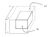
実施形態によると、カラーマッピング関数CMFは、シンタックスに対するHEVCサブセクションF.7.3.2.3.5 「Colour mapping octants syntax」、および、セマンティクスに対するサブセクションF.7.4.3.3.5 「Colour mapping octants semantics」で定義されるような、3Dカラールックアップテーブル(3DカラーLUT)を使用する。 According to embodiments, the color mapping function CMF is a HEVC subsection F.I. 7.3.2.3.5 "Color mapping octants syntax", and the subsection F. for semantics. 7.4.3.3.5 Use a 3D color look-up table (3D color LUT) as defined in "Color mapping octants semantics".
3DカラーLUTは通常、3D色空間に対する、図7で描写されるようなオクタントのグリッドとして表される。グリッドは、色空間をN個の領域Riに分割するものであり、ここでi∈[0,N-1]であり、Nは整数である。領域区分は、対称または非対称(等しくなく割られる)のいずれかであり得る。領域は、オクタントとも言う。少なくとも1つのパラメータが、HEVCのサブセクションF.7.3.2.3.4 「General colour mapping table syntax」、および、F.7.3.2.3.5 「Colour mapping octants syntax」で説明されるように、各々のオクタントに関連付けられる。カラーマッピング関数CMFは次いで、すべてのオクタントが、少なくとも1つの関連付けられるパラメータを有するときに定義される。通常、カラーマッピング関数CMFは、HEVCで、サブセクションH.8.1.4.3.1 「Colour mapping process of luma sample values」、および、H.8.1.4.3.2 「Colour mapping process of chroma sample values」で説明される補間関数にさらに関連付けられる。 A 3D color LUT is usually represented as an octant grid as depicted in FIG. 7 for a 3D color space. The grid divides the color space into N regions Ri, where i ∈ [0, N-1], where N is an integer. The region division can be either symmetric or asymmetric (divided not evenly). The area is also called octant. At least one parameter is the subsection F. of HEVC. 7.3.2.3.4 "General color mapping table syntax", and F.I. 7.3.2.3.5 Associated with each octant as described in "Color mapping octants syntax". The color mapping function CMF is then defined when all octants have at least one associated parameter. Normally, the color mapping function CMF is HEVC and the subsection H.I. 8.1.4.3.1 "Color mapping process of luma sample values", and H.M. 8.1.4.3.2 Further associated with the interpolation function described in "Color mapping process of chroma sample values".
図2で例示される方法の実施形態によると、ステップ100でモジュールICは、フレームIMFの少なくとも成分IMFjを取得する。
According to an embodiment of the method exemplified in FIG. 2, in
残差フレームResvの少なくとも1つの成分がスケール化されるとき(ステップ107)、ステップ200でモジュールISCAは、逆スケール化をフレームIMFの少なくとも1つの成分IMFjに、その成分をパラメータ
When at least one component of the residual frame Res v is scaled (step 107), in
![]()
![]()
で除算することにより適用し、そのパラメータは、ローカルメモリから、または、復号器DEC1によるビットストリームF1の少なくとも部分的な復号によってのいずれかで取得される。 Applied by dividing by, the parameters are obtained either from local memory or by at least partial decoding of the bitstream F1 by the decoder DEC1.
ステップ113でモジュールIMAPは、ステップ100から、またはステップ200からのいずれかで取得された少なくとも1つの成分の逆マッピングされたバージョンを、その少なくとも1つの取得された成分に逆マッピング演算子を適用することにより取得する。その逆マッピング演算子は、ステップ106での残差フレームの成分に適用されるマッピング演算子の逆である。
In
パラメータ Parameters
![]()
![]()
は、ローカルメモリから、または、復号器DEC1によるビットストリームF1の少なくとも部分的な復号によってのいずれかで取得される。 Is obtained either from local memory or by at least partial decoding of the bitstream F1 by the decoder DEC1.
以下では、フレームIMFの成分の逆スケール化されるバージョン(ステップ200の出力)、または、その逆マッピングされるバージョン(ステップ113の出力)は、成分IIMFjと呼ばれる。 In the following, the inversely scaled version of the components of the frame IMF (output of step 200) or its inversely mapped version (output of step 113) is referred to as component IIMF j .
ステップ103で成分Dj、ステップ101の入力が、次いで、フレームIの各々の成分Ijを成分IIMFjで除算することにより算出される。
The inputs of component D j and step 101 in
ステップ101でモジュールBAMは、バックライトフレームBaの成分Bajを、各々の成分Dから、フレームIの成分Ijに対して上述したように決定する。
In
図6は、本開示の例示的な実施形態による3DカラーLUTを創作するための方法のフローチャートを示す。 FIG. 6 shows a flow chart of a method for creating a 3D color LUT according to an exemplary embodiment of the present disclosure.
ステップ60で、3DカラーLUTの構造が決定される。ここで3DカラーLUTは通常、3D色空間に対して、上記で説明されたような、および、図7上で示されるようなオクタントを表すパラメータにより表される。
In
ステップ61で、一部の領域は、ことによると複数のオクタントRkに分離され得る。
In
ステップ62で、各々の領域Rkに対して、少なくとも1つのパラメータが、各々のオクタントに対して、フレームIMFの復号されたバージョンの画素pから、または、カラー値がその領域Rkに属するそれらの画素pの一部から、および、残差フレームRes(または、本開示の実施形態によるResv、Ress、もしくはResc)内の空間的に対応する画素p’から決定される。
In
変形形態によると、フレームIMFの復号されたバージョンの画素のサブセット(例えば、2つからの1つ)のみが、プロセスを加速するために考えられる。 According to the variant, only a subset of the pixels of the decoded version of the Frame IMF (eg, one out of two) is considered to accelerate the process.
変形形態によると、空間的に対応する画素p’は、同じ位置に配置される(colocated)画素、または、空間的変換(例えば、アップサンプリングされる、並進、その他)を受ける対応する空間的位置を有する画素のいずれかである。 According to the variant, the spatially corresponding pixel p'is a coordinated pixel or a corresponding spatial position that undergoes a spatial transformation (eg, upsampling, translation, etc.). Is one of the pixels having.
したがって、オクタントに関連付けられるパラメータは、より低い数のパラメータが1回でのハンドルであるために、計算を容易にする領域ごとにローカルに決定される。 Therefore, the parameters associated with the octant are determined locally for each region that facilitates the calculation because the lower number of parameters is a one-time handle.
ステップ62の実施形態によると、現在の領域Rkのオクタントに関連付けられる少なくとも1つのパラメータを決定することはカラーマッピング関数CMFkのパラメータを決定することを含み、そのパラメータは、フレームIMFの復号されたバージョンの画素p(または、それらのサブセット)であって、それらのカラー値がその領域Rkに属する、画素p(または、それらのサブセット)のカラー値
According to the embodiment of
![]()
![]()
の(カラーマッピング関数CMFkにより)再マッピングされるバージョンと、残差フレームRes(Resv、またはRess、またはResc)内の空間的に対応する画素p’のカラー値Res(p)との間の距離を最小化する。例えば、領域Rkに対するCMFkのパラメータは、以下の式を最小化するものである。 The remapped version of (by the color mapping function CMF k ) and the color value Res (p) of the spatially corresponding pixel p'in the residual frame Res (Res v , or Res s , or Resc ). Minimize the distance between. For example, the parameter of CMF k for the region R k minimizes the following equation.
![]()
![]()
ここでdistは距離計量である。例えば、distはL1ノルムまたはL2ノルムである。 Here, the dust is a distance measurement. For example, the dust is the L1 norm or the L2 norm.
変形形態によると、distは、重み付けされる差である。 According to the variant, the dist is a weighted difference.
例によると、CMFkのパラメータは、よく知られている最小二乗誤差最小化技法により決定される。 By example, the parameters of CMF k are determined by a well-known least squares error minimization technique.
CMFkのパラメータが決定されると、次いで領域Rkのオクタントのパラメータが決定される。オクタントOc(x,y,z)に対して、その関連付けられるパラメータ値は、CMFk(Oc(x,y,z))としてセットされる。 Once the parameters of CMF k are determined, then the parameters of the octant of region R k are determined. For octant Occ (x, y, z), its associated parameter value is set as CMF k (Oc (x, y, z)).
数学的に言えば、残差フレームResが3つの成分を備えるとき、カラーマッピング関数CMFkは、3x3マトリックスパラメータ Mathematically speaking, when the residual frame Res has three components, the color mapping function CMF k is a 3x3 matrix parameter.
![]()
![]()
、および、3つのオフセットパラメータ , And three offset parameters
![]()
![]()
を伴うパラメトリックモデルであり得るものであり、その場合、領域Rkに対する予測子Predkの成分 Can be a parametric model with, in which case the components of the predictor Pred k for the region R k .
![]()
![]()
は、 teeth,
![]()
![]()
により与えられ、ここでΔ1(p)、Δ2(p)、およびΔ3(p)は、成分Res1(それぞれ、Res2およびRes3)の値と、現在のオクタント座標の関係のある成分との間の差である。パラメータ Given by, where Δ 1 (p), Δ 2 (p), and Δ 3 (p) are related to the value of component Res 1 (Res 2 and Res 3 respectively) and the current octant coordinates. The difference between the components. Parameters
![]()
![]()
は、3DカラーLUTから取得される。 Is obtained from the 3D color LUT.
SHVCセクションH.8.1.4.3で説明されるような変形形態では、Δ1(p)、Δ2(p)、およびΔ3(p)は、成分Res1(それぞれ、Res2およびRes3)の値である。 SHVC section H. In the variants as described in 8.1.4.3 , Δ1 (p), Δ2 (p), and Δ3 (p) are of component Res 1 (Res 2 and Res 3 , respectively ). The value.
本開示は、オフセット関数を伴う3x3マトリックスの使用に制限されるものではなく、それらの偏導関数を提供する任意のパラメトリックマッピング関数への拡張となり得る。 The present disclosure is not limited to the use of 3x3 matrices with offset functions, but can be an extension to any parametric mapping function that provides their partial derivatives.
フレームIMFの復号されたバージョンはフレームの第1のシーケンスにより置き換えられ得ること、および、残差フレームはフレームの第2のシーケンスにより置き換えられ得ることに留意されたい。この例では、各々の領域またはオクタントRkに対して、パラメータは、フレームの第1のシーケンスの画素p(それらのカラー値がその領域Rkに属する)のカラー値の再マッピングされるバージョンから、および、フレームの第2のシーケンス内の空間的に対応する画素p’のカラー値から決定される。この例では、フレームの第2のシーケンス内の空間的に対応する画素p’は、画素pが属するフレームに時間的に整合するフレームに属する。 Note that the decrypted version of the frame IMF can be replaced by the first sequence of frames, and the residual frames can be replaced by the second sequence of frames. In this example, for each region or octant R k , the parameters are from the remapped version of the color values of pixel p (their color values belong to that region R k ) in the first sequence of frames. , And the color values of the spatially corresponding pixels p'in the second sequence of frames. In this example, the spatially corresponding pixel p'in the second sequence of frames belongs to a frame that is temporally consistent with the frame to which the pixel p belongs.
いくつかのカラーパラメータが、3DカラーLUTの各々のオクタント、例えば、RGBカラー値、Y’CbCr、またはYUVなどの4つのカラー値に関連付けられ得る。 Several color parameters can be associated with each octant of the 3D color LUT, eg, four color values such as RGB color values, Y'CbCr, or YUV.
式(3)の最小化は、常に解を有するとは限らない。実際、最小化はマトリックス逆変換を使用する。一部の例では、マトリックスは悪く構成され、逆変換は失敗する(例えば、マトリックスの行列式は零である)。さらに、画素であって、それらのカラー値が、与えられる領域内に在る、画素の数が、閾値より下であるとき、最小化は正確でない。この例では、その距離を最小化することがその領域Rkに対して失敗するとき、カラーパラメータを取得することは、その領域のパラメータを、Rkを包囲する領域のパラメータから補間すること、または、それらを直接、その現在の領域を包囲する領域に関して算出される色変換のパラメータから算出することを含む。例えば、Rkのカラーパラメータは、図8上で例示されるような、領域Rkを包囲する領域R’kに対して決定されるパラメータによって、3x3マトリックスおよびオフセット関数から算出される。 The minimization of equation (3) does not always have a solution. In fact, minimization uses the inverse matrix transformation. In some examples, the matrix is poorly constructed and the inverse transformation fails (eg, the determinant of the matrix is zero). Moreover, the minimization is not accurate when the number of pixels is below the threshold, the color values of which are within the given area. In this example, when minimizing that distance fails for that region R k , getting the color parameters is to interpolate the parameters of that region from the parameters of the region surrounding R k . Alternatively, it involves calculating them directly from the color conversion parameters calculated for the area surrounding the current area. For example, the color parameters of R k are calculated from a 3x3 matrix and an offset function by the parameters determined for the region R'k surrounding the region R k , as illustrated in FIG.
変形形態によると、領域Rkのカラーパラメータは、領域R’kのカラーパラメータから補間される。 According to the variant, the color parameters of the region R k are interpolated from the color parameters of the region R'k .
変形形態によると、領域Rkのカラーパラメータは、領域R’kのカラーパラメータから予測され、残差が符号化される。 According to the variant, the color parameters of the region R k are predicted from the color parameters of the region R'k and the residuals are encoded.
実施形態によると、パラメータParamは、符号化器ENC1により符号化され、ビットストリームF1内に追加される。これらのパラメータParamは、3DカラーLUTのオクタント、残差フレームの各々の画素が属するオクタントを決定するデータ、および、各々のカラーマッピング関数のパラメータ According to embodiments, the parameter Param is encoded by the encoder ENC1 and added into the bitstream F1. These parameters Param are the octant of the 3D color LUT, the data that determines the octant to which each pixel of the residual frame belongs, and the parameters of each color mapping function.
![]()
![]()
に関連付けられ得る。変形形態では、3DカラーLUTのオクタント、および/または、各々のカラーマッピング関数のパラメータ Can be associated with. In the variant form, the octant of the 3D color LUT and / or the parameters of each color mapping function.
![]()
![]()
に関連付けられるパラメータは符号化されない。 The parameters associated with are not encoded.
本開示の変形形態によると、同じパラメータ{aj,bj,cj,dj ∀j=1,2,3}が、各々のカラーマッピング関数CMFkに対して使用される。 According to the variants of the present disclosure, the same parameters {a j , b j , c j , d j ∀j = 1, 2, 3} are used for each color mapping function CMF k .
図9は、カラーマッピング関数CMFが、画素pのマッピングされるカラー値を決定するために3DカラーLUTを使用するときの、ステップ109のサブステップの図を示す。
FIG. 9 shows a sub-step diagram of
ステップ1090で、フレームIMFの復号されたバージョンの与えられる画素pに対して、画素pが属するオクタントCOが決定される。これは、3DカラーLUTの各々の次元が2項に(dyadically)区分されるときに、画素pの色成分の第1のN個のMSB(最上位ビット)の値をベースに容易に決定され得る。
In
オプションとして、ステップ1091で、HEVCの章H.8.1.4.3.1で、および、JCTVC-Q0048_r1で、章「2.1 (y,u,v) triplet adjustment when phase alignment is enabled」で説明されるように、成分の一部の調整が適用される。例えば、輝度およびクロミナンス成分の画素が整合しないとき(典型的には、4:2:0フォーマットが使用されるとき)、輝度およびクロミナンス成分の画素の空間的場所が調整され(テクスチャおよび動きの再サンプリング)、または、ビット深度が同じでないとき、成分のビット深度がさらには適応させられる。例えば、JCTVC-R1030_v6の章H.8.1.4.3.1で示されるように、ビット深度は、以下の量だけシフトさせられ得る。
Optionally, in
nMappingShift = 10 + BitDepthCmInputY - BitDepthCmOutputY
したがって、ステップ1092で、残差フレームの画素に関連付けられる予測されるカラー値が、式(4)により与えられる。
nMappingShift = 10 + BitDeptthCmInputY-BitDeptthCmOutputY
Therefore, in
オプションとして、ステップ1091での整合および/または適応が行われたとき、ステップ1093で、逆整合および/または適応が、予測される(マッピングされる)カラー値に適用される。
Optionally, when matching and / or adaptation in
図10は、フレームをバックライトフレームで除算することにより算出される残差フレームを表すビットストリームを復号するための、本開示の実施形態による方法のステップのブロック図を示す。 FIG. 10 shows a block diagram of the steps of the method according to an embodiment of the present disclosure for decoding a bitstream representing a residual frame calculated by dividing a frame by a backlit frame.
上述したように、ステップ104および105で、復号されたバックライトフレーム
As mentioned above, the backlit frame decoded in
![]()
![]()
が、復号器DEC1によるビットストリームF1の少なくとも部分的な復号により取得される。ビットストリームF1は、ローカルに記憶され、または、通信ネットワークから受信されている場合がある。 Is obtained by at least partial decoding of the bitstream F1 by the decoder DEC1. Bitstream F1 may be stored locally or received from a communication network.
ステップ112で、復号されたフレーム
Decrypted frame in
![]()
![]()
が、ビットストリームF3の少なくとも部分的な復号により取得される。 Is obtained by at least partial decoding of the bitstream F3.
ステップ1100で、予測子
At
![]()
![]()
が、フレーム But the frame
![]()
![]()
、および、3DカラーLUTに関係のある一部のパラメータ , And some parameters related to 3D color LUT
![]()
![]()
から取得される。パラメータ Obtained from. Parameters
![]()
![]()
は、メモリから、または、ビットストリームF1の少なくとも部分的な復号によってのいずれかで取得される。 Is obtained either from memory or by at least partial decoding of bitstream F1.
これらのパラメータParamは、3DカラーLUTのオクタント、残差フレームの各々の画素が属するオクタントを決定するデータ、および、各々のカラーマッピング関数のパラメータ These parameters Param are the octant of the 3D color LUT, the data that determines the octant to which each pixel of the residual frame belongs, and the parameters of each color mapping function.
![]()
![]()
に関連付けられ得る。 Can be associated with.
変形形態では、3DカラーLUT(のオクタント)、および/または、各々のカラーマッピング関数のパラメータ In the variant form, the parameters of the 3D color LUT (octant) and / or each color mapping function.
![]()
![]()
に関連付けられるカラーパラメータは、ローカルメモリから取得される。 The color parameters associated with are taken from local memory.
次いで、予測子 Then the predictor
![]()
![]()
がグリッド構造を有する3DカラーLUTの各々の領域Rkのオクタント、および、領域Rkに関係のある各々のカラーマッピング関数のパラメータ Is the octant of each region R k of the 3D color LUT having a grid structure, and the parameters of each color mapping function related to the region R k .
![]()
![]()
に関連付けられるパラメータから取得される。 Obtained from the parameters associated with.
ステップ1101で、復号された残差フレーム
Decrypted residual frame in
![]()
![]()
が、復号器DEC2によるビットストリームF2の少なくとも部分的な復号により、および、予測子 By at least partial decoding of the bitstream F2 by the decoder DEC2, and the predictor
![]()
![]()
を使用することにより予測復号される。ビットストリームF2は、ローカルに記憶され、または、通信ネットワークから受信されている場合がある。 Predictive decoding by using. The bitstream F2 may be stored locally or received from a communication network.
ステップ1101の実施形態によると、予測子は、3DカラーLUTの各々の領域Rkに対する特定の予測子
According to the embodiment of
![]()
![]()
を備える。 To prepare for.
次いで方法は、残差フレームの各々の画素p’が属するオクタントCOを決定するデータを、ビットストリームF1を少なくとも部分的に復号することにより取得し、領域Rkに属する、復号された残差フレーム The method then obtains data that determines the octant CO to which each pixel p'of the residual frame belongs by at least partially decoding the bitstream F1 and belongs to the region R k , the decoded residual frame.
![]()
![]()
の各々の画素p’のカラー値が、復号器DEC2によりビットストリームF2を少なくとも部分的に予測復号することにより、および、領域Rkに関連する予測子 The color value of each pixel p'of is predicted and decoded at least partially by the decoder DEC2 and the predictor associated with the region R k .
![]()
![]()
を使用することにより復号される。 Is decrypted by using.
ステップ1102で、復号されたフレーム
Decrypted frame in
![]()
![]()
の成分が、復号された残差フレーム The component of is the decoded residual frame
![]()
![]()
の成分 Ingredients
![]()
![]()
を、復号されたバックライトフレーム The decrypted backlight frame
![]()
![]()
の成分 Ingredients
![]()
![]()
により乗算することにより取得される。 Obtained by multiplying by.
ステップ104の実施形態によると、パラメータ
According to the embodiment of
![]()
![]()
および/または And / or
![]()
![]()
がさらには、ローカルメモリから、または、復号器DEC1によるビットストリームB1の少なくとも部分的な復号によってのいずれかで取得される。 Is further obtained either from local memory or by at least partial decoding of the bitstream B1 by the decoder DEC1.
方法によると、ステップ200でモジュールISCAは、復号された残差フレーム
According to the method, in
![]()
![]()
の少なくとも1つの成分 At least one ingredient of
![]()
![]()
を、その成分をパラメータ , Its components are parameters
![]()
![]()
で除算することにより供給している。 It is supplied by dividing by.
ステップ113でモジュールIMAPは、ステップ1101の出力、または、ステップ200の出力のいずれかである、取得される少なくとも1つの成分の逆マッピングされたバージョンを、その少なくとも1つの取得された成分に逆マッピング演算子を適用することにより取得する。
In
実施形態によると、モジュールIMAPはパラメータγjを使用する。 According to the embodiment, the module IMAP uses the parameter γ j .
例えば、パラメータγjはガンマ曲線を定義し、逆トーンマッピングは、ガンマ曲線から、復号された残差フレーム For example, the parameter γ j defines a gamma curve, and the inverse tone mapping is a residual frame decoded from the gamma curve.
![]()
![]()
の画素値に対応する値を見出すことにある。 The purpose is to find a value corresponding to the pixel value of.
復号器DEC1、DEC2、およびDEC3は、それぞれ符号化器ENC1、ENC2、およびENC3により符号化されているデータを復号するように構成される。 The decoders DEC1, DEC2, and DEC3 are configured to decode the data encoded by the encoders ENC1, ENC2, and ENC3, respectively.
符号化器ENC1、ENC2、およびENC3(ならびに、復号器DEC1、DEC2、およびDEC3)は、特定の符号化器(復号器)に制限されるものではなく、エントロピー符号化器(復号器)が必要な場合、Huffmann符号器、算術符号器、または、H.264/AVCもしくはHEVCで使用されるCabacに類するコンテキスト適応符号器などのエントロピー符号化器が有利である。 The encoders ENC1, ENC2, and ENC3 (and the decoders DEC1, DEC2, and DEC3) are not limited to a particular encoder (decoder) and require an entropy encoder (decoder). If so, Huffman code, arithmetic code, or H.M. Entropy encoders such as Cabac-like context-adaptive encoders used in 264 / AVC or HEVC are advantageous.
符号化器ENC1およびENC3(ならびに、復号器DEC1およびDEC3)は、例えば、JPEG、JPEG2000、MPEG2、h264/AVC、またはHEVCのような、損失を伴うフレーム/ビデオ符号器とすることができる特定の符号化器には制限されない。 Specific encoders ENC1 and ENC3 (and decoders DEC1 and DEC3) can be lossy frame / video encoders such as, for example, JPEG, JPEG2000, MPEG2, h264 / AVC, or HEVC. It is not limited to the encoder.
符号化器ENC2(および復号器DEC2)は、JPEG、JPEG2000、MPEG2、H.264/AVC、またはHEVCなどの予測子を使用する任意の予測符号化器に制限されない。 The encoder ENC2 (and the decoder DEC2) are JPEG, JPEG2000, MPEG2, H.I. It is not limited to any predictor-encoder that uses predictors such as 264 / AVC, or HEVC.
符号化器ENC1、ENC2、およびENC3(復号器DEC1、DEC2、およびDEC3)は、例えば、符号化器(復号器)が標準SHVCに準拠するなど、同じ符号化器(それぞれ、同じ復号器)であり得る。単一のビットストリームが次いで、ビットストリームF1、F2、およびF3により搬送されるデータを備えて生成される。 The encoders ENC1, ENC2, and ENC3 (decoders DEC1, DEC2, and DEC3) are in the same encoder (each the same decoder), for example, the encoder (decoder) complies with the standard SHVC. possible. A single bitstream is then generated with the data carried by the bitstreams F1, F2, and F3.
本開示の実施形態によると、ビットストリームF1により搬送されるデータ、および/または、ビットストリームF3により搬送されるデータは、補助画像であって、そのシンタックスがH264/AVC、HEVC、またはSHVC標準のいずれかに準拠する、補助画像として符号化される。補助画像は、コンテンツのメインストリーム(メインビデオ)に実際に対応する、いわゆる「主符号化画像」への追加で、H264/AVC、またはHEVC、またはSHVC標準で定義されている。補助画像は通常、3Dアプリケーションに対する、アルファ合成、クロミナンス強調情報、または深度情報などの追加的なフレーム情報のトランスポートを可能にする。 According to embodiments of the present disclosure, the data carried by bitstream F1 and / or the data carried by bitstream F3 is an auxiliary image whose syntax is H264 / AVC, HEVC, or SHVC standard. Encoded as an auxiliary image according to any of the above. Auxiliary images are defined in the H264 / AVC, or HEVC, or SHVC standards, in addition to the so-called "mainly coded images" that actually correspond to the mainstream (main video) of the content. Auxiliary images usually allow the transport of additional frame information such as alpha compositing, chrominance enhancement information, or depth information for 3D applications.
本開示の実施形態によると、予測符号化される残差フレームは、ビットストリームF2に、主画像であって、そのシンタックスがH.264/AVCまたはHEVC標準のいずれかに準拠する、主画像として組み込まれる。 According to an embodiment of the present disclosure, the predictive coded residual frame is in bitstream F2 the main image, the syntax of which is H.I. Incorporated as a main image, compliant with either 264 / AVC or HEVC standards.
これは、H.264/AVCまたはHEVC標準のいずれかを完全に順守する、ならびに、3DカラーLUTを使用して、予測符号化される残差フレームを復号するために必要とされるデータ、符号化されるインポーズされるフレームIMF、および、バックライトフレームBalを決定するために必要とされるデータを備える、単一のビットストリームを得ることを可能とする。表示の前に行われる補助データの復号方法は、HEVC仕様に準拠し、したがって、手を加えずに、そのすでに指定された形式で使用される。 This is H. Data required to fully adhere to either the 264 / AVC or HEVC standard, and to decode predictively encoded residual frames using a 3D color LUT, encoded impose. It is possible to obtain a single bitstream containing the frame IMF to be created and the data needed to determine the backlight frame Bal. The method of decoding auxiliary data performed prior to display conforms to the HEVC specification and is therefore used untouched in its already specified format.
本開示の実施形態によると、ステップ101から出力されるバックライトフレームBal、およびフレームIMFは、特定のフレームパッキング構成方式によって単一のフレームSFにパックされる。符号化器は、フレームSFをビットストリーム内に符号化する。
According to the embodiments of the present disclosure, the backlight frame Bal and the frame IMF output from
実施形態によると、単一のフレームSFは、特定のフレームパッキング構成方式に依存する符号化パラメータによって符号化される。 According to embodiments, a single frame SF is encoded by coding parameters that depend on the particular frame packing configuration scheme.
この実施形態の変形形態によると、符号化パラメータは、単一のフレームSFが2つの別個のスライス、すなわちフレームIMFを含むスライスと、バックライトフレームBalを含む他のスライスとに符号化されるように定義される。これらのスライスはさらには、用いられる標準符号化方式(H.264/AVC、HEVC、JPEG2000)によって、スライス群、タイル、タイル群、プレシンクト(precinct)の形式をとり得る。 According to a variant of this embodiment, the coding parameters are such that a single frame SF is encoded into two separate slices, one slice containing the frame IMF and another slice containing the backlight frame Bal. Is defined in. These slices can also be in the form of slices, tiles, tiles, precincts, depending on the standard coding scheme used (H.264 / AVC, HEVC, JPEG2000).
この変形形態は有利である。なぜならそれは、特定の処理、すなわちそのような特定の符号化が、バックライトフレームまたはフレームIMFのそれぞれに適用されること、およびフレームIMFまたはバックライトフレームのそれぞれに適用されないことを可能とするためである。 This variant is advantageous. Because it allows certain processing, i.e., such particular coding, to be applied to each of the backlight frames or frame IMFs, and not to each of the frame IMFs or backlight frames. be.
したがって、ビットストリームは、2つの別個のパックされる構成フレーム:フレームIMFおよびバックライトフレームのサンプルを含む単一のフレームSFを備える。復号器は、ビットストリームを少なくとも部分的に復号し、フレームIMF、および、必要とされるならばバックライトフレームを、復号された単一のフレームSFから取得する。 Therefore, the bitstream comprises two separate packed constituent frames: a single frame SF containing a sample of the frame IMF and the backlit frame. The decoder decodes the bitstream at least partially and obtains the frame IMF and, if necessary, the backlight frame from a single decoded frame SF.
図1~5および9~10上では、モジュールは、区別可能な物理ユニットと関連してもよく、または関連しなくてもよい機能ユニットである。例えばこれらのモジュール、またはそれらの一部は、まとめて固有の構成要素もしくは回路に導入されてもよく、または、ソフトウェアの機能性に寄与してもよい。一方、一部のモジュールは可能性として、別々の物理エンティティから構成され得る。本開示と互換性がある装置は、純粋なハードウェアを使用して、例えばASIC、もしくはFPGA、もしくはVLSI、すなわちそれぞれ≪特定用途向け集積回路≫、≪フィールドプログラマブルゲートアレイ≫、≪超大型集積回路≫等の専用のハードウェアを使用して、または、デバイスに組み込まれるいくつかの集積された電子構成要素から、または、ハードウェア構成要素およびソフトウェア構成要素の組み合わせから、実装される。 On FIGS. 1-5 and 9-10, modules are functional units that may or may not be associated with distinguishable physical units. For example, these modules, or parts thereof, may be collectively introduced into a unique component or circuit, or may contribute to the functionality of the software. On the other hand, some modules may possibly consist of separate physical entities. Devices compatible with this disclosure use pure hardware, such as ASICs, FPGAs, or VLSIs, namely << Application-Specific Integrated Circuits >>, << Field Programmable Gate Arrays >>, and << Very Large Scale Integration Circuits, respectively. It is implemented using dedicated hardware such as »or from several integrated electronic components built into the device, or from a combination of hardware and software components.
図11は、図1~5および9~10との関係で説明される方法を実装するように構成され得る、デバイス120の例示的なアーキテクチャを表す。
FIG. 11 represents an exemplary architecture of
デバイス120は、データおよびアドレスバス121により一体にリンクされる、以下の要素:
- 例えばDSP(または、ディジタル信号プロセッサー)であるマイクロプロセッサ122(または、CPU)、
- ROM(または、読出し専用メモリ)123、
- RAM(または、ランダムアクセスメモリ)124、
- アプリケーションからの送信するデータの受信のためのI/Oインターフェイス125、および、
- バッテリ126、
を備える。
The
-For example, a microprocessor 122 (or CPU), which is a DSP (or digital signal processor),
-ROM (or read-only memory) 123,
-RAM (or random access memory) 124,
-I /
-
To prepare for.
変形形態によると、バッテリ126はデバイスの外部にある。図11のこれらの要素の各々は、当業者によりよく知られており、さらには開示されない。上述したメモリの各々において、本明細書で使用される単語≪レジスタ≫は、小さな容量のエリア(いくらかのビット)に、または、非常に大きなエリア(例えば、全体のプログラム、または、大きな量の受信もしくは復号されたデータ)に対応し得る。ROM123は、少なくともプログラムおよびパラメータを備える。本開示による方法のアルゴリズムは、ROM123に記憶される。スイッチオンされるとき、CPU122は、プログラムをRAMにアップロードし、対応する命令を実行する。
According to the variant, the
RAM124はレジスタ内に、CPU122により実行され、デバイス120のスイッチオンの後にアップロードされるプログラムと、レジスタ内の入力データと、レジスタ内の方法の異なる状態での中間データと、レジスタ内の方法の実行のために使用される他の変数と、を備える。
The
本明細書で説明される実装は、例えば、方法もしくはプロセス、装置、ソフトウェアプログラム、データストリーム、または信号で実装され得る。実装の単一の形式の文脈でのみ議論した(例えば、方法またはデバイスとしてのみ議論した)場合でも、議論した特徴の実装は、他の形式(例えば、プログラム)でも実装され得る。装置は例えば、適切なハードウェア、ソフトウェア、およびファームウェアで実装され得る。方法は例えば、例えばコンピュータ、マイクロプロセッサ、集積回路、またはプログラマブル論理デバイスを一般的に含む処理デバイスを指す、例えばプロセッサーなどの装置で実装され得る。プロセッサーはさらには、例えば、エンドユーザ間の情報の通信を容易にする、コンピュータ、セル電話、ポータブル/パーソナルディジタルアシスタント(「PDA」)、および他のデバイスなどの、通信デバイスを含む。 The implementation described herein may be implemented, for example, in a method or process, device, software program, data stream, or signal. Implementations of the features discussed may be implemented in other forms (eg, programs), even if discussed only in the context of a single form of implementation (eg, discussed only as a method or device). The device may be implemented, for example, with the appropriate hardware, software, and firmware. The method can be implemented, for example, in a device such as a computer, a microprocessor, an integrated circuit, or a processing device that generally includes a programmable logic device, such as a processor. Processors further include communication devices such as computers, cell phones, portable / personal digital assistants (“PDAs”), and other devices that facilitate the communication of information between end users.
符号化または符号化器の特定の実施形態によると、フレームIは発生源から取得される。例えば発生源は、
- ローカルメモリ(123または124)、例えば、ビデオメモリ、またはRAM(または、ランダムアクセスメモリ)、フラッシュメモリ、ROM(または、読出し専用メモリ)、ハードディスク、
- ストレージインターフェイス(125)、例えば、マスストレージ、RAM、フラッシュメモリ、ROM、光学ディスク、または磁気支持体とのインターフェイス、
- 通信インターフェイス(125)、例えば、ワイヤラインインターフェイス(例えば、バスインターフェイス、ワイドエリアネットワークインターフェイス、ローカルエリアネットワークインターフェイス)、またはワイヤレスインターフェイス(IEEE802.11インターフェイス、またはBluetooth(登録商標)インターフェイスなど)、および、
- フレーム取り込み回路(例えば、例えばCCD(または、電荷結合素子)、またはCMOS(または、相補型金属酸化物半導体)などのセンサ)、
を備えるセットに属する。
According to certain embodiments of the encoding or encoder, frame I is obtained from the source. For example, the source is
-Local memory (123 or 124), eg video memory, or RAM (or random access memory), flash memory, ROM (or read-only memory), hard disk,
-Storage interface (125), eg, an interface with mass storage, RAM, flash memory, ROM, optical discs, or magnetic supports.
-Communication interfaces (125), such as wireline interfaces (eg, bus interfaces, wide area network interfaces, local area network interfaces), or wireless interfaces (such as IEEE802.11 interfaces, or Bluetooth® interfaces), and
-Frame capture circuits (eg, sensors such as CCDs (or charge coupling elements) or CMOS (or complementary metal oxide semiconductors)),
Belongs to a set that comprises.
復号または復号器の異なる実施形態によると、復号されたフレーム According to different embodiments of the decoder or decoder, the decoded frame
![]()
![]()
は送り先に送出され、具体的には送り先は、
- ローカルメモリ(123または124)、例えば、ビデオメモリ、またはRAM、フラッシュメモリ、ハードディスク、
- ストレージインターフェイス(125)、例えば、マスストレージ、RAM、フラッシュメモリ、ROM、光学ディスク、または磁気支持体とのインターフェイス、
- 通信インターフェイス(125)、例えば、ワイヤラインインターフェイス(例えば、バスインターフェイス(例えばUSB(または、ユニバーサルシリアルバス))、ワイドエリアネットワークインターフェイス、ローカルエリアネットワークインターフェイス、HDMI(登録商標)(高精細度マルチメディアインターフェイス(High Definition Multimedia Interface))インターフェイス)、またはワイヤレスインターフェイス(IEEE802.11インターフェイス、WiFi(登録商標)、またはBluetooth(登録商標)インターフェイスなど)、および、
- ディスプレイ、
を備えるセットに属する。
Is sent to the destination, specifically the destination is
-Local memory (123 or 124), eg video memory, or RAM, flash memory, hard disk,
-Storage interface (125), eg, an interface with mass storage, RAM, flash memory, ROM, optical discs, or magnetic supports.
-Communication interface (125), eg wireline interface (eg bus interface (eg USB (or universal serial bus)), wide area network interface, local area network interface, HDMI® (high definition multimedia). Interface (High Definition Multimedia Interface) interface), or wireless interface (such as the IEEE802.11 interface, HDMI®, or Bluetooth® interface), and
- display,
Belongs to a set that comprises.
符号化または符号化器の異なる実施形態によると、ビットストリームBFおよび/またはFは送り先に送出される。例えば、ビットストリームFおよびBFの1つ、または、ビットストリームFおよびBFの両方は、ローカルまたはリモートメモリ、例えば、ビデオメモリ(124)、またはRAM(124)、ハードディスク(123)に記憶される。変形形態では、1つまたは両方のビットストリームは、ストレージインターフェイス(125)、例えば、マスストレージ、フラッシュメモリ、ROM、光学ディスク、もしくは磁気支持体とのインターフェイスに送出され、および/または、通信インターフェイス(125)、例えば、ポイントツーポイントリンク、通信バス、ポイントツーマルチポイントリンク、もしくはブロードキャストネットワークへのインターフェイスを介して送信される。 According to different embodiments of the encoding or encoder, the bitstream BF and / or F is sent to the destination. For example, one of the bitstreams F and BF, or both of the bitstreams F and BF, is stored in local or remote memory, such as video memory (124), or RAM (124), hard disk (123). In a variant, one or both bitstreams are sent to an interface with a storage interface (125), such as mass storage, flash memory, ROM, optical disk, or magnetic support, and / or a communication interface ( 125), for example, transmitted over a point-to-point link, a communication bus, a point-to-multipoint link, or an interface to a broadcast network.
復号または復号器の異なる実施形態によると、ビットストリームBFおよび/またはFは発生源から取得される。例示的にはビットストリームは、ローカルメモリ、例えば、ビデオメモリ(124)、RAM(124)、ROM(123)、フラッシュメモリ(123)、またはハードディスク(123)から読出される。変形形態では、ビットストリームは、ストレージインターフェイス(125)、例えば、マスストレージ、RAM、ROM、フラッシュメモリ、光学ディスク、もしくは磁気支持体とのインターフェイスから受信され、および/または、通信インターフェイス(125)、例えば、ポイントツーポイントリンク、バス、ポイントツーマルチポイントリンク、もしくはブロードキャストネットワークへのインターフェイスから受信される。 According to different embodiments of the decoder or decoder, the bitstream BF and / or F is obtained from the source. Illustratively, the bitstream is read from local memory, such as video memory (124), RAM (124), ROM (123), flash memory (123), or hard disk (123). In a variant, the bitstream is received from an interface with a storage interface (125), such as a mass storage, RAM, ROM, flash memory, optical disk, or magnetic support, and / or a communication interface (125). For example, it is received from a point-to-point link, a bus, a point-to-multipoint link, or an interface to a broadcast network.
異なる実施形態によると、図1~6および10との関係で説明される符号化方法を実装するように構成されるデバイス120は、
- 移動可能デバイス、
- 通信デバイス、
- ゲームデバイス、
- タブレット(または、タブレットコンピュータ)、
- ラップトップ、
- 静止画カメラ、
- ビデオカメラ、
- 符号化チップ、
- 静止イメージサーバー、および、
- ビデオサーバー(例えば、ブロードキャストサーバー、ビデオオンデマンドサーバー、またはウェブサーバー)、
を備えるセットに属する。
According to different embodiments, the
-Moveable device,
-Communication device,
-Game device,
-Tablet (or tablet computer),
- Laptop,
-Still image camera,
- Video camera,
-Coded chip,
-Static image server and
-Video server (eg broadcast server, video on demand server, or web server),
Belongs to a set that comprises.
異なる実施形態によると、図10との関係で説明される復号方法を実装するように構成されるデバイス60は、
- 移動可能デバイス、
- 通信デバイス、
- ゲームデバイス、
- セットトップボックス、
- TVセット、
- タブレット(または、タブレットコンピュータ)、
- ラップトップ、
- ディスプレイ、および、
- 復号チップ、
を備えるセットに属する。
According to different embodiments, the
-Moveable device,
-Communication device,
-Game device,
-Set-top box,
-TV set,
-Tablet (or tablet computer),
- Laptop,
-Display and
-Decoding chip,
Belongs to a set that comprises.
図12で例示される実施形態によると、通信ネットワークNETを介しての2つのリモートデバイスAとBとの間の送信コンテキストで、デバイスAは、図1または2との関係で説明されるようなフレームを符号化するための方法を実装するように構成される手段を備え、デバイスBは、図10との関係で説明されるような復号するための方法を実装するように構成される手段を備える。 According to an embodiment illustrated in FIG. 12, in a transmission context between two remote devices A and B over a communication network NET, device A is as described in relation to FIG. 1 or 2. The device B comprises means configured to implement a method for encoding the frame, and device B comprises means configured to implement a method for decoding as described in relation to FIG. Be prepared.
本明細書で説明される様々なプロセスおよび機能の実装は、多様な異なる機器またはアプリケーション、特に例えば、機器またはアプリケーションで実施され得る。そのような機器の例は、符号化器、復号器、復号器からの出力を処理するポストプロセッサー、符号化器への入力を提供するプリプロセッサー、ビデオ符号器、ビデオ復号器、ビデオコーデック、ウェブサーバー、セットトップボックス、ラップトップ、パーソナルコンピュータ、セル電話、PDA、および他の通信デバイスを含む。明らかなように、機器は移動可能であり、さらには、移動可能な乗物に設置され得る。 Implementations of the various processes and functions described herein can be implemented in a wide variety of different devices or applications, particularly, for example, devices or applications. Examples of such devices are encoders, decoders, postprocessors that process the output from the decoders, preprocessors that provide inputs to the encoders, video encoders, video decoders, video codecs, the web. Includes servers, settop boxes, laptops, personal computers, cell phones, PDA, and other communication devices. As is clear, the equipment is mobile and can even be installed in a mobile vehicle.
さらに、方法は、プロセッサーにより実行される命令により実装され得るものであり、そのような命令(および/または、実装により生み出されるデータ値)は、例えば、集積回路、ソフトウェア搬送波、または、例えば、ハードディスク、コンパクトディスケット(「CD」)、光学ディスク(例えば、しばしばディジタルバーサタイルディスクまたはディジタルビデオディスクと呼ばれるDVDなど)、ランダムアクセスメモリ(「RAM」)、もしくは読出し専用メモリ(「ROM」)などの、他のストレージデバイスなどの、プロセッサー可読媒体上に記憶され得る。命令は、プロセッサー可読媒体上で有形に実施されるアプリケーションプログラムを形成し得る。命令は例えば、ハードウェア、ファームウェア、ソフトウェア、または組み合わせでのものであり得る。命令は例えば、オペレーティングシステム、別々のアプリケーション、または、その2つの組み合わせに見出され得る。プロセッサーは、したがって例えば、プロセスを実行するように構成されるデバイス、および、プロセスを実行するための命令を有する(ストレージデバイスなどの)プロセッサー可読媒体を含むデバイスの両方として特徴付けられ得る。さらにプロセッサー可読媒体は、命令に加えて、または命令の代わりに、実装により生み出されるデータ値を記憶し得る。 Further, the method can be implemented by instructions executed by the processor, such instructions (and / or data values produced by the implementation), eg, an integrated circuit, software carrier, or, eg, an optical disk. , Compact discets (“CD”), optical discs (eg, DVDs often referred to as digital versatile discs or digital video discs), random access memory (“RAM”), or read-only memory (“ROM”), etc. Can be stored on a processor-readable medium, such as a storage device. Instructions can form an application program that is tangibly executed on a processor-readable medium. Instructions can be, for example, hardware, firmware, software, or a combination. Instructions can be found, for example, in the operating system, separate applications, or a combination of the two. A processor can therefore be characterized as both a device configured to run a process and a device containing a processor readable medium (such as a storage device) that has instructions to run the process. In addition, processor-readable media may store data values produced by the implementation in addition to or in place of instructions.
当業者には明らかになるように、実装は、例えば記憶または送信され得る情報を搬送するためにフォーマットされる多様な信号を生成し得る。情報は例えば、方法を実行するための命令、または、上述した実装の1つにより生成されるデータを含み得る。例えば信号は、データとして、上述した実施形態のシンタックスを書込むため、もしくは読出すための規則を搬送するために、または、データとして、上述した実施形態により書込まれる実際のシンタックス値を搬送するためにフォーマットされ得る。そのような信号は例えば、電磁波(例えば、スペクトルの無線周波数小部分を使用する)として、または、ベースバンド信号としてフォーマットされ得る。フォーマットすることは例えば、データストリームを符号化すること、および、搬送波を、符号化されるデータストリームによって変調することを含み得る。信号が搬送する情報は例えば、アナログまたはディジタル情報であり得る。信号は、知られているように、多様な異なるワイヤードまたはワイヤレスリンクを介して送信され得る。信号は、プロセッサー可読媒体上に記憶され得る。 As will be apparent to those of skill in the art, implementations may generate a variety of signals that are formatted, for example, to carry information that may be stored or transmitted. The information may include, for example, instructions for performing the method, or data generated by one of the implementations described above. For example, the signal may be the actual syntax value written by the embodiment described above, either to write the syntax of the embodiment described above as data, or to carry a rule for reading, or as data. Can be formatted for transport. Such signals can be formatted, for example, as electromagnetic waves (eg, using a small radio frequency portion of the spectrum) or as baseband signals. Formatting can include, for example, encoding the data stream and modulating the carrier wave with the encoded data stream. The information carried by the signal can be, for example, analog or digital information. The signal can be transmitted over a variety of different wired or wireless links, as is known. The signal may be stored on a processor readable medium.
いくつかの実装が説明された。それでも、様々な変更がなされ得ることが理解されよう。例えば異なる実装の要素は、他の実装を生み出すために、組み合わされ、補完され、変更され、または除去され得る。さらに、当業者は、他の構造およびプロセスが、開示されるものの代わりになり得るものであり、結果として生じる実装は、開示される実装と、少なくとも実質的に同じ機能を、少なくとも実質的に同じ方途で実行して、少なくとも実質的に同じ結果を達成することを理解するであろう。したがって、これらおよび他の実装は、本出願により企図されるものである。
[付記1]
フレームを符号化するための方法であって、
- バックライトフレームを前記フレームから決定する(101)ステップと、
- 前記フレームおよび前記バックライトフレームに対応する残差フレームを算出する(103)ステップと、
- 前記残差フレームを、インポーズされるフレーム(IMF)から算出される(109)前記残差フレームの予測子を使用して予測符号化する(110)ステップであって、前記インポーズされるフレームは、符号化される前記フレームの低ダイナミックバージョンである、前記予測符号化する(110)ステップと、
を含むことを特徴とする、前記方法。
[付記2]
前記インポーズされるフレーム、および、符号化される前記フレームは、異なってカラーグレーディングを有する、付記1に記載の方法。
[付記3]
前記インポーズされるフレーム、および、符号化される前記フレームは、異なる色空間で表現される、付記1に記載の方法。
[付記4]
前記残差フレームの前記予測子は、前記インポーズされるフレームの復号されたバージョンから算出される、付記1~3のいずれか一に記載の方法。
[付記5]
前記残差フレームの前記予測子を算出するステップは、カラーマッピング関数(CMF)を使用することにより、前記インポーズされるフレームの前記復号されたバージョンを前記残差フレームにマッピングするステップを含む、付記1~4のいずれか一に記載の方法。
[付記6]
前記カラーマッピング関数は、3Dカラールックアップテーブルを使用する、付記5に記載の方法。
[付記7]
前記バックライトフレームは、前記インポーズされるフレームからさらに決定される、付記1~6のいずれか一に記載の方法。
[付記8]
前記バックライトフレームを決定するステップは、前記フレームの各々の成分を、前記フレームIMFの成分で除算するステップを含む、付記7に記載の方法。
[付記9]
予測符号化する(110)前に、前記残差フレームをマッピングする(106)ステップと、前記バックライトフレームを決定する前に、前記インポーズされるフレームの各々の成分を逆マッピングする(113)ステップと、をさらに含む、付記1~8のいずれか一に記載の方法。
[付記10]
前記残差フレームを予測符号化する(110)ステップは、SHVC標準に準拠する、付記1~9のいずれか一に記載の方法。
[付記11]
フレームを少なくとも1つのビットストリームから復号するための方法であって、
- バックライトフレームを、ビットストリームを少なくとも部分的に復号することにより取得する(104、105)ステップと、
- ビットストリームを少なくとも部分的に復号することにより、復号されるインポーズされるフレームを取得する(112)ステップであって、前記復号されるインポーズされるフレームは、復号される前記フレームの低ダイナミックバージョンである、前記取得する(112)ステップと、
- 予測子
![]()
- ビットストリームを少なくとも部分的に復号することにより、および、前記復号されるインポーズされるフレームから取得された前記予測子を使用することにより、復号される残差フレームを予測復号する(1101)ステップと、
- 前記復号される残差フレーム、および前記復号されるバックライトフレームに対応する前記フレームを復号するステップと、
を含む、前記方法。
[付記12]
- 3DカラーLUTに関するパラメータを、ビットストリームを少なくとも部分的に復号することにより取得するステップと、
- 前記予測子を、前記復号されるインポーズされるフレーム、および前記取得されたパラメータから取得するステップと、
をさらに含む、付記11に記載の方法。
[付記13]
前記予測子は、3DカラーLUTの各々の領域に対する特定の予測子
![]()
[付記14]
復号される残差フレームを予測復号する(1101)ステップは、SHVC標準に準拠する、付記11~13のいずれか一に記載の方法。
[付記15]
フレームを符号化するためのデバイスであって、
- バックライトフレームを前記フレームから決定することと、
- 前記フレームおよび前記バックライトフレームに対応する残差フレームを算出することと、
- 前記残差フレームを、インポーズされるフレームから算出された前記残差フレームの予測子を使用して予測符号化することであって、前記インポーズされるフレームは、符号化される前記フレームの低ダイナミックバージョンである、前記予測符号化することと、
を行うように構成されたプロセッサーを備えることを特徴とする、前記デバイス。
[付記16]
フレームを少なくとも1つのビットストリームから復号するためのデバイスであって、
- バックライトフレームを、ビットストリームを少なくとも部分的に復号することにより取得する(104、105)ことと、
- フレーム、復号されるインポーズされるフレームを、ビットストリームを少なくとも部分的に復号することにより取得する(112)ことであって、前記復号されるインポーズされるフレームは、復号される前記フレームの低ダイナミックバージョンである、前記取得する(112)ことと、
- 予測子
![]()
- 復号される残差フレームを、ビットストリームを少なくとも部分的に復号することにより、および、前記復号されるインポーズされるフレームから取得された前記予測子を使用することにより予測復号する(1101)ことと、
- 前記復号される残差フレーム、および前記復号されるバックライトフレームに対応する前記フレームを復号することと、
を行うように構成されたプロセッサーを備えることを特徴とする、前記デバイス。
[付記17]
コンピュータプログラム製品であって、このプログラムがコンピュータ上で実行されるときに、付記1に記載の符号化方法の前記ステップを実行するためのプログラムコードの命令を備える、前記コンピュータプログラム製品。
[付記18]
コンピュータプログラム製品であって、このプログラムがコンピュータで実行されるときに、付記11に記載の復号方法の前記ステップを実行するためのプログラムコードの命令を備える、前記コンピュータプログラム製品。
[付記19]
プロセッサー可読媒体であって、プロセッサーに、付記1に記載の符号化方法の少なくとも前記ステップを実行させるための命令が記憶される、前記プロセッサー可読媒体。
[付記20]
プロセッサー可読媒体であって、プロセッサーが、付記11に記載の復号方法の少なくとも前記ステップを実行させるための命令が記憶される、前記プロセッサー可読媒体。
[付記21]
プログラムコードの命令を保持する非一時的ストレージ媒体であって、前記プログラムがコンピューティングデバイスで実行されるときに、付記1~14のいずれか一に記載の方法のステップを実行する、前記非一時的ストレージ媒体。
Several implementations have been described. Nevertheless, it will be understood that various changes can be made. For example, elements of different implementations can be combined, complemented, modified, or removed to produce other implementations. Moreover, one of ordinary skill in the art may have other structures and processes to replace those disclosed, and the resulting implementation will have at least substantially the same functionality as the disclosed implementation, at least substantially the same. You will understand how to do it and achieve at least substantially the same result. Therefore, these and other implementations are contemplated by this application.
[Appendix 1]
A method for encoding frames,
-Step (101) to determine the backlight frame from the frame, and
-The step (103) of calculating the residual frame corresponding to the frame and the backlight frame, and
-The step of predictively coding the residual frame using the predictor of the residual frame (109) calculated from the frame to be imposed (IMF) (110), and the impose. The frame comprises the predictive coding (110) step, which is a low dynamic version of the frame being encoded.
The above-mentioned method.
[Appendix 2]
The method according to Appendix 1, wherein the implanted frame and the encoded frame have different color grading.
[Appendix 3]
The method according to Appendix 1, wherein the implanted frame and the encoded frame are represented in different color spaces.
[Appendix 4]
The method according to any one of Supplementary note 1 to 3, wherein the predictor of the residual frame is calculated from a decoded version of the imposed frame.
[Appendix 5]
The step of calculating the predictor of the residual frame comprises mapping the decoded version of the implanted frame to the residual frame by using a color mapping function (CMF). The method according to any one of Supplementary Notes 1 to 4.
[Appendix 6]
The method according to
[Appendix 7]
The method according to any one of Supplementary note 1 to 6, wherein the backlight frame is further determined from the frame to be imposed.
[Appendix 8]
The method according to Appendix 7, wherein the step of determining the backlight frame includes a step of dividing each component of the frame by the component of the frame IMF.
[Appendix 9]
A step (106) of mapping the residual frame prior to predictive coding (110) and a reverse mapping of each component of the imposed frame prior to determining the backlight frame (113). The method according to any one of Supplementary note 1 to 8, further comprising:
[Appendix 10]
The method according to any one of Supplementary note 1 to 9, wherein the step of predictively coding the residual frame (110) is based on the SHVC standard.
[Appendix 11]
A method for decoding a frame from at least one bitstream,
-The step of acquiring the backlight frame by at least partially decoding the bitstream (104, 105) and
-In the (112) step of acquiring the inserted frame to be decoded by decoding the bitstream at least partially, the decoded impose frame is the lower of the decoded frame. The acquisition (112) step, which is a dynamic version, and
-Predictor
![]()
-Predictive decoding of the residual frame to be decoded by at least partially decoding the bitstream and by using the predictor obtained from the implanted frame to be decoded (1101). Steps and
-A step of decoding the frame corresponding to the decoded residual frame and the decoded backlight frame, and
The method described above.
[Appendix 12]
-The step of acquiring the parameters related to the 3D color LUT by decoding the bitstream at least partially, and
-A step of acquiring the predictor from the decoded frame and the acquired parameters.
The method according to Appendix 11, further comprising.
[Appendix 13]
The predictor is a specific predictor for each region of the 3D color LUT.
![]()
[Appendix 14]
The method according to any one of Supplementary note 11 to 13, wherein the step of predictively decoding (1101) the residual frame to be decoded conforms to the SHVC standard.
[Appendix 15]
A device for encoding frames,
-Determining the backlight frame from the above frame and
-Calculating the residual frame corresponding to the frame and the backlight frame, and
-The residual frame is predictively coded using the predictor of the residual frame calculated from the frame to be impose, and the frame to be impose is the frame to be encoded. The predictive encoding, which is a low dynamic version of
The device comprising a processor configured to perform the above.
[Appendix 16]
A device for decoding frames from at least one bitstream,
-Getting the backlight frame by at least partially decoding the bitstream (104, 105) and
-The frame, the frame to be decoded, is acquired by decoding the bitstream at least partially (112), and the frame to be decoded is the frame to be decoded. The low dynamic version of the above-mentioned acquisition (112) and
-Predictor
![]()
-The decoded residual frame is predictively decoded by at least partially decoding the bitstream and by using the predictor obtained from the decoded impose frame (1101). That and
-Decoding the frame corresponding to the decoded residual frame and the decoded backlight frame, and
The device comprising a processor configured to perform the above.
[Appendix 17]
A computer program product comprising program code instructions for performing the steps of the coding method described in Appendix 1 when the program is executed on a computer.
[Appendix 18]
A computer program product comprising program code instructions for performing the steps of the decryption method described in Appendix 11 when the program is executed on a computer.
[Appendix 19]
A processor-readable medium, wherein the processor stores instructions for causing the processor to perform at least the steps of the coding method described in Appendix 1.
[Appendix 20]
A processor-readable medium, wherein the processor stores instructions for causing the processor to perform at least the steps of the decoding method described in Appendix 11.
[Appendix 21]
A non-temporary storage medium that holds instructions in a program code that, when the program is executed on a computing device, performs the steps of the method according to any one of appendices 1-14. Storage medium.
Claims (22)
バックライトフレームを前記フレームの少なくとも輝度成分から決定することと、
前記フレームおよび前記バックライトフレームに基づいて残差フレームを算出することと、
前記残差フレームを、インポーズされるフレームから算出される前記残差フレームの予測子を使用して予測符号化することであって、前記インポーズされるフレームは、前記フレームの低ダイナミックレンジバージョンである、前記予測符号化することと、
を含むことを特徴とする、前記方法。 A method of encoding a frame whose pixel value belongs to a high dynamic range.
Determining the backlight frame from at least the luminance component of the frame,
To calculate the residual frame based on the frame and the backlight frame,
The residual frame is predictively coded using the predictor of the residual frame calculated from the frame to be impose, wherein the imposed frame is a low dynamic range version of the frame. The predictive coding and
The above-mentioned method.
バックライトフレームを、前記少なくとも1つのビットストリームを少なくとも部分的に復号することにより取得することと、
前記少なくとも1つのビットストリームを少なくとも部分的に復号することにより、復号されるインポーズされるフレームを取得することであって、前記復号されるインポーズされるフレームは、前記フレームの低ダイナミックレンジバージョンである、前記取得することと、
予測子を、前記復号されるインポーズされるフレームから取得することと、
前記少なくとも1つのビットストリームを少なくとも部分的に復号することにより、および、前記予測子を使用することにより、復号される残差フレームを予測復号することと、
前記復号される残差フレーム、および前記復号されるバックライトフレームに基づいて前記フレームを復号することと、
を含む、前記方法。 A method of decoding a frame whose pixel value belongs to a high dynamic range from at least one bitstream.
Obtaining the backlight frame by at least partially decoding the at least one bitstream, and
Obtaining an impose frame to be decoded by at least partially decoding the at least one bitstream, wherein the decoded impose frame is a low dynamic range version of the frame. The above acquisition and
Obtaining the predictor from the decrypted frame,
Predictive decoding of residual frames to be decoded by at least partially decoding the at least one bitstream and by using the predictor.
Decoding the frame based on the decoded residual frame and the decoded backlight frame.
The method described above.
前記予測子を、前記復号されるインポーズされるフレーム、および前記取得されたパラメータから取得することと、
をさらに含む、請求項11に記載の方法。 Obtaining parameters for a 3D color LUT by at least partially decoding the bitstream,
Obtaining the predictor from the decoded frame and the acquired parameters,
11. The method of claim 11.
バックライトフレームを前記フレームの少なくとも輝度成分から決定することと、
前記フレームおよび前記バックライトフレームに基づいて残差フレームを算出することと、
前記残差フレームを、インポーズされるフレームから算出された前記残差フレームの予測子を使用して予測符号化することであって、前記インポーズされるフレームは、前記フレームの低ダイナミックレンジバージョンである、前記予測符号化することと、
を行うように構成されたプロセッサーを備えることを特徴とする、前記デバイス。 A device that encodes a frame whose pixel value belongs to a high dynamic range.
Determining the backlight frame from at least the luminance component of the frame,
To calculate the residual frame based on the frame and the backlight frame,
The residual frame is predictively coded using the predictor of the residual frame calculated from the frame to be impose, wherein the imposed frame is a low dynamic range version of the frame. The predictive coding and
The device comprising a processor configured to perform the above.
バックライトフレームを、前記少なくとも1つのビットストリームを少なくとも部分的に復号することにより取得することと、
復号されるインポーズされるフレームを、前記少なくとも1つのビットストリームを少なくとも部分的に復号することにより取得することであって、前記復号されるインポーズされるフレームは、前記フレームの低ダイナミックレンジバージョンである、前記取得することと、
予測子を、前記復号されるインポーズされるフレームから取得することと、
復号される残差フレームを、前記少なくとも1つのビットストリームを少なくとも部分的に復号することにより、および、前記予測子を使用することにより予測復号することと、
前記復号される残差フレーム、および前記復号されるバックライトフレームに基づいて前記フレームを復号することと、
を行うように構成されたプロセッサーを備えることを特徴とする、前記デバイス。 A device that decodes a frame whose pixel value belongs to a high dynamic range from at least one bitstream.
Obtaining the backlight frame by at least partially decoding the at least one bitstream, and
The decoded impose frame is obtained by at least partially decoding the at least one bitstream, wherein the decoded impose frame is a low dynamic range version of the frame. The above acquisition and
Obtaining the predictor from the decrypted frame,
Predictive decoding of the residual frame to be decoded by at least partially decoding the at least one bitstream and by using the predictor.
Decoding the frame based on the decoded residual frame and the decoded backlight frame.
The device comprising a processor configured to perform the above.
Applications Claiming Priority (2)
| Application Number | Priority Date | Filing Date | Title |
|---|---|---|---|
| EP15305926.6 | 2015-06-15 | ||
| EP15305926.6A EP3107300A1 (en) | 2015-06-15 | 2015-06-15 | Method and device for encoding both a high-dynamic range frame and an imposed low-dynamic range frame |
Publications (3)
| Publication Number | Publication Date |
|---|---|
| JP2017017684A JP2017017684A (en) | 2017-01-19 |
| JP2017017684A5 JP2017017684A5 (en) | 2019-07-04 |
| JP7043164B2 true JP7043164B2 (en) | 2022-03-29 |
Family
ID=53487319
Family Applications (1)
| Application Number | Title | Priority Date | Filing Date |
|---|---|---|---|
| JP2016119120A Active JP7043164B2 (en) | 2015-06-15 | 2016-06-15 | Methods and Devices for Encoding Both High Dynamic Range Frames and Impose Low Dynamic Range Frames |
Country Status (6)
| Country | Link |
|---|---|
| US (1) | US10250893B2 (en) |
| EP (2) | EP3107300A1 (en) |
| JP (1) | JP7043164B2 (en) |
| KR (1) | KR20160147670A (en) |
| CN (1) | CN106412595B (en) |
| TW (1) | TWI740830B (en) |
Families Citing this family (5)
| Publication number | Priority date | Publication date | Assignee | Title |
|---|---|---|---|---|
| US9979895B2 (en) * | 2015-09-04 | 2018-05-22 | Disney Enterprises, Inc. | High dynamic range tone mapping |
| EP3386198A1 (en) * | 2017-04-07 | 2018-10-10 | Thomson Licensing | Method and device for predictive picture encoding and decoding |
| CN108769677B (en) * | 2018-05-31 | 2021-07-30 | 宁波大学 | High dynamic range video dynamic range scalable coding method based on perception |
| KR20220066041A (en) * | 2019-09-20 | 2022-05-23 | 베이징 바이트댄스 네트워크 테크놀로지 컴퍼니, 리미티드 | Luma Mapping in Chroma Scaling |
| CN114222187B (en) * | 2021-08-12 | 2023-08-29 | 荣耀终端有限公司 | Video editing method and electronic equipment |
Citations (2)
| Publication number | Priority date | Publication date | Assignee | Title |
|---|---|---|---|---|
| JP2012520619A (en) | 2009-03-13 | 2012-09-06 | ドルビー ラボラトリーズ ライセンシング コーポレイション | Hierarchical compression of high dynamic range, visual dynamic range and wide color gamut videos |
| US20150098510A1 (en) | 2013-10-07 | 2015-04-09 | Vid Scale, Inc. | Combined scalability processing for multi-layer video coding |
Family Cites Families (22)
| Publication number | Priority date | Publication date | Assignee | Title |
|---|---|---|---|---|
| AUPR890201A0 (en) * | 2001-11-16 | 2001-12-06 | Silverbrook Research Pty. Ltd. | Methods and systems (npw005) |
| EP1478189A3 (en) * | 2003-05-16 | 2004-12-22 | Samsung Electronics Co., Ltd. | Method and apparatus for encoding/decoding image using image residue prediction |
| WO2007082562A2 (en) * | 2006-01-23 | 2007-07-26 | MAX-PLANCK-Gesellschaft zur Förderung der Wissenschaften e.V. | High dynamic range codecs |
| US8014445B2 (en) * | 2006-02-24 | 2011-09-06 | Sharp Laboratories Of America, Inc. | Methods and systems for high dynamic range video coding |
| KR101365441B1 (en) * | 2007-10-11 | 2014-02-19 | 삼성전자주식회사 | Video encoding apparatus and method and video decoding apparatus and method |
| CN102783132B (en) * | 2010-03-03 | 2016-08-03 | 皇家飞利浦电子股份有限公司 | For defining the apparatus and method of color state |
| US9754629B2 (en) * | 2010-03-03 | 2017-09-05 | Koninklijke Philips N.V. | Methods and apparatuses for processing or defining luminance/color regimes |
| EP2445214A1 (en) * | 2010-10-19 | 2012-04-25 | Fraunhofer-Gesellschaft zur Förderung der angewandten Forschung e.V. | Video coding using temporally coherent dynamic range mapping |
| RU2616158C2 (en) | 2011-04-28 | 2017-04-12 | Конинклейке Филипс Н.В. | Apparatuses and methods for hdr image encoding and decoding |
| JP5638731B1 (en) | 2011-11-01 | 2014-12-10 | ドルビー ラボラトリーズ ライセンシング コーポレイション | Adaptive false contour generation prevention in hierarchical coding of images with extended dynamic range |
| WO2013068132A1 (en) * | 2011-11-09 | 2013-05-16 | Fraunhofer-Gesellschaft zur Förderung der angewandten Forschung e.V. | Inter-layer prediction between layers of different dynamic sample value range |
| EP2613532A1 (en) * | 2012-01-06 | 2013-07-10 | Thomson Licensing | Method of and device for encoding an HDR video together with an LDR video, method of and device for reconstructing one of an HDR video and an LDR video coded together and non-transitory storage medium |
| CN102708810B (en) * | 2012-06-27 | 2014-11-12 | 南京大学(苏州)高新技术研究院 | Self-adaption LED (Light Emitting Diode) dynamic backlight method |
| PL2941872T3 (en) * | 2013-01-02 | 2019-03-29 | Dolby Laboratories Licensing Corporation | Backward-compatible coding for ultra high definition video signals with enhanced dynamic range |
| US9177393B2 (en) * | 2013-02-04 | 2015-11-03 | Qualcomm Incorporated | Mixed mode for frame buffer compression |
| EP2959672B1 (en) * | 2013-02-21 | 2019-12-04 | Koninklijke Philips N.V. | Improved hdr image encoding and decoding methods and devices |
| EP2819414A3 (en) | 2013-06-28 | 2015-02-25 | Samsung Electronics Co., Ltd | Image processing device and image processing method |
| US20160227227A1 (en) * | 2013-10-11 | 2016-08-04 | Sharp Kabushiki Kaisha | Color information and chromaticity signaling |
| WO2015097168A1 (en) * | 2013-12-27 | 2015-07-02 | Thomson Licensing | Method and device for tone-mapping a high dynamic range image |
| EP2890129A1 (en) | 2013-12-27 | 2015-07-01 | Thomson Licensing | Method and device for encoding a high-dynamic range image and/or decoding a bitstream |
| WO2015097118A1 (en) | 2013-12-27 | 2015-07-02 | Thomson Licensing | Method and device for encoding a high-dynamic range image into a bitstream and/or decoding a bitstream representing a high-dynamic range image |
| GB201408618D0 (en) * | 2014-05-15 | 2014-06-25 | Univ Warwick | Compressing high dynamic range images |
-
2015
- 2015-06-15 EP EP15305926.6A patent/EP3107300A1/en not_active Withdrawn
-
2016
- 2016-06-08 TW TW105118053A patent/TWI740830B/en active
- 2016-06-13 US US15/180,214 patent/US10250893B2/en active Active
- 2016-06-13 EP EP16174088.1A patent/EP3107301A1/en active Pending
- 2016-06-14 KR KR1020160073819A patent/KR20160147670A/en not_active Application Discontinuation
- 2016-06-15 CN CN201610826599.3A patent/CN106412595B/en active Active
- 2016-06-15 JP JP2016119120A patent/JP7043164B2/en active Active
Patent Citations (2)
| Publication number | Priority date | Publication date | Assignee | Title |
|---|---|---|---|---|
| JP2012520619A (en) | 2009-03-13 | 2012-09-06 | ドルビー ラボラトリーズ ライセンシング コーポレイション | Hierarchical compression of high dynamic range, visual dynamic range and wide color gamut videos |
| US20150098510A1 (en) | 2013-10-07 | 2015-04-09 | Vid Scale, Inc. | Combined scalability processing for multi-layer video coding |
Also Published As
| Publication number | Publication date |
|---|---|
| TW201707454A (en) | 2017-02-16 |
| EP3107300A1 (en) | 2016-12-21 |
| US20160366423A1 (en) | 2016-12-15 |
| CN106412595A (en) | 2017-02-15 |
| KR20160147670A (en) | 2016-12-23 |
| EP3107301A1 (en) | 2016-12-21 |
| TWI740830B (en) | 2021-10-01 |
| CN106412595B (en) | 2022-01-25 |
| US10250893B2 (en) | 2019-04-02 |
| JP2017017684A (en) | 2017-01-19 |
Similar Documents
| Publication | Publication Date | Title |
|---|---|---|
| JP7356478B2 (en) | Method and apparatus for encoding and decoding color pictures | |
| CN105744277B (en) | Layer decomposition in layered VDR coding | |
| JP7043164B2 (en) | Methods and Devices for Encoding Both High Dynamic Range Frames and Impose Low Dynamic Range Frames | |
| JP6946325B2 (en) | Methods and devices for encoding high dynamic range pictures, corresponding coding methods and devices | |
| JP7053722B2 (en) | A method and apparatus for signaling a picture / video format of an LDR picture within a bitstream and a picture / video format of a decoded HDR picture obtained from this LDR picture and an illumination picture. | |
| JP2018525883A (en) | Method and device for encoding and decoding color pictures | |
| US9924178B2 (en) | Method and device for encoding a high-dynamic range image and/or decoding a bitstream | |
| JP2017118492A (en) | Method, apparatus and system for determining luma value | |
| JP7094451B2 (en) | Interpolation of reconstruction function | |
| JP2019515562A (en) | Method and apparatus for encoding / decoding high dynamic range images into a coded bit stream | |
| US10462478B2 (en) | Method of video generation | |
| JP7074461B2 (en) | How and Devices to Reconstruct Display-Compatible HDR Images | |
| TW201601518A (en) | Method and device for signaling in a bitstream a picture/video format of an LDR picture and a picture/video format of a decoded HDR picture obtained from said LDR picture and an illumination picture | |
| TW201601524A (en) | Method and device for signaling in a bitstream a picture/video format of an LDR picture and a picture/video format of a decoded HDR picture obtained from said LDR picture and an illumination picture | |
| WO2015097135A1 (en) | Method and device for encoding a high-dynamic range image | |
| WO2015097126A1 (en) | Method and device for encoding a high-dynamic range image and/or decoding a bitstream | |
| KR20180054623A (en) | Determination of co-localized luminance samples of color component samples for HDR coding / decoding | |
| WO2015097124A1 (en) | Method and device for encoding a high-dynamic range image and/or decoding a bitstream | |
| WO2015097129A1 (en) | Method and device for encoding a high-dynamic range image | |
| WO2015097131A1 (en) | Method and device for encoding a high-dynamic range image | |
| WO2015097134A1 (en) | Method and device for encoding a high-dynamic range image and/or decoding a bitstream |
Legal Events
| Date | Code | Title | Description |
|---|---|---|---|
| RD03 | Notification of appointment of power of attorney |
Free format text: JAPANESE INTERMEDIATE CODE: A7423 Effective date: 20161202 |
|
| RD04 | Notification of resignation of power of attorney |
Free format text: JAPANESE INTERMEDIATE CODE: A7424 Effective date: 20161202 |
|
| A521 | Request for written amendment filed |
Free format text: JAPANESE INTERMEDIATE CODE: A523 Effective date: 20190529 |
|
| A621 | Written request for application examination |
Free format text: JAPANESE INTERMEDIATE CODE: A621 Effective date: 20190529 |
|
| A711 | Notification of change in applicant |
Free format text: JAPANESE INTERMEDIATE CODE: A711 Effective date: 20191106 |
|
| A131 | Notification of reasons for refusal |
Free format text: JAPANESE INTERMEDIATE CODE: A131 Effective date: 20200701 |
|
| A521 | Request for written amendment filed |
Free format text: JAPANESE INTERMEDIATE CODE: A523 Effective date: 20200929 |
|
| A02 | Decision of refusal |
Free format text: JAPANESE INTERMEDIATE CODE: A02 Effective date: 20201211 |
|
| A711 | Notification of change in applicant |
Free format text: JAPANESE INTERMEDIATE CODE: A711 Effective date: 20201217 |
|
| A521 | Request for written amendment filed |
Free format text: JAPANESE INTERMEDIATE CODE: A821 Effective date: 20201217 |
|
| A521 | Request for written amendment filed |
Free format text: JAPANESE INTERMEDIATE CODE: A523 Effective date: 20210317 |
|
| A521 | Request for written amendment filed |
Free format text: JAPANESE INTERMEDIATE CODE: A523 Effective date: 20210408 |
|
| C60 | Trial request (containing other claim documents, opposition documents) |
Free format text: JAPANESE INTERMEDIATE CODE: C60 Effective date: 20210408 |
|
| A521 | Request for written amendment filed |
Free format text: JAPANESE INTERMEDIATE CODE: A821 Effective date: 20210317 |
|
| A911 | Transfer to examiner for re-examination before appeal (zenchi) |
Free format text: JAPANESE INTERMEDIATE CODE: A911 Effective date: 20210819 |
|
| C21 | Notice of transfer of a case for reconsideration by examiners before appeal proceedings |
Free format text: JAPANESE INTERMEDIATE CODE: C21 Effective date: 20210820 |
|
| A131 | Notification of reasons for refusal |
Free format text: JAPANESE INTERMEDIATE CODE: A131 Effective date: 20211022 |
|
| A521 | Request for written amendment filed |
Free format text: JAPANESE INTERMEDIATE CODE: A523 Effective date: 20220120 |
|
| TRDD | Decision of grant or rejection written | ||
| A01 | Written decision to grant a patent or to grant a registration (utility model) |
Free format text: JAPANESE INTERMEDIATE CODE: A01 Effective date: 20220228 |
|
| A61 | First payment of annual fees (during grant procedure) |
Free format text: JAPANESE INTERMEDIATE CODE: A61 Effective date: 20220316 |
|
| R150 | Certificate of patent or registration of utility model |
Ref document number: 7043164 Country of ref document: JP Free format text: JAPANESE INTERMEDIATE CODE: R150 |