JP7038552B2 - Operation input device and touch panel - Google Patents
Operation input device and touch panel Download PDFInfo
- Publication number
- JP7038552B2 JP7038552B2 JP2018002122A JP2018002122A JP7038552B2 JP 7038552 B2 JP7038552 B2 JP 7038552B2 JP 2018002122 A JP2018002122 A JP 2018002122A JP 2018002122 A JP2018002122 A JP 2018002122A JP 7038552 B2 JP7038552 B2 JP 7038552B2
- Authority
- JP
- Japan
- Prior art keywords
- protective film
- touch panel
- input device
- unevenness
- operation input
- Prior art date
- Legal status (The legal status is an assumption and is not a legal conclusion. Google has not performed a legal analysis and makes no representation as to the accuracy of the status listed.)
- Active
Links
Images


Landscapes
- Position Input By Displaying (AREA)
- User Interface Of Digital Computer (AREA)
Description
開示の実施形態は、操作入力装置およびタッチパネルに関する。 The disclosed embodiments relate to an operation input device and a touch panel.
従来、ユーザによってタッチ操作されるタッチパネルを、例えば、超音波帯域の周波数で振動させることによって、タッチ操作を行うユーザの指先に所定の触感を与える操作入力装置がある(例えば、特許文献1参照)。 Conventionally, there is an operation input device that gives a predetermined tactile sensation to a user's fingertip that performs a touch operation by vibrating a touch panel that is touch-operated by the user, for example, at a frequency in the ultrasonic band (see, for example, Patent Document 1). ..
しかしながら、操作入力装置は、振動するタッチパネルとタッチパネルに触れる指先の指紋とが干渉して異音を発することがある。実施形態の一態様は、上記に鑑みてなされたものであって、タッチパネルの振動に伴う異音の発生を抑制することができる操作入力装置およびタッチパネルを提供することを目的とする。 However, in the operation input device, the vibrating touch panel and the fingerprint of the fingertip touching the touch panel may interfere with each other to generate an abnormal noise. One aspect of the embodiment is made in view of the above, and an object thereof is to provide an operation input device and a touch panel capable of suppressing the generation of abnormal noise due to vibration of the touch panel.
実施形態の一態様に係る操作入力装置は、基板と、第1保護フィルムと、第2保護フィルムとを備える。基板は、超音波周波数で振動し、タッチ入力操作を受け付ける。第1保護フィルムは、前記基板の操作面上に設けられる。第2保護フィルムは、前記第1保護フィルム上に空気膜を介して設けられる。 The operation input device according to one embodiment includes a substrate, a first protective film, and a second protective film. The substrate vibrates at the ultrasonic frequency and accepts touch input operations. The first protective film is provided on the operation surface of the substrate. The second protective film is provided on the first protective film via an air film.
実施形態の一態様に係る操作入力装置およびタッチパネルは、タッチパネルの振動に伴う異音の発生を抑制することができる。 The operation input device and the touch panel according to one embodiment of the embodiment can suppress the generation of abnormal noise due to the vibration of the touch panel.
以下、添付図面を参照して、本願の開示する操作入力装置およびタッチパネルの実施形態を詳細に説明する。なお、以下に示す実施形態によりこの発明が限定されるものではない。図1は、実施形態に係る操作入力装置1の全体構成を示す説明図である。
Hereinafter, embodiments of the operation input device and the touch panel disclosed in the present application will be described in detail with reference to the accompanying drawings. The present invention is not limited to the embodiments shown below. FIG. 1 is an explanatory diagram showing an overall configuration of an
なお、以下では、便宜上、操作入力装置1におけるユーザによってタッチ操作される側を上として説明する。このため、以下の説明では、操作入力装置1の構成要素における上側となる一方の主面を上面と称し、他方の主面を下面と称する。
In the following, for convenience, the side of the
図1に示すように、操作入力装置1は、ディスプレイ2と、支持板3と、タッチパネル4と、制御部11とを備える。ディスプレイ2は、例えば、LCD(Liquid Crystal Display)であり、ユーザによってタッチ操作される対象となるアイコンやスイッチ等の画像を表示する。
As shown in FIG. 1, the
支持板3は、ディスプレイ2上に設けられ、ディスプレイ2に表示される画像を透視可能なガラス等の透光性を有する材料によって形成された板体である。かかる支持板3は、上面に載置されるタッチパネル4を支持する。
The
タッチパネル4は、操作入力装置1の操作部として支持板3上に設けられる。タッチパネル4は、下層側から順次積層される基板5と、接着層6と、保護層7とを備える。かかるタッチパネル4は、例えば、基板5の下面における周縁部に貼付される両面テープ8によって支持板3に貼合される。
The
基板5は、ディスプレイ2上に設けられ、ディスプレイ2に表示される画像を透視可能なガラス等の透光性を有する材料によって形成された板体であり、ユーザの指先Fによるタッチ操作やスライド操作を受け付ける。
The
接着層6は、例えば、シリコンやアクリル等の透光性を有する接着剤によって形成され、基板5の操作面に保護層7を接着する。保護層7は、接着層6上に貼合されて基板5の操作面を保護する。
The
かかるタッチパネル4は、基板5の下面にタッチセンサ9が設けられ、基板5の下面におけるタッチセンサ9よりも外側の端部に振動子10が設けられる。振動子10は、例えば、圧電素子(ピエゾ素子)であり、制御部11から入力される駆動信号によって振動することで基板5を振動させる。
In such a
タッチセンサ9は、例えば、基板5の面方向に配置される複数の静電容量式感圧センサを備える。タッチセンサ9は、各静電容量式感圧センサの静電容量に応じた電圧信号を制御部11へ出力する。
The
制御部11は、検知部12と、駆動部13とを備える。検知部12は、タッチセンサ9から入力される信号に基づいて、タッチパネル4におけるユーザの操作位置を判定する。具体的には、タッチセンサ9は、ユーザがタッチパネル4を操作すると、操作面におけるユーザの操作位置に対応する位置に配設された静電容量式感圧センサの静電容量が変動する。
The
したがって、検知部12は、かかる静電容量が変動した静電容量式感圧センサの配設位置をタッチパネル4における操作位置と判定することができる。検知部12は、判定したタッチパネル4におけるユーザの操作位置を示す信号を操作入力装置1の操作によって動作が制御される制御対象の装置(図示略)へ出力する。
Therefore, the
駆動部13は、振動子10へタッチパネル4を超音波帯域の周波数で振動(以下、「超音波振動」と記載する)させる駆動信号を出力する。これにより、振動子10が振動してタッチパネル4を超音波振動させ、タッチパネル4の操作面上にスクイーズ膜が形成される。スクイーズ膜は、タッチパネル4が超音波振動することで、操作面とユーザの指先Fとの間に空気が引き込まれることにより形成される薄い空気層である。超音波帯域の周波数は、一般的には人間の耳には聞こえない高い周波数(例えば20kHz以上)のことであるが、前述したスクイーズ膜が形成される周波数であれば良い。
The
タッチパネル4は、操作面と指先Fとの間に、かかるスクイーズ膜を形成することによって操作面の摩擦抵抗を低減し、指先Fで操作面を操作するユーザにツルツルとした触感を与えることができる。
The
しかしながら、一般的な操作入力装置は、タッチパネルの振動に伴い異音を発することがある。このため、実施形態に係る操作入力装置1のタッチパネル4は、振動に伴う異音の発生を抑制可能な構造を備える。
However, a general operation input device may generate an abnormal noise due to the vibration of the touch panel. Therefore, the
次に、図2を参照し、対比例となる一般的なタッチパネルで異音が発生する原理について説明した後に、図3を参照し、実施形態に係るタッチパネルの構造について説明する。図2は、実施形態の対比例に係るタッチパネル40の一部を示す説明図である。
Next, with reference to FIG. 2, the principle of generating abnormal noise in a general touch panel that is inversely proportional will be described, and then with reference to FIG. 3, the structure of the touch panel according to the embodiment will be described. FIG. 2 is an explanatory diagram showing a part of the
図3は、実施形態に係るタッチパネル4の一部を示す説明図である。なお、図2および図3に示す構成要素のうち、図1に示す構成要素と同一の構成要素については、図1に示す符号と同一の符号を付することにより、その詳細な説明は省略する。
FIG. 3 is an explanatory diagram showing a part of the
図2に示すように、対比例に係るタッチパネル40は、基板5の上面に接着層6が設けられ、接着層6の上面に保護層70が設けられる。対比例に係るタッチパネル40は、ユーザの指先F(図1参照)の表面F1が保護層70の上面に接触した状態において、基板5が超音波振動すると、保護層70と指先Fの表面F1との間にスクイーズ膜Aが形成される。
As shown in FIG. 2, in the
これにより、対比例に係るタッチパネル40は、ユーザにツルツルとした触感を与えることができる。しかしながら、このとき、対比例に係るタッチパネル40は、保護層70の表面から異音Nを発することがある。
As a result, the
かかる異音Nは、指先Fの表面F1における指紋の溝部F2で発生する。具体的には、図2に示すように、対比例に係るタッチパネル40は、ユーザの指先Fの表面F1が保護層70の上面に接触した場合、保護層70と指紋の溝部F2との間に空間が形成される。
The abnormal noise N is generated in the groove portion F2 of the fingerprint on the surface F1 of the fingertip F. Specifically, as shown in FIG. 2, in the
対比例に係るタッチパネル40では、このような状態で基板5が超音波振動すると、保護層70から発せられる超音波と、その超音波が指紋の溝部F2によって反射される反射波とが、保護層70および溝部F2間の空間内で共鳴し、異音Nが発生する。
In the
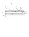
そこで、実施形態に係るタッチパネル4は、図3に示すように、基板5の操作面上に接着層6を介して設けられる保護層7を3層構造とすることによって、異音Nの発生を抑制する。
Therefore, as shown in FIG. 3, the
具体的は、保護層7は、接着層6上に設けられる第1保護フィルム71と、第1保護フィルム71上に空気膜72を介して設けられる第2保護フィルム73とを備える。第2保護フィルム73は、例えば、第1保護フィルム71の上面における縁部に設けられる接着剤によって第1保護フィルム71上に重畳される。
Specifically, the
第1保護フィルム71および第2保護フィルム73は、例えば、PET(Poly Ethylene Terephthalate)等の透光性を有する接着剤によって形成される。このように、タッチパネル4は、第1保護フィルム71、空気膜72、および第2保護フィルム73の3層構造となっている。
The first
かかるタッチパネル4は、基板5が超音波振動した場合に、第1保護フィルム71が超音波振動するが、第1保護フィルム71と第2保護フィルム73との間に空気膜72が介在するので、第2保護フィルム73が超音波振動することがない。
In such a
このため、タッチパネル4では、基板5が超音波振動すると、第1保護フィルム71の表面にスクイーズ膜Aが形成されるので、第1保護フィルム71の表面がツルツルとした感触を与える状態になる。
Therefore, in the
これにより、タッチパネル4は、ユーザが指先Fの表面F1を第2保護フィルム73に接触させてスライドさせる場合、ユーザの指先Fの表面F1に対して第2保護フィルム73越しに第1保護フィルム71の表面のツルツルとした感触を与えることができる。
As a result, when the user touches the surface F1 of the fingertip F with the second
このとき、タッチパネル4では、超音波振動する第1保護フィルム71から発せられる超音波と、その超音波が第2保護フィルム73によって反射される反射波とが、空気膜72内で共鳴し、若干の異音Nが発生する。しかし、かかる空気膜72内で発生する異音Nは、第2保護フィルム73がフィルタとして機能するため、ユーザに認識され難くなる。
At this time, in the
このように、タッチパネル4は、第1保護フィルム71、空気膜72、および第2保護フィルム73の3層構造であるので、タッチ操作を行うユーザにツルツルとした触感を与えつつ、超音波振動に伴う異音の発生を抑制することができる。
As described above, since the
また、本実施形態では、図3に示すタッチパネル4の第1保護フィルム71および第2保護フィルム73の互いに対向する表面の形状を工夫することによって、空気膜72内で発生する異音Nをさらに低減することができる。
Further, in the present embodiment, by devising the shapes of the surfaces of the first
次に、図4を参照し、第1保護フィルム71および第2保護フィルム73の表面形状を工夫した変形例に係るタッチパネル4aについて説明する。図4は、実施形態の変形例に係るタッチパネル4aの一部を示す説明図である。なお、ここでは、図4に示す構成要素のうち、図3に示す構成要素と同一の構成要素については、図3に示す符号と同一の符号を付することにより、その詳細な説明を省略する。
Next, with reference to FIG. 4, a
図4に示すように、変形例に係るタッチパネル4aは、第1保護フィルム71が上面に凹凸を有し、第2保護フィルム73が下面に凹凸を有する点が、図3に示すタッチパネル4とは異なる。
As shown in FIG. 4, the
第1保護フィルム71における凹凸は、例えば、第1保護フィルム71の上面に所定サイズのパーティクルP1を含む溶剤を塗布することによって形成される。かかる第1保護フィルム71が有する凹凸の高低差d1については、図5を参照して説明する。
The unevenness in the first
このように、第1保護フィルム71は、空気膜72に面する表面に凹凸を有するので、基板5が超音波振動する場合に、第1保護フィルム71から発せられる超音波の伝搬方向をパーティクルP1によって分散させることができる。
As described above, since the first
これにより、タッチパネル4aは、第1保護フィルム71から発せられる超音波と、その超音波が第2保護フィルム73によって反射される反射波との共鳴によって発生する異音Nの大きさを低減することができる。
As a result, the
また、第2保護フィルム73における凹凸は、例えば、第2保護フィルム73の下面に所定サイズのパーティクルP2を含む溶剤を塗布することによって形成される。かかる第2保護フィルム73が有する凹凸の高低差d2については、図6を参照して説明する。
Further, the unevenness in the second
このように、第2保護フィルム73は、空気膜72に面する表面に凹凸を有するので、基板5が超音波振動する場合に、超音波の第2保護フィルム73によって反射される反射波の伝搬方向をパーティクルP2によって分散させることができる。
As described above, since the second
これにより、タッチパネル4aは、第1保護フィルム71から発せられる超音波と、その超音波が第2保護フィルム73によって反射される反射波との共鳴によって発生する異音Nの大きさを低減することができる。
As a result, the
なお、第1保護フィルム71および第2保護フィルム73に形成される凹凸は、高低差(粗さ)が大きいほど、異音の低減効果が顕著に表れる。しかし、タッチパネル4aは、第1保護フィルム71および第2保護フィルム73に形成される凹凸の高低差が大きすぎると、タッチ操作を行うユーザにザラザラとした触感や、凸凹とした触感を与えることがある。
As for the unevenness formed on the first
このため、タッチパネル4aでは、タッチ操作を行うユーザに対してツルツルとした触感を与えつつ、超音波振動による異音の発生を低減できるように、第1保護フィルム71および第2保護フィルム73に形成される凹凸の高低差が調整される。
For this reason, the
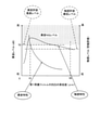
次に、図5および図6を参照し、第1保護フィルム71および第2保護フィルム73に形成される凹凸の高低差について説明する。図5は、実施形態に係る第1保護フィルム71の凹凸の高低差と、異音レベルおよび触感レベルの関係を示す説明図である。
Next, with reference to FIGS. 5 and 6, the height difference of the unevenness formed on the first
図6は、実施形態に係る第2保護フィルム73の凹凸の高低差と、異音レベルおよび触感レベルの関係を示す説明図である。図5および図6に示すグラフの横軸は、凹凸の高低差(μm)を示しており、左側の縦軸は、異音レベル(dB)を示しており、右側の縦軸は、触感レベル(感応評価)を示している。
FIG. 6 is an explanatory diagram showing the relationship between the height difference of the unevenness of the second
ここでの、凹凸の高低差(μm)は、図5では、第1保護フィルム71の上面からパーティクルP1の最上部までの高低差d1であり、図6では、第2保護フィルム73の下面からパーティクルP2の最下部までの高低差d2である。
Here, the height difference (μm) of the unevenness is the height difference d1 from the upper surface of the first
また、異音レベル(dB)は、タッチパネル4から発せられる異音の大きさのレベルである。また、触感レベル(感応評価)は、ユーザがタッチパネル4を操作した場合に感じるツルツルとした感触の高さである。
The abnormal noise level (dB) is the level of the magnitude of the abnormal noise emitted from the
なお、触感レベルが高いほど、ユーザへよりツルツルとした触感を与えることを意味し、触感レベルが低いほど、ユーザへザラザラとした感触やデコボコとした感触を与えることを意味している。 It should be noted that the higher the tactile sensation level, the smoother the tactile sensation is given to the user, and the lower the tactile sensation level, the rougher the feel or the uneven feel is given to the user.
図5および図6に示すように、異音特性は、第1保護フィルム71や第2保護フィルム73の凹凸の高低差が大きいほど、異音レベルが低くなる。これは、前述したように、凹凸の高低差が大きいほど、超音波や超音波の反射波の伝搬方向が分散するからである。
As shown in FIGS. 5 and 6, the abnormal noise level becomes lower as the height difference between the irregularities of the first
ここで、例えば、図5および図6に示すように、異音許容最高レベルを70(dB)とした場合、第1保護フィルム71や第2保護フィルム73の凹凸の高低差は、少なくとも10(μm)以上にする必要がある。
Here, for example, as shown in FIGS. 5 and 6, when the maximum abnormal noise tolerance level is 70 (dB), the height difference of the unevenness of the first
一方、触感特性は、図5および図6に示すように、凹凸の高低差が最小値から増大するにつれて急激に触感レベルが上昇するが、凹凸の高低差が例えば10(μm)を超えるあたりから、凹凸の高低差が増大するにつれて徐々に触感レベルが低下する。 On the other hand, as shown in FIGS. 5 and 6, the tactile sensation level rises sharply as the height difference of the unevenness increases from the minimum value, but the height difference of the unevenness exceeds, for example, 10 (μm). As the height difference of the unevenness increases, the tactile sensation level gradually decreases.
かかる触感特性は、ユーザの指先Fの表面F1と第2保護フィルム73との接触面積に応じて変化する摩擦力に起因すると考えられる。具体的には、ユーザが指先Fの表面F1を第2保護フィルム73の上面に圧接させた場合、第2保護フィルム73が下に凸となるように湾曲して第1保護フィルム71と接する。このとき、第2保護フィルム73の表面は、第1保護フィルム71の凹凸および第2保護フィルム73の凹凸に応じた形状となる。
It is considered that such tactile characteristics are caused by the frictional force that changes depending on the contact area between the surface F1 of the user's fingertip F and the second
このため、凹凸が最小値の場合、つまり、第1保護フィルム71および第2保護フィルム73が完全な平面に近い状態の場合、ユーザの指先Fの表面F1と第2保護フィルム73との接触面積が最大となり、摩擦力が大きくなるので触感レベルが最低となる。
Therefore, when the unevenness is the minimum value, that is, when the first
そして、凹凸の高低差が徐々に大きくなると、ユーザの指先Fの表面F1と第2保護フィルム73との接触面積が徐々に低減され、これに伴い摩擦力も軽減されるので触感レベルが向上する。しかし、凹凸の高低差が大きくなり過ぎると、ユーザが第1保護フィルム71および第2保護フィルム73の凹凸を顕著に感じることになり、徐々に触感レベルが低下する。
When the height difference of the unevenness gradually increases, the contact area between the surface F1 of the user's fingertip F and the second
ここで、図5に示す触感特性のグラフと、図6に示す触感特性のグラフとを対比すると、図5に示す第1保護フィルム71の方は、凹凸の高低差が10(μm)よりも大きくなるにつれて、触感レベルが比較的緩やかに低下している。これに対して、図6に示す第2保護フィルム73の方は、凹凸の高低差が10(μm)よりも大きくなるにつれて、触感レベルが比較的急激に低下している。
Here, when the graph of the tactile characteristics shown in FIG. 5 and the graph of the tactile characteristics shown in FIG. 6 are compared, the height difference of the unevenness of the first
これは、ユーザが第2保護フィルム73に直接触れるため、第2保護フィルム73における凹凸の高低差の変化を、第1保護フィルム71における凹凸の高低差の変化よりも敏感に感じ取るためである。
This is because the user directly touches the second
また、ユーザは、第2保護フィルム73を介して間接的に第1保護フィルム71に触れることに加え、第1保護フィルム71の表面には、基板5の超音波振動によってスクイーズ膜A(図4参照)が形成されるので、第1保護フィルム71の凹凸を感じ難い。
Further, in addition to indirectly touching the first
上記したことから、異音レベルを異音許容最高レベル以下にするには、第1保護フィルム71および第2保護フィルム73における凹凸の高低差の下限値を共に10(μm)に設定する必要がある。
From the above, in order to make the abnormal noise level below the maximum allowable abnormal noise level, it is necessary to set both the lower limit of the height difference of the unevenness of the first
ただし、一定の触感レベルを保つため、凹凸の高低差の上限値については、第2保護フィルム73を第1保護フィルム71よりも小さく設定する必要がある。換言すれば、第1保護フィルム71における凹凸の高低差の上限値は、第2保護フィルム73における凹凸の高低差の上限値よりも大きく設定することが可能である。
However, in order to maintain a constant tactile sensation level, it is necessary to set the second
そこで、本実施形態では、触感許容最低レベルが図5および図6に示すレベルである場合、第1保護フィルム71が有する凹凸の高低差は、10(μm)~50(μm)とする。一方、第2保護フィルム73の凹凸の高低差は、10(μm)~20(μm)とする。これにより、操作入力装置1は、異音レベルを異音許容最高レベル以下にしつつ、触感レベルを触感許容最低レベル以上にすることができる。
Therefore, in the present embodiment, when the minimum permissible tactile level is the level shown in FIGS. 5 and 6, the height difference of the unevenness of the first
上述したように、実施形態に係る操作入力装置1は、基板5と、第1保護フィルム71と、第2保護フィルム73とを備える。基板5は、超音波周波数で振動し、タッチ入力操作を受け付ける。第1保護フィルム71は、基板5の操作面上に設けられる。第2保護フィルム73は、第1保護フィルム71上に空気膜72を介して設けられる。これにより、操作入力装置1は、タッチパネル4の振動に伴う異音の発生を抑制することができる。
As described above, the
なお、上述した実施形態では、異音レベルが異音許容最高レベル以下になり、且つ触感レベルが触感許容最低レベル以上になるように、第1保護フィルム71および第2保護フィルム73における凹凸の高低差を設定したが、これは一例である。
In the above-described embodiment, the unevenness of the first
操作入力装置1は、異音レベルが異音許容最高レベル以下になり、且つ触感レベルが触感許容最低レベル以上になるように、第1保護フィルム71および第2保護フィルム73における凹凸の凸部の間隔や幅を設定してもよい。
The
かかる構成とする場合、第1保護フィルム71や第2保護フィルム73に凹凸を形成するために塗布する溶剤へ添加するパーティクルP1,P2の大きさおよび濃度を調整することで凸部の間隔や幅を設定する。かかる構成によっても、操作入力装置1は、タッチパネル4の振動に伴う異音を低減しつつ、ユーザに対してツルツルとした良質な触感を与えることができる。
In such a configuration, the spacing and width of the convex portions are adjusted by adjusting the sizes and concentrations of the particles P1 and P2 added to the solvent applied to form the unevenness on the first
なお、図4に示す第1保護フィルム71上に空気膜72を介して設けられる部材は、第2保護フィルム73に限定されるものではなく、指先Fが第1保護フィルム71に直接することを防止可能な部材であれば、任意の部材であってよい。
The member provided on the first
また、上述した実施形態では、ディスプレイ2上にタッチパネル4が重畳された操作入力装置1を例に挙げて説明したが、本実施形態に係るタッチパネル4は、ディスプレイ2を備えない操作入力装置に対しても適用することが可能である。
Further, in the above-described embodiment, the
例えば、車両のセンターコンソールに設けられ、ユーザが操作面を視認することなく、タッチ操作やスライド操作によって感覚的に制御対象を制御する操作入力装置は、車両のダッシュボードに設けられる操作入力装置よりも運転者の耳からの距離が近い。 For example, an operation input device provided on the center console of a vehicle that intuitively controls a control target by a touch operation or a slide operation without the user visually recognizing the operation surface is more than an operation input device provided on the dashboard of the vehicle. However, the distance from the driver's ear is short.
このため、運転者は、センターコンソールに設けられる操作入力装置から発せられる異音に敏感に反応する可能性が高い。このため、かかる操作入力装置へ実施形態に係るタッチパネル4を適用することにより、運転者の快適性をさらに向上させることができる。
Therefore, the driver is likely to react sensitively to the abnormal noise emitted from the operation input device provided in the center console. Therefore, by applying the
さらなる効果や変形例は、当業者によって容易に導き出すことができる。このため、本発明のより広範な態様は、以上のように表しかつ記述した特定の詳細および代表的な実施形態に限定されるものではない。したがって、添付の特許請求の範囲およびその均等物によって定義される総括的な発明の概念の精神または範囲から逸脱することなく、様々な変更が可能である。 Further effects and variations can be easily derived by those skilled in the art. For this reason, the broader aspects of the invention are not limited to the particular details and representative embodiments described and described above. Thus, various modifications can be made without departing from the spirit or scope of the overall concept of the invention as defined by the appended claims and their equivalents.
1 操作入力装置
2 ディスプレイ
3 支持板
4,4a,40 タッチパネル
5 基板
6 接着層
7,70 保護層
71 第1保護フィルム
72 空気膜
73 第2保護フィルム
8 両面テープ
9 タッチセンサ
10 振動子
11 制御部
12 検知部
13 駆動部
A スクイーズ膜
F 指先
F1 表面
F2 溝部
N 異音
1
Claims (6)
前記基板の操作面上に設けられる第1保護フィルムと、
前記第1保護フィルム上に空気膜を介して設けられる第2保護フィルムと
を備えることを特徴とする操作入力装置。 A board that vibrates at the ultrasonic frequency and accepts touch input operations,
The first protective film provided on the operation surface of the substrate and
An operation input device including a second protective film provided on the first protective film via an air film.
前記空気膜に面する表面に凹凸を有する
ことを特徴とする請求項1に記載の操作入力装置。 The first protective film is
The operation input device according to claim 1 , wherein the surface facing the air film has irregularities.
高低差が10μm~50μmである
ことを特徴とする請求項2に記載の操作入力装置。 The unevenness of the first protective film is
The operation input device according to claim 2 , wherein the height difference is 10 μm to 50 μm.
前記空気膜に面する表面に凹凸を有する
ことを特徴とする請求項1~3のいずれか一つに記載の操作入力装置。 The second protective film is
The operation input device according to any one of claims 1 to 3 , wherein the surface facing the air film has irregularities.
高低差が10μm~20μmである
ことを特徴とする請求項4に記載の操作入力装置。 The unevenness of the second protective film is
The operation input device according to claim 4 , wherein the height difference is 10 μm to 20 μm.
超音波周波数で振動し、タッチ入力操作を受け付ける基板と、
前記基板の操作面上に設けられる第1保護フィルムと、
前記第1保護フィルム上に空気膜を介して設けられる第2保護フィルムと
を備えることを特徴とするタッチパネル。 It is provided as an operation unit of the operation input device.
A board that vibrates at the ultrasonic frequency and accepts touch input operations,
The first protective film provided on the operation surface of the substrate and
A touch panel comprising a second protective film provided on the first protective film via an air film.
Priority Applications (2)
| Application Number | Priority Date | Filing Date | Title |
|---|---|---|---|
| JP2018002122A JP7038552B2 (en) | 2018-01-10 | 2018-01-10 | Operation input device and touch panel |
| US16/219,081 US10739906B2 (en) | 2018-01-10 | 2018-12-13 | Operation input device and touch panel |
Applications Claiming Priority (1)
| Application Number | Priority Date | Filing Date | Title |
|---|---|---|---|
| JP2018002122A JP7038552B2 (en) | 2018-01-10 | 2018-01-10 | Operation input device and touch panel |
Publications (2)
| Publication Number | Publication Date |
|---|---|
| JP2019121287A JP2019121287A (en) | 2019-07-22 |
| JP7038552B2 true JP7038552B2 (en) | 2022-03-18 |
Family
ID=67307914
Family Applications (1)
| Application Number | Title | Priority Date | Filing Date |
|---|---|---|---|
| JP2018002122A Active JP7038552B2 (en) | 2018-01-10 | 2018-01-10 | Operation input device and touch panel |
Country Status (1)
| Country | Link |
|---|---|
| JP (1) | JP7038552B2 (en) |
Families Citing this family (7)
| Publication number | Priority date | Publication date | Assignee | Title |
|---|---|---|---|---|
| JP7084039B2 (en) * | 2019-06-28 | 2022-06-14 | 京楽産業.株式会社 | Pachinko machine |
| JP2021006228A (en) * | 2019-06-28 | 2021-01-21 | 京楽産業.株式会社 | Game machine |
| JP2021006227A (en) * | 2019-06-28 | 2021-01-21 | 京楽産業.株式会社 | Game machine |
| JP2021006232A (en) * | 2019-06-28 | 2021-01-21 | 京楽産業.株式会社 | Game machine |
| JP2021006230A (en) * | 2019-06-28 | 2021-01-21 | 京楽産業.株式会社 | Game machine |
| JP6990438B2 (en) * | 2019-06-28 | 2022-01-12 | 京楽産業.株式会社 | Pachinko machine |
| JP2021006234A (en) * | 2019-06-28 | 2021-01-21 | 京楽産業.株式会社 | Game machine |
Citations (1)
| Publication number | Priority date | Publication date | Assignee | Title |
|---|---|---|---|---|
| US20100207895A1 (en) | 2009-02-16 | 2010-08-19 | Samsung Electro-Mechanics Co., Ltd. | Tactile interface device and method for controlling the same |
-
2018
- 2018-01-10 JP JP2018002122A patent/JP7038552B2/en active Active
Patent Citations (1)
| Publication number | Priority date | Publication date | Assignee | Title |
|---|---|---|---|---|
| US20100207895A1 (en) | 2009-02-16 | 2010-08-19 | Samsung Electro-Mechanics Co., Ltd. | Tactile interface device and method for controlling the same |
Also Published As
| Publication number | Publication date |
|---|---|
| JP2019121287A (en) | 2019-07-22 |
Similar Documents
| Publication | Publication Date | Title |
|---|---|---|
| JP7038552B2 (en) | Operation input device and touch panel | |
| JP7141215B2 (en) | Operation input device and touch panel | |
| US10739906B2 (en) | Operation input device and touch panel | |
| US20170220197A1 (en) | Input device, system, method of manufacturing input device and display device | |
| JP6351964B2 (en) | Input device | |
| JP5689362B2 (en) | Input device | |
| JP6111315B1 (en) | Tactile presentation device | |
| US20150160772A1 (en) | Input device | |
| JP6945368B2 (en) | Input device and touch panel display | |
| US20180348873A1 (en) | Input device | |
| JP6784297B2 (en) | Electronics | |
| KR20230091158A (en) | Haptic feedback touch device with spatialized textures | |
| US11369995B2 (en) | Method for controlling a mobile device | |
| JP7709330B2 (en) | Display device and electronic device | |
| JP6709628B2 (en) | Input device and display device | |
| JP2017199200A (en) | Touch manipulation device | |
| US10725547B2 (en) | Input device | |
| US20190025983A1 (en) | Controller, control method, and input apparatus | |
| JP6755216B2 (en) | Input device and input system | |
| WO2018151039A1 (en) | Tactile sensation presenting device | |
| CN224096201U (en) | Display device | |
| US10802590B2 (en) | Input device | |
| CN119072365A (en) | Vibration generating device and electronic device | |
| US20230095671A1 (en) | Vibration generating device and electronic apparatus | |
| WO2017061394A1 (en) | Tactile sense presentation device |
Legal Events
| Date | Code | Title | Description |
|---|---|---|---|
| A621 | Written request for application examination |
Free format text: JAPANESE INTERMEDIATE CODE: A621 Effective date: 20201208 |
|
| A977 | Report on retrieval |
Free format text: JAPANESE INTERMEDIATE CODE: A971007 Effective date: 20211008 |
|
| A131 | Notification of reasons for refusal |
Free format text: JAPANESE INTERMEDIATE CODE: A131 Effective date: 20211019 |
|
| A521 | Request for written amendment filed |
Free format text: JAPANESE INTERMEDIATE CODE: A523 Effective date: 20211217 |
|
| TRDD | Decision of grant or rejection written | ||
| A01 | Written decision to grant a patent or to grant a registration (utility model) |
Free format text: JAPANESE INTERMEDIATE CODE: A01 Effective date: 20220208 |
|
| A61 | First payment of annual fees (during grant procedure) |
Free format text: JAPANESE INTERMEDIATE CODE: A61 Effective date: 20220308 |
|
| R150 | Certificate of patent or registration of utility model |
Ref document number: 7038552 Country of ref document: JP Free format text: JAPANESE INTERMEDIATE CODE: R150 |
|
| R250 | Receipt of annual fees |
Free format text: JAPANESE INTERMEDIATE CODE: R250 |
|
| R250 | Receipt of annual fees |
Free format text: JAPANESE INTERMEDIATE CODE: R250 |