JP7038100B2 - Sorting of T lymphocytes with a microfluidic device - Google Patents
Sorting of T lymphocytes with a microfluidic device Download PDFInfo
- Publication number
- JP7038100B2 JP7038100B2 JP2019502710A JP2019502710A JP7038100B2 JP 7038100 B2 JP7038100 B2 JP 7038100B2 JP 2019502710 A JP2019502710 A JP 2019502710A JP 2019502710 A JP2019502710 A JP 2019502710A JP 7038100 B2 JP7038100 B2 JP 7038100B2
- Authority
- JP
- Japan
- Prior art keywords
- microns
- array
- channel
- region
- microfluidic device
- Prior art date
- Legal status (The legal status is an assumption and is not a legal conclusion. Google has not performed a legal analysis and makes no representation as to the accuracy of the status listed.)
- Active
Links
- 210000001744 T-lymphocyte Anatomy 0.000 title claims description 314
- 239000012530 fluid Substances 0.000 claims description 261
- 238000002955 isolation Methods 0.000 claims description 211
- 238000000034 method Methods 0.000 claims description 172
- 210000004027 cell Anatomy 0.000 claims description 105
- 239000000203 mixture Substances 0.000 claims description 40
- 108090000765 processed proteins & peptides Proteins 0.000 claims description 36
- 238000000926 separation method Methods 0.000 claims description 31
- 210000004443 dendritic cell Anatomy 0.000 claims description 27
- 239000000427 antigen Substances 0.000 claims description 26
- 102000036639 antigens Human genes 0.000 claims description 26
- 108091007433 antigens Proteins 0.000 claims description 26
- 239000011886 peripheral blood Substances 0.000 claims description 25
- 210000005259 peripheral blood Anatomy 0.000 claims description 24
- 230000000284 resting effect Effects 0.000 claims description 20
- 239000012190 activator Substances 0.000 claims description 17
- 238000005192 partition Methods 0.000 claims description 14
- 102100036301 C-C chemokine receptor type 7 Human genes 0.000 claims description 8
- 101000716065 Homo sapiens C-C chemokine receptor type 7 Proteins 0.000 claims description 8
- 101001018097 Homo sapiens L-selectin Proteins 0.000 claims description 7
- 102100033467 L-selectin Human genes 0.000 claims description 7
- 210000004296 naive t lymphocyte Anatomy 0.000 claims description 7
- 229940123205 CD28 agonist Drugs 0.000 claims description 6
- 102000008949 Histocompatibility Antigens Class I Human genes 0.000 claims description 6
- 210000000612 antigen-presenting cell Anatomy 0.000 claims description 5
- 101000738771 Homo sapiens Receptor-type tyrosine-protein phosphatase C Proteins 0.000 claims description 4
- 102100037422 Receptor-type tyrosine-protein phosphatase C Human genes 0.000 claims description 4
- 238000004519 manufacturing process Methods 0.000 claims description 4
- 210000003071 memory t lymphocyte Anatomy 0.000 claims description 4
- 108010088652 Histocompatibility Antigens Class I Proteins 0.000 claims description 3
- 210000003162 effector t lymphocyte Anatomy 0.000 claims description 2
- 239000000463 material Substances 0.000 description 151
- 239000000523 sample Substances 0.000 description 141
- 239000011248 coating agent Substances 0.000 description 119
- 239000002609 medium Substances 0.000 description 119
- 238000000576 coating method Methods 0.000 description 108
- 239000000758 substrate Substances 0.000 description 96
- 238000004720 dielectrophoresis Methods 0.000 description 90
- 239000010410 layer Substances 0.000 description 61
- 229920000642 polymer Polymers 0.000 description 55
- 125000005647 linker group Chemical group 0.000 description 46
- -1 polydimethylsiloxane Polymers 0.000 description 43
- 206010028980 Neoplasm Diseases 0.000 description 33
- 125000004429 atom Chemical group 0.000 description 31
- 125000000217 alkyl group Chemical group 0.000 description 30
- 230000003213 activating effect Effects 0.000 description 28
- 238000012258 culturing Methods 0.000 description 26
- 150000002433 hydrophilic molecules Chemical class 0.000 description 26
- 230000004913 activation Effects 0.000 description 25
- 230000003287 optical effect Effects 0.000 description 25
- 238000003384 imaging method Methods 0.000 description 22
- 230000002209 hydrophobic effect Effects 0.000 description 21
- 239000000243 solution Substances 0.000 description 21
- XUIMIQQOPSSXEZ-UHFFFAOYSA-N Silicon Chemical group [Si] XUIMIQQOPSSXEZ-UHFFFAOYSA-N 0.000 description 19
- 238000006243 chemical reaction Methods 0.000 description 19
- 239000003153 chemical reaction reagent Substances 0.000 description 19
- OKTJSMMVPCPJKN-UHFFFAOYSA-N Carbon Chemical group [C] OKTJSMMVPCPJKN-UHFFFAOYSA-N 0.000 description 17
- 239000010703 silicon Substances 0.000 description 17
- 238000009736 wetting Methods 0.000 description 17
- IJGRMHOSHXDMSA-UHFFFAOYSA-N Atomic nitrogen Chemical compound N#N IJGRMHOSHXDMSA-UHFFFAOYSA-N 0.000 description 16
- 201000011510 cancer Diseases 0.000 description 16
- 229910052799 carbon Inorganic materials 0.000 description 16
- RTZKZFJDLAIYFH-UHFFFAOYSA-N ether Substances CCOCC RTZKZFJDLAIYFH-UHFFFAOYSA-N 0.000 description 16
- 229910052710 silicon Inorganic materials 0.000 description 16
- 229920001223 polyethylene glycol Polymers 0.000 description 15
- 239000002202 Polyethylene glycol Substances 0.000 description 14
- 230000000890 antigenic effect Effects 0.000 description 14
- 239000011324 bead Substances 0.000 description 14
- 210000003819 peripheral blood mononuclear cell Anatomy 0.000 description 14
- ABLZXFCXXLZCGV-UHFFFAOYSA-N phosphonic acid group Chemical group P(O)(O)=O ABLZXFCXXLZCGV-UHFFFAOYSA-N 0.000 description 14
- 235000018102 proteins Nutrition 0.000 description 14
- 102000004169 proteins and genes Human genes 0.000 description 14
- 108090000623 proteins and genes Proteins 0.000 description 14
- 238000003491 array Methods 0.000 description 12
- 230000007274 generation of a signal involved in cell-cell signaling Effects 0.000 description 12
- 239000000126 substance Substances 0.000 description 12
- QVGXLLKOCUKJST-UHFFFAOYSA-N atomic oxygen Chemical compound [O] QVGXLLKOCUKJST-UHFFFAOYSA-N 0.000 description 11
- 150000001735 carboxylic acids Chemical group 0.000 description 11
- 238000005859 coupling reaction Methods 0.000 description 11
- 229910052760 oxygen Inorganic materials 0.000 description 11
- 239000001301 oxygen Substances 0.000 description 11
- 239000002356 single layer Substances 0.000 description 11
- 108091003079 Bovine Serum Albumin Proteins 0.000 description 10
- 125000003277 amino group Chemical group 0.000 description 10
- 229910021417 amorphous silicon Inorganic materials 0.000 description 10
- 238000000151 deposition Methods 0.000 description 10
- 239000007789 gas Substances 0.000 description 10
- 210000004698 lymphocyte Anatomy 0.000 description 10
- 210000002966 serum Anatomy 0.000 description 10
- 108091054437 MHC class I family Proteins 0.000 description 9
- 238000004458 analytical method Methods 0.000 description 9
- 229940098773 bovine serum albumin Drugs 0.000 description 9
- 239000000470 constituent Substances 0.000 description 9
- 230000008878 coupling Effects 0.000 description 9
- 238000010168 coupling process Methods 0.000 description 9
- 230000006870 function Effects 0.000 description 9
- 230000035755 proliferation Effects 0.000 description 9
- 229920002307 Dextran Polymers 0.000 description 8
- MHAJPDPJQMAIIY-UHFFFAOYSA-N Hydrogen peroxide Chemical compound OO MHAJPDPJQMAIIY-UHFFFAOYSA-N 0.000 description 8
- 229920003171 Poly (ethylene oxide) Polymers 0.000 description 8
- NINIDFKCEFEMDL-UHFFFAOYSA-N Sulfur Chemical compound [S] NINIDFKCEFEMDL-UHFFFAOYSA-N 0.000 description 8
- 150000001413 amino acids Chemical class 0.000 description 8
- 238000003556 assay Methods 0.000 description 8
- 238000001816 cooling Methods 0.000 description 8
- 125000003709 fluoroalkyl group Chemical group 0.000 description 8
- 230000005484 gravity Effects 0.000 description 8
- 238000011534 incubation Methods 0.000 description 8
- 239000003446 ligand Substances 0.000 description 8
- 201000001441 melanoma Diseases 0.000 description 8
- 229910052757 nitrogen Inorganic materials 0.000 description 8
- 239000002245 particle Substances 0.000 description 8
- 230000035515 penetration Effects 0.000 description 8
- 229920001282 polysaccharide Polymers 0.000 description 8
- 239000005017 polysaccharide Substances 0.000 description 8
- 239000004065 semiconductor Substances 0.000 description 8
- 235000000346 sugar Nutrition 0.000 description 8
- 229910052717 sulfur Inorganic materials 0.000 description 8
- 239000011593 sulfur Substances 0.000 description 8
- VYPSYNLAJGMNEJ-UHFFFAOYSA-N Silicium dioxide Chemical compound O=[Si]=O VYPSYNLAJGMNEJ-UHFFFAOYSA-N 0.000 description 7
- 230000008901 benefit Effects 0.000 description 7
- 150000001720 carbohydrates Chemical class 0.000 description 7
- 125000004432 carbon atom Chemical group C* 0.000 description 7
- 230000001143 conditioned effect Effects 0.000 description 7
- 230000008021 deposition Effects 0.000 description 7
- 239000004205 dimethyl polysiloxane Substances 0.000 description 7
- 235000013870 dimethyl polysiloxane Nutrition 0.000 description 7
- 150000004676 glycans Chemical class 0.000 description 7
- 125000004435 hydrogen atom Chemical group [H]* 0.000 description 7
- 150000007523 nucleic acids Chemical class 0.000 description 7
- 244000052769 pathogen Species 0.000 description 7
- 125000004437 phosphorous atom Chemical group 0.000 description 7
- 229920000435 poly(dimethylsiloxane) Polymers 0.000 description 7
- 102000004196 processed proteins & peptides Human genes 0.000 description 7
- 210000000130 stem cell Anatomy 0.000 description 7
- 230000009258 tissue cross reactivity Effects 0.000 description 7
- 102000043129 MHC class I family Human genes 0.000 description 6
- 102100022748 Wilms tumor protein Human genes 0.000 description 6
- 125000003275 alpha amino acid group Chemical group 0.000 description 6
- 125000000732 arylene group Chemical group 0.000 description 6
- 230000009286 beneficial effect Effects 0.000 description 6
- 229920001400 block copolymer Polymers 0.000 description 6
- 230000000903 blocking effect Effects 0.000 description 6
- 238000010367 cloning Methods 0.000 description 6
- KPUWHANPEXNPJT-UHFFFAOYSA-N disiloxane Chemical class [SiH3]O[SiH3] KPUWHANPEXNPJT-UHFFFAOYSA-N 0.000 description 6
- 125000000623 heterocyclic group Chemical group 0.000 description 6
- 238000002372 labelling Methods 0.000 description 6
- 102000039446 nucleic acids Human genes 0.000 description 6
- 108020004707 nucleic acids Proteins 0.000 description 6
- 239000002773 nucleotide Substances 0.000 description 6
- 125000003729 nucleotide group Chemical group 0.000 description 6
- CXQXSVUQTKDNFP-UHFFFAOYSA-N octamethyltrisiloxane Chemical compound C[Si](C)(C)O[Si](C)(C)O[Si](C)(C)C CXQXSVUQTKDNFP-UHFFFAOYSA-N 0.000 description 6
- 230000005693 optoelectronics Effects 0.000 description 6
- 230000036961 partial effect Effects 0.000 description 6
- 238000004987 plasma desorption mass spectroscopy Methods 0.000 description 6
- 229920001983 poloxamer Polymers 0.000 description 6
- 229920001451 polypropylene glycol Polymers 0.000 description 6
- 230000008569 process Effects 0.000 description 6
- 102220170373 rs886048117 Human genes 0.000 description 6
- 229910052814 silicon oxide Inorganic materials 0.000 description 6
- 230000032258 transport Effects 0.000 description 6
- 244000157072 Hylocereus undatus Species 0.000 description 5
- 235000018481 Hylocereus undatus Nutrition 0.000 description 5
- 108010010995 MART-1 Antigen Proteins 0.000 description 5
- 102100028389 Melanoma antigen recognized by T-cells 1 Human genes 0.000 description 5
- 208000037265 diseases, disorders, signs and symptoms Diseases 0.000 description 5
- 208000035475 disorder Diseases 0.000 description 5
- 238000005516 engineering process Methods 0.000 description 5
- 239000007850 fluorescent dye Substances 0.000 description 5
- 239000001257 hydrogen Substances 0.000 description 5
- 229910052739 hydrogen Inorganic materials 0.000 description 5
- 230000004048 modification Effects 0.000 description 5
- 238000012986 modification Methods 0.000 description 5
- 125000005010 perfluoroalkyl group Chemical group 0.000 description 5
- 239000012071 phase Substances 0.000 description 5
- 125000002924 primary amino group Chemical group [H]N([H])* 0.000 description 5
- 229920005573 silicon-containing polymer Polymers 0.000 description 5
- 125000000542 sulfonic acid group Chemical group 0.000 description 5
- XLYOFNOQVPJJNP-UHFFFAOYSA-N water Substances O XLYOFNOQVPJJNP-UHFFFAOYSA-N 0.000 description 5
- 238000012413 Fluorescence activated cell sorting analysis Methods 0.000 description 4
- QAOWNCQODCNURD-UHFFFAOYSA-N Sulfuric acid Chemical compound OS(O)(=O)=O QAOWNCQODCNURD-UHFFFAOYSA-N 0.000 description 4
- 150000001408 amides Chemical class 0.000 description 4
- 125000003118 aryl group Chemical group 0.000 description 4
- 150000001540 azides Chemical class 0.000 description 4
- 239000006143 cell culture medium Substances 0.000 description 4
- 238000002659 cell therapy Methods 0.000 description 4
- 230000008859 change Effects 0.000 description 4
- 238000004140 cleaning Methods 0.000 description 4
- 238000004891 communication Methods 0.000 description 4
- 239000012809 cooling fluid Substances 0.000 description 4
- 239000007857 degradation product Substances 0.000 description 4
- 238000009792 diffusion process Methods 0.000 description 4
- 238000001943 fluorescence-activated cell sorting Methods 0.000 description 4
- 239000011521 glass Substances 0.000 description 4
- 229910000449 hafnium oxide Inorganic materials 0.000 description 4
- WIHZLLGSGQNAGK-UHFFFAOYSA-N hafnium(4+);oxygen(2-) Chemical compound [O-2].[O-2].[Hf+4] WIHZLLGSGQNAGK-UHFFFAOYSA-N 0.000 description 4
- 125000005549 heteroarylene group Chemical group 0.000 description 4
- 230000014759 maintenance of location Effects 0.000 description 4
- 238000005259 measurement Methods 0.000 description 4
- 125000000325 methylidene group Chemical group [H]C([H])=* 0.000 description 4
- 238000012544 monitoring process Methods 0.000 description 4
- 230000001717 pathogenic effect Effects 0.000 description 4
- 230000002062 proliferating effect Effects 0.000 description 4
- 230000005855 radiation Effects 0.000 description 4
- 238000011144 upstream manufacturing Methods 0.000 description 4
- 239000002699 waste material Substances 0.000 description 4
- LFQSCWFLJHTTHZ-UHFFFAOYSA-N Ethanol Chemical compound CCO LFQSCWFLJHTTHZ-UHFFFAOYSA-N 0.000 description 3
- UFHFLCQGNIYNRP-UHFFFAOYSA-N Hydrogen Chemical compound [H][H] UFHFLCQGNIYNRP-UHFFFAOYSA-N 0.000 description 3
- 241001465754 Metazoa Species 0.000 description 3
- NBIIXXVUZAFLBC-UHFFFAOYSA-N Phosphoric acid Chemical group OP(O)(O)=O NBIIXXVUZAFLBC-UHFFFAOYSA-N 0.000 description 3
- 230000009471 action Effects 0.000 description 3
- 125000003342 alkenyl group Chemical group 0.000 description 3
- 150000001345 alkine derivatives Chemical group 0.000 description 3
- 125000002947 alkylene group Chemical group 0.000 description 3
- PNEYBMLMFCGWSK-UHFFFAOYSA-N aluminium oxide Inorganic materials [O-2].[O-2].[O-2].[Al+3].[Al+3] PNEYBMLMFCGWSK-UHFFFAOYSA-N 0.000 description 3
- 125000000129 anionic group Chemical group 0.000 description 3
- 244000052616 bacterial pathogen Species 0.000 description 3
- 239000012620 biological material Substances 0.000 description 3
- 230000015572 biosynthetic process Effects 0.000 description 3
- 239000002981 blocking agent Substances 0.000 description 3
- 238000004364 calculation method Methods 0.000 description 3
- 229910002091 carbon monoxide Inorganic materials 0.000 description 3
- 125000002091 cationic group Chemical group 0.000 description 3
- 238000004113 cell culture Methods 0.000 description 3
- 239000003814 drug Substances 0.000 description 3
- 230000005684 electric field Effects 0.000 description 3
- 244000053095 fungal pathogen Species 0.000 description 3
- 230000012010 growth Effects 0.000 description 3
- 210000000987 immune system Anatomy 0.000 description 3
- 230000003993 interaction Effects 0.000 description 3
- 239000002502 liposome Substances 0.000 description 3
- 239000004973 liquid crystal related substance Substances 0.000 description 3
- 239000007791 liquid phase Substances 0.000 description 3
- 239000011325 microbead Substances 0.000 description 3
- 238000002156 mixing Methods 0.000 description 3
- 238000012806 monitoring device Methods 0.000 description 3
- 150000002772 monosaccharides Chemical class 0.000 description 3
- 230000003071 parasitic effect Effects 0.000 description 3
- 229920000768 polyamine Polymers 0.000 description 3
- 229920001296 polysiloxane Polymers 0.000 description 3
- 238000012163 sequencing technique Methods 0.000 description 3
- 239000002904 solvent Substances 0.000 description 3
- 125000000547 substituted alkyl group Chemical group 0.000 description 3
- IIACRCGMVDHOTQ-UHFFFAOYSA-N sulfamic acid group Chemical class S(N)(O)(=O)=O IIACRCGMVDHOTQ-UHFFFAOYSA-N 0.000 description 3
- 229940124597 therapeutic agent Drugs 0.000 description 3
- 238000002560 therapeutic procedure Methods 0.000 description 3
- 150000003573 thiols Chemical class 0.000 description 3
- 238000012546 transfer Methods 0.000 description 3
- 210000004881 tumor cell Anatomy 0.000 description 3
- 244000052613 viral pathogen Species 0.000 description 3
- PEHVGBZKEYRQSX-UHFFFAOYSA-N 7-deaza-adenine Chemical compound NC1=NC=NC2=C1C=CN2 PEHVGBZKEYRQSX-UHFFFAOYSA-N 0.000 description 2
- CSCPPACGZOOCGX-UHFFFAOYSA-N Acetone Chemical compound CC(C)=O CSCPPACGZOOCGX-UHFFFAOYSA-N 0.000 description 2
- 108010088751 Albumins Proteins 0.000 description 2
- 102000009027 Albumins Human genes 0.000 description 2
- LSNNMFCWUKXFEE-UHFFFAOYSA-M Bisulfite Chemical compound OS([O-])=O LSNNMFCWUKXFEE-UHFFFAOYSA-M 0.000 description 2
- CURLTUGMZLYLDI-UHFFFAOYSA-N Carbon dioxide Chemical compound O=C=O CURLTUGMZLYLDI-UHFFFAOYSA-N 0.000 description 2
- 102000010834 Extracellular Matrix Proteins Human genes 0.000 description 2
- 108010037362 Extracellular Matrix Proteins Proteins 0.000 description 2
- 108010043121 Green Fluorescent Proteins Proteins 0.000 description 2
- VEXZGXHMUGYJMC-UHFFFAOYSA-N Hydrochloric acid Chemical compound Cl VEXZGXHMUGYJMC-UHFFFAOYSA-N 0.000 description 2
- 241001494479 Pecora Species 0.000 description 2
- 206010060862 Prostate cancer Diseases 0.000 description 2
- 208000000236 Prostatic Neoplasms Diseases 0.000 description 2
- 229920002125 Sokalan® Polymers 0.000 description 2
- 101710127857 Wilms tumor protein Proteins 0.000 description 2
- 150000001298 alcohols Chemical class 0.000 description 2
- 125000005376 alkyl siloxane group Chemical group 0.000 description 2
- 150000001412 amines Chemical class 0.000 description 2
- 210000003719 b-lymphocyte Anatomy 0.000 description 2
- 210000001772 blood platelet Anatomy 0.000 description 2
- 210000002798 bone marrow cell Anatomy 0.000 description 2
- 238000004422 calculation algorithm Methods 0.000 description 2
- 235000014633 carbohydrates Nutrition 0.000 description 2
- 230000021164 cell adhesion Effects 0.000 description 2
- 230000010261 cell growth Effects 0.000 description 2
- 238000005229 chemical vapour deposition Methods 0.000 description 2
- HVYWMOMLDIMFJA-DPAQBDIFSA-N cholesterol Chemical compound C1C=C2C[C@@H](O)CC[C@]2(C)[C@@H]2[C@@H]1[C@@H]1CC[C@H]([C@H](C)CCCC(C)C)[C@@]1(C)CC2 HVYWMOMLDIMFJA-DPAQBDIFSA-N 0.000 description 2
- 229920001577 copolymer Polymers 0.000 description 2
- 238000013461 design Methods 0.000 description 2
- 229920001971 elastomer Polymers 0.000 description 2
- 239000003792 electrolyte Substances 0.000 description 2
- 238000009503 electrostatic coating Methods 0.000 description 2
- 210000003979 eosinophil Anatomy 0.000 description 2
- 210000003743 erythrocyte Anatomy 0.000 description 2
- 150000002148 esters Chemical class 0.000 description 2
- 150000002170 ethers Chemical class 0.000 description 2
- GGABWRGYJHJXJO-UHFFFAOYSA-N ethynylphosphonic acid Chemical compound OP(O)(=O)C#C GGABWRGYJHJXJO-UHFFFAOYSA-N 0.000 description 2
- 230000001747 exhibiting effect Effects 0.000 description 2
- 238000002474 experimental method Methods 0.000 description 2
- 210000002744 extracellular matrix Anatomy 0.000 description 2
- 239000012091 fetal bovine serum Substances 0.000 description 2
- 230000004907 flux Effects 0.000 description 2
- 125000002485 formyl group Chemical group [H]C(*)=O 0.000 description 2
- 229920000578 graft copolymer Polymers 0.000 description 2
- ZRALSGWEFCBTJO-UHFFFAOYSA-O guanidinium Chemical class NC(N)=[NH2+] ZRALSGWEFCBTJO-UHFFFAOYSA-O 0.000 description 2
- 210000005260 human cell Anatomy 0.000 description 2
- 230000001900 immune effect Effects 0.000 description 2
- 150000002500 ions Chemical class 0.000 description 2
- 210000000265 leukocyte Anatomy 0.000 description 2
- 239000007788 liquid Substances 0.000 description 2
- 210000002540 macrophage Anatomy 0.000 description 2
- 210000004962 mammalian cell Anatomy 0.000 description 2
- 239000011159 matrix material Substances 0.000 description 2
- 230000007246 mechanism Effects 0.000 description 2
- 210000003593 megakaryocyte Anatomy 0.000 description 2
- QSHDDOUJBYECFT-UHFFFAOYSA-N mercury Chemical compound [Hg] QSHDDOUJBYECFT-UHFFFAOYSA-N 0.000 description 2
- 229910052753 mercury Inorganic materials 0.000 description 2
- 229910052751 metal Inorganic materials 0.000 description 2
- 239000002184 metal Substances 0.000 description 2
- 229910044991 metal oxide Inorganic materials 0.000 description 2
- 150000004706 metal oxides Chemical class 0.000 description 2
- QLOAVXSYZAJECW-UHFFFAOYSA-N methane;molecular fluorine Chemical compound C.FF QLOAVXSYZAJECW-UHFFFAOYSA-N 0.000 description 2
- 239000011859 microparticle Substances 0.000 description 2
- 230000005012 migration Effects 0.000 description 2
- 238000013508 migration Methods 0.000 description 2
- 239000000178 monomer Substances 0.000 description 2
- 125000002757 morpholinyl group Chemical group 0.000 description 2
- 239000002071 nanotube Substances 0.000 description 2
- 210000000440 neutrophil Anatomy 0.000 description 2
- QJGQUHMNIGDVPM-UHFFFAOYSA-N nitrogen group Chemical group [N] QJGQUHMNIGDVPM-UHFFFAOYSA-N 0.000 description 2
- TWNQGVIAIRXVLR-UHFFFAOYSA-N oxo(oxoalumanyloxy)alumane Chemical compound O=[Al]O[Al]=O TWNQGVIAIRXVLR-UHFFFAOYSA-N 0.000 description 2
- 230000000737 periodic effect Effects 0.000 description 2
- 125000004193 piperazinyl group Chemical group 0.000 description 2
- 229920000172 poly(styrenesulfonic acid) Polymers 0.000 description 2
- 239000004584 polyacrylic acid Substances 0.000 description 2
- 229920000867 polyelectrolyte Polymers 0.000 description 2
- 229920001184 polypeptide Polymers 0.000 description 2
- 229940005642 polystyrene sulfonic acid Drugs 0.000 description 2
- 238000005381 potential energy Methods 0.000 description 2
- 238000002360 preparation method Methods 0.000 description 2
- 238000012545 processing Methods 0.000 description 2
- UORVCLMRJXCDCP-UHFFFAOYSA-N propynoic acid Chemical compound OC(=O)C#C UORVCLMRJXCDCP-UHFFFAOYSA-N 0.000 description 2
- 238000000746 purification Methods 0.000 description 2
- KIDHWZJUCRJVML-UHFFFAOYSA-N putrescine Chemical compound NCCCCN KIDHWZJUCRJVML-UHFFFAOYSA-N 0.000 description 2
- 230000009257 reactivity Effects 0.000 description 2
- 230000002829 reductive effect Effects 0.000 description 2
- 230000011664 signaling Effects 0.000 description 2
- 125000005373 siloxane group Chemical group [SiH2](O*)* 0.000 description 2
- 125000004469 siloxy group Chemical group [SiH3]O* 0.000 description 2
- 150000003384 small molecules Chemical class 0.000 description 2
- 241000894007 species Species 0.000 description 2
- ATHGHQPFGPMSJY-UHFFFAOYSA-N spermidine Chemical compound NCCCCNCCCN ATHGHQPFGPMSJY-UHFFFAOYSA-N 0.000 description 2
- PFNFFQXMRSDOHW-UHFFFAOYSA-N spermine Chemical compound NCCCNCCCCNCCCN PFNFFQXMRSDOHW-UHFFFAOYSA-N 0.000 description 2
- 238000004528 spin coating Methods 0.000 description 2
- 239000007858 starting material Substances 0.000 description 2
- 230000004936 stimulating effect Effects 0.000 description 2
- 150000005846 sugar alcohols Polymers 0.000 description 2
- 230000004083 survival effect Effects 0.000 description 2
- 210000001635 urinary tract Anatomy 0.000 description 2
- 238000007740 vapor deposition Methods 0.000 description 2
- 230000035899 viability Effects 0.000 description 2
- 229920002554 vinyl polymer Polymers 0.000 description 2
- OZFAFGSSMRRTDW-UHFFFAOYSA-N (2,4-dichlorophenyl) benzenesulfonate Chemical compound ClC1=CC(Cl)=CC=C1OS(=O)(=O)C1=CC=CC=C1 OZFAFGSSMRRTDW-UHFFFAOYSA-N 0.000 description 1
- QNRATNLHPGXHMA-XZHTYLCXSA-N (r)-(6-ethoxyquinolin-4-yl)-[(2s,4s,5r)-5-ethyl-1-azabicyclo[2.2.2]octan-2-yl]methanol;hydrochloride Chemical compound Cl.C([C@H]([C@H](C1)CC)C2)CN1[C@@H]2[C@H](O)C1=CC=NC2=CC=C(OCC)C=C21 QNRATNLHPGXHMA-XZHTYLCXSA-N 0.000 description 1
- NGNBDVOYPDDBFK-UHFFFAOYSA-N 2-[2,4-di(pentan-2-yl)phenoxy]acetyl chloride Chemical class CCCC(C)C1=CC=C(OCC(Cl)=O)C(C(C)CCC)=C1 NGNBDVOYPDDBFK-UHFFFAOYSA-N 0.000 description 1
- JKMHFZQWWAIEOD-UHFFFAOYSA-N 2-[4-(2-hydroxyethyl)piperazin-1-yl]ethanesulfonic acid Chemical compound OCC[NH+]1CCN(CCS([O-])(=O)=O)CC1 JKMHFZQWWAIEOD-UHFFFAOYSA-N 0.000 description 1
- 108010074708 B7-H1 Antigen Proteins 0.000 description 1
- 102000008096 B7-H1 Antigen Human genes 0.000 description 1
- 241000283690 Bos taurus Species 0.000 description 1
- 206010006187 Breast cancer Diseases 0.000 description 1
- 208000026310 Breast neoplasm Diseases 0.000 description 1
- 241000283707 Capra Species 0.000 description 1
- 239000004215 Carbon black (E152) Substances 0.000 description 1
- 241000700198 Cavia Species 0.000 description 1
- 206010008342 Cervix carcinoma Diseases 0.000 description 1
- 241000252506 Characiformes Species 0.000 description 1
- 108010019670 Chimeric Antigen Receptors Proteins 0.000 description 1
- 102000008186 Collagen Human genes 0.000 description 1
- 108010035532 Collagen Proteins 0.000 description 1
- 206010009944 Colon cancer Diseases 0.000 description 1
- 208000001333 Colorectal Neoplasms Diseases 0.000 description 1
- 241000938605 Crocodylia Species 0.000 description 1
- 241000195493 Cryptophyta Species 0.000 description 1
- 102000004127 Cytokines Human genes 0.000 description 1
- 108090000695 Cytokines Proteins 0.000 description 1
- HMFHBZSHGGEWLO-SOOFDHNKSA-N D-ribofuranose Chemical compound OC[C@H]1OC(O)[C@H](O)[C@@H]1O HMFHBZSHGGEWLO-SOOFDHNKSA-N 0.000 description 1
- 239000012591 Dulbecco’s Phosphate Buffered Saline Substances 0.000 description 1
- KCXVZYZYPLLWCC-UHFFFAOYSA-N EDTA Chemical compound OC(=O)CN(CC(O)=O)CCN(CC(O)=O)CC(O)=O KCXVZYZYPLLWCC-UHFFFAOYSA-N 0.000 description 1
- 102000016942 Elastin Human genes 0.000 description 1
- 108010014258 Elastin Proteins 0.000 description 1
- 102000004190 Enzymes Human genes 0.000 description 1
- 108090000790 Enzymes Proteins 0.000 description 1
- 241000283086 Equidae Species 0.000 description 1
- 108010067306 Fibronectins Proteins 0.000 description 1
- 102000016359 Fibronectins Human genes 0.000 description 1
- 108060003393 Granulin Proteins 0.000 description 1
- 208000005016 Intestinal Neoplasms Diseases 0.000 description 1
- 206010058467 Lung neoplasm malignant Diseases 0.000 description 1
- 206010025323 Lymphomas Diseases 0.000 description 1
- 241000124008 Mammalia Species 0.000 description 1
- 108010052285 Membrane Proteins Proteins 0.000 description 1
- 206010027406 Mesothelioma Diseases 0.000 description 1
- 241000699670 Mus sp. Species 0.000 description 1
- 206010029260 Neuroblastoma Diseases 0.000 description 1
- 241000283973 Oryctolagus cuniculus Species 0.000 description 1
- 206010033128 Ovarian cancer Diseases 0.000 description 1
- 206010061535 Ovarian neoplasm Diseases 0.000 description 1
- 229910019142 PO4 Inorganic materials 0.000 description 1
- 208000031481 Pathologic Constriction Diseases 0.000 description 1
- OAICVXFJPJFONN-UHFFFAOYSA-N Phosphorus Chemical compound [P] OAICVXFJPJFONN-UHFFFAOYSA-N 0.000 description 1
- 239000004793 Polystyrene Substances 0.000 description 1
- 239000004372 Polyvinyl alcohol Substances 0.000 description 1
- 241000288906 Primates Species 0.000 description 1
- 101000781681 Protobothrops flavoviridis Disintegrin triflavin Proteins 0.000 description 1
- 239000005700 Putrescine Substances 0.000 description 1
- 241000700159 Rattus Species 0.000 description 1
- 208000006265 Renal cell carcinoma Diseases 0.000 description 1
- 108091028664 Ribonucleotide Proteins 0.000 description 1
- PYMYPHUHKUWMLA-LMVFSUKVSA-N Ribose Natural products OC[C@@H](O)[C@@H](O)[C@@H](O)C=O PYMYPHUHKUWMLA-LMVFSUKVSA-N 0.000 description 1
- 241000282887 Suidae Species 0.000 description 1
- QAOWNCQODCNURD-UHFFFAOYSA-L Sulfate Chemical compound [O-]S([O-])(=O)=O QAOWNCQODCNURD-UHFFFAOYSA-L 0.000 description 1
- 108091008874 T cell receptors Proteins 0.000 description 1
- 229920006362 Teflon® Polymers 0.000 description 1
- 208000024313 Testicular Neoplasms Diseases 0.000 description 1
- 206010057644 Testis cancer Diseases 0.000 description 1
- RYYWUUFWQRZTIU-UHFFFAOYSA-N Thiophosphoric acid Chemical group OP(O)(S)=O RYYWUUFWQRZTIU-UHFFFAOYSA-N 0.000 description 1
- 208000008385 Urogenital Neoplasms Diseases 0.000 description 1
- 208000006105 Uterine Cervical Neoplasms Diseases 0.000 description 1
- 208000002495 Uterine Neoplasms Diseases 0.000 description 1
- 208000008383 Wilms tumor Diseases 0.000 description 1
- 238000009825 accumulation Methods 0.000 description 1
- 239000002253 acid Substances 0.000 description 1
- 125000003158 alcohol group Chemical group 0.000 description 1
- 125000002355 alkine group Chemical group 0.000 description 1
- 230000029936 alkylation Effects 0.000 description 1
- 238000005804 alkylation reaction Methods 0.000 description 1
- 125000000304 alkynyl group Chemical group 0.000 description 1
- HMFHBZSHGGEWLO-UHFFFAOYSA-N alpha-D-Furanose-Ribose Natural products OCC1OC(O)C(O)C1O HMFHBZSHGGEWLO-UHFFFAOYSA-N 0.000 description 1
- 229910052782 aluminium Inorganic materials 0.000 description 1
- XAGFODPZIPBFFR-UHFFFAOYSA-N aluminium Chemical compound [Al] XAGFODPZIPBFFR-UHFFFAOYSA-N 0.000 description 1
- 230000003321 amplification Effects 0.000 description 1
- 239000012491 analyte Substances 0.000 description 1
- 210000004102 animal cell Anatomy 0.000 description 1
- 150000001450 anions Chemical class 0.000 description 1
- 239000003242 anti bacterial agent Substances 0.000 description 1
- 229940088710 antibiotic agent Drugs 0.000 description 1
- 239000012736 aqueous medium Substances 0.000 description 1
- 239000007864 aqueous solution Substances 0.000 description 1
- 239000003125 aqueous solvent Substances 0.000 description 1
- IVRMZWNICZWHMI-UHFFFAOYSA-N azide group Chemical group [N-]=[N+]=[N-] IVRMZWNICZWHMI-UHFFFAOYSA-N 0.000 description 1
- 210000003651 basophil Anatomy 0.000 description 1
- 230000033228 biological regulation Effects 0.000 description 1
- 238000001574 biopsy Methods 0.000 description 1
- 125000001246 bromo group Chemical group Br* 0.000 description 1
- 150000001721 carbon Chemical class 0.000 description 1
- 239000001569 carbon dioxide Substances 0.000 description 1
- 229910002092 carbon dioxide Inorganic materials 0.000 description 1
- 230000015556 catabolic process Effects 0.000 description 1
- 150000001768 cations Chemical class 0.000 description 1
- 230000022131 cell cycle Effects 0.000 description 1
- 230000005754 cellular signaling Effects 0.000 description 1
- 201000010881 cervical cancer Diseases 0.000 description 1
- 235000012000 cholesterol Nutrition 0.000 description 1
- 229920001436 collagen Polymers 0.000 description 1
- 150000001875 compounds Chemical class 0.000 description 1
- 239000011370 conductive nanoparticle Substances 0.000 description 1
- 238000010276 construction Methods 0.000 description 1
- 238000011109 contamination Methods 0.000 description 1
- 230000006378 damage Effects 0.000 description 1
- 230000007547 defect Effects 0.000 description 1
- 230000002950 deficient Effects 0.000 description 1
- 230000032798 delamination Effects 0.000 description 1
- 239000005547 deoxyribonucleotide Substances 0.000 description 1
- 125000002637 deoxyribonucleotide group Chemical group 0.000 description 1
- 238000005137 deposition process Methods 0.000 description 1
- 238000001514 detection method Methods 0.000 description 1
- 238000010586 diagram Methods 0.000 description 1
- 239000003989 dielectric material Substances 0.000 description 1
- 235000014113 dietary fatty acids Nutrition 0.000 description 1
- 150000002016 disaccharides Chemical class 0.000 description 1
- 150000002019 disulfides Chemical class 0.000 description 1
- 239000003937 drug carrier Substances 0.000 description 1
- 229920002549 elastin Polymers 0.000 description 1
- 239000000806 elastomer Substances 0.000 description 1
- 210000002257 embryonic structure Anatomy 0.000 description 1
- 125000004185 ester group Chemical group 0.000 description 1
- 210000003527 eukaryotic cell Anatomy 0.000 description 1
- 230000005284 excitation Effects 0.000 description 1
- 239000000194 fatty acid Substances 0.000 description 1
- 229930195729 fatty acid Natural products 0.000 description 1
- 150000004665 fatty acids Chemical class 0.000 description 1
- 210000005002 female reproductive tract Anatomy 0.000 description 1
- 229920005570 flexible polymer Polymers 0.000 description 1
- 238000001215 fluorescent labelling Methods 0.000 description 1
- 230000002538 fungal effect Effects 0.000 description 1
- 108020001507 fusion proteins Proteins 0.000 description 1
- 102000037865 fusion proteins Human genes 0.000 description 1
- 238000011331 genomic analysis Methods 0.000 description 1
- 239000003102 growth factor Substances 0.000 description 1
- 239000001963 growth medium Substances 0.000 description 1
- ZRALSGWEFCBTJO-UHFFFAOYSA-N guanidine group Chemical group NC(=N)N ZRALSGWEFCBTJO-UHFFFAOYSA-N 0.000 description 1
- 125000005843 halogen group Chemical group 0.000 description 1
- 230000036541 health Effects 0.000 description 1
- 125000001072 heteroaryl group Chemical group 0.000 description 1
- 239000005556 hormone Substances 0.000 description 1
- 229940088597 hormone Drugs 0.000 description 1
- 210000004408 hybridoma Anatomy 0.000 description 1
- 229930195733 hydrocarbon Natural products 0.000 description 1
- 150000002430 hydrocarbons Chemical class 0.000 description 1
- 238000005286 illumination Methods 0.000 description 1
- 238000010191 image analysis Methods 0.000 description 1
- 210000002865 immune cell Anatomy 0.000 description 1
- 238000010324 immunological assay Methods 0.000 description 1
- 238000011293 immunotherapeutic strategy Methods 0.000 description 1
- 238000009169 immunotherapy Methods 0.000 description 1
- 230000006872 improvement Effects 0.000 description 1
- 239000012535 impurity Substances 0.000 description 1
- 238000001727 in vivo Methods 0.000 description 1
- AMGQUBHHOARCQH-UHFFFAOYSA-N indium;oxotin Chemical compound [In].[Sn]=O AMGQUBHHOARCQH-UHFFFAOYSA-N 0.000 description 1
- 208000015181 infectious disease Diseases 0.000 description 1
- 230000004941 influx Effects 0.000 description 1
- 239000011810 insulating material Substances 0.000 description 1
- 201000002313 intestinal cancer Diseases 0.000 description 1
- 230000001788 irregular Effects 0.000 description 1
- 210000003734 kidney Anatomy 0.000 description 1
- 230000002147 killing effect Effects 0.000 description 1
- 208000032839 leukemia Diseases 0.000 description 1
- 150000002632 lipids Chemical class 0.000 description 1
- 201000005202 lung cancer Diseases 0.000 description 1
- 208000020816 lung neoplasm Diseases 0.000 description 1
- 210000005001 male reproductive tract Anatomy 0.000 description 1
- 230000001404 mediated effect Effects 0.000 description 1
- 208000030163 medullary breast carcinoma Diseases 0.000 description 1
- 239000012528 membrane Substances 0.000 description 1
- 239000002207 metabolite Substances 0.000 description 1
- 239000007769 metal material Substances 0.000 description 1
- YACKEPLHDIMKIO-UHFFFAOYSA-N methylphosphonic acid Chemical compound CP(O)(O)=O YACKEPLHDIMKIO-UHFFFAOYSA-N 0.000 description 1
- 210000001616 monocyte Anatomy 0.000 description 1
- 239000002107 nanodisc Substances 0.000 description 1
- 239000002105 nanoparticle Substances 0.000 description 1
- 238000000858 nanotransfer moulding Methods 0.000 description 1
- 239000002070 nanowire Substances 0.000 description 1
- 229920005615 natural polymer Polymers 0.000 description 1
- 201000008026 nephroblastoma Diseases 0.000 description 1
- 201000011682 nervous system cancer Diseases 0.000 description 1
- 150000004767 nitrides Chemical class 0.000 description 1
- 238000003199 nucleic acid amplification method Methods 0.000 description 1
- 239000002777 nucleoside Substances 0.000 description 1
- 125000003835 nucleoside group Chemical group 0.000 description 1
- 239000003921 oil Substances 0.000 description 1
- 239000007800 oxidant agent Substances 0.000 description 1
- 150000002923 oximes Chemical class 0.000 description 1
- 238000012856 packing Methods 0.000 description 1
- 210000003899 penis Anatomy 0.000 description 1
- 150000002972 pentoses Chemical class 0.000 description 1
- 229920005548 perfluoropolymer Polymers 0.000 description 1
- 210000004976 peripheral blood cell Anatomy 0.000 description 1
- 235000021317 phosphate Nutrition 0.000 description 1
- 125000002467 phosphate group Chemical group [H]OP(=O)(O[H])O[*] 0.000 description 1
- 150000003904 phospholipids Chemical class 0.000 description 1
- 150000003013 phosphoric acid derivatives Chemical class 0.000 description 1
- 229910052698 phosphorus Inorganic materials 0.000 description 1
- 239000011574 phosphorus Substances 0.000 description 1
- 230000002186 photoactivation Effects 0.000 description 1
- 229920002120 photoresistant polymer Polymers 0.000 description 1
- 229920003023 plastic Polymers 0.000 description 1
- 239000004033 plastic Substances 0.000 description 1
- 239000004626 polylactic acid Substances 0.000 description 1
- 229920002223 polystyrene Polymers 0.000 description 1
- 229920001343 polytetrafluoroethylene Polymers 0.000 description 1
- 239000004810 polytetrafluoroethylene Substances 0.000 description 1
- 229920002635 polyurethane Polymers 0.000 description 1
- 239000004814 polyurethane Substances 0.000 description 1
- 229920002451 polyvinyl alcohol Polymers 0.000 description 1
- 210000001236 prokaryotic cell Anatomy 0.000 description 1
- TVDSBUOJIPERQY-UHFFFAOYSA-N prop-2-yn-1-ol Chemical compound OCC#C TVDSBUOJIPERQY-UHFFFAOYSA-N 0.000 description 1
- 239000002096 quantum dot Substances 0.000 description 1
- 230000009467 reduction Effects 0.000 description 1
- 238000011160 research Methods 0.000 description 1
- 230000002441 reversible effect Effects 0.000 description 1
- 239000002336 ribonucleotide Substances 0.000 description 1
- 125000002652 ribonucleotide group Chemical group 0.000 description 1
- 239000005060 rubber Substances 0.000 description 1
- 230000035945 sensitivity Effects 0.000 description 1
- 239000000377 silicon dioxide Substances 0.000 description 1
- 235000012239 silicon dioxide Nutrition 0.000 description 1
- 238000000527 sonication Methods 0.000 description 1
- 238000001228 spectrum Methods 0.000 description 1
- 229940063673 spermidine Drugs 0.000 description 1
- 229940063675 spermine Drugs 0.000 description 1
- 238000010186 staining Methods 0.000 description 1
- 230000036262 stenosis Effects 0.000 description 1
- 208000037804 stenosis Diseases 0.000 description 1
- 230000000638 stimulation Effects 0.000 description 1
- 150000008163 sugars Chemical class 0.000 description 1
- 239000004094 surface-active agent Substances 0.000 description 1
- 229920001059 synthetic polymer Polymers 0.000 description 1
- 201000003120 testicular cancer Diseases 0.000 description 1
- 125000003396 thiol group Chemical group [H]S* 0.000 description 1
- 210000001519 tissue Anatomy 0.000 description 1
- 230000009466 transformation Effects 0.000 description 1
- 230000005909 tumor killing Effects 0.000 description 1
- JOYRKODLDBILNP-UHFFFAOYSA-N urethane group Chemical group NC(=O)OCC JOYRKODLDBILNP-UHFFFAOYSA-N 0.000 description 1
- 210000003932 urinary bladder Anatomy 0.000 description 1
- 208000037964 urogenital cancer Diseases 0.000 description 1
- 206010046766 uterine cancer Diseases 0.000 description 1
- 206010046885 vaginal cancer Diseases 0.000 description 1
- 208000013139 vaginal neoplasm Diseases 0.000 description 1
- 238000001429 visible spectrum Methods 0.000 description 1
- 230000003313 weakening effect Effects 0.000 description 1
- 229920001285 xanthan gum Polymers 0.000 description 1
- 239000000230 xanthan gum Substances 0.000 description 1
- 229940082509 xanthan gum Drugs 0.000 description 1
- 235000010493 xanthan gum Nutrition 0.000 description 1
- 229910052724 xenon Inorganic materials 0.000 description 1
- FHNFHKCVQCLJFQ-UHFFFAOYSA-N xenon atom Chemical compound [Xe] FHNFHKCVQCLJFQ-UHFFFAOYSA-N 0.000 description 1
Images


Classifications
-
- A—HUMAN NECESSITIES
- A61—MEDICAL OR VETERINARY SCIENCE; HYGIENE
- A61K—PREPARATIONS FOR MEDICAL, DENTAL OR TOILETRY PURPOSES
- A61K35/00—Medicinal preparations containing materials or reaction products thereof with undetermined constitution
- A61K35/12—Materials from mammals; Compositions comprising non-specified tissues or cells; Compositions comprising non-embryonic stem cells; Genetically modified cells
- A61K35/28—Bone marrow; Haematopoietic stem cells; Mesenchymal stem cells of any origin, e.g. adipose-derived stem cells
-
- A—HUMAN NECESSITIES
- A61—MEDICAL OR VETERINARY SCIENCE; HYGIENE
- A61K—PREPARATIONS FOR MEDICAL, DENTAL OR TOILETRY PURPOSES
- A61K35/00—Medicinal preparations containing materials or reaction products thereof with undetermined constitution
- A61K35/12—Materials from mammals; Compositions comprising non-specified tissues or cells; Compositions comprising non-embryonic stem cells; Genetically modified cells
- A61K35/14—Blood; Artificial blood
- A61K35/17—Lymphocytes; B-cells; T-cells; Natural killer cells; Interferon-activated or cytokine-activated lymphocytes
-
- A—HUMAN NECESSITIES
- A61—MEDICAL OR VETERINARY SCIENCE; HYGIENE
- A61K—PREPARATIONS FOR MEDICAL, DENTAL OR TOILETRY PURPOSES
- A61K39/00—Medicinal preparations containing antigens or antibodies
- A61K39/46—Cellular immunotherapy
- A61K39/461—Cellular immunotherapy characterised by the cell type used
- A61K39/4611—T-cells, e.g. tumor infiltrating lymphocytes [TIL], lymphokine-activated killer cells [LAK] or regulatory T cells [Treg]
-
- A—HUMAN NECESSITIES
- A61—MEDICAL OR VETERINARY SCIENCE; HYGIENE
- A61K—PREPARATIONS FOR MEDICAL, DENTAL OR TOILETRY PURPOSES
- A61K39/00—Medicinal preparations containing antigens or antibodies
- A61K39/46—Cellular immunotherapy
- A61K39/463—Cellular immunotherapy characterised by recombinant expression
- A61K39/4632—T-cell receptors [TCR]; antibody T-cell receptor constructs
-
- A—HUMAN NECESSITIES
- A61—MEDICAL OR VETERINARY SCIENCE; HYGIENE
- A61K—PREPARATIONS FOR MEDICAL, DENTAL OR TOILETRY PURPOSES
- A61K39/00—Medicinal preparations containing antigens or antibodies
- A61K39/46—Cellular immunotherapy
- A61K39/464—Cellular immunotherapy characterised by the antigen targeted or presented
- A61K39/4643—Vertebrate antigens
- A61K39/4644—Cancer antigens
- A61K39/464452—Transcription factors, e.g. SOX or c-MYC
- A61K39/464453—Wilms tumor 1 [WT1]
-
- A—HUMAN NECESSITIES
- A61—MEDICAL OR VETERINARY SCIENCE; HYGIENE
- A61K—PREPARATIONS FOR MEDICAL, DENTAL OR TOILETRY PURPOSES
- A61K39/00—Medicinal preparations containing antigens or antibodies
- A61K39/46—Cellular immunotherapy
- A61K39/464—Cellular immunotherapy characterised by the antigen targeted or presented
- A61K39/4643—Vertebrate antigens
- A61K39/4644—Cancer antigens
- A61K39/46449—Melanoma antigens
- A61K39/464491—Melan-A/MART
-
- A—HUMAN NECESSITIES
- A61—MEDICAL OR VETERINARY SCIENCE; HYGIENE
- A61P—SPECIFIC THERAPEUTIC ACTIVITY OF CHEMICAL COMPOUNDS OR MEDICINAL PREPARATIONS
- A61P35/00—Antineoplastic agents
-
- B—PERFORMING OPERATIONS; TRANSPORTING
- B01—PHYSICAL OR CHEMICAL PROCESSES OR APPARATUS IN GENERAL
- B01L—CHEMICAL OR PHYSICAL LABORATORY APPARATUS FOR GENERAL USE
- B01L3/00—Containers or dishes for laboratory use, e.g. laboratory glassware; Droppers
- B01L3/50—Containers for the purpose of retaining a material to be analysed, e.g. test tubes
- B01L3/502—Containers for the purpose of retaining a material to be analysed, e.g. test tubes with fluid transport, e.g. in multi-compartment structures
- B01L3/5027—Containers for the purpose of retaining a material to be analysed, e.g. test tubes with fluid transport, e.g. in multi-compartment structures by integrated microfluidic structures, i.e. dimensions of channels and chambers are such that surface tension forces are important, e.g. lab-on-a-chip
- B01L3/502746—Containers for the purpose of retaining a material to be analysed, e.g. test tubes with fluid transport, e.g. in multi-compartment structures by integrated microfluidic structures, i.e. dimensions of channels and chambers are such that surface tension forces are important, e.g. lab-on-a-chip characterised by the means for controlling flow resistance, e.g. flow controllers, baffles
-
- B—PERFORMING OPERATIONS; TRANSPORTING
- B01—PHYSICAL OR CHEMICAL PROCESSES OR APPARATUS IN GENERAL
- B01L—CHEMICAL OR PHYSICAL LABORATORY APPARATUS FOR GENERAL USE
- B01L3/00—Containers or dishes for laboratory use, e.g. laboratory glassware; Droppers
- B01L3/50—Containers for the purpose of retaining a material to be analysed, e.g. test tubes
- B01L3/502—Containers for the purpose of retaining a material to be analysed, e.g. test tubes with fluid transport, e.g. in multi-compartment structures
- B01L3/5027—Containers for the purpose of retaining a material to be analysed, e.g. test tubes with fluid transport, e.g. in multi-compartment structures by integrated microfluidic structures, i.e. dimensions of channels and chambers are such that surface tension forces are important, e.g. lab-on-a-chip
- B01L3/502761—Containers for the purpose of retaining a material to be analysed, e.g. test tubes with fluid transport, e.g. in multi-compartment structures by integrated microfluidic structures, i.e. dimensions of channels and chambers are such that surface tension forces are important, e.g. lab-on-a-chip specially adapted for handling suspended solids or molecules independently from the bulk fluid flow, e.g. for trapping or sorting beads, for physically stretching molecules
-
- B—PERFORMING OPERATIONS; TRANSPORTING
- B01—PHYSICAL OR CHEMICAL PROCESSES OR APPARATUS IN GENERAL
- B01L—CHEMICAL OR PHYSICAL LABORATORY APPARATUS FOR GENERAL USE
- B01L3/00—Containers or dishes for laboratory use, e.g. laboratory glassware; Droppers
- B01L3/50—Containers for the purpose of retaining a material to be analysed, e.g. test tubes
- B01L3/502—Containers for the purpose of retaining a material to be analysed, e.g. test tubes with fluid transport, e.g. in multi-compartment structures
- B01L3/5027—Containers for the purpose of retaining a material to be analysed, e.g. test tubes with fluid transport, e.g. in multi-compartment structures by integrated microfluidic structures, i.e. dimensions of channels and chambers are such that surface tension forces are important, e.g. lab-on-a-chip
- B01L3/502769—Containers for the purpose of retaining a material to be analysed, e.g. test tubes with fluid transport, e.g. in multi-compartment structures by integrated microfluidic structures, i.e. dimensions of channels and chambers are such that surface tension forces are important, e.g. lab-on-a-chip characterised by multiphase flow arrangements
- B01L3/502784—Containers for the purpose of retaining a material to be analysed, e.g. test tubes with fluid transport, e.g. in multi-compartment structures by integrated microfluidic structures, i.e. dimensions of channels and chambers are such that surface tension forces are important, e.g. lab-on-a-chip characterised by multiphase flow arrangements specially adapted for droplet or plug flow, e.g. digital microfluidics
- B01L3/502792—Containers for the purpose of retaining a material to be analysed, e.g. test tubes with fluid transport, e.g. in multi-compartment structures by integrated microfluidic structures, i.e. dimensions of channels and chambers are such that surface tension forces are important, e.g. lab-on-a-chip characterised by multiphase flow arrangements specially adapted for droplet or plug flow, e.g. digital microfluidics for moving individual droplets on a plate, e.g. by locally altering surface tension
-
- B—PERFORMING OPERATIONS; TRANSPORTING
- B03—SEPARATION OF SOLID MATERIALS USING LIQUIDS OR USING PNEUMATIC TABLES OR JIGS; MAGNETIC OR ELECTROSTATIC SEPARATION OF SOLID MATERIALS FROM SOLID MATERIALS OR FLUIDS; SEPARATION BY HIGH-VOLTAGE ELECTRIC FIELDS
- B03C—MAGNETIC OR ELECTROSTATIC SEPARATION OF SOLID MATERIALS FROM SOLID MATERIALS OR FLUIDS; SEPARATION BY HIGH-VOLTAGE ELECTRIC FIELDS
- B03C5/00—Separating dispersed particles from liquids by electrostatic effect
- B03C5/005—Dielectrophoresis, i.e. dielectric particles migrating towards the region of highest field strength
-
- B—PERFORMING OPERATIONS; TRANSPORTING
- B03—SEPARATION OF SOLID MATERIALS USING LIQUIDS OR USING PNEUMATIC TABLES OR JIGS; MAGNETIC OR ELECTROSTATIC SEPARATION OF SOLID MATERIALS FROM SOLID MATERIALS OR FLUIDS; SEPARATION BY HIGH-VOLTAGE ELECTRIC FIELDS
- B03C—MAGNETIC OR ELECTROSTATIC SEPARATION OF SOLID MATERIALS FROM SOLID MATERIALS OR FLUIDS; SEPARATION BY HIGH-VOLTAGE ELECTRIC FIELDS
- B03C5/00—Separating dispersed particles from liquids by electrostatic effect
- B03C5/02—Separators
- B03C5/022—Non-uniform field separators
- B03C5/026—Non-uniform field separators using open-gradient differential dielectric separation, i.e. using electrodes of special shapes for non-uniform field creation, e.g. Fluid Integrated Circuit [FIC]
-
- G—PHYSICS
- G01—MEASURING; TESTING
- G01N—INVESTIGATING OR ANALYSING MATERIALS BY DETERMINING THEIR CHEMICAL OR PHYSICAL PROPERTIES
- G01N1/00—Sampling; Preparing specimens for investigation
- G01N1/28—Preparing specimens for investigation including physical details of (bio-)chemical methods covered elsewhere, e.g. G01N33/50, C12Q
- G01N1/34—Purifying; Cleaning
-
- G—PHYSICS
- G01—MEASURING; TESTING
- G01N—INVESTIGATING OR ANALYSING MATERIALS BY DETERMINING THEIR CHEMICAL OR PHYSICAL PROPERTIES
- G01N1/00—Sampling; Preparing specimens for investigation
- G01N1/28—Preparing specimens for investigation including physical details of (bio-)chemical methods covered elsewhere, e.g. G01N33/50, C12Q
- G01N1/40—Concentrating samples
-
- A—HUMAN NECESSITIES
- A61—MEDICAL OR VETERINARY SCIENCE; HYGIENE
- A61K—PREPARATIONS FOR MEDICAL, DENTAL OR TOILETRY PURPOSES
- A61K2239/00—Indexing codes associated with cellular immunotherapy of group A61K39/46
- A61K2239/46—Indexing codes associated with cellular immunotherapy of group A61K39/46 characterised by the cancer treated
- A61K2239/57—Skin; melanoma
-
- B—PERFORMING OPERATIONS; TRANSPORTING
- B01—PHYSICAL OR CHEMICAL PROCESSES OR APPARATUS IN GENERAL
- B01L—CHEMICAL OR PHYSICAL LABORATORY APPARATUS FOR GENERAL USE
- B01L2200/00—Solutions for specific problems relating to chemical or physical laboratory apparatus
- B01L2200/06—Fluid handling related problems
- B01L2200/0647—Handling flowable solids, e.g. microscopic beads, cells, particles
- B01L2200/0652—Sorting or classification of particles or molecules
-
- B—PERFORMING OPERATIONS; TRANSPORTING
- B01—PHYSICAL OR CHEMICAL PROCESSES OR APPARATUS IN GENERAL
- B01L—CHEMICAL OR PHYSICAL LABORATORY APPARATUS FOR GENERAL USE
- B01L2300/00—Additional constructional details
- B01L2300/06—Auxiliary integrated devices, integrated components
- B01L2300/0627—Sensor or part of a sensor is integrated
- B01L2300/0645—Electrodes
-
- B—PERFORMING OPERATIONS; TRANSPORTING
- B01—PHYSICAL OR CHEMICAL PROCESSES OR APPARATUS IN GENERAL
- B01L—CHEMICAL OR PHYSICAL LABORATORY APPARATUS FOR GENERAL USE
- B01L2300/00—Additional constructional details
- B01L2300/08—Geometry, shape and general structure
- B01L2300/0809—Geometry, shape and general structure rectangular shaped
- B01L2300/0816—Cards, e.g. flat sample carriers usually with flow in two horizontal directions
-
- B—PERFORMING OPERATIONS; TRANSPORTING
- B01—PHYSICAL OR CHEMICAL PROCESSES OR APPARATUS IN GENERAL
- B01L—CHEMICAL OR PHYSICAL LABORATORY APPARATUS FOR GENERAL USE
- B01L2300/00—Additional constructional details
- B01L2300/12—Specific details about materials
-
- B—PERFORMING OPERATIONS; TRANSPORTING
- B01—PHYSICAL OR CHEMICAL PROCESSES OR APPARATUS IN GENERAL
- B01L—CHEMICAL OR PHYSICAL LABORATORY APPARATUS FOR GENERAL USE
- B01L2300/00—Additional constructional details
- B01L2300/16—Surface properties and coatings
- B01L2300/161—Control and use of surface tension forces, e.g. hydrophobic, hydrophilic
- B01L2300/165—Specific details about hydrophobic, oleophobic surfaces
-
- B—PERFORMING OPERATIONS; TRANSPORTING
- B01—PHYSICAL OR CHEMICAL PROCESSES OR APPARATUS IN GENERAL
- B01L—CHEMICAL OR PHYSICAL LABORATORY APPARATUS FOR GENERAL USE
- B01L2400/00—Moving or stopping fluids
- B01L2400/04—Moving fluids with specific forces or mechanical means
- B01L2400/0403—Moving fluids with specific forces or mechanical means specific forces
- B01L2400/0415—Moving fluids with specific forces or mechanical means specific forces electrical forces, e.g. electrokinetic
- B01L2400/0424—Dielectrophoretic forces
-
- B—PERFORMING OPERATIONS; TRANSPORTING
- B01—PHYSICAL OR CHEMICAL PROCESSES OR APPARATUS IN GENERAL
- B01L—CHEMICAL OR PHYSICAL LABORATORY APPARATUS FOR GENERAL USE
- B01L2400/00—Moving or stopping fluids
- B01L2400/08—Regulating or influencing the flow resistance
- B01L2400/084—Passive control of flow resistance
- B01L2400/086—Passive control of flow resistance using baffles or other fixed flow obstructions
-
- B—PERFORMING OPERATIONS; TRANSPORTING
- B01—PHYSICAL OR CHEMICAL PROCESSES OR APPARATUS IN GENERAL
- B01L—CHEMICAL OR PHYSICAL LABORATORY APPARATUS FOR GENERAL USE
- B01L3/00—Containers or dishes for laboratory use, e.g. laboratory glassware; Droppers
- B01L3/50—Containers for the purpose of retaining a material to be analysed, e.g. test tubes
- B01L3/502—Containers for the purpose of retaining a material to be analysed, e.g. test tubes with fluid transport, e.g. in multi-compartment structures
- B01L3/5027—Containers for the purpose of retaining a material to be analysed, e.g. test tubes with fluid transport, e.g. in multi-compartment structures by integrated microfluidic structures, i.e. dimensions of channels and chambers are such that surface tension forces are important, e.g. lab-on-a-chip
- B01L3/502769—Containers for the purpose of retaining a material to be analysed, e.g. test tubes with fluid transport, e.g. in multi-compartment structures by integrated microfluidic structures, i.e. dimensions of channels and chambers are such that surface tension forces are important, e.g. lab-on-a-chip characterised by multiphase flow arrangements
- B01L3/502784—Containers for the purpose of retaining a material to be analysed, e.g. test tubes with fluid transport, e.g. in multi-compartment structures by integrated microfluidic structures, i.e. dimensions of channels and chambers are such that surface tension forces are important, e.g. lab-on-a-chip characterised by multiphase flow arrangements specially adapted for droplet or plug flow, e.g. digital microfluidics
-
- B—PERFORMING OPERATIONS; TRANSPORTING
- B03—SEPARATION OF SOLID MATERIALS USING LIQUIDS OR USING PNEUMATIC TABLES OR JIGS; MAGNETIC OR ELECTROSTATIC SEPARATION OF SOLID MATERIALS FROM SOLID MATERIALS OR FLUIDS; SEPARATION BY HIGH-VOLTAGE ELECTRIC FIELDS
- B03C—MAGNETIC OR ELECTROSTATIC SEPARATION OF SOLID MATERIALS FROM SOLID MATERIALS OR FLUIDS; SEPARATION BY HIGH-VOLTAGE ELECTRIC FIELDS
- B03C2201/00—Details of magnetic or electrostatic separation
- B03C2201/26—Details of magnetic or electrostatic separation for use in medical applications
-
- G—PHYSICS
- G01—MEASURING; TESTING
- G01N—INVESTIGATING OR ANALYSING MATERIALS BY DETERMINING THEIR CHEMICAL OR PHYSICAL PROPERTIES
- G01N1/00—Sampling; Preparing specimens for investigation
- G01N1/28—Preparing specimens for investigation including physical details of (bio-)chemical methods covered elsewhere, e.g. G01N33/50, C12Q
- G01N1/40—Concentrating samples
- G01N1/4077—Concentrating samples by other techniques involving separation of suspended solids
- G01N2001/4088—Concentrating samples by other techniques involving separation of suspended solids filtration
Description
関連出願の相互参照
[0001] 本出願は、合衆国法典第35巻第119条の下、2016年7月21日出願の米国特許出願第62/365,372号(そのそれぞれの開示の全ては、参照により本明細書に援用される)の利益を主張する。
Cross-reference of related applications
[0001] This application is written in US Patent Application No. 62 / 365,372, filed July 21, 2016, under US Code Vol. 35, Article 119 (all of its disclosures are herein by reference. Insist on the interests of).
発明の分野
[0002] 本分野は、概して、マイクロ流体環境内でTリンパ球、特に活性化Tリンパ球を選別するための方法、システム及びデバイスに関する。
Field of invention
[0002] The art generally relates to methods, systems and devices for sorting T lymphocytes, particularly activated T lymphocytes, in a microfluidic environment.
発明の背景
[0003] 免疫療法は、患者自身の免疫系を用いて癌との闘病を支援する急成長中の分野である。患者自身の免疫系の刺激による癌細胞の攻撃又は外部源からの免疫系成分の投与をはじめとする様々な免疫療法ストラテジーが評価されてきた。例えば、生体内で癌細胞を攻撃するように設計されたモノクローナル抗体は、単独で又は遺伝子工学操作構築物として投与されてきた。加えて、種々のT細胞療法が研究されてきた。自己T細胞療法は、対象からT細胞を得ることと、エクスビボでT細胞を増殖させることと、増殖させたT細胞を対象に再導入することとを含む。キメラ抗原受容体T細胞(CAR-T)療法は、対象の癌を標的とするキメラ抗体含有融合タンパク質をその表面上に発現させて、T細胞によって癌細胞を死滅させるようにT細胞を遺伝子工学操作することを含む。いずれらのタイプのT細胞療法も利点を提供する。しかし、これらの療法は、依然として更なる改良を必要とする。
Background of the invention
[0003] Immunotherapy is a fast-growing field that uses the patient's own immune system to support the fight against cancer. Various immunotherapeutic strategies have been evaluated, including the attack of cancer cells by stimulation of the patient's own immune system or the administration of immune system components from external sources. For example, monoclonal antibodies designed to attack cancer cells in vivo have been administered alone or as genetically engineered constructs. In addition, various T cell therapies have been studied. Autologous T cell therapy involves obtaining T cells from a subject, proliferating T cells in Exvivo, and reintroducing the proliferated T cells into the subject. Chimeric antigen receptor T cell (CAR-T) therapy genetically engineeres T cells by expressing on their surface a chimeric antibody-containing fusion protein that targets the target cancer and killing the cancer cells with the T cells. Including operating. Both types of T cell therapy provide benefits. However, these therapies still require further improvement.
[0004] 自己T細胞療法及びCAR-T療法の両方の主要な問題の1つは、最も高い腫瘍死滅能を有するT細胞集団を生成するようにエクスビボでT細胞を選択する方法が欠如していることである。本実施形態は、望ましい表現型を有するT細胞が富化された集団が得られるようにエクスビボでT細胞を選別するための解決策を提供する。本実施形態は、かかる選別を促進するマイクロ流体デバイス及びそれから得られる組成物も提供する。 [0004] One of the major problems with both autologous T cell therapy and CAR-T therapy is the lack of a way to select T cells in Exvivo to produce the T cell population with the highest tumor killing potential. It is that you are. The present embodiment provides a solution for selecting T cells with Exvivo so that an enriched population of T cells with the desired phenotype is obtained. The present embodiment also provides a microfluidic device that facilitates such sorting and a composition obtained from it.
発明の概要
[0005] 一態様では、Tリンパ球のサイズに基づき、マイクロ流体デバイスでTリンパ球を選別する方法が提供される。本方法は、対象抗原を特異的に認識する活性化Tリンパ球が富化されたサンプルを生成することを含み得る。マイクロ流体デバイスは、第1のポストのアレイを含む第1の領域を有する流路を含み得る。第1の領域は、チャネル(例えば、メインチャネル)であり得、及び第1のポストのアレイは、チャネルの幅全体にわたって延在し得る。本方法は、Tリンパ球を含有する流体サンプルを、マイクロ流体デバイスの流路(又はチャネル)の第1の領域を通して、したがって第1のポストのアレイを通して流動させることを含む。
Outline of the invention
[0005] In one aspect, a method of sorting T lymphocytes with a microfluidic device based on the size of the T lymphocytes is provided. The method may include producing a sample enriched with activated T lymphocytes that specifically recognize the antigen of interest. The microfluidic device may include a flow path having a first region containing an array of first posts. The first region can be a channel (eg, the main channel), and the array of first posts can extend over the width of the channel. The method comprises flowing a fluid sample containing T lymphocytes through a first region of the flow path (or channel) of the microfluidic device and thus through an array of first posts.
[0006] 第1のアレイは、約4ミクロンから約10ミクロンの臨界サイズ(Dc)によって特徴付けられ得る。第1のアレイのポストは、行及び列において配置され得、ポストの行は、第1の領域の第1の方向と傾斜角(ε)だけ異なる第1のアレイ方向を画定し、第1の領域の第1の方向は、流体が第1の領域を貫流する全体方向によって画定される。第1のアレイのポストの列は、1/εに等しい周期性で周期的に繰り返すことができ、ここで、εは、ラジアン単位で測定される。第1のアレイのそれぞれの各列の隣接ポストは、流体が列に対して略横方向に貫流することができるギャップを画定する。ポストの列は、第1の領域の第1の方向に対して実質的に横方向に配置され得る(例えば、ポストの各列は、第1の領域の第1の方向に対して約80°から約100°配向される軸に沿って配置され得る)か、又はより一般的には、ポストの列は、第1の領域の第1の方向に対して約45°から約135°配向される軸に沿って配置され得る。 [0006] The first array can be characterized by a critical size (D c ) of about 4 microns to about 10 microns. The posts in the first array can be arranged in rows and columns, and the rows of posts define a first array direction that differs by an angle of inclination (ε) from the first direction in the first region, the first. The first direction of the region is defined by the overall direction in which the fluid flows through the first region. The row of posts in the first array can be periodically repeated with a periodicity equal to 1 / ε, where ε is measured in radians. Adjacent posts in each row of the first array define a gap through which fluid can flow approximately laterally with respect to the row. The rows of posts may be arranged substantially laterally to the first direction of the first region (eg, each row of posts may be approximately 80 ° with respect to the first direction of the first region. Can be placed along an axis oriented from about 100 °), or more generally, the rows of posts are oriented from about 45 ° to about 135 ° with respect to the first direction in the first region. Can be placed along the axis.
[0007] Tリンパ球を含有する流体サンプルは、例えば、CD8+Tリンパ球を含み得る。流体サンプルは、対象抗原を含む活性化剤と共にインキュベートされた出発Tリンパ球集団に由来し得る。活性化剤は、例えば、樹状細胞(DC)又は人工抗原提示細胞(aAPC)であり得る。出発Tリンパ球集団は、例えば、末梢血又はPBMCから得られ得る。任意選択的に、出発Tリンパ球集団は、ナイーブT細胞(例えば、CD8+ナイーブT細胞)が富化され得る。例えば、出発Tリンパ球集団は、30%、40%、50%、60%、70%、80%、90%又はそれを超えるのナイーブT細胞(例えば、30%、40%、50%、60%、70%、80%、90%又はそれを超えるナイーブCD8+T細胞)を含有し得る。 [0007] A fluid sample containing T lymphocytes may include, for example, CD8 + T lymphocytes. The fluid sample can be derived from a starting T lymphocyte population incubated with an activator containing the antigen of interest. The activator can be, for example, a dendritic cell (DC) or an artificial antigen presenting cell (aAPC). The starting T lymphocyte population can be obtained, for example, from peripheral blood or PBMC. Optionally, the starting T lymphocyte population can be enriched with naive T cells (eg, CD8 + naive T cells). For example, the starting T lymphocyte population is 30%, 40%, 50%, 60%, 70%, 80%, 90% or more naive T cells (eg, 30%, 40%, 50%, 60). %, 70%, 80%, 90% or more naive CD8 + T cells).
[0008] 本方法は、例えば、対象抗原に特異的なTCRを有するT細胞の同定に使用され得る。対象抗原は、細菌病原体、真菌病原体、寄生病原体又はウイルス病原体等の病原体に由来するペプチド配列であり得る。代替的に、対象抗原は、腫瘍関連抗原のペプチド配列であり得る。同定されたT細胞は、クローニングされ得、且つ1つ以上のかかるクローンに由来する細胞のサブセットは、TCRシーケンシング解析に使用され得る。代替的又は追加的に、本方法は、内因性T細胞治療剤としての使用に好適な(又は増殖時に好適な)活性化T細胞集団の分離に使用され得る。 [0008] The method can be used, for example, to identify T cells with a TCR specific for the antigen of interest. The target antigen can be a peptide sequence derived from a pathogen such as a bacterial pathogen, a fungal pathogen, a parasitic pathogen or a viral pathogen. Alternatively, the antigen of interest can be a peptide sequence of a tumor-related antigen. The identified T cells can be cloned, and a subset of cells from one or more such clones can be used for TCR sequencing analysis. Alternatively or additionally, the method can be used to separate activated T cell populations suitable for use as an endogenous T cell therapeutic agent (or suitable for proliferation).
[0009] 他の態様では、Tリンパ球の選別に好適なマイクロ流体デバイスが提供される。マイクロ流体デバイスは、第1のポストのアレイを含む第1の領域を有する流路を含み得、流路の第1の領域は、第1の領域を通した流体フローの全体方向に対応する第1の方向を有する。第1の領域は、チャネル(例えば、メインチャネル)であり得、及び第1のポストのアレイは、チャネルの幅全体にわたって延在し得る。第1のアレイは、約4ミクロンから約7ミクロン又は約7ミクロンから約10ミクロンの臨界サイズ(Dc)によって特徴付けられ得る。第1のアレイのポストは、行及び列において配置され得、第1のアレイのポストの行は、第1の領域の第1の方向と傾斜角(ε)だけ異なる第1のアレイ方向を画定する。第1のアレイのポストの列は、1/εに等しい周期性で周期的に繰り返すことができ、ここで、εは、ラジアン単位で測定される。第1のアレイのそれぞれの各列の隣接ポストは、流体が列に対して略横方向に貫流することができるギャップを画定する。ポストの列は、第1の領域の第1の方向に対して実質的に横方向に配置され得る(例えば、ポストの各列は、第1の領域の第1の方向に対して約80°から約100°配向される軸に沿って配置され得る)か、又はより一般的には、ポストの列は、第1の領域の第1の方向に対して約45°から約135°配向される軸に沿って配置され得る。 [0009] In another aspect, a microfluidic device suitable for sorting T lymphocytes is provided. The microfluidic device may include a flow path having a first region containing an array of first posts, the first region of the flow path corresponding to the overall direction of fluid flow through the first region. Has one direction. The first region can be a channel (eg, the main channel), and the array of first posts can extend over the width of the channel. The first array can be characterized by a critical size (Dc) of about 4 microns to about 7 microns or about 7 microns to about 10 microns. The posts in the first array can be arranged in rows and columns, and the rows of posts in the first array define a first array direction that differs from the first direction in the first region by the tilt angle (ε). do. The row of posts in the first array can be periodically repeated with a periodicity equal to 1 / ε, where ε is measured in radians. Adjacent posts in each row of the first array define a gap through which fluid can flow approximately laterally with respect to the row. The rows of posts may be arranged substantially laterally to the first direction of the first region (eg, each row of posts may be approximately 80 ° with respect to the first direction of the first region. Can be placed along an axis oriented from about 100 °), or more generally, the rows of posts are oriented from about 45 ° to about 135 ° with respect to the first direction in the first region. Can be placed along the axis.
[0010] マイクロ流体デバイスの流路は、第1の領域を通して通過する流体を収容する第2の領域を含み得、及び第2の領域は、第2の領域を第1のチャネルと第2のチャネルとに分離する仕切りを含み得る。第1のチャネルは、第1の領域を通して通過する任意の流体の第1の部分を収容し得、及び第2のチャネルは、第1の領域を通して通過する任意の流体の第2の部分を収容し得る。第1のチャネル又は第2のチャネルのいずれかは、第2のポストのアレイを含み得る。マイクロ流体デバイスは、1つ以上の隔離ペンを更に含み得、そのそれぞれは、第1のチャネル又は第2のチャネルのいずれかに開口する開口を有し得る。 [0010] The flow path of the microfluidic device may include a second region containing fluid passing through the first region, and the second region may include a second region with a first channel and a second region. It may contain a partition that separates from the channel. The first channel may contain a first portion of any fluid passing through the first region, and the second channel may contain a second portion of any fluid passing through the first region. Can be. Either the first channel or the second channel may include an array of second posts. The microfluidic device may further include one or more isolation pens, each of which may have an opening that opens into either the first channel or the second channel.
[0011] 更に他の態様では、Tリンパ球、特に本明細書に開示される方法のいずれか1つに従って選別/富化されたTリンパ球を含む組成物が提供される。以上で考察したように、かかる組成物は、内因性T細胞治療剤として又はかかる治療剤生成用の出発材料として使用するのに好適であり得る。 [0011] In yet another aspect, a composition comprising T lymphocytes, in particular T lymphocytes sorted / enriched according to any one of the methods disclosed herein, is provided. As discussed above, such compositions may be suitable for use as an endogenous T cell therapeutic agent or as a starting material for the production of such therapeutic agents.
[0012] 追加の態様、目的及び利点は、部分的に以下の説明に示され、部分的にその説明から明らかであり、又は実施することによって分かるであろう。態様、目的及び利点は、添付の特許請求の範囲で特に指定された要素及び組合せによって認識及び達成されるであろう。 [0012] Additional embodiments, objectives and advantages are set forth in part in the description below, which are in part obvious from the description or will be apparent by implementation. Aspects, objectives and advantages will be recognized and achieved by the elements and combinations specifically specified in the appended claims.
[0013] 以上の概要及び以下の詳細な説明の両方は、例示的且つ解説的なものにすぎず、特許請求の範囲を限定するものではないことを理解すべきである。 [0013] It should be understood that both the above outline and the following detailed description are merely exemplary and explanatory and do not limit the scope of the claims.
[0014] 本明細書に組み込まれてその一部を構成する添付の図面は、1つ(幾つか)の実施形態を例示し、本記載と合わせて本明細書に記載の原理を説明する役割を果たす。 [0014] The accompanying drawings incorporated herein and constituting in part thereof illustrate one (several) embodiments and serve to illustrate the principles described herein in conjunction with this description. Fulfill.
実施形態の詳細な説明
[0029]
本明細書には、本発明の例示的な実施形態及び適用が記載されている。しかし、本発明は、これらの例示的な実施形態及び適用、例示的な実施形態及び適用を行う方式、又はそれについて本明細書に記載される方式に限定されない。さらに、図は、簡略図又は部分図を示し得、図中の要素の寸法は、誇張されるか又は他に比例していないことがあり得る。加えて、「上」、「付着される」、「接続される」、「結合される」という用語又は類似語が本明細書で使用される場合、一方の要素が直接他方の要素上にあるか、それに付着されるか、それに接続されるか、若しくはそれに結合されるか、又は一方の要素と他方の要素との間に1つ以上の介在要素があるかにかかわらず、一方の要素(例えば、材料、層、基板等)は、他方の要素「上」にあるか、それに「付着される」か、それに「接続される」か、又はそれに「結合される」。要素のリスト(例えば、要素a、b、c)が参照される場合、かかる参照は、列挙された要素のいずれか1つのみ、列挙された要素の全てに満たない任意の組合せ、及び/又は列挙された要素の全ての組合せを含むことが意図される。本明細書でのセクション分割は、概説を容易にすることのみを目的とし、考察される要素のいずれの組合せにも限定されない。
Detailed description of the embodiment
[0029]
This specification describes exemplary embodiments and applications of the invention. However, the invention is not limited to these exemplary embodiments and applications, exemplary embodiments and applications, or methods described herein thereof. In addition, the figure may show a simplified or partial view, and the dimensions of the elements in the figure may be exaggerated or not proportional to others. In addition, when the terms "above", "attached", "connected", "combined" or similar terms are used herein, one element is directly on the other. One element, whether attached to it, connected to it, or coupled to it, or with one or more intervening elements between one element and the other. For example, a material, layer, substrate, etc.) is on, "attached" to, "attached" to, or "bonded" to the other element. When a list of elements (eg, elements a, b, c) is referenced, such reference may be any combination of only one of the listed elements, any combination of less than all of the listed elements, and / or. It is intended to include all combinations of listed elements. Sectional divisions herein are for the purpose of facilitating an overview only and are not limited to any combination of elements considered.
[0030]
本明細書で使用される場合、「実質的に」は、意図された目的で機能するのに十分であることを意味する。そのため、「実質的に」という用語は、当業者によって予想されるような、ただし全体性能にそれほど影響を及ぼさない、絶対的又は完全な状態、寸法、測定、結果等からのわずかな有意でない変動を許容する。数値又は数値として表現され得るパラメータ若しくは特性に対して用いられる場合、「実質的に」は、10パーセント以内を意味する。本明細書で使用される場合、「ones」という用語は、2つ以上を意味する。
[0030]
As used herein, "substantially" means sufficient to function for the intended purpose. As such, the term "substantially" refers to slight, insignificant variations from absolute or complete conditions, dimensions, measurements, results, etc., as would be expected by one of ordinary skill in the art, but with less impact on overall performance. Tolerate. When used for a numerical value or a parameter or characteristic that can be expressed as a numerical value, "substantially" means within 10 percent. As used herein, the term "ones" means more than one.
[0031]
本明細書で使用される場合、「複数」という用語は、2、3、4、5、6、7、8、9、10又はそれを超え得る。
[0031]
As used herein, the term "plurality" can be 2, 3, 4, 5, 6, 7, 8, 9, 10 or more.
[0032]
本明細書で使用される場合、「配置される」という用語は、その意味内において「位置する」を包含する。
[0032]
As used herein, the term "placed" includes "located" within its meaning.
[0033]
本明細書で使用される場合、「マイクロ流体デバイス」又は「マイクロ流体装置」は、流体を保持するように構成された1つ以上の離散マイクロ流体回路(各マイクロ流体回路は、限定されるものではないが、領域、流路、チャネル、チャンバ及び/又はペンをはじめとする流体相互接続回路要素を含む)と、マイクロ流体デバイスに対して流体(及び任意選択的に流体中に懸濁された微小物体)の流入及び/又は流出を可能にするように構成された少なくとも2つのポートとを含むデバイスである。典型的には、マイクロ流体デバイスのマイクロ流体回路は、少なくとも1つのマイクロ流体チャネルと少なくとも1つのチャンバとを含み、約1mL未満、例えば約750μL未満、約500μL未満、約250μL未満、約200μL未満、約150μL未満、約100μL未満、約75μL未満、約50μL未満、約25μL未満、約20μL未満、約15μL未満、約10μL未満、約9μL未満、約8μL未満、約7μL未満、約6μL未満、約5μL未満、約4μL未満、約3μL未満又は約2μL未満の体積の流体を保持するであろう。特定の実施形態では、マイクロ流体回路は、約1~2μL、約1~3μL、約1~4μL、約1~5μL、約2~5μL、約2~8μL、約2~10μL、約2~12μL、約2~15μL、約2~20μL、約5~20μL、約5~30μL、約5~40μL、約5~50μL、約10~50μL、約10~75μL、約10~100μL、約20~100μL、約20~150μL、約20~200μL、約50~200μL、約50~250μL又は約50~300μLを保持する。
[0033]
As used herein, a "microfluidic device" or "microfluidic device" is one or more discrete microfluidic circuits configured to hold fluid (each microfluidic circuit is limited). Not but fluid interconnect circuit elements such as regions, channels, channels, chambers and / or pens) and fluids (and optionally suspended in fluids) for microfluidic devices. A device comprising at least two ports configured to allow inflow and / or outflow of (microfluidic). Typically, the microfluidic circuit of a microfluidic device comprises at least one microfluidic channel and at least one chamber and is less than about 1 mL, such as less than about 750 μL, less than about 500 μL, less than about 250 μL, less than about 200 μL, Less than about 150 μL, less than about 100 μL, less than about 75 μL, less than about 50 μL, less than about 25 μL, less than about 20 μL, less than about 15 μL, less than about 10 μL, less than about 9 μL, less than about 8 μL, less than about 7 μL, less than about 6 μL, about 5 μL It will hold less than, less than about 4 μL, less than about 3 μL, or less than about 2 μL in volume. In certain embodiments, the microfluidic circuit is about 1-2 μL, about 1-3 μL, about 1-4 μL, about 1-5 μL, about 2-5 μL, about 2-8 μL, about 2-10 μL, about 2-12 μL. , About 2 to 15 μL, about 2 to 20 μL, about 5 to 20 μL, about 5 to 30 μL, about 5 to 40 μL, about 5 to 50 μL, about 10 to 50 μL, about 10 to 75 μL, about 10 to 100 μL, about 20 to 100 μL. , About 20-150 μL, about 20-200 μL, about 50-200 μL, about 50-250 μL or about 50-300 μL.
[0034]
本明細書で使用される場合、「ナノ流体デバイス」又は「ナノ流体装置」は、約1μL未満、例えば約750nL未満、約500nL未満、約250nL未満、約200nL未満、約150nL未満、約100nL未満、約75nL未満、約50nL未満、約25nL未満、約20nL未満、約15nL未満、約10nL未満、約9nL未満、約8nL未満、約7nL未満、約6nL未満、約5nL未満、約4nL未満、約3nL未満、約2nL未満、約1nL以下の体積の流体を保持するように構成された少なくとも1つの回路要素を含有するマイクロ流体回路を有するタイプのマイクロ流体デバイスである。典型的には、ナノ流体デバイスは、複数の回路要素(例えば、少なくとも2、3、4、5、6、7、8、9、10、15、20、25、50、75、100、150、200、250、300、400、500、600、700、800、900、1000、1500、2000、2500、3000、3500、4000、4500、5000、6000、7000、8000、9000、10,000個又はそれを超える)を含むであろう。特定の実施形態では、少なくとも1つの回路要素の1つ以上(例えば、全て)は、約100pLから1nL、約100pLから2nL、約100pLから5nL、約250pLから2nL、約250pLから5nL、約250pLから10nL、約500pLから5nL、約500pLから10nL、約500pLから15nL、約750pLから10nL、約750pLから15nL、約750pLから20nL、約1から10nL、約1から15nL、約1から20nL、約1から25nL又は約1から50nLの体積の流体を保持するように構成される。他の実施形態では、少なくとも1つの回路要素の1つ以上(例えば、全て)は、約100から200nL、約100から300nL、約100から400nL、約100から500nL、約200から300nL、約200から400nL、約200から500nL、約200から600nL、約200から700nL、約250から400nL、約250から500nL、約250から600nL又は約250から750nLの体積の流体を保持するように構成される。
[0034]
As used herein, a "nanofluid device" or "nanofluid device" is less than about 1 μL, such as less than about 750 nL, less than about 500 nL, less than about 250 nL, less than about 200 nL, less than about 150 nL, less than about 100 nL. Less than about 75nL, less than about 50nL, less than about 25nL, less than about 20nL, less than about 15nL, less than about 10nL, less than about 9nL, less than about 8nL, less than about 7nL, less than about 6nL, less than about 5nL, less than about 4nL, about A type of microfluidic device comprising a microfluidic circuit comprising at least one circuit element configured to hold a volume of less than 3 nL, less than about 2 nL, and less than about 1 nL. Typically, a nanofluid device will have multiple circuit elements (eg, at least 2, 3, 4, 5, 6, 7, 8, 9, 10, 15, 20, 25, 50, 75, 100, 150, 200, 250, 300, 400, 500, 600, 700, 800, 900, 1000, 1500, 2000, 2500, 3000, 3500, 4000, 4500, 5000, 6000, 7000, 8000, 9000, 10,000 or more. Will include). In certain embodiments, one or more (eg, all) of at least one circuit element is from about 100 pL to 1 nL, from about 100 pL to 2 nL, from about 100 pL to 5 nL, from about 250 pL to 2 nL, from about 250 pL to 5 nL, from about 250 pL. 10nL, about 500pL to 5nL, about 500pL to 10nL, about 500pL to 15nL, about 750pL to 10nL, about 750pL to 15nL, about 750pL to 20nL, about 1 to 10nL, about 1 to 15nL, about 1 to 20nL, from about 1 It is configured to hold a volume of 25 nL or about 1 to 50 nL of fluid. In other embodiments, one or more (eg, all) of at least one circuit element is from about 100 to 200 nL, from about 100 to 300 nL, from about 100 to 400 nL, from about 100 to 500 nL, from about 200 to 300 nL, from about 200. It is configured to hold a volume of 400 nL, about 200 to 500 nL, about 200 to 600 nL, about 200 to 700 nL, about 250 to 400 nL, about 250 to 500 nL, about 250 to 600 nL or about 250 to 750 nL.
[0035] 本明細書で使用される「マイクロ流体チャネル」又は「チャネル」とは、水平寸法及び垂直寸法の両寸法よりも有意に長い長さを有するマイクロ流体デバイスのフロー領域を意味する。チャネルの長さは、一般にチャネルの流路によって画定される。直線チャネルの場合、長さは、チャネルの「長手方向軸」になるであろう。チャネルの「水平寸法」又は「幅」とは、チャネルの長手方向軸に垂直に配向される横断面で(又はチャネルがカーブしている場合には横断面の平面でチャネルの流路の接線方向軸に垂直に)観測される水平寸法である。チャネルの「垂直寸法」又は「高さ」とは、チャネルの長手方向軸に垂直に配向される横断面で(又はチャネルがカーブしている場合には横断面の平面でチャネルの流路の接線方向軸に垂直に)観測される垂直寸法である。フローチャネルは、例えば、水平寸法又は垂直寸法のいずれかの長さの少なくとも5倍、例えばその長さの少なくとも10倍、その長さの少なくとも25倍、その長さの少なくとも100倍、その長さの少なくとも200倍、その長さの少なくとも500倍、その長さの少なくとも1,000倍、その長さの少なくとも5,000倍又はそれを超え得る。幾つかの実施形態では、フローチャネルの長さは、介在する任意の範囲を含めて約100,000ミクロンから約500,000ミクロンの範囲内である。幾つかの実施形態では、水平寸法(又は幅)は、約100ミクロンから約1000ミクロン(例えば、約150から約500ミクロン)の範囲内であり、且つ垂直寸法(又は高さ)は、約25ミクロンから約200ミクロン、例えば約40から約150ミクロンの範囲内である。フローチャネルは、マイクロ流体デバイス内で多様な空間構成を有し得るため、完全に線状の要素に限定されないことに留意しなければならない。例えば、フローチャネルは、次の構成、即ちカーブ、ベンド、スパイラル、傾斜、下降、フォーク(例えば、複数の異なる流路)及びそれらの任意の組合せを有する1つ以上のセクションであり得るか又はそれらを含み得る。加えて、フローチャネルは、その中に所望の流体フローを提供するように、その通路に沿って異なる断面積、拡幅及び狭窄を有し得る。 [0035] As used herein, "microfluidic channel" or "channel" means the flow region of a microfluidic device having a length significantly longer than both horizontal and vertical dimensions. The length of the channel is generally defined by the channel channel. For straight channels, the length will be the "longitudinal axis" of the channel. The "horizontal dimension" or "width" of a channel is the cross section oriented perpendicular to the longitudinal axis of the channel (or, if the channel is curved, the plane of the cross section and the tangential direction of the channel flow path). The observed horizontal dimension (perpendicular to the axis). The "vertical dimension" or "height" of a channel is the cross section oriented perpendicular to the longitudinal axis of the channel (or, if the channel is curved, the plane of the cross section and the tangent to the channel flow path). It is the observed vertical dimension (perpendicular to the direction axis). The flow channel is, for example, at least 5 times the length of either the horizontal or vertical dimension, eg, at least 10 times its length, at least 25 times its length, at least 100 times its length, its length. At least 200 times its length, at least 500 times its length, at least 1,000 times its length, at least 5,000 times its length or more. In some embodiments, the length of the flow channel is in the range of about 100,000 microns to about 500,000 microns, including any intervening range. In some embodiments, the horizontal dimension (or width) is in the range of about 100 microns to about 1000 microns (eg, about 150 to about 500 microns), and the vertical dimension (or height) is about 25. It is in the range of microns to about 200 microns, for example about 40 to about 150 microns. It should be noted that the flow channel is not limited to completely linear elements as it can have a variety of spatial configurations within the microfluidic device. For example, the flow channel can be one or more sections with the following configurations: curves, bends, spirals, slopes, descents, forks (eg, different channels) and any combination thereof. May include. In addition, the flow channel can have different cross-sectional areas, widening and narrowing along its passages to provide the desired fluid flow in it.
[0036] 本明細書で使用される場合、「障害物」という用語は、一般に、マイクロ流体デバイスの2つの異なる領域間又は回路要素間の標的微小物体の移動を部分的に(完全にではなく)妨げるのに十分な大きさのバンプ又は類似のタイプの構造物を意味する。2つの異なる領域/回路要素は、例えば、マイクロ流体隔離ペン及びマイクロ流体チャネル又はマイクロ流体隔離ペンの接続領域及び分離領域であり得る。 [0036] As used herein, the term "obstacle" generally refers to the movement of a target microobject partially (but not completely) between two different regions of a microfluidic device or between circuit elements. ) Means a bump or similar type of structure large enough to interfere. The two different regions / circuit elements can be, for example, a microfluidic isolation pen and a microfluidic channel or a connection and isolation region of a microfluidic isolation pen.
[0037] 本明細書で使用される場合、「狭窄」という用語は、一般に、マイクロ流体デバイスの回路要素(又は2つの回路要素間のインターフェース)の幅の狭小化を意味する。狭窄は、例えば、マイクロ流体隔離ペンとマイクロ流体チャネルとの間のインターフェース又はマイクロ流体隔離ペンの分離領域と接続領域との間のインターフェースに位置決めし得る。 [0037] As used herein, the term "stenosis" generally means narrowing the width of a circuit element (or interface between two circuit elements) of a microfluidic device. The constriction may be positioned, for example, at the interface between the microfluidic isolation pen and the microfluidic channel or the interface between the isolation area and the connection area of the microfluidic isolation pen.
[0038] 本明細書で使用される場合、「透明」という用語は、透過時に光を実質的に変化させることなく可視光を透過させる材料を意味する。 [0038] As used herein, the term "transparent" means a material that allows visible light to pass through without substantially altering the light when transmitted.
[0039] 本明細書で使用される場合、「微小物体」という用語は、一般に、本開示に従って分離及び収集し得る任意の微視的物体を意味する。限定されるものではないが、微小物体の例としては、無生物微小物体、例えばマイクロ粒子、マイクロビーズ(例えば、ポリスチレンビーズ、Luminex(商標)ビーズ等)、磁気ビーズ、マイクロロッド、マイクロワイヤ、量子ドット等、生物学的微小物体、例えば細胞(例えば、胚、卵母細胞、精子細胞、組織解離細胞、真核細胞、原生生体細胞、動物細胞、哺乳動物細胞、ヒト細胞、免疫細胞、ハイブリドーマ、培養細胞、細胞系由来細胞、癌細胞、感染細胞、トランスフェクト細胞及び/又はトランスフォーム細胞、レポーター細胞、原核細胞等)、生物オルガネラ、ベシクル又は複合体、合成ベシクル、リポソーム(例えば、合成又は膜調製物由来)、脂質ナノラフト(Ritchie et al. (2009)“Reconstitution of Membrane Proteins in Phospholipid Bilayer Nanodiscs,”Methods Enzymol., 464:211-231に記載)等、又は無生物微小物体と生物学的微小物体との組合せ(例えば、細胞付着マイクロビーズ、リポソームコーティングマイクロビーズ、リポソームコーティング磁気ビーズ等)が挙げられる。ビーズは、共有結合又は非共有結合された他の部分/分子、例えば蛍光標識、タンパク質、低分子シグナリング部分、抗原又はアッセイで使用され得る化学的/生物学的種を更に有し得る。 [0039] As used herein, the term "microscopic object" generally means any microscopic object that can be separated and collected in accordance with the present disclosure. Examples of microscopic objects include, but are not limited to, inanimate microobjects such as microparticles, microbeads (eg, polystyrene beads, Luminex ™ beads, etc.), magnetic beads, microrods, microwires, quantum dots. Such as biological microobjects such as cells (eg embryos, egg mother cells, sperm cells, tissue dissociated cells, eukaryotic cells, progenitor living cells, animal cells, mammalian cells, human cells, immune cells, hybridomas, cultures, etc. Cells, cell lineage-derived cells, cancer cells, infected cells, transfected cells and / or transform cells, reporter cells, prokaryotic cells, etc.), biological organellas, vesicles or complexes, synthetic vesicles, liposomes (eg, synthetic or membrane preparation). Ritchie et al. (2009) “Reconstitution of Membrane Proteins in Phospholipid Bilayer Nanodiscs,” Methods Enzymol., 464: 211-231), etc. (For example, cell-attached microbeads, liposome-coated microbeads, liposome-coated magnetic beads, etc.). The beads may further carry other covalently or non-covalently bonded moieties / molecules such as fluorescent labels, proteins, small molecule signaling moieties, antigens or chemical / biological species that can be used in assays.
[0040] 本明細書で使用される場合、「Tリンパ球」及び「T細胞」という用語は、同義的に用いられる。 [0040] As used herein, the terms "T lymphocyte" and "T cell" are used interchangeably.
[0041]
本明細書で使用される場合、「細胞を維持する」という用語は、細胞の生存及び/又は増殖を続けるのに必要な条件を提供する、流体及び気体の両方の成分と任意選択的に表面とを含む環境を提供することを意味する。
[0041]
As used herein, the term "maintaining cells" is optionally a surface with both fluid and gaseous components that provide the necessary conditions for continued cell survival and / or proliferation. Means to provide an environment that includes and.
[0042]
流体培地の「成分」は、溶媒分子、イオン、低分子、抗生物質、ヌクレオチド及びヌクレオシド、核酸、アミノ酸、ペプチド、タンパク質、糖、炭水化物、脂質、脂肪酸、コレステロール、代謝物等をはじめとする培地中に存在する任意の化学分子又は生化学分子である。
[0042]
The "components" of the fluid medium include solvent molecules, ions, small molecules, antibiotics, nucleotides and nucleosides, nucleic acids, amino acids, peptides, proteins, sugars, carbohydrates, lipids, fatty acids, cholesterol, metabolites and the like. Any chemical or biochemical molecule present in.
[0043]
流体培地を参照して本明細書で使用される場合、「拡散する」又は「拡散」は、流体培地の成分が濃度勾配の下方に熱力学的に移動することを意味する。
[0043]
As used herein with reference to a fluid medium, "diffusing" or "diffusing" means that the components of the fluid medium are thermodynamically moved below the concentration gradient.
[0044]
「培地のフロー」という語句は、拡散以外の任意の機構に主に起因する流体培地のバルク移動を意味する。例えば、培地のフローは、点間の圧力差に起因する一方の点から他方の点への流体培地の移動を含み得る。かかるフローは、液体の連続フロー、パルスフロー、周期フロー、ランダムフロー、間欠フロー若しくは往復フロー又はそれらの任意の組合せを含み得る。一方の流体培地が他方の流体培地に流入する場合、培地の乱流及び混合を生じ得る。
[0044]
The phrase "medium flow" means bulk transfer of fluid medium primarily due to any mechanism other than diffusion. For example, the flow of the medium may include the movement of the fluid medium from one point to the other due to the pressure difference between the points. Such flows may include continuous flow of liquid, pulse flow, periodic flow, random flow, intermittent flow or reciprocating flow or any combination thereof. If one fluid medium flows into the other fluid medium, turbulence and mixing of the medium can occur.
[0045]
「実質的にフローなし」という語句は、時間平均で流体培地中への又は流体培地中での材料の成分(例えば、対象のアナライト)の拡散速度未満の流体培地の流速を意味する。かかる材料の成分の拡散速度は、例えば、温度、成分のサイズ及び成分と流体培地との間の相互作用の強度に依存し得る。
[0045]
The phrase "substantially no flow" means a flow rate of the fluid medium that is less than the diffusion rate of the material components (eg, the analyte of interest) into or in the fluid medium on an hourly basis. The diffusion rate of the components of such a material may depend, for example, on the temperature, the size of the components and the strength of the interaction between the components and the fluid medium.
[0046]
マイクロ流体デバイス内の異なる領域を参照して本明細書で使用される場合、「流体接続される」という語句は、異なる領域が流体培地等の流体で実質的に充填されたときに各領域内の流体が単一体の流体を形成するように接続されることを意味する。これは、異なる領域内の流体(又は流体培地)が必ずしも同一の組成であることを意味するものではない。より正確には、マイクロ流体デバイスの異なる流体接続領域内の流体は、溶質がそのそれぞれの濃度勾配の下方に移動するとき及び/又はマイクロ流体デバイスを貫流するときに流束内で異なる組成(例えば、タンパク質、炭水化物、イオン、他の分子等の溶質の濃度が異なる)を有し得る。
[0046]
As used herein with reference to different regions within a microfluidic device, the phrase "fluidically connected" is used within each region when the different regions are substantially filled with a fluid such as a fluid medium. It means that the fluids of the above are connected to form a single fluid. This does not necessarily mean that the fluids (or fluid media) in different regions have the same composition. More precisely, fluids in different fluid connection regions of a microfluidic device have different compositions in the flux (eg, as the solute moves below its respective concentration gradient and / or as it flows through the microfluidic device. , Proteins, carbohydrates, ions, different concentrations of solutes such as other molecules).
[0047]
マイクロ流体(又はナノ流体)デバイスは、「掃引」領域と「非掃引」領域とを含み得る。本明細書で使用される場合、「掃引」領域は、流体がマイクロ流体回路を貫流するときに培地のフローにそれぞれ遭遇するマイクロ流体回路の1つ以上の流体相互接続回路要素を含む。掃引領域の回路要素は、例えば、領域、チャネル及びチャンバの全部又は一部を含み得る。本明細書で使用される場合、「非掃引」領域は、流体がマイクロ流体回路を貫流するときに実質的に流体のフラックスなしにそれぞれ遭遇するマイクロ流体回路の1つ以上の流体相互接続回路要素を含む。拡散を可能とするが、掃引領域と非掃引領域との間で培地が実質的にフローなしとなるように流体接続が構造化される限り、非掃引領域は、掃引領域に流体接続され得る。そのため、マイクロ流体デバイスは、掃引領域と非掃引領域との間で実質的に拡散流体連通のみを可能にしつつ、掃引領域内の培地のフローから非掃引領域を実質的に分離するように構造化され得る。例えば、マイクロ流体デバイスのフローチャネルは、掃引領域の例であり、一方、マイクロ流体デバイスの分離領域(以下にさらに詳細に記載される)は、非掃引領域の例である。
[0047]
A microfluidic (or nanofluidic) device may include a "sweep" region and a "non-sweep" region. As used herein, the "sweep" region includes one or more fluid interconnect circuit elements of the microfluidic circuit that each encounter the flow of media as the fluid flows through the microfluidic circuit. Circuit elements in the sweep area may include, for example, all or part of the area, channel and chamber. As used herein, the "non-sweep" region is one or more fluid interconnect circuit elements of a microfluidic circuit that each encounters substantially without fluid flux as the fluid flows through the microfluidic circuit. including. The non-sweep region can be fluid-connected to the sweep region as long as the fluid connection is structured so that the medium is virtually flow-free between the sweep region and the non-sweep region, while allowing diffusion. As such, the microfluidic device is structured to substantially separate the non-sweep region from the flow of media within the sweep region, while allowing virtually only diffuse fluid communication between the sweep region and the non-sweep region. Can be done. For example, the flow channel of a microfluidic device is an example of a swept region, while the isolated region of a microfluidic device (discussed in more detail below) is an example of a non-swept region.
[0048] 本明細書で使用される場合、「流路」とは、培地のフローのトラジェクトリーを画定し、且つその対象となる1つ以上の流体接続回路要素(例えば、チャネル、領域、チャンバ等)を意味する。そのため、流路は、マイクロ流体デバイスの掃引領域の例である。他の回路要素(例えば、非掃引領域)は、流路の培地のフローの対象とならない流路を含む回路要素に流体接続し得る。 [0048] As used herein, a "channel" is one or more fluid connection circuit elements (eg, channels, regions, chambers) that define and are the subject of a medium flow delimitation. Etc.). Therefore, the flow path is an example of a sweep area for a microfluidic device. Other circuit elements (eg, non-sweep regions) may be fluid connected to circuit elements that include channels that are not subject to the flow of media in the channels.
[0049]
特定の生体物質(例えば、抗体等のタンパク質)を産生する生物学的微小物体(例えば、生体細胞)の能力は、かかるマイクロ流体デバイスでアッセイされ得る。アッセイの具体的な実施形態では、対象のアナライトを産生するためにアッセイされる生物学的微小物体(例えば、細胞)を含むサンプル材料は、マイクロ流体デバイスの掃引領域に装填され得る。生物学的微小物体(例えば、ヒト細胞等の哺乳動物細胞)のうち、特定の特徴のものを選択して非掃引領域に配置することができる。次いで、残留サンプル材料を掃引領域から流出させ、アッセイ材料を掃引領域に流入させることができる。選択された生物学的微小物体は、非掃引領域内にあるため、選択された生物学的微小物体は、残留サンプル材料の流出又はアッセイ材料の流入の影響を実質的に受けない。選択された生物学的微小物体は、対象のアナライトの産生を可能にし得る。この場合、対象のアナライトは、非掃引領域から掃引領域内に拡散し得、掃引領域では、対象のアナライトは、アッセイ材料と反応して、局在化された検出可能な反応を引き起こすことができ、各反応は、特定の非掃引領域に関連付けられ得る。検出された反応に関連付けられる任意の非掃引領域を分析して、非掃引領域内のいずれの生物学的微小物体(存在する場合)が対象のアナライトの十分なプロデューサーであるかを決定することができる。
[0049]
The ability of a biological microobject (eg, a living cell) to produce a particular biological material (eg, a protein such as an antibody) can be assayed in such a microfluidic device. In a specific embodiment of the assay, sample material containing biological micro-objects (eg, cells) assayed to produce an assay of interest can be loaded into the sweep area of a microfluidic device. Among biological microscopic objects (eg, mammalian cells such as human cells), those with specific characteristics can be selected and placed in the non-swept region. The residual sample material can then be drained from the sweep region and the assay material can be flushed into the sweep region. Since the selected biological micro-object is within the non-swept region, the selected biological micro-object is substantially unaffected by the outflow of residual sample material or the influx of assay material. The selected biological microobjects may allow the production of the subject's analysts. In this case, the subject's analyst can diffuse from the non-swept region into the swept region, where in the swept region the subject's analyst reacts with the assay material to cause a localized and detectable reaction. Each reaction can be associated with a particular non-swept area. Analyzing any non-swept areas associated with the detected reaction to determine which biological micro-objects (if any) within the non-swept areas are sufficient producers of the subject's analyses. Can be done.
[0050] マイクロ流体/ナノ流体デバイスでのTリンパ球の培養、選択及び増殖。
マイクロ流体デバイス内でTリンパ球をはじめとする生体細胞の選択及び増殖を行う方法は、例えば、2016年4月22日出願の米国特許出願公開第15/135,707号(その全内容が参照により本明細書に援用される)に記載されている。マイクロ流体デバイス内でTリンパ球の活性化及び増殖を行う方法は、2017年3月16日出願の国際出願第PCT/米国特許出願公開第17/22846号(その全内容が参照により本明細書に援用される)に記載されている。
[0050] Culture, selection and proliferation of T lymphocytes in microfluidic / nanofluidic devices.
For a method of selecting and proliferating living cells such as T lymphocytes in a microfluidic device, for example, US Patent Application Publication No. 15 / 135,707 filed on April 22, 2016 (see all the contents thereof). Incorporated herein by. A method for activating and proliferating T lymphocytes in a microfluidic device is described herein in International Application No. PCT / US Patent Application Publication No. 17/22846, filed March 16, 2017 (all by reference herein). Incorporated in).
[0051] マイクロ流体デバイス並びにかかるデバイスの操作及び観測のためのシステム。
図1は、マイクロ流体デバイス100と、マイクロ流体デバイスの操作及び観測に使用することができるシステム150との一般化例を例示する。マイクロ流体デバイス100の斜視図は、マイクロ流体デバイス100に部分図を提供するために、そのカバー110の部分破断図を伴って示されている。マイクロ流体デバイス100は、一般に、流体培地180が貫流することができ、任意選択的に1つ以上の微小物体(図示せず)をマイクロ流体回路120に搬入及び/又は搬送する流路106を含むマイクロ流体回路120を含む。図1には単一のマイクロ流体回路120が例示されているが、好適なマイクロ流体デバイスは、複数(例えば、2つ又は3つ)のかかるマイクロ流体回路を含み得る。それにもかかわらず、マイクロ流体デバイス100は、ナノ流体デバイスであるように構成され得る。図1に例示される実施形態では、マイクロ流体回路120は、流路106に流体連通する単一開口をそれぞれ有する複数のマイクロ流体隔離ペン124、126、128及び130を含む。以下で更に考察されるように、マイクロ流体隔離ペンは、培地180が流路106を貫流する場合でも、マイクロ流体デバイス100等のマイクロ流体デバイス内に微小物体を保持するように最適化された各種の特徴及び構造を含む。しかし、上記に注目する前に、マイクロ流体デバイス100及びシステム150の簡単な説明を提供する。
[0051] Microfluidic devices and systems for the operation and observation of such devices.
FIG. 1 illustrates a generalized example of a
[0052]
図1に概して示されるように、マイクロ流体回路120はエンクロージャ102により画定される。エンクロージャ102は異なる構成で物理的に構造化することができるが、図1に示される例では、エンクロージャ102は、支持構造体104(例えば、基部)、マイクロ流体回路構造108、及びカバー110を含むものとして示されている。支持構造体104、マイクロ流体回路構造108、及びカバー110は、互いに取り付けることができる。例えば、マイクロ流体回路構造108は、支持構造体104の内面109に配置することができ、カバー110は、マイクロ流体回路構造108を覆って配置することができる。支持構造体104及びカバー110と一緒に、マイクロ流体回路構造108は、マイクロ流体回路120の要素を画定することができる。
[0052]
As generally shown in FIG. 1, the
[0053]
図1に示されるように、支持構造体104は、マイクロ流体回路120の下部にあり得、カバー110はマイクロ流体回路120の上部にあり得る。代替的に、支持構造体104及びカバー110は、他の向きで構成され得る。例えば、支持構造体104は、マイクロ流体回路120の上部にあり得、カバー110はマイクロ流体回路120の下部にあり得る。それに関係なく、それぞれがエンクロージャ102内又は外への通路を含む1つ又は複数のポート107があり得る。通路の例としては、弁、ゲート、貫通孔等が挙げられる。示されるように、ポート107は、マイクロ流体回路構造108のギャップにより作られる貫通孔である。しかし、ポート107は、カバー110等のエンクロージャ102の他の構成要素に配置することができる。1つのみのポート107が図1に示されているが、マイクロ流体回路120は2つ以上のポート107を有することができる。例えば、流体がマイクロ流体回路120に入るための流入口として機能する第1のポート107があり得、流体がマイクロ流体回路120を出るための流出口として機能する第2のポート107があり得る。ポート107が流入口として機能するか、それとも流出口として機能するかは、流体が流路106を通って流れる方向に依存し得る。
[0053]
As shown in FIG. 1, the
[0054] 支持構造体104は、剛性材料を含み得る。剛性材料は、ガラス又は類似の性質を有する材料であり得る。幾つかの実施形態では、支持構造体104は、変形可能材料を含み得る。変形可能材料は、PDMS等のポリマーであり得る。幾つかの実施形態では、支持構造体104は、剛性材料及び変形可能材料の両方を含み得る。
[0054] The
[0055] 支持構造体104は、1つ以上の電極(図示せず)と基板又は複数の相互接続基板とを含み得る。例えば、支持構造体104は、電極にそれぞれ電気接続された1つ以上の半導体基板を含み得る(例えば、半導体基板の全部又は一部は、単一電極に電気接続され得る)。支持構造体104は、プリント回路基板アセンブリ(「PCBA」)を更に含み得る。例えば、半導体基板は、PCBA上に実装され得る。しかし、支持構造体104は、電極も半導体基板も何ら含有する必要はない。
[0055] The
[0056] マイクロ流体回路構造体108は、マイクロ流体回路120の回路要素を画定することができるである。かかる回路要素は、マイクロ流体回路120に流体が充填されたときに流体相互接続が可能な空間又は領域、例えばフローチャネル又はチャンバを含み得、これらのいずれかは、ポストのアレイ(例えば、マイクロ流体回路構造体108によって形成される)、ペン、トラップ等を含み得る。図1に例示されるマイクロ流体回路120では、マイクロ流体回路構造体108は、フレーム114及びマイクロ流体回路材料116を含む。フレーム114は、マイクロ流体回路材料116を部分的に又は完全に包囲することができる。フレーム114は、例えば、マイクロ流体回路材料116を実質的に取り囲む比較的剛性の構造体であり得る。例えば、フレーム114は、金属材料を含み得る。
[0056] The
[0057] マイクロ流体回路材料116は、マイクロ流体回路120の回路要素(示されていないがポストのアレイを含む)及び相互接続部を画定するようにキャビティ等によってパターニングされ得る。マイクロ流体回路材料116は、ガス透過性であり得る可撓性ポリマー(例えば、ゴム、プラスチック、エラストマー、シリコーン、ポリジメチルシロキサン(「PDMS」)等)等の可撓性材料を含み得る。マイクロ流体回路材料116を構成することができる材料の他の例としては、成形ガラス、エッチング可能な材料、例えばシリコーン(例えば、光パターニング可能なシリコーン又は「PPS」)、フォトレジスト(例えば、SU8)等が挙げられる。幾つかの実施形態では、かかる材料、即ちマイクロ流体回路材料116は、剛性及び/又はガスに対して実質的に不透過性であり得る。それとは関係なく、マイクロ流体回路材料116は、支持構造体104上及びフレーム114内に配置され得る。
[0057] The
[0058]
カバー110は、枠114及び/又はマイクロ流体回路材料116の一体部分であり得る。代替的に、カバー110は、図1に示されるように、構造的に別個の要素であり得る。カバー110は、枠114及び/又はマイクロ流体回路材料116と同じ又は異なる材料を含むことができる。同様に、支持構造体104は、示されるように枠114若しくはマイクロ流体回路材料116とは別個の構造であってもよく、又は枠114若しくはマイクロ流体回路材料116の一体部分であってもよい。同様に、枠114及びマイクロ流体回路材料116は、図1に示されるように別個の構造であってもよく、又は同じ構造の一体部分であってもよい。
[0058]
The
[0059]
幾つかの実施形態では、カバー110は剛性材料を含むことができる。剛性材料は、ガラス又は同様との特性を有する材料であり得る。幾つかの実施形態では、カバー110は変形可能材料を含むことができる。変形可能材料は、PDMS等のポリマーであり得る。幾つかの実施形態では、カバー110は、剛性材料及び変形可能材料の両方を含むことができる。例えば、カバー110の1つ又は複数の部分(例えば、隔離ペン124、126、128、130上に位置する1つ又は複数の部分)は、カバー110の剛性材料と界面を接する変形可能材料を含むことができる。幾つかの実施形態では、カバー110は1つ又は複数の電極をさらに含むことができる。1つ又は複数の電極は、ガラス又は同様の絶縁材料でコーティングし得る、インジウム-錫-酸化物(ITO)等の導電性酸化物を含むことができる。代替的に、1つ又は複数の電極は、ポリマー(例えば、PDMS)等の変形可能ポリマーに埋め込まれた単層ナノチューブ、多層ナノチューブ、ナノワイヤ、導電性ナノ粒子のクラスタ、又はそれらの組合せ等の可撓性電極であり得る。マイクロ流体デバイスで使用することができる可撓性電極は、例えば、米国特許出願公開第2012/0325665号(Chiouら)に記載されており、この内容は参照により本明細書に援用される。幾つかの実施形態では、カバー110は、細胞の接着、生存、及び/又は成長を支持するように変更することができる(例えば、マイクロ流体回路120に向かって内側に面する表面の全て又は部分を調整することにより)。変更は、合成ポリマー又は天然ポリマーのコーティングを含み得る。幾つかの実施形態では、カバー110及び/又は支持構造体104は、光を透過することができる。カバー110は、ガス透過可能な少なくとも1つの材料(例えば、PDMS又はPPS)を含むこともできる。
[0059]
In some embodiments, the
[0060] マイクロ流体デバイスの流路は、ポストのアレイを含む第1の領域を含み得る。第1の領域は、流路の第1の領域の流体フローの予想方向に対応する第1の方向を共同で画定する壁(例えば、第1の側壁及び第2の側壁)の対によって境界付けられる。図6に一般的に示されるように、ポストアレイのポストは、行及び列において配置され得る。ポストの行は、第1の領域の第1の方向と傾斜角(ε)だけ異なる第1のアレイ方向を画定し得、及び第1のアレイのポストの列は、1/εに等しい周期性で周期的に繰り返し、ここで、εは、ラジアン単位で測定される。第1のアレイのそれぞれの各列の隣接ポストは、流体が列に対して略横方向に貫流することができるギャップを画定する。一般的には、ポストアレイの列の隣接ポスト間のギャップは、特性サイズを有するであろう。ポストアレイの列の隣接ポスト間のギャップを参照して本明細書で使用される場合、「特性サイズ」という用語は、ポストアレイのギャップの大部分に対して同一のサイズ(±5%)を意味する。換言すると、ポストアレイの列の隣接ポスト間のギャップの少なくとも50%は、特性サイズを有し得る。より典型的には、ポストアレイの列の隣接ポスト間のギャップの少なくとも60%、70%、80%、90%、95%又はそれを超えるものは、特性サイズを有し得る。 [0060] The flow path of the microfluidic device may include a first region containing an array of posts. The first region is bounded by a pair of walls (eg, first and second sidewalls) that jointly define the first direction corresponding to the expected direction of fluid flow in the first region of the flow path. Be done. As generally shown in FIG. 6, the posts in the post array can be arranged in rows and columns. The rows of posts can demarcate the first array direction, which differs from the first direction of the first region by the angle of inclination (ε), and the columns of the posts in the first array have a periodicity equal to 1 / ε. Here, ε is measured in radians. Adjacent posts in each row of the first array define a gap through which fluid can flow approximately laterally with respect to the row. In general, the gap between adjacent posts in a row of post arrays will have a characteristic size. As used herein with reference to the gap between adjacent posts in a column of post arrays, the term "characteristic size" refers to the same size (± 5%) for most of the gaps in the post array. means. In other words, at least 50% of the gap between adjacent posts in a row of post arrays may have characteristic size. More typically, at least 60%, 70%, 80%, 90%, 95% or more of the gaps between adjacent posts in a row of post arrays may have characteristic sizes.
[0061] アレイのポストは、より一般的には障害物と称される。障害物/ポストアレイは、例えば、米国特許第7,150,812号及び同第8,783,467号(それらの内容は、その全体が参照により本明細書に援用される)に記載されている。 [0061] The posts in the array are more commonly referred to as obstacles. Obstacles / post-arrays are described, for example, in US Pat. Nos. 7,150,812 and 8,783,467, the entire contents of which are incorporated herein by reference in their entirety. There is.
[0062] ポストアレイは、一般に、流路の第1の領域の幅全体にわたって延在するであろう。マイクロ流体デバイスは、流入口として機能する1つ以上のポート及び流出口として機能する1つ以上のポートを有し得る。例えば、図7Bに示されるように、第1の領域706の上流のポートは、流入口702として機能し得る一方、第1の領域706の下流のポートは、流出口708/710として機能し得る。代替的に、図7Aに例示されるように、第1の領域の上流に位置するポートの対は、マイクロ流体デバイスへの流入口702及び704として機能し得る(例えば、第1の上流ポート702は、Tリンパ球等の細胞を含む流体サンプルのフローを提供し得る一方、第2の上流ポート704は、細胞の欠如した培地又は緩衝液のフローを提供し得る)。同様に、下流に位置するポート708及び710の対は、マイクロ流体デバイスからの流体フローの流出を可能にし得る。例えば、第1の下流ポート708は、所望の細胞集団、特に活性化Tリンパ球集団が富化された流体の流出口を提供し得、且つ第2の下流ポート710は、廃棄物の流出口を提供し得る。幾つかの実施形態では、廃棄物ストリームは、バイパスチャネルから到来することができる。
[0062] The post array will generally extend over the width of the first region of the flow path. A microfluidic device may have one or more ports that act as inlets and one or more ports that act as outlets. For example, as shown in FIG. 7B, the port upstream of the
[0063] ポストのアレイは、一般に、約3ミクロンから約15ミクロン(例えば、約4ミクロンから約10ミクロン又は約7ミクロンから約12ミクロン)であり得る臨界サイズ(Dc)によって特徴付けられ得る。幾つかの実施形態では、アレイは、約4ミクロンから約7ミクロン(例えば、約4ミクロンから約5ミクロン、約4.5ミクロンから約5.5ミクロン、約5ミクロンから約6ミクロン、約5.5、ミクロンから約6.5ミクロン、約6ミクロンから約7ミクロン又は上記の端点によって画定される任意の範囲)のDcによって特徴付けられる。他の実施形態では、アレイは、約7ミクロンから約10ミクロン(例えば、約7ミクロンから約8ミクロン、約7.5ミクロンから約8.5ミクロン、約8ミクロンから約9ミクロン、約8.5、ミクロンから約9.5ミクロン、約9ミクロンから約10ミクロン又は上記の端点によって画定される任意の範囲)のDcによって特徴付けられる。重要なことに、Dcは、典型的には、活性化Tリンパ球未満の直径を有するナイーブTリンパ球が主に流体フローの全体方向にポストアレイを貫流する一方、活性化Tリンパ球がアレイの行によって画定される第1のアレイ方向に移動するように選択され得る。このようにして、ポストアレイを貫流する流体は、活性化Tリンパ球が富化された状態になり得る。本明細書で使用される場合、「富化」とは、流体部分の対象細胞の割合が、ポストアレイを通って移動した結果として、流体がポストアレイを通って移動する前の流体部分のかかる対象細胞の割合と比較して増加することを意味する。富化の量は、様々な方法で計算され得る。例えば、単純な測定法の1つでは、ポストアレイを通って移動した後の流体部分の活性化Tリンパ球のパーセントを、ポストアレイに入る直前の流体部分の活性化Tリンパ球のパーセントで除算する。代替的に、富化は、(N+ out/N- out)/(N+ in/N- in)として計算され得、ここで、N+ outは、ポストアレイを通って移動した後の流体部分で検出された対象細胞の数であり、N- outは、ポストアレイを通って移動した後の流体部分で検出された対象細胞以外の細胞の数であり、N+ inは、ポストアレイを通って移動する直前の流体部分で検出された対象細胞の数であり、且つN- inは、ポストアレイを通って移動する直前の流体部分で検出された対象細胞以外の細胞の数である。富化の正確な計算は、クリティカルではない。例えば、上記の定義のいずれも使用され得、少なくとも1つの計算が富化を示唆する場合、ポストアレイを通って移動した流体部分は、富化されたとみなされるであろう。 [0063] Post arrays can generally be characterized by a critical size (D c ) that can be from about 3 microns to about 15 microns (eg, about 4 microns to about 10 microns or about 7 microns to about 12 microns). .. In some embodiments, the array is from about 4 microns to about 7 microns (eg, about 4 microns to about 5 microns, about 4.5 microns to about 5.5 microns, about 5 microns to about 6 microns, about 5). It is characterized by a DC of .5, from micron to about 6.5 microns, from about 6 microns to about 7 microns, or any range defined by the endpoints above). In other embodiments, the array is from about 7 microns to about 10 microns (eg, about 7 microns to about 8 microns, about 7.5 microns to about 8.5 microns, about 8 microns to about 9 microns, about 8. It is characterized by a DC of 5, micron to about 9.5 microns, about 9 microns to about 10 microns, or any range defined by the endpoints described above). Importantly, Dc typically has naive T lymphocytes with a diameter less than activated T lymphocytes that penetrate the post-array primarily in the direction of the fluid flow, while activated T lymphocytes. It may be selected to move in the direction of the first array defined by the rows of the array. In this way, the fluid flowing through the post-array can be enriched with activated T lymphocytes. As used herein, "enrichment" refers to the portion of the fluid before the fluid moves through the post-array as a result of the proportion of cells of interest in the fluid portion moving through the post-array. It means that it increases compared to the proportion of target cells. The amount of enrichment can be calculated in various ways. For example, in one simple measurement, the percentage of activated T lymphocytes in the fluid portion after traveling through the post-array is divided by the percentage of activated T lymphocytes in the fluid portion immediately before entering the post-array. do. Alternatively, enrichment can be calculated as (N + out / N - out ) / (N + in / N - in ), where N + out is the fluid after traveling through the postarray. N-out is the number of cells of interest detected in the moiety, N - out is the number of cells other than the cells of interest detected in the fluid moiety after moving through the post-array, and N + in is the post-array. It is the number of target cells detected in the fluid portion immediately before moving through the post array, and N - in is the number of cells other than the target cells detected in the fluid portion immediately before moving through the post array. The exact calculation of enrichment is not critical. For example, if any of the above definitions can be used and at least one calculation suggests enrichment, the fluid moiety moved through the post array will be considered enriched.
[0064] 特定の実施形態では、アレイは、約1/3ラジアンから約1/100ラジアン(例えば、約1/5ラジアンから約1/20ラジアン又は約1/10ラジアンから約1/16ラジアン)の傾斜角εを有する。 [0064] In certain embodiments, the array is from about 1/3 radians to about 1/100 radians (eg, about 1/5 radians to about 1/20 radians or about 1/10 radians to about 1/16 radians). Has an radian of ε.
[0065] 第1のアレイの各列の隣接ポスト間のギャップは、約15ミクロンから約100ミクロン(例えば、約20ミクロンから約30ミクロン、約25ミクロンから約35ミクロン、約30ミクロンから約40ミクロン、約35、ミクロンから約45ミクロン、約40ミクロンから約50ミクロン、約45ミクロンから約55ミクロン、約50ミクロンから約60ミクロン、約55ミクロンから約65ミクロン、約60ミクロンから約70ミクロン、約65ミクロンから約75ミクロン、約70ミクロンから約90ミクロン、約80ミクロンから約100ミクロン又は上記の端点によって画定される任意の範囲)であり得る。幾つかの特定の実施形態では、ギャップは、約15ミクロンから約30ミクロン、約20ミクロンから約35ミクロン又は約25ミクロンから約40ミクロンであり得る。 [0065] The gap between adjacent posts in each row of the first array is from about 15 microns to about 100 microns (eg, from about 20 microns to about 30 microns, from about 25 microns to about 35 microns, from about 30 microns to about 40). Micron, about 35, micron to about 45 microns, about 40 microns to about 50 microns, about 45 microns to about 55 microns, about 50 microns to about 60 microns, about 55 microns to about 65 microns, about 60 microns to about 70 microns , About 65 microns to about 75 microns, about 70 microns to about 90 microns, about 80 microns to about 100 microns, or any range defined by the endpoints above). In some specific embodiments, the gap can be from about 15 microns to about 30 microns, from about 20 microns to about 35 microns, or from about 25 microns to about 40 microns.
[0066] 一般的には、第1のアレイの同一列の隣接ポスト間のギャップサイズは、実質的に等しく、且つ特性サイズと均等なサイズを有する。しかし、例外が許容される。特に、ポストアレイを含有する領域を境界付ける側壁に最も近接する(同一列の)隣接ポスト間のギャップサイズは、特性サイズから逸脱し得る。当業者であれば分かるように、ギャップサイズのかかる逸脱は、側壁と、かかる壁に直接隣接するポストとの間隔によって引き起こされるアレイを通る流体フローの境界不規則性を低減するように設計され得る。 [0066] In general, the gap sizes between adjacent posts in the same row of the first array are substantially equal and have a size equal to the characteristic size. However, exceptions are allowed. In particular, the gap size between adjacent posts (in the same row) closest to the sidewall bordering the region containing the post array can deviate from the characteristic size. As will be appreciated by those skilled in the art, such deviations in gap size may be designed to reduce the boundary irregularities of fluid flow through the array caused by the spacing between the sidewalls and the posts directly adjacent to such walls. ..
[0067] 特定の実施形態では、アレイのポストは、断面が円形状である。代替的に、第1のアレイのポストは、断面で見たときに三角形状、正方形状、偏菱形状、平行四辺形状、五角形状、六角形状等の多面体形状又は更に不規則形状を有する。典型的には、アレイのポストの全ては、同一の配向を有するであろう(アレイの第1の方向に対して断面で見たとき。特定の実施形態では、多面体形状/不規則形状のポストは、第1の方向によって画定される軸に対して非対称に配向される。このようにして、ポストは、ポストの断面形状の対称軸がアレイの第1の方向によって画定される軸に平行でないように配向され得る。 [0067] In certain embodiments, the posts of the array are circular in cross section. Alternatively, the posts of the first array have a polyhedral shape such as a triangular shape, a square shape, an eccentric shape, a parallel quadrilateral shape, a pentagonal shape, a hexagonal shape, or an irregular shape when viewed in cross section. Typically, all of the posts in the array will have the same orientation (when viewed in cross section with respect to the first direction of the array. In certain embodiments, the posts are polyhedral / irregularly shaped. Is asymmetrically oriented with respect to the axis defined by the first direction. Thus, the post is not parallel to the axis of symmetry of the post's cross-sectional shape that is defined by the first direction of the array. Can be oriented as such.
[0068] 第1のアレイのポストは、約30ミクロンから約100ミクロン(例えば、約30ミクロンから約50ミクロン、約30ミクロンから約60ミクロン、約30ミクロンから約70ミクロン、約40ミクロンから約60ミクロン、約40ミクロンから約70ミクロン、約40ミクロンから約80ミクロン、約40ミクロンから約90ミクロン、約50ミクロンから約70ミクロン、約50ミクロンから約80ミクロン、約50ミクロンから約90ミクロン、約50ミクロンから約100ミクロン、約60から約80ミクロン、約60ミクロンから約90ミクロン、約60ミクロンから約100ミクロン、約70ミクロンから約90ミクロン、約70ミクロンから約100ミクロン、約80ミクロンから約100ミクロン又は上記の端点によって画定される任意の範囲)の直径を有し得る。多面体形状又は不規則形状のポストでは、ポストの「直径」は、流体フローの方向(即ち第1の方向)に垂直な軸に沿って測定される最大断面幅である。 The posts of the first array are from about 30 microns to about 100 microns (eg, about 30 microns to about 50 microns, about 30 microns to about 60 microns, about 30 microns to about 70 microns, about 40 microns to about 40 microns. 60 microns, about 40 microns to about 70 microns, about 40 microns to about 80 microns, about 40 microns to about 90 microns, about 50 microns to about 70 microns, about 50 microns to about 80 microns, about 50 microns to about 90 microns , About 50 microns to about 100 microns, about 60 to about 80 microns, about 60 microns to about 90 microns, about 60 microns to about 100 microns, about 70 microns to about 90 microns, about 70 microns to about 100 microns, about 80 It can have a diameter (from micron to about 100 microns or any range defined by the endpoints above). For polyhedral or irregularly shaped posts, the "diameter" of the post is the maximum cross-sectional width measured along an axis perpendicular to the direction of fluid flow (ie, the first direction).
[0069] 表1は、所望のサイズ分離に依存して、いずれも開示された方法に使用され得る例示的なポストアレイ及びその対応する臨界サイズDcの幾つかの設計を提供する。 [0069] Table 1 provides some designs of exemplary post arrays and their corresponding critical sizes D c , all of which can be used in the disclosed methods, depending on the desired size separation.
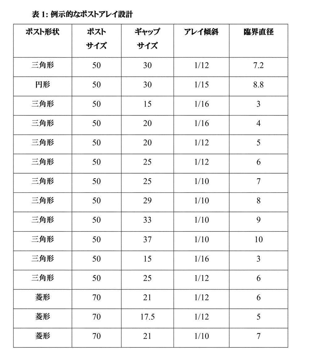
[0070] 第1のアレイのポストは、マイクロ流体回路材料116等のマイクロ流体デバイスの構築用として本明細書に記載されるいずれの材料も含め、多様な材料のいずれからも形成され得る。そのため、例えば、ポストは、シリコーンポリマー(例えば、PDMS、PPS等)から作製され得る。
[0070] The posts of the first array can be formed from any of a variety of materials, including any of the materials described herein for the construction of microfluidic devices such as the
[0071] 以上に記載のポストアレイを有するマイクロ流体デバイスは、典型的には、ポストアレイを有する第1の領域と、流体が第1の領域を通して通過した後に流体フローを受容するように構成された第2の領域とを含む流路を有するであろう。第1の領域は、第1の方向によって画定される軸に沿って長さを測定したときに約5mmから約15mm(例えば、約5mmから約10mm、約6mmから約11mm、約7mmから約12mm、約8mmから約13mm、約9mmから約14mm、約10mmから約15mm又は上記の端点によって画定される任意の範囲)の長さを有し得る。第2の領域は、第2の領域を、例えば第1のチャネルと第2のチャネルとに分離する仕切り(又は壁)によってスプリットされ得る。以下の考察から明らかであろうが、複数の仕切り(又は壁)等の他の配置も可能である。第2の領域は、ポストアレイの特性Dc未満の直径を有する粒子/細胞(例えば、Tリンパ球)が主に第1のチャネルに流入するように、且つアレイの特性Dcよりも大きい直径を有する粒子/細胞(例えば、Tリンパ球)が主に第2のチャネルに流入するように第1の領域に対して構成され得る。本明細書で使用される場合、Tリンパ球等の粒子/細胞の「直径」とは、ポストアレイを通して通過する際の粒子/細胞の有効サイズである。この有効直径は、細胞の健康、細胞周期のステージ、アレイポストの組成、アレイポストのコーティング等をはじめとする様々な因子の影響を受ける可能性がある。特定の実施形態では、第1のチャネルは、搬出/廃棄に直結する「バイパスチャネル」であり得、第2のチャネルは、ほとんどの所望の粒子/細胞(例えば、Tリンパ球)が方向付けられる選択チャネル及び/又はアッセイチャネルであり得る。 The microfluidic device with the post-array described above is typically configured to receive a fluid flow after the fluid has passed through a first region with the post-array and the first region. Will have a flow path that includes a second region. The first region is about 5 mm to about 15 mm (eg, about 5 mm to about 10 mm, about 6 mm to about 11 mm, about 7 mm to about 12 mm) when measured in length along an axis defined by the first direction. , 8 mm to about 13 mm, about 9 mm to about 14 mm, about 10 mm to about 15 mm or any range defined by the endpoints above). The second region can be split by a partition (or wall) that separates the second region into, for example, a first channel and a second channel. Other arrangements, such as multiple dividers (or walls), are possible, as will be apparent from the considerations below. The second region has a diameter larger than the characteristic Dc of the array so that particles / cells (eg, T lymphocytes) having a diameter less than the characteristic Dc of the post array flow predominantly into the first channel. Particles / cells (eg, T lymphocytes) can be configured for the first region primarily to flow into the second channel. As used herein, the "diameter" of a particle / cell, such as a T lymphocyte, is the effective size of the particle / cell as it passes through the post-array. This effective diameter can be affected by a variety of factors, including cell health, cell cycle stages, array post composition, array post coating, and the like. In certain embodiments, the first channel can be a "bypass channel" that is directly linked to export / disposal, the second channel being directed to most desired particles / cells (eg, T lymphocytes). It can be a selection channel and / or an assay channel.
[0072] 幾つかの実施形態では、第1のチャネルは、第1の領域(及びポストアレイ)から流出する流体の少なくとも50%(例えば、少なくとも60%、70%、75%、80%、85%、90%又はそれを超える)を受容するように構成される。幾つかの実施形態では、第1のチャネルは、第1の領域(及びポストアレイ)から流出する流体の約85%から約95%(例えば、約87%から約93%、約88%から約92%、約89%から約91%、約90%又は上記の端点によって画定される任意の範囲)を受容するように構成される。かかる実施形態では、第2のチャネルに流入する残りの流体(例えば、第1の領域から流出する流体の50%、45%、40%、35%、30%、25%、20%、15%、10%、5%又はそれ未満であり得る)は、ポストアレイのDcよりも大きい有効直径を有する粒子/細胞の全て又はほとんどを含み得る。そのため、例えば、Dcよりも大きい直径を有するTリンパ球が第1の領域から出て第2の領域の第2のチャネルに入ると、それらは、少なくとも約2、約2.5、約3、約3.5、約4、約4.5、約5、約6、約7、約8、約9、約10、約15、約20倍又はそれを超えて効果的に濃縮され得る。 [0072] In some embodiments, the first channel is at least 50% (eg, at least 60%, 70%, 75%, 80%, 85) of the fluid flowing out of the first region (and post-array). %, 90% or more). In some embodiments, the first channel is about 85% to about 95% (eg, about 87% to about 93%, about 88% to about 88%) of the fluid flowing out of the first region (and post-array). It is configured to accept 92%, about 89% to about 91%, about 90% or any range defined by the endpoints described above). In such an embodiment, the remaining fluid flowing into the second channel (eg, 50%, 45%, 40%, 35%, 30%, 25%, 20%, 15% of the fluid flowing out of the first region). 10%, 5% or less) may include all or most of the particles / cells having an effective diameter greater than the Dc of the post-array. So, for example, when T lymphocytes with a diameter greater than Dc exit the first region and enter the second channel of the second region, they are at least about 2, about 2.5, about 3, and so on. It can be effectively enriched at about 3.5, about 4, about 4.5, about 5, about 6, about 7, about 8, about 9, about 10, about 15, about 20 times or more.
[0073] 特定の実施形態では、マイクロ流体デバイスの流路は、第1のチャネルと第2のチャネルとにスプリットされる第2の領域を含み得、第1及び第2のチャネルは、第1のチャネルの両端の圧力差が第2のチャネルの両端の圧力差に等しくなるように構成される。この等しい圧力は、例えば、チャネルが再連結される場合(例えば、流出口ポートに達する前に)又はそれらが個別の流出口ポートに至る場合に達成され得る。各チャネルに実質的に等しい圧力が存在することを保証するために、式ΔP=QCH1×RCH1=QCH2×RCH2(式中、QCH1は、単位時間当たりの第1のチャネルの体積流量であり、QCH2は、単位時間当たりの第2のチャネルの体積流量であり、且つRCH1及びRCH2は、第1及び第2のチャネルのそれぞれの流動抵抗である)に従ってチャネルの抵抗をマッチさせることが可能である。断面が矩形状のチャネルでは、R=L/(W×d3)(式中、Lは、チャネルの長さであり、Wは、チャネルの断面寸法の1つであり、且つdは、チャネルの最小断面寸法である)である。 [0073] In certain embodiments, the flow path of the microfluidic device may include a second region split into a first channel and a second channel, the first and second channels being the first. The pressure difference between both ends of the channel is equal to the pressure difference between both ends of the second channel. This equal pressure can be achieved, for example, if the channels are reconnected (eg, before reaching the outlet port) or if they reach a separate outlet port. In order to ensure that there is substantially equal pressure in each channel, the equation ΔP = Q CH1 × R CH1 = Q CH2 × R CH2 (where Q CH1 is the volume of the first channel per unit time). The flow rate, Q CH 2 is the volumetric flow rate of the second channel per unit time, and R CH 1 and R CH 2 are the flow resistances of the first and second channels, respectively). It is possible to match. For a channel with a rectangular cross section, R = L / (W × d 3 ) (in the equation, L is the length of the channel, W is one of the cross-sectional dimensions of the channel, and d is the channel. Is the minimum cross-sectional dimension of).
[0074] 特定の実施形態では、第1のチャネルは、長さを含み、且つ第2のチャネルは長さを含み、第2のチャネルの長さは、第1のチャネルの長さよりも大きい(例えば、少なくとも6、7、8、9、10、11、12、15又は20倍大きい)。マイクロ流体デバイスは、第2の領域の第2のチャネルに通じ、且つ少なくとも1つのTリンパ球を保持するのに十分に大きい容積を有する、本明細書に記載の少なくとも1つの隔離ペンを含み得る。隔離ペンは、約250pLから約3nL(例えば、約250pLから約1nL、約375pLから約1nL、約500pLから約1nL、約750pLから約1nL、約250pLから約1.25nL、約500pLから約1.25nL、約750pLから約1.25nL、約1nLから約1.25nL、約500pLから約1.5nL、約750pLから約1.5nL、約1nLから約1.5nL、約500pLから約2nL、約750pLから約2nL、約1nLから約2nL、約1.25nLから約2nL、約1.5nLから約2nL、約1nLから約2.5nL、約1.5nLから約2.5nL、約2nLから約2.5nL、約1nLから約3nL、約1.5nLから約3nL、約2nLから約3nL又は約2.5nLから約3nL)の容積を有し得る。 [0074] In certain embodiments, the first channel comprises a length, the second channel comprises a length, and the length of the second channel is greater than the length of the first channel ([0074]. For example, at least 6, 7, 8, 9, 10, 11, 12, 15 or 20 times larger). The microfluidic device may include at least one isolation pen as described herein, which leads to a second channel in the second region and has a volume large enough to hold at least one T lymphocyte. .. Isolation pens range from about 250 pL to about 3 nL (eg, from about 250 pL to about 1 nL, from about 375 pL to about 1 nL, from about 500 pL to about 1 nL, from about 750 pL to about 1 nL, from about 250 pL to about 1.25 nL, from about 500 pL to about 1. 25 nL, about 750 pL to about 1.25 nL, about 1 nL to about 1.25 nL, about 500 pL to about 1.5 nL, about 750 pL to about 1.5 nL, about 1 nL to about 1.5 nL, about 500 pL to about 2 nL, about 750 pL. From about 2nL, from about 1nL to about 2nL, from about 1.25nL to about 2nL, from about 1.5nL to about 2nL, from about 1nL to about 2.5nL, from about 1.5nL to about 2.5nL, from about 2nL to about 2. It may have a volume of 5 nL, about 1 nL to about 3 nL, about 1.5 nL to about 3 nL, about 2 nL to about 3 nL or about 2.5 nL to about 3 nL).
[0075] マイクロ流体デバイスは、2つ以上のポストアレイを含み得る。例えば、第2のチャネルは、第2のポストのアレイを含む第1のサブ領域を含み得る。第2のチャネルは、流路の第1の領域を貫流する流体部分が第2のチャネルに進入するように、且つその流体部分及びそれに含有される任意の細胞が第2のアレイを通して通過するように構成され得る。第2のアレイは、第1のアレイに類似し得る。例えば、同一の臨界サイズDc(又は類似の臨界サイズ、例えば±0.5ミクロン)を有することで、望ましくない細胞/微小物体の除去及びサンプルの更なる富化を促進することができる。幾つかの実施形態では、第2のアレイは、異なる臨界サイズ(Dc)を有し得る。例えば、第1のアレイは、約4ミクロンから約7ミクロン(例えば、約6ミクロン)の臨界サイズを有し得、第2のアレイは、約7ミクロンから約10ミクロン(例えば、約9ミクロン)の臨界サイズを有し得る。第2のアレイの臨界サイズをより大きくすれば、所望のものよりも大きい微小物体、例えば分裂寸前の望ましくない細胞を除去することができる。 [0075] The microfluidic device may include two or more post arrays. For example, the second channel may include a first subregion containing an array of second posts. The second channel is such that the fluid portion that flows through the first region of the flow path enters the second channel and that the fluid portion and any cells contained therein pass through the second array. Can be configured in. The second array may resemble the first array. For example, having the same critical size D c (or similar critical size, eg ± 0.5 micron) can promote the removal of unwanted cells / micro-objects and further enrichment of the sample. In some embodiments, the second array may have different critical sizes ( Dc ). For example, the first array can have a critical size of about 4 microns to about 7 microns (eg, about 6 microns), and the second array can have a critical size of about 7 microns to about 10 microns (eg, about 9 microns). Can have a critical size of. Increasing the critical size of the second array can remove microscopic objects larger than desired, such as unwanted cells on the verge of division.
[0076] 幾つかの実施形態では、第2のチャネルは、その第2のポストアレイを含む第1のサブ領域と第2のサブ領域とを含み得る。第2のサブ領域は、流体フローが第1のサブ領域(及び第2のポストアレイ)を通して通過した後に流体フローを受容するように構成され得る。第2のサブ領域は、例えば、第2のチャネルを第3のチャネルと第4のチャネルとに分離する仕切り、例えば壁を含み得る。このようにして、サンプルを、一連のポストアレイを通すことにより、サンプル中の細胞(Tリンパ球)をより細かく選別することが可能である。加えて、第3のチャネル又は第4のチャネルのいずれかに通じるように隔離ペンを位置決めすることができ、これにより、液体フローを停止させて対象細胞をペンに隔離することができ、且つ任意選択的にオンチップで培養することができる。 [0076] In some embodiments, the second channel may include a first sub-region containing the second post array and a second sub-region. The second sub-region can be configured to receive the fluid flow after the fluid flow has passed through the first sub-region (and the second post-array). The second subregion may include, for example, a partition that separates the second channel into a third channel and a fourth channel, such as a wall. In this way, by passing the sample through a series of post-arrays, it is possible to finely sort the cells (T lymphocytes) in the sample. In addition, the isolation pen can be positioned to reach either the third channel or the fourth channel, thereby stopping the liquid flow and isolating the cells of interest into the pen, and optionally. It can be selectively cultured on-chip.
[0077] ポストアレイを有するマイクロ流体チップの例示的な設計は、図7A及び7B(即ちマイクロ流体デバイス700及び715)に示され、且つ実施例との関連で記載される。
Exemplary designs of microfluidic chips with post-arrays are shown in FIGS. 7A and 7B (ie,
[0078] 図1は、マイクロ流体デバイス、例えばマイクロ流体デバイス100の操作及び制御を行うためのシステム150も示す。例示されるシステム150は、電源192、撮像デバイス194及び傾斜デバイス190を含む。
[0078] FIG. 1 also shows a
[0079]
電源192は、電力をマイクロ流体デバイス100及び/又は傾斜デバイス190に提供し、バイアス電圧又は電流を必要に応じて提供することができる。電源192は、例えば、1つ又は複数の交流(AC)及び/又は直流(DC)電圧源又は電流源を含むことができる。撮像デバイス194は、マイクロ流体回路120内部の画像を捕捉する、デジタルカメラ等のデバイスを含むことができる。幾つかの場合、撮像デバイス194は、高速フレームレート及び/又は高感度(例えば、低光用途用)を有する検出器をさらに含む。撮像デバイス194は、刺激放射線及び/又は光線をマイクロ流体回路120内に向け、マイクロ流体回路120(又はマイクロ流体回路120内に含まれる微小物体)から反射されるか、又は発せられる放射線及び/又は光線を収集する機構を含むこともできる。発せられる光線は可視スペクトル内であり得、例えば、蛍光放射を含み得る。反射光線は、LED又は水銀灯(例えば、高圧水銀灯)若しくはキセノンアーク灯等の広域スペクトル灯から発せられた反射放射を含み得る。図4に関して考察するように、撮像デバイス194は顕微鏡(又は光学縦列)をさらに含み得、これは接眼レンズを含んでもよく、又は含まなくてもよい。
[0079]
The
[0080]
システム150は、1つ又は複数の回転軸の周りでマイクロ流体デバイス100を回転させるように構成される傾斜デバイス190を含むことができる。幾つかの実施形態では、傾斜デバイス190は、マイクロ流体デバイス100(したがって、マイクロ流体回路120)を水平向き(すなわち、x軸及びy軸に相対して0°)、垂直向き(すなわち、x軸及び/又はy軸に相対して90°)、又はそれらの間の任意の向きで保持することができるように、少なくとも1つの軸の周りでマイクロ流体回路120を含むエンクロージャ102を支持及び/又は保持するように構成される。軸に相対するマイクロ流体デバイス100(及びマイクロ流体回路120)の向きは、本明細書では、マイクロ流体デバイス100(及びマイクロ流体回路120)の「傾斜」と呼ばれる。例えば、傾斜デバイス190は、x軸に相対して0.1°、0.2°、0.3°、0.4°、0.5°、0.6°、0.7°、0.8°、0.9°、1°、2°、3°、4°、5°、10°、15°、20°、25°、30°、35°、40°、45°、50°、55°、60°、65°、70°、75°、80°、90°、又はそれらの間の任意の度数でマイクロ流体デバイス100を傾斜させることができる。水平向き(したがって、x軸及びy軸)は、重力により定義される垂直軸に垂直なものとして定義される。傾斜デバイスは、マイクロ流体デバイス100(及びマイクロ流体回路120)をx軸及び/又はy軸に相対して90°よりも大きい任意の角度に傾斜させるか、又はマイクロ流体デバイス100(及びマイクロ流体回路120)をx軸若しくはy軸に相対して180°に傾斜させて、マイクロ流体デバイス100(及びマイクロ流体回路120)を真逆にすることもできる。同様に、幾つかの実施形態では、傾斜デバイス190は、流路106又はマイクロ流体回路120の何らかの他の部分により定義される回転軸の周りでマイクロ流体デバイス100(及びマイクロ流体回路120)を傾斜させる。
[0080] [0080]
The
[0081]
幾つかの場合、マイクロ流体デバイス100は、流路106が1つ又は複数の隔離ペンの上方又は下方に位置するように、垂直向きに傾斜する。「上方」という用語は、本明細書で使用される場合、流路106が、重力により定義される垂直軸上で1つ又は複数の隔離ペンよりも高く位置する(すなわち、流路106の上方の隔離ペン内の物体が流路内の物体よりも高い重力位置エネルギーを有する)ことを示す。「下方」という用語は、本明細書で使用される場合、流路106が、重力により定義される垂直軸上で1つ又は複数の隔離ペンよりも下に位置する(すなわち、流路106の下方の隔離ペン内の物体が流路内の物体よりも低い重力位置エネルギーを有する)ことを示す。
[0081]
In some cases, the
[0082]
幾つかの場合、傾斜デバイス190は、流路106と平行な軸の周りでマイクロ流体デバイス100を傾斜させる。さらに、マイクロ流体デバイス100は、流路106が、隔離ペンの真上又は真下に配置されずに、1つ又は複数の隔離ペンの上方又は下方に配置されるように、90°未満の角度に傾斜することができる。他の場合、傾斜デバイス190は、流路106に直交する軸の周りでマイクロ流体デバイス100を傾斜させる。さらに他の場合、傾斜デバイス190は、流路106に平行でもなく直交もしない軸の周りでマイクロ流体デバイス100を傾斜させる。
[0082]
In some cases, the
[0083]
システム150は培地源178をさらに含むことができる。培地源178(例えば、容器、リザーバ等)は、それぞれが異なる流体培地180を保持する複数のセクション又は容器を含むことができる。したがって、培地源178は、図1に示されるように、マイクロ流体デバイス100の外部にある、マイクロ流体デバイス100とは別個のデバイスであり得る。代替的に、培地源178は、全体的又は部分的に、マイクロ流体デバイス100のエンクロージャ102内部に配置することができる。例えば、培地源178は、マイクロ流体デバイス100の部分であるリザーバを含むことができる。
[0083]
The
[0084]
図1は、システム150の一部を構成し、マイクロ流体デバイス100と併せて利用することができる制御及び監視機器152の例の簡易ブロック図表現も示す。示されるように、そのような制御及び監視機器152の例は、培地源178を制御する培地モジュール160と、マイクロ流体回路120での微小物体(図示せず)及び/又は培地(例えば、培地の液滴)の移動及び/又は選択を制御する原動モジュール162と、画像(例えば、デジタル画像)を捕捉する撮像デバイス194(例えば、カメラ、顕微鏡、光源、又はそれらの任意の組合せ)を制御する撮像モジュール164と、傾斜デバイス190を制御する傾斜モジュール166とを含むマスタコントローラ154を含む。制御機器152は、マイクロ流体デバイス100に関する他の機能を制御、監視、又は実行する他のモジュール168を含むこともできる。示されるように、機器152は、表示デバイス170及び入/出力デバイス172をさらに含むことができる。
[0084]
FIG. 1 also shows a simplified block diagram representation of an example of a control and
[0085]
マスタコントローラ154は、制御モジュール156及びデジタルメモリ158を含むことができる。制御モジュール156は、例えば、メモリ158内に非一時的データ又は信号として記憶される機械実行可能命令(例えば、ソフトウェア、ファームウェア、ソースコード等)に従って動作するように構成されるデジタルプロセッサを含むことができる。代替的に又は追加として、制御モジュール156は、ハードワイヤードデジタル回路及び/又はアナログ回路を含むことができる。培地モジュール160、原動モジュール162、撮像モジュール164、傾斜モジュール166、及び/又は他のモジュール168は、同様に構成され得る。したがって、マイクロ流体デバイス100又は任意の他のマイクロ流体装置に関して実行されるものとして本明細書で考察される機能、プロセス、行動、動作、又はプロセスのステップは、上述したように構成されるマスタコントローラ154、培地モジュール160、原動モジュール162、撮像モジュール164、傾斜モジュール166、及び/又は他のモジュール168の任意の1つ又は複数により実行され得る。同様に、マスタコントローラ154、培地モジュール160、原動モジュール162、撮像モジュール164、傾斜モジュール166、及び/又は他のモジュール168は、通信可能に結合されて、本明細書において考察される任意の機能、プロセス、行動、動作、又はステップで使用されるデータを送受信し得る。
[0085]
The
[0086]
培地モジュール160は培地源178を制御する。例えば、培地モジュール160は、培地源178を制御して、選択された流体培地180をエンクロージャ102に入れる(例えば、流入口107を介して)ことができる。培地モジュール160は、エンクロージャ102からの培地の取り出し(例えば、流出口(図示せず)を通して)を制御することもできる。したがって、1つ又は複数の培地を選択的にマイクロ流体回路120に入れ、マイクロ流体回路120から搬出することができる。培地モジュール160は、マイクロ流体回路120内部の流路106での流体培地180のフローを制御することもできる。例えば、幾つかの実施形態では、培地モジュール160は、傾斜モジュール166が傾斜デバイス190に所望の傾斜角までマイクロ流体デバイス100を傾斜させる前に、流路106内及びエンクロージャ102を通る培地180のフローを停止させる。
[0086]
The
[0087]
原動モジュール162は、マイクロ流体回路120での微小物体(図示せず)の選択、捕捉、及び移動を制御するように構成され得る。図2A及び図2Bに関して後述するように、エンクロージャ102は、誘電泳動(DEP)構成、光電子ピンセット(OET)構成、及び/又は光電子ウェッティング(OEW)構成(図1に示されず)を含むことができ、原動モジュール162は、電極及び/又はトランジスタ(例えば、フォトトランジスタ)のアクティブ化を制御して、流路106及び/又は隔離ペン124、126、128、130で微小物体(図示せず)及び/又は培地の液滴(図示せず)を選択し移動させることができる。
[0087]
The
[0088]
撮像モジュール164は撮像デバイス194を制御することができる。例えば、撮像モジュール164は、撮像デバイス194から画像データを受信し、処理することができる。撮像デバイス194からの画像データは、撮像デバイス194により捕捉された任意のタイプの情報を含むことができる(例えば、微小物体、培地の液滴、蛍光標識等の標識の蓄積の有無等)。撮像デバイス194により捕捉された情報を使用して、撮像モジュール164は、物体(例えば、微小物体、培地の液滴)の位置及び/又はマイクロ流体デバイス100内のそのような物体の移動速度をさらに計算することができる。
[0088]
The
[0089]
傾斜モジュール166は、傾斜デバイス190の傾斜移動を制御することができる。代替的に又は追加として、傾斜モジュール166は、重力を介して1つ又は複数の隔離ペンへの微小物体の移送を最適化するように、傾斜率及びタイミングを制御することができる。傾斜モジュール166は、撮像モジュール164と通信可能に結合されて、マイクロ流体回路120での微小物体及び/又は培地の液滴の移動を記述するデータを受信する。このデータを使用して、傾斜モジュール166は、マイクロ流体回路120の傾斜を調整して、マイクロ流体回路120内で微小物体及び/又は培地の液滴が移動する率を調整し得る。傾斜モジュール166は、このデータを使用して、マイクロ流体回路120内での微小物体及び/又は培地の液滴の位置を繰り返し調整することもできる。
[0089]
The
[0090]
図1に示される例では、マイクロ流体回路120は、マイクロ流体チャネル122及び隔離ペン124、126、128、130を含むものとして示されている。各ペンは、チャネル122への開口部を含むが、ペンがペン内部の微小物体を流体培地180及び/又はチャネル122の流路106又は他のペン内の微小物体から実質的に分離することができるように、その他では閉じられている。幾つかの場合、ペン124、126、128、130は、1つ又は複数の微小物体をマイクロ流体回路120内に物理的に囲い入れるように構成される。本開示による隔離ペンは、以下に詳細に考察し示すように、DEP、OET、OEW、及び/又は重力との併用に最適化された様々な形状、表面、及び特徴を含むことができる。
[0090]
In the example shown in FIG. 1, the
[0091] マイクロ流体回路120は、任意の数のマイクロ流体隔離ペンを含み得る。5つの隔離ペンが示されているが、マイクロ流体回路120は、より少ない又はより多い隔離ペンを有し得る。本開示による隔離ペンは、T細胞の培養、選択及び増殖に有用である。示されるように、マイクロ流体回路120のマイクロ流体隔離ペン124、126、128及び130は、T細胞の培養、選択及び増殖に有用な1つ以上の利益を提供し得る様々な特徴及び形状をそれぞれ含む。幾つかの実施形態では、マイクロ流体回路120は、複数の同一のマイクロ流体隔離ペンを含む。幾つかの実施形態では、マイクロ流体回路120は、複数のマイクロ流体隔離ペンを含み、隔離ペンの2つ以上は、T細胞の培養、選択及び増殖で様々な利益を提供する様々な構造及び/又は特徴を含む。
[0091] The
[0092]
図1に示される実施形態では、1つのチャネル122及び流路106が示される。しかし、他の実施形態は、それぞれが流路106を含むように構成される複数のチャネル122を含み得る。マイクロ流体回路120は、流路106及び流体培地180と流体連通する流入弁又はポート107をさらに含み、それにより、流体培地180は、流入口107を介してチャネル122にアクセスすることができる。幾つかの場合、流路106は1つの経路を含む。幾つかの場合、1つの経路はジグザグパターンで配置され、それにより、流路106は、交互になった方向で2回以上にわたってマイクロ流体デバイス100にわたり移動する。
[0092]
In the embodiment shown in FIG. 1, one
[0093]
幾つかの場合、マイクロ流体回路120は、複数の平行チャネル122及び流路106を含み、各流路106内の流体培地180は同じ方向に流れる。幾つかの場合、各流路106内の流体培地は、順方向又は逆方向の少なくとも一方で流れる。幾つかの場合、複数の隔離ペンは、それらが標的微小物体と並列に配置されることができるように構成される(例えば、チャネル122に相対して)。
[0093]
In some cases, the
[0094]
幾つかの実施形態では、マイクロ流体回路120は、1つ又は複数の微小物体トラップ132をさらに含む。トラップ132は、一般に、チャネル122の境界を形成する壁に形成され、マイクロ流体隔離ペン124、126、128、130の1つ又は複数の開口部の逆に位置し得る。幾つかの実施形態では、トラップ132は、流路106から1つの微小物体を受け取り、又は捕捉するように構成される。幾つかの実施形態では、トラップ132は、流路106から複数の微小物体を受け取り、又は捕捉するように構成される。幾つかの場合、トラップ132は、1つの標的微小物体の容積に概ね等しい容積を含む。
[0094]
In some embodiments, the
[0095]
トラップ132は、標的微小物体のトラップ132へのフローを支援するように構成される開口部をさらに含み得る。幾つかの場合、トラップ132は、1つの標的微小物体の寸法に概ね等しい高さ及び幅を有する開口部を含み、それにより、より大きい微小物体が微小物体トラップに入らないようにされる。トラップ132は、トラップ132内への標的微小物体の保持を支援するように構成される他の特徴をさらに含み得る。幾つかの場合、トラップ132は、微小流体隔離ペンの開口部と位置合わせされ、微小流体隔離ペンの開口部に関してチャネル122の逆側に配置され、それにより、チャネル122に平行な軸の周りでマイクロ流体デバイス100を傾斜されると、捕捉された微小物体は、微小物体を隔離ペンの開口部に落とす軌道でトラップ132を出る。幾つかの場合、トラップ132は、標的微小物体よりも小さく、トラップ132を通るフローを促進し、それによりトラップ132内への微小物体の捕捉確率を増大させるサイド通路134を含む。
[0095]
The trap 132 may further include an opening configured to assist the flow of the target microobject to the trap 132. In some cases, the trap 132 includes an opening having a height and width approximately equal to the dimensions of one target micro-object, thereby preventing larger micro-objects from entering the micro-object trap. The trap 132 may further include other features configured to assist in the retention of the target micro-object within the trap 132. In some cases, the trap 132 is aligned with the opening of the microfluidic isolation pen and is located opposite the
[0096]
幾つかの実施形態では、誘電泳動(DEP)力は、1つ又は複数の電極(図示せず)を介して流体培地180にわたり適用されて(例えば、流路及び/又は隔離ペンにおいて)、内部に配置された微小物体の操作、輸送、分離、及びソートを行う。例えば、幾つかの実施形態では、DEP力は、マイクロ流体回路120の1つ又は複数の部分に適用されて、1つの微小物体を流路106から所望のマイクロ流体隔離ペンに輸送する。幾つかの実施形態では、DEP力を使用して、隔離ペン(例えば、隔離ペン124、126、128、又は130)内の微小物体が隔離ペンから変位しないようにする。さらに、幾つかの実施形態では、DEP力を使用して、本開示の教示により、前に収集された微小物体を隔離ペンから選択的に取り出す。幾つかの実施形態では、DEP力は、光電子ピンセット(OET)力を含む。
[0096]
In some embodiments, dielectrophoretic (DEP) forces are applied over the
[0097]
他の実施形態では、光電子ウェッティング(OEW)力が、1つ又は複数の電極(図示せず)を介してマイクロ流体デバイス100の支持構造体104(及び/又はカバー110)での1つ又は複数の位置(例えば、流路及び/又は隔離ペンの画定に役立つ位置)に適用されて、マイクロ流体回路120に配置された液滴の操作、輸送、分離、及びソートを行う。例えば、幾つかの実施形態では、OEW力は支持構造体104(及び/又はカバー110)の1つ又は複数の位置に適用されて、1つの液滴を流路106から所望のマイクロ流体隔離ペンに輸送する。幾つかの実施形態では、OEW力を使用して、隔離ペン(例えば、隔離ペン124、126、128、又は130)内の液滴が隔離ペンから変位しないようにする。さらに、幾つかの実施形態では、OEW力を使用して、本開示の教示により、前に収集された液滴を隔離ペンから選択的に取り出す。
[0097]
In another embodiment, a photoelectron wetting (OEW) force is applied to one or more of the support structure 104 (and / or cover 110) of the
[0098]
幾つかの実施形態では、DEP力及び/又はOEW力は、フロー及び/又は重力等の他の力と組み合わせられて、マイクロ流体回路120内の微小物体及び/又は液滴の操作、輸送、分離、及びソートを行う。例えば、エンクロージャ102は傾斜して(例えば、傾斜デバイス190により)、流路106及び流路106内に配置された微小物体をマイクロ流体隔離ペンの上に位置決めすることができ、重力は、微小物体及び/又は液滴をペン内に輸送することができる。幾つかの実施形態では、DEP力及び/又はOEW力は、他の力の前に適用することができる。他の実施形態では、DEP力及び/又はOEW力は、他の力の後に適用することができる。さらに他の場合、DEP力及び/又はOEW力は、他の力と同時に又は他の力と交互に適用することができる。
[0098]
In some embodiments, the DEP force and / or the OEW force is combined with other forces such as flow and / or gravity to manipulate, transport, and separate tiny objects and / or droplets within the
[0099]
図2A~図2Fは、本開示の実施に使用することができるマイクロ流体デバイスの様々な実施形態を示す。図2Aは、マイクロ流体デバイス200が光学作動動電学的デバイスとして構成される実施形態を示す。光電子ピンセット(OET)構成を有するデバイス及び光電子ウェッティング(OEW)構成を有するデバイスを含め、様々な光学作動動電学的デバイスが当技術分野で既知である。適するOET構成の例は、以下の米国特許文献に示されており、各文献は全体的に参照により本明細書に援用される:米国特許第RE44,711号(Wuら)(元々は米国特許第7,612,355号として発行された);及び米国特許第7,956,339号(Ohtaら)。OEW構成の例は、米国特許第6,958,132号(Chiouら)及び米国特許出願公開第2012/0024708号(Chiouら)に示されており、これらは両方とも全体的に参照により本明細書に援用される。光学作動動電的デバイスのさらに別の例は、OET/OEW結合構成を含み、その例は、米国特許出願公開第20150306598号(Khandrosら)及び同第20150306599号(Khandrosら)並びにそれらの対応するPCT公報である国際公開第2015/164846号及び国際公開第2015/164847号に示されており、これらは全て全体的に参照により本明細書に援用される。
[0099]
2A-2F show various embodiments of microfluidic devices that can be used to carry out the present disclosure. FIG. 2A shows an embodiment in which the
[00100]
マイクロ流体デバイス構成。
上述したように、システムの制御及び監視機器は、マイクロ流体デバイスのマイクロ流体回路において微小物体又は液滴等の物体を選択し移動させる原動モジュールを含むことができる。マイクロ流体デバイスは、移動される物体のタイプ及び他の考慮事項に応じて様々な原動構成を有することができる。例えば、誘電泳動(DEP)構成を利用して、マイクロ流体回路において微小物体を選択し移動させることができる。したがって、マイクロ流体デバイス100の支持構造体104及び/又はカバー110は、マイクロ流体回路120内の流体培地180内の微小物体に対してDEP力を選択的に誘導し、それにより個々の微小物体又は微小物体群の選択、捕捉、及び/又は移動を行うDEP構成を含むことができる。代替的に、マイクロ流体デバイス100の支持構造体104及び/又はカバー110は、マイクロ流体回路120内の流体培地180内の液滴に対して電子ウェッティング(EW)力を選択的に誘導し、それにより個々の液滴又は液滴群の選択、捕捉、及び/又は移動を行う電子ウェッティング(EW)構成を含むことができる。
[00100]
Microfluidic device configuration.
As mentioned above, the control and monitoring equipment of the system can include a prime mover module that selects and moves objects such as micro-objects or droplets in the micro-fluidic circuit of the micro-fluidic device. Microfluidic devices can have different driving configurations depending on the type of object being moved and other considerations. For example, a dielectrophoresis (DEP) configuration can be used to select and move micro-objects in a microfluidic circuit. Thus, the
[00101]
DEP構成を含むマイクロ流体デバイス200の一例を図2A及び図2Bに示す。簡潔にするために、図2A及び図2Bは、開放領域/チャンバ202を有するマイクロ流体デバイス200のエンクロージャ102の部分の側面断面図及び上面断面図をそれぞれ示すが、領域/チャンバ202が、成長チャンバ、隔離ペン、流域、又はフローチャネル等のより詳細な構造を有する流体回路要素の部分であり得ることを理解されたい。さらに、マイクロ流体デバイス200は他の流体回路要素を含み得る。例えば、マイクロ流体デバイス200は、マイクロ流体デバイス100に関して本明細書に記載される等の複数の成長チャンバ、或いは隔離ペン及び/又は1つ若しくは複数のフロー領域又はフローチャネルを含むことができる。DEP構成は、マイクロ流体デバイス200の任意のそのような流体回路要素に組み込み得るか、又はその部分を選択し得る。上記又は下記の任意のマイクロ流体デバイス構成要素及びシステム構成要素がマイクロ流体デバイス200内に組みこまれ得、及び/又はマイクロ流体デバイス200と組み合わせて使用し得ることをさらに理解されたい。例えば、培地モジュール160、原動モジュール162、撮像モジュール164、傾斜モジュール166、及び他のモジュール168の1つ又は複数を含む上述した制御及び監視機器152を含むシステム150は、マイクロ流体デバイス200と併用し得る。
[00101]
An example of the
[00102]
図2Aにおいて見られるように、マイクロ流体デバイス200は、下部電極204及び下部電極204に重なる電極活性化基板206を有する支持構造体104と、上部電極210を有するカバー110とを含み、上部電極210は下部電極204から離間される。上部電極210及び電極活性化基板206は、領域/チャンバ202の両面を画定する。したがって、領域/チャンバ202に含まれる培地180は、上部電極210と電極活性化基板206との間に抵抗接続を提供する。下部電極204と上部電極210との間に接続され、領域/チャンバ202でのDEP力の生成のために必要に応じて電極間にバイアス電圧を生成するように構成される電源212も示されている。電源212は、例えば、交流(AC)電源であり得る。
[00102]
As seen in FIG. 2A, the
[00103]
特定の実施形態では、図2A及び図2Bに示されるマイクロ流体デバイス200は、光学作動DEP構成を有することができる。したがって、原動モジュール162により制御し得る光源220からの光222の変更パターンは、電極活性化基板206の内面208の領域214においてDEP電極の変更パターンを選択的に活性化又は非活性化することができる。(以下ではDEP構成を有するマイクロ流体デバイスの領域214を「DEP電極領域」と呼ぶ)。図2Bに示されるように、電極活性化基板206の内面208に向けられる光パターンは、正方形の光パターン224等のパターンで、選択されたDEP電極領域214a(白色で示される)を照明することができる。照明されないDEP電極領域214(斜線が付される)を以下では「暗」DEP電極領域214と呼ぶ。DEP電極活性化基板206を通る相対電気インピーダンス(すなわち、下部電極204から、流域106において培地180と界面を接する電極活性化基板206の内面208まで)は、各暗DEP電極領域214での領域/チャンバ202において培地180を通る(すなわち、電極活性化基板206の内面208からカバー110の上部電極210まで)相対電気インピーダンスよりも大きい。しかし、照明DEP電極領域214aは、各照明DEP電極領域214aでの領域/チャンバ202での培地180を通る相対インピーダンス未満である電極活性化基板206を通る相対インピーダンスの低減を示す。
[00103]
In certain embodiments, the
[00104]
電源212が活性化されている場合、上記のDEP構成は、照明DEP電極領域214aと隣接する暗DEP電極領域214との間に流体培地180内で電場勾配を生じさせ、次に、電場勾配は、流体培地180内の付近の微小物体(図示せず)を引き寄せるか、又は排斥する局所DEP力を生成する。したがって、流体培地180内の微小物体を引き寄せるか、又は排斥するDEP電極は、光源220からマイクロ流体デバイス200に投射される光パターン222を変更することにより、領域/チャンバ202の内面208での多くの異なるそのようなDEP電極領域214において選択的に活性化及び非活性化することができる。DEP力が付近の微小物体を引き寄せるか、それとも排斥するかは、電源212の周波数並びに培地180及び/又は微小物体(図示せず)の誘電特性等のパラメータに依存し得る。
[00104]
When the
[00105]
図2Bに示される照明DEP電極領域214aの正方形パターン224は単なる例である。マイクロ流体デバイス200に投射される光パターン222により、任意のパターンのDEP電極領域214を照明する(それにより活性化する)ことができ、照明/活性化されるDEP電極領域214のパターンは、光パターン222を変更又は移動させることにより繰り返し変更することができる。
[00105]
The square pattern 224 of the illuminated
[00106]
幾つかの実施形態では、電極活性化基板206は、光伝導性材料を含むか、又は光導電性材料からなることができる。そのような実施形態では、電極活性化基板206の内面208は、特徴を有さないことができる。例えば、電極活性化基板206は、水素化非晶質シリコン(a-Si:H)の層を含むか、又はa-Si:Hの層からなることができる。a-Si:Hは、例えば、約8%~40%の水素を含むことができる(水素原子の数/水素及びケイ素原子の総数に100を掛けたものとして計算)。a-Si:Hの層は厚さ約500nm~約2.0μmを有することができる。そのような実施形態では、DEP電極領域214は、光パターン218により、電極活性化基板208の内面208上の任意の場所に任意のパターンで作成することができる。したがって、DEP電極領域214の数及びパターンは、固定される必要がなく、光パターン222に対応することができる。上述したような光伝導層を含むDEP構成を有するマイクロ流体デバイスの例は、例えば、米国特許第RE44,711号(Wuら)(元々は米国特許第7,612,355号として発行された)に記載されており、その内容全体は参照により本明細書に援用される。
[00106]
In some embodiments, the
[00107]
他の実施形態では、電極活性化基板206は、半導体分野で既知等の半導体集積回路を形成する複数のドープ層、絶縁層(又は領域)、及び導電層を含む基板を含むことができる。例えば、電極活性化基板206は、例えば、横型バイポーラフォトトランジスタを含む複数のフォトトランジスタを含むことができ、各フォトトランジスタはDEP電極領域214に対応する。代替的に、電極活性化基板206は、フォトトランジスタスイッチにより制御される電極(例えば、導電性金属電極)を含むことができ、そのような各電極はDEP電極領域214に対応する。電極活性化基板206は、パターンになったそのようなフォトトランジスタ又はフォトトランジスタ制御される電極を含むことができる。パターンは、例えば、図2Bに示される等、行列に配置された実質的に正方形のフォトトランジスタ又はフォトトランジスタ制御される電極のアレイであり得る。代替的に、パターンは、六角形格子を形成する実質的に六角形のフォトトランジスタ又はフォトトランジスタ制御される電極のアレイであり得る。パターンに関係なく、電気回路素子は、電極活性化基板206の内面208におけるDEP電極領域214と下部電極210との間に電気接続を形成することができ、それらの電気接続(すなわち、フォトトランジスタ又は電極)は、光パターン222により選択的に活性化又は非活性化することができる。活性化されない場合、各電気接続は、電極活性化基板206を通る(すなわち、下部電極204から、領域/チャンバ202内の培地180と界面を接する電極活性化電極206の内面208まで)相対インピーダンスが、対応するDEP電極領域214における培地180を通る(すなわち、電極活性化基板206の内面208からカバー110の上部電極210まで)相対インピーダンスよりも大きいような高いインピーダンスを有することができる。しかし、光パターン222内の光により活性化される場合、電極活性化基板206を通る相対インピーダンスは、各照明DEP電極領域214での培地180を通る相対インピーダンス未満であり、それにより、上述したように、対応するDEP電極領域214でのDEP電極を活性化する。したがって、培地180内の微小物体(図示せず)を引き寄せるか、又は排斥するDEP電極は、光パターン218により決まるように、領域/チャンバ202での電極活性化基板206の内面208での多くの異なるDEP電極領域214において選択的に活性化及び非活性化することができる。
[00107]
In another embodiment, the
[00108]
フォトトランジスタを含む電極活性化基板を有するマイクロ流体デバイスの例は、例えば、米国特許第7,956,339号(Ohtaら)(例えば、図21及び図22に示されるデバイス300並びにその説明を参照されたい)に記載されており、それぞれの内容全体は参照により本明細書に援用される。フォトトランジスタスイッチにより制御される電極を含む電極活性化基板を有するマイクロ流体デバイスの例は、例えば、米国特許出願公開第2014/0124370号(Shortら)に記載されており(例えば、図面全体を通して示されるデバイス200、400、500、600、及び900並びにその説明を参照されたい)、これらの内容全体は参照により本明細書に援用される。
[00108]
Examples of microfluidic devices having electrode activation substrates including phototransistors are, for example, see US Pat. No. 7,965,339 (Ohta et al.) (Eg,
[00109]
DEP構成のマイクロ流体デバイスの幾つかの実施形態では、上部電極210はエンクロージャ102の第1の壁(又はカバー110)の一部であり、電極活性化基板206及び下部電極204は、エンクロージャ102の第2の壁(又は支持構造体104)の一部である。領域/チャンバ202は、第1の壁と第2の壁との間にあり得る。他の実施形態では、電極210は第2の壁(又は支持構造体104)の一部であり、電極活性化基板206及び/又は電極210の一方又は両方は、第1の壁(又はカバー110)の一部である。さらに、光源220は代替的に、下からエンクロージャ102を照明するのに使用することができる。
[00109]
In some embodiments of the microfluidic device in the DEP configuration, the
[00110]
DEP構成を有する図2A及び図2Bのマイクロ流体デバイス200を用いて、原動モジュール162は、光パターン222をデバイス200に投射して、微小物体を囲み捕捉するパターン(例えば、正方形パターン224)で電極活性化基板206の内面208のDEP電極領域214aでの第1の組の1つ又は複数のDEP電極を活性化することにより、領域/チャンバ202での培地180内の微小物体(図示せず)を選択することができる。次に、原動モジュール162は、光パターン222をデバイス200に相対して移動させて、DEP電極領域214での第2の組の1つ又は複数のDEP電極を活性化することにより、捕捉された微小物体を移動させることができる。代替的に、デバイス200を光パターン222に相対して移動させることができる。
[00110]
Using the
[00111]
他の実施形態では、マイクロ流体デバイス200は、電極活性化基板206の内面208でのDEP電極の光活性化に依存しないDEP構成を有することができる。例えば、電極活性化基板206は、少なくとも1つの電極を含む表面(例えば、カバー110)とは逆に位置する、選択的にアドレス指定可能且つエネルギー付与可能な電極を含むことができる。スイッチ(例えば、半導体基板のトランジスタスイッチ)を選択的に開閉して、DEP電極領域214でのDEP電極を活性化又は非活性化し得、それにより、活性化されたDEP電極の近傍での領域/チャンバ202内の微小物体(図示せず)に対する正味DEP力を生成する。電源212の周波数及び培地(図示せず)及び/又は領域/チャンバ202内の微小物体の誘電特性等の特徴に応じて、DEP力は、付近の微小物体を引き寄せるか、又は排斥することができる。DEP電極の組(例えば、正方形パターン224を形成するDEP電極領域214の組における)を選択的に活性化又は非活性化することにより、領域/チャンバ202における1つ又は複数の微小物体を捕捉し、領域/チャンバ202内で移動させることができる。図1の原動モジュール162は、そのようなスイッチを制御し、したがって、DEP電極の個々の電極を活性化及び非活性化して、領域/チャンバ202の周囲の特定の微小物体(図示せず)を選択、捕捉、及び移動させることができる。選択的にアドレス指定可能且つエネルギー付与可能な電極を含むDEP構成を有するマイクロ流体デバイスは、当技術分野で既知であり、例えば、米国特許第6,294,063号(Beckerら)及び同第6,942,776号(Medoro)に記載されており、これらの内容全体は参照により本明細書に援用される。
[00111]
In another embodiment, the
[00112]
更なる別例として、マイクロ流体デバイス200は電子ウェッティング(EW)構成を有することができ、EW構成は、DEP構成の代わりであってもよく、又はDEP構成を有する部分とは別個のマイクロ流体デバイス200の部分に配置されてもよい。EW構成は、光電子ウェッティング構成又は誘電体上の電子ウェッティング(EWOD)構成であり得、これらは両方とも当技術分野で既知である。幾つかのEW構成では、支持構造体104は、誘電層(図示せず)と下部電極204との間に挟まれた電極活性化基板206を有する。誘電層は、疎水性材料を含むことができ、及び/又は疎水性材料でコーティングすることができる。EW構成を有するマイクロ流体デバイス200の場合、支持構造体104の内面208は、誘電層の内面又はその疎水性コーティングである。
[00112]
As a further alternative, the
[00113]
誘電層(図示せず)は、1つ又は複数の酸化物層を含むことができ、厚さ約50nm~約250nm(例えば、約125nm~約175nm)を有することができる。特定の実施形態では、誘電層は、金属酸化物(例えば、酸化アルミニウム又は酸化ハフニウム)等の酸化物の層を含むことができる。特定の実施形態では、誘電層は、酸化ケイ素又は窒化物等の金属酸化物以外の誘電材料を含むことができる。厳密な組成及び厚さに関係なく、誘電層は約10kオーム~約50kオームのインピーダンスを有することができる。
[00113]
The dielectric layer (not shown) can include one or more oxide layers and can have a thickness of about 50 nm to about 250 nm (eg, about 125 nm to about 175 nm). In certain embodiments, the dielectric layer can include a layer of oxide such as a metal oxide (eg, aluminum oxide or hafnium oxide). In certain embodiments, the dielectric layer can include dielectric materials other than metal oxides such as silicon oxide or nitrides. Regardless of the exact composition and thickness, the dielectric layer can have an impedance of about 10 k ohms to about 50 k ohms.
[00114]
幾つかの実施形態では、領域/チャンバ202に向かって内側に面した誘電層の表面は、疎水性材料でコーティングされる。疎水性材料は、例えば、フッ素化炭素分子を含むことができる。フッ素化炭素分子の例としては、ポリテトラフルオロエチレン(例えば、TEFLON(登録商標)又はポリ(2,3-ジフルオロメチレニル-ペルフルオロテトラヒドロフラン)(例えば、CYTOP(商標))などのパーフルオロポリマーが挙げられる。疎水性材料を構成する分子は、誘電層の表面に共有結合され得る。例えば、疎水性材料の分子は、シロキサン基、ホスホン酸基、又はチオール基等のリンカーにより、誘電層の表面に共有結合され得る。したがって、幾つかの実施形態では、疎水性材料は、アルキル末端シロキサン、アルキル末端ホスホン酸、又はアルキル末端チオールを含むことができる。アルキル基は長鎖炭化水素(例えば、少なくとも10個の炭素又は少なくとも16個、18個、20個、22個、若しくはそれを超える個数の炭素の鎖を有する)であり得る。代替的に、フッ素化(又はパーフルオロ化)炭素鎖をアルキル基の代わりに使用することができる。したがって、例えば、疎水性材料は、フルオロアルキル末端シロキサン、フルオロアルキル末端ホスホン酸、又はフルオロアルキル末端チオールを含むことができる。幾つかの実施形態では、疎水性コーティングは約10nm~約50nmの厚さを有する。他の実施形態では、疎水性コーティングは厚さ10nm未満(例えば、5nm未満又は約1.5nmから3.0nm)を有する。
[00114]
In some embodiments, the surface of the dielectric layer facing inward towards the region /
[00115]
幾つかの実施形態では、電子ウェッティング構成を有するマイクロ流体デバイス200のカバー110も同様に疎水性材料(図示せず)でコーティングされる。疎水性材料は、支持構造体104の誘電層のコーティングに使用されるものと同じ疎水性材料であり得、疎水性コーティングは、支持構造体104の誘電層の疎水性コーティングの厚さと略同じである厚さを有することができる。さらに、カバー110は、支持構造体104の様式で、誘電層と上部電極210との間に挟まれた電極活性化基板206を含むことができる。電極活性化基板206及びカバー110の誘電層は、電極活性化基板206及び支持構造体104の誘電層と同じ組成及び/又は寸法を有することができる。したがって、マイクロ流体デバイス200は2つの電子ウェッティング表面を有することができる。
[00115]
In some embodiments, the
[00116]
幾つかの実施形態では、電子活性化基板206は、上述した光伝導性材料等の光伝導性材料を含むことができる。したがって、特定の実施形態では、電極活性化基板206は、水素化非晶質シリコン(a-Si:H)の層を含むか、又はa-Si:Hの層からなることができる。a-Si:Hは、例えば、約8%~40%の水素を含むことができる(水素原子の総数及びケイ素原子の総数/水素原子の総数に100を掛けたものとして計算)。a-Si:Hの層は厚さ約500nm~約2.0ミクロンを有することができる。代替的に、電子活性化基板206は、上述したように、フォトトランジスタスイッチにより制御される電極(例えば、導電性金属電極)を含むことができる。光電子ウェッティング構成を有するマイクロ流体デバイスは当技術分野で既知であり、及び/又は当技術分野で既知の電極活性化基板を用いて構築することができる。例えば、内容全体が参照により本明細書に援用される米国特許第6,958,132号(Chiouら)には、a-Si:H等の光伝導性材料を有する光電子ウェッティング構成が開示されており、一方、上記で引用した米国特許出願公開第2014/0124370号(Shortら)には、フォトトランジスタスイッチにより制御される電極を有する電極活性化基板が開示されている。
[00116]
In some embodiments, the
[00117]
したがって、マイクロ流体デバイス200は光電子ウェッティング構成を有することができ、光パターン222を使用して、電極活性化基板206での光応答性EW領域又は光応答性EW電極を活性化することができる。電極活性化基板206のそのような活性化されたEW領域又はEW電極は、支持構造体104の内面208(すなわち、重なった誘電層の内面又はその疎水性コーティング)において電子ウェッティング力を生成することができる。電子活性化基板206に入射する光パターン222を変更する(又は光源220に相対してマイクロ流体デバイス200を移動させる)ことにより、支持構造体104の内面208に接触する液滴(例えば、水性培地、水溶液又は水性溶媒を含む)は、領域/チャンバ202内に存在する不混和流体(例えば、油媒体)を通って移動することができる。
[00117]
Thus, the
[00118]
他の実施形態では、マイクロ流体デバイス200は、EWOD構成を有することができ、電極活性化基板206は、活性化のために光に依存しない、選択的にアドレス指定可能且つエネルギー付与可能な電極を含むことができる。したがって、電極活性化基板206は、パターンになったそのような電子ウェッティング(EW)電極を含むことができる。パターンは、例えば、図2Bに示される等の行列に配置された略正方形のEW電極のアレイであり得る。代替的に、パターンは、六角形格子を形成する略六角形のEW電極のアレイであり得る。パターンに関係なく、EW電極は、電気スイッチ(例えば、半導体基板のトランジスタスイッチ)により選択的に活性化(又は非活性化)することができる。電極活性化基板206でのEW電極を選択的に活性化及び非活性化することにより、重なった誘電層の内面208又はその疎水性コーティングに接触する液滴(図示せず)は、領域/チャンバ202内で移動することができる。図1の原動モジュール162は、そのようなスイッチを制御することができ、したがって、個々のEW電極を活性化及び非活性化して、領域/チャンバ202の周囲で特定の液滴を選択し移動させることができる。選択的にアドレス指定可能且つエネルギー付与可能な電極を有するEWOD構成を有するマイクロ流体デバイスは、当技術分野で既知であり、例えば、米国特許第8,685,344号(Sundarsanら)に記載されており、この内容全体は参照により本明細書に援用される。
[00118]
In another embodiment, the
[00119]
マイクロ流体デバイス200の構成に関係なく、電源212を使用して、マイクロ流体デバイス200の電気回路に給電する電位(例えば、AC電源電位)を提供することができる。電源212は、図1で参照される電源192と同じ又は電源192の構成要素であり得る。電源212は、上部電極210及び下部電極204にAC電圧及び/又は電流を提供するように構成され得る。AC電圧の場合、電源212は、上述したように、領域/チャンバ202内の個々の微小物体(図示せず)を捕捉して移動させ、及び/又はこれらも上述したように、領域/チャンバ202内の支持構造体104の内面208(すなわち、誘電層及び/又は誘電層上の疎水性コーティング)のウェッティング特性を変更するのに十分に強い正味DEP力(又は電子ウェッティング力)を生成するのに十分な周波数範囲及び平均又はピーク電力(例えば、電圧又は電流)を提供することができる。そのような周波数範囲及び平均又はピーク電力範囲は、当技術分野で既知である。例えば、米国特許第6,958,132号(Chiouら)、米国特許第RE44,711号(Wuら)(元々は米国特許第7,612,355号として発行された)、並びに米国特許出願公開第2014/0124370号(Shortら)、同第2015/0306598号(Khandrosら)、及び同第2015/0306599号(Khandrosら)を参照されたい。
[00119]
Regardless of the configuration of the
[00120] 隔離ペン。
限定されるものではないが、一般的な隔離ペン244、246及び248の例は、図2C~2Dに表されるマイクロ流体デバイス240内に示される。各隔離ペン244、246及び248は、分離領域258と、分離領域258をチャネル122に流体接続する接続領域254とを画定する分離構造体250を含み得る。接続領域254は、チャネル122への基端開口252と、分離領域258への先端開口256とを含み得る。接続領域254は、チャネル122から隔離ペン244、246、248に流入する流体培地フロー(図示せず)の最大浸透深さが分離領域258内に延在しないように構成され得る。そのため、接続領域254があるため、隔離ペン244、246、248の分離領域258に配置された微小物体(図示せず)又は他の物質(図示せず)は、チャネル122の培地180のフローからこうして分離されて、その影響を実質的に受けないようにし得る。
[00120] Isolation pen.
Examples of, but not limited to, common isolation pens 244, 246 and 248 are shown within the
[00121] そのため、チャネル122は、掃引領域の例であり得、隔離ペン244、246、248の分離領域258は、非掃引領域の例であり得る。記載のように、チャネル122及び隔離ペン244、246、248は、1つ以上の流体培地180を含有するように構成され得る。図2C~2Dに示される例では、ポート242をチャネル122に接続して、流体培地180をマイクロ流体デバイス240に導入するか又はそれから取り出すことができるようにし得る。流体培地180の導入前にマイクロ流体デバイスを二酸化炭素ガス等のガスでプライムし得る。マイクロ流体デバイス240が流体培地180を含有した後、チャネル122の流体培地180のフロー260の発生及び停止を選択的に行うことが可能である。例えば、示されるように、ポート242は、チャネル122の異なる位置(例えば、対向端)に配置され得、且つ培地のフロー260は、流入口として機能する1つのポート242から流出口として機能する他のポート242の方向に形成され得る。
[00121] Thus,
[0122] 図2Eは、本開示による隔離ペン244の例の詳細図を例示する。微小物体270の例も示される。
[0122] FIG. 2E illustrates a detailed view of an example of the
[00123] 分かるように、隔離ペン244の基端開口252を通過したマイクロ流体チャネル122の流体培地180のフロー260は、隔離ペン244への及び/又はそこからの培地180の二次フロー262を引き起こし得る。微小物体270を二次フロー262から隔離ペン244の分離領域258に分離するために、隔離ペン244の接続領域254の長さLcon(即ち基端開口252から先端開口256まで)は、接続領域254への二次フロー262の浸透深さDpよりも長くすべきである。二次フロー262の浸透深さDpは、チャネル122を流れる流体培地180の速度並びにチャネル122及びチャネル122への接続領域254の基端開口252の構成に関する種々のパラメータに依存する。所与のマイクロ流体デバイスでは、チャネル122及び開口252の構成は固定されるであろうが、チャネル122の流体培地180のフロー260のレートは、可変であろう。したがって、各隔離ペン244では、チャネル122の流体培地180のフロー260の最大速度Vmaxは、二次フロー262の浸透深さDpが接続領域254の長さLconを超えないことを保証するように同定され得る。チャネル122の流体培地180のフロー260のレートが最高速度Vmaxを超えない限り、得られる二次フロー262は、チャネル122及び接続領域254に限定して分離領域258に入らないようにすることが可能である。そのため、チャネル122の培地180のフロー260は、分離領域258から微小物体270を引き出さないであろう。より正確には、分離領域258に位置する微小物体270は、チャネル122の流体培地180のフロー260にかかわらず分離領域258に留まるであろう。
[00123] As can be seen, the
[00124] 更に、チャネル122の培地180のフロー260のレートがVmaxを超えない限り、チャネル122の流体培地180のフロー260は、多様な粒子(例えば、ナノ粒子及び/又はマイクロ粒子)をチャネル122から隔離ペン244の分離領域258に移動させないであろう。接続領域254の長さLconを二次フロー262の最大浸透深さDpよりも長くすれば、チャネル122又は他の隔離ペン(例えば、図2Dの隔離ペン246、248)からの多様な粒子による隔離ペン244の汚染を防止することができる。
[00124] Further, as long as the rate of
[00125] チャネル122及び隔離ペン244、246、248の接続領域254は、チャネル122の培地180のフロー260の影響を受け得るため、チャネル122及び接続領域254は、マイクロ流体デバイス240の掃引(又はフロー)領域とみなし得る。一方、隔離ペン244、246、248の分離領域258は、非掃引(又は非フロー)領域とみなし得る。例えば、チャネル122の第1の流体培地180の成分(図示せず)は、チャネル122から接続領域254を介して分離領域258の第2の流体培地280に第1の培地180の成分が実質的に拡散するのみで、分離領域258の第2の流体培地280と混合し得る。同様に、分離領域258の第2の培地280の成分(図示せず)は、分離領域258から接続領域254を介してチャネル122の第1の培地180に第2の培地280の成分が実質的に拡散するのみで、チャネル122の第1の培地180と混合し得る。第1の培地180は、第2の培地280と同一の培地又は異なる培地であり得る。更に、第1の培地180及び第2の培地280は、同一のものから開始して後に異なるものになり得る(例えば、分離領域258の1つ以上の細胞による第2の培地280の調整を介して、又はチャネル122を貫流する培地180を変化させることにより)。
[00125] Since the
[00126] チャネル122の流体培地180のフロー260によって引き起こされる二次フロー262の最大浸透深さDpは、上述した幾つかのパラメータに依存し得る。かかるパラメータの例としては、チャネル122の形状(例えば、チャネルは、培地を接続領域254に方向付けたり、培地を接続領域254から遠ざけたり、又はチャネル122への接続領域254の基端開口252に実質的に垂直な方向に培地を方向付けたりすることが可能である)、基端開口252におけるチャネル122の幅Wch(又は断面積)及び基端開口252における接続領域254の幅Wcon(又は断面積)、チャネル122の流体培地180のフロー260の速度V、第1の培地180及び/又は第2の培地280の粘度等が挙げられる。
[ 00126 ] The maximum penetration depth Dp of the
[00127] 幾つかの実施形態では、チャネル122及び隔離ペン244、246、248の寸法は、チャネル122の流体培地180のフロー260のベクトルに対して以下のように、即ちチャネル幅Wch(又はチャネル122の断面積)が培地180のフロー260に実質的に垂直になり得るように、開口252における接続領域254の幅Wcon(又は断面積)がチャネル122の培地180のフロー260に実質的に平行になり得るように、及び/又は接続領域の長さのLconがチャネル122の培地180のフロー260に実質的に垂直になり得るように配向され得る。上記は、単なる例にすぎず、チャネル122及び隔離ペン244、246、248の相対位置は、互いに他の配向をとり得る。
[00127] In some embodiments, the dimensions of the
[00128] 図2Eに例示されるように、接続領域254の幅Wconは、基端開口252から先端開口256まで均一であり得る。そのため、先端開口256における接続領域254の幅Wconは、基端開口252における接続領域254の幅Wconに対して本明細書に明記されたいずれかの範囲内にあり得る。代替的に、先端開口256における接続領域254の幅Wconは、基端開口252における接続領域254の幅Wconよりも大きくし得る。
[00128] As illustrated in FIG. 2E, the width W con of the
[00129] 図2Eに例示されるように、先端開口256における分離領域258の幅は、基端開口252における接続領域254の幅Wconと実質的に同一であり得る。そのため、先端開口256における分離領域258の幅は、基端開口252における接続領域254の幅Wconに対して本明細書に明記されたいずれかの範囲内にあり得る。代替的に、先端開口256における分離領域258の幅は、基端開口252における接続領域254の幅Wconよりも大きく又は小さくし得る。更に、先端開口256は、基端開口252よりも小さくし得、接続領域254の幅Wconは、基端開口252と先端開口256との間で狭窄化し得る。例えば、接続領域254は、多様なジオメトリー(例えば、接続領域の面取り、接続領域の傾斜)を用いて基端開口と先端開口との間で狭窄化し得る。更に、接続領域254の任意の部分又はサブ部分を狭窄化し得る(例えば、基端開口252に隣接する接続領域部分)。
[00129] As illustrated in FIG. 2E, the width of the
[00130] 隔離ペン(例えば、124、126、128、130、244、246又は248)の種々の実施形態では、分離領域(例えば、258)は、複数の微小物体を含有するように構成される。他の実施形態では、分離領域は、1、2、3、4、5個のみ又は類似の比較的小さい数の微小物体を含有するように構成され得る。したがって、分離領域の容積は、例えば、少なくとも3×10³、6×10³、9×10³、1×10⁴、2×10⁴、4×10⁴、8×10⁴、1×10⁵、2×10⁵、4×10⁵、8×10⁵、1×10⁶、2×10⁶、4×10⁶、6×10⁶立方ミクロン又はそれを超え得る。 [00130] In various embodiments of the isolation pen (eg, 124, 126, 128, 130, 244, 246 or 248), the separation region (eg, 258) is configured to contain a plurality of microobjects. .. In other embodiments, the separation region may be configured to contain only 1, 2, 3, 4, 5 or similar relatively small numbers of microobjects. Therefore, the volume of the separation region is, for example, at least 3 × 10 3 , 6 × 10 3 , 9 × 10 3 , 1 × 10 4 , 2 × 10 4 , 4 × 10 4 , 8 × 10 4 , 1 × 10 5 . , 2x10 5 , 4x10 5 , 8x10 5 , 1x10 6 , 2x10 6 , 4x10 6 , 6x10 6 cubic microns or more.
[00131] 隔離ペンの種々の実施形態では、基端開口(例えば、252)におけるチャネル122の幅Wchは、次のいずれかの範囲内、即ち50~1000ミクロン、50~500ミクロン、50~400ミクロン、50~300ミクロン、50~250ミクロン、50~200ミクロン、50~150ミクロン、50~100ミクロン、70~500ミクロン、70~400ミクロン、70~300ミクロン、70~250ミクロン、70~200ミクロン、70~150ミクロン、90~400ミクロン、90~300ミクロン、90~250ミクロン、90~200ミクロン、90~150ミクロン、100~300ミクロン、100~250ミクロン、100~200ミクロン、100~150ミクロン及び100~120ミクロンの範囲内にあり得る。上記は、単なる例にすぎず、チャネル122の幅Wchは他の範囲内にあり得る(例えば、以上に列挙した端点のいずれかによって画定される範囲内)。更に、チャネル122のWchは、隔離ペンの基端開口以外におけるチャネルの領域がこれらのいずれかの範囲内になるように選択され得る。 [00131] In various embodiments of the isolation pen, the width Wch of the channel 122 at the proximal opening (eg, 252) is within one of the following ranges, i.e. 50-1000 microns, 50-500 microns, 50-. 400 microns, 50-300 microns, 50-250 microns, 50-200 microns, 50-150 microns, 50-100 microns, 70-500 microns, 70-400 microns, 70-300 microns, 70-250 microns, 70- 200 microns, 70-150 microns, 90-400 microns, 90-300 microns, 90-250 microns, 90-200 microns, 90-150 microns, 100-300 microns, 100-250 microns, 100-200 microns, 100- It can be in the range of 150 microns and 100-120 microns. The above is merely an example, and the width Wch of channel 122 may be within other ranges (eg, within the range defined by any of the endpoints listed above). Further, the Wch of the channel 122 may be selected so that the area of the channel other than the base opening of the isolation pen falls within any of these ranges.
[00132] 幾つかの実施形態では、隔離ペンは、約30から約200ミクロン又は約50から約150ミクロンの断面高さを有する。幾つかの実施形態では、隔離ペンは、約100,000から約2,500,000平方ミクロン又は約200,000から約2,000,000平方ミクロンの断面積を有する。幾つかの実施形態では、接続領域は、対応する隔離ペンの断面高さにマッチする断面高さを有する。幾つかの実施形態では、接続領域は、約50から約500ミクロン又は約100から約300ミクロンの断面幅を有する。 [00132] In some embodiments, the isolation pen has a cross-sectional height of about 30 to about 200 microns or about 50 to about 150 microns. In some embodiments, the isolation pen has a cross-sectional area of about 100,000 to about 2.5 million square microns or about 200,000 to about 2,000,000 square microns. In some embodiments, the connection area has a cross-sectional height that matches the cross-sectional height of the corresponding isolation pen. In some embodiments, the contiguous zone has a cross-sectional width of about 50 to about 500 microns or about 100 to about 300 microns.
[00133] 隔離ペンの種々の実施形態では、基端開口252におけるチャネル122の高さHchは、次のいずれかの範囲内、即ち20~100ミクロン、20~90ミクロン、20~80ミクロン、20~70ミクロン、20~60ミクロン、20~50ミクロン、30~100ミクロン、30~90ミクロン、30~80ミクロン、30~70ミクロン、30~60ミクロン、30~50ミクロン、40~100ミクロン、40~90ミクロン、40~80ミクロン、40~70ミクロン、40~60ミクロン又は40~50ミクロンの範囲内にあり得る。上記は、単なる例にすぎず、チャネル122の高さHchは、他の範囲内にあり得る(例えば、以上に列挙した端点のいずれかによって画定される範囲内)。チャネル122の高さHchは、隔離ペンの基端開口以外におけるチャネルの領域のこれらのいずれかの範囲内になるよう選択され得る。
[00133] In various embodiments of the isolation pen, the height Hch of the
[00134] 隔離ペンの種々の実施形態では、基端開口252におけるチャネル122の断面積は、次のいずれかの範囲内、即ち500~50,000平方ミクロン、500~40,000平方ミクロン、500~30,000平方ミクロン、500~25,000平方ミクロン、500~20,000平方ミクロン、500~15,000平方ミクロン、500~10,000平方ミクロン、500~7,500平方ミクロン、500~5,000平方ミクロン、1,000~25,000平方ミクロン、1,000~20,000平方ミクロン、1,000~15,000平方ミクロン、1,000~10,000平方ミクロン、1,000~7,500平方ミクロン、1,000~5,000平方ミクロン、2,000~20,000平方ミクロン、2,000~15,000平方ミクロン、2,000~10,000平方ミクロン、2,000~7,500平方ミクロン、2,000~6,000平方ミクロン、3,000~20,000平方ミクロン、3,000~15,000平方ミクロン、3,000~10,000平方ミクロン、3,000~7,500平方ミクロン又は3,000~6,000平方ミクロンの範囲内にあり得る。上記は、単なる例にすぎず、基端開口252におけるチャネル122の断面積は、他の範囲内にあり得る(例えば、以上に列挙した端点のいずれかによって画定される範囲内)。
[00134] In various embodiments of the isolation pen, the cross-sectional area of the
[00135] 隔離ペンの種々の実施形態では、接続領域254の長さLconは、次のいずれかの範囲内、即ち1~200ミクロン、5~150ミクロン、10~100ミクロン、15~80ミクロン、20~60ミクロン、20~500ミクロン、40~400ミクロン、60~300ミクロン、80~200ミクロン及び100~150ミクロンの範囲内にあり得る。上記は、単なる例にすぎず、接続領域254の長さLconは、上記の例と異なる範囲内にあり得る(例えば、以上に列挙した端点のいずれかによって画定される範囲内)。
[00135] In various embodiments of the isolation pen, the length L con of the
[00136] 隔離ペンの種々の実施形態では、基端開口252における接続領域254の幅Wconは、次のいずれかの範囲内、即ち20~500ミクロン、20~400ミクロン、20~300ミクロン、20~200ミクロン、20~150ミクロン、20~100ミクロン、20~80ミクロン、20~60ミクロン、30~400ミクロン、30~300ミクロン、30~200ミクロン、30~150ミクロン、30~100ミクロン、30~80ミクロン、30~60ミクロン、40~300ミクロン、40~200ミクロン、40~150ミクロン、40~100ミクロン、40~80ミクロン、40~60ミクロン、50~250ミクロン、50~200ミクロン、50~150ミクロン、50~100ミクロン、50~80ミクロン、60~200ミクロン、60~150ミクロン、60~100ミクロン、60~80ミクロン、70~150ミクロン、70~100ミクロン及び80~100ミクロンの範囲内にあり得る。上記は、単なる例にすぎず、基端開口252における接続領域254の幅Wconは、上記の例と異なり得る(例えば、以上に列挙した端点のいずれかによって画定される範囲内)。
[00136] In various embodiments of the isolation pen, the width W con of the
[00137] 隔離ペンの種々の実施形態では、基端開口252における接続領域254の幅Wconは、次のいずれかの範囲内、即ち2~35ミクロン、2~25ミクロン、2~20ミクロン、2~15ミクロン、2~10ミクロン、2~7ミクロン、2~5ミクロン、2~3ミクロン、3~25ミクロン、3~20ミクロン、3~15ミクロン、3~10ミクロン、3~7ミクロン、3~5ミクロン、3~4ミクロン、4~20ミクロン、4~15ミクロン、4~10ミクロン、4~7ミクロン、4~5ミクロン、5~15ミクロン、5~10ミクロン、5~7ミクロン、6~15ミクロン、6~10ミクロン、6~7ミクロン、7~15ミクロン、7~10ミクロン、8~15ミクロン及び8~10ミクロンの範囲内にあり得る。上記は、単なる例にすぎず、基端開口252における接続領域254の幅Wconは、上記の例と異なり得る(例えば、以上に列挙した端点のいずれかによって画定される範囲内)。
[00137] In various embodiments of the isolation pen, the width W con of the
[00138] 隔離ペンの種々の実施形態では、接続領域254の長さLconと基端開口252における接続領域254の幅Wconとの比は、次の比のいずれか以上、即ち0.5、1.0、1.5、2.0、2.5、3.0、3.5、4.0、4.5、5.0、6.0、7.0、8.0、9.0、10.0又はそれを超え得る。上記は、単なる例にすぎず、接続領域254の長さのLconと基端開口252における接続領域254の幅Wconとの比は、上記の例と異なり得る。
[00138] In various embodiments of the isolation pen, the ratio of the length L con of the
[00139] マイクロ流体デバイス100、200、240、290、500、700、715の種々の実施形態では、Vmaxは、約0.2、0.3、0.4、0.5、0.6、0.7、0.8、0.9、1.0、1.1、1.2、1.3、1.4又は1.5μL/secに設定され得る。
[00139] In various embodiments of the
[00140] 隔離ペンを有するマイクロ流体デバイスの種々の実施形態では、隔離ペンの分離領域258の容積は、例えば、少なくとも3×10³、6×10³、9×10³、1×10⁴、2×10⁴、4×10⁴、8×10⁴、1×10⁵、2×10⁵、4×10⁵、8×10⁵、1×10⁶、2×10⁶、4×10⁶、6×10⁶立方ミクロン又はそれを超え得る。隔離ペンを有するマイクロ流体デバイスの種々の実施形態では、隔離ペンの容積は、約5×10³、7×10³、1×10⁴、3×10⁴、5×10⁴、8×10⁴、1×10⁵、2×10⁵、4×10⁵、6×10⁵、8×10⁵、1×10⁶、2×10⁶、4×10⁶、8×10⁶、1×10⁷、3×10⁷、5×10⁷若しくは約8×10⁷立方ミクロン又はそれを超え得る。幾つかの実施形態では、マイクロ流体デバイスは、1×10²以下の生体細胞を維持し得る隔離ペンを有し、且つ隔離ペンの容積は、2×10⁶立方ミクロン以下であり得る。幾つかの実施形態では、マイクロ流体デバイスは、1×10²以下の生体細胞を保持し得る隔離ペンを有し、且つ隔離ペンは、4×10⁵立方ミクロン以下であり得る。更に他の実施形態では、マイクロ流体デバイスは、50以下の生体細胞を保持し得る隔離ペンを有し、且つ隔離ペンは、4×105立方ミクロン以下であり得る。
[00140] In various embodiments of the microfluidic device with the isolation pen, the volume of the
[00141] 各種実施形態では、マイクロ流体デバイスは、本明細書で考察される実施形態のいずれかで構成される隔離ペンを有する。この場合、マイクロ流体デバイスは、約100から約500の隔離ペン、約200から約1000の隔離ペン、約500から約1500の隔離ペン、約1000から約2000の隔離ペン又は約1000から約3500の隔離ペンを有する。 [00141] In various embodiments, the microfluidic device has an isolation pen configured in any of the embodiments discussed herein. In this case, the microfluidic device is about 100 to about 500 isolation pens, about 200 to about 1000 isolation pens, about 500 to about 1500 isolation pens, about 1000 to about 2000 isolation pens or about 1000 to about 3500 isolation pens. Has an isolation pen.
[00142] 幾つかの他の実施形態では、マイクロ流体デバイスは、本明細書で考察される実施形態のいずれかで構成される隔離ペンを有する。この場合、マイクロ流体デバイスは、約1500から約3000の隔離ペン、約2000から約3500の隔離ペン、約2500から約4000の隔離ペン、約3000から約4500の隔離ペン、約3500から約5000の隔離ペン、約4000から約5500の隔離ペン、約4500から約6000の隔離ペン、約5000から約6500の隔離ペン、約5500から約7000の隔離ペン、約6000から約7500の隔離ペン、約6500から約8000の隔離ペン、約7000から約8500の隔離ペン、約7500から約9000の隔離ペン、約8000から約9500の隔離ペン、約8500から約10,000の隔離ペン、約9000から約10,500の隔離ペン、約9500から約11,000の隔離ペン、約10,000から約11,500の隔離ペン、約10,500から約12,000の隔離ペン、約11,000から約12,500の隔離ペン、約11,500から約13,000の隔離ペン、約12,000から約13,500の隔離ペン、約12,500から約14,000の隔離ペン、約13,000から約14,500の隔離ペン、約13,500から約15,000の隔離ペン、約14,000から約15,500の隔離ペン、約14,500から約16,000の隔離ペン、約15,000から約16,500の隔離ペン、約15,500から約17,000の隔離ペン、約16,000から約17,500の隔離ペン、約16,500から約18,000の隔離ペン、約17,000から約18,500の隔離ペン、約17,500から約19,000の隔離ペン、約18,000から約19,500の隔離ペン、約18,500から約20,000の隔離ペン、約19,000から約20,500の隔離ペン、約19,500から約21,000の隔離ペン又は約20,000から約21,500の隔離ペンを有する。 [00142] In some other embodiments, the microfluidic device has an isolation pen configured in any of the embodiments discussed herein. In this case, the microfluidic device is about 1500 to about 3000 isolation pens, about 2000 to about 3500 isolation pens, about 2500 to about 4000 isolation pens, about 3000 to about 4500 isolation pens, about 3500 to about 5000. Isolation pens, about 4000 to about 5500 isolation pens, about 4500 to about 6000 isolation pens, about 5000 to about 6500 isolation pens, about 5500 to about 7000 isolation pens, about 6000 to about 7500 isolation pens, about 6500 From about 8000 isolated pens, about 7000 to about 8500 isolated pens, about 7500 to about 9000 isolated pens, about 8000 to about 9500 isolated pens, about 8500 to about 10,000 isolated pens, about 9000 to about 10 , 500 isolation pens, about 9,500 to about 11,000 isolation pens, about 10,000 to about 11,500 isolation pens, about 10,500 to about 12,000 isolation pens, about 11,000 to about 12 , 500 isolation pens, about 11,500 to about 13,000 isolation pens, about 12,000 to about 13,000 isolation pens, about 12,500 to about 14,000 isolation pens, from about 13,000 About 14,500 isolation pens, about 13,500 to about 15,000 isolation pens, about 14,000 to about 15,500 isolation pens, about 14,500 to about 16,000 isolation pens, about 15, 000 to about 16,000 isolation pens, about 15,000 to about 17,000 isolation pens, about 16,000 to about 17,500 isolation pens, about 16,500 to about 18,000 isolation pens, about 17,000 to about 18,500 isolation pens, about 17,500 to about 19,000 isolation pens, about 18,000 to about 19,500 isolation pens, about 18,500 to about 20,000 isolation pens , About 19,000 to about 20,500 isolation pens, about 19,500 to about 21,000 isolation pens or about 20,000 to about 21,500 isolation pens.
[00143] 図2Fは、一実施形態によるマイクロ流体デバイス290を例示する。図2Fに例示されるマイクロ流体デバイス290は、マイクロ流体デバイス100の定型化された図である。実際には、マイクロ流体デバイス290及びその構成要素の回路要素(例えば、チャネル122及び隔離ペン128)は、本明細書で考察される寸法を有するであろう。図2Fに例示されるマイクロ流体回路120は、2つのポート107と、4つの個別のチャネル122と、4つの個別の流路106とを有する。マイクロ流体デバイス290は、各チャネル122に通じる複数の隔離ペンを更に含む。図2Fに例示されるマイクロ流体デバイスでは、隔離ペンは、図2Eに例示されるペンに類似したジオメトリーを有するため、接続領域及び分離領域の両方を有する。したがって、マイクロ流体回路120は、掃引領域(例えば、チャネル122及び二次フロー262の最大浸透深さDp以内の接続領域254の部分)と、非掃引領域(例えば、分離領域258及び二次フロー262の最大浸透深さDp以内にない接続領域254の部分)との両方を含む。
[00143] FIG. 2F illustrates a
[00144] 図3及び4は、本開示によるマイクロ流体デバイス(例えば、100、200、240、290、500、700、715)の操作及び観測に使用することができるシステム150の各種実施形態を示す。図3に示されるように、システム150は、マイクロ流体デバイス100(図示せず)又は本明細書に記載の任意の他のマイクロ流体デバイスを保持するように構成される構造体(「ネスト」)300を含み得る。ネスト300は、マイクロ流体デバイス360(例えば、光学作動動電デバイス100)とのインターフェースと、電源192からマイクロ流体デバイス360への電気接続の提供とが可能なソケット302を含み得る。ネスト300は、組み込まれた電気シグナル発生サブシステム304を更に含み得る。電気シグナル発生サブシステム304は、ソケット302にバイアス電圧を供給して、ソケット302によって保持されているときにマイクロ流体デバイス360の電極対の両端にバイアス電圧を印加するように構成され得る。そのため、電気シグナル発生サブシステム304は、電源192の一部であり得る。マイクロ流体デバイス360にバイアス電圧を印加する能力は、マイクロ流体デバイス360がソケット302によって保持されている全ての時間にバイアス電圧が印加されることを意味するものではない。より正確には、ほとんどの場合、バイアス電圧は、間欠的に、例えばマイクロ流体デバイス360で誘電泳動又はエレクトロウェッティング等の動電力の発生を促進する必要があるときのみ、印加されるであろう。
[00144] FIGS. 3 and 4 show various embodiments of
[00145] 図3に示されるように、ネスト300は、プリント回路基板アセンブリ(PCBA)320を含み得る。電気シグナル発生サブシステム304は、PCBA320への実装及び電気的組込みが可能である。例示的な支持体は、同様にPCBA320に実装されたソケット302を含む。
[00145] As shown in FIG. 3, the
[00146] 典型的には、電気シグナル発生サブシステム304は、波形発生器(図示せず)を含むであろう。電気シグナル発生サブシステム304は、オシロスコープ(図示せず)及び/又は波形発生器から受け取った波形を増幅するように構成された波形増幅回路(図示せず)を更に含み得る。オシロスコープは、存在する場合、ソケット302によって保持されるマイクロ流体デバイス360に供給された波形を測定するように構成され得る。特定の実施形態では、オシロスコープは、マイクロ流体デバイス360に近接する位置(及び波形発生器の先端)で波形を測定することにより、デバイスに印加される波形の実際の測定でより高い確度を保証する。オシロスコープ測定から得られるデータは、例えば、波形発生器へのフィードバックとして提供され得、且つ波形発生器は、かかるフィードバックに基づいてその出力を調整するように構成され得る。波形発生器とオシロスコープとの好適な組合せの例は、Red Pitaya(商標)である。
[00146] Typically, the electrical
[00147] 特定の実施形態では、ネスト300は、電気シグナル発生サブシステム304の感知及び/又は制御に使用されるマイクロプロセッサ等のコントローラ308を更に含む。好適なマイクロプロセッサの例としては、Arduino Nano(商標)等のArduino(商標)マイクロプロセッサが挙げられる。コントローラ308は、機能を発揮したり分析を実施したりするために使用され得るか、又は機能を発揮したり分析を実施したりするために外部マスターコントローラ154(図1に示される)と通信し得る。図3に例示される実施形態では、コントローラ308は、インターフェース310(例えば、プラグ又はコネクター)を介してマスターコントローラ154と通信する。
[00147] In certain embodiments, the
[00148] 幾つかの実施形態では、ネスト300は、Red Pitaya(商標)波形発生器/オシロスコープユニット(「Red Pitayaユニット」)を含む電気シグナル発生サブシステム304と、Red Pitayaユニットによって発生された波形を増幅して増幅電圧をマイクロ流体デバイス100に送る波形増幅回路とを含み得る。幾つかの実施形態では、Red Pitayaユニットは、マイクロ流体デバイス360における測定電圧が所望の値になるように、マイクロ流体デバイス360で増幅電圧を測定してから必要に応じてそれ自体の出力電圧を調整するように構成される。幾つかの実施形態では、波形増幅回路は、PCBA320に実装されたDC-DCコンバーターの対によって発生された+6.5Vから-6.5Vの電源を有することにより、マイクロ流体デバイス100において13Vppまでのシグナルをもたらし得る。
[00148] In some embodiments, the
[00149] 図3に示されるように、支持構造体300は、熱制御サブシステム306を更に含み得る。熱制御サブシステム306は、支持構造体300によって保持されるマイクロ流体デバイス360の温度を調整するように構成され得る。例えば、熱制御サブシステム306は、ペルティエ熱電デバイス(図示せず)と冷却ユニット(図示せず)とを含み得る。ペルティエ熱電デバイスは、マイクロ流体デバイス360の少なくとも1つの表面とインターフェースするように構成された第1の表面を有し得る。冷却ユニットは、例えば、液冷アルミニウムブロック等の冷却ブロック(図示せず)であり得る。ペルティエ熱電デバイスの第2表面(例えば、第1の表面に対向する表面)は、かかる冷却ブロックの表面とインターフェースするように構成され得る。冷却ブロックは、冷却ブロックを介して冷却流体を循環させるように構成された流体路330に接続され得る。図3に例示される実施形態では、支持構造体300は、外部リザーバー(図示せず)からの冷却流体の受容、冷却ブロックへの冷却流体の導入及び流体路330への貫流、次いで外部リザーバーへの冷却流体の帰還を行うように、流入口332と流出口334とを含む。幾つかの実施形態では、ペルティエ熱電デバイス、冷却ユニット及び/又は流体路330は、支持構造体300のケーシング340に実装され得る。幾つかの実施形態では、熱制御サブシステム306は、マイクロ流体デバイス360の目標温度を達成するようにペルティエ熱電デバイスの温度を調整するように構成される。ペルティエ熱電デバイスの温度調整は、例えば、Pololu(商標)熱電源(Pololu Robotics and Electronics Corp.)等の熱電源によって達成され得る。熱制御サブシステム306は、アナログ回路によって提供される温度値等のフィードバック回路を含み得る。代替的に、フィードバック回路は、ディジタル回路によって提供され得る。
[00149] As shown in FIG. 3, the
[00150] 幾つかの実施形態では、ネスト300は、レジスタ(例えば、抵抗1kΩ±0.1%、温度係数±0.02ppm/C0を有する)とNTCサーミスタ(例えば、公称抵抗値1kΩ±0.01%を有する)とを含むアナログ分圧回路であるフィードバック回路を備えた熱制御サブシステム306を含み得る。幾つかの場合、熱制御サブシステム306は、フィードバック回路から電圧を測定し、次いで、計算された温度値をオンボードPID制御ループアルゴリズムへの入力として使用する。PID制御ループアルゴリズムからの出力は、例えば、Pololu(商標)モータドライブ(図示せず)の方向シグナルピン及びパルス幅変調シグナルピンの両方を駆動して熱電源を作動させることにより、ペルティエ熱電デバイスを制御することができる。
[00150] In some embodiments, the
[00151] ネスト300は、インターフェース310を介してコントローラ308のマイクロプロセッサと外部マスターコントローラ154との通信を可能にするシリアルポート350を含み得る。加えて、コントローラ308のマイクロプロセッサは、電気シグナル発生サブシステム304及び熱制御サブシステム306との通信が可能である(例えば、Plinkツール(図示せず)を介して)。そのため、コントローラ308と、インターフェース310と、シリアルポート350とを組み合わせることにより、電気シグナル発生サブシステム308及び熱制御サブシステム306は、外部マスターコントローラ154との通信が可能である。このようにして、マスターコントローラ154は、特に、出力電圧調整のためにスケーリング計算を実施することにより、電気シグナル発生サブシステム308を支援し得る。外部マスターコントローラ154に結合された表示デバイス170を介して提供されるグラフィカルユーザーインターフェース(GUI)は、熱制御サブシステム306及び電気シグナル発生サブシステム308からそれぞれ得られる温度及び波形のデータをプロットするように構成され得る。代替的又は追加的に、GUIは、コントローラ308、熱制御サブシステム306及び電気シグナル発生サブシステム304へのアップデートを可能にし得る。
[00151] The
[00152] 以上で考察したように、システム150は、撮像デバイス194を含み得る。幾つかの実施形態では、撮像デバイス194は、光変調サブシステム404を含む。光変調サブシステム404は、ディジタルミラーデバイス(DMD)又はマイクロシャッタアレイシステム(MSA)を含み得、いずれも光源402から光を受け取り、受け取った光の一部を顕微鏡400の光学縦列に送るように構成され得る。代替的に、光変調サブシステム404は、それ自体が光を生成する(したがって光源402を必要としないで済む)デバイス、例えば有機発光ダイオードディスプレイ(OLED)、液晶オンシリコン(LCOS)デバイス、強誘電性液晶オンシリコンデバイス(FLCOS)又は透過液晶ディスプレイ(LCD)を含み得る。光変調サブシステム404は、例えば、プロジェクタであり得る。そのため、光変調サブシステム404は、構造化光及び非構造化光の両方を発光することができる。好適な光変調サブシステム404の一例は、Andor Technologies(商標)製のMosaic(商標)システムである。特定の実施形態では、システム150の撮像モジュール164及び/又は原動モジュール162は、光変調サブシステム404を制御することができる。
[00152] As discussed above, the
[00153] 特定の実施形態では、撮像デバイス194は、顕微鏡400を更に含む。かかる実施形態では、ネスト300及び光変調サブシステム404は、顕微鏡400に実装されるように個別に構成され得る。顕微鏡400は、例えば、標準的な研究グレードの光学顕微鏡又は蛍光顕微鏡であり得る。そのため、ネスト300は、顕微鏡400のステージ410に実装されるように構成され得、及び/又は光変調サブシステム404は、顕微鏡400のポートに実装されるように構成され得る。他の実施形態では、本明細書に記載のネスト300及び光変調サブシステム404は、顕微鏡400の一体化コンポーネントであり得る。
[00153] In certain embodiments, the
[00154] 特定の実施形態では、顕微鏡400は1つ以上の検出器422を更に含み得る。幾つかの実施形態では、検出器422は撮像モジュール164によって制御される。検出器422は、接眼レンズ、電荷結合デバイス(CCD)、カメラ(例えば、ディジタルカメラ)又はそれらの任意の組合せを含み得る。少なくとも2つの検出器422が存在する場合、1つの検出器は、例えば、高速フレームレートカメラであり得、他の検出器は、高感度カメラであり得る。更に、顕微鏡400は、マイクロ流体デバイス360からの反射光及び/又は発光光を受け取り、反射光及び/又は発光光の少なくとも一部を1つ以上の検出器422に集束させるように構成された光学縦列を含み得る。顕微鏡の光学縦列は、各検出器の最終倍率が異なり得るように、異なる検出器に対して異なるチューブレンズ(図示せず)も含み得る。
[00154] In certain embodiments, the
[00155] 特定の実施形態では、撮像デバイス194は、少なくとも2つの光源を使用するように構成される。例えば、第1の光源402は、構造化光(例えば、光変調サブシステム404を介する)を出力するために使用され得、第2の光源432は、非構造化光を提供するために使用され得る。第1の光源402は、光学作動動電性及び/又は蛍光励起のために構造化光を生成し得、第2の光源432は、明視野照明を提供するために使用され得る。これらの実施形態では、原動モジュール162は、第1の光源404を制御するために使用され得、撮像モジュール164は、第2の光源432を制御するために使用され得る。顕微鏡400の光学縦列は、(1)デバイスが支持構造体200によって保持されたとき、光変調サブシステム404から構造化光を受け取って、マイクロ流体デバイスの少なくとも第1の領域、例えば光学作動動電デバイスに構造化光を集束させるように、且つ(2)マイクロ流体デバイスから反射光及び/又は発光光を受け取って、かかる反射光及び/又は発光光の少なくとも一部を検出器422に集束させるように構成され得る。光学縦列は、デバイスが支持構造体300によって保持されたとき、第2の光源から非構造化光を受け取って、マイクロ流体デバイスの少なくとも第2の領域に非構造化光を集束させるように更に構成され得る。特定の実施形態では、マイクロ流体デバイスの第1及び第2の領域はオーバーラップ領域であり得る。例えば、第1の領域は、第2の領域のサブセットであり得る。
[00155] In certain embodiments, the
[00156] 図3Bでは、第1の光源402は、顕微鏡400の光学縦列に構造化光を提供する光変調サブシステム404に光を供給するように示される。第2の光源432は、ビームスプリッター436を介して光学縦列に非構造化光を提供するように示される。光変調サブシステム404からの構造化光及び第2の光源432からの非構造化光は、ビームスプリッター436から光学縦列を介して進行して一緒に第2のビームスプリッター436(又は光変調サブシステム404によって提供される光に依存してダイクロイックフィルタ406)に達し、そこで、光は、下方に反射されて、対物レンズ408を介してサンプル平面412に至る。次いで、サンプル平面412からの反射光及び/又は発光光は、対物レンズ408を介して上向きに進行して戻り、ビームスプリッター及び/又はダイクロイックフィルタ406を介してダイクロイックフィルタ424に至る。ダイクロイックフィルタ424に達する光の一部のみが通過して検出器422に達する。
[00156] In FIG. 3B, the first
[00157] 幾つかの実施形態では、第2の光源432は、青色光を発する。適切なダイクロイックフィルタ424を用いると、サンプル平面412から反射された青色光は、ダイクロイックフィルタ424を通して通過して検出器422に達し得る。これとは対照的に、光変調サブシステム404から到来する構造化光は、サンプル平面412から反射されるが、ダイクロイックフィルタ424を通して通過しない。この例では、ダイクロイックフィルタ424は、495nmよりも長い波長を有する可視光を除去している。光変調サブシステム404からの光のかかる除去は、光変調サブシステムから発せられた光が495nmよりも短い波長を何ら含んでいない場合のみ、(示されるように)完全であるにすぎない。実際には、光変調サブシステム404から到来する光が495nm(例えば、青色波長)よりも短い波長を含んでいれば、光変調サブシステムからの光の一部は、フィルタ424を通して通過して検出器422に達するであろう。かかる実施形態では、フィルタ424は、第1の光源402及び第2の光源432から検出器422に達する光の量のバランスを変化させるように作用する。これは、第1の光源402が第2の光源432よりも有意に強い場合に有益であり得る。他の実施形態では、第2の光源432は、赤色光を発することが可能であり、且つダイクロイックフィルタ424は、赤色光以外の可視光(例えば、650nmよりも短い波長を有する可視光)を除去し得る。
[00157] In some embodiments, the second
[00158] ブロッキング溶液及びブロッキング剤。
理論により限定することを意図するものではないが、マイクロ流体デバイスの1つ以上の内面が調整されているか、又はマイクロ流体デバイスとその中で成長させるT細胞との間の主要なインターフェースを提供する有機分子及び/又は親水性分子の層を呈するようにコーティングされている場合、マイクロ流体デバイス内でのT細胞の培養及び増殖が促進される(即ち、T細胞は、生存能及び増殖の増加を呈する)。幾つかの実施形態では、マイクロ流体デバイスの内面(例えば、DEP構成マイクロ流体デバイスの電極活性化基板の内面、マイクロ流体デバイスのカバーの内面及び/又は回路材料の表面)の1つ以上は、有機分子及び/又は親水性分子の所望の層を生成するようにコーティング溶液及び/又はコーティング剤で処理される。幾つかの実施形態では、マイクロ流体デバイス内で培養及び任意選択的に増殖が行われるT細胞は、1種以上のコーティング剤を含むコーティング溶液中に搬入される。
[00158] Blocking solutions and blocking agents.
Although not intended to be limited by theory, one or more inner surfaces of the microfluidic device are tuned or provide the primary interface between the microfluidic device and the T cells growing in it. When coated to exhibit a layer of organic and / or hydrophilic molecules, T cell culture and proliferation within the microfluidic device is promoted (ie, T cells increase viability and proliferation). Present). In some embodiments, one or more of the inner surfaces of the microfluidic device (eg, the inner surface of the electrode activation substrate of the DEP-constituting microfluidic device, the inner surface of the cover of the microfluidic device and / or the surface of the circuit material) are organic. It is treated with a coating solution and / or a coating agent to produce the desired layer of molecules and / or hydrophilic molecules. In some embodiments, T cells that are cultured and optionally proliferated in a microfluidic device are carried into a coating solution containing one or more coating agents.
[00159] 他の実施形態では、マイクロ流体デバイス(例えば、DEP構成マイクロ流体デバイス)の内面は、マイクロ流体デバイス内へのT細胞の導入前に、コーティング剤を含むコーティング溶液で処理又は「プライミング」される。限定されるものではないが、血清又は血清因子、ウシ血清アルブミン(BSA)、ポリマー、界面活性剤、酵素及びそれらの任意の組合せをはじめとする任意の便利なコーティング剤/コーティング溶液を使用し得る。幾つかの特定の実施形態では、マイクロ流体デバイスの内面を処理するためにコーティング剤が使用されるであろう。一例では、コーティング剤としてアルキレンエーテル部分を含むポリマーがコーティング溶液に含まれ得る。多様なアルキレンエーテル含有ポリマーが好適であり得る。限定されるものではないが、アルキレンエーテル含有ポリマーの例示的なクラスの1つは、ポリエチレンオキシド(PEO)サブユニットのブロックとポリプロピレンオキシド(PPO)サブユニットのブロックとを様々な比で及びポリマー鎖内の様々な位置で含む両親媒性非イオン性ブロックコポリマーである。Pluronic(登録商標)ポリマー(BASF)は、このタイプのブロックコポリマーであり、生細胞に接触した状態で使用するのに好適であることが当技術分野で公知である。このポリマーは、平均分子量Mwが約2000Daから約20KDaの範囲内である。幾つかの実施形態では、PEO-PPOブロックコポリマーは、約10超(例えば、12~18)の親水性親油性バランス(HLB)を有し得る。コーティング表面の生成に有用な具体的なPluronic(登録商標)ポリマーとしては、Pluronic(登録商標)L44、L64、P85及びF127(F127NFを含む)が挙げられる。アルキレンエーテル含有ポリマーの他のクラスは、ポリエチレングリコール(PEG Mw<100,000Da)又は代替的にポリエチレンオキシド(PEO、Mw>100,000)である。幾つかの実施形態では、PEGは、約1000Da、5000Da、10,000Da又は20,000DaのMwを有し得る。 [00159] In another embodiment, the inner surface of a microfluidic device (eg, a DEP-constituting microfluidic device) is treated or "primed" with a coating solution containing a coating agent prior to the introduction of T cells into the microfluidic device. Will be done. Any convenient coating agent / solution may be used, including, but not limited to, serum or serum factor, bovine serum albumin (BSA), polymers, surfactants, enzymes and any combination thereof. .. In some specific embodiments, a coating agent will be used to treat the inner surface of the microfluidic device. In one example, a polymer containing an alkylene ether moiety as a coating agent may be included in the coating solution. Various alkylene ether-containing polymers may be suitable. One of the exemplary classes of alkylene ether-containing polymers is, but is not limited to, a block of polyethylene oxide (PEO) subunits and a block of polypropylene oxide (PPO) subunits in various ratios and polymer chains. It is an amphoteric nonionic block copolymer containing at various positions within. Pluronic® Polymers (BASF) are known in the art to be block copolymers of this type and suitable for use in contact with living cells. This polymer has an average molecular weight M w in the range of about 2000 Da to about 20 kDa. In some embodiments, the PEO-PPO block copolymer may have a hydrophilic lipophilic balance (HLB) of greater than about 10 (eg, 12-18). Specific Pluronic® polymers useful for the formation of coating surfaces include Pluronic® L44, L64, P85 and F127 (including F127NF). Another class of alkylene ether-containing polymers is polyethylene glycol (PEG M w <100,000 Da) or alternative polyethylene oxide (PEO, M w > 100,000). In some embodiments, the PEG can have M w of about 1000 Da, 5000 Da, 10,000 Da or 20,000 Da.
[00160] 幾つかの実施形態では、コーティング溶液は、コーティング剤として各種タンパク質及び/又はペプチドを含み得る。具体的な実施形態では、本開示で使用されるコーティング溶液は、アルブミン(例えば、BSA)及び/又はアルブミンを含む血清(若しくは複数の異なる血清の組合せ)及び/又は1種以上の他の類似のタンパク質等のタンパク質をコーティング剤として含む。血清は、限定されるものではないが、ウシ胎仔血清、ヒツジ血清、ヤギ血清、ウマ血清等をはじめとする任意の便利な供給源に由来し得る。特定の実施形態では、ブロッキング溶液中のBSAは、5mg/mL、10mg/mL、20mg/mL、30mg/mL、40mg/mL、50mg/mL、60mg/mL、70mg/mL、80mg/mL、90mg/mL若しくはそれを超えるもの又はそれらの間の任意の位置を含めて、約1mg/mLから約100mg/mLの範囲内で存在する。特定の実施形態では、コーティング溶液中の血清は、25%、30%、35%、40%、45%若しくはそれを超えるもの又はそれらの間の任意の位置を含めて、約20%(v/v)から約50%v/vの範囲内で存在する。幾つかの実施形態では、BSAは、5mg/mLでコーティング溶液中にコーティング剤として存在するのに対し、他の実施形態では、BSAは、70mg/mLでコーティング溶液中にコーティング剤として存在する。特定の実施形態では、血清は、30%でコーティング溶液中にコーティング剤として存在する。 [00160] In some embodiments, the coating solution may contain various proteins and / or peptides as a coating agent. In a specific embodiment, the coating solution used in the present disclosure is albumin (eg, BSA) and / or serum containing albumin (or a combination of different sera) and / or one or more other similar. Contains proteins such as proteins as coating agents. Serum can be derived from any convenient source, including, but not limited to, fetal bovine serum, sheep serum, goat serum, horse serum, and the like. In certain embodiments, the BSA in the blocking solution is 5 mg / mL, 10 mg / mL, 20 mg / mL, 30 mg / mL, 40 mg / mL, 50 mg / mL, 60 mg / mL, 70 mg / mL, 80 mg / mL, 90 mg. It is present in the range of about 1 mg / mL to about 100 mg / mL, including / mL or above or any position between them. In certain embodiments, the serum in the coating solution is about 20% (v /), including 25%, 30%, 35%, 40%, 45% or more, or any position between them. It exists in the range of about 50% v / v from v). In some embodiments, BSA is present in the coating solution at 5 mg / mL, whereas in other embodiments, BSA is present in the coating solution at 70 mg / mL. In certain embodiments, serum is present as a coating agent in the coating solution at 30%.
[00161] コーティング材料。
実施形態に依存して、上記のコーティング剤/コーティング溶液のいずれも、マイクロ流体デバイス(例えば、DEP構成及び/又はEW構成のマイクロ流体デバイス)の内面の1つ以上にコーティングするために使用される各種コーティング材料と交換され得るか又はそれらと組み合わせて使用され得る。幾つかの実施形態では、マイクロ流体デバイスの少なくとも1つの表面は、T細胞の培養及び増殖に好適な有機分子及び/又は親水性分子の層を提供するコーティング材料を含む。幾つかの実施形態では、マイクロ流体デバイスの内面の実質的に全ては、コーティング材料を含む。コーティングされた内面は、フロー領域(例えば、チャネル)、チャンバ若しくは隔離ペンの表面又はそれらの組合せを含み得る。幾つかの実施形態では、複数の隔離ペンのそれぞれは、コーティング材料でコーティングされた少なくとも1つの内面を有する。他の実施形態では、複数のフロー領域又はチャネルのそれぞれは、コーティング材料でコーティングされた少なくとも1つの内面を有する。幾つかの実施形態では、複数の隔離ペンのそれぞれ及び複数のチャネルのそれぞれの少なくとも1つの内面は、コーティング材料でコーティングされる。
[00161] Coating material.
Depending on the embodiment, any of the coating agents / coating solutions described above is used to coat one or more of the inner surfaces of a microfluidic device (eg, a microfluidic device with a DEP configuration and / or an EW configuration). It can be replaced with various coating materials or used in combination with them. In some embodiments, at least one surface of the microfluidic device comprises a coating material that provides a layer of organic and / or hydrophilic molecules suitable for culturing and growing T cells. In some embodiments, substantially all of the inner surface of the microfluidic device comprises a coating material. The coated inner surface may include a flow region (eg, a channel), a chamber or isolation pen surface, or a combination thereof. In some embodiments, each of the isolation pens has at least one inner surface coated with a coating material. In other embodiments, each of the plurality of flow regions or channels has at least one inner surface coated with a coating material. In some embodiments, the inner surface of each of the plurality of isolation pens and each of the plurality of channels is coated with a coating material.
[00162] ポリマー系コーティング材料。
少なくとも1つの内面は、ポリマーを含むコーティング材料を含み得る。ポリマーは、少なくとも1つの表面に共有結合又は非共有結合(又は連結)され得る。ポリマーは、ブロックポリマー(及びコポリマー)、スターポリマー(スターコポリマー)及びグラフトポリマー又はコームポリマー(グラフトコポリマー)に見られるような様々な構造モチーフを有し得、それらは、全て本明細書に開示される方法に好適であり得る。
[00162] Polymer-based coating material.
The at least one inner surface may include a coating material containing a polymer. The polymer may be covalently or non-covalently (or linked) to at least one surface. Polymers can have various structural motifs as found in block polymers (and copolymers), star polymers (star copolymers) and graft polymers or comb polymers (graft copolymers), all of which are disclosed herein. It may be suitable for the method.
[00163] ポリマーは、アルキレンエーテル部分を含むポリマーを含み得る。多様なアルキレンエーテル含有ポリマーが本明細書に記載のマイクロ流体デバイスに使用するのに好適であり得る。限定されるものではないが、アルキレンエーテル含有ポリマーの例示的なクラスの1つは、ポリエチレンオキシド(PEO)サブユニットのブロックとポリプロピレンオキシド(PPO)サブユニットのブロックとを様々な比で及びポリマー鎖内の様々な位置で含む両親媒性非イオン性ブロックコポリマーである。Pluronic(登録商標)ポリマー(BASF)は、このタイプのブロックコポリマーであり、生細胞に接触した状態で使用するのに好適であることが当技術分野で公知である。このポリマーは、平均分子量Mwが約2000Daから約20KDaの範囲内である。幾つかの実施形態では、PEO-PPOブロックコポリマーは、約10超(例えば、12~18)の親水性親油性バランス(HLB)を有し得る。コーティング表面の生成に有用な具体的なPluronic(登録商標)ポリマーとしては、Pluronic(登録商標)L44、L64、P85及びF127(F127NFを含む)が挙げられる。アルキレンエーテル含有ポリマーの他のクラスは、ポリエチレングリコール(PEG Mw<100,000Da)又は代替的にポリエチレンオキシド(PEO、Mw>100,000)である。幾つかの実施形態では、PEGは、約1000Da、5000Da、10,000Da又は20,000DaのMwを有し得る。 [00163] The polymer may include a polymer containing an alkylene ether moiety. A variety of alkylene ether-containing polymers may be suitable for use in the microfluidic devices described herein. One of the exemplary classes of alkylene ether-containing polymers is, but is not limited to, a block of polyethylene oxide (PEO) subunits and a block of polypropylene oxide (PPO) subunits in various ratios and polymer chains. It is an amphoteric nonionic block copolymer containing at various positions within. Pluronic® Polymers (BASF) are known in the art to be block copolymers of this type and suitable for use in contact with living cells. This polymer has an average molecular weight M w in the range of about 2000 Da to about 20 kDa. In some embodiments, the PEO-PPO block copolymer may have a hydrophilic lipophilic balance (HLB) of greater than about 10 (eg, 12-18). Specific Pluronic® polymers useful for the formation of coating surfaces include Pluronic® L44, L64, P85 and F127 (including F127NF). Another class of alkylene ether-containing polymers is polyethylene glycol (PEG M w <100,000 Da) or alternative polyethylene oxide (PEO, M w > 100,000). In some embodiments, the PEG can have M w of about 1000 Da, 5000 Da, 10,000 Da or 20,000 Da.
[00164] 他の実施形態では、コーティング材料は、カルボン酸部分を含有するポリマーを含み得る。カルボン酸サブユニットは、アルキル部分、アルケニル部分又は芳香族部分を含有するサブユニットであり得る。限定されるものではないが、一例は、ポリ乳酸(PLA)である。 [00164] In other embodiments, the coating material may include a polymer containing a carboxylic acid moiety. The carboxylic acid subunit can be a subunit containing an alkyl moiety, an alkenyl moiety or an aromatic moiety. One example, but not limited to, is polylactic acid (PLA).
[00165] 他の実施形態では、コーティング材料は、スルホン酸部分を含有するポリマーを含み得る。スルホン酸サブユニットは、アルキル部分、アルケニル部分又は芳香族部分を含有するサブユニットであり得る。限定されるものではないが、一例は、ポリスチレンスルホン酸(PSSA)又はポリアネトールスルホン酸である。これらの後者の例示的なポリマーは、高分子電解質であり、T細胞の培養及び増殖に好適な有機分子及び/又は親水性分子の層を提供するように表面特性を改変し得る。 [00165] In other embodiments, the coating material may include a polymer containing a sulfonic acid moiety. The sulfonic acid subunit can be a subunit containing an alkyl moiety, an alkenyl moiety or an aromatic moiety. One example, but not limited to, is polystyrene sulfonic acid (PSSA) or polyanethole sulfonic acid. These latter exemplary polymers are polyelectrolytes and can be modified in surface properties to provide a layer of organic and / or hydrophilic molecules suitable for T cell culture and proliferation.
[00166] 幾つかの実施形態では、コーティング材料は、ウレタン部分を含有するポリマー、例えば、限定されるものではないが、ポリウレタンを含み得る。 [00166] In some embodiments, the coating material may include a polymer containing a urethane moiety, such as, but not limited to, polyurethane.
[00167] 他の実施形態では、コーティング材料は、ポリマー骨格の末端又はポリマー骨格からのペンダントのいずれかにリン酸部分を含有するポリマーを含み得る。 [00167] In other embodiments, the coating material may comprise a polymer containing a phosphate moiety at either the end of the polymer backbone or a pendant from the polymer backbone.
[00168] 他の実施形態では、コーティング材料は、糖部分を含有するポリマーを含み得る。限定されるものではないが、例として、多糖、例えば藻由来のもの又は真菌多糖例えばキサンタンガム若しくはデキストランは、マイクロ流体デバイスにおいて細胞固着を低減又は防止し得る材料の形成に好適であり得る。例えば、約3Kdaのサイズを有するデキストランポリマーは、マイクロ流体デバイス内の表面のコーティング材料を提供するために使用し得る。 [00168] In other embodiments, the coating material may comprise a polymer containing a sugar moiety. By way of example, but not limited to, polysaccharides such as those derived from algae or fungal polysaccharides such as xanthan gum or dextran may be suitable for the formation of materials capable of reducing or preventing cell sticking in microfluidic devices. For example, a dextran polymer having a size of about 3 Kda can be used to provide a surface coating material within a microfluidic device.
[00169] 他の実施形態では、コーティング材料は、ヌクレオチド部分を含有するポリマー、即ちリボヌクレオチド部分又はデオキシリボヌクレオチド部分を有し得る核酸を含み得る。核酸は、天然ヌクレオチド部分のみを含有し得るか、又はヌクレオ塩基、リボース若しくはリン酸の部分のアナログ、例えば、限定されるものではないが、7-デアザアデニン、ペントース、メチルホスホネート又はホスホロチオエートの部分を含む非天然ヌクレオチド部分を含有し得る。核酸含有ポリマーは、T細胞の培養及び増殖に好適な有機分子及び/又は親水性分子の層を提供し得る高分子電解質を含み得る。 [00169] In other embodiments, the coating material may include a polymer containing a nucleotide moiety, i.e. a nucleic acid that may have a ribonucleotide moiety or a deoxyribonucleotide moiety. Nucleic acids may contain only native nucleotide moieties or include analogs of moieties of nucleobases, ribose or phosphates such as, but not limited to, 7-deazaadenine, pentose, methylphosphonate or phosphorothioate moieties. May contain unnatural nucleotide moieties. Nucleic acid-containing polymers may include polyelectrolytes that may provide a layer of organic and / or hydrophilic molecules suitable for culturing and growing T cells.
[00170] 更に他の実施形態では、コーティング材料は、アミノ酸部分を含有するポリマーを含み得る。アミノ酸部分を含有するポリマーは、天然アミノ酸含有ポリマー又は非天然アミノ酸含有ポリマーを含み得、それらはいずれもペプチド、ポリペプチド又はタンパク質を含み得る。限定されるものではないが、一例では、タンパク質は、ウシ血清アルブミン(BSA)であり得る。幾つかの実施形態では、細胞接着を最適化して細胞成長を促進するために細胞外マトリックス(ECM)タンパク質をコーティング材料中に提供し得る。コーティング材料に含まれ得る細胞マトリックスタンパク質としては、限定されるものではないが、コラーゲン、エラスチン、RGD含有ペプチド(例えば、フィブロネクチン)又はラミニンが挙げられ得る。更に他の実施形態では、成長因子、サイトカイン、ホルモン又は他の細胞シグナリング種をマイクロ流体デバイスのコーティング材料中に提供し得る。 [00170] In yet another embodiment, the coating material may comprise a polymer containing an amino acid moiety. Polymers containing amino acid moieties may include natural amino acid-containing polymers or unnatural amino acid-containing polymers, all of which may contain peptides, polypeptides or proteins. In one example, but not limited to, the protein can be bovine serum albumin (BSA). In some embodiments, extracellular matrix (ECM) proteins may be provided in the coating material to optimize cell adhesion and promote cell growth. Cell matrix proteins that may be included in the coating material may include, but are not limited to, collagen, elastin, RGD-containing peptides (eg, fibronectin) or laminin. In yet other embodiments, growth factors, cytokines, hormones or other cell signaling species may be provided in the coating material of the microfluidic device.
[00171] 更なる実施形態では、コーティング材料は、アミン部分を含むポリマーを含み得る。ポリアミノポリマーは、天然ポリアミンポリマー又は合成ポリアミンポリマーを含み得る。天然ポリアミンの例としては、スペルミン、スペルミジン及びプトレシンが挙げられる。 [00171] In a further embodiment, the coating material may include a polymer containing an amine moiety. Polyaminopolymers may include natural polyamine polymers or synthetic polyamine polymers. Examples of natural polyamines include spermine, spermidine and putrescine.
[00172] 幾つかの実施形態では、コーティング材料は、アルキレンオキシド部分、カルボン酸部分、スルホン酸部分、リン酸部分、糖部分、ヌクレオチド部分又はアミノ酸部分の2つ以上を含有するポリマーを含み得る。他の実施形態では、ポリマーで調整された表面は、アルキレンオキシド部分、カルボン酸部分、スルホン酸部分、リン酸部分、糖部分、ヌクレオチド部分及び/又はアミノ酸部分をそれぞれ有する2種以上のポリマーの混合物を含み得、それらは、独立に又は同時にコーティング材料に組み込み得る。 [00172] In some embodiments, the coating material may comprise a polymer containing two or more of an alkylene oxide moiety, a carboxylic acid moiety, a sulfonic acid moiety, a phosphoric acid moiety, a sugar moiety, a nucleotide moiety or an amino acid moiety. In other embodiments, the polymer-prepared surface is a mixture of two or more polymers each having an alkylene oxide moiety, a carboxylic acid moiety, a sulfonic acid moiety, a phosphoric acid moiety, a sugar moiety, a nucleotide moiety and / or an amino acid moiety. Can be included, they can be incorporated into the coating material independently or simultaneously.
[00173] 共有結合コーティング材料。
幾つかの実施形態では、少なくとも1つの内面は、マイクロ流体デバイス内におけるT細胞の培養及び増殖に好適な有機分子及び/又は親水性分子の層を提供する共有結合分子を含む。共有結合分子は、結合基を含み、結合基はマイクロ流体デバイスの1つ以上の表面に共有結合される。結合基は、T細胞の培養及び増殖に好適な有機分子及び/又は親水性分子の層を提供するように構成された部分にも共有結合される。結合基が結合する表面は、マイクロ流体デバイスの基板の表面を含み得、この表面は、マイクロ流体デバイスがDEP構成を含む実施形態では、シリコン及び/又は二酸化ケイ素を含み得る。幾つかの実施形態では、共有結合コーティング材料は、マイクロ流体デバイスの内面の実質的に全てをコーティングする。
[00173] Covalent coating material.
In some embodiments, at least one inner surface comprises a covalently bound molecule that provides a layer of organic and / or hydrophilic molecules suitable for culturing and growing T cells in a microfluidic device. Covalently bonded molecules include binding groups, which are covalently attached to one or more surfaces of the microfluidic device. The binding group is also covalently attached to a moiety configured to provide a layer of organic and / or hydrophilic molecules suitable for culturing and growing T cells. The surface to which the binding group is attached may include the surface of the substrate of the microfluidic device, which surface may include silicon and / or silicon dioxide in embodiments where the microfluidic device comprises a DEP configuration. In some embodiments, the covalent coating material coats substantially all of the inner surface of the microfluidic device.
[00174] 幾つかの実施形態では、T細胞の培養及び増殖に好適な有機分子及び/又は親水性分子の層を提供するように構成された共有結合部分は、アルキル部分又はフルオロアルキル(ペルフルオロアルキルを含む)部分、単糖又は多糖(限定されるものではないが、デキストランを含み得る)、アルコール(限定されるものではないが、プロパルギルアルコールを含む)、ポリアルコール、限定されるものではないが、ポリビニルアルコールを含む、アルキレンエーテル、限定されるものではないが、ポリエチレングリコールを含む、高分子電解質(限定されるものではないが、ポリアクリル酸又はポリビニルホスホン酸を含む)、アミノ基(その誘導体、例えば、限定されるものではないが、アルキル化アミン、ヒドロキシアルキル化アミノ基、グアニジニウム及び非芳香族窒素環原子含有ヘテロ環式基、例えば、限定されるものではないが、モルホリニル又はピペラジニルを含む)、カルボン酸、限定されるものではないが、プロピオル酸を含む(カルボキシレートアニオン性表面を供給し得る)、ホスホン酸、限定されるものではないが、エチニルホスホン酸を含む(ホスホネートアニオン性表面を提供し得る)、スルホネートアニオン、カルボキシベタイン、スルホベタイン、スルファミン酸又はアミノ酸を含み得る。 [00174] In some embodiments, the covalent moiety configured to provide a layer of organic and / or hydrophilic molecules suitable for culturing and growing T cells is an alkyl moiety or fluoroalkyl (perfluoroalkyl). (Including) moieties, monosaccharides or polysaccharides (including, but not limited to, dextran), alcohols (including, but not limited to, propargyl alcohols), polyalcohols, but not limited to. , Alkylene ethers, including, but not limited to, polyvinyl alcohol, high molecular weight electrolytes, including, but not limited to, polyethylene glycol, (including, but not limited to, polyacrylic acid or polyvinyl phosphonic acid), amino groups (derivatives thereof). Includes, for example, but not limited to, alkylated amines, hydroxyalkylated amino groups, guanidinium and non-aromatic nitrogen ring atom-containing heterocyclic groups, such as, but not limited to, morpholinyl or piperazinyl. ), Carboxylic acid, including, but not limited to, propiolic acid (which may supply a carboxylate anionic surface), phosphonic acid, including, but not limited to, ethynylphosphonic acid (phosphonate anionic surface). Can include sulfonate anions, carboxybetaines, sulfobetaines, sulfamic acids or amino acids.
[00175] マイクロ流体デバイスにおいてT細胞の培養及び増殖に好適な有機分子及び/又は親水性分子の層を提供するように構成された共有結合部分は、本明細書に記載の任意のポリマーであり得、アルキレンオキシド部分、カルボン酸部分、糖部分、スルホン酸部分、リン酸部分、アミノ酸部分、核酸部分又はアミノ部分を含有する1種以上のポリマーを含み得る。 [00175] The covalent moiety configured to provide a layer of organic and / or hydrophilic molecules suitable for culturing and growing T cells in a microfluidic device is any polymer described herein. It may comprise one or more polymers containing an alkylene oxide moiety, a carboxylic acid moiety, a sugar moiety, a sulfonic acid moiety, a phosphoric acid moiety, an amino acid moiety, a nucleic acid moiety or an amino moiety.
[00176] 他の実施形態では、マイクロ流体デバイスにおいてT細胞の培養及び増殖に好適な有機分子及び/又は親水性分子の層を提供するように構成された共有結合部分は、非ポリマー部分、例えばアルキル部分、置換アルキル部分、例えばフルオロアルキル部分(限定されるものではないが、ペルフルオロアルキル部分を含む)、アミノ酸部分、アルコール部分、アミノ部分、カルボン酸部分、ホスホン酸部分、スルホン酸部分、スルファミン酸部分又は糖部分を含み得る。 [00176] In another embodiment, the covalent moiety configured to provide a layer of organic and / or hydrophilic molecules suitable for culturing and growing T cells in a microfluidic device is a non-polymer moiety, eg, Alkyl moieties, substituted alkyl moieties such as fluoroalkyl moieties (including but not limited to perfluoroalkyl moieties), amino acid moieties, alcohol moieties, amino moieties, carboxylic acid moieties, phosphonic acid moieties, sulfonic acid moieties, sulfamic acids. May include moieties or sugar moieties.
[00177] 幾つかの実施形態では、共有結合部分は、直鎖(例えば、少なくとも10個の炭素又は少なくとも14、16、18、20、22個若しくはそれを超える炭素の直鎖)を形成する炭素原子を含むアルキル基であり得る。そのため、アルキル基は、非分岐状アルキルであり得る。幾つかの実施形態では、アルキル基は、置換アルキル基を含み得る(例えば、アルキル基の炭素の幾つかは、フッ素化又は過フッ素化し得る)。アルキル基は、非置換炭素の直鎖に連結された置換(例えば、フッ素化又は過フッ素化)炭素の直鎖を含み得る。例えば、アルキル基は、非置換アルキル基を含み得る第2のセグメントに連結された、ペルフルオロアルキル基を含み得る第1のセグメントを含み得る。第1及び第2のセグメントは、直接的又は間接的に(例えば、エーテル結合により)連結し得る。アルキル基の第1のセグメントは、結合基から離れて位置し得、アルキル基の第2のセグメントは結合基に近接して位置し得る。他の実施形態では、アルキル基は、分岐状アルキル基を含み得、アルキル基のアルキル骨格に介在する1つ以上のアリーレン基を更に有し得る。幾つかの実施形態では、アルキル基又はフッ素化アルキル基の分岐状部分又はアリーレン介在部分は、結合基及び表面への共有結合から離れた箇所に位置する。 [00177] In some embodiments, the covalent moiety is a carbon forming a straight chain (eg, a straight chain of at least 10 carbons or at least 14, 16, 18, 20, 22 or more carbons). It can be an alkyl group containing an atom. Therefore, the alkyl group can be a non-branched alkyl. In some embodiments, the alkyl group may comprise a substituted alkyl group (eg, some of the carbons of the alkyl group may be fluorinated or perfluorinated). The alkyl group may include a straight chain of substituted (eg, fluorinated or perfluorinated) carbon linked to a straight chain of the unsubstituted carbon. For example, the alkyl group may include a first segment that may contain a perfluoroalkyl group linked to a second segment that may contain an unsubstituted alkyl group. The first and second segments can be linked directly or indirectly (eg, by ether bonding). The first segment of the alkyl group may be located away from the linking group and the second segment of the alkyl group may be located close to the linking group. In other embodiments, the alkyl group may comprise a branched alkyl group and may further have one or more arylene groups intervening in the alkyl backbone of the alkyl group. In some embodiments, the branched or arylene-mediated moieties of the alkyl or fluorinated alkyl group are located away from the covalent bond to the linking group and surface.
[0178] 他の実施形態では、共有結合部分は、少なくとも1つのアミノ酸を含み得、2つ以上のタイプのアミノ酸を含み得る。そのため、共有結合部分は、ペプチド又はタンパク質を含み得る。幾つかの実施形態では、共有結合部分は、細胞の成長、生存能、可搬性又はそれらの任意の組合せをサポートするために双性イオン性表面を提供し得るアミノ酸を含み得る。 [0178] In other embodiments, the covalent moiety may comprise at least one amino acid and may comprise more than one type of amino acid. Therefore, the covalent moiety may comprise a peptide or protein. In some embodiments, the covalent moiety may contain amino acids that may provide a zwitterionic surface to support cell growth, viability, portability or any combination thereof.
[00179]
共有結合部分は1つ又は複数のサッカリドを含み得る。共有結合サッカリドはモノ、ジ、又はポリサッカリドであり得る。共有結合サッカリドは、表面に付着するような結合又は加工を可能にする反応ペア部分を導入するように修飾し得る。例示的な反応ペア部分は、アルデヒド、アルキン、又はハロ部分を含み得る。ポリサッカリドは、ランダムに修飾し得、各サッカリドモノマーが修飾されてもよく、又はポリサッカリド内のサッカリドモノマーの一部のみが、表面に直接若しくは間接的に結合され得る反応ペア部分を提供するように修飾される。一例は、直鎖リンカーを介して表面に間接的に結合され得るデキストランポリサッカリドを含み得る。
[00179]
The covalent moiety may contain one or more saccharides. The covalent saccharide can be mono, di, or polysaccharide. Covalent saccharides can be modified to introduce reaction pair moieties that allow binding or processing to adhere to the surface. An exemplary reaction pair moiety may include an aldehyde, alkyne, or halo moiety. Polysaccharides can be modified randomly, each saccharide monomer may be modified, or only a portion of the saccharide monomer within the polypeptide can provide a reaction pair moiety that can be directly or indirectly attached to the surface. Is qualified to. One example may include a dextran polysaccharide that can be indirectly attached to the surface via a linear linker.
[00180]
共有結合部分は1つ又は複数のアミノ基を含み得る。アミノ基は、置換アミン部分、グアニジン部分、窒素含有ヘテロ環部分又はヘテロアリール部分であり得る。アミノ含有部分は、マイクロ流体デバイス内及び任意選択的に隔離ペン及び/又は流域(例えば、チャネル)内の環境のpH変更を可能にする構造を有し得る。
[00180]
The covalent moiety may contain one or more amino groups. The amino group can be a substituted amine moiety, a guanidine moiety, a nitrogen-containing heterocyclic moiety or a heteroaryl moiety. The amino-containing moiety may have a structure that allows pH changes in the environment within the microfluidic device and optionally within the isolation pen and / or watershed (eg, channel).
[00181] コーティング材料は、1種類のみの共有結合部分を含み得るか又は2種類以上の異なる共有結合部分を含み得る。例えば、フルオロアルキルで調整された表面(ペルフルオロアルキルを含む)は、全て同一の、例えば同一の結合基及び表面への共有結合、同一の全長、並びにフルオロアルキル部分を含む同一の数のフルオロメチレンユニットを有する複数の共有結合部分を有し得る。代替的に、コーティング材料は、表面に付着された2種類以上の共有結合部分を有し得る。例えば、コーティング材料は、特定数のメチレンユニット又はフルオロメチレンユニットを有する共有結合されたアルキル部分又はフルオロアルキル部分を有する分子を含み得、より多数のメチレンユニット又はフルオロメチレンユニットを有するアルキル鎖又はフルオロアルキル鎖に付着された共有結合荷電部分を有する分子の更なるセットを更に含み得る。幾つかの実施形態では、2種類以上の共有結合部分を有するコーティング材料は、骨格原子の数がより多い、したがって表面への共有結合の長さがより長い分子の第1のセットが、より嵩高い部分をコーティング表面に呈する能力を提供し得る一方、末端が異なり立体的要求がより低い且つ骨格原子の数がより少ない分子の第2のセットが、全基板表面を官能基化することにより、基板自体を構成するシリコン又はアルミナとの望ましくない接着又は接触を防止するのに役立ち得るように設計し得る。他の例では、共有結合部分は、表面上にランダムに交互電荷を呈する双性イオン性表面を提供し得る。 [00181] The coating material may contain only one type of covalent moiety or may include two or more different covalent moieties. For example, fluoroalkyl-prepared surfaces (including perfluoroalkyl) are all identical, eg, covalent bonds to the same bonding group and surface, the same overall length, and the same number of fluoromethylene units containing fluoroalkyl moieties. Can have multiple covalent moieties with. Alternatively, the coating material may have more than one type of covalent moiety attached to the surface. For example, the coating material may comprise a molecule having a covalently bonded alkyl moiety or fluoroalkyl moiety having a specific number of methylene units or fluoromethylene units, and an alkyl chain or fluoroalkyl having a larger number of methylene units or fluoromethylene units. It may further comprise an additional set of molecules with covalently charged moieties attached to the chain. In some embodiments, coating materials with two or more covalent moieties have a higher number of skeletal atoms, and thus the first set of molecules with longer covalent lengths to the surface is bulkier. A second set of molecules with different ends, lower steric requirements and fewer skeletal atoms can functionalize the entire substrate surface while providing the ability to expose high portions to the coated surface. It can be designed to help prevent unwanted adhesion or contact with the silicon or alumina that make up the substrate itself. In another example, the covalent moiety may provide a zwitterionic surface that randomly exhibits alternating charges on the surface.
[00182] 調整された表面特性。
幾つかの実施形態では、共有結合部分は、マイクロ流体デバイスの表面(例えば、DEP構成基板表面)に共有結合されたとき、単層を形成し得る。幾つかの実施形態では、共有結合部分によって形成される調整された表面は、10nm未満(例えば、5nm未満又は約1.5から3.0nm)の厚さを有し得る。他の実施形態では、共有結合された部分によって形成された調整された表面は、約10nmから約50nmの厚さを有し得る。幾つかの実施形態では、調整された表面は、DEP構成のマイクロ流体デバイス内の操作で好適には機能するために完全に形成された単層を必要とするものではない。
[00182] Adjusted surface properties.
In some embodiments, the covalent moieties can form a monolayer when covalently bonded to the surface of a microfluidic device (eg, the surface of a DEP constituent substrate). In some embodiments, the conditioned surface formed by the covalent moieties can have a thickness of less than 10 nm (eg, less than 5 nm or about 1.5 to 3.0 nm). In other embodiments, the conditioned surface formed by the covalent moieties can have a thickness of about 10 nm to about 50 nm. In some embodiments, the conditioned surface does not require a fully formed single layer to function favorably in operation within a DEP-configured microfluidic device.
[00183] 種々の実施形態では、マイクロ流体デバイスのコーティング材料は、望ましい電気的性質を提供し得る。理論により限定することを意図するものではないが、特定のコーティング材料でコーティングされた表面のロバスト性に影響を及ぼす因子の1つは、固有電荷トラッピングである。様々なコーティング材料が電子をトラップし得るため、コーティング材料が破壊されるおそれがある。コーティング材料の欠陥は、電荷トラッピングを増加させてコーティング材料の更なる破壊をもたらし得る。同様に、様々なコーティング材料が様々な絶縁耐力(即ち絶縁破壊をもたらす最小印加電界)を有するため、電荷トラッピングが影響を受けるおそれがある。特定の実施形態では、コーティング材料は、電荷トラッピングの量を低減又は制限する全体構造(例えば、密充填単層構造)を有し得る。 [00183] In various embodiments, the coating material of the microfluidic device may provide the desired electrical properties. Although not intended to be limited by theory, one of the factors affecting the robustness of a surface coated with a particular coating material is intrinsic charge trapping. Various coating materials can trap electrons, which can destroy the coating material. Defects in the coating material can increase charge trapping and lead to further destruction of the coating material. Similarly, charge trapping can be affected because different coating materials have different dielectric strengths (ie, the minimum applied electric field that results in dielectric breakdown). In certain embodiments, the coating material may have an overall structure (eg, a tightly packed single layer structure) that reduces or limits the amount of charge trapping.
[00184] コーティング材料の組成以外に、コーティング材料の物理的(及び電気的)厚さ等の他の因子が、マイクロ流体デバイスにおいて基板によるDEP力及び/又はエレクトロウェッティング力の発生に影響を及ぼし得る。コーティング材料を基板上に堆積させる方法(例えば、気相堆積、液相堆積、スピンコーティング又は静電コーティング)を含めて、各種因子がコーティング材料の物理的厚さ及び電気的厚さを変化させ得る。コーティング材料の物理的厚さ及び均一性は、エリプソメータを用いて測定され得る。 [00184] In addition to the composition of the coating material, other factors such as the physical (and electrical) thickness of the coating material influence the generation of DEP and / or electrowetting forces by the substrate in a microfluidic device. obtain. Various factors can change the physical and electrical thickness of the coating material, including methods of depositing the coating material on the substrate (eg, gas phase deposition, liquid phase deposition, spin coating or electrostatic coating). .. The physical thickness and uniformity of the coating material can be measured using an ellipsometer.
[00185] 電気的性質以外に、コーティング材料は、生物学的分子との併用に有益な性質を有し得る。例えば、フッ素化(又は過フッ素化)アルキル基を含有するコーティング材料は、表面ファウリング量の低減に関して非置換アルキル基と比べて利益を提供し得る。本明細書で使用される表面ファウリングとは、マイクロ流体デバイスの表面上に無差別に堆積された材料の量を意味し、これは、バイオ材料、例えばタンパク質及び分解産物、核酸及び各分解産物の永久的又は半永久的な堆積を含み得る。かかるファウリングは、表面への生物学的微小物体の接着量を増加させる可能性がある。 [00185] In addition to electrical properties, coating materials may have beneficial properties for use with biological molecules. For example, a coating material containing a fluorinated (or perfluorinated) alkyl group may provide an advantage over an unsubstituted alkyl group in terms of reducing the amount of surface fouling. As used herein, surface fouling means the amount of material indiscriminately deposited on the surface of a microfluidic device, which is a biomaterial such as protein and degradation products, nucleic acids and each degradation product. May include permanent or semi-permanent deposits of. Such fouling can increase the amount of biological microobjects that adhere to the surface.
[00186] マイクロ流体デバイスに使用することができる様々なコーティング材料の各種電気的性質及び機能性は、以下の表に含まれる。 [00186] The various electrical properties and functionality of the various coating materials that can be used in microfluidic devices are included in the table below.
[00187] 調整された表面の組成以外に、疎水性材料の物理的厚さ等の他の因子がDEP力に影響を及ぼし得る。調整された表面を基板に形成する方法(例えば、気相堆積、液相堆積、スピンコーティング、フラッディング、静電コーティング)等の各種因子は、調整された表面の物理的厚さを変化させ得る。調整された表面の物理的厚さ及び均一性は、エリプソメータを用いて測定され得る。 [00187] In addition to the adjusted surface composition, other factors such as the physical thickness of the hydrophobic material can affect the DEP force. Various factors such as methods of forming a conditioned surface on the substrate (eg, gas phase deposition, liquid phase deposition, spin coating, flooding, electrostatic coating) can vary the physical thickness of the conditioned surface. The adjusted surface physical thickness and uniformity can be measured using an ellipsometer.
[00188] 電気的性質に加えて、調整された表面は、生物学的分子との併用に有益な性質も有し得る。例えば、フッ素化(又は過フッ素化)炭素鎖を含有する調整された表面は、表面ファウリング量の低減に関してアルキル末端鎖と比べて利益を提供し得る。本明細書で使用される表面ファウリングとは、マイクロ流体デバイスの表面上への無差別な材料堆積量を意味し、これは、バイオ材料、例えばタンパク質及びその分解産物、核酸及び各分解産物等の永久的又は半永久的な堆積を含み得る。 [00188] In addition to electrical properties, the conditioned surface may also have properties that are beneficial for use with biological molecules. For example, a conditioned surface containing a fluorinated (or hyperfluorinated) carbon chain may provide benefits compared to an alkyl-terminated chain in terms of reducing the amount of surface fouling. As used herein, surface fouling means the amount of indiscriminate material deposition on the surface of a microfluidic device, which is a biomaterial such as a protein and its degradation products, nucleic acids and each degradation product. May include permanent or semi-permanent deposits of.
[00189] 表面への結合基。
コーティング材料を形成する共有結合部分は、結合基を介する表面に付着される。結合基は、シロキサン含有試薬と、酸化ケイ素(例えば、DEP構成基板の場合)又は酸化アルミニウム又は酸化ハフニウム(例えば、EW構成基板の場合)を含み得る基板表面の酸化物との反応によって形成されるシロキシ結合基であり得る。幾つかの他の実施形態では、結合基は、ホスホン酸含有試薬と基板表面の酸化物との反応によって形成されるホスホネートエステルであり得る。
[00189] Bonding group to the surface.
The covalent moiety forming the coating material is attached to the surface via the linking group. Bonding groups are formed by the reaction of a siloxane-containing reagent with an oxide on the surface of the substrate that may contain silicon oxide (eg, for DEP constituent substrates) or aluminum oxide or hafnium oxide (eg, for EW constituent substrates). It can be a siloxy binding group. In some other embodiments, the linking group can be a phosphonate ester formed by the reaction of a phosphonic acid-containing reagent with an oxide on the surface of the substrate.
[00190] 複数部分で調整された表面。
共有結合コーティング材料は、以下に記載されるように、マイクロ流体デバイスにおいてT細胞の培養及び増殖に好適な有機分子及び/又は親水性分子の層を提供するように構成された部分をすでに含有する分子の反応によって形成し得る(例えば、アルキルシロキサン試薬又はペルフルオロアルキルシロキサン試薬を含み得るフルオロ置換アルキルシロキサン試薬)。代替的に、共有結合コーティング材料は、T細胞の培養及び増殖に好適な有機分子及び/又は親水性分子の層を提供するように構成された部分と、それ自体が表面に共有結合される表面改質リガンドとをカップリングさせることによって形成し得る。
[00190] A multi-part adjusted surface.
The covalent coating material already contains a moiety configured to provide a layer of organic and / or hydrophilic molecules suitable for culturing and growing T cells in a microfluidic device, as described below. It can be formed by the reaction of molecules (eg, a fluorosubstituted alkylsiloxane reagent which can include an alkylsiloxane reagent or a perfluoroalkylsiloxane reagent). Alternatively, the covalent coating material is a moiety configured to provide a layer of organic and / or hydrophilic molecules suitable for culturing and growing T cells, and a surface that is itself covalently attached to the surface. It can be formed by coupling with a modifying ligand.
[00191] 共有結合コーティング材料を調製する方法。
幾つかの実施形態では、マイクロ流体デバイスの表面(例えば、隔離ペン及び/又はフロー領域の少なくとも1つの表面を含む)に共有結合されるコーティング材料は、式1で示される構造を有する。

In some embodiments, the coating material covalently bonded to the surface of the microfluidic device (eg, including at least one surface of the isolation pen and / or flow region) has the structure represented by Formula 1.
[00192] コーティング材料は、DEP構成基板の表面の酸化物に共有結合し得る。DEP構成基板は、シリコン又はアルミナ又は酸化ハフニウムを含み得、酸化物は、基板の天然化学構造の一部として存在し得るか又は以下で考察されるように導入し得る。 [00192] The coating material may be covalently bonded to oxides on the surface of the DEP constituent substrate. The DEP constituent substrate may contain silicon or alumina or hafnium oxide, and the oxide may be present as part of the substrate's natural chemical structure or may be introduced as discussed below.
[00193] コーティング材料は、シロキサン基又はホスホン酸基と酸化物との反応から形成されるシロキシ基又はホスホネートエステル基であり得る結合基(「LG」)を介して酸化物に付着し得る。マイクロ流体デバイスにおいてT細胞の培養及び増殖に好適な有機分子及び/又は親水性分子の層を提供するように構成された部分は、本明細書に記載の部分のいずれかであり得る。結合基LGは、マイクロ流体デバイスにおいてT細胞の培養及び増殖に好適な有機分子及び/又は親水性分子の層を提供するように構成された部分に直接的又は間接的に接続し得る。結合基LGが部分に直接的に接続される場合、任意選択的なリンカー(「L」)が存在しないため、nは、0である。結合基LGが部分に間接的に接続される場合、リンカーLが存在するため、nは、1である。リンカーLは、線状部分を有し得、線状部分の骨格は、当技術分野で公知の化学結合制限に従ってケイ素、炭素、窒素、酸素、硫黄及びリンの原子の任意の組合せから選択される1から200個の非水素原子を含み得る。限定されるものではないが、幾つかの例として、エーテル、アミノ、カルボニル、アミド又はホスホネートの基からなる群から選択される1つ以上の部分の任意の組合せがそれに介在し得る。加えて、リンカーLは、リンカーの骨格に介在する1つ以上のアリーレン、ヘテロアリーレン又はヘテロ環式の基を有し得る。幾つかの実施形態では、リンカーLの骨格は、10から20原子を含み得る。他の実施形態では、リンカーLの骨格は、約5原子から約200原子、約10原子から約80原子、約10原子から約50原子又は約10原子から約40原子を含み得る。幾つかの実施形態では、骨格原子は、全て炭素原子である。他の実施形態では、骨格原子は、全て炭素であるとは限らず、当技術分野で公知の化学結合制限に従ってケイ素、炭素、窒素、酸素、硫黄又はリンの原子の任意の可能な組合せを含み得る。 [00193] The coating material may adhere to the oxide via a linking group (“LG”) which may be a siroxy or phosphonate ester group formed from the reaction of a siloxane or phosphonic acid group with the oxide. The portion of the microfluidic device configured to provide a layer of organic and / or hydrophilic molecules suitable for culturing and growing T cells can be any of the moieties described herein. The linking group LG can be directly or indirectly linked to a portion of the microfluidic device configured to provide a layer of organic and / or hydrophilic molecules suitable for culturing and growing T cells. If the binding group LG is directly attached to the moiety, n is 0 because there is no optional linker (“L”). When the binding group LG is indirectly connected to the moiety, n is 1 because the linker L is present. The linker L may have a linear moiety, the skeleton of the linear moiety being selected from any combination of silicon, carbon, nitrogen, oxygen, sulfur and phosphorus atoms according to chemical bond restrictions known in the art. It may contain 1 to 200 non-hydrogen atoms. In some examples, but not limited to, any combination of one or more moieties selected from the group consisting of ether, amino, carbonyl, amide or phosphonate groups may intervene in it. In addition, the linker L can have one or more arylene, heteroarylene or heterocyclic groups intervening in the skeleton of the linker. In some embodiments, the backbone of the linker L may contain 10 to 20 atoms. In other embodiments, the backbone of the linker L may include from about 5 to about 200 atoms, from about 10 to about 80 atoms, from about 10 to about 50 atoms, or from about 10 to about 40 atoms. In some embodiments, the skeletal atoms are all carbon atoms. In other embodiments, the skeleton atoms are not all carbon and include any possible combination of silicon, carbon, nitrogen, oxygen, sulfur or phosphorus atoms according to chemical bond restrictions known in the art. obtain.
[00194] マイクロ流体デバイスにおいてT細胞の培養及び増殖に好適な有機分子及び/又は親水性分子の層を提供するように構成された部分が一ステッププロセスで基板の表面に付加される場合、式2の分子を用いてコーティング材料を導入し得る。
部分-(L)n-LG
式2
[00194] When a portion of a microfluidic device configured to provide a layer of organic and / or hydrophilic molecules suitable for culturing and growing T cells is added to the surface of the substrate in a one-step process. A coating material can be introduced using 2 molecules.
Part- (L) n-LG
Equation 2
[00195] 幾つかの実施形態では、マイクロ流体デバイスにおいてT細胞の培養及び増殖に好適な有機分子及び/又は親水性分子の層を提供するように構成された部分は、多ステッププロセスで基板の表面に付加し得る。T細胞の培養及び増殖に好適な有機分子及び/又は親水性分子の層を提供するように構成された部分が表面にステップワイズにカップリングされる場合、リンカーLは、式3に示されるようにカップリング基CGを更に含み得る。

[00196] 幾つかの実施形態では、カップリング基CGは、反応性部分Rxと反応性対部分Rpx(即ち反応性部分Rxと反応するように構成された部分)との反応から得られる基を表す。例えば、典型的なカップリング基CGの1つは、アミノ基と、カルボン酸の誘導体、例えば活性化エステル、酸塩化物等との反応の結果であるカルボキサミジル基を含み得る。他のCGは、トリアゾリレン基、カルボキサミジル、チオアミジル、オキシム、メルカプチル、ジスルフィド、エーテル若しくはアルケニル基又は反応性部分とそのそれぞれの反応性対部分との反応によって形成し得る任意の他の好適な基を含み得る。カップリング基CGは、リンカーLの第2の末端(即ちマイクロ流体デバイスにおいてT細胞の培養及び増殖に好適な有機分子及び/又は親水性分子の層を提供するように構成された部分に近接する末端)に位置し得る。幾つかの他の実施形態では、カップリング基CGは、リンカーLの骨格に介在し得る。幾つかの実施形態では、カップリング基CGは、いずれもクリックカップリング反応に使用されることが当技術分野で公知の反応性部分Rx又は反応性対部分Rpxであり得るアルキン基とアジド基との反応の結果であるトリアゾリレンである。トリアゾリレン基はまた、更に置換され得る。例えば、以下の段落でより詳細に説明するが、ジベンゾシクロオクテニル(dibenzocylcooctenyl)縮合トリアゾリレン基は、ジベンゾシクロオクチニル反応性対部分Rpxに結合された部分と、表面改質分子のアジド反応性部分Rxとの反応から生じ得る。様々なジベンゾシクロオクチニル修飾分子は、当技術分野で公知であるか、又はT細胞の培養及び増殖に好適な有機分子及び/又は親水性分子の層を提供するように構成された部分を組み込むように合成し得る。 [00196] In some embodiments, the coupling group CG is obtained from the reaction of the reactive moiety R x with the reactive pair portion R px (ie, the moiety configured to react with the reactive moiety R x ). Represents the group to be. For example, one of the typical coupling groups CG may include an amino group and a carboxamidyl group that is the result of a reaction with a derivative of a carboxylic acid such as an activated ester, acid chloride and the like. Other CGs include triazolylen groups, carboxamidyl, thioamidyl, oximes, mercaptyls, disulfides, ethers or alkenyl groups or any other suitable groups that can be formed by reaction of the reactive moieties with their respective reactive pairs. obtain. The coupling group CG is in close proximity to the second terminal of the linker L, i.e., a moiety configured to provide a layer of organic and / or hydrophilic molecules suitable for culturing and growing T cells in a microfluidic device. Can be located at the end). In some other embodiments, the coupling group CG may intervene in the backbone of the linker L. In some embodiments, the coupling group CG is an alkyne group and an azide, both of which can be reactive moiety R x or reactive pair R px known in the art to be used in click coupling reactions. Triazolylen is the result of a reaction with a group. The triazolylen group can also be further substituted. For example, as described in more detail in the following paragraphs, the dibenzocylcooctenyl condensed triazolylen group has dibenzocyclooctynyl-reactive pair-part Rpx -bound moieties and azide reactivity of the surface-modified molecule. It can result from a reaction with partial R x . Various dibenzocyclooctynyl-modified molecules are known in the art or incorporate moieties configured to provide a layer of organic and / or hydrophilic molecules suitable for culturing and growing T cells. Can be synthesized as.
[00197] コーティング材料が多ステッププロセスで形成される場合、マイクロ流体デバイスにおいてT細胞の培養及び増殖に好適な有機分子及び/又は親水性分子の層を提供するように構成された部分は、部分含有試薬(式5)と表面改質リガンドを共有結合して有する基板(式6)との反応によって導入し得る。

[00198] 式4の改質表面は、基板の酸化物に結合される且つ式1の調整された表面に対して以上に記載したのと同様に形成される-LG-(L’’)j-Rxの式を有する表面改質リガンドを付着して有する。基板の表面は、以上に記載のDEP構成基板表面であり得、基板に固有のもの又は導入されたもののいずれかである酸化物を含み得る。結合基LGは、以上に記載した通りである。リンカーL’’は、存在(j=1)又は不在(j=0)であり得る。リンカーL’’は、線状部分を有し得、線状部分の骨格は、当技術分野で公知の化学結合制限に従ってケイ素、炭素、窒素、酸素、硫黄及びリンの原子の任意の組合せから選択される1から100個の非水素原子を含み得る。限定されるものではないが、幾つかの例として、エーテル、アミノ、カルボニル、アミド又はホスホネートの基の任意の組合せがそれに介在し得る。加えて、リンカーL’’は、リンカーの骨格に介在する1つ以上のアリーレン、ヘテロアリーレン又はヘテロ環式の基を有し得る。幾つかの実施形態では、リンカーL’’の骨格は、10から20個の炭素原子を含み得る。他の実施形態では、リンカーL’’の骨格は、約5原子から約100原子、約10原子から約80原子、約10原子から約50原子又は約10原子から約40原子を含み得る。幾つかの実施形態では、骨格原子は、全て炭素原子である。他の実施形態では、骨格原子は、全て炭素であるとは限らず、当技術分野で公知の化学結合制限に従ってケイ素、炭素、窒素、酸素、硫黄又はリンの原子の任意の可能な組合せを含み得る。
[00198] The modified surface of
[00199] 反応性部分Rxは、表面改質リガンドと表面との共有結合から離れた表面改質リガンドの末端に存在する。反応性部分Rxは、部分を導入し、マイクロ流体デバイスにおいてT細胞の培養及び増殖に好適な有機分子及び/又は親水性分子の層を提供するカップリング反応に有用な任意の好適な反応性部分である。幾つかの実施形態では、反応性部分Rxは、アジド、アミノ、ブロモ、チオール、活性化エステル、スクシンイミジル又はアルキニルの部分であり得る。 [00199] The reactive moiety R x is present at the end of the surface modifying ligand away from the covalent bond between the surface modifying ligand and the surface. The reactive moiety Rx is any suitable reactivity useful for coupling reactions into which the moiety is introduced to provide a layer of organic and / or hydrophilic molecules suitable for culturing and growing T cells in a microfluidic device. It is a part. In some embodiments, the reactive moiety Rx can be an azide, amino, bromo, thiol, activated ester, succinimidyl or alkynyl moiety.
[00200] 部分含有試薬。
部分含有試薬(式5)は、マイクロ流体デバイスにおいてT細胞の培養及び増殖に好適な有機分子及び/又は親水性分子の層を提供するように構成された部分を供給するように構成される。
部分-(L’)m-Rpx
式5
[00200] Partially contained reagent.
The partially contained reagent (Formula 5) is configured to supply a moiety configured to provide a layer of organic and / or hydrophilic molecules suitable for culturing and growing T cells in a microfluidic device.
Part- (L') m -R px
Equation 5
[00201] T細胞の培養及び増殖に好適な有機分子及び/又は親水性分子の層を提供するように構成された部分含有試薬中の部分は、反応性対部分Rpxと反応性部分Rxとの反応によって表面改質リガンドに結合される。反応性対部分Rpxは、それぞれの反応性部分Rxと反応するように構成された任意の好適な反応性基である。限定されるものではないが、一例では、好適な反応性対部分Rpxの1つは、アルキンであり得、反応性部分Rxは、アジドであり得る。反応性対部分Rpxは、代替的にアジド部分であり得、それぞれの反応性部分Rxは、アルキンであり得る。他の実施形態では、反応性対部分Rpxは、活性エステル機能基であり得、反応性部分Rxは、アミノ基であり得る。他の実施形態では、反応性対部分Rpxは、アルデヒドであり得、反応性部分Rxは、アミノであり得る。他の反応性部分-反応性対部分の組合せが可能であり、これらの例は、何ら限定されるものではない。 [00201] The moieties in the partially contained reagents configured to provide a layer of organic and / or hydrophilic molecules suitable for culturing and growing T cells are reactive pair R px and reactive moiety R x . It is bound to the surface-modifying ligand by the reaction with. The reactive pair portion R px is any suitable reactive group configured to react with each reactive moiety R x . In one example, but not limited to, one of the suitable reactive vs. partial R px may be an alkyne and the reactive moiety R x may be an azide. The reactive pair portion R px can be an alternative azide moiety, and each reactive portion R x can be an alkyne. In other embodiments, the reactive pair portion R px can be an active ester functional group and the reactive moiety R x can be an amino group. In other embodiments, the reactive pair portion R px can be an aldehyde and the reactive portion R x can be an amino. Other reactive part-reactive pair parts combinations are possible and these examples are not limited in any way.
[00202] T細胞の培養及び増殖に好適な有機分子及び/又は親水性分子の層を提供するように構成された式5の部分含有試薬の部分は、アルキル部分又はフルオロアルキル(ペルフルオロアルキルを含む)部分、単糖又は多糖(限定されるものではないが、デキストランを含み得る)、アルコール(限定されるものではないが、プロパルギルアルコールを含む)、ポリアルコール、限定されるものではないが、ポリビニルアルコールを含む、アルキレンエーテル、限定されるものではないが、ポリエチレングリコールを含む、高分子電解質(限定されるものではないが、ポリアクリル酸又はポリビニルホスホン酸を含む)、アミノ基(その誘導体、例えば、限定されるものではないが、アルキル化アミン、ヒドロキシアルキル化アミノ基、グアニジニウム及び非芳香族窒素環原子含有ヘテロ環式基、例えば、限定されるものではないが、モルホリニル又はピペラジニルを含む)、カルボン酸、限定されるものではないが、プロピオル酸を含む(カルボキシレートアニオン性表面を供給し得る)、ホスホン酸、限定されるものではないが、エチニルホスホン酸を含む(ホスホネートアニオン性表面を提供し得る)、スルホネートアニオン、カルボキシベタイン、スルホベタイン、スルファミン酸又はアミノ酸を含めて、本明細書に記載の部分のいずれかを含み得る。 [00202] The portion of the partially contained reagent of Formula 5 configured to provide a layer of organic and / or hydrophilic molecules suitable for culturing and growing T cells is an alkyl moiety or a fluoroalkyl (including perfluoroalkyl). ) Substrate, monosaccharide or polysaccharide (including, but not limited to, dextran), alcohol (including, but not limited to, propargyl alcohol), polyalcohol, but not limited, polyvinyl. Alkylation ethers, including, but not limited to, polyethylene glycols, high molecular weight electrolytes (including, but not limited to, polyacrylic acid or polyvinylphosphonic acid), amino groups (derivatives thereof, eg, alcohols). , Not limited to, but not limited to, alkylated amines, hydroxyalkylated amino groups, guanidinium and non-aromatic nitrogen ring atom-containing heterocyclic groups, including, but not limited to, morpholinyl or piperazinyl). Carboxylic acid, including, but not limited to, propiolic acid (which may supply a carboxylate anionic surface), phosphonic acid, including, but not limited to, ethynylphosphonic acid (providing a phosphonate anionic surface). Can include), sulfonate anions, carboxybetaines, sulfobetaines, sulfamic acids or amino acids, and may include any of the moieties described herein.
[00203] T細胞の培養及び増殖に好適な有機分子及び/又は親水性分子の層を提供するように構成された式5の部分含有試薬の部分は、反応性対部分Rpxに直接的に接続し得るか(即ちL’、m=0のとき)又は間接的に接続し得る。T細胞の培養及び増殖に好適な有機分子及び/又は親水性分子の層を提供するように構成された部分に反応性対部分Rpxが間接的に接続される場合、反応性対部分Rpxは、リンカーL’(m=1)に接続し得る。反応性対部分Rpxは、リンカーL’の第1の末端に接続し得、表面ファウリングを低減するように及び/又は細胞固着を防止若しくは低減するように構成された部分は、リンカーL’の第2の末端に接続し得る。リンカーL’は、線状部分を有し得、線状部分の骨格は、当技術分野で公知の化学結合制限に従ってケイ素、炭素、窒素、酸素、硫黄及びリンの原子の任意の組合せから選択される1から100個の非水素原子を含む。限定されるものではないが、幾つかの例として、エーテル、アミノ、カルボニル、アミド又はホスホネートの基の任意の組合せがそれに介在し得る。加えて、リンカーL’は、リンカーL’の骨格に介在する1つ以上のアリーレン、ヘテロアリーレン又はヘテロ環式の基を有し得る。幾つかの実施形態では、リンカーL’の骨格は、10から20原子を含み得る。他の実施形態では、リンカーL’の骨格は、約5原子から約100原子、約10原子から約80原子、約10原子から約50原子又は約10原子から約40原子を含み得る。幾つかの実施形態では、骨格原子は、全て炭素原子である。他の実施形態では、骨格原子は、全て炭素であるとは限らず、当技術分野で公知の化学結合制限に従ってケイ素、炭素、窒素、酸素、硫黄又はリンの原子の任意の可能な組合せを含み得る。 [00203] The portion of the partially contained reagent of formula 5 configured to provide a layer of organic and / or hydrophilic molecules suitable for culturing and growing T cells is directly to the reactive vs. partial R px . Can be connected (ie, when L', m = 0) or indirectly. Reactive vs. part R px when the reactive pair R px is indirectly connected to a moiety configured to provide a layer of organic and / or hydrophilic molecules suitable for culturing and growing T cells. Can be connected to the linker L'(m = 1). The reactive pair portion R px may be connected to the first terminal of the linker L', and the moiety configured to reduce surface fouling and / or to prevent or reduce cell sticking is the linker L'. Can be connected to the second end of. The linker L'can have a linear moiety, the skeleton of the linear moiety being selected from any combination of silicon, carbon, nitrogen, oxygen, sulfur and phosphorus atoms according to chemical bond restrictions known in the art. Contains 1 to 100 non-hydrogen atoms. In some examples, but not limited to, any combination of ether, amino, carbonyl, amide or phosphonate groups may intervene in it. In addition, the linker L'can have one or more arylene, heteroarylene or heterocyclic groups intervening in the skeleton of the linker L'. In some embodiments, the backbone of the linker L'can contain 10 to 20 atoms. In other embodiments, the skeleton of the linker L'can contain from about 5 to about 100 atoms, from about 10 to about 80 atoms, from about 10 to about 50 atoms, or from about 10 to about 40 atoms. In some embodiments, the skeletal atoms are all carbon atoms. In other embodiments, the skeleton atoms are not all carbon and include any possible combination of silicon, carbon, nitrogen, oxygen, sulfur or phosphorus atoms according to chemical bond restrictions known in the art. obtain.
[00204] 部分含有試薬(式5)が表面改質リガンド(式3)を有する表面と反応する場合、式2の調整された表面を有する基板が形成される。この場合、リンカーL’及びリンカーL’’は、形式的にはリンカーLの一部であり、反応性対部分Rpxと反応性部分Rxとの反応は、式2のカップリング基CGを生成する。 [00204] When the partially contained reagent (Equation 5) reacts with a surface having a surface modifying ligand (Equation 3), a substrate with the adjusted surface of Equation 2 is formed. In this case, the linker L'and the linker L'' are formally part of the linker L, and the reaction of the reactive pair portion R px with the reactive moiety R x is the coupling group CG of formula 2. Generate.
[00205] 表面改質試薬。
表面改質試薬は、構造LG-(L’’)j-Rx(式4)を有する化合物である。結合基LGは、基板の表面の酸化物に共有結合する。基板は、DEP構成基板であり得、シリコン又はアルミナ又は酸化ハフニウムを含み得る。また、酸化物は、基板の天然化学構造の一部として存在し得るか又は本明細書で考察されるように導入し得る。結合基LGは、シロキサン基又はホスホン酸基と基板の表面上の酸化物との反応によって形成されるシロキシ基又はホスホネートエステル基等の本明細書に記載の任意の結合基であり得る。反応性部分Rxは、以上に記載される。反応性部分Rxは、結合基LGに直接的に(L’’、j=0)又はリンカーL’’(j=1)を介して間接的に接続し得る。結合基LGは、リンカーL’’の第1の末端に付着し得、反応性部分Rxは、表面改質試薬が式6のように表面に付着されると基板の表面から離れるリンカーL’’の第2の末端に接続し得る。

The surface modification reagent is a compound having the structure LG- (L'') j -R x (formula 4). The binding group LG is covalently bonded to the oxide on the surface of the substrate. The substrate can be a DEP constituent substrate and may contain silicon or alumina or hafnium oxide. Oxides can also be present as part of the natural chemical structure of the substrate or can be introduced as discussed herein. The binding group LG can be any binding group described herein, such as a syroxy group or a phosphonate ester group formed by the reaction of a siloxane group or phosphonic acid group with an oxide on the surface of the substrate. The reactive portion R x is described above. The reactive moiety R x can be directly linked to the binding group LG directly (L'', j = 0) or indirectly via the linker L'' (j = 1). The binding group LG may attach to the first end of the linker L'', and the reactive moiety Rx will leave the surface of the substrate when the surface modification reagent is attached to the surface as in formula 6'. Can be connected to the second end of the'.
[00206] リンカーL’’は、線状部分を有し得、線状部分の骨格は、ケイ素、炭素、窒素、酸素、硫黄及びリンの原子の任意の組合せから選択される1から100個の非水素原子を含む。限定されるものではないが、幾つかの例として、エーテル、アミノ、カルボニル、アミド又はホスホネートの基の任意の組合せがそれに介在し得る。加えて、リンカーL’’は、リンカーL’’の骨格に介在する1つ以上のアリーレン、ヘテロアリーレン又はヘテロ環式の基を有し得る。幾つかの実施形態では、リンカーL’’の骨格は、10から20原子を含み得る。他の実施形態では、リンカーL’’の骨格は、約5原子から約100原子、約10原子から約80原子、約10原子から約50原子又は約10原子から約40原子を含み得る。幾つかの実施形態では、骨格原子は、全て炭素原子である。他の実施形態では、骨格原子は、全て炭素であるとは限らず、当技術分野で公知の化学結合制限に従ってケイ素、炭素、窒素、酸素、硫黄又はリンの原子の任意の可能な組合せを含み得る。 [00206] The linker L'' may have a linear moiety, the skeleton of the linear moiety being 1 to 100 selected from any combination of atoms of silicon, carbon, nitrogen, oxygen, sulfur and phosphorus. Contains non-hydrogen atoms. In some examples, but not limited to, any combination of ether, amino, carbonyl, amide or phosphonate groups may intervene in it. In addition, the linker L ″ may have one or more arylene, heteroarylene or heterocyclic groups intervening in the skeleton of the linker L ″. In some embodiments, the backbone of the linker L ″ may contain 10 to 20 atoms. In other embodiments, the skeleton of the linker L ″ may contain from about 5 to about 100 atoms, from about 10 to about 80 atoms, from about 10 to about 50 atoms, or from about 10 to about 40 atoms. In some embodiments, the skeletal atoms are all carbon atoms. In other embodiments, the skeleton atoms are not all carbon and include any possible combination of silicon, carbon, nitrogen, oxygen, sulfur or phosphorus atoms according to chemical bond restrictions known in the art. obtain.
[00207] 幾つかの実施形態では、コーティング材料(又は表面改質リガンド)は、化学気相堆積を用いてマイクロ流体デバイスの内面上に堆積される。化学気相堆積を介して、コーティング材料は、コーティング材料を含む分子がマイクロ流体デバイスの内面の分子に共有結合される密充填単層を達成し得る。望ましい充填密度を達成するために、例えばアルキル末端シロキサンを含む分子は、少なくとも110℃(例えば、少なくとも120℃、130℃、140℃、150℃、160℃等)の温度で少なくとも15時間(例えば、少なくとも20、25、30、35、40、45時間又はそれを超える)の期間にわたり気相堆積され得る。かかる気相堆積は、典型的には、真空下且つ水和硫酸塩(例えば、MgSO4・7H20)等の水源の存在下で実施される。典型的には、気相堆積の温度及び継続時間を増加させると、向上した疎水性コーティング材料特性が得られる。 [00207] In some embodiments, the coating material (or surface modifying ligand) is deposited on the inner surface of the microfluidic device using chemical vapor deposition. Through chemical vapor deposition, the coating material can achieve a tightly packed monolayer in which the molecules containing the coating material are covalently bonded to the molecules on the inner surface of the microfluidic device. To achieve the desired packing density, molecules containing, for example, alkyl-terminated siloxanes are at least 110 ° C. (eg, at least 120 ° C., 130 ° C., 140 ° C., 150 ° C., 160 ° C., etc.) for at least 15 hours (eg, at least 15 ° C.). Gas phase deposition can occur over a period of at least 20, 25, 30, 35, 40, 45 hours or more). Such vapor deposition is typically carried out under vacuum and in the presence of a water source such as hydrated sulfate (eg, Л4.7H20). Typically, increasing the temperature and duration of vapor deposition results in improved hydrophobic coating material properties.
[00208] 気相堆積プロセスは、任意選択的に、例えば、カバー110、マイクロ流体回路材料116及び/又は基板(例えば、DEP構成基板の電極活性化基板206の内面208又はEW構成基板の支持構造体104の誘電体層)のプレクリーニングによって改善され得る。例えば、かかるプレクリーニングは、溶媒浴、例えばアセトン浴、エタノール浴又はそれらの組合せを含み得る。溶媒浴は超音波処理を含み得る。代替的又は追加的に、かかるプレクリーニングは、各種不純物を除去し得ると同時に、酸化表面(例えば、本明細書に記載されるように共有結合修飾し得る表面の酸化物)を導入する酸素プラズマクリーナによるカバー110、マイクロ流体回路材料116及び/又は基板の処理を含み得る。酸素プラズマクリーナは、例えば、真空条件下100Wで60秒間にわたりで操作され得る。代替的に、酸素プラズマクリーナの代わりに、表面を酸化するために過酸化水素等の酸化剤を含む液相処理を使用し得る。例えば、酸素プラズマクリーナの代わりに、塩酸と過酸化水素との混合物又は硫酸と過酸化水素との混合物(例えば、約3:1から約7:1の範囲内の硫酸対過酸化水素比を有し得るピラニア溶液)を使用し得る。
[00208] The gas phase deposition process may optionally include, for example, the
[00209] 幾つかの実施形態では、気相堆積は、マイクロ流体デバイス200をアセンブルしてマイクロ流体回路120を画定するエンクロージャ102を形成した後にマイクロ流体デバイス200の内面をコーティングするために使用される。完全にアセンブルされたマイクロ流体回路120上に密充填単層を含むコーティング材料を堆積させることは、各種機能性の提供に有益であり得る。理論により限定することを意図するものではないが、完全にアセンブルされたマイクロ流体回路120上にかかるコーティング材料を堆積させることは、マイクロ流体回路材料116と電極活性化基板206/誘電体層及び/又はカバー110との間の結合の弱化によって引き起こされるデラミネーションの防止に有益であり得る。
[00209] In some embodiments, gas phase deposition is used to assemble the
[00210] 図5は、例示的なクラスのコーティング材料を含むマイクロ流体デバイス500の断面図を表す。例示されるように、コーティング材料529(概略的に示される)は、基板504の内面508及びマイクロ流体デバイス500のカバー510の内面509の両方に共有結合された密充填分子の単層を含み得る。コーティング材料529は、幾つかの実施形態において以上で考察したように、マイクロ流体デバイス500内の回路要素及び/又は構造体を画定するために使用されるマイクロ流体回路材料(図示せず)の表面を含めて、マイクロ流体デバイス500のエンクロージャ502に近接する内向きの全ての内面508、509上に配置され得る。代替的な実施形態では、コーティング材料529は、マイクロ流体デバイス500の内面の1つのみ又は幾つかの上に配置され得る。
[00210] FIG. 5 represents a cross-sectional view of a
[00211] 図5に示される実施形態では、コーティング材料529は、アルキル末端シロキサン分子の単層を含み、各分子は、シロキシ基を介してマイクロ流体デバイス500の内面508、509に共有結合される。しかし、以上で考察されるコーティング材料529のいずれも使用され得る(例えば、アルキル末端ホスホネートエステル分子)。より特定的には、アルキル基は、少なくとも10個の炭素原子(例えば、10、12、14、16、18、20、22個又はそれを超える炭素原子)の直鎖を含み得、任意選択的に、置換アルキル基であり得る。以上で考察されるように、密充填分子の単層を含むコーティング材料529は、DEP構成マイクロ流体デバイス500の使用に有益な機能特性、例えば最小限の電荷トラッピング、低減された物理的/電気的厚さ及び実質的に均一な表面を有し得る。
[00211] In the embodiment shown in FIG. 5, the
[00212] 他の具体的な実施形態では、コーティング材料529は、そのエンクロージャ対向末端(即ち内面508、509に結合されておらず、且つエンクロージャ502に近接するコーティング材料529の単層の部分)にフルオロアルキル基(例えば、フッ素化アルキル基又は過フッ素化アルキル基)を含み得る。以上で考察されるように、コーティング材料529は、フルオロアルキル末端シロキサン又はフルオロアルキル末端ホスホネートエステルの単層を含み得、フルオロアルキル基は、コーティング材料529のエンクロージャ対向末端に存在する。かかるコーティング材料529は、非生物学的分子(例えば、基板のシリコン及び/又は酸化ケイ素)からT細胞を分離又は「遮蔽」することにより、向上したT細胞の培養及び増殖を提供することで機能利益を提供する。
[00212] In another specific embodiment, the
[0001] 他の具体的な実施形態では、マイクロ流体デバイス500の内面508、509をコーティングするために使用されるコーティング材料529は、アニオン性、カチオン性若しくは双性イオン性の部分又はそれらの任意の組合せを含み得る。理論により限定することを意図するものではないが、マイクロ流体回路500のエンクロージャ502の内面にカチオン性部分、アニオン性部分及び/又は双性イオン性部分を呈することにより、コーティング材料529は、得られる水和水が核部と非生物学的分子(例えば、基板のシリコン及び/又は酸化ケイ素)との相互作用を回避する層(又は「シールド」)として作用するように水分子との強い水素結合を形成し得る。加えて、コーティング材料529がブロッキング剤と併用される実施形態では、コーティング材料529のアニオン、カチオン及び/又は双性イオンは、エンクロージャ502内の培地180(例えば、ブロッキング溶液)に存在するブロッキング剤(例えば、溶液中のタンパク質)の荷電部分とのイオン結合を形成し得る。
[0001] In another specific embodiment, the
[0002] 更に他の具体的な実施形態では、コーティング材料は、そのエンクロージャ対向末端に親水性コーティング剤を含み得るか又はそれを呈するように化学修飾し得る。幾つかの実施形態では、コーティング剤は、PEG等のアルキレンエーテル含有ポリマーであり得る。幾つかの実施形態では、コーティング剤は、デキストラン等の多糖であり得る。以上で考察される荷電部分(例えば、アニオン性、カチオン性及び双性イオン性の部分)のように、親水性コーティング剤は、得られる水和水が核部と非生物学的分子(例えば、基板のシリコン及び/又は酸化ケイ素)との相互作用を回避する層(又は「シールド」)として作用するように水分子との強い水素結合を形成し得る。 [0002] In yet another specific embodiment, the coating material may contain or be chemically modified to exhibit a hydrophilic coating agent at the opposite end of the enclosure. In some embodiments, the coating agent can be an alkylene ether-containing polymer such as PEG. In some embodiments, the coating agent can be a polysaccharide such as dextran. Like the charged moieties discussed above (eg, anionic, cationic and zwitterionic moieties), hydrophilic coatings have a hydrated water obtained from the nucleus and non-biological molecules (eg, eg). It can form strong hydrogen bonds with water molecules to act as a layer (or "shield") that avoids interaction with the silicon and / or silicon oxide of the substrate.
[00213] 富化方法。
本明細書に開示されるデバイスは、Tリンパ球を選別するために、及び例えばTリンパ球、特に対象抗原に機能的に反応する活性化Tリンパ球が富化された集団を提供するために使用され得る。図11は、かかる方法の1つ1100のアウトラインを提供する。
[00213] Enrichment method.
The devices disclosed herein are for sorting T lymphocytes and, for example, to provide an enriched population of T lymphocytes, particularly activated T lymphocytes that functionally respond to the antigen of interest. Can be used. FIG. 11 provides an outline of one such method, 1100.
[00214] ステップ1110では、対象から末梢血のサンプルが取得される。対象は、ヒトドナー又は幾つかの他のタイプの動物、例えば哺乳動物(例えば、マウス、ラット、モルモット、ウサギ、ヒツジ、ブタ、ウシ、ウマ、霊長動物等)、トリ、爬虫動物、両生動物等であり得る。対象は健常状態であり得るか、又は対象は障害に罹患した状態であり得る。例えば、ヒト対象では、障害は、細菌病原体、真菌病原体、寄生病原体、ウイルス病原体等の病原性生物が原因となり得る。代替的に、障害は、癌の形態をとり得る。非ヒト動物では、動物は、上記のいずれかに罹患した状態であり得(即ち病原体感染又は癌)、及び/又は動物は対応するヒト障害のモデルとなる障害を有し得る。
[00214] In
[00215] 末梢血サンプルは、末梢血単核細胞(PBMC)を得るために白血球搬出によって処理され得る。PBMCは、後に使用するために洗浄及び凍結され得る。代替的に、PBMCは、洗浄及び直後の更なる処理を受け得る。 [00215] Peripheral blood samples can be processed by leukocyte export to obtain peripheral blood mononuclear cells (PBMCs). PBMCs can be washed and frozen for later use. Alternatively, PBMCs may undergo further cleaning and immediate immediate treatment.
[00216] ステップ1120では、PBMCからCD8+Tリンパ球を分離し得る。PBMCからCD8+Tリンパ球を分離するために多様な市販のキットを利用することができる。例としては、ビーズベースの精製キット、例えばEasySep(商標)ヒトCD8+T細胞富化キット(Stem Cell Technologies)及びEasySep(商標)ヒトナイーブCD8+T細胞富化キット(Stem Cell Technologies)が挙げられる。全てのCD8+T細胞が所望のものであるか又はナイーブCD8+T細胞等の特定のサブ集団のみであるかに依存して、様々なキットを選択し得る。幾つかの実施形態では、ナイーブCD8+T細胞は、ステップ1130(抗原特異的活性化)の良好な出発材料を提供し得る。
[00216] In
[00217] ビーズベースの精製の代わりとして、FACS細胞選別を用いてCD8+T細胞及び任意選択的にCD8+ナイーブT細胞を取得し得る。例えば、FACS選別のために蛍光標識抗CD8抗体を使用し得る。当業者であれば分かるように、多様な抗体及び抗体の組合せを用いて所望のCD8+T細胞集団を取得し得る。例えば、抗CD45RO(ネガティブ選択用)抗体と抗CCR7抗体(ポジティブ選択用)抗体との組合せを用いてCD8+ナイーブT細胞集団を分離し得る。加えて、抗CD45RA及び/又は抗CD62L抗体を使用し得る。以上に挙げたのと同一の抗体を用いるが、異なって用いて(例えば、ポジティブ選択のために抗CD45RO、ネガティブ選択のために抗CD45RA、ポジティブ選択のために抗CCR7等を用いて)、CD8+ナイーブT細胞の代わりにセントラルメモリT細胞(TCM)を精製し得る。 [00217] As an alternative to bead-based purification, CD8 + T cells and optionally CD8 + naive T cells can be obtained using FACS cell sorting. For example, a fluorescently labeled anti-CD8 antibody can be used for FACS sorting. As will be appreciated by those of skill in the art, a variety of antibodies and combinations of antibodies can be used to obtain the desired CD8 + T cell population. For example, a combination of an anti-CD45RO (for negative selection) antibody and an anti-CCR7 antibody (for positive selection) antibody can be used to isolate a CD8 + naive T cell population. In addition, anti-CD45RA and / or anti-CD62L antibodies may be used. The same antibodies listed above are used, but used differently (eg, using anti-CD45RO for positive selection, anti-CD45RA for negative selection, anti-CCR7 for positive selection, etc.) and CD8. + Central memory T cells ( TCM ) can be purified instead of naive T cells.
[00218] ステップ1130では、CD8+T細胞サンプルと既知の抗原とを接触させて抗原特異的活性化を刺激する。既知の抗原は、人工抗原提示細胞(aAPC)の一部であり得る。aAPCは、抗原ペプチドに結合されるMHCクラスI分子を呈するように設計され得る。MHCクラスI分子は、米国特許第5,635,363号(その全内容が参照により本明細書に援用される)に記載されるようにテトラマーとして結合され得る。aAPCは、例えば、PCT出願の国際公開第2013/086500号(2013年6月13日公開)、国際公開第2014/160132号(2014年10月2日公開)及び国際公開第2016/044530号(2016年3月24日公開)(それらの全内容が参照により本明細書に援用される)に記載されている。接触されるCD8+T細胞の数は、約1×105から約1×107(例えば、約5×105から約5×106又は約1×106)であり得る。aAPC:CD8+T細胞の比は、さまざまであり得る。例えば、比は、5:1、4:1、3:1、2:1、1:1、1:2、1:3、1:4又は1:5であり得る。
[00218] In
[00219] インキュベーションは、例えば、マイクロタイタープレートのウェル内で実施され得る。インキュベーションの長さは、少なくとも約12時間(例えば、約12時間、約24時間、約36時間、約48時間、約60、時間、約72時間、約84時間、約96時間、約108、時間、約120時間又は上記の値の2つによって画定される任意の範囲)であり得る。インキュベーションは、T細胞培養培地中で実施され得、その例は、当技術分野で広く知られる。例えば、Ho et al. (2006), J. Immunological Methods 310:40-52及び2017年3月16日出願の国際出願第PCT/米国特許出願公開第17/22846号を参照されたく、細胞培養培地にCD28アゴニスト(例えば、2マイクログラム/mLの抗CD28アゴニスト抗体)を追加し得るか、又はCD28アゴニストをaAPCに結合し得る。培養は、標準条件下(例えば、5%CO2下37℃)に維持され得る。 [00219] Incubation can be performed, for example, in the wells of a microtiter plate. The length of the incubation is at least about 12 hours (eg, about 12 hours, about 24 hours, about 36 hours, about 48 hours, about 60, hours, about 72 hours, about 84 hours, about 96 hours, about 108, hours. , Approximately 120 hours or any range defined by two of the above values). Incubation can be performed in T cell culture medium, examples of which are widely known in the art. See, for example, Ho et al. (2006), J. Immunological Methods 310: 40-52 and International Application PCT / US Patent Application Publication No. 17/22846, filed March 16, 2017, Cell Culture Medium. A CD28 agonist (eg, a 2 microgram / mL anti-CD28 agonist antibody) can be added to or the CD28 agonist can be bound to aAPC. The culture can be maintained under standard conditions (eg, 37 ° C. under 5% CO 2 ).
[00220] aAPCを使用する代わりとして、対象抗原を含有する抗原ペプチドでパルスされたDCを使用し得る。DCの使用は、例えば、2017年3月16日出願の国際出願第PCT/米国特許出願公開第17/22846号に記載されている。 [00220] As an alternative to using aPC, DC pulsed with an antigenic peptide containing the antigen of interest may be used. The use of DC is described, for example, in International Application No. PCT / US Patent Application Publication No. 17/22846, filed March 16, 2017.
[00221] 多様な抗原ペプチドが当技術分野で公知である。例としては、Melan-AのM27Lペプチド(以上のHo et al. (2006)を参照されたい)、ウィルムス腫瘍タンパク質のWT1126ペプチド(Ho et al. (2006)にも記載されている)及びNY-ESO-1(Pollack et al.(2014), J. Immunother Cancer 2:36)が挙げられる。ペプチドの選択は、aAPC上又はDC中に存在するMHCクラスI分子のタイプに依存し得る。 [00221] A variety of antigenic peptides are known in the art. Examples include the Melan-A M27L peptide (see Ho et al. (2006) above), the Wilms tumor protein WT1 126 peptide (also described in Ho et al. (2006)) and NY. -ESO-1 (Pollack et al. (2014), J. Immunother Cancer 2:36). The choice of peptide may depend on the type of MHC class I molecule present on aAPC or in DC.
[00222] ステップ1140では、ステップ1130で活性化剤に接触させたCD8+Tリンパ球のサンプルは、幾つかの大きくなった抗原特異的な活性化T細胞を含むと予想される。かかるT細胞は、活性化T細胞と休止/ナイーブT細胞とを分離するように構成されたポストアレイを有するマイクロ流体デバイスにサンプルを通して流動させることによって選択的に富化され得る。マイクロ流体デバイス(及びそれに含まれるポストアレイ)は、本明細書の種々の実施形態に記載される通りであり得る。そのため、マイクロ流体デバイスは、図7Aのマイクロ流体デバイス700に概略的に示される構成を有し得る。ポストアレイは、例えば、傾斜角ε=1/12ラジアン、同一列のポスト間ギャップ25ミクロン及び約50ミクロンの直径を有する三角形状ポストを用いて約6ミクロンの予測臨界サイズ(Dc)を有し得る。代替的に、マイクロ流体デバイスは、図7Bのマイクロ流体デバイス715に概略的に示される構成を有し得る。ポストアレイは、傾斜角ε=1/12ラジアン、同一列のポスト間ギャップ25ミクロン及び約50ミクロンの直径を有する三角形状ポストを用いて、約6ミクロンの予測臨界サイズ(Dc)を有し得、マイクロ流体デバイスはDEP構成を含む。
[00222] In
[00223] サンプルを、マイクロ流体デバイスを通して流動させる前に、バブルを排除するためにデバイスを通して緩衝液を迅速に(例えば、10~100マイクロリットル/secで)流動させることが可能である。次いで、約1.0~約10マイクロリットル/secのレートで又は約10psi~約30psi(例えば、約20psi)の圧力を用いて、ステップ1140からの接触/活性化されたT細胞サンプルを、マイクロ流体デバイスのポストアレイを通して流動させることが可能である。
[00223] Before flowing the sample through the microfluidic device, it is possible to rapidly flow the buffer through the device (eg, at 10-100 microliters / sec) to eliminate bubbles. The contact / activated T cell sample from
[00224] ステップ1140前に、抗原に特異的に結合する個別T細胞を同定するために、ステップ1130から得られるインキュベートされたサンプルを標識し得る。例えば、抗原特異的Tリンパ球の標識化及び同定を促進するために、ステップ1130からのサンプルと、抗原ペプチドに(必要に応じて)結合された蛍光標識可溶性MHCクラスIテトラマーとを接触させることが可能である。かかる標識化及び同定を用いて、図7Bのデバイス715等のマイクロ流体デバイス上の隔離ペン725内に移動させる個別Tリンパ球の選択及び後続のクローニングを行うことが可能である。代替的に、隔離ペン725内で個別Tリンパ球のクローニングを行った後、蛍光標識可溶性MHCクラスIテトラマーに結合された抗原ペプチド(必要に応じて)をマイクロ流体デバイス715の選別チャネル720に流入させて隔離ペン725内に拡散させ、そこで抗原特異的Tリンパ球クローンの標識化及び同定を行うことが可能である。以下で考察されるように、かかる標識化及び同定を用いて搬出及び後続の分析に供するTリンパ球クローンを選択し得る。
[00224] Prior to step 1140, the incubated sample obtained from
[00225] ステップ1150では、活性化CD8+Tリンパ球の富化サンプルは、任意選択的に、マイクロ流体デバイス内で増殖され得る。例えば、サンプルがマイクロ流体デバイスのポストアレイを通して通過した後、デバイスを通る流体フローを停止することができる。マイクロ流体デバイスが図7Bのマイクロ流体デバイス715に示されるような隔離ペンを含む限り、個別Tリンパ球を選択して対応する隔離ペンに移動さることが可能であり、且つ分離されたTリンパ球をクローン細胞集団に成長させることが可能である。このようにしてマイクロ流体デバイス内で活性化Tリンパ球のクローニングを行うことについては、例えば、以上で参照される2017年3月16日出願の国際出願第PCT/米国特許出願公開第17/22846号に記載されている。
[00225] In
[00226] ステップ1160では、活性化剤との接触によって活性化されたT細胞は、マイクロ流体デバイスから搬出され得る。図7Aのマイクロ流体デバイス700等のデバイスでは、かかる搬出は、選別の直後に行われ、活性化T細胞は選別流出口708から収集される。図7Bのマイクロ流体デバイス715等のデバイスでは、隔離ペン725内で増殖に成功したT細胞クローンは、チャネル720(例えば、第2のチャネル)に戻るように移動させ、流体フローを用いて流出口708/710を介して搬出され得る。ペンからの活性化T細胞クローンの移動は、例えば、OEP等の光学作動可能なDEP力を用いて達成され得る。
[00226] In
[00227] マイクロ流体デバイスの正確な構成及び搬出のタイミングにかかわらず、活性化T細胞を収集して、任意選択的にオフチップで更に増殖させたり又は各種アッセイで試験したりすることが可能である。例えば、選択されたT細胞は、TCRシーケンシング処理を行って抗原特異的TCRを同定し得る。代替的に、マイクロ流体デバイス700の流出口から収集される活性化CD8+Tリンパ球の富化サンプルは、急速増殖プロトコル(REP)を用いて増殖させてから、黒色腫に罹患している患者に導入され得る。REPは、当技術分野で公知である。例えば、以上で参照されるHo et al. (2006)を参照されたい。
[00227] Regardless of the exact configuration of the microfluidic device and the timing of unloading, activated T cells can be collected and optionally further off-chip proliferated or tested in various assays. be. For example, selected T cells can be subjected to TCR sequencing treatment to identify antigen-specific TCRs. Alternatively, an enriched sample of activated CD8 + T lymphocytes collected from the outlet of the
実施例
実施例1:マイクロ流体デバイスにおける活性化ヒトTリンパ球及び休止ヒトTリンパ球のポストアレイベースの分離
[00228] 末梢血から分離されたCD3+ヒトTリンパ球は、抗CD3/抗CD28磁気ビーズ(DYNABEADS(商標)、Thermo Fisher Scientific, Inc.)と1ビーズ/1細胞の比で混合することによって活性化させた。混合物を37℃の5%CO2インキュベーターで5時間インキュベートした。インキュベーション後、活性化T細胞/ビーズ混合物を再懸濁させ、CellTracker(商標)蛍光標識(Thermo Fisher Scientific、Inc.)で標識した。次いで、約9ミクロンの予測臨界サイズ(Dc)のポストアレイを有するマイクロ流体デバイスに標識T細胞を通して約0.1マイクロリットル/秒の流量で流動させた。ポストアレイは、同一列のポスト間ギャップ30ミクロンで傾斜角ε=1/15ラジアンを特徴とした。ポストは、約50ミクロンの直径を有する円形状を有していた。
Example Example 1: Post-array-based separation of activated and resting human T lymphocytes in a microfluidic device
[00228] CD3 + human T lymphocytes isolated from peripheral blood are mixed with anti-CD3 / anti-CD28 magnetic beads (DYNABEADS ™, Thermo Fisher Scientific, Inc.) in a 1-bead / 1-cell ratio. Activated. The mixture was incubated in a 5% CO 2 incubator at 37 ° C. for 5 hours. After incubation, the activated T cell / bead mixture was resuspended and labeled with CellTracker ™ fluorescent labeling (Thermo Fisher Scientific, Inc.). A microfluidic device with a predicted critical size (D c ) post array of about 9 microns was then flowed through labeled T cells at a flow rate of about 0.1 microliter / sec. The post-array featured a tilt angle of ε = 1/15 radians with an interpost gap of 30 microns in the same row. The post had a circular shape with a diameter of about 50 microns.
[00229] 標識T細胞は、ポストアレイを貫流するときに撮像を行った。図8に示されるように、「より大きい」サイズを有する活性化T細胞は、アレイの「選別方向」に(即ちポストの行によって画定される軸に略沿って)ポストアレイを通して通過する一方、「より小さい」サイズを有する活性化T細胞は、アレイを貫流する流体フローの略方向に(即ちポストアレイを含有するマイクロ流体デバイスの領域によって画定される流路の方向に略沿って)ポストアレイを通して通過した。休止T細胞も、アレイを通した略流体フローの方向にポストアレイを通して通過した。 [00229] Labeled T cells were imaged as they flowed through the post-array. As shown in FIG. 8, activated T cells with a "larger" size pass through the post array in the "sorting direction" of the array (ie, substantially along the axis defined by the rows of posts). Activated T cells with a "smaller" size post-array in approximately the direction of the fluid flow through the array (ie, along the direction of the flow path defined by the region of the microfluidic device containing the post-array). Passed through. Resting T cells also passed through the post-array in the direction of approximately fluid flow through the array.
[00230] この実験から、Tリンパ球は、様々なサイズを有し、適切に構成されたポストアレイを通して流動させることにより、かかるサイズ差に基づいて選別され得ることが実証される。 [00230] This experiment demonstrates that T lymphocytes have a variety of sizes and can be sorted based on such size differences by flowing through a well-structured post-array.
実施例2:マイクロ流体デバイスにおける活性化Tリンパ球と休止Tリンパ球との混合集団の処理後の活性化ヒトTリンパ球の富化
[00231] 実施例1に一般的に記載されるように、末梢血から分離されたCD3+ヒトTリンパ球は、抗CD3/抗CD28磁気ビーズ(DYNABEADS(商標)、Thermo Fisher Scientific, Inc.)と1ビーズ/1細胞の比で混合することによって活性化させた。インキュベーション後、活性化Tリンパ球集団を再懸濁させ、赤色蛍光標識を有するCellTracker(商標)試薬(Thermo Fisher Scientific、Inc.)で標識した。同時に、末梢血から分離されたCD3+Tリンパ球の非活性集団(即ち「休止」集団)を、緑色蛍光標識を有するCellTracker(商標)試薬で標識した。次いで、活性化Tリンパ球集団と休止Tリンパ球集団とを混合して、活性化集団に由来する約5%のTリンパ球を有する約1.2×10⁶細胞/mLの密度のTリンパ球混合物を生成した。
Example 2: Enrichment of activated human T lymphocytes after treatment of a mixed population of activated T lymphocytes and resting T lymphocytes in a microfluidic device
[00231] As commonly described in Example 1, CD3 + human T lymphocytes isolated from peripheral blood are anti-CD3 / anti-CD28 magnetic beads (DYNABEADS ™, Thermo Fisher Scientific, Inc.). Was activated by mixing with 1 bead / 1 cell ratio. After incubation, activated T lymphocyte populations were resuspended and labeled with CellTracker ™ reagent (Thermo Fisher Scientific, Inc.) with a red fluorescent label. At the same time, an inactive population of CD3 + T lymphocytes (ie, a "resting" population) isolated from peripheral blood was labeled with a CellTracker ™ reagent with a green fluorescent label. The activated T lymphocyte population and the resting T lymphocyte population are then mixed to produce a density of approximately 1.2 × 10⁶ cells / mL T lymphocytes with approximately 5% T lymphocytes from the activated population. A lymphocyte mixture was produced.
[00232] 図7Aのマイクロ流体デバイス700に一般的に示されるような構成を有し、2つの流入口702/704と、デバイスの流路の第1の領域に位置するポストアレイ706と、2つの流出口708/710とを備えたマイクロ流体デバイスに400マイクロリットルのTリンパ球混合物を通して流動させた。緩衝液(DPBS、5mM EDTA、10mM Hepes、2%FBS)を第2の流入口704に流入させながら、Tリンパ球混合物をサンプル流入口702に流入させた。28psiの圧力で加圧リザーバーによってリンパ球混合物を提供しながら、且つ30psiの圧力で加圧リザーバーによって緩衝液を提供しながら、リンパ球混合物及び緩衝液を、マイクロ流体デバイスを通して共流動させた。ポストアレイは、傾斜角ε=1/12ラジアン、同一列のポスト間ギャップ17.5ミクロン及び約70ミクロンの直径を有する菱形状ポストを用いて約5ミクロンの予測臨界サイズ(Dc)を有した。処理細胞サンプルを収集流出口708(「選別サンプル」)及び廃棄流出口710(「廃棄サンプル」)の両方から収集した。
[00232] The two
[00233] 出発Tリンパ球混合物の一部並びに選別サンプル及び廃棄サンプルのそれぞれをBD FACSAria(商標)セルソーター(Becton Dickinson)で分析した。図9Aに示されるように、出発Tリンパ球混合物の前方散乱分析では、2つのメインピーク、即ちより小さい休止Tリンパ球を表す1つのメインピーク及びより大きい活性化Tリンパ球を表す第2のピークが同定された。CellTracker(商標)緑色標識/CellTracker(商標)赤色標識に基づくサンプル分析でも2つの主要なタイプの細胞が同定された(図9B~9D)。予想通り、出発Tリンパ球混合物(図9B)では、細胞の93.5%は、休止Tリンパ球集団に由来するものと同定され(即ち緑色++/赤色-)、細胞の4.9%は、活性化Tリンパ球集団に由来するものと同定された(即ち緑色-/赤色++)。廃棄サンプルは、出発Tリンパ球サンプルに類似していたが、活性化Tリンパ球集団の細胞がいくらか枯渇し(図9C)、細胞の97.1%は、休止Tリンパ球集団に由来するものと同定され、細胞の1.54%は、活性化Tリンパ球集団に由来するものと同定された。これとは対照的に、選別集団(図9D)では、細胞の1.06%は、休止Tリンパ球集団に由来するものと同定され、細胞の97.9%は、活性化Tリンパ球集団に由来するものと同定された。59%の収率及び914%の富化率に対応して、選別サンプル中の合計8738細胞は、活性化Tリンパ球集団に由来するものと同定された。この実施例では、富化率は、(N+ out/N- out)/(N+ in/N- in)として計算し、式中、N+ outは、選別サンプルで検出された活性化Tリンパ球の数であり、N- outは、選別サンプルで検出された休止Tリンパ球の数であり、N+ inは、出発混合物で検出された活性化Tリンパ球の数であり、且つN- inは、出発混合物で検出された休止リンパ球の数である。 [00233] A portion of the starting T lymphocyte mixture and each of the sorted and discarded samples were analyzed on a BD FACSAria ™ cell sorter (Becton Dickinson). As shown in FIG. 9A, in the forward scatter analysis of the starting T lymphocyte mixture, there are two main peaks, one main peak representing smaller dormant T lymphocytes and a second representing larger activated T lymphocytes. A peak was identified. Sample analysis based on the CellTracker ™ green label / CellTracker ™ red label also identified two major types of cells (FIGS. 9B-9D). As expected, in the starting T lymphocyte mixture (FIG. 9B), 93.5% of the cells were identified as derived from the resting T lymphocyte population (ie green ++ / red- ) and 4.9% of the cells. , Identified to be derived from activated T lymphocyte population (ie green- / red ++ ). The discarded sample was similar to the starting T lymphocyte sample, but the cells of the activated T lymphocyte population were somewhat depleted (Fig. 9C), and 97.1% of the cells were derived from the resting T lymphocyte population. And 1.54% of the cells were identified as derived from the activated T lymphocyte population. In contrast, in the selective population (Fig. 9D), 1.06% of the cells were identified as derived from the resting T lymphocyte population and 97.9% of the cells were the activated T lymphocyte population. It was identified as being derived from. A total of 8738 cells in the sorted sample were identified as derived from the activated T lymphocyte population, corresponding to a yield of 59% and an enrichment rate of 914%. In this example, the enrichment rate is calculated as (N + out / N - out ) / (N + in / N - in ), where N + out is the activation T detected in the sorted sample. The number of lymphocytes, N - out is the number of resting T lymphocytes detected in the selected sample, N + in is the number of activated T lymphocytes detected in the starting mixture, and N -In is the number of resting lymphocytes detected in the starting mixture.
[00234] この実験から、開示されたマイクロ流体デバイスは、活性化Tリンパ球の実質的に富化された細胞集団を生成するように活性化Tリンパ球と休止Tリンパ球との混合物を処理できることが実証される。こうした結果を生成するために使用される約6ミクロンの臨界直径Dcを有するポストアレイの多くの変形形態を作製することができ、以上に実質的に示されたように、かかる変形形態のいずれも活性化Tリンパ球の富化サンプルを生成するものと予想されるであろう。 [00234] From this experiment, the disclosed microfluidic device treats a mixture of activated T lymphocytes and resting T lymphocytes to produce a substantially enriched cell population of activated T lymphocytes. It will be demonstrated that it can be done. Many variants of post-arrays with a critical diameter D c of about 6 microns used to produce these results can be made, and any of such variants, as substantially shown above. Would also be expected to produce an enriched sample of activated T lymphocytes.
実施例3:バイパスチャネルと、隔離ペンを特徴とする選別チャネルとを有するマイクロ流体デバイスにおける活性化ヒトTリンパ球の富化
[00235] 実施例1に一般的に記載されるように、末梢血から分離されたCD3+ヒトTリンパ球は、抗CD3/抗CD28磁気ビーズ(DYNABEADS(商標)、Thermo Fisher Scientific, Inc.)と1ビーズ/1細胞の比で混合することによって活性化させた。インキュベーション後、活性化Tリンパ球集団を再懸濁させ、赤色蛍光標識を有するCellTracker(商標)試薬(Thermo Fisher Scientific、Inc.)で標識した。同時に、末梢血から分離されたCD3+Tリンパ球の非活性集団(即ち「休止」集団)を、緑色蛍光標識を有するCellTracker(商標)試薬で標識した。次いで、活性化Tリンパ球集団と休止Tリンパ球集団とを混合して、活性化集団に由来する約50%のTリンパ球を有する約1.0×10⁶細胞/mLの密度のTリンパ球混合物を生成した。
Example 3: Enrichment of activated human T lymphocytes in a microfluidic device having a bypass channel and a sorting channel characterized by an isolation pen.
[00235] As commonly described in Example 1, CD3 + human T lymphocytes isolated from peripheral blood are anti-CD3 / anti-CD28 magnetic beads (DYNABEADS ™, Thermo Fisher Scientific, Inc.). Was activated by mixing with 1 bead / 1 cell ratio. After incubation, activated T lymphocyte populations were resuspended and labeled with CellTracker ™ reagent (Thermo Fisher Scientific, Inc.) with a red fluorescent label. At the same time, an inactive population of CD3 + T lymphocytes (ie, a "resting" population) isolated from peripheral blood was labeled with a CellTracker ™ reagent with a green fluorescent label. The activated T lymphocyte population and the resting T lymphocyte population are then mixed to form a density of approximately 1.0 × 10⁶ cells / mL T lymphocytes with approximately 50% T lymphocytes from the activated population. A lymphocyte mixture was produced.
[00236] 図7Bのマイクロ流体デバイス715に一般的に示される構成を有し、単一の流入口702と、デバイスのメインチャネルの第1の領域に位置するポストアレイ706と、バイパスチャネルとして機能する第1のチャネル730と、選別チャネル720として機能する第2のチャネル720と、第1のチャネル730及び第2のチャネル720が後に連結一体化される位置の直接下流に位置する単一の流出口708/710とを備えたマイクロ流体デバイスにTリンパ球混合物を通して流動させた。複数の隔離ペン725(図10参照)が第2のチャネルに開口する接続領域を有していた。Tリンパ球混合物をサンプル流入口702に流入させ、約1.0マイクロリットル/秒のレートでポストアレイ706を通して流動させた。ポストアレイは、傾斜角ε=1/12ラジアン、同一列のポスト間ギャップ25ミクロン及び約50ミクロンの直径を有する三角形状ポスト(この場合、50ミクロンの高さ及び50ミクロンの底辺で画定される)を用いて、約6ミクロンの予測臨界サイズ(Dc)を有した。
[00236] It has the configuration commonly shown in the
[00237] Tリンパ球混合物を、ポストアレイ706を通して流動させた後、流量をゼロに低下させ、図10に示されるようなマイクロ流体チップの画像を取得した。画像の分析から、第2のチャネル720の活性化Tリンパ球(赤色染色)の密度は、約4.1×10⁶細胞/mL±2.6%であることが示された。出発混合物は、約5×105細胞/mLの活性化Tリンパ球密度を有していたため、これから約8倍の富化率が示された。この実施例では、富化率をP+
out/P+
inとして計算した。式中、P+
outは、第2のチャネルで検出された活性化Tリンパ球の濃度であり、P+
inは、出発混合物で検出された活性化Tリンパ球の濃度である。
[00237] The T lymphocyte mixture was flowed through the post-array 706 and then the flow rate was reduced to zero to obtain an image of a microfluidic chip as shown in FIG. Image analysis showed that the density of activated T lymphocytes (red staining) in the
実施例4:マイクロ流体デバイスにおける富化に続くヒトTリンパ球の抗原特異的活性化
[00238] ステップ1:末梢血のサンプルを健常ヒトドナーから取得し、末梢血単核細胞(PBMC)を白血球搬出によってサンプルから採取する。PBMCは、後に使用するために洗浄及び凍結され得るか又は直ちに処理され得る。
Example 4: Antigen-specific activation of human T lymphocytes following enrichment in microfluidic devices
[00238] Step 1: A sample of peripheral blood is obtained from a healthy human donor and peripheral blood mononuclear cells (PBMC) are collected from the sample by leukocyte export. PBMCs can be washed and frozen for later use or processed immediately.
[00239] ステップ2:EasySep(商標)ヒトCD8+T細胞富化キット(Stem Cell Technologies)を用いてCD8+Tリンパ球をPBMCから分離する。 [00239] Step 2: Isolate CD8 + T lymphocytes from PBMCs using the EasySep ™ Human CD8 + T Cell Enrichment Kit (Stem Cell Technologies).
[00240] ステップ3:Melan-AのM27Lペプチドに結合されたMHCクラスIテトラマーを呈する人工抗原提示細胞(aAPC)と1T細胞:1aAPCの比で接触させることにより、5×10⁶細胞/mLのCD8+Tリンパ球を抗原特異的に活性化させた。aAPCは、例えば、PCT出願の国際公開第2013/086500号(2013年6月13日公開)、国際公開第2014/160132号(2014年10月2日公開)及び国際公開第2016/044530号(2016年3月24日公開)(それらの全内容が参照により本明細書に援用される)に記載されている。MHCクラスI分子のテトラマーは、米国特許第5,635,363号(その全内容が参照により本明細書に援用される)に記載されている。黒色腫に関連する腫瘍抗原M27Lペプチドは、例えば、Ho et al. (2006), Journal of Immunological Methods 310:40-52(その全内容が参照により本明細書に援用される)に記載されている。 [00240] Step 3: 5 × 10 6 cells / mL by contact with artificial antigen presenting cells (aAPC) exhibiting MHC class I tetramer bound to the M27L peptide of Melan-A at a ratio of 1T cells: 1aAPC. CD8 + T lymphocytes were activated in an antigen-specific manner. aPC is, for example, International Publication No. 2013/086500 (published June 13, 2013), International Publication No. 2014/160132 (published October 2, 2014) and International Publication No. 2016/044530 (published October 2, 2014) of PCT applications. Published March 24, 2016), the entire contents of which are incorporated herein by reference. Tetramers of MHC class I molecules are described in US Pat. No. 5,635,363, the entire contents of which are incorporated herein by reference. Tumor antigen M27L peptides associated with melanoma are described, for example, in Ho et al. (2006), Journal of Immunological Methods 310: 40-52, the entire contents of which are incorporated herein by reference. ..
[00241] CD8+Tリンパ球の接触は、2μg/mLの可溶性機能グレード抗CD28抗体(クローン15E8、Miltenyi130-093-375)を含有するT細胞培養培地で実施される。各種T細胞培養培地は、当技術分野で公知である。例えば、以上で参照されるHo et al. (2006)及び2017年3月16日出願の国際出願第PCT/米国特許出願公開第17/22846号を参照されたい。接触ステップは、3から4日間の期間にわたり37℃の5%CO2インキュベーター内の96ウェルプレート中においてオフチップで行われる。 Contact with CD8 + T lymphocytes is performed in T cell culture medium containing 2 μg / mL soluble functional grade anti-CD28 antibody (clone 15E8, Miltenyi 130-093-375). Various T cell culture media are known in the art. See, for example, Ho et al. (2006) and International Application No. PCT / US Patent Application Publication No. 17/22846, filed March 16, 2017, as referenced above. The contact step is performed off-chip in a 96-well plate in a 5% CO 2 incubator at 37 ° C. over a period of 3 to 4 days.
[00242] ステップ4:活性化されたCD8+Tリンパ球は、大きくなっていると予想されるため、図7Aのマイクロ流体デバイス700に一般的に示される構成を有するマイクロ流体デバイスにステップ3のインキュベーションの終了時に得られたサンプルを流動させることによって選択的に富化される。ポストアレイは、傾斜角ε=1/12ラジアン、同一列のポスト間ギャップ25ミクロン及び約50ミクロンの直径を有する三角形状ポストを用いて、約6ミクロンの予測臨界サイズ(Dc)を有する(上記の実施例3に記載の通り)。ステップ3のインキュベートされたサンプルをマイクロ流体デバイスのポストアレイに約1.0から約10マイクロリットル/secのレートで流動させる。
[00242] Step 4: Activated CD8 + T lymphocytes are expected to be enlarged, so step 3 to the microfluidic device having the configuration commonly shown in the
[00243] ステップ5:活性化CD8+Tリンパ球の富化サンプルは、マイクロ流体デバイスの流出口から収集される。その時点で、CD8+Tリンパ球は、オフチップで更に増殖され得るか又は各種免疫学的アッセイで試験され得る。 [00243] Step 5: An enriched sample of activated CD8 + T lymphocytes is collected from the outlet of the microfluidic device. At that point, CD8 + T lymphocytes can be further proliferated off-chip or tested in various immunological assays.
[00244] 上記の方法に組み込まれ得る変形形態は、以下を含む [00244] Modifications that can be incorporated into the above method include:
[00245] ステップ1では、末梢血は、黒色腫又はステップ3で使用される抗原ペプチドに依存して、異なる対応する癌に罹患しているヒトドナーから取得され得る。 [00245] In step 1, peripheral blood can be obtained from a human donor suffering from a different corresponding cancer, depending on the melanoma or the antigenic peptide used in step 3.
[00246] ステップ2では、CD8+ナイーブTリンパ球は、EasySep(商標)ヒトナイーブCD8+T細胞富化キット(Stem Cell Technologies)を用いてPBMCから分離され得る。 [00246] In step 2, CD8 + naive T lymphocytes can be isolated from PBMCs using EasySep ™ human naive CD8 + T cell enrichment kit (Stem Cell Technologies).
[00247] ステップ2では、CD8+ナイーブTリンパ球は、FACS及び抗CD45RO抗体(ネガティブ選択用)と抗CCR7抗体(ポジティブ選択用)との組合せを用いてPBMCから分離され得る。CD8+ナイーブTリンパ球のポジティブ選択に使用され得る追加の抗体としては、抗CD45RA及び/又は抗CD62L抗体が挙げられる。 [00247] In step 2, CD8 + naive T lymphocytes can be isolated from PBMCs using a combination of FACS and anti-CD45RO antibody (for negative selection) and anti-CCR7 antibody (for positive selection). Additional antibodies that can be used for positive selection of CD8 + naive T lymphocytes include anti-CD45RA and / or anti-CD62L antibodies.
[00248] ステップ2では、CD8+Tリンパ球は、FACS及び抗CD8抗体を用いてPBMCから分離され得る。 [00248] In step 2, CD8 + T lymphocytes can be isolated from PBMCs using FACS and anti-CD8 antibodies.
[00249] ステップ3では、aAPCは、広範にわたる白血病、リンパ腫及び固形腫瘍で広く発現されるウィルムス腫瘍タンパク質のWT1126ペプチドに結合されたMHCクラスIテトラマーを呈する。ステップ3でのWT1126ペプチドの使用は、ステップ1での任意のウィルムス腫瘍関連癌に罹患しているヒトドナーからの末梢血の取得と組み合わされ得る。 [00249] In step 3, aAPC presents an MHC class I tetramer bound to the WT1 126 peptide of the Wilms tumor protein, which is widely expressed in a wide range of leukemias, lymphomas and solid tumors. The use of the WT1 126 peptide in step 3 can be combined with the acquisition of peripheral blood from a human donor suffering from any Wilms tumor-related cancer in step 1.
[00250] ステップ3では、抗CD28抗体は、それを培地中に提供する代わりにaAPCにコンジュゲートすることが可能である。 [00250] In step 3, the anti-CD28 antibody can be conjugated to aAPC instead of providing it in the medium.
[00251] ステップ3では、aAPCは、Melan-AのM27Lペプチド、ウィルムス腫瘍タンパク質のWT1126ペプチド又は幾つかの他の腫瘍関連ペプチドであり得る抗原性腫瘍関連ペプチドでパルスされた樹状細胞(DC)と交換され得る。かかるDCの調製方法及びCD8+Tリンパ球を刺激するそれらの使用は、当技術分野で公知である。例えば、両方とも以上で参照されるHo et al. (2006)及び2017年3月16日出願の国際出願第PCT/米国特許出願公開第17/22846号を参照されたい。 [00251] In step 3, the aAPC is a dendritic cell (DC) pulsed with an antigenic tumor-related peptide that can be the M27L peptide of Melan-A, the WT1 126 peptide of the Wilms tumor protein, or some other tumor-related peptide. ) Can be exchanged. Methods of preparing such DCs and their use in stimulating CD8 + T lymphocytes are known in the art. See, for example, Ho et al. (2006), both referred to above, and International Application No. PCT / US Patent Application Publication No. 17/22846, filed March 16, 2017.
[00252] ステップ4では、図7Bのマイクロ流体デバイス715に一般的に示される構成を有するマイクロ流体デバイスのポストアレイを通して、ステップ3のインキュベーション後に得られたサンプルを流動させる。ポストアレイは、傾斜角ε=1/12ラジアン、同一列のポスト間ギャップ25ミクロン及び約50ミクロンの直径を有する三角形状ポストを用いて、約6ミクロンの予測臨界サイズ(Dc)を有し(上記の実施例3に記載の通り)、マイクロ流体デバイスは、DEP構成を含む。ステップ3のインキュベートされたサンプルは、選別チャネル720に選別Tリンパ球が充填されるまで、ポストアレイを通して約0.1マイクロリットル/秒のレートで流動させ、その時点でフローを停止させる。個別Tリンパ球を選択して対応する隔離ペン725に移動させ、分離されたTリンパ球をクローン細胞集団に成長させる。このようにしてマイクロ流体デバイス内で活性化Tリンパ球のクローニングを行うことについては、例えば、以上で参照される2017年3月16日出願の国際出願第PCT/米国特許出願公開第17/22846号に記載されている。クローニング後、抗原特異的TCRを同定するためのTCRシーケンシングを含み得る後続の分析に供するため、選択されたT細胞クローンの1つ以上の細胞をマイクロ流体デバイスから搬出することができる。
[00252] In
[00253] ステップ4の直前、ステップ3のインキュベートされたサンプルは、マイクロ流体デバイス715の選別チャネル720における抗原特異的Tリンパ球の標識化及び同定を促進するために、Melan-AのM27Lペプチド(又は必要に応じて他の抗原ペプチド)に結合された蛍光標識可溶性MHCクラスIテトラマーに接触させることが可能である。かかる標識化及び同定は、隔離ペン725への移動及び後続のクローニングに供する個別Tリンパ球を選択するために使用され得る。
[00253] Immediately prior to
[00254] 代替的に、隔離ペン725内で個別Tリンパ球のクローニングを行った後、Melan-AのM27Lペプチド(又は必要に応じて他の抗原ペプチド)に結合された蛍光標識可溶性MHCクラスIテトラマーをマイクロ流体デバイス715の選別チャネル720に流入させて隔離ペン725内に拡散させ、そこで抗原特異的Tリンパ球クローンの標識化及び同定を行うことが可能である。以上で考察されるように、かかる標識化及び同定を用いて搬出及び後続の分析に供するTリンパ球クローンを選択し得る。
[00254] Alternatively, a fluorescently labeled soluble MHC class I bound to the Melan-A M27L peptide (or other antigenic peptide as needed) after cloning individual T lymphocytes in a sequestering
[00255] ステップ5では、マイクロ流体デバイス700の流出口から収集される活性化CD8+Tリンパ球の富化サンプルは、黒色腫に罹患している患者を治療するために使用され得る。この変形形態は、黒色腫に罹患している対象が末梢血ドナーであるステップ1の変形形態で実施され得る。末梢血ドナーである対象は、活性化CD8+Tリンパ球の富化サンプルで治療される患者でもあり得る。任意選択的に、マイクロ流体デバイス700の流出口から収集される活性化CD8+Tリンパ球の富化サンプルは、急速増殖プロトコル(REP)を用いて増殖させてから、黒色腫に罹患している患者に導入され得る。REPは、当技術分野で公知である。例えば、以上で参照されるHo et al.(2006)を参照されたい。
[00255] In step 5, an enriched sample of activated CD8 + T lymphocytes collected from the outlet of the
実施形態のリスト
[00256] 実施形態1。マイクロ流体デバイスを用いて、活性化Tリンパ球が富化されたサンプルを作製する方法であって、マイクロ流体デバイスは、ポストの第1のアレイを含む第1の領域を有する流路を含み、方法は、活性化Tリンパ球と休止Tリンパ球との混合物を含む流体サンプルを、マイクロ流体デバイスの流路の第1の領域を通して流動させることを含み、流路の第1の領域の流体フローの方向は、第1の方向を画定し、第1のアレイのポストは、行及び列において配置され、第1のアレイのポストの行は、第1の領域の第1の方向と傾斜角(ε)だけ異なる第1のアレイ方向を画定し、及び第1のアレイのポストの列は、1/εに等しい周期性で周期的に繰り返し、εは、ラジアン単位で測定され、第1のアレイのそれぞれの各列の隣接ポストは、流体サンプルの流体が列に対して略横方向に貫流することができるギャップによって分離され、ギャップの大部分は、第1のアレイの主要なギャップサイズに対応する特性サイズを有し、及び第1のアレイは、約4ミクロンから約10ミクロンの臨界サイズ(Dc)によって特徴付けられる、方法。
List of embodiments
[00256] Embodiment 1. A method of making a sample enriched with activated T lymphocytes using a microfluidic device, wherein the microfluidic device comprises a flow path having a first region containing a first array of posts. The method comprises flowing a fluid sample containing a mixture of activated T lymphocytes and resting T lymphocytes through a first region of the flow path of the microfluidic device, the fluid flow of the first region of the flow path. The direction of is defined as the first direction, the posts of the first array are arranged in rows and columns, and the rows of the posts of the first array are the first direction and tilt angle of the first region ( The first array orientations differ by ε), and the columns of posts in the first array repeat periodically with a periodicity equal to 1 / ε, where ε is measured in radian units and the first array. The adjacent posts in each row of the fluid sample are separated by a gap that allows the fluid of the fluid sample to flow approximately laterally to the row, with the majority of the gap corresponding to the major gap size of the first array. A method, wherein the first array is characterized by a critical size ( Dc ) of about 4 to about 10 microns.
[00257] 実施形態2。流路の第1の領域は、幅を有するメインチャネルによって画定され、ポストの第1のアレイは、メインチャネルの幅全体にわたって延在する、実施形態1に記載の方法。 [00257] Embodiment 2. The method of embodiment 1, wherein the first region of the flow path is defined by a main channel having a width, and the first array of posts extends over the entire width of the main channel.
[00258] 実施形態3。第1のアレイは、約4ミクロンから約5ミクロン、約4.5ミクロンから約5.5ミクロン、約5ミクロンから約6ミクロン、約5.5ミクロンから約6.5ミクロン、約6ミクロンから約7ミクロン、約6.5ミクロンから約7.5ミクロン、約7ミクロンから約8ミクロン、約7.5ミクロンから約8.5ミクロン、約8ミクロンから約9ミクロン、約8.5ミクロンから約9.5ミクロン、約9ミクロンから約10ミクロン又は上記の端点の2つによって画定される任意の範囲のDcによって特徴付けられる、実施形態1又は2に記載の方法。 [00258] Embodiment 3. The first array is from about 4 microns to about 5 microns, from about 4.5 microns to about 5.5 microns, from about 5 microns to about 6 microns, from about 5.5 microns to about 6.5 microns, from about 6 microns. From about 7 microns, from about 6.5 microns to about 7.5 microns, from about 7 microns to about 8 microns, from about 7.5 microns to about 8.5 microns, from about 8 microns to about 9 microns, from about 8.5 microns The method according to embodiment 1 or 2, characterized by Dc in any range defined by about 9.5 microns, about 9 microns to about 10 microns or two of the endpoints described above.
[00259] 実施形態4。第1のアレイは、約4ミクロンから約7ミクロンのDcによって特徴付けられる、実施形態1又は2に記載の方法。
[00259]
[00260] 実施形態5。第1のアレイは、約7ミクロンから約10ミクロンのDcによって特徴付けられる、実施形態1又は2に記載の方法。 [00260] Embodiment 5. The method according to embodiment 1 or 2, wherein the first array is characterized by a DC of about 7 microns to about 10 microns.
[00261] 実施形態6。第1のアレイは、約1/3ラジアンから約1/100ラジアンの傾斜角εを有する、実施形態1又は5に記載の方法。 [00261] Embodiment 6. The method of embodiment 1 or 5, wherein the first array has a tilt angle ε of about 1/3 radians to about 1/100 radians.
[00262] 実施形態7。第1のアレイは、約1/5ラジアンから約1/30ラジアンの傾斜角εを有する、実施形態1から5のいずれか1つに記載の方法。 [00262] Embodiment 7. The method of any one of embodiments 1-5, wherein the first array has a tilt angle ε of about 1/5 radians to about 1/30 radians.
[00263] 実施形態8。第1のアレイは、約1/10ラジアンから約1/16ラジアンの傾斜角εを有する、実施形態1から5のいずれか1つに記載の方法。 [00263] Embodiment 8. The method of any one of embodiments 1-5, wherein the first array has a tilt angle ε of about 1/10 radians to about 1/16 radians.
[00264] 実施形態9。第1のアレイの主要なギャップサイズは、約15ミクロンから約25ミクロンである、実施形態1から8のいずれか1つに記載の方法。 [00264] Embodiment 9. The method of any one of embodiments 1-8, wherein the major gap size of the first array is from about 15 microns to about 25 microns.
[00265] 実施形態10。第1のアレイの主要なギャップサイズは、約25ミクロンから約40ミクロンである、実施形態1から8のいずれか1つに記載の方法。 [00265] Embodiment 10. The method according to any one of embodiments 1-8, wherein the major gap size of the first array is from about 25 microns to about 40 microns.
[00266] 実施形態11。第1のアレイのポストは、約30ミクロンから約100ミクロン(例えば、約40ミクロンから約85ミクロン又は約50ミクロンから約70ミクロン)の直径を有する、実施形態1から10のいずれか1つに記載の方法。
[00266]
[00267] 実施形態12。第1のアレイのポストは、主要なギャップサイズよりも大きい(例えば、1.5から5倍)の直径を有する、実施形態10又は11に記載の方法。
[00267] Embodiment 12. 10. The method of
[00268] 実施形態13。第1のアレイのポストは、主要なギャップサイズの2から4倍の直径を有する、実施形態10又は11に記載の方法。
[00268] Embodiment 13. 10. The method of
[00269] 実施形態14。第1のアレイの列は、第1の領域の第1の方向に対して横方向に配置される、実施形態1から13のいずれか1つに記載の方法。 [00269] Embodiment 14. The method according to any one of embodiments 1 to 13, wherein the rows of the first array are arranged laterally with respect to the first direction of the first region.
[00270] 実施形態15。第1のアレイのポストは、丸形状(例えば、円形状又は楕円形状)の断面を有する、実施形態1から14のいずれか1つに記載の方法。 [00270] Embodiment 15. The method according to any one of embodiments 1 to 14, wherein the posts of the first array have a round (eg, circular or elliptical) cross section.
[00271] 実施形態16。第1のアレイのポストは、多角形状(例えば、三角形状、正方形状、偏菱形状又は平行四辺形状)の断面を有する、実施形態1から14のいずれか1つに記載の方法。 [00271] Embodiment 16. The method according to any one of embodiments 1 to 14, wherein the posts in the first array have a cross section in a polygonal shape (eg, a triangular shape, a square shape, a globular shape, or a parallel quadrilateral shape).
[00272] 実施形態17。第1のアレイのポストの全ては、同一の配向を有し、配向は、ポストの断面形状の対称軸が、第1の方向によって画定される軸に平行でないようなものである、実施形態15又は16に記載の方法。 [00272] Embodiment 17. All of the posts in the first array have the same orientation, such that the axis of symmetry of the cross-sectional shape of the post is not parallel to the axis defined by the first direction. Or the method according to 16.
[00273] 実施形態18。第1のアレイのポストは、シリコーンポリマーを含む、実施形態1から17のいずれか1つに記載の方法。 [00273] Embodiment 18. The method according to any one of embodiments 1 to 17, wherein the post of the first array comprises a silicone polymer.
[00274] 実施形態19。流路の第1の領域は、第1の方向を共同で画定する第1の側壁及び第2の側壁を含み、第1又は第2の側壁のいずれかに最も近接する同一列の隣接ポスト間のギャップサイズが主要なギャップサイズから逸脱し得ることを例外として、第1のアレイの列の隣接ポスト間の全てのギャップは、第1のアレイの主要なギャップサイズに等しく、第1のアレイのポスト間のギャップサイズの逸脱は、それがなければ第1及び第2の側壁によって引き起こされる、第1のアレイを通した流体サンプルのフローの境界不規則性を低減する、実施形態1から18のいずれか1つに記載の方法。 [00274] Embodiment 19. The first region of the flow path includes a first side wall and a second side wall that jointly define the first direction, between adjacent posts in the same row that are closest to either the first or second side wall. With the exception that the gap size of the first array can deviate from the main gap size, all gaps between adjacent posts in the columns of the first array are equal to the main gap size of the first array and of the first array. Deviations in gap size between posts reduce the boundary irregularities in the flow of fluid samples through the first array, which would otherwise be caused by the first and second sidewalls, of embodiments 1-18. The method described in any one.
[00275] 実施形態20。マイクロ流体デバイスの流路は、流体サンプルがマイクロ流体デバイスの第1の領域を通して通過した後に流体サンプルを受容するように構成される第2の領域を含み、第2の領域は、第2の領域を、流体サンプルの第1の部分を受容する第1のチャネルと、流体サンプルの第2の部分を受容する第2のチャネルとに分離する仕切りを有し、第2の領域の仕切りは、流体サンプルの第2の部分において、Dcよりも大きい直径を有するTリンパ球が流体サンプルに対して富化されるように位置決めされる、実施形態1から19のいずれか1つに記載の方法。 [00275] Embodiment 20. The flow path of the microfluidic device includes a second region configured to receive the fluid sample after the fluid sample has passed through the first region of the microfluidic device, the second region being the second region. Has a partition that separates the first channel that receives the first part of the fluid sample and the second channel that receives the second part of the fluid sample, and the partition of the second region is the fluid. The method of any one of embodiments 1-19, wherein in the second portion of the sample, T lymphocytes having a diameter greater than D c are positioned to be enriched with respect to the fluid sample.
[00276] 実施形態21。Dc未満の直径を有するTリンパ球は、流体サンプルの第1の部分に主に位置する、実施形態20に記載の方法。 [00276] Embodiment 21. 20. The method of embodiment 20, wherein T lymphocytes having a diameter less than D c are predominantly located in the first portion of the fluid sample.
[00277] 実施形態22。流体サンプルの第1の部分は、流体サンプルの少なくとも50%(例えば、少なくとも55%、60%、65%、70%、75%、80%、85%、90%又はそれを超える)を含む、実施形態20又は21に記載の方法。
[00277]
[00278] 実施形態23。流体サンプルの第1の部分は、流体サンプルの約85%から約95%を含む、実施形態20又は21に記載の方法。 [00278] Embodiment 23. The method of embodiment 20 or 21, wherein the first portion of the fluid sample comprises from about 85% to about 95% of the fluid sample.
[00279] 実施形態24。第1のチャネル及び第2のチャネルは、第1のチャネルの両端の圧力差が第2のチャネルの両端の圧力差に等しくなるように構成される、実施形態20から23のいずれか1つに記載の方法。 [00279] Embodiment 24. The first channel and the second channel are configured in any one of embodiments 20 to 23 so that the pressure difference between both ends of the first channel is equal to the pressure difference between both ends of the second channel. The method described.
[00280] 実施形態25。第1のチャネルは、第1の長さを含み、且つ第2のチャネルは、第2の長さを含み、第2の長さは、第1の長さよりも大きい(例えば、第2のチャネルの第2の長さは、第1のチャネルの第1の長さの少なくとも5倍である)、実施形態20から24のいずれか1つに記載の方法。 [00280] Embodiment 25. The first channel comprises a first length, the second channel comprises a second length, and the second length is greater than the first length (eg, the second channel). The second length of the first channel is at least 5 times the first length of the first channel), according to any one of embodiments 20-24.
[00281] 実施形態26。マイクロ流体デバイスは、第2のチャネルへの基端開口を備えた接続領域を有する少なくとも1つの隔離ペンを含み、更に、少なくとも1つの隔離ペンは、少なくとも1つのTリンパ球(例えば、複数のTリンパ球)を保持するのに十分に大きい容積を有する分離領域を有する、実施形態20から25のいずれか1つに記載の方法。 [00281] Embodiment 26. The microfluidic device comprises at least one isolation pen having a connection area with a proximal opening to a second channel, further the at least one isolation pen is at least one T lymphocyte (eg, a plurality of T cells). The method of any one of embodiments 20-25, wherein the isolation region has a volume large enough to hold (lymphocytes).
[00282] 実施形態27。マイクロ流体デバイスは、複数の隔離であって、第2の領域の第2のチャネルへの基端開口を備えた接続領域をそれぞれ有し、且つ少なくとも1つのTリンパ球(例えば、複数のTリンパ球)を保持するのに十分に大きい容積を有する分離領域をそれぞれ有する複数の隔離ペンを含む、実施形態26に記載の方法。 [00282] Embodiment 27. The microfluidic device is a plurality of isolations, each having a connecting region with a proximal opening to a second channel of the second region, and at least one T lymphocyte (eg, a plurality of T lymphocytes). 26. The method of embodiment 26, comprising a plurality of isolation pens each having a separation region having a volume large enough to hold a sphere).
[00283] 実施形態28。隔離ペン又は複数のうちの各隔離ペンは、約250pLから約3nL(例えば、約250pLから約750pL、約400pLから約900pL、約500pLから約1.5nL、約1nLから約2nL、約1.5nLから約2.5nL、約2nLから約3nL又は上記の端点の2つによって画定される任意の範囲)の容積を有する、実施形態26又は27に記載の方法。
[00283]
[00284] 実施形態29。CD8+、CD45 RO+/RA-、CCR7-、CD62L-の表現型を有するTリンパ球は、流体サンプルの第2の部分において富化される、実施形態20から28のいずれか1つに記載の方法。 [00284] Embodiment 29. Described in any one of embodiments 20-28, T lymphocytes having the phenotypes CD8 + , CD45 RO + / RA-, CCR7- , CD62L- are enriched in the second portion of the fluid sample. the method of.
[00285] 実施形態30。CD8+、CD45 RO+/RA-、CCR7+、CD62L-の表現型を有するTリンパ球は、流体サンプルの第2の部分において富化される、実施形態20から28のいずれか1つに記載の方法。 [00285] Embodiment 30. Described in any one of embodiments 20-28, T lymphocytes having the phenotypes CD8 + , CD45 RO + / RA- , CCR7 + , CD62L- are enriched in the second portion of the fluid sample. the method of.
[00286] 実施形態31。第1の領域は、約5mmから約15mmの長さを有する、実施形態1から30のいずれか1つに記載の方法。 [00286] Embodiment 31. The method according to any one of embodiments 1 to 30, wherein the first region has a length of about 5 mm to about 15 mm.
[00287] 実施形態32。流体サンプルは、流路の第1の領域を通して約0.01マイクロリットル/秒から約10マイクロリットル/秒(例えば、約0.001から約0.01マイクロリットル/秒、約0.005から約0.05マイクロリットル/秒、約0.01から約0.1マイクロリットル/秒、約0.05から約0.5マイクロリットル/秒、約0.1から約1.0マイクロリットル/秒、約0.5から約5マイクロリットル/秒、約1.0から約10マイクロリットル/秒、約5から約50マイクロリットル/秒、約10から約100マイクロリットル/秒、約15から約50マイクロリットル/秒、約25から約75マイクロリットル/秒、約50から約100マイクロリットル/秒又は上記の端点の2つによって画定される任意の範囲)のレートで流動される、実施形態1から31のいずれか1つに記載の方法。 [00287] Embodiment 32. The fluid sample is from about 0.01 microliter / sec to about 10 microlitre / sec (eg, from about 0.001 to about 0.01 microliter / sec, from about 0.005 to about 0.005) through the first region of the flow path. 0.05 microliter / sec, about 0.01 to about 0.1 microliter / sec, about 0.05 to about 0.5 microliter / sec, about 0.1 to about 1.0 microliter / sec, About 0.5 to about 5 microliters / sec, about 1.0 to about 10 microliters / sec, about 5 to about 50 microliters / sec, about 10 to about 100 microliters / sec, about 15 to about 50 micros. Embodiments 1-31 flow at a rate of liters / sec, about 25 to about 75 microlitres / sec, about 50 to about 100 microliters / sec, or any range defined by the two endpoints above). The method according to any one of.
[00288] 実施形態33。第2のチャネルは、ポストの第2のアレイを含む第1のサブ領域を含み、流体サンプルを、流路の第1の領域を通して流動させることは、流体サンプルの第2の部分が、それに含有される任意の細胞と共に、第1のサブ領域の第2のポストアレイを通して流動することを引き起こし、更に、第2のチャネルの第1のサブ領域の流体フローの方向は、第2の方向を画定し、第2のアレイのポストは、行及び列において配置され、第2のアレイのポストの行は、第2の方向と傾斜角(ε)だけ異なる第2のアレイ方向を画定し、及び第2のアレイのポストの列は、1/ε’に等しい周期性で周期的に繰り返し、ε’は、ラジアン単位で測定され、第2のアレイのそれぞれの各列の隣接ポストは、流体サンプルの第2の部分の流体が列に対して略横方向に貫流することができるギャップによって分離され、ギャップの大部分は、第2のアレイの二次的なギャップサイズに対応する特性サイズを有し、及び第2のアレイは、約4ミクロンから約10ミクロンの臨界サイズ(Dc)によって特徴付けられる、実施形態20から32のいずれか1つに記載の方法。 [00288] Embodiment 33. The second channel contains a first sub-region containing a second array of posts, and the flow of the fluid sample through the first region of the flow path is contained in it by the second portion of the fluid sample. Causes flow through the second post-array of the first subregion, along with any cells that are subjected to, and further, the direction of fluid flow in the first subregion of the second channel defines the second direction. The posts of the second array are arranged in rows and columns, and the rows of the posts of the second array define the second array orientation, which differs by the tilt angle (ε) from the second orientation, and the second. The rows of posts in the second array repeat periodically with a periodicity equal to 1 / ε', ε'is measured in radian units, and the adjacent posts in each row of the second array are of the fluid sample. The fluid in the second part is separated by a gap that allows it to flow substantially laterally to the row, and most of the gap has a characteristic size that corresponds to the secondary gap size of the second array. , And the method according to any one of embodiments 20-32, wherein the second array is characterized by a critical size ( Dc ) of about 4 microns to about 10 microns.
[00289] 実施形態34。第2のチャネルは、幅を有し、第2のポストアレイは、第2のチャネルの幅全体にわたって延在する、実施形態33に記載の方法。 [00289] Embodiment 34. 33. The method of embodiment 33, wherein the second channel has a width and the second post array extends over the width of the second channel.
[00290] 実施形態35。第2のアレイは、約4ミクロンから約5ミクロン、約4.5ミクロンから約5.5ミクロン、約5ミクロンから約6ミクロン、約5.5ミクロンから約6.5ミクロン、約6ミクロンから約7ミクロン、約6.5ミクロンから約7.5ミクロン、約7ミクロンから約8ミクロン、約7.5ミクロンから約8.5ミクロン、約8ミクロンから約9ミクロン、約8.5ミクロンから約9.5ミクロン、約9ミクロンから約10ミクロン又は上記の端点の2つによって画定される任意の範囲のDcによって特徴付けられる、実施形態33又は34に記載の方法。 [00290] Embodiment 35. The second array is from about 4 microns to about 5 microns, from about 4.5 microns to about 5.5 microns, from about 5 microns to about 6 microns, from about 5.5 microns to about 6.5 microns, from about 6 microns. From about 7 microns, from about 6.5 microns to about 7.5 microns, from about 7 microns to about 8 microns, from about 7.5 microns to about 8.5 microns, from about 8 microns to about 9 microns, from about 8.5 microns 33 or 34. The method of embodiment 33 or 34, characterized by Dc in any range defined by about 9.5 microns, about 9 microns to about 10 microns or two of the endpoints described above.
[00291] 実施形態36。第2のポストアレイは、約4ミクロンから約7ミクロンのDcによって特徴付けられる、実施形態35に記載の方法。 [00291] Embodiment 36. The method of embodiment 35, wherein the second post-array is characterized by a DC of about 4 to about 7 microns .
[00292] 実施形態37。第2のポストアレイは、約7ミクロンから約10ミクロンのDcによって特徴付けられる、実施形態35に記載の方法。 [00292] Embodiment 37. The method of embodiment 35, wherein the second post-array is characterized by a DC of about 7 to about 10 microns .
[00293] 実施形態38。第2のアレイは、約1/3ラジアンから約1/100ラジアンの傾斜角εを有する、実施形態33から37のいずれか1つに記載の方法。 [00293] Embodiment 38. The method of any one of embodiments 33-37, wherein the second array has a tilt angle ε of about 1/3 radians to about 1/100 radians.
[00294] 実施形態39。第2のアレイは、約1/5ラジアンから約1/30ラジアンの傾斜角εを有する、実施形態33から37のいずれか1つに記載の方法。 [00294] Embodiment 39. The method of any one of embodiments 33-37, wherein the second array has a tilt angle ε of about 1/5 radians to about 1/30 radians.
[00295] 実施形態40。第2のアレイは、約1/10ラジアンから約1/16ラジアンの傾斜角εを有する、実施形態33から37のいずれか1つに記載の方法。 [00295] Embodiment 40. The method of any one of embodiments 33-37, wherein the second array has a tilt angle ε of about 1/10 radians to about 1/16 radians.
[00296] 実施形態41。第2のアレイの二次的なギャップサイズは、約15ミクロンから約25ミクロンである、実施形態33から40のいずれか1つに記載の方法。 [00296] Embodiment 41. The method of any one of embodiments 33-40, wherein the secondary gap size of the second array is from about 15 microns to about 25 microns.
[00297] 実施形態42。第2のアレイの二次的なギャップサイズは、約25ミクロンから約40ミクロンである、実施形態33から40のいずれか1つに記載の方法。 [00297] Embodiment 42. The method of any one of embodiments 33-40, wherein the secondary gap size of the second array is from about 25 microns to about 40 microns.
[00298] 実施形態43。第2のアレイのポストは、約30ミクロンから約100ミクロン(例えば、約40ミクロンから約85ミクロン又は約50ミクロンから約70ミクロン)の直径を有する、実施形態33から42のいずれか1つに記載の方法。 [00298] Embodiment 43. The posts of the second array are in any one of embodiments 33-42 having a diameter of about 30 microns to about 100 microns (eg, about 40 microns to about 85 microns or about 50 microns to about 70 microns). The method described.
実施形態44。第2のアレイのポストは、二次的なギャップサイズよりも大きい(例えば、1.5から5倍)の直径を有する、実施形態41又は42に記載の方法。 Embodiment 44. 42. The method of embodiment 41 or 42, wherein the posts in the second array have a diameter larger than the secondary gap size (eg, 1.5 to 5 times).
実施形態45。第2のアレイのポストは、二次的なギャップサイズの2から4倍の直径を有する、実施形態41又は42に記載の方法。 Embodiment 45. 42. The method of embodiment 41 or 42, wherein the posts in the second array have a diameter of 2 to 4 times the secondary gap size.
[00299] 実施形態46。第2のアレイの列は、第2のチャネルの第1のサブ領域の第2の方向に対して横方向に配置される、実施形態33から45のいずれか1つに記載の方法。 [00299] Embodiment 46. The method according to any one of embodiments 33 to 45, wherein the rows of the second array are arranged laterally with respect to the second direction of the first subregion of the second channel.
[00300] 実施形態47。第2のアレイのポストは、丸形状(例えば、円形状又は楕円形状)の断面を有する、実施形態33から46のいずれか1つに記載の方法。 [00300] Embodiment 47. The method according to any one of embodiments 33 to 46, wherein the posts of the second array have a round (eg, circular or elliptical) cross section.
[00301] 実施形態48。第2のアレイのポストは、多角形状(例えば、三角形状、正方形状、偏菱形状又は平行四辺形状)の断面を有する、実施形態33から46のいずれか1つに記載の方法。 [00301] Embodiment 48. The method according to any one of embodiments 33 to 46, wherein the posts of the second array have a cross section of a polygonal shape (eg, a triangular shape, a square shape, a globular shape or a parallel quadrilateral shape).
[00302] 実施形態49。第2のアレイのポストの全ては、同一の配向を有し、配向は、ポストの断面形状の対称軸が、第2の方向によって画定される軸に平行でないようなものである、実施形態47又は48に記載の方法。 [00302] Embodiment 49. All of the posts in the second array have the same orientation, such that the axis of symmetry of the cross-sectional shape of the post is not parallel to the axis defined by the second direction, embodiment 47. Or the method according to 48.
[00303] 実施形態50。第2のアレイのポストは、シリコーンポリマーを含む、実施形態33から49のいずれか1つに記載の方法。 [00303] Embodiment 50. The method of any one of embodiments 33-49, wherein the post of the second array comprises a silicone polymer.
[00304] 実施形態51。第2のチャネルの第1のサブ領域は、第2の方向を共同で画定する第3の側壁及び第4の側壁を含み、第3又は第4の側壁のいずれかに最も近接する同一列の隣接ポスト間のギャップサイズが二次的なギャップサイズから逸脱し得ることを例外として、第2のアレイの列の隣接ポスト間の全てのギャップは、第2のアレイの二次的なギャップサイズに等しく、第2のアレイのポスト間のギャップサイズの逸脱は、それがなければ第3及び第4の側壁によって引き起こされる、第2のアレイを通した流体サンプルの第2の部分のフローの境界不規則性を低減する、実施形態33から50のいずれか1つに記載の方法。 [00304] Embodiment 51. The first subregion of the second channel includes a third side wall and a fourth side wall that jointly define the second direction and is in the same row closest to either the third or fourth side wall. With the exception that the gap size between adjacent posts can deviate from the secondary gap size, all gaps between adjacent posts in the second array column will be in the secondary gap size of the second array. Equally, a gap size deviation between the posts of the second array would otherwise be caused by the third and fourth sidewalls, which would result in a non-boundary flow of the second part of the fluid sample through the second array. The method according to any one of embodiments 33 to 50, which reduces regularity.
[00305] 実施形態52。第2のチャネルは、第1のサブ領域を通して通過した後に流体サンプルの第2の部分を受容するように構成される第2のサブ領域を含み、第2のサブ領域は、第2のチャネルを、流体サンプルの第2の部分から流体の第1のサブ部分を受容する第3のチャネルと、流体サンプルの第2の部分から流体の第2のサブ部分を受容する第4のチャネルとに分離する仕切りを有し、第2のサブ領域の仕切りは、流体の第2のサブ部分において、Dcよりも大きい直径を有するTリンパ球が流体サンプルの第2の部分に対して富化されるように位置決めされる、実施形態33から51のいずれか1つに記載の方法。 [00305] Embodiment 52. The second channel comprises a second subregion configured to receive a second portion of the fluid sample after passing through the first subregion, the second subregion containing the second channel. , A third channel that receives the first subpart of the fluid from the second part of the fluid sample and a fourth channel that receives the second subpart of the fluid from the second part of the fluid sample. The partition of the second subregion is enriched with T lymphocytes having a diameter greater than D c in the second subpart of the fluid with respect to the second portion of the fluid sample. The method according to any one of embodiments 33 to 51, wherein the method is positioned so as to.
[00306] 実施形態53。Dc未満の直径を有するTリンパ球は、流体の第1のサブ部分に主に位置する、実施形態52に記載の方法。 [00306] Embodiment 53. 52. The method of embodiment 52, wherein the T lymphocytes having a diameter less than D c are predominantly located in the first subpart of the fluid.
[00307] 実施形態54。流体の第1のサブ部分は、流体サンプルの第2の部分の少なくとも50%(例えば、少なくとも55%、60%、65%、70%、75%、80%、85%、90%又はそれを超える)を含む、実施形態52に記載の方法。
[00307]
[00308] 実施形態55。流体の第1のサブ部分は、流体サンプルの第2の部分の約85%から約95%を含む、実施形態52に記載の方法。 [00308] Embodiment 55. 52. The method of embodiment 52, wherein the first subpart of the fluid comprises from about 85% to about 95% of the second part of the fluid sample.
[00309] 実施形態56。第3のチャネル及び第4のチャネルは、第3のチャネルの両端の圧力差が第4のチャネルの両端の圧力差に等しくなるように構成される、実施形態52から55のいずれか1つに記載の方法。 [00309] Embodiment 56. The third channel and the fourth channel are configured in any one of embodiments 52 to 55, wherein the pressure difference across the third channel is configured to be equal to the pressure difference across the fourth channel. The method described.
[00310] 実施形態57。第3のチャネルは、第3の長さを含み、且つ第4のチャネルは、第4の長さを含み、第4の長さは、第3の長さよりも大きい、実施形態56に記載の方法。 [00310] Embodiment 57. 56, wherein the third channel comprises a third length, the fourth channel comprises a fourth length, and the fourth length is greater than the third length. Method.
[00311] 実施形態58。第4の長さは、第3の長さの少なくとも5倍である、実施形態57に記載の方法。 [00311] Embodiment 58. 58. The method of embodiment 57, wherein the fourth length is at least five times the third length.
[00312] 実施形態59。マイクロ流体デバイスは、第3のチャネル又は第4のチャネルへの基端開口を備えた接続領域を有する少なくとも1つの隔離ペンを含み、更に、少なくとも1つの隔離ペンは、少なくとも1つのTリンパ球(例えば、複数のTリンパ球)を保持するのに十分に大きい容積を有する分離領域を有する、実施形態52から58のいずれか1つに記載の方法。 [00312] Embodiment 59. The microfluidic device comprises at least one isolation pen having a connection area with a proximal opening to a third channel or a fourth channel, further the at least one isolation pen is at least one T lymphocyte (. The method according to any one of embodiments 52-58, wherein the isolation region has a volume large enough to hold, for example, a plurality of T lymphocytes).
[00313] 実施形態60。マイクロ流体デバイスは、複数の隔離ペンを含み、複数のうちの各隔離ペンは、第3のチャネル(又は第4のチャネル)への基端開口を備えた接続領域と、少なくとも1つのTリンパ球(例えば、複数のTリンパ球)を保持するのに十分に大きい容積を有する分離領域とを有する、請求項42から45のいずれか一項に記載の方法。 [00313] Embodiment 60. The microfluidic device comprises a plurality of isolation pens, each of which is a connection region with a proximal opening to a third channel (or fourth channel) and at least one T lymphocyte. The method of any one of claims 42-45, comprising a separation region having a volume large enough to hold (eg, a plurality of T lymphocytes).
[00314] 実施形態61。隔離ペン又は複数のうちの各隔離ペンは、約250pLから約3nL(例えば、約250pLから約750pL、約400pLから約900pL、約500pLから約1.5nL、約1nLから約2nL、約1.5nLから約2.5nL、約2nLから約3nL又は上記の端点の2つによって画定される任意の範囲)の容積を有する、実施形態59又は60に記載の方法。 [00314] Embodiment 61. The isolation pen or each isolation pen of the plurality is about 250pL to about 3nL (eg, about 250pL to about 750pL, about 400pL to about 900pL, about 500pL to about 1.5nL, about 1nL to about 2nL, about 1.5nL. 25. The method of embodiment 59 or 60, wherein the method has a volume of about 2.5 nL, about 2 nL to about 3 nL, or any range defined by the two endpoints above).
[00315] 実施形態62。流体サンプルは、対象から得られる末梢血サンプル又はそれに由来するサンプルである、実施形態1から61のいずれか1つに記載の方法。 [00315] Embodiment 62. The method according to any one of embodiments 1 to 61, wherein the fluid sample is a peripheral blood sample obtained from the subject or a sample derived from the peripheral blood sample.
[00316] 実施形態63。流体サンプルは、少なくとも1つの非Tリンパ球細胞型(例えば、骨髄細胞、例えば単球、マクロファージ、好中球、好塩基球、好酸球、赤血球、樹状細胞、巨核球及び血小板、Bリンパ球、ナチュラルキラー(NK)細胞、幹細胞又はそれらの任意の組合せ)が枯渇した末梢血サンプルである、実施形態62に記載の方法。 [00316] Embodiment 63. Fluid samples include at least one non-T lymphocyte cell type (eg, bone marrow cells such as monocytes, macrophages, neutrophils, basophils, eosinophils, erythrocytes, dendritic cells, megakaryocytes and platelets, B lymphocytes). 62. The method of embodiment 62, wherein the peripheral blood sample is depleted of lymphocytes, natural killer (NK) cells, stem cells or any combination thereof).
[00317] 実施形態64。流体サンプルは、CD8+Tリンパ球が富化された末梢血サンプルである、実施形態62又は63に記載の方法。 [00317] Embodiment 64. 23. The method of embodiment 62 or 63, wherein the fluid sample is a peripheral blood sample enriched with CD8 + T lymphocytes.
[00318] 実施形態65。流体サンプルは、エフェクタTリンパ球(TEFF)及び/又はメモリTリンパ球(TCM)が枯渇している、実施形態64に記載の方法(例えば、PD-1+、PD-L1+、CD137+若しくはそれらの任意の組合せと任意選択的に組み合わせて又は代替的にCCR7+及び/又はCD62L+と組み合わせてCD45RO+表現型を有する細胞)。 [00318] Embodiment 65. The method according to embodiment 64, wherein the fluid sample is depleted of effector T lymphocytes ( TEFF ) and / or memory T lymphocytes ( TCM ) (eg, PD-1 + , PD-L1 + , CD137). + Or cells with CD45RO + phenotype in arbitrary combination with any combination thereof or optionally in combination with CCR7 + and / or CD62L + ).
[00319] 実施形態66。流体サンプルは、ナイーブTリンパ球(Tnaive)又はCD45RA+表現型(CCR7+及び/又はCD62L+と任意選択的に組み合わせて)を有する細胞が富化されている、実施形態64又は65に記載の方法。 [00319] Embodiment 66. The fluid sample according to embodiment 64 or 65, wherein the fluid sample is enriched with cells having naive T lymphocytes (T nive ) or CD45RA + phenotype (optionally combined with CCR7 + and / or CD62L + ). the method of.
[00320] 実施形態67。流体サンプルは、セントラルメモリTリンパ球(TCM)或いはCCR7+及び/又はCD62L+表現型と組み合わせてCD45RO+表現型を有する細胞が富化されている、実施形態64又は65に記載の方法。 [00320] Embodiment 67. 13. The method of embodiment 64 or 65, wherein the fluid sample is enriched with cells having a CD45RO + phenotype in combination with a central memory T lymphocyte (TCM) or CCR7 + and / or CD62L + phenotype.
[00321] 実施形態68。末梢血のサンプル又はそれに由来するサンプルを取得することであって、末梢血は、ヒト対象に由来する、取得することと、末梢血のサンプル又はそれに由来するサンプルから流体サンプルを生成することとを更に含む、実施形態62又は63に記載の方法。 [00321] Embodiment 68. To obtain a sample of peripheral blood or a sample derived from it, that peripheral blood is derived from or obtained from a human subject and to generate a fluid sample from a sample of peripheral blood or a sample derived from it. 62. The method of embodiment 62 or 63, further comprising.
[00322] 実施形態69。流体サンプルを生成することは、末梢血サンプル又はそれに由来するサンプルから少なくとも1つの非Tリンパ球細胞型を枯渇させること、及び/又は末梢血サンプル又はそれに由来するサンプルのCD8+Tリンパ球を富化することを含む、実施形態68に記載の方法。 [00322] Embodiment 69. Producing a fluid sample depletes at least one non-T lymphocyte cell type from a peripheral blood sample or a sample derived from it, and / or enriches the CD8 + T lymphocytes of a peripheral blood sample or a sample derived from it. The method according to embodiment 68, comprising the transformation.
[00323] 実施形態70。富化するステップは、末梢血サンプル又はそれに由来するサンプルのCD8+ナイーブTリンパ球又はCD45RA+表現型(CCR7+及び/又はCD62L+と任意選択的に組み合わせて)を有する細胞を富化することを含む、実施形態69に記載の方法。 [00323] Embodiment 70. The enriching step is to enrich cells with CD8 + naive T lymphocytes or CD45RA + phenotype (optionally combined with CCR7 + and / or CD62L + ) of peripheral blood samples or samples derived from them. 69. The method according to embodiment 69.
[00324] 実施形態71。流体サンプルは、対象の固形腫瘍サンプルから分離された細胞を含む、実施形態1から61のいずれか1つに記載の方法。 [00324] Embodiment 71. The method according to any one of embodiments 1 to 61, wherein the fluid sample comprises cells isolated from a solid tumor sample of interest.
[00325] 実施形態72。固形腫瘍サンプルは、細針吸引物(FNA)である、実施形態71に記載の方法。 [00325] Embodiment 72. The method of embodiment 71, wherein the solid tumor sample is a fine needle aspirator (FNA).
[00326] 実施形態73。固形腫瘍サンプルは、生検物である、実施形態71に記載の方法。 [00326] Embodiment 73. The method of embodiment 71, wherein the solid tumor sample is a biopsy.
[00327] 実施形態74。固形腫瘍は、乳癌、泌尿生殖器癌(例えば、腎臓(例えば、腎細胞癌)、尿管、膀胱、尿道等の尿路に発生する癌、男性生殖管の癌(例えば、精巣癌、前立腺癌又は精嚢、精管若しくは陰茎の癌)又は女性生殖管の癌(例えば、卵巣癌、子宮癌、頸癌、腟癌若しくは卵管癌))、神経系癌(例えば、神経芽腫)、腸癌(例えば、結腸直腸癌)、肺癌、黒色腫又は他のタイプの癌である、実施形態71から73のいずれか1つに記載の方法。 [00327] Embodiment 74. Solid tumors are cancers that occur in the urinary tract such as breast cancer, urogenital cancer (eg, kidney (eg, renal cell carcinoma), urinary tract, bladder, urinary tract, etc., cancer of the male genital tract (eg, testicular cancer, prostate cancer, or Cancer of the sperm sac, sperm duct or penis) or cancer of the female reproductive tract (eg, ovarian cancer, uterine cancer, cervical cancer, vaginal cancer or oviductal cancer), nervous system cancer (eg, neuroblastoma), intestinal cancer The method according to any one of embodiments 71-73, which is (eg, colorectal cancer), lung cancer, melanoma or other type of cancer.
[00328] 実施形態75。固形腫瘍は、髄様乳癌である、実施形態71から73のいずれか1つに記載の方法。 [00328] Embodiment 75. The method according to any one of embodiments 71 to 73, wherein the solid tumor is medullary breast cancer.
[00329] 実施形態76。固形腫瘍は、中皮腫である、実施形態71から73のいずれか1つに記載の方法。 [00329] Embodiment 76. The method according to any one of embodiments 71 to 73, wherein the solid tumor is mesothelioma.
[00330] 実施形態77。固形腫瘍は、黒色腫である、実施形態71から73のいずれか1つに記載の方法。 [00330] Embodiment 77. The method according to any one of embodiments 71 to 73, wherein the solid tumor is melanoma.
[00331] 実施形態78。固形腫瘍サンプルから分離された細胞は、少なくとも1つの非Tリンパ球細胞型(例えば、骨髄細胞、例えば単球、マクロファージ、好中球、好塩基球、好酸球、赤血球、樹状細胞、巨核球及び血小板、Bリンパ球、ナチュラルキラー(NK)細胞、幹細胞又はそれらの任意の組合せ)が枯渇している、実施形態71から77のいずれか1つに記載の方法。 [00331] Embodiment 78. Cells isolated from solid tumor samples are of at least one non-T lymphocyte cell type (eg, bone marrow cells such as monospheres, macrophages, neutrophils, basal spheres, eosinophils, erythrocytes, dendritic cells, megakaryocytes). The method according to any one of embodiments 71-77, wherein the spheres and platelets, B lymphocytes, natural killer (NK) cells, stem cells or any combination thereof) are depleted.
[00332] 実施形態79。固形腫瘍サンプルから分離された細胞は、CD8+Tリンパ球が富化されている、実施形態71から78のいずれか1つに記載の方法。 [00332] Embodiment 79. The method according to any one of embodiments 71-78, wherein the cells isolated from the solid tumor sample are enriched with CD8 + T lymphocytes.
[00333] 実施形態80。固形腫瘍サンプルから分離された細胞は、CD4+表現型を有するTリンパ球及び/又はCD45RA+表現型(CCR7+及び/又はCD62L+表現型と任意選択的に組み合わせて)を有する細胞が枯渇している、実施形態79に記載の方法。 [00333] Embodiment 80. Cells isolated from the solid tumor sample are depleted of T lymphocytes with the CD4 + phenotype and / or cells with the CD45RA + phenotype (optionally in combination with the CCR7 + and / or CD62L + phenotype). , The method according to embodiment 79.
[00334] 実施形態81。流体サンプル中のTリンパ球と活性化剤とを接触させることを更に含む、実施形態1から80のいずれか1つに記載の方法。 [00334] Embodiment 81. The method according to any one of embodiments 1 to 80, further comprising contacting the T lymphocytes in the fluid sample with the activator.
[00335] 実施形態82。Tリンパ球は、少なくとも、流体サンプルを、マイクロ流体デバイスの流路の第1の領域を通して流動させる前に活性化剤に接触される、実施形態81に記載の方法。 [00335] Embodiment 82. 18. The method of embodiment 81, wherein the T lymphocytes are contacted with an activator at least before the fluid sample is allowed to flow through the first region of the flow path of the microfluidic device.
[00336] 実施形態83。流体サンプル中のTリンパ球は、流体サンプルを、マイクロ流体デバイスの流路を通して流動させた後に活性化剤に接触される、実施形態81に記載の方法。 [00336] Embodiment 83. 18. The method of embodiment 81, wherein the T lymphocytes in the fluid sample are contacted with an activator after the fluid sample has been flowed through the flow path of the microfluidic device.
[00337] 実施形態84。Tリンパ球は、隔離ペン(例えば、第2のチャネル、第3のチャネル又は第4のチャネルへの基端開口を備えた接続領域を有する隔離ペン)内に移動された後に活性化剤に接触される、実施形態83に記載の方法。 [00337] Embodiment 84. T lymphocytes come into contact with the activator after being moved into a sequestering pen (eg, a sequestering pen with a contiguous zone with a proximal opening to a second channel, third channel or fourth channel). The method according to embodiment 83.
[00338] 実施形態85。流体サンプル中のTリンパ球は、流体サンプルを、マイクロ流体デバイスの流路の第1の領域を通して流動させる前に少なくとも1時間の期間にわたって活性化剤に接触される、実施形態81から84のいずれか1つに記載の方法。 [00338] Embodiment 85. Any of embodiments 81-84, where the T lymphocytes in the fluid sample are contacted with the activator for a period of at least 1 hour before the fluid sample is allowed to flow through the first region of the flow path of the microfluidic device. The method described in one.
[00339] 実施形態86。流体サンプル中のTリンパ球は、流体サンプルを、マイクロ流体デバイスの流路の第1の領域を通して流動させる前に少なくとも24時間の期間(例えば、少なくとも36時間、少なくとも48時間、少なくとも60時間、少なくとも72時間、少なくとも84時間、少なくとも96時間、少なくとも108時間、少なくとも120時間又は上記の値の2つによって画定される任意の時間範囲)にわたって活性化剤に接触される、実施形態81から85のいずれか1つに記載の方法。 [00339] Embodiment 86. T lymphocytes in the fluid sample have a period of at least 24 hours (eg, at least 36 hours, at least 48 hours, at least 60 hours, at least) before the fluid sample is allowed to flow through the first region of the flow path of the microfluidic device. Any of embodiments 81-85 that are contacted with the activator over 72 hours, at least 84 hours, at least 96 hours, at least 108 hours, at least 120 hours or any time range defined by two of the above values). The method described in one.
[00340] 実施形態87。活性化剤は、人工抗原提示細胞(aAPC)を含み、aAPCは、抗原ペプチド(例えば、腫瘍関連ペプチド)と複合体化されるMHCクラスI分子を含む、実施形態81から86のいずれか1つに記載の方法。 [00340] Embodiment 87. The activator comprises an artificial antigen presenting cell (aAPC), wherein the aAPC comprises any one of embodiments 81-86, comprising an MHC class I molecule complexed with an antigenic peptide (eg, a tumor-related peptide). The method described in.
[00341] 実施形態88。aAPCは、CD28アゴニストを更に含む、実施形態87に記載の方法(例えば、抗CD28アゴニスト抗体)。 [00341] Embodiment 88. The method of embodiment 87, wherein aAPC further comprises a CD28 agonist (eg, an anti-CD28 agonist antibody).
[00342] 実施形態89。活性化剤は、樹状細胞(DC)を含む、実施形態81から86のいずれか1つに記載の方法。 [00342] Embodiment 89. The method of any one of embodiments 81-86, wherein the activator comprises dendritic cells (DC).
[00343] 実施形態90。DC及び流体サンプルのTリンパ球は、自己細胞である、実施形態89に記載の方法。 [00343] Embodiment 90. The method of embodiment 89, wherein the T lymphocytes in the DC and fluid samples are autologous cells.
[00344] 実施形態91。DCは、流体サンプル中のTリンパ球に接触させる前に抗原ペプチドでパルスされる、実施形態89又は90に記載の方法。 [00344] Embodiment 91. 8. The method of embodiment 89 or 90, wherein the DC is pulsed with an antigenic peptide prior to contact with T lymphocytes in a fluid sample.
[00345] 実施形態92。抗原ペプチドは、流体サンプルのTリンパ球と同一個体由来の腫瘍細胞で同定されるか又はそれから分離される、実施形態87、88又は91に記載の方法(代替的に、抗原ペプチドは、細菌病原体、真菌病原体、寄生病原体、ウイルス病原体等の病原体で同定され得るか又はそれから分離され得る)。 [00345] Embodiment 92. The method according to embodiment 87, 88 or 91, wherein the antigenic peptide is identified or isolated from tumor cells derived from the same individual as the T lymphocytes of the fluid sample (alternatively, the antigenic peptide is a bacterial pathogen). , Can be identified with or isolated from pathogens such as fungal pathogens, parasitic pathogens, viral pathogens).
[00346] 実施形態93。抗原ペプチドは、腫瘍細胞(例えば、流体サンプルのTリンパ球と同一個体由来の腫瘍細胞)のゲノム解析によって同定される、実施形態87、88又は91に記載の方法。 [00346] Embodiment 93. 8. The method of embodiment 87, 88 or 91, wherein the antigenic peptide is identified by genomic analysis of a tumor cell (eg, a tumor cell derived from the same individual as a T lymphocyte in a fluid sample).
[00347] 実施形態94。流体サンプルが流路の第1の領域を通して且つマイクロ流体デバイスの第2のチャネル(又はマイクロ流体デバイスの第3若しくは第4のチャネル)内に通過した後、マイクロ流体デバイスの流路を通した流体サンプルのフローを停止させることを更に含む、実施形態20から94のいずれか1つに記載の方法。 [00347] Embodiment 94. Fluid through the flow path of the microfluidic device after the fluid sample has passed through the first region of the flow path and into the second channel of the microfluidic device (or the third or fourth channel of the microfluidic device). The method according to any one of embodiments 20 to 94, further comprising stopping the flow of the sample.
[00347] 実施形態95。少なくとも1つの活性化Tリンパ球を隔離ペンに導入することを更に含む、実施形態94に記載の方法。 [00347] Embodiment 95. The method of embodiment 94, further comprising introducing at least one activated T lymphocyte into an isolation pen.
[00348] 実施形態96。少なくとも1つの活性化Tリンパ球を複数の隔離ペンのそれぞれに導入することを更に含む、実施形態94に記載の方法。 [00348] Embodiment 96. The method of embodiment 94, further comprising introducing at least one activated T lymphocyte into each of the plurality of isolation pens.
[00350] 実施形態97。隔離ペン又は複数のうちの隔離ペンのそれぞれは、マイクロ流体デバイスの流路の第2のチャネル(又はマイクロ流体デバイスの流路の第3若しくは第4のチャネル)への基端開口を備えた接続領域を有する、実施形態95又は96に記載の方法。 [00350] Embodiment 97. Each of the isolation pens or isolation pens of the plurality is connected with a proximal opening to a second channel of the flow path of the microfluidic device (or a third or fourth channel of the flow path of the microfluidic device). The method of embodiment 95 or 96, comprising a region.
[00351] 実施形態98。マイクロ流体デバイスは、誘電泳動(DEP)構成を有する基板を含み、少なくとも1つのTリンパ球を隔離ペン(又は複数のうちの各隔離ペン)に導入することは、少なくとも1つのTリンパ球を選択し、且つそれを隔離ペン(又は複数のうちの各隔離ペン)に移動させるためにDEP力を使用することを含む、実施形態94から97のいずれか1つに記載の方法。 [00351] Embodiment 98. The microfluidic device comprises a substrate having a dielectric migration (DEP) configuration and introducing at least one T lymphocyte into the isolation pen (or each isolation pen of the plurality) selects at least one T lymphocyte. The method of any one of embodiments 94-97, comprising using a DEP force to move it to an isolation pen (or each isolation pen of a plurality).
[00352] 実施形態99。少なくとも1つのTリンパ球は、少なくとも部分的に、細胞表面がCD8+である(及び/又は対象抗原を特異的に検出するTCRを有する)ために選択される、実施形態98に記載の方法。 [00352] Embodiment 99. The method of embodiment 98, wherein the at least one T lymphocyte is selected, at least in part, because the cell surface is CD8 + (and / or has a TCR that specifically detects the antigen of interest).
[00353] 実施形態100。少なくとも1つのTリンパ球を隔離ペン(又は複数のうちの各隔離ペン)に導入することは、重力により、少なくとも1つのTリンパ球を隔離ペン(又は複数のうちの各隔離ペン)に引き込むようにマイクロ流体デバイスを傾斜させることを含む、実施形態94から97のいずれか1つに記載の方法。
[00353]
[00354] 実施形態101。少なくとも1つのTリンパ球を隔離ペン(又は複数のうちの各隔離ペン)に導入した後、培養培地は、マイクロ流体デバイスの流路を通して少なくとも24時間(例えば、少なくとも48時間、少なくとも72時間、少なくとも96時間又はそれを超える)の期間にわたってかん流される、実施形態94から100のいずれか1つに記載の方法。 [00354] Embodiment 101. After introducing the at least one T lymphocyte into the isolation pen (or each isolation pen of the plurality), the culture medium is allowed to pass through the flow path of the microfluidic device for at least 24 hours (eg, at least 48 hours, at least 72 hours, at least). The method according to any one of embodiments 94 to 100, which is perfused over a period of 96 hours or more.
[00355] 実施形態102。少なくとも1つのTリンパ球は、隔離ペン(又は複数のうちの各隔離ペン)に導入した後に活性化剤に接触される、実施形態94から101のいずれか1つに記載の方法。
[00355]
[00356] 実施形態103。マイクロ流体デバイスの流路の第2のチャネル(又は第3若しくは第4のチャネル)からTリンパ球集団を選択的に搬出することを更に含み、Tリンパ球集団は、マイクロ流体デバイスの流路の第2の領域の第1のチャネルを貫流した任意の細胞又はTリンパ球とは別個に搬出される、実施形態20から102のいずれか1つに記載の方法。
[00356]
[00357] 実施形態104。Tリンパ球集団は、マイクロ流体デバイスの流路の第2の領域の第2のチャネルの第2のサブ領域の第3のチャネルから搬出され、Tリンパ球集団は、第2のチャネルの第2のサブ領域の第4のチャネルを貫流した任意の細胞又はTリンパ球とは別個に搬出される、実施形態103に記載の方法。
[00357]
[00358] 実施形態105。流体を、マイクロ流体デバイスの流路の第1の領域を通して流動させる前に、マイクロ流体デバイスのフロー領域は、マイクロ流体デバイスの内面(例えば、チャネル及び/又は任意の隔離ペンの表面)に結合するブロッキング剤を含むブロッキング溶液で処理される、実施形態1から104のいずれか1つに記載の方法。
[00358]
[00359] 実施形態106。ブロッキング溶液は、血清、BSA又はポリマー(例えば、ポリエチレングリコール(PEG)及び/又はポリプロピレングリコール(PPG)を含むポリマー)を含む、実施形態105に記載の方法。
[00359]
[00360] 実施形態107。マイクロ流体デバイスは、コーティング材料を含む内面を含む、実施形態1から106のいずれか1つに記載の方法。
[00360]
[00361] 実施形態108。コーティング材料は、フルオロアルカン部分を含む、実施形態107に記載の方法。
[00361]
[00362] 実施形態109。コーティング材料は、カルボン酸部分、糖部分(例えば、デキストラン)又はポリエチレングリコール(PEG)部分を含む、実施形態107に記載の方法。
[00362]
[00363] 実施形態110。流体サンプルを、マイクロ流体デバイスの流路の第1の領域を通して流動させることは、活性化Tリンパ球が富化された選別サンプルを生成し、富化は、少なくとも2倍(例えば、少なくとも3倍、少なくとも4倍、少なくとも5倍)、少なくとも6倍、少なくとも7倍、少なくとも8倍、少なくとも9倍、少なくとも10倍又はそれを超える)である、実施形態1から109のいずれか1つに記載の方法。
[00363]
[00364] 実施形態111。ポストの第1のアレイを含む第1の領域を有する流路を含むマイクロ流体デバイスであって、第1の領域は、流路の第1の領域の流体フローの全体方向を共同で画定する第1の側壁及び第2の側壁を含み、全体方向は、第1の領域の第1の方向に対応し、第1のアレイのポストは、行及び列において配置され、第1のアレイのポストの行は、第1の領域の第1の方向と傾斜角(ε)だけ異なる第1のアレイ方向を画定し、及び第1のアレイのポストの列は、1/εに等しい周期性で周期的に繰り返し、εは、ラジアン単位で測定され、第1のアレイのそれぞれの各列の隣接ポストは、流体サンプルの流体が列に対して略横方向に貫流することができるギャップによって分離され、ギャップの大部分は、第1のアレイの主要なギャップサイズに対応する特性サイズを有し、及び第1のアレイは、約4ミクロンから約10ミクロンの臨界サイズ(Dc)によって特徴付けられる、マイクロ流体デバイス。 [00364] Embodiment 111. A microfluidic device comprising a flow path having a first region containing a first array of posts, the first region co-defining the overall direction of fluid flow in the first region of the flow path. Includes one side wall and a second side wall, the overall orientation corresponds to the first direction in the first region, the posts in the first array are arranged in rows and columns, and the posts in the first array. The row defines a first array orientation that differs from the first orientation of the first region by the tilt angle (ε), and the columns of posts in the first array are periodic with a periodicity equal to 1 / ε. Repeatedly, ε is measured in radian units and the adjacent posts in each row of the first array are separated by a gap that allows the fluid of the fluid sample to flow approximately laterally to the row, the gap. Most have characteristic sizes corresponding to the major gap size of the first array, and the first array is characterized by a critical size (D c ) of about 4 to about 10 microns. Fluid device.
[00365] 実施形態112。流路の第1の領域は、第1及び第2の側壁によって画定される幅を有するメインチャネルであり、第1のポストアレイは、メインチャネルの幅全体にわたって延在する、実施形態111に記載のデバイス。 [00365] Embodiment 112. 11. Device.
[00366] 実施形態113。第1のアレイは、約4ミクロンから約7ミクロンのDcによって特徴付けられる、実施形態111又は112に記載のデバイス。 [00366] Embodiment 113. The device according to embodiment 111 or 112, wherein the first array is characterized by a DC of about 4 microns to about 7 microns.
[00367] 実施形態114。第1のアレイは、約7ミクロンから約10ミクロンのDcによって特徴付けられる、実施形態111又は112に記載のデバイス。
[00367]
[00368] 実施形態115。第1のアレイは、約1/3ラジアンから約1/100ラジアンの傾斜角εを有する、実施形態111から114のいずれか1つに記載のデバイス。 [00368] Embodiment 115. The device according to any one of embodiments 111-114, wherein the first array has a tilt angle ε of about 1/3 radians to about 1/100 radians.
[00369] 実施形態116。第1のアレイは、約1/5ラジアンから約1/30ラジアンの傾斜角εを有する、実施形態111から114のいずれか1つに記載のデバイス。
[00369]
実施形態117。第1のアレイは、約1/10ラジアンから約1/16ラジアンの傾斜角εを有する、実施形態111から114のいずれか1つに記載のデバイス。 Embodiment 117. The device according to any one of embodiments 111-114, wherein the first array has a tilt angle ε of about 1/10 radians to about 1/16 radians.
[00370] 実施形態118。第1のアレイの主要なギャップサイズは、約15ミクロンから約25ミクロンである、実施形態111から117のいずれか1つに記載のデバイス。 [00370] Embodiment 118. The device according to any one of embodiments 111-117, wherein the primary gap size of the first array is from about 15 microns to about 25 microns.
[00371] 実施形態119。第1のアレイの主要なギャップサイズは、約25ミクロンから約40ミクロンである、実施形態111から117のいずれか1つに記載のデバイス。 [00371] Embodiment 119. The device according to any one of embodiments 111-117, wherein the primary gap size of the first array is from about 25 microns to about 40 microns.
[00372] 実施形態120。第1のアレイのポストは、約30ミクロンから約100ミクロン(例えば、約40ミクロンから約85ミクロン又は約50ミクロンから約70ミクロン)の直径を有する、実施形態111から119のいずれか1つに記載のデバイス。
[00372]
[00373] 実施形態121。第1のアレイのポストは、主要なギャップサイズよりも大きい(例えば、1.5から5倍)の直径を有する、実施形態118又は119に記載のデバイス。 [00373] Embodiment 121. The device according to embodiment 118 or 119, wherein the posts in the first array have a diameter larger than the major gap size (eg, 1.5 to 5 times).
[00374] 実施形態122。第1のアレイのポストは、主要なギャップサイズの2から4倍の直径を有する、実施形態118又は119に記載のデバイス。
[00374]
[00375] 実施形態123。第1のアレイの列は、第1の領域の第1の方向に対して横方向に配置される、実施形態111から122のいずれか1つに記載のデバイス。 [00375] Embodiment 123. The device according to any one of embodiments 111-122, wherein the rows of the first array are arranged laterally with respect to the first direction of the first region.
[00376] 実施形態124。第1のアレイのポストは、丸形状(例えば、円形状又は楕円形状)の断面を有する、実施形態111から123のいずれか1つに記載のデバイス。
[00376]
[00377] 実施形態125。第1のアレイのポストは、多角形状(例えば、三角形状、正方形状、偏菱形状又は平行四辺形状)の断面を有する、実施形態111から123のいずれか1つに記載のデバイス。 [00377] Embodiment 125. The device according to any one of embodiments 111-123, wherein the posts in the first array have a cross section in a polygonal shape (eg, a triangular shape, a square shape, a globular shape, or a parallel quadrilateral shape).
[00378] 実施形態126。第1のアレイのポストの全ては、同一の配向を有し、配向は、ポストの断面形状の対称軸が、第1の方向によって画定される軸に平行でないようなものである、実施形態124又は125に記載のデバイス。
[00378]
[00379] 実施形態127。第1のアレイのポストは、シリコーンポリマーを含む、実施形態111から126のいずれか1つに記載のデバイス。 [00379] Embodiment 127. The device according to any one of embodiments 111-126, wherein the post of the first array comprises a silicone polymer.
[00380] 実施形態128。第1又は第2の側壁のいずれかに最も近接する同一列の隣接ポスト間のギャップサイズが主要なギャップサイズから逸脱し得ることを例外として、第1のアレイの列の隣接ポスト間の全てのギャップは、第1のアレイの主要なギャップサイズに等しく、第1のアレイのポスト間のギャップサイズの逸脱は、それがなければ第1及び第2の側壁によって引き起こされる、第1のアレイを通した流体サンプルのフローの境界不規則性を低減する、実施形態111から126のいずれか1つに記載のデバイス。
[00380]
[00381] 実施形態129。マイクロ流体デバイスの流路は、流体サンプルがマイクロ流体デバイスの第1の領域を通して通過した後に流体サンプルを受容するように構成される第2の領域を含み、第2の領域は、第2の領域を、流体サンプルの第1の部分を受容する第1のチャネルと、流体サンプルの第2の部分を受容する第2のチャネルとに分離する仕切りを有する、実施形態111から128のいずれか1つに記載のデバイス。 [00381] Embodiment 129. The flow path of the microfluidic device includes a second region configured to receive the fluid sample after the fluid sample has passed through the first region of the microfluidic device, the second region being the second region. Is one of embodiments 111-128, comprising a partition separating the first channel for receiving the first portion of the fluid sample and the second channel for receiving the second portion of the fluid sample. The device described in.
[00382] 実施形態130。第2の領域の仕切りは、流体サンプルの第2の部分において、Dcよりも大きい直径を有するTリンパ球が流体サンプルに対して富化されるように位置決めされ、及びDc未満の直径を有するTリンパ球は、主に流体サンプルの第1の部分に位置する、実施形態129に記載のデバイス。
[00382]
[00383] 実施形態131。流体サンプルの第1の部分は、流体サンプルの少なくとも50%(例えば、少なくとも55%、60%、65%、70%、75%、80%、85%、90%又はそれを超える)を含む、実施形態129又は130に記載のデバイス。
[00383] Embodiment 131. The first portion of the fluid sample comprises at least 50% of the fluid sample (eg, at least 55%, 60%, 65%, 70%, 75%, 80%, 85%, 90% or more). The device according to
[00384] 実施形態132。流体サンプルの第1の部分は、流体サンプルの約85%から約95%を含む、実施形態129又は130に記載のデバイス。
[00384] Embodiment 132. The device according to
[00385] 実施形態133。第1のチャネル及び第2のチャネルは、第1のチャネルの両端の圧力差が第2のチャネルの両端の圧力差に等しくなるように構成される、実施形態129から132のいずれか1つに記載のデバイス。 [00385] Embodiment 133. The first channel and the second channel are configured in any one of embodiments 129 to 132, wherein the pressure difference across the first channel is configured to be equal to the pressure difference across the second channel. The device described.
[00386] 実施形態134。第1のチャネルは、第1の長さを含み、且つ第2のチャネルは、第2の長さを含み、第2の長さは、第1の長さよりも大きい(例えば、第2のチャネルの第2の長さは、第1のチャネルの第1の長さの少なくとも5倍である)、実施形態129から133のいずれか1つに記載のデバイス。
[00386]
[00387] 実施形態135。マイクロ流体デバイスは、第2のチャネルへの基端開口を備えた接続領域を有する少なくとも1つの隔離ペンを含み、更に、少なくとも1つの隔離ペンは、少なくとも1つのTリンパ球(例えば、複数のTリンパ球)を保持するのに十分に大きい容積を有する分離領域を有する、実施形態129から134のいずれか1つに記載のデバイス。 [00387] Embodiment 135. The microfluidic device comprises at least one isolation pen having a connection area with a proximal opening to a second channel, further the at least one isolation pen is at least one T lymphocyte (eg, a plurality of T cells). The device according to any one of embodiments 129-134, which has a separation region having a volume large enough to hold a lymphocyte).
[00388] 実施形態136。マイクロ流体デバイスは、複数の隔離ペンであって、第2の領域の第2のチャネルへの基端開口を備えた接続領域をそれぞれ有し、且つ少なくとも1つのTリンパ球(例えば、複数のTリンパ球)を保持するのに十分に大きい容積を有する分離領域をそれぞれ有する複数の隔離ペンを含む、実施形態129から134のいずれか1つに記載のデバイス。 [00388] Embodiment 136. The microfluidic device is a plurality of isolation pens, each having a connecting region with a proximal opening to a second channel of the second region, and at least one T lymphocyte (eg, a plurality of T lymphocytes). 129. The device of any one of embodiments 129-134, comprising a plurality of isolation pens each having a separation area having a volume large enough to hold a lymphocyte).
[00389] 実施形態137。隔離ペン又は複数のうちの各隔離ペンは、約250pLから約3nL(例えば、約250pLから約750pL、約400pLから約900pL、約500pLから約1.5nL、約1nLから約2nL、約1.5nLから約2.5nL、約2nLから約3nL又は上記の端点の2つによって画定される任意の範囲)の容積を有する、実施形態135又は136に記載のデバイス。 [00389] Embodiment 137. The isolation pen or each isolation pen of the plurality is about 250pL to about 3nL (eg, about 250pL to about 750pL, about 400pL to about 900pL, about 500pL to about 1.5nL, about 1nL to about 2nL, about 1.5nL. The device according to embodiment 135 or 136, which has a volume of about 2.5 nL, about 2 nL to about 3 nL, or any range defined by the two endpoints above).
[00390] 実施形態138。第1の領域は、約5mmから約15mmの長さを有する、実施形態111から137のいずれか1つに記載のデバイス。 [00390] Embodiment 138. The device according to any one of embodiments 111 to 137, wherein the first region has a length of about 5 mm to about 15 mm.
[00391] 実施形態139。第2のチャネルは、ポストの第2のアレイを含む第1のサブ領域を含み、流体サンプルを、流路の第1の領域を通して流動させることは、流体サンプルの第2の部分が、それに含有される任意の細胞と共に、第2のチャネルの第1のサブ領域の第2のポストアレイを通して流動することを引き起こし、更に、第2のチャネルの第1のサブ領域の流体フローの全体方向は、第2の方向を画定し、第2のアレイのポストは、行及び列において配置され、第2のアレイのポストの行は、第2の方向と傾斜角(ε)だけ異なる第2のアレイ方向を画定し、及び第2のアレイのポストの列は、1/ε’に等しい周期性で周期的に繰り返し、ε’は、ラジアン単位で測定され、第2のアレイのそれぞれの各列の隣接ポストは、流体サンプルの第2の部分の流体が列に対して略横方向に貫流することができるギャップによって分離され、ギャップの大部分は、第2のアレイの二次的なギャップサイズに対応する特性サイズを有し、及び第2のアレイは、約4ミクロンから約10ミクロンの臨界サイズ(Dc)によって特徴付けられる、実施形態129から138のいずれか1つに記載のデバイス。 [00391] Embodiment 139. The second channel contains a first sub-region containing a second array of posts and allowing the fluid sample to flow through the first region of the flow path is contained in it by the second portion of the fluid sample. Causes flow through the second post-array of the first sub-region of the second channel, along with any cells that are made, and further, the overall direction of fluid flow in the first sub-region of the second channel. The second array orientation defines the second orientation, the posts in the second array are arranged in rows and columns, and the rows of posts in the second array differ from the second orientation by the tilt angle (ε). And the columns of posts in the second array repeat periodically with a periodicity equal to 1 / ε', where ε'is measured in radian units and adjacent to each column of the second array. The posts are separated by a gap that allows the fluid in the second part of the fluid sample to flow approximately laterally to the row, with the majority of the gap corresponding to the secondary gap size of the second array. The device according to any one of embodiments 129-138 , wherein the second array has a characteristic size of about 4 to about 10 microns and is characterized by a critical size (Dc).
[00392] 実施形態140。第2のチャネルは、幅を有し、第2のポストアレイは、第2のチャネルの幅全体にわたって延在する、実施形態139に記載のデバイス。 [00392] Embodiment 140. 139. The device of embodiment 139, wherein the second channel has a width and the second post array extends over the width of the second channel.
[00393] 実施形態141。第1のアレイは、約4ミクロンから約5ミクロン、約4.5ミクロンから約5.5ミクロン、約5ミクロンから約6ミクロン、約5.5ミクロンから約6.5ミクロン、約6ミクロンから約7ミクロン、約6.5ミクロンから約7.5ミクロン、約7ミクロンから約8ミクロン、約7.5ミクロンから約8.5ミクロン、約8ミクロンから約9ミクロン、約8.5ミクロンから約9.5ミクロン、約9ミクロンから約10ミクロン又は上記の端点の2つによって画定される任意の範囲のDcによって特徴付けられる、実施形態139又は140に記載のデバイス。 [00393] Embodiment 141. The first array is from about 4 microns to about 5 microns, from about 4.5 microns to about 5.5 microns, from about 5 microns to about 6 microns, from about 5.5 microns to about 6.5 microns, from about 6 microns. From about 7 microns, from about 6.5 microns to about 7.5 microns, from about 7 microns to about 8 microns, from about 7.5 microns to about 8.5 microns, from about 8 microns to about 9 microns, from about 8.5 microns 139 or 140 according to embodiment 139 or 140, characterized by a DC of about 9.5 microns, about 9 microns to about 10 microns, or any range defined by the two endpoints described above.
[00394] 実施形態142。第2のポストアレイは、約4ミクロンから約7ミクロンのDcによって特徴付けられるか、又は第2のポストアレイは、約7ミクロンから約10ミクロンのDcによって特徴付けられる、実施形態139又は140に記載のデバイス。 [00394] Embodiment 142. The second post-array is characterized by a DC of about 4 to about 7 microns , or the second post-array is characterized by a DC of about 7 to about 10 microns , embodiment 139 or The device according to 140.
[00395] 実施形態143。第2のアレイは、約1/3ラジアンから約1/100ラジアンの傾斜角εを有する、実施形態139から142のいずれか1つに記載のデバイス。 [00395] Embodiment 143. The device according to any one of embodiments 139-142, wherein the second array has a tilt angle ε of about 1/3 radians to about 1/100 radians.
[00396] 実施形態144。第2のアレイは、約1/5ラジアンから約1/30ラジアンの傾斜角εを有する、実施形態139から142のいずれか1つに記載のデバイス。 [00396] Embodiment 144. The device according to any one of embodiments 139-142, wherein the second array has a tilt angle ε of about 1/5 radians to about 1/30 radians.
[00397] 実施形態145。第2のアレイの二次的なギャップサイズは、約15ミクロンから約25ミクロンである、実施形態139から144のいずれか1つに記載のデバイス。 [00397] Embodiment 145. The device according to any one of embodiments 139-144, wherein the secondary gap size of the second array is from about 15 microns to about 25 microns.
[00398] 実施形態146。第2のアレイの二次的なギャップサイズは、約25ミクロンから約40ミクロンである、実施形態139から144のいずれか1つに記載のデバイス。 [00398] Embodiment 146. The device according to any one of embodiments 139-144, wherein the secondary gap size of the second array is from about 25 microns to about 40 microns.
[00399] 実施形態147。第2のアレイのポストは、約30ミクロンから約100ミクロン(例えば、約40ミクロンから約85ミクロン又は約50ミクロンから約70ミクロン)の直径を有する、実施形態139から146のいずれか1つに記載のデバイス。 [00399] Embodiment 147. The posts of the second array have a diameter of about 30 microns to about 100 microns (eg, about 40 microns to about 85 microns or about 50 microns to about 70 microns) in any one of embodiments 139 to 146. Described device.
[00400] 実施形態148。第2のアレイのポストは、二次的なギャップサイズよりも大きい(例えば、1.5から5倍)の直径を有する、実施形態145又は146に記載のデバイス。 [00400] Embodiment 148. The device according to embodiment 145 or 146, wherein the posts in the second array have a diameter larger than the secondary gap size (eg, 1.5 to 5 times).
[00401] 実施形態149。第2のアレイのポストは、二次的なギャップサイズの2から4倍の直径を有する、実施形態145又は146に記載のデバイス。 [00401] Embodiment 149. The device of embodiment 145 or 146, wherein the posts of the second array have a diameter of 2 to 4 times the secondary gap size.
[00402] 実施形態150。第2のアレイの列は、第2のチャネルの第1のサブ領域の第2の方向に対して横方向に配置される、実施形態139から149のいずれか1つに記載のデバイス。
[00402]
[00403] 実施形態151。第2のアレイのポストは、丸形状(例えば、円形状又は楕円形状)の断面を有する、実施形態139から150のいずれか1つに記載のデバイス。 [00403] Embodiment 151. The device according to any one of embodiments 139-150, wherein the posts of the second array have a round (eg, circular or elliptical) cross section.
[00404] 実施形態152。第2のアレイのポストは、多角形状(例えば、三角形状、正方形状、偏菱形状又は平行四辺形状)の断面を有する、実施形態139から150のいずれか1つに記載のデバイス。
[00404]
[00405] 実施形態153。第2のアレイのポストの全ては、同一の配向を有し、配向は、ポストの断面形状の対称軸が、第2の方向によって画定される軸に平行でないようなものである、実施形態151又は152に記載のデバイス。 [00405] Embodiment 153. All of the posts in the second array have the same orientation, such that the axis of symmetry of the cross-sectional shape of the post is not parallel to the axis defined by the second direction, embodiment 151. Or the device according to 152.
[00406] 実施形態154。第2のアレイのポストは、シリコーンポリマーを含む、実施形態139から153のいずれか1つに記載のデバイス。
[00406]
[00407] 実施形態155。第2のチャネルの第1のサブ領域は、第2の方向を共同で画定する第3の側壁及び第4の側壁を含み、第3又は第4の側壁のいずれかに最も近接する同一列の隣接ポスト間のギャップサイズが二次的なギャップサイズから逸脱し得ることを例外として、第2のアレイの列の隣接ポスト間の全てのギャップは、第2のアレイの二次的なギャップサイズに等しく、第2のアレイのポスト間のギャップサイズの逸脱は、それがなければ第3及び第4の側壁によって引き起こされる、第2のアレイを通した流体サンプルの第2の部分のフローの境界不規則性を低減する、実施形態139から154のいずれか1つに記載のデバイス。 [00407] Embodiment 155. The first subregion of the second channel includes a third side wall and a fourth side wall that jointly define the second direction and is in the same row closest to either the third or fourth side wall. With the exception that the gap size between adjacent posts can deviate from the secondary gap size, all gaps between adjacent posts in the second array column will be in the secondary gap size of the second array. Equally, a gap size deviation between the posts of the second array would otherwise be caused by the third and fourth sidewalls, which would result in a non-boundary flow of the second part of the fluid sample through the second array. The device according to any one of embodiments 139 to 154, which reduces regularity.
[00408] 実施形態156。第2のチャネルは、流体サンプルが第1のサブ領域を通して通過した後に流体サンプルの第2の部分を受容するように構成される第2のサブ領域を含み、第2のサブ領域は、第2のチャネルを、流体サンプルの第2の部分から流体の第1のサブ部分を受容する第3のチャネルと、流体サンプルの第2の部分から流体の第2のサブ部分を受容する第4のチャネルとに分離する仕切りを有する、実施形態139から155のいずれか1つに記載のデバイス。 [00408] Embodiment 156. The second channel contains a second sub-region configured to receive a second portion of the fluid sample after the fluid sample has passed through the first sub-region, the second sub-region is the second sub-region. Channel is a third channel that receives the first subpart of the fluid from the second part of the fluid sample and a fourth channel that receives the second subpart of the fluid from the second part of the fluid sample. The device according to any one of embodiments 139 to 155, comprising a partition that separates into.
[00409] 実施形態157。第2のサブ領域の仕切りは、流体の第2のサブ部分において、Dcよりも大きい直径を有するTリンパ球が流体サンプルの第2の部分に対して富化されるように位置決めされ、Dc未満の直径を有するTリンパ球は、主に流体の第1のサブ部分に位置する、実施形態156に記載のデバイス。 [00409] Embodiment 157. The partition of the second subregion is positioned so that in the second subpart of the fluid, T lymphocytes with a diameter greater than D c are enriched with respect to the second portion of the fluid sample, D. 156. The device of embodiment 156, wherein the T lymphocytes having a diameter less than c are located primarily in the first subpart of the fluid.
[00410] 実施形態158。流体の第1のサブ部分は、流体サンプルの第2の部分の少なくとも50%(例えば、少なくとも55%、60%、65%、70%、75%、80%、85%、90%又はそれを超える)を含む、実施形態156又は157に記載のデバイス。
[00410]
[00411] 実施形態159。流体の第1のサブ部分は、流体サンプルの第2の部分の約85%から約95%を含む、実施形態156又は157に記載のデバイス。 [00411] Embodiment 159. The device of embodiment 156 or 157, wherein the first subpart of the fluid comprises from about 85% to about 95% of the second part of the fluid sample.
[00412] 実施形態160。第3のチャネル及び第4のチャネルは、第3のチャネルの両端の圧力差が第4のチャネルの両端の圧力差に等しくなるように構成される、実施形態156から159のいずれか1つに記載のデバイス。
[00412]
[00413] 実施形態161。第3のチャネルは、第3の長さを含み、且つ第4のチャネルは、第4の長さを含み、第4の長さは、第3の長さよりも大きい(例えば、第4の長さは、第3の長さの少なくとも5倍である)、実施形態160に記載のデバイス。
[00413] Embodiment 161. The third channel comprises a third length, and the fourth channel comprises a fourth length, the fourth length being greater than the third length (eg, the fourth length). Is at least 5 times the third length), the device according to
[00414] 実施形態162。マイクロ流体デバイスは、第3のチャネル又は第4のチャネルへの基端開口を備えた接続領域を有する少なくとも1つの隔離ペンを含み、更に、少なくとも1つの隔離ペンは、少なくとも1つのTリンパ球(例えば、複数のTリンパ球)を保持するのに十分に大きい容積を有する分離領域を有する、実施形態156から161のいずれか1つに記載のデバイス。
[00414]
[00415] 実施形態163。マイクロ流体デバイスは、複数の隔離ペンを含み、複数のうちの各隔離ペンは、第3のチャネル(又は第4のチャネル)への基端開口を備えた接続領域と、少なくとも1つのTリンパ球(例えば、複数のTリンパ球)を保持するのに十分に大きい容積を有する分離領域とを有する、実施形態156から161のいずれか1つに記載のデバイス。 [00415] Embodiment 163. The microfluidic device comprises a plurality of isolation pens, each of which is a connection region with a proximal opening to a third channel (or fourth channel) and at least one T lymphocyte. The device according to any one of embodiments 156-161, comprising a separation region having a volume large enough to hold (eg, a plurality of T lymphocytes).
[00416] 実施形態164。隔離ペン又は複数のうちの各隔離ペンは、約250pLから約3nL(例えば、約250pLから約750pL、約400pLから約900pL、約500pLから約1.5nL、約1nLから約2nL、約1.5nLから約2.5nL、約2nLから約3nL又は上記の端点の2つによって画定される任意の範囲)の容積を有する、実施形態162又は163に記載のデバイス。
[00416]
[00417] 実施形態165。マイクロ流体デバイスは、コーティング材料を含む内面(例えば、第1の領域、第2の領域、第1のサブ領域、第2のサブ領域、第1のチャネル、第2のチャネル、第3のチャネル、第4のチャネルの少なくとも1つの内面)を含む、実施形態111から164のいずれか1つに記載のデバイス。 [00417] Embodiment 165. The microfluidic device includes an inner surface containing a coating material (eg, first region, second region, first sub-region, second sub-region, first channel, second channel, third channel, etc. The device according to any one of embodiments 111 to 164, comprising at least one inner surface of a fourth channel).
[00418] 実施形態166。コーティング材料は、フルオロアルカン部分を含む、実施形態165に記載のデバイス。
[00418]
[00419] 実施形態167。コーティング材料は、カルボン酸部分、糖部分(例えば、デキストラン)又はポリエチレングリコール(PEG)部分を含む、実施形態165に記載のデバイス。 [00419] Embodiment 167. The device of embodiment 165, wherein the coating material comprises a carboxylic acid moiety, a sugar moiety (eg, dextran) or a polyethylene glycol (PEG) moiety.
[00420] 実施形態168。実施形態20から51及び62から110のいずれか1つに記載の方法に従って選別されたTリンパ球を含む組成物であって、Tリンパ球は、マイクロ流体デバイスの流路の第2のチャネルから細胞を搬出することによって取得され、Tリンパ球集団は、マイクロ流体デバイスの流路の第1のチャネルを貫流した任意の細胞又はTリンパ球とは別個に搬出される、組成物。
[00420]
[00421] 実施形態169。実施形態52から110のいずれか1つに記載の方法に従って選別されたTリンパ球を含む組成物であって、Tリンパ球は、マイクロ流体デバイスの流路の第3のチャネル(又は第4のチャネル)から細胞を搬出することによって取得され、Tリンパ球集団は、マイクロ流体デバイスの流路の第4のチャネル(又は第3のチャネル)を貫流した任意の細胞又はTリンパ球とは別個に搬出される、組成物。 [00421] Embodiment 169. A composition comprising T lymphocytes sorted according to the method according to any one of embodiments 52 to 110, wherein the T lymphocytes are a third channel (or fourth) of the flow path of the microfluidic device. Obtained by ejecting cells from the channel), the T lymphocyte population is separate from any cells or T lymphocytes that have flowed through the fourth channel (or third channel) of the flow path of the microfluidic device. The composition to be carried out.
[00422] 実施形態170。薬学的に許容可能な担体を更に含む、実施形態168又は169に記載の組成物。
[00422]
[00423] 実施形態171。病原性障害又は癌に罹患している対象を治療する方法であって、実施形態170に記載の組成物を投与することを含む方法。
[00423] Embodiment 171. A method of treating a subject suffering from a pathogenic disorder or cancer, comprising administering the composition according to
均等物
[00424] 上記の本明細書は、当業者による実施形態の実施を可能とするのに十分であると考えられる。以上の説明及び実施例は、特定の実施形態を詳述し、企図される最良形態を記述する。しかし、以上の内容が本文でいかに詳細に見えても、実施形態は、多くの方法で実施し得るため、添付の特許請求の範囲及びその任意の均等物に従って解釈すべきであることが分かるであろう。
Equal
[00424] The specification described above is believed to be sufficient to allow one of ordinary skill in the art to implement embodiments. The above description and examples detail specific embodiments and describe the best schemes intended. However, no matter how detailed the above may appear in the text, it can be seen that the embodiments can be implemented in many ways and should be construed according to the appended claims and any equivalent thereof. There will be.
Claims (24)
前記マイクロ流体デバイスが、流路を備え、
前記流路が、第1の領域を有し、
前記第1の領域が、幅を有するメインチャネルで画定され、
前記第1の領域が、ポストの第1のアレイを備え、
前記ポストの第1のアレイが、前記メインチャネルの幅全体にわたって延在し、
当該方法が、活性化Tリンパ球と休止Tリンパ球との混合物を含む流体サンプルを、前記マイクロ流体デバイスの前記流路の前記第1の領域を通して流動させることを含み、
前記流路の前記第1の領域における流体の流れの方向が、第1の方向を画定し、
前記第1のアレイの前記ポストが、行及び列において配置され、
前記第1のアレイのポストの前記行が、前記第1の領域の前記第1の方向と傾斜角(ε)だけ異なる第1のアレイ方向を画定し、前記第1のアレイのポストの前記列が、1/εに等しい周期性で周期的に繰り返し、εは、ラジアン単位で測定され、
前記第1のアレイのそれぞれの各列の隣接ポストが、前記流体サンプルの流体が前記列に対して略横方向に貫流することができるギャップによって分離され、前記ギャップの大部分が、前記第1のアレイの主要なギャップサイズに対応する特性サイズを有し、
前記第1のアレイが、4ミクロンから7ミクロンの臨界サイズ(Dc)によって特徴付けられ、
前記第1のアレイが、1/5ラジアンから1/30ラジアンの傾斜角εを有し、
前記第1のアレイの主要なギャップサイズが、15ミクロンから40ミクロンであり、
前記第1のアレイの前記ポストが、30ミクロンから100ミクロンの直径を有し、
前記マイクロ流体デバイスの前記流路が、前記流体サンプルが前記マイクロ流体デバイスの前記第1の領域を通過した後の前記流体サンプルを受容するように構成された第2の領域を含み、
前記第2の領域が、当該第2の領域を、前記流体サンプルの第1の部分を受容する第1のチャネルと、前記流体サンプルの第2の部分を受容する第2のチャネルと、に分離する仕切りを有し、
前記第2の領域の前記仕切りが、前記流体サンプルの前記第2の部分において、D c よりも大きい直径を有するTリンパ球が前記流体サンプルに対して富化されるように配置されており、
前記マイクロ流体デバイスが、前記第2のチャネルへの基端開口を備える接続領域を有する少なくとも1つの隔離ペンを備え、
前記少なくとも1つの隔離ペンが、少なくとも1つのTリンパ球を保持するのに十分な大きさの容積を有する分離領域を有し、
当該方法が、
前記流体サンプルが前記流路の前記第1の領域を通過し、前記マイクロ流体デバイスの前記第2のチャネル内に進入した後、前記マイクロ流体デバイスの前記流路にわたる前記流体サンプルのフローを停止させることと、
少なくとも1つの活性化Tリンパ球を前記少なくとも1つの隔離ペンに導入することと、
を含む、方法。 A method of making a sample enriched with activated T lymphocytes using a microfluidic device.
The microfluidic device comprises a flow path and
The flow path has a first region and
The first region is defined by a main channel having a width.
The first region comprises a first array of posts.
A first array of posts extends across the width of the main channel.
The method comprises flowing a fluid sample containing a mixture of activated T lymphocytes and resting T lymphocytes through the first region of the flow path of the microfluidic device.
The direction of fluid flow in the first region of the flow path defines the first direction.
The posts in the first array are arranged in rows and columns.
The row of posts in the first array defines a first array direction that differs from the first direction in the first region by a tilt angle (ε), and the column of posts in the first array. Is cyclically repeated with a periodicity equal to 1 / ε, and ε is measured in radians.
Adjacent posts in each row of the first array are separated by a gap that allows the fluid of the fluid sample to flow substantially laterally with respect to the row, with most of the gap being the first. Has characteristic sizes that correspond to the major gap sizes of the array of
The first array is characterized by a critical size (D c ) of 4 to 7 microns.
The first array has a tilt angle ε from 1/5 radians to 1/30 radians.
The main gap size of the first array is 15 to 40 microns.
The post of the first array has a diameter of 30 microns to 100 microns.
The flow path of the microfluidic device comprises a second region configured to receive the fluid sample after the fluid sample has passed through the first region of the microfluidic device.
The second region separates the second region into a first channel that receives the first portion of the fluid sample and a second channel that receives the second portion of the fluid sample. Has a partition to
The partition of the second region is arranged such that T lymphocytes having a diameter larger than D c are enriched with respect to the fluid sample in the second portion of the fluid sample.
The microfluidic device comprises at least one isolation pen having a contiguous zone with a proximal opening to the second channel.
The at least one isolation pen has a separation area having a volume large enough to hold at least one T lymphocyte.
The method is
After the fluid sample has passed through the first region of the flow path and entered the second channel of the microfluidic device, the flow of the fluid sample across the flow path of the microfluidic device is stopped. That and
Introducing at least one activated T lymphocyte into the at least one isolation pen and
Including, how.
更に、前記第2のチャネルの前記第1のサブ領域における流体フローの方向が、第2の方向を画定し、
前記第2のアレイの前記ポストが、行及び列において配置され、
前記第2のアレイのポストの前記行が、前記第2の方向と傾斜角(ε’)だけ異なる第2のアレイ方向を画定し、及び前記第2のアレイのポストの前記列が、1/ε’に等しい周期性で周期的に繰り返し、ε’は、ラジアン単位で測定され、
前記第2のアレイのそれぞれの各列の隣接ポストが、前記流体サンプルの前記第2の部分の流体が前記列に対して略横方向に貫流することができるギャップによって分離され、前記ギャップの大部分が、前記第2のアレイの二次的なギャップサイズに対応する特性サイズを有し、及び
前記第2のアレイが、4ミクロンから10ミクロンの臨界サイズ(Dc)によって特徴付けられ、
前記第2のアレイは、1/5ラジアンから1/30ラジアンの傾斜角ε’を有し、
前記第2のアレイの前記二次的なギャップサイズが、15ミクロンから40ミクロンであり、
前記第2のアレイの前記ポストが、30ミクロンから100ミクロンの直径を有する、
請求項1から9のいずれか1項に記載の方法。 The second channel has a width, the second channel contains a first subregion containing a second array of posts, and the second array of posts contains the entire width of the second channel. Extending over and allowing the fluid sample to flow through the first region of the flow path is such that the second portion of the fluid sample, along with any cells contained therein, is the first sub. Causes flow through a second array of said posts in the region,
Further, the direction of the fluid flow in the first sub-region of the second channel defines the second direction.
The posts in the second array are arranged in rows and columns.
The row of posts in the second array defines a second array direction that differs from the second direction by a tilt angle (ε'), and the column of posts in the second array is 1 /. Periodically repeated with a periodicity equal to ε', ε'is measured in radians and
Adjacent posts in each row of the second array are separated by a gap that allows the fluid in the second portion of the fluid sample to flow substantially laterally with respect to the row, resulting in a large gap. The portion has a characteristic size corresponding to the secondary gap size of the second array, and the second array is characterized by a critical size (D c ) of 4 to 10 microns.
The second array has a tilt angle ε'of 1/5 to 1/30 radians.
The secondary gap size of the second array is 15 to 40 microns.
The post of the second array has a diameter of 30 microns to 100 microns.
The method according to any one of claims 1 to 9 .
前記第2のサブ領域の前記仕切りが、前記流体の第2のサブ部分において、Dcよりも大きい直径を有するTリンパ球が前記流体サンプルの前記第2の部分に対して富化されるように位置決めされる、請求項10から14のいずれか1項に記載の方法。 The second channel comprises a second sub-region configured to receive the second portion of the fluid sample after the fluid sample has passed through the first sub-region, said second. The sub-region receives the second channel from the second portion of the fluid sample to the first sub-part of the fluid, and the third channel of the fluid from the second portion of the fluid sample. It has a partition that separates it into a fourth channel that receives two subparts,
The partition of the second subregion is such that in the second subpart of the fluid, T lymphocytes having a diameter greater than D c are enriched with respect to the second portion of the fluid sample. The method according to any one of claims 10 to 14 , wherein the method is positioned in 1.
エフェクタTリンパ球(TEFF)が枯渇している;
ナイーブTリンパ球(Tnaive)又はCD45RA+表現型を有する細胞が富化されている;又は
セントラルメモリTリンパ球(TCM)或いはCCR7+及び/又はCD62L+表現型と組み合わせてCD45RO+表現型を有する細胞が富化されている、
請求項19に記載の方法。 The fluid sample
Effector T lymphocytes ( TEFF ) are depleted;
Cells with naive T lymphocytes (T naive ) or CD45RA + phenotype are enriched; or CD45RO + phenotype in combination with central memory T lymphocytes (TCM) or CCR7 + and / or CD62L + phenotype. The cells with are enriched,
19. The method of claim 19 .
前記Tリンパ球が、少なくとも、前記流体サンプルを、前記マイクロ流体デバイスの前記流路の前記第1の領域を通して流動させる前に前記活性化剤に接触される、
請求項1から20のいずれか1項に記載の方法。 Further comprising contacting the T lymphocytes in the fluid sample with an activator.
The T lymphocytes are contacted with the activator at least before the fluid sample is allowed to flow through the first region of the flow path of the microfluidic device.
The method according to any one of claims 1 to 20 .
Priority Applications (1)
| Application Number | Priority Date | Filing Date | Title |
|---|---|---|---|
| JP2022034142A JP2022079482A (en) | 2016-07-21 | 2022-03-07 | Sorting of t lymphocytes in microfluidic device |
Applications Claiming Priority (3)
| Application Number | Priority Date | Filing Date | Title |
|---|---|---|---|
| US201662365372P | 2016-07-21 | 2016-07-21 | |
| US62/365,372 | 2016-07-21 | ||
| PCT/US2017/043395 WO2018018017A1 (en) | 2016-07-21 | 2017-07-21 | Sorting of t lymphocytes in a microfluidic device |
Related Child Applications (1)
| Application Number | Title | Priority Date | Filing Date |
|---|---|---|---|
| JP2022034142A Division JP2022079482A (en) | 2016-07-21 | 2022-03-07 | Sorting of t lymphocytes in microfluidic device |
Publications (3)
| Publication Number | Publication Date |
|---|---|
| JP2019528684A JP2019528684A (en) | 2019-10-17 |
| JP2019528684A5 JP2019528684A5 (en) | 2020-09-03 |
| JP7038100B2 true JP7038100B2 (en) | 2022-03-17 |
Family
ID=60992700
Family Applications (2)
| Application Number | Title | Priority Date | Filing Date |
|---|---|---|---|
| JP2019502710A Active JP7038100B2 (en) | 2016-07-21 | 2017-07-21 | Sorting of T lymphocytes with a microfluidic device |
| JP2022034142A Pending JP2022079482A (en) | 2016-07-21 | 2022-03-07 | Sorting of t lymphocytes in microfluidic device |
Family Applications After (1)
| Application Number | Title | Priority Date | Filing Date |
|---|---|---|---|
| JP2022034142A Pending JP2022079482A (en) | 2016-07-21 | 2022-03-07 | Sorting of t lymphocytes in microfluidic device |
Country Status (10)
| Country | Link |
|---|---|
| US (1) | US11666912B2 (en) |
| EP (1) | EP3487510B1 (en) |
| JP (2) | JP7038100B2 (en) |
| KR (1) | KR102456488B1 (en) |
| CN (1) | CN109952106B (en) |
| AU (1) | AU2017298545B2 (en) |
| CA (1) | CA3030748C (en) |
| IL (1) | IL264306B2 (en) |
| SG (1) | SG11201900442PA (en) |
| WO (1) | WO2018018017A1 (en) |
Families Citing this family (14)
| Publication number | Priority date | Publication date | Assignee | Title |
|---|---|---|---|---|
| KR102456488B1 (en) | 2016-07-21 | 2022-10-19 | 버클리 라잇츠, 인크. | Classification of T lymphocytes in microfluidic devices |
| US11473081B2 (en) | 2016-12-12 | 2022-10-18 | xCella Biosciences, Inc. | Methods and systems for screening using microcapillary arrays |
| US11213824B2 (en) | 2017-03-29 | 2022-01-04 | The Research Foundation For The State University Of New York | Microfluidic device and methods |
| JP7227162B2 (en) | 2017-06-06 | 2023-02-21 | ザイマージェン インコーポレイテッド | HTP Genome Engineering Platform for Improving Fungal Strains |
| CN111601660B (en) * | 2018-01-11 | 2022-08-16 | 纳诺卡夫公司 | Microfluidic cellular devices and methods of use thereof |
| EP3810750A4 (en) | 2018-06-06 | 2022-03-23 | Zymergen, Inc. | Manipulation of genes involved in signal transduction to control fungal morphology during fermentation and production |
| DE102018210665A1 (en) * | 2018-06-29 | 2020-01-02 | Robert Bosch Gmbh | Microfluidic flow cell and method for separating cells |
| GB201910035D0 (en) * | 2019-07-12 | 2019-08-28 | Lightcast Discovery Ltd | Apparatus and methods for manipulating microdroplets |
| CN110468048B (en) * | 2019-09-16 | 2022-09-02 | 许中伟 | Micro-scale equipment and method for controlling production of engineered immune cells based on micro-fluidic system |
| WO2021081486A2 (en) * | 2019-10-25 | 2021-04-29 | Scribe Biosciences | T-cell receptor neoantigen interaction and other cell analysis via microfluidics |
| TW202142856A (en) | 2019-11-17 | 2021-11-16 | 美商伯克利之光生命科技公司 | Systems and methods for analyses of biological samples |
| US11479779B2 (en) | 2020-07-31 | 2022-10-25 | Zymergen Inc. | Systems and methods for high-throughput automated strain generation for non-sporulating fungi |
| KR102388470B1 (en) | 2020-12-01 | 2022-04-21 | 단국대학교 천안캠퍼스 산학협력단 | Silicon-based nano plate manufacturing method, and negative electrode material including silicon-based nano plate |
| CN117916021A (en) * | 2021-06-30 | 2024-04-19 | 康特姆斯集团有限公司 | Microfluidic device for concentrating target particles in a fluid sample using dielectrophoresis |
Citations (2)
| Publication number | Priority date | Publication date | Assignee | Title |
|---|---|---|---|---|
| JP2004500095A (en) | 2000-02-24 | 2004-01-08 | エクサイト セラピーズ, インコーポレイテッド | Simultaneous stimulation and enrichment of cells |
| US20160139012A1 (en) | 2013-03-15 | 2016-05-19 | The Trustees Of Princeton University | Methods and devices for high throughput purification |
Family Cites Families (85)
| Publication number | Priority date | Publication date | Assignee | Title |
|---|---|---|---|---|
| US5635363A (en) | 1995-02-28 | 1997-06-03 | The Board Of Trustees Of The Leland Stanford Junior University | Compositions and methods for the detection, quantitation and purification of antigen-specific T cells |
| EP2290364A1 (en) | 1996-04-25 | 2011-03-02 | BioArray Solutions Ltd. | Light-controlled electrokinetic assembly of particles near surfaces |
| US6294063B1 (en) | 1999-02-12 | 2001-09-25 | Board Of Regents, The University Of Texas System | Method and apparatus for programmable fluidic processing |
| US6942776B2 (en) | 1999-05-18 | 2005-09-13 | Silicon Biosystems S.R.L. | Method and apparatus for the manipulation of particles by means of dielectrophoresis |
| US20030007894A1 (en) | 2001-04-27 | 2003-01-09 | Genoptix | Methods and apparatus for use of optical forces for identification, characterization and/or sorting of particles |
| ITTO20010411A1 (en) | 2001-05-02 | 2002-11-02 | Silicon Biosystems S R L | METHOD AND DEVICE FOR THE EXECUTION OF TESTS AND TESTS WITH HIGH PROCESSIVITY AND HIGH BIOLOGICAL VALUE ON CELLS AND / OR COMPOUNDS. |
| US7312085B2 (en) | 2002-04-01 | 2007-12-25 | Fluidigm Corporation | Microfluidic particle-analysis systems |
| US6958132B2 (en) | 2002-05-31 | 2005-10-25 | The Regents Of The University Of California | Systems and methods for optical actuation of microfluidics based on opto-electrowetting |
| US7790443B2 (en) | 2002-08-27 | 2010-09-07 | Vanderbilt University | Bioreactors with substance injection capacity |
| WO2004037374A2 (en) | 2002-10-23 | 2004-05-06 | The Trustees Of Princeton University | Method for continuous particle separation using obstacle arrays asymmetrically aligned to fields |
| WO2004065618A2 (en) | 2003-01-16 | 2004-08-05 | Thermogenic Imaging | Methods and devices for monitoring cellular metabolism in microfluidic cell-retaining chambers |
| US7666361B2 (en) | 2003-04-03 | 2010-02-23 | Fluidigm Corporation | Microfluidic devices and methods of using same |
| JP4328168B2 (en) | 2003-10-02 | 2009-09-09 | ソニー株式会社 | Detection unit for interaction between substances using capillary phenomenon, method using the detection unit, and substrate for bioassay |
| US7425253B2 (en) | 2004-01-29 | 2008-09-16 | Massachusetts Institute Of Technology | Microscale sorting cytometer |
| WO2005080606A1 (en) | 2004-02-18 | 2005-09-01 | Xiaochuan Zhou | Fluidic devices and methods for multiplex chemical and biochemical reactions |
| WO2005100541A2 (en) | 2004-04-12 | 2005-10-27 | The Regents Of The University Of California | Optoelectronic tweezers for microparticle and cell manipulation |
| US20060091015A1 (en) | 2004-11-01 | 2006-05-04 | Applera Corporation | Surface modification for non-specific adsorption of biological material |
| US20070196820A1 (en) | 2005-04-05 | 2007-08-23 | Ravi Kapur | Devices and methods for enrichment and alteration of cells and other particles |
| GB0508983D0 (en) | 2005-05-03 | 2005-06-08 | Oxford Gene Tech Ip Ltd | Cell analyser |
| TWI265864B (en) | 2005-05-20 | 2006-11-11 | Univ Nat Cheng Kung | Hydrophilic surface structure of non-hydrophilic substrate and fabricating method for the same |
| ES2865180T3 (en) | 2005-07-07 | 2021-10-15 | Univ California | Apparatus for cell culture formation |
| WO2007024701A2 (en) | 2005-08-19 | 2007-03-01 | The Regents Of The University Of California | Microfluidic methods for diagnostics and cellular analysis |
| EP1951742A4 (en) | 2005-10-27 | 2011-06-01 | Life Technologies Corp | Optoelectronic separation of biomolecules |
| JP5205275B2 (en) * | 2005-12-21 | 2013-06-05 | セントクローネ インターナショナル エービー | Treatment of sporadic cancer |
| NZ569105A (en) * | 2005-12-21 | 2011-07-29 | Sentoclone Internat Ab | A method for the expansion of tumor-reactive CD4 positive T-helper and CD positive T-lymphocytes |
| US8124015B2 (en) | 2006-02-03 | 2012-02-28 | Institute For Systems Biology | Multiplexed, microfluidic molecular assay device and assay method |
| US8137626B2 (en) | 2006-05-19 | 2012-03-20 | California Institute Of Technology | Fluorescence detector, filter device and related methods |
| US7735652B2 (en) | 2006-06-01 | 2010-06-15 | The Trustees Of Princeton University | Apparatus and method for continuous particle separation |
| US8157434B2 (en) | 2007-01-19 | 2012-04-17 | Fluidigm Corporation | High efficiency and high precision microfluidic devices and methods |
| WO2008091848A2 (en) | 2007-01-22 | 2008-07-31 | Advanced Liquid Logic, Inc. | Surface assisted fluid loading and droplet dispensing |
| WO2008119066A1 (en) | 2007-03-28 | 2008-10-02 | The Regents Of The University Of California | Single-sided lateral-field and phototransistor-based optoelectronic tweezers |
| US20100233693A1 (en) | 2007-04-16 | 2010-09-16 | On-O-ity, Inc | Methods for diagnosing, prognosing, or theranosing a condition using rare cells |
| ATE554859T1 (en) | 2007-05-24 | 2012-05-15 | Univ California | INTEGRATED FLUIDIC DEVICES WITH MAGNETIC SORTING |
| WO2009059430A1 (en) | 2007-11-07 | 2009-05-14 | The University Of British Columbia | Microfluidic device and method of using same |
| WO2009130694A2 (en) | 2008-04-21 | 2009-10-29 | Cell Kinetics Ltd. | Flat cell carriers with cell traps |
| CN101275114A (en) | 2008-04-22 | 2008-10-01 | 北京大学 | Microflow cell culture array and application thereof |
| CA2730050A1 (en) * | 2008-07-18 | 2010-01-21 | Sentoclone Ab | Composition comprising in vitro expanded t-lymphocytes and vessel formation inhibitors suitable in the treatment of cancer |
| US8579117B2 (en) | 2008-07-24 | 2013-11-12 | The Trustees Of Princeton University | Bump array device having asymmetric gaps for segregation of particles |
| GB2464300A (en) | 2008-10-10 | 2010-04-14 | Univ Dublin City | Microfluidic multiplexed cellular and molecular analysis device and method |
| JP2012522518A (en) | 2009-04-03 | 2012-09-27 | ザ リージェンツ オブ ザ ユニバーシティ オブ カリフォルニア | Method and apparatus for sorting cells and bioparticles |
| US20100273681A1 (en) | 2009-04-27 | 2010-10-28 | Wisconsin Alumni Research Foundation | Combinatorial chemistry reaction cell with optical tweezers |
| US8790916B2 (en) * | 2009-05-14 | 2014-07-29 | Genestream, Inc. | Microfluidic method and system for isolating particles from biological fluid |
| GB0909923D0 (en) | 2009-06-09 | 2009-07-22 | Oxford Gene Tech Ip Ltd | Picowell capture devices for analysing single cells or other particles |
| US20130146459A1 (en) | 2009-06-16 | 2013-06-13 | Massachusetts Institute Of Technology | Multiphase non-linear electrokinetic devices |
| JP2011000079A (en) | 2009-06-19 | 2011-01-06 | Univ Of Tokyo | Method for operating particle and micro fluid device |
| US20110186165A1 (en) | 2009-10-05 | 2011-08-04 | Borenstein Jeffrey T | Three-dimensional microfluidic platforms and methods of use and manufacture thereof |
| EP2578674A4 (en) | 2010-05-26 | 2014-04-30 | Tosoh Corp | Biological-sample affixing device |
| CN101947124B (en) | 2010-06-25 | 2012-07-04 | 博奥生物有限公司 | Integrated microfluidic chip device and using method thereof |
| US20130115606A1 (en) | 2010-07-07 | 2013-05-09 | The University Of British Columbia | System and method for microfluidic cell culture |
| US10087408B2 (en) | 2010-07-07 | 2018-10-02 | The University Of British Columbia | System and method for microfluidic cell culture |
| US9188593B2 (en) | 2010-07-16 | 2015-11-17 | The University Of British Columbia | Methods for assaying cellular binding interactions |
| US9422517B2 (en) * | 2010-07-30 | 2016-08-23 | The General Hospital Corporation | Microscale and nanoscale structures for manipulating particles |
| US9533306B2 (en) | 2010-08-02 | 2017-01-03 | The Regents Of The University Of California | Single sided continuous optoelectrowetting (SCEOW) device for droplet manipulation with light patterns |
| AU2011302302B2 (en) | 2010-09-14 | 2014-12-11 | The Regents Of The University Of California | Method and device for isolating cells from heterogeneous solution using microfluidic trapping vortices |
| US8581167B2 (en) | 2010-11-16 | 2013-11-12 | Palo Alto Research Center Incorporated | Optically patterned virtual electrodes and interconnects on polymer and semiconductive substrates |
| US10571475B2 (en) | 2010-12-03 | 2020-02-25 | Cellply S.R.L. | Rapid screening of monoclonal antibodies |
| US9891157B2 (en) | 2010-12-03 | 2018-02-13 | Cellply S.R.L. | Microanalysis of cellular function |
| CN116179323A (en) | 2011-05-27 | 2023-05-30 | 不列颠哥伦比亚大学 | Microfluidic cell capture and analysis device for high throughput analysis |
| US9227200B2 (en) | 2011-06-03 | 2016-01-05 | The Regents Of The University Of California | Microfluidic devices with flexible optically transparent electrodes |
| WO2013019491A1 (en) | 2011-08-01 | 2013-02-07 | Denovo Sciences | Cell capture system and method of use |
| US9050593B2 (en) | 2011-11-23 | 2015-06-09 | Wisconsin Alumni Research Foundation | Self-loading microfluidic device and methods of use |
| WO2013086500A1 (en) | 2011-12-09 | 2013-06-13 | The Johns Hopkins University | Artificial antigen presenting cells having a defined and dynamic shape |
| US9144806B2 (en) | 2012-07-04 | 2015-09-29 | Industrial Technology Research Institute | Optically-induced dielectrophoresis device |
| US9857333B2 (en) | 2012-10-31 | 2018-01-02 | Berkeley Lights, Inc. | Pens for biological micro-objects |
| US9403172B2 (en) | 2012-11-08 | 2016-08-02 | Berkeley Lights, Inc. | Circuit based optoelectronic tweezers |
| CN105431523B (en) | 2013-03-14 | 2020-08-21 | 约翰·霍普金斯大学 | Nanoscale artificial antigen presenting cells |
| CN105264127B (en) * | 2013-03-15 | 2019-04-09 | Gpb科学有限责任公司 | The on piece microfluidic process of particle |
| CA2906231A1 (en) | 2013-03-28 | 2014-10-02 | Marketa RICICOVA | Microfluidic devices and methods for use thereof in multicellular assays of secretion |
| WO2015058206A1 (en) | 2013-10-18 | 2015-04-23 | The General Hosptial Corporation | Microfluidic sorting using high gradient magnetic fields |
| EP3783094B1 (en) | 2013-10-22 | 2023-10-11 | Berkeley Lights, Inc. | Micro-fluidic devices for assaying biological activity |
| KR102221894B1 (en) * | 2013-10-22 | 2021-03-03 | 버클리 라잇츠, 인크. | Microfluidic devices having isolation pens and methods of testing biological micro-objects with same |
| US9889445B2 (en) | 2013-10-22 | 2018-02-13 | Berkeley Lights, Inc. | Micro-fluidic devices for assaying biological activity |
| US20150306598A1 (en) | 2014-04-25 | 2015-10-29 | Berkeley Lights, Inc. | DEP Force Control And Electrowetting Control In Different Sections Of The Same Microfluidic Apparatus |
| US20150306599A1 (en) | 2014-04-25 | 2015-10-29 | Berkeley Lights, Inc. | Providing DEP Manipulation Devices And Controllable Electrowetting Devices In The Same Microfluidic Apparatus |
| CN106461696B (en) | 2014-04-25 | 2019-06-07 | 伯克利之光生命科技公司 | DEP controlling equipment and controllable electrowetting device are provided in same microfluidic device |
| US10987412B2 (en) | 2014-09-17 | 2021-04-27 | The John Hopkins University | Reagents and methods for identifying, enriching, and/or expanding antigen-specific T cells |
| AU2015360849B2 (en) | 2014-12-08 | 2018-10-11 | Berkeley Lights, Inc. | Microfluidic device comprising lateral/vertical transistor structures and process of making and using same |
| WO2016094715A2 (en) | 2014-12-10 | 2016-06-16 | Berkeley Lights, Inc. | Movement and selection of micro-objects in a microfluidic apparatus |
| SG10202100281RA (en) | 2015-04-22 | 2021-02-25 | Berkeley Lights Inc | Microfluidic cell culture |
| US10976232B2 (en) * | 2015-08-24 | 2021-04-13 | Gpb Scientific, Inc. | Methods and devices for multi-step cell purification and concentration |
| US20200149031A1 (en) | 2015-12-21 | 2020-05-14 | The University Of British Columbia | Highly parallel assays for simultaneous identification of antibody sequences and binding partners |
| SG11201805473SA (en) | 2015-12-30 | 2018-07-30 | Berkeley Lights Inc | Microfluidic devices for optically-driven convection and displacement, kits and methods thereof |
| IL262367B (en) | 2016-04-15 | 2022-09-01 | Berkeley Lights Inc | Methods, systems and kits for sequestration pen-based assays |
| KR20190010641A (en) | 2016-05-26 | 2019-01-30 | 버클리 라잇츠, 인크. | Covalently modified surfaces, kits, and methods of preparation and use |
| KR102456488B1 (en) | 2016-07-21 | 2022-10-19 | 버클리 라잇츠, 인크. | Classification of T lymphocytes in microfluidic devices |
-
2017
- 2017-07-21 KR KR1020197004775A patent/KR102456488B1/en active IP Right Grant
- 2017-07-21 CN CN201780057785.8A patent/CN109952106B/en active Active
- 2017-07-21 AU AU2017298545A patent/AU2017298545B2/en active Active
- 2017-07-21 CA CA3030748A patent/CA3030748C/en active Active
- 2017-07-21 JP JP2019502710A patent/JP7038100B2/en active Active
- 2017-07-21 SG SG11201900442PA patent/SG11201900442PA/en unknown
- 2017-07-21 EP EP17831997.6A patent/EP3487510B1/en active Active
- 2017-07-21 WO PCT/US2017/043395 patent/WO2018018017A1/en unknown
-
2019
- 2019-01-17 IL IL264306A patent/IL264306B2/en unknown
- 2019-01-22 US US16/253,869 patent/US11666912B2/en active Active
-
2022
- 2022-03-07 JP JP2022034142A patent/JP2022079482A/en active Pending
Patent Citations (2)
| Publication number | Priority date | Publication date | Assignee | Title |
|---|---|---|---|---|
| JP2004500095A (en) | 2000-02-24 | 2004-01-08 | エクサイト セラピーズ, インコーポレイテッド | Simultaneous stimulation and enrichment of cells |
| US20160139012A1 (en) | 2013-03-15 | 2016-05-19 | The Trustees Of Princeton University | Methods and devices for high throughput purification |
Non-Patent Citations (1)
| Title |
|---|
| JOURNAL OF IMMUNOLOGICAL METHODS,2008年,329,p.151-156 |
Also Published As
| Publication number | Publication date |
|---|---|
| IL264306B1 (en) | 2023-03-01 |
| EP3487510A1 (en) | 2019-05-29 |
| CN109952106A (en) | 2019-06-28 |
| US20190283026A1 (en) | 2019-09-19 |
| IL264306B2 (en) | 2023-07-01 |
| CA3030748C (en) | 2023-08-29 |
| EP3487510B1 (en) | 2023-07-19 |
| KR102456488B1 (en) | 2022-10-19 |
| AU2017298545B2 (en) | 2022-10-27 |
| AU2017298545A1 (en) | 2019-02-14 |
| IL264306A (en) | 2019-02-28 |
| CA3030748A1 (en) | 2018-01-25 |
| EP3487510A4 (en) | 2020-02-26 |
| US11666912B2 (en) | 2023-06-06 |
| SG11201900442PA (en) | 2019-02-27 |
| JP2019528684A (en) | 2019-10-17 |
| JP2022079482A (en) | 2022-05-26 |
| KR20190031516A (en) | 2019-03-26 |
| WO2018018017A1 (en) | 2018-01-25 |
| CN109952106B (en) | 2022-08-05 |
Similar Documents
| Publication | Publication Date | Title |
|---|---|---|
| JP7038100B2 (en) | Sorting of T lymphocytes with a microfluidic device | |
| EP3430131B1 (en) | Selection and cloning of t lymphocytes in a microfluidic device | |
| TWI821913B (en) | Methods of producing patient-specific anti-cancer therapeutics and methods of treatment therefor | |
| JP7053601B2 (en) | How to screen B cell lymphocytes | |
| US20200115680A1 (en) | Selection and Cloning of T Lymphocytes in a Microfluidic Device |
Legal Events
| Date | Code | Title | Description |
|---|---|---|---|
| A521 | Request for written amendment filed |
Free format text: JAPANESE INTERMEDIATE CODE: A523 Effective date: 20200720 |
|
| A621 | Written request for application examination |
Free format text: JAPANESE INTERMEDIATE CODE: A621 Effective date: 20200720 |
|
| A977 | Report on retrieval |
Free format text: JAPANESE INTERMEDIATE CODE: A971007 Effective date: 20210528 |
|
| A131 | Notification of reasons for refusal |
Free format text: JAPANESE INTERMEDIATE CODE: A131 Effective date: 20210624 |
|
| A601 | Written request for extension of time |
Free format text: JAPANESE INTERMEDIATE CODE: A601 Effective date: 20210921 |
|
| A521 | Request for written amendment filed |
Free format text: JAPANESE INTERMEDIATE CODE: A523 Effective date: 20211224 |
|
| TRDD | Decision of grant or rejection written | ||
| A01 | Written decision to grant a patent or to grant a registration (utility model) |
Free format text: JAPANESE INTERMEDIATE CODE: A01 Effective date: 20220214 |
|
| A61 | First payment of annual fees (during grant procedure) |
Free format text: JAPANESE INTERMEDIATE CODE: A61 Effective date: 20220307 |
|
| R150 | Certificate of patent or registration of utility model |
Ref document number: 7038100 Country of ref document: JP Free format text: JAPANESE INTERMEDIATE CODE: R150 |