JP7036700B2 - microscope - Google Patents
microscope Download PDFInfo
- Publication number
- JP7036700B2 JP7036700B2 JP2018197285A JP2018197285A JP7036700B2 JP 7036700 B2 JP7036700 B2 JP 7036700B2 JP 2018197285 A JP2018197285 A JP 2018197285A JP 2018197285 A JP2018197285 A JP 2018197285A JP 7036700 B2 JP7036700 B2 JP 7036700B2
- Authority
- JP
- Japan
- Prior art keywords
- oct
- laser
- eye
- spot
- control unit
- Prior art date
- Legal status (The legal status is an assumption and is not a legal conclusion. Google has not performed a legal analysis and makes no representation as to the accuracy of the status listed.)
- Active
Links
Images
Classifications
-
- A—HUMAN NECESSITIES
- A61—MEDICAL OR VETERINARY SCIENCE; HYGIENE
- A61B—DIAGNOSIS; SURGERY; IDENTIFICATION
- A61B3/00—Apparatus for testing the eyes; Instruments for examining the eyes
- A61B3/10—Objective types, i.e. instruments for examining the eyes independent of the patients' perceptions or reactions
- A61B3/103—Objective types, i.e. instruments for examining the eyes independent of the patients' perceptions or reactions for determining refraction, e.g. refractometers, skiascopes
- A61B3/1035—Objective types, i.e. instruments for examining the eyes independent of the patients' perceptions or reactions for determining refraction, e.g. refractometers, skiascopes for measuring astigmatism
-
- A—HUMAN NECESSITIES
- A61—MEDICAL OR VETERINARY SCIENCE; HYGIENE
- A61B—DIAGNOSIS; SURGERY; IDENTIFICATION
- A61B3/00—Apparatus for testing the eyes; Instruments for examining the eyes
- A61B3/10—Objective types, i.e. instruments for examining the eyes independent of the patients' perceptions or reactions
- A61B3/1015—Objective types, i.e. instruments for examining the eyes independent of the patients' perceptions or reactions for wavefront analysis
-
- A—HUMAN NECESSITIES
- A61—MEDICAL OR VETERINARY SCIENCE; HYGIENE
- A61B—DIAGNOSIS; SURGERY; IDENTIFICATION
- A61B18/00—Surgical instruments, devices or methods for transferring non-mechanical forms of energy to or from the body
- A61B18/18—Surgical instruments, devices or methods for transferring non-mechanical forms of energy to or from the body by applying electromagnetic radiation, e.g. microwaves
- A61B18/20—Surgical instruments, devices or methods for transferring non-mechanical forms of energy to or from the body by applying electromagnetic radiation, e.g. microwaves using laser
-
- A—HUMAN NECESSITIES
- A61—MEDICAL OR VETERINARY SCIENCE; HYGIENE
- A61B—DIAGNOSIS; SURGERY; IDENTIFICATION
- A61B3/00—Apparatus for testing the eyes; Instruments for examining the eyes
- A61B3/10—Objective types, i.e. instruments for examining the eyes independent of the patients' perceptions or reactions
- A61B3/102—Objective types, i.e. instruments for examining the eyes independent of the patients' perceptions or reactions for optical coherence tomography [OCT]
-
- A—HUMAN NECESSITIES
- A61—MEDICAL OR VETERINARY SCIENCE; HYGIENE
- A61B—DIAGNOSIS; SURGERY; IDENTIFICATION
- A61B3/00—Apparatus for testing the eyes; Instruments for examining the eyes
- A61B3/10—Objective types, i.e. instruments for examining the eyes independent of the patients' perceptions or reactions
- A61B3/13—Ophthalmic microscopes
-
- A—HUMAN NECESSITIES
- A61—MEDICAL OR VETERINARY SCIENCE; HYGIENE
- A61F—FILTERS IMPLANTABLE INTO BLOOD VESSELS; PROSTHESES; DEVICES PROVIDING PATENCY TO, OR PREVENTING COLLAPSING OF, TUBULAR STRUCTURES OF THE BODY, e.g. STENTS; ORTHOPAEDIC, NURSING OR CONTRACEPTIVE DEVICES; FOMENTATION; TREATMENT OR PROTECTION OF EYES OR EARS; BANDAGES, DRESSINGS OR ABSORBENT PADS; FIRST-AID KITS
- A61F9/00—Methods or devices for treatment of the eyes; Devices for putting-in contact lenses; Devices to correct squinting; Apparatus to guide the blind; Protective devices for the eyes, carried on the body or in the hand
- A61F9/007—Methods or devices for eye surgery
- A61F9/008—Methods or devices for eye surgery using laser
- A61F9/00821—Methods or devices for eye surgery using laser for coagulation
-
- A—HUMAN NECESSITIES
- A61—MEDICAL OR VETERINARY SCIENCE; HYGIENE
- A61F—FILTERS IMPLANTABLE INTO BLOOD VESSELS; PROSTHESES; DEVICES PROVIDING PATENCY TO, OR PREVENTING COLLAPSING OF, TUBULAR STRUCTURES OF THE BODY, e.g. STENTS; ORTHOPAEDIC, NURSING OR CONTRACEPTIVE DEVICES; FOMENTATION; TREATMENT OR PROTECTION OF EYES OR EARS; BANDAGES, DRESSINGS OR ABSORBENT PADS; FIRST-AID KITS
- A61F9/00—Methods or devices for treatment of the eyes; Devices for putting-in contact lenses; Devices to correct squinting; Apparatus to guide the blind; Protective devices for the eyes, carried on the body or in the hand
- A61F9/007—Methods or devices for eye surgery
- A61F9/008—Methods or devices for eye surgery using laser
- A61F9/00825—Methods or devices for eye surgery using laser for photodisruption
-
- G—PHYSICS
- G02—OPTICS
- G02B—OPTICAL ELEMENTS, SYSTEMS OR APPARATUS
- G02B21/00—Microscopes
-
- G—PHYSICS
- G02—OPTICS
- G02B—OPTICAL ELEMENTS, SYSTEMS OR APPARATUS
- G02B21/00—Microscopes
- G02B21/0004—Microscopes specially adapted for specific applications
- G02B21/0012—Surgical microscopes
-
- G—PHYSICS
- G02—OPTICS
- G02B—OPTICAL ELEMENTS, SYSTEMS OR APPARATUS
- G02B21/00—Microscopes
- G02B21/06—Means for illuminating specimens
- G02B21/08—Condensers
- G02B21/082—Condensers for incident illumination only
-
- A—HUMAN NECESSITIES
- A61—MEDICAL OR VETERINARY SCIENCE; HYGIENE
- A61B—DIAGNOSIS; SURGERY; IDENTIFICATION
- A61B18/00—Surgical instruments, devices or methods for transferring non-mechanical forms of energy to or from the body
- A61B18/18—Surgical instruments, devices or methods for transferring non-mechanical forms of energy to or from the body by applying electromagnetic radiation, e.g. microwaves
- A61B18/20—Surgical instruments, devices or methods for transferring non-mechanical forms of energy to or from the body by applying electromagnetic radiation, e.g. microwaves using laser
- A61B2018/2035—Beam shaping or redirecting; Optical components therefor
- A61B2018/20351—Scanning mechanisms
- A61B2018/20359—Scanning mechanisms by movable mirrors, e.g. galvanometric
-
- A—HUMAN NECESSITIES
- A61—MEDICAL OR VETERINARY SCIENCE; HYGIENE
- A61F—FILTERS IMPLANTABLE INTO BLOOD VESSELS; PROSTHESES; DEVICES PROVIDING PATENCY TO, OR PREVENTING COLLAPSING OF, TUBULAR STRUCTURES OF THE BODY, e.g. STENTS; ORTHOPAEDIC, NURSING OR CONTRACEPTIVE DEVICES; FOMENTATION; TREATMENT OR PROTECTION OF EYES OR EARS; BANDAGES, DRESSINGS OR ABSORBENT PADS; FIRST-AID KITS
- A61F9/00—Methods or devices for treatment of the eyes; Devices for putting-in contact lenses; Devices to correct squinting; Apparatus to guide the blind; Protective devices for the eyes, carried on the body or in the hand
- A61F9/007—Methods or devices for eye surgery
- A61F9/008—Methods or devices for eye surgery using laser
- A61F2009/00844—Feedback systems
- A61F2009/00848—Feedback systems based on wavefront
-
- A—HUMAN NECESSITIES
- A61—MEDICAL OR VETERINARY SCIENCE; HYGIENE
- A61F—FILTERS IMPLANTABLE INTO BLOOD VESSELS; PROSTHESES; DEVICES PROVIDING PATENCY TO, OR PREVENTING COLLAPSING OF, TUBULAR STRUCTURES OF THE BODY, e.g. STENTS; ORTHOPAEDIC, NURSING OR CONTRACEPTIVE DEVICES; FOMENTATION; TREATMENT OR PROTECTION OF EYES OR EARS; BANDAGES, DRESSINGS OR ABSORBENT PADS; FIRST-AID KITS
- A61F9/00—Methods or devices for treatment of the eyes; Devices for putting-in contact lenses; Devices to correct squinting; Apparatus to guide the blind; Protective devices for the eyes, carried on the body or in the hand
- A61F9/007—Methods or devices for eye surgery
- A61F9/008—Methods or devices for eye surgery using laser
- A61F2009/00844—Feedback systems
- A61F2009/00851—Optical coherence topography [OCT]
-
- A—HUMAN NECESSITIES
- A61—MEDICAL OR VETERINARY SCIENCE; HYGIENE
- A61F—FILTERS IMPLANTABLE INTO BLOOD VESSELS; PROSTHESES; DEVICES PROVIDING PATENCY TO, OR PREVENTING COLLAPSING OF, TUBULAR STRUCTURES OF THE BODY, e.g. STENTS; ORTHOPAEDIC, NURSING OR CONTRACEPTIVE DEVICES; FOMENTATION; TREATMENT OR PROTECTION OF EYES OR EARS; BANDAGES, DRESSINGS OR ABSORBENT PADS; FIRST-AID KITS
- A61F9/00—Methods or devices for treatment of the eyes; Devices for putting-in contact lenses; Devices to correct squinting; Apparatus to guide the blind; Protective devices for the eyes, carried on the body or in the hand
- A61F9/007—Methods or devices for eye surgery
- A61F9/008—Methods or devices for eye surgery using laser
- A61F2009/00861—Methods or devices for eye surgery using laser adapted for treatment at a particular location
- A61F2009/00863—Retina
-
- A—HUMAN NECESSITIES
- A61—MEDICAL OR VETERINARY SCIENCE; HYGIENE
- A61F—FILTERS IMPLANTABLE INTO BLOOD VESSELS; PROSTHESES; DEVICES PROVIDING PATENCY TO, OR PREVENTING COLLAPSING OF, TUBULAR STRUCTURES OF THE BODY, e.g. STENTS; ORTHOPAEDIC, NURSING OR CONTRACEPTIVE DEVICES; FOMENTATION; TREATMENT OR PROTECTION OF EYES OR EARS; BANDAGES, DRESSINGS OR ABSORBENT PADS; FIRST-AID KITS
- A61F9/00—Methods or devices for treatment of the eyes; Devices for putting-in contact lenses; Devices to correct squinting; Apparatus to guide the blind; Protective devices for the eyes, carried on the body or in the hand
- A61F9/007—Methods or devices for eye surgery
- A61F9/008—Methods or devices for eye surgery using laser
- A61F2009/00861—Methods or devices for eye surgery using laser adapted for treatment at a particular location
- A61F2009/0087—Lens
Description
本願は、2017年10月20日に出願の独国特許出願第10 2017 124 545.6号明細書の優先権を主張する。この出願の内容全体は参照によって本願明細書に援用される。 This application claims the priority of German Patent Application No. 10 2017 124 545.6 filed on October 20, 2017. The entire contents of this application are incorporated herein by reference.
本発明は顕微鏡に関する。特に、本発明は、眼手術において、眼の房水及び/又は硝子体液のインターベンションのために使用され得る手術用顕微鏡に関する。白内障治療及び緑内障治療は、房水における一般的なインターベンションである。膜剥離などの網膜に対するインターベンション及び黄斑円孔のインターベンションは硝子体液において実施され得る。 The present invention relates to a microscope. In particular, the present invention relates to a surgical microscope that can be used for intervention of aqueous humor and / or vitreous humor of the eye in ocular surgery. Cataract and glaucoma treatments are common interventions in aqueous humor. Interventions with the retina, such as membrane detachment, and macular hole interventions can be performed in vitreous humor.
これらインターベンション(特に網膜に対する)では、光凝固のために治療用レーザ(治療的レーザとも呼ばれ得る)が使用される。熱効果を有するこれらレーザに加えて、フェムト秒範囲のパルス幅を有する超短パルスレーザが更に、近年、眼のインターベンションのために臨床的に導入されている。特に、これら超短パルスレーザは、角膜の屈折矯正又は水晶体の白内障手術の補助のために使用されている。加えて、硝子体液及び網膜手術における使用については既に記載した。 In these interventions (especially for the retina), therapeutic lasers (also called therapeutic lasers) are used for photocoagulation. In addition to these lasers with thermal effects, ultrashort pulse lasers with pulse widths in the femtosecond range have also been clinically introduced in recent years for ocular intervention. In particular, these ultrashort pulse lasers have been used to assist in corneal refraction correction or lens cataract surgery. In addition, its use in vitreous fluid and retinal surgery has already been described.
更に、眼手術の分野では、例えば、手術中に網膜構造を視認可能にするための光干渉断層法(OCT:optical coherence tomography)が導入されているように、近年、例えば眼の屈折の術中測定のために波面測定が導入されている。 Furthermore, in the field of eye surgery, for example, in recent years, for example, intraoperative measurement of eye refraction has been introduced, as optical coherence tomography (OCT) for making the retinal structure visible during surgery has been introduced. Wavefront measurement has been introduced for this.
したがって、これに端を発し、本発明の目的は、改良された特性を備える、顕微鏡の記載した既知の技術を使用する顕微鏡を提供することである。 Accordingly, starting from this, an object of the present invention is to provide a microscope using the known techniques described of a microscope with improved properties.
本発明は請求項1に定義される。有利な発展形態は従属請求項に示される。 The present invention is defined in claim 1. A favorable form of development is set forth in the dependent claims.
本発明による顕微鏡は、検査対象の眼を(好ましくは拡大した状態で)観察可能にする観察ビームパスと、検査対象の眼の屈折を測定するための波面測定デバイスと、OCT照明ビームパスを含むOCTデバイスであって、OCT照明放射をOCTスポットとして検査対象の眼に集束させることができるOCTデバイスと、波面測定デバイスの少なくとも1つの測定値が供給される制御ユニットと、を含むことができる。制御ユニットは、OCTスポットのビーム径及び/又はビーム形を、供給された少なくとも1つの測定値に基づき設定することができる。 The microscope according to the invention includes an observation beam path that allows the eye to be examined to be observed (preferably in a magnified state), a wave surface measuring device for measuring the deflection of the eye to be examined, and an OCT device including an OCT illumination beam path. It can include an OCT device capable of focusing OCT illumination radiation as an OCT spot on the eye to be examined, and a control unit to which at least one measurement value of the wave surface measuring device is supplied. The control unit can set the beam diameter and / or beam shape of the OCT spot based on at least one measured value supplied.
したがって、波面測定デバイスの測定値を有利に使用し、OCTスポットの性質を目下検査中の眼に合わせて個別に設定することができる。このため、検査対象の個々の眼によって生じるOCTスポットの焦点外れ及び/又は変形を十分に補償することができるため、極めて高い精度が達成される。 Therefore, the measured values of the wavefront measuring device can be advantageously used and the properties of the OCT spot can be individually set for the eye currently being examined. Therefore, extremely high accuracy can be achieved because the out-of-focus and / or deformation of the OCT spot caused by the individual eyes to be examined can be sufficiently compensated.
波面測定デバイスは、検査対象の眼の球面収差を測定することができる。更に、波面測定デバイスは、検査対象の眼の非点収差を測定することができる。測定は所望の精度で非常に迅速に実行できるため、この測定はリアルタイムで評価することができ、OCTスポットのビーム径及び/又はビーム形の設定に使用することができる。 The wavefront measuring device can measure the spherical aberration of the eye to be inspected. Further, the wavefront measuring device can measure astigmatism of the eye to be inspected. Since the measurement can be performed very quickly with the desired accuracy, this measurement can be evaluated in real time and used to set the beam diameter and / or beam shape of the OCT spot.
特に、制御ユニットは、OCT照明放射に焦点外れ及び/又は変形が加えられるようにOCTデバイスを作動させることができ、前記焦点外れ及び/又は変形は、検査対象の眼によって生じる焦点外れ及び/又は変形とは逆である。 In particular, the control unit can actuate the OCT device to add defocus and / or deformation to the OCT illumination radiation, said defocus and / or deformation caused by the eye under examination. It is the opposite of deformation.
OCTデバイスは、OCT照明放射をコリメートするためのコリメーション光学ユニットを含むことができ、制御ユニットは、OCTスポットのビーム径及び/又はビーム形を設定する目的でコリメーション光学ユニットを作動させる。 The OCT device can include a collimation optical unit for collimating the OCT illumination radiation, and the control unit operates the collimation optical unit for the purpose of setting the beam diameter and / or beam shape of the OCT spot.
特に、コリメーション光学ユニットは、軸方向に変位可能なレンズを含むことができる。制御ユニットは、OCTスポットのビーム径を設定する目的で、レンズの軸方向位置を設定することができる。 In particular, the collimation optical unit can include a lens that is axially displaceable. The control unit can set the axial position of the lens for the purpose of setting the beam diameter of the OCT spot.
更に、コリメーション光学ユニットは液体レンズを含むことができ、したがって、液体レンズは、OCTスポットのビーム径及び/又はビーム形を設定する目的で制御ユニットにより作動される。 Further, the collimation optics unit can include a liquid lens, so the liquid lens is actuated by the control unit for the purpose of setting the beam diameter and / or beam shape of the OCT spot.
更に、コリメーション光学ユニットはアダプティブミラーを含むことができ、制御ユニットは、前記アダプティブミラーを、OCTスポットのビーム径及び/又はビーム形を設定する目的で作動させる。 Further, the collimation optical unit can include an adaptive mirror, and the control unit operates the adaptive mirror for the purpose of setting the beam diameter and / or beam shape of the OCT spot.
観察ビームパスは主対物レンズを含んでもよい。更に、主対物レンズは、OCT照明ビームパスの一部及び/又は波面測定デバイスの検出ビームパスの一部であり得る。OCT測定ビームパスはOCT照明ビームパスとは反対方向に延びることから、主対物レンズは、OCT測定ビームパスの一部でもあり得る。更に、主対物レンズは、波面測定デバイスの照明ビームパスの一部であり得る。 The observation beam path may include a primary objective lens. Further, the primary objective lens may be part of the OCT illumination beam path and / or part of the detection beam path of the wavefront measuring device. Since the OCT measurement beam path extends in the opposite direction to the OCT illumination beam path, the primary objective lens can also be part of the OCT measurement beam path. In addition, the primary objective lens can be part of the illumination beam path of the wavefront measuring device.
顕微鏡は照明デバイスを含むことができる。照明デバイスは照明ビームパスを含み、照明ビームパスは主対物レンズを含んでもよい。照明デバイスは、同軸照明として、特にステレオ同軸照明(SCI:stereo coaxial illumination)として具現化され得る。特に、照明デバイスは、(特許文献1)の照明デバイス120と同様の手法で具現化され得る。ここで、特に図1~図5を、関連の説明とともに参照する。 The microscope can include a lighting device. The illumination device may include an illumination beam path, and the illumination beam path may include a primary objective lens. The illumination device can be embodied as coaxial illumination, in particular stereo coaxial illumination (SCI). In particular, the lighting device can be embodied in the same manner as the lighting device 120 of (Patent Document 1). Here, in particular, FIGS. 1 to 5 will be referred to together with related explanations.
顕微鏡は、2つの観察ビームパス(例えば、光学観察ビームパス)を有するステレオ顕微鏡として具現化され得る。両観察ビームパスは、対物レンズとして主対物レンズを含んでもよい。更に、顕微鏡は、観察ビームパス(又は各観察ビームパス)内に接眼レンズを含むことができる。特に、顕微鏡は、手術用顕微鏡として具現化される。 The microscope can be embodied as a stereo microscope having two observation beam paths (eg, an optical observation beam path). Both observation beam paths may include a primary objective lens as the objective lens. In addition, the microscope can include eyepieces within the observation beam path (or each observation beam path). In particular, the microscope is embodied as a surgical microscope.
更に、顕微鏡は治療用レーザデバイスを含むことができ、治療用レーザデバイスによってパルスレーザ放射(例えば、ピコ秒パルス又はフェムト秒パルス)を検査対象の眼に施すことができ、任意選択的に治療することができる。治療用レーザデバイスは、対応する治療用レーザ(例えば、フェムト秒/ピコ秒治療用レーザ)を含んでもよい。治療用レーザを取り付けること又は治療用レーザによるレーザ放射を顕微鏡に伝送することを目的として、特に中空コアファイバ又はフォトニック結晶ファイバとして具現化されるフレキシブルファイバを備えることができる。治療用レーザによって放出されるレーザパルスの高いパルスピークパワーは、このようなファイバを用いて問題なく伝送することができる。フレキシブルファイバを使用することで、(パルス)治療用レーザ放射を顕微鏡の自由ビームパスに案内することができる。 In addition, the microscope can include a therapeutic laser device, which can apply pulsed laser radiation (eg, picosecond pulse or femtosecond pulse) to the eye under examination, optionally treating. be able to. The therapeutic laser device may include a corresponding therapeutic laser (eg, a femtosecond / picosecond therapeutic laser). A flexible fiber embodied as a hollow core fiber or a photonic crystal fiber can be provided for the purpose of mounting a therapeutic laser or transmitting laser radiation from the therapeutic laser to a microscope. The high pulse peak power of the laser pulse emitted by the therapeutic laser can be successfully transmitted using such a fiber. Flexible fibers can be used to guide (pulse) therapeutic laser radiation into the free beam path of the microscope.
OCTデバイスは、眼のOCT照明放射を移動するために偏向ユニット(又は走査ユニット)を含むことができる。特に、顕微鏡は、治療用レーザのレーザ放射がこの走査ユニットによって偏向し且つ移動するように具現化され得る。 The OCT device can include a deflection unit (or scanning unit) to move the OCT illumination radiation of the eye. In particular, the microscope can be embodied so that the laser emission of the therapeutic laser is deflected and moved by this scanning unit.
顕微鏡は、治療用レーザ放射を治療用レーザスポットとして検査対象の眼に集束し、任意選択的に治療することを可能にする治療用レーザビームパスを有する治療用レーザデバイスを含むことができる。制御ユニットは治療用レーザスポットのビーム径及び/又はビーム形を、供給された少なくとも1つの測定値に基づき設定することができる。ここで、波面測定デバイスは、治療対象の眼の球面収差及び/又は非点収差を測定することができる。 The microscope can include a therapeutic laser device having a therapeutic laser beam path that focuses the therapeutic laser radiation as a therapeutic laser spot on the eye to be examined and allows optional treatment. The control unit can set the beam diameter and / or beam shape of the therapeutic laser spot based on at least one measured value supplied. Here, the wavefront measuring device can measure spherical aberration and / or astigmatism of the eye to be treated.
制御ユニットは、治療用レーザ放射に焦点外れ及び/又は変形が加えられるように治療用レーザデバイスを作動させることができ、前記焦点外れ及び/又は変形は、治療対象の眼によって生じる焦点外れ及び/又は変形とは逆である。 The control unit can actuate the therapeutic laser device to add defocus and / or deformation to the therapeutic laser emission, said defocus and / or deformation caused by the defocus and / or eye being treated. Or the opposite of deformation.
治療用レーザデバイスは、治療用レーザ放射をコリメートするためのコリメーション光学ユニットを含むことができ、制御ユニットは、治療用レーザスポットのビーム径及び/又はビーム形を設定する目的でコリメーション光学ユニットを作動させる。ここで、治療用レーザデバイスのコリメーション光学ユニットは、軸方向に変位可能なレンズを含むことができ、軸方向に変位可能なレンズの軸方向位置は、治療用レーザスポットのビーム径を設定する目的で制御ユニットにより設定される。 The therapeutic laser device can include a collimation optic for collimating the therapeutic laser radiation, the control unit actuating the collimation optic for the purpose of setting the beam diameter and / or beam shape of the therapeutic laser spot. Let me. Here, the collimation optical unit of the therapeutic laser device can include a lens that can be displaced in the axial direction, and the axial position of the lens that can be displaced in the axial direction is intended to set the beam diameter of the therapeutic laser spot. It is set by the control unit in.
更に、治療用レーザデバイスのコリメーション光学ユニットは液体レンズを含むことができ、液体レンズは、治療用レーザスポットのビーム径及び/又はビーム形を設定する目的で制御ユニットにより作動される。 Further, the collimation optics unit of the therapeutic laser device can include a liquid lens, which is actuated by a control unit for the purpose of setting the beam diameter and / or beam shape of the therapeutic laser spot.
治療用レーザデバイスのコリメーション光学ユニットはアダプティブミラーを含むことができ、制御ユニットは前記アダプティブミラーを、治療用レーザスポットのビーム径及び/又はビーム形を設定する目的で作動させる。 The collimation optics unit of the therapeutic laser device may include an adaptive mirror, the control unit activating the adaptive mirror for the purpose of setting the beam diameter and / or beam shape of the therapeutic laser spot.
観察ビームパスの主対物レンズは、治療用レーザビームパスの一部でもあり得る。 The primary objective of the observation beam path can also be part of a therapeutic laser beam path.
前述の特徴及びこれから以下で説明する特徴は、本発明の範囲から逸脱することなく、明記する組み合わせのみならず他の組み合わせで、又は単独で使用することができることは言うまでもない。 It goes without saying that the above-mentioned features and the features described below can be used not only in the specified combination but also in other combinations or alone without departing from the scope of the present invention.
以下、本発明による顕微鏡の例示的実施形態の概略図であり、同様に、本発明に必須の特徴を開示する添付の図1を参照しながら、本発明を、例示的実施形態に基づき更により詳細に説明する。これら例示的実施形態は単なる説明の役割を果たすものであり、限定と解釈すべきではない。例として、多数の要素又は構成要素を有する例示的実施形態の記載は、これら要素又は構成要素が全て実施に必要であるという趣旨で解釈すべきではない。むしろ、他の例示的実施形態は、また、別の要素及び構成要素、より少数の要素若しくは構成要素、又は付加的な要素若しくは構成要素を含んでもよい。特に指示のない限り、異なる例示的実施形態の要素又は構成要素を互いに組み合わせることができる。例示的実施形態の1つに関して記載する修正形態及び発展形態は、他の例示的実施形態にも適用可能であり得る。 The following is a schematic diagram of an exemplary embodiment of a microscope according to the present invention, and similarly, with reference to the attached FIG. 1 which discloses essential features of the present invention, the present invention is further described based on the exemplary embodiment. It will be explained in detail. These exemplary embodiments serve only as explanatory and should not be construed as limitations. By way of example, the description of an exemplary embodiment having a large number of elements or components should not be construed to the effect that all of these elements or components are necessary for implementation. Rather, other exemplary embodiments may also include other elements and components, a smaller number of elements or components, or additional elements or components. Unless otherwise indicated, elements or components of different exemplary embodiments may be combined with each other. The modifications and developments described for one of the exemplary embodiments may also be applicable to other exemplary embodiments.
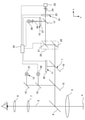
図1に示される例示的実施形態では、本発明による顕微鏡1は、2つの光学観察ビームパス(図1には1つの観察ビームパス2のみを概略的に示す)を有するステレオ手術用顕微鏡1として具現化されている。観察者が観察対象の物体4を拡大された状態で自身の眼Aによって認識できるように、ビームパス2は、観察対象の物体4から、主対物レンズ5を通り、その後、第1のビームスプリッタ6を通り、ズーム光学ユニット7及び接眼レンズ8を通って延びる。
In the exemplary embodiment shown in FIG. 1, the microscope 1 according to the invention is embodied as a stereo operating microscope 1 having two optical observation beam paths (only one
顕微鏡1は、OCT(光干渉断層)デバイス10と、波面測定デバイス11と、照明デバイス12と、治療用レーザデバイス13と、を更に含む。
The microscope 1 further includes an OCT (optical coherence tomography)
以下で詳細に記載するように、これらデバイス10~13のビームパスは重なっているとともに第1のビームスプリッタ6によって対物レンズ4に向かって偏向される。この目的のために、第2のビームスプリッタ15、第3のビームスプリッタ16、第4のビームスプリッタ17及び第5のビームスプリッタ18と、偏向ミラー19と、第1の偏向用ミラー21及び第2の偏向用ミラー22を備える走査ユニット20と、が備えられている。OCTデバイス10は、第1のコリメータ光学ユニット23と、第1のライトガイド24と、OCTモジュール25と、を含む。動作時、OCTモジュール25は必要とされるコヒーレントな照明放射(例えば1060nmの波長を有してもよい)を生成する。コヒーレントな照明放射は第1のライトガイド24内を案内され、第1のコリメータ光学ユニット23によってコリメートされる。走査ユニット20からのコヒーレントな照明放射が第3のビームスプリッタ16、第2のビームスプリッタ15及び第1のビームスプリッタ6によって対物レンズ4に向かって操作され、対物レンズ5によって物体4の所望の位置で集束され、それによって検出放射を生成し、前記放射が、コヒーレントな照明放射とは反対方向にOCTモジュールへと案内されるように、走査ユニット20は、第1の偏向用ミラー21及び第2の偏向用ミラー22によって、x方向及びy方向に所望の偏向を実施する。説明を簡略化するために、当業者には周知であり、記載されている走査されるコヒーレントな照明放射の集束の実施に必要な、第1のコリメータ光学ユニット23と対物レンズ5との間の更なる光学イメージング要素については記載しない。
As described in detail below, the beam paths of these
生成された検出放射はOCTデバイス10の照明ビームパスに沿って反対方向に通過し、第1のライトガイド24を通ってOCTモジュール25に案内され、前記OCTモジュールにおいて本質的に周知の手法で検出が実施される。
The generated detection radiation passes in the opposite direction along the illumination beam path of the
治療用レーザデバイス13は、第2のライトガイド26及び第2のコリメータ光学ユニット27を含む。物体4(眼(特にヒトの眼)であってもよい)を治療するための照明レーザデバイス13のレーザ放射は、例えば、第2のライトガイド26に結合され、第2のコリメータ光学ユニット27まで案内される。第2のコリメータ光学ユニット27はレーザ放射をコリメートし、レーザ放射は、その後、第4のビームスプリッタ17によって走査ユニット20に向かって操作され、その後結果として、OCTデバイス10の照明放射と同じビームパスに沿って通過する。レーザ放射を放出する治療用レーザ28は、治療用レーザデバイス13の一部であってもよい。治療用レーザ28は特にフェムト秒又はピコ秒範囲のパルスレーザ放射を放出するため、フェムト秒(fs)レーザ又はピコ秒(ps)レーザと呼ばれ得る。放出するレーザ放射の波長は、赤外域、例えば800~900nmの範囲又は1000~1100nmの範囲、あるいは、可視波長域内であってもよい。ここでは、典型的な波長は532nm、561nm、577nm、660nm又は670nmである。
The
波面測定デバイス11は、例えば750~850nmの範囲の波長を有するレーザ放射を放出する照明レーザ29を含み、前記レーザ放射は、第5のビームスプリッタ18、第2のビームスプリッタ15及び第1のビームスプリッタ6によって対物レンズ5に向かって操作される。更に、波面測定デバイス11は、検出用の波面センサ30(例えばShack-Hartmannカメラ23)を含み、検出される放射は、主対物レンズ5並びに第1のビームスプリッタ6、第2のビームスプリッタ15及び第3のビームスプリッタ16によって波面センサ30に向かって操作される。
The wave
照明デバイス12は、400~700nmの範囲の照明放射を放出する光源31を含み、前記照明放射は、偏向ミラー19並びに第5のビームスプリッタ18、第2のビームスプリッタ15及び第1のビームスプリッタ6によって主対物レンズ5に向かって操作される。
The
説明を簡略化するために、主対物レンズ5以外の波面測定デバイス11及び照明デバイス12の更なる光学イメージング要素については、当業者に周知であるため図示しない。
For the sake of brevity, further optical imaging elements of the
更に、以下に更に記載される通り、波面センサ30、走査ユニット20、治療用レーザ28、OCTモジュール25、並びに2つのコリメータ光学ユニット23及び27にとりわけ接続されており、顕微鏡1を制御することができる制御ユニット32が備えられている。
Further, as further described below, it is particularly connected to a
記載される、デバイス10~13のビームパスの重なりを実施するために、第1~第5のビームスプリッタ6、15~18はダイクロイックビームスプリッタとして具現化されている。以下、表1~表5に、ビームスプリッタ6、15~18の反射の値及び透過の値を百分率で示す。同様に、以下、表6及び表7に、第1及び第2の偏向用ミラー21及び22並びに偏向ミラー19の反射率の値及び透過率の値を示す。ここで、SCIは、光源31の放射を表し、OCTは、OCTモジュールの放射を表し、WFSは、照明レーザの放射を表し、及びLASERは、治療用レーザ28の放射を表す。
The first to


これら仕様は、以下に記載する考察に基づく。像の品質の低下は望ましくないため、OCTビームパスは照明の点で最適化しなければならず、OCT検出は透過率の点で最適化しなければならない。透過率の点で、波面ビームパスはOCTビームパスほど重要ではない。したがって、波面照明の損失はより強力な照明レーザ29によって補償できることから、波面ビームパスは検出の点で最適化される。治療用レーザ28の放射の場合、第1のビームスプリッタ6及び第2のビームスプリッタ15における損失は許容しなければならない。しかしながら、第1のビームスプリッタ6及び第2のビームスプリッタ15における損失は、治療用レーザ28の出力を高くすることによって補償することができる。照明デバイス12の光源31にも同じことが当てはまる。第2のビームスプリッタ15は、照明デバイス12のビームパス、波面測定デバイス11のビームパス、及び治療用レーザデバイス13のビームパスの50/50の反射率値及び透過率値に関して、各光源に適合させることができる。
These specifications are based on the considerations described below. The OCT beam path must be optimized in terms of illumination and the OCT detection must be optimized in terms of transmittance, as poor image quality is not desirable. In terms of transmittance, the wavefront beampath is less important than the OCT beampath. Therefore, the wavefront beampath is optimized in terms of detection, as the loss of wavefront illumination can be compensated for by the more
本発明による顕微鏡1を眼の治療の分野に適用する場合、OCT画像データの品質は、記録される(及び任意選択的に治療される)眼4の網膜上の照明ビームの横径に依存する。同様に、光凝固、光切断及び/又は光剥離の効率は、眼底上の治療用レーザ28のレーザ放射のレーザスポットの直径に依存する。
When applying the microscope 1 according to the present invention to the field of eye treatment, the quality of OCT image data depends on the lateral diameter of the illumination beam on the retina of the recorded (and optionally treated)
本発明によれば、顕微鏡1の場合、眼4の屈折は波面測定デバイス11によって測定される。これに並行して又はこれとは別に、OCTモジュールのレーザ放射のスポット直径及び/又は治療用レーザ28のレーザ放射のスポット直径を、その後、測定された屈折を考慮して設定することができる。OCTモジュール25のレーザ放射のスポット直径の設定は、第1のコリメーション光学ユニット23によって実施することができる。治療用レーザ28のレーザ放射のスポット直径の設定は、第2のコリメーション光学ユニット27によって実施することができる。例として、この設定は、対応するコリメーション光学ユニット23、27のレンズの軸方向変位によって実施することができる。コリメーション光学ユニット23、27は、アダプティブミラー及び/又は電気的に可変の焦点距離を持つ液体レンズを含むことも可能である。
According to the present invention, in the case of the microscope 1, the refraction of the
特に網膜を測定する及び/又は治療する場合、眼4は、OCTモジュール25のレーザ放射のレーザスポット及び/又は治療用レーザ28のレーザ放射のレーザスポットの焦点を外す及び/又はこれらレーザスポットを変形させることがある(例えば、前記レーザスポットがもはや円形でなくなるように)。波面測定デバイス11による測定は迅速且つ高精度に実施することができる。その後、既に上述の通り、測定結果を使用して、対応するコリメーション光学ユニット23、27による焦点外れを実施することができ、前記焦点外れは、眼4によって生じる焦点外れとは真逆である。当然、眼4によって生じるレーザの変形を補償するために、レーザスポットの逆の変形を同様に実施することができる。これによって、OCTモジュール25のレーザ放射のレーザスポット及び/又は治療用レーザ28のレーザスポットが治療対象の眼4内、例えば網膜上で集束し、円形になるということが有利に達成される。
Especially when measuring and / or treating the retina, the
当然、治療用レーザ28のレーザ放射のレーザスポットを最小化するだけでなく、任意の所望の直径に設定することも可能である。このことは特に光凝固及び/又は光切断の場合に有利となり得る。
Of course, it is possible not only to minimize the laser spot of the laser emission of the
本発明による顕微鏡1は、したがって、OCTモジュール25のレーザ放射のレーザスポットの直径及び/又は治療用レーザ28のレーザ放射のレーザスポットの直径を、波面測定デバイス11による測定値に基づき、直径及び/又は形状の点において目標とする状態に制御又は設定することを可能にする。
The microscope 1 according to the present invention therefore has a diameter and / or a diameter of the laser spot of the laser emission of the
更に、本発明による顕微鏡1を使用して治療モードを実現することができる。治療モードのBスキャン及び/又は体積データ(以下、OCTデータと呼ばれる)はOCTデバイス10によって取り込まれる。例として、OCTデータには血管及び他の網膜構造を含み得る。これら構造は、OCTデータの評価によって確立され得る。例として、評価はリアルタイム(又はオンライン)で実施され得る。その後、この評価に基づき、走査ユニット20を備える治療用レーザ28が、所望の位置が目標とする状態で凝固するような手法で作動され得る。
Further, the treatment mode can be realized by using the microscope 1 according to the present invention. The treatment mode B scan and / or volume data (hereinafter referred to as OCT data) is captured by the
例として、この治療モードは、連続治療モード又は並列治療モードとして実現され得る。連続治療モードの場合、まずOCTデータを測定し、このデータを基に、治療用レーザ28のレーザ放射を使用して所望の位置を凝固又は切断する。並列治療モードでは、OCTデータは永久的又は連続的に測定及び評価される。その後、治療用レーザ28は、走査ユニット20によってOCTモジュール25のレーザビーム及び治療用レーザ28のレーザビームが所望の位置を通過した時にのみ作動される。
As an example, this treatment mode can be realized as a continuous treatment mode or a parallel treatment mode. In the continuous treatment mode, the OCT data is first measured, and based on this data, the laser radiation of the
第2のライトガイド26を従来の石英ガラス繊維で実現することはできないため、顕微鏡1(可動手術用顕微鏡1として具現化してもよい)に治療用レーザ28を取り付けることは困難である。このため、治療用レーザ28によって放出されるレーザパルスの高パルスピークパワーは、第2のライトガイドの入力結合面の破壊をもたらすおそれがある。このため、第2のライトガイドとしてフォトニック結晶ファイバ(微細構造中空コアファイバとも呼ばれる)が使用される。例として、中空コア径は約40μmとすることができ、いわゆる「Kagome」構造が用いられる((非特許文献1))。このような中空コアファイバの場合、治療用レーザ28の超短パルス放射は、例えば約20mrad未満(半角)で入カ結合させることができる。このようなファイバを使用すると透過損失は非常に低く(数パーセント)、ファイバ26の端部におけるビーム品質は、M2が1.3未満のビーム品質パラメータ積に事実上維持される。更に、このフレキシブルファイバ26は、約500Wの比較的大きなパワーでも問題なく伝送することができる。医療、特に眼を治療する際には最大約10Wが必要であるため、このようなファイバは顕微鏡1に治療用レーザ28を取り付けるのに非常に適している。更に、フォトニック結晶ファイバの場合、石英ガラス繊維と比較すると顕著な分散効果がない。前記分散効果は、時間的パルス波形に関して不要な変化を生じさせる。したがって、記載される中空コアファイバは、特にフェムト秒及びピコ秒レーザパルスの伝送又は伝達に好適なフレキシブルファイバである。
Since the second
後眼部における光切断のためには、超短パルスレーザ放射を比較的低い開口数を用いて集束する必要がある。したがって、nJ及びμJ範囲のパルスエネルギーを有するフェムト秒レーザパルスは、通常、NA0.8超の開口数で集束され、焦点スポットでプラズマを生成する。プラズマは光切断を引き起こし、結果として、通常は透明の組織中に小さな泡の形成を引き起こす。光切断の結果、組織が穿孔及び/又は切断され得るように、これら光切断点は、走査ユニット20を用いて互いに隣り合わせで配置することができる。開口数がNA0.25超の場合でも、光切断は前眼部においてなお実施される。フェムト秒レーザパルスでは走査される超短パルスレーザ放射が開口数0.25未満の場合、自己集束が次第に起こる。前記自己集束はレーザビームのフィラメンテーションを生じさせ、結果的に焦点位置のずれ、ゆえに、光切断による不正確な切断を引き起こす。したがって、本発明によれば、後眼部における位置的に正確な切断のため、及び0.25未満の開口数の場合には特にピコ秒レーザパルス(0.7~20ps、特に1~3ps)を提供し、前記ピコ秒レーザパルスはμJ範囲のパルスエネルギーを有し、kHz範囲で繰り返し使用される。治療用レーザ28がMHz範囲で繰り返し動作する場合、より低いμJ範囲又はnJ範囲のより小さなパルスエネルギーを使用することも可能である。
Ultrashort pulsed laser radiation needs to be focused using a relatively low numerical aperture for light cleavage in the posterior eye. Therefore, femtosecond laser pulses with pulse energies in the nJ and μJ ranges are usually focused at numerical apertures greater than NA 0.8 and generate plasma at the focal spot. Plasma causes photocleavage and, as a result, the formation of small bubbles in normally clear tissue. These optical cleavage points can be placed side by side with each other using the
したがって、パルス品質及びビーム品質を維持する一方で微細構造中空コアファイバ26を用いて本発明による手術用顕微鏡1に超短パルス治療用レーザ28を柔軟に取り付けること、比較的大ビーム径の場合に中間焦点スポット(特に、レーザによる損傷を回避するために、光学表面上の)なく顕微鏡1内を伝送すること、特に、ピコ秒レーザパルスを使用することによって後眼部におけるずれのない集束を容易にし、治療対象の眼4の網膜の構造及び硝子体液上で切断を正確に案内する。
Therefore, while maintaining the pulse quality and beam quality, the ultrashort
別の実施形態では、治療用レーザ28のレーザ放射及びOCTモジュール25のレーザ放射を、波長の理由から、及びレーザ放射のビームプロファイルの要件に鑑み、同一ファイバ24又は26内に案内することが許容できる場合は、同一ファイバ24又は26内に案内することができる。
In another embodiment, it is permissible to guide the laser emission of the
1 顕微鏡
2 観察ビームパス
4 物体
5 主対物レンズ
6 第1のビームスプリッタ
7 ズーム光学ユニット
8 接眼レンズ
10 OCTデバイス
11 波面測定デバイス
12 照明デバイス
13 治療用レーザデバイス
15 第2のビームスプリッタ
16 第3のビームスプリッタ
17 第4のビームスプリッタ
18 第5のビームスプリッタ
19 偏向ミラー
20 走査ユニット
21 第1の偏向用ミラー
22 第2の偏向用ミラー
23 第1のコリメータ光学ユニット
24 第1のライトガイド
25 OCTモジュール
26 第2のライトガイド
27 第2のコリメータ光学ユニット
28 治療用レーザ
29 照明レーザ
30 波面センサ
31 光源
32 制御ユニット
1
Claims (8)
検査対象の前記眼(4)の屈折を測定するための波面測定デバイス(11)と、
OCT照明ビームパスを含むOCTデバイス(10)であって、OCT照明放射をOCTスポットとして検査対象の前記眼(4)に集束させることができるOCTデバイス(10)と、
前記波面測定デバイス(11)の少なくとも1つの測定値が供給される制御ユニット(32)と、
を含み、
前記制御ユニット(32)は、前記OCTスポットのビーム径及び/又はビーム形を、供給された前記少なくとも1つの測定値に基づき設定し、
前記制御ユニット(32)は、前記OCT照明放射に焦点外れ及び/又は変形が加えられるように前記OCTデバイス(10)を作動させ、前記焦点外れ及び/又は変形は、検査対象の前記眼(4)によって生じる前記焦点外れ及び/又は変形とは逆であり、
前記OCTデバイス(10)は、前記OCT照明放射をコリメートするためのコリメーション光学ユニット(23)を含み、前記制御ユニット(32)は、前記OCTスポットの前記ビーム径及び/又は前記ビーム形を設定する目的で前記コリメーション光学ユニット(23)を作動させる、
顕微鏡。 An observation beam path (2) that makes it possible to observe the eye (4) to be inspected,
A wavefront measuring device (11) for measuring the refraction of the eye (4) to be inspected, and
An OCT device (10) including an OCT illumination beam path, the OCT device (10) capable of focusing OCT illumination radiation as an OCT spot on the eye (4) to be inspected.
A control unit (32) to which at least one measured value of the wavefront measuring device (11) is supplied, and
Including
The control unit (32) sets the beam diameter and / or beam shape of the OCT spot based on the supplied at least one measured value.
The control unit (32) activates the OCT device (10) so that the OCT illumination radiation is defocused and / or deformed, and the defocus and / or deformation is caused by the eye (4) to be inspected. ) Is the opposite of the out-of-focus and / or deformation caused by
The OCT device (10) includes a collimation optical unit (23) for collimating the OCT illumination radiation, and the control unit (32) sets the beam diameter and / or the beam shape of the OCT spot. The collimation optical unit (23) is operated for the purpose .
microscope.
Applications Claiming Priority (2)
| Application Number | Priority Date | Filing Date | Title |
|---|---|---|---|
| DE102017124545.6 | 2017-10-20 | ||
| DE102017124545.6A DE102017124545B3 (en) | 2017-10-20 | 2017-10-20 | microscope |
Publications (3)
| Publication Number | Publication Date |
|---|---|
| JP2019076719A JP2019076719A (en) | 2019-05-23 |
| JP2019076719A5 JP2019076719A5 (en) | 2021-09-09 |
| JP7036700B2 true JP7036700B2 (en) | 2022-03-15 |
Family
ID=64952095
Family Applications (1)
| Application Number | Title | Priority Date | Filing Date |
|---|---|---|---|
| JP2018197285A Active JP7036700B2 (en) | 2017-10-20 | 2018-10-19 | microscope |
Country Status (3)
| Country | Link |
|---|---|
| US (1) | US10939816B2 (en) |
| JP (1) | JP7036700B2 (en) |
| DE (1) | DE102017124545B3 (en) |
Citations (9)
| Publication number | Priority date | Publication date | Assignee | Title |
|---|---|---|---|---|
| US20030007124A1 (en) | 2001-06-05 | 2003-01-09 | Adaptive Optics Associates, Inc. | Modular adaptive optical subsystem for integration with a fundus camera body and CCD camera unit and improved fundus camera employing same |
| JP2009230141A (en) | 2008-03-19 | 2009-10-08 | Carl Zeiss Surgical Gmbh | Surgical microscopy system having optical coherence tomography facility |
| JP2010279681A (en) | 2009-05-08 | 2010-12-16 | Canon Inc | Optical imaging apparatus and method of imaging optical image |
| JP2011224037A (en) | 2010-04-15 | 2011-11-10 | Canon Inc | Ocular optical system |
| JP2014523301A (en) | 2011-06-27 | 2014-09-11 | ウェイブライト ゲーエムベーハー | Apparatus and method for eye surgery |
| JP2015008839A (en) | 2013-06-27 | 2015-01-19 | 株式会社ニデック | Image processing device and image processing program |
| JP2015534482A (en) | 2012-10-01 | 2015-12-03 | オプトス ピーエルシー | Improvements in scanning laser ophthalmoscope or improvements in scanning laser ophthalmoscope |
| JP2016501045A (en) | 2012-11-07 | 2016-01-18 | クラリティ メディカル システムズ インコーポレイテッド | Apparatus and method for operating a wide diopter range real-time sequential wavefront sensor |
| WO2017044969A1 (en) | 2015-09-11 | 2017-03-16 | Simon Fraser University | Coherence-gated wavefront-sensorless adaptive-optics multi-photon microscopy, and associated systems and methods |
Family Cites Families (23)
| Publication number | Priority date | Publication date | Assignee | Title |
|---|---|---|---|---|
| DE3508306A1 (en) | 1985-03-08 | 1986-09-11 | Fa. Carl Zeiss, 7920 Heidenheim | MICROSCOPE TUBE |
| DE10202509A1 (en) | 2002-01-23 | 2003-07-31 | Leica Microsystems | Ophthalmic surgical microscope |
| DE10360570B4 (en) | 2003-12-22 | 2006-01-12 | Carl Zeiss | Optical measuring system and optical measuring method |
| DE102007019677A1 (en) | 2006-11-06 | 2008-05-08 | Carl Zeiss Surgical Gmbh | Surgical microscope with OCT system and surgical microscope illumination module with OCT system |
| US7931644B2 (en) | 2006-11-10 | 2011-04-26 | Amo Development Llc. | Operator-controlled scanning laser procedure designed for large-area epithelium removal |
| US20100324542A1 (en) | 2007-11-02 | 2010-12-23 | Kurtz Ronald M | Method to Guide a Cataract Procedure by Corneal Imaging |
| JP5139832B2 (en) | 2008-02-14 | 2013-02-06 | 浜松ホトニクス株式会社 | Observation device |
| US8459795B2 (en) | 2008-09-16 | 2013-06-11 | Carl Zeiss Meditec Ag | Measuring system for ophthalmic surgery |
| DE102008047400B9 (en) | 2008-09-16 | 2011-01-05 | Carl Zeiss Surgical Gmbh | Eye surgery Measurement System |
| DE102008063644B4 (en) | 2008-12-18 | 2018-03-29 | Carl Zeiss Meditec Ag | Surgical microscope for cataract surgery |
| DE102008062908B4 (en) | 2008-12-23 | 2011-01-20 | Carl Zeiss Ag | Eye surgery system |
| DE102009037841B4 (en) | 2009-08-18 | 2020-01-23 | Carl Zeiss Meditec Ag | Optical system with wavefront analysis system and assembly with wavefront analysis system for a microscope with microscope chassis |
| WO2011091283A1 (en) | 2010-01-22 | 2011-07-28 | Board Of Regents, The University Of Texas System | Systems, devices and methods for imaging and surgery |
| WO2011151064A1 (en) | 2010-06-03 | 2011-12-08 | Carl Zeiss Meditec Ag | Device and method for vitreous humor surgery |
| DE102010024606B4 (en) | 2010-06-22 | 2019-11-14 | Carl Zeiss Meditec Ag | Aberrometric measuring system |
| US8554037B2 (en) | 2010-09-30 | 2013-10-08 | Raydiance, Inc. | Hybrid waveguide device in powerful laser systems |
| US8777412B2 (en) * | 2012-04-05 | 2014-07-15 | Bioptigen, Inc. | Surgical microscopes using optical coherence tomography and related methods |
| US20150002812A1 (en) * | 2013-06-27 | 2015-01-01 | Nidek Co., Ltd. | Image processing apparatus and storage medium |
| CN105592829B (en) * | 2013-07-29 | 2018-11-16 | 拜尔普泰戈恩公司 | Surgical optical coherence tomography (OCT) and its related system and method for surgical operation |
| US9538911B2 (en) | 2013-09-19 | 2017-01-10 | Novartis Ag | Integrated OCT-refractometer system for ocular biometry |
| JP2017513211A (en) | 2014-02-28 | 2017-05-25 | イムラ アメリカ インコーポレイテッド | Generation and emission of multiwavelength ultrashort pulses applied to microscopes |
| WO2016011043A1 (en) | 2014-07-14 | 2016-01-21 | University Of Rochester | Real-time laser modulation and delivery in opthalmic devices for scanning, imaging, and laser treatment of the eye |
| AU2017324944B2 (en) * | 2016-09-06 | 2022-04-07 | Amo Development, Llc | Optical measurement systems and processes with wavefront aberrometer having variable focal length lens |
-
2017
- 2017-10-20 DE DE102017124545.6A patent/DE102017124545B3/en active Active
-
2018
- 2018-10-19 US US16/165,750 patent/US10939816B2/en active Active
- 2018-10-19 JP JP2018197285A patent/JP7036700B2/en active Active
Patent Citations (9)
| Publication number | Priority date | Publication date | Assignee | Title |
|---|---|---|---|---|
| US20030007124A1 (en) | 2001-06-05 | 2003-01-09 | Adaptive Optics Associates, Inc. | Modular adaptive optical subsystem for integration with a fundus camera body and CCD camera unit and improved fundus camera employing same |
| JP2009230141A (en) | 2008-03-19 | 2009-10-08 | Carl Zeiss Surgical Gmbh | Surgical microscopy system having optical coherence tomography facility |
| JP2010279681A (en) | 2009-05-08 | 2010-12-16 | Canon Inc | Optical imaging apparatus and method of imaging optical image |
| JP2011224037A (en) | 2010-04-15 | 2011-11-10 | Canon Inc | Ocular optical system |
| JP2014523301A (en) | 2011-06-27 | 2014-09-11 | ウェイブライト ゲーエムベーハー | Apparatus and method for eye surgery |
| JP2015534482A (en) | 2012-10-01 | 2015-12-03 | オプトス ピーエルシー | Improvements in scanning laser ophthalmoscope or improvements in scanning laser ophthalmoscope |
| JP2016501045A (en) | 2012-11-07 | 2016-01-18 | クラリティ メディカル システムズ インコーポレイテッド | Apparatus and method for operating a wide diopter range real-time sequential wavefront sensor |
| JP2015008839A (en) | 2013-06-27 | 2015-01-19 | 株式会社ニデック | Image processing device and image processing program |
| WO2017044969A1 (en) | 2015-09-11 | 2017-03-16 | Simon Fraser University | Coherence-gated wavefront-sensorless adaptive-optics multi-photon microscopy, and associated systems and methods |
Also Published As
| Publication number | Publication date |
|---|---|
| US20190117061A1 (en) | 2019-04-25 |
| US10939816B2 (en) | 2021-03-09 |
| JP2019076719A (en) | 2019-05-23 |
| DE102017124545B3 (en) | 2019-01-24 |
Similar Documents
| Publication | Publication Date | Title |
|---|---|---|
| CN102791228B (en) | Revise eye tissue and intraocular lens's system | |
| US11471328B2 (en) | Full depth laser ophthalmic surgical system, methods of calibrating the surgical system and treatment methods using the same | |
| JP6298127B2 (en) | Ophthalmic equipment | |
| KR101645603B1 (en) | Low wavefront error devices, systems, and methods for treating an eye | |
| US20090048586A1 (en) | Precise disruption of tissue in retinal and preretinal structures | |
| US20140257257A1 (en) | Systems and methods for treating target tissue in the vitreous cavity | |
| JP2014531294A (en) | System, interface device, use of interface device and control method by control device | |
| JP7014450B2 (en) | Therapeutic laser with reflective mirror | |
| US20180214306A1 (en) | Ophthalmic surgical apparatus | |
| CA3096285A1 (en) | Opthalmological imaging and laser delivery device, system and methods | |
| JP7036700B2 (en) | microscope | |
| JP6321696B2 (en) | System and interface device | |
| JP6627382B2 (en) | Ophthalmic laser treatment device | |
| JP2013078398A (en) | Laser operation apparatus for ophthalmology | |
| Ferhanoglu et al. | A 5-mm diameter, piezo-scanning fiber device for high speed ultrafast laser microsurgery | |
| WO2023062650A1 (en) | SINGLE AND/OR DUAL (532 AND/OR 577) nm LASER DELIVERY SYSTEM ATTACHED TO AN OPHTHALMIC MICROSCOPE | |
| Hansen et al. | Adaptive optics for the correction of eye aberrations | |
| Lorbeer et al. | Adaptive optics for the correction of eye aberrations |
Legal Events
| Date | Code | Title | Description |
|---|---|---|---|
| A521 | Request for written amendment filed |
Free format text: JAPANESE INTERMEDIATE CODE: A523 Effective date: 20210727 |
|
| A621 | Written request for application examination |
Free format text: JAPANESE INTERMEDIATE CODE: A621 Effective date: 20210727 |
|
| A871 | Explanation of circumstances concerning accelerated examination |
Free format text: JAPANESE INTERMEDIATE CODE: A871 Effective date: 20210727 |
|
| A131 | Notification of reasons for refusal |
Free format text: JAPANESE INTERMEDIATE CODE: A131 Effective date: 20210928 |
|
| A521 | Request for written amendment filed |
Free format text: JAPANESE INTERMEDIATE CODE: A523 Effective date: 20211227 |
|
| TRDD | Decision of grant or rejection written | ||
| A01 | Written decision to grant a patent or to grant a registration (utility model) |
Free format text: JAPANESE INTERMEDIATE CODE: A01 Effective date: 20220215 |
|
| A61 | First payment of annual fees (during grant procedure) |
Free format text: JAPANESE INTERMEDIATE CODE: A61 Effective date: 20220303 |
|
| R150 | Certificate of patent or registration of utility model |
Ref document number: 7036700 Country of ref document: JP Free format text: JAPANESE INTERMEDIATE CODE: R150 |