JP7036587B2 - Solar energy utilization device - Google Patents
Solar energy utilization device Download PDFInfo
- Publication number
- JP7036587B2 JP7036587B2 JP2017248816A JP2017248816A JP7036587B2 JP 7036587 B2 JP7036587 B2 JP 7036587B2 JP 2017248816 A JP2017248816 A JP 2017248816A JP 2017248816 A JP2017248816 A JP 2017248816A JP 7036587 B2 JP7036587 B2 JP 7036587B2
- Authority
- JP
- Japan
- Prior art keywords
- prism
- angle
- triangular prism
- transparent
- plate material
- Prior art date
- Legal status (The legal status is an assumption and is not a legal conclusion. Google has not performed a legal analysis and makes no representation as to the accuracy of the status listed.)
- Active
Links
- 239000000463 material Substances 0.000 claims description 67
- 230000003287 optical effect Effects 0.000 claims description 34
- 239000011521 glass Substances 0.000 description 21
- 239000007788 liquid Substances 0.000 description 12
- 239000011148 porous material Substances 0.000 description 9
- 238000010521 absorption reaction Methods 0.000 description 8
- XLYOFNOQVPJJNP-UHFFFAOYSA-N water Substances O XLYOFNOQVPJJNP-UHFFFAOYSA-N 0.000 description 8
- 238000010248 power generation Methods 0.000 description 7
- 230000000694 effects Effects 0.000 description 5
- 238000007789 sealing Methods 0.000 description 5
- 239000007789 gas Substances 0.000 description 4
- 238000011084 recovery Methods 0.000 description 4
- 239000007787 solid Substances 0.000 description 4
- FAPWRFPIFSIZLT-UHFFFAOYSA-M Sodium chloride Chemical compound [Na+].[Cl-] FAPWRFPIFSIZLT-UHFFFAOYSA-M 0.000 description 3
- NIXOWILDQLNWCW-UHFFFAOYSA-N acrylic acid group Chemical group C(C=C)(=O)O NIXOWILDQLNWCW-UHFFFAOYSA-N 0.000 description 3
- 230000005540 biological transmission Effects 0.000 description 3
- 239000005388 borosilicate glass Substances 0.000 description 3
- 229920001973 fluoroelastomer Polymers 0.000 description 3
- 238000009434 installation Methods 0.000 description 3
- 238000000034 method Methods 0.000 description 3
- 229920000515 polycarbonate Polymers 0.000 description 3
- 239000004417 polycarbonate Substances 0.000 description 3
- 229920001296 polysiloxane Polymers 0.000 description 3
- 239000005361 soda-lime glass Substances 0.000 description 3
- XKRFYHLGVUSROY-UHFFFAOYSA-N Argon Chemical compound [Ar] XKRFYHLGVUSROY-UHFFFAOYSA-N 0.000 description 2
- 230000002093 peripheral effect Effects 0.000 description 2
- 230000007704 transition Effects 0.000 description 2
- 229910052786 argon Inorganic materials 0.000 description 1
- 238000006243 chemical reaction Methods 0.000 description 1
- 230000005611 electricity Effects 0.000 description 1
- 238000005516 engineering process Methods 0.000 description 1
- 238000010438 heat treatment Methods 0.000 description 1
- 229910052743 krypton Inorganic materials 0.000 description 1
- DNNSSWSSYDEUBZ-UHFFFAOYSA-N krypton atom Chemical compound [Kr] DNNSSWSSYDEUBZ-UHFFFAOYSA-N 0.000 description 1
- 239000012466 permeate Substances 0.000 description 1
- 239000000047 product Substances 0.000 description 1
- 239000011347 resin Substances 0.000 description 1
- 229920005989 resin Polymers 0.000 description 1
- 230000002441 reversible effect Effects 0.000 description 1
Images


Classifications
-
- F—MECHANICAL ENGINEERING; LIGHTING; HEATING; WEAPONS; BLASTING
- F24—HEATING; RANGES; VENTILATING
- F24S—SOLAR HEAT COLLECTORS; SOLAR HEAT SYSTEMS
- F24S23/00—Arrangements for concentrating solar-rays for solar heat collectors
- F24S23/10—Prisms
-
- H—ELECTRICITY
- H02—GENERATION; CONVERSION OR DISTRIBUTION OF ELECTRIC POWER
- H02S—GENERATION OF ELECTRIC POWER BY CONVERSION OF INFRARED RADIATION, VISIBLE LIGHT OR ULTRAVIOLET LIGHT, e.g. USING PHOTOVOLTAIC [PV] MODULES
- H02S40/00—Components or accessories in combination with PV modules, not provided for in groups H02S10/00 - H02S30/00
- H02S40/20—Optical components
- H02S40/22—Light-reflecting or light-concentrating means
-
- E—FIXED CONSTRUCTIONS
- E06—DOORS, WINDOWS, SHUTTERS, OR ROLLER BLINDS IN GENERAL; LADDERS
- E06B—FIXED OR MOVABLE CLOSURES FOR OPENINGS IN BUILDINGS, VEHICLES, FENCES OR LIKE ENCLOSURES IN GENERAL, e.g. DOORS, WINDOWS, BLINDS, GATES
- E06B5/00—Doors, windows, or like closures for special purposes; Border constructions therefor
-
- F—MECHANICAL ENGINEERING; LIGHTING; HEATING; WEAPONS; BLASTING
- F24—HEATING; RANGES; VENTILATING
- F24S—SOLAR HEAT COLLECTORS; SOLAR HEAT SYSTEMS
- F24S20/00—Solar heat collectors specially adapted for particular uses or environments
- F24S20/60—Solar heat collectors integrated in fixed constructions, e.g. in buildings
- F24S20/63—Solar heat collectors integrated in fixed constructions, e.g. in buildings in the form of windows
-
- F—MECHANICAL ENGINEERING; LIGHTING; HEATING; WEAPONS; BLASTING
- F24—HEATING; RANGES; VENTILATING
- F24S—SOLAR HEAT COLLECTORS; SOLAR HEAT SYSTEMS
- F24S23/00—Arrangements for concentrating solar-rays for solar heat collectors
- F24S23/70—Arrangements for concentrating solar-rays for solar heat collectors with reflectors
-
- F—MECHANICAL ENGINEERING; LIGHTING; HEATING; WEAPONS; BLASTING
- F24—HEATING; RANGES; VENTILATING
- F24S—SOLAR HEAT COLLECTORS; SOLAR HEAT SYSTEMS
- F24S30/00—Arrangements for moving or orienting solar heat collector modules
- F24S30/20—Arrangements for moving or orienting solar heat collector modules for linear movement
-
- G—PHYSICS
- G02—OPTICS
- G02B—OPTICAL ELEMENTS, SYSTEMS OR APPARATUS
- G02B5/00—Optical elements other than lenses
- G02B5/04—Prisms
-
- G—PHYSICS
- G02—OPTICS
- G02B—OPTICAL ELEMENTS, SYSTEMS OR APPARATUS
- G02B5/00—Optical elements other than lenses
- G02B5/04—Prisms
- G02B5/045—Prism arrays
-
- H—ELECTRICITY
- H02—GENERATION; CONVERSION OR DISTRIBUTION OF ELECTRIC POWER
- H02S—GENERATION OF ELECTRIC POWER BY CONVERSION OF INFRARED RADIATION, VISIBLE LIGHT OR ULTRAVIOLET LIGHT, e.g. USING PHOTOVOLTAIC [PV] MODULES
- H02S40/00—Components or accessories in combination with PV modules, not provided for in groups H02S10/00 - H02S30/00
- H02S40/20—Optical components
-
- H—ELECTRICITY
- H02—GENERATION; CONVERSION OR DISTRIBUTION OF ELECTRIC POWER
- H02S—GENERATION OF ELECTRIC POWER BY CONVERSION OF INFRARED RADIATION, VISIBLE LIGHT OR ULTRAVIOLET LIGHT, e.g. USING PHOTOVOLTAIC [PV] MODULES
- H02S40/00—Components or accessories in combination with PV modules, not provided for in groups H02S10/00 - H02S30/00
- H02S40/40—Thermal components
- H02S40/44—Means to utilise heat energy, e.g. hybrid systems producing warm water and electricity at the same time
-
- Y—GENERAL TAGGING OF NEW TECHNOLOGICAL DEVELOPMENTS; GENERAL TAGGING OF CROSS-SECTIONAL TECHNOLOGIES SPANNING OVER SEVERAL SECTIONS OF THE IPC; TECHNICAL SUBJECTS COVERED BY FORMER USPC CROSS-REFERENCE ART COLLECTIONS [XRACs] AND DIGESTS
- Y02—TECHNOLOGIES OR APPLICATIONS FOR MITIGATION OR ADAPTATION AGAINST CLIMATE CHANGE
- Y02B—CLIMATE CHANGE MITIGATION TECHNOLOGIES RELATED TO BUILDINGS, e.g. HOUSING, HOUSE APPLIANCES OR RELATED END-USER APPLICATIONS
- Y02B10/00—Integration of renewable energy sources in buildings
- Y02B10/20—Solar thermal
-
- Y—GENERAL TAGGING OF NEW TECHNOLOGICAL DEVELOPMENTS; GENERAL TAGGING OF CROSS-SECTIONAL TECHNOLOGIES SPANNING OVER SEVERAL SECTIONS OF THE IPC; TECHNICAL SUBJECTS COVERED BY FORMER USPC CROSS-REFERENCE ART COLLECTIONS [XRACs] AND DIGESTS
- Y02—TECHNOLOGIES OR APPLICATIONS FOR MITIGATION OR ADAPTATION AGAINST CLIMATE CHANGE
- Y02E—REDUCTION OF GREENHOUSE GAS [GHG] EMISSIONS, RELATED TO ENERGY GENERATION, TRANSMISSION OR DISTRIBUTION
- Y02E10/00—Energy generation through renewable energy sources
- Y02E10/40—Solar thermal energy, e.g. solar towers
- Y02E10/47—Mountings or tracking
-
- Y—GENERAL TAGGING OF NEW TECHNOLOGICAL DEVELOPMENTS; GENERAL TAGGING OF CROSS-SECTIONAL TECHNOLOGIES SPANNING OVER SEVERAL SECTIONS OF THE IPC; TECHNICAL SUBJECTS COVERED BY FORMER USPC CROSS-REFERENCE ART COLLECTIONS [XRACs] AND DIGESTS
- Y02—TECHNOLOGIES OR APPLICATIONS FOR MITIGATION OR ADAPTATION AGAINST CLIMATE CHANGE
- Y02E—REDUCTION OF GREENHOUSE GAS [GHG] EMISSIONS, RELATED TO ENERGY GENERATION, TRANSMISSION OR DISTRIBUTION
- Y02E10/00—Energy generation through renewable energy sources
- Y02E10/50—Photovoltaic [PV] energy
- Y02E10/52—PV systems with concentrators
-
- Y—GENERAL TAGGING OF NEW TECHNOLOGICAL DEVELOPMENTS; GENERAL TAGGING OF CROSS-SECTIONAL TECHNOLOGIES SPANNING OVER SEVERAL SECTIONS OF THE IPC; TECHNICAL SUBJECTS COVERED BY FORMER USPC CROSS-REFERENCE ART COLLECTIONS [XRACs] AND DIGESTS
- Y02—TECHNOLOGIES OR APPLICATIONS FOR MITIGATION OR ADAPTATION AGAINST CLIMATE CHANGE
- Y02E—REDUCTION OF GREENHOUSE GAS [GHG] EMISSIONS, RELATED TO ENERGY GENERATION, TRANSMISSION OR DISTRIBUTION
- Y02E10/00—Energy generation through renewable energy sources
- Y02E10/60—Thermal-PV hybrids
Description
本発明は、太陽エネルギー利用器に関する。 The present invention relates to a solar energy utilization device.
従来、太陽エネルギーの1つである太陽光を利用して発電を行う太陽光発電パネルを搭載した太陽エネルギー利用窓が提案されている(例えば特許文献1参照)。この太陽エネルギー利用窓では、2枚の透明板材の間に、太陽光発電パネルと断面三角形状となる三角柱プリズムとが設けられている。太陽エネルギー利用窓を断面視した場合において、三角柱プリズムは、三角の第1の辺が2枚の透明板材に沿っており、第2及び第3の辺が2枚の透明板材に交差する方向に延びている。 Conventionally, a solar energy utilization window equipped with a photovoltaic power generation panel that generates electricity using sunlight, which is one of the solar energies, has been proposed (see, for example, Patent Document 1). In this solar energy utilization window, a photovoltaic power generation panel and a triangular prism prism having a triangular cross section are provided between the two transparent plates. When the solar energy utilization window is viewed in cross section, the triangular prism prism has the first side of the triangle along the two transparent plates, and the second and third sides intersect the two transparent plates. It is extended.
ここで、特許文献1に記載の太陽エネルギー利用窓において、第1の辺に対する第2及び第3の辺の角度は、太陽光の受光角との関係から定められるようになっており、且つ、太陽光発電パネルは第2の辺に接した状態で設置されている。なお、第3の辺は、第2の辺よりも太陽に近い側の辺とする(窓が立面に用いられる場合には第3の辺が第2の辺よりも上側に位置する辺とする)。 Here, in the solar energy utilization window described in Patent Document 1, the angles of the second and third sides with respect to the first side are determined from the relationship with the light receiving angle of sunlight, and The photovoltaic power generation panel is installed in contact with the second side. The third side is the side closer to the sun than the second side (when the window is used for an elevation, the third side is located above the second side). do).
このような太陽エネルギー利用窓では、三角柱プリズムによって太陽光を好適に反射して、太陽光発電パネルに多くの光を集めることが可能となっている。さらに、このような太陽エネルギー利用窓では、太陽光が地面等で反射したときの散乱光については三角柱プリズムの角度設定により通過させることができる。よって、太陽光を好適に太陽光発電パネルに集めつつも、散乱光の通過を阻害せずに室内側から景色を見ることができる太陽エネルギー利用窓を提供することができる。 In such a solar energy utilization window, it is possible to appropriately reflect sunlight by a triangular pillar prism and collect a large amount of light on a photovoltaic power generation panel. Further, in such a solar energy utilization window, scattered light when sunlight is reflected on the ground or the like can be passed by setting the angle of the triangular prism prism. Therefore, it is possible to provide a solar energy utilization window that allows the scenery to be seen from the indoor side without obstructing the passage of scattered light while suitably collecting sunlight in the photovoltaic power generation panel.
ここで、太陽エネルギー利用窓においては、太陽光発電パネルに限らず、太陽熱を利用して熱媒や空気の加熱を行う集熱器(集熱管や集熱ダクト)や、取り込んだ太陽熱を移送する熱移送手段(ヒートパイプなど)を設けてもよい。さらには、このような太陽エネルギーを収集する太陽エネルギー収集部(集エネ部)を複数種設けることも可能である。 Here, in the solar energy utilization window, not only the solar power generation panel but also a heat collector (heat collecting tube or heat collecting duct) that heats a heat medium or air by using solar heat, or a solar heat taken in is transferred. A heat transfer means (heat pipe or the like) may be provided. Furthermore, it is also possible to provide a plurality of types of solar energy collecting units (energy collecting units) for collecting such solar energy.
しかし、特許文献1に記載の太陽エネルギー利用窓は、集エネ部が第2の辺に接した状態で設置されているため、折角太陽光を集エネ部に集めたとしても、太陽熱が三角柱プリズムに伝熱してしまい、太陽エネルギーを効率良く利用する観点で改善の余地を有するものであった。 However, since the solar energy utilization window described in Patent Document 1 is installed in a state where the energy collecting portion is in contact with the second side, even if the bent sunlight is collected in the energy collecting portion, the solar heat is a triangular pillar prism. There was room for improvement from the viewpoint of efficient use of solar energy.
なお、上記の改善の余地の問題については、2枚の透明板材を備えて窓として使用される太陽エネルギー利用窓に限らず、太陽光の受光側が透明板材であってその反対側が非透明板材である太陽エネルギー利用器にも共通するものである。 Regarding the above-mentioned problem of room for improvement, it is not limited to solar energy utilization windows that are equipped with two transparent plates and are used as windows, but the light receiving side of sunlight is a transparent plate and the opposite side is a non-transparent plate. It is also common to some solar energy utilization devices.
本発明は、このような問題を解決するためになされたものであり、その目的とするところは、太陽エネルギーをより効率よく利用することが可能な太陽エネルギー利用器を提供することにある。 The present invention has been made to solve such a problem, and an object of the present invention is to provide a solar energy utilization device capable of more efficiently utilizing solar energy.
本発明に係る太陽エネルギー利用器は、2枚の板材と、三角柱プリズムと、集エネ部とを備えている。2枚の板材は太陽光の入射側のものが透明性である。集エネ部は、第2及び第3の辺のうち、下方側の辺となる直線状の第2の辺に対して、所定の隙間を挟んで設置され、太陽エネルギーを収集するものである。三角柱プリズムは、3種の光路が存在するように屈折率と三角の各内角とが設定されている。3種の光路の1つは、第1の辺から当該三角柱プリズム内に進入して直接第2の辺に到達して第2の辺から当該三角柱プリズム外に出るものである。もう1つは、第1の辺から当該三角柱プリズム内に進入して第3の辺で全反射した後に、第2の辺に到達して第2の辺から当該三角柱プリズム外に出るものである。残り1つは、第1の辺から当該三角柱プリズム内に進入して第3の辺及び第1の辺の順に全反射した後に、第2の辺に到達して第2の辺から当該三角柱プリズム外に出るものである。
さらに、太陽エネルギー利用器は、第2の辺と集エネ部との間に柱状又は粒状の介在部材を備え、第2の辺と集エネ部との間は、真空状態とされ、又は気体で満たされたうえで、介在部材が配置されている。
または、集エネ部は、断面視状態で、三角柱プリズムと略同一形状であり、三角柱プリズムと点対称となる向きに配置されており、一部分が非透明性で残部が透明性である。
または、断面視状態で、三角柱プリズムと同一形状であり、三角柱プリズムと点対称となる向きに配置された透明性の第2三角柱プリズムをさらに備え、2枚の板材は、双方が透明性の板材であり、集エネ部は、第2の辺と第5の辺との間において、双方から離間して設けられ、第2の辺と第5の辺との間で集エネ部を移動可能であって、集エネ部を第2の辺と第5の辺とにそれぞれ切離可能とする移動機構をさらに備える。
The solar energy utilization device according to the present invention includes two plate members, a triangular prism prism, and an energy collecting portion. The two plates are transparent on the incident side of sunlight. The energy collecting unit is installed with a predetermined gap between the second side and the second side having a linear shape, which is the lower side, to collect solar energy. In the triangular prism prism, the refractive index and each internal angle of the triangle are set so that three types of optical paths exist. One of the three types of optical paths enters the triangular prism prism from the first side, reaches the second side directly, and goes out of the triangular prism prism from the second side. The other is to enter the triangular prism prism from the first side, totally reflect at the third side, reach the second side, and go out of the triangular prism prism from the second side. .. The remaining one enters the triangular prism prism from the first side and is totally reflected in the order of the third side and the first side, then reaches the second side and reaches the triangular prism prism from the second side. It's something that goes out.
Further, the solar energy utilization device is provided with a columnar or granular intervening member between the second side and the energy collecting portion, and a vacuum state or a gas is provided between the second side and the energy collecting portion. After being filled, the intervening members are arranged.
Alternatively, the energy collecting portion has substantially the same shape as the triangular prism prism in a cross-sectional view, and is arranged in a direction that is point-symmetrical with the triangular prism prism, and a part is opaque and the rest is transparent.
Alternatively, in a cross-sectional view, a transparent second triangular prism prism having the same shape as the triangular prism prism and arranged in a direction symmetrical with the triangular prism prism is further provided, and the two plates are both transparent plates. The energy collecting section is provided between the second side and the fifth side at a distance from both sides, and the energy collecting section can be moved between the second side and the fifth side. Therefore, a moving mechanism that enables the energy collecting unit to be separated into the second side and the fifth side, respectively, is further provided.
本発明によれば、集エネ部は第2の辺に対して所定の隙間を挟んで設置される。このため、所定の隙間の存在によって集エネ部における太陽熱が三角柱プリズムへ移行し難くすることができる。また、三角柱プリズムは、3種の光路が存在するように屈折率と三角の各内角とが設定されているため、第1の辺から三角柱プリズム内に進入した太陽光は直接又は第3の辺や第1の辺の全反射を経て第2の辺から三角柱プリズム外に出ることとなる。すなわち、三角柱プリズムの第1の辺に入射した太陽光を第2の辺から出射させることで、所定の隙間を有して配置される集エネ部にも太陽光を集めることができる。従って、熱移行を抑えつつも太陽光を集エネ部に集めて、太陽エネルギーをより効率よく利用することができる。 According to the present invention, the energy collecting portion is installed with a predetermined gap between the second side and the second side. Therefore, the presence of a predetermined gap makes it difficult for the solar heat in the energy collecting portion to transfer to the triangular prism prism. Further, since the refractive index and each internal angle of the triangle are set so that the triangular prism prism has three types of optical paths, the sunlight entering the triangular prism prism from the first side is directly or the third side. And, it goes out of the triangular prism prism from the second side through the total reflection of the first side. That is, by emitting the sunlight incident on the first side of the triangular prism prism from the second side, the sunlight can also be collected in the energy collecting portion arranged with a predetermined gap. Therefore, it is possible to collect sunlight in the energy collecting section while suppressing heat transfer, and to use solar energy more efficiently.
以下、本発明を好適な実施形態に沿って説明する。なお、本発明は以下に示す実施形態に限られるものではなく、本発明の趣旨を逸脱しない範囲において適宜変更可能である。また、以下に示す実施形態においては、一部構成の図示や説明を省略している箇所があるが、省略された技術の詳細については、以下に説明する内容と矛盾点が発生しない範囲内において、適宜公知又は周知の技術が適用されていることはいうまでもない。 Hereinafter, the present invention will be described with reference to preferred embodiments. The present invention is not limited to the embodiments shown below, and can be appropriately modified without departing from the spirit of the present invention. Further, in the embodiments shown below, some parts of the configuration are omitted from the illustration and description, but the details of the omitted technology are within the range where there is no contradiction with the contents described below. Needless to say, publicly known or well-known techniques are applied as appropriate.
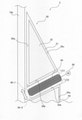
図1は、本発明の実施形態に係る太陽エネルギー利用窓を示す断面図である。なお、図1では、窓(開閉の可否を問わない)として適用可能な太陽エネルギー利用窓を太陽エネルギー利用器の一例として説明するが、太陽エネルギー利用器は窓に適用されるものに限らず、外壁に取り付けられるものであってもよい。 FIG. 1 is a cross-sectional view showing a solar energy utilization window according to an embodiment of the present invention. In FIG. 1, a solar energy utilization window that can be applied as a window (whether it can be opened or closed) will be described as an example of a solar energy utilization device, but the solar energy utilization device is not limited to that applied to a window. It may be attached to an outer wall.
図1に示す例に係る太陽エネルギー利用窓1は、概略的に2枚の板材10と、真空封止部材20と、複数の第1プリズム(三角柱プリズム)30と、複数の集エネ部40と、複数の第2プリズム50とを備えている。
The solar energy utilization window 1 according to the example shown in FIG. 1 is roughly composed of two
2枚の板材10は、互いに略平行配置される透明性の板材である。これらの板材10は例えばガラス材によって構成されており、2枚の板材10のうち室外側のものが外ガラス(透明性の板材)10aとなり、室内側のものが内ガラス(板材)10bとなる。
The two
真空封止部材20は、2枚の板材10の周端部において2枚の板材10の間に介在するものである。2枚の板材10の周端部に真空封止部材20が設けられることによって、2枚の板材10と真空封止部材20とによって閉じられた内部空間が形成される。本実施形態において内部空間は断熱性の観点から真空状態とされるが、これに限らず、空気、アルゴン又はクリプトンなどの気体で満たされていてもよい。
The
複数の第1プリズム30は、それぞれが断面視して三角形状となるプリズム(すなわち三角柱形状のプリズム)で構成されている。これらの第1プリズム30は、第1の辺30aが外ガラス10aに沿うように外ガラス10aに面して配置されている。第1プリズム30の第2の辺30bと第3の辺30cは、第1の辺30aに対して所定の角度を有して延びている。第2の辺30bは、第3の辺30cよりも鉛直下方側に位置する辺である。
The plurality of
図2は、図1に示した第1プリズム30の拡大図である。図2に示すように、第1プリズム30は、第1プリズム30の外壁を構成するプリズム壁31と、プリズム壁31の内部に封入される透明性の液体からなる内部部材32とによって構成されている。なお、第1プリズム30は、図2に示す構成に限らず、中実のガラス材や樹脂材によって構成されていてもよい。また、内部部材32は、ゲル状や固体であってもよい。
FIG. 2 is an enlarged view of the
図1に示す複数の集エネ部40は、太陽エネルギーを収集して、発電、他の媒体の加熱、及び熱移送などに太陽エネルギーを利用する機器であって、例えば太陽電池パネル、集熱器及び熱移送手段が該当する。これら集エネ部40は、それぞれが第1プリズム30の第2の辺30bに面して設けられている。
The plurality of
複数の第2プリズム50は、それぞれが断面視して三角形状となるプリズム(すなわち三角柱形状のプリズム)であって、第1プリズム30と同形状且つ同屈折率となっている。この第2プリズム50は、第1プリズム30を180°回転させた点対称となる向きとなっており、それぞれの第1プリズム30に対して1つずつ設けられている。ここで、第1プリズム30のみしか有しない場合には、第1プリズム30によって光が屈折して、室内側から視認したときの景色には歪みが生じる(すなわち散乱光SLが大きく歪む)。しかし、第2プリズム50が第1プリズム30と対になって設けられることにより、室内側から視認したときの景色の歪みが抑えられることとなる(像回復効果を有することとなる)。なお、第2プリズム50は、第1プリズム30と同様にプリズム壁及び内部部材から構成されてもよいし、中実の部材によって構成されてもよい。
Each of the plurality of
具体的に第2プリズム50は、それぞれが第4の辺50aが内ガラス10bに沿うように内ガラス10bに面して配置されている。第2プリズム50の第5の辺50bと第6の辺50cは、第4の辺50aに対して所定の角度を有して延びている。第5の辺50bは、第6の辺50cよりも鉛直上方側に位置する。このような第2プリズム50は、第6の辺50cが水平方向に隣接する第1プリズム30の第3の辺30cと対向しており、第5の辺50bが集エネ部40を挟んで上下方向に隣接する第1プリズム30の第2の辺30bと対向している。
Specifically, each of the
また、本実施形態において2枚の板材10、第1プリズム30、及び第2プリズム50は、互いに微細な隙間を有して配置されている。これらの間には、微細な隙間が維持されるように微小な柱や粒などの介在部材が介在されている。この結果、太陽エネルギー利用窓1は、外ガラス10a、介在部材、第1プリズム30、介在部材、第2プリズム50、介在部材、及び内ガラス10bの順の積層構造となり、たとえ内部空間が真空状態とされていたとしても、その圧力に耐えるように支えられることとなる。
Further, in the present embodiment, the two
さらに、本実施形態において集エネ部40は、図2に示すように、第1プリズム30の第2の辺30bに対して隙間C1を有した状態で設けられている。隙間C1を維持するためには上記と同様に微細な介在部材が介在されていてもよいし、他の固定手段によって位置が維持されるようになっていてもよい。このように、集エネ部40と第1プリズム30の第2の辺30bとの間に隙間C1を有することで両者間に真空層(又は気体層)が形成されて集エネ部40の熱が第1プリズム30に移行することを抑制することとなる。
Further, in the present embodiment, as shown in FIG. 2, the
加えて、集エネ部40は、第2プリズム50の第5の辺50bに対しても隙間C2を有した状態で設けられている。このため、集エネ部40は、第1プリズム30の第2の辺30bと第2プリズム50の第5の辺50bとの双方から離間して設けられることとなる。隙間C2を維持するためには上記と同様に微細な介在部材が介在されていてもよいし、他の固定手段によって位置が維持されるようになっていてもよい。また、集エネ部40と第2プリズム50の第5の辺50bとの間に隙間C2を有することで両者間に真空層(又は気体層)が形成されて集エネ部40の熱が第2プリズム50に移行することも抑制される。
In addition, the
なお、集エネ部40と第1プリズム30の第2の辺30bとの間に隙間C1を有することから、第1プリズム30は、第1プリズム30に進入した太陽光を第2の辺30bまで導くだけでなく、第2の辺30bにおいて全反射することなく出射されるようにする必要があり、このような条件を満たすように屈折率や三角の各内角が設定されている。
Since there is a gap C1 between the
具体的には、第1プリズム30は、3種の光路OP1~OP3が実現されるように、屈折率や三角の各内角が設定されている。ここで、3種の光路OP1~OP3のうち第1光路OP1は、外ガラス10aを通過して第1の辺30aから第1プリズム30内に進入した太陽光が、直接第2の辺30bに到達して第2の辺30bから第1プリズム30外に出るものである。第2光路OP2は、当該太陽光が第3の辺30cで全反射して第2の辺30bに到達して第2の辺30bから当該第1プリズム30外に出るものである。第3光路OP3は、第3の辺30c及び第1の辺30aの順に全反射した後に第2の辺30bに到達して第2の辺30bから第1プリズム30外に出るものである。
Specifically, in the
このような第1~第3光路OP1~OP3が実現されるためには、第1光路OP1の第2の辺30bへの入射角は臨界角未満である必要がある。また、第2光路OP2の第3の辺30cへの入射角は臨界角以上であり、全反射後の第2の辺30bへの入射角は臨界角未満である必要がある。さらに、第3光路OP3の第3の辺30cへの入射角は臨界角以上であり、全反射後の第1の辺30aへの入射角は臨界角以上であり、更に全反射後の第2の辺30bへの入射角は臨界角未満である必要がある。なお、第1プリズム30が第2光路OP2及び第3光路OP3の条件を満たす場合、第1プリズム30内において3回以上の全反射の条件は必ず満たされる。
In order to realize such first to third optical paths OP1 to OP3, the angle of incidence of the first optical path OP1 on the
ここで、以下の説明において、第1の辺30aと第3の辺30cとがなす角を頂角AAと称し、第2の辺30bと第3の辺30cとがなす角を第1底角BA1と称し、第1の辺30aと第2の辺30bとがなす角を第2底角BA2と称する。
Here, in the following description, the angle formed by the
図3は、第1プリズム30の頂角AAを25°とした場合において、第1底角BA1の角度及び第1プリズム30の屈折率を変化させたときの下限仰角(1°単位に切り上げたもの)との関係を示す図表である。なお、下限仰角とは、上記第1~第3光路OP1~OP3が実現される仰角の下限をいう。ここでいう仰角とは、太陽を見上げたときの視線の方向と2枚の板材10に直交する直交方向とのなす角をいい、太陽エネルギー利用窓1が立面状態で用いられる場合には太陽高度と同じである。このため、下限仰角以上の仰角で太陽光が第1の辺30aに入射した場合には、第1~第3光路OP1~OP3が実現されることとなる。
FIG. 3 shows the lower limit elevation angle (rounded up to the nearest 1 °) when the angle of the first base angle BA1 and the refractive index of the
図3に示すように、第1プリズム30の材質が屈折率1.17の多孔質材等である場合、第1底角BA1が105°、100°、95°、90°、85°、80°、及び75°の全てにおいて、下限仰角は41°となる。
As shown in FIG. 3, when the material of the
また、第1プリズム30の材質が屈折率1.25の多孔質材等である場合、第1底角BA1が105°、100°、95°、90°、85°、80°、及び75°の全てにおいて、下限仰角は37°となる。
When the material of the
第1プリズム30の材質が屈折率1.30の多孔質材等である場合、第1底角BA1が105°及び75°において、下限仰角は41°となり、第1底角BA1が100°、95°、90°、85°、及び80°の全てにおいて、下限仰角は34°となる。
When the material of the
第1プリズム30の材質が屈折率1.33のフッ素ゴムに水を封入したものである場合、第1底角BA1が105°、100°、95°、90°、85°、80°、及び75°の順に、下限仰角は44°、37°、33°、33°、33°、37°、及び44°となる。
When the material of the
第1プリズム30の材質が屈折率1.37のフッ素樹脂に20%食塩水を封入したものである場合、第1底角BA1が105°、100°、95°、90°、85°、80°、及び75°の順に、下限仰角は49°、41°、33°、31°、33°、41°、及び49°となる。
When the material of the
第1プリズム30の材質が屈折率1.41のアクリルにシリコーンを封入したものである場合、第1底角BA1が105°、100°、95°、90°、85°、80°、及び75°の順に、下限仰角は54°、45°、37°、30°、37°、45°、及び54°となる。
When the material of the
第1プリズム30の材質が屈折率1.48の硼珪酸ガラスである場合、第1底角BA1が105°、100°、95°、90°、85°、80°、及び75°の順に、下限仰角は65°、53°、44°、35°、44°、53°、及び65°となる。
When the material of the
第1プリズム30の材質が屈折率1.52のソーダ石灰ガラスである場合、第1底角BA1が105°、100°、95°、90°、85°、80°、及び75°の順に、下限仰角は73°、58°、48°、38°、48°、58°、及び73°となる。
When the material of the
第1プリズム30の材質が屈折率1.59のポリカーボネートである場合、第1底角BA1が105°、100°、95°、90°、85°、80°、及び75°の順に、下限仰角はNG(NGとは90°以上となってしまい、製品上意味をなさない数値となってしまうことを意味する。以下同じ。)、70°、56°、45°、56°、70°、及びNGとなる。
When the material of the
ここで、下限仰角は、小さい方がより広い角度範囲で太陽光を集エネ部40に集めることができるため、エネルギー取得の上で好ましいといえる。一方、頂角AAが小さくて集エネ部40同士の上下間隔が広く、かつ水平に近い散乱光や外景は全反射されずに室内に透過されることが、窓として望ましい。従って、ある頂角AAに対して最小下限仰角を持つこと、及び、下限仰角は設置地域や方角において、時間、季節も考慮して太陽が取りえる高度範囲を適切にカバーすることが望ましい。また、図3に示すように、屈折率が略1.41であって、第1底角BA1が90°であるときに、下限仰角は最小値(30°)となる。よって、第1プリズム30は、屈折率が略1.41であって、第1底角BA1が90°であることが好ましいといえる。しかしながら、第1プリズム30の材質等の問題から、第1プリズム30は、屈折率が略1.41及び第1底角BA1が90°でなくともよく、下限仰角の最小値+10°(40°)までの下限仰角が実現されるように、屈折率と内角とが設定されていてもよい。
Here, it can be said that the smaller the lower limit elevation angle is preferable in terms of energy acquisition because sunlight can be collected in the
すなわち、図3に示す例においては、屈折率1.25で第1底角BA1が75°以上105°以下、屈折率が1.30及び1.33で第1底角BA1が80°以上100°以下、屈折率が1.37及び1.41で第1底角BA1が85°以上95°以下、屈折率が1.48及び1.52で第1底角BA1が90°のときに、下限仰角を40°以下にでき、好ましいといえる。 That is, in the example shown in FIG. 3, the refractive index is 1.25 and the first base angle BA1 is 75 ° or more and 105 ° or less, and the refractive indexes are 1.30 and 1.33 and the first base angle BA1 is 80 ° or more and 100. When the refractive index is 1.37 and 1.41 and the first base angle BA1 is 85 ° or more and 95 ° or less, and the refractive index is 1.48 and 1.52 and the first base angle BA1 is 90 °. It can be said that the lower limit elevation angle can be set to 40 ° or less, which is preferable.
ここで、屈折率が略1.41(厳密には√2)であるときに下限仰角が最小値となる理由は臨界角が45°になる点にある。本実施形態において第1プリズム30は、第1及び第3の辺30a,30cで全反射することと、第2の辺30bにおいて全透過することが必要となるため、臨界角が45°になると、0°~45°において全反射を実現でき、45°~90°で全透過を実現できる。すなわち、全反射と全透過の角度範囲の均等化を図ることで、全反射や全透過の一方のみの傾向が極端に強くなってしまうことを防止し、下限仰角の最小化に寄与するようになっている。
Here, the reason why the lower limit elevation angle becomes the minimum value when the refractive index is approximately 1.41 (strictly speaking, √2) is that the critical angle becomes 45 °. In the present embodiment, the
なお、本実施形態において第1プリズム30は、下限仰角の最小値+10°の下限仰角が実現されるように、屈折率と内角とが設定されるものに限らない。例えば上記した三種の光路OP1~OP3を実現するためには頂角AAが25°であるときに屈折率が1.59以上、第1底角BA1が105°以上且つ75°以下とならないようにすればよい。すなわち、第1プリズム30は設置地域や方角において時間、季節も考慮して太陽が取りえる高度範囲の仰角において、3種の光路OP1~OP3が実現される屈折率及び角度設定となっていてもよいものである。なお、第1プリズム30は、太陽が取りえる高度範囲の全てにおいて3種の光路OP1~OP3が実現される屈折率及び角度設定となっている場合に限らず、太陽が取りえる高度範囲の一部(例えば設置地域の最高高度)のみで3種の光路OP1~OP3が実現される屈折率及び角度設定となっていてもよいものである。
In the present embodiment, the
なお、図3では頂角AAが25°であるときの下限仰角を示したが、頂角AAの角度が変化すると、下限仰角の値も変化する。 Although the lower limit elevation angle is shown in FIG. 3 when the apex angle AA is 25 °, the value of the lower limit elevation angle also changes when the angle of the apex angle AA changes.
図4は、第1プリズム30の頂角AAを30°とした場合において、第1底角BA1の角度及び第1プリズム30の屈折率を変化させたときの下限仰角との関係を示す図表である。
FIG. 4 is a chart showing the relationship between the angle of the first base angle BA1 and the lower limit elevation angle when the refractive index of the
図4に示すように、第1プリズム30の材質が屈折率1.17の多孔質材等である場合、第1底角BA1が105°、100°、95°、90°、85°、80°、及び75°の全てにおいて、下限仰角は35°となる。
As shown in FIG. 4, when the material of the
また、第1プリズム30の材質が屈折率1.25の多孔質材等である場合、第1底角BA1が105°、100°、95°、90°、85°、80°、及び75°の全てにおいて、下限仰角は30°となる。
When the material of the
第1プリズム30の材質が屈折率1.30の多孔質材等である場合、第1底角BA1が105°及び75°において、下限仰角は33°となり、第1底角BA1が100°、95°、90°、85°、及び80°の全てにおいて、下限仰角は27°となる。
When the material of the
第1プリズム30の材質が屈折率1.33のフッ素ゴムに水を封入したものである場合、第1底角BA1が105°、100°、95°、90°、85°、80°、及び75°の順に、下限仰角は37°、29°、26°、26°、26°、29°、及び37°となる。
When the material of the
第1プリズム30の材質が屈折率1.37のフッ素樹脂に20%食塩水を封入したものである場合、第1底角BA1が105°、100°、95°、90°、85°、80°、及び75°の順に、下限仰角は41°、33°、26°、24°、26°、33°、及び41°となる。
When the material of the
第1プリズム30の材質が屈折率1.41のアクリルにシリコーンを封入したものである場合、第1底角BA1が105°、100°、95°、90°、85°、80°、及び75°の順に、下限仰角は45°、37°、29°、22°、29°、37°、及び45°となる。
When the material of the
第1プリズム30の材質が屈折率1.48の硼珪酸ガラスである場合、第1底角BA1が105°、100°、95°、90°、85°、80°、及び75°の順に、下限仰角は53°、44°、35°、27°、35°、44°、及び53°となる。
When the material of the
第1プリズム30の材質が屈折率1.52のソーダ石灰ガラスである場合、第1底角BA1が105°、100°、95°、90°、85°、80°、及び75°の順に、下限仰角は58°、48°、38°、30°、38°、48°、及び58°となる。
When the material of the
第1プリズム30の材質が屈折率1.59のポリカーボネートである場合、第1底角BA1が105°、100°、95°、90°、85°、80°、及び75°の順に、下限仰角は70°、56°、45°、35°、45°、56°、及び70°となる。
When the material of the
このように、頂角AAの角度が30°である場合においても、屈折率が略1.41で第1底角BA1が90°であるときに、下限仰角は最小値(22°)となる。このため、頂角AAの角度が30°である場合には、下限仰角が32°以下となるように、第1プリズム30の屈折率及び内角が設定されることが好ましい。
As described above, even when the apex angle AA is 30 °, the lower limit elevation angle becomes the minimum value (22 °) when the refractive index is approximately 1.41 and the first base angle BA1 is 90 °. .. Therefore, when the apex angle AA is 30 °, it is preferable that the refractive index and the internal angle of the
図5は、第1プリズム30の頂角AAを35°とした場合において、第1底角BA1の角度及び第1プリズム30の屈折率を変化させたときの下限仰角との関係を示す図表である。
FIG. 5 is a chart showing the relationship between the angle of the first base angle BA1 and the lower limit elevation angle when the refractive index of the
図5に示すように、第1プリズム30の材質が屈折率1.17の多孔質材等である場合、第1底角BA1が105°、100°、95°、90°、85°、80°、及び75°の全てにおいて、下限仰角は29°となる。
As shown in FIG. 5, when the material of the
また、第1プリズム30の材質が屈折率1.25の多孔質材等である場合、第1底角BA1が105°、100°、95°、90°、85°、80°、及び75°の全てにおいて、下限仰角は23°となる。
When the material of the
第1プリズム30の材質が屈折率1.30の多孔質材等である場合、第1底角BA1が105°及び75°において、下限仰角は27°となり、第1底角BA1が100°、95°、90°、85°、及び80°の全てにおいて、下限仰角は21°となる。
When the material of the
第1プリズム30の材質が屈折率1.33のフッ素ゴムに水を封入したものである場合、第1底角BA1が105°、100°、95°、90°、85°、80°、及び75°の順に、下限仰角は29°、22°、19°、19°、19°、22°、及び29°となる。
When the material of the
第1プリズム30の材質が屈折率1.37のフッ素樹脂に20%食塩水を封入したものである場合、第1底角BA1が105°、100°、95°、90°、85°、80°、及び75°の順に、下限仰角は33°、26°、19°、17°、19°、26°、及び33°となる。
When the material of the
第1プリズム30の材質が屈折率1.41のアクリルにシリコーンを封入したものである場合、第1底角BA1が105°、100°、95°、90°、85°、80°、及び75°の順に、下限仰角は37°、29°、22°、14°、22°、29°、及び37°となる。
When the material of the
第1プリズム30の材質が屈折率1.48の硼珪酸ガラスである場合、第1底角BA1が105°、100°、95°、90°、85°、80°、及び75°の順に、下限仰角は44°、35°、27°、19°、27°、35°、及び44°となる。
When the material of the
第1プリズム30の材質が屈折率1.52のソーダ石灰ガラスである場合、第1底角BA1が105°、100°、95°、90°、85°、80°、及び75°の順に、下限仰角は48°、38°、30°、22°、30°、38°、及び48°となる。
When the material of the
第1プリズム30の材質が屈折率1.59のポリカーボネートである場合、第1底角BA1が105°、100°、95°、90°、85°、80°、及び75°の順に、下限仰角は56°、45°、35°、27°、35°、45°、及び56°となる。
When the material of the
このように、頂角AAの角度が35°である場合においても、屈折率が略1.41で第1底角BA1が90°であるときに、下限仰角は最小値(14°)となる。このため、頂角AAの角度が30°である場合には、下限仰角が24°以下となるように、第1プリズム30の屈折率及び内角が設定されることが好ましい。
As described above, even when the apex angle AA is 35 °, the lower limit elevation angle becomes the minimum value (14 °) when the refractive index is approximately 1.41 and the first base angle BA1 is 90 °. .. Therefore, when the apex angle AA is 30 °, it is preferable that the refractive index and the internal angle of the
図6は、第1プリズム30の屈折率を略1.41とし第1底角BA1を90°とした場合において、頂角AAの角度を変化させたときの下限仰角との関係を示す図表である。
FIG. 6 is a chart showing the relationship with the lower limit elevation angle when the angle of the apex angle AA is changed when the refractive index of the
図6に示すように、第1プリズム30の屈折率を略1.41とし第1底角BA1を90°とした場合において、頂角AAが15°であるときの下限仰角は46°であり、頂角AAが20°であるときの下限仰角は37°である。また、頂角AAが25°、30°、及び35°であるときの下限仰角は、図3~図5を参照して説明したように、順に30°、22°及び14°である。また、頂角AAが40°、及び45°であるときの下限仰角は、8°及び1°である。
As shown in FIG. 6, when the refractive index of the
ここで、下限仰角は小さいほど第1~第3光路OP1~OP3を実現する角度範囲が広くなってエネルギー取得の上で好ましいといえる。しかし、下限仰角を小さくするために頂角AAを45°に近づけていくと、第1の辺30aを底辺としたときの高さが高くなり、太陽エネルギー利用窓1の厚みが増加する傾向にある。また、頂角AAが小さくて集エネ部40同士の上下間隔が広く、かつ水平に近い散乱光や外景は全反射されずに室内に透過されることが、窓として望ましい。このため、頂角AAは、太陽エネルギー利用窓1が用いられる地域に応じて適切なものとすることが好ましい。
Here, it can be said that the smaller the lower limit elevation angle is, the wider the angle range for realizing the first to third optical paths OP1 to OP3 is, which is preferable in terms of energy acquisition. However, when the apex angle AA is brought closer to 45 ° in order to reduce the lower limit elevation angle, the height when the
例えば日本において冬至のように太陽の南中高度が最も低くなるときの仰角(立面に対する入射角)は32°である。よって、日本においては太陽エネルギー利用窓1を南面に利用する場合、頂角AAを20°や25°に設定すれば、太陽エネルギーの利用効率を高めることができると共に、太陽エネルギー利用窓1の薄型化に寄与し、間接光による採光と眺望性とを両立することができる。また、東面や西面などの日の出及び日の入り時における太陽エネルギーの利用効率を高めるのであれば、頂角AAをより大きくすればよいこととなる。よって、南面用(南半球においては北面用)の太陽エネルギー利用窓1は東面用及び西面用の太陽エネルギー利用窓1よりも頂角AAが小さいことが好ましい。また、日本又は同程度の緯度地域においては南面用、東面用及び西面用を考慮し、頂角AAは、20°以上35°以下とすることが好ましい。 For example, in Japan, the elevation angle (incident angle with respect to the elevation) is 32 ° when the mid-south altitude of the sun is the lowest as in the winter tide. Therefore, in Japan, when the solar energy utilization window 1 is used on the south side, if the apex angle AA is set to 20 ° or 25 °, the solar energy utilization efficiency can be improved and the solar energy utilization window 1 is thin. It contributes to the conversion and can achieve both the lighting by indirect light and the viewability. Further, if the efficiency of utilization of solar energy at sunrise and sunset on the east side and the west side is to be improved, the apex angle AA should be made larger. Therefore, it is preferable that the solar energy utilization window 1 for the south surface (for the north surface in the southern hemisphere) has a smaller apex angle AA than the solar energy utilization window 1 for the east surface and the west surface. In Japan or similar latitude areas, the apex angle AA is preferably 20 ° or more and 35 ° or less in consideration of the south side, the east side, and the west side.
図7は、図2に示した第1プリズム30のプリズム壁31及び内部部材32である液体の屈折率と下限仰角との関係を示す図表である。なお、図7に示す例においては、第1プリズム30の頂角AAを30°とし、第1底角BA1を90°とした。
FIG. 7 is a chart showing the relationship between the refractive index of the liquid which is the
第1プリズム30のプリズム壁31及び内部部材32の屈折率が異なる場合、プリズム壁31の屈折率は第1プリズム30の全体の屈折率に影響を与えないものとなる。以下、詳細に説明する。
When the refractive indexes of the
まず、内部部材32の屈折率が1.33である場合、プリズム壁31の屈折率が1.33、1.37、1.41、1.48、1.52、及び1.59の全てにおいて、下限仰角は26°となった。また、内部部材32の屈折率が1.37である場合、プリズム壁31の屈折率が1.33、1.37、1.41、1.48、1.52、及び1.59の全てにおいて、下限仰角は24°となった。同様にプリズム壁31の屈折率によらず、内部部材32の屈折率が1.41である場合に下限仰角は22°となり、内部部材32の屈折率が1.48である場合に下限仰角は27°となり、内部部材32の屈折率が1.52である場合に下限仰角は30°となり、内部部材32の屈折率が1.59である場合に下限仰角は35°となった。
First, when the refractive index of the
以上より、第1プリズム30の屈折率は内部部材32の屈折率によって支配され、プリズム壁31の屈折率に影響を受けないことがわかった。
From the above, it was found that the refractive index of the
次に、本実施形態に係る太陽エネルギー利用窓1の作用(太陽エネルギーの利用効率)を図2を参照して説明する。 Next, the operation (solar energy utilization efficiency) of the solar energy utilization window 1 according to the present embodiment will be described with reference to FIG.
まず、本実施形態に係る太陽エネルギー利用窓1は、第1プリズム30の屈折率及び内角の設定によって、三種の光路OP1~OP3が実現されるようになっている。このため、外ガラス10aを通過して第1の辺30aから第1プリズム30内に進入した太陽光は、直接第2の辺30bに到達して第2の辺30bから第1プリズム30外に出射される第1光路OP1を形成する。さらに、太陽光は、第3の辺30cで全反射して第2の辺30bに到達して第2の辺30bから当該第1プリズム30外に出射される第2光路OP2も形成する。加えて、太陽光は、第3の辺30c及び第1の辺30aの順に全反射した後に第2の辺30bに到達して第2の辺30bから第1プリズム30外に出射する第3光路OP3も形成する。さらに、上記の3種の光路OP1~OP3が実現される環境下においては、太陽光は3回以上の全反射を経て、第2の辺30bから出射される光路を形成することもある。
First, in the solar energy utilization window 1 according to the present embodiment, three types of optical paths OP1 to OP3 are realized by setting the refractive index and the internal angle of the
第2の辺30bから出射された太陽光は、集エネ部40に入射してエネルギー利用される。ここで、集エネ部40は第1プリズム30に接しておらず隙間C1を有して配置されている。このため、集エネ部40の熱は第1プリズム30に移行し難くなり、太陽熱をより効率的に利用することができる。
The sunlight emitted from the
このようにして、本実施形態に係る太陽エネルギー利用窓1によれば、集エネ部40は第2の辺30bに対して所定の隙間C1を挟んで設置される。このため、所定の隙間C1の存在によって集エネ部40における太陽熱が第1プリズム30へ移行し難くすることができる。また、第1プリズム30は、3種の光路OP1~OP3が存在するように屈折率と三角の各内角とが設定されているため、第1の辺30aから第1プリズム30内に進入した太陽光は直接又は第3の辺30cや第1の辺30aの全反射を経て第2の辺30bから第1プリズム30外に出ることとなる。すなわち、第1プリズム30の第1の辺30aに入射した太陽光を第2の辺30bから出射させることで、所定の隙間C1を有して配置される集エネ部40にも太陽光を集めることができる。従って、熱移行を抑えつつも太陽光を集エネ部40に集めて、太陽エネルギーをより効率よく利用することができる。
In this way, according to the solar energy utilization window 1 according to the present embodiment, the
また、第1プリズム30は、当該第1プリズム30の外壁を構成する透明性のプリズム壁31と、プリズム壁31の内部に封入される透明性の内部部材32とを有することから、第1プリズム30の屈折率が内部部材32によって支配的になり、プリズム壁31に影響を受け難く、所望の屈折率の第1プリズム30を作成し易くすることができる。
Further, since the
また、第1プリズム30は、第1の辺30aから進入する太陽光について3種の光路OP1~OP3が実現されるときの太陽光の下限仰角が、屈折率が略1.41であり、第2の辺30bと第3の辺30cとがなす角度が90°であるときに最小値となるものである。ここで、本件発明者は、第1プリズム30について略1.41であり上記角度が90°となるときに下限仰角が最小値となることを見出した。このため、この最小値よりも+10°以下の値となるように、屈折率及び上記角度が設定されることで、下限仰角を最小値に近づけて、より広い角度範囲(太陽仰角)で太陽光を集エネ部40に集めることができる太陽エネルギー利用窓1を提供することができる。
Further, the
また、第1プリズム30と同一形状であり、第1プリズム30と点対称となる向きに配置された第2プリズム50をさらに備えるため、第2プリズム50によって像回復効果をもたらすことができる。さらに、集エネ部40は、第1プリズム30の第2の辺30bと、第2プリズム50の第5の辺50bとの間において、双方から離間して設けられている。このため、集エネ部40の熱が第2プリズム50にも移行し難くなり、太陽エネルギーをより一層効率よく利用することができる。
Further, since the
次に、本発明の第2実施形態を説明する。第2実施形態に係る太陽エネルギー利用窓は第1実施形態のものと同様であるが、一部構成が異なっている。なお、以下の説明において第1実施形態と同一又は同様の要素には同じ符号を付して説明を省略する。 Next, a second embodiment of the present invention will be described. The solar energy utilization window according to the second embodiment is the same as that of the first embodiment, but the configuration is partially different. In the following description, the same elements as those in the first embodiment are designated by the same reference numerals, and the description thereof will be omitted.
図8は、第2実施形態に係る太陽エネルギー利用窓を示す断面図である。図8に示すように、第2実施形態に係る太陽エネルギー利用窓2において集エネ部40は、第1実施形態に係る第2プリズム50と同様の構成となっている。すなわち、集エネ部40は、概略透明性(後述の選択吸収部41を除き透明性)であり、断面視状態で第1プリズム30と同一形状であり、第1プリズム30と点対称となる向きに配置されている。ただし、集エネ部40の第5の辺50bに相当する箇所は、太陽光波長領域(0.3~2.5μm)では吸収率が大きく、赤外線波長領域(3.0~20μm)では放射率が小さい選択吸収部41となっている。なお、選択吸収部41に代えて太陽電池が設けられていてもよい。
FIG. 8 is a cross-sectional view showing a solar energy utilization window according to the second embodiment. As shown in FIG. 8, in the solar
このような集エネ部40は、第1プリズム30と対になって配置されている。すなわち、集エネ部40は、第5の辺50bに相当する箇所が第1プリズム30の第2の辺30bと対向配置されている。また、集エネ部40は、選択吸収部41を除く部分が、第1実施形態に示した第2プリズム50と同様に、光を屈折等させる透明性のプリズムとしても機能することから、いわゆる像回復効果を発揮することとなる。
Such an
第2実施形態において集エネ部40は、第1実施形態にて説明した第1プリズム30と同様に様々な形態とすることができ、例えば第1プリズム30と同様にプリズム壁と液体(熱媒)からなる内部部材により構成することもできる。特に、この場合には、例えば吸収式冷凍機の再生器と、集エネ部40とで熱媒を循環するためのポンプと配管とを備えることにより、加熱された熱媒を他の機器に利用させることができる。
In the second embodiment, the
また、集エネ部40は、吸湿性の中実の部材により構成されてもよい。この場合、第1プリズム30によって加熱された集エネ部40から湿気を放出させることができ、室内に加湿効果をもたらすことができる。なお、この構成の場合、2枚の板材10の表裏を反転可能に構成しておき、夜間などに表裏反転させて集エネ部40に湿気を蓄積可能とすることが好ましい。また、内ガラス10bについては水蒸気透過性のものにより構成することとなる。
Further, the
さらに、第1プリズム30をプリズム壁31と吸湿性の液体からなる内部部材32とによって構成すると共に、集エネ部40についても同様にプリズム壁と吸湿性の液体からなる内部部材とによって構成してもよい。この構成では、第1プリズム30と集エネ部40とで吸湿性の液体を循環可能に配管及びポンプを取り付けることで、例えば集エネ部40から湿気を放出し、第1プリズム30で湿気を吸収する動作を連続的に行うこともできる。この場合、例えば集エネ部40のプリズム壁、第1プリズム30のプリズム壁31、外ガラス10a及び内ガラス10bについては水蒸気透過性のものにより構成し、第1プリズム30と集エネ部40との間に水蒸気を透過しない膜を設けるとよい。また、第1プリズム30のプリズム壁31と外ガラス10aとを、水蒸気を透過しない素材によって構成してもよい。この場合には、例えば第1プリズム30内に外気を送り込み、第1プリズム30内において水分を取られて乾いた気泡を再び外気に排出する配管やポンプを備えることとなる。さらに、集エネ部40のプリズム壁と内ガラス10bとを、水蒸気を透過しない素材によって構成してもよい。この場合には、例えば集エネ部40内に室内空気を送り込み、集エネ部40内において水分を獲得して湿潤となった気泡を再び室内に戻す配管やポンプを備えることが好ましい。
Further, the
このようにして、第2実施形態に係る太陽エネルギー利用窓2によれば、第1実施形態と同様に、太陽エネルギーをより効率よく利用することができる。また、第1プリズム30を透明性のプリズム壁31と透明性の内部部材32とで構成した場合には、所望の屈折率の第1プリズム30を作成し易くすることができる。さらに、最小値よりも+10°以下の値となるように、屈折率及び上記角度が設定されることで、下限仰角を最小値に近づけて、より広い角度範囲(太陽仰角)で太陽光を集エネ部40に集めることができる太陽エネルギー利用窓2を提供することができる。
In this way, according to the solar
さらに、第2実施形態によれば、集エネ部40は、断面視状態で、第1プリズム30と同一形状であり、第1プリズム30と点対称となる向きに配置されており、一部分(選択吸収部41)が非透明性で残部が透明性であるため、透明性の部分を利用して集エネ部40に像回復プリズムの機能を持たせることができる。
Further, according to the second embodiment, the
特に、集エネ部40を、例えば第1プリズム30と同様にプリズム壁と液体(熱媒)の内部部材により構成した場合には、吸収式冷凍機の再生器等に熱媒を移送することもできる。また、集エネ部40を吸湿性の部材により構成することで、室内に加湿効果をもたらすことができる。さらに、第1プリズム30をプリズム壁31と吸湿性の液体からなる内部部材32とによって構成すると共に、集エネ部40についても同じ構成とし、第1プリズム30と集エネ部40とで吸湿性の液体を循環させることで、例えば集エネ部40から湿気を放出し、第1プリズム30で湿気を吸収する動作を連続的に行うことができる。
In particular, when the
次に、本発明の第3実施形態を説明する。第3実施形態に係る太陽エネルギー利用窓は第1実施形態のものと同様であるが、一部構成が異なっている。なお、以下の説明において第1実施形態と同一又は同様の要素には同じ符号を付して説明を省略する。 Next, a third embodiment of the present invention will be described. The solar energy utilization window according to the third embodiment is the same as that of the first embodiment, but the configuration is partially different. In the following description, the same elements as those in the first embodiment are designated by the same reference numerals, and the description thereof will be omitted.
図9は、第3実施形態に係る太陽エネルギー利用窓を示す一部拡大断面図である。図9に示すように、第3実施形態に係る太陽エネルギー利用窓3において複数の集エネ部40それぞれは、第1プリズム30に対して隙間C1を有し、第2プリズム50に対して隙間C2を有して配置されている。この状態を基本とし、第3実施形態に係る太陽エネルギー利用窓3は、第2の辺30bと第5の辺50bとの間で複数の集エネ部40を移動させる移動機構60を備えている。
FIG. 9 is a partially enlarged cross-sectional view showing a solar energy utilization window according to the third embodiment. As shown in FIG. 9, in the solar
移動機構60は、第2の辺30bと第5の辺50bとの間で集エネ部40を移動させることができれば、特にその構成を問うものではないが、例えば集エネ部40を移動させる動力源となるモータと、集エネ部40の移動レールとから構成される。
As long as the moving
また、第3実施形態において移動機構60は、第2の辺30bと第5の辺50bとにそれぞれに接触させる位置まで集エネ部40を移動可能となっている。具体的に移動機構60は、集エネ部40を符号40-1で示す位置まで移動させて第1プリズム30の第2の辺30bに接触させることができる。同様に、移動機構60は、集エネ部40を符号40-2で示す位置まで移動させて第2プリズム50の第5の辺50bに接触させることができる。
Further, in the third embodiment, the moving
これにより、第3実施形態に係る太陽エネルギー利用窓3は、第1プリズム30及び第2プリズム50のうちいずれか一方を加熱することが可能となっている。
As a result, the solar
このため、第3実施形態に係る太陽エネルギー利用窓3では以下のように動作可能となっている。例えば、第2プリズム50が吸湿性の部材や液体を有している場合において、移動機構60により集エネ部40を第2プリズム50の第5の辺50bに接触させたときには、吸湿性の部材等を加熱して湿気を放出させることができる。一方、第1プリズム30及び第2プリズム50が吸湿性の液体を有しており、両者間で循環可能となっている場合において、集エネ部40を第1プリズム30の第2の辺30bに接触させたときには、第1プリズム30において湿気を放出し、湿気が放出された吸湿性の液体を第2プリズム50に供給し、第2プリズム50において湿気を吸収させることもできる。
Therefore, the solar
このようにして、第3実施形態に係る太陽エネルギー利用窓3によれば、第1実施形態と同様に、太陽エネルギーをより(一層)効率よく利用することができる。また、第1プリズム30を透明性のプリズム壁31と透明性の内部部材32とで構成した場合には、所望の屈折率の第1プリズム30を作成し易くすることができる。さらに、最小値よりも+10°以下の値となるように、屈折率及び上記角度が設定されることで、下限仰角を最小値に近づけて、より広い角度範囲(太陽仰角)で太陽光を集エネ部40に集めることができる太陽エネルギー利用窓3を提供することができる。
In this way, according to the solar
さらに、第3実施形態によれば、集エネ部40を第2の辺30bと第5の辺50bとにそれぞれ切離可能とする移動機構60をさらに備えるため、一方のプリズム30,50を加熱したい場合には、そのプリズム30,50に集エネ部40を接触させることも可能となり、より一層機能の多様化を図ることができる。
Further, according to the third embodiment, one of the
以上、実施形態に基づき本発明を説明したが、本発明は上記実施形態に限られるものではなく、本発明の趣旨を逸脱しない範囲で、変更を加えてもよいし、可能な範囲で適宜他の技術を組み合わせてもよい。さらに、可能な範囲で公知又は周知の技術を組み合わせてもよい。 Although the present invention has been described above based on the embodiments, the present invention is not limited to the above embodiments, and changes may be made without departing from the spirit of the present invention, and other examples may be made as appropriate. Techniques may be combined. Further, known or well-known techniques may be combined to the extent possible.
例えば、本実施形態においては太陽エネルギー利用窓1~3を立面に用いる例を説明したが、太陽エネルギー利用窓1は立面に限らず傾斜面(例えば屋根面)に用いられてもよい。図8は、太陽エネルギー利用窓1~3を傾斜面に用いたときの例を示す断面図である。図8に示すように、太陽エネルギー利用窓1~3は、例えば日本においては北側に傾斜する傾斜面に用いられてもよい。このような場合であっても、立面時における下限仰角との関係から、3種の光路OP1~OP3を実現することができるからである。 For example, in the present embodiment, an example in which the solar energy utilization windows 1 to 3 are used on an elevation surface has been described, but the solar energy utilization window 1 may be used not only on an elevation surface but also on an inclined surface (for example, a roof surface). FIG. 8 is a cross-sectional view showing an example when the solar energy utilization windows 1 to 3 are used as an inclined surface. As shown in FIG. 8, the solar energy utilization windows 1 to 3 may be used, for example, in Japan on an inclined surface inclined to the north side. This is because even in such a case, three types of optical paths OP1 to OP3 can be realized in relation to the lower limit elevation angle at the time of elevation.
また、上記実施形態において太陽エネルギー利用窓1~3は、外ガラス10aと内ガラス10bとの2層構造となっているが、3層目以上の板材を備えていてもよい。
Further, in the above embodiment, the solar energy utilization windows 1 to 3 have a two-layer structure of the
さらに、第3実施形態に係る太陽エネルギー利用窓3においては、移動機構60により複数の集エネ部40が一体的に移動する(同じ移動をする)ことを想定したが、これに限らず、一部の集エネ部40のみが他の集エネ部40と異なる方向に移動させられてもよい。すなわち、それぞれの集エネ部40が異なる位置に移動させられていてもよい。
Further, in the solar
1~3 :太陽エネルギー利用窓(太陽エネルギー利用器)
10 :2枚の板材
10a :外ガラス(透明性の板材)
10b :内ガラス(板材)
20 :真空封止部材
30 :第1プリズム(三角柱プリズム)
30a :第1の辺
30b :第2の辺
30c :第3の辺
31 :プリズム壁
32 :内部部材
40 :集エネ部
41 :選択吸収部
50 :第2プリズム(第2三角柱プリズム)
50a :第4の辺
50b :第5の辺
50c :第6の辺
60 :移動機構
AA :頂角
BA1 :第1底角
BA2 :第2底角
C1,C2 :隙間
OP1~OP3 :3種の光路
SL :散乱光
1-3: Solar energy utilization window (solar energy utilization device)
10: Two
10b: Inner glass (plate material)
20: Vacuum sealing member 30: First prism (triangular prism prism)
30a:
50a:
Claims (6)
前記2枚の板材の間に配置されると共に、断面視して、前記透明性の板材に沿う第1の辺と前記第1の辺に対して角度を有する直線状の第2の辺と前記第1の辺に対して角度を有する第3の辺からなる透明性の三角柱プリズムと、
前記第2及び第3の辺のうち、下方側の辺となる第2の辺に対して、所定の隙間を挟んで設置され、太陽エネルギーを収集する集エネ部と、
前記第2の辺と前記集エネ部との間に介在した柱状又は粒状の介在部材と、を備え、
前記三角柱プリズムは、前記透明性の板材を通過して前記第1の辺から当該三角柱プリズム内に進入した太陽光のうち、直接前記第2の辺に到達して前記第2の辺から当該三角柱プリズム外に出るものと、前記第3の辺で全反射して前記第2の辺に到達して前記第2の辺から当該三角柱プリズム外に出るものと、前記第3の辺及び前記第1の辺の順に全反射した後に前記第2の辺に到達して前記第2の辺から当該三角柱プリズム外に出るものとの3種の光路が存在するように屈折率と三角の各内角とが設定され、
前記第2の辺と前記集エネ部との間は、真空状態とされ、又は気体で満たされたうえで、前記介在部材が配置されている
ことを特徴とする太陽エネルギー利用器。 Two plates consisting of a plate material and a transparent plate material arranged substantially parallel to the plate material on the incident side of sunlight from the plate material, and
A linear second side and the linear second side having an angle with respect to the first side and the first side along the transparent plate material while being arranged between the two plate materials and in a cross-sectional view. A transparent triangular prism prism consisting of a third side having an angle with respect to the first side,
Of the second and third sides, an energy collecting unit that is installed with a predetermined gap between the second side, which is the lower side, and collects solar energy.
A columnar or granular intervening member interposed between the second side and the energy collecting portion is provided.
The triangular prism prism directly reaches the second side of the sunlight that has passed through the transparent plate material and entered the triangular prism prism from the first side, and the triangular prism is from the second side. Those that go out of the prism, those that are fully reflected on the third side and reach the second side and go out of the triangular prism prism from the second side, and those that go out of the triangular prism prism, the third side and the first side. The refractive index and each internal angle of the triangle are set so that there are three types of optical paths, one that reaches the second side and goes out of the triangular prism prism from the second side after full reflection in the order of the sides. Set,
The intervening member is arranged between the second side and the energy collecting portion after being in a vacuum state or filled with gas.
A solar energy utilization device characterized by that.
ことを特徴とする請求項1に記載の太陽エネルギー利用器。 The sun according to claim 1, wherein the triangular prism prism has a transparent prism wall constituting the outer wall of the triangular prism prism and a transparent internal member enclosed inside the prism wall. Energy utilization device.
ことを特徴とする請求項1又は請求項2のいずれかに記載の太陽エネルギー利用器。 The triangular prism has a lower limit elevation angle of sunlight when the three types of optical paths are realized for sunlight entering from the first side, and has a refractive index of approximately 1.41. The minimum value is obtained when the angle formed by the third side is 90 °, and the refractive index and the second side and the above are such that the value is + 10 ° or less from the minimum value. The solar energy utilization device according to claim 1 or 2, wherein the angle formed by the third side is set.
前記2枚の板材は、双方が透明性の板材であり、
前記集エネ部は、前記三角柱プリズムの前記第2の辺と、前記第2三角柱プリズムの第5及び第6の辺のうち、上方側の辺となる第5の辺との間において、双方から離間して設けられている
ことを特徴とする請求項1から請求項3のいずれか1項に記載の太陽エネルギー利用器。 The triangular prism prism has the same shape as the triangular prism prism in a cross-sectional view, and consists of a fourth side along the two plate members and fifth and sixth sides having an angle with respect to the fourth side. Further equipped with a transparent second triangular prism prism arranged in a direction that is point-symmetrical with the
The two plates are both transparent plates.
The energy collecting portion is provided from both sides between the second side of the triangular prism prism and the fifth side of the fifth and sixth sides of the second triangular prism prism, which is the upper side. The solar energy utilization device according to any one of claims 1 to 3, characterized in that they are provided apart from each other.
前記2枚の板材の間に配置されると共に、断面視して、前記透明性の板材に沿う第1の辺と前記第1の辺に対して角度を有する直線状の第2の辺と前記第1の辺に対して角度を有する第3の辺からなる透明性の三角柱プリズムと、
前記第2及び第3の辺のうち、下方側の辺となる第2の辺に対して、所定の隙間を挟んで設置され、太陽エネルギーを収集する集エネ部と、を備え、
前記三角柱プリズムは、前記透明性の板材を通過して前記第1の辺から当該三角柱プリズム内に進入した太陽光のうち、直接前記第2の辺に到達して前記第2の辺から当該三角柱プリズム外に出るものと、前記第3の辺で全反射して前記第2の辺に到達して前記第2の辺から当該三角柱プリズム外に出るものと、前記第3の辺及び前記第1の辺の順に全反射した後に前記第2の辺に到達して前記第2の辺から当該三角柱プリズム外に出るものとの3種の光路が存在するように屈折率と三角の各内角とが設定され、
前記集エネ部は、断面視状態で、前記三角柱プリズムと略同一形状であり、前記三角柱プリズムと点対称となる向きに配置されており、一部分が非透明性で残部が透明性である
ことを特徴とする太陽エネルギー利用器。 Two plates consisting of a plate material and a transparent plate material arranged substantially parallel to the plate material on the incident side of sunlight from the plate material, and
A linear second side and the linear second side having an angle with respect to the first side and the first side along the transparent plate material while being arranged between the two plate materials and in a cross-sectional view. A transparent triangular prism prism consisting of a third side having an angle with respect to the first side,
Of the second and third sides, the second side, which is the lower side, is provided with an energy collecting unit that is installed with a predetermined gap in between and collects solar energy.
The triangular prism prism directly reaches the second side of the sunlight that has passed through the transparent plate material and entered the triangular prism prism from the first side, and the triangular prism is from the second side. Those that go out of the prism, those that are fully reflected on the third side and reach the second side and go out of the triangular prism prism from the second side, and those that go out of the triangular prism prism, the third side and the first side. The refractive index and each internal angle of the triangle are set so that there are three types of optical paths, one that reaches the second side and goes out of the triangular prism prism from the second side after full reflection in the order of the sides. Set,
The energy collecting portion has substantially the same shape as the triangular prism prism in a cross-sectional view, and is arranged in a direction that is point-symmetrical with the triangular prism prism, and a part thereof is opaque and the rest is transparent. A characteristic solar energy utilization device.
前記2枚の板材の間に配置されると共に、断面視して、前記透明性の板材に沿う第1の辺と前記第1の辺に対して角度を有する直線状の第2の辺と前記第1の辺に対して角度を有する第3の辺からなる透明性の三角柱プリズムと、
前記第2及び第3の辺のうち、下方側の辺となる第2の辺に対して、所定の隙間を挟んで設置され、太陽エネルギーを収集する集エネ部と、
断面視状態で、前記三角柱プリズムと同一形状であり、前記2枚の板材に沿う第4の辺と前記第4の辺に対して角度を有する第5及び第6の辺からなり、前記三角柱プリズムと点対称となる向きに配置された透明性の第2三角柱プリズムと、を備え、
前記三角柱プリズムは、前記透明性の板材を通過して前記第1の辺から当該三角柱プリズム内に進入した太陽光のうち、直接前記第2の辺に到達して前記第2の辺から当該三角柱プリズム外に出るものと、前記第3の辺で全反射して前記第2の辺に到達して前記第2の辺から当該三角柱プリズム外に出るものと、前記第3の辺及び前記第1の辺の順に全反射した後に前記第2の辺に到達して前記第2の辺から当該三角柱プリズム外に出るものとの3種の光路が存在するように屈折率と三角の各内角とが設定され、
前記2枚の板材は、双方が透明性の板材であり、
前記集エネ部は、前記三角柱プリズムの前記第2の辺と、前記第2三角柱プリズムの第5及び第6の辺のうち、上方側の辺となる第5の辺との間において、双方から離間して設けられ、
前記第2の辺と前記第5の辺との間で前記集エネ部を移動可能であって、前記集エネ部を前記第2の辺と前記第5の辺とにそれぞれ切離可能とする移動機構をさらに備える
ことを特徴とする太陽エネルギー利用器。 Two plates consisting of a plate material and a transparent plate material arranged substantially parallel to the plate material on the incident side of sunlight from the plate material, and
A linear second side and the linear second side having an angle with respect to the first side and the first side along the transparent plate material while being arranged between the two plate materials and in a cross-sectional view. A transparent triangular prism prism consisting of a third side having an angle with respect to the first side,
Of the second and third sides, an energy collecting unit that is installed with a predetermined gap between the second side, which is the lower side, and collects solar energy.
The triangular prism prism has the same shape as the triangular prism prism in a cross-sectional view, and consists of a fourth side along the two plate members and fifth and sixth sides having an angle with respect to the fourth side. With a transparent second triangular prism prism arranged in a direction that is point-symmetrical with the
The triangular prism prism directly reaches the second side of the sunlight that has passed through the transparent plate material and entered the triangular prism prism from the first side, and the triangular prism is from the second side. Those that go out of the prism, those that are fully reflected on the third side and reach the second side and go out of the triangular prism prism from the second side, and those that go out of the triangular prism prism, the third side and the first side. The refractive index and each internal angle of the triangle are set so that there are three types of optical paths, one that reaches the second side and goes out of the triangular prism prism from the second side after full reflection in the order of the sides. Set,
The two plates are both transparent plates.
The energy collecting portion is provided from both sides between the second side of the triangular prism prism and the fifth side of the fifth and sixth sides of the second triangular prism prism, which is the upper side. Provided apart,
The energy collecting portion can be moved between the second side and the fifth side, and the energy collecting portion can be separated into the second side and the fifth side, respectively. A solar energy utilization device characterized by having an additional moving mechanism.
Priority Applications (6)
| Application Number | Priority Date | Filing Date | Title |
|---|---|---|---|
| JP2017248816A JP7036587B2 (en) | 2017-12-26 | 2017-12-26 | Solar energy utilization device |
| EP18896250.0A EP3734184A4 (en) | 2017-12-26 | 2018-12-10 | Solar energy using apparatus |
| PCT/JP2018/045322 WO2019131087A1 (en) | 2017-12-26 | 2018-12-10 | Solar energy using apparatus |
| CN201880084064.0A CN111566416B (en) | 2017-12-26 | 2018-12-10 | Solar energy utilization device |
| AU2018394843A AU2018394843B2 (en) | 2017-12-26 | 2018-12-10 | Solar energy utilization device |
| US16/911,564 US11936336B2 (en) | 2017-12-26 | 2020-06-25 | Solar energy utilization device |
Applications Claiming Priority (1)
| Application Number | Priority Date | Filing Date | Title |
|---|---|---|---|
| JP2017248816A JP7036587B2 (en) | 2017-12-26 | 2017-12-26 | Solar energy utilization device |
Publications (3)
| Publication Number | Publication Date |
|---|---|
| JP2019113284A JP2019113284A (en) | 2019-07-11 |
| JP2019113284A5 JP2019113284A5 (en) | 2019-08-22 |
| JP7036587B2 true JP7036587B2 (en) | 2022-03-15 |
Family
ID=67067251
Family Applications (1)
| Application Number | Title | Priority Date | Filing Date |
|---|---|---|---|
| JP2017248816A Active JP7036587B2 (en) | 2017-12-26 | 2017-12-26 | Solar energy utilization device |
Country Status (6)
| Country | Link |
|---|---|
| US (1) | US11936336B2 (en) |
| EP (1) | EP3734184A4 (en) |
| JP (1) | JP7036587B2 (en) |
| CN (1) | CN111566416B (en) |
| AU (1) | AU2018394843B2 (en) |
| WO (1) | WO2019131087A1 (en) |
Families Citing this family (6)
| Publication number | Priority date | Publication date | Assignee | Title |
|---|---|---|---|---|
| JP7039352B2 (en) * | 2018-03-27 | 2022-03-22 | 矢崎エナジーシステム株式会社 | Multi-stage prism window |
| JP7043342B2 (en) * | 2018-05-16 | 2022-03-29 | 矢崎エナジーシステム株式会社 | Multi-stage prism window |
| US20230144992A1 (en) * | 2020-04-09 | 2023-05-11 | Balaji Lakshmikanth Bangolae | A light redirecting prism, a redirecting prismatic wall and a solar panel incorporating the same |
| WO2022178826A1 (en) * | 2021-02-26 | 2022-09-01 | 博立码杰通讯(深圳)有限公司 | Solar energy utilization device |
| AT525493A1 (en) * | 2021-10-01 | 2023-04-15 | Ess Holding Gmbh | Device for photothermal heating of thermoelectric generators |
| AT525494A1 (en) * | 2021-10-01 | 2023-04-15 | Ess Holding Gmbh | Device for photothermal heating of thermoelectric generators |
Citations (4)
| Publication number | Priority date | Publication date | Assignee | Title |
|---|---|---|---|---|
| JP2009026641A (en) | 2007-07-20 | 2009-02-05 | Stanley Electric Co Ltd | Light irradiation device |
| WO2009121180A1 (en) | 2008-04-02 | 2009-10-08 | Morgan Solar Inc. | Solar panel window |
| JP2012003024A (en) | 2010-06-16 | 2012-01-05 | Sony Corp | Optical body, window material, fitting, sunlight shading device, and architectural structure |
| WO2013183288A1 (en) | 2012-06-07 | 2013-12-12 | パナソニック株式会社 | Light deflector, method for manufacturing light deflector, and liquid-crystal display |
Family Cites Families (18)
| Publication number | Priority date | Publication date | Assignee | Title |
|---|---|---|---|---|
| AU522513B2 (en) * | 1977-06-24 | 1982-06-10 | Unisearch Limited | Solar concentrator & radiation distributor |
| US4344417A (en) * | 1980-10-21 | 1982-08-17 | Jan Malecek | Solar energy collector |
| JPS5948505U (en) * | 1982-09-21 | 1984-03-31 | 坂本 開六 | liquid prism |
| JPH06275859A (en) * | 1993-03-24 | 1994-09-30 | Omron Corp | Condensing device for solar cell |
| US5594591A (en) * | 1995-02-01 | 1997-01-14 | Pioneer Electronic Corporation | Prism system and a liquid crystal projection device |
| GB9913466D0 (en) * | 1999-06-10 | 1999-08-11 | 3M Innovative Properties Co | Panel-like structure for collecting radiant energy |
| US20070227581A1 (en) * | 2006-03-28 | 2007-10-04 | Zupei Chen | Concentrator solar cell module |
| US20080128016A1 (en) * | 2006-11-08 | 2008-06-05 | Silicon Valley Solar, Inc. | Parallel Aperture Prismatic Light Concentrator |
| CN101206080A (en) * | 2006-12-19 | 2008-06-25 | 上海太阳能科技有限公司 | Heat collectors for solar water heater |
| US20090101207A1 (en) * | 2007-10-17 | 2009-04-23 | Solfocus, Inc. | Hermetic receiver package |
| EP2286051A4 (en) * | 2008-04-02 | 2012-05-02 | Morgan Solar Inc | Solar panel window |
| TW201023379A (en) * | 2008-12-03 | 2010-06-16 | Ind Tech Res Inst | Light concentrating module |
| US20110265855A1 (en) * | 2008-12-31 | 2011-11-03 | Pythagoras Solar Inc. | Solar radiation prismatic concentrator |
| WO2011048595A2 (en) | 2009-10-21 | 2011-04-28 | Pythagoras Solar Inc. | Window |
| US20120090681A1 (en) * | 2010-10-14 | 2012-04-19 | Millennium Communication Co., Ltd. | Package structure of concentrated photovoltaic cell and fabrication method thereof |
| WO2012095847A1 (en) * | 2011-01-10 | 2012-07-19 | Pythagoras Solar Inc. | A window |
| DE102012102752A1 (en) * | 2011-12-26 | 2013-06-27 | Kaustik-Solar Gmbh | Apparatus and method for photovoltaic absorption of incident light |
| CN106457679B (en) * | 2014-02-28 | 2019-01-11 | 海尔曼超声波技术两合有限公司 | Ultrasonic machining unit with force snesor |
-
2017
- 2017-12-26 JP JP2017248816A patent/JP7036587B2/en active Active
-
2018
- 2018-12-10 EP EP18896250.0A patent/EP3734184A4/en active Pending
- 2018-12-10 AU AU2018394843A patent/AU2018394843B2/en active Active
- 2018-12-10 WO PCT/JP2018/045322 patent/WO2019131087A1/en unknown
- 2018-12-10 CN CN201880084064.0A patent/CN111566416B/en active Active
-
2020
- 2020-06-25 US US16/911,564 patent/US11936336B2/en active Active
Patent Citations (4)
| Publication number | Priority date | Publication date | Assignee | Title |
|---|---|---|---|---|
| JP2009026641A (en) | 2007-07-20 | 2009-02-05 | Stanley Electric Co Ltd | Light irradiation device |
| WO2009121180A1 (en) | 2008-04-02 | 2009-10-08 | Morgan Solar Inc. | Solar panel window |
| JP2012003024A (en) | 2010-06-16 | 2012-01-05 | Sony Corp | Optical body, window material, fitting, sunlight shading device, and architectural structure |
| WO2013183288A1 (en) | 2012-06-07 | 2013-12-12 | パナソニック株式会社 | Light deflector, method for manufacturing light deflector, and liquid-crystal display |
Also Published As
| Publication number | Publication date |
|---|---|
| EP3734184A1 (en) | 2020-11-04 |
| AU2018394843A1 (en) | 2020-07-16 |
| US20200328717A1 (en) | 2020-10-15 |
| CN111566416B (en) | 2022-02-11 |
| EP3734184A4 (en) | 2021-01-06 |
| JP2019113284A (en) | 2019-07-11 |
| US11936336B2 (en) | 2024-03-19 |
| AU2018394843B2 (en) | 2021-06-10 |
| WO2019131087A1 (en) | 2019-07-04 |
| CN111566416A (en) | 2020-08-21 |
Similar Documents
| Publication | Publication Date | Title |
|---|---|---|
| JP7036587B2 (en) | Solar energy utilization device | |
| US7926481B2 (en) | Solar water vapor ejector | |
| CN100582820C (en) | Reflection mirror and solar groove type heat collector adopting the same | |
| US20150083195A1 (en) | Transparent solar energy collector | |
| CN102844628A (en) | Solar collection apparatus and steam generator using the same | |
| JP5493150B2 (en) | Light control transparent window material | |
| US11162712B2 (en) | Solar light utilization apparatus and solar light utilization system | |
| JP7043343B2 (en) | Prism window and multi-stage prism window | |
| CN104300894A (en) | Light guide element for non-tracking concentrating photovoltaic system | |
| EP0601157B1 (en) | Solar thermal cell | |
| JP7039352B2 (en) | Multi-stage prism window | |
| CN110382973B (en) | Solar collector with reflective surface | |
| TW202029635A (en) | Sawtooth solar module | |
| NL2007970C2 (en) | Solar concentrator system. | |
| CN204216835U (en) | Non-tracking concentration photovoltaic system light-guide device | |
| KR20020047766A (en) | Plat type of solar absorber system comprising a transparent insulator | |
| WO2017178989A1 (en) | Holographic film of particular application in photovoltaic panels, in solar thermal panels and in solar light diffusion panels | |
| JP6839157B2 (en) | Exterior wall material | |
| NL2011400C2 (en) | Facade module element with an integrated solar collector system. | |
| JP2008047575A (en) | Light condensing plate | |
| Li | Development of Solar Thermal Harvesting Technology Which Meets the Needs of Industry | |
| PL191055B1 (en) | Converter for converting solar energy into thermal one |
Legal Events
| Date | Code | Title | Description |
|---|---|---|---|
| A521 | Request for written amendment filed |
Free format text: JAPANESE INTERMEDIATE CODE: A523 Effective date: 20190708 |
|
| A621 | Written request for application examination |
Free format text: JAPANESE INTERMEDIATE CODE: A621 Effective date: 20201119 |
|
| A131 | Notification of reasons for refusal |
Free format text: JAPANESE INTERMEDIATE CODE: A131 Effective date: 20210706 |
|
| A521 | Request for written amendment filed |
Free format text: JAPANESE INTERMEDIATE CODE: A523 Effective date: 20210823 |
|
| A131 | Notification of reasons for refusal |
Free format text: JAPANESE INTERMEDIATE CODE: A131 Effective date: 20211207 |
|
| A521 | Request for written amendment filed |
Free format text: JAPANESE INTERMEDIATE CODE: A523 Effective date: 20220121 |
|
| TRDD | Decision of grant or rejection written | ||
| A01 | Written decision to grant a patent or to grant a registration (utility model) |
Free format text: JAPANESE INTERMEDIATE CODE: A01 Effective date: 20220301 |
|
| A61 | First payment of annual fees (during grant procedure) |
Free format text: JAPANESE INTERMEDIATE CODE: A61 Effective date: 20220303 |
|
| R150 | Certificate of patent or registration of utility model |
Ref document number: 7036587 Country of ref document: JP Free format text: JAPANESE INTERMEDIATE CODE: R150 |
|
| S531 | Written request for registration of change of domicile |
Free format text: JAPANESE INTERMEDIATE CODE: R313531 |
|
| R350 | Written notification of registration of transfer |
Free format text: JAPANESE INTERMEDIATE CODE: R350 |