JP7035375B2 - Pachinko machine - Google Patents
Pachinko machine Download PDFInfo
- Publication number
- JP7035375B2 JP7035375B2 JP2017160671A JP2017160671A JP7035375B2 JP 7035375 B2 JP7035375 B2 JP 7035375B2 JP 2017160671 A JP2017160671 A JP 2017160671A JP 2017160671 A JP2017160671 A JP 2017160671A JP 7035375 B2 JP7035375 B2 JP 7035375B2
- Authority
- JP
- Japan
- Prior art keywords
- ball
- counter
- information
- balls
- jackpot
- Prior art date
- Legal status (The legal status is an assumption and is not a legal conclusion. Google has not performed a legal analysis and makes no representation as to the accuracy of the status listed.)
- Active
Links
Images


Classifications
-
- Y—GENERAL TAGGING OF NEW TECHNOLOGICAL DEVELOPMENTS; GENERAL TAGGING OF CROSS-SECTIONAL TECHNOLOGIES SPANNING OVER SEVERAL SECTIONS OF THE IPC; TECHNICAL SUBJECTS COVERED BY FORMER USPC CROSS-REFERENCE ART COLLECTIONS [XRACs] AND DIGESTS
- Y02—TECHNOLOGIES OR APPLICATIONS FOR MITIGATION OR ADAPTATION AGAINST CLIMATE CHANGE
- Y02E—REDUCTION OF GREENHOUSE GAS [GHG] EMISSIONS, RELATED TO ENERGY GENERATION, TRANSMISSION OR DISTRIBUTION
- Y02E60/00—Enabling technologies; Technologies with a potential or indirect contribution to GHG emissions mitigation
- Y02E60/10—Energy storage using batteries
Description
本発明は、パチンコ機等の遊技機に関するものである。 The present invention relates to a gaming machine such as a pachinko machine.
従来より、複数の入賞口が設けられた遊技領域へ、遊技媒体を発射手段により発射し、その遊技媒体がいずれかの入賞口に入賞すると、入賞した入賞口に対して予め定められた数の遊技媒体が遊技者に払い出される遊技機がある(例えば、特許文献1)。
この種の遊技機において、対応する入賞口へ入賞した遊技媒体を検知する複数の所定検知手段と、その複数の所定検知手段と電気的に接続され、遊技に対する遊技価値を付与するための処理を実行する遊技価値付与手段と、遊技価値付与手段と電気的に接続され、所定の処理を実行する処理実行手段とを設けたものが知られている。遊技価値付与手段には、遊技に対する遊技価値を付与するための処理に用いられる情報であって、所定検出手段の検出に対して参照される参照用情報が予め記憶される。この参照用情報は、遊技機の機種ごとに異なるものである。
Conventionally, when a gaming medium is launched into a gaming area provided with a plurality of winning openings by a launching means and the gaming medium wins a prize in any of the winning openings, a predetermined number of winning openings are used. There is a gaming machine in which a gaming medium is paid out to a player ( for example, Patent Document 1).
In this type of gaming machine, a plurality of predetermined detection means for detecting a game medium that has won a prize in the corresponding winning opening, and a process for electrically connecting the plurality of predetermined detection means to add the game value to the game. It is known that a game value-adding means to be executed and a process execution means electrically connected to the game value-giving means to execute a predetermined process are provided. The game value-giving means stores information for reference in advance, which is information used for processing for giving game value to a game and is referred to for detection of a predetermined detection means. This reference information differs depending on the model of the gaming machine.
一方、処理実行手段においても、この参照用情報に基づいて所定の処理を実行することが求められる一方、処理実行手段は製造容易化の観点から、機種で異なる参照用情報を製造時に予め記憶させないようにしたいという要望があった。On the other hand, the process executing means is also required to execute a predetermined process based on the reference information, while the process executing means does not store different reference information for each model in advance at the time of manufacturing from the viewpoint of facilitating manufacturing. There was a request to do so.
本発明は、上記事情に鑑みてなされたものであり、遊技価値付与手段において、遊技に対する遊技価値を付与するための処理に用いられる機種ごとに異なる情報であって、所定検出手段の検出に対して参照される参照用情報を、遊技価値付与手段と電気的に接続され、所定の処理を実行する処理実行手段に予め記憶させなくても使用可能にする遊技機を提供することを目的とする。 The present invention has been made in view of the above circumstances, and is information that is different for each model used for processing for adding game value to a game in the game value-giving means, and is for detection of a predetermined detection means. It is an object of the present invention to provide a gaming machine that is electrically connected to the game value-adding means and can be used without being stored in advance in the processing execution means that executes a predetermined process . ..
この目的を達成するために請求項1記載の遊技機は、発射手段と、該発射手段によって発射された遊技球が流下する流下領域と、該流下領域の所定の領域を通過した遊技球を検知する複数の所定検知手段と、前記所定の領域の一部に対応して設けられ、対応する所定の領域への遊技球の通過を制御する遊技球誘導部材と、前記複数の所定検知手段と電気的に接続され、遊技に対する遊技価値を付与するための処理を実行する遊技価値付与手段と、前記遊技価値として遊技球を払い出す払出手段と、前記遊技価値付与手段と電気的に接続され、前記払出手段と制御信号の送受信を行う事なく、前記遊技球誘導部材が設けられた前記所定の領域への遊技球の通過に係る情報の処理を含む所定の処理を実行する処理実行手段と、をもの遊技機であって、前記遊技価値付与手段は、前記遊技に対する遊技価値を付与するための処理に用いられる情報であって、前記所定検知手段の検知に対して参照される参照用情報を記憶する第1参照用情報記憶手段と、当該遊技機への電力の所定の供給が開始された後であって遊技を進行させるための所定処理の実行を開始する前に、前記第1参照用情報記憶手段に記憶されている前記参照用情報に対応した参照用情報信号を前記処理実行手段に対して送信する第1送信手段と、前記所定検知手段による検知に基づいて取得された情報である入球情報に基づく所定情報信号を前記処理実行手段に対して送信する第2送信手段と、を備え、前記処理実行手段は、前記遊技価値付与手段から送信された前記参照用情報信号に対応した参照用情報を記憶する第2参照用情報記憶手段と、前記第2送信手段から送信された前記所定情報信号と、前記第2参照用情報記憶手段に記憶された前記参照用情報とに基づいて前記所定の処理を実行する実行手段と、該実行手段による前記所定の処理の処理結果に関する情報である処理結果情報を記憶する処理結果情報記憶手段と、前記処理結果情報に基づいて所定の表示手段を制御する表示制御手段と、を備え、前記表示手段は、遊技中に遊技者が触れられない位置に設けられ、前記遊技価値付与手段と、前記処理実行手段とは、それぞれ異なる半導体チップに集積された集積回路を用いて構成され、異なる基板ボックスに収納され、前記第1送信手段は、前記参照用情報が前記第2参照用情報記憶手段に保持されているか否かにかかわらず、前記参照用情報信号を前記処理実行手段に対して送信する。 In order to achieve this object, the game machine according to claim 1 detects a launching means, a flow-down area in which a game ball launched by the launching means flows down, and a game ball that has passed through a predetermined area of the flow-down area. A plurality of predetermined detection means, a game ball guiding member provided corresponding to a part of the predetermined area and controlling the passage of the game ball to the corresponding predetermined area, and the plurality of predetermined detection means and electricity. A game value-giving means for executing a process for imparting a game value to a game , a payout means for paying out a game ball as the game value, and the game value-giving means electrically connected to the above-mentioned A processing execution means for executing a predetermined process including processing of information relating to the passage of the game ball to the predetermined area provided with the game ball guiding member without transmitting and receiving a control signal with the payout means. In the game machine, the game value-giving means stores information used in a process for imparting a game value to the game, and reference information referred to for detection by the predetermined detection means. The first reference information storage means and the first reference information after the predetermined supply of electric power to the game machine is started and before the execution of the predetermined process for advancing the game is started. The first transmission means for transmitting the reference information signal corresponding to the reference information stored in the storage means to the processing execution means, and the information acquired based on the detection by the predetermined detection means. The processing execution means includes a second transmission means for transmitting a predetermined information signal based on the ball information to the processing execution means, and the processing execution means is a reference corresponding to the reference information signal transmitted from the game value imparting means. The reference information stored in the second reference information storage means, the predetermined information signal transmitted from the second transmission means, and the reference information stored in the second reference information storage means. An execution means for executing a predetermined process, a process result information storage means for storing processing result information which is information about the process result of the predetermined process by the execution means, and a predetermined display means based on the process result information. The display control means for controlling is provided, and the display means is provided at a position where the player cannot touch during the game, and the game value-imparting means and the processing execution means are integrated on different semiconductor chips. It is configured using the integrated circuit and housed in a different board box, and the first transmitting means is used for reference regardless of whether or not the reference information is held in the second reference information storage means. Information signal It is transmitted to the processing execution means.
本発明の遊技機によれば、発射手段と、該発射手段によって発射された遊技球が流下する流下領域と、該流下領域の所定の領域を通過した遊技球を検知する複数の所定検知手段と、前記所定の領域の一部に対応して設けられ、対応する所定の領域への遊技球の通過を制御する遊技球誘導部材と、前記複数の所定検知手段と電気的に接続され、遊技に対する遊技価値を付与するための処理を実行する遊技価値付与手段と、前記遊技価値として遊技球を払い出す払出手段と、前記遊技価値付与手段と電気的に接続され、前記払出手段と制御信号の送受信を行う事なく、前記遊技球誘導部材が設けられた前記所定の領域への遊技球の通過に係る情報の処理を含む所定の処理を実行する処理実行手段と、をもの遊技機であって、前記遊技価値付与手段は、前記遊技に対する遊技価値を付与するための処理に用いられる情報であって、前記所定検知手段の検知に対して参照される参照用情報を記憶する第1参照用情報記憶手段と、当該遊技機への電力の所定の供給が開始された後であって遊技を進行させるための所定処理の実行を開始する前に、前記第1参照用情報記憶手段に記憶されている前記参照用情報に対応した参照用情報信号を前記処理実行手段に対して送信する第1送信手段と、前記所定検知手段による検知に基づいて取得された情報である入球情報に基づく所定情報信号を前記処理実行手段に対して送信する第2送信手段と、を備え、前記処理実行手段は、前記遊技価値付与手段から送信された前記参照用情報信号に対応した参照用情報を記憶する第2参照用情報記憶手段と、前記第2送信手段から送信された前記所定情報信号と、前記第2参照用情報記憶手段に記憶された前記参照用情報とに基づいて前記所定の処理を実行する実行手段と、該実行手段による前記所定の処理の処理結果に関する情報である処理結果情報を記憶する処理結果情報記憶手段と、前記処理結果情報に基づいて所定の表示手段を制御する表示制御手段と、を備え、前記表示手段は、遊技中に遊技者が触れられない位置に設けられ、前記遊技価値付与手段と、前記処理実行手段とは、それぞれ異なる半導体チップに集積された集積回路を用いて構成され、異なる基板ボックスに収納され、前記第1送信手段は、前記参照用情報が前記第2参照用情報記憶手段に保持されているか否かにかかわらず、前記参照用情報信号を前記処理実行手段に対して送信するので、参照用情報を、処理実行手段に予め記憶させなくても使用可能にできるという効果がある。 According to the gaming machine of the present invention, a launching means, a flow-down region in which a game ball launched by the launching means flows down, and a plurality of predetermined detecting means for detecting a game ball that has passed through a predetermined region of the flow-down region. , A game ball guiding member provided corresponding to a part of the predetermined area and controlling the passage of the game ball to the corresponding predetermined area, and electrically connected to the plurality of predetermined detection means to the game. A game value giving means for executing a process for giving a game value , a payout means for paying out a game ball as the game value, and the game value giving means are electrically connected to each other, and the payout means and a control signal are transmitted and received. A processing execution means for executing a predetermined process including processing of information relating to the passage of the game ball to the predetermined area provided with the game ball guiding member without performing the above-mentioned game machine. The game value-imparting means is information used in a process for imparting a game value to the game, and is a first reference information storage for storing reference information referred to for detection by the predetermined detection means. It is stored in the first reference information storage means after the means and the predetermined supply of electric power to the game machine are started and before the execution of the predetermined process for advancing the game is started. A first transmission means for transmitting a reference information signal corresponding to the reference information to the processing execution means, and a predetermined information signal based on ball entry information which is information acquired based on detection by the predetermined detection means. The second transmission means is provided with a second transmission means for transmitting the information to the process execution means, and the process execution means stores reference information corresponding to the reference information signal transmitted from the game value imparting means. Execution of executing the predetermined process based on the reference information storage means, the predetermined information signal transmitted from the second transmission means, and the reference information stored in the second reference information storage means. Means, processing result information storage means for storing processing result information which is information about the processing result of the predetermined processing by the execution means, and display control means for controlling a predetermined display means based on the processing result information. The display means is provided at a position where the player cannot touch during the game, and the game value-imparting means and the processing execution means are configured by using integrated circuits integrated in different semiconductor chips. The reference information signal is processed by the first transmission means, regardless of whether or not the reference information is held in the second reference information storage means. Against Since it is transmitted, there is an effect that the reference information can be used without being stored in the processing execution means in advance.
以下、本発明の実施形態について、添付図面を参照して説明する。まず、図1~図26を参照し、本発明をパチンコ遊技機(以下、単に「パチンコ機」という)10に適用した場合の第1実施形態について説明する。図1は、本実施形態におけるパチンコ機10の正面図であり、図2はパチンコ機10の遊技盤13の正面図であり、図3はパチンコ機10の背面図である。
Hereinafter, embodiments of the present invention will be described with reference to the accompanying drawings. First, with reference to FIGS. 1 to 26, a first embodiment when the present invention is applied to a pachinko gaming machine (hereinafter, simply referred to as “pachinko machine”) 10 will be described. 1 is a front view of the
パチンコ機10は、図1に示すように、略矩形状に組み合わせた木枠により外殻が形成される外枠11と、その外枠11と略同一の外形形状に形成され外枠11に対して開閉可能に支持された内枠12とを備えている。外枠11には、内枠12を支持するために正面視(図1参照)左側の上下2カ所に金属製のヒンジ18が取り付けられ、そのヒンジ18が設けられた側を開閉の軸として内枠12が正面手前側へ開閉可能に支持されている。
As shown in FIG. 1, the
内枠12には、多数の釘や入賞口63a,63b,64a,64b,65a等を有する遊技盤13(図2参照)が裏面側から着脱可能に装着される。この遊技盤13の前面を球が流下することにより弾球遊技が行われる。なお、内枠12には、球を遊技盤13の前面領域に発射する球発射ユニット112a(図5参照)やその球発射ユニット112aから発射された球を遊技盤13の前面領域まで誘導する発射レール(図示せず)等が取り付けられている。
A game board 13 (see FIG. 2) having a large number of nails and winning
内枠12の前面側には、その前面上側を覆う前面枠14と、その下側を覆う下皿ユニット15とが設けられている。前面枠14及び下皿ユニット15を支持するために正面視(図1参照)左側の上下2カ所に金属製のヒンジ19が取り付けられ、そのヒンジ19が設けられた側を開閉の軸として前面枠14及び下皿ユニット15が正面手前側へ開閉可能に支持されている。なお、内枠12の施錠と前面枠14の施錠とは、シリンダ錠20の鍵穴21に専用の鍵を差し込んで所定の操作を行うことでそれぞれ解除される。なお、パチンコ機10には、内枠12及び前面枠14のいずれかが開錠されて開放された(扉が開放された)ことを検出する扉開放スイッチ208g(図6参照)が設けられている。
On the front side of the
前面枠14は、装飾用の樹脂部品や電気部品等を組み付けたものであり、その略中央部には略楕円形状に開口形成された窓部14cが設けられている。前面枠14の裏面側には2枚の板ガラスを有するガラスユニット16が配設され、そのガラスユニット16を介して遊技盤13の前面がパチンコ機10の正面側に視認可能となっている。
The
前面枠14には、球を貯留する上皿17が前方へ張り出して上面を開放した略箱状に形成されており、この上皿17に賞球や貸出球などが排出される。上皿17の底面は正面視(図1参照)右側に下降傾斜して形成され、その傾斜により上皿17に投入された球が球発射ユニット112aへと案内される。また、上皿17の上面の正面視左側には、枠ボタン22が設けられている。
In the
枠ボタン22は、例えば、後述する第3図柄表示装置81(図2参照)で表示される演出のステージを変更する場合に、遊技者により押下操作されるボタンである。また、枠ボタン22は、変動演出の一態様である所謂スーパーリーチでの演出内容を遊技者に選択させるための操作ボタンとしても使用される。
The
変動演出とは、第3図柄表示装置81にて表示される演出であり、後述の通り、遊技盤13の前面領域に発射された球が特定の入賞口(後述の第2始動口64b。図2参照。)へ入球(始動入賞)したことを契機として実行され、図柄(後述の第3図柄)が所定時間変動表示された後、停止表示された図柄の組み合わせによって、当該始動入賞に対して行われる抽選の結果(大当たりか否か)を遊技者に提示する演出である。
The variable effect is an effect displayed on the third
ステージとは、第3図柄表示装置81に表示される各種演出に統一性を持たせた演出モードのことで、本パチンコ機10では「街中ステージ」,「空ステージ」,「島ステージ」の3つのステージが設けられている。上述の変動演出や、変動演出中に実行されるリーチ演出などの、各種演出は、それぞれのステージに与えられたテーマに合わせて行われるように設計されている。
The stage is an effect mode in which various effects displayed on the third
ステージの変更は、変動演出が行われていない期間や、第3図柄が遊技者に視認不能に高速に変動表示される高速変動中に、遊技者によって枠ボタン22が押下操作された場合に行われ、枠ボタン22が操作される度に「街中ステージ」→「空ステージ」→「島ステージ」→「街中ステージ」→・・・の順で繰り返し変更される。また、電源投入直後は、初期ステージとして「街中ステージ」が設定される。
The stage is changed when the
また、第3図柄表示装置81にて行われる変動演出においてノーマルリーチ演出が開始された場合に、ノーマルリーチからスーパーリーチに発展されるときは、ノーマルリーチ中にスーパーリーチの演出態様の選択画面が第3図柄表示装置81に表示されるように構成されている。
Further, when the normal reach effect is started in the variable effect performed by the third
選択画面では、スーパーリーチの演出態様として選択可能な複数の演出態様候補が表示され、演出態様候補のうち1つが選択された状態となっている。その選択画面が表示されている間に、枠ボタン22が遊技者に押下操作されると、選択された演出態様候補が変更される。そして、スーパーリーチへ発展するときに選択されていた演出態様候補に基づいて、スーパーリーチの演出態様が決定され、その演出態様に従ってスーパーリーチが第3図柄表示装置81にて実行される。
On the selection screen, a plurality of effect mode candidates that can be selected as the effect mode of super reach are displayed, and one of the effect mode candidates is selected. If the
なお、本実施形態では、枠ボタン22を押下操作されるボタンとして構成したが、枠ボタン22に代えて、遊技者によりパチンコ機10に対して所定方向(例えば、パチンコ機10に対して、前方、後方、右方および左方)に傾倒操作可能な、操作レバーにより構成してもよい。そして、操作レバーが傾倒操作された方向に基づいて、演出ステージが選択変更されたり、スーパーリーチの演出態様が選択されたりしてもよい。
In the present embodiment, the
前面枠14には、その周囲(例えばコーナー部分)に各種ランプ等の発光手段が設けられている。これら発光手段は、大当たり時や所定のリーチ時等における遊技状態の変化に応じて、点灯又は点滅することにより発光態様が変更制御され、遊技中の演出効果を高める役割を果たす。窓部14cの周縁には、LED等の発光手段を内蔵した電飾部29~33が設けられている。パチンコ機10においては、これら電飾部29~33が大当たりランプ等の演出ランプとして機能し、大当たり時やリーチ演出時等には内蔵するLEDの点灯や点滅によって各電飾部29~33が点灯または点滅して、大当たり中である旨、或いは大当たり一歩手前のリーチ中である旨が報知される。また、前面枠14の正面視左上部には、LED等の発光手段が内蔵され賞球の払い出し中とエラー発生時とを表示可能な表示ランプ34が設けられている。
The
右側の電飾部32下側には、前面枠14の裏面側を視認できるように裏面側より透明樹脂を取り付けて小窓35が形成され、遊技盤13前面の貼着スペースK1(図2参照)に貼付される証紙等はパチンコ機10の前面から視認可能とされている。また、パチンコ機10においては、より煌びやかさを醸し出すために、電飾部29~33の周りの領域にクロムメッキを施したABS樹脂製のメッキ部材36が取り付けられている。
A
窓部14cの下方には、貸球操作部40が配設されている。貸球操作部40には、度数表示部41と、球貸しボタン42と、返却ボタン43とが設けられている。パチンコ機10の側方に配置されるカードユニット(球貸しユニット)(図示せず)に紙幣やカード等を投入した状態で貸球操作部40が操作されると、その操作に応じて球の貸出が行われる。具体的には、度数表示部41はカード等の残額情報が表示される領域であり、内蔵されたLEDが点灯して残額情報として残額が数字で表示される。球貸しボタン42は、カード等(記録媒体)に記録された情報に基づいて貸出球を得るために操作されるものであり、カード等に残額が存在する限りにおいて貸出球が上皿17に供給される。返却ボタン43は、カードユニットに挿入されたカード等の返却を求める際に操作される。
A ball
なお、カードユニットを介さずに球貸し装置等から上皿17に球が直接貸し出されるパチンコ機、いわゆる現金機では貸球操作部40が不要となるが、この場合には、貸球操作部40の設置部分に飾りシール等を付加して部品構成は共通のものとしても良い。カードユニットを用いたパチンコ機と現金機との共通化を図ることができる。
A pachinko machine in which balls are lent directly to the
上皿17の下側に位置する下皿ユニット15には、その中央部に上皿17に貯留しきれなかった球を貯留するための下皿50が上面を開放した略箱状に形成されている。下皿50の右側には、球を遊技盤13の前面へ打ち込むために遊技者によって操作される操作ハンドル51が配設され、かかる操作ハンドル51の内部には球発射ユニット112aの駆動を許可するためのタッチセンサ51aと、押下操作している期間中には球の発射を停止する押しボタン式の打ち止めスイッチ51bと、操作ハンドル51の回動操作量を電気抵抗の変化により検出する可変抵抗器(図示せず)とが内蔵されている。
In the
操作ハンドル51が遊技者によって右回りに回転操作されると、タッチセンサ51aがオンされると共に可変抵抗器の抵抗値が操作量に対応して変化し、操作ハンドル51の回動操作量に応じて変化する可変抵抗器の抵抗値に対応した強さで球が発射され、これにより遊技者の操作に対応した飛び量で遊技盤13の前面へ球が打ち込まれる。球発射ユニット112aにおける球の発射間隔は、約0.6秒と定められている。また、操作ハンドル51が遊技者により操作されていない状態においては、タッチセンサ51a及び打ち止めスイッチ51bがオフとなっている。
When the operation handle 51 is rotated clockwise by the player, the
下皿50の正面下方部には、下皿50に貯留された球を下方へ排出する際に操作するための球抜きレバー52が設けられている。この球抜きレバー52は、常時、右方向に付勢されており、その付勢に抗して左方向へスライドさせることにより、下皿50の底面に形成された底面口が開口して、その底面口から球が自然落下して排出される。この球抜きレバー52の操作は、通常、下皿50の下方に下皿50から排出された球を受け取る箱(一般に「千両箱」と称される)を置いた状態で行われる。下皿50の右方には、上述したように操作ハンドル51が配設され、下皿50の左方には灰皿53が取り付けられている。
A
図2に示すように、遊技盤13は、正面視略正方形状に切削加工した木製のベース板60に、球案内用の多数の釘や風車およびレール61,62、第1普通入賞口63a、第2普通入賞口63b、第1始動口64a、第2始動口64b、可変入賞装置65、スルーゲート67、可変表示装置ユニット80等を組み付けて構成され、その周縁部が内枠12の裏面側に取り付けられる。第1普通入賞口63a、第2普通入賞口63b,第1始動口64a,第2始動口64b、可変入賞装置65、可変表示装置ユニット80は、ルータ加工によってベース板60に形成された貫通穴に配設され、遊技盤13の前面側から木ネジ等により固定されている。また、遊技盤13の前面中央部分は、前面枠14の窓部14c(図1参照)を通じて内枠12の前面側から視認することができる。以下に、主に図2を参照して、遊技盤13の構成について説明する。
As shown in FIG. 2, the
遊技盤13の前面には、帯状の金属板を略円弧状に屈曲加工して形成した外レール62が植立され、その外レール62の内側位置には外レール62と同様に帯状の金属板で形成した円弧状の内レール61が植立される。この内レール61と外レール62とにより遊技盤13の前面外周が囲まれ、遊技盤13とガラスユニット16(図1参照)とにより前後が囲まれることにより、遊技盤13の前面には、球の挙動により遊技が行われる遊技領域が形成される。遊技領域は、遊技盤13の前面であって2本のレール61,62と円弧部材70とにより区画して形成される略円形状の領域(入賞口等が配設され、発射された球が流下する領域)である。
An
2本のレール61,62は、球発射ユニット112a(図5参照)から発射された球を遊技盤13上部へ案内するために設けられたものである。内レール61の先端部分(図2の左上部)には戻り球防止部材68が取り付けられ、一旦、遊技盤13の上部へ案内された球が再度球案内通路内に戻ってしまうといった事態が防止される。外レール62の先端部(図2の右上部)には、球の最大飛翔部分に対応する位置に返しゴム69が取り付けられ、所定以上の勢いで発射された球は、返しゴム69に当たって、勢いが減衰されつつ中央部側へ跳ね返される。また、内レール61の右下側の先端部と外レール62の右上側の先端部との間には、レール間を繋ぐ円弧を内面側に設けて形成された樹脂製の円弧部材70がベース板60に打ち込んで固定されている。
The two
遊技領域の正面視右側上部(図2の右側上部)には、発光手段である複数の発光ダイオード(以下、「LED」と略す。)37aと7セグメント表示器37bとが設けられた第1図柄表示装置37が配設されている。第1図柄表示装置37は、後述する主制御装置110で行われる各制御に応じた表示がなされるものであり、主にパチンコ機10の遊技状態の表示が行われる。
A first symbol provided with a plurality of light emitting diodes (hereinafter, abbreviated as "LED") 37a and a 7-
複数のLED37aは、第1始動口64a及び第2始動口64bのいずれかの始動口への入球(始動入賞)に伴って行われる変動表示を、そのLED37aの点灯状態により示したり、変動表示終了後の停止図柄として、その始動入賞に対して行われる抽選の結果に応じた図柄を点灯状態により示したり、第1始動口64a又は第2始動口64bに入球された球のうち変動が未実行である球(保留球)の数である保留球数を点灯状態により示すものである。7セグメント表示器37bは、大当たり中のラウンド数やエラー表示を行うものである。なお、LED37aは、それぞれのLEDの発光色(例えば、赤、緑、青)が異なるよう構成され、その発光色の組み合わせにより、少ないLEDでパチンコ機10の各種遊技状態を示唆することができる。
The plurality of
なお、本パチンコ機10では、第1始動口64a又は第2始動口64bへの入球に対して大当たりか否かの当否判定(大当たり抽選)を行うと共に、大当たりと判定した場合はその大当たり種別の判定も行う。ここで判定される大当たり種別としては、15R確変大当たり、2R確変大当たり、15R通常大当たりが用意されている。
In the
LED37aには、第1始動口64a又は第2始動口64bへの入球に伴って実行される変動終了後の停止図柄として、大当たり抽選の結果が大当たりであるか否かが示されるだけでなく、大当たりである場合はその大当たり種別に応じた図柄が示される。
The
ここで、「15R確変大当たり」とは、最大ラウンド数が15ラウンドの大当たりの後に高確率状態へ移行する確変大当たりのことであり、「2R確変大当たり」とは、最大ラウンド数が2ラウンドの大当たりの後に高確率状態へ移行する確変大当たりのことである。また、「15R通常大当たり」は、最大ラウンド数が15ラウンドの大当たりの後に、低確率状態へ移行すると共に所定の変動回数の間(例えば、100変動回数)は時短状態となる大当たりのことである。 Here, the "15R probability variation jackpot" is a probability variation jackpot in which the maximum number of rounds shifts to a high probability state after the jackpot of 15 rounds, and the "2R probability variation jackpot" is a jackpot with a maximum number of rounds of 2 rounds. It is a probabilistic jackpot that shifts to a high-probability state after. Further, the "15R normal jackpot" is a jackpot in which the maximum number of rounds is 15 rounds, and then the jackpot shifts to a low probability state and the time is shortened during a predetermined number of fluctuations (for example, 100 fluctuations). ..
また、「高確率状態」とは、大当たり終了後に付加価値としてその後の大当たり確率がアップした状態、いわゆる確率変動中(確変中、確変状態)の時をいい、換言すれば、特別遊技状態(大当たり)へ移行し易い遊技の状態のことである。本実施形態における高確率状態(確変中、確変状態)は、後述する第2図柄の当たり確率がアップして第2始動口64bへ球が入球し易い遊技の状態を含む。
In addition, the "high probability state" refers to a state in which the subsequent jackpot probability is increased as an added value after the end of the jackpot, that is, during a so-called probability fluctuation (probability change, probability change state), in other words, a special gaming state (big hit). ) Is a state of the game that is easy to shift to. The high-probability state (during probabilistic change, probabilistic change state) in the present embodiment includes a game state in which the hit probability of the second symbol, which will be described later, is increased and the ball can easily enter the
一方で、「低確率状態」とは、確変中でない時をいい、大当たり確率が通常の状態、即ち、確変の時より大当たり確率が低い状態をいう。また、「低確率状態」のうちの時短状態(時短中)とは、大当たり確率が通常の状態であると共に、大当たり確率がそのままで第2図柄の当たり確率のみがアップして第2始動口64bへ球が入球し易い遊技の状態のことをいう。
On the other hand, the "low probability state" means a state in which the probability change is not in progress, and a state in which the jackpot probability is normal, that is, a state in which the jackpot probability is lower than in the probability change state. In the "low probability state", the time saving state (during the time saving) is a state in which the jackpot probability is a normal state, and the jackpot probability remains the same and only the hit probability of the second symbol is increased to increase the
なお、第2図柄の当たり確率を変更する代わりに、パチンコ機10の遊技状態に応じて、第2始動口64bに付随する後述の電動役物が開放される時間や、第2図柄による1回の当たりで電動役物が開放される回数を変更するものとしても良い。具体的には、時短状態において、第2始動口64bに付随する電動役物が開放される時間を時短状態以外の場合よりも長くしたり、1回の当たりで電動役物が開放される回数を時短状態以外の場合よりも多くしたりしてもよい。また、時短状態において、第2図柄の当たり確率のアップと、電動役物の開放時間の長時間化と、電動役物の開放回数の多回数化との少なくとも2つを同時に行うようにしてもよい。
Instead of changing the hit probability of the second symbol, the time when the electric accessory described later attached to the
遊技領域の下部左側には、第1普通入賞口63aが配設され、遊技領域の下部右側には、第2普通入賞口63bが配設されている。第1普通入賞口63aへ球が入球すると遊技盤13の裏面側に設けられる第1普通入賞口スイッチ208c(図6参照)がオンとなり、その第1普通入賞口スイッチ208cのオンに起因して8個の球が賞球として払い出される。また、第2普通入賞口63bへ球が入球すると遊技盤13の裏面側に設けられる第2普通入賞口スイッチ208d(図6参照)がオンとなり、その第2普通入賞口スイッチ208dのオンに起因して8個の球が賞球として払い出される。なお、第1普通入賞口63aに球が入賞した場合の賞球数と、第2普通入賞口63bに球が入賞した場合の賞球数とは必ずしも同じである必要はなく、例えば前者が6球、後者が8球等と、異なる賞球数であってもよい。
The first ordinary winning opening 63a is arranged on the lower left side of the game area, and the second ordinary winning
遊技領域の中央部分には、可変表示装置ユニット80が配設されている。可変表示装置ユニット80には、第3図柄表示装置81と第2図柄表示装置83とが設けられている。第3図柄表示装置81は、第1始動口64a及び第2始動口64bのいずれかの始動口への入球(始動入賞)をトリガとして、第1図柄表示装置37における変動表示と同期させながら、第3図柄の変動表示(変動演出)を行う液晶ディスプレイ(以下単に「表示装置」と略す)で構成されたものである。第2図柄表示装置83は、スルーゲート67の球の通過をトリガとして第2図柄を変動表示するLEDで構成される第2図柄表示装置83とが設けられている。また、可変表示装置ユニット80には、第3図柄表示装置81の外周を囲むようにして、センターフレーム86が配設されている。
A variable
第3図柄表示装置81は、例えば8インチサイズの大型の液晶ディスプレイで構成されるものであり、後述する表示制御装置114(図5参照)によって表示内容が制御されることにより、例えば左、中及び右の3つの図柄列が表示される。
The third
各図柄列は複数の図柄によって構成され、これらの図柄が図柄列毎に縦スクロールして第3図柄表示装置81の表示画面上にて第3図柄が可変表示されるようになっている。パチンコ機10では、主制御装置110の制御に伴った遊技状態の表示が第1図柄表示装置37で行われるのに対して、その第1図柄表示装置37の表示に応じた装飾的な表示が第3図柄表示装置81にて行われる。なお、表示装置に代えて、例えば、リール等を用いて第3図柄表示装置81を構成するようにしても良い。
Each symbol row is composed of a plurality of symbols, and these symbols are vertically scrolled for each symbol row so that the third symbol is variably displayed on the display screen of the third
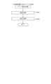
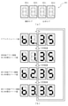
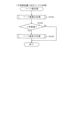
ここで、図4を参照して、第3図柄表示装置81の表示内容について説明する。図4は、第3図柄表示装置81の表示画面を説明するための図面であり、図4(a)は、表示画面の領域区分設定と有効ライン設定とを模式的に示した図であり、図4(b)は、実際の表示画面を例示した図である。
Here, the display contents of the third
第3図柄は、「0」から「9」の数字を付した10種類の主図柄により構成されている。各主図柄は、木箱よりなる後方図柄の上に「0」から「9」の数字を付して構成され、そのうち奇数番号(1,3,5,7,9)を付した主図柄は、木箱の前面ほぼ一杯に大きな数字が付加されている。これに対し、偶数番号(0,2,4,6,8)を付した主図柄は、木箱の前面ほぼ一杯にかんな、風呂敷、ヘルメット等のキャラクタを模した付属図柄が付加されており、付属図柄の右下側に偶数の数字が緑色で小さく、且つ、付属図柄の前側に表示されるように付加されている。 The third symbol is composed of 10 types of main symbols with numbers from "0" to "9". Each main symbol is composed of a rear symbol consisting of a wooden box with numbers from "0" to "9", and the main symbol with an odd number (1,3,5,7,9) is , A large number is added to almost the front of the wooden box. On the other hand, the main design with even numbers (0, 2, 4, 6, 8) has an attached design that imitates a character such as a furoshiki, a helmet, etc., which is almost full on the front of the wooden box. An even number is added to the lower right side of the attached symbol so that it is small in green and displayed on the front side of the attached symbol.
また、本実施形態のパチンコ機10においては、後述する主制御装置110(図5参照)による抽選結果が大当たりであった場合に、同一の主図柄が有効ラインL1上に揃う変動表示(変動演出)が行われ、その変動表示が終わった後に大当たりが発生するよう構成されている。大当たり終了後に高確率状態(確変状態)に移行する場合は、奇数番号が付加された主図柄(「高確率図柄」に相当)が有効ラインL1上に揃う変動表示が行われる。一方、大当たり終了後に低確率状態に移行する場合は、偶数番号が付加された主図柄(「低確率図柄」に相当)が有効ラインL1上に揃う変動表示が行われる。
Further, in the
図4(a)に示すように、第3図柄表示装置81の表示画面は、大きくは上下に2分割され、下側の2/3が第3図柄(主図柄)を変動表示(変動演出)する主表示領域Dm、それ以外の上側の1/3が予告演出、キャラクタなどを表示する副表示領域Dsとなっている。また、第3図柄表示装置81の表示画面における下底辺側中央部分には、保留球数を表示する保留球数表示領域Dbが設けられている。
As shown in FIG. 4A, the display screen of the third
主表示領域Dmは、左・中・右の3つの表示領域Dm1~Dm3に区分けされており、その表示領域Dm1に図柄列Z1が表示され、表示領域Dm2に図柄列Z2が表示され、表示領域Dm3に図柄列Z3が表示される。 The main display area Dm is divided into three display areas Dm1 to Dm3 on the left, middle, and right. The symbol column Z1 is displayed in the display area Dm1, the symbol column Z2 is displayed in the display area Dm2, and the display area is displayed. The symbol string Z3 is displayed in Dm3.
各図柄列Z1~Z3には、上述した第3図柄が規定の順序で表示される。即ち、各図柄列Z1~Z3には、数字の昇順または降順に主図柄が配列され、各図柄列Z1~Z3毎に周期性をもって上から下へとスクロールして変動表示が行われる。特に、左図柄列Z1においては主図柄の数字が降順に現れるように配列され、中図柄列Z2及び右図柄列Z3においては主図柄の数字が昇順に現れるように配列されている。 In each of the symbol rows Z1 to Z3, the above-mentioned third symbols are displayed in a specified order. That is, the main symbols are arranged in the ascending or descending order of the numbers in each of the symbol rows Z1 to Z3, and the variable display is performed by scrolling from top to bottom with periodicity for each of the symbol rows Z1 to Z3. In particular, in the left symbol row Z1, the numbers of the main symbols are arranged so as to appear in descending order, and in the middle symbol row Z2 and the right symbol row Z3, the numbers of the main symbols are arranged so as to appear in ascending order.
また、主表示領域Dmには、各図柄列Z1~Z3毎に上・中・下の3段に第3図柄が表示される。この主表示領域Dmの中段部が有効ラインL1として設定されており、毎回の変動演出に際して、左図柄列Z1→右図柄列Z3→中図柄列Z2の順に、有効ラインL1上に第3図柄が停止表示される。その第3図柄の停止時に有効ラインL1上に大当たり図柄の組合せ(同一の主図柄の組合せ)で揃えば、大当たりとして大当たり動画が表示される。 Further, in the main display area Dm, the third symbol is displayed in the upper, middle, and lower three rows for each symbol row Z1 to Z3. The middle part of this main display area Dm is set as the effective line L1, and the third symbol is placed on the effective line L1 in the order of the left symbol row Z1 → the right symbol row Z3 → the middle symbol row Z2 in each variation effect. Stop is displayed. If the combination of jackpot symbols (combination of the same main symbol) is aligned on the effective line L1 when the third symbol is stopped, the jackpot moving image is displayed as a jackpot.
副表示領域Dsは、主表示領域Dmよりも上方に横長に設けられており、更に左右方向に3つの小領域Ds1~Ds3に等区分されている。小領域Ds1~Ds3は、それぞれ、キャラクタや予告演出画像を表示する領域である。小領域Ds1~Ds3のそれぞれに表示される画像によって、主表示領域Dmにて行われる変動表示の結果として大当たりとなる期待感を遊技者に与えている。保留球数表示領域Dbは、第1始動口64a及び第2始動口64bに入球された球のうち変動表示(変動演出)が未実行である球(保留球)の数である保留球数を表示する領域である。
The sub-display area Ds is provided horizontally above the main display area Dm, and is further divided into three small areas Ds1 to Ds3 in the left-right direction. The small areas Ds1 to Ds3 are areas for displaying characters and preview effect images, respectively. The images displayed in each of the small areas Ds1 to Ds3 give the player a feeling of expectation that will be a big hit as a result of the variable display performed in the main display area Dm. The reserved ball number display area Db is the number of reserved balls, which is the number of balls (holding balls) whose fluctuation display (variation effect) has not been executed among the balls entered in the
実際の表示画面では、図4(b)に示すように、主表示領域Dmに第3図柄の主図柄が合計9個表示される。副表示領域Dsにおいては、左の小領域Ds1、右の小領域Ds3に動画が表示され、通常より大当たりへ遷移し易い状態であることが遊技者に示唆される。中央の小領域Ds2では、通常は、所定のキャラクタ(本実施形態ではハチマキを付けた少年)が所定動作をし、時として所定動作とは別の特別な動作をしたり、通常は黒色の少年の髪の毛の色や、通常は白色のハチマキの色が変化したり、別のキャラクタが現出するなどして予告演出が行われる。 On the actual display screen, as shown in FIG. 4B, a total of nine main symbols of the third symbol are displayed in the main display area Dm. In the sub-display area Ds, moving images are displayed in the small area Ds1 on the left and the small area Ds3 on the right, suggesting to the player that the transition to the jackpot is easier than usual. In the central small area Ds2, a predetermined character (a boy with a headband in this embodiment) usually performs a predetermined motion, and sometimes performs a special motion different from the predetermined motion, or is usually a black boy. The color of the hair and the color of the normally white headband will change, and another character will appear to give a notice.
一方、第3図柄表示装置81(第1図柄表示装置37)にて変動演出(変動表示)が行われている間に球が第1始動口64a又は第2始動口64bへ入球した場合、その入球回数は最大4回まで保留される。その保留球数は第1図柄表示装置37により示されると共に、保留球数表示領域Dbにおいても示される。保留球数表示領域Dbには、保留球数1球につき1つの保留球数図柄(「●」図柄)が表示され、その保留球数図柄の表示数に応じて、保留球数が表示される。
On the other hand, when the ball enters the
即ち、保留球数表示領域Dbに1つの保留球数図柄が表示されている場合は、保留球数が1球であることを示し、4つの保留球数図柄が表示されている場合は、保留球数が4球であることを示す。また、保留球数表示領域Dbに保留球数図柄が表示されていない場合は、保留球数が0球である、即ち、保留球が存在しないことを示す。 That is, when one reserved ball number symbol is displayed in the reserved ball number display area Db, it indicates that the reserved ball number is one ball, and when four reserved ball number symbols are displayed, it is reserved. Indicates that the number of balls is four. When the reserved ball number symbol is not displayed in the reserved ball number display area Db, it indicates that the reserved ball number is 0, that is, there is no reserved ball.
なお、本実施形態においては、第1始動口64a及び第2始動口64bへの入球は、合計で最大4回まで保留されるように構成したが、最大保留球数は合計で4回に限定されるものでなく、3回以下、又は、5回以上の回数(例えば、8回)に設定しても良い。また、保留球数表示領域Dbにおける保留球数図柄の表示に代えて、保留球数を第3図柄表示装置81の一部に数字で、或いは、4つに区画された領域を保留球数分だけ異なる態様(例えば、色や点灯パターン)にして表示するようにしても良い。また、第1図柄表示装置37により保留球数が示されるので、第3図柄表示装置81に保留球数を表示させないものとしてもよい。更に、可変表示装置ユニット80に、保留球数を示す保留ランプを最大保留数分の4つ設け、点灯状態の保留ランプの数に応じて、保留球数を表示するものとしてもよい。
In the present embodiment, the balls entering the
図2に戻って、説明を続ける。第2図柄表示装置83は、球がスルーゲート67を通過する毎に表示図柄(第2図柄)としての「○」の図柄と「×」の図柄とを交互に点灯させる変動表示を行うものである。パチンコ機10は、第2図柄表示装置83における変動表示が所定図柄(本実施形態においては「○」の図柄)で停止した場合に、第2始動口64bに設けられた電動役物が所定時間だけ作動状態となる(開放される)よう構成されている。
Returning to FIG. 2, the explanation will be continued. The second
球のスルーゲート67の通過回数は最大4回まで保留され、その保留球数が上述した第1図柄表示装置37により表示されると共に第2図柄保留ランプ84においても点灯表示される。第2図柄保留ランプ84は、最大保留数分の4つ設けられ、第3図柄表示装置81の下方に左右対称に配設されている。そして、第2図柄保留ランプ84の点灯された数により、保留数を表示する。
The number of times the ball has passed through the through gate 67 is held up to four times, and the number of held balls is displayed by the first
なお、第2図柄の変動表示は、本実施形態のように、第2図柄表示装置83において複数のランプの点灯と非点灯を切り換えることにより行うものの他、第1図柄表示装置37又は第3図柄表示装置81の一部を使用して行うようにしても良い。同様に、第2図柄保留ランプ84の点灯に代えて、第2図柄の変動表示を第3図柄表示装置81の一部で行うようにしても良い。また、スルーゲート67の通過は、第2始動口64bと同様に、最大保留球数は4回に限定されるものでなく、3回以下、又は、5回以上の回数(例えば、8回)に設定しても良い。また、第1図柄表示装置37により保留球数が示されるので、第2図柄保留ランプ84により点灯表示を行わないものとしても良い。
The variation display of the second symbol is performed by switching the lighting and non-lighting of a plurality of lamps in the second
可変表示装置ユニット80の下方には第1始動口64aが配設され、その第1始動口64aの下方には第2始動口64bが配設されている。第1始動口64aは、上向きに球が入球可能な開口部が設けられている。第1始動口64aの開口部は常に開放されており、球が入球可能な状態となっている。第1始動口64aへ球が入球すると遊技盤13の裏面側に設けられる第1始動口スイッチ208a(図6参照)がオンとなり、その第1始動口スイッチ208aのオンに起因して主制御装置110(図5参照)で大当たりの抽選がなされ、その抽選結果に応じた表示が第1図柄表示装置37のLED37aで示されると共に、第3図柄表示装置81にて第3図柄の変動演出が実行される。第1始動口64aは、球が入球すると3個の球が賞球として払い出される入賞口の1つにもなっている。
A
一方、第2始動口64bには、その第2始動口64bへ球が入球する開口部を覆う2枚の羽根を有する電動役物が設けられている。電動役物は、2枚の羽根を開閉することによって、第2始動口64bを開放状態(拡大状態)または閉鎖状態(縮小状態)とする。通常時において、第2始動口64bは、電動役物の羽根が閉じた(羽根が上方に起立した)閉鎖状態となっており、球が第2始動口64bへ入球できない、または、入球しづらい状態となっている。
On the other hand, the
そして、第2図柄表示装置83における変動表示が「○」の図柄で停止すると、第2始動口64bの電動役物が所定時間だけ作動される。電動役物が作動されている間、電動役物の羽根が上方に起立した状態から。略V字形(逆ハの字形)に可動した状態となり、第2始動口64bが開放状態となる。第2始動口64bが開放状態になると、球が第2始動口64bへ入球できる状態、または、閉鎖状態に比して球が入球しやすい状態となる。つまり、第2図柄表示装置83における変動表示の結果として「○」の図柄で停止して当たりとなり、第2始動口64bが開放状態となった場合に、第2始動口64bへ球が入球して大当たり抽選が多く行える状態とすることができる。
Then, when the fluctuation display in the second
第2始動口64bへ球が入球すると遊技盤13の裏面側に設けられる第2始動口スイッチ208b(図示せず)がオンとなり、その第2始動口スイッチ208bのオンに起因して主制御装置110(図5参照)で大当たりの抽選がなされ、その抽選結果に応じた表示が第1図柄表示装置37のLED37aで示されると共に、第3図柄表示装置81にて第3図柄の変動演出が実行される。第2始動口64bは、球が入球すると2個の球が賞球として払い出される入賞口の1つにもなっている。
When the ball enters the
第2始動口64bの下方には可変入賞装置65が配設されており、その略中央部分に横長矩形状の大入賞口(大開放口、特定入賞口とも言う)65aが設けられている。パチンコ機10においては、主制御装置110での抽選が大当たりとなると、所定時間(変動時間)が経過した後に、大当たりの停止図柄となるよう第1図柄表示装置37のLED37aを点灯させると共に、その大当たりに対応した停止図柄を第3図柄表示装置81に表示させて、大当たりの発生が示される。その後、球が入賞し易い特別遊技状態(大当たり)に遊技状態が遷移する。この特別遊技状態として、通常時には閉鎖されている大入賞口65aが、所定時間(例えば、30秒経過するまで、或いは、球が10個入賞するまで)開放される。
A variable winning
この大入賞口65aは、所定時間が経過すると閉鎖され、その閉鎖後、再度、その大入賞口65aが所定時間開放される。この大入賞口65aの開閉動作は、最高で例えば15回(15ラウンド)繰り返し可能にされている。
The
可変入賞装置65は、具体的には、大入賞口65aを覆う横長矩形状の開閉板と、その開閉板の下辺を軸として前方側に開閉駆動するための大入賞口ソレノイド(図示せず)とを備えている。大入賞口65aは、通常時は、球が入賞できないか又は入賞し難い閉状態になっている。大当たりの際には大入賞口ソレノイドを駆動して開閉板を前面下側に傾倒し、球が大入賞口65aに入賞しやすい開状態を一時的に形成し、その開状態と通常時の閉状態との状態を交互に繰り返すように作動する。
Specifically, the variable winning
大入賞口65aへ球が入球すると遊技盤13の裏面側に設けられる大入賞口スイッチ208e(図6参照)がオンとなり、その大入賞口スイッチ208eがオンとなった回数をカウントすることで、大入賞口65aに入賞した球の数がカウントされ、大入賞口65aの閉鎖条件が判断される。また、大入賞口スイッチ208eのオンに起因して、12個の球が賞球として払い出される。そして、大当たりにより大入賞口65aの開状態と閉状態とが繰り返されることによって、多くの球が大入賞口65aに入賞し易い状態となり、遊技者には、遊技上の価値(遊技価値)の付与として通常時より多量の賞球の払い出しが行われる。この状態が、遊技者にとって有利な特別遊技状態の一形態である。
When a ball enters the large winning
なお、上記した形態に特別遊技状態は限定されるものではない。特定入賞口と、その特定入賞口とは別に開閉される大開放口を遊技領域に設け、第1図柄表示装置37において大当たりに対応したLED37aが点灯した場合に、特定入賞口が所定時間開放され、その特定入賞口の開放中に、球が特定入賞口内へ入賞することを契機として大開放口が所定時間、所定回数開放される遊技状態を特別遊技状態として形成するようにしても良い。
The special gaming state is not limited to the above-mentioned form. A specific winning opening and a large opening that is opened and closed separately from the specific winning opening are provided in the game area, and when the
可変表示装置ユニット80の左方および右方には、それぞれ、スルーゲート67が設けられている。スルーゲート67には、球が通過するための貫通孔(図示せず)が上下方向に設けられている。遊技領域に発射された球が、スルーゲート67を通過すると、貫通孔に設けられたスルーゲートスイッチ(図示せず)がオンとなり、そのオンに起因して主制御装置110で、第2図柄(普通図柄ともいう)の当たり抽選が行われる。
Through gates 67 are provided on the left side and the right side of the variable
スルーゲート67を通過した球に対して行われた第2図柄(普通図柄)の抽選の結果、当たりと判定された場合には、第2図柄表示装置83における第2図柄の変動表示を経て「○」の図柄が停止表示された後に、第2始動口64bの電動役物が作動する。これにより、第2始動口64bへ球が入球することを困難としている電動役物の羽根が略垂直に起立した状態から略V字形(逆ハの字形)に可動して、所定時間だけ球が第2始動口64bへ入球できる状態、または、閉鎖状態に比して球が入球しやすい状態となる。
As a result of the lottery of the second symbol (ordinary symbol) performed on the ball passing through the through gate 67, if it is determined to be a hit, the variation display of the second symbol on the second
遊技盤13の下側における左右の隅部には、証紙や識別ラベル等を貼着するための貼着スペースK1,K2が設けられ、貼着スペースK1に貼られた証紙等は、前面枠14の小窓35(図1参照)を通じて視認することができる。
Attachment spaces K1 and K2 for attaching certificate stamps, identification labels, etc. are provided in the left and right corners on the lower side of the
更に、遊技盤13には、アウト口66が設けられている。いずれの入賞口63a,63b,64a,64b,65aにも入球しなかった球はアウト口66を通って図示しない球排出路へと案内される。また、入賞口63a,63b,64a,64b,65aに入球した球は、各入賞口毎に設けられた球の入球を検出するためのスイッチを通過後、その球排出路へと案内される。球排出路へ案内された球は、その案内された球を検出するためのアウトスイッチ208f(図6参照)を通過後、パチンコ機10が設置された島設備(図示せず)に排出される。
Further, the
ここで、パチンコ機10の遊技領域へ発射された球は、必ずいずれかの入賞口63a,63b,64a,64b,65a又はアウト口66に入る。よって、これらの入賞口63a,63b,64a,64b,65a及びアウト口66に入った球は、球排出路へ案内され、必ずアウトスイッチ208fを通過することになる。よって、アウトスイッチ208fにより検出された球の数をカウントすることにより、遊技領域に発射された球の数(遊技に使用された球の数)を把握できる。また、アウトスイッチ208fは、実際に遊技領域を通過して、いずれかの入賞口63a,63b,64a,64b,65a又はアウト口66に入った球を検出する。つまり、遊技領域に発射されたが、遊技領域のどこかにひっかかり、結果として遊技に使用されなかった球は検出されない。よって、アウトスイッチ208fにより検出された球の数をカウントすることにより、このような結果として遊技に使用されなかった球が遊技領域に発射された球として計数されることを抑制できる。
Here, the ball launched into the gaming area of the
遊技盤13には、球の落下方向を適宜分散、調整等するために多数の釘が植設されていると共に、風車等の各種部材(役物)が配設されている。
A large number of nails are planted on the
図3に示すように、パチンコ機10の背面側には、制御基板ユニット90,91と、裏パックユニット94とが主に備えられている。制御基板ユニット90は、主基板(主制御装置110)と音声ランプ制御基板(音声ランプ制御装置113)と表示制御基板(表示制御装置114)とが搭載されてユニット化されている。制御基板ユニット91は、払出制御基板(払出制御装置111)と発射制御基板(発射制御装置112)と電源基板(電源装置115)とカードユニット接続基板116とが搭載されてユニット化されている。
As shown in FIG. 3, the
裏パックユニット94は、保護カバー部を形成する裏パック92と払出ユニット93とがユニット化されている。また、各制御基板には、各制御を司る1チップマイコンとしてのMPU、各種機器との連絡をとるポート、各種抽選の際に用いられる乱数発生器、時間計数や同期を図る場合などに使用されるクロックパルス発生回路等が、必要に応じて搭載されている。
In the
また、主基板には、遊技機の役物比率等の性能を検査する検査装置300が接続可能な検査端子207a(図5参照)が設けられている。検査端子207aは、通常は裏パックユニット94の裏パック92に覆われており、裏パック92を開放することによって現れる。ただし、裏パック92に検査端子207a用の開口部を設け、その開口部から検査端子207aが露出されるように構成してもよい。検査装置300に接続されたケーブルのコネクタが検査端子207aへ挿入されると、その検査装置300によってパチンコ機10の役物比率といった遊技性能が検査できるようになっている。
Further, the main board is provided with an
なお、主制御装置110、音声ランプ制御装置113及び表示制御装置114、払出制御装置111及び発射制御装置112、電源装置115、カードユニット接続基板116は、それぞれ基板ボックス100~104に収納されている。基板ボックス100~104は、ボックスベースと該ボックスベースの開口部を覆うボックスカバーとを備えており、そのボックスベースとボックスカバーとが互いに連結されて、各制御装置や各基板が収納される。
The
また、基板ボックス100(主制御装置110)及び基板ボックス102(払出制御装置111及び発射制御装置112)は、ボックスベースとボックスカバーとを封印ユニット(図示せず)によって開封不能に連結(かしめ構造による連結)している。また、ボックスベースとボックスカバーとの連結部には、ボックスベースとボックスカバーとに亘って封印シール(図示せず)が貼着されている。この封印シールは、脆性な素材で構成されており、基板ボックス100,102を開封するために封印シールを剥がそうとしたり、基板ボックス100,102を無理に開封しようとすると、ボックスベース側とボックスカバー側とに切断される。よって、封印ユニット又は封印シールを確認することで、基板ボックス100,102が開封されたかどうかを知ることができる。
Further, in the board box 100 (main control device 110) and the board box 102 (
払出ユニット93は、裏パックユニット94の最上部に位置して上方に開口したタンク130と、タンク130の下方に連結され下流側に向けて緩やかに傾斜するタンクレール131と、タンクレール131の下流側に縦向きに連結されるケースレール132と、ケースレール132の最下流部に設けられ、払出モータ216(図5参照)の所定の電気的構成により球の払出を行う払出装置133とを備えている。タンク130には、遊技ホールの島設備から供給される球が逐次補給され、払出装置133により必要個数の球の払い出しが適宜行われる。タンクレール131には、当該タンクレール131に振動を付加するためのバイブレータ134が取り付けられている。
The
また、払出制御装置111には状態復帰スイッチ120が設けられ、発射制御装置112には可変抵抗器の操作つまみ121が設けられ、電源装置115にはRAM消去スイッチ122が設けられている。状態復帰スイッチ120は、例えば、払出モータ216(図5参照)部の球詰まり等、払出エラーの発生時に球詰まりを解消(正常状態への復帰)するために操作される。操作つまみ121は、発射ソレノイドの発射力を調整するために操作される。RAM消去スイッチ122は、パチンコ機10を初期状態に戻したい場合に電源投入時に操作される。
Further, the
次に、図5を参照して、本パチンコ機10の電気的構成について説明する。図5は、パチンコ機10の電気的構成を示すブロック図である。
Next, the electrical configuration of the
主制御装置110には、演算装置である1チップマイコンとしてのMPU201が搭載されている。MPU201には、該MPU201により実行される各種の制御プログラムや固定値データを記憶したROM202と、そのROM202内に記憶される制御プログラムの実行に際して各種のデータ等を一時的に記憶するためのメモリであるRAM203と、そのほか、割込回路やタイマ回路、データ送受信回路などの各種回路が内蔵されている。
The
主制御装置110では、大当たり抽選や第1図柄表示装置37及び第3図柄表示装置81における変動表示(変動演出)の設定、第2図柄表示装置83における表示結果の抽選といったパチンコ機10の主要な処理を実行する。このパチンコ機10の主要な処理は、MPU201により実行され、RAM203には、これらの処理を制御するための各種カウンタを格納するカウンタ用バッファが設けられている。
In the
MPU201のNMI端子(ノンマスカブル割込端子)には、停電等の発生による電源遮断時に、停電監視回路252からの停電信号SG1が入力されるように構成されており、その停電信号SG1がMPU201へ入力されると、停電時処理としてのNMI割込処理(図15参照)が即座に実行される。
The NMI terminal (non-maskable interrupt terminal) of the
MPU201には、アドレスバス及びデータバスで構成されるバスライン204を介して入出力ポート205が接続されている。入出力ポート205には、払出制御装置111、音声ランプ制御装置113、第1図柄表示装置37、第2図柄表示装置83、第2図柄保留ランプ84、大入賞口65aの開閉板の下辺を軸として前方側に開閉駆動するための大入賞口ソレノイドや電動役物を駆動するためのソレノイドなどからなるソレノイド209が接続され、MPU201は、入出力ポート205を介してこれらに対し各種コマンドや制御信号を送信する。
The input /
なお、払出制御装置111や音声ランプ制御装置113などのサブ制御装置に対して動作を指示するために、主制御装置110から該サブ制御装置へ各種のコマンドがデータ送受信回路によって送信されるが、かかるコマンドは、主制御装置110からサブ制御装置へ一方向にのみ送信される。
In order to instruct the operation to the sub control device such as the
また、入出力ポート205には、各入賞口に入球した球や、各入賞口及びアウト口を通って球排出路へ案内された球を検出するための各種スイッチを含むスイッチ群並びにセンサ群などからなる各種スイッチ208や、電源装置115に設けられた後述のRAM消去スイッチ回路253が接続され、MPU201は各種スイッチ208から出力される信号や、RAM消去スイッチ回路253より出力されるRAM消去信号SG2に基づいて各種処理を実行する。
Further, the input /
主制御装置110には、パチンコ機10における役物比率に関する情報を管理する役物比率管理チップが設けられている。役物比率管理チップ207は、バス206を介してMPU201と接続され、MPU201より役物比率の管理に必要な情報を受け取り、受け取った情報を加工して記憶することにより、パチンコ機10の役物比率に関する情報を管理するマイクロチップ(集積回路)である。
The
役物比率管理チップ207には、検査端子207aが接続されている。検査端子207aは、遊技機の役物比率等の性能を検査する外部の検査装置300と接続可能に構成されており、検査端子207aにケーブル及びコネクタを介して検査装置300が接続されると、役物比率管理チップ207にて管理される役物比率に関する情報や、その他検査に関する情報が、検査装置300へ送信される。検査装置300は、検査端子207aを介して受け取った役物比率に関する情報に基づき、パチンコ機10の役物比率が正常な範囲のものであるか否かを判断することができる。
An
ここで、図6を参照して、主制御装置110の詳細な構成について説明する。図6は、主制御装置110の電気的構成を示すブロック図である。
Here, a detailed configuration of the
入出力ポート205には、上述した通り、入力側としてRAM消去スイッチ回路253が接続され、出力側としてソレノイド209、第1図柄表示装置37、第2図柄表示装置38、第2図柄保留ランプ84、払出制御装置111、音声ランプ制御装置113が接続される他、入力側として接続される各種スイッチ208として、第1始動口64aに入賞した球を検出するための第1始動口スイッチ208a、第2始動口64bに入賞した球を検出するための第2始動口スイッチ208b、第1普通入賞口63aに入賞した球を検出するための第1普通入賞口スイッチ208c、第2普通入賞口63bに入賞した球を検出するための第2普通入賞口スイッチ208d、大入賞口65aに入賞した球を検出するための大入賞口スイッチ208e、各入賞口63a,63b,64a,64b,65aに入賞した球及びアウト口66に入球した球であって球排出路へと案内された球を検出するアウトスイッチ208f、及び、内枠12及び前面枠14の少なくともいずれかが施錠され開放されたことを検出する扉開放スイッチ208gが接続されている。
As described above, the RAM erase
入出力ポート205は、第1始動口スイッチ208aの出力が入力される始1ポート205aと、第2始動口スイッチ208bの出力が入力される始2ポート205bと、第1普通入賞口スイッチ208cの出力が入力される普1ポート205cと、第2普通入賞口スイッチ208dの出力が入力される普2ポート205dと、大入賞口スイッチ208eの出力が入力される大入賞口ポート205eと、アウトスイッチ208fの出力が接続されるアウトポート205fと、扉開放スイッチ208gの出力が接続される扉開放ポート205gとが設けられている。
The input /
MPU201は、2ミリ秒毎に実行されるタイマ割込処理(図10参照)の中で、各種スイッチの状態を確認するスイッチ読み込み処理(図11参照)を実行する。そのスイッチ読み込み処理の中で、MPU201は、始1ポート205a,始2ポート205b,普1ポート205c,普2ポート205d,大入賞口ポート205e及びアウトポート205fを参照し、入賞のあった入賞口の有無及び球排出路へ案内された球の有無を判断して、0.5秒の間に各入賞口の入賞した球の数、及び、球排出路へ案内された球の数(即ち、遊技領域へ発射された球の数)をカウントする。そして、そのカウントした各球の数と、その時の遊技状態(大当たり中であるか、内枠12又は前面枠14(所謂、扉)が開放中であるか、エラー状態にあるか等)とを0.5秒毎に役物比率管理チップ207へ設定する。役物比率管理チップ207は、この各球の数に基づいて役物比率を算出し、管理する。なお、内枠12又は前面枠14が開放中であるか否かは、MPU201が扉開放ポート205gを参照し、扉開放スイッチ208gの出力を確認することにより判断される。
The
MPU201のROM202は、大当たり乱数テーブル202a、大当たり種別テーブル202b、停止パターンテーブル202c、変動パターンテーブル202d、賞球数テーブル202e、トリガ情報データ202fを少なくとも格納している。RAM203に格納された各種カウンタと、ROM202に格納された各種テーブル202a~203dとによって、主制御装置110は、パチンコ機10の主要な処理を実行する。また、賞球数テーブル202e及びトリガ情報データ202fは、役物比率管理チップ207において役物比率を管理するために用いられるデータであり、主制御装置110の電源が投入された場合に役物比率管理チップ207に送信される。
The
ここで、図7を参照して、主制御装置110のRAM203内に設けられるカウンタ等について説明する。これらのカウンタ等は、大当たり抽選や第1図柄表示装置37及び第3図柄表示装置81の変動表示(変動演出)の設定、第2図柄表示装置83の表示結果の抽選などを行うために、主制御装置110のMPU201で使用される。また、各種カウンタの説明の中で、図8を参照して、主制御装置110のROM202に格納された各種テーブル202a~202dについても説明する。
Here, with reference to FIG. 7, a counter or the like provided in the
大当たり抽選や第1図柄表示装置37及び第3図柄表示装置81の変動表示(変動演出)の設定には、大当たりの抽選に使用する第1当たり乱数カウンタC1と、大当たり図柄の選択に使用する第1当たり種別カウンタC2と、停止パターン選択カウンタC3と、変動パターン選択に使用する変動種別カウンタCS1と、第1当たり乱数カウンタC1の初期値設定に使用する第1初期値乱数カウンタCINI1とが用いられる。
For the setting of the jackpot lottery and the variable display (variable effect) of the first
また、第2図柄表示装置83の抽選には、第2当たり乱数カウンタC4が用いられ、第2当たり乱数カウンタC4の初期値設定には第2初期値乱数カウンタCINI2が用いられる。これら各カウンタは、更新の都度前回値に1が加算され、最大値に達した後0に戻るループカウンタとなっている。
Further, the second random number counter C4 is used for the lottery of the second
各カウンタは、例えば、タイマ割込処理(図10参照)の実行間隔である2ミリ秒間隔で更新され、また、一部のカウンタは、メイン処理(図17参照)の中で不定期に更新されて、その更新値がRAM203の所定領域に設定されたカウンタ用バッファに適宜格納される。詳細については後述するが、RAM203には、4つの保留エリア(保留第1~第4エリア)からなる保留球格納エリア203bが設けられており、これらの各エリアには、第1始動口64a及び第2始動口64bへの入球タイミングに合わせて、第1当たり乱数カウンタC1、第1当たり種別カウンタC2、停止パターン選択カウンタC3及び変動種別カウンタCS1の各値がそれぞれ格納される。
Each counter is updated, for example, at intervals of 2 milliseconds, which is the execution interval of the timer interrupt process (see FIG. 10), and some counters are updated irregularly in the main process (see FIG. 17). Then, the updated value is appropriately stored in the counter buffer set in the predetermined area of the
各カウンタについて詳しく説明する。第1当たり乱数カウンタC1は、所定の範囲(例えば、0~899)内で順に1ずつ加算され、最大値(例えば、0~899の値を取り得るカウンタの場合は899)に達した後0に戻る構成となっている。また、第1当たり乱数カウンタC1の更新が1周した場合、その時点の第1初期値乱数カウンタCINI1の値が当該第1当たり乱数カウンタC1の初期値として読み込まれ、その初期値から第1当たり乱数カウンタC1の更新が行われる。 Each counter will be described in detail. The first random number counter C1 is incremented by 1 in order within a predetermined range (for example, 0 to 899) and reaches the maximum value (for example, 899 in the case of a counter that can take a value of 0 to 899) and then 0. It is configured to return to. Further, when the first per random number counter C1 is updated once, the value of the first initial value random number counter CINI1 at that time is read as the initial value of the first per random number counter C1, and the first hit is performed from the initial value. The random number counter C1 is updated.
第1初期値乱数カウンタCINI1は、第1当たり乱数カウンタC1と同一範囲で更新されるループカウンタとして構成される。即ち、例えば、第1当たり乱数カウンタC1が0~899の値を取り得るループカウンタである場合には、第1初期値乱数カウンタCINI1もまた、0~899の範囲のループカウンタである。この第1初期値乱数カウンタCINI1は、タイマ割込処理(図10参照)の実行毎に1回更新されると共に、メイン処理(図17参照)の残余時間内で繰り返し更新される。 The first initial value random number counter CINI1 is configured as a loop counter updated in the same range as the first random number counter C1. That is, for example, when the first random number counter C1 is a loop counter that can take a value of 0 to 899, the first initial value random number counter CINI1 is also a loop counter in the range of 0 to 899. The first initial value random number counter CINI1 is updated once for each execution of the timer interrupt process (see FIG. 10), and is repeatedly updated within the remaining time of the main process (see FIG. 17).
第1当たり乱数カウンタC1の値は、例えば定期的に(本実施形態ではタイマ割込処理毎に1回)更新され、球が第1始動口64a及び第2始動口64bのいずれかに入賞(始動入賞)したタイミングで、その時の第1当たり乱数カウンタC1の値がRAM203の保留球格納エリア203bに設けられた保留第1~第4エリアのいずれかの保留エリアの第1当たり乱数カウンタ格納エリア203b1に格納される。大当たりとなる乱数の値は、主制御装置のROM202に格納される大当たり乱数テーブル202aによって設定されており、保留エリアに格納されている第1当たり乱数カウンタC1の値が、大当たり乱数テーブル202aによって設定された大当たりとなる乱数の値と一致する場合に、大当たりと判定される。
The value of the random number counter C1 per first is updated periodically (once for each timer interruption process in this embodiment), and the ball wins a prize in either the
ここで、図8(a)を参照して、大当たり乱数テーブル202aの詳細について説明する。図8(a)は、大当たり乱数テーブル202aの一例を模式的に示した模式図である。大当たり乱数テーブル202aは、パチンコ機10の遊技状態が低確率状態(確変中ではない期間)の場合に使用される低確率状態用と、パチンコ機10の遊技状態が、低確率状態より大当たりとなる確率の高い高確率状態(確変中)の場合に使用される高確率状態用との2種類に分けられる。そして、低確率状態用と高確率状態用とのそれぞれに含まれる大当たりとなる乱数の数が異なって設定されている。このように、大当たりとなる乱数の数を異ならせることにより、低確率状態と高確率状態とで、大当たりとなる確率が変更される。
Here, the details of the jackpot random number table 202a will be described with reference to FIG. 8A. FIG. 8A is a schematic diagram schematically showing an example of the jackpot random number table 202a. The jackpot random number table 202a is for a low-probability state used when the gaming state of the
本実施形態のパチンコ機10における第1当たり乱数カウンタC1は、0~899の範囲の2バイトのループカウンタとして構成されている。この第1当たり乱数カウンタC1では、低確率状態の場合に大当たりとなる乱数の値(大当たり乱数値)の数は3で、その値「7,307,582」が、大当たり乱数テーブル202aに格納されている。
The first random number counter C1 in the
一方で、高確率状態の場合に大当たりとなる乱数の値(大当たり乱数値)の数は30で、その値「28,58,85,122,144,178,213,238,276,298,322,354,390,420,448,486,506,534,567,596,618,656,681,716,750,772,809,836,866,892」が、大当たり乱数テーブル202aに格納されている。 On the other hand, the number of random numbers (big hit random numbers) that are big hits in the high probability state is 30, and the values are "28,58,85,122,144,178,213,238,276,298,322". , 354,390,420,448,486,506,534,567,596,618,656,681,716,750,772,809,833,866,892 "is stored in the jackpot random number table 202a. ..
なお、本実施形態では、大当たり乱数テーブル202aに格納されている低確率状態用の大当たり乱数値と、高確率状態用の大当たり乱数値とで、重複した値とならないように、それぞれ大当たり乱数値を設定している。ここで、パチンコ機10の状況にかかわらず大当たり乱数値となる値が存在すれば、その値が外部から予測されやすくなるので、不正に大当たりを引き当てられる可能性が高くなる恐れがある。これに対して、本実施形態のように、状況に応じて(即ち、パチンコ機10が高確率状態か低確率状態か、に応じて)、大当たりとなる乱数の値を変えることで、大当たりとなる乱数の値が予測され難くすることができるので、不正に対する抑制を図ることができる。
In the present embodiment, the jackpot random number value for the low probability state and the jackpot random number value for the high probability state stored in the jackpot random number table 202a are set to the jackpot random number values so as not to be duplicated. It is set. Here, if there is a value that becomes a jackpot random number regardless of the situation of the
図7に戻って、説明を続ける。第1当たり種別カウンタC2は、大当たりとなった場合の大当たり種別を決定するものであり、所定の範囲(例えば、0~99)内で順に1ずつ加算され、最大値(例えば、0~99の値を取り得るカウンタの場合は99)に達した後に0に戻る構成となっている。第1当たり種別カウンタC2の値は、例えば、定期的に(本実施形態ではタイマ割込処理毎に1回)更新され、球が第1始動口64a及び第2始動口64bのいずれかの始動口に入賞(始動入賞)したタイミングで、その時の第1当たり種別カウンタC2の値が、RAM203の保留球格納エリア203bに設けられた保留第1~第4エリアのうち第1当たり乱数カウンタC1が格納される保留エリアと同じ保留エリアの第1当たり種別カウンタ格納エリア203b2に格納される。
Returning to FIG. 7, the explanation will be continued. The first hit type counter C2 determines the jackpot type in the case of a jackpot, and is incremented by 1 in order within a predetermined range (for example, 0 to 99), and the maximum value (for example, 0 to 99) is added. In the case of a counter that can take a value, it is configured to return to 0 after reaching 99). The value of the first type counter C2 is updated periodically (once for each timer interruption process in this embodiment), and the ball is started by either the
ここで、保留球格納エリア203b内の1の保留エリアに格納された第1当たり乱数カウンタC1の値が大当たりとなる乱数でなければ、即ち、外れとなる乱数であれば、変動演出における変動パターンや、停止図柄の種別(以下「停止種別」と称す)は、外れ時のものとなる。一方で、保留球格納エリア203b内の1の保留エリアに格納された第1当たり乱数カウンタC1の値が大当たりとなる乱数であれば、変動演出における変動パターンや停止種別は大当たり時のものとなる。この場合、その大当たり時の変動パターン及び停止種別は、同じ保留エリアに格納された第1当たり種別カウンタC2の値が示す大当たり種別に対応して決定される。
Here, if the value of the first hit random number counter C1 stored in the
本実施形態のパチンコ機10における第1当たり種別カウンタC2の値は、0~99の範囲のループカウンタとして構成されている。この第1当たり種別カウンタC2とROM202に格納された大当たり種別テーブル202bとに基づいて、大当たり種別が決定される。ここで、図8(b)を参照して、大当たり種別テーブル202bについて説明する。図8(b)は、大当たり種別テーブル202bの一例を模式的に示した図である。図8(b)に示すように、大当たり種別テーブル202bは、大当たり種別と第1当たり種別カウンタC2の値とを対応付けたテーブルである。
The value of the first type counter C2 in the
大当たり種別としては、上述したように、最大ラウンド数が15ラウンドの大当たり後に高確率状態へ移行する「15R確変大当たり」、最大ラウンド数が15ラウンドの大当たりの後に低確率状態へ移行すると共に、100変動回数の間は時短状態となる「15R通常大当たり」、最大ラウンド数が2ラウンドの大当たりの後に高確率状態へ移行する「2R確変大当たり」がある。 As the jackpot type, as described above, "15R probability variation jackpot" in which the maximum number of rounds shifts to a high probability state after a jackpot of 15 rounds, and the maximum number of rounds shifts to a low probability state after a jackpot of 15 rounds, and 100. There is a "15R normal jackpot" in which the time is shortened during the number of fluctuations, and a "2R probability variation jackpot" in which the maximum number of rounds shifts to a high probability state after a jackpot of 2 rounds.
大当たり種別テーブル202bでは、各大当たり種別に対して、その大当たり種別を決定する第1当たり種別カウンタC2の値が対応付けられている。図8(b)の例では、15R確変大当たりに対して第1当たり種別カウンタC2の値「0~39」が対応付けられ、15R通常大当たりに対して第1当たり種別カウンタC2の値「40~79」が対応付けられ、2R確変大当たりに対して第1当たり種別カウンタC2の値「80~99」が対応付けられている。 In the jackpot type table 202b, the value of the first hit type counter C2 for determining the jackpot type is associated with each jackpot type. In the example of FIG. 8B, the value “0 to 39” of the first hit type counter C2 is associated with the 15R probability variation jackpot, and the value “40 to 39” of the first hit type counter C2 is associated with the 15R normal jackpot. 79 ”is associated with it, and the value“ 80 to 99 ”of the first hit type counter C2 is associated with the 2R probability variation jackpot.
第1当たり乱数カウンタC1の値が大当たりとなる値であった場合に、同じ保留エリアに格納された第1当たり種別カウンタC2の値に対応付けられた大当たり種別が大当たり種別テーブル202bから決定される。例えば、第1当たり種別カウンタC2の値が「20」であれば、大当たり種別として「15R確変大当たり」が決定され、第1当たり種別カウンタC2の値が「60」であれば、大当たり種別として「15R通常大当たり」が決定され、第1当たり種別カウンタC2の値が「90」であれば、大当たり種別として「2R確変大当たり」が決定される。 When the value of the first hit random number counter C1 is a jackpot value, the jackpot type associated with the value of the first hit type counter C2 stored in the same holding area is determined from the jackpot type table 202b. .. For example, if the value of the first hit type counter C2 is "20", "15R probability variation jackpot" is determined as the jackpot type, and if the value of the first hit type counter C2 is "60", the jackpot type is " If "15R normal jackpot" is determined and the value of the first hit type counter C2 is "90", "2R probability variable jackpot" is determined as the jackpot type.
このように、本実施形態では、大当たりとなる場合に40%の確率で15R確変大当たりが選択され、40%の確率で15R通常大当たりが選択され、20%の確率で2R確変大当たりが選択される。なお、大当たりとなった場合にそれぞれの大当たり種別が選択される確率は、機種によって適宜設定される。そして、その設定された確率に応じて、大当たり種別テーブルにて、各大当たり種別に対して対応付けられる第1当たり種別カウンタC2の値が規定される。 As described above, in the present embodiment, in the case of a big hit, a 15R probability variable jackpot is selected with a 40% probability, a 15R normal jackpot is selected with a 40% probability, and a 2R probability variable jackpot is selected with a 20% probability. .. The probability that each jackpot type will be selected in the event of a jackpot is appropriately set depending on the model. Then, the value of the first hit type counter C2 associated with each jackpot type is defined in the jackpot type table according to the set probability.
なお、大当たり種別が選択される確率は、パチンコ機10の遊技状態に応じて変更されるものであってもよい。この場合、各遊技状態に対応する大当たり種別テーブルを用意し、それぞれの大当たり種別テーブルにおいて、各大当たり種別に対して対応付ける第1当たり種別カウンタC2の値の数を変更すればよい。
The probability that the jackpot type is selected may be changed according to the gaming state of the
また、大当たり種別が選択される確率は、入球した始動口によって変更されるものであってもよい。即ち、第1始動口64aへの入球を契機として保留球格納エリア203bに格納された第1当たり乱数カウンタC1の値が大当たりとなる乱数である場合に選択される各大当たり種別の確率として、例えば「15R確変大当たり」を40%、「15R通常大当たり」を40%、「2R確変大当たり」を20%とし、第2始動口64bへの入球を契機として保留球格納エリア203bに格納された第1当たり乱数カウンタC1の値が大当たりとなる乱数である場合に選択される各大当たり種別の確率として、例えば「15R確変大当たり」を55%、「15R通常大当たり」を40%、「2R確変大当たり」を5%としてもよい。
Further, the probability that the jackpot type is selected may be changed depending on the starting port where the ball enters. That is, as the probability of each jackpot type selected when the value of the first hit random number counter C1 stored in the reserved
この場合、第1始動口64aに対応する大当たり種別テーブルと、第2始動口64bに対応する大当たり種別テーブルとを用意し、それぞれの大当たり種別テーブルにおいて、各大当たり種別に対して対応付ける第1当たり種別カウンタC2の値の数を変更すればよい。そして、保留球格納エリア203bの保留第1~第4エリアには、各エリアに格納された各種カウンタの値が、第1始動口64a及び第2始動口64bのいずれの始動口への入賞に伴って格納されたものかを示すフラグもあわせて格納しておき、そのフラグに基づいて、各々のエリアに格納された第1当たり種別カウンタC2に基づく大当たり種別を決定する場合に使用する大当たり種別テーブルを選択するようにしてもよい。または、保留第1~第4エリアのそれぞれに対応する形でフラグを別途設け、そのフラグにより、対応するエリアに格納される各種カウンタの値が、第1始動口64a及び第2始動口64bのいずれの始動口への入賞に伴って格納されたものかを示し、そのフラグに基づいて、各々のエリアに格納された第1当たり種別カウンタC2に基づく大当たり種別を決定する場合に使用する大当たり種別テーブルを選択するようにしてもよい。
In this case, a jackpot type table corresponding to the
図7に戻って、各種カウンタの説明を続ける。停止パターン選択カウンタC3は、例えば0~99の範囲内で順に1ずつ加算され、最大値(つまり99)に達した後0に戻る構成となっている。本実施形態では、停止パターン選択カウンタC3によって、第3図柄表示装置81で表示される外れ時の停止種別が選択され、リーチが発生した後、最終停止図柄がリーチ図柄の前後に1つだけずれて停止する「前後外れリーチ」と、同じくリーチ発生した後、最終停止図柄がリーチ図柄の前後以外で停止する「前後外れ以外リーチ」と、リーチが発生しない「完全外れ」との3つの停止(演出)パターンが選択される。
Returning to FIG. 7, the description of various counters will be continued. The stop pattern selection counter C3 is configured to be incremented by 1 in order in the range of 0 to 99, and returns to 0 after reaching the maximum value (that is, 99). In the present embodiment, the stop pattern selection counter C3 selects the stop type at the time of disconnection displayed by the third
停止パターン選択カウンタC3の値は、例えば定期的に(本実施形態ではタイマ割込処理毎に1回)更新され、球が第1始動口64a及び第2始動口64bのいずれかの始動口に入賞(始動入賞)したタイミングで、その時の停止パターン選択カウンタC3の値が、RAM203の保留球格納エリア203bに設けられた保留第1~第4エリアのうち第1当たり乱数カウンタC1が格納される保留エリアと同じ保留エリアの停止パターン選択カウンタ格納エリア203b3に格納される。
The value of the stop pattern selection counter C3 is updated periodically (once for each timer interruption process in this embodiment), and the ball is moved to either the
停止パターン選択カウンタC3に対応して、停止種別の選択される乱数値の範囲が異なる複数の停止パターンテーブル202cがROM202に設けられている。停止パターンテーブル202cが複数用意されているのは、現在のパチンコ機10の状態が高確率状態であるか低確率状態であるか等に応じて、停止種別の選択比率を変更するためである。
The
例えば、高確率状態では、大当たりが発生し易いため必要以上にリーチ演出が選択されないように、「完全外れ」の停止種別に対応した乱数値の範囲が0~89と広い停止パターンテーブル202cが選択され、「完全外れ」が選択され易くなる。この停止パターンテーブル202cは、「前後外れリーチ」が98,99と狭くなると共に「前後外れ以外リーチ」も90~97と狭くなり、「前後外れリーチ」や「前後外れ以外リーチ」が選択され難くなる。 For example, in a high probability state, a stop pattern table 202c with a wide range of random values from 0 to 89 corresponding to the stop type of "completely off" is selected so that the reach effect is not selected more than necessary because a big hit is likely to occur. And it becomes easy to select "completely off". In this stop pattern table 202c, the "front-back off reach" is narrowed to 98,99 and the "front-back off reach" is also narrowed to 90 to 97, making it difficult to select "front-back off reach" or "front-back off reach". Become.
また、低確率状態であれば、第1始動口64a又は第2始動口64bへの球の入球時間を確保するために「完全外れ」の停止種別に対応した乱数値の範囲が0~79と狭い停止パターンテーブル202cが選択され、「完全外れ」が選択され難くなる。この停止パターンテーブル202cは、「前後外れ以外リーチ」の停止種別に対応した乱数値の範囲が80~97と広くなり、「前後外れ以外リーチ」が選択され易くなっている。よって、低確率状態では、演出時間の長いリーチ表示を多く行うことできるので、第1始動口64a又は第2始動口64bへの球の入球時間を確保でき、第3図柄表示装置81による変動表示が継続して行われ易くなる。なお、後者の停止パターンテーブル202cにおいても、「前後外れリーチ」の停止種別に対応した乱数値の範囲は98,99に設定される。
Further, in the low probability state, the range of the random number value corresponding to the stop type of "completely off" is 0 to 79 in order to secure the ball entry time to the
変動種別カウンタCS1は、例えば0~198の範囲内で順に1ずつ加算され、最大値(つまり198)に達した後0に戻る構成となっている。変動種別カウンタCS1の値は、後述するタイマ割込処理(図10参照)が1回実行される毎に1回更新され、メイン処理(図17参照)内の残余時間内でも繰り返し更新される。また、球が第1始動口64a及び第2始動口64bのいずれかの始動口に入賞(始動入賞)したタイミングで、その時の変動種別カウンタCS1の値が、RAM203の保留球格納エリア203bに設けられた保留第1~第4エリアのうち第1当たり乱数カウンタC1が格納される保留エリアと同じ保留エリアの変動種別カウンタ格納エリア203b4に格納される。
The variation type counter CS1 is configured to be incremented by 1 in order within the range of, for example, 0 to 198, reach the maximum value (that is, 198), and then return to 0. The value of the variation type counter CS1 is updated once every time the timer interrupt processing (see FIG. 10) described later is executed once, and is repeatedly updated even within the remaining time in the main processing (see FIG. 17). Further, at the timing when the ball wins a prize (starting prize) in either the
変動種別カウンタCS1は、変動パターンの決定に用いられる。即ち、MPU201は、一の保留エリアに格納された各種カウンタに基づいて変動演出を行う場合に、その保留エリアの変動種別カウンタ格納エリア203b4に格納された変動種別カウンタCS1と、ROM202に格納された変動パターンテーブル202dとによって、変動パターンを決定する。変動パターンの決定は、具体的には、図柄変動の変動時間の決定である。音声ランプ制御装置113及び表示制御装置114は、変動種別カウンタCS1により決定された変動パターン(変動時間)に基づいて、第3図柄表示装置81で表示される第3図柄のリーチ種別や細かな図柄変動態様を決定し、また予告演出実行の有無や予告演出の実行態様を決定する。
The variation type counter CS1 is used to determine the variation pattern. That is, when the variation effect is performed based on various counters stored in one hold area, the
ここで、図8(c)~(e)を参照して、変動パターンテーブル202dの詳細について説明する。本パチンコ機10は、変動パターンテーブル202dとして、大当たり時に用いられる大当たり用変動パターンテーブル202d1と、外れ時に用いられる外れ用変動パターンテーブル202d2,202d3とが用意されている。また、外れ用変動パターンテーブル202d2,202d3として、遊技状態が時短状態または確変時の高確率状態であるか、もしくは、時短状態を除く通常時の低確率状態かに応じて、外れ(確変)用変動パターンテーブル202d3及び外れ(通常)用変動パターンテーブル202d2が用意されている。
Here, the details of the variation pattern table 202d will be described with reference to FIGS. 8 (c) to 8 (e). In the
更に、各変動パターンテーブル202d1~202d3は、それぞれ、保留球数が0の場合(即ち、保留球がない場合)に参照されるテーブルと、保留球数が1の場合に参照されるテーブルと、保留球数が2の場合に参照されるテーブルと、保留球数が3の場合に参照されるテーブルと、保留球数が4の場合に参照されるテーブルとがそれぞれ別個に設けられている。 Further, each variation pattern table 202d1 to 202d3 includes a table referred to when the number of reserved balls is 0 (that is, when there is no reserved ball), and a table referred to when the number of reserved balls is 1. A table referred to when the number of reserved balls is 2, a table referenced when the number of reserved balls is 3, and a table referred to when the number of reserved balls is 4 are provided separately.
なお、本実施形態のように、必ずしも保留球数毎に変動パターンテーブルを用意する必要はなく、単に保留球数を条件として参照されるテーブルが変更されるように、各変動パターンテーブル202d1~202d3が用意されていてもよい。例えば、各変動パターンテーブル202d1~202d3が、それぞれ、保留球数が3未満の場合に参照されるテーブルと、保留球数が3以上の場合に参照されるテーブルとに分けて用意されてもよい。また、各変動パターンテーブル202d1~202d3において、参照すべきテーブルを決定するための保留球数の条件が異なっていてもよい。例えば、大当たり用変動パターンテーブル202d1は、保留球数が3未満の場合に参照されるテーブルと、保留球数が3以上の場合に参照されるテーブルとが用意され、外れ(通常)用変動パターンテーブル202d2は、保留球数毎に異なるテーブルが用意され、外れ(確変)用変動パターンテーブル202d3は、保留球数によらず1つのテーブルが用意されてもよい。 It should be noted that it is not always necessary to prepare a variation pattern table for each number of reserved balls as in the present embodiment, and each variation pattern table 202d1 to 202d3 is changed so that the table referred to simply on the condition of the number of reserved balls is changed. May be prepared. For example, each variation pattern table 202d1 to 202d3 may be prepared separately as a table referred to when the number of reserved balls is less than 3 and a table referred to when the number of reserved balls is 3 or more. .. Further, in each variation pattern table 202d1 to 202d3, the condition of the number of reserved balls for determining the table to be referred to may be different. For example, the jackpot variation pattern table 202d1 is prepared with a table that is referred to when the number of reserved balls is less than 3 and a table that is referred to when the number of reserved balls is 3 or more. The table 202d2 may be prepared with a different table for each number of reserved balls, and the variation pattern table 202d3 for deviation (probability variation) may be prepared with one table regardless of the number of reserved balls.
図8(c)は、ROM202に記憶される大当たり用変動パターンテーブル202d1のうち、保留球数が2の場合に参照される大当たり用変動パターンテーブル202d1の一例を模式的に示した図である。
FIG. 8C is a diagram schematically showing an example of the jackpot variation pattern table 202d1 referred to when the number of reserved balls is 2 among the jackpot variation pattern tables 202d1 stored in the
大当たり用変動パターンテーブル202d1は、いずれの保留球数に対応するものであっても、大当たり種別に基づいてグループ(群)に区分けされている。具体的には、大当たり種別として15R確変大当たり及び15R通常大当たりが決定された場合に参照される15R大当たり共通と、2R確変大当たりが決定された場合に参照される2R確変大当たり専用とに区分けされている。そして、その区分けされたグループに対してそれぞれ変動種別カウンタCS1の値が対応付けされている。 The jackpot variation pattern table 202d1 is divided into groups (groups) based on the jackpot type, regardless of the number of reserved balls. Specifically, the jackpot types are divided into the 15R jackpot common, which is referred to when the 15R probability variation jackpot and the 15R normal jackpot are determined, and the 2R probability variation jackpot, which is referenced when the 2R probability variation jackpot is determined. There is. Then, the value of the variable type counter CS1 is associated with each of the divided groups.
第1当たり乱数カウンタC1の値が大当たりとなる値(大当たり乱数値)であった場合に、同じ保留エリアに格納された第1当たり種別カウンタC2の値に対応する大当たり種別に応じて、変動パターンを決定する大当たり用変動パターンテーブル202d1の中で参照するグループ(群)を決定する。その大当たり用変動パターンテーブル202d1のグループ(群)において、同保留エリアに格納された変動種別カウンタCS1の値に対応付けられた変動パターンが、その保留エリアに保留された変動演出における変動パターンとして決定される。 When the value of the first hit random number counter C1 is a value that becomes a jackpot (big hit random number value), the fluctuation pattern is based on the jackpot type corresponding to the value of the first hit type counter C2 stored in the same holding area. The group (group) to be referred to in the jackpot variation pattern table 202d1 is determined. In the group (group) of the jackpot fluctuation pattern table 202d1, the fluctuation pattern associated with the value of the fluctuation type counter CS1 stored in the holding area is determined as the fluctuation pattern in the fluctuation effect held in the holding area. Will be done.
15R大当たり共通には、変動時間が30秒の変動Aと、変動時間が60秒の変動Bと、変動時間が90秒の変動Cとの3つの変動パターンが選択可能に用意され、各変動パターンに対して変動種別カウンタCS1の値が対応付けられている。 In common with the 15R jackpot, three fluctuation patterns of fluctuation A with a fluctuation time of 30 seconds, fluctuation B with a fluctuation time of 60 seconds, and fluctuation C with a fluctuation time of 90 seconds are prepared so as to be selectable, and each fluctuation pattern is prepared. Is associated with the value of the variation type counter CS1.
変動Aは、変動時間の短いリーチの後に第3図柄が揃う所謂ノーマルリーチが第3図柄表示装置81にて実行される変動パターンである。変動Bは、ノーマルリーチより変動時間の長いリーチの後に第3図柄が揃う所謂スーパーリーチが第3図柄表示装置81にて実行される変動パターンである。スーパーリーチには、例えばノーマルリーチから発展するリーチの他、単にリーチの時間が長いロングリーチ等が含まれる。変動Cは、スーパーリーチよりも更に変動時間の長いリーチの後に第3図柄が揃う所謂スペシャルリーチが第3図柄表示装置81にて実行される変動パターンである。スペシャルリーチには、例えばスーパーリーチ後に更に発展するリーチの他、ノーマルリーチからの発展先がスーパーリーチとは異なる特殊なリーチ等が含まれる。
The variation A is a variation pattern in which a so-called normal reach in which the third symbols are aligned after a reach with a short variation time is executed by the third
図8(c)に示す例では、保留球数が2の場合における変動パターンと変動種別カウンタCS1の値との対応付けが、15R大当たり共通のテーブルにおいて、変動Aに対して0~10、変動Bに対して11~99、変動Cに対して100~198となっている。15R大当たり共通のテーブルは、それが選択されるのが15R確変大当たり又は15R通常大当たりの場合であるので、遊技者に期待感を持たせるために、スペシャルリーチが実行される変動Cが選択され易くなっている。ただし、ノーマルリーチが実行される変動Aやスーパーリーチが実行される変動Bも選択されるように構成することで、どのリーチからでも大当たりを期待できる遊技性を提供できる。 In the example shown in FIG. 8C, the correspondence between the fluctuation pattern and the value of the fluctuation type counter CS1 when the number of reserved balls is 2 is 0 to 10 for fluctuation A in the table common to the 15R jackpot. It is 11 to 99 for B and 100 to 198 for fluctuation C. Since the table common to 15R jackpots is selected when the 15R probability variable jackpot or the 15R normal jackpot is selected, it is easy to select the variable C on which the special reach is executed in order to give the player a sense of expectation. It has become. However, by configuring the variation A in which the normal reach is executed and the variation B in which the super reach is executed to be selected, it is possible to provide a playability in which a big hit can be expected from any reach.
なお、本パチンコ機10では、各リーチにおいて演出内容が異なるものが多数用意されており、例えば、スーパーリーチには、背面画像(第3図柄表示装置81に表示させる主要な画像である第3図柄の背面側に表示される画像)を速く変化させて表示するリーチや、あるキャラクタを突然表示するリーチ等があり、そのほか変動開始前の予告演出が付加されるもの、再変動で大当たりとなる演出が付加されるものなど、演出内容が異なる複数のリーチが含まれている。主制御装置110では、15R確変大当たり又は15R通常大当たりとなる場合に、変動パターンとして変動A,変動B,変動Cのみを決定し、音声ランプ制御装置113や表示制御装置114において、各変動A~Cに対応する詳細な変動パターンを決定する。その詳細な変動パターンに従って、第3図柄表示装置81にて変動演出が実行される。
In the
2R確変大当たり専用には、変動時間が59秒の「2R変動」の変動パターンのみが選択可能に用意されている。大当たり用変動パターンテーブル202d1では、いずれの保留球数に対応するものであっても、2R確変大当たり専用のグループにおいて、図7(c)に示す通り、変動種別カウンタCS1が取り得る全ての値(0~198)に対して2R変動が対応付けられている。つまり、大当たり変動種別が2R確変大当たりとなる場合は、変動パターンとして必ず2R変動が選択される。 For the 2R probability variation jackpot only, only the variation pattern of "2R variation" with a variation time of 59 seconds is prepared so as to be selectable. In the jackpot variation pattern table 202d1, all the values that the variation type counter CS1 can take in the group dedicated to the 2R probability variation jackpot, regardless of the number of reserved balls, as shown in FIG. 7 (c). 2R fluctuations are associated with 0 to 198). That is, when the jackpot variation type is 2R probability variation jackpot, 2R variation is always selected as the variation pattern.
主制御装置110にて2R変動が選択されると、音声ランプ制御装置113や表示制御装置114にて2R変動に対応する詳細な変動パターンが決定される。よって、主制御装置110において、大当たり種別として2R確変大当たりが決定されると、第3図柄表示装置81には、2R変動に対応する詳細な変動パターンによって変動演出が実行される。本パチンコ機10では、2R変動に対応する詳細な変動パターンとして、例えば、第3図柄表示装置81の小領域Ds1,Ds3に「ニワトリ」又は「女の子」等のキャラクタを表示しつつ、最終的に第3図柄が特定の図柄で停止する変動パターンや、特定のランプの点灯や点滅等に伴って、最終的に第3図柄が特定の図柄で停止する変動パターン等が含まれる。
When the 2R fluctuation is selected by the
なお、大当たり時の変動パターンは、変動種別カウンタCS1のみを使用して決定するものとしたが、他の複数の変動種別カウンタを使用して決定するように構成しても良い。例えば、大当たりやリーチ演出の開始を予告する予告演出を変動開始前や変動演出中に付加するか否かが、他の変動種別カウンタにより決定されても良いし、リーチが成立した場合に、最後に停止する第3図柄を何図柄ずらして停止させる(例えば、1図柄ずれた前後外れ等)かを他の変動種別カウンタにより決定されてもよい。 The fluctuation pattern at the time of a big hit is determined by using only the fluctuation type counter CS1, but it may be configured to be determined by using a plurality of other fluctuation type counters. For example, whether or not to add a notice effect for notifying the start of a big hit or a reach effect before the start of the change or during the change effect may be determined by another fluctuation type counter, or when the reach is established, the last. The number of symbols to be shifted and stopped (for example, one symbol is displaced from the front and back, etc.) may be determined by another variation type counter.
また、大当たり用変動パターンテーブル202d1において、2R確変大当たり専用のグループを設けたが、本パチンコ機10では、2R確変大当たりとなった場合に、「2R変動」の変動パターンのみが選択されるので、2R確変大当たり専用のグループを設けず、大当たり用変動パターンテーブル202d1では15R確変大当たり又は15R通常大当たりとなった場合の変動種別カウンタCS1と変動パターンとの対応付けのみが規定されてもよい。この場合、大当たり種別として2R確変大当たりとなった場合は、大当たり用変動パターンテーブル202d1を参照せず、変動パターンとして2R変動を決定するようにしてもよい。
Further, in the jackpot variation pattern table 202d1, a group dedicated to the 2R probability variation jackpot is provided, but in this
また、本パチンコ機10では、2R確変大当たりとなった場合に「2R変動」のみが選択されるが、2R確変大当たりとなった場合に複数の変動パターンの中から1つ変動パターンが選択されるようにしてもよい。この場合は、15R大当たり共通のグループのように、2R確変大当たり専用のグループにおいても、2R確変大当たりとなった場合に選択される変動パターンに対して変動種別カウンタCS1を対応付け、ある保留エリアに格納された変動種別カウンタCS1の値に対応付けられた変動パターンが、その保留エリアに保留された変動演出における変動パターンとして決定されてもよい。
Further, in the
図8(d)は、ROM202に記憶される外れ用(通常)変動パターンテーブル202d2のうち、保留球数が2の場合に参照される外れ用(通常)変動パターンテーブル202d2の一例を模式的に示した図である。
FIG. 8D schematically shows an example of the deviation pattern table 202d2 that is referred to when the number of reserved balls is 2 among the deviation pattern table 202d2 stored in the
図8(d)に示すように、外れ用(通常)変動パターンテーブル202d2は、外れ時の停止種別として完全外れが決定された場合に参照される完全外れ専用、及び、前後外れリーチ及び前後外れ以外リーチが決定された場合に参照されるリーチ共通と、外れ時の停止種別に基づいてグループ(群)に区分けされており、その区分けされたグループに対してそれぞれ変動種別カウンタCS1の値が対応付けされている。 As shown in FIG. 8 (d), the disengagement (normal) fluctuation pattern table 202d2 is referred to when complete disengagement is determined as the stop type at the time of disengagement. It is divided into groups (groups) based on the common reach that is referred to when the reach other than is determined and the stop type at the time of disconnection, and the value of the variable type counter CS1 corresponds to each of the divided groups. It is attached.
ある保留エリアに格納された第1当たり乱数カウンタC1の値が大当たりとなる値(大当たり乱数値)ではない、即ち、外れとなる値であった場合に、遊技状態が時短状態を除く通常時の低確率状態にあるときは、その第1当たり乱数カウンタC1と同じ保留エリアに格納された停止パターン選択カウンタC3の値に対応する停止種別に応じて、その保留エリアに格納された変動種別カウンタCS1の値に対応する変動パターンが、外れ用(通常)変動パターンテーブル202d2から決定される。 When the value of the first hit random number counter C1 stored in a certain hold area is not a value that becomes a big hit (big hit random number value), that is, a value that is out of the range, the game state is normal except for the time saving state. When in the low probability state, the variable type counter CS1 stored in the holding area according to the stop type corresponding to the value of the stop pattern selection counter C3 stored in the same holding area as the first random number counter C1. The variation pattern corresponding to the value of is determined from the deviation (normal) variation pattern table 202d2.
完全外れ専用には、変動時間が7秒の変動Dと、変動時間が10秒の変動Eとの2つの変動パターンが選択可能に用意され、各変動パターンに対して変動種別カウンタCS1の値が対応付けられている。変動パターンとして変動D又は変動Eが選択された場合、第3図柄表示装置81では、第3図柄の高速変動が開始された後リーチが成立しないまま停止表示される変動演出が実行される。図8(d)に示す通り、外れ用(通常)変動パターンテーブル202d2において、保留球数が2の場合における完全外れ専用の各変動と変動種別カウンタCS1の値との対応付けは、変動Dが0~98、変動Eが99~198となっている。
Two fluctuation patterns, a fluctuation D with a fluctuation time of 7 seconds and a fluctuation E with a fluctuation time of 10 seconds, are prepared for complete deviation only, and the value of the fluctuation type counter CS1 is set for each fluctuation pattern. It is associated. When variation D or variation E is selected as the variation pattern, the third
また、リーチ共通には、上述した3つの変動A~C、即ち、変動時間が30秒でノーマルリーチを第3図柄表示装置81にて実行する変動Aと、変動時間が60秒でスーパーリーチを第3図柄表示装置81にて実行する変動Bと、変動時間が90秒でスペシャルリーチを第3図柄表示装置81にて実行する変動Cとの3つの変動パターンが選択可能に用意されている。外れ用(通常)変動パターンテーブル202d2において、保留球数が2の場合におけるリーチ共通の各変動と変動種別カウンタCS1の値との対応付けは、変動Aが0~98、変動Bが99~190、変動Cが191~198となっている。
Further, in common with the reach, the above-mentioned three fluctuations A to C, that is, the fluctuation A in which the normal reach is executed by the third
図8(e)は、ROM202に記憶される外れ用(確変)変動パターンテーブル202d3のうち、保留球数が2の場合に参照される外れ用(確変)変動パターンテーブル202d3の一例を模式的に示した図である。
FIG. 8E schematically shows an example of the deviation pattern table 202d3 that is referred to when the number of reserved balls is 2 among the deviation pattern table 202d3 stored in the
図8(e)に示すように、外れ用(通常)変動パターンテーブル202d3は、外れ用(通常)変動パターンテーブルと同様に、外れ時の停止種別として完全外れが決定された場合に参照され、変動D及び変動Eが変動パターンとして選択され得る完全外れ専用と、前後外れリーチ及び前後外れ以外リーチが決定された場合に参照され、変動A~Cが変動パターンとして選択され得るリーチ共通とに、外れ時の停止種別に基づいてグループ(群)に区分けされており、その区分けされたグループにおいて、それぞれ選択され得る変動パターンに対し変動種別カウンタCS1の値が対応付けされている。 As shown in FIG. 8 (e), the disengagement (normal) fluctuation pattern table 202d3 is referred to when complete disengagement is determined as the stop type at the time of disengagement, similarly to the disengagement (normal) fluctuation pattern table. Fluctuation D and variation E can be selected as the variation pattern, and it is referred to when the reach other than the anteroposterior reach and the anteroposterior reach is determined, and the variation A to C can be selected as the variation pattern. It is divided into groups (groups) based on the stop type at the time of disconnection, and the value of the fluctuation type counter CS1 is associated with the fluctuation patterns that can be selected for each of the divided groups.
ある保留エリアに格納された第1当たり乱数カウンタC1の値が大当たりとならない値、即ち、外れとなる値であった場合に、遊技状態が時短状態または確変時の高確率状態にあるときは、同じ保留エリアに格納された停止パターン選択カウンタC3の値に対応する停止種別に応じて、その保留エリアに格納された変動種別カウンタCS1の値に対応する変動パターンが、外れ用(確変)変動パターンテーブル202d3から決定される。 When the value of the first random number counter C1 stored in a certain hold area is a value that does not become a big hit, that is, a value that is out of the range, and the gaming state is in a time saving state or a high probability state at the time of probability change, Depending on the stop type corresponding to the value of the stop pattern selection counter C3 stored in the same hold area, the fluctuation pattern corresponding to the value of the fluctuation type counter CS1 stored in the hold area is the deviation (probability change) fluctuation pattern. Determined from table 202d3.
図8(e)に示す通り、外れ用(確変)変動パターンテーブル202d3において、保留球数が2の場合の完全外れ専用における各変動と変動種別カウンタCS1の値との対応付けは、変動Dが0~190、変動Eが191~198となっている。また、保留球数が2の場合のリーチ共通における各変動と変動種別カウンタCS1の値との対応付けは、変動Aが0~98、変動Bが99~190、変動Cが191~198となっている。つまり、リーチ共通における各変動と変動種別カウンタCS1の値との対応付けは、外れ用(通常)変動パターンテーブル202d2と外れ用(確変)変動パターンテーブル202d3とで同じとなっている。 As shown in FIG. 8 (e), in the deviation (probability variation) variation pattern table 202d3, the association between each variation exclusively for complete deviation when the number of reserved balls is 2 and the value of the variation type counter CS1 is the variation D. It is 0 to 190, and the fluctuation E is 191 to 198. Further, when the number of reserved balls is 2, the correspondence between each variation in common reach and the value of the variation type counter CS1 is 0 to 98 for variation A, 99 to 190 for variation B, and 191 to 198 for variation C. ing. That is, the correspondence between each variation in common reach and the value of the variation type counter CS1 is the same in the deviation (normal) variation pattern table 202d2 and the deviation (probability) variation pattern table 202d3.
一方、遊技状態が時短状態または確変時の高確率状態にあるときは、第2始動口64bに球が入球し易い状態となっており、変動時間の長い完全外れ(変動E)が多く実行されると、次の変動表示の開始まで時間がかかり、遊技者に待ちの状態を与え不快に感じさせる可能性がある。また、ホールとしても稼働率が低下して好ましくない。
On the other hand, when the gaming state is in a time-saving state or a high-probability state at the time of probability change, the ball is in a state where it is easy for the ball to enter the
そこで、遊技状態が時短状態または確変時の高確率状態にあるときに完全外れとなる場合は、それ以外の遊技状態(時短状態を除く通常状態)にあるときよりも変動時間の短い完全外れ(変動D)が選択され易いように、外れ用(通常)変動パターンテーブル202d2と外れ用(確変)変動パターンテーブル202d3とを構成している。これにより、次の変動表示の開始を早期に行うことで、遊技者に不快感を与える可能性を低下できる。また、稼働率が極端に低下することも抑制できる。 Therefore, when the gaming state is in the time saving state or the high probability state at the time of probability change, the complete deviation has a shorter fluctuation time than in the other gaming states (normal state excluding the time saving state) (complete deviation). The deviation pattern table 202d2 and the deviation (probability variation) variation pattern table 202d3 are configured so that the variation D) can be easily selected. As a result, the possibility of causing discomfort to the player can be reduced by starting the next variable display at an early stage. In addition, it is possible to suppress an extremely low operating rate.
なお、外れ時の変動パターンは、変動種別カウンタCS1のみを使用して選択するものとしたが、複数の変動種別カウンタを併用して選択(予告表示の有無等を選択)しても良い。また、外れ種別の選択を、外れ用(通常)変動パターンテーブルと外れ用(確変)変動パターンテーブルとに分けるように構成したが、遊技状態が通常中であっても、保留球が複数(例えば、最大4個であれば3個以上)の場合は、早期に変動表示を終了しても良いので、外れ用(確変)変動パターンテーブルを参照して選択するものとしても良い。 Although the fluctuation pattern at the time of deviation is selected by using only the fluctuation type counter CS1, a plurality of fluctuation type counters may be used in combination and selected (presence or absence of a notice display or the like is selected). Further, the selection of the deviation type is divided into the deviation (normal) fluctuation pattern table and the deviation (probability variation) fluctuation pattern table, but even if the game state is normal, there are a plurality of reserved balls (for example). In the case of 3 or more if the maximum number is 4, the variation display may be terminated at an early stage, so that the variation pattern table for deviation (probability variation) may be referred to for selection.
また、変動種別が前後外れリーチ又は前後外れ以外リーチとなる場合に選択される変動A~Cと変動種別カウンタCS1の値との対応付けは、遊技状態にかかわらず同じであるので、外れ用(通常)変動パターンテーブル202d2と外れ用(確変)変動パターンテーブル202d3とにはリーチ共通のグループを含めずに、これらの変動パターンテーブル202d2,202d3を停止種別が完全外れの場合にのみ参照されるようにし、遊技状態がどのような状態にあっても停止種別が前後外れリーチ又は前後外れ以外リーチとなる場合に参照される変動パターンテーブルを別途用意してもよい。 Further, since the correspondence between the fluctuations A to C selected when the variation type is the front-back off reach or the reach other than the front-back deviation and the value of the variation type counter CS1 is the same regardless of the gaming state, it is for out-of-bounds ( The fluctuation pattern table 202d2 and the deviation (probability) fluctuation pattern table 202d3 do not include the group common to the reach, and these fluctuation pattern tables 202d2 and 202d3 are referred to only when the stop type is completely out of order. In addition, a variable pattern table to be referred to when the stop type is a reach other than the front-back off reach or a reach other than the front-back off reach may be prepared separately regardless of the game state.
なお、本パチンコ機10では、変動種別が前後外れリーチ又は前後外れ以外リーチとなる場合に選択される変動A~Cと変動種別カウンタCS1の値との対応付けは、遊技状態にかかわらず同じであるとしたが、遊技状態に応じて異なるものとしてもよい。
In the
更に、図8(d)及び図8(e)に示す各外れ用の変動パターンテーブル202d2,202d3で、変動D及び変動Eを単に「完全外れ変動」とし、その「完全外れ変動」が選択された場合に、他のテーブルを参照して、変動Dと変動Eとを所定の確率で選択するように構成しても良い。勿論、この場合も、保留球数に対応したテーブルをそれぞれ用意しても良い。 Further, in the variation pattern tables 202d2 and 202d3 for deviations shown in FIGS. 8 (d) and 8 (e), the variation D and the variation E are simply referred to as “complete deviation variation”, and the “complete deviation variation” is selected. In this case, the variation D and the variation E may be selected with a predetermined probability by referring to another table. Of course, in this case as well, a table corresponding to the number of reserved balls may be prepared.
図7に戻り、第2当たり乱数カウンタC4は、例えば0~250の範囲内で順に1ずつ加算され、最大値(つまり250)に達した後0に戻るループカウンタとして構成されている。また、第2当たり乱数カウンタC4が1周した場合、その時点の第2初期値乱数カウンタCINI2の値が当該第2当たり乱数カウンタC4の初期値として読み込まれる。 Returning to FIG. 7, the second random number counter C4 is configured as a loop counter that is incremented by 1 in order within the range of, for example, 0 to 250, reaches the maximum value (that is, 250), and then returns to 0. Further, when the second random number counter C4 makes one round, the value of the second initial value random number counter CINI2 at that time is read as the initial value of the second random number counter C4.
第2当たり乱数カウンタC4の値は、本実施形態ではタイマ割込処理(図14参照)毎に更新され、球が左右何れかのスルーゲート67を通過したことが検知された時に取得される。当選することとなる乱数の値の数は149あり、その範囲は「5~153」となっている。即ち、取得された第2当たり乱数カウンタC4の値が「5~153」の範囲にある場合に当たりと判定され、第2図柄表示装置83に停止図柄(第2図柄)として「○」の図柄が点灯表示されると共に、第2始動口64bの電動役物が作動し、第2始動口64bが所定時間だけ開放される。
In the present embodiment, the value of the second random number counter C4 is updated for each timer interrupt process (see FIG. 14), and is acquired when it is detected that the sphere has passed through either the left or right through gate 67. The number of random numbers to be won is 149, and the range is "5 to 153". That is, when the value of the acquired second random number counter C4 is in the range of "5 to 153", it is determined to be a hit, and the second
なお、第2初期値乱数カウンタCINI2は、第2当たり乱数カウンタC4と同一範囲で更新されるループカウンタとして構成され(値=0~250)、タイマ割込処理(図10参照)毎に1回更新されると共に、メイン処理(図17参照)の残余時間内で繰り返し更新される。 The second initial value random number counter CINI2 is configured as a loop counter that is updated in the same range as the second random number counter C4 (value = 0 to 250), and is once for each timer interruption process (see FIG. 10). At the same time as being updated, it is repeatedly updated within the remaining time of the main process (see FIG. 17).
このように、RAM203には種々のカウンタ等が設けられており、主制御装置110では、このカウンタ等の値に応じて大当たり抽選や第1図柄表示装置37及び第3図柄表示装置81における変動表示(変動演出)の設定、第2図柄表示装置83における表示結果の抽選といったパチンコ機10の主要な処理を実行することができる。
As described above, the
図6に戻り、説明を続ける。ROM202の賞球数テーブル202eは、各入賞口63a,63b,64a,64b,65aに対し、球が入球(入賞)した場合に払い出される賞球の数を規定したテーブルである。ここで、図9を参照して、賞球数テーブル202eの詳細について説明する。図9は、賞球数テーブル202eの内容を模式的に示した模式図である。
Returning to FIG. 6, the explanation will be continued. The prize ball number table 202e of the
図9に示す通り、賞球数テーブル202eでは、「始動口種別」として、第1始動口64a,第2始動口64b,第1普通入賞口63a,第2普通入賞口63b,大入賞口65aが規定され、各々の入賞口に対し、その入賞口に対応する「賞球数」が規定される。具体的には、賞球数テーブル202eにおいて、第1始動口64aに対して賞球数3が対応付けられ、第2始動口64bに対して賞球数2が対応付けられ、第1普通入賞口63aに対して賞球数8が対応付けられ、第2普通入賞口63bに対して賞球数8が対応付けられ、大入賞口65aに対して賞球数12が対応付けられている。
As shown in FIG. 9, in the prize ball number table 202e, as the "starting opening type", the
なお、賞球数テーブル202eは、パチンコ機10に設けられた全ての入賞口に対して、各入賞口に対応する賞球数を規定するものである。よって、パチンコ機10において、上記各入賞口63a,63b,64a,64b,65a以外にも入賞口を設けている場合は、その入賞口に対応する賞球数も含めて、賞球数テーブル202eが規定される。
The prize ball number table 202e defines the number of prize balls corresponding to each winning opening for all the winning openings provided in the
また、本パチンコ機10では、第1普通入賞口63aと第2普通入賞口63bとで、賞球数が同一数である。よって、賞球数テーブル202eにおいて、第1普通入賞口63a及び第2普通入賞口63bを合わせて「始動口種別」を「普通入賞口」と規定し、その「普通入賞口」に対応付けて賞球数8を規定してもよい。また、仮に第1始動口64a及び第2始動口64bの賞球数が「3」と同一である場合は、賞球数テーブル202eにおいて、第1始動口64a及び第2始動口64bとを合わせて「始動口種別」を「始動口」と規定し、その「始動口」に対応付けて賞球数3を規定してもよい。
Further, in the
賞球数テーブル202eは、主制御装置110へ電源が投入された場合に実行されるMPU201の初期化処理の中で、役物比率管理チップ207へ送信され、役物比率管理チップ207において役物比率を算出する場合に使用される。
The prize ball number table 202e is transmitted to the bonus
トリガ情報データ202fは、役物比率管理チップ207において役物比率を算出するタイミング(トリガ)を規定するデータである。詳細については後述するが、役物比率管理チップ207は、トリガ情報データ202fで示されるタイミング(トリガ)で、役物比率を算出する。
The
役物比率管理チップ207では、役物比率を算出するタイミング(トリガ)として、3つのタイミング(トリガ)に対応している。1つ目は、球の発射数であり、役物比率管理チップ207は、発射された球数が所定球数となる毎に、役物比率を算出する。2つ目は、時刻であり、役物比率管理チップ207は、予め定められた時刻となった場合に役物比率を算出する。3つ目は、遊技時間であり、役物比率管理チップ207は、遊技者による遊技時間が所定時間経過した場合に役物比率を算出する。
The accessory
トリガ情報データ202fでは、役物比率管理チップ207における役物比率の算出タイミング(トリガ)として、「発射数」,「時刻」,「遊技時間」のいずれかを示す情報が規定される。
In the
トリガ情報データ202fは、「発射数」を示す情報が規定される場合、あわせて、役物比率を算出するタイミングとなる「所定球数」を示す情報を規定する。例えば、トリガ情報データ202fに、「発射数」を示す情報と「所定球数」として500球を示す情報とが規定されていた場合は、発射球数が500球となる毎に、役物比率管理チップ207において役物比率が算出される。
When the information indicating the "number of shots" is specified, the
トリガ情報データ202fは、「時刻」を示す情報が規定される場合、あわせて、役物比率を算出するタイミングとなる「予め定められた時刻」を示す情報を規定する。例えば、トリガ情報データ202fに、「時刻」を示す情報と「予め定められた時刻」として12時、17時、19時、22時を示す情報とが規定されていた場合は、時刻が12時、17時、19時、22時となったタイミングで、役物比率管理チップ207において役物比率が算出される。
When the information indicating the "time" is specified, the
トリガ情報データ202fは、「遊技時間」を示す情報が規定される場合、あわせて、役物比率を算出するタイミングとなる「所定時間」を示す情報を規定する。例えば、トリガ情報データ202fに、「遊技時間」を示す情報と「所定時間」として2時間を示す情報とが規定されていた場合は、遊技時間が2時間経過する毎に役物比率管理チップ207において役物比率が算出される。
When the information indicating the "game time" is specified, the
トリガ情報データ202fは、賞球数テーブル202eと共に、主制御装置110へ電源が投入された場合に実行されるMPU201の初期化処理の中で、役物比率管理チップ207へ送信され、役物比率管理チップ207において役物比率を算出するトリガを判断する場合に使用される。
The
RAM203は、図7に図示したカウンタ用バッファの他、MPU201の内部レジスタの内容やMPU201により実行される制御プログラムの戻り先番地などが記憶されるスタックエリアと、各種のフラグ及びカウンタ、I/O等の値が記憶される作業エリア(作業領域)とを有している。なお、RAM203は、パチンコ機10の電源の遮断後においても電源装置115からバックアップ電圧が供給されてデータを保持(バックアップ)できる構成となっており、RAM203に記憶されるデータは、全てバックアップされる。
In addition to the counter buffer shown in FIG. 7, the
電源遮断時(停電発生時を含む。以下同様)には、停電監視回路252から出力される停電信号SG1が、MPU201のNMI端子に入力される。この入力により、実行されるNMI割込処理(図15参照)によって、電源断の発生情報が設定される。そして、MPU201のメイン処理(図17)において、電源断の発生情報があると判断されると、その時のスタックポインタや、各レジスタの値がRAM203に記憶される。
When the power is cut off (including when a power failure occurs, the same applies hereinafter), the power failure signal SG1 output from the power
一方、電源投入時(停電解消による電源投入を含む。以下同様)には、RAM203に記憶される情報に基づいて、パチンコ機10の状態が電源遮断前の状態に復帰される。RAM203への書き込みはメイン処理(図20参照)によって電源遮断時に実行され、RAM203に書き込まれた各値の復帰は電源投入時の立ち上げ処理(図19参照)において実行される。
On the other hand, at the time of turning on the power (including turning on the power by eliminating the power failure, the same applies hereinafter), the state of the
RAM203は、更に、保留球数カウンタ203a、保留球格納エリア203b、保留球実行エリア203c、始1カウンタ203d、始2カウンタ203e、普1カウンタ203f、普2カウンタ203g、大入賞口カウンタ203h、アウトカウンタ203iを少なくとも有している。
The
保留球数カウンタ203aは、2ミリ秒毎に定期的に実行されるタイマ割込処理(図14参照)の中で検出される第1始動口64a及び第2始動口64bのいずれかの始動口への入球(始動入賞)に基づいて、第1図柄表示装置37で行われる変動表示(第3図柄表示装置81で行われる変動演出)の保留球数(待機回数)を最大4回まで計数するカウンタである。この保留球数カウンタ203aは、電源投入後のRAM203の初期設定処理(図16のS616)によって、初期値としてゼロが設定される。そして、始動入賞が検出されて変動表示の保留球数が増加する毎に、最大値4まで1加算される(図12のS202,S203参照)。一方、保留球数カウンタ203aは、変動演出が実行される毎に1減算される(図13のS305参照)。
The reserved
この保留球数カウンタ203aの値(即ち、保留球数)は、保留球数コマンドによって音声ランプ制御装置113に通知される(図12のS205参照)。保留球数コマンドは、始動入賞が検出されて保留球数カウンタ203aが1加算される毎に、主制御装置110から音声ランプ制御装置113に対して送信されるコマンドである。
The value of the hold
音声ランプ制御装置113は、保留球数コマンドによって、主制御装置110に保留された変動演出の保留球数そのものの値を取得することができる。これにより、音声ランプ制御装置113において、主制御装置110へアクセスすることなく変動演出の保留回数を管理することができる。また、始動入賞が検出される毎に、主制御装置110から音声ランプ制御装置113へ保留球数コマンドを送信することにより、音声ランプ制御装置113において管理される変動演出の保留球数が、ノイズ等の影響によって主制御装置110に保留された実際の変動演出の保留球数からずれてしまった場合であっても、次に受信する保留球数コマンドによって、そのずれを修正することができる。
The voice
なお、音声ランプ制御装置113は、その内部で管理する保留球数が変化する度に、表示制御装置114に対して、保留球数を通知するための表示用保留球数コマンドを送信する。表示制御装置114は、この表示用保留球数コマンドによって通知された保留球数を基に、第3図柄表示装置81の保留球数表示領域Dbに保留球数図柄を表示する。
The voice
また、本実施形態では、主制御装置110が音声ランプ制御装置113に対して保留球数コマンドを送信する場合、その保留球数コマンドにおいて、1加算された保留球数カウンタ203aの値だけでなく、その保留球数カウンタ203aの加算の契機となった上記始動入賞に伴い、カウンタ用バッファ(図6参照)より取得される第1当たり乱数カウンタC1、第1当たり種別カウンタC2、停止パターン選択カウンタC3、変動種別カウンタCS1の各値も含める。
Further, in the present embodiment, when the
つまり、始動入賞があった場合に、主制御装置110にてカウンタ用バッファより取得した第1当たり乱数カウンタC1、第1当たり種別カウンタC2、停止パターン選択カウンタC3、変動種別カウンタCS1の各値が、保留球数コマンドによって音声ランプ制御装置113に伝えられる。
That is, when there is a start prize, the values of the first random number counter C1, the first type counter C2, the stop pattern selection counter C3, and the variable type counter CS1 acquired from the counter buffer by the
音声ランプ制御装置113では、保留球数コマンドにより伝えられた第1当たり乱数カウンタC1、第1当たり種別カウンタC2、停止パターン選択カウンタC3、変動種別カウンタCS1の各値を、その各値に基づく変動演出が実行される前に先読みし、当該変動演出がどのようなものになるか(大当たりとなるか否か、変動時間はどうなるか等)をその変動演出の実行前に判断する。そして、その先読みによる判断結果に基づき、各種の演出の実行を決定できるようになっている。
In the voice
保留球格納エリア203bは、始動入賞の検出に伴ってカウンタ用バッファ(図7参照)より取得した第1当たり乱数カウンタC1、第1当たり種別カウンタC2、停止パターン選択カウンタC3、変動種別カウンタCS1の各値をそれぞれ記憶するためのメモリである。MPU201は、タイマ割込処理(図10参照)の中で、球が第1始動口64a及び第2始動口64bのいずれかへ入賞(始動入賞)したことを検出すると、カウンタ用バッファから各カウンタC1~C3,CS1の値を取得し、保留球格納エリア203bに格納する。保留球格納エリア203bは、一の始動入賞に対応するデータ(カウンタC1~C3,CS1の各値)が、最大4回分まで記憶(保留)できるように、4つの保留エリア(保留第1~第4エリア)を有している(図7参照)。
The reserved
保留球実行エリア203cは、大当たり抽選や、第1図柄表示装置37および第3図柄表示装置81の変動表示(変動演出)の設定等の処理において参照すべきデータ(カウンタC1~C3,CS1の各値)を記憶するためのメモリである。
The reserved
MPU201は、変動演出の実行開始タイミングであることを検出すると、大当たり抽選や、第1図柄表示装置37および第3図柄表示装置81の変動表示(変動演出)の設定等の処理を実行するために、上述した保留球格納エリア203bに記憶されている各始動入賞に対応するデータ(カウンタC1~C3,CS1の各値)のうち、一の始動入賞に対応するデータを、この保留球実行エリア203cへシフトする。なお、本実施形態におけるシフトとは、一の領域に記憶されているデータを別の領域へ移動させることを示す。
When the
ここで、再び図7を参照して、保留球格納エリア203b及び保留球実行エリア203cの詳細について説明する。保留球格納エリア203b及び保留球実行エリア203cは、大当たり抽選や第1図柄表示装置37及び第3図柄表示装置81の変動表示(変動演出)の設定等を行うために、主制御装置110のMPU201により使用される。
Here, the details of the reserved
大当たり抽選や第1図柄表示装置37及び第3図柄表示装置81の変動表示(変動演出)の設定には、大当たり抽選に使用する第1当たり乱数カウンタC1と、大当たり種別の決定に使用する第1当たり種別図柄カウンタC2と、外れ時の停止種別の決定に使用する停止パターン選択カウンタC3と、変動パターンの決定に使用する変動種別カウンタCS1とが用いられる。保留球格納エリア203bは、球が第1始動口64a及び第2始動口64bのいずれかへ入賞(始動入賞)した場合にMPU201によってカウンタ用バッファから取得される上記カウンタC1~C3,CS1の各値をそれぞれ記憶する。
For the setting of the jackpot lottery and the fluctuation display (variation effect) of the first
保留球格納エリア203bは、4つの保留エリア(保留第1~第4エリア)で構成されている。4つの保留エリア(保留第1~第4エリア)にはそれぞれ、第1当たり乱数カウンタC1の値を格納する第1当たり乱数カウンタ格納エリア203b1と、第1当たり種別カウンタC2の値を格納する第1当たり種別カウンタ格納エリア203b2と、停止パターン選択カウンタC3の値を格納する停止パターン選択カウンタ格納エリア203b3と、変動種別カウンタCS1の値を格納する変動種別カウンタ格納エリア203b4とが設けられている。
The holding
なお、本実施形態では、第1当たり乱数カウンタ格納エリア203b1と、第1当たり種別カウンタ格納エリア203b2と、停止パターン選択カウンタ格納エリア203b3と、変動種別カウンタ格納エリア203b4とを1つの保留球格納エリア203bの中に設けているが、保留球格納エリアを複数設け、4つの各エリア203b1,203b2,203b3,203b4をいずれかの保留球格納エリアに設けるようにしてもよい。 In this embodiment, the first random number counter storage area 203b1, the first hit type counter storage area 203b2, the stop pattern selection counter storage area 203b3, and the variable type counter storage area 203b4 are combined into one reserved ball storage area. Although it is provided in 203b, a plurality of reserved ball storage areas may be provided, and each of the four areas 203b1, 203b2, 203b3, 203b4 may be provided in any of the reserved ball storage areas.
上述した通り、保留球格納エリア203bには、球が第2始動口64bへ入賞(始動入賞)したタイミングで取得されるデータ(各カウンタC1~C3,CS1の各値)が最大4回分まで記憶されるが、その場合、4つの保留エリア(保留第1~第4エリア)の空いているエリアの中で、エリア番号(第1~第4)の小さいエリアから順番にデータが記憶される。つまり、エリア番号の小さいエリアほど、時間的に古い始動入賞に対応するデータが記憶され、保留第1エリアには、時間的に最も古い始動入賞に対応するデータが記憶されることになる。
As described above, in the reserved
一方、保留球実行エリア203cは、1つのエリアのみで構成されている。この保留球実行エリア203cには、保留球格納エリア203bと同様に、第1当たり乱数カウンタC1の値を格納する第1当たり乱数カウンタ格納エリア203c1と、第1当たり種別カウンタC2の値を格納する第1当たり種別カウンタ格納エリア203c2と、停止パターン選択カウンタC3の値を格納する停止パターン選択カウンタ格納エリア203c3、変動種別カウンタCS1の値を格納する変動種別カウンタ格納エリア203c4とが設けられている。
On the other hand, the reserved
MPU201は、変動演出の実行開始タイミングになったことを判断すると、保留球格納エリア203bの保留第1エリアに記憶されているデータ(各カウンタC1~C3,CS1の各値)を、この保留球実行エリア203cの各エリア203c1~203c4にそれぞれシフトする。そして、保留球実行エリア203cにシフトされたデータを、変動開始処理(図17参照)において参照し、その参照データに基づいて大当たり抽選を行うと共に、その抽選結果に対応する変動パターン及び停止種別を決定する。第1図柄表示装置37では、主制御装置110の制御により、この決定された変動パターン及び停止種別に基づいて、変動表示が行われる。
When the
また、ここで決定された変動パターン及び停止種別は、変動パターンコマンド及び停止種別コマンドによって、音声ランプ制御装置113へ通知され、また、音声ランプ制御装置113を介して表示制御装置114へ通知される。そして、表示制御装置114の制御によって、第3図柄表示装置81では、変動パターンコマンド及び停止種別コマンドにより通知された変動パターン及び停止種別に基づいて、変動演出が行われる。
Further, the fluctuation pattern and the stop type determined here are notified to the voice
データのシフトの詳細について説明する。MPU201は、変動演出の実行開始タイミングとなったことを判断すると、保留第1エリアの第1当たり乱数カウンタ格納エリア203b1の乱数値を、保留球実行エリア203cの第1当たり乱数カウンタ格納エリア203c1へシフトする。同様に、第1当たり種別カウンタ格納エリア203b2の乱数値を、第1当たり種別カウンタ格納エリア203c2へシフトし、停止パターン選択カウンタ格納エリア203b3の乱数値を、停止パターン選択カウンタ格納エリア203c3へシフトし、変動種別カウンタ格納エリア203b4の乱数値を、変動種別カウンタ格納エリア203c4へシフトする。
The details of the data shift will be described. When the
そして、保留球実行エリア203cへのデータのシフトが終了すると、保留第1エリアが空き状態となるため、保留球格納エリア203bの各エリア(第2~第4)に記憶(保留)されているデータを、エリア番号の1小さいエリア(第1~第3)に詰めるシフト処理を行う。なお、本実施の形態では、保留球格納エリア203bにおいて、データが記憶(保留)されている保留エリア(第1~第4)についてのみデータのシフトを行う。
Then, when the data shift to the reserved
ここで、保留球格納エリア203b内の各保留エリアに対して行われるデータシフトについて説明する。例えば、変動演出の開始判断が行われた時の保留球数カウンタ203aの値が「4」であり、保留球格納エリア203bの全エリア(第1~第4)にデータが記憶されているとする。この状態で、保留第1エリアのデータが、保留球実行エリア203cへシフトされ、保留第1エリアが空き状態となると、MPU201は、他のエリア(第2~第4)のデータをそれぞれ、エリア番号の1小さいエリア(第1~第3)にシフトする。すなわち、保留第2エリアのデータを、保留第1エリアへシフトし、保留第3エリアのデータを、保留第2エリアへシフトし、保留第4エリアのデータを、保留第3エリアへシフトする。
Here, the data shift performed for each holding area in the holding
また、例えば、変動演出の開始判断が行われた時の保留球数カウンタ203aの値が「2」であれば、MPU201は、保留第2エリアのデータのみを、保留第1エリアへシフトして、データのシフトを終了する。上述したように、本実施の形態では、データが記憶(保留)されていない保留エリア(第3~第4)については、データのシフト処理を行わないので、データのシフト回数を軽減することができ、制御的負担を軽減することができる。
Further, for example, if the value of the reserved
なお、データの有無に関わらず、保留エリア(第2~第4)の各データを、エリア番号が1小さいエリアにそれぞれシフトするように構成しても良い。その場合は、保留エリア(第2~第4)にデータが記憶(保留)されているか否かの判定が不用となるので、プログラムの作成を容易とすることができる。 Regardless of the presence or absence of data, each data in the hold area (second to fourth) may be configured to shift to an area having an area number smaller by one. In that case, it is not necessary to determine whether or not the data is stored (held) in the holding area (second to fourth), so that the program can be easily created.
図6に戻り、説明を続ける。始1カウンタ203dは、第1始動口64aに入賞した球の数を計数するためのカウンタ、始2カウンタ203eは、第2始動口64bに入賞した球の数を計数するカウンタ、普1カウンタ203fは、第1普通入賞口63aに入賞した球の数を計数するカウンタ、普2カウンタ203gは、第2普通入賞口63bに入賞した球の数を計数するカウンタ、大入賞口カウンタ203hは、大入賞口65aに入賞した球の数を計数するためのカウンタ、アウトカウンタ203iは、球排出路へ案内された球の数(即ち、遊技で使用された球の数)を計数するためのカウンタである。これらのカウンタ203d~203iは、いずれも電源投入後のRAM203の初期設定処理(図16のS616)によって、初期値としてゼロが設定される。
Returning to FIG. 6, the explanation will be continued. The
また、MPU201は、2ミリ秒毎に実行されるタイマ割込処理(図10参照)の中で実行されるスイッチ読み込み処理(図11参照)において、始1ポート205a,始2ポート205b,普1ポート205c,普2ポート205d,大入賞口ポート205e及びアウトポート205fを参照し、第1始動口スイッチ208a、第2始動口スイッチ208b、第1普通入賞口スイッチ208c、第2普通入賞口スイッチ208d、大入賞口スイッチ208f及びアウトスイッチ208gのそれぞれにおいて、球が検出されたか否かを判断する。そして、いずれかの入賞口に入賞があった(対応するスイッチにおいて球が検出された)場合は、その入賞があった入賞口に対応するカウンタが1カウントアップされ、また、アウトスイッチ208gにおいて球が検出された場合は、アウトカウンタ203iが1カウントアップされる。
Further, the
カウンタ203d~203iにおける球の数の計数は、0.5秒間継続して行われる。そして、0.5秒が経過すると、カウンタ203d~203hの値が入賞情報とし、アウトカウンタ203iの値がアウト情報として、その時の遊技状態を示す情報とあわせて、役物比率管理チップ207に設定される。役物比率管理チップ207への各カウンタ203d~203iの値の設定が完了すると、これらのカウンタ203d~203iの値はゼロに初期化され、再び、次の0.5秒間における各入賞口に入賞した球の数が入賞口毎に計数され、また、球排出路へ案内された球の数(即ち、遊技で使用された球の数)が計数される。
The counting of the number of spheres in the
このように、本パチンコ機10では、MPU201にて、0.5秒間隔毎に、各入賞口に入賞した球の数を入賞口毎に計数し、また、球排出路へ案内された球の数(即ち、遊技で使用された球の数)を計数して、その計数した結果を役物比率管理チップ207に設定する。そして、後述するように、役物比率管理チップ207では、これら計数した値を、役物比率を算出するタイミングとなるまで、それぞれの値毎に累積することで、電源が投入されてから初めて役物比率を算出するタイミングとなるまでの間、又は、前回役物比率を算出してから次に役物比率を算出するタイミングとなるまでの間に各入賞口に入賞した球の数を入賞口毎に計数し、また、球排出路へ案内された球の数(即ち、遊技で使用された球の数)を計数する。
In this way, in the
このように、MPU201にて実際に検出された入賞口への入賞の球の数等が、MPU201より役物比率管理チップ207へ入力されるので、役物比率管理チップ207では、実際の遊技において入賞と認められた球の数を正確に把握できる。
In this way, the number of winning balls to the winning opening actually detected by the
また、仮に、MPU201にて、各入賞口に入賞した球の数の入賞口毎の計数や、球排出路へ案内された球の数(即ち、遊技で使用された球の数)の計数を行わず、役物比率管理チップ207のみでこれらの計数を行うとすると、役物比率管理チップでも短い間隔(例えば、2ミリ秒間隔)で各入賞口への入賞や、球排出路へ案内された球を監視しなければならず、処理負荷が増大し、消費電力も上がるおそれがある。
Further, tentatively, in MPU201, the number of balls won in each winning opening is counted for each winning opening, and the number of balls guided to the ball discharge path (that is, the number of balls used in the game) is counted. If these counts are performed only by the accessory
これに対し、本パチンコ機10では、MPU201の計数によって、0.5秒間隔で役物比率管理チップ207にこれらの計数結果が設定されるので、役物比率管理チップ207では0.5秒毎に、電源が投入されてから初めて役物比率を算出するタイミングとなるまでの間、又は、前回役物比率を算出してから次に役物比率を算出するタイミングとなるまでの間に各入賞口に入賞した球の数を入賞口毎に計数し、また、球排出路へ案内された球の数(即ち、遊技で使用された球の数)を計数する処理を実行すればよい。よって、役物比率管理チップ207における処理負荷及び消費電力の増大を抑制できる。
On the other hand, in the
一方で、MPU201は、各入賞口に入賞した球の数を入賞口毎に計数し、また、球排出路へ案内された球の数(即ち、遊技で使用された球の数)を計数するために、例えば2ミリ秒間隔で、各入賞口への入賞や、球排出路へ案内された球を監視することになるが、そもそもこれらの監視は、大当たり抽選や賞球判定など遊技の主要な制御を行う上で必要なものであり、もともと2ミリ秒間隔と短い時間間隔で処理が行われているものである。また、パチンコ機10において、球発射ユニット112a(図5参照)により遊技領域へ発射される球の発射間隔は約0.6秒であるため、0.5秒間隔で計数される各入賞口に入賞した球の数や、球排出路へ案内された球の数(即ち、遊技で使用された球の数)は、ほとんどの場合は0球か1球であり、多くても数球であるため、RAM203に設けられたカウンタ203d~203iに必要なデータ量は小さくてよい。よって、この計数の処理によりRAM203の容量増大化を抑制できる。従って、MPU201において、0.5秒の間に各入賞口に入賞した球の数を入賞口毎に計数し、また、球排出路へ案内された球の数(即ち、遊技で使用された球の数)を計数する処理を実行させても、大きな影響は生じない。
On the other hand, the
役物比率管理チップ207には、CPU261と、バッファ262と、第1読書メモリ263と、第2読書メモリ264と、設定レジスタ265と,リアルタイムクロック(以下「RTC」という)266とが設けられており、これらはバス206を介して互いに接続されている。また、バス206は、MPU201及び検査端子207aにも接続されている。
The accessory
また、役物比率管理チップ207には、大容量のコンデンサ267が接続されている。主制御装置110に電力が供給されている間、コンデンサ267が充電されるようになっており、停電などにより主制御装置110への電力供給が停止されると、役物比率管理チップ207は、コンデンサ267に充電された電力を使用して、電源断に伴う処理を実行する。なお、コンデンサ267に代えて、充放電可能な二次電池が役物比率管理チップ207に接続されてもよい。
Further, a large-
CPU261は、役物比率管理チップ207の動作を制御する演算装置であり、役物比率管理チップ207内に設けられた図示しないROMに記憶される制御プログラムを実行することにより、パチンコ機10における役物比率の管理等を役物比率管理チップ207にて行う。役物比率管理チップ207における役物比率の管理等をCPU261にて行うことにより、ソフトウェアを変更することで、役物比率管理チップ207の機能変更や仕様変更に柔軟に対応できる。
The
RTC266は、現在の時刻を出力するものである。RTC266には、充放電可能な二次電池(図示せず)が内蔵されており、その二次電池を電源として、RTC266は常に現在の時刻を刻みながら、その時刻を出力する。RTC266にて出力される時刻は、トリガ設定エリア265bにより設定された役物比率を算出するタイミング(トリガ)が「時刻」である場合にCPU261により参照され、RTC266にて示される時刻がトリガ設定エリア265bに設定された「予め定められた時刻」と一致するか超えた場合に、役物比率を算出する処理が実行される。また、詳細は後述するが、第1読書メモリ263に大当たり中データ263g、開放中データ263h、エラー中データ263i、時間外データ263kに対して、それぞれ大当たり情報、扉開放中情報、エラー中情報又は時間外情報が追加される場合に、その時の時刻がRTC266より読み出され、その読み出された時刻が各情報とあわせて各データに追加される。
The RTC266 outputs the current time. The RTC266 has a built-in rechargeable and dischargeable secondary battery (not shown), and the RTC266 outputs the time while always ticking the current time, using the secondary battery as a power source. The time output by the RTC266 is referred to by the
バッファ262は、MPU201により設定された各種情報を一時的に記憶するためのメモリであり、データを読み書き可能な揮発性のメモリであるSRAM(Static Random Access Memory)によって構成される。バッファ262には、始1バッファ262a、始2バッファ262b、普1バッファ262c、普2バッファ262d、大入賞口バッファ262f、大当たり中バッファ262g、開放中バッファ262h、エラー中バッファ262i等が少なくとも設けられている。
The
始1バッファ262aには、0.5秒間隔でMPU201により設定される始1カウンタ203dの値が格納される。始2バッファ262bには、0.5秒間隔でMPU201により設定される始2カウンタ203eの値が格納される。普1バッファ262cには、0.5秒間隔でMPU201により設定される普1カウンタ203fの値が格納される。普2バッファ262dには、0.5秒間隔でMPU201により設定される普2カウンタ203gの値が格納される。大入賞口バッファ262eには、0.5秒間隔でMPU201により設定される大入賞口カウンタ203hの値が格納される。アウトバッファ262fには、0.5秒間隔でMPU201により設定されるアウトカウンタ203iの値が格納される。
The value of the
大当たり中バッファ262gには、0.5秒間隔でMPU201により設定される遊技状態が大当たり中であった場合に、その情報(大当たり情報)が格納される。開放中バッファ262hには、0.5秒間隔でMPU201により設定される遊技状態が内枠12又は前面枠14の開放中であった場合に、その情報(扉開放中情報)が格納される。エラー中バッファ262iには、0.5秒間隔でMPU201により設定される遊技状態がエラー中であった場合に、その情報(エラー中情報)が格納される。
The jackpot middle buffer 262g stores information (big hit information) when the gaming state set by the
役物比率管理チップ207では、バッファ262に設けられた各種バッファに対してMPU201による設定(書き込み)が行われ、MPU201から割込信号を受信すると、CPU261は、後述する設定情報受信処理(図19参照)を実行する。設定情報受信処理は、バッファ262に設定された各種情報に基づいて、入賞口毎に入賞した球の数を計数し、球排出路へ案内された球(即ち、遊技領域へ発射された球)の数を計数して、これらの球の数を第1読書メモリ263に格納すると共に、パチンコ機10の遊技状態に関する情報も第1読書メモリ263に格納する。
In the accessory
設定レジスタ265は、役物比率管理チップ207の動作に必要な設定値を設定するためのレジスタである。設定レジスタ265には、賞球数データ設定エリア265aと、トリガ設定エリア265bとが少なくとも設けられている。
The
賞球数データ設定エリア265aには、MPU201のROM202に格納された賞球数テーブル202e(図9参照)が設定される。トリガ設定エリア265bは、MPU201のROM202に格納されたトリガ情報データ202fが設定される。主制御装置110に電源が投入されると、賞球数テーブル202e及びトリガ情報データ202fが役物比率管理チップ207へ送信される。そして、CPU261により、賞球数テーブル202eが賞球数データ設定エリア265aに設定され、トリガ情報データ202fがトリガ設定エリア265bに設定される。
In the prize ball number
賞球数データ設定エリア275aに設定された賞球数テーブル202eは、役物比率を算出する場合にCPU261によって参照される。ここで、各入賞口へ入賞があった場合の各々の賞球数は、パチンコ機の機種によって定められるものであり、従来より、その情報はROM202に格納される。この賞球数に関する情報を、電源が供給される毎に、ROM202に格納された賞球数テーブル202eを役物比率管理チップ207へ送信し、役物比率管理チップ207の賞球数データ設定エリア265aに設定することにより、機種毎に異なる賞球数の情報を製造段階で役物比率管理チップ207のROMに格納しておく必要がない。よって、役物比率管理チップ207の製造を簡単にすることができる。また、パチンコ機の機種が異なる場合はROM202を変更すればよく、機種の異なるパチンコ機同士で同一の役物比率管理チップ207を用いても、役物比率を正確に算出できる。
The prize ball number table 202e set in the prize ball number data setting area 275a is referred to by the
トリガ設定エリア265bに設定されたトリガ情報データ202fもCPU261により参照され、トリガ情報データ202fにて示された役物比率を算出するタイミング(トリガ)となったか否か判定され、該タイミングとなったと判定された場合に、役物比率を算出する処理を実行する。ここで、役物比率の算出のタイミング(トリガ)は、役物比率管理チップ207において役物比率に関する情報を記録できる記憶容量に物理的な制限もあることから、役物比率管理チップ207にて該タイミングを固定してしまうのではなく、パチンコ機10における大当たり確率や確変割合などを考慮したものとなっているのが好ましい。本パチンコ機10のように、パチンコ機10における大当たり確率や確変割合などを考慮して決められた役物比率の算出のタイミングを規定するトリガ情報データ202fをROM202に格納しておき、電源が供給される毎に、ROM202にトリガ情報データ202fを役物比率管理チップ207へ送信することで、役物比率管理チップ207では、パチンコ機10における大当たり確率や確変割合などに合ったタイミングで、役物比率及び連続役物比率を算出し、それを第2読書メモリ264へ記録させておくことができる。
The
なお、主制御装置110に電源が投入されたときにMPU201により実行される立ち上げ処理(所謂ブート処理)の中で送信される賞球数テーブル202e及びトリガ情報データ202fだけが、賞球数データ設定エリア265a及びトリガ設定エリア265bへ設定されるように構成されている。立ち上げ処理は、所謂ブート処理であって、ユーザにてプログラムされない非ユーザプログラムである。よって、不正行為者により、嘘の賞球数テーブルやトリガ情報データが、賞球数データ設定エリア265a及びトリガ設定エリア265bに対して設定されることを抑制できる。
Only the prize ball number table 202e and the
第1読書メモリ263は、役物比率の算出タイミングとなるまで、MPU201によりバッファ262に対して設定された情報を、累積しながら一時的に格納するためのメモリである。第1読書メモリ263は、データを読み書き可能で揮発性のメモリ、例えばSRAMによって構成される。なお、より大容量のデータを読み書き可能な揮発性のメモリであるDRAM(Dynamic Random Access Memory)によって第1読書メモリ263を構成してもよい。
The
第1読書メモリ263には、始1カウンタ263a、始2カウンタ263b、普1カウンタ263d、普2カウンタ263e、大入賞口カウンタ263e、アウトカウンタ263f、大当たり中データ263g、開放中データ263h、エラー中データ263i、時間外データ263jが少なくとも格納される。第1読書メモリ263に格納されるこれらのカウンタ及びデータは、主制御装置110に電源がオンされた場合にMPU201より送信される初期化信号に基づいて、CPU261により全て0に初期化される(図18のS710参照)。
In the
また、第1読書メモリ263に格納されるこれらのカウンタ及びデータは、役物比率を算出するタイミングとなった場合にCPU261により実行される役物比率算出処理によって参照され、必要な処理が実行された後、再びCPU261によって全て0に初期化される(図21のS744)。これにより、第1読書メモリ263では、次に役物比率を算出するタイミングとなるまで再び、MPU201によりバッファ262に対して設定された情報を、累積しながら一時的に格納していくことになる。
Further, these counters and data stored in the
始1カウンタ263aは、役物比率を算出するタイミングとなるまでに第1始動口64aに入賞した球の数を累積して計数するためのカウンタである。MPU201によって始1バッファ262aに、0.5秒間第1始動口64aに入賞した球の数を示す始1カウンタ203dの値が設定されると、CPU261によって、その始1バッファ262aに設定された値(つまり、0.5秒間第1始動口64aに入賞した球の数)が始1カウンタ263aに加算される。
The
始2カウンタ263bは、役物比率を算出するタイミングとなるまでに第2始動口64bに入賞した球の数を累積して計数するためのカウンタである。MPU201によって始2バッファ262bに、0.5秒間第1始動口64aに入賞した球の数を示す始2カウンタ203eの値が設定されると、CPU261によって、その始2バッファ262bに設定された値(つまり、0.5秒間第2始動口64bに入賞した球の数)が始2カウンタ263bに加算される。
The
普1カウンタ263cは、役物比率を算出するタイミングとなるまでに第1普通入賞口63aに入賞した球の数を累積して計数するためのカウンタである。MPU201によって普1バッファ262cに、0.5秒間第1普通入賞口63aに入賞した球の数を示す普1カウンタ203fの値が設定されると、CPU261によって、その普1バッファ262cに設定された値(つまり、0.5秒間第1普通入賞口63aに入賞した球の数)が普1カウンタ263cに加算される。
The normal 1
普2カウンタ263dは、役物比率を算出するタイミングとなるまでに第2普通入賞口63bに入賞した球の数を累積して計数するためのカウンタである。MPU201によって普2バッファ262dに、0.5秒間第2普通入賞口63bに入賞した球の数を示す普2カウンタ203gの値が設定されると、CPU261によって、その普2バッファ262dに設定された値(つまり、0.5秒間第2普通入賞口63bに入賞した球の数)が普2カウンタ263dに加算される。
The normal 2 counter 263d is a counter for accumulating and counting the number of balls that have won in the second ordinary winning
大入賞口カウンタ263eは、役物比率を算出するタイミングとなるまでに大入賞口65aに入賞した球の数を累積して計数するためのカウンタである。MPU201によって大入賞口バッファ262eに、0.5秒間大入賞口65aに入賞した球の数を示す大入賞口カウンタ203hの値が設定されると、CPU261によって、その大入賞口バッファ262eに設定された値(つまり、0.5秒間大入賞口65aに入賞した球の数)が大入賞口カウンタ263eに加算される。
The large winning
アウトカウンタ263fは、役物比率を算出するタイミングとなるまでに球排出路へ誘導された球(即ち、遊技領域へ発射された球)の数を累積して計数するためのカウンタである。MPU201によってアウトバッファ262fに、0.5秒間球排出路へ誘導された球の数を示すアウトカウンタ203iの値が設定されると、CPU261によって、そのアウトバッファ262fに設定された値(つまり、0.5秒間球排出路へ誘導された球の数)がアウトカウンタ263fに加算される。トリガ設定エリア265bに設定された役物比率を算出するトリガが「発射数」である場合、このアウトカウンタ263fが参照され、アウトカウンタ263fで示される球の数(発射数)が、トリガ設定エリア265bに設定された「所定球数」以上となった場合に、CPU261により役物比率を算出処理が実行される。
The
大当たり中データ263gは、役物比率を算出するタイミングとなるまでにパチンコ機10の遊技状態が大当たりとなった場合に、パチンコ機10が大当たりとなったことを示す大当たり情報をそのときの時刻と合わせて規定したデータである。MPU201によって、大当たり中バッファ262gに、パチンコ機10の遊技状態として大当たり中であることを示す大当たり情報が設定されると、CPU261によって、その大当たり情報が、RTC266により示される現在時刻と合わせて、大当たり中データ263gに追加される。
The jackpot
開放中データ263hは、役物比率を算出するタイミングとなるまでにパチンコ機10の遊技状態が、内枠12又は前面枠14(扉)の開放中となった場合に、パチンコ機10が扉開放状態となったことを示す扉開放中情報をそのときの時刻と合わせて規定したデータである。MPU201によって、開放中バッファ262hに、パチンコ機10の遊技状態として、内枠12又は前面枠14が開放中であることを示す扉開放中情報が設定されると、CPU261によって、その扉開放中情報が、RTC266により示される現在時刻と合わせて、開放中データ263hに追加される。
In the opening data 263h, when the gaming state of the
エラー中データ263gは、役物比率を算出するタイミングとなるまでにパチンコ機10の遊技状態がエラー中となった場合に、パチンコ機10がエラー中となったことを示すエラー中情報をそのときの時刻と合わせて規定したデータである。MPU201によって、エラー中バッファ262iに、パチンコ機10の遊技状態としてエラー中であることを示すエラー中情報が設定されると、CPU261によって、そのエラー中情報が、RTC266により示される現在時刻と合わせて、エラー中データ263iに追加される。
The error-in-
時間外データ263jは、MPU201によるバッファ262への設定(書き込み)が、通常は営業時間外である深夜時間帯(例えば、深夜0時~早朝6時の間)に行われた場合に、パチンコ機10において深夜に何らかの動作が行われたことを示す時間外情報を、そのときの時刻と合わせて規定したデータである。MPU201によってバッファ262への設定(書き込み)が行われた場合に、そのときの時刻がCPU261によってRTC266から読み出され、その時刻が深夜時間帯であると判断された場合に、時間外情報が、RTC266により示される現在時刻と合わせて、時間外データ263jに追加される。
The
第2読書メモリ264は、データを読み書き可能な不揮発性のメモリ、例えば、フラッシュメモリで構成される。この第2読書メモリ264は、電源が断されている間も記憶されたデータが保持されていればよく、フラッシュメモリ以外でも、強誘電体メモリ(FeRAM:Ferroelectric Random Access Memory)や、磁気抵抗RAM(MRAM:Magnetoresistive Random Access Memory)、抵抗変化型メモリ(ReRAM:Resistive Random
Access Memory)などで構成されてもよい。また、第2読書メモリ264をDRAMで構成しつつ、当該DRAMに、電源が断されている間もバックアップ電圧を電源装置115より供給し続けることで、電源が断されている間もデータを保持するようにしてもよい。
The
It may be composed of Access Memory) or the like. Further, while the
第2読書メモリ264には、役物比率データ264aと、連続役物比率データ264bと、発射球数データ264cと、遊技情報データ264dとが少なくとも記憶される。
In the
役物比率データ264aは、役物比率を算出するタイミング(トリガ)毎に算出された役物比率を表すデータを、その算出した時刻と合わせて記録したデータである。連続役物比率データ264bは、同タイミング(トリガ)で算出された連続役物比率を表すデータを、その算出した時刻と合わせて記録したデータである。 The bonus ratio data 264a is data in which data representing the bonus ratio calculated for each timing (trigger) for calculating the bonus ratio is recorded together with the calculated time. The continuous bonus ratio data 264b is data in which data representing the continuous bonus ratio calculated at the same timing (trigger) is recorded together with the calculated time.
ここで、役物比率は、遊技者に払い出された球(賞球)の総数のうち、役物が作動する第2始動口64b及び大入賞口65aへの入賞に伴って払い出された球(賞球)の数の比率を示したものであり、70%以下と定められている。また、連続役物比率は、遊技者に払い出された球(賞球)の総数のうち、連続して役物が作動する大入賞口65aへの入賞に伴って払い出された球(賞球)の数の比率を示したものであり、60%以下と定められている。
Here, the prize ratio is paid out in accordance with the winning of the
本来的には、役物比率及び連続役物比率は、遊技球の試射試験を10時間行った場合における上記の比率をいうが、ここでは、トリガ設定エリア265bに設定されたトリガ情報データ202fにて示される役物比率を算出するタイミング(トリガ)毎に、CPU261により、電源が投入されてから初めてそのタイミングに到達するまでの間、または、前回のタイミングから今回のタイミングまでの間に遊技者に払い出された球(賞球)の総数のうち、第2始動口64b及び大入賞口65aへの入賞に伴って払い出された球(賞球)の数の比率が算出されて、そのときの時刻とあわせて役物比率データ264aに記録される。また、電源が投入されてから初めてそのタイミングに到達するまでの間、または、前回のタイミングから今回のタイミングまでの間に遊技者に払い出された球(賞球)の総数のうち、大入賞口65aへの入賞に伴って払い出された球(賞球)の数の比率が算出されて、そのときの時刻とあわせて連続役物比率データ264bに記録される。
Originally, the bonus ratio and the continuous bonus ratio refer to the above ratios when the test firing test of the game ball is performed for 10 hours, but here, the
また、電源が断される場合にも、コンデンサ267に充電された電力を利用して、直近の役物比率を算出するタイミング(トリガ)から電源が断されると判断された間に払い出された球(賞球)の数に基づいて、役物比率と連続役物比率とが算出され、それぞれ、そのときの時刻とあわせて役物比率データ264a又は連続役物比率データ264bに記録される。これにより、役物比率と連続役物比率とが算出されて記録されて以後、電源が断される前に払い出された賞球数に対しても、漏れることなく役物比率及び連続役物比率を算出することができる。
In addition, even when the power is turned off, the power charged in the
第1読書メモリ263に格納された始1カウンタ263aにより示される第1始動口64aに入賞した球の数と、始2カウンタ263bにより示される第2始動口64bに入賞した球の数と、普1カウンタ263cにより示される第1普通入賞口63aに入賞した球の数と、普2カウンタ263dにより示される第2普通入賞口63bに入賞した球の数と、大入賞口カウンタ263eにより示される大入賞口65aに入賞した球の数とのそれぞれに対し、賞球数データ設定エリア265aに設定された賞球数テーブル202e(図9参照)に示される各入賞口に対応付けられた賞球数を掛け合わせと、それぞれの入賞口に対し、その入賞口への入賞に伴って払い出された球の数が算出できる。そして、これらを合計することにより、遊技者に払い出された球の総数が算出できる。
The number of balls winning in the
これにより、その遊技者に払い出された球の総数に対する、第2始動口64bへの入賞に伴って払い出された球の数と大入賞口65aへの入賞に伴って払い出された球の数との合計の比率を算出することで、役物比率が算出できる。また、遊技者に払い出された球の総数に対する、大入賞口65aへの入賞に伴って払い出された球の数の比率を算出することで、連続役物比率が算出できる。
As a result, the number of balls paid out with the winning of the
発射球数データ264cは、第1読書メモリ263のアウトカウンタ263fにて計数された遊技領域へ発射された球の総数を、役物比率を算出するタイミング(トリガ)毎に、そのタイミングにおける時刻と合わせて記録したデータである。電源が投入されてから初めてそのタイミングに到達するまでの間、または、前回のタイミングから今回のタイミングまでの間に遊技領域へ発射された球の総数は、アウトカウンタ263fにより示される。役物比率を算出するタイミングとなった場合に、そのときのアウトカウンタ263fの値が、RTC266により示されるその時の時刻とあわせて、発射球数データ264cに記録される。
The number of
遊技状態データ264dは、第1読書メモリ263の大当たり中データ263g、開放中データ263h、エラー中データ263i及び時間外データ263j記憶にされた大当たり情報、扉開放中情報、エラー中情報及び時間外情報を、各々の情報に対応付けられた時刻と合わせて記録したデータである。役物比率を算出するタイミングとなった場合に、第1読書メモリ263の大当たり中データ263g、開放中データ263h、エラー中データ263i及び時間外データ263j記憶にされた大当たり情報、扉開放中情報、エラー中情報及び時間外情報と、各情報に対応付けられた時刻とが、CPU261によって、遊技状態データ264dに記録される。
The
このとき、例えば、大当たり情報が1秒未満ずつの間隔で大当たり中データ263gに記憶されている場合は、遊技状態として大当たりが連続して発生していることを意味するので、最も古い時刻の大当たり情報とその時刻のみを遊技状態データ264dに記録する。扉開放中情報、エラー中情報及び時間外情報においても同様に、各々の情報が1秒未満ずつの間隔で各データ263h~jに記憶されている場合は、それぞれ最も古い時刻の情報とその時刻のみを遊技状態データ264dに記録する。これにより、遊技状態データ264dに必要な記憶容量を小さく抑えることができる。
At this time, for example, when the jackpot information is stored in the jackpot
遊技状態データ264dに、大当たり情報、扉開放中情報、エラー中情報及び時間外情報を記録する場合は、CPU261は、各情報を古い時刻の情報から並べて(ソートして)、遊技状態データ264dへ記録する。そして、検査装置300へ遊技状態データ264dに記録された情報を出力する場合に、CPU261は、記録された順に情報を出力する。これにより、各情報は、古い時刻のものから順に出力されるので、検査装置300は、その出力された順に情報を解析することにより、時刻の経過に伴う遊技状態の変化を容易に解析できる。
When recording the jackpot information, the door opening information, the error in-time information, and the overtime information in the
ただし、CPU261は、必ずしも各情報を古い時刻の情報から並べて遊技状態データ264dに格納しなくてもよい。この場合、検査装置300へ遊技状態データ264dに記録された情報を出力する場合に、CPU261が古い時刻の情報から順に遊技状態データ264dより読み出して検査装置300へ送信してもよいし、CPU261は、記録された順に各情報を検査装置300へ出力しておき、検査装置300にて、受信した各情報を古い時刻の情報から並べ直すようにしてもよい。
However, the
なお、第1読書メモリ263の大当たり中データ263g、開放中データ263h、エラー中データ263i及び時間外データ263j記憶にされた大当たり情報、扉開放中情報、エラー中情報及び時間外情報を、各々対応付けられた時刻と合わせて、全て遊技状態データ264dに記録してもよい。遊技状態データ264dに必要な記憶容量は大きくなるが、これを検査装置300へ出力することにより、遊技状態の細かな変化を見ながら、パチンコ機10の動作状態を解析できる。
The
ここで、役物比率データ264a、連続役物比率データ264b及び発射球数データ264cに記録できる役物比率、連続役物比率及び遊技領域へ発射された球の総数に関する情報は、それぞれ所定数(例えば、1024)に限定される。また、遊技状態データ264dに記録できる大当たり情報、扉開放中情報、エラー中情報及び時間外情報の総数も、所定数(例えば、16384)に限定される。役物比率データ264a、連続役物比率データ264b、発射球数データ264c又は遊技状態データ264dに、既に所定数の情報が記録されている場合は、最も古い情報が消去され、そこに最新の情報が記録される。例えば、役物比率データ264a、連続役物比率データ264b、発射球数データ264c及び遊技状態データ264dをそれぞれリングバッファのように構成し、各々にリングバッファ上に情報の書き込みを行う位置を管理するメモリを第2読書メモリ264内又は第2読書メモリ264とは別に設けられた不揮発性メモリ内に別途用意して、情報の書き込みを行う毎に書き込みを行う位置を1ずらすことで、最も古い情報を消去し、そこに最新の情報を記録する処理が実現できる。このように、各データに記録可能な情報の数に上限を設けることで、第2読書メモリ264の記憶容量が増大することを抑制できる。また、各データにおいて記録する情報が上限数に達した場合は、最も古い情報を消去して最新の情報を記録することで、最新のパチンコ機10の状態を含めて、検査装置300に解析を行わせることができる。なお、リングバッファ上に情報の書き込みを行う位置を管理するメモリを第2読書メモリ264内に用意することにより、電源が途中で断された場合であっても、電源が供給された後に、これまでに格納された情報の続きから、新たな情報を追加して記録することができる。
Here, the information regarding the bonus ratio, the continuous bonus ratio, and the total number of balls fired into the game area, which can be recorded in the bonus ratio data 264a, the continuous bonus ratio data 264b, and the number of
検査端子207aに検査装置300が接続されると、CPU261に対して割込みが発生し、CPU261によって、第2読書メモリ264に記録された役物比率データ264aと、連続役物比率データ264bと、発射球数データ264cと、遊技状態データ264dとが、順に検査装置300へ送信される。各データ264a~dを検査装置300へ送信する場合、CPU261は、各々のデータ264a~dにおいて記録された各情報(各情報に対応付けられた記録された時刻情報を含む)を、記録された順番に読み出して、検査装置300へ送信する。検査端子207aに検査装置300を接続するだけで、割込みが発生し、第2読書メモリ264に記録された各情報を検査装置300へ送信する処理が実行されるので、その送信を素早く実行し、完了させることができる。よって、検査装置300によって、パチンコ機10より受信した情報から役物比率や連続役物比率を解析して、これら役物比率や連続役物比率から不正行為を素早く容易に発見できる。
When the
具体的には、これから検査装置300へ情報を送信するデータにおいて、各々に定められた記録可能な情報の上限数(上記所定数)を満たしていない場合は、CPU261は、そのデータに最初に情報が書き込まれた位置から、情報の書き込みを行う位置を管理するメモリにて示された位置(即ち、最新の時刻の情報が記録された位置)までに記録されている情報を順次読み出して、検査装置300へ送信する。一方、検査装置300へ情報を送信するデータにおいて、各々に定められた記録可能な情報の上限数(上記所定数)を満たしている場合は、情報の書き込みを行う位置を管理するメモリにて示された位置の次の位置(即ち、最も古い時刻の情報が記録された位置)から順に、1ずつ読み出す位置をずらして、情報の書き込みを行う位置を管理するメモリにて示された位置(即ち、最新の時刻の情報が記録された位置)までに記録された情報を順次読み出し、検査装置300へ送信する。これにより、検査装置300には、古い時刻の情報から順に情報が出力されることになる。
Specifically, when the data to be transmitted to the
第2読書メモリ264は、不揮発性のメモリによって構成されているため、途中で電源が断された場合であっても、第2読書メモリ264にはパチンコ機10における役物比率等に関する情報が記録され続ける。よって、検査装置300は、電源が断される前の情報も含めて役物比率等に関する情報を受信でき、解析することができる。
Since the
ここで、不正行為者の中には、第2始動口64bの電動役物を何らかの手法で不正に開放したり、第2始動口64bへ球を誘導したりすることで、第2始動口64bへの入賞を増やして大当たりとなる可能性を増やそうとするものがいる。また、大入賞口65aの開閉板を何らかの手法で不正に開放したり、大入賞口65aへ球を誘導したりすることで、多くの賞球を得ようとするものがいる。このような不正行為があった場合、役物比率及び連続役物比率が高くなる。
Here, some fraudsters illegally open the electric accessory of the
これに対し、本パチンコ機10では、主制御装置110に役物比率管理チップ207を設け、役物比率管理チップ207において、主制御装置110のMPU201から各入賞口への入賞情報を得ることにより、パチンコ機10における役物比率及び連続役物比率を所定のタイミングで算出し、記録し続ける。そして、検査装置300が検査端子207aに接続されると、役物比率管理チップ207に記録された役物比率及び連続役物比率が検査装置300に出力される。これにより、検査装置300において役物比率及び連続役物比率を解析することで、不正行為が行われていた場合にその不正行為を発見し得る。
On the other hand, in the
また、本パチンコ機10では、遊技領域へ発射された球数に関する情報や、遊技状態に関する情報も役物比率管理チップ207において記録され、検査装置300へ出力される。よって、検査装置300による解析により、役物比率及び連続役物比率が高くなっている場合には、遊技領域へ発射された球数に関する情報や、遊技状態に関する情報に基づいて、その原因を探ることができる。
Further, in the
また、役物比率管理チップ207は、主制御装置110に設けられ、MPU201,ROM202等と共に、1つの基板ボックス100のなかに収納されている。これにより、不正行為者が役物比率管理チップ207に入力される入賞情報等を改変することが困難である。また、役物比率管理チップ207にて記録された役物比率及び連続役物比率を改ざんしたり、消去したりすることも困難である。よって、役物比率管理チップ207により算出され、出力される役物比率及び連続役物比率に対し、高い信頼性を保たせることができる。
Further, the accessory
また、役物比率管理チップ207は、第1読書メモリ263と第2読書メモリ264とを設け、第1読書メモリ263にて入賞口毎に入賞した球の数をカウントし、第1読書メモリ263にてカウントされた入賞口毎の入賞した球の数に基づいて役物比率及び連続役物比率を算出して、第2読書メモリ264へ記録する。ここで、第2読書メモリ264は不揮発性のメモリで構成されるが、一般的に不揮発性のメモリは、書き込みに大きな電力が必要となったり、書き込みに時間がかかったり、耐久性の観点から書き込み回数に制限があったりする。本実施形態は、揮発性のメモリで構成される第1読書メモリ263と不揮発性のメモリで構成される第2読書メモリ264とを分けることで、まずは、第1読書メモリ263を用いて、入賞口毎に入賞した球の数をカウントして記憶させる処理を高速に行うことで、各入賞口に入賞した球を取りこぼしなくカウントできる。そして、後に、第1読書メモリ263に記憶された入賞口毎に入賞した球の数から、役物比率及び連続役物比率を算出して第2読書メモリ264へ記録する処理を所定のタイミング(トリガ)毎に実行することで、第2読書メモリ264への書き込み回数を少なくできるので、不揮発性メモリで構成することによる上記問題点が顕在化することを抑制できる。
Further, the accessory
図5に戻り、説明を続ける。払出制御装置111は、払出モータ216を駆動させて賞球や貸出球の払出制御を行うものである。演算装置であるMPU211は、そのMPU211により実行される制御プログラムや固定値データ等を記憶したROM212と、ワークメモリ等として使用されるRAM213とを有している。
Returning to FIG. 5, the explanation will be continued. The
払出制御装置111のRAM213は、主制御装置110のRAM203と同様に、MPU211の内部レジスタの内容やMPU211により実行される制御プログラムの戻り先番地などが記憶されるスタックエリアと、各種のフラグおよびカウンタ、I/O等の値が記憶される作業エリア(作業領域)とを有している。RAM213は、パチンコ機10の電源の遮断後においても電源装置115からバックアップ電圧が供給されてデータを保持(バックアップ)できる構成となっており、RAM213に記憶されるデータは、全てバックアップされる。なお、主制御装置110のMPU201と同様、MPU211のNMI端子にも、停電等の発生による電源遮断時に停電監視回路252から停電信号SG1が入力されるように構成されており、その停電信号SG1がMPU211へ入力されると、停電時処理としてのNMI割込処理(図15参照)が即座に実行される。
The
払出制御装置111のMPU211には、アドレスバス及びデータバスで構成されるバスライン214を介して入出力ポート215が接続されている。入出力ポート215には、主制御装置110や払出モータ216、発射制御装置112などがそれぞれ接続されている。また、図示はしないが、払出制御装置111には、払い出された賞球を検出するための賞球検出スイッチが接続されている。なお、該賞球検出スイッチは、払出制御装置111に接続されるが、主制御装置110には接続されていない。
An input /
発射制御装置112は、主制御装置110により球の発射の指示がなされた場合に、操作ハンドル51の回転操作量に応じた球の打ち出し強さとなるよう球発射ユニット112aを制御するものである。球発射ユニット112aは、図示しない発射ソレノイドおよび電磁石を備えており、その発射ソレノイドおよび電磁石は、所定条件が整っている場合に駆動が許可される。具体的には、遊技者が操作ハンドル51に触れていることをタッチセンサ51aにより検出し、球の発射を停止させるための打ち止めスイッチ51bがオフ(操作されていないこと)を条件に、操作ハンドル51の回動量に対応して発射ソレノイドが励磁され、約0.6秒間隔で、操作ハンドル51の操作量に応じた強さで球が発射される。
The
音声ランプ制御装置113は、音声出力装置(図示しないスピーカなど)226における音声の出力、ランプ表示装置(電飾部29~33、表示ランプ34など)227における点灯および消灯の出力、変動演出や連続予告演出といった第3図柄表示装置81にて行われる演出の表示態様の設定などを制御するものである。
The audio
演算装置であるMPU221は、そのMPU221により実行される制御プログラムや固定値データ等を記憶したROM222と、ワークメモリ等として使用されるRAM223とを有している。
The
音声ランプ制御装置113のMPU221には、アドレスバス及びデータバスで構成されるバスライン224を介して入出力ポート225が接続されている。入出力ポート225には、主制御装置110、表示制御装置114、音声出力装置226、ランプ表示装置227、枠ボタン22などがそれぞれ接続されている。
An input /
音声ランプ制御装置113は、枠ボタン22からの入力を監視し、遊技者によって枠ボタン22が操作された場合は、第3図柄表示装置81で表示される演出のステージを変更したり、スーパーリーチ時の演出態様を変更したりするように、音声出力装置226、ランプ表示装置227を制御し、また、表示制御装置114へ指示する。
The voice
ステージが変更される場合は、変更後のステージに応じた背面画像を第3図柄表示装置81に表示させるべく、変更後のステージに関する情報を含めた背面画像変更コマンドを表示制御装置114へ送信する。ここで、背面画像とは、第3図柄表示装置81に表示させる主要な画像である第3図柄の背面側に表示される画像のことである。
When the stage is changed, a rear image change command including information about the changed stage is transmitted to the
スーパーリーチの演出態様を変更する等、ステージの変更以外の目的で枠ボタン22が操作された場合は、表示制御装置114へ枠ボタン操作コマンドを送信する。表示制御装置114では、枠ボタン操作コマンドを受信することで、枠ボタン22の操作に応じた画像を第3図柄表示装置81に表示する。
When the
RAM223は、主制御装置110より受信したコマンドを、そのコマンドに対応した処理が行われるまで一時的に記憶するコマンド記憶領域(図示せず)や、オン状態で変動演出を開始すべきことを示す変動開始フラグ(図示せず)などを有している。
The
コマンド記憶領域はリングバッファで構成され、FIFO(First In First Out)方式によってデータの読み書きが行われる。音声ランプ制御装置113のコマンド判定処理(図25参照)が実行されると、コマンド記憶領域に記憶された未処理のコマンドのうち、最初に格納されたコマンドが読み出され、コマンド判定処理によって、そのコマンドが解析されて、そのコマンドに応じた処理が行われる。
The command storage area is composed of a ring buffer, and data is read / written by a FIFO (First In First Out) method. When the command determination process (see FIG. 25) of the voice
変動開始フラグは、電源投入時に初期値としてオフに設定され、主制御装置110から出力された停止種別コマンドを受信した場合にオンされる(図25のS1005参照)。そして、第3図柄表示装置81における変動表示の設定がなされるときにオフされる(図26のS1102参照)。
The fluctuation start flag is set to off as an initial value when the power is turned on, and is turned on when a stop type command output from the
表示制御装置114は、第3図柄表示装置(LCD)81の画面表示を制御する装置であり、第3図柄の変動表示(変動演出)や大当たり時の大当たり演出といった種々の画面表示を、音声ランプ制御装置113(主制御装置110)から送信されるコマンドに従って制御するものである。
The
表示制御装置114は、MPU231と、ROM(プログラムROM)232と、ワークRAM233と、ビデオRAM234と、キャラクタROM235と、画像コントローラ236と、入力ポート237と、出力ポート238と、バスライン239,240とを有している。入力ポート237の入力側には音声ランプ制御装置113の出力側が接続され、入力ポート237の出力側には、MPU231、ROM232、ワークRAM233、画像コントローラ236が接続されている。画像コントローラ236には、ビデオRAM234、キャラクタROM235が接続されると共に、バスライン240を介して出力ポート238が接続されている。出力ポート238の出力側には、第3図柄表示装置81が接続されている。なお、パチンコ機10は、大当たりの抽選確率や1回の大当たりで払い出される賞球数が異なる別機種であっても、第3図柄表示装置81で表示される図柄構成が全く同じ仕様の機種があるので、表示制御装置114は共通部品化されコスト低減が図られている。
The
表示制御装置114のMPU231は、音声ランプ制御装置113から出力された表示用変動パターンコマンドやその他の各種コマンドに基づいて、第3図柄表示装置81の表示内容を制御する。ROM232は、MPU231により実行される各種の制御プログラムや固定値データを記憶するためのメモリである。ワークRAM233は、MPU231による各種プログラムの実行時に使用されるワークデータやフラグを一時的に記憶するためのメモリである。
The
キャラクタROM235は、第3図柄表示装置81に表示される図柄(背景図柄や第3図柄)などの演出用のデータ(キャラクタ情報)を圧縮された形式で記憶したメモリである。ビデオRAM234は、第3図柄表示装置81に表示させる画像を生成するためにキャラクタROM235から読み出された複数のキャラクタ情報を解凍した形式で記憶する領域(図示せず)と、その解凍した複数のキャラクタ情報の少なくとも一部を用いて生成した1フレーム分の表示データを、その表示がなされるまで一時的に記憶するフレームバッファ領域(図示せず)とを有するメモリである。
The
画像コントローラ236は、MPU231、ビデオRAM234、出力ポート238のそれぞれのタイミングを調整してデータの読み書きを介在すると共に、ビデオRAM234のフレームバッファ領域に記憶される表示データを所定のタイミングで読み出して第3図柄表示装置81に表示させるものである。
The
電源装置115は、パチンコ機10の各部に電源を供給するための電源部251と、停電等による電源遮断を監視する停電監視回路252と、RAM消去スイッチ122(図3参照)が設けられたRAM消去スイッチ回路253とを有している。電源部251は、図示しない電源経路を通じて、各制御装置110~114等に対して各々に必要な動作電圧を供給する装置である。その概要としては、電源部251は、外部より供給される交流24ボルトの電圧を取り込み、各種スイッチ208などの各種スイッチや、ソレノイド209などのソレノイド、モータ等を駆動するための12ボルトの電圧、ロジック用の5ボルトの電圧、RAMバックアップ用のバックアップ電圧などを生成し、これら12ボルトの電圧、5ボルトの電圧及びバックアップ電圧を各制御装置110~114等に対して必要な電圧を供給する。
The
停電監視回路252は、停電等の発生による電源遮断時に、主制御装置110のMPU201及び払出制御装置111のMPU211の各NMI端子へ停電信号SG1を出力するための回路である。停電監視回路252は、電源部251から出力される最大電圧である直流安定24ボルトの電圧を監視し、この電圧が22ボルト未満になった場合に停電(電源断、電源遮断)の発生と判断して、停電信号SG1を主制御装置110及び払出制御装置111のNMI端子へ出力する。停電信号SG1の出力によって、主制御装置110及び払出制御装置111は、停電の発生を認識し、NMI割込処理を実行する。なお、電源部251は、直流安定24ボルトの電圧が22ボルト未満になった後においても、NMI割込処理の実行に充分な時間の間、制御系の駆動電圧である5ボルトの電圧の出力を正常値に維持するように構成されている。よって、主制御装置110及び払出制御装置111は、NMI割込処理(図18参照)を正常に実行し完了することができる。
The power
RAM消去スイッチ回路253は、RAM消去スイッチ122(図3参照)が押下された場合に、主制御装置110へ、バックアップデータをクリアさせるためのRAM消去信号SG2を出力するための回路である。主制御装置110は、パチンコ機10の電源投入時に、RAM消去信号SG2を入力した場合に、バックアップデータをクリアすると共に、払出制御装置111においてバックアップデータをクリアさせるための払出初期化コマンドを払出制御装置111に対して送信する。
The RAM erase
次に、図10から図17のフローチャートを参照して、主制御装置110内のMPU201により実行される各制御処理を説明する。かかるMPU201の処理としては大別して、電源投入に伴い起動される立ち上げ処理と、その立ち上げ処理後に実行されるメイン処理と、定期的に(本実施形態では2ミリ秒周期で)起動されるタイマ割込処理と、NMI端子への停電信号SG1の入力により起動されるNMI割込処理とがある。ここでは、説明の便宜上、はじめにタイマ割込処理とNMI割込処理とを説明し、その後立ち上げ処理とメイン処理とを説明する。
Next, each control process executed by the
図10は、主制御装置110内のMPU201により実行されるタイマ割込処理を示すフローチャートである。タイマ割込処理は、例えば2ミリ秒毎に繰り返し実行される定期処理である。MPU201がこのタイマ割込処理を実行することによって、定期的に実行すべき各種の処理が行われる。
FIG. 10 is a flowchart showing a timer interrupt process executed by the
このタイマ割込処理では、まず、外部出力処理を実行する(S101)。タイマ割込処理やメイン処理では、各種処理に基づいて、払出制御装置111や音声ランプ制御装置113等へ送信すべきコマンド等を生成し、RAM203に設けられたコマンド送信用リングバッファに一旦記憶する。S101の外部出力処理では、このコマンド送信用リングバッファに記憶されたコマンド等の出力データを、サブ側の各制御装置(周辺制御装置)に送信する。
In this timer interrupt process, first, an external output process is executed (S101). In the timer interrupt process and the main process, commands to be transmitted to the
例えば、始動入賞処理(図12参照)で設定された保留球数コマンドを音声ランプ制御装置113に送信する。また、変動処理(図13参照)や変動処理の一処理である変動開始処理(図14)で設定された変動パターンコマンド、停止種別コマンド、確定コマンド等を音声ランプ制御装置113に送信する。その他、後述のS111の処理において球の発射を行う場合に設定された球発射信号を、発射制御装置112に送信する。
For example, the hold ball number command set in the start winning process (see FIG. 12) is transmitted to the voice
次に、払出制御装置111より受信した賞球計数信号や払出異常信号を読み込み(S102)、次いで、大当たり状態である場合において可変入賞装置65の大入賞口(大開放口)65aを開放又は閉鎖するための大開放口開閉処理を実行する(S103)。即ち、大当たり状態のラウンド毎に大入賞口65aを開放し、大入賞口65aの最大開放時間が経過したか、又は大入賞口65aに球が規定数入賞したかを判定する。そして、これらいずれかの条件が成立すると大入賞口65aを閉鎖する。この大入賞口65aの開放と閉鎖とを所定ラウンド数繰り返し実行する。
Next, the prize ball counting signal and the payout abnormality signal received from the
次に、第2図柄表示装置83による第2図柄(例えば「○」又は「×」の図柄)の表示制御処理を実行する(S105)。簡単に説明すると、球がスルーゲート67を通過したことを条件に、その通過したタイミングで第2当たり乱数カウンタC4の値が取得されると共に、第2図柄表示装置83にて第2図柄の変動表示が実施される。そして、第2当たり乱数カウンタC4の値により第2図柄の抽選が実施され、第2図柄の当たり状態になると、第2始動口64bに付随する電動役物を所定時間開放する。
Next, the display control process of the second symbol (for example, the symbol of “◯” or “×”) by the second
次いで、スイッチ読み込み処理を実行する(S106)。即ち、主制御装置110に接続されている各種スイッチ208の状態を読み込むと共に、当該スイッチの状態を判定して検出情報(入賞検知情報)を保存する。また、入賞検知情報に基づいて払出制御装置111に対して送信すべき獲得球数に対応する賞球コマンドをRAM203に設けられたコマンド送信用リングバッファに設定する。これにより、次に実行されるタイマ割込処理のS101の処理によって、賞球コマンドが払出制御装置111に向けて送信される。スイッチ読み込み処理(S106)の詳細については、図11を参照して後述する。
Next, the switch reading process is executed (S106). That is, the state of various switches 208 connected to the
次に、第1初期値乱数カウンタCINI1と第2初期値乱数カウンタCINI2の更新を実行する(S107)。具体的には、第1初期値乱数カウンタCINI1を1加算すると共に、そのカウンタ値が最大値(本実施形態では899)に達した際、0にクリアする。そして、第1初期値乱数カウンタCINI1の更新値を、RAM203の該当するカウンタ用バッファ領域に格納する。同様に、第2初期値乱数カウンタCINI2を1加算すると共に、そのカウンタ値が最大値(本実施形態では250)に達した際、0にクリアし、その第2初期値乱数カウンタCINI2の更新値をRAM203の該当するカウンタ用バッファ領域に格納する。
Next, the first initial value random number counter CINI1 and the second initial value random number counter CINI2 are updated (S107). Specifically, the first initial value random number counter CINI1 is added by 1, and when the counter value reaches the maximum value (899 in this embodiment), it is cleared to 0. Then, the updated value of the first initial value random number counter CINI1 is stored in the corresponding counter buffer area of the
更に、第1当たり乱数カウンタC1、第1当たり種別カウンタC2、停止パターン選択カウンタC3、変動種別カウンタCS1及び第2当たり乱数カウンタC4の更新を実行する(S108)。具体的には、第1当たり乱数カウンタC1、第1当たり種別カウンタC2、停止パターン選択カウンタC3、変動種別カウンタCS1及び第2当たり乱数カウンタC4をそれぞれ1加算すると共に、それらのカウンタ値が最大値(本実施形態ではそれぞれ、899,99,99,198,250)に達した際、それぞれ0にクリアする。また、第1当たり乱数カウンタC1又は第2当たり乱数カウンタC4が1周した場合、その時点の第1初期値乱数カウンタCINI1又は第2初期値乱数カウンタCINI2の値を当該第1当たり乱数カウンタC1又は第2当たり乱数カウンタC2の初期値として読み込み、その初期値を第1当たり乱数カウンタC1又は第2当たり乱数カウンタC2に設定する。そして、各カウンタC1~C4の更新値を、RAM203の該当するカウンタ用バッファ領域に格納する。
Further, the first per random number counter C1, the first per type counter C2, the stop pattern selection counter C3, the variation type counter CS1 and the second per random number counter C4 are updated (S108). Specifically, the first per random number counter C1, the first per type counter C2, the stop pattern selection counter C3, the variation type counter CS1 and the second per random number counter C4 are each added by 1, and their counter values are the maximum values. When it reaches (899,99,99,198,250, respectively in this embodiment), it is cleared to 0, respectively. Further, when the first random number counter C1 or the second random number counter C4 makes one round, the value of the first initial value random number counter CINI1 or the second initial value random number counter CINI2 at that time is used as the first random number counter C1 or the first random number counter CINI2. It is read as the initial value of the second random number counter C2, and the initial value is set in the first random number counter C1 or the second random number counter C2. Then, the updated values of the counters C1 to C4 are stored in the corresponding counter buffer area of the
次に、第1図柄表示装置37による表示を行うための処理や第3図柄表示装置81による第3図柄の変動パターンなどを設定する変動処理を実行し(S109)、次いで、第1始動口64a及び第2始動口64bのいずれかの始動口への入賞に伴う始動入賞処理を実行する(S110)。なお、変動処理の詳細は図13を参照して後述し、始動入賞処理の詳細は図12を参照して後述する。
Next, a process for displaying by the first
始動入賞処理を実行した後は、発射制御処理を実行し(S111)、更に、定期的に実行すべきその他の処理を実行して(S112)、タイマ割込処理を終了する。なお、発射制御処理は、遊技者が操作ハンドル51に触れていることをタッチセンサ51aにより検出し、且つ、発射を停止させるための打ち止めスイッチ51bが操作されていないことを条件に、球の発射のオン/オフを決定する処理である。そして、球の発射がオンである場合、発射制御装置112へ球発射信号を送信するために、その球発射信号の情報を、ワークRAM203に設けられたコマンド送信用リングバッファに設定する。これにより、次に実行されるタイマ割込処理のS101の処理によって、球発射信号が払出制御装置111を介して発射制御装置112へ送信される。
After the start winning process is executed, the launch control process is executed (S111), and other processes that should be executed periodically are executed (S112) to end the timer interrupt process. The launch control process detects that the player is touching the operation handle 51 by the
また、その他の処理(S112)においては、パチンコ機10がエラー状態にあるか否かを判断する処理が含まれる。例えば、S111の処理において球発射信号の情報を設定しているにもかかわらず、球排出路へ案内された球(即ち、遊技領域へ発射された球)がアウトスイッチ208fにより所定時間以上検出されなかった場合は、球詰まりの可能性があるとしてエラー状態にあると判断する。また、S102の処理において払出異常信号が読み込まれた場合は、球の払い出しがエラー状態にあると判断する。更に、パチンコ機10に大きな振動が与えられた場合や、パチンコ機10に磁石が近づけられたと判断された場合も、遊技に不正行為が行われた可能性があるとしてエラー状態にあると判断する。
In addition, the other process (S112) includes a process of determining whether or not the
なお、パチンコ機10に大きな振動が与えられたか否かの判断は、パチンコ機10に振動を感知する振動感知センサを設け、振動感知センサの出力が主制御装置110の入出力ポート205へ入力されるように構成しておき、S112の処理の中で、振動感知センサの出力を読み込むことにより行われる。また、パチンコ機10に磁石が近づけられたか否かの判断は、パチンコ機10に磁気の変化を感知する磁気感知センサを設け、磁気感知センサの出力が主制御装置110の入出力ポート205へ入力されるように構成しておき、S112の処理の中で、磁気感知センサの出力を読み込むことにより行われる。
To determine whether or not a large vibration has been applied to the
S112の処理において、エラー状態にあると判断された場合は、そのエラー種別に関する情報を含むエラーコマンドをRAM203に設けられたコマンド送信用リングバッファに設定する。これにより、次に実行されるタイマ割込処理のS101の処理によって、エラーコマンドが音声ランプ制御装置113に向けて送信される。そして、エラー種別に応じた警告音を音声出力装置226より出力させ、また、表示ランプ34を点灯・点滅させ、また、第3図柄表示装置81にエラー種別に応じた画像を表示させることができる。
If it is determined in the process of S112 that the error state is present, an error command including information on the error type is set in the command transmission ring buffer provided in the
次に、図11のフローチャートを参照して、主制御装置110内のMPU201により実行されるタイマ割込処理の一処理であるスイッチ読み込み処理(S106)を説明する。図11は、このスイッチ読み込み処理(S106)を示すフローチャートである。
Next, the switch read process (S106), which is one of the timer interrupt processes executed by the
スイッチ読み込み処理では、まず、第1始動口スイッチ208a,第2始動口スイッチ208b,第1普通入賞口スイッチ208c,第2普通入賞口スイッチ208d,大入賞口スイッチ208f及びアウトスイッチ208gの各スイッチの出力を、入出力ポート205の始1ポート205a,始2ポート205b,普1ポート205c,普2ポート205d,大入賞口ポート205e及びアウトポート205fを参照することで読み込み、第1始動口64a,第2始動口64b,第1普通入賞口63a,第2普通入賞口63b,大入賞口65aへの入賞の有無と、球排出路へ案内された球の有無とを判定して、検出情報(入賞検知情報)を保存する(S151)。1球の入賞及び球排出路へ案内された1球の判定は、各スイッチ208a~208fの出力に基づいて、3回のタイマ割込処理に亘って行われる。
In the switch reading process, first, the first
次いで、入賞検知情報に基づいて、第1始動口64a,第2始動口64b,第1普通入賞口63a,第2普通入賞口63b,大入賞口65aのうち、S151の処理によって入賞があったと判定された入賞口がある場合は、その入賞のあった入賞口に対応する数(即ち、賞球数テーブル202eにより規定された数)の賞球が払い出されるように、獲得球数に対応する賞球コマンドをRAM203に設けられたコマンド送信用リングバッファに設定する(S152)。これにより、次に実行されるタイマ割込処理のS101の処理によって、賞球コマンドが払出制御装置111に向けて送信される。
Next, based on the prize detection information, it is said that a prize was won by the processing of S151 among the
そして、入賞検知情報に基づいて、第1始動口64a,第2始動口64b,第1普通入賞口63a,第2普通入賞口63b,大入賞口65aのうち、S151の処理によって入賞があったと判定された入賞口がある場合は、始1カウンタ203d,始2カウンタ203e,普1カウンタ203f,普2カウンタ203g,大入賞口カウンタ203hのうち、入賞のあった入賞口に対応するカウンタを1カウントアップすると共に、球排出路へ案内された球があったと判定された場合は、アウトカウンタ203iを1カウントアップする(S153)。
Then, based on the winning detection information, among the
次に、前回役物比率管理チップ207へ入賞情報(各カウンタ203d~iの値及びパチンコ機10の遊技状態に関する情報)を設定してから、0.5秒経過したか否かを判断する(S154)。その結果、0.5秒経過していなければ(S154:No)、そのままスイッチ読み込み処理を終了し、タイマ割込処理に戻る。 Next, it is determined whether or not 0.5 seconds have passed since the winning information (values of each counter 203d to i and information on the gaming state of the pachinko machine 10) was set in the previous accessory ratio management chip 207 (). S154). As a result, if 0.5 seconds have not elapsed (S154: No), the switch reading process is terminated as it is, and the process returns to the timer interrupt process.
一方、0.5秒経過していると判断される場合は(S154:Yes)、S155~S157の処理が実行される。まず、S155の処理では、始1カウンタ203d,始2カウンタ203e,普1カウンタ203f,普2カウンタ203g,大入賞口カウンタ203hの値を入賞情報とし、アウトカウンタ203iの値をアウト情報として、その時のパチンコ機10の遊技状態と合わせて、役物比率管理チップ207に設定する(S155)。
On the other hand, if it is determined that 0.5 seconds have passed (S154: Yes), the processes of S155 to S157 are executed. First, in the processing of S155, the values of the
これにより、始1カウンタ203dの値が役物比率管理チップ207の始1バッファ262aに設定され、始2カウンタ203eの値が役物比率管理チップ207の始2バッファ262bに設定され、普1カウンタ203fの値が役物比率管理チップ207の普1バッファ262cに設定され、普2カウンタ203gの値が役物比率管理チップ207の普1バッファ262dに設定され、大入賞口カウンタ203hの値が役物比率管理チップ207の大入賞口バッファ262eに設定され、アウトカウンタ203iの値が役物比率管理チップ207のアウトバッファ262fに設定される。
As a result, the value of the
このように、カウンタ203d~203iにおける球の数の計数は、0.5秒間継続して行われ、0.5秒が経過すると、カウンタ203d~203hの値が入賞情報とし、アウトカウンタ203iの値がアウト情報として、その時の遊技状態を示す情報とあわせて、役物比率管理チップ207に設定される。即ち、本パチンコ機10では、MPU201にて、0.5秒間隔毎に、各入賞口に入賞した球の数を入賞口毎に計数し、また、球排出路へ案内された球の数(即ち、遊技で使用された球の数)を計数して、その計数した結果を役物比率管理チップ207に設定する。そして、後述するように、役物比率管理チップ207では、これら計数した値を、役物比率を算出するタイミングとなるまで、それぞれの値毎に累積することで、電源が投入されてから初めて役物比率を算出するタイミングとなるまでの間、又は、前回役物比率を算出してから次に役物比率を算出するタイミングとなるまでの間に各入賞口に入賞した球の数を入賞口毎に計数し、また、球排出路へ案内された球の数(即ち、遊技で使用された球の数)を計数する。
In this way, the counting of the number of spheres in the
仮に、MPU201にて、各入賞口に入賞した球の数の入賞口毎の計数や、球排出路へ案内された球の数(即ち、遊技で使用された球の数)の計数を行わず、役物比率管理チップ207のみでこれらの計数を行うとすると、役物比率管理チップでも短い間隔(例えば、2ミリ秒間隔)で各入賞口への入賞や、球排出路へ案内された球を監視しなければならず、処理負荷が増大し、消費電力も上がるおそれがある。
Temporarily, the MPU201 does not count the number of balls won in each winning opening for each winning opening or the number of balls guided to the ball discharge path (that is, the number of balls used in the game). Assuming that these counts are performed only by the accessory
これに対し、本パチンコ機10では、MPU201の計数によって、0.5秒間隔で役物比率管理チップ207にこれらの計数結果が設定されるので、役物比率管理チップ207では0.5秒毎に、電源が投入されてから初めて役物比率を算出するタイミングとなるまでの間、又は、前回役物比率を算出してから次に役物比率を算出するタイミングとなるまでの間に各入賞口に入賞した球の数を入賞口毎に計数し、また、球排出路へ案内された球の数(即ち、遊技で使用された球の数)を計数する処理を実行すればよい。よって、役物比率管理チップ207における処理負荷及び消費電力の増大を抑制できる。
On the other hand, in the
一方で、MPU201は、各入賞口に入賞した球の数を入賞口毎に計数し、また、球排出路へ案内された球の数(即ち、遊技で使用された球の数)を計数するために、タイマ割込処理が実行される2ミリ秒間隔で、各入賞口への入賞や、球排出路へ案内された球を監視することになるが、そもそもこれらの監視は、大当たり抽選や賞球判定など遊技の主要な制御を行う上で必要なものであり、もともと2ミリ秒間隔と短い時間間隔で処理が行われているものである。また、パチンコ機10において、球発射ユニット112a(図5参照)により遊技領域へ発射される球の発射間隔は約0.6秒であるため、0.5秒間隔で計数される各入賞口に入賞した球の数や、球排出路へ案内された球の数(即ち、遊技で使用された球の数)は、ほとんどの場合は0球か1球であり、多くても数球であるため、RAM203に設けられたカウンタ203d~203iに必要なデータ量は小さくてよい。よって、この計数の処理によりRAM203の容量増大化を抑制できる。従って、MPU201において、0.5秒の間に各入賞口に入賞した球の数を入賞口毎に計数し、また、球排出路へ案内された球の数(即ち、遊技で使用された球の数)を計数する処理を実行させても、大きな影響は生じない。
On the other hand, the
S155の処理により設定される遊技状態としては、例えば、大当たり中と、内枠12又は前面枠14の開放中と、エラー中とが含まれる。内枠12又は前面枠14が開放中であるか否かは、MPU201が扉開放ポート205gを参照し、扉開放スイッチ208gの出力を確認することにより判断される。
The gaming state set by the process of S155 includes, for example, during a big hit, during opening of the
また、遊技状態がエラー中であるか否かは、タイマ割込処理のS112の処理により判断された結果に基づく。S155の処理では、S112の処理においてエラー状態にあると判断された場合に、遊技状態としてエラー中であることを示す情報を役物比率管理チップ207に設定する。
Further, whether or not the gaming state is in error is based on the result determined by the processing of S112 of the timer interrupt processing. In the process of S155, when it is determined in the process of S112 that an error state is in effect, information indicating that an error is in progress as a game state is set in the accessory
S155の処理により設定された遊技状態に大当たり中が含まれる場合は、大当たり中バッファ262gに大当たり情報が格納され、その遊技状態に内枠12又は前面枠14の開放中が含まれる場合は、開放中バッファ262hに扉開放中情報が格納され、その遊技状態にエラー中が含まれる場合は、エラー中バッファ262iにエラー中情報が格納される。そして、役物比率管理チップ207において、これらの情報が最終的に第2読書メモリ264の遊技状態データ264dに記録されることになる。検査装置300が検査端子207aに接続された場合には、その遊技状態に関する情報が役物比率に関する情報とあわせて検査装置300へ送信される。よって、検査装置300は、パチンコ機10の役物比率の解析を行うなかで、役物比率に不可解な傾向が認められる場合は、遊技状態を示す情報を参照することで、その原因を探ることができる。
When the game state set by the process of S155 includes the jackpot, the jackpot information is stored in the jackpot middle buffer 262 g, and when the game state includes the opening of the
S155の処理の後、役物比率管理チップ207に割込信号を送信する(S156)。役物比率管理チップ207は、この割込信号に基づいて、後述する設定情報受信処理(図19参照)を実行し、バッファ262に設定された各種情報に基づいて、入賞口毎に入賞した球の数を計数し、球排出路へ案内された球(即ち、遊技領域へ発射された球)の数を計数して、これらの球の数を第1読書メモリ263に格納すると共に、パチンコ機10の遊技状態に関する情報も第1読書メモリ263に格納する。
After the processing of S155, an interrupt signal is transmitted to the accessory ratio management chip 207 (S156). The accessory
S156の処理の後、各入賞口に対応する始1カウンタ203d,始2カウンタ203e,普1カウンタ203f,普2カウンタ203g,大入賞口カウンタ203hと、アウトスイッチ208fに対応するアウトカウンタ203iを0の初期化して(S157)、スイッチ読み込み処理を終了し、タイマ割込処理へ戻る。S157の処理により、これらのカウンタ203d~203iが0に初期化されると、再び、次の0.5秒間における各入賞口に入賞した球の数がカウンタ203d~203hによって入賞口毎に計数され、また、球排出路へ案内された球の数(即ち、遊技で使用された球の数)がアウトカウンタ203iによって計数される。
After the processing of S156, the
なお、S154の処理では、主制御装置110に電源が供給されてから初めて本処理が実行される場合には、前回役物比率管理チップ207へ入賞情報(各カウンタ203d~iの値及びパチンコ機10の遊技状態に関する情報)を設定してから、0.5秒経過したもの(S154:Yes)と見なして、S155の処理へ移行する。これにより、電源が断される前に検出された各入賞口へ入賞した球の数や、球排出路へ案内された球の数であって、電源断時点で役物比率管理チップ207に設定されなかった、RAM203の各カウンタ203d~203iの値が、電源断中も保持されていることを条件に、電源が供給された直後に、役物比率管理チップ207へ設定できる。よって、役物比率管理チップ207において、電源断に伴う入賞情報やアウト情報の記録漏れを抑制することができる。
In the process of S154, when this process is executed for the first time after the power is supplied to the
次に、図12のフローチャートを参照して、主制御装置110内のMPU201により実行されるタイマ割込処理の一処理である始動入賞処理(S110)を説明する。図12は、この始動入賞処理(S110)を示すフローチャートである。始動入賞処理は、第1始動口64a及び第2始動口64bのいずれかの始動口への入球(始動入賞)の有無を判断し、始動入賞があった場合は、各カウンタC1~C3,CS1の値を保留球格納エリア203bに格納する(保留する)処理を実行する。また、保留する各カウンタC1~C3,CS1の値を保留球数と合わせて音声ランプ制御装置113へ送信するための処理を実行する。
Next, with reference to the flowchart of FIG. 12, a start winning process (S110), which is one process of the timer interrupt process executed by the
MPU201は、この始動入賞処理を実行すると、まず、球が第1始動口64a又は第2始動口64bに入賞(始動入賞)したか否かを判別する(S201)。ここでは、スイッチ読み込み処理(図11参照)のS151の処理により、第1始動口64aへの入賞を検出する第1始動口スイッチ208aと、第2始動口64bへの入賞を検出する第2始動口スイッチ208bとの出力信号とに基づいて判断された、第1始動口64a又は第2始動口64bへの入賞の有無の結果を利用する。
When the
球が第1始動口64a又は第2始動口64bに入賞した(始動入賞があった)と判別されると(S201:Yes)、保留球数カウンタ203aの値(主制御装置110において保留されている変動演出の保留球数N)が上限値(本実施形態では4)未満であるか否かを判別する(S202)。そして、第1始動口64a及び第2始動口64bのいずれの始動口へも入賞がないか(S201:No)、或いは、第1始動口64a又は第2始動口64bへの入賞があっても保留球数N<4でなければ(S202:No)、タイマ割込処理へ戻る。
When it is determined that the ball has won a prize in the
一方、第1始動口64a又は第2始動口64bへの入賞があり(S201:Yes)、且つ、保留球数N<4であれば(S202:Yes)、保留球数カウンタ203aの値(保留球数N)を1加算する(S203)。そして、第1当たり乱数カウンタC1、第1当たり種別カウンタC2、停止パターン選択カウンタC3及び変動種別カウンタCS1の各値をカウンタ用バッファ(図7参照)から読み出し、RAM203の保留球格納エリア203bに設けられた保留第1~第4エリアのうち、保留球数カウンタ203aで示される値に対応するエリアの第1当たり乱数カウンタ格納エリア203b1、第1当たり種別カウンタ格納エリア203b2、停止パターン選択カウンタ格納エリア203b3及び変動種別カウンタ格納エリア203b4に各々保留(格納)する(S204)。
On the other hand, if there is a prize in the
具体的には、S203の処理による加算後の保留球数カウンタ203aの値が「1」であれば、保留第1エリアの各格納エリアにそれぞれカウンタC1~C3,CS1の値が保留される。また、加算後の保留球数カウンタ203aの値が「2」であれば保留第2エリアの各格納エリアに、加算後の保留球数カウンタ203aの値が「3」であれば保留第3エリアの各格納エリアに、加算後の保留球数カウンタ203aの値が「4」であれば保留第4エリアの各格納エリアに、各々カウンタC1~C3,CS1の値が保留される。
Specifically, if the value of the reserved
次に、S203の処理による加算後の保留球数カウンタ203aの値(保留球数N)と、S204の処理により保留球格納エリア203bに格納(保留)した第1当たり乱数カウンタC1、第1当たり種別カウンタC2、停止パターン選択カウンタC3及び変動種別カウンタCS1の各値を含む保留球数コマンドを音声ランプ制御装置113へ送信するために、該保留球数コマンドをRAM203に設けられたコマンド送信用リングバッファに設定する(S205)。これにより、次に実行されるタイマ割込処理のS101の外部出力処理によって、保留球数コマンドが音声ランプ制御装置113に対して送信される。
Next, the value of the reserved
音声ランプ制御装置113では、保留球数コマンドを受信することにより、保留球数Nに対応した保留球数図柄を保留球数表示領域Db(図4参照)に表示させるべく表示制御装置114に指示する。また、音声ランプ制御装置113は、保留球数コマンドに含まれる各カウンタC1~C3,CS1の値を用いて、その各値に基づく変動演出が実行される前に先読みし、当該変動演出がどのようなものになるか(大当たりとなるか否か、変動時間はどうなるか等)をその変動演出の実行前に判断する。そして、その先読みによる判断結果に基づき、各種の演出の実行を決定できるようになっている。
By receiving the hold ball number command, the voice
なお、S205の処理において保留球数コマンドに含める各カウンタC1~C3,CS1の値は、S204の処理によりカウンタ用バッファから読み出した値そのものを用いてもよいし、S204の処理において保留球格納エリア203bに格納(保留)された値を読み出したものを用いてもよい。 As the value of each counter C1 to C3, CS1 included in the reserved ball number command in the processing of S205, the value itself read from the counter buffer in the processing of S204 may be used, or the reserved ball storage area may be used in the processing of S204. The value stored (held) in 203b may be read out and used.
S205の処理を終えると、タイマ割込処理に戻る。 When the processing of S205 is completed, the process returns to the timer interrupt processing.
次に、図13を参照して、主制御装置110内のMPU201により実行されるタイマ割込処理の一処理である変動処理(S109)について説明する。図13は、この変動処理(S109)を示すフローチャートである。変動処理(S109)は、第1図柄表示装置37における変動表示や第3図柄表示装置81にて行う変動演出を制御するものである。
Next, with reference to FIG. 13, a variation process (S109), which is one process of the timer interrupt process executed by the
この変動処理では、まず、今現在大当たり中であるか否かを判別する(S301)。大当たり中としては、大当たりの際に第3図柄表示装置81及び第1図柄表示装置37で表示される大当たり遊技の最中と大当たり遊技終了後の所定時間の最中とが含まれる。判別の結果、大当たり中であれば(S301:Yes)、そのまま本処理を終了する。
In this fluctuation processing, first, it is determined whether or not the jackpot is currently being hit (S301). The jackpot includes the middle of the jackpot game displayed by the third
大当たり中でなければ(S301:No)、第1図柄表示装置37の表示態様が変動中であるか否かを判別し(S302)、第1図柄表示装置37の表示態様が変動中でなければ(S302:No)、次いで、第1図柄表示装置37における変動表示が停止後、所定時間経過したか否かを判別する(S303)。その結果、変動停止後、所定時間経過していなければ(S303:No)、そのまま本処理を終了する。これにより、変動演出における停止図柄が所定時間だけ第1図柄表示装置37および第3図柄表示装置81に表示されるので、遊技者に対して、その停止図柄を視認させることができる。
If it is not a big hit (S301: No), it is determined whether or not the display mode of the first
一方、S303の処理の結果、変動停止後、所定時間経過していれば(S303:Yes)、保留球数カウンタ203aの値(主制御装置110において保留されている変動表示の保留球数N)が0よりも大きいか否かを判別する(S304)。その結果、保留球数カウンタ203aの値(保留球数N)が0でなければ(S304:Yes)、変動演出の実行開始タイミングであると判断し、まず、保留球数カウンタ203aの値(保留球数N)を1減算する(S305)。これは、変動開始処理(S307)によって、保留されていた変動演出のうち1の変動演出の実行が開始されるため、保留球数が1つ減少するためである。
On the other hand, as a result of the processing of S303, if a predetermined time has elapsed after the fluctuation is stopped (S303: Yes), the value of the reserved
次いで、保留球格納エリア203bに格納されたデータをシフト処理する(S306)。このデータシフト処理は、保留球格納エリア203bの保留第1~第4エリアに格納されているデータを保留球実行エリア203cへ向けて順にシフトさせる処理であって、保留第1エリア→保留球実行エリア203c、保留第2エリア→保留第1エリア、保留第3エリア→保留第2エリア、保留第4エリア→保留第3エリアといった具合に、各エリア内のデータがシフトされる。
Next, the data stored in the reserved
S306のデータシフト処理の後は、データシフト処理により保留球実行エリア203cに格納された各種カウンタの値に基づいて、第1図柄表示装置37及び第3図柄表示装置81に対する変動開始処理を実行し(S307)、タイマ割込処理に戻る。なお、変動開始処理については、図14を参照して後述する。
After the data shift processing of S306, the fluctuation start processing for the first
S304の処理において、保留球数カウンタ203aの値(保留球数N)が0であると判別されると(S304:No)、第3図柄表示装置81においてデモ演出が行われている状態であるか否か、即ち、デモ中であるか否かを判別する(S308)。この判別処理では、音声ランプ制御装置113を介して表示制御装置114にデモコマンドを送信した後、保留球数カウンタ203aの値(保留球数N)の値が0より大きいと判断されるまでの間をデモ中として判別する。
In the process of S304, when it is determined that the value (number of reserved balls N) of the reserved
そして、デモ中ではないと判別された場合は(S308:No)、音声ランプ制御装置113へ送信すべきデモコマンドを設定して(S309)、タイマ割込処理に戻る。一方、デモ中であると判別された場合は(S309:Yes)、そのままタイマ割込処理に戻る。S309の処理で設定されたデモコマンドは、RAM203に設けられたコマンド送信用のリングバッファに記憶され、次に実行されるタイマ割込処理の外部出力処理(図14のS101)の中で、音声ランプ制御装置113に向けて送信される。音声ランプ制御装置113は、デモコマンドを受信すると、第3図柄表示装置81にデモ演出を表示するように表示制御装置114に指示する。
If it is determined that the demo is not in progress (S308: No), a demo command to be transmitted to the voice
ここで、デモコマンドが設定されるのは、上述したように、変動停止後、所定時間が経過したときに保留球が1つも存在しない場合である。よって、変動停止後、所定時間経過しても変動表示が開始されない場合は、第3図柄表示装置81にデモ演出が表示される。
Here, the demo command is set when, as described above, there is no reserved ball when a predetermined time has elapsed after the fluctuation has stopped. Therefore, if the fluctuation display is not started even after a predetermined time has elapsed after the fluctuation is stopped, the demo effect is displayed on the third
なお、S308の処理においてデモ中ではない(S308:No)と判断された場合に、更に、変動停止後、前記所定時間よりも長い第2の所定時間が経過したか否かを判断する処理を実行し、変動停止後、第2の所定時間が経過したことをもってS309の処理を実行してデモコマンドを設定するようにしてもよい。これにより、変動停止後、保留球が1つも存在しない場合に、すぐにデモ演出を開始することなく、比較的長い時間、その停止した変動演出の停止図柄を遊技者に見せることができる。 If it is determined in the process of S308 that the demonstration is not in progress (S308: No), a process of determining whether or not a second predetermined time longer than the predetermined time has elapsed after the fluctuation is stopped is further performed. The demo command may be set by executing the process of S309 when the second predetermined time has elapsed after the execution and the fluctuation stop. As a result, when there is no reserved ball after the fluctuation is stopped, the player can be shown the stopped symbol of the stopped fluctuation effect for a relatively long time without starting the demonstration effect immediately.
S302の処理において、第1図柄表示装置37の表示態様が変動中であると判別されると(S302:Yes)、変動時間が経過したか否かを判別する(S310)。第1図柄表示装置37の変動中の表示時間は、変動種別カウンタCS1により選択された変動パターンに応じて決められており(変動パターンコマンドに応じて決められており)、この変動時間が経過していなければ(S310:No)、第1図柄表示装置37の表示を更新して(S311)、タイマ割込処理に戻る。
In the process of S302, when it is determined that the display mode of the first
本実施形態では、第1図柄表示装置37のLED37aの内、変動が開始されてから変動時間が経過するまでは、例えば、現在点灯しているLEDが赤であれば、その赤のLEDを消灯すると共に緑のLEDを点灯させ、緑のLEDが点灯していれば、その緑のLEDを消灯すると共に青のLEDを点灯させ、青のLEDが点灯していれば、その青のLEDを消灯すると共に赤のLEDを点灯させる表示態様が設定される。
In the present embodiment, among the
なお、変動処理は2ミリ秒毎に実行されるが、その変動処理の実行毎にLEDの点灯色を変更すると、LEDの点灯色の変化を遊技者が確認することができない。そこで、遊技者がLEDの点灯色の変化を確認することができるように、変動処理が実行される毎にカウンタ(図示せず)を1カウントし、そのカウンタが200に達した場合に、LEDの点灯色の変更を行う。即ち、0.4秒毎にLEDの点灯色の変更を行っている。なお、カウンタの値は、LEDの点灯色が変更されたら、0にリセットされる。 The variation processing is executed every 2 milliseconds, but if the LED lighting color is changed each time the variation processing is executed, the player cannot confirm the change in the LED lighting color. Therefore, a counter (not shown) is counted by 1 each time the fluctuation process is executed so that the player can confirm the change in the lighting color of the LED, and when the counter reaches 200, the LED is displayed. Change the lighting color of. That is, the lighting color of the LED is changed every 0.4 seconds. The value of the counter is reset to 0 when the lighting color of the LED is changed.
一方、第1図柄表示装置37の変動時間が経過していれば(S310:Yes)、第1図柄表示装置37に対して、停止図柄に対応した表示態様を設定する(S312)。停止図柄は、図14を参照して後述する変動開始処理(S307)によって予め設定される。変動開始処理では、S306の処理によって保留球実行エリア203cに格納された第1当たり乱数カウンタC1の値に応じて大当たりか否かが決定され、大当たりである場合には、第1当たり種別カウンタC2の値により、大当たり後に15R確変大当たり(最大ラウンド数が15ラウンドの大当たり後に高確率状態へ移行する確変大当たり)となる図柄か、2R確変大当たり(最大ラウンド数が2ラウンドの大当たり後に高確率状態へ移行する確変大当たり)となる図柄か、15R通常大当たり(最大ラウンド数が15ラウンドの大当たりの後に低確率状態へ移行する大当たり)となる図柄かが決定される。
On the other hand, if the fluctuation time of the first
本実施形態では、大当たり後に15R確変大当たりになる場合には青色のLEDを点灯させ、2R確変大当たりになる場合には赤色のLEDを点灯させ、15R通常大当たりになる場合には赤色のLEDと青色のLEDとを点灯さる。また、外れである場合には赤色のLEDと緑色のLEDとを点灯させる。なお、各LEDは、次の変動表示が開始される場合に点灯が解除されるが、変動の停止後数秒間のみ点灯させるものとしても良い。 In this embodiment, a blue LED is turned on when a 15R probability variation jackpot is reached after a big hit, a red LED is turned on when a 2R probability variation jackpot is reached, and a red LED and blue are turned on when a 15R normal jackpot is reached. LED and turn on. If it is off, the red LED and the green LED are turned on. It should be noted that each LED is turned off when the next fluctuation display is started, but it may be turned on only for a few seconds after the fluctuation is stopped.
S312の処理で停止図柄に対応した第1図柄表示装置37の表示態様が設定されると、第3図柄表示装置81における変動演出の停止図柄を、第1図柄表示装置37におけるLEDの点灯と同調して確定表示させるために、確定コマンドを設定して(S313)、タイマ割込処理に戻る。音声ランプ制御装置113は、この確定コマンドを受信すると、表示制御装置114に対して、第3図柄表示装置81における第3図柄の変動表示を停止して、停止図柄を確定表示するように指示を行う。
When the display mode of the first
次に、図14を参照して、主制御装置110内のMPU201により実行される変動処理の一処理である変動開始処理(S307)について説明する。図14は、変動開始処理(S307)を示したフローチャートである。この変動開始処理(S307)は、保留球格納エリアの実行エリアに格納された各種カウンタの値に基づき、「大当たり」又は「外れ」の抽選(大当たり抽選)を行うと共に、第1図柄表示装置37および第3図柄表示装置81で行われる変動演出の演出パターン(変動パターン)等を決定する。
Next, with reference to FIG. 14, a variation start process (S307), which is one process of the variation process executed by the
変動開始処理では、まず、保留球実行エリア203cに格納されている第1当たり乱数カウンタC1の値と大当たり乱数テーブル202a(図8(a)参照)とに基づいて大当たりか否かを判別する大当たり抽選(当否判定)処理を行う(S401)。
In the fluctuation start processing, first, the jackpot that determines whether or not it is a jackpot is determined based on the value of the first hit random number counter C1 stored in the reserved
大当たりか否かは第1当たり乱数カウンタC1の値とその時々のモードとの関係に基づいて判別される。上述した通り、大当たり乱数テーブル202aにおいて、パチンコ機10の取りうる遊技状態(モード)が通常の低確率状態にある場合には、「7,307,582」が大当たり乱数値として規定される。また、パチンコ機10の取りうる遊技状態(モード)が高確率状態にある場合には「28,58,85,122,144,178,213,238,276,298,322,354,390,420,448,486,506,534,567,596,618,656,681,716,750,772,809,836,866,892」が大当たり乱数値として規定される。
Whether or not it is a big hit is determined based on the relationship between the value of the first random number counter C1 and the mode at that time. As described above, in the jackpot random number table 202a, when the possible gaming state (mode) of the
S401の処理では、保留球格納エリアの実行エリアに格納されている第1当たり乱数カウンタC1の値と、これら大当たり乱数テーブル202aにて規定される大当たり乱数値とを比較して、それらが一致する場合に、大当たりであると判別する。S401の処理の結果、大当たりであると判別された場合(S401:Yes)、保留球実行エリア203cに格納されている第1当たり種別カウンタC2の値と、大当たり種別テーブル202b(図8(b)参照)とに基づいて、大当たり時の表示態様を設定する(S402)。
In the process of S401, the value of the first hit random number counter C1 stored in the execution area of the reserved ball storage area is compared with the jackpot random number value defined in these jackpot random number tables 202a, and they match. In some cases, it is determined to be a big hit. When it is determined that the jackpot is a jackpot as a result of the processing of S401 (S401: Yes), the value of the first hit type counter C2 stored in the reserved
この処理では、大当たり種別テーブル202bによって、保留球実行エリア203cに格納されている第1当たり種別カウンタC2の値に対応付けられた大当たり種別、即ち、最大ラウンド数が15ラウンドの大当たり後に高確率状態へ移行する15R確変大当たりか、最大ラウンド数が15ラウンドの大当たりの後に低確率状態へ移行する15R通常大当たりか、最大ラウンド数が2ラウンドの大当たり後に高確率状態へ移行する2R確変大当たりか、が判別される。そして、判別された大当たり種別に基づいて、第1図柄表示装置37における大当たり時の表示態様(LED37aの点灯状態)が設定される。
In this process, according to the jackpot type table 202b, the jackpot type associated with the value of the first hit type counter C2 stored in the reserved
また、第3図柄表示装置81において、大当たり種別に対応した各種大当たり図柄を停止表示させるべく、大当たり種別(15R確変大当たり、2R確変大当たり、15R通常大当たり)をそのまま停止種別として設定することにより、第3図柄表示装置81における大当たり時の表示態様を設定する。
Further, in the third
次に、大当たり時の変動パターンを決定し(S403)、S406の処理へ移行する。具体的には、第1図柄表示装置37および第3図柄表示装置81において、大当たり時の表示態様で停止表示されるまでの変動時間が決定される。大当たり時の変動パターンの決定では、まず、保留球数カウンタ203aにて示されるその時の保留球数に応じて、使用する大当たり用変動パターンテーブル202d1(図8(c)参照)を選択する。そして、S402の処理において大当たり種別として15R確変大当たり又は15R通常大当たりが設定された場合は、選択した大当たり用変動パターンテーブル202d1の「15R大当たり共通」のグループにおいて、保留球実行エリア203cに格納されている変動種別カウンタCS1の値に対応付けられた変動パターンを選択する。即ち、この場合、変動A,変動B,変動Cのうちいずれかが選択される。
Next, the fluctuation pattern at the time of big hit is determined (S403), and the process proceeds to S406. Specifically, in the first
また、S402の処理において大当たり種別として2R確変大当たりが設定された場合は、選択した大当たり用変動パターンテーブル202d1の「2R確変大当たり専用」のグループにおいて、保留球実行エリア203cに格納されている変動種別カウンタCS1の値に対応付けられた変動パターンを選択する。本実施形態では、この場合、2R変動のみが選択される。なお、変動パターン(変動A,変動B,変動C,2R変動)と変動時間との関係は、テーブル等により予め規定されている。
When 2R probability variation jackpot is set as the jackpot type in the processing of S402, the variation type stored in the reserved
一方、S401の処理で大当たりではないと判別された場合には(S401:No)、外れ時の表示態様を設定する(S404)。S404の処理では、第1図柄表示装置37の表示態様を外れ図柄に対応した表示態様に設定すると共に、保留球実行エリア203cに格納されている停止パターン選択カウンタC3の値に基づいて、第3図柄表示装置81において表示させる停止種別として、前後外れリーチ、前後外れ以外リーチ、完全外れのいずれかを設定する。本実施形態では、上述したように、パチンコ機10の遊技状態が高確率状態であるか、低確率状態であるかに応じて、各停止種別に対応する停止パターン選択カウンタC3の値の範囲が異なるようにテーブルが設定されている。
On the other hand, if it is determined by the process of S401 that it is not a big hit (S401: No), the display mode at the time of disconnection is set (S404). In the process of S404, the display mode of the first
次に、外れ時の変動パターンを決定し(S405)、S406の処理へ移行する。具体的には、第1図柄表示装置37および第3図柄表示装置81において、外れ図柄で停止表示するまでの変動時間が決定される。このとき、パチンコ機10の遊技状態が時短状態を除く通常時の低確率状態にある場合は、保留球数カウンタ203aにて示されるその時の保留球数に対応した外れ(通常)用変動パターンテーブル202d2(図8(d)参照)が選択される。また、パチンコ機10の遊技状態が時短状態または確変時の高確率状態にある場合は、保留球数カウンタ203aにて示されるその時の保留球数に対応した外れ(確変)用変動パターンテーブル202d3(図8(e)参照)が選択される。
Next, the fluctuation pattern at the time of disconnection is determined (S405), and the process proceeds to S406. Specifically, in the first
そして、S404の処理において停止種別として完全外れが設定された場合は、選択した外れ(通常)用変動パターンテーブル202d2又は外れ(確変)用変動パターンテーブル202d3の「完全外れ専用」のグループにおいて、保留球実行エリア203cに格納されている変動種別カウンタCS1の値に対応付けられた変動パターンを選択する。即ち、この場合、変動D又は変動Eが選択される。
Then, when complete deviation is set as the stop type in the processing of S404, it is held in the "complete deviation only" group of the selected deviation (normal) fluctuation pattern table 202d2 or deviation (probability) fluctuation pattern table 202d3. The variation pattern associated with the value of the variation type counter CS1 stored in the
また、S402の処理において停止種別として前後外れリーチ,前後外れ以外リーチが設定された場合は、選択した外れ(通常)用変動パターンテーブル202d2又は外れ(確変)用変動パターンテーブル202d3の「リーチ共通」のグループにおいて、保留球実行エリア203cに格納されている変動種別カウンタCS1の値に対応付けられた変動パターンを選択する。即ち、この場合、変動A,変動B,変動Cが選択される。そして、予めテーブル等により規定された変動パターンと変動時間との関係に基づいて、変動時間が設定される。
Further, when the front / rear out reach and the reach other than the front / rear outbound are set as the stop types in the processing of S402, the "common reach" of the selected outlier (normal) variation pattern table 202d2 or outlier (probability variation) variation pattern table 202d3. In the group of, the fluctuation pattern associated with the value of the fluctuation type counter CS1 stored in the reserved
S406の処理では、S403及びS405の処理によって決定された変動パターンに基づいて、音声ランプ制御装置113を介してその変動パターンを表示制御装置114へ通知する変動パターンコマンドを設定する(S406)。また、S402又はS404の処理で設定された停止種別を、音声ランプ制御装置113を介して表示制御装置114へ通知するための停止種別コマンドを設定し(S415)、変動処理へ戻る。これらの変動パターンコマンドおよび停止種別コマンドは、RAM203に設けられたコマンド送信用のリングバッファに記憶され、次に実行されるタイマ割込処理(図14)のS101の処理で、これらのコマンドが音声ランプ制御装置113に送信される。音声ランプ制御装置113は、変動パターンコマンドや停止種別コマンドを受信すると、それに基づき表示用変動パターンコマンドや表示種別コマンドを生成して、表示制御装置114へ送信する。
In the process of S406, based on the variation pattern determined by the processes of S403 and S405, a variation pattern command for notifying the variation pattern to the
図15は、主制御装置110内のMPU201により実行されるNMI割込処理を示すフローチャートである。NMI割込処理は、停電の発生等によるパチンコ機10の電源遮断時に、主制御装置110のMPU201により実行される処理である。このNMI割込処理により、電源断の発生情報がRAM203に記憶される。即ち、停電の発生等によりパチンコ機10の電源が遮断されると、停電信号SG1が停電監視回路252から主制御装置110内のMPU201のNMI端子に出力される。すると、MPU201は、実行中の制御を中断してNMI割込処理を開始し、電源断の発生情報の設定として、電源断の発生情報をRAM203に記憶し(S501)、NMI割込処理を終了する。
FIG. 15 is a flowchart showing an NMI interrupt process executed by the
なお、上記のNMI割込処理は、払出制御装置111でも同様に実行され、かかるNMI割込処理により、電源断の発生情報がRAM213に記憶される。即ち、停電の発生等によりパチンコ機10の電源が遮断されると、停電信号SG1が停電監視回路252から払出制御装置111内のMPU211のNMI端子に出力され、MPU211は実行中の制御を中断して、NMI割込処理を開始するのである。
The above NMI interrupt process is also executed in the
次に、図16を参照して、主制御装置110に電源が投入された場合に主制御装置110内のMPU201により実行される立ち上げ処理について説明する。図16は、この立ち上げ処理を示すフローチャートである。この立ち上げ処理は電源投入時のリセットにより起動される。立ち上げ処理では、まず、電源投入に伴う初期設定処理を実行する(S601)。例えば、スタックポインタに予め決められた所定値を設定する。次いで、サブ側の制御装置(音声ランプ制御装置113、払出制御装置111等の周辺制御装置)が動作可能な状態になるのを待つために、ウエイト処理(本実施形態では1秒)を実行する(S602)。そして、RAM203のアクセスを許可する(S603)。
Next, with reference to FIG. 16, the start-up process executed by the
その後は、電源装置115に設けたRAM消去スイッチ122(図3参照)がオンされているか否かを判別し(S604)、オンされていれば(S604:Yes)、処理をS614へ移行する。一方、RAM消去スイッチ122がオンされていなければ(S604:No)、更にRAM203に電源断の発生情報が記憶されているか否かを判別し(S605)、記憶されていなければ(S605:No)、前回の電源遮断時の処理が正常に終了しなかった可能性があるので、この場合も、処理をS614へ移行する。
After that, it is determined whether or not the RAM erasing switch 122 (see FIG. 3) provided in the
RAM203に電源断の発生情報が記憶されていれば(S605:Yes)、RAM判定値を算出し(S606)、算出したRAM判定値が正常でなければ(S607:No)、即ち、算出したRAM判定値が電源遮断時に保存したRAM判定値と一致しなければ、バックアップされたデータは破壊されているので、かかる場合にも処理をS614へ移行する。 If the power cutoff occurrence information is stored in the RAM 203 (S605: Yes), the RAM determination value is calculated (S606), and if the calculated RAM determination value is not normal (S607: No), that is, the calculated RAM. If the determination value does not match the RAM determination value saved when the power is cut off, the backed up data is destroyed, and the process is shifted to S614 even in such a case.
なお、図17のS706の処理で後述する通り、RAM判定値は、例えばRAM203の作業領域アドレスにおけるチェックサム値である。このRAM判定値に代えて、RAM203の所定のエリアに書き込まれたキーワードが正しく保存されているか否かによりバックアップの有効性を判断するようにしても良い。
As will be described later in the process of S706 in FIG. 17, the RAM determination value is, for example, a checksum value at the work area address of the
S614の処理では、サブ側の制御装置(周辺制御装置)となる払出制御装置111を初期化するために払出初期化コマンドを送信する(S614)。払出制御装置111は、この払出初期化コマンドを受信すると、RAM203のスタックエリア以外のエリア(作業領域)をクリアし、初期値を設定して、遊技球の払い出し制御を開始可能な状態となる。主制御装置110は、払出初期化コマンドの送信後は、RAM203の初期化処理(S615,S616)を実行する。
In the process of S614, a payout initialization command is transmitted in order to initialize the
上述したように、本パチンコ機10では、例えばホールの営業開始時など、電源投入時にRAMデータを初期化する場合にはRAM消去スイッチ122を押しながら電源が投入される。従って、立ち上げ処理の実行時にRAM消去スイッチ122が押されていれば、RAMの初期化処理(S615,S616)を実行する。また、電源断の発生情報が設定されていない場合や、RAM判定値(チェックサム値等)によりバックアップの異常が確認された場合も同様に、RAM203の初期化処理(S615,S616)を実行する。RAMの初期化処理(S615,S616)では、RAM203の使用領域を0クリアし(S615)、その後、RAM203に初期値を設定する(S616)。RAM203の初期化処理の実行後は、S610の処理へ移行する。
As described above, in the
一方、RAM消去スイッチ122がオンされておらず(S604:No)、電源断の発生情報が記憶されており(S605:Yes)、更にRAM判定値(チェックサム値等)が正常であれば(S607:Yes)、RAM203にバックアップされたデータを保持したまま、電源断の発生情報をクリアする(S608)。そして、サブ側の制御装置(周辺制御装置)を駆動電源遮断時の遊技状態に復帰させるための復電時の払出復帰コマンドを送信し(S609)、S610の処理へ移行する。払出制御装置111は、この払出復帰コマンドを受信すると、RAM213に記憶されたデータを保持したまま、遊技球の払い出し制御を開始可能な状態となる。
On the other hand, if the RAM erase
S610の処理では、初期化信号を役物比率管理チップ207へ送信する(S610)。これにより、役物比率管理チップ207では、初期化信号を受信することにより、バッファ262及び第1読書メモリ263を全て0に初期化する等の初期設定処理を実行し(図18のS711)、役物比率管理チップ207が役物比率の管理が行えるように初期化する。
In the process of S610, the initialization signal is transmitted to the accessory ratio management chip 207 (S610). As a result, the accessory
次いで、賞球数テーブル202eの情報を役物比率管理チップ207へ送信する(S611)。これにより、役物比率管理チップ207において、賞球数テーブル202eが賞球数データ設定エリア265aに設定され、賞球数テーブル202eにより示された各入賞口へ入賞があった場合の各々の賞球数に基づいて、パチンコ機10の役物比率及び連続役物比率が計算される。
Next, the information of the prize ball number table 202e is transmitted to the accessory ratio management chip 207 (S611). As a result, in the prize ball
ここで、各入賞口へ入賞があった場合の各々の賞球数は、パチンコ機の機種によって定められるものであり、従来より、その情報はROM202に格納される。この賞球数に関する情報を、電源が供給される毎に、ROM202に格納された賞球数テーブル202eを役物比率管理チップ207へ送信し、役物比率管理チップ207の賞球数データ設定エリア265aに設定することにより、機種毎に異なる賞球数の情報を製造段階で役物比率管理チップ207のROMに格納しておく必要がない。よって、役物比率管理チップ207の製造を簡単にすることができる。また、パチンコ機の機種が異なる場合はROM202を変更するだけでよく、機種の異なるパチンコ機同士で同一の役物比率管理チップ207を用いても、役物比率を正確に算出できる。
Here, the number of prize balls for each winning slot is determined by the model of the pachinko machine, and the information is conventionally stored in the
次いで、トリガ情報データ202fの情報を役物比率管理チップ207へ送信する(S612)。これにより、役物比率管理チップ207において、トリガ情報データ202fがトリガ設定エリア265bに設定され、トリガ情報データ202fにより示される役物比率を算出するタイミング(トリガ)となった場合に、パチンコ機10の役物比率及び連続役物比率が計算される。
Next, the information of the
ここで、役物比率の算出のタイミング(トリガ)は、役物比率管理チップ207において役物比率に関する情報を記録できる記憶容量に物理的な制限もあることから、役物比率管理チップ207にて該タイミングを固定してしまうのではなく、パチンコ機10における大当たり確率や確変割合などを考慮したものとなっているのが好ましい。本パチンコ機10のように、パチンコ機10における大当たり確率や確変割合などを考慮して決められた役物比率の算出のタイミングを規定するトリガ情報データ202fをROM202に格納しておき、電源が供給される毎に、ROM202にトリガ情報データ202fを役物比率管理チップ207へ送信することで、役物比率管理チップ207では、パチンコ機10における大当たり確率や確変割合などに合ったタイミングで、役物比率及び連続役物比率を算出し、それを第2読書メモリ264へ記録させておくことができる。
Here, the timing (trigger) for calculating the bonus ratio is determined by the bonus
S612の処理の後、割込みを許可する(S613)。そして、後述するメイン処理に移行する。 After the processing of S612, the interrupt is permitted (S613). Then, it shifts to the main process described later.
次に、図16を参照して、上記した立ち上げ処理後に主制御装置110内のMPU201により実行されるメイン処理について説明する。図16は、このメイン処理を示すフローチャートである。このメイン処理では、大別してカウンタの更新処理と電源断時処理とが実行される。
Next, with reference to FIG. 16, the main process executed by the
メイン処理では、RAM203に電源断の発生情報が記憶されているか否かを判別する(S701)。そして、RAM203に電源断の発生情報が記憶されていなければ(S701:No)、停電監視回路252から停電信号SG1は出力されておらず、電源は遮断されていない。よって、かかる場合には、第1初期値乱数カウンタCINI1、第2初期値乱数カウンタCINI2及び変動種別カウンタCS1の更新を繰り返し実行する(S702,S703)。
In the main process, it is determined whether or not the power cutoff occurrence information is stored in the RAM 203 (S701). If the information on the occurrence of the power failure is not stored in the RAM 203 (S701: No), the power failure signal SG1 is not output from the power
まず、第1初期値乱数カウンタCINI1と第2初期値乱数カウンタCINI2との更新を実行する(S702)。具体的には、第1初期値乱数カウンタCINI1と第2初期値乱数カウンタCINI2を1加算すると共に、そのカウンタ値が最大値(本実施形態では899、250)に達した際、0にクリアする。そして、第1初期値乱数カウンタCINI1と第2初期値乱数カウンタCINI2の更新値を、RAM203の該当するカウンタ用バッファ領域にそれぞれ格納する。次に、変動種別カウンタCS1の更新を、S108(図10参照)の処理と同一の方法によって実行し(S703)、S701の処理へ移行する。
First, the first initial value random number counter CINI1 and the second initial value random number counter CINI2 are updated (S702). Specifically, the first initial value random number counter CINI1 and the second initial value random number counter CINI2 are added by 1, and when the counter value reaches the maximum value (899, 250 in this embodiment), it is cleared to 0. .. Then, the updated values of the first initial value random number counter CINI1 and the second initial value random number counter CINI2 are stored in the corresponding counter buffer area of the
ここで、このメイン処理が実行されている間、図10を参照して説明したタイマ割込処理が所定時間間隔(本実施形態では2ミリ秒)で起動され実行される。タイマ割込処理では、遊技の状態に応じて異なる処理が実行される。例えば、大当たり中には、大入賞口65aの開閉を制御する実行が行われ、スルーゲート67への球の通過があれば、第2図柄表示装置83による第2図柄の表示制御が行われる。また、第1図柄表示装置37での変動表示を開始する場合に実行される大当たり抽選では、高確率状態か低確率状態かによって、取得した第1当たり乱数カウンタC1と比較する大当たり乱数値の数が異なってくる。よって、1回のタイマ割込処理の実行にかかる時間は、遊技の状態に応じて変化することになる。従って、一のタイマ割込処理が終了してから次のタイマ割込処理の実行タイミングに至るまでの残余時間は一定でなく、その時々の遊技の状態に応じて変化する。
Here, while this main process is being executed, the timer interrupt process described with reference to FIG. 10 is started and executed at predetermined time intervals (2 milliseconds in this embodiment). In the timer interrupt process, different processes are executed depending on the state of the game. For example, during the big hit, the execution of controlling the opening and closing of the big winning
メイン処理の一処理である上記のS702,S703の処理は、このタイマ割込処理の残余時間の中で実行されることになる。つまり、かかる残余時間を使用して第1初期値乱数カウンタCINI1と第2初期値乱数カウンタCINI2との更新が繰り返し実行されることになるので、第1初期値乱数カウンタCINI1と第2初期値乱数カウンタCINI2(即ち、第1当たり乱数カウンタC1の初期値、第2当たり乱数カウンタC4の初期値)とをランダムに更新することができ、同様に変動種別カウンタCS1についてもランダムに更新することができる。特に、第1初期値乱数カウンタCINI1と第2初期値乱数カウンタCINI2とをランダムに更新することによって、これらを更新の初期値として使用する第1当たり乱数カウンタC1及び第2当たり乱数カウンタC2の更新に、ランダム性を持たせることができる。 The above-mentioned processes S702 and S703, which are one of the main processes, are executed within the remaining time of the timer interrupt process. That is, since the update of the first initial value random number counter CINI1 and the second initial value random number counter CINI2 is repeatedly executed using the remaining time, the first initial value random number counter CINI1 and the second initial value random number are used. The counter CINI2 (that is, the initial value of the first random number counter C1 and the initial value of the second random number counter C4) can be updated at random, and similarly, the variable type counter CS1 can also be updated at random. .. In particular, by randomly updating the first initial value random number counter CINI1 and the second initial value random number counter CINI2, the first random number counter C1 and the second random number counter C2 that use these as initial values for updating are updated. Can be given randomness.
S701の処理において、RAM203に電源断の発生情報が記憶されていれば(S701:Yes)、停電の発生または電源のオフにより電源が遮断され、停電監視回路252から停電信号SG1が出力された結果、図15のNMI割込処理が実行されたということなので、S704以降の電源遮断時の処理が実行される。まず、各割込処理の発生を禁止し(S704)、電源が遮断されたことを示す電源断コマンドを他の制御装置(払出制御装置111や音声ランプ制御装置113等の周辺制御装置)に対して送信すると共に、電源断情報を役物比率管理チップ207へ送信する(S705)。そして、RAM判定値を算出して、その値を保存し(S706)、RAM203のアクセスを禁止して(S707)、電源が完全に遮断して処理が実行できなくなるまで無限ループを継続する。ここで、RAM判定値は、例えば、RAM203のバックアップされるスタックエリア及び作業エリアにおけるチェックサム値である。
In the process of S701, if the power outage occurrence information is stored in the RAM 203 (S701: Yes), the power is cut off due to the occurrence of a power failure or the power is turned off, and the power failure signal SG1 is output from the power
なお、S701の処理は、タイマ割込処理の残余時間内に行われるS702とS703の処理の1サイクルの終了時となるタイミングで実行されている。これにより、主制御装置110のメイン処理において、タイマ割込処理による各種設定が終了し、また、各カウンタCINI1,CINI2,CS1の更新が終わったタイミングで、電源断の発生情報を確認している。よって、電源遮断の状態から復帰する場合には、立ち上げ処理の終了後、処理をS701の処理から開始することができる。即ち、立ち上げ処理において初期化された場合と同様に、処理をS701の処理から開始することができる。
The process of S701 is executed at the timing when one cycle of the processes of S702 and S703, which is performed within the remaining time of the timer interrupt process, ends. As a result, in the main processing of the
従って、電源遮断時の処理において、MPU201が使用している各レジスタの内容をスタックエリアへ退避したり、スタックポインタの値を保存しなくても、初期設定の処理(S601)において、スタックポインタが所定値(初期値)に設定されることで、S701の処理から開始することができる。その結果、主制御装置110の制御負担を軽減することができると共に、主制御装置110が誤動作したり暴走することなく正確な制御を行うことができる。
Therefore, even if the contents of each register used by the
本実施形態では、定期的に実行する処理をタイマ割込処理で実行し、メイン処理において、タイマ割込処理の残余時間に各カウンタCINI1,CINI2,CS1の更新を実行する場合について説明したが、タイマ割込処理にて実行していた処理の一部または全部を、メイン処理の中で所定時間(例えば、2ミリ秒)毎に実行するように構成してもよい。例えば、本実施形態においてタイマ割込処理にて実行していた賞球計数信号,払出異常信号読み込み処理(S102)、大開放口開閉処理(S103)、第2図柄制御処理(S105)及びスイッチ読み込み処理(S106)の一部または全部を、タイマ割込処理ではなく、メイン処理の中で2ミリ秒毎に実行するように構成してもよい。 In the present embodiment, the case where the process to be executed periodically is executed by the timer interrupt process and the counters CINI1, CINI2, and CS1 are updated in the remaining time of the timer interrupt process in the main process has been described. A part or all of the processing executed in the timer interrupt processing may be configured to be executed every predetermined time (for example, 2 milliseconds) in the main processing. For example, the prize ball counting signal, the payout abnormality signal reading process (S102), the large opening opening / closing process (S103), the second symbol control process (S105), and the switch reading that were executed in the timer interrupt process in the present embodiment. A part or all of the process (S106) may be configured to be executed every 2 milliseconds in the main process instead of the timer interrupt process.
この場合、メイン処理の中で所定時間(2ミリ秒)経過したか否かを判断するステップを設け、所定時間経過したと判断された場合のみ、所定時間毎に実行する処理を実行し、各カウンタCINI1,CINI2,CS1の更新は、所定時間の経過の有無にかかわらず実行するようにしてもよい。これにより、各カウンタCINI1,CINI2,CS1の更新は、所定時間毎に実行する処理の残余時間に実行されることになるが、所定時間毎に実行する処理は、遊技の状態に応じてその実行にかかる時間が変化するため、このように構成した場合であっても、各カウンタCINI1,CINI2,CS1をランダムに更新することができる。 In this case, a step for determining whether or not a predetermined time (2 milliseconds) has elapsed is provided in the main process, and only when it is determined that the predetermined time has elapsed, the process to be executed every predetermined time is executed, and each of them is executed. The counters CINI1, CINI2, and CS1 may be updated regardless of whether or not a predetermined time has elapsed. As a result, each of the counters CINI1, CINI2, and CS1 is updated in the remaining time of the process to be executed at predetermined time intervals, but the process to be executed at predetermined time intervals is executed according to the state of the game. Since the time required for the operation changes, the counters CINI1, CINI2, and CS1 can be randomly updated even in such a configuration.
次に、図18~図22を参照して、役物比率管理チップ207内のCPU261により実行される各制御処理を説明する。かかるCPU261の処理としては大別して、電源投入に伴い起動される役物比率管理メイン処理と、MPU201より入賞情報等が設定され、その後MPU201より受信した割込信号に基づいて実行される設定情報受信処理と、検査装置300が検査端子207aに接続されたことに基づいて実行される検査結果出力処理とがある。
Next, with reference to FIGS. 18 to 22, each control process executed by the
まず、図18を参照して、役物比率管理チップ207内のCPU261により実行される役物比率管理メイン処理を説明する。図18は、この役物比率管理メイン処理を示したフローチャートである。この役物比率管理メイン処理は、役物比率管理チップ207に電源が供給された場合に起動される。
First, with reference to FIG. 18, the bonus ratio management main process executed by the
役物比率管理メイン処理が実行されると、まず、MPU201より初期化信号を受信したか否かを判断する(S710)。初期化信号を受信していないと判断される間は(S710:No)、S710の判断を継続して行う。そして、初期化信号を受信したと判断される場合は(S710:Yes)、S711の処理へ進み、初期設定を行う(S711)。これにより、役物比率管理チップ207では、少なくともMPU201におけるRAM203の初期化が完了し、MPU201による遊技の制御が開始可能な段階となるのを待って、役物比率管理チップ207の初期設定を実行することになる。
When the accessory ratio management main process is executed, it is first determined whether or not the initialization signal has been received from the MPU 201 (S710). While it is determined that the initialization signal has not been received (S710: No), the determination of S710 is continuously performed. Then, when it is determined that the initialization signal has been received (S710: Yes), the process proceeds to the process of S711 and the initial setting is performed (S711). As a result, the bonus
S711の初期設定では、役物比率管理チップ207の動作を開始するにあたって、役物比率管理チップ207内にある各々のデバイスに必要な初期化を実行する。例えば、バッファ262と第1読書メモリ263とを全て0に初期化する。これにより、バッファ262においては、各バッファ262a~262iに対してMPU201により設定されないバッファがあったとしても、意味のないデータが該バッファに残ることを抑制でき、その意味のないデータが第1読書メモリ263へ記憶されることを防止できる。また、第1読書メモリ263では、役物比率管理チップ207に電源が供給されてから役物比率を算出するタイミングとなるまでに、各入賞口へ入賞した球の数や球排出路へ案内された球の数(即ち、遊技領域へ発射された球の数)を累積してカウントし、また、その間の遊技状態に関する情報を記憶しておくことができる。
In the initial setting of S711, in starting the operation of the accessory
次いで、MPU201より賞球数テーブル202eの情報を受信したか否かを判断する(S712)。そして、受信していない間は(S712:No)、S712の処理を継続して実行する。一方、受信したと判断される場合は(S712:Yes)、受信した賞球数テーブル202eを賞球数データ設定エリア265aに設定する(S713)。これにより、役物比率管理チップ207において、賞球数テーブル202eが賞球数データ設定エリア265aに設定され、賞球数テーブル202eにより示された各入賞口へ入賞があった場合の各々の賞球数に基づいて、パチンコ機10の役物比率及び連続役物比率が計算される。
Next, it is determined whether or not the information of the prize ball number table 202e is received from the MPU 201 (S712). Then, while it is not received (S712: No), the process of S712 is continuously executed. On the other hand, when it is determined that the prize has been received (S712: Yes), the received prize ball number table 202e is set in the prize ball number
次に、MPU201よりトリガ情報データ202fの情報を受信したか否かを判断する(S714)。そして、受信していない間は(S714:No)、S714の処理を継続して実行する。一方、受信したと判断される場合は(S714:Yes)、受信したトリガ情報データ202fをトリガ設定エリア265bに設定する。これにより、役物比率管理チップ207において、トリガ設定エリア265bに設定されたトリガ情報データ202fにより示される役物比率を算出するタイミング(トリガ)となった場合に、パチンコ機10の役物比率及び連続役物比率が計算される。
Next, it is determined whether or not the information of the
このように、主制御装置110に電源が投入されたときにMPU201により実行される立ち上げ処理(所謂ブート処理)の中で送信される賞球数テーブル202e及びトリガ情報データ202fだけが、賞球数データ設定エリア265a及びトリガ設定エリア265bへ設定されるように構成されている。よって、不正行為者により、嘘の賞球数テーブルやトリガ情報データが、賞球数データ設定エリア265a及びトリガ設定エリア265bに対して設定されることを抑制できる。
As described above, only the prize ball number table 202e and the
次に、S710~S715の処理が終了すると、割り込み許可を設定する(S716)。これにより、以後、MPU201より入賞情報等が設定された後に送信された割込信号を受信すると、設定情報受信処理が実行され、検査装置300が検査端子207aに接続されたことに基づいて発生した割込信号によって、検査結果出力処理が実行される。
Next, when the processing of S710 to S715 is completed, interrupt permission is set (S716). As a result, when the interrupt signal transmitted after the winning information or the like is set from the
なお、割込信号が同時に入力された場合は、設定情報受信処理が検査結果出力処理よりも優先して実行される。これにより、MPU201から入力される最新の入賞情報、アウト情報及び遊技状態に関する情報を役物比率管理チップ207にて累積して記憶させた上で、検査装置300に役物比率等の情報を送信できるので、検査装置300での解析を最新の情報を含めて行わせることができる。一方で、割込信号が同時に入力された場合は、検査結果出力処理が検査装置出力処理よりも優先して実行されてもよい。この場合、検査装置300を検査端子207aに接続した場合に、役物比率等に関する情報を検査装置300へ送信できる。
When the interrupt signal is input at the same time, the setting information reception process is executed with priority over the inspection result output process. As a result, the latest winning information, out information, and game status information input from the
次に、MPU201より電源断情報を受信したか否かを判断し(S717)、電源断情報を受信しない限り(S717:No)、S717を継続して実行する。また、その間、MPU201より割込信号をCPU261が受信した場合は、S717の処理に優先して設定情報受信処理を実行し、検査端子207aに検査装置300が接続されたことに基づいて発生する割込信号を受信した場合は、検査結果出力処理を実行する。
Next, it is determined whether or not the power cutoff information has been received from the MPU 201 (S717), and S717 is continuously executed unless the power cutoff information is received (S717: No). In the meantime, when the
S717の処理の結果、電源断情報を受信した場合は(S717:Yes)、停電等によって主制御装置110(役物比率管理チップ207)への電源が断される状態である。そこで、役物比率算出処理を実行し(S718)、電源が完全に遮断して処理が実行できなくなるまで無限ループを継続する。役物比率算出処理の詳細については、図21を参照して後述する。 When the power supply cutoff information is received as a result of the processing of S717 (S717: Yes), the power supply to the main control device 110 (accessory ratio management chip 207) is cut off due to a power failure or the like. Therefore, the accessory ratio calculation process is executed (S718), and the infinite loop is continued until the power supply is completely shut off and the process cannot be executed. The details of the accessory ratio calculation process will be described later with reference to FIG. 21.
次いで、図19及び図20を参照して、役物比率管理チップ207内のCPU261により実行される設定情報受信処理を説明する。図19は、この設定情報受信処理を示したフローチャートである。この設定情報受信処理は、MPU201より入賞情報等が設定された後、MPU201より受信した割込信号に基づいて実行される。
Next, the setting information reception process executed by the
設定情報受信処理は、MPU201により各バッファ262a~262eに設定された入賞情報(始1カウンタ203d,始2カウンタ203e,普1カウンタ203f,普2カウンタ203g,大入賞口カウンタ203hの各値)及びアウトバッファ262fに設定されたアウト情報(アウトカウンタ203iの値)と、各バッファ262g~262iに設定された遊技状態とを、第1読書メモリ263に記憶させる処理である。また、役物比率の算出タイミングである場合は、第1読書メモリ263に記憶された各カウンタ263a~263eに基づいて役物比率及び連続役物比率を算出し、発射球数や遊技状態に関するデータと合わせて、第2読書メモリ264に記録する処理も行う。
The setting information reception process includes winning information (values of
まず、図19を参照する。設定情報受信処理では、まず、開放中バッファ262hに扉解放中情報があるか否かを判断する(S720)。開放中バッファ262hに扉解放中情報がある場合は(S720:Yes)、開放中データ263hに、扉解放中情報をRTC266により示される現在の時刻と合わせて、設定(追加して記憶)する(S721)。 First, refer to FIG. In the setting information receiving process, first, it is determined whether or not there is door opening information in the opening buffer 262h (S720). If there is door opening information in the opening buffer 262h (S720: Yes), the door opening information is set (added and stored) in the opening data 263h together with the current time indicated by RTC266 (additionally stored). S721).
S720の処理により、開放中バッファ262hに扉解放中情報がないと判断される場合(S720:No)、及び、S721の処理の後、次いで、エラー中バッファ262iにエラー中情報があるか否かを判断する(S722)。エラー中バッファ262iにエラー中情報がある場合は(S722:Yes)、エラー中データ263iに、エラー中情報をRTC266により示される現在の時刻と合わせて、設定(追加して記憶)する(S723)。 When it is determined by the processing of S720 that the opening buffer 262h does not have the door opening information (S720: No), and after the processing of S721, whether or not the error buffer 262i has the error information. Is determined (S722). If there is error information in the error buffer 262i (S722: Yes), the error information is set (added and stored) in the error data 263i together with the current time indicated by RTC266 (S723). ..
S722の処理により、エラー中バッファ262iにエラー中情報がないと判断される場合(S722:No)、及び、S723の処理の後、次いで、RTC266により示される現在の時刻が深夜時間帯(深夜0時~早朝6時の間)にあるか否かを判断する(S724)。通常、深夜時間帯は営業時間外であるため、この深夜時間帯にMPU201から割込信号が送信されて、本設定情報受信処理が実行されたということは、何らかの不正行為が深夜時間帯に行われたとも考えられる。そこで、S724の処理により、深夜時間帯であると判断される場合は(S724:Yes)、その旨の記録を残しておくため、時間外データ264jに、時間外情報をRTC266により示される現在の時刻と合わせて、設定(追加して記憶)する(S725)。 When it is determined by the processing of S722 that there is no error information in the error buffer 262i (S722: No), and after the processing of S723, the current time indicated by the RTC266 is the midnight time zone (midnight 0). It is determined whether or not it is between 0:00 and 6:00 in the early morning (S724). Normally, the midnight time zone is outside business hours, so the fact that the interrupt signal was transmitted from the MPU201 during this midnight time zone and this setting information reception process was executed means that some kind of fraudulent activity was performed during the midnight time zone. It is also thought that it was broken. Therefore, if it is determined by the processing of S724 that it is in the midnight time zone (S724: Yes), in order to keep a record to that effect, the current overtime information is indicated by RTC266 in the overtime data 264j. Set (add and store) in accordance with the time (S725).
S724の処理により、深夜時間帯でないと判断される場合(S724:No)、及び、S725の処理の後、次いで、大当たり中バッファ262gに大当たり情報があるか否かを判断する(S726)。大当たり中バッファ262gに大当たり情報がある場合は(S726:Yes)、大当たり中データ263gに、大当たり情報をRTC266により示される現在の時刻と合わせて、設定(追加して記憶)する(S727)。
When it is determined by the processing of S724 that it is not in the midnight time zone (S724: No), and after the processing of S725, it is subsequently determined whether or not there is jackpot information in the jackpot middle buffer 262g (S726). If the jackpot information is in the jackpot medium buffer 262g (S726: Yes), the jackpot information is set (added and stored) in the jackpot
S726の処理により、大当たり中バッファ262gに大当たり情報がないと判断される場合(S726:No)、及び、S727の処理の後、各入賞口及びアウトスイッチ208fに対応するバッファ262a~262fに設定された値を、それぞれ第1読書メモリ263の対応するカウンタ263a~263fに加算する(S728)。
When it is determined by the processing of S726 that there is no jackpot information in the jackpot medium buffer 262g (S726: No), and after the processing of S727, the
具体的には、第1始動口64aに対応する始1バッファ262aに設定された値(つまり、0.5秒間第1始動口64aに入賞した球の数)を始1カウンタ263aに加算する。これにより、第1始動口64aへ入賞した球の数が始1カウンタ263aに累積される。第2始動口64bに対応する始2バッファ262bに設定された値(つまり、0.5秒間第2始動口64bに入賞した球の数)を始2カウンタ263bに加算する。これにより、第2始動口64bへ入賞した球の数が始2カウンタ263bに累積される。
Specifically, the value set in the
第1普通入賞口63aに対応する普1バッファ262aに設定された値(つまり、0.5秒間第1普通入賞口63aに入賞した球の数)を普1カウンタ263aに加算する。これにより、第1普通入賞口63aへ入賞した球の数が普1カウンタ263aに累積される。第2普通入賞口63bに対応する普2バッファ262bに設定された値(つまり、0.5秒間第2普通入賞口63bに入賞した球の数)を普2カウンタ263bに加算する。これにより、第2普通入賞口63bへ入賞した球の数が普2カウンタ263bに累積される。大入賞口65aに対応する大入賞口バッファ262eに設定された値(つまり、0.5秒間大入賞口65aに入賞した球の数)を大入賞口カウンタ263eに加算する。これにより、大入賞口65aへ入賞した球の数が大入賞口カウンタ263eに累積される。
The value set in the normal 1
第1読書メモリ263の各カウンタ263a~264f及び各データ263g~264jは、役物比率管理チップ207に電源が供給されたときに実行される初期設定処理(図18参照)と、役物比率を算出するタイミングとなった場合に実行される後述のS744(図21参照)とにおいて0に初期化される。これにより、第1読書メモリ263では、次に役物比率を算出するタイミングとなるまで再び、MPU201によりバッファ262に対して設定された情報を、累積しながら一時的に格納していくことになる。
The
続いて、図20を参照して、設定情報入賞処理の説明を続ける。S728の処理の後、トリガ設定エリア265bに設定されたトリガ情報データ202fを参照する(S729)。そして、そのトリガ情報データ202fにて示される、役物比率を算出するトリガ(タイミング)が、「発射数」であった場合(S729:「発射数」)、アウトカウンタ263fの値(即ち、遊技領域へ発射された球の数)が、トリガ情報データ202fに含まれる「所定球数」(設定値)以上となっているか否かを判断する(S730)。アウトカウンタ263fの値が「所定球数」以上となっている場合は(S730:Yes)、役物比率を算出するタイミングとなったと判断して、役物比率算出処理を実行して(S733)、S734へ移行する。なお、役物比率算出処理の詳細については図21を参照して後述する。一方、アウトカウンタ263fの値が「所定球数」以上となっていない場合は(S730:No)、そのままS734の処理へ移行する。
Subsequently, with reference to FIG. 20, the description of the setting information winning process will be continued. After the processing of S728, the
役物比率を算出するトリガ(タイミング)を発射球数によって規定することにより、必ず所定の球が発射された中での役物比率及び連続役物比率を算出することができる。よって、多くの球が、種々の入賞口に入賞し賞球が行われた段階での役物比率及び連続役物比率を算出できるので、平均化された役物比率及び連続役物比率を算出できる。従って、正常な遊技における短時間での役物比率及び連続役物比率の変動を排除できるので、検査装置300における不正行為の解析をより容易に行わせることができる。
By defining the trigger (timing) for calculating the bonus ratio by the number of fired balls, it is possible to always calculate the bonus ratio and the continuous bonus ratio while a predetermined ball is fired. Therefore, since many balls can calculate the bonus ratio and the continuous bonus ratio at the stage when the prize balls are won in various winning openings, the averaged bonus ratio and the continuous bonus ratio can be calculated. can. Therefore, since it is possible to eliminate fluctuations in the bonus ratio and the continuous bonus ratio in a short time in a normal game, it is possible to more easily analyze the fraudulent activity in the
S729の処理において、トリガ情報データ202fにて示される、役物比率を算出するトリガ(タイミング)が、「時刻」であった場合(S729:「時刻」)、RTC266にて示される現在の時刻が、トリガ情報データ202fに含まれる「予め定められた時刻」(設定値)に到達しているか否かを判断する(S731)。ここで、到達しているとは、RTC266にて示される現在時刻が、「予め定められた時刻」と一致する場合だけでなく、「予め定められた時刻」を初めて過ぎた場合を含むものである。
In the processing of S729, when the trigger (timing) for calculating the accessory ratio shown in the
S731の処理により、RTC266にて示される現在の時刻が「予め定められた時刻」に到達していると判断される場合は(S731:Yes)、役物比率を算出するタイミングとなったと判断して、役物比率算出処理を実行して(S733)、S734へ移行する。一方、RTC266にて示される現在の時刻が「予め定められた時刻」に到達してない場合は(S731:No)、そのままS734の処理へ移行する。 If it is determined by the processing of S731 that the current time indicated by RTC266 has reached the "predetermined time" (S731: Yes), it is determined that it is time to calculate the bonus ratio. Then, the bonus ratio calculation process is executed (S733), and the process proceeds to S734. On the other hand, if the current time indicated by RTC266 has not reached the "predetermined time" (S731: No), the process proceeds to S734 as it is.
役物比率を算出するトリガ(タイミング)を現在の時刻によって規定することにより、パチンコ機10においてあまり遊技が行われなかった状況下においても、予め定められた時刻の到来によって、確実に役物比率及び連続役物比率を算出することができる。よって、この確実に算出された役物比率及び連続役物比率によって、検査装置300に対し、確実に不正行為の有無の解析を行わせることができる。
By defining the trigger (timing) for calculating the bonus ratio by the current time, even in a situation where the
S729の処理において、トリガ情報データ202fにて示される、役物比率を算出するトリガ(タイミング)が、「遊技時間」であった場合(S729:「遊技時間」)、パチンコ機10にて遊技者により遊技が行われた累計時間(遊技時間)が、トリガ情報データ202fに含まれる「所定時間」以上となったかを判断する(S732)。
In the process of S729, when the trigger (timing) for calculating the accessory ratio shown in the
ここで、遊技時間は、例えば次の方法で算出できる。即ち、第1読書メモリ263に遊技時間カウンタを設けておく。遊技時間カウンタは、第1読書メモリ263に記憶される他のカウンタやデータと同様に、役物比率管理チップ207に電源が供給されたときに実行される初期設定処理(図18参照)と、役物比率を算出するタイミングとなった場合に実行される後述のS744(図21参照)とにおいて0に初期化される。そして、設定情報受信処理において、アウトバッファ262fの値を確認し、1以上の値が設定されている場合には、球排出路に案内された球が検出された、即ち、遊技領域に球が発射されたことを意味するので、遊技時間カウンタを1カウントアップする。設定情報受信カウンタは、MPU201より0.5秒間隔で送信される割込信号によって起動されるものである。よって、遊技時間カウンタの値に0.5秒を積算することで、遊技時間を算出できる。
Here, the game time can be calculated by, for example, the following method. That is, a game time counter is provided in the
S732の処理により、遊技時間が「所定時間」以上となった判断される場合は(S732:Yes)、役物比率を算出するタイミングとなったと判断して、役物比率算出処理を実行して(S733)、S734へ移行する。一方、遊技時間が「所定時間」未満である場合は(S731:No)、そのままS734の処理へ移行する。 If it is determined by the processing of S732 that the game time is equal to or longer than the "predetermined time" (S732: Yes), it is determined that it is time to calculate the bonus ratio, and the bonus ratio calculation process is executed. (S733), shift to S734. On the other hand, if the game time is less than the "predetermined time" (S731: No), the process proceeds to S734 as it is.
役物比率及び連続役物比率は、本来的には遊技球の試射試験を10時間行って算出されるものである。役物比率を算出するトリガ(タイミング)を遊技時間によって規定することにより、本来の定義に近い役物比率及び連続役物比率を役物比率管理チップにて算出できるので、検査装置300に対し、この本来の定義に近い役物比率及び連続役物比率を用いて解析を行わせることができる。 The bonus ratio and the continuous bonus ratio are originally calculated by performing a test firing test of a game ball for 10 hours. By defining the trigger (timing) for calculating the bonus ratio by the game time, the bonus ratio and the continuous bonus ratio close to the original definition can be calculated by the bonus ratio management chip. The analysis can be performed using the bonus ratio and the continuous bonus ratio that are close to the original definition.
S734の処理では、バッファ262をすべて0に初期化する(S734)。これにより、次回のMPU201からの入賞情報,アウト情報及び遊技情報の設定において、各バッファ262a~262iに対し設定されないバッファがあったとしても、意味のないデータが該バッファに残ることを抑制でき、その意味のないデータが第1読書メモリ263へ記憶されることを防止できる。S734の処理の後、設定情報受信処理を終了する。
In the process of S734, all the
次いで、図21を参照して、役物比率管理チップ207内のCPU261により実行される役物比率算出処理(S718,S733)について説明する。図21は、この役物比率算出処理を示したフローチャートである。役物比率算出処理は、第1読書メモリ263に記憶された情報から役物比率及び連続役物比率を算出して第2読書メモリ264へ記録する処理であり、役物比率を算出するタイミング(トリガ)となった場合に実行される(図20参照)ほか、電源が断される場合にも実行される(図18参照)。
Next, with reference to FIG. 21, the bonus ratio calculation process (S718, S733) executed by the
役物比率算出処理では、まず、第1読書メモリ263に格納されたカウンタ263a~263fの値から役物比率を算出し、RTC266により示される現在の時刻と合わせて役物比率データ264aに追加して記録する(S740)。次いで、第1読書メモリ263に格納されたカウンタ263a~263fの値から連続役物比率を算出し、RTC266により示される現在の時刻と合わせて連続役物比率データ264bに追加して記録する(S741)。
In the bonus ratio calculation process, first, the bonus ratio is calculated from the values of the
役物比率及び連続役物比率は、次のようにして算出される。即ち、第1読書メモリ263に格納された始1カウンタ263aにより示される第1始動口64aに入賞した球の数と、始2カウンタ263bにより示される第2始動口64bに入賞した球の数と、普1カウンタ263cにより示される第1普通入賞口63aに入賞した球の数と、普2カウンタ263dにより示される第2普通入賞口63bに入賞した球の数と、大入賞口カウンタ263eにより示される大入賞口65aに入賞した球の数とのそれぞれに対し、賞球数データ設定エリア265aに設定された賞球数テーブル202e(図9参照)に示される各入賞口に対応付けられた賞球数を掛け合わせと、それぞれの入賞口に対し、その入賞口への入賞に伴って払い出された球の数を算出する。次いで、これらを合計することにより、遊技者に払い出された球の総数を算出する。
The bonus ratio and the continuous bonus ratio are calculated as follows. That is, the number of balls winning in the
そして、その遊技者に払い出された球の総数に対する、第2始動口64bへの入賞に伴って払い出された球の数と大入賞口65aへの入賞に伴って払い出された球の数との合計の比率を算出することで、役物比率を算出する。また、遊技者に払い出された球の総数に対する、大入賞口65aへの入賞に伴って払い出された球の数の比率を算出することで、連続役物比率を算出する。
Then, with respect to the total number of balls paid out to the player, the number of balls paid out with the winning of the
本来的には、役物比率及び連続役物比率は、遊技球の試射試験を10時間行った場合における上記の比率をいうが、本実施形態では、トリガ設定エリア265bに設定されたトリガ情報データ202fにて示される役物比率を算出するタイミング(トリガ)毎に、電源が投入されてから初めてそのタイミングに到達するまでの間、または、前回のタイミングから今回のタイミングまでの間に遊技者に払い出された球(賞球)の総数のうち、第2始動口64b及び大入賞口65aへの入賞に伴って払い出された球(賞球)の数の比率が役物比率として算出されて、そのときの時刻とあわせて役物比率データ264aに記録される。また、電源が投入されてから初めてそのタイミングに到達するまでの間、または、前回のタイミングから今回のタイミングまでの間に遊技者に払い出された球(賞球)の総数のうち、大入賞口65aへの入賞に伴って払い出された球(賞球)の数の比率が連続役物比率として算出されて、そのときの時刻とあわせて連続役物比率データ264bに記録される。
Originally, the bonus ratio and the continuous bonus ratio refer to the above ratios when the test firing test of the game ball is performed for 10 hours, but in the present embodiment, the trigger information data set in the
また、電源が断される場合にも、コンデンサ267に充電された電力を利用して、直近の役物比率を算出するタイミング(トリガ)から電源が断されると判断された間に払い出された球(賞球)の数に基づいて、役物比率と連続役物比率とが算出され、それぞれ、そのときの時刻とあわせて役物比率データ264a又は連続役物比率データ264bに記録される。これにより、役物比率と連続役物比率とが算出されて記録されて以後、電源が断される前に払い出された賞球数に対しても、漏れることなく役物比率及び連続役物比率を算出することができる。
In addition, even when the power is turned off, the power charged in the
次に、遊技領域へ発射された球の総数を示すアウトカウンタ263fの値をRTC266により示される現在の時刻と合わせて発射球数データ264cに追加して記録する(S742)。さらに、大当たり中データ263g、開放中データ263h、エラー中データ263i、時間外データ263jに記憶された各種大当たり情報、扉開放中情報、エラー中情報、時間外情報と、各々の情報に対応付けれた時刻(その情報が記憶された時刻)とを、古い時刻の情報から順に並べて(ソートして)、遊技状態データ264dに追加して記録する(S743)。
Next, the value of the
S743の処理では、例えば、大当たり情報が1秒未満ずつの間隔で大当たり中データ263gに記憶されている場合は、遊技状態として大当たりが連続して発生していることを意味するので、最も古い時刻の大当たり情報とその時刻のみを遊技状態データ264dに記録する。扉開放中情報、エラー中情報及び時間外情報においても同様に、おのおのの情報が1秒未満ずつの間隔で各データ263h~jに記憶されている場合は、それぞれ最も古い時刻の情報とその時刻のみを遊技状態データ264dに記録する。これにより、遊技状態データ264dに必要な記憶容量を小さく抑えることができる。
In the processing of S743, for example, when the jackpot information is stored in the jackpot
以上のように、役物比率管理チップ207では、MPU201から入賞情報やアウト情報、及び遊技状態に関する情報を受信すると、第1読書メモリ263にてこれらの情報を累積して一時的に記憶し、役物比率を算出するタイミング(トリガ)となる毎に、第1読書メモリ263に記憶された情報に基づいて役物比率及び連続役物比率を算出して、第2読書メモリ264へ追加して記録する。これにより、少ない記憶容量で役物比率等を管理し、検査装置300へ役物比率等に関する情報を送信できる。
As described above, when the accessory
また、第2読書メモリ264には、役物比率及び連続役物比率に対し、それらが第2読書メモリ264に記録された時刻も記憶される。さらに、第2読書メモリ264には、役物比率及び連続役物比率だけでなく、遊技領域へ発射された球の総数を示す情報が、その情報が第2読書メモリ264に記録される時刻と合わせて記録され、さらに、遊技状態に関する情報(大当たり情報、扉開放中情報、エラー中情報、時間外情報)が、各情報が第1読書メモリ263に記憶された時間とあわせて第2読書メモリ264に記憶される。よって、検査装置300において役物比率及び連続役物比率を解析した結果、役物比率又は連続役物比率に大きな変化があった場合、その変化のあった役物比率又は連続役物比率が第2読書メモリ264に記録された時刻付近での、遊技領域に発射された球の総数や、遊技状態を解析することにより、役物比率又は連続役物比率が変化した原因を探ることができる。
Further, the
ここで、役物比率データ264a、連続役物比率データ264b及び発射球数データ264cに記録できる役物比率、連続役物比率及び遊技領域へ発射された球の総数に関する情報は、それぞれ所定数(例えば、1024)に限定される。また、遊技状態データ264dに記録できる当たり情報、扉開放中情報、エラー中情報及び時間外情報の総数も、所定数(例えば、16384)に限定される。役物比率データ264a、連続役物比率データ264b、発射球数データ264c又は遊技状態データ264dに、既に所定数の情報が記録されている場合は、最も古い情報が消去され、そこに最新の情報が記録される。
Here, the information regarding the bonus ratio, the continuous bonus ratio, and the total number of balls fired into the game area, which can be recorded in the bonus ratio data 264a, the continuous bonus ratio data 264b, and the number of
具体的には、連続役物比率データ264b、発射球数データ264c及び遊技状態データ264dをそれぞれリングバッファで構成し、各々にリングバッファ上に情報の書き込みを行う位置を管理するメモリを用意して、情報の書き込みを行うごとに書き込みを行う位置を1ずらすことで、最も古い情報を消去し、そこに最新の情報を記録する処理が実現できる。
Specifically, the continuous accessory ratio data 264b, the number of
このように、各データに記録可能な情報の数に上限を設けることで、第2読書メモリ264の記憶容量が増大することを抑制できる。また、各データにおいて記録する情報が上限数に達した場合は、最も古い情報を消去して最新の情報を記録することで、最新のパチンコ機10の状態を含めて、検査装置300に解析を行わせることができる。
In this way, by setting an upper limit on the number of information that can be recorded in each data, it is possible to suppress an increase in the storage capacity of the
S743の処理の後、第1読書メモリ263をすべて0に初期化する(S744)。これにより、第1読書メモリ263により、次に役物比率を算出するタイミングとなるまで再び、MPU201によりバッファ262に対して設定された情報を、累積しながら一時的に格納していくことになる。
After the processing of S743, all the
S744の処理を終了すると、役物比率算出処理を終了する。 When the process of S744 is completed, the accessory ratio calculation process is completed.
次に、図22を参照して、役物比率管理チップ207内のCPU261により実行される検査結果出力処理を説明する。図22は、この検査結果出力処理を示したフローチャートである。この検査結果出力処理は、検査端子207aに検査装置300を接続するケーブルのコネクタが挿入された場合にCPU261に入力される割込信号に基づいて実行される。検査結果出力処理では、第2読書メモリ264のデータを検査装置300へ出力する。
Next, with reference to FIG. 22, the inspection result output process executed by the
検査結果出力処理が実行されると、まず、役物比率データ264aに記録された全ての役物比率と、各役物比率に対応付けられた、その役物比率が第2読書メモリ264に記録された時刻とを、記録時刻が古い役物比率から順に検査装置300へ出力する(S751)。
When the inspection result output process is executed, first, all the bonus ratios recorded in the bonus ratio data 264a and the bonus ratios associated with each bonus ratio are recorded in the
具体的には、役物比率データ264aにおいて、記録可能な情報の上限数(所定数)を満たしていない場合は、CPU261は、その役物比率データ264aに最初に役物比率の情報が書き込まれた位置から、情報の書き込みを行う位置を管理するメモリにて示された位置(即ち、最新の時刻の役物比率の情報が記録された位置)までに記録されている役物比率の情報を順次読み出して、検査装置300へ送信する。一方、役物比率データ264aにおいて、記録可能な情報の上限数(所定数)を満たしている場合は、情報の書き込みを行う位置を管理するメモリにて示された位置の次の位置(即ち、最も古い時刻の役物比率の情報が記録された位置)から順に、1ずつ読み出す位置をずらして、情報の書き込みを行う位置を管理するメモリにて示された位置(即ち、最新の時刻の役物比率の情報が記録された位置)までに記録された情報を順次読み出し、検査装置300へ送信する。これにより、検査装置300には、古い時刻の情報から順に役物比率の情報が出力されることになる。
Specifically, when the upper limit number (predetermined number) of recordable information is not satisfied in the bonus ratio data 264a, the
次に、連続役物比率データ264bに記録された全ての連続役物比率と、各連続役物比率に対応付けられた、その連続役物比率が第2読書メモリ264に記録された時刻とを、記録時刻が古い役物比率から順に検査装置300へ出力する(S752)。
Next, all the continuous bonus ratios recorded in the continuous bonus ratio data 264b and the time when the continuous bonus ratio associated with each continuous bonus ratio is recorded in the
具体的には、連続役物比率データ264bにおいて、記録可能な情報の上限数(所定数)を満たしていない場合は、CPU261は、その連続役物比率データ264bに最初に連続役物比率の情報が書き込まれた位置から、情報の書き込みを行う位置を管理するメモリにて示された位置(即ち、最新の時刻の連続役物比率の情報が記録された位置)までに記録されている連続役物比率の情報を順次読み出して、検査装置300へ送信する。一方、連続役物比率データ264bにおいて、記録可能な情報の上限数(所定数)を満たしている場合は、情報の書き込みを行う位置を管理するメモリにて示された位置の次の位置(即ち、最も古い時刻の連続役物比率の情報が記録された位置)から順に、1ずつ読み出す位置をずらして、情報の書き込みを行う位置を管理するメモリにて示された位置(即ち、最新の時刻の連続役物比率の情報が記録された位置)までに記録された情報を順次読み出し、検査装置300へ送信する。これにより、検査装置300には、古い時刻の情報から順に連続役物比率の情報が出力されることになる。
Specifically, when the continuous bonus ratio data 264b does not satisfy the upper limit number (predetermined number) of recordable information, the
次いで、発射球数データ264cに記録された全ての遊技領域へ発射された球数(発射球数)に関する情報と、各発射球数の情報に対応付けられた、その発射球数の情報が第2読書メモリ264に記録された時刻とを、記録時刻が古い役物比率から順に検査装置300へ出力する(S753)。
Next, the information on the number of balls (number of shots) fired to all the game areas recorded in the number of
具体的には、発射球数データ264cにおいて、記録可能な情報の上限数(所定数)を満たしていない場合は、CPU261は、その発射球数データ264cに最初に発射球数の情報が書き込まれた位置から、情報の書き込みを行う位置を管理するメモリにて示された位置(即ち、最新の時刻の発射球数の情報が記録された位置)までに記録されている発射球数の情報を順次読み出して、検査装置300へ送信する。一方、発射球数データ264cにおいて、記録可能な情報の上限数(所定数)を満たしている場合は、情報の書き込みを行う位置を管理するメモリにて示された位置の次の位置(即ち、最も古い時刻の発射球数の情報が記録された位置)から順に、1ずつ読み出す位置をずらして、情報の書き込みを行う位置を管理するメモリにて示された位置(即ち、最新の時刻の発射球数の情報が記録された位置)までに記録された情報を順次読み出し、検査装置300へ送信する。これにより、検査装置300には、古い時刻の情報から順に発射球数の情報が出力されることになる。
Specifically, when the maximum number of recordable information (predetermined number) is not satisfied in the launch
次いで、遊技状態データ264dに記録された全ての大当たり情報、扉開放中情報、エラー中情報及び時間外情報と、各情報に対応付けられた、その情報が第1読書メモリ263に記憶された時刻とを、その時刻が古い情報から順に検査装置300へ出力する(S754)。
Next, all the jackpot information, the door opening information, the error in-time information, and the overtime information recorded in the
具体的には、遊技状態データ264dにおいて、記録可能な情報の上限数(所定数)を満たしていない場合は、CPU261は、その遊技状態データ264dに最初に情報が書き込まれた位置から、情報の書き込みを行う位置を管理するメモリにて示された位置(即ち、最新の時刻の情報が記録された位置)までに記録されている情報を順次読み出して、検査装置300へ送信する。一方、遊技状態データ264dにおいて、記録可能な情報の上限数(所定数)を満たしている場合は、情報の書き込みを行う位置を管理するメモリにて示された位置の次の位置(即ち、最も古い時刻の情報が記録された位置)から順に、1ずつ読み出す位置をずらして、情報の書き込みを行う位置を管理するメモリにて示された位置(即ち、最新の時刻の情報が記録された位置)までに記録された情報を順次読み出し、検査装置300へ送信する。上述した通り、遊技状態データ264dには、遊技状態に関する各情報が古い時刻の情報から並べて(ソートして)、遊技状態データ264dへ記録されている。よって、検査装置300には、古い時刻の情報から順に遊技状態に関する情報が出力されることになる。
Specifically, when the
S751~S754の処理により、各情報が、古い時刻のものから順に出力されるので、検査装置300は、その出力された順に各々の情報を解析することにより、時刻の経過に伴う役物比率、連続役物比率、発射球数及び遊技状態の変化を容易に解析できる。
By the processing of S751 to S754, each information is output in order from the oldest time, so that the
S754の処理の後、検査結果出力処理を終了する。 After the processing of S754, the inspection result output processing is terminated.
以上の通り、本パチンコ機10では、主制御装置110に役物比率管理チップ207を設け、MPU201から入賞情報を得て、役物比率管理チップ207にて役物比率及び連続役物比率を算出して記録する。そして、検査装置300が検査端子207aに接続されると、役物比率管理チップ207に記録された役物比率及び連続役物比率に関する情報が、検査装置300へ出力される。
As described above, in the
ここで、不正行為者の中には、第2始動口64bの電動役物を何らかの手法で不正に開放したり、第2始動口64bへ球を誘導したりすることで、第2始動口64bへの入賞を増やして大当たりとなる可能性を増やそうとするものがいる。また、大入賞口65aの開閉板を何らかの手法で不正に開放したり、大入賞口65aへ球を誘導したりすることで、多くの賞球を得ようとするものがいる。このような不正行為があった場合、役物比率及び連続役物比率が高くなる。
Here, some fraudsters illegally open the electric accessory of the
これに対し、本パチンコ機10では、上述のように構成されているので、検査装置300において役物比率及び連続役物比率を解析することで、不正行為が行われていた場合にその不正行為を発見し得る。
On the other hand, since the
また、本パチンコ機10では、遊技領域へ発射された球数に関する情報や、遊技状態に関する情報も役物比率管理チップ207において記録され、検査装置300へ出力される。よって、検査装置300による解析により、役物比率及び連続役物比率が高くなっている場合には、遊技領域へ発射された球数に関する情報や、遊技状態に関する情報に基づいて、その原因を探ることができる。
Further, in the
また、役物比率管理チップ207は、主制御装置110に設けられ、MPU201,ROM202等と共に、1つの基板ボックス100のなかに収納されている。これにより、不正行為者が役物比率管理チップ207に入力される入賞情報等を改変することが困難である。よって、役物比率管理チップ207により算出され、出力される役物比率及び連続役物比率に対し、高い信頼性を保たせることができる。
Further, the accessory
また、MPU201に役物比率等の管理を行わせるのではなく、役物比率等を管理する専用の役物比率管理チップ207を設けたので、MPU201の処理負担の増加を抑制でき、遊技の主な制御にMPU201を専念させることができる。
Further, since the
また、役物比率管理チップ207には、賞球数データ設定エリア265aを設け、電源が供給された段階で、ROM202に格納されている賞球数テーブル202eを賞球数データ設定エリア265aに設定し、役物比率管理チップ207は、賞球数データ設定エリア265aに設定された賞球数テーブル202eを用いて役物比率及び連続役物比率を算出する。これにより、機種毎に異なる賞球数の情報を製造段階で役物比率管理チップ207のROMに格納しておく必要がない。よって、役物比率管理チップ207の製造を簡単にすることができる。また、パチンコ機の機種が異なる場合はROM202を変更すればよく、機種の異なるパチンコ機同士で同一の役物比率管理チップ207を用いても、役物比率を正確に算出できる。
Further, the prize ball number
次に、図23から図27を参照して、音声ランプ制御装置113内のMPU221により実行される各制御処理を説明する。かかるMPU221の処理としては大別して、電源投入に伴い起動される立ち上げ処理と、その立ち上げ処理後に実行されるメイン処理とがある。
Next, with reference to FIGS. 23 to 27, each control process executed by the
まず、図23を参照して、音声ランプ制御装置113内のMPU221により実行される立ち上げ処理を説明する。図23は、この立ち上げ処理を示したフローチャートである。この立ち上げ処理は電源投入時に起動される。
First, with reference to FIG. 23, the start-up process executed by the
立ち上げ処理が実行されると、まず、電源投入に伴う初期設定処理を実行する(S801)。具体的には、スタックポインタに予め決められた所定値を設定する。その後、電源断処理中フラグがオンしているか否かによって、今回の立ち上げ処理が瞬間的な電圧降下(瞬間的な停電、所謂「瞬停」)によって、S915の電源断処理(図24参照)の実行途中に開始されたものであるか否かが判断される(S802)。図24を参照して後述する通り、音声ランプ制御装置113は、主制御装置110から電源断コマンドを受信すると(図24のS912参照)、S915の電源断処理を実行する。かかる電源断処理の実行前に、電源断処理中フラグがオンされ、該電源断処理の終了後に、電源断処理中フラグはオフされる。よって、S915の電源断処理が実行途中であるか否かは、電源断処理中フラグの状態によって判断できる。
When the start-up process is executed, first, the initial setting process associated with turning on the power is executed (S801). Specifically, a predetermined predetermined value is set in the stack pointer. After that, depending on whether or not the power cutoff processing flag is turned on, the power cutoff process of S915 (see FIG. 24) is caused by a momentary voltage drop (momentary power failure, so-called "momentary power failure") in this start-up process. ) Is started in the middle of execution (S802). As will be described later with reference to FIG. 24, when the voice
電源断処理中フラグがオフであれば(S802:No)、今回の立ち上げ処理は、電源が完全に遮断された後に開始されたか、瞬間的な停電が生じた後であってS915の電源断処理の実行を完了した後に開始されたか、或いは、ノイズなどによって音声ランプ制御装置113のMPU221にのみリセットがかかって(主制御装置110からの電源断コマンドを受信することなく)開始されたものである。よって、これらの場合には、RAM223のデータが破壊されているか否かを確認する(S803)。
If the power off processing flag is off (S802: No), the start-up process this time is started after the power is completely cut off, or after a momentary power failure occurs and the power of S915 is turned off. It was started after the execution of the process was completed, or it was started by resetting only the MPU221 of the audio lamp control device 113 (without receiving the power off command from the main control device 110) due to noise or the like. be. Therefore, in these cases, it is confirmed whether or not the data in the
RAM223のデータ破壊の確認は、次のように行われる。即ち、RAM223の特定の領域には、S806の処理によって「55AAh」のキーワードとしてのデータが書き込まれている。よって、その特定領域に記憶されるデータをチェックし、該データが「55AAh」であればRAM223のデータ破壊は無く、逆に「55AAh」でなければRAM223のデータ破壊を確認することができる。RAM223のデータ破壊が確認されれば(S803:Yes)、S804へ移行して、RAM223の初期化を開始する。一方、RAM223のデータ破壊が確認されなければ(S803:No)、S808へ移行する。
Confirmation of data corruption in
なお、今回の立ち上げ処理が、電源が完全に遮断された後に開始された場合には、RAM223の特定領域に「55AAh」のキーワードは記憶されていないので(電源断によってRAM223の記憶は喪失するから)、RAM223のデータ破壊と判断され(S803:Yes)、S804へ移行する。一方、今回の立ち上げ処理が、瞬間的な停電が生じた後であってS915の電源断処理の実行を完了した後に開始されたか、或いは、ノイズなどによって音声ランプ制御装置113のMPU221にのみリセットがかかって開始された場合には、RAM223の特定領域には「55AAh」のキーワードが記憶されているので、RAM223のデータは正常と判断されて(S803:No)、S808へ移行する。
If the start-up process is started after the power is completely cut off, the keyword "55AAh" is not stored in the specific area of the RAM 223 (the memory of the
電源断処理中フラグがオンであれば(S802:Yes)、今回の立ち上げ処理は、瞬間的な停電が生じた後であって、S915の電源断処理の実行途中に、音声ランプ制御装置113のMPU221にリセットがかかって開始されたものである。かかる場合は電源断処理の実行途中なので、RAM223の記憶状態は必ずしも正しくない。よって、かかる場合には制御を継続することはできないので、処理をS804へ移行して、RAM223の初期化を開始する。
If the power off processing flag is on (S802: Yes), the start-up process this time is after a momentary power failure occurs, and during the execution of the power off process of S915, the voice
S804の処理では、RAM223の全範囲の記憶領域をチェックする(S804)。チェック方法としては、まず、1バイト毎に「0FFh」を書き込み、それを1バイト毎に読み出して「0FFh」であるか否かを確認し、「0FFh」であれば正常と判別する。かかる1バイト毎の書き込み及び確認を、「0FFh」に次いで、「55h」、「0AAh」、「00h」の順に行う。このRAM223の読み書きチェックにより、RAM223のすべての記憶領域が0クリアされる。
In the process of S804, the storage area of the entire range of the
RAM223のすべての記憶領域について、読み書きチェックが正常と判別されれば(S805:Yes)、RAM223の特定領域に「55AAh」のキーワードを書き込んで、RAM破壊チェックデータを設定する(S806)。この特定領域に書き込まれた「55AAh」のキーワードを確認することにより、RAM223にデータ破壊があるか否かがチェックされる。一方、RAM223のいずれかの記憶領域で読み書きチェックの異常が検出されれば(S805:No)、RAM223の異常を報知して(S807)、電源が遮断されるまで無限ループする。RAM223の異常は、表示ランプ34により報知される。なお、音声出力装置226により音声を出力してRAM223の異常報知を行うようにしても良いし、表示制御装置114にエラーコマンドを送信して、第3図柄表示装置81にエラーメッセージを表示させるようにしてもよい。
If it is determined that the read / write check is normal for all the storage areas of the RAM 223 (S805: Yes), the keyword "55AAh" is written in the specific area of the
S808の処理では、電源断フラグがオンされているか否かを判別する(S808)。電源断フラグはS915の電源断処理の実行時にオンされる(図24のS914参照)。つまり、電源断フラグは、S915の電源断処理が実行される前にオンされるので、電源断フラグがオンされた状態でS808の処理に至るのは、今回の立ち上げ処理が、瞬間的な停電が生じた後であってS915の電源断処理の実行を完了した状態で開始された場合である。従って、かかる場合には(S808:Yes)、音声ランプ制御装置113の各処理を初期化するためにRAMの作業エリアをクリアし(S809)、RAM223の初期値を設定した後(S810)、割込み許可を設定して(S811)、メイン処理へ移行する。なお、RAM223の作業エリアとしては、主制御装置110から受信したコマンド等を記憶する領域以外の領域をいう。
In the process of S808, it is determined whether or not the power off flag is turned on (S808). The power-off flag is turned on when the power-off process of S915 is executed (see S914 in FIG. 24). That is, since the power-off flag is turned on before the power-off process of S915 is executed, the process of S808 is reached with the power-off flag turned on because the start-up process is instantaneous. This is a case where the power is started after the power failure has occurred and the execution of the power cutoff process of S915 has been completed. Therefore, in such a case (S808: Yes), the work area of the RAM is cleared in order to initialize each process of the voice lamp control device 113 (S809), the initial value of the
一方、電源断フラグがオフされた状態でS808の処理に至るのは、今回の立ち上げ処理が、例えば電源が完全に遮断された後に開始されたためにS804からS806の処理を経由してS808の処理へ至ったか、或いは、ノイズなどによって音声ランプ制御装置113のMPU221にのみリセットがかかって(主制御装置110からの電源断コマンドを受信することなく)開始された場合である。よって、かかる場合には(S808:No)、RAM223の作業領域のクリア処理であるS809をスキップして、処理をS810へ移行し、RAM223の初期値を設定した後(S810)、割込み許可を設定して(S811)、メイン処理へ移行する。
On the other hand, the reason why the processing of S808 is reached with the power off flag turned off is that the startup processing of this time is started after the power is completely cut off, for example, so that the processing of S808 is performed via the processing of S804 to S806. This is the case when the process is reached or the
なお、S809のクリア処理をスキップするのは、S804からS806の処理を経由してS808の処理へ至った場合には、S804の処理によって、既にRAM223のすべての記憶領域はクリアされているし、ノイズなどによって音声ランプ制御装置113のMPU221にのみリセットがかかって、立ち上げ処理が開始された場合には、RAM223の作業領域のデータをクリアせず保存しておくことにより、音声ランプ制御装置113の制御を継続できるからである。
It should be noted that the reason for skipping the clearing process of S809 is that when the processing of S808 is reached via the processing of S804 to S806, all the storage areas of the
次に、図22を参照して、音声ランプ制御装置113の立ち上げ処理後に音声ランプ制御装置113内のMPU221により実行されるメイン処理について説明する。図22は、このメイン処理を示したフローチャートである。メイン処理が実行されると、まず、前回S901の処理が実行されてから1ミリ秒以上が経過したか否かが判別され(S901)、1ミリ秒以上経過していなければ(S901:No)、S902~S908の処理を行わずにS910の処理へ移行する。S901の処理で、1ミリ秒経過したか否かを判別するのは、S902~S908が短い周期(1ミリ秒以内)で処理する必要がないものであるのに対して、S910の変動表示処理やS911のコマンド判定処理は、短い周期で実行する方が好ましい処理であるからである。S911の処理が短い周期で実行されることにより、主制御装置110から送信されるコマンドの受信洩れを防止でき、S910の処理が短い周期で実行されることにより、コマンド判定処理によって受信されたコマンドに基づき、変動演出に関する設定を遅滞なく行うことができる。
Next, with reference to FIG. 22, the main process executed by the
S901の処理において、前回S901の処理が実行されてから1ミリ秒以上経過していると判断される場合は(S901:Yes)、S902の処理へ移行する。なお、S901の処理が、図21に示す立ち上げ処理の後初めて実行された場合は、そのままS902の処理へ移行する。 In the process of S901, if it is determined that 1 millisecond or more has elapsed since the previous process of S901 was executed (S901: Yes), the process proceeds to the process of S902. When the process of S901 is executed for the first time after the start-up process shown in FIG. 21, the process directly proceeds to the process of S902.
S902の処理では、S903~S911の処理によって設定された、表示制御装置114に対する各種コマンドを、表示制御装置114に対して送信する(S902)。次いで、表示ランプ34の点灯態様の設定や後述するS906の処理で編集されるランプの点灯態様となるよう各ランプの出力を設定し(S903)、その後電源投入報知処理を実行する(S904)。電源投入報知処理は、電源が投入された場合に所定の時間(例えば30秒)電源が投入されたことを知らせる報知を行うものであり、その報知は音声出力装置226やランプ表示装置227により行われる。また、第3図柄表示装置81の画面において電源が供給されたことを報知するようコマンドを表示制御装置114に送信するものとしても良い。なお、電源投入時でなければ、電源投入報知処理による報知は行わずにS905の処理へ移行する。
In the process of S902, various commands for the
次いで、枠ボタン入力監視・演出処理が実行される(S905)。この枠ボタン入力監視・演出処理では、演出効果を高めるために遊技者に操作される枠ボタン22が押されたか否かの入力を監視し、枠ボタン22の入力が確認された場合に対応した演出を行うよう設定する処理である。この処理では、枠ボタン22の遊技者による操作が検出されると、表示制御装置114に対して枠ボタン22が操作されたことを通知する枠ボタン操作コマンドを設定する。
Next, the frame button input monitoring / effect processing is executed (S905). In this frame button input monitoring / effect processing, the input of whether or not the
また、変動演出が未実行の期間や、高速変動期間中に枠ボタン22が押された場合は、ステージを変更する処理を行い、枠ボタン操作コマンドに代えて、表示制御装置114に対する背面画像変更コマンドを設定する。この背面画像変更コマンドに、変更後のステージに対応する背面画像の種別に関する情報を含めることにより、表示制御装置114において、第3図柄表示装置81に表示される背面画像を、ステージに応じた画像に変更する処理が行われる。また、変動表示開始時に予告キャラが出現した場合に枠ボタン22を押すことで今回の変動による大当たりの期待値を表示したり、リーチ演出中に枠ボタン22を押すことで大当たりへの期待感を持てる演出に変更したり、枠ボタン22を複数のリーチ演出のうち1のリーチ演出を選択するための決定ボタンとしても良い。なお、枠ボタン22が配設されていない場合には、S905の処理は省略される。
Further, when the
枠ボタン入力監視・演出処理(S905)が終わると、次いで、ランプ編集処理を実行し(S906)、その後音編集・出力処理を実行する(S907)。ランプ編集処理では、第3図柄表示装置81で行われる表示に対応するよう電飾部29~33の点灯パターンなどが設定される。音編集・出力処理では、第3図柄表示装置81で行われる表示に対応するよう音声出力装置226の出力パターンなどが設定され、その設定に応じて音声出力装置226から音が出力される。
After the frame button input monitoring / effect processing (S905) is completed, the lamp editing process is executed (S906), and then the sound editing / output processing is executed (S907). In the lamp editing process, the lighting patterns of the
S907の処理後、液晶演出実行管理処理を実行する(S908)。液晶演出実行管理処理では、主制御装置110から送信される変動パターンコマンドに基づいて第3図柄表示装置81で行われる変動表示に要する時間と同期した時間が設定される。この液晶演出実行監視処理で設定された時間に基づいてS906のランプ編集処理が実行され、また、S907の音編集・出力処理も第3図柄表示装置81で行われる変動表示に要する時間と同期した時間で実行される。S908の処理の後、S910の処理へ移行する。
After the process of S907, the liquid crystal display effect execution management process is executed (S908). In the liquid crystal display execution management process, a time synchronized with the time required for the fluctuation display performed by the third
S910の処理では、第3図柄表示装置81において変動演出を表示させるために、主制御装置110より受信した変動パターンコマンドに基づいて表示用変動パターンコマンドを生成し、そのコマンドを表示制御装置114に送信するために設定する処理である変動表示処理を実行する。この変動表示処理の詳細については、図26を参照して後述する。そして、変動表示処理の後、主制御装置110より受信したコマンドに応じた処理を行うコマンド判定処理を行う(S911)。このコマンド判定処理の詳細については、図25を参照して後述する。
In the process of S910, in order to display the variation effect on the third
S911の処理が終わると、ワークRAM233に電源断の発生情報が記憶されているか否かを判別する(S912)。電源断の発生情報は、主制御装置110から電源断コマンドを受信した場合に記憶される。S912の処理で電源断の発生情報が記憶されていれば(S912:Yes)、電源断フラグ及び電源断処理中フラグを共にオンして(S914)、電源断処理を実行する(S915)。電源断処理の実行後は、電源断処理中フラグをオフし(S916)、その後、処理を無限ループする。電源断処理では、割込処理の発生を禁止すると共に、各出力ポートをオフして、音声出力装置226およびランプ表示装置227からの出力をオフする。また、電源断の発生情報の記憶も消去する。
When the processing of S911 is completed, it is determined whether or not the power cutoff occurrence information is stored in the work RAM 233 (S912). The power-off occurrence information is stored when a power-off command is received from the
一方、S912の処理で電源断の発生情報が記憶されていなければ(S912:No)、RAM223に記憶されるキーワードに基づき、RAM223が破壊されているか否かが判別され(S913)、RAM223が破壊されていなければ(S913:No)、S901の処理へ戻り、繰り返しメイン処理が実行される。一方、RAM223が破壊されていれば(S913:Yes)、以降の処理の実行を停止させるために、処理を無限ループする。
On the other hand, if the power-off occurrence information is not stored in the process of S912 (S912: No), it is determined whether or not the
ここで、RAM破壊と判別されて無限ループするとメイン処理が実行されないので、その後、第3図柄表示装置81による表示が変化しない。よって、遊技者は、異常が発生したことを知ることができるので、ホールの店員などを呼びパチンコ機10の修復などを頼むことができる。また、RAM223が破壊されていると確認された場合に、音声出力装置226やランプ表示装置227によりRAM破壊の報知を行うものとしても良い。
Here, if it is determined that the RAM is destroyed and an infinite loop is performed, the main process is not executed, so that the display by the third
次に、図25を参照して、音声ランプ制御装置113内のMPU221により実行されるコマンド判定処理(S911)について説明する。図23は、このコマンド判定処理(S911)を示したフローチャートである。このコマンド判定処理(S911)は、音声ランプ制御装置113内のMPU221により実行されるメイン処理(図24参照)の中で実行され、上述したように、主制御装置110から受信したコマンドを判定する。
Next, the command determination process (S911) executed by the
コマンド判定処理では、まず、RAM223に設けられたコマンド記憶領域から、未処理のコマンドのうち主制御装置110より受信した最初のコマンドを読み出して解析し、主制御装置110より変動パターンコマンドを受信したか否かを判別する(S1001)。そして、変動パターンコマンドを受信したと判別された場合(S1001:Yes)、該変動パターンコマンドから変動パターンを抽出して(S1002)、メイン処理に戻る。ここで抽出された変動パターンは、RAM223に記憶され、後述の変動表示処理(図26参照)において、表示制御装置114に対して変動演出の開始とその変動パターンを通知する表示用変動パターンコマンドを設定する場合に用いられる。
In the command determination process, first, the first command received from the
一方、変動パターンコマンドを受信していないと判別された場合(S1001:No)、次いで、主制御装置110より停止種別コマンドを受信したか否かを判別する(S1003)。そして、停止種別コマンドを受信したと判別された場合(S1003:Yes)、該停止種別コマンドから停止種別を抽出し(S1004)、変動開始フラグをオンに設定して(S1005)、メイン処理に戻る。 On the other hand, when it is determined that the variation pattern command has not been received (S1001: No), it is then determined whether or not the stop type command has been received from the main control device 110 (S1003). Then, when it is determined that the stop type command has been received (S1003: Yes), the stop type is extracted from the stop type command (S1004), the fluctuation start flag is set to ON (S1005), and the process returns to the main process. ..
なお、停止種別コマンドは、変動演出を開始する場合に主制御装置110が変動パターンコマンドを送信後、その変動パターンコマンドによって変動パターンが示された変動演出の停止種別を示すものとして、主制御装置110より必ず送信されるコマンドである。S1005の処理によって変動開始フラグをオンに設定することにより、後に実行される変動表示処理において、先に受信した変動パターンコマンドより抽出した変動パターンと、停止種別コマンドより抽出した停止種別とに基づいて、これらの変動パターンと停止種別とを表示制御装置114へ通知する表示用変動パターンコマンドと表示用停止種別コマンドとを生成し、表示制御装置114へ送信するための処理を実行する。
The stop type command indicates the stop type of the variation effect in which the variation pattern is indicated by the variation pattern command after the
S1003の処理の結果、停止種別コマンドを受信していないと判別された場合(S1003:No)、次いで、主制御装置110より保留球数コマンドを受信したか否かを判別する(S1006)。そして、保留球数コマンドを受信したと判別された場合(S1006:Yes)、該保留球数コマンドに含まれる主制御装置110の保留球数カウンタ203aの値(即ち、保留された変動演出の保留球数)を抽出し、これを音声ランプ制御装置113のRAM223に格納する(S1007)。
When it is determined that the stop type command has not been received as a result of the processing of S1003 (S1003: No), then it is determined whether or not the hold ball number command has been received from the main control device 110 (S1006). Then, when it is determined that the hold ball number command has been received (S1006: Yes), the value of the hold
ここで、保留球数コマンドは、球が第1始動口64a及び第2始動口64bのいずれかに入賞(始動入賞)したときに主制御装置110から送信されるものであるので、始動入賞がある毎に、S1007の処理によって、音声ランプ制御装置113のRAM223に記憶された保留球数の値を、主制御装置110の保留球数カウンタ203aの値に合わせることができる。よって、ノイズなどの影響により、音声ランプ制御装置113の保留球数の値が主制御装置110の保留球数カウンタ203aの値とずれても、始動入賞検出時に、音声ランプ制御装置113の保留球数カウンタ223aの値を修正し、主制御装置110の保留球数カウンタ203aの値に合わせることができる。
Here, since the hold ball number command is transmitted from the
次いで、受信した保留球数コマンドに含まれる第1当たり乱数カウンタC1,第1当たり種別カウンタC2,停止パターン選択カウンタC3,変動種別カウンタCS1の各値を抽出し、RAM223に格納する(S1008)。 Next, each value of the first random number counter C1, the first hit type counter C2, the stop pattern selection counter C3, and the variation type counter CS1 included in the received reserved ball count command is extracted and stored in the RAM 223 (S1008).
保留球数コマンドに含まれる各カウンタC1~C3,CS1の値は、球が第1始動口64a及び第2始動口64bに入賞(始動入賞)したときに主制御装置110においてカウンタ用バッファより取得されたものである。音声ランプ制御装置113は、RAM223に格納された各カウンタC1~C3,CS1を参照することで、先読み処理を実行できるようになっている。即ち、保留された変動演出が実行された場合にその変動演出の結果がどのようになるか(大当たりとなるか否か、変動時間はどうなるか等)を変動演出の実行前に判断して、各種の演出の実行を決定することができる。
The values of the counters C1 to C3 and CS1 included in the hold ball number command are acquired from the counter buffer in the
次いで、S1007の処理によってRAM223に格納された保留球数の値を表示制御装置114へ通知するための表示用保留球数コマンドを設定し(S1009)、メイン処理へ戻る。ここで設定された表示用保留球数コマンドは、RAM223に設けられたコマンド送信用リングバッファに一旦格納され、メイン処理のコマンド出力処理(S902)により表示制御装置114に対して送信される。これにより、表示制御装置114では、保留球数に応じた保留球数図柄を第3図柄表示装置81に表示させるように処理を実行する。
Next, a display hold ball number command for notifying the
S1006の処理の結果、保留球数コマンドを受信していないと判別された場合(S1006:No)、次いで、主制御装置110より確定コマンドを受信したか否かを判別する(S1010)。確定コマンドは、第3図柄表示装置81にて実行中の変動演出を確定表示させるためコマンドである。この確定コマンドを受信したと判別された場合は(S1010:Yes)、表示制御装置114に対して確定コマンドの受信を通知するための表示用確定コマンドを設定して(S1011)、メイン処理へ戻る。ここで設定された表示用確定コマンドは、RAM223に設けられたコマンド送信用リングバッファに一旦格納され、メイン処理のコマンド出力処理(S902)により表示制御装置114に対して送信される。表示制御装置114では、表示用確定コマンドを受信することにより、第3図柄表示装置81にて実行中の変動演出を停止させ、先に表示用停止種別コマンドにて示された停止種別に対応する停止図柄を表示することで、確定表示させる。
When it is determined that the reserved ball number command has not been received as a result of the processing of S1006 (S1006: No), then it is determined whether or not the confirmation command has been received from the main controller 110 (S1010). The confirmation command is a command for confirming and displaying the variation effect being executed by the third
S1010の処理の結果、確定コマンドを受信していないと判別された場合は(S1010:No)、その他のコマンドを受信したか否かを判別し、その受信したコマンドに応じた処理を実行して(S1012)、メイン処理に移行する。例えば、その他のコマンドが、音声ランプ制御装置113で用いるコマンドであればそのコマンドに対応した処理を行い、処理結果をRAM223に記憶し、表示制御装置114で用いるコマンドであればそのコマンドを表示制御装置114に送信するように、コマンドの設定を行う。主制御装置110より受信したデモコマンドは、このS1013の処理によって、表示用デモコマンドとして設定され、RAM223に設けられたコマンド送信用リングバッファに一旦格納された後、メイン処理のコマンド出力処理(S902)により表示制御装置114に対して送信される。
If it is determined that the confirmation command has not been received as a result of the processing of S1010 (S1010: No), it is determined whether or not another command has been received, and the processing corresponding to the received command is executed. (S1012), the process shifts to the main process. For example, if the other command is a command used by the voice
次に、図26を参照して、音声ランプ制御装置113内のMPU221により実行される変動表示処理(S910)について説明する。図26は、この変動表示処理(S910)を示したフローチャートである。
Next, with reference to FIG. 26, the variation display process (S910) executed by the
この変動表示処理(S910)は、音声ランプ制御装置113内のMPU221により実行されるメイン処理(図24参照)の中で実行され、上述したように、第3図柄表示装置81において変動演出を表示させるために、主制御装置110より受信した変動パターンコマンド及び停止種別コマンドに基づいて表示用変動パターンコマンド及び表示用停止種別コマンドを生成し、これらのコマンドを表示制御装置114に送信するために設定する処理である。
This variation display process (S910) is executed in the main process (see FIG. 24) executed by the
変動表示処理では、まず、RAM223に設けられた変動開始フラグがオンか否かを判別する(S1101)。そして、変動開始フラグがオンではない(即ち、オフである)と判別された場合(S1101:No)、主制御装置110より停止種別コマンドを受信していない状態であるので、この変動表示処理を終了して、メイン処理に戻る。
In the variation display process, first, it is determined whether or not the variation start flag provided in the
一方、変動開始フラグがオンであると判別された場合(S1101:Yes)、変動開始フラグをオフし(S1102)、コマンド判定処理(図25参照)のS1002の処理において変動パターンコマンドより抽出された変動演出における変動パターンを、RAM223より取得する(S1103)。ここで抽出された変動パターンは、変動時間である。音声ランプ制御装置113では、変動時間毎に複数の詳細な変動パターンが用意されており、抽出された変動パターン(変動時間)に用意された複数の詳細な変動パターンの中から1の詳細な変動パターンを抽選にて決定して、決定された詳細な変動パターンを表示制御装置114へ通知するための表示用変動パターンコマンドを設定する(S1104)。
On the other hand, when it is determined that the fluctuation start flag is on (S1101: Yes), the fluctuation start flag is turned off (S1102), and it is extracted from the fluctuation pattern command in the processing of S1002 of the command determination processing (see FIG. 25). The variation pattern in the variation effect is acquired from the RAM 223 (S1103). The fluctuation pattern extracted here is the fluctuation time. In the voice
ここで設定された表示用変動パターンコマンドは、RAM223に設けられたコマンド送信用リングバッファに一旦格納され、メイン処理のコマンド出力処理(S902)により表示制御装置114に対して送信される。表示制御装置114では、この表示用変動パターンコマンドを受信することによって、この表示用変動パターンコマンドによって示される詳細な変動パターンで第3図柄表示装置81に第3図柄の変動表示が行われるように、その変動演出の表示制御を開始する。
The display variation pattern command set here is temporarily stored in the command transmission ring buffer provided in the
次いで、コマンド判定処理(図23参照)のS1004の処理において停止種別コマンドより抽出された変動演出における停止種別を、RAM223より取得する(S1105)。そして、抽出された停止種別を表示制御装置114へ通知するための表示用停止種別コマンドを設定する(S1104)。ここで設定された表示用停止種別コマンドは、RAM223に設けられたコマンド送信用リングバッファに一旦格納され、メイン処理のコマンド出力処理(S902)により表示制御装置114に対して送信される。表示制御装置114では、S1105の処理により設定された表示用変動パターンコマンドによって実行される変動演出を確定表示させる場合に、この表示用停止種別コマンドにて示される停止種別に対応する停止図柄を設定する。
Next, the stop type in the variation effect extracted from the stop type command in the process of S1004 of the command determination process (see FIG. 23) is acquired from the RAM 223 (S1105). Then, a display stop type command for notifying the
次いで、表示用変動パターンコマンドの設定に伴い、保留球が消費される(即ち、保留球に対応する変動表示の設定が行われた)のに合わせて、RAM223の保留球数の値を1減らし(S1107)、更新後の保留球数の値を表示制御装置114に対して通知するための表示用保留球数コマンドを設定する(S1108)。そして、メイン処理へ戻る。
Next, the value of the number of reserved balls in the
S1108の処理により設定された表示用保留球数コマンドは、RAM223に設けられたコマンド送信用リングバッファに一旦格納され、メイン処理のコマンド出力処理(S902)により表示制御装置114に対して送信される。表示制御装置114は、表示用保留球数コマンドにより示される保留球数に応じた数の保留球数図柄を第3図柄表示装置81に表示させる処理を実行する。よって、遊技者は、第3図柄表示装置81に表示された保留球数図柄の数をカウントすることによって、保留された球の数を認識することができる。
The display reserved ball count command set by the process of S1108 is temporarily stored in the command transmission ring buffer provided in the
次に、図27を参照して、表示制御装置114のMPU231により実行される各制御について説明する。かかるMPU231の処理としては大別して、電源投入後から繰り返し実行されるメイン処理と、音声ランプ制御装置113よりコマンドを受信した場合に実行されるコマンド割込処理と、画像コントローラ236より1フレーム分の画像の描画処理が完了する20ミリ秒毎に送信されるV割込信号をMPU231が検出した場合に実行されるV割込処理とがある。MPU231は、通常、メイン処理を実行し、コマンドの受信やV割込信号の検出に合わせて、コマンド割込処理やV割込処理を実行する。尚、コマンドの受信とV割込信号の検出とが同時に行われた場合は、コマンド受信処理を優先的に実行する。これにより、音声ランプ制御装置113より受信したコマンドの内容を素早く反映して、V割込処理を実行させることができる。
Next, with reference to FIG. 27, each control executed by the
まず、図27(a)を参照して、表示制御装置114内のMPU231により実行されるメイン処理について説明する。図27(a)は、このメイン処理を示したフローチャートである。メイン処理は、電源が投入された場合に起動され、電源が断されるまで実行され続けるものである。
First, the main process executed by the
電源が投入されてMPU231によりメイン処理が実行されると、まず、初期設定処理を実行する(S1401)。具体的には、まず、MPU231を初期設定し、ワークRAM233、ビデオRAM234の記憶をクリアする処理が行われる。そして、キャラクタROM235に記憶された圧縮形式のキャラクタ情報を読み出し、読み出したキャラクタ情報を解凍して、解凍後のキャラクタ情報をビデオRAM234に記憶する。更に、初期画面を表示するために、ビデオRAM234に書き込まれたキャラクタ情報から初期画面に対応した情報を抽出し、解凍したキャラクタ情報を記憶したビデオRAM234内の領域とは異なるビデオRAM234内の領域に用意されたフレームバッファ領域に、抽出したキャラクタ情報を書き込む。また、その他、初期化に必要な設定を行う。
When the power is turned on and the main process is executed by the
初期設定処理が完了すると、次いで、割込許可を設定し(S1402)、以後、メイン処理は電源が切断されるまで、無限ループ処理を実行する。これにより、S1402の処理によって割込許可が設定されて以降、コマンドの受信およびV割込信号の検出に従って、コマンド割込処理およびV割込処理を実行する。 When the initial setting process is completed, the interrupt permission is set (S1402), and thereafter, the main process executes an infinite loop process until the power is turned off. As a result, after the interrupt permission is set by the process of S1402, the command interrupt process and the V interrupt process are executed according to the reception of the command and the detection of the V interrupt signal.
次いで、図27(b)を参照して、表示制御装置114のMPU231で実行されるコマンド割込処理について説明する。図27(b)は、そのコマンド割込処理を示すフローチャートである。上述したように、音声ランプ制御装置113からコマンドを受信すると、MPU231によってコマンド割込処理が実行される。
Next, the command interrupt process executed by the
このコマンド割込処理では、受信したコマンドデータを抽出し、ワークRAM233に設けられたコマンドバッファ領域に、その抽出したコマンドデータを順次格納して(S1501)、終了する。このコマンド割込処理によってコマンドバッファ領域に格納された各種コマンドは、後述するV割込処理のコマンド判定処理によって読み出され、そのコマンドに応じた処理が行われる。 In this command interrupt process, the received command data is extracted, the extracted command data is sequentially stored in the command buffer area provided in the work RAM 233 (S1501), and the process is terminated. Various commands stored in the command buffer area by this command interrupt process are read by the command determination process of the V interrupt process described later, and the process corresponding to the command is performed.
次いで、図27(c)を参照して、表示制御装置114のMPU231で実行されるV割込処理について説明する。図27(c)は、そのV割込処理を示すフローチャートである。このV割込処理では、コマンド割込処理によってコマンドバッファ領域に格納されたコマンドに対応する各種処理を実行すると共に、第3図柄表示装置81に表示させる画像を特定した上で、その画像の描画および表示を画像コントローラ236に対して指示するものである。
Next, the V interrupt process executed by the
上述したように、このV割込処理は、画像コントローラ236からのV割込信号が検出されることによって実行が開始される。このV割込信号は、画像コントローラ236において、1フレーム分の画像の描画処理が完了する20ミリ秒毎に生成され、MPU231に対して送信される信号である。よって、このV割込信号に同期させてV割込処理を実行することにより、画像コントローラ236に対して描画指示が、1フレーム分の画像の描画処理が完了する20ミリ秒毎に行われることになる。よって、画像コントローラ236では、画像の描画処理や表示処理が終了していない段階で、次の画像の描画指示を受け取ることがないので、画像の描画途中で新たな画像の描画を開始したり、表示中の画像情報が格納されているフレームバッファに、新たな描画指示に伴って画像が展開されたりすることを防止することができる。
As described above, the execution of this V interrupt process is started when the V interrupt signal from the
このV割込処理では、図27(c)に示すように、まず、コマンド判定処理(S1602)を実行する。この、コマンド判定処理(S1602)では、コマンド割込処理によってコマンドバッファ領域に格納された音声ランプ制御装置113からのコマンドの内容を解析し、そのコマンドに応じた処理を実行する。例えば、表示用変動パターンコマンドが格納されていた場合は、その表示用変動パターンテーブルコマンドにより示された詳細な変動パターンによって変動演出が第3図柄表示装置81に実行されるように、画像の描画および表示の制御を開始する。
In this V interrupt process, as shown in FIG. 27 (c), first, the command determination process (S1602) is executed. In this command determination process (S1602), the content of the command from the voice
表示用停止種別コマンドが格納されていた場合は、その表示用停止種別コマンドにより示される停止図柄で第3図柄表示装置81にて実行される変動演出が停止表示されるように、高速変動中(第3図柄の内容が遊技者に認識できないように第3図柄の変動表示が行われている間)に、表示中の第3図柄の入れ替えを行う。表示用確定コマンドが格納されていた場合は、第3図柄表示装置81にて実行されている変動演出において確定表示がなされるように画像の描画および表示の制御を行う。
When the display stop type command is stored, high-speed fluctuation is in progress so that the variation effect executed by the third
さて、このコマンド判定処理(S1602)では、その時点でコマンドバッファ領域に格納されている全てのコマンドを解析して、処理を実行する。これは、コマンド判定処理が、V割込処理の実行される20ミリ秒間隔で行われるため、その20ミリ秒の間に複数のコマンドがコマンドバッファ領域に格納されている可能性が高いためである。特に、主制御装置110において、変動演出の開始が決定された場合、表示用変動パターンコマンドや停止種別コマンドなどが同時にコマンドバッファ領域に格納されている可能性が高い。従って、これらのコマンドを一度に解析して実行することによって、主制御装置110や音声ランプ制御装置113によって選定された変動演出やその他の演出の態様を素早く把握し、その態様に応じた演出画像を第3図柄表示装置81に表示させるように、画像の描画を制御することができる。
By the way, in this command determination process (S1602), all the commands stored in the command buffer area at that time are analyzed and the process is executed. This is because the command determination process is performed at intervals of 20 milliseconds when the V interrupt process is executed, so there is a high possibility that multiple commands are stored in the command buffer area during that 20 milliseconds. be. In particular, when the start of the variation effect is determined in the
コマンド判定処理(S1602)が終了すると、次いで、表示設定処理(S1603)を実行する。表示設定処理(S1603)では、コマンド判定処理(S1602)などによって定められた第3図柄表示装置81に表示すべき画面の種別に基づき、第3図柄表示装置81において次に表示すべき1フレーム分の画像の内容を、具体的に特定する。
When the command determination process (S1602) is completed, the display setting process (S1603) is then executed. In the display setting process (S1603), one frame to be displayed next on the third
表示設定処理(S1603)が実行された後、次いで、タスク処理を実行する(S1064)。このタスク処理では、表示設定処理(S1603)によって特定された、第3表示装置281に表示すべき次の1フレーム分の画像の内容に基づき、その画像を構成するキャラクタ(スプライト、表示物)の種別を特定すると共に、各キャラクタ(スプライト)毎に、表示座標位置や拡大率、回転角度といった、描画に必要な各種パラメータを決定する。 After the display setting process (S1603) is executed, the task process is then executed (S1064). In this task process, based on the content of the image for the next frame to be displayed on the third display device 281 specified by the display setting process (S1603), the characters (sprites, display objects) constituting the image In addition to specifying the type, various parameters required for drawing, such as the display coordinate position, enlargement ratio, and rotation angle, are determined for each character (sprite).
そして、描画処理を実行する(S1504)。この描画処理では、タスク処理(S1503)で決定された、1フレームを構成する各種キャラクタの種別やそれぞれのキャラクタの描画に必要なパラメータを、画像コントローラ236に対して送信する。これにより、画像コントローラ236では、これらの情報に従って、画像の描画処理を実行すると共に、1V前に受信した情報に従って描画した画像を第3図柄表示装置81に表示させるべく、駆動信号とあわせてその画像データを第3図柄表示装置81へ送信する制御を行う。
Then, the drawing process is executed (S1504). In this drawing process, the types of various characters constituting one frame and the parameters necessary for drawing each character determined in the task process (S1503) are transmitted to the
その後、その他の必要な処理、例えば、表示制御装置114に設けられた各種カウンタの更新処理を実行した後(S1505)、V割込処理を終了する。 After that, after executing other necessary processing, for example, updating processing of various counters provided in the display control device 114 (S1505), the V interrupt processing is terminated.
以上、説明したように、第1実施形態のパチンコ機10によれば、主制御装置110に役物比率管理チップ207を設け、MPU201から入賞情報を得て、役物比率管理チップ207にて役物比率及び連続役物比率を算出して記録する。そして、検査装置300が検査端子207aに接続されると、役物比率管理チップ207に記録された役物比率及び連続役物比率に関する情報が、検査装置300へ出力される。
As described above, according to the
ここで、不正行為者の中には、第2始動口64bの電動役物を何らかの手法で不正に開放したり、第2始動口64bへ球を誘導したりすることで、第2始動口64bへの入賞を増やして大当たりとなる可能性を増やそうとするものがいる。また、大入賞口65aの開閉板を何らかの手法で不正に開放したり、大入賞口65aへ球を誘導したりすることで、多くの賞球を得ようとするものがいる。このような不正行為があった場合、役物比率及び連続役物比率が高くなる。
Here, some fraudsters illegally open the electric accessory of the
これに対し、本パチンコ機10では、上述のように構成されているので、検査装置300において役物比率及び連続役物比率を解析することで、不正行為が行われていた場合にその不正行為を発見し得る。
On the other hand, since the
また、本パチンコ機10では、遊技領域へ発射された球数に関する情報や、遊技状態に関する情報も役物比率管理チップ207において記録され、検査装置300へ出力される。よって、検査装置300による解析により、役物比率及び連続役物比率が高くなっている場合には、遊技領域へ発射された球数に関する情報や、遊技状態に関する情報に基づいて、その原因を探ることができる。
Further, in the
次いで、図28~図30を参照して、本発明を適用した第2実施形態のパチンコ機10について説明する。第1実施形態のパチンコ機10では、役物比率を算出するタイミングとなった場合に、第1読書メモリ263に格納された各カウンタ263a~263eの値に基づいて役物比率及び連続役物比率を算出し、第2読書メモリ264に記録していく場合について説明した。これに対し、第2実施形態のパチンコ機10では、トリガ設定エリア265bに設定されたトリガ情報データ202fにて示されるトリガ(タイミング)となった場合に、第1読書メモリ263に記録された各カウンタ263a~263eの値をそのまま第2読書メモリ264に記録し、検査装置300には、その第2読書メモリ264に記録された各カウンタ263a~263eの値をそのまま出力する。
Next, the
以下、第2実施形態のパチンコ機10について、第1実施形態のパチンコ機10と相違する点を中心に説明する。以下の第2実施形態のパチンコ機10の説明において、第1実施形態のパチンコ機10と同一の構成及び処理については、第1実施形態と同一の符号を付し、その説明を省略する。
Hereinafter, the
図28は、第2実施形態のパチンコ機10における主制御装置110の電気的構成を示すブロック図である。第2実施形態の主制御装置110の電気的構成において、第1実施形態と相違する点は、役物比率管理チップ207の第2読書メモリにおいて、第1実施形態の役物比率データ264a及び連続役物比率データ264bに代えて、入賞カウンタデータ264eを記録する点である。
FIG. 28 is a block diagram showing an electrical configuration of the
また、第2実施形態では、トリガ設定エリア265bに設定されたトリガ情報データ202fの意味合いが、第1実施形態と異なる。即ち、第2実施形態では、トリガ情報データ202fは、第1読書メモリ263に記憶された各カウンタ263a~263eの値を、第2読書メモリ264へ記録するトリガ(タイミング)を示すものとなる。なお、トリガ情報データ202fの意味合いが第1実施形態と異なるだけであり、その内容そのものは第1実施形態と同一である。
Further, in the second embodiment, the meaning of the
つまり、トリガ情報データ202fでは、第1読書メモリ263に記憶された各カウンタ263a~263eの値を、第2読書メモリ264へ記録するトリガ(タイミング)として、「発射数」,「時刻」,「遊技時間」のいずれかを示す情報が規定される。
That is, in the
トリガ情報データ202fは、「発射数」を示す情報が規定される場合、あわせて、役物比率を算出するタイミングとなる「所定球数」を示す情報を規定する。例えば、トリガ情報データ202fに、「発射数」を示す情報と「所定球数」として500球を示す情報とが規定されていた場合は、発射球数が500球となる毎に、第1読書メモリ263に記憶された各カウンタ263a~263eの値が、第2読書メモリ264へ記録される。
When the information indicating the "number of shots" is specified, the
トリガ情報データ202fは、「時刻」を示す情報が規定される場合、あわせて、役物比率を算出するタイミングとなる「予め定められた時刻」を示す情報を規定する。例えば、トリガ情報データ202fに、「時刻」を示す情報と「予め定められた時刻」として12時、17時、19時、22時を示す情報とが規定されていた場合は、時刻が12時、17時、19時、22時となったタイミングで、第1読書メモリ263に記憶された各カウンタ263a~263eの値が、第2読書メモリ264へ記録される。
When the information indicating the "time" is specified, the
トリガ情報データ202fは、「遊技時間」を示す情報が規定される場合、あわせて、役物比率を算出するタイミングとなる「所定時間」を示す情報を規定する。例えば、トリガ情報データ202fに、「遊技時間」を示す情報と「所定時間」として2時間を示す情報とが規定されていた場合は、遊技時間が2時間経過する毎に、第1読書メモリ263に記憶された各カウンタ263a~263eの値が、第2読書メモリ264へ記録される。
When the information indicating the "game time" is specified, the
入賞カウンタデータ264eは、第1読書メモリ263に記憶された各カウンタ263a~263eの値を第2読書メモリ264へ記録するタイミング(トリガ)毎に、第1読書メモリ263の始1カウンタ263aにて計数された第1始動口64aに入賞した球の総数と、始2カウンタ263bにて計数された第2始動口64bに入賞した球の総数と、普1カウンタ263cにて計数された第1普通入賞口63aに入賞した球の総数と、普2カウンタ263dにて計数された第2普通入賞口63bに入賞した球の総数と、大入賞口カウンタ263eにて計数された大入賞口65aに入賞した球の総数とを、その記録するタイミングにおける時刻と合わせて記録したデータである。
The winning counter data 264e is used at the
電源が投入されてから初めてそのタイミングに到達するまでの間、または、前回のタイミングから今回のタイミングまでの間に各入賞口に入賞した球総数は、各入賞口毎に対応するカウンタ263a~263eにより示される。第1読書メモリ263に記憶された各カウンタ263a~263eの値を、第2読書メモリ264へ記録するタイミングとなった場合に、そのときの各カウンタ263a~263eの値が、RTC266により示されるその時の時刻とあわせて、入賞カウンタデータ264eに記録される。
The total number of balls that have won in each winning opening during the period from when the power is turned on until the timing is reached for the first time, or from the previous timing to the current timing, is the counter 263a to 263e corresponding to each winning opening. Indicated by. When it is time to record the values of the
入賞カウンタデータ264eは、1つの時刻に対応付けて、その時刻における第1始動口64aに入賞した球の総数,第2始動口64bに入賞した球の総数,第1普通入賞口63aに入賞した球の総数,第2普通入賞口63bに入賞した球の総数,大入賞口65aに入賞した球の総数を記録するようにしてもよい。
The winning counter data 264e was associated with one time, and the total number of balls that won the
また、入賞カウンタデータ264eに、第1始動口64aに入賞した球の総数を記録するエリアと,第2始動口64bに入賞した球の総数を記憶するエリアと,第1普通入賞口63aに入賞した球の総数を記録するエリアと,第2普通入賞口63bに入賞した球の総数を記憶するエリアと,大入賞口65aに入賞した球の総数を記録するエリアとを設け、第1読書メモリ263に記憶された各カウンタ263a~263eの値を、第2読書メモリ264へ記録するタイミング(トリガ)となった場合に、各エリア毎に、対応する入賞口に入賞した球の総数を、そのタイミングにおける時刻と合わせて記録させるように、入賞口カウンタデータ264eを構成してもよい。
Further, in the winning counter data 264e, an area for recording the total number of balls won in the
ここで、入賞カウンタデータ264eに記録できる各入賞口へ入賞した球の総数に関する情報は、所定数(例えば、16384)に限定される。例えば、1つの時刻に対応付けて、その時刻における第1始動口64aに入賞した球の総数,第2始動口64bに入賞した球の総数,第1普通入賞口63aに入賞した球の総数,第2普通入賞口63bに入賞した球の総数,大入賞口65aに入賞した球の総数を記録するように入賞カウンタデータ264eを構成した場合において、入賞カウンタデータ264eに既に所定数の情報が記録されている場合は、最も古い時刻の情報が消去され、そこに最新の情報が記録される。例えば、入賞カウンタデータ264eをリングバッファのように構成し、リングバッファ上に情報の書き込みを行う位置を管理するメモリを別途用意して、情報の書き込みを行うごとに書き込みを行う位置を1ずらすことで、最も古い情報を消去し、そこに最新の情報を記録する処理が実現できる。このように、入賞カウンタデータ264eに記録可能な情報の数に上限を設けることで、第2読書メモリ264の記憶容量が増大することを抑制できる。また、入賞カウンタデータ264eにおいて記録する情報が上限数に達した場合は、最も古い情報を消去して最新の情報を記録することで、最新のパチンコ機10の状態を含めて、検査装置300に解析を行わせることができる。
Here, the information regarding the total number of balls won in each winning opening that can be recorded in the winning counter data 264e is limited to a predetermined number (for example, 16384). For example, the total number of balls that won the
なお、第1始動口64aに入賞した球の総数を記録するエリアと,第2始動口64bに入賞した球の総数を記憶するエリアと,第1普通入賞口63aに入賞した球の総数を記録するエリアと,第2普通入賞口63bに入賞した球の総数を記憶するエリアと,大入賞口65aに入賞した球の総数を記録するエリアとを設けて、入賞カウンタデータ264eを構成した場合は、各エリア毎にリングバッファを構成し、各エリアで記録可能な情報の数に上限を設けて、上記のように制御してもよい。これにより、各エリアにおいて、記録する情報が上限数に達した場合は、最も古い情報を消去して最新の情報を記録することで、最新のパチンコ機10の状態を含めて、検査装置300に解析を行わせることができる。
An area for recording the total number of balls won in the
検査端子207aに検査装置300が接続されると、CPU261に対して割込みが発生し、CPU261によって、第2読書メモリ264に記録された入賞カウンタデータ264eと、発射球数データ264cと、遊技状態データ264dとが、順に検査装置300へ送信される。各データ264e,264c,264dを検査装置300へ送信する場合、CPU261は、各々のデータ264e,264c,264dにおいて記録された各情報(各情報に対応付けられた記録された時刻情報を含む)を、記録された順番に読み出して、検査装置300へ送信する。
When the
具体的には、これから検査装置300へ情報を送信するデータにおいて、各々に定められた記録可能な情報の上限数(上記所定数)を満たしていない場合は、CPU261は、そのデータに最初に情報が書き込まれた位置から、情報の書き込みを行う位置を管理するメモリにて示された位置(即ち、最新の時刻の情報が記録された位置)までに記録されている情報を順次読み出して、検査装置300へ送信する。一方、検査装置300へ情報を送信するデータにおいて、各々に定められた記録可能な情報の上限数(上記所定数)を満たしている場合は、情報の書き込みを行う位置を管理するメモリにて示された位置の次の位置(即ち、最も古い時刻の情報が記録された位置)から順に、1ずつ読み出す位置をずらして、情報の書き込みを行う位置を管理するメモリにて示された位置(即ち、最新の時刻の情報が記録された位置)までに記録された情報を順次読み出し、検査装置300へ送信する。これにより、検査装置300には、古い時刻の情報から順に情報が出力されることになる。
Specifically, when the data to be transmitted to the
なお、第1始動口64aに入賞した球の総数を記録するエリアと,第2始動口64bに入賞した球の総数を記憶するエリアと,第1普通入賞口63aに入賞した球の総数を記録するエリアと,第2普通入賞口63bに入賞した球の総数を記憶するエリアと,大入賞口65aに入賞した球の総数を記録するエリアとを設けて、入賞カウンタデータ264eを構成した場合は、各エリア毎に上記の通りに情報を読み出すことで、各入賞口毎に、その入賞口へ入賞した球の総数が、検査装置300に対して、古い時刻の情報から順に出力されることになる。
An area for recording the total number of balls won in the
次いで、図29を参照して、第2実施形態における役物比率管理チップ207内のCPU261により実行される入賞情報保存処理(S718,S733)について説明する。図29は、この入賞情報保存処理を示したフローチャートである。第1実施形態では、役物比率を算出するタイミング(トリガ)となった場合と(図20参照)、電源が断される場合に(図18参照)、第1読書メモリ263に記憶された情報から役物比率及び連続役物比率を算出して第2読書メモリ264へ記録する役物比率算出処理を実行したが(図21参照)、第2実施形態では、第1読書メモリ263に記憶された各情報を第2読書メモリ264へ記録するタイミング(トリガ)となった場合と(図20参照)、電源が断される場合に(図18参照)、役物比率算出処理に代えて、入賞情報保存処理を実行する。この入賞情報保存処理は、第1読書メモリ263に記憶された各情報を第2読書メモリ264へ記録する処理である。
Next, the winning information storage process (S718, S733) executed by the
入賞情報保存処理では、まず、第1読書メモリ263に記憶された、入賞口に対応する各カウンタ263a~263eの値を、RTC266にて示される現在の時刻と合わせて、第2読書メモリ264の入賞カウンタデータ264eに追加して記録する(S761)。これにより、トリガ設定エリア265bに設定されたトリガ情報データ202fにて示される役タイミング(トリガ)毎に、電源が投入されてから初めてそのタイミングに到達するまでの間、または、前回のタイミングから今回のタイミングまでの間に、第1読書メモリ263の始1カウンタ263aにて計数された第1始動口64aに入賞した球の総数と、始2カウンタ263bにて計数された第2始動口64bに入賞した球の総数と、普1カウンタ263cにて計数された第1普通入賞口63aに入賞した球の総数と、普2カウンタ263dにて計数された第2普通入賞口63bに入賞した球の総数と、大入賞口カウンタ263eにて計数された大入賞口65aに入賞した球の総数とが、第2読書メモリ264に追加して記録される。
In the winning information storage process, first, the values of the
また、電源が断される場合にも、コンデンサ267に充電された電力を利用して、直近の第2読書メモリ264へ記録を行ったタイミング(トリガ)から電源が断されると判断された間に、第1読書メモリ263の始1カウンタ263aにて計数された第1始動口64aに入賞した球の総数と、始2カウンタ263bにて計数された第2始動口64bに入賞した球の総数と、普1カウンタ263cにて計数された第1普通入賞口63aに入賞した球の総数と、普2カウンタ263dにて計数された第2普通入賞口63bに入賞した球の総数と、大入賞口カウンタ263eにて計数された大入賞口65aに入賞した球の総数とが、第2読書メモリ264に追加して記録される。これにより、直近の第2読書メモリ264へ記録を行ったタイミング(トリガ)から電源が断されると判断された間にあった各入賞口への入賞に対しても、漏れることなく、その入賞のあった球の総数を各入賞口毎に第2読書メモリ264へ記録することができる。
Also, even when the power is turned off, while it is determined that the power is turned off from the timing (trigger) when recording to the latest
続くS742~S744では、第1実施形態の役物比率算出処理のS742~S744と同一の処理(図21参照)を実行し、入賞情報保存処理を終了する。 In the following S742 to S744, the same processing (see FIG. 21) as in S742 to S744 of the accessory ratio calculation processing of the first embodiment is executed, and the winning information storage processing is completed.
次に、図30を参照して、第2実施形態における役物比率管理チップ207内のCPU261により実行される検査結果出力処理を説明する。図30は、この検査結果出力処理を示したフローチャートである。この検査結果出力処理は、第1実施形態と同様に、検査端子207aに検査装置300を接続するケーブルのコネクタが挿入された場合にCPU261に入力される割込信号に基づいて実行される。検査結果出力処理では、第2読書メモリ264のデータを検査装置300へ出力する。
Next, with reference to FIG. 30, the inspection result output process executed by the
第2実施形態における検査結果出力処理が実行されると、まず、賞球数データ設定エリア265aに設定された賞球数テーブル202eを検査装置300へ出力する(S771)。次いで、入賞カウンタデータ264eに記録された各入賞口における入賞した球の総数を示す情報を全て、各情報に対応付けられた、その情報が第2読書メモリ264に記録された時刻と共に、記録時刻が古い情報から順に検査装置300へ出力する(S772)。S772の処理に続いて実行されるS753、S754では、第1実施形態の検査結果出力処理のS753、S754と同一の処理を実行し、検査結果出力処理を終了する。
When the inspection result output process in the second embodiment is executed, first, the prize ball number table 202e set in the prize ball number
検査装置300は、S772にて出力された各入賞口における入賞した球の総数を示す情報と、S771にて出力された賞球数テーブル202eに基づいて、役物比率及び連続役物比率を算出し、算出した役物比率及び連続役物比率を解析する。そして、検査装置300による解析により、役物比率及び連続役物比率が高くなっている場合には、遊技領域へ発射された球数に関する情報や、遊技状態に関する情報に基づいて、その原因を探ることができる。また、S772の処理により、各入賞口における入賞した球の総数を示す情報が、古い時刻のものから順に出力されるので、検査装置300は、その出力された順に各々の情報を解析することにより、時刻の経過に伴う役物比率及び連続役物比率の変化を容易に解析できる。
The
以上説明した通り、第2実施形態のパチンコ機10によれば、役物比率管理チップ207において、トリガ設定エリア265bに格納されたトリガ情報データ202fにて示されるタイミング(トリガ)となる毎に、第1読書メモリ263に格納された、各入賞口毎に入賞した球の総数を計数する各カウンタ263a~263eの値が、第2読書メモリ264の入賞カウンタデータ264eへ順次記録される。そして、検査装置300が検査端子207aに接続された場合に、第2読書メモリ264の入賞カウンタデータ264eに記録された各入賞口毎の入賞した球の総数を示す情報が、賞球数テーブル202eと合わせて、検査装置300へ送信される。
As described above, according to the
このように、第2実施形態のパチンコ機10では、全ての入賞口に対してそれぞれ、該当の入賞口に入賞された球の総数を求め、第2読書メモリ264に記録する。よって、第1実施形態のように算出した役物比率及び連続役物比率を第2読書メモリ264に記録する場合と比して、第2読書メモリ264に必要な記憶容量が大きくなるが、検査装置300には、各入賞口毎の入賞した球の総数が送信されるため、検査装置300による解析の結果、役物比率や連続役物比率に大きな変化があった場合には、検査装置300により、各入賞口毎の入賞した球の総数を参照することで、より正確にその原因を把握できる。
In this way, in the
また、検査装置300に送信される各入賞口に入賞された球の総数を示す情報には、その情報が第2読書メモリ264に記録された時刻が対応付けられて、検査装置300に送信される。よって、検査装置300において、各入賞口に入賞した球の総数を示す情報に基づいて役物比率及び連続役物比率を解析した結果、役物比率又は連続役物比率に大きな変化があった場合、その変化のあった役物比率又は連続役物比率の算出に使用された各入賞口に入賞した球の総数を第2読書メモリ264に記録された時刻を特定し、その時刻付近での、各入賞口に入賞した球の総数や、遊技領域に発射された球の総数又は遊技状態を解析することにより、役物比率又は連続役物比率が変化した原因を探ることができる。
Further, the information indicating the total number of balls won in each winning opening transmitted to the
そのほか、第1実施形態のパチンコ機10が有する構成と同一の構成によって、その構成によって得られる効果と同様の効果を奏することができる。
In addition, the same configuration as that of the
次いで、図31~図34を参照して、本発明を適用した第3実施形態のパチンコ機10について説明する。第1及び第2実施形態のパチンコ機10では、役物比率管理チップ207を主制御装置110に設け、その役物比率管理チップ207にてパチンコ機10における役物比率に関する情報を管理する場合について説明した。これに対し、第3実施形態のパチンコ機10は、役物比率に関する情報の管理をMPU201にて行う。また、第3実施形態のパチンコ機10は、役比表示装置400を設け、役物比率に関する情報をその役比表示装置400に表示する。
Next, the
以下、第3実施形態のパチンコ機10について、第1実施形態又は第2実施形態のパチンコ機10と相違する点を中心に説明する。以下の第3実施形態のパチンコ機10の説明において、第1実施形態又は第2実施形態のパチンコ機10と同一の構成及び処理については、第1実施形態又は第2実施形態と同一の符号を付し、その説明を省略する。
Hereinafter, the
図31は、第3実施形態のパチンコ機10の電気的構成を示すブロック図である。第3実施形態のパチンコ機10が、第1実施形態及び第2実施形態のパチンコ機10と相違する点は、主制御装置110の構成が異なっている点である。その他の構成は、第1実施形態及び第2実施形態のパチンコ機10と同一である。
FIG. 31 is a block diagram showing an electrical configuration of the
第3実施形態の主制御装置110は、上述した通り、役物比率管理チップ207が設けられておらず、役物比率に関する情報の管理をMPU201にて行う。具体的には、第1実施形態又は第2実施形態の役物比率管理チップ207のCPU261が実行していた役物比率管理メイン処理を、MPU201にて実行するタイマ割込処理の中で実行する。このとき、役物比率管理チップ207の第1読書メモリ263に記憶される各カウンタやデータは、第3実施形態では、RAM203に記憶される。
As described above, the
また、役物比率管理チップ207に設けられた第2読書メモリ264は、入出力ポート205に接続される形で、主制御装置110に設けられる。また、第1実施形態及び第2実施形態において役物比率管理チップ207に設けられたRTC266は、第3実施形態では、MPU201に内蔵(図示せず)されたものを利用する。
Further, the
更に、検査装置300が接続される検査端子207aは、入出力ポート205に接続される。検査端子207aにケーブル及びコネクタを介して検査装置300が接続されると、MPU201は検査結果出力処理を実行し、役物比率に関する情報や、その他検査に関する情報が検査装置300へ送信される。
Further, the
また、役比表示装置400は、主制御装置110の入出力ポート205に接続される。この役比表示装置400は、例えば、複数の7セグメント表示器にて構成され、主制御装置110を構成する主基板上に配設される。即ち、パチンコ機10の背面側を見たときに、役比表示装置400の表示画面が見えるように組付けられている。なお、パチンコ機10の正面側から役比表示装置400の表示画面が見えるように組付けられてもよい。
Further, the combination
役比表示装置400には、役物比率や連続役物比率、又は、役物比率や連続役物比率に関係する情報(例えば、ベース値等)が表示される。役比表示装置400に表示される役物比率や連続役物比率に関する情報としては、例えば、入賞により払い出された球の総数を入賞口毎に示す情報であってもよいし、全ての入賞口への入賞により払い出された球の総数と、役物が作動する入賞口(第2始動口64b及び大入賞口65a)への入賞により払い出された球の総数と、役物が連続して作動する入賞口(大入賞口65a)への入賞により払い出された球の総数とを示す情報であってもよい。また、遊技領域に発射された球の総数(発射球数)を示す情報が、役比表示装置400に表示される役物比率や連続役物比率に関する情報に含まれてもよい。役比表示装置400は、7セグメント表示器に代えて、所定の画素数を備えた液晶ディスプレイ、有機EL(Electro-Luminescence)ディスプレイ等により構成され、これに役物比率や連続役物比率、又は、役物比率や連続役物比率に関係する情報が表示されるようにしてもよい。
The bonus
MPU201は、ROM202及びRAM203が内蔵されているほか、MPU201の心臓部であるALU(Arithmetic Logic Unit)に最も近い階層で各種データを記憶する複数のレジスタ200を有している。複数のレジスタ200には、演算途中の値を一時的に保持したり、処理に必要なメモリのアドレスを格納したりするなど、特定の目的をもたずに種々の状況で汎用的に用いられる汎用レジスタや、ALUの演算結果を累積し総和をとるためのアキュムレータレジスタ等の種々のレジスタが含まれる。
The
また、複数のレジスタ200には、ALUの演算による桁あふれを示すフラグや、割込みの状態を示すフラグ等により構成されるフラグレジスタ200a(ステータスレジスタ等ともいう)も含まれる。フラグレジスタ200aは、そのレジスタの性格上、命令が1つ実行される度にその内容が更新され得るものである。
Further, the plurality of
RAM203は、使用領域内エリア203xと、使用領域外エリア203yとが設けられており、各々、作業エリア(内作業エリア203x1、外作業エリア203y1)とスタックエリア(内スタックエリア203x2、外スタックエリア203y2)とが設けられている。
The
これは、MPU201が遊技の主な制御を行う一方、このMPU201にて役物比率に関する情報の管理が行われるように構成した場合、RAM203に記憶され、遊技の主な制御に用いられる各種カウンタやデータが、RAM203に記憶され、役物比率に関する情報の管理に用いられる各種カウンタやデータによって誤って破壊されることを抑制する必要があるためである。即ち、遊技の主な制御に用いられる各種カウンタやデータは、遊技者の利益を保護するために、確実に優先して保護しなければならない。また、遊技の主な制御を行う際にRAM203のスタックエリアに退避されたデータも、途中で役物比率に関する情報の管理に関する処理が行われた後に遊技の主な制御が再び問題なく継続して行われるよう、確実に保護しなければならない。
This is stored in the
そこで、主制御装置110のMPU201は、遊技の主な制御に用いられる各種カウンタやデータを使用領域内エリア203xの内作業エリア203x1に記憶し、また、遊技の主な制御を行う際にスタックエリアに退避すべきデータを、使用領域内エリア203xの内スタックエリア203x2に退避する。一方、MPU201は、役物比率に関する情報の管理に用いられる各種カウンタやデータを使用領域外エリア203yの外作業エリア203y1に記憶し、また、役物比率に関する情報の管理を行う際にスタックエリアに退避すべきデータを使用領域外エリア203yの外スタックエリア203y2に退避する。これにより、遊技の主な制御に用いられる各種カウンタやデータ、その制御を行う際にスタックエリアに退避されるデータを、確実に保護できる。
Therefore, the
次いで、図32を参照して、第3実施形態において、主制御装置110内のMPU201により実行されるタイマ割込処理を示すフローチャートである。タイマ割込処理は、例えば4ミリ秒毎に繰り返し実行される定期処理である。MPU201がこのタイマ割込処理を実行することによって、定期的に実行すべき各種の処理が行われる。
Next, with reference to FIG. 32, it is a flowchart showing the timer interrupt process executed by the
このタイマ割込処理では、まず、遊技の主な制御を行う遊技処理を実行する(S2001)。例えば、第1実施形態において説明した主制御装置110内のMPU201により実行されるタイマ割込処理(図10参照)のS101~S111等の処理が、S2001の処理で実行される。即ち、遊技の主な制御としては、大当たりの抽選、変動表示の設定、大当たり時における大入賞口(大開放口)65aの開閉制御、及び、第2図柄表示装置83の当たり抽選等が含まれる。上述した通り、MPU201は、S2001の処理を実行している間、RAM203の中で使用領域内エリア203x(内作業エリア203x1及び内スタックエリア203x2)を使用する。
In this timer interrupt process, first, a game process that mainly controls the game is executed (S2001). For example, the processing of S101 to S111 of the timer interrupt processing (see FIG. 10) executed by the
次いで、役物比率に関する情報の管理を行う役比処理を実行する(S2002)。役比処理の詳細は図33を参照して後述する。S2002の処理の後、タイマ割込処理を終了する。 Next, a role ratio process for managing information regarding the accessory ratio is executed (S2002). The details of the combination processing will be described later with reference to FIG. 33. After the processing of S2002, the timer interrupt processing is terminated.
このように、本実施形態のタイマ割込処理では、遊技処理を先に行い、その後、役比処理を行うことで、重要な制御である遊技の主な制御が優先して実行される。 As described above, in the timer interrupt processing of the present embodiment, the game processing is performed first, and then the combination ratio processing is performed, so that the main control of the game, which is an important control, is preferentially executed.
次いで、図33を参照して、タイマ割込処理(図32参照)で実行される役比処理(S2002)の詳細について説明する。図33は、その役比処理を示すフローチャートである。この役比処理では、まず、割込を禁止し(S2011)、次いで、PUSH命令にてフラグレジスタ200aを内スタックエリア203x2に退避し(S2012)、その後、CALL命令にて役比メイン処理を実行するサブルーチンプログラムを読み出して、役比メイン処理を実行する(S2013)。役比メイン処理の詳細については、図33を参照して後述する。なお、S2011及びS2012の処理の段階では、MPU201は、RAM203の使用領域内エリア203xを使用して処理を実行する。
Next, with reference to FIG. 33, the details of the winning combination processing (S2002) executed in the timer interrupt processing (see FIG. 32) will be described. FIG. 33 is a flowchart showing the combination ratio processing. In this combination processing, interrupting is first prohibited (S2011), then the
S2013の処理が終了し、役比メイン処理のサブルーチンプログラムからこの役比処理に戻ってくると、次いで、内スタックエリア203x2に退避されたフラグレジスタ200aをPOP命令にて復帰し(S2015)、割込を許可して(S2016)、その後、役比処理を終了する。なお、S2015及びS2016の処理も、MPU201は、RAM203の使用領域内エリア203xを使用して処理を実行する。
When the processing of S2013 is completed and the subroutine program of the combination ratio main processing returns to this combination processing, then the
なお、S2012の処理において、ロード(LD)命令を用いて、フラグレジスタ200aを内作業エリア200x1に退避し、S2014の処理において、ロード(LD)命令を用いて、内作業エリア200x1に退避されたフラグレジスタ200aを復帰させてもよい。
In the processing of S2012, the
次いで、図34を参照して、役比処理(S2002)(図33参照)により、サブルーチンプログラムが読み出されることによって実行される役比メイン処理(S2013)の詳細について説明する。図34は、その役比メイン処理を示すフローチャートである。 Next, with reference to FIG. 34, the details of the combination ratio main processing (S2013) executed by reading the subroutine program by the combination ratio processing (S2002) (see FIG. 33) will be described. FIG. 34 is a flowchart showing the combination ratio main process.
役比メイン処理では、まず、ロード(LD)命令にて、MPU201のスタックポインタ(図示せず)を、外スタックエリア203y2の開始位置に設定する(S2021)。これにより、以後の処理において、外スタックエリア203y2にデータが退避される。また、MPU201は、この処理以後、RAM203の作業エリアとして外作業エリア203y1を使用する。即ち、MPU201は、外作業エリア203y1を用いて各種カウンタやデータを記憶し、また、必要に応じて外スタックエリア203y2を使用する。
In the role ratio main process, first, the stack pointer (not shown) of the
次いで、レジスタ200のうち、役物比率に関する処理で使用するレジスタ200(ただし、フラグレジスタ200aを除く)を個々に、外作業エリア203y1の各々に決められた領域に、ロード(LD)命令にて退避させる(S2022)。そして、役物比率に関する処理を実行する(S2023)。
Next, among the
このS2023の処理では、例えば、第1実施形態又は第2実施形態において、役物比率管理チップ207のCPU261にて実行される役物比率管理メイン処理(図18参照)と同様の処理を実行し、また、役比表示装置400の表示を制御する処理を実行する。また、検査装置300が検査端子207aに接続された場合に、第1実施形態又は第2実施形態の役物比率管理チップ207のCPU261にて実行される検査結果出力処理(図22,30参照)と同様の処理が、S2023の処理の中で実行されるようにしてもよい。
In the process of S2023, for example, in the first embodiment or the second embodiment, the same process as the accessory ratio management main process (see FIG. 18) executed by the
S2023の処理が終了すると、次いで、MPU201のスタックポインタ(図示せず)を、内スタックエリア203x2内の固定アドレスにロード(LD)命令にて設定する(S2024)。これにより、以後の処理において、再び内スタックエリア203x2にデータが開始される。
When the processing of S2023 is completed, the stack pointer (not shown) of the
ここで、この役比メイン処理(S2013)が実行される役比処理(S2002)は、図31に示すタイマ割込処理の中で遊技の主な制御を実行する遊技処理(S2001)が一通り終了した後に行われる。また、タイマ割込処理は、MPU201にて実行されるメイン処理(図17)の無限ループ(S701~S703のループ)の中で、カウンタ更新処理(S702~S703)が非実行のときに読み出され、実行される。
Here, the role ratio process (S2002) in which the combination ratio main process (S2013) is executed is a game process (S2001) that executes the main control of the game in the timer interrupt process shown in FIG. 31. It is done after the end. Further, the timer interrupt process is read when the counter update process (S702 to S703) is not executed in the infinite loop (loop of S701 to S703) of the main process (FIG. 17) executed by the
よって、上記S2024の処理が実行されるときに、内スタックエリア203x2には、メイン処理からタイマ割込処理へ移行するときに退避されたデータと、S2012の処理により退避されたフラグレジスタ200aとが退避されており(ただし、ロード命令によりフラグレジスタ200aが内作業エリア200x1に退避された場合は内スタックエリア203x2には存在しない)、この退避されているデータの数は固定されている。従って、S2012の処理において、スタックポインタを、内スタックエリア203x2内にスタックされている位置に指定する場合に、スタックポインタに対してその固定アドレスを設定するだけで、確実にその位置を指定できる。そして、スタックポインタを内スタックエリア203x2から外スタックエリア203y2へ移行する前(S2012の処理を実行する前)に、内スタックエリア203x2内を示すスタックポインタの値を退避させておく必要がないため、その退避のためにRAM203の容量が増加することを抑制できる。
Therefore, when the process of S2020 is executed, the data saved when shifting from the main process to the timer interrupt process and the
次いで、S2022の処理により、個々に外作業エリア203y1の決められた領域に退避された各レジスタ200の値を、各々、ロード(LD)命令にて対応する外作業エリア203y1の決められた領域から読み出して対応のレジスタ200に設定することで、復帰させる(S2025)。そして、S2025の処理の後、役比メイン処理を終了し、役比処理へ戻る。また、S2025の処理が終了した後、MPU201は、RAM203の作業エリアとして内作業エリア203x1を使用する。即ち、MPU201は、内作業エリア203x1を用いて各種カウンタやデータを記憶し、また、必要に応じて内スタックエリア203x2を使用する。
Next, the value of each
このように、MPU201では、役物比率に関する処理(S2023)を実行する場合に、使用領域外エリア203y(外作業エリア203y1及び外スタックエリア203y2)を使用して各処理を実行するが、その使用領域外エリア203yを使用するS2023の処理へ移行する段階で、MPU201に設けられたレジスタ200のうち、この役物比率に関する処理にて使用されるレジスタ200をRAM203の外作業エリア203y1へ個々に退避する。そして、S2023の処理が終了しMPU201が使用領域内エリア203xを用いる処理へ戻る前に、その外作業エリア203y1に退避させたレジスタ200を、個々に対応するレジスタ200へ復帰させる。その後、使用領域内エリア203x(内作業エリア203x1及び内スタックエリア203x2)を使用する、遊技の主な制御を行う遊技処理が実行される。
As described above, in the
ここで、使用領域内エリア203xを使用する遊技の主な制御を行う遊技処理から、使用領域外エリア203yを使用する役物比率に関する処理を行って、再び、使用領域内エリア203xを使用する遊技の主な制御を行う遊技処理に戻る場合、遊技者の利益の保護と、遊技の主な制御が再び問題なく継続して行われなければならないことと、から、遊技の主な制御を行う遊技処理が、役物比率に関する処理に影響を受けてはならない。そのため、RAM203は、遊技の主な制御の処理に用いられる使用領域内エリア203xと、役物比率に関する処理に用いられる使用領域外エリア203yとで分かれている。しかしながら、レジスタ200は、RAM203と比較して容量も少なく、また、使用目的が特定されたレジスタ200も存在するため、遊技の主な制御の処理と役物比率に関する処理とで、使用するレジスタ200を分けることは不可能又は困難である。
Here, from the game process in which the main control of the game using the used
また、役物比率に関する処理を行う前と後、換言すれば、使用領域内エリア203xを使用する遊技の主な制御を行う遊技処理から使用領域外エリア203yを使用する役物比率に関する処理へ移行する段階と、使用領域外エリア203yを使用する役物比率に関する処理から使用領域内エリア203xを使用する遊技の主な制御を行う遊技処理へ移行する段階とで、レジスタ200の内容を同一とすることで、遊技の主な制御を行う遊技処理が、間で実行された役物比率に関する処理に影響を受けないことを確実に担保したい、という要望もある。
Further, before and after the processing related to the accessory ratio, in other words, the game processing in which the main control of the game using the
一方、使用領域外エリア203yを使用する役物比率に関する処理を行う前に、全てのレジスタ200の内容を、PUSH命令を用いて一括して外スタックエリア203y2に退避させ、役物比率に関する処理を行った後に、全てのレジスタ200に対して、POP命令を用いて一括して外スタックエリア203y2から復帰させる方法も考えられる。しかしながら、この場合は、全てのレジスタ200の内容を退避させるために、外スタックエリア203y2の容量を予め大きく設定しておく必要があり、外作業エリア200y1の容量が小さくなるか、RAM203を大容量化しなければならない。
On the other hand, before performing the processing related to the accessory ratio using the area outside the used
これに対し、本実施形態では、使用領域内エリア203xを使用する遊技の主な制御を行う遊技処理から、使用領域外エリア203yを使用する役物比率に関する処理へ移行する場合に、MPU201に設けられたレジスタ200のうち、この役物比率に関する処理にて使用されるレジスタ200をRAM203の外作業エリア203y1へ個々に退避するとともに、役比処理に関する処理の実行後、その使用領域外エリア203yを使用する役物比率に関する処理から使用領域内エリア203xを使用する遊技の主な制御を行う遊技処理へ移行する(戻る)場合に、外作業エリア203y1へ退避されたレジスタ200を個々に復帰させる。これにより、使用領域内エリア203xを使用する遊技の主な制御を行う遊技処理から、使用領域外エリア203yを使用する役物比率に関する処理へ移行する段階と、使用領域外エリア203yを使用する役物比率に関する処理から、使用領域内エリア203xを使用する遊技の主な制御を行う遊技処理へ移行する段階とでレジスタ200の内容を同一とすることができるので、遊技の主な制御を行う遊技処理が、間で実行された役物比率に関する処理に影響を受けないことを確実に担保できる。
On the other hand, in the present embodiment, the
また、使用領域内エリア203xを使用する遊技の主な制御を行う遊技処理から、使用領域外エリア203yを使用する役物比率に関する処理へ移行する段階と、使用領域外エリア203yを使用する役物比率に関する処理から、使用領域内エリア203xを使用する遊技の主な制御を行う遊技処理へ移行する段階とで、全てのレジスタ200の内容を退避/復帰させるのではなく、役物比率に関する処理にて使用される一部のレジスタ200のみの内容を退避/復帰させるので、そのレジスタの内容を退避するために必要なRAM203(外作業エリア203y1)の容量を抑制できる。よって、RAM203を小容量化したり、外作業エリア203y1において他のデータ等を記憶させる領域を大きく確保できたりすることができる。
Further, the stage of shifting from the game process of mainly controlling the game using the
なお、役物比率に関する処理にて使用されないレジスタ200については、そもそも役物比率に関する処理により影響を受けることがなく、その内容は、役物比率に関する処理を実行する前と後で保持され続ける。よって、その役物比率に関する処理にて使用されないレジスタ200の内容を退避/復帰させることなく、役物比率に関する処理にて使用される一部のレジスタ200のみの内容を退避/復帰させるだけで、遊技の主な制御を行う遊技処理が、間で実行された役物比率に関する処理に影響を受けないことを確実に担保できる。
The
ただし、フラグレジスタ200aは、MPU201にて実行される全ての命令で用いられるレジスタであるため、当然、役物比率に関する処理にも使用されるレジスタとなるが、S2022の処理では、フラグレジスタ200aについては例外的に退避を行っていない。これは、図33に示す役比処理において役比メイン処理(S2013)を読み出すだけでフラグレジスタ200aの内容が変わってしまい、遊技の主な制御を実行する遊技処理から役物比率に関する処理へ移行するときのその遊技処理が終了した時点のフラグレジスタの値を、S2022の処理の段階では退避させることができないためである。
However, since the
そこで、本実施形態では、図33に示す役比処理において役比メイン処理(S2013)を読み出す前に、フラグレジスタ200aだけを内スタックエリア203x2へ退避し、役比メイン処理(S2013)の終了後、そのフラグレジスタ200aだけを内スタックエリア203x2から復帰させる。これにより、遊技処理が終了した時点のフラグレジスタの値を、役物比率に関する処理の実行後に確実に復帰させることができる。
Therefore, in the present embodiment, before reading the combination ratio main process (S2013) in the combination ratio processing shown in FIG. 33, only the
また、使用領域内エリア203xを使用する遊技の主な制御を行う遊技処理から、使用領域外エリア203yを使用する役物比率に関する処理へ移行する段階と、使用領域外エリア203yを使用する役物比率に関する処理から、使用領域内エリア203xを使用する遊技の主な制御を行う遊技処理へ移行する段階とでの、レジスタ200の退避/復帰は、個々のレジスタ毎に個別で行うので、遊技の主な制御を行う遊技処理が、間で実行された役物比率に関する処理に影響を受けないことを担保するために退避/復帰が必要なレジスタ200のみ(即ち、役物比率に関する処理に使用されるレジスタ200のみ)を個々に指定して、その退避/復帰を行わせることができる。
Further, the stage of shifting from the game process of mainly controlling the game using the
また、レジスタ200を、外スタックエリア203y2ではなく、外作業エリア203y1に退避させるので、外スタックエリア203y2に必要な容量を少なくし、外作業エリア203y1の容量を大きく確保できる。また、MPU201の中には、その機種(種類)によって、スタックエリアと作業エリアとを予め指定するものがある。そのようなMPU201には、その予め指定されたスタックエリアの領域を超えて、データが更に退避されスタックされると、RAM203の内容そのものをクリア(0に初期化)してしまう機能を有するものがある。これに対し、レジスタ200を、外スタックエリア203y2ではなく外作業エリア203y1に退避させることで、外スタックエリア203y2がすぐにスタックされたデータで一杯になることを抑制できる。よって、このような機能を有するMPU201において、外スタックエリア203y2の予め指定された領域を超えてデータが更にスタックされたために、RAM203がクリアされることを抑制できる。
Further, since the
また、レジスタ200を、PUSH命令/POP命令を用いて退避させるのではなく、ロード(LD)命令を用いて退避させるので、その退避させる場所を、プログラムによって固定させることができる。よって、役物比率に関する処理を行っている間、レジスタ200が退避されている領域を明確に避けて、外作業エリア203y1を使用するようにプログラムを組むことで、遊技の主な制御を行う遊技処理で用いられていたレジスタ200の内容を確実に保護できる。
Further, since the
なお、役物比率に関する処理において、全てのレジスタ200が使用される場合は、その全てのレジスタ200を、個々にロード(LD)命令を用いて外作業エリア203y1の決められた領域に退避/復帰させるようにしてもよい。これによっても、レジスタ200を外作業エリア200y1に退避させる場合の効果を享受できる。
When all the
また、役物比率に関する処理において使用される一部のレジスタ200を退避させる場合に、個々にPUSH命令を用いて外スタックエリア203y2の決められた領域に退避し、その外スタックエリア203y2の決められた領域に退避されたレジスタ200を、個々にPOP命令を用いて復帰させてもよい。これにより、レジスタの内容を退避するために必要なRAM203の容量を抑制できる。よって、RAM203を小容量化したり、外作業エリア203y1を記憶させる領域を大きく確保できたりすることができる。なお、この場合、POP命令を用いて退避されたレジスタ200を復帰される場合は、LIFO方式、即ち、後にPUSH命令にて退避させたレジスタ200を、先にPOP命令にて復帰させる必要がある。
Further, when saving some of the
そのほか、第1実施形態,第2実施形態のパチンコ機10が有する構成と同一の構成によって、その構成によって得られる効果と同様の効果を奏することができる。
In addition, the same configuration as that of the
次いで、図35、図36を参照して、本発明を適用した第4実施形態のパチンコ機10について説明する。第3実施形態のパチンコ機10では、主制御装置110において、使用領域内エリア203xを使用する遊技の主な制御を行う遊技処理から、使用領域外エリア203yを使用する役物比率に関する処理へ移行する段階で、その役物比率に関する処理で使用されるレジスタ200を個別に退避し、役物比率に関する処理の終了後、その使用領域外エリア203yを使用する役物比率に関する処理から、使用領域内エリア203xを使用する遊技の主な制御を行う遊技処理へ移行する段階で、その退避させたレジスタ200を個別に復帰させる場合について説明した。これに対し、第4実施形態のパチンコ機10では、主制御装置110において、タイマ割込処理(図32)の中で実行される役物処理(S2002)において、使用領域内エリア203xを使用する処理を実行中に、使用領域外エリア203yを使用する役物比率に関する処理を実行する役物メイン処理(S2013)をCALL命令にて読み出す段階で、その役物比率に関する処理で使用されるレジスタ200を個々に0にクリアして、役物メイン処理(S2013)をCALL命令にて読み出す。また、役物メイン処理(S2013)において、使用領域外エリア203yを使用する役物メイン処理(S2013)を終了させ、使用領域内エリア203xを使用する処理に戻る段階で、その役物比率に関する処理で使用されたレジスタ200を個々に0にクリアしたうえで、役比処理へ戻る。
Next, with reference to FIGS. 35 and 36, the
以下、第4実施形態のパチンコ機10について、第3実施形態のパチンコ機10と相違する点を中心に説明する。以下の第4実施形態のパチンコ機10の説明において、第1~第3実施形態のパチンコ機10と同一の構成及び処理については、第1~第3実施形態と同一の符号を付し、その説明を省略する。
Hereinafter, the
この第4実施形態のパチンコ機10は、第3実施形態のパチンコ機10と比して、主制御装置110のMPU201により実行されるタイマ割込処理の一処理である役比処理(S2002)の一部処理と、その役比処理(S2002)の一処理である役比メイン処理(S2013)の一部処理が異なっている。
Compared to the
図35は、第4実施形態における役比処理(S2002)を示すフローチャートである。この役比処理では、まず、第3実施形態と同一のS2011,S2012の処理を実行した後、次いで、役物比率に関する処理にて使用される全てのレジスタ200(ただし、フラグレジスタ200aを除く)に対して、個々にロード(LD)命令を用いて0にクリアする。そして、S2013の処理へ移行し、CALL命令にて使用領域外エリア203yを使用する役比メイン処理を実行するサブルーチンプログラムを読み出して、役比メイン処理を実行する。そして、第3実施形態と同一のS2014,S2015の処理を実行して、その後、役比処理を終了する。
FIG. 35 is a flowchart showing the winning combination processing (S2002) in the fourth embodiment. In this combination ratio processing, first, the same processing of S2011 and S2012 as in the third embodiment is executed, and then all the
次に、図36は、第4実施形態における役比メイン処理(S2013)を示すフローチャートである。この役比メイン処理では、まず、第3実施形態と同一のS2021の処理を実行し、次に、第3実施形態と同一のS2023の処理(即ち、役物比率に関する処理)を実行した後、次いで、その役物比率に関する処理で使用されたレジスタ200を個々に0にクリアする(S2041)。そして、第3実施形態と同一のS2024の処理を実行して、使用領域外エリア203yを使用する役比メイン処理を終了し、役比処理へ戻って、使用領域内エリア203xを使用する処理を実行する。
Next, FIG. 36 is a flowchart showing the combination ratio main process (S2013) in the fourth embodiment. In this role ratio main process, first, the same process of S2021 as in the third embodiment is executed, then the same process of S2023 as in the third embodiment (that is, the process related to the accessory ratio) is executed, and then the process is executed. Next, the
この第4実施形態では、使用領域外エリア203yを使用する役物比率に関する処理で使用されるレジスタ200において、役物比率に関する処理によって値が変更され、その値がそのまま対応するレジスタ200に残されつつ、使用領域内エリア203xを使用する遊技の主な制御を行う遊技処理をMPU201が実行したとしても、その遊技処理に何ら影響を与えないことが前提となる。この場合、本来であれば、使用領域内エリア203xを使用する遊技の主な制御を行う遊技処理から、使用領域外エリア203yを使用する役物比率に関する処理へ移行する段階で、MPU201に設けられたレジスタ200のうち、この役物比率に関する処理にて使用されるレジスタ200を退避させ、役物比率に関する処理を実行後、使用領域外エリア203yを使用する役物比率に関する処理から、使用領域内エリア203xを使用する遊技の主な制御を行う遊技処理へ移行する段階で、退避させたレジスタ200を復帰させなくても、問題はない。しかしながら、これでは、役物比率に関する処理の前後でレジスタ200の値は変わってしまうので、外部の人間が、本当にこれで問題ないか否かを判断することはできない。
In the fourth embodiment, in the
そこで、本実施形態のように、まず、役比処理では、使用領域内エリア203xを使用する遊技の主な制御を行う遊技処理から、使用領域外エリア203yを使用する役物比率に関する処理へ移行する段階、即ち、CALL命令にて役比メイン処理を実行するサブルーチンプログラムを読み出す前に、一度、その役比メイン処理で行われる役物比率に関する処理において使用される全てのレジスタ200を個々に0にクリアする。そして、役比メイン処理において、役物比率に関する処理を実行後、その使用領域外エリア203yを使用する役物比率に関する処理から、使用領域内エリア203xを使用する遊技の主な制御を行う遊技処理へ移行する段階で、その役物比率に関する処理において使用された全てのレジスタ200(つまり、役比メイン処理を実行する前に0にクリアされたレジスタ200と同一のレジスタ200)を個々に0にクリアする。これにより、使用領域内エリア203xを使用する遊技の主な制御を行う遊技処理から、使用領域外エリア203yを使用する役物比率に関する処理へ移行する段階(役比メイン処理を読み出す段階)と、使用領域外エリア203yを使用する役物比率に関する処理から、使用領域内エリア203xを使用する遊技の主な制御を行う遊技処理へ移行する段階(役比メイン処理から役比処理へ戻る段階)とで、レジスタ200の内容を一見して同一とすることができる。よって、遊技の主な制御を行う遊技処理が、間で実行された役物比率に関する処理に影響を受けないことを確実に担保できる。なお、役物比率に関する処理にて使用されないレジスタ200は、役物比率に関する処理の前後で内容が変化せず、保持され続けるので、この使用されないレジスタ200は、0にクリアされていなくても、両者の段階で同一となる。
Therefore, as in the present embodiment, first, in the combination ratio processing, the game processing in which the main control of the game using the
ここで、本第4実施形態では、S2031及びS2041の処理において、役物比率に関する処理で使用されるレジスタ200を個々に0にクリアする場合について説明したが、必ずしも0にクリアする必要はなく、例えば、S2031及びS2041の処理で、同一の所定の値を記憶させるようにしても、上記効果を享受できる。ただし、電源が投入され、MPU201に入力されたリセットが解除された直後(ソフトウェア的な初期化が実行されていない段階)では、全レジスタが0に初期化されることに鑑みて、S2031及びS2041の処理において、役物比率に関する処理で使用されるレジスタ200を個々に0にクリアする(初期化する)ことが望ましい。また、役物比率に関する処理で使用されるレジスタ200を個々に0にクリアすることによって、一見してそのレジスタ200が0にクリアされたものであることを把握できる。
Here, in the fourth embodiment, the case where the
そのほか、第1実施形態~第3実施形態のパチンコ機10が有する構成と同一の構成によって、その構成によって得られる効果と同様の効果を奏することができる。
In addition, the same configuration as that of the
次いで、図37~図44を参照して、本発明を適用した第5実施形態のパチンコ機10について説明する。この第5実施形態のパチンコ機10では、第3実施形態又は第4実施形態のパチンコ機10に設けられた役比表示装置400に代えて、4つの7セグメント表示器(7セグメント部の右下側に設けられたドットセグメントを含むもの)401a,401b,401c,401dで構成されたベース表示装置401(図38(a)参照)が設けられている。このベース表示装置401には、役物比率に関する情報の1つとして、パチンコ機10のベース値が表示される。
Next, the
ベース値とは、大当たり時、高確率(確変)時、時短時を除く通常時において、100発の球に対して払い出される(賞球される)球の数(割合)である。第5実施形態のパチンコ機10では、遊技領域から球排出路へ案内されたアウト球の数(即ち、遊技領域に打ち出された球の数、換言すれば、遊技で使用された球の数。以下「総アウト個数」と称す。)が60000個となる毎に、その60000個の球に対するベース値を計測し、保存する。
The base value is the number (ratio) of balls to be paid out (prize) for 100 balls in a big hit, a high probability (probability change), and a normal time excluding a short time. In the
そして、ベース表示装置401には、総アウト個数が60000個に到達するまでの期間中リアルタイムに計測しているベース値(以下「リアルタイムベース値」と称す)と、前回(直近で)総アウト個数が60000個に達したときに計測されたベース値(以下「前回ベース値」と称す)とに加え、前回よりも1つ前に(前々回)総アウト個数が60000個に達したときに計測されたベース値(以下「前々回ベース値」と称す)と、前々回よりも1つ前に(前々々回)総アウト個数が60000個に達したときに計測されたベース値(以下「前々々回ベース値」と称す)とが、所定期間(本実施形態では5秒)毎に切り替えて表示される。リアルタイムベース値以外に過去複数回分のベース値(前回ベース値、前々回ベース値、前々々回ベース値)も表示することで、不正行為があったか否かの判断をより正確に行えるようになり、また、その不正行為があった時期もある程度予測可能とすることができる。
Then, the
また、第5実施形態では、パチンコ機10に電源が投入される度に、その電源投入直後にベース表示装置401に設けられた7セグメント表示器401a~401dの全てのセグメント(ドットセグメントを含む)を所定期間(本実施形態では5秒)点灯するように構成される。ベース表示装置401において、一部セグメントが断線等の故障により点灯しない状態にあると、ベース値等が正しく表示できなくなり、不正行為の有無の判断において誤った判断をしてしまうおそれがある。電源が投入される度にベース表示装置401に設けられた7セグメント表示器401a~401dの全てのセグメントを所定期間点灯することで、全てのセグメントが正常に点灯できるかを確認でき、ベース表示装置401の表示が正常に行われるか否かを容易に判断できる。
Further, in the fifth embodiment, every time the power is turned on to the
また、第5実施形態のパチンコ機10は、製造工場におけるパチンコ機10の完全新規立上時、又は、使用済みのパチンコ機10を中古台として別ホールへ移動するとき等、パチンコ機10の新規立上げする場合に、最初に総アウト個数が所定個数(本実施形態では300個)となるまでの間のベース表示装置401の表示を、通常のベース値表示とは異なる特殊表示態様で表示させる。パチンコ機10の新規立上げでは、パチンコ機10の品質確認等のための出荷検査等において、各入賞口に手で球を入れ賞球の払い出しを行う場合がある。よって、このときのベース値は、実際のパチンコ機10のベース値とは大きく異なってくる。そこで、パチンコ機10の新規立上げを行う場合に、最初に総アウト個数が所定個数(本実施形態では300個)となるまでの間のベース表示装置401の表示を通常のベース値表示とは異なる特殊表示態様で表示させることで、表示中のベース値が正規のベース値ではないことを示すことができる。また、当該表示が行われることで、パチンコ機10が新規立上げ状態であることを示唆することができる。
Further, the
以下、第5実施形態のパチンコ機10について、第1~第4実施形態のパチンコ機10と相違する点を中心に説明する。以下の第5実施形態のパチンコ機10の説明において、第1~第4実施形態のパチンコ機10と同一の構成及び処理については、第1~第4実施形態と同一の符号を付し、その説明を省略する。
Hereinafter, the
図37は、第5実施形態のパチンコ機10の電気的構成を示すブロック図である。第5実施形態のパチンコ機10が、第3実施形態のパチンコ機10と相違する点は、第3実施形態では役比表示装置400が主制御装置110に接続されているのに対し、第5実施形態では、ベース表示装置401が主制御装置110に接続されえている点である。このベース表示装置401は、上述した通り、パチンコ機10のベース値を表示するためのものである。
FIG. 37 is a block diagram showing an electrical configuration of the
なお、第3実施形態における役比表示装置400にて、パチンコ機10の役物比率と併せて、パチンコ機10のベース値を所定期間毎に切り替えて表示するようにしてもよい。また、本実施形態において、検査端子207aを必ずしも設ける必要はなく、検査装置300に対して役物比率に関する情報を出力する構成としなくてもよい。また、検査装置300に対して役物比率に関する情報を出力しない場合、第2読書メモリ264を省略してもよい。
In addition, in the combination
ここで、図38を参照して、ベース表示装置401の詳細について説明する。まず、図38(a)は、ベース表示装置401を模式的に示した模式図である。このベース表示装置401は、4つの7セグメント表示器401a~401dが横一列に並んで構成され、主制御装置110を構成する主基板上に配設される。即ち、パチンコ機10の背面側を見たときに、ベース表示装置401の表示画面が見えるように組付けられ、4桁の数字又は英字が確認できるようになっている。なお、パチンコ機10の正面側からベース表示装置401の表示画面が見えるように組付けられてもよい。
Here, the details of the
各7セグメント表示器401a~401dは、それぞれ、7セグメント部の他に7セグメント部の右下側に設けられたドットセグメントを有するものである。ベース表示装置401は、4つの7セグメント表示器401a~401dのうち、左側2つの7セグメント表示器401a,401bを識別セグとして使用し、右側2つの7セグメント表示器401c,401dを比率セグとして使用する。識別セグは、比率セグに表示する内容を特定するための識別情報を示すために用いられる。比率セグは、識別セグで示された識別情報により特定される内容の比率を表示するために用いられる。
Each of the 7-
図38(b)は、ベース表示装置401における表示内容を模式的に示した模式図である。上述した通り、ベース表示装置401には、総アウト個数が60000個に到達するまでの期間中リアルタイムに計測しているリアルタイムベース値と、前回(直近で)総アウト個数が60000個に達したときに計測された前回ベース値と、前回よりも1つ前に(前々回)総アウト個数が60000個に達したときに計測された前々回ベース値と、前々回よりも1つ前に(前々々回)総アウト個数が60000個に達したときに計測された前々々回ベース値とが、5秒毎に切り替えて表示される。
FIG. 38B is a schematic diagram schematically showing the display contents of the
ベース表示装置401において、リアルタイムベース値を表示する場合、識別セグに「bL.」を表示して、比率セグにその計測中のリアルタイムベース値を2桁で表示する。識別セグに「bL.」が表示されることにより、比率セグに表示された数字がリアルタイムベース値であることを見た者に認識させることができる。
When displaying the real-time base value in the
ベース表示装置401において、前回ベース値を表示する場合、識別セグに「b1.」を表示して、比率セグに前回ベース値を2桁で表示する。識別セグに「b1.」が表示されることにより、比率セグに表示された数字が前回ベース値であることを見た者に認識させることができる。
When displaying the previous base value in the
ベース表示装置401において、前々回ベース値を表示する場合、識別セグに「b2.」を表示して、比率セグに前々回ベース値を2桁で表示する。識別セグに「b2.」が表示されることにより、比率セグに表示された数字が前々回ベース値であることを見た者に認識させることができる。
When displaying the base value two times before the previous time on the
ベース表示装置401において、前々々回ベース値を表示する場合、識別セグに「b3.」を表示して、比率セグに前々々回ベース値を2桁で表示する。識別セグに「b3.」が表示されることにより、比率セグに表示された数字が前々々回ベース値であることを見た者に認識させることができる。
When displaying the base value two times before the previous time on the
このように、ベース表示装置401には、リアルタイムベース値以外に過去複数回分のベース値(前回ベース値、前々回ベース値、前々々回ベース値)も表示する。ここで、リアルタイムベース値は、上述した通り、総アウト個数が60000個に満たすまでの期間、リアルタイムに計測しているベース値である。ここで、一般的にホールでは、1台のパチンコ機10に対して1日当たり約10000~20000個の球が打ち出されて遊技が行われる。即ち、60000個の球に対して計測された前回ベース値、前々回ベース値、前々々回ベース値は、3~6日程度の数日間にわたるベース値を示したものになる。仮に、リアルタイムベース値をベース表示装置401に非表示とすると、60000個の球の対するベース値の計測が行われるまでに3~6日程度かかることとなるため、前回ベース値であっても、それは3~6日前のベース値である可能性がある。よって、前回ベース値の計測が行われた後に何らかの不正行為があった場合に、次の60000個の球に対するベース値が計測されてベース表示装置401に表示される3~6日の間、その不正行為が発見できないおそれがある。これに対し、リアルタイムベース値をベース表示装置401に表示することにより、現在のベース値を速報値として見せることができるので、何らかの不正行為が行われた場合に、リアルタイムベース値から即座にその不正行為があった可能性を発見できる。
In this way, in addition to the real-time base value, the
一方、リアルタイムベース値は、上述した通り、総アウト個数が60000個に満たない状態でリアルタイムに計測しているベース値である。ベース値は、上述した通り、通常時において、100発の球に対して払い出される(賞球される)球の数(割合)であるため、パチンコ機10の遊技状態がどのような変遷をたどったか(例えば、通常状態がたまたま長時間継続した、大当たり状態がたまたま頻発した、確変状態がたまたま長時間継続した、等)によって、リアルタイムベース値が変動するおそれがある。よって、リアルタイムベース値だけをベース表示装置401に表示したのでは、不正行為があったか否かの判断が難しい場合が起こり得る。
On the other hand, the real-time base value is a base value measured in real time when the total number of outs is less than 60,000 as described above. As described above, the base value is the number (ratio) of balls paid out (prize balls) for 100 balls in normal times, so what kind of transition is the gaming state of the
これに対して、60000個の球に対して計測された前回ベース値、前々回ベース値、前々々回ベース値は、3~6日程度の数日間にわたるベース値を示したものになるので、パチンコ機10が、対応する数日間、どのような遊技状態をたどったとしても、前回ベース値、前々回ベース値、前々々回ベース値は、平均化されたものとなり得る。よって、ベース表示装置401にリアルタイムベース値だけでなく、前回ベース値等の60000個の球に対して計測されたベース値を表示することで、より正確な不正行為の有無の判断を行うことができる。
On the other hand, the previous base value, the pre-previous base value, and the pre-previous base value measured for 60,000 balls show the base values over several days of about 3 to 6 days. No matter what kind of gaming state the
一方で、60000個の球に対して計測されたベース値として前回ベース値だけを表示した場合、その前回ベース値が計測された期間中、たまたまパチンコ機10に慣れた遊技者が遊技を行ったとすると、一般的にそのベース値が低くなる。よって、リアルタイムベース値と前回ベース値だけをベース表示装置401に表示させた場合にも、不正行為があったか否かの判断が難しい場合が起こり得る。これに対し、60000個の球に対して計測されたベース値として前回ベース値だけでなく、前々回ベース値、前々々回ベース値などの複数のベース値を表示することで、各々のベース値において、遊技を行った遊技者の慣れに基づくベース値の変動があったかどうかを見極めることができる。よって、より正確な不正行為の有無の判断を行うことができる。
On the other hand, when only the previous base value is displayed as the base value measured for 60,000 balls, it is said that the player who happened to be accustomed to the
なお、本実施形態では、ベース表示装置401において、リアルタイムベース値、前回ベース値、前々回ベース値、前々々回ベース値を5秒毎に切り替えて表示するが、例えば、7セグメント表示器の数を増やし、リアルタイムベース値及び前回ベース値を同時に表示する態様と、前々回ベース値及び前々々回ベース値を同時に表示する態様を、所定期間毎に切り替えて表示してもよい。また、リアルタイムベース値、前回ベース値、前々回ベース値、前々々回ベース値を全て同時にベース表示装置401に表示するようにしてもよい。
In the present embodiment, the
また、本実施形態では、ベース表示装置401に表示させる、60000個の球に対して計測されたベース値として、前回ベース値、前々回ベース値、前々々回ベース値の3つを表示する場合について説明したが、前回ベース値、前々回ベース値の2つを表示するようにしてもよいし、前回ベース値、前々回ベース値、前々々回ベース値に加えて、前々々回ベース値よりも1つ前に(前々々々回)総アウト個数が60000個に達したときに計測された前々々々回ベース値を更に表示するようにしてもよい。即ち、ベース表示装置401に表示させる、60000個の球に対して計測されたベース値として、2以上の任意の数のベース値を表示するようにしてもよい。
Further, in the present embodiment, when the base value measured for 60,000 spheres to be displayed on the
図37に戻り説明を続ける。ベース表示装置401は、主制御装置110内に設けられ且つ入出力ポート205と接続されたベース表示装置制御回路402に接続される。ベース表示装置制御回路402は、MPU201からの駆動・制御信号に基づいて、ベース表示装置401の各7セグメント表示器401a~401dを駆動・制御して、図38(b)に示したような各種表示を行うものである。
Returning to FIG. 37, the explanation will be continued. The
ベース表示装置401にベース値を表示させるための処理では、RAM203の使用領域外エリア203yを用いてその処理が行われる。即ち、ベース表示装置401にベース値を表示させるために必要な情報は、使用領域外エリア203yの外作業エリア203y1に記憶される。ここで、図39を参照して、外作業エリア203y1に記憶される、ベース表示装置401にベース値を表示させるために必要な情報の詳細について説明する。まず、図39(a)は、RAM203の外作業エリア203y1に格納される、ベース値を表示させるために必要な情報を模式的に示した模式図である。
In the process for displaying the base value on the
外作業エリア203y1に格納される、ベース値を表示させるために必要な情報として、総アウト個数カウンタ203j、低確払出個数カウンタ203k、リアルタイムベース値データ203l、前回ベース値データ203m、前々回ベース値データ203n、前々々回ベース値データ203o、新規立上フラグ203p、表示種別カウンタ203qが少なくとも用意されている。
As information necessary for displaying the base value stored in the outside work area 203y1, the total out
このうち、総アウト個数カウンタ203j、低確払出個数カウンタ203k、リアルタイムベース値データ203l、前回ベース値データ203m、前々回ベース値データ203n、前々々回ベース値データ203o、新規立上フラグ203pは、RAM消去スイッチ122が操作されながら電源がオンされた場合であっても初期化(クリア)されずに、情報が保持され続けるようになっている。これにより、電源投入時にRAM消去スイッチ122が操作されても、その操作が行われる前から行われているリアルタイムベース値の計測が継続され、その計測されたリアルタイムベース値をベース表示装置401に表示させることができる。また、RAM消去スイッチ122の操作が行われる前に保持された前回ベース値、前々回ベース値、前々々回ベース値をベース表示装置401に表示させることができる。
Of these, the total out
一方、第5実施形態では、主基板が収納された基板ボックス100の中にRAM全消去スイッチ(図示せず)を設け、そのRAM全消去スイッチが操作されながら電源がオンされた場合に限り、総アウト個数カウンタ203j、低確払出個数カウンタ203k、リアルタイムベース値データ203l、前回ベース値データ203m、前々回ベース値データ203n、前々々回ベース値データ203o、新規立上フラグ203pも含めてRAM203が初期化(クリア)されるようになっている。製造工場におけるパチンコ機10の完全新規立上時、又は、使用済みのパチンコ機10を中古台として別ホールへ移動するとき等、パチンコ機10の新規立上げする場合に、RAM全消去スイッチを操作しながら電源をオンすることで、総アウト個数カウンタ203j、低確払出個数カウンタ203k、リアルタイムベース値データ203l、前回ベース値データ203m、前々回ベース値データ203n、前々々回ベース値データ203o、新規立上フラグ203pを初期化でき、そこから、ベース値の計測を新たに開始することができる。また、使用済みのパチンコ機10を中古台として別ホールへ移動するときにも、これらの情報を初期化(クリア)できるようにすることで、前のホールにて不正行為が行われてベース値が変化していたとしても、その情報が次の店で継続して表示されることにより、その次の店にて不正行為があったとの疑念が生じてしまうことを抑制できる。また、RAM全消去スイッチは開封不能に連結された基板ボックス100の中に設けられているので、基板ボックス100の連結を壊して開封しない限り、操作できない。よって、不正行為者が、ベース値の表示に必要な情報を抹消することを抑制し、確実にこれらの情報を保護できる。
On the other hand, in the fifth embodiment, only when the RAM total erasure switch (not shown) is provided in the
なお、RAM全消去スイッチに代えて、鍵穴等の穴を設け、その穴に合う鍵等が差し込まれた場合に限り、総アウト個数カウンタ203j、低確払出個数カウンタ203k、リアルタイムベース値データ203l、前回ベース値データ203m、前々回ベース値データ203n、前々々回ベース値データ203o、新規立上フラグ203pが初期化されるようにしてもよい。これにより、その穴に合う鍵等を持っているもののみが、ベース値の表示に必要な情報を消去できるので、不正行為者が、ベース値の表示に必要な情報を抹消することを抑制し、確実にこれらの情報を保護できる。
In addition, instead of the RAM all erasure switch, a hole such as a keyhole is provided, and only when a key or the like matching the hole is inserted, the total out
総アウト個数カウンタ203jは、球排出路へ案内された球の数(即ち、遊技で使用された球の数)である総アウト個数を計数するためのカウンタである。総アウト個数カウンタ203jは、RAM全消去スイッチを操作しながら電源がオンされた場合にゼロに初期化され、アウトスイッチ208gにおいて球が検出された場合に、球排出路へ球が案内されたものとして1が加算される。そして、総アウト個数カウンタ203jが60000となった場合に、MPU201は、総アウト個数が60000個に達したと判断し、後述する所定の処理を実行するとともに、総アウト個数カウンタ203jをゼロに初期化する。これにより、再び、総アウト個数カウンタ203jによって、総アウト個数が60000個に達するまで総アウト個数がカウントされる。
The total out
低確払出個数カウンタ203kは、大当たり時、高確率(確変)時、時短時を除く通常時において払い出された賞球の個数を計数するためのカウンタである。低確払出個数カウンタ203kは、RAM全消去スイッチを操作しながら電源がオンされた場合にゼロに初期化される。そして、遊技状態が通常時である場合に球の払い出し(賞球)があると、その払い出された球の数だけ低確払出個数カウンタ203kに加算される。
The low probability
例えば、本実施形態では、通常時に、開口部が常に開放された所謂「ヘソ」と呼ばれる第1始動口64aや、一般入賞口である第1普通入賞口63a、第2普通入賞口63bに対して入球があったことが、第1始動口スイッチ208a、第1普通入賞口スイッチ208c、第2普通入賞口スイッチ208dによって検出されると、対応する入賞口に対して設定された賞球数が賞球数テーブル202e(図6、図9参照)によって判断され、その賞球数が低確払出個数カウンタ203kに加算される。
For example, in the present embodiment, with respect to the so-called "heso" first starting opening 64a whose opening is always open, the first ordinary winning opening 63a, and the second ordinary winning
なお、パチンコ機10において、「外れ」の一態様として「小当たり」を設け、「小当たり」となった場合に大入賞口65aが数秒且つ数開放されるように構成した場合に、遊技状態が通常時に、「小当たり」における大入賞口65aに開放に伴って、その大入賞口65aに入球があり、賞球が行われた場合は、その賞球数が低確払出個数カウンタ203kに加算されてもよい。また、遊技状態が通常時において第2始動口64bに入球があり賞球が行われた場合にその賞球数が低確払出個数カウンタ203kに加算されてもよい。
In addition, in the
低確払出個数カウンタ203kへの賞球数の加算は、総アウト個数カウンタ203jが60000個となるまで累積して行われる。即ち、総アウト個数カウンタ203jが60000個となったときの低確払出個数カウンタ203kの値は、遊技領域へ打ち出された60000個の球に対して、遊技状態が通常時に払い出された球の個数となる。
The addition of the number of prize balls to the low probability
総アウト個数カウンタ203jが60000個となると、総アウト個数カウンタ203jと共に、低確払出個数カウンタ203kがゼロに初期化される。これにより、再び、総アウト個数が60000個に達するまでの期間、遊技状態が通常時において払い出された球の個数が、低確払出個数カウンタ203kによってカウントされる。
When the total out
MPU201は、リアルタイムベース値を、所定期間毎(例えば、タイマ割込処理が実行される4ミリ秒毎)に、次の(1)式を用いて算出する。
リアルタイムベース値=低確払出個数カウンタ203kの値/総アウト個数カウンタ203jの値×100・・・(1)
(1)式により算出されたリアルタイムベース値はリアルタイムベース値データ203lに格納される。
The
Real-time base value = value of low probability
The real-time base value calculated by the equation (1) is stored in the real-time base value data 203l.
即ち、リアルタイムベース値データ203lは、計測(算出)されたリアルタイムベース値を示すデータである。また、前回ベース値データ203mは、前回ベース値を示すデータ、前々回ベース値データ203nは、前々回ベース値を示すデータ、前々々回ベース値データ203oは、前々々回ベース値を示すデータである。
That is, the real-time base value data 203l is data indicating the measured (calculated) real-time base value. Further, the previous
ここで、図39(b)を参照して、リアルタイムベース値データ203l、前回ベース値データ203m、前々回ベース値データ203n、前々々回ベース値データ203oの構成について説明する。図39(b)は、各ベース値データ203l~203oの構成を模式的に示した模式図である。
Here, with reference to FIG. 39B, the configuration of the real-time base value data 203l, the previous
図39(b)に示す通り、各ベース値データ203l~203oは、8ビット(1バイト)で構成され、MSB側の第7ビット(最上位ビット)が、有効データフラグとなっており、残りの第0~第6ビット(下位7ビット)にベース値が格納される。各ベース値データ203l~203oは、有効データフラグが1である場合に、有効なベース値が第0~第6ビットに格納されていることを意味する。一方、各ベース値データ203l~203oは、有効データフラグが0である場合に、第0~第6ビットに有効なベース値が格納されていないことを意味する。 As shown in FIG. 39 (b), each base value data 203l to 203o is composed of 8 bits (1 byte), and the 7th bit (most significant bit) on the MSB side is a valid data flag, and the rest. The base value is stored in the 0th to 6th bits (lower 7 bits) of. Each base value data 203l to 203o means that a valid base value is stored in the 0th to 6th bits when the valid data flag is 1. On the other hand, each base value data 203l to 203o means that a valid base value is not stored in the 0th to 6th bits when the valid data flag is 0.
各ベース値データ203l~203oは、RAM全消去スイッチを操作しながら電源がオンされた場合に、全て有効データフラグ及びベース値ともゼロに初期化される。即ち、RAM全消去スイッチを操作しながら電源がオンされた直後は、リアルタイムベース値、前回ベース値、前々回ベース値、前々々回ベース値ともすべて有効なデータが格納されていない状態となる。 When the power is turned on while operating the RAM full erase switch, all the base value data 203l to 203o are initialized to zero for both the valid data flag and the base value. That is, immediately after the power is turned on while operating the RAM full erase switch, valid data is not stored in all of the real-time base value, the previous base value, the previous two times base value, and the previous two times base value.
その後、総アウト個数カウンタ203jが300になるまで、リアルタイムベース値には、(1)式にて算出されたベース値がリアルタイムベース値データ203lのベース値に格納される一方、リアルタイムベース値データ203lの有効データフラグは0のままとする。そして、この場合、ベース表示装置401において、リアルタイムベース値を表示するときに、識別セグに「88.」を点滅(又は点灯)させると共に、リアルタイムベース値データ203lに格納されたリアルタイムベース値を比率セグに点滅(又は点灯)表示する。
After that, until the total out
上述した通り、RAM全消去スイッチは、製造工場におけるパチンコ機10の完全新規立上時、又は、使用済みのパチンコ機10を中古台として別ホールへ移動するとき等、パチンコ機10の新規立上げする場合に操作されるものである。そして、パチンコ機10の新規立上げでは、パチンコ機10の品質確認等のための出荷検査等において、各入賞口に手で球を入れ賞球の払い出しを行う場合がある。よって、このときのベース値は、実際のパチンコ機10のベース値とは大きく異なってくる。そこで、パチンコ機10の新規立上げを行う場合に、最初に総アウト個数が300個となるまでの間のベース表示装置401の表示を、識別セグに「88.」を点滅(又は点灯)させると共に、リアルタイムベース値データ203lに格納されたリアルタイムベース値を比率セグに点滅(又は点灯)表示する、通常のベース値表示とは異なる特殊表示態様で表示させることで、表示中のベース値が正規のベース値(有効なベース値)ではないことを示すことができる。また、当該表示が行われることで、パチンコ機10が新規立上げ状態であることを示唆することができる。なお、この特殊表示態様において、識別セグの「88.」及び比率セグのリアルタイムベース値を共に点灯させてもよいし、点滅させてもよい。また、識別セグの「88.」を点灯させ、比率セグのリアルタイムベース値を点滅させてもよいし、逆に、識別セグの「88.」を点滅させ、比率セグのリアルタイムベース値を点灯させてもよい。
As described above, the RAM complete erase switch is used when the
総アウト個数カウンタ203jが300個になると、リアルタイムベース値データ203lの有効データフラグが1に設定される。これにより、リアルタイムベース値データ203lに格納されたベース値が有効なベース値となる。よって、リアルタイムベース値データ203lの有効データフラグが1となったことに基づいて、ベース表示装置401の識別セグに「bL.」を点灯させ、比率セグにリアルタイムベース値データ203lのベース値を表示することで、有効なリアルタイムベース値を報知することができる。
When the total out
一方、この段階では、前回ベース値データ203m、前々回ベース値データ203n、前々々回ベース値データ203oは、いずれも有効データフラグが0のままである。このとき、所定期間毎に切り替えて前回ベース値、前々回ベース値、前々々回ベースをベース表示装置401に表示する場合、識別セグには、各ベース値に対応する表示を行う一方、比率セグには「--」を点灯させる。これにより、前回ベース値、前々回ベース値、前々々回ベースとして有効なベース値が得られていないことを示すことができる。
On the other hand, at this stage, the valid data flag remains 0 in all of the previous
総アウト個数カウンタ203jが60000個になると、その時にリアルタイムベース値データ203lに格納されているベース値が、総アウト個数60000個に対するベース値となる。そこで、前々回ベース値データ203nを前々々回ベース値データ203oにシフトさせ、前回ベース値データ203mを前々回ベース値データ203nにシフトさせたうえで、リアルタイムベース値データ203lを前回ベース値データ203mにシフトさせる。これにより、総アウト個数が60000個に達したときに計測されたベース値が、前回ベース値として保持される。
When the total number of outs counter 203j reaches 60,000, the base value stored in the real-time base value data 203l at that time becomes the base value for the total number of outs 60,000. Therefore, the
ここで、前回ベース値データ203mへデータをシフトするときに、シフト対象であるリアルタイムベース値データ203lの有効データフラグは「1」となっており、シフト後の前回ベース値データ203mの有効データフラグも「1」となる。よって、これ以降、ベース表示装置401に前回ベース値を表示する場合に、前回ベース値データ203mに格納されたベース値を有効なベース値として比率セグに表示する。
Here, when the data is shifted to the previous
また、前々回ベース値データ203nに前回ベース値データ203mをシフトさせる場合、前回ベース値データ203mの有効データフラグが「1」となっていれば(RAM全消去スイッチを操作しながら電源がオンされてRAM203の全ての初期化が実行された後、総アウト個数が60000個に2回目に達した場合に該当)、シフト後の前々回ベース値データ203nの有効データフラグが「1」となる。よって、これ以降、ベース表示装置401に前々回ベース値を表示する場合に、前々回ベース値データ203nに格納されたベース値を有効なベース値として比率セグに表示する。
Further, when shifting the previous
更に、前々々回ベース値データ203oに前々回ベース値データ203nをシフトさせる場合、前々回ベース値データ203nの有効データフラグが「1」となっていれば(RAM全消去スイッチを操作しながら電源がオンされてRAM203の全ての初期化が実行された後、総アウト個数が60000個に3回目に達した場合に該当)、シフト後の前々々回ベース値データ203oの有効データフラグが「1」となる。よって、これ以降、ベース表示装置401に前々々回ベース値を表示する場合に、前々々回ベース値データ203oに格納されたベース値を有効なベース値として比率セグに表示する。
Further, when shifting the
総アウト個数カウンタ203jが60000個となり、リアルタイムベース値データ203lが前回ベース値データ203mへシフトされると、総アウト個数カウンタ203jが0に初期化されるのにあわせて、リアルタイムベース値データ203lも有効データフラグを含めて0に初期化される。そして、再び総アウト個数カウンタ203jが300個となるまで、リアルタイムベース値データ203lの有効データフラグは0のまま保持され、総アウト個数カウンタ203jが300個となると、リアルタイムベース値データ203lの有効データフラグに1が格納される。以後、総アウト個数カウンタ203jが60000個となるまで、リアルタイムベース値データ203lの有効データフラグに1が保持される。
When the total out
ここで、総アウト個数が少ない間、計測されるリアルタイムベース値は、そのときの遊技内容に大きく左右されるため、それを表示したとしても無意味なベース値となり、不正行為の判断に悪影響を及ぼすおそれがある。そこで、総アウト個数が0~300の間は、リアルタイムベース値データ203lの有効データフラグを0とすることで、ベース表示装置401にリアルタイムベース値を表示する場合に、識別セグには、リアルタイムベース値を示す「bL.」を点灯する一方、比率セグには「--」を点灯させる。これにより、総アウト個数が少ないことにより、現在有効なリアルタイムベース値が得られていないことを示すことができる。なお、この場合、識別セグには、リアルタイムベース値を示す「bL.」を点滅させて、比率セグにはリアルタイムベース値データ203lのベース値を表示させてもよい。これにより、総アウト個数が少ないことにより、現在有効なリアルタイムベース値が得られていないことを示すことができると共に、参考として、そのときのリアルタイムベース値を報知できる。
Here, since the real-time base value measured while the total number of outs is small is greatly affected by the game content at that time, even if it is displayed, it becomes a meaningless base value, which adversely affects the judgment of fraudulent activity. May affect. Therefore, when the total number of outs is between 0 and 300, the valid data flag of the real-time base value data 203l is set to 0, and when the real-time base value is displayed on the
一方、総アウト個数が300個となった以降は、リアルタイムベース値データ203lの有効データフラグを1とすることで、ベース表示装置401にリアルタイムベース値を表示する場合に、識別セグには、リアルタイムベース値を示す「bL.」を点灯する一方、比率セグには、リアルタイムベース値データ203lに格納されたベース値を有効なベース値として表示する。
On the other hand, after the total number of outs reaches 300, when the real-time base value is displayed on the
図39(a)に戻り、新規立上フラグ203pは、製造工場におけるパチンコ機10の完全新規立上時、又は、使用済みのパチンコ機10を中古台として別ホールへ移動するとき等、パチンコ機10が新規立上げ期間中であることを示すフラグである。新規立上フラグ203pがオンの場合に、パチンコ機10が新規立上げ期間中であることを示し、オフの場合に、パチンコ機10が新規立上げ期間中ではないことを示す。
Returning to FIG. 39 (a), the new start-up
新規立上フラグ203pは、パチンコ機10を新規立上げする場合に操作されるRAM全消去スイッチを操作しながら電源がオンされた場合にオンに初期化され、パチンコ機10が新規立上げ期間中であることが示される。そして、総アウト個数カウンタ203jが300個となるまで、新規立上フラグ203pはオンに保持され、総アウト個数カウンタ203jが300異なると、新規立上フラグ203pがオフに設定される。以後、新規立上フラグ203pは、オフのまま維持される。
The new start-up
新規立上フラグ203pがオンの場合に、ベース表示装置401には、上述した特殊表示態様、即ち、識別セグに「88.」を点滅(又は点灯)し、比率セグにリアルタイムベース値データ203lに格納されたリアルタイムベース値を点滅(又は点灯)表示する態様で、リアルタイムベース値を表示する。また、当該表示が行われることで、パチンコ機10が新規立上げ状態であることを示唆することができる。
When the
表示種別カウンタ203qは、ベース表示装置401に表示させるベース値の種別を決定するためのカウンタである。表示種別カウンタ203qが0の場合に、ベース表示装置401にはリアルタイムベース値を表示させ、表示種別カウンタ203qが1の場合に、ベース表示装置401には前回ベース値を表示させ、表示種別カウンタ203qが2の場合に、ベース表示装置401には前々回ベース値を表示させ、表示種別カウンタ203qが3の場合に、ベース表示装置401には前々々回ベース値を表示させる。
The
表示種別カウンタ203qは、新規立上フラグ203pがオフに設定されるとき、即ち、パチンコ機10の新規立上げが行われてから総アウト個数が300個となって新規立上げ期間が終了するときに、0に初期化される。そして、表示種別カウンタ203qは、5秒毎に1ずつカウントアップされ、カウントアップするときに表示種別カウンタ203qの値が3のときは、0に戻される。これにより、ベース表示装置401に表示されるベース値が、5秒毎に、リアルタイムベース値、前回ベース値、前々回ベース値、前々々回ベース値の順に変わり、前々々回ベース値の表示の後、リアルタイムベース値に戻って、リアルタイムベース値、前回ベース値、前々回ベース値、前々々回ベース値の表示が5秒毎に切り替わりながら繰り返される。
The
次いで、図40を参照して、第5実施形態において、主制御装置110に電源が投入された場合に主制御装置110内のMPU201により実行される立ち上げ処理について説明する。図40は、この立ち上げ処理を示すフローチャートである。ここでは、この立ち上げ処理について、第1実施形態における主制御装置110内のMPU201により実行される立ち上げ処理(図16参照)と相違する点を中心に説明する。なお、上述した通り、第1実施形態の立ち上げ処理と同一の処理が実行されるところについては、同一の符号を付し、その説明を省略する。
Next, with reference to FIG. 40, the start-up process executed by the
まず、S604の処理により、RAM消去スイッチ122がオンされたと判断された場合と(S604:Yes)、S605の処理により、RAM203に電源断の発生情報が記憶されていないと判断された場合と(S605:No)、S607の処理により、算出したRAM判定値が正常でないと判断された場合とにおいて(S607:No)、払出制御装置111へ払出初期化コマンドを送信した後(S614)、RAM203の使用領域のうち、ベース値の表示に必要な情報である総アウト個数カウンタ203j、低確払出個数カウンタ203k、リアルタイムベース値データ203l、前回ベース値データ203m、前々回ベース値データ203n、前々々回ベース値データ203o、新規立上フラグ203pを除いた領域を0クリアし(S3001)、ベース値の表示に必要な情報等を除くそのクリアしたRAM203のエリアに対して初期値を設定する(S3002)。
First, when it is determined by the processing of S604 that the
これにより、電源投入時にRAM消去スイッチ122が操作されても、その操作が行われる前から行われているリアルタイムベース値の計測が継続され、その計測されたリアルタイムベース値をベース表示装置401に表示させることができる。また、RAM消去スイッチ122の操作が行われる前に保持された前回ベース値、前々回ベース値、前々々回ベース値をベース表示装置401に表示させることができる。そして、不正行為者が、その証拠を抹消しようとRAM消去スイッチ122を操作したとしても、ベース値の表示に必要な情報は保持され続けるので、不正行為の証拠が消されることを抑制できる。
As a result, even if the RAM erase
S604の処理により、RAM消去スイッチ122がオンされていないと判断された場合は(S604)、次いで、RAM全消去スイッチがオンされたか否かを判断する(S3003)。そして、RAM全消去スイッチがオンされていなければ(S3003:No)、S605の処理へ移行する。
If it is determined by the process of S604 that the RAM erase
一方、RAM全消去スイッチがオンされていれば(S3003:Yes)、S614の処理と同様に、払出制御装置111を初期化するために払出初期化コマンドを送信し(S3004)、次いで、RAM203の全初期化処理(S3005,S3006)を実行する。RAM203の全初期化処理(S3005,S3006)では、ベース値の表示に必要な情報である総アウト個数カウンタ203j、低確払出個数カウンタ203k、リアルタイムベース値データ203l、前回ベース値データ203m、前々回ベース値データ203n、前々々回ベース値データ203o、新規立上フラグ203pを含めてRAM203の使用領域を0クリアし(S3005)、その後、RAM203に初期値を設定する(S3006)。
On the other hand, if the RAM total erase switch is turned on (S3003: Yes), a payout initialization command is transmitted to initialize the payout control device 111 (S3004), and then the
上述した通り、RAM全消去スイッチは、製造工場におけるパチンコ機10の完全新規立上時、又は、使用済みのパチンコ機10を中古台として別ホールへ移動するとき等、パチンコ機10の新規立上げする場合に、操作されるようになっている。そして、RAM全消去スイッチを操作しながら電源をオンすることで、総アウト個数カウンタ203j、低確払出個数カウンタ203k、リアルタイムベース値データ203l、前回ベース値データ203m、前々回ベース値データ203n、前々々回ベース値データ203o、新規立上フラグ203pを初期化でき、そこから、ベース値の計測を新たに開始することができる。また、使用済みのパチンコ機10を中古台として別ホールへ移動するときにも、これらの情報を初期化(クリア)できるようにすることで、前のホールにて不正行為が行われてベース値が変化していたとしても、その情報が次の店で継続して表示されることにより、その次の店にて不正行為があったとの疑念が生じてしまうことを抑制できる。また、RAM全消去スイッチは開封不能に連結された基板ボックス100の中に設けられているので、基板ボックス100の連結を壊して開封しない限り、操作できない。よって、不正行為者が、ベース値の表示に必要な情報を抹消することを抑制し、確実にこれらの情報を保護できる。
As described above, the RAM complete erase switch is used when the
S609,S3002,S3006のいずれかの処理が実行されると、次いで、ベース表示装置401に設けられた7セグメント表示器401a~401dの全てのセグメント(ドットセグメントを含む)を点灯し(S3007)、その状態で、5秒間ウエイト処理を実行する(S3008)。これにより、パチンコ機10に電源が投入される度に、ベース表示装置401に設けられた7セグメント表示器401a~401dの全てのセグメント(ドットセグメントを含む)が少なくとも5秒間継続して点灯される。
When any of the processes of S609, S3002, and S3006 is executed, all segments (including dot segments) of the 7-
ベース表示装置401において、一部セグメントが断線等の故障により点灯しない状態にあると、ベース値等が正しく表示できなくなり、不正行為の有無の判断において誤った判断をしてしまうおそれがある。電源が投入される度にベース表示装置401に設けられた7セグメント表示器401a~401dの全てのセグメントを少なくとも5秒間点灯することで、全てのセグメントが正常に点灯できるかを確認でき、ベース表示装置401の表示が正常に行われるか否かを容易に判断できる。
In the
また、この点灯が行われる5秒間、立ち上げ処理の進行がウエイトされ、通常の遊技処理の開始が待たされる。これにより、ベース表示装置401においてベース値が正しく表示できない状態にあった場合に、不正行為があるか否かの判断ができないまま遊技が進行してしまうことを抑制でき、仮に不正行為があった場合に、遊技者やホール等に対して何らかの不利益が生じることを抑制できる。
Further, the progress of the start-up process is waited for 5 seconds when this lighting is performed, and the start of the normal game process is awaited. As a result, when the base value cannot be displayed correctly on the
なお、本実施形態では、電源が投入される度にベース表示装置401に設けられた7セグメント表示器401a~401dの全てのセグメントを点灯している間、5秒間、遊技が進行しないように停止するが、その点灯を行っている間に、通常の遊技処理を開始して、遊技を進行させてもよい。この場合、遊技の進行にあわせてリアルタイムベース値を計測しつつ、ベース表示装置401におけるベース値の表示のみを待機させるようにしてもよい。これにより、瞬間的な停電が発生したときに、ベース表示装置401に設けられた7セグメント表示器401a~401dの全てのセグメントを点灯する処理が行われたとしても、遊技者はすぐに遊技を再開できる。
In this embodiment, every time the power is turned on, all the segments of the 7-
立ち上げ処理では、S3008の処理の後、S613の処理へ移行する。 In the start-up process, after the process of S3008, the process proceeds to the process of S613.
次いで、図41を参照して、第5実施形態において、主制御装置110内のMPU201により実行されるベース値処理について説明する。図41は、そのベース値処理を示すフローチャートである。このベース値処理は、第3実施形態にて示した、主制御装置110内のMPU201により定期的(例えば4ミリ秒毎)に実行されるタイマ割込処理(図32参照)の、役比処理(S2002)の一処理として実行されもので、ベース値の算出(計測)と、ベース値の表示とを行うものである。
Next, with reference to FIG. 41, the base value processing executed by the
このベース値処理では、まず、ベース値算出処理を実行し(S3101)、リアルタイムベース値を算出(計測)するとともに、総アウト個数が60000個となった場合に、各ベース値データ203l~203o間のシフト処理等を実行する。このベース値算出処理の詳細については、図42を参照して後述する。 In this base value processing, first, the base value calculation process is executed (S3101), the real-time base value is calculated (measured), and when the total number of outs reaches 60,000, each base value data is between 203l and 203o. Shift processing etc. is executed. The details of this base value calculation process will be described later with reference to FIG. 42.
次いで、前回、ベース値表示処理(S3103)を実行してから1秒経過したか否かを判断し(S3102)、前回、ベース値表示処理(S3103)を実行してから1秒経過したと判断される場合は(S3102:Yes)、ベース値表示処理を実行して(S3103)、ベース表示装置401にベース値を表示する処理を実行する。なお、ベース値表示処理の詳細については、図43及び図44を参照して後述する。
Next, it is determined whether or not 1 second has elapsed since the last time the base value display process (S3103) was executed (S3102), and it is determined that 1 second has passed since the last time the base value display process (S3103) was executed. If this is the case (S3102: Yes), the base value display process is executed (S3103), and the process of displaying the base value on the
S3103の処理が完了すると、ベース値処理を終了する。一方、S3102の処理の結果、前回、ベース値表示処理(S3103)を実行してから1秒経過していないと判断される場合は(S3102:No)、ベース値表示処理(S3103)をスキップしてベース値処理を終了する。これにより、ベース値表示処理(S3103)は1秒間隔で実行され、ベース表示装置401の表示が1秒毎に駆動制御される。
When the processing of S3103 is completed, the base value processing is terminated. On the other hand, as a result of the processing of S3102, if it is determined that one second has not elapsed since the last time the base value display processing (S3103) was executed (S3102: No), the base value display processing (S3103) is skipped. And end the base value processing. As a result, the base value display process (S3103) is executed at 1-second intervals, and the display of the
なお、S3102の判断処理において、主制御装置110の電源が投入された後(即ち、図40に示す立ち上げ処理が実行された後)に初めてS3102の処理が実行された場合は、前回、ベース値表示処理(S3103)を実行してから1秒経過したか否かを行わず、そのまま肯定判断(S3102:Yes)して、ベース値表示処理(S3103)を実行する。これにより、図40に示す立ち上げ処理が実行された後、速やかに、ベース表示装置401の駆動制御処理を実行できる。
In the determination process of S3102, if the process of S3102 is executed for the first time after the power of the
次いで、図42を参照して、主制御装置110内のMPU201により実行されるベース値処理の一処理である上述のベース値算出処理(S3101)の詳細について説明する。図42は、そのベース値算出処理を示すフローチャートである。
Next, with reference to FIG. 42, the details of the above-mentioned base value calculation process (S3101), which is one process of the base value process executed by the
ベース値算出処理(S3101)では、まず、第1始動口スイッチ208a,第1普通入賞口スイッチ208c,第2普通入賞口スイッチ208d及びアウトスイッチ208gの各スイッチの出力を少なくとも読み込み、第1始動口64a,第1普通入賞口63a,第2普通入賞口63bへの入賞の有無と、球排出路へ案内された球の有無とを判定して、検出情報(入賞検知情報)を保存する(S3201)。なお、1球の入賞及び球排出路へ案内された1球の判定は、各スイッチ208a,208c,208d,208gの出力に基づいて、3回のタイマ割込処理に亘って行われる。
In the base value calculation process (S3101), first, at least the outputs of the first
次いで、アウトスイッチ208gがオンであったか否かを判断し(S3201)、アウトスイッチ208gがオンであり、球排出路へ案内された球があったと判断される場合は(S3201:Yes)、総アウト個数カウンタ203jに1を加算する(S3203)。これにより、球排出路へ案内された球の個数(即ち、打ち出された球の個数)である総アウト個数が、総アウト個数カウンタ203jにて計数される。
Next, it is determined whether or not the out switch 208g is on (S3201), and if it is determined that the out switch 208g is on and there is a ball guided to the ball discharge path (S3201: Yes), the total out 1 is added to the
S3203の処理の後、又は、S3201の処理により、アウトスイッチ208gがオンではなく、球排出路へ案内された球がないと判断される場合は(S3201:No)、次いで、遊技状態が大当たり時でなく、低確率状態であり且つ時短状態でないか、即ち、遊技状態が通常時であるか否かを判断する(S3204)。そして、遊技状態が大当たり時でなく、低確率状態であり且つ時短状態でない、即ち、遊技状態が通常時であると判断される場合は(S3204:Yes)、S3205の処理を実行する。 If it is determined that the out switch 208g is not on and there is no ball guided to the ball discharge path after the processing of S3203 or by the processing of S3201 (S3201: No), then the gaming state is a big hit. Instead, it is determined whether or not the state is a low probability state and the time is not shortened, that is, whether or not the gaming state is the normal time (S3204). Then, when it is determined that the gaming state is not the big hit time, the low probability state and the time saving state, that is, the gaming state is the normal time (S3204: Yes), the process of S3205 is executed.
即ち、S3205の処理では、S3201の処理により保存された入賞検知情報に基づいて、第1始動口64a,第1普通入賞口63a,第2普通入賞口63bのうち入賞があったと判定された入賞口がある場合は、その入賞のあった入賞口に対応する数(即ち、賞球数テーブル202eにより規定された数)の賞球数を、低確払出個数カウンタ203kに加算する。これにより、大当たり時、高確率(確変)時、時短時を除く通常時において払い出された賞球の個数が、低確払出個数カウンタ203kによって計数される。
That is, in the processing of S3205, it is determined that there was a prize among the first starting
S3205の処理の後、又は、S3204の処理によって、遊技状態が大当たり時、高確率(確変)時、又は、時短時である、即ち、遊技状態が通常時でないと判断される場合は(S3204:No)、次いで、上記した(1)式によりリアルタイムベース値を算出し、算出したリアルタイムベース値を、リアルタイムベース値データ203lのベース値として格納する(S3206)。この処理により、ベース値の計測がリアルタイムで行われる。 When it is determined that the gaming state is a big hit, a high probability (probability change), or a short time, that is, the gaming state is not the normal time after the processing of S3205 or by the processing of S3204 (S3204: No), then the real-time base value is calculated by the above equation (1), and the calculated real-time base value is stored as the base value of the real-time base value data 203l (S3206). By this processing, the measurement of the base value is performed in real time.
次いで、総アウト個数カウンタ203jの値が60000であるか否か、即ち、総アウト個数が60000個に達したか否かを判断する(S3207)。その結果、総アウト個数が60000個に達していない場合は(S3207:No)、S3208~S3210の処理をスキップし、S3211の処理へ移行する。一方、総アウト個数が60000個に達している場合は(S3207:Yes)は、S3208~S3210の処理を実行して、S3211の処理へ移行する。
Next, it is determined whether or not the value of the total out
S3208の処理では、まず、前々回ベース値データ203nを前々々回ベース値データ203oにシフトさせ、前回ベース値データ203mを前々回ベース値データ203nにシフトさせたうえで、リアルタイムベース値データ203lを前回ベース値データ203mにシフトさせる(S3208)。これにより、総アウト個数が60000個に達したときに計測されたリアルタイムベース値が、前回ベース値として保持され、以後、そのベース値が前回ベース値としてベース表示装置401に表示される。また、これまで前回ベース値及び前々回ベース値として表示された各ベース値が、以後、前々回ベース値及び前々々回ベース値としてベース表示装置401に表示される。
In the processing of S3208, first, the
なお、各ベース値をFIFO(First In First Out)方式のリングバッファに格納してもよい。この場合は、S3208の処理において、リアルタイムベース値を格納するアドレス(リングバッファポインタ)を更新するようにすればよい。ただし、FIFO方式リングバッファにベース値を格納した場合、一旦リングバッファポインタが、ノイズ等の何らかの影響によって壊れてしまった場合、以後、ベース値を正しくRAM203に格納し、また、表示できなくなる恐れがある。これに対し、本実施形態のように、リアルタイムベース値、前回ベース値、前々回ベース値及び前々々回ベース値を格納するRAM203の領域を固定し、総アウト個数が60000個となるたびに、その間をデータシフトさせることで、FIFO方式リングバッファにベース値を格納した場合に生じ得る上記問題を回避できる。
Each base value may be stored in a ring buffer of a FIFO (First In First Out) method. In this case, in the process of S3208, the address (ring buffer pointer) for storing the real-time base value may be updated. However, when the base value is stored in the FIFO method ring buffer, once the ring buffer pointer is damaged due to some influence such as noise, the base value may be correctly stored in the
また、S3208の処理では、LDIR命令1つで、これらのシフト処理を実行する。LDIR命令は、転送したいデータの先頭アドレス(HL)と、転送先の先頭アドレス(DE)と、転送バイト数(BC)を設定するだけで、データのブロック転送が可能となる。即ち、(HL)から(DE)へデータを転送し、(HL)と(DE)を共に1加算すると共に、(BC)を1減算する。そして、これを(BC)が0になるまで繰り返す。そこで、前々々回ベース値データ203oをアドレス(AA)に格納し(AAはRAM203の一アドレス)、前々回ベース値データ203nをアドレス(AA+1)に格納し、前回ベース値データ203mをアドレス(AA+2)に格納し、リアルタイムベース値データ203lをアドレス(AA+3)に格納しておき、転送したいデータの先頭アドレス(HL)を(AA)と設定し、転送先のアドレスを(AA+1)と設定し、転送バイト数を3バイトと設定して、LDIR命令を1つ実行するだけで、容易にS3208のシフト処理を実現できる。
Further, in the processing of S3208, these shift processings are executed by one LDIR instruction. The LDIR instruction enables block transfer of data only by setting the start address (HL) of the data to be transferred, the start address (DE) of the transfer destination, and the number of transfer bytes (BC). That is, the data is transferred from (HL) to (DE), (HL) and (DE) are both added by 1, and (BC) is subtracted by 1. Then, this is repeated until (BC) becomes 0. Therefore, the base value data 203o two times before the previous time is stored in the address (AA) (AA is one address of the RAM 203), the
続くS3209の処理では、リアルタイムベース値データ203lのベース値と有効データフラグとを0に初期化する(S3209)。これにより、再び、総アウト個数が60000個となるまで、新たにベース値がリアルタイムに計測される一方、総アウト個数が300個となるまでの間は、リアルタイムベース値データ203lの有効データフラグが0のまま保持される。総アウト個数が少ない間、計測されるリアルタイムベース値は、そのときの遊技内容に大きく左右されるため、それを表示したとしても無意味なベース値となり、不正行為の判断に悪影響を及ぼすおそれがある。そこで、総アウト個数が0~300の間は、リアルタイムベース値データ203lの有効データフラグを0とすることで、ベース表示装置401にリアルタイムベース値を表示する場合に、識別セグには、リアルタイムベース値を示す「bL.」を点灯する一方、比率セグには「--」を点灯させる。これにより、総アウト個数が少ないことにより、現在有効なリアルタイムベース値が得られていないことを示すことができる。
In the subsequent processing of S3209, the base value and the valid data flag of the real-time base value data 203l are initialized to 0 (S3209). As a result, the base value is newly measured in real time until the total number of outs reaches 60,000, while the valid data flag of the real-time base value data 203l is set until the total number of outs reaches 300. It is kept at 0. While the total number of outs is small, the real-time base value measured is greatly affected by the game content at that time, so even if it is displayed, it will be a meaningless base value, which may adversely affect the judgment of fraudulent activity. be. Therefore, when the total number of outs is between 0 and 300, the valid data flag of the real-time base value data 203l is set to 0, and when the real-time base value is displayed on the
続くS3210の処理では、総アウト個数カウンタ203jを0の初期化する(S3210)。これにより、再び、総アウト個数カウンタ203jによって、総アウト個数が60000個に達するまで総アウト個数がカウントされる。
In the subsequent processing of S3210, the total out
S3211の処理では、総アウト個数カウンタ203jの値が300であるか否か、即ち、総アウト個数が300個に達したか否かを判断する(S3211)。その結果、総アウト個数が300個に達していない場合は(S3211:No)、S3212~S3215の処理をスキップし、そのままベース値算出処理を終了する。一方、総アウト個数が300個に達している場合は(S3211:Yes)は、S3212~S3215の処理を実行した後、本ベース値算出処理を終了する。
In the process of S3211, it is determined whether or not the value of the total out
S3212の処理では、新規立上フラグ203pがオンか否かを判断する(S3212)。その結果、新規立上フラグ203pがオンである場合(S3212:Yes)、RAM全消去スイッチを操作しながら電源がオンされたことにより、パチンコ機10が新規立上げ期間中であることを意味する。そして、先のS3211の処理の結果、総アウト個数が300個に達したことから、その新規立上げ期間を終了するタイミングであるので、新規立上フラグ203pをオフに設定する(S3213)。そして、表示種別カウンタ203qをゼロに初期化する(S3214)。これにより、以後、ベース表示装置401には、リアルタイムベース値、前回ベース値、前々回ベース値、前々々回ベース値が5秒毎に切り替わって表示される。
In the process of S3212, it is determined whether or not the
S3214の処理の後、又は、S3212の処理によって、新規立上フラグ203pがオフであると判断された場合は(S3212:No)、次いで、リアルタイムベース値データ203lの有効データフラグに1が設定される。これにより、総アウト個数が300個となった以降は、リアルタイムベース値データ203lの有効データフラグを1とすることで、ベース表示装置401にリアルタイムベース値を表示する場合に、識別セグには、リアルタイムベース値を示す「bL.」が点灯される一方、比率セグには、リアルタイムベース値データ203lに格納されたベース値が有効なベース値として表示される。
If it is determined that the
次いで、図43及び図44を参照して、主制御装置110内のMPU201により実行されるベース値処理の一処理であり、1秒間隔で実行される上述のベース値表示処理(S3103)の詳細について説明する。図43及び図44は、そのベース値算出処理(S3103)を示すフローチャートである。
Next, with reference to FIGS. 43 and 44, details of the above-mentioned base value display process (S3103), which is one process of the base value process executed by the
まず、図43を参照し、ベース値算出処理(S3103)が開始されると、新規立上フラグ203pがオンか否かを判断する(S3301)。そして、新規立上フラグ203pがオンである場合(S3301:Yes)、RAM全消去スイッチを操作しながら電源がオンされたことにより、パチンコ機10が新規立上げ期間中であることを意味する。そこで、ベース表示装置401の識別セグに「88.」を点滅(又は点灯)表示させ、比率セグにリアルタイムベース値データ203lのベース値を点滅(又は点灯)表示させるよう、ベース表示装置制御回路402に制御信号を送信する(S3302)。そして、ベース値表示処理を終了する。
First, with reference to FIG. 43, when the base value calculation process (S3103) is started, it is determined whether or not the
上述した通り、パチンコ機10の新規立上げでは、パチンコ機10の品質確認等のための出荷検査等において、各入賞口に手で球を入れ賞球の払い出しを行う場合がある。よって、このときのベース値は、実際のパチンコ機10のベース値とは大きく異なってくる。そこで、パチンコ機10の新規立上げ期間中は、ベース表示装置401の表示を、識別セグに「88.」を点滅(又は点灯)させると共に、リアルタイムベース値データ203lに格納されたリアルタイムベース値を比率セグに点滅(又は点灯)表示する、通常のベース値表示とは異なる特殊表示態様で表示させることで、表示中のベース値が正規のベース値(有効なベース値)ではないことを示すことができる。また、当該表示が行われることで、パチンコ機10が新規立上げ状態であることを示唆することができる。
As described above, in the new start-up of the
一方、S3302の処理の結果、新規立上フラグ203pがオフである場合(S3301:No)、次いで、表示種別カウンタを更新又は初期化してから5秒経過したかを判断する(S3303)。その結果、5秒経過している場合は(S3303:Yes)、表示種別カウンタ203qを更新し(S3304)、図44に示すS3305の処理へ移行する。一方、S3303の処理の結果、5秒経過していない場合は(S3303:No)、S3304の処理をスキップして、図44に示すS3305の処理へ移行する。
On the other hand, when the new start-up
S3304の表示種別カウンタ203qの更新では、表示種別カウンタ203qが3以外である場合、その表示種別カウンタ203qに1を加算する。また、表示種別カウンタ203qが3である場合は、表示種別カウンタ203qを0に初期化する。表示種別カウンタ203qを5秒毎に更新することで、ベース表示装置401に表示されるベース値の種類が、リアルタイムベース値、前回ベース値、前々回ベース値、前々々回ベース値、リアルタイムベース値、前回ベース値、…の順に5秒毎に切り替えられる。
In updating the
図44を参照して、S3305の処理では、表示種別カウンタ203qの値を判断する(S3305)。そして、表示種別カウンタ203qが0の場合は(S3305:「0」)、ベース表示装置401にリアルタイムベース値を表示する期間である。そこで、リアルタイムベース値データ203lの有効データフラグが1であるかを判断し(S3306)、その有効データフラグが1である場合は(S3306:Yes)、ベース表示装置401の識別セグに「bL.」を点灯表示し、比率セグにリアルタイムベース値データ203lのベース値を点灯表示するように、ベース表示装置制御回路402に対して制御信号を送信する(S3307)。上述した通り、リアルタイムベース値データ203lのベース値が、総アウト個数300以上に対して計測されたものである場合に、そのベース値が有効なものとしてリアルタイムベース値データ203lの有効データフラグが1に設定される。よって、有効なベース値として計測されたリアルタイムベース値を、ベース表示装置401に表示して、示すことができる。
With reference to FIG. 44, in the process of S3305, the value of the
一方、S3306の処理の結果、リアルタイムベース値データ203lの有効データフラグが0である場合(S3306:No)、ベース表示装置401の識別セグに「bL.」を点灯表示しつつ、比率セグに「--」を点灯表示するように、ベース表示装置制御回路402に対して制御信号を送信する(S3308)。
On the other hand, when the valid data flag of the real-time base value data 203l is 0 as a result of the processing of S3306 (S3306: No), "bL." Is lit and displayed in the identification segment of the
上述した通り、リアルタイムベース値データ203lのベース値が、総アウト個数300に満たないときに計測されたものである場合に、そのベース値が有効なものではないとしてリアルタイムベース値データ203lの有効データフラグに0が設定される。これにより、総アウト個数が少ないことにより、現在有効なリアルタイムベース値が得られていないことを示すことができる。 As described above, when the base value of the real-time base value data 203l is measured when the total number of outs is less than 300, it is assumed that the base value is not valid and the valid data of the real-time base value data 203l. The flag is set to 0. This makes it possible to indicate that a currently valid real-time base value has not been obtained due to the small total number of outs.
また、S3305の処理の結果、表示種別カウンタ203qが1の場合は(S3305:「1」)、ベース表示装置401に前回ベース値を表示する期間である。そこで、前回ベース値データ203mの有効データフラグが1であるかを判断し(S3309)、その有効データフラグが1である場合は(S3309:Yes)、ベース表示装置401の識別セグに「b1.」を点灯表示し、比率セグに前回ベース値データ203mのベース値を点灯表示するように、ベース表示装置制御回路402に対して制御信号を送信する(S3310)。これにより、前回ベース値データ203mに有効なベース値が格納された場合には、その有効な前回ベース値をベース表示装置401に表示して、示すことができる。
If the
また、総アウト個数が60000個に達し、前回ベース値データ203mへデータをシフトするときに、シフト対象であるリアルタイムベース値データ203lの有効データフラグは「1」となっており、シフト後の前回ベース値データ203mの有効データフラグも「1」となる。よって、パチンコ機10の新規立上げが行われてから総アウト個数が最初に60000個に達して以降、ベース表示装置401に前回ベース値を表示する場合に、前回ベース値データ203mに格納されたベース値が有効なベース値として比率セグに表示されることになる。
Further, when the total number of outs reaches 60,000 and the data is shifted to the previous
一方、S3309の処理の結果、前回ベース値データ203mの有効データフラグが0である場合は(S3309:No)、ベース表示装置401の識別セグに「b1.」を点灯表示しつつ、比率セグに「--」を点灯表示するように、ベース表示装置制御回路402に対して制御信号を送信する(S3311)。これにより、前回ベース値として有効なベース値が得られていない場合には、比率セグに表示される「--」によって、有効な前回ベース値が得られていないことを示すことができる。
On the other hand, as a result of the processing of S3309, when the valid data flag of the previous
S3305の処理の結果、表示種別カウンタ203qが2の場合は(S3305:「2」)、ベース表示装置401に前々回ベース値を表示する期間である。そこで、前々回ベース値データ203nの有効データフラグが1であるかを判断し(S3312)、その有効データフラグが1である場合は(S3312:Yes)、ベース表示装置401の識別セグに「b2.」を点灯表示し、比率セグに前々回ベース値データ203nのベース値を点灯表示するように、ベース表示装置制御回路402に対して制御信号を送信する(S3313)。これにより、前々回ベース値データ203nに有効なベース値が格納された場合には、その有効な前々回ベース値をベース表示装置401に表示して、示すことができる。
If the
また、前々回ベース値データ203nに前回ベース値データ203mをシフトさせる場合、前回ベース値データ203mの有効データフラグが「1」となっていれば(RAM全消去スイッチを操作しながら電源がオンされてRAM203の全ての初期化が実行された後、総アウト個数が60000個に2回目に達した場合に該当)、シフト後の前々回ベース値データ203nの有効データフラグが「1」となる。よって、これ以降、ベース表示装置401に前々回ベース値を表示する場合に、前々回ベース値データ203nに格納されたベース値が有効なベース値として比率セグに表示されることになる。
Further, when shifting the previous
一方、S3312の処理の結果、前々回ベース値データ203nの有効データフラグが0である場合は(S3312:No)、ベース表示装置401の識別セグに「b2.」を点灯表示しつつ、比率セグに「--」を点灯表示するように、ベース表示装置制御回路402に対して制御信号を送信する(S3313)。これにより、前々回ベース値として有効なベース値が得られていない場合には、比率セグに表示される「--」によって、有効な前々回ベース値が得られていないことを示すことができる。
On the other hand, as a result of the processing of S3312, when the valid data flag of the
S3305の処理の結果、表示種別カウンタ203qが3の場合は(S3305:「3」)、ベース表示装置401に前々々回ベース値を表示する期間である。そこで、前々々回ベース値データ203oの有効データフラグが1であるかを判断し(S3315)、その有効データフラグが1である場合は(S3315:Yes)、ベース表示装置401の識別セグに「b3.」を点灯表示し、比率セグに前々々回ベース値データ203oのベース値を点灯表示するように、ベース表示装置制御回路402に対して制御信号を送信する(S3316)。これにより、前々々回ベース値データ203oに有効なベース値が格納された場合には、その有効な前々々回ベース値をベース表示装置401に表示して、示すことができる。
As a result of the processing of S3305, when the
また、前々々回ベース値データ203oに前々回ベース値データ203nをシフトさせる場合、前々回ベース値データ203nの有効データフラグが「1」となっていれば(RAM全消去スイッチを操作しながら電源がオンされてRAM203の全ての初期化が実行された後、総アウト個数が60000個に3回目に達した場合に該当)、シフト後の前々々回ベース値データ203oの有効データフラグが「1」となる。よって、これ以降、ベース表示装置401に前々々回ベース値を表示する場合に、前々々回ベース値データ203oに格納されたベース値が有効なベース値として比率セグに表示されることになる。
Further, when shifting the
一方、S3315の処理の結果、前々々回ベース値データ203oの有効データフラグが0である場合は(S3315:No)、ベース表示装置401の識別セグに「b2.」を点灯表示しつつ、比率セグに「--」を点灯表示するように、ベース表示装置制御回路402に対して制御信号を送信する(S3317)。これにより、前々々回ベース値として有効なベース値が得られていない場合には、比率セグに表示される「--」によって、有効な前々々回ベース値が得られていないことを示すことができる。
On the other hand, as a result of the processing of S3315, when the valid data flag of the base value data 203o is 0 two times before (S3315: No), "b2." Is lit and displayed on the identification segment of the
S3307,S3308,S3310,S3311,S3313,S3314,S3316,S3371のいずれかの処理が終了すると、図43に示す通り、ベース値表示処理を終了する。 When any of the processes of S3307, S3308, S3310, S3311, S3313, S3314, S3316, and S3371 is completed, the base value display process is terminated as shown in FIG. 43.
以上説明した通り、第5実施形態のパチンコ機10によれば、ベース表示装置401には、総アウト個数が60000個に到達するまでの期間中リアルタイムに計測しているリアルタイムベース値(以下「リアルタイムベース値」と称す)と、前回(直近で)総アウト個数が60000個に達したときに計測された前回ベース値と称す)と、前回よりも1つ前に(前々回)総アウト個数が60000個に達したときに計測された前々回ベース値と、前々回よりも1つ前に(前々々回)総アウト個数が60000個に達したときに計測された前々々回ベース値とが、所定期間毎に切り替えて表示される。リアルタイムベース値以外に過去複数回分のベース値(前回ベース値、前々回ベース値、前々々回ベース値)も表示することで、不正行為があったか否かの判断をより正確に行えるようになり、また、その不正行為があった時期もある程度予測可能とすることができる。
As described above, according to the
また、第5実施形態では、パチンコ機10に電源が投入される度に、その電源投入直後にベース表示装置401に設けられた7セグメント表示器401a~401dの全てのセグメント(ドットセグメントを含む)を所定期間(本実施形態では5秒)点灯する。これにより、全てのセグメントが正常に点灯できるかを確認でき、ベース表示装置401の表示が正常に行われるか否かを容易に判断できる。
Further, in the fifth embodiment, every time the power is turned on to the
また、第5実施形態のパチンコ機10は、製造工場におけるパチンコ機10の完全新規立上時、又は、使用済みのパチンコ機10を中古台として別ホールへ移動するとき等、パチンコ機10の新規立上げする場合に、最初に総アウト個数が所定個数(本実施形態では300個)となるまでの間のベース表示装置401の表示を、通常のベース値表示とは異なる特殊表示態様で表示させる。パチンコ機10の新規立上げでは、パチンコ機10の品質確認等のための出荷検査等において、各入賞口に手で球を入れ賞球の払い出しを行う場合がある。よって、このときのベース値は、実際のパチンコ機10のベース値とは大きく異なってくる。そこで、パチンコ機10の新規立上げを行う場合に、最初に総アウト個数が所定個数(本実施形態では300個)となるまでの間のベース表示装置401の表示を通常のベース値表示とは異なる特殊表示態様で表示させることで、表示中のベース値が正規のベース値ではないことを示すことができる。また、当該表示が行われることで、パチンコ機10が新規立上げ状態であることを示唆することができる。
Further, the
そのほか、第1実施形態~第4実施形態のパチンコ機10が有する構成と同一の構成によって、その構成によって得られる効果と同様の効果を奏することができる。
In addition, the same configuration as that of the
以上、上記実施形態に基づき本発明を説明したが、本発明は上記形態に何ら限定されるものではなく、本発明の趣旨を逸脱しない範囲内で種々の変形改良が可能であることは容易に推察できるものである。例えば、各実施形態は、それぞれ、他の実施形態が有する構成の一部または複数部分を、その実施形態に追加し或いはその実施形態の構成の一部または複数部分と交換等することにより、その実施形態を変形して構成するようにしても良い。また、上記実施形態で挙げた数値は一例であり、他の数値を採用することは当然可能である。 Although the present invention has been described above based on the above-described embodiment, the present invention is not limited to the above-described embodiment, and it is easy to make various modifications and improvements within a range that does not deviate from the gist of the present invention. It can be inferred. For example, each embodiment may be added to the embodiment or exchanged with a part or a plurality of parts of the configuration of the embodiment by adding a part or a plurality of parts of the configuration of another embodiment to the embodiment or exchanging the parts or a plurality of parts thereof. The embodiment may be modified and configured. Further, the numerical values given in the above embodiment are examples, and it is naturally possible to adopt other numerical values.
上記各実施形態では、役物比率や連続役物比率を算出し、記録し、また、検査装置300へ出力する場合について説明したが、役物比率や連続役物比率に代えて、又は、役物比率や連続役物比率に加えて、パチンコ機10の遊技性能を示す情報、例えば、ベース値、打ち込んだ球100個に対して吸い込まれた球の個数(=100-ベース値)、大当たりとなるまでの平均アウト個数等を算出し、記録し、また、検査装置300へ出力するようにしてもよい。
In each of the above embodiments, the case where the bonus ratio and the continuous bonus ratio are calculated, recorded, and output to the
上記各実施形態では、第1読書メモリ263にカウンタを設けて、入賞口毎に入賞した球の数を計数する場合について説明したが、第1読書メモリ263に設けたカウンタによって、入賞口毎に、入賞により払い出された球の数を計数してもよい。そして、第1実施形態では、役物比率を算出するタイミングとなった場合に、第1読書メモリ263により計数された、入賞口毎の、入賞により払い出された球の数に基づいて、役物比率及び連続役物比率を算出して、第2読書メモリ264に累積して記録するようにしてもよい。また、第2実施形態では、役物比率を算出するタイミングとなった場合に、役物比率を算出するタイミングとなった場合に、第1読書メモリ263により計数された、入賞口毎の、入賞により払い出された球の数を、第2読書メモリ264に累積して記録するようにしてもよい。この場合、バッファ262に対して、入賞口毎の0.5秒間に入賞のあった球の数が格納されると、CPU261によって、入賞口毎に、入賞のあった球の数に対して対応する入賞口の賞球の数を乗じて、その0.5秒間にあった入賞により払い出した球の数を算出し、その算出した払い出した球の数を、第1読書メモリ263に設けられた対応する入賞口のカウンタに加算することで、入賞口毎に、入賞により払い出された球の数を計数してもよい。また、MPU201は、一の入賞口で入賞があったことが検出されると、その入賞があった入賞口を示す情報をバッファ262に書き込むようにし、CPU261では、バッファ262に入賞があった入賞口を示す情報が書き込まれると、その入賞口への入賞によって払い出される球の数を、第1読書メモリ263に設け得られた対応する入賞口のカウンタに加算することで、入賞口毎に、入賞により払い出された球の数を計数してもよい。また、MPU201は、0.5秒毎(又は所定時間毎)に、入賞口毎に、その入賞口への入賞によって払い出された球の数を計数して、その数をバッファ262に格納し、CPU261は、そのバッファ262への書き込みが行われると、入賞口毎に、バッファ262に書き込まれた、0.5秒間にその入賞口への入賞によって払い出された球の数を、第1読書メモリ263に設け得られた対応する入賞口のカウンタに加算することで、入賞口毎に、入賞により払い出された球の数を計数してもよい。また、MPU201は、一の入賞口で入賞があったことが検出されると、バッファ262におけるその入賞があった入賞口に対応する領域に、その入賞によって払い出された球の数を格納し、CPU261では、バッファ262への書き込みが行われると、払い出された球の数が格納された入賞口に対応する第1読書メモリ263のカウンタに、そのバッファ262に書き込まれた払い出された球の数を加算することで、入賞口毎に、入賞により払い出された球の数を計数してもよい。このように、第1読書メモリ263に設けたカウンタによって、入賞口毎に、入賞により払い出された球の数を計数するように構成しても、この計数した入賞口毎の入賞により払い出された球の数から役物比率及び連続役物比率を算出できるので、この算出した役物比率及び連続役物比率を解析することで、不正行為の発見を行うことができる。なお、MPU201によって、バッファ262に対し、入賞により払い出された球の数が格納される場合は、役物比率管理チップ207に対し、賞球数テーブル202eを送信しなくてもよく、バッファ262に格納された入賞口毎の、その入賞口への入賞により払い出された球の数から、役物比率及び連続役物比率を算出できる。また、検査装置300にて役物比率や連続役物比率を算出するために、入賞口毎に計数された、入賞により払い出された球の数を検査装置300へ送信するようにしてもよい。この場合は、検査装置300に対して、賞球数テーブル202eの内容を検査装置300へ送信しなくても、検査装置300において、約門比率や連続役物比率を算出できる。
In each of the above embodiments, a case where a counter is provided in the
上記第1実施形態では、役物比率データ264a及び連続役物比率データ264bを第2読書メモリ264に記録し、それを検査装置300へ送信する場合について説明したが、役物比率データ264aのみを第2読書メモリ264に記録し、それを検査装置300へ送信するようにしてもよいし、連続役物比率データ264bのみを第2読書メモリ264に記録し、それを検査装置300へ送信するようにしてもよい。検査装置300は、役物比率管理チップ207から送信された役物比率又は連続役物比率を解析することで、不正行為の解析を行うことができる。
In the first embodiment, the case where the accessory ratio data 264a and the continuous accessory ratio data 264b are recorded in the
上記各実施形態では、第1読書メモリ263を揮発性のメモリで構成する場合について説明したが、第1読書メモリ263を不揮発性のメモリ(例えば、フラッシュメモリ、FeRAM、MRAM、ReRAM等)で構成されてもよい。また、電源が断されている間も、バックアップ電圧を電源装置115より第1読書メモリ263に供給するように構成してもよい。この場合、役物比率管理チップ207に電源が供給されたときにCPU261により実行されるS711の処理(図18参照)において、第1読書メモリ263の初期化は非実行としてよい。これにより、電源が断されている間も第1読書メモリ263に記憶された各カウンタ263a~263f及び各データ263g~263jを保持し続けることができる。よって、役物比率管理チップ207への電源が断されるときに、役物比率算出処理又は入賞情報保存処理を実行しなくても、電源が断される前に、直近の第2読書メモリ264へ記録を行ったタイミング(トリガ)から電源が断されると判断された間にあった各入賞口への入賞を漏らすことなく、役物比率等を算出し、また、その入賞の総数を第2読書メモリ264へ記録することができる。従って、この場合、コンデンサ267を不要としてもよい。
In each of the above embodiments, the case where the
上記各実施形態では、検査装置300が検査端子207aに接続された場合に、検査結果出力処理を実行し、第2読書メモリ264に記録された情報を出力する場合について説明したが、該情報に加えて、第1読書メモリ263に記憶された情報も出力するようにしてもよい。第1読書メモリ263に記憶された情報は、まだ第2読書メモリ264へ記録するタイミング(トリガ)に到達していないため、第2読書メモリ264に記録された役物比率及び連続役物比率の算出に使用されていない情報であったり、又は、第2読書メモリ264に記録されていない情報である。よって、第1読書メモリ263に記憶された情報を検査装置300へ送信することにより、最新の情報を用いて検査装置300に解析を行わせることができる。
In each of the above embodiments, when the
また、第1実施形態では、第2読書メモリ264に記録された情報として、役物比率管理チップ207にて算出された役物比率及び連続役物比率が検査装置300へ送信されることになるが、あわせて第1読書メモリ263に記憶された情報も検査装置300へ送信することにより、短期間の情報ではあるが、各入賞口に入賞した球の総数という、役物比率及び連続役物比率を算出する前の生の情報が、検査装置300にて把握できるようになる。よって、検査装置300における解析をより深く正確に行うことができる。
Further, in the first embodiment, the bonus ratio and the continuous bonus ratio calculated by the bonus
なお、第1実施形態の変形例として、第2読書メモリ264に記録された情報として、役物比率管理チップ207にて算出された役物比率及び連続役物比率を検査装置300へ送信すると共に第1読書メモリ263に記憶された情報も検査装置300へ送信するように構成した場合、更に、賞球数テーブル202eを検査装置300へ送信してもよい。これにより、検査装置300は、賞球数テーブル202eを用いて、第1読書メモリ263より送信された各入賞口毎の入賞した球の総数から、最新の役物比率及び連続役物比率を算出し、解析することができる。なお、ここで算出された役物比率及び連続役物比率は、トリガ設定エリア265bに設定されたトリガ情報データ202fにて示されるタイミングとなる前の、短期間での各入賞口への入賞した球の総数に基づいて算出されたものであるので、算出された役物比率及び連続役物比率が必ずしも正確な値とならないが、参考値として検査装置300の解析に用いることができるものである。
As a modification of the first embodiment, the bonus ratio and the continuous bonus ratio calculated by the bonus
また、検査装置300が検査端子207aに接続された場合に、第1読書メモリ263に記憶された情報に基づいて、CPU261にて役物比率及び連続役物比率を算出し、その算出した役物比率及び連続役物比率を、第2読書メモリ264に記録された情報とあわせて検査装置300へ出力してもよい。これにより、検査装置300は、役物比率管理チップ207より出力された役物比率及び連続役物比率を用いて容易に不正行為の解析を行うことができる。この場合、第1読書メモリ263に記憶された情報もあわせて検査装置300へ出力してもよい。これにより、最新の入賞に関わる情報を用いて、検査装置300により深い解析を行わせることができる。この場合も、賞球数テーブル202eを検査装置300へ送信してもよい。これにより、検査装置300にて、賞球数テーブル202eを参考にしながら更に深い解析を行わせることができる。
Further, when the
上記各実施形態では、役物比率管理チップ207において、揮発性の第1読書メモリ263と、不揮発性の第2読書メモリ264とを設け、トリガ設定エリア265bに設定されたトリガ情報データ202fにて示されるタイミング(トリガ)となるまで、MPU201によりバッファ262に対して設定された情報を、累積しながら第1読書メモリ263へ一時的に記憶し、該タイミングとなった場合に、第1読書メモリ263に記憶された情報に基づいて、役物比率及び連続役物比率を算出して第2読書メモリ264に記録する、または、該タイミングとなるまでに第1読書メモリ263に累積して記憶された各種情報を第2読書メモリ264へ記録する場合について説明した。これに対し、役物比率管理チップ207において、第1読書メモリ263の役割を担う第1読書領域と、第2読書メモリ264の役割を担う第2読書領域とが少なくとも設けられた不揮発性のメモリを設け、トリガ設定エリア265bに設定されたトリガ情報データ202fにて示されるタイミング(トリガ)となるまで、MPU201によりバッファ262に対して設定された情報を、累積しながら第1読書領域に一時的に記憶し、該タイミングとなった場合に、第1読書領域に一時的に記憶された情報に基づいて、役物比率及び連続役物比率を算出して第2読書領域に記録する、または、該タイミングとなるまでに第1読書エリアに累積して記憶された各種情報を第2読書領域へ記録してもよい。これにより、メモリの部品点数を減らすことができるので、役物比率管理チップ207のコスト増加を抑制できる。
In each of the above embodiments, in the accessory
上記各実施形態では、MPU201において、0.5秒の間に各入賞口に対して入賞した球の数を入賞口毎にカウントし、また、球排出路へ案内された球の数をカウントして、その入賞口毎に計数した球の数と、球排出路へ案内された球の数と、その時の遊技状態に関する情報が、0.5秒毎に役物比率管理チップ207のバッファ262に設定されると共に、バッファ262に該設定が行われる毎に、バッファ262に設定された各入賞口に対して入賞した球の数と、球排出路へ案内された球の数と、遊技状態に関する情報とが、第1読書メモリ263に累積して記憶される場合について説明した。これに対し、MPU201において、各種スイッチの出力に基づき、2ミリ秒毎に実行されるタイマ割込処理の中で、第1始動口スイッチ208aの出力により第1始動口64aの入賞が検出された場合には始1バッファ262aをオンし、第2始動口スイッチ208bの出力により第2始動口64bの入賞が検出された場合には始2バッファ262bをオンし、第1普通入賞口スイッチ208cの出力により第1普通入賞口63aの入賞が検出された場合には普1バッファ262cをオンし、第2普通入賞口スイッチ208dの出力により第2普通入賞口63bの入賞が検出された場合には普2バッファ262dをオンし、大入賞口スイッチ208の出力により大入賞口65aの入賞が検出された場合には大入賞口バッファ262eをオンし、アウトスイッチ208fにて球排出路へ案内された球が検出された場合には、アウトバッファ262fをオンするとともに、その時の遊技状態に応じて対応する大当たり中バッファ262g、開放中バッファ262h、エラー中バッファ262iをオンしたうえで、割込信号を役物比率管理チップ207へ送信してもよい。そして、役物比率管理チップ207では、割込信号を受けて実行する設定情報受信処理において、始1バッファ262aがオンされている場合は始1カウンタ263aを1カウントアップし、始2バッファ262bがオンされている場合は始2カウンタ263bを1カウントアップし、普1バッファ262cがオンされている場合は普1カウンタ263cを1カウントアップし、普2バッファ262dがオンされている場合は普2カウンタ263dを1カウントアップし、大入賞口バッファ262eがオンされている場合は大入賞口カウンタ263eを1カウントアップし、アウトバッファ262fがオンされている場合はアウトカウンタ263fを1カウントアップするようにし、大当たり中バッファ262gがオンの場合は、大当たり中データ263gに大当たり情報をそのときの時刻と合わせて追加して記憶し、開放中バッファ262hがオンの場合は、開放中データ263hに扉開放中情報をそのときの時刻と合わせて追加して記憶し、エラー中バッファ262iがオンの場合は、エラー中データ263iにエラー中情報をそのときの時刻と合わせて追加して記憶するとともに、設定情報受信処理を実行している時刻が深夜時間帯の場合は、時間外データ263jに時間外情報をそのときの時刻と合わせて追加して記憶するようにしてもよい。これにより、MPU201にて、0.5秒の間に各入賞口に入賞した球の数や、球排出路へ案内された球の数を計数する必要がないため、MPU201の処理負荷が増大することを抑制できる。よって、MPU201にて本来行うべき遊技の主要な制御にMPU201の処理能力の多くを割り当てることができる。
In each of the above embodiments, in the
また、この場合、第1始動口スイッチ208a、第2始動口スイッチ208b、第1普通入賞口スイッチ208c、第2普通入賞口スイッチ208d、大入賞口スイッチ208e、アウトスイッチ208fを、役物比率管理チップ207へ直接入力してもよい。そして、役物比率管理チップ207にて、第1始動口スイッチ208a、第2始動口スイッチ208b、第1普通入賞口スイッチ208c、第2普通入賞口スイッチ208d、大入賞口スイッチ208e、アウトスイッチ208fの各出力から、第1始動口64a、第2始動口64b、第1普通入賞口63a、第2普通入賞口63b、大入賞口65aへの入賞の有無と、球排出路へ案内された球の有無とを判断し、入賞があった場合には、入賞のあった始動口に対応する第1読書メモリ263のカウンタ263a~264eを1カウントアップし、球排出路へ案内された球があった場合は、アウトカウンタ263fを1カウントアップするように構成してもよい。これにより、入賞口への入賞があった場合や、球排出路へ球が案内された場合に、その状況がすぐに役物比率管理チップ207へ反映させることができる。また、扉開放スイッチ208gを直接役物比率管理チップ207へ入力し、扉解放スイッチ208gの出力に基づいて、内枠12又は前面枠14の開放の有無を役物比率管理チップ207にて判断して、内枠12又は前面枠14の開放があった場合には、扉開放中情報を、その時のRTC266で示される時間と合わせて開放中データ263hに追加して記憶するように、役物比率管理チップ207を構成してもよい。これにより、内枠12又は前面枠14の開放があった場合に、即座にその状況を役物比率管理チップ207へ反映させることができる。
Further, in this case, the first
上記各実施形態では、役物比率管理チップ207において、トリガ設定エリア265bに設定されたトリガ情報データ202fで示されるタイミング(トリガ)となるまでに各入賞口へ入賞した球の数を、第1読書メモリ263の各カウンタ263a~264eにて計数し、また、該タイミング(トリガ)となるまでに球排出路へ排出された球の数を、第1読書メモリ263のアウトカウンタ263fにて計数する場合について説明したが、第1読書メモリ263には、0.5秒毎にMPU201より設定される始1バッファ262a,始2バッファ262b,普1バッファ262c,普2バッファ262d,大入賞口バッファ262e,アウトバッファ262dの各値(即ち、0.5秒の間に入賞した各入賞口毎の球の数、及び、0.5秒の間に球排出路へ案内された球の数)が、RTC266で示されるその時の時刻と合わせて、順次記憶されるようにしてもよい。そして、トリガ設定エリア265bに設定されたトリガ情報データ202fにて示されるタイミング(トリガ)となった場合に、第1読書メモリ263に記憶された各値から、役物比率及び連続役物比率を算出して第2読書メモリ264へ記録し、又は、そのタイミングとなるまでに各入賞口へ入賞した球の総数を入賞毎に算出すると共に、そのタイミングとなるまでに球排出路へ排出された球の総数を算出して、これらを第2読書メモリ264へ記録するようにしてもよい。これによっても、第2読書メモリ264に記録された情報を検査装置300へ送信することにより、検査装置300にて役物比率や連続役物比率から不正行為が行われた可能性の有無を判断することができる。そして、この場合、検査装置300へ第2読書メモリ264に記録された情報を送信するときに、第1読書メモリ263に記憶された情報、即ち、0.5秒の間に入賞した各入賞口毎の球の数、及び、0.5秒の間に球排出路へ案内された球の数と、それらの球の数に対応付けられた時刻(つまり、その球の数が第1読書メモリ263に記憶されたときの時刻)ともあわせて、検査装置300へ送信するようにしてもよい。これにより、0.5秒という極めて短い時間毎に、どの入賞口にどれくらいの球がどの時刻に入賞したか、といった情報や、0.5秒という極めて短い時間毎に、どのくらいの球がどの時刻に球排出路へ案内されたか(即ち、遊技領域へ発射されたか)といったきめ細かい情報を、検査装置300にて把握できるようになる。よって、検査装置300における解析をより深く正確に行うことができる。
In each of the above embodiments, in the accessory
なお、第1実施形態の変形例として、第2読書メモリ264に記録された情報として、役物比率管理チップ207にて算出された役物比率及び連続役物比率を検査装置300へ送信すると共に第1読書メモリ263に記憶された情報も検査装置300へ送信するように構成した場合、更に、賞球数テーブル202eを検査装置300へ送信してもよい。これにより、検査装置300は、第1読書メモリ263より送信された0.5秒毎の各入賞口へ入賞した球の数から、各入賞口毎の入賞した球の総数を算出した上で、賞球数テーブル202eを用いて、最新の役物比率及び連続役物比率を算出し、解析することができる。なお、ここで算出された役物比率及び連続役物比率は、トリガ設定エリア265bに設定されたトリガ情報データ202fにて示されるタイミングとなる前の、短期間での各入賞口への入賞した球の総数に基づいて算出されたものであるので、算出された役物比率及び連続役物比率が必ずしも正確な値とならないが、参考値として検査装置300の解析に用いることができるものである。
As a modification of the first embodiment, the bonus ratio and the continuous bonus ratio calculated by the bonus
また、第1読書メモリ263に、0.5秒の間に入賞した各入賞口毎の球の数、及び、0.5秒の間に球排出路へ案内された球の数と、それらの球の数に対応付けられた時刻(つまり、その球の数が第1読書メモリ263に記憶されたときの時刻)とを記憶させる場合、トリガ設定エリア265bに設定されたトリガ情報データ202fにより示されたタイミング(トリガ)となったときに、第1読書メモリ263に記憶された当該情報を第2読書メモリ264へ記録するようにしてもよい。そして、検査装置300には、この第2読書メモリ264に記録された、0.5秒の間に入賞した各入賞口毎の球の数、及び、0.5秒の間に球排出路へ案内された球の数と、それらの球の数に対応付けられた時刻とを送信し、あわせて賞球数データ設定エリア265aに設定された賞球数テーブル202eを検査装置300へ送信するようにしてもよい。これにより、検査装置300では、0.5秒毎の各入賞口へ入賞した球の数から、所定区間毎に、各入賞口毎の入賞した球の総数を算出した上で、賞球数テーブル202eを用いて、各所定区間の役物比率及び連続役物比率を算出することで、この役物比率及び連続役物比率の変化から、不正行為の可能性を解析することができる。また、不正行為が疑われる役物比率及び連続役物比率の変化があった場合、検査装置300には、0.5秒の間に入賞した各入賞口毎の球の数、及び、0.5秒の間に球排出路へ案内された球の数と、それらの球の数に対応付けられた時刻といった、遊技にかかわる詳細な情報が入力されているので、この情報に基づいて、役物比率及び連続役物比率の変化の原因をきめ細かに探ることができる。
In addition, the number of balls for each winning opening that won a prize in the
また、第1読書メモリ263を設けず、0.5秒毎にMPU201より設定される始1バッファ262a,始2バッファ262b,普1バッファ262c,普2バッファ262d,大入賞口バッファ262e,アウトバッファ262dの各値(即ち、0.5秒の間に入賞した各入賞口毎の球の数、及び、0.5秒の間に球排出路へ案内された球の数)が、RTC266で示されるその時の時刻と合わせて、順次第2読書メモリ264へ直接記録するようにしてもよい。この場合、0.5秒毎に大当たり中バッファ262g、開放中バッファ262h、エラー中バッファ262iに設定される遊技状態に関する情報も、RTC266で示される時刻と合わせて、第2読書メモリ264の遊技状態データ264dに記録するようにしてもよく、また、バッファ262へのMPU201からの設定が深夜時間帯に行われていた場合は、時間外情報をRTC266にて示される時刻と合わせて遊技状態データ264dに記録するようにしてもよい。これにより、第1読書メモリ263を不要とすることができるので、役物比率管理チップ207のコストアップを抑制できる。
Further, the
また、MPU201において、各種スイッチの出力に基づき、2ミリ秒毎に実行されるタイマ割込処理の中で、第1始動口スイッチ208aの出力により第1始動口64aの入賞が検出された場合には始1バッファ262aをオンし、第2始動口スイッチ208bの出力により第2始動口64bの入賞が検出された場合には始2バッファ262bをオンし、第1普通入賞口スイッチ208cの出力により第1普通入賞口63aの入賞が検出された場合には普1バッファ262cをオンし、第2普通入賞口スイッチ208dの出力により第2普通入賞口63bの入賞が検出された場合には普2バッファ262dをオンし、大入賞口スイッチ208の出力により大入賞口65aの入賞が検出された場合には大入賞口バッファ262eをオンし、アウトスイッチ208fにて球排出路へ案内された球が検出された場合には、アウトバッファ262fをオンするように構成した場合、第1読書メモリ263には、2ミリ秒毎にMPU201より設定される始1バッファ262a,始2バッファ262b,普1バッファ262c,普2バッファ262d,大入賞口バッファ262e,アウトバッファ262dの各値(即ち、各入賞口における2ミリ秒間の入賞の有無を示す情報、及び、2ミリ秒間の球排出路へ案内された球の有無を示す情報)が、RTC266で示されるその時の時刻と合わせて、順次記憶されるようにしてもよい。そして、トリガ設定エリア265bに設定されたトリガ情報データ202fにて示されるタイミング(トリガ)となった場合に、第1読書メモリ263に記憶された各値に基づいて、役物比率及び連続役物比率を算出して第2読書メモリ264へ記録し、又は、そのタイミングとなるまでに各入賞口へ入賞した球の総数を入賞毎に算出すると共に、そのタイミングとなるまでに球排出路へ排出された球の総数を算出して、これらを第2読書メモリ264へ記録するようにしてもよい。これによっても、第2読書メモリ264に記録された情報を検査装置300へ送信することにより、検査装置300にて役物比率や連続役物比率から不正行為が行われた可能性の有無を判断することができる。そして、この場合、検査装置300へ第2読書メモリ264に記録された情報を送信するときに、第1読書メモリ263に記憶された情報、即ち、各入賞口における2ミリ秒間の入賞の有無を示す情報、及び、2ミリ秒間の球排出路へ案内された球の有無を示す情報と、それらの情報に対応付けられた時刻(つまり、その情報が第1読書メモリ263に記憶されたときの時刻)ともあわせて、検査装置300へ送信するようにしてもよい。これにより、2ミリ秒という極めて短い時間間隔でどの入賞口へどの時刻に入賞したか、といった情報や、2ミリ秒という極めて短い時間間隔でどの時刻に球排出路へ案内されたか(即ち、遊技領域へ発射されたか)といったきめ細かい情報を、検査装置300にて把握できるようになる。よって、検査装置300における解析をより深く正確に行うことができる。
Further, in the
また、MPU201において、各種スイッチの出力に基づき、2ミリ秒毎に実行されるタイマ割込処理の中で、第1始動口スイッチ208aの出力により第1始動口64aの入賞が検出された場合には始1バッファ262aをオンし、第2始動口スイッチ208bの出力により第2始動口64bの入賞が検出された場合には始2バッファ262bをオンし、第1普通入賞口スイッチ208cの出力により第1普通入賞口63aの入賞が検出された場合には普1バッファ262cをオンし、第2普通入賞口スイッチ208dの出力により第2普通入賞口63bの入賞が検出された場合には普2バッファ262dをオンし、大入賞口スイッチ208の出力により大入賞口65aの入賞が検出された場合には大入賞口バッファ262eをオンし、アウトスイッチ208fにて球排出路へ案内された球が検出された場合には、アウトバッファ262fをオンするように構成した場合、第1読書メモリ263には、各入賞口に対応する各バッファ262a~262eのうちオンされたバッファがある場合には、その入賞があった入賞口を示す情報が、また、アウトバッファ262fがオンされた場合には、球排出路へ案内された球があったことを示す情報が、RTC266で示されるその時の時刻とわせて、順次記憶されるようにしてもよい。そして、トリガ設定エリア265bに設定されたトリガ情報データ202fにて示されるタイミング(トリガ)となった場合に、第1読書メモリ263に記憶された各情報に基づいて、役物比率及び連続役物比率を算出して第2読書メモリ264へ記録し、又は、そのタイミングとなるまでに各入賞口へ入賞した球の総数を入賞毎に算出すると共に、そのタイミングとなるまでに球排出路へ排出された球の総数を算出して、これらを第2読書メモリ264へ記録するようにしてもよい。これによっても、第2読書メモリ264に記録された情報を検査装置300へ送信することにより、検査装置300にて役物比率や連続役物比率から不正行為が行われた可能性の有無を判断することができる。そして、この場合、検査装置300へ第2読書メモリ264に記録された情報を送信するときに、第1読書メモリ263に記憶された情報、即ち、各入賞口における2ミリ秒間の入賞の有無を示す情報、及び、2ミリ秒間の球排出路へ案内された球の有無を示す情報と、それらの情報に対応付けられた時刻(つまり、その情報が第1読書メモリ263に記憶されたときの時刻)ともあわせて、検査装置300へ送信するようにしてもよい。これにより、どの入賞口へどの時刻に入賞したか、といった情報や、どの時刻に球排出路へ案内されたか(即ち、遊技領域へ発射されたか)といったきめ細かい情報を、検査装置300にて把握できるようになる。よって、検査装置300における解析をより深く正確に行うことができる。
Further, in the
なお、第1実施形態の変形例として、第2読書メモリ264に記録された情報として、役物比率管理チップ207にて算出された役物比率及び連続役物比率を検査装置300へ送信すると共に第1読書メモリ263に記憶された情報も検査装置300へ送信するように構成した場合、更に、賞球数テーブル202eを検査装置300へ送信してもよい。これにより、検査装置300は、第1読書メモリ263より送信された2ミリ秒毎の各入賞口へ入賞した球の有無を示す情報から、各入賞口毎の入賞した球の総数を算出した上で、賞球数テーブル202eを用いて、最新の役物比率及び連続役物比率を算出し、解析することができる。なお、ここで算出された役物比率及び連続役物比率は、トリガ設定エリア265bに設定されたトリガ情報データ202fにて示されるタイミングとなる前の、短期間での各入賞口への入賞した球の総数に基づいて算出されたものであるので、算出された役物比率及び連続役物比率が必ずしも正確な値とならないが、参考値として検査装置300の解析に用いることができるものである。
As a modification of the first embodiment, the bonus ratio and the continuous bonus ratio calculated by the bonus
また、第1読書メモリ263に、各入賞口における2ミリ秒間の入賞の有無を示す情報、及び、2ミリ秒間の球排出路へ案内された球の有無を示す情報と、それらの情報に対応付けられた時刻(つまり、その情報が第1読書メモリ263に記憶されたときの時刻)とを記憶させる場合、トリガ設定エリア265bに設定されたトリガ情報データ202fにより示されたタイミング(トリガ)となったときに、第1読書メモリ263に記憶された当該情報を第2読書メモリ264へ記録するようにしてもよい。そして、検査装置300には、この第2読書メモリ264に記録された、各入賞口における2ミリ秒間の入賞の有無を示す情報、及び、2ミリ秒間の球排出路へ案内された球の有無を示す情報と、それらの情報に対応付けられた時刻とを送信し、あわせて賞球数データ設定エリア265aに設定された賞球数テーブル202eを検査装置300へ送信するようにしてもよい。これにより、検査装置300では、2ミリ秒毎の各入賞口へ入賞した球の有無を示す情報から、所定区間毎に、各入賞口毎の入賞した球の総数を算出した上で、賞球数テーブル202eを用いて、各所定区間の役物比率及び連続役物比率を算出することで、この役物比率及び連続役物比率の変化から、不正行為の可能性を解析することができる。また、不正行為が疑われる役物比率及び連続役物比率の変化があった場合、検査装置300には、各入賞口における2ミリ秒間の入賞の有無を示す情報、及び、2ミリ秒間の球排出路へ案内された球の有無を示す情報と、それらの情報に対応付けられた時刻といった、遊技にかかわる詳細な情報が入力されているので、この情報に基づいて、役物比率及び連続役物比率の変化の原因をきめ細かに探ることができる。
In addition, the
また、第1読書メモリ263に、入賞があった入賞口を示す情報、及び、球排出路へ案内された球があったことを示す情報と、それらの情報に対応付けられた時刻(つまり、その情報が第1読書メモリ263に記憶されたときの時刻)とを記憶させる場合、トリガ設定エリア265bに設定されたトリガ情報データ202fにより示されたタイミング(トリガ)となったときに、第1読書メモリ263に記憶された当該情報を第2読書メモリ264へ記録するようにしてもよい。そして、検査装置300には、この第2読書メモリ264に記録された、入賞があった入賞口を示す情報、及び、球排出路へ案内された球があったことを示す情報と、それらの情報に対応付けられた時刻とを送信し、あわせて賞球数データ設定エリア265aに設定された賞球数テーブル202eを検査装置300へ送信するようにしてもよい。これにより、検査装置300では、入賞があった入賞口を示す情報から、所定区間毎に、各入賞口毎の入賞した球の総数を算出した上で、賞球数テーブル202eを用いて、各所定区間の役物比率及び連続役物比率を算出することで、この役物比率及び連続役物比率の変化から、不正行為の可能性を解析することができる。また、不正行為が疑われる役物比率及び連続役物比率の変化があった場合、検査装置300には、入賞があった入賞口を示す情報、及び、球排出路へ案内された球があったことを示す情報と、それらの情報に対応付けられた時刻といった、遊技にかかわる詳細な情報が入力されているので、この情報に基づいて、役物比率及び連続役物比率の変化の原因をきめ細かに探ることができる。
In addition, the information indicating the winning opening where the prize was won, the information indicating that there was a ball guided to the ball discharge path, and the time associated with the information (that is,) in the
また、第1読書メモリ263を設けず、2ミリ秒毎にMPU201より設定される始1バッファ262a,始2バッファ262b,普1バッファ262c,普2バッファ262d,大入賞口バッファ262e,アウトバッファ262dの各値(即ち、各入賞口における2ミリ秒間の入賞の有無を示す情報、及び、2ミリ秒間の球排出路へ案内された球の有無を示す情報)が、RTC266で示されるその時の時刻と合わせて、順次第2読書メモリ264へ直接記録するようにしてもよい。この場合、2ミリ秒毎に大当たり中バッファ262g、開放中バッファ262h、エラー中バッファ262iに設定される遊技状態に関する情報も、RTC266で示される時刻と合わせて、第2読書メモリ264の遊技状態データ264dに記録するようにしてもよく、また、バッファ262へのMPU201からの設定が深夜時間帯に行われていた場合は、時間外情報をRTC266にて示される時刻と合わせて遊技状態データ264dに記録するようにしてもよい。これにより、第1読書メモリ263を不要とすることができるので、役物比率管理チップ207のコストアップを抑制できる。
Further, the
上記各実施形態において、第2読書メモリ264に情報が記録される領域(例えば、第1実施形態では、役物比率データ264a、連続役物比率データ264b、発射球数データ264c及び遊技状態データ264dが記録される領域、第2実施形態では、発射球数データ264c、遊技状態データ264d及び入賞カウンタデータ264eが記録される領域)におけるチェックサム値を算出して第2読書メモリ264に記憶しておき、検査装置300へ第2読書メモリ264に記録された情報を送信する場合に、該チェックサム値もあわせて送信してもよい。そして、検査装置300において、第2読書メモリ264に記録された情報を受信すると、その受信した情報からチェックサム値を算出し、役物比率管理チップ207より送信されたチェックサム値と比較して、一致する場合は、受信した情報が正しい情報であると判断して解析を行うようにしてもよい。これにより、誤った情報に基づいて検査装置300により解析が行われることを抑制できる。
In each of the above embodiments, an area in which information is recorded in the second reading memory 264 (for example, in the first embodiment, the accessory ratio data 264a, the continuous accessory ratio data 264b, the number of launched
上記各実施形態では、検査装置300が検査端子207aに接続された場合に、割込信号が発生し、その割込信号に基づいてCPU261にて検査結果出力処理が実行されて、役物比率管理チップ207にて記録された情報が、検査装置300へ出力される場合について説明したが、必ずしもこれに限られるものではなく、検査端子207aに接続された検査装置300から送信されるコマンドに基づいて、役物比率管理チップ207に記録された情報を検査装置300へ出力するようにしてもよい。これにより、検査装置300が、役物比率管理チップ207から送信される情報を受信可能な状態となってから、役物比率管理チップ207に対してコマンドを送信すれば、検査装置300において、役物比率管理チップ207から送信される情報を確実に受信できる。
In each of the above embodiments, when the
上記各実施形態において、CPU261において役物比率算出処理(第1実施形態)又は入賞情報保存処理(第2実施形態)が実行されているときに、検査装置300が検査端子207aに接続されて割込信号が発生した場合、役物比率算出処理又は入賞情報保存処理が実行されている間は、その割込信号に対応する検査結果出力処理の実行を待機させ、役物比率算出処理又は入賞情報保存処理が終了した後に、検査結果出力の実行を開始するようにしてもよい。これにより、役物比率算出処理又は入賞情報保存処理の実行途中に、検査結果出力処理が実行されて、第2読書メモリ264への書き込み途中であるがためにおかしな情報が、検査装置300へ送信されるといった事態が生じることを抑制できる。
In each of the above embodiments, when the accessory ratio calculation process (first embodiment) or the winning information storage process (second embodiment) is being executed by the
上記各実施形態では、主制御装置110においてMPU201から役物比率管理チップ207へ一方向に、入賞情報等が送信される場合について説明したが、MPU201が役物比率管理チップ207から出力された情報を得て、その情報に基づいて何らかの処理を実行してもよい。例えば、役物比率管理チップ207の動作が停止してしまった場合や、役物比率管理チップ207での処理に何らかのエラーが発生した場合に、その情報が役物比率管理チップ207からMPU201に送信され、MPU201は、その情報に基づいて、第1図柄表示装置37での表示、ランプの点灯・点滅、音声による出力、第3図柄表示装置81での表示等により、その旨を報知するように制御してもよい。これにより、役物比率管理チップ207の異常をホール関係者が知ることができ、何らかの対応を行うことができる。また、MPU201は、役物比率管理チップ207の動作が停止してしまったことを意味する情報や、役物比率管理チップ207での処理に何らかのエラーが発生したことを意味する情報に基づいて、役物比率管理チップ207にリセットをかけるようにしてもよい。これにより、役物比率管理チップ207の異常を自動で解消して、再び役物比率管理チップ207を動作させることができる。
In each of the above embodiments, the case where the winning information or the like is transmitted from the
また、第1実施形態のパチンコ機10において、役物比率管理チップ207にて算出された役物比率がMPU201にて受信され、その役物比率が第1の所定の比率よりも高い場合、パチンコ機10にて第1の所定の報知を行うようにMPU201が制御してもよい。また、第1実施形態のパチンコ機10において、役物比率管理チップ207にて算出された連続役物比率がMPU201にて受信され、その連続役物比率が第2の所定の比率よりも高い場合、パチンコ機10にて第2の所定の報知を行うようにMPU201が制御してもよい。また、第2実施形態におけるパチンコ機10においても、第1読書メモリ263や第2読書メモリ264に格納された情報から、適宜役物比率又は連続役物比率を算出し、それをMPU201へ送信して、MPU201は、役物比率管理チップ207より受信した役物比率や連続役物比率に基づいて、上記の比較と報知を行いようにしてもよい。第1の所定の報知や第2の所定の報知としては、第1図柄表示装置37のLED37aを所定の色で表示させたり、7セグメント表示器37bに所定の数字を表示させてもよい。また、第1の所定の報知や第2の所定の報知として、所定のランプを所定の方法で点灯又は点滅させたり、所定の音声を出力するように、音声ランプ制御装置113へコマンドを送信するようにしてもよいし、第3図柄表示装置81に所定の図柄又は文字を表示するように、音声ランプ制御装置113へコマンドを送信し、該コマンドに基づいて音声ランプ制御装置113から表示制御装置114へ更にコマンドを送信するようにしてもよい。また、第1の所定の報知や第2の所定の報知として、図示しない中継基盤を介して、パチンコ機10が設置されるホールに設けられたホールコンピュータに、役物比率が第1の所定の比率よりも高いことを示す情報、または、連続役物比率が第2の所定の比率よりも高いことを示す情報を送信するようにしてもよい。これらの報知により、パチンコ機10の役物比率又は連続役物比率の異常を、ホール関係者にパチンコ機10から直に伝えることができる。よって、パチンコ機10に不正行為が行われた可能性があるパチンコ機10を容易に発見できる。また、このような報知が行われることで、不正行為の抑止につなげることができる。
Further, in the
上記各実施形態において、役物比率管理チップ207が、算出した役物比率又は連続役物比率が、第1の所定の比率又は第2の所定の比率よりも高いか否かを判断し、その判断結果を、MPU201に出力してもよい。そして、MPU201が、役物比率管理チップ207より受信した上記判断結果に基づいて、第1の所定の報知又は第2の所定の報知を行うように制御してもよい。また、役物比率管理チップ207そのものが、上記の判断結果に基づいて、第1の所定の報知又は第2の所定の報知を行う制御を実行してもよい。たとえば、これらの報知を行うLEDを役物比率管理チップ207に接続し、役物比率管理チップ207が、第1の所定の報知又は第2の所定の報知を行う場合にこれらのLEDを駆動制御してもよい。また、役物比率管理チップ207が、直接第1図柄表示装置37を制御して、LED37aを所定の色で表示させたり、7セグメント表示器37bに所定の数字を表示させてもよい。また、役物比率管理チップ207から音声ランプ制御装置113に向けて、第1の所定の報知又は第2の所定の報知を行うためのコマンドを直接送信し、音声ランプ制御装置113において、そのコマンドに基づき、所定のランプの点灯・点滅や所定の音声の出力、又は、第3図柄表示装置81における所定の表示を行うように制御させてもよい。また、役物比率管理チップ207から直接、ホールコンピュータに対し、役物比率が第1の所定の比率よりも高いことを示す情報、または、連続役物比率が第2の所定の比率よりも高いことを示す情報を送信するようにしてもよい。これによっても、パチンコ機10の役物比率又は連続役物比率の異常を、ホール関係者にパチンコ機10から直に伝えることができる。よって、パチンコ機10に不正行為が行われた可能性があるパチンコ機10を容易に発見できる。また、このような報知が行われることで、不正行為の抑止につなげることができる。
In each of the above embodiments, the bonus
上記第2実施形態では、役物比率管理チップ207が第2読書メモリ264に記録された情報を検査装置300へ送信する場合に、あわせて、賞球数データ設定エリア265aに設定された賞球数テーブル202eの情報を検査装置300へ送信する場合について説明した。これに対し、役物比率管理チップ207では、検査装置300が検査端子207aに出力されたことを契機として、又は、検査装置300からの制御信号に基づいて、MPU201に対し、賞球数テーブル202eの送信を要求し、その要求に対してMPU201により送信された賞球数テーブル202eを、役物比率管理チップ207が検査装置300へ送信するように構成してもよい。また、検査装置300が、直接MPU201に対して賞球数テーブル202eの送信を要求する信号を出力し、MPU201が、その要求信号を受けて、検査装置300に対し直接賞球数テーブル202eを送信するようにしてもよい。また、検査装置300を検査端子207aに接続してから、パチンコ機10の電源をオンにする仕様としておき、MPU201が実行する立ち上げ処理の中で、賞球数テーブル202eを検査装置300へ送信するようにしてもよい。これにより、役物比率管理チップ207は、賞球数データ設定エリア265aを不要とでき、レジスタを削減できる。
In the second embodiment, when the accessory
また、主制御装置110では、検査装置300に対し、賞球数テーブル202eを送信せず、検査装置300に対する賞球数の設定は、手入力により行われるようにしてもよい。これにより、主制御装置110では、賞球数テーブル202eを送信する制御を行わなくてもよいので、MPU201のプログラムや、役物比率管理チップ207のプログラムが複雑化することを抑制できる。
Further, the
上記第1実施形態では、賞球数テーブル202eを検査装置300へ送信しない場合について説明したが、第1実施形態のパチンコ機10においても、賞球数テーブル202eを検査装置300へ送信してもよい。これにより、検査装置300では、賞球数テーブル202eも参考にしながら、役物比率及び連続役物比率の変化による不正行為の可能性の有無の解析を行うことができる。
In the first embodiment, the case where the prize ball number table 202e is not transmitted to the
上記各実施形態において、第2読書メモリ264と検査端子207aとの間に、第2読書メモリ264から検査装置300へ送信される情報を一時的に格納する出力用レジスタ(バッファ)を設けてもよい。これにより、第2読書メモリ264から読み出される情報の読み出し速度と、役物比率管理チップ207へ情報を送信するための送信速度とが異なる場合であっても、出力用レジスタを介することで、第2読書メモリ264から検査装置300へ容易に情報を送信することができる。
In each of the above embodiments, an output register (buffer) for temporarily storing information transmitted from the
上記各実施形態では、電源が断されることが検出された場合に、第1読書メモリ263に記憶された情報に基づいて、役物比率等に関する情報を第2読書メモリ264へ記録する場合について説明した。これに対し、第1読書メモリ263を不揮発性のメモリとして構成するか、第1読書メモリ263にバックアップ電圧を供給する等することで、第1読書メモリ263を電源が断されている間も保存可能に構成しておき、電源が供給されたときに、第1読書メモリ263に記憶された情報に基づいて、役物比率等に関する情報を第2読書メモリ264へ記録するようにしてもよい。これによっても、第2読書メモリ264へ記録されて以後、電源が断される前に払い出された賞球数に対して、漏れることなく役物比率及び連続役物比率を算出することができる。また、電源が投入された場合に、第2読書メモリ264への記録を行うので、第2読書メモリ264への記録の途中で電源が完全に断されるおそれを抑制できる。
In each of the above embodiments, when it is detected that the power is turned off, information on the accessory ratio and the like is recorded in the
上記各実施形態では、電源が断されることが検出された場合に、CPU261の制御によって自動的に、第1読書メモリ263に記憶された情報に基づいて、役物比率等に関する情報を第2読書メモリ264へ記録する場合について説明した。これに対し、トリガ情報データ202fにおいて、第1読書メモリ263に記憶された情報に基づいて、役物比率等に関する情報を第2読書メモリ264へ記録するタイミング(トリガ)として、「電源断」又は「電源供給」を規定できるようにしてもよい。そして、トリガ設定エリア265bに設定されたトリガ情報データ202fが「電源断」である場合は、電源が断されることが検出された場合に、第1読書メモリ263に記憶された情報に基づいて、役物比率等に関する情報を第2読書メモリ264へ記録し、トリガ設定エリア265bに設定されたトリガ情報データ202fが「電源供給」である場合は、電源が供給された場合に、第1読書メモリ263に記憶された情報に基づいて、役物比率等に関する情報を第2読書メモリ264へ記録してもよい。これにより、MPU201におけるトリガ情報データ202fの設定に応じて、第1読書メモリ263に記憶された情報に基づく、役物比率等に関する情報を第2読書メモリ264への記録を、電源が断される場合や、電源が供給された場合に行わせることができる。なお、トリガ情報データ202fとして「電源供給」が規定できる場合は、第1読書メモリ263を不揮発性のメモリとして構成するか、第1読書メモリ263にバックアップ電圧を供給する等することで、第1読書メモリ263を電源が断されている間も保存可能に構成しておけばよい。
In each of the above embodiments, when it is detected that the power is turned off, the information regarding the accessory ratio and the like is automatically obtained by the control of the
上記各実施形態では、トリガ情報データ202fにおいて、第1読書メモリ263に記憶された情報に基づいて、役物比率等に関する情報を第2読書メモリ264へ記録するタイミング(トリガ)として、「発射数」,「時刻」,「遊技時間」のいずれかを示す情報が規定される場合について説明した。これに対し、トリガ情報データ202fにおいて、「電源供給時間」を規定できるようにしてもよい。トリガ情報データ202fにおいて「電源供給時間」を示す情報が規定される場合、あわせて、役物比率等に関する情報を第2読書メモリ264へ記録するタイミングとなる「所定時間」を示す情報を規定してもよい。例えば、トリガ情報データ202fに、「電源供給時間」を示す情報と「所定時間」として4時間を示す情報とが規定されていた場合は、役物比率管理チップ207は、トリガ設定エリア265bに、当該トリガ情報データ202fを設定した段階で、RTC266により示される時刻を取得し、その取得された時刻を「電源供給時間計測開始時刻」としてメモリに記憶させておき、その後、RTC266により示される時刻と「電源供給時間計測開始時刻」との差分から電源が供給されてから4時間経過したかを判断して、4時間経過した場合に、役物比率管理チップ207において、第1読書メモリ263に記憶された情報に基づいて、役物比率等に関する情報を第2読書メモリ264へ記録してもよい。そして、該記録が行われたときの時刻をRTC266より取得して、その時刻を新たな「電源供給時間計測開始時刻」としてメモリに記憶させ、その後、RTC266により示される時刻と「電源供給時間計測開始時刻」との差分から、更に4時間が経過したかを判断するようにしてもよい。役物比率を算出するトリガ(タイミング)を電源供給時間によって規定することにより、パチンコ機10においてあまり遊技が行われなかった状況下においても、電源供給時間が所定時間経過したことによって、確実に役物比率及び連続役物比率を算出することができる。よって、この確実に算出された役物比率及び連続役物比率によって、検査装置300に対し、確実に不正行為の有無の解析を行わせることができる。
In each of the above embodiments, in the
上記第2実施形態では、トリガ情報データ202fにて示されるタイミング(トリガ)毎の、各々の入賞口において入賞した球の総数を示す、第2読書メモリ264の入賞カウンタデータ264eに記録された情報を、賞球数テーブル202eと合わせて、検査装置300へ送信する場合について説明した。これに対し、トリガ情報データ202fにて示されるタイミング(トリガ)毎の、各々の入賞口において入賞した球の総数を示す情報を、検査装置300へ送信する場合に、各タイミング毎の情報に基づいて、各々のタイミングにおける役物比率及び連続役物比率を算出し、この算出した役物比率及び連続役物比率を示す情報もあわせて、検査装置300へ送信してもよい。または、検査装置300への送信を行う場合に、第2読書メモリ264に記憶された各々の入賞口において入賞した球の総数を示す情報に代えて、その情報に基づいて役物比率及び連続役物比率を算出し、この算出した役物比率及び連続役物比率を検査装置300へ送信してもよい。これにより、検査装置300において、役物比率及び連続役物比率を算出する必要がなくなり、検査装置300による解析を容易にすることができる。また、検査装置300にて役物比率及び連続役物比率を算出する場合に、不正に又は誤って設定された賞球数テーブルに基づいて、役物比率及び連続役物比率が算出されるおそれがあるが、役物比率管理チップ207において役物比率及び連続役物比率を算出すれば、電源投入時にMPU201により実行される立ち上げ処理により設定された賞球数データ設定エリア265aの賞球数テーブル202eを用いることで、賞球数テーブル202eが不正に改ざんされるおそれがなく、正確に役物比率及び連続役物比率を算出できる。
In the second embodiment, the information recorded in the winning counter data 264e of the
また、第2実施形態に限らず、第2読書メモリ264に、役物比率又は連続役物比率を示す情報が記憶されておらず、これらの少なくともいずれかを算出するために必要な情報が第2読書メモリ264に記憶されている場合には、検査装置300への送信を行うときに、CPU261によって、第2読書メモリ264に記憶されている情報から役物比率及び連続役物比率を算出し、その算出した役物比率及び連続役物比率を、第2読書メモリ264に記憶されている情報とあわせて、または、その情報に代えて、検査装置300へ出力してもよい。これにより、検査装置300において、役物比率及び連続役物比率を算出する必要がなくなり、検査装置300による解析を容易にすることができる。また、検査装置300にて役物比率及び連続役物比率を算出する場合に、不正に又は誤って設定された賞球数テーブルに基づいて、役物比率及び連続役物比率が算出されるおそれがあるが、役物比率管理チップ207において役物比率及び連続役物比率を算出すれば、電源投入時にMPU201により実行される立ち上げ処理により設定された賞球数データ設定エリア265aの賞球数テーブル202eを用いることで、賞球数テーブル202eが不正に改ざんされるおそれがなく、正確に役物比率及び連続役物比率を算出できる。また、算出した役物比率及び連続役物比率を、第2読書メモリ264に記憶されている情報とあわせて、検査装置300へ出力すれば、検査装置300において、役物比率及び連続役物比率に不審な点があると判断された場合に、第2読書メモリ264に記憶されている情報に基づいて、その原因を探ることができる。また、検査装置300において、第2読書メモリ264に記憶されている情報により役物比率及び連続役物比率を算出し、役物比率管理チップ207より出力された役物比率及び連続役物比率と一致するか否かを判断することにより、何らかの不正行為が行われていないか判断することが可能となる。
Further, not limited to the second embodiment, the
上記各実施形態において、球排出路へ案内された球を検出するためのアウトスイッチ208fを設け、アウトスイッチ208fにより球が検出された回数をカウントすることで、遊技領域へ発射された球の数を計数する場合について説明したが、遊技領域へ発射された球の数を計数する方法として種々の方法を用いてもよい。例えば、アウト口66を通った球を検出するアウト口スイッチを設け、そのアウト口スイッチにより検出されたアウト口66を通った球の数と、第1始動口スイッチ208aにより検出された第1始動口64aを通った球の数と、第2始動口スイッチ208bにより検出された第2始動口64bを通った球の数と、第1普通入賞口スイッチ208cにより検出された第1普通入賞口63aを通った球の数と、第2普通入賞口スイッチ208dにより検出された第2普通入賞口63bを通った球の数と、大入賞口スイッチ208eにより検出された大入賞口65aを通った球の数とを合計することにより、遊技領域へ発射された球の数を算出してもよい。また、球発射ユニット112aに供給された球を検出する供給球検出スイッチと、球発射ユニット112aにより発射され、遊技領域へ届かずにファール球として球案内通路から排出された球を検出するファール球検出スイッチとを設け、供給球検出スイッチにて球が検出される毎に1カウントアップされ、ファール球検出スイッチにて球が検出される毎に1カウントダウンするカウンタによって、遊技領域へ発射された球の数を計数してもよい。また、供給球検出スイッチに代えて、球発射ユニット112aにより発射された球を検出する発射球検出スイッチを設け、発射球検出スイッチにて球が検出される毎に1カウントアップされ、ファール球検出スイッチにて球が検出される毎に1カウントダウンするカウンタによって、遊技領域へ発射された球の数を計数してもよい。また、内レール61の先端部分に設けられた戻り球防止部材68に、遊技球検出スイッチを設け、遊技球検出スイッチにおいて、球案内通路から遊技領域へ案内された球を検出し、遊技球検出スイッチにて球が検出される毎に1カウントアップするカウンタを設けることで、遊技領域へ発射された球を計数してもよい。
In each of the above embodiments, an out switch 208f for detecting a ball guided to the ball discharge path is provided, and the number of times the ball is detected by the out switch 208f is counted to determine the number of balls launched into the game area. Although the case of counting is described, various methods may be used as a method of counting the number of balls fired into the game area. For example, an out port switch for detecting a ball that has passed through the
上記各実施形態において、役物比率管理チップ207にCPU261を設け、CPU261により実行されるソフトウェアに基づいて、役物比率や連続役物比率に関する情報を第2読書メモリ264に記録して、検査装置300へ送信する場合について説明した。これに対し、役物比率管理チップ207の一部又は全部の機能をワイヤードロジックで構成してもよい。ワイヤードロジックで構成することにより、役物比率に関する情報の管理を高速に行うことができる。
In each of the above embodiments, the
上記各実施形態では、役物比率管理チップ207を主制御装置110に設け、役物比率管理チップ207にて役物比率に関する情報を記録し、検査装置300へ送信する場合について説明した。これに対し、MPU201に不揮発性のメモリを接続し、MPU201にて役物比率に関する情報を該不揮発性のメモリに記録し、MPU201によって該不揮発性のメモリに記録された情報を検査装置300へ送信するように制御してもよい。これにより、MPU201にて検出された各入賞口における球の入賞や、球排出路へ案内された球に関する情報を、別のチップに転送することなくMPU201自身で用いて、役物比率に関する情報を管理できるので、ノイズの影響を受けにくくなり、より正確に役物比率に関する情報の管理を行うことができる。
In each of the above embodiments, the case where the accessory
また、役物比率管理チップ207を主制御装置110とは別に設け、役物比率管理チップ207と主制御装置110とが接続されるように構成してもよい。この場合、役物比率管理チップ207を主制御装置110と同じ基板ボックス100内に収納されてもよいし、主制御装置110が収納された基板ボックス100とは別の基板ボックスに収納されてもよい。主制御装置110とは別の基板ボックスに役物比率管理チップ207を収納する場合、役物比率管理チップ207専用の基板ボックスに役物比率管理チップ207が収納されてもよいし、他の制御装置等が収納された基板ボックス101~104のいずれかの基板ボックスに、役物比率管理チップ207が収納されてもよい。
Further, the accessory
また、役物比率管理チップ207は、払出制御装置111に接続されてもよいし、役物比率管理チップ207が払出制御装置111に設けられてもよい。そして、役物比率管理チップ207は、払出制御装置111からの信号に基づいて、役物比率に関する情報を記録し、検査装置300へ送信するようにしてもよい。この場合、主制御装置110から、払出制御装置111に対し、入賞口毎の入賞に関する情報(例えば、入賞口毎の、所定時間(例えば、0.5秒)の間に入賞のあった球の数を示す情報)が送信され、その情報が役物比率管理チップ207のバッファ262に格納されてもよい。また、主制御装置110から払出制御装置111に対して送信される賞球コマンドにおいて、賞球数(払い出す球の数)とあわせて、どの入賞口への入賞に伴う賞球であるかを示す情報を含めておき、その賞球コマンドに基づいて、バッファ262に、入賞のあった入賞口に対応する領域に、賞球コマンドで示される賞球数を設定し、そのバッファ262に設定された賞球数を、第1読書メモリ263に設けられた対応する入賞口のカウンタへ加算することで、そのカウンタで、入賞口毎に、対応する入賞口への入賞により払い出された球の数を計数してもよい。更に、役物比率管理チップ207に代えて、払出制御装置111のMPU211が役物比率管理チップ207の機能を実現してもよい。これらによっても、役物比率管理チップ207又は払出制御装置111にて役物比率に関する情報を記録し、検査装置300へ送信することができる。なお、これらの場合、主制御装置110において、電源が投入された場合にMPU201により実行される立ち上げ処理によって、賞球数テーブル202eの情報や、トリガ情報データ202fの情報が、主制御装置110から払出制御装置111に対して、コマンドにより送信されてもよい。これにより、主制御装置110のROM202に格納されたこれらの情報を用いて、払出制御装置111側にて、役物比率等を管理することができる。
Further, the bonus
また、役物比率管理チップ207は、音声ランプ制御装置113に接続されてもよいし、役物比率管理チップ207が音声ランプ制御装置113に設けられてもよい。そして、役物比率管理チップ207は、音声ランプ制御装置113からの信号に基づいて、役物比率に関する情報を記録し、検査装置300へ送信するようにしてもよい。この場合、主制御装置110から、音声ランプ制御装置113に対し、入賞口毎の入賞に関する情報(例えば、入賞口毎の、所定時間(例えば、0.5秒)の間に入賞のあった球の数を示す情報)が送信され、その情報が役物比率管理チップ207のバッファ262に格納されてもよい。更に、役物比率管理チップ207に代えて、音声ランプ制御装置113のMPU221が役物比率管理チップ207の機能を実現してもよい。これらによっても、役物比率管理チップ207又は音声ランプ制御装置113にて役物比率に関する情報を記録し、検査装置300へ送信することができる。また、役物比率管理チップ207又は音声ランプ制御装置113にて役物比率を管理することで、算出した役物比率や連続役物比率等を第3図柄表示装置81に表示させるために、表示制御装置114に対してコマンドを送信してもよい。第3図柄表示装置81に表示によって、ホール関係者が役物比率や連続役物比率がおかしいパチンコ機10を容易に発見できたり、不正行為者が不成行為を行うことを抑制したりすることができる。また、役物比率管理チップ207又は音声ランプ制御装置113が算出した役物比率や連続役物比率が所定の状態(例えば、不正行為が疑われる状態)にある場合に、音声出力装置226から所定の報知音を出力させたり、ランプ表示装置227を所定の態様で点灯・点滅させたりする制御を音声ランプ制御装置113が行ったり、所定の表示を第3図柄表示装置81に表示させるために、表示制御装置114に対してコマンドを送信してもよい。これにより、ホール関係者が、不正行為が疑われるパチンコ機10を容易に発見し、また、不正行為者が不成行為を行うことを抑制したりすることができる。なお、これらの場合において、主制御装置110において、電源が投入された場合にMPU201により実行される立ち上げ処理によって、賞球数テーブル202eの情報や、トリガ情報データ202fの情報が、主制御装置110から音声ランプ制御装置113に対して、コマンドにより送信されてもよい。これにより、主制御装置110のROM202に格納されたこれらの情報を用いて、音声ランプ制御装置113側にて、役物比率等を管理することができる。
Further, the accessory
また、役物比率管理チップ207は、表示制御装置114に接続されてもよいし、役物比率管理チップ207が表示制御装置114に設けられてもよい。そして、役物比率管理チップ207は、表示制御装置114からの信号に基づいて、役物比率に関する情報を記録し、検査装置300へ送信するようにしてもよい。この場合、主制御装置110から、音声ランプ制御装置113を介して表示制御装置114に対し、入賞口毎の入賞に関する情報(例えば、入賞口毎の、所定時間(例えば、0.5秒)の間に入賞のあった球の数を示す情報)が送信され、その情報が役物比率管理チップ207のバッファ262に格納されてもよい。更に、役物比率管理チップ207に代えて、表示制御装置114のMPU231が役物比率管理チップ207の機能を実現してもよい。これらによっても、役物比率管理チップ207又は表示制御装置114にて役物比率に関する情報を記録し、検査装置300へ送信することができる。また、役物比率管理チップ207又は表示制御装置114にて役物比率を管理することで、算出した役物比率や連続役物比率等を第3図柄表示装置81に表示させる制御を、表示制御装置114が行ってもよい。第3図柄表示装置81に表示によって、ホール関係者が役物比率や連続役物比率がおかしいパチンコ機10を容易に発見できたり、不正行為者が不成行為を行うことを抑制したりすることができる。また、役物比率管理チップ207又は表示制御装置114が算出した役物比率や連続役物比率が所定の状態(例えば、不正行為が疑われる状態)にある場合に、所定の表示を第3図柄表示装置81に表示させるための制御を表示制御装置114が行ってもよい。これにより、ホール関係者が、不正行為が疑われるパチンコ機10を容易に発見し、また、不正行為者が不成行為を行うことを抑制したりすることができる。なお、これらの場合において、主制御装置110において、電源が投入された場合にMPU201により実行される立ち上げ処理によって、賞球数テーブル202eの情報や、トリガ情報データ202fの情報が、主制御装置110から音声ランプ制御装置113を介して、表示制御装置114に対して、コマンドにより送信されてもよい。これにより、主制御装置110のROM202に格納されたこれらの情報を用いて、表示制御装置114側にて、役物比率等を管理することができる。
Further, the accessory
上記各実施形態において、主制御装置110が設けられた基板上、または、役物比率管理チップ207と接続され、もしくは、役物比率管理チップ207が搭載され、もしくは、役物比率管理チップ207の機能を実現した制御装置が設けられた基板上に7セグメント表示器を複数設けた表示装置を設け、その表示装置に役物比率や連続役物比率、役物比率や連続役物比率に関係する情報、又は、遊技性能を示す情報(例えば、ベース値等)を表示するようにしてもよい。該表示装置は、7セグメント表示器に代えて、所定の画素数を備えた液晶ディスプレイ、有機EL(Electro-Luminescence)ディスプレイ等により構成されてもよい。該表示装置は、主制御装置110が設けられた基板上、または、役物比率管理チップ207と接続され、もしくは、役物比率管理チップ207が搭載され、もしくは、役物比率管理チップ207の機能を実現した制御装置が設けられた基板上に設けられるのではなく、主制御装置110が設けられた基板、または、役物比率管理チップ207と接続され、もしくは、役物比率管理チップ207が搭載され、もしくは、役物比率管理チップ207の機能を実現した制御装置が設けられた基板と接続されて設けられてもよい。該表示装置は、パチンコ機10の背面側を見たときに、該表示装置の表示画面が見えるように組付けられてもよいし、パチンコ機10の正面側から該表示装置の表示画面が見えるように組付けられてもよい。
In each of the above embodiments, the accessory
該表示装置に表示される役物比率や連続役物比率に関する情報としては、例えば、入賞により払い出された球の総数を入賞口毎に示す情報であってもよいし、全ての入賞口への入賞により払い出された球の総数と、役物が作動する入賞口(本実施形態では、第2始動口64b及び大入賞口65a)への入賞により払い出された球の総数と、役物が連続して作動する入賞口(本実施形態では、大入賞口65a)への入賞により払い出された球の総数とを示す情報であってもよい。また、遊技領域に発射された球の総数(発射球数)を示す情報が、表示装置に表示される役物比率や連続役物比率に関する情報に含まれてもよい。該表示装置は、7セグメント表示器に代えて、所定の画素数を備えた液晶ディスプレイ、有機EL(Electro-Luminescence)ディスプレイ等により構成され、これに役物比率や連続役物比率、又は、役物比率や連続役物比率に関係する情報が表示されるようにしてもよい。
The information regarding the bonus ratio and the continuous bonus ratio displayed on the display device may be, for example, information indicating the total number of balls paid out by winning for each winning slot, or to all winning slots. The total number of balls paid out by winning the prize, the total number of balls paid out by winning the winning opening (in this embodiment, the second starting opening 64b and the large winning
該表示装置に表示される役物比率や連続役物比率、役物比率や連続役物比率に関係する情報、または、遊技性能を示す情報は、直近の第2読書メモリ264へ記録を行ったタイミング(トリガ)において、その第2読書メモリ264へ記録された情報そのもの、又は、その情報から生成された情報であってもよい。また、直近を含む複数の第2読書メモリ264へ記録を行ったタイミング(トリガ)において、その第2読書メモリ264へ記録されたそのもの、又は、各タイミング毎に第2読書メモリ264へ記録された情報から生成された情報を、役物比率や連続役物比率、役物比率や連続役物比率に関係する情報、または、遊技性能を示す情報として該表示装置に表示させてもよい。また、直近を含む複数の第2読書メモリ264へ記録を行ったタイミング(トリガ)において、その第2読書メモリ264へ記録された情報、又は、第2読書メモリ264に記録された全タイミング(トリガ)の情報から、役物比率や連続役物比率、役物比率や連続役物比率に関係する情報、または、遊技性能を示す情報の平均値をとり、その平均値を該表示装置に表示させてもよい。更には、第2読書メモリ264に記録された情報だけでなく、第1読書メモリ263に記憶された情報も反映させて、役物比率や連続役物比率、役物比率や連続役物比率に関係する情報、または、遊技性能を示す情報を生成し、該表示装置に表示させてもよい。
Information related to the bonus ratio, the continuous bonus ratio, the bonus ratio, the continuous bonus ratio, or the information indicating the game performance displayed on the display device was recorded in the latest
これにより、その表示装置を見ることで、役物比率や連続役物比率、役物比率や連続役物比率に関係する情報、または、遊技性能を示す情報から、不正行為が行われた可能性を判断することができる。なお、この表示装置には、役物比率、連続役物、役物比率や連続役物比率に関係する情報、遊技性能を示す情報のいずれかを同時に表示させてもよいし、1つずつ表示させてもよい。また、役物比率、連続役物比率、役物比率や連続役物比率に関係する情報、遊技性能を示す情報のいずれかを、所定時間毎に交互に表示させてもよい。交互に表示させる場合は、何を表示させているかを示す情報をあわせて表示させてもよい。また、表示装置に表示する役物比率又は連続役物比率や、その他情報が、所定の比率を超えている場合(たとえば、役物比率については70%を超えている場合、連続役物比率については60%を超えている場合)については、その表示した役物比率又は連続役物比率、その他情報を、通常と異なる色で表示させたり、点滅表示させたりしてもよい。また、該表示装置において、パチンコ機10に電源が投入されてから所定期間(例えば、30秒間といった所定の時間であってもよいし、主制御装置110のMPU201により立ち上げ処理が終了するまでの期間といった、所定の処理が終了するまでの期間であってもよい)に限り、役物比率や連続役物比率、役物比率や連続役物比率に関係する情報、または、遊技性能を示す情報を表示するようにしてもよい。これにより、ホール関係者が、パチンコ機10に電源を投入した場合に表示装置に表示された役物比率や連続役物比率、また、役物比率や連続役物比率に関係する情報を確認することで、何らかの不正行為があったか否かを容易に確認できる。また、該表示装置において、パチンコ機10の電源が断されたと判断された場合に、役物比率や連続役物比率、役物比率や連続役物比率に関係する情報、または、遊技性能を示す情報を表示するようにしてもよい。これにより、ホール関係者が、パチンコ機10の電源を断した場合に表示装置に表示された役物比率や連続役物比率を確認することで、何らかの不正行為があったか否かを容易に確認できる。なお、パチンコ機10の電源が断されたと判断された場合の表示装置への役物比率や連続役物比率、役物比率や連続役物比率に関係する情報、または、遊技性能を示す情報の表示は、所定期間(例えば、10秒間といった所定の時間であってもよいし、主制御装置110のMPU201により電源断に関する処理が終了するまで(例えば、S705の処理が終了するまで)の期間といった、所定の処理が終了するまでの期間であってもよい)に限ってもよい。また、パチンコ機10の電源が断されたと判断された場合の表示装置への役物比率や連続役物比率、役物比率や連続役物比率に関係する情報、または、遊技性能を示す情報は、バックアップ電源や、2次電池、大容量のコンデンサ等からの電力を使用して行ってもよい。また、表示装置は、基板ボックス内に収納されていてもよい。これにより、表示装置に対して不正な値を表示させるといった行為が行われることを抑制できる。
As a result, by looking at the display device, there is a possibility that fraudulent activity was performed from the information related to the bonus ratio, the continuous bonus ratio, the bonus ratio, the continuous bonus ratio, or the information indicating the game performance. Can be judged. It should be noted that this display device may simultaneously display any one of the bonus ratio, the continuous bonus, the information related to the bonus ratio and the continuous bonus ratio, and the information indicating the game performance, or display them one by one. You may let me. Further, any one of the bonus ratio, the continuous bonus ratio, the bonus ratio, the information related to the bonus ratio and the continuous bonus ratio, and the information indicating the game performance may be alternately displayed at predetermined time intervals. When displaying alternately, information indicating what is being displayed may also be displayed. In addition, when the bonus ratio or continuous bonus ratio displayed on the display device or other information exceeds a predetermined ratio (for example, when the bonus ratio exceeds 70%, the continuous bonus ratio If it exceeds 60%), the displayed accessory ratio or continuous accessory ratio and other information may be displayed in a different color from the usual one, or may be displayed in a blinking manner. Further, in the display device, the
また、該表示装置に役物比率や連続役物比率、役物比率や連続役物比率に関係する情報、または、遊技性能を示す情報を表示させるためのボタンを設け、そのボタンが操作された場合に、該表示装置に役物比率や連続役物比率、役物比率や連続役物比率に関係する情報、または、遊技性能を示す情報を表示させるようにしてもよい。これにより、役物比率や連続役物比率、その他情報を確認した場合に限り、該ボタンを操作することによって、役物比率や連続役物比率、役物比率や連続役物比率に関係する情報、または、遊技性能を示す情報を表示装置に表示させることができるので、該表示装置において消費電力が無駄に消費されることを抑制できる。また、ボタンの操作は、パチンコ機10において遊技が非実行状態にある場合に限り有効として、該表示装置に役物比率や連続役物比率、役物比率や連続役物比率に関係する情報、または、遊技性能を示す情報を表示させるようにしてもよい。パチンコ機10において遊技が非実行状態であるとの判断は、例えば、アウトスイッチ208fによる球排出路へ案内された球の検出が所定時間以上非検出とされた場合や、操作ハンドル51が回転操作されていない場合、球発射ユニット112aにより球の発射が非実行とされている場合、遊技領域へ案内された球が非検出とされた場合に行ってよい。これにより、遊技を行いながら、表示装置に表示される情報を見て、不正行為者が何らかの不正を行おうとすることを抑制できる。
Further, the display device is provided with a button for displaying information related to the bonus ratio, the continuous bonus ratio, the bonus ratio, the continuous bonus ratio, or the information indicating the game performance, and the button is operated. In this case, the display device may be made to display information related to the bonus ratio, the continuous bonus ratio, the bonus ratio, the continuous bonus ratio, or the information indicating the game performance. As a result, information related to the bonus ratio, the continuous bonus ratio, the bonus ratio, and the continuous bonus ratio can be obtained by operating the button only when the bonus ratio, the continuous bonus ratio, and other information are confirmed. Or, since the information indicating the game performance can be displayed on the display device, it is possible to suppress the wasteful consumption of power consumption in the display device. Further, the button operation is effective only when the game is in the non-execution state in the
また、該ボタンの操作は、他のボタンとの組み合わせで操作された場合に限り、有効となるようにしてもよい。これにより、有効となるボタン操作の組み合わせを知らない不正行為者が、役物比率や連続役物比率、役物比率や連続役物比率に関係する情報、または、遊技性能を示す情報を、表示装置に簡単には表示できないようにすることができる。また、表示装置に役物比率や連続役物比率、役物比率や連続役物比率に関係する情報、または、遊技性能を示す情報を表示させるためのボタンを操作しながら、パチンコ機10に電源を投入した場合に限り、役物比率や連続役物比率、役物比率や連続役物比率に関係する情報、または、遊技性能を示す情報を表示装置に表示してもよい。これにより、ホール関係者が、パチンコ機10に電源を投入する場合に、該ボタンをあわせて操作することによって、表示装置に表示された役物比率や連続役物比率、役物比率や連続役物比率に関係する情報、または、遊技性能を示す情報を確認することで、前日の営業中や夜間の営業時間外等に何らかの不正行為があったか否かを容易に確認できる。また、表示装置に役物比率や連続役物比率、役物比率や連続役物比率に関係する情報、または、遊技性能を示す情報を表示させるためのボタンを操作しながら、パチンコ機10の電源を断した場合に限り、役物比率や連続役物比率、役物比率や連続役物比率に関係する情報、または、遊技性能を示す情報を表示装置に表示してもよい。これにより、ホール関係者が、パチンコ機10の電源を断した場合に、該ボタンをあわせて操作することによって、表示装置に表示された役物比率や連続役物比率、役物比率や連続役物比率に関係する情報、または、遊技性能を示す情報を確認することで、本日の営業前や本日の営業中等に何らかの不正行為があったか否かを容易に確認できる。該ボタンの操作による表示装置への役物比率や連続役物比率、役物比率や連続役物比率に関係する情報、または、遊技性能を示す情報の表示は、所定期間の経過に基づいて終了してもよいし、該ボタンが再び操作された場合に終了してもよい。また、該ボタンの操作が継続して行われている期間のみ、役物比率や連続役物比率、役物比率や連続役物比率に関係する情報、または、遊技性能を示す情報を表示させてもよい。
Further, the operation of the button may be effective only when the button is operated in combination with another button. As a result, a fraudster who does not know the effective combination of button operations displays information related to the bonus ratio, continuous bonus ratio, bonus ratio, continuous bonus ratio, or information indicating game performance. It can be prevented from being easily displayed on the device. Further, the
また、該ボタンが操作され、表示装置に役物比率や連続役物比率、役物比率や連続役物比率に関係する情報、または、遊技性能を示す情報が表示されている場合は、パチンコ機10の遊技モードをチェックモードとし、主制御装置110における遊技の主要な制御を一時的に停止させてもよい。これにより、遊技が進行することに伴って、表示装置に表示される役物比率や連続役物比率、役物比率や連続役物比率に関係する情報、または、遊技性能を示す情報が変化し、該役物比率等の確認がし難くなることを抑制できる。この場合、主制御装置110は、パチンコ機10の遊技モードをチェックモードにして、遊技の主要な制御を一時的に停止させる段階で、音声ランプ制御装置113(及び表示制御装置114)に対し、チェックモードに遷移することを通知するコマンドを送信してもよい。そして、音声ランプ制御装置113及び表示制御装置114では、チェックモードに遷移することを通知するコマンドを受信すると、例えば、第3図柄表示装置81にチェックモードに対応する所定の画像(例えば、黒画面)を表示させたり、実行中の変動演出をチェックモード期間中、高速変動させ続けたり、音声出力装置226から出力される音声もチェックモードに対応する所定の音声としたり、高速変動に対応する音声を出力したりするように制御してもよい。これにより、遊技者に対して、パチンコ機10がチェックモードに突入していることを示すことができる。また、主制御装置110は、パチンコ機10の遊技モードとしてチェックモードを解除し、遊技の主要な制御を再開させる段階で、音声ランプ制御装置113(及び表示制御装置114)に対し、チェックモードが解除されることを通知するコマンドを送信してもよい。これにより、音声ランプ制御装置113及び表示制御装置114では、第3図柄表示装置81に表示される画像や、音声出力装置226から出力される音声を、チェックモードへ遷移する前のものに戻すことができる。
If the button is operated and the display device displays information related to the bonus ratio, continuous bonus ratio, bonus ratio, continuous bonus ratio, or information indicating game performance, the pachinko machine The game mode of 10 may be set as a check mode, and the main control of the game in the
また、これまで説明した変形例は、ボタン操作が行われると、主制御装置110等の基板上に設けられた表示装置に役物比率や連続役物比率、役物比率や連続役物比率に関係する情報、または、遊技性能を示す情報を表示する場合について説明したが、これに加え、または、これに代えて、ボタン操作が行われると、第1図柄表示装置37や第3図柄表示装置81、ランプ表示装置227等に、役物比率や連続役物比率、役物比率や連続役物比率に関係する情報、または、遊技性能を示す情報を表示するようにしてもよいし、音声出力装置226から、役物比率や連続役物比率、または、遊技性能を示す何らかの報知音を出力するようにしてもよい。そして、この場合も、ボタン操作に関わり、上述した変形例を適宜適用してもよい。
Further, in the modified examples described so far, when the button operation is performed, the display device provided on the substrate such as the
また、上記各実施形態では、検査装置300が検査端子207aに接続されると、役物比率に関わる情報が検査装置300へ送信される場合について説明したが、これに代えて、これまで説明したボタン操作が行われた場合に、役物比率に関わる情報が検査装置300へ送信されるようにしてもよい。この場合も、ボタン操作に関わり、上述した変形例を適宜適用してもよい。
Further, in each of the above embodiments, when the
上記各実施形態では、役物比率管理チップ207にて管理した情報を、検査装置300へ送信する場合について説明したが、この役物比率管理チップ207にて管理した情報に基づいて、主制御装置110等の基板上に設けられた表示装置に役物比率や連続役物比率他各種情報を表示したり、第1図柄表示装置37や第3図柄表示装置81、ランプ表示装置227等に、役物比率や連続役物比率に関する情報又は遊技性能を示す情報を表示したり、音声出力装置226から、役物比率や連続役物比率、遊技性能に関する何らかの報知音を出力するようにしたりして、何らかの報知を行うように構成した場合は、検査装置300への送信が必ずしも行われなくてもよい。
In each of the above embodiments, the case where the information managed by the accessory
上記各実施形態において、役物比率管理チップ207に大容量のコンデンサ267又は二次電池を接続し、停電などにより主制御装置110への電力供給が停止された場合に、役物比率管理チップ207において、コンデンサ267に充電された電力を使用して、電源断に伴う処理を実行する場合について説明した。これに対し、コンデンサ267又は二次電池に代えて、電源装置115よりバックアップ電圧が役物比率管理チップ207へ供給されるようにしてもよい。これにより、第1読書メモリ263に記憶された情報を電源が断される間も保持することができる。また、深夜時間帯に不正行為者が不正な情報をバッファ262に設定しようとした場合、時間外情報を第1読書メモリ263の時間外データ263jに記憶させ、その後所定のタイミングで、第2読書メモリ264の遊技状態データ264dに該時間外情報を記録させることができる。
In each of the above embodiments, when a large-
上記実施形態では、S724の処理(図19参照)により、MPU201によりバッファ262の設定後の割込信号の送信が、深夜時間帯に行われたか否かを判定する場合、RTC266により示される時刻が、深夜0時~早朝6時の間にあるか否かを判定する場合について説明した画、この深夜時間帯の判定に用いる時刻の閾値が、MPU201によって設定されるようにしてもよい。例えば、MPU201のROM202に、当該時刻の閾値を規定する深夜時間帯判定時刻データを記憶させておき、電源が供給された場合にMPU201により実行される立ち上げ処理の中で、賞球数テーブル202eやトリガ情報データ202fとあわせて、設定レジスタ265に設けた深夜時間帯判定時刻設定エリアに、ROM202に記憶された深夜時間帯判定時刻データを設定するようにしてもよい。そして、S724の処理において、この深夜時間帯判定時刻データで示される時間帯に、MPU201によるバッファ262の設定後の割込信号の送信が行われたか否かを判断してもよい。これにより、深夜時間帯の判断を、ROM202によって可変に設定できる。
In the above embodiment, when it is determined by the process of S724 (see FIG. 19) whether or not the interrupt signal after setting the
上記各実施形態において、役物比率管理チップ207へ電源が投入された場合に、その電源投入情報を、そのときのRTC266で示される時刻と合わせて、第1読書メモリ263に記憶し、所定のタイミングで、その電源投入情報を、その時刻と合わせて、第2読書メモリ264の遊技状態データ264dに記録してもよい。また、役物比率管理チップ207へ電源が投入された場合に、その電源投入情報を、そのときのRTC266で示される時刻と合わせて、直接遊技状態データ264dに記録してもよい。これにより、検査装置300に対して、電源が投入された時刻に関する情報も送信される。よって、役物比率及び連続役物比率の変化による不正行為の可能性がある場合、その電源が投入された時刻もあわせて、その原因を多面的に探ることができる。
In each of the above embodiments, when the power is turned on to the accessory
また、上記各実施形態において、役物比率管理チップ207への電源が断される場合に、その電源断情報を、そのときのRTC266で示される時刻と合わせて、第1読書メモリ263に記憶し、所定のタイミングで、その電源断情報を、その時刻と合わせて、第2読書メモリ264の遊技状態データ264dに記録してもよい。この場合、第1読書メモリ263は、不揮発性のメモリで構成されるか、バックアップ電圧が供給されるようにすればよい。また、役物比率管理チップ207への電源が断される場合に、その電源断情報を、そのときのRTC266で示される時刻と合わせて、直接遊技状態データ264dに記録してもよい。この場合、第1読書メモリ263は、必ずしも不揮発性メモリで構成されたり、バックアップ電圧が供給されたりする必要はない。これにより、検査装置300に対して、電源が断された時刻に関する情報も送信される。よって、役物比率及び連続役物比率の変化による不正行為の可能性がある場合、その電源が断された時刻もあわせて、その原因を多面的に探ることができる。
Further, in each of the above embodiments, when the power to the accessory
上記実施形態において、主制御装置110に供給される電源が断され、MPU201のメイン処理(図17参照)にて、S704~S707の処理が実行される場合に、S704の処理の実行後、S705の処理が実行される前に、図11に示すS155及びS156の処理と同一の処理を実行してもよい。即ち、電源断時の処理において、割込み処理の発生を禁止した後(S704)、RAM203の始1カウンタ203d,始2カウンタ203e,普1カウンタ203f,普2カウンタ203g,大入賞口カウンタ203hの値を入賞情報とし、アウトカウンタ203iの値をアウト情報として、その時のパチンコ機10の遊技状態と合わせて、役物比率管理チップ207に設定して、役物比率管理チップ207に割込信号を送信してもよい。これにより、電源が断される直前に各入賞口へ入賞した球の数や球排出路へ案内された球であって、役物比率管理チップ207においてカウントされていない球を、電源が断される前に、役物比率管理チップ207にてカウントさせることができる。よって、電源が断される直前に各入賞口へ入賞した球の数や球排出路へ案内された球を、漏れなく役物比率管理チップ207にて記録させることができる。
In the above embodiment, when the power supplied to the
上記各実施形態では、トリガ情報データ202fにて示される、役物比率を算出するトリガ(タイミング)が「遊技時間」であった場合に、アウトスイッチ208fにより球排出路へ案内された球が検出された時間をカウントすることによって、遊技時間を算出する場合について説明したが、必ずしもこれに限られるものではない。例えば、アウト口66を通過した球を検出するアウト口スイッチを設け、そのアウト口スイッチ、第1始動口スイッチ208a、第2始動口スイッチ208b、第1普通入賞口スイッチ208c、第2普通入賞口スイッチ208d及び大入賞口スイッチ208eのいずれかのスイッチによって、各入賞口またはアウト口への球の通過が検出された場合に、その検出された時間をカウントすることによって、遊技時間を算出してもよい。また、操作ハンドル51に設けられたタッチセンサ51aの出力に基づいて遊技者が操作ハンドル51に手を触れていると判断される時間を累積して遊技時間を算出してもよいし、操作ハンドル51が遊技者により回転操作されている時間を累積して遊技時間を算出してもよいし、遊技者が操作ハンドル51に手を触れ且つ操作ハンドル51を回転操作している時間を累積して遊技時間を算出してもよい。また、発射制御装置112により球発射ユニット112aが駆動され、球の発射が行われている時間を累積して、遊技時間を算出してもよい。また、内レール61の先端部分に設けられた戻り球防止部材68に、遊技球検出スイッチを設け、遊技球検出スイッチにおいて、球案内通路から遊技領域へ案内された球が検出され続ける時間をカウントすることによって、遊技時間を算出してもよい。
In each of the above embodiments, when the trigger (timing) for calculating the accessory ratio, which is shown in the
上記各実施形態では、大当たり確率及び/又は第2図柄の当たり確率が、主制御装置110にて予め設定され、ホール関係者等により大当たり確率及び/又は第2図柄の当たり確率を変更できないようにしていたが、これに代えて、ホール関係者等により大当たり確率及び/又は第2図柄の当たり確率を、複数段階(例えば、6段階)に変更できるように構成してもよい。これにより、ホール側において、同一機種のパチンコ機に対し、台毎に大当たり確率及び/又は第2図柄の当たり確率を異ならせることで、遊技者に対し、台を選択する楽しみを与えることができる。
In each of the above embodiments, the jackpot probability and / or the hit probability of the second symbol is set in advance by the
大当たり確率及び/又は第2図柄の当たり確率の変更は、例えば、次のように行えるようにしてもよい。まず、大当たり確率及び/又は第2図柄の当たり確率が変更可能な複数段階(以下、ここでは6段階(レベル1~6)として説明する)毎に、対応するレベル(段階)における大当たり乱数値及び/又は第2図柄の当たり乱数値が、ROM202に予め格納される。各レベルに対して定められた大当たり乱数値及び/又は第2図柄の当たり乱数値の数によって、そのレベルにおける大当たり確率及び/又は第2図柄の当たり確率が定まる。
The jackpot probability and / or the hit probability of the second symbol may be changed as follows, for example. First, the jackpot random value and the jackpot random value at the corresponding level (stage) are set for each of a plurality of stages (hereinafter, referred to as 6 stages (
パチンコ機10の背面側に設けられた主基板には、大当たり確率及び/又は第2図柄の当たり確率の変更を行うための鍵穴が設けられている。鍵穴は、通常は裏パックユニット94の裏パック92に覆われており、裏パック92を開放することによって現れる。ただし、裏パック92に鍵穴用の開口部を設け、その開口部から鍵穴が露出されるように構成してもよい。該鍵穴は、「確率設定オフ」側と「確率設定オン」側との2つの位置の間を専用の鍵によって回動可能に構成されており、「確率設定オフ」側にあるときに鍵穴に対してその専用の鍵が抜き差し可能となっている。専用の鍵によって、鍵穴が「確率設定オン」の位置にされると、パチンコ機10は、大当たり確率及び/又は第2図柄の当たり確率の変更が行なえる。なお、パチンコ機10の電源がオフの間に、専用の鍵によって、鍵穴が「確率設定オフ」から「確率設定オン」の位置に回動され、パチンコ機10の電源がオンされたときに、パチンコ機10は、大当たり確率及び/又は第2図柄の当たり確率の変更が行える確率設定モードで起動するように構成してもよい。これにより、ホールにおけるパチンコ機10の起動時にあわせて、大当たり確率及び/又は第2図柄の当たり確率の変更を安全に行うことができる。また、パチンコ機10の電源がオンの間に、専用の鍵によって、鍵穴が「確率設定オフ」から「確率設定オン」の位置に回動された場合は、大当たり確率及び/又は第2図柄の当たり確率の変更が行えないようにしてもよい。これにより、営業中に不正行為者が、不正に大当たり確率及び/又は第2図柄の当たり確率を変更できないようにすることができる。
The main board provided on the back side of the
パチンコ機10には、大当たり確率及び/又は第2図柄の当たり確率を変更するための押下型の確率設定ボタンが主基板に設けられている。この確率設定ボタンは、鍵穴と同様に、通常は裏パックユニット94の裏パック92に覆われており、裏パック92を開放することによって現れる。ただし、裏パック92に確率設定ボタン用の開口部を設け、その開口部から確率設定ボタンが露出されるように構成してもよい。パチンコ機10が確率設定モードになると、これまでの大当たり確率及び/又は第2図柄の当たり確率のレベル(段階)が、例えば、主基板に設けられた表示装置に表示される。そして、確率設定ボタンが押下されると、大当たり確率及び/又は第2図柄の当たり確率のレベルが1つ上がり、それが表示装置に表示される。また、確率設定ボタンが押下される前のレベルが「6」の場合は、その確率設定ボタンが押下されると、レベル「1」が表示装置に表示される。なお、パチンコ機10が確率設定モードになったときに、表示装置に表示されるレベルは、これまでの大当たり確率及び/又は第2図柄の当たり確率のレベルに代えて、予め定められたレベル(例えばレベル「1」)であってもよい。
The
表示装置に、設定したい大当たり確率及び/又は第2図柄の当たり確率のレベルが表示された場合に、RAM消去スイッチ122が押下されると、その表示装置に表示されたレベルの大当たり値又は第2図柄の当たり値が設定されて、パチンコ機10が起動される。これにより、設定したレベルの大当たり確率及び/又は第2図柄の当たり確率で、パチンコ機10は動作する。また、設定したい大当たり確率及び/又は第2図柄の当たり確率のレベルが表示されたときに、専用の鍵が差し込まれた鍵穴が「確率設定オフ」の位置に回動された場合に、その表示装置に表示されたレベルの大当たり値又は第2図柄の当たり値が設定されて、パチンコ機10が起動されるようにしてもよい。これによっても、設定したレベルの大当たり確率及び/又は第2図柄の当たり確率で、パチンコ機10が動作する。
When the RAM erase
ここで、パチンコ機10に、役物比率や連続役物比率、又は、役物比率や連続役物比率に関係する情報を表示するための表示装置を設けていた場合、パチンコ機10が確率設定モードで起動されたときには、その表示装置に、設定する大当たり確率及び/又は第2図柄の当たり確率のレベルを表示するようにしてもよい。これにより、パチンコ機10に搭載する表示装置の数が増えることを抑制することで、コスト増加を軽減できる。また、表示装置を兼用し、部品点数の増加を抑えることで、各部品の配置(レイアウト)を容易に行うことができる。
Here, if the
さて、パチンコ機10において、大当たり確率及び/又は第2図柄の当たり確率を変更できるように構成した場合、その変更に応じて、役物比率や連続役物比率は当然変わってくる。よって、役物比率管理チップ207にて管理している役物比率や連続役物比率の変化が、大当たり確率及び/又は第2図柄の当たり確率の変更によるものなのか、何らかの不正によるものかが分からなくなるおそれがある。
By the way, when the
そこで、大当たり確率及び/又は第2図柄の当たり確率を変更された場合、第2読書メモリ264に記録された情報や、第1読書メモリ263に記憶された情報をすべて消去するようにしてもよい。これにより、大当たり確率及び/又は第2図柄の当たり確率の変更にともなって、役物比率や連続役物比率が変化した影響を排除できる。また、この場合、大当たり確率及び/又は第2図柄の当たり確率を変更されたことを示す情報を、第2読書メモリ264へ記録し、接続された検査装置300へ、その情報を出力するようにしてもよい。これにより、第2読書メモリ264に記録された情報等が、大当たり確率及び/又は第2図柄の当たり確率が変更されたことによって消去されたことを検査の段階で把握でき、不正があったか否かの判断の参考とすることができる。この場合、その変更が行われた日時をあわせて記憶させてもよい。また、この大当たり確率及び/又は第2図柄の当たり確率を変更されたことを示す情報には、変更後のレベルを示す情報を含んでもよいし、変更前のレベルの情報を含んでもよい。これらの日時やレベルに基づいて、不正があったか否かの判断をより確実に行うことができる。
Therefore, when the jackpot probability and / or the hit probability of the second symbol is changed, all the information recorded in the
一方、大当たり確率及び/又は第2図柄の当たり確率を変更された場合であっても、第2読書メモリ264に記録された情報や、第1読書メモリ263に記憶された情報をすべて保存したままにしてもよい。これにより、大当たり確率及び/又は第2図柄の当たり確率が変更される前に、不正があったか否かの解析を行うことができる。また、この場合、大当たり確率及び/又は第2図柄の当たり確率を変更されたことを示す情報を、第2読書メモリ264へ記録し、接続された検査装置300へ、その情報を出力するようにしてもよい。これにより、役物比率や連続役物比率が変化した影響が、大当たり確率及び/又は第2図柄の当たり確率の変更によるものか否かを容易に判断できる。この大当たり確率及び/又は第2図柄の当たり確率を変更されたことを示す情報には、その変更が行われた日時を含んでもよい。また、変更後のレベルを示す情報を含んでもよいし、変更前のレベルの情報を含んでもよい。これらの日時やレベルに基づいて、役物比率や連続役物比率の変化の要因の解析をより確実に行うことができる。
On the other hand, even when the jackpot probability and / or the hit probability of the second symbol is changed, all the information recorded in the
また、大当たり確率及び/又は第2図柄の当たり確率を変更された場合であっても、第2読書メモリ264に記録された情報や、第1読書メモリ263に記憶された情報をすべて保存したままにする場合、役物比率や連続役物比率、又は、役物比率や連続役物比率に関係する情報を表示するために設けられた表示装置には、大当たり確率及び/又は第2図柄の当たり確率が変更された後に、第2読書メモリ264及び/又は第1読書メモリ263に記録等された情報に基づいて、役物比率や連続役物比率、又は、役物比率や連続役物比率に関係する情報を表示するようにしてもよい。よって、この表示装置に表示される役物比率や連続役物比率、又は、役物比率や連続役物比率に関係する情報については、大当たり確率及び/又は第2図柄の当たり確率の変更にともなって、役物比率や連続役物比率が変化した影響を排除でき、その大当たり確率及び/又は第2図柄の当たり確率の変更後の不正行為を容易に発見できる。また、この場合において、大当たり確率及び/又は第2図柄の当たり確率を変更されたことを示す情報を、その変更が行われた日時とともに、第2読書メモリ264へ記録するようにしてもよい。この情報に基づいて、大当たり確率及び/又は第2図柄の当たり確率が変更された後に、第2読書メモリ264に記録された情報を容易に判断し、それに基づいて、役物比率や連続役物比率、又は、役物比率や連続役物比率に関係する情報を表示することができる。
Further, even if the jackpot probability and / or the hit probability of the second symbol is changed, all the information recorded in the
また、大当たり確率及び/又は第2図柄の当たり確率を変更された場合であっても、第2読書メモリ264に記録された情報や、第1読書メモリ263に記憶された情報をすべて保存したままにする場合、大当たり確率及び/又は第2図柄の当たり確率のレベル(段階)毎に分けて、第2読書メモリ264に情報を記録するようにしてもよい。これにより、大当たり確率及び/又は第2図柄の当たり確率のレベル毎に、そのレベルが設定されたときの役物比率や連続役物比率を、第2読書メモリ264に記録された情報から判断することができる。よって、大当たり確率及び/又は第2図柄の当たり確率の変更に伴う役物比率や連続役物比率の変化と、不正行為に伴う役物比率や連続役物比率の変化とを明確に切り替えて解析できる。
Further, even if the jackpot probability and / or the hit probability of the second symbol is changed, all the information recorded in the
大当たり確率及び/又は第2図柄の当たり確率を変更された場合に、直前に第2読書メモリ264に記録された情報1つ又は複数のみを保存しておき、そのほかは消去してもよい。また、第1読書メモリ263に記憶された情報は保存したままにしてもよい。また、第2読書メモリ264に記録された情報はすべて消去し、第1読書メモリ263に記憶された情報のみ保存したままにしてもよい。これにより、大当たり確率及び/又は第2図柄の当たり確率が変更される前の役物比率や連続役物比率が、解析や表示に対して影響することを極力排除できる一方、大当たり確率及び/又は第2図柄の当たり確率が変更される前に、不正行為が行われていた可能性があるか否かの解析を可能とすることができる。この場合、大当たり確率及び/又は第2図柄の当たり確率を変更されたことを示す情報を、第2読書メモリ264へ記録し、接続された検査装置300へ、その情報を出力するようにしてもよい。これにより、役物比率や連続役物比率が変化した影響が、大当たり確率及び/又は第2図柄の当たり確率の変更によるものか否かを容易に判断できるとともに、第2読書メモリ264に記録された一部の情報等が、大当たり確率及び/又は第2図柄の当たり確率が変更されたことによって消去されたことを検査の段階で把握でき、不正があったか否かの判断の参考とすることができる。この大当たり確率及び/又は第2図柄の当たり確率を変更されたことを示す情報には、その変更が行われた日時をあわせて記憶させてもよい。また、変更後のレベルを示す情報を含んでもよいし、変更前のレベルの情報を含んでもよい。これらの日時やレベルに基づいて、役物比率や連続役物比率の変化の要因の解析をより確実に行うことができる。
When the jackpot probability and / or the hit probability of the second symbol is changed, only one or a plurality of information recorded in the
上記各実施形態では、第1読書メモリ263や第2読書メモリ264に記録等された情報が、外部から消去できないようにすることで、不正行為者が不正行為の証拠を抹消できないようにしていた。一方で、パチンコ機市場では中古市場もあり、一の店から他の店に販売され、その他の店にて設置されることもしばしば行われる。この場合、前の一の店にて不正行為が行われ、役物比率等が変化していたとしても、その情報が第1読書メモリ263や第2読書メモリ264に残っていると、現在の他の店にて不正行為があったとの疑念が生じてしまうおそれがあった。そこで、このような場合に備えて、一の店から他の店に販売される場合、第1読書メモリ263や第2読書メモリ264に記録等された情報を消去したり、転売される情報を第2読書メモリ264に記録させたりできるようにしてもよい。第1読書メモリ263や第2読書メモリ264に記録等された情報を消去すれば、前の一の店にて行われた不正行為の記録が、次の他の店にて引き継がれることを抑制できる。また、転売される情報を第2読書メモリ264に記録すれば、前の一の店における役物比率等の関わる情報と、次の他の店における役物比率等の関わる情報とを明確に切りかけて、解析を行うことができるとともに、前の一の店における役物比率等の関わる情報から、その前の一の店にて行われた不正行為を発見することも可能とすることができる。
In each of the above embodiments, the information recorded in the
第1読書メモリ263や第2読書メモリ264に記録等された情報の消去や、転売される情報の第2読書メモリ264への記録は、パチンコ機10のメーカ等の一部の限られたところに限定されるとよい。これにより、不正行為の記録の抹消やごまかしが容易に行われることを抑制できる。また、その第1読書メモリ263や第2読書メモリ264に記録等された情報の消去や、転売される情報の第2読書メモリ264への記録は、次の方法で行われるようにしてもよい。例えば、検査端子207aに検査装置300を接続し、その検査装置300から、専用のコマンドを役物比率管理チップ207へ入力することで、第1読書メモリ263や第2読書メモリ264に記録等された情報の消去や、転売される情報の第2読書メモリ264への記録するプログラムが実行されるようにしてもよい。このコマンドは、一部の者以外秘密の特殊なコマンドとすることで、不正行為者による不正行為の記録の抹消やごまかしが容易に行われることを抑制できる。また、主基板に、鍵穴等の穴を設け、その穴に合う鍵等が差し込まれた場合に限り、第1読書メモリ263や第2読書メモリ264に記録等された情報の消去や、転売される情報の第2読書メモリ264への記録するプログラムが実行されるようにしてもよい。これにより、その穴に合う鍵等を持っているもののみが、第1読書メモリ263や第2読書メモリ264に記録等された情報の消去や、転売される情報の第2読書メモリ264への記録を行うことができるので、不正行為者による不正行為の記録の抹消やごまかしが容易に行われることを抑制できる。また、主基板が収納された基板ボックス100の中にスイッチを設け、そのスイッチが操作された場合に限り、第1読書メモリ263や第2読書メモリ264に記録等された情報の消去や、転売される情報の第2読書メモリ264への記録するプログラムが実行されるようにしてもよい。これにより、基板ボックス100を開封しない限り、スイッチが操作できず、第1読書メモリ263や第2読書メモリ264に記録等された情報の消去や、転売される情報の第2読書メモリ264への記録が行えない。上述した通り、基板ボックス100は、ボックスベースとボックスカバーとが開封不能に連結(かしめ構造による連結)されており、ボックスベースとボックスカバーとの連結部には、ボックスベースとボックスカバーとに亘って封印シールが貼着されている。よって、不正行為者は、基板ボックスを容易に開封できないため、不正行為者による不正行為の記録の抹消やごまかしが容易に行われることを抑制できる。また、仮に基板ボックスが開封され、スイッチが操作された場合には、その開封された証拠が残るため、容易に不正行為が行われたことを判断することができる。
Erasing the information recorded in the
上記第3~第5実施形態において、RAM203において使用領域外エリア203yを使用する処理として、役物比率に関する処理を例示したが、必ずしもこれに限られるものではなく、遊技の主な制御を除いた種々の処理であってよい。例えば、不正行為を判定する処理であってもよい。この不正行為を判定する処理では、例えば、磁石の接近や振動、入賞口への不自然な入球(大入賞口65aが閉じた状態にもかかわらず検出された入球)の有無を判断し、不正行為があった場合に報知を行うための処理が行われてもよい。また、使用領域外エリア203yを使用する処理として、機能(目的)の異なる複数の処理(例えば、「役物比率に関する処理」と「不正行為を判定する処理」)が含まれていてもよい。
In the third to fifth embodiments, the process relating to the accessory ratio is exemplified as the process of using the
上記第3~第5実施形態において、レジスタ200の内容をロード(LD)命令を用いて使用領域外エリア203yの外作業エリア203y1へ退避させる場合について説明したが、これをロード(LD)命令に代えてストア(ST)命令を用いて、使用領域外エリア203yの外作業エリア203y1へ退避させても、同様の作用効果が得られる。
In the third to fifth embodiments, the case where the contents of the
上記第5実施形態では、リアルタイムベース値に加えて、過去に所定期間毎に計数された3つのベース値(前回ベース値、前々回ベース値、前々々回ベース値)をベース表示装置401に表示する場合について説明したが、過去に所定期間毎に計数されたベース値を少なくとも2つ(例えば、前回ベース値と前々回ベース値)、リアルタイムベース値とあわせて表示するものであってよく、過去に所定期間毎に計数された4つ以上のベース値を、リアルタイムベース値とあわせて表示するものであってもよい。
In the fifth embodiment, in addition to the real-time base value, three base values (previous base value, previous two times base value, and previous two times base value) counted for each predetermined period in the past are displayed on the
上記第5実施形態では、複数の期間において計測した各ベース値と、リアルタイムで計測中のベース値とを、ベース表示装置401に表示する場合について説明したが、ベース値に代えて、又は、ベース値に追加して、役物比率、連続役物比率、役物比率や連続役物比率に関連する情報、及び/又は、その他遊技性能を示す情報を、複数の期間において計測したそれぞれと、リアルタイムで計測したものとを、表示装置に表示するものであってもよい。
In the fifth embodiment, the case where each base value measured in a plurality of periods and the base value being measured in real time are displayed on the
上記第5実施形態では、MPU201によりベース値処理(図41)を実行しベース表示装置401に各種ベース値を表示する場合について説明したが、主制御装置110にベース値を管理する管理チップを設け、又は、主制御装置110とは別にベース値を管理する管理チップを設け、その管理チップにてベース値処理と同等の処理を実行し、リアルタイムベース値を算出しつつ、リアルタイムベース値、前回ベース値、前々回ベース値、前々々回ベース値をベース表示装置401に表示するようにしてもよい。この場合、ベース表示装置401の表示を管理チップが直接制御してもよいし、管理チップがMPU201を介してMPU201によりベース表示装置401の表示を制御するようにしてもよい。また、ベース表示装置401は、管理チップに直接接続されてもよい。
In the fifth embodiment, the case where the base value processing (FIG. 41) is executed by the
また、図39(a)に示した各種カウンタ203j、203k、203qやベース値データ203l~203o、フラグ203pは、管理チップ内のRAMに格納されるようにしてもよい。この場合、RAM全消去スイッチがオンされながら電源がオンされると、MPU201は、立ち上げ処理の中で管理チップに対し、その旨を通知する信号を送信し、管理チップはその信号を受けて、各種カウンタ203j、203k、203qやベース値データ203l~203o、フラグ203p等を初期化するようにしてもよい。
Further, the
また、電源がオンされた場合に、管理チップが、ベース表示装置401に対して、4つの7セグメント表示器401a~401dの全てのセグメントを全点灯する制御を行ってもよい。この場合、管理チップが電源オンに伴って立ち上がった後すぐに、当該制御を行ってもよいし、電源がオンされたときにMPU201がその立ち上げ処理の中で管理チップに対して初期化信号を送信するようにし、管理チップがその初期化信号を受けて実行する処理の中で、当該制御を実行するようにしてもよい。
Further, when the power is turned on, the management chip may control the
上記第5実施形態において、前回ベース値、前々回ベース値、前々々回ベースをベース表示装置401に表示する場合に、そのベース値として有効なベース値が存在しない場合は、比較セグに「--」を表示して、有効なベース値がないことを示す場合について説明した。これに対し、前回ベース値、前々回ベース値、前々々回ベースとしていずれも有効なベース値が存在しない場合は、リアルタイムベース値のみをベース表示装置401に表示するようにしてもよい。これにより、前回ベース値、前々回ベース値、前々々回ベース値に有効なベース値がないことを示すことができる。また、有効なベース値がない前回ベース値、前々回ベース値、前々々回ベース値が無駄に表示され続けることを抑制できる。一方、この場合、リアルタイムベース値と前回ベース値とをベース表示装置401に表示し、前回ベース値については比較セグにて「--」を表示するようにしてもよい。これによっても、前回ベース値、前々回ベース値、前々々回ベース値に有効なベース値がないことを示すことができる。また、リアルタイムベース値だけでなく、前回ベース値を表示させることによって、有効なベース値が得られた以降は、前回ベース値等もベース表示装置401に表示されることを示唆できる。
In the fifth embodiment, when the previous base value, the previous two times base value, and the previous two times base are displayed on the
また、前回ベース値に有効なベース値が存在し、前々回ベース値、前々々回ベースとして有効なベース値が存在しない場合は、リアルタイムベース値と前回ベース値とのみをベース表示装置401に表示してもよい。また、前回ベース値、前々回ベース値に有効なベース値が存在し、前々々回ベースとして有効なベース値が存在しない場合は、リアルタイムベース値と前回ベース値と前々回ベース値のみをベース表示装置401に表示してもよい。これにより、表示されないベース値については、有効なベース値がないことを示すことができる。また、有効なベース値がないものについては無駄に表示され続けることを抑制できる。
If there is a valid base value for the previous base value and there is no valid base value for the previous two times base value and the previous two times base value, only the real-time base value and the previous base value are displayed on the
一方、前回ベース値に有効なベース値が存在し、前々回ベース値、前々々回ベースとして有効なベース値が存在しない場合は、リアルタイムベース値と前回ベース値と前々回ベース値とをベース表示装置401に表示し、前々回ベース値については比較セグにて「--」を表示するようにしてもよい。また、前回ベース値、前々回ベース値に有効なベース値が存在し、前々々回ベースとして有効なベース値が存在しない場合は、リアルタイムベース値と前回ベース値と前々回ベース値と前々々回ベース値とをベース表示装置401に表示し、前々々回ベース値については比較セグにて「--」を表示するようにしてもよい。これによっても、有効なベース値がない種別のベース値を示すことができる。また、有効なベース値がない種別のベース値を1つ表示させることによって、有効なベース値が得られた以降は、その種別のベース値がベース表示装置401に表示されることを示唆できる。
On the other hand, if there is a valid base value in the previous base value and there is no valid base value as the previous two times base value and the previous two times base value, the real-time base value, the previous base value, and the previous two times base value are displayed as a base display device. It may be displayed on 401, and "---" may be displayed in the comparison segment for the base value two times before. Also, if there is a valid base value for the previous base value and the previous two times base value, and there is no valid base value for the previous two times base value, the real-time base value, the previous base value, the previous two times base value, and the previous two times base value are not present. The base value may be displayed on the
第5実施形態において、パチンコ機10に電源が投入される度に、その電源投入直後にベース表示装置401に設けられた7セグメント表示器401a~401dの全てのセグメント(ドットセグメントを含む)を所定期間(本実施形態では5秒)点灯する場合について説明したが、点灯に代えて、全てのセグメントを所定期間点滅させるようにしてもよい。全てのセグメントを点滅させることによって、全てのセグメントが正常に点灯できるかだけでなく、全てのセグメントが正常に消灯できるかを確認でき、ベース表示装置401の表示が正常に行われるか否かを容易に判断できる。
In the fifth embodiment, every time the power is turned on to the
また、製造工場におけるパチンコ機10の完全新規立上時、又は、使用済みのパチンコ機10を中古台として別ホールへ移動するとき等、パチンコ機10の新規立上げする場合において、例えば、RAM全消去スイッチが操作されながら電源がオンされて以降、総アウト個数が300個に達するまでの間に限り、ベース表示装置401に設けられた7セグメント表示器401a~401dの全てのセグメント(ドットセグメントを含む)を所定期間(本実施形態では5秒)点灯又は点滅させるようにしてもよい。これにより、少なくともパチンコ機10の新規立上時において、ベース表示装置401の表示が正常に行われるか否かの確認を行うことができる。また、当該点灯が行われる間は、パチンコ機10が新規立上げ状態であることを示唆することができる。
Further, when the
また、RAM消去スイッチ122が操作されながら電源がオンされた場合に、ベース表示装置401に設けられた7セグメント表示器401a~401dの全てのセグメント(ドットセグメントを含む)を所定期間(本実施形態では5秒)点灯又は点滅させるようにしてもよい。
Further, when the power is turned on while the
上記第5実施形態において、パチンコ機10に電源が投入された直後にベース表示装置401に設けられた7セグメント表示器401a~401dの全てのセグメント(ドットセグメントを含む)を所定期間(本実施形態では5秒)点灯(又は点滅)する制御を、立ち上げ処理(図40参照)の所定の箇所(S3007)で実行する場合について説明したが、その点灯(又は点滅)の制御は、立ち上げ処理の中の任意の箇所で行われてもよい。例えば、立ち上げ処理の実行が開始されて最初に当該制御を実行してもよいし、初期設定(S601)の後に当該制御を実行してもよい。また、割込み許可の設定(S613)を行った後に当該制御を実行してもよい。また、当該制御を立ち上げ処理以外のところで実行してもよい。例えば、立ち上げ処理終了後の実行されるメイン処理(図17参照)において、ループ処理(S701~S703)が実行される前に当該制御を実行してもよい。また、タイマ割込み処理の中で、例えば、タイマ割込み処理の一処理であるベース値処理(図41参照)において、このタイマ割込み処理又はベース値処理が、電源が投入された後初めて実行されたものであるか否かを判断し、電源が投入された後初めて実行されたものである場合に、当該制御を実行してもよい。つまり、電源投入後に一度ベース表示装置401に設けられた7セグメント表示器401a~401dの全てのセグメント(ドットセグメントを含む)を所定期間(本実施形態では5秒)点灯(又は点滅)させるようにできれば、どのタイミングでこの制御を行ってもよい。
In the fifth embodiment, all segments (including dot segments) of the 7-
上記第5実施形態では、製造工場におけるパチンコ機10の完全新規立上時、又は、使用済みのパチンコ機10を中古台として別ホールへ移動するとき等、パチンコ機10の新規立上げする場合において、総アウト個数が300個に達するまでは、電源が投入される度に、ベース表示装置401に設けられた7セグメント表示器401a~401dの全てのセグメント(ドットセグメントを含む)を所定期間(本実施形態では5秒)点灯させ、その後、ベース表示装置401の表示を、識別セグに「88.」を点滅(又は点灯)させると共に、リアルタイムベース値データ203lに格納されたリアルタイムベース値を比率セグに点滅(又は点灯)表示する、通常のベース値表示とは異なる特殊表示態様で表示させる場合について説明したが、この場合、電源が投入される度に、ベース表示装置401に設けられた7セグメント表示器401a~401dの全てのセグメント(ドットセグメントを含む)を所定期間(本実施形態では5秒)点灯させることを非実行としてもよい。この場合、パチンコ機10の新規立上げ期間中は、特殊表示態様でベース表示装置401にベース値が表示されるので、表示中のベース値が正規のベース値ではないことを示すことができ、また、当該表示が行われることで、パチンコ機10が新規立上げ状態であることを示唆することができる。
In the fifth embodiment, when the
また、第5実施形態又は前記変形例では、パチンコ機10が新規立上げ期間にあるときにベース表示装置401に表示される特殊表示態様として、識別セグに「88.」を点滅(又は点灯)させると共に、リアルタイムベース値データ203lに格納されたリアルタイムベース値を比率セグに点滅(又は点灯)表示する態様を説明したが、必ずしもこの態様である必要はなく、通常のベース値を表示する態様とは異なる態様でベース表示装置401の表示を行えばよい。例えば、パチンコ機10が新規立上げ期間にあるときは、識別セグを点滅させながら「bL.」、「b1.」、「b2.」、「b3.」を5秒間隔で切り替えて表示し、比較セグに「--」を点灯表示する態様で、ベース表示装置401の表示を行ってもよい。これにより、この表示が行われている間は、パチンコ機10が新規立上げ状態であることを示唆することができる。また、この態様において、「bL.」を点滅表示される間は、リアルタイムベース値データ203lに格納されたリアルタイムベース値を比率セグに点灯又は点滅表示させてもよい。これにより、その時のリアルタイムベース値を参考に示すことができる。
Further, in the fifth embodiment or the above-mentioned modification, "88." is blinked (or lit) in the identification segment as a special display mode displayed on the
上記実施形態では、主制御装置110から各コマンドが音声ランプ制御装置113に対して送信され、その音声ランプ制御装置113から表示制御装置114に対して表示の指示がなされるよう構成したが、主制御装置110から表示制御装置114に直接コマンドを送信するものとしてもよい。また、表示制御装置に音声ランプ制御装置を接続して、表示制御装置から各音声の出力とランプの点灯を指示するコマンドを音声ランプ制御装置に送信するよう構成してもよい。さらに、音声ランプ制御装置と表示制御装置とを1の制御装置として構成するものとしてもよい。これらを1つの制御装置とすることで、部品点数が削減でき、パチンコ機のコスト増加を抑制することができる。
In the above embodiment, each command is transmitted from the
上記実施形態では、音声ランプ制御装置113にて実行されるコマンド判定処理(S911)において、停止種別コマンドを受信すれば必ず変動開始フラグをオンに設定する場合について説明したが、変動パターンコマンドの受信があった上で停止種別コマンドを受信した場合に、変動開始フラグをオンに設定してもよい。これにより、変動パターンコマンドの受信がなく、停止種別コマンドを受信したような場合に、おかしな変動演出が実行されることを抑制できる。
In the above embodiment, in the command determination process (S911) executed by the voice
また、変動パターンコマンドを受信したタイミングで、変動開始フラグをオンに設定してもよい。この場合、音声ランプ制御装置113にて実行される変動表示処理(S910)では、変動開始フラグがオンされたことに基づいて、変動パターンコマンドにより抽出した変動パターンを表示制御装置114へ通知する表示用変動パターンコマンドを生成し、表示制御装置114へ送信するようにしてもよい。これにより、音声ランプ制御装置113にて停止種別コマンドの受信を待つことなく、表示制御装置114に対して、この表示用変動パターンコマンドに基づき、変動演出を第3図柄表示装置81に実行させることができる。なお、この場合、音声ランプ制御装置113では、停止種別コマンドを受信したタイミングで、該停止種別コマンドより抽出された停止種別を表示制御装置114へ通知するための表示用停止種別コマンドを生成し、表示制御装置114へ送信するようにしてもよい。そして、表示制御装置114では、この表示用停止種別コマンドに基づいて、第3図柄表示装置81に実行させた変動演出の停止図柄を決定してもよい。
Further, the fluctuation start flag may be set to be on at the timing when the fluctuation pattern command is received. In this case, in the variation display process (S910) executed by the voice
上記実施形態では、画像コントローラ236が、描画処理を終了する1フレーム分の画像の表示間隔毎(上記実施形態では20ミリ秒毎)に、V割込信号をMPU231に対して送信する場合について説明したが、画像コントローラ236は、第3図柄表示装置81を駆動して1フレーム分の画像を表示させる度に、このV割込信号をMPU231に対して送信するようにしてもよい。第3図柄表示装置81の駆動は、常に1フレーム分の画像を常に等時間間隔(20ミリ秒間隔)で表示されるように行われるので、1フレーム分の画像の表示毎にV割込信号を送信することで、その時間間隔を計時しなくても正確に保つことができる。
In the above embodiment, a case where the
上記実施形態において、デモ演出は、「0」から「9」の数字が付されていない主図柄からなる第3図柄を停止表示させるものであってもよい。また、数字の付された主図柄または数字の付されていない主図柄からなる第3図柄を、半透明状態で停止表示させるものであってもよい。また、第3図柄を表示させずに背面画像だけを変化させるものであってもよい。また、変動表示で用いられる第3図柄や背面画像とは全く異なるキャラクタや背面画像を表示させるものであってもよい。 In the above embodiment, the demonstration effect may be to stop and display the third symbol composed of the main symbols not given the numbers "0" to "9". Further, the third symbol consisting of the main symbol with a number or the main symbol without a number may be stopped and displayed in a semi-transparent state. Further, only the back image may be changed without displaying the third symbol. Further, a character or a back image completely different from the third symbol or the back image used in the variable display may be displayed.
上記実施形態において、変動演出が行われる第3図柄表示装置81にて連続予告演出を実行してもよいし、第3図柄表示装置81とは別の第4図柄表示装置を設け、第3図柄表示装置81で実行される変動演出と合わせて、第4図柄表示装置に第4図柄を表示させることによって、連続予告演出を実行してもよい。この場合、第4図柄表示装置の制御を表示制御装置114で行ってもよいし、音声ランプ制御装置113で行ってもよい。また、各種演出に応じて作動する役物をパチンコ機10に設け、その役物を変動演出と合わせて所定の態様で作動させることによって、連続予告演出を実行してもよい。また、音声ランプ制御装置113の制御により、パチンコ機10の音声出力装置226から連続予告演出用の音声を出力させることによって、連続予告演出を実行してもよいし、パチンコ機10の電飾部29~33を変動演出と合わせて点灯または点滅させることによって、連続予告演出を実行してもよい。
In the above embodiment, the continuous advance notice effect may be executed by the third
これにより、第3図柄表示装置81(および第1図柄表示装置37)において変動演出が行われる度に、連続して第4図柄表示装置に図柄が表示されたり、役物が所定の態様で作動したり、音声出力装置226から音声が出力されたり、若しくは、電飾部29~33が点灯または点滅することによって、遊技者に対して大当たりの期待感を持たせることができる。また、遊技者は、通常、変動演出が行われる第3図柄表示装置81を注視して遊技を継続して行うが、第3図柄表示装置81とは別の第4図柄表示装置による図柄の表示、役物の作動、音声出力装置226からの音声出力、若しくは電飾部29~33の点灯・点滅によって連続予告演出が行われるで、遊技者に対して、通常とは異なる演出が行われたことを容易に認識させることができる。また、連続予告演出を、第4図柄表示装置による図柄の表示、役物の作動、音声出力装置226からの音声出力、または電飾部29~33の点灯・点滅といった簡単な制御で容易に連続予告演出を行わせることができる。
As a result, every time the third symbol display device 81 (and the first symbol display device 37) performs a variation effect, the symbol is continuously displayed on the fourth symbol display device, or the accessory operates in a predetermined mode. However, the sound is output from the
また、連続予告演出を音声出力装置226からの音声出力や、電飾部29~33の点灯または点滅によって行えば、その連続予告演出の制御は音声ランプ制御装置113によって行われるので、始動入賞時における当否判定や変動開始時の抽選処理を主制御装置110に行わせ、連続予告演出を音声ランプ制御装置113に行わせ、変動演出を表示制御装置114に行わせることで、パチンコ機10により連続予告演出を行う場合、それぞれの制御装置に各処理を分担させることができる。よって、1つの制御装置に負荷が集中するのを防ぐことができるので、各制御装置のMPUに求められる性能を低く抑えることができる。
Further, if the continuous notice effect is performed by the voice output from the
尚、第3図柄表示装置81における連続予告演出用の図柄の表示、第4図柄表示装置における連続予告演出用の図柄の表示、役物の所定の態様での作動、音声出力装置226からの音声出力、及び、電飾部29~33の点灯または点滅のうち、少なくとも2以上を組み合わせ、それぞれを連動させて制御することにより、連続予告演出を実行してもよい。これにより、より多彩な連続予告演出を実行させることができる。また、連続予告演出の実行方法(第3図柄表示装置81による表示、第4図柄表示装置による表示、役物の作動、音声出力装置226からの音声出力、電飾部29~33の点灯または点滅、又は、それらの組み合わせ)を変えることで、連続予告演出終了後の遊技状態(15R確変大当たり、2R確変大当たり、15R通常大当たり、外れ)に応じて選定される連続予告演出態様を複数用意してもよい。
It should be noted that the display of the symbol for the continuous advance notice effect on the third
また、連続予告演出が行われる場合に、変動演出とは別の連続予告演出用の画像が第3図柄表示装置81に表示させてもよいし、連続予告演出を、変動演出が終了したときに表示される停止図柄として、所定の図柄の組み合わせである、所謂「チャンス目」を表示させることによって行ってもよい。この場合、表示制御装置114のMPU221で実行されるコマンド判定処理(図27(c)のS1602)にて連続予告コマンドの受信を判断すると、チャンス目に対応する停止図柄判別フラグをオンにすると共に、その他の停止図柄判別フラグをオフに設定するようにしてもよい。コマンド判定処理では、停止識別コマンド処理の後にその他コマンド処理の中で連続予告コマンドに対応する処理を実行するので、表示用停止識別コマンドの受信によって設定された停止図柄に代えて、チャンス目が停止図柄として設定される。よって、変動停止時にチャンス目を確定表示させることができる。そして、第3図柄表示装置81において、変動演出ごとに停止図柄としてチャンス目が連続して表示されれば、遊技者に対して、最終的に大当たりが得られる期待感を持たせることができる。
Further, when the continuous advance notice effect is performed, an image for the continuous advance notice effect different from the variable effect effect may be displayed on the third
上記実施形態において、主制御装置110は、第1始動口64a,第2始動口64bへの入賞(始動入賞)があった場合に、「1」加算された保留球数を音声ランプ制御装置113へ通知する保留球数コマンドに対して、該始動入賞に伴いカウンタ用バッファより取得された各カウンタC1~C3,CS1をそのまま含めて、音声ランプ制御装置113へ送信する場合について説明したが、保留球数コマンドに含めるカウンタの種類は、カウンタC1~C3,CS1の一部であってもよいし、その他のカウンタの値を含めてもよい。また、主制御装置110より音声ランプ制御装置113に対して始動入賞に伴って取得した各カウンタの値を通知する場合に、これらの各カウンタの値を示す情報を保留球数コマンドに含めて通知するのではなく、保留球数コマンドとは別のコマンドに各カウンタの値を示す情報を含めて、これらの値を音声ランプ制御装置113に対して通知してもよい。別のコマンドとしては、始動入賞に伴って取得した各カウンタの値を音声ランプ制御装置113へ通知する専用のコマンドであってもよいし、変動パターンコマンドや停止図柄コマンド等、別の情報を音声ランプ制御装置113へ通知するためのコマンドに、始動入賞に伴って取得した各カウンタの値が加えられたものであってもよい。別のコマンドとして、始動入賞に伴って取得した各カウンタの値を音声ランプ制御装置113へ通知する場合、該コマンドに、その通知する各カウンタの値が、いずれの保留回数に対応する変動演出に係るものであるかを示す情報を含めてもよい。これにより、音声ランプ制御装置113は、該コマンドに含まれる保留回数に関する情報に基づいて、その保留回数に対応する先読み情報第1~第4エリアのいずれかのエリアに、該コマンドに含まれる各カウンタの値を格納することができる。
In the above embodiment, the
上記実施形態では、音声ランプ制御装置113において、保留球数コマンドを受信した場合に、該保留球数コマンドにて示される各カウンタC1~C3,CS1の値そのものをRAM223に格納してもよいし、保留球数コマンド(又は、各カウンタの値が示されるコマンド)を受信した場合に、該コマンドにて示される各カウンタの値に基づいて、大当たりか否か、大当たりの場合の大当たり種別、外れの場合の外れ種別等の一部または全部を判定し、これらの判定結果を、該コマンドにて示される各カウンタの値に代えて、または、該カウンタの値の一部または全部とあわせて、RAM223に格納してもよい。
In the above embodiment, when the voice
上記各実施形態では、第1始動口64a及び第2始動口64bのどちらに球が入賞したかに関係なく、1つの保留球数カウンタ203aを用いて、主制御装置110にて保留球数をカウントする場合について説明した。これに対し、第1始動口64aに対応する第1始動口用の保留球数カウンタと、第2始動口64bに対応する第2始動口用の保留球数カウンタと主制御装置110のRAM203に用意し、第1始動口64aへの始動入賞に伴う保留球数と、第2始動口64bへの始動入賞に保留球数とを、それぞれ別個にカウントしてもよい。
In each of the above embodiments, the number of reserved balls is determined by the
また、上記各実施形態では、第1始動口64a及び第2始動口64bのどちらに球が入賞したかに関係なく、保留可能な最大保留球数を「4」に定める場合について説明したが、第1始動口64aへの始動入賞に伴って保留可能な最大保留球数と、第2始動口64bへの始動入賞に伴って保留可能な最大保留球数とを、別個に定めて管理してもよい。例えば、第1始動口64aへの始動入賞に伴って保留可能な最大保留球数を「4」とし、第2始動口64bへの始動入賞に伴って保留可能な最大保留球数を「4」として、ある時点において、第1始動口64aへの始動入賞に伴って保留された保留球数が「4」であって、第2始動口64bへの始動入賞に伴って保留された保留球数が「2」である状況では、第1始動口64aにこれ以上始動入賞があっても、その始動入賞は保留されないが、第2始動口64bに始動入賞があった場合は保留されるようにしてもよい。これにより、第1始動口64aと第2始動口64bとが別個のものとして遊技者に認識させることができ、遊技の興趣を高めることができる。
Further, in each of the above embodiments, the case where the maximum number of reserved balls that can be held is set to "4" regardless of whether the balls are won in the
また、例えば、第2始動口64bへの始動入賞に基づく変動演出が、第1始動口64aへの始動入賞に基づく変動演出に対して優先して行われるようにしてもよい。または、第1始動口64aへの始動入賞に基づく変動演出が、第2始動口64bへの始動入賞に基づく変動演出に対して優先して行われるようにしてもよい。これにより、優先して変動演出が行われる始動口を、遊技者に対してより注目させることができる。
Further, for example, the variable effect based on the start winning to the
上記実施形態において、入球した場合に大当たりの抽選が開始される始動口として、第1始動口64a及び第2始動口64bと2つの始動口が遊技盤13に配設されている場合について説明したが、必ずしもこれに限られるものではなく、始動口の数は1つであってもよいし、3つ以上の複数であってもよい。なお、始動口が2以上ある場合、各々の始動口に対して、対応する保留球数カウンタをRAM203に用意し、始動口毎に、対応する始動口への入賞に伴って保留された保留球数をカウントするようにしてもよい。また、始動口毎に、対応する始動口への始動入賞に伴って保留可能な最大保留球数を設定してもよい。
In the above embodiment, a case where a
また、始動口が2以上ある場合、始動口への入賞に伴って保留が行われたことを通知するために主制御装置110が音声ランプ制御装置113へ送信する保留球数コマンドには、いずれの始動口への入賞によって保留が行われたかものかを示す情報を含めてもよい。また、変動を開始する場合に主制御装置110が音声ランプ制御装置113へ送信する変動パターンコマンドにも、いずれの始動口により保留された変動演出であるかを示す情報を含めてもよい。これにより、音声ランプ制御装置113において、始動口毎にそれぞれ保留球数カウンタを用意しておき、保留球数コマンドを受信した場合、その保留球数コマンドに示された始動口に対する保留球数カウンタに保留球数を設定し、変動パターンコマンドを受信した場合、その変動パターンコマンドに示された始動口に対する保留球数カウンタを1減らせば、始動口毎に保留球数をカウントすることができる。
Further, when there are two or more starting ports, the hold ball number command transmitted by the
また、複数の始動口が遊技盤13に配設される場合、それぞれの始動口への入賞(始動入賞)に伴って取得されたカウンタ値を音声ランプ制御装置113へ通知してもよい。この場合、主制御装置110が始動入賞に伴い取得されたカウンタ値を音声ランプ制御装置113に対して通知するためのコマンドには、いずれの始動口への始動入賞に伴って取得されたものであるかを示す情報を含めてもよい。また、変動を開始する場合に主制御装置110が音声ランプ制御装置113へ送信する変動パターンコマンドにも、いずれの始動口への始動入賞に伴う変動演出であるかを示す情報を含めてもよい。更に、音声ランプ制御装置113のRAM223において、始動口毎にそれぞれ先読み情報格納エリアを用意し、対応する始動口への始動入賞に伴って主制御装置110より送信された各カウンタ値を、対応する先読み情報格納エリアに格納してもよい。これにより、変動パターンコマンドを受信する毎に、その変動パターンコマンドで示される変動演出の実行契機となった始動入賞を検出した始動口に対応する先読み情報格納エリアに対してシフト処理を行うことができる。よって、始動口毎に保留中の変動演出に対応する各カウンタの値を、音声ランプ制御装置113においても保持させることができる。従って、始動入賞した始動口により、大当たりとなる確率や大当たり種別の振り分け確率、外れ種別の振り分け確率等が異なるような場合に、先読み処理において、それぞれの変動演出について、大当たりとなるか否か、大当たりとなる場合の大当たり種別、外れとなる場合の外れ種別などを、どの始動口への始動入賞かに基づいて正しく判定することができる。また、1の始動口への始動入賞に基づく変動演出が、他の始動口への始動入賞に基づく変動演出に優先して行われるような場合に、1の始動口への始動入賞に基づく変動演出に対応するカウンタの値から順番に先読み処理を行うことができ、直近で大当たりとなる変動演出の保留回数を正しく判断することができる。
Further, when a plurality of starting ports are arranged on the
また、複数の始動口が設けられている場合、音声ランプ制御装置113は、始動口への始動入賞に基づいて取得された各カウンタの値をコマンドにより主制御装置110から受信した場合に連続予告演出の開始を決定すると、始動入賞があった始動口に関わらず、その時点で保留されている全ての変動演出(保留球)にわたって、連続予告演出を実行させてもよい。また、複数の始動口が設けられており、一の始動口への入賞に対する変動演出を、他の始動口への入賞に対する変動演出よりも優先的に実行するパチンコ機においては、その優先的に変動演出が実行される始動口への入賞に対して取得されたカウンタ値の先読み結果のみから、連続予告演出の開始を決定するようにしてもよい。これにより、優先度の低い始動口への入賞に対応する変動演出に対して、連続予告演出の実行の設定の有無が判断されず、この変動演出に対して連続予告演出は開始されない。仮に、優先度の低い始動口への入賞に対応する変動演出に対して連続予告演出が開始され、優先度の高い始動口に絶え間なく変動演出が保留される場合に、連続予告演出がなかなか終了しないという事態が生じるおそれがある。これに対し、本変形例では、優先度の低い始動口への入賞に対応する変動演出に対して、連続予告演出の実行の設定の有無が判断されず、この変動演出に対して連続予告演出は開始されないので、そのような事態が生じることを抑えることができる。
Further, when a plurality of start ports are provided, the voice
上記実施形態では、音声ランプ制御装置113において、主制御装置110より送信された変動パターンコマンドを受信すると、RAM223に記憶された保留球数の値を1減らす(図26のS1107参照)場合について説明したが、必ずしもこれに限られるものでない。例えば、主制御装置110のMPU201によって実行される変動処理(図13
参照)において、変動開始処理(S307)により変動パターンコマンドが設定されるのに合わせて減算された主制御装置110の保留球数カウンタ203aの値(N)を(図13のS305参照)、主制御装置110から音声ランプ制御装置113に対して送信するように、保留球数コマンドを設定し、その保留球数コマンドが変動パターンコマンドの送信と合わせて主制御装置110から音声ランプ制御装置113へ送信されるようにしてもよい。これにより、音声ランプ制御装置113では、より正確に主制御装置110に保留された保留球の数を把握することができる。尚、この場合、図26のS1107は省略される。また、変動パターンコマンドに、減算後の保留球数カウンタ203aの値(N)を含めてもよい。この場合、音声ランプ制御装置113では、変動パターンコマンドを受信した場合に該変動パターンコマンドに含まれる保留球数(N)を抽出して、RAM223に記憶された保留球数に設定すればよい。
In the above embodiment, when the voice
(See), the value (N) of the reserved
上記実施形態においては、第1始動口64a及び第2始動口64bへの入賞およびスルーゲート67の通過は、それぞれ最大4回まで保留されるように構成したが、最大保留球数は4回に限定されるものでなく、3回以下、又は、5回以上の回数(例えば、8回)に設定してもよい。また、第1始動口64a及び第2始動口64bへの入賞に対し、始動口によって別箇に最大保留球数を設定するようにしてもよく、各々の始動口における最大保留球数は「4」以外の任意の数であってもよい。また、各始動口における最大保留球数は必ずしも同一の値とする必要はなく、異なる値であってもよい。また、第1始動口64a及び第2始動口64bへの入賞に基づく変動表示の保留球数を、第3図柄表示装置81の一部において、数字で、或いは、4つに区画された領域を保留球数分だけ異なる態様(例えば、色や点灯パターン)にして表示するようにしてもよく、第1図柄表示装置37とは別体でランプ等の発光部材を設け、該発光部材によって保留球数を通知するように構成してもよい。
In the above embodiment, the winning and passing through the through gate 67 to the
また、上記実施形態に示すように、動的表示の一種である変動表示は、第3図柄表示装置81の表示画面上で識別情報としての図柄を縦方向にスクロールさせるものに限定されず、横方向あるいはL字形等の所定経路に沿って図柄を移動表示して行うものであってもよい。また、識別情報の動的表示としては、図柄の変動表示に限られるものではなく、例えば、1又は複数のキャラクタを図柄と共に、若しくは、図柄とは別に多種多様に動作表示または変化表示させて行われる演出表示なども含まれるのである。この場合、1又は複数のキャラクタが、第3図柄として用いられる。
Further, as shown in the above embodiment, the variable display, which is a kind of dynamic display, is not limited to the one in which the symbol as the identification information is scrolled vertically on the display screen of the third
上記各実施形態では、変動演出を実行する場合に、全図柄Z1~Z3を遊技者が視認不可な程度に高速にスクロールする高速変動を表示させる場合について説明したが、この高速変動の表示に代えて、全図柄Z1~Z3をそれぞれ視認不可な程度に縮小して表示したり、全図柄Z1~Z3をそれぞれ多数の白い点がランダムに表示されるスノーノイズ状の画像として表示してもよい。 In each of the above embodiments, a case where all the symbols Z1 to Z3 are scrolled at a high speed to the extent that the player cannot see them is displayed when the variation effect is executed, but instead of displaying the high-speed variation. Therefore, all the symbols Z1 to Z3 may be reduced to an invisible degree and displayed, or all the symbols Z1 to Z3 may be displayed as a snow noise-like image in which a large number of white dots are randomly displayed.
本発明を上記実施形態とは異なるタイプのパチンコ機等に実施してもよい。例えば、一度大当たりすると、それを含めて複数回(例えば2回、3回)大当たり状態が発生するまで、大当たり期待値が高められるようなパチンコ機(通称、2回権利物、3回権利物と称される)として実施してもよい。また、大当たり図柄が表示された後に、所定の領域に球を入賞させることを必要条件として遊技者に所定の遊技価値を付与する特別遊技を発生させるパチンコ機として実施してもよい。また、Vゾーン等の特別領域を有する入賞装置を有し、その特別領域に球を入賞させることを必要条件として特別遊技状態となるパチンコ機に実施してもよい。更に、パチンコ機以外にも、アレパチ、雀球、スロットマシン、いわゆるパチンコ機とスロットマシンとが融合した遊技機などの各種遊技機として実施するようにしても良い。 The present invention may be implemented in a pachinko machine or the like of a type different from the above-described embodiment. For example, once a big hit is made, a pachinko machine (commonly known as a two-time right item or a three-time right item) that raises the expected value of the big hit until multiple (for example, two or three times) big hits occur. It may be carried out as). Further, after the jackpot symbol is displayed, it may be implemented as a pachinko machine that generates a special game that gives a player a predetermined game value on the condition that a ball is won in a predetermined area. Further, it may be carried out on a pachinko machine that has a winning device having a special area such as a V zone and is in a special gaming state on the condition that a ball is won in the special area. Further, in addition to the pachinko machine, it may be implemented as various gaming machines such as a pachinko machine, a sparrow ball, a slot machine, a so-called gaming machine in which a pachinko machine and a slot machine are fused.
なお、スロットマシンは、例えばコインを投入して図柄有効ラインを決定させた状態で操作レバーを操作することにより図柄が変動され、ストップボタンを操作することにより図柄が停止されて確定される周知のものである。従って、スロットマシンの基本概念としては、「複数の識別情報からなる識別情報列を変動表示した後に識別情報を確定表示する表示装置を備え、始動用操作手段(例えば操作レバー)の操作に起因して識別情報の変動表示が開始され、停止用操作手段(例えばストップボタン)の操作に起因して、或いは、所定時間経過することにより、識別情報の変動表示が停止して確定表示され、その停止時の識別情報の組合せが特定のものであることを必要条件として、遊技者に所定の遊技価値を付与する特別遊技を発生させるスロットマシン」となり、この場合、遊技媒体はコイン、メダル等が代表例として挙げられる。 In the slot machine, for example, the symbol is changed by operating the operation lever in a state where a coin is inserted and the symbol effective line is determined, and the symbol is stopped and confirmed by operating the stop button. It is a thing. Therefore, the basic concept of the slot machine is "provided with a display device that displays the identification information in a variable manner after displaying the identification information string composed of a plurality of identification information in a variable manner, and is caused by the operation of the starting operation means (for example, the operation lever). The variable display of the identification information is started, and the variable display of the identification information is stopped and confirmed and displayed due to the operation of the stop operation means (for example, the stop button) or after a predetermined time has elapsed. A slot machine that generates a special game that gives a player a predetermined game value on the condition that the combination of time identification information is specific. In this case, the game medium is represented by coins, medals, etc. Take as an example.
スロットマシンでは、所定期間中に払い出された遊技媒体(コイン、メダル)の総数に対する、ボーナス(役物)により払い出された遊技媒体の数の比率が役物比率となる。そこで、各役が成立した場合に払い出される遊技媒体の数を、賞球数テーブル202eに代えて主制御装置のROMに格納しておき、役物比率管理チップ又は役物比率管理チップと同等の機能を実行する制御装置にて、非ボーナスゲーム期間(通常期間)において成立した(有効ライン上に図柄が揃った)役の数、ボーナスゲーム期間中において成立した役の数、AT期間中において成立した役の数を計数して、役物比率や連続役物比率を管理してもよい。 In slot machines, the ratio of the number of game media paid out by bonuses (features) to the total number of game media (coins, medals) paid out during a predetermined period is the bonus ratio. Therefore, the number of game media to be paid out when each combination is established is stored in the ROM of the main control device instead of the prize ball number table 202e, and is equivalent to the bonus ratio management chip or the bonus ratio management chip. In the control device that executes the function, the number of winning combinations (the symbols are aligned on the valid line) during the non-bonus game period (normal period), the number of winning combinations during the bonus game period, and the winning combination during the AT period. You may manage the bonus ratio and the continuous bonus ratio by counting the number of winning combinations.
また、パチンコ機とスロットマシンとが融合した遊技機の具体例としては、複数の図柄からなる図柄列を変動表示した後に図柄を確定表示する表示装置を備えており、球打出用のハンドルを備えていないものが挙げられる。この場合、所定の操作(ボタン操作)に基づく所定量の球の投入の後、例えば操作レバーの操作に起因して図柄の変動が開始され、例えばストップボタンの操作に起因して、或いは、所定時間経過することにより、図柄の変動が停止され、その停止時の確定図柄がいわゆる大当たり図柄であることを必要条件として遊技者に所定の遊技価値を付与する特別遊技が発生させられ、遊技者には、下部の受皿に多量の球が払い出されるものである。かかる遊技機をスロットマシンに代えて使用すれば、遊技ホールでは球のみを遊技価値として取り扱うことができるため、パチンコ機とスロットマシンとが混在している現在の遊技ホールにおいてみられる、遊技価値たるメダルと球との別個の取扱による設備上の負担や遊技機設置個所の制約といった問題を解消し得る。 Further, as a specific example of a gaming machine in which a pachinko machine and a slot machine are fused, a display device for variablely displaying a symbol sequence consisting of a plurality of symbols and then confirming the symbol is provided, and a handle for launching a ball is provided. Some are not. In this case, after a predetermined amount of balls are thrown in based on a predetermined operation (button operation), the symbol variation is started, for example, due to the operation of the operation lever, and for example, due to the operation of the stop button or a predetermined amount. With the passage of time, the fluctuation of the symbol is stopped, and a special game is generated in which the player is given a predetermined game value on the condition that the confirmed symbol at the time of the stop is a so-called jackpot symbol, and the player is given a predetermined game value. Is for paying out a large amount of balls to the lower saucer. If such a gaming machine is used instead of a slot machine, only the ball can be treated as a gaming value in the gaming hall, which is a gaming value seen in the current gaming hall where pachinko machines and slot machines coexist. It is possible to solve problems such as the burden on equipment and restrictions on the location of gaming machines due to the separate handling of medals and balls.
以下に、本発明の遊技機に加えて上述した実施形態に含まれる各種発明の概念を示す。なお、以下に示す各種発明の概念は、それぞれ、他の発明の概念が有する構成の一部または複数部分を、その発明の概念に追加し或いはその他の発明の概念が有する構成の一部または複数部分と交換等することにより、その発明の概念を変形して構成するようにしても良い。 Hereinafter, the concepts of various inventions included in the above-described embodiments in addition to the gaming machine of the present invention will be shown. In addition, each of the concepts of various inventions shown below is a part or a plurality of configurations having a concept of another invention by adding a part or a plurality of parts to the concept of the invention. The concept of the invention may be modified and configured by exchanging with a portion or the like.
(課題1)
以下に示す遊技機A1からA9、B1からB6、C1からC3、D1からD6、E1からE3、F1からF5、G1からG3、H1からH3、I1からI4、J1からJ5、K1からK5、L1からL5、M1からM6、N1からN5、O1は、次の課題を解決するためになされたものである。
(Problem 1)
The following gaming machines A1 to A9, B1 to B6, C1 to C3, D1 to D6, E1 to E3, F1 to F5, G1 to G3, H1 to H3, I1 to I4, J1 to J5, K1 to K5, L1 From L5, from M1 to M6, from N1 to N5, and O1 are made to solve the following problems.
即ち、従来より、複数の入賞口が設けられた遊技領域へ、遊技媒体を発射手段により発射し、その遊技媒体がいずれかの入賞口に入賞すると、入賞した入賞口に対して予め定められた数の遊技媒体が遊技者に払い出される遊技機がある。また、入賞口の一部には、役物が設けられ、その役物の作動によって遊技媒体の入賞に影響が及ぼされるものがある(例えば、特開2003-340046号公報)。 That is, conventionally, when a gaming medium is launched by a launching means into a gaming area provided with a plurality of winning openings and the gaming medium wins a prize in any of the winning openings, the winning openings are predetermined. There are gaming machines in which a number of gaming media are paid out to the players. In addition, some of the winning openings are provided with an accessory, and the operation of the accessory affects the winning of the game medium (for example, Japanese Patent Application Laid-Open No. 2003-340046).
さて、不正行為者の中には、役物が設けられた入賞口の該役物を不正に作動させたり、その入賞口へ遊技媒体が入賞するように誘導したりして、役物が設けられた入賞口への入賞を増やそうとするものがいる。しかしながら、このような不正行為を発見する対応が不十分である。 By the way, among the fraudulent actors, the character is provided by illegally operating the character in the prize opening provided with the character, or inducing the winning opening to win a prize in the game medium. There are those who try to increase the winnings to the winning openings. However, the response to discover such fraudulent activity is insufficient.
本技術的思想は、上記事情に鑑みてなされたものであり、不正行為の発見を好適に行うことが可能な遊技機を提供することを目的とする。 The present technical idea was made in view of the above circumstances, and an object thereof is to provide a gaming machine capable of suitably detecting fraudulent acts.
(手段及び効果1)
遊技に基づいて作動する役物を有する第1入賞口を含む複数の入賞口が設けられた遊技領域と、
遊技媒体を前記遊技領域へ発射するための発射手段と、
前記入賞口毎に設けられ、対応する入賞口への前記遊技媒体の入賞を検出する入賞検出手段と、
前記発射手段により発射された遊技媒体が、いずれかの入賞口に入賞したことが前記入賞検出手段により検出された場合に、その遊技媒体の入賞した入賞口に対して予め定められた数の遊技媒体を払い出す払出手段と、
その払出手段により払い出された前記遊技媒体の数に対する、前記第1入賞口への入賞に基づいて払い出された前記遊技媒体の数の比率に関係する情報を、記憶手段に累積して記憶させる記憶制御手段と、
前記記憶手段に累積して記憶された前記情報に基づく信号を少なくとも出力する出力手段と、を備えることを特徴とする遊技機A1。
(Means and effects 1)
A game area provided with a plurality of winning openings including a first winning opening having an accessory that operates based on the game, and
A launching means for launching a game medium into the game area,
A winning detection means provided for each winning opening and detecting the winning of the game medium to the corresponding winning opening,
When the winning detection means detects that the gaming medium launched by the launching means has won a prize in any of the winning openings, a predetermined number of games are played for the winning openings of the game medium. Withdrawal means to pay out the medium,
Information related to the ratio of the number of the game media paid out based on the winning to the first winning opening to the number of the game media paid out by the payout means is accumulated and stored in the storage means. Memory control means to make
A gaming machine A1 comprising: an output means for outputting at least a signal based on the information accumulated and stored in the storage means.
遊技機A1によれば、遊技に基づいて作動する役物を有する第1入賞口を含む複数の入賞口が設けられた遊技領域へ、遊技媒体が発射手段により発射される。各入賞口にはそれぞれ、遊技媒体の入賞を検出する入賞検出手段が設けられている。そして、発射手段により発射された遊技媒体が、いずれかの入賞口に入賞したことが入賞検出手段により検出されると、その遊技媒体の入賞した入賞口に対して予め定められた数の遊技媒体が払出手段により払い出される。また、払出手段により払い出された遊技媒体の数に対する、第1入賞口への入賞に基づいて払い出された遊技媒体の数の比率に関係する情報が、記憶制御手段によって記憶手段に記憶される。そして、少なくとも記憶手段に記憶された情報に基づく信号が出力手段によって出力される。これにより、出力された信号に基づいて、入賞口への入賞に伴って払い出された遊技媒体の数のうち、第1入賞口(即ち、役物の作動)によるものの比率である役物比率を解析でき、その役物比率に基づいて不正行為を発見できるという効果がある。 According to the gaming machine A1, the gaming medium is launched by the launching means into a gaming area provided with a plurality of winning openings including a first winning opening having an accessory that operates based on the game. Each winning opening is provided with a winning detection means for detecting the winning of the game medium. Then, when it is detected by the winning detection means that the game medium launched by the launching means has won a prize in any of the winning openings, a predetermined number of gaming media are used for the winning opening of the gaming medium. Is paid out by the payout means. Further, information related to the ratio of the number of game media paid out based on the winning to the first winning opening to the number of game media paid out by the payout means is stored in the storage means by the storage control means. To. Then, at least a signal based on the information stored in the storage means is output by the output means. As a result, the bonus ratio, which is the ratio of the number of game media paid out in connection with the winning to the winning slot based on the output signal, is due to the first winning slot (that is, the operation of the bonus). It has the effect of being able to analyze and detect fraudulent activity based on the ratio of the characters.
遊技機A1において、
前記入賞検出手段と、前記発射手段により発射された遊技媒体が、いずれかの入賞口に入賞したことが前記入賞検出手段により検出された場合に、その遊技媒体の入賞した入賞口に基づいて払い出す遊技媒体の数を設定し、前記払出手段へ通知する払出数設定手段と、を有して、遊技の主要な制御を行う主制御手段を備え、
前記記憶手段と、前記記憶制御手段と、前記出力手段とを前記主制御手段に設けたことを特徴とする遊技機A2。
In the gaming machine A1
When it is detected by the winning detection means that the winning detection means and the game medium launched by the launching means have won a prize in any of the winning openings, payment is made based on the winning opening of the gaming medium. It has a payout number setting means for setting the number of game media to be put out and notifying the payout means, and has a main control means for performing main control of the game.
A gaming machine A2 characterized in that the storage means, the storage control means, and the output means are provided in the main control means.
遊技機A2によれば、遊技機A1の奏する効果に加え、次の効果を奏する。即ち、入賞検出手段と、発射手段により発射された遊技媒体が、いずれかの入賞口に入賞したことが入賞検出手段により検出された場合に、その遊技媒体の入賞した入賞口に基づいて払い出す遊技媒体の数を設定し、払出手段へ通知する払出数設定手段とを有し、遊技の主要な制御が行われる主制御手段に、払出手段により払い出された遊技媒体の数に対する、第1入賞口への入賞に基づいて払い出された遊技媒体の数の比率に関係する情報を、累積して記憶する記憶手段と、前記情報を累積して記憶手段に記憶される記憶制御手段と、記憶手段に累積して記憶された情報に基づく信号を少なくとも出力する出力手段とが設けられている。これにより、入賞検出手段による入賞口への入賞の検出、その検出に基づく遊技媒体の払い出し数の設定、その設定された払い出し数に基づいて、払出手段により払い出された遊技媒体の数に対する、第1入賞口への入賞に基づいて払い出された遊技媒体の数の比率に関係する情報の記憶手段への記憶、及び、記憶手段に記憶された情報に基づく信号の出力が、すべて主制御手段の中で行うことができる。よって、不正行為者が、出力手段から不正な情報を出力して、役物比率に基づく不正行為の発見を妨げようとしても、上記の構成が主制御手段で完結しているので、不正な情報を入力し難い。従って、不正行為者により不正な情報が出力されることによって、役物比率に基づく不正行為の発見が妨げられることを抑制できるという効果がある。 According to the gaming machine A2, in addition to the effect played by the gaming machine A1, the following effects are played. That is, when it is detected by the winning detection means that the winning detection means and the game medium launched by the launching means have won a prize in either of the winning openings, the payment is made based on the winning opening of the game medium. It has a payout number setting means for setting the number of game media and notifying the payout means, and is the first to the main control means in which the main control of the game is performed, with respect to the number of game media paid out by the payout means. A storage means for accumulating and storing information related to the ratio of the number of game media paid out based on the winning to the winning opening, a storage control means for accumulating the information and storing it in the storage means, and a storage means. An output means for outputting at least a signal based on the information accumulated and stored in the storage means is provided. As a result, the winning detection to the winning opening by the winning detection means, the setting of the payout number of the game media based on the detection, and the number of the game media paid out by the payout means based on the set payout number. The storage of information related to the ratio of the number of game media paid out based on the winning of the first winning opening to the storage means and the output of the signal based on the information stored in the storage means are all the main controls. It can be done by means. Therefore, even if the fraudster tries to output fraudulent information from the output means to prevent the discovery of fraudulent activity based on the accessory ratio, the above configuration is completed by the main control means, so that the fraudulent information Is difficult to enter. Therefore, there is an effect that the output of fraudulent information by the fraudster can prevent the discovery of fraudulent activity based on the accessory ratio from being hindered.
遊技機A2において、
前記主制御手段は、ボックスペースと該ボックスベースの開口部を覆うボックスカバーとが開封不能に連結された基板ボックスに収納されていることを特徴とする遊技機A3。
In the gaming machine A2
The gaming machine A3 is characterized in that the main control means is housed in a substrate box in which a box pace and a box cover covering an opening of the box base are connected so as not to be opened.
遊技機A3によれば、遊技機A2の奏する効果に加え、次の効果を奏する。即ち、主制御手段は、ボックスペースと該ボックスベースの開口部を覆うボックスカバーとが開封不能に連結された基板ボックスに収納されているので、不正行為者が、出力手段に対して不正な情報を出力させて、役物比率に基づく不正行為の発見を妨げようとしても、不正な情報の入力が困難となる。よって、不正行為者により不正な情報が出力されることによって、役物比率に基づく不正行為の発見が妨げられることをより確実に抑制できるという効果がある。 According to the gaming machine A3, the following effects are exhibited in addition to the effects of the gaming machine A2. That is, since the main control means is housed in the board box in which the box pace and the box cover covering the opening of the box base are unopenably connected, the fraudster can give fraudulent information to the output means. Is output to prevent the detection of fraudulent acts based on the bonus ratio, but it becomes difficult to input fraudulent information. Therefore, there is an effect that it is possible to more reliably suppress the hindrance of the discovery of fraudulent activity based on the accessory ratio due to the output of fraudulent information by the fraudulent person.
遊技機A1から3のいずれかにおいて、
外部装置と接続可能な外部装置接続手段と、
その外部装置接続手段に前記外部装置が接続されたことを検出する外部装置接続検出手段を備え、
前記出力手段は、前記外部装置接続検出手段により前記外部装置が接続されたことが検出されたことを契機として、前記外部装置に対して、前記記憶手段に累積して記憶された前記情報に基づく信号を出力することを特徴とする遊技機A4。
In any of the gaming machines A1 to 3,
External device connection means that can be connected to external devices,
An external device connection detecting means for detecting that the external device is connected to the external device connecting means is provided.
The output means is based on the information accumulated and stored in the storage means for the external device, triggered by the detection that the external device is connected by the external device connection detection means. A gaming machine A4 characterized by outputting a signal.
遊技機A4によれば、遊技機A1から3のいずれかが奏する効果に加え、次の効果を奏する。即ち、外部装置接続手段に外部装置が接続されると、それが外部装置接続手段によって検出され、その検出を契機として、外部装置に対して、記憶手段に累積して記憶された情報に基づく信号が出力手段により出力される。これにより、外部装置を遊技機の外部装置接続手段へ接続するだけで、外部装置に対して、払出手段により払い出された遊技媒体の数に対する、第1入賞口への入賞に基づいて払い出された遊技媒体の数の比率に関係する情報に基づく信号が遊技機より出力されるので、役物比率に基づく不正行為を素早く容易に発見できるという効果がある。 According to the gaming machine A4, in addition to the effect played by any of the gaming machines A1 to 3, the following effects are played. That is, when an external device is connected to the external device connecting means, it is detected by the external device connecting means, and the detection triggers a signal to the external device based on the information accumulated and stored in the storage means. Is output by the output means. As a result, simply by connecting the external device to the external device connecting means of the gaming machine, the payout is made to the external device based on the winning of the first winning opening for the number of gaming media paid out by the payout means. Since a signal based on information related to the ratio of the number of game media played is output from the game machine, there is an effect that fraudulent acts based on the character ratio can be detected quickly and easily.
遊技機A1から4のいずれかにおいて、
前記出力手段は、前記記憶手段に累積して記憶された前記情報に基づく信号と、各入賞口において、対応する入賞口への入賞があった場合に前記払出手段により払い出される遊技媒体の数を示すための信号とを少なくとも出力することを特徴とする遊技機A5。
In any of the gaming machines A1 to 4,
The output means has a signal based on the information accumulated and stored in the storage means, and the number of gaming media to be paid out by the payout means when there is a prize in the corresponding winning opening in each winning opening. A gaming machine A5 characterized by outputting at least a signal for indicating.
遊技機A5によれば、遊技機A1から4のいずれかが奏する効果に加え、次の効果を奏する。即ち、少なくとも記憶手段に記憶された情報に基づく信号と、各入賞口において、対応する入賞口への入賞があった場合に払出手段により払い出される遊技媒体の数を示すための信号とが出力手段によって出力される。これにより、出力手段より出力された信号を受け取ったものが、接続した遊技機における、入賞口毎の入賞があった場合に払い出される遊技媒体の数に関する情報を有していなくても、遊技機から出力される該信号に基づいて、容易に役物比率を解析できるという効果がある。 According to the gaming machine A5, in addition to the effect played by any of the gaming machines A1 to 4, the following effects are played. That is, at least a signal based on the information stored in the storage means and a signal for indicating the number of game media to be paid out by the payout means when there is a prize in the corresponding winning opening in each winning opening are output means. Output by. As a result, even if the one that receives the signal output from the output means does not have information on the number of gaming media to be paid out when there is a prize for each winning opening in the connected gaming machine, the gaming machine There is an effect that the accessory ratio can be easily analyzed based on the signal output from.
遊技機A1からA5のいずれかにおいて、
前記入賞検出手段により検出された入賞に関する情報を第2記憶手段に記憶させる第2記憶制御手段と、
所定の契機がおとずれたことを判断する判断手段と、を備え、
前記記憶制御手段は、前記判断手段により前記所定の契機がおとずれたと判断された場合に、前記第2記憶手段に記憶された前記入賞検出手段により検出された入賞に関する情報に基づいて、前記払出手段により払い出された前記遊技媒体の数に対する、前記第1入賞口への入賞に基づいて払い出された前記遊技媒体の数の比率に関係する情報を記憶手段に記憶させることを特徴とする遊技機A6。
In any of the gaming machines A1 to A5
A second storage control means for storing information about the winning detected by the winning detecting means in the second storage means, and a second storage control means.
Equipped with a judgment means to judge that a predetermined opportunity has passed,
The storage control means is the payout means based on the information regarding the prize detected by the prize detection means stored in the second storage means when it is determined by the determination means that the predetermined trigger has passed. The game is characterized in that information related to the ratio of the number of the game media paid out based on the winning to the first winning opening to the number of the game media paid out by the player is stored in the storage means. Machine A6.
遊技機A6によれば、遊技機A1から5のいずれかが奏する効果に加え、次の効果を奏する。即ち、第2記憶制御手段によって、入賞検出手段により検出された入賞に関する情報が一旦第2記憶手段に記憶される。そして、判断手段により所定の契機がおとずれたと判断された場合に、第2記憶手段に記憶された入賞検出手段により検出された入賞に関する情報に基づいて、払出手段により払い出された遊技媒体の数に対する、第1入賞口への入賞に基づいて払い出された遊技媒体の数の比率に関係する情報が、記憶制御手段により記憶手段に累積して記憶される。これにより、まずは第2記憶手段へ入賞検出手段により検出された入賞に関する情報を記憶させることで、入賞口への入賞を取りこぼしくなく、第2記憶手段に記憶される情報に反映させることができる。そして、第2記憶手段に記憶された情報に基づき、所定の契機がおとずれる毎に、すべての入賞を反映させて、払出手段により払い出された遊技媒体の数に対する、第1入賞口への入賞に基づいて払い出された遊技媒体の数の比率に関係する情報を記憶手段に記憶させることができる。よって、払出手段により払い出された遊技媒体の数に対する、第1入賞口への入賞に基づいて払い出された遊技媒体の数の比率に関係する情報として、より正確な情報を出力することができるという効果がある。 According to the gaming machine A6, in addition to the effect played by any of the gaming machines A1 to 5, the following effects are played. That is, the second storage control means temporarily stores the information regarding the winning detected by the winning detecting means in the second storage means. Then, when it is determined by the determination means that the predetermined opportunity has passed, the number of gaming media paid out by the payout means based on the information regarding the prize detected by the prize detection means stored in the second storage means. Information related to the ratio of the number of game media paid out based on the winning to the first winning opening is accumulated and stored in the storage means by the storage control means. As a result, by first storing the information related to the winning detected by the winning detecting means in the second storage means, it is possible to reflect the winning in the winning opening in the information stored in the second storage means. .. Then, based on the information stored in the second storage means, every time a predetermined opportunity is reached, all the prizes are reflected, and the prize is awarded to the first prize opening for the number of game media paid out by the payout means. Information related to the ratio of the number of game media paid out based on the above can be stored in the storage means. Therefore, it is possible to output more accurate information as information related to the ratio of the number of game media paid out based on the winning to the first winning opening to the number of game media paid out by the payout means. It has the effect of being able to do it.
遊技機A6において、
前記出力手段は、前記記憶手段に累積して記憶された前記情報に基づく信号と、前記第2記憶手段に記憶された情報に基づく信号とを少なくとも出力することを特徴とする遊技機A7。
In the gaming machine A6
The gaming machine A7 is characterized in that the output means outputs at least a signal based on the information accumulated and stored in the storage means and a signal based on the information stored in the second storage means.
遊技機A7によれば、遊技機A6の奏する効果に加え、次の効果を奏する。即ち、出力手段により、記憶手段に累積して記憶された情報に基づく信号だけでなく、第2記憶手段に記憶された情報に基づく信号も出力される。これにより、記憶手段に記憶された情報に反映されていない、第2記憶手段に記憶された最新の入賞口への入賞に関する情報も出力されるので、最新の入賞状況も含めて、不正行為の有無を判断できるという効果がある。 According to the gaming machine A7, in addition to the effects of the gaming machine A6, the following effects are exhibited. That is, the output means outputs not only the signal based on the information accumulated and stored in the storage means but also the signal based on the information stored in the second storage means. As a result, information on winning the latest winning opening stored in the second storage means, which is not reflected in the information stored in the storage means, is also output. It has the effect of being able to determine the presence or absence.
遊技機A1からA7のいずれかにおいて、
前記第1入賞口には、遊技に基づいて連続して作動する役物を有する第2入賞口を含み、
前記記憶制御手段は、前記払出手段により払い出された前記遊技媒体の数に対する、前記第2入賞口への入賞に基づいて払い出された前記遊技媒体の数の比率に関係する情報を、前記記憶手段に累積して記憶させ、
前記出力手段は、前記記憶手段に累積して記憶された、前記払出手段により払い出された前記遊技媒体の数に対する、前記第1入賞口への入賞に基づいて払い出された前記遊技媒体の数の比率に関係する情報と、前記払出手段により払い出された前記遊技媒体の数に対する、前記第2入賞口への入賞に基づいて払い出された前記遊技媒体の数の比率に関係する情報とを出力することを特徴とする遊技機A8。
In any of the gaming machines A1 to A7
The first winning opening includes a second winning opening having an accessory that operates continuously based on a game.
The storage control means obtains information related to the ratio of the number of game media paid out based on the winning to the second winning opening to the number of game media paid out by the payout means. Accumulate and memorize in storage means,
The output means is the game medium paid out based on the winning of the first winning opening with respect to the number of the game media paid out by the payout means accumulated and stored in the storage means. Information related to the ratio of the number and information related to the ratio of the number of the gaming media paid out based on the winning to the second winning opening to the number of the gaming media paid out by the payout means. A game machine A8 characterized by outputting and.
遊技機A8によれば、遊技機A1からA7のいずれかが奏する効果に加え、次の効果を奏する。即ち、遊技領域に設けられた第1入賞口には、遊技に基づいて連続して作動する役物を有する第2入賞口が含まれており、払出手段により払い出された遊技媒体の数に対する、第2入賞口への入賞に基づいて払い出された遊技媒体の数の比率に関係する情報も、記憶制御手段によって記憶手段に記憶される。そして、記憶手段に累積して記憶された、払出手段により払い出された遊技媒体の数に対する、第1入賞口への入賞に基づいて払い出された遊技媒体の数の比率に関係する情報と、払出手段により払い出された遊技媒体の数に対する、第2入賞口への入賞に基づいて払い出された遊技媒体の数の比率に関係する情報とが出力される。これにより、出力手段より出力された信号を受け取ったものが、入賞口への入賞に伴って払い出された遊技媒体の数のうち、第1入賞口(即ち、役物の作動)によるものの比率である役物比率のみならず、第2入賞口(即ち、役物が連続して作動する場合における該役物の作動)によるものの比率である連続役物比率を解析でき、その役物比率及び連続役物比率に基づいて、不正行為の発見をより正確に行うことができるという効果がある。 According to the gaming machine A8, in addition to the effect played by any of the gaming machines A1 to A7, the following effects are played. That is, the first winning opening provided in the game area includes the second winning opening having a character that operates continuously based on the game, and the number of game media paid out by the payout means is increased. Information related to the ratio of the number of game media paid out based on the winning of the second winning opening is also stored in the storage means by the storage control means. Then, with information related to the ratio of the number of game media paid out based on the winning to the first winning opening to the number of game media paid out by the payout means accumulated and stored in the storage means. , Information related to the ratio of the number of game media paid out based on the winning to the second winning opening to the number of game media paid out by the payout means is output. As a result, the ratio of the number of game media paid out in connection with the winning of the winning opening is due to the first winning opening (that is, the operation of the accessory) that receives the signal output from the output means. It is possible to analyze not only the bonus ratio, which is the ratio of the second winning opening (that is, the operation of the bonus when the bonus is continuously operated), but also the continuous bonus ratio and the bonus ratio. There is an effect that fraudulent activity can be detected more accurately based on the continuous bonus ratio.
遊技機A1からA8のいずれかにおいて、
前記入賞検出手段と、前記発射手段により発射された遊技媒体が、いずれかの入賞口に入賞したことが前記入賞検出手段により検出された場合に、その遊技媒体の入賞した入賞口に基づいて払い出す遊技媒体の数を設定し、前記払出手段へ通知する払出数設定手段と、を有して、遊技の主要な制御を行う主制御手段を備え、
該主制御手段は、遊技の主要な制御を行うための演算を実行する演算手段を有し、
少なくとも、前記入賞検出手段と、前記払出数設定手段と、前記記憶制御手段と、前記出力手段とは、前記演算手段による演算の実行によって実現されることを特徴とする遊技機A7。
In any of the gaming machines A1 to A8
When it is detected by the winning detection means that the winning detection means and the game medium launched by the launching means have won a prize in any of the winning openings, payment is made based on the winning opening of the gaming medium. It has a payout number setting means for setting the number of game media to be put out and notifying the payout means, and has a main control means for performing main control of the game.
The main control means has a calculation means for executing a calculation for performing a main control of the game.
At least, the gaming machine A7 is characterized in that the winning detection means, the payout number setting means, the storage control means, and the output means are realized by executing a calculation by the calculation means.
遊技機A9によれば、遊技機A1からA8のいずれかが奏する効果に加え、次の効果を奏する。即ち、入賞検出手段と、発射手段により発射された遊技媒体が、いずれかの入賞口に入賞したことが入賞検出手段により検出された場合に、その遊技媒体の入賞した入賞口に基づいて払い出す遊技媒体の数を設定し、払出手段へ通知する払出数設定手段とを有し、遊技の主要な制御が行われる主制御手段には、遊技の主要な制御を行うための演算を実行する演算手段が設けられている。そして、少なくとも、入賞検出手段と、払出数設定手段と、記憶手段に累積して記憶される、払出手段により払い出された遊技媒体の数に対する、第1入賞口への入賞に基づいて払い出された遊技媒体の数の比率に関係する情報の生成と、記憶手段に累積して記憶された情報に基づく信号を少なくとも出力する出力手段とは、演算手段による演算の実行によって実現される。これにより、入賞検出手段による入賞口への入賞の検出、その検出に基づく遊技媒体の払い出し数の設定、その設定された払い出し数に基づいて払出手段により払い出された遊技媒体の数に対する、第1入賞口への入賞に基づいて払い出された遊技媒体の数の比率に関係する情報の記憶制御手段による記憶手段への記憶、及び、記憶手段に記憶された情報に基づく信号の出力が、すべて主制御手段の演算装置によって行うことができる。よって、不正行為者が、出力手段に対して不正な情報を出力させて、役物比率に基づく不正行為の発見を妨げようとしても、不正な情報の入力が困難となる。従って、不正行為者により不正な情報が出力されることによって、役物比率に基づく不正行為の発見が妨げられることをより確実に抑制できるという効果がある。 According to the gaming machine A9, in addition to the effect played by any of the gaming machines A1 to A8, the following effects are played. That is, when the winning detection means and the winning detection means detect that the game medium launched by the launching means has won a prize in either of the winning openings, the game medium is paid out based on the winning opening of the gaming medium. The main control means, which has a payout number setting means for setting the number of game media and notifying the payout means, and in which the main control of the game is performed, is an operation for executing an operation for performing the main control of the game. Means are provided. Then, at least, the number of game media paid out by the payout means, which is accumulated and stored in the prize detection means, the payout number setting means, and the storage means, is paid out based on the winning to the first winning opening. The generation of information related to the ratio of the number of game media played and the output means for outputting at least a signal based on the information accumulated and stored in the storage means are realized by executing the calculation by the calculation means. As a result, the number of winnings to the winning opening by the winning detection means is detected, the number of game media to be paid out is set based on the detection, and the number of game media paid out by the payout means is set based on the set number of payouts. 1 The storage of information related to the ratio of the number of game media paid out based on the winning of the winning opening to the storage means by the storage control means, and the output of the signal based on the information stored in the storage means. All can be done by the arithmetic unit of the main control means. Therefore, even if the fraudster tries to prevent the detection of fraudulent activity based on the accessory ratio by causing the output means to output fraudulent information, it becomes difficult to input the fraudulent information. Therefore, there is an effect that the output of fraudulent information by the fraudster can more reliably suppress the hindrance of the discovery of fraudulent activity based on the bonus ratio.
遊技機A1からA8のいずれかにおいて、
遊技の主要な制御を行う主制御手段を備え、
該主制御手段は、遊技の主要な制御を行うための演算を実行する演算手段を備えており、
前記入賞検出手段と、前記発射手段により発射された遊技媒体が、いずれかの入賞口に入賞したことが前記入賞検出手段により検出された場合に、その遊技媒体の入賞した入賞口に基づいて払い出す遊技媒体の数を設定し、前記払出手段へ通知する払出数設定手段とは、前記演算手段による演算の実行によって実現され、
前記記憶制御手段と、前記出力手段とは、前記演出手段と別のマイクロチップに設けられたことを特徴とする遊技機B1。
In any of the gaming machines A1 to A8
Equipped with a main control means that performs the main control of the game,
The main control means includes a calculation means for executing a calculation for performing a main control of the game.
When it is detected by the winning detection means that the winning detection means and the game medium launched by the launching means have won a prize in any of the winning openings, payment is made based on the winning opening of the gaming medium. The payout number setting means for setting the number of game media to be put out and notifying the payout means is realized by executing the calculation by the calculation means.
The gaming machine B1 is characterized in that the storage control means and the output means are provided on a microchip different from the effect means.
遊技機B1によれば、遊技機A1からA7のいずれかが奏する効果に加え、次の効果を奏する。即ち、遊技の主要な制御を行う主制御手段には、その制御を行うための演算を実行する演算手段が設けられており、入賞検出手段と、発射手段により発射された遊技媒体が、いずれかの入賞口に入賞したことが入賞検出手段により検出された場合に、その遊技媒体の入賞した入賞口に基づいて払い出す遊技媒体の数を設定し、払出手段へ通知する払出数設定手段とが、演算主手段による演算の実行によって実現される。一方、払出手段により払い出された遊技媒体の数に対する、第1入賞口への入賞に基づいて払い出された遊技媒体の数の比率に関係する情報を記憶手段に累積して記憶させる記憶制御手段と、記憶手段に累積して記憶された情報に基づく信号を少なくとも出力する出力手段とは、演算手段と別のマイクロチップに設けられる。これにより、別のマイクロチップを設けるだけで、演算手段により実行される演算の命令(プログラム)を大幅に書き換えることなく、払出手段により払い出された遊技媒体の数に対する、第1入賞口への入賞に基づいて払い出された遊技媒体の数の比率に関係する情報に基づく信号を出力することができるという効果がある。また、払出手段により払い出された遊技媒体の数に対する、第1入賞口への入賞に基づいて払い出された遊技媒体の数の比率に関係する情報に基づく信号を出力するために、演算手段における処理負担の増加を抑制でき、演算手段の処理能力の大部分を、遊技の主要な制御にあてることができるという効果がある。 According to the gaming machine B1, in addition to the effect played by any of the gaming machines A1 to A7, the following effects are played. That is, the main control means that performs the main control of the game is provided with a calculation means that executes the calculation for performing the control, and either the winning detection means or the game medium launched by the launching means is provided. When the winning opening is detected by the winning detection means, the number of game media to be paid out is set based on the winning opening of the game medium, and the payout number setting means is notified to the payout means. , It is realized by executing the operation by the operation main means. On the other hand, a storage control that accumulates and stores information related to the ratio of the number of game media paid out based on the winning to the first winning opening to the number of game media paid out by the payout means in the storage means. The means and the output means for outputting at least a signal based on the information accumulated and stored in the storage means are provided on a microchip different from the arithmetic means. As a result, the first winning opening for the number of game media paid out by the payout means can be obtained without significantly rewriting the operation instruction (program) executed by the calculation means simply by providing another microchip. There is an effect that a signal based on information related to the ratio of the number of game media paid out based on the winning can be output. Further, in order to output a signal based on information related to the ratio of the number of game media paid out based on the winning to the first winning opening to the number of game media paid out by the payout means, the calculation means. It is possible to suppress an increase in the processing load in the above, and it is possible to allocate most of the processing capacity of the arithmetic means to the main control of the game.
遊技機B1において、
前記マイクロチップは、前記主制御手段に設けられたことを特徴とする遊技機B2。
In the gaming machine B1
The gaming machine B2, wherein the microchip is provided in the main control means.
遊技機B2によれば、遊技機B1の奏する効果に加え、次の効果を奏する。即ち、記憶制御手段と、出力手段とは、演出手段とが設けられたマイクロチップは、主制御手段に設けられている。これにより、その設定された払い出し数に基づいて、払出手段により払い出された遊技媒体の数に対する、第1入賞口への入賞に基づいて払い出された遊技媒体の数の比率に関係する情報の記憶手段への記憶、及び、記憶手段に記憶された情報に基づく信号の出力が、主制御手段の中で行われる。よって、不正行為者が、出力手段に対して不正な情報を出力させて、役物比率に基づく不正行為の発見を妨げようとしても、上記の構成が主制御手段で完結しているので、不正な情報を入力し難い。従って、不正行為者により不正な情報が出力されることによって、役物比率に基づく不正行為の発見が妨げられることを抑制できるという効果がある。 According to the gaming machine B2, the following effects are exhibited in addition to the effects of the gaming machine B1. That is, the microchip provided with the storage control means, the output means, and the effect means is provided in the main control means. Thereby, information related to the ratio of the number of game media paid out based on the winning to the first winning opening to the number of game media paid out by the payout means based on the set number of payouts. Storage in the storage means and output of a signal based on the information stored in the storage means are performed in the main control means. Therefore, even if the fraudster tries to prevent the discovery of fraudulent activity based on the accessory ratio by causing the output means to output fraudulent information, the above configuration is completed by the main control means, so that the fraudulent act is fraudulent. It is difficult to enter various information. Therefore, there is an effect that the output of fraudulent information by the fraudster can prevent the discovery of fraudulent activity based on the accessory ratio from being hindered.
遊技機B1又はB2において、
前記主制御手段と前記マイクロチップとは、ボックスペースと該ボックスベースの開口部を覆うボックスカバーとが開封不能に連結された基板ボックスに、共に収納されていることを特徴とする遊技機B3。
In the gaming machine B1 or B2
The gaming machine B3 is characterized in that the main control means and the microchip are housed together in a board box in which a box pace and a box cover covering an opening of the box base are connected so as not to be opened.
遊技機B3によれば、遊技機B1又はB2の奏する効果に加え、次の効果を奏する。即ち、主制御手段とマイクロチップとは、ボックスペースと該ボックスベースの開口部を覆うボックスカバーとが開封不能に連結された基板ボックスに収納されているので、不正行為者が、出力手段に対して不正な情報を出力させて、役物比率に基づく不正行為の発見を妨げようとしても、不正な情報の入力が困難となる。よって、不正行為者により不正な情報が出力されることによって、役物比率に基づく不正行為の発見が妨げられることをより確実に抑制できるという効果がある。 According to the gaming machine B3, in addition to the effects of the gaming machines B1 or B2, the following effects are exhibited. That is, since the main control means and the microchip are housed in the board box in which the box pace and the box cover covering the opening of the box base are unopenably connected, the fraudster can send the output means to the output means. Even if an attempt is made to output fraudulent information to prevent the discovery of fraudulent activity based on the role ratio, it becomes difficult to input fraudulent information. Therefore, there is an effect that it is possible to more reliably suppress the hindrance of the discovery of fraudulent activity based on the accessory ratio due to the output of fraudulent information by the fraudulent person.
遊技機B1からB3のいずれかにおいて、
前記主制御手段は、
各入賞口において、対応する入賞口への入賞があった場合に前記払出手段により払い出される遊技媒体の数に関する情報を記憶する払出情報記憶手段を備え、
前記演算手段は、前記主制御手段に電源が投入された場合に立ち上げ処理を実行し、
該立ち上げ処理は、前記払出情報記憶手段の記憶に基づいて、各入賞口に対し、対応する入賞口への入賞があった場合に前記払出手段により払い出される遊技媒体の数を示す情報を、前記マイクロチップへ送信するための処理を含むことを特徴とする遊技機B4。
In any of the gaming machines B1 to B3
The main control means
Each winning opening is provided with a payout information storage means for storing information regarding the number of game media to be paid out by the payout means when a prize is won in the corresponding winning opening.
The arithmetic means executes a start-up process when the power is turned on to the main control means.
In the start-up process, based on the memory of the payout information storage means, information indicating the number of gaming media to be paid out by the payout means when there is a prize in the corresponding winning opening is provided to each winning opening. The gaming machine B4 comprising a process for transmitting to the microchip.
遊技機B4によれば、遊技機B1からB3のいずれかが奏する効果に加え、次の効果を奏する。即ち、主制御手段には、各入賞口において、対応する入賞口への入賞があった場合に払出手段により払い出される遊技媒体の数に関する情報が、払出情報記憶手段に記憶される。演算手段では、主制御手段に電源が投入された場合に立ち上げ処理が実行され、その立ち上げ処理の中で、払出情報記憶手段の記憶に基づいて、各入賞口に対し、対応する入賞口への入賞があった場合に払出手段により払い出される遊技媒体の数を示す情報が、マイクロチップへ送信される。これにより、遊技機の機種毎に異なる各入賞口の入賞に対して払い出される遊技媒体の数を示す情報を、マイクロチップに予め記憶させておかなくても、マイクロチップは、電源投入時に主制御手段より送信される前記情報に基づいて、役物比率を算出したり、または、その情報に基づく信号を出力して、出力手段より出力される信号を受け取ったものに対して、役物比率を算出させたりすることができるという効果がある。 According to the gaming machine B4, in addition to the effect produced by any of the gaming machines B1 to B3, the following effects are exhibited. That is, in the main control means, information regarding the number of game media to be paid out by the payout means when there is a prize in the corresponding winning opening in each winning opening is stored in the payout information storage means. In the calculation means, the start-up process is executed when the power is turned on to the main control means, and in the start-up process, the corresponding winning openings are used for each winning opening based on the memory of the payout information storage means. Information indicating the number of game media to be paid out by the payout means when there is a prize is transmitted to the microchip. As a result, even if the information indicating the number of game media to be paid out for the winning of each winning opening, which is different for each model of the gaming machine, is not stored in the microchip in advance, the microchip is mainly controlled when the power is turned on. Based on the information transmitted from the means, the bonus ratio is calculated, or a signal based on the information is output, and the bonus ratio is calculated with respect to the signal output from the output means. It has the effect of being able to calculate.
遊技機B1からB4のいずれかにおいて、
前記マイクロチップは、前記記憶制御手段と前記出力手段とを実現するための演算を行う第2演算手段を備えることを特徴とする遊技機B5。
In any of the gaming machines B1 to B4
The gaming machine B5 is characterized in that the microchip includes a second calculation means for performing a calculation for realizing the storage control means and the output means.
遊技機B5によれば、遊技機B1からB4のいずれかが奏する効果に加え、次の効果を奏する。即ち、マイクロチップには第2演算手段が設けられており、払出手段により払い出された遊技媒体の数に対する、第1入賞口への入賞に基づいて払い出された遊技媒体の数の比率に関係する情報を記憶手段に累積して記憶させる記憶制御手段と、記憶手段に累積して記憶された情報に基づく信号を少なくとも出力する出力手段とは、この第2演算手段の演算によって実現される。これにより、第2演出手段の演算の命令(プログラム)を変更することで、記憶制御手段や出力手段等の機能変更や仕様変更に柔軟に対応できるという効果がある。 According to the gaming machine B5, in addition to the effect played by any of the gaming machines B1 to B4, the following effects are played. That is, the microchip is provided with a second calculation means, which is the ratio of the number of game media paid out based on the winning to the first winning opening to the number of game media paid out by the payout means. The storage control means for accumulating and storing related information in the storage means and the output means for outputting at least a signal based on the information accumulated and stored in the storage means are realized by the calculation of the second calculation means. .. As a result, by changing the operation command (program) of the second effect means, there is an effect that it is possible to flexibly respond to the function change and the specification change of the storage control means, the output means, and the like.
遊技機B1からB4のいずれかにおいて、
前記マイクロチップは、前記記憶制御手段と前記出力手段とをワイヤードロジックにより実現することを特徴とする遊技機B6。
In any of the gaming machines B1 to B4
The gaming machine B6 is characterized in that the microchip realizes the storage control means and the output means by wired logic.
遊技機B6によれば、遊技機B1からB4のいずれかが奏する効果に加え、次の効果を奏する。即ち、マイクロチップは、ワイヤードロジックによって、払出手段により払い出された遊技媒体の数に対する、第1入賞口への入賞に基づいて払い出された遊技媒体の数の比率に関係する情報を記憶手段に累積して記憶させる記憶制御手段と、記憶手段に累積して記憶された情報に基づく信号を少なくとも出力する出力手段とが実現される。これにより、払出手段により払い出された遊技媒体の数に対する、第1入賞口への入賞に基づいて払い出された遊技媒体の数の比率に関係する情報の記憶手段への記憶や出力といった処理が高速に行うことができるという効果がある。 According to the gaming machine B6, in addition to the effect played by any of the gaming machines B1 to B4, the following effects are played. That is, the microchip stores information related to the ratio of the number of game media paid out based on the winning to the first winning opening to the number of game media paid out by the payout means by the wired logic. A storage control means for accumulating and storing information in the storage means and an output means for outputting at least a signal based on the information accumulated and stored in the storage means are realized. As a result, processing such as storage and output of information related to the ratio of the number of game media paid out based on the winning to the first winning opening to the number of game media paid out by the payout means in the storage means. Has the effect of being able to do it at high speed.
遊技機A1からA9、B1からB6のいずれかにおいて、
前記記憶手段は、電源が断されている間も記憶された情報を保持可能に構成されていることを特徴とする遊技機C1。
In any of the gaming machines A1 to A9 and B1 to B6,
The gaming machine C1 is characterized in that the storage means is configured to be able to retain the stored information even when the power is turned off.
遊技機C1によれば、遊技機A1からA9、B1からB6のいずれかが奏する効果に加え、次の効果を奏する。即ち、記憶手段に記憶された、払出手段により払い出された前記遊技媒体の数に対する、第1入賞口への入賞に基づいて払い出された前記遊技媒体の数の比率に関係する情報は、電源が断されている間も保持される。これにより、遊技機への電源の投入の有無にかかわらず、長期間にわたる払出手段により払い出された前記遊技媒体の数に対する、第1入賞口への入賞に基づいて払い出された前記遊技媒体の数の比率に関係する情報を、累積して記憶手段に記憶させておくことができる。よって、出力手段より出力された信号を受けったものは、長期間にわたる該遊技機の役物比率を解析できるので、過去の不正行為も含めて発見できるという効果がある。 According to the gaming machine C1, in addition to the effect produced by any of the gaming machines A1 to A9 and B1 to B6, the following effects are exhibited. That is, the information related to the ratio of the number of the game media paid out based on the winning to the first winning opening to the number of the game media paid out by the payout means stored in the storage means is It is retained even when the power is turned off. As a result, regardless of whether or not the power is turned on to the gaming machine, the gaming medium paid out based on the winning of the first winning opening with respect to the number of the gaming media paid out by the payout means over a long period of time. Information related to the ratio of the numbers can be accumulated and stored in the storage means. Therefore, the signal output from the output means can be analyzed for the role ratio of the gaming machine over a long period of time, so that there is an effect that past fraudulent acts can be detected.
遊技機C1において、
電源が断されている間は情報が保持不能な第2記憶手段と、
前記入賞検出手段により検出された入賞に関する情報を前記第2記憶手段に記憶させる第2記憶制御手段と、
所定の契機がおとずれたことを判断する判断手段と、を備え、
前記記憶制御手段は、前記判断手段により前記所定の契機がおとずれたと判断された場合に、前記第2記憶手段に記憶された前記入賞検出手段により検出された入賞に関する情報に基づいて、前記払出手段により払い出された前記遊技媒体の数に対する、前記第1入賞口への入賞に基づいて払い出された前記遊技媒体の数の比率に関係する情報を記憶手段に記憶させることを特徴とする遊技機C2。
In the gaming machine C1
A second storage means that cannot retain information while the power is turned off,
A second storage control means for storing information about a prize detected by the prize detecting means in the second storage means, and a second storage control means.
Equipped with a judgment means to judge that a predetermined opportunity has passed,
The storage control means is the payout means based on the information regarding the prize detected by the prize detection means stored in the second storage means when it is determined by the determination means that the predetermined trigger has passed. The game is characterized in that information related to the ratio of the number of the game media paid out based on the winning to the first winning opening to the number of the game media paid out by the player is stored in the storage means. Machine C2.
遊技機C2によれば、遊技機C1の奏する効果に加え、次の効果を奏する。即ち、第2記憶制御手段によって、入賞検出手段により検出された入賞に関する情報が一旦第2記憶手段に記憶される。その第2記憶手段は、電源が断されている間は情報が保持不能となっている。そして、判断手段により所定の契機がおとずれたと判断された場合に、第2記憶手段に記憶された入賞検出手段により検出された入賞に関する情報に基づいて、払出手段により払い出された遊技媒体の数に対する、第1入賞口への入賞に基づいて払い出された遊技媒体の数の比率に関係する情報が、記憶制御手段によって記憶手段に累積して記憶される。これにより、まずは第2記憶手段へ入賞検出手段により検出された入賞に関する情報を記憶させることで、入賞口への入賞を取りこぼしくなく、第2記憶手段に記憶される情報に反映させることができる。そして、所定の契機がおとずれる毎に、第2記憶手段に記憶された情報に基づき、すべての入賞を反映させて、払出手段により払い出された遊技媒体の数に対する、第1入賞口への入賞に基づいて払い出された遊技媒体の数の比率に関係する情報を記憶手段に記憶させることができる。よって、払出手段により払い出された遊技媒体の数に対する、第1入賞口への入賞に基づいて払い出された遊技媒体の数の比率に関係する情報として、より正確な情報を出力することができるという効果がある。また、記憶手段は、電源が断されている間も記憶された情報を保持可能に構成されており、一般的に、書き込みに大きな電力が必要となったり、書き込み時間に時間がかかったり、耐久性の観点から書き込み回数に制限があったりするが、上記のように構成することで、記憶手段への書き込み回数を減らすことができ、記憶手段の上記問題が顕在化することを抑制できる。 According to the gaming machine C2, in addition to the effect played by the gaming machine C1, the following effects are played. That is, the second storage control means temporarily stores the information regarding the winning detected by the winning detecting means in the second storage means. The second storage means cannot retain information while the power is turned off. Then, when it is determined by the determination means that the predetermined opportunity has passed, the number of gaming media paid out by the payout means based on the information regarding the prize detected by the prize detection means stored in the second storage means. Information related to the ratio of the number of game media paid out based on the winning to the first winning opening is accumulated and stored in the storage means by the storage control means. As a result, by first storing the information related to the winning detected by the winning detecting means in the second storage means, it is possible to reflect the winning in the winning opening in the information stored in the second storage means. .. Then, every time a predetermined opportunity is passed, based on the information stored in the second storage means, all the prizes are reflected, and the prize is awarded to the first prize opening for the number of game media paid out by the payout means. Information related to the ratio of the number of game media paid out based on the above can be stored in the storage means. Therefore, it is possible to output more accurate information as information related to the ratio of the number of game media paid out based on the winning to the first winning opening to the number of game media paid out by the payout means. It has the effect of being able to do it. In addition, the storage means is configured to be able to retain the stored information even when the power is turned off, and generally requires a large amount of power for writing, takes a long time for writing, and is durable. Although the number of times of writing is limited from the viewpoint of sex, by configuring as described above, the number of times of writing to the storage means can be reduced, and the above-mentioned problem of the storage means can be suppressed from becoming apparent.
遊技機C2において、
前記出力手段は、前記記憶手段に累積して記憶された前記情報に基づく信号と、前記第2記憶手段に記憶された情報に基づく信号とを少なくとも出力することを特徴とする遊技機C3。
In the gaming machine C2
The gaming machine C3 is characterized in that the output means outputs at least a signal based on the information accumulated and stored in the storage means and a signal based on the information stored in the second storage means.
遊技機C3によれば、遊技機C2の奏する効果に加え、次の効果を奏する。即ち、出力手段により、記憶手段に累積して記憶された情報に基づく信号だけでなく、第2記憶手段に記憶された情報に基づく信号も出力される。これにより、記憶手段に記憶された情報に反映されていない、第2記憶手段に記憶された最新の入賞口への入賞に関する情報も出力されるので、最新の入賞状況も含めて、不正行為の有無を判断できるという効果がある。 According to the gaming machine C3, the following effects are exhibited in addition to the effects of the gaming machine C2. That is, the output means outputs not only the signal based on the information accumulated and stored in the storage means but also the signal based on the information stored in the second storage means. As a result, information on winning the latest winning opening stored in the second storage means, which is not reflected in the information stored in the storage means, is also output. It has the effect of being able to determine the presence or absence.
遊技機A1からA9、B1からB6、C1からC3のいずれかにおいて、
前記記憶制御手段は、前記払出手段により払い出された前記遊技媒体の数に対する、前記第1入賞口への入賞に基づいて払い出された前記遊技媒体の数の比率に関係する情報として、前記入賞検出手段により検出された入賞を示す情報を、前記記憶手段に累積して記憶させることを特徴とする遊技機D1。
In any of the gaming machines A1 to A9, B1 to B6, and C1 to C3.
The storage control means is used as information related to the ratio of the number of the gaming media paid out based on the winning to the first winning opening to the number of the gaming media paid out by the payout means. A gaming machine D1 characterized in that information indicating a prize detected by a prize detecting means is accumulated and stored in the storage means.
遊技機D1によれば、遊技機A1からA9、B1からB6、C1からC3のいずれかが奏する効果に加え、次の効果を奏する。即ち、記憶制御手段によって、記憶手段には、払出手段により払い出された遊技媒体の数に対する、第1入賞口への入賞に基づいて払い出された遊技媒体の数の比率に関係する情報として、入賞検出手段により入賞が検出された入賞口を示す情報が、累積して記憶される。そして、この情報に基づく信号が出力される。出力手段より出力された信号を受け取ったものは、この入賞が検出された入賞口を示す情報に基づいて、払出手段により払い出された遊技媒体の数や、第1入賞口への入賞に基づいて払い出された遊技媒体の数を算出でき、これらの数から役物比率を解析することができる。そして、役物比率に不審な変化が認められる場合、入賞が検出された入賞口を示す情報に基づいて、その原因を深く探ることができる。よって、役物比率に基づく不正行為の発見をより確実に行うことができるという効果がある。 According to the gaming machine D1, in addition to the effect produced by any of the gaming machines A1 to A9, B1 to B6, and C1 to C3, the following effects are exhibited. That is, as information related to the ratio of the number of game media paid out based on the winning to the first winning opening to the number of game media paid out by the storage means by the storage control means. , Information indicating a winning opening for which a winning is detected by the winning detecting means is accumulated and stored. Then, a signal based on this information is output. Those who received the signal output from the output means are based on the number of game media paid out by the payout means and the prize in the first prize opening, based on the information indicating the winning opening in which this winning is detected. The number of game media paid out can be calculated, and the bonus ratio can be analyzed from these numbers. Then, when a suspicious change is found in the accessory ratio, the cause can be deeply investigated based on the information indicating the winning opening in which the winning is detected. Therefore, there is an effect that it is possible to more reliably detect fraudulent acts based on the accessory ratio.
遊技機D1において、
前記入賞検出手段により検出された入賞に関する情報を第2記憶手段に記憶させる第2記憶制御手段と、
所定の契機がおとずれたことを判断する判断手段と、を備え、
前記記憶制御手段は、前記判断手段により前記所定の契機がおとずれたと判断された場合に、前記第2記憶手段に記憶された前記入賞検出手段により検出された入賞に関する情報を、前記払出手段により払い出された前記遊技媒体の数に対する、前記第1入賞口への入賞に基づいて払い出された前記遊技媒体の数の比率に関係する情報として、前記記憶手段に累積して記憶させることを特徴とする遊技機D2。
In the game machine D1
A second storage control means for storing information about the winning detected by the winning detecting means in the second storage means, and a second storage control means.
Equipped with a judgment means to judge that a predetermined opportunity has passed,
When the determination means determines that the predetermined trigger has passed, the storage control means pays the information regarding the winning detected by the winning detection means stored in the second storage means by the payout means. It is characterized in that it is accumulated and stored in the storage means as information related to the ratio of the number of the game media paid out based on the winning to the first winning opening to the number of the game media issued. The gaming machine D2.
遊技機D1によれば、遊技機D2のいずれかが奏する効果に加え、次の効果を奏する。即ち、第2記憶制御手段によって、入賞検出手段により検出された入賞に関する情報が一旦第2記憶手段に記憶される。そして、判断手段により所定の契機がおとずれたと判断された場合に、第2記憶手段に記憶された入賞検出手段により検出された入賞に関する情報が、払出手段により払い出された遊技媒体の数に対する、第1入賞口への入賞に基づいて払い出された遊技媒体の数の比率に関係する情報として、記憶制御手段により記憶手段に累積して記憶される。これにより、まずは第2記憶手段へ入賞検出手段により検出された入賞に関する情報を記憶させることで、入賞口への入賞を取りこぼしくなく、第2記憶手段に記憶される情報に反映させることができる。そして、所定の契機がおとずれる毎に、すべての入賞を反映させた第2記憶手段に記憶された情報が、払出手段により払い出された遊技媒体の数に対する、第1入賞口への入賞に基づいて払い出された遊技媒体の数の比率に関係する情報として、記憶手段に累積して記憶させることができる。よって、払出手段により払い出された遊技媒体の数に対する、第1入賞口への入賞に基づいて払い出された遊技媒体の数の比率に関係する情報として、より正確な情報を出力することができるという効果がある。 According to the gaming machine D1, in addition to the effect produced by any of the gaming machines D2, the following effects are exhibited. That is, the second storage control means temporarily stores the information regarding the winning detected by the winning detecting means in the second storage means. Then, when it is determined by the determination means that the predetermined opportunity has passed, the information regarding the prize detected by the prize detection means stored in the second storage means is based on the number of game media paid out by the payout means. Information related to the ratio of the number of game media paid out based on the winning of the first winning opening is accumulated and stored in the storage means by the storage control means. As a result, by first storing the information related to the winning detected by the winning detecting means in the second storage means, it is possible to reflect the winning in the winning opening in the information stored in the second storage means. .. Then, every time a predetermined opportunity is passed, the information stored in the second storage means reflecting all the prizes is based on the prize in the first prize opening for the number of game media paid out by the payout means. As information related to the ratio of the number of game media paid out, it can be accumulated and stored in the storage means. Therefore, it is possible to output more accurate information as information related to the ratio of the number of game media paid out based on the winning to the first winning opening to the number of game media paid out by the payout means. It has the effect of being able to do it.
遊技機D2において、
前記出力手段は、前記記憶手段に累積して記憶された前記情報に基づく信号と、前記第2記憶手段に記憶された情報に基づく信号とを少なくとも出力することを特徴とする遊技機D3。
In the gaming machine D2
The gaming machine D3 is characterized in that the output means outputs at least a signal based on the information accumulated and stored in the storage means and a signal based on the information stored in the second storage means.
遊技機D3によれば、遊技機D2の奏する効果に加え、次の効果を奏する。即ち、出力手段により、記憶手段に累積して記憶された情報に基づく信号だけでなく、第2記憶手段に記憶された情報に基づく信号も出力される。これにより、記憶手段に記憶された情報に反映されていない、第2記憶手段に記憶された最新の入賞口への入賞に関する情報も出力されるので、最新の入賞状況も含めて、不正行為の有無を判断できるという効果がある。 According to the gaming machine D3, in addition to the effect played by the gaming machine D2, the following effects are played. That is, the output means outputs not only the signal based on the information accumulated and stored in the storage means but also the signal based on the information stored in the second storage means. As a result, information on winning the latest winning opening stored in the second storage means, which is not reflected in the information stored in the storage means, is also output. It has the effect of being able to determine the presence or absence.
遊技機D1からD3のいずれかにおいて、
前記出力手段は、前記記憶手段に累積して記憶された前記情報に基づく信号と、各入賞口において、対応する入賞口への入賞があった場合に前記払出手段により払い出される遊技媒体の数を示すための信号とを少なくとも出力することを特徴とする遊技機D4。
In any of the gaming machines D1 to D3
The output means has a signal based on the information accumulated and stored in the storage means, and the number of gaming media to be paid out by the payout means when there is a prize in the corresponding winning opening in each winning opening. A gaming machine D4 characterized by outputting at least a signal for indicating.
遊技機D4によれば、遊技機D1からD3のいずれかが奏する効果に加え、次の効果を奏する。即ち、少なくとも記憶手段に記憶された情報に基づく信号と、各入賞口において、対応する入賞口への入賞があった場合に払出手段により払い出される遊技媒体の数を示すための信号とが出力手段によって出力される。これにより、出力手段より出力された信号を受け取ったものが、接続した遊技機における、入賞口毎の入賞があった場合に払い出される遊技媒体の数に関する情報を有していなくても、遊技機から出力される入賞に関する情報から役物比率を算出して、解析できるという効果がある。 According to the gaming machine D4, in addition to the effect played by any of the gaming machines D1 to D3, the following effects are played. That is, at least a signal based on the information stored in the storage means and a signal for indicating the number of game media to be paid out by the payout means when there is a prize in the corresponding winning opening in each winning opening are output means. Output by. As a result, even if the one that receives the signal output from the output means does not have information on the number of gaming media to be paid out when there is a prize for each winning opening in the connected gaming machine, the gaming machine There is an effect that the bonus ratio can be calculated and analyzed from the information about the winning prize output from.
遊技機D1からD4のいずれかにおいて、
前記記憶手段に累積して記憶された前記情報に基づいて、前記払出手段により払い出された前記遊技媒体の数に対する、前記第1入賞口への入賞に基づいて払い出された前記遊技媒体の数の比率を算出する比率算出手段を備え、
前記出力手段は、前記記憶手段に累積して記憶された前記情報に基づく信号として、前記比率算出手段により算出された前記比率を示す信号を出力することを特徴とする遊技機D5。
In any of the gaming machines D1 to D4
Based on the information accumulated and stored in the storage means, the game medium paid out based on the winning of the first winning opening with respect to the number of the game media paid out by the payout means. Equipped with a ratio calculation means to calculate the ratio of numbers
The gaming machine D5 is characterized in that the output means outputs a signal indicating the ratio calculated by the ratio calculation means as a signal based on the information accumulated and stored in the storage means.
遊技機D5によれば、遊技機D1からD4のいずれかが奏する効果に加え、次の効果を奏する。即ち、記憶手段に累積して記憶された情報に基づいて、払出手段により払い出された遊技媒体の数に対する、第1入賞口への入賞に基づいて払い出された遊技媒体の数の比率が、比率算出手段により算出される。そして、この比率算出手段により算出された比率を示す信号が、記憶手段に累積して記憶された情報に基づく信号として、出力手段により出力される。これにより、出力手段により出力された信号を受け取ったものは、当該比率(役物比率)を算出する必要がなくなり、不正行為の解析を容易にすることができるという効果がある。また、出力手段により出力された信号を受け取ったものにおいて、役物比率を算出しようとした場合、不正に又は誤って設定された、各入賞口において、対応する入賞口への入賞があった場合に払出手段により払い出される遊技媒体の数に基づいて、役物比率が算出されるおそれがある。これに対し、遊技機D5では、役物比率を比率算出手段により算出して出力するので、正確に役物比率及び連続役物比率を算出できるという効果がある。 According to the gaming machine D5, in addition to the effect played by any of the gaming machines D1 to D4, the following effects are played. That is, the ratio of the number of game media paid out based on the winning to the first winning opening to the number of game media paid out by the payout means based on the information accumulated and stored in the storage means. , Calculated by the ratio calculation means. Then, the signal indicating the ratio calculated by the ratio calculation means is output by the output means as a signal based on the information accumulated and stored in the storage means. As a result, the signal output by the output means does not need to be calculated, and there is an effect that the analysis of fraudulent activity can be facilitated. In addition, when the signal output by the output means is received and an attempt is made to calculate the bonus ratio, when there is a prize in the corresponding winning slot in each winning slot that is set illegally or incorrectly. There is a possibility that the bonus ratio will be calculated based on the number of game media paid out by the payout means. On the other hand, in the gaming machine D5, since the bonus ratio is calculated and output by the ratio calculating means, there is an effect that the bonus ratio and the continuous bonus ratio can be calculated accurately.
遊技機D5において、
前記出力手段は、前記記憶手段に累積して記憶された前記情報に基づく信号として、前記記憶手段に累積して記憶された前記情報を示す信号と、前記比率算出手段により算出された前記比率を示す信号とを出力することを特徴とする遊技機D6。
In the gaming machine D5
The output means has, as a signal based on the information accumulated and stored in the storage means, a signal indicating the information accumulated and stored in the storage means and the ratio calculated by the ratio calculating means. The gaming machine D6 characterized by outputting the indicated signal.
遊技機D6によれば、遊技機D5の奏する効果に加え、次の効果を奏する。即ち、記憶手段に累積して記憶された、入賞検出手段により検出された入賞に関する情報を示す信号と、比率算出手段により算出された、払出手段により払い出された遊技媒体の数に対する、第1入賞口への入賞に基づいて払い出された遊技媒体の数の比率を示す信号とが、出力手段により出力される。これにより、出力手段から出力された、前記比率(役物比率)に不審な点があった場合に、あわせて出力された、入賞検出手段により検出された入賞に関する情報から、その原因を探ることができるという効果がある。 According to the gaming machine D6, in addition to the effect played by the gaming machine D5, the following effects are played. That is, the first with respect to the signal indicating the information regarding the prize detected by the prize detecting means accumulated and stored in the storage means and the number of game media paid out by the payout means calculated by the ratio calculation means. A signal indicating the ratio of the number of game media paid out based on the winning to the winning opening is output by the output means. As a result, when there is a suspicious point in the ratio (feature ratio) output from the output means, the cause is searched for from the information regarding the prize detected by the prize detection means, which is also output. It has the effect of being able to.
遊技機A1からA9、B1からB6、C1からC3のいずれかにおいて、
前記入賞検出手段により検出された入賞に関する情報を第2記憶手段に記憶させる第2記憶制御手段と、
所定の契機がおとずれたことを判断する判断手段と、
その判断手段により前記所定の契機がおとずれたと判断された場合に、前記第2記憶手段に記憶された前記情報に基づいて、前記払出手段により払い出された前記遊技媒体の数に対する、前記第1入賞口への入賞に基づいて払い出された前記遊技媒体の数の比率を算出する比率算出手段と、を備え、
前記記憶制御手段は、前記比率算出手段により算出された比率を示す情報を、前記記憶手段に累積して記憶させることを特徴とする遊技機E1。
In any of the gaming machines A1 to A9, B1 to B6, and C1 to C3.
A second storage control means for storing information about the winning detected by the winning detecting means in the second storage means, and a second storage control means.
Judgment means to judge that a predetermined opportunity has passed,
When it is determined by the determination means that the predetermined opportunity has been missed, the first item with respect to the number of game media paid out by the payout means based on the information stored in the second storage means. A ratio calculation means for calculating the ratio of the number of the game media paid out based on the winning to the winning opening is provided.
The gaming machine E1 is characterized in that the storage control means accumulates and stores information indicating a ratio calculated by the ratio calculation means in the storage means.
遊技機E1によれば、遊技機A1からA9、B1からB6、C1からC3のいずれかが奏する効果に加え、次の効果を奏する。即ち、第2記憶制御手段によって、入賞検出手段により検出された入賞に関する情報が一旦第2記憶手段に記憶される。所定の契機がおとずれたことが判断手段により判断されると、第2記憶手段に記憶された情報に基づいて、払出手段により払い出された遊技媒体の数に対する、第1入賞口への入賞に基づいて払い出された遊技媒体の数の比率が、比率算出手段により算出される。そして、この算出された比率を示す情報が、記憶制御手段によって、記憶手段に累積して記憶される。これにより、この算出された比率(役物比率)が出力されるので、出力手段により出力された信号を受け取ったものは、当該比率(役物比率)を算出する必要がなくなり、不正行為の解析を容易にすることができるという効果がある。また、出力手段により出力された信号を受け取ったものにて役物比率を算出しようとした場合、不正に又は誤って設定された、各入賞口において、対応する入賞口への入賞があった場合に払出手段により払い出される遊技媒体の数に基づいて、役物比率が算出されるおそれがあるが、役物比率を比率算出手段により算出して出力するので、正確に役物比率及び連続役物比率を算出できるという効果がある。また役物比率を示す情報を記憶手段に累積して記憶させるので、記憶手段に記憶させる情報量を小さくでき、記憶手段に必要な記憶容量が増大することを抑制できるという効果がある。 According to the gaming machine E1, in addition to the effect produced by any of the gaming machines A1 to A9, B1 to B6, and C1 to C3, the following effects are exhibited. That is, the second storage control means temporarily stores the information regarding the winning detected by the winning detecting means in the second storage means. When it is determined by the judgment means that the predetermined opportunity has not passed, the first prize opening is awarded for the number of game media paid out by the payout means based on the information stored in the second storage means. The ratio of the number of game media paid out based on the basis is calculated by the ratio calculation means. Then, the information indicating the calculated ratio is accumulated and stored in the storage means by the storage control means. As a result, this calculated ratio (feature ratio) is output, so that the signal output by the output means does not need to be calculated, and the analysis of fraudulent activity is performed. Has the effect of facilitating. In addition, when trying to calculate the bonus ratio by receiving the signal output by the output means, when there is a prize in the corresponding winning slot in each winning slot that is set illegally or incorrectly. There is a possibility that the bonus ratio will be calculated based on the number of game media paid out by the payout means, but since the bonus ratio is calculated and output by the ratio calculation means, the bonus ratio and the continuous bonus are accurately calculated. It has the effect of being able to calculate the ratio. Further, since the information indicating the accessory ratio is accumulated and stored in the storage means, the amount of information stored in the storage means can be reduced, and there is an effect that the storage capacity required for the storage means can be suppressed from increasing.
遊技機E1において、
前記出力手段は、前記記憶手段に累積して記憶された前記情報に基づく信号と、前記第2記憶手段に記憶された情報に基づく信号とを少なくとも出力することを特徴とする遊技機E2。
In the gaming machine E1
The gaming machine E2 is characterized in that the output means outputs at least a signal based on the information accumulated and stored in the storage means and a signal based on the information stored in the second storage means.
遊技機E2によれば、遊技機E1の奏する効果に加え、次の効果を奏する。即ち、出力手段により、記憶手段に累積して記憶された情報に基づく信号だけでなく、第2記憶手段に記憶された情報に基づく信号も出力される。これにより、記憶手段に記憶された情報に反映されていない、第2記憶手段に記憶された最新の入賞口への入賞に関する情報も出力されるので、最新の入賞状況も含めて、不正行為の有無を判断できるという効果がある。また、記憶手段に記憶された情報は役物比率であるのに対し、第2記憶手段に記憶された情報は、入賞検出手段により検出された入賞に関する情報であるので、その入賞に関する情報を用いることで、不正行為と疑われる状況の原因をより深く解析できるという効果がある。 According to the gaming machine E2, in addition to the effect of the gaming machine E1, the following effects are exhibited. That is, the output means outputs not only the signal based on the information accumulated and stored in the storage means but also the signal based on the information stored in the second storage means. As a result, information on winning the latest winning opening stored in the second storage means, which is not reflected in the information stored in the storage means, is also output. It has the effect of being able to determine the presence or absence. Further, while the information stored in the storage means is the accessory ratio, the information stored in the second storage means is the information related to the winning detected by the winning detecting means, so the information related to the winning is used. This has the effect of allowing a deeper analysis of the cause of the suspected fraudulent situation.
遊技機E1又はE2において、
前記出力手段は、前記記憶手段に累積して記憶された前記情報に基づく信号と、各入賞口において、対応する入賞口への入賞があった場合に前記払出手段により払い出される遊技媒体の数を示すための信号とを少なくとも出力することを特徴とする遊技機E3。
In the gaming machine E1 or E2
The output means has a signal based on the information accumulated and stored in the storage means, and the number of gaming media to be paid out by the payout means when there is a prize in the corresponding winning opening in each winning opening. A gaming machine E3 characterized by outputting at least a signal for indicating.
遊技機E3によれば、遊技機E1又はE2の奏する効果に加え、次の効果を奏する。即ち、少なくとも記憶手段に記憶された情報に基づく信号と、各入賞口において、対応する入賞口への入賞があった場合に払出手段により払い出される遊技媒体の数を示すための信号とが出力手段によって出力される。これにより、役物比率を解析して不正行為が疑われる状況がある場合に、各入賞口において、対応する入賞口への入賞があった場合に払出手段により払い出される遊技媒体の数を参考にして、その状況の原因を探ることができるという効果がある。 According to the gaming machine E3, in addition to the effects of the gaming machines E1 or E2, the following effects are exhibited. That is, at least a signal based on the information stored in the storage means and a signal for indicating the number of game media to be paid out by the payout means when there is a prize in the corresponding winning opening in each winning opening are output means. Output by. As a result, when there is a situation in which fraudulent activity is suspected by analyzing the bonus ratio, the number of game media paid out by the payout means when there is a prize in the corresponding winning slot in each winning slot is referred to. It has the effect of being able to find the cause of the situation.
遊技機A1からA9、B1からB6、C1からC3のいずれかにおいて、
前記入賞検出手段による検出に基づいて、所定の契機がおとずれてから次の所定の契機がおとずれるまでに各入賞口に入賞した遊技媒体の数を入賞口毎に計数し、その入賞口毎に計数した、入賞した遊技媒体の数を示す情報を第2記憶手段に記憶させる第2記憶制御手段と、
所定の契機がおとずれたことを判断する判断手段と、を備え、
前記記憶制御手段は、前記判断手段により前記所定の契機がおとずれたと判断された場合に、前記第2記憶手段に記憶された前記情報を、前記払出手段により払い出された前記遊技媒体の数に対する、前記第1入賞口への入賞に基づいて払い出された前記遊技媒体の数の比率に関係する情報として、前記記憶手段に累積して記憶させることを特徴とする遊技機F1。
In any of the gaming machines A1 to A9, B1 to B6, and C1 to C3.
Based on the detection by the winning detection means, the number of game media that have won a prize in each winning opening from the time when the predetermined opportunity is passed to the time when the next predetermined trigger is reached is counted for each winning opening, and is counted for each winning opening. A second storage control means for storing information indicating the number of winning game media in the second storage means,
Equipped with a judgment means to judge that a predetermined opportunity has passed,
The storage control means transfers the information stored in the second storage means to the number of the gaming media paid out by the payout means when it is determined by the determination means that the predetermined trigger has passed. The gaming machine F1 is characterized in that information related to the ratio of the number of the gaming media paid out based on the winning of the first winning opening is accumulated and stored in the storage means.
遊技機F1によれば、遊技機A1からA9、B1からB6、C1からC3のいずれかが奏する効果に加え、次の効果を奏する。即ち、入賞検出手段による検出に基づいて、所定の契機がおとずれてから次の所定の契機がおとずれるまでに各入賞口に入賞した遊技媒体の数が、第2記憶制御手段によって入賞口毎に計数され、その入賞口毎に計数された、入賞した遊技媒体の数を示す情報が、第2記憶手段に記憶される。そして、判断手段により、所定の契機がおとずれたことが判断されると、第2記憶手段に記憶された、入賞口毎に計数された、入賞した遊技媒体を示す情報が、払出手段により払い出された遊技媒体の数に対する、第1入賞口への入賞に基づいて払い出された遊技媒体の数の比率に関係する情報として、記憶制御手段により記憶手段に累積して記憶される。これにより、まずは、入賞検出手段により検出された入賞を、入賞口毎に第2記憶制御手段により計数させることで、入賞口への入賞を取りこぼしくなく、第2記憶手段に記憶される情報に反映させることができる。そして、所定の契機がおとずれる毎に、すべての入賞を反映させて第2記憶手段に記憶された、入賞口毎の入賞した遊技媒体の数を示す情報が、払出手段により払い出された遊技媒体の数に対する、第1入賞口への入賞に基づいて払い出された遊技媒体の数の比率に関係する情報として、記憶手段に累積して記憶させることができる。よって、払出手段により払い出された遊技媒体の数に対する、第1入賞口への入賞に基づいて払い出された遊技媒体の数の比率に関係する情報として、より正確な情報を出力することができるという効果がある。また、記憶手段には、所定の契機がおとずれてから次の所定の契機がおとずれるまでに入賞した入賞口毎の遊技媒体の総数が記憶されることとなるので、記憶手段に必用な記憶容量が増大することを抑制できるという効果がある。さらに、第2記憶手段も、所定の契機がおとずれてから次の所定の契機がおとずれるまでに各入賞口に入賞した遊技媒体の数を示す情報が記憶されるので、第2記憶手段に必要な記憶容量が増大することを抑制できるという効果がある。 According to the gaming machine F1, in addition to the effect produced by any of the gaming machines A1 to A9, B1 to B6, and C1 to C3, the following effects are exhibited. That is, based on the detection by the winning detection means, the number of game media that have won prizes in each winning opening from the time when the predetermined trigger is passed to the time when the next predetermined trigger is passed is counted for each winning opening by the second memory control means. Information indicating the number of winning game media counted for each winning opening is stored in the second storage means. Then, when it is determined by the determination means that the predetermined opportunity has passed, the information indicating the winning game medium, which is stored in the second storage means and is counted for each winning opening, is paid out by the payout means. Information related to the ratio of the number of game media paid out based on the winning of the first winning opening to the number of game media played is accumulated and stored in the storage means by the storage control means. As a result, first, the prizes detected by the prize detection means are counted by the second storage control means for each prize opening, so that the prize in the prize opening is not missed and the information stored in the second storage means is stored. It can be reflected. Then, every time a predetermined opportunity is passed, information indicating the number of winning game media for each winning opening, which is stored in the second storage means to reflect all the winnings, is paid out by the payout means. As information related to the ratio of the number of game media paid out based on the winning of the first winning opening to the number of, the information can be accumulated and stored in the storage means. Therefore, it is possible to output more accurate information as information related to the ratio of the number of game media paid out based on the winning to the first winning opening to the number of game media paid out by the payout means. It has the effect of being able to do it. Further, since the storage means stores the total number of game media for each winning opening from the time when the predetermined opportunity is passed until the next predetermined opportunity is reached, the storage capacity required for the storage means is stored. It has the effect of suppressing the increase. Further, the second storage means is also necessary for the second storage means because it stores information indicating the number of game media that have won prizes in each winning opening from the time when the predetermined opportunity is set to the time when the next predetermined opportunity is set. It has the effect of suppressing the increase in storage capacity.
遊技機F1において、
前記出力手段は、前記記憶手段に累積して記憶された前記情報に基づく信号と、前記第2記憶手段に記憶された情報に基づく信号とを少なくとも出力することを特徴とする遊技機F2。
In the game machine F1
The gaming machine F2 is characterized in that the output means outputs at least a signal based on the information accumulated and stored in the storage means and a signal based on the information stored in the second storage means.
遊技機F2によれば、遊技機F1の奏する効果に加え、次の効果を奏する。即ち、出力手段により、記憶手段に累積して記憶された情報に基づく信号だけでなく、第2記憶手段に記憶された情報に基づく信号も出力される。これにより、記憶手段に記憶された情報に反映されていない、第2記憶手段に記憶された、最新の入賞口への入賞を含む、入賞口毎の入賞した遊技媒体の数を示す情報も出力されるので、最新の入賞状況も含めて、不正行為の有無を判断できるという効果がある。 According to the gaming machine F2, in addition to the effect played by the gaming machine F1, the following effects are played. That is, the output means outputs not only the signal based on the information accumulated and stored in the storage means but also the signal based on the information stored in the second storage means. As a result, information indicating the number of winning game media for each winning opening, including the winning of the latest winning opening stored in the second storage means, which is not reflected in the information stored in the storage means, is also output. Therefore, it has the effect of being able to judge whether or not there is any fraudulent activity, including the latest winning status.
遊技機F1又はF2において、
前記出力手段は、前記記憶手段に累積して記憶された前記情報に基づく信号と、各入賞口において、対応する入賞口への入賞があった場合に前記払出手段により払い出される遊技媒体の数を示すための信号とを少なくとも出力することを特徴とする遊技機F3。
In the gaming machine F1 or F2
The output means has a signal based on the information accumulated and stored in the storage means, and the number of gaming media to be paid out by the payout means when there is a prize in the corresponding winning opening in each winning opening. A gaming machine F3 characterized by outputting at least a signal for indicating.
遊技機F3によれば、遊技機F1又はF2の奏する効果に加え、次の効果を奏する。即ち、少なくとも記憶手段に記憶された情報に基づく信号と、各入賞口において、対応する入賞口への入賞があった場合に払出手段により払い出される遊技媒体の数を示すための信号とが出力手段によって出力される。これにより、出力手段より出力された信号を受け取ったものが、接続した遊技機における、入賞口毎の入賞があった場合に払い出される遊技媒体の数に関する情報を有していなくても、遊技機から出力される入賞に関する情報から役物比率を算出して、解析できるという効果がある。 According to the gaming machine F3, in addition to the effects of the gaming machines F1 or F2, the following effects are exhibited. That is, at least a signal based on the information stored in the storage means and a signal for indicating the number of game media to be paid out by the payout means when there is a prize in the corresponding winning opening in each winning opening are output means. Output by. As a result, even if the one that receives the signal output from the output means does not have information on the number of gaming media to be paid out when there is a prize for each winning opening in the connected gaming machine, the gaming machine There is an effect that the bonus ratio can be calculated and analyzed from the information about the winning prize output from.
遊技機F1からF3のいずれかにおいて、
前記記憶手段に累積して記憶された前記情報に基づいて、前記払出手段により払い出された前記遊技媒体の数に対する、前記第1入賞口への入賞に基づいて払い出された前記遊技媒体の数の比率を算出する比率算出手段を備え、
前記出力手段は、前記記憶手段に累積して記憶された前記情報に基づく信号として、前記比率算出手段により算出された前記比率を示す信号を出力することを特徴とする遊技機F4。
In any of the gaming machines F1 to F3
Based on the information accumulated and stored in the storage means, the game medium paid out based on the winning of the first winning opening with respect to the number of the game media paid out by the payout means. Equipped with a ratio calculation means to calculate the ratio of numbers
The gaming machine F4 is characterized in that the output means outputs a signal indicating the ratio calculated by the ratio calculation means as a signal based on the information accumulated and stored in the storage means.
遊技機F4によれば、遊技機F1からF3のいずれかが奏する効果に加え、次の効果を奏する。即ち、記憶手段に累積して記憶された情報に基づいて、払出手段により払い出された遊技媒体の数に対する、第1入賞口への入賞に基づいて払い出された遊技媒体の数の比率が、比率算出手段により算出される。そして、この比率算出手段により算出された比率を示す信号が、記憶手段に累積して記憶された情報に基づく信号として、出力手段により出力される。これにより、出力手段より出力された信号を受け取ったものは、当該比率(役物比率)を算出する必要がなくなり、不正行為の解析を容易にすることができるという効果がある。また、出力手段より出力された信号を受け取ったものは、役物比率を算出しようとした場合、不正に又は誤って設定された、各入賞口において、対応する入賞口への入賞があった場合に払出手段により払い出される遊技媒体の数に基づいて、役物比率が算出されるおそれがある。これに対し、遊技機F4では、役物比率を比率算出手段により算出して出力するので、正確に役物比率及び連続役物比率を算出できるという効果がある。 According to the gaming machine F4, in addition to the effect played by any of the gaming machines F1 to F3, the following effects are played. That is, the ratio of the number of game media paid out based on the winning to the first winning opening to the number of game media paid out by the payout means based on the information accumulated and stored in the storage means. , Calculated by the ratio calculation means. Then, the signal indicating the ratio calculated by the ratio calculation means is output by the output means as a signal based on the information accumulated and stored in the storage means. As a result, the signal output from the output means does not need to be calculated, and there is an effect that the analysis of fraudulent activity can be facilitated. In addition, when the signal output from the output means is received, when trying to calculate the bonus ratio, when there is a prize in the corresponding winning slot in each winning slot that is set illegally or incorrectly. There is a possibility that the bonus ratio will be calculated based on the number of game media paid out by the payout means. On the other hand, in the gaming machine F4, since the bonus ratio is calculated and output by the ratio calculating means, there is an effect that the bonus ratio and the continuous bonus ratio can be calculated accurately.
遊技機F4において、
前記出力手段は、前記記憶手段に累積して記憶された前記情報に基づく信号として、前記記憶手段に累積して記憶された前記情報を示す信号と、前記比率算出手段により算出された前記比率を示す信号とを出力することを特徴とする遊技機F5。
In the gaming machine F4
The output means has, as a signal based on the information accumulated and stored in the storage means, a signal indicating the information accumulated and stored in the storage means and the ratio calculated by the ratio calculating means. The gaming machine F5 characterized by outputting the indicated signal.
遊技機F5によれば、遊技機F4の奏する効果に加え、次の効果を奏する。即ち、記憶手段に累積して記憶された情報として、所定の契機がおとずれてからから次の所定の契機がおとずれるまでに、各入賞口に入賞した遊技媒体の数を入賞口毎に示す信号と、比率算出手段により算出された、払出手段により払い出された遊技媒体の数に対する、第1入賞口への入賞に基づいて払い出された遊技媒体の数の比率を示す信号とが、出力手段により出力される。これにより、出力手段から出力された、前記比率(役物比率)に不審な点があった場合に、あわせて出力された、所定の契機がおとずれてからから次の所定の契機がおとずれるまでに、各入賞口に入賞した入賞口毎の遊技媒体の数から、その原因を探ることができるという効果がある。 According to the gaming machine F5, in addition to the effects of the gaming machine F4, the following effects are exhibited. That is, as the information accumulated and stored in the storage means, a signal indicating the number of game media that have won a prize in each winning opening from the time when the predetermined opportunity is passed to the time when the next predetermined trigger is passed is a signal. , A signal indicating the ratio of the number of game media paid out based on the winning to the first winning opening to the number of game media paid out by the payout means calculated by the ratio calculation means is the output means. Is output by. As a result, when there is a suspicious point in the ratio (role ratio) output from the output means, from the time when the predetermined trigger that is output together to the time when the next predetermined trigger is set. , There is an effect that the cause can be searched from the number of game media for each winning opening.
遊技機A1からA9、B1からB6、C1からC3のいずれかにおいて、
前記入賞検出手段による検出に基づいて、所定の契機がおとずれてから次の所定の契機がおとずれるまでに各入賞口に入賞した遊技媒体の数を入賞口毎に計数し、その入賞口毎に計数した、入賞した遊技媒体の数を示す情報を第2記憶手段に記憶させる第2記憶制御手段と、
所定の契機がおとずれたことを判断する判断手段と、
その判断手段により前記所定の契機がおとずれたと判断された場合に、前記第2記憶手段に記憶された前記情報に基づいて、前記払出手段により払い出された前記遊技媒体の数に対する、前記第1入賞口への入賞に基づいて払い出された前記遊技媒体の数の比率を算出する比率算出手段と、を備え、
前記記憶制御手段は、前記比率算出手段により算出された比率を示す情報を、前記記憶手段に累積して記憶させることを特徴とする遊技機G1。
In any of the gaming machines A1 to A9, B1 to B6, and C1 to C3.
Based on the detection by the winning detection means, the number of game media that have won prizes in each winning opening from the time when the predetermined opportunity is passed to the time when the next predetermined trigger is reached is counted for each winning opening, and is counted for each winning opening. A second storage control means for storing information indicating the number of winning game media in the second storage means,
Judgment means to judge that a predetermined opportunity has passed,
When it is determined by the determination means that the predetermined opportunity has been missed, the first item with respect to the number of game media paid out by the payout means based on the information stored in the second storage means. A ratio calculation means for calculating the ratio of the number of the game media paid out based on the winning to the winning opening is provided.
The gaming machine G1 is characterized in that the storage control means accumulates and stores information indicating a ratio calculated by the ratio calculation means in the storage means.
遊技機G1によれば、遊技機A1からA9、B1からB6、C1からC3のいずれかが奏する効果に加え、次の効果を奏する。即ち、入賞検出手段による検出に基づいて、所定の契機がおとずれてから次の所定の契機がおとずれるまでに各入賞口に入賞した遊技媒体の数が、第2記憶制御手段によって入賞口毎に計数され、その入賞口毎に計数された、入賞した遊技媒体の数を示す情報が、第2記憶手段に記憶される。所定の契機がおとずれたことが判断手段により判断されると、第2記憶手段に記憶された情報に基づいて、払出手段により払い出された遊技媒体の数に対する、第1入賞口への入賞に基づいて払い出された遊技媒体の数の比率が、比率算出手段により算出される。そして、この算出された比率を示す情報が、記憶制御手段によって、記憶手段に累積して記憶される。これにより、この算出された比率(役物比率)が出力されるので、出力手段により出力された信号を受け取ったものは、当該比率(役物比率)を算出する必要がなくなり、不正行為の解析を容易にすることができるという効果がある。また、出力手段より出力された信号を受け取ったものは、役物比率を算出しようとした場合、不正に又は誤って設定された、各入賞口において、対応する入賞口への入賞があった場合に払出手段により払い出される遊技媒体の数に基づいて、役物比率が算出されるおそれがあるが、役物比率を比率算出手段により算出して出力するので、正確に役物比率及び連続役物比率を算出できるという効果がある。また役物比率を示す情報を記憶手段に累積して記憶させるので、記憶手段に記憶させる情報量を小さくでき、記憶手段に必要な記憶容量が増大することを抑制できるという効果がある。更に、第2記憶手段も、所定の契機がおとずれてから次の所定の契機がおとずれるまでに各入賞口に入賞した遊技媒体の数を示す情報が記憶されるので、第2記憶手段に必要な記憶容量が増大することを抑制できるという効果がある。 According to the gaming machine G1, in addition to the effect produced by any of the gaming machines A1 to A9, B1 to B6, and C1 to C3, the following effects are exhibited. That is, based on the detection by the winning detection means, the number of game media that have won prizes in each winning opening from the time when the predetermined trigger is passed to the time when the next predetermined trigger is passed is counted for each winning opening by the second memory control means. Information indicating the number of winning game media counted for each winning opening is stored in the second storage means. When it is determined by the judgment means that the predetermined opportunity has not passed, the first prize opening is awarded for the number of game media paid out by the payout means based on the information stored in the second storage means. The ratio of the number of game media paid out based on the basis is calculated by the ratio calculation means. Then, the information indicating the calculated ratio is accumulated and stored in the storage means by the storage control means. As a result, this calculated ratio (feature ratio) is output, so that the signal output by the output means does not need to be calculated, and the analysis of fraudulent activity is performed. Has the effect of facilitating. In addition, when the signal output from the output means is received, when trying to calculate the bonus ratio, when there is a prize in the corresponding winning slot in each winning slot that is set illegally or incorrectly. There is a possibility that the bonus ratio will be calculated based on the number of game media paid out by the payout means, but since the bonus ratio is calculated and output by the ratio calculation means, the bonus ratio and the continuous bonus are accurately calculated. It has the effect of being able to calculate the ratio. Further, since the information indicating the accessory ratio is accumulated and stored in the storage means, the amount of information stored in the storage means can be reduced, and there is an effect that the storage capacity required for the storage means can be suppressed from increasing. Further, the second storage means is also necessary for the second storage means because it stores information indicating the number of game media that have won prizes in each winning opening from the time when the predetermined opportunity is set to the time when the next predetermined opportunity is set. It has the effect of suppressing the increase in storage capacity.
遊技機G1において、
前記出力手段は、前記記憶手段に累積して記憶された前記情報に基づく信号と、前記第2記憶手段に記憶された情報に基づく信号とを少なくとも出力することを特徴とする遊技機G2。
In the gaming machine G1
The gaming machine G2 is characterized in that the output means outputs at least a signal based on the information accumulated and stored in the storage means and a signal based on the information stored in the second storage means.
遊技機G2によれば、遊技機G1の奏する効果に加え、次の効果を奏する。即ち、出力手段により、記憶手段に累積して記憶された情報に基づく信号だけでなく、第2記憶手段に記憶された情報に基づく信号も出力される。これにより、記憶手段に記憶された情報に反映されていない、第2記憶手段に記憶された、最新の入賞口への入賞を含む、入賞口毎の入賞した遊技媒体の数を示す情報も出力されるので、最新の入賞状況も含めて、不正行為の有無を判断できるという効果がある。また、記憶手段に記憶された情報は役物比率であるのに対し、第2記憶手段に記憶された情報は、所定の契機がおとずれてから次の所定の契機がおとずれるまでに各入賞口に入賞した遊技媒体の数を示す情報であるので、その情報を用いることで、不正行為と疑われる状況の原因をより深く解析できるという効果がある。 According to the gaming machine G2, the following effects are exhibited in addition to the effects of the gaming machine G1. That is, the output means outputs not only the signal based on the information accumulated and stored in the storage means but also the signal based on the information stored in the second storage means. As a result, information indicating the number of winning game media for each winning opening, including the winning of the latest winning opening stored in the second storage means, which is not reflected in the information stored in the storage means, is also output. Therefore, it has the effect of being able to judge whether or not there is any fraudulent activity, including the latest winning status. Further, while the information stored in the storage means is the accessory ratio, the information stored in the second storage means is stored in each winning opening from the time when the predetermined opportunity is set to the time when the next predetermined opportunity is set. Since it is information indicating the number of winning game media, there is an effect that the cause of the situation suspected of being fraudulent can be analyzed more deeply by using the information.
遊技機G1又はG2において、
前記出力手段は、前記記憶手段に累積して記憶された前記情報に基づく信号と、各入賞口において、対応する入賞口への入賞があった場合に前記払出手段により払い出される遊技媒体の数を示すための信号とを少なくとも出力することを特徴とする遊技機G3。
In the gaming machine G1 or G2
The output means has a signal based on the information accumulated and stored in the storage means, and the number of gaming media to be paid out by the payout means when there is a prize in the corresponding winning opening in each winning opening. A gaming machine G3 characterized by outputting at least a signal for indicating.
遊技機G3によれば、遊技機G1又はG2の奏する効果に加え、次の効果を奏する。即ち、少なくとも記憶手段に記憶された情報に基づく信号と、各入賞口において、対応する入賞口への入賞があった場合に払出手段により払い出される遊技媒体の数を示すための信号とが出力手段によって出力される。これにより、出力手段より出力された信号を受け取ったものは、役物比率を解析して不正行為が疑われる状況がある場合に、各入賞口において、対応する入賞口への入賞があった場合に払出手段により払い出される遊技媒体の数を参考にして、その状況の原因を探ることができるという効果がある。 According to the gaming machine G3, in addition to the effects of the gaming machines G1 or G2, the following effects are exhibited. That is, at least a signal based on the information stored in the storage means and a signal for indicating the number of game media to be paid out by the payout means when there is a prize in the corresponding winning opening in each winning opening are output means. Output by. As a result, when the signal output from the output means is analyzed and there is a situation in which fraud is suspected by analyzing the accessory ratio, when there is a prize in the corresponding winning slot in each winning slot. There is an effect that the cause of the situation can be investigated by referring to the number of game media paid out by the payout means.
遊技機A1からA9、B1からB6、C1からC3、D1からD6、E1からE3、F1からF5、G1からG3のいずれかにおいて、
所定の契機がおとずれてから次の所定の契機がおとずれるまでに前記入賞検出手段により検出された入賞に関する情報を第2記憶手段に記憶させる第2記憶制御手段と、
所定の契機がおとずれたことを判断する判断手段と、を備え、
前記記憶制御手段は、前記判断手段により前記所定の契機がおとずれたと判断された場合に、前記第2記憶手段に記憶された前記入賞検出手段により検出された入賞に関する情報に基づいて、前記払出手段により払い出された前記遊技媒体の数に対する、前記第1入賞口への入賞に基づいて払い出された前記遊技媒体の数の比率に関係する情報を記憶手段に記憶させることを特徴とする遊技機H1。
In any of the gaming machines A1 to A9, B1 to B6, C1 to C3, D1 to D6, E1 to E3, F1 to F5, and G1 to G3.
A second storage control means for storing information about a prize detected by the prize detection means in the second storage means from the time when the predetermined opportunity is passed until the next predetermined opportunity is reached.
Equipped with a judgment means to judge that a predetermined opportunity has passed,
The storage control means is the payout means based on the information regarding the prize detected by the prize detection means stored in the second storage means when it is determined by the determination means that the predetermined trigger has passed. The game is characterized in that information related to the ratio of the number of the game media paid out based on the winning to the first winning opening to the number of the game media paid out by the player is stored in the storage means. Machine H1.
遊技機H1によれば、遊技機A1からA9、B1からB6、C1からC3、D1からD6、E1からE3、F1からF5、G1からG3のいずれかが奏する効果に加え、次の効果を奏する。即ち、第2記憶制御手段によって、所定の契機がおとずれてから次の所定の契機がおとずれるまでに入賞検出手段により検出された入賞に関する情報が一旦第2記憶手段に記憶される。そして、判断手段により所定の契機がおとずれたと判断された場合に、第2記憶手段に記憶された入賞検出手段により検出された入賞に関する情報に基づいて、払出手段により払い出された遊技媒体の数に対する、第1入賞口への入賞に基づいて払い出された遊技媒体の数の比率に関係する情報が、記憶制御手段により記憶手段に累積して記憶される。これにより、まずは第2記憶手段へ入賞検出手段により検出された入賞に関する情報を記憶させることで、入賞口への入賞を取りこぼしくなく、第2記憶手段に記憶される情報に反映させることができる。そして、第2記憶手段に記憶された情報に基づき、所定の契機がおとずれる毎に、すべての入賞を反映させて、払出手段により払い出された遊技媒体の数に対する、第1入賞口への入賞に基づいて払い出された遊技媒体の数の比率に関係する情報を記憶手段に記憶させることができる。よって、払出手段により払い出された遊技媒体の数に対する、第1入賞口への入賞に基づいて払い出された遊技媒体の数の比率に関係する情報として、より正確な情報を出力することができるという効果がある。また、第2記憶手段には、所定の契機がおとずれてから次の所定の契機がおとずれるまでに入賞検出手段により検出された入賞に関する情報のみが記憶されるので、第2記憶手段の記憶容量を小さく抑えることができるという効果がある。 According to the gaming machine H1, in addition to the effect of any of the gaming machines A1 to A9, B1 to B6, C1 to C3, D1 to D6, E1 to E3, F1 to F5, and G1 to G3, the following effects are exhibited. .. That is, the second storage control means temporarily stores the information regarding the winning detected by the winning detecting means from the time when the predetermined opportunity is set to the time when the next predetermined opportunity is set. Then, when it is determined by the determination means that the predetermined opportunity has passed, the number of gaming media paid out by the payout means based on the information regarding the prize detected by the prize detection means stored in the second storage means. Information related to the ratio of the number of game media paid out based on the winning to the first winning opening is accumulated and stored in the storage means by the storage control means. As a result, by first storing the information related to the winning detected by the winning detecting means in the second storage means, it is possible to reflect the winning in the winning opening in the information stored in the second storage means. .. Then, based on the information stored in the second storage means, every time a predetermined opportunity is reached, all the prizes are reflected, and the prize is awarded to the first prize opening for the number of game media paid out by the payout means. Information related to the ratio of the number of game media paid out based on the above can be stored in the storage means. Therefore, it is possible to output more accurate information as information related to the ratio of the number of game media paid out based on the winning to the first winning opening to the number of game media paid out by the payout means. It has the effect of being able to do it. Further, since only the information related to the prize detected by the prize detecting means is stored in the second storage means from the time when the predetermined opportunity is set to the time when the next predetermined opportunity is set, the storage capacity of the second storage means can be stored. It has the effect of keeping it small.
遊技機H1において、
前記出力手段は、前記記憶手段に累積して記憶された前記情報に基づく信号と、前記第2記憶手段に記憶された情報に基づく信号とを少なくとも出力することを特徴とする遊技機H2。
In the gaming machine H1
The gaming machine H2 is characterized in that the output means outputs at least a signal based on the information accumulated and stored in the storage means and a signal based on the information stored in the second storage means.
遊技機H2によれば、遊技機H1の奏する効果に加え、次の効果を奏する。即ち、出力手段により、記憶手段に累積して記憶された情報に基づく信号だけでなく、第2記憶手段に記憶された情報に基づく信号も出力される。これにより、記憶手段に記憶された情報に反映されていない、第2記憶手段に記憶された最新の入賞口への入賞に関する情報も出力されるので、最新の入賞状況も含めて、不正行為の有無を判断できるという効果がある。 According to the gaming machine H2, in addition to the effect of the gaming machine H1, the following effects are exhibited. That is, the output means outputs not only the signal based on the information accumulated and stored in the storage means but also the signal based on the information stored in the second storage means. As a result, information on winning the latest winning opening stored in the second storage means, which is not reflected in the information stored in the storage means, is also output. It has the effect of being able to determine the presence or absence.
遊技機H1又はH2において、
前記第2記憶手段は、電源が断される間も記憶された情報を保持可能に構成されていることを特徴とする遊技機H3。
In the gaming machine H1 or H2
The gaming machine H3 is characterized in that the second storage means is configured to be able to retain the stored information even when the power is turned off.
遊技機H3によれば、遊技機H1又はH2の奏する効果に加え、次の効果を奏する。即ち、第2記憶手段に記憶された、所定の契機がおとずれてから次の所定の契機がおとずれるまでに入賞検出手段により検出された入賞に関する情報は、電源が断される間も保持される。これにより、電源が断された場合に、第2記憶手段に記憶され、まだ、記憶手段への記憶に反映されていない入賞に関する情報が失われることを抑制でき、出力される信号の信頼性を高めることができるという効果がある。 According to the gaming machine H3, in addition to the effects of the gaming machines H1 or H2, the following effects are exhibited. That is, the information regarding the winning, which is stored in the second storage means and is detected by the winning detecting means from the time when the predetermined trigger is passed until the next predetermined trigger is passed, is retained even when the power is turned off. As a result, when the power is turned off, it is possible to prevent the loss of information regarding the winning that is stored in the second storage means and is not yet reflected in the storage in the storage means, and the reliability of the output signal can be improved. It has the effect of being able to increase.
遊技機A1からA9、B1からB6、C1からC3、D1からD6、E1からE3、F1からF5、G1からG3、H1からH3のいずれかにおいて、
前記入賞検出手段により検出された入賞に関する情報を第2記憶手段に記憶させる第2記憶制御手段と、
所定の契機がおとずれたことを判断する判断手段と、
電源が断されることを検出する電源断検出手段と、を備え、
前記記憶制御手段は、前記判断手段により前記所定の契機がおとずれたと判断された場合と、前記電源断検出手段により電源が断されることが検出された場合とに、前記第2記憶手段に記憶された前記入賞検出手段により検出された入賞に関する情報に基づいて、前記払出手段により払い出された前記遊技媒体の数に対する、前記第1入賞口への入賞に基づいて払い出された前記遊技媒体の数の比率に関係する情報を記憶手段に記憶させることを特徴とする遊技機I1。
In any of the gaming machines A1 to A9, B1 to B6, C1 to C3, D1 to D6, E1 to E3, F1 to F5, G1 to G3, and H1 to H3.
A second storage control means for storing information about the winning detected by the winning detecting means in the second storage means, and a second storage control means.
Judgment means to judge that a predetermined opportunity has passed,
It is equipped with a power failure detection means for detecting that the power is cut off.
The storage control means stores in the second storage means when it is determined by the determination means that the predetermined trigger has passed and when it is detected by the power supply cutoff detecting means that the power supply is cut off. The gaming medium paid out based on the winning of the first winning opening with respect to the number of the gaming media paid out by the payout means based on the information regarding the winning detected by the winning detection means. A gaming machine I1 characterized in that information related to the ratio of the numbers of the above is stored in a storage means.
遊技機I1によれば、遊技機A1からA9、B1からB6、C1からC3、D1からD6、E1からE3、F1からF5、G1からG3、H1からH3のいずれかが奏する効果に加え、次の効果を奏する。即ち、第2記憶制御手段によって、入賞検出手段により検出された入賞に関する情報が一旦第2記憶手段に記憶される。そして、判断手段により所定の契機がおとずれたと判断された場合に、第2記憶手段に記憶された入賞検出手段により検出された入賞に関する情報に基づいて、払出手段により払い出された遊技媒体の数に対する、第1入賞口への入賞に基づいて払い出された遊技媒体の数の比率に関係する情報が、記憶制御手段により記憶手段に累積して記憶される。更に、電源断検出手段により、電源が断されることが検出される場合にも、第2記憶手段に記憶された入賞検出手段により検出された入賞に関する情報に基づいて、払出手段により払い出された遊技媒体の数に対する、第1入賞口への入賞に基づいて払い出された遊技媒体の数の比率に関係する情報が、記憶制御手段により記憶手段に累積して記憶される。これにより、まずは第2記憶手段へ入賞検出手段により検出された入賞に関する情報を記憶させることで、入賞口への入賞を取りこぼしくなく、第2記憶手段に記憶される情報に反映させることができる。そして、第2記憶手段に記憶された情報に基づき、所定の契機がおとずれる毎に、さらには、所定の契機がおとずれる前に電源が断される場合にも、すべての入賞を反映させて、払出手段により払い出された遊技媒体の数に対する、第1入賞口への入賞に基づいて払い出された遊技媒体の数の比率に関係する情報を記憶手段に記憶させることができる。よって、電源が断された場合に、第2記憶手段に記憶され、まだ、記憶手段への記憶に反映されていない入賞に関する情報が失われることを抑制でき、払出手段により払い出された遊技媒体の数に対する、第1入賞口への入賞に基づいて払い出された遊技媒体の数の比率に関係する情報として、より正確な情報を出力することができるという効果がある。 According to the gaming machine I1, in addition to the effect of any of the gaming machines A1 to A9, B1 to B6, C1 to C3, D1 to D6, E1 to E3, F1 to F5, G1 to G3, and H1 to H3, the following Play the effect of. That is, the second storage control means temporarily stores the information regarding the winning detected by the winning detecting means in the second storage means. Then, when it is determined by the determination means that the predetermined opportunity has passed, the number of gaming media paid out by the payout means based on the information regarding the prize detected by the prize detection means stored in the second storage means. Information related to the ratio of the number of game media paid out based on the winning to the first winning opening is accumulated and stored in the storage means by the storage control means. Further, even when it is detected by the power supply cutoff detecting means that the power supply is turned off, the payout means pays out based on the information regarding the winning prize detected by the winning prize detecting means stored in the second storage means. Information related to the ratio of the number of gaming media paid out based on the winning of the first winning opening to the number of gaming media is accumulated and stored in the storage means by the storage control means. As a result, by first storing the information related to the winning detected by the winning detecting means in the second storage means, it is possible to reflect the winning in the winning opening in the information stored in the second storage means. .. Then, based on the information stored in the second storage means, every time a predetermined opportunity is reached, and even when the power is turned off before the predetermined opportunity is reached, all the prizes are reflected and the payment is made. Information related to the ratio of the number of game media paid out based on the winning to the first winning opening to the number of game media paid out by the means can be stored in the storage means. Therefore, when the power is turned off, it is possible to prevent the loss of information regarding the winning that is stored in the second storage means and is not yet reflected in the storage in the storage means, and the game medium paid out by the payout means. There is an effect that more accurate information can be output as information related to the ratio of the number of game media paid out based on the winning of the first winning opening to the number of.
遊技機I1において、
電源が断された後も少なくとも所定期間の間、電力を供給可能な電力供給手段を備え、
前記電力供給手段は、少なくとも前記記憶制御手段に前記電力を供給することを特徴とする遊技機I2。
In the gaming machine I1
Equipped with a power supply means that can supply power for at least a predetermined period after the power is turned off.
The gaming machine I2, wherein the electric power supply means supplies the electric power to at least the storage control means.
遊技機I2によれば、遊技機I1の奏する効果に加え、次の効果を奏する。即ち、少なくとも記憶制御手段には、電源が断された後も少なくとも所定期間の間、電力供給手段によって電力が供給される。よって、記憶制御手段は、電源断検出手段により電源が断されることが検出された場合に、その電力を用いて、第2記憶手段に記憶された入賞検出手段により検出された入賞に関する情報に基づいて、払出手段により払い出された遊技媒体の数に対する、第1入賞口への入賞に基づいて払い出された遊技媒体の数の比率に関係する情報を、記憶手段に確実に記憶させることができるという効果がある。 According to the gaming machine I2, in addition to the effect of the gaming machine I1, the following effects are exhibited. That is, at least the storage control means is supplied with power by the power supply means for at least a predetermined period after the power is turned off. Therefore, when it is detected that the power supply is cut off by the power supply cutoff detecting means, the storage control means uses the power to provide information on the winning prize detected by the winning prize detecting means stored in the second storage means. Based on this, to ensure that the storage means stores information related to the ratio of the number of game media paid out based on the winning to the first winning opening to the number of game media paid out by the payout means. It has the effect of being able to.
遊技機I2において、
前記電力供給手段は、前記第2記憶手段に前記電力を供給することを特徴とする遊技機I3。
In the gaming machine I2
The gaming machine I3, wherein the power supply means supplies the power to the second storage means.
遊技機I3によれば、遊技機I2の奏する効果に加え、次の効果を奏する。即ち、記憶制御手段だけでなく第2記憶手段にも、電源が断された後も少なくとも所定期間の間、電力供給手段によって電力が供給される。これより、第2記憶手段に記憶された状況が消去される前に、確実に、第2記憶手段に記憶された入賞検出手段により検出された入賞に関する情報に基づいて、払出手段により払い出された遊技媒体の数に対する、第1入賞口への入賞に基づいて払い出された遊技媒体の数の比率に関係する情報を、記憶手段に記憶させることができるという効果がある。 According to the gaming machine I3, the following effects are exhibited in addition to the effects of the gaming machine I2. That is, power is supplied not only to the storage control means but also to the second storage means by the power supply means for at least a predetermined period after the power is turned off. From this, before the situation stored in the second storage means is erased, the payout means is surely paid out based on the information regarding the prize detected by the prize detection means stored in the second storage means. There is an effect that information related to the ratio of the number of game media paid out based on the winning to the first winning opening to the number of game media can be stored in the storage means.
遊技機A1からA9、B1からB6、C1からC3、D1からD6、E1からE3、F1からF5、G1からG3、H1からH3、I1からI3のいずれかにおいて、
前記入賞検出手段により検出された入賞に関する情報を第2記憶手段に記憶させる第2記憶制御手段と、
所定の契機がおとずれたことを判断する判断手段と、を備え、
前記第2記憶手段は、電源が断される間も記憶された情報を保持可能に構成され、
前記記憶制御手段は、電源が供給された場合と、前記判断手段により前記所定の契機がおとずれたと判断された場合とに、前記第2記憶手段に記憶された前記入賞検出手段により検出された入賞に関する情報に基づいて、前記払出手段により払い出された前記遊技媒体の数に対する、前記第1入賞口への入賞に基づいて払い出された前記遊技媒体の数の比率に関係する情報を記憶手段に記憶させることを特徴とする遊技機I4。
In any of the gaming machines A1 to A9, B1 to B6, C1 to C3, D1 to D6, E1 to E3, F1 to F5, G1 to G3, H1 to H3, and I1 to I3.
A second storage control means for storing information about the winning detected by the winning detecting means in the second storage means, and a second storage control means.
Equipped with a judgment means to judge that a predetermined opportunity has passed,
The second storage means is configured to be able to retain the stored information even when the power is turned off.
The storage control means has won a prize detected by the prize detecting means stored in the second storage means when the power is supplied and when it is determined by the determination means that the predetermined trigger has passed. Information related to the ratio of the number of the gaming media paid out based on the winning to the first winning opening to the number of the gaming media paid out by the payout means is stored as the storage means. A game machine I4 characterized by being stored in a machine.
遊技機I4によれば、遊技機A1からA9、B1からB6、C1からC3、D1からD6、E1からE3、F1からF5、G1からG3、H1からH3、I1からI3のいずれかが奏する効果に加え、次の効果を奏する。即ち、第2記憶制御手段によって、入賞検出手段により検出された入賞に関する情報が一旦第2記憶手段に記憶される。第2記憶手段に記憶された情報は、電源が断されている間も保持される。そして、電源が供給された場合と、判断手段により所定の契機がおとずれたと判断された場合とに、第2記憶手段に記憶された入賞検出手段により検出された入賞に関する情報に基づいて、払出手段により払い出された遊技媒体の数に対する、第1入賞口への入賞に基づいて払い出された遊技媒体の数の比率に関係する情報が、記憶制御手段により記憶手段に累積して記憶される。これにより、まずは第2記憶手段へ入賞検出手段により検出された入賞に関する情報を記憶させることで、入賞口への入賞を取りこぼしくなく、第2記憶手段に記憶される情報に反映させることができる。そして、第2記憶手段に記憶された情報に基づき、電源が供給された場合と、所定の契機がおとずれる毎とに、すべての入賞を反映させて、払出手段により払い出された遊技媒体の数に対する、第1入賞口への入賞に基づいて払い出された遊技媒体の数の比率に関係する情報を記憶手段に記憶させることができる。よって、電源が断された場合に、第2記憶手段に記憶され、まだ、記憶手段への記憶に反映されていない入賞に関する情報が、電源供給後に確実に記憶手段に記憶される情報に反映させることができ、第2記憶手段に記憶された情報が失われることを抑制できる。従って、払出手段により払い出された遊技媒体の数に対する、第1入賞口への入賞に基づいて払い出された遊技媒体の数の比率に関係する情報として、より正確な情報出力することができるという効果がある。また、電源が断されることが検出された場合に、第2記憶手段に記憶された情報に基づいて記憶手段への情報の記憶を行えば、その記憶手段への情報の記憶の途中で電力供給が途絶えて、第2記憶手段に記憶されたすべての情報を反映して記憶手段への情報の記憶が行えなかったり、記憶手段におかしな情報が記憶されたりする可能性が起こり得るが、電源が供給された場合に、第2記憶手段に記憶された情報に基づいて記憶手段への情報の記憶を行うので、そのような問題が生じることを抑制できるという効果がある。 According to the gaming machine I4, the effect of any of the gaming machines A1 to A9, B1 to B6, C1 to C3, D1 to D6, E1 to E3, F1 to F5, G1 to G3, H1 to H3, and I1 to I3. In addition, it has the following effects. That is, the second storage control means temporarily stores the information regarding the winning detected by the winning detecting means in the second storage means. The information stored in the second storage means is retained even when the power is turned off. Then, the payout means is based on the information regarding the prize detected by the prize detection means stored in the second storage means when the power is supplied and when it is determined by the determination means that the predetermined trigger has passed. Information related to the ratio of the number of game media paid out based on the winning to the first winning opening to the number of game media paid out by the storage control means is accumulated and stored in the storage means by the storage control means. .. As a result, by first storing the information related to the winning detected by the winning detecting means in the second storage means, it is possible to reflect the winning in the winning opening in the information stored in the second storage means. .. Then, based on the information stored in the second storage means, the number of game media paid out by the payout means, reflecting all the prizes, when the power is supplied and when the predetermined opportunity is reached. Information related to the ratio of the number of game media paid out based on the winning to the first winning opening can be stored in the storage means. Therefore, when the power is turned off, the information regarding the winning that is stored in the second storage means and is not yet reflected in the storage in the storage means is surely reflected in the information stored in the storage means after the power is supplied. It is possible to prevent the information stored in the second storage means from being lost. Therefore, more accurate information can be output as information related to the ratio of the number of game media paid out based on the winning to the first winning opening to the number of game media paid out by the payout means. There is an effect. Further, when it is detected that the power is turned off, if the information is stored in the storage means based on the information stored in the second storage means, the electric power is stored in the middle of the storage of the information in the storage means. There is a possibility that the supply may be interrupted and all the information stored in the second storage means may not be reflected and the information may not be stored in the storage means, or strange information may be stored in the storage means. Is supplied, the information is stored in the storage means based on the information stored in the second storage means, so that there is an effect that such a problem can be suppressed.
遊技機A1からA9、B1からB6、C1からC3、D1からD6、E1からE3、F1からF5、G1からG3、H1からH3、I1からI4のいずれかにおいて、
前記入賞検出手段により検出された入賞に関する情報を第2記憶手段に記憶させる第2記憶制御手段と、
所定の契機がおとずれたことを判断する判断手段と、を備え、
前記記憶制御手段は、前記判断手段により前記所定の契機がおとずれたと判断された場合に、前記第2記憶手段に記憶された前記入賞検出手段により検出された入賞に関する情報に基づいて、前記払出手段により払い出された前記遊技媒体の数に対する、前記第1入賞口への入賞に基づいて払い出された前記遊技媒体の数の比率に関係する情報を記憶手段に記憶させるものであり、
前記所定の契機は、前記遊技領域へ発射された遊技媒体の数が所定数となったことを含むことを特徴とする遊技機J1。
In any of the gaming machines A1 to A9, B1 to B6, C1 to C3, D1 to D6, E1 to E3, F1 to F5, G1 to G3, H1 to H3, and I1 to I4.
A second storage control means for storing information about the winning detected by the winning detecting means in the second storage means, and a second storage control means.
Equipped with a judgment means to judge that a predetermined opportunity has passed,
The storage control means is the payout means based on the information regarding the prize detected by the prize detection means stored in the second storage means when it is determined by the determination means that the predetermined trigger has passed. Information related to the ratio of the number of the game media paid out based on the winning to the first winning opening to the number of the game media paid out by the storage means is stored in the storage means.
The predetermined opportunity is the gaming machine J1 characterized in that the number of gaming media launched into the gaming area has reached a predetermined number.
遊技機J1によれば、遊技機A1からA9、B1からB6、C1からC3、D1からD6、E1からE3、F1からF5、G1からG3、H1からH3、I1からI4のいずれかが奏する効果に加え、次の効果を奏する。即ち、第2記憶制御手段によって、入賞検出手段により検出された入賞に関する情報が一旦第2記憶手段に記憶される。そして、判断手段により所定の契機がおとずれたと判断された場合に、第2記憶手段に記憶された入賞検出手段により検出された入賞に関する情報に基づいて、払出手段により払い出された遊技媒体の数に対する、第1入賞口への入賞に基づいて払い出された遊技媒体の数の比率に関係する情報が、記憶制御手段により記憶手段に累積して記憶される。これにより、まずは第2記憶手段へ入賞検出手段により検出された入賞に関する情報を記憶させることで、入賞口への入賞を取りこぼしくなく、第2記憶手段に記憶される情報に反映させることができる。そして、第2記憶手段に記憶された情報に基づき、所定の契機がおとずれる毎に、すべての入賞を反映させて、払出手段により払い出された遊技媒体の数に対する、第1入賞口への入賞に基づいて払い出された遊技媒体の数の比率に関係する情報を記憶手段に記憶させることができる。よって、払出手段により払い出された遊技媒体の数に対する、第1入賞口への入賞に基づいて払い出された遊技媒体の数の比率に関係する情報として、より正確な情報を出力することができるという効果がある。また、所定の契機には、遊技領域へ発射された遊技媒体の数が所定数となったことを含むので、所定の遊技媒体が発射された中での払出手段により払い出された遊技媒体の数に対する、第1入賞口への入賞に基づいて払い出された遊技媒体の数の比率(役物比率)を算出することができる。よって、多くの遊技媒体が、種々の入賞口に入賞し、払い出しが行われた段階での役物比率を算出できるので、平均化された役物比率を算出できる。従って、正常な遊技における短時間での役物比率の変動を排除できるので、出力手段により出力された信号を受け取ったものにおける不正行為の解析をより容易に行わせることができる。 According to the gaming machine J1, the effect of any of the gaming machines A1 to A9, B1 to B6, C1 to C3, D1 to D6, E1 to E3, F1 to F5, G1 to G3, H1 to H3, and I1 to I4. In addition, it has the following effects. That is, the second storage control means temporarily stores the information regarding the winning detected by the winning detecting means in the second storage means. Then, when it is determined by the determination means that the predetermined opportunity has passed, the number of gaming media paid out by the payout means based on the information regarding the prize detected by the prize detection means stored in the second storage means. Information related to the ratio of the number of game media paid out based on the winning to the first winning opening is accumulated and stored in the storage means by the storage control means. As a result, by first storing the information related to the winning detected by the winning detecting means in the second storage means, it is possible to reflect the winning in the winning opening in the information stored in the second storage means. .. Then, based on the information stored in the second storage means, every time a predetermined opportunity is reached, all the prizes are reflected, and the prize is awarded to the first prize opening for the number of game media paid out by the payout means. Information related to the ratio of the number of game media paid out based on the above can be stored in the storage means. Therefore, it is possible to output more accurate information as information related to the ratio of the number of game media paid out based on the winning to the first winning opening to the number of game media paid out by the payout means. It has the effect of being able to do it. Further, since the predetermined opportunity includes that the number of game media launched into the game area has reached a predetermined number, the game medium paid out by the payout means while the predetermined game medium is launched. It is possible to calculate the ratio (combination ratio) of the number of game media paid out based on the winning of the first winning opening to the number. Therefore, since many game media can win the prizes in various winning openings and calculate the bonus ratio at the stage when the payout is performed, the averaged bonus ratio can be calculated. Therefore, since it is possible to eliminate the fluctuation of the accessory ratio in a short time in a normal game, it is possible to more easily analyze the fraudulent activity in the signal output by the output means.
遊技機A1からA9、B1からB6、C1からC3、D1からD6、E1からE3、F1からF5、G1からG3、H1からH3、I1からI4、J1のいずれかにおいて、
前記入賞検出手段により検出された入賞に関する情報を第2記憶手段に記憶させる第2記憶制御手段と、
所定の契機がおとずれたことを判断する判断手段と、を備え、
前記記憶制御手段は、前記判断手段により前記所定の契機がおとずれたと判断された場合に、前記第2記憶手段に記憶された前記入賞検出手段により検出された入賞に関する情報に基づいて、前記払出手段により払い出された前記遊技媒体の数に対する、前記第1入賞口への入賞に基づいて払い出された前記遊技媒体の数の比率に関係する情報を記憶手段に記憶させるものであり、
前記所定の契機は、現在の時刻が所定の時刻となったことを含むことを特徴とする遊技機J2。
In any of the gaming machines A1 to A9, B1 to B6, C1 to C3, D1 to D6, E1 to E3, F1 to F5, G1 to G3, H1 to H3, I1 to I4, and J1.
A second storage control means for storing information about the winning detected by the winning detecting means in the second storage means, and a second storage control means.
Equipped with a judgment means to judge that a predetermined opportunity has passed,
The storage control means is the payout means based on the information regarding the prize detected by the prize detection means stored in the second storage means when it is determined by the determination means that the predetermined trigger has passed. Information related to the ratio of the number of the game media paid out based on the winning to the first winning opening to the number of the game media paid out by the storage means is stored in the storage means.
The gaming machine J2 is characterized in that the predetermined opportunity includes the fact that the current time has reached a predetermined time.
遊技機J2によれば、遊技機A1からA9、B1からB6、C1からC3、D1からD6、E1からE3、F1からF5、G1からG3、H1からH3、I1からI4、J1のいずれかが奏する効果に加え、次の効果を奏する。即ち、第2記憶制御手段によって、入賞検出手段により検出された入賞に関する情報が一旦第2記憶手段に記憶される。そして、判断手段により所定の契機がおとずれたと判断された場合に、第2記憶手段に記憶された入賞検出手段により検出された入賞に関する情報に基づいて、払出手段により払い出された遊技媒体の数に対する、第1入賞口への入賞に基づいて払い出された遊技媒体の数の比率に関係する情報が、記憶制御手段により記憶手段に累積して記憶される。これにより、まずは第2記憶手段へ入賞検出手段により検出された入賞に関する情報を記憶させることで、入賞口への入賞を取りこぼしくなく、第2記憶手段に記憶される情報に反映させることができる。そして、第2記憶手段に記憶された情報に基づき、所定の契機がおとずれる毎に、すべての入賞を反映させて、払出手段により払い出された遊技媒体の数に対する、第1入賞口への入賞に基づいて払い出された遊技媒体の数の比率に関係する情報を記憶手段に記憶させることができる。よって、払出手段により払い出された遊技媒体の数に対する、第1入賞口への入賞に基づいて払い出された遊技媒体の数の比率に関係する情報として、より正確な情報を出力することができるという効果がある。また、所定の契機には、現在の時刻が所定の時刻となったことを含むので、遊技が行われなかった状況下においても所定の時刻の到来によって、確実に、払出手段により払い出された遊技媒体の数に対する、第1入賞口への入賞に基づいて払い出された遊技媒体の数の比率(役物比率)を算出することができる。よって、この確実に算出された役物比率によって、出力手段より出力された信号を受け取ったものに対し、確実に不正行為の有無の解析を行わせることができるという効果がある。 According to the gaming machine J2, any one of the gaming machines A1 to A9, B1 to B6, C1 to C3, D1 to D6, E1 to E3, F1 to F5, G1 to G3, H1 to H3, I1 to I4, and J1. In addition to the effects it plays, it has the following effects. That is, the second storage control means temporarily stores the information regarding the winning detected by the winning detecting means in the second storage means. Then, when it is determined by the determination means that the predetermined opportunity has passed, the number of gaming media paid out by the payout means based on the information regarding the prize detected by the prize detection means stored in the second storage means. Information related to the ratio of the number of game media paid out based on the winning to the first winning opening is accumulated and stored in the storage means by the storage control means. As a result, by first storing the information related to the winning detected by the winning detecting means in the second storage means, it is possible to reflect the winning in the winning opening in the information stored in the second storage means. .. Then, based on the information stored in the second storage means, every time a predetermined opportunity is reached, all the prizes are reflected, and the prize is awarded to the first prize opening for the number of game media paid out by the payout means. Information related to the ratio of the number of game media paid out based on the above can be stored in the storage means. Therefore, it is possible to output more accurate information as information related to the ratio of the number of game media paid out based on the winning to the first winning opening to the number of game media paid out by the payout means. It has the effect of being able to do it. In addition, since the predetermined opportunity includes the fact that the current time has reached the predetermined time, the player is surely paid out by the payout means by the arrival of the predetermined time even in the situation where the game is not performed. It is possible to calculate the ratio of the number of game media paid out based on the winning of the first winning opening (the bonus ratio) to the number of game media. Therefore, there is an effect that the presence or absence of fraudulent activity can be reliably analyzed for the signal output from the output means by the reliably calculated bonus ratio.
遊技機A1からA9、B1からB6、C1からC3、D1からD6、E1からE3、F1からF5、G1からG3、H1からH3、I1からI4、J1、J2のいずれかにおいて、
前記入賞検出手段により検出された入賞に関する情報を第2記憶手段に記憶させる第2記憶制御手段と、
所定の契機がおとずれたことを判断する判断手段と、を備え、
前記記憶制御手段は、前記判断手段により前記所定の契機がおとずれたと判断された場合に、前記第2記憶手段に記憶された前記入賞検出手段により検出された入賞に関する情報に基づいて、前記払出手段により払い出された前記遊技媒体の数に対する、前記第1入賞口への入賞に基づいて払い出された前記遊技媒体の数の比率に関係する情報を記憶手段に記憶させるものであり、
前記所定の契機は、遊技が行われた累計時間が所定時間となったことを含むことを特徴とする遊技機J3。
In any of the gaming machines A1 to A9, B1 to B6, C1 to C3, D1 to D6, E1 to E3, F1 to F5, G1 to G3, H1 to H3, I1 to I4, J1 and J2.
A second storage control means for storing information about the winning detected by the winning detecting means in the second storage means, and a second storage control means.
Equipped with a judgment means to judge that a predetermined opportunity has passed,
The storage control means is the payout means based on the information regarding the prize detected by the prize detection means stored in the second storage means when it is determined by the determination means that the predetermined trigger has passed. Information related to the ratio of the number of the game media paid out based on the winning to the first winning opening to the number of the game media paid out by the storage means is stored in the storage means.
The predetermined opportunity is the gaming machine J3 characterized in that the cumulative time during which the game is played has reached the predetermined time.
遊技機J3によれば、遊技機A1からA9、B1からB6、C1からC3、D1からD6、E1からE3、F1からF5、G1からG3、H1からH3、I1からI4、J1、J2のいずれかが奏する効果に加え、次の効果を奏する。即ち、第2記憶制御手段によって、入賞検出手段により検出された入賞に関する情報が一旦第2記憶手段に記憶される。そして、判断手段により所定の契機がおとずれたと判断された場合に、第2記憶手段に記憶された入賞検出手段により検出された入賞に関する情報に基づいて、払出手段により払い出された遊技媒体の数に対する、第1入賞口への入賞に基づいて払い出された遊技媒体の数の比率に関係する情報が、記憶制御手段により記憶手段に累積して記憶される。これにより、まずは第2記憶手段へ入賞検出手段により検出された入賞に関する情報を記憶させることで、入賞口への入賞を取りこぼしくなく、第2記憶手段に記憶される情報に反映させることができる。そして、第2記憶手段に記憶された情報に基づき、所定の契機がおとずれる毎に、すべての入賞を反映させて、払出手段により払い出された遊技媒体の数に対する、第1入賞口への入賞に基づいて払い出された遊技媒体の数の比率に関係する情報を記憶手段に記憶させることができる。よって、払出手段により払い出された遊技媒体の数に対する、第1入賞口への入賞に基づいて払い出された遊技媒体の数の比率に関係する情報として、より正確な情報を出力することができるという効果がある。また、所定の契機には、遊技が行われた累計時間が所定時間となったことを含む。ここで、払出手段により払い出された遊技媒体の数に対する、第1入賞口への入賞に基づいて払い出された遊技媒体の数の比率(役物比率)は、本来的には遊技球の試射試験を10時間行って算出されるものである。払出手段により払い出された遊技媒体の数に対する、第1入賞口への入賞に基づいて払い出された遊技媒体の数の比率に関係する情報を、遊技時間が所定時間となったことを契機として記憶手段へ記憶させることで、本来の定義に近い役物比率を算出できる。よって、出力手段より出力された信号を受け取ったものに対し、この本来の定義に近い役物比率を用いて解析を行わせることができるという効果がある。 According to the gaming machine J3, any of the gaming machines A1 to A9, B1 to B6, C1 to C3, D1 to D6, E1 to E3, F1 to F5, G1 to G3, H1 to H3, I1 to I4, J1 and J2. In addition to the effect played by Kagami, the following effects are played. That is, the second storage control means temporarily stores the information regarding the winning detected by the winning detecting means in the second storage means. Then, when it is determined by the determination means that the predetermined opportunity has passed, the number of gaming media paid out by the payout means based on the information regarding the prize detected by the prize detection means stored in the second storage means. Information related to the ratio of the number of game media paid out based on the winning to the first winning opening is accumulated and stored in the storage means by the storage control means. As a result, by first storing the information related to the winning detected by the winning detecting means in the second storage means, it is possible to reflect the winning in the winning opening in the information stored in the second storage means. .. Then, based on the information stored in the second storage means, every time a predetermined opportunity is reached, all the prizes are reflected, and the prize is awarded to the first prize opening for the number of game media paid out by the payout means. Information related to the ratio of the number of game media paid out based on the above can be stored in the storage means. Therefore, it is possible to output more accurate information as information related to the ratio of the number of game media paid out based on the winning to the first winning opening to the number of game media paid out by the payout means. It has the effect of being able to do it. In addition, the predetermined opportunity includes that the cumulative time during which the game has been played has reached the predetermined time. Here, the ratio of the number of game media paid out based on the winning to the first winning opening to the number of game media paid out by the payout means (role ratio) is essentially that of the game ball. It is calculated by conducting a test firing test for 10 hours. Information related to the ratio of the number of game media paid out based on the winning to the first winning opening to the number of game media paid out by the payout means is triggered by the game time becoming a predetermined time. By storing it in the storage means, it is possible to calculate the accessory ratio that is close to the original definition. Therefore, there is an effect that the signal output from the output means can be analyzed by using the accessory ratio close to the original definition.
遊技機A1からA9、B1からB6、C1からC3、D1からD6、E1からE3、F1からF5、G1からG3、H1からH3、I1からI4、J1からJ3のいずれかにおいて、
前記入賞検出手段により検出された入賞に関する情報を第2記憶手段に記憶させる第2記憶制御手段と、
所定の契機がおとずれたことを判断する判断手段と、を備え、
前記記憶制御手段は、前記判断手段により前記所定の契機がおとずれたと判断された場合に、前記第2記憶手段に記憶された前記入賞検出手段により検出された入賞に関する情報に基づいて、前記払出手段により払い出された前記遊技媒体の数に対する、前記第1入賞口への入賞に基づいて払い出された前記遊技媒体の数の比率に関係する情報を記憶手段に記憶させるものであり、
前記所定の契機は、電源が供給された累計時間が、第2の所定時間となったことを含むことを特徴とする遊技機J4。
In any of the gaming machines A1 to A9, B1 to B6, C1 to C3, D1 to D6, E1 to E3, F1 to F5, G1 to G3, H1 to H3, I1 to I4, J1 to J3.
A second storage control means for storing information about the winning detected by the winning detecting means in the second storage means, and a second storage control means.
Equipped with a judgment means to judge that a predetermined opportunity has passed,
The storage control means is the payout means based on the information regarding the prize detected by the prize detection means stored in the second storage means when it is determined by the determination means that the predetermined trigger has passed. Information related to the ratio of the number of the game media paid out based on the winning to the first winning opening to the number of the game media paid out by the storage means is stored in the storage means.
The predetermined opportunity is the gaming machine J4, characterized in that the cumulative time during which the power is supplied has reached the second predetermined time.
遊技機J4によれば、遊技機A1からA9、B1からB6、C1からC3、D1からD6、E1からE3、F1からF5、G1からG3、H1からH3、I1からI4、J1からJ3のいずれかが奏する効果に加え、次の効果を奏する。 According to the gaming machine J4, any of the gaming machines A1 to A9, B1 to B6, C1 to C3, D1 to D6, E1 to E3, F1 to F5, G1 to G3, H1 to H3, I1 to I4, and J1 to J3. In addition to the effect played by Kagami, the following effects are played.
即ち、第2記憶制御手段によって、入賞検出手段により検出された入賞に関する情報が一旦第2記憶手段に記憶される。そして、判断手段により所定の契機がおとずれたと判断された場合に、第2記憶手段に記憶された入賞検出手段により検出された入賞に関する情報に基づいて、払出手段により払い出された遊技媒体の数に対する、第1入賞口への入賞に基づいて払い出された遊技媒体の数の比率に関係する情報が、記憶制御手段により記憶手段に累積して記憶される。これにより、まずは第2記憶手段へ入賞検出手段により検出された入賞に関する情報を記憶させることで、入賞口への入賞を取りこぼしくなく、第2記憶手段に記憶される情報に反映させることができる。そして、第2記憶手段に記憶された情報に基づき、所定の契機がおとずれる毎に、すべての入賞を反映させて、払出手段により払い出された遊技媒体の数に対する、第1入賞口への入賞に基づいて払い出された遊技媒体の数の比率に関係する情報を記憶手段に記憶させることができる。よって、払出手段により払い出された遊技媒体の数に対する、第1入賞口への入賞に基づいて払い出された遊技媒体の数の比率に関係する情報として、より正確な情報を出力することができるという効果がある。また、所定の契機には、電源が供給された累計時間が、第2の所定時間となったことを含むので、あまり遊技が行われなかった状況下においても、電源が供給された時間が第2の所定時間となったことによって、確実に、払出手段により払い出された遊技媒体の数に対する、第1入賞口への入賞に基づいて払い出された遊技媒体の数の比率(役物比率)を算出することができる。よって、この確実に算出された役物比率によって、出力手段より出力された信号を受け取ったものに対し、確実に不正行為の有無の解析を行わせることができるという効果がある
遊技機A1からA9、B1からB6、C1からC3、D1からD6、E1からE3、F1からF5、G1からG3、H1からH3、I1からI4、J1からJ4のいずれかにおいて、
遊技の主要な制御を行う主制御手段を備え、
該主制御手段は、遊技の主要な制御を行うための演算を実行する演算手段を備えており、
前記入賞検出手段と、前記発射手段により発射された遊技媒体が、いずれかの入賞口に入賞したことが前記入賞検出手段により検出された場合に、その遊技媒体の入賞した入賞口に基づいて払い出す遊技媒体の数を設定し、前記払出手段へ通知する払出数設定手段とは、前記演算手段による演算の実行によって実現され、
前記記憶制御手段と、前記出力手段とは、前記演出手段と別のマイクロチップに設けられており、
該マイクロチップは、
前記入賞検出手段により検出された入賞に関する情報を第2記憶手段に記憶させる第2記憶制御手段と、
所定の契機がおとずれたことを判断する判断手段と、を備え、
前記記憶制御手段は、前記判断手段により前記所定の契機がおとずれたと判断された場合に、前記第2記憶手段に記憶された前記入賞検出手段により検出された入賞に関する情報に基づいて、前記払出手段により払い出された前記遊技媒体の数に対する、前記第1入賞口への入賞に基づいて払い出された前記遊技媒体の数の比率に関係する情報を記憶手段に記憶させるものであり、
前記主制御手段は、
前記所定の契機を示した情報を記憶する所定契機情報記憶手段を備え、
前記演算手段は、前記主制御手段に電源が投入された場合に立ち上げ処理を実行し、
該立ち上げ処理は、前記所定契機情報記憶手段に記憶された情報に基づいて、前記マイクロチップに対し、所定の契機を示す情報を送信するための処理を含むことを特徴とする遊技機J5。
That is, the second storage control means temporarily stores the information regarding the winning detected by the winning detecting means in the second storage means. Then, when it is determined by the determination means that the predetermined opportunity has passed, the number of gaming media paid out by the payout means based on the information regarding the prize detected by the prize detection means stored in the second storage means. Information related to the ratio of the number of game media paid out based on the winning to the first winning opening is accumulated and stored in the storage means by the storage control means. As a result, by first storing the information related to the winning detected by the winning detecting means in the second storage means, it is possible to reflect the winning in the winning opening in the information stored in the second storage means. .. Then, based on the information stored in the second storage means, every time a predetermined opportunity is reached, all the prizes are reflected, and the prize is awarded to the first prize opening for the number of game media paid out by the payout means. Information related to the ratio of the number of game media paid out based on the above can be stored in the storage means. Therefore, it is possible to output more accurate information as information related to the ratio of the number of game media paid out based on the winning to the first winning opening to the number of game media paid out by the payout means. It has the effect of being able to do it. In addition, since the cumulative time when the power is supplied becomes the second predetermined time in the predetermined opportunity, the time when the power is supplied is the second even in the situation where the game is not played much. By the predetermined time of 2, the ratio of the number of game media paid out based on the winning to the first winning opening to the number of game media paid out by the payout means (role ratio) ) Can be calculated. Therefore, there is an effect that the presence or absence of fraudulent activity can be reliably analyzed for the signal output from the output means by the reliably calculated bonus ratio. , B1 to B6, C1 to C3, D1 to D6, E1 to E3, F1 to F5, G1 to G3, H1 to H3, I1 to I4, J1 to J4.
Equipped with a main control means that performs the main control of the game,
The main control means includes a calculation means for executing a calculation for performing a main control of the game.
When it is detected by the winning detection means that the winning detection means and the game medium launched by the launching means have won a prize in any of the winning openings, payment is made based on the winning opening of the gaming medium. The payout number setting means for setting the number of game media to be put out and notifying the payout means is realized by executing the calculation by the calculation means.
The storage control means and the output means are provided on a microchip different from the effect means.
The microchip is
A second storage control means for storing information about the winning detected by the winning detecting means in the second storage means, and a second storage control means.
Equipped with a judgment means to judge that a predetermined opportunity has passed,
The storage control means is the payout means based on the information regarding the prize detected by the prize detection means stored in the second storage means when it is determined by the determination means that the predetermined trigger has passed. Information related to the ratio of the number of the game media paid out based on the winning to the first winning opening to the number of the game media paid out by the storage means is stored in the storage means.
The main control means
A predetermined trigger information storage means for storing information indicating the predetermined trigger is provided.
The arithmetic means executes a start-up process when the power is turned on to the main control means.
The gaming machine J5 is characterized in that the start-up process includes a process for transmitting information indicating a predetermined trigger to the microchip based on the information stored in the predetermined trigger information storage means.
遊技機J5によれば、遊技機A1からA9、B1からB6、C1からC3、D1からD6、E1からE3、F1からF5、G1からG3、H1からH3、I1からI4、J1からJ4のいずれかが奏する効果に加え、次の効果を奏する。即ち、遊技の主要な制御を行う主制御手段には、その制御を行うための演算を実行する演算手段が設けられており、入賞検出手段と、発射手段により発射された遊技媒体が、いずれかの入賞口に入賞したことが入賞検出手段により検出された場合に、その遊技媒体の入賞した入賞口に基づいて払い出す遊技媒体の数を設定し、払出手段へ通知する払出数設定手段とが、演算主手段による演算の実行によって実現される。一方、払出手段により払い出された遊技媒体の数に対する、第1入賞口への入賞に基づいて払い出された遊技媒体の数の比率に関係する情報を記憶手段に累積して記憶させる記憶制御手段と、記憶手段に累積して記憶された情報に基づく信号を少なくとも出力する出力手段とは、演算手段と別のマイクロチップに設けられる。これにより、別のマイクロチップを設けるだけで、演算手段により実行される演算の命令(プログラム)を大幅に書き換えることなく、払出手段により払い出された遊技媒体の数に対する、第1入賞口への入賞に基づいて払い出された遊技媒体の数の比率に関係する情報に基づく信号を出力することができるという効果がある。 According to the gaming machine J5, any of the gaming machines A1 to A9, B1 to B6, C1 to C3, D1 to D6, E1 to E3, F1 to F5, G1 to G3, H1 to H3, I1 to I4, and J1 to J4. In addition to the effect played by Kagami, the following effects are played. That is, the main control means that performs the main control of the game is provided with a calculation means that executes the calculation for performing the control, and either the winning detection means or the game medium launched by the launching means is provided. When the winning opening is detected by the winning detection means, the number of game media to be paid out is set based on the winning opening of the game medium, and the payout number setting means is notified to the payout means. , It is realized by executing the operation by the operation main means. On the other hand, a storage control that accumulates and stores information related to the ratio of the number of game media paid out based on the winning to the first winning opening to the number of game media paid out by the payout means in the storage means. The means and the output means for outputting at least a signal based on the information accumulated and stored in the storage means are provided on a microchip different from the arithmetic means. As a result, the first winning opening for the number of game media paid out by the payout means can be obtained without significantly rewriting the operation instruction (program) executed by the calculation means simply by providing another microchip. There is an effect that a signal based on information related to the ratio of the number of game media paid out based on the winning can be output.
また、払出手段により払い出された遊技媒体の数に対する、第1入賞口への入賞に基づいて払い出された遊技媒体の数の比率に関係する情報に基づく信号を出力するために、演算手段における処理負担の増加を抑制でき、演算手段の処理能力の大部分を、遊技の主要な制御にあてることができるという効果がある。また、マイクロチップでは、第2記憶制御手段によって、入賞検出手段により検出された入賞に関する情報が一旦第2記憶手段に記憶される。そして、判断手段により所定の契機がおとずれたと判断された場合に、第2記憶手段に記憶された入賞検出手段により検出された入賞に関する情報に基づいて、払出手段により払い出された遊技媒体の数に対する、第1入賞口への入賞に基づいて払い出された遊技媒体の数の比率に関係する情報が、記憶制御手段により記憶手段に累積して記憶される。これにより、まずは第2記憶手段へ入賞検出手段により検出された入賞に関する情報を記憶させることで、入賞口への入賞を取りこぼしくなく、第2記憶手段に記憶される情報に反映させることができる。そして、第2記憶手段に記憶された情報に基づき、所定の契機がおとずれる毎に、すべての入賞を反映させて、払出手段により払い出された遊技媒体の数に対する、第1入賞口への入賞に基づいて払い出された遊技媒体の数の比率に関係する情報を記憶手段に記憶させることができる。よって、払出手段により払い出された遊技媒体の数に対する、第1入賞口への入賞に基づいて払い出された遊技媒体の数の比率に関係する情報として、より正確な情報を出力することができるという効果がある。 Further, in order to output a signal based on information related to the ratio of the number of game media paid out based on the winning to the first winning opening to the number of game media paid out by the payout means, the calculation means. It is possible to suppress an increase in the processing load in the above, and it is possible to allocate most of the processing capacity of the arithmetic means to the main control of the game. Further, in the microchip, the information regarding the prize detected by the prize detecting means is temporarily stored in the second storage means by the second storage control means. Then, when it is determined by the determination means that the predetermined opportunity has passed, the number of gaming media paid out by the payout means based on the information regarding the prize detected by the prize detection means stored in the second storage means. Information related to the ratio of the number of game media paid out based on the winning to the first winning opening is accumulated and stored in the storage means by the storage control means. As a result, by first storing the information related to the winning detected by the winning detecting means in the second storage means, it is possible to reflect the winning in the winning opening in the information stored in the second storage means. .. Then, based on the information stored in the second storage means, every time a predetermined opportunity is reached, all the prizes are reflected, and the prize is awarded to the first prize opening for the number of game media paid out by the payout means. Information related to the ratio of the number of game media paid out based on the above can be stored in the storage means. Therefore, it is possible to output more accurate information as information related to the ratio of the number of game media paid out based on the winning to the first winning opening to the number of game media paid out by the payout means. It has the effect of being able to do it.
一方、主制御手段には、前記所定の契機が所定契機情報記憶手段に記憶されている。そして、演算手段では、主制御手段に電源が投入された場合に立ち上げ処理が実行され、その立ち上げ処理の中で、所定契機情報記憶手段に記憶された情報に基づいて、所定の契機を示す情報が、マイクロチップへ送信される。ここで、払出手段により払い出された遊技媒体の数に対する、第1入賞口への入賞に基づいて払い出された遊技媒体の数の比率(役物比率)に関する情報の記憶は、その役物比率に関する情報を記憶する記憶手段の記憶容量に物理的な制限もあることから、マイクロチップにて、その記憶の契機を固定してしまうのではなく、遊技機における大当たり確率や確変割合などを考慮したものとなっているのが好ましい。よって、主制御手段に、前記所定の契機を所定契機情報記憶手段に記憶させ、電源が投入される毎に、その所定の契機を示す情報をマイクロチップへ送信することで、マイクロチップでは、遊技機における大当たり確率や確変割合などに合った所定の契機で、払出手段により払い出された遊技媒体の数に対する、第1入賞口への入賞に基づいて払い出された遊技媒体の数の比率(役物比率)に関する情報を記憶手段へ記憶させることができるという効果がある。 On the other hand, in the main control means, the predetermined trigger is stored in the predetermined trigger information storage means. Then, in the calculation means, the start-up process is executed when the power is turned on to the main control means, and in the start-up process, a predetermined trigger is set based on the information stored in the predetermined trigger information storage means. The information shown is transmitted to the microchip. Here, the memory of the information regarding the ratio of the number of game media paid out based on the winning to the first winning opening to the number of game media paid out by the payout means (feature ratio) is the bonus. Since there is a physical limit to the storage capacity of the storage means that stores information related to the ratio, the microchip does not fix the opportunity for that storage, but considers the jackpot probability and probability variation rate in the gaming machine. It is preferable that it is a product. Therefore, the main control means stores the predetermined trigger in the predetermined trigger information storage means, and each time the power is turned on, the information indicating the predetermined trigger is transmitted to the microchip. The ratio of the number of gaming media paid out based on the winning to the first winning slot to the number of gaming media paid out by the payout means at a predetermined opportunity that matches the jackpot probability and probability variation rate in the machine ( There is an effect that information on the accessory ratio) can be stored in the storage means.
遊技機A1からA9、B1からB6、C1からC3、D1からD6、E1からE3、F1からF5、G1からG3、H1からH3、I1からI4、J1からJ5のいずれかにおいて、
前記遊技機の遊技状態を示す情報を累積して第3記憶手段に記憶させる第3記憶制御手段を備え、
前記出力手段は、前記第3記憶手段に記憶された前記遊技機の遊技状態を示す情報を出力することを特徴とする遊技機K1。
In any of the gaming machines A1 to A9, B1 to B6, C1 to C3, D1 to D6, E1 to E3, F1 to F5, G1 to G3, H1 to H3, I1 to I4, J1 to J5.
A third storage control means for accumulating information indicating the gaming state of the gaming machine and storing it in the third storage means is provided.
The gaming machine K1 is characterized in that the output means outputs information indicating a gaming state of the gaming machine stored in the third storage means.
遊技機K1によれば、遊技機A1からA9、B1からB6、C1からC3、D1からD6、E1からE3、F1からF5、G1からG3、H1からH3、I1からI4、J1からJ5のいずれかが奏する効果に加え、次の効果がある。即ち、第3記憶制御手段によって、遊技機の遊技状態を示す情報が累積して第3記憶手段に記憶される。その第3記憶手段に記憶された遊技機の遊技状態を示す情報が、出力手段により出力される。これにより、出力手段より出力された信号を受け取ったものは、不正行為が疑われる状況である場合に、遊技機の遊技状態を解析して、その原因を探ることができるという効果がある。 According to the gaming machine K1, any of the gaming machines A1 to A9, B1 to B6, C1 to C3, D1 to D6, E1 to E3, F1 to F5, G1 to G3, H1 to H3, I1 to I4, and J1 to J5. In addition to the effect of the sword, there are the following effects. That is, the third storage control means accumulates information indicating the gaming state of the gaming machine and stores it in the third storage means. Information indicating the gaming state of the gaming machine stored in the third storage means is output by the output means. As a result, the person who receives the signal output from the output means can analyze the gaming state of the gaming machine and find the cause when the situation is suspected to be fraudulent.
遊技機K1において、
前記遊技領域の前面を覆う扉枠を備え、
前記第3記憶手段に情報として記憶される前記遊技機の遊技状態は、前記扉枠が開放中である状態を含むことを特徴とする遊技機K2。
In the game machine K1
A door frame covering the front surface of the game area is provided.
The gaming machine K2, wherein the gaming state of the gaming machine stored as information in the third storage means includes a state in which the door frame is open.
遊技機K2によれば、遊技機K1の奏する効果に加え、次の効果がある。即ち、第3記憶手段に情報として記憶される遊技機の遊技状態に、遊技領域の前面を覆う扉枠が開放中である状態が含まれるので、出力手段より出力された信号を受け取ったものは、この扉枠が開放中である状態の発生状況から、不正行為が行われた可能性があるか否かを判断できるという効果がある。 According to the gaming machine K2, in addition to the effects played by the gaming machine K1, there are the following effects. That is, since the gaming state of the gaming machine stored as information in the third storage means includes the state in which the door frame covering the front surface of the gaming area is open, the signal output from the output means is received. There is an effect that it is possible to judge whether or not there is a possibility of fraudulent activity from the occurrence situation of the state where the door frame is open.
遊技機K1又はK2において、
前記第3記憶手段に情報として記憶される前記遊技機の遊技状態は、遊技機のエラー状態を含むことを特徴とする遊技機K3。
In the gaming machine K1 or K2
The gaming machine K3, wherein the gaming state of the gaming machine stored as information in the third storage means includes an error state of the gaming machine.
遊技機K3によれば、遊技機K1又はK2の奏する効果に加え、次の効果がある。即ち、第3記憶手段に情報として記憶される遊技機の遊技状態に、遊技機のエラー状態が含まれるので、出力手段より出力された信号を受け取ったものは、遊技機のエラー状態の発生状況から、不正行為が行われた可能性があるか否かを判断できるという効果がある。 According to the gaming machine K3, in addition to the effects played by the gaming machines K1 or K2, there are the following effects. That is, since the gaming state of the gaming machine stored as information in the third storage means includes the error state of the gaming machine, the one receiving the signal output from the output means is the occurrence status of the error state of the gaming machine. Therefore, it has the effect of being able to determine whether or not there is a possibility of fraudulent activity.
遊技機K1からK3のいずれかにおいて、
前記第3記憶手段に情報として記憶される前記遊技機の遊技状態は、遊技者に所定の遊技価値が付与される当たり状態を含むことを特徴とする遊技機K4。
In any of the gaming machines K1 to K3
The gaming machine K4, characterized in that the gaming state of the gaming machine stored as information in the third storage means includes a hit state in which a predetermined gaming value is given to the player.
遊技機K4によれば、遊技機K1からK3のいずれかが奏する効果に加え、次の効果がある。即ち、第3記憶手段に情報として記憶される遊技機の遊技状態に、遊技者に所定の遊技価値が付与される当たり状態が含まれるので、出力手段より出力された信号を受け取ったものは、遊技機の当たり状態の発生状況から、不正行為が行われた可能性があるか否かを判断できるという効果がある。 According to the gaming machine K4, in addition to the effect played by any of the gaming machines K1 to K3, there are the following effects. That is, since the gaming state of the gaming machine stored as information in the third storage means includes the hit state in which the player is given a predetermined gaming value, the signal output from the output means is received. It has the effect of being able to determine whether or not there is a possibility of fraudulent activity based on the occurrence of the hit state of the gaming machine.
遊技機K1からK4のいずれかにおいて、
前記第3記憶手段に情報として記憶される前記遊技機の遊技状態は、所定の時間内に前記入賞検出手段によっていずれかの入賞口に入賞があったことが検出された状態を含むことを特徴とする遊技機K5。
In any of the gaming machines K1 to K4
The gaming state of the gaming machine stored as information in the third storage means is characterized by including a state in which it is detected by the winning detection means that a winning slot has been won in any of the winning openings within a predetermined time. The gaming machine K5.
遊技機K5によれば、遊技機K1からK4のいずれかが奏する効果に加え、次の効果がある。即ち、第3記憶手段に情報として記憶される遊技機の遊技状態に、所定の時間内に前記入賞検出手段によっていずれかの入賞口に入賞があったことが検出された状態が含まれる。よって、出力手段より出力された信号を受け取ったものは、例えば深夜時間帯といった営業時間外に、入賞があった状態が含まれるか否かから、不正行為が行われた可能性があるか否かを判断できるという効果がある。 According to the gaming machine K5, in addition to the effect played by any of the gaming machines K1 to K4, there are the following effects. That is, the gaming state of the gaming machine stored as information in the third storage means includes a state in which it is detected by the winning detecting means that any winning opening has won a prize within a predetermined time. Therefore, whether or not the signal output from the output means may have been cheated based on whether or not the signal output from the output means includes a state in which a prize has been won outside business hours such as midnight hours. It has the effect of being able to judge.
始動条件の成立に基づいて当たりの抽選を行う抽選手段を備え、抽選手段による抽選の結果が当たりであることを契機として遊技者に対して有利な遊技価値を付与する遊技機であって、
遊技に基づいて作動する役物を有する第1入賞口を含む複数の入賞口が設けられた遊技領域と、
遊技媒体を前記遊技領域へ発射するための発射手段と、
前記入賞口毎に設けられ、対応する入賞口への前記遊技媒体の入賞を検出する入賞検出手段と、
前記発射手段により発射された遊技媒体が、いずれかの入賞口に入賞したことが前記入賞検出手段により検出された場合に、その遊技媒体の入賞した入賞口に対して予め定められた数の遊技媒体を払い出す払出手段と、
その払出手段により払い出された前記遊技媒体の数に対する、前記第1入賞口への入賞に基づいて払い出された前記遊技媒体の数の比率に関係する情報を、記憶手段に累積して記憶させる記憶制御手段と、
前記記憶手段に累積して記憶された前記情報に基づく信号を少なくとも出力する出力手段と、
前記抽選手段による抽選において当たりとなる確率を変更する変更手段と、
その変更手段により前記確率が変更された場合に、前記記憶手段に累積して記憶された前記情報をすべて消去する消去手段と、を備えることを特徴とする遊技機L1。
It is a gaming machine that is equipped with a lottery means for performing a winning lottery based on the establishment of a starting condition, and gives an advantageous gaming value to a player when the result of the lottery by the lottery means is a winning.
A game area provided with a plurality of winning openings including a first winning opening having an accessory that operates based on the game, and
A launching means for launching a game medium into the game area,
A winning detection means provided for each winning opening and detecting the winning of the game medium to the corresponding winning opening,
When it is detected by the winning detection means that the game medium launched by the launching means has won a prize in any of the winning openings, a predetermined number of games are played for the winning openings of the game medium. Withdrawal means to pay out the medium,
Information related to the ratio of the number of the game media paid out based on the winning to the first winning opening to the number of the game media paid out by the payout means is accumulated and stored in the storage means. Memory control means to make
An output means that outputs at least a signal based on the information accumulated and stored in the storage means, and
A changing means for changing the probability of winning in the lottery by the lottery means, and
The gaming machine L1 is provided with an erasing means for erasing all the information accumulated and stored in the storage means when the probability is changed by the changing means.
遊技機L1によれば、遊技に基づいて作動する役物を有する第1入賞口を含む複数の入賞口が設けられた遊技領域へ、遊技媒体が発射手段により発射される。各入賞口にはそれぞれ、遊技媒体の入賞を検出する入賞検出手段が設けられている。そして、発射手段により発射された遊技媒体が、いずれかの入賞口に入賞したことが入賞検出手段により検出されると、その遊技媒体の入賞した入賞口に対して予め定められた数の遊技媒体が払出手段により払い出される。また、払出手段により払い出された遊技媒体の数に対する、第1入賞口への入賞に基づいて払い出された遊技媒体の数の比率に関係する情報が、記憶制御手段によって記憶手段に記憶される。そして、少なくとも記憶手段に記憶された情報に基づく信号が出力手段によって出力される。これにより、出力された信号に基づいて、入賞口への入賞に伴って払い出された遊技媒体の数のうち、第1入賞口(即ち、役物の作動)によるものの比率である役物比率を解析でき、その役物比率に基づいて不正行為を発見できるという効果がある。一方、遊技者に対して有利な遊技価値を付与する契機となる抽選手段の抽選において、当たりとなる確率が変更手段により変更されると、記憶手段に累積して記憶された情報が、消去手段によりすべて消去される。ここで、当たりとなる確率が変更されると、役物比率も変わってくる。よって、当たりとなる確率が変更される前に記憶手段に累積して記憶された情報がそのまま残っていると、その累積して記憶された情報に基づいて解析できる役物比率の変化が、その当たりとなる確率の変更に伴うものなのか、不正行為によるものなのかが不明となる。これに対し、当たりとなる確率が変更された場合に、記憶手段に累積して記憶された情報がすべて消去されることで、当たりとなる確率の変更にともなって、役物比率が変化した影響を記憶手段に残ることを排除できるという効果がある。 According to the gaming machine L1, the gaming medium is launched by the launching means into a gaming area provided with a plurality of winning openings including a first winning opening having an accessory that operates based on the game. Each winning opening is provided with a winning detection means for detecting the winning of the game medium. Then, when it is detected by the winning detection means that the gaming medium launched by the launching means has won a prize in any of the winning openings, a predetermined number of gaming media are used for the winning opening of the gaming medium. Is paid out by the payout means. Further, information related to the ratio of the number of game media paid out based on the winning to the first winning opening to the number of game media paid out by the payout means is stored in the storage means by the storage control means. To. Then, at least a signal based on the information stored in the storage means is output by the output means. As a result, the bonus ratio, which is the ratio of the number of game media paid out in connection with the winning to the winning slot based on the output signal, is due to the first winning slot (that is, the operation of the bonus). It has the effect of being able to analyze and detect fraudulent activity based on the ratio of the characters. On the other hand, in the lottery of the lottery means that gives the player an advantageous game value, when the probability of winning is changed by the changing means, the information accumulated and stored in the storage means is erased. Will erase everything. Here, if the probability of winning is changed, the bonus ratio also changes. Therefore, if the information accumulated and stored in the storage means remains as it is before the probability of winning is changed, the change in the accessory ratio that can be analyzed based on the accumulated and stored information is the change. It is unclear whether it is due to a change in the probability of winning or due to fraudulent activity. On the other hand, when the probability of winning is changed, all the information accumulated and stored in the storage means is erased, so that the effect of the change in the bonus ratio due to the change of the probability of winning. It has the effect of eliminating the fact that it remains in the memory means.
遊技機L1において、
前記記憶制御手段は、前記変更手段により前記確率が変更された場合に、その変更が行われたことを示す情報を、前記記憶手段に記憶させるものであることを特徴とする遊技機L2。
In the gaming machine L1
The gaming machine L2 is characterized in that, when the probability is changed by the changing means, the storage control means stores information indicating that the change has been made in the storage means.
遊技機L2によれば、遊技機L1の奏する効果に加え、次の効果がある。即ち、変更手段により当たりとなる確率が変更された場合に、その変更が行われたことを示す情報が、記憶制御手段によって記憶手段に記憶される。これにより、記憶手段に記憶された情報が、当たりとなる確率が変更されたことによって消去されたことを解析の段階で把握でき、不正があったか否かの判断の参考とすることができるという効果がある。 According to the gaming machine L2, in addition to the effects played by the gaming machine L1, there are the following effects. That is, when the probability of winning is changed by the changing means, the information indicating that the change is made is stored in the storage means by the storage control means. This has the effect that the information stored in the storage means can be grasped at the analysis stage that the information stored in the storage means has been erased due to the change in the probability of hitting, and can be used as a reference for determining whether or not there is fraud. There is.
遊技機L2において、
前記記憶制御手段は、前記変更手段により前記確率が変更された場合に、その変更が行われたことを示す情報を、その変更が行われた日時を示す情報とあわせて、前記記憶手段に記憶させるものであることを特徴とする遊技機L3。
In the gaming machine L2
When the probability is changed by the changing means, the storage control means stores the information indicating that the change is made in the storage means together with the information indicating the date and time when the change is made. A gaming machine L3 characterized by being made to.
遊技機L3によれば、遊技機L2の奏する効果に加え、次の効果がある。即ち、変更手段により当たりとなる確率が変更された場合に、その変更が行われたことを示す情報が、その変更が行われた日時を示す情報とあわせて、記憶制御手段によって記憶手段に記憶される。これにより、記憶手段に記憶された情報が、当たりとなる確率が変更されたことによって消去されたことを解析の段階で把握できるとともに、その変更が行われた(即ち、消去が行われた)日時も把握できるので、不正があったか否かの判断をより確実に行うことができるという効果がある。 According to the gaming machine L3, in addition to the effects played by the gaming machine L2, there are the following effects. That is, when the probability of winning is changed by the changing means, the information indicating that the change is made is stored in the storage means by the storage control means together with the information indicating the date and time when the change is made. Will be done. As a result, it is possible to grasp at the analysis stage that the information stored in the storage means has been erased due to the change in the probability of hitting, and the change has been made (that is, the erase has been made). Since the date and time can also be grasped, there is an effect that it is possible to more reliably determine whether or not there was fraud.
遊技機L2又はL3において、
前記記憶制御手段は、前記変更手段により前記確率が変更された場合に、その変更が行われたことを示す情報を、変更後の当たりとなる確率を示す情報とあわせて、前記記憶手段に記憶させるものであることを特徴とする遊技機L4。
In the gaming machine L2 or L3
When the probability is changed by the changing means, the storage control means stores the information indicating that the change has been made in the storage means together with the information indicating the probability of winning after the change. A gaming machine L4 characterized by being made to.
遊技機L4によれば、遊技機L2又はL3の奏する効果に加え、次の効果がある。即ち、変更手段により当たりとなる確率が変更された場合に、その変更が行われたことを示す情報が、変更後の当たりとなる確率を示す情報とあわせて、記憶制御手段によって記憶手段に記憶される。これにより、記憶手段に記憶された情報が、当たりとなる確率が変更されたことによって消去されたことを解析の段階で把握できるとともに、その変更後の当たりとなる確率も把握できるので、その変更後の当たりとなる確率も押さえながら、不正があったか否かの判断をより確実に行うことができるという効果がある。 According to the gaming machine L4, in addition to the effects played by the gaming machines L2 or L3, there are the following effects. That is, when the probability of winning is changed by the changing means, the information indicating that the change has been made is stored in the storage means by the storage control means together with the information indicating the probability of winning after the change. Will be done. As a result, it is possible to grasp at the analysis stage that the information stored in the storage means has been erased due to the change in the probability of hitting, and it is also possible to grasp the probability of winning after the change. It has the effect of being able to more reliably determine whether or not there was fraud while suppressing the probability of a later hit.
遊技機L2からL4のいずれかにおいて、
前記記憶制御手段は、前記変更手段により前記確率が変更された場合に、その変更が行われたことを示す情報を、変更前の当たりとなる確率を示す情報とあわせて、前記記憶手段に記憶させるものであることを特徴とする遊技機L5。
In any of the gaming machines L2 to L4,
When the probability is changed by the changing means, the storage control means stores the information indicating that the change has been made in the storage means together with the information indicating the probability of hitting before the change. A gaming machine L5 characterized by being made to.
遊技機L5によれば、遊技機L2からL4の奏する効果に加え、次の効果がある。即ち、変更手段により当たりとなる確率が変更された場合に、その変更が行われたことを示す情報が、変更前の当たりとなる確率を示す情報とあわせて、記憶制御手段によって記憶手段に記憶される。これにより、記憶手段に記憶された情報が、当たりとなる確率が変更されたことによって消去されたことを解析の段階で把握できるとともに、その変更前の当たりとなる確率も把握できるので、その変更前の当たりとなる確率も押さえながら、不正があったか否かの判断をより確実に行うことができるという効果がある。 According to the gaming machine L5, in addition to the effects played by the gaming machines L2 to L4, there are the following effects. That is, when the probability of winning is changed by the changing means, the information indicating that the change has been made is stored in the storage means by the storage control means together with the information indicating the probability of winning before the change. Will be done. As a result, it is possible to grasp at the analysis stage that the information stored in the storage means has been erased due to the change in the probability of hitting, and it is also possible to grasp the probability of hitting before the change. It has the effect of being able to more reliably determine whether or not there was fraud while suppressing the probability of a previous hit.
始動条件の成立に基づいて当たりの抽選を行う抽選手段を備え、抽選手段による抽選の結果が当たりであることを契機として遊技者に対して有利な遊技価値を付与する遊技機であって、
遊技に基づいて作動する役物を有する第1入賞口を含む複数の入賞口が設けられた遊技領域と、
遊技媒体を前記遊技領域へ発射するための発射手段と、
前記入賞口毎に設けられ、対応する入賞口への前記遊技媒体の入賞を検出する入賞検出手段と、
前記発射手段により発射された遊技媒体が、いずれかの入賞口に入賞したことが前記入賞検出手段により検出された場合に、その遊技媒体の入賞した入賞口に対して予め定められた数の遊技媒体を払い出す払出手段と、
その払出手段により払い出された前記遊技媒体の数に対する、前記第1入賞口への入賞に基づいて払い出された前記遊技媒体の数の比率に関係する情報を、記憶手段に累積して記憶させる記憶制御手段と、
前記記憶手段に累積して記憶された前記情報に基づく信号を少なくとも出力する出力手段と、
前記抽選手段による抽選において当たりとなる確率を変更する変更手段と、を備え、
前記記憶手段に累積して記憶された前記情報は、前記変更手段により前記確率が変更された場合であっても保持され続けることを特徴とする遊技機M1。
It is a gaming machine that is equipped with a lottery means for performing a winning lottery based on the establishment of a starting condition, and gives an advantageous gaming value to a player when the result of the lottery by the lottery means is a winning.
A game area provided with a plurality of winning openings including a first winning opening having an accessory that operates based on the game, and
A launching means for launching a game medium into the game area,
A winning detection means provided for each winning opening and detecting the winning of the game medium to the corresponding winning opening,
When it is detected by the winning detection means that the game medium launched by the launching means has won a prize in any of the winning openings, a predetermined number of games are played for the winning openings of the game medium. Withdrawal means to pay out the medium,
Information related to the ratio of the number of the game media paid out based on the winning to the first winning opening to the number of the game media paid out by the payout means is accumulated and stored in the storage means. Memory control means to make
An output means that outputs at least a signal based on the information accumulated and stored in the storage means, and
It is provided with a changing means for changing the probability of winning in the lottery by the lottery means.
The gaming machine M1 is characterized in that the information accumulated and stored in the storage means is continuously retained even when the probability is changed by the changing means.
遊技機M1によれば、遊技に基づいて作動する役物を有する第1入賞口を含む複数の入賞口が設けられた遊技領域へ、遊技媒体が発射手段により発射される。各入賞口にはそれぞれ、遊技媒体の入賞を検出する入賞検出手段が設けられている。そして、発射手段により発射された遊技媒体が、いずれかの入賞口に入賞したことが入賞検出手段により検出されると、その遊技媒体の入賞した入賞口に対して予め定められた数の遊技媒体が払出手段により払い出される。また、払出手段により払い出された遊技媒体の数に対する、第1入賞口への入賞に基づいて払い出された遊技媒体の数の比率に関係する情報が、記憶制御手段によって記憶手段に記憶される。そして、少なくとも記憶手段に記憶された情報に基づく信号が出力手段によって出力される。これにより、出力された信号に基づいて、入賞口への入賞に伴って払い出された遊技媒体の数のうち、第1入賞口(即ち、役物の作動)によるものの比率である役物比率を解析でき、その役物比率に基づいて不正行為を発見できるという効果がある。一方、遊技者に対して有利な遊技価値を付与する契機となる抽選手段の抽選において、当たりとなる確率が変更手段により変更された場合であっても記憶手段に記憶された情報はすべて保持され続ける。これにより、当たりとなる確率の変更に伴って、役物比率は変わってくるが、当たりとなる確率が変更される前に、不正があったか否かの解析を行うことができるという効果がある。 According to the gaming machine M1, the gaming medium is launched by the launching means into a gaming area provided with a plurality of winning openings including a first winning opening having an accessory that operates based on the game. Each winning opening is provided with a winning detection means for detecting the winning of the game medium. Then, when it is detected by the winning detection means that the game medium launched by the launching means has won a prize in any of the winning openings, a predetermined number of gaming media are used for the winning opening of the gaming medium. Is paid out by the payout means. Further, information related to the ratio of the number of game media paid out based on the winning to the first winning opening to the number of game media paid out by the payout means is stored in the storage means by the storage control means. To. Then, at least a signal based on the information stored in the storage means is output by the output means. As a result, the bonus ratio, which is the ratio of the number of game media paid out in connection with the winning to the winning slot based on the output signal, is due to the first winning slot (that is, the operation of the bonus). It has the effect of being able to analyze and detect fraudulent activity based on the ratio of the characters. On the other hand, in the lottery of the lottery means that gives the player an advantageous game value, all the information stored in the storage means is retained even if the probability of winning is changed by the changing means. continue. As a result, the bonus ratio changes with the change of the winning probability, but there is an effect that it is possible to analyze whether or not there is fraud before the winning probability is changed.
遊技機M1において、
前記記憶制御手段は、前記変更手段により前記確率が変更された場合に、その変更が行われたことを示す情報を、前記記憶手段に記憶させるものであることを特徴とする遊技機M2。
In the gaming machine M1
The gaming machine M2 is characterized in that, when the probability is changed by the changing means, the storage control means stores information indicating that the change has been made in the storage means.
遊技機M2によれば、遊技機M1の奏する効果に加え、次の効果がある。即ち、変更手段により当たりとなる確率が変更された場合に、その変更が行われたことを示す情報が、記憶制御手段によって記憶手段に記憶される。これにより、当たりとなる確率が変更されたことによって役物比率が変化していることを解析の段階で把握でき、不正があったか否かの判断の参考とすることができるという効果がある。 According to the gaming machine M2, in addition to the effects played by the gaming machine M1, there are the following effects. That is, when the probability of winning is changed by the changing means, the information indicating that the change is made is stored in the storage means by the storage control means. This has the effect that it is possible to grasp at the analysis stage that the accessory ratio has changed due to the change in the probability of winning, and it can be used as a reference for determining whether or not there has been fraud.
遊技機M2において、
前記記憶制御手段は、前記変更手段により前記確率が変更された場合に、その変更が行われたことを示す情報を、その変更が行われた日時を示す情報とあわせて、前記記憶手段に記憶させるものであることを特徴とする遊技機M3。
In the gaming machine M2
When the probability is changed by the changing means, the storage control means stores the information indicating that the change is made in the storage means together with the information indicating the date and time when the change is made. A gaming machine M3 characterized by being made to.
遊技機M3によれば、遊技機M2の奏する効果に加え、次の効果がある。即ち、変更手段により当たりとなる確率が変更された場合に、その変更が行われたことを示す情報が、その変更が行われた日時を示す情報とあわせて、記憶制御手段によって記憶手段に記憶される。これにより、当たりとなる確率が変更された日時が容易に把握できるので、それ以降に役物比率が変化した場合、当たりとなる確率の変更に伴うものである可能性があることを、解析のときに容易に判断できるという効果がある。 According to the gaming machine M3, in addition to the effects played by the gaming machine M2, there are the following effects. That is, when the probability of winning is changed by the changing means, the information indicating that the change is made is stored in the storage means by the storage control means together with the information indicating the date and time when the change is made. Will be done. This makes it easy to grasp the date and time when the winning probability was changed, so if the accessory ratio changes after that, it may be due to the change in the winning probability. It has the effect of being easy to judge at times.
遊技機M2又はM3において、
前記記憶制御手段は、前記変更手段により前記確率が変更された場合に、その変更が行われたことを示す情報を、変更後の当たりとなる確率を示す情報とあわせて、前記記憶手段に記憶させるものであることを特徴とする遊技機M4。
In the gaming machine M2 or M3
When the probability is changed by the changing means, the storage control means stores the information indicating that the change has been made in the storage means together with the information indicating the probability of winning after the change. A gaming machine M4 characterized by being made to.
遊技機M4によれば、遊技機M2又はM3の奏する効果に加え、次の効果がある。即ち、変更手段により当たりとなる確率が変更された場合に、その変更が行われたことを示す情報が、変更後の当たりとなる確率を示す情報とあわせて、記憶制御手段によって記憶手段に記憶される。これにより、変更後の当たりとなる確率も把握できるので、その変更後の当たりとなる確率も押さえながら、不正があったか否かの判断をより確実に行うことができるという効果がある。 According to the gaming machine M4, in addition to the effects of the gaming machine M2 or M3, there are the following effects. That is, when the probability of winning is changed by the changing means, the information indicating that the change has been made is stored in the storage means by the storage control means together with the information indicating the probability of winning after the change. Will be done. As a result, since the probability of winning after the change can be grasped, there is an effect that it is possible to more reliably determine whether or not there is fraud while suppressing the probability of winning after the change.
遊技機M2からM4のいずれかにおいて、
前記記憶制御手段は、前記変更手段により前記確率が変更された場合に、その変更が行われたことを示す情報を、変更前の当たりとなる確率を示す情報とあわせて、前記記憶手段に記憶させるものであることを特徴とする遊技機M5。
In any of the gaming machines M2 to M4
When the probability is changed by the changing means, the storage control means stores the information indicating that the change has been made in the storage means together with the information indicating the probability of hitting before the change. A gaming machine M5 characterized by being made to.
遊技機M5によれば、遊技機M2からM4の奏する効果に加え、次の効果がある。即ち、変更手段により当たりとなる確率が変更された場合に、その変更が行われたことを示す情報が、変更前の当たりとなる確率を示す情報とあわせて、記憶制御手段によって記憶手段に記憶される。これにより、変更前の当たりとなる確率も把握できるので、その変更前の当たりとなる確率も押さえながら、不正があったか否かの判断をより確実に行うことができるという効果がある。 According to the gaming machine M5, in addition to the effects played by the gaming machines M2 to M4, there are the following effects. That is, when the probability of winning is changed by the changing means, the information indicating that the change has been made is stored in the storage means by the storage control means together with the information indicating the probability of winning before the change. Will be done. As a result, since the probability of hitting before the change can be grasped, there is an effect that it is possible to more reliably determine whether or not there is fraud while suppressing the probability of hitting before the change.
遊技機M1からM5のいずれかにおいて、
前記記憶手段に記憶された前記情報に基づいて、役物比率に関わる情報を表示する表示手段を備え、
前記表示手段は、前記変更手段による前記確率の変更が行われた場合に、その変更後に記憶された前記情報のみに基づいて、前記役物比率に関わる情報を表示することを特徴とするM6。
In any of the gaming machines M1 to M5
A display means for displaying information related to the accessory ratio based on the information stored in the storage means is provided.
The display means is characterized in that, when the probability is changed by the change means, the information related to the accessory ratio is displayed based only on the information stored after the change.
遊技機M6によれば、遊技機M1からM5の奏する効果に加え、次の効果がある。即ち、表示手段には、記憶手段に記憶された情報に基づいて、役物比率に関わる情報が表示される。このとき、変更手段による確率の変更が行われた場合に、その変更後に記憶された情報のみに基づいて、役物比率に関わる情報が表示される。これにより、この表示手段に表示される役物比率に関わる情報については、当たりの確率の変更に伴う役物比率の変化を排除でき、その当たり確率の変更後の不正行為を容易に発見できるという効果がある。 According to the gaming machine M6, in addition to the effects played by the gaming machines M1 to M5, there are the following effects. That is, the display means displays information related to the accessory ratio based on the information stored in the storage means. At this time, when the probability is changed by the changing means, the information related to the bonus ratio is displayed based only on the information stored after the change. As a result, with respect to the information related to the bonus ratio displayed on this display means, it is possible to eliminate the change in the bonus ratio due to the change in the winning probability, and it is possible to easily detect the fraudulent activity after the change in the winning probability. effective.
遊技機M1からM6のいずれかにおいて、
前記記憶制御手段は、前記情報を、前記変更手段による変更により設定され得る前記確率毎に分けて、前記記憶手段に累積して記憶させることを特徴とする遊技機M7。
In any of the gaming machines M1 to M6
The gaming machine M7 is characterized in that the storage control means divides the information into each of the probabilities that can be set by the change by the changing means, and accumulates and stores the information in the storage means.
遊技機M7によれば、遊技機M1からM6の奏する効果に加え、次の効果がある。即ち、記憶手段に記憶される情報は、変更手段による変更により設定され得る当たりとなる確率毎に分けて、記憶手段に累積して記憶される。これにより、設定され得る当たりとなる確率毎に、その確率が設定されたときの役物比率を記憶手段に記憶された情報から容易に判断することができる。よって、当たりとなる確率の変更に伴う役物比率の変化と、不正行為に伴う役物比率の変化とを明確に切り替えて解析できるという効果がある。 According to the gaming machine M7, in addition to the effects played by the gaming machines M1 to M6, there are the following effects. That is, the information stored in the storage means is accumulated and stored in the storage means by dividing it into hit probabilities that can be set by the change by the changing means. Thereby, for each probability that can be set, the accessory ratio when the probability is set can be easily determined from the information stored in the storage means. Therefore, there is an effect that the change in the bonus ratio due to the change in the probability of winning and the change in the bonus ratio due to fraudulent activity can be clearly switched and analyzed.
始動条件の成立に基づいて当たりの抽選を行う抽選手段を備え、抽選手段による抽選の結果が当たりであることを契機として遊技者に対して有利な遊技価値を付与する遊技機であって、
遊技に基づいて作動する役物を有する第1入賞口を含む複数の入賞口が設けられた遊技領域と、
遊技媒体を前記遊技領域へ発射するための発射手段と、
前記入賞口毎に設けられ、対応する入賞口への前記遊技媒体の入賞を検出する入賞検出手段と、
前記発射手段により発射された遊技媒体が、いずれかの入賞口に入賞したことが前記入賞検出手段により検出された場合に、その遊技媒体の入賞した入賞口に対して予め定められた数の遊技媒体を払い出す払出手段と、
その払出手段により払い出された前記遊技媒体の数に対する、前記第1入賞口への入賞に基づいて払い出された前記遊技媒体の数の比率に関係する情報を、記憶手段に累積して記憶させる記憶制御手段と、
前記記憶手段に累積して記憶された前記情報に基づく信号を少なくとも出力する出力手段と、
前記抽選手段による抽選において当たりとなる確率を変更する変更手段と、
その変更手段により前記確率が変更された場合に、前記記憶手段に累積して記憶された前記情報のうち直近に記憶された一部の情報を除いて消去する消去手段と、を備えることを特徴とする遊技機N1。
It is a gaming machine that is equipped with a lottery means for performing a winning lottery based on the establishment of a starting condition, and gives an advantageous gaming value to a player when the result of the lottery by the lottery means is a winning.
A game area provided with a plurality of winning openings including a first winning opening having an accessory that operates based on the game, and
A launching means for launching a game medium into the game area,
A winning detection means provided for each winning opening and detecting the winning of the game medium to the corresponding winning opening,
When it is detected by the winning detection means that the game medium launched by the launching means has won a prize in any of the winning openings, a predetermined number of games are played for the winning openings of the game medium. Withdrawal means to pay out the medium,
Information related to the ratio of the number of the game media paid out based on the winning to the first winning opening to the number of the game media paid out by the payout means is accumulated and stored in the storage means. Memory control means to make
An output means that outputs at least a signal based on the information accumulated and stored in the storage means, and
A changing means for changing the probability of winning in the lottery by the lottery means, and
It is characterized by comprising an erasing means for erasing the information accumulated and stored in the storage means except for a part of the most recently stored information when the probability is changed by the changing means. Game machine N1.
遊技機N1によれば、遊技に基づいて作動する役物を有する第1入賞口を含む複数の入賞口が設けられた遊技領域へ、遊技媒体が発射手段により発射される。各入賞口にはそれぞれ、遊技媒体の入賞を検出する入賞検出手段が設けられている。そして、発射手段により発射された遊技媒体が、いずれかの入賞口に入賞したことが入賞検出手段により検出されると、その遊技媒体の入賞した入賞口に対して予め定められた数の遊技媒体が払出手段により払い出される。また、払出手段により払い出された遊技媒体の数に対する、第1入賞口への入賞に基づいて払い出された遊技媒体の数の比率に関係する情報が、記憶制御手段によって記憶手段に記憶される。そして、少なくとも記憶手段に記憶された情報に基づく信号が出力手段によって出力される。これにより、出力された信号に基づいて、入賞口への入賞に伴って払い出された遊技媒体の数のうち、第1入賞口(即ち、役物の作動)によるものの比率である役物比率を解析でき、その役物比率に基づいて不正行為を発見できるという効果がある。一方、遊技者に対して有利な遊技価値を付与する契機となる抽選手段の抽選において、当たりとなる確率が変更手段により変更されると、記憶手段に累積して記憶された情報のうち直近に記憶された一部の情報を除いて消去手段により消去される。ここで、当たりとなる確率が変更されると、役物比率も変わってくる。よって、当たりとなる確率が変更される前に記憶手段に累積して記憶された情報がそのまま残っていると、その累積して記憶された情報に基づいて解析できる役物比率の変化が、その当たりとなる確率の変更に伴うものなのか、不正行為によるものなのかが不明となる。これに対し、当たりとなる確率が変更された場合に、記憶手段に累積して記憶された情報が直近に記憶された一部を除いて消去されることで、当たりとなる確率の変更にともなって、役物比率が変化した影響を記憶手段に残ることを極力排除できる一方、当たりとなる確率が変更される前に、不正行為が行われていた可能性があるか否かの解析を可能とすることができるという効果がある。 According to the gaming machine N1, the gaming medium is launched by the launching means into a gaming area provided with a plurality of winning openings including a first winning opening having an accessory that operates based on the game. Each winning opening is provided with a winning detection means for detecting the winning of the game medium. Then, when it is detected by the winning detection means that the game medium launched by the launching means has won a prize in any of the winning openings, a predetermined number of gaming media are used for the winning opening of the gaming medium. Is paid out by the payout means. Further, information related to the ratio of the number of game media paid out based on the winning to the first winning opening to the number of game media paid out by the payout means is stored in the storage means by the storage control means. To. Then, at least a signal based on the information stored in the storage means is output by the output means. As a result, the bonus ratio, which is the ratio of the number of game media paid out in connection with the winning to the winning slot based on the output signal, is due to the first winning slot (that is, the operation of the bonus). It has the effect of being able to analyze and detect fraudulent activity based on the ratio of the characters. On the other hand, in the lottery of the lottery means that gives the player an advantageous game value, if the probability of winning is changed by the changing means, the information accumulated and stored in the storage means will be the latest. It is erased by the erasing means except for a part of the stored information. Here, if the probability of winning is changed, the bonus ratio also changes. Therefore, if the information accumulated and stored in the storage means remains as it is before the probability of winning is changed, the change in the accessory ratio that can be analyzed based on the accumulated and stored information is the change. It is unclear whether it is due to a change in the probability of winning or due to fraudulent activity. On the other hand, when the probability of winning is changed, the information accumulated and stored in the storage means is erased except for the part stored most recently, which changes the probability of winning. Therefore, while it is possible to eliminate as much as possible the effect of the change in the character ratio from remaining in the storage means, it is possible to analyze whether or not there is a possibility of fraudulent activity before the probability of winning is changed. It has the effect of being able to.
遊技機N1において、
前記記憶制御手段は、前記変更手段により前記確率が変更された場合に、その変更が行われたことを示す情報を、前記記憶手段に記憶させるものであることを特徴とする遊技機N2。
In the gaming machine N1
The gaming machine N2 is characterized in that, when the probability is changed by the changing means, the storage control means stores information indicating that the change has been made in the storage means.
遊技機N2によれば、遊技機N1の奏する効果に加え、次の効果がある。即ち、変更手段により当たりとなる確率が変更された場合に、その変更が行われたことを示す情報が、記憶制御手段によって記憶手段に記憶される。これにより、当たりとなる確率が変更されたことによって役物比率が変化していることを解析の段階で把握できるとともに、記憶手段に記憶された情報が、当たりとなる確率が変更されたことによって消去されたことを解析の段階で把握でき、不正があったか否かの判断の参考とすることができるという効果がある。 According to the gaming machine N2, in addition to the effects played by the gaming machine N1, there are the following effects. That is, when the probability of winning is changed by the changing means, the information indicating that the change is made is stored in the storage means by the storage control means. As a result, it is possible to grasp at the analysis stage that the accessory ratio has changed due to the change in the probability of winning, and the probability that the information stored in the storage means has changed has changed. It has the effect that it can be grasped at the analysis stage that it has been erased and can be used as a reference for determining whether or not there was fraud.
遊技機N2において、
前記記憶制御手段は、前記変更手段により前記確率が変更された場合に、その変更が行われたことを示す情報を、その変更が行われた日時を示す情報とあわせて、前記記憶手段に記憶させるものであることを特徴とする遊技機N3。
In the gaming machine N2
When the probability is changed by the changing means, the storage control means stores the information indicating that the change is made in the storage means together with the information indicating the date and time when the change is made. A gaming machine N3 characterized by being made to.
遊技機N3によれば、遊技機N2の奏する効果に加え、次の効果がある。即ち、変更手段により当たりとなる確率が変更された場合に、その変更が行われたことを示す情報が、その変更が行われた日時を示す情報とあわせて、記憶制御手段によって記憶手段に記憶される。これにより、当たりとなる確率が変更されたことによって役物比率が変化していることを解析の段階で把握できるとともに、記憶手段に記憶された情報が、当たりとなる確率が変更されたことによって消去されたことを解析の段階で把握でき、さらに、その変更が行われた(即ち、消去が行われた)日時も把握できるので、不正があったか否かの判断をより確実に行うことができるという効果がある。 According to the gaming machine N3, in addition to the effects played by the gaming machine N2, there are the following effects. That is, when the probability of winning is changed by the changing means, the information indicating that the change is made is stored in the storage means by the storage control means together with the information indicating the date and time when the change is made. Will be done. As a result, it is possible to grasp at the analysis stage that the accessory ratio has changed due to the change in the probability of winning, and the probability that the information stored in the storage means has changed has changed. Since it is possible to grasp the fact that the deletion has occurred at the analysis stage, and also the date and time when the change was made (that is, the deletion was made), it is possible to more reliably determine whether or not there was fraud. There is an effect.
遊技機N2又はN3において、
前記記憶制御手段は、前記変更手段により前記確率が変更された場合に、その変更が行われたことを示す情報を、変更後の当たりとなる確率を示す情報とあわせて、前記記憶手段に記憶させるものであることを特徴とする遊技機N4。
In the gaming machine N2 or N3
When the probability is changed by the changing means, the storage control means stores the information indicating that the change has been made in the storage means together with the information indicating the probability of winning after the change. A gaming machine N4 characterized by being made to.
遊技機N4によれば、遊技機N2又はN3の奏する効果に加え、次の効果がある。即ち、変更手段により当たりとなる確率が変更された場合に、その変更が行われたことを示す情報が、変更後の当たりとなる確率を示す情報とあわせて、記憶制御手段によって記憶手段に記憶される。これにより、当たりとなる確率が変更されたことによって役物比率が変化していることを解析の段階で把握できるとともに、記憶手段に記憶された情報が、当たりとなる確率が変更されたことによって消去されたことを解析の段階で把握でき、さらに、その変更後の当たりとなる確率も把握できるので、その変更後の当たりとなる確率も押さえながら、不正があったか否かの判断をより確実に行うことができるという効果がある。 According to the gaming machine N4, in addition to the effects of the gaming machine N2 or N3, there are the following effects. That is, when the probability of winning is changed by the changing means, the information indicating that the change has been made is stored in the storage means by the storage control means together with the information indicating the probability of winning after the change. Will be done. As a result, it is possible to grasp at the analysis stage that the accessory ratio has changed due to the change in the probability of winning, and the probability that the information stored in the storage means has changed has changed. Since it is possible to grasp the fact that it has been erased at the analysis stage, and also to grasp the probability of hitting after the change, it is possible to more reliably judge whether or not there was fraud while suppressing the probability of hitting after the change. It has the effect of being able to do it.
遊技機N2からN4のいずれかにおいて、
前記記憶制御手段は、前記変更手段により前記確率が変更された場合に、その変更が行われたことを示す情報を、変更前の当たりとなる確率を示す情報とあわせて、前記記憶手段に記憶させるものであることを特徴とする遊技機N5。
In any of the gaming machines N2 to N4
When the probability is changed by the changing means, the storage control means stores the information indicating that the change has been made in the storage means together with the information indicating the probability of hitting before the change. A gaming machine N5 characterized by being made to.
遊技機N5によれば、遊技機N2からN4の奏する効果に加え、次の効果がある。即ち、変更手段により当たりとなる確率が変更された場合に、その変更が行われたことを示す情報が、変更前の当たりとなる確率を示す情報とあわせて、記憶制御手段によって記憶手段に記憶される。これにより、当たりとなる確率が変更されたことによって役物比率が変化していることを解析の段階で把握できるとともに、記憶手段に記憶された情報が、当たりとなる確率が変更されたことによって消去されたことを解析の段階で把握でき、さらに、その変更前の当たりとなる確率も把握できるので、その変更前の当たりとなる確率も押さえながら、不正があったか否かの判断をより確実に行うことができるという効果がある。 According to the gaming machine N5, in addition to the effects played by the gaming machines N2 to N4, there are the following effects. That is, when the probability of winning is changed by the changing means, the information indicating that the change has been made is stored in the storage means by the storage control means together with the information indicating the probability of winning before the change. Will be done. As a result, it is possible to grasp at the analysis stage that the accessory ratio has changed due to the change in the probability of winning, and the probability that the information stored in the storage means has changed has changed. Since it is possible to grasp the fact that it has been erased at the analysis stage, and also to grasp the probability of hitting before the change, it is possible to more reliably judge whether or not there was fraud while suppressing the probability of hitting before the change. It has the effect of being able to do it.
始動条件の成立に基づいて当たりの抽選を行う抽選手段を備え、抽選手段による抽選の結果が当たりであることを契機として遊技者に対して有利な遊技価値を付与する遊技機であって、
遊技に基づいて作動する役物を有する第1入賞口を含む複数の入賞口が設けられた遊技領域と、
遊技媒体を前記遊技領域へ発射するための発射手段と、
前記入賞口毎に設けられ、対応する入賞口への前記遊技媒体の入賞を検出する入賞検出手段と、
前記発射手段により発射された遊技媒体が、いずれかの入賞口に入賞したことが前記入賞検出手段により検出された場合に、その遊技媒体の入賞した入賞口に対して予め定められた数の遊技媒体を払い出す払出手段と、
その払出手段により払い出された前記遊技媒体の数に対する、前記第1入賞口への入賞に基づいて払い出された前記遊技媒体の数の比率に関係する情報を、記憶手段に累積して記憶させる記憶制御手段と、
前記記憶手段に累積して記憶された前記情報に基づく信号を少なくとも出力する出力手段と、
前記記憶手段に記憶された前記情報に基づいて、役物比率に関わる情報を表示する表示手段と、
前記抽選手段による抽選において当たりとなる確率を変更するモードに切り替えるモード切替手段と、
そのモード切替手段により前記変更するモードに切り替えられた場合に、前記表示手段に、変更したい前記当たりとなる確率を示す値を表示させる手段と、
前記当たりとなる確率を変更するモードが終了した段階で、前記表示手段に表示された変更したい前記当たりとなる確率を、前記当たりとなる確率として設定する設定手段と、を備えることを特徴とする遊技機O1。
It is a gaming machine that is equipped with a lottery means for performing a winning lottery based on the establishment of a starting condition, and gives an advantageous gaming value to a player when the result of the lottery by the lottery means is a winning.
A game area provided with a plurality of winning openings including a first winning opening having an accessory that operates based on the game, and
A launching means for launching a game medium into the game area,
A winning detection means provided for each winning opening and detecting the winning of the game medium to the corresponding winning opening,
When it is detected by the winning detection means that the game medium launched by the launching means has won a prize in any of the winning openings, a predetermined number of games are played for the winning openings of the game medium. Withdrawal means to pay out the medium,
Information related to the ratio of the number of the game media paid out based on the winning to the first winning opening to the number of the game media paid out by the payout means is accumulated and stored in the storage means. Memory control means to make
An output means that outputs at least a signal based on the information accumulated and stored in the storage means, and
A display means for displaying information related to the accessory ratio based on the information stored in the storage means, and a display means.
A mode switching means for switching to a mode for changing the probability of winning in the lottery by the lottery means, and
A means for displaying a value indicating the probability of the hit to be changed on the display means when the mode is switched to the mode to be changed by the mode switching means.
It is characterized by comprising a setting means for setting the probability of the hit to be changed displayed on the display means as the probability of the hit at the stage when the mode for changing the probability of hit is completed. Game machine O1.
遊技機O1によれば、遊技に基づいて作動する役物を有する第1入賞口を含む複数の入賞口が設けられた遊技領域へ、遊技媒体が発射手段により発射される。各入賞口にはそれぞれ、遊技媒体の入賞を検出する入賞検出手段が設けられている。そして、発射手段により発射された遊技媒体が、いずれかの入賞口に入賞したことが入賞検出手段により検出されると、その遊技媒体の入賞した入賞口に対して予め定められた数の遊技媒体が払出手段により払い出される。また、払出手段により払い出された遊技媒体の数に対する、第1入賞口への入賞に基づいて払い出された遊技媒体の数の比率に関係する情報が、記憶制御手段によって記憶手段に記憶される。そして、少なくとも記憶手段に記憶された情報に基づく信号が出力手段によって出力される。これにより、出力された信号に基づいて、入賞口への入賞に伴って払い出された遊技媒体の数のうち、第1入賞口(即ち、役物の作動)によるものの比率である役物比率を解析でき、その役物比率に基づいて不正行為を発見できるという効果がある。また、表示手段には、記憶手段に記憶された情報に基づいて、役物比率に関わる情報が表示されるので、その表示手段の表示を見て、容易に、不正行為が行われたか否かを判断できるという効果がある。一方、モード切替手段によって、抽選手段による抽選において当たりとなる確率を変更するモードに切り替えられると、表示手段には、変更したい当たりとなる確率を示す値が表示される。そして、当たりとなる確率を変更するモードが終了した段階で、表示手段に表示された変更したい当たりとなる確率が、設定手段によって、当たりとなる確率として設定される。これにより、役物比率に関わる情報を表示する表示手段を、当たりとなる確率を変更する場合に変更したい当たりとなる確率を表示する表示手段としても用いることができる。これにより、遊技機に搭載する表示手段の数が増えることを抑制できるという効果がある。 According to the gaming machine O1, the gaming medium is launched by the launching means into a gaming area provided with a plurality of winning openings including a first winning opening having an accessory that operates based on the game. Each winning opening is provided with a winning detection means for detecting the winning of the game medium. Then, when it is detected by the winning detection means that the gaming medium launched by the launching means has won a prize in any of the winning openings, a predetermined number of gaming media are used for the winning opening of the gaming medium. Is paid out by the payout means. Further, information related to the ratio of the number of game media paid out based on the winning to the first winning opening to the number of game media paid out by the payout means is stored in the storage means by the storage control means. To. Then, at least a signal based on the information stored in the storage means is output by the output means. As a result, the bonus ratio, which is the ratio of the number of game media paid out in connection with the winning to the winning slot based on the output signal, is due to the first winning slot (that is, the operation of the bonus). It has the effect of being able to analyze and detect fraudulent activity based on the ratio of the characters. In addition, since the display means displays information related to the accessory ratio based on the information stored in the storage means, it is easy to see whether or not the fraudulent act has been performed by looking at the display of the display means. It has the effect of being able to judge. On the other hand, when the mode switching means is switched to the mode in which the probability of winning in the lottery by the lottery means is changed, the display means displays a value indicating the probability of winning to be changed. Then, at the stage when the mode for changing the probability of winning is completed, the probability of winning to be changed displayed on the display means is set as the probability of winning by the setting means. Thereby, the display means for displaying the information related to the accessory ratio can also be used as the display means for displaying the probability of winning to be changed when the probability of winning is changed. This has the effect of suppressing an increase in the number of display means mounted on the gaming machine.
(課題2)
以下に示す遊技機P1からP5、Q1からQ5、R1からR5、S1からS4、T1、T2、U1、U2は、次の課題を解決するためになされたものである。
(Problem 2)
The following gaming machines P1 to P5, Q1 to Q5, R1 to R5, S1 to S4, T1, T2, U1, and U2 are designed to solve the following problems.
即ち、遊技を制御する主制御手段において使用されるRAM(Random Access Menory)を、遊技の主な制御を行う処理に使用する第1記憶領域と、その他の処理に使用する第2記憶領域とに分割し、遊技の主な制御で使用する情報が、その他の処理によって破壊されることから保護ように構成された遊技機が知られている(例えば、特許第6154863号公報)。 That is, the RAM (Random Access Memory) used in the main control means for controlling the game is used as a first storage area used for the process of performing the main control of the game and a second storage area used for other processes. There are known gaming machines that are divided and configured to protect information used in the main control of the game from being destroyed by other processing (eg, Japanese Patent No. 6154863).
一方、遊技の主な制御を行う処理で使用される情報に対するその他の処理からのより適切な保護が求められている。 On the other hand, there is a need for more appropriate protection from other processes for the information used in the processes that perform the main control of the game.
本技術的思想は、上記事情に鑑みてなされたものであり、遊技の主な制御で使用される情報を好適に保護できる遊技機を提供する。 The present technical idea is made in view of the above circumstances, and provides a gaming machine capable of suitably protecting information used in the main control of a game.
(手段及び効果2)
遊技を制御する主制御手段を備えた遊技機において、
前記主制御手段は、
演算を行う演算手段と、
複数のレジスタと、
前記演算手段により遊技の主な制御を行う第1の処理が実行される場合に使用される第1情報を読み書き可能に記憶する第1記憶手段と、
その第1記憶手段とは記憶領域が異なり、前記演算手段により前記第1の処理とは異なる第2の処理が実行される場合に使用される第2情報を読み書き可能に記憶する第2記憶手段と、
前記演算手段が前記第1記憶手段に記憶された前記第1情報を使用して前記第1の処理を実行している段階から、前記演算手段が前記第2記憶手段に記憶される前記第2情報を使用して前記第2の処理を実行する段階へ移行する場合に、前記レジスタの内容を、ロード命令又はストア命令にて第2記憶手段の所定の領域へ退避させる退避手段と、
前記演算手段が前記第2記憶手段に記憶された前記第2情報を使用して前記第2の処理を実行している段階から、前記演算手段が前記第1記憶手段に記憶される前記第1情報を使用して前記第1の処理を実行する段階に戻る場合に、前記第2記憶手段の前記所定の領域に退避された前記レジスタの内容を、対応するレジスタに復帰させる復帰手段と、を備えることを特徴とする遊技機P1。
(Means and effects 2)
In a gaming machine equipped with a main control means for controlling a game,
The main control means
An arithmetic means for performing arithmetic and
With multiple registers
A first storage means for readable and writable storage of the first information used when the first process for performing the main control of the game is executed by the calculation means.
A second storage means that literately stores second information used when a second process different from the first process is executed by the arithmetic means, which has a storage area different from that of the first storage means. When,
From the stage where the calculation means is executing the first process using the first information stored in the first storage means, the calculation means is stored in the second storage means. When shifting to the stage of executing the second process using information, a save means for saving the contents of the register to a predetermined area of the second storage means by a load instruction or a store instruction, and a save means.
From the stage where the calculation means is executing the second process using the second information stored in the second storage means, the calculation means is stored in the first storage means. When returning to the stage of executing the first process using the information, the return means for returning the contents of the register saved in the predetermined area of the second storage means to the corresponding register. A game machine P1 characterized by being provided.
遊技機P1によれば、遊技を制御する主制御手段が設けられている。その主制御手段では、演算を行う演算手段により遊技の主な制御を行う第1の処理が実行される場合に、その第1の処理の実行に使用される第1情報が読み書き可能に第1記憶手段に記憶される。また、その第1記憶手段とは記憶領域が異なり、演算手段により第1の処理とは異なる第2の処理が実行される場合に使用される第2情報が、読み書き可能に第2記憶手段に記憶される。そして、演算手段が第1記憶手段に記憶された第1情報を使用して第1の処理を実行している段階から、演算手段が第2記憶手段に記憶される第2情報を使用して第2の処理を実行する段階へ移行する場合に、レジスタの内容が、退避手段によって、ロード命令又はストア命令にて第2記憶手段の所定の領域へ退避させられる。一方、演算手段が第2記憶手段に記憶された第2情報を使用して第2の処理を実行している段階から、演算手段が第1記憶手段に記憶される第1情報を使用して第1の処理を実行する段階に戻る場合に、第2記憶手段の所定の領域に退避されたレジスタの内容が、復帰手段によって、対応するレジスタに復帰させられる。これにより、このレジスタに記憶される情報についても、遊技の主な制御を行う処理で使用される情報に対して、その他の処理から適切に保護できる。また、レジスタの内容が、ロード命令又はストア命令にて第2記憶手段の所定の領域へ退避させられので、スタック領域へ退避させる場合と比して、退避される場所を所定の領域に固定させることができる。よって、第2処理を行っている間、レジスタの内容が退避される所定の領域を明確に避けて第2記憶手段を使用するようにプログラムを組みことで、第1処理で用いられていたレジスタの内容を確実に保護できる。よって、遊技の主な制御で使用される情報を好適に保護できるという効果がある。 According to the gaming machine P1, a main control means for controlling the gaming is provided. In the main control means, when the first process for performing the main control of the game is executed by the arithmetic means for performing the calculation, the first information used for executing the first process is readable and writable. It is stored in the storage means. Further, the storage area is different from that of the first storage means, and the second information used when the second process different from the first process is executed by the arithmetic means is readable and writable in the second storage means. It will be remembered. Then, from the stage where the arithmetic means is executing the first process using the first information stored in the first storage means, the arithmetic means uses the second information stored in the second storage means. When shifting to the stage of executing the second process, the contents of the register are saved in a predetermined area of the second storage means by the save instruction by the load instruction or the store instruction. On the other hand, from the stage where the arithmetic means is executing the second process using the second information stored in the second storage means, the arithmetic means uses the first information stored in the first storage means. When returning to the stage of executing the first process, the contents of the register saved in the predetermined area of the second storage means are returned to the corresponding register by the return means. As a result, the information stored in this register can be appropriately protected from other processes with respect to the information used in the process of performing the main control of the game. Further, since the contents of the register are saved in the predetermined area of the second storage means by the load instruction or the store instruction, the saved place is fixed in the predetermined area as compared with the case of saving in the stack area. be able to. Therefore, the register used in the first process is used by constructing a program so as to clearly avoid a predetermined area in which the contents of the register are saved and use the second storage means during the second process. You can surely protect the contents of. Therefore, there is an effect that the information used in the main control of the game can be suitably protected.
遊技機P1において、
前記第2記憶手段は、前記演算手段への命令に基づいて情報をスタックするスタック領域と、前記演算手段への命令に基づいて使用される情報を格納する作業領域とを備え、
前記退避手段は、前記レジスタの内容を前記第2記憶手段の前記作業領域に設けられた前記所定の領域へ退避することを特徴とする遊技機P2。
In the gaming machine P1
The second storage means includes a stack area for stacking information based on an instruction to the arithmetic means, and a work area for storing information used based on the instruction to the arithmetic means.
The gaming machine P2 is characterized in that the evacuation means saves the contents of the register to the predetermined area provided in the work area of the second storage means.
遊技機P2によれば、遊技機P1の奏する効果に加え、次の効果を奏する。即ち、第2記憶手段には、演算手段への命令に基づいて情報をスタックするスタック領域と、演算手段への演算に基づいて使用される情報を格納する作業領域とが設けられており、退避手段により退避されるレジスタの内容は、第2記憶手段の作業領域に設けられた所定の領域に退避される。よって、スタック領域に必要な容量を少なくし、作業領域の容量を大きく確保できるという効果がる。 According to the gaming machine P2, the following effects are exhibited in addition to the effects of the gaming machine P1. That is, the second storage means is provided with a stack area for stacking information based on an instruction to the calculation means and a work area for storing information used based on the calculation to the calculation means. The contents of the register saved by the means are saved in a predetermined area provided in the work area of the second storage means. Therefore, there is an effect that the capacity required for the stack area can be reduced and the capacity of the work area can be secured large.
遊技機P2において、
前記演算手段は、
予め前記スタック領域の範囲を指定するスタック領域指定手段と、
そのスタック領域指定手段により指定された範囲を超えて、前記スタック領域に情報がスタックされた場合に、少なくともそのスタック領域が設けられた前記第2記憶手段に記憶された情報をすべてクリアする記憶クリア手段と、を備えることを特徴とする遊技機P3。
In the gaming machine P2
The calculation means is
A stack area designation means for designating the range of the stack area in advance, and
When information is stacked in the stack area beyond the range specified by the stack area designation means, at least the storage clear that clears all the information stored in the second storage means provided with the stack area. A gaming machine P3 characterized by providing means and means.
遊技機P3によれば、遊技機P2の奏する効果に加え、次の効果を奏する。即ち、演算手段は、スタック領域指定手段により、予めスタック領域の範囲を指定する。一方、その指定された範囲を超えて、スタック領域に情報がスタックされた場合に、少なくともそのスタック領域が設けられた第2記憶手段に記憶された情報が、記憶クリア手段によってクリアされる。ここで、演算手段が第1記憶手段に記憶された第1情報を使用して第1の処理を実行している段階から、演算手段が第2記憶手段に記憶される第2情報を使用して第2の処理を実行する段階へ移行する場合に、レジスタの内容は、スタック領域ではなく作業領域に、退避手段によって退避させられる。よって、その退避によって、スタック領域において指定された範囲を超えて情報がスタックされることを抑制でき、従って、第2記憶手段に記憶された情報がすべてクリアされる可能性を抑制できるという効果がある。 According to the gaming machine P3, the following effects are exhibited in addition to the effects of the gaming machine P2. That is, the arithmetic means designates the range of the stack area in advance by the stack area designation means. On the other hand, when the information is stacked in the stack area beyond the designated range, at least the information stored in the second storage means provided with the stack area is cleared by the storage clearing means. Here, from the stage where the calculation means is executing the first process using the first information stored in the first storage means, the calculation means uses the second information stored in the second storage means. When shifting to the stage of executing the second process, the contents of the register are saved in the work area instead of the stack area by the save means. Therefore, the evacuation has the effect of suppressing the stacking of information beyond the specified range in the stack area, and thus suppressing the possibility that all the information stored in the second storage means is cleared. be.
遊技機P1からP3のいずれかにおいて、
前記退避手段により前記所定の領域へ内容が退避される前記レジスタは、前記演算処理が前記第2処理を実行する場合に使用されるレジスタを含むことを特徴とする遊技機P4。
In any of the gaming machines P1 to P3
The gaming machine P4, wherein the register whose contents are saved to the predetermined area by the saving means includes a register used when the arithmetic processing executes the second processing.
遊技機P4によれば、遊技機P1からP3のいずれかが奏する効果に加え、次の効果を奏する。即ち、演算処理が第2処理を実行する場合に使用されるレジスタを含むレジスタが、演算手段が第1記憶手段に記憶された第1情報を使用して第1の処理を実行している段階から、演算手段が第2記憶手段に記憶される第2情報を使用して第2の処理を実行する段階へ移行する場合に、退避手段によって、第2記憶手段の所定の領域へ退避される。これにより、第2処理を実行することによって使用されるレジスタは、所定の領域へ退避させた内容に基づいて、第2の処理を実行する直前の内容に、確実に復帰させることができる。 According to the gaming machine P4, in addition to the effect played by any of the gaming machines P1 to P3, the following effects are played. That is, the stage in which the register including the register used when the arithmetic processing executes the second processing executes the first processing by using the first information stored in the first storage means by the arithmetic means. When the arithmetic means shifts to the stage of executing the second process using the second information stored in the second storage means, the save means saves the second information to a predetermined area of the second storage means. .. As a result, the register used by executing the second process can be reliably restored to the content immediately before the second process is executed, based on the content saved in the predetermined area.
遊技機P4において、前記退避手段により前記所定の領域へ内容が退避される前記レジスタは、前記演算処理が前記第2処理を実行する場合に使用されるレジスタであることを特徴とする遊技機P5。 In the gaming machine P4, the register whose contents are saved to the predetermined area by the saving means is a register used when the arithmetic processing executes the second processing. ..
遊技機P5によれば、遊技機P4の奏する効果に加え、次の効果を奏する。即ち、演算処理が第2処理を実行する場合に使用されるレジスタが、演算手段が第1記憶手段に記憶された第1情報を使用して第1の処理を実行している段階から、演算手段が第2記憶手段に記憶される第2情報を使用して第2の処理を実行する段階へ移行する場合に、退避手段によって、第2記憶手段の所定の領域へ退避される。これにより、必要最低限のレジスタだけを所定の領域へ退避させ、第2の処理を実行する直前の内容に、確実に復帰させることができるという効果がある。 According to the gaming machine P5, the following effects are exhibited in addition to the effects of the gaming machine P4. That is, the register used when the arithmetic processing executes the second processing performs the arithmetic from the stage where the arithmetic means executes the first processing using the first information stored in the first storage means. When the means shifts to the stage of executing the second process using the second information stored in the second storage means, the save means saves the means to a predetermined area of the second storage means. This has the effect of saving only the minimum necessary registers to a predetermined area and reliably restoring the contents immediately before executing the second process.
遊技を制御する主制御手段を備えた遊技機において、
前記主制御手段は、
演算を行う演算手段と、
複数のレジスタと、
前記演算手段により遊技の主な制御を行う第1の処理が実行される場合に使用される第1情報を読み書き可能に記憶する第1記憶手段と、
その第1記憶手段とは記憶領域が異なり、前記演算手段により前記第1の処理とは異なる第2の処理が実行される場合に使用される第2情報を読み書き可能に記憶する第2記憶手段と、
前記演算手段が前記第1記憶手段に記憶された前記第1情報を使用して前記第1の処理を実行している段階から、前記演算手段が前記第2記憶手段に記憶される前記第2情報を使用して前記第2の処理を実行する段階へ移行する場合に、前記複数のレジスタのうち一部のレジスタの内容を第2記憶手段の所定の領域へ退避させる退避手段と、
前記演算手段が前記第2記憶手段に記憶された前記第2情報を使用して前記第2の処理を実行している段階から、前記演算手段が前記第1記憶手段に記憶される前記第1情報を使用して前記第1の処理を実行する段階に戻る場合に、前記第2記憶手段の前記所定の領域に退避された前記レジスタの内容を、対応するレジスタに復帰させる復帰手段と、を備えることを特徴とする遊技機Q1。
In a gaming machine equipped with a main control means for controlling a game,
The main control means
An arithmetic means for performing arithmetic and
With multiple registers
A first storage means for readable and writable storage of the first information used when the first process for performing the main control of the game is executed by the calculation means.
A second storage means that literately stores second information used when a second process different from the first process is executed by the arithmetic means, which has a storage area different from that of the first storage means. When,
From the stage where the calculation means is executing the first process using the first information stored in the first storage means, the calculation means is stored in the second storage means. When shifting to the stage of executing the second process using information, a save means for saving the contents of some of the plurality of registers to a predetermined area of the second storage means, and a save means.
From the stage where the calculation means is executing the second process using the second information stored in the second storage means, the calculation means is stored in the first storage means. When returning to the stage of executing the first process using the information, the return means for returning the contents of the register saved in the predetermined area of the second storage means to the corresponding register. A game machine Q1 characterized by being prepared.
遊技機Q1によれば、遊技を制御する主制御手段が設けられている。その主制御手段では、演算を行う演算手段により遊技の主な制御を行う第1の処理が実行される場合に、その第1の処理の実行に使用される第1情報が読み書き可能に第1記憶手段に記憶される。また、その第1記憶手段とは記憶領域が異なり、演算手段により第1の処理とは異なる第2の処理が実行される場合に使用される第2情報が、読み書き可能に第2記憶手段に記憶される。そして、演算手段が第1記憶手段に記憶された第1情報を使用して第1の処理を実行している段階から、演算手段が第2記憶手段に記憶される第2情報を使用して第2の処理を実行する段階へ移行する場合に、複数のレジスタのうち一部のレジスタの内容が、退避手段によって第2記憶手段の所定の領域へ退避させられる。一方、演算手段が第2記憶手段に記憶された第2情報を使用して第2の処理を実行している段階から、演算手段が第1記憶手段に記憶される第1情報を使用して第1の処理を実行する段階に戻る場合に、第2記憶手段の所定の領域に退避されたレジスタの内容が、復帰手段によって、対応するレジスタに復帰させられる。これにより、このレジスタに記憶される情報についても、遊技の主な制御を行う処理で使用される情報に対して、その他の処理から適切に保護できる。また、一部のレジスタに限定して、第2記憶手段の所定の領域へ退避させるので、レジスタの内容の退避に必要な記憶容量を低く抑えることができ、メモリの容量を小さくしたり、他の情報等を記憶させる領域を大きくしたりすることができる。よって、遊技の主な制御で使用される情報を好適に保護できるという効果がある。 According to the gaming machine Q1, a main control means for controlling the gaming is provided. In the main control means, when the first process for performing the main control of the game is executed by the arithmetic means for performing the calculation, the first information used for executing the first process is readable and writable. It is stored in the storage means. Further, the storage area is different from that of the first storage means, and the second information used when the second process different from the first process is executed by the arithmetic means is readable and writable in the second storage means. It will be remembered. Then, from the stage where the arithmetic means is executing the first process using the first information stored in the first storage means, the arithmetic means uses the second information stored in the second storage means. When shifting to the stage of executing the second process, the contents of some of the plurality of registers are saved by the save means to a predetermined area of the second storage means. On the other hand, from the stage where the arithmetic means is executing the second process using the second information stored in the second storage means, the arithmetic means uses the first information stored in the first storage means. When returning to the stage of executing the first process, the contents of the register saved in the predetermined area of the second storage means are returned to the corresponding register by the return means. As a result, the information stored in this register can be appropriately protected from other processes with respect to the information used in the process of performing the main control of the game. Further, since only some registers are saved in a predetermined area of the second storage means, the storage capacity required for saving the contents of the registers can be kept low, the memory capacity can be reduced, and the like. It is possible to increase the area for storing information and the like. Therefore, there is an effect that the information used in the main control of the game can be suitably protected.
遊技機Q1において、
前記第2記憶手段は、前記演算手段への命令に基づいて情報をスタックするスタック領域と、前記演算手段への命令に基づいて使用される情報を格納する作業領域とを備え、
前記退避手段は、前記一部のレジスタの内容を前記第2記憶手段の前記作業領域に設けられた前記所定の領域へ退避することを特徴とする遊技機Q2。
In the gaming machine Q1
The second storage means includes a stack area for stacking information based on an instruction to the arithmetic means, and a work area for storing information used based on the instruction to the arithmetic means.
The gaming machine Q2 is characterized in that the evacuation means saves the contents of a part of the registers to the predetermined area provided in the work area of the second storage means.
遊技機Q2によれば、遊技機Q1の奏する効果に加え、次の効果を奏する。即ち、第2記憶手段には、演算手段への命令に基づいて情報をスタックするスタック領域と、演算手段への演算に基づいて使用される情報を格納する作業領域とが設けられており、退避手段により退避される一部のレジスタの内容は、第2記憶手段の作業領域に設けられた所定の領域に退避される。よって、スタック領域に必要な容量を少なくし、作業領域の容量を大きく確保できるという効果がる。 According to the gaming machine Q2, the following effects are exhibited in addition to the effects of the gaming machine Q1. That is, the second storage means is provided with a stack area for stacking information based on an instruction to the calculation means and a work area for storing information used based on the calculation to the calculation means. The contents of some of the registers saved by the means are saved in a predetermined area provided in the work area of the second storage means. Therefore, there is an effect that the capacity required for the stack area can be reduced and the capacity of the work area can be secured large.
遊技機Q2において、
前記演算手段は、
予め前記スタック領域の範囲を指定するスタック領域指定手段と、
そのスタック領域指定手段により指定された範囲を超えて、前記スタック領域に情報がスタックされた場合に、少なくともそのスタック領域が設けられた前記第2記憶手段に記憶された情報をすべてクリアする記憶クリア手段と、を備えることを特徴とする遊技機Q3。
In the gaming machine Q2
The calculation means is
A stack area designation means for designating the range of the stack area in advance, and
When information is stacked in the stack area beyond the range specified by the stack area designation means, at least the storage clear that clears all the information stored in the second storage means provided with the stack area. A gaming machine Q3 characterized by having means and means.
遊技機Q3によれば、遊技機Q2の奏する効果に加え、次の効果を奏する。即ち、演算手段は、スタック領域指定手段により、予めスタック領域の範囲を指定する。一方、その指定された範囲を超えて、スタック領域に情報がスタックされた場合に、少なくともそのスタック領域が設けられた第2記憶手段に記憶された情報が、記憶クリア手段によってクリアされる。ここで、演算手段が第1記憶手段に記憶された第1情報を使用して第1の処理を実行している段階から、演算手段が第2記憶手段に記憶される第2情報を使用して第2の処理を実行する段階へ移行する場合に、一部のレジスタの内容は、スタック領域ではなく作業領域に、退避手段によって退避させられる。よって、その退避によって、スタック領域において指定された範囲を超えて情報がスタックされることを抑制でき、従って、第2記憶手段に記憶された情報がすべてクリアされる可能性を抑制できるという効果がある。 According to the gaming machine Q3, the following effects are exhibited in addition to the effects of the gaming machine Q2. That is, the arithmetic means designates the range of the stack area in advance by the stack area designation means. On the other hand, when the information is stacked in the stack area beyond the designated range, at least the information stored in the second storage means provided with the stack area is cleared by the storage clearing means. Here, from the stage where the calculation means is executing the first process using the first information stored in the first storage means, the calculation means uses the second information stored in the second storage means. When shifting to the stage of executing the second process, the contents of some registers are saved in the work area instead of the stack area by the save means. Therefore, the evacuation has the effect of suppressing the stacking of information beyond the specified range in the stack area, and thus suppressing the possibility that all the information stored in the second storage means is cleared. be.
遊技機Q1からQ3のいずれかにおいて、
前記退避手段により前記所定の領域へ内容が退避される前記一部のレジスタは、前記演算処理が前記第2処理を実行する場合に使用されるレジスタを含むことを特徴とする遊技機Q4。
In any of the gaming machines Q1 to Q3
The gaming machine Q4, wherein the partial register whose contents are saved to the predetermined area by the saving means includes a register used when the arithmetic processing executes the second processing.
遊技機Q4によれば、遊技機Q1からQ3のいずれかが奏する効果に加え、次の効果を奏する。即ち、演算処理が第2処理を実行する場合に使用されるレジスタを含む一部のレジスタが、演算手段が第1記憶手段に記憶された第1情報を使用して第1の処理を実行している段階から、演算手段が第2記憶手段に記憶される第2情報を使用して第2の処理を実行する段階へ移行する場合に、退避手段によって、第2記憶手段の所定の領域へ退避される。これにより、第2処理を実行することによって使用されるレジスタは、所定の領域へ退避させた内容に基づいて、第2の処理を実行する直前の内容に、確実に復帰させることができる。 According to the gaming machine Q4, in addition to the effect played by any of the gaming machines Q1 to Q3, the following effects are played. That is, some registers including the register used when the arithmetic processing executes the second processing execute the first processing by using the first information stored in the first storage means by the arithmetic means. When the arithmetic means shifts to the stage of executing the second process using the second information stored in the second storage means, the save means moves to a predetermined area of the second storage means. It is evacuated. As a result, the register used by executing the second process can be reliably restored to the content immediately before the second process is executed, based on the content saved in the predetermined area.
遊技機Q4において、前記退避手段により前記所定の領域へ内容が退避される前記一部のレジスタは、前記演算処理が前記第2処理を実行する場合に使用されるレジスタであることを特徴とする遊技機Q5。 In the gaming machine Q4, the part of the register whose contents are saved to the predetermined area by the saving means is a register used when the arithmetic processing executes the second processing. Game machine Q5.
遊技機Q5によれば、遊技機Q4の奏する効果に加え、次の効果を奏する。即ち、演算処理が第2処理を実行する場合に使用されるレジスタが、一部のレジスタとして、演算手段が第1記憶手段に記憶された第1情報を使用して第1の処理を実行している段階から、演算手段が第2記憶手段に記憶される第2情報を使用して第2の処理を実行する段階へ移行する場合に、退避手段によって、第2記憶手段の所定の領域へ退避される。これにより、必要最低限のレジスタだけを所定の領域へ退避させ、第2の処理を実行する直前の内容に、確実に復帰させることができるという効果がある。 According to the gaming machine Q5, in addition to the effects of the gaming machine Q4, the following effects are exhibited. That is, the register used when the arithmetic processing executes the second processing is a part of the register, and the arithmetic means executes the first processing by using the first information stored in the first storage means. When the arithmetic means shifts to the stage of executing the second process using the second information stored in the second storage means, the save means moves to a predetermined area of the second storage means. It is evacuated. This has the effect of saving only the minimum necessary registers to a predetermined area and reliably restoring the contents immediately before executing the second process.
遊技を制御する主制御手段を備えた遊技機において、
前記主制御手段は、
演算を行う演算手段と、
複数のレジスタと、
前記演算手段により遊技の主な制御を行う第1の処理が実行される場合に使用される第1情報を読み書き可能に記憶する第1記憶手段と、
その第1記憶手段とは記憶領域が異なり、前記演算手段により前記第1の処理とは異なる第2の処理が実行される場合に使用される第2情報を読み書き可能に記憶する第2記憶手段と、
前記演算手段が前記第1記憶手段に記憶された前記第1情報を使用して前記第1の処理を実行している段階から、前記演算手段が前記第2記憶手段に記憶される前記第2情報を使用して前記第2の処理を実行する段階へ移行する場合に、前記レジスタの内容を、レジスタ毎に個別の命令で第2記憶手段の所定の領域へ退避させる退避手段と、
前記演算手段が前記第2記憶手段に記憶された前記第2情報を使用して前記第2の処理を実行している段階から、前記演算手段が前記第1記憶手段に記憶される前記第1情報を使用して前記第1の処理を実行する段階に戻る場合に、前記第2記憶手段の前記所定の領域に退避された前記レジスタの内容を、対応するレジスタに復帰させる復帰手段と、を備えることを特徴とする遊技機R1。
In a gaming machine equipped with a main control means for controlling a game,
The main control means
An arithmetic means for performing arithmetic and
With multiple registers
A first storage means for readable and writable storage of the first information used when the first process for performing the main control of the game is executed by the calculation means.
A second storage means that literately stores second information used when a second process different from the first process is executed by the arithmetic means, which has a storage area different from that of the first storage means. When,
From the stage where the calculation means is executing the first process using the first information stored in the first storage means, the calculation means is stored in the second storage means. When shifting to the stage of executing the second process using information, a save means for saving the contents of the register to a predetermined area of the second storage means by an individual instruction for each register, and a save means.
From the stage where the calculation means is executing the second process using the second information stored in the second storage means, the calculation means is stored in the first storage means. When returning to the stage of executing the first process using the information, the return means for returning the contents of the register saved in the predetermined area of the second storage means to the corresponding register. A game machine R1 characterized by being provided.
遊技機R1によれば、遊技を制御する主制御手段が設けられている。その主制御手段では、演算を行う演算手段により遊技の主な制御を行う第1の処理が実行される場合に、その第1の処理の実行に使用される第1情報が読み書き可能に第1記憶手段に記憶される。また、その第1記憶手段とは記憶領域が異なり、演算手段により第1の処理とは異なる第2の処理が実行される場合に使用される第2情報が、読み書き可能に第2記憶手段に記憶される。そして、演算手段が第1記憶手段に記憶された第1情報を使用して第1の処理を実行している段階から、演算手段が第2記憶手段に記憶される第2情報を使用して第2の処理を実行する段階へ移行する場合に、レジスタの内容が、レジスタ毎に個別の命令で、退避手段によって第2記憶手段の所定の領域へ退避させられる。一方、演算手段が第2記憶手段に記憶された第2情報を使用して第2の処理を実行している段階から、演算手段が第1記憶手段に記憶される第1情報を使用して第1の処理を実行する段階に戻る場合に、第2記憶手段の所定の領域に退避されたレジスタの内容が、復帰手段によって、対応するレジスタに復帰させられる。これにより、このレジスタに記憶される情報についても、遊技の主な制御を行う処理で使用される情報に対して、その他の処理から適切に保護できる。また、レジスタ毎に個別の命令で、第2記憶手段の所定の領域へ退避させるので、遊技の主な制御を行う遊技処理が、その他の処理に影響を受けないことを担保するために退避が必要なレジスタのみを個々に指定して、その退避を行わせることができる。よって、遊技の主な制御で使用される情報を好適に保護できるという効果がある。 According to the gaming machine R1, a main control means for controlling the gaming is provided. In the main control means, when the first process for performing the main control of the game is executed by the arithmetic means for performing the calculation, the first information used for executing the first process is readable and writable. It is stored in the storage means. Further, the storage area is different from that of the first storage means, and the second information used when the second process different from the first process is executed by the arithmetic means is readable and writable in the second storage means. It will be remembered. Then, from the stage where the arithmetic means is executing the first process using the first information stored in the first storage means, the arithmetic means uses the second information stored in the second storage means. When shifting to the stage of executing the second process, the contents of the register are saved in a predetermined area of the second storage means by the save means by an individual instruction for each register. On the other hand, from the stage where the arithmetic means is executing the second process using the second information stored in the second storage means, the arithmetic means uses the first information stored in the first storage means. When returning to the stage of executing the first process, the contents of the register saved in the predetermined area of the second storage means are returned to the corresponding register by the return means. As a result, the information stored in this register can be appropriately protected from other processes with respect to the information used in the process of performing the main control of the game. Further, since the evacuation is performed by an individual instruction for each register to a predetermined area of the second storage means, the evacuation is performed to ensure that the game process that mainly controls the game is not affected by other processes. It is possible to specify only the necessary registers individually and save them. Therefore, there is an effect that the information used in the main control of the game can be suitably protected.
遊技機R1において、
前記第2記憶手段は、前記演算手段への命令に基づいて情報をスタックするスタック領域と、前記演算手段への命令に基づいて使用される情報を格納する作業領域とを備え、
前記退避手段は、前記レジスタの内容を前記第2記憶手段の前記作業領域に設けられた前記所定の領域へ退避することを特徴とする遊技機R2。
In the gaming machine R1
The second storage means includes a stack area for stacking information based on an instruction to the arithmetic means, and a work area for storing information used based on the instruction to the arithmetic means.
The gaming machine R2 is characterized in that the evacuation means saves the contents of the register to the predetermined area provided in the work area of the second storage means.
遊技機R2によれば、遊技機R1の奏する効果に加え、次の効果を奏する。即ち、第2記憶手段には、演算手段への命令に基づいて情報をスタックするスタック領域と、演算手段への演算に基づいて使用される情報を格納する作業領域とが設けられており、退避手段により退避されるレジスタの内容は、第2記憶手段の作業領域に設けられた所定の領域に退避される。よって、スタック領域に必要な容量を少なくし、作業領域の容量を大きく確保できるという効果がる。 According to the gaming machine R2, in addition to the effect of the gaming machine R1, the following effects are exhibited. That is, the second storage means is provided with a stack area for stacking information based on an instruction to the calculation means and a work area for storing information used based on the calculation to the calculation means. The contents of the register saved by the means are saved in a predetermined area provided in the work area of the second storage means. Therefore, there is an effect that the capacity required for the stack area can be reduced and the capacity of the work area can be secured large.
遊技機R2において、
前記演算手段は、
予め前記スタック領域の範囲を指定するスタック領域指定手段と、
そのスタック領域指定手段により指定された範囲を超えて、前記スタック領域に情報がスタックされた場合に、少なくともそのスタック領域が設けられた前記第2記憶手段に記憶された情報をすべてクリアする記憶クリア手段と、を備えることを特徴とする遊技機R3。
In the gaming machine R2
The calculation means is
A stack area designation means for designating the range of the stack area in advance, and
When information is stacked in the stack area beyond the range specified by the stack area designation means, at least the storage clear that clears all the information stored in the second storage means provided with the stack area. A gaming machine R3 characterized by providing means and means.
遊技機R3によれば、遊技機R2の奏する効果に加え、次の効果を奏する。即ち、演算手段は、スタック領域指定手段により、予めスタック領域の範囲を指定する。一方、その指定された範囲を超えて、スタック領域に情報がスタックされた場合に、少なくともそのスタック領域が設けられた第2記憶手段に記憶された情報が、記憶クリア手段によってクリアされる。ここで、演算手段が第1記憶手段に記憶された第1情報を使用して第1の処理を実行している段階から、演算手段が第2記憶手段に記憶される第2情報を使用して第2の処理を実行する段階へ移行する場合に、レジスタの内容は、スタック領域ではなく作業領域に、退避手段によって退避させられる。よって、その退避によって、スタック領域において指定された範囲を超えて情報がスタックされることを抑制でき、従って、第2記憶手段に記憶された情報がすべてクリアされる可能性を抑制できるという効果がある。 According to the gaming machine R3, in addition to the effects of the gaming machine R2, the following effects are exhibited. That is, the arithmetic means designates the range of the stack area in advance by the stack area designation means. On the other hand, when the information is stacked in the stack area beyond the designated range, at least the information stored in the second storage means provided with the stack area is cleared by the storage clearing means. Here, from the stage where the calculation means is executing the first process using the first information stored in the first storage means, the calculation means uses the second information stored in the second storage means. When shifting to the stage of executing the second process, the contents of the register are saved in the work area instead of the stack area by the save means. Therefore, the evacuation has the effect of suppressing the stacking of information beyond the specified range in the stack area, and thus suppressing the possibility that all the information stored in the second storage means is cleared. be.
遊技機R1からR3のいずれかにおいて、
前記退避手段により前記所定の領域へ内容が退避される前記レジスタは、前記演算処理が前記第2処理を実行する場合に使用されるレジスタを含むことを特徴とする遊技機R4。
In any of the gaming machines R1 to R3
The gaming machine R4, wherein the register whose contents are saved to the predetermined area by the saving means includes a register used when the arithmetic processing executes the second processing.
遊技機R4によれば、遊技機R1からR3のいずれかが奏する効果に加え、次の効果を奏する。即ち、演算処理が第2処理を実行する場合に使用されるレジスタを含むレジスタが、演算手段が第1記憶手段に記憶された第1情報を使用して第1の処理を実行している段階から、演算手段が第2記憶手段に記憶される第2情報を使用して第2の処理を実行する段階へ移行する場合に、退避手段によって、第2記憶手段の所定の領域へ退避される。これにより、第2処理を実行することによって使用されるレジスタは、所定の領域へ退避させた内容に基づいて、第2の処理を実行する直前の内容に、確実に復帰させることができる。 According to the gaming machine R4, in addition to the effect played by any of the gaming machines R1 to R3, the following effects are played. That is, the stage in which the register including the register used when the arithmetic processing executes the second processing executes the first processing by using the first information stored in the first storage means by the arithmetic means. When the arithmetic means shifts to the stage of executing the second process using the second information stored in the second storage means, the save means saves the second information to a predetermined area of the second storage means. .. As a result, the register used by executing the second process can be reliably restored to the content immediately before the second process is executed, based on the content saved in the predetermined area.
遊技機R4において、前記退避手段により前記所定の領域へ内容が退避される前記レジスタは、前記演算処理が前記第2処理を実行する場合に使用されるレジスタであることを特徴とする遊技機R5。 In the gaming machine R4, the register whose contents are saved to the predetermined area by the saving means is a register used when the arithmetic processing executes the second processing. ..
遊技機R5によれば、遊技機R4の奏する効果に加え、次の効果を奏する。即ち、演算処理が第2処理を実行する場合に使用されるレジスタが、演算手段が第1記憶手段に記憶された第1情報を使用して第1の処理を実行している段階から、演算手段が第2記憶手段に記憶される第2情報を使用して第2の処理を実行する段階へ移行する場合に、退避手段によって、第2記憶手段の所定の領域へ退避される。これにより、必要最低限のレジスタだけを所定の領域へ退避させ、第2の処理を実行する直前の内容に、確実に復帰させることができるという効果がある。 According to the gaming machine R5, in addition to the effects of the gaming machine R4, the following effects are exhibited. That is, the register used when the arithmetic processing executes the second processing performs the arithmetic from the stage where the arithmetic means executes the first processing using the first information stored in the first storage means. When the means shifts to the stage of executing the second process using the second information stored in the second storage means, the save means saves the means to a predetermined area of the second storage means. This has the effect of saving only the minimum necessary registers to a predetermined area and reliably restoring the contents immediately before executing the second process.
遊技を制御する主制御手段を備えた遊技機において、
前記主制御手段は、
演算を行う演算手段と、
複数のレジスタと、
前記演算手段により遊技の主な制御を行う第1の処理が実行される場合に使用される第1情報を読み書き可能に記憶する第1記憶手段と、
その第1記憶手段とは記憶領域が異なり、前記演算手段により役物比率に関する第2の処理が実行される場合に使用される第2情報を読み書き可能に記憶する第2記憶手段と、
前記演算手段が前記第1記憶手段に記憶された前記第1情報を使用して前記第1の処理を実行している段階から、前記演算手段が前記第2記憶手段に記憶される前記第2情報を使用して前記第2の処理を実行する段階へ移行する場合に、前記レジスタの内容を第2記憶手段の所定の領域へ退避させる退避手段と、
前記演算手段が前記第2記憶手段に記憶された前記第2情報を使用して前記第2の処理を実行している段階から、前記演算手段が前記第1記憶手段に記憶される前記第1情報を使用して前記第1の処理を実行する段階に戻る場合に、前記第2記憶手段の前記所定の領域に退避された前記レジスタの内容を、対応するレジスタに復帰させる復帰手段と、を備えることを特徴とする遊技機S1。
In a gaming machine equipped with a main control means for controlling a game,
The main control means
An arithmetic means for performing arithmetic and
With multiple registers
A first storage means for readable and writable storage of the first information used when the first process for performing the main control of the game is executed by the calculation means.
A second storage means that literately stores the second information used when the second process relating to the accessory ratio is executed by the calculation means, which has a storage area different from that of the first storage means.
From the stage where the calculation means is executing the first process using the first information stored in the first storage means, the calculation means is stored in the second storage means. When shifting to the stage of executing the second process using the information, the save means for saving the contents of the register to a predetermined area of the second storage means, and the save means.
From the stage where the calculation means is executing the second process using the second information stored in the second storage means, the calculation means is stored in the first storage means. When returning to the stage of executing the first process using the information, the return means for returning the contents of the register saved in the predetermined area of the second storage means to the corresponding register. A game machine S1 characterized by being provided.
遊技機S1によれば、遊技を制御する主制御手段が設けられている。その主制御手段では、演算を行う演算手段により遊技の主な制御を行う第1の処理が実行される場合に、その第1の処理の実行に使用される第1情報が読み書き可能に第1記憶手段に記憶される。また、その第1記憶手段とは記憶領域が異なり、演算手段により役物比率に関する第2の処理が実行される場合に使用される第2情報が、読み書き可能に第2記憶手段に記憶される。そして、演算手段が第1記憶手段に記憶された第1情報を使用して第1の処理を実行している段階から、演算手段が第2記憶手段に記憶される第2情報を使用して第2の処理を実行する段階へ移行する場合に、レジスタの内容が退避手段によって第2記憶手段の所定の領域へ退避させられる。一方、演算手段が第2記憶手段に記憶された第2情報を使用して第2の処理を実行している段階から、演算手段が第1記憶手段に記憶される第1情報を使用して第1の処理を実行する段階に戻る場合に、第2記憶手段の所定の領域に退避されたレジスタの内容が、復帰手段によって、対応するレジスタに復帰させられる。これにより、このレジスタに記憶される情報についても、遊技の主な制御を行う処理で使用される情報に対して、役物比率に関する処理から適切に保護できる。よって、遊技の主な制御で使用される情報を好適に保護できるという効果がある。 According to the gaming machine S1, a main control means for controlling the gaming is provided. In the main control means, when the first process for performing the main control of the game is executed by the arithmetic means for performing the calculation, the first information used for executing the first process is readable and writable. It is stored in the storage means. Further, the storage area is different from that of the first storage means, and the second information used when the second process relating to the accessory ratio is executed by the arithmetic means is literately stored in the second storage means. .. Then, from the stage where the arithmetic means is executing the first process using the first information stored in the first storage means, the arithmetic means uses the second information stored in the second storage means. When shifting to the stage of executing the second process, the contents of the register are saved in a predetermined area of the second storage means by the save means. On the other hand, from the stage where the arithmetic means is executing the second process using the second information stored in the second storage means, the arithmetic means uses the first information stored in the first storage means. When returning to the stage of executing the first process, the contents of the register saved in the predetermined area of the second storage means are returned to the corresponding register by the return means. As a result, the information stored in this register can also be appropriately protected from the processing related to the bonus ratio with respect to the information used in the processing that mainly controls the game. Therefore, there is an effect that the information used in the main control of the game can be suitably protected.
遊技機S1において、
前記退避手段は、前記レジスタの内容を、ロード命令又はストア命令にて第2記憶手段の所定の領域へ退避させることを特徴とする遊技機S2。
In the game machine S1
The gaming machine S2 is characterized in that the saving means saves the contents of the register to a predetermined area of the second storage means by a load command or a store command.
遊技機S2によれば、遊技機S1の奏する効果に加え、次の効果がある。即ち、レジスタの内容が、ロード命令又はストア命令にて第2記憶手段の所定の領域へ退避させられので、スタック領域へ退避させる場合と比して、退避される場所を所定の領域に固定させることができるという効果がある。 According to the gaming machine S2, in addition to the effects played by the gaming machine S1, there are the following effects. That is, since the contents of the register are saved in the predetermined area of the second storage means by the load instruction or the store instruction, the saved place is fixed in the predetermined area as compared with the case of saving in the stack area. It has the effect of being able to do it.
遊技機S1又はS2において、
前記退避手段は、前記複数のレジスタのうち一部のレジスタの内容を第2記憶手段の所定の領域へ退避させることを特徴とする遊技機S3。
In the gaming machine S1 or S2
The gaming machine S3 is characterized in that the evacuation means saves the contents of some of the plurality of registers to a predetermined area of the second storage means.
遊技機S3によれば、遊技機S1又はS2の奏する効果に加え、次の効果がある。即ち、一部のレジスタに限定して、第2記憶手段の所定の領域へ退避させるので、レジスタの内容の退避に必要な記憶容量を低く抑えることができ、メモリの容量を小さくしたり、他の情報等を記憶させる領域を大きくしたりすることができるという効果がある。 According to the gaming machine S3, in addition to the effects played by the gaming machines S1 or S2, there are the following effects. That is, since only some of the registers are saved in a predetermined area of the second storage means, the storage capacity required for saving the contents of the registers can be kept low, the memory capacity can be reduced, or the like. There is an effect that the area for storing the information and the like can be enlarged.
遊技機S1からS3のいずれかにおいて、
前記退避手段は、前記レジスタの内容を、レジスタ毎に個別の命令で第2記憶手段の所定の領域へ退避させることを特徴とする遊技機S4。
In any of the gaming machines S1 to S3
The gaming machine S4 is characterized in that the evacuation means saves the contents of the register to a predetermined area of the second storage means by an individual instruction for each register.
遊技機S4によれば、遊技機S1からS3のいずれかが奏する効果に加え、次の効果がある。即ち、レジスタ毎に個別の命令で、第2記憶手段の所定の領域へ退避させるので、遊技の主な制御を行う遊技処理が、その他の処理に影響を受けないことを担保するために退避が必要なレジスタのみを個々に指定して、その退避を行わせることができるという効果がある。 According to the gaming machine S4, in addition to the effect played by any of the gaming machines S1 to S3, there are the following effects. That is, since the evacuation is performed by an individual instruction for each register to a predetermined area of the second storage means, the evacuation is performed to ensure that the game process that mainly controls the game is not affected by other processes. There is an effect that it is possible to specify only the necessary registers individually and save them.
遊技を制御する主制御手段を備えた遊技機において、
前記主制御手段は、
演算を行う演算手段と、
前記演算手段により遊技の主な制御を行う第1の処理が実行される場合に使用される第1情報を読み書き可能に記憶する第1記憶手段と、
その第1記憶手段とは記憶領域が異なり、前記演算手段により前記第1の処理とは異なる第2の処理が実行される場合に使用される第2情報を読み書き可能に記憶する第2記憶手段と、
スタックポインタと、を備え、
前記第2の処理は、前記第1の処理の所定の位置で読み出されるプログラムにより実行されるものであり、
前記主制御手段は、
前記演算手段が前記第2記憶手段に記憶された前記第2情報を使用して前記第2の処理を実行している段階から、前記演算手段が前記第1記憶手段に記憶される前記第1情報を使用して前記第1の処理を実行する段階に戻る場合に、前記スタックポインタを固定の値に設定するスタックポインタ設定手段を備えることを特徴とする遊技機T1。
In a gaming machine equipped with a main control means for controlling a game,
The main control means
An arithmetic means for performing arithmetic and
A first storage means for readable and writable storage of the first information used when the first process for performing the main control of the game is executed by the calculation means.
A second storage means that literately stores second information used when a second process different from the first process is executed by the arithmetic means, which has a storage area different from that of the first storage means. When,
With a stack pointer,
The second process is executed by a program read out at a predetermined position of the first process.
The main control means
From the stage where the calculation means is executing the second process using the second information stored in the second storage means, the calculation means is stored in the first storage means. The gaming machine T1 is provided with a stack pointer setting means for setting the stack pointer to a fixed value when returning to the stage of executing the first process using information.
遊技機T1によれば、遊技を制御する主制御手段が設けられている。その主制御手段では、演算を行う演算手段により遊技の主な制御を行う第1の処理が実行される場合に、その第1の処理の実行に使用される第1情報が読み書き可能に第1記憶手段に記憶される。また、その第1記憶手段とは記憶領域が異なり、演算手段により第1の処理とは異なる第2の処理が実行される場合に使用される第2情報が、読み書き可能に第2記憶手段に記憶される。ここで、第2の処理は、第1の処理の所定の位置で読み出されるプログラムにより実行されるものである。そして、演算手段が第2記憶手段に記憶された第2情報を使用して第2の処理を実行している段階から、演算手段が第1記憶手段に記憶される第1情報を使用して第1の処理を実行する段階に戻る場合に、スタックポインタ設定手段によって、スタックポインタが固定の値に設定される。第2の処理は、第1の処理の所定の位置で読み出されるプログラムであるため、その第2の処理の実行が開始されるときに、第1の処理においてスタックされた情報の数は、常に一定である。そこで、そのスタックされた情報の数に基づく固定の値を、第2の処理を実行している段階から第1の処理を実行する段階に戻るときにスタックポインタに設定するだけで、再び実行される第1の処理において、スタックされた情報を確実に読み出すことができる。よって、演算手段が第1記憶手段に記憶された第1情報を使用して第1の処理を実行している段階から、演算手段が第2記憶手段に記憶される第2情報を使用して第2の処理を実行する段階へ移行する場合に、第1処理にて使用される第1記憶手段に設けられたスタックエリアを指し示すスタックポインタの値を退避させておく必要がないため、その退避のために記憶容量が増加することを抑制できる。よって、遊技の主な制御で使用される情報を好適に保護できるという効果がある。 According to the gaming machine T1, a main control means for controlling the gaming is provided. In the main control means, when the first process for performing the main control of the game is executed by the arithmetic means for performing the calculation, the first information used for executing the first process is readable and writable. It is stored in the storage means. Further, the storage area is different from that of the first storage means, and the second information used when the second process different from the first process is executed by the arithmetic means is readable and writable in the second storage means. It will be remembered. Here, the second process is executed by the program read out at a predetermined position of the first process. Then, from the stage where the arithmetic means is executing the second process using the second information stored in the second storage means, the arithmetic means uses the first information stored in the first storage means. When returning to the stage of executing the first process, the stack pointer setting means sets the stack pointer to a fixed value. Since the second process is a program read at a predetermined position in the first process, the number of information stacked in the first process is always when the execution of the second process is started. It is constant. Therefore, a fixed value based on the number of stacked information can be set in the stack pointer when returning from the stage where the second process is executed to the stage where the first process is executed, and the process is executed again. In the first process, the stacked information can be reliably read out. Therefore, from the stage where the arithmetic means is executing the first process using the first information stored in the first storage means, the arithmetic means uses the second information stored in the second storage means. When moving to the stage of executing the second process, it is not necessary to save the value of the stack pointer indicating the stack area provided in the first storage means used in the first process, so that the save is made. Therefore, it is possible to suppress the increase in storage capacity. Therefore, there is an effect that the information used in the main control of the game can be suitably protected.
遊技機T1において、
前記演算手段は、メイン処理と、該メイン処理の中で実行されるループ処理と、所定時間毎に発生するタイマ割込みが検出された場合に、前記ループ処理の所定の位置で実行されるタイマ割込処理とを実行するものであり、
前記第1の処理及び第2の処理は、前記タイマ割込処理の中で実行される処理であることを特徴とする遊技機T2。
In the gaming machine T1
The arithmetic means includes a main process, a loop process executed in the main process, and a timer allocation executed at a predetermined position of the loop process when a timer interrupt generated at a predetermined time is detected. It executes an interrupt process and
The gaming machine T2, wherein the first process and the second process are processes executed in the timer interrupt process.
遊技機T2によれば、遊技機T1の奏する効果に加え、次の効果を奏する。即ち、メイン処理と、メイン処理の中で実行されるループ処理と、所定時間毎に発生するタイマ割込みが検出された場合に、そのループ処理の所定の位置で実行されるタイマ割込処理とが、演算手段によって実行される。そして、第1の処理及び第2の処理は、タイマ割込処理の中で実行される。これにより、第1の処理の所定の位置で読み出されるプログラムにより、第2の処理の実行が開始されるときに、第1の処理においてスタックされた情報の数は、必ず固定の数となる。よって、その固定の数に基づく固定の値を、第2の処理を実行している段階から第1の処理を実行する段階に戻るときにスタックポインタに設定するだけで、再び実行される第1の処理において、スタックされた情報を確実に読み出すことができるという効果がある。 According to the gaming machine T2, the following effects are exhibited in addition to the effects of the gaming machine T1. That is, the main process, the loop process executed in the main process, and the timer interrupt process executed at a predetermined position of the loop process when a timer interrupt generated at a predetermined time is detected. , Executed by arithmetic means. Then, the first process and the second process are executed in the timer interrupt process. As a result, when the program read out at a predetermined position in the first process starts the execution of the second process, the number of information stacked in the first process is always a fixed number. Therefore, a fixed value based on the fixed number is simply set in the stack pointer when returning from the stage of executing the second process to the stage of executing the first process, and the first process is executed again. In the process of, there is an effect that the stacked information can be surely read out.
遊技を制御する主制御手段を備えた遊技機において、
前記主制御手段は、
演算を行う演算手段と、
複数のレジスタと、
前記演算手段により遊技の主な制御を行う第1の処理が実行される場合に使用される第1情報を読み書き可能に記憶する第1記憶手段と、
その第1記憶手段とは記憶領域が異なり、前記演算手段により前記第1の処理とは異なる第2の処理が実行される場合に使用される第2情報を読み書き可能に記憶する第2記憶手段と、
前記演算手段が前記第1記憶手段に記憶された前記第1情報を使用して前記第1の処理を実行している段階から、前記演算手段が前記第2記憶手段に記憶される前記第2情報を使用して前記第2の処理を実行する段階へ移行する場合に、所定のレジスタに固定値を格納する第1固定値格納手段と、
前記演算手段が前記第2記憶手段に記憶された前記第2情報を使用して前記第2の処理を実行している段階から、前記演算手段が前記第1記憶手段に記憶される前記第1情報を使用して前記第1の処理を実行する段階に戻る場合に、前記所定のレジスタに前記固定値を格納する第2固定値格納手段と、を備えることを特徴とする遊技機U1。
In a gaming machine equipped with a main control means for controlling a game,
The main control means
An arithmetic means for performing arithmetic and
With multiple registers
A first storage means for readable and writable storage of the first information used when the first process for performing the main control of the game is executed by the calculation means.
A second storage means that literately stores second information used when a second process different from the first process is executed by the arithmetic means, which has a storage area different from that of the first storage means. When,
From the stage where the calculation means is executing the first process using the first information stored in the first storage means, the calculation means is stored in the second storage means. A first fixed value storage means for storing a fixed value in a predetermined register when shifting to the stage of executing the second process using information.
From the stage where the calculation means is executing the second process using the second information stored in the second storage means, the calculation means is stored in the first storage means. A gaming machine U1 comprising: a second fixed value storage means for storing the fixed value in the predetermined register when returning to the stage of executing the first process using information.
遊技機U1によれば、遊技を制御する主制御手段が設けられている。その主制御手段では、演算を行う演算手段により遊技の主な制御を行う第1の処理が実行される場合に、その第1の処理の実行に使用される第1情報が読み書き可能に第1記憶手段に記憶される。また、その第1記憶手段とは記憶領域が異なり、演算手段により第1の処理とは異なる第2の処理が実行される場合に使用される第2情報が、読み書き可能に第2記憶手段に記憶される。そして、演算手段が第1記憶手段に記憶された第1情報を使用して第1の処理を実行している段階から、演算手段が第2記憶手段に記憶される第2情報を使用して第2の処理を実行する段階へ移行する場合に、第1固定値格納手段により所定のレジスタに固定値が格納される。一方、演算手段が第2記憶手段に記憶された第2情報を使用して第2の処理を実行している段階から、演算手段が第1記憶手段に記憶される第1情報を使用して第1の処理を実行する段階に戻る場合に、第1固定値格納手段により固定値が格納された所定のレジスタに対し、その固定値が第2固定値格納手段によって格納される。これにより、演算手段が第1記憶手段に記憶された第1情報を使用して第1の処理を実行している段階から、演算手段が第2記憶手段に記憶される第2情報を使用して第2の処理を実行する段階へ移行するときと、演算手段が第2記憶手段に記憶された第2情報を使用して第2の処理を実行している段階から、演算手段が第1記憶手段に記憶される第1情報を使用して第1の処理を実行する段階に戻るときとで、レジスタの内容を一見して同一とすることができる。よって、遊技の主な制御を行う第1の処理が、間で実行された第2の処理に影響を受けないことを確実に担保できる。従って、遊技の主な制御で使用される情報を好適に保護できるという効果がある。 According to the gaming machine U1, a main control means for controlling the gaming is provided. In the main control means, when the first process for performing the main control of the game is executed by the arithmetic means for performing the calculation, the first information used for executing the first process is readable and writable. It is stored in the storage means. Further, the storage area is different from that of the first storage means, and the second information used when the second process different from the first process is executed by the arithmetic means is readable and writable in the second storage means. It will be remembered. Then, from the stage where the arithmetic means is executing the first process using the first information stored in the first storage means, the arithmetic means uses the second information stored in the second storage means. When shifting to the stage of executing the second process, the fixed value is stored in a predetermined register by the first fixed value storage means. On the other hand, from the stage where the arithmetic means is executing the second process using the second information stored in the second storage means, the arithmetic means uses the first information stored in the first storage means. When returning to the stage of executing the first process, the fixed value is stored in the predetermined register in which the fixed value is stored by the first fixed value storage means by the second fixed value storage means. As a result, from the stage where the arithmetic means is executing the first process using the first information stored in the first storage means, the arithmetic means uses the second information stored in the second storage means. From the stage of shifting to the stage of executing the second process and the stage of executing the second process using the second information stored in the second storage means, the arithmetic means is the first. The contents of the registers can be seemingly the same when returning to the stage of executing the first process using the first information stored in the storage means. Therefore, it can be ensured that the first process that mainly controls the game is not affected by the second process executed between them. Therefore, there is an effect that the information used in the main control of the game can be suitably protected.
遊技機U1において、
前記固定値は0であることを特徴とする遊技機U2。
In the gaming machine U1
The gaming machine U2, characterized in that the fixed value is 0.
遊技機U2によれば、遊技機U1の奏する効果に加え、次の効果を奏する。即ち、演算手段が第1記憶手段に記憶された第1情報を使用して第1の処理を実行している段階から、演算手段が第2記憶手段に記憶される第2情報を使用して第2の処理を実行する段階へ移行するときと、演算手段が第2記憶手段に記憶された第2情報を使用して第2の処理を実行している段階から、演算手段が第1記憶手段に記憶される第1情報を使用して第1の処理を実行する段階に戻るときとで、所定のレジスタの固定値として0が格納される。これにより、この所定のレジスタが一見して0にクリアされたものであることを把握できる。
(課題3)
以下に示す遊技機V1からV9、W1からW7、X1からX6は、次の課題を解決するためになされたものである。
According to the gaming machine U2, the following effects are exhibited in addition to the effects of the gaming machine U1. That is, from the stage where the arithmetic means is executing the first process using the first information stored in the first storage means, the arithmetic means uses the second information stored in the second storage means. From the stage of shifting to the stage of executing the second process and the stage of executing the second process using the second information stored in the second storage means, the calculation means stores the first storage. When returning to the stage of executing the first process using the first information stored in the means, 0 is stored as a fixed value of a predetermined register. As a result, it can be grasped that this predetermined register is cleared to 0 at first glance.
(Problem 3)
The gaming machines V1 to V9, W1 to W7, and X1 to X6 shown below are made to solve the following problems.
従来より、複数の入賞口が設けられた遊技領域へ、遊技媒体を発射手段により発射し、その遊技媒体がいずれかの入賞口に入賞すると、入賞した入賞口に対して予め定められた数の遊技媒体が遊技者に払い出される遊技機がある。(例えば、特開2003-340046号公報)。 Conventionally, when a gaming medium is launched into a gaming area provided with a plurality of winning openings by a launching means and the gaming medium wins a prize in any of the winning openings, a predetermined number of winning openings are used. There are gaming machines in which gaming media are paid out to players. (For example, Japanese Patent Application Laid-Open No. 2003-3400046).
さて、不正行為者の中には、所定の入賞口への遊技媒体の入賞をしにくくしたり、逆に所定の入賞口へ遊技媒体が入賞しやすくなるように誘導したりするものがいる。しかしながら、このような不正行為を発見する対応が不十分であった。 By the way, some fraudsters make it difficult for the game medium to win a prize in a predetermined winning slot, or conversely induce the game medium to easily win a prize in the predetermined winning slot. However, the response to discover such fraudulent activity was insufficient.
本技術的思想は、上記事情に鑑みてなされたものであり、不正行為の発見を好適に行うことが可能な遊技機を提供することを目的とする。
(手段及び効果3)
複数の入賞口が設けられた遊技領域と、
遊技媒体を前記遊技領域へ発射するための発射手段と、
前記入賞口毎に設けられ、対応する入賞口への前記遊技媒体の入賞を検出する入賞検出手段と、
前記発射手段により発射された遊技媒体が、いずれかの入賞口に入賞したことが前記入賞検出手段により検出された場合に、その遊技媒体の入賞した入賞口に対して予め定められた数の遊技媒体を払い出す払出手段と、を備えた遊技機であって、
該遊技機において実行された遊技の性能を示す遊技性能情報を表示する遊技性能情報表示手段と、
その遊技性能情報表示手段において正常な表示が可能か否かを確認するための確認用表示を所定期間行わせる確認用表示手段と、を備えることを特徴とする遊技機V1。
This technical idea was made in view of the above circumstances, and an object thereof is to provide a gaming machine capable of suitably detecting fraudulent acts.
(Means and effects 3)
A game area with multiple winning openings,
A launching means for launching a game medium into the game area,
A winning detection means provided for each winning opening and detecting the winning of the game medium to the corresponding winning opening,
When it is detected by the winning detection means that the gaming medium launched by the launching means has won a prize in any of the winning openings, a predetermined number of games are played for the winning openings of the gaming medium. A gaming machine equipped with a payout means for paying out media,
A game performance information display means for displaying game performance information indicating the performance of a game executed in the game machine, and a game performance information display means.
The gaming machine V1 is characterized by comprising a confirmation display means for confirming whether or not normal display is possible in the game performance information display means for a predetermined period of time.
遊技機V1によれば、複数の入賞口が設けられた遊技領域へ、遊技媒体が発射手段により発射される。各入賞口にはそれぞれ、遊技媒体の入賞を検出する入賞検出手段が設けられている。そして、発射手段により発射された遊技媒体が、いずれかの入賞口に入賞したことが入賞検出手段により検出されると、その遊技媒体の入賞した入賞口に対して予め定められた数の遊技媒体が払出手段により払い出される。そのような遊技機において実行された遊技の性能を示す遊技性能情報が、遊技性能情報表示手段に表示される。その遊技性能表示手段に対しては、正常な表示が可能か否かを確認するための確認用表示が、確認用表示手段によって所定期間行われる。この確認用表示によって、遊技性能表示手段において正常な表示が可能か否かを確認できるので、遊技性能表示手段に表示された遊技性能情報が正常なものか否かを判断できる。これにより、正常と判断される遊技性能情報に基づいて、不正行為の有無を判定できるので、不正行為の発見を好適に行うことができるという効果がある。 According to the gaming machine V1, the gaming medium is launched by the launching means into the gaming area provided with a plurality of winning openings. Each winning opening is provided with a winning detection means for detecting the winning of the game medium. Then, when it is detected by the winning detection means that the game medium launched by the launching means has won a prize in any of the winning openings, a predetermined number of gaming media are used for the winning opening of the gaming medium. Is paid out by the payout means. The game performance information indicating the performance of the game executed in such a game machine is displayed on the game performance information display means. For the game performance display means, a confirmation display for confirming whether or not normal display is possible is performed by the confirmation display means for a predetermined period. Since it is possible to confirm whether or not normal display is possible in the game performance display means by this confirmation display, it is possible to determine whether or not the game performance information displayed in the game performance display means is normal. As a result, the presence or absence of fraudulent activity can be determined based on the game performance information determined to be normal, so that there is an effect that the fraudulent activity can be detected suitably.
遊技機V1において、
前記確認用表示手段は、電源が投入された場合に前記確認用表示を前記遊技性能情報表示手段に所定期間行わせることを特徴とする遊技機V2。
In the gaming machine V1
The game machine V2 is characterized in that the confirmation display means causes the game performance information display means to display the confirmation display for a predetermined period when the power is turned on.
遊技機V2によれば、遊技機V1の奏する効果に加え、次の効果を奏する。即ち、電源が投入された場合に、遊技性能表示手段に対して正常な表示が可能か否かを確認するための確認用表示が確認用表示手段によって所定期間行われる。これにより、電源を投入する度に、遊技性能表示手段の表示が正常か否かを判断できるので、より精度よく正常と判断される遊技性能情報に基づいて、不正行為の有無を判定できるという効果がある。 According to the gaming machine V2, in addition to the effects of the gaming machine V1, the following effects are exhibited. That is, when the power is turned on, the confirmation display means for confirming whether or not normal display is possible for the game performance display means is performed for a predetermined period. As a result, it is possible to determine whether or not the display of the game performance display means is normal each time the power is turned on, so that it is possible to determine the presence or absence of fraudulent activity based on the game performance information that is determined to be normal more accurately. There is.
遊技機V1において、
前記確認用表示手段は、所定の操作手段に対して所定の操作があった場合に、前記確認用表示を前記遊技性能情報表示手段に所定期間行わせることを特徴とする遊技機V3。
In the gaming machine V1
The game machine V3 is characterized in that the confirmation display means causes the game performance information display means to perform the confirmation display for a predetermined period when a predetermined operation is performed on the predetermined operation means.
遊技機V3によれば、遊技機V1の奏する効果に加え、次の効果を奏する。即ち、所定の操作手段に対して所定の操作があった場合に、遊技性能表示手段に対して正常な表示が可能か否かを確認するための確認用表示が確認用表示手段によって所定期間行われる。これにより、所定の操作手段に対して所定の操作を行えば、遊技性能表示手段の表示が正常か否かを判断できる。よって、その判断を行いときに、所定の操作手段に対して所定の操作を行うことで、当該判断が行えるので、不正行為の発見を好適に行うことができるという効果がある。 According to the gaming machine V3, in addition to the effects of the gaming machine V1, the following effects are exhibited. That is, when a predetermined operation is performed on a predetermined operation means, a confirmation display for confirming whether or not normal display is possible on the game performance display means is displayed for a predetermined period by the confirmation display means. Will be. Thereby, if a predetermined operation is performed on the predetermined operation means, it can be determined whether or not the display of the game performance display means is normal. Therefore, when making the determination, the determination can be made by performing a predetermined operation on the predetermined operation means, so that there is an effect that fraudulent activity can be detected suitably.
遊技機V1において、
前記遊技機が新規立上げ期間であることを特定するための新規立上げ特定手段を備え、
前記確認用表示手段は、前記新規立上げ期間である場合に、前記確認用表示を前記遊技性能情報表示手段に所定期間行わせることを特徴とする遊技機V4。
In the gaming machine V1
A new start-up specifying means for specifying that the gaming machine is in the new start-up period is provided.
The gaming machine V4 is characterized in that the confirmation display means causes the game performance information display means to perform the confirmation display for a predetermined period when the new start-up period is reached.
遊技機V4によれば、遊技機V1の奏する効果に加え、次の効果を奏する。即ち、特定手段によって、遊技機が新規立上げ期間であることが特定された場合に、遊技性能表示手段に対して正常な表示が可能か否かを確認するための確認用表示が確認用表示手段によって所定期間行われる。これにより、少なくとも遊技機が新規立上げ期間であるときには、遊技性能表示手段の表示が正常か否かを判断できる。よって、遊技性能表示手段の表示が正常に行えない遊技機の出荷を抑えることができるという効果がある。 According to the gaming machine V4, in addition to the effects of the gaming machine V1, the following effects are exhibited. That is, when it is specified by the specific means that the gaming machine is in the new start-up period, the confirmation display for confirming whether or not normal display is possible for the gaming performance display means is the confirmation display. It is carried out by means for a predetermined period. Thereby, at least when the gaming machine is in the new start-up period, it can be determined whether or not the display of the gaming performance display means is normal. Therefore, there is an effect that it is possible to suppress the shipment of gaming machines that cannot normally display the gaming performance display means.
遊技機V1からV4のいずれかにおいて、
前記所定時間中は、遊技の進行を停止する停止手段を備えることを特徴とする遊技機V5。
In any of the gaming machines V1 to V4
The gaming machine V5 is provided with a stopping means for stopping the progress of the game during the predetermined time.
遊技機V5によれば、遊技機V1からV4のいずれかの奏する効果に加え、前記確認用表示手段により前記確認用表示を前記遊技性能情報表示手段に行わせている所定期間中は、遊技の進行が停止手段によって停止されるので、遊技性能表示手段に確認用表示が行われて、遊技性能情報が非表示の間、不正行為があるか否かの判断ができないまま遊技が進行してしまうことを抑制できるという効果がある。 According to the gaming machine V5, in addition to the effect of any of the gaming machines V1 to V4, during a predetermined period in which the confirmation display means causes the gaming performance information display means to perform the confirmation display, the game is played. Since the progress is stopped by the stop means, the game performance display means displays the confirmation, and while the game performance information is hidden, the game progresses without being able to determine whether or not there is fraudulent activity. It has the effect of suppressing this.
遊技機V1からV4のいずれかにおいて、
前記所定時間中も遊技の進行を継続することを特徴とする遊技機V6。
In any of the gaming machines V1 to V4
The gaming machine V6, characterized in that the progress of the gaming is continued even during the predetermined time.
遊技機V6によれば、遊技機V1からV4のいずれかの奏する効果に加え、前記確認用表示手段により前記確認用表示を前記遊技性能情報表示手段に行わせている所定期間中も、遊技の進行が継続されるので、確認用表示が遊技性能情報表示手段に表示されることで、遊技が待たされることを抑制できるという効果がある。 According to the gaming machine V6, in addition to the effect of any of the gaming machines V1 to V4, even during a predetermined period in which the confirmation display means causes the gaming performance information display means to display the confirmation. Since the progress is continued, the confirmation display is displayed on the game performance information display means, which has the effect of suppressing the waiting for the game.
遊技機V1からV6のいずれかにおいて、
前記遊技性能情報表示手段は、複数のセグメントで構成されたセグメント表示器を複数備え、各セグメント表示器に対して、個々のセグメントを点灯、点滅又は消灯させることによって情報を表示するものであり、
前記確認用表示は、前記複数のセグメント表示器の全てのセグメントを点灯させた表示であることを特徴とする遊技機V7。
In any of the gaming machines V1 to V6
The game performance information display means includes a plurality of segment indicators composed of a plurality of segments, and displays information by turning on, blinking, or extinguishing each segment for each segment indicator.
The gaming machine V7 is characterized in that the confirmation display is a display in which all segments of the plurality of segment indicators are turned on.
遊技機V7によれば、遊技機V1からV6のいずれかの奏する効果に加え、次の効果を奏する。即ち、遊技性能情報表示手段は、複数のセグメントで構成されたセグメント表示器を複数備え、各セグメント表示器に対して、個々のセグメントを点灯、点滅又は消灯させることによって情報を表示するものである。そして、確認用表示は、その複数のセグメント表示器の全てのセグメントを点灯させた表示である。これにより、全てのセグメントが正常に点灯できるかを確認でき、遊技性能情報表示手段の表示が正常に行われるか否かを容易に判断できるという効果がある。 According to the gaming machine V7, in addition to the effect played by any of the gaming machines V1 to V6, the following effects are played. That is, the game performance information display means includes a plurality of segment indicators composed of a plurality of segments, and displays information by turning on, blinking, or extinguishing each segment for each segment indicator. .. The confirmation display is a display in which all the segments of the plurality of segment indicators are turned on. This has the effect that it is possible to confirm whether or not all the segments can be normally lit, and it is possible to easily determine whether or not the display of the game performance information display means is normally performed.
遊技機V1からV6のいずれかにおいて、
前記遊技性能情報表示手段は、複数のセグメントで構成されたセグメント表示器を複数備え、各セグメント表示器に対して、個々のセグメントを点灯、点滅又は消灯させることによって情報を表示するものであり、
前記確認用表示は、前記複数のセグメント表示器の全てのセグメントを点滅させた表示であることを特徴とする遊技機V8。
In any of the gaming machines V1 to V6
The game performance information display means includes a plurality of segment indicators composed of a plurality of segments, and displays information by turning on, blinking, or extinguishing each segment for each segment indicator.
The gaming machine V8 is characterized in that the confirmation display is a display in which all segments of the plurality of segment indicators are blinked.
遊技機V8によれば、遊技機V1からV6のいずれかの奏する効果に加え、次の効果を奏する。即ち、遊技性能情報表示手段は、複数のセグメントで構成されたセグメント表示器を複数備え、各セグメント表示器に対して、個々のセグメントを点灯、点滅又は消灯させることによって情報を表示するものである。そして、確認用表示は、その複数のセグメント表示器の全てのセグメントを点滅させた表示である。これにより、全てのセグメントが正常に点灯及び消灯できるかを確認でき、遊技性能情報表示手段の表示が正常に行われるか否かを容易に判断できるという効果がある。 According to the gaming machine V8, in addition to the effect played by any of the gaming machines V1 to V6, the following effects are played. That is, the game performance information display means includes a plurality of segment indicators composed of a plurality of segments, and displays information by turning on, blinking, or extinguishing each segment for each segment indicator. .. The confirmation display is a display in which all the segments of the plurality of segment indicators are blinked. This has the effect that it is possible to confirm whether all the segments can be turned on and off normally, and it is possible to easily determine whether or not the display of the game performance information display means is normally performed.
遊技機V1からV8のいずれかにおいて、前記遊技性能情報表示手段に表示される前記遊技性能情報は、遊技領域へ発射された遊技媒体の数が100に対して、遊技状態が通常時に払い出された遊技媒体の数であるベース値であることを特徴とする遊技機V9。 In any of the gaming machines V1 to V8, the gaming performance information displayed on the gaming performance information display means is paid out when the number of gaming media launched into the gaming area is 100 and the gaming state is normal. A gaming machine V9 characterized by having a base value which is the number of gaming media.
遊技機V9によれば、遊技機V1からV8のいずれかの奏する効果に加え、次の効果を奏する。即ち、遊技性能情報表示手段には、遊技性能情報として、遊技領域へ発射された遊技媒体の数が100に対して、遊技状態が通常時に払い出された遊技媒体の数であるベース値が表示される。これにより、不正行為の発見を好適に行うことができるという効果がある。 According to the gaming machine V9, in addition to the effect played by any of the gaming machines V1 to V8, the following effects are played. That is, the game performance information display means displays, as game performance information, a base value, which is the number of game media whose game state is normally paid out, while the number of game media launched into the game area is 100. Will be done. This has the effect that fraudulent activity can be detected favorably.
複数の入賞口が設けられた遊技領域と、
遊技媒体を前記遊技領域へ発射するための発射手段と、
前記入賞口毎に設けられ、対応する入賞口への前記遊技媒体の入賞を検出する入賞検出手段と、
前記発射手段により発射された遊技媒体が、いずれかの入賞口に入賞したことが前記入賞検出手段により検出された場合に、その遊技媒体の入賞した入賞口に対して予め定められた数の遊技媒体を払い出す払出手段と、を備えた遊技機であって、
該遊技機において実行された遊技の性能を示す遊技性能情報を表示する遊技性能情報表示手段と、
前記遊技機が新規立上げ期間であることを特定するための新規立上げ特定手段と、
前記新規立上げ特定手段により前記新規立上げ期間であることが特定される場合に、通常時とは異なる特殊表示態様で、前記遊技性能情報表示手段を表示させる特殊表示態様表示手段と、を備えることを特徴とする遊技機W1。
A game area with multiple winning openings,
A launching means for launching a game medium into the game area,
A winning detection means provided for each winning opening and detecting the winning of the game medium to the corresponding winning opening,
When it is detected by the winning detection means that the gaming medium launched by the launching means has won a prize in any of the winning openings, a predetermined number of games are played for the winning openings of the gaming medium. A gaming machine equipped with a payout means for paying out media,
A game performance information display means for displaying game performance information indicating the performance of a game executed in the game machine, and a game performance information display means.
A new start-up specifying means for specifying that the gaming machine is in the new start-up period, and
When the new start-up specifying means specifies that the new start-up period is in effect, the new start-up specifying means includes a special display mode display means for displaying the game performance information display means in a special display mode different from the normal time. The gaming machine W1 characterized by this.
遊技機W1によれば、複数の入賞口が設けられた遊技領域へ、遊技媒体が発射手段により発射される。各入賞口にはそれぞれ、遊技媒体の入賞を検出する入賞検出手段が設けられている。そして、発射手段により発射された遊技媒体が、いずれかの入賞口に入賞したことが入賞検出手段により検出されると、その遊技媒体の入賞した入賞口に対して予め定められた数の遊技媒体が払出手段により払い出される。そのような遊技機において実行された遊技の性能を示す遊技性能情報が、遊技性能情報表示手段に表示される。一方、新規立上特定手段により遊技機が新規立上げ期間であることが特定された場合、特殊表示態様表示手段によって、通常時とは異なる特殊表示態様で、遊技性能情報表示手段の表示が行われる。これにより、その特殊表示態様で表示された遊技性能情報表示手段から、現在新規立上げ期間中であることを示すことができ、不正行為の判断が可能な情報を有していないことを示すことができるという効果がある。 According to the gaming machine W1, the gaming medium is launched by the launching means into the gaming area provided with a plurality of winning openings. Each winning opening is provided with a winning detection means for detecting the winning of the game medium. Then, when it is detected by the winning detection means that the game medium launched by the launching means has won a prize in any of the winning openings, a predetermined number of gaming media are used for the winning opening of the gaming medium. Is paid out by the payout means. The game performance information indicating the performance of the game executed in such a game machine is displayed on the game performance information display means. On the other hand, when it is specified by the new start-up specifying means that the gaming machine is in the new start-up period, the special display mode display means displays the game performance information display means in a special display mode different from the normal time. Will be. As a result, it is possible to indicate that the new start-up period is currently in progress from the game performance information display means displayed in the special display mode, and to indicate that there is no information capable of determining fraudulent activity. It has the effect of being able to.
遊技機W1において、
前記遊技性能情報表示手段は、複数のセグメントで構成されたセグメント表示器を複数備え、各セグメント表示器に対して、個々のセグメントを点灯、点滅又は消灯させることによって情報を表示するものであり、
前記特殊表示態様は、前記複数のセグメント表示器の全てのセグメントを点灯又は点滅させた表示態様であることを特徴とする遊技機W2。
In the gaming machine W1
The game performance information display means includes a plurality of segment indicators composed of a plurality of segments, and displays information by turning on, blinking, or extinguishing each segment for each segment indicator.
The gaming machine W2 is characterized in that the special display mode is a display mode in which all segments of the plurality of segment display indicators are turned on or blinked.
遊技機W2によれば、遊技機W1の奏する効果に加え、次の効果を奏する。即ち、遊技性能情報表示手段は、複数のセグメントで構成されたセグメント表示器を複数備え、各セグメント表示器に対して、個々のセグメントを点灯、点滅又は消灯させることによって情報を表示するものである。そして、特殊表示態様は、その複数のセグメント表示器の全てのセグメントを点灯又は点滅させた表示態様である。これにより、遊技性能情報表示手段において、複数のセグメント表示器の全てのセグメントが点灯又は点滅されることで、現在新規立上げ期間中であることを容易に示すことができるという効果がある。 According to the gaming machine W2, the following effects are exhibited in addition to the effects of the gaming machine W1. That is, the game performance information display means includes a plurality of segment indicators composed of a plurality of segments, and displays information by turning on, blinking, or extinguishing each segment for each segment indicator. .. The special display mode is a display mode in which all the segments of the plurality of segment indicators are turned on or blinked. As a result, in the game performance information display means, there is an effect that it is possible to easily indicate that the new start-up period is in progress by turning on or blinking all the segments of the plurality of segment indicators.
遊技機W1又はW2において、
前記遊技性能情報表示手段は、
複数のセグメントで構成されたセグメント表示器を複数備え、各セグメント表示器に対して、個々のセグメントを点灯、点滅又は消灯させることによって情報を表示するものであり、
一部のセグメント表示器は、前記遊技性能情報を表示するために用いられ、他のセグメント表示器は、前記一部のセグメント表示器に表示された前記遊技性能情報の種別を識別するための識別情報を表示するために用いられるものであり、
前記特殊表示態様は、前記他のセグメント表示器において、前記遊技性能情報の種別を識別するための識別情報とは異なる情報を点灯又は点滅表示させた表示態様であることを特徴とする遊技機W3。
In the gaming machine W1 or W2
The game performance information display means is
It is equipped with a plurality of segment indicators composed of a plurality of segments, and information is displayed for each segment indicator by turning on, blinking, or turning off each segment.
Some segment indicators are used to display the game performance information, and other segment indicators are identifications for identifying the type of the game performance information displayed on some of the segment indicators. It is used to display information and
The special display mode is a display mode in which information different from the identification information for identifying the type of the game performance information is lit or blinked in the other segment display device. ..
遊技機W3によれば、遊技機W1又はW2の奏する効果に加え、次の効果を奏する。即ち、遊技性能情報表示手段は、複数のセグメントで構成されたセグメント表示器を複数備え、各セグメント表示器に対して、個々のセグメントを点灯、点滅又は消灯させることによって情報を表示するものである。また、一部のセグメント表示器は、遊技性能情報を表示するために用いられ、他のセグメント表示器は、一部のセグメント表示器に表示された遊技性能情報の種別を識別するための識別情報を表示するために用いられるものである。そして、特殊表示態様は、他のセグメント表示器において、遊技性能情報の種別を識別するための識別情報とは異なる情報を点灯又は点滅表示させた表示態様である。これにより、遊技性能情報表示手段の他のセグメント表示器において、遊技性能情報の種別を識別するための識別情報とは異なる情報が点灯又は点滅表示されると、現在新規立上げ期間中であることを容易に示すことができるという効果がある。 According to the gaming machine W3, in addition to the effects of the gaming machines W1 or W2, the following effects are exhibited. That is, the game performance information display means includes a plurality of segment indicators composed of a plurality of segments, and displays information by turning on, blinking, or extinguishing each segment for each segment indicator. .. In addition, some segment indicators are used to display game performance information, and other segment indicators are identification information for identifying the type of gaming performance information displayed on some segment indicators. Is used to display. The special display mode is a display mode in which information different from the identification information for identifying the type of game performance information is lit or blinked in another segment display. As a result, when information different from the identification information for identifying the type of the game performance information is lit or blinking on the other segment display of the game performance information display means, the new start-up period is currently in progress. Has the effect of being able to easily indicate.
遊技機W3において、
前記特殊表示態様は、前記一部のセグメント表示器において、リアルタイムに計測された遊技性能を示す遊技性能情報を点灯又は点滅表示させた表示態様であることを特徴とする遊技機W4。
In the gaming machine W3
The game machine W4 is characterized in that the special display mode is a display mode in which game performance information indicating game performance measured in real time is turned on or blinked in some of the segment display devices.
遊技機W4によれば、遊技機W3の奏する効果に加え、次の効果を奏する。即ち、特殊表示態様は、一部のセグメント表示器において、リアルタイムに計測された遊技性能を示す遊技性能情報を点灯又は点滅表示させた表示態様である。これにより、新規立上げ期間中であるため、当該遊技機の正規な遊技性能を計測できないものの、リアルタイムに計測された遊技性能を示す情報を参考として示すことができるという効果がある。 According to the gaming machine W4, in addition to the effects of the gaming machine W3, the following effects are exhibited. That is, the special display mode is a display mode in which the game performance information indicating the game performance measured in real time is turned on or blinked on some segment displays. As a result, since the new start-up period is in progress, the regular gaming performance of the gaming machine cannot be measured, but there is an effect that the information indicating the gaming performance measured in real time can be shown as a reference.
前記遊技性能情報表示手段は、
複数のセグメントで構成されたセグメント表示器を複数備え、各セグメント表示器に対して、個々のセグメントを点灯、点滅又は消灯させることによって情報を表示するものであり、
一部のセグメント表示器は、前記遊技性能情報を表示するために用いられ、他のセグメント表示器は、前記一部のセグメント表示器に表示された前記遊技性能情報の種別を識別するための識別情報を表示するために用いられるものであり、
前記特殊表示態様は、前記他のセグメント表示器において、前記遊技性能情報の種別を識別するための識別情報を点滅表示させた表示態様であることを特徴とする遊技機W5。
The game performance information display means is
It is equipped with a plurality of segment indicators composed of a plurality of segments, and information is displayed for each segment indicator by turning on, blinking, or turning off each segment.
Some segment indicators are used to display the game performance information, and other segment indicators are identifications for identifying the type of the game performance information displayed on some of the segment indicators. It is used to display information and
The gaming machine W5 is characterized in that the special display mode is a display mode in which identification information for identifying the type of the game performance information is blinked and displayed on the other segment display device.
遊技機W5によれば、遊技機W1又はW2の奏する効果に加え、次の効果を奏する。即ち、遊技性能情報表示手段は、複数のセグメントで構成されたセグメント表示器を複数備え、各セグメント表示器に対して、個々のセグメントを点灯、点滅又は消灯させることによって情報を表示するものである。また、一部のセグメント表示器は、遊技性能情報を表示するために用いられ、他のセグメント表示器は、一部のセグメント表示器に表示された遊技性能情報の種別を識別するための識別情報を表示するために用いられるものである。そして、特殊表示態様は、他のセグメント表示器において、遊技性能情報の種別を識別するための識別情報を点滅表示させた表示態様である。これにより、遊技性能情報表示手段の他のセグメント表示器において、遊技性能情報の種別を識別するための識別情報が点滅表示されると、現在新規立上げ期間中であることを容易に示すことができるという効果がある。 According to the gaming machine W5, in addition to the effects of the gaming machines W1 or W2, the following effects are exhibited. That is, the game performance information display means includes a plurality of segment indicators composed of a plurality of segments, and displays information by turning on, blinking, or extinguishing each segment for each segment indicator. .. In addition, some segment indicators are used to display game performance information, and other segment indicators are identification information for identifying the type of gaming performance information displayed on some segment indicators. Is used to display. The special display mode is a display mode in which identification information for identifying the type of game performance information is blinked and displayed on another segment display device. As a result, when the identification information for identifying the type of the game performance information is blinking and displayed on the other segment display of the game performance information display means, it can be easily indicated that the new start-up period is currently in progress. It has the effect of being able to do it.
遊技機W5において、
前記特殊表示態様は、前記一部のセグメント表示器において、前記遊技性能情報とは異なる情報を点灯表示させた表示態様であることを特徴とする遊技機W6。
In the gaming machine W5
The gaming machine W6 is characterized in that the special display mode is a display mode in which information different from the game performance information is lit and displayed on some of the segment display devices.
遊技機W6によれば、遊技機W5の奏する効果に加え、次の効果を奏する。即ち、特殊表示態様は、一部のセグメント表示器において、遊技性能情報とは異なる情報を点灯表示させた表示態様である。これにより、新規立上げ期間中であるため、当該遊技機の正規な遊技性能が計測できていないことを、明確に示すことができるという効果がある。 According to the gaming machine W6, in addition to the effects of the gaming machine W5, the following effects are exhibited. That is, the special display mode is a display mode in which information different from the game performance information is lit and displayed on some segment displays. This has the effect of being able to clearly show that the regular gaming performance of the gaming machine has not been measured because the new launch period is in progress.
遊技機W1からW6のいずれかにおいて、前記遊技性能情報表示手段に表示される前記遊技性能情報は、遊技領域へ発射された遊技媒体の数が100に対して、遊技状態が通常時に払い出された遊技媒体の数であるベース値であることを特徴とする遊技機W7。 In any of the gaming machines W1 to W6, the gaming performance information displayed on the gaming performance information display means is paid out when the number of gaming media launched into the gaming area is 100 and the gaming state is normal. The gaming machine W7 characterized by having a base value which is the number of gaming media.
遊技機W7によれば、遊技機W1からW6のいずれかの奏する効果に加え、次の効果を奏する。即ち、遊技性能情報表示手段には、遊技性能情報として、遊技領域へ発射された遊技媒体の数が100に対して、遊技状態が通常時に払い出された遊技媒体の数であるベース値が表示される。これにより、不正行為の発見を好適に行うことができるという効果がある。 According to the gaming machine W7, in addition to the effect played by any of the gaming machines W1 to W6, the following effects are played. That is, the game performance information display means displays, as game performance information, a base value, which is the number of game media whose game state is normally paid out, while the number of game media launched into the game area is 100. Will be done. This has the effect that fraudulent activity can be detected favorably.
複数の入賞口が設けられた遊技領域と、
遊技媒体を前記遊技領域へ発射するための発射手段と、
前記入賞口毎に設けられ、対応する入賞口への前記遊技媒体の入賞を検出する入賞検出手段と、
前記発射手段により発射された遊技媒体が、いずれかの入賞口に入賞したことが前記入賞検出手段により検出された場合に、その遊技媒体の入賞した入賞口に対して予め定められた数の遊技媒体を払い出す払出手段と、を備えた遊技機であって、
所定期間毎に、その所定期間の間、該遊技機において実行された遊技の性能を示す遊技性能情報を取得する遊技性能情報取得手段と、
複数の所定期間に対して、前記遊技性能取得手段により取得された遊技性能情報を各々記憶する遊技性能情報記憶手段と、
その遊技性能情報記憶手段に記憶された、複数の所定期間に対して取得された遊技性能情報を表示する遊技性能情報表示手段と、を備えることを特徴とする遊技機X1。
A game area with multiple winning openings,
A launching means for launching a game medium into the game area,
A winning detection means provided for each winning opening and detecting the winning of the game medium to the corresponding winning opening,
When it is detected by the winning detection means that the gaming medium launched by the launching means has won a prize in any of the winning openings, a predetermined number of games are played for the winning openings of the gaming medium. A gaming machine equipped with a payout means for paying out media,
A game performance information acquisition means for acquiring game performance information indicating the performance of a game executed in the game machine for each predetermined period, and a game performance information acquisition means.
A game performance information storage means for storing game performance information acquired by the game performance acquisition means for a plurality of predetermined periods, and a game performance information storage means.
A gaming machine X1 comprising: a gaming performance information display means for displaying game performance information acquired for a plurality of predetermined periods stored in the game performance information storage means.
遊技機X1によれば、複数の入賞口が設けられた遊技領域へ、遊技媒体が発射手段により発射される。各入賞口にはそれぞれ、遊技媒体の入賞を検出する入賞検出手段が設けられている。そして、発射手段により発射された遊技媒体が、いずれかの入賞口に入賞したことが入賞検出手段により検出されると、その遊技媒体の入賞した入賞口に対して予め定められた数の遊技媒体が払出手段により払い出される。ここで、所定期間毎に、その所定期間の間、そのような遊技機において実行された遊技の性能を示す遊技性能情報が、遊技性能情報取得手段により取得され、その各々の遊技性能情報が遊技性能情報記憶手段に記憶される。そして、その遊技性能情報記憶手段に記憶され、複数の所定期間に対して取得された遊技性能情報が、遊技性能情報表示手段に表示される。これにより、複数の所定期間における遊技性能情報が示さるので、不正行為があったか否かの判断をより正確に行えるようになり、また、その不正行為があった時期もある程度予測可能とすることができる。よって、不正行為の発見を好適に行うことができるという効果がある。 According to the gaming machine X1, the gaming medium is launched by the launching means into the gaming area provided with a plurality of winning openings. Each winning opening is provided with a winning detection means for detecting the winning of the game medium. Then, when it is detected by the winning detection means that the game medium launched by the launching means has won a prize in any of the winning openings, a predetermined number of gaming media are used for the winning opening of the gaming medium. Is paid out by the payout means. Here, at each predetermined period, game performance information indicating the performance of the game executed in such a gaming machine is acquired by the game performance information acquisition means, and the respective game performance information is the game. It is stored in the performance information storage means. Then, the game performance information stored in the game performance information storage means and acquired for a plurality of predetermined periods is displayed in the game performance information display means. As a result, since the game performance information for a plurality of predetermined periods is shown, it becomes possible to more accurately determine whether or not there has been fraudulent activity, and it is possible to predict the time when the fraudulent activity has occurred to some extent. can. Therefore, there is an effect that fraudulent activity can be detected favorably.
遊技機X1において、
前記遊技性能取得手段は、前記所定期間の途中でリアルタイムに前記遊技機において実行された遊技の性能を示す遊技性能情報を取得し、
前記遊技性能情報記憶手段は、そのリアルタイムに取得された前記遊技性能情報を記憶するものであり、
前記遊技性情報表示手段は、前記遊技性能情報記憶手段に記憶された、複数の所定期間に対して取得された遊技性能情報とあわせて、前記リアルタイムに取得された前記遊技性能情報を表示することを特徴とする遊技機X2。
In the gaming machine X1
The game performance acquisition means acquires game performance information indicating the performance of a game executed in the game machine in real time during the predetermined period.
The game performance information storage means stores the game performance information acquired in real time.
The game performance information display means displays the game performance information acquired in real time together with the game performance information stored in the game performance information storage means acquired for a plurality of predetermined periods. A game machine X2 featuring.
遊技機X2によれば、遊技機X1の奏する効果に加え、次の効果を奏する。即ち、遊技性能取得手段によって、所定期間の途中でリアルタイムに遊技機において実行された遊技の性能を示す遊技性能情報が取得され、そのリアルタイムに取得された遊技性能情報が、遊技性能情報記憶手段に記憶される。そして、その遊技性能情報記憶手段に記憶された、複数の所定期間に対して取得された遊技性能情報とあわせて、リアルタイムに取得された遊技性能情報が、遊技性能情報表示手段に表示される。これにより、リアルタイムに取得される遊技性能情報も示されるので、不正行為があったか否かの判断をより正確に行うことができるという効果がある。 According to the gaming machine X2, in addition to the effect played by the gaming machine X1, the following effects are played. That is, the game performance acquisition means acquires game performance information indicating the performance of the game executed in the game machine in real time in the middle of a predetermined period, and the game performance information acquired in real time is used as the game performance information storage means. It will be remembered. Then, the game performance information acquired in real time is displayed on the game performance information display means together with the game performance information acquired for a plurality of predetermined periods stored in the game performance information storage means. As a result, the game performance information acquired in real time is also shown, which has the effect of making it possible to more accurately determine whether or not there has been fraudulent activity.
遊技機X1において、
前記遊技性能情報記憶手段は、
前回の所定期間における遊技性能情報を記憶する第1記憶エリアと、
前々回の所定期間における遊技性能情報を記憶する第2記憶エリアと、を少なくとも備え、
前記所定期間が経過した場合に、前記第1記憶エリアに記憶された遊技性能情報を前記第2記憶エリアへシフトさせ、前記遊技性能取得手段により取得された前記所定期間の間、前記遊技機において実行された遊技の性能を示す遊技性能情報を前記第1記憶エリアに記憶させることを特徴とする遊技機X3。
In the gaming machine X1
The game performance information storage means is
The first storage area for storing game performance information in the previous predetermined period,
It is provided with at least a second storage area for storing game performance information in a predetermined period two times before.
When the predetermined period has elapsed, the gaming performance information stored in the first storage area is shifted to the second storage area, and the gaming machine is used for the predetermined period acquired by the gaming performance acquisition means. The gaming machine X3, characterized in that the gaming performance information indicating the performance of the executed game is stored in the first storage area.
遊技機X3によれば、遊技機X1の奏する効果に加え、次の効果を奏する。即ち、遊技性能情報記憶手段には、前回の所定期間における遊技性能情報を記憶する第1記憶エリアと、前々回の所定期間における遊技性能情報を記憶する第2記憶エリアとが、少なくとも設けられている。そして、所定期間が経過した場合に、第1記憶エリアに記憶された遊技性能情報が第2記憶エリアへシフトされ、遊技性能取得手段により取得されたその所定期間の間、遊技機において実行された遊技の性能を示す遊技性能情報が第1記憶エリアに記憶される。これにより、所定期間が経過するごとに、新たに取得された遊技性能情報が、最も古く取得された遊技性能情報に代えて、遊技性能情報記憶手段に記憶され、遊技性能情報表示手段に表示される。よって、新しい遊技性能情報に基づいて、不正行為があったか否かの判断をより行うことができるという効果がある。 According to the gaming machine X3, in addition to the effect played by the gaming machine X1, the following effects are played. That is, the game performance information storage means is provided with at least a first storage area for storing game performance information in the previous predetermined period and a second storage area for storing game performance information in the predetermined period two times before. .. Then, when the predetermined period elapses, the game performance information stored in the first storage area is shifted to the second storage area, and the game performance information is executed in the gaming machine during the predetermined period acquired by the game performance acquisition means. Game performance information indicating the performance of the game is stored in the first storage area. As a result, every time a predetermined period elapses, the newly acquired game performance information is stored in the game performance information storage means and displayed in the game performance information display means instead of the oldest acquired game performance information. To. Therefore, there is an effect that it is possible to further determine whether or not there has been a fraudulent act based on the new game performance information.
遊技機X2において、
前記遊技性能情報記憶手段は、
前記遊技性能取得手段により、前記所定期間の途中でリアルタイムに取得される前記遊技性能情報を上書きにより記憶する第0記憶エリアと、
前回の所定期間における遊技性能情報を記憶する第1記憶エリアと、
前々回の所定期間における遊技性能情報を記憶する第2記憶エリアと、を少なくとも備え、
前記所定期間が経過した場合に、前記第1記憶エリアに記憶された遊技性能情報を前記第2記憶エリアへシフトさせ、前記第0記憶エリアに記憶された遊技性能情報を前記第11記憶エリアへシフトさせることを特徴とする遊技機X4。
In the gaming machine X2
The game performance information storage means is
The 0th storage area for storing the game performance information acquired in real time in real time by the game performance acquisition means by overwriting, and
The first storage area for storing game performance information in the previous predetermined period,
It is provided with at least a second storage area for storing game performance information in a predetermined period two times before.
When the predetermined period has elapsed, the game performance information stored in the first storage area is shifted to the second storage area, and the game performance information stored in the 0th storage area is moved to the eleventh storage area. A gaming machine X4 characterized by shifting.
遊技機X4によれば、遊技機X2の奏する効果に加え、次の効果を奏する。即ち、遊技性能情報記憶手段には、遊技性能取得手段により、所定期間の途中でリアルタイムに取得される遊技性能情報を上書きにより記憶する第0記憶エリアと、前回の所定期間における遊技性能情報を記憶する第1記憶エリアと、前々回の所定期間における遊技性能情報を記憶する第2記憶エリアとが、少なくとも設けられている。そして、所定期間が経過した場合に、第1記憶エリアに記憶された遊技性能情報が第2記憶エリアへシフトされ、第0記憶エリアに記憶された遊技性能情報が第1記憶エリアへシフトされる。これにより、所定期間が経過するごとに、新たに取得された遊技性能情報が、最も古く取得された遊技性能情報に代えて、遊技性能情報記憶手段に記憶され、遊技性能情報表示手段に表示される。よって、新しい遊技性能情報に基づいて、不正行為があったか否かの判断をより行うことができるという効果がある。また、所定期間が経過したときに第0記憶エリアに記憶された遊技性能情報は、その所定期間における遊技性能情報となる。それを、第1記憶エリアにそのままシフトさせることで、容易に、第1記憶エリアに、前回の所定期間における遊技性能情報を記憶させることができるという効果がある。 According to the gaming machine X4, in addition to the effects of the gaming machine X2, the following effects are exhibited. That is, the game performance information storage means stores the 0th storage area for storing the game performance information acquired in real time in real time by the game performance acquisition means by overwriting, and the game performance information in the previous predetermined period. A first storage area for storing game performance information in a predetermined period two times before the previous time is provided at least. Then, when the predetermined period elapses, the game performance information stored in the first storage area is shifted to the second storage area, and the game performance information stored in the 0th storage area is shifted to the first storage area. .. As a result, every time a predetermined period elapses, the newly acquired game performance information is stored in the game performance information storage means and displayed in the game performance information display means instead of the oldest acquired game performance information. To. Therefore, there is an effect that it is possible to further determine whether or not there has been a fraudulent act based on the new game performance information. Further, the game performance information stored in the 0th storage area when the predetermined period elapses becomes the game performance information in the predetermined period. By shifting it to the first storage area as it is, there is an effect that the game performance information in the previous predetermined period can be easily stored in the first storage area.
遊技機X3又はX4において、
前記遊技性能情報記憶手段における各記憶エリア間の遊技性能情報のシフトを、LDIR命令を用いて実行するシフト処理手段を備えることを特徴とする遊技機X5。
In the gaming machine X3 or X4
The gaming machine X5 is provided with a shift processing means for executing a shift of gaming performance information between each storage area in the gaming performance information storage means by using an LDIR command.
遊技機X5によれば、遊技機X3又はX4の奏する効果に加え、次の効果を奏する。即ち、シフト処理手段により、LDIR命令によって、遊技性能情報記憶手段における各記憶エリア間の遊技性能情報のシフトが行われる。これにより、一つの命令で容易にシフト処理を実行できるという効果がある。 According to the gaming machine X5, in addition to the effects of the gaming machine X3 or X4, the following effects are exhibited. That is, the shift processing means shifts the game performance information between the storage areas in the game performance information storage means by the LDIR command. This has the effect that the shift process can be easily executed with one instruction.
遊技機X1からX5のいずれかにおいて、前記遊技性能情報表示手段に表示される前記遊技性能情報は、遊技領域へ発射された遊技媒体の数が100に対して、遊技状態が通常時に払い出された遊技媒体の数であるベース値であることを特徴とする遊技機X6。 In any of the gaming machines X1 to X5, the gaming performance information displayed on the gaming performance information display means is paid out when the number of gaming media launched into the gaming area is 100 and the gaming state is normal. A gaming machine X6 characterized by having a base value which is the number of gaming media.
遊技機X6によれば、遊技機X1からX5のいずれかの奏する効果に加え、次の効果を奏する。即ち、遊技性能情報表示手段には、遊技性能情報として、遊技領域へ発射された遊技媒体の数が100に対して、遊技状態が通常時に払い出された遊技媒体の数であるベース値が表示される。これにより、不正行為の発見を好適に行うことができるという効果がある。 According to the gaming machine X6, in addition to the effect played by any of the gaming machines X1 to X5, the following effects are played. That is, the game performance information display means displays, as game performance information, a base value, which is the number of game media whose game state is normally paid out, while the number of game media launched into the game area is 100. Will be done. This has the effect that fraudulent activity can be detected favorably.
遊技機A1からA9、B1からB6、C1からC3、D1からD6、E1からE3、F1からF5、G1からG3、H1からH3、I1からI4、J1からJ5、K1からK5、L1からL5、M1からM6、N1からN5、O1、P1からP5、Q1からQ5、R1からR5、S1からS4、T1、T2、U1、U2、V1からV9、W1からW7、X1からX6のいずれかにおいて、前記遊技機はスロットマシンであることを特徴とする遊技機Y1。中でも、スロットマシンの基本構成としては、「複数の識別情報からなる識別情報列を動的表示した後に識別情報を確定表示する可変表示手段を備え、始動用操作手段(例えば操作レバー)の操作に起因して識別情報の動的表示が開始され、停止用操作手段(ストップボタン)の操作に起因して、或いは、所定時間経過することにより、識別情報の動的表示が停止され、その停止時の確定識別情報が特定識別情報であることを必要条件として、遊技者に有利な特別遊技状態を発生させる特別遊技状態発生手段とを備えた遊技機」となる。この場合、遊技媒体はコイン、メダル等が代表例として挙げられる。 A1 to A9, B1 to B6, C1 to C3, D1 to D6, E1 to E3, F1 to F5, G1 to G3, H1 to H3, I1 to I4, J1 to J5, K1 to K5, L1 to L5, In any of M1 to M6, N1 to N5, O1, P1 to P5, Q1 to Q5, R1 to R5, S1 to S4, T1, T2, U1, U2, V1 to V9, W1 to W7, and X1 to X6. The gaming machine Y1 is characterized in that the gaming machine is a slot machine. Among them, the basic configuration of the slot machine is "provided with a variable display means for dynamically displaying an identification information string composed of a plurality of identification information and then confirming the display of the identification information, and for operating a starting operation means (for example, an operation lever). Due to this, the dynamic display of the identification information is started, and the dynamic display of the identification information is stopped due to the operation of the stop operation means (stop button) or after a predetermined time has elapsed, and at the time of the stop. It is a gaming machine provided with a special gaming state generating means for generating a special gaming state advantageous to the player, provided that the definite identification information of the above is the specific identification information. In this case, coins, medals, and the like are typical examples of the game medium.
遊技機A1からA9、B1からB6、C1からC3、D1からD6、E1からE3、F1からF5、G1からG3、H1からH3、I1からI4、J1からJ5、K1からK5、L1からL5、M1からM6、N1からN5、O1、P1からP5、Q1からQ5、R1からR5、S1からS4、T1、T2、U1、U2、V1からV9、W1からW7、X1からX6のいずれかにおいて、前記遊技機はパチンコ遊技機であることを特徴とする遊技機Y2。中でも、パチンコ遊技機の基本構成としては操作ハンドルを備え、その操作ハンドルの操作に応じて球を所定の遊技領域へ発射し、球が遊技領域内の所定の位置に配設された作動口に入賞(又は作動口を通過)することを必要条件として、表示手段において動的表示されている識別情報が所定時間後に確定停止されるものが挙げられる。また、特別遊技状態の発生時には、遊技領域内の所定の位置に配設された可変入賞装置(大入賞口)が所定の態様で開放されて球を入賞可能とし、その入賞個数に応じた有価価値(景品球のみならず、磁気カードへ書き込まれるデータ等も含む)が付与されるものが挙げられる。 A1 to A9, B1 to B6, C1 to C3, D1 to D6, E1 to E3, F1 to F5, G1 to G3, H1 to H3, I1 to I4, J1 to J5, K1 to K5, L1 to L5, In any of M1 to M6, N1 to N5, O1, P1 to P5, Q1 to Q5, R1 to R5, S1 to S4, T1, T2, U1, U2, V1 to V9, W1 to W7, and X1 to X6. The gaming machine Y2 is characterized in that the gaming machine is a pachinko gaming machine. Among them, the basic configuration of the pachinko gaming machine is provided with an operation handle, and the ball is launched into a predetermined game area according to the operation of the operation handle, and the ball is placed in a predetermined position in the game area. As a necessary condition for winning (or passing through the operating port), the identification information dynamically displayed in the display means is fixedly stopped after a predetermined time. Further, when a special gaming state occurs, a variable winning device (large winning opening) arranged at a predetermined position in the gaming area is opened in a predetermined manner to enable a ball to be won, and is valuable according to the number of winnings. Some are given value (including not only prize balls but also data written on a magnetic card).
遊技機A1からA9、B1からB6、C1からC3、D1からD6、E1からE3、F1からF5、G1からG3、H1からH3、I1からI4、J1からJ5、K1からK5、L1からL5、M1からM6、N1からN5、O1、P1からP5、Q1からQ5、R1からR5、S1からS4、T1、T2、U1、U2、V1からV9、W1からW7、X1からX6のいずれかにおいて、前記遊技機はパチンコ遊技機とスロットマシンとを融合させたものであることを特徴とする遊技機Y3。中でも、融合させた遊技機の基本構成としては、「複数の識別情報からなる識別情報列を動的表示した後に識別情報を確定表示する可変表示手段を備え、始動用操作手段(例えば操作レバー)の操作に起因して識別情報の変動が開始され、停止用操作手段(例えばストップボタン)の操作に起因して、或いは、所定時間経過することにより、識別情報の動的表示が停止され、その停止時の確定識別情報が特定識別情報であることを必要条件として、遊技者に有利な特別遊技状態を発生させる特別遊技状態発生手段とを備え、遊技媒体として球を使用すると共に、前記識別情報の動的表示の開始に際しては所定数の球を必要とし、特別遊技状態の発生に際しては多くの球が払い出されるように構成されている遊技機」となる。 A1 to A9, B1 to B6, C1 to C3, D1 to D6, E1 to E3, F1 to F5, G1 to G3, H1 to H3, I1 to I4, J1 to J5, K1 to K5, L1 to L5, In any of M1 to M6, N1 to N5, O1, P1 to P5, Q1 to Q5, R1 to R5, S1 to S4, T1, T2, U1, U2, V1 to V9, W1 to W7, and X1 to X6. The gaming machine Y3 is characterized in that the gaming machine is a fusion of a pachinko gaming machine and a slot machine. Among them, as a basic configuration of the fused gaming machine, "a variable display means for dynamically displaying an identification information string composed of a plurality of identification information and then confirming and displaying the identification information is provided, and a starting operation means (for example, an operation lever). The fluctuation of the identification information is started due to the operation of, and the dynamic display of the identification information is stopped due to the operation of the stop operation means (for example, the stop button) or after a predetermined time elapses. A special gaming state generating means for generating a special gaming state advantageous to the player is provided on the condition that the definite identification information at the time of stopping is the specific identification information, the ball is used as the game medium, and the identification information is described. A game machine that requires a predetermined number of balls to start the dynamic display of the game, and is configured to pay out a large number of balls when a special game state occurs. "
なお、上記各実施形態に記載の「球」が特許請求の範囲の「遊技媒体」に対応し、上記各実施形態に記載の「役物比率」が特許請求の範囲の「払出手段により払い出された前記遊技媒体の数に対する、前記第1入賞口への入賞に基づいて払い出された前記遊技媒体の数の比率」に対応し、上記各実施形態に記載の「連続役物比率」が特許請求の範囲の「払出手段により払い出された前記遊技媒体の数に対する、前記第2入賞口への入賞に基づいて払い出された前記遊技媒体の数の比率」に対応する。 The "ball" described in each of the above embodiments corresponds to the "game medium" in the claims, and the "feature ratio" described in each of the above embodiments corresponds to the "payment means" in the claims. The "continuous bonus ratio" described in each of the above embodiments corresponds to the "ratio of the number of the game media paid out based on the winning of the first winning opening to the number of the game media". It corresponds to "the ratio of the number of the game media paid out based on the prize to the second winning opening to the number of the game media paid out by the payout means" in the claims.
10 パチンコ機(遊技機)
63a 第1普通入賞口(入賞口)
63b 第2普通入賞口(入賞口)
64a 第1始動口(入賞口、第1入賞口)
64b 第2始動口(入賞口、第1入賞口)
65a 大入賞口(入賞口、第1入賞口、第2入賞口)
100 基板ボックス
110 主制御装置(主制御手段)
111 払出制御装置(払出手段)
112a 球発射ユニット(発射手段)
122 RAM消去スイッチ(所定の操作手段)
200 レジスタ
201 MPU(演算手段)
202e 賞球数テーブル(払出情報記憶手段)
202f トリガ情報データ(所定契機情報記憶手段)
203l リアルタイムベース値データ(遊技性能情報記憶手段の一部、第0記憶エリア)
203m 前回ベース値データ(遊技性能情報記憶手段の一部、第1記憶エリア)
203n 前々回ベース値データ(遊技性能情報記憶手段の一部、第2記憶エリア)
203o 前々々回ベース値データ(遊技性能情報記憶手段の一部)
203p 新規立上フラグ(新規立上げ特定手段)
203x 使用領域内エリア(第1記憶手段)
203x1 外作業エリア(第1作業領域)
203x2 外スタックエリア(第1スタック領域)
203y 使用領域外エリア(第2記憶手段)
203y1 外作業エリア(作業領域、第2作業領域)
203y2 外スタックエリア(スタック領域、第2スタック領域)
207 役物比率管理チップ(マイクロチップ)
207a 検査端子(外部装置接続手段)
208a 第1始動口スイッチ(入賞検出手段)
208b 第2始動口スイッチ(入賞検出手段)
208c 第1普通入賞口スイッチ(入賞検出手段)
208d 第2普通入賞口スイッチ(入賞検出手段)
208e 大入賞口スイッチ(入賞検出手段)
261 CPU(外部装置接続検出手段、第2演算手段、比率算出手段)
263 第1読書メモリ(第2記憶手段)
264 第2読書メモリ(記憶手段、第3記憶手段)
267 コンデンサ(電力供給手段)
300 検査装置(外部装置)
401 ベース表示装置(遊技性能情報表示手段)
401a~401d 7セグメント表示器(セグメント表示器)
S152 (払出数設定手段)
S717 (電源断検出手段)
S728 (第2記憶制御手段)
S729 (判断手段)
S740,S741 (記憶制御手段、比率算出手段)
S723 (第3記憶制御手段)
S761 (記憶制御手段)
S751~S754,S771,S772 (出力手段)
S2022 (退避手段)
S2024 (スタックポインタ設定手段)
S2025 (復帰手段)
S2031 (第1固定値格納手段)
S2041 (第2固定値格納手段)
S3007 (確認用表示手段)
S3008 (停止手段)
S3208 (遊技性能情報取得手段、シフト処理手段)
S3302 (特殊表示態様表示手段)
10 Pachinko machine (game machine)
63a 1st ordinary winning opening (winning opening)
63b 2nd ordinary winning opening (winning opening)
64a 1st start opening (winning opening, 1st winning opening)
64b 2nd start opening (winning opening, 1st winning opening)
65a Large prize opening (winning opening, first winning opening, second winning opening)
100
111 Payout control device (payout means)
112a Ball launch unit (launching means)
122 RAM erase switch (predetermined operating means)
200
202e Prize ball number table (payout information storage means)
202f Trigger information data (predetermined trigger information storage means)
203l Real-time base value data (part of game performance information storage means, 0th storage area)
203m Previous base value data (part of game performance information storage means, first storage area)
203n Base value data two times before (part of game performance information storage means, second storage area)
203o Base value data two times before (part of game performance information storage means)
203p New start-up flag (new start-up identification means)
203x Area in used area (first storage means)
203x1 outside work area (first work area)
203x2 outer stack area (first stack area)
203y Area outside the used area (second storage means)
203y1 Outside work area (work area, second work area)
203y2 outer stack area (stack area, second stack area)
207 Accessory ratio management chip (microchip)
207a Inspection terminal (external device connection means)
208a First start port switch (winning detection means)
208b 2nd start port switch (winning detection means)
208c 1st ordinary winning opening switch (winning detection means)
208d 2nd ordinary winning opening switch (winning detection means)
208e Grand prize opening switch (winning detection means)
261 CPU (external device connection detection means, second calculation means, ratio calculation means)
263 1st reading memory (2nd storage means)
264 Second reading memory (storage means, third storage means)
267 Capacitor (power supply means)
300 Inspection device (external device)
401 Base display device (game performance information display means)
401a-401d 7-segment display (segment display)
S152 (Means for setting the number of payouts)
S717 (Power failure detection means)
S728 (second memory control means)
S729 (Judgment means)
S740, S741 (memory control means, ratio calculation means)
S723 (third memory control means)
S761 (memory control means)
S751 to S7544, S771, S772 (output means)
S2022 (evacuation means)
S2024 (Stack pointer setting means)
S2025 (return means)
S2031 (first fixed value storage means)
S2041 (second fixed value storage means)
S3007 (confirmation display means)
S3008 (stopping means)
S3208 (Game performance information acquisition means, shift processing means)
S3302 (Special display mode display means)
Claims (1)
該発射手段によって発射された遊技球が流下する流下領域と、
該流下領域の所定の領域を通過した遊技球を検知する複数の所定検知手段と、
前記所定の領域の一部に対応して設けられ、対応する所定の領域への遊技球の通過を制御する遊技球誘導部材と、
前記複数の所定検知手段と電気的に接続され、遊技に対する遊技価値を付与するための処理を実行する遊技価値付与手段と、
前記遊技価値として遊技球を払い出す払出手段と、
前記遊技価値付与手段と電気的に接続され、前記払出手段と制御信号の送受信を行う事なく、前記遊技球誘導部材が設けられた前記所定の領域への遊技球の通過に係る情報の処理を含む所定の処理を実行する処理実行手段と、
を備える遊技機であって、
前記遊技価値付与手段は、
前記遊技に対する遊技価値を付与するための処理に用いられる情報であって、前記所定検知手段の検知に対して参照される参照用情報を記憶する第1参照用情報記憶手段と、
当該遊技機への電力の所定の供給が開始された後であって遊技を進行させるための所定処理の実行を開始する前に、前記第1参照用情報記憶手段に記憶されている前記参照用情報に対応した参照用情報信号を前記処理実行手段に対して送信する第1送信手段と、
前記所定検知手段による検知に基づいて取得された情報である入球情報に基づく所定情報信号を前記処理実行手段に対して送信する第2送信手段と、
を備え、
前記処理実行手段は、
前記遊技価値付与手段から送信された前記参照用情報信号に対応した参照用情報を記憶する第2参照用情報記憶手段と、
前記第2送信手段から送信された前記所定情報信号と、前記第2参照用情報記憶手段に記憶された前記参照用情報とに基づいて前記所定の処理を実行する実行手段と、
該実行手段による前記所定の処理の処理結果に関する情報である処理結果情報を記憶する処理結果情報記憶手段と、
前記処理結果情報に基づいて所定の表示手段を制御する表示制御手段と、を備え、
前記表示手段は、遊技中に遊技者が触れられない位置に設けられ、
前記遊技価値付与手段と、前記処理実行手段とは、それぞれ異なる半導体チップに集積された集積回路を用いて構成され、異なる基板ボックスに収納され、
前記第1送信手段は、前記参照用情報が前記第2参照用情報記憶手段に保持されているか否かにかかわらず、前記参照用情報信号を前記処理実行手段に対して送信することを特徴とする遊技機。 The means of launch and
The flow area where the game ball launched by the launching means flows down, and
A plurality of predetermined detection means for detecting a game ball that has passed through a predetermined area of the flow area, and
A game ball guiding member provided corresponding to a part of the predetermined area and controlling the passage of the game ball to the corresponding predetermined area.
A game value-adding means that is electrically connected to the plurality of predetermined detection means and executes a process for adding a game value to the game.
The payout means for paying out the game ball as the game value,
Processing of information related to the passage of a game ball to the predetermined area provided with the game ball guiding member without being electrically connected to the game value adding means and transmitting and receiving a control signal to and from the payout means . Processing execution means for executing predetermined processing including
It is a gaming machine equipped with
The game value-adding means is
A first reference information storage means that stores reference information that is information used in a process for imparting a game value to the game and is referred to for detection by the predetermined detection means.
The reference stored in the first reference information storage means after the predetermined supply of electric power to the gaming machine is started and before the execution of the predetermined processing for advancing the game is started. A first transmission means for transmitting a reference information signal corresponding to the information to the processing execution means, and
A second transmission means for transmitting a predetermined information signal based on the ball entry information, which is information acquired based on the detection by the predetermined detection means, to the processing execution means.
Equipped with
The processing execution means is
A second reference information storage means for storing reference information corresponding to the reference information signal transmitted from the game value adding means, and a second reference information storage means.
An execution means that executes the predetermined process based on the predetermined information signal transmitted from the second transmission means and the reference information stored in the second reference information storage means.
A processing result information storage means for storing processing result information which is information on the processing result of the predetermined processing by the execution means, and a processing result information storage means.
A display control means for controlling a predetermined display means based on the processing result information is provided.
The display means is provided at a position where the player cannot touch during the game.
The game value-adding means and the processing execution means are configured by using integrated circuits integrated in different semiconductor chips, and are housed in different board boxes.
The first transmission means is characterized in that the reference information signal is transmitted to the processing execution means regardless of whether or not the reference information is held in the second reference information storage means. A game machine to play.
Priority Applications (2)
| Application Number | Priority Date | Filing Date | Title |
|---|---|---|---|
| JP2017160671A JP7035375B2 (en) | 2017-08-23 | 2017-08-23 | Pachinko machine |
| JP2022032967A JP2022069510A (en) | 2017-08-23 | 2022-03-03 | Game machine |
Applications Claiming Priority (1)
| Application Number | Priority Date | Filing Date | Title |
|---|---|---|---|
| JP2017160671A JP7035375B2 (en) | 2017-08-23 | 2017-08-23 | Pachinko machine |
Related Child Applications (1)
| Application Number | Title | Priority Date | Filing Date |
|---|---|---|---|
| JP2022032967A Division JP2022069510A (en) | 2017-08-23 | 2022-03-03 | Game machine |
Publications (3)
| Publication Number | Publication Date |
|---|---|
| JP2019037404A JP2019037404A (en) | 2019-03-14 |
| JP2019037404A5 JP2019037404A5 (en) | 2021-04-22 |
| JP7035375B2 true JP7035375B2 (en) | 2022-03-15 |
Family
ID=65724713
Family Applications (2)
| Application Number | Title | Priority Date | Filing Date |
|---|---|---|---|
| JP2017160671A Active JP7035375B2 (en) | 2017-08-23 | 2017-08-23 | Pachinko machine |
| JP2022032967A Withdrawn JP2022069510A (en) | 2017-08-23 | 2022-03-03 | Game machine |
Family Applications After (1)
| Application Number | Title | Priority Date | Filing Date |
|---|---|---|---|
| JP2022032967A Withdrawn JP2022069510A (en) | 2017-08-23 | 2022-03-03 | Game machine |
Country Status (1)
| Country | Link |
|---|---|
| JP (2) | JP7035375B2 (en) |
Cited By (1)
| Publication number | Priority date | Publication date | Assignee | Title |
|---|---|---|---|---|
| JP2022069510A (en) * | 2017-08-23 | 2022-05-11 | 株式会社三洋物産 | Game machine |
Families Citing this family (6)
| Publication number | Priority date | Publication date | Assignee | Title |
|---|---|---|---|---|
| JP6985725B2 (en) * | 2017-09-29 | 2021-12-22 | 株式会社サンセイアールアンドディ | Pachinko machine |
| JP2019071930A (en) * | 2017-10-11 | 2019-05-16 | 株式会社三洋物産 | Game machine |
| JP7049650B2 (en) * | 2018-01-12 | 2022-04-07 | 京楽産業.株式会社 | Pachinko machine |
| JP7049649B2 (en) * | 2018-01-12 | 2022-04-07 | 京楽産業.株式会社 | Pachinko machine |
| JP2020174992A (en) * | 2019-04-19 | 2020-10-29 | 株式会社三洋物産 | Game machine |
| JP2020182730A (en) * | 2019-05-09 | 2020-11-12 | 株式会社三洋物産 | Game machine |
Family Cites Families (5)
| Publication number | Priority date | Publication date | Assignee | Title |
|---|---|---|---|---|
| JP3017852B2 (en) * | 1991-08-02 | 2000-03-13 | 株式会社テクニカルアドバンス | Game ball payout device |
| JPH1052559A (en) * | 1996-08-09 | 1998-02-24 | Sophia Co Ltd | Pinball game, machine |
| JP6504546B2 (en) * | 2016-01-15 | 2019-04-24 | パナソニックIpマネジメント株式会社 | Estimation apparatus and estimation method |
| JP6286457B2 (en) * | 2016-02-09 | 2018-02-28 | 沖電気工業株式会社 | Optical multiplexing / demultiplexing device and arrayed waveguide diffraction grating type optical wavelength filter |
| JP7035375B2 (en) * | 2017-08-23 | 2022-03-15 | 株式会社三洋物産 | Pachinko machine |
-
2017
- 2017-08-23 JP JP2017160671A patent/JP7035375B2/en active Active
-
2022
- 2022-03-03 JP JP2022032967A patent/JP2022069510A/en not_active Withdrawn
Cited By (1)
| Publication number | Priority date | Publication date | Assignee | Title |
|---|---|---|---|---|
| JP2022069510A (en) * | 2017-08-23 | 2022-05-11 | 株式会社三洋物産 | Game machine |
Also Published As
| Publication number | Publication date |
|---|---|
| JP2019037404A (en) | 2019-03-14 |
| JP2022069510A (en) | 2022-05-11 |
Similar Documents
| Publication | Publication Date | Title |
|---|---|---|
| JP6838526B2 (en) | Game machine | |
| JP7035375B2 (en) | Pachinko machine | |
| JP7019980B2 (en) | Pachinko machine | |
| JP7005965B2 (en) | Pachinko machine | |
| JP7005966B2 (en) | Pachinko machine | |
| JP7019986B2 (en) | Pachinko machine | |
| JP7019985B2 (en) | Pachinko machine | |
| JP2022069508A (en) | Game machine | |
| JP2022031556A (en) | Game machine | |
| JP2022069509A (en) | Game machine | |
| JP6992869B2 (en) | Pachinko machine | |
| JP2022010234A (en) | Game machine | |
| JP2022031550A (en) | Game machine | |
| JP2022031552A (en) | Game machine | |
| JP2022069507A (en) | Game machine | |
| JP7056704B2 (en) | Pachinko machine | |
| JP7056709B2 (en) | Pachinko machine | |
| JP2022069543A (en) | Game machine | |
| JP2022090078A (en) | Game machine | |
| JP2022069558A (en) | Game machine | |
| JP2022010235A (en) | Game machine | |
| JP7047272B2 (en) | Pachinko machine | |
| JP6948867B2 (en) | Pachinko machine | |
| JP2022022387A (en) | Game machine | |
| JP2022093538A (en) | Game machine |
Legal Events
| Date | Code | Title | Description |
|---|---|---|---|
| A521 | Request for written amendment filed |
Free format text: JAPANESE INTERMEDIATE CODE: A523 Effective date: 20200330 |
|
| A621 | Written request for application examination |
Free format text: JAPANESE INTERMEDIATE CODE: A621 Effective date: 20200824 |
|
| A521 | Request for written amendment filed |
Free format text: JAPANESE INTERMEDIATE CODE: A523 Effective date: 20210129 |
|
| A131 | Notification of reasons for refusal |
Free format text: JAPANESE INTERMEDIATE CODE: A131 Effective date: 20210713 |
|
| A521 | Request for written amendment filed |
Free format text: JAPANESE INTERMEDIATE CODE: A523 Effective date: 20210913 |
|
| TRDD | Decision of grant or rejection written | ||
| A01 | Written decision to grant a patent or to grant a registration (utility model) |
Free format text: JAPANESE INTERMEDIATE CODE: A01 Effective date: 20220201 |
|
| A61 | First payment of annual fees (during grant procedure) |
Free format text: JAPANESE INTERMEDIATE CODE: A61 Effective date: 20220214 |
|
| R150 | Certificate of patent or registration of utility model |
Ref document number: 7035375 Country of ref document: JP Free format text: JAPANESE INTERMEDIATE CODE: R150 |