JP7034412B2 - Flexible secondary battery - Google Patents
Flexible secondary battery Download PDFInfo
- Publication number
- JP7034412B2 JP7034412B2 JP2019520850A JP2019520850A JP7034412B2 JP 7034412 B2 JP7034412 B2 JP 7034412B2 JP 2019520850 A JP2019520850 A JP 2019520850A JP 2019520850 A JP2019520850 A JP 2019520850A JP 7034412 B2 JP7034412 B2 JP 7034412B2
- Authority
- JP
- Japan
- Prior art keywords
- electrode
- coating layer
- secondary battery
- insulating coating
- active material
- Prior art date
- Legal status (The legal status is an assumption and is not a legal conclusion. Google has not performed a legal analysis and makes no representation as to the accuracy of the status listed.)
- Active
Links
Images


Classifications
-
- H—ELECTRICITY
- H01—ELECTRIC ELEMENTS
- H01M—PROCESSES OR MEANS, e.g. BATTERIES, FOR THE DIRECT CONVERSION OF CHEMICAL ENERGY INTO ELECTRICAL ENERGY
- H01M4/00—Electrodes
- H01M4/02—Electrodes composed of, or comprising, active material
- H01M4/36—Selection of substances as active materials, active masses, active liquids
- H01M4/362—Composites
- H01M4/366—Composites as layered products
-
- H—ELECTRICITY
- H01—ELECTRIC ELEMENTS
- H01M—PROCESSES OR MEANS, e.g. BATTERIES, FOR THE DIRECT CONVERSION OF CHEMICAL ENERGY INTO ELECTRICAL ENERGY
- H01M4/00—Electrodes
- H01M4/02—Electrodes composed of, or comprising, active material
- H01M4/64—Carriers or collectors
- H01M4/70—Carriers or collectors characterised by shape or form
- H01M4/78—Shapes other than plane or cylindrical, e.g. helical
-
- H—ELECTRICITY
- H01—ELECTRIC ELEMENTS
- H01M—PROCESSES OR MEANS, e.g. BATTERIES, FOR THE DIRECT CONVERSION OF CHEMICAL ENERGY INTO ELECTRICAL ENERGY
- H01M10/00—Secondary cells; Manufacture thereof
- H01M10/05—Accumulators with non-aqueous electrolyte
- H01M10/058—Construction or manufacture
-
- H—ELECTRICITY
- H01—ELECTRIC ELEMENTS
- H01M—PROCESSES OR MEANS, e.g. BATTERIES, FOR THE DIRECT CONVERSION OF CHEMICAL ENERGY INTO ELECTRICAL ENERGY
- H01M10/00—Secondary cells; Manufacture thereof
- H01M10/05—Accumulators with non-aqueous electrolyte
- H01M10/058—Construction or manufacture
- H01M10/0587—Construction or manufacture of accumulators having only wound construction elements, i.e. wound positive electrodes, wound negative electrodes and wound separators
-
- H—ELECTRICITY
- H01—ELECTRIC ELEMENTS
- H01M—PROCESSES OR MEANS, e.g. BATTERIES, FOR THE DIRECT CONVERSION OF CHEMICAL ENERGY INTO ELECTRICAL ENERGY
- H01M10/00—Secondary cells; Manufacture thereof
- H01M10/42—Methods or arrangements for servicing or maintenance of secondary cells or secondary half-cells
- H01M10/4235—Safety or regulating additives or arrangements in electrodes, separators or electrolyte
-
- H—ELECTRICITY
- H01—ELECTRIC ELEMENTS
- H01M—PROCESSES OR MEANS, e.g. BATTERIES, FOR THE DIRECT CONVERSION OF CHEMICAL ENERGY INTO ELECTRICAL ENERGY
- H01M4/00—Electrodes
- H01M4/02—Electrodes composed of, or comprising, active material
- H01M4/36—Selection of substances as active materials, active masses, active liquids
-
- H—ELECTRICITY
- H01—ELECTRIC ELEMENTS
- H01M—PROCESSES OR MEANS, e.g. BATTERIES, FOR THE DIRECT CONVERSION OF CHEMICAL ENERGY INTO ELECTRICAL ENERGY
- H01M4/00—Electrodes
- H01M4/02—Electrodes composed of, or comprising, active material
- H01M4/62—Selection of inactive substances as ingredients for active masses, e.g. binders, fillers
- H01M4/628—Inhibitors, e.g. gassing inhibitors, corrosion inhibitors
-
- H—ELECTRICITY
- H01—ELECTRIC ELEMENTS
- H01M—PROCESSES OR MEANS, e.g. BATTERIES, FOR THE DIRECT CONVERSION OF CHEMICAL ENERGY INTO ELECTRICAL ENERGY
- H01M4/00—Electrodes
- H01M4/02—Electrodes composed of, or comprising, active material
- H01M4/64—Carriers or collectors
- H01M4/66—Selection of materials
- H01M4/661—Metal or alloys, e.g. alloy coatings
-
- H—ELECTRICITY
- H01—ELECTRIC ELEMENTS
- H01M—PROCESSES OR MEANS, e.g. BATTERIES, FOR THE DIRECT CONVERSION OF CHEMICAL ENERGY INTO ELECTRICAL ENERGY
- H01M4/00—Electrodes
- H01M4/02—Electrodes composed of, or comprising, active material
- H01M2004/025—Electrodes composed of, or comprising, active material with shapes other than plane or cylindrical
-
- H—ELECTRICITY
- H01—ELECTRIC ELEMENTS
- H01M—PROCESSES OR MEANS, e.g. BATTERIES, FOR THE DIRECT CONVERSION OF CHEMICAL ENERGY INTO ELECTRICAL ENERGY
- H01M4/00—Electrodes
- H01M4/02—Electrodes composed of, or comprising, active material
-
- H—ELECTRICITY
- H01—ELECTRIC ELEMENTS
- H01M—PROCESSES OR MEANS, e.g. BATTERIES, FOR THE DIRECT CONVERSION OF CHEMICAL ENERGY INTO ELECTRICAL ENERGY
- H01M4/00—Electrodes
- H01M4/02—Electrodes composed of, or comprising, active material
- H01M4/13—Electrodes for accumulators with non-aqueous electrolyte, e.g. for lithium-accumulators; Processes of manufacture thereof
-
- Y—GENERAL TAGGING OF NEW TECHNOLOGICAL DEVELOPMENTS; GENERAL TAGGING OF CROSS-SECTIONAL TECHNOLOGIES SPANNING OVER SEVERAL SECTIONS OF THE IPC; TECHNICAL SUBJECTS COVERED BY FORMER USPC CROSS-REFERENCE ART COLLECTIONS [XRACs] AND DIGESTS
- Y02—TECHNOLOGIES OR APPLICATIONS FOR MITIGATION OR ADAPTATION AGAINST CLIMATE CHANGE
- Y02E—REDUCTION OF GREENHOUSE GAS [GHG] EMISSIONS, RELATED TO ENERGY GENERATION, TRANSMISSION OR DISTRIBUTION
- Y02E60/00—Enabling technologies; Technologies with a potential or indirect contribution to GHG emissions mitigation
- Y02E60/10—Energy storage using batteries
-
- Y—GENERAL TAGGING OF NEW TECHNOLOGICAL DEVELOPMENTS; GENERAL TAGGING OF CROSS-SECTIONAL TECHNOLOGIES SPANNING OVER SEVERAL SECTIONS OF THE IPC; TECHNICAL SUBJECTS COVERED BY FORMER USPC CROSS-REFERENCE ART COLLECTIONS [XRACs] AND DIGESTS
- Y02—TECHNOLOGIES OR APPLICATIONS FOR MITIGATION OR ADAPTATION AGAINST CLIMATE CHANGE
- Y02P—CLIMATE CHANGE MITIGATION TECHNOLOGIES IN THE PRODUCTION OR PROCESSING OF GOODS
- Y02P70/00—Climate change mitigation technologies in the production process for final industrial or consumer products
- Y02P70/50—Manufacturing or production processes characterised by the final manufactured product
Landscapes
- Chemical & Material Sciences (AREA)
- Chemical Kinetics & Catalysis (AREA)
- Electrochemistry (AREA)
- General Chemical & Material Sciences (AREA)
- Engineering & Computer Science (AREA)
- Manufacturing & Machinery (AREA)
- Composite Materials (AREA)
- Materials Engineering (AREA)
- Secondary Cells (AREA)
- Battery Electrode And Active Subsutance (AREA)
- Cell Electrode Carriers And Collectors (AREA)
- Cell Separators (AREA)
Description
本発明は、フレキシブル二次電池に関し、より詳しくは、変形が自在であって電池の柔軟性が向上したフレキシブル二次電池に関する。
本出願は、2016年12月9日出願の韓国特許出願第10-2016-0167907号に基づく優先権を主張し、該当出願の明細書及び図面に開示された内容は、すべて本出願に援用される。
The present invention relates to a flexible secondary battery, and more particularly to a flexible secondary battery that is freely deformable and has improved battery flexibility.
This application claims priority based on Korean Patent Application No. 10-2016-0167907 filed on December 9, 2016, and all the contents disclosed in the specification and drawings of the relevant application are incorporated in this application. To.
近年の無線通信技術の発展はモバイルデバイスの大衆化を主導しており、このような無線化技術の発達とともに、二次電池が装置の電源として必須に適用される傾向が強くなっている。一方、環境汚染防止などの面から電気自動車、ハイブリッド自動車などが開発されているが、このような車両の動力源も二次電池である。 The development of wireless communication technology in recent years has led the popularization of mobile devices, and with the development of such wireless technology, there is a strong tendency for secondary batteries to be indispensably applied as a power source for devices. On the other hand, electric vehicles, hybrid vehicles, etc. have been developed from the viewpoint of preventing environmental pollution, and the power source for such vehicles is also a secondary battery.
このように、二次電池は多くの産業分野でその使用頻度が急増し、適用される分野の特性に合わせて二次電池の出力、容量、構造などが多様化している。 As described above, the frequency of use of the secondary battery is rapidly increasing in many industrial fields, and the output, capacity, structure, etc. of the secondary battery are diversified according to the characteristics of the field to which the secondary battery is applied.
一般に、二次電池は板状の集電体の表面に活物質を塗布してカソードとアノードを構成し、カソードとアノードとの間に分離膜が介在された形態の電極組立体を備える。このような電極組立体は、主に、液体電解質または固体電解質とともに、円筒型または角形の金属缶、若しくは、アルミニウムラミネートシートで構成されたパウチ型ケースの内部に収納される。また、このような電極組立体は、二次電池の容量増大のため、シート状のカソード/分離膜/アノードが巻き取られたゼリーロール状、または、薄板状の多数の単位電極が順次積層された構造を有し得る。したがって、電極組立体における電極(カソード及びアノード)の構造は本質的に板状である。 Generally, a secondary battery comprises an electrode assembly in which an active material is applied to the surface of a plate-shaped current collector to form a cathode and an anode, and a separation membrane is interposed between the cathode and the anode. Such an electrode assembly is housed primarily, along with a liquid or solid electrolyte, inside a cylindrical or square metal can, or a pouch-shaped case made of an aluminum laminate sheet. Further, in such an electrode assembly, in order to increase the capacity of the secondary battery, a large number of jelly roll-shaped or thin plate-shaped unit electrodes in which a sheet-shaped cathode / separation membrane / anode is wound are sequentially laminated. Can have a structure. Therefore, the structure of the electrodes (cathode and anode) in the electrode assembly is essentially plate-shaped.
このような板状電極構造は、電極組立体の巻取または積層の際、高い集積度を具現可能であるという長所はあるが、産業分野の必要に応じた構造的な変形が困難であるとの限界を有する。また、板状電極構造は、充放電の際、電極の体積変化に敏感であり、セル内部で発生するガスを外部に排出し難く、電極同士の電位差が大きくなり易いなどの様々な問題を有している。 Such a plate-shaped electrode structure has an advantage that a high degree of integration can be realized when winding or laminating an electrode assembly, but it is difficult to structurally deform it according to the needs of the industrial field. Has the limit of. In addition, the plate-shaped electrode structure is sensitive to changes in the volume of the electrodes during charging and discharging, it is difficult to discharge the gas generated inside the cell to the outside, and the potential difference between the electrodes tends to increase. is doing.
特に、需要者の多様な要求に応じて二次電池を使用するデバイスの種類が多様化し、デバイスのデザインが重視されている中、特殊な形態のデバイスには伝統的な構造及び/または形態(円筒型、角形またはパウチ型)の二次電池を装着するための別途の部位または空間を設けなければならず、無線技術の拡張またはデザインの限界の面から大きい障害要因になっている。例えば、新たに開発されたデバイスにおいて、二次電池を装着する空間が狭くて長い部分である場合、板状電極を基本にする従来の電極組立体を備える二次電池を構造的に変化させて装着することは本質的に不可能であるか又は効率的ではない。すなわち、円筒型電池、コイン型電池、角形電池は特定の形態を有しているため、変形が自在ではなくて使用が制限的であり、電池の使用先に合わせて任意に捩じたり曲げるなどの変形が自在ではないという問題があった。 In particular, as the types of devices that use secondary batteries have diversified in response to the diverse demands of consumers and the design of devices has been emphasized, special types of devices have traditional structures and / or forms (in particular). A separate site or space for mounting a (cylindrical, square or pouch) secondary battery must be provided, which is a major obstacle in terms of the expansion of wireless technology or the limitations of design. For example, in a newly developed device, when the space for mounting the secondary battery is narrow and long, the secondary battery equipped with the conventional electrode assembly based on the plate-shaped electrode is structurally changed. Wearing is essentially impossible or inefficient. That is, since a cylindrical battery, a coin-type battery, and a square battery have a specific form, they cannot be deformed freely and their use is limited. There was a problem that the deformation of was not free.
本発明は、上記問題点に鑑みてなされたものであり、変形が容易であって、二次電池の安定性と優れた性能を維持できるように構造が改善されたフレキシブル二次電池を提供することを目的とする。 The present invention has been made in view of the above problems, and provides a flexible secondary battery that is easily deformed and has an improved structure so that the stability and excellent performance of the secondary battery can be maintained. The purpose is.
本発明の一態様によれば、下記具現例のフレキシブル二次電池が提供される。
第1具現例は、
長さ方向に延びた第1電極集電体、前記第1電極集電体の外側に形成された第1電極活物質層、及び前記第1電極活物質層の外側に形成された第1絶縁性コーティング層を備える第1電極;並びに
長さ方向に延びた第2電極集電体、前記第2電極集電体の外側に形成された第2電極活物質層、及び前記第2電極活物質層の外側に形成された第2絶縁性コーティング層を備える第2電極を備え、
前記第1電極と第2電極とが互いに接触して交互に配置されるように巻き取られているフレキシブル二次電池に関する。
According to one aspect of the present invention, a flexible secondary battery according to the following embodiment is provided.
The first embodiment is
A first electrode current collector extending in the length direction, a first electrode active material layer formed on the outside of the first electrode current collector, and a first insulation formed on the outside of the first electrode active material layer. A first electrode provided with a sex coating layer; a second electrode current collector extending in the length direction, a second electrode active material layer formed on the outside of the second electrode current collector, and the second electrode active material. A second electrode with a second insulating coating layer formed on the outside of the layer.
The present invention relates to a flexible secondary battery in which the first electrode and the second electrode are wound so as to be in contact with each other and arranged alternately.
第2具現例は、第1具現例において、
前記第1電極集電体及び第2電極集電体が、それぞれ独立して、ステンレス鋼;アルミニウム;ニッケル;チタン;焼成炭素;銅;カーボン、ニッケル、チタンまたは銀で表面処理されたステンレス鋼;アルミニウム-カドミウム合金;導電材で表面処理された非伝導性高分子;伝導性高分子;Ni、Al、Au、Ag、Al、Pd/Ag、Cr、Ta、Cu、BaまたはITOである金属粉末を含む金属ペースト;若しくは黒鉛、カーボンブラックまたは炭素ナノチューブである炭素粉末を含む炭素ペースト;から形成されたフレキシブル二次電池に関する。
The second embodiment is the first embodiment.
The first electrode current collector and the second electrode current collector are independently surface-treated with stainless steel; aluminum; nickel; titanium; calcined carbon; copper; carbon, nickel, titanium or silver; Aluminum-Cadmium alloy; Non-conductive polymer surface treated with conductive material; Conductive polymer; Metal powder which is Ni, Al, Au, Ag, Al, Pd / Ag, Cr, Ta, Cu, Ba or ITO The present invention relates to a flexible secondary battery formed of a metal paste containing; or a carbon paste containing carbon powder, which is a graphite, carbon black or carbon nanotube.
第3具現例は、第1具現例または第2具現例において、
前記第1電極がカソードであり、前記第2電極がアノードであるか、または、前記第1電極がアノードであり、前記第2電極がカソードであることを特徴とするフレキシブル二次電池に関する。
The third embodiment is described in the first embodiment or the second embodiment.
The present invention relates to a flexible secondary battery, wherein the first electrode is a cathode and the second electrode is an anode, or the first electrode is an anode and the second electrode is a cathode.
第4具現例は、第1具現例~第3具現例のうちいずれか一具現例において、
前記第1電極がアノードであって、前記第2電極がカソードである場合、第1電極活物質は、天然黒鉛、人造黒鉛または炭素質材料;リチウム含有チタン複合酸化物(LTO);Si、Sn、Li、Zn、Mg、Cd、Ce、NiまたはFeである金属類(Me);前記金属類(Me)の合金類;前記金属類(Me)の酸化物(MeOx);及び前記金属類(Me)と炭素との複合体からなる群より選択されたいずれか1つの活物質またはこれらのうち2種以上の混合物を含み、
前記第2電極活物質は、LiCoO2、LiNiO2、LiMn2O4、LiCoPO4、LiFePO4、LiNiMnCoO2及びLiNi1-x-y-zCoxM1yM2zO2(M1及びM2は互いに独立して、Al、Ni、Co、Fe、Mn、V、Cr、Ti、W、Ta、Mg及びMoからなる群より選択されたいずれか1つであり、x、y及びzは互いに独立した酸化物組成元素の原子分率であって、0≦x<0.5、0≦y<0.5、0≦z<0.5、0<x+y+z≦1である)からなる群より選択されたいずれか1つの活物質またはこれらのうち2種以上の混合物を含むフレキシブル二次電池に関する。
The fourth embodiment is the embodiment of any one of the first embodiment to the third embodiment.
When the first electrode is an anode and the second electrode is a cathode, the active material of the first electrode is natural graphite, artificial graphite or a carbonaceous material; lithium-containing titanium composite oxide (LTO); Si, Sn. , Li, Zn, Mg, Cd, Ce, Ni or Fe; metals (Me); alloys of the metals (Me); oxides (MeOx) of the metals (Me); and the metals ( It contains any one active material selected from the group consisting of a complex of Me) and carbon or a mixture of two or more of them.
The second electrode active material is LiCoO 2 , LiNiO 2 , LiMn 2 O 4 , LiCoPO 4 , LiFePO 4 , LiNiMnCoO 2 , and LiNi 1-x-y-z Co x M1 y M2 z O 2 (M1 and M2 are each other. Independently, any one selected from the group consisting of Al, Ni, Co, Fe, Mn, V, Cr, Ti, W, Ta, Mg and Mo, and x, y and z are independent of each other. The atomic fraction of the oxide composition element, selected from the group consisting of 0≤x <0.5, 0≤y <0.5, 0≤z <0.5, 0 <x + y + z≤1). The present invention relates to a flexible secondary battery containing any one of the active substances or a mixture of two or more of them.
第5具現例は、第1具現例~第4具現例のうちいずれか一具現例において、
前記第1電極がカソードであって、前記第2電極がアノードである場合、前記第1電極活物質は、LiCoO2、LiNiO2、LiMn2O4、LiCoPO4、LiFePO4、LiNiMnCoO2及びLiNi1-x-y-zCoxM1yM2zO2(M1及びM2は互いに独立して、Al、Ni、Co、Fe、Mn、V、Cr、Ti、W、Ta、Mg及びMoからなる群より選択されたいずれか1つであり、x、y及びzは互いに独立した酸化物組成元素の原子分率であって、0≦x<0.5、0≦y<0.5、0≦z<0.5、0<x+y+z=1である)からなる群より選択されたいずれか1つの活物質またはこれらのうち2種以上の混合物を含み、
前記第2電極活物質は、天然黒鉛、人造黒鉛または炭素質材料;リチウム含有チタン複合酸化物(LTO);Si、Sn、Li、Zn、Mg、Cd、Ce、NiまたはFeである金属類(Me);前記金属類(Me)の合金類;前記金属類(Me)の酸化物(MeOx);及び前記金属類(Me)と炭素との複合体からなる群より選択されたいずれか1つの活物質またはこれらのうち2種以上の混合物を含むフレキシブル二次電池に関する。
The fifth embodiment is the embodiment of any one of the first embodiment to the fourth embodiment.
When the first electrode is a cathode and the second electrode is an anode, the first electrode active materials are LiCoO 2 , LiNiO 2 , LiMn 2 O 4 , LiCoPO 4 , LiFePO 4 , LiNiMnCoO 2 and LiNi 1 . -X-y-z Co x M1 y M2 z O 2 (M1 and M2 are independent of each other and consist of Al, Ni, Co, Fe, Mn, V, Cr, Ti, W, Ta, Mg and Mo. One of the two selected from the above, x, y and z are the atomic fractions of the oxide composition elements independent of each other, and 0 ≦ x <0.5, 0 ≦ y <0.5, 0 ≦. Contains any one active material selected from the group consisting of z <0.5, 0 <x + y + z = 1) or a mixture of two or more of them.
The second electrode active material is a natural graphite, an artificial graphite or a carbonaceous material; a lithium-containing titanium composite oxide (LTO); a metal such as Si, Sn, Li, Zn, Mg, Cd, Ce, Ni or Fe ( Me); any one selected from the group consisting of alloys of the metals (Me); oxides of the metals (Me) (MeOx); and composites of the metals (Me) and carbon. It relates to a flexible secondary battery containing an active material or a mixture of two or more of them.
第6具現例は、第1具現例~第5具現例のうちいずれか一具現例において、
前記第1絶縁性コーティング層及び第2絶縁性コーティング層が、それぞれ独立して、多孔性ポリマーコーティング層、無機系全固体電解質コーティング層、有機系全固体コーティング層、またはポリオレフィン発泡分離膜であるフレキシブル二次電池に関する。
The sixth embodiment is the embodiment of any one of the first embodiment to the fifth embodiment.
The first insulating coating layer and the second insulating coating layer are independently flexible, such as a porous polymer coating layer, an inorganic all-solid-state electrolyte coating layer, an organic all-solid-state coating layer, or a polyolefin foam separation film. Regarding secondary batteries.
第7具現例は、第1具現例~第6具現例のうちいずれか一具現例において、
前記第1電極と第2電極とを全て囲む第3絶縁性コーティング層を備えるフレキシブル二次電池に関する。
The seventh embodiment is the embodiment of any one of the first embodiment to the sixth embodiment.
The present invention relates to a flexible secondary battery provided with a third insulating coating layer that surrounds the first electrode and the second electrode.
第8具現例は、第1具現例~第7具現例のうちいずれか一具現例において、
前記第3絶縁性コーティング層が多孔性ポリマーコーティング層、無機系全固体電解質コーティング層、有機系全固体コーティング層、またはポリオレフィン発泡分離膜であるフレキシブル二次電池に関する。
The eighth embodiment is the embodiment of any one of the first embodiment to the seventh embodiment.
The present invention relates to a flexible secondary battery in which the third insulating coating layer is a porous polymer coating layer, an inorganic all-solid electrolyte coating layer, an organic all-solid coating layer, or a polyolefin foam separation film.
本発明の一実施例によるフレキシブル二次電池は、第1電極と第2電極が長さ方向に延びた形態であって、これら電極が互いに接触して交互に配置されるように巻き取られることで電池の可撓性を向上させることができるため、変形によって鋭い部分が形成されて短絡を引き起こし得るホイル型電極と異なって、変形による短絡の危険を減少させることができる。 The flexible secondary battery according to an embodiment of the present invention has a form in which the first electrode and the second electrode extend in the length direction, and the electrodes are wound so as to be in contact with each other and arranged alternately. Since the flexibility of the battery can be improved, the risk of short circuit due to deformation can be reduced, unlike the foil type electrode in which a sharp portion is formed by deformation and can cause a short circuit.
また、本発明の一実施例によるフレキシブル二次電池において、巻き取られた電極は変形が容易であるため、電極の活物質層に加えられる力を分散して集電体から活物質層が脱離することを防止することができる。 Further, in the flexible secondary battery according to the embodiment of the present invention, since the wound electrode is easily deformed, the force applied to the active material layer of the electrode is dispersed and the active material layer is removed from the current collector. It is possible to prevent the separation.
本明細書に添付される次の図面は、本発明の望ましい実施例を例示するものであり、発明の詳細な説明とともに本発明の技術的な思想をさらに理解させる役割をするため、本発明は図面に記載された事項だけに限定されて解釈されてはならない。 The following drawings, which are attached to the present specification, illustrate desirable embodiments of the present invention and serve to further understand the technical idea of the present invention as well as a detailed description of the present invention. It should not be construed as being limited to the matters described in the drawings.
以下、図面を参照して本発明を詳しく説明する。本明細書及び図面に示された構成は本発明の最も望ましい一実施例に過ぎず、本発明の技術的思想を全て代弁するものではないため、本出願の時点においてこれらに代替できる多様な均等物及び変形例があり得ることを理解せねばならない。 Hereinafter, the present invention will be described in detail with reference to the drawings. The configurations shown herein and in the drawings are merely one of the most desirable embodiments of the invention and do not represent all the technical ideas of the invention, and thus various equalities that can be substituted for them at the time of this application. It must be understood that there can be objects and variants.
本発明の一態様によるフレキシブル二次電池は、長さ方向に延びた第1電極集電体、前記第1電極集電体の外側に形成された第1電極活物質層、及び前記第1電極活物質層の外側に形成された第1絶縁性コーティング層を備える第1電極;並びに、長さ方向に延びた第2電極集電体、前記第2電極集電体の外側に形成された第2電極活物質層、及び前記第2電極活物質層の外側に形成された第2絶縁性コーティング層を備える第2電極を備え、前記第1電極と第2電極とが交互に配置されるように巻き取られている。 The flexible secondary battery according to one aspect of the present invention has a first electrode current collector extending in the length direction, a first electrode active material layer formed on the outside of the first electrode current collector, and the first electrode. A first electrode having a first insulating coating layer formed on the outside of the active material layer; and a second electrode current collector extending in the length direction, a second electrode formed on the outside of the second electrode current collector. A second electrode having a two-electrode active material layer and a second insulating coating layer formed on the outside of the second electrode active material layer is provided, and the first electrode and the second electrode are alternately arranged. It is wound up in.
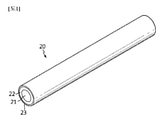
図1を参照すれば、本発明のフレキシブル二次電池の電極(第1電極及び第2電極)は、長さ方向に延びた電極集電体21、前記電極集電体21の外側に形成された電極活物質層22、及び前記電極活物質層22の外側に形成された絶縁性コーティング層23を備えている。
Referring to FIG. 1, the electrodes (first electrode and second electrode) of the flexible secondary battery of the present invention are formed on the electrode
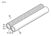
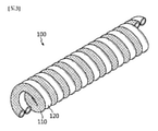
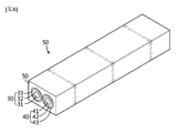
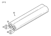
図2及び図3を参照すれば、長さ方向に延びた第1電極集電体31、前記第1電極集電体31の外側に形成された第1電極活物質層32、及び前記第1電極活物質層32の外側に形成された第1絶縁性コーティング層33を備える第1電極30;並びに、長さ方向に延びた第2電極集電体41、前記第2電極集電体41の外側に形成された第2電極活物質層42、及び前記第2電極活物質層42の外側に形成された第2絶縁性コーティング層43を備える第2電極40を用意し、このような第1電極30、110と第2電極40、120とを互いに接触させた状態で交互に配置されるように巻き取ることで、本発明のフレキシブル二次電池100を形成することができる。
Referring to FIGS. 2 and 3, the first electrode
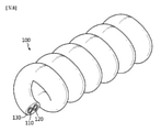
本発明のフレキシブル二次電池において、前記第1電極と第2電極とは、長さ方向に延びて、互いに接して交互に配置されるように螺旋状に巻き取られた構造を有する。ここで、螺旋状とは、英語でスパイラル(spiral)またはヘリックス(helix)であって、一定範囲をねじれ曲がった形状であり、一般にバネ状と類似する形状を通称する。 In the flexible secondary battery of the present invention, the first electrode and the second electrode have a structure extending in the length direction and spirally wound so as to be in contact with each other and arranged alternately. Here, the spiral shape is a spiral or a helix in English, and is a shape twisted in a certain range, and is generally referred to as a shape similar to a spring shape.
本発明のフレキシブル二次電池は、第1電極及び第2電極のうち一方は内側に配置し、他方は外側に配置して、内側の電極を外側の電極が囲む同心円状ではなく、第1電極及び第2電極が同一円周上で交差して並んで配列された形態を有する。 In the flexible secondary battery of the present invention, one of the first electrode and the second electrode is arranged inside and the other is arranged outside, and the inner electrode is not concentric with the outer electrode, but the first electrode. And the second electrode has a form in which the second electrodes are arranged side by side so as to cross each other on the same circumference.
内側電極とそれを囲む外側電極とを備える従来の電池構造では、内側電極と外側電極との間に分離層(セパレータ、電解質層など)を配置して両電極間の絶縁性を与えようとする。しかし、外側電極が内側電極を囲みながら一部離隔する部分が存在し、特に電池に外力が加えられて曲げ現象が繰り返される場合、内側電極と外側電極との曲げ半径が異なることから引張/収縮される範囲が相異なって、応力解消のために離隔する間に摩擦が生じて分離膜の損傷または電極活物質の脱離現象が起き、それによって離隔部分で電極間の短絡現象が生じる問題がある。 In a conventional battery structure including an inner electrode and an outer electrode surrounding the inner electrode, a separation layer (separator, electrolyte layer, etc.) is arranged between the inner electrode and the outer electrode to provide insulation between the two electrodes. .. However, there is a part where the outer electrode surrounds the inner electrode and is partially separated, and especially when an external force is applied to the battery and the bending phenomenon is repeated, the bending radius between the inner electrode and the outer electrode is different, so that tension / contraction occurs. There is a problem that the range is different, friction occurs during separation to relieve stress, damage to the separation membrane or detachment of the electrode active material occurs, which causes a short-circuit phenomenon between the electrodes at the separation part. be.
また、直線状または螺旋状の第1電極構造体の外側を螺旋状に囲む第2電極構造体を備えた従来の電池の場合は、本発明と異なり、第2電極構造体が螺旋状に囲みながら第1電極構造体と接する部分が柔軟性を低下させ、また繰り返して曲げられれば、その部分の摩擦による分離膜の損傷または電極活物質の脱離による電極構造体の損傷のような問題が生じる。 Further, in the case of a conventional battery provided with a second electrode structure that spirally surrounds the outside of the linear or spiral first electrode structure, unlike the present invention, the second electrode structure is spirally surrounded. However, if the portion in contact with the first electrode structure reduces flexibility and is repeatedly bent, problems such as damage to the separation membrane due to friction at that portion or damage to the electrode structure due to detachment of the electrode active material may occur. Occurs.
一方、本発明のフレキシブル二次電池は、第1電極と第2電極との巻き取られる面(巻取面)が同じ円周面上に配置され、電池が曲げられるとき同じ曲げ半径内で動くため、垂直方向の刺激が全く発生しなくなる。また、本発明のフレキシブル二次電池は、第1電極と第2電極とが互いに接触した状態で配列されることで可撓性が大きく改善され、電池が繰り返して曲げられても、第1絶縁性コーティング層と第2絶縁性コーティング層とが摩擦して絶縁性コーティング層が損傷される問題がなく、上述した従来の電池構造で生じる電極間の短絡現象などを防止することができる。 On the other hand, in the flexible secondary battery of the present invention, the winding surface (winding surface) of the first electrode and the second electrode is arranged on the same circumferential surface, and when the battery is bent, it moves within the same bending radius. Therefore, no vertical stimulus is generated. Further, in the flexible secondary battery of the present invention, the flexibility is greatly improved by arranging the first electrode and the second electrode in a state of being in contact with each other, and even if the battery is repeatedly bent, the first insulation is provided. There is no problem that the insulating coating layer is damaged due to friction between the sex coating layer and the second insulating coating layer, and it is possible to prevent a short-circuit phenomenon between electrodes that occurs in the above-mentioned conventional battery structure.
前記第1電極集電体及び第2電極集電体の断面は、特にその形態を限定しないが、円形、楕円形または多角形の形態であり得、多角形としては三角形、四角形または六角形の形態が挙げられる。 The cross section of the first electrode current collector and the second electrode current collector is not particularly limited in its form, but may be in the form of a circle, an ellipse, or a polygon, and the polygon may be a triangle, a quadrangle, or a hexagon. The form is mentioned.
前記第1電極集電体及び第2電極集電体としては、ステンレス鋼;アルミニウム;ニッケル;チタン;焼成炭素;銅;ステンレス鋼の表面をカーボン、ニッケル、チタン、銀で表面処理したもの;アルミニウム-カドミウム合金;導電材で表面処理された非伝導性高分子;若しくは伝導性高分子を使用して製造されたものが望ましい。 The first electrode current collector and the second electrode current collector include stainless steel; aluminum; nickel; titanium; calcined carbon; copper; stainless steel whose surface is surface-treated with carbon, nickel, titanium, and silver; aluminum. -Cadmium alloy; non-conductive polymer surface-treated with a conductive material; or manufactured using a conductive polymer is desirable.
集電体は、活物質の電気化学反応によって生成された電子を集めるか又は電気化学反応に必要な電子を供給する役割を果たし、一般に銅またはアルミニウムなどの金属を使用する。特に、導電材で表面処理された非伝導性高分子または伝導性高分子からなる高分子伝導体を使用する場合は、銅またはアルミニウムのような金属を使用した場合より相対的に可撓性が優れる。また、金属集電体に代替して高分子集電体を使用することで、電池の軽量性を達成することができる。 The current collector serves to collect the electrons generated by the electrochemical reaction of the active material or supply the electrons required for the electrochemical reaction, and generally uses a metal such as copper or aluminum. In particular, when a polymer conductor composed of a non-conductive polymer or a conductive polymer surface-treated with a conductive material is used, it is relatively more flexible than when a metal such as copper or aluminum is used. Excellent. Further, by using a polymer current collector instead of the metal current collector, the lightness of the battery can be achieved.
前記導電材としては、ポリアセチレン、ポリアニリン、ポリピロール、ポリチオフェン及びポリ窒化硫黄、ITO(Indium Tin Oxide)、銅、銀、パラジウム及びニッケルなどが使用可能であり、前記伝導性高分子としては、ポリアセチレン、ポリアニリン、ポリピロール、ポリチオフェン及びポリ窒化硫黄などが使用可能である。ただし、集電体に使用される非伝導性高分子は特に種類を限定しない。 As the conductive material, polyacetylene, polyaniline, polypyrrole, polythiophene and polysulfur nitride, ITO (Indium Tin Oxide), copper, silver, palladium, nickel and the like can be used, and as the conductive polymer, polyacetylene and polyaniline can be used. , Polypyrrole, polythiophene, polysulfur nitride and the like can be used. However, the type of non-conductive polymer used for the current collector is not particularly limited.
前記第1電極がカソードであって、前記第2電極がアノードであり得、逆に前記第1電極がアノードであって、前記第2電極がカソードであり得る。したがって、前記第1電極集電体及び第2電極集電体の材質は、各電極の種類によって適切に選択可能である。 The first electrode may be the cathode and the second electrode may be the anode, and conversely the first electrode may be the anode and the second electrode may be the cathode. Therefore, the materials of the first electrode current collector and the second electrode current collector can be appropriately selected depending on the type of each electrode.
前記第1電極がアノードであって、前記第2電極がカソードである場合、前記第1電極活物質層はアノード活物質層になり、非制限的な例として、天然黒鉛、人造黒鉛、炭素質材料;リチウム含有チタン複合酸化物(LTO);Si、Sn、Li、Zn、Mg、Cd、Ce、NiまたはFeである金属類(Me);前記金属類(Me)の合金類;前記金属類(Me)の酸化物(MeOx);及び前記金属類(Me)と炭素との複合体などが挙げられ、前記第2電極活物質層はカソード活物質層になり、非制限的な例として、LiCoO2、LiNiO2、LiMn2O4、LiCoPO4、LiFePO4、LiNiMnCoO2及びLiNi1-x-y-zCoxM1yM2zO2(M1及びM2は互いに独立して、Al、Ni、Co、Fe、Mn、V、Cr、Ti、W、Ta、Mg及びMoからなる群より選択されたいずれか1つであり、x、y及びzは互いに独立した酸化物組成元素の原子分率であって、0≦x<0.5、0≦y<0.5、0≦z<0.5、0<x+y+z≦1である)などが挙げられる。 When the first electrode is an anode and the second electrode is a cathode, the first electrode active material layer becomes an anode active material layer, and non-limiting examples include natural graphite, artificial graphite, and carbonaceous material. Materials; Lithium-containing titanium composite oxide (LTO); Metals (Me) which are Si, Sn, Li, Zn, Mg, Cd, Ce, Ni or Fe; Alloys of the metals (Me); The metals. Examples thereof include an oxide (MeOx) of (Me); and a composite of the metal (Me) and carbon, and the second electrode active material layer becomes a cathode active material layer, and a non-limiting example thereof is. LiCoO 2 , LiNiO 2 , LiMn 2 O 4 , LiCoPO 4 , LiFePO 4 , LiNiMnCoO 2 and LiNi 1-x-y-z Co x M1 y M2 z O 2 (M1 and M2 are independent of each other, Al, Ni, It is one selected from the group consisting of Co, Fe, Mn, V, Cr, Ti, W, Ta, Mg and Mo, and x, y and z are atomic fractions of oxide composition elements independent of each other. 0≤x <0.5, 0≤y <0.5, 0≤z <0.5, 0 <x + y + z≤1) and the like.
また、前記第1電極がカソードであって、前記第2電極がアノードである場合は、第1電極活物質層がカソード活物質層になり、第2電極活物質層がアノード活物質層になり得る。 When the first electrode is the cathode and the second electrode is the anode, the first electrode active material layer becomes the cathode active material layer, and the second electrode active material layer becomes the anode active material layer. obtain.
前記電極活物質層は、電極活物質の外に、バインダー及び導電材をさらに含み、集電体と結合して電極を構成することができる。このようなバインダーは、外力によって折れるか又は酷く曲がるなどの電極の変形が起きる場合、電極活物質を集電体と結着させて脱離の発生を防止することができる。 The electrode active material layer further contains a binder and a conductive material in addition to the electrode active material, and can be combined with a current collector to form an electrode. Such a binder can prevent the occurrence of desorption by binding the electrode active material to the current collector when the electrode is deformed such as to be broken or severely bent by an external force.
前記導電材は、カーボンブラック、アセチレンブラック、ケッチェンブラック、炭素繊維、炭素ナノチューブ及びグラフェンからなる群より選択されるいずれか1種または2種以上の混合物を含むことができるが、これらに限定されることはない。 The conductive material may contain, but is limited to, any one or a mixture of two or more selected from the group consisting of carbon black, acetylene black, ketjen black, carbon fibers, carbon nanotubes and graphene. There is no such thing.
前記バインダーは、ポリフッ化ビニリデン(PVdF)、ポリフッ化ビニリデン-ヘキサフルオロプロピレン、ポリフッ化ビニリデン-トリクロロエチレン、ポリブチルアクリレート、ポリメチルメタクリレート、ポリアクリロニトリル、ポリビニルピロリドン、ポリビニルアセテート、エチレンビニルアセテート共重合体、ポリエチレンオキサイド、ポリアリレート、セルロースアセテート、セルロースアセテートブチレート、セルロースアセテートプロピオネート、シアノエチルプルラン、シアノエチルポリビニルアルコール、シアノエチルセルロース、シアノエチルスクロース、プルラン、カルボキシルメチルセルロース、スチレンブタジエンゴム、アクリロニトリルスチレンブタジエン共重合体及びポリイミドからなる群より選択されたいずれか1種または2種以上の混合物であり得るが、これらに限定されることはない。 The binder is polyvinylidene fluoride (PVdF), vinylidene fluoride-hexafluoropropylene, vinylidene fluoride-trichloroethylene, polybutyl acrylate, polymethylmethacrylate, polyacrylonitrile, polyvinylpyrrolidone, polyvinylacetate, ethylene vinylacetate copolymer, polyethylene. From oxide, polyarylate, cellulose acetate, cellulose acetate butyrate, cellulose acetate propionate, cyanoethyl pullulan, cyanoethyl polyvinyl alcohol, cyanoethyl cellulose, cyanoethyl sucrose, purulan, carboxylmethyl cellulose, styrene butadiene rubber, acrylonitrile styrene butadiene copolymer and polyimide. It can be, but is not limited to, any one or a mixture of two or more selected from the group.
また、本発明のフレキシブル二次電池の第1電極及び第2電極は、それぞれ、電極活物質層の外側に絶縁性コーティング層(第1絶縁性コーティング層、第2絶縁性コーティング層)を備える。 Further, the first electrode and the second electrode of the flexible secondary battery of the present invention each include an insulating coating layer (first insulating coating layer, second insulating coating layer) on the outside of the electrode active material layer.
このような絶縁性コーティング層は、第1電極と第2電極とが接触した状態で交互に配置されていても、電極間に短絡が起きることを防止する電気的絶縁層の役割を果たすと共に、電極同士の間でリチウムイオンが移動可能な通路を形成する役割を果たすことができる。 Such an insulating coating layer serves as an electrical insulating layer that prevents a short circuit from occurring between the electrodes even if the first electrode and the second electrode are alternately arranged in contact with each other. It can serve to form a path through which lithium ions can move between the electrodes.
さらに、前記絶縁性コーティング層は、電極が過度に曲げられても、電極に可撓性を与えながら、電極集電体の外側に形成された活物質層から活物質が脱離することを防止する保護コーティング層の役割も果たすことができる。 Further, the insulating coating layer provides flexibility to the electrode even if the electrode is excessively bent, and prevents the active material from desorbing from the active material layer formed on the outside of the electrode current collector. It can also serve as a protective coating layer.
その結果、本発明のフレキシブル二次電池によれば、内側電極及びそれを囲む外側電極を有する従来の電池構造で内側電極と外側電極との間に必ず介在された分離層(セパレータまたは電解質)を省略することができる。 As a result, according to the flexible secondary battery of the present invention, a separation layer (separator or electrolyte) always interposed between the inner electrode and the outer electrode in a conventional battery structure having an inner electrode and an outer electrode surrounding the inner electrode is provided. It can be omitted.
また、このような絶縁性コーティング層の存在によって本発明のフレキシブル二次電池は、変形が自在であって、一定レベルの弾性を有するようになるため、可撓性に非常に優れる。また、一般に使用されるホイル型電極では、変形によって鋭い部分が形成されて電解質層を突き刺して短絡を起こし得るが、本発明のフレキシブル二次電池は容易に曲げられたり折れないため、変形によって鋭い部分が形成されて短絡を起こす恐れがない。 Further, the presence of such an insulating coating layer makes the flexible secondary battery of the present invention freely deformable and has a certain level of elasticity, so that the flexible secondary battery is very excellent in flexibility. Further, in a foil type electrode generally used, a sharp portion is formed by deformation and may pierce the electrolyte layer to cause a short circuit. However, since the flexible secondary battery of the present invention is not easily bent or broken, it is sharp due to deformation. There is no risk of short circuits being formed due to the formation of portions.
本発明の一実施例によれば、前記第1絶縁性コーティング層及び第2絶縁性コーティング層は、それぞれ独立して、多孔性ポリマーコーティング層、無機系全固体電解質コーティング層、有機系全固体コーティング層、またはポリオレフィン発泡分離膜であり得る。 According to one embodiment of the present invention, the first insulating coating layer and the second insulating coating layer are independently a porous polymer coating layer, an inorganic all-solid electrolyte coating layer, and an organic all-solid coating. It can be a layer or a polyolefin foam separation membrane.
前記多孔性ポリマーコーティング層は、ポリマーの相分離現象を用いて気孔を形成したポリマー膜であり、このようなポリマーとしてはポリフッ化ビニリデン、ポリフッ化ビニリデン-ヘキサフルオロプロピレン、ポリフッ化ビニリデン-トリクロロエチレンなどが適用可能である。 The porous polymer coating layer is a polymer film in which pores are formed by using the phase separation phenomenon of the polymer, and examples of such a polymer include polyvinylidene fluoride, vinylidene fluoride-hexafluoropropylene, and vinylidene fluoride-trichlorethylene. Applicable.
前記無機系全固体電解質コーティング層は、無機固体電解質及び高分子バインダーを有する固体電解質組成物を塗布して形成するコーティング層である。前記無機固体電解質は、周期律表の第1族または第2族に属する金属を含み、該金属イオン(望ましくは、リチウムイオン)の伝導性を有するものの、電子伝導性を有しないことが一般的である。 The inorganic all-solid electrolyte coating layer is a coating layer formed by applying a solid electrolyte composition having an inorganic solid electrolyte and a polymer binder. The inorganic solid electrolyte contains a metal belonging to the first group or the second group of the periodic table, and has the conductivity of the metal ion (preferably lithium ion), but generally does not have the electron conductivity. Is.
本発明の一実施例において前記無機固体電解質は、全固体二次電池に適用される固体電解質材料を適切に選定して使用でき、詳しくは、硫化物系無機固体電解質、酸化物系無機固体電解質などを使用することができる。 In one embodiment of the present invention, the inorganic solid electrolyte can be used by appropriately selecting a solid electrolyte material applicable to an all-solid secondary battery. Specifically, a sulfide-based inorganic solid electrolyte and an oxide-based inorganic solid electrolyte can be used. Etc. can be used.
硫化物系無機固体電解質は、硫黄(S)を含み、また、周期律表の第1族または第2族に属する金属を含み、イオン伝導性を有し、電子絶縁性を有することが望ましい。例えば、下記式(1)で表される組成を満たすリチウムイオン伝導性無機固体電解質を有し得る。
It is desirable that the sulfide-based inorganic solid electrolyte contains sulfur (S), contains a metal belonging to
LiaMbPcSd…(1)
式(1)において、MはB、Zn、Si、Cu、Ga及びGeから選択される元素を示し、a~dは各元素の組成比を示し、a:b:c:dはそれぞれ1~12:0~0.2:1:2~9を満たす。
式(1)において、Li、M、P及びSの組成比は、望ましくはbが0である。より望ましくは、bが0であって、a、c及びdの組成比がa:c:d=1~9:1:3~7である。さらに望ましくは、bが0であって、a:c:d=1.5~4:1:3.25~4.5である。各元素の組成比は、後述するように、硫化物系固体電解質を製造するときの原料化合物の配合量を調整することで制御することができる。
Li a M b P c S d ... (1)
In the formula (1), M indicates an element selected from B, Zn, Si, Cu, Ga and Ge, a to d indicate the composition ratio of each element, and a: b: c: d indicate 1 to 1 to each. Satisfy 12: 0 to 0.2: 1: 2 to 9.
In the formula (1), the composition ratio of Li, M, P and S is preferably 0 for b. More preferably, b is 0 and the composition ratios of a, c and d are a: c: d = 1 to 9: 1: 3 to 7. More preferably, b is 0, and a: c: d = 1.5 to 4: 1: 3.25 to 4.5. As will be described later, the composition ratio of each element can be controlled by adjusting the blending amount of the raw material compound when producing the sulfide-based solid electrolyte.
硫化物系無機固体電解質は、非結晶(ガラス)であっても良く、結晶化(ガラスセラミック化)されていても良く、一部のみが結晶化されていても良い。Li-P-S系ガラス及びLi-P-S系ガラスセラミックにおけるLi2SとP2S5との比率は、Li2S:P2S5のモル比で、望ましくは65:35~85:15、より望ましくは68:32~75:25である。Li2SとP2S5との比率を上記の範囲にすることで、リチウムイオン伝導度を高めることができる。リチウムイオン伝導度は、1×10⁻⁴S/cm以上が望ましく、1×10-3S/cm以上がより望ましい。 The sulfide-based inorganic solid electrolyte may be non-crystallized (glass), crystallized (glass-ceramicized), or partially crystallized. The ratio of Li 2S to P 2 S 5 in Li-P-S-based glass and Li-PS-based glass ceramic is the molar ratio of Li 2 S: P 2 S 5 , preferably 65:35 to 85. : 15, more preferably 68:32 to 75:25. By setting the ratio of Li 2 S and P 2 S 5 to the above range, the lithium ion conductivity can be increased. The lithium ion conductivity is preferably 1 × 10 -4 S / cm or more, and more preferably 1 × 10 -3 S / cm or more.
このような化合物としては、例えばLi2Sと第13族~第15族元素の硫化物とを含む原料組成物からなるものが挙げられる。 Examples of such a compound include those composed of a raw material composition containing Li 2S and a sulfide of Group 13 to Group 15 elements.
具体的には、例えば、Li2S-P2S5、Li2S-GeS2、Li2S-GeS2-ZnS、Li2S-Ga2S3、Li2S-GeS2-Ga2S3、Li2S-GeS2-P2S5、Li2S-GeS2-Sb2S5、Li2S-GeS2-Al2S3、Li2S-SiS2、Li2S-Al2S3、Li2S-SiS2-Al2S3、Li2S-SiS2-P2S5、Li2S-SiS2-LiI、Li2S-SiS2-Li4SiO4、Li2S-SiS2-Li3PO4、Li10GeP2S12などが挙げられる。中でも、Li2S-P2S5、Li2S-GeS2-Ga2S3、Li2S-GeS2-P2S5、Li2S-SiS2-P2S5、Li2S-SiS2-Li4SiO4、Li2S-SiS2-Li3PO4からなる結晶質及び/または非晶質の原料組成物が、高いリチウムイオン伝導性を有することから望ましい。 Specifically, for example, Li 2 SP 2 S 5 , Li 2 S-GeS 2 , Li 2 S-GeS 2 -ZnS, Li 2 S-Ga 2 S 3 , Li 2 S-GeS 2 -Ga 2 S 3 , Li 2 S-GeS 2 -P 2 S 5 , Li 2 S-GeS 2 -Sb 2 S 5 , Li 2 S-GeS 2 -Al 2 S 3 , Li 2 S-SiS 2 , Li 2 S- Al 2 S 3 , Li 2 S-SiS 2 -Al 2 S 3 , Li 2 S-SiS 2 -P 2 S 5 , Li 2 S-SiS 2 -LiI, Li 2 S-SiS 2 -Li 4 SiO 4 , Examples thereof include Li 2 S-SiS 2 -Li 3 PO 4 , Li 10 GeP 2 S 12 . Among them, Li 2 SP 2 S 5 , Li 2 S-GeS 2 -Ga 2 S 3 , Li 2 S-GeS 2 -P 2 S 5 , Li 2 S-SiS 2 -P 2 S 5 , Li 2 S -SiS 2 -Li 4 SiO 4 , Li 2 S-SiS 2 -Li 3 A crystalline and / or amorphous raw material composition consisting of PO 4 is desirable because it has high lithium ion conductivity.
このような原料組成物を用いて硫化物系固体電解質材料を合成する方法としては、例えば非晶質化法が挙げられる。非晶質化法は、例えば、機械粉砕(mechanical milling)法及び溶融急冷(melt quenching)法が挙げられる。中でも、常温での処理が可能であり、製造工程を簡略化できることから、機械粉砕法が望ましい。 As a method for synthesizing a sulfide-based solid electrolyte material using such a raw material composition, for example, an amorphization method can be mentioned. Examples of the amorphization method include a mechanical milling method and a melt quenching method. Above all, the mechanical pulverization method is desirable because it can be processed at room temperature and the manufacturing process can be simplified.
酸化物系無機固体電解質は、酸素原子(O)を含み、また周期律表の第1族又は第2族に属する金属を含み、イオン伝導性を有して電子絶縁性をさらに有するものが望ましい。
It is desirable that the oxide-based inorganic solid electrolyte contains an oxygen atom (O), contains a metal belonging to
具体的には、例えば、LixaLayaTiO3〔xa=0.3~0.7、ya=0.3~0.7〕(LLT)、Li7La3Zr2O12(LLZ)、LISICON(Lithium super ionic conductor)型結晶構造を有するLi3.5Zn0.25GeO4、NASICON(Natrium super ionic conductor)型結晶構造を有するLiTi2P3O12、Li1+xb+yb(Al,Ga)xb(Ti,Ge)2-xbSiybP3-ybO12(ただし、0≦xb≦1、0≦yb≦1)、ガーネット型結晶構造を有するLi7La3Zr2O12が挙げられる。 Specifically, for example, Li xa La ya TiO 3 [xa = 0.3 to 0.7, ya = 0.3 to 0.7] (LLT), Li 7 La 3 Zr 2 O 12 (LLZ), Li 3.5 Zn 0.25 GeO 4 with a Lithium (Lithium super ionic controller) type crystal structure, LiTi 2 P 3 O 12 + Li 1 b with a NASION (Lithium super ionic crystal) crystal structure. (Ti, Ge) 2-xb Si yb P 3-yb O 12 (where 0 ≦ xb ≦ 1, 0 ≦ yb ≦ 1), and Li 7 La 3 Zr 2 O 12 having a garnet-type crystal structure can be mentioned.
また、Li、P及びOを含むリン化合物も望ましい。例えば、リン酸リチウム(Li3PO4)、リン酸リチウムの酸素の一部を窒素で置換したLiPON、LiPOD(DはTi、V、Cr、Mn、Fe、Co、Ni、Cu、Zr、Nb、Mo、Ru、Ag、Ta、W、Pt、Auなどから選択される少なくとも1種)が挙げられる。また、LiAON(AはSi、B、Ge、Al、C、Gaなどから選択される少なくとも1種)なども望ましく使用可能である。 Further, a phosphorus compound containing Li, P and O is also desirable. For example, lithium phosphate (Li 3 PO 4 ), LiPON in which a part of oxygen of lithium phosphate is replaced with nitrogen, LiPOD (D is Ti, V, Cr, Mn, Fe, Co, Ni, Cu, Zr, Nb. , Mo, Ru, Ag, Ta, W, Pt, Au, etc.). Further, LiAON (A is at least one selected from Si, B, Ge, Al, C, Ga and the like) and the like can also be preferably used.
中でも、Li1+xb+yb(Al,Ga)xb(Ti,Ge)2-xbSiybP3-ybO12(ただし、0≦xb≦1、0≦yb≦1)は、高いリチウムイオン伝導性を有し、化学的に安定して取り扱いが容易であるため、望ましい。これらは単独で使用しても良く、2種以上を組み合わせて使用しても良い。 Among them, Li 1 + xb + yb (Al, Ga) xb (Ti, Ge) 2-xb Si yb P 3-yb O 12 (however, 0 ≦ xb ≦ 1, 0 ≦ yb ≦ 1) has high lithium ion conductivity. However, it is desirable because it is chemically stable and easy to handle. These may be used alone or in combination of two or more.
酸化物系固体電解質のリチウムイオン伝導度は、1×10⁻⁶S/cm以上が望ましく、1×10-5S/cm以上がより望ましく、5×10-5S/cm以上がさらに望ましい。 The lithium ion conductivity of the oxide-based solid electrolyte is preferably 1 × 10 -6 S / cm or more, more preferably 1 × 10 -5 S / cm or more, and further preferably 5 × 10 -5 S / cm or more.
前記無機系全固体電解質コーティング層に使用される高分子バインダーとしては、アミド結合を有するポリマーとしてポリアミド、ポリアクリルアミドなど;イミド結合を有するポリマーとしてポリイミドなど;ウレタン結合を有するポリマーとしてポリウレタンなど;ニトリルブタジエンゴム(NBR)、ブタジエンゴム、ブチレンゴムなどのゴム;ポリアクリレート系;SBS(poly(styrene-butadiene-styrene))などが挙げられる。 The polymer binder used for the inorganic all-solid electrolyte coating layer includes polyamide, polyacrylamide, etc. as a polymer having an amide bond; polyimide, etc. as a polymer having an imide bond; polyurethane, etc. as a polymer having a urethane bond; nitrile butadiene, etc. Examples include rubbers (NBR), butadiene rubbers, butylene rubbers and the like; polyacrylate-based; SBS (poly (polyimide-butadie-stylerene)) and the like.
また、有機系全固体コーティング層は、例えば、極性非架橋高分子、オキサイド系非架橋高分子、高分子架橋構造体、またはこれらのうち2以上の混合物を含むことができる。 Further, the organic all-solid coating layer can contain, for example, a polar non-crosslinked polymer, an oxide-based non-crosslinked polymer, a polymer crosslinked structure, or a mixture of two or more thereof.
前記極性非架橋高分子としては、特にその種類を限定しないが、ポリアクリロニトリル、ポリ塩化ビニル、ポリフッ化ビニリデン、ポリフッ化ビニリデン-ヘキサフルオロプロピレン共重合体、ポリエチレンイミン、ポリメチルメタクリレート、ポリブチルアクリレート、ポリビニルアルコール、ポリビニルピロリドン、ポリビニルアセテート、エチレンビニルアセテート共重合体、リン酸エステルポリマー、ポリアジテーションリシン(agitation lysine)、イオン性解離基を含む重合剤、またはこれらのうち2以上の混合物を使用することができる。 The type of the polar non-crosslinked polymer is not particularly limited, but polyacrylonitrile, polyvinyl chloride, polyvinylidene fluoride, polyvinylidene fluoride-hexafluoropropylene copolymer, polyethyleneimine, polymethylmethacrylate, polybutylacrylate, and the like. Use a polymer containing polyvinyl alcohol, polyvinylpyrrolidone, polyvinylacetate, ethylene vinylacetate copolymer, phosphate ester polymer, polyvinylidene fluoride, ionic dissociation group, or a mixture of two or more of these. Can be done.
前記オキサイド系非架橋高分子としては、ポリエチレンオキサイド、ポリプロピレンオキサイド、ポリオキシメチレン、ポリジメチルシロキサン、ポリエチレンスルファイド、これらの誘導体、またはこれらのうち2以上の混合物を使用できるが、特にこれらに限定されることはない。 As the oxide-based non-crosslinked polymer, polyethylene oxide, polypropylene oxide, polyoxymethylene, polydimethylsiloxane, polyethylenesulfide, derivatives thereof, or a mixture of two or more of them can be used, but is particularly limited thereto. There is no such thing.
前記高分子架橋構造体は、2つ以上の官能基を有する単量体の重合体、または、2つ以上の官能基を有する単量体と1つの官能基を有する極性単量体との共重合体を使用することができる。 The polymer crosslinked structure is a polymer of a monomer having two or more functional groups, or a copolymer of a monomer having two or more functional groups and a polar monomer having one functional group. Polymers can be used.
前記2つ以上の官能基を有する単量体としては、その種類を特に限定しないが、トリメチロールプロパンエトキシレートトリアクリレート、ポリエチレングリコールジメタクリレート、ポリエチレングリコールジアクリレート、ジビニルベンゼン、ポリエステルジメタクリレート、ジビニルエーテル、トリメチロールプロパン、トリメチロールプロパントリメタクリレート、エトキシ化ビスフェノールAジメタクリレート、またはこれらのうち2以上の混合物を使用できるが、これらに限定されることはない。 The type of the monomer having two or more functional groups is not particularly limited, but trimethylolpropane ethoxylate triacrylate, polyethylene glycol dimethacrylate, polyethylene glycol diacrylate, divinylbenzene, polyester dimethacrylate, and divinyl ether. , Trimethylolpropane, trimethylolpropane trimethacrylate, ethoxylated bisphenol A dimethacrylate, or mixtures of two or more of these can be used, but is not limited thereto.
前記1つの官能基を有する極性単量体は、メチルメタクリレート、エチルメタクリレート、ブチルメタクリレート、メチルアクリレート、ブチルアクリレート、エチレングリコールメチルエーテルアクリレート、エチレングリコールメチルエーテルメタクリレート、アクリロニトリル、ビニルアセテート、塩化ビニル、フッ化ビニル、またはこれらのうち2以上の混合物を使用できるが、これらに限定されることはない。 The polar monomer having one functional group includes methyl methacrylate, ethyl methacrylate, butyl methacrylate, methyl acrylate, butyl acrylate, ethylene glycol methyl ether acrylate, ethylene glycol methyl ether methacrylate, acrylonitrile, vinyl acetate, vinyl chloride, and fluoride. Vinyl, or a mixture of two or more of these, can be used, but is not limited to these.
前記ポリオレフィン発泡分離膜は、ポリオレフィンの液相に発泡剤を添加したコーティング液を電極活物質層の外側に塗布した後、乾燥及び発泡させて発泡分離膜層に形成することができる。このようなポリオレフィンとしては、ポリエチレン、ポリプロピレンなどが適用可能であり、前記発泡剤としては、アゾ(-N=N-)系化合物、カーボネート系化合物、ヒドラジド系化合物、ニトリル系化合物、アミン系化合物、アミド系化合物及びカルバジド系化合物からなる群より選択される1種以上の発泡剤を適用可能である。 The polyolefin foam separation membrane can be formed into a foam separation membrane layer by applying a coating liquid obtained by adding a foaming agent to the liquid phase of polyolefin to the outside of the electrode active material layer, and then drying and foaming. As such a polyolefin, polyethylene, polypropylene and the like can be applied, and as the foaming agent, an azo (-N = N-) compound, a carbonate compound, a hydrazide compound, a nitrile compound, an amine compound, etc. One or more foaming agents selected from the group consisting of amide compounds and carbazide compounds can be applied.
本発明の絶縁性コーティング層は、リチウム塩をさらに含むことができる。リチウム塩は、イオン伝導度及び反応速度を向上させることができ、これらの非制限的な例としては、LiCl、LiBr、LiI、LiClO4、LiBF4、LiB10Cl10、LiPF6、LiCF3SO3、LiCF3CO2、LiAsF6、LiSbF6、LiAlCl4、CH3SO3Li、CF3SO3Li、(CF3SO2)2NLi、(FSO2)2NLi、クロロホウ酸リチウム、低級脂肪族カルボン酸リチウム及びテトラフェニルホウ酸リチウムが挙げられる。 The insulating coating layer of the present invention may further contain a lithium salt. Lithium salts can improve ionic conductivity and reaction rate, and non-limiting examples of these are LiCl, LiBr, LiI, LiClO 4 , LiBF 4 , LiB 10 Cl 10 , LiPF 6 , LiCF 3 SO. 3 , LiCF 3 CO 2 , LiAsF 6 , LiSbF 6 , LiAlCl 4 , CH 3 SO 3 Li, CF 3 SO 3 Li, (CF 3 SO 2 ) 2 NLi, (FSO 2 ) 2 NLi, lithium chloroborate, lower fat Examples thereof include group lithium carboxylate and lithium tetraphenylborate.
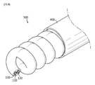
図4を参照すれば、本発明の一実施例によるフレキシブル二次電池は、長さ方向に延びた第1電極集電体210、前記第1電極集電体の外側に形成された第1電極活物質層220、及び前記第1電極活物質層の外側に形成された第1絶縁性コーティング層230を備える第1電極200;並びに長さ方向に延びた第2電極集電体310、前記第2電極集電体の外側に形成された第2電極活物質層320、及び前記第2電極活物質層の外側に形成された第2絶縁性コーティング層330を備える第2電極300を備え、前記第1電極と第2電極とが互いに接触して交互に配置されるように巻き取られており、これら第1電極及び第2電極の外側を囲むカバー部材400を備えることができる。
Referring to FIG. 4, the flexible secondary battery according to the embodiment of the present invention has a first electrode
前記カバー部材は、絶縁体であって、空気中の水分及び外部衝撃から電極を保護するために電極組立体を囲んで形成される。カバー部材としては通常の高分子樹脂を使用でき、一例として、PVC、HDPEまたはエポキシ樹脂が使用可能である。 The cover member is an insulator and is formed around the electrode assembly in order to protect the electrodes from moisture in the air and external impact. As the cover member, a normal polymer resin can be used, and as an example, PVC, HDPE or epoxy resin can be used.
本発明の一実施例によれば、前記第1電極と第2電極とを全て囲む第3絶縁性コーティング層をさらに備えることができる。前記第3絶縁性コーティング層も、上述した第1絶縁性コーティング層及び第2絶縁性コーティング層と同様に、多孔性ポリマーコーティング層、無機系全固体電解質コーティング層、有機系全固体コーティング層またはポリオレフィン発泡分離膜であり得、これらそれぞれの内容は上述したようである。 According to one embodiment of the present invention, a third insulating coating layer that surrounds the first electrode and the second electrode can be further provided. The third insulating coating layer is also a porous polymer coating layer, an inorganic all-solid-state electrolyte coating layer, an organic all-solid-state coating layer, or a polyolefin, similarly to the first insulating coating layer and the second insulating coating layer described above. It can be a foam separation membrane, and the contents of each of these are as described above.
このような第3絶縁性コーティング層を備えたフレキシブル二次電池は、第1電極と第2電極とが隣接して構成され、これらを囲む別途の絶縁性コーティング層がないフレキシブル二次電池に比べて、フレキシブル二次電池の連続的な曲げによっても第1電極と第2電極とが互いに離隔せず、最初配列された位置を一対でそのまま維持するようになって、その結果、曲げによって第1電極と第2電極とが離隔するか、第1電極と第2電極との外側に備えられた第1絶縁性コーティング層と第2絶縁性コーティング層との摩擦などによって絶縁性コーティング層が損傷されるか、または、電極が短絡する問題をさらに防止することができる。 A flexible secondary battery provided with such a third insulating coating layer is compared with a flexible secondary battery in which a first electrode and a second electrode are configured adjacent to each other and there is no separate insulating coating layer surrounding them. As a result, the first electrode and the second electrode do not separate from each other even by continuous bending of the flexible secondary battery, and the initially arranged positions are maintained as they are in a pair, and as a result, the first electrode is bent. The insulating coating layer is damaged by the separation of the electrode and the second electrode, or by friction between the first insulating coating layer and the second insulating coating layer provided on the outside of the first electrode and the second electrode. Or, the problem of short-circuiting the electrodes can be further prevented.
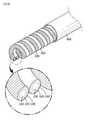
図5~図8を参照すれば、長さ方向に延びた第1電極集電体31、前記第1電極集電体31の外側に形成された第1電極活物質層32、及び前記第1電極活物質層32の外側に形成された第1絶縁性コーティング層33を備える第1電極30;並びに長さ方向に延びた第2電極集電体41、前記第2電極集電体41の外側に形成された第2電極活物質層42、及び前記第2電極活物質層42の外側に形成された第2絶縁性コーティング層43を備える第2電極40を用意し、このような第1電極30、110と第2電極40、120とを所定間隔で配置した後、これらを全て囲む第3絶縁性コーティング層50、130を形成する。その後、第3絶縁性コーティング層50、130が形成された第1電極30、110と第2電極40、120とを螺旋状に巻き取って、第1電極30、110と第2電極40、120とが交互に配置された本発明の一実施例によるフレキシブル二次電池100を形成することができる。
Referring to FIGS. 5 to 8, the first electrode
特に、図5~図7を参照すれば、前記第3絶縁性コーティング層50、130の断面の形態は、楕円形、長方形、ピーナッツ型などが可能であり、外にも、円形、正方形、三角形などの多様な多角形の形態も適用可能である。 In particular, referring to FIGS. 5 to 7, the cross-sectional morphology of the third insulating coating layers 50 and 130 can be elliptical, rectangular, peanut-shaped, or the like, and is also circular, square, or triangular. Various polygonal forms such as are also applicable.
図9を参照すれば、前記第3絶縁性コーティング層50、130の外側を囲むカバー部材400を備えることができる。
Referring to FIG. 9, a
以下、上述した構造のフレキシブル二次電池の製造方法について簡略に説明する。 Hereinafter, a method for manufacturing a flexible secondary battery having the above-mentioned structure will be briefly described.
まず、その長さ方向に直交する断面が円形、楕円形または多角形の形態である細長いワイヤ状の第1電極集電体の表面に活物質層を形成する。 First, an active material layer is formed on the surface of an elongated wire-shaped first electrode current collector whose cross section orthogonal to the length direction is in the form of a circle, an ellipse, or a polygon.
第1電極活物質層を形成するコーティング方法としては、一般的なコーティング方法を適用でき、具体的には活物質を含む電極スラリーを押出機を用いて連続的または不連続的に押出コーティングする方法で製造することが望ましい。このとき、前記活物質層は間歇コーティングされて一定間隔を維持するように形成されても良い。 As a coating method for forming the first electrode active material layer, a general coating method can be applied, specifically, a method of continuously or discontinuously extruding an electrode slurry containing an active material using an extruder. It is desirable to manufacture with. At this time, the active material layer may be intermittently coated and formed so as to maintain a constant interval.
その後、前記第1電極活物質層を囲むように第1絶縁性コーティング層を形成する。 Then, the first insulating coating layer is formed so as to surround the first electrode active material layer.
第1絶縁性コーティング層を形成する方法も特に限定されず、絶縁性コーティング層を形成する材料を含む絶縁性コーティング層組成物(コーティング液)を用いて当業界で適用可能な多様な方法でコーティングできる。例えば、ディップコーティング、押出コーティングなどを適用できるが、線形であるとのフレキシブル二次電池の特性上、押出コーティング方法などが製造の容易性の面から望ましい。 The method for forming the first insulating coating layer is not particularly limited, and the insulating coating layer composition (coating liquid) containing the material for forming the insulating coating layer is used to coat the first insulating coating layer by various methods applicable in the art. can. For example, dip coating, extrusion coating, etc. can be applied, but due to the characteristics of a flexible secondary battery that is linear, an extrusion coating method or the like is preferable from the viewpoint of ease of manufacture.
例えば、押出コーティング方法は、コーティング液を押出機を通じて基材の外面に押出して連続的にコーティングする方法であって、コーティング基材の長さに制限が少なく、均一な形状の基材に連続的なコーティングが可能である。図10を参照すれば、一般に、押出機はホッパー1、シリンダー2及びダイ5からなっている。一般的な押出コーティング方法は、コーティング原料を押出機のホッパーに入れ、シリンダーを一定温度に維持してコーティング原料を溶かしながら、シリンダー2内のスクリュー3を回転させてコーティング液を押し出し、シリンダーの前方に設けられたダイ5を通過させて基材にコーティングする。フレキシブル二次電池は、水平断面より長さ方向に長く延びて、一定な所定の水平断面を有する形態的特性を有しているため、押出コーティングによる連続的なコーティング方法を使用することが望ましい。
For example, the extrusion coating method is a method in which a coating liquid is extruded to the outer surface of a base material through an extruder to continuously coat the base material, and the length of the coated base material is not limited and the base material has a uniform shape. Coating is possible. Referring to FIG. 10, the extruder generally consists of a
電極スラリーを押出機のホッパー1に注入し、シリンダー内のスクリュー3を回転させて混合して、シリンダー2の前方に設けられたダイ5を通過させて押出機に供給される集電体に電極スラリーを押し出してコーティングすることで、長さ方向に延びる第1電極(アノードまたはカソード)及び第2電極(カソードまたはアノード)を製造する。電極を形成する集電体はワイヤ状であり得る。集電体の形態によるダイの種類は特に限定されないが、集電体がワイヤ状である場合は、パイプ型のO-ダイ(図11を参照)に集電体を通過させながら外面に電極スラリーをコーティングすることができる。押出機に注入された電極スラリーは、コーティング材料供給部11を通じて供給され、O-ダイ10を通じて排出されて、O-ダイの側面から挿入されたワイヤ状の集電体12に排出された電極スラリーを押出コーティングする。このとき、電極スラリーの濃度または押出速度を調整するか、若しくは、押出機に供給される速度である集電体の線速を調整することで、コーティング層の厚さを容易に調節することができる。
The electrode slurry is injected into the
その後、前記活物質の電極層と反対電極の活物質を使用する点を除き、第1電極を製造する方法と同様に、第2絶縁性コーティング層が備えられた第2電極を用意する、このとき、第1絶縁性コーティング層及び第2絶縁性コーティング層の厚さは、例えば、5~150μmであり得る。 After that, a second electrode provided with a second insulating coating layer is prepared in the same manner as in the method for manufacturing the first electrode, except that the electrode layer of the active material and the active material of the opposite electrode are used. When, the thickness of the first insulating coating layer and the second insulating coating layer can be, for example, 5 to 150 μm.
その後、用意した第1電極と第2電極とを互いに接触させた状態で、螺旋状に長さ方向に巻き取ることで、前記第1電極と第2電極とが交互に同じ円周面に配置される電極組立体を形成することができる。 After that, the prepared first electrode and the second electrode are spirally wound in the length direction in a state of being in contact with each other, so that the first electrode and the second electrode are alternately arranged on the same circumferential surface. It is possible to form an electrode assembly to be formed.
このように製造された電極組立体をカバー部材で囲んでフレキシブル二次電池を製造することができる。前記カバー部材は絶縁体であって、空気中の水分及び外部衝撃から電極を保護するために最外面に形成する。カバー部材としては、通常の高分子樹脂を使用でき、例えば、ポリ塩化ビニル(PVC)、高密度ポリエチレン(HDPE)またはエポキシ樹脂が使用可能である。 A flexible secondary battery can be manufactured by surrounding the electrode assembly thus manufactured with a cover member. The cover member is an insulator and is formed on the outermost surface in order to protect the electrodes from moisture in the air and external impact. As the cover member, a normal polymer resin can be used, and for example, polyvinyl chloride (PVC), high density polyethylene (HDPE) or epoxy resin can be used.
また、本発明の一実施例によれば、前記第1電極と第2電極とを全て囲む第3絶縁性コーティング層をさらに備えることができる。このとき、第3絶縁性コーティング層は、図11のような押出機において、ダイに2つの孔を設けて2つのコーティング基材を注入可能にし、それぞれの孔に第1電極と第2電極を供給し、コーティング材料として第3絶縁性コーティング層材料を注入して形成することができる。 Further, according to one embodiment of the present invention, a third insulating coating layer that surrounds the first electrode and the second electrode can be further provided. At this time, in the extruder as shown in FIG. 11, the third insulating coating layer is provided with two holes in the die so that the two coating base materials can be injected, and the first electrode and the second electrode are placed in the respective holes. It can be supplied and formed by injecting a third insulating coating layer material as a coating material.
以下、本発明の理解を助けるために実施例を挙げて詳しく説明する。しかし、本発明による実施例は多くの他の形態に変形され得、本発明の範囲が後述する実施例に限定されると解釈されてはならない。本発明の実施例は当業界で平均的な知識を持つ者に本発明をより完全に説明するために提供されるものである。 Hereinafter, in order to help understanding of the present invention, examples will be given and described in detail. However, the examples according to the invention can be transformed into many other embodiments and should not be construed as limiting the scope of the invention to the examples described below. The embodiments of the present invention are provided to more fully explain the present invention to those with average knowledge in the art.
実施例1
天然黒鉛/アセチレンブラック/PVdF=70/5/25の混合物をN-メチルピロリドン(NMP)溶媒と混合してアノード活物質スラリーを製造した後、前記スラリーを直径125μmの銅からなるワイヤ状の集電体にコーティングしてアノード活物質層を形成した。
Example 1
A mixture of natural graphite / acetylene black / PVdF = 70/5/25 is mixed with an N-methylpyrrolidone (NMP) solvent to produce an anode active material slurry, and then the slurry is collected in the form of a wire made of copper having a diameter of 125 μm. The electric body was coated to form an anode active material layer.
LiCoO2/アセチレンブラック/PVdF=70/5/25の混合物をN-メチルピロリドン(NMP)溶媒と混合してカソード活物質スラリーを製造した後、前記スラリーを直径125μmのアルミニウムからなるワイヤ状の集電体にコーティングしてカソード活物質層を形成した。 A mixture of LiCoO 2 / acetylene black / PVdF = 70/5/25 is mixed with an N-methylpyrrolidone (NMP) solvent to produce a cathode active material slurry, and then the slurry is collected in the form of a wire made of aluminum having a diameter of 125 μm. The electric body was coated to form a cathode active material layer.
アセトニトリル(AN)溶媒にポリエチレンオキサイド(PEO)(重量平均分子量(Mw)=4,000,000g/mol)を溶かして4wt%のPEO溶液を用意し、そこにリチウム塩としてリチウムビス(フルオロスルホニル)イミド(LiFSI、(FSO2)2NLi)を[EO]/[Li+]=20/1(モル比)になるように添加した。その後、PEO溶液でPEOとリチウム塩とが十分溶解するように70℃で一晩中撹拌した。 A 4 wt% PEO solution is prepared by dissolving polyethylene oxide (PEO) (weight average molecular weight (Mw) = 4,000,000 g / mol) in an acetonitrile (AN) solvent, and lithium bis (fluorosulfonyl) is used as a lithium salt therein. Iimide (LiFSI, (FSO 2 ) 2 NLi) was added so that [EO] / [Li +] = 20/1 (molar ratio). Then, the mixture was stirred at 70 ° C. overnight so that the PEO and the lithium salt were sufficiently dissolved in the PEO solution.
また、高分子架橋構造体を製造するため、2つの官能基を有するポリエチレングリコールジアクリレート(PEGDA)(重量平均分子量(Mw)=575)、開始剤として過酸化ベンゾイル(BPO)を、PEOとリチウム塩の溶液に投入し、十分撹拌させて絶縁性コーティング層用組成物を用意した。このとき、PEGDAはPEOの100重量部に対して20重量部を、BPOはPEGDAの100重量部に対して1重量部の含量で使用した。 Further, in order to produce a polymer crosslinked structure, polyethylene glycol diacrylate (PEGDA) having two functional groups (weight average molecular weight (Mw) = 575), benzoyl peroxide (BPO) as an initiator, PEO and lithium. The composition for the insulating coating layer was prepared by putting it in a salt solution and stirring it sufficiently. At this time, PEGDA was used in a content of 20 parts by weight with respect to 100 parts by weight of PEO, and BPO was used in a content of 1 part by weight with respect to 100 parts by weight of PEGDA.
その後、用意した絶縁性コーティング層用組成物を上記のように用意したアノード活物質層とカソード活物質層上にそれぞれコーティングした。コーティング方式は押出方式を用いた。 Then, the prepared composition for the insulating coating layer was coated on the anode active material layer and the cathode active material layer prepared as described above, respectively. An extrusion method was used as the coating method.
具体的に、用意した絶縁性コーティング層用組成物を押出機のホッパーに注入した。押出機シリンダーの温度は50℃に維持し、スクリューの回転速度は60~70rpmに維持した。上記のように製造されたアノード活物質層が形成された集電体を押出機のO-ダイ(図11参照)に1分当り3mの速度で供給し、アノード活物質層の外面に絶縁性コーティング層用組成物を押出コーティングした後、乾燥機のチャンバ内で100℃条件で乾燥して、同一温度条件で12時間真空乾燥して水分を除去して第1絶縁性コーティング層を備えるアノード(第1電極)を製造した。このとき、形成された第1絶縁性コーティング層の厚さは約20μmであった。 Specifically, the prepared composition for an insulating coating layer was poured into the hopper of the extruder. The temperature of the extruder cylinder was maintained at 50 ° C. and the rotation speed of the screw was maintained at 60-70 rpm. The current collector on which the anode active material layer manufactured as described above is formed is supplied to the O-die of the extruder (see FIG. 11) at a rate of 3 m per minute, and the outer surface of the anode active material layer is insulated. After the composition for the coating layer is extruded and coated, it is dried in the chamber of the dryer under 100 ° C. conditions, and vacuum dried at the same temperature conditions for 12 hours to remove water, and an anode provided with the first insulating coating layer ( The first electrode) was manufactured. At this time, the thickness of the formed first insulating coating layer was about 20 μm.
上記のように製造されたアノード活物質層が形成された集電体を使用した点を除き、アノードを製造する方法と同じ方法で、第2絶縁性コーティング層が外面に形成されたカソード(第2電極)を製造した。 A cathode having a second insulating coating layer formed on the outer surface (second 2 electrodes) was manufactured.
その後、用意したアノードとカソードとを互いに接触させた状態で螺旋状に長さ方向に巻き取ることで、前記アノードとカソードとが交互に同じ円周面に配置されるバネ状の電極組立体を形成した。このように製造された電極組立体をポリ塩化ビニル(PVC)樹脂のカバー部材で囲んでフレキシブル二次電池を製造した。 After that, the prepared anode and cathode are spirally wound in the length direction in a state of being in contact with each other to form a spring-shaped electrode assembly in which the anode and the cathode are alternately arranged on the same circumferential surface. Formed. A flexible secondary battery was manufactured by surrounding the electrode assembly thus manufactured with a cover member made of polyvinyl chloride (PVC) resin.
実施例2
天然黒鉛/アセチレンブラック/PVdF=70/5/25の混合物をN-メチルピロリドン(NMP)溶媒と混合してアノード活物質スラリーを製造した後、前記スラリーを直径125μmの銅からなるワイヤ状の集電体にコーティングしてアノード活物質層を形成した。
Example 2
A mixture of natural graphite / acetylene black / PVdF = 70/5/25 is mixed with an N-methylpyrrolidone (NMP) solvent to produce an anode active material slurry, and then the slurry is collected in the form of a wire made of copper having a diameter of 125 μm. The electric body was coated to form an anode active material layer.
LiCoO2/アセチレンブラック/PVdF=70/5/25の混合物をN-メチルピロリドン(NMP)溶媒と混合してカソード活物質スラリーを製造した後、前記スラリーを直径125μmのアルミニウムからなるワイヤ状の集電体にコーティングしてカソード活物質層を形成した。 A mixture of LiCoO 2 / acetylene black / PVdF = 70/5/25 is mixed with an N-methylpyrrolidone (NMP) solvent to produce a cathode active material slurry, and then the slurry is collected in the form of a wire made of aluminum having a diameter of 125 μm. The electric body was coated to form a cathode active material layer.
アセトニトリル(AN)溶媒にポリエチレンオキサイド(PEO)(重量平均分子量(Mw)=4,000,000g/mol)を溶かして4wt%のPEO溶液を用意し、そこにリチウム塩としてリチウムビス(フルオロスルホニル)イミド(LiFSI、(FSO2)2NLi)を[EO]/[Li+]=20/1(モル比)になるように添加した。その後、PEO溶液でPEOとリチウム塩とが十分溶解するように70℃で一晩中撹拌した。 A 4 wt% PEO solution is prepared by dissolving polyethylene oxide (PEO) (weight average molecular weight (Mw) = 4,000,000 g / mol) in an acetonitrile (AN) solvent, and lithium bis (fluorosulfonyl) is used as a lithium salt therein. Iimide (LiFSI, (FSO 2 ) 2 NLi) was added so that [EO] / [Li +] = 20/1 (molar ratio). Then, the mixture was stirred at 70 ° C. overnight so that the PEO and the lithium salt were sufficiently dissolved in the PEO solution.
また、高分子架橋構造体を製造するため、2つの官能基を有するポリエチレングリコールジアクリレート(PEGDA)(重量平均分子量(Mw)=575)、開始剤として過酸化ベンゾイル(BPO)を、PEOとリチウム塩の溶液に投入し、十分撹拌させて絶縁性コーティング層用組成物を用意した。このとき、PEGDAはPEOの100重量部に対して20重量部を、BPOはPEGDAの100重量部に対して1重量部の含量で使用した。 Further, in order to produce a polymer crosslinked structure, polyethylene glycol diacrylate (PEGDA) having two functional groups (weight average molecular weight (Mw) = 575), benzoyl peroxide (BPO) as an initiator, PEO and lithium. The composition for the insulating coating layer was prepared by putting it in a salt solution and stirring it sufficiently. At this time, PEGDA was used in a content of 20 parts by weight with respect to 100 parts by weight of PEO, and BPO was used in a content of 1 part by weight with respect to 100 parts by weight of PEGDA.
その後、用意した絶縁性コーティング層用組成物を上記のように用意したアノード活物質層とカソード活物質層上にそれぞれコーティングした。コーティング方式は押出方式を用いた。 Then, the prepared composition for the insulating coating layer was coated on the anode active material layer and the cathode active material layer prepared as described above, respectively. An extrusion method was used as the coating method.
具体的に、用意した絶縁性コーティング層用組成物を押出機のホッパーに注入した。押出機シリンダーの温度は50℃に維持し、スクリューの回転速度は60~70rpmに維持した。上記のように製造されたアノード活物質層が形成された集電体を押出機のO-ダイに1分当り3mの速度で供給し、アノード活物質層の外面に絶縁性コーティング層用組成物を押出コーティングした後、乾燥機のチャンバ内で100℃条件で乾燥して、同一温度条件で12時間真空乾燥して水分を除去して第1絶縁性コーティング層を備えるアノード(第1電極)を製造した。このとき、形成された第1絶縁性コーティング層の厚さは約20μmであった。 Specifically, the prepared composition for an insulating coating layer was poured into the hopper of the extruder. The temperature of the extruder cylinder was maintained at 50 ° C. and the rotation speed of the screw was maintained at 60-70 rpm. The current collector on which the anode active material layer produced as described above is formed is supplied to the O-die of the extruder at a rate of 3 m per minute, and the outer surface of the anode active material layer is coated with a composition for an insulating coating layer. After the extrusion coating, the anode (first electrode) provided with the first insulating coating layer is dried in the chamber of the dryer under 100 ° C. conditions and vacuum dried for 12 hours under the same temperature conditions to remove water. Manufactured. At this time, the thickness of the formed first insulating coating layer was about 20 μm.
上記のように製造されたアノード活物質層が形成された集電体を使用した点を除き、アノードを製造する方法と同じ方法で、第2絶縁性コーティング層が外面に形成されたカソード(第2電極)を製造した。 A cathode having a second insulating coating layer formed on the outer surface (second 2 electrodes) was manufactured.
その後、用意したアノードとカソードとを所定間隔を維持するように配置した状態で、これらアノードとカソードを全て囲む第3絶縁性コーティング層を押出コーティング方式で形成した。 Then, with the prepared anode and cathode arranged so as to maintain a predetermined distance, a third insulating coating layer surrounding all of the anode and the cathode was formed by an extrusion coating method.
具体的に、用意した絶縁性コーティング層用組成物を押出機のホッパーに注入し、押出機シリンダーの温度は50℃に維持し、スクリューの回転速度は60~70rpmに維持した。所定間隔で離隔した2つの孔(注入口)を有する押出機のO-ダイに上記のように用意したアノードとカソードをそれぞれ1分当り3mの速度で供給し、アノードとカソードの外面を全て囲むように絶縁性コーティング層用組成物を押出コーティングした後、乾燥機のチャンバ内で100℃条件で乾燥して、同一温度条件で12時間真空乾燥して水分を除去してアノードとカソードを全て囲む第3絶縁性コーティング層を形成した。 Specifically, the prepared composition for insulating coating layer was injected into the hopper of the extruder, the temperature of the extruder cylinder was maintained at 50 ° C., and the rotation speed of the screw was maintained at 60 to 70 rpm. The anode and cathode prepared as described above are supplied to the O-die of the extruder having two holes (injection ports) separated by a predetermined interval at a rate of 3 m per minute, respectively, and surround the entire outer surface of the anode and cathode. After extruding and coating the composition for the insulating coating layer as described above, it is dried in the chamber of the dryer under 100 ° C. conditions and vacuum dried under the same temperature conditions for 12 hours to remove water and surround the anode and cathode. A third insulating coating layer was formed.
その後、第3絶縁性コーティング層が形成されたアノードとカソードを一緒に螺旋状に長さ方向に巻き取ることで、アノードとカソードとが交互に同じ円周面に配置されるバネ状の電極組立体を形成した。このように製造された電極組立体をポリ塩化ビニル(PVC)樹脂のカバー部材で囲んでフレキシブル二次電池を製造した。 After that, the anode and cathode on which the third insulating coating layer is formed are spirally wound together in the length direction, so that the anode and cathode are alternately arranged on the same circumferential surface. Formed a solid. A flexible secondary battery was manufactured by surrounding the electrode assembly thus manufactured with a cover member made of polyvinyl chloride (PVC) resin.
30、110 第1電極
31 第1電極集電体
32 第1電極活物質層
33 第1絶縁性コーティング層
40、120 第2電極
41 第2電極集電体
42 第2電極活物質層
43 第2絶縁性コーティング層
100 フレキシブル二次電池
30, 110
Claims (12)
長さ方向に延びた第2電極集電体、前記第2電極集電体の外側に囲むように形成された第2電極活物質層、及び前記第2電極活物質層の外側に囲むように形成された第2絶縁性コーティング層を備える第2電極;並びに
前記第1電極と第2電極とを全て囲む第3絶縁性コーティング層を備え、
前記第3絶縁性コーティング層が形成された第1電極と第2電極とが螺旋状に巻き取られており、
前記第1電極と第2電極とが同一円周上で交互に並んで配置されるように互いに接触しているフレキシブル二次電池。 A first electrode current collector extending in the length direction, a first electrode active material layer formed so as to surround the outside of the first electrode current collector, and a so as to surround the outside of the first electrode active material layer. First electrode with first insulating coating layer formed ;
A second electrode current collector extending in the length direction, a second electrode active material layer formed so as to surround the outside of the second electrode current collector, and a second electrode active material layer so as to surround the outside of the second electrode active material layer. A second electrode with a formed second insulating coating layer ;
A third insulating coating layer that surrounds the first electrode and the second electrode is provided.
The first electrode and the second electrode on which the third insulating coating layer is formed are spirally wound up.
A flexible secondary battery in which the first electrode and the second electrode are in contact with each other so as to be arranged alternately side by side on the same circumference.
Applications Claiming Priority (3)
| Application Number | Priority Date | Filing Date | Title |
|---|---|---|---|
| KR20160167907 | 2016-12-09 | ||
| KR10-2016-0167907 | 2016-12-09 | ||
| PCT/KR2017/014489 WO2018106093A1 (en) | 2016-12-09 | 2017-12-11 | Flexible secondary cell |
Publications (2)
| Publication Number | Publication Date |
|---|---|
| JP2019537207A JP2019537207A (en) | 2019-12-19 |
| JP7034412B2 true JP7034412B2 (en) | 2022-03-14 |
Family
ID=62491240
Family Applications (1)
| Application Number | Title | Priority Date | Filing Date |
|---|---|---|---|
| JP2019520850A Active JP7034412B2 (en) | 2016-12-09 | 2017-12-11 | Flexible secondary battery |
Country Status (8)
| Country | Link |
|---|---|
| US (1) | US11316168B2 (en) |
| EP (1) | EP3512029B1 (en) |
| JP (1) | JP7034412B2 (en) |
| KR (1) | KR102140308B1 (en) |
| CN (1) | CN109891659B (en) |
| ES (1) | ES2977757T3 (en) |
| HU (1) | HUE066488T2 (en) |
| WO (1) | WO2018106093A1 (en) |
Families Citing this family (7)
| Publication number | Priority date | Publication date | Assignee | Title |
|---|---|---|---|---|
| US12046708B2 (en) * | 2017-11-03 | 2024-07-23 | Renata Sa | Foldable flexible assembling of cells for a lithium-ion battery and current collector with carbon based conductive material |
| DE102018221904A1 (en) * | 2018-12-17 | 2020-06-18 | Robert Bosch Gmbh | Electrode unit for a battery cell, battery cell and method for producing an electrode unit |
| KR102804521B1 (en) * | 2019-11-22 | 2025-05-07 | 주식회사 엘지에너지솔루션 | Cable type secondary battery |
| JP7149317B2 (en) * | 2020-11-19 | 2022-10-06 | 本田技研工業株式会社 | solid state battery |
| JP7136943B2 (en) * | 2021-01-20 | 2022-09-13 | 本田技研工業株式会社 | solid state battery |
| JPWO2023073467A1 (en) * | 2021-10-26 | 2023-05-04 | ||
| US12347864B2 (en) | 2022-08-05 | 2025-07-01 | Honda Motor Co., Ltd. | Additives for self-standing electrodes |
Citations (7)
| Publication number | Priority date | Publication date | Assignee | Title |
|---|---|---|---|---|
| JP2001325951A (en) | 2000-05-16 | 2001-11-22 | Denso Corp | Electrode for non-aqueous electrolyte secondary battery, method for producing the same, and non-aqueous electrolyte secondary battery |
| JP2003208918A (en) | 2002-01-15 | 2003-07-25 | Matsushita Electric Ind Co Ltd | Battery manufacturing method |
| JP2006244921A (en) | 2005-03-04 | 2006-09-14 | Sanyo Electric Co Ltd | Separator for nonaqueous electrolyte secondary battery, and nonaqueous electrolyte secondary battery using the same |
| JP2013535802A (en) | 2010-08-14 | 2013-09-12 | シャイン カンパニー リミテッド | Electrode assembly including fibrous structure and battery including the same |
| KR101530678B1 (en) | 2014-01-06 | 2015-06-22 | 주식회사 엘지화학 | Cable Type Secondary Battery Having Metal Coated Polymer Collector |
| US20160020483A1 (en) | 2014-07-16 | 2016-01-21 | Commissariat à l'Energie Atomique et aux Energies Alternatives | Cable-Type Battery And Method For Fabricating a Cable-Type Battery |
| JP2016091858A (en) | 2014-11-06 | 2016-05-23 | エルジー・ケム・リミテッド | Cable type secondary battery |
Family Cites Families (14)
| Publication number | Priority date | Publication date | Assignee | Title |
|---|---|---|---|---|
| JPH10247520A (en) | 1997-02-28 | 1998-09-14 | Japan Storage Battery Co Ltd | Non-aqueous electrolyte battery |
| KR100742739B1 (en) * | 2005-07-15 | 2007-07-25 | 경상대학교산학협력단 | Thread type variable battery for easy weaving |
| KR101283488B1 (en) * | 2010-02-01 | 2013-07-12 | 주식회사 엘지화학 | Cable-Type Secondary Battery |
| KR20110127972A (en) * | 2010-05-20 | 2011-11-28 | 주식회사 엘지화학 | Cable type secondary battery with metal coated polymer current collector |
| KR20120012613A (en) | 2010-08-02 | 2012-02-10 | 삼성전자주식회사 | Refrigerator and its control method |
| KR101363388B1 (en) | 2011-03-11 | 2014-02-14 | 주식회사 엘지화학 | Cable-Type Secondary Battery |
| US9812730B2 (en) | 2011-08-02 | 2017-11-07 | Johnson & Johnson Vision Care, Inc. | Biocompatible wire battery |
| CN103814471A (en) | 2011-09-19 | 2014-05-21 | 株式会社Lg化学 | Cable type secondary battery |
| WO2014021691A1 (en) * | 2012-08-03 | 2014-02-06 | (주)오렌지파워 | Cathode material, cathode assembly, secondary battery, and method for manufacturing same |
| CN103346356B (en) * | 2013-07-09 | 2015-07-08 | 田秀君 | Lithium ion battery as well as preparation method thereof and lithium-ion battery pack |
| CN103904357B (en) | 2014-03-09 | 2016-03-02 | 宁国市龙晟柔性储能材料科技有限公司 | A kind of stretchable wire lithium ion battery and preparation method thereof |
| CN105047999B (en) * | 2015-07-31 | 2017-07-07 | 复旦大学 | Fibrous hydridization energy storage device with high-energy-density and high power density and preparation method thereof |
| KR101704528B1 (en) | 2016-05-02 | 2017-02-09 | 주식회사 제낙스 | Electrode assembly having fiber-shaped structures and battery |
| CN108713273B (en) * | 2016-12-14 | 2021-07-13 | 株式会社Lg化学 | Cable Type Secondary Battery |
-
2017
- 2017-12-11 HU HUE17877575A patent/HUE066488T2/en unknown
- 2017-12-11 CN CN201780065285.9A patent/CN109891659B/en active Active
- 2017-12-11 WO PCT/KR2017/014489 patent/WO2018106093A1/en not_active Ceased
- 2017-12-11 ES ES17877575T patent/ES2977757T3/en active Active
- 2017-12-11 US US16/331,024 patent/US11316168B2/en active Active
- 2017-12-11 EP EP17877575.5A patent/EP3512029B1/en active Active
- 2017-12-11 KR KR1020170169738A patent/KR102140308B1/en active Active
- 2017-12-11 JP JP2019520850A patent/JP7034412B2/en active Active
Patent Citations (7)
| Publication number | Priority date | Publication date | Assignee | Title |
|---|---|---|---|---|
| JP2001325951A (en) | 2000-05-16 | 2001-11-22 | Denso Corp | Electrode for non-aqueous electrolyte secondary battery, method for producing the same, and non-aqueous electrolyte secondary battery |
| JP2003208918A (en) | 2002-01-15 | 2003-07-25 | Matsushita Electric Ind Co Ltd | Battery manufacturing method |
| JP2006244921A (en) | 2005-03-04 | 2006-09-14 | Sanyo Electric Co Ltd | Separator for nonaqueous electrolyte secondary battery, and nonaqueous electrolyte secondary battery using the same |
| JP2013535802A (en) | 2010-08-14 | 2013-09-12 | シャイン カンパニー リミテッド | Electrode assembly including fibrous structure and battery including the same |
| KR101530678B1 (en) | 2014-01-06 | 2015-06-22 | 주식회사 엘지화학 | Cable Type Secondary Battery Having Metal Coated Polymer Collector |
| US20160020483A1 (en) | 2014-07-16 | 2016-01-21 | Commissariat à l'Energie Atomique et aux Energies Alternatives | Cable-Type Battery And Method For Fabricating a Cable-Type Battery |
| JP2016091858A (en) | 2014-11-06 | 2016-05-23 | エルジー・ケム・リミテッド | Cable type secondary battery |
Also Published As
| Publication number | Publication date |
|---|---|
| ES2977757T3 (en) | 2024-08-29 |
| EP3512029A1 (en) | 2019-07-17 |
| US11316168B2 (en) | 2022-04-26 |
| HUE066488T2 (en) | 2024-08-28 |
| EP3512029B1 (en) | 2024-03-06 |
| KR20180066882A (en) | 2018-06-19 |
| WO2018106093A1 (en) | 2018-06-14 |
| CN109891659B (en) | 2022-05-10 |
| CN109891659A (en) | 2019-06-14 |
| KR102140308B1 (en) | 2020-07-31 |
| JP2019537207A (en) | 2019-12-19 |
| US20190267633A1 (en) | 2019-08-29 |
| EP3512029A4 (en) | 2019-10-23 |
Similar Documents
| Publication | Publication Date | Title |
|---|---|---|
| JP7034412B2 (en) | Flexible secondary battery | |
| JP7048841B2 (en) | Lithium electrode and lithium secondary battery including it, and flexible secondary battery | |
| EP2533328B1 (en) | Method for manufacturing cable-type secondary battery | |
| EP2830126B1 (en) | Electrode for secondary battery, preparation thereof, and secondary battery and cable-type secondary battery comprising the same | |
| JP5923178B2 (en) | Negative electrode for cable type secondary battery and cable type secondary battery including the same | |
| KR102093965B1 (en) | Lithium-sulfur battery | |
| US9406939B2 (en) | Cable-type secondary battery | |
| JP6037579B2 (en) | Cable type secondary battery | |
| KR101322695B1 (en) | Cable-Type Secondary Battery | |
| JP5730416B2 (en) | Cable type secondary battery | |
| JP5728090B2 (en) | Cable type secondary battery | |
| US9356308B2 (en) | Cable-type secondary battery | |
| CN103891012A (en) | Negative electrode for secondary battery and secondary battery having same | |
| CN103443973A (en) | Sodium secondary battery electrode and sodium secondary battery | |
| EP2793306B1 (en) | Cable-type rechargeable battery | |
| KR20200142897A (en) | Sulfur-carbon composite, positive electrode for lithium secondary battery and lithium secondary battery comprising the same | |
| KR101590580B1 (en) | Anode for a cable-type secondary battery and cable-type secondary battery including the same | |
| KR20170056310A (en) | Cable-type secondary battery | |
| CN114600290A (en) | Flexible secondary battery | |
| JP2006147276A (en) | Nonaqueous electrolyte secondary battery | |
| KR20170093607A (en) | Cable-type secondary battery |
Legal Events
| Date | Code | Title | Description |
|---|---|---|---|
| A521 | Request for written amendment filed |
Free format text: JAPANESE INTERMEDIATE CODE: A523 Effective date: 20190418 |
|
| A621 | Written request for application examination |
Free format text: JAPANESE INTERMEDIATE CODE: A621 Effective date: 20190418 |
|
| A977 | Report on retrieval |
Free format text: JAPANESE INTERMEDIATE CODE: A971007 Effective date: 20200427 |
|
| A131 | Notification of reasons for refusal |
Free format text: JAPANESE INTERMEDIATE CODE: A131 Effective date: 20200615 |
|
| A521 | Request for written amendment filed |
Free format text: JAPANESE INTERMEDIATE CODE: A523 Effective date: 20200911 |
|
| TRDD | Decision of grant or rejection written | ||
| A01 | Written decision to grant a patent or to grant a registration (utility model) |
Free format text: JAPANESE INTERMEDIATE CODE: A01 Effective date: 20210301 |
|
| A711 | Notification of change in applicant |
Free format text: JAPANESE INTERMEDIATE CODE: A712 Effective date: 20210331 |
|
| A61 | First payment of annual fees (during grant procedure) |
Free format text: JAPANESE INTERMEDIATE CODE: A61 Effective date: 20210331 |
|
| A521 | Request for written amendment filed |
Free format text: JAPANESE INTERMEDIATE CODE: A523 Effective date: 20211203 |
|
| R150 | Certificate of patent or registration of utility model |
Ref document number: 7034412 Country of ref document: JP Free format text: JAPANESE INTERMEDIATE CODE: R150 |
|
| R250 | Receipt of annual fees |
Free format text: JAPANESE INTERMEDIATE CODE: R250 |
|
| R250 | Receipt of annual fees |
Free format text: JAPANESE INTERMEDIATE CODE: R250 |