JP7033637B2 - Methods and devices for supporting remapping of QoS (Quality of Service) flows to DRBs (Data Radio Bearers) for side-link communication in wireless communication systems. - Google Patents
Methods and devices for supporting remapping of QoS (Quality of Service) flows to DRBs (Data Radio Bearers) for side-link communication in wireless communication systems. Download PDFInfo
- Publication number
- JP7033637B2 JP7033637B2 JP2020173832A JP2020173832A JP7033637B2 JP 7033637 B2 JP7033637 B2 JP 7033637B2 JP 2020173832 A JP2020173832 A JP 2020173832A JP 2020173832 A JP2020173832 A JP 2020173832A JP 7033637 B2 JP7033637 B2 JP 7033637B2
- Authority
- JP
- Japan
- Prior art keywords
- drb
- qos flow
- rrc message
- rrc
- message
- Prior art date
- Legal status (The legal status is an assumption and is not a legal conclusion. Google has not performed a legal analysis and makes no representation as to the accuracy of the status listed.)
- Active
Links
Images


Classifications
-
- H—ELECTRICITY
- H04—ELECTRIC COMMUNICATION TECHNIQUE
- H04W—WIRELESS COMMUNICATION NETWORKS
- H04W72/00—Local resource management
- H04W72/12—Wireless traffic scheduling
- H04W72/1263—Mapping of traffic onto schedule, e.g. scheduled allocation or multiplexing of flows
-
- H—ELECTRICITY
- H04—ELECTRIC COMMUNICATION TECHNIQUE
- H04W—WIRELESS COMMUNICATION NETWORKS
- H04W28/00—Network traffic management; Network resource management
- H04W28/02—Traffic management, e.g. flow control or congestion control
- H04W28/0252—Traffic management, e.g. flow control or congestion control per individual bearer or channel
- H04W28/0263—Traffic management, e.g. flow control or congestion control per individual bearer or channel involving mapping traffic to individual bearers or channels, e.g. traffic flow template [TFT]
-
- H—ELECTRICITY
- H04—ELECTRIC COMMUNICATION TECHNIQUE
- H04W—WIRELESS COMMUNICATION NETWORKS
- H04W28/00—Network traffic management; Network resource management
- H04W28/02—Traffic management, e.g. flow control or congestion control
- H04W28/0268—Traffic management, e.g. flow control or congestion control using specific QoS parameters for wireless networks, e.g. QoS class identifier [QCI] or guaranteed bit rate [GBR]
-
- H—ELECTRICITY
- H04—ELECTRIC COMMUNICATION TECHNIQUE
- H04W—WIRELESS COMMUNICATION NETWORKS
- H04W28/00—Network traffic management; Network resource management
- H04W28/16—Central resource management; Negotiation of resources or communication parameters, e.g. negotiating bandwidth or QoS [Quality of Service]
- H04W28/24—Negotiating SLA [Service Level Agreement]; Negotiating QoS [Quality of Service]
-
- H—ELECTRICITY
- H04—ELECTRIC COMMUNICATION TECHNIQUE
- H04W—WIRELESS COMMUNICATION NETWORKS
- H04W76/00—Connection management
- H04W76/10—Connection setup
- H04W76/14—Direct-mode setup
-
- H—ELECTRICITY
- H04—ELECTRIC COMMUNICATION TECHNIQUE
- H04W—WIRELESS COMMUNICATION NETWORKS
- H04W92/00—Interfaces specially adapted for wireless communication networks
- H04W92/16—Interfaces between hierarchically similar devices
- H04W92/18—Interfaces between hierarchically similar devices between terminal devices
Description
本出願は、2019年10月29日に出願された米国仮特許出願第62/927,332号の利益を主張し、その全開示は、参照によりその全体が本明細書に組み込まれる。 This application claims the benefit of US Provisional Patent Application No. 62 / 927,332 filed October 29, 2019, the entire disclosure of which is incorporated herein by reference in its entirety.
本開示は、一般に、無線通信ネットワークに関し、より詳細には、無線通信システムにおいて、デバイス・ツー・デバイスチャネル測定を送信する方法および装置に関する。 The present disclosure relates generally to wireless communication networks, and more particularly to methods and devices for transmitting device-to-device channel measurements in wireless communication systems.
移動体通信デバイスとの大量データの通信に対する要求が急速に高まる中、従来の移動体音声通信ネットワークは、インターネットプロトコル(IP)データパケットをやり取りするネットワークへと発展している。そのようなIPデータパケット通信は、移動体通信デバイスのユーザに、ボイスオーバIP、マルチメディア、マルチキャスト、およびオンデマンド通信サービスを提供可能である。 With the rapid increase in demand for communication of large amounts of data with mobile communication devices, conventional mobile voice communication networks have evolved into networks for exchanging Internet Protocol (IP) data packets. Such IP data packet communication can provide voice-over IP, multimedia, multicast, and on-demand communication services to users of mobile communication devices.
例示的なネットワーク構造は、発展型ユニバーサル地上無線アクセスネットワーク(E-UTRAN)である。E-UTRANシステムは、上記のボイスオーバIPおよびマルチメディアサービスを実現するために、高いデータスループットを提供可能である。現在、次世代(例えば、5G)の新しい無線技術が3GPP標準化機構によって論じられている。このため、現行の3GPP標準内容に対する変更が現在提出され、3GPP標準の発展および確定に向けて検討されている。 An exemplary network structure is an advanced universal terrestrial radio access network (E-UTRAN). The E-UTRAN system can provide high data throughput to realize the voice over IP and multimedia services described above. Currently, next-generation (eg, 5G) new wireless technologies are being discussed by the 3GPP Standardization Organization. For this reason, changes to the current 3GPP standard content are currently being submitted and are being considered for the development and finalization of the 3GPP standard.
第1のUE(ユーザ機器)が、PC5 QoS(Quality of Service)フローのSL-DRB(Sidelink-Data Radio Bearer)への再マッピングをサポートする観点からの方法および装置が開示される。一実施態様において、本方法は、第1のUEが、第2のUEとのサイドリンク通信の確立することを含む。本方法は、第1のUEが、サイドリンク通信のPC5 QoSフローを第1のSL-DRBへマッピングすることを含む。本方法はまた、第1のUEが、PC5 RRC(Radio Resource Control)メッセージを第2のUEに送信することであって、PC5 RRCメッセージは、PC5 QoSフローが第2のSL-DRBにマッピングされることを示す、送信することを含む。追加的に、本方法は、第1のUEが、PC5 RRCメッセージの送信に成功したことが下位レイヤによって確認された後、またはPC5 RRCメッセージに対応するPC5 RRC完了メッセージを第2のUEから受信した後、エンドマーカー制御PDU(Protocol Data Unit)を第2のUEに送信することを含む。 A method and an apparatus from the viewpoint of supporting the remapping of a PC5 QoS (Quality of Service) flow to SL-DRB (Siderink-Data Radio Bearer) by a first UE (user equipment) are disclosed. In one embodiment, the method comprises establishing a side link communication with the second UE by the first UE. The method comprises mapping the PC5 QoS flow of sidelink communication to the first SL-DRB by the first UE. The method is also such that the first UE sends a PC5 RRC (Radio Quality Control) message to the second UE, where the PC5 QoS flow is mapped to the second SL-DRB. Including sending, indicating that. Additionally, the method receives a PC5 RRC completion message from the second UE after the lower layer confirms that the first UE has successfully transmitted the PC5 RRC message, or the PC5 RRC completion message corresponding to the PC5 RRC message. After that, the end marker control PDU (Protocol Data Unit) is transmitted to the second UE.
以下に説明する例示的な無線通信システムおよびデバイスは、無線通信システムを採用し、ブロードキャストサービスをサポートする。無線通信システムは、音声、データ等の様々なタイプの通信を提供するように広く展開されている。これらのシステムが、符号分割多元接続(CDMA)、時間分割多元接続(TDMA)、直交周波数分割多元接続(OFDMA)、3GPP LTE(Long Term Evolution)無線アクセス、3GPP LTE-AもしくはLTE-Advanced(Long Term Evolution Advanced)、3GPP2 UMB(Ultra Mobile Broadband)、WiMax、3GPP NR(New Radio)、またはその他何らかの変調技術に基づいてもよい。 The exemplary wireless communication systems and devices described below employ wireless communication systems and support broadcast services. Wireless communication systems are widely deployed to provide various types of communication such as voice and data. These systems include code division multiple access (CDMA), time division multiple access (TDMA), orthogonal frequency division multiple access (OFDMA), 3GPP LTE (Long Term Evolution) radio access, 3GPP LTE-A or LTE-Advanced (Long). It may be based on Term Evolution Advanced, 3GPP2 UMB (Ultra Mobile Broadband), WiMax, 3GPP NR (New Radio), or some other modulation technique.
特に、以下に説明する例示的な無線通信システムおよびデバイスが、本明細書において3GPPと呼ばれる「第3世代パートナーシッププロジェクト」という名称のコンソーシアムにより提示される標準などの1つ以上の標準をサポートするように設計されてもよく、その標準は、TS 23.287 V16.0.0, “Architecture enhancements for 5G System (5GS) to support Vehicle-to-Everything (V2X) services (Release 16)”; TR 38.885 V16.0.0, “NR; Study on NR Vehicle-to-Everything (V2X) (Release 16)”; 3GPP電子メールの議論[107bis#13] “Running CR to TS38.300 for NR V2X_v4”; 3GPP電子メールの議論[107bis#12] “Running CR to TS37.324 for 5G_V2X_NRSL_v4”; および 3GPP RAN2#106 Chairman’s noteを含む。上記に挙げた標準および文書は、その全体が参照により本明細書に明示的に援用される。
In particular, the exemplary wireless communication systems and devices described below support one or more standards, such as those presented by a consortium entitled "Third Generation Partnership Project" referred to herein as 3GPP. The standard may be designed to TS 23.287 V16.0.0, "Archecture enhancements for 5G System (5GS) to support Wireless-to-Everything (V2X) services (Releases) 16). 885 V16.0.0, “NR; Study on NR Wireless-to-Everything (V2X) (Release 16)”; 3GPP Email Discussion [107bis # 13] “Running CR to TS38.300 for NR V2X_v4”; E-mail discussion [107bis # 12] "Running CR to TS37.324 for 5G_V2X_NRSL_v4"; and
図1は、本発明の一実施形態に係る多重アクセス無線通信システムを示している。アクセスネットワーク100(AN)は、複数のアンテナグループを含み、あるグループは104および106を含み、別のグループは108および110を含み、また別のグループは112および114を含む。図1においては、各アンテナグループに対して、アンテナが2つしか示されていないが、より多くのあるいはより少ないアンテナが各アンテナグループに利用されてよい。アクセス端末116(AT)は、アンテナ112および114と通信しており、アンテナ112および114は、順方向リンク120を介して情報をアクセス端末116に送信すると共に、逆方向リンク118を介して情報をアクセス端末116から受信している。アクセス端末(AT)122は、アンテナ106および108と通信しており、アンテナ106および108は、順方向リンク126を介して情報をアクセス端末(AT)122に送信すると共に、逆方向リンク124を介して情報をアクセス端末(AT)122から受信している。FDDシステムにおいては、通信リンク118、120、124、および126は通信に異なる周波数を使用してよい。例えば、順方向リンク120では、逆方向リンク118によって使用される周波数とは異なる周波数を使用してよい。
FIG. 1 shows a multiple access wireless communication system according to an embodiment of the present invention. The access network 100 (AN) comprises a plurality of antenna groups, one group comprising 104 and 106, another group comprising 108 and 110, and another group comprising 112 and 114. In FIG. 1, only two antennas are shown for each antenna group, but more or less antennas may be utilized for each antenna group. The access terminal 116 (AT) communicates with the
アンテナの各グループおよび/またはアンテナが通信するように設計されたエリアは、アクセスネットワークのセクターと称することが多い。本実施形態において、アンテナグループはそれぞれ、アクセスネットワーク100によってカバーされるエリアのセクターにおいて、アクセス端末と通信するように設計されている。
Each group of antennas and / or areas designed for the antennas to communicate with are often referred to as the sector of the access network. In this embodiment, each antenna group is designed to communicate with an access terminal in a sector of the area covered by the
順方向リンク120および126を介した通信において、アクセスネットワーク100の送信アンテナは、異なるアクセス端末116および122に対する順方向リンクの信号対雑音比を改善するために、ビームフォーミングを利用してよい。また、カバレッジにランダムに分散したアクセス端末への送信にビームフォーミングを使用するアクセスネットワークは、1つのアンテナからすべてのそのアクセス端末に送信を行うアクセスネットワークよりも、隣接セルのアクセス端末への干渉が少ない。
In communication over
アクセスネットワーク(AN)は、端末と通信するのに使用される固定局または基地局でよく、アクセスポイント、ノードB、基地局、拡張型基地局、進化型ノードB(eNB)、またはその他何らかの専門用語で呼ばれることもある。アクセス端末(AT)は、ユーザ機器(UE)、無線通信デバイス、端末、アクセス端末、またはその他何らかの専門用語で呼ばれることもある。 An access network (AN) can be a fixed station or base station used to communicate with a terminal, such as an access point, node B, base station, extended base station, evolved node B (eNB), or some other specialty. Sometimes referred to by terminology. The access terminal (AT) may also be referred to by a user device (UE), a wireless communication device, a terminal, an access terminal, or some other terminology.
図2は、MIMOシステム200における送信機システム210(アクセスネットワークとしても知られている)および受信機システム250(アクセス端末(AT)またはユーザ機器(UE)としても知られている)の実施形態の簡易ブロック図である。送信機システム210では、多くのデータストリームのトラフィックデータがデータ源212から送信(TX)データプロセッサ214に提供される。
FIG. 2 shows embodiments of a transmitter system 210 (also known as an access network) and a receiver system 250 (also known as an access terminal (AT) or user equipment (UE)) in
一実施形態において、各データストリームは、それぞれの送信アンテナを介して送信される。TXデータプロセッサ214は、データストリームに対して選択された特定の符号化方式に基づいて、各データストリームについてのトラフィックデータをフォーマット、符号化、およびインターリーブして、符号化データを提供する。 In one embodiment, each data stream is transmitted via its own transmit antenna. The TX data processor 214 formats, encodes, and interleaves the traffic data for each data stream based on the particular coding scheme selected for the data stream to provide the coded data.
各データストリームについての符号化データを、OFDM技術を使用してパイロットデータと多重化してよい。パイロットデータは、代表的には、既知の様態で処理される既知のデータパターンであり、受信機システムでチャネル応答を推定するのに使用されてよい。そして、各データストリームについての多重化パイロットおよび符号化データは、データストリームに対して選択された特定の変調方式(例えば、BPSK、QPSK、M-PSK、またはM-QAM)に基づいて変調(すなわち、シンボルマッピング)されて、変調シンボルを提供する。各データストリームについてのデータレート、符号化、および変調は、プロセッサ230により実行される命令によって決定されてよい。
The coded data for each data stream may be multiplexed with pilot data using OFDM technology. Pilot data is typically a known data pattern that is processed in a known manner and may be used to estimate the channel response in the receiver system. The multiplexed pilot and coded data for each data stream is then modulated (ie, E.g., BPSK, QPSK, M-PSK, or M-QAM) based on the particular modulation scheme selected for the data stream. , Symbol mapping) to provide a modulated symbol. The data rate, coding, and modulation for each data stream may be determined by instructions executed by
そして、すべてのデータストリームについての変調シンボルはTX MIMOプロセッサ220に与えられ、これが(例えば、OFDMの場合に)変調シンボルをさらに処理してよい。そして、TX MIMOプロセッサ220は、NT個の変調シンボルストリームをNT個の送信機(TMTR)222a~222tに提供する。特定の実施形態において、TX MIMOプロセッサ220は、ビームフォーミング加重をデータストリームのシンボルおよびシンボルが送信されているアンテナに適用する。
Modulation symbols for all data streams are then given to the
各送信機222は、各シンボルストリームを受信および処理して1つ以上のアナログ信号を提供し、さらに、アナログ信号を調節(例えば、増幅、フィルタリング、およびアップコンバート)して、MIMOチャネルを介した送信に適した変調信号を提供する。そして、送信機222a~222tからのNT個の変調信号がそれぞれ、NT個のアンテナ224a~224tから送信される。
Each transmitter 222 receives and processes each symbol stream to provide one or more analog signals, and further tunes (eg, amplifies, filters, and upconverts) the analog signals through MIMO channels. Provides a modulated signal suitable for transmission. Then, the TN modulated signals from the
受信機システム250においては、送信された変調信号はNR個のアンテナ252a~252rによって受信され、各アンテナ252からの受信信号は、各受信機(RCVR)254a~254rに提供される。各受信機254は、それぞれの受信信号を調節(例えば、フィルタリング、増幅、およびダウンコンバート)して、調節された信号をディジタル化してサンプルを与え、さらに、これらのサンプルを処理して対応する「受信」シンボルストリームを提供する。
In the
そして、RXデータプロセッサ260は、特定の受信機処理技術に基づいて、NR個の受信機254からのNR個の受信シンボルストリームを受信および処理して、NT個の「検出」シンボルストリームを提供する。そして、RXデータプロセッサ260は、各検出シンボルストリームを復調、デインターリーブ、および復号して、データストリームについてのトラフィックデータを復元する。RXデータプロセッサ260による処理は、送信機システム210でのTX MIMOプロセッサ220およびTXデータプロセッサ214により実行される処理と相補的である。
The
プロセッサ270は、どのプリコーディングマトリクス(後述)使用するかを定期的に決定する。プロセッサ270は、マトリクス指標部およびランク値部を含む逆方向リンクメッセージを構築する。
逆方向リンクメッセージは、通信リンクおよび/または受信データストリームに関する様々なタイプの情報を含んでよい。そして、逆方向リンクメッセージは、データ源236からの多くのデータストリームについてのトラフィックデータも受信するTXデータプロセッサ238により処理され、変調器280により変調され、送信機254a~254rにより調節され、送信機システム210に送り戻される。
The reverse link message may contain various types of information about the communication link and / or the received data stream. The reverse link message is then processed by the
送信機システム210では、受信機システム250からの変調信号がアンテナ224により受信され、受信機222により調節され、復調器240により復調され、RXデータプロセッサ242により処理されて、受信機システム250により送信された逆方向リンクメッセージを抽出する。そして、プロセッサ230は、ビームフォーミング加重を決定するのにどのプリコーディングマトリクスを使用するかを決定し、そして、抽出されたメッセージを処理する。
In the
図3を参照すると、この図は、本発明の一実施形態による通信デバイスの代替的な簡易機能ブロック図を示している。図3に示されるように、無線通信システムにおける通信デバイスは、図1のUE(若しくはAT)116および122または図1の基地局(若しくはAN)100を実現するのに利用可能であり、無線通信システムは、好ましくはLTEまたはNRシステムである。通信デバイスは、入力デバイス302、出力デバイス304、制御回路306、中央演算処理装置(CPU)308、メモリ310、プログラムコード312、およびトランシーバ314を含んでよい。制御回路306は、CPU308を介してメモリ310内のプログラムコード312を実行することにより、通信デバイスの動作を制御する。通信デバイス300は、キーボード、キーパッド等の入力デバイス302を介してユーザにより入力された信号を受信することができ、モニタ、スピーカ等の出力デバイス304を介して画像および音声を出力することができる。トランシーバ314は、無線信号を受信および送信するのに使用され、受信信号を制御回路306に伝達すると共に、制御回路306により生成された信号を無線で出力する。無線通信システムにおける通信デバイス300は、図1のAN100を実現するのにも利用可能である。
Referring to FIG. 3, this figure shows an alternative simplified functional block diagram of a communication device according to an embodiment of the present invention. As shown in FIG. 3, the communication device in the wireless communication system can be used to realize the UE (or AT) 116 and 122 of FIG. 1 or the base station (or AN) 100 of FIG. 1 and wireless communication. The system is preferably an LTE or NR system. The communication device may include an input device 302, an
図4は、本発明の一実施形態による図3に示すプログラムコード312の簡易ブロック図である。本実施形態において、プログラムコード312は、アプリケーションレイヤ400、レイヤ3部402、およびレイヤ2部404を含み、レイヤ1部406に結合されている。レイヤ3部402は一般的に、無線リソース制御を実行する。レイヤ2部404は一般的に、リンク制御を実行する。レイヤ1部406は一般的に、物理的接続を実行する。
FIG. 4 is a simplified block diagram of the program code 312 shown in FIG. 3 according to an embodiment of the present invention. In this embodiment, the program code 312 includes an application layer 400, a
3GPP TS 23.287は、V2X(Vehicle-to-Everything)通信を以下のように規定する:
[外1]


[外2]


[外3]

[Outside 1]
[Outside 2]
[Outside 3]
3GPP TS 38.885 V16.0.0は、NR V2XサイドリンクのためのQoS管理を以下のように規定する:
[外4]

[外5]

[Outside 4]
[Outside 5]
RAN2#107bis会議後に発行されたNR V2X_v4のためのTS 38.300への3GPP Running CR(3GPP電子メールの議論[107bis#13]“Running CR to TS 38.300 for NR V2X_v4”で議論されているように)は、以下のようにサイドリンクに関する合意を獲得している。
[外6]

[外7]

[外8]

[外9]

[外10]


[Outside 6]
[Outside 7]
[Outside 8]
[Outside 9]
[Outside 10]
RAN2#107bis会議後に発行された5G_V2X_NRSL_v4のためのTS37.324への3GPP Running CR(3GPP電子メールの議論[107bis#12]“ Running CR to TS37.324 for 5G_V2X_NRSL_v4”で議論されているように)は、以下のようにサイドリンクに関する合意を獲得している。
[外11]

[外12]

[外13]


[Outside 11]
[Outside 12]
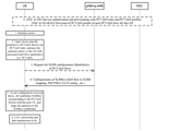
3GPP TR 38.885 V16.0.0の図7-1によれば、TX UEは、RX(Reception)UEとのサイドリンクユニキャスト通信中に、新しいPC5 QoSフローのためのSLRB設定を要求してもよい。次いで、gNBは、SLRB設定をTX(Transmission)UEに提供し、SLRB(Sidelink Radio Bearer)設定は、PC5 QoSフローのSLRB(またはSL-DRB)へのマッピングおよびSL-DRBのためのSLRBパラメータ(例えば、SDAP(Service Data Adaptation Protocol)、PDCP(Packet Data Convergence Protocol)、RLC(Radio Link Control)、またはLCH(Logical Channel)設定)を含んでもよい。 According to Figure 7-1 of 3GPP TR 38.885 V16.0.0, the TX UE requests SLRB settings for the new PC5 QoS flow during sidelink unicast communication with the RX (Reception) UE. You may. The gNB then provides the SLRB setting to the TX (Transmission) UE, and the SLRB (Sidelink Radio Bearer) setting is the mapping of the PC5 QoS flow to the SLRB (or SL-DRB) and the SLRB parameters for the SL-DRB ( For example, SDAP (Service Data Analysis Protocol), PDCP (Packet Data Convergence Protocol), RLC (Radio Link Control), or LCH (Logical Channel) setting) may be included.
3GPP RAN2#106 Chairman’s noteで議論されているように、NR SL QoSおよびSLRB設定に関するRAN2#106合意は、以下を含む。- RRC_CONNECTED UEの場合、新しいPC5 QoSフローの送信のために、それは、RRC専用シグナリングを介してPC5 QoSフローのQoS情報をgNB/ng-eNBに報告してもよい。- RRC_CONNECTED UEの場合、UEによって報告されたQoS情報に基づいて、gNB/ng-eNBはSLRB設定を提供し、RRC専用シグナリングを介してPC5 QoSフローのSLRBへのマッピングを設定してもよい。UEは、SLRB設定を受信した後にのみ、SLRBを確立/再設定することができる。UEがSLRBを確立/再設定するときについては、さらに検討する。- UEのSLユニキャストの場合、NW設定/事前設定されたSLRB設定は、TXのみに関連するSLRBパラメータと、TXとRXの両方に関連し、ピアUEと整列する必要があるSLRBパラメータとを含む。- SLユニキャストの場合、開始UEは、TXとRXの両方に関連し、ピアUEと整列する必要があるSLRBパラメータをピアUEに通知する。詳細パラメータについては、さらに検討する。
As discussed in
上記の合意によって、TX UEは、gNBからこれらのSLRBパラメータを受信した後、TXおよびRXの両方に関連するSLRBパラメータをRX UEに転送する必要がある。追加的に、3GPP電子メールの議論[107bis#12] “Running CR to TS37.324 for 5G_V2X_NRSL_v4”のSection 5.Xによって、gNBは、PC5 QoSフローを第2のSL-DRBに再マッピングしてもよく、RRCレイヤがPC5 QoSフローに対して新しいPC5 QoSフローのSL-DRBへのマッピングルールを設定したときに、PC5 QoSフローに対して新しいPC5 QoSフローのSL-DRBへのマッピングルールを記憶し、エンドマーカー制御PDU(旧PC5 QoSフローのための旧SL-DRB上で)をRX UEに送信してもよい。エンドマーカー制御PDUは、TX UEが関連するPC5 QoSフローの旧SL-DRBへのマッピングを停止することを示すために使用され、PC5 QoSフローからの次のサイドリンクデータPDUが第2のSL-DRBで送信されることを示唆する。TX UEは、事前設定またはRRC状態遷移を行うときにgNBによってブロードキャストされるシステム情報に基づいて、PC5 QoSフローの第2のSL-DRBへの再マッピングをしてもよい。
According to the above agreement, the TX UE needs to transfer the SLRB parameters related to both TX and RX to the RX UE after receiving these SLRB parameters from the gNB. In addition, 3GPP email discussion [107bis # 12] "Running CR to TS37.324 for 5G_V2X_NRSL_v4"
Uuインタフェースの場合、QoSフローのDRBへの再マッピングのための手順は、gNBが既存のQoSフローに対して新しいQoSフローのDRBへのマッピングを設定するときに行われる。UL送信の場合、gNBは、関連するQoSフローに対するエンドマーカー制御PDU(Protocol Data Unit)をUEから受信する前に、再マッピングが発生することを既に知っている。従って、gNBは、再マッピングが発生したときに、新しくマッピングされたDRB上で受信された関連QoSフローから上りリンクデータPDUをバッファすることを開始し、次いで、元のDRB上の関連QoSフローに対するエンドマーカー制御PDUの受信時に、これらのバッファされた上りリンクデータPDUを配信することができる。エンドマーカー制御PDUを受信することは、元のDRB上の全ての上りリンクデータPDUが受信され、上位レイヤに配信されるべきであったことを意味し、従って、関連するQoSフローからの上りリンクデータPDUの順次配信が、QoSフローのDRBへの再マッピング遷移中に確実にされ得る。 For the Uu interface, the procedure for remapping the QoS flow to the DRB is performed when the gNB sets the mapping of the new QoS flow to the DRB for the existing QoS flow. In the case of UL transmission, the gNB already knows that remapping will occur before receiving the end marker control PDU (Protocol Data Unit) for the associated quality of service from the UE. Therefore, when a remapping occurs, the gNB will start buffering the uplink data PDU from the associated QoS flow received on the newly mapped DRB and then against the associated QoS flow on the original DRB. These buffered uplink data PDUs can be delivered upon receipt of the end marker control PDU. Receiving an end marker control PDU means that all uplink data PDUs on the original DRB should have been received and delivered to higher layers, and therefore uplinks from the associated QoS flow. Sequential delivery of data PDUs can be ensured during the remapping transition of the QoS flow to the DRB.
PC5インタフェースの場合、TX UEはまた、エンドマーカー制御PDUをRX UEに送信することに加えて、PC5 QoSフローのSL-DRBへの再マッピングが発生したときに、RX UEに新しいマッピングを通知するために、PC5 RRC(Radio Resource Control)メッセージを送信する必要がある。PC5 RRCメッセージとエンドマーカー制御PDUは、異なるサイドリンクTB(Transport Block)で送信される可能性があるため、それらは、RX UEによって異なる時間インスタンスにおいて受信される可能性がある。エンドマーカー制御PDUが(例えば、PC5 RRCメッセージの送信に失敗したことにより)PC5 RRCメッセージの受信前にRX UEによって受信された場合、エンドマーカー制御PDUはRX UEによって無視される可能性がある。なぜなら、RX UEはエンドマーカー制御PDUに関連付けられたPC5 QoSフローに再マッピングが発生していないとみなすためである。結果として、RX UEは、バッファされたサイドリンクデータPDUを上位レイヤに配信するようにトリガされず、第2のSL-DRB上で送信されたこれらのサイドリンクデータPDUは、PC5 QoSフローのSL-DRBへの再マッピングを示すPC5 RRCメッセージがTX UEから後に受信された後に、RX UEによってバッファされる。 For the PC5 interface, the TX UE also notifies the RX UE of the new mapping when a remapping of the PC5 QoS flow to the SL-DRB occurs, in addition to sending the end marker control PDU to the RX UE. Therefore, it is necessary to send a PC5 RRC (Radio Quality Control) message. Since PC5 RRC messages and end marker control PDUs may be transmitted on different sidelink TBs (Transport Blocks), they may be received on different time instances by the RX UE. If the end marker control PDU is received by the RX UE prior to receiving the PC5 RRC message (eg, due to a failure to send the PC5 RRC message), the end marker control PDU may be ignored by the RX UE. This is because the RX UE considers that the remapping has not occurred in the PC5 QoS flow associated with the end marker control PDU. As a result, the RX UE is not triggered to deliver the buffered sidelink data PDUs to the higher layers, and these sidelink data PDUs transmitted over the second SL-DRB are the SLs of the PC5 QoS flow. -The PC5 RRC message indicating the remapping to the DRB is later received from the TX UE and then buffered by the RX UE.
関連するV2Xサービスへの影響は深刻である。なぜなら、第2のSL-DRBで送信される以下のサイドリンクデータPDUはすべて、PC5 QoSフローのSL-DRBへの再マッピングが発生した後にバッファされ、上位レイヤに配信されないためである。RX UEは、PC5 RRCメッセージの受信時に、これらのバッファされたサイドリンクデータPDUをいつ上位レイヤに配信するかを考慮するためにタイマを開始することができるが、この待ち時間は、必ずしも必要ではない。なぜなら、RX UEがすでにエンドマーカー制御PDUを受信しているためである。したがって、この問題は考慮され解決されるべきである。 The impact on related V2X services is serious. This is because all of the following sidelink data PDUs transmitted by the second SL-DRB are buffered after the remapping of the PC5 QoS flow to the SL-DRB occurs and are not delivered to the upper layer. The RX UE may start a timer upon receipt of the PC5 RRC message to consider when to deliver these buffered sidelink data PDUs to higher layers, but this wait time is not always necessary. do not have. This is because the RX UE has already received the end marker control PDU. Therefore, this issue should be considered and resolved.
1つの一般的な解決策は、RX UEが関連するPC5 QoSフローのためのエンドマーカー制御PDUを受信したが、RX UEが関連するPC5 QoSフローのためのPC5 QoSフローのSL-DRBへのマッピングを再設定するためのPC5 RRCメッセージを受信していないときに、RX UEはPC5 RRCメッセージの受信を期待することができる。PC5 RRCメッセージが受信されたときに、RX UEは、第2のSL-DRB上で関連するPC5 QoSフローからサイドリンクデータPDUの受信を開始してもよく、関連するPC5 QoSフローのための旧SL-DRB上のエンドマーカー制御PDUを待つことなく、それらの受信したサイドリンクデータPDUを上位レイヤに配信することができる。 One common solution is to receive an end marker control PDU for the PC5 QoS flow associated with the RX UE, but map the PC5 QoS flow to SL-DRB for the PC5 QoS flow associated with the RX UE. The RX UE can expect to receive the PC5 RRC message when it has not received the PC5 RRC message to reconfigure. Upon receipt of the PC5 RRC message, the RX UE may initiate reception of sidelink data PDUs from the associated PC5 QoS flow on the second SL-DRB, the old for the associated PC5 QoS flow. The received side link data PDUs can be delivered to the upper layer without waiting for the end marker control PDU on the SL-DRB.
別の可能性のある一般的な解決策は、PC5 RRCメッセージの送信に成功したことが下位レイヤによって確認されたときに、TX UEがエンドマーカー制御PDUをRX UEに送信することである。例えば、RLC(Radio Link Control)レイヤは、RX UEから受信した1つ以上のRLC STATUS PDUに従って、PC5 RRCメッセージの送信に成功したことを確認してもよく、RLC STATUS PDUは、どのRLC DATA PDUが受信されたかを示してもよい。別の例として、MAC(Medium Access Control)レイヤは、RX UEから受信したHARQフィードバックに従ってPC5 RRCメッセージの送信に成功したことを確認してもよく、HARQ(Hybrid Automatic Repeat Request)フィードバックは、PC5 RRCメッセージの送信に使用された論理チャネルを含むSL TBがRX UEによって受信されたことを示す。 Another possible common solution is for the TX UE to send an end marker control PDU to the RX UE when the lower layer confirms that the PC5 RRC message has been successfully sent. For example, the RLC (Radio Link Control) layer may confirm that the PC5 RRC message has been successfully transmitted according to one or more RLC STATUS PDUs received from the RX UE, and the RLC STATUS PDU may be any RLC DATA PDU. May indicate whether was received. As another example, the MAC (Medium Access Control) layer may confirm that the PC5 RRC message has been successfully transmitted according to the HARQ feedback received from the RX UE, and the HARQ (Hybrid Automatic Repeat Request) feedback is the PC5 RRC. Indicates that the SL TB containing the logical channel used to send the message was received by the RX UE.
PC5 RRCメッセージの受信に応答して、RX UEは、PC5 RRC完了メッセージをTX UEに返信してもよい。したがって、RX UEからのPC5 RRC完了メッセージを受信したときに、TX UEがエンドマーカー制御PDUを送信することも可能であってもよい。 In response to receiving the PC5 RRC message, the RX UE may reply the PC5 RRC completion message to the TX UE. Therefore, it may be possible for the TX UE to send an end marker control PDU when it receives the PC5 RRC completion message from the RX UE.
一般に、上記の2つの選択肢の両方とも、PC5 RRCメッセージを受信した後に、RX UEによってエンドマーカー制御PDUが受信されることを確実にすることができ、PC5 QoSフローのSL-DRBへの再マッピングを示すPC5 RRCメッセージを受信したときに、RX UEが、第2のSL-DRB上で受信した関連するPC5 QoSフローからのサイドリンクデータPDUのバッファを開始することができ、次に、エンドマーカー制御PDUの受信時に、これらのバッファリングされたサイドリンクデータPDUを上位レイヤに配信するようにする。 In general, both of the above two options can ensure that the RX UE receives the end marker control PDU after receiving the PC5 RRC message and remap the PC5 QoS flow to SL-DRB. Upon receiving the PC5 RRC message indicating, the RX UE may start buffering the sidelink data PDU from the associated PC5 QoS flow received on the second SL-DRB, and then the end marker. Upon receiving the control PDU, these buffered side link data PDUs are delivered to the upper layer.
さらに、3GPP電子メールの議論 [107bis#12] ” Running CR to TS37.324 for 5G_V2X_NRSL_v4”のセクション5.Xで規定されているように、TX UEにおけるサイドリンクユニキャスト通信に関連付けられたSDAP(Service Data Adaptation Protocol)エンティティは、RRCレイヤが、PC5 QoSフローに対する新しいPC5 QoSフローのSL-DRBへのマッピングルールを設定するときに、PC5 QoSフローに対する新しいPC5 QoSフローのSL-DRBへのマッピングルールを記憶するものとする。新しいマッピングルールでは、TX UEは、第2のSL-DRB上でPC5 QoSフローからのサイドリンクデータPDUを送信することを開始してもよい。また、PC5 QoSフローのSL-DRBへの再マッピングを示し、任意で、第2のSL-DRBのためのSLRBパラメータを含むPC5 RRCメッセージよりも早く、第2のSL-DRB上で送信されるサイドリンクデータPDUがRX UEによって受信され得ることが可能である。第2のSL-DRBに対して2つのケースがあり得る。すなわち、第2のSL-DRBは、既存のSL-DRBであるか、または新しく作成されるSL-DRBである。
In addition, 3GPP Email Discussion [107bis # 12] "Running CR to TS37.324 for 5G_V2X_NRSL_v4"
第2のSL-DRBが既存のSL-DRB(例えば、デフォルトのSL-DRBまたは非デフォルトのSL-DRB)である場合、これらのサイドリンクデータPDUは、バッファされることなく直接上位レイヤに配信される可能性があり、従って、関連するPC5 QoSフローに順序ずれ配信が発生することがある。第2のSL-DRBが新しいSL-DRBである場合、RX UEはこれらのサイドリンクデータPDUを復号することができない。なぜなら、PC5 RRCメッセージに含まれる新しいSL-DRBのためのSLRBパラメータがまだRX UEによって受信されていないためである。結果として、これらのサイドリンクデータPDUが失われる。PC5 QoSフローのSL-DRBへの再マッピング遷移中に順序ずれ配信またはデータ損失を回避する方法が考慮されるべきである。 If the second SL-DRB is an existing SL-DRB (eg, default SL-DRB or non-default SL-DRB), these sidelink data PDUs will be delivered directly to the upper layer without buffering. Therefore, out-of-order delivery may occur in the associated PC5 QoS flow. If the second SL-DRB is the new SL-DRB, the RX UE will not be able to decode these sidelink data PDUs. This is because the SLRB parameters for the new SL-DRB contained in the PC5 RRC message have not yet been received by the RX UE. As a result, these sidelink data PDUs are lost. Methods should be considered to avoid out-of-order delivery or data loss during the remapping transition of the PC5 QoS flow to SL-DRB.
一般に、可能な解決策は、PC5 RRCメッセージの送信に成功したことが下位レイヤによって確認されたか、またはRX UEからPC5 RRCメッセージに対応するPC5 RRC完了メッセージを受信したときに、TX UEが第2のSL-DRB上でサイドリンクデータPDUの送信を開始することである。 In general, a possible solution is when the lower layer confirms that the PC5 RRC message has been successfully sent, or when the RX UE receives a PC5 RRC completion message corresponding to the PC5 RRC message, the TX UE has a second. It is to start the transmission of the side link data PDU on the SL-DRB of.
サイドリンクユニキャスト通信に関連するSDAPエンティティは、RRCレイヤまたはTX UEがPC5 QoSフローに対する新しいPC5 QoSフローのSL-DRBへのマッピングルールを設定するときに、送信のためにエンドマーカー制御PDUを下位レイヤに送信し、関連するPC5 QoSフローに対して新しいPC5 QoSフローのSL-DRBへのマッピングルールを記憶するものとするため、上記の解決策を説明する別の方法は、PC5 RRCメッセージの下位レイヤによる送信が成功したとき、またはPC5 RRC完了メッセージがRX UEから受信されたときに、RRCレイヤまたはTX UEがPC5 QoSフローに対する新しいPC5 QoSフローのSL-DRBへのマッピングルールをSDAPエンティティに設定することである。 The SDAP entity associated with side-link unicast communication subordinates the end marker control PDU for transmission when the RRC layer or TX UE sets a mapping rule for the new PC5 QoS flow to SL-DRB for the PC5 QoS flow. Another way to explain the above solution is to subordinate the PC5 RRC message because it is to be sent to the layer and remember the mapping rules for the new PC5 QoS flow to SL-DRB for the associated PC5 QoS flow. When the layer transmission is successful, or when a PC5 RRC completion message is received from the RX UE, the RRC layer or TX UE sets a mapping rule for the new PC5 QoS flow to the SL-DRB for the PC5 QoS flow in the SDAP entity. It is to be.
図14は、第1のUEが、PC5 QoS(Quality of Service)フローのSL-DRB(Sidelink-Data Radio Bearer)への再マッピングをサポートする観点からの、1つの例示的な実施形態によるフローチャート1400である。ステップ1405において、第1のUEは、第2のUEとのサイドリンク通信を確立する。ステップ1410において、第1のUEは、サイドリンク通信のPC5 QoSフローを第1のSL-DRBへマッピングする。ステップ1415において、第1のUEは、PC5 RRCメッセージを第2のUEに送信し、PC5 RRCメッセージは、PC5 QoSフローが第2のSL-DRBにマッピングされることを示す。ステップ1420において、第1のUEは、PC5 RRCメッセージの送信に成功したことが下位レイヤによって確認された後、またはPC5 RRCメッセージに対応するPC5 RRC完了メッセージを第2のUEから受信した後、エンドマーカー制御PDUを第2のUEに送信する。
FIG. 14 is a
図3および図4を再度参照すると、第1のUEが、PC5 QoSフローのSL-DRBへの再マッピングサポートする1つの例示的な実施形態において、第1のUE300は、メモリ310に記憶されたプログラムコード312を含む。CPU 308は、プログラムコード312を実行して、第1のUEが、(i) 第2のUEとのサイドリンク通信を確立することと、(ii) サイドリンク通信のPC5 QoSフローを第1のSL-DRBへマッピングすることと、(iii) PC5 RRCメッセージを第2のUEに送信することであって、PC5 RRCメッセージは、PC5 QoSフローが第2のSL-DRBにマッピングされることを示す、送信することと、(iv) PC5 RRCメッセージの送信に成功したことが下位レイヤによって確認された後、またはPC5 RRCメッセージに対応するPC5 RRC完了メッセージを第2のUEから受信した後、エンドマーカー制御PDUを第2のUEに送信することと、を行うことを可能にすることができる。さらに、CPU308は、プログラムコード312を実行して、本明細書に記載の上述のアクションおよびステップまたは他のすべてを行うことができる。
Referring again to FIGS. 3 and 4, in one exemplary embodiment in which the first UE supports remapping the PC5 QoS flow to SL-DRB, the
図15は、第1のUEがPC5 QoSフローのSL-DRBへの再マッピングをサポートする観点からの、1つの例示的な実施形態によるフローチャート1500である。ステップ1505において、第1のUEは、第2のUEとのサイドリンク通信を確立する。ステップ1510において、第1のUEは、サイドリンク通信のPC5 QoSフローを第1のSL-DRBにマッピングする。ステップ1515において、第1のUEは、PC5 RRCメッセージを第2のUEに送信し、PC5 RRCメッセージは、PC5 QoSフローが第2のSL-DRBにマッピングされることを示す。ステップ1520において、第1のUEは、PC5 RRCメッセージの送信に成功したことが下位レイヤによって確認されたとき、またはPC5 RRCメッセージに対応するPC5 RRC完了メッセージを第2のUEから受信したときに、第2のSL-DRB上でPC5 QoSフローからのサイドリンクデータPDUを第2のUEに送信することを開始する。
FIG. 15 is a
図3および図4を参照すると、第1のUEがPC5 QoSフローのSL-DRBへの再マッピングをサポートする1つの例示的な実施形態である。第1のUE300は、メモリ310に記憶されたプログラムコード312を含む。CPU308は、プログラムコード312を実行して、第1のUEが、(i) 第2のUEとのサイドリンク通信を確立することと、(ii) サイドリンク通信のPC5 QoSフローを第1のSL-DRBにマッピングすることと、(iii) PC5 RRCメッセージを第2のUEに送信することであって、PC5 RRCメッセージは、PC5 QoSフローが第2のSL-DRBにマッピングされることを示す、送信することと、(iv) PC5 RRCメッセージの送信に成功したことが下位レイヤによって確認されたとき、またはPC5 RRCメッセージに対応するPC5 RRC完了メッセージを第2のUEから受信したときに、第2のSL-DRB上でPC5 QoSフローからのサイドリンクデータPDUを第2のUEに送信することを開始することと、を行うことを可能にすることができる。さらに、CPU308は、プログラムコード312を実行して、本明細書に記載の上述のアクションおよびステップまたは他のすべてを行うことができる。
Referring to FIGS. 3 and 4, the first UE is one exemplary embodiment that supports remapping of a PC5 QoS flow to SL-DRB. The
図14~15に例示され、上述した実施形態に関連して、一実施形態では、第1のUEは、PC5 RRCメッセージの送信に成功したことが下位レイヤによって確認された後、または第2のUEからPC5 RRC完了メッセージを受信した後に、サイドリンク通信のPC5 QoSフローを第2のSL-DRBに再マッピングすることができる。 Illustrated in FIGS. 14-15, in connection with the embodiments described above, in one embodiment, after the lower layer confirms that the first UE has successfully transmitted the PC5 RRC message, or the second. After receiving the PC5 RRC completion message from the UE, the PC5 QoS flow for sidelink communication can be remapped to the second SL-DRB.
図16は、第1のUEが、PC5 QoSフローのSL-DRBへの再マッピングをサポートする観点からの、1つの例示的な実施形態によるフローチャート1600である。ステップ1605において、第1のUEは、第2のUEとのサイドリンク通信を確立し、SDAPエンティティは、サイドリンク通信のために第1のUEによって生成される。ステップ1610において、第1のUEは、サイドリンク通信のPC5 QoSフローを第1のSL-DRBにマッピングする。ステップ1615において、第1のUEは、PC5のRRCメッセージを第2のUEに送信し、PC5 RRCメッセージは、PC5 QoSフローが第2のSL-DRBにマッピングされることを示す。ステップ1620において、第1のUEは、PC5 RRCメッセージの送信に成功したことが下位レイヤによって確認されたとき、またはPC5 RRCメッセージに対応するPC5 RRC完了メッセージを第2のUEから受信したときに、PC5 QoSフローに対する新しいPC5 QoSフローのSL-DRBへのマッピングルールをSDAPエンティティに設定する。
FIG. 16 is a
図3および図4を参照すると、第1のUEが、PC5 QoSフローのSL-DRBへの再マッピングをサポートする1つの例示的な実施形態である。第1のUE300は、メモリ310に記憶されたプログラムコード312を含む。CPU 308は、第1のUEが、(i) 第2のUEとのサイドリンク通信を確立することであって、SDAPエンティティは、サイドリンク通信のために第1のUEによって生成される、確立することと、(ii) サイドリンク通信のPC5 QoSフローを第1のSL-DRBにマッピングすることと、(iii) PC5のRRCメッセージを第2のUEに送信することであって、PC5 RRCメッセージは、PC5 QoSフローが第2のSL-DRBにマッピングされることを示す、送信することと、(iV) PC5 RRCメッセージの送信に成功したことが下位レイヤによって確認されたとき、またはPC5 RRCメッセージに対応するPC5 RRC完了メッセージを第2のUEから受信したときに、PC5 QoSフローに対する新しいPC5 QoSフローのSL-DRBへのマッピングルールをSDAPエンティティに設定することと、を行うことを可能にすることができる。さらに、CPU308は、プログラムコード312を実行して、本明細書に記載の上述のアクションおよびステップまたは他のすべてを行うことができる。
Referring to FIGS. 3 and 4, the first UE is one exemplary embodiment that supports remapping of a PC5 QoS flow to SL-DRB. The
図14~16に例示され、上述した実施形態に関連して、一実施形態では、第1のUEはまた、ネットワークノードからRRCメッセージを受信することができ、RRCメッセージは、PC5 QoSフローが第2のSL-DRBにマッピングされることを示す。 Illustrated in FIGS. 14-16, in connection with the embodiments described above, in one embodiment the first UE can also receive an RRC message from a network node, the RRC message being the PC5 QoS flow. It is shown that it is mapped to SL-DRB of 2.
一実施形態では、ネットワークノードは基地局(例えば、gNB)であってもよい。第1のUEはRRC_CONNECTEDであってもよい。サイドリンク通信は、サイドリンクユニキャスト通信であってもよい。RRCメッセージは、第2のSL-DRB上の送信と受信の両方に関連するSLRBパラメータを含んでもよい。代替的には、RRCメッセージは、第2のSL-DRB上の送信にのみ関連するSLRBパラメータを含んでもよい。 In one embodiment, the network node may be a base station (eg, gNB). The first UE may be RRC_CONNECTED. The side link communication may be side link unicast communication. The RRC message may include SLRB parameters related to both transmission and reception on the second SL-DRB. Alternatively, the RRC message may include SLRB parameters that are only relevant for transmission over the second SL-DRB.
一実施形態では、PC5 RRCメッセージは、第2のSL-DRB上の送信と受信の両方に関連するSLRBパラメータを含んでもよい。エンドマーカー制御PDUは、PC5 QoSフローのアイデンティティ、例えばPFI(PC5 QoS Flow Identifier)を含んでもよい。エンドマーカー制御PDUは、第1のSL-DRB上で送信されてもよい。 In one embodiment, the PC5 RRC message may include SLRB parameters associated with both transmission and reception on the second SL-DRB. The end marker control PDU may include the identity of the PC5 Quality of Service, such as PFI (PC5 Quality of Service Identifier). The end marker control PDU may be transmitted on the first SL-DRB.
一実施形態では、SDAPエンティティは、PC5 QoSフローに対して新しいPC5 QoSフローのSL-DRBへのマッピングルールが設定されたときに、エンドマーカー制御PDUを下位レイヤに送信することができる。さらに、SDAPエンティティは、PC5 QoSフローに対して新しいPC5 QoSフローのSL-DRBへのマッピングルールが設定されたときに、新しいPC5 QoSフローのSL-DRBへのマッピングルールを記憶することができる。追加的に、SDAPエンティティは、新しいPC5 QoSフローのSL-DRBへのマッピングルールが設定されたときに、サイドリンク通信のPC5 QoSフローを第2のSL-DRBに再マッピングすることができる。 In one embodiment, the SDAP entity can send an end marker control PDU to a lower layer when a new PC5 QoS flow mapping rule to SL-DRB is set for the PC5 QoS flow. Further, the SDAP entity can store the mapping rule for the new PC5 QoS flow to SL-DRB when the mapping rule for the new PC5 QoS flow to SL-DRB is set for the PC5 QoS flow. Additionally, the SDAP entity can remap the PC5 QoS flow for sidelink communication to the second SL-DRB when the mapping rule for the new PC5 QoS flow to SL-DRB is set.
図17は、第2のUEが、第1のUEとのサイドリンク通信のPC5 QoSフローのためのサイドリンク受信を行う観点からの1つの例示的な実施形態によるフローチャート1700である。ステップ1705において、第2のUEは、第1のUEからPC5 RRCメッセージを受信し、PC5 RRCメッセージは、PC5 QoSフローが第2のSL-DRBにマッピングされることを示す。ステップ1710において、第2のUEは、第1のUEから第2のSL-DRB上でPC5 QoSフローの1つ以上のサイドリンクデータPDUを受信する。ステップ1715において、第2のUEは、PC5 RRCメッセージを受信する前にPC5 QoSフローに対するエンドマーカー制御PDUを受信した場合、1つ以上のサイドリンクデータPDUを上位レイヤに配信する。
FIG. 17 is a
一実施形態では、第2のUEは、PC5 QoSフローのエンドマーカー制御PDUがまだ受信していない場合、1つ以上のサイドリンクデータPDUをバッファすることができ、それらを上位レイヤに配信しない。また、第2のUEは、PC5 RRCメッセージを受信した後にエンドマーカー制御PDUを受信した場合、1つ以上のサイドリンクデータPDUを配信し、第2のUEがPC5 RRCメッセージを受信する前にエンドマーカー制御PDUを受信しない。 In one embodiment, the second UE can buffer one or more sidelink data PDUs if the end marker control PDU of the PC5 QoS flow has not yet received and does not deliver them to the higher layers. Also, if the second UE receives the end marker control PDU after receiving the PC5 RRC message, it delivers one or more sidelink data PDUs and ends before the second UE receives the PC5 RRC message. Do not receive marker control PDUs.
一実施形態では、PC5 QoSフローは、PC5 RRCメッセージを受信する前に、第1のSL-DRBにマッピングされ得る。サイドリンク通信は、サイドリンクユニキャスト通信であり得る。PC5 RRCメッセージは、第2のSL-DRB上の送信と受信の両方に関連するSLRBパラメータを含んでもよいエンドマーカー制御PDUは、PC5 QoSフローのアイデンティティ、例えばPFI(PC5 QoS Flow Identifier)を含んでもよい。ネットワークノードは、基地局(例えば、gNB)であってもよい。 In one embodiment, the PC5 QoS flow may be mapped to a first SL-DRB prior to receiving the PC5 RRC message. The side link communication can be side link unicast communication. The PC5 RRC message may include SLRB parameters related to both transmission and reception on the second SL-DRB. The end marker control PDU may include the identity of the PC5 QoS flow, eg, PFI (PC5 QoS Flow Identifier). good. The network node may be a base station (eg, gNB).
図3および図4を参照すると、第2のUEが、第1のUEとのサイドリンク通信のPC5のQoSフローのためのサイドリンク受信を行う1つの例示的な実施形態である。第2のUE300は、メモリ310に記憶されたプログラムコード312を含む。CPU 308は、第2のUEが、(i) 第1のUEからPC5 RRCメッセージを受信することであって、PC5 RRCメッセージは、PC5 QoSフローが第2のSL-DRBにマッピングされることを示す、受信することと、(ii) 第1のUEから第2のSL-DRB上でPC5 QoSフローの1つ以上のサイドリンクデータPDUを受信することと、(iii)PC5 RRCメッセージを受信する前にPC5 QoSフローに対するエンドマーカー制御PDUを受信した場合、1つ以上のサイドリンクデータPDUを上位レイヤに配信することと、を行うことを可能にすることができる。さらに、CPU 308は、プログラムコード312を実行して、本明細書に記載の上述のアクションおよびステップまたは他のすべてを実行することができる。
Referring to FIGS. 3 and 4, the second UE is one exemplary embodiment of sidelink reception for a QoS flow of PC5 for sidelink communication with the first UE. The
以上、本開示の種々の態様を説明した。当然のことながら、本明細書の教示内容を多種多様な形態で具現化することができ、本明細書に開示したいかなる指定の構造、機能、または両者も代表的なものに過ぎない。本明細書の教示内容に基づいて、当業者には当然のことながら、本明細書に開示した態様を、他のいかなる態様からも独立に実装することができ、これら態様のうちの2つ以上を種々組み合わせることができる。例えば、本明細書に記載した態様のうちの任意の数の態様を用いて、装置を実装することができ、方法を実現することができる。追加的に、本明細書に記載した態様のうちの1つ以上の追加または代替で、他の構造、機能、または構造と機能を用いて、このような装置を実装することができ、このような方法を実現することができる。上記概念の一部の一例として、いくつかの態様においては、パルス繰り返し周波数に基づいて、同時チャネルを確立することができる。いくつかの態様においては、パルス位置またはオフセットに基づいて、同時チャネルを確立することができる。いくつかの態様においては、時間ホッピングシーケンスに基づいて、同時チャネルを確立することができる。いくつかの態様においては、パルス繰り返し周波数、パルス位置またはオフセット、および時間ホッピングシーケンスに基づいて同時チャネルを確立することができる。 The various aspects of the present disclosure have been described above. Of course, the teachings of this specification can be embodied in a wide variety of forms, and any designated structure, function, or both disclosed herein is representative. Based on the teachings of this specification, one of ordinary skill in the art can, of course, implement the embodiments disclosed herein independently of any other embodiment, and two or more of these embodiments. Can be combined in various ways. For example, any number of aspects described herein can be used to implement the device and implement methods. Additionally, in addition or alternative to one or more of the embodiments described herein, other structures, functions, or structures and functions may be used to implement such devices, such. Can be realized. As an example of some of the above concepts, in some embodiments, simultaneous channels can be established based on the pulse repetition frequency. In some embodiments, simultaneous channels can be established based on pulse position or offset. In some embodiments, simultaneous channels can be established based on a time hopping sequence. In some embodiments, simultaneous channels can be established based on pulse repetition frequency, pulse position or offset, and time hopping sequence.
当業者であれば、多様な異なるテクノロジおよび技術のいずれかを使用して、情報および信号を表わしてよいを理解するであろう。例えば、上記説明全体で言及されることがあるデータ、命令、コマンド、情報、信号、ビット、シンボル、およびチップは、電圧、電流、電磁波、磁場若しくは粒子、光場若しくは粒子、またはこれらの任意の組み合わせによって表わしてよい。 Those of skill in the art will understand that information and signals may be represented using any of a wide variety of different technologies and techniques. For example, the data, instructions, commands, information, signals, bits, symbols, and chips that may be referred to throughout the above description may be voltage, current, electromagnetic waves, magnetic fields or particles, light fields or particles, or any of these. It may be represented by a combination.
さらに、当業者には当然のことながら、本明細書に開示された態様に関連して説明した種々の例示的な論理ブロック、モジュール、プロセッサ、手段、回路、およびアルゴリズムステップは、電子的ハードウェア(例えば、ソースコーディングまたはその他何らかの技術を用いて設計することがあるディジタル実装、アナログ実装、またはこれら2つの組み合わせ)、命令を含む種々の形態のプログラム若しくは設計コード(本明細書においては便宜上、「ソフトウェア」または「ソフトウェアモジュール」と称されることがある)、または両者の組み合わせとして実装されてよい。このハードウェアおよびソフトウェアの互換性を明確に示すため、種々の例示的な構成要素、ブロック、モジュール、回路、およびステップを、概略的にそれぞれの機能の側面から上述した。そのような機能がハードウェアとして実装されるか、ソフトウェアとして実装されるかは、特定用途およびシステム全体に課される設計上の制約によって決まる。当業者であれば、特定各用途に対して、説明した機能を様々なやり方で実装してもよいが、そのような実装の決定は、本開示の範囲からの逸脱の原因として解釈されるべきではない。 Moreover, as a matter of course to those skilled in the art, the various exemplary logic blocks, modules, processors, means, circuits, and algorithm steps described in connection with the embodiments disclosed herein are electronic hardware. Various forms of programming or design code, including (eg, digital implementations, analog implementations, or a combination of the two, which may be designed using source coding or some other technique), instructions (in the present specification, for convenience, ". It may be implemented as "software" or "software module"), or a combination of both. To articulate this hardware and software compatibility, various exemplary components, blocks, modules, circuits, and steps have been outlined above in terms of their respective functions. Whether such functionality is implemented as hardware or software depends on the design constraints imposed on the particular application and the system as a whole. Those skilled in the art may implement the described functionality in various ways for each particular application, but such implementation decisions should be construed as a source of deviations from the scope of this disclosure. is not it.
追加的に、本明細書に開示される態様に関連して説明した種々の例示的な論理ブロック、モジュール、および回路は、集積回路(「IC」)、アクセス端末、またはアクセスポイント内で実装される、あるいはこれらによって実行されてよい。ICとしては、汎用プロセッサ、ディジタルシグナルプロセッサ(DSP)、特定用途向け集積回路(ASIC)、フィールドプログラマブルゲートアレイ(FPGA)、その他プログラマブル論理デバイス、ディスクリートゲート若しくはトランジスタロジック、ディスクリートハードウェアコンポーネント、電気部品、光学部品、機械部品、または本明細書で説明した機能を実行するように設計されたこれらの任意の組み合わせを含み、IC内、IC外、またはその両方に存在するコードまたは命令を実行してよい。汎用プロセッサは、マイクロプロセッサとしてよいが、代替として、プロセッサは、従来の任意のプロセッサ、コントローラ、マイクロコントローラ、または状態機械としてよい。また、プロセッサは、DSPとマイクロプロセッサとの組み合わせ、複数のマイクロプロセッサ、DSPコアと協働する1つ以上のマイクロプロセッサ、またはその他任意のこのような構成である、コンピュータデバイスの組み合わせとして実装されてよい。 Additionally, the various exemplary logic blocks, modules, and circuits described in connection with aspects disclosed herein are implemented within an integrated circuit (“IC”), access terminal, or access point. Or may be performed by these. ICs include general purpose processors, digital signal processors (DSPs), application specific integrated circuits (ASICs), field programmable gate arrays (FPGAs), other programmable logic devices, discrete gates or transistor logic, discrete hardware components, electrical components, etc. It may include optical components, mechanical components, or any combination of these designed to perform the functions described herein, and may execute codes or instructions that are present inside, outside, or both ICs. .. The general purpose processor may be a microprocessor, but as an alternative, the processor may be any conventional processor, controller, microcontroller, or state machine. The processor may also be implemented as a combination of a DSP and a microprocessor, multiple microprocessors, one or more microprocessors working with a DSP core, or any other combination of computer devices in such a configuration. good.
任意の開示プロセスにおけるステップの如何なる特定の順序または階層は、実例的な手法の一例であることが了解される。設計の選好に基づいて、プロセスにおけるステップの特定の順序または階層を、本開示の範囲内に留まりつつ、再構成してよいことが了解される。添付の方法の請求項は、種々のステップの要素を実例的な順序で示しており、提示の特定順序または階層に限定されることを意図していない。 It is understood that any particular sequence or hierarchy of steps in any disclosure process is an example of an exemplary approach. It is understood that the particular order or hierarchy of steps in the process may be reconstructed, while remaining within the scope of the present disclosure, based on design preferences. The claims of the attached method show the elements of the various steps in an exemplary order and are not intended to be limited to a particular order or hierarchy of presentations.
本明細書に開示される態様に関連して記載された方法またはアルゴリズムのステップを、ハードウェアにおいて直接具現化してよく、プロセッサにより実行されるソフトウェアモジュールにおいて具現化してよく、これら2つの組み合わせにおいて具現化してよい。(例えば、実行可能な命令および関連するデータを含む)ソフトウェアモジュールおよび他のデータは、RAMメモリ、フラッシュメモリ、ROMメモリ、EPROMメモリ、EEPROMメモリ、レジスタ、ハードディスク、リムバーブルディスク、CD-ROM等のデータメモリ、または当技術分野において知られているその他任意の形態のコンピュータ可読記憶媒体に存在してよい。実例的な記憶媒体がコンピュータ/プロセッサ(本明細書においては便宜上、「プロセッサ」と称されることがある)等の機械に結合されてよい、このようなプロセッサは、記憶媒体からの情報(例えば、コード)の読み出しおよび記憶媒体への情報の書き込みが可能である。実例的な記憶媒体は、プロセッサと一体化されてよい。プロセッサおよび記憶媒体は、ASICに存在してよい。ASICは、ユーザ機器に存在していてもよい。代替として、プロセッサおよび記憶媒体は、ディスクリートコンポーネントとしてユーザ機器に存在してよい。さらに、いくつかの態様においては、任意の適当なコンピュータプログラム製品が、本開示の態様のうちの1つ以上に関連するコードを含むコンピュータ可読媒体を含んでもよい。いくつかの態様において、コンピュータプログラム製品は、パッケージング材料を含んでよい。 The steps of the methods or algorithms described in relation to the embodiments disclosed herein may be embodied directly in hardware, in software modules executed by a processor, and in a combination of the two. It may be changed. Software modules and other data (including, for example, executable instructions and related data) include RAM memory, flash memory, ROM memory, EPROM memory, EEPROM memory, registers, hard disks, removable disks, CD-ROMs, etc. It may reside in data memory, or any other form of computer-readable storage medium known in the art. An exemplary storage medium may be coupled to a machine such as a computer / processor (sometimes referred to herein as a "processor" for convenience), such a processor being information from the storage medium (eg, "processor"). , Code) can be read and information can be written to the storage medium. The exemplary storage medium may be integrated with the processor. The processor and storage medium may be present in the ASIC. The ASIC may be present in the user equipment. Alternatively, the processor and storage medium may be present in the user equipment as discrete components. Further, in some embodiments, any suitable computer program product may comprise a computer-readable medium containing the code associated with one or more of the embodiments of the present disclosure. In some embodiments, the computer program product may include packaging material.
以上、種々の態様に関連して本発明を説明したが、本発明は、さらに改良可能であることが了解される。本願は、概して本発明の原理に従うと共に、本発明が関係する技術分野における既知で慣習的な実施となるような本開示からの逸脱を含む本発明の任意の変形、使用、または適応を網羅することを意図している。 Although the present invention has been described above in relation to various aspects, it is understood that the present invention can be further improved. The present application generally follows the principles of the invention and covers any modification, use, or adaptation of the invention, including deviations from the present disclosure that would be known and customary practices in the art in which the invention relates. Is intended to be.
Claims (16)
第2のUEとのサイドリンク通信の確立することと、
前記サイドリンク通信のPC5 QoSフローを第1のSL-DRBへマッピングすることと、PC5 RRC(Radio Resource Control)メッセージを前記第2のUEに送信することであって、前記PC5 RRCメッセージは、前記PC5 QoSフローが第2のSL-DRBにマッピングされることを示す、送信することと、
前記PC5 RRCメッセージの送信に成功したことが下位レイヤによって確認された後、または前記PC5 RRCメッセージに対応するPC5 RRC完了メッセージを前記第2のUEから受信した後、エンドマーカー制御PDU(Protocol Data Unit)を前記第2のUEに送信することと、
前記PC5 RRCメッセージ送信に成功したことが下位レイヤによって確認された後、または前記PC5 RRC完了メッセージを前記第2のUEから受信した後、前記サイドリンク通信の前記PC5 QoSフローを前記第2のSL-DRBに再マッピングすることと、を含む、方法。 A first UE (user device) is a method for supporting remapping of a PC5 QoS (Quality of Service) flow to SL-DRB (Siderink-Data Radio Bearer).
Establishing side-link communication with the second UE,
The PC5 QoS flow of the side link communication is mapped to the first SL-DRB, and the PC5 RRC (Radio Quality Control) message is transmitted to the second UE, and the PC5 RRC message is the above. Sending and transmitting, indicating that the PC5 QoS flow is mapped to the second SL-DRB.
After the lower layer confirms that the PC5 RRC message has been successfully transmitted, or after receiving the PC5 RRC completion message corresponding to the PC5 RRC message from the second UE, the end marker control PDU (Protocol Data Unit) ) To the second UE
After the lower layer confirms that the PC5 RRC message transmission was successful, or after receiving the PC5 RRC completion message from the second UE, the PC5 QoS flow of the side link communication is transferred to the second SL. -Methods, including remapping to DRB .
制御回路と、
前記制御回路に設けられたプロセッサと、
前記制御回路内に設置され、前記プロセッサに動作可能に結合されたメモリと、を含み、
前記プロセッサは、前記メモリに記憶されたプログラムコードを実行して、
第2のUEとのサイドリンク通信の確立することと、
前記サイドリンク通信のPC5 QoS(Quality of Service)フローを第1のSL-DRB(Sidelink-Data Radio Bearer)へマッピングすることと、
PC5 RRC(Radio Resource Control)メッセージを前記第2のUEに送信することであって、前記PC5 RRCメッセージは、前記PC5 QoSフローが第2のSL-DRBにマッピングされることを示す、送信することと、
前記PC5 RRCメッセージの送信に成功したことが下位レイヤによって確認された後、または前記PC5 RRCメッセージに対応するPC5 RRC完了メッセージを前記第2のUEから受信した後、エンドマーカー制御PDU(Protocol Data Unit)を前記第2のUEに送信することと、
前記PC5 RRCメッセージ送信に成功したことが下位レイヤによって確認された後、または前記PC5 RRC完了メッセージを前記第2のUEから受信した後、前記サイドリンク通信の前記PC5 QoSフローを前記第2のSL-DRBに再マッピングすることと、を行うように構成されている、UE。 UE (user equipment)
Control circuit and
The processor provided in the control circuit and
Including a memory installed in the control circuit and operably coupled to the processor.
The processor executes the program code stored in the memory,
Establishing side-link communication with the second UE,
Mapping the PC5 QoS (Quality of Service) flow of the side link communication to the first SL-DRB (Siderink-Data Radio Bearer), and
Sending a PC5 RRC (Radio Quality Control) message to the second UE, the PC5 RRC message indicating that the PC5 QoS flow is mapped to the second SL-DRB. When,
After the lower layer confirms that the PC5 RRC message has been successfully transmitted, or after receiving the PC5 RRC completion message corresponding to the PC5 RRC message from the second UE, the end marker control PDU (Protocol Data Unit) ) To the second UE
After the lower layer confirms that the PC5 RRC message transmission was successful, or after receiving the PC5 RRC completion message from the second UE, the PC5 QoS flow of the side link communication is transferred to the second SL. -The UE configured to remap to the DRB and to do.
ネットワークノードからRRCメッセージを受信することであって、前記RRCメッセージは、前記PC5 QoSフローが前記第2のSL-DRBにマッピングされることを示す、受信することを行うように構成されている、請求項9に記載のUE。 The processor executes the program code stored in the memory,
Receiving an RRC message from a network node, wherein the RRC message is configured to perform receiving, indicating that the PC5 QoS flow is mapped to the second SL-DRB. The UE according to claim 9 .
Applications Claiming Priority (2)
| Application Number | Priority Date | Filing Date | Title |
|---|---|---|---|
| US201962927332P | 2019-10-29 | 2019-10-29 | |
| US62/927,332 | 2019-10-29 |
Publications (3)
| Publication Number | Publication Date |
|---|---|
| JP2021072619A JP2021072619A (en) | 2021-05-06 |
| JP2021072619A5 JP2021072619A5 (en) | 2021-07-26 |
| JP7033637B2 true JP7033637B2 (en) | 2022-03-10 |
Family
ID=73014242
Family Applications (1)
| Application Number | Title | Priority Date | Filing Date |
|---|---|---|---|
| JP2020173832A Active JP7033637B2 (en) | 2019-10-29 | 2020-10-15 | Methods and devices for supporting remapping of QoS (Quality of Service) flows to DRBs (Data Radio Bearers) for side-link communication in wireless communication systems. |
Country Status (7)
| Country | Link |
|---|---|
| US (1) | US10952230B1 (en) |
| EP (1) | EP3817447B1 (en) |
| JP (1) | JP7033637B2 (en) |
| KR (1) | KR102269703B1 (en) |
| CN (1) | CN112752299B (en) |
| ES (1) | ES2901630T3 (en) |
| TW (1) | TWI750851B (en) |
Families Citing this family (8)
| Publication number | Priority date | Publication date | Assignee | Title |
|---|---|---|---|---|
| WO2020197279A1 (en) * | 2019-03-28 | 2020-10-01 | Lg Electronics Inc. | Method and apparatus for exchange of capability information for sidelink communications in a wireless communication system |
| TWI721923B (en) * | 2019-08-02 | 2021-03-11 | 華碩電腦股份有限公司 | Method and apparatus for releasing sidelink radio bearer in a wireless communication system |
| EP4024943A4 (en) * | 2019-10-02 | 2022-09-14 | Samsung Electronics Co., Ltd. | Method and device for performing communication between terminals in wireless communication system |
| BR112022011462A2 (en) * | 2019-12-13 | 2022-08-23 | Beijing Xiaomi Mobile Software Co Ltd | METHOD FOR PROCESSING DATA, USER EQUIPMENT, AND MEMORY STORAGE MEDIA |
| US11140574B1 (en) * | 2020-03-18 | 2021-10-05 | Sprint Spectrum L.P. | Dynamic PDCP duplication with bearer modification, to help overcome reduced wireless quality |
| US11659410B2 (en) * | 2021-05-03 | 2023-05-23 | Qualcomm Incorporated | Directional quality of service for beamformed sidelink communication |
| EP4327533A1 (en) * | 2021-05-07 | 2024-02-28 | Huawei Technologies Co., Ltd. | Method and apparatus for group quality-of-service control of multiple quality-of-service flows |
| CN117981440A (en) * | 2021-09-17 | 2024-05-03 | 瑞典爱立信有限公司 | Terminal device, network node and method therein |
Citations (2)
| Publication number | Priority date | Publication date | Assignee | Title |
|---|---|---|---|---|
| US20180324631A1 (en) | 2017-05-05 | 2018-11-08 | Mediatek Inc. | Using sdap headers for handling of as/nas reflective qos and to ensure in-sequence packet delivery during remapping in 5g communication systems |
| US20190320362A1 (en) | 2018-04-13 | 2019-10-17 | Qualcomm Incorporated | Facilitating quality of service flow remapping utilizing a service data adaptation protocol layer |
Family Cites Families (33)
| Publication number | Priority date | Publication date | Assignee | Title |
|---|---|---|---|---|
| WO2007146431A2 (en) * | 2006-06-15 | 2007-12-21 | Interdigital Technology Corporation | Method and apparatus for reducing transmission overhead |
| US10965479B2 (en) * | 2016-04-02 | 2021-03-30 | Comcast Cable Communications, Llc | Bearer modification for V2X communications |
| KR20180090658A (en) * | 2017-02-03 | 2018-08-13 | 삼성전자주식회사 | Method and apparatus for processing a security key in a handover using multiple connections in a mobile communication system |
| WO2018159959A1 (en) * | 2017-03-01 | 2018-09-07 | Lg Electronics Inc. | Method for transmitting tcp ack packet in wireless communication system and a device therefor |
| US10187928B2 (en) | 2017-03-07 | 2019-01-22 | Indian Institute Of Technology Bombay | Methods and systems for controlling a SDN-based multi-RAT communication network |
| CN108633074B (en) * | 2017-03-23 | 2022-05-13 | 华硕电脑股份有限公司 | Method and apparatus for reporting side link service assistance information in wireless communication system |
| KR102293998B1 (en) * | 2017-03-30 | 2021-08-27 | 삼성전자 주식회사 | Method for data processing considering TCP-IP |
| ES2758174T3 (en) * | 2017-07-20 | 2020-05-04 | Asustek Comp Inc | Method and apparatus for providing QoS flow service (quality of service) in a wireless communication system |
| EP3435700B1 (en) * | 2017-07-24 | 2020-09-16 | ASUSTek Computer Inc. | Method and apparatus for serving quality of service (qos) flow in a wireless communication system |
| GB2565536A (en) * | 2017-08-10 | 2019-02-20 | Nec Corp | Communication system |
| US10694427B2 (en) * | 2017-09-27 | 2020-06-23 | Intel IP Corporation | Solution for vehicle-to-everything (V2X) communication authorization in 5G system |
| CN110892749A (en) * | 2018-02-14 | 2020-03-17 | Lg电子株式会社 | Method and apparatus for modifying mapping rules |
| CN113630827B (en) * | 2018-04-04 | 2023-12-29 | 北京三星通信技术研究有限公司 | Method for supporting switching and corresponding base station and network node |
| US20190349805A1 (en) | 2018-05-11 | 2019-11-14 | Mediatek Inc. | User equipments and methods for handling an update on quality of service (qos) flow to data radio bearer (drb) mapping |
| KR102629306B1 (en) * | 2018-05-21 | 2024-01-25 | 삼성전자 주식회사 | A method and apparatus of processing by classifying sdap control pdu in a mobile communication system |
| US20190373666A1 (en) * | 2018-05-29 | 2019-12-05 | Phazr, Inc. | Systems and Methods for Wireless Communication Using Control and User Plane Separation in a Virtualized Radio Base Stations Network |
| US11071025B2 (en) * | 2018-06-29 | 2021-07-20 | FG Innovation Company Limited | Cell handover with minimum mobility interruption |
| US20200037132A1 (en) * | 2018-07-27 | 2020-01-30 | Qualcomm Incorporated | Methods and apparatus for peer ue search and notification for unicast over sidelink |
| US20200037190A1 (en) * | 2018-07-30 | 2020-01-30 | Qualcomm Incorporated | Methods and apparatus for qos support for sidelink in network scheduled mode |
| US11184819B2 (en) * | 2018-09-20 | 2021-11-23 | Qualcomm Incorporated | Avoiding out of order uplink data reception upon data radio bearer release, handover to another data radio bearer, or quality of service flow addition |
| US11102839B2 (en) * | 2018-11-02 | 2021-08-24 | Qualcomm Incorporated | Unicast sidelink establishment |
| US11224007B2 (en) * | 2018-11-19 | 2022-01-11 | Huawei Technologies Co., Ltd. | System and method for supporting sidelink radio bearers |
| US11553542B2 (en) * | 2019-01-11 | 2023-01-10 | Qualcomm Incorporated | Device-to-device signaling |
| US11252777B2 (en) * | 2019-01-27 | 2022-02-15 | Qualcomm Incorporated | Coordinating radio resource control signaling with upper layer direct link establishment procedures |
| KR20200094343A (en) * | 2019-01-30 | 2020-08-07 | 삼성전자주식회사 | Apparatus and method for configuring and managing quality of service of radio bearer for direct communication in wireless communication system |
| US11910457B2 (en) * | 2019-01-31 | 2024-02-20 | Apple Inc. | Unicast sidelink access stratum level connection maintenance |
| KR102658886B1 (en) * | 2019-02-14 | 2024-04-18 | 삼성전자 주식회사 | Method and apparatus for performing user equipment capability procedure for supporting vehicle communication in next generation mobile communication system |
| TWI713343B (en) * | 2019-03-14 | 2020-12-11 | 華碩電腦股份有限公司 | Method and apparatus for sidelink logical channel establishment in a wireless communication system |
| KR20210135336A (en) * | 2019-03-26 | 2021-11-12 | 삼성전자주식회사 | Method and apparatus for initiating RRC (RADIO RESOURCE CONTROL) connection for V2X (VEHICLE-TO-EVERYTHING) communication |
| KR20200114863A (en) * | 2019-03-29 | 2020-10-07 | 삼성전자주식회사 | Apparatus and method for supporting one-to-one communication service in wireless communication system |
| US11464066B2 (en) * | 2019-04-05 | 2022-10-04 | Qualcomm Incorporated | Establishing radio bearers on millimeter wave frequencies for device-to-device communications |
| KR102631108B1 (en) * | 2019-04-26 | 2024-01-30 | 삼성전자 주식회사 | METHOD FOR SUPPORTING DEVICE TO DEVICE COMMUNICATION THROUGH BROADCAST AND GROUPCAST BASED ON QoS FLOW IN WIRELESS COMMUNICATION SYSTEM |
| US11979932B2 (en) * | 2019-05-10 | 2024-05-07 | Qualcomm Incorporated | Radio link maintenance for sidelink wireless communications |
-
2020
- 2020-10-15 JP JP2020173832A patent/JP7033637B2/en active Active
- 2020-10-15 EP EP20201921.2A patent/EP3817447B1/en active Active
- 2020-10-15 KR KR1020200133491A patent/KR102269703B1/en active IP Right Grant
- 2020-10-15 ES ES20201921T patent/ES2901630T3/en active Active
- 2020-10-15 US US17/071,145 patent/US10952230B1/en active Active
- 2020-10-15 CN CN202011101368.9A patent/CN112752299B/en active Active
- 2020-10-15 TW TW109135789A patent/TWI750851B/en active
Patent Citations (2)
| Publication number | Priority date | Publication date | Assignee | Title |
|---|---|---|---|---|
| US20180324631A1 (en) | 2017-05-05 | 2018-11-08 | Mediatek Inc. | Using sdap headers for handling of as/nas reflective qos and to ensure in-sequence packet delivery during remapping in 5g communication systems |
| US20190320362A1 (en) | 2018-04-13 | 2019-10-17 | Qualcomm Incorporated | Facilitating quality of service flow remapping utilizing a service data adaptation protocol layer |
Non-Patent Citations (2)
| Title |
|---|
| Huawei, HiSilicon,Remaining issues on SLRB configuration,3GPP TSG-RAN WG2 Meeting #107 R2-1913712,2019年10月04日,pp.1-12 |
| ZTE Corporation, Sanechips,Discussion on SDAP issues,3GPP TSG RAN WG2 Meeting #107 R2-1909080,2019年08月16日,pp.1-5 |
Also Published As
| Publication number | Publication date |
|---|---|
| EP3817447A1 (en) | 2021-05-05 |
| TWI750851B (en) | 2021-12-21 |
| ES2901630T3 (en) | 2022-03-23 |
| US10952230B1 (en) | 2021-03-16 |
| EP3817447B1 (en) | 2021-11-03 |
| KR20210053192A (en) | 2021-05-11 |
| TW202118337A (en) | 2021-05-01 |
| CN112752299B (en) | 2021-12-14 |
| KR102269703B1 (en) | 2021-06-28 |
| CN112752299A (en) | 2021-05-04 |
| JP2021072619A (en) | 2021-05-06 |
Similar Documents
| Publication | Publication Date | Title |
|---|---|---|
| JP7033637B2 (en) | Methods and devices for supporting remapping of QoS (Quality of Service) flows to DRBs (Data Radio Bearers) for side-link communication in wireless communication systems. | |
| JP6994439B2 (en) | Methods and Devices for Providing Quality of Service (QoS) Flows in Wireless Communities | |
| JP6779343B2 (en) | Methods and devices for handling sidelink reception in wireless communication systems | |
| JP6970267B2 (en) | Methods and equipment for requesting sidelink transmission resources in wireless communication systems | |
| KR102468109B1 (en) | Method and apparatus for reporting ue (user equipment) capability information for slrb (sidelink radio bearer) configuration in a wireless communication system | |
| JP7071472B2 (en) | Methods and devices for transmitting device-to-device sidelink reports in wireless communication systems. | |
| JP2020102842A (en) | Method and apparatus for supporting one-to-one sidelink communication in wireless communication system | |
| JP2020150537A (en) | Method and apparatus for side link logical channel establishment in wireless communication system | |
| JP6902651B2 (en) | Methods and Devices for Requesting Sidelink Radio Bearer (SLRB) Settings for Unicast Transmission in Wireless Communities | |
| JP6983297B2 (en) | Methods and devices for establishing sidelink SRB (Signaling Radio Bearer) in wireless communication systems | |
| CN113163454B (en) | Method and apparatus for requesting sidelink transmission resource in wireless communication system | |
| KR102345732B1 (en) | Method and apparatus for sidelink identifier change in a wireless communication system | |
| CN116033602B (en) | Method and apparatus for supporting user equipment to network relay communication in wireless communication system | |
| CN116033600B (en) | Method and apparatus for supporting user equipment to network relay communication in wireless communication | |
| KR20190085447A (en) | Apparatus and method for performing control signaling in wireless communication system | |
| US11665709B1 (en) | Method and apparatus for supporting sidelink relay adaptation layer for UE-to-network relay in a wireless communication system | |
| WO2024022343A1 (en) | Method and apparatus used in wireless communication | |
| KR20240018362A (en) | Method and apparatus for duplicate pdu discarding for multi-path transmission in a wireless communication system | |
| CN117500089A (en) | Method and user equipment for duplicate protocol data unit discarding |
Legal Events
| Date | Code | Title | Description |
|---|---|---|---|
| A621 | Written request for application examination |
Free format text: JAPANESE INTERMEDIATE CODE: A621 Effective date: 20201211 |
|
| A521 | Request for written amendment filed |
Free format text: JAPANESE INTERMEDIATE CODE: A523 Effective date: 20210518 |
|
| A871 | Explanation of circumstances concerning accelerated examination |
Free format text: JAPANESE INTERMEDIATE CODE: A871 Effective date: 20210518 |
|
| A131 | Notification of reasons for refusal |
Free format text: JAPANESE INTERMEDIATE CODE: A131 Effective date: 20210824 |
|
| TRDD | Decision of grant or rejection written | ||
| A01 | Written decision to grant a patent or to grant a registration (utility model) |
Free format text: JAPANESE INTERMEDIATE CODE: A01 Effective date: 20220215 |
|
| A61 | First payment of annual fees (during grant procedure) |
Free format text: JAPANESE INTERMEDIATE CODE: A61 Effective date: 20220228 |
|
| R150 | Certificate of patent or registration of utility model |
Ref document number: 7033637 Country of ref document: JP Free format text: JAPANESE INTERMEDIATE CODE: R150 |