JP7029442B2 - Devices, systems and methods for temperature limiting indications and detection of temperature sensitive items - Google Patents
Devices, systems and methods for temperature limiting indications and detection of temperature sensitive items Download PDFInfo
- Publication number
- JP7029442B2 JP7029442B2 JP2019510703A JP2019510703A JP7029442B2 JP 7029442 B2 JP7029442 B2 JP 7029442B2 JP 2019510703 A JP2019510703 A JP 2019510703A JP 2019510703 A JP2019510703 A JP 2019510703A JP 7029442 B2 JP7029442 B2 JP 7029442B2
- Authority
- JP
- Japan
- Prior art keywords
- sensor
- temperature
- fluid
- container
- microfluidic
- Prior art date
- Legal status (The legal status is an assumption and is not a legal conclusion. Google has not performed a legal analysis and makes no representation as to the accuracy of the status listed.)
- Active
Links
Images


Classifications
-
- G—PHYSICS
- G01—MEASURING; TESTING
- G01K—MEASURING TEMPERATURE; MEASURING QUANTITY OF HEAT; THERMALLY-SENSITIVE ELEMENTS NOT OTHERWISE PROVIDED FOR
- G01K11/00—Measuring temperature based upon physical or chemical changes not covered by groups G01K3/00, G01K5/00, G01K7/00 or G01K9/00
- G01K11/06—Measuring temperature based upon physical or chemical changes not covered by groups G01K3/00, G01K5/00, G01K7/00 or G01K9/00 using melting, freezing, or softening
-
- B—PERFORMING OPERATIONS; TRANSPORTING
- B65—CONVEYING; PACKING; STORING; HANDLING THIN OR FILAMENTARY MATERIAL
- B65D—CONTAINERS FOR STORAGE OR TRANSPORT OF ARTICLES OR MATERIALS, e.g. BAGS, BARRELS, BOTTLES, BOXES, CANS, CARTONS, CRATES, DRUMS, JARS, TANKS, HOPPERS, FORWARDING CONTAINERS; ACCESSORIES, CLOSURES, OR FITTINGS THEREFOR; PACKAGING ELEMENTS; PACKAGES
- B65D79/00—Kinds or details of packages, not otherwise provided for
- B65D79/02—Arrangements or devices for indicating incorrect storage or transport
Description
本出願は、2016年8月31日に出願された、オーストラリア仮特許出願第2016903474号の利益を主張するものであり、その内容は、本明細書の一部を構成するものとして本明細書に援用する。 This application claims the benefit of Australian Provisional Patent Application No. 2016903474, filed on August 31, 2016, the contents of which are incorporated herein by reference. Use it.
本発明は、品物の温度制限の違反を示すための装置、温度制限違反を検出するためのシステムおよび方法に関する。特に(排他的なものではない)、感温性品物の保管、処理および移送の間に生じる温度制限違反の恒久的な機械読み取り可能な指示を可能とする装置に関する。 The present invention relates to a device for indicating a temperature limit breach of an article, a system and a method for detecting a temperature limit breach. In particular (not exclusively) with respect to devices that allow permanent machine-readable instructions for temperature limit violations that occur during storage, processing and transfer of temperature sensitive items.
いくつかの例を挙げると赤血球、血漿、細菌株またはウイルス株、胚、配偶子、および抽出されたDNAのような、特定の生体試料は、長期保管のために非常に低い温度で維持されることを必要とされる。当該試料は、典型的には、-60℃から-200℃未満の温度で維持されることを必要とされる。これを達成するために、試料は通常、バイアル、バッグ、カセットまたは他の類似する容器に入れられ、機械的冷凍庫内に若しくはドライアイスに-60℃から-150℃の温度で保管され、または液体窒素を包含する極低温タンク内に-150℃未満で保管される。当該温度での保管は、試料の完全な状態を確保し、したがって解凍されたときの細胞の生存可能性を最大化する。 Certain biological samples, such as red blood cells, plasma, bacterial or viral strains, embryos, gametes, and extracted DNA, are maintained at very low temperatures for long-term storage, to name a few. Is needed. The sample is typically required to be maintained at a temperature of −60 ° C. to less than −200 ° C. To achieve this, the sample is usually placed in a vial, bag, cassette or other similar container and stored in a mechanical freezer or on dry ice at a temperature of -60 ° C to -150 ° C, or a liquid. Stored below -150 ° C in a cryogenic tank containing nitrogen. Storage at that temperature ensures the perfect condition of the sample and thus maximizes the viability of the cells when thawed.
異なる生体試料は、異なる臨界温度、つまり、細胞構造レベルで変化が生じ得る温度を超える温度、したがって生体試料が劣化し得る温度を超える温度を有する。試料は、必ずしもその臨界温度を超えて解凍するわけではなく(通常は水のガラス転移温度と考えられる)、凍結状態を維持している間に細胞の損傷を被り得る。試料は、最初に凍結されたときから最終処理のために制御された方法で意図的に解凍されるまで、常にその臨界温度より下に保たれなければならないと、一般的に認められている。 Different biological samples have different critical temperatures, that is, temperatures above the temperature at which changes can occur at the cellular structure level, and thus above the temperature at which the biological sample can deteriorate. The sample does not necessarily thaw above its critical temperature (usually considered to be the glass transition temperature of water) and can suffer cell damage while maintaining a frozen state. It is generally accepted that a sample must always be kept below its critical temperature from the time it is first frozen until it is deliberately thawed in a controlled manner for final treatment.
同様に、同じ原理が、いくつかの例を挙げると生鮮食品、食品、傷みやすいもの、調剤、薬品、および化合物などの他の感温性製品に当てはまる。例えば、冷凍食品のための典型的な基準は、-18℃未満の温度で保管され、扱われなければならないということである。つまり、品物のそれぞれの種類は、利用できるように保つことを確保するために異なる臨界温度値または範囲に依存する。安全温度で凍結され、安定にされた後、さらなる保管、処理または移送は、品物がその臨界温度より低く保たれることを確保しなければならない。そうしないと、品物が利用できなくなり得、治療のための薬など、かなりの金銭的価値または重要性を有する品物の損失をもたらす。 Similarly, the same principles apply to other temperature-sensitive products such as fresh foods, foods, perishables, preparations, medicines, and compounds, to name a few. For example, a typical standard for frozen foods is that they must be stored and handled at temperatures below -18 ° C. That is, each type of item depends on a different critical temperature value or range to ensure that it remains available. After being frozen and stabilized at a safe temperature, further storage, processing or transfer must ensure that the item is kept below its critical temperature. Otherwise, the item may become unavailable, resulting in the loss of items of considerable monetary value or significance, such as medications for treatment.
前述の品物を消費し、または処理するそれぞれの業界は、品物の温度およびトラッキングを維持するために異なる保管、処理、移送システムに依存する。サプライチェーンの様々な段階で、品物がまだ現在利用できると、また、品物の臨界温度値または範囲を超えさせるような出来事に遭遇しなかったと判定することは、重要である。品物の臨界温度値又は範囲は、品物の「温度制限」として本明細書では称される。さらに、品物の温度制限を超えさせる又は違反させる出来事は、「温度制限違反」として本明細書では称される。品物の温度制限の違反が生じたか否かを判定するために温度ロガーおよび指示器を採用することが知られている。 Each industry that consumes or processes the aforementioned goods depends on different storage, processing and transport systems to maintain the temperature and tracking of the goods. At various stages in the supply chain, it is important to determine that the item is still currently available and that no event has been encountered that would cause the item to exceed the critical temperature value or range. The critical temperature value or range of an article is referred to herein as the "temperature limit" of the article. Further, an event that causes or violates the temperature limit of an item is referred to herein as a "temperature limit violation". It is known to employ temperature loggers and indicators to determine if a temperature limit violation of an item has occurred.
温度ロガーは、電子回路を有するサーミスタまたは熱電対などの検出要素、および経時的な温度測定値を記録するためのメモリを包含する小さな電子装置である。典型的には、これらの装置は、熱的な履歴をダウンロードするために無線で質問される。当該履歴は、任意の温度制限違反の合図をするために、個別に処理される。しかしながら、温度ロガーは、温度制限違反の恒久的な記録を提供しない。したがって、記録されたデータの改ざんまたは損失、および処理の間に間違いを取り込むおそれがある。 A temperature logger is a small electronic device that includes a detection element such as a thermistor or thermocouple with an electronic circuit and a memory for recording temperature measurements over time. Typically, these devices are asked wirelessly to download a thermal history. The history is processed individually to signal any temperature limit violation. However, temperature loggers do not provide a permanent record of temperature limit violations. Therefore, the recorded data may be tampered with or lost, and errors may be captured during processing.
さらに、温度ロガーは、記録されたデータの質問のために品物または保管環境から取り除かれなければならない。この工程は、品物を利用できなくし得る周辺温度に品物をさらすおそれがある。温度ロガーはまた、大きさの制限によって品物と密接な接触をできない可能性がある。したがって、短い温度逸脱は、品物自体が温度の致命的な上昇を経験していないため、偽陰性の指示をもたらし得る。そのような不正確さは、品物を利用できないと誤って識別させる。温度ロガーはまた、-40℃より高い保管温度で使用するように制限され、したがって、超低温(-60℃未満)または極低温の状況で使用され得ない。 In addition, temperature loggers must be removed from the item or storage environment for questions of recorded data. This process may expose the item to ambient temperatures that may make the item unavailable. Temperature loggers may also be unable to make close contact with the item due to size restrictions. Therefore, short temperature deviations can give false negative indications because the item itself has not experienced a fatal rise in temperature. Such inaccuracies misidentify the item as unavailable. Temperature loggers are also restricted to use at storage temperatures above −40 ° C. and therefore cannot be used in ultra-low temperatures (less than −60 ° C.) or cryogenic conditions.
温度指示片が、食品および調剤などの、0℃から-60℃の温度での保管を必要とする品物の温度制限違反を識別するためにコールドチェーン物流で使用される。指示片は、典型的には、品物または品物を格納する容器に接着され、所定の温度範囲で色を変化させるために化学反応を利用するステッカーである。同様に、温度指示バイアルが、様々な品物の極低温の保管場所で使用され、所定の温度範囲で色を変化させる感熱性材料を含む。指示片またはバイアルは、品物の臨界温度値または範囲に対応する温度範囲に基づいて品物とともに使用するために選択される。 Temperature indicators are used in cold chain logistics to identify temperature limit violations for items that require storage at temperatures between 0 ° C and -60 ° C, such as food and preparation. An indicator is a sticker that is typically glued to an item or container that stores the item and utilizes a chemical reaction to change color over a given temperature range. Similarly, temperature indicator vials are used in cryogenic storage locations for various items and contain heat sensitive materials that change color over a predetermined temperature range. The indicator piece or vial is selected for use with the item based on the temperature range corresponding to the critical temperature value or range of the item.
温度ロガーとは対照的に、温度指示片またはバイアルは、温度制限違反の恒久的な視覚的指示を提供する。しかしながら、これは、指示器の色の変化を観察し、反応するために人間の作業者を必要とする。したがって、潜在的なヒューマンエラーの原因となる。例えば、品物が保管されている冷凍状態で指示器を観察することは難しい。場合によっては、品物はまた、指示器を観察するために保管場所からの移動を必要とし得る。これは、品物を利用できなくする周辺温度に品物をさらし得る。さらに、指示片またはバイアルは、大きさの制限によって品物と密接な接触をできない可能性があり、上述されているような偽陰性の指示の原因となり得る。 In contrast to temperature loggers, temperature indicator pieces or vials provide permanent visual instructions for temperature limit violations. However, this requires a human operator to observe and react to the color change of the indicator. Therefore, it causes potential human error. For example, it is difficult to observe the indicator in the frozen state where the item is stored. In some cases, the item may also require movement from the storage location to observe the indicator. This can expose the item to ambient temperatures that make it unavailable. In addition, the indicator piece or vial may not be in close contact with the item due to size restrictions and may cause false negative instructions as described above.
したがって、品物の温度制限の違反の恒久的な機械読み取り可能な指示を可能とする装置と、従来技術の一つ以上の問題および/または不都合を改善し、および/または打開する装置の少なくともいずれか一方を提供することが望ましい。 Thus, at least one of a device that allows permanent machine-readable instructions for a violation of the temperature limit of an item and a device that ameliorates and / or overcomes one or more problems and / or inconveniences of the prior art. It is desirable to provide one.
従来技術として認識されている特許文書または何らかの他の事項への言及は、優先日の時点で、文書または他の事項が周知であると、または文書または他の事項が有する情報は一般的な常識の一部であるとの承認とは見なされない。 References to patent documents or any other matter that are recognized as prior art are that, as of the priority date, the document or other matter is well known, or that the information contained in the document or other matter is common sense. It is not considered an approval to be part of.
一態様において、本発明は、品物の温度制限の違反を指示するための装置を提供する。装置は、品物の近くに配置でき、また、温度制限が違反されたときに状態を恒久的に変化させるように構成されたセンサを含む。センサ状態の変化は、温度制限違反の恒久的な指示を提供するために機械読み取り可能である。センサは、温度制限が違反されたときに固体から液体へと相を変化させる流体を格納するための容器と、容器からの液相での流体の流れを受けるための、容器と流体通信する流路とを含む。センサは、センサの状態が恒久的に変化されるように液相で流体の流れをさせるように配置される。センサはさらに、停止状態からセンサの起動までは流体の流れがセンサ状態を恒久的に変化させるのを妨げるように構成される。 In one aspect, the invention provides a device for indicating a violation of a temperature limit of an article. The device can be placed close to the item and also includes a sensor configured to permanently change state when a temperature limit is violated. Changes in sensor state are machine readable to provide permanent indication of temperature limit violations. The sensor is a container for storing the fluid that changes the phase from solid to liquid when the temperature limit is violated, and a flow that communicates with the container to receive the flow of the fluid in the liquid phase from the container. Including the road. The sensor is arranged to allow fluid flow in the liquid phase so that the state of the sensor is permanently changed. The sensor is further configured to prevent fluid flow from permanently changing the sensor state from the stopped state to the start of the sensor.
好適には、装置は、センサ状態の恒久的な変化によってされる温度制限違反の恒久的な記録を確保する。当該記録は、後で処理するために機械読み取り可能である。例えば、センサ状態の変化は、品物の保管、処理および/または移送の間などの、サプライチェーンの間の任意の時点で機械読み取り可能であってもよい。したがって、装置は、温度制限違反を識別するように視覚的な指示器を観察するために又はデータ記録を処理するために人間の作業者に頼らないので、従来技術の装置より正確かつ確実に温度制限違反を指示する。 Preferably, the device ensures a permanent record of temperature limit violations caused by permanent changes in sensor state. The record is machine readable for later processing. For example, changes in sensor state may be machine readable at any time during the supply chain, such as during storage, processing and / or transfer of goods. Therefore, the device does not rely on human workers to observe visual indicators to identify temperature limit violations or to process data recordings, thus making the temperature more accurate and reliable than prior art devices. Instruct a restriction violation.
いくつかの実施形態において、センサは、流体の流れがセンサ状態を恒久的に変化させるのを防ぐための障壁を含む。障壁は、停止状態からセンサを起動させるために除去可能である。センサは、停止状態から起動状態へと起動され得る。障壁は、シール、膜またはバルブの一つを含んでもよい。障壁は、容器に格納された流体が流路へと流れるのを防ぐために容器と流路の間に配置されてもよい。付加的に/代替的に、障壁は、流路内に、または容器端以外の流路の端部に配置されてもよい。 In some embodiments, the sensor comprises a barrier to prevent fluid flow from permanently changing the sensor state. The barrier can be removed to activate the sensor from a standstill. The sensor can be activated from the stopped state to the activated state. The barrier may include one of a seal, a membrane or a valve. The barrier may be placed between the container and the flow path to prevent the fluid stored in the container from flowing into the flow path. Additional / alternative, the barrier may be placed in the flow path or at the end of the flow path other than the container end.
流体の流れを可能とするために、センサは、通気経路を通じて流体の流れをさせるように、センサ内の圧力を等しくするための通気経路を含んでもよい。通気経路は、少なくとも容器と流体通信してもよい。障壁は、容器と通気経路の間、容器端以外の通気経路の端部、または通気経路内、の少なくとも一箇所に配置されてもよい。 To allow fluid flow, the sensor may include a ventilation path to equalize the pressure in the sensor so that the fluid flows through the ventilation path. The ventilation path may be at least fluid communication with the container. The barrier may be located at least one location between the container and the ventilation path, at the end of the ventilation path other than the container edge, or within the ventilation path.
障壁は、所望の温度で劣化するまたは小さくなる温度依存性材料を含む障壁、所望の温度で障壁への力を除去するように収縮する気体を充填されたカプセルをさらに含むセンサ、の少なくとも一つによってセンサを起動させるように自動的に除去可能であってもよい。 The barrier is at least one of a barrier containing a temperature-dependent material that deteriorates or shrinks at the desired temperature, and a sensor further comprising a gas-filled capsule that shrinks to remove force on the barrier at the desired temperature. May be automatically removable to activate the sensor.
障壁はまた、障壁への磁力を変更するように磁場が加えられ、および/または除去され得る磁性材料を含む障壁、障壁への力を加え、および/または除去するように動作可能な外部アクチュエータに連結された障壁、の少なくとも一つによって、センサを起動させるように手動で除去可能であってもよい。例えば、障壁は、十分な磁場の中に配置されたとき、ボールが例えば容器と流路の間に取り込まれるようにする小さなボールベアリングで構成されてもよい。 The barrier is also a barrier containing a magnetic material that can be magnetically applied and / or removed to change the magnetic field to the barrier, to an external actuator that can act to apply and / or remove a force on the barrier. It may be manually removable to activate the sensor by at least one of the coupled barriers. For example, the barrier may consist of small ball bearings that allow the ball to be taken up, for example, between the container and the flow path when placed in sufficient magnetic field.
センサは、温度制限が違反されたときに、起動状態から動作された状態へとセンサ状態を変化させてもよい。センサ状態の変化は、恒久的であり、起動状態に戻すことはできない。 The sensor may change the sensor state from the activated state to the operated state when the temperature limit is violated. Changes in the sensor state are permanent and cannot be returned to the activated state.
センサの流路は、毛細管力が容器から流路内へと流体の流れを行わせるような大きさと形状にされてもよい。例えば、センサは、マイクロ流体に基づいていてもよく、流路は、毛細管力が流体の流れを行わせるような大きさのマイクロ流体の流路であってもよい。流路はまた、容器から流路内への流体の流れを促すように親水性表面を含んでもよい。これは、流路の酸素プラズマエッチングを通じて得られてもよい。さらに、容器は、容器から流路内への流体の流れを促すように疎水性表面を含んでもよい。例えば、容器は、疎水性コーティングを含んでもよい。 The flow path of the sensor may be sized and shaped such that the capillary force causes the fluid to flow from the container into the flow path. For example, the sensor may be based on microfluidics, and the flow path may be a flow path of microfluidics sized such that the capillary force causes the flow of fluid. The flow path may also include a hydrophilic surface to facilitate the flow of fluid from the container into the flow path. This may be obtained through oxygen plasma etching of the flow path. In addition, the container may include a hydrophobic surface to facilitate the flow of fluid from the container into the flow path. For example, the container may contain a hydrophobic coating.
センサは、支持層、および少なくとも容器と流路を含む支持層に接着された付加的な層で構成されてもよい。好ましくは、センサのキャパシタ、インダクタおよび電気回路はまた、支持層に接着された付加的な層に含まれる。装置はまた、品物との密接な熱的接触を提供するセンサを収容する熱伝導性のエンクロージャを含んでもよい。これは有益には、センサの温度が品物の実際の温度と密接に一致するため、偽陰性の指示の可能性を減らす。 The sensor may consist of a support layer and an additional layer bonded to the support layer, including at least the container and flow path. Preferably, the sensor capacitors, inductors and electrical circuits are also included in an additional layer bonded to the support layer. The device may also include a thermally conductive enclosure that houses a sensor that provides close thermal contact with the item. This beneficially reduces the possibility of false negative indications because the temperature of the sensor closely matches the actual temperature of the item.
センサに格納された流体は、品物の温度制限に対応する所望の融点を有するように選択された単一の流体または流体の組み合わせであってもよい。好ましくは、流体は水溶液である。例えば、流体は、約-50℃の融点を有する70%エタノール溶液であってもよい。いくつかの実施形態では、装置は、複数のセンサを含み、それぞれのセンサは、品物の一つの温度制限より多くの違反を指示するために異なる流体を格納する。品物の温度制限は、単一の温度または温度の範囲であってもよい。 The fluid stored in the sensor may be a single fluid or a combination of fluids selected to have the desired melting point corresponding to the temperature limit of the article. Preferably, the fluid is an aqueous solution. For example, the fluid may be a 70% ethanol solution with a melting point of about −50 ° C. In some embodiments, the device comprises a plurality of sensors, each of which stores a different fluid to indicate more violations than one temperature limit of the item. The temperature limit of an item may be a single temperature or a range of temperatures.
センサは、センサの状態が恒久的に変化されるように液相での流体の流れをさせるように配置される。つまり、品物の温度がもはや温度制限(すなわち品物用の臨界温度値または範囲)を超えていない場合でも、センサ状態がリセットできない。流体の流れは、センサの性質の恒久的な変化をさせてもよい。性質は、インピーダンス、レジスタンス、静電容量およびインダクタンスを含むグループの一つから選択された電気的特性を含んでもよい。 The sensor is arranged to allow fluid flow in the liquid phase so that the state of the sensor is permanently changed. That is, the sensor state cannot be reset even if the temperature of the item no longer exceeds the temperature limit (ie, the critical temperature value or range for the item). The fluid flow may cause a permanent change in the nature of the sensor. Properties may include electrical properties selected from one of the groups including impedance, resistance, capacitance and inductance.
いくつかの実施形態において、センサは、キャパシタを含み、流体の流れは、静電容量の恒久的な変更をさせる。流体の流れは、静電容量の恒久的な変更をさせるためにキャパシタの導体へ向かって進み、または導体から流れてきてもよい。キャパシタは、流体の流れがキャパシタの導体に向かって進められるように流路と流体通信するように配置されてもよい。例えば、キャパシタは、流路内、または容器端以外の(容器の反対側などの)流路の端部に配置されてもよい。代替的に、キャパシタは、流体の流れがキャパシタの導体から流れてくるように容器内に配置されてもよい。それぞれの様々な構成において、キャパシタの導体は、流体の流れが横切った結果として恒久的に変化される。 In some embodiments, the sensor comprises a capacitor and the fluid flow causes a permanent change in capacitance. The fluid flow may flow towards or out of the conductor of the capacitor to cause a permanent change in capacitance. The capacitor may be arranged to communicate fluidly with the flow path so that the flow of fluid is directed towards the conductor of the capacitor. For example, the capacitor may be located in the flow path or at the end of the flow path other than the end of the container (such as on the opposite side of the container). Alternatively, the capacitor may be placed in the container so that the flow of fluid flows from the conductor of the capacitor. In each of the various configurations, the conductor of the capacitor is permanently altered as a result of the crossing of the fluid flow.
センサはまた、センサ状態の変化の機械読み取り可能な指示器を提供するように構成されたキャパシタに接続された電気回路を含んでもよい。例えば、電気回路は、インダクタを含んでもよく、機械読み取り可能な指示器は、電気回路の共振周波数の変化であってもよい。機械読み取り可能な指示器は、直接接触または無線質問を通じて電気回路に質問することで検出されてもよい。共振周波数の変化は、温度制限違反が発生したという指示を与えるためだけでなく、センサでの液相から変わった流体の量、および品物の温度制限が違反された時間を示すために解析されてもよい。これは、少量の流体のみが再冷凍前に解凍されたような、短い温度逸脱が生じた場合、有益であり得る。したがって、品物の利用可能性は、温度制限違反の度合いによって評価され得る。 The sensor may also include an electrical circuit connected to a capacitor configured to provide a machine readable indicator of changes in sensor state. For example, the electrical circuit may include an inductor and the machine readable indicator may be a change in the resonant frequency of the electrical circuit. Machine-readable indicators may be detected by asking the electrical circuit through direct contact or wireless questioning. The change in resonance frequency is analyzed not only to give an indication that a temperature limit violation has occurred, but also to indicate the amount of fluid that has changed from the liquid phase at the sensor, and the time during which the temperature limit of the item was violated. May be good. This can be beneficial in the event of short temperature deviations, such as when only a small amount of fluid was thawed prior to refreezing. Therefore, the availability of an item can be assessed by the degree of temperature limit violation.
センサはさらに、特有の品物識別を提供するためなどの、品物の機械読み取り可能な識別器を設けるように構成されてもよい。好適には、電気回路は、機械読み取り可能な指示器とともに機械読み取り可能な識別器を設けるように構成されてもよい。両方とも、質問器を使用することによってなどの、電気回路の単一の問い合わせで読み取り可能であり得る。例えば、センサは、識別コードをコード化する複数の共振メンバを含んでもよく、共振メンバは、互いに異なる共振周波数を有してもよい。好ましくは、共振メンバは、識別コードを読み取るための質問器から電気回路への励磁信号の付与によるローレンツ型の力によって振動可能である。 The sensor may also be configured to provide a machine-readable classifier for the item, such as to provide a unique item identification. Preferably, the electrical circuit may be configured to provide a machine-readable indicator as well as a machine-readable indicator. Both can be readable by a single query of the electrical circuit, such as by using an interrogator. For example, the sensor may include a plurality of resonant members encoding an identification code, and the resonant members may have different resonant frequencies from each other. Preferably, the resonant member is vibrable by a Lorentz-type force due to the application of an excitation signal from the interrogator to read the identification code to the electrical circuit.
センサはさらに、センサ状態の変化の恒久的な視覚的指示器を設けるように構成されてもよい。これは好適には、温度制限違反の作業者による即時の検出を可能とする。指示チャンバは、流路と流体通信を設けられてもよく、有色色素を含浸された吸収材を含んでもよい。色素は、吸収材が流体の流れによって湿ったとき、色を変化させることができる。指示チャンバは、吸収された流体の流れが容器に戻るのを防ぎ、センサの状態が恒久的に変化されることを確保するために、容器の反対側などの、容器端以外の流路の端部に配置されてもよい。 The sensor may also be configured to provide a permanent visual indicator of changes in sensor state. This preferably allows immediate detection by the operator of the temperature limit violation. The indicator chamber may be provided with fluid communication with the flow path and may include an absorbent material impregnated with a colored dye. The dye can change color when the absorber is moistened by a fluid flow. The indicator chamber is at the end of the flow path other than the container end, such as the other side of the container, to prevent the flow of absorbed fluid from returning to the container and to ensure that the state of the sensor changes permanently. It may be arranged in a section.
通気経路は、容器と指示チャンバとの間の復路であってもよい。いくつかの実施形態において、キャパシタは、指示チャンバまたは通気経路内に配置され得る。代替的に、通気経路は、容器と流路の両方に周辺環境(例えば大気)への通気孔を付けることによって得られてもよい。 The ventilation path may be the return path between the container and the indicator chamber. In some embodiments, the capacitors may be placed in the indicating chamber or ventilation path. Alternatively, the ventilation path may be obtained by providing ventilation holes to the surrounding environment (eg, the atmosphere) in both the container and the flow path.
品物は、感温性であって、生体試料、生鮮食品、食品、傷みやすいもの、調剤および化合物を含むグループの一つから選択されてもよい。これらの品物のそれぞれは、-200℃から0℃の温度での保管を必要とされ得る。したがって、温度制限は、-200℃から0℃の範囲内である温度値または温度範囲のいずれかであってもよい。 The article is temperature sensitive and may be selected from one of a group comprising biological samples, fresh foods, foods, perishables, preparations and compounds. Each of these items may need to be stored at a temperature of −200 ° C to 0 ° C. Therefore, the temperature limit may be either a temperature value or a temperature range within the range of −200 ° C. to 0 ° C.
別の態様において、本発明は、品物の温度制限の違反を検出するためのシステムを提供される。システムは、品物の近くに配置された上述されたような品物の温度制限の違反を示すための装置、および温度制限が違反されたときセンサ状態の変化を識別するため、かつセンサ状態の識別された変化に基づいて温度制限の違反を検出するために構成された質問器を含む。 In another aspect, the invention provides a system for detecting violations of temperature limits of an article. The system is a device placed near the item to indicate a violation of the temperature limit of the item as described above, and to identify changes in the sensor state when the temperature limit is violated, and to identify the sensor state. Includes an interrogator configured to detect temperature limit violations based on changes.
システムは、品物に熱的に近接して配置可能な一つ以上の温度センサを含んでもよい。温度センサは、レーザ若しくは赤外線の少なくともいずれか一つを含む光学温度センサ、または熱電対、サーミスタ若しくは抵抗温度検出器(RTD)の少なくともいずれか一つを含む有線温度センサの一方または両方から選択されてもよい。 The system may include one or more temperature sensors that can be placed in thermal proximity to the item. The temperature sensor is selected from one or both of an optical temperature sensor containing at least one of a laser or an infrared, or a wired temperature sensor including at least one of a thermocouple, thermistor or resistance temperature detector (RTD). You may.
いくつかの実施形態において、質問器はさらに、温度制限違反が検出された場合に警告を発する警告部品を含む。警告は、聴覚的、視覚的または感覚的な警告の一つであってもよい。質問器はさらに、通信ネットワークを通じてアクセス可能なデータログを提供するために、検出された温度制限違反、品物の識別および品物の温度の一つ以上をリモートコンピュータシステムに伝達するための通信モジュールを含んでもよい。 In some embodiments, the interrogator further comprises a warning component that warns when a temperature limit violation is detected. The warning may be one of the auditory, visual or sensory warnings. The interrogator also includes a communication module to convey one or more of the detected temperature limit violations, item identification and item temperature to the remote computer system in order to provide data logs accessible through the communication network. But it may be.
いくつかの実施形態において、質問器は、センサ状態の変化の機械読み取り可能な指示器を検出するように構成されてもよい。例えば、機械読み取り可能な指示器は、上述されたようなセンサの静電容量の恒久的な変化であってもよい。質問器は、センサの電気回路に質問するように構成された質問コイルを含んでもよい。さらに、質問コイルは、使用時にセンサの電気回路に近接するように配置されてもよい。機械読み取り可能な指示器は、質問器によって検出された電気回路の共振周波数の変化であってもよい。共振周波数の変化は、電気回路との直接接触を通じて、または質問器を使用する無線で受動的な質問を通じて、検出され得る。 In some embodiments, the interrogator may be configured to detect a machine-readable indicator of changes in sensor state. For example, the machine-readable indicator may be a permanent change in the capacitance of the sensor as described above. The interrogator may include an interrogation coil configured to interrogate the electrical circuit of the sensor. In addition, the interrogation coil may be placed in close proximity to the sensor's electrical circuitry during use. The machine-readable indicator may be a change in the resonant frequency of the electrical circuit detected by the interrogator. Changes in resonant frequency can be detected through direct contact with electrical circuits or through radio-passive interrogation using interrogators.
質問器は、質問コイルがセンサの誘導コイルに近接しているときに、励磁信号が質問コイルの質問信号から誘導コイルに誘導されるように、質問コイルで質問信号を生成するために集積信号処理回路を含んでもよい。 The interrogator processes the integrated signal to generate the interrogation signal in the interrogation coil so that the excitation signal is guided from the interrogation coil of the interrogation coil to the induction coil when the interrogation coil is in close proximity to the induction coil of the sensor. It may include a circuit.
いくつかの実施形態において、質問器はさらに、品物の機械読み取り可能な識別器を検出するように構成される。機械読み取り可能な識別器は、品物に特有の識別コードを含んでもよい。センサは、少なくとも一つの共振メンバを含んでもよく、機械読み取り可能な識別器は、少なくとも一つの共振メンバの共振周波数の変化であってもよい。一般的な導電体は、少なくとも一つの共振メンバに沿って伸びていてもよい。さらに、導電体は、センサの電気回路の一部であってもよい。したがって、機械読み取り可能な識別器および機械読み取り可能な指示器は、質問器によって電気回路の単一の質問で検出され得る。 In some embodiments, the interrogator is further configured to detect a machine readable classifier for the item. The machine-readable classifier may include an identification code specific to the item. The sensor may include at least one resonant member, and the machine-readable classifier may be a change in the resonant frequency of at least one resonant member. The general conductor may extend along at least one resonant member. Further, the conductor may be part of the electrical circuit of the sensor. Thus, a machine-readable discriminator and a machine-readable indicator can be detected by a questioner in a single question in an electrical circuit.
温度制限は、-200℃から0℃の範囲内の温度値または温度範囲のどちらかであってもよい。さらに、品物は、感温性であって、生体試料、生鮮食品、食品、傷みやすいもの、調剤および化合物を含むグループの一つから選択されてもよい。 The temperature limit may be either a temperature value in the range −200 ° C. to 0 ° C. or a temperature range. In addition, the goods may be selected from one of the groups that are temperature sensitive and include biological samples, fresh foods, foods, perishables, preparations and compounds.
別の実施形態において、本発明は、品物の温度制限の違反を検出する方法を提供する。方法は、上述されたような品物の温度制限の違反を示すための装置を品物の近くに配置するステップと、温度制限が違反されたときにセンサ状態の変化を識別するステップと、センサ状態の識別された変化に基づいて温度制限の違反を検出するステップとを含む。 In another embodiment, the invention provides a method of detecting a violation of a temperature limit of an article. The method consists of placing a device near the item to indicate a violation of the temperature limit of the item as described above, identifying a change in the sensor state when the temperature limit is violated, and the sensor state. Includes steps to detect temperature limit violations based on the identified changes.
いくつかの実施形態において、方法はさらに、品物の近くに装置を配置する前に、センサの状態が恒久的に変化されるように液相での流体の流れを可能とするために、センサを停止状態から起動させるステップを含む。いくつかの実施形態において、センサを起動させることは、流体の流れがセンサ状態を恒久的に変化させるのを防ぐ障壁を除去するステップを含む。障壁は、シール、膜またはバルブの一つを含んでもよい。障壁は、容器と流路との間、流路内または容器端以外の流路の端部、容器と少なくとも容器と流体通信する通気経路との間、通気経路内または容器端以外の通気経路の端部、の一つ以上から除去されてもよい。 In some embodiments, the method further mounts the sensor in order to allow fluid flow in the liquid phase so that the state of the sensor is permanently changed before placing the device near the article. Includes a step to start from a stopped state. In some embodiments, activating the sensor comprises removing a barrier that prevents fluid flow from permanently changing the sensor state. The barrier may include one of a seal, a membrane or a valve. Barriers are between the container and the flow path, at the end of the flow path in or outside the flow path, between the container and at least the ventilation path for fluid communication with the container, in the ventilation path or at a ventilation path other than the container end. It may be removed from one or more of the ends.
障壁を除去するステップは、障壁の温度依存性材料が劣化するまたは小さくなることと、センサの気体を充填されたカプセルが障壁への力を除去するように収縮することの少なくとも一方のような所望の温度へ周辺温度を自動的に変化させることを含む。障壁を除去することのステップはまた、障壁への磁力を変更するために障壁の磁性材料へ影響する磁場の存在を利用することおよび/または除去することと、障壁に連結された外部アクチュエータを操作することによって障壁へ加えられている力を利用するおよび/または除去することの少なくとも一方によって、障壁を手動で除去することを含んでもよい。 The steps to remove the barrier are desired, such as at least one of the deterioration or shrinkage of the temperature-dependent material of the barrier and the contraction of the gas-filled capsule of the sensor to remove the force on the barrier. Includes automatic change of ambient temperature to the temperature of. The steps of removing the barrier also utilize and / or remove the presence of a magnetic field affecting the magnetic material of the barrier to change the magnetic force on the barrier and operate an external actuator attached to the barrier. Manual removal of the barrier may be included by at least one of utilizing and / or removing the force applied to the barrier by doing so.
いくつかの実施形態において、方法はさらに、センサを起動させる前に、容器に格納された流体が、液体から固体へ相を変化させるように周辺温度を下げるステップを含む。このステップの後、センサは、上述されているように起動される前の停止状態にある。 In some embodiments, the method further comprises lowering the ambient temperature so that the fluid contained in the container changes phase from liquid to solid prior to activating the sensor. After this step, the sensor is in a stopped state before being activated as described above.
センサ状態の変化を識別することは、センサ状態の変化の機械読み取り可能な指示器を検出するステップを含んでもよい。機械読み取り可能な指示器を検出することは、センサの電気回路に質問するステップと、電気回路の共振周波数の変化を検出するステップとを含んでもよい。共振周波数の変化は、電気回路への直接の接触を通じて、または質問器を使用する無線で受動的な質問を通じて、測定されてもよい。 Identifying a change in sensor state may include detecting a machine-readable indicator of the change in sensor state. Detecting a machine-readable indicator may include asking the electrical circuit of the sensor and detecting changes in the resonant frequency of the electrical circuit. Changes in resonant frequency may be measured through direct contact to the electrical circuit or through wireless, passive questioning using an interrogator.
方法はさらに、品物の機械読み取り可能な識別器を検出するステップを含んでもよい。機械読み取り可能な識別器を検出することは、センサの電気回路に質問するステップと、電気回路の共振周波数の変化を検出するステップとを含んでもよい。好適には、機械読み取り可能な指示器および機械読み取り可能な識別器は、質問器を使用する電気回路の単一の質問で検出され得る。 The method may further include detecting a machine readable classifier for the item. Detecting a machine-readable classifier may include asking the electrical circuit of the sensor and detecting changes in the resonant frequency of the electrical circuit. Preferably, the machine-readable indicator and the machine-readable discriminator can be detected by a single question in an electrical circuit that uses the interrogator.
いくつかの実施形態において、センサ状態の変化を識別することは、センサ状態の変化の恒久的な視覚的な指示器を観察するステップを含む。恒久的な視覚的な指示器を観察することは、有色色素を有するセンサの指示チャンバを見るステップと、指示チャンバの色素の色の変化をチェックするステップとを含んでもよい。 In some embodiments, identifying a change in sensor state comprises observing a permanent visual indicator of the change in sensor state. Observing a permanent visual indicator may include looking at the indicator chamber of a sensor with a colored dye and checking for a change in the color of the dye in the indicator chamber.
温度制限は、-200℃から0℃の範囲内の温度値または温度範囲のどちらかであってもよい。さらに、品物は、感温性であって、生体試料、生鮮食品、食品、傷みやすいもの、調剤および化合物を含むグループの一つから選択されてもよい。 The temperature limit may be either a temperature value in the range −200 ° C. to 0 ° C. or a temperature range. In addition, the goods may be selected from one of the groups that are temperature sensitive and include biological samples, fresh foods, foods, perishables, preparations and compounds.
本発明は、同様の特徴が同じ符号によって説明される添付図面を参照してより詳細に記載される。示されている実施形態は、単なる例であり、添付されている特許請求の範囲で定められる本発明の範囲を限定するものとして扱われないと理解される。 The invention is described in more detail with reference to the accompanying drawings in which similar features are described by the same reference numerals. It is understood that the embodiments shown are merely examples and are not treated as limiting the scope of the invention as defined by the appended claims.
本発明の実施形態は、一定の縮尺ではなく、単に本発明の説明を補助するためのものである図面を参照することにより本明細書にて説明される。本発明に関する装置、システムおよび方法は、恒久的な機械読み取り可能な指示、並びに感温性品物の保管、処理および移送の間に生じる温度制限違反の検出を可能にすることにおける有用性を有する。本発明に関する装置、システムおよび方法は、赤血球、血漿、細菌株またはウイルス株、配偶子および胚などの生体試料、生鮮食品、食品、傷みやすいもの、調剤、薬品および化合物などの製品、並びに低温、超低温(すなわち、-60℃未満)または極低温の保管場所を必要とする他の感温性品物を含む様々な品物とともに使用され得る。 Embodiments of the invention are described herein by reference to drawings which are not to a constant scale and are merely intended to aid the description of the invention. The devices, systems and methods according to the invention have utility in enabling permanent machine-readable instructions as well as detection of temperature limit violations that occur during storage, processing and transfer of temperature sensitive items. Devices, systems and methods according to the invention include red blood cells, plasma, bacterial or viral strains, biological samples such as gametes and embryos, fresh foods, foods, products such as perishables, preparations, drugs and compounds, and low temperatures. It can be used with a variety of products, including other thermosensitive products that require ultra-low temperature (ie, <-60 ° C) or very low temperature storage.
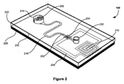
図1は、本発明の好ましい実施形態による品物の温度制限の違反を示すための装置100を説明する。装置100は、品物の近くに置くことができ、温度制限が違反されたときに状態を恒久的に変化させるように構成されたセンサ200を含む。センサ状態の変化は、温度制限違反の恒久的な指示を与えるために機械読み取り可能である。センサ200は、温度制限が違反されたとき、固体から液体へ相を変化させる流体202を保管するための容器214を含む。センサ200はまた、容器214からの液相での流体202の流れを受けるための、容器214と流体通信する流路216を含む。センサ200は、センサ200の状態が恒久的に変化されるように液相で流体202を流れさせるように配置される。センサ200はさらに、停止状態からセンサ200の起動までは流体の流れがセンサの状態を恒久的に変化させることを防ぐように構成される。
FIG. 1 illustrates an
装置100は、密接な熱的接触を提供するために品物の近くに配置されることが可能である(示されていない)。いくつかの実施形態において、装置100は、品物に直接または実質的に近くに配置するための大きさおよび/または形状にされてもよい。装置100は、品物内への配置、または品物若しくは品物を保管する容器に直接取り付ける配置のためにコンパクトでも良い。例えば、装置100は、重量または大きさの感知可能な増加をさせることなく、生体試料内に配置されること、またはバイアル、バッグ、若しくは類似する容器などの保管容器内へ組み込まれることが可能なような大きさでもよい。さらに、装置100は、品物との密接な熱的接触を与えるためにセンサ200を収容する熱伝導性のエンクロージャを含んでもよい(示されていない)。エンクロージャは、特定の品物および温度制御された保管環境のために適するように選択された熱伝導特性を有する材料を含んでもよい。
The
密接な熱的接触は有益に、装置100が温度制限違反を正確に指示することについて品物に直接または実質的に近くに示された温度を頼りにすることを保証する。装置100が密接な熱的接触でない場合、短い温度逸脱は、品物自体が温度の致命的な上昇または下降を経験していないため、偽陰性の指示をもたらし得る。したがって、密接な熱的接触は、品物の実際の温度に正確にまたは実質的に密接に一致する温度に頼る装置100に起因する偽陰性の指示の可能性を減らす。
Close thermal contact beneficially ensures that the
図1で示されているように、センサ200は、支持層または基板228を含む。支持層228は、ガラス、アクリル、シリコンウエハ、またはポリエチレンテレフタレート(PET)などの他の可撓性ポリマで構成されてもよい。好ましくは、支持層228は、支持層228に接着された付加的な層を支持するために十分に厚い。例えば、図2で示されている装置100の代替的な実施形態では、上層230は、支持層または基板228に接着され、センサ構成要素を含んでいる。支持層228はまた、表面の酸素プラズマエッチングなどによって、親水性になるよう処理されてもよい。親水性表面は、支持層228を横断する流体の流れを促すために特に好適であり、これはより詳細には後述される。
As shown in FIG. 1, the
センサ200は、流体202を保管するための容器または流体の源泉214を含む。流体202は、溶液の形の単一の流体、または混合物の形の流体の組み合わせであってもよい。単一の流体または流体の組み合わせ202は、品物の温度制限に対応する所望の融点を有するように選択される。好ましくは、流体202は、流体の融点および凝固点などの流体202の特性が希釈によって変化し得るような水溶液である。例えば、70%エタノール溶液は、-50℃付近で融点を有するが、一方、100%エタノールは、-114℃付近で融点を有し、そのため温度は水で希釈することで変化し得る。他の適切な流体202は、-127℃の融点を有する1-プロパノールなどの他のアルコールを含んでもよい。
The
装置100が品物の近くに配置される前に、流体202は最初は、液体状態で容器214に格納される。図1に示されているように、容器214は、流路216と通じている。流路216内への流体202の不慮の流れを防ぐために、センサ200は、容器214と流路216との間に配置されている障壁224を含む。障壁224は、容器214からの流体の流れがセンサの状態を恒久的に変化させることを防ぐことができ、障壁224は、センサ200を起動させるために取り除くことが可能である。障壁224は、容器214と流路216との間に配置されているシール、膜またはバルブ224として図1では説明される。他の実施形態において、障壁224はまた、流路216内に、または指示チャンバ218に連結されている容器214の反対側などの、容器端以外の流路216の端部に設けられてもよい。障壁224は、センサ200が起動状態になるまで、センサ200の他の構成要素への流体の漏れが可能とならないことを保証する。
The fluid 202 is initially stored in the
(示されていない)他の実施形態において、障壁224は、図1および図2に示され、かつ後述でより詳細に記載されているような、センサ200の通気経路222内に配置されてもよい。障壁224は、容器または保管チャンバ214と通気経路222との間に、容器端以外の通気経路222の端部に、または通気経路222内に配置されてもよい。これらの実施形態での障壁は、背圧に起因する流体202の流れを防ぐ。
In other embodiments (not shown), the
一旦流体202が容器214内に取り込まれると、センサ200は、流体202が液体から固体へ相を変化するような温度制御環境に配置される。例えば、センサ200は、流体202は、その凝固点より下の温度で凍るように、機械的冷凍庫などの、低温度環境に配置されてもよい。一旦流体が凍り、固体に変わると、センサ200は、停止状態になる。
Once the
停止状態からセンサ200を起動させるために、障壁224は、センサ200が起動状態または作動待機状態になるように、取り除かれなければならない(示されていない)。センサ200の起動または作動待機は、障壁224の自動的な、または手動の除去によって生じてもよい。障壁224は、容器214から流路216および/または通気経路222への流体経路をブロックする膜、シールまたはバルブであってもよく、流路216および/または通気経路222と流体通信する容器214の開口をブロックしてもよい。センサ200は、いくつかの実施形態ではセンサ200は複数の障壁224を含み得るが、少なくとも一つの障壁224を含む。
In order to activate the
センサ200の作動待機は、障壁224への外力を利用しまたは取り除くことによってなどの、障壁224の手動の除去によって生じ得る。いくつかの実施形態において、障壁または膜224は、磁場の存在によって容器214内に流体202を取り込む磁性材料を含んでもよい。例えば、障壁または膜224は、容器214と流路216との間の空間に取り込まれることになる小さなボールベアリングで構成されてもよい。障壁または膜224は、装置100を磁場の外へ移動することで、または磁場を停止することで取り除かれてもよい。代替的に、障壁または膜224は、外部アクチュエータに機械的に接続されてもよく、外部アクチュエータは、容器214内に流体202を取り込むために圧力を膜224に作用させる。障壁または膜224は、外部アクチュエータの操作を通じて取り除かれてもよい。
The standby for operation of the
他の実施形態において、センサ200の作動待機は、障壁224の自動的な除去によって生じ得る。障壁または膜224は、温度依存性形状記憶材料などの温度依存性材料を含んでもよい。周辺温度が所望の温度に達したとき、材料は、所望の温度で材料によってもたらされる力に起因してセンサ200を起動させるために劣化または壊して開けてもよい。代替的に、障壁または膜224は、センサ200を起動させるために小さくなる温度依存性材料を含んでもよい。材料は、周辺温度が所望の温度に達したとき、材料収縮が容器214から流路216への流体経路をブロックしないように、より大きな熱膨張係数を含んでもよい。
In other embodiments, the standby for operation of the
別の実施形態において、センサ200は、力を及ぼすために、気体の膨張/収縮を頼りにした(密封をされたカプセル内で圧力を減らす)、気体を充填されたカプセルを含んでもよい。カプセルは、カプセル内で膨張する他の構成要素の中でCO2ガスを生成する二つの化学物質(例えば、炭酸カルシウムおよび酢酸)の混合物を密封することによって構成されてもよい。膨張されたカプセルは、容器214内に流体202を取り込むために障壁または膜224に力を加える。周辺温度が所望の温度に達したとき、カプセルは、流路16のどちらかの端部で取り除くために障壁または膜224と相互作用して収縮し、センサ200を起動させる。カプセルは、混合物および配置を変化させることによって特定の温度値または温度範囲でセンサ200を動作させるように設計され得る。
In another embodiment, the
他の実施形態において、センサ200は、流路の片端または両端にバルブ作動手段224を含んでもよい。バルブ作動手段224は、温度依存性の条件下で動作可能なバルブであってもよい。例えば、周辺温度が所望の温度に達したとき、バルブ224は開いてもよく、それによって流路216内への流体の流れを可能にする。代替的に、バルブ224は、空気ポンプなどの外部アクチュエータを通じて動作可能であってもよい。
In other embodiments, the
一旦センサ200が起動状態になったとき、装置100は、温度制限違反の指示用に品物の近くに配置される。特に、流体202は、品物の温度制限、すなわち、利用可能性を確保するために必要とされる臨界温度値または範囲、に正確に、またはほぼ実質的に一致する所望の融点を有するように選択される。したがって、品物の温度制限が違反されたとき、すなわち、品物の温度が閾値温度値または範囲を超えたとき、流体202の温度は、流体を融解させ、固体から液体へ相を変えさせるその融点を超える。障壁224が取り除かれているため、流体202は、容器214から、および流路216内へ液体状態で流れることが可能である。
Once the
流体の流れを促すために、流路216は、毛細管力が容器214からの、および流路216内への流体の流れを行わせるような大きさと形状にされてもよい。いくつかの実施形態において、センサ200は、マイクロ流体センサであってもよく、流路216は、毛細管力が流路216内への流体の流れを行わせるような大きさのマイクロ流体流路であってもよい。流路216の寸法が、特に高さおよび幅に関して、十分に小さい場合、毛細管力は、流体の流れを行わせる主要な要因である。容器214はまた、流路216内への流体の流れを行わせることを補助するために疎水性表面を含んでもよい。例えば、容器214は、TiO2コーティングの薄層を含んでもよい。流路216はまた、流路の表面の酸素プラズマエッチングで得られるような、流体の流れを行わせることを補助するために親水性表面を含んでもよい。
To facilitate the flow of fluid, the
センサ200は、流体202の流れが、センサ200の状態が起動状態から動作された状態へと恒久的に変化されるように配置される。流体の流れは、センサ200が起動状態に戻ることができないような、不可逆であるセンサ200の特性の恒久的な変更を引き起こす。図1に示されているように、容器214は、電気キャパシタ204を形成するために導体または電極を包含し、それによって流体の源泉214での流体202の存在がキャパシタ204の誘電率を変え、そのためファラッドを単位とする測定された静電容量(キャパシタンス)値を決定する。実施形態では示されていないが、キャパシタ204は、電極表面積および測定される静電容量を最大化するために指を互いに組み合わせた形状(櫛形)で構成されてもよい。
The
容器214から流路216への流体の流れは、静電容量の恒久的な変化を引き起こす。特に、流体の流れは、キャパシタ204の導体または電極206から流路216へと進められ、センサ200を起動状態に戻すために容器214へ戻ることは不可能である。キャパシタの導体または電極206の表面はしたがって、流体の流れに起因して恒久的に変化される。
The flow of fluid from the
他の実施形態において、センサ200は、静電容量以外の流体202の他の電気的または化学的特性を測定するように構成されてもよく、これはセンサ200の動作された状態を示す。例えば、センサ特性の恒久的な変化は、インピーダンス、レジスタンスおよびインダクタンスなどの、静電容量以外の電気的特性を含む。代替的に、センサ特性の恒久的な変化は、密度、粘度および伝導度などの、化学的な特性を含んでもよい。
In other embodiments, the
図1に示されているように、センサ200は、容器端以外の流路216の端部に指示チャンバ218を含み、流路216の端部は容器214とは反対側にある。温度制限が違反され、流体202が融解したとき、流体は、容器214から流路216へ流れ、指示チャンバ218に至るまで流路216に沿って進む。指示チャンバ218は、流体202を吸収する吸収材を含む。一旦これが生じると、流体202は、吸収材に取り込まれ、それによって流体202が流路216を介して容器214へ再び入るのを防ぐ。したがって、指示チャンバ218は、センサ200がリセットされ得ないことを保証し、起動状態から動作された状態へと状態を恒久的に変化させる。
As shown in FIG. 1, the
センサ200はまた、センサ状態の動作された状態への変化の恒久的な視覚的指示器を提供するように構成される。指示チャンバ218の吸収材は、吸収材が流体の流れで湿ったときに色を変化させる有色色素を含浸される。したがって、色の変化が、温度制限違反の即時の視覚的指示を提供するために人間の作業者によって観察され得る。これに関して、指示チャンバ218は、図2で示されているような装置100の上層230とともに、好ましくは透明である。
The
センサ200は、温度制限違反の指示のための定められた時間の許容範囲を提供するために最適化される。時間の許容範囲は、センサ200が温度制限違反に反応し、センサ状態を動作された状態へと変化するのにかかる、秒または分などの、時間の長さを示す。時間の許容範囲は、品物の特質にかなり依存し得る。例えば、生体試料は、典型的には人間の作業者が温度制限違反をすぐに警告され得るように短い時間の許容範囲を必要とする。しかしながら、時間の許容範囲は、食品には極めて重要でなくてもよく、食品は、指示前に長い期間を持ちこたえることが可能であり得る。所望の時間の許容範囲を得るために、流路216の長さおよび形状が流体202の量および種類に関連して、特定の品物のための時宜にかなった方法で温度制限違反が指示されることを保証するために、最適化される。
The
流体202を流すために、センサ200は、容器214と指示チャンバ218との間の圧力を等しくするための通気経路222を含む。図1に示されているように、センサ200は、容器214と指示チャンバ218との間に圧力均等化復路222を含む。復路222は、TiO2コーティングの薄層などの、容器214から復路222への流体の浸入を避けるために疎水性表面を含んでもよい。付加的に/代替的に、障壁224はまた、復路222への流体の浸入を防ぐために復路222と容器214との間に設けられてもよい。他の実施形態において、容器214および指示チャンバ218は、図2に示されているように、圧力を均等化するために大気への通気孔を付けられてもよい。
To allow the fluid 202 to flow, the
装置100の代替的な実施形態が、図2に示されている。図1の装置100とは異なり、キャパシタ204は、流体の流れがキャパシタ204の導体206に向かって進められるように、容器または保管チャンバの端部以外の流路216の端部、例えば、容器または保管チャンバ214とは反対側にある流路216の端部、に配置されている。流体202が融解したとき、流体は、容器214から流路216へと流れ、キャパシタ204の導体206を横切って流れる。流体202の存在は、キャパシタ204の誘電率を変え、したがって静電容量の恒久的な変化を引き起こす。キャパシタ204の表面は、流体の流れに起因して恒久的に変化される。周辺温度が流体の融点より下に下がったとき流体202は、液体から固体へと相を変える。そうでなければ、液体状態でキャパシタ電極206を横切ったままである。
An alternative embodiment of
図2のセンサ200はまた、容器または保管チャンバ214とキャパシタ204との間に通気経路222を含む。通気経路222は、容器214およびキャパシタ204がセンサ200内の圧力を均等化し、流体202がそれを通じて流れるようにするために、大気への通気孔を付けられたようなものである。示されていないが、センサ200はまた、上述されたような指示チャンバ218を含んでもよく、キャパシタ204は、指示チャンバ218に組み込まれてもよい。指示チャンバ216の吸収材による流体202の吸収に起因して、流体202は、容器214へ戻ること、およびセンサ200を起動状態に戻すことを妨げられる。
The
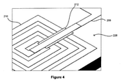
図3と図4は、図2の実施形態のキャパシタ204とインダクタ210の拡大図を示す。本実施形態において、キャパシタ204は、指形状およびそれらの間に間隙を有する二つの電極206を有する櫛形キャパシタである。指形状の数および指形状の間の間隙は、静電容量値を決定する。櫛形状は好適には、電極表面積および測定される静電容量を最大化する。静電容量は、流体の種類によって決まる特定の範囲、および質問器400の周波数範囲に合わせられる(図5参照)。キャパシタ204は、金、白金、アルミニウムなどの金属で構成されてもよい。同様に、センサ100は、キャパシタ204と同じ材料で構成され得るインダクタ210を含む。インダクタ210の巻数および巻きの間の距離は、インダクタンスの範囲を決定するために選択される。二酸化ケイ素または酸化アルミニウムなどの酸化物の絶縁層212は、図4に示されているように導体パッドを絶縁するためにインダクタ210に含まれる。
3 and 4 show enlarged views of the
図1から図4に示されているように、センサ200は、キャパシタ204に接続された電気回路208を含む。電気回路208は、キャパシタ204とともに電気的に調整された共振回路を形成するインダクタ210を含む。図1、図2および図4に示されているようなインダクタ210は、ワイヤが巻かれた要素であり、また、本発明の状況で用いるために当業者に考えられるような個別の要素を含んでもよい。インダクタ210は、ヘンリを単位とする測定されたインダクタンスの固定値を提供する。上述されているように、静電容量は、温度制限が違反されたとき、容器214から流路216への流体の流れに起因して変化する。回路208のヘルツを単位とする測定された共振周波数は、下記方程式によって定められる。ここで、
f0は、ヘルツを単位とする共振周波数であり、
Lは、ヘンリを単位とするインダクタンスであり、
Cは、ファラッドを単位とする静電容量である。
As shown in FIGS. 1 to 4, the
f 0 is a resonance frequency in Hertz as a unit.
L is an inductance in which Henry is a unit.
C is a capacitance in Farad as a unit.
![]()
![]()
共振周波数は、容器214から流路216への流体の流れによる静電容量の変化に起因して変わる。したがって、電気回路208の共振周波数の変化は、品物の温度制限違反の恒久的な指示を与える。共振周波数および温度制限違反に起因する周波数の変化量は、キャパシタ204およびインダクタ210の寸法を変えることで、および/または、当業者に考えられるような個別のキャパシタおよびインダクタなどの、他の構成要素を電気回路208に加えることで、調整され得る。共振周波数の変化は、温度制限違反の恒久的な指示を与えるために機械読み取り可能である。共振回路208は、装置100のハウジング上に露出された端子を通じた直接の電気的な接触によって信号を質問されてもよい(示されていない)。好ましくは、共振回路208は、後述するような質問コイル402とセンサの誘導コイル210との間の誘導結合によって受動的に且つ無線で信号を質問される。
The resonance frequency changes due to a change in capacitance due to the flow of fluid from the
共振周波数の変化は、温度制限違反が発生したという指示を与えるためだけでなく、液体に変わったセンサ200内の流体202の量、および品物の温度制限が違反された時間を示すためにも解析され得る。これは、少量の流体202のみが再冷凍前に解凍されたような、少しの温度逸脱が生じた場合に有益であり得る。したがって、品物の利用可能性は、温度制限違反の度合いによって評価され得る。
The change in resonance frequency is analyzed not only to indicate that a temperature limit violation has occurred, but also to indicate the amount of
適切な電気回路208の例は、下記のように導かれ得る。直径5mmの20回巻きのプリンテッド・スパイラル・インダクタ210は、約5μHを生成する。5mm×5mmの寸法内に500本の指形状で形成された櫛形キャパシタ204は、流体202の存在なしに約66pFの静電容量を生成する(誘電率ε=1)。100%エタノールが流体202として使用されていると仮定すると、エタノールがキャパシタ204上にある静電容量の値は、約387pFである(誘電率ε≒30)。水がキャパシタ204上にある静電容量の値は、約940pFである(誘電率ε≒80)。これらの状況のそれぞれは、下記の共振周波数、流体202なしでは約8.8MHz、エタノールのみでは約3.6MHz、水のみでは2.3MHzを生成する。水とエタノールの濃度の混合を変えることで、静電容量値は、したがって共振周波数は、上記制限の間で変化する。
An example of a suitable
図5に示されているように、装置100は、本発明の好ましい実施形態によると、質問器400とともに、システム500の一部を形成してもよい。装置100は、品物の近くに配置されてもよく、質問器400は、温度制限が違反されたときにセンサ状態の変化を識別し、センサ状態の識別された変化に基づいて温度制限の違反を検出するように構成されてもよい。
As shown in FIG. 5, the
質問器400は、装置100の誘導コイル210を通じてセンサ回路208によってもたらされるデータを読み込むために使用されてもよい。質問器400は、装置100の誘導コイル210の近くに置くことができる棒の形であってもよい。好適には、質問器400は、装置100をその温度制御された保管環境から取り出すことなく誘導コイル210を通じてデータを読み込むことができる。図5に示されているように、質問器400は特に、質問コイル402および関連された質問回路404を含む。質問回路404は、質問コイル402で励磁信号を生成するように適合される。励磁信号は、電磁誘導によってセンサ200の誘導コイル210へと伝達される。機械読み取り可能な指示器を有するセンサ200は、誘導コイル210に誘導された励磁信号からエネルギを取り出し、センサ200内の電気回路208にエネルギを与える。センサ200は、誘導コイル210によってセンサ回路208でコード化されたデータ、すなわち共振周波数の変化、を送信する。そして、このデータは、質問コイル402によって取得され、質問回路404によって読み込まれる。いくつかの実施形態において、データは、質問回路404から中央コンピュータ406へ記憶のために伝達されてもよい。
The
センサ200はさらに、特有の品物の識別を提供するために品物の機械読み取り可能な識別器を提供するように構成される。機械読み取り可能な識別器を提供するために、センサ200は、識別コードをコード化する複数の共振メンバを含んでもよく、共振メンバは、互いに異なる共振周波数を有してもよい。識別コードは、品物の番号、種類、製造日および賞味期限などの品物の識別用の情報、並びに位置の識別用の情報を含んでもよい。好適には、品物は、温度制御された保管環境から取り出す必要なしに識別されてもよく、それによって品物の利用可能性を損なう可能性を減らす。
The
本発明の好ましい実施形態において、センサ200は、図6に示されているような、特定の共振周波数をそれぞれ有する複数の微小機械的振動可能なまたは共振メンバ232を含む。一般的な導電体244は、振動可能なメンバ232に沿って伸びている。導電体244は、共振メンバ232に対応する三つのU字形状部分を含む図1に示されているようなセンサ200の電気回路208の一部である。本明細書に記載および示されていないが、図2の装置100は同様に、複数の共振メンバ232を含んでもよい。振動可能なメンバ232は、図6に示されているようにセンサ200の支持層または基板228上に形成される。振動可能なメンバ232は、誘導コイル210を用いてファラデーの電磁誘導によって導電体244に交流電流を誘導する質問器400で生成された加えられた励磁信号または質問信号によって振動させられる。
In a preferred embodiment of the invention, the
振動可能なメンバ232は、ローレンツ力によって振動可能であってもよい。ローレンツ力は、直交磁場を通じて伝わる荷電粒子に作用する力である。この場合、磁場は、導電体244を通じた電流の流れに直交する方向へ振動可能なメンバ232に加えられる。いくつかの実施形態において、装置100はさらに、磁場がセンサ200へ直角に作用される磁石104または要素を含んでもよい。例えば、磁石104は、装置100内でセンサ200に隣接し、下方に配置されてもよい。代替的に、磁石104は、品物内または品物を保管する容器内に含まれてもよい(示されていない)。
The vibrable
図6は、基板228から突き出る二つの柱240と柱242によって支持されたビーム238を含む橋梁構造236の形での振動可能なメンバ232を描く。図6で示されている構造は、既知のエッチング、蒸着工程の使用を伴う従来型の半導体製造手法によって形成されてもよい。一旦、橋梁構造236が基板228上に形成された場合、導電経路244は、構造236の長さに沿って蒸着される。導電経路244は、図1に示されているような電気回路208の一部を形成する。振動可能なメンバ232は、国際特許出願第WO2004/084131号でより詳細に記載されており、本明細書の一部を構成するものとしてその全体を本明細書に援用する。
FIG. 6 depicts a
質問信号がセンサ200に加えられたとき、交流電流が、伝導経路244を通じた電流の流れを引き起こす誘導コイル210内に誘導される。直交した磁場の存在内で、電流の流れの方向と磁場の方向の両方に直交する方向へ力がビーム238に加えられる。導体244内の電流が交流電流であるため、生成された直交する力はまた、交互の力であり、ビーム238の振動をもたらす。導体244内の交流電流の周波数がビーム238の共振周波数である、または共振周波数に近い場合、ビーム238は振動するであろう。
When the interrogation signal is applied to the
図7を参照すると、センサ200の一部を形成する共振メンバ232のそれぞれは、所定の数の共振周波数f1、f2、f3などの一つに対応する名目上の共振周波数を有する。好ましくは、共振周波数f1、f2、f3などは、異なる周波数範囲である。質問器400がf1以降の任意の周波数位置で共振周波数を検出した場合、質問回路404は、2進数「1」として共振周波数を解釈する。一方、任意の所定の周波数位置に共振周波数がないことは、2進数「0」として解釈される。質問回路404によって検出された2進数1および2進数0の数列は、機械読み取り可能な識別器に対応する。
Referring to FIG. 7, each of the
温度制限違反に起因する共振周波数の変化(すなわち、機械読み取り可能な指示器)は、類似の方法で質問器400によって検出されてもよい。好ましくは、温度制限違反に起因する共振周波数は、センサ200の共振メンバ232とは異なる周波数範囲内である。質問器400が、例えばf3以降の周波数位置で、共振周波数を検出した場合、質問回路404は、2進数「1」として共振周波数を解釈し、そうでなければ共振周波数がないことは、2進数「0」として解釈される。さらに、質問回路404は、インピーダンス値を通じて機械読み取り可能な識別器と機械読み取り可能な指示器に対応した数列を識別してもよい。図7に示されているように、インピーダンス値は、機械読み取り可能な識別器用よりも機械読み取り可能な指示器用の方が大きくてもよい。したがって、機械読み取り可能な指示器および機械読み取り可能な識別器は好適には、質問器400による電気回路108の単一の質問内で読み取られてもよい。質問器400および共振メンバ232は、国際特許出願第WO2010/037166号より詳細に記載されており、本明細書の一部を構成するものとしてその全体を本明細書に援用する。
Changes in resonant frequency (ie, machine readable indicators) due to temperature limit violations may be detected by the
他の実施形態において、機械読み取り可能な識別器は、センサ200の基板228内へ組み込まれなくてもよい。装置100は、機械読み取り可能な識別器を有する機械読み取り可能なタグを保管するように構成されてもよい。代替的に、装置100は、品物の温度制限違反の識別と指示の二つの機能を提供するための機械読み取り可能なタグを取り付けるような大きさであってもよい。好ましくは、機械読み取り可能なタグおよびセンサ200は、単一の質問で機械読み取り可能な指示器と機械読み取り可能な識別器の読み取りをさせるために極めて近くにある。
In other embodiments, the machine-readable classifier does not have to be integrated into the
機械読み取り可能な識別器を有する機械読み取り可能なタグは、RFIDタグに基づいたCMOSなどの、MEMS構造を含む必要のない能動的または受動的なRFIDタグに置き換えられてもよい。例えば、温度依存値を有する抵抗は、タグの一部を形成でき、その値は読み取られ得る。代替的に、タグの一部を形成するアンテナは、同調アンテナによって検出可能である温度依存性インピーダンスを有してもよい。当業者は、本発明の状況で用いるために適したさまざまな機械読み取り可能なタグを思いつくことができる。 Machine-readable tags with machine-readable classifiers may be replaced with active or passive RFID tags that do not need to contain MEMS structures, such as CMOS based on RFID tags. For example, a resistor with a temperature dependent value can form part of a tag, the value of which can be read. Alternatively, the antenna forming part of the tag may have a temperature dependent impedance that can be detected by a tuned antenna. One of ordinary skill in the art can come up with a variety of machine-readable tags suitable for use in the context of the present invention.
いくつかの実施形態において、装置100は、複数のセンサ200を含み、それぞれのセンサ200は、品物の一つより多くの温度制限の違反を指示するための異なる流体を保管する。好適には、これは、品物の解凍の異なる段階の間に提供されるように温度制限違反の視覚的および/または機械読み取り可能なフィードバックをさせる。品物の温度制限は、単一の温度閾値、または温度の範囲であってもよい。品物は、感温性であって、生体試料、生鮮食品、食品、傷みやすいもの、調剤および化合物を含むグループの一つから選択されてもよい。これらの品物のそれぞれは、-200℃から0℃の温度での保管を必要とし得る。したがって、温度制限は、-200℃から0℃の範囲内である温度値または温度範囲のいずれかであってもよい。
In some embodiments, the
いくつかの実施形態において、装置100は、MEMS(微小電気機械システム)技術を使用して製造される。これはまた、PST(マイクロシステム技術)およびマイクロマシニングとして知られている。好ましくは、本明細書に記載されているような微小機械的振動可能なまたは共振メンバ232は、MEMS技術を使用して製造される。MEMS技術は、集積回路用の製造技術およびマイクロマシニング用に特に開発された技術を含む。MEMS技術は一般的に、マイクロメートルからミリメートルの範囲の寸法を有する構成要素の製造に関する。
In some embodiments, the
MEMS手法は、他の周知のリソグラフおよびマイクロマシニング工程とともに、例えば、マスキング、蒸着、エッチングのステップを含む。MEMS手法は、例えばフォトリソグラフィおよび薄膜蒸着または薄膜成長を含んでもよい。典型的には、工程は、積層構造をもたらす。多くの構造層が、基板上に形成され得、必要な構成要素は、基板、並びに/または基板に蒸着される犠牲材料および構成材料の選択的なエッチングによって形成され得る。その結果得られる微細加工された構成要素は、標準的な集積回路工程を使って製造された電子機器と結合されてもよい。 The MEMS technique, along with other well-known lithographic and micromachining steps, includes, for example, masking, vapor deposition, and etching steps. MEMS techniques may include, for example, photolithography and thin film deposition or thin film growth. Typically, the process results in a laminated structure. Many structural layers can be formed on the substrate and the required components can be formed by selective etching of the substrate and / or sacrificial materials and constituent materials deposited on the substrate. The resulting microfabricated components may be coupled to electronic devices manufactured using standard integrated circuit processes.
図2から図4のセンサ200を形成する工程は、これから記載されるが、図1から図4に示されているセンサ200は、標準的なフォトリソグラフィ方法を用いて製造されてもよい。最初に、基板または支持層228は、フォトレジストでコーティングされる。フォトレジストの厚みは、フォトレジストの種類と回転速度によって決定される。フォトレジストは、SU8またはポリジメチルシロキサン(PDMS)などのポリマであってもよい。基板は、最適な出力密度で紫外線源のもとで露光される。センサの配置は、コンピュータ支援ソフトウェアで開発されたマスクによって適用される。マスクは通常クロムで作られ、所望のパターンを含む。ポジ型レジストのため、露光される領域は、次のステップで取り除かれる。そして、電子ビーム蒸着器が、金などの金属の層を蒸着するために使用され、金属の層は、蒸着され、リフトオフされる。キャパシタ204、およびインダクタ210の一部は、単一のステップで蒸着されてもよい。
The steps of forming the
次のステップは、インダクタ210の導体パッドを絶縁するための絶縁層212を作成することである。このために、上述されたステップを繰り返すが、異なるパターンを備え、金属から二酸化ケイ素または酸化アルミニウムなどの酸化物へ変更した別のフォトリソグラフィ工程が実行される。さらなるフォトリソグラフィ工程が、誘導コイル210の中央をインダクタパッド212と接続するために必要とされる。別のフォトリソグラフィ工程が、流路216を作成するために必要とされる。流路216の高さと幅は、レジストの種類と回転速度に基づいてフォトレジストで基板228をコーティングするとき、管理可能である。最終的に、上層またはカバー230が、容器214および通気経路222を形成するために基板228に取り付けられる。上層230は、アクリルまたはポリ塩化ビニル(PVC)で作られ、基板228に接着されてもよい。
The next step is to create an insulating
図5のシステム500に戻り、質問器400は、センサ状態の変化の機械読み取り可能な指示器を検出するように構成されてもよい。図5に示されているように、質問器400は、質問コイル402を含む。質問コイル402は、センサ200の電気回路208に質問するように構成される(図1から図4参照)。質問コイル402は、使用時にセンサ200の電気回路208に近接するように配置されてもよい。質問器400は、装置100への直接の接触が必要ない一方、機械可能な指示器を検出するために極めて接近して配置されるべきである。好ましくは、装置100は、品物から直接または品物の近くから装置100の除去を必要とすることなく質問されることが可能である。これは、好適には、質問の間、温度制御環境に保つことができるため品物の利用可能性を確保する。
Returning to the
図5は、質問コイル402に質問信号を生成することができる集積信号処理回路404を含む質問器400を示す。質問コイル402が、センサ200の誘導コイル210に近接しているとき、励磁信号が、質問コイル402の質問信号から誘導コイル210に誘導される。機械読み取り可能な指示器は、電気回路208の共振周波数の変化として質問器400によって検出される。
FIG. 5 shows an
いくつかの実施形態において、質問器400はさらに、品物の機械読み取り可能な識別器を検出するように構成される。機械読み取り可能な識別器は、本明細書に記載されているような品物のための特有の識別コードを含んでもよい。識別コードはまた、時間、日付、品物の位置および作業者または使用者などの情報を含んでもよい。これに関して、センサ200は、図1および図6に示されているような少なくとも一つの共振メンバ232を含んでもよい。機械読み取り可能な識別器は、電気回路208の共振周波数の変化として質問器400によって検出されてもよい。
In some embodiments, the
図1に示されているように、少なくとも一つの共振メンバ232は、センサ200の基板228上に含まれてもよく、共通の導電体244は、電気回路208の一部であってもよい。したがって、機械読み取り可能な識別器および機械読み取り可能な指示器は、質問器による電気回路208の単一の質問で検出され得る。機械読み取り可能な識別器および機械読み取り可能な指示器は、上記および図7に関して記載されているように共振周波数および/またはインピーダンスの変化の度合いに基づいて区別されてもよい。
As shown in FIG. 1, at least one
いくつかの実施形態において、質問器400は、温度制限違反が検出された場合、アラートを発する。これは、品物の温度が、その品物が臨界温度より上または下で利用できなくなる又は劣化する、臨界温度を超える場合、作業者に警告するのに役立つ。当該警告は、聴覚的、視覚的または感覚的な性質のもの(例えば、LED、点滅するLED若しくはLEDの色の変化による照明、トーンなどの可聴式警告、または振動)であってもよい。
In some embodiments, the
システム500はまた、一つ以上の温度センサを含んでもよく、レーザ若しくは赤外線の少なくともいずれか一つを含む光学検出手段、または熱電対、サーミスタ若しくは抵抗温度検出器(RTD)の少なくともいずれか一つを含む有線検出手段の一方または両方から選択されてもよい。前述の例は、網羅的なものではなく、他の適切な手段が想定され得ると理解される。それぞれの温度センサは、単一の品物または一つより多くの品物に関連付けられてもよい。多くの温度センサが設けられている場合、品物のいたるところで温度の任意の変化が特定され得る。温度センサは好適には、センサ200によって指示され、および/または検出される温度制限違反に加えて、即時の温度測定を提供する。
The
いくつかの実施形態において、質問器400はさらに、温度制限違反を検出すること、品物の識別および品物の温度の一つ以上を伝達するための通信モジュールを含む。温度および識別データは、記録され、ライブ又はその後のある時点のいずれかでリモートコンピュータまたはサーバにダウンロードされ得、または、さもなければ電気的に伝達され得る。したがって、品物がその生涯にわたって対象であり得る様々な保管、処理および移送活動の間を通して、品物の永久的なデータログを維持することができる。いくつかの実施形態において、記録は、連続的にされてもよく、データは、リモートコンピュータまたはサーバに定期的に伝達され、または必要に応じて連続的にストリーム配信されてもよい。
In some embodiments, the
温度制限は、-200℃から0℃の範囲内の温度値または温度範囲のいずれかであってもよい。品物は、感温性であって、生体試料、生鮮食品、食品、傷みやすいもの、調剤および化合物を含むグループの一つから選択されてもよい。 The temperature limit may be either a temperature value in the range −200 ° C. to 0 ° C. or a temperature range. The article is temperature sensitive and may be selected from one of a group comprising biological samples, fresh foods, foods, perishables, preparations and compounds.
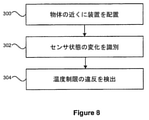
図8を参照すると、本発明の好ましい実施形態による、品物の温度制限の違反を検出するための方法のステップを示すフローチャートが説明されている。方法は、品物の近くに本明細書に記載されているような本発明に関する装置100を配置するステップ300を含む。方法はまた、温度制限が違反されたときにセンサ状態の変化を識別するステップ302を含む。さらに、方法は、センサ状態の識別された変化に基づいて温度制限の違反を検出するステップ304を含む。
With reference to FIG. 8, a flowchart showing steps of a method for detecting a violation of a temperature limit of an article according to a preferred embodiment of the present invention is described. The method comprises placing a
好ましくは、本発明に関する装置100は、密接な熱的接触を提供するために品物の近くに配置される。また、本発明の装置100は、品物に直接または実質的に近くに配置するための大きさにされ、および/または形状にされてもよい。方法は、生体試料などの品物内に装置100を配置すること、またはバイアル、バッグ、若しくは類似する容器などの保管容器内へ装置100を組み込むことを含んでもよい。方法はまた、品物または品物を保管する容器に装置100を直接取り付けることを含んでもよい。
Preferably, the
図9は、図8に示されている方法のさらなるステップを示すフローチャートを説明する。いくつかの実施形態において、センサ状態の変化を識別することは、センサ状態の変化の読み取り可能な識別器を検出するステップ306を含む。図10に示されているように、読み取り可能な識別器を検出することは、ステップ308でセンサ200の電気回路208に質問すること、およびステップ310で電気回路208の共振周波数の変化を検出することを含んでもよい。方法は、共振周波数の変化を計測するためにセンサ200の電気回路208に直接接触することを含んでもよい。
FIG. 9 illustrates a flow chart showing further steps of the method shown in FIG. In some embodiments, identifying a change in sensor state comprises detecting a readable classifier of the change in
代替的に、方法は、受動的な無線質問のためにセンサ200の近くに質問器400を棒の形で配置することを含んでもよい。図5に示されているように、質問器400の質問コイル402に励磁信号を生成すること、およびセンサ200の誘導コイル210へ誘導によって励磁信号を伝達することを含んでもよい。さらに、方法は、誘導コイル210を通じて質問コイル402に、センサ回路208の機械読み取り可能な指示器をコード化しているデータを伝達することを含んでもよい。共振周波数の変化は、質問コイル402によって取得されたデータを読み込むことで質問回路404によって検出されてもよい。方法はまた、保管のために質問回路404から中央コンピュータ406にデータを伝達することを含んでもよい。
Alternatively, the method may include placing the
図9は、センサ状態の変化を識別することがまた、品物の機械読み取り可能な識別器を検出するステップ312を含んでもよいことを説明する。図10に示されているように、機械読み取り可能な識別器を検出することは、ステップ308でセンサ200の電気回路208に質問すること、およびステップ310で電気回路208の共振周波数の変化を検出することを含む。機械読み取り可能な識別器は、上記されたような質問器400を使用する読み取り可能な指示器に類似する方法で検出され得る。さらに、方法は、質問器400を使用することによってなどの、電気回路208の単一の質問で機械読み取り可能な指示器および機械読み取り可能な識別器を検出することを含んでもよい。方法はまた、周波数値および/またはインピーダンス値に基づいて、機械読み取り可能な指示器と機械読み取り可能な識別器の検出された共振周波数を区別すること含んでもよい。
FIG. 9 illustrates that identifying changes in sensor state may also include
センサ状態の変化を識別するステップ302はまた、図9に示されているようなセンサ状態の変化の恒久的な視覚的指示器を観察するステップ314を含む。図11に示されているように、視覚的指示器を観察することは、有色色素を有するセンサ200の指示チャンバ218を見るステップ316、および指示チャンバ218の色素の色の変化をチェックするステップ318を含む。好適には、視覚的指示器の観測は、温度制限違反の作業者による即時の検出のために提供される。
Step 302 for identifying changes in sensor state also includes observing a permanent visual indicator of changes in sensor state as shown in FIG. As shown in FIG. 11, observing the visual indicator is
図12および図13は、センサ200の起動に関する図8に示された方法のさらなるステップを示すフローチャートを説明する。品物の近くに装置100を配置するステップ300の前に方法は、センサ200の容器214に格納された流体202が、液体から固体へと相を変化させるように周辺温度を下げるステップ320を含む。ステップ320の後、センサ200は、停止状態である。これに続いて、方法は、容器214に格納された流体202をセンサ200の流路216へと流すために、センサ200を停止状態から起動させるステップ322を含んでもよい。
12 and 13 illustrate a flow chart showing further steps of the method shown in FIG. 8 for activating the
センサ200を起動させるステップ322は、流体の流れがセンサ状態を恒久的に変化させるのを妨げる障壁224を除去するステップを含んでもよい。障壁224は、上記されているようにシール、膜またはバルブの一つを含んでもよい。図13に示されているように、障壁224を除去するステップは、障壁224を自動的に除去するステップ324と障壁224を手動で除去するステップ326の一方または両方を含んでもよい。障壁224を自動的に除去するステップ324は、障壁224の温度依存性材料が劣化するまたは小さくなることと、センサ200の気体を充填されたカプセルが障壁224への力を除去するために収縮することの少なくとも一方のような所望の温度へ周辺温度を自動的に変化させることを含んでもよい。障壁224を手動で除去するステップ326は、障壁224への磁力を変更するために障壁224の磁性材料へ影響する磁場の存在を利用することおよび/または除去すること、並びに障壁224へ連結された外部アクチュエータによって障壁224へ加えられている力を利用することおよび/または除去することを含んでもよい。好ましくは、磁場の存在および外部アクチュエータによって加えられている力は、障壁224への力を取り除くために除去される。
Step 322 for activating the
いくつかの実施形態において、方法は、品物の複数の温度制限違反を検出することを含む。装置100は、品物の複数の温度制限の違反を指示するために、それぞれのセンサ200が異なる流体202を格納している、複数のセンサ200を含んでもよい。有益には、これは、温度制限違反の視覚的または機械読み取り可能な検出が品物の解凍の異なる段階にわたって提供されるようにする。流体202は、品物の温度制限に対応する所望の融点を有するように選択された単一の流体または流体の組み合わせであってもよい。さらに、温度制限は、-200℃から0℃の範囲内の温度値または温度範囲のいずれかであってもよい。品物は、感温性であって、生体試料、生鮮食品、食品、傷みやすいもの、調剤および化合物を含むグループの一つから選択されてもよい。
In some embodiments, the method comprises detecting multiple temperature limit violations of an article. The
好適には、本発明に関する装置、システムおよび方法は、感温性品物(特に低温、超低温(すなわち、-60℃未満)または極低温の保管場所を必要とする品物)の保管、処理および移送の間に生じる温度制限違反の恒久的な指示および検出を提供する。装置、システムおよび方法は、センサ状態の恒久的な変化によってもたらされる温度制限違反の恒久的な記録を保証する。記録は、後で処理するために機械読み取り可能である。したがって、装置、システムおよび方法は、指示器の観察またはデータ記録の処理を人間の作業者に依存しないため、より正確かつ確実に、温度制限違反を指示し、検出する。 Preferably, the appliances, systems and methods according to the invention are for the storage, processing and transfer of temperature sensitive products, especially those that require a cold, ultra-low temperature (ie, less than -60 ° C) or cryogenic storage location. Provides permanent indication and detection of temperature limit violations that occur in between. Devices, systems and methods ensure a permanent record of temperature limit violations caused by permanent changes in sensor state. The recording is machine readable for later processing. Thus, devices, systems and methods are more accurate and reliable in indicating and detecting temperature limit violations, as the processing of indicator observations or data recordings is independent of human workers.
装置、システムおよび方法はまた、人間の作業者による迅速な介入を可能とするために温度制限違反の即時の検出用の視覚的なフィードバックを提供する。さらに、装置、システムおよび方法は、品物の機械読み取り可能な識別を可能とする。当該識別は、有益には、装置の同じ機械質問の間に生じてもよい。温度制限違反の受動的な無線検出が得られるため、装置は、何らかの電源またはエネルギ源を必要とせず、さらに、殺菌ガンマ線による悪影響を及ぼされない。装置はまた、好適には、温度制限違反の正確な指示および検出のための密接な熱的接触をすぐに提供することができるような大きさと形状にされる。 Devices, systems and methods also provide visual feedback for immediate detection of temperature limit violations to allow rapid intervention by human workers. In addition, appliances, systems and methods enable machine-readable identification of goods. The identification may conveniently occur during the same machine question of the device. Since passive radio detection of temperature limit violations is obtained, the device does not require any power source or energy source and is not adversely affected by germicidal gamma rays. The device is also preferably sized and shaped to be able to immediately provide close thermal contact for accurate indication and detection of temperature limit violations.
「備える(comprise)」「備える(comprises)」「備えられた(comprisesd)」または「備えている、備えること(comprising)」の用語のいずれか又は全てが、本明細書(特許請求の範囲を含む)に使用される場合、当該用語は、述べられた特徴、整数、ステップまたは構成要素の存在を明記するが、一つ以上のその他の特徴、整数、ステップまたは構成要素の存在を除外しないものとして解釈される。 Any or all of the terms "comprise," "comprise," "comprised," or "comprising, complimenting" are used herein (claims). When used in (including), the term specifies the presence of the stated feature, integer, step or component, but does not exclude the presence of one or more other features, integers, steps or components. Interpreted as.
添付されている特許請求の範囲で定められるような本発明の範囲から逸脱することなく、様々な変更、追加および/または代替が前述された部分に対して行われることができると、理解される。 It is understood that various changes, additions and / or substitutions may be made to the aforementioned portions without departing from the scope of the invention as set forth in the appended claims. ..
以下の特許請求の範囲は、単なる例として提供され、あらゆる将来の利用で主張され得るものの範囲を限定することを意図されていないと、理解される。特徴は、発明または複数の発明をさらに定めるまたは再度定めるために、後日、特許請求の範囲へ加えられてもよく、または特許請求の範囲から除かれてもよい。 It is understood that the following claims are provided as an example only and are not intended to limit the scope of what can be claimed in any future use. Features may be added to or excluded from the claims at a later date in order to further define or redefine the invention or invention.
Claims (17)
前記温度制限が違反されたときに固体から液体へと相を変化させる流体を格納するための容器であって、前記容器は、最初は液体状態で前記流体を格納し、前記温度制御環境内へ前記装置が配置されると、前記流体は、液体から固体へと相を変化させ、前記マイクロ流体センサは、停止状態になる、容器と、
前記温度制限が違反されたときに前記容器からの液相での前記流体の流れを受けるように前記容器と流体通信するマイクロ流体流路であって、前記マイクロ流体流路は、毛細管力が前記容器から前記マイクロ流体流路内へと前記流体の流れを行わせるような大きさと形状にされる、マイクロ流体流路と、
前記停止状態から前記マイクロ流体センサの起動まで前記流体の流れが前記センサ状態を恒久的に変化させるのを防ぐように、前記容器と前記マイクロ流体流路との間に配置された障壁と、を含み、前記障壁は、前記マイクロ流体センサを前記停止状態から、前記温度制限が違反されると前記マイクロ流体流路が前記容器から前記流体の流れを受ける、起動状態へと起動させるために除去可能であり、
前記マイクロ流体流路への前記流体の流れは、前記マイクロ流体センサの前記状態が前記起動状態から動作された状態へと恒久的に変化されるように前記マイクロ流体センサの電気的特性を恒久的に変化させ、
前記マイクロ流体センサは、前記動作された状態へのセンサ状態の恒久的な変化の機械読み取り可能な指示器を提供するように構成された電気回路をさらに含む、
装置。 A device that indicates a violation of the temperature limit of an item stored in a temperature control environment, the device can be placed near the item, and the state of the sensor is permanent when the temperature limit is violated. The microfluidic sensor comprises a microfluidic sensor configured to change to, the change in sensor state is machine readable to provide permanent indication of the temperature limit violation, said microfluidic sensor.
A container for storing a fluid that changes its phase from solid to liquid when the temperature limit is violated , the container initially storing the fluid in a liquid state and into the temperature control environment. When the device is placed, the fluid changes phase from liquid to solid, and the microfluidic sensor goes into a stopped state, with the container.
A microfluidic flow path that fluidly communicates with the container so that it receives the flow of the fluid in the liquid phase from the container when the temperature limit is violated , wherein the microfluidic flow path has a capillary force. A microfluidic flow path sized and shaped to allow the fluid to flow from the container into the microfluidic flow path .
A barrier placed between the container and the microfluidic flow path so that the flow of the fluid does not permanently change the sensor state from the stopped state to the activation of the microfluidic sensor. The barrier can be removed to activate the microfluidic sensor from the stopped state to an activated state in which the microfluidic flow path receives the flow of the fluid from the container when the temperature limit is violated. And
The flow of the fluid into the microfluidic flow path permanently changes the electrical properties of the microfluidic sensor such that the state of the microfluidic sensor is permanently changed from the activated state to the operated state. Change to
The microfluidic sensor further comprises an electrical circuit configured to provide a machine readable indicator of a permanent change in the sensor state to said operational state.
Device.
所望の温度で劣化するまたは小さくなる温度依存性材料を含む前記障壁と、
所望の温度で前記障壁への力を除去するように収縮する気体充填カプセルをさらに含む前記マイクロ流体センサと、
前記障壁への磁力を変更するように磁場が加えられ、および/または除去され得る磁性材料を含む前記障壁と、
前記障壁への力を加え、および/または除去するように動作可能な外部アクチュエータに連結された前記障壁と、の少なくとも一つによって前記マイクロ流体センサを起動させるために除去することができる、請求項1から請求項4のいずれか一項に記載の装置。 The barrier is
With the barrier containing a temperature dependent material that deteriorates or shrinks at the desired temperature,
The microfluidic sensor, further comprising a gas-filled capsule that contracts to remove force on the barrier at a desired temperature.
With the barrier containing a magnetic material that can be applied and / or removed by a magnetic field to alter the magnetic force on the barrier.
A claim that can be removed to activate the microfluidic sensor by at least one of the barrier coupled to an external actuator capable of acting to apply and / or remove a force on the barrier. The device according to any one of claims 1 to 4 .
前記品物の近くに配置された、請求項1から請求項12のいずれか一項に記載の装置と、
前記温度制限が違反されたときにセンサ状態の前記変化を識別し、
センサ状態の前記識別された変化に基づいて前記温度制限の違反を検出するように、構成された質問器とを含む、
システム。 A system for detecting a violation of the temperature limit of an item stored in a temperature control environment .
The device according to any one of claims 1 to 12 , which is arranged near the item.
Identifying the change in sensor state when the temperature limit is violated,
Including an interrogator configured to detect a violation of the temperature limit based on the identified change in sensor state.
system.
Applications Claiming Priority (3)
| Application Number | Priority Date | Filing Date | Title |
|---|---|---|---|
| AU2016903474A AU2016903474A0 (en) | 2016-08-31 | A device, system and method for temperature limit indication and detection of temperature-sensitive items | |
| AU2016903474 | 2016-08-31 | ||
| PCT/AU2017/050933 WO2018039727A1 (en) | 2016-08-31 | 2017-08-31 | A device, system and method for temperature limit indication and detection of temperature-sensitive items |
Publications (3)
| Publication Number | Publication Date |
|---|---|
| JP2019526797A JP2019526797A (en) | 2019-09-19 |
| JP2019526797A5 JP2019526797A5 (en) | 2020-10-08 |
| JP7029442B2 true JP7029442B2 (en) | 2022-03-03 |
Family
ID=61299605
Family Applications (1)
| Application Number | Title | Priority Date | Filing Date |
|---|---|---|---|
| JP2019510703A Active JP7029442B2 (en) | 2016-08-31 | 2017-08-31 | Devices, systems and methods for temperature limiting indications and detection of temperature sensitive items |
Country Status (6)
| Country | Link |
|---|---|
| US (1) | US11467042B2 (en) |
| EP (1) | EP3507578B1 (en) |
| JP (1) | JP7029442B2 (en) |
| CN (1) | CN110192091A (en) |
| AU (1) | AU2017320346B2 (en) |
| WO (1) | WO2018039727A1 (en) |
Families Citing this family (9)
| Publication number | Priority date | Publication date | Assignee | Title |
|---|---|---|---|---|
| JP7204396B2 (en) * | 2018-09-20 | 2023-01-16 | 株式会社東芝 | Temperature threshold sensor, temperature threshold detection device and temperature threshold detection system |
| WO2020072945A1 (en) | 2018-10-05 | 2020-04-09 | TMRW Life Sciences, Inc. | Apparatus to preserve and identify biological samples at cryogenic conditions |
| US11607691B2 (en) | 2019-10-29 | 2023-03-21 | TMRW Life Sciences, Inc. | Apparatus to facilitate transfer of biological specimens stored at cryogenic conditions |
| IT202000001084A1 (en) * | 2020-01-21 | 2021-07-21 | Enea Agenzia Naz Per Le Nuove Tecnologie Lenergia E Lo Sviluppo Economico Sostenibile | Impedance response temperature indicator that can be integrated into HF RFID systems in the form of an RFID transponder with a chip or chipless and method of making this temperature indicator. |
| CA3176037A1 (en) | 2020-05-18 | 2021-11-25 | Brian BIXON | Handling and tracking of biological specimens for cryogenic storage |
| CN112034018B (en) * | 2020-08-24 | 2021-12-28 | 江南大学 | Glucose biosensor based on PDMS microfluidic channel, preparation method and application |
| KR102653569B1 (en) * | 2020-11-16 | 2024-04-03 | 한국화학연구원 | irreversible sub-zero temperature/time sensor |
| USD963194S1 (en) | 2020-12-09 | 2022-09-06 | TMRW Life Sciences, Inc. | Cryogenic vial carrier |
| US20240019316A1 (en) * | 2022-07-18 | 2024-01-18 | Temptime Corporation | Capacitance-based temperature sensor with delay |
Citations (2)
| Publication number | Priority date | Publication date | Assignee | Title |
|---|---|---|---|---|
| EP0545274A1 (en) | 1991-12-03 | 1993-06-09 | SOCIETE COOL S.a.r.l. | Preservation state indicator for frozen or refrigerated products and method for applying this indicator |
| US7275863B1 (en) | 2003-12-04 | 2007-10-02 | Time Temperature Integration, Inc. | Threshold calorimeter/shelf life monitor |
Family Cites Families (19)
| Publication number | Priority date | Publication date | Assignee | Title |
|---|---|---|---|---|
| US3695903A (en) | 1970-05-04 | 1972-10-03 | American Standard Inc | Time/temperature indicators |
| JPS59164929A (en) | 1983-03-11 | 1984-09-18 | Mishima Seishi Kk | Irreversible temperature sensor |
| IT1254353B (en) | 1992-05-07 | 1995-09-14 | Consiglio Nazionale Ricerche | THERMAL HISTORY INDICATOR DEVICE IN PARTICULAR FOR FROZEN AND SIMILAR PRODUCTS. |
| US6848390B2 (en) | 1999-04-28 | 2005-02-01 | Jeffrey W. Akers | Shape memory thermal exposure monitor |
| DE60328089D1 (en) * | 2002-04-03 | 2009-08-06 | 3M Innovative Properties Co | PRODUCTS FOR DISPLAYING TIME OR TIME TEMPERATURE |
| AU2003901240A0 (en) | 2003-03-17 | 2003-04-03 | Zip Holdings Pty Ltd | Memory devices |
| BRPI0414495A (en) | 2003-09-17 | 2006-11-14 | Cryolog S A | process and device to determine if a product is in a state of use or consumption |
| US7940605B2 (en) * | 2005-04-29 | 2011-05-10 | Prasidiux, Llc | Stimulus indicating device employing polymer gels |
| WO2007002161A2 (en) * | 2005-06-21 | 2007-01-04 | Cornerstone Research Group, Inc. | Environmental condition cumulative tracking integration sensor using shape memory polymer |
| JP4957089B2 (en) * | 2006-06-13 | 2012-06-20 | 富士ゼロックス株式会社 | Sensor |
| JP2008164587A (en) | 2006-12-06 | 2008-07-17 | Canon Inc | Resonance tag with temperature sensor |
| GB0718816D0 (en) * | 2007-09-26 | 2007-11-07 | Intray Ltd | Time indicator device |
| US20110199188A1 (en) | 2008-10-03 | 2011-08-18 | Bluechiip Pty Ltd | Ringup/ ringdown interrogation of rfid tags |
| NO331993B1 (en) * | 2011-04-15 | 2012-05-21 | Keep It Technologies As | Time-temperature indicator system |
| EP3014300A4 (en) * | 2013-06-28 | 2017-03-01 | Jp Laboratories, Inc. | Time indicating devices based on counterbalancing reactions |
| JP5723474B1 (en) * | 2014-09-02 | 2015-05-27 | 日油技研工業株式会社 | Temperature control material |
| CN105136330B (en) * | 2015-07-29 | 2019-10-15 | 深圳九星印刷包装集团有限公司 | Time-temperature instruction device and its manufacturing method |
| US10908031B1 (en) * | 2015-10-16 | 2021-02-02 | Prasidiux, Llc | Stimulus indicating device employing the swelling action of polymer gels |
| CN105758551A (en) * | 2016-02-25 | 2016-07-13 | 深圳九星印刷包装集团有限公司 | Time-temperature indicating device |
-
2017
- 2017-08-31 US US16/328,807 patent/US11467042B2/en active Active
- 2017-08-31 WO PCT/AU2017/050933 patent/WO2018039727A1/en unknown
- 2017-08-31 JP JP2019510703A patent/JP7029442B2/en active Active
- 2017-08-31 CN CN201780066433.9A patent/CN110192091A/en active Pending
- 2017-08-31 EP EP17844689.4A patent/EP3507578B1/en active Active
- 2017-08-31 AU AU2017320346A patent/AU2017320346B2/en active Active
Patent Citations (2)
| Publication number | Priority date | Publication date | Assignee | Title |
|---|---|---|---|---|
| EP0545274A1 (en) | 1991-12-03 | 1993-06-09 | SOCIETE COOL S.a.r.l. | Preservation state indicator for frozen or refrigerated products and method for applying this indicator |
| US7275863B1 (en) | 2003-12-04 | 2007-10-02 | Time Temperature Integration, Inc. | Threshold calorimeter/shelf life monitor |
Also Published As
| Publication number | Publication date |
|---|---|
| EP3507578A4 (en) | 2020-05-06 |
| WO2018039727A1 (en) | 2018-03-08 |
| CN110192091A (en) | 2019-08-30 |
| US20190212210A1 (en) | 2019-07-11 |
| EP3507578A1 (en) | 2019-07-10 |
| JP2019526797A (en) | 2019-09-19 |
| US11467042B2 (en) | 2022-10-11 |
| AU2017320346B2 (en) | 2022-09-15 |
| AU2017320346A1 (en) | 2019-04-18 |
| EP3507578B1 (en) | 2023-05-10 |
Similar Documents
| Publication | Publication Date | Title |
|---|---|---|
| JP7029442B2 (en) | Devices, systems and methods for temperature limiting indications and detection of temperature sensitive items | |
| US10722623B2 (en) | Smart bag used in sensing physiological and/or physical parameters of bags containing biological substance | |
| EP3216228B1 (en) | Disposable multivariable sensing devices having radio frequency based sensors | |
| US20110163850A1 (en) | MEMS Sensor Enabled RFID System and Method for Operating the Same | |
| US9626612B2 (en) | Radio frequency identification sensor assembly | |
| US20060152313A1 (en) | Temperature sensing devices, systems and methods | |
| JP2017530441A (en) | Time-temperature tracking label | |
| US20050069861A1 (en) | Cryogenic storage device comprising a transponder | |
| CN112469979B (en) | Flexible sensor tag system | |
| JP2019526797A5 (en) | ||
| JP2018529163A (en) | Smart tag for sample transport management, sample transport box and sample transport management system using the same | |
| US20210033472A1 (en) | Wearable tag reader for temperature-controlled environments | |
| JP6848365B2 (en) | Logistics management system | |
| JP7474698B2 (en) | Wearable Tag Reader for Temperature Controlled Environments | |
| US20220026283A1 (en) | Temperature indicator | |
| US20240003754A1 (en) | Apparatuses and methods for optical or visual detection of temperature change via phase change material | |
| US20240003752A1 (en) | Apparatuses and methods for temperature detection using phase change materials | |
| US20240003755A1 (en) | Apparatuses and methods for temperature detection using pressure sensor | |
| US20240003753A1 (en) | Apparatuses and methods for implementing digital ledgers via phase change materials | |
| US20240003756A1 (en) | Apparatuses and methods for temperature detection using electrical sensors with phase change materials | |
| KR101021741B1 (en) | RF tag apparatus having thermo color function | |
| WO2023220253A1 (en) | Temperature indicator |
Legal Events
| Date | Code | Title | Description |
|---|---|---|---|
| A521 | Request for written amendment filed |
Free format text: JAPANESE INTERMEDIATE CODE: A523 Effective date: 20200828 |
|
| A621 | Written request for application examination |
Free format text: JAPANESE INTERMEDIATE CODE: A621 Effective date: 20200828 |
|
| A977 | Report on retrieval |
Free format text: JAPANESE INTERMEDIATE CODE: A971007 Effective date: 20210531 |
|
| A131 | Notification of reasons for refusal |
Free format text: JAPANESE INTERMEDIATE CODE: A131 Effective date: 20210608 |
|
| A601 | Written request for extension of time |
Free format text: JAPANESE INTERMEDIATE CODE: A601 Effective date: 20210907 |
|
| A521 | Request for written amendment filed |
Free format text: JAPANESE INTERMEDIATE CODE: A523 Effective date: 20211102 |
|
| TRDD | Decision of grant or rejection written | ||
| A01 | Written decision to grant a patent or to grant a registration (utility model) |
Free format text: JAPANESE INTERMEDIATE CODE: A01 Effective date: 20220208 |
|
| A61 | First payment of annual fees (during grant procedure) |
Free format text: JAPANESE INTERMEDIATE CODE: A61 Effective date: 20220218 |
|
| R150 | Certificate of patent or registration of utility model |
Ref document number: 7029442 Country of ref document: JP Free format text: JAPANESE INTERMEDIATE CODE: R150 |