JP7029045B2 - Chair - Google Patents
Chair Download PDFInfo
- Publication number
- JP7029045B2 JP7029045B2 JP2017190673A JP2017190673A JP7029045B2 JP 7029045 B2 JP7029045 B2 JP 7029045B2 JP 2017190673 A JP2017190673 A JP 2017190673A JP 2017190673 A JP2017190673 A JP 2017190673A JP 7029045 B2 JP7029045 B2 JP 7029045B2
- Authority
- JP
- Japan
- Prior art keywords
- back plate
- main body
- frame portion
- plate main
- portions
- Prior art date
- Legal status (The legal status is an assumption and is not a legal conclusion. Google has not performed a legal analysis and makes no representation as to the accuracy of the status listed.)
- Active
Links
Images


Description
本発明は、オフィス等において好適に使用される椅子に関する。 The present invention relates to a chair preferably used in an office or the like.
従来から着座者の背中を支持し得る背板を有した椅子が種々知られている(例えば、特許文献1を参照)。 Various chairs having a back plate that can support the back of a seated person have been conventionally known (see, for example, Patent Document 1).
従来の背板は、複雑な構造を反映させることによって、着座者の荷重を受けた際における弾性変形を惹起させ得るものとなっている。このため、従来の背板は、所定の強度を確保しつつ着座者の背中を好適に支持し得る設計の自由度に優れたものとは言えなかった。 The conventional back plate can cause elastic deformation when a seated person is loaded by reflecting a complicated structure. Therefore, it cannot be said that the conventional back plate has an excellent degree of freedom in design that can suitably support the back of the seated person while ensuring a predetermined strength.
本発明は、以上のような事情に着目してなされたもので、少なくとも、着座者の背中を好適に支持し得る背板を有した椅子を提供することにある。 The present invention has been made in view of the above circumstances, and an object of the present invention is to provide at least a chair having a back plate that can suitably support the back of a seated person.
すなわち、本発明は次の構成をなしている。 That is, the present invention has the following configuration.
請求項1に記載の発明は、合成樹脂により形成された背板を備えてなる椅子であって、前記背板が、前後方向に貫通した複数の孔が形成された背板本体と、この背板本体の左右に配設された上下に延びる縦背支持部とを備えてなるものであり、前記背板本体が、上下方向に隣接し合う孔の間に、前記縦背支持部間を繋ぎ左右方向に略直線状に延びた横帯部分を備えており、前記背板本体が、左右方向に隣接し合う孔の間に、当該背板本体の上下端部間を繋ぐように上下方向に略直線状に延びた縦帯部分を備えており、前記横帯部分が、前記背板本体における前記上下端部を除く略全域において上下方向に複数並び配されてなるものであり、且つ、前記縦帯部分が、前記背板本体における左右端部領域にのみ左右方向に複数並び配されてなるものである椅子である。
The invention according to
請求項2に記載の発明は、前記背板本体の中央領域に設けられた前記孔の幅寸法が、前記中央領域の外周域に位置する周縁領域に設けられた前記孔の幅寸法よりも大きく設定されている請求項1記載の椅子である。
In the invention according to
請求項3に記載の発明は、前記背板本体に設けられた前記孔の大きさが、前記中央領域から前記周縁領域側に向かって、漸次小さくなるように設定されている請求項2記載の椅子である。
The invention according to
請求項4に記載の発明は、上下に最も近接して隣り合う一方の孔と他方の孔が、中心点が鉛直方向に一致しないように前記背板本体に設けられている請求項1、2又は3記載の椅子である。
The invention according to
請求項5に記載の発明は、前記背板本体が、上側に向かって漸次厚み寸法が短くなるように形成されている請求項1、2、3又は4記載の椅子である。
The invention according to
請求項6に記載の発明は、前記孔が略矩形状をなしている請求項1、2、3、4又は5記載の椅子である。
The invention according to
以上説明したように本発明によれば、着座者の背中を好適に支持し得る背板を有した椅子を提供することができる。 As described above, according to the present invention, it is possible to provide a chair having a back plate that can suitably support the back of a seated person.
以下、本発明の一実施形態を、図1~20を参照して説明する。 Hereinafter, an embodiment of the present invention will be described with reference to FIGS. 1 to 20.
この実施形態は、本発明を、オフィスや会議室や教育施設等において好適に使用される椅子Aに適用したものである。この椅子Aは、図14~16に示すように、同一形状をなす他の椅子Aを上下方向にスタッキング可能に構成したものである。 In this embodiment, the present invention is applied to a chair A preferably used in an office, a conference room, an educational facility, or the like. As shown in FIGS. 14 to 16, this chair A is configured so that other chairs A having the same shape can be stacked in the vertical direction.
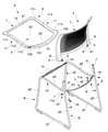
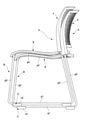
椅子Aは、支持フレームBに座Eを支持させるとともに支持フレームBに背凭れFを支持させているものである。支持フレームBの下端には、使用状態において支持フレームBと床面との間に位置するスペーサたる前スペーサCと後スペーサDが設けられている。 In the chair A, the support frame B supports the seat E, and the support frame B supports the backrest F. At the lower end of the support frame B, a front spacer C and a rear spacer D, which are spacers located between the support frame B and the floor surface in use, are provided.
支持フレームBは、左右に対をなし床面と略平行に前後方向に延びてなるベースフレーム部g1と、ベースフレーム部g1の前端部に立設された前脚フレーム部g2と、ベースフレーム部g1の後端部に立設された後脚フレーム部g3と、前脚フレーム部g2の上端部と後脚フレーム部g3の上端部間に架設された側座受フレーム部g4と、側座受フレーム部g4の前端部間を繋ぐ前横架フレーム部Hと、側座受フレーム部g4の後端部間を繋ぐ横架フレーム部たる後横架フレーム部Iと、後脚フレーム部g3の上端部から上方に延設された背支持フレーム部たる外背支持フレーム部Jと、側座受フレーム部g4の後端部から外背支持フレーム部Jに沿うように上方に延設された内背支持フレーム部Kとを備えてなるものである。 The support frame B has a base frame portion g1 that forms a pair on the left and right and extends in the front-rear direction substantially parallel to the floor surface, a front leg frame portion g2 erected at the front end portion of the base frame portion g1, and a base frame portion g1. The rear leg frame portion g3 erected at the rear end portion, the side seat receiving frame portion g4 erected between the upper end portion of the front leg frame portion g2 and the upper end portion of the rear leg frame portion g3, and the side seat receiving frame portion. From the front horizontal frame portion H connecting the front end portions of the g4, the rear horizontal frame portion I which is the horizontal frame portion connecting the rear end portions of the side seat receiving frame portion g4, and the upper end portion of the rear leg frame portion g3. The outer back support frame portion J, which is the back support frame portion extended upward, and the inner back support frame extended upward along the outer back support frame portion J from the rear end portion of the side seat receiving frame portion g4. It is provided with a part K.
外背支持フレーム部J、後脚フレーム部g3、ベースフレーム部g1、前脚フレーム部g2、側座受フレーム部g4、及び、内背支持フレーム部Kは、この順番で、一本の金属製パイプ材により連続して形成されている。換言すれば、支持フレームBは、外背支持フレーム部J、後脚フレーム部g3、ベースフレーム部g1、前脚フレーム部g2、側座受フレーム部g4、及び、内背支持フレーム部Kを一体に設けてなるものである。 The outer back support frame part J, the rear leg frame part g3, the base frame part g1, the front leg frame part g2, the side seat receiving frame part g4, and the inner back support frame part K are made of one metal pipe in this order. It is continuously formed by wood. In other words, the support frame B integrally includes the outer back support frame portion J, the rear leg frame portion g3, the base frame portion g1, the front leg frame portion g2, the side seat receiving frame portion g4, and the inner back support frame portion K. It is provided.
左右に対をなして配設された後脚フレーム部g3、ベースフレーム部g1、前脚フレーム部g2、及び、側座受フレーム部g4は、左の脚要素Gと右の脚要素Gを構成している。これら左右の脚要素G間を繋いでいる前横架フレーム部H、及び、後横架フレーム部Iは、金属板により形成されている。 The rear leg frame portion g3, the base frame portion g1, the front leg frame portion g2, and the side seat receiving frame portion g4 arranged in pairs on the left and right constitute the left leg element G and the right leg element G. ing. The front horizontal frame portion H and the rear horizontal frame portion I connecting the left and right leg elements G are formed of a metal plate.
ベースフレーム部g1の前端部下面には、スペーサである前スペーサCがねじv1により取り付けられている。ベースフレーム部g1の後端部下面には、後スペーサDがねじv2により取り付けられている。 A front spacer C, which is a spacer, is attached to the lower surface of the front end portion of the base frame portion g1 by a screw v1. A rear spacer D is attached to the lower surface of the rear end portion of the base frame portion g1 by a screw v2.
左右に対をなして配設されている前脚フレーム部g2の離間距離は、同一形状をなす他の椅子Aとのスタッキングを可能とするために、左右に対をなして配されている後脚フレーム部g3の離間距離よりも短く設定されている。前脚フレーム部g2は、ベースフレーム部g1の前端部から連設され正面視において内向きに傾斜して延びた下前脚フレーム部分g21と、下前脚フレーム部分g21の上端から上方に向かって略鉛直に延びた上前脚フレーム部分g22とを備えている。 The distance between the front leg frame portions g2 arranged in pairs on the left and right is such that the rear legs are arranged in pairs on the left and right to enable stacking with other chairs A having the same shape. It is set shorter than the separation distance of the frame portion g3. The front leg frame portion g2 is connected to the front end portion of the base frame portion g1 and extends inwardly and inclined inward in front view, and the lower front leg frame portion g21 and the lower front leg frame portion g21 substantially vertically upward from the upper end. It is provided with an extended upper front leg frame portion g22.
側座受フレーム部g4は、座Eを支持するべく座Eにおける側座枠部11の下面に添接し得る形状をなしている。側座受フレーム部g4は、側面視において緩やかなS字形状をなしている。側座受フレーム部g4は、前から順に、第一の前傾フレーム部分g41、後傾フレーム部分g42、及び、第二の前傾フレーム部分g43を備えてなる。
The side seat receiving frame portion g4 has a shape that can be attached to the lower surface of the side
第一の前傾フレーム部分g41は、座枠1における側座枠部11の第一の前傾部分111の下面に添接し得るものである。後傾フレーム部分g42は、座枠1における側座枠部11の後傾部分112の下面に添接し得るものである。第二の前傾フレーム部分g43は、座枠1における側座枠部11の第二の前傾部分113の下面に添接し得るものである。
The first forward tilted frame portion g41 can be attached to the lower surface of the first forward tilted
前横架フレーム部Hは、左右方向中間部が上向きコ字状に形成された金属板により構成されたものであり、座枠1の前座枠部12の下面側に嵌合し当該前座枠部12を下側から支持し得るものである。前横架フレーム部Hは、その左右端部近傍に座枠1を止着するためのねじv3が挿通し得るねじ挿通孔h1を有している。前横架フレーム部Hの左右端は、溶接により側座受フレーム部g4の前端部に取り付けられている。
The front horizontal frame portion H is formed of a metal plate whose left-right intermediate portion is formed in an upward U-shape, and is fitted to the lower surface side of the front
後横架フレーム部Iは、座枠1の後座枠部13を下側から支持し得るものである。後横架フレーム部Iは、左右の側座受フレーム部g4の後端部間を繋いでいる。後横架フレーム部Iは、平面視又は底面視において後方に向かって凸をなすように湾曲した形状をなしている。後横架フレーム部Iは、上下面を有し前傾した姿勢をなす後横架フレーム部本体i1と、後横架フレーム部本体i1の後端縁から一体に立設された起立フレーム部分i2とを備えている。
The rear horizontal frame portion I can support the rear
後横架フレーム部本体i1は、その左右端部近傍に座枠1を止着するためのねじv4が挿通し得る上下方向に貫通したねじ挿通孔i11を有している。起立フレーム部分i2は、その左右端部近傍に背板Lを止着するための背凭れ用止着具たるねじv5が挿通し得る前後方向に貫通したねじ挿通孔i22を有している。起立フレーム部分i2のねじ挿通孔i22は、当該起立フレーム部分i2の左右端部近傍において上向きに突出した凸部i21に設けられている。後横架フレーム部Iの左右端は、溶接により側座受フレーム部g4の後端部に取り付けられている。
The rear horizontal frame portion main body i1 has a screw insertion hole i11 penetrating in the vertical direction through which a screw v4 for fastening the
前スペーサC、及び、後スペーサDは、座E及び背凭れFを支持した支持フレームBを床面に対して安定支持させるためのものである。前スペーサC、及び、後スペーサDは、合成樹脂により形成されたブロック状のものである。前スペーサC、及び、後スペーサDの外側面c3、d3は、側面視において略台形状をなし且つ面一に形成されている。前スペーサC、及び、後スペーサDの最大幅寸法は、ベースフレーム部g1の幅寸法よりも大きく、且つ、ベースフレーム部g1の幅寸法の1.2倍以下の大きさに設定されている。 The front spacer C and the rear spacer D are for stably supporting the support frame B that supports the seat E and the backrest F with respect to the floor surface. The front spacer C and the rear spacer D are block-shaped formed of synthetic resin. The outer surfaces c3 and d3 of the front spacer C and the rear spacer D have a substantially trapezoidal shape in a side view and are formed flush with each other. The maximum width dimension of the front spacer C and the rear spacer D is set to be larger than the width dimension of the base frame portion g1 and 1.2 times or less the width dimension of the base frame portion g1.
前スペーサCは、使用状態において床面に当接し得る床当接面c2を有している。前スペーサCは、支持フレームBにおけるベースフレーム部g1の前部にねじv1により取り付けられている。前スペーサCは、その前端部内面側に凹陥部c1を有している。前スペーサCには、上下方向に貫通したねじ挿通孔c4を備えている。 The front spacer C has a floor contact surface c2 that can come into contact with the floor surface in the used state. The front spacer C is attached to the front portion of the base frame portion g1 in the support frame B by a screw v1. The front spacer C has a recessed portion c1 on the inner surface side of the front end portion thereof. The front spacer C is provided with a screw insertion hole c4 that penetrates in the vertical direction.
床当接面c2は、前スペーサCの下面をなすものである。床当接面c2は、後部に設けられたメイン当接面構成部c21と、メイン当接面構成部c21の前に位置し当該メイン当接面構成部c21よりも幅狭に設けられた延長当接面構成部c22とを備えている。 The floor contact surface c2 forms the lower surface of the front spacer C. The floor contact surface c2 is located in front of the main contact surface component c21 provided at the rear and the main contact surface component c21, and is an extension provided narrower than the main contact surface component c21. It is provided with a contact surface component c22.
凹陥部c1は、スタッキング時において他の椅子Aにおける支持フレームBの一部を位置させ得る収容空間spを形成したものである。凹陥部c1は、側面視において前傾した凹陥部形成面c11を有している。この凹陥部形成面c11は、スタッキング時において、同一構造をなす他の椅子Aの前脚フレーム部g2における下端部の一部に当接し得るようになっている。すなわち、前スペーサCの凹陥部c1に形成された凹陥部形成面c11は、他の椅子Aにおける前脚フレーム部g2の下前脚フレーム部分g21の上面に当接し、スタッキング時における椅子Aと他の椅子Aとの相対位置を位置決めし得るようになっている。 The recessed portion c1 forms a storage space sp in which a part of the support frame B in the other chair A can be positioned at the time of stacking. The recessed portion c1 has a recessed portion forming surface c11 that is tilted forward in a side view. The recessed portion forming surface c11 can come into contact with a part of the lower end portion of the front leg frame portion g2 of another chair A having the same structure during stacking. That is, the recessed portion forming surface c11 formed in the recessed portion c1 of the front spacer C abuts on the upper surface of the lower front leg frame portion g21 of the front leg frame portion g2 in the other chair A, and the chair A and the other chair during stacking. The position relative to A can be positioned.
前スペーサCは、外側面が略長方形をなし、前端から後端まで全面が段差や凹部のない平面状をなしている。前スペーサCは、全体形状が直方体をベースにしており、その範囲内で前端部内面側から床当接面c2に至る凹陥部c1を有している。しかして、同一形状をなす椅子Aを上下方向に複数積み重ねたときに、下の椅子Aの前脚フレーム部g2が上の椅子Aの前スペーサCの凹陥部c1に嵌合するように位置するものとなっている。前スペーサCは、ベースフレーム部g1の延伸方向に沿った直方体をなしている。つまり、前スペーサCは、ベースフレームg1から外方に向けて大きく張り出したものとはなっていないため、椅子A全体をコンパクトにすることができる。 The outer surface of the front spacer C is substantially rectangular, and the entire surface from the front end to the rear end is flat with no steps or recesses. The front spacer C is based on a rectangular parallelepiped as a whole, and has a recessed portion c1 extending from the inner surface side of the front end portion to the floor contact surface c2 within the range. When a plurality of chairs A having the same shape are stacked in the vertical direction, the front leg frame portion g2 of the lower chair A is positioned so as to fit into the recessed portion c1 of the front spacer C of the upper chair A. It has become. The front spacer C forms a rectangular parallelepiped along the stretching direction of the base frame portion g1. That is, since the front spacer C does not project greatly outward from the base frame g1, the entire chair A can be made compact.
なお、支持フレームBの安定性(例えば、前方への傾動に対する安定性)を考慮した場合、前スペーサCは、できるだけ支持フレームBの前側に取り付けることが好適である。また、前スペーサCと後スペーサDとの間隔はできるだけ広くとることが好適である。その一方で、前スペーサCの位置を支持フレームBの前側に過度に及ばせようとした場合には、スタッキング状態において、下に位置する他の椅子Aの前脚フレーム部g2と干渉してしまうという不具合が生じ得る。この実施形態の前スペーサCは、前端部内面側の一部に凹陥部c1を形成することにより、かかる不具合を解消したものとなっている。 Considering the stability of the support frame B (for example, the stability against tilting forward), it is preferable to attach the front spacer C to the front side of the support frame B as much as possible. Further, it is preferable that the distance between the front spacer C and the rear spacer D is as wide as possible. On the other hand, if the position of the front spacer C is excessively extended to the front side of the support frame B, it will interfere with the front leg frame portion g2 of the other chair A located below in the stacking state. Problems can occur. The front spacer C of this embodiment solves such a problem by forming a recessed portion c1 in a part of the inner surface side of the front end portion.
座Eは、支持フレームBに支持されたものである。座Eは、略四角枠状をなす座枠1とこの座枠1内に張設された張地2とを有したものである。座枠1及び張地2は熱圧成型により一体化されている。
The seat E is supported by the support frame B. The seat E has a
座枠1は、前後方向に延びた左右の側座枠部11と、この左右の側座枠部11の前端間を繋ぐ左右方向に延びた前座枠部12と、左右の側座枠部11の後端間を繋ぐ後座枠部13とを備えてなるものである。
The
左右の側座枠部11は、支持フレームBの側座受フレーム部g4によって下側から支持されるものである。左右の側座枠部11は、側座受フレーム部g4の形状に沿うように側面視において緩やかなS字形状をなしている。すなわち、左右の側座枠部11は、前端部に位置してなり側面視において前傾した姿勢をなす第一の前傾部分111と、この第一の前傾部分111の後端から連設され側面視において後傾した姿勢をなす後傾部分112と、この後傾部分112の後端から連設され側面視において前傾した姿勢をなす第二の前傾部分113とを備えている。
The left and right side
第一の前傾部分111は、側座受フレーム部g4の第一の前傾フレーム部分g41に下側から支持される。後傾部分112は、側座受フレーム部g4の後傾フレーム部分g42に下側から支持される。第二の前傾部分113は、側座受フレーム部g4の第二の前傾フレーム部分g43に下側から支持される。
The first forward tilted
また、図7及び図10に示すように、左右の側座枠部11の下面には、底面視において略矩形状をなすとともに正面視及び背面視において略L字状をなす引き寄せ部材11aがねじv6により取り付けられている。引き寄せ部材11aは、その外方端部が側座受フレーム部g4の下面に係わり合い、ねじv6を左右の側座枠部11に螺着することにより左右の側座枠部11と側座受フレーム部g4とを引き寄せるようにしてある。
Further, as shown in FIGS. 7 and 10, on the lower surface of the left and right side
前座枠部12は、左右の側座枠部11の前端間に架け渡されている。前座枠部12は、支持フレームBの前横架フレーム部Hに下側から支持される。
The front
後座枠部13は、後横架フレーム部Iに下側から支持されるものである。後座枠部13は、その後端縁に下方に向けて突出させた垂下壁131を備えている。後座枠部13の左右両端部には、外背支持フレーム部J、内背支持フレーム部K、及び、背板Lにおける左右の延出部Nを配設するための切欠部132が設けられている。
The rear
座Eは、背板Lを支持フレームBの後横架フレーム部Iに止着する背凭れ用止着具たるねじv5を隠蔽し得るものとなっている。すなわち、座Eにおける座枠1の後座枠部13が、背板Lを後横架フレーム部Iにねじ止めするためのねじv5を外部から視認し難いように覆い得るものとなっている。
The seat E can conceal the screw v5, which is a backrest fastener for fastening the back plate L to the rear horizontal frame portion I of the support frame B. That is, the rear
本実施形態に示す椅子Aは、座Eの一部である後座枠部13が、背凭れFの背板Lに一体に形成された突出部6の上を覆うように配されている。そして、椅子Aは、支持フレームBに背板Lを取り付けた後に、当該支持フレームBに座Eを取り付けている。椅子Aは座Eを外さない限り背板Lは外れないものとなっている。換言すれば、この実施形態における椅子Aは、背板Lの一部である突出部6、及び、突出部6のねじ挿通孔61を挿通するねじv5を隠蔽し得る座Eを備えている。しかして、座Eは、背板Lを支持フレームBから外すことなく、座Eのみを独立して、支持フレームBから無理なく離脱させることができるものとなっている。
In the chair A shown in the present embodiment, the rear
張地2は、座枠1に張り設けられたシート状をなしている。張地2は可撓性を備えた織物により構成されており、それ自体では保形性を有しないものとなっている。張地2は、その周縁が座枠1に支持されている。換言すれば、張地2は、座枠1によって囲まれた領域に配設されている。
The
張地2は、前後方向の張力すなわち前座枠部12と後座枠部13とを相寄る方向に引っ張る力よりも左右方向の張力すなわち左右の側座枠部11同士を相寄る方向に引っ張る力が強くなるように設定されている。より具体的に言えば、張地2は、左右方向に延びてなる複数の緯糸(図示せず)と、前後方向に延びてなり緯糸とは弾力特性が異なる複数の経糸(図示せず)を備えてなるものである。張地2は、緯糸の弾力特性が経糸の弾力特性よりも高く設定されている。
The
張地2の後部は、後方に向かって漸次上側に位置するように設定された弾性変形可能な着座面である後着座面23を形成している。張地2における前後方向中央部は、後方に向かって漸次下側に位置するように設定された弾性変形可能な着座面である中央着座面22を形成している。張地2における前部は、後方に向かって漸次上側に位置するように設定された弾性変形可能な前着座面21を形成している。
The rear portion of the
つまり、座枠1の側座枠部11において第一の前傾部分111間に支持されている張地2の前部が前着座面21を構成しており、座枠1の側座枠部11において後傾部分112間に支持されている張地2の前後方向中央が中央着座面22を構成しており、座枠1の側座枠部11において第二の前傾部分113間に支持されている張地2の後部が後着座面23を構成している。なお、図9においては、張地2の断面を把握しやすいように太線で示している。
That is, the front portion of the
この実施形態における座枠1に支持された張地2は、当該張地2のみによって、いわゆる三次元的に隆起した形態を採り得るものとなっている。換言すれば、張地2は、その周端縁よりも内側の部位に対して他の部材による外力を加えられることなく三次元的に隆起した形態を採り得るものとなっている。つまり、張地2全体は側面視において張地2を支持する側座枠部11の形状に追従して側面視においてS字状に起伏する形態をなしている。これに加えて、張地2における前後方向と左右方向の張力を相違させることにより、張地2の左右方向中央部分におけるS字状の起伏の程度は、それよりも側座枠部11に近い位置におけるS字状の起伏の程度よりも緩やかに設定されている。
The
背凭れFは、合成樹脂により形成された背板Lを備えたものである。 The backrest F includes a back plate L formed of a synthetic resin.
背板Lは、前面側に背凭れ面を形成した本体部Mと、この本体部Mから下方に突設された左右の延出部Nとを備えたものである。 The back plate L includes a main body portion M having a backrest surface formed on the front surface side, and left and right extending portions N projecting downward from the main body portion M.
本体部Mは、前後方向に貫通した複数の孔pが形成された背板本体3と、この背板本体3の左右に配設された上下に延びる縦背支持部4とを備えてなるものである。
The main body portion M includes a back plate
背板本体3は略矩形状をなしている。背板本体3には前後方向に貫通した複数の孔pが設けられている。背板本体3に形成された複数の孔pは正面視において略矩形状をなしている。より具体的に言えば、複数の孔pは正面視において略正方形状をなしている。
The back plate
なお、この明細書における「略正方形」には、四辺が外方または内方に凸をなすように若干湾曲してなるものを含むものとする。 It should be noted that the "substantially square" in this specification includes those having four sides slightly curved so as to be convex outward or inward.
背板本体3は、着座者の背中を支持し得る主要部を構成するものである。背板本体3は、上側に向かって漸次厚み寸法が短くなるように形成されている。背板本体3は、図20に示すように、上下方向に隣接し合う孔pの間に、縦背支持部4間を繋ぎ左右方向に略直線状に延びた横帯部分31を備えている。横帯部分31は、背板本体3における上下端部33、34を除く略全域において上下方向に複数並び配されている。
The
なお、図20において、横帯部分31の把握の便宜のため、横帯部分31に該当する領域上に直線状の一点鎖線を示している。
In FIG. 20, for the convenience of grasping the
背板本体3は、図19に示すように、左右方向に隣接し合う孔pの間に、当該背板本体3の上下端部33、34間を繋ぐように上下方向に略直線状に延びた縦帯部分32を備えている。縦帯部分32は、背板本体3における左右端部領域3aにのみ左右方向に複数並び配されている。
As shown in FIG. 19, the back plate
なお、図20において、縦帯部分32の把握の便宜のため、縦帯部分32に該当する領域上に直線状の一点鎖線を示している。
In FIG. 20, for the convenience of grasping the
背板本体3の中央領域3bに設けられた孔pの幅寸法は、図19に示すように、中央領域3bの外周域に位置する周縁領域3cに設けられた孔pの幅寸法よりも大きく設定されている。すなわち、背板本体3に設けられた孔pの大きさは、中央領域3bから周縁領域3cに向かって、漸次小さくなるように設定されている。
As shown in FIG. 19, the width dimension of the hole p provided in the
略同一高さ位置に左右方向に直線状に並び配された複数の孔pは、隣り合う孔pの中心点間の距離が周縁領域3cに向かうほど大きくなるように背板本体3に設けられている。換言すれば、左右方向に直線状に並び配された複数の孔pのピッチは、中央領域3bから周縁領域3cに向かうほど大きくなるように設定されている。左右方向に直線状に並び配された複数の孔pの中心点同士を結んでなる仮想線ksは、正面視において上下方向に平行且つ略等間隔をなすように設定されている。
A plurality of holes p arranged linearly in the left-right direction at substantially the same height position are provided on the back plate
上下に最も近接して隣り合う一方の孔pと他方の孔pが、中心点が鉛直方向に一致しないように背板本体3に設けられている。
One hole p and the other hole p, which are closest to each other in the vertical direction, are provided on the back plate
左右の縦背支持部4は、背板本体3を挟むように左右に配設されている。左右の縦背支持部4は背板本体3を支持し得る剛性を保持したものであり、前後方向に貫通する孔は設けられていない。左右の縦背支持部4の下端には、下方に向けて突出する左右の延出部Nが一体に設けられている。
The left and right vertical
左右の延出部Nは、内部に上下方向に穿設され外背支持フレーム部J及び内背支持フレーム部Kが収容される図示しない収容部を有した柱状の外観をなす延出部本体5と、延出部本体5の下端部から内方に突設された突出部6と、延出部本体5の下端部から前方に突設された鍔部7を備えてなる。
The left and right extension portions N have a columnar appearance and have a columnar appearance, which is formed inside in the vertical direction and has an accommodation portion (not shown) in which the outer back support frame portion J and the inner back support frame portion K are accommodated. A
突出部6は、板状をなしており延出部本体5の下端部から後横架フレーム部Iにおける起立フレーム部分i2の背面側に沿うように突設されている。すなわち、左右の突出部6は、突片状のものである。左右の突出部6は、その中央部に背凭れ用止着具であるねじv5が挿通し得る前後方向に貫通した止着具挿通孔たるねじ挿通孔61が形成されている。
The protruding
鍔部7は、側座受フレーム部g4の後端部上に位置しているものである。鍔部7は、座Eの切欠部132を臨む側座枠部11の後端部によって上側から被覆されるようになっている。つまり、鍔部7は、支持フレームBと座Eとの間に挟まれ得る位置に配されている。
The
背板Lは、起立姿勢をなす外背支持フレーム部J、及び、起立姿勢をなす内背支持フレーム部Kに外嵌して支持フレームBに支持されている。また、背板Lは、外背支持フレーム部J、及び、内背支持フレーム部Kから抜け出ないように、支持フレームBを構成する左右方向に延びた後横架フレーム部Iに対してねじv5により止着されている。この実施形態では、ねじv5は、座Eの一部分である後座枠部13によって隠蔽されており座面よりも上方から見た場合、すなわち、使用者が通常採り得る姿勢で見た場合に視認不可能となっている。椅子Aは、斜め上方から視認されやすいものであり、外観の良さを向上させるためには後斜め上方からの外観を気にする必要がある。
The back plate L is externally fitted to the outer back support frame portion J in the upright posture and the inner back support frame portion K in the upright posture, and is supported by the support frame B. Further, the back plate L is screwed v5 with respect to the rear horizontal frame portion I extending in the left-right direction constituting the support frame B so as not to come off from the outer back support frame portion J and the inner back support frame portion K. Is stopped by. In this embodiment, the screw v5 is concealed by the rear
以上説明したように、本実施形態に係る椅子Aは、合成樹脂により形成された背板Lを備えてなる。そして、背板Lが、前後方向に貫通した複数の孔pが形成された背板本体3と、この背板本体3の左右に配設された上下に延びる縦背支持部4とを備えてなる。背板本体3が、上下方向に隣接し合う孔pの間に、縦背支持部4間を繋ぎ左右方向に略直線状に延びた横帯部分31を備えており、背板本体3が、左右方向に隣接し合う孔pの間に、当該背板本体3の上下端部33、34間を繋ぐように上下方向に略直線状に延びた縦帯部分32を備えている。そして、横帯部分31が、背板本体3における上下端部33、34を除く略全域において上下方向に複数並び配されてなるものであり、且つ、縦帯部分32が、背板本体3における左右端部領域3aにのみ左右方向に複数並び配されてなるものである。このため、着座者の背中を好適に支持し得る背板Lを有した椅子Aを提供することができるものとなる。
As described above, the chair A according to the present embodiment includes a back plate L formed of a synthetic resin. The back plate L is provided with a back plate
つまり、本実施形態における背板Lであれば、同一形状をなす複数の孔pを形成し、その孔pの大きさ及びその配列を調整することによって、弾性変形し得る構成を実現している。換言すれば、この実施形態の背板Lであれば、構造の複雑化が抑制された態様によって、着座者の背中を好適に支持し得る設計の自由度に優れたものとなっている。 That is, in the case of the back plate L in the present embodiment, a configuration capable of elastic deformation is realized by forming a plurality of holes p having the same shape and adjusting the size and arrangement of the holes p. .. In other words, the back plate L of this embodiment has an excellent degree of freedom in design that can suitably support the back of the seated person by the mode in which the complexity of the structure is suppressed.
背板本体3の中央領域3bに設けられた孔pの幅寸法が、中央領域3bの外周域に位置する周縁領域3cに設けられた孔pの幅寸法よりも大きく設定されている。このため、着座者の背中に直接的に添接しやすい中央領域3bの弾性変形性、及び、前後方向への通気性を好適に高めることができるものとなっている。
The width dimension of the hole p provided in the
背板本体3に設けられた孔pの大きさが、中央領域3bから周縁領域3c側に向かって、漸次小さくなるように設定されている。このため、着座者の背中に直接的に添接しやすい中央領域3bの弾性変形性、及び、前後方向への通気性を好適に高めることができるだけでなく、外観に優れた背板Lを提供し得るものとなっている。
The size of the hole p provided in the back plate
略同一高さ位置に左右方向に直線状に並び配された複数の孔pが、隣り合う孔pの中心点間の距離が略等しくなるように背板本体3に設けられている。このため、孔pの配列が規則性を帯びたものとなり、外観に優れた背板Lを提供し得るものとなっている。
A plurality of holes p arranged linearly in the left-right direction at substantially the same height position are provided on the back plate
上下に最も近接して隣り合う一方の孔pと他方の孔pが、中心点が鉛直方向に一致しないように背板本体3に設けられている。このため、鉛直方向における孔pの配列が過度に単純なものとなっておらず、且つ、一定の規則性を帯びたものとなり、外観に優れた背板Lを提供し得るものとなっている。
One hole p and the other hole p, which are closest to each other in the vertical direction, are provided on the back plate
背板本体3が、上側に向かって漸次厚み寸法が短くなるように形成されている。このため、背板Lは、上側に向かって弾性変形し易いものとなっているため、着座者の背中を好適に支持し得るものとなっている。
The back plate
孔pが略矩形状をなしているため、外観に優れた背板Lを提供し得るものとなっている。 Since the holes p have a substantially rectangular shape, it is possible to provide a back plate L having an excellent appearance.
なお、本発明は、以上に詳述した実施形態に限られるものではない。 The present invention is not limited to the embodiment described in detail above.
背凭れは、背板を備えたものであればよい。換言すれば、背凭れには、背板以外のものを備えていてもよい。例えば、背凭れは、背板とともに背板を覆うカバーを備えていてもよい。 The backrest may be provided with a back plate. In other words, the backrest may be provided with something other than the backboard. For example, the backrest may be provided with a cover covering the backboard together with the backboard.
孔の形状は種々の形状を設定することができるものであり、上述した実施形態に示したものに限定されるものではない。孔の形状は、例えば、円形や楕円形をなしているものであってもよい。 The shape of the hole can be set to various shapes, and is not limited to the shape shown in the above-described embodiment. The shape of the hole may be, for example, a circular shape or an elliptical shape.
横帯部分の幅寸法や縦帯部分の幅寸法は適宜の寸法のものを採用することができるものであり、上述した実施形態に示したものに限定されるものではない。また、縦帯部分が配された左右端部領域の広さは適宜設定され得るものであることは言うまでもない。 As the width dimension of the horizontal band portion and the width dimension of the vertical band portion, those having appropriate dimensions can be adopted, and are not limited to those shown in the above-described embodiment. Further, it goes without saying that the size of the left and right end regions in which the vertical band portions are arranged can be appropriately set.
その他、各部の具体的構成についても上記実施形態に限られるものではなく、本発明の趣旨を逸脱しない範囲で種々変形が可能である。 In addition, the specific configuration of each part is not limited to the above embodiment, and various modifications can be made without departing from the spirit of the present invention.
A…椅子
L…背板
p…孔
3…背板本体
4…縦背支持部
31…横帯部分
32…縦帯部分
33…上端部
34…下端部
A ... Chair L ... Back plate p ...
Claims (6)
前記背板が、前後方向に貫通した複数の孔が形成された背板本体と、この背板本体の左右に配設された上下に延びる縦背支持部とを備えてなるものであり、
前記背板本体が、上下方向に隣接し合う孔の間に、前記縦背支持部間を繋ぎ左右方向に略直線状に延びた横帯部分を備えており、
前記背板本体が、左右方向に隣接し合う孔の間に、当該背板本体の上下端部間を繋ぐように上下方向に略直線状に延びた縦帯部分を備えており、
前記横帯部分が、前記背板本体における前記上下端部を除く略全域において上下方向に複数並び配されてなるものであり、且つ、前記縦帯部分が、前記背板本体における左右端部領域にのみ左右方向に複数並び配されてなるものである椅子。 A chair with a backboard made of synthetic resin.
The back plate includes a back plate main body having a plurality of holes penetrating in the front-rear direction, and vertically extending vertical back support portions arranged on the left and right sides of the back plate main body.
The back plate main body is provided with a horizontal band portion that connects the vertical back support portions and extends substantially linearly in the left-right direction between holes adjacent to each other in the vertical direction.
The back plate main body is provided with a vertical band portion extending substantially linearly in the vertical direction so as to connect the upper and lower ends of the back plate main body between holes adjacent to each other in the left-right direction.
A plurality of the horizontal band portions are arranged side by side in the vertical direction in substantially the entire area excluding the upper and lower end portions of the back plate main body, and the vertical band portions are left and right end regions of the back plate main body. Chairs that are arranged side by side only in the left-right direction.
Priority Applications (1)
| Application Number | Priority Date | Filing Date | Title |
|---|---|---|---|
| JP2017190673A JP7029045B2 (en) | 2017-09-29 | 2017-09-29 | Chair |
Applications Claiming Priority (1)
| Application Number | Priority Date | Filing Date | Title |
|---|---|---|---|
| JP2017190673A JP7029045B2 (en) | 2017-09-29 | 2017-09-29 | Chair |
Publications (2)
| Publication Number | Publication Date |
|---|---|
| JP2019063177A JP2019063177A (en) | 2019-04-25 |
| JP7029045B2 true JP7029045B2 (en) | 2022-03-03 |
Family
ID=66338150
Family Applications (1)
| Application Number | Title | Priority Date | Filing Date |
|---|---|---|---|
| JP2017190673A Active JP7029045B2 (en) | 2017-09-29 | 2017-09-29 | Chair |
Country Status (1)
| Country | Link |
|---|---|
| JP (1) | JP7029045B2 (en) |
Families Citing this family (1)
| Publication number | Priority date | Publication date | Assignee | Title |
|---|---|---|---|---|
| EP4088621A4 (en) * | 2020-01-09 | 2024-04-03 | Nature Arch Inc | Chair, seat portion, and backrest |
Citations (5)
| Publication number | Priority date | Publication date | Assignee | Title |
|---|---|---|---|---|
| JP2007143716A (en) | 2005-11-04 | 2007-06-14 | Okamura Corp | Backrest device for chair |
| WO2014063259A1 (en) | 2012-10-23 | 2014-05-01 | Vitra Patente Ag | Backrest for a chair |
| US20140265493A1 (en) | 2013-03-15 | 2014-09-18 | Hni Technologies Inc. | Chair with activated back flex |
| CN105640109A (en) | 2014-11-10 | 2016-06-08 | 广力达企业有限公司 | Chair back structure |
| JP2017086363A (en) | 2015-11-09 | 2017-05-25 | 株式会社イトーキ | Chair |
-
2017
- 2017-09-29 JP JP2017190673A patent/JP7029045B2/en active Active
Patent Citations (5)
| Publication number | Priority date | Publication date | Assignee | Title |
|---|---|---|---|---|
| JP2007143716A (en) | 2005-11-04 | 2007-06-14 | Okamura Corp | Backrest device for chair |
| WO2014063259A1 (en) | 2012-10-23 | 2014-05-01 | Vitra Patente Ag | Backrest for a chair |
| US20140265493A1 (en) | 2013-03-15 | 2014-09-18 | Hni Technologies Inc. | Chair with activated back flex |
| CN105640109A (en) | 2014-11-10 | 2016-06-08 | 广力达企业有限公司 | Chair back structure |
| JP2017086363A (en) | 2015-11-09 | 2017-05-25 | 株式会社イトーキ | Chair |
Also Published As
| Publication number | Publication date |
|---|---|
| JP2019063177A (en) | 2019-04-25 |
Similar Documents
| Publication | Publication Date | Title |
|---|---|---|
| US8033598B2 (en) | Mesh folding chair | |
| US8317269B2 (en) | Mesh stacking chair | |
| US20100156156A1 (en) | Clamping joint for a chair | |
| US20100181807A1 (en) | Mesh chair with open-end hoop | |
| CN106004593B (en) | Cap anchor clamp tool | |
| US10813463B2 (en) | Compliant backrest | |
| US20230165376A1 (en) | Compliant backrest | |
| JP2005532092A (en) | Elastic mat for cushion | |
| JP7029045B2 (en) | Chair | |
| JP7173726B2 (en) | Chair | |
| JP7071811B2 (en) | Chair | |
| JP7029044B2 (en) | Chair | |
| JP2000270962A (en) | Flexible base plate for chair | |
| JP6997936B2 (en) | Chair | |
| JPH07100031A (en) | Shell of chair | |
| JP2010000166A (en) | Backrest member of chair | |
| JP3240391U (en) | chairs | |
| JP2022065078A (en) | Chair | |
| JP7246164B2 (en) | a chair with a backrest and the same | |
| JP3196793U (en) | Body support | |
| JP4793831B2 (en) | sofa | |
| US20050052068A1 (en) | Spring support for seating area of furniture | |
| JP6552083B2 (en) | Chair load bearing member and chair | |
| JP2018075079A (en) | Load support member for chair, and chair | |
| KR20220107687A (en) | Chair with backrest module |
Legal Events
| Date | Code | Title | Description |
|---|---|---|---|
| A621 | Written request for application examination |
Free format text: JAPANESE INTERMEDIATE CODE: A621 Effective date: 20200820 |
|
| A977 | Report on retrieval |
Free format text: JAPANESE INTERMEDIATE CODE: A971007 Effective date: 20210628 |
|
| A131 | Notification of reasons for refusal |
Free format text: JAPANESE INTERMEDIATE CODE: A131 Effective date: 20210706 |
|
| TRDD | Decision of grant or rejection written | ||
| A01 | Written decision to grant a patent or to grant a registration (utility model) |
Free format text: JAPANESE INTERMEDIATE CODE: A01 Effective date: 20220118 |
|
| A61 | First payment of annual fees (during grant procedure) |
Free format text: JAPANESE INTERMEDIATE CODE: A61 Effective date: 20220131 |
|
| R150 | Certificate of patent or registration of utility model |
Ref document number: 7029045 Country of ref document: JP Free format text: JAPANESE INTERMEDIATE CODE: R150 |