JP7027298B2 - Video content processing device and content processing method in the video content processing device - Google Patents
Video content processing device and content processing method in the video content processing device Download PDFInfo
- Publication number
- JP7027298B2 JP7027298B2 JP2018225220A JP2018225220A JP7027298B2 JP 7027298 B2 JP7027298 B2 JP 7027298B2 JP 2018225220 A JP2018225220 A JP 2018225220A JP 2018225220 A JP2018225220 A JP 2018225220A JP 7027298 B2 JP7027298 B2 JP 7027298B2
- Authority
- JP
- Japan
- Prior art keywords
- content
- video
- value
- control means
- output
- Prior art date
- Legal status (The legal status is an assumption and is not a legal conclusion. Google has not performed a legal analysis and makes no representation as to the accuracy of the status listed.)
- Active
Links
Images


Description
本発明の実施形態は、映像コンテンツの処理装置およびその処理方法に関する。 An embodiment of the present invention relates to a video content processing device and a processing method thereof.
高度BSデジタル放送/高度広帯域CSデジタル放送(新4K8K衛星放送)の本格運用に向けて、高度BSデジタル放送/高度広帯域CSデジタル放送に関する規格化が、一般社団法人電波産業会(ARIB:Association of Radio Industries and Businesses)を中心として進められている。 For the full-scale operation of advanced BS digital broadcasting / advanced wideband CS digital broadcasting (new 4K8K satellite broadcasting), standardization of advanced BS digital broadcasting / advanced wideband CS digital broadcasting has been promoted by the Association of Radio Industries and Businesses (ARIB). Industries and Businesses).
高度BSデジタル放送/高度広帯域CSデジタル放送によりコンテンツを受信する放送信号受信装置において、受信したコンテンツを、放送信号受信装置が備えるIPインタフェースを介して出力する際に、適用するコンテンツ保護方式の実現が要望されている。 In a broadcast signal receiver that receives content by advanced BS digital broadcasting / advanced wideband CS digital broadcasting, it is possible to realize a content protection method that is applied when the received content is output via the IP interface of the broadcast signal receiver. It is requested.
一実施形態によれば、MMT-TLV方式で多重されている放送信号を受信する映像コンテンツ処理装置において、
前記放送信号で送られてくるコンテンツを受信する受信手段と、
IPインタフェースを持つ出力手段と、
DTCP2によるコンテンツ保護方式のフォーマットに従い、前記出力手段を介して前記コンテンツを出力する処理を行う制御手段と、を具備し、
前記制御手段は、
前記受信手段により受信した前記コンテンツに付随して前記MMT-TLV方式で多重されている放送信号に含まれるSI信号に配置されたvideo_transfer_characteristicsを解析する手段を有し、
さらに前記制御手段は、前記SI信号に配置されている映像コンポーネント記述子の前記video_transfer_characteristicsの値に応じて、前記コンテンツ保護方式のフォーマットに含まれるコンテンツ利用識別子のうちEIの値を0又は1に設定する、映像コンテンツ処理装置が提供される。
According to one embodiment, in a video content processing device that receives broadcast signals multiplexed by the MMT-TLV system,
A receiving means for receiving the content transmitted by the broadcast signal, and
An output means with an IP interface and
A control means for performing a process of outputting the content via the output means according to the format of the content protection method by DTCP2 is provided .
The control means is
It has a means for analyzing video_transfer_characteristics arranged in the SI signal included in the broadcast signal multiplexed by the MMT-TLV method accompanying the content received by the receiving means.
Further, the control means sets the EI value of the content usage identifier included in the format of the content protection method to 0 or 1 according to the value of the video_transfer_characteristics of the video component descriptor arranged in the SI signal. A video content processing device is provided.
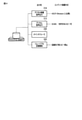
図1は、本発明の実施形態に係る放送信号受信装置(手段)140を含むシステム全体の構成例を示す図である。
本システムは、放送信号送信装置(手段)100、放送信号受信装置(手段)140、通信衛星150、他の放送信号受信装置140-2、レコーダ131を含む。放送信号受信装置(手段)140は、有線LANあるいは無線LAN等のネットワーク120を介して接続されている例えばデータコンテンツサーバとデータコンテンツサービスのやり取りを行ったり、DLNA(登録商標)(Digital Living Network Alliance)準拠の他の放送信号受信装置140-2やレコーダ131と映像や音声のコンテンツのやり取りを行ったりすることが可能である。
FIG. 1 is a diagram showing a configuration example of the entire system including the broadcast signal receiving device (means) 140 according to the embodiment of the present invention.
This system includes a broadcast signal transmitting device (means) 100, a broadcasting signal receiving device (means) 140, a
放送番組を放送する放送信号送信装置(手段)100は、放送番組サーバ101および第1の基本機能102を備える。放送信号送信装置100は、放送局とも呼ぶ。また放送信号送信装置100は、各放送事業者の番組を集約して通信衛星150にアップリンクする地上局であってもよい。
The broadcast signal transmission device (means) 100 for broadcasting a broadcast program includes a
放送番組サーバ101は、放送局100として放送する番組のデータ、番組の名称、放送日時、内容の説明等を予め保存しておくエリアである。放送番組サーバ101は、各放送事業者から送られてきた番組等のデータを保存するサーバであってもよい。
第1の基本機能102は、放送局100の基本的な機能であり、放送する番組の映像データや音声データ等を符号化(エンコードとも呼ぶ)し、制御情報であるSI(Signaling Information)信号を含めて多重化して放送信号として送出する機能を持つ。
The
The first
SI信号には、後述するコンテンツコピー制御記述子、コンテンツ利用制御記述子、映像コンポーネント記述子と呼ばれる制御情報が含まれる。
放送信号送信装置100から送出される放送信号の多重化方式は、非特許文献1に記載のMMT・TLV方式を準拠するものとする。
The SI signal includes control information called a content copy control descriptor, a content utilization control descriptor, and a video component descriptor, which will be described later.
The multiplexing method of the broadcasting signal transmitted from the broadcasting
放送信号受信装置(手段)140は、第2の基本機能141、制御手段142を含む。また放送信号受信装置140は、周辺機器と接続するためのI/Fを介して、表示装置160、HDD(Hard Disk Drive)162、リムーバブルディスク165等と接続可能である。放送信号受信装置140は、デジタルテレビジョン受信装置とも呼ぶ。放送信号受信装置140は、また映像コンテンツ処理装置とも呼ぶ。
The broadcast signal receiving device (means) 140 includes a second
第2の基本機能141は、テレビジョン受信装置140としての基本的な機能であり、放送局100から送られてくる放送信号を受信し、放送信号に含まれる符号化された映像信号(映像ストリームとも呼ぶ)、符号化された音声信号(音声ストリームとも呼ぶ)、SI信号を分離し、映像信号および音声信号を復号化(デコードとも呼ぶ)したり、SI信号を解析したりする機能を持つ。
The second
制御手段142は、テレビジョン受信装置140の全体的な動作を制御する制御手段である。また制御手段142は、テレビジョン受信装置140に接続されている周辺機器、例えば表示装置160、スピーカ161、テレビジョン受信装置140にバインドされているHDD(Hard Disk Drive)162、リムーバブルディスク165等との接続の管理やデータの送受信の管理も行う。
The control means 142 is a control means for controlling the overall operation of the
また制御手段142は、後述するデジタル音声出力、デジタル映像音声出力、高速デジタルI/F等の出力先に応じて、出力するコンテンツの保護を行う。制御手段142が行う、出力先ごとのコンテンツの保護方式の例は図4を用いて説明する。
表示装置160は、第2の基本機能141で受信した放送信号に含まれる映像を表示する手段である。表示装置160は、第2の基本機能141で受信した放送信号に含まれる音声信号を出力するスピーカ161を内蔵していてもよい。
Further, the control means 142 protects the output content according to the output destinations such as digital audio output, digital video audio output, and high-speed digital I / F, which will be described later. An example of the content protection method for each output destination performed by the control means 142 will be described with reference to FIG.
The
また音声信号を出力する装置は、表示装置160に内蔵されているスピーカ161とは別にUSB(Universal Serial Bus)やHDMI(登録商標)等のI/Fによりテレビジョン受信装置と接続された外部のスピーカであってもよい。
In addition to the
図1に示す例では、表示装置160は、放送信号受信装置140と別体として記載しているが、放送信号受信装置140の1機能として放送信号受信装置140と一体であってもよい。
図2は、本発明の実施形態が適用される放送信号受信装置140に放送波を送出する放送信号送信装置100の構成例を概略的に示す図である。放送信号送信装置100は、放送局サーバ101に蓄えられている放送番組を放送信号で送信するために、番組の映像データや音声データ等を符号化(エンコード)して放送信号して送出する。
In the example shown in FIG. 1, the
FIG. 2 is a diagram schematically showing a configuration example of a broadcast
音声エンコーダ211は、放送局サーバ101に蓄えられている番組の音声データを符号化する機能を持つ。音声エンコーダ211は、放送する番組を放送局サーバ101から読み出すと、読み出した番組の音声データを符号化する。
映像エンコーダ212は、放送局サーバ101に蓄えられている番組の映像データを符号化する機能を持つ。映像エンコーダ212は、放送する番組を放送局サーバ101から読み出すと、読み出した番組の映像データを符号化する。
The
The
制御情報生成手段213は、TLVパケットおよびMMTの制御情報であるSI信号を生成する機能を持つ。非特許文献1に記載のように、TLVパケットの制御情報とは、IPパケットの多重に関する制御情報(TLV-SIとも呼ばれる)であり、選局のための情報やIPアドレスとサービスの対応情報を提供する。またMMTの制御情報とは、MMTのパッケージの構成や放送サービスに関連する制御情報(MMT-SIとも呼ばれる)である。後述するコンテンツコピー制御記述子、コンテンツ利用制御記述子、映像コンポーネント記述子は、MMT-SIの1つである。
The control information generation means 213 has a function of generating SI signals which are control information of TLV packets and MMT. As described in
制御情報生成手段213は、音声エンコーダ211、映像エンコーダ212がエンコード対象とした番組に付随する制御情報を含むTLVパケットおよびMMTの制御情報の信号を生成する。
スクランブラ215は、音声エンコーダ211から出力されたエンコードされた音声ストリーム、映像エンコーダ212から出力されたエンコードされた映像ストリームを、CASモジュール216と連携してスクランブルする機能を持つ。
The control information generation means 213 generates signals of TLV packets and MMT control information including control information associated with the program to be encoded by the
The
CASモジュール216は、スクランブラ215がスクランブルする際に使用する鍵を生成するモジュールである。
マルチプレクサ(多重化処理)217は、音声エンコーダ211が音声データをエンコードして生成した音声ストリーム、映像エンコーダ212が映像データをエンコードして生成した映像ストリームおよび制御情報生成手段213で生成された制御情報(SI信号)を、MMT・TLV方式で多重する機能を持つ。マルチプレクサ(多重化処理)217は、音声ストリーム、映像ストリーム、TLVパケットおよびMMTの制御情報(SI信号)を多重化したTLVストリームを生成する。
The
The multiplexer (multiplexing process) 217 is an audio stream generated by encoding audio data by the
送信手段218は、TLVストリームを放送波として送出する機能を持つ。送信手段218は、マルチプレクサ(多重化処理)217が生成したTLVストリームを、16APSKなどの変調や誤り訂正符号化などの伝送路符号化処理を行い放送波として送出する。 The transmission means 218 has a function of transmitting a TLV stream as a broadcast wave. The transmission means 218 performs transmission line coding processing such as modulation such as 16APSK and error correction coding to transmit the TLV stream generated by the multiplexer (multiplexing processing) 217 as a broadcast wave.
図3は、本発明の実施形態に係る放送信号受信装置140の構成例を概略的に示す図である。
放送信号受信装置140は、放送信号を受信する受信機能である第2の基本機能141と制御手段142を含む。
第2の基本機能141は、チューナー301、復調器302、デスクランブラ303、デマルチプレクサ(TLV/MMT分離処理)304、音声デコーダ305、映像デコーダ306、CASモジュール308、提示処理309を含む。
FIG. 3 is a diagram schematically showing a configuration example of the broadcast
The broadcast
The second
チューナー301は、必要な放送信号を検出し、検出した放送信号を復調器302に入力する。
復調器302は、多重化されているTLVストリームを復調し、復調したTLVストリームをデマルチプレクサ304(TLV/MMT分離処理)に入力する。
The
The
デマルチプレクサ(TLV/MMT分離処理)304は、入力されたTLVストリームを、映像ストリーム、音声ストリーム、制御情報(SI信号)に分離する。スクランブルされている音声ストリームと映像ストリームは、デマルチプレクサ304(TLV/MMT分離処理)により分離された制御情報に含まれるEMM/EMCを用いてCASモジュール308により生成された鍵を用いて、デスクランブラ303によりデスクランブルされる。制御情報(SI信号)は、制御手段142により解析され処理される。
The demultiplexer (TLV / MMT separation process) 304 separates the input TLV stream into a video stream, an audio stream, and control information (SI signal). The scrambled audio and video streams are descrambled using the key generated by the
デスクランブラ303は、デスクランブルした音声ストリームを音声デコーダ305に、映像ストリームを映像デコーダ306に入力する。
音声デコーダ305は、入力された音声ストリームを復号化(デコード)し、例えばスピーカ316に出力する音声信号を生成する。
The
The
映像デコーダ306は、入力された映像ストリームを復号化し、例えば表示装置317に表示する映像信号を生成する。
復合化された映像信号は、文字及びグラフィック画像の提示処理309を経由して出力される。
なおデスクランブラ303でデスクランブルされた音声ストリームと映像ストリームは、デスクランブルされるごとに音声デコーダや映像デコーダに入力されて復号化され、スピーカ316や表示装置317に出力されてもよいし、制御手段142が管理する蓄積装置(手段)(例えば図1のHDD162)に一時的に蓄積(一時蓄積)されたのちに、音声デコーダや映像デコーダに入力されて復号化され、スピーカ316や表示装置317に出力されてもよいし、制御手段142が管理する蓄積装置(手段)(例えば図1のHDD162やリムーバブルディスク165)に蓄積(記録、コピーとも言う)してから、音声デコーダや映像デコーダに入力されて復号化され、スピーカ316や表示装置317に出力されてもよい。
The
The recombined video signal is output via the character and graphic
The audio stream and the video stream descrambled by the
提示処理309は、映像デコーダ306が映像ストリームを復号化して生成した映像信号に文字やグラフィック画像を合成して表示装置317に表示する映像を生成する。
音声出力311は、放送信号受信装置140が備えるスピーカ316に音声信号を出力するためのI/Fである。なお制御手段142は、音声デコーダ305から出力される音声信号の通常の出力先として、音声出力311を設定してもよい。
The
The
映像出力312は、放送信号受信装置140が備える表示装置317に映像信号を出力するためのI/Fである。なお制御手段142は、映像デコーダ306から出力される映像信号の通常の出力先として、映像出力312を設定してもよい。
デジタル音声出力313は、放送信号受信装置140の外部接続機器であるオーディオ機器(図示せず)に音声信号を出力するためのI/Fである。デジタル音声出力313のI/Fは、例えばHDMIのI/Fである。オーディオ機器等の外部接続機器は、マルチチャンネルオーディオに対応する機器であってもよい。
The
The
デジタル映像音声出力314は、放送信号受信装置140の外部接続機器であるAV機器(図示せず)に音声信号および映像信号を出力するためのI/Fである。デジタル映像音声出力314のI/Fは、例えばHDMIのI/Fである。AV機器等の外部接続機器は、マルチチャンネルオーディオに対応する機器であってもよい。
The digital video /
復号化された音声信号の出力先は、例えば音声出力311のI/Fを介して放送信号受信装置140に備えられたスピーカ316であってもよい、あるいは例えばHDMI等のデジタル音声出力313あるいはデジタル映像音声出力314のI/Fを介して接続された外部接続機器であってもよい。
The output destination of the decoded audio signal may be, for example, a
同様に復号化された映像信号の出力先は、例えば映像出力312のI/Fを介して放送信号受信装置140に備えられた表示装置317であってもよい、あるいは例えばHDMI等のデジタル映像音声出力314のI/Fを介して接続された他の外部接続機器であってもよい。
Similarly, the output destination of the decoded video signal may be a
高速デジタルI/F330は、IPインタフェースであり、有線LANあるいは無線LAN等のネットワーク120を介して接続されている例えばデータコンテンツサーバとデータコンテンツサービスのやり取りを行ったり、DLNA(Digital Living Network Alliance)準拠の他の放送信号受信装置140-2やレコーダ131等の接続機器と映像や音声のコンテンツのやり取りを行ったりするためのI/Fである。
The high-speed digital I / F330 is an IP interface that exchanges data content services with, for example, a data content server connected via a
制御手段142は、受信したコンテンツの音声信号および映像信号を、音声出力311、映像出力312、デジタル音声出力313、デジタル映像音声出力314、高速デジタルI/F330のいずれの出力先から出力するかを、例えば表示装置317に表示する機能設定画面においてユーザ選択により設定できるように制御してもよい。
The control means 142 determines from which of the
同様に制御手段142は、受信したコンテンツを高速デジタルI/F330を介して出力する際に、蓄積装置(手段)を経由(一時蓄積)して出力するか、蓄積装置(手段)を経由(一時蓄積)せずに出力するかを、表示装置317に表示する機能設定画面においてユーザ選択により設定できるように制御してもよい。
Similarly, when the received content is output via the high-speed digital I /
同様に制御手段142は、受信したコンテンツを高速デジタルI/F330を介して出力する際に、蓄積装置(手段)に蓄積(記録、コピーとも言う)してから出力するか、蓄積装置(手段)に蓄積(記録、コピーとも言う)しないで出力するかを、表示装置317に表示する機能設定画面においてユーザ選択により設定できるように制御してもよい。これにより放送信号受信装置140のユーザは、受信したコンテンツを蓄積するあるいは一時蓄積することを、選択して設定することが可能である。
Similarly, when the received content is output via the high-speed digital I /
I/O320は、ディスク等のように放送信号受信装置140から取り外すことが可能な記録媒体を制御して、受信したコンテンツを一時蓄積または記録(コピー、蓄積とも言う)することが可能な周辺機器と接続するためのI/Fである。周辺機器は、再生機能を有していてもよい。
The I /
なお放送信号受信装置140は、図3に示すように音声出力311、映像出力312、デジタル音声出力313、デジタル映像音声出力314、高速デジタルI/F330、I/O320の各出力先を持つが、これは一例でありこれ以外の出力先を有してもよいし、図3に示す出力先の一部だけを有してもよい。第2の基本機能のうち、チューナー301、復調器302、デスクランブラ302、デマルチプレクサ304、CASモジュールを受信手段とも呼ぶ。
As shown in FIG. 3, the broadcast
これらの第2の基本機能141に含まれる各機能ブロックは、システムバス326を介してCPU325と接続されており、ROM323やNVRAM321に保存されているデータをもとに動作するCPU325の処理により制御される。
CPU325は、システムバス326を介して第2の基本機能141に含むれる各機能ブロックと接続されており、またシステムバス326を介してRAM(主メモリ)324、ROM323、NVRAM321と接続されている。またCPU325は、第2の基本機能141を含み放送信号受信装置140全体を制御している。
Each functional block included in these second
The
上述した蓄積装置(手段)は、例えばRAM324であってもよい、あるいはCPU325の処理により制御される他の記録手段(図示せず)であってもよい。
また表示装置317に表示する機能設定画面において、ユーザが選択して設定した出力先や受信したコンテンツを高速デジタルI/F330を介して出力する際に蓄積装置(手段)を経由(一時蓄積)するか、蓄積(記録、コピーとも言う)するか否かの情報は、CPU325により例えばNVRAM321に保存されてもよい。
The above-mentioned storage device (means) may be, for example, a
Further, on the function setting screen displayed on the
NVRAM321、ROM323、RAM324、CPU325、システムバス326をまとめて制御手段142と呼ぶ。
図4は、本実施形態に係る放送信号受信装置140が有する出力先とその出力先を介してコンテンツを出力する場合のコンテンツ保護方式との組み合わせの一例を示す図である。
NVRAM321, ROM323, RAM324, CPU325, and
FIG. 4 is a diagram showing an example of a combination of an output destination of the broadcast
制御手段142は、例えばコンテンツコピー制御記述子によりコピーを制限するように指定されている、あるいはコンテンツ利用制御記述子によりコンテンツ保護を施すように指定されているコンテンツを、デジタル映像音声出力314を介して出力する場合、非特許文献1および非特許文献2に記載のようにHDCP(High-bandwidth Digital Content Protection System)の仕様に従って、コンテンツ保護を施して出力することが出来る。
The control means 142 uses, for example, the digital video /
また制御手段142は、例えばコンテンツコピー制御記述子によりコピーを制限するように指定されている、あるいはコンテンツ利用制御記述子によりコンテンツ保護を施すように指定されているコンテンツを、デジタル音声出力313を介して出力する場合、非特許文献1および非特許文献2に記載のようにSCMS(Serial Copy Management System)の仕様に従って、コンテンツ保護を施して出力することが出来る。
Further, the control means 142 uses the
また制御手段142は、例えばコンテンツコピー制御記述子によりコピーを制限するように指定されている、あるいはコンテンツ利用制御記述子によりコンテンツ保護を施すように指定されているコンテンツを、I/O320に接続されている例えば図1に示すリムーバブルディスク165に記録(蓄積、コピーとも言う)する場合、非特許文献2に記載の認定基準に従ってコンテンツ保護を施して出力することが出来る。
Further, the control means 142 is connected to the I /
さらに本実施形態の放送信号受信装置140は、コンテンツコピー制御記述子によりコピーを制限するように指定されている、あるいはコンテンツ利用制御記述子によりコンテンツ保護を施すように指定されているコンテンツを、IPインタフェースである高速デジタルI/F330を介して出力するために、DTCP2(Digital Transmission Content Protection-2)の仕様に沿ったコンテンツ保護を施して出力することが出来る。高速デジタルI/F330を介して出力する出力先は、例えば他の放送信号受信装置140-2やレコーダ131である。
Further, the broadcast
以下、本実施形態の放送信号受信装置140における、放送信号で送られてきたコンテンツを高速デジタルI/F330を介して出力する際に適用するコンテンツ保護方式であるDTCP2(Digital Transmission Content Protection-2)の処理について説明する。
Hereinafter, DTCP2 (Digital Transmission Content Protection-2), which is a content protection method applied when the content transmitted by the broadcast signal is output via the high-speed digital I /
非特許文献3に記載の通りDTCP2のCMI(Content Management Information)は、放送信号受信装置140から送出されるコンテンツの、例えばコピー制御やコピー回数等の利用ルールに関する制御情報を含む。
CMIは、複数のDescriptorから構成され、各Descriptorはコンテンツ利用識別子と呼ばれる複数の制御情報から構成される。映像音声のコンテンツに対してコンテンツ保護を施す場合、Descriptor1に含まれる各コンテンツ利用識別子に値を設定する必要がある。
As described in
The CMI is composed of a plurality of descriptors, and each descriptor is composed of a plurality of control information called a content usage identifier. When content protection is applied to video and audio content, it is necessary to set a value for each content usage identifier included in Descriptor1.
そこで本実施形態の放送信号受信装置140は、DTCP2のCMIに含まれるDescriptor1の各コンテンツ利用識別子に、放送信号で送られてきたコンテンツを高速デジタルI/F330を介して出力するための値を設定する機能を有する。
図5Aおよび図5Bは、本実施形態に係る放送信号受信装置140において、受信したコンテンツを高速デジタルI/F330を介して出力するために、CMIに含まれるDescriptor1の各コンテンツ利用識別子に設定する設定値の一例を示す図である。
Therefore, the broadcast
5A and 5B are settings to be set in each content usage identifier of
図5Aは、本実施形態に係る放送信号受信装置140において、受信したコンテンツを高速デジタルI/F330を介して出力するために、コンテンツに付随して送られてきたSI信号に含まれるコンテンツコピー制御記述子のデジタルコピー制御情報(digital_recording_control_data)のビットアサインおよびコンテンツ利用制御記述子の出力保護ビット(encryption_mode)、一時蓄積制御ビット(retention_mode)、一時蓄積許容時間(retention_state)のビットアサインに応じて、Descriptor1に含まれるCCI(Copy Control Information)、EPN(Encryption Plus Non-assertion)、Retention_mode/Retention_Stateの各コンテンツ利用識別子に設定する設定値の一例を示した図である。なおコンテンツコピー制御記述子のフォーマットは図20Aおよび図20Bを用いて、コンテンツ利用制御記述子のフォーマットは図21Aおよび図21Bを用いて説明する。
FIG. 5A shows content copy control included in the SI signal transmitted accompanying the content in order to output the received content via the high-speed digital I /
制御手段142は、放送波で送られてきたコンテンツを高速デジタルI/F330を介して出力する場合、コンテンツに付随するSI情報に含まれるコンテンツコピー制御記述子に配置されたデジタルコピー制御情報(digital_recording_control_data)およびコンテンツ利用制御記述子に配置された出力保護ビット(encryption_mode)、一時蓄積制御ビット(retention_mode)、一時蓄積許容時間(retention_state)を用いて、Descriptor1に含まれるCCI、EPN、Retention_mode/Retention_Stateの各コンテンツ利用識別子に設定する設定値を決定する。
When the control means 142 outputs the content transmitted by the broadcast wave via the high-speed digital I /
制御手段142は、デジタルコピー制御情報の値が00、出力保護ビットの値が1の場合は、一時蓄積制御ビットの値および一時蓄積許容時間の値に関わらず、DTCP2によるコンテンツ保護を行わずに、高速デジタルI/F330を介してコンテンツを出力する(図5Aの51の場合)。 When the value of the digital copy control information is 00 and the value of the output protection bit is 1, the control means 142 does not perform content protection by DTCP2 regardless of the value of the temporary storage control bit and the value of the temporary storage allowable time. , The content is output via the high-speed digital I / F330 (in the case of 51 in FIG. 5A).
同様に制御手段142は、デジタルコピー制御情報の値が00、出力保護ビットの値が0の場合は、一時蓄積制御ビットの値および一時蓄積許容時間の値に関わらず、Descriptor1に含まれるCCI、EPN、Retention_mode/Retention_Stateに図5Aの52に示す組み合わせの値を設定する。
Similarly, when the value of the digital copy control information is 00 and the value of the output protection bit is 0, the control means 142 includes CCI, which is included in
同様に制御手段142は、デジタルコピー制御情報の値が10の場合は、出力保護ビットの値、一時蓄積制御ビットの値および一時蓄積許容時間の値に関わらず、Descriptor1に含まれるCCI、EPN、Retention_mode/Retention_Stateに図5Aの53に示す組み合わせの値あるいは54に示す組み合わせの値を設定する。ここで図5Aの53に示す組み合わせの値を設定する場合は、蓄積装置(手段)を経由しないで高速デジタルI/F330を介して出力する場合であり、54に示す組み合わせの値を設定する場合は、蓄積装置(手段)を経由して高速デジタルI/F330を介して出力する場合である。
Similarly, when the value of the digital copy control information is 10, the control means 142 includes CCI, EPN, and CCI, EPN, which are included in
同様に制御手段142は、デジタルコピー制御情報の値が11の場合は、出力保護ビットの値、一時蓄積制御ビットの値および一時蓄積許容時間の値に関わらず、Descriptor1に含まれるCCI、EPN、Retention_mode/Retention_Stateに図5Aの56に示す組み合わせの値あるいは57に示す組み合わせの値を設定する。ここで制御手段142は、蓄積装置(手段)を経由しないで高速デジタルI/F330を介して出力する場合に図5Aの56に示す組み合わせの値を設定し、蓄積装置(手段)を経由して高速デジタルI/F330を介して出力する場合に図5Aの57に示す組み合わせの値を設定する。
Similarly, when the value of the digital copy control information is 11, the control means 142 includes CCI, EPN, and CCI, EPN, which are included in
同様に制御手段142は、コンテンツに付随するSI情報にコンテンツコピー制御記述子が含まれていない場合、DTCP2によるコンテンツ保護を行わずに、高速デジタルI/F330を介してコンテンツを出力する(図5Aの58の場合)。
さらに制御手段142は、放送波で送られてきたコンテンツを高速デジタルI/F330を介して出力する場合、Descriptor1に含まれるCC(Copy Count)、APS(Analog Protection System)、ICT(Image_Constrain_Token)、DOT(Digital_Only_Token)、AST(Analog_Sunset_Token)、HDR(Hight_Dynamic_Range_Token)、L2-Only(L2_protection-Only_Token)、EI(Enhanced_Image_Token)、SDO(Standard_Digital_Output_Token)、AET(Audio Enhancement Token)の各コンテンツ利用識別子の設定値も設定する。
Similarly, when the SI information accompanying the content does not include the content copy control descriptor, the control means 142 outputs the content via the high-speed digital I /
Further, when the control means 142 outputs the content transmitted by the broadcast wave via the high-speed digital I /
図5Bは、本実施形態に係る放送信号受信装置140において、受信したコンテンツを高速デジタルI/F330を介して出力するために、Descriptor1に含まれるCC、APS、ICT、DOT、AST、HDR、L2-Only、EI、SDO、AETの各コンテンツ利用識別子に設定する設定値の一例を示す図である。
FIG. 5B shows CC, APS, ICT, DOT, AST, HDR, L2 included in the
制御手段142は、CCに0000を設定する。
また制御手段142は、APSに00を設定する。
また制御手段142は、ICTに1を設定する。
また制御手段142は、DOTに1を設定する。
また制御手段142は、ASTに1を設定する。
The control means 142 sets CC to 0000.
Further, the control means 142 sets APS to 00.
Further, the control means 142 sets ICT to 1.
Further, the control means 142 sets DOT to 1.
Further, the control means 142 sets AST to 1.
また制御手段142は、HDRに0を設定する。
また制御手段142は、L2-Onlyに0を設定する。
また制御手段142は、高速デジタルI/F330を介して出力するコンテンツの輝度レンジがSDR(Standard Dynamic Range)かつ色域が従来色域かつ画素数が2K1Kを超えない場合、EIに0を設定し、それ以外の場合、EIに1を設定する。あるいは制御手段142は、色域および輝度レンジに関わらず画素数が2K1Kを超えない場合にはEIに0を設定し、それ以外の場合にはEIに1を設定するとしてもよい。
Further, the control means 142 sets HDR to 0.
Further, the control means 142 sets L2-Only to 0.
Further, the control means 142 sets EI to 0 when the luminance range of the content output via the high-speed digital I /
また制御手段142は、高速デジタルI/F330を介して出力するコンテンツの輝度レンジがSDR(Standard Dynamic Range)かつ色域が従来色域かつ画素数が2K1Kを超えない場合、SDOに1を設定し、それ以外の場合、SDOに0を設定する。あるいは制御手段142は、色域および輝度レンジに関わらず画素数が2K1Kを超えない場合にはSDOに1を設定し、それ以外の場合にはSDOに0を設定するとしてもよい。
Further, the control means 142 sets SDO to 1 when the luminance range of the content output via the high-speed digital I /
なお制御手段142は、設定したEIの値に応じてSDOの値を設定してもよい。制御手段142は、例えばEIに設定した値を反転した値を、SDOの値に設定してもよい。あるいは制御手段142は、設定したSDOの値に応じてEIの値を設定してもよい。制御手段142は、例えばSDOに設定した値を反転した値をEIに設定してもよい。 The control means 142 may set the SDO value according to the set EI value. The control means 142 may set, for example, a value obtained by inverting the value set in EI as the value of SDO. Alternatively, the control means 142 may set the EI value according to the set SDO value. The control means 142 may set the EI to, for example, a value obtained by inverting the value set in the SDO.
制御手段142は、高速デジタルI/F330を介して出力するコンテンツの輝度レンジがSDR(Standard Dynamic Range)かつ色域が従来色域かつ画素数が2K1Kを超えないかどうかを、コンテンツに付随して送られてくるSI信号に含まれる映像コンポーネント記述子の映像信号伝達特性(video_transfer_characteristics)によって判定し、EIに設定する値を決定してもよい。この場合制御手段142は、映像信号伝達特性が1である場合にはEIに0を設定し、それ以外の場合にはEIに1を設定する。あるいは制御手段142は、映像信号伝達特性が1または2である場合にはEIに0を設定し、それ以外の場合にはEIに1を設定するとしてもよい。
The control means 142 attaches to the content whether the luminance range of the content output via the high-speed digital I /
また制御手段142は、高速デジタルI/F330を介して出力するコンテンツの輝度レンジがSDR(Standard Dynamic Range)かつ色域が従来色域かつ画素数が2K1Kを超えないかどうかを、コンテンツに付随して送られてくるSI信号に含まれる映像コンポーネント記述子の映像信号伝達特性(video_transfer_characteristics)によって判定し、SDOに設定する値を決定してもよい。この場合制御手段142は、映像信号伝達特性が1である場合にはSDOに1を設定し、それ以外の場合にはSDOに0を設定する。あるいは制御手段142は、映像信号伝達特性が1または2である場合にはSDOに1を設定し、それ以外の場合にはSDOに0を設定するとしてもよい。
Further, the control means 142 attaches to the content whether or not the brightness range of the content output via the high-speed digital I /
また制御手段142は、高速デジタルI/F330を介して出力するコンテンツの画素数が2K1Kを超えないかどうかを、コンテンツに付随して送られてくるSI信号に含まれる映像コンポーネント記述子の映像信号解像度(video_resolution)によって判定し、EIに設定する値を決定してもよい。この場合制御手段142は、映像信号解像度6若しくは7である場合にはEIに1を設定し、それ以外の場合にはEIに0を設定する。
Further, the control means 142 determines whether or not the number of pixels of the content output via the high-speed digital I /
また制御手段142は、高速デジタルI/F330を介して出力するコンテンツの画素数が2K1Kを超えないかどうかを、コンテンツに付随して送られてくるSI信号に含まれる映像コンポーネント記述子の映像信号解像度(video_resolution)によって判定し、SDOに設定する値を決定してもよい。この場合制御手段142は、映像信号解像度6若しくは7である場合にはSDOに0を設定し、それ以外の場合にはSDOに1を設定する。
Further, the control means 142 determines whether or not the number of pixels of the content output via the high-speed digital I /
また制御手段142は、AETに1を設定する。
図6から図19までは、非特許文献3に記載の通り、図5Aおよび図5Bで説明したDescriptor1に含まれる各コンテンツ利用識別子のビットアサインと、そのビットアサインに対応する意味を示す一覧である。
Further, the control means 142 sets AET to 1.
6 to 19 are a list showing bit assignments of each content usage identifier included in
図6は、RM(Retention_mode)のビットアサイン601と、各ビットアサインの意味602を示す一覧である。RMの各ビットアサインの右側に記載されている内容が、該当するビットアサインの意味である。例えばRMのビットアサイン601が0は、CCIに設定されている値が11の場合は、DTCP2によるコンテンツ保護のモードがRetentionModeであることを意味しており、CCIに11以外が設定されている場合は、RetentionModeでないことを意味している。またRMのビットアサイン601が1は、DTCP2によるコンテンツ保護のモードがRetentionModeでないことを意味している。
FIG. 6 is a list showing
同様に図7は、RetentionStateのビットアサイン701と、各ビットアサインのRetentionTime702を示す一覧である。RetentionStateの各ビットアサインの右側に記載されている内容が、該当するビットアサインのRetentionTimeである。
Similarly, FIG. 7 is a list showing the
同様に図8は、EPNのビットアサイン801と、各ビットアサインの意味802を示す一覧である。
同様に図9は、CCIのビットアサイン901と、各ビットアサインの意味902を示す一覧である。
同様に図10は、AETのビットアサイン1001と、各ビットアサインの意味1002を示す一覧である。
Similarly, FIG. 8 is a list showing the
Similarly, FIG. 9 is a list showing the
Similarly, FIG. 10 is a list showing the
同様に図11は、DOTのビットアサイン1101と、各ビットアサインの意味1102を示す一覧である。
同様に図12は、ASTのビットアサイン1201と、各ビットアサインの意味1202を示す一覧である。
同様に図13は、ICTのビットアサイン1301と、各ビットアサインの意味1302を示す一覧である。
Similarly, FIG. 11 is a list showing the
Similarly, FIG. 12 is a list showing the
Similarly, FIG. 13 is a list showing the
同様に図14は、APSのビットアサイン1401と、各ビットアサインの意味1402を示す一覧である。
同様に図15は、SDOのビットアサイン1501と、各ビットアサインの意味1502を示す一覧である。
同様に図16は、HDRのビットアサイン1601と、各ビットアサインの意味1602を示す一覧である。
Similarly, FIG. 14 is a list showing the
Similarly, FIG. 15 is a list showing the
Similarly, FIG. 16 is a list showing the
同様に図17は、L2-Onlyのビットアサイン1701と、各ビットアサインの意味1702を示す一覧である。
同様に図18は、EIのビットアサイン1801と、各ビットアサインの意味1802を示す一覧である。
同様に図19は、CCのビットアサイン1901と、各ビットアサインの意味1902を示す一覧である。
Similarly, FIG. 17 is a list showing the
Similarly, FIG. 18 is a list showing the
Similarly, FIG. 19 is a list showing the
また図20Aから図22Cまでは、非特許文献1に記載の通り、図5Aで説明したコンテンツコピー制御記述子のフォーマットおよびコンテンツ利用制御記述子のフォーマット並びに図5Bで説明した映像コンポーネント記述子のフォーマットを示す図である。
Further, from FIG. 20A to FIG. 22C, as described in
図20Aは、コンテンツコピー制御記述子のフォーマットを示す図である。
図20Bは、デジタルコピー制御情報(digital_recording_control_data)のビットアサイン2011と、各ビットアサインの意味2012を示す一覧である。
FIG. 20A is a diagram showing the format of the content copy control descriptor.
FIG. 20B is a list showing the
図20Aの2001がデジタルコピー制御情報(digital_recording_control_data)である。デジタルコピー制御情報(digital_recording_control_data)2001は、00から11のビットアサインに応じて、図20Bに示すように意味が定義されている。例えばデジタルコピー制御情報のビットアサインが00は、制約条件なしにコピー可能であることを意味している。 2001 of FIG. 20A is digital copy control information (digital_recording_control_data). The meaning of the digital copy control information (digital_recording_control_data) 2001 is defined as shown in FIG. 20B according to the bit assignments of 00 to 11. For example, a bit assignment of digital copy control information of 00 means that copying is possible without restrictions.
図21Aは、コンテンツ利用制御記述子のフォーマットを示す図である。
図21Bは、一時蓄積許容時間(retention_state)のビットアサイン2111と、各ビットアサインの一時蓄積許容時間2112を示す一覧である。
図21Aの2101が一時蓄積制御ビット(retention_mode)、2102が一時蓄積許容時間(retention_state)、2103が出力保護ビット(encryption_mode)である。
FIG. 21A is a diagram showing the format of the content utilization control descriptor.
FIG. 21B is a list showing the bit assignment 2111 of the temporary storage allowable time (retention_state) and the temporary storage allowable time 2112 of each bit assignment.
2101 of FIG. 21A is a temporary storage control bit (retention_mode), 2102 is a temporary storage allowable time (retention_state), and 2103 is an output protection bit (encryption_mode).
一時蓄積制御ビット(retention_mode)2101の値が0は、受信したコンテンツに付随したコンテンツコピー制御記述子のdigital_recording_control_dataの値が11(コピー禁止)であっても、放送信号受信装置140は該当コンテンツを一時蓄積することが可能であることを意味しており、1の場合は、放送信号受信装置140は、受信したコンテンツを一時蓄積することができないことを意味している。
Even if the value of the temporary storage control bit (retention_mode) 2101 is 0 and the value of digital_recording_control_data of the content copy control descriptor attached to the received content is 11 (copy prohibited), the broadcast
一時蓄積許容時間(retention_state)2102は、000から111のビットアサインに応じて、図21Bに示すように一時蓄積許容時間が定義されている。例えば一時蓄積許容時間のビットアサインが111は、一時蓄積許容時間が1時間30分であることを意味している。 The temporary storage allowance time (retention_state) 2102 defines the temporary storage allowance time as shown in FIG. 21B according to the bit assignments of 000 to 111. For example, a bit assignment of the allowable temporary storage time of 111 means that the allowable temporary storage time is 1 hour and 30 minutes.
出力保護ビット(encryption_mode)2103の値が0は、高速デジタルI/F330を介してコンテンツを出力する際に、コンテンツ保護の処理を行わなければならないことを意味しており、1の場合は、高速デジタルI/F330を介してコンテンツを出力する際に、コンテンツ保護の処理を行わなくてよいことを意味している。
A value of 0 in the output protection bit (encryption_mode) 2103 means that content protection processing must be performed when the content is output via the high-speed digital I /
図22Aは、映像コンポーネント記述子のフォーマットを示す図である。
図22Aの2201が映像信号解像度(video_resolution)、2202が映像信号伝達特性(video_transfer_characteristics)である。
FIG. 22A is a diagram showing the format of the video component descriptor.
2201 of FIG. 22A is a video signal resolution (video_resolution), and 2202 is a video signal transfer characteristic (video_transfer_characteristics).
図22Bは、映像信号解像度(video_resolution)のビットアサイン2211と、各ビットアサインの意味2212を示す一覧である。
図22Cは、映像信号伝達特性(video_transfer_characteristics)のビットアサイン2213と、各ビットアサインの意味2214を示す一覧である。
FIG. 22B is a list showing the
FIG. 22C is a list showing
また本実施形態に係る放送信号受信装置140は、放送波で送られてきたコンテンツを高速デジタルI/F330を介して出力する場合、CMIのDescriptor1に図5Bに示した設定値以外を設定してもよい。
図23は、本実施形態に係る放送信号受信装置140において、受信したコンテンツを高速デジタルI/F330を介して出力するために、CMIのDescriptor1に含まれるDOT、ASTの各コンテンツ利用識別子に設定する設定値の他の例を示す図である。図5Bの場合と異なり図23の例では、DOTには0、ASTには0が設定される。これ以外の各コンテンツ利用識別子に設定される設定値は、図5Aおよび図5Bの場合と同一である。
Further, when the broadcast
FIG. 23 is set in each content usage identifier of DOT and AST included in
図24は、本実施形態に係る放送信号受信装置140において、受信したコンテンツを高速デジタルI/F330を介して出力するために、Descriptor1の各コンテンツ利用識別子に値を設定する処理フローの例を示す図である。
例えばNVRAM321に設定されている受信したコンテンツの出力先が高速デジタルI/F330になっている場合、制御手段142は、コンテンツを受信すると、受信したコンテンツに対してDTCP2によるコンテンツ保護を施すために、Descriptor1の各コンテンツ利用識別子に値を設定する設定処理を開始する(S2400)。
FIG. 24 shows an example of a processing flow in which a value is set for each content usage identifier of
For example, when the output destination of the received content set in the
制御手段142は、受信したコンテンツに付随するSI信号に、コンテンツコピー制御記述子が含まれているかを確認する(S2401)。
確認した結果コンテンツコピー制御記述子が含まれていない場合(S2401のNo)、Descriptor1の各コンテンツ利用識別子に設定を行わずに(S2419、図5Aの58の場合)処理を終了する(S2430)。この場合制御手段142は、受信したコンテンツにコンテンツ保護を施すことなく、高速デジタルI/F330を介して出力する。
The control means 142 confirms whether the content copy control descriptor is included in the SI signal associated with the received content (S2401).
As a result of confirmation, when the content copy control descriptor is not included (No of S2401), the process is terminated without setting each content usage identifier of Descriptor 1 (S2419, 58 in FIG. 5A) (S2430). In this case, the control means 142 outputs the received content via the high-speed digital I /
確認した結果コンテンツコピー制御記述子が含まれている場合(S2401のYes)、制御手段142は、コンテンツコピー制御記述子のデジタルコピー制御情報の値を確認する(S2402)。
確認(S2402)した結果、デジタルコピー制御情報の値が00の場合(S2403が00の場合)、制御手段142は、出力保護ビットの値を確認する(S2404)。
As a result of the confirmation, when the content copy control descriptor is included (Yes in S2401), the control means 142 confirms the value of the digital copy control information of the content copy control descriptor (S2402).
As a result of the confirmation (S2402), when the value of the digital copy control information is 00 (when S2403 is 00), the control means 142 confirms the value of the output protection bit (S2404).
確認(S2404)した結果、出力保護ビットの値が1の場合(S2405が1の場合)、制御手段142は、Descriptor1の各コンテンツ利用識別子に設定を行わずに(S2406、図5の51の場合)処理を終了する(S2430)。この場合制御手段142は、受信したコンテンツにコンテンツ保護を施すことなく、高速デジタルI/F330を介して出力する。
As a result of the confirmation (S2404), when the value of the output protection bit is 1 (when S2405 is 1), the control means 142 does not set each content usage identifier of Descriptor 1 (S2406, 51 in FIG. 5). ) End the process (S2430). In this case, the control means 142 outputs the received content via the high-speed digital I /
確認した(S2404)結果、出力保護ビットの値が0の場合(S2405が0の場合)、制御手段142は、Descriptor1の各コンテンツ利用識別子に図5Aに示す52の組み合わせの値を設定する(S2407)。さらに制御手段142は、映像コンポーネント記述子の映像信号伝達特性の値を確認する(S2421)。制御手段142は、Descriptor1の各コンテンツ利用識別子に、S2421で確認した映像信号伝達特性を用いて決定したEIの値を含む、図5Bに示す59-1の組み合わせの値を設定(S2422)して、処理を終了する(S2430)。 As a result of confirmation (S2404), when the value of the output protection bit is 0 (when S2405 is 0), the control means 142 sets the value of the combination of 52 shown in FIG. 5A in each content usage identifier of Descriptor1 (S2407). ). Further, the control means 142 confirms the value of the video signal transmission characteristic of the video component descriptor (S2421). The control means 142 sets the value of the combination of 59-1 shown in FIG. 5B, including the value of EI determined by using the video signal transmission characteristic confirmed in S2421, in each content usage identifier of Descriptor 1 (S2422). , The process is terminated (S2430).
S2402において確認した結果、デジタルコピー制御情報の値が10の場合(S2403が10の場合)、制御手段142は、受信したコンテンツを高速デジタルI/F330を介して出力する際に、蓄積してから出力する設定になっているかを確認する(S2408)。制御手段142は、蓄積してから出力する設定になっているかを、例えばNVRAM321に保存されている情報を参照することで確認することができる。
As a result of confirmation in S2402, when the value of the digital copy control information is 10 (when S2403 is 10), the control means 142 stores the received content when it is output via the high-speed digital I /
確認(S2408)した結果、蓄積を行わないで出力する設定になっている場合(S2409のNo)、制御手段142は、Descriptor1の各コンテンツ利用識別子に図5Aに示す53の組み合わせの値を設定する(S2410)。さらに制御手段142は、映像コンポーネント記述子の映像信号伝達特性の値を確認する(S2421)。制御手段142は、Descriptor1の各コンテンツ利用識別子に、S2421で確認した映像信号伝達特性を用いて決定したEIの値を含む、図5Bに示す59-1の組み合わせの値を設定(S2422)して、処理を終了する(S2430)。 As a result of confirmation (S2408), when it is set to output without accumulating (No of S2409), the control means 142 sets the value of the combination of 53 shown in FIG. 5A in each content usage identifier of Descriptor1. (S2410). Further, the control means 142 confirms the value of the video signal transmission characteristic of the video component descriptor (S2421). The control means 142 sets the value of the combination of 59-1 shown in FIG. 5B, including the value of EI determined by using the video signal transmission characteristic confirmed in S2421, in each content usage identifier of Descriptor 1 (S2422). , The process is terminated (S2430).
確認(S2408)した結果、蓄積してから出力する設定になっている場合(S2409のYes)、制御手段142は、Descriptor1の各コンテンツ利用識別子に図5Aに示す54の組み合わせの値を設定する(S2411)。さらに制御手段142は、映像コンポーネント記述子の映像信号伝達特性の値を確認する(S2421)。制御手段142は、Descriptor1の各コンテンツ利用識別子に、S2421で確認した映像信号伝達特性を用いて決定したEIの値を含む、図5Bに示す59-1の組み合わせの値を設定(S2422)して、処理を終了する(S2430)。 As a result of confirmation (S2408), when it is set to output after accumulating (Yes in S2409), the control means 142 sets the value of the combination of 54 shown in FIG. 5A in each content usage identifier of Descriptor1 (Yes). S2411). Further, the control means 142 confirms the value of the video signal transmission characteristic of the video component descriptor (S2421). The control means 142 sets the value of the combination of 59-1 shown in FIG. 5B, including the value of EI determined by using the video signal transmission characteristic confirmed in S2421, in each content usage identifier of Descriptor 1 (S2422). , The process is terminated (S2430).
S2402において確認した結果、デジタルコピー制御情報の値が11の場合(S2403が11の場合)、制御手段142は、一時蓄積ビットの値を確認する(S2413)。
確認(S2413)した結果、一時蓄積ビットの値が1の場合(S2414が1の場合)、制御手段142は、Descriptor1の各コンテンツ利用識別子に図5Aに示す56の組み合わせの値を設定する(S2417)。さらに制御手段142は、映像コンポーネント記述子の映像信号伝達特性の値を確認する(S2421)。制御手段142は、Descriptor1の各コンテンツ利用識別子に、S2421で確認した映像信号伝達特性を用いて決定したEIの値を含む図5Bに示す、59-1の組み合わせの値を設定(S2422)して、処理を終了する(S2430)。
As a result of confirmation in S2402, when the value of the digital copy control information is 11 (when S2403 is 11), the control means 142 confirms the value of the temporary storage bit (S2413).
As a result of the confirmation (S2413), when the value of the temporary storage bit is 1 (when S2414 is 1), the control means 142 sets the value of the combination of 56 shown in FIG. 5A for each content usage identifier of Descriptor1 (S2417). ). Further, the control means 142 confirms the value of the video signal transmission characteristic of the video component descriptor (S2421). The control means 142 sets the value of the combination of 59-1 shown in FIG. 5B including the value of EI determined by using the video signal transmission characteristic confirmed in S2421 in each content usage identifier of Descriptor 1 (S2422). , The process is terminated (S2430).
確認(S2413)した結果、一時蓄積ビットの値が0の場合(S2414が0の場合)、制御手段142は、受信したコンテンツを高速デジタルI/F330を介して出力する際に、一時蓄積を行ってから出力する設定になっているかを確認する(S2415)。
As a result of the confirmation (S2413), when the value of the temporary storage bit is 0 (when S2414 is 0), the control means 142 performs temporary storage when outputting the received content via the high-speed digital I /
確認(S2415)した結果、一時蓄積を行って出力する設定になっている場合(S2416のYes)、制御手段142は、Descriptor1の各コンテンツ利用識別子に図5Aに示す57の組み合わせの値を設定する(S2418)。さらに制御手段142は、映像コンポーネント記述子の映像信号伝達特性の値を確認する(S2421)。制御手段142は、Descriptor1の各コンテンツ利用識別子に、S2421で確認した映像信号伝達特性を用いて決定したEIの値を含む、図5Bに示す59-1の組み合わせの値を設定(S2422)して、処理を終了する(S2430)。 As a result of confirmation (S2415), when it is set to perform temporary storage and output (Yes in S2416), the control means 142 sets the value of the combination of 57 shown in FIG. 5A in each content usage identifier of Descriptor1. (S2418). Further, the control means 142 confirms the value of the video signal transmission characteristic of the video component descriptor (S2421). The control means 142 sets the value of the combination of 59-1 shown in FIG. 5B, including the value of EI determined by using the video signal transmission characteristic confirmed in S2421, in each content usage identifier of Descriptor 1 (S2422). , The process is terminated (S2430).
確認(S2415)した結果、一時蓄積を行わないで出力する設定になっている場合(S2416のNo)、制御手段142は、Descriptor1の各コンテンツ利用識別子に図5Aに示す56の組み合わせの値を設定する(S2417)。さらに制御手段142は、映像コンポーネント記述子の映像信号伝達特性の値を確認する(S2421)。制御手段142は、Descriptor1の各コンテンツ利用識別子に、S2421で確認した映像信号伝達特性を用いて決定したEIの値を含む図5Bに示す、59-1の組み合わせの値を設定(S2422)して、処理を終了する(S2430)。 As a result of confirmation (S2415), when it is set to output without performing temporary storage (No of S2416), the control means 142 sets the value of the combination of 56 shown in FIG. 5A for each content usage identifier of Descriptor1. (S2417). Further, the control means 142 confirms the value of the video signal transmission characteristic of the video component descriptor (S2421). The control means 142 sets the value of the combination of 59-1 shown in FIG. 5B including the value of EI determined by using the video signal transmission characteristic confirmed in S2421 in each content usage identifier of Descriptor 1 (S2422). , The process is terminated (S2430).
S2402において確認した結果、デジタルコピー制御情報の値が01の場合(S2403が01の場合)、制御手段142は、受信したコンテンツを高速デジタルI/F330を介して出力することは禁止されていると判断して(S2412、図5Aの55の場合)処理を終了する(S2430)。
As a result of confirmation in S2402, when the value of the digital copy control information is 01 (when S2403 is 01), the control means 142 is prohibited from outputting the received content via the high-speed digital I /
制御手段142は、Descriptor1の各コンテンツ利用識別子に、図5Aに示す52の組み合わせの値と図5Bに示す59-1の組み合わせの値、あるいは図5Aに示す53の組み合わせの値と図5Bに示す59-1の組み合わせの値、図5Aに示す54の組み合わせの値と図5Bに示す59-1の組み合わせの値、図5Aに示す56の組み合わせの値と図5Bに示す59-1の組み合わせの値、図5Aに示す57の組み合わせの値と図5Bに示す59-1の組み合わせの値のいずれかを設定した場合に、設定済みのDescriptor1を含めてDTCP2のフォーマットに従い、該当コンテンツを高速デジタルI/F330を介して出力する。
The control means 142 sets the value of the combination of 52 shown in FIG. 5A and the value of the combination of 59-1 shown in FIG. 5B, or the value of the combination of 53 shown in FIG. 5A and the value of the combination shown in FIG. 5B for each content usage identifier of
図25は、本実施形態に係る放送信号受信装置140において、高速デジタルI/F330を介してコンテンツを送出する場合、送出先の接続機器までの送出ルートの例を概略的に示す図である。接続機器は、例としてネットワーク120を経由して接続されているレコーダ131(ディスプレイ132と接続)とする。
FIG. 25 is a diagram schematically showing an example of a transmission route to a connected device of a transmission destination when content is transmitted via a high-speed digital I /
放送信号受信装置140が受信したコンテンツに付随するコンテンツコピー制御記述子のデジタルコピー制御情報(digital_recording_control_data)が11(コピー禁止)の場合を例に説明する。
制御手段142は、受信したコンテンツに付随するコンテンツコピー制御記述子のデジタルコピー制御情報(digital_recording_control_data)が11(コピー禁止)の場合、ネットワーク120を経由して接続されているレコーダ131に接続されたディスプレイ132において、受信したコンテンツを視聴だけできるようにDescriptor1のCCI、EPN、Retention_mode、Retention_Stateの値を設定することができる。
The case where the digital copy control information (digital_recording_control_data) of the content copy control descriptor accompanying the content received by the broadcast
When the digital copy control information (digital_recording_control_data) of the content copy control descriptor accompanying the received content is 11 (copy prohibited), the control means 142 is a display connected to the
この場合制御手段142は、受信したコンテンツを蓄積装置(手段)2520に一時蓄積してから出力するか、蓄積装置(手段)2520に一時蓄積せずに出力するかで、Descriptor1のCCI、EPN、Retention_mode、Retention_Stateに設定する値が異なる。 In this case, the control means 142 determines whether the received content is temporarily stored in the storage device (means) 2520 and then output, or is output without being temporarily stored in the storage device (means) 2520. The values set in Retition_mode and Retition_State are different.
受信したコンテンツを蓄積装置(手段)2520に一時蓄積せず出力する場合、制御手段142は、Descriptor1のCCI、EPN、Retention_mode、Retention_Stateに、図5Aの56に示す組み合わせの値を設定する。これにより放送信号受信装置140で受信したコンテンツは、CCI、EPN、Retention_mode、Retention_Stateが図5Aの56に示す組み合わせの値で設定されたDTCP2のフォーマットに従ってコンテンツ保護が施され、レコーダ131に対してルート2501で送出される。
When the received content is output without being temporarily stored in the storage device (means) 2520, the control means 142 sets the CCI, EPN, Retion_mode, and Retition_State of
コンテンツ保護が施されたコンテンツを受信した他の放送信号受信装置140-2は、CCI、EPN、Retention_mode、Retention_Stateの値を参照することで、受信したコンテンツを視聴または一時蓄積(タイムシフト)のみ可能でコピーすることはできないように制御する。 The other broadcast signal receiving device 140-2 that has received the content protected content can only view or temporarily store (time-shift) the received content by referring to the values of CCI, EPN, Retion_mode, and Retention_State. Control so that it cannot be copied with.
受信したコンテンツを蓄積装置(手段)2520に一時蓄積して出力する場合、制御手段142は、Descriptor1のCCI、EPN、Retention_mode、Retention_Stateに、図5Aの57に示す組み合わせの値を設定する。これにより放送信号受信装置140で受信したコンテンツは、CCI、EPN、Retention_mode、Retention_Stateが図5Aの57に示す組み合わせの値で設定されたDTCP2のフォーマットに従ってコンテンツ保護が施され、レコーダ131に対してルート2502で送出される。
When the received content is temporarily stored in the storage device (means) 2520 and output, the control means 142 sets the CCI, EPN, Retion_mode, and Retition_State of
コンテンツ保護が施されたコンテンツを受信したレコーダ131は、CCI、EPN、Retention_mode、Retention_Stateの値を参照することで、受信したコンテンツを接続されているディスプレイ132で視聴のみ可能で、一時蓄積(タイムシフト)もコピーも不可能なように制御する。
The
図26Aは、本実施形態に係る放送信号受信装置140において、高速デジタルI/F330を介してコンテンツを送出する場合、送出先であるレコーダ131までの送出ルートの別の例を概略的に示す図である。接続機器は、図25同様にネットワーク120を経由して接続されているレコーダ131(ディスプレイ132と接続)とする。
FIG. 26A is a diagram schematically showing another example of a transmission route to the
放送信号受信装置140が受信したコンテンツに付随するコンテンツコピー制御記述子のデジタルコピー制御情報(digital_recording_control_data)が00(制約条件なしにコピー可能)の場合を例に説明する。
制御手段142は、受信したコンテンツに付随するコンテンツコピー制御記述子のデジタルコピー制御情報が00(制約条件なしにコピー可能)の場合、ネットワーク120を経由して接続されているレコーダ131において、受信したコンテンツを制約条件なしにコピーすることができるようにDescriptor1のCCI、EPN、Retention_mode、Retention_Stateの値を設定することができる。
The case where the digital copy control information (digital_recording_control_data) of the content copy control descriptor accompanying the content received by the broadcast
When the digital copy control information of the content copy control descriptor accompanying the received content is 00 (copying is possible without restrictions), the control means 142 receives the information on the
この場合制御手段142は、コンテンツ利用制御記述子の出力保護ビット(encryption_mode)の値によって、出力の処理が異なる。
出力保護ビットが0(コンテンツ保護が必要)場合、制御手段142は、Descriptor1のCCI、EPN、Retention_mode、Retention_Stateに、図5Aの52に示す組み合わせの値を設定する。これにより放送信号受信装置140で受信したコンテンツは、CCI、EPN、Retention_mode、Retention_Stateが図5Aの52に示す組み合わせの値で設定されたDTCP2のフォーマットに従ってコンテンツ保護が施され、レコーダ131に対してルート2601で送出される。
In this case, the control means 142 differs in output processing depending on the value of the output protection bit (encryption_mode) of the content utilization control descriptor.
When the output protection bit is 0 (content protection is required), the control means 142 sets the CCI, EPN, Retion_mode, and Retition_State of
なお受信したコンテンツに付随するコンテンツコピー制御記述子のデジタルコピー制御情報が00(制約条件なしにコピー可能)の場合、ルート2601のように蓄積装置2520に蓄積しないで送出する場合でも、ルート2602のように蓄積装置2520に蓄積(記録、コピーとも言う)してから送出する場合でも、CCI、EPN、Retention_mode、Retention_Stateに設定する値は変わらない。
If the digital copy control information of the content copy control descriptor attached to the received content is 00 (copying is possible without restrictions), the
出力保護ビットが1(コンテンツ保護が必要なし)の場合、制御手段142は、受信したコンテンツにコンテンツ保護を施すことなく、高速デジタルI/F330を介して出力する。 コンテンツ保護が施されたコンテンツを受信したレコーダ131は、CCI、EPN、の値を参照することで、受信したコンテンツを制約条件なしにコピーできるように制御する。
When the output protection bit is 1 (content protection is not required), the control means 142 outputs the received content via the high-speed digital I /
図26Bは、本実施形態に係る放送信号受信装置140において、高速デジタルI/F330を介してコンテンツを送出する場合、送出先であるレコーダ131までの送出ルート別の例を概略的に示す図である。接続機器は、図25同様にネットワーク120を経由して接続されているレコーダ131(ディスプレイ132と接続)とする。
FIG. 26B is a diagram schematically showing an example of each transmission route to the
放送信号受信装置140が受信したコンテンツに付随するコンテンツコピー制御記述子のデジタルコピー制御情報が10(1世代のみコピー可能)の場合を例に説明する。
制御手段142は、受信したコンテンツに付随するコンテンツコピー制御記述子のデジタルコピー制御情報が10(1世代のみコピー可能)の場合、ネットワーク120を経由して接続されているレコーダ131において、受信したコンテンツを1世代のみコピーすることができるようにDescriptor1のCCI、EPN、Retention_mode、Retention_Stateの値を設定することができる。
The case where the digital copy control information of the content copy control descriptor accompanying the content received by the broadcast
When the digital copy control information of the content copy control descriptor accompanying the received content is 10 (only one generation can be copied), the control means 142 receives the received content in the
この場合制御手段142は、受信したコンテンツを蓄積装置(手段)2520に蓄積(記録、コピーとも言う)してから出力するか、蓄積装置(手段)2520に蓄積(記録、コピーとも言う)しないで出力するかで、Descriptor1のCCI、EPN、Retention_mode、Retention_Stateに設定する値が異なる。 In this case, the control means 142 does not store (also referred to as recording or copying) the received content in the storage device (means) 2520 and then output it, or store (also referred to as recording or copying) in the storage device (means) 2520. The values set in CCI, EPN, Retition_mode, and Retention_State of Descriptor1 differ depending on the output.
受信したコンテンツを蓄積装置(手段)2520にコピーしないで出力する場合、制御手段142は、Descriptor1のCCI、EPN、Retention_mode、Retention_Stateに、図5Aの53に示す組み合わせの値を設定する。これにより放送信号受信装置140で受信したコンテンツは、CCI、EPN、Retention_mode、Retention_Stateが図5Aの53に示す組み合わせの値で設定されたDTCP2のフォーマットに従ってコンテンツ保護が施され、レコーダ131に対してルート2611で送出される。
When the received content is output without being copied to the storage device (means) 2520, the control means 142 sets the values of the combination shown in 53 of FIG. As a result, the content received by the broadcast
コンテンツ保護が施されたコンテンツを受信したレコーダ131は、CCI、EPNの値を参照することで、受信したコンテンツを1回だけコピーできるように制御する。
受信したコンテンツを蓄積装置(手段)2520に蓄積(記録、コピーとも言う)してから出力する場合、制御手段142は、Descriptor1のCCI、EPN、Retention_mode、Retention_Stateに、図5Aの54に示す組み合わせの値を設定する。これにより放送信号受信装置140で受信したコンテンツは、CCI、EPN、Retention_mode、Retention_Stateが図5Aの54に示す組み合わせの値で設定されたDTCP2のフォーマットに従ってコンテンツ保護が施され、レコーダ131に対してルート2612で送出される。
The
When the received content is stored (also referred to as recording or copying) in the storage device (means) 2520 and then output, the control means 142 combines the CCI, EPN, Retition_mode, and Retition_State of
コンテンツ保護が施されたコンテンツを受信したレコーダ131は、CCI、EPN、Retention_mode、Retention_Stateの値を参照することで、受信したコンテンツをコピーすることはできず、接続されているディスプレイ132で視聴と一時蓄積が可能で、コピーは不可能なように制御する。
The
以上のように本実施形態に係る放送信号受信装置140は、放送信号で送られてきたコンテンツを高速デジタルI/F330を介してネットワーク120に接続されている接続機器に送出するために、そのコンテンツに付随するSI情報に含まれるコンテンツコピー制御記述子およびコンテンツ利用制御記述子を用いて、高速デジタルI/F330を介してコンテンツを送出するための設定値を、DTCP2のフォーマットに設定することが可能である。このように制御することで放送信号受信装置140は、放送信号で送られてきたコンテンツに付随しているSI情報に含まれるコンテンツ保護情報を引き継いでコンテンツ保護を施し、接続機器にコンテンツを送出することが可能となる。
As described above, the broadcast
さらに本実施形態に係る放送信号受信装置140は、受信したコンテンツを出力する際に、蓄積装置へのコピーを経由して出力したか否かに応じて、コンテンツ保護を施し、接続機器にコンテンツを送出することも可能である。
さらに本実施形態に係る放送信号受信装置140は、放送信号で送られてきたコンテンツを高速デジタルI/F330を介してネットワーク120に接続されている接続機器に送出するために、そのコンテンツに付随するSI情報に含まれる映像コンポーネント記述子の映像信号解像度(video_resolution)の値や映像信号伝達特性(video_transfer_characteristics)の値を用いて、コンテンツ保護を施し、接続機器にコンテンツを送出することも可能である。このようにコンテンツ保護を施すことで、放送信号受信装置140から送出されたコンテンツを受信した接続機器は、施されたコンテンツ保護の情報に適するように、受信したコンテンツの保護の制御を行うことが可能となる。例えば接続機器は、受信したコンテンツを別の外部機器へ出力する、しない等の制御を行うことが可能である。
Further, when the broadcast
Further, the broadcast
以上のように本実施形態の放送信号受信装置は、放送信号により受信したコンテンツを、IPインタフェースを介して出力する際に、SI情報の内容に応じて適切はコンテンツ保護方式を行うことが可能となる。
本実施形態の放送信号受信装置140は、MMT-TLV方式で多重されている放送信号を受信する放送信号受信装置として説明したが、それに限らない。
As described above, the broadcast signal receiving device of the present embodiment can appropriately perform a content protection method according to the content of SI information when outputting the content received by the broadcast signal via the IP interface. Become.
The broadcast
放送信号受信装置140は、例えばMPEG-2方式で多重されている放送信号を受信する放送信号受信装置であってもよい。
以下、放送信号受信装置140が、MPEG-2方式で多重されている放送信号を受信する場合、受信したコンテンツをIPインタフェースを介して出力する場合のCMIのDescriptor1の各コンテンツ利用識別子に設定する設定値の例について説明する。
The broadcast
Hereinafter, when the broadcast
放送信号受信装置140がMPEG-2方式で多重されている放送信号を受信する場合、放送信号で放送されるコンテンツに付随する制御情報であるPSI(Program Specific Information)やSI(Service Information)には、コンテンツコピー制御記述子に対応する記述子としてデジタルコピー制御記述子が、コンテンツ利用制御記述子に対応する記述子としてコンテント利用記述子が、映像コンポーネント記述子に対応する記述子としてビデオデコードコントロール記述子が含まれる。
When the broadcast
図27は、MPEG-2方式で多重されている放送信号を受信する放送信号受信装置140において、受信したコンテンツを高速デジタルI/F330を介して出力するために、CMIのDescriptor1に含まれるCC、APS等の各コンテンツ利用識別子に設定する設定値の一例を示す図である
制御手段142は、デジタルコピー制御記述子のコピー制御形式情報(copy_control_type)が01の場合は、図5Aの一覧の場合と同様に、デジタルコピー制御記述子のコピー制御形式情報(copy_control_type)の値およびデジタルコピー制御情報(digital_recording_control_data)の値、コンテント利用記述子の出力保護ビット(encryption_mode)の値、一時蓄積制御ビット(retention_mode)の値および一時蓄積許容時間(retention_state)の値の組み合わせに応じて、Descriptor1に含まれるCCI、EPN、およびRetention_mode/Retention_Stateに図27に示す52、53、54、56、57の値の組み合わせの値を設定する。
FIG. 27 shows the CC included in the
同様に制御手段142は、コピー制御形式情報(copy_control_type)が01以外の場合は、受信したコンテンツを高速デジタルI/F330を介して出力することが禁止されていると判断して、処理を終了する(図27の55-2場合)。
Similarly, when the copy control format information (copy_control_type) is other than 01, the control means 142 determines that it is prohibited to output the received content via the high-speed digital I /
同様に制御手段142は、コンテンツに付随するSI情報にコンテンツコピー制御記述子が含まれていない場合、Descriptor1の各コンテンツ利用識別子に設定を行わずに、処理を終了する(図27の58の場合)。この場合制御手段142は、受信したコンテンツにコンテンツ保護を施すことなく、高速デジタルI/F330を介して出力する。
Similarly, when the content copy control descriptor is not included in the SI information attached to the content, the control means 142 ends the process without setting each content usage identifier of Descriptor 1 (in the case of 58 in FIG. 27). ). In this case, the control means 142 outputs the received content via the high-speed digital I /
さらに制御手段142は、放送波で送られてきたコンテンツを高速デジタルI/F330を介して出力する場合、Descriptor1に含まれるCC(Copy Count)、APS(Analog Protection System)、ICT(Image_Constrain_Token)、DOT(Digital_Only_Token)、AST(Analog_Sunset_Token)、HDR(Hight_Dynamic_Range_Token)、L2-Only(L2_protection-Only_Token)、EI(Enhanced_Image_Token)、SDO(Standard_Digital_Output_Token)、AET(Audio Enhancement Token)の各コンテンツ利用識別子の設定値も設定する。
Further, when the control means 142 outputs the content transmitted by the broadcast wave via the high-speed digital I /
制御手段142が各コンテンツ利用識別子に設定する値は、例えば図5Bに示す例と同じ値であってもよい。
ただし制御手段142は、APSについては、コンテント利用記述子のアナログ出力コピー制御情報(APS_Control_Data)の値をそのまま設定してもよい。また制御手段142は、EIの値の設定については、PSIに含まれるビデオデコードコントロール記述子のビデオエンコードフォーマット(video_encode_format)および/または伝達特性(transfer_characteristics)のビットアサインに対応して設定する値を決定してもよいし、SI情報に関わらず0を設定してもよい。また制御手段142は、SDOの設定については、制御手段142は、PSIに含まれるビデオデコードコントロール記述子のビデオエンコードフォーマット(video_encode_format)および/または伝達特性(transfer_characteristics)のビットアサインに対応して設定する値を決定してもよいし、SI情報に関わらず1を設定してもよい。
The value set by the control means 142 for each content usage identifier may be, for example, the same value as the example shown in FIG. 5B.
However, the control means 142 may set the value of the analog output copy control information (APS_Control_Data) of the content usage descriptor as it is for the APS. Further, the control means 142 determines the value to be set in accordance with the bit assignment of the video encode format (video_encode_format) and / or the transfer characteristic (transfer_characteristics) of the video decode control descriptor included in the PSI for setting the value of the EI. Alternatively, 0 may be set regardless of the SI information. Further, the control means 142 sets the SDO setting corresponding to the bit assignment of the video encode format (video_encode_format) and / or the transfer characteristic (transfer_characteristics) of the video decode control descriptor included in the PSI. The value may be determined, or 1 may be set regardless of the SI information.
以上のように、本実施形態の放送信号受信装置140は、MPEG-2方式で多重されている放送信号を受信する場合においても、受信したコンテンツをIPインタフェースを介して出力する際に、DTCP2を用いてコンテンツ保護を施して出力することが可能である。
As described above, the broadcast
本発明のいくつかの実施形態を説明したが、これらの実施形態は例として提示したものであり、発明の範囲を限定することは意図していない。これら新規な実施形態は、その他の様々な形態で実施されることが可能であり、発明の要旨を逸脱しない範囲で、種々の省略、置き換え、変更を行うことができる。これら実施形態やその変形は、発明の範囲や要旨に含まれるとともに、特許請求の範囲に記載された発明とその均等の範囲に含まれる。さらにまた、請求項の各構成要素において、構成要素を分割して表現した場合、或いは複数を合わせて表現した場合、或いはこれらを組み合わせて表現した場合であっても本発明の範疇である。また請求項を制御ロジックとして表現した場合、コンピュータを実行させるインストラクションを含むプログラムとして表現した場合、及び前記インストラクションを記載したコンピュータ読み取り可能な記録媒体として表現した場合でも本発明の装置を適用したものである。また、使用している名称や用語についても限定されるものではなく、他の表現であっても実質的に同一内容、同趣旨であれば、本発明に含まれるものである。 Although some embodiments of the present invention have been described, these embodiments are presented as examples and are not intended to limit the scope of the invention. These novel embodiments can be implemented in various other embodiments, and various omissions, replacements, and changes can be made without departing from the gist of the invention. These embodiments and variations thereof are included in the scope and gist of the invention, and are also included in the scope of the invention described in the claims and the equivalent scope thereof. Furthermore, in each of the constituent elements of the claim, even if the constituent elements are divided and expressed, or a plurality of the constituent elements are expressed together, or even if they are expressed in combination, it is within the scope of the present invention. Further, the apparatus of the present invention is applied even when the claim is expressed as a control logic, when it is expressed as a program including an instruction for executing a computer, and when it is expressed as a computer-readable recording medium in which the instruction is described. be. Further, the names and terms used are not limited, and other expressions are included in the present invention as long as they have substantially the same content and the same meaning.
100・・・放送信号送信装置、150・・・通信衛星、140・・・放送信号受信装置、120・・・ネットワーク、131・・・レコーダ、132・・・ディスプレイ、140-2・・・他の放送信号受信装置、160・・・表示装置、162・・・HDD、165・・・リムーバブルディスク。 100 ... Broadcast signal transmitter, 150 ... Communication satellite, 140 ... Broadcast signal receiver, 120 ... Network, 131 ... Recorder, 132 ... Display, 140-2 ... etc. Broadcast signal receiver, 160 ... Display device, 162 ... HDD, 165 ... Removable disk.
Claims (8)
前記放送信号で送られてくるコンテンツを受信する受信手段と、
IPインタフェースを持つ出力手段と、
DTCP2によるコンテンツ保護方式のフォーマットに従い、前記出力手段を介して前記コンテンツを出力する処理を行う制御手段と、を具備し、
前記制御手段は、
前記受信手段により受信した前記コンテンツに付随して前記MMT-TLV方式で多重されている放送信号に含まれるSI信号に配置されたvideo_transfer_characteristicsを解析する手段を有し、
さらに前記制御手段は、前記SI信号に配置されている映像コンポーネント記述子の前記video_transfer_characteristicsの値に応じて、前記コンテンツ保護方式のフォーマットに含まれるコンテンツ利用識別子のうちEIの値を0又は1に設定する、映像コンテンツ処理装置。 In a video content processing device that receives broadcast signals multiplexed by the MMT-TLV method,
A receiving means for receiving the content transmitted by the broadcast signal, and
An output means with an IP interface and
A control means for performing a process of outputting the content via the output means according to the format of the content protection method by DTCP2 is provided.
The control means is
It has a means for analyzing video_transfer_characteristics arranged in the SI signal included in the broadcast signal multiplexed by the MMT-TLV method accompanying the content received by the receiving means.
Further, the control means sets the EI value of the content usage identifier included in the format of the content protection method to 0 or 1 according to the value of the video_transfer_characteristics of the video component descriptor arranged in the SI signal. Video content processing device.
前記放送信号で送られてくるコンテンツを受信し、
前記受信した前記コンテンツに付随して前記MMT-TLV方式で多重されている放送信号に含まれるSI信号に配置されたvideo_transfer_characteristicsを解析し、
IPインタフェースを持つ出力手段を介して前記コンテンツを出力する際に、DTCP2によるコンテンツ保護方式のフォーマットに従い前記コンテンツを出力する場合、
前記コンテンツに付随して前記放送信号に含まれる前記SI信号に配置されている映像コンポーネント記述子のvideo_transfer_characteristicsの値に応じて、前記コンテンツ保護方式のフォーマットに含まれるコンテンツ利用識別子のうちEIの値を0又は1に設定する、コンテンツ処理方法。 In a video content processing device that receives broadcast signals multiplexed by the MMT-TLV method,
Upon receiving the content sent by the broadcast signal,
The video_transfer_characteristics arranged in the SI signal included in the broadcast signal multiplexed by the MMT-TLV method accompanying the received content is analyzed.
When the content is output via an output means having an IP interface, the content is output according to the format of the content protection method by DTCP2.
The value of EI among the content usage identifiers included in the format of the content protection method is set according to the value of video_transfer_characteristics of the video component descriptor arranged in the SI signal included in the broadcast signal accompanying the content. Content processing method set to 0 or 1.
Priority Applications (3)
| Application Number | Priority Date | Filing Date | Title |
|---|---|---|---|
| JP2018225220A JP7027298B2 (en) | 2018-11-30 | 2018-11-30 | Video content processing device and content processing method in the video content processing device |
| JP2022018070A JP7316402B2 (en) | 2018-11-30 | 2022-02-08 | VIDEO CONTENT PROCESSING DEVICE AND CONTENT PROCESSING METHOD IN VIDEO CONTENT PROCESSING DEVICE |
| JP2023115136A JP2023139083A (en) | 2018-11-30 | 2023-07-13 | Video content processing apparatus and content processing method therein |
Applications Claiming Priority (1)
| Application Number | Priority Date | Filing Date | Title |
|---|---|---|---|
| JP2018225220A JP7027298B2 (en) | 2018-11-30 | 2018-11-30 | Video content processing device and content processing method in the video content processing device |
Related Child Applications (1)
| Application Number | Title | Priority Date | Filing Date |
|---|---|---|---|
| JP2022018070A Division JP7316402B2 (en) | 2018-11-30 | 2022-02-08 | VIDEO CONTENT PROCESSING DEVICE AND CONTENT PROCESSING METHOD IN VIDEO CONTENT PROCESSING DEVICE |
Publications (2)
| Publication Number | Publication Date |
|---|---|
| JP2020088795A JP2020088795A (en) | 2020-06-04 |
| JP7027298B2 true JP7027298B2 (en) | 2022-03-01 |
Family
ID=70910208
Family Applications (1)
| Application Number | Title | Priority Date | Filing Date |
|---|---|---|---|
| JP2018225220A Active JP7027298B2 (en) | 2018-11-30 | 2018-11-30 | Video content processing device and content processing method in the video content processing device |
Country Status (1)
| Country | Link |
|---|---|
| JP (1) | JP7027298B2 (en) |
Citations (4)
| Publication number | Priority date | Publication date | Assignee | Title |
|---|---|---|---|---|
| JP2010154378A (en) | 2008-12-26 | 2010-07-08 | Hitachi Consumer Electronics Co Ltd | Output control method |
| JP2015014978A (en) | 2013-07-08 | 2015-01-22 | ソニー株式会社 | Content receiver and content reception method and computer program |
| JP2018046319A (en) | 2016-09-12 | 2018-03-22 | マクセル株式会社 | Broadcast receiver |
| WO2019188256A1 (en) | 2018-03-28 | 2019-10-03 | ソニー株式会社 | Information processing device, information processing method, and program |
-
2018
- 2018-11-30 JP JP2018225220A patent/JP7027298B2/en active Active
Patent Citations (4)
| Publication number | Priority date | Publication date | Assignee | Title |
|---|---|---|---|---|
| JP2010154378A (en) | 2008-12-26 | 2010-07-08 | Hitachi Consumer Electronics Co Ltd | Output control method |
| JP2015014978A (en) | 2013-07-08 | 2015-01-22 | ソニー株式会社 | Content receiver and content reception method and computer program |
| JP2018046319A (en) | 2016-09-12 | 2018-03-22 | マクセル株式会社 | Broadcast receiver |
| WO2019188256A1 (en) | 2018-03-28 | 2019-10-03 | ソニー株式会社 | Information processing device, information processing method, and program |
Also Published As
| Publication number | Publication date |
|---|---|
| JP2020088795A (en) | 2020-06-04 |
Similar Documents
| Publication | Publication Date | Title |
|---|---|---|
| JP6629714B2 (en) | Broadcast wave generation method | |
| JP7027298B2 (en) | Video content processing device and content processing method in the video content processing device | |
| JP7012633B2 (en) | Video content processing device and content processing method in the video content processing device | |
| JP7297954B2 (en) | VIDEO CONTENT PROCESSING DEVICE AND CONTENT PROCESSING METHOD IN VIDEO CONTENT PROCESSING DEVICE | |
| JP7316402B2 (en) | VIDEO CONTENT PROCESSING DEVICE AND CONTENT PROCESSING METHOD IN VIDEO CONTENT PROCESSING DEVICE | |
| JP6789808B2 (en) | Recording device, recording method | |
| JP6789805B2 (en) | Recording device, recording method | |
| JP6789809B2 (en) | Display device, display control method of display device | |
| JP6789806B2 (en) | Display device, display control method of display device | |
| JP6171065B2 (en) | Display device and display method | |
| JP7171674B2 (en) | Transmission/reception system | |
| JP7171673B2 (en) | Display device | |
| JP7171672B2 (en) | receiver | |
| JP7171676B2 (en) | receiver | |
| JP7307513B2 (en) | Display device | |
| JP7352611B2 (en) | Video signal processing device | |
| JP6695465B2 (en) | Display device | |
| JP6789807B2 (en) | Broadcast wave transmission / reception system | |
| JP6249311B2 (en) | Output device | |
| JP6286082B2 (en) | Display device | |
| WO2020011268A1 (en) | Method and device for transmitting and receiving broadcast signal | |
| KR100744875B1 (en) | Method for transmitting additional information on copy protection | |
| JP2019140702A (en) | Display device | |
| JP2019140701A (en) | Display device | |
| JP2020058048A (en) | Generation method of broadcast wave |
Legal Events
| Date | Code | Title | Description |
|---|---|---|---|
| A621 | Written request for application examination |
Free format text: JAPANESE INTERMEDIATE CODE: A621 Effective date: 20200907 |
|
| A977 | Report on retrieval |
Free format text: JAPANESE INTERMEDIATE CODE: A971007 Effective date: 20210528 |
|
| A131 | Notification of reasons for refusal |
Free format text: JAPANESE INTERMEDIATE CODE: A131 Effective date: 20210601 |
|
| A521 | Request for written amendment filed |
Free format text: JAPANESE INTERMEDIATE CODE: A523 Effective date: 20210730 |
|
| A131 | Notification of reasons for refusal |
Free format text: JAPANESE INTERMEDIATE CODE: A131 Effective date: 20211221 |
|
| A521 | Request for written amendment filed |
Free format text: JAPANESE INTERMEDIATE CODE: A523 Effective date: 20220118 |
|
| TRDD | Decision of grant or rejection written | ||
| A01 | Written decision to grant a patent or to grant a registration (utility model) |
Free format text: JAPANESE INTERMEDIATE CODE: A01 Effective date: 20220201 |
|
| A61 | First payment of annual fees (during grant procedure) |
Free format text: JAPANESE INTERMEDIATE CODE: A61 Effective date: 20220216 |
|
| R151 | Written notification of patent or utility model registration |
Ref document number: 7027298 Country of ref document: JP Free format text: JAPANESE INTERMEDIATE CODE: R151 |