JP7026432B2 - Controls, remote controllers, control systems, and control programs - Google Patents

Controls, remote controllers, control systems, and control programs Download PDF

Info

Publication number
JP7026432B2
JP7026432B2 JP2016026554A JP2016026554A JP7026432B2 JP 7026432 B2 JP7026432 B2 JP 7026432B2 JP 2016026554 A JP2016026554 A JP 2016026554A JP 2016026554 A JP2016026554 A JP 2016026554A JP 7026432 B2 JP7026432 B2 JP 7026432B2
Authority
JP
Japan
Prior art keywords
user
information
remote controller
section
notification information
Prior art date
Legal status (The legal status is an assumption and is not a legal conclusion. Google has not performed a legal analysis and makes no representation as to the accuracy of the status listed.)
Active
Application number
JP2016026554A
Other languages
Japanese (ja)
Other versions
JP2017145983A (en
JP2017145983A5 (en
Inventor
哲平 松岡
Current Assignee (The listed assignees may be inaccurate. Google has not performed a legal analysis and makes no representation or warranty as to the accuracy of the list.)
Mitsubishi Electric Corp
Original Assignee
Mitsubishi Electric Corp
Priority date (The priority date is an assumption and is not a legal conclusion. Google has not performed a legal analysis and makes no representation as to the accuracy of the date listed.)
Filing date
Publication date
Application filed by Mitsubishi Electric Corp filed Critical Mitsubishi Electric Corp
Priority to JP2016026554A priority Critical patent/JP7026432B2/en
Publication of JP2017145983A publication Critical patent/JP2017145983A/en
Publication of JP2017145983A5 publication Critical patent/JP2017145983A5/ja
Application granted granted Critical
Publication of JP7026432B2 publication Critical patent/JP7026432B2/en
Active legal-status Critical Current
Anticipated expiration legal-status Critical

Links

Images

Description

本発明は、ユーザによるリモートコントローラの特定を補助する制御装置、リモートコントローラ、制御システム、および制御プログラムに関する。 The present invention relates to a control device, a remote controller, a control system, and a control program that assist the user in identifying a remote controller.

オフィスビルやマンションのような建物の空調設備において、1台の室外機に対して、建屋内の空間を2以上に分割した区画の空調を行う複数台の室内機が接続され、複数のリモートコントローラ(以下、リモコンと略す)がそれぞれの室内機を制御する場合がある。このような場合、これらの複数のリモコンが同一の区画に設置されることがある。このような状況では、区画内のユーザが自らの居場所の空調設定を変更したい場合、ユーザは自らの居場所がある区画の空調を行う室内機を制御するリモコンを特定する必要がある。 In the air conditioning equipment of a building such as an office building or an apartment, multiple indoor units that air-condition the space inside the building divided into two or more are connected to one outdoor unit, and multiple remote controllers are connected. (Hereinafter, abbreviated as remote controller) may control each indoor unit. In such a case, these plurality of remote controllers may be installed in the same section. In such a situation, if the user in the section wants to change the air-conditioning setting of his / her place of residence, the user needs to specify the remote controller that controls the indoor unit that air-conditions the section in which his / her place of residence is located.

室内機とリモコンの対応関係を把握する方法としては、例えば、互いに接続された室内機とリモコンに同一の番号をシールや印字で表示したり、リモコンに室内機の詳細な設置位置をシールや印字で表示したり、室内機とリモコンの対応表を作成したりする方法がある。 As a method of grasping the correspondence between the indoor unit and the remote controller, for example, the same number is displayed on the indoor unit and the remote controller connected to each other by a sticker or a print, or the detailed installation position of the indoor unit is affixed or printed on the remote controller. There is a method to display with, or to create a correspondence table between the indoor unit and the remote controller.

特許文献1には、リモコンの操作に連動して、操作されたリモコンに対応する室内機に設けられた表示部に自身がリモコンの操作対象である旨を表示し、室内機とリモコンの接続関係をユーザに通知する空気調和機が開示されている。 In Patent Document 1, in conjunction with the operation of the remote controller, the display unit provided in the indoor unit corresponding to the operated remote controller indicates that it is the operation target of the remote controller, and the connection relationship between the indoor unit and the remote controller. The air conditioner for notifying the user is disclosed.

特開2009-79786号公報Japanese Unexamined Patent Publication No. 2009-77986

しかしながら、シールや印字での表示ははがれや劣化等で情報が失われるという課題があった。対応表は目視で接続先を探す必要があり、確認に時間がかかるという課題があった。また、特許文献1に記載の空気調和機では、リモコンを操作しない限り室内機の表示部にユーザへの通知が出力されないため、リモコンが複数設置されている場合に任意の室内機を制御するリモコンを特定するには、目標とする室内機に表示が現れるまでリモコンを1つ1つ操作しなければならないという課題があった。 However, there is a problem that information is lost due to peeling or deterioration of the display on a sticker or printing. There is a problem that it takes time to confirm the correspondence table because it is necessary to visually search for the connection destination. Further, in the air conditioner described in Patent Document 1, since the notification to the user is not output to the display unit of the indoor unit unless the remote controller is operated, the remote controller that controls an arbitrary indoor unit when a plurality of remote controllers are installed. In order to specify, there is a problem that the remote controllers must be operated one by one until the display appears on the target indoor unit.

本発明は、上述のような事情に鑑みてなされたもので、ユーザが自分の居場所がある区画の室内環境を変化させる機器のリモコンを容易にかつ確実に確認できるようにすることを目的とする。 The present invention has been made in view of the above circumstances, and an object of the present invention is to enable a user to easily and surely confirm a remote controller of a device that changes the indoor environment of a section where a user is located. ..

上記目的を達成するため、本発明に係る制御装置は、建屋内の空間を2以上に分割した各区画の室内環境をそれぞれ変化させる機器に紐づけられ、紐づけられたそれぞれの前記機器を制御する2以上のリモートコントローラと通信可能な制御装置である。制御装置は、識別情報取得部と、情報取得部と、通知情報生成部と、通知情報出力部とを備える。識別情報取得部は、前記区画に入場するユーザを識別するユーザ識別情報を取得する。情報取得部は、ユーザ識別情報と分割した区画のうちユーザの居場所がある区画とが対応づけられたユーザ情報と、各機器がそれぞれ室内環境を変化させる区画と各機器を制御するリモートコントローラとが対応づけられた機器情報を取得する。通知情報生成部は、情報取得部が取得したユーザ情報および機器情報に基づいて、ユーザの居場所がある区画の室内環境を変化させる機器を制御するリモートコントローラを特定して該リモートコントローラを通知する通知情報を生成する。通知情報出力部は、通知情報生成部が生成した通知情報を出力する。 In order to achieve the above object, the control device according to the present invention is associated with a device that changes the indoor environment of each section in which the space in the building is divided into two or more, and controls each of the linked devices. It is a control device capable of communicating with two or more remote controllers. The control device includes an identification information acquisition unit, an information acquisition unit, a notification information generation unit, and a notification information output unit. The identification information acquisition unit acquires user identification information that identifies a user who enters the section . The information acquisition unit consists of user information associated with the user identification information and the section in which the user's location is located, and the section in which each device changes the indoor environment and the remote controller that controls each device. Acquire the associated device information. The notification information generation unit identifies a remote controller that controls a device that changes the indoor environment of a section where the user is located, based on the user information and device information acquired by the information acquisition unit, and notifies the remote controller. Generate information. The notification information output unit outputs the notification information generated by the notification information generation unit.

本発明によれば、制御装置が、ユーザを識別するユーザ識別情報に基づいて、ユーザの居場所がある区画の室内環境を変化させる機器を特定し、特定した機器を制御するリモコンを通知することで、ユーザは自分の居場所がある区画の室内環境を変化させる機器のリモコンを容易にかつ確実に確認できるようになる。 According to the present invention, the control device identifies a device that changes the indoor environment of a section where the user is located based on the user identification information that identifies the user, and notifies the remote controller that controls the specified device. , The user can easily and surely confirm the remote control of the device that changes the indoor environment of the section where the user is located.

本発明の実施の形態1に係る制御システムの構成例を示す図である。It is a figure which shows the structural example of the control system which concerns on Embodiment 1 of this invention. 実施の形態1に係る制御装置の機能構成例を示す図である。It is a figure which shows the functional structure example of the control apparatus which concerns on Embodiment 1. FIG. 実施の形態1に係るユーザ情報の一例を示す図である。It is a figure which shows an example of the user information which concerns on Embodiment 1. FIG. 実施の形態1に係る機器情報の一例を示す図である。It is a figure which shows an example of the device information which concerns on Embodiment 1. FIG. 実施の形態1に係る制御装置の動作の一例を示すフローチャートである。It is a flowchart which shows an example of the operation of the control device which concerns on Embodiment 1. FIG. 実施の形態1に係る通知画面の一例を示す図である。It is a figure which shows an example of the notification screen which concerns on Embodiment 1. FIG. 本発明の実施の形態2に係る制御システムの構成例を示す図である。It is a figure which shows the structural example of the control system which concerns on Embodiment 2 of this invention. 実施の形態2に係る制御装置の機能構成例を示す図である。It is a figure which shows the functional structure example of the control apparatus which concerns on Embodiment 2. FIG. 実施の形態2に係るユーザ情報の一例を示す図である。It is a figure which shows an example of the user information which concerns on Embodiment 2. FIG. 本発明の実施の形態3に係る制御システムの構成例を示す図である。It is a figure which shows the structural example of the control system which concerns on Embodiment 3 of this invention. 実施の形態3に係る制御装置およびリモコンの動作の一例を示すフローチャートである。It is a flowchart which shows an example of the operation of the control device and the remote control which concerns on Embodiment 3. FIG. 実施の形態3に係るユーザの動作およびリモコンの変化の様子を表す図である。It is a figure which shows the state of the operation of the user and the state of change of the remote control which concerns on Embodiment 3. FIG. 本発明の実施の形態4に係る制御システムの構成例を示す図である。It is a figure which shows the structural example of the control system which concerns on Embodiment 4 of this invention. 実施の形態4に係るカードリーダ、制御装置およびリモコンの動作の一例を示すフローチャートである。It is a flowchart which shows an example of the operation of the card reader, the control device and the remote control which concerns on Embodiment 4. FIG. 本発明の実施の形態に係る制御装置のハードウェア構成の一例を示す図である。It is a figure which shows an example of the hardware composition of the control device which concerns on embodiment of this invention.

以下に、本発明を実施するための形態について図面を参照して詳細に説明する。なお、図中同一または相当する部分には同じ符号を付す。 Hereinafter, embodiments for carrying out the present invention will be described in detail with reference to the drawings. The same or corresponding parts in the figure are designated by the same reference numerals.

(実施の形態1)
図1は、本発明の実施の形態1に係る制御システムの構成例を示す図である。制御システム100は、制御装置1と、室内機200a、室内機200b、室内機200cおよび室内機200d(以下、総称して室内機200という)と、室外機500と、リモコン300a、リモコン300bおよびリモコン300c(以下、総称してリモコン300という)とで構成される。制御システム100の構成要素は、室外機500を除いて建屋20内に設置されている。建屋20内には、空調が行われる空間21がある。空間21は、例えば執務室、会議室、応接室、実験室、加工場、組立場、作業場、居住空間などである。空間21は、区画210a、区画210bおよび区画210c(以下、総称して区画210という)に分かれている。
(Embodiment 1)
FIG. 1 is a diagram showing a configuration example of a control system according to the first embodiment of the present invention. The control system 100 includes a control device 1, an indoor unit 200a, an indoor unit 200b, an indoor unit 200c and an indoor unit 200d (hereinafter collectively referred to as an indoor unit 200), an outdoor unit 500, a remote controller 300a, a remote controller 300b and a remote controller. It is composed of 300c (hereinafter collectively referred to as remote controller 300). The components of the control system 100 are installed in the building 20 except for the outdoor unit 500. In the building 20, there is a space 21 in which air conditioning is performed. The space 21 is, for example, an office, a conference room, a drawing room, a laboratory, a processing plant, an assembly site, a work place, a living space, or the like. The space 21 is divided into a section 210a, a section 210b and a section 210c (hereinafter, collectively referred to as a section 210).

室内機200aは主として区画210aの空調を行う。室内機200bは主として区画210bの空調を行う。室内機200cおよび室内機200dは主として区画210cの空調を行う。図1では、空間21内に3つの区画210がある例を示したが、空間21内の区画210は3つに限らず、2つ以上であればよい。また、2つ以上の区画210は、必ずしも壁で区切られた部屋でなくともよく、例えば、パーティションで区切られた空間でもよいし、ひとつながりの空間を仮想的に区切った空間でもよい。また、区画210が2つ以上の部屋を含んでもよい。例えば、スタジオ室(実演室)とモニタ室のように一体で空調を制御する場合は、それらを合わせて1つの区画210とみなしてもよい。図1では、建屋20に1つの空間21がある例を示したが、建屋20には2以上の空間21があってもよい。 The indoor unit 200a mainly air-conditions the compartment 210a. The indoor unit 200b mainly air-conditions the compartment 210b. The indoor unit 200c and the indoor unit 200d mainly perform air conditioning in the section 210c. In FIG. 1, an example in which there are three sections 210 in the space 21 is shown, but the number of sections 210 in the space 21 is not limited to three, and may be two or more. Further, the two or more sections 210 do not necessarily have to be rooms separated by a wall, and may be, for example, a space separated by partitions or a space in which a connected space is virtually separated. Further, the compartment 210 may include two or more rooms. For example, when the air conditioning is controlled integrally like a studio room (demonstration room) and a monitor room, they may be collectively regarded as one section 210. Although FIG. 1 shows an example in which the building 20 has one space 21, the building 20 may have two or more spaces 21.

室内機200は、室外機500に接続している。リモコン300は、室内機200および制御装置1と通信可能に接続する。リモコン300aは、室内機200aを制御する。リモコン300bは、室内機200bを制御する。リモコン300cは、室内機200cおよび室内機200dを制御する。図1では、4つの室内機200がある例を示したが、室内機200は4つに限らず、2つ以上であればよい。図1では、3つのリモコン300がある例を示したが、リモコン300は3つに限らず、2つ以上であればよい。制御装置1に接続される各機器にはアドレスが割り振られており、制御装置1はアドレスで指定した機器と通信を行う。 The indoor unit 200 is connected to the outdoor unit 500. The remote controller 300 is communicably connected to the indoor unit 200 and the control device 1. The remote controller 300a controls the indoor unit 200a. The remote controller 300b controls the indoor unit 200b. The remote controller 300c controls the indoor unit 200c and the indoor unit 200d. Although FIG. 1 shows an example in which there are four indoor units 200, the number of indoor units 200 is not limited to four, and may be two or more. Although FIG. 1 shows an example in which there are three remote controllers 300, the number of remote controllers 300 is not limited to three, and may be two or more. An address is assigned to each device connected to the control device 1, and the control device 1 communicates with the device specified by the address.

制御装置1、リモコン300a、リモコン300bおよびリモコン300cは、区画210cに設置されている。図1の例では、これらの機器はすべて区画210cの壁に並べて取り付けられている。各機器間の通信規格は、例えばEthernet(登録商標)やEIA-422、EIA-485である。各機器間の配線がすべて同じものである必要はなく、例えば一部にLAN(Local Area Network)ケーブルを用いてもよい。また、各機器間の接続の一部または全部をWi-Fi(登録商標)やBluetooth(登録商標)のような無線接続に置換えてもよい。制御装置1は、モニタ101とカードリーダ102とを備える。モニタ101は制御装置1が出力する情報を画面表示する。カードリーダ102は、ユーザを識別するユーザIDが記録されたIDカードを読み取る。 The control device 1, the remote controller 300a, the remote controller 300b, and the remote controller 300c are installed in the compartment 210c. In the example of FIG. 1, all of these devices are mounted side by side on the wall of compartment 210c. Communication standards between the devices are, for example, Ethernet (registered trademark), EIA-422, and EIA-485. The wiring between the devices does not have to be the same, and for example, a LAN (Local Area Network) cable may be partially used. Further, a part or all of the connection between the devices may be replaced with a wireless connection such as Wi-Fi (registered trademark) or Bluetooth (registered trademark). The control device 1 includes a monitor 101 and a card reader 102. The monitor 101 displays the information output by the control device 1 on the screen. The card reader 102 reads an ID card in which a user ID that identifies the user is recorded.

図2は、実施の形態1に係る制御装置の機能構成例を示す図である。制御装置1は、ID入力部11と、情報取得部12と、記憶部13と、通知情報生成部14と、通知情報出力部15とを備える。ID入力部11は、カードリーダ102に接続する通信インターフェースで構成され、カードリーダ102が読み取ったユーザIDを示すユーザID情報を取得する。ユーザID情報は本発明におけるユーザ識別情報であって、ID入力部11は、本発明における識別情報取得部である。ユーザ識別情報は、ユーザID情報に限らずユーザの氏名や生年月日など、ユーザを識別可能な情報であればなんでもよい。ID入力部11は、取得したユーザID情報を情報取得部12に送る。 FIG. 2 is a diagram showing a functional configuration example of the control device according to the first embodiment. The control device 1 includes an ID input unit 11, an information acquisition unit 12, a storage unit 13, a notification information generation unit 14, and a notification information output unit 15. The ID input unit 11 is composed of a communication interface connected to the card reader 102, and acquires user ID information indicating a user ID read by the card reader 102. The user ID information is the user identification information in the present invention, and the ID input unit 11 is the identification information acquisition unit in the present invention. The user identification information is not limited to the user ID information, and may be any information that can identify the user, such as the user's name and date of birth. The ID input unit 11 sends the acquired user ID information to the information acquisition unit 12.

記憶部13は、ハードディスク、スタティックRAM(Random Access Memory)またはフラッシュメモリなどの不揮発メモリで構成され、ユーザID情報と、ユーザの居場所がある区画210を示す情報とを含むユーザ情報を記憶する。ユーザの居場所とは、例えばオフィス内のユーザのデスクがある場所や、ユーザが作業を行う場所、ユーザの自室など、ユーザに対してあらかじめ決められた場所である。フリーレイアウトのオフィスようにユーザの居場所が日によって変わるような場合は、ユーザが選択した場所をユーザの居場所として特定する。ユーザの居場所を特定する方法は、例えば、ユーザがユーザ端末を接続したポートで特定してもよいし、ユーザが選択した場所に設けられたカードリーダにユーザIDが記録されたIDカードをかざすことで制御装置1に通知してもよいし、ユーザがユーザ端末から選択した場所を示す情報を制御装置1に送信してもよい。また、記憶部13は、室内機200が空調を行う区画210を示す情報と、区画210の空調を行う室内機200を制御するリモコン300を示す情報とを含む機器情報を記憶する。ここで、記憶部13が記憶するユーザ情報および機器情報について、図3および図4を用いて説明する。 The storage unit 13 is composed of a non-volatile memory such as a hard disk, a static RAM (Random Access Memory), or a flash memory, and stores user information including user ID information and information indicating a section 210 in which the user's location is located. The user's whereabouts are predetermined places for the user, such as a place where the user's desk is located in the office, a place where the user works, and a user's own room. When the user's location changes from day to day, such as in a free layout office, the location selected by the user is specified as the user's location. As a method of specifying the user's whereabouts, for example, the user may specify by the port to which the user terminal is connected, or the ID card in which the user ID is recorded is held over a card reader provided at the place selected by the user. May be notified to the control device 1 or information indicating a location selected by the user from the user terminal may be transmitted to the control device 1. Further, the storage unit 13 stores device information including information indicating a section 210 in which the indoor unit 200 performs air conditioning and information indicating a remote controller 300 for controlling the indoor unit 200 in which the indoor unit 200 performs air conditioning. Here, the user information and the device information stored in the storage unit 13 will be described with reference to FIGS. 3 and 4.

図3は、実施の形態1に係るユーザ情報の一例を示す図である。図3の例では、ユーザ情報は、ユーザの氏名を示す「氏名」と、ユーザのユーザIDを示す「ユーザID」と、ユーザの居場所がある区画210を示す「区画」との項目で構成される。「山田一郎」、「田中二郎」、「中山三郎」の3名のユーザのユーザIDはそれぞれ、「001」、「002」、「003」である。また、「山田一郎」、「田中二郎」、「中山三郎」の3名のユーザの居場所はそれぞれ、区画210a、区画210bおよび区画210cに含まれる。ユーザ情報はこれに限らず、少なくともユーザIDを示す情報と、ユーザの居場所がある区画210を示す情報とを含んでいればよい。また、ユーザ情報は、ユーザの部署名や、職種、業務内容など、図3には示されていない情報を含んでもよい。 FIG. 3 is a diagram showing an example of user information according to the first embodiment. In the example of FIG. 3, the user information is composed of the items of "name" indicating the user's name, "user ID" indicating the user's user ID, and "section" indicating the section 210 where the user's location is located. To. The user IDs of the three users "Ichiro Yamada", "Jiro Tanaka", and "Saburo Nakayama" are "001", "002", and "003", respectively. Further, the locations of the three users "Ichiro Yamada", "Jiro Tanaka", and "Saburo Nakayama" are included in the sections 210a, 210b, and 210c, respectively. The user information is not limited to this, and may include at least information indicating a user ID and information indicating a section 210 in which the user's location is located. Further, the user information may include information not shown in FIG. 3, such as a user's department name, job type, and business content.

図4は、実施の形態1に係る機器情報の一例を示す図である。図4の例では、機器情報は、室内機200を示す「室内機」と、室内機200が空調を行う区画210を示す「区画」と、区画210の空調を行う室内機200を制御するリモコン300を示す「リモコン」との項目で構成される。室内機200aおよび室内機200bはそれぞれ、区画210aおよび区画210bの空調を行い、室内機200cおよび室内機200dは、区画210cの空調を行う。室内機200aおよび室内機200bはそれぞれ、リモコン300aおよびリモコン300bに制御され、室内機200cおよび室内機200dは、リモコン300cに制御される。なお、「リモコン」は、室内機200を制御するリモコン300のアドレスであってもよい。機器情報はこれに限らず、少なくとも室内機200が空調を行う区画210を示す情報と、区画210の空調を行う室内機200を制御するリモコン300を示す情報とを含んでいればよい。また、機器情報は、室内機200の機種名や、型番など、図4には示されていない情報を含んでもよい。 FIG. 4 is a diagram showing an example of device information according to the first embodiment. In the example of FIG. 4, the device information includes an "indoor unit" indicating the indoor unit 200, a "section" indicating the section 210 in which the indoor unit 200 performs air conditioning, and a remote controller for controlling the indoor unit 200 in which the section 210 is air-conditioned. It is composed of an item with a "remote control" indicating 300. The indoor unit 200a and the indoor unit 200b air-condition the compartment 210a and the compartment 210b, respectively, and the indoor unit 200c and the indoor unit 200d air-condition the compartment 210c, respectively. The indoor unit 200a and the indoor unit 200b are controlled by the remote controller 300a and the remote controller 300b, respectively, and the indoor unit 200c and the indoor unit 200d are controlled by the remote controller 300c. The "remote controller" may be the address of the remote controller 300 that controls the indoor unit 200. The device information is not limited to this, and may include at least information indicating a section 210 in which the indoor unit 200 performs air conditioning and information indicating a remote controller 300 for controlling the indoor unit 200 in which the indoor unit 200 performs air conditioning. Further, the device information may include information not shown in FIG. 4, such as the model name and model number of the indoor unit 200.

図2の情報取得部12は、CPU(Central Processing Unit)、ROM(Read Only Memory)およびRAMなどで構成され、ID入力部11から受け取ったユーザID情報に対応するユーザ情報を記憶部13から読み出す。情報取得部12は、さらに読み出したユーザ情報に含まれるユーザの居場所がある区画210を示す情報に対応する機器情報を記憶部13から読み出す。情報取得部12は、読み出したユーザ情報および機器情報を通知情報生成部14に送る。通知情報生成部14は、CPU、ROMおよびRAMなどで構成され、情報取得部12から受け取ったユーザ情報および機器情報に基づいて、ユーザの居場所がある区画210の空調を行う室内機200を制御するリモコン300(以下、対象リモコンという)を通知する通知情報を生成する。通知情報生成部14は、生成した通知情報を通知情報出力部15に送る。通知情報出力部15は、モニタ101に接続する通信インターフェースで構成され、通知情報生成部14から受け取った通知情報をモニタ101に出力し、通知情報の画像表示や文字表示を行う。 The information acquisition unit 12 of FIG. 2 is composed of a CPU (Central Processing Unit), a ROM (Read Only Memory), a RAM, and the like, and reads user information corresponding to the user ID information received from the ID input unit 11 from the storage unit 13. .. The information acquisition unit 12 further reads out from the storage unit 13 the device information corresponding to the information indicating the section 210 in which the user's location is located, which is included in the read user information. The information acquisition unit 12 sends the read user information and device information to the notification information generation unit 14. The notification information generation unit 14 is composed of a CPU, ROM, RAM, and the like, and controls the indoor unit 200 that air-conditions the section 210 where the user is located, based on the user information and device information received from the information acquisition unit 12. Generates notification information for notifying the remote controller 300 (hereinafter referred to as a target remote controller). The notification information generation unit 14 sends the generated notification information to the notification information output unit 15. The notification information output unit 15 is composed of a communication interface connected to the monitor 101, outputs the notification information received from the notification information generation unit 14 to the monitor 101, and displays images and characters of the notification information.

制御装置1がスピーカのような音声出力装置を備える場合には、通知情報出力部15は通知情報を音声出力してもよい。あるいは、制御装置1が、ユーザが視認できる位置に通知用ランプを備えている場合には通知情報をランプの点消灯で出力してもよい。通知用ランプは例えばLEDである。ランプの点消灯による通知情報の出力は、例えば、制御装置1は壁に並べられたリモコン300と同じ配置で複数の通知用ランプを備え、対象リモコンに相当する位置の通知用ランプを点灯または消灯させることで対象リモコンをユーザに通知する。ランプの点消灯は、ランプの点滅であってもよい。ここで、図5を用いて制御装置1が行う処理について説明する。 When the control device 1 includes a voice output device such as a speaker, the notification information output unit 15 may output the notification information by voice. Alternatively, if the control device 1 is provided with a notification lamp at a position that can be visually recognized by the user, the notification information may be output by turning on and off the lamp. The notification lamp is, for example, an LED. For the output of the notification information by turning the lamp on and off, for example, the control device 1 is provided with a plurality of notification lamps in the same arrangement as the remote controller 300 arranged on the wall, and the notification lamp at the position corresponding to the target remote controller is turned on or off. Notify the user of the target remote controller by letting it. The lighting of the lamp may be turned on and off by blinking the lamp. Here, the processing performed by the control device 1 will be described with reference to FIG.

図5は、実施の形態1に係る制御装置の動作の一例を示すフローチャートである。以下の処理は、制御装置1の起動中に、建屋20内のユーザが制御装置1の設置場所まで移動し、カードリーダ102にIDカードをかざすと開始する。制御装置1のID入力部11は、カードリーダ102が読み取ったユーザIDを示すユーザID情報を取得する(ステップS11)。ID入力部11は、取得したユーザID情報を情報取得部12に送る。情報取得部12は、ID入力部11から受け取ったユーザID情報に対応するユーザ情報を記憶部13から読み出す(ステップS12)。 FIG. 5 is a flowchart showing an example of the operation of the control device according to the first embodiment. The following processing starts when the user in the building 20 moves to the installation location of the control device 1 and holds the ID card over the card reader 102 while the control device 1 is being activated. The ID input unit 11 of the control device 1 acquires user ID information indicating the user ID read by the card reader 102 (step S11). The ID input unit 11 sends the acquired user ID information to the information acquisition unit 12. The information acquisition unit 12 reads the user information corresponding to the user ID information received from the ID input unit 11 from the storage unit 13 (step S12).

図3の例を参照すると、例えば、ID入力部11から受け取ったユーザID情報が示すユーザIDが001であった場合、情報取得部12は、「氏名」山田一郎、「ユーザID」001、「区画」210aのユーザ情報を読み出す。情報取得部12は、さらに読み出したユーザ情報に含まれるユーザの居場所がある区画210を示す情報に対応する機器情報を記憶部13から読み出す(ステップS13)。図4の例を参照すると、情報取得部12は、「室内機」200a、「区画」210a、「リモコン」300aの機器情報を読み出す。 Referring to the example of FIG. 3, for example, when the user ID indicated by the user ID information received from the ID input unit 11 is 001, the information acquisition unit 12 has "name" Ichiro Yamada, "user ID" 001, and "user ID" 001. Read the user information of the section "210a". The information acquisition unit 12 further reads out from the storage unit 13 the device information corresponding to the information indicating the section 210 where the user is located, which is included in the read user information (step S13). Referring to the example of FIG. 4, the information acquisition unit 12 reads out the device information of the "indoor unit" 200a, the "section" 210a, and the "remote controller" 300a.

情報取得部12は、読み出したユーザ情報および機器情報を通知情報生成部14に送る。通知情報生成部14は、情報取得部12から受け取ったユーザ情報および機器情報に基づいて、対象リモコンを通知する通知情報を生成し(ステップS14)、通知情報出力部15に送る。通知情報は、文字情報であってもよいし、画像情報であってもよいし、それらの組み合わせであってもよい。例えば、リモコンの製造番号を画像データとしてあらかじめ記憶しておいて表示してもよいし、リモコンの配置を示す画像データをあらかじめ記憶しておいて表示してもよい。 The information acquisition unit 12 sends the read user information and device information to the notification information generation unit 14. The notification information generation unit 14 generates notification information for notifying the target remote controller based on the user information and device information received from the information acquisition unit 12 (step S14), and sends the notification information to the notification information output unit 15. The notification information may be text information, image information, or a combination thereof. For example, the serial number of the remote controller may be stored and displayed in advance as image data, or the image data indicating the arrangement of the remote controller may be stored and displayed in advance.

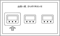
図3および図4の例の場合、通知情報生成部14は、情報取得部12から受け取った「氏名」山田一郎、「ユーザID」001、「区画」210aのユーザ情報と、「室内機」200a、「区画」210a、「リモコン」300aの機器情報とに基づいて、例えば「山田一郎さんの席の空調制御用リモコンは300aです」といったメッセージを表示する通知画面を生成し、通知情報として通知情報出力部15に送る。通知情報出力部15は、通知情報生成部14から受け取った通知情報をモニタ101に出力し(ステップS15)、処理を終了する。ここで、モニタ101に出力され、画面表示される通知画面について図6を用いて説明する。 In the case of the examples of FIGS. 3 and 4, the notification information generation unit 14 includes the user information of the "name" Yamada Ichiro, the "user ID" 001, the "section" 210a, and the "indoor unit" 200a received from the information acquisition unit 12. , Based on the device information of "section" 210a and "remote control" 300a, generate a notification screen that displays a message such as "The remote control for air conditioning control of Mr. Ichiro Yamada's seat is 300a", and notify information as notification information. It is sent to the output unit 15. The notification information output unit 15 outputs the notification information received from the notification information generation unit 14 to the monitor 101 (step S15), and ends the process. Here, the notification screen output to the monitor 101 and displayed on the screen will be described with reference to FIG.

図6は、実施の形態1に係る通知画面の一例を示す図である。通知情報生成部14は、情報取得部12から「氏名」山田一郎、「ユーザID」001、「区画」210aのユーザ情報と、「室内機」200a、「区画」210a、「リモコン」300aの機器情報とを受け取ると、「山田一郎さんのリモコンは」というメッセージと、リモコン300aの位置を示す画像とを表示する図6に示すような通知画面を生成する。図6の例では、リモコン300の画像を実際に壁に並べられた順に配置通りに表示させ、リモコン300aの画像を破線で囲み、矢印で示すことで、リモコン300aの位置を示している。 FIG. 6 is a diagram showing an example of a notification screen according to the first embodiment. The notification information generation unit 14 includes user information of "name" Yamada Ichiro, "user ID" 001, "section" 210a, and devices of "indoor unit" 200a, "section" 210a, and "remote control" 300a from the information acquisition unit 12. Upon receiving the information, a notification screen as shown in FIG. 6 displaying the message "Ichiro Yamada's remote controller" and the image showing the position of the remote controller 300a is generated. In the example of FIG. 6, the images of the remote controller 300 are displayed in the order in which they are actually arranged on the wall, the image of the remote controller 300a is surrounded by a broken line, and the position of the remote controller 300a is indicated by an arrow.

以上説明したように実施の形態1の制御装置1によれば、制御装置1がユーザID情報に基づいて、ユーザの居場所がある区画210の空調を行う室内機200を特定し、対象リモコンをユーザに通知することで、ユーザは対象リモコンを容易にかつ確実に確認できるようになる。また、制御装置1がユーザID情報を取得するたびに、ユーザの対象リモコンを通知する通知情報を生成して出力しているので、ユーザ情報や機器情報が変更される場合にも対応できる。 As described above, according to the control device 1 of the first embodiment, the control device 1 identifies the indoor unit 200 that air-conditions the section 210 where the user is located based on the user ID information, and the target remote controller is the user. By notifying the user, the user can easily and surely confirm the target remote controller. Further, each time the control device 1 acquires the user ID information, the notification information for notifying the target remote controller of the user is generated and output, so that it is possible to cope with the case where the user information or the device information is changed.

(実施の形態2)
図7は、本発明の実施の形態2に係る制御システムの構成例を示す図である。制御システム200は、制御システム100の構成要素に加え、サーバ600、スイッチングハブ700、ユーザ端末800a、ユーザ端末800bおよびユーザ端末800c(以下、総称してユーザ端末800という)を備える。サーバ600およびスイッチングハブ700は、建屋20内の空間22内に設置される。制御装置1、サーバ600およびユーザ端末800はそれぞれ、スイッチングハブ700にLANケーブルで物理的に接続され、同一ネットワーク上に接続される。
(Embodiment 2)
FIG. 7 is a diagram showing a configuration example of the control system according to the second embodiment of the present invention. The control system 200 includes a server 600, a switching hub 700, a user terminal 800a, a user terminal 800b, and a user terminal 800c (hereinafter collectively referred to as a user terminal 800) in addition to the components of the control system 100. The server 600 and the switching hub 700 are installed in the space 22 in the building 20. The control device 1, the server 600, and the user terminal 800 are each physically connected to the switching hub 700 with a LAN cable, and are connected to each other on the same network.

サーバ600は、ハードディスク、スタティックRAMまたはフラッシュメモリなどの不揮発メモリで構成される記憶部を備え、ユーザ情報および機器情報を記憶する。つまり、制御システム100では制御装置1の記憶部13が記憶していたユーザ情報および機器情報を、制御システム200ではサーバ600の記憶部が記憶する。ユーザ端末800は、ユーザが使用する端末であって、少なくとも制御装置1から受信した通知情報を出力する機能を備える。その他の構成は、制御システム100と同様である。図1と同様の構成については同一の符号を付しており、同一の符号の構成に関する説明は省略する。 The server 600 includes a storage unit composed of a non-volatile memory such as a hard disk, static RAM, or flash memory, and stores user information and device information. That is, in the control system 100, the user information and the device information stored in the storage unit 13 of the control device 1 are stored in the storage unit of the server 600 in the control system 200. The user terminal 800 is a terminal used by the user and has a function of outputting at least the notification information received from the control device 1. Other configurations are the same as those of the control system 100. The same components as those in FIG. 1 are designated by the same reference numerals, and the description of the configurations having the same reference numerals will be omitted.

図8は、実施の形態2に係る制御装置の機能構成例を示す図である。実施の形態2の制御装置1は、実施の形態1の制御装置1の構成要素から記憶部13を除いた構成である。情報取得部12は、例えばCPU、ROMおよびRAM、ネットワークに接続する通信インターフェースなどで構成され、ID入力部11から受け取ったユーザID情報に対応するユーザ情報をサーバ600から取得する。サーバ600の記憶部が記憶するユーザ情報は、実施の形態1のユーザ情報に加え、ユーザが使用するユーザ端末800を示す情報を含む。ここで、サーバ600の記憶部が記憶するユーザ情報について、図9を用いて説明する。 FIG. 8 is a diagram showing a functional configuration example of the control device according to the second embodiment. The control device 1 of the second embodiment has a configuration in which the storage unit 13 is removed from the components of the control device 1 of the first embodiment. The information acquisition unit 12 is composed of, for example, a CPU, ROM and RAM, a communication interface connected to a network, and the like, and acquires user information corresponding to the user ID information received from the ID input unit 11 from the server 600. The user information stored in the storage unit of the server 600 includes, in addition to the user information of the first embodiment, information indicating the user terminal 800 used by the user. Here, the user information stored in the storage unit of the server 600 will be described with reference to FIG.

図9は、実施の形態2に係るユーザ情報の一例を示す図である。図9の例では、ユーザ情報は、図3に示す「氏名」、「ユーザID」、「区画」の項目に加え、ユーザが使用するユーザ端末800を示す「ユーザ端末」の項目を有する。「ユーザ端末」の項目は、「山田一郎」、「田中二郎」、「中山三郎」の3名のユーザがそれぞれ、ユーザ端末800a、ユーザ端末800b、ユーザ端末800cを使用することを示している。なお、ユーザが使用するユーザ端末800を示す情報は、サーバ600の記憶部が記憶するユーザ情報に含まず、制御装置1が記憶してもよい。 FIG. 9 is a diagram showing an example of user information according to the second embodiment. In the example of FIG. 9, the user information has the item of "user terminal" indicating the user terminal 800 used by the user, in addition to the items of "name", "user ID", and "section" shown in FIG. The item of "user terminal" indicates that the three users "Ichiro Yamada", "Jiro Tanaka", and "Saburo Nakayama" use the user terminal 800a, the user terminal 800b, and the user terminal 800c, respectively. The information indicating the user terminal 800 used by the user is not included in the user information stored in the storage unit of the server 600, and may be stored in the control device 1.

図8の制御装置1の情報取得部12は、さらに取得したユーザ情報に含まれるユーザの居場所がある区画210を示す情報に対応する機器情報をサーバ600から取得する。情報取得部12は、取得したユーザ情報および機器情報を通知情報生成部14に送る。通知情報生成部14は、情報取得部12から受け取ったユーザ情報および機器情報に基づいて、対象リモコンを通知する通知情報を生成する。通知情報出力部15は、モニタ101に接続する通信インターフェースと、ネットワークに接続する通信インターフェースとで構成され、通知情報生成部14から受け取った通知情報を、モニタ101に画面表示し、ユーザが使用するユーザ端末800に送信する。なお、ユーザ端末800がユーザの所持する携帯端末であって、通知情報出力部15が通知情報をユーザが使用するユーザ端末800にのみ送信する構成の場合は、制御装置1はモニタ101を備えなくてもよい。 The information acquisition unit 12 of the control device 1 of FIG. 8 further acquires device information corresponding to the information indicating the section 210 where the user is located, which is included in the acquired user information, from the server 600. The information acquisition unit 12 sends the acquired user information and device information to the notification information generation unit 14. The notification information generation unit 14 generates notification information for notifying the target remote controller based on the user information and device information received from the information acquisition unit 12. The notification information output unit 15 is composed of a communication interface connected to the monitor 101 and a communication interface connected to the network. The notification information received from the notification information generation unit 14 is displayed on the monitor 101 on the screen and used by the user. It is transmitted to the user terminal 800. If the user terminal 800 is a mobile terminal owned by the user and the notification information output unit 15 is configured to transmit the notification information only to the user terminal 800 used by the user, the control device 1 does not include the monitor 101. You may.

図8には図示しないが、制御装置1は、通知情報を生成するための文字情報や画像情報を記憶する記憶部を備える。また、情報取得部12は、サーバ600から取得したユーザ情報および機器情報を一時記憶する。制御装置1の機能構成は図8の例に限らず、プッシュスイッチやタッチパネルといった入力装置で構成される入力部を備え、サーバ600から取得したユーザ情報および機器情報を、ユーザが入力部から書き換え可能に構成してもよい。この場合、制御装置1の情報取得部12はサーバ600から取得したユーザ情報および機器情報を通知情報出力部15に送り、モニタ101に画面表示させてもよい。これにより、ユーザはユーザ情報および機器情報を確認しながら書き換えることができる。通知情報出力部15は、書き換えられたユーザ情報および機器情報をサーバ600に送信する。これにより、サーバ600の記憶部のユーザ情報および機器情報を更新することができる。 Although not shown in FIG. 8, the control device 1 includes a storage unit for storing character information and image information for generating notification information. Further, the information acquisition unit 12 temporarily stores the user information and the device information acquired from the server 600. The functional configuration of the control device 1 is not limited to the example of FIG. 8, and includes an input unit composed of an input device such as a push switch and a touch panel, and the user can rewrite the user information and the device information acquired from the server 600 from the input unit. It may be configured as. In this case, the information acquisition unit 12 of the control device 1 may send the user information and the device information acquired from the server 600 to the notification information output unit 15 and display them on the monitor 101 on the screen. As a result, the user can rewrite while checking the user information and the device information. The notification information output unit 15 transmits the rewritten user information and device information to the server 600. As a result, the user information and the device information in the storage unit of the server 600 can be updated.

その他の機能構成は、実施の形態1の制御装置1と同様である。図2と同様の構成については同一の符号を付しており、同一の符号の構成に関する説明は省略する。なお、ユーザは、ユーザ端末800からサーバ600にアクセスし、サーバ600の記憶部のユーザ情報および機器情報を更新してもよい。ここで、図5を用いて実施の形態2の制御装置1が行う処理について説明する。説明のため、サーバ600の記憶部には図9に示したユーザ情報および図4に示した機器情報が記憶されているものとする。 Other functional configurations are the same as those of the control device 1 of the first embodiment. The same reference numerals are given to the configurations similar to those in FIG. 2, and the description of the configurations having the same reference numerals will be omitted. The user may access the server 600 from the user terminal 800 and update the user information and the device information in the storage unit of the server 600. Here, the process performed by the control device 1 of the second embodiment will be described with reference to FIG. For the sake of explanation, it is assumed that the user information shown in FIG. 9 and the device information shown in FIG. 4 are stored in the storage unit of the server 600.

以下の処理は、制御装置1の起動中に、建屋20内のユーザが制御装置1の設置場所まで移動し、カードリーダ102にIDカードをかざすと開始する。ここでは具体的に、建屋20内で、氏名が「田中二郎」であるユーザが、自分のIDが記録されているIDカードをカードリーダ102にかざした場合について説明する。制御装置1のID入力部11は、カードリーダ102が読み取ったユーザID002を示すユーザID情報を取得する(ステップS11)。ID入力部11は、取得したユーザID情報を情報取得部12に送る。情報取得部12は、ID入力部11から受け取ったユーザID情報が示すユーザID002に対応する「氏名」田中二郎、「ユーザID」002、「区画」210bのユーザ情報を読み出す(ステップS12)。情報取得部12は、さらに「室内機」200b、「区画」210b、「リモコン」300bの機器情報を読み出す(ステップS13)。情報取得部12は、読み出したユーザ情報および機器情報を通知情報生成部14に送る。 The following processing starts when the user in the building 20 moves to the installation location of the control device 1 and holds the ID card over the card reader 102 while the control device 1 is being activated. Here, specifically, a case where a user whose name is “Jiro Tanaka” holds an ID card in which his / her own ID is recorded over a card reader 102 in the building 20 will be described. The ID input unit 11 of the control device 1 acquires the user ID information indicating the user ID 002 read by the card reader 102 (step S11). The ID input unit 11 sends the acquired user ID information to the information acquisition unit 12. The information acquisition unit 12 reads out the user information of the "name" Jiro Tanaka, the "user ID" 002, and the "section" 210b corresponding to the user ID 002 indicated by the user ID information received from the ID input unit 11 (step S12). The information acquisition unit 12 further reads out the device information of the "indoor unit" 200b, the "section" 210b, and the "remote controller" 300b (step S13). The information acquisition unit 12 sends the read user information and device information to the notification information generation unit 14.

通知情報生成部14は、情報取得部12から受け取った「氏名」田中二郎、「ユーザID」002、「区画」210bのユーザ情報と、「室内機」200b、「区画」210b、「リモコン」300bの機器情報とに基づいて、例えば「田中二郎さんの席の空調制御用リモコンは300bです」といったメッセージを表示する通知画面を生成し(ステップS14)、通知情報として通知情報出力部15に送る。通知情報出力部15は、通知情報生成部14から受け取った通知情報を、氏名が「田中二郎」であるユーザが使用するユーザ端末800bに送信し(ステップS15)、処理を終了する。 The notification information generation unit 14 includes user information of "name" Jiro Tanaka, "user ID" 002, and "section" 210b received from the information acquisition unit 12, and "indoor unit" 200b, "section" 210b, and "remote control" 300b. A notification screen for displaying a message such as "The remote controller for air conditioning control of Mr. Jiro Tanaka's seat is 300b" is generated (step S14) based on the device information of the above, and is sent to the notification information output unit 15 as notification information. The notification information output unit 15 transmits the notification information received from the notification information generation unit 14 to the user terminal 800b used by the user whose name is "Jiro Tanaka" (step S15), and ends the process.

以上説明したように実施の形態2の制御装置1によれば、制御装置1がユーザID情報に基づいて、ユーザの居場所がある区画210の空調を行う室内機200を特定し、対象リモコンをユーザに通知することで、ユーザは対象リモコンを容易にかつ確実に確認できるようになる。また、制御装置1がユーザID情報を取得するたびに、ユーザの対象リモコンを通知する通知情報を生成して出力しているので、ユーザ情報や機器情報が変更される場合にも対応できる。さらに、制御装置1がユーザ情報および機器情報を保持せず、サーバ600から取得するので、制御装置1を小型化できる。制御装置1が入力部を備える構成の場合、ユーザは制御装置1からサーバ600に記憶されたユーザ情報および機器情報を更新することができる。ユーザ端末800がサーバ600と同じネットワークに接続されているので、ユーザは、ユーザ端末800からサーバ600に記憶されたユーザ情報および機器情報を更新することも可能である。 As described above, according to the control device 1 of the second embodiment, the control device 1 identifies the indoor unit 200 that air-conditions the section 210 where the user is located based on the user ID information, and the target remote controller is the user. By notifying the user, the user can easily and surely confirm the target remote controller. Further, each time the control device 1 acquires the user ID information, the notification information for notifying the target remote controller of the user is generated and output, so that it is possible to cope with the case where the user information or the device information is changed. Further, since the control device 1 does not hold the user information and the device information but acquires the user information and the device information from the server 600, the control device 1 can be miniaturized. When the control device 1 is configured to include an input unit, the user can update the user information and the device information stored in the server 600 from the control device 1. Since the user terminal 800 is connected to the same network as the server 600, the user can also update the user information and the device information stored in the server 600 from the user terminal 800.

(実施の形態3)
図10は、本発明の実施の形態3に係る制御システムの構成例を示す図である。制御システム300は、制御システム200の構成要素と同様であるが、制御装置1が建屋20内の空間22内に設置される。実施の形態3の制御装置1はモニタ101を備えるが、カードリーダ102は制御装置1に接続する外部機器であって、区画210cに設置される。制御装置1とカードリーダ102との接続は、有線接続でもよいし、無線接続でもよい。また、リモコン300はユーザが視認できる位置に通知用ランプを備えている。通知用ランプは例えばLEDである。その他の構成は、制御システム200と同様である。図7と同様の構成については同一の符号を付しており、同一の符号の構成に関する説明は省略する。実施の形態3の制御装置1の機能構成は、図8と同様である。
(Embodiment 3)
FIG. 10 is a diagram showing a configuration example of the control system according to the third embodiment of the present invention. The control system 300 is the same as the components of the control system 200, but the control device 1 is installed in the space 22 in the building 20. The control device 1 of the third embodiment includes the monitor 101, but the card reader 102 is an external device connected to the control device 1 and is installed in the compartment 210c. The connection between the control device 1 and the card reader 102 may be a wired connection or a wireless connection. Further, the remote controller 300 is provided with a notification lamp at a position that can be visually recognized by the user. The notification lamp is, for example, an LED. Other configurations are the same as those of the control system 200. The same components as those in FIG. 7 are designated by the same reference numerals, and the description of the configurations having the same reference numerals will be omitted. The functional configuration of the control device 1 of the third embodiment is the same as that of FIG.

実施の形態3の通知情報は、対象リモコンの通知用ランプを点滅させる点滅制御信号を含む。通知情報出力部15は、モニタ101に接続する通信インターフェースと、ネットワークに接続する通信インターフェースとで構成され、通知情報生成部14から受け取った通知情報に含まれる対象リモコンを通知する通知画面をモニタ101に画面表示し、通知情報に含まれる点滅制御信号をリモコン300に送信する。なお、通知情報が点滅制御信号のみである場合には、制御装置1がモニタ101を備えなくてもよい。ここで、図11を用いて実施の形態3の制御装置1が行う処理について説明する。説明のため、サーバ600の記憶部には図9に示したユーザ情報および図4に示した機器情報が記憶されているものとする。 The notification information of the third embodiment includes a blinking control signal for blinking the notification lamp of the target remote controller. The notification information output unit 15 is composed of a communication interface connected to the monitor 101 and a communication interface connected to the network, and monitors a notification screen for notifying the target remote controller included in the notification information received from the notification information generation unit 14. The blinking control signal included in the notification information is transmitted to the remote controller 300. When the notification information is only a blinking control signal, the control device 1 does not have to include the monitor 101. Here, the process performed by the control device 1 of the third embodiment will be described with reference to FIG. For the sake of explanation, it is assumed that the user information shown in FIG. 9 and the device information shown in FIG. 4 are stored in the storage unit of the server 600.

図11は、実施の形態3に係る制御装置およびリモコンの動作の一例を示すフローチャートである。以下の処理は、制御装置1およびリモコン300の起動中に、建屋20内のユーザがカードリーダ102の設置場所まで移動し、カードリーダ102にIDカードをかざすと開始する。図11の例では具体的に、建屋20内で、氏名が「中山三郎」であるユーザが、自分のIDが記録されているIDカードをカードリーダ102にかざした場合について説明する。また、通知情報は点滅制御信号のみであって、制御装置1はモニタ101を備えないものとする。 FIG. 11 is a flowchart showing an example of the operation of the control device and the remote controller according to the third embodiment. The following processing starts when the user in the building 20 moves to the installation location of the card reader 102 and holds the ID card over the card reader 102 while the control device 1 and the remote controller 300 are activated. In the example of FIG. 11, specifically, a case where a user whose name is “Saburo Nakayama” holds an ID card in which his / her own ID is recorded over a card reader 102 in the building 20 will be described. Further, it is assumed that the notification information is only a blinking control signal, and the control device 1 does not include the monitor 101.

制御装置1のID入力部11は、カードリーダ102が読み取ったユーザID003を示すユーザID情報を取得する(ステップS21)。ID入力部11は、取得したユーザID情報を情報取得部12に送る。情報取得部12は、ID入力部11から受け取ったユーザID情報が示すユーザID003に対応する「氏名」中山三郎、「ユーザID」003、「区画」210cのユーザ情報を読み出す(ステップS22)。情報取得部12は、さらに「室内機」200c、「区画」210c、「リモコン」300cの機器情報を読み出す(ステップS23)。情報取得部12は、読み出した機器情報を通知情報生成部14に送る。 The ID input unit 11 of the control device 1 acquires the user ID information indicating the user ID 003 read by the card reader 102 (step S21). The ID input unit 11 sends the acquired user ID information to the information acquisition unit 12. The information acquisition unit 12 reads out the user information of the "name" Saburo Nakayama, the "user ID" 003, and the "section" 210c corresponding to the user ID 003 indicated by the user ID information received from the ID input unit 11 (step S22). The information acquisition unit 12 further reads out the device information of the "indoor unit" 200c, the "section" 210c, and the "remote controller" 300c (step S23). The information acquisition unit 12 sends the read device information to the notification information generation unit 14.

通知情報生成部14は、情報取得部12から受け取った「室内機」200c、「区画」210c、「リモコン」300cの機器情報に基づいて、対象リモコンであるリモコン300cの通知用ランプを点滅させる点滅制御信号を生成し(ステップS24)、通知情報として通知情報出力部15に送る。通知情報出力部15は、通知情報生成部14から受け取った通知情報(点滅制御信号)を、リモコン300cに送信し(ステップS25)、処理を終了する。リモコン300cは、制御装置1から通知情報(点滅制御信号)を受信すると(ステップS31)、通知用ランプを点滅させる(ステップS32)。決められた時間が経過していない場合(ステップS33;NO)、リモコン300cは、ステップS32およびステップS33を繰り返し、通知用ランプの点滅を継続する。決められた時間が経過した場合(ステップS33;YES)、リモコン300cは処理を終了する。なお、通知用ランプを点滅させる決められた時間は点滅制御信号で指定してもよいし、リモコン300に内蔵されたプログラムで規定されているものであってもよい。上記の処理が実行される際のユーザの動作およびリモコン300cの変化の様子を、図12を用いて説明する。 The notification information generation unit 14 blinks the notification lamp of the remote controller 300c, which is the target remote controller, based on the device information of the "indoor unit" 200c, the "section" 210c, and the "remote controller" 300c received from the information acquisition unit 12. A control signal is generated (step S24) and sent to the notification information output unit 15 as notification information. The notification information output unit 15 transmits the notification information (blinking control signal) received from the notification information generation unit 14 to the remote controller 300c (step S25), and ends the process. When the remote controller 300c receives the notification information (blinking control signal) from the control device 1 (step S31), the remote controller 300c blinks the notification lamp (step S32). If the predetermined time has not elapsed (step S33; NO), the remote controller 300c repeats step S32 and step S33, and continues blinking the notification lamp. When the predetermined time has elapsed (step S33; YES), the remote controller 300c ends the process. The predetermined time for blinking the notification lamp may be specified by a blinking control signal, or may be specified by a program built in the remote controller 300. The operation of the user and the change of the remote controller 300c when the above processing is executed will be described with reference to FIG.

図12は、実施の形態3に係るユーザの動作およびリモコンの変化の様子を表す図である。図12(a)は、氏名が「中山三郎」であるユーザが、自分のIDが記録されているIDカードをカードリーダ102にかざした様子を表している。図12(a)の例では、カードリーダ102に完了通知ランプを備え、カードリーダ102がIDカードを読み取り完了すると完了通知ランプが点灯するように構成されている。完了通知ランプは例えばLEDである。制御装置1のID入力部11は、カードリーダ102が読み取ったユーザID003を示すユーザID情報を取得する。図12(b)は、氏名が「中山三郎」であるユーザが、自分のIDが記録されているIDカードをカードリーダ102にかざした際のリモコン300の様子を表している。リモコン300のうち、氏名が「中山三郎」であるユーザの対象リモコンであるリモコン300cは、制御装置1から通知情報(点滅制御信号)を受信し、通知用ランプを点滅させている。 FIG. 12 is a diagram showing the operation of the user and the change of the remote controller according to the third embodiment. FIG. 12A shows a user whose name is “Saburo Nakayama” holding an ID card in which his / her ID is recorded over the card reader 102. In the example of FIG. 12A, the card reader 102 is provided with a completion notification lamp, and the completion notification lamp is configured to light up when the card reader 102 completes reading the ID card. The completion notification lamp is, for example, an LED. The ID input unit 11 of the control device 1 acquires the user ID information indicating the user ID 003 read by the card reader 102. FIG. 12B shows a state of the remote controller 300 when a user whose name is "Saburo Nakayama" holds an ID card in which his / her ID is recorded over a card reader 102. Among the remote controllers 300, the remote controller 300c, which is the target remote controller of the user whose name is "Saburo Nakayama", receives the notification information (blinking control signal) from the control device 1 and blinks the notification lamp.

通知用ランプは点滅させてもよいし、消灯状態から点灯させてもよいし、点灯状態から消灯させてもよい。また、リモコン300は、通知用ランプを備える構成としたが、リモコン300は、液晶ディスプレイのような文字や画像を表示する表示装置や、ブザーやスピーカなどの音声出力装置、またはBluetoothやWi-Fiや特定小電力無線などの無線通信用装置を備え、これらによって通知情報を出力する構成にしてもよい。また、対象リモコンに点滅制御信号を送信する構成としたが、対象リモコンが制御する室内機200に点滅制御信号を送信し、室内機200が対象リモコンに点滅制御信号を送信する構成にしてもよい。 The notification lamp may be blinked, may be turned on from the off state, or may be turned off from the on state. Further, the remote controller 300 is configured to include a notification lamp, but the remote controller 300 includes a display device for displaying characters and images such as a liquid crystal display, an audio output device such as a buzzer and a speaker, or Bluetooth or Wi-Fi. It may be configured to be equipped with a wireless communication device such as a specific low power radio or a specific low power wireless device, and output notification information by these devices. Further, although the blinking control signal is transmitted to the target remote controller, the blinking control signal may be transmitted to the indoor unit 200 controlled by the target remote controller, and the indoor unit 200 may transmit the blinking control signal to the target remote controller. ..

以上説明したように実施の形態3の制御装置1によれば、制御装置1がユーザID情報に基づいて、ユーザの居場所がある区画210の空調を行う室内機200を特定し、対象リモコンをユーザに通知することで、ユーザは対象リモコンを容易にかつ確実に確認できるようになる。また、制御装置1がユーザID情報を取得するたびに、ユーザの対象リモコンを通知する通知情報を生成して出力しているので、ユーザ情報や機器情報が変更される場合にも対応できる。さらに、対象リモコンの通知用ランプを点滅させることで視認性が向上し、ユーザはより迅速に対象リモコンを確認できるようになる。 As described above, according to the control device 1 of the third embodiment, the control device 1 identifies the indoor unit 200 that air-conditions the section 210 where the user is located based on the user ID information, and the target remote controller is the user. By notifying the user, the user can easily and surely confirm the target remote controller. Further, each time the control device 1 acquires the user ID information, the notification information for notifying the target remote controller of the user is generated and output, so that it is possible to cope with the case where the user information or the device information is changed. Further, by blinking the notification lamp of the target remote controller, the visibility is improved, and the user can check the target remote controller more quickly.

(実施の形態4)
図13は、本発明の実施の形態4に係る制御システムの構成例を示す図である。制御システム400は、制御システム300の構成要素と同様であるが、カードリーダ102が建屋20の入り口23に設置され、カードリーダ102と制御装置1とは、スイッチングハブ700にLANケーブルで物理的に接続され、同一ネットワーク上に接続される。つまり、実施の形態4では、空調設備(室内機200、リモコン300および室外機500)以外の各機器間の通信インターフェースはすべてLANに集約されている。カードリーダ102は、ユーザがかざしたIDカードに記録されたユーザIDを読み取り、読み取ったユーザIDを示すユーザID情報を制御装置1に送信する。その他の構成は、制御システム300と同様である。図10と同様の構成については同一の符号を付しており、同一の符号の構成に関する説明は省略する。
(Embodiment 4)
FIG. 13 is a diagram showing a configuration example of the control system according to the fourth embodiment of the present invention. The control system 400 is the same as the components of the control system 300, but the card reader 102 is installed at the entrance 23 of the building 20, and the card reader 102 and the control device 1 are physically connected to the switching hub 700 by a LAN cable. Connected and connected on the same network. That is, in the fourth embodiment, all the communication interfaces between the devices other than the air conditioning equipment (indoor unit 200, remote controller 300, and outdoor unit 500) are integrated in the LAN. The card reader 102 reads the user ID recorded on the ID card held by the user, and transmits the user ID information indicating the read user ID to the control device 1. Other configurations are the same as those of the control system 300. The same components as those in FIG. 10 are designated by the same reference numerals, and the description of the configurations having the same reference numerals will be omitted.

実施の形態4の制御装置1の機能構成は、図8と同様である。なお、実施の形態3と同様に、通知情報が対象リモコンの通知用ランプを点滅させる点滅制御信号のみである場合には、制御装置1がモニタ101を備えなくてもよい。ここで、図14を用いて実施の形態4の制御装置1が行う処理について説明する。説明のため、サーバ600の記憶部には図9に示したユーザ情報および図4に示した機器情報が記憶されているものとする。 The functional configuration of the control device 1 of the fourth embodiment is the same as that of FIG. As in the third embodiment, when the notification information is only a blinking control signal that blinks the notification lamp of the target remote controller, the control device 1 does not have to include the monitor 101. Here, the process performed by the control device 1 of the fourth embodiment will be described with reference to FIG. For the sake of explanation, it is assumed that the user information shown in FIG. 9 and the device information shown in FIG. 4 are stored in the storage unit of the server 600.

図14は、実施の形態4に係るカードリーダ、制御装置およびリモコンの動作の一例を示すフローチャートである。以下の処理は、カードリーダ102、制御装置1およびリモコン300の起動中に、ユーザが建屋20の入り口23に設置されたカードリーダ102にIDカードをかざすと開始する。図14の例では具体的に、氏名が「山田一郎」であるユーザが入り口23で自分のIDが記録されているIDカードをカードリーダ102にかざした後であって通知用ランプを点滅させる決められた時間が経過する前に、氏名が「中山三郎」であるユーザが入り口23で自分のIDが記録されているIDカードをカードリーダ102にかざした場合について説明する。また、通知情報は点滅制御信号のみであって、制御装置1はモニタ101を備えないものとする。 FIG. 14 is a flowchart showing an example of the operation of the card reader, the control device, and the remote controller according to the fourth embodiment. The following processing starts when the user holds the ID card over the card reader 102 installed at the entrance 23 of the building 20 while the card reader 102, the control device 1, and the remote controller 300 are being activated. In the example of FIG. 14, specifically, the user whose name is "Ichiro Yamada" decides to blink the notification lamp after holding the ID card in which his / her ID is recorded at the entrance 23 over the card reader 102. A case where a user whose name is "Saburo Nakayama" holds an ID card in which his / her ID is recorded held over a card reader 102 at the entrance 23 will be described before the elapsed time elapses. Further, it is assumed that the notification information is only a blinking control signal, and the control device 1 does not include the monitor 101.

氏名が「山田一郎」であるユーザが入り口23で自分のIDが記録されているIDカードをカードリーダ102にかざしたことにより、リモコン300aの通知用ランプが点滅している(ステップS61)。カードリーダ102は、氏名が「中山三郎」であるユーザがかざしたIDカードに記録されたユーザID003を読み取り(ステップS41)、ユーザID003を示すユーザID情報を制御装置1に送信し(ステップS42)、処理を終了する。制御装置1のID入力部11は、カードリーダ102からユーザID情報を受信する(ステップS51)。ID入力部11は、受信したユーザID情報を情報取得部12に送る。情報取得部12は、前回ID入力部11からユーザID情報を受け取ってから決められた時間が経過しているか否かを判定する(ステップS52)。 When the user whose name is "Ichiro Yamada" holds the ID card in which his / her ID is recorded over the card reader 102 at the entrance 23, the notification lamp of the remote controller 300a is blinking (step S61). The card reader 102 reads the user ID 003 recorded on the ID card held by the user whose name is "Saburo Nakayama" (step S41), and transmits the user ID information indicating the user ID 003 to the control device 1 (step S42). , End the process. The ID input unit 11 of the control device 1 receives the user ID information from the card reader 102 (step S51). The ID input unit 11 sends the received user ID information to the information acquisition unit 12. The information acquisition unit 12 determines whether or not a predetermined time has elapsed since the user ID information was previously received from the ID input unit 11 (step S52).

氏名が「山田一郎」であるユーザのユーザID001を示すユーザID情報を受け取ってから決められた時間が経過していないので(ステップS52;NO)、情報取得部12ユーザID001を示すユーザID情報を受け取ってから決められた時間が経過していないことを示す情報を通知情報生成部14に送る。通知情報生成部14は、情報取得部12からユーザID001を示すユーザID情報を受け取ってから決められた時間が経過していないことを示す情報を受け取ると、通知用ランプの点滅を終了させる終了制御信号を生成し(ステップS53)、通知情報出力部15に送る。通知情報出力部15は、通知情報生成部14から受け取った終了制御信号をリモコン300aに送信する(ステップS54)。リモコン300aは、制御装置1から終了制御信号を受信すると(ステップS62)、通知用ランプの点滅を終了し(ステップS63)、処理を終了する。なお、前回ユーザID情報を受け取ってから決められた時間が経過している場合には(ステップS52;YES)、処理はステップS55に移行する。 Since the determined time has not passed since the user ID information indicating the user ID 001 of the user whose name is "Ichiro Yamada" has been received (step S52; NO), the user ID information indicating the information acquisition unit 12 user ID 001 is used. Information indicating that the predetermined time has not elapsed since the receipt is sent to the notification information generation unit 14. When the notification information generation unit 14 receives information indicating that a predetermined time has not elapsed since receiving the user ID information indicating the user ID 001 from the information acquisition unit 12, the notification information generation unit 14 ends the blinking of the notification lamp. A signal is generated (step S53) and sent to the notification information output unit 15. The notification information output unit 15 transmits the end control signal received from the notification information generation unit 14 to the remote controller 300a (step S54). When the remote controller 300a receives the end control signal from the control device 1 (step S62), the remote control 300a ends the blinking of the notification lamp (step S63), and ends the process. If the determined time has elapsed since the previous user ID information was received (step S52; YES), the process proceeds to step S55.

情報取得部12は、ID入力部11から受け取ったユーザID情報が示すユーザID003に対応する「氏名」中山三郎、「ユーザID」003、「区画」210cのユーザ情報を読み出す(ステップS55)。情報取得部12は、さらに「室内機」200c、「区画」210c、「リモコン」300cの機器情報を読み出す(ステップS56)。情報取得部12は、読み出した機器情報を通知情報生成部14に送る。通知情報生成部14は、情報取得部12から受け取った「室内機」200c、「区画」210c、「リモコン」300cの機器情報に基づいて、対象リモコンであるリモコン300cの通知用ランプを点滅させる点滅制御信号を生成し(ステップS57)、通知情報として通知情報出力部15に送る。通知情報出力部15は、通知情報生成部14から受け取った通知情報(点滅制御信号)を、リモコン300cに送信し(ステップS58)、処理を終了する。リモコン300cは、制御装置1から通知情報(点滅制御信号)を受信すると(ステップS71)、通知用ランプを点滅させる(ステップS72)。決められた時間が経過していない場合(ステップS73;NO)、リモコン300cは、ステップS72およびステップS73を繰り返し、通知用ランプの点滅を継続する。決められた時間が経過した場合(ステップS73;YES)、リモコン300cは処理を終了する。 The information acquisition unit 12 reads out the user information of the "name" Saburo Nakayama, the "user ID" 003, and the "section" 210c corresponding to the user ID 003 indicated by the user ID information received from the ID input unit 11 (step S55). The information acquisition unit 12 further reads out the device information of the "indoor unit" 200c, the "section" 210c, and the "remote controller" 300c (step S56). The information acquisition unit 12 sends the read device information to the notification information generation unit 14. The notification information generation unit 14 blinks the notification lamp of the remote controller 300c, which is the target remote controller, based on the device information of the "indoor unit" 200c, the "section" 210c, and the "remote controller" 300c received from the information acquisition unit 12. A control signal is generated (step S57) and sent to the notification information output unit 15 as notification information. The notification information output unit 15 transmits the notification information (blinking control signal) received from the notification information generation unit 14 to the remote controller 300c (step S58), and ends the process. When the remote controller 300c receives the notification information (blinking control signal) from the control device 1 (step S71), the remote controller 300c blinks the notification lamp (step S72). If the predetermined time has not elapsed (step S73; NO), the remote controller 300c repeats steps S72 and S73, and continues blinking the notification lamp. When the predetermined time has elapsed (step S73; YES), the remote controller 300c ends the process.

リモコン300cがステップS72およびステップS73を繰り返している間に制御装置1のID入力部11がカードリーダ102から他のユーザID情報を受信した場合に終了制御信号が制御装置1からリモコン300cに送信され、リモコン300cは決められた時間の経過を待たずに通知用ランプの点滅を終了する。図14の例では、制御装置1は、前回ユーザID情報を取得してから決められた時間が経過しているか否かを判定する構成としたが、制御装置1は、決められた時間が経過しているか否かに関わらず、ユーザID情報を取得すると、前回通知情報を送信したリモコン300に終了制御信号を送信する構成にしてもよい。さらに、カードリーダ102はスイッチングハブ700を介して制御装置1と接続される構成としたが、例えばカードリーダ102によりユーザの入退場を管理する入退場管理システムを設け、制御装置1が入退場管理システムからユーザのIDを受信する構成としてもよい。 When the ID input unit 11 of the control device 1 receives other user ID information from the card reader 102 while the remote controller 300c repeats steps S72 and S73, an end control signal is sent from the control device 1 to the remote controller 300c. It is transmitted, and the remote controller 300c ends blinking of the notification lamp without waiting for the elapse of a predetermined time. In the example of FIG. 14, the control device 1 is configured to determine whether or not a predetermined time has elapsed since the previous acquisition of the user ID information, but the control device 1 has an elapsed time. Regardless of whether or not the user ID information is acquired, the end control signal may be transmitted to the remote controller 300 that previously transmitted the notification information. Further, the card reader 102 is configured to be connected to the control device 1 via the switching hub 700. For example, an entrance / exit management system for managing the entrance / exit of the user is provided by the card reader 102, and the control device 1 manages the entrance / exit. It may be configured to receive the user's ID from the system.

特に、多くのユーザが頻繁にIDカードをかざして入り口23を通行する環境においては、次のIDカードがかざされたタイミングで前のリモコン300の通知用ランプの点滅処理を中止した場合に、点滅処理を中止されたリモコン300を利用するユーザが対象リモコンを特定できない可能性がある。これを防ぐため、リモコン300の通知用ランプの点灯・点滅に際して、ユーザごとに点灯・点滅させる通知用ランプの色を変化させたり、点灯・点滅パターンを変化させたりしてもよい。この場合、ユーザごとの通知用ランプの色や点灯・点滅パターンをあらかじめ一意に割り当てておいてもよいし、識別可能な通知用ランプの色や点灯・点滅パターンをユーザごとに割り当てることが困難な場合は、例えば、カードリーダ102にもリモコン300の通知用ランプと同様のランプ(例えば完了通知ランプ)を設け、IDカードをかざすたびにカードリーダ102のランプを異なる色や点灯・点滅パターンで制御し、リモコン300の通知用ランプもカードリーダ102のランプと同じ色や点灯・点滅パターンで制御するようにしてもよい。 In particular, in an environment where many users frequently hold the ID card over the entrance 23, the blinking of the notification lamp of the previous remote controller 300 is stopped at the timing when the next ID card is held over. There is a possibility that the user who uses the remote controller 300 whose processing has been canceled cannot specify the target remote controller. In order to prevent this, when the notification lamp of the remote controller 300 is lit / blinking, the color of the notification lamp to be lit / blinking may be changed for each user, or the lighting / blinking pattern may be changed. In this case, the color and lighting / blinking pattern of the notification lamp for each user may be uniquely assigned in advance, or it is difficult to assign the color and lighting / blinking pattern of the identifiable notification lamp for each user. In this case, for example, the card reader 102 is also provided with a lamp similar to the notification lamp of the remote control 300 (for example, a completion notification lamp), and the lamp of the card reader 102 is controlled by a different color or lighting / blinking pattern each time the ID card is held over. However, the notification lamp of the remote control 300 may be controlled by the same color and lighting / blinking pattern as the lamp of the card reader 102.

以上説明したように実施の形態4の制御装置1によれば、制御装置1がユーザID情報に基づいて、ユーザの居場所がある区画210の空調を行う室内機200を特定し、対象リモコンをユーザに通知することで、ユーザは対象リモコンを容易にかつ確実に確認できるようになる。また、制御装置1がユーザID情報を取得するたびに、ユーザの対象リモコンを通知する通知情報を生成して出力しているので、ユーザ情報や機器情報が変更される場合にも対応できる。さらに、対象リモコンの通知用ランプを点滅させることで視認性が向上し、ユーザはより迅速に対象リモコンを確認できるようになる。 As described above, according to the control device 1 of the fourth embodiment, the control device 1 identifies the indoor unit 200 that air-conditions the section 210 where the user is located based on the user ID information, and the target remote controller is the user. By notifying the user, the user can easily and surely confirm the target remote controller. Further, each time the control device 1 acquires the user ID information, the notification information for notifying the target remote controller of the user is generated and output, so that it is possible to cope with the case where the user information or the device information is changed. Further, by blinking the notification lamp of the target remote controller, the visibility is improved, and the user can check the target remote controller more quickly.

ユーザがカードリーダ102にIDカードをかざしたときに点滅中の通知用ランプがある場合には、点滅を終了させることで、同時に異なるリモコン300の通知用ランプが点滅することにより、どちらのユーザの対象リモコンか判別できなくなるのを防ぐことができる。また、居場所が異なる複数のユーザが建屋20に入る際に通行する入り口23にカードリーダ102を配置することで、ユーザがカードリーダ102にIDカードをかざして対象リモコンを特定するためだけに移動する必要が無くなる。さらに、リモコン300の通知用ランプを点滅させる決められた時間をカードリーダ102の設置位置からリモコン300の設置位置までの移動にかかる時間よりも十分長い時間に設定すれば、カードリーダ102の設置位置とリモコン300の設置位置が離れている場合でも、ユーザがカードリーダ102の設置位置からリモコン300の設置位置まで移動している間に通知用ランプによる通知が終了してしまうことを防止できる。 If there is a blinking notification lamp when the user holds the ID card over the card reader 102, by ending the blinking, the notification lamp of the different remote controller 300 blinks at the same time, so that which user's It is possible to prevent the target remote controller from being indistinguishable. Further, by arranging the card reader 102 at the entrance 23 through which a plurality of users having different locations enter the building 20, the user moves by holding the ID card over the card reader 102 only to specify the target remote controller. There is no need. Further, if the fixed time for blinking the notification lamp of the remote controller 300 is set to be sufficiently longer than the time required for moving from the installation position of the card reader 102 to the installation position of the remote controller 300, the installation position of the card reader 102 can be set. Even when the installation positions of the remote controller 300 are separated from each other, it is possible to prevent the notification by the notification lamp from ending while the user is moving from the installation position of the card reader 102 to the installation position of the remote controller 300.

なお、本発明は、上記の実施の形態に限定されるものではない。本発明の主旨を逸脱しない範囲内で、当業者が想到しうる変形を本実施の形態に施したものも、本発明に含まれる。つまり、本発明は、その発明の範囲内において、実施の形態を適宜、変形、省略することが可能である。 The present invention is not limited to the above embodiment. The present invention also includes a modification of the present embodiment that can be conceived by a person skilled in the art without departing from the gist of the present invention. That is, in the present invention, the embodiments can be appropriately modified or omitted within the scope of the invention.

上記の実施の形態では、制御装置1のID入力部11は、カードリーダ102を用いてユーザID情報を取得するが、ユーザID情報の取得方法はこれに限らず、ID入力部11は、例えば、プッシュスイッチやタッチパネルといったユーザインターフェースで構成され、ユーザIDの入力を受け付け、ユーザが入力したユーザIDを示すユーザID情報を取得してもよい。 In the above embodiment, the ID input unit 11 of the control device 1 acquires the user ID information by using the card reader 102, but the method of acquiring the user ID information is not limited to this, and the ID input unit 11 is, for example, , A user interface such as a push switch or a touch panel may be configured to accept input of a user ID and acquire user ID information indicating the user ID input by the user.

上記の実施の形態では、制御装置1が室内機200を制御する対象リモコンをユーザに通知するが、これに限らず、制御装置1がユーザに通知する対象リモコンは、照明装置や換気装置、空気清浄機など、建屋20内の空間21の室内環境を変化させる機器のリモコンであれば何でもよい。 In the above embodiment, the control device 1 notifies the user of the target remote controller for controlling the indoor unit 200, but the target remote controller notified by the control device 1 to the user is not limited to this, and the target remote controller is a lighting device, a ventilation device, or air. Any remote controller for a device such as a purifier that changes the indoor environment of the space 21 in the building 20 may be used.

図15は、本発明の実施の形態に係る制御装置のハードウェア構成の一例を示す図である。制御装置1は、ハードウェア構成としてプロセッサ81、メモリ82、インターフェース83を備える。制御装置1の情報取得部12および通知情報生成部14の各機能は、プロセッサ81がメモリ82に記憶された制御プログラムを実行することにより実現される。メモリ82は、例えばRAM(Random Access Memory)やFlash ROM(Read Only Memory)、それらを組み合わせたものであり、記憶部13は、メモリ82上に構成される。 FIG. 15 is a diagram showing an example of a hardware configuration of a control device according to an embodiment of the present invention. The control device 1 includes a processor 81, a memory 82, and an interface 83 as a hardware configuration. Each function of the information acquisition unit 12 and the notification information generation unit 14 of the control device 1 is realized by the processor 81 executing the control program stored in the memory 82. The memory 82 is, for example, a RAM (Random Access Memory), a Flash ROM (Read Only Memory), or a combination thereof, and the storage unit 13 is configured on the memory 82.

インターフェース83は、各機器と接続する通信I/Fと、ユーザからの情報の入力を受け付けるユーザインターフェース(以下、ユーザI/Fと略す)で構成される。通信I/Fは、ID入力部11および通知情報出力部15として機能する。インターフェース83は必要に応じて他の種類のインターフェースを含んでもよい。例えば、インターフェース83は、ユーザからの情報の入力を受け付けるユーザI/Fを含んでもよい。ユーザI/Fは、例えば、プッシュスイッチやタッチパネルといった入力装置であり、制御装置1が入力部を備える構成では、入力部として機能する。図15では、プロセッサ81およびメモリ82をそれぞれ1つで構成する例を示しているが、複数のプロセッサ81および複数のメモリ82が連携して各機能を実行してもよい。 The interface 83 includes a communication I / F that connects to each device and a user interface (hereinafter, abbreviated as user I / F) that receives input of information from the user. The communication I / F functions as an ID input unit 11 and a notification information output unit 15. The interface 83 may include other types of interfaces as needed. For example, the interface 83 may include a user I / F that accepts input of information from the user. The user I / F is, for example, an input device such as a push switch or a touch panel, and functions as an input unit in a configuration in which the control device 1 includes an input unit. Although FIG. 15 shows an example in which the processor 81 and the memory 82 are each configured by one, the plurality of processors 81 and the plurality of memories 82 may cooperate with each other to execute each function.

また、上述の機能を、OS(Operating System)とアプリケーションとの分担、またはOSとアプリケーションとの協同により実現する場合等には、OS以外の部分のみを媒体に格納してもよい。さらに、搬送波に各プログラムを重畳し、通信ネットワークを介して配信することも可能である。例えば、通信ネットワーク上の掲示板(BBS、Bulletin Board System)に当該プログラムを掲示し、ネットワークを介して当該プログラムを配信してもよい。そして、これらのプログラムを起動し、オペレーティングシステムの制御下で、他のアプリケーションプログラムと同様に実行することにより、上述の処理を実行できるように構成してもよい。 Further, when the above-mentioned functions are realized by sharing the OS (Operating System) and the application or by cooperating with the OS and the application, only the part other than the OS may be stored in the medium. Further, it is also possible to superimpose each program on the carrier wave and distribute it via the communication network. For example, the program may be posted on a bulletin board system (BBS, Bulletin Board System) on a communication network, and the program may be distributed via the network. Then, by starting these programs and executing them in the same manner as other application programs under the control of the operating system, the above-mentioned processing may be executed.

1 制御装置、11 ID入力部、12 情報取得部、13 記憶部、14 通知情報生成部、15 通知情報出力部、20 建屋、21,22 空間、23 入り口、81 プロセッサ、82 メモリ、83 インターフェース、100,200,300,400 制御システム、101 モニタ、102 カードリーダ、200,200a,200b,200c,200d 室内機、210,210a,210b,210c 区画、300,300a,300b,300c リモコン、500 室外機、600 サーバ、700 スイッチングハブ、800,800a,800b,800c ユーザ端末。 1 Control device, 11 ID input unit, 12 information acquisition unit, 13 storage unit, 14 notification information generation unit, 15 notification information output unit, 20 building, 21.22 space, 23 entrance, 81 processor, 82 memory, 83 interface, 100,200,300,400 control system, 101 monitor, 102 card reader, 200,200a, 200b, 200c, 200d indoor unit, 210,210a, 210b, 210c compartment, 300,300a, 300b, 300c remote control, 500 outdoor unit , 600 servers, 700 switching hubs, 800, 800a, 800b, 800c user terminals.

Claims (9)

建屋内の空間を2以上に分割した各区画の室内環境をそれぞれ変化させる機器に紐づけられ、紐づけられたそれぞれの前記機器を制御する2以上のリモートコントローラと通信可能な制御装置であって、
前記区画に入場するユーザを識別するユーザ識別情報を取得する識別情報取得部と、
前記ユーザ識別情報と前記分割した区画のうち前記ユーザの居場所がある区画とが対応づけられたユーザ情報と、前記各機器がそれぞれ室内環境を変化させる区画と前記各機器を制御する前記リモートコントローラとが対応づけられた機器情報とを取得する情報取得部と、
前記情報取得部が取得した前記ユーザ情報および前記機器情報に基づいて、前記ユーザの居場所がある前記区画の室内環境を変化させる機器を制御するリモートコントローラを特定して該リモートコントローラを通知する通知情報を生成する通知情報生成部と、
前記通知情報生成部が生成した前記通知情報を出力する通知情報出力部と、
を備える制御装置。
It is a control device that is linked to a device that changes the indoor environment of each section that divides the space inside the building into two or more, and can communicate with two or more remote controllers that control each of the linked devices. ,
An identification information acquisition unit that acquires user identification information that identifies a user who enters the section, and an identification information acquisition unit.
The user information in which the user identification information is associated with the section in which the user's location is located among the divided sections, the section in which each device changes the indoor environment, and the remote controller that controls each device. The information acquisition unit that acquires the device information associated with
Notification information that identifies a remote controller that controls a device that changes the indoor environment of the section where the user's location is located based on the user information and the device information acquired by the information acquisition unit, and notifies the remote controller. Notification information generator and
A notification information output unit that outputs the notification information generated by the notification information generation unit, and
A control device equipped with.
建屋内の空間を2以上に分割した各区画の室内環境をそれぞれ変化させる機器に紐づけられ、紐づけられたそれぞれの前記機器を制御する2以上のリモートコントローラと通信可能な制御装置であって、
前記建屋の入退場を管理する入退場管理システムから、前記建屋に入場するユーザを識別するユーザ識別情報を取得する識別情報取得部と、
前記ユーザ識別情報と前記分割した区画のうち前記ユーザの居場所がある区画とが対応づけられたユーザ情報と、前記各機器がそれぞれ室内環境を変化させる区画と前記各機器を制御する前記リモートコントローラとが対応づけられた機器情報とを取得する情報取得部と、
前記情報取得部が取得した前記ユーザ情報および前記機器情報に基づいて、前記ユーザの居場所がある前記区画の室内環境を変化させる機器を制御するリモートコントローラを特定して該リモートコントローラを通知する通知情報を生成する通知情報生成部と、
前記通知情報生成部が生成した前記通知情報を出力する通知情報出力部と、
を備える制御装置。
It is a control device that is linked to a device that changes the indoor environment of each section that divides the space inside the building into two or more, and can communicate with two or more remote controllers that control each of the linked devices. ,
An identification information acquisition unit that acquires user identification information that identifies a user entering the building from an entrance / exit management system that manages the entrance / exit of the building.
The user information in which the user identification information is associated with the section in which the user's location is located among the divided sections, the section in which each device changes the indoor environment, and the remote controller that controls each device. The information acquisition unit that acquires the device information associated with
Notification information that identifies a remote controller that controls a device that changes the indoor environment of the section where the user's location is located based on the user information and the device information acquired by the information acquisition unit, and notifies the remote controller. Notification information generator and
A notification information output unit that outputs the notification information generated by the notification information generation unit, and
A control device equipped with.
前記ユーザが使用するユーザ端末とさらに通信可能であって、
前記通知情報出力部は、前記通知情報を前記ユーザ端末に送信する、
請求項1又は2に記載の制御装置。
It is possible to further communicate with the user terminal used by the user,
The notification information output unit transmits the notification information to the user terminal.
The control device according to claim 1 or 2 .
前記通知情報は、前記ユーザの名称を示す情報を含む、
請求項1からのいずれか1項に記載の制御装置。
The notification information includes information indicating the name of the user.
The control device according to any one of claims 1 to 3 .
前記通知情報は、前記ユーザの居場所がある前記区画の室内環境を変化させる前記機器を制御するリモートコントローラの配置を模した画像であって、前記ユーザの居場所がある前記区画の室内環境を変化させる前記機器を制御するリモートコントローラを強調表示させる画像を表示させるための情報を含む、
請求項1からのいずれか1項に記載の制御装置。
The notification information is an image that imitates the arrangement of a remote controller that controls the device that changes the indoor environment of the section where the user's location is located, and changes the indoor environment of the section where the user's location is located. Contains information for displaying an image that highlights the remote controller that controls the device.
The control device according to any one of claims 1 to 4 .
前記リモートコントローラが、画像表示、文字表示、音声出力およびランプの点消灯の少なくともいずれかで前記通知情報を出力する機能を備える場合に、
前記通知情報出力部は、前記ユーザの居場所がある前記区画の室内環境を変化させる前記機器を制御する前記リモートコントローラに前記通知情報を送信する、
請求項1又は2に記載の制御装置。
When the remote controller has a function of outputting the notification information by at least one of image display, character display, voice output, and turning on / off of the lamp.
The notification information output unit transmits the notification information to the remote controller that controls the device that changes the indoor environment of the section where the user's location is located.
The control device according to claim 1 or 2 .
制御装置と通信可能な、建屋内の空間を2以上に分割した区画の室内環境を変化させる機器を制御するリモートコントローラであって、
前記制御装置から、前記分割した区画のうちユーザの居場所がある前記区画の室内環境を変化させる前記機器を制御するリモートコントローラとして前記制御装置により特定された前記リモートコントローラを通知する通知情報であって前記ユーザの名称を示す情報を含む通知情報を受信し、
画像表示、文字表示および音声出力の少なくともいずれかで、前記通知情報を決められた時間出力する、
リモートコントローラ。
It is a remote controller that controls equipment that can change the indoor environment of a section that divides the space inside the building into two or more, which can communicate with the control device.
Notification information for notifying the remote controller specified by the control device as a remote controller for controlling the device that changes the indoor environment of the section where the user's location is located in the divided section from the control device. Receive notification information including information indicating the user's name ,
The notification information is output for a predetermined time by at least one of image display, character display, and voice output .
Remote controller.
請求項1からのいずれか1項に記載の制御装置と、建屋内の空間を2以上に分割した各区画の室内環境をそれぞれ変化させる2以上の機器と、それぞれの前記機器に紐づけられ、紐づけられたそれぞれの前記機器を制御し、前記制御装置と通信可能な2以上のリモートコントローラと、
を備える制御システム。
The control device according to any one of claims 1 to 6 and two or more devices that change the indoor environment of each section that divides the space inside the building into two or more are associated with the respective devices. , Two or more remote controllers capable of controlling each of the associated devices and communicating with the control device,
Control system with.
建屋内の空間を2以上に分割した各区画の室内環境をそれぞれ変化させる機器に紐づけられ、紐づけられたそれぞれの前記機器を制御する2以上のリモートコントローラと通信可能なコンピュータを、
前記区画に入場するユーザを識別するユーザ識別情報と前記分割した区画のうち前記ユーザの居場所がある区画とが対応づけられたユーザ情報と、前記各機器がそれぞれ室内環境を変化させる区画と前記各機器を制御する前記リモートコントローラとが対応づけられた機器情報とを取得する情報取得部、
前記情報取得部が取得した前記ユーザ情報および前記機器情報に基づいて、前記ユーザの居場所がある前記区画の室内環境を変化させる機器を制御するリモートコントローラを特定して該リモートコントローラを通知する通知情報を生成する通知情報生成部、ならびに、
前記通知情報生成部が生成した前記通知情報を出力する通知情報出力部、
として機能させる制御プログラム。
A computer that is linked to a device that changes the indoor environment of each section that divides the space inside the building into two or more, and can communicate with two or more remote controllers that control each of the linked devices.
User identification information that identifies a user entering the section, user information associated with the section in which the user's location is located among the divided sections, and a section in which each device changes the indoor environment and each of the sections. An information acquisition unit that acquires device information associated with the remote controller that controls the device,
Notification information that identifies a remote controller that controls a device that changes the indoor environment of the section where the user's location is located based on the user information and the device information acquired by the information acquisition unit, and notifies the remote controller. Notification information generator, as well as
Notification information output unit that outputs the notification information generated by the notification information generation unit,
A control program that functions as.
JP2016026554A 2016-02-16 2016-02-16 Controls, remote controllers, control systems, and control programs Active JP7026432B2 (en)

Priority Applications (1)

Application Number Priority Date Filing Date Title
JP2016026554A JP7026432B2 (en) 2016-02-16 2016-02-16 Controls, remote controllers, control systems, and control programs

Applications Claiming Priority (1)

Application Number Priority Date Filing Date Title
JP2016026554A JP7026432B2 (en) 2016-02-16 2016-02-16 Controls, remote controllers, control systems, and control programs

Publications (3)

Publication Number Publication Date
JP2017145983A JP2017145983A (en) 2017-08-24
JP2017145983A5 JP2017145983A5 (en) 2019-03-22
JP7026432B2 true JP7026432B2 (en) 2022-02-28

Family

ID=59680691

Family Applications (1)

Application Number Title Priority Date Filing Date
JP2016026554A Active JP7026432B2 (en) 2016-02-16 2016-02-16 Controls, remote controllers, control systems, and control programs

Country Status (1)

Country Link
JP (1) JP7026432B2 (en)

Families Citing this family (2)

* Cited by examiner, † Cited by third party
Publication number Priority date Publication date Assignee Title
CN110631218B (en) * 2018-06-21 2021-10-29 青岛海尔空调器有限总公司 Control method, device and system for air equipment and computer storage medium
CN111306713A (en) * 2020-03-02 2020-06-19 青岛海尔空调器有限总公司 Method and device for controlling self-cleaning of air conditioner and air conditioner

Citations (4)

* Cited by examiner, † Cited by third party
Publication number Priority date Publication date Assignee Title
JP2004150667A (en) 2002-10-29 2004-05-27 Mitsubishi Electric Corp Equipment management device
JP2004301435A (en) 2003-03-31 2004-10-28 Mitsubishi Electric Corp Air-conditioning control system
JP2005140422A (en) 2003-11-06 2005-06-02 Mitsubishi Electric Corp Entrance/leaving management system
JP2008309379A (en) 2007-06-13 2008-12-25 Mitsubishi Electric Corp Remote controller for air conditioning, air conditioner, and air conditioning system

Family Cites Families (3)

* Cited by examiner, † Cited by third party
Publication number Priority date Publication date Assignee Title
JP2007329811A (en) * 2006-06-09 2007-12-20 Shimizu Corp Central supervisory system
JP2008192095A (en) * 2007-02-08 2008-08-21 Shimizu Corp Access management system
JP6400325B2 (en) * 2014-04-30 2018-10-03 三菱重工サーマルシステムズ株式会社 Indoor unit controller, air conditioner equipped with the same, and control method for indoor unit controller

Patent Citations (4)

* Cited by examiner, † Cited by third party
Publication number Priority date Publication date Assignee Title
JP2004150667A (en) 2002-10-29 2004-05-27 Mitsubishi Electric Corp Equipment management device
JP2004301435A (en) 2003-03-31 2004-10-28 Mitsubishi Electric Corp Air-conditioning control system
JP2005140422A (en) 2003-11-06 2005-06-02 Mitsubishi Electric Corp Entrance/leaving management system
JP2008309379A (en) 2007-06-13 2008-12-25 Mitsubishi Electric Corp Remote controller for air conditioning, air conditioner, and air conditioning system

Also Published As

Publication number Publication date
JP2017145983A (en) 2017-08-24

Similar Documents

Publication Publication Date Title
JP4960089B2 (en) Image transmission system
US10916110B2 (en) Emergency lighting, evacuation, and rescue routing with power over-ethernet
JP7026432B2 (en) Controls, remote controllers, control systems, and control programs
JP2014115936A (en) Lecture support server, lecture support system, and lecture support program
JP2020089264A (en) Electric charging storage
US20220136727A1 (en) Remote monitoring device and air-conditioning system
US20100312413A1 (en) Advanced wireless projector presentation system with network management control
JP4319073B2 (en) Karaoke set system
JP2008262034A (en) Image display system
JP2018092219A (en) Information processing apparatus, control method, program, device and information processing system
US20190179274A1 (en) Control content management system, power control system, control content management method, and computer-readable recording medium
JP2002075663A (en) Illumination equipment
JP2015225612A (en) Digital signage system and signage device to be used for the same, program for digital signage information server, program for signage device, and program for portable terminal
JP2011091782A (en) Visible light communication system
JP2011070881A (en) Lighting control device
JP6643740B1 (en) Information processing device, charging storage, and program
JP2021022072A (en) Environment control system, environment control method, and program
JP2021057241A (en) Lighting system, lighting device, and lighting control device
WO2022172355A1 (en) Firmware updating system, firmware transmission device, air conditioner, and firmware updating method and program
JP5721755B2 (en) Equipment control device, equipment control system, equipment control method and program
JP5884793B2 (en) Loom monitoring system in a weaving factory
JP6182908B2 (en) Management device, management system, and management program
JP6328326B2 (en) Equipment management device, operation support screen display method and program
JP6419203B2 (en) Management device, management system, program, and recording medium
JP6320636B2 (en) Equipment system

Legal Events

Date Code Title Description
A521 Request for written amendment filed

Free format text: JAPANESE INTERMEDIATE CODE: A523

Effective date: 20190208

A621 Written request for application examination

Free format text: JAPANESE INTERMEDIATE CODE: A621

Effective date: 20190208

A977 Report on retrieval

Free format text: JAPANESE INTERMEDIATE CODE: A971007

Effective date: 20191105

A131 Notification of reasons for refusal

Free format text: JAPANESE INTERMEDIATE CODE: A131

Effective date: 20191112

A521 Request for written amendment filed

Free format text: JAPANESE INTERMEDIATE CODE: A523

Effective date: 20200114

A131 Notification of reasons for refusal

Free format text: JAPANESE INTERMEDIATE CODE: A131

Effective date: 20200428

A02 Decision of refusal

Free format text: JAPANESE INTERMEDIATE CODE: A02

Effective date: 20201013

A521 Request for written amendment filed

Free format text: JAPANESE INTERMEDIATE CODE: A523

Effective date: 20210112

C60 Trial request (containing other claim documents, opposition documents)

Free format text: JAPANESE INTERMEDIATE CODE: C60

Effective date: 20210112

A911 Transfer to examiner for re-examination before appeal (zenchi)

Free format text: JAPANESE INTERMEDIATE CODE: A911

Effective date: 20210127

C21 Notice of transfer of a case for reconsideration by examiners before appeal proceedings

Free format text: JAPANESE INTERMEDIATE CODE: C21

Effective date: 20210202

A912 Re-examination (zenchi) completed and case transferred to appeal board

Free format text: JAPANESE INTERMEDIATE CODE: A912

Effective date: 20210226

C211 Notice of termination of reconsideration by examiners before appeal proceedings

Free format text: JAPANESE INTERMEDIATE CODE: C211

Effective date: 20210302

C22 Notice of designation (change) of administrative judge

Free format text: JAPANESE INTERMEDIATE CODE: C22

Effective date: 20210406

C22 Notice of designation (change) of administrative judge

Free format text: JAPANESE INTERMEDIATE CODE: C22

Effective date: 20211005

C13 Notice of reasons for refusal

Free format text: JAPANESE INTERMEDIATE CODE: C13

Effective date: 20211019

A521 Request for written amendment filed

Free format text: JAPANESE INTERMEDIATE CODE: A523

Effective date: 20211217

C23 Notice of termination of proceedings

Free format text: JAPANESE INTERMEDIATE CODE: C23

Effective date: 20220111

C03 Trial/appeal decision taken

Free format text: JAPANESE INTERMEDIATE CODE: C03

Effective date: 20220215

C30A Notification sent

Free format text: JAPANESE INTERMEDIATE CODE: C3012

Effective date: 20220215

A61 First payment of annual fees (during grant procedure)

Free format text: JAPANESE INTERMEDIATE CODE: A61

Effective date: 20220215

R150 Certificate of patent or registration of utility model

Ref document number: 7026432

Country of ref document: JP

Free format text: JAPANESE INTERMEDIATE CODE: R150