JP7025352B2 - X-ray imaging device for compact (pseudo) isotropic multi-source X-ray imaging - Google Patents
X-ray imaging device for compact (pseudo) isotropic multi-source X-ray imaging Download PDFInfo
- Publication number
- JP7025352B2 JP7025352B2 JP2018563125A JP2018563125A JP7025352B2 JP 7025352 B2 JP7025352 B2 JP 7025352B2 JP 2018563125 A JP2018563125 A JP 2018563125A JP 2018563125 A JP2018563125 A JP 2018563125A JP 7025352 B2 JP7025352 B2 JP 7025352B2
- Authority
- JP
- Japan
- Prior art keywords
- ray
- grid
- strips
- source
- sources
- Prior art date
- Legal status (The legal status is an assumption and is not a legal conclusion. Google has not performed a legal analysis and makes no representation as to the accuracy of the status listed.)
- Active
Links
- 238000003384 imaging method Methods 0.000 title claims description 37
- 230000005855 radiation Effects 0.000 claims description 43
- 230000003287 optical effect Effects 0.000 claims description 12
- 230000008030 elimination Effects 0.000 claims description 3
- 238000003379 elimination reaction Methods 0.000 claims description 3
- 239000000463 material Substances 0.000 description 9
- 238000010521 absorption reaction Methods 0.000 description 6
- 230000015572 biosynthetic process Effects 0.000 description 6
- 230000002093 peripheral effect Effects 0.000 description 6
- 238000001914 filtration Methods 0.000 description 5
- 239000002131 composite material Substances 0.000 description 3
- 230000001419 dependent effect Effects 0.000 description 3
- 239000000203 mixture Substances 0.000 description 3
- 230000004048 modification Effects 0.000 description 3
- 238000012986 modification Methods 0.000 description 3
- 239000012790 adhesive layer Substances 0.000 description 2
- 238000007689 inspection Methods 0.000 description 2
- 238000004519 manufacturing process Methods 0.000 description 2
- 238000000034 method Methods 0.000 description 2
- 230000001902 propagating effect Effects 0.000 description 2
- QNRATNLHPGXHMA-XZHTYLCXSA-N (r)-(6-ethoxyquinolin-4-yl)-[(2s,4s,5r)-5-ethyl-1-azabicyclo[2.2.2]octan-2-yl]methanol;hydrochloride Chemical compound Cl.C([C@H]([C@H](C1)CC)C2)CN1[C@@H]2[C@H](O)C1=CC=NC2=CC=C(OCC)C=C21 QNRATNLHPGXHMA-XZHTYLCXSA-N 0.000 description 1
- 241000446313 Lamella Species 0.000 description 1
- 241001465754 Metazoa Species 0.000 description 1
- 239000000853 adhesive Substances 0.000 description 1
- 230000001070 adhesive effect Effects 0.000 description 1
- 239000000956 alloy Substances 0.000 description 1
- 229910045601 alloy Inorganic materials 0.000 description 1
- 229910052782 aluminium Inorganic materials 0.000 description 1
- XAGFODPZIPBFFR-UHFFFAOYSA-N aluminium Chemical compound [Al] XAGFODPZIPBFFR-UHFFFAOYSA-N 0.000 description 1
- 210000000988 bone and bone Anatomy 0.000 description 1
- 229920002678 cellulose Polymers 0.000 description 1
- 239000001913 cellulose Substances 0.000 description 1
- 230000008859 change Effects 0.000 description 1
- 238000006243 chemical reaction Methods 0.000 description 1
- 239000000284 extract Substances 0.000 description 1
- 230000005484 gravity Effects 0.000 description 1
- 230000012447 hatching Effects 0.000 description 1
- 239000011133 lead Substances 0.000 description 1
- 239000002184 metal Substances 0.000 description 1
- 229910052751 metal Inorganic materials 0.000 description 1
- 150000002739 metals Chemical class 0.000 description 1
- 238000002601 radiography Methods 0.000 description 1
- 230000008707 rearrangement Effects 0.000 description 1
- 230000004044 response Effects 0.000 description 1
- 238000005476 soldering Methods 0.000 description 1
- 230000003068 static effect Effects 0.000 description 1
- 239000000126 substance Substances 0.000 description 1
- 239000000758 substrate Substances 0.000 description 1
- 230000002195 synergetic effect Effects 0.000 description 1
- WFKWXMTUELFFGS-UHFFFAOYSA-N tungsten Chemical compound [W] WFKWXMTUELFFGS-UHFFFAOYSA-N 0.000 description 1
- 229910052721 tungsten Inorganic materials 0.000 description 1
- 239000010937 tungsten Substances 0.000 description 1
- 238000011144 upstream manufacturing Methods 0.000 description 1
Images


Classifications
-
- A—HUMAN NECESSITIES
- A61—MEDICAL OR VETERINARY SCIENCE; HYGIENE
- A61B—DIAGNOSIS; SURGERY; IDENTIFICATION
- A61B6/00—Apparatus or devices for radiation diagnosis; Apparatus or devices for radiation diagnosis combined with radiation therapy equipment
- A61B6/42—Arrangements for detecting radiation specially adapted for radiation diagnosis
- A61B6/4291—Arrangements for detecting radiation specially adapted for radiation diagnosis the detector being combined with a grid or grating
-
- A—HUMAN NECESSITIES
- A61—MEDICAL OR VETERINARY SCIENCE; HYGIENE
- A61B—DIAGNOSIS; SURGERY; IDENTIFICATION
- A61B6/00—Apparatus or devices for radiation diagnosis; Apparatus or devices for radiation diagnosis combined with radiation therapy equipment
- A61B6/40—Arrangements for generating radiation specially adapted for radiation diagnosis
- A61B6/4007—Arrangements for generating radiation specially adapted for radiation diagnosis characterised by using a plurality of source units
-
- A—HUMAN NECESSITIES
- A61—MEDICAL OR VETERINARY SCIENCE; HYGIENE
- A61B—DIAGNOSIS; SURGERY; IDENTIFICATION
- A61B6/00—Apparatus or devices for radiation diagnosis; Apparatus or devices for radiation diagnosis combined with radiation therapy equipment
- A61B6/48—Diagnostic techniques
- A61B6/484—Diagnostic techniques involving phase contrast X-ray imaging
Landscapes
- Health & Medical Sciences (AREA)
- Life Sciences & Earth Sciences (AREA)
- Medical Informatics (AREA)
- Engineering & Computer Science (AREA)
- Radiology & Medical Imaging (AREA)
- Biomedical Technology (AREA)
- Biophysics (AREA)
- Nuclear Medicine, Radiotherapy & Molecular Imaging (AREA)
- Optics & Photonics (AREA)
- Pathology (AREA)
- Physics & Mathematics (AREA)
- High Energy & Nuclear Physics (AREA)
- Heart & Thoracic Surgery (AREA)
- Molecular Biology (AREA)
- Surgery (AREA)
- Animal Behavior & Ethology (AREA)
- General Health & Medical Sciences (AREA)
- Public Health (AREA)
- Veterinary Medicine (AREA)
- Apparatus For Radiation Diagnosis (AREA)
Description
本発明は、X線撮像装置に関する。 The present invention relates to an X-ray imaging apparatus.
非回転式多線源(マルチソース)X線撮像器は、Cアーム撮像器又はCT等の回転式対応品において必要とされるような複雑な機械構造を要することなく3D撮像のために使用することができる。 Non-rotating multi-source X-ray imagers are used for 3D imaging without the need for complex mechanical structures such as those required for C-arm imagers or rotary compatible products such as CT. be able to.
これらの多線源X線撮像器の幾つかにおいては散乱線を低減するために散乱線除去格子(ASG)が用いられる。 In some of these multi-source X-ray imagers, a scattered radiation removal grid (ASG) is used to reduce the scattered radiation.
改善された多線源撮像装置に対する需要が存在するであろう。 There will be a demand for improved multi-source imaging devices.
本発明の目的は、独立請求項の主題により解決され、更なる実施態様は従属請求項に含まれる。 An object of the present invention is settled by the subject matter of the independent claims, further embodiments are included in the dependent claims.
本発明の第1態様によれば、複数のX線源を有するX線撮像装置(IA)が提供され、該X線撮像装置は少なくとも2つの組の直線状X線不透過性細条(strip)を有するX線撮像用の散乱線除去格子を備え、該少なくとも2つの組における細条の各々はそれぞれ長軸を有し、前記少なくとも2つの組における異なる組からの細条であって、平行でない長軸を有する少なくとも2つの細条が存在する。 According to the first aspect of the present invention, an X-ray image pickup device (IA) having a plurality of X-ray sources is provided, and the X-ray image pickup device is provided with at least two sets of linear X-ray opaque strips. ), Each of the strips in the at least two sets has a major axis, and the strips from different pairs in the at least two sets are parallel. There are at least two strips with non-major axes.
一実施態様によれば、前記少なくとも2つの組における1つの組からの少なくとも1つの細条は、前記少なくとも2つの組における前記1つの組からの1つの他の細条に対して自身の長軸の回りで傾斜又は角度付けされる。言い換えると、これら細条は、対応する組の細条が散乱線フィルタリング機能を果たすことができるX線源が配置されるべき3D空間内のライン(“線源ライン”)上に収束される。 According to one embodiment, at least one strip from one set in the at least two sets has its own major axis relative to one other strip from the one set in the at least two sets. Tilted or angled around. In other words, these strips are converged on a line in 3D space (the "source line") where the X-ray source, where the corresponding set of strips can perform the scattered radiation filtering function, should be located.
一実施態様によれば、前記少なくとも2つの組のうちの少なくとも1つの組における細条は面を形成する。言い換えると、当該ASGの少なくとも一部は平面とすることができるか又は少なくとも平面状部分を含む。 According to one embodiment, the strips in at least one of the at least two sets form a surface. In other words, at least a portion of the ASG can be planar or includes at least a planar portion.
一実施態様によれば、前記少なくとも2つの組のうちの少なくとも1つの組における細条は湾曲した面を形成する。言い換えると、当該ASGの少なくとも一部は湾曲される。 According to one embodiment, the strips in at least one of the at least two sets form a curved surface. In other words, at least part of the ASG is curved.
一実施態様によれば、前記少なくとも2つの組は共通面内に配置される。ここでは、平面の及び湾曲した組の組み合わせも同様に考えられる。 According to one embodiment, the at least two sets are arranged in a common plane. Here, a combination of planar and curved pairs is also considered.
一実施態様によれば、前記散乱線除去格子は少なくともn(n≧3)個の斯様な組を有し、該少なくともn個の組における異なる組からのn個の細条の各長軸はn個の頂点を持つ多角形を形成する。更に詳細には、一例示的実施態様によれば、前記散乱線除去格子は3個の斯様な組を有し、該3個の組における異なる組からの3個の細条の各長軸は三角形を形成する。他の例として、前記散乱線除去格子は4個の斯様な組を有し、該4個の組における異なる組からの4個の細条の各長軸は四角形を形成する。 According to one embodiment, the scattered radiation elimination grid has at least n (n ≧ 3) such sets and each major axis of n strips from different sets in the at least n sets. Form a polygon with n vertices. More specifically, according to one exemplary embodiment, the scattered radiation elimination grid has three such sets and each major axis of three strips from different sets in the three sets. Form a triangle. As another example, the scattered radiation removal grid has four such sets, and each major axis of the four strips from different sets in the four sets forms a quadrangle.
一実施態様によれば、前記散乱線除去格子は当該X線撮像装置のX線検出器の前に配置される。特に、前記散乱線除去格子は前記X線検出器のハウジングに結合することができる。 According to one embodiment, the scattered ray removing grid is arranged in front of the X-ray detector of the X-ray image pickup device. In particular, the scattered radiation removal grid can be coupled to the housing of the X-ray detector.
一実施態様においては、前記X線源の全てにより共用される単一の検出器が存在する。 In one embodiment, there is a single detector shared by all of the X-ray sources.
一実施態様によれば、前記検出器に向かって各X線ビームを放出するように構成された少なくとも3つのX線源が存在し、これらX線源は前記検出器の光軸上に又は該光軸の周囲に配置される。 According to one embodiment, there are at least three X-ray sources configured to emit each X-ray beam towards the detector, and these X-ray sources are on the optical axis of the detector or said. It is placed around the optical axis.
一実施態様によれば、前記少なくとも3つのX線源は前記検出器と交差しない面上に配置可能である。 According to one embodiment, the at least three X-ray sources can be placed on a plane that does not intersect the detector.
一実施態様によれば、前記散乱線除去格子は前記X線ビームの何れか1つに対して指向的にフィルタリングを行うように構成される。特に、当該ASGは、前記X線源の異なる位置から異なる方向に沿って該ASGを介して伝搬するビームの何れにおける散乱も低減するために用いることができる。 According to one embodiment, the scattered radiation removal grid is configured to directionally filter any one of the X-ray beams. In particular, the ASG can be used to reduce scattering in any of the beams propagating through the ASG from different positions of the X-ray source along different directions.
一実施態様によれば、前記ビームの少なくとも1つは、前記少なくとも2つの組における異なる組からの細条を同時に照射する。言い換えると、ASGの領域は同じビームにより共有される。 According to one embodiment, at least one of the beams simultaneously irradiates strips from different sets in the at least two sets. In other words, the area of ASG is shared by the same beam.
一実施態様によれば、前記細条は、前記散乱光除去格子を当該撮像装置の前記X線源のうちの1つのX線源の焦点を通過するライン(“線源ライン”)に収束させるように、互いに対して傾斜される。 According to one embodiment, the strip converges the scattered light removal grid to a line (“source line”) that passes through the focal point of one of the X-ray sources of the imaging device. As such, they are tilted relative to each other.
一実施態様によれば、前記少なくとも2つの組における異なる組からの細条は、前記複数のX線源における異なるX線源の焦点を通過する異なる線源ラインに収束される。 According to one embodiment, the strips from different sets in the at least two sets are converged to different source lines that pass through the focal points of the different X-ray sources in the plurality of X-ray sources.
更に詳細には、細条の組は、該組内の細条の長軸に平行な線源ラインに向かって収束され、この線源ラインは一般的に該組の前面から所与の距離離れて位置される。この距離は、異なる組に対して相違し得る。 More specifically, a set of strips converges towards a source line parallel to the major axis of the strip within the set, which source line is generally a given distance from the front of the set. Is positioned. This distance can be different for different pairs.
各組は、当該(複合又は“超”)ASGの異なる副格子又はモジュールに対応する。前記少なくとも2つの組からの細条を平行でない長軸に沿って各々延在させることは、1以上の交点を確定するための3Dにおける少なくとも2つの交差する線源ラインを定めることを可能にする。線源ラインは、当該組における細条の相互の角度付け(角形成)により定まる。一実施態様においてなされるように、これらの1以上の交点における各交点上に線源を配置することは、該線源からのビームによりASG領域を共有することを可能にする。言い換えると、同一のX線源を異なる組の細条の各一部により散乱線フィルタリングすることができ、このことは、散乱線除去格子のフットプリント(占有面積)を減少させることを可能にする。複数のX線源のうちの1つ及び1つのみのための散乱線除去格子フィルタの専用の副領域を有する必要がないからである。このことは、全体の撮像装置の全体としての一層コンパクトなデザインにつながる。 Each set corresponds to a different sublattice or module of the (composite or "super") ASG. Extending each of the strips from the at least two sets along a non-parallel major axis makes it possible to define at least two intersecting source lines in 3D to determine one or more intersections. .. The source line is determined by the mutual angle (angle formation) of the strips in the set. Placing a source on each intersection at these one or more intersections, as is done in one embodiment, allows the beam from the source to share the ASG region. In other words, the same X-ray source can be scatter-filtered by each part of a different set of strips, which makes it possible to reduce the footprint of the scatter-removal grid. .. This is because it is not necessary to have a dedicated sub-region of the scatter-removal grid filter for one and only one of the plurality of X-ray sources. This leads to a more compact design of the entire imaging device as a whole.
提案される格子は、複数の線源が、通常一連の非常に異なる投影角を生じる二次元構成で配置される(線源が直線又は湾曲したラインに沿って系列として“1D”で並べられるというより)システムにおいて特に有用である。 The proposed grid is such that multiple sources are arranged in a two-dimensional configuration that usually produces a series of very different projection angles (the sources are arranged in "1D" as a series along a straight or curved line. More) Especially useful in systems.
上記において、細条の組は、通常、当該ASGのモジュール又は副格子に対応するが、このことは必ずしも全ての実施態様においてそうである必要はなく、その場合、異なる向きの長軸を各々備える2つの(又はそれ以上の)組の細条が同一/単一のモジュールの一部となる。 In the above, the set of strips usually corresponds to the module or sub-grid of the ASG, but this does not necessarily have to be the case in all embodiments, in which case it comprises a major axis in a different orientation. Two (or more) sets of subsections are part of the same / single module.
ここでは、以下の表記が採用される:
sj:j番目のX線源;
Bj:線源sjから放出されるビーム;
bj:ビームBjにより照射されるASG上の領域;
Mj:本明細書におけるASGの細条のモジュール又は組;
STj:モジュールMjの細条;
slj:ASGモジュールMjにより発生される線源ライン。
Here, the following notation is adopted:
sj: jth X-ray source;
Bj: Beam emitted from the radiation source sj;
bj: Region on the ASG irradiated by the beam Bj;
Mj: Module or set of ASG subsections herein;
STj: Detailed section of module Mj;
slj: Source line generated by the ASG module Mj.
本発明の例示的実施態様を、添付図面を参照して説明する。 An exemplary embodiment of the invention will be described with reference to the accompanying drawings.
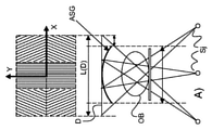
図1を参照すると、多線源X線撮像装置IAの幾つかの構成要素の概略側面図が示されている。撮像装置IAは、X線検出器Dに向かって各X線ビームB1、B2及びB3を放出することができる3以上のX線源sj(3つのX線源s1、s2及びs3しか図示されていないが、これは限定するものではない)を有している。上記ビームの形状は、オプションとしての前置コリメータ(図示略)により整形することができる。ビームBjは好ましくは円錐状ビームであるが、扇形ビームも想定することができる。更に、ここでは代替実施態様において平行な投射ビームも想定することができる。 Referring to FIG. 1, schematic side views of some components of the multi-source X-ray imager IA are shown. The image pickup apparatus IA shows only three or more X-ray sources sj (three X-ray sources s1, s2 and s3) capable of emitting each X-ray beam B1, B2 and B3 toward the X-ray detector D. Not, but this is not limited to). The shape of the beam can be shaped by an optional pre-collimator (not shown). The beam Bj is preferably a conical beam, but a fan-shaped beam can also be assumed. Further, parallel projection beams can also be envisioned here in alternative embodiments.
検出器Dは、検出器ピクセルから形成された放射線感知面を有している。線源sjと検出器Dとの間の検査又は撮像領域には、患者ベッド又は検査テーブル等の支持面SP上に支持された人若しくは動物の患者又は該患者の解剖学的部分等の撮像されるべき被検体OBが配置される。撮像装置IAは純粋に2D的な投影放射線撮影のために使用することができるが、ここでは、好ましい実施態様として3D撮像も考えられる。この目的のために、当該検査領域の周りに配置される複数のX線源sjにより、複数の異なる投影画像πが異なる投影方向から取得される(X線ビームB1~B3の異なる伝搬方向に対応して)。この場合、投影画像πは、利用可能なアルゴリズムにより、当該被検体OBにおける関心ボリュームVOI内に位置する部分の3D画像へと再構成することができる。該VOIは、3D空間における全てのビーム又は斯かるビームのうちの少なくとも2つの交差部として定義される。この場合、全てのX線源が同時に動作することは必要ではない。 The detector D has a radiation sensing surface formed from the detector pixels. In the examination or imaging region between the radiation source sj and the detector D, a human or animal patient supported on a support surface SP such as a patient bed or an examination table, or an anatomical portion of the patient is imaged. The subject OB to be placed is placed. The image pickup apparatus IA can be used for purely 2D projection radiography, but here, 3D imaging is also considered as a preferred embodiment. For this purpose, a plurality of different projection images π are acquired from different projection directions by a plurality of X-ray sources sj arranged around the inspection area (corresponding to different propagation directions of the X-ray beams B1 to B3). do). In this case, the projected image π can be reconstructed into a 3D image of a portion located within the volume of interest VOI in the subject OB by an available algorithm. The VOI is defined as the intersection of all beams in 3D space or at least two of such beams. In this case, it is not necessary for all X-ray sources to operate at the same time.
撮像は、大まかに、以下の通り進行する。被検体OB内の物質を介して進行するX線ビームBjは変更される。検出器ピクセルに入射するものは、この変更された放射線である。入射する放射線は、個々の検出器ピクセルにおいて電気信号(直接又は間接変換による)を生じる。これら信号はAD回路により各投影画像πに変換することができる。これらは、次いで、3D再構成アルゴリズムにより処理されて3D画像を生成することができ、該3D画像は次いでモニタ上で見るためにレンダリングされ、後の使用のために記憶され、又はそれ以外で処理することができる。ここでは、異なる実施態様において吸収イメージング、位相コントラスト撮像及び暗視野撮像(小角散乱撮像としても知られている)の全てが想定される。後者の2つの撮像用途の場合、通常、干渉計(図示略)が撮像装置IAにおける追加の装置部品として必要とされる。 Imaging roughly proceeds as follows. The X-ray beam Bj traveling through the substance in the subject OB is altered. It is this modified radiation that is incident on the detector pixel. The incident radiation produces an electrical signal (either by direct or indirect conversion) at each detector pixel. These signals can be converted into each projected image π by the AD circuit. These can then be processed by a 3D reconstruction algorithm to produce a 3D image, which is then rendered for viewing on a monitor, stored for later use, or otherwise processed. can do. Here, all of absorption imaging, phase contrast imaging and darkfield imaging (also known as small angle scattering imaging) are envisioned in different embodiments. For the latter two imaging applications, an interferometer (not shown) is typically required as an additional device component in the imaging device IA.
X線撮像装置IAは、二次元広角多線源撮像型のものであると見ることができる。即ち、複数の線源は、全てが線(直線又は曲線)に沿って順に直線状に配置されるのではなく、純粋に直線状の線源配置と比較して相対的に大きな投影角度差を必要とするような当該被検体の周りの二次元の配置を定める。当該装置は特に静止X線源を使用し、従って、別々の線源は当該検出器の周囲の固定された機械的構造(フレーム等)に配置される。一実施態様においては当該線源が電動化され又はX線源の周りの異なる位置へ手動で移動することができるようにすることも考えられるが、CT又はCアーム撮像等の回転式システムにおけるように撮像の間における動きは存在しない。このことは、これらの回転式システムが必要とする機械的オーバーヘッドを低減することを可能にする。簡単な実施態様において、X線検出器は操作者により移動可能ではなく、撮像されるべき被検体OBの周囲の固定された幾何学的装置に永久的に固定される。 The X-ray image pickup device IA can be seen as a two-dimensional wide-angle multi-radioactive source image pickup type. That is, a plurality of radiation sources are not all arranged linearly in order along a line (straight line or curve), but have a relatively large projection angle difference as compared with a purely linear radiation source arrangement. Define a two-dimensional arrangement around the subject as required. The device specifically uses static X-ray sources, so separate sources are placed in a fixed mechanical structure (frame, etc.) around the detector. In one embodiment, it may be possible to allow the source to be electrified or manually moved to a different position around the X-ray source, as in a rotary system such as CT or C-arm imaging. There is no movement during imaging. This makes it possible to reduce the mechanical overhead required by these rotary systems. In a simple embodiment, the X-ray detector is not mobile by the operator and is permanently anchored to a fixed geometric device around the subject OB to be imaged.
デジタルX線検出器Dは、一般的に、撮像されるべき被検体上に適切に取り付けられるハウジング内の平面長方形状(図1におけるような)を持つ平面パネル検出器である。他の例として、湾曲された放射感知性の検出器も想定される。当該検出器は、場合に応じて、天井に取付けたり、床に取り付けることができる。図1には好ましい実施態様として単一の放射線感知面を持つ単一の検出器のみが示されているが、ここでは、複数の検出器ユニットを持つ他の実施態様が必ずしも除外されるものではない。 The digital X-ray detector D is generally a planar panel detector having a planar rectangular shape (as in FIG. 1) in a housing that is appropriately mounted on the subject to be imaged. As another example, a curved radiation-sensitive detector is also envisioned. The detector can be mounted on the ceiling or on the floor, as the case may be. Although FIG. 1 shows only a single detector with a single radiation sensing surface as a preferred embodiment, it does not necessarily exclude other embodiments with multiple detector units. do not have.
以下においては、図1に示される構成要素に関連する種々の位置及び方向を示すために座標系を導入することが有益であろう。軸X,Yは、撮像されるべき被検体OBが存在する水平な被検体面を定める。該面は、図1における図面の面内へと延びる。一般的に、これらの軸は、患者支持体SPの各辺に平行である。 In the following, it may be useful to introduce a coordinate system to indicate the various positions and orientations associated with the components shown in FIG. The axes X and Y define a horizontal subject surface on which the subject OB to be imaged is located. The plane extends into the plane of the drawing in FIG. Generally, these axes are parallel to each side of the patient support SP.
検出器Dの放射感知面により定められる画像面も存在し、一般的に、この面は上記X,Y面と又は湾曲した検出器の場合は少なくとも接平面と平行である。 There is also an image plane defined by the radiation sensing plane of the detector D, which is generally parallel to the X, Y planes or at least the tangent plane in the case of a curved detector.
上記画像面に対して垂直に、上記検出器感知面の中心を通って、且つ、上記被検体面を介して当該撮像器の主光軸Zが走る。この軸Zは、理想的には、関心ボリュームVOIを(好ましくは、中心を)通過する。“前”“背後”、“下流”又は“上流”等の本明細書で使用される空間関係用語は、X線ビームBjの伝搬方向に対して使用される。 The main optical axis Z of the imager runs perpendicular to the image plane, through the center of the detector sensing plane, and through the subject plane. This axis Z ideally passes through the volume of interest VOI (preferably through the center). Spatial terms used herein, such as "front," "back," "downstream," or "upstream," are used with respect to the propagating direction of the X-ray beam Bj.
X線源sj(時には、単に“線源”と称する)は、検査領域を跨いで検出器Dの反対側に配置される。更に詳細には(そして、図1の(好ましい)実施態様において)、線源sjは、撮像されるべき被検体OB(又は被検体支持体SP)の下に配置される(重力場に対して)一方、検出器は上側に配置される。図1に示される固有の幾何学的構成は限定するものではない。図1に示されるものの逆の幾何学構成も想定されるからであり、その場合、重力に対して、被検体又は被検体支持体の下側に配置されるものは検出器であり、従って、X線源は被検体/支持体の上側に取り付けられる(重力場に対して)。しかしながら、上述した座標系及び空間関係用語は斯かる再配置に対して不変であり、これら実施態様の両方に適用可能であることが理解されよう。 The X-ray source sj (sometimes referred to simply as the "source") is located on the opposite side of the detector D across the inspection area. More specifically (and in the (preferably) embodiment of FIG. 1), the source sj is placed under the subject OB (or subject support SP) to be imaged (relative to the gravitational field). ) On the other hand, the detector is located on the upper side. The unique geometrical composition shown in FIG. 1 is not limited. This is because the reverse geometric configuration of what is shown in FIG. 1 is also assumed, in which case it is the detector that is placed underneath the subject or subject support against gravity, and therefore The X-ray source is attached above the subject / support (relative to the gravitational field). However, it will be appreciated that the coordinate system and spatial terms described above are invariant to such rearrangements and are applicable to both of these embodiments.
X線源sjは、一般的に、当該検出器の主光軸の周りにおいて、Z軸に沿って見た場合に円形、楕円形又は多角形等の多数の異なる(幾何学的)線源構成(ここでは、“線源幾何学構成”と称する)でグループ化される。該幾何学的線源構成は、幾つかの(又は全ての)線源位置を通過する包絡曲線により定義することができる。幾つかの実施態様において、線源sjのうちの1以上は、残りの線源により形成される包絡曲線の内側に配置され得る。加えて又は代わりに、線源は単一の線に沿って又は複数の線に沿って直線状に配置することもできる。 The X-ray source sj generally has a number of different (geometric) source configurations, such as circular, oval, or polygonal, when viewed along the Z axis, around the main light axis of the detector. It is grouped by (here, referred to as "source geometric composition"). The geometric source configuration can be defined by an envelope curve that passes through several (or all) source positions. In some embodiments, one or more of the sources sj may be placed inside the envelope curve formed by the remaining sources. In addition or instead, the source can be arranged linearly along a single line or along multiple lines.
好ましくは、上記幾何学的構成はVOIを経る主光軸Zの周りで対称とし、前記線源の少なくとも幾つかは、好ましくは、VOI/光学軸Zの周りに等角度で(“等方的に”)分散される。斯様なVOIの周りでの等角的又は等方性配置は好ましい空間的実施態様であるが、ここでは、線源配置が厳格な等角的配置から変化する準等方性配置も考えられる。線源配置は、好ましくは、被検体に対して対称とするが、このことは全ての実施態様においてそうである必要はない。非対称配置も考えられるからである。幾つかの実施態様において(必ずしも全ての実施態様においてではない)、当該配置が非対称である又は準等方的に過ぎない場合、線源の少なくとも対称な又は等方的な部分組が存在する。言い換えると、さもなければ等方性の又は対称な配置は、異なる使用シナリオにおいて必要とされるように線源ライン上に追加の線源を配置することにより拡大することができる。この(少なくとも準)等方性線源幾何学構成は、良好な3D再構成又は4D再構成(3D再構成の時間系列である)を可能にすることが分かっている。X線源sjは、それらの各ビームBjを下(又は上)から異なる方向に沿ってX線感知面上に或る角度で投射するように動作する。更に、被検体の前後像(AP view)を提供する中央線源s5が存在し得る。該中央線源は、被検体OB/被検体支持体SPの下において中心軸Z上に配置され、ビームBを該軸Zに沿って放出する。 Preferably, the geometry is symmetrical about the principal optical axis Z through the VOI, and at least some of the sources are preferably equiangular around the VOI / optical axis Z ("isotropic"). ") Dispersed. An isotropic or isotropic arrangement around such a VOI is a preferred spatial embodiment, but here a quasi-isotropic arrangement in which the source arrangement changes from a strict isometric arrangement is also conceivable. .. The source arrangement is preferably symmetrical with respect to the subject, but this does not have to be the case in all embodiments. This is because an asymmetrical arrangement is also possible. In some embodiments (but not necessarily in all embodiments), if the arrangement is asymmetric or only quasi-isotropic, then there is at least a symmetric or isotropic subset of the source. In other words, the otherwise isotropic or symmetric arrangement can be expanded by placing additional sources on the source line as required in different usage scenarios. This (at least quasi) isotropic source geometry has been found to enable good 3D or 4D reconstruction (which is a time series of 3D reconstruction). The X-ray source sj operates to project each of these beams Bj from below (or above) along different directions onto the X-ray sensing surface at an angle. In addition, there may be a central source s5 that provides an AP view of the subject. The central source is located on the central axis Z under the subject OB / subject support SP and emits the beam B along the axis Z.
必ずしも全ての実施態様においてではないが一実施態様において、X線源sjは面(“線源面”)内に光学軸を該面に垂直にして配置される。もっとも、ここでは傾斜した線源面も考えられる。VOI/関心被検体は、該線源面に交差しない。更に、ここで想定される撮像器IAにおいて、検出器面は線源面とは相違し、特に検出器は該線源面と交差しない。また、前述したように、線源sjは、一般的に、固定されて移動可能でないが、線源の配置を、従って線源幾何学構成を変更するために少なくとも1つ、2以上又は全ての線源が直線的に平行移動され及び/又は再配向されるような実施態様も考えられる。線源sjの位置は、必ずしも面に制限されることはなく、Zに平行な異なるz位置に配置することもできる。例えば、被検体OBに対して一層急な(当該ビームの一層長い組織内経路長の)投射方向を持つ線源は一層強い強度の線源を必要とし得るので、これら線源は一層遠位の一層弱い線源よりも当該患者に一層近い“面外”に配置することができる。 In one embodiment, but not necessarily in all embodiments, the X-ray source sj is arranged in a plane (“source plane”) with its optical axis perpendicular to the plane. However, an inclined source surface is also conceivable here. The VOI / subject of interest does not intersect the source plane. Further, in the imager IA assumed here, the detector surface is different from the radiation source surface, and in particular, the detector does not intersect the radiation source surface. Also, as mentioned above, the source sj is generally fixed and not mobile, but at least one, two or more or all to change the placement of the source and thus the source geometry. An embodiment in which the radiation source is linearly translated and / or reoriented is also conceivable. The position of the radiation source sj is not necessarily limited to the plane, and may be arranged at different z positions parallel to Z. For example, sources with a steeper (longer intra-tissue path length of the beam) projection direction to the subject OB may require stronger sources, so these sources are more distal. It can be placed "out of plane" closer to the patient than a weaker source.
撮像装置IAは散乱線除去格子ASG(ここでは、同様に単にASGとも称する)を更に有し、該格子は検出器の前に、特には被検体と検出器Dの感知面との間に位置される。該散乱線除去格子は、一般的に検出器感知面と形状及び寸法が同一の拡がりである面(“ASG面”)を形成する。言い換えると、該ASGは湾曲面又は平面であり得る。該ASGは検出器自体上に取り付けられるか(これは必ずしも当てはまらない)、又は取付部材により検出器から離れて取り付けられる。 The image pickup device IA further has a scatter ray removal grid ASG (also simply referred to herein simply as ASG), which is located in front of the detector, in particular between the subject and the sensing surface of the detector D. Will be done. The scattered ray removing grid generally forms a surface (“ASG surface”) having the same shape and dimensions as the detector sensing surface. In other words, the ASG can be a curved surface or a flat surface. The ASG is mounted on the detector itself (this is not always the case) or is mounted away from the detector by a mounting member.
当該ASGの機能は、画像品質を向上させることである。特に、吸収イメージングの場合、検出器Dにおいて検出される信号はX線ビームBjが撮像されるべき被検体OBの物質を通過する際に受ける減衰(即ち、強度の喪失)に対応する。理想的には、この減衰は吸収事象に完全に起因するものであるべきである。しかしながら、現実には、そうとはならない。即ち、散乱からの寄与分も存在するので、該減衰の全てが吸収(即ち、光電吸収)に帰属するものとはならない。言い換えると、入射するX線放射に応答して記録される電気信号は吸収に完全に起因すべきである。そこで、散乱線除去格子ASGの機能は、該散乱寄与分を除去又は少なくとも減少させることである。当該ASGは、X線ビームB1~B3に対して指向性フィルタとして作用する。更に詳細には、該ASGは、所与の線源sjに関して個々の光子を、これら光子の軌道方位に従ってフィルタリングするように構成される。即ち、好ましくは、線源sjの焦点から発するX線は該ASGを通過することができる一方、該ASGは散乱事象から生じる全ての他の“はぐれ”X線は少なくとも部分的に阻止する。図1に示されるように、幾何学的に言うと、照射ボリュームは、焦点FSjから検出器に向かって発する一群の幾何学的光線を描くことにより画定することができる。当該散乱線除去格子は、事前に画定された幾何学的照射ボリューム内の幾何学的ラインの何れかに沿って進行する放射だけを通過させるように構成される。 The function of the ASG is to improve the image quality. In particular, in the case of absorption imaging, the signal detected by the detector D corresponds to the attenuation (ie, loss of intensity) that the X-ray beam Bj receives as it passes through the material of the subject OB to be imaged. Ideally, this decay should be entirely due to the absorption event. However, in reality this is not the case. That is, since there is also a contribution from scattering, not all of the attenuation belongs to absorption (that is, photoelectric absorption). In other words, the electrical signal recorded in response to incident X-ray radiation should be entirely due to absorption. Therefore, the function of the scattered radiation removal grid ASG is to remove or at least reduce the scattering contribution. The ASG acts as a directional filter for the X-ray beams B1 to B3. More specifically, the ASG is configured to filter individual photons with respect to a given source sj according to the orbital orientation of these photons. That is, preferably, X-rays emanating from the focal point of the source sj can pass through the ASG, while the ASG at least partially blocks all other "stray" X-rays resulting from the scattering event. Geometrically speaking, as shown in FIG. 1, the irradiation volume can be defined by drawing a group of geometric rays emanating from the focal point FSj towards the detector. The scatter-removal grid is configured to pass only radiation traveling along any of the geometric lines within the pre-defined geometric irradiation volume.
概略すると、ここで提案される新規な散乱線除去格子ASGは、自身の指向性フィルタリング機能を、3D空間において異なる位置に配置された複数のX線源sjにより放出可能な異なるX線ビームBjの如何なる1つに対しても単一の統一体として果たすように構成される。 In summary, the novel scattered radiation removal grid ASG proposed here has its own directional filtering function of different X-ray beams Bj that can be emitted by multiple X-ray sources sj located at different positions in 3D space. It is configured to serve as a single unity for any one.
図1に示された例示的幾何学構成を再び参照すると、異なるX線ビームBjは全検出器面における異なる副領域bjを照射することがわかる。言い換えると、照射される副領域は分離されている。しかしながら、このことは必ずしも全ての実施態様においてそうであるとは限らない。X線撮像器IAの一層コンパクトな構成は、異なる位置からの異なるX線源が同一の副領域を共有する場合、又は少なくともその様に照射される異なる副領域の間の幾何学的交差部が存在する場合に達成され得るからである。異なる線源sjによる該検出器領域共有は、必ずしもではないが、ここに提案される装置IAの好ましい実施態様である。当該新規な散乱線除去格子は、検出器領域共有を達成することを可能にし、X線源のうちの異なるものが同一の副領域を使用する場合、又は異なる線源から照射される検出器領域の交差部が存在する場合でさえも、共同の又は共通の単一のASGユニットとして機能するように構成される。 Revisiting the exemplary geometry shown in FIG. 1, it can be seen that the different X-ray beams Bj illuminate different subregions bj on the entire detector surface. In other words, the irradiated sub-regions are separated. However, this is not always the case in all embodiments. A more compact configuration of the X-ray imager IA is when different X-ray sources from different locations share the same subregion, or at least the geometric intersections between the different subregions so irradiated. It can be achieved if it exists. Sharing the detector region with different sources sj is a preferred embodiment of the device IA proposed herein, but not necessarily. The novel scatter-removal grid makes it possible to achieve detector region sharing, where different X-ray sources use the same subregion or are emitted from different sources. It is configured to function as a common or common single ASG unit, even in the presence of the intersections of.
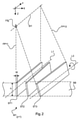
この共有ASG機能が構造的にどの様に達成されるかをより良く説明するために、ここで図2を参照する。提案される散乱線除去格子ASGは、異なる(即ち、2以上の)格子部、格子モジュール又はパネルMjのアセンブリとして想定される。図2は、1つの斯様な格子モジュール(Mj、一例としてj=1)の一部を斜視図で示す。各モジュールは、一群の又は一連の平らな放射線不透過性細条(strip)又は“薄板(lamella)”を有する。この一群の個別の細条は、実質的にX線を遮断するために、鉛、タングステン若しくは合金から、又は他の金属若しくは適切な高Z材料の材料から形成される。各モジュールMjは自身の細条STjにより固有に定まるので、当該一群の細条に対しても同様にシンボル“Mj”を入れ替え可能に使用する。 FIG. 2 is referred to here to better illustrate how this shared ASG function is structurally achieved. The proposed scatter-removal grid ASG is envisioned as an assembly of different (ie, two or more) grids, grid modules or panel Mj. FIG. 2 is a perspective view showing a part of one such grid module (Mj, j = 1 as an example). Each module has a group or series of flat radiodensity strips or "lamellas". This group of individual strips is formed from lead, tungsten or alloys, or from other metals or materials of suitable high Z material, in order to substantially block X-rays. Since each module Mj is uniquely determined by its own strip STj, the symbol "Mj" is similarly interchangeably used for the group of strips.
長手方向の細条STjは、任意の2つの隣接する細条の間における対応する緩衝又は充填材料SBの細条と交互に配置される。図2には解説のために3つの細条ST1,ST2,ST3のみが示されているが、通常は4以上の細条が存在すると理解される。上記緩衝材料SBは、セルロース(例えば、ボール紙/紙等)、アルミニウム又はその他のX線放射透過性(translucent)材料から形成される。言い換えると、上記緩衝材料は、当該モジュールの構造的完全性のためのものであるが、該ASGモジュールを介しての実質的に妨害されない通過を提供するよう構成される。該緩衝細条はミリメートル厚の十分の1程度(例えば、約0.1~0.3mm)であるが、この数値は解説的例に過ぎない。 Longitudinal strips STj are arranged alternately with the strips of the corresponding buffer or filling material SB between any two adjacent strips. Although only three strips ST1, ST2, and ST3 are shown in FIG. 2 for explanation, it is usually understood that there are four or more strips. The cushioning material SB is formed from cellulose (eg, cardboard / paper, etc.), aluminum or other translucent material. In other words, the cushioning material is configured to provide substantially unobstructed passage through the ASG module, although it is for structural integrity of the module. The buffer strip is about one tenth of the millimeter thickness (eg, about 0.1-0.3 mm), but this number is only an explanatory example.
各細条は、高さh、厚さW及び最も長い辺に沿って延びる長軸を有する。解説目的で、これら細条は一実施態様では数百ミリメートル程度の長さ(例えば、400mm)、ミリメートルの約百分の1程度の厚さ(例えば、0.03mm)及び約ミリメートルの程度の高さ(例えば、2mm)である。当該モジュールに対して約1000~2000(例えば、約1500又は1600)の細条が存在する。これら全ての数値は純粋に例示的なもので、手元の撮像装置AIの仕様に依存するであろう。異なる細条の長軸は、L1,L3と図示されている(L2は示されていない)。所与のモジュールの斯かる細条の長軸は、互いに平行である。斯かる細条の幾つか(必ずしも全てではない)は、図2において角度αにより概念的に示されているように、互いに対して且つ各長軸の回りで角度を付けられ又は傾斜されている。斯様な角度付け(角形成)にも拘わらず、これら細条は面内に位置する(即ち、長軸は全て面内に配置される)。この配置は、平らな又は平面的ASGモジュール/パネルを生じさせる。他の例として、長軸が平行ではあるが同一の面内には配置されず、非平面状の又は湾曲したASG格子モジュールを定めるような湾曲したASGモジュールも考えられる。 Each strip has a height h, a thickness W and a long axis extending along the longest side. For explanatory purposes, these strips are, in one embodiment, about a few hundred millimeters long (eg, 400 mm), about one-hundredth of a millimeter thick (eg, 0.03 mm), and about a millimeter high. (For example, 2 mm). There are about 1000-2000 (eg, about 1500 or 1600) streaks for the module. All these numbers are purely exemplary and will depend on the specifications of the imager AI at hand. The major axes of the different strips are shown as L1, L3 (L2 is not shown). The major axes of such strips of a given module are parallel to each other. Some (but not all) of these strips are angled or tilted relative to each other and around each major axis, as conceptually shown by angle α in FIG. .. Despite such angulation (angle formation), these streaks are located in-plane (ie, all major axes are in-plane). This arrangement results in a flat or planar ASG module / panel. As another example, a curved ASG module that has parallel major axes but is not arranged in the same plane and defines a non-planar or curved ASG grid module is also conceivable.
この相互の角形成は、当該細条をX線源sjのうちの特定のX線源の焦点FSiに収束させることを可能にする。この意味で、自身の細条群を備える各モジュールMiは複数のX線源sjのうちの1つに関連付け可能である。更に詳細には(該収束幾何学構造を更に詳細に説明すると)、各細条は、当該細条が位置する面(焦点面)FPijの一区分であると理解することができる。各長軸も対応する面内に位置する。当該角形成により、これらの面FPijは、関連するX線源sjの焦点FSjを通過するラインにおいて交差するであろう。所与のモジュールの各細条が位置する焦点面の交差により形成される該ラインは、ここでは、“線源ライン”sljと称される。各ASGモジュールが3D空間において特定のX線源sjの位置と関連付けることができるのは、自身の線源ラインを介してである。更に詳細には、所与のモジュールにおける複数の細条の固有の幾何学的向きは3D空間において1つの線源ラインを生じさせ、該モジュールは自身のASG機能を、焦点が該線源ライン上にたまたま位置する任意のX線源に対しても、又は、等価的に、同一の線源sjに関して該線源ライン上の異なる位置に対しても果たすことができる。言い換えると、X線源sjとASGモジュールMjとの間の該関連付け関係は、1:1ではなく、多数対1である。2以上の線源sjが同一の線源ラインsli上に配置されるような実施態様が想定される。細条の角形成及び斯かる細条の長軸の向きは、線源ラインsljの3Dにおける位置を固有に決定する。特に、細条の長手方向の向き(ワールド座標枠に対する)は、所与の格子モジュールMjに関する線源ライン方位を固有に決定する。従って、“モジュールMjの線源ラインの向き”について述べることが適切且つ好都合である。所与の面内の2つのモジュールMj,Mkが異なる線源ライン方位を有する場合、このことは、これらモジュールの細条STj、STkの長軸が異なる(即ち、これら長軸が非平行である)ことを意味する。異なるモジュールMiに関して、当該モジュールから該モジュールの線源ラインsljまでの距離は相違し得ることに注意すべきである。 This mutual angle formation makes it possible to converge the strips to the focal point FSi of a particular X-ray source of the X-ray sources sj. In this sense, each module Mi with its own strips can be associated with one of a plurality of X-ray sources sj. In more detail (explaining the convergent geometric structure in more detail), each strip can be understood as a division of the plane (focal plane) FPij in which the strip is located. Each major axis is also located in the corresponding plane. Due to the angle formation, these planes FPij will intersect at the line passing through the focal point FSj of the associated X-ray source sj. The line formed by the intersection of the focal planes where each strip of a given module is located is referred to herein as the "source line" slj. It is through its own source line that each ASG module can be associated with the location of a particular X-ray source sj in 3D space. More specifically, the unique geometric orientation of the strips in a given module gives rise to one source line in 3D space, where the module has its own ASG function and the focus is on the source line. It can be played for any source that happens to be located, or equivalently for different positions on the source line with respect to the same source sj. In other words, the association between the X-ray source sj and the ASG module Mj is many-to-one rather than 1: 1. An embodiment is envisioned in which two or more source sj are arranged on the same source line sli. The formation of the streaks and the orientation of the major axis of such streaks uniquely determines the position of the source line slj in 3D. In particular, the longitudinal orientation of the strips (relative to the world coordinate frame) uniquely determines the source line orientation for a given grid module Mj. Therefore, it is appropriate and convenient to describe "direction of the source line of the module Mj". If two modules Mj, Mk in a given plane have different source line orientations, this means that the major axes of the narrow strips STj, STk of these modules are different (ie, these major axes are non-parallel). ) Means that. It should be noted that for different modules Mi, the distance from the module to the source line slj of the module can be different.
細条の角形成は“対称”又は“非対称”とすることができる。対称な角度付け(図2に示されるような)においては、中心の細条において角度付けは存在せず、残りの細条の角度付けは当該細条が中心細条から遠くに配置されるほど強くなり、中心細条から左側の全ての細条は時計方向に角度が付けられる一方、右側の全ての細条は反時計方向に角度が付けられる。非対称角度付けにおいて、角度付けされていない中心細条は存在しない(即ち、全ての細条は反時計方向又は時計方向の何れかに角度付けされる)。これの結果は、所与の対称モジュールMjに対して、当該モジュールの線源ラインの該モジュールの面上への垂直投影(orthogonal projection)が該モジュールMjの領域(即ち、該モジュールの細条STjによりカバーされる領域)の中心に入るというものである。非対称モジュールの場合、このことは当てはまらない。この場合、線源ラインの垂直投影は、中心が外れるか又は当該格子モジュールMjの領域の外側に位置し得る。即ち、非対称格子モジュールは、自身の線源ラインを該モジュールMj自身が配置された場所から“離れて”又は“横方向に”定義することを可能にする。 The streak angle formation can be "symmetrical" or "asymmetrical". In symmetrical angulation (as shown in FIG. 2), there is no angulation in the central strip, and the angling of the remaining strips is such that the strip is located farther from the central strip. It becomes stronger and all the strips on the left side of the central strip are angled clockwise, while all the strips on the right side are angled counterclockwise. In asymmetric angled, there are no unangled central strips (ie, all strips are angled either counterclockwise or clockwise). The result of this is that for a given symmetric module Mj, the orthogonal projection of the source line of the module onto the plane of the module is the region of the module Mj (ie, the subsection STj of the module). It is to enter the center of the area covered by). This is not the case for asymmetric modules. In this case, the vertical projection of the source line may be off-center or located outside the region of the grid module Mj. That is, the asymmetric grid module allows its source line to be defined "away" or "laterally" from where the module Mj itself is located.
ここに提案されるASGは、該ASGを言わば単一の超格子(super-grid)として形成するために互いに隣接した配置された図2に示される種類の複数の格子モジュールを含む。更に詳細には、本明細書では、平行でない長軸を有する各細条を備えた少なくとも2つの格子モジュールMi,Mjが存在するような複数の細条モジュールMiを含むASGが提案される。このように、当該ASGは異なる線源ラインを生じるように構成されると共に、焦点が空間内に分散される複数の異なるX線源に対して、これら線源の斯かる焦点の何れか1つが上記線源ラインの少なくとも1つ上に位置する限りにおいて、全く同じASGがASG機能を提供することができる。言い換えると、単一のASG格子(モジュール式格子Mjのアセンブリとして形成された)が、3D内に分散された非常に複雑な線源幾何学構造をサポートすることができる。更に、当該ASGは交差する線源ラインを生成するように構成される。1つの線源を2つ(又は、それ以上の)線源ラインの交点上に配置することは、ASG領域を共有することを可能にする。言い換えると、交点における線源からのビームは、当該交差する線源ラインを生じる2つのモジュールにより共同してフィルタリングされる。このことは、当該ASGの、従って全体としての当該撮像器の全体のフットプリント(面積)を低減することを可能にする。以下において、図3~図7は種々の線源sjの幾何学構成を示し、各々は、全てがここで想定される異なる実施態様によりサポートするASG細条幾何学構成によるものである。以下の図において当該ASGに関して提供される図は、光学軸Zに沿う上からの平面図であり、そうでない限り、検出器D、被検体OB及び支持面SPは提示を容易にするために除かれている。以下のものの全ては、逆の幾何学構成(線源が被検体の上で、検出器が被検体の下)における撮像器に対して等しく適応されるものである。 The proposed ASG comprises a plurality of grid modules of the type shown in FIG. 2 arranged adjacent to each other to form the ASG as a so-called single super-grid. More specifically, the present specification proposes an ASG comprising a plurality of strip modules Mi such that there are at least two grid modules Mi, Mj with each strip having a non-parallel major axis. Thus, the ASG is configured to give rise to different source lines, and for a plurality of different X-ray sources whose focal points are dispersed in space, any one of these sources has such a focal point. Exactly the same ASG can provide the ASG function as long as it is located at least one above the source line. In other words, a single ASG grid (formed as an assembly of modular grids Mj) can support highly complex source geometry distributed within 3D. Further, the ASG is configured to generate intersecting source lines. Placing one source on the intersection of two (or more) source lines makes it possible to share the ASG region. In other words, the beam from the source at the intersection is co-filtered by the two modules that give rise to the intersecting source lines. This makes it possible to reduce the overall footprint of the ASG, and thus the imager as a whole. In the following, FIGS. 3-7 show the geometrical configurations of the various sources sj, each with an ASG fine-strand geometrical configuration, all supported by the different embodiments envisioned herein. The figure provided for the ASG in the following figure is a plan view from above along the optical axis Z, otherwise the detector D, subject OB and support surface SP are removed for ease of presentation. It has been done. All of the following are equally applicable to the imager in the reverse geometry (source above the subject, detector below the subject).
ここで図3を更に詳細に参照すると、一実施態様による多線源撮像のために構成されたASGが示されている。 Here, with reference to FIG. 3 in more detail, an ASG configured for multi-source imaging according to one embodiment is shown.
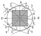
平面図Zにおける当該ASGの全体的配置は長方形(特には、正方形)であるが、如何なる他の四角形若しくは多角形又は実際に円形若しくは楕円形の配置も他の実施態様において想定される。図3のA)及びB)において、当該格子ASGは平面状である。図3に示される特定のASGは、異なる線源ライン方位(向き)を持つ5つの群(組)M1~M5を含んでいる。4つのモジュールM1~M4は、中心モジュールM5の周囲でグループ化されている。細条の長軸の方向は、この図及び後続の図4~図7において異なる斜線(ハッチング)で示され、斜線の向きは長軸の向きを表している。これらのモジュールMj(j=1~5)により生ぜられる対応する線源ラインはslj(j=1~5)として示されている。 The overall arrangement of the ASG in plan view Z is rectangular (especially a square), but any other quadrilateral or polygonal or actually circular or elliptical arrangement is envisioned in other embodiments. In A) and B) of FIG. 3, the grid ASG is planar. The particular ASG shown in FIG. 3 includes five groups (sets) M1 to M5 with different source line orientations. The four modules M1 to M4 are grouped around the central module M5. The direction of the long axis of the strip is shown by different diagonal lines (hatching) in this figure and subsequent FIGS. 4 to 7, and the direction of the diagonal line indicates the direction of the long axis. The corresponding source lines generated by these modules Mj (j = 1-5) are shown as slj (j = 1-5).
図3に示されるように5組のASG細条を有することは単に一実施態様によるもので、ASG当たり5未満又は6以上のモジュールの他の数も考えられることが理解されるであろう。ASG当たりのモジュールの数は、使用されるべきX線源の数の関数である。この数は、線源の数以下である。交差する線源ライン及び幾つかの線源を同一の線源ライン上に配置することができるという事実により、この数は好ましくは未満とする。 It will be appreciated that having 5 sets of ASG substrates as shown in FIG. 3 is solely by one embodiment, and other numbers of less than 5 or more than 6 modules per ASG are also possible. The number of modules per ASG is a function of the number of X-ray sources to be used. This number is less than or equal to the number of sources. This number is preferably less than due to the fact that intersecting source lines and several sources can be located on the same source line.
図示された実施態様においては、8個の線源s1~s8に対して5つの格子M1~M5が存在する。X線源sjは、当該格子の軸Zの周りに円形線源幾何学構成で配置されたドットとして示されている。図3の固有の実施態様においては、軸Zの周りに配置された8個の線源が存在し、追加の中心のX線源s8が軸Z上に当該患者の上側又は下側に配置されている。この中心の線源s8は、AP(前後)又はPAビューでの撮像を提供する。 In the illustrated embodiment, there are five grids M1 to M5 for eight sources s1 to s8. The X-ray source sj is shown as dots arranged in a circular source geometric configuration around the axis Z of the grid. In a unique embodiment of FIG. 3, there are eight sources located around axis Z, with an additional central X-ray source s8 located above or below the patient on axis Z. ing. This central source s8 provides imaging in AP (front and back) or PA views.
モジュールM2,M3は、異なる向きの線源ラインsl2,sl3を発生し、従って平行でない方向に走る細条を有する。モジュールM1,M4も同様である。しかしながら、対向する対のモジュールM2,M4及びM3,M1は、各々同一の向きの線源ラインを有している。このように、図3は、全てのモジュールが異なる向きを備えた線源ラインを持つというものではない実施態様である。同一の向きの線源ラインを持つ2つのモジュールが存在しないような他の代替実施態様も考えられる。 Modules M2, M3 have strips that generate source lines sl2, sl3 in different directions and thus run in non-parallel directions. The same applies to the modules M1 and M4. However, the opposite pair of modules M2, M4 and M3, M1 each have a source line in the same orientation. As such, FIG. 3 is an embodiment in which not all modules have source lines with different orientations. Other alternative embodiments are conceivable such that there are no two modules with the same source line.
組M1、M4、M3及びM2の各細条の長軸、従って斯かる組の線源ラインは、一緒になって四角形を、特に点線が各交点まで辿られるなら菱形を形成する。 The major axes of the strips of sets M1, M4, M3 and M2, and thus the source lines of such sets, together form a quadrangle, especially a rhombus if the dotted line is traced to each intersection.
図3から、先ず、周辺の外側のモジュールM1~M4における細条は、各線源ラインが各組Miの直ぐ垂直下に位置されるのではなく、光軸Zから離れて横方向に僅かにオフセットされるように収束されることが理解され得る。このことは、線源ラインを患者テーブルから更に離れて位置させることを可能にする。線源ラインを光軸Zの近くに位置させることは、一層小さなフットプリントを持つ撮像装置を構築することを可能にする。言い換えると、周辺モジュールM1~M4は非対称である一方、中心格子M5は対称である。 From FIG. 3, first, in the strips of the modules M1 to M4 on the outer side of the periphery, each source line is not positioned immediately vertically below each set Mi, but is slightly offset laterally away from the optical axis Z. It can be understood that it is converged as it is. This allows the source line to be located further away from the patient table. Positioning the source line near the optical axis Z makes it possible to construct an image pickup device with a smaller footprint. In other words, the peripheral modules M1 to M4 are asymmetric, while the central grid M5 is symmetric.
各副格子Mjは、対応する線源ライン上に位置するX線源のためにフィルタリングを行う。図3で想定されるASGは、線源ラインsl2,sl3が交差しているM2及びM3等の副格子を含む。言い換えると、この交点に配置されるX線源s8は、自身のビームB8を両副格子M2,M3により共同してフィルタリングさせる。言い換えると、これは、フィルタリング動作が同一のX線源に対して2つの格子の間で共有される前述した例である。線源ラインsl3及びsl2の交点上の9時の位置に配置されるX線源s8は、自身のビームを、副格子M2及び副格子M3における細条の各部分組によりフィルタリングさせる。線源ラインsl4及びsl1の交点上の3時の位置に配置されたX線源に関係する格子M1,M4に関しても同様のことが成り立つ。 Each sub-lattice Mj filters for an X-ray source located on the corresponding source line. The ASG assumed in FIG. 3 includes sub-lattices such as M2 and M3 at which the source lines sl2 and sl3 intersect. In other words, the X-ray source s8 arranged at this intersection causes its own beam B8 to be filtered jointly by both sub-lattices M2 and M3. In other words, this is the above-mentioned example in which the filtering operation is shared between two grids for the same X-ray source. The X-ray source s8, located at 9 o'clock on the intersection of the source lines sl3 and sl2, filters its beam by sub-lattice M2 and sub-lattice M3 strips. The same applies to the grids M1 and M4 related to the X-ray source arranged at the 3 o'clock position on the intersection of the source lines sl4 and sl1.
中心の副格子M5は、患者テーブルの下に(逆幾何学構成では上に)配置されるAP X線源により放出されるビームをフィルタリングする。 The central sublattice M5 filters the beam emitted by the AP X-ray source located below the patient table (upper in the inverse geometry configuration).
当該ASGは、好ましくは、全体として異なる副格子M1~M5からなり、異なるモジュールの各細条がM2,M3及びM1,M4に関して示されるように或る角度で交わる統一体として形成される。 The ASG is preferably composed of different sub-lattices M1 to M5 as a whole and is formed as a unit in which the strips of different modules intersect at an angle as shown for M2, M3 and M1, M4.
ここで提案される格子共有は、図3のB)に更に詳細に示されている。線源s8は、線源ラインsl3及びsl2の交点ISPに配置される。該線源から放出されたビームB8は、副格子M2及びM3によりASGフィルタリングされる。ビームB8は、両格子M2及びM3の各部分をカバーする領域b8を照射する。M2において照射される細条の部分組は“up”として示される一方、同じビームB8により格子M3において照射される細条の部分組は“lw”として示されている。 The grid sharing proposed here is shown in more detail in B) of FIG. The source s8 is arranged at the intersection ISP of the source lines sl3 and sl2. The beam B8 emitted from the radiation source is ASG filtered by the sub-lattices M2 and M3. The beam B8 irradiates the region b8 covering each portion of both grids M2 and M3. The substructure of the streaks irradiated in M2 is indicated as "up", while the substructure of the strips irradiated in the grid M3 by the same beam B8 is indicated as "lw".
図3における各線源の位置は線源ラインに沿ってシフトさせることができ、この場合、この態様により得られる線源幾何学構成の何れも、ASG機能の点で全く同一のASG格子によりサポートされる。従って、各線源が線源ラインの少なくとも1つの上に位置する限り、異なる線源幾何学構成に対して当該ASG格子を再設計する必要はない。更に言い換えると、所与の格子ASGによりサポートされる全ての可能性のあるX線源配置の組は、線源ラインの系により定義される。交点を持つ線源ライン構成を有することが好ましく、この結果、図3のB)に示されるような共有ASG領域が得られる。 The position of each source in FIG. 3 can be shifted along the source line, in which case any of the source geometry obtained in this embodiment is supported by the exact same ASG grid in terms of ASG function. To. Therefore, as long as each source is located above at least one of the source lines, there is no need to redesign the ASG grid for different source geometry. In other words, the set of all possible X-ray source arrangements supported by a given grid ASG is defined by the system of source lines. It is preferable to have a radiation source line configuration having intersections, and as a result, a shared ASG region as shown in B) of FIG. 3 is obtained.
図3における副格子の全ては、全て四角形、特には長方形である。これは、常にそうであるとは限らない。三角形又は多角形の形状等の他の幾何学的形状も用いることができ、その場合、当該ASGを斯かる副格子から同一又は異なる形状の組み合わせでのタイル張りとして構築することができるからである。即ち、図3において、当該ASGは長方形状の副格子M1~M5のタイル張りである。 All of the sub-lattices in FIG. 3 are all rectangular, especially rectangular. This is not always the case. Other geometric shapes, such as triangular or polygonal shapes, can also be used, in which case the ASG can be constructed from such sublattices as tiles in the same or a combination of different shapes. .. That is, in FIG. 3, the ASG is tiled with rectangular sub-lattices M1 to M5.
2を超える(3以上の)線源ライン(例えば、中心副格子M5の線源ラインsl5及び線源ラインsl2,sl1)が、図3のA)に示されるように交差することができる。この交点(図示略)における他の線源の配置は、結果として、自身のビームASGを3つの副格子により共同で(例えば、中心格子M5及び副格子M1及びM2により)フィルタリングさせることになる。 More than 2 (3 or more) source lines (eg, source lines sl5 and source lines sl2, sl1 of the central sublattice M5) can intersect as shown in A) of FIG. The placement of other sources at this intersection (not shown) results in the co-filtering of its beam ASG by three sub-lattices (eg, by central grids M5 and sub-lattices M1 and M2).
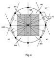
ここで、15個のX線源s1~s15を持つ撮像器IAのための円形線源幾何学構成の、図3におけるものに類似したASGを示す図4を参照する。図3と比較して、中心格子M5の線源ラインsl5上の中心線源s9の両側に2つ、及び4つの線源ラインsl1~sl4上に各々配置された4つの他の線源の、6個の追加の線源が追加されている(明るいドットとして示されている)。平面図における線源位置の包絡線は、光軸の周りの円形となる。ここでは各周辺線源ライン上に3つの線源が存在し、4つの線源が中心軸Z上の1つの線源を伴って中心格子の線源ラインsl5上に対称に配置され、該4つの線源は中心軸から両側に2つずつオフセットされている。 Here we refer to FIG. 4, which shows an ASG similar to that in FIG. 3 in a circular source geometric configuration for an imager IA with 15 X-ray sources s1 to s15. Compared to FIG. 3, two of the two on each side of the center source s9 on the source line sl5 of the center grid M5, and four other sources arranged on each of the four source lines sl1 to sl4. Six additional sources have been added (shown as bright dots). The envelope of the source position in the plan view is a circle around the optical axis. Here, there are three sources on each peripheral source line, and the four sources are symmetrically arranged on the source line sl5 of the central grid with one source on the central axis Z. The two sources are offset from the central axis by two on each side.
この実施態様及び全ての残りの実施態様におけるのと同様に、中心格子M5の線源ラインは患者支持体の長軸と平行に走る一方、他の実施態様において該中心格子の線源ラインは交差して走る。この後者の配置は、図3、図4及び図5におけるASGを90°時計方向又は反時計方向に回転させることにより得られる。ここでも、中心の格子M5は対称である一方、残りのものは逆対称である。上記のものは90°の回転に限定されるものではない。ここでは、90°以外の何れかの回転により得られ得るASGの実施態様も考えられるからである。 As in this embodiment and all remaining embodiments, the source line of the central grid M5 runs parallel to the long axis of the patient support, while in other embodiments the source lines of the central grid intersect. And run. This latter arrangement is obtained by rotating the ASG in FIGS. 3, 4 and 5 90 ° clockwise or counterclockwise. Again, the central grid M5 is symmetric, while the rest are inversely symmetric. The above is not limited to 90 ° rotation. This is because, here, an embodiment of ASG that can be obtained by any rotation other than 90 ° is also conceivable.
次ぎに、ここでは楕円配置である他の線源幾何学構成を示す図5を参照すると、図5のA)では9個の線源s1~s9が使用される一方、図5のB)では15個の線源s1~s15が使用されている。該ASGは、4つの周辺格子M1~M4及びAPビュー撮像のための1つの中心格子M5を備えた前述したものに類似している。図5のA)におけるASGの形状は平面な長方形である一方、図5のB)におけるものは平面な正方形である。これらの線源により発生される5つの線源ラインsl1~sl5が存在し、4つの交点を持つ菱型形状を画定している。bjは、前述と同様に、線源sjにより照射される副格子の各領域を示している。例えば、b5は当該ASGの下側又は上側に配置される線源s5により照射される中心格子の領域を示し、長方形b7は線源s7により照射されs8によりフィルタリングされる領域を示す。 Next, referring to FIG. 5 showing another source geometrical configuration which is an elliptical arrangement here, nine sources s1 to s9 are used in A) of FIG. 5, while B) of FIG. Fifteen radiation sources s1 to s15 are used. The ASG is similar to the one described above with four peripheral grids M1 to M4 and one central grid M5 for AP view imaging. The shape of the ASG in A) of FIG. 5 is a flat rectangle, while the shape of the ASG in B) of FIG. 5 is a flat square. There are five source lines sl1 to sl5 generated by these sources, defining a rhombic shape with four intersections. bj indicates each region of the sub-lattice irradiated by the radiation source sj as described above. For example, b5 indicates a region of the central grid illuminated by the source s5 located below or above the ASG, and rectangle b7 indicates a region illuminated by the source s7 and filtered by s8.
線源ラインの交点に位置する線源(例えば、図5のA),B)における線源s2及びs8)により見られるように、この実施態様においても副格子共有が存在する。共有される各領域は、b8及びb2として示されている。図5のB)における線源幾何学構成は、図5のA)に示されるものから、6個の追加の線源を、2つを中心格子の線源ライン上において主光軸Zの両側に、4つの他の線源(一層大きなドットとして示される)が4つの各線源ライン上において図5のA)の線源の対の間に配置されるようにして追加することにより得られる。所与の線源ライン上に一層多くの線源を追加することは、即ち所与の線源ラインに一層多くの線源を一層密に移植することは、より多くの断層撮影情報の抽出を可能にし、このことは骨除去画像処理に役立ち得る。これが、共通線源ラインsl2上に線源s7及びs8の間で追加された追加の線源sxからの主ビームに関して図5のB)に示されている。上述した様な平面的ASG格子の変形例として、湾曲した実施態様が示される図6を次ぎに参照する。 Sub-lattice sharing also exists in this embodiment, as seen by the sources s2 and s8) at the sources (eg, A), B) located at the intersection of the source lines. Each shared area is shown as b8 and b2. The source geometry in B) of FIG. 5 is from that shown in A) of FIG. 5, with six additional sources, two on both sides of the main optical axis Z on the source line of the central grid. It is obtained by adding four other sources (shown as larger dots) so that they are placed between the pairs of sources of A) in FIG. 5 on each of the four source lines. Adding more sources on a given source line, i.e. transplanting more sources more densely on a given source line, will extract more tomographic information. It enables and this can be useful for bone removal imaging. This is shown in FIG. 5B) with respect to the main beam from the additional source sx added between the sources s7 and s8 on the common source line sl2. As a modification of the planar ASG lattice as described above, FIG. 6 showing a curved embodiment will be referred to next.
この湾曲したASGは、前述したものに、さもなければ、中心格子及び4つの外側格子M1~M4を含む先のものに類似する。該湾曲したASG格子は、対応して湾曲した面を持つ検出器と共に使用するよう構成される。 This curved ASG is similar to the one described above, or earlier, including the central grid and the four outer grids M1 through M4. The curved ASG grid is configured for use with a detector with a correspondingly curved surface.
図6のA)は、湾曲した構成対平面的構成を示すと共に、矢印Lにより示されるように達成可能な一層コンパクトな構造を示している。該湾曲した格子は、平面図(上側)で示されると共に、撮像器IAで使用される間のX,Z面における側面図で示されている。 A) of FIG. 6 shows a curved vs. planar configuration and shows a more compact structure achievable as indicated by the arrow L. The curved grid is shown in plan view (upper side) and in side views in planes X and Z while used in the imager IA.
図6のC)は、一実施態様による、ここで提案される湾曲した格子の平面図対斜視図を示す。図示された実施態様において、湾曲されるのは中心格子M5のみであり、周辺格子M1~M4は以前と同様に平面状である。周辺副格子M1~M4は湾曲した中心格子に対して、該中心格子の直線状の1対の辺において該中心格子の接線方向の延長の形で接合される。各辺に異なる線源ライン方位を持つ2つの副格子が追加され、中心格子を跨いで対向する対は、図3~図5の先の実施態様と同様に同じ線源ライン方位を有する。中心格子M5は、初期的には角度付けされていない細条しか備えない平らな副格子を用いて得られ、該副格子は、次いで、自身の細条に平行な軸の回りに湾曲されて、これら細条全体を通して対称な角度付けを実現する。該湾曲した複合格子ASGを湾曲した及び平面状のモジュールの混合から構築するというより、当該ASGが全体を通して湾曲され、従って湾曲したモジュールのみから形成されるような他の“純粋な”実施態様も考えられる。 FIG. 6C) shows a plan view vs. a perspective view of the curved lattice proposed here according to one embodiment. In the illustrated embodiment, only the central grid M5 is curved, and the peripheral grids M1 to M4 are planar as before. Peripheral sub-lattices M1 to M4 are joined to a curved central grid in the form of a tangential extension of the central grid on a pair of linear sides of the central grid. Two sub-lattices with different source line orientations are added on each side, and the opposing pairs across the central grid have the same source line orientation as in the previous embodiments of FIGS. 3-5. The central grid M5 is initially obtained using a flat sub-lattice with only unangled strips, which are then curved around an axis parallel to its own strips. , Achieve symmetrical angulation throughout these strips. Rather than constructing the curved composite lattice ASG from a mixture of curved and planar modules, there are other "pure" embodiments in which the ASG is curved throughout and thus formed only from the curved modules. Conceivable.
図6のB)は、平面状副格子の間に湾曲した中心格子を有することにより授かる製造上の利点を示す。図6のB)の上部に示されるように、平面状副格子における最大傾斜角は、中心格子が追加の角度付け成分を加えることになるので、減少させることができる。図2に示され且つ理解されるように、傾斜/角度付けは各副格子において外側部分に向かって比例的に増加し、最も外側の細条が最も強い傾きを有する。該最外側の細条の傾きは、当該格子に関する最大傾斜と称する。この場合、湾曲した格子を有することは、この最大角を、生成することを一層容易にして、増加させることを可能にする。 B) of FIG. 6 shows the manufacturing advantages conferred by having a curved central grid between the planar sub-grids. As shown in the upper part of B) in FIG. 6, the maximum tilt angle in the planar sub-lattice can be reduced as the central grid adds additional angulation components. As shown and understood in FIG. 2, tilting / angulation increases proportionally towards the outer portion of each sublattice, with the outermost strip having the strongest tilt. The slope of the outermost strip is referred to as the maximum slope with respect to the grid. In this case, having a curved grid makes it possible to increase this maximum angle, making it easier to generate.
上述した全ての実施態様は(対称な)中心格子を含むが、このことは、図7に示されるように全ての実施態様に対して当てはまるというものではない。 All the embodiments described above include a (symmetrical) central grid, but this is not the case for all embodiments as shown in FIG.
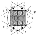
図7のA)は、ここで想定される平面状ASGを中心の周りの四象限として配置された4つの副格子を有するものとして示している。先のように、中心格子は存在しない。当該格子は4つの線源ラインを定め、これら線源ラインは長方形等の四角形、又は特にこのケースでは正方形を形成するように交差する。図7のB)~図7のD)は、対応する線源sjにより生成される異なる照射領域bjを示す。線源s8及びs2並びに線源s6及びs4は線源ラインの交点に配置され、従って、これら線源の各ビームは共同フィルタリングのために異なる副格子の異なる部分を使用する。例えば、線源s8は副格子M2及びM3を照射する一方、線源2は副格子M1,M4を照射し、等々となる。図7のB)に示されるように、線源s1、s3、s9及びs7に関しては、格子共有は存在しない。照射される領域b1、b7、b9及びb3は照射される副格子領域と同じ拡がりを有するが、このことは,非格子共有照射においても、例えば図5のB)に示されるように(線源s12の照射領域b12は副格子M2の全領域より小さい)全ての実施態様において必ずしもそうである必要はない。
A) of FIG. 7 shows the planar ASG assumed here as having four sub-lattices arranged as four quadrants around the center. As before, there is no central grid. The grid defines four source lines, which intersect to form a quadrangle, such as a rectangle, or, in this case, a square. B) of FIG. 7 to D) of FIG. 7 show different irradiation regions bj generated by the corresponding radiation source sj. Sources s8 and s2 and sources s6 and s4 are located at the intersections of the source lines, so each beam of these sources uses different parts of different sublattices for co-filtering. For example, the radiation source s8 irradiates the sub-lattices M2 and M3, while the
図8は、8個の線源s1~s8(図8では、sjとして示されている)を有する線源構成のASGの中心軸Zに沿う上からの平面図である。これらは2つの正方形に配置され、4つの線源の2つの組は、各々、斯かる2つの正方形の各頂点を定めている。該2つの正方形の副構造は互いに対して軸Zの回りに約10°~15°回転され、図8に示された構成を得ている。3以上の正方形から形成される構成及び/又は2以上の正方形が互いに対して何らかの他の角度で回転される場合等の、上記の変形例も考えられる。しかしながら、上記の何れも正方形に限定されるものではない。ここでは、頂点の数が3以上である如何なる他の多角形線源配置(三角形、五角形等)も考えられるからである。必ずしもではないが、好ましくは、前述した理由により少なくとも準等方性線源幾何学構成を達成するために該多角形は規則的(例えば、前述した正方形、二等辺三角形等)とする。 FIG. 8 is a plan view from above along the central axis Z of the ASG having a radiation source configuration having eight radiation sources s1 to s8 (indicated as sj in FIG. 8). They are arranged in two squares, and two sets of four sources each define each vertex of such two squares. The two square substructures are rotated about 10 ° to 15 ° about axis Z with respect to each other to obtain the configuration shown in FIG. The above modification is also conceivable, such as a configuration formed from three or more squares and / or a case where two or more squares are rotated at some other angle with respect to each other. However, none of the above is limited to a square. This is because any other polygonal source arrangement (triangle, pentagon, etc.) with three or more vertices can be considered here. Preferably, but not necessarily, the polygon is regular (eg, square, isosceles triangle, etc., described above) to achieve at least a quasi-isotropic source geometry for the reasons described above.
図3~図7,図8の上記実施態様の全てにおいて、当該ASGが平面状である(即ち、全てのモジュールが共通面内に位置する)場合、全てのモジュールが対称というわけではない。少なくとも1つの(前記実施態様におけるように、4等)非対称な格子(又は複数の格子)が存在する。しかしながら、少なくとも部分的に湾曲され、全ての副格子Mjが対称であるような他の実施態様も考えられる。このことは、非常にコンパクトなフットプリントを達成することを可能にする。この構成は、移動式(例えば、車輪付)X線撮像器にとり有利であり得る。 In all of the above embodiments of FIGS. 3-7, 8, if the ASG is planar (ie, all modules are located in a common plane), not all modules are symmetrical. There is at least one (4, etc.) asymmetric grid (or grids, as in the embodiment). However, other embodiments are also conceivable such that they are at least partially curved and all sublattices Mj are symmetric. This makes it possible to achieve a very compact footprint. This configuration may be advantageous for mobile (eg, with wheels) X-ray imagers.
ここに提案されるASGの製造は、一般的に、使用されるべき当該撮像器の撮像幾何学構成の仕様を必要とする。特に、当該撮像器の寸法及び該撮像器のフットプリントが分からねばならない。更に詳細には、周辺X線源の概略配置及びAPビューが必要とされるかが分からねばならない。また、X線源に対する検出器の位置も分からねばならない。これらの幾何学構造的仕様が与えられた場合、必要とされる線源ラインを計算することができ、これらを、副格子を製造するために用いることができる。3Dにおける線源ラインの位置から、必要とされる傾斜角、特に細条の最大傾斜角を計算することができる。 The manufacture of ASG proposed herein generally requires specifications of the imaging geometry of the imager to be used. In particular, the dimensions of the imager and the footprint of the imager must be known. In more detail, it must be known whether a schematic layout of peripheral X-ray sources and an AP view are required. You also need to know the position of the detector with respect to the X-ray source. Given these geometrical specifications, the required source lines can be calculated and these can be used to make sublattices. From the position of the source line in 3D, the required tilt angle, especially the maximum tilt angle of the strips, can be calculated.
一実施態様において、前記細条はモノリシック構造として構成され、異なるモジュールにおける細条は、曲げられる1つの連続した超細条の一部であり、必要とされるパターンを配置するために角度付けされる。この形状は、完成したASGを得るために充填材料により充填される。半モノリシック的方法においては、複数の細条が、累進的に増加する寸法の一連の入れ子状の多角形状に形成される。 In one embodiment, the strips are configured as a monolithic structure, the strips in different modules are part of one continuous ultra-stripe that is bent and angled to place the required pattern. Ru. This shape is filled with a filling material to obtain the finished ASG. In the semi-monolithic method, multiple strips are formed into a series of nested polygonal shapes with progressively increasing dimensions.
しかしながら、好ましくは、当該格子は、各々が所要に応じて角度付けされ且つ充填材料により分離された一連の細条により別個に作製された所望の数の副格子から製造されるものとする。このように形成された副格子は、次いで、それらの縁部において結合され(接着される等)て、複合ASGを形成する。言い換えると、当該ASGは副格子のアセンブリである。好ましくは、副格子は異なる組の隣接する細条の間に間隙が存在しないように結合され、フィルタリングされていない放射線の通過を防止するために、これらは半田付け等により接続することが好ましい。 However, preferably, the lattice is made from a desired number of sub-lattices, each angled as required and separately made of a series of strips separated by a filling material. The sublattices thus formed are then combined (glued, etc.) at their edges to form a composite ASG. In other words, the ASG is an assembly of sub-lattices. Preferably, the sublattices are coupled so that there are no gaps between different sets of adjacent strips, which are preferably connected by soldering or the like to prevent the passage of unfiltered radiation.
副格子を作製する1つの方法は、自身の辺の1つに隆起された肩部を備える平面状の作業プレートを使用することである。次いで、X線不透過性細条STjが、この肩部に当接されて緩衝細条と交互の態様で積み上げられ、副格子を構築する。この細条系を一緒に接着するために、上記緩衝細条/X線不透過性細条の界面に接着剤が介挿される。次いで、細条積層体は作業プレートから解放され、所望の寸法に(必要なら)切断されて、ASG格子モジュールMjを得る。被着の前又は後に、前記充填細条は切断工具により適切な角度で切断され、前記X線不透過性細条STjが次いで被着される角度付けされた面を形成しなければならず、かくして当該細条の角度付けを実行する。他の例として且つ好ましくは、前記充填細条及びX線不透過性細条を結合するために十分な厚さ及び柔軟性の接着層が塗布され、次いで各細条の斯かる細条の中間の隣接する細条に対する僅かな角度付けを可能にするのは、この接着層である。 One way to make a sub-grid is to use a planar working plate with a raised shoulder on one of its sides. The X-ray opaque streaks STj are then abutted against the shoulders and stacked alternately with the buffer streaks to form a sublattice. In order to bond the strips together, an adhesive is interposed at the interface of the buffered strips / X-ray opaque strips. The strip laminate is then released from the working plate and cut to the desired dimensions (if necessary) to give the ASG grid module Mj. Before or after attachment, the fill strip must be cut at an appropriate angle by a cutting tool to form an angled surface to which the X-ray opaque strip STj is then adhered. Thus, the angle of the strip is performed. As another example and preferably, an adhesive layer of sufficient thickness and flexibility is applied to bond the filled strips and the X-ray opaque strips, and then in the middle of the strips of each strip. It is this adhesive layer that allows for a slight angle to the adjacent strips of.
本発明の実施態様が異なる主題に関して説明されたことに注意すべきである。特に、幾つかの実施態様は方法のタイプの請求項に関して説明され、他の実施態様は装置のタイプの実施態様に関して説明されている。しかしながら、当業者であれば、上記及び下記の記載から、そうでないと注記しない限り、1つのタイプの主題に属するフィーチャの如何なる組み合わせにも加えて、異なる主題に関するフィーチャの間の如何なる組み合わせも、この出願により開示されていると見なされることが分かるであろう。しかしながら、全てのフィーチャは、これらフィーチャの単なる寄せ集め以上の相乗効果を呈するように組み合わせることができるものである。 It should be noted that embodiments of the present invention have been described with respect to different subjects. In particular, some embodiments are described with respect to method type claims and other embodiments are described with respect to device type embodiments. However, one of ordinary skill in the art would appreciate any combination of features belonging to one type of subject, as well as any combination of features relating to different subjects, unless otherwise noted from the above and below statements. You will find that it is considered to be disclosed by the application. However, all features can be combined to create a synergistic effect that goes beyond just a jumble of these features.
以上、本発明を図面及び上記記載において詳細に図示及び説明したが、このような図示及び説明は解説的又は例示的なもので限定するものではないと見なされるべきである。即ち、本発明は開示された実施態様に限定されるものではない。開示された実施態様に対する他の変形例は、当業者によれば、請求項に記載の本発明を実施するに際して当該図面、開示内容及び従属請求項の精査から理解し、実施することができるものである。 Although the present invention has been illustrated and described in detail in the drawings and the above description, such illustration and description should be regarded as being explanatory or exemplary and not limiting. That is, the present invention is not limited to the disclosed embodiments. Other modifications to the disclosed embodiments can be understood and implemented by those skilled in the art from scrutiny of the drawings, disclosure content and dependent claims in carrying out the invention described in the claims. Is.
尚、請求項において、“有する”なる文言は他の要素又はステップを排除するものではなく、単数形は複数を排除するものではない。また、単一のプロセッサ又は他のユニットは、請求項に記載された幾つかの項目の機能を満たすことができる。また、特定の手段が互いに異なる従属請求項に記載されているという単なる事実は、これら手段の組み合わせを有利に用いることができないということを示すものではない。また、請求項における如何なる符号も、当該範囲を限定するものと見なしてはならない。 It should be noted that in the claims, the word "have" does not exclude other elements or steps, and the singular does not exclude plurals. Also, a single processor or other unit may fulfill the functions of some of the items described in the claims. Also, the mere fact that certain means are described in different dependent claims does not indicate that the combination of these means cannot be used in an advantageous manner. Also, any code in the claims shall not be considered to limit the scope.
Claims (14)
Applications Claiming Priority (3)
| Application Number | Priority Date | Filing Date | Title |
|---|---|---|---|
| EP16172577 | 2016-06-02 | ||
| EP16172577.5 | 2016-06-02 | ||
| PCT/EP2017/063396 WO2017207734A1 (en) | 2016-06-02 | 2017-06-01 | X-ray imaging apparatus for compact (quasi-)isotropic multi source x-ray imaging |
Publications (3)
| Publication Number | Publication Date |
|---|---|
| JP2019517320A JP2019517320A (en) | 2019-06-24 |
| JP2019517320A5 JP2019517320A5 (en) | 2020-07-16 |
| JP7025352B2 true JP7025352B2 (en) | 2022-02-24 |
Family
ID=56098100
Family Applications (1)
| Application Number | Title | Priority Date | Filing Date |
|---|---|---|---|
| JP2018563125A Active JP7025352B2 (en) | 2016-06-02 | 2017-06-01 | X-ray imaging device for compact (pseudo) isotropic multi-source X-ray imaging |
Country Status (5)
| Country | Link |
|---|---|
| US (1) | US11058375B2 (en) |
| EP (1) | EP3463090B1 (en) |
| JP (1) | JP7025352B2 (en) |
| CN (1) | CN109195525B (en) |
| WO (1) | WO2017207734A1 (en) |
Cited By (1)
| Publication number | Priority date | Publication date | Assignee | Title |
|---|---|---|---|---|
| KR101164490B1 (en) | 2012-04-25 | 2012-07-18 | 주식회사 드림앤첼린지 | Bicycle transmission |
Families Citing this family (5)
| Publication number | Priority date | Publication date | Assignee | Title |
|---|---|---|---|---|
| US11051771B2 (en) | 2014-06-17 | 2021-07-06 | Xintek, Inc. | Stationary intraoral tomosynthesis imaging systems, methods, and computer readable media for three dimensional dental imaging |
| EP3498171A1 (en) * | 2017-12-15 | 2019-06-19 | Koninklijke Philips N.V. | Single shot x-ray phase-contrast and dark field imaging |
| JP7282334B2 (en) | 2018-10-26 | 2023-05-29 | サラウンド メディカル システムズ インコーポレイテッド | Intraoral tomosynthesis radiography device, system and method with replaceable collimator |
| CN111657979A (en) * | 2019-03-08 | 2020-09-15 | 江苏一影医疗设备有限公司 | CT imaging system and imaging method thereof |
| US11771387B2 (en) * | 2020-01-29 | 2023-10-03 | Aixscan Inc. | Fast 3D radiography using multiple pulsed X-ray sources in motion |
Citations (3)
| Publication number | Priority date | Publication date | Assignee | Title |
|---|---|---|---|---|
| JP2010540063A (en) | 2007-10-01 | 2010-12-24 | コーニンクレッカ フィリップス エレクトロニクス エヌ ヴィ | Computed tomography equipment |
| JP2011174715A (en) | 2010-02-23 | 2011-09-08 | Canon Inc | X-ray imaging device |
| JP2014500947A (en) | 2010-10-19 | 2014-01-16 | コーニンクレッカ フィリップス エヌ ヴェ | Differential phase contrast imaging |
Family Cites Families (23)
| Publication number | Priority date | Publication date | Assignee | Title |
|---|---|---|---|---|
| DE545048C (en) | 1927-04-20 | 1932-02-24 | Gaiffe Gallot Et Pilon Sa Ets | Aperture for X-ray apparatus |
| JP3730319B2 (en) * | 1996-06-21 | 2006-01-05 | 株式会社東芝 | X-ray computed tomography system |
| GB9904692D0 (en) * | 1999-03-01 | 1999-04-21 | Isis Innovation | X-ray image processing |
| US6222904B1 (en) * | 1999-07-22 | 2001-04-24 | Canon Kabushiki Kaisha | Stereo x-ray anti-scatter grid |
| US6438210B1 (en) * | 2000-03-28 | 2002-08-20 | General Electric Company | Anti-scatter grid, method, and apparatus for forming same |
| US6470072B1 (en) * | 2000-08-24 | 2002-10-22 | General Electric Company | X-ray anti-scatter grid |
| US6987836B2 (en) | 2001-02-01 | 2006-01-17 | Creatv Microtech, Inc. | Anti-scatter grids and collimator designs, and their motion, fabrication and assembly |
| DE10136946A1 (en) | 2001-07-28 | 2003-02-06 | Philips Corp Intellectual Pty | Scattered radiation grid for an X-ray device |
| ATE492887T1 (en) | 2005-09-19 | 2011-01-15 | Koninkl Philips Electronics Nv | GRID FOR SELECTIVE ABSORPTION OF ELECTROMAGNETIC RADIATION AND PROCESS FOR PRODUCTION THEREOF |
| US20100189211A1 (en) * | 2007-07-11 | 2010-07-29 | Koninklijke Philips Electronics N.V. | X-ray souce for measuring radiation |
| DE112008001902T5 (en) * | 2007-07-19 | 2010-10-14 | North Carolina State University | Stationary Digital X-Ray Breast Tomosynthesis Systems and Related Procedures |
| DE102007058986B3 (en) | 2007-12-07 | 2009-07-30 | Siemens Ag | Anti-scatter grid and method of manufacture |
| US20100246753A1 (en) | 2009-03-25 | 2010-09-30 | Varian Medical Systems, Inc. | Fourth Generation Computed Tomography Scanner |
| JP5460106B2 (en) * | 2009-04-03 | 2014-04-02 | キヤノン株式会社 | X-ray imaging apparatus, control method therefor, and computer program |
| WO2010133920A1 (en) * | 2009-05-20 | 2010-11-25 | Koninklijke Philips Electronics N.V. | Anti-scatter arrangement for a radiation detector |
| FR2953320B1 (en) | 2009-11-27 | 2013-07-05 | Gen Electric | REVERSE ANTI-DIFFUSING GRID |
| US9048002B2 (en) | 2010-10-08 | 2015-06-02 | Turtle Bay Partners, Llc | Three-dimensional focused anti-scatter grid and method for manufacturing thereof |
| JP2012130586A (en) * | 2010-12-22 | 2012-07-12 | Fujifilm Corp | X-ray image detecting apparatus, radiographing apparatus, and radiographing system |
| US9901315B2 (en) * | 2013-03-15 | 2018-02-27 | Hologic, Inc. | X-ray scatter reducing device for use with 2D mammography and tomosynthesis |
| US20170206996A1 (en) * | 2014-07-23 | 2017-07-20 | Turtle Bay Partners,LLC | Practical method for fabricating foam interspaced anti-scatter grid and improved grids |
| CN109314754B (en) | 2016-02-23 | 2021-07-20 | 皇家飞利浦有限公司 | Device, X-ray detector and method for imaging an object |
| US10062466B2 (en) * | 2016-03-31 | 2018-08-28 | General Electric Company | Apparatus, system and method for reducing radiation scatter in an imaging system |
| US10881365B2 (en) | 2016-05-13 | 2021-01-05 | Koninklijke Philips N.V. | System and method for multi-beam X-ray exposure for 4D imaging |
-
2017
- 2017-06-01 CN CN201780033259.8A patent/CN109195525B/en active Active
- 2017-06-01 WO PCT/EP2017/063396 patent/WO2017207734A1/en unknown
- 2017-06-01 JP JP2018563125A patent/JP7025352B2/en active Active
- 2017-06-01 EP EP17727868.6A patent/EP3463090B1/en active Active
- 2017-06-01 US US16/305,904 patent/US11058375B2/en active Active
Patent Citations (3)
| Publication number | Priority date | Publication date | Assignee | Title |
|---|---|---|---|---|
| JP2010540063A (en) | 2007-10-01 | 2010-12-24 | コーニンクレッカ フィリップス エレクトロニクス エヌ ヴィ | Computed tomography equipment |
| JP2011174715A (en) | 2010-02-23 | 2011-09-08 | Canon Inc | X-ray imaging device |
| JP2014500947A (en) | 2010-10-19 | 2014-01-16 | コーニンクレッカ フィリップス エヌ ヴェ | Differential phase contrast imaging |
Cited By (1)
| Publication number | Priority date | Publication date | Assignee | Title |
|---|---|---|---|---|
| KR101164490B1 (en) | 2012-04-25 | 2012-07-18 | 주식회사 드림앤첼린지 | Bicycle transmission |
Also Published As
| Publication number | Publication date |
|---|---|
| CN109195525A (en) | 2019-01-11 |
| EP3463090B1 (en) | 2020-01-01 |
| EP3463090A1 (en) | 2019-04-10 |
| US11058375B2 (en) | 2021-07-13 |
| WO2017207734A1 (en) | 2017-12-07 |
| JP2019517320A (en) | 2019-06-24 |
| CN109195525B (en) | 2023-09-08 |
| US20200315559A1 (en) | 2020-10-08 |
Similar Documents
| Publication | Publication Date | Title |
|---|---|---|
| JP7025352B2 (en) | X-ray imaging device for compact (pseudo) isotropic multi-source X-ray imaging | |
| US6894281B2 (en) | Grid for the absorption of X-rays | |
| JP6488292B2 (en) | X-ray system such as a tomosynthesis system and method for acquiring an image of an object | |
| US10393890B2 (en) | X-ray imaging device | |
| RU2662074C1 (en) | Dual-energy differential phase-contrast imaging | |
| KR102179319B1 (en) | Mammography imaging arrangement for tomosynthesis | |
| CN105427914B (en) | For manufacturing the method and collimator of collimator and collimator bridge | |
| JP6820870B2 (en) | Scanning X-ray device with full field detector | |
| CN1672039A (en) | Anti-scattering X-ray shielding for CT scanners | |
| CN105534535B (en) | Device and method for X-ray phase contrast | |
| JPH01500968A (en) | Tomographic image forming method and device | |
| US9924911B2 (en) | Tomosynthesis collimation | |
| KR20160061998A (en) | X-ray imaging apparatus | |
| JP2019517320A5 (en) | ||
| JP2016030215A (en) | CT detector | |
| JP2024026391A (en) | X-ray detector with focused scintillator structure for uniform imaging | |
| JP7385564B2 (en) | X-ray imaging device | |
| WO2012053342A1 (en) | Grid for radiation imaging, method for manufacturing same, and radiation imaging system | |
| WO2012053368A1 (en) | Grid for radiation imaging, method for manufacturing same, and radiation imaging system | |
| US11249034B2 (en) | X-ray Talbot capturing apparatus | |
| WO2012147749A1 (en) | Radiography system and radiography method | |
| JP2012228369A (en) | Radiographic system, and radiographic method | |
| JPS61159179A (en) | Ect collimator | |
| WO2012133553A1 (en) | Radiography system and radiography method | |
| JP6696296B2 (en) | Talbot photography device |
Legal Events
| Date | Code | Title | Description |
|---|---|---|---|
| A521 | Request for written amendment filed |
Free format text: JAPANESE INTERMEDIATE CODE: A523 Effective date: 20200529 |
|
| A621 | Written request for application examination |
Free format text: JAPANESE INTERMEDIATE CODE: A621 Effective date: 20200529 |
|
| A977 | Report on retrieval |
Free format text: JAPANESE INTERMEDIATE CODE: A971007 Effective date: 20210324 |
|
| A131 | Notification of reasons for refusal |
Free format text: JAPANESE INTERMEDIATE CODE: A131 Effective date: 20210401 |
|
| A601 | Written request for extension of time |
Free format text: JAPANESE INTERMEDIATE CODE: A601 Effective date: 20210629 |
|
| A521 | Request for written amendment filed |
Free format text: JAPANESE INTERMEDIATE CODE: A523 Effective date: 20210929 |
|
| TRDD | Decision of grant or rejection written | ||
| A01 | Written decision to grant a patent or to grant a registration (utility model) |
Free format text: JAPANESE INTERMEDIATE CODE: A01 Effective date: 20220114 |
|
| A61 | First payment of annual fees (during grant procedure) |
Free format text: JAPANESE INTERMEDIATE CODE: A61 Effective date: 20220210 |
|
| R150 | Certificate of patent or registration of utility model |
Ref document number: 7025352 Country of ref document: JP Free format text: JAPANESE INTERMEDIATE CODE: R150 |