JP7024732B2 - Display device - Google Patents
Display device Download PDFInfo
- Publication number
- JP7024732B2 JP7024732B2 JP2018558878A JP2018558878A JP7024732B2 JP 7024732 B2 JP7024732 B2 JP 7024732B2 JP 2018558878 A JP2018558878 A JP 2018558878A JP 2018558878 A JP2018558878 A JP 2018558878A JP 7024732 B2 JP7024732 B2 JP 7024732B2
- Authority
- JP
- Japan
- Prior art keywords
- exciters
- display cell
- exciter
- display
- display device
- Prior art date
- Legal status (The legal status is an assumption and is not a legal conclusion. Google has not performed a legal analysis and makes no representation as to the accuracy of the status listed.)
- Active
Links
Images


Classifications
-
- H—ELECTRICITY
- H04—ELECTRIC COMMUNICATION TECHNIQUE
- H04R—LOUDSPEAKERS, MICROPHONES, GRAMOPHONE PICK-UPS OR LIKE ACOUSTIC ELECTROMECHANICAL TRANSDUCERS; DEAF-AID SETS; PUBLIC ADDRESS SYSTEMS
- H04R1/00—Details of transducers, loudspeakers or microphones
- H04R1/02—Casings; Cabinets ; Supports therefor; Mountings therein
- H04R1/028—Casings; Cabinets ; Supports therefor; Mountings therein associated with devices performing functions other than acoustics, e.g. electric candles
-
- H—ELECTRICITY
- H04—ELECTRIC COMMUNICATION TECHNIQUE
- H04R—LOUDSPEAKERS, MICROPHONES, GRAMOPHONE PICK-UPS OR LIKE ACOUSTIC ELECTROMECHANICAL TRANSDUCERS; DEAF-AID SETS; PUBLIC ADDRESS SYSTEMS
- H04R7/00—Diaphragms for electromechanical transducers; Cones
- H04R7/02—Diaphragms for electromechanical transducers; Cones characterised by the construction
- H04R7/04—Plane diaphragms
-
- G—PHYSICS
- G09—EDUCATION; CRYPTOGRAPHY; DISPLAY; ADVERTISING; SEALS
- G09F—DISPLAYING; ADVERTISING; SIGNS; LABELS OR NAME-PLATES; SEALS
- G09F9/00—Indicating arrangements for variable information in which the information is built-up on a support by selection or combination of individual elements
-
- H—ELECTRICITY
- H04—ELECTRIC COMMUNICATION TECHNIQUE
- H04M—TELEPHONIC COMMUNICATION
- H04M1/00—Substation equipment, e.g. for use by subscribers
- H04M1/02—Constructional features of telephone sets
- H04M1/03—Constructional features of telephone transmitters or receivers, e.g. telephone hand-sets
- H04M1/035—Improving the acoustic characteristics by means of constructional features of the housing, e.g. ribs, walls, resonating chambers or cavities
-
- H—ELECTRICITY
- H04—ELECTRIC COMMUNICATION TECHNIQUE
- H04R—LOUDSPEAKERS, MICROPHONES, GRAMOPHONE PICK-UPS OR LIKE ACOUSTIC ELECTROMECHANICAL TRANSDUCERS; DEAF-AID SETS; PUBLIC ADDRESS SYSTEMS
- H04R1/00—Details of transducers, loudspeakers or microphones
- H04R1/02—Casings; Cabinets ; Supports therefor; Mountings therein
-
- H—ELECTRICITY
- H04—ELECTRIC COMMUNICATION TECHNIQUE
- H04R—LOUDSPEAKERS, MICROPHONES, GRAMOPHONE PICK-UPS OR LIKE ACOUSTIC ELECTROMECHANICAL TRANSDUCERS; DEAF-AID SETS; PUBLIC ADDRESS SYSTEMS
- H04R7/00—Diaphragms for electromechanical transducers; Cones
- H04R7/02—Diaphragms for electromechanical transducers; Cones characterised by the construction
- H04R7/04—Plane diaphragms
- H04R7/045—Plane diaphragms using the distributed mode principle, i.e. whereby the acoustic radiation is emanated from uniformly distributed free bending wave vibration induced in a stiff panel and not from pistonic motion
-
- H—ELECTRICITY
- H04—ELECTRIC COMMUNICATION TECHNIQUE
- H04R—LOUDSPEAKERS, MICROPHONES, GRAMOPHONE PICK-UPS OR LIKE ACOUSTIC ELECTROMECHANICAL TRANSDUCERS; DEAF-AID SETS; PUBLIC ADDRESS SYSTEMS
- H04R9/00—Transducers of moving-coil, moving-strip, or moving-wire type
- H04R9/02—Details
-
- H—ELECTRICITY
- H04—ELECTRIC COMMUNICATION TECHNIQUE
- H04R—LOUDSPEAKERS, MICROPHONES, GRAMOPHONE PICK-UPS OR LIKE ACOUSTIC ELECTROMECHANICAL TRANSDUCERS; DEAF-AID SETS; PUBLIC ADDRESS SYSTEMS
- H04R9/00—Transducers of moving-coil, moving-strip, or moving-wire type
- H04R9/02—Details
- H04R9/022—Cooling arrangements
-
- H—ELECTRICITY
- H04—ELECTRIC COMMUNICATION TECHNIQUE
- H04R—LOUDSPEAKERS, MICROPHONES, GRAMOPHONE PICK-UPS OR LIKE ACOUSTIC ELECTROMECHANICAL TRANSDUCERS; DEAF-AID SETS; PUBLIC ADDRESS SYSTEMS
- H04R9/00—Transducers of moving-coil, moving-strip, or moving-wire type
- H04R9/02—Details
- H04R9/025—Magnetic circuit
-
- H—ELECTRICITY
- H04—ELECTRIC COMMUNICATION TECHNIQUE
- H04R—LOUDSPEAKERS, MICROPHONES, GRAMOPHONE PICK-UPS OR LIKE ACOUSTIC ELECTROMECHANICAL TRANSDUCERS; DEAF-AID SETS; PUBLIC ADDRESS SYSTEMS
- H04R9/00—Transducers of moving-coil, moving-strip, or moving-wire type
- H04R9/06—Loudspeakers
-
- H—ELECTRICITY
- H04—ELECTRIC COMMUNICATION TECHNIQUE
- H04R—LOUDSPEAKERS, MICROPHONES, GRAMOPHONE PICK-UPS OR LIKE ACOUSTIC ELECTROMECHANICAL TRANSDUCERS; DEAF-AID SETS; PUBLIC ADDRESS SYSTEMS
- H04R9/00—Transducers of moving-coil, moving-strip, or moving-wire type
- H04R9/06—Loudspeakers
- H04R9/066—Loudspeakers using the principle of inertia
-
- H—ELECTRICITY
- H04—ELECTRIC COMMUNICATION TECHNIQUE
- H04R—LOUDSPEAKERS, MICROPHONES, GRAMOPHONE PICK-UPS OR LIKE ACOUSTIC ELECTROMECHANICAL TRANSDUCERS; DEAF-AID SETS; PUBLIC ADDRESS SYSTEMS
- H04R2201/00—Details of transducers, loudspeakers or microphones covered by H04R1/00 but not provided for in any of its subgroups
- H04R2201/003—Mems transducers or their use
-
- H—ELECTRICITY
- H04—ELECTRIC COMMUNICATION TECHNIQUE
- H04R—LOUDSPEAKERS, MICROPHONES, GRAMOPHONE PICK-UPS OR LIKE ACOUSTIC ELECTROMECHANICAL TRANSDUCERS; DEAF-AID SETS; PUBLIC ADDRESS SYSTEMS
- H04R2499/00—Aspects covered by H04R or H04S not otherwise provided for in their subgroups
- H04R2499/10—General applications
- H04R2499/15—Transducers incorporated in visual displaying devices, e.g. televisions, computer displays, laptops
Landscapes
- Engineering & Computer Science (AREA)
- Physics & Mathematics (AREA)
- Acoustics & Sound (AREA)
- Signal Processing (AREA)
- Multimedia (AREA)
- General Physics & Mathematics (AREA)
- Theoretical Computer Science (AREA)
- Diaphragms For Electromechanical Transducers (AREA)
- Details Of Audible-Bandwidth Transducers (AREA)
- Audible-Bandwidth Dynamoelectric Transducers Other Than Pickups (AREA)
Description
本開示は、表示装置に関する。 The present disclosure relates to a display device.
ディスプレイの薄型軽量化が急激な伸長を遂げている。それに伴い、スピーカについても薄型軽量化が進み、コーン型スピーカに代わって、フラットパネルスピーカ(FPS)を用いることが提案されている。さらに、フラットパネルスピーカにおける振動板として、ディスプレイパネルを用いることも提案されている。フラットパネルスピーカについては、例えば、特許文献1~3参照に開示されている。
The thinness and weight reduction of displays have achieved rapid growth. Along with this, the speakers have become thinner and lighter, and it has been proposed to use a flat panel speaker (FPS) instead of the cone type speaker. Further, it has been proposed to use a display panel as a diaphragm in a flat panel speaker. The flat panel speaker is disclosed, for example, in
しかし、従来では、フラットパネルスピーカにおける振動板として、ディスプレイパネルを用いた場合に、表示映像に色ムラが生じる場合があった。従って、表示映像の色ムラを抑えることの可能な表示装置を提供することが望ましい。 However, conventionally, when a display panel is used as a diaphragm in a flat panel speaker, color unevenness may occur in the displayed image. Therefore, it is desirable to provide a display device capable of suppressing color unevenness of the displayed image.
本開示の一実施形態に係る表示装置は、映像を表示する薄板状の表示セルと、表示セルの裏面側に配置され、表示セルを振動させる複数の加振器とを備えている。複数の加振器は、当該複数の加振器により表示セルに振動を発生させたときに当該複数の加振器が1つの加振器とみなされるように構成されている。 The display device according to the embodiment of the present disclosure includes a thin plate-shaped display cell for displaying an image, and a plurality of vibrators arranged on the back surface side of the display cell to vibrate the display cell. The plurality of exciters are configured so that the plurality of vibrators are regarded as one exciter when the display cell is vibrated by the plurality of vibrators.
本開示の一実施形態に係る表示装置では、表示セルの裏面側に配置された複数の加振器が、当該複数の加振器により表示セルに振動を発生させたときに当該複数の加振器が1つの加振器とみなされるように構成されている。これにより、音質への影響を抑えつつ、各加振器で発生した熱が一か所に集中せず、ある程度分散する。 In the display device according to the embodiment of the present disclosure, when a plurality of vibrators arranged on the back surface side of the display cell generate vibration in the display cell by the plurality of vibrators, the plurality of vibrations are vibrated. The device is configured to be considered as one exciter. As a result, the heat generated by each exciter is not concentrated in one place and is dispersed to some extent while suppressing the influence on the sound quality.
本開示の一実施形態に係る表示装置によれば、音質への影響を抑えつつ、各加振器で発生した熱が一か所に集中せず、ある程度分散するようにしたので、熱の局所的な分布に起因する表示映像の色ムラを抑えることができる。なお、本技術の効果は、ここに記載された効果に必ずしも限定されず、本明細書中に記載されたいずれの効果であってもよい。 According to the display device according to the embodiment of the present disclosure, the heat generated by each vibrating device is not concentrated in one place but dispersed to some extent while suppressing the influence on the sound quality. It is possible to suppress color unevenness of the displayed image due to a specific distribution. The effect of the present technology is not necessarily limited to the effect described here, and may be any effect described in the present specification.
以下、本開示を実施するための形態について、図面を参照して詳細に説明する。以下の説明は本開示の一具体例であって、本開示は以下の態様に限定されるものではない。 Hereinafter, embodiments for carrying out the present disclosure will be described in detail with reference to the drawings. The following description is a specific example of the present disclosure, and the present disclosure is not limited to the following aspects.
<1.第1の実施の形態>
[構成]
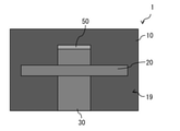
本開示の第1の実施の形態に係る表示装置1について説明する。図1は、本実施の形態に係る表示装置1の側面構成例を表したものである。図2は、図1の表示装置1の背面構成例を表したものである。表示装置1は、映像表示面10Aに映像を表示するとともに、映像表示面10Aから音声を出力する。言い換えると、表示装置1は、フラットパネルスピーカを映像表示面10Aに内蔵しているとも言える。<1. First Embodiment>
[Constitution]
The
表示装置1は、例えば、映像を表示するとともに振動板としても機能するパネル部10と、パネル部10の裏面に配置され、パネル部10を振動させる加振部20とを備えている。表示装置1は、さらに、例えば、加振部20を制御する信号処理部30と、パネル部10を、回動部50を介して支持する支持部40とを備えている。回動部50は、支持部40によってパネル部10の裏面を支持するときのパネル部10の傾斜角を調整するためのものであり、例えば、パネル部10および支持部40を回動可能に支持するヒンジによって構成されている。
The
加振部20および信号処理部30は、パネル部10の裏面に配置されている。パネル部10は、パネル部10の裏面側に、パネル部10、加振部20および信号処理部30を保護するバックシャーシ19を有している。バックシャーシ19は、例えば、板状の金属板もしくは樹脂板によって構成されている。バックシャーシ19が、回動部50に連結されている。
The
図3は、バックシャーシ19を取り外したときの、表示装置1の背面の構成例を表したものである。図4は、図3のA-A線での断面構成例を表したものである。図5は、図3のB-B線での断面構成例を表したものである。なお、図5には、後述の加振器21(アクチュエータ)付近の断面構成が例示されているが、この断面構成は、他の加振器(例えば加振器22(アクチュエータ))付近の断面構成と同様の断面構成となっているものとする。
FIG. 3 shows a configuration example of the back surface of the
パネル部10は、例えば、映像を表示する薄板状の表示セル11と、空隙15を介して表示セル11と対向配置されたインナープレート12(対向プレート)とを有している。表示セル11の表面(加振部20とは反対側の表面)が映像表示面10Aとなっている。表示セル11は、例えば、マトリクス状に配置された複数の表示画素を有している。複数の表示画素は、例えば、表示セル11に設けられたガラス基板によって支持されている。つまり、表示セル11は、例えば、ガラス基板を含んで構成されている。パネル部10は、さらに、例えば、インナープレート12の裏面に接して配置されたガラス基板13と、表示セル11とインナープレート12との間に配置された固定部材14とを有している。
The
固定部材14は、表示セル11とインナープレート12とを互いに固定する機能と、空隙15を維持するスペーサとしての機能とを有している。固定部材14は、例えば、表示セル11の外縁に沿って配置されている。固定部材14は、例えば、表示セル11が振動している時に表示セル11の端縁が自由端として振る舞える程度の柔軟性を有していてもよい。固定部材14は、例えば、両面に接着層を有するスポンジによって構成されている。
The fixing
インナープレート12は、後述の加振器21,22を支持する基板である。インナープレート12は、例えば、加振器21,22を設置する箇所に開口を有している。ガラス基板13は、インナープレート12よりも高い剛性を有しており、インナープレート12の撓みもしくは振動を抑える役割を有している。ガラス基板13は、インナープレート12の開口と対向する位置に開口を有している。ガラス基板13に設けられた開口は、加振器21もしくは加振器22を挿通することが可能な大きさとなっている。ガラス基板13の代わりに、ガラス基板13と同等の剛性を有する樹脂基板が設けられていてもよい。
The
加振部20は、例えば、2つの加振器(加振器21,22)を有している。加振器21および加振器22は、互いに共通の構成となっている。加振器21,22は、加振器21,22により表示セル11に振動を発生させたときに音声周波数(例えば20Hz~20kHz)全体において最も振動し易い箇所を避けて配置されている。加振器21,22は、さらに、加振器21,22により表示セル11に振動を発生させたときに音声周波数全体において最も振動し難い箇所を避けて配置されている。表示セル11の振動は、例えば、レーザドップラー振動計を用いて、表示セル11の面全体の振動を音声周波数全体において計測することにより得られる。加振器21,22は、例えば、表示セル11の左右方向および上下方向において、割り切れない比率の箇所に配置されている。「割り切れない比率」の例としては、3:4、5:7、3:7、2:5、7:11などが挙げられる。
The
図6(A),図6(B)は、加振器21の一構成例を展開して表したものである。図7(A),図7(B)は、加振器21の他の構成例を展開して表したものである。図6(A),図6(B)には、加振器21が、後述の平面コイル21a2および後述の永久磁石21b2を含む微小な加振器によって構成されている場合が例示されている。図7(A),図7(B)には、加振器21が、平面コイル21a2および永久磁石21b2を含む2つの微小な加振器によって構成されている場合が例示されている。加振器21は、図6(A)、図6(B)、図7(A)、図7(B)の記載に限定されるものではなく、例えば、平面コイル21a2および永久磁石21b2を含む複数の微小な加振器によって構成されていてもよい。
6 (A) and 6 (B) show an expanded example of the configuration of the
加振器21は、表示セル11を裏面から見たときに、左寄りに配置されている。加振器22は、表示セル11を裏面から見たときに、右寄りに配置されている。加振器21,22は、それぞれ、所定の間隙を介して互いに対向配置されたプリント基板コイル21Aおよび平型マグネット21Bを有し、振動源となるスピーカ用アクチュエータである。
The
プリント基板コイル21Aは、例えば、図6(A)に示したように、1つの平面コイル21a2(ボイスコイル)が実装されたプリント基板21a1を有している。プリント基板21a1は、平面コイル21a2に接続された配線を有している。平面コイル21a2は、後述の振動伝達部材23および後述の放熱シート24を介して表示セル11の裏面に固定されている。加振器21および加振器22において、平面コイル21a2は、例えば、プリント基板21a1のうち表示セル11とは反対側の面に形成されている。平型マグネット21Bは、例えば、図6(B)に示したように、所定の間隙を介して平面コイル21a2と対向して配置された永久磁石21b2と、永久磁石21b2を支持する支持基板21b1とを有する磁気回路である
The printed
プリント基板コイル21Aは、例えば、図7(A)に示したように、複数の平面コイル21a2(ボイスコイル)が実装されたプリント基板21a1を有していてもよい。プリント基板21a1は、複数の平面コイル21a2を互いに直列に接続する配線を有している。複数の平面コイル21a2は、後述の振動伝達部材23および後述の放熱シート24を介して表示セル11の裏面に固定されている。加振器21および加振器22において、複数の平面コイル21a2は、例えば、プリント基板21a1のうち表示セル11とは反対側の面に形成されている。平型マグネット21Bは、例えば、図7(B)に示したように、所定の間隙を介して複数の平面コイル21a2と対向して配置された複数の永久磁石21b2と、複数の永久磁石21b2を支持する支持基板21b1とを有する磁気回路であってもよい。支持基板21b1上の複数の永久磁石21b2において、互いに隣接する2つの永久磁石21b2のS極とN極の向きは、互いに反対向きとなっている。
The printed
加振器21,22は、それぞれ、各平面コイル21a2に電気信号の音声電流が流れると、電磁作用の原理に従って各平面コイル21a2に駆動力を発生させる。この駆動力が後述の振動伝達部材23を介して表示セル11に伝達され、表示セル11に音声電流の変化に応じた振動を発生させ、空気が振動して音圧が変化する。
When the voice current of the electric signal flows through each of the plane coils 21a2, the
加振部20は、さらに、例えば、加振器(加振器21,22)ごとに、振動伝達部材23および放熱シート24を有している。
The
放熱シート24は、表示セル11と各加振器(加振器21および加振器22)との間に設けられている。放熱シート24は、表示セル11の裏面に貼り合わされている。放熱シート24は、加振器21もしくは加振器22から発生した熱を放散させる機能(高熱伝導性)を有しており、かつ、音の振動を表示セル11に効率良く伝えることのできる素材によって構成されていることが好ましい。放熱シート24は、例えば、金属製(例えばアルミニウム)の薄膜によって構成されている。放熱シート24は、例えば、アルミニウム合金の薄膜によって構成されている。
The
振動伝達部材23は、例えば、放熱シート24と、加振器21もしくは加振器22のプリント基板21a1とに接しており、放熱シート24と、加振器21もしくは加振器22のプリント基板21a1とに固定されている。振動伝達部材23は、少なくとも、音波領域(20Hz以上)では反発する特性を有する部材によって構成されている。振動伝達部材23は、例えば、熱硬化性樹脂、両面テープ、または、低反発ウレタンなどによって構成されている。振動伝達部材23が熱硬化性樹脂によって構成されている場合、振動伝達部材23は、例えば、各平面コイル21a2に通電することで各平面コイル21a2に熱を発生させ、その熱で熱硬化性樹脂を硬化させることにより形成される。振動伝達部材23が両面テープによって構成されている場合、振動伝達部材23は、例えば、各平面コイル21a2に一定のパルス信号を入力して、両面テープを各平面コイル21a2で強く押しつけることにより、放熱シート24と、加振器21もしくは加振器22のプリント基板21a1とに固定される。振動伝達部材23が低反発ウレタンによって構成されている場合、低反発ウレタンは、音波領域(20Hz以上)では反発する特性を有するとともに、周波数の低い領域(20Hz未満)には追随する特性を有していることが好ましい。これにより、低反発ウレタンは、音の振動を減衰させることなく、外部からの衝撃による表示セル11の変位に追随することができる。
The
[効果]
次に、本実施の形態に係る表示装置1の効果について説明する。[effect]
Next, the effect of the
ディスプレイの薄型軽量化が急激な伸長を遂げている。それに伴い、スピーカについても薄型軽量化が進み、コーン型スピーカに代わって、フラットパネルスピーカ(FPS)を用いることが提案されている。さらに、フラットパネルスピーカにおける振動板として、ディスプレイパネルを用いることも提案されている。 The thinness and weight reduction of displays have achieved rapid growth. Along with this, the speakers have become thinner and lighter, and it has been proposed to use a flat panel speaker (FPS) instead of the cone type speaker. Further, it has been proposed to use a display panel as a diaphragm in a flat panel speaker.
しかし、従来では、フラットパネルスピーカにおける振動板として、ディスプレイパネルを用いた場合に、表示映像に色ムラが生じる場合があった。 However, conventionally, when a display panel is used as a diaphragm in a flat panel speaker, color unevenness may occur in the displayed image.
一方、本実施の形態に係る表示装置1では、表示セル11の裏面側に配置された複数の加振器(加振器21もしくは加振器22内の複数の微小な加振器)が、当該複数の加振器(加振器21もしくは加振器22内の複数の微小な加振器)により表示セル11に振動を発生させたときに当該複数の加振器(加振器21もしくは加振器22内の複数の微小な加振器)が1つの加振器とみなされるように構成されている。具体的には、複数の平面コイル21a2が共通のプリント基板21a1に固定されており、そのプリント基板21a1が表示セル11の裏面に固定されている。これにより、音質への影響を抑えつつ、各加振器で発生した熱が一か所に集中せず、ある程度分散する。その結果、熱の局所的な分布に起因する表示映像の色ムラを抑えることができる。
On the other hand, in the
また、本実施の形態に係る表示装置1では、表示セル11と各加振器(加振器21および加振器22)との間に複数の放熱シート24が設けられており、さらに、各加振器(加振器21および加振器22)において、放熱シート24を介して表示セル11の裏面に複数の平面コイル21a2が設けられている。これにより、各平面コイル21a2で発生した熱が放熱シート24を介して外部に放散される。さらに、複数の平面コイル21a2が表示セル11の裏面と平行な面内に配置されるので、各平面コイル21a2で発生した熱が一か所に集中せず、ある程度分散する。その結果、熱の局所的な分布に起因する表示映像の色ムラを抑えることができる。
Further, in the
また、本実施の形態に係る表示装置1では、各加振器(加振器21および加振器22)において、複数の平面コイル21a2は、プリント基板21a1のうち表示セル11とは反対側の面に形成されている。これにより、放熱シート24と、各平面コイル21a2との間には、プリント基板21a1によって間隙が形成されるので、各平面コイル21a2に電流が流れたときに形成される磁界の通り道がプリント基板21a1によって確保される。その結果、音声出力に支障を及ぼすことなく、熱の局所的な分布に起因する表示映像の色ムラを抑えることができる。
Further, in the
<2.第1の実施の形態の変形例>
上記実施の形態において、例えば、図9、図10に示したように、支持部40および回転部50が省略されていてもよい。ただし、この場合には、表示装置1を、壁などに設けられたフックに掛けるための凹部32がバックシャーシ19に設けられていることが好ましい。<2. Modification example of the first embodiment>
In the above embodiment, for example, as shown in FIGS. 9 and 10, the
<3.第2の実施の形態>
[構成]
次に、本開示の第2の実施の形態に係る表示装置2について説明する。図11は、本実施の形態に係る表示装置2の側面構成例を表したものである。図12は、図11の表示装置2の背面構成例を表したものである。表示装置2は、映像表示面60Aに映像を表示するとともに、映像表示面60Aから音声を出力する。言い換えると、表示装置2は、フラットパネルスピーカを映像表示面60Aに内蔵しているとも言える。<3. Second Embodiment>
[Constitution]
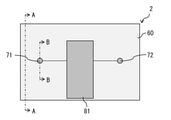
Next, the
表示装置2は、例えば、映像を表示するとともに振動板としても機能するパネル部60と、パネル部60の裏面に配置され、パネル部60を振動させる加振部70とを備えている。表示装置2は、さらに、例えば、加振部70を制御する信号処理部80と、パネル部60を、回動部100を介して支持する支持部90とを備えている。回動部100は、支持部90によってパネル部60の裏面を支持するときのパネル部60の傾斜角を調整するためのものであり、例えば、パネル部60および支持部90を回動可能に支持するヒンジによって構成されている。
The
加振部70および信号処理部80は、パネル部60の裏面に配置されている。パネル部60は、パネル部60の裏面側に、パネル部60、加振部70および信号処理部80を保護するバックシャーシ69を有している。バックシャーシ69は、例えば、板状の金属板もしくは樹脂板によって構成されている。バックシャーシ69が、回動部100に連結されている。
The
図13は、バックシャーシ69を取り外したときの、表示装置2の背面の構成例を表したものである。図14は、図13のA-A線での断面構成例を表したものである。図15は、図13のB-B線での断面構成例を表したものである。なお、図15には、後述の加振器71(アクチュエータ)付近の断面構成が例示されているが、この断面構成は、他の加振器(例えば加振器72(アクチュエータ))付近の断面構成と同様の断面構成となっているものとする。
FIG. 13 shows a configuration example of the back surface of the
パネル部60は、例えば、映像を表示する薄板状の表示セル61と、空隙65を介して表示セル61と対向配置されたインナープレート62(対向プレート)とを有している。表示セル61の表面(加振部70とは反対側の表面)が映像表示面60Aとなっている。表示セル61は、例えば、マトリクス状に配置された複数の表示画素を有している。複数の表示画素は、例えば、表示セル61に設けられたガラス基板によって支持されている。つまり、表示セル61は、例えば、ガラス基板を含んで構成されている。パネル部60は、さらに、例えば、インナープレート62の裏面に接して配置されたガラス基板63と、表示セル61とインナープレート62との間に配置された固定部材64とを有している。
The
固定部材64は、表示セル61とインナープレート62とを互いに固定する機能と、空隙65を維持するスペーサとしての機能とを有している。固定部材64は、例えば、表示セル61の外縁に沿って配置されている。固定部材64は、例えば、表示セル61が振動している時に表示セル61の端縁が自由端として振る舞える程度の柔軟性を有していてもよい。固定部材64は、例えば、両面に接着層を有するスポンジなどの緩衝層によって構成されている。
The fixing
インナープレート62は、後述の加振器71,72(具体的には後述の筐体71A)を支持する基板である。インナープレート62は、例えば、加振器71,72を設置する箇所に開口を有しており、その開口の周囲に、加振器71,72を支持するための凸部62Aを有している。凸部62Aは、表示セル61とは反対側に突出している。ガラス基板63は、インナープレート62よりも高い剛性を有しており、インナープレート62の撓みもしくは振動を抑える役割を有している。ガラス基板63は、凸部62Aと対向する位置に開口を有している。ガラス基板63に設けられた開口は、凸部62Aおよび加振器71もしくは加振器72を挿通することが可能な大きさとなっている。ガラス基板63の代わりに、ガラス基板63と同等の剛性を有する樹脂基板が設けられていてもよい。
The
加振部70は、例えば、2つの加振器(加振器71および加振器72)を有している。加振器71および加振器72は、互いに共通の構成となっている。加振器71,72は、加振器71,72により表示セル61に振動を発生させたときに音声周波数(例えば20Hz~20kHz)全体において最も振動し易い箇所を避けて配置されている。加振器71,72は、さらに、加振器71,72により表示セル61に振動を発生させたときに音声周波数全体において最も振動し難い箇所を避けて配置されている。表示セル61の振動は、例えば、レーザドップラー振動計を用いて、表示セル61の面全体の振動を音声周波数全体において計測することにより得られる。加振器71,72は、例えば、表示セル61の左右方向および上下方向において、割り切れない比率の箇所に配置されている。「割り切れない比率」の例としては、3:4、5:7、3:7、2:5、7:11などが挙げられる。
The
加振器71は、表示セル61を裏面から見たときに、左寄りに配置されている。加振器72は、表示セル61を裏面から見たときに、右寄りに配置されている。加振器71,72は、それぞれ、例えば、ボイスコイルと、ボイスコイルを巻き付けるボビンと、磁気回路とを有し、振動源となるスピーカ用アクチュエータである。加振器71,72は、それぞれ、さらに、ボイスコイルおよびボビンを振動可能に保持するとともに、磁気回路を収容する筐体71Aを有している。筐体71Aは、ダイキャスト(例えばアルミダイキャスト)で作られており、放熱性に優れている。筐体71Aは、例えば、筐体71Aを凸部62Aに固定する際に使用するネジを挿通させるための複数のネジ穴73aを有している。各加振器(加振器71および加振器72)において、筐体71Aはインナープレート62に固定されている。
The
加振器71,72は、それぞれ、ボイスコイルに電気信号の音声電流が流れると、電磁作用の原理に従ってボイスコイルに駆動力を発生させる。この駆動力が後述の振動伝達部材73を介して表示セル61に伝達され、表示セル61に音声電流の変化に応じた振動を発生させ、空気が振動して音圧が変化する。
When the voice current of the electric signal flows through the voice coil, the
加振部70は、さらに、例えば、加振器(加振器71,72)ごとに、振動伝達部材73を有している。
The
振動伝達部材73は、例えば、表示セル61の裏面と、加振器71もしくは加振器72のボビンとに接しており、表示セル61の裏面と、加振器71もしくは加振器72のボビンとに固定されている。振動伝達部材73は、少なくとも、音波領域(20Hz以上)では反発する特性を有する部材によって構成されている。振動伝達部材73は、例えば、熱硬化性樹脂、両面テープ、または、低反発ウレタンなどによって構成されている。振動伝達部材73が熱硬化性樹脂によって構成されている場合、振動伝達部材73は、例えば、ボイスコイルに通電することでボイスコイルに熱を発生させ、その熱で熱硬化性樹脂を硬化させることにより形成される。振動伝達部材73が両面テープによって構成されている場合、振動伝達部材73は、例えば、ボイスコイルに一定のパルス信号を入力して、両面テープをボイスコイルで強く押しつけることにより、表示セル61の裏面と、加振器71もしくは加振器72のボビンとに固定される。振動伝達部材73が低反発ウレタンによって構成されている場合、低反発ウレタンは、音波領域(20Hz以上)では反発する特性を有するとともに、周波数の低い領域(20Hz未満)には追随する特性を有していることが好ましい。これにより、低反発ウレタンは、音の振動を減衰させることなく、外部からの衝撃による表示セル61の変位に追随することができる。
The
[効果]
本実施の形態に係る表示装置2では、各加振器(加振器71,72)の筐体71Aが、ダイキャストで作られている。これにより、各加振器(加振器71,72)で発生した熱が筐体71Aから素早く外部に放散される。その結果、熱の局所的な分布に起因する表示映像の色ムラを抑えることができる。[effect]
In the
また、本実施の形態では、各加振器(加振器71,72)が、表示セル61と所定の間隙65を介して対向配置されたインナープレート62に固定されている。これにより、各加振器(加振器71,72)の振動を効率よく表示セル61に伝達することができる。
Further, in the present embodiment, each of the exciters (
<4.第2の実施の形態の変形例>
[変形例A]
第2の実施の形態において、例えば、図16に示したように、表示セル61と各加振器(加振器71,72)との間に放熱シート74が設けられていてもよい。<4. Modification example of the second embodiment>
[Modification A]
In the second embodiment, for example, as shown in FIG. 16, a
放熱シート74は、表示セル61の裏面に貼り合わされている。放熱シート74は、加振器71もしくは加振器72から発生した熱を放散させる機能(高熱伝導性)を有しており、かつ、音の振動を表示セル61に効率良く伝えることのできる素材によって構成されていることが好ましい。放熱シート74は、例えば、金属製(例えばアルミニウム)の薄膜によって構成されている。放熱シート74は、例えば、アルミニウム合金の薄膜によって構成されている。振動伝達部材73は、例えば、放熱シート74と、加振器71もしくは加振器72のボビンとに接しており、放熱シート74と、加振器71もしくは加振器72のボビンとに固定されている。
The
本変形例では、表示セル61と各加振器(加振器71,72)との間に複数の放熱シート74が設けられている。これにより、各加振器(加振器71,72)で発生した熱が放熱シート74を介して外部に放散される。これにより、各加振器(加振器71,72)で発生した熱が一か所に集中せず、ある程度分散する。その結果、熱の局所的な分布に起因する表示映像の色ムラを抑えることができる。
In this modification, a plurality of
[変形例B]
第2の実施の形態およびその変形例において、加振部70が、例えば、図17、図18、図19、図20に示したように、複数の加振器71と、複数の加振器72とを有していてもよい。なお、図17には、2つの加振器71と、2つの加振器72とが設けられている場合が例示されている。また、図18には、3つの加振器71と、3つの加振器72とが設けられている場合が例示されている。また、図19には、加振器71,72が振動伝達部材73を介して表示セル61に固定されている場合が例示されている。また、図20には、加振器71,72が振動伝達部材73および放熱シート74を介して表示セル61に固定されている場合が例示されている。図19、図20は、図17、図18に記載のパネル部60の断面構成の一例を表したものである。[Modification B]
In the second embodiment and its modification, the
複数の加振器71は、表示セル61を振動させるためのものであり、表示セル61の裏面に配置されている。複数の加振器71は、表示セル61を裏面から見たときに、左寄りに配置されている。複数の加振器72は、表示セル61を振動させるためのものであり、表示セル61の裏面に配置されている。複数の加振器72は、表示セル61を裏面から見たときに、右寄りに配置されている。
The plurality of
本変形例では、表示セル61の裏面側に配置された複数の加振器71が、当該複数の加振器71により表示セル61に振動を発生させたときに当該複数の加振器71が1つの加振器とみなされるように構成されている。具体的には、複数の加振器71は、互いに独立して表示セル61を振動させることが可能になっており、最大幅が20kHzの半波長以下の領域内に配置されている。例えば、表示セル61に含まれるガラス基板内の音速は4000m~5000m/秒程度であり、音声帯域の最大値(例えば20kHz)での1波長の長さが20~25cmなので、複数の加振器71、または複数の加振器72が、最大値が20kHzの半波長以下の領域(図19、図20の領域71d)内に配置されている場合には、表示セル61に含まれるガラス基板においては、複数の加振器71、または複数の加振器72を1つの音源としてみなすことができる。これにより、各加振器71,72で発生した熱をある程度分散させつつ、音質を向上させることができる。
In this modification, when the plurality of
<5.第3の実施の形態>
[構成]
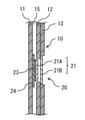
次に、本開示の第4の実施の形態に係る表示装置3について説明する。図21は、本実施の形態に係る表示装置3の側面構成例を表したものである。図22は、図21の表示装置3の背面構成例を表したものである。表示装置3は、映像表示面110Aに映像を表示するとともに、映像表示面110Aから音声を出力する。言い換えると、表示装置3は、フラットパネルスピーカを映像表示面110Aに内蔵しているとも言える。<5. Third Embodiment>
[Constitution]
Next, the
表示装置3は、例えば、映像を表示するとともに振動板としても機能するパネル部110と、パネル部110の裏面に配置され、パネル部110を振動させる加振部120とを備えている。表示装置3は、さらに、例えば、加振部120を制御する信号処理回路131が内蔵された支持部130を備えている。支持部130は、回動部140を介してバックシャーシ119に固定されている。回動部140は、支持部130によってパネル部110の裏面を支持するときのパネル部110の傾斜角を調整するためのものであり、例えば、パネル部110および支持部130を回動可能に支持するヒンジによって構成されている。
The
図23は、バックシャーシ119を取り外したときの、表示装置3の背面の構成例を表したものである。図24は、図23のA-A線での断面構成例を表したものである。パネル部110は、例えば、映像を表示する薄板状の表示セル111を有している。表示セル111の表面(加振部120とは反対側の表面)が映像表示面110Aとなっている。表示セル111は、例えば、マトリクス状に配置された複数の表示画素を有している。複数の表示画素は、例えば、表示セル111に設けられたガラス基板によって支持されている。つまり、表示セル111は、例えば、ガラス基板を含んで構成されている。
FIG. 23 shows a configuration example of the back surface of the
加振部120は、例えば、2つの加振器(加振器121(アクチュエータ)および加振器122(アクチュエータ))を有している。加振器121および加振器122は、互いに共通の構成となっている。加振器121,122は、加振器121,122により表示セル111に振動を発生させたときに音声周波数(例えば20Hz~20kHz)全体において最も振動し易い箇所を避けて配置されている。加振器121,122は、さらに、加振器121,122により表示セル111に振動を発生させたときに音声周波数全体に
おいて最も振動し難い箇所を避けて配置されている。表示セル111の振動は、例えば、レーザドップラー振動計を用いて、表示セル111の面全体の振動を音声周波数全体において計測することにより得られる。加振器121,122は、例えば、表示セル111の左右方向および上下方向において、割り切れない比率の箇所に配置されている。「割り切れない比率」の例としては、3:4、5:7、3:7、2:5、7:11などが挙げられる。The
加振器121は、表示セル111を裏面から見たときに、左寄りに配置されている。加振器122は、表示セル111を裏面から見たときに、右寄りに配置されている。加振部120は、さらに、2つの加振器(加振器121,122)と、信号処理回路131とを電気的に接続する配線基板123を有している。配線基板123には、例えば、フレキシブル配線基板が接続されており、このフレキシブル配線基板を介して、2つの加振器(加振器121,122)と、信号処理回路131とが電気的に接続されている。
The
加振器121,122は、それぞれ、例えば、ボイスコイルと、ボイスコイルを巻き付けるボビンと、磁気回路とを有し、振動源となるスピーカ用アクチュエータである。加振器121,122は、それぞれ、さらに、ボイスコイルおよびボビンを振動可能に保持するとともに、磁気回路を収容する筐体121Aを有している。筐体121Aは、ダイキャスト(例えばアルミダイキャスト)で作られており、放熱性に優れている。
The
加振器121,122は、それぞれ、ボイスコイルに電気信号の音声電流が流れると、電磁作用の原理に従ってボイスコイルに駆動力を発生させる。この駆動力が後述の振動伝達部材125を介して表示セル111に伝達され、表示セル111に音声電流の変化に応じた振動を発生させ、空気が振動して音圧が変化する。
The
加振部120は、さらに、例えば、加振器(加振器121,122)ごとに、固定部材124および振動伝達部材125を有している。各加振器(加振器121,122)は、例えば、固定部材124を介して、表示セル111の裏面に固定されている。各加振器(加振器121,122)は、固定部材124によって、表示セル111の裏面に対して、当該加振器(加振器121,122)と対向する位置とは異なる位置に固定されている。固定部材124は、表示セル111と筐体121Aとを互いに固定する機能を有している。固定部材124は、例えば、表示セル111が振動している時に表示セル111の振動を減衰させない程度の柔軟性を有していてもよい。固定部材124は、例えば、両面に接着層を有するスポンジによって構成されている。
The
振動伝達部材125は、例えば、表示セル111の裏面と、加振器121もしくは加振器122のボビンとに接しており、表示セル111の裏面と、加振器121もしくは加振器122のボビンとに固定されている。振動伝達部材125は、少なくとも、音波領域(20Hz以上)では反発する特性を有する部材によって構成されている。振動伝達部材125は、例えば、熱硬化性樹脂、両面テープ、または、低反発ウレタンなどによって構成されている。振動伝達部材125が熱硬化性樹脂によって構成されている場合、振動伝達部材125は、例えば、ボイスコイルに通電することでボイスコイルに熱を発生させ、その熱で熱硬化性樹脂を硬化させることにより形成される。振動伝達部材125が両面テープによって構成されている場合、振動伝達部材125は、例えば、ボイスコイルに一定のパルス信号を入力して、両面テープをボイスコイルで強く押しつけることにより、表示セル111の裏面と、加振器121もしくは加振器122のボビンとに固定される。振動伝達部材125が低反発ウレタンによって構成されている場合、低反発ウレタンは、音波領域(20Hz以上)では反発する特性を有するとともに、周波数の低い領域(20Hz未満)には追随する特性を有していることが好ましい。これにより、低反発ウレタンは、音の振動を減衰させることなく、外部からの衝撃による表示セル111の変位に追随することができる。
The
[効果]
本実施の形態に係る表示装置3では、各加振器(加振器121,122)の筐体121Aが、ダイキャストで作られている。これにより、各加振器(加振器121,122)で発生した熱が筐体121Aから素早く外部に放散される。その結果、熱の局所的な分布に起因する表示映像の色ムラを抑えることができる。[effect]
In the
また、本実施の形態では、各加振器(加振器121,122)において、筐体121Aは、表示セル111の裏面に対して、当該加振器(加振器121,122)と対向する位置とは異なる位置に固定されている。これにより、各加振器(加振器121,122)が表示セル111とともに振動するので、共振による振幅が大きくなり、低周波領域での出力を大きくすることができる。
Further, in the present embodiment, in each of the exciters (
<6.第3の実施の形態の変形例>
[変形例C]
第3の実施の形態において、例えば、図25に示したように、表示セル111と各加振器(加振器121,122)との間に放熱シート126が設けられていてもよい。<6. Modification example of the third embodiment>
[Modification C]
In the third embodiment, for example, as shown in FIG. 25, a
放熱シート126は、表示セル111の裏面に貼り合わされている。放熱シート126は、加振器121もしくは加振器122から発生した熱を放散させる機能(高熱伝導性)を有しており、かつ、音の振動を表示セル111に効率良く伝えることのできる素材によって構成されていることが好ましい。放熱シート126は、例えば、金属製(例えばアルミニウム)の薄膜によって構成されている。放熱シート126は、例えば、アルミニウム合金の薄膜によって構成されている。振動伝達部材125は、例えば、放熱シート126と、加振器121もしくは加振器122のボビンとに接しており、放熱シート126と、加振器121もしくは加振器122のボビンとに固定されている。
The
本変形例では、表示セル111と各加振器(加振器121,122)との間に複数の放熱シート126が設けられている。これにより、各加振器(加振器121,122)で発生した熱が放熱シート126を介して外部に放散される。これにより、各加振器(加振器121,122)で発生した熱が一か所に集中せず、ある程度分散する。その結果、熱の局所的な分布に起因する表示映像の色ムラを抑えることができる。
In this modification, a plurality of
[変形例D]
第3の実施の形態およびその変形例において、加振部120が、例えば、図26、図27、図28、図29に示したように、複数の加振器121と、複数の加振器122とを有していてもよい。なお、図26には、2つの加振器121と、2つの加振器122とが設けられている場合が例示されている。また、図27には、3つの加振器121と、3つの加振器122とが設けられている場合が例示されている。また、図28には、加振器121,122が振動伝達部材125を介して表示セル111に固定されている場合が例示されている。また、図29には、加振器121,122が振動伝達部材125および放熱シート126を介して表示セル111に固定されている場合が例示されている。図28、図29は、図26、図27に記載のパネル部110の断面構成の一例を表したものである。[Modification D]
In the third embodiment and its modification, the
複数の加振器121は、表示セル111を振動させるためのものであり、表示セル111の裏面に配置されている。複数の加振器121は、表示セル111を裏面から見たときに、左寄りに配置されている。複数の加振器122は、表示セル111を振動させるためのものであり、表示セル111の裏面に配置されている。複数の加振器122は、表示セル111を裏面から見たときに、右寄りに配置されている。
The plurality of
本変形例では、表示セル111の裏面側に配置された複数の加振器121が、当該複数の加振器121により表示セル111に振動を発生させたときに当該複数の加振器121が1つの加振器とみなされるように構成されている。具体的には、複数の加振器121は、互いに独立して表示セル111を振動させることが可能になっており、最大幅が20kHzの半波長以下の領域内に配置されている。例えば、表示セル111に含まれるガラス基板内の音速は4000m~5000m/秒程度であり、音声帯域の最大値(例えば20kHz)での1波長の長さが20~25cmなので、複数の加振器121、または複数の加振器122が、最大値が20kHzの半波長以下の領域(図28、図29の領域121d)内に配置されている場合には、表示セル111に含まれるガラス基板においては、複数の加振器121、または複数の加振器122を1つの音源としてみなすことができる。これにより、各加振器121,122で発生した熱をある程度分散させつつ、音質を向上させることができる。
In this modification, when the plurality of
<7.各実施の形態に共通の変形例>
[変形例E]
上記各実施の形態およびそれらの変形例において、加振器の数は、3つ以上であってもよい。例えば、上記第1の実施の形態およびその変形例において、加振器20が、例えば、図30に示したように、3つの加振器(加振器21,22,25)を有していてもよい。この場合、3番目の加振器(加振器25(アクチュエータ))は、加振器21と加振器22との間に位置している。加振器25は、加振器21と同様の構成を有している。また、例えば、上記第2実施の形態およびその変形例において、加振器70が、例えば、図31に示したように、3つの加振器(加振器71,72,76)を有していてもよい。この場合、3番目の加振器(加振器76(アクチュエータ))は、加振器71と加振器72との間に位置している。加振器76は、加振器71と同様の構成を有している。また、例えば、上記第3実施の形態およびその変形例において、加振器120が、例えば、図32に示したように、3つの加振器(加振器121,122,128)を有していてもよい。この場合、3番目の加振器(加振器128(アクチュエータ))は、加振器121と加振器122との間に位置している。加振器128は、加振器121と同様の構成を有している。本変形例においても、上記各実施の形態およびそれらの変形例における効果と同様の効果を得ることができる。<7. Modification example common to each embodiment>
[Modification example E]
In each of the above embodiments and modifications thereof, the number of exciters may be three or more. For example, in the first embodiment and its modifications, the
[変形例F]
上記各実施の形態およびそれらの変形例において、加振器の数は、1つであってもよい。例えば、加振器20が、例えば、図33に示したように、1つの加振器(加振器25)を有していてもよい。また、例えば、加振器70が、例えば、図34に示したように、1つの加振器(加振器76)を有していてもよい。また、例えば、加振器120が、例えば、図35に示したように、1つの加振器(加振器128)を有していてもよい。本変形例においても、上記各実施の形態およびそれらの変形例における効果と同様の効果を得ることができる。[Modification F]
In each of the above embodiments and modifications thereof, the number of exciters may be one. For example, the
[変形例G]
上記変形例Eにおいて、加振器70が、例えば、図36に示したように、複数の加振器71、複数の加振器72、および複数の加振器76を有していてもよい。このとき、複数の加振器71が、当該複数の加振器71により表示セル61に振動を発生させたときに当該複数の加振器71が1つの加振器とみなされるように構成されている。また、複数の加振器72が、当該複数の加振器72により表示セル61に振動を発生させたときに当該複数の加振器72が1つの加振器とみなされるように構成されている。また、複数の加振器76が、当該複数の加振器76により表示セル61に振動を発生させたときに当該複数の加振器76が1つの加振器とみなされるように構成されている。[Modification example G]
In the above modification E, the
[変形例H]
上記変形例Eにおいて、加振器120が、例えば、図37に示したように、複数の加振器121、複数の加振器122、および複数の加振器128を有していてもよい。このとき、複数の加振器121が、当該複数の加振器121により表示セル111に振動を発生させたときに当該複数の加振器121が1つの加振器とみなされるように構成されている。また、複数の加振器122が、当該複数の加振器122により表示セル111に振動を発生させたときに当該複数の加振器122が1つの加振器とみなされるように構成されている。また、複数の加振器128が、当該複数の加振器128により表示セル111に振動を発生させたときに当該複数の加振器128が1つの加振器とみなされるように構成されている。[Modification H]
In the above modification E, the
[変形例I]
上記変形例Fにおいて、加振器70が、例えば、図38示したように、複数の加振器76を有していてもよい。このとき、複数の加振器76が、当該複数の加振器76により表示セル61に振動を発生させたときに当該複数の加振器76が1つの加振器とみなされるように構成されている。[Modification I]
In the above modification F, the
[変形例J]
上記変形例Fにおいて、加振器120が、例えば、図39示したように、複数の加振器128を有していてもよい。このとき、複数の加振器128が、当該複数の加振器128により表示セル111に振動を発生させたときに当該複数の加振器128が1つの加振器とみなされるように構成されている。[Modification example J]
In the above modification F, the
以上、実施の形態およびその変形例を挙げて本開示を説明したが、本開示は上記実施の形態等に限定されるものではなく、種々変形が可能である。なお、本明細書中に記載された効果は、あくまで例示である。本開示の効果は、本明細書中に記載された効果に限定されるものではない。本開示が、本明細書中に記載された効果以外の効果を持っていてもよい。 Although the present disclosure has been described above with reference to the embodiments and examples thereof, the present disclosure is not limited to the above-described embodiments and the like, and various modifications are possible. The effects described in this specification are merely examples. The effects of the present disclosure are not limited to the effects described herein. The present disclosure may have effects other than those described herein.
例えば、上記実施の形態等において、加振器71,72,76のダイキャスト製の筐体71A内に、熱伝導性に優れた磁性流体が充填されていてもよい。また、例えば、上記実施の形態等において、加振器121,122,128のダイキャスト製の筐体121A内に、熱伝導性に優れた磁性流体が充填されていてもよい。これらのようにした場合には、磁性流体によってボイスコイルが冷却されるので、熱の局所的な分布に起因する表示映像の色ムラを抑えることができる。
For example, in the above embodiment, the die-
また、例えば、上記実施の形態等において、信号処理部30,80および信号処理回路131は、表示セル11,61,111で消費される電力の積算電力を監視してもよい。このようにした場合、信号処理部30,80および信号処理回路131は、瞬間の電力値が所定の閾値thを超える場合であっても、表示セル11,61,111に流す電流に対して制限を行わず、積算電力値が所定の閾値thを超えた場合に、表示セル11,61,111に流す電流に対して制限を行うことができる。その結果、過度な電流制限がなされなくなるので、表示品位を損なうことなく、発熱を効果的に抑えることができる。
Further, for example, in the above embodiment, the
また、例えば、本開示は以下のような構成を取ることができる。
(1)
映像を表示する薄板状の表示セルと、
前記表示セルの裏面側に配置され、前記表示セルを振動させる複数の加振器と
を備え、
前記複数の加振器は、当該複数の加振器により前記表示セルに振動を発生させたときに当該複数の加振器が1つの加振器とみなされるように構成されている
表示装置。
(2)
前記表示セルがガラス基板を含んで構成され、
前記複数の加振器は、互いに独立して前記表示セルを振動させることが可能になっており、最大幅が20kHzの半波長以下の領域内に配置されている
(1)に記載の表示装置。
(3)
各前記加振器は、ダイキャストで作られた筐体を有している
(2)に記載の表示装置。
(4)
前記表示セルと所定の間隙を介して対向配置された対向プレートを更に備え、
各前記加振器において、前記筐体は前記対向プレートに固定されている
(3)に記載の表示装置。
(5)
各前記加振器において、前記筐体は前記表示セルの裏面に対して、当該加振器と対向する位置とは異なる位置に固定されている
(3)に記載の表示装置。
(6)
各前記加振器は、
前記表示セルの裏面に固定された平面コイルと、
所定の間隙を介して複数の前記平面コイルと対向して配置された永久磁石と
を有する
(1)に記載の表示装置。
(7)
各前記加振器は、前記平面コイルに固定されるとともに前記表示セルの裏面に固定されたプリント基板を有し、
各前記加振器において、前記平面コイルは、前記プリント基板のうち前記表示セルとは反対側の面に形成されている
(6)に記載の表示装置。
(8)
前記表示セルと各前記加振器との間に1または複数の放熱シートを更に備えた
(1)ないし(7)のいずれか1つに記載の表示装置。
(9)
前記1または複数の放熱シートは、アルミニウム合金で構成されている
(8)に記載の表示装置。Further, for example, the present disclosure may have the following structure.
(1)
A thin plate-shaped display cell that displays images, and
It is arranged on the back side of the display cell and is equipped with a plurality of vibrators that vibrate the display cell.
The plurality of exciters are display devices configured such that the plurality of vibrators are regarded as one exciter when the plurality of vibrators generate vibration in the display cell.
(2)
The display cell is configured to include a glass substrate.
The display device according to (1), wherein the plurality of exciters can vibrate the display cell independently of each other and are arranged in a region having a maximum width of 20 kHz or less and a half wavelength or less. ..
(3)
The display device according to (2), wherein each of the vibration exciters has a die-cast housing.
(4)
Further provided with facing plates arranged opposite to the display cell via a predetermined gap,
The display device according to (3), wherein in each of the shakers, the housing is fixed to the facing plate.
(5)
The display device according to (3), wherein in each of the exciters, the housing is fixed to the back surface of the display cell at a position different from the position facing the exciter.
(6)
Each of the above exciters
A flat coil fixed to the back surface of the display cell and
The display device according to (1), which has a plurality of permanent magnets arranged to face the planar coil through a predetermined gap.
(7)
Each of the exciters has a printed circuit board fixed to the planar coil and fixed to the back surface of the display cell.
The display device according to (6), wherein in each of the shakers, the flat coil is formed on a surface of the printed circuit board opposite to the display cell.
(8)
The display device according to any one of (1) to (7), further comprising one or a plurality of heat dissipation sheets between the display cell and each of the vibration exciters.
(9)
The display device according to (8), wherein the one or more heat dissipation sheets are made of an aluminum alloy.
本出願は、日本国特許庁において2016年12月27日に出願された日本特許出願番号第2016-253664号と、2017年5月19日に出願された日本特許出願番号第2017-099629号とを基礎として優先権を主張するものであり、この出願のすべての内容を参照によって本出願に援用する。 This application includes Japanese Patent Application No. 2016-2536664 filed at the Japan Patent Office on December 27, 2016 and Japanese Patent Application No. 2017-099629 filed on May 19, 2017. All the contents of this application are incorporated into this application by reference.
当業者であれば、設計上の要件や他の要因に応じて、種々の修正、コンビネーション、サブコンビネーション、および変更を想到し得るが、それらは添付の請求の範囲やその均等物の範囲に含まれるものであることが理解される。 Those skilled in the art may conceive various modifications, combinations, sub-combinations, and changes, depending on design requirements and other factors, which are included in the claims and their equivalents. It is understood that it is one of ordinary skill in the art.
Claims (8)
前記表示セルの裏面側に配置され、前記表示セルを振動させる複数の加振器と
を備え、
前記複数の加振器は、当該複数の加振器により前記表示セルに振動を発生させたときに当該複数の加振器が1つの加振器とみなされるように構成され、
前記表示セルがガラス基板を含んで構成され、
前記複数の加振器は、互いに独立して前記表示セルを振動させることが可能になっており、最大幅が20kHzの半波長以下の領域内に配置されている
表示装置。 A thin plate-shaped display cell that displays images, and
It is arranged on the back side of the display cell and is equipped with a plurality of vibrators that vibrate the display cell.
The plurality of exciters are configured so that the plurality of vibrators are regarded as one exciter when the plurality of vibrators generate vibration in the display cell .
The display cell is configured to include a glass substrate.
The plurality of exciters can vibrate the display cell independently of each other, and are arranged in a region having a maximum width of 20 kHz or less and a half wavelength or less.
Display device.
請求項1に記載の表示装置。 The display device according to claim 1 , wherein each of the vibration exciters has a housing made of die-cast.
各前記加振器において、前記筐体は前記対向プレートに固定されている
請求項2に記載の表示装置。 Further provided with facing plates arranged opposite to the display cell via a predetermined gap,
The display device according to claim 2 , wherein in each of the shakers, the housing is fixed to the facing plate.
請求項2に記載の表示装置。 The display device according to claim 2 , wherein in each of the exciters, the housing is fixed to a position different from the position facing the exciter with respect to the back surface of the display cell.
前記表示セルの裏面側に配置され、前記表示セルを振動させる複数の加振器と
を備え、
前記複数の加振器は、当該複数の加振器により前記表示セルに振動を発生させたときに当該複数の加振器が1つの加振器とみなされるように構成され、
各前記加振器は、
前記表示セルの裏面に固定された平面コイルと、
所定の間隙を介して複数の前記平面コイルと対向して配置された永久磁石と
を有する
表示装置。 A thin plate-shaped display cell that displays images, and
With a plurality of exciters arranged on the back side of the display cell and vibrating the display cell
Equipped with
The plurality of exciters are configured so that the plurality of vibrators are regarded as one exciter when the plurality of vibrators generate vibration in the display cell.
Each of the above exciters
A flat coil fixed to the back surface of the display cell and
It has a plurality of permanent magnets arranged opposite to the planar coil through a predetermined gap.
Display device.
各前記加振器において、前記平面コイルは、前記プリント基板のうち前記表示セルとは反対側の面に形成されている
請求項5に記載の表示装置。 Each of the exciters has a printed circuit board fixed to the planar coil and fixed to the back surface of the display cell.
The display device according to claim 5 , wherein in each of the shakers, the flat coil is formed on a surface of the printed circuit board opposite to the display cell.
前記表示セルの裏面側に配置され、前記表示セルを振動させる複数の加振器と、
前記表示セルと各前記加振器との間に設けられた1または複数の放熱シートと
を備え、
前記複数の加振器は、当該複数の加振器により前記表示セルに振動を発生させたときに当該複数の加振器が1つの加振器とみなされるように構成されている
表示装置。 A thin plate-shaped display cell that displays images, and
A plurality of exciters arranged on the back surface side of the display cell and vibrating the display cell, and
With one or more heat dissipation sheets provided between the display cell and each of the exciters
Equipped with
The plurality of exciters are configured so that the plurality of vibrators are regarded as one exciter when the plurality of vibrators generate vibration in the display cell.
Display device.
請求項7に記載の表示装置。 The display device according to claim 7 , wherein the one or more heat dissipation sheets are made of an aluminum alloy.
Priority Applications (1)
| Application Number | Priority Date | Filing Date | Title |
|---|---|---|---|
| JP2022019383A JP7239032B2 (en) | 2016-12-27 | 2022-02-10 | Display device |
Applications Claiming Priority (5)
| Application Number | Priority Date | Filing Date | Title |
|---|---|---|---|
| JP2016253664 | 2016-12-27 | ||
| JP2016253664 | 2016-12-27 | ||
| JP2017099629 | 2017-05-19 | ||
| JP2017099629 | 2017-05-19 | ||
| PCT/JP2017/040558 WO2018123292A1 (en) | 2016-12-27 | 2017-11-10 | Display device |
Related Child Applications (1)
| Application Number | Title | Priority Date | Filing Date |
|---|---|---|---|
| JP2022019383A Division JP7239032B2 (en) | 2016-12-27 | 2022-02-10 | Display device |
Publications (2)
| Publication Number | Publication Date |
|---|---|
| JPWO2018123292A1 JPWO2018123292A1 (en) | 2019-10-31 |
| JP7024732B2 true JP7024732B2 (en) | 2022-02-24 |
Family
ID=62708062
Family Applications (2)
| Application Number | Title | Priority Date | Filing Date |
|---|---|---|---|
| JP2018558878A Active JP7024732B2 (en) | 2016-12-27 | 2017-11-10 | Display device |
| JP2022019383A Active JP7239032B2 (en) | 2016-12-27 | 2022-02-10 | Display device |
Family Applications After (1)
| Application Number | Title | Priority Date | Filing Date |
|---|---|---|---|
| JP2022019383A Active JP7239032B2 (en) | 2016-12-27 | 2022-02-10 | Display device |
Country Status (6)
| Country | Link |
|---|---|
| US (2) | US11659309B2 (en) |
| EP (1) | EP3565275B1 (en) |
| JP (2) | JP7024732B2 (en) |
| KR (1) | KR102376136B1 (en) |
| CN (2) | CN109845291B (en) |
| WO (1) | WO2018123292A1 (en) |
Families Citing this family (14)
| Publication number | Priority date | Publication date | Assignee | Title |
|---|---|---|---|---|
| KR101817105B1 (en) * | 2016-12-30 | 2018-02-22 | 엘지디스플레이 주식회사 | Actuator fixing apparatus and display device for generating sound by panel vibration type having the same |
| EP3528510B1 (en) * | 2016-10-13 | 2022-02-09 | Panasonic Intellectual Property Management Co., Ltd. | Flat speaker and display device |
| KR102625724B1 (en) | 2018-10-05 | 2024-01-15 | 엘지디스플레이 주식회사 | Display apparatus |
| EP3859981A4 (en) | 2018-11-16 | 2021-11-10 | Huawei Technologies Co., Ltd. | Mobile terminal |
| KR102652088B1 (en) * | 2019-01-17 | 2024-03-28 | 삼성디스플레이 주식회사 | Display device |
| KR20200096368A (en) * | 2019-02-01 | 2020-08-12 | 삼성디스플레이 주식회사 | Display device |
| CN112148067B (en) | 2019-06-27 | 2022-09-02 | 北京小米移动软件有限公司 | Screen component and mobile terminal |
| KR20220043107A (en) | 2019-07-31 | 2022-04-05 | 소니그룹주식회사 | display device |
| CN110572494B (en) * | 2019-09-16 | 2021-07-09 | Oppo广东移动通信有限公司 | Screen assembly and electronic equipment |
| US11638093B2 (en) | 2020-06-30 | 2023-04-25 | Waves Audio Ltd. | Thermal limiter for a panel speaker |
| KR20220011424A (en) * | 2020-07-21 | 2022-01-28 | 엘지디스플레이 주식회사 | Display apparatus |
| KR20220050671A (en) * | 2020-10-16 | 2022-04-25 | 엘지디스플레이 주식회사 | Display device |
| KR20230147605A (en) * | 2021-02-25 | 2023-10-23 | 소니그룹주식회사 | Video audio output module and video audio presentation device |
| WO2024006481A1 (en) * | 2022-06-29 | 2024-01-04 | Valcom, Inc. | Distributed mode loudspeaker with free motion heat sink |
Citations (3)
| Publication number | Priority date | Publication date | Assignee | Title |
|---|---|---|---|---|
| JP2004072226A (en) | 2002-08-02 | 2004-03-04 | Alps Electric Co Ltd | Acoustic device |
| JP2005130397A (en) | 2003-10-27 | 2005-05-19 | Yamaha Corp | Array speaker and speaker system |
| JP2015219528A (en) | 2014-05-20 | 2015-12-07 | 三星ディスプレイ株式會社Samsung Display Co.,Ltd. | Display device |
Family Cites Families (18)
| Publication number | Priority date | Publication date | Assignee | Title |
|---|---|---|---|---|
| US5537482A (en) * | 1994-07-25 | 1996-07-16 | Jlj, Inc. | Magnetic, variable-volume sound producing device |
| IL130678A0 (en) | 1997-01-09 | 2000-06-01 | New Transducers Ltd | Loudspeakers |
| HUP0102858A3 (en) | 1998-01-20 | 2003-03-28 | New Transducers Ltd | Active acoustic devices comprising panel members |
| GB9826164D0 (en) * | 1998-11-30 | 1999-01-20 | New Transducers Ltd | Acoustic devices |
| US20020018578A1 (en) | 2000-08-03 | 2002-02-14 | Paul Burton | Bending wave loudspeaker |
| TW200425765A (en) * | 2002-08-15 | 2004-11-16 | Diamond Audio Technology Inc | Subwoofer |
| JP2004289772A (en) * | 2003-01-30 | 2004-10-14 | Authentic Ltd | Panel speaker |
| EP1947901A4 (en) * | 2005-11-02 | 2011-02-09 | Nec Corp | Speaker, image element protective screen, case of terminal, and terminal |
| JP4645423B2 (en) | 2005-11-22 | 2011-03-09 | ソニー株式会社 | Television equipment |
| GB0617551D0 (en) * | 2006-09-07 | 2006-10-18 | New Transducers Ltd | Electromagnetic actuator |
| KR100842093B1 (en) * | 2007-03-14 | 2008-06-30 | 주식회사 예일전자 | A sensing signal output apparatus |
| JP4333778B2 (en) * | 2007-05-23 | 2009-09-16 | 船井電機株式会社 | Equipment with built-in speakers, LCD television receiver |
| JP5014883B2 (en) * | 2007-06-06 | 2012-08-29 | ミネベア株式会社 | Speaker |
| JP5192799B2 (en) | 2007-12-25 | 2013-05-08 | パナソニック株式会社 | Panel for display device installation |
| CN104469567A (en) * | 2013-09-25 | 2015-03-25 | 鸿富锦精密工业(深圳)有限公司 | Loudspeaker and displayer |
| US9749750B2 (en) * | 2014-07-01 | 2017-08-29 | Corning Incorporated | Cross-cancellation of audio signals in a stereo flat panel speaker |
| EP3041265B1 (en) * | 2014-09-08 | 2019-12-18 | Adamson Systems Engineering Inc. | Loudspeaker with improved directional behavior and reduction of acoustical interference |
| CN205847561U (en) * | 2016-06-07 | 2016-12-28 | 瑞声科技(新加坡)有限公司 | Vibrational system and the speaker of this vibrational system of application |
-
2017
- 2017-11-10 CN CN201780064944.7A patent/CN109845291B/en active Active
- 2017-11-10 US US16/343,467 patent/US11659309B2/en active Active
- 2017-11-10 KR KR1020197010851A patent/KR102376136B1/en active IP Right Grant
- 2017-11-10 CN CN202210147935.7A patent/CN114554356A/en active Pending
- 2017-11-10 EP EP17885758.7A patent/EP3565275B1/en active Active
- 2017-11-10 WO PCT/JP2017/040558 patent/WO2018123292A1/en unknown
- 2017-11-10 JP JP2018558878A patent/JP7024732B2/en active Active
-
2020
- 2020-04-29 US US16/861,890 patent/US11356759B2/en active Active
-
2022
- 2022-02-10 JP JP2022019383A patent/JP7239032B2/en active Active
Patent Citations (3)
| Publication number | Priority date | Publication date | Assignee | Title |
|---|---|---|---|---|
| JP2004072226A (en) | 2002-08-02 | 2004-03-04 | Alps Electric Co Ltd | Acoustic device |
| JP2005130397A (en) | 2003-10-27 | 2005-05-19 | Yamaha Corp | Array speaker and speaker system |
| JP2015219528A (en) | 2014-05-20 | 2015-12-07 | 三星ディスプレイ株式會社Samsung Display Co.,Ltd. | Display device |
Also Published As
| Publication number | Publication date |
|---|---|
| CN109845291A (en) | 2019-06-04 |
| US11356759B2 (en) | 2022-06-07 |
| CN109845291B (en) | 2022-03-08 |
| EP3565275B1 (en) | 2023-07-19 |
| JPWO2018123292A1 (en) | 2019-10-31 |
| EP3565275A4 (en) | 2020-01-08 |
| KR20190094333A (en) | 2019-08-13 |
| EP3565275A1 (en) | 2019-11-06 |
| US20200260168A1 (en) | 2020-08-13 |
| CN114554356A (en) | 2022-05-27 |
| JP7239032B2 (en) | 2023-03-14 |
| US20190268681A1 (en) | 2019-08-29 |
| WO2018123292A1 (en) | 2018-07-05 |
| KR102376136B1 (en) | 2022-03-18 |
| JP2022062222A (en) | 2022-04-19 |
| US11659309B2 (en) | 2023-05-23 |
Similar Documents
| Publication | Publication Date | Title |
|---|---|---|
| JP7024732B2 (en) | Display device | |
| JP6489291B2 (en) | Flat panel speaker and display device | |
| KR102259805B1 (en) | Display device | |
| US11503410B2 (en) | Display module, display device and method of forming display module | |
| WO2020107621A1 (en) | Surface sound-emitting apparatus and electronic device | |
| JP2008283350A (en) | Flexible display audio apparatus | |
| US9392373B2 (en) | Acoustic generator, acoustic generation device, and electronic device | |
| US20230007374A1 (en) | Display apparatus | |
| JP6166038B2 (en) | SOUND GENERATOR, SOUND GENERATOR, AND ELECTRONIC DEVICE | |
| JP6034182B2 (en) | SOUND GENERATOR, SOUND GENERATOR, AND ELECTRONIC DEVICE | |
| JP2014123812A (en) | Sound generator, sound generating system, and electronic apparatus | |
| CN213342673U (en) | Display device and soundable OLED screen | |
| US20230209743A1 (en) | Electronic apparatus | |
| JP2009278171A (en) | Electromagnetic transducer | |
| WO2014091813A1 (en) | Acoustic generator, acoustic generation device, and electronic device | |
| JP2009278168A (en) | Electromagnetic transducer |
Legal Events
| Date | Code | Title | Description |
|---|---|---|---|
| A521 | Request for written amendment filed |
Free format text: JAPANESE INTERMEDIATE CODE: A523 Effective date: 20201006 |
|
| A621 | Written request for application examination |
Free format text: JAPANESE INTERMEDIATE CODE: A621 Effective date: 20201006 |
|
| A131 | Notification of reasons for refusal |
Free format text: JAPANESE INTERMEDIATE CODE: A131 Effective date: 20211005 |
|
| A521 | Request for written amendment filed |
Free format text: JAPANESE INTERMEDIATE CODE: A523 Effective date: 20211202 |
|
| TRDD | Decision of grant or rejection written | ||
| A01 | Written decision to grant a patent or to grant a registration (utility model) |
Free format text: JAPANESE INTERMEDIATE CODE: A01 Effective date: 20220111 |
|
| A61 | First payment of annual fees (during grant procedure) |
Free format text: JAPANESE INTERMEDIATE CODE: A61 Effective date: 20220124 |
|
| R151 | Written notification of patent or utility model registration |
Ref document number: 7024732 Country of ref document: JP Free format text: JAPANESE INTERMEDIATE CODE: R151 |