JP7020760B2 - Timer device for nurse call system - Google Patents
Timer device for nurse call system Download PDFInfo
- Publication number
- JP7020760B2 JP7020760B2 JP2018076826A JP2018076826A JP7020760B2 JP 7020760 B2 JP7020760 B2 JP 7020760B2 JP 2018076826 A JP2018076826 A JP 2018076826A JP 2018076826 A JP2018076826 A JP 2018076826A JP 7020760 B2 JP7020760 B2 JP 7020760B2
- Authority
- JP
- Japan
- Prior art keywords
- timer
- time
- key
- displayed
- pressed
- Prior art date
- Legal status (The legal status is an assumption and is not a legal conclusion. Google has not performed a legal analysis and makes no representation as to the accuracy of the status listed.)
- Active
Links
Images


Description
本発明は、患者や被介護者が自分の意志で看護師や介護師を呼び出したり、患者や被介護者の所定の状態を検出して看護師や介護師を呼び出したりするためのナースコールシステムに適用されるナースコール用タイマー装置に関する。 The present invention is a nurse call system for a patient or a care recipient to call a nurse or a caregiver at his / her own will, or to detect a predetermined condition of a patient or a care recipient and call a nurse or a caregiver. Regarding the nurse call timer device applied to.
一般に、病院や介護施設などでは、ナースコールシステムが用いられている。ナースコールシステムは、入院している患者が看護師のサポートを必要とする際、または、介護施設の被介護者が介護師のサポートを必要とする際に、患者や被介護者(以下、患者と記載する)がナースコール子機の呼出ボタンを操作することによって看護師や介護師(以下、医療従事者と記載する)を呼び出すことができるように成されたシステムである。 Generally, a nurse call system is used in hospitals and long-term care facilities. The nurse call system is used when a hospitalized patient needs the support of a nurse, or when a care recipient in a care facility needs the support of a nurse, the patient or care recipient (hereinafter referred to as the patient). It is a system that can call a nurse or a caregiver (hereinafter referred to as a medical worker) by operating the call button of the nurse call slave unit.
多くのナースコールシステムは、病室のベッド近傍やトイレ、浴室などに設置されるナースコール子機と、医療従事者が常駐するナースステーションに設置されるナースコール親機と、病室や介護室等の各部屋の出入口付近の廊下側に設置される廊下灯と、通話やデータの送受信に関する制御を行う制御機とを備えて構成されている。また、上述した構成に加え、医療従事者が携帯する携帯端末(例えば、PHS(Personal Handy phone System)端末など)とPBX(Private Branch Exchange:電話交換機)とを組み合わせて、移動中の医療従事者が呼び出しに応答できるようにしたナースコールシステムも提供されている。 Many nurse call systems include nurse call slave units installed near beds in hospital rooms, toilets, bathrooms, etc., nurse call master units installed at nurse stations where medical staff are stationed, and hospital rooms and nursing rooms. It is equipped with a corridor light installed on the corridor side near the entrance and exit of each room, and a controller that controls the transmission and reception of calls and data. In addition to the above-mentioned configuration, a mobile terminal (for example, a PHS (Personal Handy phone System) terminal) carried by a medical worker and a PBX (Private Branch Exchange) may be combined with a mobile medical worker on the move. There is also a nurse call system that allows you to answer calls.
ナースコール親機には、LED(Light-Emitting Diode)などのランプと患者名とを対応付けて表示パネルに表示するボード型と呼ばれるものがある。このボード型のナースコール親機では、患者からの呼び出しが発生すると、その患者に対応するランプを点灯(または点滅)させて呼び出しを行った患者を視認できるようにしている。 The nurse call master unit includes a board type that displays a lamp such as an LED (Light-Emitting Diode) and a patient name on a display panel in association with each other. In this board-type nurse call master unit, when a call from a patient occurs, the lamp corresponding to the patient is turned on (or blinks) so that the patient who made the call can be visually recognized.
また、ナースコール親機には、パソコンを利用したものもある。このパソコンを利用したナースコール親機では、実際のベッドの配置と同じようにディスプレイ上にレイアウト画像を表示し、レイアウト画像上に患者名を表示するようにしている。そして、このようなナースコール親機は、患者からの呼び出しが行われたときに、その患者に対応する部分を強調して表示(例えば、ポップアップ画像の表示など)を行うことで、どの患者が呼び出しを行ったのかを医療従事者に視認させることができる。 In addition, some nurse call master units use a personal computer. In the nurse call master unit using this personal computer, the layout image is displayed on the display in the same way as the actual bed arrangement, and the patient name is displayed on the layout image. Then, when such a nurse call master unit is called by a patient, the part corresponding to the patient is highlighted and displayed (for example, a pop-up image is displayed), so that which patient can receive the call. It is possible to make the medical staff visually recognize whether or not the call has been made.
ナースコール子機は、患者ごとに設置されており、患者が医療従事者を呼び出すための呼出ボタンを備えている。ここで、ナースコール子機は、患者の手元に置かれる呼出ボタンと、有線や無線などにより呼出ボタンを接続する壁面に設置されたウォールユニットとにより構成される。また、患者の所定の状態を検出するセンサー(例えば、マットセンサーや赤外線センサーなど)をウォールユニットに接続し、センサーが患者の所定の状態を検出することで医療従事者を呼び出すようにしたナースコール子機も知られている。 The nurse call handset is installed for each patient and is equipped with a call button for the patient to call a healthcare professional. Here, the nurse call slave unit is composed of a call button placed at the patient's hand and a wall unit installed on the wall surface to which the call button is connected by wire or wireless. In addition, a nurse call is made by connecting a sensor that detects the predetermined condition of the patient (for example, a mat sensor or an infrared sensor) to the wall unit, and the sensor detects the predetermined condition of the patient to call a medical staff. Handsets are also known.
ところで、医療従事者が患者の看護や介助を行った際に、所定時間の経過後に医療従事者を呼び出すようにすることが求められている。これにより、医療従事者がトイレなどの共用部に患者を連れて行った場合などに、医療従事者が患者の側に付きっきりにならずに他の業務を遂行することを可能とする。また、医療従事者が患者の看護や介助を行う際に、センサーを所定時間だけ停止することが求められている。これにより、医療従事者がセンサーを使用している患者の看護を行う際にセンサーが医療従事者を検出することによる誤報の発生を防止することができる。 By the way, when a medical worker cares for or assists a patient, it is required to call the medical worker after a lapse of a predetermined time. This makes it possible for the medical staff to carry out other tasks without being obsessed with the patient when the medical staff takes the patient to a common area such as a toilet. In addition, when a medical worker cares for or assists a patient, it is required to stop the sensor for a predetermined time. This makes it possible to prevent the occurrence of false alarms due to the sensor detecting the medical staff when the medical staff cares for the patient using the sensor.
これらの要望に応えるために、ウォールユニットなどにタイマー機能を持たせ、医療従事者がタイマーの時間を設定し、設定した時間の経過後にナースコールの呼び出しを行ったり、設定した時間が経過するまでセンサーの動作を無効としたりすることが考えられる。ここで、ウォールユニットなどにおけるタイマーの時間を設定するためのタイマーキーの設置面積が限られている場合、このタイマーキーは1つのボタンにより構成されることが好ましい。また、タイマーの時間を設定できるようにすると、タイマーの設定時間や残時間を表示するための表示部も必要となるため、ウォールユニットにおけるタイマーキーの専有面積はできるだけ少ない方が好ましい。 In order to meet these demands, the wall unit etc. is equipped with a timer function, the medical staff sets the timer time, calls the nurse call after the set time elapses, or until the set time elapses. It is conceivable to invalidate the operation of the sensor. Here, when the installation area of the timer key for setting the timer time in the wall unit or the like is limited, it is preferable that the timer key is composed of one button. Further, if the timer time can be set, a display unit for displaying the timer setting time and the remaining time is also required. Therefore, it is preferable that the area occupied by the timer key in the wall unit is as small as possible.
このようにタイマーキーを1つのボタンとした場合、タイマー装置に複数の時間設定値を記憶しておき、タイマーキーを押下する度に時間設定値を切り替えていく技術が知られている(例えば、特許文献1など)。しかしながら、この特許文献1に記載の技術では、タイマー装置に複数の時間設定値を記憶し、その中から所望の時間設定値を選ぶので、記憶されている時間設定値以外の時間を設定することが困難になってしまうという問題があった。
When the timer key is used as one button in this way, a technique is known in which a plurality of time setting values are stored in the timer device and the time setting value is switched each time the timer key is pressed (for example).
一方、タイマー装置のボタンを押下する度にタイマーの時間設定値を増やすようにし、ボタンの長押しによりタイマーの時間設定値を増加し続けるようにする技術も知られている(例えば、特許文献2など)。しかしながら、この特許文献2に記載の技術では、時間設定値を長く設定したい場合、ボタンを何度も押下したり、ボタンを長時間押下し続けたりしなければならないのでタイマーの時間設定が面倒になってしまうという問題があった。
On the other hand, there is also known a technique in which the time setting value of the timer is increased each time the button of the timer device is pressed, and the time setting value of the timer is continuously increased by pressing and holding the button (for example, Patent Document 2). Such). However, in the technique described in
本発明は、このような問題を解決するために成されたものであり、ナースコールシステム用のタイマー装置において、1つのボタンで時間設定を行う場合に、時間設定の自由度を高くしつつ、時間設定を容易に行うことができるようにすることを目的とする。 The present invention has been made to solve such a problem, and in a timer device for a nurse call system, when the time is set with one button, the degree of freedom of time setting is increased while increasing the degree of freedom. The purpose is to make it easy to set the time.
上述した課題を解決するために、本発明では、計時を行うタイマーと、1つのボタンにより構成されており、タイマー時間を設定するタイマーキーと、タイマー時間およびタイマー残時間を表示する表示部と、予め設定したタイマー時間候補を複数記憶する記憶部と、タイマーキーを押下する度に記憶部に記憶されたタイマー時間候補を表示部に順次表示させるとともにタイマーによる計時を開始させ、タイマー残時間が0となったときにナースコールシステムに信号を出力する制御部とを備え、この制御部は、タイマーキーの押下によってタイマー時間候補が表示部に表示されている状態でタイマーキーが長押しされると、表示部に表示されている時間を通常と異なる形態で表示させ、この状態でタイマーキーが押下される度にタイマー時間候補の時間を分単位で増加させるとともに、再度タイマーキーが長押しされると、表示部に表示されている時間を通常の形態で表示してタイマーによる計時を開始させるようにしている。 In order to solve the above-mentioned problems, the present invention includes a timer for measuring time, a timer key for setting the timer time, a display unit for displaying the timer time and the remaining timer time, and a display unit for displaying the timer time and the remaining timer time. A storage unit that stores multiple preset timer time candidates and a timer time candidate stored in the storage unit each time the timer key is pressed are displayed in sequence on the display unit, and timer counting is started, and the remaining timer time is 0. A control unit that outputs a signal to the nurse call system when becomes , The time displayed on the display is displayed in a different form than usual, and each time the timer key is pressed in this state, the timer time candidate time is increased in minutes and the timer key is pressed and held again. And, the time displayed on the display unit is displayed in the normal form and the timer is started to measure the time.
上記のように構成した本発明によれば、タイマーキーを押下することにより、所望の設定時間に近く、かつ、所望の設定時間より短いタイマー時間候補が選択され、その後にタイマーキーを長押しすることで選択されたタイマー時間候補を分単位で増加させる設定時間増加モードに移行し、この状態でタイマーキーを押下する度にタイマー時間候補の時間を分単位で増加することができるので、1つのボタン(タイマーキー)で時間設定を行う場合に、時間設定の自由度を高くしつつ、時間設定を容易に行うことができる。 According to the present invention configured as described above, by pressing the timer key, a timer time candidate that is close to the desired set time and shorter than the desired set time is selected, and then the timer key is pressed and held. By doing so, it shifts to the set time increase mode that increases the selected timer time candidate in minutes, and each time the timer key is pressed in this state, the timer time candidate time can be increased in minutes. When setting the time with a button (timer key), it is possible to easily set the time while increasing the degree of freedom in setting the time.
以下、本発明の一実施形態を図面に基づいて説明する。なお、ここでは病院に設置される看護支援用のナースコールシステムに使用されるタイマー装置を例にとって説明するが、本実施形態のナースコールシステム用タイマー装置は、病院に設置されるものに限定されない。例えば、介護施設等に設置される場合にも適用可能である。図1は、本実施形態によるナースコールシステム用タイマー装置1の構成例を示すブロック図である。
Hereinafter, an embodiment of the present invention will be described with reference to the drawings. Although the timer device used in the nurse call system for nursing support installed in the hospital will be described here as an example, the timer device for the nurse call system of the present embodiment is not limited to the one installed in the hospital. .. For example, it can be applied when it is installed in a long-term care facility or the like. FIG. 1 is a block diagram showing a configuration example of a
図1において、1はタイマー装置であり、患者のベッドの近傍や、病室の出入口近傍の廊下側などに設置され、医療従事者によって使用される。また、このタイマー装置1には、患者の所定の状態を検出するセンサー類が必要に応じて接続される。ここで、タイマー装置1は、制御部2、タイマー3、タイマーキー4、表示部5、記憶部6、インターフェース7を備えて構成されている。
In FIG. 1,
制御部2は、タイマー装置1の各構成要素を後述するように制御するためのものであり、CPU(Central Processing Unit)やメモリなどにより構成されている。タイマー3は、時間を計測するためのものである。ここで、タイマーの計時手法はどのような手法であっても良い。
The
タイマーキー4は、タイマー3により計測される時間設定を行うためのものであり、1つのボタンにより構成されている。表示部5は、デジタル表示器などにより構成されており、タイマーキー4の押下により設定された時間を表示したり、タイマー3により計時が行われている場合の残時間を表示したりする。記憶部6は、メモリなどの記憶手段により構成されており、予め設定したタイマー時間候補を複数記憶する。ここで、タイマー時間候補は、図示しないディップスイッチの操作などにより設定され、記憶部6に記憶される。
The timer key 4 is for setting the time measured by the
インターフェース7は、タイマー装置1と図示しないナースコール親機とを接続して通信を行うためのものである。また、インターフェース7には図示しないセンサー類が接続されることがある。ここで、タイマー装置1は、タイマー3で計時した時間が0となった場合にナースコールの呼出信号を制御部2にて生成し、インターフェース7から出力する場合(すなわち、タイマーナースコール機能)と、タイマー3で計時した時間が0となるまで接続されているセンサー類の動作を無効とする場合(すなわち、センサー一時停止機能)とで使い分けられる。なお、上述した呼出信号には、このタイマー装置1を他のタイマー装置1やナースコール子機と識別するための識別情報が含まれる。また、識別情報としては、ベッド番号などの情報が用いられる。また、上述した機能の切り替えは図示しないディップスイッチなどにより行われる。
The interface 7 is for connecting the
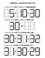
このように構成されたタイマー装置1は次にように動作する。ここで、図2は、本実施形態によるタイマー装置1の表示部5の表示例を示す図である。まず、タイマーキー4の押下により、制御部2は、記憶部6に予め記憶されているタイマー時間候補を読み出し、表示部5に順次表示させる。図2(1)では、タイマーキー4の押下により、タイマー時間候補が「5」、「10」、「30」(単位は分)と切り替わる。また、「30」が表示されている状態でタイマーキー4が押下されると、表示部5の表示が「5」に戻る。
The
そして、表示部5に例えば「30」が表示されている状態でタイマーキー4が長押し(例えば2秒以上など)されると、表示部5に表示されている「30」の表示が点滅に切り替わり、タイマー装置1のモードが分単位での設定時間増加モードに切り替わる(図2(2))。ここで、表示部5の時間表示が点灯している状態が特許請求の範囲の通常の形態の表示に該当し、表示部5の時間表示が点滅している状態が特許請求の範囲の通常と異なる形態の表示に該当する。
Then, when the timer key 4 is pressed and held (for example, for 2 seconds or more) while "30" is displayed on the display unit 5, the display of "30" displayed on the display unit 5 blinks. The mode is switched and the mode of the
この状態でタイマーキー4が押下されると、制御部2は、タイマーキー4が押下される度にタイマー時間候補として表示部5に表示されている「30」の表示を分単位で増加させる。図2(3)に示す例では、「30」の表示を「31」、「32」へと順次切り替えている。なお、設定されるタイマー時間の最大値は、表示部5の表示能力と一致していることが好ましく、表示部5が「99」まで表示可能であればタイマー時間の最大値は「99」であることが好ましく、この状態で更にタイマーキー4が操作されると、表示部5の表示は「1」となることが好ましい。
When the timer key 4 is pressed in this state, the
そして、所望のタイマー時間が表示部5に表示されている状態で再度タイマーキー4が長押しされると、制御部2は、表示部5に表示されている時間表示を点灯させるとともに、タイマー3による計時を開始する。図2(3)に示す例では、タイマー3により計時される時間は32分となる。この状態で、タイマー3により計時される時間が経過すると、図2(4)に示すように、「31」、「30」、「29」と残時間が減少していく。
Then, when the timer key 4 is pressed and held again while the desired timer time is displayed on the display unit 5, the
そして、タイマー装置1では、タイマー3で計時した時間が0となった場合にナースコールの呼出信号を制御部2にて生成し、インターフェース7から出力したり、タイマー3で計時した時間が0となるまで接続されているセンサー類の動作を無効としたりする。
Then, in the
次に、本実施形態によるタイマー装置1の動作を説明する。図3は、本実施形態によるタイマー装置1の動作を示すフローチャートである。まず、タイマーキー4が押下されたか否かを制御部2にて判定する(ステップS1)。タイマーキー4が押下されたと制御部2にて判定した場合(ステップS1にてYES)、制御部2は記憶部6に記憶されているタイマー時間候補の中から最も短い時間のものを取得して表示部5に表示し、タイマー3を動作させてその時間(表示部5に表示されている時間)から計時を開始する(ステップS2)。一方、タイマーキー4が押下されていないと制御部2にて判定した場合(ステップS1にてNO)、制御部2はステップS1を繰り返す。
Next, the operation of the
タイマー3による計時が開始されている状態で、タイマーキー4が押下されたか否かを制御部2にて判定する(ステップS3)。タイマーキー4が押下されたと制御部2にて判定した場合(ステップS3にてYES)、制御部2は記憶部6に記憶されているタイマー時間候補の中から次に短い時間のものを取得して表示部5に表示し、タイマー3を再度動作させてその時間(表示部5に表示されている時間)から計時を開始する(ステップS4)。一方、タイマーキー4が押下されていないと制御部2にて判定した場合(ステップS3にてNO)、ステップS5の処理へ移行する。
The
ステップS5では、タイマーキー4が長押しされたか否かを制御部2にて判定する。タイマーキー4が長押しされたと制御部2にて判定した場合(ステップS5にてYES)、制御部2は、表示部5に表示されている時間表示を点滅させ、分単位での設定時間増加モードへ切り替えて(ステップS6)、ステップS9の処理へ移行する。一方、タイマーキー4が長押しされていないと制御部2にて判定した場合(ステップS5にてNO)、タイマー3での計時が終了したか否かを制御部2にて判定する(ステップS7)。
In step S5, the
タイマー3での計時が終了したと制御部2にて判定した場合(ステップS7にてYES)、制御部2は信号を生成し、インターフェース7を介して生成した信号を出力する(ステップS8)。一方、タイマー3での計時が終了していないと制御部2にて判定した場合(ステップS7にてNO)、ステップS3の処理へ戻る。ここで、制御部2にて生成される信号は、このタイマー装置1をタイマー子機として使用する場合はナースコールの呼出信号となり、このタイマー装置1をセンサー類の一時停止に使用する場合には一時停止解除信号となる(この場合、タイマー3の計時開始とともにセンサー類の動作が一時停止される)。
When the
ステップS9では、タイマーキー4が押下されたか否かを制御部2にて判定する。タイマーキー4が押下されたと制御部2にて判定した場合には(ステップS9にてYES)、表示部5に表示されている設定時間およびタイマー3にて計時されている設定時間を1分増加させる(ステップS10)。
In step S9, the
そして、タイマーキー4が長押しされたか否かを制御部2にて判定する(ステップS11)。タイマーキー4が長押しされたと制御部2にて判定した場合には(ステップS11にてYES)、制御部2は表示部5の時間表示を点灯させ、タイマー3を動作させてその時間から計時を開始し(ステップS12)、ステップS5の処理へ移行する。一方、タイマーキー4が長押しされていないと制御部2にて判定した場合には(ステップS11にてNO)、ステップS9の処理へ移行する。
Then, the
一方、タイマーキー4が押下されていないと制御部2にて判定した場合には(ステップS9にてNO)、制御部2は所定時間が経過したか否かを判定する(ステップS13)。ここで所定時間とは、タイマーキー4の長押しにより設定時間増加モードへ移行したにも関わらず無操作の時間が続いたことで、今回のタイマー装置1の設定動作を終了すべき時間のことであり、1~2分程度であることが好ましい。所定時間が経過したと制御部2にて判定した場合には(ステップS13にてYES)、制御部2は、表示部5の時間表示を消灯させ、タイマー3の動作を停止させて計時を終了する(ステップS14)。
On the other hand, when the
一方、所定時間が経過していないと制御部2にて判定した場合には(ステップS13にてNO)、ステップS11の処理へ移行する。ここでは上述したように、タイマーキー4が長押しされたと制御部2にて判定した場合には(ステップS11にてYES)、制御部2は表示部5の時間表示を点灯させ、タイマー3を動作させてその時間から計時を開始し(ステップS12)、ステップS5の処理へ移行する。一方、タイマーキー4が長押しされていないと制御部2にて判定した場合には(ステップS11にてNO)、ステップS9の処理へ移行する。
On the other hand, if the
以上詳しく説明したように、本実施形態によれば、1つのボタンにより構成されており、タイマー時間を設定するタイマーキー4と、タイマー時間およびタイマー残時間を表示する表示部5と、タイマーキー4を押下する度に予め記憶されているタイマー時間候補を表示部5に順次表示させるとともに計時を開始させ、タイマー残時間が0となったときにナースコールシステムに信号を出力する制御部2とを備えたナースコールシステム用タイマー装置であって、この制御部2は、タイマーキー4の押下によってタイマー時間候補が表示部5に表示されている状態でタイマーキー4が長押しされると、表示部5に表示されている時間を点滅表示させ、この状態でタイマーキー4が押下される度にタイマー時間候補の時間を分単位で増加させるとともに、再度タイマーキー4が長押しされると、表示部5に表示されている時間を点灯表示して計時を開始させるようにしている。
As described in detail above, according to the present embodiment, the timer key 4 for setting the timer time, the display unit 5 for displaying the timer time and the remaining timer time, and the timer key 4 are configured by one button. Each time the button is pressed, the timer time candidates stored in advance are sequentially displayed on the display unit 5, the timer is started, and the
これにより、タイマーキー4を押下することにより、所望の設定時間に近く、かつ、所望の設定時間より短いタイマー時間候補が選択され、その後にタイマーキー4を長押しすることで選択されたタイマー時間候補を分単位で増加させるモードに移行し、この状態でタイマーキー4を押下する度にタイマー時間候補の時間を分単位で増加することができるので、1つのボタン(タイマーキー)で時間設定を行う場合に、時間設定の自由度を高くしつつ、時間設定を容易に行うことができる。 As a result, by pressing the timer key 4, a timer time candidate that is close to the desired set time and shorter than the desired set time is selected, and then the timer time selected by pressing and holding the timer key 4 is selected. It shifts to the mode to increase the candidates in minutes, and each time the timer key 4 is pressed in this state, the time of the timer time candidate can be increased in minutes, so set the time with one button (timer key). When doing so, the time can be easily set while increasing the degree of freedom in setting the time.
なお、前述した実施形態では、タイマーキー4を物理的なボタンにより構成しているが、これに限定されない。例えば、タイマーキー4をタッチパネル上に表示するようにしても良い。この場合、表示部5を同じタッチパネル上に表示することも可能である。 In the above-described embodiment, the timer key 4 is configured by a physical button, but the present invention is not limited to this. For example, the timer key 4 may be displayed on the touch panel. In this case, it is also possible to display the display unit 5 on the same touch panel.
また、前述した実施形態では、タイマー時間候補を3つとしているが、これに限定されない。例えば、タイマー時間候補を2つとしても良いし、4つ以上としても良い。すなわち、タイマー時間候補は複数であれば良い。 Further, in the above-described embodiment, the number of timer time candidates is three, but the present invention is not limited to this. For example, the number of timer time candidates may be two or four or more. That is, a plurality of timer time candidates may be used.
その他、上記実施形態は、本発明を実施するにあたっての具体化の一例を示したものに過ぎず、これによって本発明の技術的範囲が限定的に解釈されてはならないものである。すなわち、本発明はその精神、またはその主要な特徴から逸脱することなく、様々な形で実施することができる。 In addition, the above embodiment is merely an example of the embodiment of the present invention, and the technical scope of the present invention should not be construed in a limited manner by this. That is, the invention can be practiced in various ways without departing from its spirit or its main characteristics.
1 タイマー装置
2 制御部
3 タイマー
4 タイマーキー
5 表示部
6 記憶部
7 インターフェース
1
Claims (1)
1つのボタンにより構成されており、タイマー時間を設定するタイマーキーと、
前記タイマー時間およびタイマー残時間を表示する表示部と、
予め設定したタイマー時間候補を複数記憶する記憶部と、
前記タイマーキーを押下する度に前記記憶部に記憶された前記タイマー時間候補を前記表示部に順次表示させるとともに前記タイマーによる計時を開始させ、タイマー残時間が0となったときに信号を生成してナースコールシステムに出力する制御部とを備えたナースコールシステム用タイマー装置であって、
前記制御部が、前記タイマーキーの押下によって前記タイマー時間候補が前記表示部に表示されている状態で前記タイマーキーが長押しされると、前記表示部に表示されている時間を通常と異なる形態で表示させ、この状態で前記タイマーキーが押下される度に前記タイマー時間候補の時間を分単位で増加させるとともに、再度前記タイマーキーが長押しされると、前記表示部に表示されている時間を通常の形態で表示して前記タイマーによる計時を開始させることを特徴とするナースコールシステム用タイマー装置。 A timer that keeps time,
It consists of one button, a timer key to set the timer time, and
A display unit that displays the timer time and the remaining timer time,
A storage unit that stores multiple preset timer time candidates,
Each time the timer key is pressed, the timer time candidates stored in the storage unit are sequentially displayed on the display unit, the timer is started to be timed, and a signal is generated when the remaining timer time becomes 0. It is a timer device for a nurse call system equipped with a control unit that outputs to the nurse call system.
When the timer key is pressed and held while the timer time candidate is displayed on the display unit by pressing the timer key, the time displayed on the display unit is changed from the normal time by the control unit. In this state, each time the timer key is pressed, the time of the timer time candidate is increased in minutes, and when the timer key is pressed and held again, the time displayed on the display unit is displayed. A timer device for a nurse call system, characterized in that the timer is displayed in a normal form and the timer is started.
Priority Applications (1)
| Application Number | Priority Date | Filing Date | Title |
|---|---|---|---|
| JP2018076826A JP7020760B2 (en) | 2018-04-12 | 2018-04-12 | Timer device for nurse call system |
Applications Claiming Priority (1)
| Application Number | Priority Date | Filing Date | Title |
|---|---|---|---|
| JP2018076826A JP7020760B2 (en) | 2018-04-12 | 2018-04-12 | Timer device for nurse call system |
Publications (2)
| Publication Number | Publication Date |
|---|---|
| JP2019180932A JP2019180932A (en) | 2019-10-24 |
| JP7020760B2 true JP7020760B2 (en) | 2022-02-16 |
Family
ID=68338393
Family Applications (1)
| Application Number | Title | Priority Date | Filing Date |
|---|---|---|---|
| JP2018076826A Active JP7020760B2 (en) | 2018-04-12 | 2018-04-12 | Timer device for nurse call system |
Country Status (1)
| Country | Link |
|---|---|
| JP (1) | JP7020760B2 (en) |
Citations (4)
| Publication number | Priority date | Publication date | Assignee | Title |
|---|---|---|---|---|
| JP2006149770A (en) | 2004-11-30 | 2006-06-15 | Keakomu:Kk | Nurse call system |
| JP2012110586A (en) | 2010-11-26 | 2012-06-14 | Aiphone Co Ltd | Nurse call system |
| JP2013004292A (en) | 2011-06-16 | 2013-01-07 | Hitachi Appliances Inc | Induction heating cooker |
| JP2015021885A (en) | 2013-07-22 | 2015-02-02 | ブラザー工業株式会社 | Electronic apparatus |
Family Cites Families (3)
| Publication number | Priority date | Publication date | Assignee | Title |
|---|---|---|---|---|
| JPS5886598U (en) * | 1981-12-09 | 1983-06-11 | カシオ計算機株式会社 | timer time setting device |
| JPS59151083A (en) * | 1983-02-17 | 1984-08-29 | Seiko Epson Corp | Wrist watch with timer function |
| DE3622681A1 (en) * | 1986-07-05 | 1988-01-21 | Diehl Gmbh & Co | ELECTRONIC CLOCK WITH A DIGITAL DISPLAY |
-
2018
- 2018-04-12 JP JP2018076826A patent/JP7020760B2/en active Active
Patent Citations (4)
| Publication number | Priority date | Publication date | Assignee | Title |
|---|---|---|---|---|
| JP2006149770A (en) | 2004-11-30 | 2006-06-15 | Keakomu:Kk | Nurse call system |
| JP2012110586A (en) | 2010-11-26 | 2012-06-14 | Aiphone Co Ltd | Nurse call system |
| JP2013004292A (en) | 2011-06-16 | 2013-01-07 | Hitachi Appliances Inc | Induction heating cooker |
| JP2015021885A (en) | 2013-07-22 | 2015-02-02 | ブラザー工業株式会社 | Electronic apparatus |
Also Published As
| Publication number | Publication date |
|---|---|
| JP2019180932A (en) | 2019-10-24 |
Similar Documents
| Publication | Publication Date | Title |
|---|---|---|
| JP2007282878A (en) | False alarm prevention device and method | |
| JP4936359B2 (en) | Nurse call system | |
| JP5424395B2 (en) | Nurse call system | |
| JP7020760B2 (en) | Timer device for nurse call system | |
| JP2012005611A (en) | Nurse call system | |
| JP5674203B2 (en) | Nurse call system | |
| JP2010005058A (en) | Nurse call system | |
| JP2010005057A (en) | Nurse call system | |
| JP5306921B2 (en) | Nurse call system | |
| JP2011250879A (en) | Nurse call system | |
| JP5943425B2 (en) | Nurse call system | |
| JP5898512B2 (en) | Nurse call system | |
| JP6993064B2 (en) | Nurse call system | |
| JP2014042687A (en) | Nurse call system | |
| JP5971796B2 (en) | Nurse call system | |
| JP2008086386A (en) | Call display controller | |
| JP2008073078A (en) | Call display control device and call display method | |
| JP5850572B2 (en) | Nurse call system | |
| JP2020005892A (en) | Nurse call system | |
| JP6412381B2 (en) | Nurse call system | |
| JP2013030115A (en) | Patient watch system | |
| JP2017161972A (en) | Nurse call slave machine | |
| JP5761849B2 (en) | Nurse call system | |
| JP2006255006A (en) | Nurse call system and nurse call slave machine | |
| JP2017127344A (en) | Nurse call system |
Legal Events
| Date | Code | Title | Description |
|---|---|---|---|
| A621 | Written request for application examination |
Free format text: JAPANESE INTERMEDIATE CODE: A621 Effective date: 20210317 |
|
| A977 | Report on retrieval |
Free format text: JAPANESE INTERMEDIATE CODE: A971007 Effective date: 20220121 |
|
| TRDD | Decision of grant or rejection written | ||
| A01 | Written decision to grant a patent or to grant a registration (utility model) |
Free format text: JAPANESE INTERMEDIATE CODE: A01 Effective date: 20220202 |
|
| A61 | First payment of annual fees (during grant procedure) |
Free format text: JAPANESE INTERMEDIATE CODE: A61 Effective date: 20220202 |
|
| R150 | Certificate of patent or registration of utility model |
Ref document number: 7020760 Country of ref document: JP Free format text: JAPANESE INTERMEDIATE CODE: R150 |