JP7020380B2 - Supercharging system - Google Patents
Supercharging system Download PDFInfo
- Publication number
- JP7020380B2 JP7020380B2 JP2018218071A JP2018218071A JP7020380B2 JP 7020380 B2 JP7020380 B2 JP 7020380B2 JP 2018218071 A JP2018218071 A JP 2018218071A JP 2018218071 A JP2018218071 A JP 2018218071A JP 7020380 B2 JP7020380 B2 JP 7020380B2
- Authority
- JP
- Japan
- Prior art keywords
- supercharging
- supercharger
- variable nozzle
- opening degree
- nozzle mechanism
- Prior art date
- Legal status (The legal status is an assumption and is not a legal conclusion. Google has not performed a legal analysis and makes no representation as to the accuracy of the status listed.)
- Active
Links
Images


Classifications
-
- F—MECHANICAL ENGINEERING; LIGHTING; HEATING; WEAPONS; BLASTING
- F02—COMBUSTION ENGINES; HOT-GAS OR COMBUSTION-PRODUCT ENGINE PLANTS
- F02B—INTERNAL-COMBUSTION PISTON ENGINES; COMBUSTION ENGINES IN GENERAL
- F02B37/00—Engines characterised by provision of pumps driven at least for part of the time by exhaust
- F02B37/007—Engines characterised by provision of pumps driven at least for part of the time by exhaust with exhaust-driven pumps arranged in parallel, e.g. at least one pump supplying alternatively
-
- F—MECHANICAL ENGINEERING; LIGHTING; HEATING; WEAPONS; BLASTING
- F02—COMBUSTION ENGINES; HOT-GAS OR COMBUSTION-PRODUCT ENGINE PLANTS
- F02B—INTERNAL-COMBUSTION PISTON ENGINES; COMBUSTION ENGINES IN GENERAL
- F02B37/00—Engines characterised by provision of pumps driven at least for part of the time by exhaust
- F02B37/013—Engines characterised by provision of pumps driven at least for part of the time by exhaust with exhaust-driven pumps arranged in series
-
- F—MECHANICAL ENGINEERING; LIGHTING; HEATING; WEAPONS; BLASTING
- F02—COMBUSTION ENGINES; HOT-GAS OR COMBUSTION-PRODUCT ENGINE PLANTS
- F02B—INTERNAL-COMBUSTION PISTON ENGINES; COMBUSTION ENGINES IN GENERAL
- F02B37/00—Engines characterised by provision of pumps driven at least for part of the time by exhaust
- F02B37/12—Control of the pumps
- F02B37/24—Control of the pumps by using pumps or turbines with adjustable guide vanes
-
- F—MECHANICAL ENGINEERING; LIGHTING; HEATING; WEAPONS; BLASTING
- F02—COMBUSTION ENGINES; HOT-GAS OR COMBUSTION-PRODUCT ENGINE PLANTS
- F02D—CONTROLLING COMBUSTION ENGINES
- F02D23/00—Controlling engines characterised by their being supercharged
-
- Y—GENERAL TAGGING OF NEW TECHNOLOGICAL DEVELOPMENTS; GENERAL TAGGING OF CROSS-SECTIONAL TECHNOLOGIES SPANNING OVER SEVERAL SECTIONS OF THE IPC; TECHNICAL SUBJECTS COVERED BY FORMER USPC CROSS-REFERENCE ART COLLECTIONS [XRACs] AND DIGESTS
- Y02—TECHNOLOGIES OR APPLICATIONS FOR MITIGATION OR ADAPTATION AGAINST CLIMATE CHANGE
- Y02T—CLIMATE CHANGE MITIGATION TECHNOLOGIES RELATED TO TRANSPORTATION
- Y02T10/00—Road transport of goods or passengers
- Y02T10/10—Internal combustion engine [ICE] based vehicles
- Y02T10/12—Improving ICE efficiencies
Description
この開示は、過給システムに関し、特に、並列に接続された複数の過給機を有する過給システムに関する。 This disclosure relates to a supercharging system, and particularly to a supercharging system having a plurality of superchargers connected in parallel.
エンジンの吸気を過給する過給システムとしては、たとえば、並列に接続された複数の過給機を有する構成が公知である。たとえば、並列に接続された2つの過給機を有する過給システムにおいては、2つの過給機のうちの一つを用いてエンジンの吸気を過給する過給モード(以下、シングル過給モードとも記載する)と、両方の過給機を用いてエンジンの吸気を過給する過給モード(以下、ツイン過給モードとも記載する)とを切替える切替制御が行なわれる。 As a supercharging system for supercharging the intake air of an engine, for example, a configuration having a plurality of superchargers connected in parallel is known. For example, in a supercharging system having two superchargers connected in parallel, a supercharging mode in which one of the two superchargers is used to supercharge the intake air of the engine (hereinafter referred to as a single supercharging mode). It is also described) and a supercharging mode in which the intake air of the engine is supercharged using both superchargers (hereinafter, also referred to as a twin supercharging mode) is switched.
このような切替制御を実行する場合において、過給圧の段差が生じる場合がある。この過給圧の段差を低減させるために、2つ目の過給機の始動を補助するためのモータを備える過給システムがある(たとえば、特許文献1参照)。 When executing such switching control, a step in the boost pressure may occur. In order to reduce this step in the supercharging pressure, there is a supercharging system including a motor for assisting the start of the second turbocharger (see, for example, Patent Document 1).
しかし、特許文献1の過給システムでは、モータを搭載するためのコストが掛かり、モータを搭載するためのスペースを確保する必要があり、また、モータを搭載すると車両の重量が増加してしまう。
However, in the supercharging system of
この開示は、上述の問題を解決するためになされたものであり、その目的は、過給機の始動を補助する装置を追加することなく、過給圧の段差を低減することが可能な過給システムを提供することである。 This disclosure has been made to solve the above-mentioned problems, and the purpose of the disclosure is to reduce the step of the supercharging pressure without adding a device for assisting the start of the supercharger. To provide a pay system.
この開示による過給システムは、エンジンから排出される排気によって駆動する第1タービンと、第1タービンへ流入する排気の流速を開度によって調整する第1可変ノズル機構とを含み、エンジンに吸入される空気を過給する第1過給機と、エンジンから排出される排気によって駆動する第2タービンと、第2タービンへ流入する排気の流速を開度によって調整する第2可変ノズル機構とを含み、エンジンに吸入される空気を過給する第2過給機と、第1過給機において過給された空気がエンジンに供給される第1過給モードから、第1過給機において過給された空気と第2過給機において過給された空気とがエンジンに供給される第2過給モードに切替える制御装置とを備える。制御装置は、第1過給モードから第2過給モードに切替える前に、第2過給機に排気を供給しつつ、第2過給機によって過給された空気を第1過給機に供給する助走運転を実行し、助走運転中に、第2過給機の過給圧が第1過給機の過給圧に到達した場合に第2過給モードに切替え、助走運転を開始する場合に、第2可変ノズル機構の開度が、第1可変ノズル機構の開度よりも小さくなるように第2可変ノズル機構を制御する。 The supercharging system according to this disclosure includes a first turbine driven by exhaust discharged from the engine and a first variable nozzle mechanism that adjusts the flow velocity of the exhaust flowing into the first turbine according to the opening degree, and is sucked into the engine. Includes a first turbocharger that supercharges the air, a second turbocharger driven by the exhaust discharged from the engine, and a second variable nozzle mechanism that adjusts the flow velocity of the exhaust flowing into the second turbine according to the opening degree. From the second supercharger that supercharges the air sucked into the engine and the first supercharging mode in which the supercharged air in the first supercharger is supplied to the engine, the first supercharger is supercharged. It is provided with a control device for switching to the second supercharging mode in which the supercharged air and the supercharged air in the second supercharger are supplied to the engine. Before switching from the first supercharging mode to the second supercharging mode, the control device supplies the exhaust to the second supercharger and transfers the air supercharged by the second supercharger to the first supercharger. The run-up operation to be supplied is executed, and when the supercharging pressure of the second supercharger reaches the supercharging pressure of the first supercharger during the run-up operation, the mode is switched to the second supercharging mode and the run-up operation is started. In this case, the second variable nozzle mechanism is controlled so that the opening degree of the second variable nozzle mechanism is smaller than the opening degree of the first variable nozzle mechanism.
好ましくは、制御装置は、助走運転中に、第2過給機の過給圧の上昇が停滞する場合、第2可変ノズル機構の開度が第1可変ノズル機構の開度と同じとなるように第2可変ノズル機構を制御する。 Preferably, the control device makes the opening degree of the second variable nozzle mechanism the same as the opening degree of the first variable nozzle mechanism when the increase in the boost pressure of the second supercharger is stagnant during the run-up operation. The second variable nozzle mechanism is controlled.
好ましくは、制御装置は、助走運転中、第1可変ノズル機構の開度が、第1過給機のタービン効率が最も良くなる開度と第1過給機のタービン仕事が最も良くなる開度との間の所定開度となるよう第1可変ノズル機構を制御する。 Preferably, the control device has an opening degree of the first variable nozzle mechanism that maximizes the turbine efficiency of the first turbocharger and an opening degree that maximizes the turbine work of the first turbocharger during the run-up operation. The first variable nozzle mechanism is controlled so as to have a predetermined opening degree between.
さらに好ましくは、制御装置は、エンジンから排出される排気の圧力が制限圧力に達する場合の第1可変ノズル機構の制限開度を算出し、算出された制限開度を所定開度が上回る場合、第1可変ノズル機構の開度が制限開度となるよう第1可変ノズル機構を制御する。 More preferably, the control device calculates the limit opening of the first variable nozzle mechanism when the pressure of the exhaust gas discharged from the engine reaches the limit pressure, and when the predetermined opening exceeds the calculated limit opening, The first variable nozzle mechanism is controlled so that the opening degree of the first variable nozzle mechanism becomes the limiting opening degree.
この開示に従えば、過給機の始動を補助する装置を追加することなく、過給圧の段差を低減することが可能な過給システムを提供することができる。 According to this disclosure, it is possible to provide a supercharging system capable of reducing a step in the supercharging pressure without adding a device for assisting the start of the supercharger.
以下、図面を参照しつつ、この開示の実施の形態について説明する。以下の説明では、同一の部品には同一の符号が付されている。それらの名称および機能も同じである。したがってそれらについての詳細な説明は繰返されない。 Hereinafter, embodiments of this disclosure will be described with reference to the drawings. In the following description, the same parts are designated by the same reference numerals. Their names and functions are the same. Therefore, detailed explanations about them are not repeated.
<過給システムの構成について>
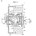
図1は、この実施の形態におけるエンジン1の概略構成の一例を示す図である。図1を参照して、このエンジン1は、たとえば、走行のための駆動源として車両に搭載される。この実施の形態においては、エンジン1は、ディーゼルエンジンである場合を一例として説明するが、たとえば、ガソリンエンジンであってもよい。
<About the configuration of the supercharging system>
FIG. 1 is a diagram showing an example of a schematic configuration of an
エンジン1は、バンク10A,10Bと、エアクリーナ20と、インタークーラ25と、吸気マニホールド28A,28Bと、プライマリ過給機30と、セカンダリ過給機40と、排気マニホールド50A,50B(以下「エキマニ」ともいう)と、排気処理装置81と、制御装置200とを備える。
The
バンク10Aには、複数の気筒12Aが形成される。バンク10Bには、複数の気筒12Bが形成される。各気筒12A,12B内にはピストン(図示せず)が収納されており、ピストンの頂部と気筒の内壁とによって燃焼室(燃料が燃焼する空間)が形成されている。各気筒12A,12B内をピストンが摺動することによって燃焼室の容積が変化される。各気筒12A,12Bには、インジェクタ(図示せず)が設けられており、エンジン1の動作中においては、制御装置200によって設定されたタイミングおよび量の燃料を各気筒12A,12B内に噴射する。なお、各インジェクタから噴射する燃料の噴射量およびタイミングは、たとえば、エンジン回転数NE、吸入空気量Qin、アクセルペダルの踏み込み量あるいは車両の速度等から制御装置200によって設定される。
A plurality of
各気筒12A,12Bのピストンは、コネクティングロッドを介して共通のクランクシャフト(図示せず)に連結される。各気筒12A,12B内において所定の順序で燃料が燃焼することによってピストンが各気筒12A,12B内を摺動し、ピストンの上下運動がコネクティングロッドを経由してクランクシャフトの回転運動に変換される。
The pistons of the
プライマリ過給機30は、コンプレッサ31とタービン32とを含むターボチャージャーである。プライマリ過給機30のコンプレッサ31は、エンジン1の吸気通路(すなわち、エアクリーナ20から吸気マニホールド28A,28Bまでの通路)に設けられる。プライマリ過給機30のタービン32は、エンジン1の排気通路(すなわち、排気マニホールド50A,50Bから排気処理装置81までの通路)に設けられる。
The
コンプレッサ31内には、コンプレッサホイール33が回転自在に収納される。タービン32内には、タービンホイール34と可変ノズル機構35とが設けられる。タービンホイール34は、回転自在にタービン32内に収納される。コンプレッサホイール33と、タービンホイール34とは、回転軸36によって連結されており、一体的に回転する。コンプレッサホイール33は、タービンホイール34に供給される排気のエネルギー(排気エネルギー)によって回転駆動される。
The
可変ノズル機構35は、タービン32を作動させる排気の流速を変化させる。可変ノズル機構35は、タービンホイール34の外周側に配置され、排気流入口から供給される排気をタービンホイール34に導く複数のノズルベーン(図示せず)と、複数のノズルベーンの各々を回転させることによって隣接するノズルベーン間の隙間(以下の説明においてこの隙間をVN開度と記載する)を変化させる駆動装置(図示せず)とを含む。可変ノズル機構35は、たとえば、制御装置200からの制御信号VN1に応じて駆動装置を用いてノズルベーンを回転させることによってVN開度を変化させる。
The
セカンダリ過給機40は、コンプレッサ41とタービン42とを含むターボチャージャーである。この実施の形態においては、セカンダリ過給機40は、プライマリ過給機30と同じ構造およびサイズであることとする。セカンダリ過給機40のコンプレッサ41は、エンジン1の吸気通路において、コンプレッサ31に並列して設けられ、エンジン1の吸気を過給する。セカンダリ過給機40のタービン42は、エンジン1の排気通路において、タービン32に並列して設けられる。
The
コンプレッサ41内には、コンプレッサホイール43が回転自在に収納される。タービン42内には、タービンホイール44と可変ノズル機構45とが設けられる。タービンホイール44は、回転自在にタービン42内に収納される。コンプレッサホイール43と、タービンホイール44とは、回転軸46によって連結されており、一体的に回転する。コンプレッサホイール43は、タービンホイール44に供給される排気エネルギーによって回転駆動される。
The
なお、可変ノズル機構45は、可変ノズル機構35と同様の構成を有するため、その詳細な説明は繰り返さない。可変ノズル機構45は、たとえば、制御装置200からの制御信号VN2に応じて駆動装置を用いてノズルベーンを回転させることによってVN開度を変化させる。
Since the
エアクリーナ20は、吸気口(図示せず)から吸入された空気から異物を除去する。エアクリーナ20には、吸気管23の一方端が接続される。吸気管23の他方端は、分岐して吸気管21の一方端および吸気管22の一方端に接続される。
The
吸気管21の他方端は、プライマリ過給機30のコンプレッサ31の吸気流入口に接続される。プライマリ過給機30のコンプレッサ31の吸気流出口には、吸気管37の一方端が接続される。吸気管37の他方端は、インタークーラ25に接続される。コンプレッサ31は、コンプレッサホイール33の回転によって吸気管21を通じて吸入される空気を過給して吸気管37に供給する。
The other end of the
吸気管22の他方端は、セカンダリ過給機40のコンプレッサ41の吸気流入口に接続される。セカンダリ過給機40のコンプレッサ41の吸気流出口には、吸気管47の一方端が接続される。吸気管47の他方端は、吸気管37の途中の接続部P3に接続される。コンプレッサ41は、コンプレッサホイール43の回転によって吸気管22を通じて吸入される空気を過給して吸気管47に供給する。
The other end of the
吸気管47の途中には第1制御弁62が設けられている。第1制御弁62は、たとえば、制御装置200からの制御信号CV1に応じてON(開)/OFF(閉)制御されるノーマリーオフのVSV(負圧切替弁)である。
A
また、吸気管47において第1制御弁62よりも上流側(コンプレッサ41側)に位置する接続部P4に、還流管48の一方端が接続されている。また、還流管48の他方端は吸気管21に接続されている。還流管48は、吸気管47を流れる空気の少なくとも一部をプライマリ過給機30のコンプレッサ31よりも上流側に還流させるための通路である。還流管48を通じて吸気管21に還流した空気は、コンプレッサ31に供給される。
Further, one end of the
還流管48の途中には第2制御弁64が設けられている。第2制御弁64は、たとえば、制御装置200からの制御信号CV2に応じてON(開)/OFF(閉)制御されるノーマリーオフの電磁弁(ソレノイドバルブ)である。
A
接続部P3には、コンプレッサ31によって過給された空気と、コンプレッサ41によって過給され、第1制御弁62を通過した空気とが供給される。これらの空気は、接続部P3で合流してインタークーラ25に流入する。
The air supercharged by the
インタークーラ25は、流入した空気を冷却するように構成される。インタークーラ25は、たとえば空冷式又は水冷式の熱交換器である。インタークーラ25には、2カ所の吸気流出口が設けられる。インタークーラ25の一方の出口には、吸気管27Aの一方端が接続される。吸気管27Aの他方端は、吸気マニホールド28Aに接続される。インタークーラ25の他方の出口には、吸気管27Bの一方端が接続される。吸気管27Bの他方端は、吸気マニホールド28Bに接続される。
The
吸気マニホールド28A、28Bは、それぞれバンク10A、10Bにおける気筒12A、12Bの吸気ポート(図示せず)に連結される。一方、排気マニホールド50A,50Bは、それぞれバンク10A,10Bにおける気筒12A,12Bの排気ポート(図示せず)に連結される。
The
各気筒12A,12Bの燃焼室から排気ポートを通じて気筒外に排出された排気(燃焼後のガス)は、エンジン1の排気通路を経由して外に排出される。上記の排気通路は、排気マニホールド50A,50B、排気管51A,51Bと、接続部P1と、排気管52A,52B,53A,53Bと、接続部P2とを含む。排気管51Aの一方端は、排気マニホールド50Aに接続される。排気管51Bの一方端は、排気マニホールド50Bに接続される。排気管51Aの他方端と、排気管51Bの他方端とは、接続部P1において一旦合流した後に、分岐して排気管52Aの一方端および排気管52Bの一方端に接続される。
Exhaust gas (gas after combustion) discharged from the combustion chambers of the
排気管52Aの他方端は、タービン32の排気流入口に接続される。タービン32の排気流出口には、排気管53Aの一方端が接続される。排気管52Bの他方端は、タービン42の排気流入口に接続される。タービン42の排気流出口には、排気管53Bの一方端が接続される。
The other end of the
排気管52Bの途中には第3制御弁66が設けられる。第3制御弁66は、たとえば、制御装置200からの制御信号CV3に応じてON(開)/OFF(閉)制御されるノーマリーオンのVSV(負圧切替弁)である。
A
排気管53Aの他方端と排気管53Bの他方端とは、接続部P2において合流し、排気処理装置81に接続される。排気処理装置81は、たとえば、SCR触媒、酸化触媒、あるいは、PM除去フィルタ等によって構成され、排気管53Aおよび排気管53Bから流通する排気を浄化する。
The other end of the
エンジン1の動作は、制御装置200によって制御される。制御装置200は、各種処理を行なうCPU(Central Processing Unit)と、プログラムおよびデータを記憶するROM(Read Only Memory)およびCPUの処理結果等を記憶するRAM(Random Access Memory)等を含むメモリと、外部との情報のやり取りを行なうための入出力ポート(いずれも図示せず)とを含む。入力ポートには、各種センサ類(たとえば、エアフローメータ102、第1圧力センサ106および第2圧力センサ108等)が接続される。出力ポートには、制御対象となる機器(たとえば、複数のインジェクタ、可変ノズル機構35,45、第1制御弁62、第2制御弁64、第3制御弁66等)が接続される。
The operation of the
制御装置200は、各センサおよび機器からの信号、ならびにメモリに格納されたマップおよびプログラムに基づいて、エンジン1が所望の運転状態となるように各種機器を制御する。なお、各種制御については、ソフトウェアによる処理に限られず、専用のハードウェア(電子回路)により処理することも可能である。また、制御装置200には、時間の計測を行うためのタイマー回路(図示せず)が内蔵されている。
The
エアフローメータ102は、吸入空気量Qinを検出する。エアフローメータ102は、検出した吸入空気量Qinを示す信号を制御装置200に送信する。
The
エンジン回転数センサ104は、エンジン回転数NEを検出する。エンジン回転数センサ104は、検出したエンジン回転数NEを示す信号を制御装置200に送信する。
The engine speed sensor 104 detects the engine speed NE. The engine rotation speed sensor 104 transmits a signal indicating the detected engine rotation speed NE to the
第1圧力センサ106は、吸気管37の接続部P3における圧力(以下、第1過給圧と記載する)Ppを検出する。第1圧力センサ106は、検出した第1過給圧Ppを示す信号を制御装置200に送信する。
The
第2圧力センサ108は、吸気管47の接続部P4における圧力(以下、第2過給圧Psと記載する)を検出する。第2圧力センサ108は、第2過給圧Psを示す信号を制御装置200に送信する。
The
この実施の形態において、プライマリ過給機30とセカンダリ過給機40と制御装置200とによって「過給システム」が構成される。
In this embodiment, the "supercharging system" is configured by the
制御装置200は、第1制御弁62、第2制御弁64および第3制御弁66を制御することにより、プライマリ過給機30(プライマリターボ)のみで過給を行なうシングル過給モードと、プライマリ過給機30(プライマリターボ)およびセカンダリ過給機40(セカンダリターボ)の両方で過給を行なうツイン過給モードとのうちのいずれか一方から他方に切替える切替制御を実行可能に構成される。また、制御装置200は、シングル過給モードからツイン過給モードに切替える場合には、シングル過給モードから、セカンダリ過給機40による過給圧を一定以上に上昇させる助走モードでの運転を実行した後に、過給モードをツイン過給モードに切替える。
The
以下、シングル過給モード、助走モードおよびツイン過給モードの各々における過給システムの動作について図2、図3および図4を参照しつつ説明する。 Hereinafter, the operation of the supercharging system in each of the single supercharging mode, the approaching mode, and the twin supercharging mode will be described with reference to FIGS. 2, 3, and 4.
<シングル過給モードについて>
制御装置200は、所定の実行条件が成立する場合に、シングル過給モードで過給システムを動作させる。所定の実行条件とは、たとえば、エンジン回転数NEおよび吸入空気量Qinに基づくエンジン1の運転状態が低負荷運転状態であるという条件を含む。制御装置200は、過給モードがシングル過給モードである場合には、第1制御弁62、第2制御弁64および第3制御弁66をいずれも閉状態(オフ状態)にする。
<About single supercharging mode>
The
図2は、シングル過給モード時の過給システムの動作を説明するための図である。図2の矢印に示すように、排気マニホールド50A,50Bを流通する排気は、排気管52Aを経由してプライマリ過給機30のタービン32に流れ、排気管53Aを経由して排気処理装置81に流れる。タービン32に供給された排気によって、タービンホイール34が回転し、タービンホイール34の回転にともなってコンプレッサホイール33が回転する。
FIG. 2 is a diagram for explaining the operation of the supercharging system in the single supercharging mode. As shown by the arrows in FIG. 2, the exhaust gas flowing through the
エアクリーナ20から吸入される空気は、吸気管23および吸気管21を経由してコンプレッサ31に流れる。コンプレッサ31から吐出された吸気は、吸気管37を経由してインタークーラ25に流れる。インタークーラ25に流れた吸気は、吸気管27A,27Bに分岐して吸気マニホールド28A,28Bの各々に流れる。
The air sucked from the
<助走モードについて>
制御装置200は、たとえば、過給モードがシングル過給モードであって、かつ、プライマリ過給機30の回転数がしきい値を超える場合に、シングル過給モードからツイン過給モードへの切替要求があると判定する。
<About run-up mode>
The
制御装置200は、シングル過給モードからツイン過給モードへの切替要求がある場合には、ツイン過給モードに切替える前に助走モードを実行する。すなわち、制御装置200は、第2制御弁64および第3制御弁66の両方を開状態(オン状態)にし、第1制御弁62を閉状態(オフ状態)にする。
When there is a request for switching from the single supercharging mode to the twin supercharging mode, the
図3は、助走モード時の過給システムの動作を説明するための図である。図3の矢印に示すように、排気マニホールド50A,50Bを流通する排気は、接続部P1で一旦合流した後に排気管52A,52Bに分岐し、プライマリ過給機30,セカンダリ過給機40のタービン32,42の両方に流れ、排気管53A,53Bを経由して排気処理装置81に流通する。
FIG. 3 is a diagram for explaining the operation of the supercharging system in the run-up mode. As shown by the arrow in FIG. 3, the exhaust gas flowing through the
タービン32に供給された排気によって、タービンホイール34が回転し、タービンホイール34の回転にともなってコンプレッサホイール33が回転する。タービン42に供給された排気によって、タービンホイール44が回転し、タービンホイール44の回転にともなってコンプレッサホイール43が回転する。
The exhaust supplied to the
エアクリーナ20から吸入される空気は、吸気管23から吸気管21,22に分岐してコンプレッサ31,41の両方に流れる。コンプレッサ31から吐出された吸気は、吸気管37を経由してインタークーラ25に流れる。コンプレッサ41から吐出された吸気は、吸気管47から接続部P4を経由して還流管48に流れ、還流管48から吸気管21を経由してコンプレッサ31に流れる。
The air sucked from the
インタークーラ25に流れた吸気は、吸気管27A,27Bに分岐して吸気マニホールド28A,28Bの各々に流れる。助走モードにおいては、プライマリ過給機30によってインタークーラ25に流れる吸気を過給しつつ、セカンダリ過給機40の回転数が上昇される。セカンダリ過給機40の回転数が上昇するにつれてセカンダリ過給機40のコンプレッサ41から吐出される吸気の圧力が上昇していく。
The intake air flowing through the
<ツイン過給モードについて>
制御装置200は、助走モード中におけるセカンダリ過給機40の過給能力が十分高くなったタイミングで、ツイン過給モードで過給システムを動作させる。制御装置200は、過給モードがツイン過給モードである場合には、第1制御弁62を開状態(オン状態)にするとともに、第2制御弁64を閉状態(オフ状態)にする。
<About twin supercharging mode>
The
図4は、ツイン過給モード時の過給システムの動作を説明するための図である。助走モード時においては、セカンダリ過給機40のコンプレッサ41から吐出された吸気が吸気管47の途中から還流管48を経由して吸気管21に流れていたのに対して、ツイン過給モード時においては、図4の矢印に示すように、セカンダリ過給機40のコンプレッサ41から吐出された吸気が吸気管47から吸気管37を経由してインタークーラ25に流れる。
FIG. 4 is a diagram for explaining the operation of the supercharging system in the twin supercharging mode. In the run-up mode, the intake air discharged from the
なお、上述以外の排気および吸気の流れは助走モード時の排気および吸気の流れと同様である。そのため、その詳細な説明は繰り返さない。 The exhaust and intake flows other than the above are the same as the exhaust and intake flows in the run-up mode. Therefore, the detailed explanation will not be repeated.
図11は、従来の過給圧の変化について説明するための図である。図11を参照して、実線はセカンダリ過給機40の第2過給圧Ps、破線はプライマリ過給機30の第1過給圧Ppを示す。シングル過給モードから上述の助走モードに切替えずにツイン過給モードに直接切替える場合、シングル過給モードにおいてプライマリ過給機30の第1過給圧Ppが上昇した後に、ツイン過給モードに切替えたとき、セカンダリ過給機40の第2過給圧Psの急激な上昇に伴い、プライマリ過給機30の第1過給圧Ppが急激に下がる。このため、第1過給圧Ppの過給圧の段差が大きくなる。これにより、たとえば過給圧の上昇のもたつきによりドライバビリティが悪化したり、たとえば過給圧の比較的大きな変動により過給機に負担が掛かることで過給機の信頼性が悪化したりする。
FIG. 11 is a diagram for explaining a change in the conventional boost pressure. With reference to FIG. 11, the solid line shows the second supercharging pressure Ps of the
この過給圧の段差を低減させるために、過給システムにおいて、2つ目のセカンダリ過給機40の始動を補助するためのモータを備えるようにすることが考えられる。しかし、このような過給システムでは、モータを搭載するためのコストが掛かり、モータを搭載するためのスペースを確保する必要があり、また、モータを搭載すると車両の重量が増加してしまう。
In order to reduce this step in the supercharging pressure, it is conceivable to provide a motor for assisting the start of the second
そこで、この実施の形態においては、制御装置200は、シングル過給モードからツイン過給モードに切替える前に、セカンダリ過給機40に排気を供給しつつ、セカンダリ過給機40によって過給された空気をプライマリ過給機30に供給する助走モードでの運転を実行し、助走モードでの運転中に、セカンダリ過給機40の過給圧がプライマリ過給機30の過給圧に到達した場合にツイン過給モードに切替え、助走モードでの運転を開始する場合に、可変ノズル機構45の開度が、可変ノズル機構35の開度よりも小さくなるように可変ノズル機構45を制御する。
Therefore, in this embodiment, the
これにより、セカンダリ過給機40の始動を補助する装置を追加することなく、過給圧の段差を低減することができる。その結果、ドライバビリティおよび過給機の信頼性が改善される。
This makes it possible to reduce the step in the supercharging pressure without adding a device that assists in starting the
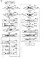
図5は、制御装置で実行される処理の一例を示すフローチャートである。この処理は、制御装置200によって、メイン処理から所定の制御周期ごとに繰返し呼出されて実行される。図5を参照して、制御装置200は、過給モードフラグがシングル過給モードを示す値であるか否かを判断する(ステップS101)。過給モードフラグは、現在制御されている過給モードを示すフラグであって、制御されている過給モードとして、シングル過給モード、ツイン過給モード、および、助走モードのいずれかを示す値を取り得る。
FIG. 5 is a flowchart showing an example of processing executed by the control device. This process is repeatedly called and executed by the
過給モードフラグがシングル過給モードを示さない(ステップS101でNO)と判断した場合、制御装置200は、実行する処理をステップS111の処理に進める。
If it is determined that the supercharging mode flag does not indicate the single supercharging mode (NO in step S101), the
一方、過給モードフラグがシングル過給モードを示す(ステップS101でYES)と判断した場合、制御装置200は、ツイン過給モードへの切替要求が有るか否かを判断する(ステップS102)。たとえば、前述したように、プライマリ過給機30の回転数がしきい値を超える場合に、ツイン過給モードへの切替要求が有ると判断する。切替要求が無い(ステップS102でNO)と判断した場合、制御装置200は、実行する処理をステップS111の処理に進める。
On the other hand, when it is determined that the supercharging mode flag indicates the single supercharging mode (YES in step S101), the
一方、切替要求が有る(ステップS102でYES)と判断した場合、制御装置200は、過給モードフラグを助走モードを示す値に書換える(ステップS103)。次に、制御装置200は、可変ノズル機構35の制御信号VN1で指令開度として出力する制限開度VN1thを、制限開度の推定モデルで算出する(ステップS104)。
On the other hand, if it is determined that there is a switching request (YES in step S102), the
図6は、制限開度の推定モデルを用いた制限開度の算出を説明するための図である。図6を参照して、まず、以下の数式(1)で示すノズル式を用いて目標有効開口面積μAを算出する。 FIG. 6 is a diagram for explaining the calculation of the limited opening degree using the estimation model of the limited opening degree. With reference to FIG. 6, first, the target effective opening area μA is calculated using the nozzle formula shown by the following mathematical formula (1).

なお、A:実開口面積、μA:目標有効開口面積、m:吸入空気量Ga+噴射燃料の質量流量Gf、R:気体定数、T4:エキマニ内温度、P6:排気通路の背圧、P4:エキマニ内圧力、a,b:P6/P4の値ごとに予め定められた定数、である。 A: actual opening area, μA: target effective opening area, m: intake air amount Ga + mass flow rate Gf of injected fuel, R: gas constant, T4: exhaust manifold internal temperature, P6: exhaust manifold back pressure, P4: exhaust manifold Internal pressure, a, b: a predetermined constant for each value of P6 / P4.
数式(1)のエキマニ内圧力P4として入力される制限エキマニ内圧力P4thは、排気バルブのバルブステムのオイルシールが吹き抜けたり、排気バルブが開弁したりしない値として予め定められる。吸入空気量Ga、エキマニ内温度T4、および、背圧P6は、それぞれ、エアフローメータ102、温度センサ114、および、圧力センサ116からの検出信号に応じて特定される。噴射燃料の質量流量Gfは、燃料の噴射のために制御装置200により算出される燃料噴射量から算出される。
The limit exhaust manifold internal pressure P4th input as the exhaust manifold internal pressure P4 in the formula (1) is predetermined as a value at which the oil seal of the valve stem of the exhaust valve does not blow through or the exhaust valve does not open. The intake air amount Ga, the exhaust manifold internal temperature T4, and the back pressure P6 are specified according to the detection signals from the
次に、VN開度と有効開口面積との関係を示す開度特性マップを用いて、算出された目標有効開口面積μAから制限開度VN1thを算出する。 Next, the limited opening VN1th is calculated from the calculated target effective opening area μA by using the opening characteristic map showing the relationship between the VN opening and the effective opening area.
図5に戻って、制御装置200は、可変ノズル機構35のベース開度VN1bが、VN1thより大きいか否かを判断する(ステップS105)。
Returning to FIG. 5, the
図7は、プライマリ過給機30の可変ノズル機構35のベース開度の算出を説明するための図である。図7を参照して、実線はタービン仕事、破線はタービン効率を示す。可変ノズル機構35においては、制御信号VN1で示される開度が開き側から閉まり側に変化するのに従って、ピークまでは、排気の膨張比が増大することに伴って、プライマリ過給機30のタービン仕事が上昇するが、ピークに達した後、閉まり側にさらに変化するのに従って、プライマリ過給機30を通過する排気のガス量が低下することに伴って、プライマリ過給機30のタービン仕事が低下する。また、プライマリ過給機30のタービン効率は、プライマリ過給機30の特性によりある開度でピークを持つ。
FIG. 7 is a diagram for explaining the calculation of the base opening degree of the
このタービン仕事がピークとなる開度と、タービン効率がピークとなる開度との間の開度を、ベース開度VN1bとする。たとえば、タービン仕事がピークとなる開度と、タービン効率がピークとなる開度との中央の開度を、ベース開度VN1bとする。 The opening degree between the opening degree at which the turbine work peaks and the opening degree at which the turbine efficiency peaks is defined as the base opening degree VN1b. For example, the central opening degree between the opening degree at which the turbine work peaks and the opening degree at which the turbine efficiency peaks is defined as the base opening degree VN1b.
この実施の形態のように、助走モードにおいて、制御信号VN1,VN2で示される指令開度を閉め側で制御すると、排気の流路面積が小さくなる一方、プライマリ過給機30の過給圧の段差が小さくなるため、エキマニ内圧力P4が上昇しやすくなってしまう。排気バルブのバルブステムのオイルシールが吹き抜けたり、排気バルブが開弁したりしないように、制限エキマニ内圧力P4thを設けているが、エキマニ内圧力P4が制限エキマニ内圧力P4thを超えてしまう懸念がある。
When the command opening indicated by the control signals VN1 and VN2 is controlled on the closed side in the run-up mode as in this embodiment, the exhaust flow path area becomes smaller, while the boost pressure of the
図8は、エキマニ内圧力と制御信号VN1で示される指令開度との変化を示す図である。図8を参照して、制御信号VN1で示される指令開度に制限を設けず、指令開度をベース開度VN1bとした場合、助走モード中にエキマニ内圧力P4が制限エキマニ内圧力P4thを超えてしまう場合がある。 FIG. 8 is a diagram showing changes between the pressure inside the exhaust manifold and the command opening degree indicated by the control signal VN1. With reference to FIG. 8, when the command opening indicated by the control signal VN1 is not limited and the command opening is set to the base opening VN1b, the exhaust manifold internal pressure P4 exceeds the limited exhaust manifold internal pressure P4th during the run-up mode. It may end up.
このため、指令開度が制限開度VN1thを超える場合は、指令開度を制限晃度VN1thとする。これにより、エキマニ内圧力P4が制限エキマニ内圧力P4thを超えないようにすることができる。 Therefore, when the command opening exceeds the limit opening VN1th, the command opening is set to the limit degree VN1th. Thereby, the exhaust manifold internal pressure P4 can be prevented from exceeding the limiting exhaust manifold internal pressure P4th.
図5に戻って、VN1bがVN1thより大きくない(ステップS105でNO)と判断した場合、制御装置200は、制御信号VN1での指令開度を、ベース開度VN1bとして、制御信号VN1を出力する(ステップS106)。
Returning to FIG. 5, when it is determined that VN1b is not larger than VN1th (NO in step S105), the
一方、VN1bがVN1thより大きい(ステップS105でYES)と判断した場合、制御装置200は、指令開度を制限開度VN1thとした制御信号VN1をプライマリ過給機30の可変ノズル機構35に出力する(ステップS107)。
On the other hand, when it is determined that VN1b is larger than VN1th (YES in step S105), the
ステップS106またはステップS107の後、制御装置200は、指令開度を、制御上の最小の開度である制御全閉(開口面積が0である訳ではない。)の開度VN2bとした制御信号VN2をセカンダリ過給機40の可変ノズル機構45に出力する(ステップS108)。
After step S106 or step S107, the

なお、Cpg:定圧比熱(0.26)、K:排気ガスの比熱比(1.33)、G4:過給機通過ガス量、T4:エキマニ内温度、P4:エキマニ内圧力、P6:排気通路の背圧、である。 Cpg: constant pressure specific heat (0.26), K: specific heat ratio of exhaust gas (1.33), G4: amount of gas passing through the supercharger, T4: temperature inside the exhaust mani, P4: pressure inside the exhaust gas, P6: exhaust passage Back pressure.

なお、Cpa:定温比熱(0.24)、k:空気の比熱比(1.4)、Ga:吸入空気量、T1:吸入空気温度、P3:過給機後吸気圧力、P2:過給機前吸気圧力、である。 Cpa: constant temperature specific heat (0.24), k: specific heat ratio of air (1.4), Ga: intake air amount, T1: intake air temperature, P3: intake pressure after supercharger, P2: supercharger The front intake pressure.
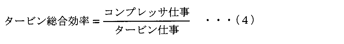
上に示した数式(2)から数式(4)は過給機の物理式である。ステップS107およびステップS108で示すように、この実施の形態においては、助走モードにおいて、プライマリ過給機30の可変ノズル機構35の開度よりも、セカンダリ過給機40の可変ノズル機構45の開度を閉め側で使用する。このため、開き側で使用する場合と比較して、セカンダリ過給機40の側の圧力損失の増加により、プライマリ過給機30の過給機通過ガス量G4の低下を抑制することができる。また、開き側で使用する場合と比較して、エキマニ内圧力P4の低下を抑制することができるため、膨張比P4/P6の低下を抑制できる。これにより、数式(2)によれば、プライマリ過給機30のタービン仕事の低下を抑制することができ、コンプレッサ仕事の低下を抑制することができる。また、数式(3)によれば、プライマリ過給機30の過給機後吸気圧力P3=第1過給圧Ppの低下を抑制することができる。
The formulas (2) to (4) shown above are the physical formulas of the turbocharger. As shown in steps S107 and S108, in this embodiment, in the approach mode, the opening degree of the
次に、制御装置200は、第2制御弁64の制御信号CV2を、第2制御弁64を開状態にする信号とし(ステップS109)、第3制御弁66の制御信号CV3を、第3制御弁66を開状態にする信号とする(ステップS110)。
Next, the
制御装置200は、過給モードフラグが、助走モードを示す値であるか否かを判断する(ステップS111)。助走モードでない(ステップS111でNO)と判断した場合、制御装置200は、実行する処理をこの助走モード処理の呼出元に戻す。
The
一方、助走モードである(ステップS111でYES)と判断した場合、制御装置200は、セカンダリ過給機40の第2過給圧Psが停滞しているか否かを判断する(ステップS112)。たとえば、第2過給圧Psが停滞しているか否かは、第2過給圧Psの時間微分値が、停滞と判断し得る所定値より小さくなったか否かによって判断されるようにする。
On the other hand, when it is determined that the run-up mode is set (YES in step S111), the
第2過給圧Psが停滞している(ステップS112でYES)と判断した場合、可変ノズル機構45の制御信号VN2での指令開度を制御信号VN1での指令開度と同じ開度に変更して、制御信号VN2を出力する(ステップS113)。
When it is determined that the second boost pressure Ps is stagnant (YES in step S112), the command opening in the control signal VN2 of the
図9は、セカンダリ過給機40の第2過給圧Psが停滞する場合を説明するための図である。図9を参照して、実線はセカンダリ過給機40の第2過給圧Ps、破線はプライマリ過給機30の第1過給圧Ppを示す。助走モードに切替えられる前に、第1過給圧Ppが高い場合、第2過給圧Psが第1過給圧Ppまで追付かずに、図9の二点鎖線で示すように、停滞してしまう場合がある。このような場合に、セカンダリ過給機40の可変ノズル機構45の開度を大きくすることで、図9で示すように、第2過給圧Psが第1過給圧Ppに追付き、第2過給圧Psの停滞を解消することができる。この場合に、この実施の形態においては、セカンダリ過給機40の可変ノズル機構45の開度を、プライマリ過給機30の可変ノズル機構35の開度と同じ開度まで大きくする。
FIG. 9 is a diagram for explaining a case where the second supercharging pressure Ps of the
図5に戻って、第2過給圧Psが停滞していない(ステップS112でNO)と判断した場合、または、ステップS113の後、制御装置200は、セカンダリ過給機40の第2過給圧Psがプライマリ過給機30の第1過給圧Ppと等しくなったか否かを判断する(ステップS114)。等しくなっていない(ステップS114でNO)と判断した場合、制御装置200は、実行する処理をこの助走モード処理の呼出元に戻す。
Returning to FIG. 5, when it is determined that the second supercharging pressure Ps is not stagnant (NO in step S112), or after step S113, the
一方、第2過給圧Psが第1過給圧Ppと等しくなった(ステップS114でYES)と判断した場合、過給モードフラグをツイン過給モードを示す値に変更し(ステップS115)、第1制御弁62の制御信号CV1を、第1制御弁62を開状態にする信号とし(ステップS116)、第2制御弁64の制御信号CV2を、第2制御弁64を閉状態にする信号とする(ステップS117)。その後、制御装置200は、実行する処理をこの助走モード処理の呼出元に戻す。
On the other hand, when it is determined that the second supercharging pressure Ps becomes equal to the first supercharging pressure Pp (YES in step S114), the supercharging mode flag is changed to a value indicating the twin supercharging mode (step S115). The control signal CV1 of the
図10は、この実施の形態における過給圧の変化について説明するための図である。図10を参照して、実線はセカンダリ過給機40の第2過給圧Ps、破線はプライマリ過給機30の第1過給圧Pp、2点鎖線は、従来の第1過給圧Ppおよび第2過給圧Psを示す。図5で示した制御を実行することによって、シングル過給モードとツイン過給モードとの間に助走モードが設けられることで、図11で示した従来のプライマリ過給機30の第1過給圧Ppの段差と比較して、第1過給圧Ppの段差を低減することができる。
FIG. 10 is a diagram for explaining a change in boost pressure in this embodiment. With reference to FIG. 10, the solid line is the second supercharging pressure Ps of the
[変形例]
(1) 前述した実施の形態では、エンジン1の吸気通路には、プライマリ過給機30およびセカンダリ過給機40が設けられるものとして説明したが、エンジン1の吸気通路には、プライマリ過給機30およびセカンダリ過給機40に加えて、たとえば、吸気絞り弁や排気再循環装置のEGR(Exhaust Gas Recirculation)ガス流入口が設けられてもよい。
[Modification example]
(1) In the above-described embodiment, the
(2) 前述した実施の形態では、エンジン1は、V型6気筒のエンジンを一例として説明したが、たとえば、その他の気筒レイアウト(たとえば、直列型あるいは水平型)のエンジンであってもよい。
(2) In the above-described embodiment, the
(3) 前述した実施の形態では、プライマリ過給機30の回転数によってシングル過給モードからツイン過給モードへの切替要求があるか否かを判定するものとして説明したが、プライマリ過給機30の回転数に加えて、プライマリ過給機30の効率や車両の運転状態(たとえば、加速状態)等のドライバビリティの観点からシングル過給モードからツイン過給モードへの切替要求があるか否かを判定してもよい。
(3) In the above-described embodiment, it has been described that it is determined whether or not there is a request for switching from the single supercharging mode to the twin supercharging mode based on the rotation speed of the
(4) 前述した実施の形態では、過給システムとして2つの過給機を備えるものとして説明したが、3つ以上の過給機を有するものであってもよい。 (4) In the above-described embodiment, the supercharging system has been described as having two superchargers, but it may have three or more superchargers.
(5) 前述した実施の形態では、第1圧力センサ106は、吸気管37内の圧力を検出するものとして説明したが、少なくともプライマリ過給機30のコンプレッサ31の第1過給圧Ppが検出できればよく、たとえば、吸気管27A内の圧力を検出してもよいし、あるいは、吸気管27B内の圧力を検出してもよい。
(5) In the above-described embodiment, the
(6) 前述した実施の形態では、制御装置200は、第2過給圧Psが第1過給圧Ppに到達したときに過給モードをツイン過給モードに切替えるものとして説明したが、少なくとも第2過給圧Psが第1過給圧Ppに到達していればよく、たとえば、制御装置200は、第2過給圧Psが第1過給圧Ppに到達した後の所定のタイミングで過給モードをツイン過給モードに切替えてもよい。
(6) In the above-described embodiment, the
(7) 前述した実施の形態においては、図5のステップS112で示したように、第2過給圧Psが停滞しているか否かは、第2過給圧Psの時間微分値が、停滞と判断し得る所定値より小さくなったか否かによって判断されるようにした。しかし、これに限定されず、第2過給圧Psが停滞しているか否かは、助走モードに切替えられてからの期間が、停滞と判断し得る所定期間以上となったか否かによって判断されるようにしてもよいし、Pp-Psの時間微分値が、停滞と判断し得る所定値より小さくなったか否かによって判断されるようにしてもよいし、第1過給圧Ppの時間微分値が、停滞と判断し得る所定値より小さくなったか否かによって判断されるようにしてもよい。 (7) In the above-described embodiment, as shown in step S112 of FIG. 5, whether or not the second supercharging pressure Ps is stagnant is determined by the time derivative value of the second supercharging pressure Ps being stagnant. It is now judged by whether or not it is smaller than the predetermined value that can be judged. However, not limited to this, whether or not the second boost pressure Ps is stagnant is determined by whether or not the period after switching to the run-up mode is longer than a predetermined period that can be determined to be stagnant. Alternatively, it may be determined whether or not the time derivative value of Pp-Ps is smaller than a predetermined value that can be determined to be stagnant, or the time derivative of the first boost pressure Pp may be determined. The value may be determined based on whether or not the value is smaller than a predetermined value that can be determined to be stagnant.
(8) 前述した実施の形態においては、図5のステップS113で示したように、セカンダリ過給機40の可変ノズル機構45の開度を、プライマリ過給機30の可変ノズル機構35の開度と同じ開度まで大きくするようにした。しかし、これに限定されず、セカンダリ過給機40の可変ノズル機構45の開度を大きくすればよく、セカンダリ過給機40の可変ノズル機構45の開度とプライマリ過給機30の可変ノズル機構35の開度との間の所定開度まで大きくするようにしてもよい。
(8) In the above-described embodiment, as shown in step S113 of FIG. 5, the opening degree of the
(9) 前述した実施の形態を、プライマリ過給機30とセカンダリ過給機40と制御装置200とによって構成される過給システムの開示、エンジン1等の内燃機関の開示、エンジン1等の内燃機関のECU100等の制御装置の開示、このような制御装置による制御方法の開示、または、このような内燃機関と制御装置とを含む内燃機関システムの開示として捉えることができる。
(9) Disclosure of a supercharging system including a
[効果]
(1) 図1から図4で示したように、過給システムは、エンジン1から排出される排気によって駆動するタービン32と、タービン32へ流入する排気の流速を開度によって調整する可変ノズル機構35とを含み、エンジン1に吸入される空気を過給するプライマリ過給機30と、エンジン1から排出される排気によって駆動するタービン42と、タービン42へ流入する排気の流速を開度によって調整する可変ノズル機構45とを含み、エンジン1に吸入される空気を過給するセカンダリ過給機40と、プライマリ過給機30において過給された空気がエンジン1に供給されるシングル過給モードから、プライマリ過給機30において過給された空気とセカンダリ過給機40において過給された空気とがエンジン1に供給されるツイン過給モードに切替える制御装置200とを備える。
[effect]
(1) As shown in FIGS. 1 to 4, the supercharging system is a variable nozzle mechanism that adjusts the flow velocity of the
図5で示したように、制御装置200は、シングル過給モードからツイン過給モードに切替える前に、セカンダリ過給機40に排気を供給しつつ、セカンダリ過給機40によって過給された空気をプライマリ過給機30に供給する助走モードでの運転を実行する。図5のステップS114からステップS117で示したように、助走モードでの運転中に、セカンダリ過給機40の第2過給圧Psがプライマリ過給機30の第1過給圧Ppに到達した場合にツイン過給モードに切替える。図5のステップS106からステップS108で示したように、助走モードでの運転を開始する場合に、セカンダリ過給機40の可変ノズル機構45の開度が、プライマリ過給機30の可変ノズル機構35の開度よりも小さくなるように可変ノズル機構45を制御する。
As shown in FIG. 5, the
これにより、セカンダリ過給機40の始動を補助する装置を追加することなく、過給圧の段差を低減することができる。その結果、ドライバビリティおよび過給機の信頼性が改善される。
This makes it possible to reduce the step in the supercharging pressure without adding a device that assists in starting the
(2) 制御装置200は、助走モードでの運転中に、セカンダリ過給機40の第2過給圧Psの上昇が停滞する場合、セカンダリ過給機40の可変ノズル機構45の開度がプライマリ過給機30の可変ノズル機構35の開度と同じとなるように可変ノズル機構45を制御する。これにより、セカンダリ過給機40の可変ノズル機構45の開度を小さくすることにより、第2過給圧Psの上昇が停滞する場合であっても、停滞を解消することができる。
(2) When the increase of the second supercharging pressure Ps of the
(3) 制御装置200は、助走モードでの運転中、プライマリ過給機30の可変ノズル機構35のベース開度VN1bが、プライマリ過給機30のタービン効率が最も良くなる開度とプライマリ過給機30のタービン仕事が最も良くなる開度との中央の開度となるようプライマリ過給機30の可変ノズル機構35を制御する。これにより、セカンダリ過給機40の可変ノズル機構45の開度が、プライマリ過給機30の可変ノズル機構35の開度よりも小さくなるように制御する場合であっても、プライマリ過給機30のタービン効率およびタービン仕事をバランス良く高い値とすることができる。
(3) In the
(4) 制御装置200は、エンジン1から排出される排気の圧力が制限エキマニ内圧力P4thに達する場合のプライマリ過給機30の可変ノズル機構35の制限開度VN1thを算出し、算出された制限開度VN1thをベース開度VN1bが上回る場合、可変ノズル機構35の開度が制限開度VN1thとなるよう可変ノズル機構35を制御する。これにより、エキマニ内圧力P4が制限エキマニ内圧力P4thを超えないようにすることができる。
(4) The
今回開示された各実施の形態は、適宜組合わせて実施することも予定されている。そして、今回開示された実施の形態は、すべての点で例示であって制限的なものではないと考えられるべきである。本開示の範囲は、上記した実施の形態の説明ではなくて特許請求の範囲によって示され、特許請求の範囲と均等の意味および範囲内でのすべての変更が含まれることが意図される。 It is also planned that the embodiments disclosed this time will be implemented in combination as appropriate. And it should be considered that the embodiments disclosed this time are exemplary in all respects and not restrictive. The scope of the present disclosure is set forth by the claims rather than the description of the embodiments described above, and is intended to include all modifications within the meaning and scope of the claims.
1 エンジン、10A,10B バンク、12A,12B 気筒、20 エアクリーナ、21,22,23,27A,27B,37,47 吸気管、25 インタークーラ、28A,28B 吸気マニホールド、30 プライマリ過給機、31,41 コンプレッサ、32,42 タービン、33,43 コンプレッサホイール、34,44 タービンホイール、35,45 可変ノズル機構、36,46 回転軸、40 セカンダリ過給機、48 還流管、50A,50B 排気マニホールド、51A,51B,52A,52B,53A,53B 排気管、62 第1制御弁、64 第2制御弁、66 第3制御弁、81 排気処理装置、102 エアフローメータ、104 エンジン回転数センサ、106 第1圧力センサ、108 第2圧力センサ、114 温度センサ、116 圧力センサ、200 制御装置。 1 engine, 10A, 10B bank, 12A, 12B cylinder, 20 air cleaner, 21,22,23,27A, 27B, 37,47 intake pipe, 25 intercooler, 28A, 28B intake manifold, 30 primary supercharger, 31, 41 Compressor, 32,42 Turbine, 33,43 Compressor Wheel, 34,44 Turbine Wheel, 35,45 Variable Nozzle Mechanism, 36,46 Rotating Shaft, 40 Secondary Supercharger, 48 Recirculation Pipe, 50A, 50B Exhaust Manifold, 51A , 51B, 52A, 52B, 53A, 53B Exhaust pipe, 62 1st control valve, 64 2nd control valve, 66 3rd control valve, 81 Exhaust treatment device, 102 Air flow meter, 104 Engine rotation speed sensor, 106 1st pressure Sensor, 108 second pressure sensor, 114 temperature sensor, 116 pressure sensor, 200 control device.
Claims (4)
前記エンジンから排出される排気によって駆動する第2タービンと、前記第2タービンへ流入する排気の流速を開度によって調整する第2可変ノズル機構とを含み、前記エンジンに吸入される空気を過給する第2過給機と、
前記第1過給機において過給された空気が前記エンジンに供給される第1過給モードから、前記第1過給機において過給された空気と前記第2過給機において過給された空気とが前記エンジンに供給される第2過給モードに切替える制御装置とを備え、
前記制御装置は、
前記第1過給モードから前記第2過給モードに切替える前に、前記第2過給機に排気を供給しつつ、前記第2過給機によって過給された空気を前記第1過給機に供給する助走運転を実行し、
前記助走運転中に、前記第2過給機の過給圧が前記第1過給機の過給圧に到達した場合に前記第2過給モードに切替え、
前記助走運転を開始する場合に、前記第2可変ノズル機構の開度が、前記第1可変ノズル機構の開度よりも小さくなるように前記第2可変ノズル機構を制御する、過給システム。 It includes a first turbine driven by exhaust gas discharged from the engine and a first variable nozzle mechanism that adjusts the flow velocity of the exhaust gas flowing into the first turbine according to the opening degree, and supercharges the air sucked into the engine. The first supercharger and
A second turbine driven by the exhaust gas discharged from the engine and a second variable nozzle mechanism for adjusting the flow velocity of the exhaust gas flowing into the second turbine according to the opening degree are included, and the air sucked into the engine is supercharged. The second supercharger to do
From the first supercharging mode in which the supercharged air in the first supercharger is supplied to the engine, the supercharged air in the first supercharger and the second supercharger are supercharged. It is equipped with a control device that switches to a second supercharging mode in which air is supplied to the engine.
The control device is
Before switching from the first supercharging mode to the second supercharging mode, the first supercharger uses the air supercharged by the second supercharger while supplying exhaust gas to the second supercharger. Perform a run-up operation to supply to
When the supercharging pressure of the second supercharger reaches the supercharging pressure of the first supercharger during the run-up operation, the mode is switched to the second supercharging mode.
A supercharging system that controls the second variable nozzle mechanism so that the opening degree of the second variable nozzle mechanism becomes smaller than the opening degree of the first variable nozzle mechanism when the run-up operation is started.
前記エンジンから排出される排気の圧力が制限圧力に達する場合の前記第1可変ノズル機構の制限開度を算出し、
算出された前記制限開度を前記所定開度が上回る場合、前記第1可変ノズル機構の開度が制限開度となるよう前記第1可変ノズル機構を制御する、請求項3に記載の過給システム。 The control device is
The limit opening of the first variable nozzle mechanism when the pressure of the exhaust gas discharged from the engine reaches the limit pressure is calculated.
The supercharging according to claim 3, wherein when the predetermined opening exceeds the calculated limited opening, the first variable nozzle mechanism is controlled so that the opening of the first variable nozzle mechanism becomes the limited opening. system.
Priority Applications (4)
| Application Number | Priority Date | Filing Date | Title |
|---|---|---|---|
| JP2018218071A JP7020380B2 (en) | 2018-11-21 | 2018-11-21 | Supercharging system |
| RU2021116466A RU2760416C1 (en) | 2018-11-21 | 2019-11-14 | Charging system |
| AU2019383763A AU2019383763B2 (en) | 2018-11-21 | 2019-11-14 | Supercharging system |
| PCT/JP2019/044647 WO2020105533A1 (en) | 2018-11-21 | 2019-11-14 | Supercharging system |
Applications Claiming Priority (1)
| Application Number | Priority Date | Filing Date | Title |
|---|---|---|---|
| JP2018218071A JP7020380B2 (en) | 2018-11-21 | 2018-11-21 | Supercharging system |
Publications (2)
| Publication Number | Publication Date |
|---|---|
| JP2020084856A JP2020084856A (en) | 2020-06-04 |
| JP7020380B2 true JP7020380B2 (en) | 2022-02-16 |
Family
ID=70773635
Family Applications (1)
| Application Number | Title | Priority Date | Filing Date |
|---|---|---|---|
| JP2018218071A Active JP7020380B2 (en) | 2018-11-21 | 2018-11-21 | Supercharging system |
Country Status (4)
| Country | Link |
|---|---|
| JP (1) | JP7020380B2 (en) |
| AU (1) | AU2019383763B2 (en) |
| RU (1) | RU2760416C1 (en) |
| WO (1) | WO2020105533A1 (en) |
Citations (3)
| Publication number | Priority date | Publication date | Assignee | Title |
|---|---|---|---|---|
| JP2005155356A (en) | 2003-11-21 | 2005-06-16 | Toyota Motor Corp | Engine supercharging device by parallel double turbocharger |
| JP2008255902A (en) | 2007-04-05 | 2008-10-23 | Toyota Motor Corp | Twin turbo control device |
| JP2010209845A (en) | 2009-03-11 | 2010-09-24 | Toyota Motor Corp | Control device for internal combustion engine |
Family Cites Families (9)
| Publication number | Priority date | Publication date | Assignee | Title |
|---|---|---|---|---|
| JP2686954B2 (en) * | 1988-04-05 | 1997-12-08 | マツダ株式会社 | Control device for supercharged engine |
| DE3903563C1 (en) * | 1988-07-19 | 1990-03-22 | Mtu Friedrichshafen Gmbh | |
| JP4337489B2 (en) * | 2003-09-26 | 2009-09-30 | トヨタ自動車株式会社 | Supercharger |
| DE102004030259A1 (en) * | 2004-06-23 | 2005-11-24 | Audi Ag | Dual turbo charger system for IC engine with exhaust driven turbines has one turbine with variable geometry to better match the engine demands |
| JP4300364B2 (en) * | 2004-09-29 | 2009-07-22 | 日産自動車株式会社 | Supercharging pressure regulator for variable supercharging system |
| DE102008018133A1 (en) * | 2008-04-10 | 2010-03-18 | Ford Global Technologies, LLC, Dearborn | Method for operating internal-combustion engine, involves arranging exhaust turbocharger, another exhaust turbocharger and shut-off valves in fresh air branch or exhaust gas branch with exhaust turbocharger arrangement |
| DE102009013040A1 (en) * | 2009-03-13 | 2010-09-16 | Volkswagen Ag | Internal combustion engine with register charging |
| US9151217B2 (en) * | 2012-12-21 | 2015-10-06 | Ford Global Technologies, Llc | Twin turbocharger wastegate control |
| JP7012611B2 (en) * | 2018-06-25 | 2022-01-28 | 株式会社豊田自動織機 | Supercharging system |
-
2018
- 2018-11-21 JP JP2018218071A patent/JP7020380B2/en active Active
-
2019
- 2019-11-14 RU RU2021116466A patent/RU2760416C1/en active
- 2019-11-14 AU AU2019383763A patent/AU2019383763B2/en active Active
- 2019-11-14 WO PCT/JP2019/044647 patent/WO2020105533A1/en active Application Filing
Patent Citations (3)
| Publication number | Priority date | Publication date | Assignee | Title |
|---|---|---|---|---|
| JP2005155356A (en) | 2003-11-21 | 2005-06-16 | Toyota Motor Corp | Engine supercharging device by parallel double turbocharger |
| JP2008255902A (en) | 2007-04-05 | 2008-10-23 | Toyota Motor Corp | Twin turbo control device |
| JP2010209845A (en) | 2009-03-11 | 2010-09-24 | Toyota Motor Corp | Control device for internal combustion engine |
Also Published As
| Publication number | Publication date |
|---|---|
| AU2019383763A1 (en) | 2021-06-03 |
| JP2020084856A (en) | 2020-06-04 |
| WO2020105533A1 (en) | 2020-05-28 |
| RU2760416C1 (en) | 2021-11-24 |
| AU2019383763B2 (en) | 2022-10-06 |
Similar Documents
| Publication | Publication Date | Title |
|---|---|---|
| RU139593U1 (en) | SYSTEM (OPTIONS) OF TURBOCHARGERS | |
| CN104755739A (en) | Controlling exhaust gas flow to the EGR system through a scavenger valve | |
| JP2014125992A (en) | Supercharging system and method of controlling supercharging system | |
| JP7012611B2 (en) | Supercharging system | |
| JP6772901B2 (en) | Internal combustion engine exhaust system | |
| JP6614221B2 (en) | Control device for internal combustion engine | |
| JP7020380B2 (en) | Supercharging system | |
| JP7159980B2 (en) | supercharging system | |
| JP5760773B2 (en) | Control device for turbocharged internal combustion engine | |
| JP2017106415A (en) | Control device for internal combustion engine | |
| JP2011111929A (en) | Internal combustion engine and method for controlling the same | |
| WO2020158405A1 (en) | Turbocharging system | |
| JP7056596B2 (en) | Supercharging system | |
| JP5930288B2 (en) | Internal combustion engine | |
| JP5906099B2 (en) | Engine supercharger | |
| JP7070368B2 (en) | Supercharging system | |
| JP7099406B2 (en) | Supercharging system | |
| JP2021085342A (en) | Supercharging system | |
| JP7121563B2 (en) | supercharging system | |
| JP2018184870A (en) | Control device for engine | |
| JP6332210B2 (en) | Engine supercharger | |
| JP2010024995A (en) | Control device for internal combustion engine | |
| JP6835655B2 (en) | EGR device | |
| JP2607624Y2 (en) | Intake device for supercharged engine | |
| JP2023043289A (en) | Supercharging device for internal combustion engine |
Legal Events
| Date | Code | Title | Description |
|---|---|---|---|
| A621 | Written request for application examination |
Free format text: JAPANESE INTERMEDIATE CODE: A621 Effective date: 20210216 |
|
| TRDD | Decision of grant or rejection written | ||
| A01 | Written decision to grant a patent or to grant a registration (utility model) |
Free format text: JAPANESE INTERMEDIATE CODE: A01 Effective date: 20220104 |
|
| A61 | First payment of annual fees (during grant procedure) |
Free format text: JAPANESE INTERMEDIATE CODE: A61 Effective date: 20220117 |
|
| R151 | Written notification of patent or utility model registration |
Ref document number: 7020380 Country of ref document: JP Free format text: JAPANESE INTERMEDIATE CODE: R151 |