JP7019589B2 - Efficient state machine for real-time dataflow programming - Google Patents
Efficient state machine for real-time dataflow programming Download PDFInfo
- Publication number
- JP7019589B2 JP7019589B2 JP2018549927A JP2018549927A JP7019589B2 JP 7019589 B2 JP7019589 B2 JP 7019589B2 JP 2018549927 A JP2018549927 A JP 2018549927A JP 2018549927 A JP2018549927 A JP 2018549927A JP 7019589 B2 JP7019589 B2 JP 7019589B2
- Authority
- JP
- Japan
- Prior art keywords
- state
- token
- component
- input
- data
- Prior art date
- Legal status (The legal status is an assumption and is not a legal conclusion. Google has not performed a legal analysis and makes no representation as to the accuracy of the status listed.)
- Active
Links
Images


Classifications
-
- G—PHYSICS
- G06—COMPUTING; CALCULATING OR COUNTING
- G06F—ELECTRIC DIGITAL DATA PROCESSING
- G06F9/00—Arrangements for program control, e.g. control units
- G06F9/06—Arrangements for program control, e.g. control units using stored programs, i.e. using an internal store of processing equipment to receive or retain programs
- G06F9/44—Arrangements for executing specific programs
- G06F9/448—Execution paradigms, e.g. implementations of programming paradigms
-
- G—PHYSICS
- G06—COMPUTING; CALCULATING OR COUNTING
- G06F—ELECTRIC DIGITAL DATA PROCESSING
- G06F8/00—Arrangements for software engineering
- G06F8/30—Creation or generation of source code
- G06F8/35—Creation or generation of source code model driven
-
- G—PHYSICS
- G06—COMPUTING; CALCULATING OR COUNTING
- G06F—ELECTRIC DIGITAL DATA PROCESSING
- G06F9/00—Arrangements for program control, e.g. control units
- G06F9/06—Arrangements for program control, e.g. control units using stored programs, i.e. using an internal store of processing equipment to receive or retain programs
- G06F9/44—Arrangements for executing specific programs
- G06F9/448—Execution paradigms, e.g. implementations of programming paradigms
- G06F9/4498—Finite state machines
-
- G—PHYSICS
- G06—COMPUTING; CALCULATING OR COUNTING
- G06F—ELECTRIC DIGITAL DATA PROCESSING
- G06F11/00—Error detection; Error correction; Monitoring
- G06F11/36—Preventing errors by testing or debugging software
- G06F11/3664—Environments for testing or debugging software
-
- G—PHYSICS
- G06—COMPUTING; CALCULATING OR COUNTING
- G06F—ELECTRIC DIGITAL DATA PROCESSING
- G06F11/00—Error detection; Error correction; Monitoring
- G06F11/36—Preventing errors by testing or debugging software
- G06F11/3668—Software testing
-
- G—PHYSICS
- G06—COMPUTING; CALCULATING OR COUNTING
- G06F—ELECTRIC DIGITAL DATA PROCESSING
- G06F16/00—Information retrieval; Database structures therefor; File system structures therefor
- G06F16/90—Details of database functions independent of the retrieved data types
- G06F16/95—Retrieval from the web
- G06F16/953—Querying, e.g. by the use of web search engines
- G06F16/9535—Search customisation based on user profiles and personalisation
-
- G—PHYSICS
- G06—COMPUTING; CALCULATING OR COUNTING
- G06F—ELECTRIC DIGITAL DATA PROCESSING
- G06F8/00—Arrangements for software engineering
- G06F8/30—Creation or generation of source code
- G06F8/31—Programming languages or programming paradigms
-
- G—PHYSICS
- G06—COMPUTING; CALCULATING OR COUNTING
- G06F—ELECTRIC DIGITAL DATA PROCESSING
- G06F8/00—Arrangements for software engineering
- G06F8/30—Creation or generation of source code
- G06F8/34—Graphical or visual programming
-
- G—PHYSICS
- G06—COMPUTING; CALCULATING OR COUNTING
- G06F—ELECTRIC DIGITAL DATA PROCESSING
- G06F8/00—Arrangements for software engineering
- G06F8/40—Transformation of program code
-
- G—PHYSICS
- G06—COMPUTING; CALCULATING OR COUNTING
- G06F—ELECTRIC DIGITAL DATA PROCESSING
- G06F9/00—Arrangements for program control, e.g. control units
- G06F9/06—Arrangements for program control, e.g. control units using stored programs, i.e. using an internal store of processing equipment to receive or retain programs
- G06F9/46—Multiprogramming arrangements
- G06F9/48—Program initiating; Program switching, e.g. by interrupt
Landscapes
- Engineering & Computer Science (AREA)
- Theoretical Computer Science (AREA)
- Software Systems (AREA)
- General Engineering & Computer Science (AREA)
- Physics & Mathematics (AREA)
- General Physics & Mathematics (AREA)
- Databases & Information Systems (AREA)
- Quality & Reliability (AREA)
- Computer Hardware Design (AREA)
- Computing Systems (AREA)
- Data Mining & Analysis (AREA)
- Computer And Data Communications (AREA)
- Debugging And Monitoring (AREA)
- Information Transfer Between Computers (AREA)
- Stored Programmes (AREA)
- Data Exchanges In Wide-Area Networks (AREA)
- Information Retrieval, Db Structures And Fs Structures Therefor (AREA)
- Devices For Executing Special Programs (AREA)
- User Interface Of Digital Computer (AREA)
- Testing Or Calibration Of Command Recording Devices (AREA)
Description
説明
関連出願との相互参照
この特許出願は、2016年3月23日に出願された米国特許出願第62/312,106号、第62/312,187号、第62/312,223号、および第62/312,255号の利益を主張し、それらは、本願で引用されたすべての他の引例とともに、引用により援用される。
Explanation Cross-reference with related applications This patent application is a US patent application filed March 23, 2016, Nos. 62 / 312, 106, 62 / 312, 187, 62 / 312, 223, and. Claiming the interests of Nos. 62 / 312,255, they are incorporated by citation, along with all other references cited in this application.
発明の背景
この発明はコンピューティングの分野に関し、より具体的には、産業用機械によって生成される大量のデータを取扱うためのエッジコンピューティングにおいて用いられてもよいリアルタイムデータフロープログラミングのための効率的な状態機械に関する。
Background of the Invention The present invention relates to the field of computing, more specifically, efficient for real-time dataflow programming which may be used in edge computing for handling large amounts of data generated by industrial machines. State related to the machine.
従来の企業ソフトウェアアプリケーションホスティングは、規模の経済性およびシステム効率を活用するために、データセンターまたは「クラウド」インフラストラクチャに依拠してきた。しかしながら、これらのデータセンターは、企業がそのビジネス活動のほとんどを行なう物理的活動地点(たとえば工場、倉庫、小売店など)から任意に離れている場合がある。産業用インターネット・オブ・シングス(industrial Internet of things :IIoT)とは、非常に高頻度でイベントを追跡するセンサを用いた物理的活動の計測に依拠するデバイスまたは使用事例の集合を指す。 Traditional enterprise software application hosting has relied on data centers or "cloud" infrastructure to take advantage of economies of scale and system efficiency. However, these data centers may be arbitrarily remote from the physical activity points (eg factories, warehouses, retail stores, etc.) where a company conducts most of its business activities. The Industrial Internet of Things (IIoT) refers to a set of devices or use cases that rely on the measurement of physical activity using sensors that track events very frequently.
多くのセクターにおける産業用機械が、製造、石油およびガス、採鉱、運輸、電力および水、再生可能エネルギー、ヘルスケア、小売、スマートビルディング、スマートシティ、および接続された車両を含むこのインターネット・オブ・シングス(IoT)の下に入る。クラウドコンピューティングの成功にもかかわらず、多くの欠点が存在する。そのデータのすべてをクラウドストレージへ送信することは実用的ではない。なぜなら、接続性が常にそこにあるとは限らず、帯域幅が十分ではなく、レイテンシにおける変動が高すぎ、または、帯域幅が存在していたとしても、それは法外なコストがかかるためである。接続性、帯域幅、およびコストが問題ではなかったとしても、リアルタイムの意思決定および予測保守はなく、それは機械への著しい損傷をもたらし得る。 Industrial machinery in many sectors is this Internet of Things, including manufacturing, oil and gas, mining, transportation, electricity and water, renewable energy, healthcare, retail, smart buildings, smart cities, and connected vehicles. Enter under the Things (IoT). Despite the success of cloud computing, there are many drawbacks. It is not practical to send all of that data to cloud storage. This is because connectivity is not always there, bandwidth is not sufficient, latency variability is too high, or bandwidth is present, at an exorbitant cost. .. Even if connectivity, bandwidth, and cost are not an issue, there is no real-time decision making and predictive maintenance, which can result in significant damage to the machine.
したがって、改良されたエッジ解析を含む改良されたコンピューティングシステム、アーキテクチャ、および手法、ならびにリアルタイムデータフロープログラミングのためのより効率的な状態機械が、産業用機械によって生成される大量のデータを取扱うために必要とされる。 Therefore, improved computing systems, architectures, and techniques, including improved edge analysis, and more efficient state machines for real-time dataflow programming can handle large amounts of data generated by industrial machines. Needed for.
発明の簡単な概要
効率的な状態機械に基づくパターンマッチング技術は、入力キューにおけるトークンを処理し、バックトラッキングなしに、1つ以上の所定の入力パターンにマッチする、トークンのシーケンスにおけるパターンを識別する。トークンには、データを含むこと、またはデータを含まないこと、および時間コンポーネントを含むことが可能である。トークンは、物性をデジタル量に変換するセンサによって生成されたデータのストリームであることができる。パターンマッチング技術は、入力キューを単一の方向において処理し、以前に検査されたトークンを検査しない。ある実現例では、マッチングされるべき特定のパターンを、状態機械を使用して指定し、状態機械は状態表において指定され、状態スタックを使用して動作する。
Brief Overview of the Invention An efficient state machine-based pattern matching technique processes tokens in an input queue and identifies patterns in a sequence of tokens that match one or more given input patterns without backtracking. .. Tokens can contain data or no data, and can contain time components. A token can be a stream of data generated by a sensor that converts physical properties into digital quantities. Pattern matching techniques process input queues in a single direction and do not inspect previously inspected tokens. In one embodiment, a particular pattern to be matched is specified using a state machine, the state machine is specified in the state table, and the state stack is used to operate.
具体的な実現例では、パターンマッチング技術は、エッジコンピューティングシステムにおいて用いられ、エッジでのインテリジェンスを可能にするための方法である。特徴は、以下を含む。ゲートウェイデバイスまたは組込まれたシステム上でホストされるソフトウェア層においてセンサデータによってトリガすること。ソフトウェア層はローカルエリアネットワークに接続される。サービス、アプリケーション、およびデータ処理エンジンのリポジトリが、ソフトウェア層によってアクセス可能にされる。ソフトウェア層によって利用可能にされた式言語を通して、センサデータを特定条件の発生の意味論的記述と整合させること。式を連続的に実行することによってパターンイベントを自動的に発見すること。アプリケーションおよび解析式をつなぐために、ソフトウェア層によって管理されるネットワーク全体のゲートウェイデバイスおよび組込まれたシステムを越えて、サービスおよびアプリケーションをインテリジェントに構成すること。リソース利用可能性に基づいてアプリケーションおよび解析のレイアウトを最適化すること。ソフトウェア層の健全性を監視すること。未加工のセンサデータまたは式の結果を、ローカル時系列データベースまたはクラウドストレージに格納すること。サービスおよびコンポーネントは、どのゲートウェイ環境でも円滑な動作を保証するために、コンテナ化され得る。 In a specific implementation, pattern matching techniques are used in edge computing systems to enable intelligence at the edge. Features include: Triggered by sensor data at a software layer hosted on a gateway device or embedded system. The software layer is connected to the local area network. Services, applications, and data processing engine repositories are made accessible by the software layer. To align the sensor data with the semantic description of the occurrence of a particular condition through the formula language made available by the software layer. Automatically discover pattern events by executing expressions continuously. Intelligently configure services and applications across network-wide gateway devices and embedded systems managed by the software layer to connect applications and analytic expressions. Optimize application and analysis layouts based on resource availability. Monitor the health of the software layer. Store raw sensor data or expression results in a local time series database or cloud storage. Services and components can be containerized to ensure smooth operation in any gateway environment.
エッジインテリジェンスは、インターネット・オブ・シングス(IoT)データのソースでイネーブルにされる。システムは、リアルタイムのエッジ解析およびアプリケーションのために、IoTデバイスセンサデータへの強化(enrich)されたアクセス(ストリームモードまたはバッチモード、または双方)を提供する。システムは、低メモリフットプリント機械で動作する高性能解析エンジンを通して解析関数および解析式を実行するための高効率で表現的なコンピュータ言語を含む。システムは、さらなる機械学習のために収集データをクラウドへ発行することを可能にする。システムは、エッジアプリを開発するためのソフトウェア開発キットを含む。クラウドベースの管理コンソールが、エッジデプロイメント、構成、アプリケーション、および解析式の管理を可能にする。 Edge intelligence is enabled at the source of Internet of Things (IoT) data. The system provides enriched access (stream mode and / or batch mode) to IoT device sensor data for real-time edge analysis and applications. The system includes a highly efficient and expressive computer language for executing analytic functions and expressions through a high performance analysis engine running on a low memory footprint machine. The system allows the collected data to be published to the cloud for further machine learning. The system includes a software development kit for developing edge apps. A cloud-based management console allows you to manage edge deployments, configurations, applications, and analytic expressions.
エッジインフラストラクチャおよびプラットフォームの特定の一実現化例は、フォグホーン・システムズ・インコーポレイテッド(FogHorn Systems, Inc)(フォグホーン)による。フォグホーンのウェブサイト、www.foghorn-systems.com、出版物(白書、ユーザガイド、指導書、ビデオなどを含む)、ならびに、フォグホーンの技術および製品についての他の出版物が、引用により援用される。 An example of a particular realization of edge infrastructure and platforms is by FogHorn Systems, Inc. The foghorn website, www.foghorn-systems.com, publications (including white papers, user guides, instructional books, videos, etc.), as well as other publications on foghorn technology and products are incorporated by citation. ..
フォグホーンは、産業用および商業用インターネット・オブ・シングス(IoT)データのためのエッジインテリジェンスを可能にするためのプラットフォームを提供する。何百億もの産業用および商業用IoTデバイスによって生成されるデータの量は、インターネット全体を圧倒するのに十分莫大になるであろう。フォグホーンのプラットフォームはIoTデータを、それがまさしく生じるところ、すなわちネットワークのエッジで処理し、解析し、それに応答する。フォグホーンの「インテリジェントエッジ」ソフトウェアプラットホームは、前例がないレベルの自動化、業務効率、コスト削減などを可能にする。 Foghorn provides a platform to enable edge intelligence for industrial and commercial Internet of Things (IoT) data. The amount of data generated by tens of billions of industrial and commercial IoT devices will be huge enough to overwhelm the entire Internet. The foghorn platform processes, analyzes, and responds to IoT data exactly where it occurs, at the edge of the network. Foghorn's "intelligent edge" software platform enables unprecedented levels of automation, operational efficiency and cost savings.
産業用インターネット・オブ・シングス(IIoT)は、センサ、機械類、およびコンピュータといった、相互接続された産業用および商業用デバイスからなる。IIoTの目標は、分散された企業全体にわたって、より優れたデバイス制御、データ管理、機械自動化、および業務効率を可能にすることである。会社は、システム全体の管理および最適化のためにクラウドコンピューティングを活用しながら、リアルタイムの解析および自動化応答を使用してグリーンフィールドIIoT機会を捕らえるためにエッジでフォグコンピューティングを適用することができる。フォグホーンのエッジコンピューティングプラットフォームはまた、追加のコンピューティングリソースを追加することが実行できない場合に、既存のプログラマブルロジックコントローラ(programmable logic controller:PLC)(たとえば、ブラウンフィールド機会)において動作するように設計される。ブラウンフィールドとは、確立されたシステムを勘案しながら情報技術(information technology:IT)問題領域を解決するための新しいシステムの実現を指す。新しいソフトウェアアーキテクチャは、既存のおよび動作中のソフトウェアを考慮する。 The Industrial Internet of Things (IIoT) consists of interconnected industrial and commercial devices such as sensors, machinery, and computers. The goal of IIoT is to enable better device control, data management, machine automation, and operational efficiency across distributed enterprises. Companies can apply fog computing at the edge to seize Greenfield IIoT opportunities using real-time analytics and automated responses while leveraging cloud computing for overall system management and optimization. .. Foghorn's edge computing platform is also designed to work with existing programmable logic controllers (PLCs) (eg Brownfield Opportunities) when additional computing resources cannot be added. To. Brownfield refers to the realization of a new system for solving information technology (IT) problem domains while considering an established system. The new software architecture takes into account existing and running software.
エッジインテリジェンスプラットフォームとは、IIoTデバイスが存在するエッジのより近くまでデータ処理および解析を拡張する、フォグコンピューティング概念に基づいたソフトウェアベースのソリューションである。遠くの集中型クラウドへすべてのデータを送信する代わりに、エッジデバイスとの近接性を維持することは、待ち時間を最小化し、最大性能、より速い応答時間、ならびにより効果的な保守および業務戦略を可能にする。それはまた、全体的な帯域幅要件と、広範に分散されたネットワークを管理するコストとを著しく減少させる。 An edge intelligence platform is a software-based solution based on the fog computing concept that extends data processing and analysis closer to the edge where the IIoT device resides. Maintaining proximity to edge devices instead of sending all data to a distant centralized cloud minimizes latency, maximum performance, faster response times, and more effective maintenance and business strategies. Enables. It also significantly reduces the overall bandwidth requirements and the cost of managing a widely distributed network.
エッジでのIIoT操作に焦点を合わせることは、全体的な帯域幅要件を減少させ、時間依存の条件への即時の自動化応答を可能にする。産業界は何十億もの新しいIIoTデバイスを追加しており、これらのデバイスは集団で、毎日多くのペタバイトのデータを生成する。このデータのすべてをクラウドに送信することは、法外なコストがかかるだけでなく、より大きいセキュリティリスクも生み出す。エッジで動作することは、はるかにより速い応答時間、リスクの減少、および全体的コストの低下を保証する。 Focusing on IIoT operations at the edge reduces overall bandwidth requirements and allows for immediate automated response to time-dependent conditions. The industry is adding billions of new IIoT devices, which collectively generate a lot of petabytes of data every day. Sending all of this data to the cloud is not only exorbitantly costly, but also creates a greater security risk. Working at the edge guarantees much faster response times, reduced risk, and lower overall costs.
2015年8月27日に出願された米国特許出願第62/210,981号、および2016年8月29日に出願された米国特許出願第15/250,720号は、ここに引用により援用され、エッジコンピューティング環境およびプラットフォームを記載する。2017年3月23日に出願された米国特許出願第15/467,313号は、ここに引用により援用され、リアルタイムデータフロープログラミングにおけるパターン駆動型反応の構成を記載する。2017年3月23日に出願された米国特許出願第15/467,318号は、ここに引用により援用され、リアルタイムデータフロープログラミング言語のためのツールおよび方法を記載する。 US Patent Application Nos. 62 / 210,981 filed August 27, 2015 and US Patent Application Nos. 15 / 250,720 filed August 29, 2016 are incorporated herein by reference. , Edge computing environment and platform. US Patent Application No. 15 / 467,313, filed March 23, 2017, is incorporated herein by reference to describe the configuration of pattern-driven reactions in real-time dataflow programming. US Patent Application No. 15 / 467,318, filed March 23, 2017, is incorporated herein by reference to describe tools and methods for a real-time dataflow programming language.
一実装形態では、方法は、データストリームをセンサ(たとえば物理量を監視し、監視された物理量をデジタル形式のデータストリームに変換するハードウェアデバイス)から受信することと、データストリームを入力キュー(たとえばFIFOメモリ)に格納することとを備え、各トークンは、データが受信されるときのタイムスタンプとともに格納されるデータストリームのデータを含み(またはデータを含まず)、前記方法はさらに、単一の方向に入力キューを通ってトークンを読出し、以前に読出されたトークンを再読出ししないことによって、1つ以上の所定のパターンにマッチする、データストリームにおけるパターンを識別することと、データストリーム内において所定のパターンを識別すると、所定のパターンが識別されたという肯定的な表示を出力キューにおいて出力することとを備える。 In one implementation, the method is to receive the data stream from a sensor (eg, a hardware device that monitors the physical quantity and converts the monitored physical quantity into a digital data stream) and puts the data stream into an input queue (eg, FIFA). Each token contains (or does not contain) data in a data stream that is stored with a time stamp when the data is received, and the method further comprises a single direction. Identifying a pattern in a data stream that matches one or more predetermined patterns by reading tokens through an input queue and not rereading previously read tokens, and a given pattern within the data stream. Identifying a pattern comprises outputting a positive indication in the output queue that a predetermined pattern has been identified.
別の実装形態では、システムは以下を備える:入力キューは、FIFOメモリとして編成されるコンピュータメモリにおいてメモリ位置を含み、 入力キューは処理されるべきトークンを格納し、各トークンは、データを含み(またはデータを含まず)、トークンが入力キューに入ったときのタイムスタンプを含む。ドライバコンポーネントは、バックトラッキングなしで入力キューにおけるトークンを処理し、1つ以上の所定の入力パターンにマッチする、トークンのシーケンスにおけるパターンを識別し、マッチした所定の入力パターンを識別すると、出力イベント出力を生成する。出力キューは、FIFOメモリとして編成されるコンピュータメモリにおいて第2のメモリ位置を含み、出力キューは、ドライバコンポーネントによって生成された出力イベントのシーケンスを格納する。状態表コンポーネントは、所定の入力パターンを状態表フォーマットで格納する。状態スタックコンポーネントは、LIFOメモリとして編成されるコンピュータメモリにおいて第3のメモリ位置を含み、スタックフレームには、変換状態番号、記号、もしくはデッドライン、または任意の組み合わせが含まれる。 In another embodiment, the system comprises: an input queue contains memory locations in computer memory organized as FIFA memory, an input queue stores tokens to be processed, and each token contains data ( Or does not include data), including the time stamp when the token entered the input queue. The driver component processes the tokens in the input queue without backtracking, identifies the patterns in the sequence of tokens that match one or more predetermined input patterns, and identifies the matched predetermined input patterns to output an output event. To generate. The output queue contains a second memory location in computer memory organized as FIFO memory, and the output queue stores a sequence of output events generated by the driver component. The state table component stores a predetermined input pattern in the state table format. The state stack component contains a third memory location in computer memory organized as LIFO memory, and the stack frame contains conversion state numbers, symbols, or deadlines, or any combination.
別の実装形態では、方法は以下を備える:FIFOメモリとして編成されるコンピュータメモリにおいて第1のメモリ位置を含む入力キューを提供することを備え、入力キューは処理されるべきトークンを格納し、各トークンは、データを含み(またはデータを含まず)、トークンが入力キューに入ったときのタイムスタンプを含む。ドライバコンポーネントを提供することを備え、ドライバコンポーネントは、バックトラッキングなしで入力キューにおけるトークンを処理し、1つ以上の所定の入力パターンにマッチする、トークンのシーケンスにおけるパターンを識別し、マッチした所定の入力パターンを識別すると、出力イベント出力を生成する。FIFOメモリとして編成されるコンピュータメモリにおいて第2のメモリ位置を含む出力キューを提供することを備え、出力キューは、ドライバコンポーネントによって生成された出力イベントを格納する。所定の入力パターンを状態表フォーマットで格納する状態表コンポーネントを提供することを備える。スタックフレームを格納する状態スタックコンポーネント(たとえばLIFOメモリ)を提供することを備える。 In another embodiment, the method comprises: providing an input queue containing a first memory location in computer memory organized as FIFA memory, where the input queue stores tokens to be processed and each The token contains (or does not contain) data and contains the time stamp when the token entered the input queue. Provided to provide a driver component, the driver component processes tokens in an input queue without backtracking, identifies patterns in a sequence of tokens that match one or more predetermined input patterns, and matches predetermined. Once the input pattern is identified, it produces an output event output. It comprises providing an output queue containing a second memory location in computer memory organized as FIFO memory, which stores output events generated by the driver component. It is provided with a state table component that stores a predetermined input pattern in a state table format. It comprises providing a state stack component (eg, LIFO memory) for storing stack frames.
本発明の他の目的、特徴、および利点は、以下の詳細な説明および添付図面を考慮すれば明らかになるであろう。図面では、図全体を通し、同じ参照記号は同じ特徴を表わす。 Other objects, features, and advantages of the invention will become apparent in light of the following detailed description and accompanying drawings. In the drawings, the same reference symbols represent the same features throughout the figure.
発明の詳細な説明
図1は、本発明の一実施形態を取入れる分散型コンピュータネットワーク100の簡略ブロック図である。コンピュータネットワーク100は、複数の通信リンク128を介して通信ネットワーク124に結合された、複数のクライアントシステム113、116、および119と、サーバシステム122とを含む。通信ネットワーク124は、分散型ネットワーク100のさまざまなコンポーネントが互いに通信して情報を交換することを可能にするためのメカニズムを提供する。
Detailed Description of the Invention FIG. 1 is a simplified block diagram of a distributed
通信ネットワーク124はそれ自体、多くの相互接続されたコンピュータシステムおよび通信リンクで構成されてもよい。通信リンク128は、配線リンク、光リンク、衛星または他の無線通信リンク、波動伝搬リンク、もしくは、情報の通信のための他のメカニズムであってもよい。通信リンク128は、DSL、ケーブル、イーサネット(登録商標)または他の配線リンク、受動または能動光リンク、3G、3.5G、4Gおよび他のモビリティ、衛星または他の無線通信リンク、波動伝搬リンク、もしくは、情報の通信のための任意の他のメカニズムであってもよい。
The
図1に示すさまざまなシステム間の通信を容易にするために、さまざまな通信プロトコルが使用されてもよい。これらの通信プロトコルは、VLAN、MPLS、TCP/IP、トンネリング、HTTPプロトコル、無線アプリケーションプロトコル(wireless application protocol:WAP)、ベンダー固有プロトコル、カスタマイズされたプロトコルなどを含んでいてもよい。一実施形態では、通信ネットワーク124はインターネットであり、他の実施形態では、通信ネットワーク124は、ローカルエリアネットワーク(local area network:LAN)、ワイドエリアネットワーク(wide area network:WAN)、無線ネットワーク、イントラネット、私的ネットワーク、公的ネットワーク、スイッチドネットワーク、およびこれらの組合せなどを含む、任意の好適な通信ネットワークであってもよい。
Various communication protocols may be used to facilitate communication between the various systems shown in FIG. These communication protocols may include WLAN, MPLS, TCP / IP, tunneling, HTTP protocol, wireless application protocol (WAP), vendor specific protocol, customized protocol and the like. In one embodiment, the
図1の分散型コンピュータネットワーク100は、本発明を取入れる実施形態の単なる例示であり、請求項に記載されるようなこの発明の範囲を限定しない。当業者であれば、他の変形、変更、および代替物を認識するであろう。たとえば、2つ以上のサーバシステム122が通信ネットワーク124に接続されてもよい。別の例として、複数のクライアントシステム113、116、および119は、アクセスプロバイダ(図示せず)を介して、または何らかの他のサーバシステムを介して、通信ネットワーク124に結合されてもよい。
The distributed
クライアントシステム113、116、および119は典型的には、情報を提供するサーバシステムから情報を要求する。この理由により、サーバシステムは典型的には、クライアントシステムよりも多いコンピューティングおよびストレージ容量を有する。しかしながら、特定のコンピュータシステムは、そのコンピュータシステムが情報を要求しているか、または提供しているかに依存して、クライアントまたはサーバとして、双方として機能してもよい。加えて、この発明の局面はクライアント-サーバ環境を使用して説明されてきたが、この発明はスタンドアロンコンピュータシステムにおいても具現化され得ることが明らかであるはずである。
サーバ122は、クライアントシステム113、116、および119から情報要求を受信し、要求を満たすために必要とされる処理を行ない、要求に対応する結果を要求元クライアントシステムへ送り返す役割を担う。要求を満たすために必要とされる処理は、サーバシステム122によって行なわれてもよく、またはそれに代えて、通信ネットワーク124に接続された他のサーバに委任されてもよい。
The
クライアントシステム113、116、および119は、ユーザが、サーバシステム122によって格納された情報にアクセスし、情報をクエリすることを可能にする。特定の一実施形態では、クライアントシステムは、デスクトップアプリケーション、もしくはモバイルスマートフォンまたはタブレットアプリケーションなどのスタンドアロンアプリケーションとして動作可能である。別の実施形態では、クライアントシステム上で実行される「ウェブブラウザ」アプリケーションが、ユーザが、サーバシステム122によって格納された情報を選択し、情報にアクセスし、情報を検索し、またはクエリすることを可能にする。ウェブブラウザの例は、マイクロソフト社(Microsoft Corporation)によって提供されるインターネットエクスプローラ(Internet Explorer)ブラウザプログラム、モジラ(Mozilla)によって提供されるファイアーフォックス(Firefox)(登録商標)ブラウザ、グーグル(Google(登録商標))によって提供されるクローム(Chrome)ブラウザ、アップル(Apple)によって提供されるサファリ(Safari)ブラウザなどを含む。
クライアント-サーバ環境では、いくつかのリソース(たとえばファイル、音楽、ビデオ、またはデータ)はクライアントで格納され、一方、他のリソースは、サーバなどネットワークにおけるどこか他のところに格納されるかまたはそこから配信され、ネットワーク(たとえばインターネット)を介してアクセス可能である。したがって、ユーザのデータは、ネットワークまたは「クラウド」に格納され得る。たとえば、ユーザは、クラウド(たとえばサーバ)上にリモートに格納されている、クライアントデバイス上の文書に対して作業することができる。クライアントデバイス上のデータは、クラウドと同期され得る。 In a client-server environment, some resources (eg files, music, video, or data) are stored on the client, while other resources are stored or are stored somewhere else in the network, such as the server. Delivered from and accessible over a network (eg the Internet). Therefore, the user's data may be stored on the network or in the "cloud". For example, a user can work on a document on a client device that is stored remotely on a cloud (eg, a server). Data on client devices can be synchronized with the cloud.
図2は、本発明の例示的なクライアントまたはサーバシステムを示す。一実施形態では、ユーザは、図2に示すようなコンピュータワークステーションシステムを通して、システムとインターフェイス接続する。図2は、モニタ203と、スクリーン205と、筐体207(システムユニット、キャビネット、またはケースとも呼ばれてもよい)と、キーボードまたは他の人間入力デバイス209と、マウスまたは他のポインティングデバイス211とを含む、コンピュータシステム201を示す。マウス211は、マウスボタン213などの1つ以上のボタンを有していてもよい。
FIG. 2 shows an exemplary client or server system of the present invention. In one embodiment, the user interfaces with the system through a computer workstation system as shown in FIG. FIG. 2 includes a
本発明は、特定のフォームファクタ(たとえば、デスクトップコンピュータのフォームファクタ)のどのコンピューティングデバイスにも限定されず、さまざまなフォームファクタのあらゆるタイプのコンピューティングデバイスを含み得る、ということが理解されるべきである。ユーザは、スマートフォン、パーソナルコンピュータ、ラップトップ、電子タブレットデバイス、全地球測位システム(global positioning system:GPS)受信機、ポータブルメディアプレイヤー、携帯情報端末(personal digital assistant:PDA)、他のネットワークアクセスデバイス、および、データを送受信できる他の処理デバイスを含む、任意のコンピューティングデバイスとインターフェイス接続することができる。 It should be understood that the invention is not limited to any computing device in a particular form factor (eg, desktop computer form factor), but may include any type of computing device in different form factors. Is. Users include smartphones, personal computers, laptops, electronic tablet devices, global positioning system (GPS) receivers, portable media players, personal digital assistants (PDAs), and other network access devices. And can be interfaced with any computing device, including other processing devices capable of sending and receiving data.
たとえば、特定の一実現化例では、クライアントデバイスは、アップルiPhone(登録商標)(たとえば、アップルiPhone6)、アップルiPad(登録商標)(たとえば、アップルiPad、またはアップルiPad mini)、アップルiPod(登録商標)(たとえば、アップルiPod Touch)、サムスン(Samsung)ギャラクシー(Galaxy)製品(たとえば、ギャラクシーSシリーズ製品、またはギャラクシーノート(Galaxy Note)シリーズ製品)、グーグル(登録商標)ネクサス(Nexus)デバイス(たとえば、グーグルネクサス6、グーグルネクサス7、またはグーグルネクサス9)、およびマイクロソフトデバイス(たとえば、マイクロソフトサーフェス(Surface)タブレット)といった、スマートフォンまたはタブレットデバイスであり得る。典型的には、スマートフォンは、電話部分(および関連付けられた無線機)とコンピュータ部分とを含み、それらはタッチスクリーンディスプレイを介してアクセス可能である。
For example, in one particular realization example, the client device is an Apple iPhone® (eg, Apple iPhone6), an Apple iPad® (eg, Apple iPad, or Apple iPad mini), an Apple iPad®. ) (For example, Apple iPad Touch, Samsung Galaxy products (eg Galaxy S series products, or Galaxy Note series products), Google® Nexus devices (eg, eg) It can be a smartphone or tablet device, such as a
電話部分のデータ(たとえば、連絡先および電話番号)と、コンピュータ部分のデータ(たとえば、ブラウザを含むアプリケーションプログラム、画像、ゲーム、ビデオ、および音楽)とを格納するための不揮発性メモリがある。スマートフォンは典型的には、写真およびビデオを撮るためのカメラ(たとえば、前向きのカメラまたは後部カメラ、もしくは両方)を含む。たとえば、スマートフォンまたはタブレットは、1つ以上の他のデバイスにストリーミングされ得るライブビデオを撮るために使用され得る。 There is non-volatile memory for storing data in the telephone part (eg, contacts and phone numbers) and data in the computer part (eg, application programs including browsers, images, games, videos, and music). Smartphones typically include cameras for taking pictures and videos (eg, forward-facing cameras and / or rear-facing cameras). For example, a smartphone or tablet can be used to capture live video that can be streamed to one or more other devices.
筐体207は、プロセッサ、メモリ、大容量ストレージデバイス217などといった、よく知られたコンピュータコンポーネント(それらのうちのいくつかは図示されず)を収容する。大容量ストレージデバイス217は、大容量ディスクドライブ、フロッピー(登録商標)ディスク、磁気ディスク、光ディスク、光磁気ディスク、固定ディスク、ハードディスク、CD-ROM、書込可能CD、DVD、書込可能DVD(たとえば、DVD-R、DVD+R、DVD-RW、DVD+RW、HD-DVD、またはブルーレイ(登録商標)ディスク)、フラッシュおよび他の不揮発性ソリッドステートストレージ(たとえば、USBフラッシュドライブまたはソリッドステートドライブ(solid state drive:SSD))、バッテリによってバックアップされた揮発性メモリ、テープストレージ、リーダ、および他の同様の媒体、ならびにこれらの組合せを含んでいてもよい。
The
この発明の、コンピュータにより実現される、またはコンピュータにより実行可能なバージョン、もしくはコンピュータプログラム製品が、コンピュータ読取可能媒体を使用して具現化され、コンピュータ読取可能媒体上に格納され、またはコンピュータ読取可能媒体に関連付けられてもよい。コンピュータ読取可能媒体は、命令を実行のために1つ以上のプロセッサに提供することに関与する任意の媒体を含んでいてもよい。そのような媒体は、不揮発性媒体、揮発性媒体、および伝送媒体を含むものの、それらに限定されない多くの形を取ってもよい。不揮発性媒体は、たとえば、フラッシュメモリ、もしくは、光学ディスクまたは磁気ディスクを含む。揮発性媒体は、キャッシュメモリまたはRAMなどのスタティックメモリまたはダイナミックメモリを含む。伝送媒体は、同軸ケーブル、銅線、光ファイバー線、およびバスに配置されたワイヤを含む。伝送媒体はまた、無線波および赤外線データ通信中に生成されるような電磁波、無線周波、音響波、または光波の形を取り得る。 A computer-implemented or computer-executable version of the invention, or computer program product, is embodied using a computer-readable medium, stored on a computer-readable medium, or a computer-readable medium. May be associated with. The computer-readable medium may include any medium involved in providing an instruction to one or more processors for execution. Such media may take many forms, including, but not limited to, non-volatile media, volatile media, and transmission media. Non-volatile media include, for example, flash memory or optical or magnetic disks. Volatile media include static or dynamic memory such as cache memory or RAM. Transmission media include coaxial cables, copper wires, fiber optic wires, and wires located on buses. The transmission medium can also take the form of electromagnetic waves, radio frequencies, acoustic waves, or light waves as produced during radio and infrared data communications.
たとえば、本発明のソフトウェアの、機械により実行可能なバイナリバージョンが、RAMまたはキャッシュメモリ内に、もしくは大容量ストレージデバイス217上に格納されてもよく、または存在してもよい。本発明のソフトウェアのソースコードも、大容量ストレージデバイス217(たとえば、ハードディスク、磁気ディスク、テープ、またはCD-ROM)上に格納されてもよく、または存在してもよい。さらに別の例として、この発明のコードは、ワイヤ、無線波を介して、または、インターネットなどのネットワークを通して伝送されてもよい。
For example, a machine-executable binary version of the software of the invention may be stored or present in RAM or cache memory, or on
図3は、本発明のソフトウェアを実行するために使用されるコンピュータシステム201のシステムブロック図を示す。図2と同様に、コンピュータシステム201は、モニタ203と、キーボード209と、大容量ストレージデバイス217とを含む。コンピュータシステム501はさらに、中央プロセッサ302、システムメモリ304、入力/出力(I/O)コントローラ306、ディスプレイアダプタ308、シリアルまたはユニバーサルシリアルバス(universal serial bus:USB)ポート312、ネットワークインターフェイス318、およびスピーカ320といったサブシステムを含む。この発明はまた、追加の、またはより少ないサブシステムを有するコンピュータシステムで使用されてもよい。たとえば、あるコンピュータシステムは2つ以上のプロセッサ302を含んでいてもよく(すなわち、マルチプロセッサシステム)、または、あるシステムはキャッシュメモリを含んでいてもよい。
FIG. 3 shows a system block diagram of a
322などの矢印は、コンピュータシステム201のシステムバスアーキテクチャを表わす。しかしながら、これらの矢印は、サブシステム同士をリンクするよう機能する任意の相互接続スキームの例示である。たとえば、スピーカ320は、ポートを通して他のサブシステムに接続されてもよく、または、中央プロセッサ302への内部直接接続を有していてもよい。プロセッサは、複数のプロセッサまたはマルチコアプロセッサを含んでいてもよく、それは、情報の並列処理を許可してもよい。図2に示すコンピュータシステム201は、本発明での使用にとって好適なコンピュータシステムの単なる一例である。本発明での使用にとって好適なサブシステムの他の構成は、当業者には容易に明らかになるであろう。
Arrows such as 322 represent the system bus architecture of
コンピュータソフトウェア製品は、C、C++、C#、パスカル(Pascal)、フォートラン(Fortran)、パール(Perl)、(マスワークス(MathWorks)、www.mathworks.comからの)マトラボ(Matlab)、SAS、SPSS、JavaScript(登録商標)、AJAX、Java(登録商標)、パイソン(Python)、アーラン(Erlang)、およびルビー・オン・レイルズ(Ruby on Rails)といった、さまざまな好適なプログラミング言語のうちのいずれで書かれてもよい。コンピュータソフトウェア製品は、データ入力モジュールおよびデータ表示モジュールを有する独立したアプリケーションであってもよい。これに代えて、コンピュータソフトウェア製品は、分散オブジェクトとしてインスタンス化され得るクラスであってもよい。コンピュータソフトウェア製品はまた、(オラクル社(Oracle Corporation)からの)Java Beans、またはエンタープライズJava Beans(オラクル社からのEJB)といったコンポーネントソフトウェアであってもよい。 Computer software products include C, C ++, C #, Pascal, Fortran, Perl, MathWorks, Matlab (from www.mathworks.com), SAS, SPSS. , Javascript®, AJAX, Java®, Python, Erlang, and Ruby on Rails, in any of a variety of suitable programming languages. You may be asked. The computer software product may be a stand-alone application with a data entry module and a data display module. Alternatively, the computer software product may be a class that can be instantiated as a distributed object. The computer software product may also be component software such as Java Beans (from Oracle Corporation) or Enterprise Java Beans (EJB from Oracle).
システム用のオペレーティングシステムは、マイクロソフトウィンドウズ(登録商標)ファミリーのシステム(たとえば、ウィンドウズ(登録商標)95、98、Me、ウィンドウズNT、ウィンドウズ2000、ウィンドウズXP、ウィンドウズXP x64エディション、ウィンドウズビスタ(Vista)、ウィンドウズ7、ウィンドウズ8、ウィンドウズ10、ウィンドウズCE、ウィンドウズモバイル、ウィンドウズRT)、シンビアン(Symbian)OS、タイゼン(Tizen)、リナックス(登録商標)、HP-UX、UNIX(登録商標)、サン(Sun)OS、ソラリス(Solaris)、Mac OS X、アップルiOS、アンドロイド(登録商標)、アルファ(Alpha)OS、AIX、IRIX32、またはIRIX64のうちの1つであってもよい。他のオペレーティングシステムが使用されてもよい。マイクロソフトウィンドウズは、マイクロソフト社の商標である。
The operating system for the system is a Microsoft Windows® family system (eg, Windows® 95, 98, Me, Windows NT, Windows 2000, Windows XP, Windows XP x64 Edition, Windows Vista, Windows 7,
また、コンピュータはネットワークに接続されてもよく、このネットワークを使用して他のコンピュータにインターフェイス接続されてもよい。ネットワークは、とりわけ、イントラネット、またはインターネットであってもよい。ネットワークは、有線ネットワーク(たとえば、銅を使用)、電話網、パケットネットワーク、光学ネットワーク(たとえば、光ファイバーを使用)、または無線ネットワーク、もしくはこれらの任意の組合せであってもよい。たとえば、データおよび他の情報は、Wi-Fi(数例を挙げると、IEEE規格802.11、802.11a、802.11b、802.11e、802.11g、802.11i、802.11n、802.11ac、および802.11ad)、近距離無線通信(near field communication:NFC)、無線自動識別(radio-frequency identification:RFID)、モバイルまたはセルラー無線(たとえば、2G、3G、4G、3GPP LTE、WiMAX、LTE、LTEアドバンスト、フラッシュOFDM、HIPERMAN、アイバースト(iBurst)、EDGEエボリューション、UMTS、UMTS-TDD、1xRDD、およびEV-DO)といったプロトコルを使用した無線ネットワークを使用して、コンピュータとこの発明のシステムのコンポーネント(またはステップ)との間で渡されてもよい。たとえば、あるコンピュータからの信号が、コンポーネントまたは他のコンピュータへ、少なくとも部分的に無線で転送されてもよい。 Computers may also be connected to a network and may be interfaced to other computers using this network. The network may be, among other things, an intranet or the Internet. The network may be a wired network (eg, using copper), a telephone network, a packet network, an optical network (eg, using fiber optics), or a wireless network, or any combination thereof. For example, the data and other information may be Wi-Fi (IEEE Standards 802.11, 802.1a, 802.11b, 802.11e, 802.11g, 802.11i, 802.1n, 802, to name a few). .11ac and 802.1ad), near field communication (NFC), radio-frequency identification (RFID), mobile or cellular radio (eg 2G, 3G, 4G, 3GPP LTE, WiMAX) , LTE, LTE Advanced, Flash OFDM, HIPERMAN, iBurst, EDGE Evolution, UMTS, UMTS-TDD, 1xRDD, and EV-DO) using wireless networks with computers and the invention. It may be passed to and from a component (or step) of the system. For example, a signal from one computer may be transferred, at least in part, wirelessly to a component or another computer.
ウェブブラウザがコンピュータワークステーションシステム上で実行される一実施形態では、ユーザは、インターネットなどのネットワークを通して、ワールド・ワイド・ウェブ(World Wide Web:WWW)上のシステムにアクセスする。ウェブブラウザは、HTML、XML、テキスト、PDF、およびポストスクリプトを含むさまざまなフォーマットのウェブページまたは他のコンテンツをダウンロードするために使用されており、システムの他の部分へ情報をアップロードするために使用されてもよい。ウェブブラウザは、ウェブ上のリソースを識別するためにユニフォーム・リソース・アイデンティファイヤ(uniform resource identifier:URL)を使用してもよく、ウェブ上のファイルを転送する際にハイパーテキスト転送プロトコル(HTTP)を使用してもよい。 In one embodiment in which a web browser is run on a computer workstation system, the user accesses the system on the World Wide Web (WWW) through a network such as the Internet. Web browsers are used to download web pages or other content in various formats, including HTML, XML, text, PDFs, and postscripts, and are used to upload information to other parts of the system. May be done. Web browsers may use a uniform resource identifier (URL) to identify resources on the web, the Hypertext Transfer Protocol (HTTP) when transferring files on the web. May be used.
他の実現化例では、ユーザは、ネイティブアプリケーションおよび非ネイティブアプリケーションのいずれかまたは双方を通して、システムにアクセスする。ネイティブアプリケーションは、特定のコンピューティングシステム上にローカルにインストールされ、そのコンピューティングシステムのオペレーティングシステムまたは1つ以上のハードウェアデバイス、もしくはこれらの組合せに固有である。これらのアプリケーション(「アプリ」と呼ばれる場合もある)は、直接インターネットアップグレードパッチングメカニズムを介して、またはアプリケーションストア(たとえば、アップルiTunesおよびApp store、グーグルプレイ(Google Play)ストア、ウィンドウズフォン(Windows Phone)ストア、およびブラックベリー(登録商標)App Worldストア)を通して、(たとえば周期的に)アップデートされ得る。 In another implementation, the user accesses the system through either or both of the native and non-native applications. Native applications are installed locally on a particular computing system and are specific to that computing system's operating system or one or more hardware devices, or a combination thereof. These applications (sometimes referred to as "apps") can be sent directly through the Internet upgrade patching mechanism or through the application store (eg Apple iTunes and App store, Google Play store, Windows Phone). It can be updated (eg periodically) through the store, and the Blackberry® App World store.
システムは、プラットフォームから独立した非ネイティブアプリケーションで動作可能である。たとえば、クライアントは、1つ以上のサーバから、当該サーバとのネットワーク接続を使用して、ウェブアプリケーションを通してシステムにアクセスし、当該ウェブアプリケーションをウェブブラウザにロードすることができる。たとえば、ウェブアプリケーションは、ウェブブラウザによって、アプリケーションサーバからインターネットを通してダウンロードされ得る。非ネイティブアプリケーションも、ディスクなどの他のソースから得られ得る。 The system can run on platform-independent non-native applications. For example, a client can access a system through a web application and load the web application into a web browser using a network connection with the server from one or more servers. For example, a web application may be downloaded from an application server over the Internet by a web browser. Non-native applications can also be obtained from other sources such as disks.
図4は、典型的にはセンサ409とクラウド412との間にあるエッジゲートウェイまたは同等物上で動作するエッジコンピューティングプラットフォーム406のブロック図を示す。エッジコンピューティングプラットフォームは、産業用機械および他の産業用インターネット・オブ・シングスを管理し最適化するために重要であるエッジインテリジェンスを導き出すことを可能にする。エッジゲートウェイのコンポーネントは、取込み421と、強化425と、複合イベント処理(complex event processing:CEP)エンジン429と、適用432と、式言語を通した解析435と、移送438とを含む。クラウドは、エッジプロビジョニングおよびオーケストレーション443と、クラウドおよびエッジ解析ならびにアプリポータビリティ446とを含み得る。
FIG. 4 shows a block diagram of an
上述のように、エッジコンピューティングプラットフォームの特定の一実現化例は、フォグホーンからのものである。フォグホーンは、「エッジインテリジェンス」という急速に台頭してきているドメインにおけるリーダーである。制御システムおよび物理センサのより近くで高性能処理、解析、および異種アプリケーションをホストすることにより、フォグホーンの画期的なソリューションは、閉ループデバイス最適化のためのエッジインテリジェンスを可能にする。これは、製造、石油およびガス、電力および水、運輸、採鉱、再生可能エネルギー、スマートシティなどにおける法人顧客のために、ビッグデータおよび現場でのリアルタイム処理をもたらす。フォグホーンの技術は、世界の有力な産業用インターネットイノベータ、ならびに、クラウドコンピューティング、高性能エッジゲートウェイ、およびIoTシステムインテグレーションにおける主要事業者によって採用されている。 As mentioned above, one particular realization example of an edge computing platform is from the fog horn. Foghorn is a leader in the rapidly emerging domain of "edge intelligence." By hosting high-performance processing, analysis, and heterogeneous applications closer to control systems and physical sensors, Foghorn's breakthrough solution enables edge intelligence for closed-loop device optimization. This will bring big data and real-time on-site processing for corporate customers in manufacturing, oil and gas, electricity and water, transportation, mining, renewable energy, smart cities and more. Foghorn technology has been adopted by the world's leading industrial Internet innovators, as well as leading operators in cloud computing, high performance edge gateways, and IoT system integration.
フォグホーンは、ストリームモードおよびバッチモード双方でのエッジアプリのための強化されたIoTデバイスおよびセンサデータアクセス;解析関数を実行するための非常に効率的で表現的なDSL;低フットプリント機械上で動作可能である強力な小型解析エンジン;さらなる機械学習のために収集されたデータをクラウドへ送信するための発行機能;エッジアプリを開発するためのSDK(多言語);構成のエッジデプロイメント、アプリ、および解析式を管理するための管理コンソールを提供する。 Foghorn has enhanced IoT device and sensor data access for edge apps in both stream and batch modes; highly efficient and expressive DSL for performing analysis functions; operates on low footprint machines A powerful small analysis engine that is possible; Publishing capabilities to send collected data to the cloud for further machine learning; SDK (multilingual) for developing edge apps; Edge deployments of configurations, apps, and Provides a management console for managing parse expressions.
フォグホーンは、産業用機械からのセンサデータのリアルタイムの現場ストリーム処理を可能にする、効率的で非常にスケーラブルなエッジ解析プラットフォームを提供する。フォグホーンのソフトウェアスタックは、エッジおよびクラウド上で動作するサービスの組合せである。 Foghorn provides an efficient and highly scalable edge analysis platform that enables real-time field stream processing of sensor data from industrial machines. The foghorn software stack is a combination of services running on the edge and in the cloud.
「エッジ」ソリューションは、未処理のデータをオフライン解析のためにクラウド環境へ発行するオプションを用いて、ローカルストレージリポジトリへのセンサデータの取込みをサポートしてもよい。しかしながら、多くの産業環境および産業デバイスはインターネット接続性がなく、このデータを使用できなくしている。しかし、インターネット接続性があったとしても、生成されるデータの純然たる量は、利用可能な帯域幅を容易に上回るであろう。または、あまりに法外なコストがかかるためにクラウドに送信できないであろう。加えて、データがクラウドにアップロードされ、データセンターで処理され、結果がエッジに送り返される時までに、行動を取るには遅すぎるかもしれない。 The "edge" solution may support the ingestion of sensor data into a local storage repository with the option of publishing raw data to the cloud environment for offline analysis. However, many industrial environments and devices lack internet connectivity, making this data unusable. However, even with internet connectivity, the net amount of data generated will easily exceed the available bandwidth. Or it would be too expensive to send to the cloud. In addition, it may be too late to take action by the time the data is uploaded to the cloud, processed in the data center, and the results are sent back to the edge.
フォグホーンのソリューションは、解析エンジンとしても公知である超小型の複合イベント処理(CEP)エンジンと、多くの着信センサストリームのデータに関する規則を表現する強力で表現的なドメイン固有言語(domain specific language:DSL)とを提供することによって、この問題に対処する。これらの表現からの出力は次に、高くつく機械故障またはダウンタイムを防止するために、ならびに、リアルタイムの産業活動およびプロセスの効率および安全性を高めるために、直ちに使用され得る。 Foghorn's solution is a micro-complex event processing (CEP) engine, also known as an analysis engine, and a powerful and expressive domain specific language (DSL) that expresses the rules for data in many incoming sensor streams. ) And to address this issue. The output from these representations can then be used immediately to prevent costly mechanical failures or downtime, as well as to increase the efficiency and safety of real-time industrial activities and processes.
フォグホーンのプラットフォームは、低フットプリント環境および高スループットまたはゲートウェイ環境で動作する能力;着信ストリーミングセンサデータに作用できる非常にスケーラブルで高性能のCEPエンジン;強化されたデータアクセスを用いた異種アプリの開発およびエッジへのデプロイメント;クラウドおよびエッジを越えるアプリケーションモビリティ;進んだ機械学習(machine learning:ML)およびクラウドとエッジとの間のモデル転送を含む。独創的に、フォグホーンは、主な産業用データ取込みプロトコル(たとえば、OPC-UA、モドバス(Modbus)、MQTT、DDSなど)、および他のデータ転送プロトコルをサポートする。加えて、ユーザは、カスタムプロトコルアダプタを、フォグホーンのデータ取込み層へ容易にプラグインすることができる。 The foghorn platform has the ability to operate in low footprint and high throughput or gateway environments; a highly scalable and high performance CEP engine that can act on incoming streaming sensor data; heterogeneous app development with enhanced data access and Deployment to the edge; cloud and cross-edge application mobility; includes advanced machine learning (ML) and model transfer between the cloud and the edge. Ingeniously, foghorns support major industrial data capture protocols (eg, OPC-UA, Modbus, MQTT, DDS, etc.), and other data transfer protocols. In addition, users can easily plug custom protocol adapters into the foghorn's data acquisition layer.
フォグホーンのエッジサービスは、IIoTデバイスが存在するネットワークのエッジで動作する。エッジソフトウェアスタックは、センサおよび産業用デバイスからのデータを高速データバス上へ取込み、次にユーザ定義の解析式をストリーミングデータに対して実行して、洞察を得てデバイスを最適化する役割を担う。これらの解析式は、フォグホーンの非常にスケーラブルで小フットプリントの複合イベント処理(CEP)エンジンによって実行される。 The foghorn edge service operates at the edge of the network where the IIoT device resides. The edge software stack is responsible for populating data from sensors and industrial devices onto a high-speed data bus and then executing user-defined analytic expressions against streaming data for insight and device optimization. .. These analytic formulas are performed by the foghorn's highly scalable, small footprint complex event processing (CEP) engine.
フォグホーンのエッジサービスはまた、時間ベースのセンサデータクエリについてのローカル時系列データベースと、ストリームモードおよびバッチモード双方でデータを消費できるアプリケーションを開発するための多言語SDKとを含む。オプションで、このデータはまた、顧客が選んだクラウド格納先へ発行され得る。 Foghorn's edge services also include a local time series database for time-based sensor data queries and a multilingual SDK for developing applications that can consume data in both stream and batch modes. Optionally, this data can also be published to a cloud storage location of your choice.
フォグホーンのプラットフォームはまた、エッジをリモートに構成し管理するためにクラウド環境または構内環境で動作するサービスを含む。フォグホーンのクラウドサービスは、解析式を開発およびデプロイメントし、ドッカー(Docker)(www.docker.com)として公知であるアプリケーションを使用してアプリケーションをエッジへデプロイメントし、顧客のアイデンティティアクセス管理および持続性ソリューションとのサービスの統合を管理するための管理UIを含む。プラットフォームはまた、クラウドで開発された機械学習モデルを、エッジで実行され得るセンサ式へ変換することもできるであろう。 The Foghorn platform also includes services that operate in cloud or premises to remotely configure and manage edges. Foghorn's cloud service develops and deploys analytic formulas, deploys applications to the edge using applications known as Docker (www.docker.com), and customer identity access management and sustainability solutions. Includes a management UI for managing service integration with. The platform will also be able to transform machine learning models developed in the cloud into sensors that can be run at the edge.
例として、あるアプリケーションは、キャビテーションイベントによるポンプへの高くつく損傷を防止するために、リアルタイムデータ監視および解析、予測保守スケジューリング、ならびに自動化された流れの方向転換を適用する。別の例は、発電を最大化し、機器の寿命を延ばし、正確なエネルギー予測のために履歴解析を適用するためにフォグホーンエッジインテリジェンスソフトウェアを使用した、風力エネルギー管理システムである。 As an example, one application applies real-time data monitoring and analysis, predictive maintenance scheduling, and automated flow diversion to prevent costly damage to the pump from cavitation events. Another example is a wind energy management system that uses foghorn edge intelligence software to maximize power generation, extend the life of equipment, and apply historical analysis for accurate energy prediction.
図5は、エッジコンピューティングプラットフォームのより詳細なブロック図を示す。このプラットフォームは、データ取込み512、データ処理515、およびデータ発行518という3つの論理層または区分を有する。データ取込みコンポーネントは、データを生成するセンサまたはデバイス523に接続されるエージェント520を含む。エージェントは、それぞれのプロトコルサーバからの1つ以上のプロトコルを介して、センサからデータを集め、または取込む。エージェントは、とりわけ、MQTT、OPC UA、モドバス、およびDDSといったプロトコル用のクライアントまたはブローカーであり得る。センサによって提供または出力されるデータは典型的には、バイナリデータストリームである。センサからエージェントへのこのデータの伝送または配信は、プッシュ法またはプル法によるものであり得る。
FIG. 5 shows a more detailed block diagram of the edge computing platform. The platform has three logical layers or compartments:
プッシュは、所与のトランザクションに対する要求が送信側(たとえばセンサ)によって開始される通信のスタイルを記述する。プル(またはゲット)は、情報の伝送に対する要求が受信側(たとえばエージェント)によって開始される通信のスタイルを記述する。別の通信手法は、受信側またはエージェントが、センサが送信するべきデータを持っているか周期的に問合せるかまたはチェックする、ポーリングである。 A push describes the style of communication in which a request for a given transaction is initiated by the sender (eg, a sensor). A pull (or get) describes the style of communication in which a request for the transmission of information is initiated by the receiver (eg, an agent). Another method of communication is polling, in which the receiver or agent periodically queries or checks if the sensor has data to send.
MQTT(以前はMQテレメトリトランスポート(Telemetry Transport))とは、TCP/IPプロトコルに加えて使用するための、ISO規格の発行-サブスクライブベースの「軽量」メッセージ通信プロトコルである。代替的なプロトコルは、アドバンストメッセージキューイングプロトコル、IETF制約アプリケーションプロトコル、XMPP、およびウェブアプリケーションメッセージングプロトコル(Web Application Messaging Protocol:WAMP)を含む。 MQTT (formerly MQT Telemetry Transport) is an ISO standard issuance-subscribe-based "lightweight" message communication protocol for use in addition to the TCP / IP protocol. Alternative protocols include Advanced Message Queuing Protocol, IETF Constraint Application Protocol, XMPP, and Web Application Messaging Protocol (WAMP).
OPC統一アーキテクチャ(OPC Unified Architecture:OPC UA)とは、OPC協議会(OPC Foundation)によって開発された、相互運用性のための産業用M2M通信プロトコルである。それは、オープンプラットフォーム通信(Open Platform Communications:OPC)の後継版である。 OPC Unified Architecture (OPC UA) is an industrial M2M communication protocol for interoperability developed by the OPC Foundation. It is the successor to Open Platform Communications (OPC).
モドバスとは、元々1979年にモディコン(Modicon)(現在のシュナイダーエレクトリック(Schneider Electric))によってそのプログラマブルロジックコントローラ(PLC)とともに使用するために発行された、シリアル通信プロトコルである。単純かつ頑強であるため、それはそれ以降、すべての意図および目的のために標準通信プロトコルとなった。それは現在、産業用電子デバイスを接続する、一般に利用可能な手段である。 Modbus is a serial communication protocol originally published by Modicon (now Schneider Electric) in 1979 for use with its programmable logic controller (PLC). Being simple and robust, it has since become the standard communication protocol for all intents and purposes. It is now a generally available means of connecting industrial electronic devices.
データ処理515はデータバス532を含み、それは、データ取込み層のエージェント520に接続される。データバスは、すべての接続されたコンポーネント間のデータおよび制御メッセージ双方のための中央バックボーンである。コンポーネントは、データバスを通って流れるデータおよび制御メッセージをサブスクライブする。解析エンジン535は、1つのそのような重要なコンポーネントである。解析エンジンは、式言語538で開発された解析式に基づいて、センサデータの解析を行なう。データバスに接続する他のコンポーネントは、構成サービス541と、メトリックサービス544と、エッジマネージャ547とを含む。データバスはまた、未加工のバイナリデータを消費可能なデータフォーマット(JSONなど)へ復号するとともに、必要で有用な追加のメタデータで装飾することによって、センサからの着信データを強化する「デコーダサービス」を含む。また、強化は、データ復号、メタデータ装飾、データ正規化などを含み得るが、それらに限定されない。
The
JSON(JavaScriptオブジェクト表記法とも呼ばれる)とは、属性値ペアからなるデータオブジェクトを伝送するために人間が読めるテキストを使用する、オープンスタンダードフォーマットである。JSONは、非同期ブラウザまたはサーバ通信(AJAJ)または双方のために使用される共通データフォーマットである。JSONの代替例はXMLであり、それはAJAXによって使用される。 JSON (also known as Javascript object notation) is an open standard format that uses human-readable text to transmit a data object consisting of attribute-value pairs. JSON is a common data format used for asynchronous browsers and / or server communication (AJAJ). An alternative to JSON is XML, which is used by AJAX.
エッジマネージャはクラウド412に、特にクラウドマネージャ552に接続する。クラウドマネージャは、同様にクラウドにある、顧客アイデンティティおよびアクセス管理(identity and access management:IAM)用プロキシ555とユーザインターフェイスコンソール558とに接続される。また、クラウドを介してアクセス可能なアプリ561もある。アイデンティティおよびアクセス管理とは、正しい個人が正しい時間に正しい理由で正しいリソースにアクセスすることを可能にする、セキュリティおよびビジネス規律である。
The edge manager connects to the
データ処理515内では、ソフトウェア開発キット(software development kit:SDK)564コンポーネントもデータバスに接続し、それは、エッジゲートウェイ上にデプロイメントされ得る、機能するアプリケーション567の作成を可能にする。ソフトウェア開発キットはまた、データを取出すためにローカル時系列データベースに接続する。アプリケーションは、ドッカーなどのコンテナ技術を使用することなどによってコンテナ化され得る。
Within the
ドッカーコンテナは、1つのソフトウェアを完全なファイルシステムで包み、ファイルシステムは、コード、ランタイム、システムツール、およびシステムライブラリといった、それが動作するために必要なものすべてを含み、サーバにインストールされ得るものを何でも含む。これは、ソフトウェアが、それが動作している環境にかかわらず、常に同じように動作することを保証する。 A docker container wraps a piece of software in a complete file system, which contains everything needed for it to work, including code, runtimes, system tools, and system libraries, and can be installed on the server. Including anything. This ensures that the software always behaves the same regardless of the environment in which it is operating.
データ発行518は、クラウド内の格納位置573に接続されるデータパブリッシャ570を含む。また、ソフトウェア開発キット564のアプリケーション567は、時系列データベース576内のデータにアクセスできる。時系列データベース(time-series database:TSDB)とは、時系列データ、時間によって索引付けされた数の配列(たとえば、日付-時刻、または日付-時間範囲)を取扱うために最適化されたソフトウェアシステムである。時系列データベースは典型的には、新しい情報がデータベースに追加されると最も古い情報が除去される、回転または循環バッファまたはキューである。データパブリッシャ570もデータバスに接続し、ローカル時系列データベースに、またはクラウドストレージに格納される必要があるデータをサブスクライブする。
The data issue 518 includes a
図6は、エッジインフラストラクチャ602とクラウドインフラストラクチャとの間の動作フローを示す。いくつかの特定のエッジインフラストラクチャは上に説明された。センサ606からデータが集められる。これらのセンサは、産業用デバイス、小売デバイス、ヘルスケアデバイス、または医療デバイス、もしくは、電力または通信用途、もしくは、これらの任意の組合せのためのものであり得る。 FIG. 6 shows the operation flow between the edge infrastructure 602 and the cloud infrastructure. Some specific edge infrastructures have been described above. Data is collected from sensor 606. These sensors can be for industrial devices, retail devices, healthcare devices, or medical devices, or for power or communication applications, or any combination thereof.
エッジインフラストラクチャはソフトウェアプラットホーム609を含み、それは、データ処理612と、ローカル時系列データベース615と、クラウドシンク618と、解析複合イベント処理エンジン(CEP)621と、解析リアルタイムストリーミングドメイン固有言語(DSL)624(たとえば、フォグホーンによるVel言語)と、リアルタイムアグリゲーションおよびアクセス627とを有する。プラットフォームは、以下により詳細に説明される仮想センサ630を含み得る。仮想センサは、強化されたリアルタイムデータアクセスを提供する。 The edge infrastructure includes software platform 609, which includes data processing 612, local time series database 615, cloud sync 618, analysis complex event processing engine (CEP) 621, and analysis real-time streaming domain-specific language (DSL) 624. It has (eg, Vel language with foghorn) and real-time aggregation and access 627. The platform may include a virtual sensor 630 as described in more detail below. Virtual sensors provide enhanced real-time data access.
プラットフォームは、ソフトウェア開発キットまたはSDKを使用して開発され得る、アプリまたはアプリケーション1、2および3などの1つ以上のアプリケーション633を介してアクセス可能である。アプリは(たとえば、複数の異なる言語で開発された)異種であってもよく、複合イベント処理エンジン621を活用するとともに、機械学習を行なうことができる。アプリは、アプリストア637を使用して配布可能であり、アプリストア637は、エッジプラットフォーム開発者またはエッジプラットフォームの顧客(パートナーと呼ばれてもよい)によって提供されてもよい。アプリストアを通して、ユーザは、アプリをダウンロードし、他人と共有することができる。アプリは、機械学習、遠隔監視、予測保守、または動作インテリジェンス、またはこれらの任意の組合せを含む、解析および適用639を行なうことができる。
The platform is accessible via one or
アプリについては、エッジとクラウドとの間に動的アプリモビリティがある。たとえば、フォグホーンのソフトウェア開発キットを使用して開発されたアプリケーションは、エッジ上に、またはクラウド内にデプロイメント可能であり、それにより、エッジとクラウドとの間にアプリモビリティを達成する。アプリは、エッジの一部として、またはクラウドの一部として使用され得る。一実現化例では、この特徴はアプリがコンテナ化されることによって可能になり、そのため、アプリは、それらが実行されるプラットフォームから独立して動作可能である。同じことが解析式についても言える。 For apps, there is dynamic app mobility between the edge and the cloud. For example, applications developed using Foghorn's software development kit can be deployed on the edge or in the cloud, thereby achieving app mobility between the edge and the cloud. The app can be used as part of the edge or as part of the cloud. In one implementation example, this feature is made possible by the containerization of apps, so that apps can operate independently of the platform on which they run. The same is true for analytical formulas.
クラウドまたは私的データセンター644でのデータの監視または格納を含む、統合運営および管理640を可能にするデータアプリがある。 There are data apps that enable integrated operations and management 640, including monitoring or storing data in the cloud or private data centers 644.
物理センサは電子変換器であり、それは、その環境のいくつかの特性をアナログまたはデジタル測定値として測定する。アナログ測定値は典型的には、アナログ/デジタル変換器を使用してデジタル量に変換される。センサデータは、必要ベースで測定(ポーリング)されるか、または、一定速度のストリームとして利用可能である。典型的なセンサ仕様は、範囲、精度、解像度、ずれ、安定性、および他の属性である。多くの測定システムおよびアプリケーションは、処理、移送、または格納のためにセンサデータを直接利用し、または通信する。 A physical sensor is an electronic converter that measures some characteristics of its environment as analog or digital measurements. Analog measurements are typically converted to digital quantities using an analog / digital converter. Sensor data can be measured (polled) on a required basis or available as a constant velocity stream. Typical sensor specifications are range, accuracy, resolution, deviation, stability, and other attributes. Many measurement systems and applications directly utilize or communicate sensor data for processing, transfer, or storage.
システムは、解析式言語を使用して作成されたソフトウェアベースのセンサである、仮想センサとも呼ばれる「プログラマブルソフトウェア定義センサ」を有する。一実現化例では、解析式言語は、フォグホーンの解析式言語である。この式言語はVelとして公知である。Vel言語は、実行の待ち時間が少ない制約された低フットプリント環境においてリアルタイムストリーミング解析をサポートするために効率的に実現される。たとえば、システムの待ち時間は約10ミリ秒以下であり得る。 The system has a "programmable software-defined sensor", also called a virtual sensor, which is a software-based sensor created using an analytic language. In one realization example, the analytic language is the foghorn analytic language. This formula language is known as Vel. The Vel language is efficiently implemented to support real-time streaming analysis in a constrained low footprint environment with low execution latency. For example, the latency of the system can be less than about 10 milliseconds.
一実現化例では、プログラマブルソフトウェア定義センサは、「センサ式言語」(sensor expression language)またはSXLと呼ばれる宣言型アプリケーションプログラムインターフェイス(API)を用いて作成される。SXL言語の特定の一実現化例は、フォグホーンからのVelである。Velセンサは、この構成を通して作成されたVelセンサであり、物理センサおよびVelセンサを含む複数のソースによって生成されたデータを処理することから導き出された測定値を提供する。本願では、VelおよびSXLは交換可能に使用される。 In one implementation example, the programmable software-defined sensor is created using a declarative application program interface (API) called a "sensor expression language" or SXL. A particular realization example of the SXL language is Vel from a fog horn. A Vel sensor is a Vel sensor created through this configuration and provides measurements derived from processing data generated by multiple sources, including physical sensors and Vel sensors. In the present application, Vel and SXL are used interchangeably.
Velセンサは、これら3つのソースのうちのいずれか1つまたはそれらの組合せから導き出され得る。 The Vel sensor can be derived from any one of these three sources or a combination thereof.
1.単一のセンサデータ。
1.1.単一の物理センサから導き出される仮想センサまたはVelセンサは、任意の組合せの動的較正、信号処理、数式、データ圧縮またはデータ解析を使用して、着信センサデータを変換し得る。
1. 1. Single sensor data.
1.1. A virtual sensor or Vel sensor derived from a single physical sensor may use any combination of dynamic calibration, signal processing, mathematical formulas, data compression or data analysis to transform incoming sensor data.
2.複数の物理センサデータ。
2.1.複数の異種物理センサから(上述の方法を使用して)変換として導き出された仮想センサまたはVelセンサ。
2. 2. Multiple physical sensor data.
2.1. A virtual or Vel sensor derived as a transformation (using the method described above) from multiple heterogeneous physical sensors.
3.Velセンサ装置の実現にとって利用可能にされた、物理センサデータと仮想センサデータとの組合せ。 3. 3. A combination of physical and virtual sensor data made available for the realization of Vel sensor devices.
Velセンサはドメイン固有であり、特定のアプリケーションを念頭に置いて作成される。Velプログラミングインターフェイスの特定の一実現化例は、アプリケーションが、変換(たとえば数式)およびアグリゲーションを通してデータ解析を定義することを可能にする。Velは、典型的にはプログラミング言語に基づいた1組の数学演算子を含む。Velセンサは、Vel構成またはプログラムを実行することによって、ランタイムにデータに作用する。 Vel sensors are domain-specific and are created with specific applications in mind. A specific implementation example of the Vel programming interface allows an application to define data analysis through transformations (eg, mathematical expressions) and aggregation. Vel typically contains a set of mathematical operators based on a programming language. The Vel sensor acts on the data at runtime by executing the Vel configuration or program.
Velセンサの作成:Velセンサは、データをリアルタイムで利用可能にするためのソフトウェア装置として設計される。これは、アプリケーションによって必要とされるレートでVelセンサデータを生成するために、Velで開発されたアプリケーションが、組込まれたコンピュートハードウェアに対してリアルタイムで実行されることを必要とする。これを達成するために、システムは高効率の実行エンジンを含む。 Creating a Vel sensor: A Vel sensor is designed as a software device for making data available in real time. This requires the application developed in Vel to run in real time against the embedded compute hardware in order to generate the Vel sensor data at the rate required by the application. To achieve this, the system includes a highly efficient execution engine.
Velセンサの利点は、以下を含む。
1.プログラム可能性:Velは、Velセンサをプログラマブルにして、データを合成し、データ品質、頻度および情報についての特定のアプリケーション要件に整合させる。Velセンサは、物理センサおよび他の(たとえば、前から存在する)Velセンサから供給されたデータにプラグインするための無線ソフトウェアアップグレードとして広く分散され得る。このため、アプリケーション開発者は、物理インフラストラクチャのレイアウトから独立したビジネスロジックの効率的実行の助けとなるデジタルインフラストラクチャを作成することができる。
Advantages of the Vel sensor include:
1. 1. Programmability: Vel makes the Vel sensor programmable to synthesize data and align it with specific application requirements for data quality, frequency and information. Vel sensors can be widely distributed as radio software upgrades for plugging into data supplied by physical sensors and other (eg, pre-existing) Vel sensors. This allows application developers to create digital infrastructure that aids in the efficient execution of business logic that is independent of the layout of the physical infrastructure.
2.保守性または透明性:Velセンサは、アプリケーションと物理センサとの間にデジタル抽象化層を作成し、それは、物理センサへのアップグレードおよびサービスによる物理インフラストラクチャの変化から開発者を隔離する。 2. 2. Maintainability or Transparency: Vel sensors create a digital abstraction layer between applications and physical sensors, which isolates developers from physical infrastructure changes due to upgrades to physical sensors and services.
3.効率:Velセンサは、物理センサからの未加工データをそれらに含まれる情報の正確な表現へ変換することによって、情報管理における効率を生み出す。この効率は、アプリケーションにおける下流での計算、ネットワーキング、および格納のようなITリソースの効率的な利用につながる。 3. 3. Efficiency: Vel sensors create efficiency in information management by transforming raw data from physical sensors into an accurate representation of the information contained therein. This efficiency leads to efficient use of IT resources such as downstream computation, networking, and storage in applications.
4.リアルタイムデータ:Velセンサは、実在または物理センサデータストリームから計算されるリアルタイムセンサデータを提供する。これは、データを最小の時間遅延でアプリケーションにとって利用可能にする。 4. Real-time data: Vel sensors provide real-time sensor data calculated from real or physical sensor data streams. This makes the data available to the application with minimal time delay.
実現化例:システムは、Velインターフェイスに基づいて、Velセンサのスケーラブルでリアルタイムの実現化例を設計した。Velは、Java言語によってサポートされる演算子を含み、物理センサおよびそれらのプロトコルと良好に統合される。 Implementation example: The system designed a scalable, real-time implementation example of the Vel sensor based on the Vel interface. Vel includes operators supported by the Java language and integrates well with physical sensors and their protocols.
システムは、実行される物理センサのデータに対する演算を正確に表現するための新規の方法をもたらす。この宣言型の式は、デジタル抽象化の定義を、物理センサに対する実現から隔てる。 The system provides a new way to accurately represent the operations performed on the physical sensor data. This declarative expression separates the definition of digital abstraction from its realization for physical sensors.
さまざまな型のデータのストリームのセットと、それらのストリームにおけるデータの特定のパターンに反応しそれら特定のパターンを処理することを意図した関数のセットとが与えられると、本発明は、データがストリームで到着するとこれらの関数が適切かつ効率的に呼び出され得るようにこれらの関数を記述および変換する技術である。 Given a set of streams of data of various types and a set of functions intended to react to and process a particular pattern of data in those streams, the invention presents the data to be a stream. It is a technique for describing and transforming these functions so that they can be called appropriately and efficiently when they arrive at.
この種の問題を解決する必要性は、すべての形式のデータフロープログラミングで共通して発生する。これは、エンタープライズデータセンター内およびエンタープライズデータセンター間のデータフローなどの非常に大規模なアーキテクチャ、ならびに埋込まれたデバイスにおけるイベントのフローなどの非常に小規模なアーキテクチャに適用可能である。 The need to solve this type of problem is common to all forms of dataflow programming. This is applicable to very large architectures such as data flows within and between enterprise data centers, as well as very small architectures such as event flows on embedded devices.
本発明は、データフロープログラミングのすべての領域に適用可能であるが、一致を検出でき、ハンドラ関数を適用できる速度が最も重要であり、実行に費やすストレージおよび計算リソースが限られている場合に最適である。 The present invention is applicable to all areas of dataflow programming, but is best when the speed at which matches can be detected and handler functions can be applied is paramount, and the storage and computational resources devoted to execution are limited. Is.
実施例。所与の整数のストリームから、1つ以上の非零値に1つ以上の零が続くものをマッチングしたい。このパターンがマッチすると、非零値の和を計算し、その結果を別のストリームに書き込みたい。 Example. I want to match a stream of given integers with one or more non-zero values followed by one or more zeros. If this pattern matches, I want to calculate the sum of the non-zero values and write the result to another stream.
この問題のパターンマッチング部分を正規表現の表記法で書き、和の計算を別途算術式として書くことができる。それが起こると、エッジコンピューティングにおいてデータフローアプリケーションで使用するために設計されたVelプログラミング言語を使用することにより、変換全体を統一された表記法で書くことができ、したがって、 The pattern matching part of this problem can be written in regular expression notation, and the sum calculation can be written separately as an arithmetic expression. When that happens, the entire transformation can be written in a unified notation by using the Vel programming language designed for use in dataflow applications in edge computing, and therefore.

この技術は、上記の関数のパラメータ化を状態機械に変換するであろう。次に、それは、一致をその状態機械に基づいて決定性有限オートマトンとして実現し、結果の一致を合計式に供給するであろう。このフローを図7に示す。これは、状態0 705、状態1 710、「リストaから」ブロック715、および「和(a)をプッシュする」ブロック720である。
This technique will convert the parameterization of the above functions into a state machine. It will then realize the match as a deterministic finite automaton based on its state machine and supply the resulting match to the sum equation. This flow is shown in FIG. This is
この問題は、各ハンドラ関数ごとにマッチング関数を生成することで解決できる。マッチング関数は、ストリームからデータのウィンドウを入力として受け入れ、一致の場合は真を返し、不一致の場合は偽を返す。データがウィンドウを通って流れると、一致が見つかるまで、マッチング関数を繰り返し適用する必要がある。一致が見つかると、ハンドラ関数が適用される。 This problem can be solved by generating a matching function for each handler function. The matching function accepts a window of data from the stream as input and returns true if there is a match and false if there is a mismatch. As the data flows through the window, the matching function must be applied repeatedly until a match is found. If a match is found, the handler function is applied.
この解決策は、ハンドラ関数がデータベースクエリに対して使用されるのと同様の方法で指定されるため、生ずる。SQLのようなWHERE節は、一致のための条件を記述するブール式を与え、マッチング関数はこの式の直接的コンパイルである。 This solution arises because the handler function is specified in the same way that it is used for database queries. A WHERE clause like SQL gives a Boolean expression that describes the conditions for matching, and the matching function is a direct compilation of this expression.
別々のマッチング関数は、新たなデータがストリームバッファに流入するときに個別に評価されなければならない。一致は各関数ごとに独立して判断される。 Separate matching functions must be evaluated individually as new data flows into the stream buffer. Matching is determined independently for each function.
状態機械を使用して一致を実行する方が、複数の任意のブール式を繰り返し適用するよりも、効率的である。 Performing a match using a state machine is more efficient than repeatedly applying multiple arbitrary Boolean expressions.
本発明は、関数のパラメータを宣言するパターン記述言語から状態機械を導出する。導出された状態機械は、データストリーム内において、一致を、従来のブール式マッチング関数よりも、より効率的に検出する。 The present invention derives a state machine from a pattern description language that declares the parameters of a function. The derived state machine finds matches in the data stream more efficiently than traditional Boolean matching functions.
導出された状態機械はまた、データストリームにおいて検出された一致のためにハンドラ関数のセットを実装してもよい。複数のマッチング関数および対応するハンドラ関数を組み合わせて、どのハンドラ関数に対しても効率的に一致を認識する単一の状態機械に縮小してもよい。 The derived state machine may also implement a set of handler functions for the matches found in the data stream. Multiple matching functions and corresponding handler functions may be combined and reduced to a single state machine that efficiently recognizes matches for any handler function.
導出された状態機械はまた、状態機械によって認識されるシーケンスを変更することなく、追加のノードを介する自由(イプシロン)遷移を含むように拡張されてもよい。 The derived state machine may also be extended to include free (epsilon) transitions through additional nodes without changing the sequence recognized by the state machine.
このような追加のノードを介して遷移することにより、データ上でさまざまなアクションをトリガしてもよい。たとえば、決定性有限オートマトン(DFA)またはスタックマシンのシフトバッファにおけるデータの、保持領域への収集をトリガすることができる。これらのデータは、後で関数適用に対する引数の基礎を形成してもよい。 By transitioning through such additional nodes, various actions may be triggered on the data. For example, it can trigger the collection of data in a deterministic finite automaton (DFA) or stack machine's shift buffer into a holding area. These data may later form the basis of the arguments for function application.
この出願ではDFAという用語を使用しているが、これらのオートマトンまたはユニットはスタックマシンと称されてもよい。厳密に言えば、決定性有限オートマトンは、空間における有限の性能を意味する。しかしながら、この特許のオートマトンは、必ずしも有限であるとは限らず、非有限であり得るが、依然として単純であり得る。したがって、この特許に記載されているDFAは、非有限であってもよい。 Although the term DFA is used in this application, these automata or units may be referred to as stack machines. Strictly speaking, a deterministic finite automaton means finite performance in space. However, the automata in this patent are not necessarily finite, can be non-finite, but can still be simple. Therefore, the DFA described in this patent may be non-finite.
このような追加のノードを介して遷移することにより、以前のノードで取り込まれたデータを関数適用引数として使用して、ハンドラ関数の呼び出しをトリガすることもできる。 By transitioning through such an additional node, the data captured by the previous node can also be used as a function apply argument to trigger a call to the handler function.
正規表現および値式の局面を組み合わせたスクリプトからの変換により、パターンのマッチングおよび値の計算を効率的に行い得る拡張された状態機械またはDFAが生まれる。 Transformations from scripts that combine regular expression and value expression aspects result in extended state machines or DFAs that can efficiently match patterns and calculate values.
結果として生じる組み合わされたマッチングまたは計算アルゴリズムは、パターンマッチングおよび値計算の別個の編成よりも効率的である。 The resulting combined matching or calculation algorithm is more efficient than the separate organization of pattern matching and value calculation.
語彙ソースからDFAまたは状態機械を構築する方法は、非決定性有限オートマトン(NFA)で始まり、次いでそれを最小のDFAに縮小する。DFAの目的は、一連の入力データ内でパターンを認識することである。この議論のため、状態機械を通って流れるデータをトークンと呼び、DFAによって認識される特定のパターンをトークンの言語と呼ぶ。 The method of constructing a DFA or state machine from a vocabulary source begins with a nondeterministic finite automaton (NFA) and then reduces it to the smallest DFA. The purpose of the DFA is to recognize a pattern in a series of input data. For this discussion, the data flowing through the state machine is called a token, and the specific pattern recognized by the DFA is called the language of the token.
図8のNFAの部分を考える。この部分は偶然DFAでもあるが、この例では重要ではない。それは、トークンアルファの受信で、状態A805から状態B810に遷移する。 Consider the NFA portion of FIG. This part happens to be a DFA, but it's not important in this example. It transitions from state A805 to state B810 upon receipt of token alpha.
図9に示すように、イプシロン遷移920を有する追加のノードを追加することによって、このNFAを拡張することができる。イプシロンエッジは、入力の状態にかかわらず、いつでも‐あたかも自由に‐辿られることができる。
As shown in FIG. 9, this NFA can be extended by adding an additional node with an
1つ以上のイプシロンエッジが存在すると、状態機械は非決定性になるが、しかし、イプシロンエッジはアルゴリズムによって除去されてもよく、NFAはこの手段によって同等のDFAに縮小され、表駆動法によって効率的に実施されることができる。したがって、効率的な実装の戦略を依然として維持しながら、これらの別途のイプシロン遷移を導入することができる。 The presence of one or more epsilon edges makes the state machine nondeterministic, but the epsilon edges may be removed by the algorithm and the NFA is reduced to an equivalent DFA by this means and is efficient by the table drive method. Can be carried out in. Therefore, these separate epsilon transitions can be introduced while still maintaining an efficient implementation strategy.
図9の状態機械は、トークンアルファ925の受信で状態A905から状態X915に遷移し、それから随意に状態Xから状態B910に進むことができる。アルファの刺激は、図8におけるより単純な機械と同様に、依然として状態Aから状態Bへの遷移をもたらす結果となり、この遷移を達成するために追加の入力は必要ない。したがって、図9のNFAは、図8と同じ言語を変換することが分かる。そうするためには、単に、状態Xを通る別途の状態遷移が必要である。
The state machine of FIG. 9 can transition from state A905 to state X915 upon receipt of
別途の状態は、副作用のパフォーマンスをそれに関連付けるために役立つ。これらの副作用が状態機械の定義も状態機械を流れるデータも変更しない限り、追加のノードは言語の認識に影響を与えないが、副作用は追加作業を行い得る。 Separate conditions are useful for associating side effect performance with it. As long as these side effects do not change the definition of the state machine or the data flowing through the state machine, additional nodes do not affect language recognition, but side effects can do additional work.
データフロー反応実現例では、追加作業には、データに対する任意の数の有用なアクション、またはそのデータを使用することを含めることができる。例示的な一実現例では、作業は以下を含む。 In a data flow reaction implementation example, additional work can include any number of useful actions on the data, or the use of that data. In one exemplary implementation, the work includes:
1.ノードを流れるデータを検査し、それのコピーを外部コレクタに発する。
2.データがノードを通過する際にデータに変換を適用し、変換されたデータを一時バッファに収集する。または、
3.収集したデータを一時バッファから追加の変換にフラッシュし、その結果を別のDFAまたはスタックマシンにプッシュする。
1. 1. Inspect the data flowing through the node and send a copy of it to an external collector.
2. 2. Apply transformations to the data as it passes through the node and collect the transformed data in a temporary buffer. or,
3. 3. Flush the collected data from the temporary buffer to additional conversions and push the result to another DFA or stack machine.
例として、ソースフラグメントを考える: As an example, consider a source fragment:

フラグメントは、2つの項からなるパターンを記述する。(1)aと呼ばれる第1項。非零値の1回以上の繰り返しとマッチする。(2)名前が与えられていない第2項。1つ以上の零の繰り返しとマッチする。 Fragments describe a pattern consisting of two terms. (1) The first term called a. Matches one or more non-zero value iterations. (2) The second term for which no name is given. Matches one or more zero iterations.
これを反応の基礎として使用したいと考える。呼び入れられたソースから値を読み、入力の中でフラグメントのパターンを認識すると、フラグメントの右辺を評価し、呼び出された宛先に結果をプッシュすることで、反応する。 We would like to use this as the basis of the reaction. It reacts by reading the value from the called source, recognizing the fragment pattern in the input, evaluating the right-hand side of the fragment, and pushing the result to the called destination.
たとえば、値[101, 202, 303, 0, 0]からなる場合、最初の3つの値をaに、最後の2つの値を匿名の第2項にバインドすることで、パターンをマッチングするであろう。次に、aにバインドされた値[101, 202, 303]のリストに合計関数を適用することによって、右辺を評価し、606を返すであろう。次いで606をプッシュアウトするであろう。 For example, if you have the values [101, 202, 303, 0, 0], you can match the pattern by binding the first three values to a and the last two values to the anonymous second term. Let's go. It would then evaluate the right-hand side and return 606 by applying the sum function to the list of values [101, 202, 303] bound to a. Then 606 will be pushed out.
本発明によるこの例のような関数パターンの変換は、コンピュータ実行の変換プログラムを介して実施することができる。プログラムは、2つの異なる形式の変換:関数指向部分“sum(a)”を、計算を実行するであろう実行可能文のブロックに変換すること、およびパターン指向部分“a:{!= 0} .. {>0}, :0 .. {>0}”を、パターンを認識し、引数を取り込み、関数を呼び出すであろうDFAまたはスタックマシンに変換すること、を実行しなくてはならないだろう。前者をタスク関数変換と呼び、後者をタスクパターン変換を呼ぼう。 The conversion of a function pattern as in this example according to the present invention can be carried out via a computer-executed conversion program. The program transforms two different forms of transformation: the function-oriented part “sum (a)” into a block of executable statements that will perform the computation, and the pattern-oriented part “a: {! = 0}. .. {> 0},: 0 .. {> 0} ”must be transformed into a DFA or stack machine that will recognize the pattern, take the arguments and call the function. Let's do it. The former is called task function conversion, and the latter is called task pattern conversion.
関数変換は、コンパイラおよびインタプリタの書込みを専門とするコンピュータプログラマによってよく理解されている。パターン変換、関数変換とパターン変換とのフィッティング、ならびにその後のパターン認識および関数ディスパッチの自動化は、本発明の主題である。 Function conversions are well understood by computer programmers who specialize in writing compilers and interpreters. Pattern transformation, fitting between function transformations and pattern transformations, and subsequent automation of pattern recognition and function dispatch are the subjects of the present invention.
関数変換は、ソーステキストを受け入れ、テキストをトークンに分割し、その後、文法によって導かれて、ソーステキストの構文的内容を記述する抽象構文木(AST)の葉を形成するようにトークンを配置することからなる。次に、抽象構文木は、ソースによって記述される関数を評価するために必要な命令のブロックを最終的に生成する一連のアルゴリズムによって走査される。 The function transformation accepts the source text, divides the text into tokens, and then arranges the tokens to form a leaf of an abstract syntax tree (AST) that describes the syntactic content of the source text, guided by the grammar. It consists of things. The abstract syntax tree is then scanned by a set of algorithms that finally generate the blocks of instructions needed to evaluate the function described by the source.
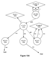
パターン変換は、上述の構文解析によって形成された抽象構文木から始まる。抽象構文木には、パターン宣言のルートを形成する1つ以上のノードが含まれる。たとえば、上記の我々のパターンは、図10の左下に示すように、2つの子を有する単一のルートノードで構成され、各子はパターンの1つの項を記述するかもしれない。図10において、反応ルートノード1005、パターンルートノード1010、和(a)ノード1015、ノード1020、および<no name>(名前無し)ノード10が存在する。
The pattern transformation begins with the abstract syntax tree formed by the parsing described above. The abstract syntax tree contains one or more nodes that form the root of the pattern declaration. For example, our pattern above consists of a single root node with two children, as shown in the lower left of FIG. 10, where each child may describe one term of the pattern. In FIG. 10, there are a
マッチングする例およびそれをマッチングする繰り返しを認識するように指定するパターン項ノードが、正規表現における項と同じ情報を担持することを認識する。さらに、子ノードのシーケンスは、まとめて順に、正規表現の項の線形連言(linear conjunction)と同じ情報を特定する。正規表現または正規表現の項の線形連言は、NFAへの変換項とすることができる。我々は、本発明において同じアルゴリズムが使用され得、パターン項は正規表現の項の代わりとなることを発見した。 Recognize that the pattern term node that specifies to recognize matching examples and matching iterations carries the same information as the terms in the regular expression. In addition, the sequence of child nodes collectively, in turn, identifies the same information as the linear conjunction in the regular expression term. A regular expression or a linear conjunction of a regular expression term can be a conversion term to NFA. We have found that the same algorithm can be used in the present invention and that pattern terms are an alternative to regular expression terms.
基本的なNFAがそのように形成されたら、それに、別途の、副作用誘導状態を、アクションがパターン項によって必要とされる位置において注入し、受容状態の後、反応の関数を呼び出すことができる。 Once the basic NFA is so formed, a separate, side effect-inducing state can be injected into it at the position where the action is required by the pattern term, and after the receptive state, the function of the reaction can be called.
この例を続けると、項aは、それにマッチする値のリストを収集し、最終的にそれらを引数として反応の関数に渡し得ることを必要とする。したがって、図9に示す変換を項aの結果であるNFA状態に適用し、新たな状態を使用して、マッチングする項を収集する作業を行なう。次いで、変換を、再び、今度はNFAの受容状態に適用し、収集された値を使用して反応の関数を呼び出し、結果を反応のコンシューマにプッシュし、収集バッファをクリアする。この強化されたNFAがDFAに変換され、状態が縮小された後、図7に示すマシンが残る。 Continuing this example, term a needs to collect a list of matching values and finally pass them as arguments to the function of the reaction. Therefore, the transformation shown in FIG. 9 is applied to the NFA state that is the result of item a, and the new state is used to collect matching terms. The transformation is then applied again, this time to the acceptance state of the NFA, using the collected values to call a function of the reaction, pushing the result to the consumer of the reaction and clearing the collection buffer. After this enhanced NFA is converted to DFA and the state reduced, the machine shown in FIG. 7 remains.
ステップは、状態機械エンジンを駆動するよう状態アクション表を用いるためのアルゴリズムのように、NFAをDFAに変換し、DFAを状態縮小し、DFAを状態アクション表として表現するために使用される。 Steps are used to convert an NFA to a DFA, reduce the DFA, and represent the DFA as a state action table, like an algorithm for using a state action table to drive a state machine engine.
本発明の技術によって生成されたNFAは、変換されて表に表現されることができる。ただし、結果の表には、各状態を通過するときに実行される副作用ラムダからなる別途の列が含まれる。このような状態アクションラムダ表を使用する自動化エンジンは、他の技術とは異なり、遷移するたびに追加のラムダを実行する。 The NFA produced by the technique of the present invention can be converted and represented in a table. However, the resulting table contains a separate column of side effect lambdas that will be executed as each state is passed. Automation engines that use such state-action lambda tables, unlike other technologies, perform additional lambdas with each transition.
データフローコンピューティング環境で使用するためのリアクティブ関数を記述し変換する方法であって、(i)リアクティブ関数を識別することと、(ii)関数への入力を提供するパラメータのパターンを識別することと、(iii)関数に渡された引数に基づいて評価されるべき式を識別することと、(iv)パラメータのパターンを、パターンにマッチする入力のシーケンスを認識することができる状態機械に変換することと、(v)状態機械を、入力データを収集および変換してそれを関数に対する引数として使用する準備をする作業を行なう追加の状態で拡張することと、(vi)状態機械を、単純なソフトウェアまたはハードウェアによる自動化が可能な状態アクション効果表に縮小することとを備える。 A method of describing and transforming a reactive function for use in a dataflow computing environment, (i) identifying the reactive function and (ii) identifying the pattern of parameters that provide input to the function. A state machine capable of identifying the expression to be evaluated based on the arguments passed to the (iii) function, and (iv) the pattern of the parameters, the sequence of inputs that match the pattern. And (v) extending the state machine to an additional state that does the work of collecting and transforming the input data and preparing to use it as an argument to the function, and (vi) the state machine. It comprises reducing to a state action effect table that can be automated by simple software or hardware.
関数のセット、および引数として値のシーケンスを与えられると、本発明は、引数がマッチする関数に実行をディスパッチするか、または引数がいずれの関数ともマッチしないと判断する、方法である。この方法は、値式、型式、および正規表現を組み合わせることによって、それが、型システムで表現可能な値のシーケンスを曖昧さなしにマッチングできるという点において新規である。 Given a set of functions and a sequence of values as arguments, the present invention is a method of dispatching an execution to a function whose arguments match, or determining that the arguments do not match any function. This method is novel in that by combining value expressions, types, and regular expressions, it is possible to unambiguously match a sequence of values that can be represented by the type system.
この種の問題を解決する必要があるのは、トランスレータ、インタープリタ、コンパイラの開発においてであり、多相的ディスパッチの概念と密接に関係している。シーケンスの任意の接頭辞を構成する要素が単一のオブジェクト(タプル)を構成すると考えるならば、正しい関数にディスパッチするタスクは、タプルのクラスのメソッドの多相的ディスパッチと等価であると考えることができる。 It is in the development of translators, interpreters and compilers that this kind of problem needs to be solved and is closely related to the concept of polymorphic dispatch. If you think that the elements that make up any prefix of a sequence make up a single object (tuple), then the task of dispatching to the correct function is equivalent to the polymorphic dispatching of the methods of the tuple's class. Can be done.
本発明は、この種の多相的ディスパッチが必要とされるあらゆる状況に適用可能である。これには、プログラムの外部から発生したデータのストリームに応答する必要があるイベント駆動型またはリアクティブ型プログラムのすべての態様が含まれる。本発明は、エッジもしくはフォグコンピューティング環境またはネットワーク接続環境で頻繁に発生するような、複数のデータストリームのリアルタイム処理に関する適用例において特に有用である。 The present invention is applicable in all situations where this type of polymorphic dispatch is required. This includes all aspects of event-driven or reactive programs that need to respond to streams of data originating from outside the program. The present invention is particularly useful in applications relating to real-time processing of multiple data streams, such as those that occur frequently in edge or fog computing or networked environments.
正規表現は、通常、特定のパターンに適合する文字列を検出するために使用される。最も密接に関連する多くの正規表現言語、およびそれらに基づいた効率的なマッチングエンジンを実装する多くのツールがある。これらは、一般に、文字のシーケンスのマッチングに限定される。 Regular expressions are typically used to find strings that fit a particular pattern. There are many of the most closely related regular expression languages, and many tools that implement efficient matching engines based on them. These are generally limited to matching character sequences.
文字列以外のドメインで動作する他のパターンベースの表記法がある。XML文書においてパターンを記述するXPATHがその一例である。これらの表記法は、通常、正規表現よりも完全性が低く、パワフルではないことが多く、特定のドメインに合わせて調整されている。 There are other pattern-based notations that work in domains other than strings. An example is XPATH, which describes a pattern in an XML document. These notations are usually less complete and often less powerful than regular expressions and are tailored to a particular domain.
いくつかのプログラミング言語は、型ベースのパターンマッチングシステムを用いてランタイム多相的ディスパッチを実行する。関数の複数のオーバーロードが定義され、それらの各々は異なるパターンの型および値をとり、引数の型および値を関数パラメータのパターンと照合することによって、ディスパッチが実行時に解決される。Haskellはそのようなプログラミング言語の1つである。 Some programming languages use a type-based pattern matching system to perform run-time polymorphic dispatch. Multiple overloads of a function are defined, each of which takes a different pattern of types and values, and the dispatch is resolved at run time by matching the argument types and values with the function parameter patterns. Haskell is one such programming language.
言語仕様言語は、文脈自由文法を一連の生成規則として記述する。これらの規則は言語の構文を構成する。コンパイラコンパイラは、これらの規則を、言語のインスタンスを認識できる表駆動型決定性有限状態機械に変換する。Bisonは、そのような言語仕様言語およびそれの関連するコンパイラコンパイラの例である。 Language Specification Languages describe context-free grammars as a series of production rules. These rules make up the syntax of the language. Compiler The compiler translates these rules into a table-driven deterministic finite-state machine that can recognize instances of the language. Bison is an example of such a language specification language and its associated compiler.
正規表現などの文法駆動型パターンマッチングシステムは、決定性有限オートマトン(DFA)や状態機械などの単純な機械として表現できるため、効率的実行の利点があるが、それらには、完全な型システムの幅広いモデリング機能はない。Haskellで使用されているような型駆動型パターンマッチングシステムは、はるかにより豊富なモデリング機能を備えているが、合理的に効率的な実装を優先して表現できるものをしばしば犠牲にし、それでも依然として、DFAに基づく高速マッチングシステムほど効率的ではない。 Grammar-driven pattern matching systems such as regular expressions have the advantage of efficient execution because they can be represented as simple machines such as deterministic finite automata (DFAs) and state machines, but they have a wide range of complete type systems. There is no modeling function. Type-driven pattern matching systems, such as those used in Haskell, have much more modeling capabilities, but often sacrifice something that can be represented in favor of a reasonably efficient implementation, and yet still. Not as efficient as a fast matching system based on DFA.
本発明は、型に基づくマッチングシステムを扱い、それは、その型の中で表現可能なすべての状態と照合することができながら、依然として状態機械として効率的に実施され得る。型と状態との一般化されたパターンは、パターンのインスタンスを効率的に認識する表駆動型状態機械に変換される。 The present invention deals with a type-based matching system, which can still be efficiently implemented as a state machine while being able to collate with all the states expressible within that type. A generalized pattern of types and states is transformed into a table-driven state machine that efficiently recognizes instances of the pattern.
これらのパターンに基づいて関数パラメータを定義することにより、関数はまさにどのような恣意的なデータパターンともマッチングし、マッチングにおいて、マッチングするデータ要素間からその引数をバインドすることができる。メンバー関数の状態機械をマージし、その結果を最小の状態数に縮小することによって、関数の合併(union)のためのマッチングパターンを記述する状態機械が形成される。オーバーロード間の曖昧さ回避、または全体的な不一致の検出は、シーケンス内で可能な限り早く起こり、関数適用の解決をスピードアップする。また、シーケンス内でできるだけ遅くまで一致を遅らせて、可能な限り多くの入力を受け入れる関数の「貪欲」バージョンを生成することもできる。 By defining function parameters based on these patterns, the function can match exactly any arbitrary data pattern and, in matching, bind its arguments between the matching data elements. By merging the state machines of the member functions and reducing the result to the minimum number of states, a state machine that describes the matching pattern for the union of the functions is formed. Disambiguation between overloads, or detection of overall discrepancies, occurs as soon as possible in the sequence, speeding up the resolution of function applications. You can also delay the match as late as possible in the sequence to produce a "greedy" version of the function that accepts as many inputs as possible.
あるメソッドは、値式、型式、および正規表現を組み合わせて、それが、型システムで表現可能な任意の値のシーケンスと曖昧さなくマッチングし得るようにする。このメソッドは関数適用を解決し、最小限の判断数で正しいオーバーロードにディスパッチする。このメソッドにより、オーバーロードされた関数適用は、文脈自由文法と同じ作業を実行し、文法的な下位構成要素を帰納的に認識して変換関数をそれに適用することによって特定の言語を認識することができる。 Some methods combine value expressions, types, and regular expressions so that they can be unambiguously matched to any sequence of values that can be represented in the type system. This method resolves the function application and dispatches it to the correct overload with a minimum number of decisions. With this method, the overloaded function application performs the same task as a context-free grammar, recognizing a particular language by inductively recognizing grammatical subcomponents and applying transformation functions to it. Can be done.
このメソッドは、複数の異なる型を含む型システムに関連して適用可能であり、たとえば、(1)整数、実数、および文字列などの基本的な単相型の集合(set)。(2)多相型の集合およびそれらのコンストラクタ、特に、我々が間もなく論ずるある特定のプロパティを持つ多相集合型。(3)sum型。(4)レコードの形式のproduct型。(5)パターンの形式のproduct型。タプルの、それのフィールドの繰り返しを含むことへの一般化である。(6)ラムダ型。パターン型を任意の型にマッピングする。(7)ラムダのリストからなる多ラムダ型。 This method is applicable in relation to a type system containing several different types, for example: (1) a set of basic single-phase types such as integers, real numbers, and strings. (2) Polymorphic sets and their constructors, especially polymorphic sets with certain properties that we will discuss shortly. (3) sum type. (4) Product type in record format. (5) Product type in the form of a pattern. A generalization of tuples to include repeating their fields. (6) Lambda type. Map the pattern type to any type. (7) Multi-lambda type consisting of a list of lambdas.
集合は、1つ以上の要素の範囲からなる多相型である。集合型は、それが含む要素の型上においてパラメータ化され、たとえば、整数の集合は文字列の集合とは異なる型である。集合型は、その内容の制限によってさらに特徴づけられる。特に、集合型は、有限もしくは無限であるよう、またはその左辺もしくは右辺において閉じられているかもしくは開いているよう、またはこれらの任意の組み合わせであるように、制約されてもよい。以下の整数の集合の例を考えてみよう。 A set is a polymorphic type consisting of a range of one or more elements. A set type is parameterized on the type of the element it contains, for example, a set of integers is a different type than a set of strings. Aggregate types are further characterized by their content limitations. In particular, the aggregate type may be constrained to be finite or infinite, closed or open on its left or right side, or any combination thereof. Consider the following example of a set of integers.

[>= 1]と[> 0]との間に区別はなく、なぜならば、要素は整数型であり、整数は相異なって可算であるからである。要素が、仮に、実数や文字列のように、非可算型である場合、明示的な包含または特定の端点の包含が必要となる。たとえば、集合[>= “cat”]は、文字列“cat”、および辞書編集上“cat”の後に分類するすべての文字列で構成されている。 There is no distinction between [> = 1] and [> 0], because the elements are of integer type and integers are differently countable. If the element is uncountable, such as a real number or a string, explicit inclusion or inclusion of a particular endpoint is required. For example, the set [> = “cat”] consists of the character string “cat” and all the character strings classified after “cat” in lexicography.
集合のインスタンスを型として使用してもよい。そのような型のインスタンスは、集合の要素でなければならない。たとえば、型として使用される集合[> 0]は、正の整数だけを値として許可するであろう。実際、すべての型をこのように考えることができる。たとえば、単相の整数型は、すべての整数の集合からなる集合型と考えることができる。 An instance of a set may be used as a type. Instances of such type must be elements of the set. For example, a set [> 0] used as a type would only allow positive integers as values. In fact, all types can be thought of this way. For example, a single-phase integer type can be thought of as a set type consisting of a set of all integers.
我々のsum型は、他の型の単純な合併(union)である。たとえば、型int(整数)または型string(文字列)は、その2つの構成要素型の和である。sum型の構成要素型のいずれかの何れのインスタンスも、sum型のインスタンスである。これにより、たとえば、各々が整数または文字列のいずれかである値のリストである型リスト(intまたはstring)を記述することができる。unionのunionは平坦(flatten)になり、型式(intもしくはstring)または(intもしくはreal(実数))はintまたはrealまたはstringに等しくなる。unionにおける型の順序は重要ではないが、正規性のため、すべてのunion型をここにおいてそれらの構成要素がアルファベット順であるように提示する。 Our sum type is a simple union of other types. For example, the type int (integer) or the type string (string) is the sum of the two component types. Any instance of any component type of sum type is an instance of sum type. This allows, for example, to describe a type list (int or string) that is a list of values, each of which is either an integer or a string. The union of a union becomes flatten, and the type (int or string) or (int or real (real number)) is equal to int or real or string. The order of the types in the union is not important, but for normality, all union types are presented here so that their components are in alphabetical order.
我々のレコード型は名前付きフィールドを使用し、各フィールドを型に関連付ける。たとえば、{birthday: date; first_name: string; last_name: string}({誕生日: 日付; 名: 文字列; 姓: 文字列})レコード型は常に有限数のフィールドを有し、各フィールドは型内において一意の名前を有する。フィールドの順序は重要ではない。{x: int; y: int}は{y: int; x: int}と同じであるが、unionに対してしたように、我々はレコード型を、それらの構成要素がアルファベット順にある状態で提示する。 Our record type uses named fields and associates each field with a type. For example, {birthday: date; first_name: string; last_name: string} ({birthday: date; first name: string; last name: string}) The record type always has a finite number of fields, each field in the type. Has a unique name in. The order of the fields is not important. {x: int; y: int} is the same as {y: int; x: int}, but as we did for union, we present record types with their components in alphabetical order. do.
レコードの型はそれ自体がレコードであることに注意されたい。値{x: 3; y: 4}は型{x: int; y: int}を有する。 Note that the record type is itself a record. The value {x: 3; y: 4} has the type {x: int; y: int}.
我々のパターン型は、型のシーケンスとして定義されている点で、タプルに似ている;しかしながら、タプルは暗示的にその要素の各々が正確に1回現れると仮定しているが、パターンはそれの各要素が繰り返しを有することを許す。この繰り返しは整数の集合として与えられる。たとえば、パターン<a: int # [1 .. 3]; b: string # [1 .. 3]>は1つから3つの整数の後に1つから3つの文字列が続くものとマッチする。 Our pattern type is similar to a tuple in that it is defined as a sequence of types; however, the tuple implicitly assumes that each of its elements appears exactly once, but the pattern is it. Allow each element of to have repetition. This iteration is given as a set of integers. For example, the pattern <a: int # [1 .. 3]; b: string # [1 .. 3]> matches one to three integers followed by one to three strings.
ラムダのパラメータとして使用すると、パターンのフィールドはラムダの評価内でバインドされる引数を生じさせる。たとえば、前の段落で与えられたパターンをマッチングした後、範囲に2つのローカル識別子aおよびbを有するであろう。Aの値は1つから3つの整数のリストになり、bの値は1つから3つの文字列のリストになるであろう。 When used as a lambda parameter, the pattern field yields an argument that is bound within the lambda evaluation. For example, after matching the pattern given in the previous paragraph, the range will have two local identifiers a and b. The value of A will be a list of 1 to 3 integers, and the value of b will be a list of 1 to 3 strings.
パターンについて1つ以上のフィールドが名前を持たないことも有効である。名前のないフィールドはマッチングされるが、それに対するどのような値も引数としてバインドされない。たとえば、<a: int # [ 1 .. 3 ]; string # [ 1 .. 3] >をマッチングした場合、前のように1つから3つの整数の後に1つから3つの文字列が続くものをマッチングさせ、整数をaというリストとしてバインドするが、文字列はバインドしないであろう。 It is also useful that one or more fields have no name for the pattern. An unnamed field is matched, but no value for it is bound as an argument. For example, if you match <a: int # [1 .. 3]; string # [1 .. 3]>, one to three integers followed by one to three strings as before. Matches and binds integers as a list called a, but will not bind strings.
パターンは無限長であってもよい。たとえば、パターン<a: int # [ 1 .. ]>は1つ以上の整数と上限なしでマッチする。これは有効である。ただし、無限入力ストリームを処理するために使用する場合、無限のパターンを、値の収集をいつ停止すべきか示す時間間隔などの他のトリガとペアにする必要がある。 The pattern may be infinite. For example, the pattern <a: int # [1 ..]> matches one or more integers with no upper bound. This is valid. However, when used to process an infinite input stream, the infinite pattern must be paired with other triggers, such as a time interval that indicates when to stop collecting values.
一般に、パターンは、それがマッチするデータを消費するが、しかしながら、そのデータの部分集合のみを消費することも、またはまったく消費しないことが可能である。パターンには、ピークポイントと呼ばれるアットマークが含まれてもよく、それを越えて、パターンはデータとマッチし、引数をバインドするが、入力ストリームからは消費しない。たとえば、パターン<a: int; b: int; peek; c: int> は3つの整数とマッチし、3つのローカル識別子をバインドするが、入力から2つの整数しか消費しない。 In general, a pattern consumes the data it matches, however, it is possible to consume only a subset of that data, or not at all. The pattern may contain an at sign called a peak point, beyond which the pattern matches the data and binds its arguments, but does not consume it from the input stream. For example, the pattern <a: int; b: int; peek; c: int> matches three integers and binds three local identifiers, but consumes only two integers from the input.
フィールドのないレコードまたはフィールドのないパターンを有することは有効である。これらの2つのケースは、両方ともproduct型を意味するため、互いに有意に区別できない。語彙的には、この概念をボイドというキーワードで指定する。ボイドは一意の値である。それ自身の型でもある。合併で使用される場合、ボイドはintまたはvoidなど、任意選択的な型の表記をもたらし、存在する場合にはintである値を意味するが、まったく存在しないかもしれない。 It is useful to have a record without fields or a pattern without fields. These two cases are both indistinguishable from each other because they both mean product type. Vocabulary, this concept is specified by the keyword void. Voids are unique values. It is also its own type. When used in a merger, a void results in an optional type notation, such as int or void, meaning a value that is an int if present, but may not exist at all.
我々の目的のために、型マッチングは構造的であり、名目上のものではない。型には名前はなく、記述だけがある。同じ記述を有する2つの型は同じ型である。記述が別の型の記述の部分集合である型は、その型の一般化である。たとえば、型{x: int; y: int}および{x: int; y: int; z: int}を考える。2つのフィールド-xおよびy-を有する型は、3つのフィールド-x, yおよびz-を有する型の部分集合であるため、前者は後者の一般化と見なすことができる。これはパターンにも当てはまる。別のものの接頭辞であるパターンもその一般化である。 For our purposes, type matching is structural, not nominal. The type has no name, only a description. Two types with the same description are the same type. A type whose description is a subset of the description of another type is a generalization of that type. For example, consider the types {x: int; y: int} and {x: int; y: int; z: int}. The former can be regarded as a generalization of the latter, since a type with two fields -x and y- is a subset of a type with three fields -x, y and z-. This also applies to patterns. The pattern, which is the prefix of another, is also a generalization.
我々のラムダ型は、入力パターンを出力型にマッピングする。たとえば、<int # [1 .. 3]> → intは、1つから3つの整数をとり、ある整数を返す、ある関数の型である。我々の多ラムダ型は、ラムダ型のリストで構成されている。ラムダの順序はここでは重要である。多ラムダ適用を解決する際、それの構成要素ラムダのうちマッチする最初のラムダにディスパッチすることになる。 Our lambda type maps the input pattern to the output type. For example, <int # [1 .. 3]> → int is a type of function that takes one to three integers and returns an integer. Our multi-lambda type consists of a list of lambda types. The order of lambdas is important here. When resolving a multi-lambda application, it will be dispatched to the first matching lambda of its component lambdas.
このように定義されると、多ラムダをディスパッチするのに必要なパターンマッチングは、決定性有限オートマトン(DFA)に縮小され得る。どのようにするかを示すために、比較のための基礎として状態機械の構築方法を使用し、必要に応じてそれを拡張する。ある記述は、まず、非決定性有限オートマトン(NFA)を構築すること、および次いでそれをDFAに縮小することを含むが;しかしながら、実際には、これは一般に単一のステップで行うことができる。 With this definition, the pattern matching required to dispatch multiple lambdas can be reduced to a deterministic finite automaton (DFA). To show how to do it, use the state machine construction method as the basis for comparison and extend it as needed. One description involves first constructing a nondeterministic finite automaton (NFA), and then reducing it to a DFA; however, in practice this can generally be done in a single step.
前述したように、この出願ではDFAという用語を使用しているが、これらのオートマトンまたはユニットはスタックマシンと称されてもよい。厳密に言えば、決定性有限オートマトンは、空間における有限の性能を暗示する。しかしながら、この特許のオートマトンは、必ずしも有限であるとは限らず、非有限であり得るが、依然として単純であり得る。したがって、この特許に記載されているDFAは、非有限であってもよい。 As mentioned earlier, although this application uses the term DFA, these automata or units may also be referred to as stack machines. Strictly speaking, a deterministic finite automaton implies finite performance in space. However, the automata in this patent are not necessarily finite, can be non-finite, but can still be simple. Therefore, the DFA described in this patent may be non-finite.
第1に、多ラムダの構成要素-個々のラムダパターン-は、離接の要素として考えなければならない。正規表現を変換する場合、構文a|b (a OR B)は離接であり、一致a1105または一致b1110である。我々の例では、a AND bは各々ラムダパターンである。図11に従って離接のための部分グラフを作成する。 First, the components of multiple lambdas-individual lambda patterns-must be considered as elements of separation. When converting a regular expression, the syntax a | b (a OR B) is a detachment, which is match a1105 or match b1110. In our example, a AND b are each lambda pattern. A subgraph for disengagement is created according to FIG.
我々は個々のパターンのフィールドをまず合接により表わす。正規表現の変換では、構文ab1210は合接であり、一致a1205の後にb1215が続く。我々の例では、a AND bはパターンの各フィールドである。図12に従って、合接のための部分グラフを作成する。 We first represent the fields of the individual patterns by conjunction. In the regular expression conversion, the syntax ab1210 is conjunction, and the match a1205 is followed by b1215. In our example, a AND b is each field of the pattern. A subgraph for conjunction is created according to FIG.
フィールドの反復係数は、従来はa+またはa*またはa{n:m}と書かれた正規表現の閉包と同じである。ここでも、図13のような構造でこれらの閉包を表現できる。この場合、反復集合の値に基づいて、部分グラフにおけるなんらかの変化が必要になる。たとえば、ノードi1305からノードj1310への順方向イプシロン1315は、集合が零を含む場合にのみ含まれる。これらの変化は大部分明白であり、ここで説明したのと同じ基本的な考え方に沿って継続する。 The field iteration factor is traditionally the same as the closure of a regular expression written as a + or a * or a {n: m}. Again, these closures can be represented by the structure shown in FIG. In this case, some changes in the subgraph are needed based on the values of the iterative set. For example, forward epsilon 1315 from node i1305 to node j1310 is included only if the set contains zeros. These changes are largely obvious and continue in line with the same basic ideas described here.
中間のNFAが完結した後、それをDFAに縮小し、次いでそのDFAを最小のDFAに達するまで状態縮小する。次に、DFAを、状態機械の自動化に使用される通常の種類のソフトウェアまたはハードウェアによる自動化に適した状態-アクション表として表現する。この表の受容状態は、多ラムダへのエントリポイントをマーキングし、中間状態は引数をバインドするために使用されるデータの集まりを提供する。 After the intermediate NFA is completed, it is reduced to DFA, and then the DFA is reduced to the minimum DFA. The DFA is then expressed as a state-action table suitable for automation by the usual types of software or hardware used to automate state machines. The acceptance state of this table marks the entry point to the multi-lambda, and the intermediate state provides a collection of data used to bind the arguments.
DFAがそのように自動化され、入力ストリームが提供されると、それは、ストリームからの入力の接頭辞にマッチし、正しいオーバーロードにディスパッチしてそれらを処理し、計算結果を生成する。このプロセスが繰り返されることが許されている場合、結果は、入力ストリームからの一致ごとに1つの、生じた結果のシーケンスである。これは、データストリーム内で検出されたさまざまな型の引数の対応するパターンによってトリガされる多相型関数によって、入力データストリームの効率的なリアルタイム処理を提供する。 When the DFA is so automated and an input stream is provided, it matches the prefixes of the inputs from the stream and dispatches them to the correct overload to process them and produce the result of the calculation. If this process is allowed to be repeated, the result is a sequence of resulting results, one for each match from the input stream. It provides efficient real-time processing of the input data stream with polymorphic functions triggered by the corresponding patterns of different types of arguments found in the data stream.
値と型識別子との混合を含む複数の種類の関数引数を含むデータストリームに応答して多相型関数の実行をディスパッチする方法であって、(i)実行されるべき多相型関数を識別することを備え、当該多相型関数は、異なる種類の引数のパターンに各々が関連付けられる複数のオーバーロードを有し、前記方法はさらに、(ii)各オーバーロードについて、オーバーロードの引数パターンをマッチングすることによって、入力ストリームからバインドされる引数値の集合にわたって評価される出力式を識別することと、(iii)各オーバーロードの引数パターンを、入力ストリームにおけるパターンについて一致を効率的に認識するDFAに変換することと、(iv)個々のオーバーロードのDFAを、全体として多相型関数のための単一のDFAに結合することとを備え、結果として得られる結合されたDFAは、個々のDFAによってマッチングされるであろう任意のパターンをマッチングし、マッチングする入力を処理すべきオーバーロードを選択することができ、前記方法はさらに、(v)結合されたDFAにデータストリームを適用し、DFAは、次いで、必要に応じてストリームからデータを検査もしくは消費またはその両方を行なって、一致または無一致を判定し、一致の場合には、入力引数値を適切にバインドし、評価されるべき適切な出力式を選択することと、(vi)出力式の評価をディスパッチし、結果を返すこととを備える。 A method of dispatching the execution of a polymorphic function in response to a data stream containing multiple types of function arguments, including a mixture of values and type identifiers, (i) identifying the polymorphic function to be executed. The polymorphic function has multiple overloads, each associated with a different type of argument pattern, the method further (ii) for each overload, an overload argument pattern. By matching, it identifies the output expression that is evaluated across the set of argument values bound from the input stream, and (iii) efficiently recognizes the argument pattern of each overload for a pattern in the input stream. It comprises converting to DFA and (iv) binding individual overloaded DFA to a single DFA for polymorphic functions as a whole, and the resulting combined DFA is individual. Any pattern that would be matched by DFA can be matched and the overload to process the matching input can be selected, the method further (v) applying the data stream to the combined DFA. , DFA then inspects and / or consumes data from the stream as needed to determine a match or no match, and if there is a match, properly binds and evaluates the input argument values. It comprises selecting the appropriate output expression to be and (vi) dispatching the evaluation of the output expression and returning the result.
リアクティブ関数によって生成される異なる型のデータのストリームのセットが与えられると、本発明は、それらのストリームを、それらの出力が、統合された型の単一のストリームに効率的に構成され得るように、表現する技術である。 Given a set of streams of different types of data generated by a reactive function, the invention can efficiently configure those streams into a single stream of integrated type whose output can be integrated. It is a technique to express.
この種の問題を解決する必要性は、すべての形式のデータフロープログラミングで共通して発生する。これは、エンタープライズデータセンター内およびエンタープライズデータセンター間のデータフローなどの非常に大規模なアーキテクチャ、ならびに埋込まれたデバイスにおけるイベントのフローなどの非常に小規模なアーキテクチャに適用可能である。 The need to solve this type of problem is common to all forms of dataflow programming. This is applicable to very large architectures such as data flows within and between enterprise data centers, as well as very small architectures such as event flows on embedded devices.
本発明は、データフロープログラミングのすべての領域に適用可能であるが、一致を検出でき、ハンドラ関数を適用できる速度が最も重要であり、実行に費やすストレージおよび計算リソースが限られている場合に最適である。 The present invention is applicable to all areas of dataflow programming, but is best when the speed at which matches can be detected and handler functions can be applied is paramount, and the storage and computational resources devoted to execution are limited. Is.
実施例。n個の別個の入力ストリームのセットからなる流入Ai:0<k<nを考える。各ストリームは、型Tiの要素のキューで構成される。各ストリームは、型Ti→Uiのリアクティブ関数fiによって消費および変換されており、型Uiの要素のキューから各々がなる流出のn個のストリームBiが存在する。すべてのストリームBiを、Σ Tk→Σ Ukのマージ関数mを用いて、単一のストリームCにマージしたい。 Example. Consider an inflow Ai: 0 <k <n consisting of a set of n separate input streams. Each stream consists of a queue of elements of type Ti. Each stream is consumed and converted by the reactive function fi of type Ti → Ui, and there are n streams Bi of each outflow from the queue of elements of type Ui. I want to merge all streams Bi into a single stream C using the Σ Tk → Σ Uk merge function m.
3つのストリームの間で発生するこのようなマージの例をVel言語で書いて以下に示す。 An example of such a merge that occurs between three streams is written in Vel language and is shown below.

ストリームCは、B0、B1およびB2からの値から構成され、それらが生成されるときにインターリーブされる。Bストリームの内容を実現することにポイントがないことに注意されたく、なぜならばそれらはCストリームを構成するためだけに使用されるためである。それらは匿名の一時的な部分式として同じく簡単に表現できるであろう。 Stream C consists of values from B0, B1 and B2 and is interleaved when they are generated. Note that there is no point in achieving the contents of the B stream, because they are only used to compose the C stream. They could also be easily expressed as anonymous temporary subexpressions.

本発明は、各変換関数fiを決定性有限オートマトン(DFA)に変換し、マージ関数mをこれらのDFAの合併として単一の最小DFAに変換することを記載する。その結果、中間流Biの内容を実現する必要なく流入Aiを流出Cにマージする最大効率的な手段が得られる。 It is described that each conversion function fi is converted into a deterministic finite automaton (DFA) and the merge function m is converted into a single minimum DFA as a merger of these DFAs. As a result, the most efficient means of merging the inflow Ai into the outflow C without having to realize the contents of the intermediate flow Bi is obtained.
この技術は、繰り返し適用され、後続の中間流の層を単一のリアクティブ関数に融合させることができる。これは、Velの場合のように、宣言型データフロー言語のインフィックスまたは演算子で表されるマージの概念と整合している。 This technique can be applied repeatedly to fuse subsequent layers of intermediate flow into a single reactive function. This is consistent with the concept of merging represented by infixes or operators in declarative dataflow languages, as in Vel.
この問題はブルートフォースによって解決できる。すなわち、マージ関数が中間流の唯一のコンシューマであっても、中間流を実現し、それらを消費することによって達成される。 This problem can be solved by brute force. That is, even if the merge function is the only consumer of the intermediate stream, it is achieved by realizing the intermediate stream and consuming them.
また、マージ関数では、それの流入および流出が、すべて、同じ型のものであるか、そうでなければ、型のないシステムの場合においては未分類のものであることを必要とすることもよくある。これは、それらの型システムにunion型(sum型とも呼ばれる)がないためである。データフローシステムにおける真のマージの存在は、union型の使用を要求する。 Also, merge functions often require that their inflows and outflows are all of the same type, or otherwise unclassified in the case of untyped systems. be. This is because those type systems do not have union types (also called sum types). The existence of true merges in dataflow systems requires the use of union types.
一部のデータフローシステムでは、真のマージを欠き、代わりに複数入力単一出力リアクティブ変換を実施する。これらはそれら自体有用な構成体であるが、真のマージ関数ほど単純でも一般的でもなく、完全に最適化することはできない。 Some dataflow systems lack true merging and instead perform multi-input single-output reactive transformations. Although these are useful constructs in their own right, they are neither as simple nor as common as true merge functions and cannot be fully optimized.
マッチング関数をDFAとして表現することは、ブール型の任意の式として表現するよりも効率的である。各自の駆動流入を伴う複数のマッチング関数のDFAは、単一の流出を伴うマージ関数を表す単一の効率的なDFAを形成するために統合される。DFAのマージは、できるだけ早くまたはできるだけ遅く結果がマッチングするように行われ、結果として2つの異なる潜在的に望ましい挙動が生じる。複数の反応を1つのDFAに構成することにより、最小の機械、つまり、最小数の判断を用いてすべての一致を実行するアルゴリズムが得られる。最小の機械は、小規模なプラットフォーム用の複数の反応の最も好適な実現例である。最小の機械は、マッチング式の複数の別々の評価よりもアルゴリズム上の利点を有するため、他のすべてが等しい場合、より効率的に実行される。 Expressing the matching function as a DFA is more efficient than expressing it as an arbitrary Boolean expression. DFAs of multiple matching functions with their own drive inflows are integrated to form a single efficient DFA representing a merge function with a single outflow. The DFA merging is done so that the results match as soon as possible or as late as possible, resulting in two different potentially desirable behaviors. By constructing multiple reactions into one DFA, we obtain the smallest machine, an algorithm that performs all matches with the smallest number of judgments. The smallest machine is the most suitable implementation of multiple reactions for a small platform. The smallest machine has an algorithmic advantage over multiple separate evaluations of the matching expression, so it runs more efficiently if everything else is equal.
変換DFAのセットを単一のDFAにマージするには、正規表現で代替(alternation)を考えるように変換DFAを考慮する必要がある。正規表現を変換する場合、構文a|bは代替であり:一致a OR 一致bである。我々の例では、a AND bは各々変換関数からのDFAである。図11に従ってそれらの代替のための部分グラフを作成する。 To merge a set of transformed DFAs into a single DFA, you need to consider the transformed DFA as if you were thinking of an alternation with a regular expression. When converting a regular expression, syntax a | b is an alternative: match a OR match b. In our example, a AND b are each DFA from the transformation function. Subgraphs for those alternatives are created according to FIG.
中間の非決定性有限オートマトン(NFA)が完結した後、それをDFAに縮小し、次いでそのDFAを最小のDFAに達するまで状態縮小する。次に、DFAを、状態機械の自動化に使用される通常の種類のソフトウェアまたはハードウェアによる自動化に適した状態-アクション表として表現する。この表の受容状態は、マージされたデータ要素が出力ストリームに放出される点をマーキングする。 After the intermediate nondeterministic finite automaton (NFA) is completed, it is reduced to DFA, and then the DFA is reduced to the minimum DFA. The DFA is then expressed as a state-action table suitable for automation by the usual types of software or hardware used to automate state machines. The acceptance state of this table marks the point at which the merged data elements are released into the output stream.
DFAがそのように自動化され、入力ストリームのセットが提供される場合、DFAは、各入力を、その入力に関連付けられた元の変換関数に従って変換し、すべての結果を1つの出力上でともにインターリーブして与える。 If the DFA is so automated and a set of input streams is provided, the DFA transforms each input according to the original conversion function associated with that input and interleaves all the results together on one output. And give.
入力データの複数の独立したストリームを出力データを単一のストリームにマージする方法は、(i)複数の潜在的な入力データストリームを識別することと、(ii)入力ストリームごとに1つ、各入力ストリームにおけるデータ上で実行され、その結果が一緒になるようマージされる、複数の変換関数を識別することと、(iii)入力データ要素を、複数のストリームから同時に受け取り、データ要素を単一の出力ストリームにインタリーブするマージ関数を識別することと、(iv)各変換関数を、変換を効率的に実行するDFAに変換することと、(v)変換DFAを、変換を効率的に実行し、その結果を単一のストリームにインターリーブする単一の結合されたDFAにマージすることと、(vi)結合されたDFAにデータストリームを適用し、DFAは次いで変換およびマージの作業を実行することと、(vii)マージされた出力を使用のために宛先にディスパッチすることとを備える。 The methods for merging multiple independent streams of input data into a single stream are (i) identifying multiple potential input data streams and (ii) one for each input stream, each. Identifying multiple transformation functions that are executed on the data in the input stream and merged so that the results are combined, and (iii) receive the input data elements from multiple streams at the same time and single the data elements. Identifying the merge functions that interleave to the output stream of, (iv) converting each conversion function to a DFA that performs the conversion efficiently, and (v) the conversion DFA that efficiently performs the conversion. To merge the result into a single combined DFA that interleaves into a single stream, and (vi) apply the data stream to the combined DFA, which then performs the conversion and merging work. And (vii) to dispatch the merged output to a destination for use.
本発明は、Velプログラミング言語でソフトウェアを開発するためのツールおよび関連する方法である。Velは、データフロープログラムの表現に役立つプログラミング言語である。正しいデータフロープログラミングには多くの課題がある。いくつかはすべての形式のコンピュータプログラミングに共通する課題であり、他のいくつかはデータフローパラダイムに特有の課題である。このツールは、以下を含む、Velプログラミングの多くの分野に対応している:(1)構文的および意味的な正しさをチェックする。(2)論理的な正しさをチェックする。(3)デバッグ支援。(4)ソースコードを安全かつポータブルな形式(つまり、パッケージ化されたコード)に変換する。(5)さまざまなコンピューティングプラットフォーム、特に小規模なプラットフォームに適した、ネイティブで最適なバイナリ形式へのソースコードまたはパッケージ化されたコードの変換。(6)パッケージ化されたコードの記述およびその署名の確認。(7)パッケージ化されたコードのバッチモード解釈。(8)Velソースのインタラクティブな解釈。(9)パッケージ化されたコードまたはネイティブコードを実行するデータフロー環境のシミュレーション。(10)ライブデータフロー環境におけるバイナリコードの遠隔実行、監視、および制御。 The present invention is a tool and related methods for developing software in the Vel programming language. Vel is a programming language that is useful for expressing data flow programs. Correct dataflow programming presents many challenges. Some are common to all forms of computer programming, and some are specific to the dataflow paradigm. This tool covers many areas of Vel programming, including: (1) Checking for syntactic and semantic correctness. (2) Check the logical correctness. (3) Debugging support. (4) Convert the source code into a safe and portable format (ie, packaged code). (5) Conversion of source code or packaged code into a native and optimal binary format suitable for various computing platforms, especially small platforms. (6) Description of packaged code and confirmation of its signature. (7) Batch mode interpretation of packaged code. (8) Interactive interpretation of Vel source. (9) Simulation of a data flow environment that executes packaged code or native code. (10) Remote execution, monitoring, and control of binary code in a live data flow environment.
これらは、Vel言語でソフトウェアを開発している誰もが達成する必要があるタスクである。本発明は、Velプログラミングに熟練した者が、正確で有用なソフトウェアを作成することを可能にするために、これらの分野すべてにおいて十分なサポートを提供する。 These are the tasks that anyone developing software in the Vel language needs to accomplish. The present invention provides sufficient support in all of these areas to enable those skilled in Vel programming to create accurate and useful software.
構文上および意味上の正しさをチェックすることは、多くの形態の自動ソフトウェア変換に共通するタスクである。論理的な正しさをチェックするためのツールは、通常、変換ツール自体には組み込まれていない。これらの種類のツールは別々に存在するのが一般的であり、それらがテストしているコードの不完全な洞察をしばしば伴う。 Checking for syntactic and semantic correctness is a common task in many forms of automated software conversion. Tools for checking logical correctness are usually not built into the conversion tool itself. These types of tools typically exist separately and often involve incomplete insights into the code they are testing.
デバッグはソフトウェア開発の共通タスクであるが、ほとんどのデバッグツールは命令型プログラミングに重点を置いている。関数型およびリアクティブプログラミングのデバッグは、命令型デバッグとはまったく異なる課題を提示するため、それほど一般的に対応されない。特に、これらの言語では、「フライト中の」計算を検査するのは困難であり得、なぜならば、それらの値はデバッガ(およびデバッガプログラマ)が覗き得るアドレスを有さないことが多いからである。 Debugging is a common task in software development, but most debugging tools focus on imperative programming. Debugging functional and reactive programming presents a completely different challenge than imperative debugging and is therefore less commonly addressed. Especially in these languages, it can be difficult to inspect "in-flight" computations, because their values often do not have an address that the debugger (and debugger programmer) can look into. ..
複数のネイティブプラットフォームアーキテクチャを対象とする能力は、Cなどのシステム言語のコンパイラにはまれではないが、スクリプトレベルの言語では一般的に見られるパワーではない。スクリプト言語は、コンパイルされないか、またはそれらのホストのために部分的にコンパイルされるかまたはジャストインタイムでコンパイルされる(ジットされる(jitted))傾向があるが、クロスコンパイル(1つのアーキテクチャで実行されるが、別のアーキテクチャに対してコードを生成するコンパイラ)はまれである。小規模なプラットフォーム上で実行するためにスクリプトレベルの言語を具体的にコンパイルすることは非常に珍しいことである。 The ability to target multiple native platform architectures is not uncommon in system language compilers such as C, but is not the power commonly found in script-level languages. Scripting languages tend to be uncompiled, partially compiled for their hosts, or just-in-time compiled (jitted), but cross-compiled (in one architecture). A compiler that runs, but generates code for another architecture) is rare. It is very rare to specifically compile a script-level language to run on a small platform.
対話型シェルは、スクリプト言語の共通の機能である。たとえば、Pythonはシェルを実装している。実際の、またはシミュレートされたデータフロー環境に接続されるシェルは、あまり一般的ではない。 The interactive shell is a common feature of scripting languages. For example, Python implements a shell. Shells that connect to real or simulated dataflow environments are less common.
コンパイルされたコードの遠隔実行は、一部のオペレーティングシステムの機能であり、オープンソースおよび商用の両方のいくつかのサードパーティツールからも利用可能である。これらは、具体的に小規模なプラットフォームを対象としない傾向があるが、小規模なプラットフォーム用の遠隔実行ツールの例が存在する。これらはデータフロープログラミングに特有のものではなく、遠隔で実行されるべきプログラムを開発するのに使用されるツールに組み込まれていない。 Remote execution of compiled code is a feature of some operating systems and is also available from several third-party tools, both open source and commercial. These tend not specifically target small platforms, but there are examples of remote execution tools for small platforms. These are not specific to dataflow programming and are not built into the tools used to develop programs that should be run remotely.
Velコードを開発するための単一の統合されたツールは、Vel言語で作業するソフトウェア開発者にとって有用で便利である。このツールは主にVel言語を変換するコンパイラであるが、Velプログラミングに関連する他のいくつかの関数のセットも提供する。ツールで論理的な正しさのテストを構文的および意味的な正しさのテストとともに実行すると、開発者はより効率的になり、コードの正確性を高めることができる。論理テストでは、コンパイラによるコードの洞察の恩恵があり、診断メッセージはより完全なものになり得る。対話型シェルにより、開発者はコードをテストして即座の応答を得ることができる。これは開発やデバッグに便利である。シェルはまた、プログラマがデータフロー環境を視認できるようにする。 A single integrated tool for developing Vel code is useful and convenient for software developers working in the Vel language. This tool is primarily a compiler that translates the Vel language, but it also provides a set of several other functions related to Vel programming. Running logical correctness tests with tools along with syntactic and semantic correctness tests can make developers more efficient and improve the accuracy of their code. Logical testing benefits from code insights from the compiler, and diagnostic messages can be more complete. The interactive shell allows developers to test their code for immediate response. This is useful for development and debugging. The shell also makes the dataflow environment visible to the programmer.
小規模なプラットフォームでの使用に適したスタンドアロンのバイナリ実行可能コードを生成することは、さまざまな小型デバイスで複雑な計算を実行することにしばしば依存する、物のインターネット使用事例を可能にする。シミュレートされたデータフロー環境を提供することで、開発者はコードにおけるバグを解消し、論理的な正しさに対するテストと連携して、パッケージが正しく動作していることを実証できる。コンパイルされたパッケージを遠隔で実行する場合、特に遠隔プラットフォームが小さい場合、プログラマは、自分のプログラム上で迅速に、プログラムをそれのターゲットハードウェア上で1つのコマンドでコンパイルしテストすることを、たとえターゲットプラットフォームが、自分がその上で開発しているものでなくても、反復できる。 Generating stand-alone binary executable code suitable for use on small platforms enables Internet of Things use cases that often rely on performing complex computations on a variety of small devices. By providing a simulated dataflow environment, developers can eliminate bugs in their code and work with testing for logical correctness to demonstrate that the package is working properly. Even if the compiled package is run remotely, especially if the remote platform is small, the programmer can quickly compile and test the program on its target hardware with a single command on its target hardware. It can be repeated even if the target platform is not something you are developing on it.
言語をそれの語彙的表現からこの中間の記号的表現に変換(フェーズ1コンパイル)し、次いでこの中間表現を計算ハードウェアによって実行され得る形式に変換(フェーズ2コンパイル)するプロセス。
The process of converting a language from its lexical representation to this intermediate symbolic representation (
Velフェーズ1変換ツールは、コンパイラに共通する一般的な戦略に従い、具体的には次のとおりである。(1)入力文字列を解析してそれをトークンのシーケンスに分解する。(2)トークンのシーケンスを解析して構文木を形成する。(3)構文木内の記号宣言を識別する。(4)構文木内の記号参照の特定および解決。(5)共通の部分式の削除や定数の折り畳みなどの初期の最適化。(6)型チェック。(7)最適化および記号成熟の追加フェーズ。(8)記号の最終決定および中間表現の放出。
The
Velフェーズ1トランスレータの際立った特徴の1つは、それが、決定性有限オートマトンまたはDFAを用いて、関数適用に必要なパターンマッチングを実行し、反応をトリガすることである。フェーズ1変換ツールは以下を含む。(1)入力言語を構文木に変換する構文解析器。(2)解析中の言語がDSLまたはマクロ解析器の態様で解析器によって修正され得るように、変換中のプログラムが自己参照を行うことを可能にする語彙バインドコンポーネント。(3)バインドされた構文木を、データフロー、パターン、反応、関数式、タイマー、および入出力パラメータ化を表す記号に変換する意味解析アルゴリズム。(4)式木を、多かれ少なかれマイクロプロセッサALU命令への直接変換に適したスタックに変換する式トランスレータ。(5)反応のパターンおよび式を潜在的に非最小のDFAの中間収集物に変換するためのDFAジェネレータ。(6)DFAの中間収集物から統合された最小のDFAを作成するためのDFA結合および縮小アルゴリズム。
One of the distinguishing features of the
フェーズ1変換ツールの出力は以下を含む:(1)変換に関与する各ストリームの論理的アイデンティティ。各々が複数のストリームの中で一意的な参照であり得るようにする。(2)各ストリームにおけるデータにおけるフローの記述。各々、内方向(反応に向かう、すなわち外部ソースへのサブスクリプション)、外方向(反応から離れる、つまり外部の宛先へのパブリケーション)、内方向および外方向の両方(パブリケーション/サブスクリプションのペア)、または内部(他の反応における中間ステップとしてのみ使用されるため、パブリケーションまたはサブスクリプションとして表面化されない)である。(3)各ストリームにおいて流れるデータの型の記述。ストリームに注入またはストリームから抽出されるデータが型の正しさを静的にチェックされるように、都度有限項で記述される。(4)DFAの状態および遷移を記述する表のセット。(5)反応の間に実行されるべき計算を記述する式スタックのセット。(6)ストリーム入力をDFA入力にマッピングする表。(7)時限イベント(timed event)をDFA入力にマッピングする表。(8)DFA出力をアクションのペアにマッピングする表。各ペアは、式スタックへの参照およびストリーム出力から構成され、DFAの出力が所与の式で変換され、次いで所与のストリームにプッシュされることを示す。
The output of the
Velインタプリタおよびデータフローシミュレータはフェーズ1変換の出力を直接使用する。インタプリタはコードの実行においてハードウェアプラットフォームをエミュレートし、データフローシミュレータはストリーミングデータ環境をエミュレートし、Velストリームに入力を提供し、Velストリームから出力を収集する。これらの2つのタスクを命令解釈およびデータフローエミュレーションと呼ぼう。
The Vel interpreter and data flow simulator use the output of the
命令解釈は、コンパイラおよびインタプリタの作成を専門とするコンピュータプログラマがよく理解するタスクのカテゴリである。タスクには、実行時変数の状態を格納できる実行コンテキストを構築し、プログラムの命令を一度に1つずつ実行し、実行コンテキストからデータにアクセスし、必要に応じてそれを更新することが含まれる。 Instruction interpretation is a category of tasks well understood by computer programmers who specialize in creating compilers and interpreters. Tasks include building an execution context that can store the state of run-time variables, executing program instructions one at a time, accessing data from the execution context, and updating it as needed. ..
Velの場合、実行コンテキストには、変換の過程でデータのストリームを保持するキューのセット、およびDFAで記述された変換を実行する表駆動型の状態機械エンジンも含まれている必要がある。キューは、データの流通チャネルを記述する、Velソースにおける宣言のため、発生する。これらのうちのいくつかは、Velプログラムの外部入力または出力であり、他のいくつかは入力と出力との間の中間状態を記述する純粋な内部チャネルである。 In the case of Vel, the execution context must also include a set of queues that hold a stream of data in the process of conversion, and a table-driven state machine engine that performs the conversion described in DFA. Queues are generated because of the declaration in the Vel source that describes the distribution channel of the data. Some of these are external inputs or outputs of the Vel program, and some are purely internal channels that describe the intermediate state between the inputs and outputs.
データフローエミュレーションは、ファイルやソケットなどのデータのために外部ソースおよびシンクへのアクセスを提供することと、これらの外部システムと解釈されているVelプログラムとの間でデータを交換するために必要なプログラミングとからなる。これには、外部ソースからデータを読み出してそれらデータをプログラムの入力を表すキューにプッシュする注入関数と、プログラム出力を表すキューからデータをポップしてそれらデータを外部シンクに書き込む抽出関数とが含まれる。 Data flow emulation is required to provide access to external sources and sinks for data such as files and sockets, and to exchange data between these external systems and the interpreted Vel program. It consists of programming. It includes an injection function that reads data from an external source and pushes it to a queue that represents the input of the program, and an extraction function that pops the data from the queue that represents the program output and writes the data to an external sink. Is done.
本発明によるVelの解釈が正規とは異なるところでは、DFAが関与するようになる態様である。状態機械エンジンは、キューからデータを読み取り、それらデータを使用してそれらのDFAの状態を前進させる。DFA表には、DFAがそれらの状態を通過するときに実行される副作用の列が含まれる。これらの副作用は、命令解釈を呼び出して計算を実行し、その結果は他のキューにプッシュされ、これが他のDFAをトリガする。 Where the interpretation of Vel by the present invention is different from normal, it is an embodiment in which DFA becomes involved. The state machine engine reads data from the queue and uses the data to advance the state of their DFA. The DFA table contains a column of side effects that are performed as the DFA passes through those states. These side effects call the instruction interpretation to perform the calculation and the result is pushed to another queue, which triggers another DFA.
このようにして、本発明による解釈中のVelプログラムは、最初に、高速かつ小規模な状態機械のセットによって表され、必要なときに一般的な命令解釈にドロップバックするだけである。これにより、命令解釈だけですべて処理される場合よりも、プログラムの実行効率が向上する。 In this way, the Vel program being interpreted by the present invention is initially represented by a set of fast and small state machines and only drops back to general instruction interpretation when needed. As a result, the execution efficiency of the program is improved as compared with the case where all the processing is performed only by the instruction interpretation.
Velフェーズ2変換ツールは、大部分、Vel言語に固有ではなく、実行対象のプラットフォームに固有である。フェーズ2トランスレータのVel言語関連コンポーネントは次のとおりである。(1)フェーズ1によって生成された中間表現の初期取入れ。(2)反応性システムを生成するフェーズ2コード生成の全体的編成。(3)データフォーマットの外部エンコードおよびデコード、またはリアルタイムクロックの内部調整を実行するもののような、ランタイムサポートコンポーネントのライブラリの提供。
Most of the
マルチソース・マルチ宛先データフロー環境におけるデータストリームのリアルタイム処理のためにプログラムを作成するためのツールは、以下を含む。(1)複数の潜在的なデータストリームを識別すること。(2)ストリームにおけるデータのパターンに対応するリアクティブ関数およびパラメータのセットを識別すること。(3)宣言されたパターンにマッチするデータを変換するための処理関数およびパラメータのセットを識別すること。(4)データが収集または破棄される時間の間隔や、データが収集または破棄される前後の特定の時点など、データフローのパターンが比較される時限イベントのセットを識別すること。(5)識別されたストリーム、反応、関数、および時限イベントを記述するデータフロープログラムを作成すること。(6)このプログラムを、Velプログラム文を対応するDFAに変換するためのDFAジェネレータを組み込んだフェーズ1変換ツールと、プラットフォーム上での実行のために変換されたVel文に対応するプラットフォーム固有のハードウェア命令を生成するためのフェーズ2変換ツールとを備える2フェーズ変換ツールに、入力として与えること。(7)変換ツールの各フェーズの出力を受け取ること。
Tools for programming for real-time processing of data streams in a multi-source, multi-destination dataflow environment include: (1) Identifying multiple potential data streams. (2) Identify the set of reactive functions and parameters that correspond to the pattern of data in the stream. (3) Identify a set of processing functions and parameters for transforming data that matches the declared pattern. (4) Identify a set of timed events where data flow patterns are compared, such as the time interval at which data is collected or destroyed, or at specific times before or after data is collected or destroyed. (5) Create a dataflow program that describes the identified streams, reactions, functions, and timed events. (6)
フェーズ1変換ツールの出力は、以下を含むインタプリタコンポーネントによって使用されてもよい:(1)コードの実行においてハードウェアプラットフォームをエミュレートする命令インタプリタ。(2)ストリーミングデータ環境をエミュレートし、Velストリームに入力を提供し、Velストリームから出力を収集するデータフローシミュレータ。
The output of the
フェーズ1変換ツールの出力は、以下を含むフェーズ2変換ツールへの入力として使用することができる:(1)中間表現からの命令をターゲットハードウェアプラットフォームによる実行に適した形式に変換するハードウェア命令ジェネレータ。(2)データフロー環境におけるリアクティブプログラムとしての使用に適した形式に出力の生成を向けるプログラム編成モジュール。(3)実行に必要なランタイムサポートコンポーネントのライブラリ。フェーズ2変換ツールの出力は、対象とされるハードウェアプラットフォーム上での使用に適した実行可能なプログラムである。
The output of the
さまざまな型のデータのストリームのセットと、それらのストリームにおけるデータの特定のパターンに反応しそれら特定のパターンを処理することを意図した関数のセットが与えられると、本発明は、データがストリームで到着するとこれらの関数が適切かつ効率的に呼び出され得るようにこれらの関数を記述および変換する技術である。 Given a set of streams of data of various types and a set of functions intended to react to and process a particular pattern of data in those streams, the invention presents the data in a stream. A technique for describing and transforming these functions so that they can be called appropriately and efficiently upon arrival.
この種の問題を解決する必要性は、すべての形式のデータフロープログラミングで共通して発生する。これは、エンタープライズデータセンター内およびエンタープライズデータセンター間のデータフローなどの非常に大規模なアーキテクチャ、ならびに埋込まれたデバイスにおけるイベントのフローなどの非常に小規模なアーキテクチャに適用可能である。 The need to solve this type of problem is common to all forms of dataflow programming. This is applicable to very large architectures such as data flows within and between enterprise data centers, as well as very small architectures such as event flows on embedded devices.
本発明は、データフロープログラミングのすべての領域に適用可能であるが、一致を検出でき、ハンドラ関数を適用できる速度が最も重要であり、実行に費やすストレージおよび計算リソースが限られている場合に最適である。 The present invention is applicable to all areas of dataflow programming, but is best when the speed at which matches can be detected and handler functions can be applied is paramount, and the storage and computational resources devoted to execution are limited. Is.
実施例。たとえば、所与の整数のストリームから、1つ以上の非零値に1つ以上の零が続くものをマッチングしたい、とする。このパターンがマッチすると、非零値の和を計算し、その結果を別のストリームに書き込みたい。 Example. For example, suppose you want to match a stream of given integers with one or more non-zero values followed by one or more zeros. If this pattern matches, I want to calculate the sum of the non-zero values and write the result to another stream.
この問題のパターンマッチング部分を正規表現のような表記法で記述し、その和の計算を別途算術表現として書くことができる。それが起こると、エッジコンピューティングにおいてデータフローアプリケーションで使用するために設計されたVelプログラミング言語を使用することにより、変換全体を統一された表記法で書くことができ、したがって、 The pattern matching part of this problem can be described in a notation like a regular expression, and the calculation of the sum can be written separately as an arithmetic expression. When that happens, the entire transformation can be written in a unified notation by using the Vel programming language designed for use in dataflow applications in edge computing, and therefore.

1行目では、fooが整数のストリームであると宣言する。2行目では、pを非零値に1つ以上の零が続くものにマッチするパターンとして定義し、非零値の和を計算する。3行目では、pをfooに適用して新たなストリームバーを定義し、それに適用の結果がプッシュされる。 The first line declares that foo is a stream of integers. In the second line, p is defined as a pattern that matches a non-zero value followed by one or more zeros, and the sum of the non-zero values is calculated. In the third line, p is applied to foo to define a new stream bar, and the result of the application is pushed to it.
この技術は、上記のパターンを状態機械に変換するであろう。次に、それは、その一致をその状態機械に基づいて決定性プッシュダウンオートマトンとして実現し、結果の一致を合計式に供給するであろう。 This technique will convert the above pattern into a state machine. It will then realize the match as a deterministic pushdown automaton based on its state machine and supply the resulting match in a sum equation.
上記の例で示した種類の問題は、2つの関数、つまりマッチングのための関数および一致の発見後に結果を計算するための関数を生成することで解決できる。マッチング関数は、ストリームからデータのウィンドウを入力として受け入れ、一致の場合は真を返し、不一致の場合は偽を返す。一致が見つかると、データウィンドウは結果計算関数に渡され、出力が生成される。 The kind of problem shown in the above example can be solved by generating two functions, one for matching and one for calculating the result after finding a match. The matching function accepts a window of data from the stream as input and returns true if there is a match and false if there is a mismatch. If a match is found, the data window is passed to the result calculator and output is produced.
データがウィンドウを通って流れると、一致が見つかるまで、マッチング関数を繰り返し適用する必要がある。従って、効率は、マッチング関数を実行できる速度に制限される。特定の呼び出しにおいてマッチング関数によって計算されたどのような値も、一般的に、後の呼び出しでは再利用されもしなければ、一致が検出されたときに結果計算関数による使用について利用可能でもない。おそらく有用である中間計算の結果の保持の欠如は、非効率性の潜在的原因である。 As the data flows through the window, the matching function must be applied repeatedly until a match is found. Therefore, efficiency is limited to the speed at which the matching function can be executed. Any value calculated by the matching function in a particular call is generally neither reused in later calls nor available for use by the result calculation function when a match is found. The lack of retention of the results of intermediate calculations, which is probably useful, is a potential cause of inefficiency.
ストリーム処理がストリーミングSQLのような言語で指定されている場合は、この2関数構成が単純になる。ストリーミングSELECTステートメントのwhere文節は、一致条件を記述するブール式を提供し、マッチング関数はこの式の直接コンパイルである。SELECTのproduct文節で名前を付けられた値のタプルは、次いで、出力生成関数を定義するための基礎を提供する。 When stream processing is specified in a language such as streaming SQL, this two-function configuration is simplified. The where clause of the streaming SELECT statement provides a Boolean expression that describes the match condition, and the matching function is a direct compilation of this expression. A tuple of values named in the SELECT product clause then provides the basis for defining an output-generating function.
状態機械を使用して一致を実行する方が、複数の任意のブール式を繰り返し適用するよりも、効率的である。 Performing a match using a state machine is more efficient than repeatedly applying multiple arbitrary Boolean expressions.
本発明は、関数のパラメータを宣言するパターン記述言語から状態機械を導出する。導出された状態機械は、データストリーム内において、一致を、従来のブール式マッチング関数よりも、より効率的に検出する。 The present invention derives a state machine from a pattern description language that declares the parameters of a function. The derived state machine finds matches in the data stream more efficiently than traditional Boolean matching functions.
導出された状態機械はまた、データストリームにおいて検出された一致に基づいて出力を生成するよう、ハンドラ関数のセットを実装してもよい。複数のマッチング関数および対応するハンドラ関数を組み合わせて、単一の状態機械に縮小し、それによって、多数のパターンについて同時に一致を効率的に認識し、多くの種類の出力を同時に生成してもよい。 The derived state machine may also implement a set of handler functions to produce output based on the matches found in the data stream. Multiple matching functions and corresponding handler functions may be combined to reduce to a single state machine, thereby efficiently recognizing matches for many patterns at the same time and producing many types of output at the same time. ..
正規表現および値式の局面を組み合わせるスクリプトは、重要な中間計算の結果を保持することによってパターンを効率的にマッチングして出力を計算できる決定性状態機械に自動的に変換できる。結果として生じる組み合わされたマッチングまたは計算アルゴリズムは、パターンマッチングおよび出力生成の別個の編成よりも効率的である。 Scripts that combine regular expression and value expression aspects can be automatically transformed into a deterministic state machine that can efficiently match patterns and calculate output by preserving the results of important intermediate calculations. The resulting combined matching or computational algorithm is more efficient than the separate organization of pattern matching and output generation.
したがって、全体のアプローチは次のようになる。(1)正規表現のような表記法を使用して一致を特定し、関数式のような表記法を使用してこれらの一致に基づいて出力計算を特定するソーススクリプトから開始する。(2)スクリプトの正規表現のような部分を文法規則のセットに変換し、スクリプトの関数式のような部分をそれら文法規則の属性のセットに変換する。(3)文法および属性から状態機械を生成する。(4)状態機械を、マッチングされるべき入力が流入し、その結果が流出するプッシュダウンオートマトンとして実装する。 Therefore, the overall approach is as follows. (1) Start with a source script that uses notations like regular expressions to identify matches and uses notations like function expressions to identify output calculations based on these matches. (2) Convert a part like a regular expression of a script into a set of grammar rules, and convert a part like a function expression of a script into a set of attributes of those grammar rules. (3) Generate a state machine from grammar and attributes. (4) The state machine is implemented as a pushdown automaton in which the input to be matched flows in and the result flows out.
ある技術は、時限順方向右端(timed forward right-most)(1)パターンマッチングまたはTFR(1)と呼ばれる。以下の議論では、TFR(1)パターンマッチング状態機械を規定し、それを適用してステップ4を達成する方法を詳述する。以下のセクションは、ステップ3の目標に従って文法をTFR(1)状態機械に変換する(すなわち、文法および属性から状態機械を生成する)方法を説明する。
One technique is called timed forward right-most (1) pattern matching or TFR (1). The following discussion defines a TFR (1) pattern matching state machine and details how it can be applied to achieve step 4. The following sections describe how to transform a grammar into a TFR (1) state machine (ie, generate a state machine from the grammar and attributes) according to the goal of
ソーススクリプトから文法規則および属性のセットに変換する具体的な方法は、必然的にソーススクリプト言語自体に依存し、したがって、本文書の範囲外である。しかし、文法規則および属性の使用は、コンピュータ言語実装の中では一般的な手法であり、したがって、ステップ2は、実装者にとって大きなハードルを呈しはしないと仮定することは妥当である。
The specific method of converting a source script into a set of grammar rules and attributes necessarily depends on the source scripting language itself and is therefore outside the scope of this document. However, the use of grammar rules and attributes is a common practice in computer language implementations, so it is reasonable to assume that
TFR(l)パターンマッチング
このセクションでは、文脈自由文法の大きなクラスに基づいてストリーミング入力のパターンを効率的に認識するために使用できる技術であるTFR(1)パターンマッチングを提示する。この省略形は、「時限順方向右端(Timed Forward Right-most)(1)」技術を表し、この技術の持つ時間を認識する性質、一度に1つの入力トークンだけを見ながら、(時間に関して)順方向の順序で入力を走査し、最も右の構文的派生を生成するという事実を指す。
TFR (l) Pattern Matching This section presents TFR (1) pattern matching, a technique that can be used to efficiently recognize patterns in a streaming input based on a large class of context-free grammar. This abbreviation stands for "Timed Forward Right-most (1)" technology, which has the property of recognizing time, looking at only one input token at a time (in terms of time). Refers to the fact that it scans the input in forward order and produces the rightmost syntactic derivation.
概要。パターンマッチャー(以下、単に「マッチャー」)の目的は、出力のストリームを生成することによって入力のストリームに反応することである。予想される入力のパターンが事前に記述され、そのパターンにマッチするようにマッチャーが予め構築される。入力パターンにマッチした後、マッチャーは、マッチした入力に基づいて1つ以上の出力を生成する。 Overview. The purpose of a pattern matcher (hereinafter simply "matcher") is to react to a stream of inputs by producing a stream of outputs. The expected input pattern is pre-written and the matcher is pre-built to match that pattern. After matching an input pattern, the matcher produces one or more outputs based on the matched inputs.
TFR(1)マッチャーには、いくつかの特筆すべき特徴がある。(1)マッチャーは、マッチングされるべきパターンおよび適用されるべき変換を記述する文法のような規則のセットからアルゴリズムを介して構築できる。(2)マッチャーは、マッチング中にタイムアウトという概念を組み込むことができ、時間の経過により一致を進ませる。(3)マッチャーは、任意の明確な文脈自由文法からアルゴリズムを介して構築することができる。(4)マッチャーは、コンパクトで効率的であり、限られた記憶域もしくはローエンドプロセッサーまたはその両方を伴うコンピュータでの実装に適している。入力をマッチングするには最小限のステップ数が必要である。(5)マッチャーはバックトラッキングなしで動作し、入力内で厳密に前方に移動し、それを、流れるストリームの処理に適するものにする。(6)マッチャーは、不一致(誤った)入力の検出が可能になるとすぐにそのようにし、それらを通過して早送りし、入力ストリームと再同期し、マッチングを再開することができる。(7)マッチャーは、入力シーケンスをマッチングした後、マッチングするデータを任意の関数への引数として使用することができ、その結果は出力として生成される。 The TFR (1) matcher has some notable features. (1) Matchers can be constructed via algorithms from a set of rules such as grammars that describe patterns to be matched and transformations to be applied. (2) The matcher can incorporate the concept of a timeout during matching, and the match progresses over time. (3) Matchers can be constructed from any explicit context-free grammar via an algorithm. (4) Matchers are compact and efficient, and are suitable for computer implementation with limited storage and / or low-end processors. A minimum number of steps is required to match the inputs. (5) The matcher operates without backtracking and moves exactly forward in the input, making it suitable for processing the flowing stream. (6) The matcher can do so as soon as it becomes possible to detect mismatched (wrong) inputs, fast forward through them, resynchronize with the input stream, and resume matching. (7) After matching the input sequence, the matcher can use the matching data as an argument to any function, and the result is generated as an output.
時間および無限を伴う構文。ストリームで流れるデータは、構文的に解析することができる。このアプローチは、コンピュータソースコードの構文解析に使用される種類の構文解析に似ている。実際、TFR(1)は正規のLR(1)構文解析アルゴリズムに似ており、正規のLR(1)および構文解析に概して精通していることは、TFR(1)に興味のある読者にとって役に立つ。 Syntax with time and infinity. The data flowing in the stream can be analyzed syntactically. This approach is similar to the type of parsing used to parse computer source code. In fact, TFR (1) is similar to the canonical LR (1) parsing algorithm, and general familiarity with canonical LR (1) and parsing is useful to readers interested in TFR (1). ..
ストリームは、ファイルとは2つの点で異なる。(1)ストリームにおける各データ要素は、それに対して(暗示的または明示的に)それがストリームに入った特定の時刻が関連付けられ、一方ファイルにおけるデータ要素は、どのような特定の時間もそれとは関連付けられない。(2)ストリームは明示的な終端を有する必要はなく、無限に流れ続けることができるが、ファイルは固定されたサイズを有するので、その終端は常に期待され得る。 Streams differ from files in two ways. (1) Each data element in a stream is associated (implicitly or explicitly) with a specific time when it entered the stream, while a data element in a file is associated with it at any specific time. Not associated. (2) The stream does not have to have an explicit termination and can continue to flow indefinitely, but since the file has a fixed size, that termination can always be expected.
LR(1)は、他の大抵の構文解析アルゴリズムと同様に、ファイルに対して動作することを意図される。それは時間を考慮せず、正しい動作のためにファイル終端マーカーに依存する。しかしながら、TFR(1)はストリーミング入力との使用を意図される。それは時間を意識しており、ファイル終端マーカーを必要としない。 LR (1) is intended to work on files, like most other parsing algorithms. It does not consider time and relies on file termination markers for correct operation. However, TFR (1) is intended for use with streaming inputs. It is time conscious and does not require a file termination marker.
入力
入力キューは、一度に1つずつ処理されるべき離散的な入来イベントの、先入れ先出しの、非終端シーケンスである。これは、ネットワークソケット、シリアルポート、インメモリ構造、またはエンドレスキューもしくはストリームの概念の任意の他の有形もしくは抽象的実現例であってもよい。マッチャーの目的は、このストリームにおいてパターンを認識することである。
Input An input queue is a first-in, first-out, non-terminal sequence of discrete incoming events that should be processed one at a time. This may be a network socket, serial port, in-memory structure, or any other tangible or abstract implementation of the concept of end rescue or stream. The purpose of the matcher is to recognize the pattern in this stream.
各々は、トークンがキューに入った時刻をマーキングするスタンプ、および場合によってはその他の何らかの情報を担持する。イベントには以下の3つの種類:トークン、経過、およびブレークがある。 Each carries a stamp marking the time when the token was queued, and possibly some other information. There are three types of events: tokens, progress, and breaks.
トークンは、解析されるべきデータを担持するイベントである。これは最も一般的な種類のイベントであり、「イベント」および「トークン」という用語は往々にして相互交換可能に使用される。トークンによって担持されるデータ要素は、任意の強力なデータ型のインスタンスであることができ、特定の入力キューにおけるすべてのトークンは、同じ型のデータを担持する。トークンは、通常、(マッチャーがワイヤフォーマットをデコードしているかまたは語を認識しているときは)シングルバイトまたはシングル文字を、または(マッチャーがセンサから多次元データを解析しているときは)多値のデータレコードを、担持する。 A token is an event that carries the data to be analyzed. This is the most common type of event, and the terms "event" and "token" are often used interchangeably. The data element carried by the token can be an instance of any strong data type, and all tokens in a particular input queue carry the same type of data. Tokens are usually single bytes or single characters (when the matcher is decoding the wire format or recognizing words), or many (when the matcher is parsing multidimensional data from the sensor). Carry a data record of the value.
場合によっては、トークン型の可能な状態の数は非常に多い。これは、可能な状態が256しかない8ビットのバイトには当てはまらないが、32ビットの整数または多くのフィールドで構成されたレコードなど、より大きな型の場合には当てはまる。これらの場合、しばしばトークン分類関数を提供する必要がある。トークンが与えられると、分類関数はトークンが属するクラスを返す。たとえば、あるパターンには32ビット整数の2つのクラス(零および非零)が含まれる。ドライバは、実行するアクションを決定するときに、トークン自体の代わりにトークンのクラスを使用する。 In some cases, the number of possible states of token type is very large. This is not the case for 8-bit bytes, which have only 256 possible states, but for larger types, such as 32-bit integers or records made up of many fields. In these cases, it is often necessary to provide a token classification function. Given a token, the classification function returns the class to which the token belongs. For example, a pattern contains two classes of 32-bit integers (zero and non-zero). The driver uses the class of tokens instead of the tokens themselves when deciding which action to take.
経過は、それのスタンプの他はデータを担持しないイベントである。それは、本質的には、時間の経過以外は何も示さない、「非イベント」である。この種のイベントを入力キューに含めることは有用であり、なぜならば、それは、たとえ報告すべきデータがなくてもイベントを積極的に受信している入力キューと、何も受信していない入力キューとを区別するからである。 Progress is an event that carries no data other than its stamp. It is essentially a "non-event" that shows nothing but the passage of time. It is useful to include this type of event in the input queue, because it is an input queue that is actively receiving events even if there is no data to report, and an input queue that is not receiving anything. This is because it distinguishes between.
ブレークは、入力キューの瞬間的な中断を示すイベントである。マッチャーは、作業中の部分一致をどのようなものであろうとも済ませ、すぐにその出力を報告することによって、ブレークに応答する。ブレークは、入力の終わりのマーカーではなく、追加のイベントはブレークに続くことができ(および一般的にはそうす)る。それは、単に、入力ストリームに任意で注入できるイベントであり、マッチャーのアクションを加速する。 A break is an event that indicates a momentary interruption of the input queue. The matcher responds to the break by finishing any partial match at work and immediately reporting its output. The break is not a marker at the end of the input, and additional events can (and generally do) follow the break. It is simply an event that can be optionally injected into the input stream, accelerating the matcher's action.
規則。我々は文法を一連の規則として書く。各規則では、左にリダクションが現れ、右に記号のシーケンスが現れる。各記号はトークンまたはリダクションのいずれかである。たとえば、 Rule. We write the grammar as a set of rules. In each rule, the reduction appears on the left and the sequence of symbols appears on the right. Each symbol is either a token or a reduction. for example,

これらの2つの規則は、トークンnumおよび“+”ならびにリダクションEからなる言語を記述する。r1によって、入力にnumが現れるたびに、それはEとみなされてもよい。r2によって、入力にE + Eのシーケンスを見るたびに、それら3つの記号をまとめて新たなEを構成してもよい。したがって、シーケンスnum、num + num、およびnum + num + numは、すべて、当該言語の有効なセンテンスである。 These two rules describe a language consisting of tokens num and “+” as well as reduction E. Whenever num appears in the input by r1, it may be considered as E. With r2, each time you see a sequence of E + E on the input, you may combine those three symbols to form a new E. Therefore, the sequences num, num + num, and num + num + num are all valid sentences in the language.
規則が空である可能性もあり、それは、規則の右辺に記号がないことを意味する。これは、特定の構文片をオプションと見なす場合に便利である。たとえば、 The rule may be empty, which means that there is no symbol on the right-hand side of the rule. This is useful if you consider certain syntax pieces to be optional. for example,

我々は空を表すために小文字のラムダを右辺に書く。この場合、リダクションLは、それ自体に“x”が続くもの(r3による)からなり、そうでなければ、それは無である(r4による)。したがって、シーケンスx、x x、およびx x xは、すべて、当該言語の有効なセンテンスである。空のシーケンスも、当該言語の有効なセンテンスである。Lがそれにマッチするであろうからである。空の規則でタイムアウトを指定することもできる。たとえば、 We write a lowercase lambda on the right side to represent the sky. In this case, the reduction L consists of itself followed by an "x" (according to r3), otherwise it is nothing (according to r4). Therefore, the sequences x, x x, and x x x are all valid sentences for the language. An empty sequence is also a valid sentence for the language. Because L will match it. You can also specify a timeout with an empty rule. for example,

この言語のCリダクションは、上記の言語のLリダクションと非常によく似ているが、Lはxを無限に収集するが、Cは限られた時間量だけxを収集する。ここでの時間量は5単位として与えられる。この単位は、任意の都合のよい時間の尺度とすることができる。実際には、タイムアウトはミリ秒単位で与えられる可能性がある。ここでその違いを理解するために、タイムスタンプ付きの入力のシーケンスを考えてみる。 The C reduction in this language is very similar to the L reduction in the above language, where L collects x indefinitely, while C collects x for a limited amount of time. The amount of time here is given as 5 units. This unit can be any convenient measure of time. In practice, timeouts can be given in milliseconds. To understand the difference, consider a sequence of time-stamped inputs.

ここでは、3つのxが速やかに連続して到着し、次に切れ間があり、次に「y」が到着する。r3およびr4を使用してこの入力と照合すると、「y」の出現はxの文字列の終わりを示すであろうから、マッチャーはLを時間1010で報告するであろう。しかしながら、r5およびr6を使用すると、時間の経過だけでリダクションを呼び出すのに十分であろうから、マッチャーはCを時刻1005で報告するであろう。
Here, three x's arrive quickly in succession, then there is a gap, and then "y" arrives. When collated with this input using r3 and r4, the appearance of "y" would indicate the end of the string for x, so Matcher would report L at
直感的に、ラムダルール(タイムアウトのない空の規則)は、何をすべきかを決定する前に次のトークンを見ることができるまで待つことになり、それは、ラムダルールが無限に待つことを意味する。タウルール(タイムアウト付きの空の規則)も次のトークンを待つが、そのトークンが充分にすぐに来ない場合、タウルールはそのトークンが存在しないなかで行動することを決定する。 Intuitively, a lambda rule (an empty rule with no timeout) will wait until you can see the next token before deciding what to do, which means that the lambda rule will wait indefinitely. do. Taurule (an empty rule with a timeout) also waits for the next token, but if that token doesn't come soon enough, Taurule decides to act in the absence of that token.
属性。属性は、文法規則のセットにわたって定義された関数である。マッチャーがある規則を適用してリダクションを実行すると、それはその規則に対する属性関数も適用する。結果は、さらなる属性を計算するため、もしくはマッチャーの出力になるため、またはその両方に使用できる値である。このプロセスを属性合成と呼ぶ。上記のサンプル言語の1つをもう一度見てみよう。 attribute. Attributes are functions defined across a set of grammar rules. When a matcher applies a rule and performs a reduction, it also applies an attribute function to that rule. The result is a value that can be used to calculate additional attributes, or to be the output of a matcher, or both. This process is called attribute synthesis. Let's take a look at one of the sample languages above again.

ここで認識されている言語は先の例から変わっていないが、ただし、明示的な名前が記号に追加されている。我々の属性の定義において、これらの名前を使用できる。 The languages recognized here have not changed from the previous example, but with the addition of explicit names to the symbols. You can use these names in our attribute definitions.

ここでは、我々は、型intの値を生成する属性valを定義している。r1が適用されると、valの値は単純に数aであるよう定義され、これは入力ストリームから取られたリテラル番号である。r2が適用されると、valの値は帰納的に定義され、aおよびbのvalを評価し、結果を合計する。記号aおよびbはEのインスタンスである。 Here we define an attribute val that produces a value of type int. When r1 is applied, the value of val is simply defined to be the number a, which is a literal number taken from the input stream. When r2 is applied, the value of val is recursively defined, the vals of a and b are evaluated, and the results are summed. The symbols a and b are instances of E.
直感的には、属性合成は、個々のトークン(またはトークン自体だけ)から導出され得る値で始まる。マッチャーが規則を適用してリダクションを生成するにつれて、合成はより大きな範囲の操作に向かって進行する。ハイレベルのリダクションの属性は、それがまたがるトークンのいずれかまたはすべてに直接的または間接的に依存する。 Intuitively, attribute synthesis begins with a value that can be derived from an individual token (or just the token itself). As the matcher applies the rules to generate reductions, the composition progresses towards a larger range of operations. The attributes of a high level reduction depend directly or indirectly on any or all of the tokens it spans.
拡張された文法および再起動。拡張された文法は、厳密に1つのオメガルールを含む文法である。オメガルールは通常の文法規則と似ているが、ただし、右に厳密に1つの記号があり、左に特殊なオメガ記号があることを除く。たとえば、
ここで、オメガルールであるr0を追加して、先の例からの文法を拡張した。
Enhanced syntax and reboot. An extended grammar is a grammar that contains exactly one omega rule. Omega rules are similar to regular grammatical rules, except that there is exactly one symbol on the right and a special omega symbol on the left. for example,
Here, we added the omega rule r0 to extend the grammar from the previous example.

ある文法のオメガルールは、マッチャーに対して、どこから始まり、どこで終わるかを教える。最初に起動されると、マッチャーはオメガルールの右側にある記号をマッチングしようとする。この場合、r0は、マッチャーは最初にリダクションEをマッチングしようとすることになる、と言う。 A grammar of omega rules teaches matchers where to start and where to end. When first activated, Matcher attempts to match the symbol to the right of the Omega rule. In this case, r0 says that the matcher will try to match the reduction E first.
オメガルールの右側の記号をマッチングした後(またはそれをマッチングすることに失敗したことから回復した後)、マッチャーは自動的に再起動し、その記号を再びマッチングしようと試みる。したがって、マッチャーはオメガルールを無期限にマッチングし続ける。 After matching the symbol to the right of the Omega rule (or recovering from a failed match), Matcher automatically restarts and attempts to match that symbol again. Therefore, Matcher will continue to match Omega rules indefinitely.
入力キューにおけるブレークイベントは、マッチャーに、現在待ち状態かもしれないラムダルールまたはタウルールを受け入れさせ、すぐにオメガルールに縮小するよう進ませる。その後、マッチャーは再起動してブレーク後のイベントを受け入れる。 A break event in the input queue causes the matcher to accept a lambda or tau rule that may be currently waiting and promptly reduce it to an omega rule. The matcher then reboots to accept the post-break event.
オメガルールは、厳密に1つの属性の定義において現れなければならない。この属性は、次のセクションで説明するように、マッチャーの出力を計算するために使用される。 Omega rules must appear exactly in the definition of one attribute. This attribute is used to calculate the output of the matcher, as described in the next section.
出力。出力キューは、離散的な出力イベントの、先入れ先出しの非終端シーケンスである。出力キューは概念的には入力キューと似ているが、マッチャーに向かう代わりに、マッチャーから離れる方向に流れる。入力キューと同様に、出力キューは、ネットワークソケット、シリアルポート、インメモリ構造、またはエンドレスキューもしくはストリームの概念の任意の他の有形もしくは抽象的実現例であってもよい。マッチャーの目的は、このキューにイベントを送信することである。マッチャーは出力キューからの読出を決して試みない。 output. An output queue is a first-in, first-out, non-terminal sequence of discrete output events. The output queue is conceptually similar to the input queue, but instead of heading towards the matcher, it flows away from the matcher. Like input queues, output queues may be network sockets, serial ports, in-memory structures, or any other tangible or abstract implementation of the concept of end rescues or streams. The purpose of the matcher is to send an event to this queue. Matchers never try to read from the output queue.
出力キューの各イベントには、マッチャーがイベントを生成した瞬間をマーキングするスタンプが含まれている。各イベントはデータ要素も担持し、それは、任意の強力なデータ型のインスタンスであることができ、特定の出力キューにおけるすべてのイベントは、同じ型のデータを担持する。これは、入力キューにおけるイベントと同じ型でも、異なる型でもよい。 Each event in the output queue contains a stamp that marks the moment the matcher generated the event. Each event also carries a data element, which can be an instance of any powerful data type, and all events in a particular output queue carry the same type of data. It can be of the same type as the event in the input queue or of a different type.
マッチャーがオメガルールによって縮小すると、マッチャーはオメガルールの(唯一の)属性を評価し、結果をイベントとして出力キューにプッシュする。このように生成された出力イベントは、最新の入力イベントのスタンプと等しいスタンプを有することになる。 When a matcher shrinks due to an omega rule, the matcher evaluates the (only) attribute of the omega rule and pushes the result as an event to the output queue. The output event thus generated will have a stamp equal to the stamp of the latest input event.
アーキテクチャ。図14は、TFR(1)パターンマッチャーのコンポーネントを示す。各TFR(1)マッチャーは、入力キュー1405、出力キュー1412、ドライバプログラム1419、状態スタック1426、および状態表1433からなる。
architecture. FIG. 14 shows the components of the TFR (1) pattern matcher. Each TFR (1) matcher consists of an input queue 1405, an output queue 1412, a
マッチャーは、入力キューの先頭に読出位置を保持する。それは、キューの前から一度に1つずつイベントをポップする。マッチャーは入力キュー内を先読みすることも、読出位置をキューにおける前のポイントに巻き戻そうとすることも、入力キューにイベントをプッシュしようとすることもしない。この1度に1つの、順方向のみの、読出のみの、入力の処理は、TFR(1)を、リアルタイムストリームの効率的な処理に適したものにする。 The matcher holds the read position at the beginning of the input queue. It pops events one at a time from the front of the queue. The matcher does not look ahead in the input queue, try to rewind the read position to the previous point in the queue, or push an event to the input queue. This one at a time, forward-only, read-only, input processing makes TFR (1) suitable for efficient processing of real-time streams.
ドライバプログラムはすべてのマッチャーに対して同じである。それは、別の表で定義されている状態によって駆動されるプッシュダウンオートマトンである。ドライバプログラムに対するあるアルゴリズムを以下に示す。ドライバプログラムの各実装は、それのホストハードウェア、オペレーティングシステムプラットフォーム、およびその環境の他の詳細に特有のものである。しかしながら、ドライバはマッチングされるべきパターンに固有ではない。ドライバプログラムは常に同じであり、マッチングされるべきパターンに固有の状態表である。 The driver program is the same for all matchers. It is a pushdown automaton driven by the states defined in another table. An algorithm for a driver program is shown below. Each implementation of a driver program is specific to its host hardware, operating system platform, and other details of its environment. However, the driver is not specific to the pattern to be matched. The driver program is always the same and is a state table specific to the pattern to be matched.
ドライバは、状態スタックを用いて、状態表によって定義された状態を介してそれの進行状況を追跡する。スタック上の最初のエントリは、常に、表における最初の状態への参照で構成される。スタック上の各後続のエントリは、表におけるある状態への参照、その状態を解決しなければならないデッドライン、および入力キューから取ったトークンまたは文法規則の左辺から取ったリダクションからなる。 The driver uses the state stack to track its progress through the states defined by the state table. The first entry on the stack always consists of a reference to the first state in the table. Each subsequent entry on the stack consists of a reference to a state in the table, a deadline that must be resolved, and a reduction taken from the left-hand side of the token or grammar rule taken from the input queue.
状態スタック上のリダクションは、それらに対して、それらの規則から計算され得る属性が関連付けられる。新たなリダクションを適用する準備が整うと、スタックの一番上の状態は、その新たなリダクションに関連付けられた属性定義関数を適用するために使用される呼び出しフレームを提供する。このように、状態スタックは関数呼出スタックでもある。これはまた、中間計算の結果が後で使用するために自動的に保持されるが、(スタックがポップされたときに)それらがもはや潜在的な関心がなくなったときには破棄されることも意味する。 Reductions on the state stack are associated with them with attributes that can be calculated from their rules. When the new reduction is ready to be applied, the top state of the stack provides the call frame used to apply the attribute definition function associated with the new reduction. Thus, the state stack is also a function call stack. This also means that the results of intermediate calculations are automatically retained for later use, but are discarded (when the stack is popped) when they are no longer of potential interest. ..
状態表は、マッチングされるべきパターンおよび生成されるべき出力を記述する文法規則ならびに属性からアルゴリズムを介して生成される。次に、表の生成方法について説明する。一旦生成されると、状態表は変更されない。ドライバプログラムは表によって導かれるが、それは表を変更しない。実際、ドライバプログラムのいくつかのインスタンスの場合、同じ状態表を共有することが可能である。これは、複数の入力ストリームで同じパターンをマッチングし、複数の出力ストリームを生成したい場合に便利な構成であろう。 The state table is generated via an algorithm from grammatical rules and attributes that describe the patterns to be matched and the output to be produced. Next, a method of generating a table will be described. Once generated, the state table does not change. The driver program is guided by the table, but it does not change the table. In fact, it is possible for several instances of the driver program to share the same state table. This would be a useful configuration if you want to match the same pattern across multiple input streams and generate multiple output streams.
状態表は有限数の行で構成され、各行は構文解析状態を定義する。構文解析状態は、文法駆動型パターンマッチングの意思決定プロセスにおいて明確なポイントを定義する抽象的な概念である。各構文解析状態は、アクション、遷移、タイムアウト値の3つの部分から構成される。 The state table consists of a finite number of rows, each row defining the parsing state. Parsing state is an abstract concept that defines a clear point in the decision-making process of grammar-driven pattern matching. Each parsing state consists of three parts: action, transition, and timeout value.
構文解析状態のアクションは、各トークン値を、ドライバがとるべきアクションにマッピングする。ドライバは、表のこの部分をそれのメインループで使用する。表のこのセクションは、文法のトークンまたはトークンがグループ化されるクラスによってキーイングされる(keyed)。ブレークイベントも、表のこのセクションにおけるキーである。 Actions in the parsed state map each token value to the action the driver should take. The driver uses this part of the table in its main loop. This section of the table is keyed by the grammar token or the class to which the tokens are grouped. Break events are also key in this section of the table.
構文解析状態の遷移は、各種類の記号を構文解析状態にマッピングする。ドライバは、縮小アクションを実行するときに表の一部を使用する。表のこのセクションは、文法のリダクションによってキーイングされる(keyed)。 The parsing state transition maps each type of symbol to the parsing state. The driver uses part of the table when performing the shrink action. This section of the table is keyed by the grammar reduction.
構文解析状態のタイムアウトは、ドライバがその状態に留まれる最大時間量を示す。これは、明示的に無限であり得(一般的には明示的に無限である)、ドライバがその状態で任意の時間量を費やし得ることを意味する。 The parsing state timeout indicates the maximum amount of time the driver can stay in that state. This means that it can be explicitly infinite (generally explicitly infinite) and the driver can spend any amount of time in that state.
ドライバアルゴリズム。ドライバは、単一のエントリを含むスタックで開始する。このエントリは開始状態(常にs0と示される)を指し、開始時間にs0のタイムアウトを加えたものに等しいデッドラインを有する。この最初のスタックエントリには関連付けられる記号はないが、後のエントリは各々トークンまたはリダクションのいずれかを担持する。 Driver algorithm. The driver starts on a stack containing a single entry. This entry refers to the start state (always indicated as s0) and has a deadline equal to the start time plus the s0 timeout. This first stack entry has no associated symbol, but each later entry carries either a token or a reduction.
ドライバは次いでそれのメインループに入り、それは無期限に反復する。各反復の開始時に、ドライバはスタックの一番上のエントリおよび入力キューの前部分のイベントを見る。 The driver then goes into its main loop, which iterates indefinitely. At the beginning of each iteration, the driver sees the top entry on the stack and the events at the front of the input queue.
ドライバは、現在のイベントのスタンプと現在のスタックエントリのデッドラインを比較する。スタンプがデッドライン以上の場合、状態は期限が切れ、ドライバはすぐにその状態を離れるように試みなければならない。期限切れ状態の間、ドライバは実際のイベントの種類にかかわらず、現在の入力をブレークとして処理することになる。 The driver compares the stamp of the current event with the deadline of the current stack entry. If the stamp is above the deadline, the state has expired and the driver must attempt to leave the state immediately. During the expired state, the driver will treat the current input as a break, regardless of the actual event type.
現在のイベントが経過であり(現在の状態が期限切れでない)場合、ドライバは単にそれを破棄して(下記参照)、メインループの先頭に戻る。経過は、状態を期限切れとすること以外の目的を果たさない。 If the current event is elapsed (the current state has not expired), the driver simply discards it (see below) and returns to the top of the main loop. The course serves no purpose other than expiring the state.
現在のイベントがトークンまたはブレークの場合(または現在の状態が期限切れで、現在のイベントをブレークとして処理している場合)、ドライバは現在の状態のアクション部分においてとるべきアクションを参照する。アクションは、入力キューを次のトークンに進めるか、スタックをプッシュもしくはポップするか、出力キューにプッシュするか、またはこれらを組み合わせる。アクションを実行した後、ドライバはメインループの先頭に戻る。 If the current event is a token or break (or if the current state has expired and you are treating the current event as a break), the driver will see the action to take in the action part of the current state. The action advances the input queue to the next token, pushes or pops the stack, pushes to the output queue, or a combination of these. After performing the action, the driver returns to the beginning of the main loop.
ドライバが実行できるアクションには5種類:シフト、破棄、縮小、再起動、またはパニックがある。各反復において、ドライバはこれらのうちの厳密に1つを実行することになる。 There are five types of actions that the driver can perform: shift, discard, shrink, restart, or panic. At each iteration, the driver will perform exactly one of these.
シフトアクションは状態への参照からなる。このアクションは、ドライバに、入力キューから現在のイベントをポップさせ、入力キューを次のイベントに進めさせる。イベントはトークンでなければならず、ドライバは経過またはブレークをシフトしない。ドライバは、次いで、アクションによって示された状態、新たなデッドライン、およびポップされたトークンからなる新たなエントリをスタックにプッシュする。新たなデッドラインは、現在のデッドライン、またはイベントのスタンプ+状態のタイムアウトのうち、より小さいものと等しい。 The shift action consists of a reference to the state. This action causes the driver to pop the current event from the input queue and advance the input queue to the next event. The event must be a token and the driver does not shift progress or breaks. The driver then pushes a new entry onto the stack consisting of the state indicated by the action, a new deadline, and a popped token. The new deadline is equal to the current deadline, or the event stamp + state timeout, which is smaller.
破棄アクションは、ドライバに、入力キューから現在のイベントをポップさせ、入力キューを次のイベントに進めさせる。ドライバは同じ状態のままである。これは経過および本当のブレークに起こることである。 The destroy action causes the driver to pop the current event from the input queue and advance the input queue to the next event. The driver remains in the same state. This is what happens in the course and the real break.
縮小アクションは、文法規則への参照で構成される。縮小アクションは、合成、スタックからのポップ、スタックへのプッシュという3つのフェーズで行われる。 The shrink action consists of a reference to a grammar rule. The shrink action takes place in three phases: compositing, popping from the stack, and pushing to the stack.
合成する。ドライバは、適用されている規則の属性を評価する。
スタックからポップする。ドライバはスタックから1つ以上のエントリをポップする。ポップするエントリの数は、適用される規則の右辺の長さによって与えられる。ポップ後のスタックの一番上における状態をPと呼び、適用された規則の左辺側の記号をLと呼ぶ。
Synthesize. The driver evaluates the attributes of the applied rule.
Pop from the stack. The driver pops one or more entries from the stack. The number of entries to pop is given by the length of the right-hand side of the rule applied. The state at the top of the stack after popping is called P, and the symbol on the left side of the applied rule is called L.
スタックにプッシュする。ドライバは状態Pの遷移において記号Lを参照し、新たな状態Nを与える。次に、ドライバは、状態N、新たなデッドライン、および記号Lからなる新たなエントリをスタックにプッシュする。 Push to the stack. The driver refers to the symbol L in the transition of state P and gives a new state N. The driver then pushes a new entry on the stack consisting of state N, a new deadline, and the symbol L.
再起動アクションは、合成、スタックリセット、ブレーク破棄の3つのフェーズで実行される。 The restart action is executed in three phases: synthesis, stack reset, and break discard.
合成。ドライバは、オメガルールの属性を評価し、結果を出力キューにプッシュする。
スタックリセット。ドライバはスタックからすべてのエントリをクリアし、次いで、新たな開始エントリをプッシュする。新たなエントリは、s0への参照と、入力イベントのスタンプ+s0のタイムアウトに等しいデッドラインとから構成される。エントリには記号は含まれない。
Synthetic. The driver evaluates the attributes of the omega rule and pushes the result to the output queue.
Stack reset. The driver clears all entries from the stack and then pushes a new start entry. The new entry consists of a reference to s0 and a deadline equal to the input event stamp + s0 timeout. The entry does not contain a symbol.
ブレーク破棄。現在の入力が本当のブレークであり(そして現在の状態が期限切れになったために単にそれとして処理されているのではない)場合、ドライバはそれをそこで破棄する。 Break break. If the current input is a real break (and not just treated as it because the current state has expired), the driver discards it there.
パニックアクションは、ドライバに、再同期化できるまで入力を破棄させ、ついで、スタックを再起動させる。 The panic action causes the driver to discard the input until it can be resynchronized, and then restart the stack.
構文解析
直感的には、マッチャーは、パターンマッチングのタスクを、パターンのピースを各1つがマッチングする一連のサブタスクに分割する。これらのタスクの各々は、次いで分解され、このプロセスは、マッチングされるべきピースが単純に、自明にマッチされ得る入力トークンそれら自体になるまで繰り返される。
Parsing Intuitively, Matcher divides a pattern matching task into a series of subtasks, each matching a piece of the pattern. Each of these tasks is then decomposed and this process is repeated until the pieces to be matched are simply input tokens themselves that can be trivially matched.
マッチング可能なピースにパターンを分解するタスクはマッチャージェネレータによって行われ、結果は状態表の状態においてエンコードされる。ドライバはこれらの状態に従って、マッチングサブタスクを実行する。 The task of decomposing the pattern into matchable pieces is done by the matcher generator, and the result is encoded in the state of the state table. The driver executes matching subtasks according to these states.
ドライバがシフトアクションをとるとき、それは、入力トークンがドライバの現在のマッチングサブタスクの一部であるからである。ドライバは、一致の現在のピースを、トークンを含むように拡張している。 When the driver takes a shift action, it is because the input token is part of the driver's current matching subtask. The driver extends the current piece of match to include tokens.
ドライバが縮小アクションを実行するとき、それは、入力トークンがドライバの現在のマッチングサブタスクの一部ではないからである。ドライバは一致の現在のピースの終わりをマーキングし、入力トークンが最初の部分になる次のピースに移動している。 When the driver performs a shrink action, it is because the input token is not part of the driver's current matching subtask. The driver marks the end of the current piece of match and moves to the next piece where the input token is the first part.
ドライバがパニックアクションをとるとき、それは、入力トークンがマッチングサブタスクの一部ではなく、そのポイントまでの全マッチング状態が誤っているからである。ドライバは、それの累積された状態を問題のトークンとならんで破棄し、新たに開始する。 When the driver takes a panic action, it is because the input token is not part of the matching subtask and all matching states up to that point are incorrect. The driver discards its accumulated state alongside the token in question and starts anew.
ドライバの挙動は完全に決定論的なので、ダイアグラムで簡単にモデル化できる。この文書にはいくつかのそのような図があり、それらは一貫した表記を採用している。 The driver's behavior is completely deterministic and can be easily modeled with a diagram. There are several such figures in this document, which adopt a consistent notation.
円。表におけるある状態。これは、状態のタイムアウトも示し、それは無限であり得る。 Circle. A state in the table. This also indicates a state timeout, which can be infinite.
実線矢印。シフトアクション。エッジ上のラベルは、マッチングされるトークンを示す。矢印は次の状態に至る。 Solid arrow. Shift action. Labels on the edges indicate the tokens to be matched. The arrow leads to the next state.
後ろ向き矢印。縮小アクション、ポップフェーズ。エッジ上のラベルは、マッチングされるトークンを示す。矢印は適用されている文法規則から至る。 Back arrow. Shrink action, pop phase. Labels on the edges indicate the tokens to be matched. The arrows lead from the applied grammar rules.
菱形。文法規則。括弧内のテキストは、スタックからポップするエントリの数およびマッチングされるべき記号を示す。 Rhombus. Grammar rules. The text in parentheses indicates the number of entries to pop from the stack and the symbol to be matched.
破線矢印。縮小アクション、プッシュフェーズ。エッジ上のラベルは、マッチングされるべき記号を示す。 Dashed arrow. Shrink action, push phase. Labels on the edges indicate the symbols to be matched.
ダイアグラムを使用して、ドライバのアルゴリズムを実行することができる。
1.別の紙片を使用して、スタックを追跡する。最初のデッドラインとともに、状態s0をスタックにプッシュすることから始める。
You can use the diagram to execute the driver's algorithm.
1. 1. Use another piece of paper to track the stack. Start by pushing state s0 onto the stack with the first deadline.
2.スタックの一番上の状態および現在の入力トークンを見る。その状態から抜け出し、現在のトークンでラベル付けされているエッジに従う。 2. 2. View the top state of the stack and the current input token. Get out of that state and follow the edge labeled with the current token.
3.エッジが別の状態につながる実線の矢印の場合は、それが指す状態を新たなデッドラインおよび現在のトークンとともにスタックにプッシュし、入力を次のトークンに進めて、ステップ2に戻る。
3. 3. If the edge is a solid arrow leading to another state, push the state it points to the stack with a new deadline and the current token, advance the input to the next token, and return to
4.エッジが、規則に接続する後ろ向き矢印の場合は、それが接続する規則を見る。この規則は、ポップするエントリ数およびリダクションを一覧表示する。示された数のエントリをスタックからポップし、新たな一番上の状態を見る。その状態から通じ、リダクションでラベル付けされた破線のエッジを見つける。破線のエッジが指し示す状態を新たなデッドラインおよびリダクションとともに、スタック上にプッシュする。リダクションがオメガではない場合は、ステップ2に戻り、それ以外の場合は、ステップ1に戻る。 4. If the edge is a backward arrow that connects to the rule, look at the rule it connects to. This rule lists the number of entries and reductions to pop. Pop the indicated number of entries from the stack to see the new top state. From that state, find the edge of the dashed line labeled with the reduction. Push the state pointed to by the dashed edge onto the stack with new deadlines and reductions. If the reduction is not omega, it returns to step 2, otherwise it returns to step 1.
実施例。このセクションでは、アクション中のTFR(1)のいくつかの例を示す。実行可能な場合は、それを、ストリーミングSQLのように式の評価に基づくストリームベースのパターンマッチングの他の一般的な形式の挙動と比較する。 Example. This section shows some examples of TFR (1) in action. When practicable, it is compared to the behavior of other common forms of stream-based pattern matching based on expression evaluation, such as streaming SQL.
実施例1:ペット
この例では、ペットのリストを探すマッチャーを考える。各リストは任意の数のペット(またはペットがいない)を含むことができ、各ペットはcat(猫)、dog(犬)またはcanary(カナリア)のいずれかである。リストは、入力ストリームから50の時間単位の間隔で収集される。
Example 1: Pets In this example, consider a matcher looking for a list of pets. Each list can contain any number of pets (or no pets), and each pet is either a cat, a dog, or a canary. The list is collected from the input stream at intervals of 50 hours.
表Bは、文法を示している。オメガルール(r0)はペットのリストをマッチングする。各リストは、ペットのリストにペットが続くもの(r5)、または無(r4)から構成されている。リストを収集するためのこの文法的構造は、入力の右端導出を求めるパーサの共通の特徴である。規則r1, r2,およびr3は、ペットが何であり得るかを定義する。 Table B shows the grammar. Omega Rule (r0) matches a list of pets. Each list consists of a list of pets followed by pets (r5) or none (r4). This grammatical structure for collecting lists is a common feature of parsers seeking right-end derivations of inputs. Rules r1, r2, and r3 define what a pet can be.
表Cは、この文法から導出した状態を示している。「s4」などのアクションは「シフトして状態4に進む」を意味し、「r2」などのアクションは「規則2で縮小して遷移を辿る」ことを意味する。カールする矢印は再起動を意味する。空白のアクションはパニックを意味する。
Table C shows the states derived from this grammar. An action such as "s4" means "shift to state 4", and an action such as "r2" means "reduce according to
図15A~図15Bは、表Cと同じ情報をより視覚的に理解できる方法で示す。この図では、たとえば、「dog」と他の2種類のペットとの区別が、一致において非常に早い時期に起こるのに対し、「cat」と「canary」との区別は、さらに2つのステップを要することが容易にわかる。 15A-15B show the same information as Table C in a more visually comprehensible way. In this figure, for example, the distinction between "dog" and the other two pets occurs very early in the match, while the distinction between "cat" and "canary" takes two more steps. It's easy to see what it takes.


図15A~図15Bは、“pets”の状態機械図を示す。図は規則および状態を示している。図15Aには、状態s0 1510、s1 1515、s2 1520、s3 1525、およびs4 1530がある。規則r0 1533、r5 1535、およびr4 1536がある。矢印1540および1542は、図15Bの対応する矢印に接続する。図15Bには、状態s6 1550、s5 1555、s7 1560、s8 1565、s9 1568、s10 1570、s11 1575、およびs12 1580がある。規則r2 1583、r1 1585、r3 1588がある。
15A-15B show state machine diagrams of "pets". The figure shows the rules and conditions. FIG. 15A has
表Dは、ドライバが入力「catcanarydog」を時間で1単位分分離された各イベントとマッチングするトレースを示している。入力は次いで時間単位50まで経過で終了する。 Table D shows a trace where the driver matches the input "catcanarydog" with each event separated by one unit in time. The input then ends after the lapse of time up to the hour unit 50.
注意すべき点がいくつかある:(1)ドライバは入力トークン(スタック上の)を、それらがマッチするパターンの部分を認識するのに十分な時間だけバッファリングする。それらがマッチすると、入力は縮小される。(2)各入力は、ドライバによって一度だけ検査される。(3)ドライバは、入力があることとならんで、入力がないことに、反応する。最終的なリダクションは単に経過トリガされる。(3)ドライバは、起動した状態で終了し、マッチングを続ける準備ができている。 There are a few things to note: (1) The driver buffers the input tokens (on the stack) long enough to recognize the part of the pattern they match. When they match, the input is reduced. (2) Each input is inspected only once by the driver. (3) The driver reacts to the absence of input as well as the presence of input. The final reduction is simply a transitional trigger. (3) The driver is finished in the started state and is ready to continue matching.


ストリームプロセッサは、一致を探すために式の評価を使用することができる。たとえば、ストリーミングSQLのSELECT文では、where節が検出される。この節は、評価する式を特定し、結果が真の場合に選択はマッチする。たとえば、現在の入力が識別子語で表された場合、ペットを探すwhere節は、語=“cat”または語=“dog”または語=“canary”かもしれない。 The stream processor can use expression evaluation to look for a match. For example, in the SELECT statement of streaming SQL, the where clause is detected. This section identifies the expression to evaluate and the selection matches if the result is true. For example, if the current input is represented by an identifier word, the where clause looking for a pet may be word = "cat" or word = "dog" or word = "canary".
選択が一致を達成するまで、語の内容をバッファリングする必要がある。新たな入力が到着するたびに、語を1文字分拡張し、その後、式全体を再評価する必要がある。 The word content needs to be buffered until the selection achieves a match. Each time new input arrives, the word needs to be expanded by one character and then the entire expression needs to be re-evaluated.
以前の反復から学習したことは、次のものに持ち込まれない。たとえば、語が現在“do”を含むとした場合、式はそれを“cat”および“canary”と比較する必要が依然としてあるであろうが、それらはマッチする可能性はない。判定に達する前に、語の各文字が任意の回数調べられるかもしれない。 What you have learned from previous iterations is not brought into the next. For example, if the word now contains "do", the expression would still need to compare it to "cat" and "canary", but they are unlikely to match. Each letter of the word may be examined any number of times before reaching the verdict.
これは、入力を2回以上調べることはないTFR(1)よりはるかに効率が悪い。各構文解析状態には、それに先行する状態に関する情報が暗示的に担持される。たとえば、犬対非犬の判断はs1で行われる。s3およびs4のような後続の状態は、“dog”が依然として一致の可能性があるかどうかをすでに知っている。 This is much less efficient than TFR (1), which does not examine the input more than once. Each parsing state implicitly carries information about the state that precedes it. For example, the dog vs. non-dog decision is made in s1. Subsequent states like s3 and s4 already know if the "dog" is still likely to match.
TFR(1)状態表を構築する。このセクションでは、文法規則のセットから状態表を構築するために使用されるアルゴリズムについて記載する。3つの全体的なステップがある:
1.すべての記号の最初の集合および後続の集合を計算する。
TFR (1) Build a state table. This section describes the algorithm used to build a state table from a set of grammar rules. There are three overall steps:
1. 1. Compute the first set and subsequent sets of all symbols.
2.開始アイテムから開始状態を生成し、開始状態から直接的または間接的に到達可能なすべての状態を生成する。 2. 2. Generate a start state from a start item and generate all states that can be reached directly or indirectly from the start state.
3.生成された各状態について表エントリを生成する。
しかしながら、これらのステップを説明し得る前に、まず、関連する概念のいくつかを定義する必要がある。
3. 3. Generate a table entry for each generated state.
However, before we can explain these steps, we first need to define some of the relevant concepts.
概念。最初および後続。記号の最初の集合は、その記号から導出されたイベントのシーケンスを開始できるトークンのセットである。記号が空の規則を伴うリダクションである場合、記号の最初の集合には特別なマーカーεも含まれる。 concept. First and subsequent. The first set of symbols is a set of tokens that can initiate a sequence of events derived from that symbol. If the symbol is a reduction with an empty rule, the first set of symbols also contains a special marker ε.
First(X)を計算するために:
1.Xがトークンである場合、First(X)は単に{X}である。
To calculate First (X):
1. 1. If X is a token, First (X) is simply {X}.
2.Xが空の規則を伴うリダクションである場合は、First(X)にεを加える。
3.Xをその左辺とする各空でない規則に対して、First(X)に最初の記号の各々の最初の集合を右辺に加える。この右辺の記号がそれ自体が空の規則を伴うリダクションである場合、First(X)に次の記号の最初の集合を右辺に加える。空の規則のない右辺の記号に遭遇するまで、または右辺の記号がなくなるまで、この方法で続行する。
2. 2. If X is a reduction with an empty rule, add ε to First (X).
3. 3. For each non-empty rule with X on its left side, add the first set of each of the first symbols to First (X) on the right side. If this symbol on the right-hand side is a reduction with an empty rule in itself, add the first set of the following symbols to First (X) to the right-hand side. Continue this way until you encounter a symbol on the right side with no empty rules, or until you run out of symbols on the right side.
最初の集合は、2つ以上の記号からなるシーケンスαに対しても定義される。First(α)を計算するために:
1.αにおける最初の記号の最初の集合から始める。これにεが含まれていない場合は、この集合をFirst(α)として返す。
The first set is also defined for the sequence α consisting of two or more symbols. To calculate First (α):
1. 1. Start with the first set of first symbols in α. If it does not contain ε, return this set as First (α).
2.それにεが含まれている場合は、集合からεを除去し、αにおける次の記号の最初の集合を加える。このようにして、εを含まない最初の集合を有する記号に遭遇するまで、またはαの終わりに達するまで、継続する。 2. 2. If it contains ε, remove ε from the set and add the first set of the following symbols in α. In this way, it continues until it encounters a symbol with the first set containing no ε, or until it reaches the end of α.
記号の後続集合は、認識可能なシーケンスにおいてその記号に続き得るイベントのセットである。Follow(X)を計算するには:
1.XがΩの場合、そのFollow(X)にはFirst(Ω)におけるすべてのイベントとならんでブレークイベントが含まれる。
A subsequent set of symbols is a set of events that can follow the symbol in a recognizable sequence. To calculate Follow (X):
1. 1. If X is Ω, then Follow (X) contains all the events in First (Ω) as well as break events.
2.Xが右辺に現れる各規則を調べる。Aをこの規則の左辺とし、βをこの規則においてXの右に現れる記号のシーケンスとする。βが空でない場合、Follow(X)にはFirst(β)が含まれ;そうでなければ、Follow(X)にはFollow(A)が含まれる。 2. 2. Examine each rule where X appears on the right side. Let A be the left side of this rule and β be the sequence of symbols that appear to the right of X in this rule. If β is not empty, Follow (X) contains First (β); otherwise, Follow (X) contains Follow (A).
アイテムおよび状態。文法のアイテムは、一致中に到達した特定のポイントを表す。アイテムは、文法の規則の1つへの参照、規則内のドット位置、および先読みイベントから構成される。たとえば、[pet → ≪c≫ ・ ≪a≫ ≪t≫, ≪c≫]はペットの文法のアイテムである。 Item and condition. Grammar items represent specific points reached during a match. The item consists of a reference to one of the grammar rules, a dot position within the rule, and a look-ahead event. For example, [pet → ≪c≫ ・ ≪a≫ ≪t≫, ≪c≫] are items of pet grammar.
アイテムにおけるドット位置は、次に一致が生ずる厳密な位置を示す。ドットは、規則の右辺にある任意の記号の前に来ることもあれば、最後の記号の後に来ることもある。後者の場合、アイテムは完全であると言われる。アイテムが完全でない場合は、ドットの直後の記号はアイテムのコーナーと呼ばれる。完全なアイテムにはコーナー記号はない。ドットの前の記号のシーケンスはアルファシーケンスと呼ばれ、コーナーの後の記号のシーケンスはベータシーケンスと呼ばれる。アルファシーケンスおよびベータシーケンスのいずれかまたは両方を空にすることができる。 The dot position on the item indicates the exact position where the next match will occur. The dot may come before any symbol on the right-hand side of the rule, or it may come after the last symbol. In the latter case, the item is said to be complete. If the item is not perfect, the symbol immediately following the dot is called the item's corner. Complete items do not have corner symbols. The sequence of symbols before the dots is called the alpha sequence, and the sequence of symbols after the corners is called the beta sequence. You can empty either or both of the alpha and beta sequences.
空の規則を参照するアイテムは、単一の可能なドット位置しか有さない。そのようなアイテムは完全と考えられる。それは、コーナー記号はなく、それのアルファシーケンスおよびベータシーケンスは空である。 Items that reference an empty rule have only a single possible dot position. Such items are considered complete. It has no corner symbol and its alpha and beta sequences are empty.
アイテムの先読みイベントは、トークンまたはブレークのいずれかである。完全なアイテムでは、先読みは、パーサジェネレータがアイテムをそのまま縮小するか別のイベントにシフトするかを決定するのを助ける。 The item look-ahead event is either a token or a break. For complete items, look-ahead helps the parser generator decide whether to shrink the item as is or shift it to another event.
文法の開始アイテムは、マッチングが始まり得るアイテムの1つである。各開始アイテムは、オメガルールを参照し、そのドットを左端に有する。文法の開始アイテムのセットを生成するには、Follow(Ω)を計算する。Follow(Ω)の各記号Fに対して、開始アイテムを先読みFとともに加える。 The grammar start item is one of the items that matching can start. Each starting item refers to an omega rule and has its dot on the far left. To generate a set of starting items for a grammar, calculate Follow (Ω). For each symbol F of Follow (Ω), add a start item with look-ahead F.
状態はアイテムのセットである。たとえば、{[pets → pets pet ・, ≪c≫], [pets → pets pet ・, ≪d≫], [pets → pets pet ・, ―]}は、ペットの文法における状態s2である。 The state is a set of items. For example, {[pets → pets pet ・, ≪c≫], [pets → pets pet ・, ≪d≫], [pets → pets pet ・, ―]} is the state s2 in the pet grammar.
各アイテムはタイムアウトを有する。アイテムが完全である場合、そのタイムアウトはその規則のタイムアウトと同じになる。空でない規則またはラムダルールは無限のタイムアウトを有する。)アイテムが完全でない場合、そのタイムアウトは無限である。 Each item has a timeout. If the item is complete, its timeout will be the same as the rule's timeout. A non-empty rule or lambda rule has an infinite timeout. ) If the item is not perfect, its timeout is infinite.
各状態もタイムアウトを有し、それはそのアイテムの中で最も小さいタイムアウトに等しい。 Each state also has a timeout, which is equal to the smallest timeout for that item.
クロージャ。状態はアイテムのセットであるが、アイテムのすべてのセットが状態であるのではない。状態になるには、セットは完全なクロージャでなければならない。クロージャ関数は、アイテムの初期セットから、状態を完成させるのに必要なアイテムを加えることによって、完全な状態を生成する。 closure. A state is a set of items, but not all sets of items are states. The set must be a complete closure to be in a state. The closure function creates a complete state from the initial set of items by adding the items needed to complete the state.
Jがアイテムのセットである場合、Closure(J)を次のように計算する。
1.最初にJにおけるすべてのアイテムを含むアイテムのリストtodo、および最初は空であるアイテムのセットdoneで開始する。
If J is a set of items, then Closure (J) is calculated as follows:
1. 1. Start with a list of items todo that contains all the items in J, and then a set of items that are initially empty.
2.todoが空の場合、doneを文法の状態として返す。
3.todoから1つのアイテムをポップする。アイテムがすでにdoneにある場合、またはアイテムが完成している場合(つまり、その右端にドットがある場合)、アイテムを破棄してステップ2に戻る。
2. 2. If todo is empty, return done as the grammatical state.
3. 3. Pop one item from todo. If the item is already done, or if the item is complete (that is, there is a dot on its right edge), discard the item and return to
4.Bをアイテムのコーナー記号とし、βをアイテムのベータシーケンスとし、Xをアイテムの先読みとし、nextをイベントFirst(βX)のセットとする。 4. Let B be the corner symbol of the item, β be the beta sequence of the item, X be the look-ahead of the item, and next be the set of event First (βX).
5.ブレークイベントをnextに加える。
6.Bが左辺に現れる各規則について、およびnextにおける各イベントYについて、アイテム[rule, 0, Y]をtodoに加える。
5. Add a break event to next.
6. Add the item [rule, 0, Y] to todo for each rule where B appears on the left side, and for each event Y in next.
7.ステップ2に戻る。
Goto。状態は、あるシーケンスγに対して実行可能なアイテムのセットを含み、各シーケンスは、それをこのように表す状態を有する。したがって、γと同一であるが、1イベント分だけより長いシーケンスγXも、ある状態によって表されなければならない。γの状態がJの場合、γXの状態はXを伴うJのgotoと呼ばれる。
7. Return to step 2.
Goto. The states include a set of items that can be executed for a sequence γ, and each sequence has a state that represents it in this way. Therefore, a sequence γX that is identical to γ but longer than one event must also be represented by a state. If the state of γ is J, the state of γX is called the goto of J with X.
Goto(J, X)を計算するには:
1.最初にJにおけるすべてのアイテムを含むアイテムのリストtodo、および最初は空であるアイテムのセットnextで開始する。
To calculate Goto (J, X):
1. 1. Start with a list of items todo that contains all the items in J, and then a set of items next that is initially empty.
2.todoが空の場合、Closure(next)をgoto状態として返す。
3.todoから1つのアイテムをポップする。アイテムが完成している場合、またはアイテムのコーナー記号がXでない場合は、アイテムを破棄してステップ2に戻る。
2. 2. If todo is empty, Closure (next) is returned as goto state.
3. 3. Pop one item from todo. If the item is complete, or if the item's corner symbol is not X, discard the item and return to
4.アイテムとドットとの規則による規則をアイテムのドット位置とし、Yをアイテムの先読みとする。アイテム[rule, dot + 1, Y]をnextに加える。 4. The rule of the item and the dot is the dot position of the item, and Y is the look-ahead of the item. Add the item [rule, dot + 1, Y] to next.
5.ステップ2に戻る。
構築アルゴリズム。ここで、この章の冒頭で述べた構築アルゴリズムの3つのステップについて説明する。最初の集合および後続の集合を計算する最初のステップは、単純に、すべての記号を通って反復し、前のセクションの定義を適用することである。ここで、第2のステップおよび第3のステップについて説明する。
5. Return to step 2.
Construction algorithm. Here we describe the three steps of the construction algorithm mentioned at the beginning of this chapter. The first step in calculating the first set and subsequent sets is simply to iterate through all the symbols and apply the definitions in the previous section. Here, the second step and the third step will be described.
状態生成。文法のすべての状態を生成するには:
1.最初に開始アイテムのクロージャを含む状態のリストtodo、および最初は空である状態のセットdoneで、開始する。
State generation. To generate all the states of the grammar:
1. 1. Start with a list of states to do, including closures for the starting item, and a set done, initially empty.
2.todoが空の場合は、doneを文法の状態のセットとして返す。
3.todoから1つの状態Jをポップする。Jがすでにdoneにある場合は、それを破棄してステップ2に戻る。
2. 2. If todo is empty, returns done as a set of grammatical states.
3. 3. Pop one state J from todo. If J is already in done, discard it and return to
4.(Ωおよびブレークを含む)文法における各記号Xについて、KをGoto(J, X)とする。Kが空でない場合は、Kをtodoに加える。 4. For each symbol X in the grammar (including Ω and breaks), let K be Goto (J, X). If K is not empty, add K to todo.
5.ステップ2に戻る。
表Eは、このアルゴリズムを表Bの文法に適用した結果を示す。
5. Return to step 2.
Table E shows the results of applying this algorithm to the grammar of Table B.


表生成。状態が生成された後、各状態はパーサ表の行に変換される。各行は、アクションおよび遷移の2つの部分で構成されている。 Table generation. After the states are generated, each state is converted into a row in the parser table. Each line consists of two parts: an action and a transition.
状態Jのアクションを計算するには:
Jの各アイテムについて、規則をアイテムの規則とし、Bをアイテムのコーナー記号(もしあれば)とし、Xをアイテムの先読みとする。
To calculate the action for state J:
For each item of J, let the rule be the rule of the item, B be the corner symbol of the item (if any), and X be the look-ahead of the item.
a.アイテムが完成しており、その左辺がΩの場合、action(J, X)はrestart(再起動)である。 a. If the item is complete and its left side is Ω, action (J, X) is restart.
b.アイテムが完成しており、その左辺がΩでない場合、action(J, X)はreduce(rule)である。 b. If the item is complete and its left-hand side is not Ω, action (J, X) is reduce (rule).
c.アイテムが完成しておらず、Bがトークンであり、Goto(J, B)が空でない場合、action(J, X)はshift(Goto(J, B))である。 c. If the item is not complete, B is a token, and Goto (J, B) is not empty, action (J, X) is shift (Goto (J, B)).
d.他のすべての場合において、action(J, X)はパニックである。
状態Jの遷移を計算するには:
文法における各リダクションAについて、KをGoto(J, A)とする。
d. In all other cases, action (J, X) is a panic.
To calculate the transition of state J:
For each reduction A in the grammar, let K be Goto (J, A).
a.Kが空でない場合、transition(J, A)はKである。
b.Kが空である場合、transition(J, A)は未定義である。
a. If K is not empty, transition (J, A) is K.
b. If K is empty, transition (J, A) is undefined.
これらのアルゴリズムを表Eに適用すると、表Bが生成される。
その他の最適化。先に述べたように、TFR(1)パーサ表を構築するためのこのアルゴリズムは、標準LR(1)パーサ表を構築するためのアルゴリズムと同様であり、それの拡張である。LR(1)パーサに適用されるさまざまな一般化、最適化、および状態リダクション戦略は、TFR(1)パーサ表にも準用される。そのような戦略には、LR(1)からLALR(1)への最適化およびLR(1)のGLR(1)への一般化が含まれるが、これらに限定されない。
Applying these algorithms to Table E produces Table B.
Other optimizations. As mentioned earlier, this algorithm for constructing the TFR (1) parser table is similar to and is an extension of the algorithm for constructing the standard LR (1) parser table. The various generalizations, optimizations, and state reduction strategies that apply to the LR (1) parser also apply mutatis mutandis to the TFR (1) parser table. Such strategies include, but are not limited to, optimization from LR (1) to LALR (1) and generalization of LR (1) to GLR (1).
データフローコンピューティング環境で使用するためのリアクティブ関数を記述し変換する方法は、(1)リアクティブ関数を識別することと、(2)関数への入力を提供するパラメータのパターンを識別することと、(3)関数に渡された引数に基づいて評価されるべき式を識別することと、(4)パラメータのパターンを、パターンにマッチする入力のシーケンスを認識することができる状態機械に変換することと、(5)入力データを出力データに変換するよう関数を呼び出す機能で状態機械を拡張することと、(6)単純なソフトウェアまたはハードウェアによる自動化が可能な決定性プッシュダウンオートマトンとして状態機械を実現することとを備える。 The method of describing and transforming a reactive function for use in a dataflow computing environment is to (1) identify the reactive function and (2) identify the pattern of parameters that provide input to the function. And (3) identify the expression to be evaluated based on the arguments passed to the function, and (4) convert the pattern of the parameters into a state machine that can recognize the sequence of inputs that match the pattern. And (5) extend the state machine with the ability to call a function to convert the input data to output data, and (6) the state machine as a deterministic pushdown machine that can be automated by simple software or hardware. To be prepared for.
一実装形態では、方法は、物理量を監視し、監視された物理量をデジタル形式のデータストリームに変換するハードウェアセンサからデータストリームを受信することと、前記データストリームを入力キューに格納することとを備え、データストリームにおける各トークンは、トークンが受信されたときのタイムスタンプと共に格納され、前記方法はさらに、単一の方向に入力キューを通ってトークンを読出し、以前に読出されたトークンを再読出ししないことによって、1つ以上の所定のパターンにマッチするデータストリームにおけるパターンを識別することと、データストリーム内において所定のパターンを識別すると、所定のパターンが識別されたという肯定的な表示を前記出力キューにおいて出力することとを備える。 In one embodiment, the method is to receive a data stream from a hardware sensor that monitors the physical quantity and converts the monitored physical quantity into a digital data stream, and stores the data stream in an input queue. Each token in the data stream is stored with a time stamp when the token was received, and the method further reads the token through the input queue in a single direction and rereads the previously read token. By not identifying a pattern in a data stream that matches one or more predetermined patterns, and identifying a predetermined pattern in the data stream, the output gives a positive indication that the predetermined pattern has been identified. Equipped with output in the queue.
この方法は、所定のパターンがデータストリームにおいて識別されていない間に、出力キューにおいて、所定のパターンが識別されたという否定的な表示を出力することをさらに備えることができ、所定のパターンは状態表および状態スタックに格納される。 This method can further comprise outputting in the output queue a negative indication that a given pattern has been identified while the given pattern has not been identified in the data stream, with the given pattern being state. Stored in the table and state stack.
別の実装形態では、システムは以下を備える:入力キューは、コンピュータメモリにおいて第1のメモリ位置を含み、入力キューは、処理されるべきトークンの先入れ先出しシーケンスを第1のメモリ位置に格納し、キューにおける各トークンに関連付けられるタイムスタンプは、関連付けられるトークンが入力キューに入った時間を示し、トークンはネットワークを介して入力キューによって受信される。ドライバコンポーネントは入力キューに接続され、ドライバコンポーネントは、バックトラッキングなしで入力キューにおけるトークンを処理し、1つ以上の所定の入力パターンにマッチする、トークンのシーケンスにおけるパターンを識別し、マッチした所定の入力パターンを識別すると、出力イベント出力を生成する。出力キューは、ドライバコンポーネントに接続され、コンピュータメモリにおいて第2のメモリ位置を含み、出力キューは、第2のメモリ位置に、ドライバコンポーネントによって生成された出力イベントの先入れ先出しシーケンスを格納する。状態表コンポーネントはドライバコンポーネントに接続され、状態表コンポーネントは所定の入力パターンを状態表フォーマットで格納する。状態スタックコンポーネントは、ドライバコンポーネントに接続され、コンピュータメモリにおいて第3のメモリ位置を含み、状態スタックコンポーネントは第3のメモリ位置にフレームの後入れ先出しのシーケンシャルストレージを格納する。フレームには、変換状態番号、記号、およびデッドラインが含まれる。 In another embodiment, the system comprises: an input queue contains a first memory location in computer memory, and an input queue stores a first-in, first-out sequence of tokens to be processed in the first memory location and queues. The time stamp associated with each token in is the time the associated token entered the input queue, and the token is received by the input queue over the network. The driver component is connected to the input queue, which processes the tokens in the input queue without backtracking, identifies patterns in the sequence of tokens that match one or more predetermined input patterns, and matches predetermined Once the input pattern is identified, it produces an output event output. The output queue is connected to the driver component and contains a second memory location in computer memory, where the output queue stores a first-in, first-out sequence of output events generated by the driver component. The state table component is connected to the driver component, and the state table component stores a given input pattern in the state table format. The state stack component is connected to the driver component and contains a third memory location in computer memory, which stores the frame's back-in, first-out sequential storage in the third memory location. The frame contains conversion status numbers, symbols, and deadlines.
入力キューで受信されるトークンは、物性をデジタル量に変換するハードウェアセンサによって生成することができる。ドライバコンポーネントの動作は、状態スタックの一番上のフレーム上で参照される状態を検査することと、入力キューにおける次の入力トークンを検査し、状態スタックに基づいてそれのカテゴリを判断することと、状態表によって示されるカテゴリのトークンのために状態表によって示されるアクションを実行することとを含み得る。 The tokens received in the input queue can be generated by a hardware sensor that converts physical properties into digital quantities. The behavior of the driver component is to check the state referenced on the top frame of the state stack, check the next input token in the input queue, and determine its category based on the state stack. , May include performing the action indicated by the state table for the token of the category indicated by the state table.
入力キューは、入力キューによって受信された時間に基づく順序付けられたリストにトークンを格納する。キューにおける第1の方向は、最も早く受信されたトークンから最後に受信されたトークンまでの時間順序である。ドライバコンポーネントは、入力キューを第1の方向において検査することによってトークンを処理し、以前に検査されたトークンを検査しない。 The input queue stores the tokens in an ordered list based on the time received by the input queue. The first direction in the queue is the time order from the earliest received token to the last received token. The driver component processes the token by inspecting the input queue in the first direction and does not inspect the previously inspected token.
入力キューは、入力キューによって受信された時間順序でトークンをリストに格納する。キューにおける第1の方向は、最も早く受信されたトークンから最後に受信されたトークンまでの時間順序である。キューにおける第2の方向は、最後に受信されたトークンから最も早く受信されたトークンまでの時間順序である。第2の方向は、第1の方向とは反対である。ドライバコンポーネントは、入力キューを第1の方向または第2の方向のいずれかのみで検査し、第1および第2の方向の両方では検査しないことによって、トークンを処理する。 The input queue stores the tokens in a list in the time order received by the input queue. The first direction in the queue is the time order from the earliest received token to the last received token. The second direction in the queue is the time order from the last received token to the earliest received token. The second direction is opposite to the first direction. The driver component processes the token by inspecting the input queue in either the first or second direction and not in both the first and second directions.
ドライバは入力キューの各トークンを1回だけ読出し、読出されたトークンをあとで再び読出すためにバッファに保持しない。マッチングされる所定の入力パターンは、無限長のある数のトークンを有することができる。状態表コンポーネントは状態機械を指定し、ある数の行を含み、各行は状態機械の変換状態を提供する。 The driver reads each token in the input queue only once and does not hold the read token in the buffer for later reading again. A given input pattern to be matched can have a certain number of tokens of infinite length. The state table component specifies a state machine and contains a number of rows, each row providing the transformed state of the state machine.
各行は、入力トークンカテゴリ値または入力ブレークカテゴリ値を、その値の入力トークンが受信されるととられるアクションにマッピングするアクションのセットと、派生記号型を、その型の派生記号を合成するとドライバが変更すべき状態にマッピングする遷移のセットと、状態機械が特定の状態にとどまることが許される時間の間隔を示すタイムアウトとを含む。 Each line combines a set of actions that map an input token category value or an input break category value to an action that is taken when an input token for that value is received, a derived symbol type, and the driver synthesizes the derived symbol for that type. It contains a set of transitions that map to the state to be changed, and a timeout that indicates the time interval at which the state machine is allowed to stay in a particular state.
変換状態番号は、状態表の行への参照である。記号は、入力トークンもしくは他の記号から導出されたトークンもしくは中間記号、または組み合わせである。デッドラインは、ドライバがフレームをスタックからポップして外す未来の瞬間である。 The conversion status number is a reference to a row in the status table. The symbol is an input token or a token or intermediate symbol derived from another symbol, or a combination. The deadline is the future moment when the driver pops the frame off the stack.
一実装形態では、ドライバコンポーネントおよび状態表コンポーネントは、プログラマブルゲートアレイにおいて実施される。別の実装形態では、ドライバコンポーネントおよび状態表コンポーネントは、コンピュータを使用して実施される。状態表コンポーネントは状態機械を指定し、ドライバコンポーネントは、ストリームデータを有するトークンが入力キューにおいて受信されない時間の経過に基づいて、状態機械における第1の状態から状態機械の第2の状態に変化する。 In one implementation, the driver and state table components are implemented in a programmable gate array. In another implementation, the driver and state table components are implemented using a computer. The state table component specifies the state machine, and the driver component changes from the first state in the state machine to the second state in the state machine based on the passage of time when the token with stream data is not received in the input queue. ..
状態表コンポーネントは、状態機械を指定する。ドライバコンポーネントは、ストリームデータを有するトークンのシーケンスが第1の期間中に入力キューにおいて受信されることに基づいて、状態機械における第1の状態から状態機械の第2の状態に変化する。ドライバコンポーネントは、ストリームデータを有するトークンのシーケンスが第2の期間中に入力キューにおいて受信されないことに基づいて、状態機械における第3の状態から状態機械の第4の状態に変化する。 The state table component specifies the state machine. The driver component changes from a first state in the state machine to a second state in the state machine based on the sequence of tokens having stream data received in the input queue during the first period. The driver component changes from a third state in the state machine to a fourth state in the state machine based on the fact that the sequence of tokens with stream data is not received in the input queue during the second period.
別の実装形態では、方法は以下を備える:コンピュータメモリにおいて第1のメモリ位置を含む入力キューを提供することを備え、入力キューは、処理されるべきトークンの先入れ先出しシーケンスを第1のメモリ位置に格納し、キューにおける各トークンに関連付けられるタイムスタンプは、関連付けられるトークンが入力キューに入った時間を示し、トークンはネットワークを介して入力キューによって受信される。入力キューに接続されるドライバコンポーネントを提供することを備え、ドライバコンポーネントは、バックトラッキングなしで入力キューにおけるトークンを処理し、1つ以上の所定の入力パターンにマッチする、トークンのシーケンスにおけるパターンを識別し、マッチした所定の入力パターンを識別すると、出力イベント出力を生成する。ドライバコンポーネントに接続され、コンピュータメモリにおいて第2のメモリ位置を含む出力キューを提供することを備え、出力キューは、第2のメモリ位置に、ドライバコンポーネントによって生成された出力イベントの先入れ先出しシーケンスを格納する。ドライバコンポーネントに接続される状態表コンポーネントを提供することを備え、状態表コンポーネントは所定の入力パターンを状態表フォーマットで格納する。ドライバコンポーネントに接続され、コンピュータメモリにおいて第3のメモリ位置を含む状態スタックコンポーネントを提供することを備え、状態スタックコンポーネントは第3のメモリ位置にフレームの後入れ先出しのシーケンシャルストレージを格納し、フレームには、変換状態番号、記号、およびデッドラインが含まれる。 In another embodiment, the method comprises: providing an input queue containing a first memory location in computer memory, where the input queue places the first-in, first-out sequence of tokens to be processed into the first memory location. The time stamp stored and associated with each token in the queue indicates the time the associated token entered the input queue, and the token is received by the input queue over the network. Provided to provide a driver component connected to an input queue, the driver component processes tokens in the input queue without backtracking and identifies patterns in the sequence of tokens that match one or more predetermined input patterns. And when it identifies a given matching input pattern, it produces an output event output. Attached to the driver component and provided with an output queue containing a second memory location in computer memory, the output queue stores a first-in, first-out sequence of output events generated by the driver component in the second memory location. .. The state table component is provided with a state table component connected to the driver component, and the state table component stores a predetermined input pattern in the state table format. Connected to the driver component, it comprises providing a state stack component in computer memory that includes a third memory location, which stores the frame's back-in, first-out sequential storage in the third memory position and into the frame. Includes conversion status numbers, symbols, and deadlines.
状態表コンポーネントのために状態表を生成することは、終端記号の集合を識別することを含み、各記号は入力データのカテゴリを表し、さらに、非終端記号の集合を識別することを含み、各非終端記号は、終端記号または非終端記号の少なくとも1つのパターンを表し、さらに、文法規則のセットを識別することと、トップレベルの規則を識別することと、属性のセットを識別することと、各識別された終端記号および非終端記号に対して最初の集合を計算することと、各識別された終端記号および非終端記号について後続集合を計算することと、対応する後続集合の要素の各々を有する、トップレベルの規則のクロージャから開始状態を生成することとを含む。 Generating a state table for a state table component involves identifying a set of terminal symbols, each symbol representing a category of input data, and further including identifying a set of nonterminal symbols, each nonterminal. Symbols represent at least one pattern of terminal or non-terminal symbols, and are further identified to identify a set of grammatical rules, to identify top-level rules, and to identify a set of attributes. Top-level computing for the first set for terminal and non-terminal symbols, computing the subsequent set for each identified terminal and non-terminal symbol, and having each of the elements of the corresponding subsequent set. Includes generating start states from rule closures.
状態表を生成することは、開始状態から状態変化遷移が存在する各状態のクロージャを帰納的に生成することによって開始状態から到達可能なすべての状態を生成することと、組み合わせおよびリダクションによって状態のセットを最適化することと、各状態についてのアクション、遷移、およびタイムアウト値を生成することとを含む。 Generating a state table is to generate all the states reachable from the start state by inductively generating closures for each state where the state change transition exists from the start state, and by combination and reduction of the states. Includes optimizing the set and generating action, transition, and timeout values for each state.
文法規則のセットは、以下を含み得る:各空でない規則はA → B0 . . . Bnの形を取り、ここでAは非終端記号であり、B0からBnは各々終端記号または非終端記号のいずれかであり;各空の規則はA → τの形を取り、ここで、τはある有益な時間単位で特徴づけられる有限時間量であるか、または無制限な時間量を示す無限大である。 A set of grammatical rules may include: each non-empty rule takes the form A → B0 ... Bn, where A is a non-terminal symbol and B0-Bn are either terminal symbols or non-terminal symbols, respectively. Each empty rule takes the form of A → τ, where τ is a finite amount of time characterized by some useful time unit, or an infinite amount of time.
属性のセットは、以下のものを含むことができる:各属性は、α:T = {A0 → λ0, . . . An → λn}の形式をとり、αは属性の名前であり、Tは属性の型であり、Aは非終端記号であり、λはその記号の属性の値を計算するために使用される関数である。トップレベルの規則は、Ω→Bの形を取ることができ、Bは終端記号または非終端記号のいずれかである。 The set of attributes can include: each attribute takes the form α: T = {A0 → λ0, ... An → λn}, where α is the name of the attribute and T is the attribute. Is a type of, A is a non-terminating symbol, and λ is the function used to calculate the value of the attribute of that symbol. Top-level rules can take the form Ω → B, where B is either a terminal symbol or a non-terminal symbol.
本発明のこの記載は、例示および説明のために提示されたものである。それは、網羅的であることを意図するものでもなく、本発明を記載された正確な形態に限定することも意図されておらず、上記教示に照らして多くの修正および変形が可能である。実施形態は、本発明の原理およびその実際の適用を最もよく説明するために選択され、記載された。この記載により、当業者は、本発明を、さまざまな実施形態において、および特定の用途に適したさまざまな修正を加えて、最も有効に活用し実施することが可能になる。本発明の範囲は、特許請求の範囲によって規定される。 This description of the invention is presented for illustration and illustration. It is not intended to be exhaustive, nor is it intended to limit the invention to the exact form described, and many modifications and variations are possible in light of the above teachings. Embodiments have been selected and described to best illustrate the principles of the invention and its practical application. This description allows one of ordinary skill in the art to make the most effective use of the present invention in various embodiments and with various modifications suitable for a particular application. The scope of the present invention is defined by the claims.
Claims (23)
コンピュータメモリにおいて第1のメモリ位置を含む入力キューを備え、前記入力キューは、処理されるべきトークンの先入れ先出しシーケンスを前記第1のメモリ位置に格納し、前記入力キューにおける各トークンはデータを含むかまたはデータを含まず、前記トークンが前記入力キューに入った時間を示すタイムスタンプを含み、データを含む各トークンは、解析されるべきデータおよびタイムスタンプを担持し、データを含まない各トークンは、経過イベントを表し、解析されるべきデータを担持せず、タイムスタンプを担持し、前記トークンはネットワークを介して前記入力キューによって受信され、前記システムはさらに、
前記入力キューに結合されるドライバコンポーネントを備え、前記ドライバコンポーネントは、バックトラッキングなしで前記入力キューにおける前記トークンを処理し、1つ以上の所定の入力パターンにマッチする、前記トークンのシーケンスにおけるパターンを識別し、マッチした所定の入力パターンを識別すると、出力イベントを生成し、前記システムはさらに、
前記ドライバコンポーネントに結合され、前記コンピュータメモリにおいて第2のメモリ位置を含む出力キューを備え、前記出力キューは、前記第2のメモリ位置に、前記ドライバコンポーネントによって生成された前記出力イベントの先入れ先出しシーケンスを格納し、前記システムはさらに、
前記ドライバコンポーネントに結合される状態表コンポーネントを備え、前記状態表コンポーネントは、前記所定の入力パターンを、行を含む状態表フォーマットで格納し、各行は前記状態表コンポーネントによって記述される複数の状態のうちのある状態を表し、前記システムはさらに、
前記ドライバコンポーネントに結合され、前記コンピュータメモリにおいて第3のメモリ位置を含む状態スタックコンポーネントを備え、前記状態スタックコンポーネントは前記第3のメモリ位置にフレームの後入れ先出しのシーケンシャルストレージを格納し、フレームは、変換状態番号、記号、およびデッドラインを含み、前記変換状態番号は前記状態表コンポーネントによって記述されるある状態に対応する行への参照を示す、システム。 It ’s a system,
A computer memory comprises an input queue containing a first memory location, which stores a first-in, first-out sequence of tokens to be processed in the first memory location, and does each token in the input queue contain data? Or each token that does not contain data and contains a time stamp indicating the time the token entered the input queue, each token containing data carries the data and time stamp to be parsed, and each token containing no data Representing a elapsed event, carrying no data to be analyzed, carrying a time stamp, the token being received by the input queue over the network, the system further
A pattern in a sequence of said tokens comprising a driver component coupled to the input queue, the driver component processing said tokens in said input queue without backtracking and matching one or more predetermined input patterns. Once identified and identified a given matching input pattern, an output event is generated and the system further
An output queue coupled to the driver component and comprising a second memory location in the computer memory is provided in the output queue at the second memory location with a first-in, first-out sequence of the output events generated by the driver component. Stored and said system further
The state table component comprises a state table component coupled to the driver component, which stores the predetermined input pattern in a state table format including rows, where each row has a plurality of states described by the state table component. Representing a state of ours, the system further
It comprises a state stack component coupled to the driver component and comprising a third memory location in the computer memory, the state stack component storing frame back-in, first-out sequential storage in the third memory location, where the frame is , A conversion state number, a symbol, and a deadline, wherein the conversion state number indicates a reference to a row corresponding to a state described by the state table component.
前記状態スタックコンポーネントの一番上のフレーム上で参照される状態を検査することと、
前記入力キューにおける次の入力トークンを検査し、前記状態スタックコンポーネントに基づいて入力データのカテゴリを判断することと、
前記状態表コンポーネントによって示されるカテゴリのトークンのために前記状態表コンポーネントによって示されるアクションを実行することとを含む、請求項1または2に記載のシステム。 The operation of the driver component is
Checking the state referenced on the top frame of the state stack component,
Checking the next input token in the input queue to determine the category of input data based on the state stack component.
The system of claim 1 or 2, comprising performing the action indicated by the state table component for a token of the category indicated by the state table component .
前記ドライバコンポーネントは、前記入力キューを前記第1の方向において検査することによって前記トークンを処理し、以前に検査されたトークンを検査しない、請求項1~3のいずれか1項に記載のシステム。 The input queue stores the tokens in an ordered list based on the time received by the input queue, and the first direction in the input queue is from the earliest received token to the last received token. In time order,
The system of any one of claims 1-3, wherein the driver component processes the token by inspecting the input queue in the first direction and does not inspect the previously inspected token.
前記ドライバコンポーネントは、前記入力キューを前記第1の方向または前記第2の方向のいずれかで検査し、前記第1の方向および前記第2の方向の両方では検査しないことによって、前記トークンを処理する、請求項1~3のいずれか1項に記載のシステム。 The input queue stores the tokens in a list in the time order received by the input queue, and the first direction in the input queue is the time order from the earliest received token to the last received token. The second direction in the input queue is the time order from the last received token to the earliest received token, and the second direction is opposite to the first direction. And
The driver component processes the token by inspecting the input queue in either the first direction or the second direction and not in both the first direction and the second direction. The system according to any one of claims 1 to 3.
入力トークンカテゴリ値または入力ブレークカテゴリ値を、その値の入力トークンが受信されるととられるアクションにマッピングするアクションのセットと、
各種の記号を前記ドライバコンポーネントが変更すべき状態にマッピングする遷移のセットと、
前記状態機械が特定の状態にとどまることが許される時間の間隔を示すタイムアウトとを含む、請求項1~7のいずれか1項に記載のシステム。 The state table component specifies a state machine, contains multiple rows, and each row that provides the transformed state of the state machine is
A set of actions that map an input token category value or input break category value to the action taken when the input token for that value is received,
A set of transitions that map various symbols to the states that the driver component should change,
The system of any one of claims 1-7, comprising a time-out indicating an interval of time during which the state machine is allowed to remain in a particular state.
前記ドライバコンポーネントは、ストリームデータを有するトークンのシーケンスが第2の期間中に前記入力キューにおいて受信されないことに基づいて、第3の前記状態機械から第4の前記状態機械に変化する、請求項1~12のいずれか1項に記載のシステム。 The state table component specifies a state machine, and the driver component is the first from the first state machine based on the sequence of tokens having stream data received in the input queue during the first period . Change to the above -mentioned state machine of 2
The driver component changes from the third state machine to the fourth state machine based on the sequence of tokens having stream data not being received in the input queue during the second period. The system according to any one of 12 to 12.
コンピュータメモリにおいて第1のメモリ位置を含む入力キューを提供することを備え、前記入力キューは、処理されるべきトークンの先入れ先出しシーケンスを前記第1のメモリ位置に格納し、前記入力キューにおける各トークンに関連付けられるタイムスタンプは、関連付けられるトークンが前記入力キューに入った時間を示し、前記トークンはネットワークを介して前記入力キューによって受信され、前記方法はさらに、
前記入力キューに結合されるドライバコンポーネントを提供することを備え、前記ドライバコンポーネントは、バックトラッキングなしで前記入力キューにおける前記トークンを処理し、1つ以上の所定の入力パターンにマッチする、前記トークンのシーケンスにおけるパターンを識別し、マッチした所定の入力パターンを識別すると、出力イベントを生成し、前記方法はさらに、
前記ドライバコンポーネントに結合され、前記コンピュータメモリにおいて第2のメモリ位置を含む出力キューを提供することを備え、前記出力キューは、前記第2のメモリ位置に、前記ドライバコンポーネントによって生成された前記出力イベントの先入れ先出しシーケンスを格納し、前記方法はさらに、
前記ドライバコンポーネントに結合される状態表コンポーネントを提供することを備え、前記状態表コンポーネントは前記所定の入力パターンを状態表フォーマットで格納し、前記方法はさらに、
前記ドライバコンポーネントに結合され、前記コンピュータメモリにおいて第3のメモリ位置を含む状態スタックコンポーネントを提供することを備え、前記状態スタックコンポーネントは前記第3のメモリ位置にフレームの後入れ先出しのシーケンシャルストレージを格納し、フレームは、変換状態番号、記号、およびデッドラインを含み、前記変換状態番号は前記状態表コンポーネントによって記述されるある状態に対応し、前記方法はさらに、
前記状態表コンポーネントのために状態表を生成することを備え、前記状態表コンポーネントのために状態表を生成することは、
入力データのカテゴリを各々が表わす終端記号の集合を識別することと、
終端記号または非終端記号の少なくとも1つのパターンを各々が表わす非終端記号の集合を識別することと、
文法規則のセットを識別することと、
トップレベルの規則を識別することと、
属性のセットを識別することと、
各識別された終端記号および非終端記号について最初の集合を計算することと、
各識別された終端記号および非終端記号について後続集合を計算することと、
対応する後続集合の各要素を有する、前記トップレベルの規則のクロージャから開始状態を生成することとを含み、
前記状態表を生成することは、
前記開始状態から状態変化遷移が存在する各状態のクロージャを帰納的に生成することによって前記開始状態から到達可能なすべての状態を生成することと、
組み合わせおよびリダクションによって状態のセットを最適化することと、
各状態についてのアクション、遷移、およびタイムアウト値を生成することとを含み、
前記属性のセットは、
各属性が、α:T = {A0 → λ0,…An → λn}の形式をとり、αが属性の名前であり、Tが属性の型であり、Aが非終端記号であり、λがその記号の属性の値を計算するために使用される関数であることを含む、方法。 It ’s a method,
The computer memory comprises providing an input queue containing a first memory location, which stores a first-in, first-out sequence of tokens to be processed in the first memory location and in each token in the input queue. The associated time stamp indicates the time when the associated token entered the input queue, the token is received by the input queue over the network, and the method further comprises.
The driver component comprises providing a driver component to be coupled to the input queue, which processes the token in the input queue without backtracking and matches one or more predetermined input patterns of the token. Once the pattern in the sequence has been identified and the predetermined input pattern matched has been identified, an output event has been generated, the method further comprising:
The output queue is coupled to the driver component to provide an output queue containing a second memory location in the computer memory, the output queue being at the second memory location the output event generated by the driver component. The first-in first-out sequence is stored, and the above method further
Provided to provide a state table component coupled to the driver component, the state table component stores the predetermined input pattern in a state table format, and the method further comprises.
Combined with the driver component, it comprises providing a state stack component in the computer memory that includes a third memory location, which stores the frame's back-in, first-out sequential storage in the third memory position. However, the frame comprises a conversion state number, a symbol, and a deadline, the conversion state number corresponds to a state described by the state table component, and the method further comprises.
Providing to generate a state table for the state table component and generating a state table for the state table component
Identifying the set of terminal symbols, each representing a category of input data,
Identifying a set of nonterminal symbols, each representing at least one pattern of terminal or nonterminal symbols.
Identifying a set of grammar rules and
Identifying top-level rules and
Identifying a set of attributes and
Computing the first set for each identified terminal symbol and non-terminal symbol,
Computing the successor set for each identified terminal symbol and non-terminal symbol,
Including generating a start state from the closure of the top-level rule, which has each element of the corresponding successor set.
Generating the state table is
To generate all the states reachable from the start state by inductively generating the closure of each state in which the state change transition exists from the start state.
Optimizing the set of states by combination and reduction,
Includes generating action, transition, and timeout values for each state
The set of attributes is
Each attribute takes the form α: T = {A0 → λ0,… An → λn}, where α is the name of the attribute, T is the type of the attribute, A is the non-terminal symbol, and λ is the symbol. A method, including being a function used to calculate the value of an attribute of.
コンピュータメモリにおいて第1のメモリ位置を含む入力キューを提供することを備え、前記入力キューは、処理されるべきトークンの先入れ先出しシーケンスを前記第1のメモリ位置に格納し、前記入力キューにおける各トークンに関連付けられるタイムスタンプは、関連付けられるトークンが前記入力キューに入った時間を示し、前記トークンはネットワークを介して前記入力キューによって受信され、前記方法はさらに、
前記入力キューに結合されるドライバコンポーネントを提供することを備え、前記ドライバコンポーネントは、バックトラッキングなしで前記入力キューにおける前記トークンを処理し、1つ以上の所定の入力パターンにマッチする、前記トークンのシーケンスにおけるパターンを識別し、マッチした所定の入力パターンを識別すると、出力イベントを生成し、前記方法はさらに、
前記ドライバコンポーネントに結合され、前記コンピュータメモリにおいて第2のメモリ位置を含む出力キューを提供することを備え、前記出力キューは、前記第2のメモリ位置に、前記ドライバコンポーネントによって生成された前記出力イベントの先入れ先出しシーケンスを格納し、前記方法はさらに、
前記ドライバコンポーネントに結合される状態表コンポーネントを提供することを備え、前記状態表コンポーネントは前記所定の入力パターンを状態表フォーマットで格納し、
前記方法はさらに、
前記ドライバコンポーネントに結合され、前記コンピュータメモリにおいて第3のメモリ位置を含む状態スタックコンポーネントを提供することを備え、前記状態スタックコンポーネントは前記第3のメモリ位置にフレームの後入れ先出しのシーケンシャルストレージを格納し、フレームは、変換状態番号、記号、およびデッドラインを含み、前記変換状態番号は前記状態表コンポーネントによって記述されるある状態に対応し、前記方法はさらに、
前記状態表コンポーネントのために状態表を生成することを備え、前記状態表コンポーネントのために状態表を生成することは、
入力データのカテゴリを各々が表わす終端記号の集合を識別することと、
終端記号または非終端記号の少なくとも1つのパターンを各々が表わす非終端記号の集合を識別することと、
文法規則のセットを識別することと、
トップレベルの規則を識別することと、
属性のセットを識別することと、
各識別された終端記号および非終端記号について最初の集合を計算することと、
各識別された終端記号および非終端記号について後続集合を計算することと、
対応する後続集合の各要素を有する、前記トップレベルの規則のクロージャから開始状態を生成することとを含み、
前記状態表を生成することは、
前記開始状態から状態変化遷移が存在する各状態のクロージャを帰納的に生成することによって前記開始状態から到達可能なすべての状態を生成することと、
組み合わせおよびリダクションによって状態のセットを最適化することと、
各状態についてのアクション、遷移、およびタイムアウト値を生成することとを含み、
前記文法規則のセットは、
各空でない規則がA → B0…Bnの形を取り、Aが非終端記号であり、B0からBnが各々終端記号または非終端記号のいずれかであることと、
各空の規則がタイムアウトτの形を取り、τがある有益な時間単位で特徴づけられる有限時間量であるか、または無制限な時間量を示す無限大であることとを含む、方法。 It ’s a method,
The computer memory comprises providing an input queue containing a first memory location, which stores a first-in, first-out sequence of tokens to be processed in the first memory location and in each token in the input queue. The associated time stamp indicates the time when the associated token entered the input queue, the token is received by the input queue over the network, and the method further comprises.
The driver component comprises providing a driver component to be coupled to the input queue, which processes the token in the input queue without backtracking and matches one or more predetermined input patterns of the token. Once the pattern in the sequence has been identified and the predetermined input pattern matched has been identified, an output event has been generated, the method further comprising:
The output queue is coupled to the driver component to provide an output queue containing a second memory location in the computer memory, the output queue being at the second memory location the output event generated by the driver component. The first-in first-out sequence is stored, and the above method further
Provided to provide a state table component to be coupled to the driver component, the state table component stores the predetermined input pattern in a state table format.
The method further
Combined with the driver component, it comprises providing a state stack component in the computer memory that includes a third memory location, which stores the frame's back-in, first-out sequential storage in the third memory position. However, the frame comprises a conversion state number, a symbol, and a deadline, the conversion state number corresponds to a state described by the state table component, and the method further comprises.
Providing to generate a state table for the state table component and generating a state table for the state table component
Identifying the set of terminal symbols, each representing a category of input data,
Identifying a set of nonterminal symbols, each representing at least one pattern of terminal or nonterminal symbols.
Identifying a set of grammar rules and
Identifying top-level rules and
Identifying a set of attributes and
Computing the first set for each identified terminal symbol and non-terminal symbol,
Computing the successor set for each identified terminal symbol and non-terminal symbol,
Including generating a start state from the closure of the top-level rule, which has each element of the corresponding successor set.
Generating the state table is
To generate all the states reachable from the start state by inductively generating the closure of each state in which the state change transition exists from the start state.
Optimizing the set of states by combination and reduction,
Includes generating action, transition, and timeout values for each state
The set of grammar rules is
Each non-empty rule takes the form of A → B0… Bn, where A is a non-terminal symbol and B0 through Bn are either terminal symbols or non-terminal symbols, respectively.
A method in which each empty rule takes the form of a timeout τ, and τ is an infinite amount of time characterized by a useful time unit, or an infinite amount of time.
コンピュータメモリにおいて第1のメモリ位置を含む入力キューを提供することを備え、前記入力キューは、処理されるべきトークンの先入れ先出しシーケンスを前記第1のメモリ位置に格納し、前記入力キューにおける各トークンに関連付けられるタイムスタンプは、関連付けられるトークンが前記入力キューに入った時間を示し、前記トークンはネットワークを介して前記入力キューによって受信され、前記方法はさらに、
前記入力キューに結合されるドライバコンポーネントを提供することを備え、前記ドライバコンポーネントは、バックトラッキングなしで前記入力キューにおける前記トークンを処理し、1つ以上の所定の入力パターンにマッチする、前記トークンのシーケンスにおけるパターンを識別し、マッチした所定の入力パターンを識別すると、出力イベントを生成し、前記方法はさらに、
前記ドライバコンポーネントに結合され、前記コンピュータメモリにおいて第2のメモリ位置を含む出力キューを提供することを備え、前記出力キューは、前記第2のメモリ位置に、前記ドライバコンポーネントによって生成された前記出力イベントの先入れ先出しシーケンスを格納し、前記方法はさらに、
前記ドライバコンポーネントに結合される状態表コンポーネントを提供することを備え、前記状態表コンポーネントは前記所定の入力パターンを状態表フォーマットで格納し、前記方法はさらに、
前記ドライバコンポーネントに結合され、前記コンピュータメモリにおいて第3のメモリ位置を含む状態スタックコンポーネントを提供することを備え、前記状態スタックコンポーネントは前記第3のメモリ位置にフレームの後入れ先出しのシーケンシャルストレージを格納し、フレームは、変換状態番号、記号、およびデッドラインを含み、前記変換状態番号は前記状態表コンポーネントによって記述されるある状態に対応し、前記方法はさらに、
前記状態表コンポーネントのために状態表を生成することを備え、前記状態表コンポーネントのために状態表を生成することは、
入力データのカテゴリを各々が表わす終端記号の集合を識別することと、
終端記号または非終端記号の少なくとも1つのパターンを各々が表わす非終端記号の集合を識別することと、
文法規則のセットを識別することと、
トップレベルの規則を識別することと、
属性のセットを識別することと、
各識別された終端記号および非終端記号について最初の集合を計算することと、
各識別された終端記号および非終端記号について後続集合を計算することと、
対応する後続集合の各要素を有する、前記トップレベルの規則のクロージャから開始状態を生成することとを含み、
前記文法規則のセットは、
各空でない規則がA → B0…Bnの形を取り、Aが非終端記号であり、B0からBnが各々終端記号または非終端記号のいずれかであることと、
各空の規則がA → τの形を取り、τがある有益な時間単位で特徴づけられる有限時間量であるか、または無制限な時間量を示す無限大であることとを含む、方法。 It ’s a method,
The computer memory comprises providing an input queue containing a first memory location, which stores a first-in, first-out sequence of tokens to be processed in the first memory location and in each token in the input queue. The associated time stamp indicates the time when the associated token entered the input queue, the token is received by the input queue over the network, and the method further comprises.
The driver component comprises providing a driver component to be coupled to the input queue, which processes the token in the input queue without backtracking and matches one or more predetermined input patterns of the token. Once the pattern in the sequence has been identified and the predetermined input pattern matched has been identified, an output event has been generated, the method further comprising:
The output queue is coupled to the driver component to provide an output queue containing a second memory location in the computer memory, the output queue being at the second memory location the output event generated by the driver component. The first-in first-out sequence is stored, and the above method further
Provided to provide a state table component coupled to the driver component, the state table component stores the predetermined input pattern in a state table format, and the method further comprises.
Combined with the driver component, it comprises providing a state stack component in the computer memory that includes a third memory location, which stores the frame's back-in, first-out sequential storage in the third memory position. However, the frame comprises a conversion state number, a symbol, and a deadline, the conversion state number corresponds to a state described by the state table component, and the method further comprises.
Providing to generate a state table for the state table component and generating a state table for the state table component
Identifying the set of terminal symbols, each representing a category of input data,
Identifying a set of nonterminal symbols, each representing at least one pattern of terminal or nonterminal symbols.
Identifying a set of grammar rules and
Identifying top-level rules and
Identifying a set of attributes and
Computing the first set for each identified terminal symbol and non-terminal symbol,
Computing the successor set for each identified terminal symbol and non-terminal symbol,
Including generating a start state from the closure of the top-level rule, which has each element of the corresponding successor set.
The set of grammar rules is
Each non-empty rule takes the form of A → B0… Bn, where A is a non-terminal symbol and B0 through Bn are either terminal symbols or non-terminal symbols, respectively.
A method in which each empty rule takes the form of A → τ, and τ is an infinite amount of time characterized by a useful time unit, or an infinite amount of time.
コンピュータメモリにおいて第1のメモリ位置を含む入力キューを提供することを備え、前記入力キューは、処理されるべきトークンの先入れ先出しシーケンスを前記第1のメモリ位置に格納し、前記入力キューにおける各トークンに関連付けられるタイムスタンプは、関連付けられるトークンが前記入力キューに入った時間を示し、前記トークンはネットワークを介して前記入力キューによって受信され、前記方法はさらに、
前記入力キューに結合されるドライバコンポーネントを提供することを備え、前記ドライバコンポーネントは、バックトラッキングなしで前記入力キューにおける前記トークンを処理し、1つ以上の所定の入力パターンにマッチする、前記トークンのシーケンスにおけるパターンを識別し、マッチした所定の入力パターンを識別すると、出力イベントを生成し、前記方法はさらに、
前記ドライバコンポーネントに結合され、前記コンピュータメモリにおいて第2のメモリ位置を含む出力キューを提供することを備え、前記出力キューは、前記第2のメモリ位置に、前記ドライバコンポーネントによって生成された前記出力イベントの先入れ先出しシーケンスを格納し、前記方法はさらに、
前記ドライバコンポーネントに結合される状態表コンポーネントを提供することを備え、前記状態表コンポーネントは前記所定の入力パターンを状態表フォーマットで格納し、前記方法はさらに、
前記ドライバコンポーネントに結合され、前記コンピュータメモリにおいて第3のメモリ位置を含む状態スタックコンポーネントを提供することを備え、前記状態スタックコンポーネントは前記第3のメモリ位置にフレームの後入れ先出しのシーケンシャルストレージを格納し、フレームは、変換状態番号、記号、およびデッドラインを含み、前記変換状態番号は前記状態表コンポーネントによって記述されるある状態に対応し、前記方法はさらに、
前記状態表コンポーネントのために状態表を生成することを備え、前記状態表コンポーネントのために状態表を生成することは、
入力データのカテゴリを各々が表わす終端記号の集合を識別することと、
終端記号または非終端記号の少なくとも1つのパターンを各々が表わす非終端記号の集合を識別することと、
文法規則のセットを識別することと、
トップレベルの規則を識別することと、
属性のセットを識別することと、
各識別された終端記号および非終端記号について最初の集合を計算することと、
各識別された終端記号および非終端記号について後続集合を計算することと、
対応する後続集合の各要素を有する、前記トップレベルの規則のクロージャから開始状態を生成することとを含み、
前記属性のセットは、
各属性が、α:T = {A0 → λ0,…An → λn}の形式をとり、αが属性の名前であり、Tが属性の型であり、Aが非終端記号であり、λがその記号の属性の値を計算するために使用される関数であることを含む、方法。 It ’s a method,
The computer memory comprises providing an input queue containing a first memory location, which stores a first-in, first-out sequence of tokens to be processed in the first memory location and in each token in the input queue. The associated time stamp indicates the time when the associated token entered the input queue, the token is received by the input queue over the network, and the method further comprises.
The driver component comprises providing a driver component to be coupled to the input queue, which processes the token in the input queue without backtracking and matches one or more predetermined input patterns of the token. Once the pattern in the sequence has been identified and the predetermined input pattern matched has been identified, an output event has been generated, the method further comprising:
The output queue is coupled to the driver component to provide an output queue containing a second memory location in the computer memory, the output queue being at the second memory location the output event generated by the driver component. The first-in first-out sequence is stored, and the above method further
Provided to provide a state table component coupled to the driver component, the state table component stores the predetermined input pattern in a state table format, and the method further comprises.
Combined with the driver component, it comprises providing a state stack component in the computer memory that includes a third memory location, which stores the frame's back-in, first-out sequential storage in the third memory position. However, the frame comprises a conversion state number, a symbol, and a deadline, the conversion state number corresponds to a state described by the state table component, and the method further comprises.
Providing to generate a state table for the state table component and generating a state table for the state table component
Identifying the set of terminal symbols, each representing a category of input data,
Identifying a set of nonterminal symbols, each representing at least one pattern of terminal or nonterminal symbols.
Identifying a set of grammar rules and
Identifying top-level rules and
Identifying a set of attributes and
Computing the first set for each identified terminal symbol and non-terminal symbol,
Computing the successor set for each identified terminal symbol and non-terminal symbol,
Including generating a start state from the closure of the top-level rule, which has each element of the corresponding successor set.
The set of attributes is
Each attribute takes the form α: T = {A0 → λ0,… An → λn}, where α is the name of the attribute, T is the type of the attribute, A is the non-terminal symbol, and λ is the symbol. A method, including being a function used to calculate the value of an attribute of.
各属性が、α:T = {A0 → λ0,…An → λn}の形式をとり、αが属性の名前であり、Tが属性の型であり、Aが非終端記号であり、λがその記号の属性の値を計算するために使用される関数であることを含む、請求項16または17に記載の方法。 The set of attributes is
Each attribute takes the form α: T = {A0 → λ0,… An → λn}, where α is the name of the attribute, T is the type of the attribute, A is the non-terminal symbol, and λ is the symbol. The method of claim 16 or 17, comprising being a function used to calculate the value of an attribute of.
コンピュータメモリにおいて第1のメモリ位置を含む入力キューを備え、前記入力キューは、処理されるべきトークンの先入れ先出しシーケンスを前記第1のメモリ位置に格納し、前記入力キューにおける各トークンはデータを含むかまたはデータを含まず、前記トークンが前記入力キューに入った時間を示すタイムスタンプを含み、データを含む各トークンは、解析されるべきデータおよびタイムスタンプを担持し、データを含まない各トークンは、経過イベントを表し、解析されるべきデータを担持せず、タイムスタンプを担持し、前記トークンはネットワークを介して前記入力キューによって受信され、前記システムはさらに、
前記入力キューに結合されるドライバコンポーネントを備え、前記ドライバコンポーネントは、前記入力キューにおける前記トークンを処理し、1つ以上の所定の入力パターンにマッチする、前記トークンのシーケンスにおけるパターンを識別し、マッチした所定の入力パターンを識別すると、出力イベントを生成し、前記システムはさらに、
前記ドライバコンポーネントに結合され、前記コンピュータメモリにおいて第2のメモリ位置を含む出力キューを備え、前記出力キューは、前記第2のメモリ位置に、前記ドライバコンポーネントによって生成された前記出力イベントの先入れ先出しシーケンスを格納し、前記システムはさらに、
前記ドライバコンポーネントに結合される状態表コンポーネントを備え、前記状態表コンポーネントは、前記所定の入力パターンを、行を含む状態表フォーマットで格納し、各行は前記状態表コンポーネントによって記述される複数の状態のうちのある状態を表し、前記システムはさらに、
前記ドライバコンポーネントに結合され、前記コンピュータメモリにおいて第3のメモリ位置を含む状態スタックコンポーネントを備え、前記状態スタックコンポーネントは前記第3のメモリ位置にフレームの後入れ先出しのシーケンシャルストレージを格納し、フレームは、変換状態番号、記号、およびデッドラインを含み、前記変換状態番号は前記状態表コンポーネントによって記述されるある状態に対応する、システム。 It ’s a system,
A computer memory comprises an input queue containing a first memory location, which stores a first-in, first-out sequence of tokens to be processed in the first memory location, and does each token in the input queue contain data? Or each token that does not contain data and contains a time stamp indicating the time the token entered the input queue, each token containing data carries the data and time stamp to be parsed, and each token containing no data Representing a elapsed event, carrying no data to be analyzed, carrying a time stamp, the token being received by the input queue over the network, the system further
The driver component comprises a driver component coupled to the input queue, which processes the token in the input queue to identify and match a pattern in the sequence of said tokens that matches one or more predetermined input patterns. Once the given input pattern is identified, an output event is generated and the system further
An output queue coupled to the driver component and comprising a second memory location in the computer memory is provided in the output queue at the second memory location with a first-in, first-out sequence of the output events generated by the driver component. Stored and said system further
The state table component comprises a state table component coupled to the driver component, which stores the predetermined input pattern in a state table format including rows, where each row has a plurality of states described by the state table component. Representing a state of ours, the system further
It comprises a state stack component coupled to the driver component and comprising a third memory location in the computer memory, the state stack component storing frame back-in, first-out sequential storage in the third memory location, where the frame is , A conversion state number, a symbol, and a deadline, wherein the conversion state number corresponds to a state described by the state table component.
Priority Applications (1)
| Application Number | Priority Date | Filing Date | Title |
|---|---|---|---|
| JP2022014853A JP7326510B2 (en) | 2016-03-23 | 2022-02-02 | Efficient state machines for real-time dataflow programming |
Applications Claiming Priority (9)
| Application Number | Priority Date | Filing Date | Title |
|---|---|---|---|
| US201662312106P | 2016-03-23 | 2016-03-23 | |
| US201662312187P | 2016-03-23 | 2016-03-23 | |
| US201662312223P | 2016-03-23 | 2016-03-23 | |
| US201662312255P | 2016-03-23 | 2016-03-23 | |
| US62/312,223 | 2016-03-23 | ||
| US62/312,106 | 2016-03-23 | ||
| US62/312,187 | 2016-03-23 | ||
| US62/312,255 | 2016-03-23 | ||
| PCT/US2017/023906 WO2017165708A1 (en) | 2016-03-23 | 2017-03-23 | Efficient state machines for real-time dataflow programming |
Related Child Applications (1)
| Application Number | Title | Priority Date | Filing Date |
|---|---|---|---|
| JP2022014853A Division JP7326510B2 (en) | 2016-03-23 | 2022-02-02 | Efficient state machines for real-time dataflow programming |
Publications (3)
| Publication Number | Publication Date |
|---|---|
| JP2019512973A JP2019512973A (en) | 2019-05-16 |
| JP2019512973A5 JP2019512973A5 (en) | 2020-04-30 |
| JP7019589B2 true JP7019589B2 (en) | 2022-02-15 |
Family
ID=59897282
Family Applications (5)
| Application Number | Title | Priority Date | Filing Date |
|---|---|---|---|
| JP2018549906A Pending JP2019516167A (en) | 2016-03-23 | 2017-03-23 | Tools and methods for a real time data flow programming language |
| JP2018549927A Active JP7019589B2 (en) | 2016-03-23 | 2017-03-23 | Efficient state machine for real-time dataflow programming |
| JP2018549799A Active JP6896759B2 (en) | 2016-03-23 | 2017-03-23 | Synthesis of pattern-driven reactions in real-time dataflow programming |
| JP2022004285A Active JP7371141B2 (en) | 2016-03-23 | 2022-01-14 | Tools and methods for real-time dataflow programming languages |
| JP2022014853A Active JP7326510B2 (en) | 2016-03-23 | 2022-02-02 | Efficient state machines for real-time dataflow programming |
Family Applications Before (1)
| Application Number | Title | Priority Date | Filing Date |
|---|---|---|---|
| JP2018549906A Pending JP2019516167A (en) | 2016-03-23 | 2017-03-23 | Tools and methods for a real time data flow programming language |
Family Applications After (3)
| Application Number | Title | Priority Date | Filing Date |
|---|---|---|---|
| JP2018549799A Active JP6896759B2 (en) | 2016-03-23 | 2017-03-23 | Synthesis of pattern-driven reactions in real-time dataflow programming |
| JP2022004285A Active JP7371141B2 (en) | 2016-03-23 | 2022-01-14 | Tools and methods for real-time dataflow programming languages |
| JP2022014853A Active JP7326510B2 (en) | 2016-03-23 | 2022-02-02 | Efficient state machines for real-time dataflow programming |
Country Status (8)
| Country | Link |
|---|---|
| US (11) | US10564941B2 (en) |
| EP (3) | EP3433711A4 (en) |
| JP (5) | JP2019516167A (en) |
| KR (3) | KR102092722B1 (en) |
| CN (5) | CN115373977A (en) |
| AU (4) | AU2017238638B2 (en) |
| SA (2) | SA518400086B1 (en) |
| WO (3) | WO2017165712A1 (en) |
Families Citing this family (136)
| Publication number | Priority date | Publication date | Assignee | Title |
|---|---|---|---|---|
| US10140191B2 (en) * | 2015-07-24 | 2018-11-27 | Accenture Global Services Limited | System for development of IoT system architecture |
| US10324773B2 (en) * | 2015-09-17 | 2019-06-18 | Salesforce.Com, Inc. | Processing events generated by internet of things (IoT) |
| JP2019516167A (en) | 2016-03-23 | 2019-06-13 | フォグホーン システムズ, インコーポレイテッドFoghorn Systems, Inc. | Tools and methods for a real time data flow programming language |
| US10110563B1 (en) | 2016-04-28 | 2018-10-23 | Palo Alto Networks, Inc. | Reduction and acceleration of a deterministic finite automaton |
| US10635420B2 (en) * | 2016-07-12 | 2020-04-28 | Oracle International Corporation | Overriding a migrated method in an updated type |
| EP3475887B1 (en) * | 2016-08-22 | 2023-07-19 | Oracle International Corporation | System and method for dynamic lineage tracking, reconstruction, and lifecycle management |
| US20180069925A1 (en) * | 2016-09-08 | 2018-03-08 | BigStream Solutions, Inc. | Systems and methods for automatic transferring of big data computations from centralized systems to at least one of messaging systems and data collection systems |
| US10055339B2 (en) * | 2016-09-28 | 2018-08-21 | Wipro Limited | Methods and systems for testing mobile applications |
| US10025566B1 (en) * | 2016-10-07 | 2018-07-17 | The Mathworks, Inc. | Scheduling technique to transform dataflow graph into efficient schedule |
| US11323519B2 (en) * | 2017-04-19 | 2022-05-03 | Microsoft Technology Licensing, Llc | Internet of things pub-sub data publisher |
| GB201706300D0 (en) * | 2017-04-20 | 2017-06-07 | Microsoft Technology Licensing Llc | Debugging tool |
| US11537368B2 (en) * | 2017-06-03 | 2022-12-27 | Apple Inc. | Integrating machine learning models into an interpreted software development environment |
| US10387129B2 (en) | 2017-06-29 | 2019-08-20 | General Electric Company | Deployment of environment-agnostic services |
| US10872149B1 (en) * | 2017-07-25 | 2020-12-22 | Perspecta Labs Inc. | Anomaly detection based on side-channel emanations |
| US10452624B2 (en) * | 2017-08-02 | 2019-10-22 | Vmware, Inc. | Storage and analysis of data records associated with managed devices in a device management platform |
| US10545742B2 (en) * | 2017-09-06 | 2020-01-28 | Nicira, Inc. | Annotation-driven framework for generating state machine updates |
| CN111263933A (en) | 2017-09-30 | 2020-06-09 | 甲骨文国际公司 | Real-time debug instances in deployed container platforms |
| US11113608B2 (en) | 2017-10-30 | 2021-09-07 | Accenture Global Solutions Limited | Hybrid bot framework for enterprises |
| CN111480150B (en) * | 2017-11-02 | 2024-07-16 | 芯力能简易股份公司 | Software environment for controlling engine debugging, testing, calibration and tuning |
| US10310959B2 (en) | 2017-11-07 | 2019-06-04 | Bank Of America Corporation | Pre-deployment validation system using intelligent databases |
| RO133453A2 (en) * | 2017-12-28 | 2019-06-28 | Siemens Aktiengesellschaft | Motor for processing signals and events |
| US11012416B2 (en) * | 2018-01-15 | 2021-05-18 | Akamai Technologies, Inc. | Symbolic execution for web application firewall performance |
| CN108400917B (en) * | 2018-01-22 | 2021-05-18 | 深圳市新科聚合网络技术有限公司 | Intelligent manufacturing-oriented edge computing gateway and system |
| CN110347396B (en) * | 2018-04-03 | 2023-05-26 | 阿里巴巴集团控股有限公司 | System construction method, control method, device, control system and computing equipment |
| DE112018007472T5 (en) * | 2018-04-13 | 2021-02-11 | Mitsubishi Electric Corporation | Data processing device, data processing method and program |
| US10986183B2 (en) * | 2018-05-02 | 2021-04-20 | Hewlett Packard Enterprise Development Lp | Data management in a network environment |
| US11388222B2 (en) * | 2018-05-04 | 2022-07-12 | Verizon Patent And Licensing Inc. | Mobile edge computing |
| US11226797B2 (en) * | 2018-05-24 | 2022-01-18 | Chaldal, Inc. | Representation and analysis of workflows using abstract syntax trees |
| EP3579174A1 (en) | 2018-06-08 | 2019-12-11 | Hexagon Technology Center GmbH | Mobile vehicles in manufacturing |
| US11275485B2 (en) * | 2018-06-15 | 2022-03-15 | Sap Se | Data processing pipeline engine |
| US10666557B2 (en) * | 2018-08-03 | 2020-05-26 | Hitachi, Ltd. | Method to manage data flow for edge-core distributed analytics systems |
| CN109150703B (en) * | 2018-08-23 | 2019-07-02 | 北方工业大学 | Intelligent cloud gateway for industrial Internet of things and communication method thereof |
| WO2020043538A1 (en) * | 2018-08-28 | 2020-03-05 | Koninklijke Philips N.V. | A distributed edge-environment computing platform for context-enabled ambient intelligence, environmental monitoring and control, and large-scale near real-time informatics |
| WO2020047292A2 (en) * | 2018-08-29 | 2020-03-05 | Fathym, Inc. | Method for communicating and debugging across iot systems |
| WO2020041872A1 (en) | 2018-08-30 | 2020-03-05 | Streamworx.Ai Inc. | Systems, methods and computer program products for scalable, low-latency processing of streaming data |
| US11252258B2 (en) * | 2018-09-27 | 2022-02-15 | Hewlett Packard Enterprise Development Lp | Device-aware dynamic protocol adaptation in a software-defined network |
| EP3629151A1 (en) | 2018-09-28 | 2020-04-01 | dspace digital signal processing and control engineering GmbH | Method for modifying models for generating source code |
| US20200117576A1 (en) * | 2018-10-12 | 2020-04-16 | Ca, Inc. | Assessing the container-readiness of software applications |
| US11960261B2 (en) | 2019-07-12 | 2024-04-16 | Johnson Controls Tyco IP Holdings LLP | HVAC system with sustainability and emissions controls |
| US12007732B2 (en) | 2019-07-12 | 2024-06-11 | Johnson Controls Tyco IP Holdings LLP | HVAC system with building infection control |
| CN109299380B (en) * | 2018-10-30 | 2021-07-02 | 浙江工商大学 | Exercise personalized recommendation method based on multi-dimensional features in online education platform |
| CN109471401B (en) * | 2018-11-08 | 2021-02-26 | 金蝶软件(中国)有限公司 | Data processing method and edge calculation data box |
| US11727021B2 (en) * | 2018-12-14 | 2023-08-15 | Tibco Software Inc. | Process control tool for processing big and wide data |
| KR102620904B1 (en) * | 2019-01-10 | 2024-01-03 | 브레인 코그니티브스 피티이. 엘티디. | natural solutions language |
| JP2022522958A (en) * | 2019-01-10 | 2022-04-21 | テクトロニクス・インコーポレイテッド | Separate and distributed measurement analysis system using dynamic application builder |
| US11761660B2 (en) | 2019-01-30 | 2023-09-19 | Johnson Controls Tyco IP Holdings LLP | Building control system with feedback and feedforward total energy flow compensation |
| US11150926B2 (en) * | 2019-02-22 | 2021-10-19 | International Business Machines Corporation | Native code generation for cloud services |
| US11790263B2 (en) | 2019-02-25 | 2023-10-17 | International Business Machines Corporation | Program synthesis using annotations based on enumeration patterns |
| KR102188562B1 (en) * | 2019-02-28 | 2020-12-09 | 숙명여자대학교산학협력단 | IoT APPLICATION PROGRAMMING ENVIRONMENT BASED ON VISUAL BLOCK LANGUAGE AND ITS OPERATING METHOD |
| ES2784865A1 (en) * | 2019-03-26 | 2020-10-01 | Ind Internet Of Robots S L U | INDUSTRIAL MACHINERY MONITORING SYSTEM AND METHOD TO CARRY OUT SUCH MONITORING (Machine-translation by Google Translate, not legally binding) |
| US11616839B2 (en) | 2019-04-09 | 2023-03-28 | Johnson Controls Tyco IP Holdings LLP | Intelligent edge computing platform with machine learning capability |
| US10951387B2 (en) | 2019-04-22 | 2021-03-16 | Pinnacle Peak Holding Corporation | Systems and methods for self-formation and self-management of full-duplex communication networks |
| CN112181396A (en) * | 2019-07-02 | 2021-01-05 | 北京京东尚科信息技术有限公司 | RN code automatic generation system, method, equipment and medium |
| US11274842B2 (en) | 2019-07-12 | 2022-03-15 | Johnson Controls Tyco IP Holdings LLP | Systems and methods for optimizing ventilation, filtration, and conditioning schemes for buildings |
| US11714393B2 (en) | 2019-07-12 | 2023-08-01 | Johnson Controls Tyco IP Holdings LLP | Building control system with load curtailment optimization |
| US20210034031A1 (en) * | 2019-08-02 | 2021-02-04 | Hitachi, Ltd. | Using ai for ensuring data integrity of industrial controllers |
| US11074081B2 (en) * | 2019-08-02 | 2021-07-27 | GM Global Technology Operations LLC | Architecture and method supporting multiple vision stream using shared server on embedded platform |
| US10691728B1 (en) * | 2019-08-13 | 2020-06-23 | Datadog, Inc. | Transforming a data stream into structured data |
| TWI720580B (en) * | 2019-08-14 | 2021-03-01 | 樂澄資訊顧問有限公司 | Visual modularization program system |
| US11121905B2 (en) | 2019-08-15 | 2021-09-14 | Forcepoint Llc | Managing data schema differences by path deterministic finite automata |
| WO2021042065A1 (en) * | 2019-08-29 | 2021-03-04 | Unilog Content Solutions, Llc | System and method for non-programmatically constructing software solutions on configurable computing platform |
| US20220303283A1 (en) * | 2019-09-12 | 2022-09-22 | Jabil Inc. | Method and System for Managing Secure IoT Device Applications |
| CN110647324B (en) * | 2019-09-18 | 2023-05-16 | 编缘(杭州)教育科技有限公司 | Python and Scratch interactive programming method and electronic device |
| US10942710B1 (en) | 2019-09-24 | 2021-03-09 | Rockwell Automation Technologies, Inc. | Industrial automation domain-specific language programming paradigm |
| US11048483B2 (en) | 2019-09-24 | 2021-06-29 | Rockwell Automation Technologies, Inc. | Industrial programming development with an extensible integrated development environment (IDE) platform |
| US11163536B2 (en) | 2019-09-26 | 2021-11-02 | Rockwell Automation Technologies, Inc. | Maintenance and commissioning |
| US11733687B2 (en) | 2019-09-26 | 2023-08-22 | Rockwell Automation Technologies, Inc. | Collaboration tools |
| US11042362B2 (en) | 2019-09-26 | 2021-06-22 | Rockwell Automation Technologies, Inc. | Industrial programming development with a trained analytic model |
| US11392112B2 (en) | 2019-09-26 | 2022-07-19 | Rockwell Automation Technologies, Inc. | Virtual design environment |
| US11080176B2 (en) | 2019-09-26 | 2021-08-03 | Rockwell Automation Technologies, Inc. | Testing framework for automation objects |
| US11068260B2 (en) * | 2019-09-27 | 2021-07-20 | Hypernet Labs, Inc. | Containerizing source code for execution in different language using drag-and-drop operation |
| US12050442B2 (en) | 2019-10-21 | 2024-07-30 | Tyco Fire & Security Gmbh | Edge devices and gateways with machine learning for detecting anomalies in building equipment vibration data |
| US11422547B2 (en) | 2019-10-21 | 2022-08-23 | Johnson Controls Tyco IP Holdings LLP | Building management system with machine learning for detecting anomalies in vibration data sets |
| US11150877B2 (en) * | 2019-11-06 | 2021-10-19 | Google Llc | Automatically generating machine learning models for software tools that operate on source code |
| US11632333B2 (en) | 2019-11-14 | 2023-04-18 | Sayantek, Inc | System and method for implementation of a distributed data flow-based framework |
| CN112817573B (en) * | 2019-11-18 | 2024-03-01 | 北京沃东天骏信息技术有限公司 | Method, apparatus, computer system, and medium for building a streaming computing application |
| US10929181B1 (en) * | 2019-11-22 | 2021-02-23 | Iterate Studio, Inc. | Developer independent resource based multithreading module |
| CN110908916B (en) * | 2019-11-27 | 2022-02-22 | 威创集团股份有限公司 | Debugging tool and debugging method |
| CN114830614B (en) * | 2019-12-13 | 2024-06-11 | 利维帕尔森有限公司 | Function instant service cloud chat robot for two-way communication system |
| US11763217B2 (en) | 2019-12-20 | 2023-09-19 | Iterate Studio, Inc. | Dynamic feature loading |
| CN111459965B (en) * | 2019-12-24 | 2023-05-05 | 中国科学院沈阳自动化研究所 | Information monitoring system for edge calculation |
| WO2021137669A1 (en) * | 2019-12-30 | 2021-07-08 | 매니코어소프트주식회사 | Method for generating program for accelerator for deep learning |
| JP2023511631A (en) | 2020-01-28 | 2023-03-20 | アビニシオ テクノロジー エルエルシー | editor for generating computational graphs |
| EP3869228B1 (en) | 2020-02-21 | 2022-07-06 | Tata Consultancy Services Limited | Edge based sensor actuation and control in iot network for event monitoring |
| US11061652B1 (en) * | 2020-03-26 | 2021-07-13 | Cognizant Technology Solutions India Pvt. Ltd. | System and a method for moving legacy applications to cloud |
| US11308447B2 (en) | 2020-04-02 | 2022-04-19 | Rockwell Automation Technologies, Inc. | Cloud-based collaborative industrial automation design environment |
| WO2021211911A1 (en) * | 2020-04-16 | 2021-10-21 | Blackswan Technologies Inc. | Artificial intelligence cloud operating system |
| US11609893B1 (en) * | 2020-05-27 | 2023-03-21 | The Mathworks, Inc. | Systems and methods for generating and modifying a pattern for pattern matching utilizing a hierarchical structure that stores one or more values |
| US11573934B1 (en) * | 2020-06-03 | 2023-02-07 | Egnyte, Inc. | System and method of presenting a hybrid cloud cache as a file system |
| CN111782194B (en) * | 2020-06-26 | 2022-09-13 | 西北工业大学 | Automatic generation method of portable unit code based on aviation embedded open system architecture |
| US20220004369A1 (en) * | 2020-07-01 | 2022-01-06 | Johnson Controls Tyco IP Holdings LLP | Rule builder and simulator tool for creating complex event processing rules |
| EP3940586A1 (en) * | 2020-07-17 | 2022-01-19 | Sony Group Corporation | An electronic device and a related method for detecting and counting an action |
| US12047249B2 (en) * | 2020-08-27 | 2024-07-23 | Siemens Industry Software Inc. | Centralized management of data flow maps for distributed edge node deployment |
| SE545771C2 (en) * | 2020-08-28 | 2024-01-09 | Stream Analyze Sweden Ab | Method and system for data processing |
| CN112052053B (en) * | 2020-10-10 | 2023-12-19 | 国科晋云技术有限公司 | Method and system for cleaning ore mining program in high-performance computing cluster |
| CN112394914B (en) * | 2020-10-28 | 2022-05-24 | 浙江大学 | Edge-centered programming method for application of Internet of things |
| US11290330B1 (en) | 2020-10-30 | 2022-03-29 | Nutanix, Inc. | Reconciliation of the edge state in a telemetry platform |
| US11700178B2 (en) | 2020-10-30 | 2023-07-11 | Nutanix, Inc. | System and method for managing clusters in an edge network |
| US11374807B2 (en) | 2020-10-30 | 2022-06-28 | Nutanix, Inc. | Handling dynamic command execution in hybrid cloud environments |
| CN116391172B (en) * | 2020-11-09 | 2024-09-06 | “工艺系统”有限责任公司 | System and method for creating and executing highly extended cloud applications |
| US11550583B2 (en) * | 2020-11-13 | 2023-01-10 | Google Llc | Systems and methods for handling macro compatibility for documents at a storage system |
| CN112363856A (en) * | 2020-11-19 | 2021-02-12 | 北京计算机技术及应用研究所 | Method for realizing interoperation of deep learning framework and application program based on DDS |
| CN112416197B (en) * | 2020-11-23 | 2021-12-03 | 山东师范大学 | Excel and VBA-based program single-step demonstration device and method |
| CN112506489B (en) * | 2020-11-30 | 2024-06-18 | 广州市智能软件产业研究院 | Cross-platform method, computer and storage medium for safety protocol modeling end and verification end |
| CN112327815A (en) * | 2020-11-30 | 2021-02-05 | 北京一雄信息科技有限公司 | Method and device for batch testing of accuracy of data stream of automobile diagnostic instrument |
| US11403090B2 (en) | 2020-12-08 | 2022-08-02 | Alibaba Group Holding Limited | Method and system for compiler optimization based on artificial intelligence |
| KR102305845B1 (en) | 2020-12-21 | 2021-09-29 | 쿠팡 주식회사 | Electronic apparatus for verifying code and method thereof |
| JP7492451B2 (en) | 2020-12-22 | 2024-05-29 | 株式会社日立製作所 | Data control system and data control method |
| US20210117418A1 (en) * | 2020-12-23 | 2021-04-22 | Vikram Dadwal | Time-aware general-purpose input output for industrial control systems |
| EP4036752A1 (en) * | 2021-01-29 | 2022-08-03 | ABB Schweiz AG | Method for analysing process data related to a segment of a production process |
| US20220300850A1 (en) * | 2021-03-16 | 2022-09-22 | Data Gran, Inc. | End-to-end machine learning pipelines for data integration and analytics |
| KR102500395B1 (en) * | 2021-03-30 | 2023-02-16 | 서울시립대학교 산학협력단 | Apparatus and method for repairing bug source code for program |
| US20220350866A1 (en) * | 2021-05-03 | 2022-11-03 | EMC IP Holding Company LLC | Multi-path layer configured to de-obfuscate logs produced by multi-path input-output drivers |
| JP2024520512A (en) | 2021-05-28 | 2024-05-24 | ジョンソン・コントロールズ・タイコ・アイピー・ホールディングス・エルエルピー | Cascade control system, cascade control method and non-transitory computer readable medium |
| CN113312652B (en) * | 2021-06-25 | 2024-05-03 | 国网辽宁省电力有限公司电力科学研究院 | Cloud edge cooperative power terminal acquisition data integrity verification system based on improved CAT |
| EP4405810A1 (en) * | 2021-09-21 | 2024-07-31 | BlackBerry Limited | Method and system for vehicle data file playback |
| US11902664B2 (en) | 2021-09-22 | 2024-02-13 | Adam A. Locke | Cellular telephone with protracting monitor screen and camera |
| CN113944601A (en) * | 2021-10-15 | 2022-01-18 | 上海大学 | Method for real-time acquisition, transmission and processing of high-frequency mass data of fan |
| WO2023066777A1 (en) * | 2021-10-19 | 2023-04-27 | Koninklijke Philips N.V. | Efficient log file transfer and processing using grouping of regular expressions and service level dependence |
| WO2023081634A1 (en) * | 2021-11-05 | 2023-05-11 | Swarm Engineering, Inc. | Method of creating self-assembling, transient analytic and learning agents in a message-driven architecture |
| US12095823B2 (en) | 2021-12-10 | 2024-09-17 | Bank Of America Corporation | System and method for self-clustering edge computing protection |
| CN114385178B (en) * | 2021-12-14 | 2024-07-23 | 厦门大学 | Code generation method based on abstract syntax tree structure information enhancement |
| KR102455142B1 (en) * | 2022-01-18 | 2022-10-17 | 한국과학기술원 | A high-speed network packet payload inspection system based on ebpf/xdp for a container environment |
| CN114115834B (en) * | 2022-01-25 | 2022-04-26 | 之江实验室 | Software and hardware co-compiling processing method and system |
| US11907142B2 (en) | 2022-02-04 | 2024-02-20 | Red Hat, Inc. | Configuring polling times for software applications |
| US12047253B2 (en) | 2022-02-11 | 2024-07-23 | Nutanix, Inc. | System and method to provide priority based quality of service for telemetry data |
| WO2023167862A1 (en) | 2022-03-01 | 2023-09-07 | Johnson Controls Tyco IP Holdings LLP | Building automation system with flexible architecture |
| US12050017B2 (en) | 2022-03-01 | 2024-07-30 | Tyco Fire & Security Gmbh | Building automation system with edge device local configuration |
| US11765065B1 (en) | 2022-03-23 | 2023-09-19 | Nutanix, Inc. | System and method for scalable telemetry |
| TWI823408B (en) * | 2022-05-27 | 2023-11-21 | 國立成功大學 | Mechanical device cloud control system |
| US11989537B2 (en) * | 2022-06-09 | 2024-05-21 | Xilinx, Inc. | Dataflow-based computer program visualization and refactoring |
| US11972257B2 (en) * | 2022-07-12 | 2024-04-30 | Rockwell Automation Technologies, Inc. | Industrial automation system topology with point to point business rule integration |
| WO2024068483A1 (en) | 2022-09-30 | 2024-04-04 | Sun Chemical B.V. | Led-curable offset inks containing aluminum additives |
| EP4357915A1 (en) * | 2022-10-18 | 2024-04-24 | Nokia Solutions and Networks Oy | A computer program generating apparatus and method |
| KR102651797B1 (en) * | 2023-09-18 | 2024-03-28 | (주) 웨다 | Machine learning platform system based on software-defined manufacturing for ai non-technical |
| CN118132730B (en) * | 2024-04-30 | 2024-07-02 | 苏州元脑智能科技有限公司 | Data query method, system, device, equipment and readable storage medium |
Citations (5)
| Publication number | Priority date | Publication date | Assignee | Title |
|---|---|---|---|---|
| US20030035582A1 (en) | 2001-08-14 | 2003-02-20 | Christian Linhart | Dynamic scanner |
| JP2008524965A (en) | 2004-12-21 | 2008-07-10 | ミスルトウ テクノロジーズ, インコーポレイテッド | Network interface and firewall devices |
| US20080270342A1 (en) | 2007-04-30 | 2008-10-30 | Tarari, Inc. | Hardware processing of regular expressions |
| WO2015071978A1 (en) | 2013-11-13 | 2015-05-21 | 富士通株式会社 | Event management program, event management method, and distributed system |
| US20150161214A1 (en) | 2013-12-05 | 2015-06-11 | Oracle International Corporation | Pattern matching across multiple input data streams |
Family Cites Families (107)
| Publication number | Priority date | Publication date | Assignee | Title |
|---|---|---|---|---|
| US3979733A (en) * | 1975-05-09 | 1976-09-07 | Bell Telephone Laboratories, Incorporated | Digital data communications system packet switch |
| US4975865A (en) * | 1989-05-31 | 1990-12-04 | Mitech Corporation | Method and apparatus for real-time control |
| US5181025A (en) * | 1991-05-24 | 1993-01-19 | The United States Of America As Represented By The Secretary Of The Air Force | Conformal telemetry system |
| JPH06168222A (en) * | 1992-11-30 | 1994-06-14 | Toshiba Corp | Simulator for plant |
| EP0687089B1 (en) * | 1994-06-10 | 2003-05-28 | Hewlett-Packard Company, A Delaware Corporation | Event-processing system and method of constructing such a system |
| JP2965058B2 (en) * | 1995-12-18 | 1999-10-18 | 日本電気株式会社 | CPU instruction emulation system |
| US5916305A (en) * | 1996-11-05 | 1999-06-29 | Shomiti Systems, Inc. | Pattern recognition in data communications using predictive parsers |
| US5896522A (en) * | 1996-12-31 | 1999-04-20 | Unisys Corporation | Selective emulation interpretation using transformed instructions |
| JP3033713B2 (en) * | 1997-06-12 | 2000-04-17 | 北海道日本電気ソフトウェア株式会社 | Virtual machine emulation device |
| US6219628B1 (en) * | 1997-08-18 | 2001-04-17 | National Instruments Corporation | System and method for configuring an instrument to perform measurement functions utilizing conversion of graphical programs into hardware implementations |
| US7743362B2 (en) * | 1998-02-17 | 2010-06-22 | National Instruments Corporation | Automatic generation of application domain specific graphical programs |
| US6826756B1 (en) * | 1998-06-30 | 2004-11-30 | Symbol Technologies, Inc. | Automatic transfer of data from an input device to a software application |
| US6522875B1 (en) | 1998-11-17 | 2003-02-18 | Eric Morgan Dowling | Geographical web browser, methods, apparatus and systems |
| JP3788111B2 (en) * | 1999-06-30 | 2006-06-21 | 株式会社デンソー | Information service system |
| US7937665B1 (en) * | 2000-06-13 | 2011-05-03 | National Instruments Corporation | System and method for automatically generating a graphical program to implement a prototype |
| US7590644B2 (en) * | 1999-12-21 | 2009-09-15 | International Business Machine Corporation | Method and apparatus of streaming data transformation using code generator and translator |
| US6725287B1 (en) | 2000-11-09 | 2004-04-20 | Elity Systems, Inc. | Method and system for capturing streaming data by an actionable information engine |
| US9141708B2 (en) * | 2001-02-23 | 2015-09-22 | Metaframe Technologies Gmbh | Methods for generating selection structures, for making selections according to selection structures and for creating selection descriptions |
| US7984423B2 (en) * | 2001-08-14 | 2011-07-19 | National Instruments Corporation | Configuration diagram which displays a configuration of a system |
| US7203635B2 (en) | 2002-06-27 | 2007-04-10 | Microsoft Corporation | Layered models for context awareness |
| US7293112B2 (en) * | 2002-11-12 | 2007-11-06 | National Instruments Corporation | Graphical program node for displaying acquired images |
| JP2004303114A (en) * | 2003-04-01 | 2004-10-28 | Hitachi Ltd | Interpreter and native code execution method |
| US7647562B2 (en) * | 2003-04-03 | 2010-01-12 | National Instruments Corporation | Deployment and execution of a graphical program on an embedded device from a PDA |
| US20070011334A1 (en) * | 2003-11-03 | 2007-01-11 | Steven Higgins | Methods and apparatuses to provide composite applications |
| US7318075B2 (en) * | 2004-02-06 | 2008-01-08 | Microsoft Corporation | Enhanced tabular data stream protocol |
| US7836426B2 (en) * | 2004-05-06 | 2010-11-16 | National Instruments Corporation | Automatic generation of application domain specific graphical programs |
| US7650574B2 (en) * | 2004-05-11 | 2010-01-19 | National Instruments Corporation | Visually indicating problems found during programmatic analysis of a graphical program |
| US7650594B2 (en) * | 2004-05-27 | 2010-01-19 | National Instruments Corporation | Graphical program analyzer with framework for adding user-defined tests |
| JP2006095440A (en) * | 2004-09-29 | 2006-04-13 | Toshiba Corp | Operation management system in sewage treatment plant |
| GB2425622A (en) * | 2005-04-27 | 2006-11-01 | Ncapsa Ltd | Programming real-time systems using data flow diagrams |
| US7627544B2 (en) | 2005-05-20 | 2009-12-01 | Microsoft Corporation | Recognizing event patterns from event streams |
| CN101180842B (en) * | 2005-05-23 | 2011-03-23 | Nxp股份有限公司 | Integrated circuit with internal communication network |
| US20070044072A1 (en) * | 2005-08-16 | 2007-02-22 | Hayles Timothy J | Automatically Generating a Graphical Data Flow Program Based on a Circuit Diagram |
| US7864178B2 (en) * | 2005-11-09 | 2011-01-04 | National Instruments Corporation | Creating machine vision inspections using a state diagram representation |
| US8543337B2 (en) | 2006-04-21 | 2013-09-24 | The Mathworks, Inc. | Block diagram explorer in a method and apparatus for integrated modeling, simulation and analysis of chemical and biological systems |
| US8046739B2 (en) * | 2006-08-04 | 2011-10-25 | National Instruments Corporation | System and method for enabling a graphical program to propagate attributes of inputs and outputs of blocks |
| US9038041B2 (en) * | 2006-12-04 | 2015-05-19 | Tibco Software, Inc. | Stream processor with compiled programs |
| US8370812B2 (en) | 2007-04-02 | 2013-02-05 | International Business Machines Corporation | Method and system for automatically assembling processing graphs in information processing systems |
| US8812261B2 (en) | 2007-08-23 | 2014-08-19 | Applied Materials, Inc. | Method and apparatus to automatically create virtual sensors with templates |
| US20090106011A1 (en) | 2007-10-22 | 2009-04-23 | International Business Machines Corporation | System and method for developing and deploying sensor and actuator applications over distributed computing infrastructure |
| US8364456B2 (en) * | 2008-01-10 | 2013-01-29 | The Mathworks, Inc. | Conditionally executed states |
| KR101468546B1 (en) | 2008-02-11 | 2014-12-03 | 삼성전자 주식회사 | Method for operating image sensor |
| US20090228407A1 (en) | 2008-03-05 | 2009-09-10 | The Boeing Company | Distributed cognitive architecture |
| US9305238B2 (en) * | 2008-08-29 | 2016-04-05 | Oracle International Corporation | Framework for supporting regular expression-based pattern matching in data streams |
| CN101442540B (en) * | 2008-12-30 | 2012-09-05 | 合肥昊特信息科技有限公司 | High speed mode matching algorithm based on field programmable gate array |
| US8250016B2 (en) * | 2009-04-17 | 2012-08-21 | Alcatel Lucent | Variable-stride stream segmentation and multi-pattern matching |
| US8286191B2 (en) * | 2009-05-14 | 2012-10-09 | International Business Machines Corporation | Dynamically composing data stream processing applications |
| US8478967B2 (en) * | 2009-06-01 | 2013-07-02 | National Instruments Corporation | Automatically creating parallel iterative program code in a data flow program |
| US8880524B2 (en) * | 2009-07-17 | 2014-11-04 | Apple Inc. | Scalable real time event stream processing |
| US8584120B2 (en) * | 2009-11-23 | 2013-11-12 | Julian Michael Urbach | Stream-based software application delivery and launching system |
| US9864588B2 (en) * | 2009-12-09 | 2018-01-09 | The Mathworks, Inc. | Canonicalized versions of reuse candidates in graphical state diagrams |
| CN101860978B (en) | 2010-05-14 | 2012-05-09 | 南京邮电大学 | Internet of things system structure |
| US8719774B2 (en) * | 2010-07-30 | 2014-05-06 | National Instruments Corporation | Developing programs for hardware implementation in a graphical specification and constraint language Via iterative estimation of performance or resource utilization |
| WO2012061109A1 (en) * | 2010-10-25 | 2012-05-10 | Ab Initio Technology Llc | Managing data set objects in a dataflow graph that represents a computer program |
| WO2012103146A2 (en) * | 2011-01-25 | 2012-08-02 | Micron Technology, Inc. | Utilizing special purpose elements to implement a fsm |
| US9858051B2 (en) * | 2011-06-24 | 2018-01-02 | Cavium, Inc. | Regex compiler |
| JP5640910B2 (en) * | 2011-06-27 | 2014-12-17 | 富士通株式会社 | Verification device and verification program |
| US8948643B2 (en) * | 2011-06-30 | 2015-02-03 | Xerox Corporation | Method and system for controlling multiple printers in a TISP or TIPP system for increased stability |
| WO2013072925A2 (en) | 2011-09-19 | 2013-05-23 | Tata Consultancy Services Limited | A computing platform for development and deployment of sensor data based applications and services |
| US8756189B2 (en) * | 2011-10-31 | 2014-06-17 | International Business Machines Corporation | Rule generation for event processing system |
| US20130144814A1 (en) * | 2011-12-05 | 2013-06-06 | International Business Machines Corporation | Conditional probability operator for event processing systems |
| US20130191809A1 (en) * | 2012-01-25 | 2013-07-25 | Microsoft Corporation | Graphical representation of an order of operations |
| US10360502B2 (en) * | 2012-02-15 | 2019-07-23 | The Mathworks, Inc. | Generating a state diagram |
| US9141631B2 (en) * | 2012-04-16 | 2015-09-22 | International Business Machines Corporation | Table boundary detection in data blocks for compression |
| TW201404636A (en) | 2012-06-08 | 2014-02-01 | Airbiquity Inc | Assessment of electronic sensor data to remotely identify a motor vehicle and monitor driver behavior |
| US20140013313A1 (en) * | 2012-07-03 | 2014-01-09 | Johan Eker | Editor/Development Tool for Dataflow Programs |
| US9253054B2 (en) * | 2012-08-09 | 2016-02-02 | Rockwell Automation Technologies, Inc. | Remote industrial monitoring and analytics using a cloud infrastructure |
| US8893080B2 (en) * | 2012-08-15 | 2014-11-18 | Telefonaktiebolaget L M Ericsson (Publ) | Parallelization of dataflow actors with local state |
| EP2901643B1 (en) | 2012-09-28 | 2017-03-22 | Telefonaktiebolaget LM Ericsson (publ) | An apparatus for, a method of, and a network server for detecting data patterns in a data stream |
| US8914875B2 (en) | 2012-10-26 | 2014-12-16 | Facebook, Inc. | Contextual device locking/unlocking |
| US9043264B2 (en) * | 2012-12-14 | 2015-05-26 | International Business Machines Corporation | Scanning data streams in real-time against large pattern collections |
| CN103024059B (en) | 2012-12-19 | 2015-08-26 | 北京时代凌宇科技有限公司 | A kind of middleware system for Internet of things |
| WO2014145801A2 (en) * | 2013-03-15 | 2014-09-18 | Fisher-Rosemount Systems, Inc. | Data modeling studio |
| CN103200249A (en) | 2013-03-26 | 2013-07-10 | 大连理工大学 | Method for achieving Internet of things intelligent data gateway system |
| US20140359590A1 (en) * | 2013-05-30 | 2014-12-04 | National Instruments Corporation | Development and Deployment of Parallel Floating-Point Math Functionality on a System with Heterogeneous Hardware Components |
| KR20150049763A (en) | 2013-10-31 | 2015-05-08 | 대우조선해양 주식회사 | Waste water treatment system using hull area and dissoved solid treatment system in combined cycle barge mounted power generaton plant |
| US10423667B2 (en) * | 2013-12-23 | 2019-09-24 | British Telecommunications Plc | Pattern matching machine |
| US9843647B2 (en) | 2014-02-25 | 2017-12-12 | Here Global B.V. | Method and apparatus for providing selection and prioritization of sensor data |
| US9806974B2 (en) | 2014-04-23 | 2017-10-31 | Cisco Technology, Inc. | Efficient acquisition of sensor data in an automated manner |
| US9712645B2 (en) | 2014-06-26 | 2017-07-18 | Oracle International Corporation | Embedded event processing |
| US9933762B2 (en) * | 2014-07-09 | 2018-04-03 | Honeywell International Inc. | Multisite version and upgrade management system |
| US20160065306A1 (en) | 2014-09-02 | 2016-03-03 | Chin Sheng Henry Chong | System and method for green communication for intelligent mobile internet of things |
| CN104361058A (en) * | 2014-10-31 | 2015-02-18 | 广东工业大学 | Hash structure complex event detection method for mass data flow |
| US9940112B2 (en) * | 2014-11-06 | 2018-04-10 | Capgemini Technology Services India Limited | Efficient framework for deploying middleware services |
| US10054450B2 (en) | 2014-11-21 | 2018-08-21 | Here Global B.V. | Method and apparatus for determining trajectory paths on a transportation structure |
| US9846574B2 (en) * | 2014-12-19 | 2017-12-19 | Signalfx, Inc. | Representing result data streams based on execution of data stream language programs |
| US10599982B2 (en) | 2015-02-23 | 2020-03-24 | Machinesense, Llc | Internet of things based determination of machine reliability and automated maintainenace, repair and operation (MRO) logs |
| US9495647B2 (en) | 2015-02-24 | 2016-11-15 | Sas Institute Inc. | Acceleration of sparse support vector machine training through safe feature screening |
| US9960962B2 (en) * | 2015-06-10 | 2018-05-01 | Johnson Controls Technology Company | Building automation system with smart communications controller for building equipment |
| US20170052767A1 (en) * | 2015-08-20 | 2017-02-23 | CITIUS SOFTWARE CORPORATION dba KBMax | Visual rule language systems and methods for enterprise business software |
| US10318404B2 (en) * | 2015-08-28 | 2019-06-11 | Turck Holding, GmbH | Web-based programming environment for embedded devices |
| US10756991B2 (en) * | 2015-09-17 | 2020-08-25 | Salesforce.Com, Inc. | Simplified entity engagement automation |
| US10331495B2 (en) * | 2016-02-05 | 2019-06-25 | Sas Institute Inc. | Generation of directed acyclic graphs from task routines |
| JP2019516167A (en) * | 2016-03-23 | 2019-06-13 | フォグホーン システムズ, インコーポレイテッドFoghorn Systems, Inc. | Tools and methods for a real time data flow programming language |
| US11204816B2 (en) | 2017-05-09 | 2021-12-21 | Microsoft Technology Licensing, Llc | Deployment of modular applications from the cloud to local devices |
| US10310896B1 (en) * | 2018-03-15 | 2019-06-04 | Sas Institute Inc. | Techniques for job flow processing |
| US11935646B1 (en) * | 2018-03-26 | 2024-03-19 | Glassbeam, Inc. | Predicting medical device failure based on operational log data |
| CN111506610B (en) * | 2020-04-20 | 2023-05-26 | 浙江中烟工业有限责任公司 | Real-time stream data preprocessing method oriented to tobacco industry production site |
| US11782410B2 (en) | 2020-06-06 | 2023-10-10 | Honeywell International Inc. | Building management system with control logic distributed between a virtual controller and a smart edge controller |
| US11940786B2 (en) | 2020-06-06 | 2024-03-26 | Honeywell International Inc. | Building management system and method with virtual controller and failsafe mode |
| EP3919991A3 (en) | 2020-06-06 | 2022-02-16 | Honeywell International Inc. | Method and system for configuring a building management system |
| US11720074B2 (en) | 2020-06-06 | 2023-08-08 | Honeywell International Inc. | Method and system for managing virtual controllers in a building management system |
| CN116134388A (en) | 2020-06-15 | 2023-05-16 | 霍尼韦尔国际公司 | Edge controller for a facility |
| US11526449B2 (en) * | 2020-08-31 | 2022-12-13 | Advanced Micro Devices, Inc. | Limited propagation of unnecessary memory updates |
| US20240090154A1 (en) * | 2020-12-28 | 2024-03-14 | PassiveLogic, Inc. | Distributed building automation controllers |
| US11252209B1 (en) * | 2021-07-13 | 2022-02-15 | Audacious Inquiry, LLC | Network architecture for parallel data stream analysis and modification |
| US20240185612A1 (en) * | 2022-12-06 | 2024-06-06 | Kodiak Robotics, Inc. | Systems and methods for controlling a vehicle by detecting and tracking objects through associated detections |
-
2017
- 2017-03-23 JP JP2018549906A patent/JP2019516167A/en active Pending
- 2017-03-23 CN CN202210437492.5A patent/CN115373977A/en active Pending
- 2017-03-23 EP EP17771201.5A patent/EP3433711A4/en active Pending
- 2017-03-23 US US15/467,313 patent/US10564941B2/en active Active
- 2017-03-23 US US15/467,318 patent/US10127022B2/en active Active
- 2017-03-23 KR KR1020187030473A patent/KR102092722B1/en active IP Right Grant
- 2017-03-23 AU AU2017238638A patent/AU2017238638B2/en active Active
- 2017-03-23 CN CN201780019786.3A patent/CN108885580B/en active Active
- 2017-03-23 WO PCT/US2017/023911 patent/WO2017165712A1/en active Application Filing
- 2017-03-23 KR KR1020187030471A patent/KR102128571B1/en active IP Right Grant
- 2017-03-23 AU AU2017238637A patent/AU2017238637B2/en active Active
- 2017-03-23 CN CN202211226634.XA patent/CN115629829A/en active Pending
- 2017-03-23 CN CN201780019779.3A patent/CN108885545B/en active Active
- 2017-03-23 US US15/467,306 patent/US10572230B2/en active Active
- 2017-03-23 JP JP2018549927A patent/JP7019589B2/en active Active
- 2017-03-23 AU AU2017238633A patent/AU2017238633B2/en active Active
- 2017-03-23 JP JP2018549799A patent/JP6896759B2/en active Active
- 2017-03-23 CN CN201780019780.6A patent/CN108885632B/en active Active
- 2017-03-23 WO PCT/US2017/023906 patent/WO2017165708A1/en active Application Filing
- 2017-03-23 KR KR1020187030472A patent/KR102092721B1/en active IP Right Grant
- 2017-03-23 EP EP17771196.7A patent/EP3433768A4/en active Pending
- 2017-03-23 EP EP17771200.7A patent/EP3433769B1/en active Active
- 2017-03-23 WO PCT/US2017/023912 patent/WO2017165713A1/en active Application Filing
-
2018
- 2018-09-23 SA SA518400086A patent/SA518400086B1/en unknown
- 2018-09-23 SA SA518400085A patent/SA518400085B1/en unknown
- 2018-11-13 US US16/190,105 patent/US10628135B2/en active Active
-
2020
- 2020-02-14 US US16/792,149 patent/US11561774B2/en active Active
- 2020-02-25 US US16/801,099 patent/US11226795B2/en active Active
- 2020-04-21 US US16/854,873 patent/US10977010B2/en active Active
-
2021
- 2021-04-13 US US17/229,782 patent/US11422778B2/en active Active
-
2022
- 2022-01-14 JP JP2022004285A patent/JP7371141B2/en active Active
- 2022-01-18 US US17/648,281 patent/US12093666B2/en active Active
- 2022-02-02 JP JP2022014853A patent/JP7326510B2/en active Active
- 2022-05-03 AU AU2022202972A patent/AU2022202972B2/en active Active
- 2022-08-22 US US17/892,927 patent/US20230367559A1/en active Pending
-
2023
- 2023-01-10 US US18/095,382 patent/US20230147358A1/en active Pending
Patent Citations (5)
| Publication number | Priority date | Publication date | Assignee | Title |
|---|---|---|---|---|
| US20030035582A1 (en) | 2001-08-14 | 2003-02-20 | Christian Linhart | Dynamic scanner |
| JP2008524965A (en) | 2004-12-21 | 2008-07-10 | ミスルトウ テクノロジーズ, インコーポレイテッド | Network interface and firewall devices |
| US20080270342A1 (en) | 2007-04-30 | 2008-10-30 | Tarari, Inc. | Hardware processing of regular expressions |
| WO2015071978A1 (en) | 2013-11-13 | 2015-05-21 | 富士通株式会社 | Event management program, event management method, and distributed system |
| US20150161214A1 (en) | 2013-12-05 | 2015-06-11 | Oracle International Corporation | Pattern matching across multiple input data streams |
Also Published As
Similar Documents
| Publication | Publication Date | Title |
|---|---|---|
| JP7019589B2 (en) | Efficient state machine for real-time dataflow programming |
Legal Events
| Date | Code | Title | Description |
|---|---|---|---|
| A521 | Request for written amendment filed |
Free format text: JAPANESE INTERMEDIATE CODE: A523 Effective date: 20200319 |
|
| A621 | Written request for application examination |
Free format text: JAPANESE INTERMEDIATE CODE: A621 Effective date: 20200319 |
|
| A977 | Report on retrieval |
Free format text: JAPANESE INTERMEDIATE CODE: A971007 Effective date: 20210310 |
|
| A131 | Notification of reasons for refusal |
Free format text: JAPANESE INTERMEDIATE CODE: A131 Effective date: 20210511 |
|
| A521 | Request for written amendment filed |
Free format text: JAPANESE INTERMEDIATE CODE: A523 Effective date: 20210730 |
|
| TRDD | Decision of grant or rejection written | ||
| A01 | Written decision to grant a patent or to grant a registration (utility model) |
Free format text: JAPANESE INTERMEDIATE CODE: A01 Effective date: 20220104 |
|
| A61 | First payment of annual fees (during grant procedure) |
Free format text: JAPANESE INTERMEDIATE CODE: A61 Effective date: 20220202 |
|
| R150 | Certificate of patent or registration of utility model |
Ref document number: 7019589 Country of ref document: JP Free format text: JAPANESE INTERMEDIATE CODE: R150 |
|
| S111 | Request for change of ownership or part of ownership |
Free format text: JAPANESE INTERMEDIATE CODE: R313113 |
|
| R350 | Written notification of registration of transfer |
Free format text: JAPANESE INTERMEDIATE CODE: R350 |