JP7019502B2 - Pachinko machine - Google Patents
Pachinko machine Download PDFInfo
- Publication number
- JP7019502B2 JP7019502B2 JP2018081952A JP2018081952A JP7019502B2 JP 7019502 B2 JP7019502 B2 JP 7019502B2 JP 2018081952 A JP2018081952 A JP 2018081952A JP 2018081952 A JP2018081952 A JP 2018081952A JP 7019502 B2 JP7019502 B2 JP 7019502B2
- Authority
- JP
- Japan
- Prior art keywords
- game
- display
- value
- state
- jackpot
- Prior art date
- Legal status (The legal status is an assumption and is not a legal conclusion. Google has not performed a legal analysis and makes no representation as to the accuracy of the status listed.)
- Active
Links
Images


Description
本発明は、遊技媒体を遊技領域に発射可能な遊技機に関する。 The present invention relates to a gaming machine capable of launching a gaming medium into a gaming area.
パチンコ遊技機などの遊技機では、遊技機の射幸性を管理するために、総獲得球数に対する大入賞口開放中などの役物作動中に得られる役物獲得球数を役物比率として算出し、また発射球数に対する通常遊技中などの遊技状態ごとに得られる獲得球数をベースとして算出し、これらの獲得球数に関する情報を役物比率表示器に表示するものがあった(特許文献1)。また、特許文献1には、遊技機に接続された検査装置に出力するための試験信号として、遊技状態を示す信号などを設定することが開示されている。
In gaming machines such as pachinko gaming machines, in order to manage the gambling of the gaming machines, the number of winning balls obtained during the operation of the winning role, such as when the large winning opening is open with respect to the total number of winning balls, is calculated as the winning combination ratio. In addition, there is one that calculates based on the number of acquired balls obtained for each gaming state such as during normal gaming with respect to the number of launched balls, and displays information on the number of acquired balls on the accessory ratio display (Patent Document). 1). Further,
しかし、前述した特許文献1の遊技機では、遊技状態を示す試験信号を設定するものの、例えば、遊技者に与された遊技媒体数である獲得球数に関する特定情報を表示させるために当該試験信号を利用して遊技状態を特定するようなことはされておらず、遊技状態の特定のために新たに処理を追加した場合は、当該処理に関するプログラム容量が増大してしまう虞があった。
However, in the above-mentioned gaming machine of
本発明は、かかる実情に鑑み考え出されたものであり、その目的は、試験信号の生成のために用いた情報を遊技状態の特定のために利用することにより、付与された遊技媒体数に関する特定情報を表示することができる遊技機を提供することである。 The present invention has been conceived in view of such circumstances, and an object thereof relates to the number of gaming media given by using the information used for generating a test signal for specifying a gaming state. It is to provide a gaming machine capable of displaying specific information.
手段Aの遊技機は、遊技媒体を遊技領域に発射可能な遊技機において、
通常状態を含む複数種類の遊技状態のうちのいずれかに制御可能な状態制御手段と、
遊技の進行を制御可能な遊技制御手段と、
前記遊技機外部に対して出力するための試験信号を生成する信号生成手段と、
遊技媒体の入賞に基づいて遊技媒体を付与する付与手段と、
前記通常状態において前記遊技領域に発射された遊技媒体数に対する、前記通常状態において前記付与手段により付与された遊技媒体数の割合を特定する特定情報を算出する算出手段と、
前記算出手段により算出された、前記通常状態における前記特定情報を表示可能な表示手段と、を備え、
前記算出手段は、前記信号生成手段が試験信号のうちの遊技状態を特定可能な試験信号の生成のために用いた情報に基づいて前記通常状態を特定可能であり、
前記遊技制御手段は、特定の制御命令を含む制御命令を実行可能であり、
前記信号生成手段は、試験信号を生成するときに、前記特定の制御命令は実行せず、
前記表示手段は、遊技機への電力供給が開始されてから所定期間に亘って該電力供給が開始されたことを報知する表示であって、前記特定情報の表示とは異なる特定表示を表示可能である、
ことを特徴とする。
さらに、(1) 遊技媒体を遊技領域に発射可能な遊技機(パチンコ遊技機1等)において、
所定状態(通常状態等)を含む複数種類の遊技状態のうちのいずれかに制御可能な状態制御手段(CPU103等)と、
前記遊技機外部に対して出力するための試験信号(試験用信号A~G等)を生成する信号生成手段(試験用信号処理等)と、
遊技媒体(遊技球等)の入賞に基づいて遊技媒体を付与する付与手段(CPU103が遊技球(賞球)を払い出す処理等)と、
前記所定状態における、前記遊技領域に発射された遊技媒体数(通常状態発射球数等)に対する、前記付与手段により付与された遊技媒体数(通常状態賞球数等)の割合(通常状態ベース等)に関する特定情報(通常状態ベース、通常状態ベースを加工したデータ等)を算出する算出手段(表示モニタ処理等)と、
前記算出手段により算出された、前記所定状態における前記特定情報を表示可能な表示手段(表示モニタ207SG029等)とを備え、
前記算出手段は、前記信号生成手段が試験信号のうちの遊技状態を特定可能な試験信号の生成のために用いた情報(試験用フラグA~G等)に基づいて前記所定状態を特定可能である(図9-2に示すように、試験用フラグA~Gに基づいて遊技状態が通常状態であるか否かが判定される)。
The gaming machine of means A is a gaming machine capable of launching a gaming medium into a gaming area.
A state control means that can control any of a plurality of types of gaming states including a normal state,
A game control means that can control the progress of the game,
A signal generation means for generating a test signal for output to the outside of the gaming machine,
A granting means for granting a game medium based on a prize in the game medium,
A calculation means for calculating specific information that specifies the ratio of the number of game media granted by the granting means in the normal state to the number of game media fired in the game area in the normal state.
A display means capable of displaying the specific information in the normal state calculated by the calculation means is provided.
The calculation means can specify the normal state based on the information used by the signal generation means for generating the test signal that can specify the gaming state of the test signals.
The game control means can execute a control command including a specific control command.
The signal generation means does not execute the specific control command when generating a test signal,
The display means is a display for notifying that the power supply has been started for a predetermined period after the power supply to the gaming machine is started, and can display a specific display different from the display of the specific information. Is,
It is characterized by that.
Further, (1) in a gaming machine (
A state control means (CPU103, etc.) that can control any of a plurality of types of gaming states including a predetermined state (normal state, etc.), and
A signal generation means (test signal processing, etc.) for generating a test signal (test signals A to G, etc.) for output to the outside of the gaming machine, and
Granting means for granting a game medium based on a prize of a game medium (game ball, etc.) (processing in which the
The ratio of the number of game media (number of prize balls in the normal state, etc.) given by the granting means to the number of game media (number of balls launched in the normal state, etc.) fired in the game area in the predetermined state (normal state base, etc.) ), A calculation means (display monitor processing, etc.) for calculating specific information (normal state base, data processed from normal state base, etc.),
A display means (display monitor 207SG029 or the like) capable of displaying the specific information in the predetermined state calculated by the calculation means is provided.
The calculation means can specify the predetermined state based on the information (test flags A to G, etc.) used by the signal generation means for generating the test signal capable of specifying the gaming state of the test signals. (As shown in FIG. 9-2, it is determined whether or not the gaming state is the normal state based on the test flags A to G).
このような構成によれば、試験信号の生成のために用いた情報を遊技状態の特定のため
に利用することにより、付与された遊技媒体数に関する特定情報を表示することができる。
According to such a configuration, by using the information used for generating the test signal for specifying the gaming state, it is possible to display the specific information regarding the number of given gaming media.
(2) 上記(1)の遊技機において、
前記算出手段は、
前記所定状態において前記遊技領域に発射された遊技媒体数である所定発射数(通常状態発射球数等)と、全ての遊技状態において前記遊技領域に発射された遊技媒体数である総発射数(総発射球数等)とを更新し、
遊技状態が前記所定状態ではない場合には、前記所定発射数を更新しない一方で、前記総発射数を更新する(図9-1(B)に示すように、通常状態以外では、通常状態発射球数は更新されないが総発射球数は更新される)。
(2) In the gaming machine of (1) above
The calculation means is
A predetermined number of shots (number of balls fired in a normal state, etc.), which is the number of game media fired in the game area in the predetermined state, and a total number of shots, which is the number of game media fired in the game area in all game states (the number of game media fired in the game area). (Total number of fired balls, etc.) and updated
When the gaming state is not the predetermined state, the predetermined number of shots is not updated, while the total number of shots is updated (as shown in FIG. 9-1 (B), the normal state is fired except in the normal state. The number of balls is not updated, but the total number of fired balls is updated).
このような構成によれば、全遊技状態における特定情報を算出するための総発射数と、所定状態における特定情報を算出するための所定発射数とを正確に算出することができるため、的確に遊技状態ごとの特定情報を算出することができる。 According to such a configuration, the total number of shots for calculating the specific information in all the gaming states and the predetermined number of shots for calculating the specific information in the predetermined state can be accurately calculated. Specific information for each gaming state can be calculated.
(3) 上記(2)の遊技機において、
前記信号生成手段は、
プログラムに基づいて制御命令を実行して試験信号を生成し、
試験信号を生成する際には、特定の制御命令(特定命令等)は実行しない(図9-2に示すように、試験用信号処理において特定命令を実行しない)。
(3) In the gaming machine of (2) above
The signal generation means is
Execute control instructions based on the program to generate test signals,
When generating a test signal, a specific control command (specific command, etc.) is not executed (as shown in FIG. 9-2, the specific command is not executed in the test signal processing).
このような構成によれば、安定してプログラムを実行させることができる。 According to such a configuration, the program can be executed stably.
(基本説明)
まず、パチンコ遊技機1の基本的な構成及び制御(一般的なパチンコ遊技機の構成及び制御でもある。)について説明する。
(Basic explanation)
First, the basic configuration and control of the pachinko gaming machine 1 (also the configuration and control of a general pachinko gaming machine) will be described.
(パチンコ遊技機1の構成等)
図1は、パチンコ遊技機1の正面図であり、主要部材の配置レイアウトを示す。パチンコ遊技機(遊技機)1は、大別して、遊技盤面を構成する遊技盤(ゲージ盤)2と、遊技盤2を支持固定する遊技機用枠(台枠)3とから構成されている。遊技盤2には、遊技領域が形成され、この遊技領域には、遊技媒体としての遊技球が、所定の打球発射装置から
発射されて打ち込まれる。
(Configuration of
FIG. 1 is a front view of the
遊技盤2の所定位置(図1に示す例では、遊技領域の右側方)には、複数種類の特別識別情報としての特別図柄(特図ともいう)の可変表示(特図ゲームともいう)を行う第1特別図柄表示装置4A及び第2特別図柄表示装置4Bが設けられている。これらは、それぞれ、7セグメントのLEDなどからなる。特別図柄は、「0」~「9」を示す数字や「-」などの点灯パターンなどにより表される。特別図柄には、LEDを全て消灯したパターンが含まれてもよい。
A variable display (also referred to as a special figure game) of a special symbol (also referred to as a special figure) as a plurality of types of special identification information is displayed at a predetermined position of the game board 2 (in the example shown in FIG. 1, on the right side of the game area). The first special
なお、特別図柄の「可変表示」とは、例えば、複数種類の特別図柄を変動可能に表示することである(後述の他の図柄についても同じ)。変動としては、複数の図柄の更新表示、複数の図柄のスクロール表示、1以上の図柄の変形、1以上の図柄の拡大/縮小などがある。特別図柄や後述の普通図柄の変動では、複数種類の特別図柄又は普通図柄が更新表示される。後述の飾り図柄の変動では、複数種類の飾り図柄がスクロール表示又は更新表示されたり、1以上の飾り図柄が変形や拡大/縮小されたりする。なお、変動には、ある図柄を点滅表示する態様も含まれる。可変表示の最後には、表示結果として所定の特別図柄が停止表示(導出又は導出表示などともいう)される(後述の他の図柄の可変表示についても同じ)。なお、可変表示を変動表示、変動と表現する場合がある。 The "variable display" of the special symbol is, for example, to display a plurality of types of special symbols in a variable manner (the same applies to other symbols described later). Variations include update display of a plurality of symbols, scroll display of a plurality of symbols, deformation of one or more symbols, enlargement / reduction of one or more symbols, and the like. In the variation of the special symbol or the ordinary symbol described later, a plurality of types of special symbols or ordinary symbols are updated and displayed. In the variation of the decorative symbol described later, a plurality of types of decorative symbols are scrolled or updated, and one or more decorative symbols are deformed or enlarged / reduced. It should be noted that the fluctuation includes a mode in which a certain symbol is blinking and displayed. At the end of the variable display, a predetermined special symbol is stopped and displayed (also referred to as derivation or derivation display) as a display result (the same applies to the variable display of other symbols described later). The variable display may be expressed as variable display or variable.
なお、第1特別図柄表示装置4Aにおいて可変表示される特別図柄を「第1特図」ともいい、第2特別図柄表示装置4Bにおいて可変表示される特別図柄を「第2特図」ともいう。また、第1特図を用いた特図ゲームを「第1特図ゲーム」といい、第2特図を用いた特図ゲームを「第2特図ゲーム」ともいう。なお、特別図柄の可変表示を行う特別図柄表示装置は1種類であってもよい。
The special symbol variably displayed on the first special
遊技盤2における遊技領域の中央付近には画像表示装置5が設けられている。画像表示装置5は、例えばLCD(液晶表示装置)や有機EL(Electro Luminescence)等から構成され、各種の演出画像を表示する。画像表示装置5は、プロジェクタ及びスクリーンから構成されていてもよい。画像表示装置5には、各種の演出画像が表示される。
An
例えば、画像表示装置5の画面上では、第1特図ゲームや第2特図ゲームと同期して、特別図柄とは異なる複数種類の装飾識別情報としての飾り図柄(数字などを示す図柄など)の可変表示が行われる。ここでは、第1特図ゲーム又は第2特図ゲームに同期して、「左」、「中」、「右」の各飾り図柄表示エリア5L、5C、5Rにおいて飾り図柄が可変表示(例えば上下方向のスクロール表示や更新表示)される。なお、同期して実行される特図ゲーム及び飾り図柄の可変表示を総称して単に可変表示ともいう。
For example, on the screen of the
画像表示装置5の画面上には、実行が保留されている可変表示に対応する保留表示や、実行中の可変表示に対応するアクティブ表示を表示するための表示エリアが設けられていてもよい。保留表示及びアクティブ表示を総称して可変表示に対応する可変表示対応表示ともいう。
On the screen of the
保留されている可変表示の数は保留記憶数ともいう。第1特図ゲームに対応する保留記憶数を第1保留記憶数、第2特図ゲームに対応する保留記憶数を第2保留記憶数ともいう。また、第1保留記憶数と第2保留記憶数との合計を合計保留記憶数ともいう。 The number of variable displays on hold is also called the number of hold storages. The number of reserved storage corresponding to the first special figure game is also referred to as the first reserved storage number, and the number of reserved storage corresponding to the second special figure game is also referred to as the second reserved storage number. Further, the total of the first reserved storage number and the second reserved storage number is also referred to as a total reserved storage number.
また、遊技盤2の所定位置には、複数のLEDを含んで構成された第1保留表示器25Aと第2保留表示器25Bとが設けられ、第1保留表示器25Aは、LEDの点灯個数によって、第1保留記憶数を表示し、第2保留表示器25Bは、LEDの点灯個数によって、第2保留記憶数を表示する。
Further, at a predetermined position of the
画像表示装置5の下方には、入賞球装置6Aと、可変入賞球装置6Bとが設けられている。
Below the
入賞球装置6Aは、例えば所定の玉受部材によって常に遊技球が進入可能な一定の開放状態に保たれる第1始動入賞口を形成する。第1始動入賞口に遊技球が進入したときには、所定個(例えば3個)の賞球が払い出されるとともに、第1特図ゲームが開始され得る。
The winning
可変入賞球装置6B(普通電動役物)は、ソレノイド81(図2参照)によって閉鎖状態と開放状態とに変化する第2始動入賞口を形成する。可変入賞球装置6Bは、例えば、一対の可動翼片を有する電動チューリップ型役物を備え、ソレノイド81がオフ状態であるときに可動翼片が垂直位置となることにより、当該可動翼片の先端が入賞球装置6Aに近接し、第2始動入賞口に遊技球が進入しない閉鎖状態になる(第2始動入賞口が閉鎖状態になるともいう。)。その一方で、可変入賞球装置6Bは、ソレノイド81がオン状態であるときに可動翼片が傾動位置となることにより、第2始動入賞口に遊技球が進入できる開放状態になる(第2始動入賞口が開放状態になるともいう。)。第2始動入賞口に遊技球が進入したときには、所定個(例えば3個)の賞球が払い出されるとともに、第2特図ゲームが開始され得る。なお、可変入賞球装置6Bは、閉鎖状態と開放状態とに変化するものであればよく、電動チューリップ型役物を備えるものに限定されない。
The variable winning
遊技盤2の所定位置(図1に示す例では、遊技領域の左右下方4箇所)には、所定の玉受部材によって常に一定の開放状態に保たれる一般入賞口10が設けられる。この場合には、一般入賞口10のいずれかに進入したときには、所定個数(例えば10個)の遊技球が賞球として払い出される。
At a predetermined position of the game board 2 (in the example shown in FIG. 1, four locations on the lower left and right sides of the game area), a general winning
入賞球装置6Aと可変入賞球装置6Bの下方には、大入賞口を有する特別可変入賞球装置7が設けられている。特別可変入賞球装置7は、ソレノイド82(図2参照)によって開閉駆動される大入賞口扉を備え、その大入賞口扉によって開放状態と閉鎖状態とに変化する特定領域としての大入賞口を形成する。
Below the winning
一例として、特別可変入賞球装置7では、大入賞口扉用(特別電動役物用)のソレノイド82がオフ状態であるときに大入賞口扉が大入賞口を閉鎖状態として、遊技球が大入賞口に進入(通過)できなくなる。その一方で、特別可変入賞球装置7では、大入賞口扉用のソレノイド82がオン状態であるときに大入賞口扉が大入賞口を開放状態として、遊技球が大入賞口に進入しやすくなる。
As an example, in the special variable winning
大入賞口に遊技球が進入したときには、所定個数(例えば14個)の遊技球が賞球として払い出される。大入賞口に遊技球が進入したときには、例えば第1始動入賞口や第2始動入賞口及び一般入賞口10に遊技球が進入したときよりも多くの賞球が払い出される。
When a game ball enters the large prize opening, a predetermined number (for example, 14) of game balls are paid out as prize balls. When a game ball enters the large winning opening, more prize balls are paid out than when the game ball enters, for example, the first starting winning opening, the second starting winning opening, and the general winning
一般入賞口10を含む各入賞口に遊技球が進入することを「入賞」ともいう。特に、始動口(第1始動入賞口、第2始動入賞口始動口)への入賞を始動入賞ともいう。
The entry of a game ball into each winning opening including the general winning
遊技盤2の所定位置(図1に示す例では、遊技領域の左側方)には、普通図柄表示器20が設けられている。一例として、普通図柄表示器20は、7セグメントのLEDなどからなり、特別図柄とは異なる複数種類の普通識別情報としての普通図柄の可変表示を行う。普通図柄は、「0」~「9」を示す数字や「-」などの点灯パターンなどにより表される。普通図柄には、LEDを全て消灯したパターンが含まれてもよい。このような普通図柄の可変表示は、普図ゲームともいう。
A
画像表示装置5の左方には、遊技球が通過可能な通過ゲート41が設けられている。遊技球が通過ゲート41を通過したことに基づき、普図ゲームが実行される。
A passing
普通図柄表示器20の上方には、普図保留表示器25Cが設けられている。普図保留表示器25Cは、例えば4個のLEDを含んで構成され、実行が保留されている普図ゲームの数である普図保留記憶数をLEDの点灯個数により表示する。
Above the
遊技盤2の表面には、上記の構成以外にも、遊技球の流下方向や速度を変化させる風車及び多数の障害釘が設けられている。遊技領域の最下方には、いずれの入賞口にも進入しなかった遊技球が取り込まれるアウト口が設けられている。
In addition to the above configuration, the surface of the
遊技機用枠3の左右上部位置には、効果音等を再生出力するためのスピーカ8L、8Rが設けられており、さらに遊技領域周辺部には、遊技効果用の遊技効果ランプ9が設けられている。遊技効果ランプ9は、LEDを含んで構成されている。
遊技盤2の所定位置(図1では図示略)には、演出に応じて動作する可動体32が設けられている。
At a predetermined position of the game board 2 (not shown in FIG. 1), a
遊技機用枠3の右下部位置には、遊技球を打球発射装置により遊技領域に向けて発射するために遊技者等によって操作される打球操作ハンドル(操作ノブ)30が設けられている。
At the lower right position of the
遊技領域の下方における遊技機用枠3の所定位置には、賞球として払い出された遊技球や所定の球貸機により貸し出された遊技球を、打球発射装置へと供給可能に保持(貯留)する打球供給皿(上皿)が設けられている。上皿の下方には、上皿満タン時に賞球が払い出される打球供給皿(下皿)が設けられている。
At a predetermined position of the
遊技領域の下方における遊技機用枠3の所定位置には、遊技者が把持して傾倒操作が可能なスティックコントローラ31Aが取り付けられている。スティックコントローラ31Aには、遊技者が押下操作可能なトリガボタンが設けられている。スティックコントローラ31Aに対する操作は、コントローラセンサユニット35A(図2参照)により検出される。
A
遊技領域の下方における遊技機用枠3の所定位置には、遊技者が押下操作などにより所定の指示操作を可能なプッシュボタン31Bが設けられている。プッシュボタン31Bに対する操作は、プッシュセンサ35B(図2参照)により検出される。
A
パチンコ遊技機1では、遊技者の動作(操作等)を検出する検出手段として、スティックコントローラ31Aやプッシュボタン31Bが設けられるが、これら以外の検出手段が設けられていてもよい。
The
(遊技の進行の概略)
パチンコ遊技機1が備える打球操作ハンドル30への遊技者による回転操作により、遊技球が遊技領域に向けて発射される。遊技球が通過ゲート41を通過すると、普通図柄表示器20による普図ゲームが開始される。なお、前回の普図ゲームの実行中の期間等に遊技球が通過ゲート41を通過した場合(遊技球が通過ゲート41を通過したが当該通過に基づく普図ゲームを直ちに実行できない場合)には、当該通過に基づく普図ゲームは所定の上限数(例えば4)まで保留される。
(Outline of the progress of the game)
The game ball is launched toward the game area by the rotation operation of the
この普図ゲームでは、特定の普通図柄(普図当り図柄)が停止表示されれば、普通図柄の表示結果が「普図当り」となる。その一方、確定普通図柄として、普図当り図柄以外の普通図柄(普図ハズレ図柄)が停止表示されれば、普通図柄の表示結果が「普図ハズレ」となる。「普図当り」となると、可変入賞球装置6Bを所定期間開放状態とする開放制御が行われる(第2始動入賞口が開放状態になる)。
In this normal symbol game, if a specific normal symbol (design per normal symbol) is stopped and displayed, the display result of the normal symbol becomes "per normal symbol". On the other hand, if a normal symbol other than a normal symbol (a normal symbol lost symbol) is stopped and displayed as a confirmed normal symbol, the display result of the normal symbol becomes "normal symbol lost". When it becomes "per-normal", the opening control is performed so that the variable winning
入賞球装置6Aに形成された第1始動入賞口に遊技球が進入すると、第1特別図柄表示装置4Aによる第1特図ゲームが開始される。
When the game ball enters the first starting winning opening formed in the winning
可変入賞球装置6Bに形成された第2始動入賞口に遊技球が進入すると、第2特別図柄表示装置4Bによる第2特図ゲームが開始される。
When the game ball enters the second starting winning opening formed in the variable winning
なお、特図ゲームの実行中の期間や、後述する大当り遊技状態や小当り遊技状態に制御されている期間に、遊技球が始動入賞口へ進入(入賞)した場合(始動入賞が発生したが当該始動入賞に基づく特図ゲームを直ちに実行できない場合)には、当該進入に基づく特図ゲームは所定の上限数(例えば4)までその実行が保留される。 In addition, when the game ball enters (wins) the start winning opening during the period during which the special figure game is being executed, or during the period controlled by the big hit game state or the small hit game state described later (starting prize has occurred). If the special figure game based on the start prize cannot be executed immediately), the execution of the special figure game based on the approach is suspended up to a predetermined upper limit number (for example, 4).
特図ゲームにおいて、確定特別図柄として特定の特別図柄(大当り図柄、例えば「7」、後述の大当り種別に応じて実際の図柄は異なる。)が停止表示されれば、「大当り」となり、大当り図柄とは異なる所定の特別図柄(小当り図柄、例えば「2」)が停止表示されれば、「小当り」となる。また、大当り図柄や小当り図柄とは異なる特別図柄(ハズレ図柄、例えば「-」)が停止表示されれば「ハズレ」となる。 In the special symbol game, if a specific special symbol (big hit symbol, for example, "7", the actual symbol differs depending on the jackpot type described later) is stopped and displayed as a confirmed special symbol, it becomes "big hit" and the jackpot symbol. If a predetermined special symbol (small hit symbol, for example, "2") different from the above is stopped and displayed, it becomes "small hit". Further, if a special symbol (missing symbol, for example, "-") different from the big hit symbol or the small hit symbol is stopped and displayed, it becomes "missing".
特図ゲームでの表示結果が「大当り」になった後には、遊技者にとって有利な有利状態として大当り遊技状態に制御される。特図ゲームでの表示結果が「小当り」になった後には、小当り遊技状態に制御される。 After the display result in the special figure game becomes "big hit", it is controlled to the big hit game state as an advantageous state advantageous for the player. After the display result in the special figure game becomes "small hit", it is controlled to the small hit game state.
大当り遊技状態においては、遊技者は、遊技球を大入賞口に進入させることで、賞球を得ることができる。従って、大当り遊技状態は、遊技者にとって有利な状態である。大当り遊技状態におけるラウンド数が多い程、また、開放上限期間が長い程遊技者にとって有利となる。 In the big hit game state, the player can obtain the prize ball by letting the game ball enter the big prize opening. Therefore, the jackpot gaming state is an advantageous state for the player. The larger the number of rounds in the jackpot game state and the longer the open upper limit period, the more advantageous it is for the player.
なお、「大当り」には、大当り種別が設定されている。例えば、大入賞口の開放態様(ラウンド数や開放上限期間)や、大当り遊技状態後の遊技状態(後述の、通常状態、時短状態、確変状態など)を複数種類用意し、これらに応じて大当り種別が設定されている。大当り種別として、多くの賞球を得ることができる大当り種別や、賞球の少ない又はほとんど賞球を得ることができない大当り種別が設けられていてもよい。 A big hit type is set for "big hit". For example, multiple types of opening modes (number of rounds and opening upper limit period) of the big winning opening and game states after the big hit gaming state (normal state, time saving state, probability change state, etc., which will be described later) are prepared, and the big hit is made according to these. The type is set. As the big hit type, a big hit type in which a large number of prize balls can be obtained or a big hit type in which a small number of prize balls or almost no prize balls can be obtained may be provided.
小当り遊技状態では、特別可変入賞球装置7により形成される大入賞口が所定の開放態様で開放状態となる。例えば、小当り遊技状態では、一部の大当り種別のときの大当り遊技状態と同様の開放態様(大入賞口の開放回数が上記ラウンド数と同じであり、かつ、大入賞口の閉鎖タイミングも同じ等)で大入賞口が開放状態となる。なお、大当り種別と同様に、「小当り」にも小当り種別を設けてもよい。
In the small hit game state, the large winning opening formed by the special variable winning
大当り遊技状態が終了した後は、上記大当り種別に応じて、時短状態や確変状態に制御されることがある。 After the jackpot game state is completed, it may be controlled to a time saving state or a probability change state according to the jackpot type.
時短状態では、平均的な特図変動時間(特図を変動させる期間)を通常状態よりも短縮させる制御(時短制御)が実行される。時短状態では、平均的な普図変動時間(普図を変動させる期間)を通常状態よりも短縮させたり、普図ゲームで「普図当り」となる確率を
通常状態よりも向上させる等により、第2始動入賞口に遊技球が進入しやすくなる制御(高開放制御、高ベース制御)も実行される。時短状態は、特別図柄(特に第2特別図柄)の変動効率が向上する状態であるので、遊技者にとって有利な状態である。
In the time saving state, control (time saving control) is executed in which the average special figure fluctuation time (period in which the special figure is changed) is shortened from the normal state. In the time-saving state, the average fluctuation time of the normal map (the period during which the normal map is changed) is shortened from the normal state, and the probability of becoming a "normal map hit" in the normal map game is improved from the normal state. Control (high opening control, high base control) that makes it easier for the game ball to enter the second start winning opening is also executed. The time saving state is a state in which the fluctuation efficiency of the special symbol (particularly the second special symbol) is improved, which is advantageous for the player.
確変状態(確率変動状態)では、時短制御に加えて、表示結果が「大当り」となる確率が通常状態よりも高くなる確変制御が実行される。確変状態は、特別図柄の変動効率が向上することに加えて「大当り」となりやすい状態であるので、遊技者にとってさらに有利な状態である。 In the probabilistic state (probability fluctuation state), in addition to the time saving control, the probability change control in which the probability that the display result becomes a "big hit" is higher than in the normal state is executed. The probabilistic state is a state in which the fluctuation efficiency of the special symbol is improved and the “big hit” is likely to occur, which is a more advantageous state for the player.
時短状態や確変状態は、所定回数の特図ゲームが実行されたことと、次回の大当り遊技状態が開始されたこと等といった、いずれか1つの終了条件が先に成立するまで継続する。所定回数の特図ゲームが実行されたことが終了条件となるものを、回数切り(回数切り時短、回数切り確変等)ともいう。 The time saving state and the probabilistic change state continue until any one of the end conditions such as the execution of the special figure game a predetermined number of times and the start of the next big hit game state are satisfied first. A game whose end condition is that the special figure game has been executed a predetermined number of times is also referred to as a number-cutting (time-cutting time reduction, number-cutting probability change, etc.).
通常状態とは、遊技者にとって有利な大当り遊技状態等の有利状態、時短状態、確変状態等の特別状態以外の遊技状態のことであり、普図ゲームにおける表示結果が「普図当り」となる確率及び特図ゲームにおける表示結果が「大当り」となる確率などのパチンコ遊技機1が、パチンコ遊技機1の初期設定状態(例えばシステムリセットが行われた場合のように、電源投入後に所定の復帰処理を実行しなかったとき)と同一に制御される状態である。
The normal state is a gaming state other than a special state such as an advantageous state such as a big hit gaming state, a time saving state, and a probability change state, which is advantageous for the player, and the display result in the normal figure game is "normal figure hit". The
確変制御が実行されている状態を高確状態、確変制御が実行されていない状態を低確状態ともいう。時短制御が実行されている状態を高ベース状態、時短制御が実行されていない状態を低ベース状態ともいう。これらを組み合わせて、時短状態は低確高ベース状態、確変状態は高確高ベース状態、通常状態は低確低ベース状態などともいわれる。高確状態かつ低ベース状態は高確低ベース状態ともいう。 The state in which the probability change control is executed is also called a high probability state, and the state in which the probability change control is not executed is also called a low probability state. The state in which the time reduction control is executed is also called a high base state, and the state in which the time reduction control is not executed is also called a low base state. By combining these, it is also called a low-accuracy high-base state in a time-saving state, a high-accuracy high-base state in a probabilistic state, and a low-accuracy low-base state in a normal state. The high-accuracy state and the low-base state are also called the high-accuracy low-base state.
小当り遊技状態が終了した後は、遊技状態の変更が行われず、特図ゲームの表示結果が「小当り」となる以前の遊技状態に継続して制御される(但し、「小当り」発生時の特図ゲームが、上記回数切りにおける上記所定回数目の特図ゲームである場合には、当然遊技状態が変更される)。なお、特図ゲームの表示結果として「小当り」がなくてもよい。 After the small hit game state ends, the game state is not changed, and the game state is continuously controlled to the game state before the display result of the special figure game becomes "small hit" (however, "small hit" occurs. If the special figure game at the time is the special figure game of the predetermined number of times in the above number of times cut, the game state is naturally changed). In addition, it is not necessary that there is no "small hit" as the display result of the special figure game.
なお、遊技状態は、大当り遊技状態中に遊技球が特定領域(例えば、大入賞口内の特定領域)を通過したことに基づいて、変化してもよい。例えば、遊技球が特定領域を通過したとき、その大当り遊技状態後に確変状態に制御してもよい。 The gaming state may change based on the fact that the gaming ball has passed through a specific area (for example, a specific area in the big winning opening) during the big hit game state. For example, when the game ball passes through a specific area, it may be controlled to a probable change state after the big hit game state.
(演出の進行など)
パチンコ遊技機1では、遊技の進行に応じて種々の演出(遊技の進行状況を報知したり、遊技を盛り上げたりする演出)が実行される。当該演出について以下説明する。なお、当該演出は、画像表示装置5に各種の演出画像を表示することによって行われるが、当該表示に加えて又は代えて、スピーカ8L、8Rからの音声出力、及び/又は、遊技効果ランプ9の点等/消灯、可動体32の動作等により行われてもよい。
(Progress of production, etc.)
In the
遊技の進行に応じて実行される演出として、画像表示装置5に設けられた「左」、「中」、「右」の飾り図柄表示エリア5L、5C、5Rでは、第1特図ゲーム又は第2特図ゲームが開始されることに対応して、飾り図柄の可変表示が開始される。第1特図ゲームや第2特図ゲームにおいて表示結果(確定特別図柄ともいう。)が停止表示されるタイミングでは、飾り図柄の可変表示の表示結果となる確定飾り図柄(3つの飾り図柄の組合せ)も停止表示(導出)される。
As an effect executed according to the progress of the game, in the decorative
飾り図柄の可変表示が開始されてから終了するまでの期間では、飾り図柄の可変表示の態様が所定のリーチ態様となる(リーチが成立する)ことがある。ここで、リーチ態様とは、画像表示装置5の画面上にて停止表示された飾り図柄が後述の大当り組合せの一部を構成しているときに未だ停止表示されていない飾り図柄については可変表示が継続している態様などのことである。
In the period from the start to the end of the variable display of the decorative symbol, the variable display mode of the decorative symbol may become a predetermined reach mode (reach is established). Here, the reach mode is a variable display for a decorative symbol that has not yet been stopped and displayed when the decorative symbol that has been stopped and displayed on the screen of the
また、飾り図柄の可変表示中に上記リーチ態様となったことに対応してリーチ演出が実行される。パチンコ遊技機1では、演出態様に応じて表示結果(特図ゲームの表示結果や飾り図柄の可変表示の表示結果)が「大当り」となる割合(大当り信頼度、大当り期待度とも呼ばれる。)が異なる複数種類のリーチ演出が実行される。リーチ演出には、例えば、ノーマルリーチと、ノーマルリーチよりも大当り信頼度の高いスーパーリーチと、がある。
In addition, the reach effect is executed in response to the above-mentioned reach mode during the variable display of the decorative pattern. In the
特図ゲームの表示結果が「大当り」となるときには、画像表示装置5の画面上において、飾り図柄の可変表示の表示結果として、予め定められた大当り組合せとなる確定飾り図柄が導出される(飾り図柄の可変表示の表示結果が「大当り」となる)。一例として、「左」、「中」、「右」の飾り図柄表示エリア5L、5C、5Rにおける所定の有効ライン上に同一の飾り図柄(例えば、「7」等)が揃って停止表示される。
When the display result of the special figure game is "big hit", a definite decorative symbol that is a predetermined jackpot combination is derived as a display result of the variable display of the decorative symbol on the screen of the image display device 5 (decoration). The display result of the variable display of the symbol is "big hit"). As an example, the same decorative symbols (for example, "7") are all stopped and displayed on predetermined effective lines in the decorative
大当り遊技状態の終了後に確変状態に制御される「確変大当り」である場合には、奇数の飾り図柄(例えば、「7」等)が揃って停止表示され、大当り遊技状態の終了後に確変状態に制御されない「非確変大当り(通常大当り)」である場合には、偶数の飾り図柄(例えば、「6」等)が揃って停止表示されるようにしてもよい。この場合、奇数の飾り図柄を確変図柄、偶数の飾り図柄を非確変図柄(通常図柄)ともいう。非確変図柄でリーチ態様となった後に、最終的に「確変大当り」となる昇格演出を実行するようにしてもよい。 In the case of "probability change jackpot" which is controlled to the probability change state after the end of the jackpot game state, an odd number of decorative symbols (for example, "7" etc.) are all stopped and displayed, and the probability change state is changed after the end of the jackpot game state. In the case of an uncontrolled "non-probability variable jackpot (normal jackpot)", an even number of decorative symbols (for example, "6") may be stopped and displayed. In this case, the odd-numbered decorative symbol is also referred to as a probabilistic symbol, and the even-numbered decorative symbol is also referred to as a non-probable variable symbol (normal symbol). After the non-probability pattern becomes the reach mode, the promotion effect that finally becomes the "probability change jackpot" may be executed.
特図ゲームの表示結果が「小当り」となるときには、画像表示装置5の画面上において、飾り図柄の可変表示の表示結果として、予め定められた小当り組合せとなる確定飾り図柄(例えば、「1 3 5」等)が導出される(飾り図柄の可変表示の表示結果が「小当り」となる)。一例として、「左」、「中」、「右」の飾り図柄表示エリア5L、5C、5Rにおける所定の有効ライン上にチャンス目を構成する飾り図柄が停止表示される。なお、特図ゲームの表示結果が、一部の大当り種別(小当り遊技状態と同様の態様の大当り遊技状態の大当り種別)の「大当り」となるときと、「小当り」となるときとで、共通の確定飾り図柄が導出表示されてもよい。
When the display result of the special figure game is "small hit", the fixed decorative symbol (for example, "for example,") which is a predetermined small hit combination as the display result of the variable display of the decorative symbol on the screen of the
特図ゲームの表示結果が「ハズレ」となる場合には、飾り図柄の可変表示の態様がリーチ態様とならずに、飾り図柄の可変表示の表示結果として、非リーチ組合せの確定飾り図柄(「非リーチハズレ」ともいう。)が停止表示される(飾り図柄の可変表示の表示結果が「非リーチハズレ」となる)ことがある。また、表示結果が「ハズレ」となる場合には、飾り図柄の可変表示の態様がリーチ態様となった後に、飾り図柄の可変表示の表示結果として、大当り組合せでない所定のリーチ組合せ(「リーチハズレ」ともいう)の確定飾り図柄が停止表示される(飾り図柄の可変表示の表示結果が「リーチハズレ」となる)こともある。 When the display result of the special figure game is "missing", the variable display mode of the decorative symbol is not the reach mode, and the display result of the variable display of the decorative symbol is a definite decorative symbol of a non-reach combination ("" (Also referred to as "non-reach loss") may be stopped and displayed (the display result of the variable display of the decorative pattern may be "non-reach loss"). In addition, when the display result is "missing", after the variable display mode of the decorative symbol becomes the reach mode, the display result of the variable display of the decorative symbol is a predetermined reach combination ("reach loss") that is not a big hit combination. The confirmed decorative symbol (also referred to as) may be stopped and displayed (the display result of the variable display of the decorative symbol may be "reach loss").
パチンコ遊技機1が実行可能な演出には、上記の可変表示対応表示(保留表示やアクティブ表示)を表示することも含まれる。また、他の演出として、例えば、大当り信頼度を予告する予告演出等が飾り図柄の可変表示中に実行される。予告演出には、実行中の可変表示における大当り信頼度を予告する予告演出や、実行前の可変表示(実行が保留されている可変表示)における大当り信頼度を予告する先読み予告演出がある。先読み予告演出
として、可変表示対応表示(保留表示やアクティブ表示)の表示態様を通常とは異なる態様に変化させる演出が実行されるようにしてもよい。
The effect that the
また、画像表示装置5において、飾り図柄の可変表示中に飾り図柄を一旦仮停止させた後に可変表示を再開させることで、1回の可変表示を擬似的に複数回の可変表示のように見せる擬似連演出を実行するようにしてもよい。
Further, in the
大当り遊技状態中にも、大当り遊技状態を報知する大当り中演出が実行される。大当り中演出としては、ラウンド数を報知する演出や、大当り遊技状態の価値が向上することを示す昇格演出が実行されてもよい。また、小当り遊技状態中にも、小当り遊技状態を報知する小当り中演出が実行される。なお、小当り遊技状態中と、一部の大当り種別(小当り遊技状態と同様の態様の大当り遊技状態の大当り種別で、例えばその後の遊技状態を高確状態とする大当り種別)での大当り遊技状態とで、共通の演出を実行することで、現在が小当り遊技状態中であるか、大当り遊技状態中であるかを遊技者に分からないようにしてもよい。そのような場合であれば、小当り遊技状態の終了後と大当り遊技状態の終了後とで共通の演出を実行することで、高確状態であるか低確状態であるかを識別できないようにしてもよい。 Even during the big hit game state, the big hit middle effect that notifies the big hit game state is executed. As the big hit middle effect, an effect of notifying the number of rounds and a promotion effect indicating that the value of the big hit gaming state is improved may be executed. Further, even during the small hit game state, the small hit medium effect for notifying the small hit game state is executed. It should be noted that the big hit game during the small hit game state and in some big hit types (the big hit type of the big hit game state having the same aspect as the small hit game state, for example, the big hit type in which the subsequent game state is a highly accurate state). By executing a common effect depending on the state, the player may not know whether the current state is in the small hit game state or the big hit game state. In such a case, by executing a common effect after the end of the small hit game state and after the end of the big hit game state, it is not possible to distinguish between the high probability state and the low probability state. You may.
また、例えば特図ゲーム等が実行されていないときには、画像表示装置5にデモ(デモンストレーション)画像が表示される(客待ちデモ演出が実行される)。 Further, for example, when a special figure game or the like is not executed, a demo (demonstration) image is displayed on the image display device 5 (a customer waiting demo effect is executed).
(基板構成)
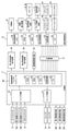
パチンコ遊技機1には、例えば図2に示すような主基板11、演出制御基板12、音声制御基板13、ランプ制御基板14、中継基板15などが搭載されている。その他にも、パチンコ遊技機1の背面には、例えば払出制御基板、情報端子基板、発射制御基板、電源基板などといった、各種の基板が配置されている。
(Board configuration)
For example, the
主基板11は、メイン側の制御基板であり、パチンコ遊技機1における上記遊技の進行(特図ゲームの実行(保留の管理を含む)、普図ゲームの実行(保留の管理を含む)、大当り遊技状態、小当り遊技状態、遊技状態など)を制御する機能を有する。主基板11は、遊技制御用マイクロコンピュータ100、スイッチ回路110、ソレノイド回路111などを有する。
The
主基板11に搭載された遊技制御用マイクロコンピュータ100は、例えば1チップのマイクロコンピュータであり、ROM(Read Only Memory)101と、RAM(Random Access Memory)102と、CPU(Central Processing Unit)103と、乱数回路104と、I/O(Input/Output port)105とを備える。
The
CPU103は、ROM101に記憶されたプログラムを実行することにより、遊技の進行を制御する処理(主基板11の機能を実現する処理)を行う。このとき、ROM101が記憶する各種データ(後述の変動パターン、後述の演出制御コマンド、後述の各種決定を行う際に参照される各種テーブルなどのデータ)が用いられ、RAM102がメインメモリとして使用される。RAM102は、その一部または全部がパチンコ遊技機1に対する電力供給が停止しても、所定期間記憶内容が保存されるバックアップRAMとなっている。なお、ROM101に記憶されたプログラムの全部又は一部をRAM102に展開して、RAM102上で実行するようにしてもよい。
The
乱数回路104は、遊技の進行を制御するときに使用される各種の乱数値(遊技用乱数)を示す数値データを更新可能にカウントする。遊技用乱数は、CPU103が所定のコンピュータプログラムを実行することで更新されるもの(ソフトウェアで更新されるもの
)であってもよい。
The
I/O105は、例えば各種信号(後述の検出信号)が入力される入力ポートと、各種信号(第1特別図柄表示装置4A、第2特別図柄表示装置4B、普通図柄表示器20、第1保留表示器25A、第2保留表示器25B、普図保留表示器25Cなどを制御(駆動)する信号、ソレノイド駆動信号)を伝送するための出力ポートとを含んで構成される。
The I /
スイッチ回路110は、遊技球検出用の各種スイッチ(ゲートスイッチ21、始動口スイッチ(第1始動口スイッチ22Aおよび第2始動口スイッチ22B)、カウントスイッチ23)からの検出信号(遊技球が通過又は進入してスイッチがオンになったことを示す検出信号など)を取り込んで遊技制御用マイクロコンピュータ100に伝送する。検出信号の伝送により、遊技球の通過又は進入が検出されたことになる。
The
ソレノイド回路111は、遊技制御用マイクロコンピュータ100からのソレノイド駆動信号(例えば、ソレノイド81やソレノイド82をオンする信号など)を、普通電動役物用のソレノイド81や大入賞口扉用のソレノイド82に伝送する。
The
主基板11(遊技制御用マイクロコンピュータ100)は、遊技の進行の制御の一部として、遊技の進行に応じて演出制御コマンド(遊技の進行状況等を指定(通知)するコマンド)を演出制御基板12に供給する。主基板11から出力された演出制御コマンドは、中継基板15により中継され、演出制御基板12に供給される。当該演出制御コマンドには、例えば主基板11における各種の決定結果(例えば、特図ゲームの表示結果(大当り種別を含む。)、特図ゲームを実行する際に使用される変動パターン(詳しくは後述))、遊技の状況(例えば、可変表示の開始や終了、大入賞口の開放状況、入賞の発生、保留記憶数、遊技状態)、エラーの発生等を指定するコマンド等が含まれる。
The main board 11 (
演出制御基板12は、主基板11とは独立したサブ側の制御基板であり、演出制御コマンドを受信し、受信した演出制御コマンドに基づいて演出(遊技の進行に応じた種々の演出であり、可動体32の駆動、エラー報知、電断復旧の報知等の各種報知を含む)を実行する機能を有する。
The
演出制御基板12には、演出制御用CPU120と、ROM121と、RAM122と、表示制御部123と、乱数回路124と、I/O125とが搭載されている。
The
演出制御用CPU120は、ROM121に記憶されたプログラムを実行することにより、表示制御部123とともに演出を実行するための処理(演出制御基板12の上記機能を実現するための処理であり、実行する演出の決定等を含む)を行う。このとき、ROM121が記憶する各種データ(各種テーブルなどのデータ)が用いられ、RAM122がメインメモリとして使用される。
The
演出制御用CPU120は、コントローラセンサユニット35Aやプッシュセンサ35Bからの検出信号(遊技者による操作を検出したときに出力される信号であり、操作内容を適宜示す信号)に基づいて演出の実行を表示制御部123に指示することもある。
The
表示制御部123は、VDP(Video Display Processor)、CGROM(Character Generator ROM)、VRAM(Video RAM)などを備え、演出制御用CPU120からの演出の実行指示に基づき、演出を実行する。
The
表示制御部123は、演出制御用CPU120からの演出の実行指示に基づき、実行する演出に応じた映像信号を画像表示装置5に供給することで、演出画像を画像表示装置5
に表示させる。表示制御部123は、さらに、演出画像の表示に同期した音声出力や、遊技効果ランプ9の点灯/消灯を行うため、音指定信号(出力する音声を指定する信号)を音声制御基板13に供給したり、ランプ信号(ランプの点灯/消灯態様を指定する信号)をランプ制御基板14に供給したりする。また、表示制御部123は、可動体32を動作させる信号を当該可動体32又は当該可動体32を駆動する駆動回路に供給する。
The
To display. The
音声制御基板13は、スピーカ8L、8Rを駆動する各種回路を搭載しており、当該音指定信号に基づきスピーカ8L、8Rを駆動し、当該音指定信号が指定する音声をスピーカ8L、8Rから出力させる。
The
ランプ制御基板14は、遊技効果ランプ9を駆動する各種回路を搭載しており、当該ランプ信号に基づき遊技効果ランプ9を駆動し、当該ランプ信号が指定する態様で遊技効果ランプ9を点灯/消灯する。このようにして、表示制御部123は、音声出力、ランプの点灯/消灯を制御する。
The
なお、音声出力、ランプの点灯/消灯の制御(音指定信号やランプ信号の供給等)、可動体32の制御(可動体32を動作させる信号の供給等)は、演出制御用CPU120が実行するようにしてもよい。
The
乱数回路124は、各種演出を実行するために使用される各種の乱数値(演出用乱数)を示す数値データを更新可能にカウントする。演出用乱数は、演出制御用CPU120が所定のコンピュータプログラムを実行することで更新されるもの(ソフトウェアで更新されるもの)であってもよい。
The
演出制御基板12に搭載されたI/O125は、例えば主基板11などから伝送された演出制御コマンドを取り込むための入力ポートと、各種信号(映像信号、音指定信号、ランプ信号)を伝送するための出力ポートとを含んで構成される。
The I /
演出制御基板12、音声制御基板13、ランプ制御基板14といった、主基板11以外の基板をサブ基板ともいう。パチンコ遊技機1のようにサブ基板が機能別に複数設けられていてもよいし、1のサブ基板が複数の機能を有するように構成してもよい。
Boards other than the
(動作)
次に、パチンコ遊技機1の動作(作用)を説明する。
(motion)
Next, the operation (action) of the
(主基板11の主要な動作)
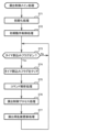
まず、主基板11における主要な動作を説明する。パチンコ遊技機1に対して電力供給が開始されると、遊技制御用マイクロコンピュータ100が起動し、CPU103によって遊技制御メイン処理が実行される。図3は、主基板11におけるCPU103が実行する遊技制御メイン処理を示すフローチャートである。
(Main operation of main board 11)
First, the main operation of the
図3に示す遊技制御メイン処理では、CPU103は、まず、割込禁止に設定する(ステップS1)。続いて、必要な初期設定を行う(ステップS2)。初期設定には、スタックポインタの設定、内蔵デバイス(CTC(カウンタ/タイマ回路)、パラレル入出力ポート等)のレジスタ設定、RAM102をアクセス可能状態にする設定等が含まれる。
In the game control main process shown in FIG. 3, the
次いで、クリアスイッチからの出力信号がオンであるか否かを判定する(ステップS3)。クリアスイッチは、例えば電源基板に搭載されている。クリアスイッチがオンの状態で電源が投入されると、出力信号(クリア信号)が入力ポートを介して遊技制御用マイクロコンピュータ100に入力される。クリアスイッチからの出力信号がオンである場合(
ステップS3;Yes)、初期化処理(ステップS8)を実行する。初期化処理では、CPU103は、RAM102に記憶されるフラグ、カウンタ、バッファをクリアするRAMクリア処理を行い、作業領域に初期値を設定する。
Next, it is determined whether or not the output signal from the clear switch is ON (step S3). The clear switch is mounted on the power supply board, for example. When the power is turned on with the clear switch turned on, an output signal (clear signal) is input to the
Step S3; Yes), the initialization process (step S8) is executed. In the initialization process, the
また、CPU103は、初期化を指示する演出制御コマンドを演出制御基板12に送信する(ステップS9)。演出制御用CPU120は、当該演出制御コマンドを受信すると、例えば画像表示装置5において、遊技機の制御の初期化がなされたことを報知するための画面表示を行う。
Further, the
クリアスイッチからの出力信号がオンでない場合には(ステップS3;No)、RAM102(バックアップRAM)にバックアップデータが保存されているか否かを判定する(ステップS4)。不測の停電等(電断)によりパチンコ遊技機1への電力供給が停止したときには、CPU103は、当該電力供給の停止によって動作できなくなる直前に、電源供給停止時処理を実行する。この電源供給停止時処理では、RAM102にデータをバックアップすることを示すバックアップフラグをオンする処理、RAM102のデータ保護処理等が実行される。データ保護処理には、誤り検出符号(チェックサム、パリティビット等)の付加、各種データをバックアップする処理が含まれる。バックアップされるデータには、遊技を進行するための各種データ(各種フラグ、各種タイマの状態等を含む)の他、前記バックアップフラグの状態や誤り検出符号も含まれる。ステップS4では、バックアップフラグがオンであるか否かを判定する。バックアップフラグがオフでRAM102にバックアップデータが記憶されていない場合(ステップS4;No)、初期化処理(ステップS8)を実行する。
If the output signal from the clear switch is not on (step S3; No), it is determined whether or not the backup data is stored in the RAM 102 (backup RAM) (step S4). When the power supply to the
RAM102にバックアップデータが記憶されている場合(ステップS4;Yes)、CPU103は、バックアップしたデータのデータチェックを行い(誤り検出符号を用いて行われる)、データが正常か否かを判定する(ステップS5)。ステップS5では、例えば、パリティビットやチェックサムにより、RAM102のデータが、電力供給停止時のデータと一致するか否かを判定する。これらが一致すると判定された場合、RAM102のデータが正常であると判定する。
When the backup data is stored in the RAM 102 (step S4; Yes), the
RAM102のデータが正常でないと判定された場合(ステップS5;No)、内部状態を電力供給停止時の状態に戻すことができないので、初期化処理(ステップS8)を実行する。
If it is determined that the data in the
RAM102のデータが正常であると判定された場合(ステップS5;Yes)、CPU103は、主基板11の内部状態を電力供給停止時の状態に戻すための復旧処理(ステップS6)を行う。復旧処理では、CPU103は、RAM102の記憶内容(バックアップしたデータの内容)に基づいて作業領域の設定を行う。これにより、電力供給停止時の遊技状態に復旧し、特別図柄の変動中であった場合には、後述の遊技制御用タイマ割込み処理の実行によって、復旧前の状態から特別図柄の変動が再開されることになる。
When it is determined that the data in the
そして、CPU103は、電断からの復旧を指示する演出制御コマンドを演出制御基板12に送信する(ステップS7)。これに合わせて、バックアップされている電断前の遊技状態を指定する演出制御コマンドや、特図ゲームの実行中であった場合には当該実行中の特図ゲームの表示結果を指定する演出制御コマンドを送信するようにしてもよい。これらコマンドは、後述の特別図柄プロセス処理で送信設定されるコマンドと同じコマンドを使用できる。演出制御用CPU120は、電断からの復旧時を特定する演出制御コマンドを受信すると、例えば画像表示装置5において、電断からの復旧がなされたこと又は電断からの復旧中であることを報知するための画面表示を行う。演出制御用CPU120は、前記演出制御コマンドに基づいて、適宜の画面表示を行うようにしてもよい。
Then, the
復旧処理または初期化処理を終了して演出制御基板12に演出制御コマンドを送信した後には、CPU103は、乱数回路104を初期設定する乱数回路設定処理を実行する(ステップS10)。そして、所定時間(例えば2ms)毎に定期的にタイマ割込がかかるように遊技制御用マイクロコンピュータ100に内蔵されているCTCのレジスタの設定を行い(ステップS11)、割込みを許可する(ステップS12)。その後、ループ処理に入る。以後、所定時間(例えば2ms)ごとにCTCから割込み要求信号がCPU103へ送出され、CPU103は定期的にタイマ割込み処理を実行することができる。
After the restoration process or the initialization process is completed and the effect control command is transmitted to the
こうした遊技制御メイン処理を実行したCPU103は、CTCからの割込み要求信号を受信して割込み要求を受け付けると、図4のフローチャートに示す遊技制御用タイマ割込み処理を実行する。図4に示す遊技制御用タイマ割込み処理を開始すると、CPU103は、まず、所定のスイッチ処理を実行することにより、スイッチ回路110を介してゲートスイッチ21、第1始動口スイッチ22A、第2始動口スイッチ22B、カウントスイッチ23といった各種スイッチからの検出信号の受信の有無を判定する(ステップS21)。続いて、所定のメイン側エラー処理を実行することにより、パチンコ遊技機1の異常診断を行い、その診断結果に応じて必要ならば警告を発生可能とする(ステップS22)。この後、所定の情報出力処理を実行することにより、例えばパチンコ遊技機1の外部に設置されたホール管理用コンピュータに供給される大当り情報(大当りの発生回数等を示す情報)、始動情報(始動入賞の回数等を示す情報)、確率変動情報(確変状態となった回数等を示す情報)などのデータを出力する(ステップS23)。
When the
情報出力処理に続いて、主基板11の側で用いられる遊技用乱数の少なくとも一部をソフトウェアにより更新するための遊技用乱数更新処理を実行する(ステップS24)。この後、CPU103は、特別図柄プロセス処理を実行する(ステップS25)。CPU103がタイマ割込み毎に特別図柄プロセス処理を実行することにより、特図ゲームの実行及び保留の管理や、大当り遊技状態や小当り遊技状態の制御、遊技状態の制御などが実現される(詳しくは後述)。
Following the information output process, a game random number update process for updating at least a part of the game random numbers used on the
特別図柄プロセス処理に続いて、普通図柄プロセス処理が実行される(ステップS26)。CPU103がタイマ割込み毎に普通図柄プロセス処理を実行することにより、ゲートスイッチ21からの検出信号に基づく(通過ゲート41に遊技球が通過したことに基づく)普図ゲームの実行及び保留の管理や、「普図当り」に基づく可変入賞球装置6Bの開放制御などを可能にする。普図ゲームの実行は、普通図柄表示器20を駆動することにより行われ、普図保留表示器25Cを点灯させることにより普図保留数を表示する。
Following the special symbol process process, the normal symbol process process is executed (step S26). By executing the normal symbol process processing for each timer interrupt, the
普通図柄プロセス処理を実行した後、遊技制御用タイマ割込み処理の一部として、電断が発生したときの処理、賞球を払い出すための処理等などが行われてもよい。その後、CPU103は、コマンド制御処理を実行する(ステップS27)。CPU103は、上記各処理にて演出制御コマンドを送信設定することがある。ステップS27のコマンド制御処理では、送信設定された演出制御コマンドを演出制御基板12などのサブ側の制御基板に対して伝送させる処理が行われる。コマンド制御処理を実行した後には、割込みを許可してから、遊技制御用タイマ割込み処理を終了する。
After executing the normal symbol process process, as a part of the game control timer interrupt process, a process when a power failure occurs, a process for paying out a prize ball, and the like may be performed. After that, the
図5は、特別図柄プロセス処理として、図4に示すステップS25にて実行される処理の一例を示すフローチャートである。この特別図柄プロセス処理において、CPU103は、まず、始動入賞判定処理を実行する(ステップS101)。
FIG. 5 is a flowchart showing an example of the process executed in step S25 shown in FIG. 4 as the special symbol process process. In this special symbol process process, the
始動入賞判定処理では、始動入賞の発生を検出し、RAM102の所定領域に保留情報を格納し保留記憶数を更新する処理が実行される。始動入賞が発生すると、表示結果(大
当り種別を含む)や変動パターンを決定するための乱数値が抽出され、保留情報として記憶される。また、抽出した乱数値に基づいて、表示結果や変動パターンを先読み判定する処理が実行されてもよい。保留情報や保留記憶数を記憶した後には、演出制御基板12に始動入賞の発生、保留記憶数、先読み判定等の判定結果を指定するための演出制御コマンドを送信するための送信設定が行われる。こうして送信設定された始動入賞時の演出制御コマンドは、例えば特別図柄プロセス処理が終了した後、図4に示すステップS27のコマンド制御処理が実行されることなどにより、主基板11から演出制御基板12に対して伝送される。
In the start winning determination process, a process of detecting the occurrence of a start winning, storing the hold information in a predetermined area of the
S101にて始動入賞判定処理を実行した後、CPU103は、RAM102に設けられた特図プロセスフラグの値に応じて、ステップS110~S120の処理のいずれかを選択して実行する。なお、特別図柄プロセス処理の各処理(ステップS110~S120)では、各処理に対応した演出制御コマンドを演出制御基板12に送信するための送信設定が行われる。
After executing the start winning determination process in S101, the
ステップS110の特別図柄通常処理は、特図プロセスフラグの値が“0”(初期値)のときに実行される。この特別図柄通常処理では、保留情報の有無などに基づいて、第1特図ゲーム又は第2特図ゲームを開始するか否かの判定が行われる。また、特別図柄通常処理では、表示結果決定用の乱数値に基づき、特別図柄や飾り図柄の表示結果を「大当り」または「小当り」とするか否かや「大当り」とする場合の大当り種別を、その表示結果が導出表示される以前に決定(事前決定)する。さらに、特別図柄通常処理では、決定された表示結果に対応して、特図ゲームにおいて停止表示させる確定特別図柄(大当り図柄や小当り図柄、ハズレ図柄のいずれか)が設定される。その後、特図プロセスフラグの値が“1”に更新され、特別図柄通常処理は終了する。なお、第2特図を用いた特図ゲームが第1特図を用いた特図ゲームよりも優先して実行されるようにしてもよい(特図2優先消化ともいう)。また、第1始動入賞口及び第2始動入賞口への遊技球の入賞順序を記憶し、入賞順に特図ゲームの開始条件を成立させるようにしてもよい(入賞順消化ともいう)。 The special symbol normal processing in step S110 is executed when the value of the special symbol process flag is “0” (initial value). In this special symbol normal processing, it is determined whether or not to start the first special figure game or the second special figure game based on the presence or absence of the reserved information. In addition, in the special symbol normal processing, whether or not the display result of the special symbol or decorative symbol is set to "big hit" or "small hit" based on the random number value for determining the display result, and the big hit type when the display result is set to "big hit". Is determined (predetermined) before the display result is derived and displayed. Further, in the special symbol normal processing, a definite special symbol (either a big hit symbol, a small hit symbol, or a lost symbol) to be stopped and displayed in the special symbol game is set according to the determined display result. After that, the value of the special symbol process flag is updated to "1", and the special symbol normal processing ends. It should be noted that the special figure game using the second special figure may be executed with priority over the special figure game using the first special figure (also referred to as special figure 2 priority digestion). Further, the winning order of the game balls to the first starting winning opening and the second starting winning opening may be stored, and the starting condition of the special figure game may be satisfied in the winning order (also referred to as winning order digestion).
乱数値に基づき各種の決定を行う場合には、ROM101に格納されている各種のテーブル(乱数値と比較される決定値が決定結果に割り当てられているテーブル)が参照される。主基板11における他の決定、演出制御基板12における各種の決定についても同じである。演出制御基板12においては、各種のテーブルがROM121に格納されている。
When making various decisions based on the random number value, various tables stored in the ROM 101 (a table in which the decision value to be compared with the random number value is assigned to the decision result) are referred to. The same applies to other decisions on the
ステップS111の変動パターン設定処理は、特図プロセスフラグの値が“1”のときに実行される。この変動パターン設定処理には、表示結果を「大当り」または「小当り」とするか否かの事前決定結果等に基づき、変動パターン決定用の乱数値を用いて変動パターンを複数種類のいずれかに決定する処理などが含まれている。変動パターン設定処理では、変動パターンを決定したときに、特図プロセスフラグの値が“2”に更新され、変動パターン設定処理は終了する。 The variation pattern setting process in step S111 is executed when the value of the special figure process flag is “1”. In this fluctuation pattern setting process, one of a plurality of types of fluctuation patterns is used by using a random value for determining the fluctuation pattern based on the pre-determination result of whether or not the display result is "big hit" or "small hit". It includes the process of determining. In the variation pattern setting process, when the variation pattern is determined, the value of the special figure process flag is updated to "2", and the variation pattern setting process ends.
変動パターンは、特図ゲームの実行時間(特図変動時間)(飾り図柄の可変表示の実行時間でもある)や、飾り図柄の可変表示の態様(リーチの有無等)、飾り図柄の可変表示中の演出内容(リーチ演出の種類等)を指定するものであり、可変表示パターンとも呼ばれる。 The fluctuation pattern includes the execution time of the special figure game (special figure fluctuation time) (which is also the execution time of the variable display of the decorative symbol), the variable display mode of the decorative symbol (presence or absence of reach, etc.), and the variable display of the decorative symbol. It specifies the content of the effect (type of reach effect, etc.), and is also called a variable display pattern.
ステップS112の特別図柄変動処理は、特図プロセスフラグの値が“2”のときに実行される。この特別図柄変動処理には、第1特別図柄表示装置4Aや第2特別図柄表示装置4Bにおいて特別図柄を変動させるための設定を行う処理や、その特別図柄が変動を開
始してからの経過時間を計測する処理などが含まれている。また、計測された経過時間が変動パターンに対応する特図変動時間に達したか否かの判定も行われる。そして、特別図柄の変動を開始してからの経過時間が特図変動時間に達したときには、特図プロセスフラグの値が“3”に更新され、特別図柄変動処理は終了する。
The special symbol variation process in step S112 is executed when the value of the special symbol process flag is “2”. In this special symbol variation processing, the processing for setting the special symbol to be varied in the first special
ステップS113の特別図柄停止処理は、特図プロセスフラグの値が“3”のときに実行される。この特別図柄停止処理には、第1特別図柄表示装置4Aや第2特別図柄表示装置4Bにて特別図柄の変動を停止させ、特別図柄の表示結果となる確定特別図柄を停止表示(導出)させるための設定を行う処理が含まれている。そして、表示結果が「大当り」である場合には特図プロセスフラグの値が“4”に更新される。その一方で、大当りフラグがオフであり、表示結果が「小当り」である場合には、特図プロセスフラグの値が“8”に更新される。また、表示結果が「ハズレ」である場合には、特図プロセスフラグの値が“0”に更新される。表示結果が「小当り」又は「ハズレ」である場合、時短状態や確変状態に制御されているときであって、回数切りの終了成立する場合には、遊技状態も更新される。特図プロセスフラグの値が更新されると、特別図柄停止処理は終了する。
The special symbol stop processing in step S113 is executed when the value of the special symbol process flag is “3”. In this special symbol stop process, the first special
ステップS114の大当り開放前処理は、特図プロセスフラグの値が“4”のときに実行される。この大当り開放前処理には、表示結果が「大当り」となったことなどに基づき、大当り遊技状態においてラウンドの実行を開始して大入賞口を開放状態とするための設定を行う処理などが含まれている。大入賞口を開放状態とするときには、大入賞口扉用のソレノイド82に対してソレノイド駆動信号を供給する処理が実行される。このときには、例えば大当り種別がいずれであるかに対応して、大入賞口を開放状態とする開放上限期間や、ラウンドの上限実行回数を設定する。これらの設定が終了すると、特図プロセスフラグの値が“5”に更新され、大当り開放前処理は終了する。
The jackpot opening preprocessing in step S114 is executed when the value of the special figure process flag is “4”. This big hit pre-opening process includes a process of setting to open the big winning opening by starting the execution of the round in the big hit game state based on the display result being "big hit". It has been. When the large winning opening is opened, a process of supplying a solenoid drive signal to the
ステップS115の大当り開放中処理は、特図プロセスフラグの値が“5”のときに実行される。この大当り開放中処理には、大入賞口を開放状態としてからの経過時間を計測する処理や、その計測した経過時間やカウントスイッチ23によって検出された遊技球の個数などに基づいて、大入賞口を開放状態から閉鎖状態に戻すタイミングとなったか否かを判定する処理などが含まれている。そして、大入賞口を閉鎖状態に戻すときには、大入賞口扉用のソレノイド82に対するソレノイド駆動信号の供給を停止させる処理などを実行した後、特図プロセスフラグの値が“6”に更新し、大当り開放中処理を終了する。
The process of opening the jackpot in step S115 is executed when the value of the special figure process flag is “5”. In this big hit opening process, the big winning opening is based on the process of measuring the elapsed time since the big winning opening is opened, the measured elapsed time, the number of game balls detected by the
ステップS116の大当り開放後処理は、特図プロセスフラグの値が“6”のときに実行される。この大当り開放後処理には、大入賞口を開放状態とするラウンドの実行回数が設定された上限実行回数に達したか否かを判定する処理や、上限実行回数に達した場合に大当り遊技状態を終了させるための設定を行う処理などが含まれている。そして、ラウンドの実行回数が上限実行回数に達していないときには、特図プロセスフラグの値が“5”に更新される一方、ラウンドの実行回数が上限実行回数に達したときには、特図プロセスフラグの値が“7”に更新される。特図プロセスフラグの値が更新されると、大当り解放後処理は終了する。 The post-processing after opening the jackpot in step S116 is executed when the value of the special figure process flag is “6”. In this big hit post-opening process, there is a process of determining whether or not the number of rounds to be executed with the big winning opening open has reached the set maximum number of executions, and a big hit game state when the maximum number of executions has been reached. It includes the process of making settings to terminate. Then, when the number of round executions has not reached the upper limit, the value of the special figure process flag is updated to "5", while when the number of round executions reaches the upper limit, the special figure process flag is set. The value is updated to "7". When the value of the special figure process flag is updated, the jackpot release post-processing ends.
ステップS117の大当り終了処理は、特図プロセスフラグの値が“7”のときに実行される。この大当り終了処理には、大当り遊技状態の終了を報知する演出動作としてのエンディング演出が実行される期間に対応した待ち時間が経過するまで待機する処理や、大当り遊技状態の終了に対応して確変制御や時短制御を開始するための各種の設定を行う処理などが含まれている。こうした設定が行われたときには、特図プロセスフラグの値が“0”に更新され、大当り終了処理は終了する。 The jackpot end process of step S117 is executed when the value of the special figure process flag is “7”. In this jackpot end process, there is a process of waiting until the waiting time corresponding to the period corresponding to the period in which the ending effect as an effect effect for notifying the end of the jackpot game state is executed, and a probable change corresponding to the end of the jackpot game state. It includes processing to make various settings for starting control and time reduction control. When such a setting is made, the value of the special figure process flag is updated to "0", and the jackpot end process ends.
ステップS118の小当り開放前処理は、特図プロセスフラグの値が“8”のときに実
行される。この小当り開放前処理には、表示結果が「小当り」となったことに基づき、小当り遊技状態において大入賞口を開放状態とするための設定を行う処理などが含まれている。このときには、特図プロセスフラグの値が“9”に更新され、小当り開放前処理は終了する。
The small hit release preprocessing in step S118 is executed when the value of the special figure process flag is “8”. This small hit pre-opening process includes a process of setting the large winning opening to be in the open state in the small hit game state based on the display result being "small hit". At this time, the value of the special figure process flag is updated to "9", and the small hit opening preprocessing ends.
ステップS119の小当り開放中処理は、特図プロセスフラグの値が“9”のときに実行される。この小当り開放中処理には、大入賞口を開放状態としてからの経過時間を計測する処理や、その計測した経過時間などに基づいて、大入賞口を開放状態から閉鎖状態に戻すタイミングとなったか否かを判定する処理などが含まれている。大入賞口を閉鎖状態に戻して小当り遊技状態の終了タイミングとなったときには、特図プロセスフラグの値が“10”に更新され、小当り開放中処理は終了する。 The small hit opening process in step S119 is executed when the value of the special figure process flag is “9”. In this small hit opening process, it is the timing to return the big prize opening from the open state to the closed state based on the process of measuring the elapsed time from the opening state of the big winning opening and the measured elapsed time. It includes a process to determine whether or not it is. When the large winning opening is returned to the closed state and the end timing of the small hit game state is reached, the value of the special figure process flag is updated to "10", and the processing during the small hit opening process ends.
ステップS120の小当り終了処理は、特図プロセスフラグの値が“10”のときに実行される。この小当り終了処理には、小当り遊技状態の終了を報知する演出動作が実行される期間に対応した待ち時間が経過するまで待機する処理などが含まれている。ここで、小当り遊技状態が終了するときには、小当り遊技状態となる以前のパチンコ遊技機1における遊技状態を継続させる。小当り遊技状態の終了時における待ち時間が経過したときには、特図プロセスフラグの値が“0”に更新され、小当り終了処理は終了する。
The small hit end process of step S120 is executed when the value of the special figure process flag is “10”. The small hit end process includes a process of waiting until a waiting time corresponding to a period in which the effect operation for notifying the end of the small hit game state is executed has elapsed. Here, when the small hit gaming state ends, the gaming state in the
(演出制御基板12の主要な動作)
次に、演出制御基板12における主要な動作を説明する。演出制御基板12では、電源基板等から電源電圧の供給を受けると、演出制御用CPU120が起動して、図6のフローチャートに示すような演出制御メイン処理を実行する。図6に示す演出制御メイン処理を開始すると、演出制御用CPU120は、まず、所定の初期化処理を実行して(ステップS71)、RAM122のクリアや各種初期値の設定、また演出制御基板12に搭載されたCTC(カウンタ/タイマ回路)のレジスタ設定等を行う。また、初期動作制御処理を実行する(ステップS72)。初期動作制御処理では、可動体32を駆動して初期位置に戻す制御、所定の動作確認を行う制御といった可動体32の初期動作を行う制御が実行される。
(Main operation of the effect control board 12)
Next, the main operation of the
その後、タイマ割込みフラグがオンとなっているか否かの判定を行う(ステップS73)。タイマ割込みフラグは、例えばCTCのレジスタ設定に基づき、所定時間(例えば2ミリ秒)が経過するごとにオン状態にセットされる。このとき、タイマ割込みフラグがオフであれば(ステップS73;No)、ステップS73の処理を繰り返し実行して待機する。 After that, it is determined whether or not the timer interrupt flag is turned on (step S73). The timer interrupt flag is set to the ON state every time a predetermined time (for example, 2 milliseconds) elapses, based on the register setting of the CTC, for example. At this time, if the timer interrupt flag is off (step S73; No), the process of step S73 is repeatedly executed and waits.
また、演出制御基板12の側では、所定時間が経過するごとに発生するタイマ割込みとは別に、主基板11からの演出制御コマンドを受信するための割込みが発生する。この割込みは、例えば主基板11からの演出制御INT信号がオン状態となることにより発生する割込みである。演出制御INT信号がオン状態となることによる割込みが発生すると、演出制御用CPU120は、自動的に割込み禁止に設定するが、自動的に割込み禁止状態にならないCPUを用いている場合には、割込み禁止命令(DI命令)を発行することが望ましい。演出制御用CPU120は、演出制御INT信号がオン状態となることによる割込みに対応して、例えば所定のコマンド受信割込み処理を実行する。このコマンド受信割込み処理では、I/O125に含まれる入力ポートのうちで、中継基板15を介して主基板11から送信された制御信号を受信する所定の入力ポートより、演出制御コマンドを取り込む。このとき取り込まれた演出制御コマンドは、例えばRAM122に設けられた演出制御コマンド受信用バッファに格納する。その後、演出制御用CPU120は、割込み許可に設定してから、コマンド受信割込み処理を終了する。
Further, on the side of the
ステップS73にてタイマ割込みフラグがオンである場合には(ステップS73;Yes)、タイマ割込みフラグをクリアしてオフ状態にするとともに(ステップS74)、コマンド解析処理を実行する(ステップS75)。コマンド解析処理では、例えば主基板11の遊技制御用マイクロコンピュータ100から送信されて演出制御コマンド受信用バッファに格納されている各種の演出制御コマンドを読み出した後に、その読み出された演出制御コマンドに対応した設定や制御などが行われる。例えば、どの演出制御コマンドを受信したかや演出制御コマンドが特定する内容等を演出制御プロセス処理等で確認できるように、読み出された演出制御コマンドをRAM122の所定領域に格納したり、RAM122に設けられた受信フラグをオンしたりする。また、演出制御コマンドが遊技状態を特定する場合、遊技状態に応じた背景の表示を表示制御部123に指示してもよい。
If the timer interrupt flag is on in step S73 (step S73; Yes), the timer interrupt flag is cleared and turned off (step S74), and the command analysis process is executed (step S75). In the command analysis process, for example, after reading various effect control commands transmitted from the
ステップS75にてコマンド解析処理を実行した後には、演出制御プロセス処理を実行する(ステップS76)。演出制御プロセス処理では、例えば画像表示装置5の表示領域における演出画像の表示動作、スピーカ8L、8Rからの音声出力動作、遊技効果ランプ9及び装飾用LEDといった装飾発光体における点灯動作、可動体32の駆動動作といった、各種の演出装置を動作させる制御が行われる。また、各種の演出装置を用いた演出動作の制御内容について、主基板11から送信された演出制御コマンド等に応じた判定や決定、設定などが行われる。
After executing the command analysis process in step S75, the effect control process process is executed (step S76). In the effect control process processing, for example, an effect image display operation in the display area of the
ステップS76の演出制御プロセス処理に続いて、演出用乱数更新処理が実行され(ステップS77)、演出制御基板12の側で用いられる演出用乱数の少なくとも一部がソフトウェアにより更新される。その後、ステップS73の処理に戻る。ステップS73の処理に戻る前に、他の処理が実行されてもよい。
Following the effect control process process in step S76, the effect random number update process is executed (step S77), and at least a part of the effect random numbers used on the
図7は、演出制御プロセス処理として、図6のステップS76にて実行される処理の一例を示すフローチャートである。図7に示す演出制御プロセス処理において、演出制御用CPU120は、まず、先読予告設定処理を実行する(ステップS161)。先読予告設定処理では、例えば、主基板11から送信された始動入賞時の演出制御コマンドに基づいて、先読み予告演出を実行するための判定や決定、設定などが行われる。また、当該演出制御コマンドから特定される保留記憶数に基づき保留表示を表示するための処理が実行される。
FIG. 7 is a flowchart showing an example of the process executed in step S76 of FIG. 6 as the effect control process process. In the effect control process process shown in FIG. 7, the
ステップS161の処理を実行した後、演出制御用CPU120は、例えばRAM122に設けられた演出プロセスフラグの値に応じて、以下のようなステップS170~S177の処理のいずれかを選択して実行する。
After executing the process of step S161, the
ステップS170の可変表示開始待ち処理は、演出プロセスフラグの値が“0”(初期値)のときに実行される処理である。この可変表示開始待ち処理は、主基板11から可変表示の開始を指定するコマンドなどを受信したか否かに基づき、画像表示装置5における飾り図柄の可変表示を開始するか否かを判定する処理などを含んでいる。画像表示装置5における飾り図柄の可変表示を開始すると判定された場合、演出プロセスフラグの値を“1”に更新し、可変表示開始待ち処理を終了する。
The variable display start waiting process in step S170 is a process executed when the value of the effect process flag is “0” (initial value). This variable display start waiting process is a process of determining whether or not to start variable display of the decorative symbol on the
ステップS171の可変表示開始設定処理は、演出プロセスフラグの値が“1”のときに実行される処理である。この可変表示開始設定処理では、演出制御コマンドにより特定される表示結果や変動パターンに基づいて、飾り図柄の可変表示の表示結果(確定飾り図柄)、飾り図柄の可変表示の態様、リーチ演出や各種予告演出などの各種演出の実行の有無やその態様や実行開始タイミングなどを決定する。そして、その決定結果等を反映した演出制御パターン(表示制御部123に演出の実行を指示するための制御データの集まり)を設定する。その後、設定した演出制御パターンに基づいて、飾り図柄の可変表示の実
行開始を表示制御部123に指示し、演出プロセスフラグの値を“2”に更新し、可変表示開始設定処理を終了する。表示制御部123は、飾り図柄の可変表示の実行開始の指示により、画像表示装置5において、飾り図柄の可変表示を開始させる。
The variable display start setting process in step S171 is a process executed when the value of the effect process flag is “1”. In this variable display start setting process, the display result of the variable display of the decorative symbol (fixed decorative symbol), the mode of the variable display of the decorative symbol, the reach effect, and various types are based on the display result and the variation pattern specified by the effect control command. It is determined whether or not various effects such as a notice effect are executed, the mode thereof, and the execution start timing. Then, an effect control pattern (a collection of control data for instructing the
ステップS172の可変表示中演出処理は、演出プロセスフラグの値が“2”のときに実行される処理である。この可変表示中演出処理において、演出制御用CPU120は、表示制御部123を指示することで、ステップS171にて設定された演出制御パターンに基づく演出画像を画像表示装置5の表示画面に表示させることや、可動体32を駆動させること、音声制御基板13に対する指令(効果音信号)の出力によりスピーカ8L、8Rから音声や効果音を出力させること、ランプ制御基板14に対する指令(電飾信号)の出力により遊技効果ランプ9や装飾用LEDを点灯/消灯/点滅させることといった、飾り図柄の可変表示中における各種の演出制御を実行する。こうした演出制御を行った後、例えば演出制御パターンから飾り図柄の可変表示終了を示す終了コードが読み出されたこと、あるいは、主基板11から確定飾り図柄を停止表示させることを指定するコマンドを受信したことなどに対応して、飾り図柄の表示結果となる確定飾り図柄を停止表示させる。確定飾り図柄を停止表示したときには、演出プロセスフラグの値が“3”に更新され、可変表示中演出処理は終了する。
The variable display effect process in step S172 is a process executed when the value of the effect process flag is “2”. In this variable display effect processing, the
ステップS173の特図当り待ち処理は、演出プロセスフラグの値が“3”のときに実行される処理である。この特図当り待ち処理において、演出制御用CPU120は、主基板11から大当り遊技状態又は小当り遊技状態を開始することを指定する演出制御コマンドの受信があったか否かを判定する。そして、大当り遊技状態又は小当り遊技状態を開始することを指定する演出制御コマンドを受信したきに、そのコマンドが大当り遊技状態の開始を指定するものであれば、演出プロセスフラグの値を“6”に更新する。これに対して、そのコマンドが小当り遊技状態の開始を指定するものであれば、演出プロセスフラグの値を小当り中演出処理に対応した値である“4”に更新する。また、大当り遊技状態又は小当り遊技状態を開始することを指定するコマンドを受信せずに、当該コマンドの受信待ち時間が経過したときには、特図ゲームにおける表示結果が「ハズレ」であったと判定して、演出プロセスフラグの値を初期値である“0”に更新する。演出プロセスフラグの値を更新すると、特図当り待ち処理を終了する。
The special figure hit waiting process in step S173 is a process executed when the value of the effect process flag is “3”. In this special figure hit waiting process, the
ステップS174の小当り中演出処理は、演出制御プロセスフラグの値が“4”のときに実行される処理である。この小当り中演出処理において、演出制御用CPU120は、例えば小当り遊技状態における演出内容に対応した演出制御パターン等を設定し、その設定内容に基づく小当り遊技状態における各種の演出制御を実行する。また、小当り中演出処理では、例えば主基板11から小当り遊技状態を終了することを指定するコマンドを受信したことに対応して、演出プロセスフラグの値を小当り終了演出に対応した値である“5”に更新し、小当り中演出処理を終了する。
The small hit medium effect process in step S174 is a process executed when the value of the effect control process flag is “4”. In this small hit medium effect process, the
ステップS175の小当り終了演出処理は、演出制御プロセスフラグの値が“5”のときに実行される処理である。この小当り終了演出処理において、演出制御用CPU120は、例えば小当り遊技状態の終了などに対応した演出制御パターン等を設定し、その設定内容に基づく小当り遊技状態の終了時における各種の演出制御を実行する。その後、演出プロセスフラグの値を初期値である“0”に更新し、小当り終了演出処理を終了する。
The small hit end effect process in step S175 is a process executed when the value of the effect control process flag is “5”. In this small hit end effect process, the
ステップS176の大当り中演出処理は、演出プロセスフラグの値が“6”のときに実行される処理である。この大当り中演出処理において、演出制御用CPU120は、例えば大当り遊技状態における演出内容に対応した演出制御パターン等を設定し、その設定内容に基づく大当り遊技状態における各種の演出制御を実行する。また、大当り中演出処理では、例えば主基板11から大当り遊技状態を終了することを指定するコマンドを受信し
たことに対応して、演出制御プロセスフラグの値をエンディング演出処理に対応した値である“7”に更新し、大当り中演出処理を終了する。
The jackpot effect process in step S176 is a process executed when the value of the effect process flag is “6”. In this big hit middle effect processing, the
ステップS177のエンディング演出処理は、演出プロセスフラグの値が“7”のときに実行される処理である。このエンディング演出処理において、演出制御用CPU120は、例えば大当り遊技状態の終了などに対応した演出制御パターン等を設定し、その設定内容に基づく大当り遊技状態の終了時におけるエンディング演出の各種の演出制御を実行する。その後、演出プロセスフラグの値を初期値である“0”に更新し、エンディング演出処理を終了する。
The ending effect process of step S177 is a process executed when the value of the effect process flag is “7”. In this ending effect processing, the
(基本説明の変形例)
この発明は、上記基本説明で説明したパチンコ遊技機1に限定されず、本発明の趣旨を逸脱しない範囲で、様々な変形及び応用が可能である。
(Modified example of basic explanation)
The present invention is not limited to the
上記基本説明のパチンコ遊技機1は、入賞の発生に基づいて所定数の遊技媒体を景品として払い出す払出式遊技機であったが、遊技媒体を封入し入賞の発生に基づいて得点を付与する封入式遊技機であってもよい。
The
特別図柄の可変表示中に表示されるものは1種類の図柄(例えば、「-」を示す記号)だけで、当該図柄の表示と消灯とを繰り返すことによって可変表示を行うようにしてもよい。さらに可変表示中に当該図柄が表示されるものも、可変表示の停止時には、当該図柄が表示されなくてもよい(表示結果としては「-」を示す記号が表示されなくてもよい)。 Only one type of symbol (for example, a symbol indicating "-") is displayed during the variable display of the special symbol, and the variable display may be performed by repeating the display and extinguishing of the symbol. Further, even if the symbol is displayed during the variable display, the symbol may not be displayed when the variable display is stopped (the symbol indicating "-" may not be displayed as the display result).
上記基本説明では、遊技機としてパチンコ遊技機1を示したが、メダルが投入されて所定の賭け数が設定され、遊技者による操作レバーの操作に応じて複数種類の図柄を回転させ、遊技者によるストップボタンの操作に応じて図柄を停止させたときに停止図柄の組合せが特定の図柄の組み合わせになると、所定数のメダルが遊技者に払い出されるゲームを実行可能なスロット機(例えば、ビッグボーナス、レギュラーボーナス、RT、AT、ART、CZ(以下、ボーナス等)のうち1以上を搭載するスロット機)にも本発明を適用可能である。
In the above basic explanation, the
本発明を実現するためのプログラム及びデータは、パチンコ遊技機1に含まれるコンピュータ装置などに対して、着脱自在の記録媒体により配布・提供される形態に限定されるものではなく、予めコンピュータ装置などの有する記憶装置にインストールしておくことで配布される形態を採っても構わない。さらに、本発明を実現するためのプログラム及びデータは、通信処理部を設けておくことにより、通信回線等を介して接続されたネットワーク上の、他の機器からダウンロードすることによって配布する形態を採っても構わない。
The program and data for realizing the present invention are not limited to the form of being distributed and provided by a detachable recording medium to the computer device included in the
そして、ゲームの実行形態も、着脱自在の記録媒体を装着することにより実行するものだけではなく、通信回線等を介してダウンロードしたプログラム及びデータを、内部メモリ等に一旦格納することにより実行可能とする形態、通信回線等を介して接続されたネットワーク上における、他の機器側のハードウェア資源を用いて直接実行する形態としてもよい。さらには、他のコンピュータ装置等とネットワークを介してデータの交換を行うことによりゲームを実行するような形態とすることもできる。 The execution mode of the game is not limited to the one executed by attaching a detachable recording medium, but can be executed by temporarily storing the program and data downloaded via the communication line or the like in the internal memory or the like. It may be executed directly by using the hardware resources of other devices on the network connected via a communication line or the like. Furthermore, the game can be executed by exchanging data with another computer device or the like via a network.
なお、本明細書において、演出の実行割合などの各種割合の比較の表現(「高い」、「低い」、「異ならせる」などの表現)は、一方が「0%」の割合であることを含んでもよい。例えば、一方が「0%」の割合で、他方が「100%」の割合又は「100%」未満
の割合であることも含む。
In this specification, one of the expressions for comparison of various ratios such as the execution ratio of the production (expressions such as "high", "low", and "differentiate") is "0%". It may be included. For example, one may have a percentage of "0%" and the other may have a percentage of "100%" or less than "100%".
(本実施形態の特徴部207SGに関する説明)
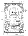
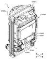
次に、本実施の形態の特徴部207SGについて説明する。図8-1は、本実施の形態の特徴部207SGにおけるパチンコ遊技機1の正面図であり、主要部材の配置レイアウトを示す。図8-1及び図8-7に示すように、パチンコ遊技機(遊技機)1は、大別して、縦長の方形枠状に形成された外枠207SG001aと、遊技盤面を構成する遊技盤(ゲージ盤)2と、遊技盤2を支持固定する遊技機用枠(台枠)207SG003とから構成されている。遊技盤2には、遊技領域が形成され、この遊技領域には、遊技媒体としての遊技球が所定の打球発射装置から発射されて打ち込まれる。また、遊技機用枠207SG003には、ガラス窓を有するガラス扉枠207SG003aが左側辺を中心として遊技機用枠207SG003の前面を開放する扉開放位置と該前面を閉鎖する扉閉鎖位置との間で回動可能に設けられ、該ガラス扉枠207SG003aにより遊技領域を開閉できるようになっており、ガラス扉枠207SG003aを閉鎖したときにガラス窓を通して遊技領域を透視できるようになっている。
(Explanation of Feature Unit 207SG of the Present Embodiment)
Next, the feature portion 207SG of the present embodiment will be described. FIG. 8-1 is a front view of the
また、遊技機用枠207SG003は、遊技場の店員等が所有する扉キーを図示しない錠前に挿入して解錠することで開放可能となり、店員以外の遊技者等は遊技機用枠207SG003及びガラス扉枠207SG003aを開放することはできないようになっている。 Further, the gaming machine frame 207SG003 can be opened by inserting the door key owned by the clerk of the game hall into a lock (not shown) and unlocking it, and the game machine frame 207SG003 and the glass can be opened by players other than the clerk. The door frame 207SG003a cannot be opened.
また、図8-1に示すように、パチンコ遊技機(遊技機)1の遊技盤2における画像表示装置5の左側は、遊技球が流下可能な左遊技領域207SG002Lに形成されており、遊技盤2における画像表示装置5の右側は、遊技球が流下可能な右遊技領域207SG002Rに形成されている。
Further, as shown in FIG. 8-1, the left side of the
左遊技領域207SG002Lは、打球操作ハンドル30の操作によって比較的弱く打ち出された(左打ち)遊技球が流下する遊技領域であり、右遊技領域207SG002Rは、打球操作ハンドル30の操作によって左遊技領域207SG002Lを流下する遊技球よりも強く打ち出された(右打ち)遊技球が、画像表示装置5の上方経路207SG002Cを通過して流下する遊技領域である。
The left game area 207SG002L is a game area in which the (left-handed) game ball launched relatively weakly by the operation of the hitting ball operation handle 30 flows down, and the right game area 207SG002R is the left game area 207SG002L by the operation of the hitting ball operation handle 30. This is a game area in which a game ball launched (right-handed) stronger than the game ball flowing down passes through the upper path 207SG002C of the
また、左遊技領域207SG002Lには、一般入賞口10が配置されており、右遊技領域207SG002Rには、該右遊技領域207SG002Rの上流方から下流側にかけて、通過ゲート41、可変入賞球装置6B、一般入賞口10、特別可変入賞球装置7が配置されている。つまり、左遊技領域207SG002Lを流下する遊技球は、一般入賞口10と入賞球装置6Aが形成する第1始動入賞口に入賞可能となっており、右遊技領域207SG002Rを流下する遊技球は、可変入賞球装置6Bが形成する第2始動入賞口、一般入賞口10及び特別可変入賞球装置7が形成する大入賞口に入賞可能となっているとともに、通過ゲート41を通過可能となっている。
Further, a general winning
図8-1に示すように、入賞球装置6Aと可変入賞球装置6B及び特別可変入賞球装置7の間には、複数の障害釘207SGK1が配設されている。このため、左遊技領域207SG002Lを流下する遊技球は、第2始動入賞口や大入賞口に入賞不能であるとともに、右遊技領域207SG002Rを流下する遊技球は、第1始動入賞口に入賞不能となっている。
As shown in FIG. 8-1, a plurality of obstacle nails 207SGK1 are arranged between the winning
図8-2及び図8-7に示すように、本実施の形態の特徴部207SGにおける主基板11は、第1部材と第2部材とにより開放可能に構成された基板ケース207SG201に収納された状態でパチンコ遊技機1の背面に搭載されている。また、主基板11には、
パチンコ遊技機1の設定値を変更可能な設定値変更状態に切り替えるための錠スイッチ207SG051と、設定値変更状態において後述する大当りの当選確率(出玉率)等の設定値を変更するための設定スイッチとして機能する設定切替スイッチ207SG052と、遊技機用枠207SG003の開放を検知する開放センサ207SG090と、が設けられている。尚、詳細は後述するが、本実施の形態の特徴部207SGにおける設定値変更状態は、遊技場の店員等がパチンコ遊技機1に設定されている設定値を確認可能な状態(設定値確認状態)でもある。
As shown in FIGS. 8-2 and 8-7, the
The lock switch 207SG051 for switching the set value of the
これら錠スイッチ207SG051及び設定切替スイッチ207SG052といった遊技者が操作可能な操作部が設けられた設定切替本体部は、主基板11とともに基板ケース207SG201内に収容されており、錠スイッチ207SG051及び設定切替スイッチ207SG052は、基板ケース207SG201を開放しなくても操作可能となるように基板ケース207SG201の背面に形成された開口を介して背面側に露出している。
The setting switching main body unit provided with an operation unit that can be operated by the player, such as the lock switch 207SG051 and the setting changeover switch 207SG052, is housed in the board case 207SG201 together with the
錠スイッチ207SG051及び設定切替スイッチ207SG052を有する基板ケース207SG201は、パチンコ遊技機1の背面に設けられているため、遊技機用枠207SG003を閉鎖した状態では操作が極めて困難であり、所定の扉キーを用いて遊技機用枠207SG003を開放することで操作が可能となる。また、錠スイッチ207SG051は、遊技場の店員等が所有する設定キーの操作を要することから、設定キーを所持する店員のみ操作が可能とされている。また、錠スイッチ207SG051は、設定キーによって、後述するONとOFFの切替操作を実行可能なスイッチでもある。尚、本実施の形態の特徴部207SGでは、扉キーと設定キーとが別個のキーである形態を例示しているが、これらは1のキーにて兼用されていてもよい。
Since the board case 207SG201 having the lock switch 207SG051 and the setting changeover switch 207SG052 is provided on the back surface of the
また、基板ケース207SG201には、設定値や後述するベース値を表示可能な表示モニタ207SG029が配置されている。該表示モニタ207SG029は、主基板11に接続されているとともに、基板ケース207SG201の上部に配置されている。つまり、表示モニタ207SG029は、基板ケース207SG201における主基板11を視認する際の正面に配置されている。主基板11は、遊技機用枠207SG003を開放していない状態では視認できないので、主基板11を視認する際の正面とは、遊技機用枠207SG003を開放した状態における遊技盤2の裏面側を視認する際の正面であり、パチンコ遊技機1の正面とは異なる。ただし、主基板11を視認する際の正面とパチンコ遊技機1の正面とが共通するようにしてもよい。
Further, a display monitor 207SG029 capable of displaying a set value and a base value described later is arranged on the board case 207SG201. The display monitor 207SG029 is connected to the
また、図8-1及び図8-2に示すように、本実施の形態の特徴部207SGにおけるパチンコ遊技機1の遊技盤2の所定位置(例えば、遊技領域の左下方位置)には、第1特図の変動表示を実行可能な第1特別図柄表示装置207SG004A、第2特図の変動表示を実行可能な第2特別図柄表示装置207SG004B、第1保留記憶数を表示可能な第1保留表示器207SG025A、第2保留記憶数を表示可能な第2保留表示器207SG025B、普通図柄の変動表示を実行可能な普通図柄表示器207SG020、普図保留記憶数を表示可能な普図保留表示器207SG025C、大当り遊技中に当該大当り遊技のラウンド数(大当り種別)を表示可能なラウンド表示器207SG131、高ベース状態(時短状態)や大当り遊技状態等の遊技球を右遊技領域207SG002Rに向けて打ち出す遊技状態において点灯する右打ちランプ207SG132、確変状態であるとき点灯する確変ランプ207SG133、高ベース状態(時短状態)において点灯する時短ランプ207SG134が纏めて配置されている遊技情報表示部207SG200が設けられている。
Further, as shown in FIGS. 8-1 and 8-2, a predetermined position (for example, a lower left position of the gaming area) of the
図8-3及び図8-4に示すように、第1特別図柄表示装置207SG004Aと第2
特別図柄表示装置207SG004Bとは、それぞれ8セグメントのLEDから構成されている。また、第1特別図柄表示装置207SG004Aと第2特別図柄表示装置207SG004Bとでは、特別図柄の変動表示結果がハズレや小当りである場合は、共通の組合せで該変動表示結果を導出表示可能となっている。
As shown in FIGS. 8-3 and 8-4, the first special symbol display device 207SG004A and the second
The special symbol display device 207SG004B is composed of 8-segment LEDs, respectively. Further, in the first special symbol display device 207SG004A and the second special symbol display device 207SG004B, if the variation display result of the special symbol is a loss or a small hit, the variation display result can be derived and displayed by a common combination. ing.
第1特別図柄の変動表示において該変動表示結果が大当りとなる場合について、第1特別図柄表示装置207SG004Aは、大当り種別毎に2種類の大当り図柄(点灯するLEDの組合せ)にて変動表示結果と導出表示可能となっている。また、第2特別図柄の変動表示において該変動表示結果が大当りとなる場合について、第2特別図柄表示装置207SG004Bは、大当り種別毎に2種類の大当り図柄(点灯するLEDの組合せ)にて変動表示結果と導出表示可能となっている。 When the variation display result of the first special symbol is a big hit, the first special symbol display device 207SG004A uses two types of jackpot symbols (combination of lit LEDs) for each jackpot type to display the variation display result. Derived display is possible. Further, in the case where the variation display result is a big hit in the variation display of the second special symbol, the second special symbol display device 207SG004B displays the variation with two types of jackpot symbols (combination of lit LEDs) for each jackpot type. The result and derivation can be displayed.
尚、本実施の形態の特徴部207SGにおいては、第1特別図柄表示装置207SG004Aと第2特別図柄表示装置207SG004Bとで導出表示可能な大当り図柄は全て異なっているが、第1特別図柄表示装置207SG004Aで導出表示可能な大当り図柄と第2特別図柄表示装置207SG004Bで導出表示可能な大当り図柄は少なくとも一部が重複していてもよい。 In the feature unit 207SG of the present embodiment, the jackpot symbols that can be derived and displayed by the first special symbol display device 207SG004A and the second special symbol display device 207SG004B are all different, but the first special symbol display device 207SG004A At least a part of the jackpot symbol that can be derived and displayed in the above and the jackpot symbol that can be derived and displayed by the second special symbol display device 207SG004B may overlap.
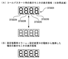
図8-5に示すように、第1保留表示器207SG025Aと第2保留表示器207SG025Bとは、それぞれ4セグメントのLEDが左右方向に並列して配置されている。これら第1保留表示器207SG025Aと第2保留表示器207SG025Bとでは、保留記憶数が1個であれば左端部のLEDのみが点灯し、保留記憶数が増加していく毎に左から2番目、左から3番目、左から4番目のLEDが順次点灯する。そして、変動表示が実行される毎に、保留記憶が減少する(消費される)ことに応じて、該変動表示に対応する保留表示器でのLEDが所定のシフト方向(本実施の形態の特徴部207SGでは左方向)に向けて消灯していく。 As shown in FIG. 8-5, the first hold indicator 207SG025A and the second hold indicator 207SG025B each have four segments of LEDs arranged side by side in the left-right direction. In these first hold display 207SG025A and second hold display 207SG025B, if the number of hold storage is one, only the LED at the left end is lit, and each time the number of hold storage increases, it is the second from the left. The third LED from the left and the fourth LED from the left light up in sequence. Then, each time the variable display is executed, the LED on the hold display corresponding to the variable display is set in a predetermined shift direction (characteristic of the present embodiment) in response to the decrease (consumption) of the reserved memory. In the unit 207SG, the light is turned off toward the left side).
尚、本実施の形態の特徴部207SGでは、第1特図保留記憶と第2特図保留記憶とが両方存在する場合は、第2特図保留記憶にもとづく変動表示が優先して実行される様になっている。このため、図8-6に示すように、例えば第1特図保留記憶が1個存在するとともに第2特図保留記憶が2個存在する場合(第1保留表示器207SG025Aの左端部のLEDのみが点灯しているとともに、第2保留表示器207SG25Bの左2個のLEDが点灯している場合)は、第2特図保留記憶にもとづく変動表示の実行によって第2特図保留記憶が0個となった後に、第1特図保留記憶にもとづく変動表示が実行される。 In the feature unit 207SG of the present embodiment, when both the first special figure holding storage and the second special figure holding storage exist, the variable display based on the second special figure holding storage is preferentially executed. It has become like. Therefore, as shown in FIG. 8-6, for example, when there is one first special figure holding memory and two second special figure holding storages (only the LED at the left end of the first holding indicator 207SG025A). Is lit and the two LEDs on the left of the second hold indicator 207SG25B are lit), the second special figure hold memory is 0 due to the execution of the variable display based on the second special figure hold memory. After that, the variable display based on the first special figure hold storage is executed.
また、図8-6に示すように、ラウンド表示器207SG131は5個のセグメント(LED)から構成されている。尚、本実施の形態の特徴部207SGにおける大当り種別としては、5ラウンド大当りである大当りA、10ラウンド大当りである大当りB、15ラウンド大当りである大当りCの計3個の大当り種別が設けられており、これら大当り種別に応じてラウンド表示器207SG131を構成するセグメントのうちいずれのセグメントが点灯するかが異なっている。 Further, as shown in FIG. 8-6, the round display 207SG131 is composed of five segments (LEDs). As the jackpot types in the feature unit 207SG of the present embodiment, a total of three jackpot types are provided: a jackpot A which is a 5-round jackpot, a jackpot B which is a 10-round jackpot, and a jackpot C which is a 15-round jackpot. Therefore, which of the segments constituting the round display 207SG131 is lit differs depending on the type of jackpot.
主基板11から演出制御基板12に向けて伝送される制御信号は、中継基板15によって中継される。中継基板15を介して主基板11から演出制御基板12に対して伝送される制御コマンドは、例えば電気信号として送受信される演出制御コマンドである。演出制御コマンドには、例えば画像表示装置5における画像表示動作を制御するために用いられる表示制御コマンドや、スピーカ8L、8Rからの音声出力を制御するために用いられる音声制御コマンド、遊技効果ランプ9や装飾用LEDの点灯動作などを制御するために用いられるLED制御コマンドが含まれている。
The control signal transmitted from the
尚、本実施の形態の特徴部207SGにおける演出制御基板12には、変動表示中等にそれぞれの原点位置と演出位置との間で動作可能な第1可動体207SG321及び第2可動体207SG322と、第1可動体207SG321が該第1可動体207SG321の原点位置に位置していることを検出可能な原点検出センサ207SG331と、第2可動体207SG322が該第2可動体207SG322の原点位置に位置していることを検出可能な原点検出センサ207SG332と、が接続されている。
The
図8-8(A)は、本実施の形態における特徴部207SGで用いられる演出制御コマンドの内容の一例を示す説明図である。演出制御コマンドは、例えば2バイト構成であり、1バイト目はMODE(コマンドの分類)を示し、2バイト目はEXT(コマンドの種類)を表す。MODEデータの先頭ビット(ビット7)は必ず「1」とされ、EXTデータの先頭ビットは「0」とされる。尚、図8-8(A)に示されたコマンド形態は一例であって、他のコマンド形態を用いてもよい。また、この例では、制御コマンドが2つの制御信号で構成されることになるが、制御コマンドを構成する制御信号数は、1であってもよいし、3以上の複数であってもよい。 FIG. 8-8 (A) is an explanatory diagram showing an example of the contents of the effect control command used in the feature unit 207SG in the present embodiment. The effect control command has, for example, a 2-byte configuration, the first byte represents MODE (command classification), and the second byte represents EXT (command type). The first bit (bit 7) of the MODE data is always "1", and the first bit of the EXT data is "0". The command form shown in FIG. 8-8 (A) is an example, and other command forms may be used. Further, in this example, the control command is composed of two control signals, but the number of control signals constituting the control command may be one or a plurality of three or more.
図8-8(A)に示す例において、コマンド8001Hは、第1特別図柄表示装置207SG004Aにおける第1特図を用いた特図ゲームにおける変動開始を指定する第1変動開始コマンドである。コマンド8002Hは、第2特別図柄表示装置207SG004Bにおける第2特図を用いた特図ゲームにおける変動開始を指定する第2変動開始コマンドである。コマンド81XXHは、特図ゲームにおける特別図柄の変動表示に対応して画像表示装置5における「左」、「中」、「右」の各飾り図柄表示エリア5L,5C,5Rで変動表示される飾り図柄などの変動パターン(変動時間)を指定する変動パターン指定コマンドである。ここで、XXHは不特定の16進数であることを示し、演出制御コマンドによる指示内容に応じて任意に設定される値であればよい。尚、変動パターン指定コマンドでは、指定する変動パターンなどに応じて、異なるEXTデータが設定される。
In the example shown in FIG. 8-8 (A), the command 8001H is a first variation start command for designating the variation start in the special figure game using the first special diagram in the first special symbol display device 207SG004A. The command 8002H is a second fluctuation start command for designating the fluctuation start in the special symbol game using the second special symbol in the second special symbol display device 207SG004B. The command 81XXH is a decoration that is variablely displayed in each of the "left", "middle", and "right" decorative
コマンド8CXXHは、変動表示結果通知コマンドであり、特別図柄や飾り図柄などの変動表示結果を指定する演出制御コマンドである。変動表示結果通知コマンドでは、例えば図8-8(B)に示すように、変動表示結果が「ハズレ」であるか「大当り」であるか「小当り」であるかの決定結果(事前決定結果)や、変動表示結果が「大当り」となる場合の大当り種別を複数種類のいずれとするかの決定結果(大当り種別決定結果)に応じて、異なるEXTデータが設定される。 The command 8CXXH is a variable display result notification command, and is an effect control command for designating a variable display result such as a special symbol or a decorative symbol. In the variation display result notification command, for example, as shown in FIG. 8-8 (B), the determination result (predetermined result) of whether the variation display result is "miss", "big hit", or "small hit". ) Or, different EXT data are set according to the determination result (big hit type determination result) of which of a plurality of types the jackpot type is to be used when the variable display result is "big hit".
変動表示結果通知コマンドでは、例えば図8-8(B)に示すように、コマンド8C00Hは、変動表示結果が「ハズレ」となる旨の事前決定結果を示す第1変動表示結果指定コマンドである。コマンド8C01Hは、変動表示結果が「大当り」で大当り種別が「大当りA」となる旨の事前決定結果及び大当り種別決定結果を通知する第2変動表示結果指定コマンドである。コマンド8C02Hは、変動表示結果が「大当り」で大当り種別が「大当りB」となる旨の事前決定結果及び大当り種別決定結果を通知する第3変動表示結果指定コマンドである。コマンド8C03Hは、変動表示結果が「大当り」で大当り種別が「大当りC」となる旨の事前決定結果及び大当り種別決定結果を通知する第4変動表示結果指定コマンドである。コマンド8C04Hは、変動表示結果が「小当り」となる旨の事前決定結果を通知する第5変動表示結果指定コマンドである。 In the variation display result notification command, for example, as shown in FIG. 8-8 (B), the command 8C00H is a first variation display result designation command indicating a preliminary determination result that the variation display result is “missing”. The command 8C01H is a second variable display result designation command for notifying the pre-determined result that the variable display result is "big hit" and the big hit type is "big hit A" and the big hit type determination result. The command 8C02H is a third variable display result designation command for notifying the pre-determined result that the variable display result is "big hit" and the big hit type is "big hit B" and the big hit type determination result. The command 8C03H is a fourth variable display result designation command for notifying the pre-determined result that the variable display result is "big hit" and the big hit type is "big hit C" and the big hit type determination result. The command 8C04H is a fifth variable display result designation command for notifying a preliminary determination result that the variable display result is a "small hit".
コマンド8F00Hは、画像表示装置5における「左」、「中」、「右」の各飾り図柄表示エリア5L,5C,5Rで飾り図柄の変動停止(確定)を指定する図柄確定コマンドである。コマンド95XXHは、パチンコ遊技機1における現在の遊技状態を指定する遊技状態指定コマンドである。遊技状態指定コマンドでは、例えばパチンコ遊技機1における現在の遊技状態に応じて、異なるEXTデータが設定される。具体的な一例として、コ
マンド9500Hを時短制御が行われない遊技状態(低ベース状態、通常状態)に対応した第1遊技状態指定コマンドとし、コマンド9501Hを時短制御が行われる遊技状態(高ベース状態、時短状態)に対応した第2遊技状態指定コマンドとする。
The command 8F00H is a symbol confirmation command for designating the change stop (confirmation) of the decorative symbol in each of the “left”, “middle”, and “right” decorative
コマンド96XXHは、パチンコ遊技機1においてエラー(異常)の発生および発生したエラー(異常)の種別を指定するエラー(異常)指定コマンドである。エラー(異常)指定コマンドでは、例えば、各エラー(異常)に対応するEXTデータが設定されることにより、演出制御基板12側において、いずれのエラー(異常)の発生が判定されたのかを特定することができ、特定したエラー(異常)の発生が、後述するエラー報知処理によって報知される。
The command 96XXH is an error (abnormal) designation command that specifies the occurrence of an error (abnormality) and the type of the error (abnormality) that has occurred in the
コマンドA0XXHは、大当り遊技状態または小当り遊技状態の開始を示す演出画像の表示を指定する当り開始指定コマンド(「ファンファーレコマンド」ともいう)である。コマンドA1XXHは、大当り遊技状態または小当り遊技状態において、大入賞口が開放状態となっている期間であることを通知する大入賞口開放中通知コマンドである。コマンドA2XXHは、大当り遊技状態または小当り遊技状態において、大入賞口が開放状態から閉鎖状態に変化した期間であることを通知する大入賞口開放後通知コマンドである。コマンドA3XXHは、大当り遊技状態または小当り遊技状態の終了時における演出画像の表示を指定する当り終了指定コマンドである。 The command A0XXH is a hit start designation command (also referred to as a “fanfare command”) for designating the display of an effect image indicating the start of a big hit gaming state or a small hit gaming state. The command A1XXH is a big winning opening opening notification command for notifying that the big winning opening is in the open state in the big hit gaming state or the small hit gaming state. The command A2XXH is a notification command after opening the large winning opening that notifies that the period during which the large winning opening has changed from the open state to the closed state in the big hit gaming state or the small hit gaming state. The command A3XXH is a hit end designation command for designating the display of the effect image at the end of the big hit game state or the small hit game state.
当り開始指定コマンドや当り終了指定コマンドでは、例えば変動表示結果通知コマンドと同様のEXTデータが設定されることなどにより、事前決定結果や大当り種別決定結果に応じて異なるEXTデータが設定されてもよい。あるいは、当り開始指定コマンドや当り終了指定コマンドでは、事前決定結果及び大当り種別決定結果と設定されるEXTデータとの対応関係を、変動表示結果通知コマンドにおける対応関係とは異ならせるようにしてもよい。大入賞口開放中通知コマンドや大入賞口開放後通知コマンドでは、大当り遊技状態または小当り遊技状態におけるラウンドの実行回数(例えば「1」~「15」)に対応して、異なるEXTデータが設定される。 In the hit start designation command and the hit end designation command, different EXT data may be set according to the pre-determined result and the jackpot type determination result, for example, by setting the same EXT data as the variable display result notification command. .. Alternatively, in the hit start designation command or the hit end designation command, the correspondence between the pre-determined result and the jackpot type determination result and the set EXT data may be different from the correspondence in the variable display result notification command. .. In the notification command during the opening of the big winning opening and the notification command after opening the big winning opening, different EXT data are set according to the number of round executions (for example, "1" to "15") in the big hit game state or the small hit game state. Will be done.
コマンドB100Hは、入賞球装置6Aが形成する第1始動入賞口を通過(進入)した遊技球が第1始動口スイッチ22Aにより検出されて始動入賞(第1始動入賞)が発生したことに基づき、第1特別図柄表示装置207SG004Aにおける第1特図を用いた特図ゲームを実行するための第1始動条件が成立したことを通知する第1始動口入賞指定コマンドである。コマンドB200Hは、可変入賞球装置6Bが形成する第2始動入賞口を通過(進入)した遊技球が第2始動口スイッチ22Bにより検出されて始動入賞(第2始動入賞)が発生したことに基づき、第2特別図柄表示装置207SG004Bにおける第2特図を用いた特図ゲームを実行するための第2始動条件が成立したことを通知する第2始動口入賞指定コマンドである。
The command B100H is based on the fact that the game ball that has passed (entered) the first starting winning opening formed by the winning
コマンドC1XXHは、画像表示装置5などにて特図保留記憶数を特定可能に表示するために、第1特図保留記憶数を通知する第1保留記憶数通知コマンドである。コマンドC2XXHは、画像表示装置5などにて特図保留記憶数を特定可能に表示するために、第2特図保留記憶数を通知する第2保留記憶数通知コマンドである。第1保留記憶数通知コマンドは、例えば第1始動入賞口を遊技球が通過(進入)して第1始動条件が成立したことに基づいて、第1始動口入賞指定コマンドが送信されるときに、主基板11から演出制御基板12に対して送信される。第2保留記憶数通知コマンドは、例えば第2始動入賞口を遊技球が通過(進入)して第2始動条件が成立したことに基づいて、第2始動口入賞指定コマンドが送信されるときに、主基板11から演出制御基板12に対して送信される。また、第1保留記憶数通知コマンドや第2保留記憶数通知コマンドは、第1開始条件と第2開始条件のいずれかが成立したとき(保留記憶数が減少したとき)に、特図ゲームの実行
が開始されることなどに対応して送信されるようにしてもよい。
The command C1XXH is a first reserved storage number notification command for notifying the first special figure reserved storage number in order to identifiablely display the special figure reserved storage number on the
第1保留記憶数通知コマンドや第2保留記憶数通知コマンドに代えて、合計保留記憶数を通知する合計保留記憶数通知コマンドを送信するようにしてもよい。すなわち、合計保留記憶数の増加(または減少)を通知するための合計保留記憶数通知コマンドが用いられてもよい。 Instead of the first hold storage number notification command and the second hold storage number notification command, the total hold storage number notification command for notifying the total hold storage number may be transmitted. That is, a total hold storage number notification command may be used to notify an increase (or decrease) of the total hold storage number.
コマンドD0XXHは、新たに設定された設定値を主基板11から演出制御基板12(演出制御用CPU120)に指定するための設定値指定コマンドである。コマンドE101Hは、パチンコ遊技機1がRAM102の内容をクリアせずに起動したこと(電断復旧したこと、ホットスタートとも言う)を通知するホットスタート通知コマンドである。コマンドE102Hは、パチンコ遊技機1がRAM102の内容をクリアして起動したこと(コールドスタート)を通知するコールドスタート通知コマンドである。コマンドE103Hは、パチンコ遊技機1において設定値の変更操作が開始されたこと(パチンコ遊技機1が設定値変更状態で起動したこと)を通知する設定値変更開始通知コマンドである。コマンドE104Hは、パチンコ遊技機1において設定値の変更操作が終了したことを通知する設定値変更終了通知コマンドである。コマンドE105Hは、パチンコ遊技機1において設定値の確認操作が開始されたこと(パチンコ遊技機1が設定値確認状態で起動したこと)を通知する設定値確認開始通知コマンドである。コマンドE106Hは、パチンコ遊技機1の設定値の確認操作が終了したことを通知する設定値変更終了通知コマンドである。
The command D0XXH is a setting value designation command for designating a newly set setting value from the
主基板11に搭載された遊技制御用マイクロコンピュータ100は、例えば1チップのマイクロコンピュータであり、遊技制御用のプログラムや固定データ等を記憶するROM(Read Only Memory)101と、遊技制御用のワークエリアを提供するRAM(Random Access Memory)102と、遊技制御用のプログラムを実行して制御動作を行うCPU(Central Processing Unit)103と、CPU103とは独立して乱数値を示す数値データの更新を行う乱数回路104と、I/O(Input/Output port)105と、時刻情報を出力可能なリアルタイムクロック(RTC)106とを備えて構成される。
The
一例として、遊技制御用マイクロコンピュータ100では、CPU103がROM101から読み出したプログラムを実行することにより、パチンコ遊技機1における遊技の進行を制御するための処理が実行される。このときには、CPU103がROM101から固定データを読み出す固定データ読出動作や、CPU103がRAM102に各種の変動データを書き込んで一時記憶させる変動データ書込動作、CPU103がRAM102に一時記憶されている各種の変動データを読み出す変動データ読出動作、CPU103がI/O105を介して遊技制御用マイクロコンピュータ100の外部から各種信号の入力を受付ける受信動作、CPU103がI/O105を介して遊技制御用マイクロコンピュータ100の外部へと各種信号を出力する送信動作なども行われる。
As an example, in the
図8-9は、主基板11の側においてカウントされる乱数値を例示する説明図である。図8-9に示すように、この実施の形態の特徴部207SGでは、主基板11の側において、特図表示結果判定用の乱数値MR1の他、大当り種別判定用の乱数値MR2、変動パターン判定用の乱数値MR3、普図表示結果判定用の乱数値MR4、MR4の初期値決定用の乱数値MR5のそれぞれを示す数値データが、カウント可能に制御される。尚、遊技効果を高めるために、これら以外の乱数値が用いられてもよい。これらの乱数値MR1~MR5は、CPU103にて、異なるランダムカウンタを用いて、ソフトウェアによる更新によってカウントするようにしてもよいし、乱数回路104によって更新されてもよい。乱数回路104は、遊技制御用マイクロコンピュータ100に内蔵されるものであってもよいし、遊技制御用マイクロコンピュータ100とは異なる乱数回路チップとして構成
されるものであってもよい。こうした遊技の進行を制御するために用いられる乱数は、遊技用乱数ともいう。
FIG. 8-9 is an explanatory diagram illustrating a random number value counted on the side of the
尚、本実施の形態では各乱数値MR1~MR5をそれぞれ図8-9に示す範囲の値として用いる形態を例示しているが、本発明はこれに限定されるものではなく、これら各乱数値MR1~MR5の範囲は、パチンコ遊技機1に設定されている設定値に応じて異ならせてもよい。
In the present embodiment, each random value MR1 to MR5 is used as a value in the range shown in FIGS. 8-9, but the present invention is not limited to this, and each random value is not limited to this. The range of MR1 to MR5 may be different depending on the set value set in the
図8-10は、本実施の形態における変動パターンを示している。本実施の形態では、変動表示結果が「ハズレ」となる場合のうち、飾り図柄の変動表示態様が「非リーチ」である場合と「リーチ」である場合のそれぞれに対応して、また、変動表示結果が「大当り」となる場合などに対応して、複数の変動パターンが予め用意されている。また、変動表示結果が「小当り」となる場合などに対応して、1の変動パターンが予め用意されている。尚、変動表示結果が「ハズレ」で飾り図柄の変動表示態様が「非リーチ」である場合に対応した変動パターンは、非リーチ変動パターン(「非リーチハズレ変動パターン」ともいう)と称され、変動表示結果が「ハズレ」で飾り図柄の変動表示態様が「リーチ」である場合に対応した変動パターンは、リーチ変動パターン(「リーチハズレ変動パターン」ともいう)と称される。また、非リーチ変動パターンとリーチ変動パターンは、変動表示結果が「ハズレ」となる場合に対応したハズレ変動パターンに含まれる。変動表示結果が「大当り」である場合に対応した変動パターンは、大当り変動パターンと称される。変動表示結果が「小当り」である場合に対応した変動パターンは、小当り変動パターンと称される。 FIG. 8-10 shows a variation pattern in the present embodiment. In the present embodiment, among the cases where the variation display result is "missing", the variation display mode of the decorative symbol corresponds to each of the case of "non-reach" and the case of "reach", and also varies. A plurality of fluctuation patterns are prepared in advance in response to a case where the display result is a "big hit". Further, one variation pattern is prepared in advance in response to a case where the variation display result is a “small hit”. The variation pattern corresponding to the case where the variation display result is "loss" and the variation display mode of the decorative pattern is "non-reach" is called a non-reach variation pattern (also referred to as "non-reach loss variation pattern") and varies. The variation pattern corresponding to the case where the display result is "loss" and the variation display mode of the decorative pattern is "reach" is called a reach variation pattern (also referred to as "reach loss variation pattern"). Further, the non-reach fluctuation pattern and the reach fluctuation pattern are included in the loss fluctuation pattern corresponding to the case where the fluctuation display result is “loss”. The fluctuation pattern corresponding to the case where the fluctuation display result is "big hit" is called a jackpot fluctuation pattern. The fluctuation pattern corresponding to the case where the fluctuation display result is "small hit" is referred to as a small hit fluctuation pattern.
大当り変動パターンやリーチ変動パターンには、ノーマルリーチのリーチ演出が実行されるノーマルリーチ変動パターンと、スーパーリーチα、スーパーリーチβといったスーパーリーチのリーチ演出が実行されるスーパーリーチ変動パターンとがある。尚、本実施の形態では、ノーマルリーチ変動パターンを1種類のみしか設けていないが、本発明はこれに限定されるものではなく、スーパーリーチと同様に、ノーマルリーチα、ノーマルリーチβ、…のように、複数のノーマルリーチ変動パターンを設けてもよい。また、スーパーリーチ変動パターンでも、スーパーリーチαやスーパーリーチβに加えてスーパーリーチγ…といった3以上のスーパーリーチ変動パターンを設けてもよい。 The jackpot fluctuation pattern and the reach fluctuation pattern include a normal reach fluctuation pattern in which the reach effect of the normal reach is executed, and a super reach fluctuation pattern in which the reach effect of the super reach such as super reach α and super reach β is executed. In the present embodiment, only one type of normal reach fluctuation pattern is provided, but the present invention is not limited to this, and like the super reach, the normal reach α, the normal reach β, ... A plurality of normal reach fluctuation patterns may be provided. Further, as for the super reach fluctuation pattern, three or more super reach fluctuation patterns such as super reach γ may be provided in addition to the super reach α and the super reach β.
図8-10に示すように、本実施の形態の特徴部207SGにおけるノーマルリーチのリーチ演出が実行されるノーマルリーチ変動パターンの特図変動時間については、スーパーリーチ変動パターンであるスーパーリーチα、スーパーリーチβよりも短く設定されている。また、本実施の形態におけるスーパーリーチα、スーパーリーチβといったスーパーリーチのリーチ演出が実行されるスーパーリーチ変動パターンの特図変動時間については、スーパーリーチβのスーパーリーチ演出が実行される変動パターンの方が、スーパーリーチαのスーパーリーチ演出が実行される変動パターンよりも特図変動時間が長く設定されている。 As shown in FIG. 8-10, regarding the special figure fluctuation time of the normal reach fluctuation pattern in which the reach effect of the normal reach is executed in the feature portion 207SG of the present embodiment, the super reach fluctuation patterns, super reach α and super reach β, are shown. Is set shorter than. Further, regarding the special figure variation time of the super reach fluctuation pattern in which the super reach effect such as super reach α and super reach β is executed in the present embodiment, the variation pattern in which the super reach effect of the super reach β is executed is In that case, the special figure fluctuation time is set longer than the fluctuation pattern in which the super reach effect of the super reach α is executed.
尚、本実施の形態では、前述したようにスーパーリーチβ、スーパーリーチα、ノーマルリーチの順に変動表示結果が「大当り」となる大当り期待度が高くなるように設定されているため、ノーマルリーチ変動パターン及びスーパーリーチ変動パターンにおいては変動時間が長いほど大当り期待度が高くなっている。 In this embodiment, as described above, the normal reach fluctuation pattern and the normal reach fluctuation pattern and the normal reach fluctuation pattern are set so that the jackpot expectation that the fluctuation display result becomes "big hit" is set in the order of super reach β, super reach α, and normal reach. In the super reach fluctuation pattern, the longer the fluctuation time, the higher the expectation of a big hit.
尚、本実施の形態の特徴部207SGにおいては、後述するように、これら変動パターンを、例えば、非リーチの種別や、ノーマルリーチの種別や、スーパーリーチの種別等のように、変動パターンの種別を先に決定してから、該決定した種別に属する変動パターンに属する変動パターンから実行する変動パターンを決定するのではなく、これらの種別を
決定することなしに変動パターン判定用の乱数値MR3のみを用いて決定するようにしているが、本発明はこれに限定されるものではなく、たとえば、変動パターン判定用の乱数値MR3に加えて、変動パターン種別判定用の乱数値を設けて、これら変動パターン種別判定用の乱数値から変動パターンの種別を先に決定してから、該決定した種別に属する変動パターンに属する変動パターンから実行する変動パターンを決定するようにしてもよい。
In the feature unit 207SG of the present embodiment, as will be described later, these fluctuation patterns are classified into the types of fluctuation patterns, for example, the type of non-reach, the type of normal reach, the type of super reach, and the like. Instead of determining the variation pattern to be executed from the variation patterns belonging to the variation pattern belonging to the determined type after determining first, only the random value MR3 for determining the variation pattern is used without determining these types. However, the present invention is not limited to this, and for example, in addition to the random value MR3 for determining the variation pattern, a random value for determining the variation pattern type is provided to determine these variations. The type of the variation pattern may be determined first from the random value for determining the pattern type, and then the variation pattern to be executed may be determined from the variation patterns belonging to the variation pattern belonging to the determined type.
また、本実施の形態の特徴部207SGでは、図8-10に示すように、変動パターン毎に変動内容(演出内容)が予め決定されている形態を例示しているが、本発明はこれに限定されるものではなく、設定されている設定値に応じて同じ変動パターンであっても変動内容(演出内容)が異なるようにしてもよい。例えば、ノーマルリーチハズレの変動パターンPA2-1の場合は、設定されている設定値が1の場合は、ノーマルリーチハズレとなる変動パターンとし、設定されている設定値が2の場合は、擬似連演出を2回実行して非リーチハズレとなる変動パターンとして、設定されている設定値が3の場合は、擬似連演出を3回実行してスーパーリーチハズレとなる変動パターン…等とすればよい。 Further, as shown in FIG. 8-10, the feature unit 207SG of the present embodiment exemplifies a mode in which the variation content (effect content) is predetermined for each variation pattern, but the present invention illustrates this. The variation content (effect content) may be different even if the variation pattern is the same, depending on the set value. For example, in the case of the fluctuation pattern PA2-1 of the normal reach loss, if the set value is 1, the fluctuation pattern is the normal reach loss, and if the set value is 2, a pseudo continuous effect is performed. If the set value is 3 as the fluctuation pattern that is executed twice and becomes non-reach loss, the pseudo-continuous effect may be executed three times to obtain a fluctuation pattern that results in super reach loss.
遊技制御用マイクロコンピュータ100では、CPU103がROM101から読み出したプログラムを実行し、RAM102をワークエリアとして用いることで、パチンコ遊技機1における遊技の進行を制御するための各種の処理が実行される。また、CPU103は、乱数生成プログラムを実行することで、主基板11の側において用いられる各種の乱数の全てを生成可能とされている。
In the
遊技制御用マイクロコンピュータ100が備えるROM101には、ゲーム制御用のプログラムの他にも、遊技の進行を制御するために用いられる各種のテーブルデータなどが記憶されている。例えば、ROM101には、CPU103が各種の判定や決定を行うために用意された、図8-11~図8-13などに示す複数の判定テーブルを構成するテーブルデータが記憶されている。また、ROM101には、CPU103が主基板11から各種の制御信号を出力させるために用いられる複数の制御パターンテーブルを構成するテーブルデータや、特別図柄や普通図柄などの変動表示における各図柄の変動態様となる変動パターンを複数種類格納する変動パターンテーブルなどが記憶されている。
The
ROM101が記憶する判定テーブルには、例えば図8-11(A)に示す表示結果判定テーブル(設定値1)、図8-11(B)に示す表示結果判定テーブル(設定値2)、図8-11(C)に示す表示結果判定テーブル(設定値3)、図8-12(A)に示す表示結果判定テーブル(設定値4)、図8-12(B)に示す表示結果判定テーブル(設定値5)、図8-12(C)に示す表示結果判定テーブル(設定値6)、図8-13(A)に示す大当り種別判定テーブル(第1特別図柄用)、図8-13(B)に示す大当り種別判定テーブル(第2特別図柄用)の他、大当り変動パターン判定テーブル、小当り変動パターン判定テーブル、ハズレ変動パターン判定テーブル、普図表示結果判定テーブル(図示略)、普図変動パターン決定テーブル(図示略)などが含まれている。
The determination table stored in the
本実施の形態の特徴部207SGのパチンコ遊技機1は、設定値に応じて大当りの当選確率(出玉率)が変わる構成とされている。詳しくは、後述する特別図柄プロセス処理の特別図柄通常処理において、設定値に応じた表示結果判定テーブル(当選確率)を用いることにより、大当りの当選確率(出玉率)が変わるようになっている。設定値は1~6の6段階からなり、6が最も出玉率が高く、6、5、4、3、2、1の順に値が小さくなるほど出玉率が低くなる。すなわち、設定値として6が設定されている場合には遊技者にとって最も有利度が高く、5、4、3、2、1の順に値が小さくなるほど有利度が段階的に低くなる。換言すれば、設定値とは、最も大きい値である6が最も遊技場側にとって不利な値であり、5、4、3、2、1の順に値が小さくなるほど遊技場側にとって有利な値と
なる。
The
図8-11(A)~図8-11(C)及び図8-12(A)~図8-12(C)は、各設定値に対応する表示結果判定テーブルを示す説明図である。表示結果判定テーブルとは、ROM101に記憶されているデータの集まりであって、MR1と比較される当り判定値が設定されているテーブルである。本実施の形態の特徴部207SGでは、表示結果判定テーブルとして、第1特図と第2特図とで共通の表示結果判定テーブルを用いているが、本発明はこれに限定されるものではなく、第1特図と第2特図とで個別の表示結果判定テーブルを用いるようにしても良い。
8-11 (A) to 8-11 (C) and 8-12 (A) to 8-12 (C) are explanatory views showing display result determination tables corresponding to each set value. The display result determination table is a collection of data stored in the
図8-11(A)~図8-11(C)及び図8-12(A)~図8-12(C)に示すように、各表示結果判定テーブルにおいては、遊技状態が確変状態(高確状態)であるときに、通常状態または時短状態(低確状態)であるときよりも多くの判定値が、「大当り」の特図表示結果に割り当てられている。これにより、パチンコ遊技機1において確変制御が行われる確変状態(高確状態)では、通常状態または時短状態(低確状態)であるときに特図表示結果を「大当り」として大当り遊技状態に制御すると決定される確率(本実施の形態の特徴部207SGでは、設定値が1の場合は1/300、設定値が2の場合は1/280、設定値が3の場合は1/260、設定値が4の場合は1/240、設定値が5の場合は1/220、設定値が6の場合は1/200)に比べて、特図表示結果を「大当り」として大当り遊技状態に制御すると決定される確率が高くなる(本実施の形態の特徴部207SGでは、設定値が1の場合は1/200、設定値が2の場合は1/180、設定値が3の場合は1/160、設定値が4の場合は1/140、設定値が5の場合は1/120、設定値が6の場合は1/100)。即ち、各表示結果判定テーブルでは、パチンコ遊技機1における遊技状態が確変状態(高確状態)であるときに、通常状態や時短状態であるときに比べて大当り遊技状態に制御すると決定される確率が高くなるように、判定値が大当り遊技状態に制御するか否かの決定結果に割り当てられている。
As shown in FIGS. 8-11 (A) to 8-11 (C) and 8-12 (A) to 8-12 (C), in each display result determination table, the gaming state is a probable change state ( In the high probability state), more judgment values are assigned to the special figure display result of the "big hit" than in the normal state or the time saving state (low probability state). As a result, in the probabilistic state (high probability state) in which the probability change control is performed in the
また、各表示結果判定テーブルにおいては、遊技状態や設定値にかかわらず、特図表示結果を「小当り」として小当り遊技状態に制御すると決定される確率が同一となるように判定値が割り当てられている。具体的には、図8-11(A)~図8-11(C)及び図8-12(A)~図8-12(C)に示すように、遊技状態や設定値にかかわらず、特図表示結果を「小当り」として小当り遊技状態に制御すると決定される確率が1/200に設定されている。尚、本実施の形態の特徴部207SGでは、設定値にかかわらず特図表示結果を「小当り」として小当り遊技状態に制御すると決定される確率が同一確率である形態を例示しているが、本発明はこれに限定されるものではなく、設定値に応じて特図表示結果を「小当り」として小当り遊技状態に制御すると決定される確率を異ならせてもよい。 Further, in each display result judgment table, the judgment values are assigned so that the probability of being determined to control the special figure display result as a "small hit" to the small hit game state is the same regardless of the game state or the set value. Has been done. Specifically, as shown in FIGS. 8-11 (A) to 8-11 (C) and 8-12 (A) to 8-12 (C), regardless of the gaming state or the set value. The probability of being determined to control the small hit gaming state with the special figure display result as "small hit" is set to 1/200. It should be noted that the feature unit 207SG of the present embodiment exemplifies a mode in which the probability of being determined to control the small hit game state with the special figure display result as "small hit" is the same regardless of the set value. The present invention is not limited to this, and the probability of being determined to control the special figure display result as a "small hit" to the small hit gaming state may be different depending on the set value.
更に、前述したように、各遊技状態においては、パチンコ遊技機1に設定されている設定値が1の場合が最も特図表示結果を「大当り」として大当り遊技状態に制御すると決定される確率が低く、設定値の値が大きくなるほど特図表示結果を「大当り」として大当り遊技状態に制御すると決定される確率が高くなるように判定値が割り当てられている(大当り確率:設定値6>設定値5>設定値4>設定値3>設定値2>設定値1)。
Further, as described above, in each gaming state, when the set value set in the
つまり、CPU103は、その時点で設定されている設定値に対応する表示結果判定テーブルを参照して、MR1の値が図8-11(A)~図8-11(C)及び図8-12(A)~図8-12(C)に示す大当りに対応するいずれかの当り判定値に一致すると、特別図柄に関して大当り(大当りA~大当りC)とすることを決定する。また、MR1が図8-11(A)~図8-11(C)及び図8-12(A)~図8-12(C)に示す小当りに対応するいずれかの当り判定値に一致すると、特別図柄に関して小当りとすることを
決定する。すなわち、設定値に応じた確率で大当り及び小当りの当選を決定する。尚、図8-11(A)~図8-11(C)及び図8-12(A)~図8-12(C)に示す「確率」は、大当りになる確率(割合)並びに小当りになる確率(割合)を示す。また、大当りにするか否か決定するということは、大当り遊技状態に制御するか否か決定するということであるが、第1特別図柄表示装置207SG004Aまたは第2特別図柄表示装置207SG004Bにおける停止図柄を大当り図柄にするか否か決定するということでもある。また、小当りにするか否か決定するということは、小当り遊技状態に制御するか否か決定するということであるが、第1特別図柄表示装置207SG004Aまたは第2特別図柄表示装置207SG004Bにおける停止図柄を小当り図柄にするか否か決定するということでもある。
That is, the
また、本実施の形態の特徴部207SGでは、CPU103は、図8-11(A)~図8-11(C)及び図8-12(A)~図8-12(C)に示す表示結果判定テーブルを用いて大当りまたは小当りとするか否かを判定するようになっているが、設定値毎に大当り判定テーブルと小当り判定テーブルとを別個に設け、変動表示結果を大当りとするか否か、小当りとするか否かを個別に判定してもよい。
Further, in the feature unit 207SG of the present embodiment, the
尚、本実施の形態では、パチンコ遊技機1に設定可能な設定値として1~6の計6個の設定値を設けているが、本発明はこれに限定されるものではなく、パチンコ遊技機1に設定可能な設定値は、5個以下や7個以上であってもよい。
In the present embodiment, a total of 6 setting values, 1 to 6, are provided as setting values that can be set in the
図8-13(A)及び図8-13(B)は、ROM101に記憶されている大当り種別判定テーブル(第1特別図柄用)、大当り種別判定テーブル(第2特別図柄用)を示す説明図である。このうち、図8-13(A)は、遊技球が第1始動入賞口に入賞したことに基づく保留記憶を用いて(すなわち、第1特別図柄の変動表示が行われるとき)大当り種別を決定する場合のテーブルである。また、図8-13(B)は、遊技球が第2始動入賞口に入賞したことに基づく保留記憶を用いて(すなわち、第2特別図柄の変動表示が行われるとき)大当り種別を決定する場合のテーブルである。
8-13 (A) and 8-13 (B) are explanatory views showing a jackpot type determination table (for the first special symbol) and a jackpot type determination table (for the second special symbol) stored in the
大当り種別判定テーブルは、変動表示結果を大当り図柄にする旨の判定がなされたときに、当り種別判定用の乱数(MR2)に基づいて、大当りの種別を大当りA~大当りCのうちのいずれかに決定するために参照されるテーブルである。 In the jackpot type determination table, when it is determined that the variable display result is a jackpot symbol, the jackpot type is selected from jackpot A to jackpot C based on the random number (MR2) for determining the jackpot type. It is a table referenced to determine.
ここで、本実施の形態の特徴部207SGにおける大当り種別について、図8-14を用いて説明する。本実施の形態の特徴部207SGでは、大当り種別として、大当り遊技状態の終了後において時短制御のみが実行されて低確高ベース状態に移行する大当りA(非確変大当りともいう)と、大当り遊技の終了後において高確制御と時短制御とが実行されて高確高ベース状態に移行する大当りBや大当りC(確変大当りともいう)が設定されている。 Here, the jackpot type in the feature portion 207SG of the present embodiment will be described with reference to FIGS. 8-14. In the feature unit 207SG of the present embodiment, as the jackpot type, the jackpot A (also referred to as non-probability variable jackpot) in which only the time saving control is executed after the end of the jackpot game state and the game shifts to the low probability high base state, and the jackpot game After the end, the high-accuracy control and the time-saving control are executed, and the jackpot B and the jackpot C (also referred to as the probabilistic jackpot) for shifting to the high-accuracy high-base state are set.
「大当りA」による大当り遊技状態は、特別可変入賞球装置7を遊技者にとって有利な第1状態に変化させるラウンドが5回(いわゆる5ラウンド)、繰返し実行される通常開放大当りであり、「大当りB」による大当り遊技状態は、特別可変入賞球装置7を遊技者にとって有利な第1状態に変化させるラウンドが10回(いわゆる10ラウンド)、繰返し実行される通常開放大当りである。更に、「大当りC」による大当り遊技状態は、特別可変入賞球装置7を遊技者にとって有利な第1状態に変化させるラウンドが15回(いわゆる15ラウンド)、繰返し実行される通常開放大当りである。
The big hit game state by "big hit A" is a normal open big hit in which the special variable winning
「大当りA」による大当り遊技状態の終了後において実行される時短制御は、所定回数(本実施の形態の特徴部207SGでは100回)の特図ゲームが実行されること、或い
は該所定回数の特図ゲームが実行される前に大当り遊技状態となることにより終了する。
The time saving control executed after the end of the big hit game state by the "big hit A" is that the special figure game is executed a predetermined number of times (100 times in the feature unit 207SG of the present embodiment), or the special figure game of the predetermined number of times is executed. Figure Ends when the game is in a big hit game state before the game is executed.
一方、大当りBや大当りCの大当り遊技状態の終了後において実行される高確制御と時短制御は、該大当り遊技状態の終了後において再度大当りが発生するまで継続して実行される。よって、再度発生した大当りが大当りBや大当りCである場合には、大当り遊技状態の終了後に再度、高確制御と時短制御が実行されるので、大当り遊技状態が通常状態を介することなく連続的に発生する、いわゆる連荘状態となる。 On the other hand, the high-accuracy control and the time saving control executed after the end of the jackpot gaming state of the jackpot B or the jackpot C are continuously executed until the jackpot occurs again after the end of the jackpot gaming state. Therefore, when the big hit that occurs again is the big hit B or the big hit C, the high accuracy control and the time saving control are executed again after the end of the big hit gaming state, so that the big hit gaming state is continuous without going through the normal state. It becomes a so-called consecutive villa state that occurs in.
尚、本実施の形態の特徴部207SGにおいては、大当り種別として大当りA~大当りCの3種類を設ける形態を例示しているが、本発明はこれに限定されるものではなく、大当り種別は2種類以下、または4種類以上設けてもよい。 In the feature unit 207SG of the present embodiment, a mode in which three types of jackpot A to jackpot C are provided as jackpot types is exemplified, but the present invention is not limited to this, and the jackpot type is 2. There may be less than one type, or four or more types.
また、図8-13(A)に示すように、大当り種別判定テーブル(第1特別図柄用)においては、設定値が「1」である場合は、MR2の判定値の範囲0~299のうち、0~99までが大当りAに割り当てられており、100~249までが大当りBに割り当てられており、250~299までが大当りCに割り当てられている。また、設定値が「2」である場合は、MR2の判定値の範囲0~299のうち、0~99までが大当りAに割り当てられており、100~229までが大当りBに割り当てられており、200~299までが大当りCに割り当てられている。また、設定値が「3」である場合は、MR2の判定値の範囲0~299のうち、0~99までが大当りAに割り当てられており、100~209までが大当りBに割り当てられており、150~299までが大当りCに割り当てられている。また、設定値が「4」である場合は、MR2の判定値の範囲0~299のうち、0~99までが大当りAに割り当てられており、100~189までが大当りBに割り当てられており、190~299までが大当りCに割り当てられている。また、設定値が「5」である場合は、MR2の判定値の範囲0~299のうち、0~99までが大当りAに割り当てられており、100~169までが大当りBに割り当てられており、170~299までが大当りCに割り当てられている。また、設定値が「6」である場合は、MR2の判定値の範囲0~299のうち、0~99までが大当りAに割り当てられており、100~149までが大当りBに割り当てられており、150~299までが大当りCに割り当てられている。 Further, as shown in FIG. 8-13 (A), in the jackpot type determination table (for the first special symbol), when the set value is "1", the MR2 determination value ranges from 0 to 299. , 0 to 99 are assigned to the jackpot A, 100 to 249 are assigned to the jackpot B, and 250 to 299 are assigned to the jackpot C. When the set value is "2", out of the range 0 to 299 of the judgment value of MR2, 0 to 99 are assigned to the jackpot A, and 100 to 229 are assigned to the jackpot B. , 200-299 are assigned to jackpot C. When the set value is "3", out of the range 0 to 299 of the judgment value of MR2, 0 to 99 are assigned to the jackpot A, and 100 to 209 are assigned to the jackpot B. , 150-299 are assigned to jackpot C. When the set value is "4", out of the range 0 to 299 of the judgment value of MR2, 0 to 99 are assigned to the jackpot A, and 100 to 189 are assigned to the jackpot B. , 190-299 are assigned to jackpot C. When the set value is "5", out of the range 0 to 299 of the judgment value of MR2, 0 to 99 are assigned to the jackpot A, and 100 to 169 are assigned to the jackpot B. , 170-299 are assigned to jackpot C. When the set value is "6", out of the range 0 to 299 of the judgment value of MR2, 0 to 99 are assigned to the jackpot A, and 100 to 149 are assigned to the jackpot B. , 150-299 are assigned to jackpot C.
このように、第1特別図柄の特図ゲームにおいて大当りが発生した場合は、大当り遊技終了後に時短制御のみが実行される大当りAを決定する割合が同一である一方で、大当り遊技終了後に時短制御と確変制御の両方が実行される大当りBと大当りCのうち、大当りCを決定する割合が設定値6、5、4、3、2、1の順に低くなる。つまり、変動特図が第1特別図柄である場合は、パチンコ遊技機1に設定されている設定値が6である場合が最も出玉率が高く、設定値が5、4,3、2、1の順に小さくなるほど出玉率が低くなっている。
In this way, when a big hit occurs in the special figure game of the first special symbol, the ratio of determining the big hit A in which only the time saving control is executed after the big hit game ends is the same, while the time saving control after the big hit game ends. Of the jackpot B and jackpot C for which both the probability variation control and the probability variation control are executed, the ratio of determining the jackpot C decreases in the order of the set values 6, 5, 4, 3, 2, and 1. That is, when the variable special symbol is the first special symbol, the ball ejection rate is highest when the set value set in the
一方で、図8-13(B)に示すように、大当り種別判定テーブル(第2特別図柄用)においては、設定値が「1」である場合は、MR2の判定値の範囲0~299のうち、0~99までが大当りAに割り当てられており、100~199までが大当りBに割り当てられており、200~299までが大当りCに割り当てられている。また、設定値が「2」である場合は、MR2の判定値の範囲0~299のうち、0~99までが大当りAに割り当てられており、100~179までが大当りBに割り当てられており、180~299までが大当りCに割り当てられている。また、設定値が「3」である場合は、MR2の判定値の範囲0~299のうち、0~99までが大当りAに割り当てられており、100~159までが大当りBに割り当てられており、160~299までが大当りCに割り当てられている。また、設定値が「4」である場合は、MR2の判定値の範囲0~299のうち、0~99までが大当りAに割り当てられており、100~139までが大当りBに
割り当てられており、140~299までが大当りCに割り当てられている。また、設定値が「5」である場合は、MR2の判定値の範囲0~299のうち、0~99までが大当りAに割り当てられており、100~119までが大当りBに割り当てられており、120~299までが大当りCに割り当てられている。また、設定値が「6」である場合は、MR2の判定値の範囲0~299のうち、0~99までが大当りAに割り当てられており、100~299までが大当りCに割り当てられている(大当りBには判定値が割り当てられていない)。
On the other hand, as shown in FIG. 8-13 (B), in the jackpot type determination table (for the second special symbol), when the set value is "1", the range of the determination value of MR2 is 0 to 299. Of these, 0 to 99 are assigned to jackpot A, 100 to 199 are assigned to jackpot B, and 200 to 299 are assigned to jackpot C. When the set value is "2", out of the range 0 to 299 of the judgment value of MR2, 0 to 99 are assigned to the jackpot A, and 100 to 179 are assigned to the jackpot B. , 180-299 are assigned to jackpot C. When the set value is "3", out of the range 0 to 299 of the judgment value of MR2, 0 to 99 are assigned to the jackpot A, and 100 to 159 are assigned to the jackpot B. , 160-299 are assigned to jackpot C. When the set value is "4", out of the range 0 to 299 of the judgment value of MR2, 0 to 99 are assigned to the jackpot A, and 100 to 139 are assigned to the jackpot B. , 140-299 are assigned to jackpot C. When the set value is "5", out of the range 0 to 299 of the judgment value of MR2, 0 to 99 are assigned to the jackpot A, and 100 to 119 are assigned to the jackpot B. , 120-299 are assigned to jackpot C. When the set value is "6", out of the range 0 to 299 of the judgment value of MR2, 0 to 99 are assigned to the jackpot A, and 100 to 299 are assigned to the jackpot C. (A judgment value is not assigned to the jackpot B).
このように、第2特別図柄の特図ゲームにおいて大当りが発生した場合は、大当り遊技終了後に時短制御のみが実行される大当りAを決定する割合が同一である一方で、大当り遊技終了後に時短制御と確変制御の両方が実行される大当りBと大当りCのうち、大当りCを決定する割合が設定値6、5、4、3、2、1の順に低くなる。つまり、変動特図が第2特別図柄である場合は、パチンコ遊技機1に設定されている設定値が6である場合が最も出玉率が高く、設定値が5、4,3、2、1の順に小さくなるほど出玉率が低くなっている。
In this way, when a big hit occurs in the special figure game of the second special symbol, the ratio of determining the big hit A in which only the time saving control is executed after the big hit game ends is the same, while the time saving control after the big hit game ends. Of the jackpot B and jackpot C for which both the probability variation control and the probability variation control are executed, the ratio of determining the jackpot C decreases in the order of the set values 6, 5, 4, 3, 2, and 1. That is, when the variable special symbol is the second special symbol, the ball ejection rate is highest when the set value set in the
尚、本実施の形態の特徴部207SGでは、変動特図が第2特図であり、且つパチンコ遊技機1に設定されている設定値が6である場合には、大当り種別を大当りBに決定しない形態を例示している、つまり、設定されている設定値に応じて大当り種別の決定割合が異なることには、いずれかの大当り種別を決定しないこと(決定割合が0%である)ことを含んでいるが、変動特図が第2特図であり、且つパチンコ遊技機1に設定されている設定値が6である場合においても、大当り種別を大当りBに決定する場合を設けてもよい。
In the feature unit 207SG of the present embodiment, when the variable special figure is the second special figure and the set value set in the
このように、本実施の形態の特徴部207SGでは、設定されている設定値に応じて変動表示結果が大当りとなった場合の大当り種別の決定割合が異なっているので、遊技興趣を向上できるようになっている。 As described above, in the feature unit 207SG of the present embodiment, the determination ratio of the jackpot type when the variable display result becomes a jackpot differs according to the set value, so that the game entertainment can be improved. It has become.
尚、本実施の形態の特徴部207SGでは、大当り種別を大当り種別判定用の乱数値であるMR2を用いて決定しているが、本発明はこれに限定されるものではなく、大当り種別は、特図表示結果判定用の乱数値であるMR1を用いて決定してもよい。 In the feature unit 207SG of the present embodiment, the jackpot type is determined by using MR2 which is a random value for determining the jackpot type, but the present invention is not limited to this, and the jackpot type is not limited to this. It may be determined using MR1 which is a random value for determining the special figure display result.
また、本実施の形態の特徴部207SGでは、パチンコ遊技機1に設定される設定値が大きいほど遊技者にとって有利となる(大当り確率が高まることや、大当り種別としての大当りCが決定されやすくなること等)形態を例示しているが、本発明はこれに限定されるものではなく、パチンコ遊技機1に設定される設定値が小さいほど遊技者にとって有利となるようにしてもよい。
Further, in the feature unit 207SG of the present embodiment, the larger the set value set in the
また、本実施の形態の特徴部207SGでは、パチンコ遊技機1に設定される設定値に応じて大当り確率が変化する一方で、遊技性自体は変化しない形態を例示しているが、本発明はこれに限定されるものではなく、パチンコ遊技機1に設定される設定値に応じて遊技性が変化するようにしてもよい。
Further, the feature unit 207SG of the present embodiment exemplifies a mode in which the jackpot probability changes according to the set value set in the
例えば、パチンコ遊技機1に設定される設定値が1である場合は、通常状態での大当り確率が1/320、確変状態が65%の割合でループする遊技性(所謂確変ループタイプ)とし、パチンコ遊技機1に設定されている設定値が2である場合は、通常状態での大当り確率が1/200、大当り遊技中に遊技球が、特別可変入賞球装置7内に設けられた所定スイッチを通過することに基づいて大当り遊技終了後の遊技状態を確変状態に制御する一方で、変動特図に応じて大当り遊技中に遊技球が該所定スイッチを通過する割合が異なる遊技性(所謂V確変タイプ)とし、パチンコ遊技機1に設定されている設定値が3である場合は、大当り確率が1/320且つ小当り確率が1/50であり、高ベース中(時短
制御中)に遊技球が特別可変入賞球装置7内に設けられた所定スイッチを通過することに基づいて大当り遊技状態に制御する遊技性(所謂1種2種混合タイプ)としてもよい。更に、パチンコ遊技機1に設定されている設定値が1~3のいずれかである場合は遊技性が同一であるが、これら設定値が1~3のいずれかである場合よりも大当り確率や小当り確率が高い一方で大当り遊技中に獲得可能な賞球数が少ない設定(例えば、パチンコ遊技機1に設定されている設定値が4~6のいずれかである場合)を設けてもよい。
For example, when the set value set in the
更に、このように、設定値に応じて遊技性を変化させる場合は、共通のスイッチを異なる用途に使用してもよい。具体的には、上述の例であれば、設定値が1~3の場合は、特別可変入賞球装置7内に設けられた所定スイッチを演出用スイッチ(遊技球が所定領域を通過する毎に所定の演出を実行するためのスイッチ)として使用し、設定値が4~6の場合は、該所定スイッチを遊技用スイッチ(遊技球が所定スイッチを通過したことに基づいて遊技状態を確変状態や大当り遊技状態に制御するためのスイッチ)として使用してもよい。
Further, in this way, when the playability is changed according to the set value, a common switch may be used for different purposes. Specifically, in the above example, when the set value is 1 to 3, the predetermined switch provided in the special variable winning
また、ROM101には、変動パターン判定用の乱数値MR3に基づいて変動パターンを決定するための変動パターン判定テーブルも記憶されており、変動パターンを、事前決定結果に応じて前述した複数種類のうちのいずれかの変動パターンに決定する。
Further, the
具体的には、変動パターン判定テーブルとしては、変動表示結果を「大当り」にすることが事前決定されたときに使用される大当り用変動パターン判定テーブルと、変動表示結果を「小当り」にすることが事前決定されたときに使用される大当り用変動パターン判定テーブルと、変動表示結果を「ハズレ」にすることが事前決定されたときに使用されるハズレ用変動パターン判定テーブルとが予め用意されている。 Specifically, as the fluctuation pattern judgment table, the fluctuation pattern judgment table for big hits used when it is predetermined to set the fluctuation display result to "big hit" and the fluctuation display result to be "small hit". A fluctuation pattern judgment table for big hits, which is used when it is pre-determined, and a fluctuation pattern judgment table for loss, which is used when it is pre-determined to make the fluctuation display result "miss", are prepared in advance. ing.
大当り用変動パターン判定テーブルにおいては、ノーマルリーチ大当りの変動パターン(PB1-1)、スーパーリーチα大当りの変動パターン(PB1-2)、スーパーリーチβ大当りの変動パターン(PB1-3)の各変動パターンに対して、変動パターン判定用の乱数値MR3がとりうる範囲のうち所定の乱数値が判定値として割り当てられている。 In the jackpot fluctuation pattern determination table, the fluctuation patterns of the normal reach jackpot (PB1-1), the fluctuation pattern of the super reach α jackpot (PB1-2), and the fluctuation pattern of the super reach β jackpot (PB1-3) are used. On the other hand, a predetermined random number value is assigned as the determination value in the range that the random number value MR3 for determining the fluctuation pattern can take.
図8-15(A)及び図8-15(B)に示すように、大当り用変動パターン判定テーブルとしては、大当り種別が大当りAである場合に使用される大当り用変動パターン判定テーブル(大当りA用)と、大当り種別が大当りB、大当りC用である場合に使用される大当り用変動パターン判定テーブル(大当りB、大当りC用)が予め用意されており、これら大当り用変動パターン判定テーブル(大当りA用)と大当り用変動パターン判定テーブル(大当りB、大当りC用)には、ノーマルリーチ大当りの変動パターン(PB1-1)、スーパーリーチα大当りの変動パターン(PB1-2)、スーパーリーチβ大当りの変動パターン(PB1-3)の各変動パターンに対して、変動パターン判定用の乱数値MR3がとりうる範囲のうち所定の乱数値が判定値として割り当てられている。 As shown in FIGS. 8-15 (A) and 8-15 (B), the jackpot variation pattern determination table is a jackpot variation pattern determination table (big hit A) used when the jackpot type is jackpot A. The jackpot variation pattern determination table (for jackpot B and jackpot C) used when the jackpot type is for jackpot B and jackpot C is prepared in advance, and these jackpot fluctuation pattern determination tables (big hit) are prepared in advance. The fluctuation pattern judgment table for (for A) and the jackpot (for jackpot B and jackpot C) includes the fluctuation pattern of the normal reach jackpot (PB1-1), the fluctuation pattern of the super reach α jackpot (PB1-2), and the fluctuation pattern of the super reach β jackpot. For each variation pattern of the variation pattern (PB1-3), a predetermined random value within the range that the random number value MR3 for determining the variation pattern can take is assigned as a determination value.
図8-15(A)に示すように、大当り用変動パターン判定テーブル(大当りA用)においては、設定値が「1」である場合は、MR3の判定値の範囲1~997のうち、1~400までがノーマルリーチ大当りの変動パターン(PB1-1)に割り当てられており、401~850までがスーパーリーチα大当りの変動パターン(PB1-2)に割り当てられており、851~997までがスーパーリーチβ大当りの変動パターン(PB1-3)に割り当てられている。また、設定値が「2」である場合は、MR3の判定値の範囲1~997のうち、1~380までがノーマルリーチ大当りの変動パターン(PB1-1)に割り当てられており、381~835までがスーパーリーチα大当りの変動パターン(PB1-2)に割り当てられており、836~997までがスーパーリーチβ大当りの
変動パターン(PB1-3)に割り当てられている。また、設定値が「3」である場合は、MR3の判定値の範囲1~997のうち、1~360までがノーマルリーチ大当りの変動パターン(PB1-1)に割り当てられており、361~820までがスーパーリーチα大当りの変動パターン(PB1-2)に割り当てられており、821~997までがスーパーリーチβ大当りの変動パターン(PB1-3)に割り当てられている。また、設定値が「4」である場合は、MR3の判定値の範囲1~997のうち、1~340までがノーマルリーチ大当りの変動パターン(PB1-1)に割り当てられており、341~805までがスーパーリーチα大当りの変動パターン(PB1-2)に割り当てられており、806~997までがスーパーリーチβ大当りの変動パターン(PB1-3)に割り当てられている。また、設定値が「5」である場合は、MR3の判定値の範囲1~997のうち、1~320までがノーマルリーチ大当りの変動パターン(PB1-1)に割り当てられており、321~790までがスーパーリーチα大当りの変動パターン(PB1-2)に割り当てられており、791~997までがスーパーリーチβ大当りの変動パターン(PB1-3)に割り当てられている。また、設定値が「6」である場合は、MR3の判定値の範囲1~997のうち、1~300までがノーマルリーチ大当りの変動パターン(PB1-1)に割り当てられており、301~775までがスーパーリーチα大当りの変動パターン(PB1-2)に割り当てられており、776~997までがスーパーリーチβ大当りの変動パターン(PB1-3)に割り当てられている。
As shown in FIG. 8-15 (A), in the jackpot variation pattern determination table (for jackpot A), when the set value is "1", 1 of the
図8-15(B)に示すように、大当り用変動パターン判定テーブル(大当りB、大当りC用)においては、設定値が「1」である場合、MR3の判定値の範囲1~997のうち、1~200までがノーマルリーチ大当りの変動パターン(PB1-1)に割り当てられており、201~550までがスーパーリーチα大当りの変動パターン(PB1-2)に割り当てられており、551~997までがスーパーリーチβ大当りの変動パターン(PB1-3)に割り当てられている。また、設定値が「2」である場合、MR3の判定値の範囲1~997のうち、1~180までがノーマルリーチ大当りの変動パターン(PB1-1)に割り当てられており、181~510までがスーパーリーチα大当りの変動パターン(PB1-2)に割り当てられており、511~997までがスーパーリーチβ大当りの変動パターン(PB1-3)に割り当てられている。また、設定値が「3」である場合、MR3の判定値の範囲1~997のうち、1~160までがノーマルリーチ大当りの変動パターン(PB1-1)に割り当てられており、161~470までがスーパーリーチα大当りの変動パターン(PB1-2)に割り当てられており、471~997までがスーパーリーチβ大当りの変動パターン(PB1-3)に割り当てられている。また、設定値が「4」である場合、MR3の判定値の範囲1~997のうち、1~140までがノーマルリーチ大当りの変動パターン(PB1-1)に割り当てられており、141~430までがスーパーリーチα大当りの変動パターン(PB1-2)に割り当てられており、431~997までがスーパーリーチβ大当りの変動パターン(PB1-3)に割り当てられている。また、設定値が「5」である場合、MR3の判定値の範囲1~997のうち、1~120までがノーマルリーチ大当りの変動パターン(PB1-1)に割り当てられており、121~390までがスーパーリーチα大当りの変動パターン(PB1-2)に割り当てられており、391~997までがスーパーリーチβ大当りの変動パターン(PB1-3)に割り当てられている。また、設定値が「6」である場合、MR3の判定値の範囲1~997のうち、1~100までがノーマルリーチ大当りの変動パターン(PB1-1)に割り当てられており、101~350までがスーパーリーチα大当りの変動パターン(PB1-2)に割り当てられており、351~997までがスーパーリーチβ大当りの変動パターン(PB1-3)に割り当てられている。
As shown in FIG. 8-15 (B), in the jackpot variation pattern determination table (for jackpot B and jackpot C), when the set value is "1", the range of the determination values of MR3 is 1 to 997. 1 to 200 are assigned to the fluctuation pattern of the normal reach jackpot (PB1-1), 201 to 550 are assigned to the fluctuation pattern of the super reach α jackpot (PB1-2), and 551 to 997 are assigned to the fluctuation pattern (PB1-2). It is assigned to the fluctuation pattern (PB1-3) of the super reach β jackpot. When the set value is "2", 1 to 180 of the
このように、特図ゲームにおいて大当りAが当選した場合に、スーパーリーチα大当りの変動パターン(PB1-2)を決定する割合が、スーパーリーチβ大当りの変動パターン(PB1-3)を決定する割合よりも高く、かつ、設定値6、5、4、3、2、1の順
に低くなるようになっている。また、特図ゲームにおいて大当りBまたは大当りCが当選した場合に、スーパーリーチβ大当りの変動パターン(PB1-3)を決定する割合が、スーパーリーチα大当りの変動パターン(PB1-2)を決定する割合よりも高く、かつ、設定値6、5、4、3、2、1の順に低くなるようになっている。
In this way, when the jackpot A is won in the special figure game, the ratio of determining the fluctuation pattern of the super reach α jackpot (PB1-2) determines the fluctuation pattern of the super reach β jackpot (PB1-3). It is higher than that and lowers in the order of the set values 6, 5, 4, 3, 2, and 1. Further, when the jackpot B or the jackpot C is won in the special figure game, the ratio of determining the fluctuation pattern of the super reach β jackpot (PB1-3) determines the fluctuation pattern of the super reach α jackpot (PB1-2). It is higher than the ratio and lowers in the order of the set values 6, 5, 4, 3, 2, and 1.
つまり、本実施の形態では、これらの判定値が、大当りの種別が「大当りB」または「大当りC」である場合にはスーパーリーチβが決定され易く、大当りの種別が「大当りA」である場合には、スーパーリーチαが決定され易いように割り当てられていることで、スーパーリーチβの変動パターンが実行されたときには、「大当りB」または「大当りC」となるのではないかという遊技者の期待感を高めることできる。 That is, in the present embodiment, when these determination values are the jackpot type "big hit B" or "big hit C", the super reach β is easily determined, and the jackpot type is "big hit A". In this case, the player is assigned so that the super reach α can be easily determined, so that when the fluctuation pattern of the super reach β is executed, the player may be “big hit B” or “big hit C”. It is possible to raise the expectation of.
また、小当り用変動パターン判定テーブルにおいては、小当りの変動パターン(PC1-1)の変動パターンに対して、変動パターン判定用の乱数値MR3がとりうる範囲のうち所定の乱数値が判定値として割り当てられている。具体的には、図8-15(C)に示すように、小当り用変動パターン判定テーブルにおいては、設定値が1~6のいずれである場合でも、MR3の判定値の範囲0~997のうち、0~997までが小当りの変動パターン(PC1-1)に割り当てられている。尚、本実施における小当りの変動パターンとしてはPC1-1のみが設けられているが、本発明はこれに限定されるものではなく、小当りの変動パターンとしては2以上の変動パターンを設け、設定値1~6で小当りの変動パターンを複数の変動パターンから異なる割合で決定してもよい。 Further, in the small hit variation pattern determination table, a predetermined random number value is the determination value within the range that the random number value MR3 for the variation pattern determination can take for the variation pattern of the small hit variation pattern (PC1-1). Assigned as. Specifically, as shown in FIG. 8-15 (C), in the small hit variation pattern determination table, the range of the determination value of MR3 is 0 to 997 regardless of the set value of 1 to 6. Of these, 0 to 997 are assigned to the small hit fluctuation pattern (PC1-1). Although only PC1-1 is provided as the variation pattern of the small hit in the present invention, the present invention is not limited to this, and two or more variation patterns are provided as the variation pattern of the small hit. The fluctuation pattern of the small hit may be determined from a plurality of fluctuation patterns at different ratios with the set values 1 to 6.
また、ハズレ用変動パターン判定テーブルには、遊技状態が時短制御の実施されていない低ベース状態において保留記憶数が1個以下である場合に使用されるハズレ用変動パターン判定テーブルAと、低ベース状態において合計保留記憶数が2~4個である場合に使用されるハズレ用変動パターン判定テーブルBと、低ベース状態において合計保留記憶数が5~8個である場合に使用されるハズレ用変動パターン判定テーブルCと、遊技状態が時短制御の実施されている高ベース状態である場合に使用されるハズレ用変動パターン判定テーブルDとが予め用意されている。 Further, the variation pattern determination table for loss includes the variation pattern determination table A for loss, which is used when the number of reserved storages is 1 or less in the low base state in which the game state is not subjected to the time reduction control, and the low base. Loss variation pattern determination table B used when the total number of reserved storages is 2 to 4 in the state, and loss variation used when the total number of reserved storages is 5 to 8 in the low base state. A pattern determination table C and a variation pattern determination table D for loss, which is used when the game state is a high base state in which time reduction control is performed, are prepared in advance.
ハズレ用変動パターン判定テーブルAにおいては、短縮なしの非リーチハズレの変動パターン(PA1-1)、ノーマルリーチハズレの変動パターン(PA2-1)、スーパーリーチαハズレの変動パターン(PA2-2)、スーパーリーチβハズレの変動パターン(PA2-3)に対して変動パターン判定用の乱数値MR3がとりうる範囲のうち所定の乱数値が判定値として割り当てられている。 In the variation pattern determination table A for loss, the variation pattern of non-reach loss without shortening (PA1-1), the variation pattern of normal reach loss (PA2-1), the variation pattern of super reach α loss (PA2-2), and the super reach. A predetermined random value within the range that the random value MR3 for determining the variation pattern can take is assigned as the determination value to the variation pattern (PA2-3) of β loss.
図8-16(A)に示すように、ハズレ用変動パターン判定テーブルA(低ベース中合算保留記憶数1個以下用)においては、設定値が「1」である場合、MR3の判定値の範囲1~997のうち、1~450までが非リーチハズレの変動パターン(PA1-1)に割り当てられており、451~700までがノーマルリーチハズレの変動パターン(PA2-1)に割り当てられており、701~900までがスーパーリーチαハズレの変動パターン(PA2-2)に割り当てられ、901~997までがスーパーリーチβハズレの変動パターン(PA2-3)に割り当てられている。また、設定値が「2」である場合、MR3の判定値の範囲1~997のうち、1~430までが非リーチハズレの変動パターン(PA1-1)に割り当てられており、431~700までがノーマルリーチハズレの変動パターン(PA2-1)に割り当てられており、701~900までがスーパーリーチαハズレの変動パターン(PA2-2)に割り当てられ、901~997までがスーパーリーチβハズレの変動パターン(PA2-3)に割り当てられている。また、設定値が「3」である場合、MR3の判定値の範囲1~997のうち、1~410までが非リーチハズレの変動パターン(PA1-1)に割り当てられており、411~700までがノーマルリーチハズレの変動パターン(PA2-1)に割り当てられており、701~900
までがスーパーリーチαハズレの変動パターン(PA2-2)に割り当てられ、901~997までがスーパーリーチβハズレの変動パターン(PA2-3)に割り当てられている。また、設定値が「4」である場合、MR3の判定値の範囲1~997のうち、1~390までが非リーチハズレの変動パターン(PA1-1)に割り当てられており、391~700までがノーマルリーチハズレの変動パターン(PA2-1)に割り当てられており、701~900までがスーパーリーチαハズレの変動パターン(PA2-2)に割り当てられ、901~997までがスーパーリーチβハズレの変動パターン(PA2-3)に割り当てられている。また、設定値が「5」である場合、MR3の判定値の範囲1~997のうち、1~370までが非リーチハズレの変動パターン(PA1-1)に割り当てられており、371~700までがノーマルリーチハズレの変動パターン(PA2-1)に割り当てられており、701~900までがスーパーリーチαハズレの変動パターン(PA2-2)に割り当てられ、901~997までがスーパーリーチβハズレの変動パターン(PA2-3)に割り当てられている。また、設定値が「6」である場合、MR3の判定値の範囲1~997のうち、1~350までが非リーチハズレの変動パターン(PA1-1)に割り当てられており、351~700までがノーマルリーチハズレの変動パターン(PA2-1)に割り当てられており、701~900までがスーパーリーチαハズレの変動パターン(PA2-2)に割り当てられ、901~997までがスーパーリーチβハズレの変動パターン(PA2-3)に割り当てられている。
As shown in FIG. 8-16 (A), in the fluctuation pattern determination table A for loss (for low-base medium total hold storage number of 1 or less), when the set value is "1", the determination value of MR3 is determined. Of the
Are assigned to the fluctuation pattern of super reach α loss (PA2-2), and 901 to 997 are assigned to the fluctuation pattern of super reach β loss (PA2-3). When the set value is "4", 1 to 390 of the judgment value ranges 1 to 997 of MR3 are assigned to the non-reach loss fluctuation pattern (PA1-1), and 391 to 700 are assigned. It is assigned to the fluctuation pattern of normal reach loss (PA2-1), 701 to 900 are assigned to the fluctuation pattern of super reach α loss (PA2-2), and 901 to 997 are assigned to the fluctuation pattern of super reach β loss (PA2-1). It is assigned to PA2-3). When the set value is "5", 1 to 370 of the judgment value ranges 1 to 997 of MR3 are assigned to the non-reach loss fluctuation pattern (PA1-1), and 371 to 700 are assigned. It is assigned to the fluctuation pattern of normal reach loss (PA2-1), 701 to 900 are assigned to the fluctuation pattern of super reach α loss (PA2-2), and 901 to 997 are assigned to the fluctuation pattern of super reach β loss (PA2-1). It is assigned to PA2-3). When the set value is "6", 1 to 350 of the judgment value ranges 1 to 997 of MR3 are assigned to the non-reach loss fluctuation pattern (PA1-1), and 351 to 700 are assigned. It is assigned to the fluctuation pattern of normal reach loss (PA2-1), 701 to 900 are assigned to the fluctuation pattern of super reach α loss (PA2-2), and 901 to 997 are assigned to the fluctuation pattern of super reach β loss (PA2-1). It is assigned to PA2-3).
また、ハズレ用変動パターン判定テーブルBにおいては、合計保留記憶数が2~4個に対応する短縮の非リーチハズレの変動パターン(PA1-2)、ノーマルリーチハズレの変動パターン(PA2-1)、スーパーリーチαハズレの変動パターン(PA2-2)、スーパーリーチβハズレの変動パターン(PA2-3)に対して変動パターン判定用の乱数値MR3がとりうる範囲のうち所定の乱数値が判定値として割り当てられている。 Further, in the variation pattern determination table B for loss, a shortened non-reach loss variation pattern (PA1-2), a normal reach loss variation pattern (PA2-1), and a super reach corresponding to a total reserved storage number of 2 to 4 are obtained. A predetermined random number value is assigned as a judgment value within the range that the random number value MR3 for determining the fluctuation pattern can take for the fluctuation pattern of α loss (PA2-2) and the fluctuation pattern of super reach β loss (PA2-3). ing.
図8-16(B)に示すように、ハズレ用変動パターン判定テーブルB(低ベース中合算保留記憶数2~4個用)においては、設定値が「1」である場合、MR3の判定値の範囲1~997のうち、1~500までが非リーチハズレの変動パターン(PA1-2)に割り当てられており、501~700までがノーマルリーチハズレの変動パターン(PA2-1)に割り当てられており、701~900までがスーパーリーチαハズレの変動パターン(PA2-2)に割り当てられ、901~997までがスーパーリーチβハズレの変動パターン(PA2-3)に割り当てられている。また、設定値が「2」である場合、MR3の判定値の範囲1~997のうち、1~480までが非リーチハズレの変動パターン(PA1-2)に割り当てられており、481~700までがノーマルリーチハズレの変動パターン(PA2-1)に割り当てられており、701~900までがスーパーリーチαハズレの変動パターン(PA2-2)に割り当てられ、901~997までがスーパーリーチβハズレの変動パターン(PA2-3)に割り当てられている。また、設定値が「3」である場合、MR3の判定値の範囲0~997のうち、1~460までが非リーチハズレの変動パターン(PA1-2)に割り当てられており、461~700までがノーマルリーチハズレの変動パターン(PA2-1)に割り当てられており、701~900までがスーパーリーチαハズレの変動パターン(PA2-2)に割り当てられ、901~997までがスーパーリーチβハズレの変動パターン(PA2-3)に割り当てられている。また、設定値が「4」である場合、MR3の判定値の範囲1~997のうち、1~440までが非リーチハズレの変動パターン(PA1-2)に割り当てられており、441~700までがノーマルリーチハズレの変動パターン(PA2-1)に割り当てられており、701~900までがスーパーリーチαハズレの変動パターン(PA2-2)に割り当てられ、901~997までがスーパーリーチβハズレの変動パターン(PA2-3)に割り当てられている。また、設定値が「5」である場合、MR3の判定値の範囲1~997のうち、1~420までが非リーチハズレの変動パターン(PA1-2)に割り当てられており、421~700までがノーマルリーチハズレの変動パターン(PA2-1)
に割り当てられており、701~900までがスーパーリーチαハズレの変動パターン(PA2-2)に割り当てられ、901~997までがスーパーリーチβハズレの変動パターン(PA2-3)に割り当てられている。また、設定値が「6」である場合、MR3の判定値の範囲1~997のうち、1~400までが非リーチハズレの変動パターン(PA1-2)に割り当てられており、401~700までがノーマルリーチハズレの変動パターン(PA2-1)に割り当てられており、701~900までがスーパーリーチαハズレの変動パターン(PA2-2)に割り当てられ、901~997までがスーパーリーチβハズレの変動パターン(PA2-3)に割り当てられている。
As shown in FIG. 8-16 (B), in the variation pattern determination table B for loss (for low-base medium total
701 to 900 are assigned to the fluctuation pattern of super reach α loss (PA2-2), and 901 to 997 are assigned to the fluctuation pattern of super reach β loss (PA2-3). When the set value is "6", 1 to 400 of the judgment value ranges 1 to 997 of MR3 are assigned to the non-reach loss fluctuation pattern (PA1-2), and 401 to 700 are assigned. It is assigned to the fluctuation pattern of normal reach loss (PA2-1), 701 to 900 are assigned to the fluctuation pattern of super reach α loss (PA2-2), and 901 to 997 are assigned to the fluctuation pattern of super reach β loss (PA2-1). It is assigned to PA2-3).
また、ハズレ用変動パターン判定テーブルCにおいては、合計保留記憶数が5~8個に対応する短縮の非リーチハズレの変動パターン(PA1-3)、ノーマルリーチハズレの変動パターン(PA2-1)、スーパーリーチαハズレの変動パターン(PA2-2)、スーパーリーチβハズレの変動パターン(PA2-3)に対して変動パターン判定用の乱数値MR3がとりうる範囲のうち所定の乱数値が判定値として割り当てられている。 Further, in the variation pattern determination table C for loss, a shortened non-reach loss variation pattern (PA1-3), a normal reach loss variation pattern (PA2-1), and a super reach corresponding to a total reserved storage number of 5 to 8 are obtained. A predetermined random number value is assigned as a judgment value within the range that the random number value MR3 for determining the fluctuation pattern can take for the fluctuation pattern of α loss (PA2-2) and the fluctuation pattern of super reach β loss (PA2-3). ing.
図8-16(C)に示すように、ハズレ用変動パターン判定テーブルC(低ベース中合算保留記憶数5個以上用)においては、設定値が「1」である場合、MR3の判定値の範囲1~997のうち、1~550までが非リーチハズレの変動パターン(PA1-3)に割り当てられており、551~700までがノーマルリーチハズレの変動パターン(PA2-1)に割り当てられており、701~900までがスーパーリーチαハズレの変動パターン(PA2-2)に割り当てられ、901~997までがスーパーリーチβハズレの変動パターン(PA2-3)に割り当てられている。また、設定値が「2」である場合、MR3の判定値の範囲1~997のうち、1~530までが非リーチハズレの変動パターン(PA1-3)に割り当てられており、531~700までがノーマルリーチハズレの変動パターン(PA2-1)に割り当てられており、701~900までがスーパーリーチαハズレの変動パターン(PA2-2)に割り当てられ、901~997までがスーパーリーチβハズレの変動パターン(PA2-3)に割り当てられている。また、設定値が「3」である場合、MR3の判定値の範囲1~997のうち、1~510までが非リーチハズレの変動パターン(PA1-3)に割り当てられており、511~700までがノーマルリーチハズレの変動パターン(PA2-1)に割り当てられており、701~900までがスーパーリーチαハズレの変動パターン(PA2-2)に割り当てられ、901~997までがスーパーリーチβハズレの変動パターン(PA2-3)に割り当てられている。また、設定値が「4」である場合、MR3の判定値の範囲1~997のうち、1~490までが非リーチハズレの変動パターン(PA1-3)に割り当てられており、491~700までがノーマルリーチハズレの変動パターン(PA2-1)に割り当てられており、701~900までがスーパーリーチαハズレの変動パターン(PA2-2)に割り当てられ、901~997までがスーパーリーチβハズレの変動パターン(PA2-3)に割り当てられている。また、設定値が「5」である場合、MR3の判定値の範囲1~997のうち、1~470までが非リーチハズレの変動パターン(PA1-3)に割り当てられており、471~700までがノーマルリーチハズレの変動パターン(PA2-1)に割り当てられており、701~900までがスーパーリーチαハズレの変動パターン(PA2-2)に割り当てられ、901~997までがスーパーリーチβハズレの変動パターン(PA2-3)に割り当てられている。また、設定値が「6」である場合、MR3の判定値の範囲1~997のうち、1~450までが非リーチハズレの変動パターン(PA1-3)に割り当てられており、451~700までがノーマルリーチハズレの変動パターン(PA2-1)に割り当てられており、701~900までがスーパーリーチαハズレの変動パターン(PA2-2)に割り当てられ、901~997までがスーパーリーチβハズレの変動パターン(PA2-3)に割り当てられている。
As shown in FIG. 8-16 (C), in the fluctuation pattern determination table C for loss (for low-base medium total pending storage number of 5 or more), when the set value is "1", the determination value of MR3 is determined. Of the
また、ハズレ用変動パターン判定テーブルDにおいては、時短制御中に対応する短縮の
非リーチハズレの変動パターン(PA1-4)、ノーマルリーチハズレの変動パターン(PA2-1)、スーパーリーチαハズレの変動パターン(PA2-2)、スーパーリーチβハズレの変動パターン(PA2-3)に対して変動パターン判定用の乱数値MR3がとりうる範囲のうち所定の乱数値が判定値として割り当てられている。
Further, in the variation pattern determination table D for loss, the variation pattern of the shortened non-reach loss (PA1-4), the variation pattern of the normal reach loss (PA2-1), and the variation pattern of the super reach α loss corresponding to the time reduction control (PA1-4). A predetermined random number value is assigned as a determination value within the range that the random number value MR3 for determining the variation pattern can take for the variation pattern (PA2-3) of PA2-2) and super reach β loss.
図8-10(D)に示すように、ハズレ用変動パターン判定テーブルD(高ベース中用)においては、設定値が「1」である場合、MR3の判定値の範囲1~997のうち、1~550までが非リーチハズレの変動パターン(PA1-4)に割り当てられており、551~700までがノーマルリーチハズレの変動パターン(PA2-1)に割り当てられており、701~900までがスーパーリーチαハズレの変動パターン(PA2-2)に割り当てられ、901~997までがスーパーリーチβハズレの変動パターン(PA2-3)に割り当てられている。また、設定値が「2」である場合、MR3の判定値の範囲1~997のうち、1~530までが非リーチハズレの変動パターン(PA1-4)に割り当てられており、531~700までがノーマルリーチハズレの変動パターン(PA2-1)に割り当てられており、701~900までがスーパーリーチαハズレの変動パターン(PA2-2)に割り当てられ、901~997までがスーパーリーチβハズレの変動パターン(PA2-3)に割り当てられている。また、設定値が「3」である場合、MR3の判定値の範囲1~997のうち、1~510までが非リーチハズレの変動パターン(PA1-4)に割り当てられており、511~700までがノーマルリーチハズレの変動パターン(PA2-1)に割り当てられており、701~900までがスーパーリーチαハズレの変動パターン(PA2-2)に割り当てられ、901~997までがスーパーリーチβハズレの変動パターン(PA2-3)に割り当てられている。
また、設定値が「4」である場合、MR3の判定値の範囲1~997のうち、1~490までが非リーチハズレの変動パターン(PA1-4)に割り当てられており、491~700までがノーマルリーチハズレの変動パターン(PA2-1)に割り当てられており、701~900までがスーパーリーチαハズレの変動パターン(PA2-2)に割り当てられ、901~997までがスーパーリーチβハズレの変動パターン(PA2-3)に割り当てられている。また、設定値が「5」である場合、MR3の判定値の範囲1~997のうち、1~470までが非リーチハズレの変動パターン(PA1-4)に割り当てられており、471~700までがノーマルリーチハズレの変動パターン(PA2-1)に割り当てられており、701~900までがスーパーリーチαハズレの変動パターン(PA2-2)に割り当てられ、901~997までがスーパーリーチβハズレの変動パターン(PA2-3)に割り当てられている。また、設定値が「6」である場合、MR3の判定値の範囲1~997のうち、1~450までが非リーチハズレの変動パターン(PA1-4)に割り当てられており、451~700までがノーマルリーチハズレの変動パターン(PA2-1)に割り当てられており、701~900までがスーパーリーチαハズレの変動パターン(PA2-2)に割り当てられ、901~997までがスーパーリーチβハズレの変動パターン(PA2-3)に割り当てられている。
As shown in FIG. 8-10 (D), in the fluctuation pattern determination table D for loss (for high base and medium), when the set value is "1", the range of the determination values of MR3 is 1 to 997. 1 to 550 are assigned to the non-reach loss variation pattern (PA1-4), 551 to 700 are assigned to the normal reach loss variation pattern (PA2-1), and 701 to 900 are assigned to the super reach α. It is assigned to the fluctuation pattern of loss (PA2-2), and 901 to 997 are assigned to the fluctuation pattern of super reach β loss (PA2-3). When the set value is "2", 1 to 530 of the judgment value ranges 1 to 997 of MR3 are assigned to the non-reach loss fluctuation pattern (PA1-4), and 531 to 700 are assigned. It is assigned to the fluctuation pattern of normal reach loss (PA2-1), 701 to 900 are assigned to the fluctuation pattern of super reach α loss (PA2-2), and 901 to 997 are assigned to the fluctuation pattern of super reach β loss (PA2-1). It is assigned to PA2-3). When the set value is "3", 1 to 510 of the judgment value ranges 1 to 997 of MR3 are assigned to the non-reach loss fluctuation pattern (PA1-4), and 511 to 700 are assigned. It is assigned to the fluctuation pattern of normal reach loss (PA2-1), 701 to 900 are assigned to the fluctuation pattern of super reach α loss (PA2-2), and 901 to 997 are assigned to the fluctuation pattern of super reach β loss (PA2-1). It is assigned to PA2-3).
When the set value is "4", 1 to 490 of the judgment value ranges 1 to 997 of MR3 are assigned to the non-reach loss fluctuation pattern (PA1-4), and 491 to 700 are assigned. It is assigned to the fluctuation pattern of normal reach loss (PA2-1), 701 to 900 are assigned to the fluctuation pattern of super reach α loss (PA2-2), and 901 to 997 are assigned to the fluctuation pattern of super reach β loss (PA2-1). It is assigned to PA2-3). When the set value is "5", 1 to 470 of the
このように、ハズレ用変動パターン判定テーブルA~Dを用いる場合、非リーチ変動パターンやノーマルリーチ変動パターンを決定する割合は、スーパーリーチ変動パターンを決定する割合よりも高く、ノーマルリーチ変動パターンを決定する割合は、設定値6、5、4、3、2、1の順に低くなるように設定されている。また、ハズレ用変動パターン判定テーブルA~Dを用いる場合は、変動パターン判定テーブルにかかわらず判定値のうち701~900までがスーパーリーチαハズレの変動パターン、901~997までがスーパーリーチβハズレの変動パターンにそれぞれ割り当てられている、つまり、変動表示結果がハズレである場合は、設定されている設定値にかかわらずスーパーリーチの変動パターンを共通の決定割合で決定するので、スーパーリーチの変動パターンによる変動表示が実行されないことにより演出効果が低下してしまうことを防ぐことができる。 In this way, when the fluctuation pattern determination tables A to D for loss are used, the ratio of determining the non-reach fluctuation pattern and the normal reach fluctuation pattern is higher than the ratio of determining the super reach fluctuation pattern, and the ratio of determining the normal reach fluctuation pattern. Is set to decrease in the order of the set values 6, 5, 4, 3, 2, and 1. When the fluctuation pattern judgment tables A to D for loss are used, 701 to 900 of the judgment values are the fluctuation patterns of super reach α loss, and 901 to 997 are the super reach β loss regardless of the fluctuation pattern judgment table. When each is assigned to a fluctuation pattern, that is, when the fluctuation display result is a loss, the fluctuation pattern of the super reach is determined by a common determination ratio regardless of the set value, so that the fluctuation pattern of the super reach It is possible to prevent the effect from being reduced due to the fact that the variable display is not executed.
尚、本実施の形態の特徴部207SGにおいては、ハズレ用変動パターンとしてスーパーリーチαハズレの変動パターンの決定割合とスーパーリーチβハズレの変動パターンの決定割合とが各設定値間にて完全に同一の形態を例示しているが、本発明はこれに限定されるものではなく、これらスーパーリーチαハズレの変動パターンの決定割合とスーパーリーチβハズレの変動パターンの決定割合とは、各設定値間において僅差(例えば、1%程度)で異なっていてもよい。 In the feature unit 207SG of the present embodiment, the determination ratio of the fluctuation pattern of the super reach α loss and the determination ratio of the fluctuation pattern of the super reach β loss are completely the same between the set values as the variation pattern for loss. However, the present invention is not limited to this, and the determination ratio of the fluctuation pattern of the super reach α loss and the determination ratio of the fluctuation pattern of the super reach β loss are between each set value. May differ by a small margin (for example, about 1%).
尚、本実施の形態の特徴部207SGでは、変動表示結果がハズレである場合は、設定されている設定値にかかわらずスーパーリーチの変動パターンの決定割合が同一である形態を例示しているが、本発明はこれに限定されるものではなく、変動表示結果がハズレである場合は、設定されている設定値にかかわらず非リーチ、ノーマルリーチ、スーパーリーチの全ての変動パターンの決定割合が同一であってもよいし、また、非リーチとノーマルリーチとのいずれかの変動パターンの決定割合のみが同一であってもよい。 In the feature unit 207SG of the present embodiment, when the variation display result is a loss, the embodiment in which the determination ratio of the variation pattern of the super reach is the same regardless of the set value is exemplified. The present invention is not limited to this, and when the variation display result is lost, the determination ratio of all variation patterns of non-reach, normal reach, and super reach is the same regardless of the set value set. It may be present, or only the determination ratio of the fluctuation pattern of either non-reach or normal reach may be the same.
また、本実施の形態の特徴部207SGでは、変動表示結果がハズレである場合は、設定されている設定値にかかわらずスーパーリーチαハズレの変動パターンの決定割合とスーパーリーチβハズレの変動パターンの決定割合の両方が設定されている設定値にかかわらず同一である形態を例示しているが、本発明はこれに限定されるものではなく、変動表示結果がハズレである場合は、スーパーリーチαハズレの変動パターンの決定割合とスーパーリーチβハズレの変動パターンの決定割合のどちらか一方のみの決定割合が設定されている設定値にかかわらず同一であってもよい。 Further, in the feature unit 207SG of the present embodiment, when the variation display result is a loss, the determination rate of the variation pattern of the super reach α loss and the variation pattern of the super reach β loss are determined regardless of the set value. Although the embodiment in which both of the determination ratios are the same regardless of the set value is illustrated, the present invention is not limited to this, and when the variable display result is a loss, the super reach α is exemplified. The determination ratio of only one of the determination ratio of the fluctuation pattern of the loss and the determination ratio of the fluctuation pattern of the super reach β loss may be the same regardless of the set value.
また、本実施の形態の特徴部207SGでは、変動表示結果がハズレである場合は、設定されている設定値にかかわらずスーパーリーチαハズレの変動パターンの決定割合とスーパーリーチβハズレの変動パターンの決定割合の両方が設定されている設定値にかかわらず同一である形態を例示しているが、本発明はこれに限定されるものではなく、変動表示結果が大当りである場合においても、設定されている設定値にかかわらずスーパーリーチ大当りの変動パターンの決定割合が設定されている設定値にかかわらず同一であってもよい。 Further, in the feature unit 207SG of the present embodiment, when the variation display result is a loss, the determination rate of the variation pattern of the super reach α loss and the variation pattern of the super reach β loss are determined regardless of the set value. Although the embodiment in which both of the determination ratios are the same regardless of the set value is illustrated, the present invention is not limited to this, and is set even when the variable display result is a big hit. Regardless of the set value, the determination rate of the fluctuation pattern of the super reach jackpot may be the same regardless of the set value.
尚、本実施の形態の特徴部207SGでは、変動表示結果がハズレである場合は、設定されている設定値に応じて非リーチやノーマルリーチの変動パターンの決定割合が異なる形態を例示しているが、設定されている設定値によっては、非リーチの変動パターンとノーマルリーチの変動パターンのうち、決定されない変動パターンが1つまたは複数あってもよい。つまり、設定されている設定値に応じて変動パターンの決定割合が異なることには、いずれかの変動パターンを決定しないこと(決定割合が0%であること)や、特定の変動パターンを100%の割合で決定することも含まれている。 In the feature unit 207SG of the present embodiment, when the variation display result is lost, the embodiment in which the determination ratio of the variation pattern of non-reach or normal reach differs depending on the set value is illustrated. , Depending on the set value, there may be one or a plurality of undetermined fluctuation patterns among the non-reach fluctuation pattern and the normal reach fluctuation pattern. In other words, if the determination ratio of the fluctuation pattern differs depending on the set value, one of the fluctuation patterns should not be determined (the determination ratio is 0%), or a specific fluctuation pattern is 100%. It is also included to determine by the ratio of.
尚、短縮なしの非リーチハズレの変動パターン(PA1-1)よりも非リーチハズレの変動パターン(PA1-2)の方が変動時間は短く、さらに、変動パターン(PA1-2)よりも非リーチハズレの変動パターン(PA1-3)の方が変動時間は短い(図8-10参照)。よって、保留記憶数が増加した場合には、変動時間が短い非リーチハズレの変動パターンが決定されることにより、保留記憶が消化されやすくなって、保留記憶数が上限数である4に達しているときに始動入賞することで、保留記憶がなされない無駄な始動入賞が発生し難くなるようになるとともに、保留記憶数が減少した場合には、変動時間が長い短縮なしの非リーチハズレの変動パターン(PA1-1)が決定されることによって、変動表示の時間が長くなることにより、変動表示が実行されないことによる遊技の興趣低下を防ぐことができるようになる。 The variation time of the non-reach loss variation pattern (PA1-2) is shorter than that of the non-reach loss variation pattern (PA1-1) without shortening, and the variation of the non-reach loss is shorter than the variation pattern (PA1-2). The pattern (PA1-3) has a shorter fluctuation time (see FIG. 8-10). Therefore, when the number of reserved memories increases, the fluctuation pattern of non-reach loss with a short fluctuation time is determined, so that the reserved memories are easily digested, and the number of reserved memories reaches the upper limit of 4. Occasionally, by winning a start, it becomes difficult for a useless start prize that is not stored on hold to occur, and when the number of stored memories decreases, the fluctuation time is long and the fluctuation pattern of non-reach loss without shortening ( By determining PA1-1), it becomes possible to prevent a decrease in the interest of the game due to the fact that the variable display is not executed because the variable display time becomes long.
また、本実施の形態の特徴部207SGでは、図8-16(A)~図8-16(C)に
示すように、合算保留記憶数に応じて異なるハズレ用変動パターン判定テーブルを用いて変動パターンを決定する形態を例示しているが、本発明はこれに限定されるものではなく、変動対象の特別図柄における保留記憶数(例えば、第1特別図柄の変動表示を実行する場合は第1特別図柄の保留記憶数、第2特別図柄の変動表示を実行する場合は第2特別図柄の保留記憶数)に応じて異なるハズレ用変動パターン判定テーブルを用いて変動パターンを決定してもよい。
Further, in the feature unit 207SG of the present embodiment, as shown in FIGS. 8-16 (A) to 8-16 (C), variations are made using a variation pattern determination table for loss, which differs depending on the total number of reserved storages. Although the embodiment for determining the pattern is illustrated, the present invention is not limited to this, and the reserved storage number in the special symbol to be changed (for example, when the variable display of the first special symbol is executed, the first A variation pattern may be determined using a variation pattern determination table for loss, which differs depending on the number of reserved storages of the special symbol and the number of pending storages of the second special symbol when the variation display of the second special symbol is executed.
また、本実施の形態の特徴部207SGの各ハズレ用変動パターン判定テーブルにおいては、パチンコ遊技機1に設定されている設定値が1~6のいずれの数値であっても、スーパーリーチハズレの変動パターン(PA2-2及びPA2-3)に割り当てられている乱数値の範囲が同一となっている。しかしながら、大当り確率及びハズレ確率は、パチンコ遊技機1に設定されている設定値に応じて異なっているので、実際に変動表示がスーパーリーチハズレの変動パターンにて実行される割合(スーパーリーチハズレの変動パターンの出現率)は、パチンコ遊技機1に設定されている設定値に応じて異なっている。尚、本実施の形態の特徴部207SGでは、パチンコ遊技機1に設定されている設定値に応じて変動表示がスーパーリーチハズレの変動パターンにて実行される割合が異なる形態を例示しているが、本発明はこれに限定されるものではなく、設定値毎の大当り確率及びハズレ確率を考慮し、パチンコ遊技機1に設定されている設定値にかかわらず同一の割合で変動表示がスーパーリーチハズレの変動パターンにて実行されるようにしてもよい。
Further, in the variation pattern determination table for each loss of the feature unit 207SG of the present embodiment, the variation pattern of the super reach loss is set regardless of the numerical value of 1 to 6 set in the
図8-1に示す遊技制御用マイクロコンピュータ100が備えるRAM102は、その一部または全部が所定の電源基板において作成されるバックアップ電源によってバックアップされているバックアップRAMであればよい。すなわち、パチンコ遊技機1に対する電力供給が停止しても、所定期間(バックアップ電源としてのコンデンサが放電してバックアップ電源が電力供給不能になるまで)は、RAM102の一部または全部の内容は保存される。特に、少なくとも、遊技状態すなわち遊技制御手段の制御状態に応じたデータ(特図プロセスフラグなど)と未払出賞球数を示すデータとは、バックアップRAMに保存されるようにすればよい。遊技制御手段の制御状態に応じたデータとは、停電等が生じた後に復旧した場合に、そのデータにもとづいて、制御状態を停電等の発生前に復旧させるために必要なデータである。また、制御状態に応じたデータと未払出賞球数を示すデータとを遊技の進行状態を示すデータと定義する。
The
このようなRAM102には、パチンコ遊技機1における遊技の進行などを制御するために用いられる各種のデータを保持する領域として、図示しない遊技制御用データ保持エリアが設けられている。遊技制御用データ保持エリアは、第1特図保留記憶部と、第2特図保留記憶部と、普図保留記憶部と、遊技制御フラグ設定部と、遊技制御タイマ設定部と、遊技制御カウンタ設定部と、遊技制御バッファ設定部とを備えている。
Such a
第1特図保留記憶部は、入賞球装置6Aが形成する第1始動入賞口を遊技球が通過(進入)して始動入賞(第1始動入賞)が発生したものの未だ開始されていない特図ゲーム(第1特別図柄表示装置207SG004Aにおける第1特図を用いた特図ゲーム)の保留データを記憶する。一例として、第1特図保留記憶部は、第1始動入賞口への入賞順(遊技球の検出順)に保留番号と関連付けて、その遊技球の通過(進入)における第1始動条件の成立に基づいてCPU103により乱数回路104等から抽出された変動表示結果判定用の乱数値MR1や大当り種別判定用の乱数値MR2、変動パターン判定用の乱数値MR3を示す数値データなどを保留データとして、その記憶数が所定の上限値(例えば「4」)に達するまで記憶する。こうして第1特図保留記憶部に記憶された保留データは、第1特図を用いた特図ゲームの実行が保留されていることを示し、この特図ゲームにおける変動表示結果(特図表示結果)に基づき大当りとなるか否かなどを判定可能にする保留情報となる。
In the first special figure reservation storage unit, the game ball passes (enters) through the first start winning opening formed by the winning
第2特図保留記憶部は、可変入賞球装置6Bが形成する第2始動入賞口を遊技球が通過(進入)して始動入賞(第2始動入賞)が発生したものの未だ開始されていない特図ゲーム(第2特別図柄表示装置207SG004Bにおける第2特図を用いた特図ゲーム)の保留データを記憶する。一例として、第2特図保留記憶部は、第2始動入賞口への入賞順(遊技球の検出順)に保留番号と関連付けて、その遊技球の通過(進入)における第2始動条件の成立に基づいてCPU103により乱数回路104等から抽出された変動表示結果判定用の乱数値MR1や大当り種別判定用の乱数値MR2、変動パターン判定用の乱数値MR3を示す数値データなどを保留データとして、その数が所定の上限値(例えば「4」)に達するまで記憶する。こうして第2特図保留記憶部に記憶された保留データは、第2特図を用いた特図ゲームの実行が保留されていることを示し、この特図ゲームにおける変動表示結果(特図表示結果)に基づき大当りとなるか否かなどを判定可能にする保留情報となる。
In the second special figure reservation storage unit, the game ball passes (enters) through the second start winning opening formed by the variable winning
尚、第1始動入賞口を遊技球が通過(進入)したことによる第1始動条件の成立に基づく保留情報(第1保留情報)と、第2始動入賞口を遊技球が通過(進入)したことによる第2始動入賞の成立に基づく保留情報(第2保留情報)とを、共通の保留記憶部にて保留番号と対応付けて記憶するようにしてもよい。この場合には、第1始動入賞口と第2始動入賞口のいずれを遊技球が通過(進入)したかを示す始動口データを保留情報に含め、保留番号と対応付けて記憶させればよい。 It should be noted that the hold information (first hold information) based on the establishment of the first start condition due to the game ball passing (entering) through the first start winning opening and the game ball passing (entering) through the second start winning opening. The hold information (second hold information) based on the establishment of the second start winning prize may be stored in association with the hold number in the common hold storage unit. In this case, the start opening data indicating which of the first start winning opening and the second starting winning opening the game ball has passed (entered) may be included in the hold information and stored in association with the hold number. ..
普図保留記憶部は、通過ゲートを通過した遊技球がゲートスイッチ21によって検出されたにもかかわらず、未だ普通図柄表示器20により開始されていない普図ゲームの保留情報を記憶する。例えば、普図保留記憶部は、遊技球が通過ゲートを通過した順に保留番号と対応付けて、その遊技球の通過に基づいてCPU103により乱数回路104等から抽出された普図表示結果判定用の乱数値MR4を示す数値データなどを保留データとして、その数が所定の上限値(例えば「4」)に達するまで記憶する。
The normal figure hold storage unit stores the hold information of the normal figure game that has not yet been started by the
遊技制御フラグ設定部には、パチンコ遊技機1における遊技の進行状況などに応じて状態を更新可能な複数種類のフラグが設けられている。例えば、遊技制御フラグ設定部には、複数種類のフラグそれぞれについて、フラグの値を示すデータや、オン状態あるいはオフ状態を示すデータが記憶される。
The game control flag setting unit is provided with a plurality of types of flags that can update the state according to the progress of the game in the
遊技制御タイマ設定部には、パチンコ遊技機1における遊技の進行を制御するために用いられる各種のタイマが設けられている。例えば、遊技制御タイマ設定部には、複数種類のタイマそれぞれにおけるタイマ値を示すデータが記憶される。
The game control timer setting unit is provided with various timers used to control the progress of the game in the
遊技制御カウンタ設定部には、パチンコ遊技機1における遊技の進行を制御するために用いられるカウント値を計数するための複数種類のカウンタが設けられている。例えば、遊技制御カウンタ設定部には、複数種類のカウンタそれぞれにおけるカウント値を示すデータが記憶される。ここで、遊技制御カウンタ設定部には、遊技用乱数の一部または全部をCPU103がソフトウェアにより更新可能にカウントするためのランダムカウンタが設けられてもよい。
The game control counter setting unit is provided with a plurality of types of counters for counting the count values used for controlling the progress of the game in the
遊技制御カウンタ設定部のランダムカウンタには、乱数回路104で生成されない乱数値、例えば、乱数値MR1~MR4を示す数値データが、ランダムカウント値として記憶され、CPU103によるソフトウェアの実行に応じて、定期的あるいは不定期に、各乱数値を示す数値データが更新される。CPU103がランダムカウント値を更新するために実行するソフトウェアは、ランダムカウント値を乱数回路104における数値データの更新動作とは別個に更新するためのものであってもよいし、乱数回路104から抽出され
た数値データの全部又は一部にスクランブル処理や演算処理といった所定の処理を施すことによりランダムカウント値を更新するためのものであってもよい。
Random numbers that are not generated by the
遊技制御バッファ設定部には、パチンコ遊技機1における遊技の進行を制御するために用いられるデータを一時的に記憶する各種のバッファが設けられている。例えば、遊技制御バッファ設定部には、複数種類のバッファそれぞれにおけるバッファ値を示すデータが記憶される。
The game control buffer setting unit is provided with various buffers for temporarily storing data used for controlling the progress of the game in the
次に、本実施の形態の特徴部207SGにおける表示モニタ207SG029の表示について説明する。 Next, the display of the display monitor 207SG029 in the feature unit 207SG of the present embodiment will be described.
図8-17(A)に示すように、表示モニタ207SG029は、第1表示部207SG029A、第2表示部207SG029B、第3表示部207SG029C、第4表示部207SG029Dを備えている。第1表示部207SG029A~第5表示部207SG29Eは、いずれも「8」の字を描く7つのセグメントによって構成される7セグメントと、7セグメントの右側方下部に配置されたドットによって構成されている。これらの第1表示部207SG029A~第5表示部207SG29Eは、それぞれ種々の色、例えば赤色、青色、緑色、黄色、白色等で点灯、点滅可能とされている。また、これらの色を極短周期で変化させながら異なる色やいわゆるレインボーで表示させることも可能である。 As shown in FIG. 8-17 (A), the display monitor 207SG029 includes a first display unit 207SG029A, a second display unit 207SG029B, a third display unit 207SG029C, and a fourth display unit 207SG029D. The first display unit 207SG029A to the fifth display unit 207SG29E are each composed of seven segments composed of seven segments drawing the character "8" and dots arranged on the lower right side of the seven segments. The first display unit 207SG029A to the fifth display unit 207SG29E can be lit and blinked in various colors such as red, blue, green, yellow, and white, respectively. It is also possible to display these colors in different colors or so-called rainbows while changing them in a very short cycle.
尚、本実施の形態の特徴部207SGにおける表示モニタ207SG029の表示制御は、パチンコ遊技機1の試験時においてROM101やRAM102の全領域における試験対象外の領域を用いて実行されるようになっている。
The display control of the display monitor 207SG029 in the feature unit 207SG of the present embodiment is executed by using the non-tested area in the entire area of the
表示モニタ207SG029には、図8-17(B)及び図8-17(C)に示すように、全遊技状態のアウト6000球毎の通常状態(低確低ベース状態)で算出されたベース値(計測中のリアルタイム値)であるベースLと、全遊技状態における1回目のアウト6000球毎の通常状態(低確低ベース状態)で算出されたベース値であるベース1と、全遊技状態における2回目のアウト6000球毎の通常状態(低確低ベース状態)で算出されたベース値であるベース2と、全遊技状態における3回目のアウト6000球毎の通常状態(低確低ベース状態)で算出されたベース値であるベース3と、を表示可能となっている。ベースL、ベース1、ベース2、ベース3は、百分率にて表示モニタ207SG029に表示される。
As shown in FIGS. 8-17 (B) and 8-17 (C), the display monitor 207SG029 has a base value calculated in a normal state (low accuracy and low base state) for each out 6000 ball in all game states. Base L (real-time value during measurement),
実際に表示モニタ207SG029にてベースLを表示する場合は、該ベースLの略記である「bL.」を表示するために第1表示部207SG029Aに「b」、第2表示部207SG029Bに「L.」が表示されるとともに、算出した値の上位2桁(「00」~「99」の値)が第3表示部207SG029Cと第4表示部207SG029Dとにおいて表示される。また、表示モニタ207SG029にてベース1を表示する場合は、該ベースの略記である「b1.」を表示するために第1表示部207SG029Aに「b」、第2表示部207SG029Bに「1.」が表示されるとともに、算出した値の上位2桁(「00」~「99」の値)が第3表示部207SG029Cと第4表示部207SG029Dとにおいて表示される。また、表示モニタ207SG029にてベース2を表示する場合は、該ベースの略記である「b2.」を表示するために第1表示部207SG029Aに「b」、第2表示部207SG029Bに「2.」が表示されるとともに、算出した値の上位2桁(「00」~「99」の値)が第3表示部207SG029Cと第4表示部207SG029Dとにおいて表示される。また、表示モニタ207SG029にてベース3を表示する場合は、該ベースの略記である「b3.」を表示するために第1表示部207SG029Aに「b」、第2表示部207SG029Bに「3.」が表示され
るとともに、算出した値の上位2桁(「00」~「99」の値)が第3表示部207SG029Cと第4表示部207SG029Dとにおいて表示される。
When the base L is actually displayed on the display monitor 207SG029, "b" is displayed on the first display unit 207SG029A and "L." is displayed on the second display unit 207SG029B in order to display the abbreviation "bL." Is displayed, and the upper two digits (values of "00" to "99") of the calculated value are displayed on the third display unit 207SG029C and the fourth display unit 207SG029D. When the
本実施の形態の表示モニタ207SG029では、主基板11(CPU103)の制御によってこれらベースL、ベース1、ベース2、ベース3を順次表示する制御を実行するようになっている。例えば、図8-19に示すように、主基板11は、ベースL→ベース1→ベース2→ベース3の順番で表示モニタ207SG029の表示を5秒間隔で切り替える制御を実行する。尚、これら表示モニタ207SG029における各ベース値の表示は、パチンコ遊技機1に設定されている設定値に応じて表示色が異なるようになっている。具体的には、図8-18に示すように、パチンコ遊技機1に設定されている設定値が「1」である場合は表示モニタ207SG029における各ベース値を白色にて表示し、パチンコ遊技機1に設定されている設定値が「2」である場合は表示モニタ207SG029における各ベース値を青色にて表示し、パチンコ遊技機1に設定されている設定値が「3」である場合は表示モニタ207SG029における各ベース値を黄色にて表示し、パチンコ遊技機1に設定されている設定値が「4」である場合は表示モニタ207SG029における各ベース値を緑色にて表示し、パチンコ遊技機1に設定されている設定値が「5」である場合は表示モニタ207SG029における各ベース値を赤色にて表示し、パチンコ遊技機1に設定されている設定値が「6」である場合は表示モニタ207SG029における各ベース値を紫色にて表示する。このため遊技場の店員等は、CPU103が後述する設定値変更処理を実行せずとも、表示モニタ207SG029の表示色を確認するのみでパチンコ遊技機1に設定されている設定値を特定可能となっている。
In the display monitor 207SG029 of the present embodiment, the control of sequentially displaying the base L, the
次に、本実施の形態の特徴部207SGにおける遊技制御メイン処理について説明する。図8-20は、CPU103が実行する遊技制御メイン処理を示すフローチャートである。遊技制御メイン処理では、CPU103は、先ず、割込禁止に設定する(207SGSa001)。続いて、必要な初期設定を行う(207SGSa002)。初期設定には、スタックポインタの設定、内蔵デバイス(CTC(カウンタ/タイマ回路)、パラレル入出力ポート等)のレジスタ設定、RAM102をアクセス可能状態にする設定等が含まれる。
Next, the game control main process in the feature unit 207SG of the present embodiment will be described. FIG. 8-20 is a flowchart showing a game control main process executed by the
次いで、CPU103は、RAM102にバックアップデータが記憶されているか否か(107SGSa003)や、RAM102(バックアップRAM)が正常であるか否か(107SGSa004)を判定する。バックアップデータが記憶されていない場合(207SGSa003;N)やRAM102が正常でない場合(207SGSa004;N)は、207SGSa017に進み、バックアップデータが記憶されており、且つRAM102が正常である場合(207SGSa003;Y、207SGSa004;Y)は、更にRAM102に格納されている設定値が1~6のいずれかであるか、つまり、RAM102に正常な値の設定値が格納されているか否かを判定する(207SGSa005)。
Next, the
RAM102に格納されている設定値が1~6のいずれかではない場合(207SGSa005;N)は、207SGSa017に進み、RAM102に格納されている設定値が1~6のいずれかである場合(207SGSa005;Y)は、電断前に後述する設定値変更処理の実行中であったこと(設定値変更処理の実行中に電断が発生したこと)を示す設定値変更中フラグがセットされているか否かを判定する(207SGSa006)。設定値変更中フラグがセットされている場合(207SGSa006;Y)は、207SGSa017に進み、設定値変更中フラグがセットされていない場合は、後述するRAMクリア処理を実行したことを示すRAMクリアフラグがセットされていれば該RAMクリアフラグをクリアし(207SGSa007)、クリアスイッチがONであるか否か、つまり、クリアスイッチが操作されている状態でパチンコ遊技機1が起動したか否かを判定
する(207SGSa008)。
If the set value stored in the
クリアスイッチがONである場合(207SGSa008;Y)は、RAM102をクリアするRAMクリア処理を実行し(207SGSa009)、RAMクリアフラグを改めてセットして207SGSa011に進む(207SGSa010)。尚、クリアスイッチがOFFである場合(207SGSa008;N)は、207SGSa009及び207SGSa010を実行せずに207SGSa011に進む。
When the clear switch is ON (207SGSa008; Y), the RAM clear process for clearing the
207SGSa011においてCPU103は、錠スイッチ207SG051がONであるか否かを判定する(207SGSa011)。錠スイッチ207SG051がONである場合(207SGSa011;Y)は、更に開放センサ207SG090がONであるか否かを判定する(207SGSa012)。開放センサ207SG090がONである場合、つまり、錠スイッチ207SG051がON且つ遊技機用枠207SG003が開放されている状態でパチンコ遊技機1が起動した場合(207SGSa012;Y)は、RAMクリアフラグがセットされているか否かを判定する(207SGSa013a)。
In 207SGSa011, the
RAMクリアフラグがセットされている場合(207SGSa013a;Y)は、パチンコ遊技機1に設定されている設定値を変更するための設定値変更処理(207SGSa013b)を実行して207SGSa014に進み、RAMクリアフラグがセットされていない場合(207SGSa013a;N)は、パチンコ遊技機1に設定されている設定値を確認するための設定値確認処理(207SGSa013c)を実行して207SGSa014に進む。
When the RAM clear flag is set (207SGSa013a; Y), the set value change process (207SGSa013b) for changing the set value set in the
尚、錠スイッチ207SG051がOFFである場合(207SGSa011;N)や開放センサがOFFである場合(207SGSa012;N)は、207SGSa013a~207SGSa013cの処理を実行せずに207SGSa014に進む。 When the lock switch 207SG051 is OFF (207SGSa011; N) or the release sensor is OFF (207SGSa012; N), the process proceeds to 207SGSa014 without executing the processes of 207SGSa013a to 207SGSa014c.
207SGSa014においてCPU103は、RAMクリアフラグがセットされているか否か、つまり、今回のパチンコ遊技機1の起動に際してRAM102をクリアしたか(RAMクリア処理(207SGSa009)を実行したか)否かを判定する(207SGSa014)。RAMクリアフラグがセットされている場合(207SGSa014;Y)は207SGSa022に進み、RAMクリアフラグがセットされていない場合(207SGSa014;N)は、主基板11の内部状態を電力供給停止(電断)時の状態に戻すための復旧処理を行う(207SGSa015)。
In 207SGSa014, the
復旧処理では、CPU103は、RAM102の記憶内容(バックアップしたデータの内容)に基づいて作業領域の設定を行う。これにより、電力供給停止時の遊技状態に復旧し、特別図柄の変動中であった場合には、後述の遊技制御用タイマ割込み処理の実行によって、復旧前の状態から特別図柄の変動が再開されることになる。そして、CPU103は、パチンコ遊技機1が電断前の状態で復旧(ホットスタートで起動)したとして、演出制御基板12に対してホットスタート通知コマンドを含む復旧時のコマンドを送信し、207SGSa028に進む(207SGSa016)。
In the recovery process, the
また、207SGSa017においてCPU103は、クリアスイッチがONであるか否か、つまり、クリアスイッチが操作されている状態でパチンコ遊技機1が起動したか否かを判定する(207SGSa017)。クリアスイッチがONである場合(207SGSa017;Y)は、更に錠スイッチ207SG051がONであるか否か(207SGSa018)や、開放センサ207SG090がONであるか否かを判定する(207SGSa019)。
Further, in the 207SGSa017, the
錠スイッチ207SG051がONであり(207SGSa018;Y)、且つ開放センサ207SG090がONである場合、つまり、RAM102にバックアップデータが存在しない、RAM102が正常ではない、または、正常な設定値が設定されていないが、遊技場の従業員等の操作により正式な手順によりパチンコ遊技機1を起動した場合(遊技機用枠207SG003を開放し、錠スイッチ207SG051をONとした状態でクリアスイッチを操作しつつパチンコ遊技機1を起動した場合)は、RAM102に記憶されている設定値をクリアするとともに(207SGSa020)、設定値変更中フラグがセットされていれば該設定値変更中フラグをクリアする(207SGSa021)。そして、前述した207SGSa009~207SGSa016の処理を実行する。
When the lock switch 207SG051 is ON (207SGSa018; Y) and the release sensor 207SG090 is ON, that is, there is no backup data in the
尚、クリアスイッチがOFFである場合(207SGSa017;N)、錠スイッチ207SG051がOFFである場合(207SGSa018;N)、開放センサ207SG090がOFFである場合(207SGSa019;N)は、207SGSa031に進む。 When the clear switch is OFF (207SGSa017; N), the lock switch 207SG051 is OFF (207SGSa018; N), and the release sensor 207SG090 is OFF (207SGSa019; N), the process proceeds to 207SGSa031.
また、2078SGSa022においてCPU103は、パチンコ遊技機1がコールドスタートにて起動したとして、演出制御基板12に対してコールドスタート通知コマンドを含む復旧時のコマンドを送信する(207SGSa022)。そして、パチンコ遊技機1のコールドスタートを報知するための期間に応じたコールドスタート報知タイマをセットし(207SGSa023)、図8-26(A)に示すように、表示モニタ207SG029を構成する全セグメントの点滅を開始することによってコールドスタートの報知を開始する(207SGSa024)。
Further, in 2078SGSa022, the
207SGSa024の実行後、CPU103は、コールドスタート報知タイマの値を-1し(207SGSa025)、該コールドスタート報知タイマがタイマアウトしたか否かを判定する(207SGSa026)。コールドスタート報知タイマがタイマアウトしていない場合(207SGSa026;N)は、207SGSa025と207SGSa026の処理を繰り返し実行し、コールドスタート報知タイマがタイマアウトした場合(207SGSa026;Y)は、表示モニタ207SG029における全セグメントの点滅を終了し(207SGSa027)、207SGSa028に進む。
After executing 207SGSa024, the
尚、本実施の形態の特徴部207SGでは、パチンコ遊技機1のコールとスタート時にコールドスタート報知タイマの期間(例えば、5秒間)に亘って表示モニタ207SG029を構成する全セグメントを点滅させる形態を例示しているが、本発明はこれに限定されるものではなく、パチンコ遊技機1のコールとスタート時には、表示モニタ207SG029を構成する全セグメントのうち一部のセグメントのみを点滅させるようにしてもよいし、また、表示モニタ207SG029を構成する全セグメントのうち少なくとも一部のセグメントを点灯させるようにしてもよい。
In the feature unit 207SG of the present embodiment, an example is exemplified in which all the segments constituting the display monitor 207SG029 are blinked over the period of the cold start notification timer (for example, 5 seconds) at the time of calling and starting the
そして、207SGSa028においてCPU103は、乱数回路104を初期設定する乱数回路設定処理(207SGSa028)を実行し、所定時間(例えば2ms)毎に定期的にタイマ割込がかかるように遊技制御用マイクロコンピュータ100に内蔵されているCTCのレジスタの設定を行い(207SGSa029)、割込みを許可する(207SGSa030)。その後、ループ処理に入る。以後、所定時間(例えば2ms)ごとにCTCから割込み要求信号がCPU103へ送出され、CPU103は定期的にタイマ割込み処理を実行することができる。
Then, in the 207SGSa028, the
また、207SGSa031においてCPU103は、RAM102に異常な設定値が記憶されていること(設定値異常エラー)や、後述する設定変更中の電断から復帰したこ
と等にもとづいて、演出制御基板12に対して設定値の異常に応じたエラー指定コマンドを送信する(207SGSa031)。更に、エラー報知実行待ちタイマをセットする(207SGSa032)。そして、CPU103は、エラー報知実行待ちタイマの値を-1し(207SGSa033)、該エラー報知実行待ちタイマがタイマアウトしたか否かを判定する(207SGSa034)。エラー報知実行待ちタイマがタイマアウトしていない場合(207SGSa034;N)は、207SGSa033と207SGSa034の処理を繰り返し実行し、エラー報知実行待ちタイマがタイマアウトした場合(207SGSa034;Y)は、図8-26(B)に示すように、設定値異常エラーの発生や設定変更中の電断から復帰しことの報知(エラー報知)として、表示モニタ207SG029を構成する第1表示部207SG029A、第2表示部207SG029B、第3表示部207SG029C、第4表示部207SG029Dのそれぞれにおいて「E.」を表示する(207SGSa035)。
Further, in the 207SGSa031, the
また、CPU103は、図8-27(B)に示すように、第1特別図柄表示装置207SG004A及び第2特別図柄表示装置207SG004Bを構成する全てのLEDを点滅させるとともに(207SGSa036)、パチンコ遊技機1に設けられた図示しないターミナル基板を介して遊技場の管理コンピュータ等の管理装置に対してセキュリティ信号を出力し207SGSa032に進む(207SGSa037)。以降、CPU103は、パチンコ遊技機1の電断発生まで(遊技場の店員等の操作によってパチンコ遊技機1の電源がOFFになるまで)207SGSa032~207SGSa037の処理を繰り返し実行することで、表示モニタ207SG029、第1特別図柄表示装置207SG004A、第2特別図柄表示装置207SG004Bによるエラーの発生報知を実行する。
Further, as shown in FIG. 8-27 (B), the
このように、本実施の形態の特徴部207SGにおけるパチンコ遊技機1は、異常な設定値が設定されていることや設定値の変更中の電断から復帰した場合に、表示モニタ207SG029、第1特別図柄表示装置207SG004A、第2特別図柄表示装置207SG004Bによるエラーの発生報知を実行するので、遊技場の店員等は、パチンコ遊技機1の正面側と背面側の両面からエラーの発生や設定値の変更中の電断から復帰したことを認識することが可能となっている。加えて、パチンコ遊技機1のエラーの発生や設定値の変更中の電断からの復帰は遊技場の管理装置においても認識することができるので、パチンコ遊技機1のセキュリティ性を向上できるようになっている。
As described above, the
尚、本実施の形態の特徴部207SGの遊技制御メイン処理では、図8-20に示すように、207SGSa008においてクリアスイッチがONであると判定した場合(207SGSa008;Y)や207SGSa021において設定値変更中フラグをクリアした後にRAMクリア処理(207SGSa009)を実行する形態を例示しているが、本発明はこれに限定されるものではなく、本発明はこれに限定されるものではなく、該RAMクリア処理は、207SGSa008においてクリアスイッチがONであると判定した場合(207SGSa008;Y)や207SGSa021において設定値変更中フラグをクリアした後ではなく、207SGSa014においてRAMクリアフラグがセットされていると判定した場合(207SGSa014;Y)に実行してもよい。 In the game control main process of the feature unit 207SG of the present embodiment, as shown in FIG. 8-20, when it is determined that the clear switch is ON in 207SGSa008 (207SGSa008; Y) or the set value is being changed in 207SGSa021. Although the embodiment in which the RAM clear process (207SGSa009) is executed after clearing the flag is exemplified, the present invention is not limited thereto, and the present invention is not limited thereto, and the RAM clear process is not limited thereto. Is not when it is determined in 207SGSa008 that the clear switch is ON (207SGSa008; Y) or after clearing the setting value changing flag in 207SGSa021 but when it is determined that the RAM clear flag is set in 207SGSa014 (207SGSa014). It may be executed in Y).
図8-21(A)は、CPU103が遊技制御面処理において実行するRAMクリア処理(207SGSa009)を示すフローチャートである。RAMクリア処理では、CPU103は、先ず、RAM102における先頭から2番目のアドレスを指定する(207SGSa041)。次いで、指定したアドレスに「00H」をセット(格納)する(207SGSa042)。そして、指定されたアドレスがRAM102の最後のアドレス(後述するFXXX)であるか否かを判定する(207SGSa043)。指定されたアドレスがRAM102の最後のアドレスでない場合(207SGSa043;N)は、RAM102における次のアドレスを指定し(207SGSa044)、該指定したアドレスが
RAMクリアフラグを格納しているアドレス(F002)であるか否かを判定する(207SGSa45)。
FIG. 8-21 (A) is a flowchart showing a RAM clear process (207SGSa009) executed by the
指定したアドレスがRAMクリアフラグを格納しているアドレスでない場合(207SGSa045;N)は207SGSa042に進み、指定したアドレスがRAMクリアフラグを格納しているアドレスである場合(207SGSa045;N)は、更に次のアドレスを指定して207SGSa042に進む(207SGSa046)。尚、指定されたアドレスがRAM102の最後のアドレスである場合(207SGSa043;Y)は、RAMクリア処理を終了する。 If the specified address is not the address that stores the RAM clear flag (207SGSa045; N), the process proceeds to 207SGSa042, and if the specified address is the address that stores the RAM clear flag (207SGSa045; N), the next step is continued. Specify the address of 207SGSa042 and proceed to 207SGSa042 (207SGSa046). When the designated address is the last address of the RAM 102 (207SGsa043; Y), the RAM clear processing is terminated.
尚、本実施の形態の特徴部207SGにおけるRAM102は、図8-21(B)に示すように、格納領域毎にアドレス(F000~FXXX)が割り当てられている。これら格納領域のうち、RAM102の先頭のアドレス(F000)には、パチンコ遊技機1に設定されている設定値が格納されており、RAM102の先頭から2番目のアドレス(F001)には、後述する仮設定値が格納されている。更に、3番目のアドレス(F002)には、RAMクリアフラグが格納されている。その他のアドレス(F003以降)には、特図保留記憶や普図保留記憶、各種カウンタの値、各種タイマ、各種フラグ、パチンコ遊技機1にて発生したエラー情報を含む遊技情報が格納されている。尚、バックアップデータ(バックアップフラグを含む)は、その他の情報が記憶される領域のうち、特定のバックアップデータ記憶領域に記憶される。また、工場出荷時におけるRAM102の先頭のアドレス(F000)には、工場出荷状態を示す値(例えば、設定値「0」)がセットされている。尚、RAM102の先頭のアドレス(F000)に工場出荷状態を示す値がセットされている状態においてパチンコ遊技機1を起動した場合は、必ず設定変更処理が実行されるようにしてもよいし、画像表示装置5での表示等によって設定変更処理を実行するためのパチンコ遊技機1を再起動するように促してもよい。
As shown in FIG. 8-21 (B), the
つまり、本実施の形態の特徴部207SGにおけるRAMクリア処理とは、設定値を除くアドレスに「00H」を格納することによって設定値とRAMクリアフラグ以外のデータをクリアする処理である。 That is, the RAM clear processing in the feature unit 207SG of the present embodiment is a process of clearing data other than the set value and the RAM clear flag by storing "00H" in the address excluding the set value.
尚、本実施の形態における特徴部207SGでは、RAMクリア処理において設定値以外のデータをクリアする形態を例示しているが、本発明はこれに限定されるものではなく、パチンコ遊技機1がコールドスタートで起動した場合は、RAM102の所定のアドレス(本実施の形態の特徴部207SGではアドレスF003以降)に格納されている遊技情報のみをクリアするようにしてもよい。
The feature unit 207SG in the present embodiment illustrates a mode in which data other than the set value is cleared in the RAM clearing process, but the present invention is not limited to this, and the
また、本実施の形態における特徴部207SGでは、RAM102にRAMクリアフラグを記憶する形態を例示しているが、本発明はこれに限定されるものではなく、RAMクリアフラグを、遊技制御用マイクロコンピュータ100のレジスタ(例えば、演算の中心となるアキュームレータ、アキュームレータの状態を記憶するフラグレジスタ、汎用レジスタのいずれか)に記憶することで、RAM102にRAMクリアフレアグを記憶したり読み出したりする処理を省略し、CPU103の処理負荷を軽減できるようにしてもよい。尚、RAM102にRAMクリアフラグを記憶する場合は、RAMクリアフラグを遊技制御用マイクロコンピュータ100のレジスタに記憶する場合よりも該レジスタの自由度を向上できるので、RAMクリアフラグがCPU103の処理によって他の情報(データ)に上書きされてしまうことを防ぐことができる。
Further, the feature unit 207SG in the present embodiment illustrates a mode in which the RAM clear flag is stored in the
図8-22は、CPU103が遊技制御メイン処理で実行する設定値変更処理(207SGSa013b)を示すフローチャートである。設定値変更処理においてCPU103は、先ず、第1特別図柄表示装置207SG004A及び第2特別図柄表示装置207S
G004Bを構成する全セグメントの点灯を開始するとともに(207SGSa051)、右打ちランプ207SG132及び第1保留表示器207SG025A、第2保留表示器207SG025Bの点滅を開始する(207SGSa052、図8-27(A)参照)。更にCPU103は、設定値変更処理に応じた態様(図8-6に示す大当りA、大当りB、大当りCのいずれでもない態様)として、ラウンド表示器207SG131を構成するセグメントのうち、1のセグメントのみの点灯を開始する(207SGSa052a)。
FIG. 8-22 is a flowchart showing a set value change process (207SGSa013b) executed by the
While starting lighting of all the segments constituting G004B (207SGSa051), the right-handed lamp 207SG132 and the first hold indicator 207SG025A and the second hold indicator 207SG025B start blinking (see 207SGSa052, FIG. 8-27 (A)). ). Further, the
また、CPU103は、演出制御基板12に対して設定値変更開始通知コマンドを送信し(207SGSa053)、RAM102のアドレスF000に設定値として1~6のいずれかの値が記憶されているか否かを判定する(207SGSa053a)。RAM102に設定値として1~6以外の値が記憶されている場合や、RAM102に設定値が記憶されていない場合(207SGSa020において設定値がクリアされている場合)は、RAM102におけるアドレスF000に設定値として「1」をセット(設定値を「1」にリセット)して207SGSa054に進む(207SGSa053b)。尚、RAM102に設定値として1^&のいずれかの値が記憶されている場合(207SGSa053a;Y)は、207SGSa053bの処理を実行せずに207SGSa054に進む。
Further, the
207SGSa054においてCPU103は、電源断検出処理を実行するまで待機するための電源断検出処理実行開始待ちタイマをセットする。そして、該電源断検出処理実行開始待ちタイマの値を-1し(207SGSa055)、電源断検出処理実行開始待ちタイマがタイマアウトしたか否かを判定する(207SGSa056)。電源断検出処理実行開始待ちタイマがタイマアウトしていない場合(207SGSa056;N)は、207SGSa055と207SGSa056の処理を繰り返し実行し、電源断検出処理実行開始待ちタイマがタイマアウトした場合(207SGSa056;Y)は、電源断検出処理を実行する(207SGSa057)。
In the 207SGSa054, the
電源断検出処理の実行後、CPU103は、RAM102におけるアドレスF000に格納されている設定値の表示を表示モニタ207SG029において開始し(207SGSa058)、パチンコ遊技機1に設けられた図示しないターミナル基板を介して遊技場の管理コンピュータ等の管理装置に対してセキュリティ信号を出力する(207SGSa059)。
After executing the power cutoff detection process, the
そしてCPU103は、設定値変更中フラグをセットし(207SGSa061)、設定切替スイッチ207SG052の操作が有りか否かを判定する(207SGSa062)。設定切替スイッチ207SG052の操作が無い場合(207SGSa062;N)は207SGSa065に進み、設定切替スイッチ207SG052の操作が有る場合(207SGSa062;Y)は、該設定切替スイッチ207SG052の操作にもとづいてRAM102におけるアドレスF001の内容を更新する(207SGSa063)。
Then, the
具体的には、表示モニタ207SG029に表示されている設定値が「1」である場合は、該「1」よりも遊技者にとって1段階有利な設定値である「2」を仮の設定値としてRAM102のアドレスF001に格納し、表示モニタ207SG029に表示されている設定値が「2」である場合は、該「2」よりも遊技者にとって1段階有利な設定値である「3」を仮の設定値としてRAM102のアドレスF001に格納する等、表示モニタ207SG029に表示されている設定値よりも1大きい数値を借りの設定としてRAM102のアドレスF001に格納する。尚、表示モニタ207SG029に表示されている設定値が「6」である場合は、「1」を仮の設定値としてRAM102のアドレスF001に格納すればよい。
Specifically, when the setting value displayed on the display monitor 207SG029 is "1", "2", which is a setting value one step more advantageous to the player than the "1", is set as a temporary setting value. When the set value stored in the address F001 of the
そして、CPU103は、RAM102におけるアドレスF001格納されている設定値(仮の設定値)を表示モニタ207SG029に表示し(207SGSa064)、錠スイッチ207SG051がONであるか否かを判定する(207SGSa065)。
Then, the
錠スイッチ207SG051がONである場合(207SGSa065;Y)、CPU103は、207SGSa062~207SGSa065の処理を繰り返し実行することによってRAM102のアドレスF001に新たな仮の設定値を格納する処理や、アドレスF001に格納されている設定値を表示モニタ207SG029に表示する処理を実行する。
When the lock switch 207SG051 is ON (207SGSa065; Y), the
また、207SGSa065において錠スイッチ207SG051がOFFである場合(207SGSa065;N)は、CPU103は、設定値変更中フラグをクリアする(207SGSa066)とともに、表示モニタ207SG029における設定値(または仮の設定値)の表示を終了し(207SGSa067)、第1特別図柄表示装置207SG004A及び第2特別図柄表示装置207SG004Bを構成する全セグメントを消灯する(207SGSa067a)。更に、CPU103は、右打ちランプ207SG132、第1保留表示器207SG025A及び第2保留表示器207SG025Bの点滅と、ラウンド表示器207SG131を構成するセグメントの点灯を終了する(207SGSa068、207SGSa068a)。
When the lock switch 207SG051 is OFF in 207SGSa065 (207SGSa065; N), the
そしてCPU103は、RAM102におけるアドレスF001に仮の設定値が格納されているか否かを判定する(207SGSa069)。RAM102におけるアドレスF001に仮の設定値が格納されていない場合(207SGSa069;N)は207SGSa072に進み、RAM102におけるアドレスF001に仮の設定値が格納されている場合(207SGSa069;Y)は、更にRAM102におけるアドレスF000に格納されている設定値の値とアドレスF001に格納されている仮の設定値の値とが異なっているか否かを判定する(207SGSa070)。
Then, the
RAM102におけるアドレスF000に格納されている設定値の値とアドレスF001に格納されている仮の設定値の値とが同一である場合(207SGSa070;N)は207SGSa072に進み、RAM102におけるアドレスF000に格納されている設定値の値とアドレスF001に格納されている仮の設定値の値とが異なっている場合(207SGSa070;Y)は、RAM102におけるアドレスF001に格納されている仮の設定値をアドレスF000に格納し(207SGSa071)、207SGSa072に進む。つまり、207SGSa071の処理では、仮の設定値を実際の設定値としてRAM102に更新記憶する。
When the value of the set value stored in the address F000 in the
また、CPU103は、演出制御基板12に対して設定値変更終了通知コマンドを送信し(207SGSa073)、設定値変更処理を終了する。
Further, the
図8-23は、CPU103が遊技制御メイン処理で実行する設定値確認処理(207SGSa013c)を示すフローチャートである。設定値確認処理においてCPU103は、先ず、第1特別図柄表示装置207SG004A及び第2特別図柄表示装置207SG004Bを構成する全セグメントの点灯を開始するとともに(207SGSa101)、右打ちランプ207SG132及び第1保留表示器207SG025A、第2保留表示器207SG025Bの点滅を開始する(207SGSa102、図8-27(A)参照)。更にCPU103は、設定値確認処理に応じた態様(図8-6に示す大当りA、大当りB、大当りCのいずれでもない態様)として、ラウンド表示器207SG131を構成するセグメントのうち、1のセグメントのみの点灯を開始する(207SGSa103)
。
FIG. 8-23 is a flowchart showing a set value confirmation process (207SGSa013c) executed by the
..
また、CPU103は、演出制御基板12に対して設定値確認開始通知コマンドを送信し(207SGSa104)、電源断検出処理を実行するまで待機するための電源断検出処理実行開始待ちタイマをセットする(207SGSa105)。そして、該電源断検出処理実行開始待ちタイマの値を-1し(207SGSa106)、電源断検出処理実行開始待ちタイマがタイマアウトしたか否かを判定する(207SGSa107)。電源断検出処理実行開始待ちタイマがタイマアウトしていない場合(207SGSa107;N)は、207SGSa106と207SGSa107の処理を繰り返し実行し、電源断検出処理実行開始待ちタイマがタイマアウトした場合(207SGSa107;Y)は、電源断検出処理を実行する(207SGSa108)。尚、本電源断検出処理(207SGSa108)は、前述した設定値変更処理の電源断検出処理(207SGSa057)と同一の処理である。
Further, the
電源断検出処理の実行後、CPU103は、RAM102におけるアドレスF000に格納されている設定値の表示を表示モニタ207SG029において開始し(207SGSa109)、パチンコ遊技機1に設けられた図示しないターミナル基板を介して遊技場の管理コンピュータ等の管理装置に対してセキュリティ信号を出力する(207SGSa110)。
After executing the power cutoff detection process, the
そしてCPU103は、錠スイッチ207SG051がONであるか否かを判定する(207SGSa111)。錠スイッチ207SG051がONである場合(207SGSa111;Y)、CPU103は、207SGSa111の処理を繰り返し実行することによって錠スイッチ207SG051がOFFとなるまで待機する。また、207SGSa111において錠スイッチ207SG051がOFFである場合(207SGSa111;N)は、表示モニタ207SG029における設定値の表示を終了するとともに(207SGSa112)、第1特別図柄表示装置207SG004A及び第2特別図柄表示装置207SG004Bを構成する全セグメントを消灯する(207SGSa112a)。更に、CPU103は、右打ちランプ207SG132、第1保留表示器207SG025A及び第2保留表示器207SG025Bの点滅と、ラウンド表示器207SG131を構成するセグメントの点灯を終了する(207SGSa113、207SGSa114)。
Then, the
そしてCPU103は、演出制御基板12に対して設定値確認終了通知コマンドを送信し(207SGSa115)、設定値確認処理を終了する。
Then, the
このように、設定値変更処理や設定値確認処理の開始時から第1特別図柄表示装置207SG004A、第2特別図柄表示装置207Sg004B及びラウンド表示器207SG131の点灯と、第1保留表示器207SG025A、第2保留表示器207Sg025B及び右打ちランプ207SG232の点滅とを開始することによって、遊技者や遊技場の店員等は、パチンコ遊技機1の正面側から該パチンコ遊技機1が設定値の変更中または設定値の確認中であることを認識可能となっている。
In this way, from the start of the set value change process and the set value confirmation process, the first special symbol display device 207SG004A, the second special symbol display device 207Sg004B and the round display 207SG131 are lit, and the first hold display device 207SG025A, second. By starting the blinking of the hold display 207Sg025B and the right-handed lamp 207SG232, the player, the clerk of the game hall, etc., are changing the set value of the
尚、本実施の形態の特徴部207SGでは、設定値変更処理や設定値確認処理の開始時に、設定値変更処理や設定値確認処理に応じた態様として、ラウンド表示器207SG131を構成するセグメントのうち1のLEDのみを点灯する形態を例示しているが、本発明はこれに限定されるものではなく、ラウンド表示器207SG131を構成するセグメントの点灯パターンは、図8-6に示す大当りA、大当りB、大当りCのいずれにも該当しない態様であれば特にその点灯態様は問わない。 In the feature unit 207SG of the present embodiment, among the segments constituting the round display 207SG131, as a mode corresponding to the set value change process and the set value confirmation process at the start of the set value change process and the set value confirmation process. Although the embodiment in which only the LED of No. 1 is lit is exemplified, the present invention is not limited to this, and the lighting patterns of the segments constituting the round display 207SG131 are the jackpot A and the jackpot shown in FIG. 8-6. As long as it does not correspond to either B or the jackpot C, the lighting mode is not particularly limited.
また、本実施の形態の特徴部207SGでは、図8-27(A)に示すように、設定値変更処理や設定値確認処理の開始時に、設定値変更処理や設定値確認処理に応じた態様として、ラウンド表示器207SG131を構成するセグメントが同一態様にて点灯する形態を例示しているが、本発明はこれに限定されるものではなく、ラウンド表示器207SG131を構成するセグメントは、設定値変更処理の開始時と設定値確認処理の開始時とで異なる態様にて点灯してもよい。 Further, as shown in FIG. 8-27 (A), the feature unit 207SG of the present embodiment responds to the set value change process and the set value confirmation process at the start of the set value change process and the set value confirmation process. The present invention exemplifies a mode in which the segments constituting the round display 207SG131 are lit in the same manner, but the present invention is not limited to this, and the segments constituting the round display 207SG131 are changed in set value. It may be lit in different modes at the start of the process and at the start of the set value confirmation process.
以上のように本実施の形態の特徴部207SGでは、パチンコ遊技機1の電源を一旦OFF(電断)した後に再起動する際に、遊技機用枠207SG003が開放されている状態で錠スイッチ207SG051とクリアスイッチとをONとすることで設定値変更処理を実行するようになっている。
As described above, in the feature unit 207SG of the present embodiment, when the
このとき、表示モニタ207SG029では、図8-25(A)~図8-25(E)に示すように、パチンコ遊技機1の電源をOFFとすることによって第1表示部207SG029A、第2表示部207SG029B、第3表示部207SG029C、第4表示部207SG029Dを用いた表示(図8-17に示すベース値の表示)が終了する。つまり、本実施の形態における表示モニタ207SG029は、起動時に設定値変更処理を実行する場合と、起動が終了した後にベース値を表示する場合とでは、使用する表示部数が異なっている。
At this time, in the display monitor 207SG029, as shown in FIGS. 8-25 (A) to 8-25 (E), by turning off the power of the
次に、パチンコ遊技機1の再起動によってCPU103が設定値変更処理を開始すると、第4表示部207SG029Dにおいてパチンコ遊技機1に設定されている設定値の表示が開始される。そして、このように第4表示部207SG029Dにおいて設定値が表示されている状態で設定切替スイッチ207SG052が操作されると、第4表示部207SG029Dでの表示が更新されていくようになっている。尚、この状態にて錠スイッチ207SG051がOFFとなった場合は、第4表示部207SG29Dに表示されている数値が新たな設定値として設定される。
Next, when the
また、本実施の形態の特徴部207SGでは、パチンコ遊技機1の電源を一旦OFF(電断)した後に再起動する際に、遊技機用枠207SG003が開放されている状態で錠スイッチ207SG051をON(クリアスイッチはOFF)とすることで設定値確認処理を実行するようになっている。
Further, in the feature unit 207SG of the present embodiment, when the
このとき、表示モニタ207SG029では、図8-25(A)、図8-25(B)及び図8-25(E)に示すように、パチンコ遊技機1の電源をOFFとすることによって第1表示部207SG029A、第2表示部207SG029B、第3表示部207SG029C、第4表示部207SG029Dを用いた表示(図8-17に示すベース値の表示)が終了する。つまり、本実施の形態における表示モニタ207SG029は、起動時に設定値確認処理を実行する場合と、起動が終了した後にベース値を表示する場合とでは、使用する表示部数が異なっている。
At this time, in the display monitor 207SG029, as shown in FIGS. 8-25 (A), 8-25 (B), and 8-25 (E), the
次に、パチンコ遊技機1の再起動によってCPU103が設定値確認処理を開始すると、第4表示部207SG029Dにおいてパチンコ遊技機1に設定されている設定値の表示が開始される。尚、該第4表示部207SG029Dにおける設定値の表示は、錠スイッチ207SG051がOFFとなることによって終了し、パチンコ遊技機1が遊技可能な状態となる。
Next, when the
図8-24は、CPU103が設定値変更処理や設定値確認処理で実行する電断検出処理(207SGSa013c)を示すフローチャートである。設定値確認処理においてCPU103は、先ず、電源基板(図示略)からの電源電圧が所定値以下に低下したことを
示す電源断信号の入力が有るか否かを判定する(207SGS081)。電源断信号の入力が無い場合は(207SGS081;N)、処理を終了し、電源断信号の入力が有る場合は(207SGS081;Y)、RAM122に記憶されている設定値情報を含むバックアップデータを特定し(207SGS082)、該特定したバックアップデータをRAM122に設けられたバックアップデータ記憶領域に格納する(207SGS083)。そして、バックアップデータを復旧させるときに用いるチェックデータを作成し、バックアップデータ記憶領域に格納した後(207SGS084)、パチンコ遊技機1が電断するまでいずれの処理も実行しないループ処理に移行する。
FIG. 8-24 is a flowchart showing a power failure detection process (207SGSa013c) executed by the
尚、本実施の形態の特徴部207SGにおける遊技制御用タイマ割込処理では、図8-28に示すように、CPU103は、前述した207SGSa057及び207SGSa108と同一の電源断検出処理(207SGS200)を実行した後にS21~S27(図4参照)を実行するようになっている。
In the game control timer interrupt process in the feature unit 207SG of the present embodiment, as shown in FIGS. 8-28, the
次に、演出制御用CPU120が実行する処理について説明する。
Next, the processing executed by the
図8-29は、演出制御用CPU120が実行する演出制御メイン処理を示すフローチャートである。演出制御メイン処理において演出制御用CPU120は、先ず、所定の初期化処理を実行して(207SGS401)、RAM122のクリアや各種初期値の設定、また演出制御基板12に搭載されたCTC(カウンタ/タイマ回路)のレジスタ設定等を行う。
FIG. 8-29 is a flowchart showing an effect control main process executed by the
また、演出制御用CPU120は、主基板11から送信されるコマンドの受信待ち期間に応じたコマンド受信待ちタイマをセットする(207SGS403)。そして、コマンド受信待ちタイマの値を-1し(207SGS404)、該コマンド受信待ちタイマがタイマアウトしたか否かを判定する(207SGS405)。コマンド受信待ちタイマがタイマアウトした場合(207SGS405;N)は、207SGS404及び207SGS405の処理を繰り返し実行し、コマンド受信待ちタイマがタイマアウトするまで待機する。
Further, the
そして、コマンド受信待ちタイマがタイマアウトした場合(207SGS405;Y)、演出制御用CPU120は、ホットスタート通知コマンドの受信が有るか否かを判定する(207SGS406)。ホットスタート通知コマンドの受信が有る場合(207SGS406;Y)、即ち、パチンコ遊技機1が電断復旧した場合は、RAM122に記憶されている遊技者情報(後述する遊技者情報入力処理において該遊技者情報の入力を受け付けてからRAM122に記憶される変動回数、大当り回数、スーパーリーチ回数等を含む情報)をクリアし(207SGS407)、207SGS427に進む。
Then, when the command reception waiting timer goes out (207SGS405; Y), the
ホットスタート通知コマンドの受信が無い場合(207SGS406;N)、演出制御用CPU120は、コールド通知コマンドの受信が有るか否かを判定する(207SGS408)。コールド通知コマンドの受信が有る場合(207SGS408;Y)は、RAM122に記憶されている遊技者情報と演出用情報(前回のパチンコ遊技機1の起動時からRAM122に記憶される変動回数、大当り回数、スーパーリーチ回数等を含む情報)をクリアするとともに(207SGS409)、RAM102に記憶されていた情報がクリアされたことや、RAM122に記憶されていた遊技者情報と演出用情報がクリアされたことを報知(RAMクリア報知を実行)するためのRAMクリア報知処理を実行する(207SGS410)。尚、RAMクリア報知処理では、画像表示装置5における画像(例えば、図8-236(A)に示すように、画像表示装置5においてRAM122に記憶されていた遊技者情報と演出用情報がクリアされたことを報知する報知画像207SG005M1)の表示、遊技効果ランプ9の発光、スピーカ8L,8Rからの音出力等を所定
期間(例えば、10秒間)し、パチンコ遊技機1を起動した遊技場の店員等にRAM122に記憶されていた遊技者情報と演出用情報とがクリアされたことを報知できればよい。そして、RAMクリア報知処理の実行後は、207SGS427に進む。
When the hot start notification command is not received (207SGS406; N), the
また、コールドスタート通知コマンドの受信が無い場合(207SGS408;N)、演出制御用CPU120は、設定値変更開始通知コマンドまたは設定値確認開始通知コマンドの受信が有るか否かを判定する(207SGS411)。設定値変更開始通知コマンドまたは設定値確認開始通知コマンドの受信が有る場合(207SGS411;Y)、即ち、パチンコ遊技機1が設定値変更状態や設定値確認状態で起動した場合は、設定値の変更操作中であることの報知(設定値変更中報知)や設定値の確認中であることの報知(設定値確認中報知)を実行するための設定値関連報知処理を実行する(207SGS412)。
Further, when the cold start notification command is not received (207SGS408; N), the
尚、本実施の形態の特徴部207SGでは、設定値変更中報知や設定値確認中報知として、図8-36(B)及び図8-36(C)に示すように、画像表示装置5において、設定変値の更中であることを示す報知画像207SG005M2や設定値の確認中であることを示す報知画像207SG005M3を表示するが、パチンコ遊技機1が設定値変更状態や設定値確認状態で起動している状態とは、一般的に遊技機用枠207SG003が開放されており、且つ設定値の変更や確認を行う遊技場の店員等は、主基板11に搭載されている表示モニタ207SG029を視認している状態である。つまり、設定値変更状態や設定値確認状態とは、設定値の変更や確認を行う遊技場の店員等からは画像表示装置5において表示されている画像を視認することができない状態であるため、該遊技場の店員は画像表示装置5の表示からはパチンコ遊技機1が設定値変更状態や設定値確認状態であるか否かを判断することができないと考えられる。そこで、設定値変更中報知や設定値確認中報知としては、スピーカ8L,8Rからの音出力や、遊技効果ランプ9の発光によって、設定値の変更や確認を行う遊技場の店員にパチンコ遊技機1が設定値変更状態や設定値確認状態で起動していることを報知してもよい。
In the feature unit 207SG of the present embodiment, as shown in FIGS. 8-36 (B) and 8-36 (C), the
また、演出制御用CPU120は、第1可動体207SG321の動作チェックを行うための第1可動体初期化処理(207SGS413)と、第2可動体207SG322の動作チェックを行うための第2可動体初期化処理(207SGS414)を実行する。尚、本実施の形態の特徴部207SGにおける第1可動体初期化処理と第2可動体初期化処理とでは、第1可動体207SG321の動作チェックが終了した後に第2可動体207SG322の動作チェックを実行するようになっている(図8-35参照)。
Further, the
ここで、第1可動体初期化処理と第2可動体初期化処理について図8-33及び図8-34を用いて説明する。図8-33は、演出制御用CPU120が行う非検出時動作制御と実動作確認用動作制御の動作態様を示す概略説明図である。図8-34は、(A)は実動作確認用動作制御における制御速度を示す説明図、(B)は非検出時動作制御における制御速度を示す説明図である。
Here, the first movable body initialization process and the second movable body initialization process will be described with reference to FIGS. 8-33 and 8-34. FIG. 8-33 is a schematic explanatory view showing the operation modes of the non-detection operation control and the actual operation confirmation operation control performed by the
第1可動体207SG321と第2可動体207SG322は、それぞれの原点位置(第1位置)と演出位置(第2位置)との間で往復動作可能に設けられており、原点位置から演出位置(第2位置)への往動作や演出位置から原点位置への復動作は、変動表示中等における第1可動体207SG321と第2可動体207SG322の実際の動作態様である。 The first movable body 207SG321 and the second movable body 207SG322 are provided so as to be able to reciprocate between the origin position (first position) and the effect position (second position), respectively, from the origin position to the effect position (first position). The forward movement to the second position) and the return movement from the effect position to the origin position are actual operation modes of the first movable body 207SG321 and the second movable body 207SG322 in the variable display or the like.
演出制御用CPU120は、第1可動体初期化処理や第2可動体初期化処理を実行したときに可動体207SG321,207SG322の被検出部が原点検出センサ207SG331,207SG332により検出されない場合、つまり、可動体207SG321
,207SG322が何らかの理由(例えば、搬送や遊技島への設置時に原点位置から動いてしまっている場合、前回の動作時に原点復帰できなかった場合(例えば、演出の実行時において、モータの脱調、故障、引っ掛かりなどにより可動体207SG321,207SG322の原点復帰が確認できなかったり動作できなくなるといった可動体エラー(動作異常)が発生した場合など)、遊技機の振動により原点位置から動いてしまった場合など)により原点位置以外の位置(例えば、図8-22における非検出時動作制御に対応する黒丸で示す位置など、原点位置と合体位置との間の所定位置)にある場合、原点復帰させるための非検出時動作制御を実行する。この非検出時動作制御を実行する場合、可動体207SG321,207SG322は原点位置から離れた位置にあるため、動作としては可動体207SG321,207SG322を原点位置方向に移動させる動作のみとされている。
The
, 207SG322 has moved from the origin position during transportation or installation on the game island, or could not return to the origin during the previous operation (for example, when the production is executed, the motor is out of step. Movable body error (operation abnormality) such as the origin return of the movable bodies 207SG3211 and 207SG322 cannot be confirmed or cannot be operated due to a failure or catching), or the movable body has moved from the origin position due to vibration of the gaming machine. ) Is at a position other than the origin position (for example, a predetermined position between the origin position and the coalescing position such as the position indicated by the black circle corresponding to the operation control at the time of non-detection in FIG. 8-22), for returning to the origin. Executes operation control at the time of non-detection. When this non-detection operation control is executed, since the movable bodies 207SG321 and 207SG322 are located at positions away from the origin position, the only operation is to move the movable bodies 207SG321 and 207SG322 toward the origin position position.
また、演出制御用CPU120は、第1可動体初期化処理や第2可動体初期化処理において非検出時動作制御を実行した場合、または、可動体207SG321,207SG322が原点検出センサ207SG331,207SG332により検出された場合、実動作確認動作制御を実行する。実動作確認用動作制御は、可動体207SG321,207SG322を用いた演出(例えば、変動表示中に実行な可動体演出等)において実際に行われる実動作と同一の動作とされている。
Further, the
次に、演出制御用CPU120が非検出時動作制御と実動作確認動作制御を実行する際に設定する制御速度について比較する。尚、図8-34(A)及び図8-34(B)にて示す速度は、演出制御用CPU120が各可動体207SG321,207SG322を動作させるために設定する制御速度であって、可動体207SG321,207SG322の実際の動作速度とは異なる。つまり、例えば、所定の可動体207SG321,207SG322を動作させる場合において、原点位置と演出位置との間における一の移動区間と他の移動区間に同一の制御速度を設定した場合でも、一の移動区間と他の移動区間とで態様が異なる場合(例えば、バネがある区間とない区間、直線区間と曲線区間)や、同一の移動区間でも上昇する場合と下降する場合においては、可動体207SG321,207SG322を実際に動作させた場合の動作速度は制御速度とは異なることがある。また、可動体207SG321,207SG322に対し同一の制御速度を設定しても、各可動体207SG321,207SG322の大きさ、重量、動作態様、動作距離、駆動機構等の違いがある場合、各可動体207SG321,207SG322の実際の動作速度は必ずしも同一にはならない。複数の可動体207SG321,207SG322を同一性能のステッピングモータにて動作させる場合において、各可動体207SG321,207SG322に対し同一の制御速度を設定しても、各可動体207SG321,207SG322の大きさ、重量、動作態様、動作距離、駆動機構等の違いがある場合、各可動体207SG321,207SG322の実際の動作速度は必ずしも同一にはならない。
Next, the control speed set when the
図8-34(A)に示すように、演出制御用CPU120は、実動作確認用動作制御を実行する場合、セットした実動作確認用プロセスデータにおいて実動作確認用プロセスタイマのタイマカウント値に対応して設定されている制御速度に基づいて可動体207SG321,207SG322を動作させる。具体的には、原点位置から加速した後に減速して演出位置に停止させるとともに、演出位置から加速した後に減速して原点位置に停止させる制御を行う。すなわち、各可動体207SG321,207SG322が正常に動作可能であることを確認するための実動作確認用動作制御では、原点位置と演出位置との間において、可動体207SG321,207SG322の制御速度を低速→高速→低速の順に変化させる。つまり、演出制御用CPU120は、各可動体207SG321,207SG322を用いた演出を実行する場合、第1速度である最低速度(低速)と該最低速度よりも速い第2速度としての最高速度(高速)との範囲内の速度で各可動体207SG
321,207SG322が動作するように制御するため、実動作確認用動作制御を実行する場合においても、第1速度である最低速度(低速)と該最低速度よりも速い第2速度としての最高速度(高速)との範囲内の速度で各可動体207SG321,207SG322が動作するように制御する。
As shown in FIG. 8-34 (A), when the
Since the 321 and 207SG322 are controlled to operate, even when the operation control for actual operation confirmation is executed, the minimum speed (low speed) which is the first speed and the maximum speed (low speed) as the second speed faster than the minimum speed (low speed). The movable bodies 207SG3211 and 207SG322 are controlled to operate at a speed within the range of (high speed).
すなわち、上記第1速度としての最低速度や第2速度としての最高速度は、可動体207SG321,207SG322の実際の動作速度であって、該動作速度としての最低速度や最高速度となるように制御速度が設定されることになる。尚、以下においては、最低制御速度に基づいて可動体207SG321,207SG322を動作させた場合は最低速度にて動作し、最高制御速度に基づいて可動体207SG321,207SG322を動作させた場合は最高速度にて動作するものとして説明する。 That is, the minimum speed as the first speed and the maximum speed as the second speed are the actual operating speeds of the movable bodies 207SG321 and 207SG322, and the control speeds are controlled so as to be the minimum speed and the maximum speed as the operating speeds. Will be set. In the following, when the movable bodies 207SG321 and 207SG322 are operated based on the minimum control speed, the movable bodies 207SG321 and 207SG322 are operated at the minimum speed, and when the movable bodies 207SG3211 and 207SG322 are operated based on the maximum control speed, the maximum speed is reached. It will be explained as if it works.
ここで、可動体207SG321,207SG322の加速時及び減速時における動作速度が、実動作確認用動作制御における最低速度となるように制御速度が設定されている。また、演出位置に移動した後に原点位置に復帰させる際においては、演出位置に停止させるときよりも長い時間にわたり実動作確認用動作制御における最低速度となるように制御することで、可動体207SG321,207SG322を確実に減速させてから原点検出センサ207SG331,207SG332により被検出部が検出されるようにしている。 Here, the control speed is set so that the operation speeds of the movable bodies 207SG321 and 207SG322 at the time of acceleration and deceleration are the minimum speeds in the operation control for confirming the actual operation. Further, when returning to the origin position after moving to the effect position, the movable body 207SG3211 is controlled so as to be the lowest speed in the operation control for actual operation check for a longer time than when the object is stopped at the effect position. After the 207SG322 is surely decelerated, the detected portion is detected by the origin detection sensors 207SG331 and 207SG332.
また、図8-34(B)に示すように、演出制御用CPU120は、非検出時動作制御を実行する場合、原点位置と演出位置との間の任意の位置から原点位置まで移動させる期間において、常に実動作確認用動作制御における最低速度(第1速度)にて動作するように制御する。つまり、演出制御用CPU120は、第1動作制御としての非検出時動作制御における最高速度(最大動作速度)が、第2動作制御としての実動作確認用動作制御における最低速度以下の速度(本実施の形態の特徴部207SGでは、実動作確認用動作制御における最低速度と同じ速度)となるように、常に実動作確認用動作制御において設定されている制御速度のうち最も低い最低制御速度に基づいて可動体207SG321,207SG322を動作させる制御を行う。
Further, as shown in FIG. 8-34 (B), when the
この場合、可動体207SG321,207SG322は原点位置からどの程度離れた位置にあるかが不明であるため、可動体207SG321,207SG322が原点位置の近傍に位置していた場合、実動作確認用動作制御において加速したときの制御速度、つまり高速で動作させると、可動体207SG321,207SG322が原点位置に復帰したときに原点検出センサ207SG331,207SG332にて被検出部を確実に検出できなかったり、近距離から可動体207SG321,207SG322が原点位置に復帰して移動規制されたときの衝撃により可動体207SG321,207SG322等が破損したりする虞があるため、実動作確認用動作制御における最低速度にて動作するように制御する。 In this case, since it is unknown how far the movable bodies 207SG321 and 207SG322 are from the origin position, when the movable bodies 207SG321 and 207SG322 are located near the origin position, in the operation control for actual operation confirmation. When operated at the control speed when accelerating, that is, at high speed, the origin detection sensors 207SG331 and 207SG332 cannot reliably detect the detected portion when the movable bodies 207SG321 and 207SG322 return to the origin position, or they can move from a short distance. Since there is a risk that the movable bodies 207SG321, 207SG322, etc. may be damaged by the impact when the bodies 207SG321 and 207SG322 return to the origin position and the movement is restricted, the movable body 207SG321, 207SG322, etc. may be damaged. Control.
図8-29に戻り、第1可動体初期化処理(207SGS413)と第2可動体初期化処理(207SGS413)の実行後、演出制御用CPU120は、第1可動体207SG321の動作チェック中に設定値の変更または設定値の確認が終了したことを示す設定値早期変更終了フラグがセットされているか否かを判定する(207SGS415)。設定値早期変更終了フラグがセットされていない場合(207SGS415;N)は、更に設定値変更終了通知コマンドまたは設定値確認終了通知コマンドの受信があるか否かを判定する(207SGS416)。設定値変更終了通知コマンドまたは設定値確認終了通知コマンドの受信がある場合(207SGS416;N)207SGS412に進み、設定値変更終了通知コマンド及び設定値確認終了通知コマンドの受信が無い場合(207SGS416;Y)は207SGS417に進む。尚、設定値早期変更終了フラグがセットさ
れている場合(207SGS415;Y)は、207SGS416の処理を実行せずに207SGS417に進む。
Returning to FIG. 8-29, after executing the first movable body initialization process (207SGS413) and the second movable body initialization process (207SGS413), the
207SGS417において演出制御用CPU120は、第1可動体207SG321の初期化(動作チェック)が終了したか否かを判定する(207SGS417)。第1可動体207SG321の初期化が終了していない場合(207SGS417;N)は、設定値早期変更終了フラグをセットして207SG412に進み(207SGS418)、第1可動体207SG321の初期化が終了している場合(207SGS417;Y)は、第2可動体207SG322の初期化(動作チェック)が終了しているか否かを判定する(207SGS419)。第2可動体207SG322の初期化が終了していない場合(207SGS419;N)は207SGS412に進み、第2可動体207SG322の初期化が終了している場合(207SGS419;Y)は、設定値早期変更終了フラグがセットされているか否かを判定する(207SGS420)。
In the 207SGS417, the
207SGS420において、設定値早期変更終了フラグガセットされている場合(207SGS420;Y)は、設定値早期変更終了フラグをクリアし(207SGS421)、207SGS413と同一処理である第1可動体初期化処理(207SGS422)と、207SGS414と同一処理である第2可動体初期化処理(207SGS423)を実行し、これら第1可動体初期化処理(207SGS422)と207SGS414と第2可動体初期化処理(207SGS423)において第1可動体207SG321と第2可動体207SG322の初期化(動作チェック)が終了したか否かを判定する(207SGS424)。第1可動体207SG321と第2可動体207SG322の初期化が終了していない場合(207SGS424;N)は207SGS422に進み、第1可動体207SG321と第2可動体207SG322の初期化が終了している場合(207SGS424;Y)は、207SGS427に進む。 In the 207SGS420, when the set value early change end flag is set (207SGS420; Y), the set value early change end flag is cleared (207SGS421), and the first movable body initialization process (207SGS422), which is the same process as the 207SGS413, is performed. The second movable body initialization process (207SGS423), which is the same process as the 207SGS414, is executed, and the first movable body initialization process (207SGS422), the 207SGS414, and the second movable body initialization process (207SGS423) are performed. It is determined whether or not the initialization (operation check) of the body 207SG321 and the second movable body 207SG322 is completed (207SGS424). When the initialization of the first movable body 207SG321 and the second movable body 207SG322 is not completed (207SGS424; N), the process proceeds to 207SGS422, and when the initialization of the first movable body 207SG321 and the second movable body 207SG322 is completed. (207SGS424; Y) proceeds to 207SGS427.
以上のようにこれら207SG412~207SG424の処理については、図8-35(A)に示すように、演出制御用CPU120は、設定値変更開始通知コマンドや設定値確認開始通知コマンドを受信した時点(パチンコ遊技機1が設定値変更状態や設定値確認状態に制御された時点)から設定値変更報知や設定値確認中報知を開始するとともに、第1可動体初期化処理と第2可動体初期化処理を実行する。尚、前述したように、本実施の形態の特徴部207SGでは、第2可動体初期化処理は、第1可動体初期化処理が終了してから実行される、つまり、第1可動体207SG321の動作チェック終了後に第2可動体207SG322の動作チェックが実行されるようになっている。
As described above, regarding the processing of these 207SG412 to 207SG424, as shown in FIG. 8-35 (A), the
このとき、図8-35(A)に示すように、第1可動体初期化処理と第2可動体初期化処理に演出制御用CPU120が設定値変更終了通知コマンドや設定値確認終了通知コマンドを受信した場合、つまり、第1可動体207SG321と第2可動体207SG322の動作チェックが終了した後に設定値の変更や設定値の確認が終了した場合は、再度第1可動体初期化処理と第2可動体初期化処理が実行されるようになっている。
At this time, as shown in FIG. 8-35 (A), the
一方で、図8-35(B)に示すように、第1可動体初期化処理と第2可動体初期化処理のうち、第1可動体初期化処理のみが終了しているタイミングで演出制御用CPU120が設定値変更終了通知コマンドや設定値確認終了通知コマンドを受信した場合、つまり、第1可動体207SG321の動作チェックは終了しているが未だ第2可動体207SG322の動作チェックが終了していない状態で設定値の変更や設定値の確認が終了した場合は、第2可動体初期化処理が終了した後、再度第1可動体初期化処理と第2可動体初期化処理が実行されるようになっている。
On the other hand, as shown in FIG. 8-35 (B), the effect control is performed at the timing when only the first movable body initialization process is completed among the first movable body initialization process and the second movable body initialization process. When the
更に、図8-35(C)に示すように、第1可動体初期化処理が未だ終了していないタ
イミングで演出制御用CPU120が設定値変更終了通知コマンドや設定値確認終了通知コマンドを受信した場合、つまり、第1可動体207SG321の動作チェックが終了していない状態で設定値の変更や設定値の確認が終了した場合は、実行中の第1可動体初期化処理と第2可動体初期化処理のみを実行し、再度第1可動体初期化処理と第2可動体初期化処理とが実行されないようになっている。
Further, as shown in FIG. 8-35 (C), the
尚、207SGS411において設定値変更開始通知コマンド及び設定値確認開始通知コマンドの受信が無い場合(207SGS411;N)、演出制御用CPU120は、エラー指定コマンドの受信が有るか否かを判定する(207SGS425)。エラー指定コマンドの受信が有る場合(207SGS425;Y)は、エラー指定コマンドが示すエラー報知を行うためのエラー報知処理(207SGS426)を実行し、エラー指定コマンドの受信が無い場合(207SGS425;N)は、207SGS403に進む。
When the setting value change start notification command and the setting value confirmation start notification command are not received in the 207SGS411 (207SGS411; N), the
尚、本実施の形態の特徴部207SGにおけるエラー報知としては、図8-36(D)に示すように、画像表示装置5においてエラー指定コマンドから特定したエラーに応じた報知画像207SG005M4を表示すればよい。
As the error notification in the feature unit 207SG of the present embodiment, as shown in FIG. 8-36 (D), if the notification image 207SG005M4 corresponding to the error specified from the error designation command is displayed on the
このように、本実施の形態の特徴部207SGにおける演出制御メイン処理では、図8-30に示すように、パチンコ遊技機1をホットスタートで起動した場合には、遊技者情報(該遊技者情報の入力を受け付けてからの変動回数、大当り回数、スーパーリーチ回数等)をRAM122からクリアする一方で、演出用情報(パチンコ遊技機1の前回起動時からの変動回数、大当り回数、スーパーリーチ回数等)と設定値情報(パチンコ遊技機1に設定されている設定値に対応する「1」~「6」のいずれかの数値)についてはRAM122からクリアしないようになっている。また、パチンコ遊技機1をコールドスタートで起動した場合には、遊技者情報と演出用情報をRAM122からクリアする一方で、設定値情報についてはRAM122からクリアしないようになっている。更に、パチンコ遊技機1を設定値変更状態や設定確認状態にて起動した場合には、遊技者情報と演出用情報とをRAM122からクリアしない一方で、設定値情報についてはRAM122に既に記憶されている設定値情報に上書き(更新記憶)するようになっている。
As described above, in the effect control main process in the feature unit 207SG of the present embodiment, as shown in FIG. 8-30, when the
つまり、本実施の形態の特徴部207SGにおいては、パチンコ遊技機1がホットスタート、コールドスタート、設定値確認状態、設定値変更状態のいずれで起動するかに応じてRAM122からクリアする情報が異なっている。
That is, in the feature unit 207SG of the present embodiment, the information to be cleared from the
そして、207SGS427において演出制御用CPU120は、ホットスタート通知コマンド、コールドスタート通知コマンド、設定値変更終了通知コマンド、設定値確認終了通知コマンドのいずれを受信したかを特定し、画像表示装置5において該受信したコマンドに応じた初期図柄の表示を開始する。具体的には、図8-31に示すように、受信したコマンドがホットスタート通知コマンドや設定値確認終了通知コマンド、コールドスタート通知コマンドである場合、つまり、パチンコ遊技機1に新たな設定値が設定されていない場合には、画像表示装置5に初期図柄として左から「1」、「2」、「3」の組み合わせで飾り図柄の表示を開始する。また、受信したコマンドが設定値変更終了通知コマンドである場合、つまり、パチンコ遊技機1に新たな設定値が設定された可能性のある場合には、画像表示装置5に初期図柄として左から「4」、「5」、「6」の組み合わせで飾り図柄の表示を開始する。
Then, in the 207SGS427, the
尚、本実施の形態における特徴部207SGにおいては、パチンコ遊技機1に新たな設定値が設定された可能性のある場合には、画像表示装置5に初期図柄として左から「4」、「5」、「6」の組み合わせで飾り図柄の表示を開始する形態を例示しているが、本発明はこれに限定されるものではなく、遊技者にとって有利な設定値(例えば、「6」)が
設定された場合は、遊技者にとって不利な設定値が(例えば「1」)が設定された場合よりも高い割合で初期図柄として飾り図柄を「4」、「5」、「6」の組み合わせで表示してもよい。このようにすることで、パチンコ遊技機1に遊技者にとって有利な設定値が設定されていることを示唆することでき、遊技興趣を向上できる。
In the feature unit 207SG in the present embodiment, if there is a possibility that a new set value is set in the
尚、本実施の形態における特徴部207SGにおいては、パチンコ遊技機1に新たな設定値が設定された可能性のある場合には、画像表示装置5に初期図柄として左から「4」、「5」、「6」の組み合わせで飾り図柄の表示を開始する形態を例示しているが、本発明はこれに限定されるものではなく、遊技者にとって有利な設定値(例えば、「6」)が設定された場合と、遊技者にとって不利な設定値が(例えば「1」)が設定された場合とで、画像表示装置5に表示する初期図柄を異ならせてもよい。また、遊技者にとって有利な設定値(例えば、「6」)が設定された場合と、遊技者にとって不利な設定値が(例えば「1」)が設定された場合とで、スピーカ8L,8Rから出力される音の音量や、遊技効果ランプ9の光量等を異ならせるようにしてもよい。
In the feature unit 207SG in the present embodiment, if there is a possibility that a new set value is set in the
そして、図8-29に戻り演出制御用CPU120は、最初の4変動において先読予告演出の実行を規制するために、先読規制カウンタに「4」をセットする(207SGS428)。その後、演出制御用CPU120は、タイマ割込フラグの監視(207SGS429)を行うループ処理に移行する。タイマ割込が発生すると、演出制御用CPU120は、タイマ割込処理においてタイマ割込フラグをセットする。タイマ割込フラグがセット(オン)されていたら、演出制御用CPU120は、そのフラグをクリアし(207SGS430)、以下の処理を実行する。
Then, returning to FIG. 8-29, the
演出制御用CPU120は、まず、パチンコ遊技機1が起動したことを報知するための起動報知処理を実行する(207SGS431)。起動報知処理においては、例えば、該割込がパチンコ遊技機1の起動から最初の割込であるか否かを判定する。パチンコ遊技機1の起動から最初の割込である場合は、ホットスタート通知コマンド、コールドスタート通知コマンド、設定値変更終了通知コマンド、設定値確認終了通知コマンドのいずれを受信したかを特定し、該受信したコマンドに対応する起動報知用プロセステーブルを選択するとともに、該受信したコマンドに対応する起動報知用プロセスタイマをスタートさせる。そして、起動報知用プロセスタイマをスタートさせた後は、次回以降の割込において起動報知処理を実行することによって起動報知用プロセスタイマの値と起動報知用プロセステーブルにもとづいてパチンコ遊技機1の起動報知を実行すればよい。
First, the
尚、本実施の形態における特徴部207SGでは、パチンコ遊技機1の起動時に受信したコマンドがホットスタート通知コマンド、コールドスタート通知コマンド、設定値変更終了通知コマンド、設定値確認終了通知コマンドのいずれかであるかに応じて、パチンコ遊技機1の起動報知の態様が異なっている。
In the feature unit 207SG in the present embodiment, the command received at the time of starting the
具体的には、図8-32に示すように、パチンコ遊技機1を起動する際にホットスタート通知コマンドや設定値確認終了通知コマンドを受信している場合、つまり、パチンコ遊技機1に新たな設定値が設定されていない場合には、遊技効果ランプ9の60秒間の発光とスピーカ8L,8Rから30秒間の出力音Aの出力を実行する。尚、これら遊技効果ランプ9の60秒間の発光開始タイミングとスピーカ8L,8Rから30秒間の出力音Aの出力開始タイミングとは同であるが、これら遊技効果ランプ9の60秒間の発光開始タイミングとスピーカ8L,8Rから30秒間の出力音Aの出力開始タイミングとは異なっていてもよい。
Specifically, as shown in FIGS. 8-32, when the hot start notification command or the set value confirmation end notification command is received when the
また、パチンコ遊技機1を起動する際にコールドスタート通知コマンドを受信している場合、つまり、パチンコ遊技機1に新たな設定値が設定されておらず、且つRAM102
におけるデータがクリアされている場合には、遊技効果ランプ9の60秒間の発光とスピーカ8L,8Rから30秒間の出力音Bの出力を実行する。尚、これら遊技効果ランプ9の60秒間の発光開始タイミングとスピーカ8L,8Rから30秒間の出力音Bの出力開始タイミングとは同一であるが、これら遊技効果ランプ9の60秒間の発光開始タイミングとスピーカ8L,8Rから30秒間の出力音Bの出力開始タイミングは異なっていてもよい。
Further, when the cold start notification command is received when starting the
When the data in the above is cleared, the
つまり、本発明における特定制御とは、パチンコ遊技機1がホットスタートや設定確認状態で起動した場合に、演出制御用CPU120が、遊技効果ランプ9の60秒間の発光とスピーカ8L,8Rから30秒間の出力音Aの出力を実行することと、パチンコ遊技機1がコールドスタートで起動した場合に、演出制御用CPU120が遊技効果ランプ9の60秒間の発光とスピーカ8L,8Rから30秒間の出力音Bの出力を実行することの両方を含んでいる。
That is, the specific control in the present invention means that when the
また、パチンコ遊技機1を起動する際に設定値変更終了通知コマンドまたは設定値変更終了通知コマンドを受信している場合には、遊技効果ランプ9の40秒間の発光とスピーカ8L,8Rから20秒間の出力音Cの出力、そして画像表示装置5において40秒間のメッセージ画像(例えば、設定値の変更が終了した旨のメッセージ画像)の表示を実行する。尚、これら遊技効果ランプ9の40秒間の発光開始タイミングとスピーカ8L,8Rからの20秒間の出力音Cの出力開始タイミング、画像表示装置5でのメッセージ画像の表示開始タイミングは同一であるが、これら遊技効果ランプ9の40秒間の発光開始タイミングとスピーカ8L,8Rからの20秒間の出力音Cの出力開始タイミング、画像表示装置5でのメッセージ画像の表示開始タイミングは異なっていてもよい。
When the set value change end notification command or the set value change end notification command is received when the
特に、パチンコ遊技機1を起動する際に設定値変更終了通知コマンドを受信している場合は、パチンコ遊技機1を起動する際にホットスタート通知コマンドやコールドスタート通知コマンドを受信している場合とは異なり、画像表示装置5においてメッセージ画像の表示を行うため、パチンコ遊技機1の設定値が変更されたことが認識され易いようになっている。
In particular, when the setting value change end notification command is received when starting the
尚、本実施の形態の特徴部207SGでは、パチンコ遊技機1が起動した際の起動報知を遊技効果ランプ9、スピーカ8L,8R、画像表示装置5を用いて実行する形態を例示しているが、本発明はこれに限定されるものではなく、パチンコ遊技機1に遊技場の管理コンピュータや各台計数機等の管理装置に信号を出力可能な外部出力端子を設け、パチンコ遊技機1が起動した際の起動報知として、該外部出力端子から管理装置にパチンコ遊技機1が起動したことを特定可能な信号を出力するようにしてもよい。
The feature unit 207SG of the present embodiment exemplifies a mode in which the activation notification when the
また、本実施例の特徴部207SGでは、パチンコ遊技機1がホットスタート、コールドスタート、設定変更状態、設定確認状態のいずれで起動した場合であっても起動報知を実行する装置が一部共通である(いずれにおいても遊技効果ランプ9の発光とスピーカ8L,8Rからの音出力を実行する)形態を例示しているが、本発明はこれに限定されるものではなく、パチンコ遊技機1がホットスタート、コールドスタート、設定変更状態、設定確認状態のいずれで起動したかに応じて起動報知を実行する装置が異なる(例えば、パチンコ遊技機1がコールドスタートで起動した場合には、画像表示装置5にてメッセージ画像を表示し、パチンコ遊技機1が設定変更状態で起動した場合には、前述した外部出力端子から管理装置に信号を出力する等)ようにしてもよい。
Further, in the feature unit 207SG of this embodiment, even if the
また、パチンコ遊技機1がホットスタート、コールドスタート、設定変更状態、設定確認状態のいずれで起動したかに応じて起動報知を実行する各装置での報知態様を異ならせてもよい。具体的には、パチンコ遊技機1がコールドスタートで起動した場合は、パチン
コ遊技機1に設けられている全ての遊技効果ランプ9を発光させる一方で、パチンコ遊技機1が設定変更状態で起動した場合には、パチンコ遊技機1に設けられている遊技効果ランプ9のうち一部のみを発光させてもよい。
Further, the notification mode of each device that executes the activation notification may be different depending on whether the
更に、パチンコ遊技機1が設定変更状態で起動した場合は、遊技機用枠207SG003が開放されている状態であるので、スピーカ8L,8Rのうち一方のみから音出力を行い(パチンコ遊技機1に3個以上のスピーカが設けられている場合は、一部のスピーカからのみ音出力を行う)、パチンコ遊技機1がコールドスタートで起動した場合は、遊技機用枠207SG003が閉鎖されている状態であることが多いので、全てのスピーカ8L,8Rからの音出力を行うようにしてもよい。更に、パチンコ遊技機1が設定変更状態で起動した場合は、画像表示装置5において「設定変更中」等の設定変更中である旨を示すメッセージ画像を表示する一方で、パチンコ遊技機1がコールドスタートで起動した場合は、画像表示装置5において「RAMがクリアされました」等のRAM102やRAM122がクリアされた旨を示すメッセージ画像を表示してもよい。
Further, when the
更に、パチンコ遊技機1に前述した外部出力端子を複数設ける場合は、各報知に応じて管理装置に信号を出力する端子を異ならせてもよい。例えば、パチンコ遊技機1が設定変更状態で起動した場合は、設定値変更中報知として、設定値の変更が終了するまでの期間(設定値変更終了通知コマンドや設定値指定コマンドを受信するまでの期間)にわたって設定変更に対応する端子から管理装置に信号を出力し、設定値の変更が終了した後は、RAMクリア報知として、エラーやRAMクリアに対応する端子から管理装置に信号を出力する。尚、パチンコ遊技機1がコールドスタートで起動した場合は、RAMクリア報知として、エラーやRAMクリアに対応する端子から管理装置に信号を出力するのみでよい。
Further, when the
尚、外部出力端子を各報知において共通して用いる場合には、各報知に応じて管理装置に対して信号を出力するタイミングを異ならせるようにしてもよい。 When the external output terminal is used in common for each notification, the timing of outputting the signal to the management device may be different according to each notification.
以上のように起動報知処理では、受信したコマンドに応じてパチンコ遊技機1の起動報知態様が異なる形態を例示しているが、本発明はこれに限定されるものではなく、これらパチンコ遊技機1の起動報知は、受信したコマンドにかかわらず1の報知態様にて実行してもよい。また、パチンコ遊技機1の起動報知は、ホットスタート通知コマンド、コールドスタート通知コマンド、設定値確認終了通知コマンド、設定値変更終了通知コマンドのいずれを受信した場合でも実行する形態を例示しているが、本発明はこれに限定されるものではなく、これらホットスタート通知コマンド、コールドスタート通知コマンド、設定値確認終了通知コマンド、設定値変更終了通知コマンドのうちで、受信してもパチンコ遊技機1の起動報知を実行しないコマンドを設けてもよい。
As described above, the activation notification process exemplifies a mode in which the activation notification mode of the
また、本実施の形態における特徴部207SGにおいては、本発明における初期化演出として、パチンコ遊技機1を起動した際に受信したコマンドに応じて異なる態様の起動報知を実行したり、パチンコ遊技機1を起動した際に受信したコマンドに応じて異なる組み合わせの飾り図柄を画像表示装置5に表示する形態を例示しているが、本発明はこれに限定されるものではなく、これら初期化演出としての起動報知の態様や飾り図柄の組み合わせは、パチンコ遊技機1を起動した際に受信したコマンドに応じて全て異なっていてもよいし、一部のみが同一であってもよい。
Further, in the feature unit 207SG in the present embodiment, as an initialization effect in the present invention, a different mode of activation notification is executed according to a command received when the
また、本実施の形態における特徴部207SGにおいては、パチンコ遊技機1がホットスタートで起動した場合、コールドスタートで起動した場合、設定変更状態で起動した場合、設定確認状態で起動した場合のいずれにおいても起動報知を実行する形態を例示しているが、本発明はこれに限定されるものではなく、パチンコ遊技機1がホットスタートで起動した場合や設定確認状態で起動した場合は、これら起動報知を実行しないようにして
もよい。
Further, in the feature unit 207SG in the present embodiment, the
図8-29に戻り、次に演出制御用CPU120は、電源断検出処理を実行する(207SGS432)。電源断検出処理では、図8-37に示すように、演出制御用CPU120は、先ず、電源基板(図示略)からの電源電圧が所定値以下に低下したことを示す電源断信号の入力が有るか否かを判定する(207SGS441)。電源断信号の入力が無い場合は(207SGS441;N)、処理を終了し、電源断信号の入力が有る場合は(207SGS441;Y)、RAM122に記憶されている設定値情報や遊技者情報等を含むバックアップデータを特定し(207SGS442)、該特定したバックアップデータをRAM122に設けられたバックアップデータ記憶領域に格納する(207SGS443)。そして、バックアップデータを復旧させるときに用いるチェックデータを作成し、バックアップデータ記憶領域に格納した後(207SGS444)、パチンコ遊技機1が電断するまでいずれの処理も実行しないループ処理に移行する。
Returning to FIG. 8-29, the
図8-29に戻り、次に演出制御用CPU120は、受信した演出制御コマンドを解析し、受信した演出制御コマンドに応じたフラグをセットする処理等を行う(コマンド解析処理:207SGS433)。このコマンド解析処理において演出制御用CPU120は、受信コマンドバッファに格納されている主基板11から送信されてきたコマンドの内容を確認する。尚、遊技制御用マイクロコンピュータ100から送信された演出制御コマンドは、演出制御INT信号にもとづく割込処理で受信され、RAM122に形成されているバッファ領域に保存されている。コマンド解析処理では、バッファ領域に保存されている演出制御コマンドがどのコマンド(図8-8参照)であるのか解析する。
Returning to FIG. 8-29, the
次いで、演出制御用CPU120は、演出制御プロセス処理を行う(207SGS434)。演出制御プロセス処理では、制御状態に応じた各プロセスのうち、現在の制御状態(演出制御プロセスフラグ)に対応した処理を選択して画像表示装置5の表示制御を実行する。
Next, the
次いで、大当り図柄判定用乱数などの演出用乱数を生成するためのカウンタのカウント値を更新する演出用乱数更新処理(207SGS435)、遊技者情報の入力を受け付ける遊技者情報入力処理(207SGS436)、遊技者情報を出力する遊技者情報出力処理(207SGS437)、演出用情報を集計する演出用情報集計処理(207SGS438)を実行する。その後、S52に移行する。 Next, a random number update process for effect (207SGS435) that updates the count value of the counter for generating a random number for effect such as a random number for determining a jackpot symbol, a player information input process (207SGS436) that accepts input of player information, and a game. The player information output process (207SGS437) for outputting the person information and the effect information aggregation process (207SGS438) for aggregating the effect information are executed. After that, it shifts to S52.
尚、遊技者情報入力処理では、演出制御用CPU120は、遊技者のスティックコントローラ31Aやプッシュボタン31Bの操作によってパスワード(予め遊技者の遊技情報が記憶されている外部のサーバにて生成されたパスワード。遊技者は、スマートフォン等の通信端末を使用することで該サーバにアクセスし、生成されたパスワードを受信可能)の入力を受け付け、該パスワードから特定した遊技者情報をRAM122に記憶する。更に、演出制御用CPU120は、変動表示、大当り遊技、スーパーリーチが実行される毎に記憶している遊技者情報としての変動回数、大当り回数、スーパーリーチ回数等を更新記憶する。
In the player information input process, the
遊技者情報出力処理では、演出制御用CPU120は、遊技者のスティックコントローラ31Aやプッシュボタン31Bの操作によって、RAM122に記憶されている遊技者情報にもとづいて2次元コードを生成し、該2次元コードを画像表示装置5に表示する。そして、該2次元コードの表示終了後は、RAM122に記憶される遊技者情報をクリアする。尚、遊技者は、画像表示装置5に表示された2次元コードをスマートフォン等の携帯端末にて読み込むことによって今回の遊技にて集計した遊技者情報を外部サーバに送信することによって、パチンコ遊技機1における累計の遊技者情報を該サーバに記憶させて
おくことができる。
In the player information output processing, the
演出用情報集計処理では、演出制御用CPU120は、変動表示、大当り遊技、スーパーリーチが実行される毎に演出用情報としてRAM122に記憶されている変動回数、大当り回数、スーパーリーチ回数等を更新記憶する。
In the effect information aggregation process, the
次に、本実施の形態の特徴部207SGにおける演出制御プロセス処理について説明する。図8-38に示すように、演出制御プロセス処理において演出制御用CPU120は、先ず、先読規制カウンタの値が「0」であるか否かを判定する(207SGS451)。先読規制カウンタの値が「0」である場合(207SGS451;Y)は、先読予告設定処理(S161)を実行した後、演出制御プロセスフラグに応じてS170~S177(図7参照)のいずれかの処理を実行する。
Next, the effect control process processing in the feature unit 207SG of the present embodiment will be described. As shown in FIGS. 8-38, in the effect control process process, the
また、先読規制カウンタの値が「1」~「4」のいずれかである場合(207SGS451;N)は、更に演出制御プロセスフラグの値が「1」であるか否かを判定する(207SGS452)。演出制御プロセスフラグの値が「0」、「2」~「7」のいずれかである場合(207SGS452;N)は、演出制御プロセスフラグに応じてS170~S177(図7参照)のいずれかの処理を実行し、演出制御プロセスフラグの値が「1」のである場合(207SGS452;Y)は、先読規制カウンタの値を-1し(207SGS453)、演出制御プロセスフラグに応じてS170~S177(図7参照)のいずれかの処理を実行する。以上のように207SGS451~207SGS453の処理を実行することで、起動直後のパチンコ遊技機1においては、変動表示が4回実行されるまで先読予告演出の実行が規制されるようになっている。
Further, when the value of the read-ahead restriction counter is any one of "1" to "4" (207SGS451; N), it is further determined whether or not the value of the effect control process flag is "1" (207SGS452). ). When the value of the effect control process flag is any of "0", "2" to "7" (207SGS452; N), any of S170 to S177 (see FIG. 7) according to the effect control process flag. When the process is executed and the value of the effect control process flag is "1" (207SGS452; Y), the value of the read-ahead restriction counter is decremented by -1 (207SGS453), and S170 to S177 (207SGS452) according to the effect control process flag. (See FIG. 7), any of the processes is executed. By executing the processes of 207SGS451 to 207SGS453 as described above, in the
尚、本実施の形態における特徴部207SGにおいては、パチンコ遊技機1が起動したことにもとづいて、演出制御用CPU120が演出制御メイン処理及び演出制御プロセス処理を実行することで、4回の変動表示にわたって先読予告演出の実行を規制する形態を例示しているが、本発明はこれに限定されるものではなく、パチンコ遊技機1が起動したことにもとづいて、CPU103が始動入賞判定処理(図5参照)を実行しないことで、4回の変動表示にわたって先読予告演出の実行を規制するようにしてもよい。
In the feature unit 207SG in the present embodiment, the
以上のように本実施の形態の特徴部207SGでは、パチンコ遊技機1において遊技が可能な状態となったことにもとづいて、4回の変動表示に亘って先読予告演出の実行を規制する形態を例示しているが、本発明はこれに限定されるものではなく、遊技が可能となったことにもとづいて、遊技進行に関わる設定として、スピーカ8L,8Rから出力される音の音量、遊技効果ランプ9の光量、RTCに応じた演出の設定等を工場出荷時の状態としてもよい。
As described above, in the feature unit 207SG of the present embodiment, the execution of the pre-reading notice effect is restricted over four variable displays based on the state in which the
以上、本実施の形態におけるパチンコ遊技機1においては、演出制御用CPU120は、第1示唆演出としてのスーパーリーチAやスーパーリーチBのリーチ演出と、第2示唆演出としてのスーパーリーチCやスーパーリーチDのリーチ演出と、を実行可能であるとともに、スーパーリーチCやスーパーリーチDのリーチ演出を実行する際には、該スーパーリーチCやスーパーリーチDのリーチ演出の開始時から該スーパーリーチCやスーパーリーチDのリーチ演出に対応したタイトル31AK007を報知するので、リーチ演出に応じたタイトル31AK007の報知を実行することができ、演出効果を向上できる。
As described above, in the
また、本実施の形態には、以下に示す発明207SGも含まれている。つまり、従来、設定値変更機能付きパチンコ遊技機として、例えば、特開2010-200902号公報に記載されているものがある。しかしながら、特開2010-200902号公報に記載されている遊技機にあっては、設定状態であることが液晶画面でのみ報知されるため、設
定状態であることの報知を好適に行うことができないという問題があった。そのため、該問題点に着目した場合に、該問題を解決する発明207SGの手段1に記載の遊技機として、
可変表示を行い、遊技者にとって有利な有利状態(例えば、大当り遊技状態)に制御可能な遊技機(例えば、パチンコ遊技機1)であって、
複数の設定値(例えば、設定値としての1~6)のうちのいずれかの設定値を設定可能な設定手段(例えば、CPU103が図8-22に示す設定値変更処理を実行する部分)と、
前記設定手段によって設定された設定値にもとづいて前記有利状態に関する制御を実行可能な遊技制御手段(例えば、CPU103が特別図柄プロセス処理を実行する部分)と、
を備え、
前記遊技制御手段により制御され、少なくとも可変表示を行うことが可能な可変表示部(例えば、第1特別図柄表示装置207SG004Aと第2特別図柄表示装置207SG004B)を含む情報表示部(例えば、遊技情報表示部207SG200)を有し、
特定条件が成立したとき(例えば、図8-20に示すように、パチンコ遊技機1の起動時にクリアスイッチ、錠スイッチ207SG051、開放センサ207SG090がそれぞれONであるとき)に前記設定手段による設定値の設定を行うことが可能な設定状態(例えば、CPU103が図8-22に示す設定値変更処理を実行中である状態)に移行し、
前記設定状態であるときに、該設定状態であることを認識可能な表示を前記情報表示部において行う(例えば、図8-27(A)に示すように、CPU103が設定値変更処理の実行中である場合は第1特別図柄表示装置207SG004Aと第2特別図柄表示装置207SG004Bとを構成する全セグメントを点灯させる部分)
ことを特徴とする遊技機が記載されており、この特徴によれば、遊技機において重要な表示となる可変表示が実行される情報表示部において設定状態であることが報知されるので、好適な報知を行うことができる。
The present embodiment also includes the invention 207SG shown below. That is, conventionally, as a pachinko gaming machine with a setting value changing function, for example, there is one described in Japanese Patent Application Laid-Open No. 2010-200902. However, in the gaming machine described in Japanese Patent Application Laid-Open No. 2010-20092, since the setting state is notified only on the liquid crystal screen, it is not possible to suitably notify the setting state. There was a problem. Therefore, when focusing on the problem, as the gaming machine according to the
A gaming machine (for example, a pachinko gaming machine 1) that can be variably displayed and controlled to an advantageous state (for example, a jackpot gaming state) that is advantageous to the player.
With a setting means capable of setting any one of a plurality of setting values (for example, 1 to 6 as setting values) (for example, a portion where the
A game control means (for example, a portion where the
Equipped with
An information display unit (for example, a game information display) including a variable display unit (for example, a first special symbol display device 207SG004A and a second special symbol display device 207SG004B) controlled by the game control means and capable of performing at least variable display. Part 207SG200)
When a specific condition is satisfied (for example, as shown in FIG. 8-20, when the clear switch, the lock switch 207SG051, and the release sensor 207SG090 are each ON when the
When the set state is set, the information display unit displays a display recognizable as the set state (for example, as shown in FIG. 8-27 (A), the
A gaming machine characterized by this is described, and according to this feature, it is notified that the information display unit in which the variable display, which is an important display in the gaming machine, is executed is in the set state, which is preferable. Notification can be performed.
更には、発明207SGの手段2に記載の遊技機として、
可変表示を行い、遊技者にとって有利な有利状態(例えば、大当り遊技状態)に制御可能な遊技機(例えば、パチンコ遊技機1)であって、
複数の設定値(例えば、設定値としての1~6)のうちのいずれかの設定値を設定可能な設定手段(例えば、CPU103が図8-22に示す設定値変更処理を実行する部分)と、
前記設定手段によって設定された設定値にもとづいて前記有利状態に関する制御を実行可能な遊技制御手段(例えば、CPU103が特別図柄プロセス処理を実行する部分)と、
を備え、
前記遊技制御手段により制御され、少なくとも可変表示を行うことが可能な可変表示部(例えば、第1特別図柄表示装置207SG004Aと第2特別図柄表示装置207SG004B)を含む情報表示部(例えば、遊技情報表示部207SG200)を有し、
確認条件が成立したとき(例えば、図8-20に示すように、パチンコ遊技機1の起動時にクリアスイッチがOFF、錠スイッチ207SG051と開放センサ207SG090とがONであるとき)に前記設定手段により設定されている設定値の確認を行うことが可能な確認状態(例えば、CPU103が図8-23に示す設定値確認処理を実行中である状態)に移行し、
前記確認状態であるときに、該確認状態であることを認識可能な表示を前記情報表示部において行う(例えば、図8-27(A)に示すように、CPU103が設定値確認処理の実行中である場合は第1特別図柄表示装置207SG004Aと第2特別図柄表示装置207SG004Bとを構成する全セグメントを点灯させる部分)
ことを特徴とする遊技機が記載されており、この特徴によれば、遊技機において重要な表示となる可変表示が実行される情報表示部において確認状態であることが報知されるので、好適な報知を行うことができる。
Further, as the gaming machine according to the
A gaming machine (for example, a pachinko gaming machine 1) that can be variably displayed and controlled to an advantageous state (for example, a jackpot gaming state) that is advantageous to the player.
With a setting means capable of setting any one of a plurality of setting values (for example, 1 to 6 as setting values) (for example, a portion where the
A game control means (for example, a portion where the
Equipped with
An information display unit (for example, a game information display) including a variable display unit (for example, a first special symbol display device 207SG004A and a second special symbol display device 207SG004B) controlled by the game control means and capable of performing at least variable display. Part 207SG200)
When the confirmation condition is satisfied (for example, as shown in FIG. 8-20, when the clear switch is OFF and the lock switch 207SG051 and the release sensor 207SG090 are ON when the
When the confirmation state is reached, the information display unit displays a display recognizable as the confirmation state (for example, as shown in FIG. 8-27 (A), the
A gaming machine characterized by this is described, and according to this feature, it is notified in the information display unit where the variable display, which is an important display in the gaming machine, is executed, and thus it is preferable. Notification can be performed.
更には、発明207SGの手段3に記載の遊技機として、
前記設定状態または前記確認状態であることを認識可能な表示は、遊技中において前記情報表示部に表示される表示とは異なる表示である(例えば、図8-4及び図8-27に示すように、第1特別図柄表示装置207SG004Aと第2特別図柄表示装置207SG004Bとが変動表示結果を導出表示する場合の表示態様と、設定値変更状態や設定値確認状態である場合の表示態様と、が異なる部分)
ことを特徴とする遊技機が記載されており、この特徴によれば、設定状態または確認状態であることを的確に認識できる。
Further, as the gaming machine according to the
The display recognizable as the setting state or the confirmation state is a display different from the display displayed on the information display unit during the game (for example, as shown in FIGS. 8-4 and 8-27). In addition, the display mode when the first special symbol display device 207SG004A and the second special symbol display device 207SG004B derive and display the variable display result, and the display mode when the set value is changed or the set value is confirmed are displayed. Different part)
A gaming machine characterized by this is described, and according to this feature, it is possible to accurately recognize that it is in a set state or a confirmation state.
更には、発明207SGの手段4に記載の遊技機として、
前記設定状態または前記確認状態であるときに、前記設定状態または前記確認状態であることを認識可能な表示を前記可変表示部において行う(例えば、第1特別図柄表示装置207SG004Aや第2特別図柄表示装置207SG004Bを構成する全セグメントを点灯させる部分)
ことを特徴とする遊技機が記載されており、この特徴によれば、可変表示部において好適な報知を行うことができる。
Further, as the gaming machine according to the
When the setting state or the confirmation state is in effect, the variable display unit displays the setting state or the confirmation state (for example, the first special symbol display device 207SG004A or the second special symbol display). The part that lights all the segments that make up the device 207SG004B)
A gaming machine characterized by this is described, and according to this feature, suitable notification can be performed in the variable display unit.
更には、発明207SGの手段5に記載の遊技機として、
前記可変表示部は、独立して点灯可能な複数の小表示部にて構成され(例えば、第1特別図柄表示装置207SG004Aや第2特別図柄表示装置207SG004Bがそれぞれ8個のセグメントにて構成されている部分)、
前記設定状態または前記確認状態であることを認識可能な表示として、前記小表示部の全てを点灯状態とした表示を行う(例えば、第1特別図柄表示装置207SG004Aや第2特別図柄表示装置207SG004Bを構成する全セグメントを点灯させる部分)
ことを特徴とする遊技機が記載されており、この特徴によれば、前記設定状態または前記確認状態であることを認識し易くできる。
Further, as the gaming machine according to the
The variable display unit is composed of a plurality of small display units that can be independently lit (for example, the first special symbol display device 207SG004A and the second special symbol display device 207SG004B are each composed of eight segments. Part),
As a display recognizable as the setting state or the confirmation state, the display is performed with all of the small display units in the lit state (for example, the first special symbol display device 207SG004A or the second special symbol display device 207SG004B). The part that lights all the constituent segments)
A gaming machine characterized by this is described, and according to this feature, it is possible to easily recognize that the setting state or the confirmation state.
更には、発明207SGの手段6に記載の遊技機として、
遊技媒体を遊技領域(例えば、左遊技領域207SG002Lと右遊技領域207SG002R)に発射して遊技を行う遊技機(例えば、パチンコ遊技機1)であって、
前記情報表示部は、前記遊技領域において遊技媒体の発射方向を報知する発射方向報知部(例えば、右打ちランプ207SG132)を含み、
前記設定状態または前記確認状態であるときに、前記設定状態または前記確認状態であることを認識可能な表示を前記発射方向報知部において行う(例えば、図8-27(A)に示すように、設定値変更状態や設定値確認状態において右打ちランプ207SG132を点滅させる部分)
ことを特徴とする遊技機が記載されており、この特徴によれば、発射方向報知部において好適な報知を行うことができる。
Further, as the gaming machine according to the
A gaming machine (for example, a pachinko gaming machine 1) that launches a gaming medium into a gaming area (for example, left gaming area 207SG002L and right gaming area 207SG002R) to play a game.
The information display unit includes a launch direction notification unit (for example, right-handed lamp 207SG132) that notifies the launch direction of the game medium in the game area.
When the setting state or the confirmation state is in effect, the launch direction notification unit displays a display recognizable as the setting state or the confirmation state (for example, as shown in FIG. 8-27 (A)). The part that blinks the right-handed lamp 207SG132 when the set value is changed or the set value is confirmed)
A gaming machine characterized by this is described, and according to this feature, suitable notification can be performed in the launch direction notification unit.
更には、発明207SGの手段7に記載の遊技機として、
可変表示に関する情報を保留情報として記憶可能な保留記憶手段(例えば、CPU103が図5に示す始動入賞判定処理を実行する部分)を備え、
前記情報表示部は、前記保留記憶手段に記憶されている保留記憶に対応した保留表示を表示可能な保留表示部(例えば、第1保留表示器207SG025Aと第2保留表示器207SG025B)を含み、
前記設定状態または前記確認状態であるときに、前記設定状態または前記確認状態であ
ることを認識可能な表示を前記保留表示部において行う(例えば、図8-27(A)に示すように、設定値変更状態や設定値確認状態において第1保留表示器207SG025Aと第2保留表示器207SG025Bとを構成する全セグメントを点滅させる部分)ことを特徴とする遊技機が記載されており、この特徴によれば、保留表示部において好適な報知を行うことができる。
Further, as the gaming machine according to the
It is provided with a hold storage means (for example, a portion where the
The information display unit includes a hold display unit (for example, a first hold display 207SG025A and a second hold display 207SG025B) capable of displaying a hold display corresponding to the hold storage stored in the hold storage means.
When the setting state or the confirmation state is reached, a display recognizable as the setting state or the confirmation state is performed on the hold display unit (for example, as shown in FIG. 8-27 (A)). A gaming machine characterized by blinking all segments constituting the first hold indicator 207SG025A and the second hold indicator 207SG025B in the value change state or the set value confirmation state) is described. For example, suitable notification can be performed on the hold display unit.
更には、発明207SGの手段8に記載の遊技機として、
前記有利状態において、遊技媒体が進入可能な第1状態と該第1状態よりも遊技媒体が進入し難い第2状態とに変化可能な特別可変装置(特別可変入賞球装置7)を備え、
前記情報表示部は、前記特別可変装置が前記有利状態において前記第1状態となる回数を報知する回数報知部(例えば、ラウンド表示器207SG131)を備え、
前記設定状態または前記確認状態であるときに、前記設定状態または前記確認状態であることを認識可能な表示を前記回数報知部において行う(例えば、図8-27(A)に示すように、設定値変更状態や設定値確認状態においてラウンド表示器207SG131を構成するセグメントのうち、1のセグメントのみを点灯する部分)
ことを特徴とする遊技機が記載されており、この特徴によれば、回数報知部において好適な報知を行うことができる。
Further, as the gaming machine according to the
In the advantageous state, a special variable device (special variable winning ball device 7) capable of changing between a first state in which the game medium can enter and a second state in which the game medium is more difficult to enter than the first state is provided.
The information display unit includes a number notification unit (for example, a round display 207SG131) that notifies the number of times the special variable device is in the first state in the advantageous state.
When the setting state or the confirmation state is in effect, the number-of-times notification unit displays the setting state or the confirmation state (for example, as shown in FIG. 8-27 (A)). Of the segments that make up the round display 207SG131 in the value change state or set value confirmation state, only one segment is lit)
A gaming machine characterized by this is described, and according to this feature, suitable notification can be performed by the number-of-times notification unit.
更には、発明207SGの手段8に記載の遊技機として、
前記遊技制御手段が遊技の進行を制御するための遊技情報を少なくとも記憶可能な遊技情報記憶手段(例えば、RAM102)と、
電源投入時の遊技機の状態を検出可能な検出手段(例えば、クリアスイッチ)と、
前記検出手段により検出された電源投入時の遊技機の状態を特定可能な状態情報(例えば、RAMクリアフラグ)を記憶可能な状態情報記憶手段(例えば、RAM102のアドレスF002の領域)と、
を備え、
前記遊技制御手段は、
前記検出手段により検出される電源投入時の遊技機の状態が特殊状態(例えば、クリアスイッチがONである状態)であることを含む第1条件(例えば、クリアスイッチがONである状態)が成立しているときには、前記遊技情報の消去を伴う前記遊技情報記憶手段の初期化を行うための初期化処理(例えば、CPU103が図8-21(A)に示すRAMクリア処理を実行する部分)を実行可能であり、
前記検出手段により検出される電源投入時の遊技機の状態が特殊状態(例えば、クリアスイッチがONである状態)であることを含む第2条件(例えば、クリアスイッチがONであり、且つ錠スイッチ207SG051と開放センサ207SG090とがONである状態)が成立しているときには、前記設定値を変更するための設定変更処理を実行可能であるとともに、前記第1条件が成立した場合に実行する前記初期化処理と共通の初期化処理を、前記状態情報記憶手段に記憶されている状態情報にもとづいて実行可能であり(例えば、RAMクリア処理と設定値変更処理を実行可能な部分)、
前記第1条件と前記第2条件のいずれが成立した場合であっても、前記状態情報を消去しない(例えば、図8-21(A)に示すように、RAMクリア処理においてRAMクリアフラグをクリアしない部分)
ことを特徴とする遊技機が記載されており、この特徴によれば、第1条件の成立時と第2条件の成立時とで初期化処理の共通化することができるので、初期化処理の処理プログラムの記憶容量が増大してしまうことを防ぎつつ、状態情報にもとづいた初期化処理を的確に実行できる。
Further, as the gaming machine according to the
A game information storage means (for example, RAM 102) capable of storing at least game information for the game control means to control the progress of the game, and
A detection means (for example, a clear switch) that can detect the state of the gaming machine when the power is turned on,
A state information storage means (for example, the area of the address F002 of the RAM 102) that can store the state information (for example, the RAM clear flag) that can specify the state of the gaming machine at the time of turning on the power detected by the detection means.
Equipped with
The game control means is
The first condition (for example, the state in which the clear switch is ON) including that the state of the gaming machine at the time of turning on the power detected by the detection means is a special state (for example, the state in which the clear switch is ON) is satisfied. At this time, an initialization process for initializing the game information storage means accompanied by erasing the game information (for example, a portion where the
A second condition (for example, the clear switch is ON and the lock switch is ON) including that the state of the gaming machine at the time of turning on the power detected by the detection means is a special state (for example, a state in which the clear switch is ON). When the 207SG051 and the open sensor 207SG090 are ON), the setting change process for changing the set value can be executed, and the initial stage to be executed when the first condition is satisfied. The initialization process common to the conversion process can be executed based on the state information stored in the state information storage means (for example, the part where the RAM clear process and the set value change process can be executed).
The state information is not erased regardless of whether the first condition or the second condition is satisfied (for example, as shown in FIG. 8-21 (A), the RAM clear flag is cleared in the RAM clear process. Not part)
A gaming machine characterized by this is described, and according to this feature, the initialization process can be standardized when the first condition is satisfied and when the second condition is satisfied, so that the initialization process can be performed. It is possible to accurately execute the initialization process based on the state information while preventing the storage capacity of the processing program from increasing.
また、本実施の形態には、以下に示す発明208SGも含まれている。つまり、従来、設定値変更機能付きパチンコ遊技機として、例えば、特開2010-200902号公報に記載されているものがある。しかしながら、特開2010-200902号公報に記載
されている遊技機にあっては、設定状態において所定のエラーが発生したことを好適に放置することができないという問題があった。そのため、該問題点に着目した場合に、該問題を解決する発明208SGの手段1に記載の遊技機として、
可変表示を行い、遊技者にとって有利な有利状態(例えば、大当り遊技状態)に制御可能な遊技機(例えば、パチンコ遊技機1)であって、
複数の設定値(例えば、設定値としての1~6)のうちのいずれかの設定値を設定可能な設定手段(例えば、CPU103が図8-22に示す設定値変更処理を実行する部分)と、
前記設定手段によって設定された設定値にもとづいて前記有利状態に関する制御を実行可能な遊技制御手段(例えば、CPU103が特別図柄プロセス処理を実行する部分)と、
を備え、
前記遊技制御手段により制御され、少なくとも可変表示を行うことが可能な可変表示部(例えば、第1特別図柄表示装置207SG004Aと第2特別図柄表示装置207SG004B)を含む情報表示部(例えば、遊技情報表示部207SG200)を有し、
特定条件が成立したとき(例えば、図8-20に示すように、パチンコ遊技機1の起動時にクリアスイッチ、錠スイッチ207SG051、開放センサ207SG090がそれぞれONであるとき)に前記設定手段による設定値の設定を行うことが可能な設定状態(例えば、CPU103が図8-22に示す設定値変更処理を実行中である状態)に移行し、
前記特定条件が成立したが所定のエラーが発生した場合には、該所定のエラーが発生したことを特定可能な表示を前記可変表示領域において行う(例えば、図8-27(B)に示すように、設定値以上エラーが発生した場合は、第1特別図柄表示装置207SG004Aと第2特別図柄表示装置207SG004Bとを構成する全セグメントを点滅させる部分)
ことを特徴とする遊技機が記載されており、この特徴によれば、遊技機において重要な表示となる可変表示が実行される可変表示領域において、特定条件が成立しても所定のエラーが発生したことが表示により報知されるので、特定条件が成立したが所定のエラーが発生したことの報知を好適に行うことができる。
The present embodiment also includes the invention 208SG shown below. That is, conventionally, as a pachinko gaming machine with a setting value changing function, for example, there is one described in Japanese Patent Application Laid-Open No. 2010-200902. However, the gaming machine described in Japanese Patent Application Laid-Open No. 2010-20092 has a problem that it is not possible to suitably leave the occurrence of a predetermined error in the set state. Therefore, when focusing on the problem, as the gaming machine according to the
A gaming machine (for example, a pachinko gaming machine 1) that can be variably displayed and controlled to an advantageous state (for example, a jackpot gaming state) that is advantageous to the player.
With a setting means capable of setting any one of a plurality of setting values (for example, 1 to 6 as setting values) (for example, a portion where the
A game control means (for example, a portion where the
Equipped with
An information display unit (for example, a game information display) including a variable display unit (for example, a first special symbol display device 207SG004A and a second special symbol display device 207SG004B) controlled by the game control means and capable of performing at least variable display. Part 207SG200)
When a specific condition is satisfied (for example, as shown in FIG. 8-20, when the clear switch, the lock switch 207SG051, and the release sensor 207SG090 are each ON when the
When the specific condition is satisfied but a predetermined error occurs, a display capable of specifying that the predetermined error has occurred is performed in the variable display area (for example, as shown in FIGS. 8-27 (B)). If an error occurs above the set value, all segments constituting the first special symbol display device 207SG004A and the second special symbol display device 207SG004B are blinked).
A gaming machine characterized by this is described, and according to this feature, a predetermined error occurs even if a specific condition is satisfied in the variable display area where the variable display, which is an important display in the gaming machine, is executed. Since it is notified by the display that it has been done, it is possible to preferably notify that a predetermined error has occurred although the specific condition is satisfied.
更には、発明208SGの手段2に記載の遊技機として、
前記所定のエラーは、少なくとも前記設定値が記憶されている記憶領域に関するエラー(例えば、設定値以上エラー)である
ことを特徴とする遊技機が記載されており、この特徴によれば、設定値が記憶されている記憶領域に関するエラーが発生し、設定値の再設定が必要であることの報知を好適に行うことができる。
Further, as the gaming machine according to the
A gaming machine is described in which the predetermined error is at least an error related to a storage area in which the set value is stored (for example, an error equal to or larger than the set value). According to this feature, the set value is described. It is possible to preferably notify that an error has occurred in the storage area in which the device is stored and the set value needs to be reset.
更には、発明208SGの手段3に記載の遊技機として、
前記設定状態において変更された新たな設定値が確定する前に電断が発生した場合には、該電断からの復旧時において、前記設定値が記憶されている記憶領域に関するエラーが発生していなくても、エラーが発生したことを特定可能な表示を前記可変表示領域において行う(例えば、図287(B)に示すように設定変更中の電断から復帰した場合においても、第1特別図柄表示装置207SG004Aと第2特別図柄表示装置207SG004Bとを構成する全セグメントを点滅させる部分)
ことを特徴とする遊技機が記載されており、この特徴によれば、新たにエラーを設けることなしに、設定値が確定する前に電断が発生したことにより、設定値の再設定が必要であることの報知を好適に行うことができる。
Further, as the gaming machine according to the
If a power failure occurs before the new setting value changed in the setting state is confirmed, an error regarding the storage area in which the setting value is stored has occurred at the time of recovery from the power failure. Even if there is no error, a display that can identify the occurrence of an error is performed in the variable display area (for example, as shown in FIG. 287 (B), even when the power is restored from the power failure during the setting change, the first special symbol is displayed. A part that blinks all the segments constituting the display device 207SG004A and the second special symbol display device 207SG004B)
A gaming machine characterized by this is described, and according to this feature, it is necessary to reset the set value because a power failure occurs before the set value is confirmed without setting a new error. It is possible to preferably notify that the above is true.
また、本実施の形態には、以下に示す発明209SGも含まれている。つまり、従来、設定値変更機能付きパチンコ遊技機として、例えば、特開2010-200902号公報
に記載されているものがある。また、付与される遊技価値に関する所定情報を表示可能な情報表示手段を備えるパチンコ遊技機として、例えば、特許第6209653号公報に記載されているものがある。しかしながら、特開2010-200902号公報に記載されているパチンコ遊技機に特許第6209653号公報に記載されている情報表示手段を適用する場合、設定値を確認するための表示部と情報表示手段とを個別に設けると遊技機のコストを低減できないという問題があった。そのため、該問題点に着目した場合に、該問題を解決する発明209SGの手段1に記載の遊技機として、
遊技媒体を用いた遊技が可能であり、遊技者にとって有利な有利状態に制御可能な遊技機であって、
複数の設定値(例えば、設定値としての1~6)のうちのいずれかの設定値を設定可能な設定手段(例えば、CPU103が図8-22に示す設定値変更処理を実行する部分)と、
前記設定手段によって設定された設定値にもとづいて前記有利状態に関する制御を実行可能な遊技制御手段(例えば、CPU103が特別図柄プロセス処理を実行する部分)と、
遊技媒体が所定領域に進入することにもとづいて遊技価値を付与する遊技価値付与手段(例えば、遊技球が第1始動入賞口、第2始動入賞口、一般入賞口10、大入賞口等に入賞することによって賞球が払い出される部分)と、
複数の表示部(例えば、第1表示部207SG029A~第4表示部207SG029D)を有し、前記遊技価値付与手段によって付与される遊技価値に関する所定情報(例えば、図8-17(C)に示すベース値)を表示可能な情報表示手段(例えば、表示モニタ207SG029)と、
を備え、
前記情報表示手段は、所定条件が成立したときに前記設定手段により設定されている設定値を特定可能な設定値情報を表示可能であって(例えば、図8-25に示すように、パチンコ遊技機1を起動した際に錠スイッチ207SG051と開放センサ207SG090がON且つクリアスイッチがOFFである場合、設定値確認状態において設定値を表示可能な部分)、
前記所定情報が表示される場合と前記設定値情報が表示される場合とで、使用される前記表示部の数が異なる(例えば、図8-25に示すように、表示モニタ207SG029においてベース値が表示される場合は、第1表示部207SG029A、第2表示部207SG029B、第3表示部207SG029C、第4表示部207SG029Dが使用され、表示モニタ207SG029において設定値が表示される場合は、第4表示部207SG029Dのみが使用される部分)
ことを特徴とする遊技機が記載されており、この特徴によれば、遊技価値に関する所定情報を表示可能な情報表示手段に設定値情報も表示されるため、設定値情報を表示する表示手段を個別に設ける必要がなく、遊技機のコストを低減できる。
The present embodiment also includes the invention 209SG shown below. That is, conventionally, as a pachinko gaming machine with a setting value changing function, for example, there is one described in Japanese Patent Application Laid-Open No. 2010-200902. Further, as a pachinko gaming machine provided with information display means capable of displaying predetermined information regarding a given gaming value, for example, there is one described in Japanese Patent No. 6209655A. However, when the information display means described in Japanese Patent No. 6209655 is applied to the pachinko gaming machine described in Japanese Patent Application Laid-Open No. 2010-200902, a display unit and an information display means for confirming a set value are used. There is a problem that the cost of the gaming machine cannot be reduced if the above are individually provided. Therefore, when focusing on the problem, as the gaming machine according to the
It is a gaming machine that can play a game using a gaming medium and can be controlled to an advantageous state that is advantageous to the player.
With a setting means capable of setting any one of a plurality of setting values (for example, 1 to 6 as setting values) (for example, a portion where the
A game control means (for example, a portion where the
A game value-giving means (for example, a game ball wins a first start winning opening, a second starting winning opening, a general winning
A base having a plurality of display units (for example, the first display unit 207SG029A to the fourth display unit 207SG029D) and having predetermined information regarding the game value given by the game value-giving means (for example, FIG. 8-17 (C)). An information display means (for example, display monitor 207SG029) capable of displaying an value) and
Equipped with
The information display means can display set value information capable of specifying a set value set by the setting means when a predetermined condition is satisfied (for example, as shown in FIGS. 8-25, a pachinko game. When the lock switch 207SG051 and the release sensor 207SG090 are ON and the clear switch is OFF when the
The number of the display units used differs depending on whether the predetermined information is displayed or the set value information is displayed (for example, as shown in FIGS. 8-25, the base value is different in the display monitor 207SG029. When displayed, the first display unit 207SG029A, the second display unit 207SG029B, the third display unit 207SG029C, and the fourth display unit 207SG029D are used, and when the set value is displayed on the display monitor 207SG029, the fourth display unit The part where only 207SG029D is used)
A gaming machine characterized by this is described, and according to this feature, the set value information is also displayed in the information display means capable of displaying predetermined information regarding the game value, so that the display means for displaying the set value information is provided. It is not necessary to install them individually, and the cost of the gaming machine can be reduced.
更には、発明209SGの手段2に記載の遊技機として、
前記情報表示手段は、少なくとも前記設定値が記憶されている記憶領域に関するエラーが発生したことを特定可能なエラー情報を表示可能であって(例えば、図8-26(B)に示すように、設定値異常エラーが発生した場合は、第1表示部207SG029A、第2表示部207SG029B、第3表示部207SG029C、第4表示部207SG029Dにおいて「E.」が表示される部分)、
前記所定情報が表示される場合と前記エラー情報が表示される場合とで、使用される前記表示部の数が同じである(例えば、図8-25(A)及び図8-26(B)に示すように、表示モニタ207SG029においてベース値を表示する場合と異常エラーの発生を表示する場合とで、どちらも第1表示部207SG029A、第2表示部207SG029B、第3表示部207SG029C、第4表示部207SG029Dを使用する部分)ことを特徴とする遊技機が記載されており、この特徴によれば、設定値が記憶されている
記憶領域に関するエラーが発生したことを報知できるとともに、設定値情報とは異なるエラー情報であることを認識し易くできる。
Further, as the gaming machine according to the
The information display means can display error information that can identify at least that an error has occurred in a storage area in which the set value is stored (for example, as shown in FIG. 8-26 (B)). When a setting value abnormality error occurs, "E." is displayed in the first display unit 207SG029A, the second display unit 207SG029B, the third display unit 207SG029C, and the fourth display unit 207SG029D).
The number of the display units used is the same depending on whether the predetermined information is displayed or the error information is displayed (for example, FIGS. 8-25 (A) and 8-26 (B)). As shown in the above, both when the base value is displayed on the display monitor 207SG029 and when the occurrence of an abnormal error is displayed, the first display unit 207SG029A, the second display unit 207SG029B, the third display unit 207SG029C, and the fourth display are displayed. A gaming machine characterized by (part using part 207SG029D) is described, and according to this feature, it is possible to notify that an error has occurred in a storage area in which a set value is stored, and also to notify the set value information. Can be easily recognized as different error information.
更には、発明209SGの手段3に記載の遊技機として、
前記表示部は、独立して点灯可能な複数の小表示部から構成されており(例えば、第1表示部207SG029A、第2表示部207SG029B、第3表示部207SG029C、第4表示部207SG029Dがそれぞれ8個のセグメントから構成されている部分)、
電源投入時の遊技機の状態を検出可能な検出手段(例えば、クリアスイッチ)を備え、
前記情報表示手段は、前記検出手段により検出された電源投入時の遊技機の状態が初期化条件(例えば、クリアスイッチがONであること)を満たす場合には、各表示部を構成する前記小表示部の全てを点灯した全点灯表示状態となる(例えば、図8-26(A)に示すように、第1表示部207SG029A、第2表示部207SG029B、第3表示部207SG029C、第4表示部207SG029Dを構成する全セグメントの全点灯と全消灯を繰り返す(点滅させる)部分)
ことを特徴とする遊技機が記載されており、この特徴によれば、小表示部の全てが正常であるか否かを確認できる。
Further, as the gaming machine according to the
The display unit is composed of a plurality of small display units that can be independently lit (for example, the first display unit 207SG029A, the second display unit 207SG029B, the third display unit 207SG029C, and the fourth display unit 207SG029D are eight, respectively. Part made up of individual segments),
Equipped with a detection means (for example, a clear switch) that can detect the state of the gaming machine when the power is turned on.
When the state of the gaming machine at the time of turning on the power detected by the detection means satisfies the initialization condition (for example, the clear switch is ON), the information display means constitutes each display unit. All of the display units are turned on (for example, as shown in FIG. 8-26 (A), the first display unit 207SG029A, the second display unit 207SG029B, the third display unit 207SG029C, and the fourth display unit are displayed. The part that repeats (blinks) all lighting and all extinguishing of all segments that make up the 207SG029D)
A gaming machine characterized by this is described, and according to this feature, it can be confirmed whether or not all of the small display units are normal.
更には、発明209SGの手段4に記載の遊技機として、
電源投入時の遊技機の状態を検出可能な検出手段(例えば、クリアスイッチ)を備え、
前記情報表示手段は、前記検出手段により検出された電源投入時の遊技機の状態が前記所定条件を満たす場合には、前記全点灯表示状態とならずに前記設定値情報を表示する(例えば、図8-22に示すように、CPU103が設定値確認処理を実行する場合は、207SGSa015と207SGSa016との実行後、207SGSa28~207SGSa030が実行されて表示モニタ207SG029にベース値が表示される部分)
ことを特徴とする遊技機が記載されており、この特徴によれば、設定値の確認を迅速に行うことができる。
Further, as the gaming machine according to the
Equipped with a detection means (for example, a clear switch) that can detect the state of the gaming machine when the power is turned on.
When the state of the gaming machine at the time of turning on the power detected by the detection means satisfies the predetermined condition, the information display means displays the set value information without the full lighting display state (for example,). As shown in FIG. 8-22, when the
A gaming machine characterized by this is described, and according to this feature, it is possible to quickly confirm the set value.
また、本実施の形態には、以下に示す発明210SGも含まれている。つまり、従来、設定値の変更操作にもとづいて可動体の確認動作を実行するパチンコ遊技機として、例えば、特開2017-189349号公報に記載されているものがある。しかしながら、特開2017-189349号公報に記載されているパチンコ遊技機にあっては、設定値の変更中に可動体の確認動作を実行すると、作業者が該確認動作を見逃すことが考えられる。そこで、設定値の変更操作の終了後に再度確認動作を実行することが考えられるが、この場合は、1回目の可動体の確認動作中に設定値の変更操作が終了すると、該変更操が終了したタイミングから新たな可動体の確認動作が開始されることとなり、意図しない動作を可動体が行ってしまう虞があるという問題があった。そのため、該問題点に着目した場合に、該問題を解決する発明210SGの手段1に記載の遊技機として、
遊技者にとって有利な有利状態(例えば、大当り遊技状態)に制御可能な遊技機(例えば、パチンコ遊技機1)であって、
動作可能に設けられた可動体(例えば、第1可動体207SG321と第2可動体207SG322)と、
前記可動体の動作を制御する制御手段(例えば、演出制御用CPU120が第1可動体初期化処理や第2可動体初期化処理を実行する部分)と、
複数の設定値(例えば、設定値としての1~6)のうちのいずれかの設定値を設定可能な設定手段(例えば、CPU103が図8-22に示す設定値変更処理を実行する部分)と、
前記設定手段によって設定された設定値にもとづいて前記有利状態に関する制御を実行可能な遊技制御手段(例えば、CPU103が特別図柄プロセス処理を実行する部分)と、
を備え、
特定条件が成立したときに前記設定手段による設定値の設定を行うことが可能な設定状態に移行し(例えば、図8-20に示すように、パチンコ遊技機1の起動時にクリアスイッチ、錠スイッチ207SG051、開放センサ207SG090がそれぞれONである場合に、CPU103が設定値変更処理を実行する部分)、
前記制御手段は、
前記可動体が正常に動作可能であることを確認するための確認動作を前記可動体に行わせるための確認動作制御(例えば、実動作確認動作制御)を、前記設定状態に移行したときと前記設定状態が終了したときとに実行可能であり(例えば、図8-35に示すように、演出制御用CPU120が、設定値変更開始通知コマンドや設定値確認開始通知コマンドを受信したタイミングから、実動作確認動作制御を含む第1可動体初期化処理と第2可動体初期化処理とを順番に実行する部分と、設定値変更終了通知コマンドや設定値確認終了通知コマンドを受信したタイミングから実動作確認動作制御を含む第1可動体初期化処理と第2可動体初期化処理とを順番に実行する部分)、
前記設定状態に移行したときの確認動作制御により前記可動体が確認動作を行っているときに前記設定状態が終了した場合には、該設定状態が終了したことによる確認動作制御は実行しない(例えば、図8-35(C)に示すように、演出制御用CPU120が設定値変更開始通知コマンドや設定値確認開始通知コマンドを受信したことにもとづいて実行中の第2可動体初期化処理中に演出制御用CPU120が設定値変更終了通知コマンドや設定値確認終了通知コマンドを受信した場合には、演出制御用CPU120が設定値変更終了通知コマンドや設定値確認終了通知コマンドを受信したことにもとづく第1可動体初期化処理と第2可動体初期化処理とを実行しない部分)
ことを特徴とする遊技機が記載されており、この特徴によれば、意図しない動作を可動体が行ってしまうことを防ぐことができる。
The present embodiment also includes the invention 210SG shown below. That is, conventionally, as a pachinko gaming machine that executes a confirmation operation of a movable body based on an operation of changing a set value, for example, there is one described in Japanese Patent Application Laid-Open No. 2017-189349. However, in the pachinko gaming machine described in Japanese Patent Application Laid-Open No. 2017-189349, if the confirmation operation of the movable body is executed while the set value is changed, the operator may miss the confirmation operation. Therefore, it is conceivable to execute the confirmation operation again after the setting value change operation is completed. In this case, when the setting value change operation is completed during the first confirmation operation of the movable body, the change operation is completed. There is a problem that the confirmation operation of the new movable body is started from the timing of the movement, and the movable body may perform an unintended operation. Therefore, when focusing on the problem, as the gaming machine according to the
A gaming machine (for example, a pachinko gaming machine 1) that can be controlled to an advantageous state (for example, a big hit gaming state) that is advantageous to the player.
Movable bodies (for example, the first movable body 207SG321 and the second movable body 207SG322) provided so as to be movable, and
A control means for controlling the operation of the movable body (for example, a portion where the
With a setting means capable of setting any one of a plurality of setting values (for example, 1 to 6 as setting values) (for example, a portion where the
A game control means (for example, a portion where the
Equipped with
When a specific condition is satisfied, the setting state shifts to a setting state in which the setting value can be set by the setting means (for example, as shown in FIG. 8-20, a clear switch and a lock switch are used when the
The control means is
When the confirmation operation control for causing the movable body to perform the confirmation operation for confirming that the movable body can be operated normally (for example, the actual operation confirmation operation control) is shifted to the set state and the above. It can be executed when the setting state is completed (for example, as shown in FIGS. 8-35, the
If the setting state is terminated while the movable body is performing the confirmation operation by the confirmation operation control when the setting state is entered, the confirmation operation control due to the termination of the setting state is not executed (for example,). As shown in FIG. 8-35 (C), during the second movable body initialization process being executed based on the fact that the
A gaming machine characterized by this is described, and according to this feature, it is possible to prevent a movable body from performing an unintended operation.
更には、発明210SGの手段2に記載の遊技機として、
遊技者にとって有利な有利状態(例えば、大当り遊技状態)に制御可能な遊技機(例えば、パチンコ遊技機1)であって、
動作可能に設けられた可動体(例えば、第1可動体207SG321と第2可動体207SG322)と、
前記可動体の動作を制御する制御手段(例えば、演出制御用CPU120が第1可動体初期化処理や第2可動体初期化処理を実行する部分)と、
複数の設定値(例えば、設定値としての1~6)のうちのいずれかの設定値を設定可能な設定手段(例えば、CPU103が図8-22に示す設定値変更処理を実行する部分)と、
前記設定手段によって設定された設定値にもとづいて前記有利状態に関する制御を実行可能な遊技制御手段(例えば、CPU103が特別図柄プロセス処理を実行する部分)と、
を備え、
確認条件が成立したときに前記設定手段により設定されている設定値の確認を行うことが可能な確認状態に移行し(例えば、図8-20に示すように、パチンコ遊技機1の起動時にクリアスイッチがOFF、錠スイッチ207SG051と開放センサ207SG090とがONの場合にCPU103が設定値確認処理を実行する部分)、
前記制御手段は、
前記可動体が正常に動作可能であることを確認するための確認動作を前記可動体に行わせるための確認動作制御(例えば、第1可動体初期化処理と第2可動体初期化処理)を、前記確認状態に移行したときと前記確認状態が終了したときとに実行可能であり(例えば、図8-35に示すように、演出制御用CPU120が、設定値変更開始通知コマンドや設定値確認開始通知コマンドを受信したタイミングから、実動作確認動作制御を含む第1可動体初期化処理と第2可動体初期化処理とを順番に実行する部分と、設定値変更終了通
知コマンドや設定値確認終了通知コマンドを受信したタイミングから、実動作確認動作制御を含む第1可動体初期化処理と第2可動体初期化処理とを順番に実行する部分)、
前記確認状態に移行したときの確認動作制御により前記可動体が確認動作を行っているときに前記確認状態が終了した場合には、該確認状態が終了したことによる確認動作制御は実行しない(例えば、図8-35(C)に示すように、演出制御用CPU120が設定値変更開始通知コマンドや設定値確認開始通知コマンドを受信したことにもとづいて実行中の第2可動体初期化処理中に演出制御用CPU120が設定値変更終了通知コマンドや設定値確認終了通知コマンドを受信した場合には、演出制御用CPU120が設定値変更終了通知コマンドや設定値確認終了通知コマンドを受信したことにもとづく第1可動体初期化処理と第2可動体初期化処理とを実行しない部分)
ことを特徴とする遊技機が記載されており、この特徴によれば、意図しない動作を可動体が行ってしまうことを防ぐことができる。
Further, as the gaming machine according to the
A gaming machine (for example, a pachinko gaming machine 1) that can be controlled to an advantageous state (for example, a big hit gaming state) that is advantageous to the player.
Movable bodies (for example, the first movable body 207SG321 and the second movable body 207SG322) provided so as to be movable, and
A control means for controlling the operation of the movable body (for example, a portion where the
With a setting means capable of setting any one of a plurality of setting values (for example, 1 to 6 as setting values) (for example, a portion where the
A game control means (for example, a portion where the
Equipped with
When the confirmation condition is satisfied, the system shifts to a confirmation state in which the set value set by the setting means can be confirmed (for example, as shown in FIG. 8-20, it is cleared when the
The control means is
Confirmation operation control (for example, first movable body initialization process and second movable body initialization process) for causing the movable body to perform a confirmation operation for confirming that the movable body can operate normally. It can be executed when the confirmation state is entered and when the confirmation state is completed (for example, as shown in FIGS. 8-35, the
If the confirmation state is terminated while the movable body is performing the confirmation operation by the confirmation operation control when the transition to the confirmation state is performed, the confirmation operation control due to the termination of the confirmation state is not executed (for example,). As shown in FIG. 8-35 (C), during the second movable body initialization process being executed based on the fact that the
A gaming machine characterized by this is described, and according to this feature, it is possible to prevent a movable body from performing an unintended operation.
更には、発明210SGの手段3に記載の遊技機として、
前記制御手段は、
前記可動体が所定の原点位置に位置していないときには、前記可動体を前記原点位置に位置させるための復帰動作をさせるための復帰動作制御(例えば、非検出時動作制御)を、前記確認動作制御を実行する前に実行可能であって、
前記復帰動作中において前記設定状態または前記確認状態が終了した場合には、該復帰動作の終了後に前記確認動作制御を実行する(例えば、第1可動体初期化処理や第2可動体初期化処理において、非検出自動作制御を終了した後に実動作確認動作制御を実行する部分)
ことを特徴とする遊技機が記載されており、この特徴によれば、意図しない動作を可動体が行ってしまうことを防ぐことができる。
Further, as the gaming machine according to the
The control means is
When the movable body is not located at a predetermined origin position, the return operation control (for example, operation control at the time of non-detection) for causing the return operation for positioning the movable body at the origin position is performed by the confirmation operation. It is feasible and can be executed before the control is executed.
When the setting state or the confirmation state ends during the return operation, the confirmation operation control is executed after the return operation ends (for example, a first movable body initialization process or a second movable body initialization process). In the part where the actual operation confirmation operation control is executed after the non-detection automatic operation control is completed)
A gaming machine characterized by this is described, and according to this feature, it is possible to prevent a movable body from performing an unintended operation.
更には、発明210SGの手段4に記載の遊技機として、
前記制御手段は、
前記可動体が確認動作を行っているときに前記設定状態または前記確認状態が終了した場合には、該確認動作の動作状況が所定条件を満たす場合には該設定状態または該確認状態が終了したことによる確認動作制御は実行しない(例えば、図8-35(C)に示すように、演出制御用CPU120が設定値変更開始通知コマンドや設定値確認開始通知コマンドを受信したことにもとづく第1可動体初期化処理の実行中に設定値変更終了通知コマンドや設定値確認終了通知コマンドを受信した場合は、第2可動体初期化処理の実行後に新たに第1可動体初期化処理や第2可動体初期化処理を実行しない部分)一方、該確認動作の動作状況が所定条件を満たさない場合には該設定状態または該確認状態が終了したことによる確認動作制御を実行する(例えば、図8-35(B)に示すように、演出制御用CPU120が設定値変更開始通知コマンドや設定値確認開始通知コマンドを受信したことにもとづく第1可動体初期化処理が終了し、第2可動体初期化処理の実行中に設定値変更通知コマンドや設定値確認通知コマンドを受信した場合は、該第2可動体初期化処理の終了後に新たに第1可動体初期化処理と第2可動体初期化処理とを順番に実行する部分)
ことを特徴とする遊技機が記載されており、この特徴によれば、設定状態または確認状態が終了した場合に、確認動作の動作状況に応じて確認動作を再度実行させることができる。
Further, as the gaming machine according to the
The control means is
When the set state or the confirmation state is terminated while the movable body is performing the confirmation operation, the set state or the confirmation state is terminated when the operation status of the confirmation operation satisfies a predetermined condition. Therefore, the confirmation operation control is not executed (for example, as shown in FIGS. 8-35 (C), the first movable based on the reception of the setting value change start notification command and the setting value confirmation start notification command by the
A gaming machine characterized by this is described, and according to this feature, when the setting state or the confirmation state is completed, the confirmation operation can be executed again according to the operation state of the confirmation operation.
更には、発明210SGの手段5に記載の遊技機として、
複数の前記可動体を備え、
前記制御手段は、
前記可動体の各々について前記確認動作制御を順次実行可能であって(例えば、演出制御用CPU120が第1顔伝い初期化処理と第2可動体初期化処理とを順番に実行する部分)、
前記可動体の全てについて前記確認動作が終了していないときに前記設定状態または前記確認状態が終了した場合には、前記確認動作が終了した前記可動体の数が所定条件を満たす場合には該設定状態または該確認状態が終了したことによる確認動作制御は実行しない(例えば、図8-35(C)に示すように、演出制御用CPU120が設定値変更開始通知コマンドや設定値確認開始通知コマンドを受信したことにもとづく第1可動体初期化処理の実行中に設定値変更終了通知コマンドや設定値確認終了通知コマンドを受信した場合は、第2可動体初期化処理の実行後に新たに第1可動体初期化処理や第2可動体初期化処理を実行しない部分)一方、前記確認動作が終了した前記可動体の数が所定条件を満たさない場合には該設定状態または該確認状態が終了したことによる確認動作制御を前記可動体の各々について実行する(例えば、図8-35(B)に示すように、演出制御用CPU120が設定値変更開始通知コマンドや設定値確認開始通知コマンドを受信したことにもとづく第1可動体初期化処理が終了し、第2可動体初期化処理の実行中に設定値変更通知コマンドや設定値確認通知コマンドを受信した場合は、該第2可動体初期化処理の終了後に新たに第1可動体初期化処理と第2可動体初期化処理とを順番に実行する部分)
ことを特徴とする遊技機が記載されており、この特徴によれば、設定状態または確認状態が終了した場合に、確認動作の動作状況に応じて確認動作を再度実行させることができる。
Further, as the gaming machine according to the
Equipped with the plurality of said movable bodies,
The control means is
The confirmation operation control can be sequentially executed for each of the movable bodies (for example, a portion in which the
If the setting state or the confirmation state is completed when the confirmation operation is not completed for all of the movable bodies, and if the number of the movable bodies for which the confirmation operation is completed satisfies a predetermined condition, the setting state or the confirmation state is completed. The confirmation operation control due to the setting state or the end of the confirmation state is not executed (for example, as shown in FIG. 8-35 (C), the
A gaming machine characterized by this is described, and according to this feature, when the setting state or the confirmation state is completed, the confirmation operation can be executed again according to the operation state of the confirmation operation.
以上、本実施の形態における特徴部207SGを図面により説明してきたが、具体的な構成はこれら実施例に限られるものではなく、本発明の要旨を逸脱しない範囲における変更や追加があっても本発明に含まれる。 Although the feature portion 207SG in the present embodiment has been described above with reference to the drawings, the specific configuration is not limited to these examples, and the present invention may be changed or added without departing from the gist of the present invention. Included in the invention.
例えば、前記実施の形態の特徴部207SGでは、遊技情報表示部207SG200を、第1特別図柄表示装置207SG004A、第2特別図柄表示装置207SG004B、第1保留表示器207SG025A、第2保留表示器207SG025B、普通図柄表示器207SG020、普図保留表示器207SG025C、ラウンド表示器207SG131、右打ちランプ207SG132、確変ランプ207SG133、時短ランプ207SG134から構成する形態を例示したが、本発明はこれに限定されるものではなく、遊技情報表示部207SG200は、第1特別図柄表示装置207SG004Aと第2特別図柄表示装置207SG004Bとを含まなくとも含んでいればよい。 For example, in the feature unit 207SG of the above-described embodiment, the game information display unit 207SG200 is used as a first special symbol display device 207SG004A, a second special symbol display device 207SG004B, a first hold display device 207SG025A, a second hold display device 207SG025B, and the like. The present invention exemplifies a form composed of a design display 207SG020, a normal drawing hold display 207SG025C, a round display 207SG131, a right-handed lamp 207SG132, a probability variation lamp 207SG133, and a time saving lamp 207SG134, but the present invention is not limited thereto. The game information display unit 207SG200 may include the first special symbol display device 207SG004A and the second special symbol display device 207SG004B even if they are not included.
また、前記実施の形態の特徴部207SGでは、CPU103が設定値変更処理を実行中(設定値変更状態)である場合と設定値確認処理を実行中(設定値確認状態)である場合とで第1特別図柄表示装置207SG004Aと第2特別図柄表示装置207SG004Bとを同一態様にて点灯させる形態を例示したが、本発明はこれに限定されるものではなく、CPU103が設定値変更処理を実行中である場合と設定値確認処理を実行中である場合とで、第1特別図柄表示装置207SG004Aと第2特別図柄表示装置207SG004Bとを異なる態様で点灯または点滅させるようにしてもよい。このようにすることで、第1特別図柄表示装置207SG004Aと第2特別図柄表示装置207SG004Bとの点灯態様または点滅態様によりパチンコ遊技機1が設定値変更状態と設定値確認状態とのどちらの状態であるのかを分かり易く報知できる。
Further, in the feature unit 207SG of the embodiment, there are cases where the
また、前記実施の形態の特徴部207SGでは、設定値変更状態や設定値確認状態では、第1特別図柄表示装置207SG004Aや第2特別図柄表示装置207SG004Bを構成する全セグメントを点灯させることによって、第1特別図柄表示装置207SG004Aや第2特別図柄表示装置207SG004Bの表示態様(点灯態様)を第1特別図柄表示装置207SG004Aや第2特別図柄表示装置207SG004Bが変動表示結果を導出表示する場合の表示態様と異ならせる形態を例示したが、本発明はこれに限定されるものではなく、設定値変更状態や設定値確認状態における第1特別図柄表示装置207SG004Aや第2特別図柄表示装置207SG004Bの表示態様(点灯態様)は、
第1特別図柄表示装置207SG004Aや第2特別図柄表示装置207SG004Bが変動表示結果を導出表示する場合の表示態様と異なっていれば、これら第1特別図柄表示装置207SG004Aや第2特別図柄表示装置207SG004Bを構成する全セグメントのうち一部のセグメントを点灯させなくともよい。
Further, in the feature unit 207SG of the above-described embodiment, in the set value change state or the set value confirmation state, all the segments constituting the first special symbol display device 207SG004A and the second special symbol display device 207SG004B are turned on. 1 Display mode when the first special symbol display device 207SG004A or the second special symbol display device 207SG004B derives and displays the display mode (lighting mode) of the special symbol display device 207SG004A or the second special symbol display device 207SG004B. The present invention is not limited to this, and the present invention is not limited to this, and the display mode (lighting) of the first special symbol display device 207SG004A and the second special symbol display device 207SG004B in the set value change state and the set value confirmation state is illustrated. Aspect) is
If the first special symbol display device 207SG004A and the second special symbol display device 207SG004B are different from the display mode when the variable display result is derived and displayed, the first special symbol display device 207SG004A and the second special symbol display device 207SG004B may be used. It is not necessary to light some of the constituent segments.
また、前記実施の形態の特徴部207SGにおいて、設定値変更状態や設定値確認状態では、第1特別図柄表示装置207SG004Aと第2特別図柄表示装置207SG004Bと構成する全セグメント及びラウンド表示器207SG131を構成する1のセグメントの点灯、右打ちランプ207SG132及び第1保留表示器207SG025Aと第2保留表示器207SG025Bとを構成する全セグメントの点滅を行う形態を例示したが、本発明はこれに限定されるものではなく、設定値変更状態や設定値確認状態では、ラウンド表示器207SG131を構成する1のセグメントの点灯、右打ちランプ207SG132の点滅、第1保留表示器207SG025Aと第2保留表示器207SG025Bとを構成する全セグメントの点滅については、実行しない、もしくは一部のみ実行してもよい。 Further, in the feature unit 207SG of the above-described embodiment, in the set value change state and the set value confirmation state, all segments and the round display 207SG131 constituting the first special symbol display device 207SG004A and the second special symbol display device 207SG004B are configured. Although the embodiment in which one segment is lit and all the segments constituting the right-handed lamp 207SG132, the first hold indicator 207SG025A, and the second hold indicator 207SG025B are blinking is illustrated, the present invention is limited thereto. Instead, in the set value change state or the set value confirmation state, one segment constituting the round display 207SG131 is lit, the right-handed lamp 207SG132 is blinking, and the first hold display 207SG025A and the second hold display 207SG025B are configured. For blinking of all segments, it may not be executed or only a part of it may be executed.
また、前記実施の形態の特徴部207SGにおいて、設定値変更状態や設定値確認状態では、ラウンド表示器207SG131を構成するセグメントのうち1のセグメントのみを点灯する形態を例示しているが、本発明はこれに限定されるものではなく、図8-6に示す大当り種別に該当する組合せでなければ、設定値変更状態や設定値確認状態におけるラウンド表示器207SG131を構成するセグメントの点灯数は複数であってもよい。 Further, in the feature unit 207SG of the above-described embodiment, an embodiment in which only one of the segments constituting the round display 207SG131 is lit in the set value change state or the set value confirmation state is illustrated. Is not limited to this, and unless it is a combination corresponding to the jackpot type shown in FIG. 8-6, the number of lights of the segments constituting the round display 207SG131 in the set value change state or the set value confirmation state is a plurality. There may be.
また、前記実施の形態の特徴部207SGでは、第1特別図柄表示装置207SG004Aと第2特別図柄表示装置207SG004Bを用いて設定値異常エラーの報知を実行する形態を例示したが、本発明はこれに限定されるものではなく、例えば、パチンコ遊技機1にエラー報知用のLEDを個別に設け、該LEDを点灯または点滅させることによって設定値異常エラーが発生したことを報知してもよい。
Further, in the feature unit 207SG of the above-described embodiment, the embodiment in which the notification of the set value abnormality error is executed by using the first special symbol display device 207SG004A and the second special symbol display device 207SG004B has been exemplified. The present invention is not limited, and for example, the
また、前記実施の形態の特徴部207SGにおいては、パチンコ遊技機1にベース値を表示するための表示モニタ207SG029を備える形態を例示したが、本発明はこれに限定されるものではなく、パチンコ遊技機1には表示モニタ207SG029を備えないようにしてもよい。尚、このようにパチンコ遊技機1に表示モニタ207SG029を備えない場合は、設定値変更状態や設定値確認状態において設定値(または仮の設定値)を表示する表示手段を新たに備えればよい。
Further, in the feature unit 207SG of the above-described embodiment, an embodiment in which the
また、前記実施の形態の特徴部207SGでは、第1可動体初期化処理や第2可動体初期化処理の実行中に設定値の変更や設定値の確認が終了した場合は、第1可動体初期化処理の実行中であるか否か、つまり、第1可動体207SG321の確認動作が既に終了したか否かに応じて新たな第1可動体初期化処理や第2可動体初期化処理を実行するか否かを決定する形態を例示したが、本発明はこれに限定されるものではなく、新たな第1可動体初期化処理や第2可動体初期化処理を実行するか否は、各可動体の動作距離や各可動体の確認動作に要する残り期間等に応じて決定してもよい。 Further, in the feature unit 207SG of the above-described embodiment, when the change of the set value and the confirmation of the set value are completed during the execution of the first movable body initialization process and the second movable body initialization process, the first movable body is formed. A new first movable body initialization process or second movable body initialization process is performed depending on whether or not the initialization process is being executed, that is, whether or not the confirmation operation of the first movable body 207SG321 has already been completed. Although the embodiment for determining whether or not to execute is exemplified, the present invention is not limited to this, and whether or not to execute a new first movable body initialization process or second movable body initialization process is determined. It may be determined according to the operating distance of each movable body, the remaining period required for the confirmation operation of each movable body, and the like.
また、前記実施の形態の特徴部207SGでは、遊技情報表示部207SG200を構成する第1特別図柄表示装置207SG004A、第2特別図柄表示装置207SG004B、第1保留表示器207SG025A、第2保留表示器207SG025B、ラウンド表示器207SG0131、右打ちランプ207SG132等を、遊技中とは異なる態様とすることによってパチンコ遊技機1が設定値変更状態や設定値確認状態であることを報知する形態を例示したが、本発明はこれに限定されるものではなく、遊技情報表示部207SG200を構成する第1特別図柄表示装置207SG004A、第2特別図柄表示
装置207SG004B、第1保留表示器207SG025A、第2保留表示器207SG025B、ラウンド表示器207SG0131、右打ちランプ207SG132等は、パチンコ遊技機1が設定値変更状態や設定値確認状態であることを報知可能であれば遊技中において表示(点灯または点滅)される態様であってもよい。
Further, in the feature unit 207SG of the above-described embodiment, the first special symbol display device 207SG004A, the second special symbol display device 207SG004B, the first hold display device 207SG025A, and the second hold display device 207SG025B, which constitute the game information display unit 207SG200, The present invention exemplifies a mode in which the
また、前記実施の形態の特徴部207SGでは、遊技情報表示部207SG200を構成する第1特別図柄表示装置207SG004A、第2特別図柄表示装置207SG004B、第1保留表示器207SG025A、第2保留表示器207SG025B、ラウンド表示器207SG0131、右打ちランプ207SG132等を、遊技中とは異なる態様とすることによってパチンコ遊技機1が設定値変更状態や設定値確認状態であることを報知する形態を例示したが、本発明はこれに限定されるものではなく、『遊技中とは異なる態様』には、点滅周期が異なることや輝度、各セグメントの発光色が異なること等を含んでいてもよい。
Further, in the feature unit 207SG of the above-described embodiment, the first special symbol display device 207SG004A, the second special symbol display device 207SG004B, the first hold display device 207SG025A, and the second hold display device 207SG025B, which constitute the game information display unit 207SG200, The present invention exemplifies a mode in which the
また、前記実施の形態の特徴部207SGでは、演出制御用CPU120が設定値変更開始通知コマンドや設定値確認開始通知コマンドを受信した時点から、第1可動体初期化処理や第2可動体初期化処理として、各可動体の非検出時動作制御と実動作確認動作制御とを実行する形態を例示したが、本発明はこれに限定されるものではなく、演出制御用CPU120が設定値変更開始通知コマンドや設定値確認開始通知コマンドを受信した時点から、各可動体の非検出時動作制御を実行し、演出制御用CPU120が設定値変更終了通知コマンドや設定値確認終了通知コマンドを受信した時点から、各可動体の実動作確認動作制御を実行してもよい。
Further, in the feature unit 207SG of the above-described embodiment, from the time when the
また、前記実施の形態の特徴部207SGでは、遊技情報表示部207SG200を構成する第1特別図柄表示装置207SG004A、第2特別図柄表示装置207SG004B、第1保留表示器207SG025A、第2保留表示器207SG025B、ラウンド表示器207SG131、右打ちランプ207SG132を点灯または点滅させることによってパチンコ遊技機1が設定値変更状態または設定値確認状態であることを報知する形態を例示したが、本発明はこれに限定されるものではなく、パチンコ遊技機1が設定値変更状態や設定値確認状態であるときに第1特別図柄表示装置207SG004A、第2特別図柄表示装置207SG004B、第1保留表示器207SG025A、第2保留表示器207SG025B、ラウンド表示器207SG131、右打ちランプ207SG132の点灯や点滅が実行されることの説明書きをパチンコ遊技機1の所定箇所(例えば、遊技情報表示部207SG200の近傍位置)に設けてもよい。このようにすることで、当該パチンコ遊技機1について熟知していない遊技場の店員等が、第1特別図柄表示装置207SG004A、第2特別図柄表示装置207SG004B、第1保留表示器207SG025A、第2保留表示器207SG025B、ラウンド表示器207SG131、右打ちランプ207SG132の点灯や点滅をパチンコ遊技機1の故障等と誤認してしまうことを防ぐことができる。
Further, in the feature unit 207SG of the above-described embodiment, the first special symbol display device 207SG004A, the second special symbol display device 207SG004B, the first hold display device 207SG025A, and the second hold display device 207SG025B, which constitute the game information display unit 207SG200, An example is exemplified in a mode in which the
尚、本実施の形態の特徴部207SGの遊技制御メイン処理では、図8-20に示すように、207SGSa008においてクリアスイッチがONであると判定した場合(207SGSa008;Y)や207SGSa021において設定値変更中フラグをクリアした後にRAMクリア処理(207SGSa009)を実行する形態を例示しているが、本発明はこれに限定されるものではなく、本発明はこれに限定されるものではなく、該RAMクリア処理は、207SGSa008においてクリアスイッチがONであると判定した場合(207SGSa008;Y)や207SGSa021において設定値変更中フラグをクリアした後ではなく、207SGSa014においてRAMクリアフラグがセットされていると判定した場合(207SGSa014;Y)に実行してもよい。 In the game control main process of the feature unit 207SG of the present embodiment, as shown in FIG. 8-20, when it is determined that the clear switch is ON in 207SGSa008 (207SGSa008; Y) or the set value is being changed in 207SGSa021. Although the embodiment in which the RAM clear process (207SGSa009) is executed after clearing the flag is exemplified, the present invention is not limited thereto, and the present invention is not limited thereto, and the RAM clear process is not limited thereto. Is not when it is determined in 207SGSa008 that the clear switch is ON (207SGSa008; Y) or after clearing the setting value changing flag in 207SGSa021 but when it is determined that the RAM clear flag is set in 207SGSa014 (207SGSa014). It may be executed in Y).
〔特徴部005F,006Fに関する説明〕
本実施の形態の特徴部005F,006Fについて説明する。特徴部005F,006Fにおいては、通常状態(大当り遊技状態、確変状態、および時短状態を除く遊技状態)におけるベース値を表示モニタ207SG029に表示させる表示モニタ処理について説明する。特徴部005Fは、図9-1,図9-2などを用いて説明する。特徴部006Fは、図10などを用いて説明する。
[Explanation of feature units 005F and 006F]
The feature units 005F and 006F of this embodiment will be described. In the feature units 005F and 006F, a display monitor process for displaying the base value in the normal state (game state excluding the big hit game state, probability change state, and time saving state) on the display monitor 207SG029 will be described. The feature unit 005F will be described with reference to FIGS. 9-1 and 9-2. The feature unit 006F will be described with reference to FIG.
特徴部005Fにおいては、試験信号の生成のために用いる試験用フラグに基づき、通常状態であることを判定する処理を含む表示モニタ処理について説明する。特徴部006Fにおいては、特図プロセスフラグ、確変フラグおよび時短フラグに基づき、通常状態であることを判定する処理を含む表示モニタ処理について説明する。 In the feature unit 005F, a display monitor process including a process of determining a normal state based on a test flag used for generating a test signal will be described. In the feature unit 006F, a display monitor process including a process of determining a normal state based on a special figure process flag, a probability change flag, and a time saving flag will be described.
〔特徴部005Fに関する説明〕
本実施の形態の特徴部005Fについて説明する。特徴部005Fにおいては、図8-17(A)に示すように、表示モニタ207SG029にベース値を表示する。以下、ベース値の算出方法などについて説明する。
[Explanation of feature section 005F]
The feature unit 005F of this embodiment will be described. In the feature unit 005F, as shown in FIG. 8-17 (A), the base value is displayed on the display monitor 207SG029. Hereinafter, the method of calculating the base value and the like will be described.
図9-1(A)はベース値の算出方法について説明する図であり、図9-1(B)は遊技状態ごとのデータ更新について説明する図である。本実施の形態の特徴部005Fにおけるベース値とは、遊技領域に発射された遊技球数(発射球数、アウト数)に対する各入賞口への遊技球の入賞による払い出し球の合計数(賞球数)が占める割合である。ベース値には、通常状態(低確低ベース状態)におけるベース値(通常状態ベース)と、全遊技状態におけるベース値(総ベース)とがある。 FIG. 9-1 (A) is a diagram for explaining a method of calculating a base value, and FIG. 9-1 (B) is a diagram for explaining data update for each gaming state. The base value in the feature unit 005F of the present embodiment is the total number of payout balls (prize balls) for each winning opening for the number of game balls (number of shot balls, number of outs) fired in the game area. Number) is the ratio. The base value includes a base value (normal state base) in a normal state (low probability low base state) and a base value (total base) in all gaming states.
ここで、パチンコ遊技機1の背面側の下部には、各入賞口に入賞した遊技球やアウト口に進入した遊技球をパチンコ遊技機1外に排出するためのノズル(排出口)が設けられている。ノズル内には、パチンコ遊技機1内から排出される遊技球を検出する(すなわち、遊技領域に発射された遊技球が検出される)ための排出口スイッチ005F070(図8-1、図8-2参照)が設けられている。スイッチ回路110は、排出口スイッチ005F070からの検出信号を取り込んで遊技制御用マイクロコンピュータ100に伝送する。発射球数(アウト数)は、排出口スイッチ005F070の検出信号に基づいて計数される。なお、発射球数は、次のように計測してもよい。打球発射装置から発射された遊技球は発射レール上の発射路を通じて遊技領域に発射されるが、発射レール上にセンサを設けて遊技領域に発射された発射球数(アウト数)を計測するようにしてもよい。たとえば、その際、遊技領域に発射された遊技球が計測可能となるように(ファール球を計測しないように)、発射レール上に設けられている戻り球を防止する部分にセンサを設置してもよい。
Here, at the lower part on the back side of the
図9-1(A)に示すように、通常状態におけるベース値(通常状態ベース)は、通常状態において遊技領域に発射された遊技球数(通常状態発射球数)に対する、通常状態において払い出された賞球合計数(通常状態賞球数)が占める割合である。また、全遊技状態(電源投入後における全ての種類の遊技状態)におけるベース値(総ベース)は、全遊技状態において遊技領域に発射された遊技球数(総発射球数)に対する、全遊技状態において払い出された賞球合計数(総賞球数)が占める割合である。 As shown in FIG. 9-1 (A), the base value in the normal state (normal state base) is paid out in the normal state with respect to the number of game balls fired in the game area in the normal state (number of balls launched in the normal state). It is the ratio occupied by the total number of prize balls (the number of prize balls in the normal state). In addition, the base value (total base) in all gaming states (all types of gaming states after the power is turned on) is the total gaming state with respect to the number of gaming balls (total number of launched balls) fired in the gaming area in all gaming states. This is the ratio of the total number of prize balls paid out in (total number of prize balls).
CPU103は、図4の遊技制御用タイマ割り込み処理において表示モニタ処理を実行する。ベース値は、表示モニタ処理において、全遊技状態のアウト6000球毎に算出される。表示モニタ207SG029には、図8-17(B)および図8-17(C)に示すように、全遊技状態のアウト6000球毎の通常状態で算出されたベース値(計測中のリアルタイム値)であるベースLと、全遊技状態における1回目のアウト6000球毎の
通常状態で算出されたベース値であるベース1などが表示可能である。
The
ベース値の算出に用いられる通常状態発射球数、通常状態賞球数、総発射球数、および総賞球数のデータ(以下、「表示モニタ用データ」と称する)は、RAM102の所定領域に格納される。図9-1(B)に示すように、これらのデータは遊技状態ごとに更新される。
The data of the number of normal state fired balls, the number of normal state prize balls, the total number of fired balls, and the total number of prize balls used for calculating the base value (hereinafter referred to as "display monitor data") are stored in a predetermined area of the
具体的には、総発射球数のデータは、表示モニタ処理において、遊技球が排出口スイッチ005F070により検出されるたびに(つまり、遊技領域への発射毎に)1加算されてデータが更新され、RAM102の所定領域に格納される。また、総賞球数のデータは、表示モニタ処理において、入賞による払い出しが発生するたびに払い出された賞球数が加算されてデータが更新され、RAM102の所定領域に格納される。すなわち、総発射球数および総賞球数は、通常状態および通常状態以外の遊技状態においてもデータ更新されることになる(図9-1(B)参照)。
Specifically, the data of the total number of fired balls is added by 1 each time the game ball is detected by the discharge port switch 005F070 in the display monitor processing (that is, each time the game ball is launched into the game area), and the data is updated. , Stored in a predetermined area of the
これに対して、通常状態発射球数は、表示モニタ処理において、通常状態において遊技球が排出口スイッチ005F070により検出されるたびに(つまり、遊技領域への発射毎に)1加算されてデータが更新され、RAM102の所定領域に格納される。また、通常状態賞球数のデータは、表示モニタ処理において、通常状態において入賞による払い出しが発生するたびに払い出された賞球数が加算されてデータが更新され、RAM102の所定領域に格納される。すなわち、通常状態発射球数および通常状態賞球数は、通常状態においてデータ更新されるが、通常状態以外の遊技状態においてはデータ更新されない(図9-1(B)参照)。
On the other hand, the number of fired balls in the normal state is incremented by 1 each time the game ball is detected by the outlet switch 005F070 in the normal state in the display monitor processing (that is, each time the game ball is fired into the game area), and the data is added. It is updated and stored in a predetermined area of the
また、表示モニタ処理において、上記データ更新時に、更新された各種データ(RAM102の所定領域に格納された表示モニタ用データ)に不整合が生じていないかをチェックするデータチェック処理を行う。データチェック処理においては、通常状態発射球数と総発射球数とが、予め定められた関係になっているか否かを判定する。そして、予め定められた関係になっていないと判定された場合は、RAMクリアフラグをONに設定する。そして、RAMクリアフラグがON状態であることに基づいて、RAM102に記憶された所定領域の情報が初期化される。
Further, in the display monitor process, a data check process is performed to check whether or not inconsistencies have occurred in the updated various data (display monitor data stored in the predetermined area of the RAM 102) at the time of updating the data. In the data check process, it is determined whether or not the number of fired balls in the normal state and the total number of fired balls have a predetermined relationship. Then, if it is determined that the relationship is not predetermined, the RAM clear flag is set to ON. Then, based on the fact that the RAM clear flag is in the ON state, the information of the predetermined area stored in the
ここで、「予め定められた関係になっていない」とは、「通常状態発射球数が総発射球数を超える」ことを指す。総発射球数は、通常状態以外でも更新されるデータであるため、通常状態発射球数が総発射球数を超えることは有り得ない。このため、CPU103は、通常状態発射球数が総発射球数を超える場合には、RAM102に記憶されたデータに何らかのデータ異常が発生していると判断して、RAMクリア処理を実行するようにしている。
Here, "there is no predetermined relationship" means that "the number of balls launched in the normal state exceeds the total number of balls launched". Since the total number of fired balls is data that is updated even in a state other than the normal state, it is impossible that the total number of fired balls in the normal state exceeds the total number of fired balls. Therefore, when the number of fired balls in the normal state exceeds the total number of fired balls, the
RAMクリアフラグをON状態になったときは、CPU103は、次のようにしてRAMクリア処理を実行させる。図4に示す遊技制御用タイマ割込み処理のメイン側エラー処理(S22)において、RAMクリアフラグがON状態であるときに、RAMクリア処理を実行するようにする。これにより、図8-21に示すように、RAMクリア処理において、RAM102に記憶された所定領域の情報が初期化されることになる。
When the RAM clear flag is turned on, the
また、例えば、RAMクリアフラグをON状態になったときは、CPU103は、次のようにしてRAMクリア処理を実行させるようにしてもよい。コマンド制御処理(S27)において、RAMクリアフラグがON状態であるときに、演出制御基板12に対して、RAM異常を特定可能な演出制御コマンドを送信する。そして、演出制御用CPU120は、当該コマンドに基づきRAM異常であることを報知させるようにしてもよい。そして
、遊技場の店員などが所定の操作(電源の再投入など)を行うことによって、RAMクリアフラグに基づきRAMクリア処理を実行させるようにしてもよい。
Further, for example, when the RAM clear flag is turned on, the
次に、表示モニタ処理において、遊技状態が通常状態であるか否かを判定する処理などについて説明する。本実施の形態の特徴部005Fにおいては、遊技状態が通常状態であるか否かの判定を行う際には、試験用フラグを用いる。 Next, in the display monitor process, a process of determining whether or not the gaming state is a normal state will be described. In the feature unit 005F of the present embodiment, a test flag is used when determining whether or not the gaming state is the normal state.
図9-2は、試験用フラグに基づき遊技状態が通常状態であるか否かを判定する処理について説明するための図である。図9-2に示すように、表示モニタ処理において、試験用信号処理に用いられる試験用フラグに基づき通常状態フラグが設定される。そして、表示モニタ処理において、通常状態フラグを用いて遊技状態が通常状態であるか否かを判定する。以下、詳細に説明する。 FIG. 9-2 is a diagram for explaining a process of determining whether or not the gaming state is the normal state based on the test flag. As shown in FIG. 9-2, in the display monitor processing, the normal state flag is set based on the test flag used for the test signal processing. Then, in the display monitor processing, it is determined whether or not the gaming state is the normal state by using the normal state flag. Hereinafter, it will be described in detail.
特徴部005Fにおいては、主基板11には、主基板11上で伝送される各種の試験用信号を外部試験装置でモニタするための試験用コネクタ(図示なし)が設置されている。CPU103は、各種の試験用信号をI/O105を介して試験用コネクタへ出力するための試験信号出力処理を実行する。試験信号出力処理は、図4の遊技制御用タイマ割り込み処理において実行される処理である。試験信号は、遊技機の性能確認のために用いられる信号であって、試験機関における外部試験装置が遊技機の動作や状態の検査(形式試験)を行うことを可能とする信号である。
In the feature unit 005F, the
試験用コネクタにおいては、信号出力端子の各ピンに対応する出力信号が予め定められている。このため、遊技機の試験を行う際には、試験用コネクタに対応するコネクタが設けられた信号出力用ケーブルを試験用コネクタに接続することで複数の試験用信号を一括して外部出力させることができる。これにより、打玉の発射に関する適合性試験や、賞球の払出しに関する適合性試験、普通電動役物(例えば可変入賞球装置6B等)に関する適合性試験などからなる形式試験を容易に行うことができる。
In the test connector, the output signal corresponding to each pin of the signal output terminal is predetermined. Therefore, when testing a gaming machine, a plurality of test signals are collectively output to the outside by connecting a signal output cable provided with a connector corresponding to the test connector to the test connector. Can be done. This makes it possible to easily perform a formal test consisting of a compatibility test for launching a hit ball, a compatibility test for paying out a prize ball, and a compatibility test for an ordinary electric accessory (for example, a variable winning
試験信号には、遊技状態を特定可能な試験用信号A~Gが含まれる。試験用信号Aは、役物連続作動装置作動中信号である。役物連続作動装置作動中信号は、大当り遊技状態に制御されている期間中にON状態となる。 The test signal includes test signals A to G capable of specifying the gaming state. The test signal A is a signal during operation of the accessory continuous actuating device. The function continuous operation device operating signal is turned on during the period controlled by the jackpot gaming state.
試験用信号Bは、普通図柄1高確率状態信号である。普通図柄1高確率状態信号は、普図ゲームにおける表示結果が「普図当り」となる確率が通常状態よりも高い状態中にON状態となる。
The test signal B is a
試験用信号Cは、普通図柄1変動時間短縮状態信号である。普通図柄1変動時間短縮状態信号は、普図変動時間が通常状態よりも短縮された状態中にON状態となる。
The test signal C is a
試験用信号Dは、特別図柄1高確率状態信号である。特別図柄1高確率状態信号は、第1特図ゲームにおける表示結果が「大当り」となる確率が通常状態よりも高い状態中にON状態となる。試験用信号Eは、特別図柄2高確率状態信号である。特別図柄2高確率状態信号は、第2特図ゲームにおける表示結果が「大当り」となる確率が通常状態よりも高い状態中にON状態となる。
The test signal D is a
試験用信号Fは、特別図柄1変動時間短縮状態信号である。特別図柄1変動時間短縮状態信号は、第1特図ゲームにおける特図変動時間が通常状態よりも短縮された状態中にON状態となる。試験用信号Gは、特別図柄2変動時間短縮状態信号である。特別図柄2変動時間短縮状態信号は、第2特図ゲームにおける特図変動時間が通常状態よりも短縮された状態中にON状態となる。
The test signal F is a
なお、試験用信号には、上記A~F以外の信号も含まれる。例えば、発射検出スイッチの検出による発射球信号や、始動口スイッチの検出による始動入賞信号などが含まれる。 The test signal also includes signals other than the above A to F. For example, a launch ball signal due to the detection of the launch detection switch, a start winning signal due to the detection of the start port switch, and the like are included.
これらの試験用信号は、RAM102の所定領域に格納された試験用フラグに基づき生成される。試験用フラグは、試験用信号処理において試験信号の生成のために用いられる専用フラグである。試験用信号A~Gは、それぞれ試験用フラグA~Gに基づき生成される。
These test signals are generated based on the test flags stored in a predetermined area of the
例えば、試験用信号A(役物連続作動装置作動中信号)は、試験用フラグA(役物連続作動装置作動中フラグ)に基づき生成される。試験用フラグA(役物連続作動装置作動中フラグ)は、試験用信号処理において、大当り遊技状態に制御されている期間中にON状態に設定される。試験用信号Aは、試験用フラグAがONに設定されているときにON状態となり、試験用フラグAがOFFに設定されているときにOFF状態となる。すなわち、試験用信号A(役物連続作動装置作動中信号)は、大当り遊技状態に制御されている期間中にON状態となる。試験信号B~Gについても同様である。 For example, the test signal A (traffic continuous actuation device operating signal) is generated based on the test flag A (combination continuous actuating device operating flag). The test flag A (flag for operating the accessory continuous operation device) is set to the ON state during the period controlled to the jackpot gaming state in the test signal processing. The test signal A is turned on when the test flag A is set to ON, and is turned OFF when the test flag A is set to OFF. That is, the test signal A (the signal during operation of the accessory continuous operation device) is turned on during the period controlled by the jackpot gaming state. The same applies to the test signals B to G.
このように、試験用フラグは、試験用信号処理において、大当り遊技状態などの各種状態に基づき設定が行われ、試験用信号を生成するために用いられる。さらに、試験用フラグは、表示モニタ処理において、遊技状態が通常状態であるか否かを判定するためにも用いられる。 As described above, the test flag is set in the test signal processing based on various states such as the jackpot game state, and is used to generate the test signal. Further, the test flag is also used in the display monitor process to determine whether or not the gaming state is the normal state.
具体的には、表示モニタ処理において、RAM102に格納された試験用フラグA~Gに基づき、通常状態フラグを設定する。通常状態フラグは、試験用フラグA~GのいずれもがON状態でないときに、ONに設定される。また、通常状態フラグは、試験用フラグA~GのいずれかがON状態となったときに、OFFに設定される。
Specifically, in the display monitor process, the normal state flag is set based on the test flags A to G stored in the
本実施の形態においては、大当り遊技状態、確変状態、および時短状態のいずれかである場合に、試験用フラグA~Gのうちの少なくとも1つ以上のフラグがONとなる。このため、試験用フラグA~GのいずれもがON状態でないときには、通常状態であると判定することができる。 In the present embodiment, at least one of the test flags A to G is turned on in any of the jackpot gaming state, the probability change state, and the time saving state. Therefore, when none of the test flags A to G is in the ON state, it can be determined that the test flag is in the normal state.
次に、表示モニタ処理においては、通常状態フラグを用いて遊技状態が通常状態であるか否かを判定するとともに、ベースを算出する。算出方法は、図9-1において説明した通りである。 Next, in the display monitor process, the normal state flag is used to determine whether or not the game state is the normal state, and the base is calculated. The calculation method is as described in FIG. 9-1.
このように、表示モニタ処理においては、遊技状態を特定可能な試験信号の生成のために用いた情報である試験用フラグA~Gに基づいて通常状態を特定し、通常状態発射球数に対する通常状態賞球数の割合である通常状態ベースを算出し、当該通常状態ベースが表示モニタ207SG029に表示される。 As described above, in the display monitor processing, the normal state is specified based on the test flags A to G, which are the information used for generating the test signal capable of specifying the game state, and the normal state is normally fired with respect to the number of fired balls. The normal state base, which is the ratio of the number of state prize balls, is calculated, and the normal state base is displayed on the display monitor 207SG029.
また、特徴部005Fにおいては、試験用信号処理において特定命令を使用しないようにしている。具体的には、特定命令は、CALLV命令、RST命令、LDQ命令である。以下、特定命令を含む命令について説明する。 Further, in the feature unit 005F, the specific instruction is not used in the test signal processing. Specifically, the specific instructions are a CALLV instruction, an RST instruction, and an LDQ instruction. Hereinafter, instructions including specific instructions will be described.
上述のようにCPU103は、ROM101に記憶されたプログラムを実行することにより、遊技の進行を制御する処理を行う。CPU103が実行するプログラムは、プログラム全体の進行を管理するメインルーチンと、他のプログラムの実行中に呼び出されるサブルーチンとを含む。CPU103にROM101に記憶されたプログラムを呼び出して実行させる呼出命令として、上述の特定命令が含まれる。
As described above, the
CALL命令は、メインルーチンまたはサブルーチンにおいて指定されたアドレスに格納されたサブルーチンを呼び出して実行させる命令である。CPU103は、CALL命令によりサブルーチンを呼び出す場合には、呼び出し元のアドレスをスタック領域に格納し、指定されたアドレスに格納されたサブルーチンを呼び出して実行する。そして、当該サブルーチンの終了後、スタック領域に格納されている呼び出し元のアドレス、すなわちCALL命令を実行した呼び出し元のメインルーチンまたはサブルーチンのプログラムに復帰する。
The CALL instruction is an instruction to call and execute a subroutine stored at an address specified in the main routine or the subroutine. When the subroutine is called by the CALL instruction, the
また、CALL命令は、通常のCALL命令と、特殊なCALL命令であるCALLV命令と、を含む。通常のCALL命令は、上位アドレス及び下位アドレスの双方を指定して指定された上位アドレス及び下位アドレスによりアドレスを特定してサブルーチンを呼び出す命令であるのに対して、CALLV命令は、下位アドレスのみを指定することで、ROM101の所定領域(ベクタテーブル領域)に「予め設定された上位アドレス」及び指定された下位アドレスによりアドレスを特定してサブルーチンを呼び出す命令であり、通常のCALL命令に比較して少ないデータ量でサブルーチンを呼び出すことが可能となる。
Further, the CALL instruction includes a normal CALL instruction and a CALLV instruction which is a special CALL instruction. The normal CALL instruction is an instruction that calls a subroutine by specifying both the upper address and the lower address and specifying the address by the specified upper address and lower address, whereas the CALLV instruction only uses the lower address. By specifying this, it is an instruction to specify the address by the "preset upper address" and the specified lower address in the predetermined area (vector table area) of
RST命令は、「予め定められた複数の特定アドレス」に対応する値を指定することで、指定された値に対応する特定アドレスに格納されたサブルーチンを呼び出して実行させる命令であり、上記した通常のCALL命令やCALLV命令に比較して少ないデータ量でサブルーチンを呼び出すことが可能となる。 The RST instruction is an instruction to call and execute a subroutine stored in a specific address corresponding to a specified value by designating a value corresponding to "a plurality of predetermined specific addresses", and is usually executed as described above. It is possible to call a subroutine with a smaller amount of data than the CALL instruction or CALLV instruction of.
LD命令は、メインルーチンまたはサブルーチンにおいて指定されたアドレスに格納されたデータを指定されたレジスタに読み出す命令である。メイン制御部41は、LD命令により指定されたアドレスに格納されたデータを読み出し、LD命令により指定されたレジスタに読み出したデータを格納する。
The LD instruction is an instruction to read the data stored at the address specified in the main routine or the subroutine to the specified register. The
また、LD命令は、通常のLD命令と、特殊なLD命令であるLDQ命令と、を含む。通常のLD命令は、上位アドレス及び下位アドレスの双方を指定して指定された上位アドレス及び下位アドレスによりROM101またはRAM102の特定領域に格納されているデータを読み出す命令であるのに対して、LDQ命令は、下位アドレスのみを指定することで、RAM102の内部機能レジスタ領域における特別なレジスタ(Qレジスタ)に「予め設定された上位アドレス」及び指定された下位アドレスによりアドレスを特定してROM101またはRAM102の特定領域に格納されているデータを読み出して指定されたレジスタに読み出したデータを格納する命令であり、通常のLD命令に比較して少ないデータ量で所定のデータを所定のレジスタに格納することが可能となる。
Further, the LD instruction includes a normal LD instruction and an LDQ instruction which is a special LD instruction. The normal LD instruction is an instruction to read the data stored in the specific area of the
ここで、CPU103が実行するプログラムには、遊技の進行に係わるプログラムと遊技の進行に係わらないプログラムとが含まれる。遊技の進行に係わるプログラムとは、当該プログラムに基づく処理を実行しないと、遊技の進行に支障をきたす(遊技の結果に影響を与える)処理を実行するためのプログラムである。遊技の進行に係わるプログラムは、ROM101の遊技プログラム領域(たとえば、0000H~)に格納されており、「領域内プログラム」とも称する。
Here, the program executed by the
遊技の進行に係わるプログラムには、遊技制御用タイマ割込み処理において実行される特別図柄プロセス処理や普通図柄プロセス処理を実行するプログラムなどが含まれる。遊技の進行に係わるプログラムに用いられるデータは、RAM102の遊技RAM領域(たとえば、F000H~)に格納されている。
The program related to the progress of the game includes a program that executes a special symbol process process and a normal symbol process process that are executed in the timer interrupt process for game control. The data used for the program related to the progress of the game is stored in the game RAM area (for example, F000H or more) of the
一方、遊技の進行に係わらないプログラムとは、当該プログラムに基づく処理を実行しなかったとしても、遊技の進行に支障をきたすことがない(遊技の結果に影響を与えない)処理を実行するためのプログラムである。遊技の進行に係わらないプログラムは、ROM101の遊技プログラム領域とは異なる非遊技プログラム領域(たとえば、2000H~)に格納されており、「領域外プログラム」とも称する。遊技の進行に係わらないプログラムには、試験用信号処理や表示モニタ処理を実行するプログラムなどが含まれる。たとえば、試験用信号処理は、型式試験のための試験信号を出力するための処理であって、当該処理を実行しなかったとしても遊技の進行に支障をきたすことはない。遊技の進行に係わらないプログラムに用いられるデータは、RAM102の遊技RAM領域とは異なる非遊技RAM領域(たとえば、F300H~)に格納されている。
On the other hand, the program that is not related to the progress of the game is to execute the process that does not hinder the progress of the game (does not affect the result of the game) even if the process based on the program is not executed. Program. The program not related to the progress of the game is stored in a non-game program area (for example, 2000H or more) different from the game program area of the
遊技の進行に係わるプログラムの中には、使用頻度が高いものや、単純なプログラムとは異なりデータ同士を足し合わせる複雑な演算処理を行うなど、通常のプログラム上の命令では存在しない処理を行うものがある。このため、このような処理をサブルーチン化することでプログラム容量の圧縮を行っている。そして、これらのサブルーチンは、CALLV命令などの各種命令によって呼び出されて使用される。 Some programs related to the progress of the game are frequently used, and unlike simple programs, they perform complicated arithmetic processing that adds data to each other, which does not exist in the instructions on a normal program. There is. Therefore, the program capacity is compressed by making such a process into a subroutine. Then, these subroutines are called and used by various instructions such as the CALLV instruction.
遊技の進行に係わるプログラムのうち特に使用頻度の高いサブルーチンは、ROM101の遊技RAM領域(0000H~)のうち先頭アドレスが特定値(たとえば、00H)となる領域に格納されている。上述のCALLV命令における「上位アドレス」には、特定値が設定されている。また、RST命令における「特定アドレス」の領域には、遊技の進行に係わるプログラムのサブルーチンの記憶アドレス中の先頭アドレスが格納されている。また、RAM102に格納された遊技の進行に係わるプログラムに用いられるデータのうち特に使用頻度の高いデータを、遊技RAM領域(F000H~)のうち先頭アドレスが特定値(たとえば、F0H)となる領域に格納するとともに、当該特定値をQレジスタに遊技データの「上位アドレス」として設定している。
Of the programs related to the progress of the game, the frequently used subroutines are stored in the game RAM area (0000H to) of the
以上説明したように、アドレスを設定することで、遊技の進行に係わるプログラムにおいて特定命令であるCALLV命令、RST命令、LDQ命令が使用される。このようにすることで、少ないデータ量で遊技の進行に係わるプログラムのサブルーチンを呼び出すことができるとともに、少ないデータ量で当該プログラムに用いられる遊技データを読み出して所定のレジスタに格納することができる。 As described above, by setting the address, the CALLV instruction, the RST instruction, and the LDQ instruction, which are specific instructions, are used in the program related to the progress of the game. By doing so, it is possible to call the subroutine of the program related to the progress of the game with a small amount of data, and it is possible to read the game data used for the program with a small amount of data and store it in a predetermined register.
一方で、試験信号処理を実行する遊技の進行に係わらないプログラムにおいては、次のような理由から、特定命令を使用しないようにしている。たとえば、CALLV命令を例に挙げて説明すると、先に説明したように、CALLV命令における「上位アドレス」には、遊技プログラム領域(0000H~)内のある領域を指し示す特定値(たとえば、「00」)が設定されている。これに対して、試験信号処理を実行するプログラムは、遊技プログラム領域とは異なる領域である非遊技プログラム領域(2000H~)に格納されている。このように両者は格納されている領域が異なるため、試験信号処理においてCALLV命令を実行しようとした場合、特定値を変更する処理が必要となる(たとえば、特定値「00」を「20」に変更)。 On the other hand, in the program that executes the test signal processing and is not related to the progress of the game, the specific instruction is not used for the following reasons. For example, to explain by taking the CALLV instruction as an example, as described above, the "upper address" in the CALLV instruction is a specific value (for example, "00") indicating a certain area in the game program area (0000H to). ) Is set. On the other hand, the program that executes the test signal processing is stored in the non-game program area (2000H or more), which is an area different from the game program area. In this way, since the stored areas are different between the two, when the CALLV instruction is to be executed in the test signal processing, it is necessary to change the specific value (for example, the specific value "00" is changed to "20". change).
そして、その後、遊技の進行に係わるプログラムにおいて、CALLV命令を実行しようとした場合、特定値を元に戻す処理が必要となる(たとえば、特定値「20」を「00」に戻す)。しかし、CALLV命令によって少ないデータ量でプログラムのサブルーチンを呼び出すようにしているにも関わらず、このように特定値を変更して元に戻す処理をさせてしまうと、無駄にプログラム容量を増加させてしまい、かえってプログラム容量を圧迫させてしまうことになる。また、万が一、特定値を変更して元に戻す処理に失敗してしまった場合には、遊技の進行に係わるプログラムのうち特に使用頻度の高いサブルーチ
ンを実行することができなくなってしまい、遊技の進行に重大な障害が発生する可能性がある。
After that, when an attempt is made to execute a CALLV instruction in a program related to the progress of the game, a process of returning the specific value to the original value is required (for example, the specific value "20" is returned to "00"). However, even though the subroutine of the program is called with a small amount of data by the CALLV instruction, if the process of changing the specific value and returning it to the original value is performed in this way, the program capacity is unnecessarily increased. On the contrary, it will put pressure on the program capacity. In addition, in the unlikely event that the process of changing a specific value and restoring it fails, it will not be possible to execute the subroutines that are frequently used among the programs related to the progress of the game, and the game will not be able to be executed. There can be serious obstacles to progress.
また、LDQ命令を試験信号処理において使用する場合も同様である。LDQ命令における「上位アドレス」には、遊技RAM領域(F000H~)内のある領域を指し示す特定値(たとえば、「F0」)が設定されている。これに対して、試験信号処理を実行するプログラム(遊技の進行に係わらないプログラム)に用いられるデータは、遊技RAM領域とは異なる領域である非遊技RAM領域(たとえば、F300H~)に格納されている。このため、試験信号処理においてLDQ命令を実行する場合、特定値を変更し、さらに元に戻す処理が必要となる(たとえば、特定値「F0」を「F3」に変更し、さらに「F3」を「F0」に戻す)。このような処理を実行することで、上記同様、プログラム容量を圧迫させてしまう上に、当該処理に失敗した場合は、遊技の進行に重大な障害が発生する可能性がある。 The same applies when the LDQ instruction is used in the test signal processing. A specific value (for example, "F0") indicating a certain area in the game RAM area (F000H to) is set in the "upper address" in the LDQ instruction. On the other hand, the data used in the program that executes the test signal processing (the program that is not related to the progress of the game) is stored in the non-game RAM area (for example, from F300H), which is a different area from the game RAM area. There is. Therefore, when executing the LDQ instruction in the test signal processing, it is necessary to change the specific value and then restore it (for example, change the specific value "F0" to "F3" and further change "F3". Return to "F0"). By executing such a process, the program capacity is squeezed as described above, and if the process fails, a serious obstacle may occur in the progress of the game.
以上説明したように、遊技の進行に係わらない試験用信号処理において特定命令を使用しないようにすることで、プログラム容量を圧迫させてしまうことがなく、遊技の進行に重大な障害が発生する可能性を回避することができる。これにより、安定してプログラムを実行することができるようになる。 As described above, by not using a specific instruction in the test signal processing that is not related to the progress of the game, the program capacity is not overwhelmed, and a serious obstacle may occur in the progress of the game. Sex can be avoided. This makes it possible to execute the program in a stable manner.
図9-1および図9-2に示す表示モニタ処理により、以下のような効果を得ることができる。 The following effects can be obtained by the display monitor processing shown in FIGS. 9-1 and 9-2.
(1) 図9-2に示すように、表示モニタ処理においては、遊技状態を特定可能な試験信号の生成のために用いた情報である試験用フラグA~Gに基づいて通常状態を特定し、通常状態発射球数に対する通常状態賞球数の割合である通常状態ベースを算出し、当該通常状態ベースが表示モニタ207SG029に表示される。これにより、試験信号の生成のために用いた試験用フラグA~Gを通常状態の特定のために利用することにより、通常状態ベースを表示モニタ207SG029表示させることができる。 (1) As shown in FIG. 9-2, in the display monitor processing, the normal state is specified based on the test flags A to G, which are the information used for generating the test signal capable of specifying the game state. , The normal state base, which is the ratio of the number of normal state prize balls to the number of normal state fired balls, is calculated, and the normal state base is displayed on the display monitor 207SG029. Thereby, by using the test flags A to G used for generating the test signal for specifying the normal state, the normal state base can be displayed on the display monitor 207SG029.
(2) 図9-1(B)に示すように、表示モニタ処理において、通常状態において遊技領域に発射された通常状態発射球数と、全ての遊技状態において遊技領域に発射された総発射球数とを更新し、遊技状態が通常状態ではない場合には、通常状態発射球数を更新しない一方で、総発射球数を更新する。このようにすることで、全遊技状態におけるベース(総ベース)を算出するための総発射球数と、通常状態におけるベース(通常状態ベース)を算出するための通常状態発射球数とを正確に算出することができるため、的確に遊技状態ごとのベースを算出することができる。 (2) As shown in FIG. 9-1 (B), in the display monitor processing, the number of balls fired in the normal state in the normal state and the total number of balls fired in the game area in all the game states. If the game state is not the normal state, the number and the number are updated, and the total number of fired balls is updated while the normal state fired ball number is not updated. By doing so, the total number of fired balls for calculating the base (total base) in all gaming states and the number of normal state fired balls for calculating the base in the normal state (normal state base) can be accurately calculated. Since it can be calculated, it is possible to accurately calculate the base for each gaming state.
(3) 図9-2に示すように、試験用信号処理において試験信号を生成する際には、特定命令(CALLV命令、RST命令、LDQ命令)を実行しないため、安定してプログラムを実行させることができる。 (3) As shown in FIG. 9-2, when the test signal is generated in the test signal processing, the specific instruction (CALLV instruction, RST instruction, LDQ instruction) is not executed, so that the program is stably executed. be able to.
(特徴部005Fに関する変形例)
以上、特徴部005Fを図面により説明してきたが、具体的な構成は本例で示したものに限られるものではなく、本発明の要旨を逸脱しない範囲における変更や追加があっても本発明に含まれる。以下に、特徴部005Fの変形例について説明する。
(Modification example of feature unit 005F)
Although the feature unit 005F has been described above with reference to the drawings, the specific configuration is not limited to that shown in this example, and the present invention may be changed or added without departing from the gist of the present invention. included. A modified example of the feature unit 005F will be described below.
(1) 表示モニタ207SG029に表示するベース値は、アウト6000球毎に算出されるベースL,1~3(図8-17(C)参照)に限らず、アウト60000球毎に算出されるものであってもよい。また、通常状態におけるベース値であるベースL,1~3に限らず、全遊技状態におけるベース値を表示モニタ207SG029に表示させるも
のであってもよい。また、大当り遊技状態、時短状態、確変状態などの各種遊技状態におけるベース値を表示モニタ207SG029に表示させるものであってもよい。
(1) The base value displayed on the display monitor 207SG029 is not limited to the bases L, 1 to 3 (see FIG. 8-17 (C)) calculated for each out 6000 balls, but is calculated for each out 60000 balls. May be. Further, the base value is not limited to the bases L, 1 to 3 which are the base values in the normal state, and the base values in all the gaming states may be displayed on the display monitor 207SG029. Further, the display monitor 207SG029 may display the base value in various game states such as a big hit game state, a time saving state, and a probability change state.
(2) また、表示モニタ207SG029に表示する通常状態ベースは、算出された数値(通常状態発射球数に対する通常状態賞球数が占める割合)をそのまま表示させるようにしたが、これに限らず、算出された通常状態ベースを加工したデータであってもよい。例えば、5%未満であるときにAと表示させ、25%以上50%未満であるときにBと表示させ、50%以上75%未満であるときにCと表示させ、75%以上であるときにDと表示させるようにしてもよい。 (2) In addition, the normal state base displayed on the display monitor 207SG029 displays the calculated numerical value (the ratio of the number of normal state prize balls to the number of normal state launch balls) as it is, but the present invention is not limited to this. It may be the data obtained by processing the calculated normal state base. For example, when it is less than 5%, it is displayed as A, when it is 25% or more and less than 50%, it is displayed as B, when it is 50% or more and less than 75%, it is displayed as C, and when it is 75% or more. May be displayed as D.
(3) 図9-1に示したように、表示モニタ処理において、通常状態発射球数が総発射球数とを比較し、通常状態発射球数が総発射球数を超える場合には、RAMクリアフラグをONに設定ようにした。しかし、RAM102に記憶されたデータにデータ異常が発生していることを判断する方法は、上記に限らず、次のようなものであってもよい。例えば、通常状態賞球数と総賞球数とを比較し、通常状態賞球数が総賞球数を超える場合は、RAMクリアフラグをONに設定することで、RAM102の所定領域を初期化するようにしてもよい。
(3) As shown in FIG. 9-1, in the display monitor processing, the number of launching balls in the normal state is compared with the total number of launching balls, and when the number of firing balls in the normal state exceeds the total number of launching balls, RAM The clear flag is set to ON. However, the method for determining that a data abnormality has occurred in the data stored in the
(4) また、RAMクリア処理を実行する際には、図8-21(B)に示したように、設定値およびRAMクリアフラグを除くアドレスの内容をクリアするものに限らず、表示モニタ用データが格納されている領域のみをクリアするものであってもよい。 (4) Further, when executing the RAM clear process, as shown in FIG. 8-21 (B), it is not limited to the one that clears the contents of the address excluding the set value and the RAM clear flag, but is used for the display monitor. It may be the one that clears only the area where the data is stored.
(5) 図9-1に示したように、表示モニタ処理において、RAM102に格納された試験用フラグA~Gに基づき、通常状態フラグを設定するようにした。しかし、試験用フラグA(役物連続作動装置作動中信号)に代えて、特別図柄1当りフラグ(特別図柄1当り信号)および特別図柄2当りフラグ(特別図柄2当り信号)により大当り遊技状態を特定するようにしてもよい。特別図柄1当り信号は、第1特図ゲームに基づき大当り遊技状態への制御中にON状態となる。特別図柄2当り信号は、第2特図ゲームに基づき大当り遊技状態への制御中にON状態となる。具体的には、特別図柄1当りフラグ、特別図柄2当りフラグおよび試験用フラグB~GのいずれもがON状態でないときに通常状態フラグをON設定にすればよい。
(5) As shown in FIG. 9-1, in the display monitor processing, the normal state flag is set based on the test flags A to G stored in the
(6) また、これに限らず、通常状態を特定可能な信号用フラグであればどのようなものを用いてもよい。また、CPU103が実行する処理内で使用されるデータやフラグであって、通常状態を特定可能なものであればどのようなものを用いてもよい。
(6) Further, the present invention is not limited to this, and any signal flag that can specify the normal state may be used. Further, any data or flag used in the process executed by the
(7) 上述した遊技機1は、各々が識別可能な複数種類の識別情報を変動表示可能な可変表示部を複数備え、可変表示部を変動表示した後、可変表示部の変動表示を停止することで表示結果を導出し、複数の可変表示部の表示結果の組合せである表示結果組合せに応じて入賞が発生可能なスロットマシンであってもよい。
(7) The above-mentioned
〔特徴部006Fに関する説明〕
本実施の形態の特徴部006Fについて説明する。特徴部006Fにおいても、特徴部005Fと同様に、ベース値を算出し、表示モニタ207SG029に表示する。ベース値の算出方法などについては、図9-1を用いた説明と同じであるのでここでは説明を省略する。また、特徴部005Fに関する変形例において説明した事項についても、特徴部006Fに適用可能である。
[Explanation of feature unit 006F]
The feature unit 006F of this embodiment will be described. Similarly to the feature unit 005F, the feature unit 006F also calculates the base value and displays it on the display monitor 207SG029. Since the method of calculating the base value is the same as the description using FIG. 9-1, the description is omitted here. Further, the matters described in the modified example regarding the feature unit 005F can also be applied to the feature unit 006F.
図9-1(B)を用いて説明したように、ベース値の算出に用いるデータは、遊技状態が通常状態であるか否かによってデータの更新方法が異なる。特徴部005Fにおいては
、遊技状態が通常状態であるか否かの判定を行う際に試験用フラグを用いたが、特徴部006Fにおいては、遊技状態が通常状態であるか否かの判定を行う際に、前述した特図プロセスフラグなどを用いる。
As described with reference to FIG. 9-1 (B), the data used for calculating the base value differs in the data updating method depending on whether or not the gaming state is the normal state. In the feature unit 005F, the test flag was used when determining whether or not the gaming state is in the normal state, but in the feature unit 006F, it is determined whether or not the gaming state is in the normal state. At that time, the above-mentioned special figure process flag and the like are used.
図10は、特図プロセスフラグなどに基づき遊技状態が通常状態であるか否かを判定する処理について説明するための図である。図10に示すように、表示モニタ処理において、通常状態フラグは、特図プロセスフラグ、時短フラグおよび確変フラグに基づき設定される。そして、表示モニタ処理において、通常状態フラグに基づき遊技状態が通常状態であるか否かを判定する。 FIG. 10 is a diagram for explaining a process of determining whether or not the gaming state is a normal state based on a special figure process flag or the like. As shown in FIG. 10, in the display monitor processing, the normal state flag is set based on the special figure process flag, the time saving flag, and the probability change flag. Then, in the display monitor processing, it is determined whether or not the gaming state is the normal state based on the normal state flag.
特図プロセスフラグは、遊技の進行状況を示すフラグであり、特別図柄プロセス処理(S25)の各処理において用いられるフラグである。CPU103は、特図プロセスフラグに基づき遊技の進行を制御する。大当たり遊技状態に制御されているときは、特図プロセスフラグの値は“5”~“7”に設定される。
The special figure process flag is a flag indicating the progress of the game, and is a flag used in each process of the special symbol process process (S25). The
また、時短フラグは、時短状態中にONに設定されるフラグである。また、確変フラグは、確変状態中にONに設定されるフラグである。時短フラグおよび確変フラグは、大当り終了処理(S117)においてONに設定するか否かが判定され、特別図柄停止処理(S113)においてOFFに設定するか否かが判定される。 Further, the time saving flag is a flag set to ON during the time saving state. Further, the probability change flag is a flag set to ON during the probability change state. It is determined whether or not the time reduction flag and the probability change flag are set to ON in the jackpot end processing (S117), and whether or not they are set to OFF in the special symbol stop processing (S113).
通常状態フラグは、特図プロセスフラグの値が“4”~“7”ではなく、時短フラグおよび確変フラグがいずれもON状態でないときに、ON状態に設定される。 The normal state flag is set to the ON state when the value of the special figure process flag is not "4" to "7" and neither the time saving flag nor the probability change flag is the ON state.
通常状態(低確低ベース状態)は、大当り遊技状態(特図プロセスフラグの値が“4”~“7”)、確変状態(確変フラグがON状態)、および時短状態(時短状態がON状態)を除く状態である。このため、特図プロセスフラグの値が“4”~“7”ではなく、時短フラグおよび確変フラグがいずれもON状態でないときには、通常状態であると判定することができる。 The normal state (low probability low base state) is a big hit game state (value of the special figure process flag is "4" to "7"), a probability change state (probability change flag is ON state), and a time reduction state (time reduction state is ON state). ) Is excluded. Therefore, when the value of the special figure process flag is not "4" to "7" and neither the time saving flag nor the probability change flag is in the ON state, it can be determined that the state is the normal state.
次に、表示モニタ処理において、通常状態フラグを用いて遊技状態が通常状態であるか否かを判定するとともに、ベースを算出する。算出方法は、図9-1において説明した通りである。 Next, in the display monitor process, the normal state flag is used to determine whether or not the game state is the normal state, and the base is calculated. The calculation method is as described in FIG. 9-1.
このように、表示モニタ処理において、遊技の進行状況を示す特図プロセスフラグを用いて通常状態を特定し、通常状態発射球数に対する通常状態賞球数の割合である通常状態ベースを算出し、当該通常状態ベースは表示モニタ207SG029に表示される。 In this way, in the display monitor processing, the normal state is specified by using the special figure process flag indicating the progress of the game, and the normal state base, which is the ratio of the number of normal state prize balls to the number of normal state fired balls, is calculated. The normal state base is displayed on the display monitor 207SG029.
図10に示す表示モニタ処理により、以下のような効果を得ることができる。 The following effects can be obtained by the display monitor processing shown in FIG.
(1) 図10に示すように、表示モニタ処理においては、遊技の進行状況を示す特図プロセスフラグを用いて通常状態を特定し、通常状態発射球数に対する通常状態賞球数の割合である通常状態ベースを算出し、当該通常状態ベースが表示モニタ207SG029に表示される。これにより、遊技の進行状況を示す特図プロセスフラグを通常状態の特定のために利用することにより、通常状態ベースを表示モニタ207SG029に表示させることができる。 (1) As shown in FIG. 10, in the display monitor processing, the normal state is specified by using the special figure process flag indicating the progress of the game, and the ratio of the number of normal state prize balls to the number of normal state fired balls. The normal state base is calculated, and the normal state base is displayed on the display monitor 207SG029. Thereby, the normal state base can be displayed on the display monitor 207SG029 by using the special figure process flag indicating the progress of the game for specifying the normal state.
(2) 図10に示すように、特図プロセスフラグと、遊技状態を判別するための時短フラグおよび確変フラグとに基づいて遊技状態が通常状態であるか否かが判定されるため、的確に通常状態であるか否かを特定することができる。 (2) As shown in FIG. 10, it is determined accurately whether or not the game state is the normal state based on the special figure process flag, the time reduction flag for determining the game state, and the probability change flag. It is possible to specify whether or not it is in a normal state.
(3) 図9-2に示すように、領域内プログラムである試験用信号処理において試験信号を生成する際には、領域内で使用される特定命令であるLDQ、コール、リスタート命令などは実行しないため、試験用信号処理を領域外で完結するプログラムとすることができる。これにより、安定してプログラムを実行させることができる。 (3) As shown in Fig. 9-2, when a test signal is generated in the test signal processing, which is an intra-regional program, the LDQ, call, restart instruction, etc., which are specific instructions used in the region, are used. Since it is not executed, the test signal processing can be completed as a program outside the region. As a result, the program can be executed stably.
(4) 図9-1に示すように、表示モニタ処理において、通常状態において遊技領域に発射された通常状態賞球数と、全ての遊技状態において遊技領域に発射された総発射球数とを更新するとともに、通常状態発射球数が総発射球数を超えないか否かを判定する。また、通常状態発射球数が総発射球数を超える場合にはRAMクリア処理が実行される。これにより、誤って算出された通常状態ベースが表示モニタ207SG029に表示されてしまうことを防止することができる。 (4) As shown in FIG. 9-1, in the display monitor processing, the number of prize balls in the normal state fired in the game area in the normal state and the total number of shot balls fired in the game area in all the game states are calculated. At the same time as updating, it is determined whether or not the number of fired balls in the normal state does not exceed the total number of fired balls. Further, when the number of fired balls in the normal state exceeds the total number of fired balls, the RAM clear process is executed. This makes it possible to prevent the erroneously calculated normal state base from being displayed on the display monitor 207SG029.
(特徴部006Fに関する変形例)
以上、特徴部006Fを図面により説明してきたが、具体的な構成は本例で示したものに限られるものではなく、本発明の要旨を逸脱しない範囲における変更や追加があっても本発明に含まれる。以下に、特徴部006Fの変形例について説明する。
(Modification example of feature unit 006F)
Although the feature unit 006F has been described above with reference to the drawings, the specific configuration is not limited to that shown in this example, and the present invention may be changed or added without departing from the gist of the present invention. included. A modified example of the feature unit 006F will be described below.
(1) 図10に示したように、表示モニタ処理において、遊技の進行状況を示す特図プロセスフラグ、時短フラグおよび確変フラグに基づき、通常状態フラグを設定するようにした。しかし、これに限らず、CPU103が実行する処理内で使用されるデータやフラグであって、通常状態を特定可能なものであればどのようなものを用いてもよい。
(1) As shown in FIG. 10, in the display monitor processing, the normal state flag is set based on the special figure process flag, the time saving flag, and the probability change flag indicating the progress of the game. However, the present invention is not limited to this, and any data or flag used in the process executed by the
たとえば、右遊技領域207SG002Rに向けて遊技球の発射操作を行う遊技状態(右打ち状態)であることを特定可能なデータやフラグ(試験信号を生成するためのフラグや演出制御コマンドを生成するためのデータ等)を用いてもよい。この場合、右打ち状態以外の状態を通常状態と判定するようにしてもよい。右打ち状態は、大当り遊技状態あるいは大当り遊技状態後の時短状態に制御されているときや、後述のKT機能を搭載するパチンコ遊技機において高確低ベース状態(高確状態かつ低ベース状態)に制御されているときなどに制御される状態である。 For example, in order to generate data and flags (flags for generating test signals and effect control commands) that can identify the game state (right-handed state) in which the game ball is launched toward the right game area 207SG002R. Data, etc.) may be used. In this case, a state other than the right-handed state may be determined as a normal state. The right-handed state is a high-accuracy low-base state (high-accuracy state and low-base state) in a pachinko gaming machine equipped with a KT function, which will be described later, when it is controlled to a jackpot gaming state or a time-saving state after a jackpot gaming state. It is a state that is controlled when it is controlled.
また、ガラス扉枠207SG003aの開放を指定するドア開放コマンドや、遊技の進行を停止させる遊技停止状態(エラー状態や設定確認状態等)を指定する遊技停止コマンドを生成するためのデータやフラグを用いてもよい。ドア開放状態や遊技停止状態においては、発射球数や賞球数を計数されないようにしてもよく、このような状態を除外して、通常状態を判定するようにしてもよい。 In addition, data and flags for generating a door opening command for specifying the opening of the glass door frame 207SG003a and a game stop command for specifying a game stop state (error state, setting confirmation state, etc.) for stopping the progress of the game are used. You may. In the door open state or the game stopped state, the number of fired balls and the number of prize balls may not be counted, and such a state may be excluded to determine the normal state.
ここで、パチンコ遊技機には、KT機能を搭載するものがある。KTとは、小当りタイムの略称である。KT機では、所定条件の成立(ある特定の大当り後に制御される等)により通常状態よりも小当りになりやすいKT状態に制御される。KT状態では、主に第2特別図柄の変動を行わせることにより小当りを頻繁に発生させ、遊技者に有利な遊技状態(出玉が増える状態)になる。 Here, some pachinko gaming machines are equipped with a KT function. KT is an abbreviation for small hit time. The KT machine is controlled to a KT state in which a small hit is more likely than a normal state when a predetermined condition is satisfied (controlled after a specific big hit, etc.). In the KT state, small hits are frequently generated mainly by changing the second special symbol, and the game state is advantageous to the player (a state in which the number of balls is increased).
(2) 図10に示したように、通常状態フラグは、特図プロセスフラグの値が“4”~“7”ではなく、時短フラグおよび確変フラグがいずれもON状態でないときに、ONに設定されるようにした。しかし、これに限らず、特図プロセスフラグの値が“4”~“10”ではなく、時短フラグおよび確変フラグがいずれもON状態でないときに、ON設定されるようにしてもよい(特図プロセスフラグの値が“8”~“10”であるときは、小当たり遊技状態である)。このようにすることで、表示モニタ207SG029に、小当たり遊技状態を除く通常状態におけるベース値を表示させることができる。 (2) As shown in FIG. 10, the normal state flag is set to ON when the value of the special figure process flag is not "4" to "7" and neither the time saving flag nor the probability change flag is in the ON state. I tried to be done. However, the present invention is not limited to this, and may be set to ON when the value of the special figure process flag is not "4" to "10" and neither the time saving flag nor the probability change flag is in the ON state (special figure). When the value of the process flag is "8" to "10", it is a small hit game state). By doing so, the display monitor 207SG029 can display the base value in the normal state excluding the small hit game state.
なお、今回開示された実施の形態はすべての点で例示であって制限的なものではないと考えられるべきである。本発明の範囲は上記した説明ではなく特許請求の範囲によって示され、特許請求の範囲と均等の意味および範囲内でのすべての変更が含まれることが意図される。 It should be noted that the embodiments disclosed this time are exemplary in all respects and are not restrictive. The scope of the present invention is shown by the scope of claims rather than the above description, and is intended to include all modifications within the meaning and scope equivalent to the scope of claims.
1 パチンコ遊技機、4A 第1特別図柄表示器、4B 第2特別図柄表示器、5 演出表示装置、100 遊技制御用マイクロコンピュータ、120 演出制御用CPU。 1 Pachinko game machine, 4A 1st special symbol display, 4B 2nd special symbol display, 5 effect display device, 100 game control microcomputer, 120 effect control CPU.
Claims (1)
通常状態を含む複数種類の遊技状態のうちのいずれかに制御可能な状態制御手段と、
遊技の進行を制御可能な遊技制御手段と、
前記遊技機外部に対して出力するための試験信号を生成する信号生成手段と、
遊技媒体の入賞に基づいて遊技媒体を付与する付与手段と、
前記通常状態において前記遊技領域に発射された遊技媒体数に対する、前記通常状態において前記付与手段により付与された遊技媒体数の割合を特定する特定情報を算出する算出手段と、
前記算出手段により算出された、前記通常状態における前記特定情報を表示可能な表示手段と、を備え、
前記算出手段は、前記信号生成手段が試験信号のうちの遊技状態を特定可能な試験信号の生成のために用いた情報に基づいて前記通常状態を特定可能であり、
前記遊技制御手段は、特定の制御命令を含む制御命令を実行可能であり、
前記信号生成手段は、試験信号を生成するときに、前記特定の制御命令は実行せず、
前記表示手段は、遊技機への電力供給が開始されてから所定期間に亘って該電力供給が開始されたことを報知する表示であって、前記特定情報の表示とは異なる特定表示を表示可能である、遊技機。 In a gaming machine that can launch a gaming medium into the gaming area
A state control means that can control any of a plurality of types of gaming states including a normal state ,
A game control means that can control the progress of the game,
A signal generation means for generating a test signal for output to the outside of the gaming machine,
A granting means for granting a game medium based on a prize in the game medium,
A calculation means for calculating specific information that specifies the ratio of the number of game media granted by the granting means in the normal state to the number of game media fired in the game area in the normal state.
A display means capable of displaying the specific information in the normal state calculated by the calculation means is provided.
The calculation means can specify the normal state based on the information used by the signal generation means for generating the test signal that can specify the gaming state of the test signals .
The game control means can execute a control command including a specific control command.
The signal generation means does not execute the specific control command when generating a test signal,
The display means is a display for notifying that the power supply has been started for a predetermined period after the power supply to the gaming machine is started, and can display a specific display different from the display of the specific information. Is a gaming machine.
Priority Applications (1)
| Application Number | Priority Date | Filing Date | Title |
|---|---|---|---|
| JP2018081952A JP7019502B2 (en) | 2018-04-23 | 2018-04-23 | Pachinko machine |
Applications Claiming Priority (1)
| Application Number | Priority Date | Filing Date | Title |
|---|---|---|---|
| JP2018081952A JP7019502B2 (en) | 2018-04-23 | 2018-04-23 | Pachinko machine |
Publications (3)
| Publication Number | Publication Date |
|---|---|
| JP2019187666A JP2019187666A (en) | 2019-10-31 |
| JP2019187666A5 JP2019187666A5 (en) | 2021-08-12 |
| JP7019502B2 true JP7019502B2 (en) | 2022-02-15 |
Family
ID=68387987
Family Applications (1)
| Application Number | Title | Priority Date | Filing Date |
|---|---|---|---|
| JP2018081952A Active JP7019502B2 (en) | 2018-04-23 | 2018-04-23 | Pachinko machine |
Country Status (1)
| Country | Link |
|---|---|
| JP (1) | JP7019502B2 (en) |
Families Citing this family (2)
| Publication number | Priority date | Publication date | Assignee | Title |
|---|---|---|---|---|
| JP2021153931A (en) * | 2020-03-27 | 2021-10-07 | 京楽産業.株式会社 | Game machine |
| JP2021153932A (en) * | 2020-03-27 | 2021-10-07 | 京楽産業.株式会社 | Game machine |
Family Cites Families (1)
| Publication number | Priority date | Publication date | Assignee | Title |
|---|---|---|---|---|
| JP6543312B2 (en) * | 2017-09-27 | 2019-07-10 | 株式会社藤商事 | Gaming machine |
-
2018
- 2018-04-23 JP JP2018081952A patent/JP7019502B2/en active Active
Also Published As
| Publication number | Publication date |
|---|---|
| JP2019187666A (en) | 2019-10-31 |
Similar Documents
| Publication | Publication Date | Title |
|---|---|---|
| JP6918768B2 (en) | Pachinko machine | |
| JP7019502B2 (en) | Pachinko machine | |
| JP6918767B2 (en) | Pachinko machine | |
| JP6785258B2 (en) | Game machine | |
| JP7019779B2 (en) | Pachinko machine | |
| JP7191993B2 (en) | game machine | |
| JP7073447B2 (en) | Pachinko machine | |
| JP7150795B2 (en) | game machine | |
| JP7016780B2 (en) | Pachinko machine | |
| JP6905501B2 (en) | Pachinko machine | |
| JP7066497B2 (en) | Pachinko machine | |
| JP7019777B2 (en) | Pachinko machine | |
| JP7019776B2 (en) | Pachinko machine | |
| JP7019775B2 (en) | Pachinko machine | |
| JP7019778B2 (en) | Pachinko machine | |
| JP7035148B2 (en) | Pachinko machine | |
| JP7277016B2 (en) | game machine | |
| JP7277017B2 (en) | game machine | |
| JP7016781B2 (en) | Pachinko machine | |
| JP7024014B2 (en) | Pachinko machine | |
| JP6965402B2 (en) | Pachinko machine | |
| JP6965401B2 (en) | Pachinko machine | |
| JP7191994B2 (en) | game machine | |
| JP6878374B2 (en) | Pachinko machine | |
| JP6989476B2 (en) | Pachinko machine |
Legal Events
| Date | Code | Title | Description |
|---|---|---|---|
| A621 | Written request for application examination |
Free format text: JAPANESE INTERMEDIATE CODE: A621 Effective date: 20210305 |
|
| A521 | Request for written amendment filed |
Free format text: JAPANESE INTERMEDIATE CODE: A523 Effective date: 20210702 |
|
| TRDD | Decision of grant or rejection written | ||
| A977 | Report on retrieval |
Free format text: JAPANESE INTERMEDIATE CODE: A971007 Effective date: 20220121 |
|
| A01 | Written decision to grant a patent or to grant a registration (utility model) |
Free format text: JAPANESE INTERMEDIATE CODE: A01 Effective date: 20220201 |
|
| A61 | First payment of annual fees (during grant procedure) |
Free format text: JAPANESE INTERMEDIATE CODE: A61 Effective date: 20220202 |
|
| R150 | Certificate of patent or registration of utility model |
Ref document number: 7019502 Country of ref document: JP Free format text: JAPANESE INTERMEDIATE CODE: R150 |