JP7018560B2 - Systems and equipment for monitoring biological samples in cold storage - Google Patents
Systems and equipment for monitoring biological samples in cold storage Download PDFInfo
- Publication number
- JP7018560B2 JP7018560B2 JP2019528173A JP2019528173A JP7018560B2 JP 7018560 B2 JP7018560 B2 JP 7018560B2 JP 2019528173 A JP2019528173 A JP 2019528173A JP 2019528173 A JP2019528173 A JP 2019528173A JP 7018560 B2 JP7018560 B2 JP 7018560B2
- Authority
- JP
- Japan
- Prior art keywords
- canister
- docking assembly
- container
- neck
- module
- Prior art date
- Legal status (The legal status is an assumption and is not a legal conclusion. Google has not performed a legal analysis and makes no representation as to the accuracy of the status listed.)
- Active
Links
Images


Classifications
-
- G—PHYSICS
- G06—COMPUTING; CALCULATING OR COUNTING
- G06K—GRAPHICAL DATA READING; PRESENTATION OF DATA; RECORD CARRIERS; HANDLING RECORD CARRIERS
- G06K7/00—Methods or arrangements for sensing record carriers, e.g. for reading patterns
- G06K7/10—Methods or arrangements for sensing record carriers, e.g. for reading patterns by electromagnetic radiation, e.g. optical sensing; by corpuscular radiation
- G06K7/10009—Methods or arrangements for sensing record carriers, e.g. for reading patterns by electromagnetic radiation, e.g. optical sensing; by corpuscular radiation sensing by radiation using wavelengths larger than 0.1 mm, e.g. radio-waves or microwaves
-
- B—PERFORMING OPERATIONS; TRANSPORTING
- B01—PHYSICAL OR CHEMICAL PROCESSES OR APPARATUS IN GENERAL
- B01L—CHEMICAL OR PHYSICAL LABORATORY APPARATUS FOR GENERAL USE
- B01L3/00—Containers or dishes for laboratory use, e.g. laboratory glassware; Droppers
- B01L3/54—Labware with identification means
- B01L3/545—Labware with identification means for laboratory containers
-
- A—HUMAN NECESSITIES
- A01—AGRICULTURE; FORESTRY; ANIMAL HUSBANDRY; HUNTING; TRAPPING; FISHING
- A01N—PRESERVATION OF BODIES OF HUMANS OR ANIMALS OR PLANTS OR PARTS THEREOF; BIOCIDES, e.g. AS DISINFECTANTS, AS PESTICIDES OR AS HERBICIDES; PEST REPELLANTS OR ATTRACTANTS; PLANT GROWTH REGULATORS
- A01N1/00—Preservation of bodies of humans or animals, or parts thereof
- A01N1/02—Preservation of living parts
- A01N1/0236—Mechanical aspects
- A01N1/0242—Apparatuses, i.e. devices used in the process of preservation of living parts, such as pumps, refrigeration devices or any other devices featuring moving parts and/or temperature controlling components
- A01N1/0252—Temperature controlling refrigerating apparatus, i.e. devices used to actively control the temperature of a designated internal volume, e.g. refrigerators, freeze-drying apparatus or liquid nitrogen baths
- A01N1/0257—Stationary or portable vessels generating cryogenic temperatures
-
- A—HUMAN NECESSITIES
- A01—AGRICULTURE; FORESTRY; ANIMAL HUSBANDRY; HUNTING; TRAPPING; FISHING
- A01N—PRESERVATION OF BODIES OF HUMANS OR ANIMALS OR PLANTS OR PARTS THEREOF; BIOCIDES, e.g. AS DISINFECTANTS, AS PESTICIDES OR AS HERBICIDES; PEST REPELLANTS OR ATTRACTANTS; PLANT GROWTH REGULATORS
- A01N1/00—Preservation of bodies of humans or animals, or parts thereof
- A01N1/02—Preservation of living parts
- A01N1/0236—Mechanical aspects
- A01N1/0263—Non-refrigerated containers specially adapted for transporting or storing living parts whilst preserving, e.g. cool boxes, blood bags or "straws" for cryopreservation
- A01N1/0268—Carriers for immersion in cryogenic fluid, both for slow-freezing and vitrification, e.g. open or closed "straws" for embryos, oocytes or semen
-
- B—PERFORMING OPERATIONS; TRANSPORTING
- B01—PHYSICAL OR CHEMICAL PROCESSES OR APPARATUS IN GENERAL
- B01L—CHEMICAL OR PHYSICAL LABORATORY APPARATUS FOR GENERAL USE
- B01L2300/00—Additional constructional details
- B01L2300/02—Identification, exchange or storage of information
- B01L2300/021—Identification, e.g. bar codes
- B01L2300/022—Transponder chips
-
- B—PERFORMING OPERATIONS; TRANSPORTING
- B01—PHYSICAL OR CHEMICAL PROCESSES OR APPARATUS IN GENERAL
- B01L—CHEMICAL OR PHYSICAL LABORATORY APPARATUS FOR GENERAL USE
- B01L2300/00—Additional constructional details
- B01L2300/02—Identification, exchange or storage of information
- B01L2300/023—Sending and receiving of information, e.g. using bluetooth
-
- B—PERFORMING OPERATIONS; TRANSPORTING
- B01—PHYSICAL OR CHEMICAL PROCESSES OR APPARATUS IN GENERAL
- B01L—CHEMICAL OR PHYSICAL LABORATORY APPARATUS FOR GENERAL USE
- B01L2300/00—Additional constructional details
- B01L2300/06—Auxiliary integrated devices, integrated components
- B01L2300/0609—Holders integrated in container to position an object
-
- B—PERFORMING OPERATIONS; TRANSPORTING
- B01—PHYSICAL OR CHEMICAL PROCESSES OR APPARATUS IN GENERAL
- B01L—CHEMICAL OR PHYSICAL LABORATORY APPARATUS FOR GENERAL USE
- B01L2300/00—Additional constructional details
- B01L2300/18—Means for temperature control
- B01L2300/1883—Means for temperature control using thermal insulation
-
- B—PERFORMING OPERATIONS; TRANSPORTING
- B01—PHYSICAL OR CHEMICAL PROCESSES OR APPARATUS IN GENERAL
- B01L—CHEMICAL OR PHYSICAL LABORATORY APPARATUS FOR GENERAL USE
- B01L7/00—Heating or cooling apparatus; Heat insulating devices
- B01L7/50—Cryostats
Description
本発明は、概して、低温貯蔵中の生物学的試料の監視に関し、特に、例えば液体窒素などの低温流体のような、クーラント液中に貯蔵されている生物学的試料の監視に関する。 The invention generally relates to the monitoring of biological samples in cold storage, in particular to the monitoring of biological samples stored in coolant, such as cold fluids such as liquid nitrogen.
前書
幹細胞、血液、および組織学的試料、並びに、精子、胚、卵などの生殖試料などの、さまざまな生物学的試料が低温貯蔵されている。
Preface Various biological samples, such as stem cells, blood, and histological samples, as well as reproductive samples such as sperm, embryos, and eggs, are stored cold.
そのような試料に標識を付け、そして追跡することは非常に重要である。2つの異なる試料を混合することは重大な結果をもたらすかもしれない。加えて、試料の標識が失われた場合、その試料を識別するのは困難で、費用がかかり、時間がかかり、あるいはおそらく不可能である。 It is very important to label and track such samples. Mixing two different samples may have serious consequences. In addition, if a sample's label is lost, it is difficult, costly, time consuming, or perhaps impossible to identify the sample.
生物学的試料は、たびたび、低温流体(例えば液体窒素)のようなクーラント液を含む真空フラスコのような容器に貯蔵される。特定の種類の生物学的試料は定期的に監視する必要がある。しかしながら、短時間ではあるが、それらの同一性が検査されるために試料が低温貯蔵から取り出されると、生物学的試料は温まってしまう傾向があり、このことは生物学的試料の保管寿命を短くする可能性がある。 Biological samples are often stored in containers such as vacuum flasks containing coolants such as cold fluids (eg liquid nitrogen). Certain types of biological samples need to be monitored on a regular basis. However, for short periods of time, the biological samples tend to warm up when the samples are removed from cold storage to test their identity, which increases the shelf life of the biological samples. May be shortened.
これらおよび他の理由から、低温貯蔵中の生物学的試料の効果的かつ効率的な監視を可能にするシステムおよび装置が必要とされている。 For these and other reasons, there is a need for systems and appliances that enable effective and efficient monitoring of biological samples during cold storage.
本発明の態様は、添付の特許請求の範囲に記載されている。 Aspects of the invention are described in the appended claims.
図面の詳細な説明
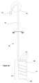
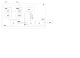
図1は、クーラント液20を充填された槽体10内に収容したままで、生物学的試料を遠隔ライブ監視を可能にするシステムの例示的な実施形態を示す。図1は、このような槽体10を通る断面図であり、したがって、槽体内に存在するシステムの部材を明確に示すものである。
Detailed Description of Drawings FIG. 1 shows an exemplary embodiment of a system that allows remote live monitoring of a biological sample while still housed in a
図示する特定の実施例では、槽体10は、ジュワー(Dewar)フラスコなどの真空フラスコである。そのような真空フラスコは外部環境から槽体10の内容物を断熱することができ、これは生物学的試料を冷却状態で維持するのにクーラント液20を補助することができる。図示される特定の実施例では、槽体は、筐体12内に設けられた二重壁容器1を含む。
In the particular embodiment illustrated, the
槽体10の内容物は、長時間室温より著しく低い温度に維持することができる。さらに、槽体10内の低温を維持するのを助けるために、槽体10内のクーラント液20は、定期的に交換することが可能である。例えば、クーラント液20は、経時的に蒸発し得るので、液体状態でより低い温度のクーラント液20を、蒸発した液体に代えて加えることが可能である。
The contents of the
クーラント液は、例えば、液体窒素などの低温クーラント液であってもよい。液体窒素は63Kの凝固点を有し、非常に低温で液体状態であるため、一般に使用される。さらに、77Kの非常に低い沸点は、フラスコ内を本質的に定常的にゆっくりとした沸騰状態に保つことができ、その沸点付近のほぼ一定の温度を維持することになるという結果を得る、ということを意味する。 The coolant liquid may be, for example, a low temperature coolant liquid such as liquid nitrogen. Liquid nitrogen has a freezing point of 63 K and is generally used because it is in a liquid state at a very low temperature. In addition, the very low boiling point of 77K results in the fact that the inside of the flask can be kept in an essentially steady and slow boiling state, maintaining a nearly constant temperature near that boiling point. Means that.
図1から分かるように、システムは、ドッキングアセンブリ200と複数のキャニスタ100を含む。図中には2つだけのキャニスタ100(1)、100(2)が示されているが、槽体に適した実質的に任意の数のキャニスタ(例えば4つ、6つ、8つ等のキャニスタ)が与えられ得ることが理解されるべきである。それぞれのキャニスタ100は、いくつかの容器50を保持するように構成されており、それぞれの容器50は少なくとも1個の生物学的試料を含み、かつ当該容器50を識別する、その結果、当該容器50内の生物学的試料(群)を識別することができることとなるRFIDタグを取り付けられている。
As can be seen from FIG. 1, the system includes a
簡単な例を与えるために、容器50は、例えば、それぞれのこのような容器が、単一の試料を含み、そして対応するRFIDタグが取り付けられた、バイアル、ストローおよび/またはバッグであり得る。しかしながら、システムは、階層的に組み合わされている容器群50を用いて、より複雑な方法で利用されることが想定される。例えば、(それぞれがそれぞれの単一の試料を含む)複数のストロー群が、単一のヴィーゾチューブ(visotube)内に格納され、複数のヴィーゾチューブ群が次に単一のゴブレット内に収容され、そして複数のゴブレットがキャニスタ100中に収容され得る。それゆえ、例えば、このような単一のゴブレットは、複数のヴィーゾチューブ群を含み、このヴィーゾチューブのそれぞれは複数のストロー群を含み、このストローのそれぞれはそれぞれ単一の試料を含むののであるから、単一のゴブレットは、潜在的に多数の試料を含んでいる、ということが理解されるであろう。このようなそれぞれのストロー、ヴィーゾチューブ、およびゴブレットは、当該容器50を識別するそれぞれのRFIDタグを取り付けられ得るものであり、従って、用語「容器」は、本明細書において一般的な意味で用いられるものであり、そして、ストロー、ヴィーゾチューブ、および/またはゴブレットを意味し得るものであることが理解されるであろう。
To give a simple example, the
さらに、いくつかの場合にあっては、容器は使い捨てのものであっても良い。 Further, in some cases, the container may be disposable.
また、例えば、図1に示す様式のように、ドッキングアセンブリ200は、例えば、槽体10上に取り付けることができるように、構成されている。図面に示すように、ドッキングアセンブリは、いくつかのコネクタ202を含んでおり、それぞれのコネクタ202は、キャニスタ100の1つによって設けられた1つのコネクタ102と係合するよう構成されている。例えば、図1において、キャニスタ100(1)、100(2)の双方に関するコネクタ102(1)、102(2)は、ドッキングアセンブリ200によって提供されるコネクタ群202のそれぞれ1つと係合する。1つのキャニスタ102上の1つのコネクタとドッキングアセンブリ202上の1つのコネクタとの間の係合は、ドッキングアセンブリ200および当該キャニスタ100との間の電気的接続を提供する。
Further, for example, as shown in FIG. 1, the
特定の実施例では、コネクタ102、202は、FAKRAコネクタである。しかし、それらは、SMA、SMBまたはSMCコネクタのような任意の適切なタイプのものであってもよい。
In a particular embodiment, the
上述したように、容器50のそれぞれは、その容器を識別するRFIDタグを備えている。キャニスタ100のそれぞれは、それに保持されている容器50のRFIDタグを無線で問い合わせするように動作可能である。その結果、当該キャニスタ100は、容器50上のRFIDタグからそれが保持する保持容器50を識別する情報を受信する。キャニスタ100は、コネクタ102,202ならびにキャニスタ100とドッキングアセンブリ200との間に与えられた電気的接続を介して、ドッキングアセンブリ200にこの識別情報を通信するように構成されている。システムは、次いで、それぞれの容器50が1つないしそれ以上の対応する生物学的試料に関連付けられたデータベースにアクセスすることによって、どの生物学的試料が、特定のキャニスタ100内に存在するのかを識別することができる。あるいは、またはそれに加えて、それぞれのRFIDタグが、容器が含む生物学的試料(群)を識別するデータを更に格納していても良い。この生物学的試料データは、ドッキングアセンブリ200に送られる識別情報の一部を形成してもよい。いずれの場合であっても、システムは、生物学的試料が槽体10内に収容されたままで、生物学的試料の遠隔ライブ監視を実施することが可能である。
As mentioned above, each of the
特定の実施例では、RFIDタグは、例えば、ISO 18000-6Aに準拠した、HF(高周波)帯域で動作する。また、このようなタグは、低コストでありながら、多くのキャニスタ設計に十分以上である、約1メートルの最大読取範囲を代表的に有する。 In certain embodiments, RFID tags operate in the HF (radio frequency) band, for example, according to ISO 18000-6A. Also, such tags typically have a maximum reading range of about 1 meter, which is more than sufficient for many canister designs at a low cost.
他の実施例では、より低い周波数、例えばLF(低周波数)帯域において動作するタグが使用され得るかもしれない(例えば、ISO 18000-3に準拠して)。ただし、これらは、代表的には、より短い最大読取範囲を有している。同様に、さらに他の実施例では、より高い周波数で動作するタグも、おそらく、使用される可能性がある。ただし、これらは一般的に非常に多くの電力を必要とし、一般的に高価なものである。 In other embodiments, tags operating at lower frequencies, eg, the LF (low frequency) band, may be used (eg, in accordance with ISO 18000-3). However, they typically have a shorter maximum read range. Similarly, in yet other embodiments, tags operating at higher frequencies may also be used. However, these generally require a great deal of power and are generally expensive.
蒸発により、クーラント液20の一部はガス状であってもよいことに留意すべきある。得られたガスもまた代表的には低温であるので、図1に示すように、キャニスタ100内に保持された容器50がクーラント液20の液体部分内に浸漬されることは必ずしも必要ではないかもしれない。実際、気相ジュワーフラスコなどのようないくつかの槽体では、容器がクーラント液のガス部分に保持されるのが一般的である。
It should be noted that due to evaporation, a portion of the coolant liquid 20 may be gaseous. Since the obtained gas is also typically cold, it may not always be necessary for the
いくつかの実施例では、ドッキングアセンブリ200は、容器RFIDタグのキャニスタ100によって読取りを管理し、制御することができます。従って、あるいはその他の点から、キャニスタ100は、アクティブな(動力式)部材を何ら含まなくても良い。
In some embodiments, the
ドッキングアセンブリ200は、従って、コネクタ102,202によって提供される電気的接続を介して、キャニスタ100と通信するように構成されてもよく、それによってキャニスタ100が、それの保持する容器50のRFIDタグに無線で質問することをなさせる。例えば、ある特定のキャニスタにおける容器50のRFIDタグを読取るために、ドッキングアセンブリ200は、そのキャニスタ100に電気的問合せ信号を送信しても良く、キャニスタは対応する無線問合せ信号をRFIDタグへ送信する。RFIDタグは無線応答信号で応答し、この無線応答信号は電気的応答信号がキャニスタ100内で発生されることをもたらす。キャニスタ100は次いでこの電気的応答信号をドッキングアセンブリ200へと運ぶ。
The
いくつかの実施例では、ドッキングアセンブリ200はさらに、無線トランシーバ250(図1には図示せず)を含むことができる。無線接続は、それが貯蔵施設における散らかり(clutter)の量を減らし、そして槽体対してオン及びオフに容易に切り替えることを可能にするゆえに便利である。
In some embodiments, the
このような無線トランシーバ250は、槽体10のキャニスタ100内に保持された容器50を識別する情報を、サーバ300に送信するために用いられ得る。このような識別情報は、例えば、槽体10においてどのキャニスタ100中にどの容器50が保持されているかを特定し得るものである。サーバは、この情報をデータベースに対して確認し、それによって、ある特定の容器50が、正しいキャニスタ100内(そして、システムにおいて複数の槽体が存在する場合には、実際に、正しい槽体10内)に保持されているか否かを決定することができる。
Such a
上述したように、いくつかのケースでは、それぞれのRFIDタグは、更に、その対応する容器50に含まれる生物学的試料(群)を識別するデータを追加的に記憶していても良い。この生物学的試料データはまた、サーバ300に送信された識別情報の一部を形成しても良い。さらに、この生物学的試料データを、ある特定の容器50が正しいキャニスタ100内に保持されているか否かの決定の一部として使用することできる。
As mentioned above, in some cases, each RFID tag may further store additional data identifying the biological sample (group) contained in its corresponding
ドッキングアセンブリ200は、無線トランシーバ250を使用してサーバに追加情報を送信するように構成されてもよい。例えば、ドッキングアセンブリ200は、槽体10の蓋が除去されたことをサーバ300に通知しても良く、同様に、蓋が元に戻された場合にサーバに通知しても良い。ドッキングアセンブリ200は、従って、蓋が槽体の上の所定の位置にあるか否かを検知するための1つまたは複数のマイクロスイッチを含むことができる。
The
同様に、ドッキングアセンブリ200は、そのドッキングアセンブリ200のコネクタ202の一方がこれに接続されたキャニスタ100を有した場合に、サーバに通知しても良く、同様に、キャニスタがドッキングアセンブリコネクタ202の一方より接続を切られた場合に、サーバに通知しても良い。ドッキングアセンブリ200は、これゆえ、キャニスタが、ドッキングアセンブリコネクタ202の対応する1つに接続されているか否かを検知するためのそれぞれのマイクロスイッチを含むことができる。
Similarly, the
このような追加情報は、例えば、蓋の除去/再置、またはドッキングアセンブリコネクタ202の1つに対するキャニスタの接続/切断のような、関連する事象が発生するたびに、送信されても良いし、または定期的な間隔で送信されても良い。後者の場合には、追加の情報は、事象の時間、ならびにそれらの状態(「蓋の除去」、「蓋の再置」等)を含んでも良い。
Such additional information may be transmitted each time a related event occurs, such as removal / repositioning of the lid, or connection / disconnection of the canister to one of the
無線トランシーバ250はまた、サーバ300からのメッセージを受信するように利用され得る。例えば、サーバ300は、「読取」メッセージをドッキングアセンブリ200に送信し得る。このような「読取」メッセージを受信すると、ドッキングアセンブリ200は、キャニスタ100に、それが含む容器のRFIDタグを問合せることをもたらし得る。「読取」メッセージは、ドッキングアセンブリ200にあるキャニスタを特定することができるものであり得、または、全てのキャニスタ100にそれらが含む容器のRFIDタグを無線で問合せるよう指示することをドッキングアセンブリ200にもたらす、一般的「読取」メッセージであり得る。
The
ある特定のキャニスタ100を特定する「読取」メッセージは、例えば、特定のキャニスタに関するデータの「論理的信頼性」が乏しい場合にサーバによって利用されることができる。
A "read" message identifying a
いくつかの実施例では、ドッキングアセンブリ200は、(例えば、サーバか300からの適切な「読取」要求に応答して)いくつかの、または全てのキャニスタ100に読取を実行させることになるようにした場合に、それぞれのキャニスタに順番に、その中の容器50のRFIDタグを問い合わせさせるように構成され得る。そのようなアプローチは、読取られている様々なキャニスタ間の干渉を減少させ得る。
In some embodiments, the
他の実施例では、ドッキングアセンブリ200は、指定されたグループのキャニスタ100、または全てのキャニスタ100に、同時に読取を実行させるように構成されてもよい。
In another embodiment, the
ドッキングアセンブリ200は様々な形態を取り得る。特に、槽体10の蓋が所定位置にある時に、このドッキングアセンブリ200とキャニスタ100との間の、コネクタ102,202によって与えられる電気的接続が維持されるように構成することができる。さらに、蓋が所定位置にあるか取り外されているかにかかわらず、これらの電気的接続が維持されるように構成することができる。それゆえ、またはそれ以外で、槽体10を開く必要なしに、容器50のRFIDタグを読み取ることができる。これにより、試料の温度に大きな影響を与えることなく試料を遠隔監視することができ、したがって試料が保管され得る時間を増加させることができる。
The
図1に示される例示的な実施形態では、ドッキングアセンブリ200は、槽体10の首部の周りに装着されるように構成された首部モジュール200Aを含む。そのような首部モジュール200Aは、槽体10の首部の周りに適合するように概してリング形状であり得る。それに加えて、またはその代わりに、首部モジュール200Aの形状は、それが異なるサイズの槽体10の首部の周りに適合することができるように調整可能であり得る。ある特定の実施例においては、首部モジュール200Aは、例えば、それがある範囲の異なる槽体での使用を可能にし得る、ある範囲の直径を有するリングを形成することができるように構成され得る。それゆえ、またはそれ以外で、首部モジュール200Aは部分的に可撓性であり得る(例えば調節可能なベルトまたはストラップとして構成されている)。
In the exemplary embodiment shown in FIG. 1, the
図1から明らかなように、ドッキングアセンブリ200用のコネクタ202は首部モジュール200Aに設けられている。ある特定の実施例においては、ドッキングアセンブリ200が槽体に取り付けられたときに、コネクタ202が槽体の首の周りに円周方向に配置されるように、コネクタは首部モジュール200A上に配置され得る。
As is clear from FIG. 1, the
特に、ドッキングアセンブリ用のコネクタ202が首部モジュール200A上に設けられる場合、首部モジュール200Aは、槽体10のための蓋が所定の位置にあるか取り外されているかにかかわらず、首部モジュール200Aとキャニスタ100との間の電気的接続が維持されるように適切に構成され得る。それゆえ、またはそれ以外で、槽体10を開く必要なしに、容器50のRFIDタグを読み取ることができる。
In particular, if the
図1に示す特定の実施形態では、ドッキングアセンブリ200は、槽体の本体の周りに結び付けられるように構成されている追加モジュール200Bを任意に含むことができる。この追加モジュール200Bは首部モジュール200Aに電気的に接続されているので、例えば当該追加モジュール200Bは首部モジュール200Aからデータを受信する、および/または、追加モジュール200Bは、「読取」命令などのコマンドを首部モジュール200Aに送信することができる。図3を関連して以下に説明するように、追加モジュール200Bは無線送受信機250を提供してもよく、また、例えば1つまたは複数のプロセッサとして配列されたマイクロコントローラ240を含んでもよい。
In the particular embodiment shown in FIG. 1, the
ドッキングアセンブリ200は、代わりに(またはおそらく、さらに加えて)、蓋モジュールを含み得る。このような蓋モジュールは、槽体の上部を密封するように成形されててもよく、したがって槽体の標準的な蓋に置き換わっても良い(代わりに、容器の標準的な蓋の上部に積載するように成形され得るが、)。蓋モジュールと首部モジュールの両方が設けられる場合、それらは、例えば互いに係合するように相補的な形状を有することによって構成されてもよい。さらに、それらは、必要に応じて、蓋モジュールを槽体10から取り外すことを依然として可能にしながら、例えばそれらを互いに物理的に連結するテザーを介して電気的に接続されてもよい。もちろん、代替的に、蓋モジュールと首部モジュールとの間に電気的接続を提供しないテザーを設けることもできる。
The
ドッキングアセンブリ200は、1つまたは複数の電池などの内部電源を備えることができる。したがって、ドッキングアセンブリは、電源コードを用いて電源に取り付ける必要がない場合がある。これは、貯蔵施設における散らかり(clutter)の量を減らし、そして槽体対してオン及びオフに容易に切り替えることを可能にするゆえに便利である。
The
ここで、図1に示されているシステムにおける使用に適したキャニスタ100の例示的な実施形態を示す、図2A~図2Cに注目する。
Attention is now paid to FIGS. 2A-2C, which show exemplary embodiments of the
キャニスタ100の例示的実施形態の側面図である図2Aは、キャニスタ100が受容部を含み、その中に複数の容器50が保持されていることを明確に示している。図2Aからさらに分かるように、受容部はアンテナ110を含む。アンテナ110は、受容部内に保持された容器50のRFIDタグからの電磁放射の形で送られる識別情報を受信するように構成されている。
FIG. 2A, which is a side view of an exemplary embodiment of the
図2Aの特定の実施例において、キャニスタ100は、長手方向の一端で前記受容部106に取り付けられ、長手方向の他端でコネクタ102に取り付けられる細長部材108をさらに含む。
In a particular embodiment of FIG. 2A, the
図2Aから理解され得るように、キャニスタは、コネクタ102に隣接して設けられるハンドル109を含み得る。図2Aに示されるある特定の実施例において、ハンドル109は、細長部材108の屈曲部として設けられる。例えば、細長部材108は、キャニスタ100が細長部材108によって取り扱われることを可能にするために十分に剛性であり得、例えば、ユーザが細長部材108を握ることによって槽体10からキャニスタ100を取り除くことを可能にする。
As can be seen from FIG. 2A, the canister may include a
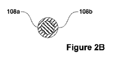
図2Aおよび図2Bに示されるある特定の実施例において、アンテナ106とコネクタ102との間の電気的接続は、この細長部材108の内部において前記細長部材の長さに沿って配置された細長導体180aによって提供される。この点は、図2Aのキャニスタ100の細長部材108を通る断面図である図2Bにおいてより明らかに示される。図面から理解され得るように、細長導体108aは、電気的および/または熱的に絶縁されている絶縁材料の層108b内に入れられている。例えば、絶縁材料は、1W/mK未満、より好ましくは0.1W/mK未満の熱伝導率を有し得る。そのような材料が電気的に絶縁性である場合、槽体10の壁部11(これはしばしば金属製である)を介した1つのキャニスタから別のキャニスタへの電気信号の伝達が減少する可能性があり、したがって、異なるキャニスタ100間の干渉を低減することが可能である。さらに図2Bから理解され得るように、絶縁材料108bは、細長部材108の外表面を提供する。
In certain embodiments shown in FIGS. 2A and 2B, the electrical connection between the
好ましい絶縁材料は、ガラス繊維(例えば、エポキシまたはポリエステル樹脂結合ガラス繊維)およびポリマー(例えば、ポリイミド、ポリアミド、ポリエチレンテレフタレートグリコール変性、超高分子量ポリエチレンなど)を含み得る。 Preferred insulating materials may include glass fibers (eg, epoxy or polyester resin bonded glass fibers) and polymers (eg, polyimide, polyamide, polyethylene terephthalate glycol modified, ultra high molecular weight polyethylene, etc.).
細長導体108aは、比較的低い熱伝導率を有するように選択されることができる導電性材料で形成することができる。これにより、細長部材108によるクーラント液への、さらには槽体の外部から生物学的試料への熱伝達を低減することができる。導電性材料108aの熱伝導率は、例えば100W/mK未満、より好ましくは20W/mK未満であり得る。
The
ある特定の実施例において、細長導体108aの導電性材料は、16W/mKの熱伝導率を有する、ステンレス鋼であり得る。それゆえ(またはそれ以外で)、細長部材108内での細長導体は、ステンレス鋼ケーブル、例えば同軸ステンレス鋼ケーブルによって、提供され得る。
In certain embodiments, the conductive material of the
ここで図2Aに戻ると、図示される特定の例において、受容部106は、受容部106の側面を規定する壁部1061と、受容部106の底部を画定する基部1062とを含む。図2Aに示されるように、前記基部1062が容器50を支持している状態で、容器50を当該受容部106内に保持した場合に、前記壁部は、前記容器50を囲繞するように周囲の周りに延長されることができる。図2A~図2Cにも示されるように、いくつかの実施形態においては、基部1062は、壁部の縁に接続され得る。図2A~図2Cにさらに示されるように、基部1062は、代表的には、キャニスタが槽体から取り除かれた際に、受容部106からクーラント液が排出されることを可能とするように構成されており、そしてそれゆえ基部1062は、クーラント液がそれを通って排出され得る複数の穴部107を含み得る。
Returning to FIG. 2A, in the particular example illustrated, the receiving
図2Aに示される実施例では、受容部106の壁部はアンテナ110を含む。アンテナ110は、例えば、壁内の1つの層として提供されてもよく、および/または壁内に封入されてもよい。
In the embodiment shown in FIG. 2A, the wall portion of the receiving
図2Aに示すある特定の実施例において、アンテナは、螺旋状コイルとして配され細長導電性要素を含むものである。しかしながら、アンテナ110は、容器50のRFIDタグと無線で通信することを可能にする任意の適切な形状を有し得る。アンテナは、可撓性PCBシートによって都合よく提供することができる。
In one particular embodiment shown in FIG. 2A, the antenna is arranged as a spiral coil and includes an elongated conductive element. However, the
いくつかの実施例では、壁部は、RFIDタグによって放射された電磁波放射の受容部106から漏れを実質的に阻止するように構成された電磁波遮蔽層を含むことができる。このような遮蔽層は、読取時に異なるキャニスタ100間の干渉を減らすことができる。アンテナ110は、電磁波遮蔽層の内部に好ましく設けられることができる。
In some embodiments, the wall portion may include an electromagnetic wave shielding layer configured to substantially block leakage from the electromagnetic
より詳細には、電磁波遮蔽層は、例えばファラデーシールドとして構成されることができる。したがって、遮蔽層は、メッシュとしてまたは連続層として成形された、導電性材料の層を含み得る。導電性材料は、ステンレス鋼などの金属から形成することができる。 More specifically, the electromagnetic wave shielding layer can be configured as, for example, a Faraday shield. Thus, the shielding layer may include a layer of conductive material molded as a mesh or as a continuous layer. The conductive material can be formed from a metal such as stainless steel.
壁部は、追加的に、またはこれに代えて、1つまたはそれ以上の磁気増幅層を含み得る。このような磁気増幅層は高い透磁率を有することができ、例えば、磁気増幅層の比透磁率は50より大きい、好ましくは75より大きい、さらに好ましくは100より大きいものとされ得る。さらに、磁気増幅層は、例えば0.1未満、より好ましくは0.05未満の、低い磁気損失正接を有し得る。高い磁気損失正接値は、代表的には、より多くの熱生成を意味し、それはクーラント液の温度、さらには生物学的試料の温度に影響を及ぼし得るので、一般に望ましくない。 The wall may additionally or instead include one or more magnetic amplification layers. Such a magnetic amplification layer can have a high magnetic permeability, for example, the specific magnetic permeability of the magnetic amplification layer can be greater than 50, preferably greater than 75, more preferably greater than 100. Further, the magnetic amplification layer may have a low magnetic loss tangent, for example less than 0.1, more preferably less than 0.05. A high magnetic loss tangent value typically means more heat generation, which is generally undesirable as it can affect the temperature of the coolant and even the temperature of the biological sample.
磁気増幅層は、例えば、磁性であるが電気的に非導電性である材料を含み得る。例えば、フェライト材料、特にニッケル-亜鉛フェライトのようなソフトフェライト材料を用いることができる。フェライト材料を含有する磁気増幅層は、ポリマーで裏打ちされたフェライトシートによって都合よく提供され得る。スピネル材料もまた、磁気増幅層に利用することができ、実際、多くのフェライトはまたスピネルでもある。本発明者らは、ニッケルスピネルマグネシウムアルミニウム材料、特にトランス-テック(Trans-Tech)製のTT2-111を用いて実験した。 The magnetic amplification layer may include, for example, a material that is magnetic but electrically non-conductive. For example, ferrite materials, especially soft ferrite materials such as nickel-zinc ferrite, can be used. The magnetic amplification layer containing the ferrite material can be conveniently provided by a ferrite sheet lined with a polymer. Spinel materials can also be utilized in magnetic amplification layers, and in fact many ferrites are also spinels. We experimented with nickel spinel magnesium aluminum materials, especially TT2-111 made by Trans-Tech.
他の実施例においては、磁気増幅層は、例えば、磁性でかつ導電性の材料を含み得る。例えば、軟磁性合金を利用することができる。例えば、MuMetal(登録商標)などのニッケル-鉄合金を用いることができる。 In other embodiments, the magnetic amplification layer may include, for example, a magnetic and conductive material. For example, a soft magnetic alloy can be used. For example, nickel-iron alloys such as MuMetal® can be used.
透磁率は一般に温度と共に(いくつかの場合においては強く)変化するので、磁気増幅層のために適切な材料を選択するときには、クーラント液20の温度を考慮する必要があり得る。 Permeability generally varies with temperature (strong in some cases), so it may be necessary to consider the temperature of the coolant 20 when selecting the appropriate material for the magnetic amplification layer.
壁部は積層構造のものでもよい。例えば、アンテナ110は、2つの磁気増幅層の間に設けられ得、さらに必要に応じて、これらの層のすべての外側に設けられた電磁波遮蔽層を備えてもよい。
The wall portion may have a laminated structure. For example, the
あるいはまた、アンテナおよび様々な層などの構成要素を、受容部106を形成するように材料内に封入することもできる。この封入する材料は、上述のガラス繊維およびポリマー材料などの電気的および/または熱的絶縁材料とし得る。
Alternatively, components such as the antenna and various layers can be encapsulated in the material to form the
より一般的には、電気的および/または熱的絶縁材料は、受容部106の壁部の外表面を提供し得る。上記したように、このような材料が電気的絶縁である場合、槽体10の壁部11(これはしばしば金属製である。)を介した1つのキャニスタから他のキャニスタへの電気信号の伝達、または実際は異なるキャニスタ100の受容部同士の間の直接接触による伝達は、低減させ得る。したがって、異なるキャニスタ100間の干渉を低減させ得る。
More generally, electrical and / or thermal insulating materials may provide the outer surface of the wall of the receiving
さらに別の実施例では、キャニスタ100は、例えばステンレス鋼(その低い熱伝導率が上記で注目されている)、または上述の軟磁性合金のうちの1つなど、実質的に金属材料で形成され得る。このような場合には、細長部材108とは異なる金属材料を受容部106に使用することができる。その他のそのような場合には、双方に同じ金属材料を使用することができる。いずれの場合も、アンテナ100および細長導体108aなどの、電気信号を搬送するキャニスタ100の構成要素は、そのような電気信号がキャニスタ100の外表面に運ばれることを防止するように電気的絶縁材料(例えば、薄い電気絶縁層として)の内部に入れることができる。これは、キャニスタ100の間の干渉の危険性を減らすことができる。
In yet another embodiment, the
図2Aに示される実施例では、受容部106の壁部はアンテナ110を含むが、これは絶対に不可欠というわけではない。これは、キャニスタ100の真下から見た図である図2Cに示されるキャニスタの例示的実施形態によって実証される。図2Cから明らかなように、そこに示されるキャニスタの実施例では、アンテナ110’が受容部106の基部内に設けられる。図面からも理解され得るように、アンテナ110’は、受容部106の基部の周囲のループ状経路に概略続く、細長導電性部材を含む。またさらに明らかなように、ループ状経路は形状が略円形である。
In the embodiment shown in FIG. 2A, the wall portion of the receiving
図2Cに示されるある特定の実施例において、細長導電性部材は、前記ループ状経路の周りに延びるように、それ自体で複数回折り返されている。図面から明らかなように、細長導電性部材の長さの実質的な大部分は、前記ループ状経路に平行に向けられているよりも、前記ループ状経路に垂直に向けられる。そのような手段は、信号の送信および受信に利用可能なアンテナの断面積を増大させ得る。 In one particular embodiment shown in FIG. 2C, the elongated conductive member is itself multiple times folded back so as to extend around the looped path. As is clear from the drawings, substantially most of the length of the elongated conductive member is directed perpendicular to the looped path rather than parallel to the looped path. Such means can increase the cross-sectional area of the antenna available for transmitting and receiving signals.
図2Cはまた、そこを通って冷却液が流出することができる基部内の穴部107を明確に示している。
FIG. 2C also clearly shows the
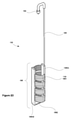
図2Dは、キャニスタ100のさらなる例示的実施形態の斜視図であり、図2Aに示されたキャニスタ100とは対照的に、アンテナ110は、受容部106の壁部1061の大部分を提供する。その結果、アンテナ110は、通信機能を提供することに加えて、アンテナが容器50を受容部106内に保持するという点で機械的機能を提供する。そのような構成は製造が容易であり得る。
FIG. 2D is a perspective view of a further exemplary embodiment of the
図2Dに示す特定の例示的実施形態では、アンテナ110は、螺旋状コイルとして配置された細長導電性要素を含む。図面から明らかなように、この螺旋状コイルはシート状金属材料から形成されている。そのような構成は(信号の送信および受信に関して)アンテナ110の有効性を改良させ得る一方で、物理的に頑丈でありかつ容器50を受容部60内に効果的に保持することができる。
In the particular exemplary embodiment shown in FIG. 2D, the
螺旋状コイルを含むアンテナ110の代替として(またはそれに加えて)、アンテナは、線形配列に配置された複数の導電性リングを含むことができる。これらのリングは、それらが共通の中心軸(その周りで各リングは回転対称である)を共有するように配置され得る。図2Dに示される螺旋状コイルと同様に、そのようなリングはシート状金属材料で形成され得る。
As an alternative (or in addition to) to the
図2Dに示されるある特定の実施例において、螺旋状コイルは、それぞれ受容部106の壁部1061の一部を提供する2つの支持部1063A、1063Bに固定される。これらの支持部は、構成要素の物理的堅牢性を向上させることができる。さらに、それらは、コイルの巻きが互いに接触しないことを確実にし得、そしてこの理由のために(またはその他によって)非導電性材料から形成され得る。
In certain embodiments shown in FIG. 2D, the spiral coil is secured to two
図2Dに示される螺旋状コイルの連続した巻きの間の間隔は、コイル軸に沿った各巻きの範囲よりも顕著に小さいことに留意されたい。これにより、アンテナ110の有効性を(信号の送信および受信に関して)向上させることができる一方で、アンテナ110が容器50を受容部60内に効果的に保持することも可能になる。導電性リングが使用される場合も同様の手法がとられ、連続するリング間の間隔は、共通の中心軸に沿った各リングの範囲よりも著しく小さいものとされる。
Note that the spacing between the continuous windings of the spiral coil shown in FIG. 2D is significantly smaller than the range of each winding along the coil axis. This can improve the effectiveness of the antenna 110 (with respect to signal transmission and reception), while also allowing the
図1および図2A~図2Dを参照して上述したキャニスタ100を製造するとき、クーラント液20の温度に応じて、低温を特徴とする特殊材料を使用することが適切であり得る。例えば、特別なエポキシ(例えばスチースキャスト2850(stycast2850))およびワニス(例えばGE7031)を接合(例えば細長部材108の受容部106への接合)に利用することができる。「錫ペスト」(tin pest)と一般的に呼ばれるプロセスにおいて、低温環境が錫を劣化させることがある理由から、少量の錫を含有するはんだ(例えば60/40の錫鉛はんだ)を、電気部品を接続するために利用することができる。
When manufacturing the
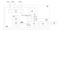
ここで図3に注目すると、それは図1に示されるシステムでの使用に適したドッキングアセンブリの例示的実施形態を概略的に示すブロック図である。図面から分かるように、ドッキングアセンブリは2つのモジュール、首部モジュール200Aおよび追加モジュール200B、を含む。追加モジュール200Bが正しい槽体10と物理的に関連付けられたままであることを確実にするために、追加のモジュール200Bは槽体の本体の周りに結び付けられるように構成されてもよい。
Focusing here on FIG. 3, it is a block diagram schematically illustrating an exemplary embodiment of a docking assembly suitable for use in the system shown in FIG. As can be seen from the drawings, the docking assembly includes two modules, a
図1を参照して上記で簡単に説明したように、そして図3に示すように、追加モジュール200Bは首部モジュール200Aに電気的に接続されている。図3に示すように、この接続により、追加モジュール200Bが首部モジュール200Aからデータを受信することが可能になり、追加モジュール200Bが「読取」コマンドなどのコマンドを首部モジュール200Aに送信することが可能になる。図3で示される特別な実施例では、追加モジュール200Bは、サーバ300との無線通信を可能にする無線トランシーバ250を提供し、例えば1つまたは複数のプロセッサとして構成され得るマイクロコントローラ240を含む。
As briefly described above with reference to FIG. 1 and as shown in FIG. 3, the
図3にも示されるように、首部モジュール200Aは単一のRFID質問器またはリーダ210を含む。このRFID質問器はRFIDチップ212および同調回路211を含む。RID質問器210は電気的問合せ信号を生成するように構成される。電気的問合せ信号がキャニスタのアンテナ110に印加されると、それは無線質問信号をそのアンテナによって、当該キャニスタ100内に保持されている容器50のRFIDタグへ送信する。
As also shown in FIG. 3, the
逆に、RFID質問器は、容器50のRFIDタグによって放射された無線応答信号の受信に応答してキャニスタ100のアンテナ110内で生成され、キャニスタ100と首部モジュール200Aとの間の電気的接続を介してRFID質問器に伝達された、電気応答信号を分析するように動作可能である。より詳細には、RFID質問器210は、電気的応答信号の分析に基づくデータをマイクロコントローラ240に送信する。これは、RFID質問器210が電気応答信号に符号化されたデータをマイクロコントローラ240によって読取可能なフォーマットに変換すると見なすことができる。
Conversely, the RFID interrogator is generated within the
図3にも示されるように、単一のRFID質問器210は、マルチプレクサ211を介して、複数のコネクタ202(1)~202(N)(およびそれによってキャニスタ100とドッキングアセンブリ200との間の複数の電気的接続)に電気的に接続される。このマルチプレクサ211は、RFID質問器210と各キャニスタ100とを順番に接続して信号を送受信するように構成されている。
As also shown in FIG. 3, a
図3に示すように、マルチプレクサ211はマイクロコントローラ240の制御下にある。したがって、RFID質問器210が接続される特定のキャニスタ100は、例えば、マイクロコントローラ240によってマルチプレクサ211に送信されたスイッチングコマンドに応じていつでも変えられ得る。
As shown in FIG. 3, the
図3にさらに示されているように、首部モジュールは、マイクロコントローラ240の制御下にある状態インジケータの集まりおよび/または表示ディスプレイ(全体として260として示されている)をさらに含む。したがって、この表示ディスプレイおよび/またはインジケータを用いてユーザーに示される状態情報は、マイクロコントローラ240によって送信された表示コマンドに応じて変わり得る。
As further shown in FIG. 3, the neck module further includes a collection of status indicators under the control of
ある特定の実施例において、LEDなどのような、首部モジュール200A上のインジケータは、エラーが発生したこと、例えば、容器50が誤ったキャニスタ100に配置されたこと、をユーザに示すように構成されている。容器50が誤ったキャニスタ100内にあるという決定は、マイクロコントローラ240が無線トランシーバ250を使用してサーバ300と通信することを要求し得ることに留意すべきである。
In certain embodiments, indicators on the
加えて、または代わりに、首部モジュール200A上のインジケータは、取り外されるべき容器を含むキャニスタの識別を示すように構成されてもよい。これは、例えば、無線トランシーバを介してサーバ300からマイクロコントローラ240に送信される情報メッセージに応答して起こり得る。情報メッセージは、除去されるべき容器がどのキャニスタに配置されているかを特定する。これは、前の時点で実行された各キャニスタ100内の容器50の監視(例えば、システムによって実行された一連の定期監視の最新のもの)に基づき得る。または、サーバ300は、どのキャニスタ100が問題の容器50を収容しているかを示す直前に、容器50の監視を実行するようにマイクロコントローラ240に特別に指示していてもよい。
In addition, or instead, the indicator on the
当然のことながら、そのようなインジケータおよび表示ディスプレイは首部モジュール200A上に設ける必要はなく、代わりに追加モジュール200B上に設けることができ、または専用モジュール上に設けることができることを理解されたい。しかしながら、キャニスタ100への接続を提供するドッキングアセンブリ200のそのモジュール上にそのような特徴を提供することは便利であり、それによりこれらの状態情報を提供する特徴はユーザがキャニスタと相互作用しながら見ることができる。ある特定の実施例においては、それぞれのインジケータは、各キャニスタ100への接続に隣接してを設けることができる。
It should be appreciated that such indicators and display displays need not be provided on the
図4は、図1のシステムでの使用に適したドッキングアセンブリのさらなる例示的実施形態のブロック図を示す。図3のドッキングアセンブリとは対照的に、図4のドッキングアセンブリ200は、複数のRFID質問器210(1)~210(N)を含む。より具体的には、各RFID質問器210、210(1)~210(N)が、ドッキングアセンブリコネクタ202(1)~202(N)のそれぞれに対して設けられる。したがって、専用のRFID質問器210(1)~210(N)が、ドッキングアセンブリ200に接続されているすべてのキャニスタ100に対して設けられる。
FIG. 4 shows a block diagram of a further exemplary embodiment of a docking assembly suitable for use in the system of FIG. In contrast to the docking assembly of FIG. 3, the
図4からも分かるように、RFID質問器210(1)~210(N)は、データバス230を介してマイクロコントローラ240に接続されている。したがって、マイクロコントローラ240からの読出メッセージの受信に応答して、データバス230は、RFID質問器210(1)~210(N)のうちの特定の1つにその対応するキャニスタ100を読み取らせることができる。
As can be seen from FIG. 4, the RFID interrogators 210 (1) to 210 (N) are connected to the
図3および図4を参照して説明したドッキングアセンブリの例示的実施形態では、ドッキングアセンブリは首部モジュール200Aおよび追加のモジュール200Bを含むものとしたが、他の実施形態では同じ機能が異なるモジュールに存在してもよく、さらにまた、単一モジュールのみ(これは首部モジュール200Aでも追加モジュール200Bでもないかもしれない;例えば単一モジュールは蓋モジュールであり得る)に存在していてもよいことが、理解されるべきである。
In an exemplary embodiment of the docking assembly described with reference to FIGS. 3 and 4, the docking assembly includes a
上記の実施例においては、単一の槽体10のみを参照したが、システムは複数の槽体10と共に使用されるように拡張可能であることが理解されるべきである。そのような場合、システムは、それぞれの槽体10上に装着されたそれぞれのドッキングアセンブリを有して、多重の、ドッキングアセンブリ200に類似するものを、含み得る。単一のサーバ300がドッキングアセンブリ200のグループまたは全部を制御することができる。例えば、サーバは、ドッキングアセンブリ200のそれぞれに読出メッセージを送信するように動作可能であり得、これはそれぞれのキャニスタ100に保持された容器50を識別するデータをサーバ300に送信することで対応される。そのような読出メッセージは、定期的におよび/またはユーザによる特定のコマンドに応答して送信することができる。
In the above examples, only a
より一般的には、他の実施例および変形態様は、添付の特許請求の範囲内で考慮されることが理解されるべきである。 More generally, it should be understood that other embodiments and variations are considered within the appended claims.
さらに、上記の説明は、これを読んだ当業者の本発明の理解を助け、本発明をどのように実施することができるかを示すものである、いくつかの非限定的な例を提供することを意図していることに留意すべきである。 Further, the above description provides some non-limiting examples that help one of ordinary skill in the art to understand the invention and show how the invention can be practiced. It should be noted that it is intended.
Claims (9)
1ないしそれ以上のキャニスタと、ドッキングアセンブリとを有し、
前記キャニスタは、それぞれが、コネクタを有し、そして少なくとも1つ以上の容器を保持するように構成されており、
前記容器はそれぞれ、1ないしそれ以上の生物学的試料を含み、かつ当該容器を識別するRFIDタグと関連付けられており、
前記ドッキングアセンブリは、前記槽体上に装着可能とされ、そして複数のコネクタを有し、当該コネクタのそれぞれは前記キャニスタの1つのコネクタと係合するように構成されており、これによってドッキングアセンブリと当該キャニスタとの間の電気的接続を提供しており、
前記ドッキングアセンブリは、槽体の首部の周りに装着されるように構成されたリング状の首部モジュールを含み、
前記ドッキングアセンブリのための複数のコネクタが前記首部モジュール上に設けられており、
そして、それぞれのキャニスタは、そこに保持する前記容器のRFIDタグを無線で問合わせるように操作可能であり、これによりこの問合せの結果として前記容器を識別する情報を受信し、また当該キャニスタと前記ドッキングアセンブリとの間の前記電気的接続を介してドッキングアセンブリへこの識別情報を通信することを可能としていることを特徴とするシステム。 A system for remote live monitoring of biological samples while still housed in a tank filled with coolant.
It has one or more canisters and a docking assembly,
Each canister has a connector and is configured to hold at least one container.
Each of the containers contains one or more biological samples and is associated with an RFID tag that identifies the container.
The docking assembly is mountable on the tank body and has a plurality of connectors, each of which is configured to engage one connector of the canister, whereby the docking assembly and the docking assembly. It provides an electrical connection to and from the canister.
The docking assembly includes a ring-shaped neck module configured to be mounted around the neck of the tank body.
A plurality of connectors for the docking assembly are provided on the neck module.
Then, each canister can be operated so as to wirelessly inquire the RFID tag of the container held therein, thereby receiving the information identifying the container as a result of this inquiry, and the canister and the said. A system characterized in that it is possible to communicate this identification information to the docking assembly via said electrical connection to and from the docking assembly.
前記ドッキングアセンブリは、前記無線トランシーバを用いて前記識別情報をサーバに無線で送信するように、前記サーバによって送られた読出メッセージを前記ドッキングアセンブリが前記無線トランシーバを用いて受信した際に、前記無線トランシーバを用いて前記識別情報をサーバに無線で送信するように、構成されている、請求項1または2に記載のシステム。 The docking assembly also has a wireless transceiver and
The docking assembly wirelessly transmits the identification information to the server using the wireless transceiver when the docking assembly receives a read message sent by the server using the wireless transceiver. The system of claim 1 or 2, configured to wirelessly transmit the identification information to a server using a transceiver.
当該首部モジュールおよび蓋モジュールは、お互い係合しかつ相互の電気的な接続を有するように構成されている請求項1乃至5のいずれか1つに記載のシステム。 The docking assembly includes a lid module arranged to engage the top of the tank, which seals the top of the tank.
The system according to any one of claims 1 to 5, wherein the neck module and the lid module are configured to engage with each other and have electrical connections to each other.
前記インジケータはエラーが発生したことをユーザに指示するように構成され、
前記インジケータが、取り除かれるべき容器を含むキャニスタの識別性を示すように構成されている、
請求項1乃至7のいずれか1つに記載のシステム。 The docking assembly includes a plurality of indicators configured to show state information to the user, the indicator being an LED.
The indicator is configured to indicate to the user that an error has occurred.
The indicator is configured to indicate the identity of the canister containing the container to be removed.
The system according to any one of claims 1 to 7 .
複数のコネクタと、少なくとも1つのRFID質問器を有してなり、
当該コネクタのそれぞれは、キャニスタの対応する1つコネクタと係合するように構成されており、これによってドッキングアセンブリと当該キャニスタとの間の電気的接続が提供され、そして、それぞれのキャニスタは、少なくとも1つ以上の容器を保持するように構成されており、前記容器はそれぞれ、1ないしそれ以上の生物学的試料を含みかつ当該容器を識別するRFIDタグと関連付けられており
前記RFID質問器のそれぞれは、
電気的問合せ信号を生成し、そして前記電気的接続のそれぞれ1つを介して、それぞれのキャニスタのアンテナに前記電気的問合せ信号を送信し、当該電気的問合せ信号は、当該キャニスタのアンテナによって、当該キャニスタに保持された容器のRFIDタグへの無線問合せ信号の伝達をもたらすように、そして
容器の前記RFIDタグによって放射された無線応答信号の受信に応答して前記キャニスタのアンテナにおいて生成され、前記キャニスタ及び前記ドッキングアセンブリとの間の前記電気的接続を介してRFID質問器へと伝達された電気的応答信号を分析するように、動作可能なものとされており、
前記ドッキングアセンブリは、槽体の首部の周りに装着されるように構成されたリング状の首部モジュールをさらに含み、
前記ドッキングアセンブリのための前記複数のコネクタは、前記首部モジュール上に設けられている、
ことを特徴とするドッキングアセンブリ。
A docking assembly for remote live monitoring of a biological sample while still housed in a tank filled with a coolant, the docking assembly can be mounted on the tank. and,
It has multiple connectors and at least one RFID interrogator,
Each of the connectors is configured to engage one corresponding connector in the canister, which provides an electrical connection between the docking assembly and the canister, and each canister is at least. Each of the RFID interrogators is configured to hold one or more containers, each of which contains one or more biological samples and is associated with an RFID tag that identifies the container. teeth,
An electrical query signal is generated and transmitted the electrical query signal to the antenna of each canister via each one of the electrical connections, the electrical query signal being referred to by the canister's antenna. Generated at the canister's antenna to provide transmission of a radio inquiry signal to the RFID tag of the container held in the canister and in response to reception of the radio response signal radiated by the RFID tag of the container, said canister. And are made operable to analyze the electrical response signal transmitted to the RFID interrogator via the electrical connection to and from the docking assembly.
The docking assembly further includes a ring-shaped neck module configured to be mounted around the neck of the tank body.
The plurality of connectors for the docking assembly are provided on the neck module.
A docking assembly that features that.
Applications Claiming Priority (3)
| Application Number | Priority Date | Filing Date | Title |
|---|---|---|---|
| GB1613484.3 | 2016-08-04 | ||
| GB1613484.3A GB2552710A (en) | 2016-08-04 | 2016-08-04 | System and apparatus for auditing biological samples in cold storage |
| PCT/GB2017/052315 WO2018025053A1 (en) | 2016-08-04 | 2017-08-04 | System and apparatus for auditing biological samples in cold storage |
Publications (3)
| Publication Number | Publication Date |
|---|---|
| JP2019526280A JP2019526280A (en) | 2019-09-19 |
| JP2019526280A5 JP2019526280A5 (en) | 2020-09-17 |
| JP7018560B2 true JP7018560B2 (en) | 2022-02-14 |
Family
ID=59887303
Family Applications (1)
| Application Number | Title | Priority Date | Filing Date |
|---|---|---|---|
| JP2019528173A Active JP7018560B2 (en) | 2016-08-04 | 2017-08-04 | Systems and equipment for monitoring biological samples in cold storage |
Country Status (8)
| Country | Link |
|---|---|
| US (1) | US11446669B2 (en) |
| EP (2) | EP3493909B1 (en) |
| JP (1) | JP7018560B2 (en) |
| CN (1) | CN109922886B (en) |
| DK (1) | DK3493909T3 (en) |
| ES (2) | ES2817797T3 (en) |
| GB (1) | GB2552710A (en) |
| WO (1) | WO2018025053A1 (en) |
Families Citing this family (9)
| Publication number | Priority date | Publication date | Assignee | Title |
|---|---|---|---|---|
| CA2957526C (en) | 2014-08-08 | 2023-03-28 | Fremon Scientific, Inc. | Smart bag used in sensing physiological and/or physical parameters of bags containing biological substance |
| US10816446B2 (en) | 2018-05-07 | 2020-10-27 | Fremon Scientific, Inc. | Thawing biological substances |
| US10973226B2 (en) | 2018-10-05 | 2021-04-13 | TMRW Life Sciences, Inc. | Apparatus to preserve and identify biological samples at cryogenic conditions |
| MX2022005127A (en) | 2019-10-29 | 2022-08-04 | Tmrw Life Sciences Inc | Apparatus to facilitate transfer of biological specimens stored at cryogenic conditions. |
| WO2021236463A1 (en) | 2020-05-18 | 2021-11-25 | TMRW Life Sciences, Inc. | Handling and tracking of biological specimens for cryogenic storage |
| USD951481S1 (en) | 2020-09-01 | 2022-05-10 | TMRW Life Sciences, Inc. | Cryogenic vial |
| WO2022090997A1 (en) * | 2020-10-29 | 2022-05-05 | Janssen Biotech, Inc. | Cryogenic storage transportation tracking system |
| USD963194S1 (en) | 2020-12-09 | 2022-09-06 | TMRW Life Sciences, Inc. | Cryogenic vial carrier |
| US11937597B1 (en) | 2023-04-19 | 2024-03-26 | Biotech, Inc. | Cryopreservation device with integrated tracking device chamber |
Citations (2)
| Publication number | Priority date | Publication date | Assignee | Title |
|---|---|---|---|---|
| US20050247782A1 (en) | 2004-04-23 | 2005-11-10 | Gougen Ambartsoumian | Low temperature radio frequency identification tracking system |
| US20140023472A1 (en) | 2011-04-19 | 2014-01-23 | Hirata Corporation | Piston supply apparatus and piston supply method |
Family Cites Families (15)
| Publication number | Priority date | Publication date | Assignee | Title |
|---|---|---|---|---|
| FR2466405A1 (en) * | 1979-09-28 | 1981-04-10 | Air Liquide | DEVICE FOR STORING PRODUCTS SUCH AS SEEDS OR THE LIKE COMPRISING A CRYOBIOLOGICAL RESERVOIR |
| US5022236A (en) * | 1989-08-04 | 1991-06-11 | Cryo-Cell International, Inc. | Storage apparatus, particularly with automatic insertion and retrieval |
| US5419143A (en) * | 1992-12-22 | 1995-05-30 | International Cryogenics, Inc. | Cryogenic apparatus for sample protection in a dewar |
| DE10202304A1 (en) | 2002-01-22 | 2003-07-31 | Fraunhofer Ges Forschung | Cryogenic storage device with transponder |
| EP1769428A1 (en) * | 2004-05-12 | 2007-04-04 | IVF Limited | Identification of cryo-preserved samples |
| WO2009003231A1 (en) * | 2007-07-02 | 2009-01-08 | Mems-Id Pty Ltd | Tagging systems, methods and apparatus |
| WO2011069190A1 (en) * | 2009-12-07 | 2011-06-16 | Bluechiip Pty Ltd | Sample storage and monitoring system |
| US8872627B2 (en) * | 2010-02-12 | 2014-10-28 | Biotillion, Llc | Tracking biological and other samples using RFID tags |
| CN102905989B (en) * | 2010-05-18 | 2014-07-16 | St再生科技有限公司 | Method and apparatus for suspending a container |
| US20130232998A1 (en) * | 2012-03-12 | 2013-09-12 | Thermo Fisher Scientific (Asheville) Llc | Vertical storage rack for cold storage units |
| GB201212415D0 (en) * | 2012-07-11 | 2012-08-22 | Cryogatt Systems Ltd | RFID probe |
| EP2743865B1 (en) * | 2012-12-11 | 2019-06-12 | Incide, S.a. | RFID tag, system and method for identification of samples at cryogenic temperatures |
| US10401082B2 (en) | 2013-02-20 | 2019-09-03 | Biotillion, Llc | Tracking of sample boxes using energy harvesting |
| US10459410B2 (en) * | 2013-03-15 | 2019-10-29 | Shazi Iqbal | Automatic tracking of a specimen holder moved from one specimen rack to another |
| US20160364640A1 (en) * | 2015-06-09 | 2016-12-15 | Promega Corporation | Radio frequency identification techniques in an ultra-low temperature environment |
-
2016
- 2016-08-04 GB GB1613484.3A patent/GB2552710A/en not_active Withdrawn
-
2017
- 2017-08-04 ES ES17768193T patent/ES2817797T3/en active Active
- 2017-08-04 DK DK17768193.9T patent/DK3493909T3/en active
- 2017-08-04 JP JP2019528173A patent/JP7018560B2/en active Active
- 2017-08-04 EP EP17768193.9A patent/EP3493909B1/en active Active
- 2017-08-04 US US16/322,342 patent/US11446669B2/en active Active
- 2017-08-04 WO PCT/GB2017/052315 patent/WO2018025053A1/en unknown
- 2017-08-04 ES ES20179832T patent/ES2927389T3/en active Active
- 2017-08-04 EP EP20179832.9A patent/EP3756764B1/en active Active
- 2017-08-04 CN CN201780061357.2A patent/CN109922886B/en active Active
Patent Citations (2)
| Publication number | Priority date | Publication date | Assignee | Title |
|---|---|---|---|---|
| US20050247782A1 (en) | 2004-04-23 | 2005-11-10 | Gougen Ambartsoumian | Low temperature radio frequency identification tracking system |
| US20140023472A1 (en) | 2011-04-19 | 2014-01-23 | Hirata Corporation | Piston supply apparatus and piston supply method |
Also Published As
| Publication number | Publication date |
|---|---|
| CN109922886A (en) | 2019-06-21 |
| EP3756764B1 (en) | 2022-06-15 |
| CN109922886B (en) | 2021-12-03 |
| US11446669B2 (en) | 2022-09-20 |
| EP3756764A1 (en) | 2020-12-30 |
| WO2018025053A1 (en) | 2018-02-08 |
| EP3493909B1 (en) | 2020-07-15 |
| DK3493909T3 (en) | 2020-08-24 |
| US20190193078A1 (en) | 2019-06-27 |
| EP3493909A1 (en) | 2019-06-12 |
| ES2927389T3 (en) | 2022-11-04 |
| GB2552710A (en) | 2018-02-07 |
| ES2817797T3 (en) | 2021-04-08 |
| JP2019526280A (en) | 2019-09-19 |
Similar Documents
| Publication | Publication Date | Title |
|---|---|---|
| JP7018560B2 (en) | Systems and equipment for monitoring biological samples in cold storage | |
| US10328431B2 (en) | Storage devices for RFID-tracked biological and other samples | |
| JP7097297B2 (en) | System for identifying cryogenic straws and cryopreserved specimens | |
| ES2758993T3 (en) | RFID interrogation probe | |
| US8220717B2 (en) | Tubular container enabling individual identification | |
| EP2965266B1 (en) | Rfid caps and lids | |
| EP2315163A1 (en) | Identification of cryo-preserved samples | |
| WO2007024540A1 (en) | Hierarchical sample coding and storage system | |
| WO2013053011A1 (en) | Storage cassette | |
| JP2019526280A5 (en) | ||
| EP2743865B1 (en) | RFID tag, system and method for identification of samples at cryogenic temperatures | |
| WO2020144966A1 (en) | Rfid tag, rfid system using same, and container | |
| JP2018136246A (en) | Containing device containing sample container and inspection system using the same | |
| KR20220079020A (en) | Passive identification sensing tag for high reliability and cost reduction of smart logistics, and fresh logistics management system including the same | |
| JP2017037388A (en) | Connector type IC tag |
Legal Events
| Date | Code | Title | Description |
|---|---|---|---|
| A521 | Request for written amendment filed |
Free format text: JAPANESE INTERMEDIATE CODE: A523 Effective date: 20200731 |
|
| A621 | Written request for application examination |
Free format text: JAPANESE INTERMEDIATE CODE: A621 Effective date: 20200731 |
|
| A131 | Notification of reasons for refusal |
Free format text: JAPANESE INTERMEDIATE CODE: A131 Effective date: 20210525 |
|
| A977 | Report on retrieval |
Free format text: JAPANESE INTERMEDIATE CODE: A971007 Effective date: 20210526 |
|
| A601 | Written request for extension of time |
Free format text: JAPANESE INTERMEDIATE CODE: A601 Effective date: 20210824 |
|
| A601 | Written request for extension of time |
Free format text: JAPANESE INTERMEDIATE CODE: A601 Effective date: 20211018 |
|
| A521 | Request for written amendment filed |
Free format text: JAPANESE INTERMEDIATE CODE: A523 Effective date: 20211125 |
|
| TRDD | Decision of grant or rejection written | ||
| A01 | Written decision to grant a patent or to grant a registration (utility model) |
Free format text: JAPANESE INTERMEDIATE CODE: A01 Effective date: 20211210 |
|
| A61 | First payment of annual fees (during grant procedure) |
Free format text: JAPANESE INTERMEDIATE CODE: A61 Effective date: 20220111 |
|
| R150 | Certificate of patent or registration of utility model |
Ref document number: 7018560 Country of ref document: JP Free format text: JAPANESE INTERMEDIATE CODE: R150 |