JP7017546B2 - Storage system, path management method, and path management program - Google Patents
Storage system, path management method, and path management program Download PDFInfo
- Publication number
- JP7017546B2 JP7017546B2 JP2019176446A JP2019176446A JP7017546B2 JP 7017546 B2 JP7017546 B2 JP 7017546B2 JP 2019176446 A JP2019176446 A JP 2019176446A JP 2019176446 A JP2019176446 A JP 2019176446A JP 7017546 B2 JP7017546 B2 JP 7017546B2
- Authority
- JP
- Japan
- Prior art keywords
- path
- storage
- control unit
- storage control
- logical unit
- Prior art date
- Legal status (The legal status is an assumption and is not a legal conclusion. Google has not performed a legal analysis and makes no representation as to the accuracy of the status listed.)
- Active
Links
- 238000007726 management method Methods 0.000 title claims 3
- 238000000034 method Methods 0.000 description 57
- 238000012545 processing Methods 0.000 description 17
- 238000010586 diagram Methods 0.000 description 16
- 230000015654 memory Effects 0.000 description 10
- 230000006870 function Effects 0.000 description 5
- 230000004044 response Effects 0.000 description 5
- 238000004891 communication Methods 0.000 description 2
- 239000000835 fiber Substances 0.000 description 2
- 238000013507 mapping Methods 0.000 description 2
- 238000012217 deletion Methods 0.000 description 1
- 230000037430 deletion Effects 0.000 description 1
- 238000005516 engineering process Methods 0.000 description 1
- 239000004065 semiconductor Substances 0.000 description 1
- 230000003068 static effect Effects 0.000 description 1
- 230000008685 targeting Effects 0.000 description 1
Images


Classifications
-
- G—PHYSICS
- G06—COMPUTING; CALCULATING OR COUNTING
- G06F—ELECTRIC DIGITAL DATA PROCESSING
- G06F3/00—Input arrangements for transferring data to be processed into a form capable of being handled by the computer; Output arrangements for transferring data from processing unit to output unit, e.g. interface arrangements
- G06F3/06—Digital input from, or digital output to, record carriers, e.g. RAID, emulated record carriers or networked record carriers
- G06F3/0601—Interfaces specially adapted for storage systems
- G06F3/0602—Interfaces specially adapted for storage systems specifically adapted to achieve a particular effect
- G06F3/061—Improving I/O performance
-
- G—PHYSICS
- G06—COMPUTING; CALCULATING OR COUNTING
- G06F—ELECTRIC DIGITAL DATA PROCESSING
- G06F3/00—Input arrangements for transferring data to be processed into a form capable of being handled by the computer; Output arrangements for transferring data from processing unit to output unit, e.g. interface arrangements
- G06F3/06—Digital input from, or digital output to, record carriers, e.g. RAID, emulated record carriers or networked record carriers
- G06F3/0601—Interfaces specially adapted for storage systems
- G06F3/0628—Interfaces specially adapted for storage systems making use of a particular technique
- G06F3/0655—Vertical data movement, i.e. input-output transfer; data movement between one or more hosts and one or more storage devices
- G06F3/0659—Command handling arrangements, e.g. command buffers, queues, command scheduling
-
- G—PHYSICS
- G06—COMPUTING; CALCULATING OR COUNTING
- G06F—ELECTRIC DIGITAL DATA PROCESSING
- G06F3/00—Input arrangements for transferring data to be processed into a form capable of being handled by the computer; Output arrangements for transferring data from processing unit to output unit, e.g. interface arrangements
- G06F3/06—Digital input from, or digital output to, record carriers, e.g. RAID, emulated record carriers or networked record carriers
- G06F3/0601—Interfaces specially adapted for storage systems
- G06F3/0602—Interfaces specially adapted for storage systems specifically adapted to achieve a particular effect
- G06F3/061—Improving I/O performance
- G06F3/0611—Improving I/O performance in relation to response time
-
- G—PHYSICS
- G06—COMPUTING; CALCULATING OR COUNTING
- G06F—ELECTRIC DIGITAL DATA PROCESSING
- G06F3/00—Input arrangements for transferring data to be processed into a form capable of being handled by the computer; Output arrangements for transferring data from processing unit to output unit, e.g. interface arrangements
- G06F3/06—Digital input from, or digital output to, record carriers, e.g. RAID, emulated record carriers or networked record carriers
- G06F3/0601—Interfaces specially adapted for storage systems
- G06F3/0628—Interfaces specially adapted for storage systems making use of a particular technique
- G06F3/0629—Configuration or reconfiguration of storage systems
- G06F3/0635—Configuration or reconfiguration of storage systems by changing the path, e.g. traffic rerouting, path reconfiguration
-
- G—PHYSICS
- G06—COMPUTING; CALCULATING OR COUNTING
- G06F—ELECTRIC DIGITAL DATA PROCESSING
- G06F3/00—Input arrangements for transferring data to be processed into a form capable of being handled by the computer; Output arrangements for transferring data from processing unit to output unit, e.g. interface arrangements
- G06F3/06—Digital input from, or digital output to, record carriers, e.g. RAID, emulated record carriers or networked record carriers
- G06F3/0601—Interfaces specially adapted for storage systems
- G06F3/0628—Interfaces specially adapted for storage systems making use of a particular technique
- G06F3/0653—Monitoring storage devices or systems
-
- G—PHYSICS
- G06—COMPUTING; CALCULATING OR COUNTING
- G06F—ELECTRIC DIGITAL DATA PROCESSING
- G06F3/00—Input arrangements for transferring data to be processed into a form capable of being handled by the computer; Output arrangements for transferring data from processing unit to output unit, e.g. interface arrangements
- G06F3/06—Digital input from, or digital output to, record carriers, e.g. RAID, emulated record carriers or networked record carriers
- G06F3/0601—Interfaces specially adapted for storage systems
- G06F3/0668—Interfaces specially adapted for storage systems adopting a particular infrastructure
- G06F3/067—Distributed or networked storage systems, e.g. storage area networks [SAN], network attached storage [NAS]
-
- G—PHYSICS
- G06—COMPUTING; CALCULATING OR COUNTING
- G06F—ELECTRIC DIGITAL DATA PROCESSING
- G06F3/00—Input arrangements for transferring data to be processed into a form capable of being handled by the computer; Output arrangements for transferring data from processing unit to output unit, e.g. interface arrangements
- G06F3/06—Digital input from, or digital output to, record carriers, e.g. RAID, emulated record carriers or networked record carriers
- G06F3/0601—Interfaces specially adapted for storage systems
- G06F3/0668—Interfaces specially adapted for storage systems adopting a particular infrastructure
- G06F3/0671—In-line storage system
- G06F3/0673—Single storage device
-
- G—PHYSICS
- G06—COMPUTING; CALCULATING OR COUNTING
- G06F—ELECTRIC DIGITAL DATA PROCESSING
- G06F3/00—Input arrangements for transferring data to be processed into a form capable of being handled by the computer; Output arrangements for transferring data from processing unit to output unit, e.g. interface arrangements
- G06F3/06—Digital input from, or digital output to, record carriers, e.g. RAID, emulated record carriers or networked record carriers
- G06F3/0601—Interfaces specially adapted for storage systems
- G06F3/0668—Interfaces specially adapted for storage systems adopting a particular infrastructure
- G06F3/0671—In-line storage system
- G06F3/0683—Plurality of storage devices
- G06F3/0689—Disk arrays, e.g. RAID, JBOD
Description
本発明は、1以上の記憶デバイスを有するストレージノードを複数備えるストレージシステム等に関し、上位装置から論理デバイスにアクセスするパスを管理する技術に関する。 The present invention relates to a storage system including a plurality of storage nodes having one or more storage devices, and relates to a technique for managing a path for accessing a logical device from a higher-level device.
近年、企業や官庁等において蓄積されるデータ量は増加の一途を辿っており、データを格納するストレージシステムにおいては、ストレージ装置を容易にスケールアウトできる構成であることが望ましい。 In recent years, the amount of data accumulated in companies, government offices, etc. has been steadily increasing, and it is desirable that the storage system for storing data has a configuration that allows the storage device to be easily scaled out.
ストレージシステムに格納されるデータは論理ユニットとして管理されている。ストレージシステムに格納されるデータを利用する上位装置(ホスト装置)では、ストレージシステムに管理されている論理ユニットに対する接続パスを管理している。ホスト装置は、ストレージシステムに対して論理ユニットに対する接続パスを問い合わせて把握することができる。 The data stored in the storage system is managed as a logical unit. The host device (host device) that uses the data stored in the storage system manages the connection path to the logical unit managed by the storage system. The host device can inquire about the connection path to the logical unit from the storage system and grasp it.
ホスト装置においては、実行されるOS(オペレーティングシステム)の種類によって、設定できる接続パスの上限が異なっている。このため、スケールアウト等によりストレージ装置の数が増加すると、ストレージシステムから得られる接続パスの数が、OSに設定できる接続パスの上限を超える場合がある。 In the host device, the upper limit of the connection path that can be set differs depending on the type of OS (operating system) to be executed. Therefore, when the number of storage devices increases due to scale-out or the like, the number of connection paths obtained from the storage system may exceed the upper limit of the connection paths that can be set in the OS.
このように、接続パスの数が上限を超えている場合には、OS側の再設定等を手動で行う必要があり、手間がかかる。 As described above, when the number of connection paths exceeds the upper limit, it is necessary to manually reconfigure the OS side, which is troublesome.
これに対して、特許文献1には、削除させる論理パスを選定して、ホスト装置に通知することにより、ホスト装置におけるOS上の論理パスを自動更新する技術が開示されている。
On the other hand,
しかし、特許文献1に開示された技術においては、ホスト装置側で、ストレージ装置からのパスの削除の通知に対応してパスを削除する機能を備える必要がある。すなわち、ホスト装置をストレージ装置に合わせて機能を追加しておかなければならないという問題がる。
However, in the technique disclosed in
また、ホスト装置の他の構成や制限等により、またはホスト装置のユーザのポリシー等により、ホスト装置側で使用するパスを選択することが要請される場合がある。 In addition, it may be required to select the path to be used on the host device side due to other configurations or restrictions of the host device or the policy of the user of the host device.
本発明は、上記事情に鑑みなされたものであり、その目的は、上位装置に適切なパスを容易に認識させることのできる技術を提供することにある。 The present invention has been made in view of the above circumstances, and an object of the present invention is to provide a technique capable of making a higher-level device easily recognize an appropriate path.
上記目的を達成するため、一観点に係るストレージシステムは、1以上の記憶デバイスを有するストレージノードを複数備えるストレージシステムであって、ストレージノードは、プロセッサ部を備え、プロセッサ部は、上位装置から記憶デバイスの記憶領域が提供される所定の論理ユニットにアクセス可能なパスの中から、上位装置に対して使用可能なパスとして通知する優先パスを選択し、上位装置からの所定の論理ユニットへのパスの問い合わせに対して優先パスを応答するようにする。 In order to achieve the above object, the storage system according to one aspect is a storage system including a plurality of storage nodes having one or more storage devices, the storage node includes a processor unit, and the processor unit stores from a higher-level device. From the paths that can access the predetermined logical unit for which the storage area of the device is provided, select the priority path to be notified as a usable path to the higher-level device, and the path from the higher-level device to the predetermined logical unit. To respond to the query of the preferred path.
本発明によれば、上位装置に適切なパスを容易に認識させることができる。 According to the present invention, the host device can easily recognize an appropriate path.
実施形態について、図面を参照して説明する。なお、以下に説明する実施形態は特許請求の範囲に係る発明を限定するものではなく、また実施形態の中で説明されている諸要素及びその組み合わせの全てが発明の解決手段に必須であるとは限らない。 The embodiments will be described with reference to the drawings. It should be noted that the embodiments described below do not limit the invention according to the claims, and all of the elements and combinations thereof described in the embodiments are indispensable for the means for solving the invention. Is not always.
以下の説明では、「AAAテーブル」の表現にて情報を説明することがあるが、情報は、どのようなデータ構造で表現されていてもよい。すなわち、情報がデータ構造に依存しないことを示すために、「AAAテーブル」を「AAA情報」と呼ぶことができる。 In the following description, the information may be described by the expression of "AAA table", but the information may be expressed by any data structure. That is, the "AAA table" can be referred to as "AAA information" to show that the information does not depend on the data structure.
また、以下の説明では、「プロセッサ部」は、1以上のプロセッサを含む。少なくとも1つのプロセッサは、典型的には、CPU(Central Processing Unit)のようなマイクロプロセッサである。1以上のプロセッサの各々は、シングルコアでもよいしマルチコアでもよい。プロセッサは、処理の一部または全部を行うハードウェア回路を含んでもよい。 Further, in the following description, the "processor unit" includes one or more processors. The at least one processor is typically a microprocessor such as a CPU (Central Processing Unit). Each of the one or more processors may be single-core or multi-core. The processor may include hardware circuits that perform some or all of the processing.
図1は、一実施形態に係る計算機システムの全体構成図である。 FIG. 1 is an overall configuration diagram of a computer system according to an embodiment.
計算機システム1は、1以上のコンピュートノード2と、ストレージシステム3とを備える。ストレージシステム3は、複数のストレージノード4を備える。コンピュートノード2と、ストレージシステム3の各ストレージノード4とは、ネットワーク6を介して接続されている。
The
ネットワーク6は、例えばファイバーチャネル(FC:Fibre Channel)、イーサネット(登録商標)、InfiniBand又は無線LAN(Local Area Network)などから構成されている。
The
また、ストレージノード4は、バックエンドネットワーク5を介して接続されている。バックエンドネットワーク5は、例えば、イーサネット(登録商標)、InfiniBand又は無線LANなどから構成されている。
Further, the
なお、ネットワーク6及びバックエンドネットワーク5は、同一のネットワークにより構成されていてもよい。また、各コンピュートノード2及び各ストレージノード4は、ネットワーク6やバックエンドネットワーク5以外の管理用ネットワークに接続されていてもよい。
The
コンピュートノード2は、例えば、汎用のコンピュータにより構成され、ストレージノード3に対してホスト(上位装置)として機能する。なお、コンピュートノード2は、仮想マシンのような仮想的なコンピュータ装置であってもよい。
The
コンピュートノード2は、例えば、ストレージシステム3へのログイン時に、ストレージシステム3の各パスを介して、所定の論理ユニット(LU)にアクセス可能なパスか否かを問い合わせ、ストレージシステム3からアクセス可能なパスであるとの応答を受け付けた場合には、そのパスをその論理ユニットに接続可能なパスとして設定する。なお、コンピュートノード2において設定可能なパスの数は、コンピュートノード2のOS(Operating System)によって所定数に制限される場合がある。
For example, when logging in to the
また、コンピュートノード2は、ユーザ操作や実装されたアプリケーションプログラムからの要求に応じて、ネットワーク6を介してストレージシステム3にリード要求又はライト要求(アクセス要求、又はI/O(Input/Output)要求という)を送信する。
Further, the
ストレージノード4は、例えば、汎用の物理サーバで構成され、コンピュートノード2に対してデータを読み書きするための記憶領域を提供する記憶デバイス12を有する。
The
図2は、一実施形態に係るストレージノードの構成図である。 FIG. 2 is a configuration diagram of a storage node according to an embodiment.
ストレージノード4は、例えば、PC(Personal Computer)によって構成されている。ストレージノード4は、1以上のCPU(Central Processing Unit)10と、1以上のメモリ11と、複数の記憶デバイス12と、1以上のネットワークインターフェース(I/F)13と、1以上のネットワークI/F14と、を備えている。CPU10と、メモリ11と、記憶デバイス12と、ネットワークI/F13と、ネットワークI/F14とは、内部バス15を介して接続されている。
The
ネットワークI/F13は、例えば、FCカード、有線LANカード、無線LANカードなどのインターフェースであり、ネットワーク6を介しての他の装置(例えば、コンピュートノード2)との通信時におけるプロトコル制御を行う。
The network I / F 13 is, for example, an interface of an FC card, a wired LAN card, a wireless LAN card, or the like, and controls a protocol at the time of communication with another device (for example, a compute node 2) via the
ネットワークI/F14は、例えば、NIC(Network Interface Card)カード、有線LANカード、無線LANカードなどのインターフェースであり、バックエンドネットワーク5を介しての他の装置(ストレージノード4)との通信時におけるプロトコル制御を行う。
The network I / F14 is an interface of, for example, a NIC (Network Interface Card) card, a wired LAN card, a wireless LAN card, etc., and is used during communication with another device (storage node 4) via the back-
CPU10は、メモリ11に格納されているプログラムに従って各種処理を実行する。
The
メモリ11は、例えば、SRAM(Static RAM(Random Access Memory))やDRAM(Dynamic RAM)などの揮発性の半導体メモリであり、CPU10で実行されるプログラムや、必要な情報を記憶する。
The
メモリ11は、パス優先度管理テーブル20と、ノードペア管理テーブル30と、CLM(Compute Target Mapping)テーブル40と、SC(Storage Controler)チェーンテーブル50と、CTLM(Compute Target Lu Mapping)テーブル60と、パス管理プログラム80とを格納する。パス管理プログラム80は、CPU10に実行されることにより、パスを管理する処理、例えば、後述するパス優先度選択処理、ボリュームパス作成処理、ボリュームパス追加処理、CTLMテーブル生成処理を実行する。メモリ11の各テーブルの詳細については後述する。
The
記憶デバイス12は、例えば、NVMe(Non-Volatile Memory)ドライブやSAS(Serial Attached SCSI(Small Computer System Interface)ドライブ、SATA(Serial ATA(Advanced Technology Attachment))、SSD(Solid State Drive)又はSCM(Storage Class Memory)などの不揮発性の記憶デバイスなどであり、コンピュートノード2に対してデータを読み書きするための記憶領域を有する論理ユニット(ボリューム)を提供する。
The
図3は、一実施形態に係る計算機システムの機能構成図である。 FIG. 3 is a functional configuration diagram of a computer system according to an embodiment.
本実施形態では、ストレージシステム3は、複数のストレージノード4をグループとしたクラスタ7を単位として管理している。なお、図3においては、クラスタ7を1つとしているが、クラスタを複数備えるようにしてもよい。
In the present embodiment, the
ストレージノード4は、コントロールプレーン71と、フロントエンド部(FE部)72と、1以上のストレージ制御部(SC部)74とを備えている。
The
コントロールプレーン71は、クラスタ7全体や自ノードを制御する。また、コントロールプレーン71は、コンピュートノード2からLUのパスに対する問合せがあった場合には、CTLMテーブル60が存在する場合には、CTLMテーブル60を参照し、問い合わせ元のコンピュートノード2のコンピュートノード番号と、問合せ対象のLUのLUNとが登録されているか否かを判定し、登録されている場合には、アクセス可能として、コンピュートノード2に応答する。一方、CTLMテーブル60が無い場合には、コントロールプレーン71は、CLMテーブル40を参照し、問い合わせ元のコンピュートノード2のコンピュートノード番号と、問合せ対象のLUのLUNとが登録されているか否かを判定し、登録されている場合には、アクセス可能として、コンピュートノード2に応答する。
The
FE部72は、ストレージノード4におけるI/O処理のフロントエンドとして機能する。例えば、FE部72は、コンピュートノード2からI/O要求が与えられた場合に、そのI/O要求を、自ノード内のストレージ制御部74や、他ノード内のストレージ制御部74に振り分ける。
The
ストレージ制御部74は、SDS(Software Defined Storage)のコントローラとして機能する。本実施形態では、ストレージ制御部74は、図示しないストレージ制御ソフトウェアをCPU10が実行することにより構成される。ストレージ制御部74は、FE部72から与えられるコンピュートノード2からのI/O要求を受け付け、受け付けたI/O要求に応じて、LU73に対するI/O処理を実行する。
The
本実施形態では、ストレージノード4の各ストレージ制御部74は、別のストレージノード4のストレージ制御部74とで、冗長化構成を構成するペア(ストレージ制御部ペア)75として設定される。なお、3つ以上のストレージ制御部74により冗長化構成を形成するようにしてもよい。
In the present embodiment, each
このストレージ制御部ペア75においては、一方のストレージ制御部74がコンピュートノード2からのI/O要求を受け付けることができる状態(現用系の状態、アクティブモードという)に設定され、他方のストレージ制御部74がコンピュートノード2からのI/O要求を受け付けない状態(待機系の状態、スタンバイモードという)に設定される。
In this storage
ストレージ制御部ペア75では、アクティブモードに設定されたストレージ制御部74(アクティブのストレージ制御部という)やこのストレージ制御部74が配置されたストレージノード4に障害が発生した場合などに、スタンバイモードに設定されていたストレージ制御部74(スタンバイのストレージ制御部という)がアクティブモードに切り替えられる。これにより、アクティブのストレージ制御部74が稼働し得なくなった場合に、このストレージ制御部74が実行していたI/O処理を、ストレージ制御部ペア75を構成するスタンバイのストレージ制御部74が引き継ぐことになる。
The storage
ストレージノード4においては、コンピュートノード2に対して、データを格納する記憶領域としてLU73を提供している。LU73は、ストレージノード4内におけるボリュームと対応付けられて管理されている。コンピュートノード2は、LU73にアクセスする際には、ストレージノード4に定義されたターゲット76に対してI/O要求を送信する。これを実現するために、コンピュートノード2は、LU73にアクセスするための、自ノードの物理ポート(図示せず)から、ストレージノード4のターゲット76までのパスを管理している。なお、ターゲット76は、ストレージノード4のネットワークI/F13の物理ポートと1対1に対応付けられている。
The
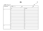
図4は、一実施形態に係るCTLMテーブルの構成図である。 FIG. 4 is a block diagram of a CTLM table according to an embodiment.
CTLMテーブル60は、コンピュートノード2に提供される論理ユニット(Logical Unit)と、ストレージシステム3におけるボリュームとの対応関係を格納する。CTLMテーブル60のエントリは、コンピュートノード#(番号)61と、ターゲット#(番号)62と、LUN64と、Volume#(番号)65とのフィールドを含む。なお、LUN64と、Volume#(番号)65とのフィールドによって、LUN管理テーブル63が構成される。なお、本実施形態においては、各ストレージノード4は、図4に示すCTLMテーブル60における自身に存在するターゲット番号に対応するエントリのみを格納するようにしている。
The CTLM table 60 stores the correspondence between the logical unit provided to the
コンピュートノード#61には、エントリに対応するコンピュートノード2の識別番号(コンピュートノード番号)が格納される。ターゲット#62には、エントリに対応するボリュームにアクセスする際のストレージノード4のターゲット76の識別番号(ターゲット番号)が格納される。LUN64には、エントリに対応する論理ユニットの識別番号(LUN)が格納される。LUNは、論理ユニットについてのコンピュートノード2での一意の番号である。Volume#(番号)65には、エントリに対応するボリュームの番号が格納される。ボリュームの番号は、ストレージシステム3内で一意の番号である。
In the
図5は、一実施形態に係るパス優先度管理テーブルの構成図である。 FIG. 5 is a configuration diagram of a path priority management table according to an embodiment.
パス優先度管理テーブル20は、コンピュートノード2毎に設けられている。パス優先度管理テーブル20は、ボリューム毎の優先するターゲット(優先パスに対応)を管理するテーブルであり、ボリューム毎のエントリを有する。パス優先度管理テーブル20のエントリは、ボリューム番号21と、ストレージノード番号22と、優先ターゲット番号23と、第2優先ターゲット番号24と、第3優先ターゲット番号25と、第4優先ターゲット番号26とのフィールドを含む。
The path priority management table 20 is provided for each
ボリューム番号21には、エントリに対応するボリュームの識別番号が格納される。ストレージノード番号22には、エントリに対応するボリュームを格納しているストレージノード4の識別番号が格納される。優先ターゲット番号23には、エントリに対応するボリュームにアクセスする際に優先して使用することが好ましい1番目のターゲットの番号が格納される。第2優先ターゲット番号24には、エントリに対応するボリュームにアクセスする際に優先して使用することが好ましい2番目のターゲットの番号が格納される。第3優先ターゲット番号25には、エントリに対応するボリュームにアクセスする際に優先して使用することが好ましい3番目のターゲットの番号が格納される。第4優先ターゲット番号26には、エントリに対応するボリュームにアクセスする際に優先して使用することが好ましい4番目のターゲットの番号が格納される。
The
図6は、一実施形態に係るCLMテーブルの構成図である。 FIG. 6 is a block diagram of a CLM table according to an embodiment.
CLMテーブル40は、ストレージノード4においてアクセス可能な各ボリュームについての、コンピュートノード2における論理ユニットと、ストレージシステム3におけるボリュームとの対応関係を格納する。CLMテーブル40のエントリは、コンピュートノード#(番号)41と、LUN43と、Volume#(番号)44とのフィールドを含む。なお、LUN43と、Volume#(番号)44とのフィールドによって、LUN管理テーブル42が構成される。
The CLM table 40 stores the correspondence between the logical unit in the
コンピュートノード#41には、エントリに対応するコンピュートノード2の識別番号(コンピュートノード番号)が格納される。LUN43には、エントリに対応する論理ユニットの識別番号(LUN)が格納される。Volume#(番号)44には、エントリに対応するボリュームの番号が格納される。
The identification number (compute node number) of the
図7は、一実施形態に係るノードペア管理テーブルの構成図である。 FIG. 7 is a configuration diagram of a node pair management table according to an embodiment.
ノードペア管理テーブル30は、ストレージ制御部ペア75を管理するためのテーブルであり、ストレージ制御部ペア75毎のエントリを格納する。ノードペア管理テーブル30のエントリは、ストレージ制御部ペア#(番号)31と、アクティブストレージノード#(番号)32と、スタンバイストレージノード#(番号)33とのフィールドを含む。
The node pair management table 30 is a table for managing the storage
ストレージ制御部ペア番号31には、ストレージ制御部ペア75の識別番号(ストレージ制御部ペア番号)が格納される。アクティブストレージノード番号32には、エントリに対応するストレージ制御部ペア75の内のアクティブ状態のストレージ制御部74を格納するストレージノード4(アクティブストレージノード)の識別番号が格納される。スタンバイストレージノード番号33には、エントリに対応するストレージ制御部ペア75の内のスタンバイ状態のストレージ制御部74を格納するストレージノード4(スタンバイストレージノード)の識別番号が格納される。
The storage control
図8は、一実施形態に係るSCチェーンテーブルの構成図である。 FIG. 8 is a block diagram of the SC chain table according to the embodiment.
SC(ストレージ制御部)チェーンテーブル50は、アクティブのストレージ制御部からストレージ制御部ペア75の関係に基づいて辿れるストレージ制御部74を管理するテーブルであり、ストレージノード4毎のエントリを有する。SCチェーンテーブル50のエントリは、ストレージノード#51と、アクティブストレージ制御部#52と、スタンバイストレージ制御部#53と、第2スタンバイストレージ制御部#54と、第3スタンバイストレージ制御部#55とのフィールドを含む。
The SC (storage control unit) chain table 50 is a table that manages the
ストレージノード#51には、エントリに対応するストレージノード4の番号が格納される。アクティブストレージ制御部#52には、エントリに対応するストレージノード4におけるボリュームのI/O処理を実行するアクティブのストレージ制御部74の番号が格納される。スタンバイストレージ制御部#53には、エントリに対応するアクティブのストレージ制御部74とストレージ制御部ペア75となっているスタンバイのストレージ制御部74の番号が格納される。第2スタンバイストレージ制御部#54には、スタンバイストレージ制御部#53の番号のスタンバイのストレージ制御部74があるストレージノード4におけるアクティブのストレージ制御部74とストレージ制御部ペア75となっているスタンバイのストレージ制御部74の番号が格納される。第3スタンバイストレージ制御部#55には、第2スタンバイストレージ制御部#54の番号のスタンバイのストレージ制御部74があるストレージノード4におけるアクティブのストレージ制御部74とストレージ制御部ペア75となっているスタンバイのストレージ制御部74の番号が格納される。
The
次に、計算機システム1における処理動作について説明する。まず、パス優先度選択処理について説明する。
Next, the processing operation in the
図9は、一実施形態に係るパス優先度選択処理のフローチャートである。 FIG. 9 is a flowchart of the path priority selection process according to the embodiment.
パス優先度選択処理は、例えば、ストレージシステム3を起動する際に、ストレージノード4のコントロールプレーン71により実行される処理である。なお、コントロールプレーン71によるこの処理は、CPU10がパス管理プログラム80を実行することにより実現される。
The path priority selection process is, for example, a process executed by the
まず、CPU10は、ストレージノード4で管理しているLU(ボリュームと対応)の内の未処理の1つのLUを処理対象とし、処理対象のLU(対象LU)のパスとして定義済みのターゲット情報を各ストレージノード4から取得する(ステップS11)。ここで、ターゲット情報としては、ターゲット番号と、LU番号と、対応するパスが排他管理されている場合における排他管理用のキー(例えば、SCSI Reserve key)とが含まれていてもよい。
First, the
次いで、CPU10は、対象LUのパスのターゲットにおける未処理のターゲットのパス(対象パス)を対象として以下の処理(S12~S17)を行う。まず、CPU10は、処理対象のターゲット(対象ターゲット)のターゲット情報として、排他管理用のキーが登録されているか否かを判定し(ステップS12)、登録されている場合(ステップS12:Y)には、排他管理のために必要なパスであることを示しているので、このパスをパス優先度管理テーブル20に登録するために、処理をステップS17に進める。
Next, the
一方、排他管理用のキーが登録されていない場合(ステップS12:N)には、CPU10は、このパスがアクティブのストレージ制御部74へのパスであるか否かを判定する(ステップS13)。
On the other hand, when the exclusive management key is not registered (step S12: N), the
この結果、このパスがアクティブのストレージ制御部74へのパスである場合(ステップS13:Y)には、対象LUに高速にアクセスできるパスであることを示しているので、処理をステップS16に進める。 As a result, when this path is a path to the active storage control unit 74 (step S13: Y), it indicates that the path can access the target LU at high speed, so that the process proceeds to step S16. ..
一方、対象パスがアクティブのストレージ制御部74へのパスでない場合(ステップS13:N)には、CPU10は、対象パスがスタンバイのストレージ制御部74へのパスであるか否かを判定する(ステップS14)。
On the other hand, when the target path is not the path to the active storage control unit 74 (step S13: N), the
この結果、対象パスがスタンバイのストレージ制御部74へのパスである場合(ステップS14:Y)には、アクティブのストレージ制御部74への障害時において、迅速なアクセスが可能なパスであることを示しているので、処理をステップS16に進める。
As a result, when the target path is a path to the standby storage control unit 74 (step S14: Y), it is determined that the path can be quickly accessed in the event of a failure to the active
一方、対象パスがスタンバイのストレージ制御部74へのパスでない場合(ステップS14:N)には、CPU10は、対象パスが第2のスタンバイのストレージ制御部74へのパスであるか否かを判定する(ステップS15)。ここで、第2のスタンバイのストレージ制御部74とは、スタンバイのストレージ制御部74と同一のストレージノード4に存在するアクティブのストレージ制御部74とストレージ制御部ペア75を構成している他のストレージノード4のスタンバイのストレージ制御部74である。
On the other hand, when the target path is not the path to the standby storage control unit 74 (step S14: N), the
この結果、対象パスが第2のスタンバイのストレージ制御部74へのパスである場合(ステップS15:Y)には、アクティブのストレージ制御部74及びスタンバイのストレージ制御部74への障害時において、次に迅速なアクセスが可能なパスであることを示しているので、処理をステップS16に進める。
As a result, when the target path is the path to the
一方、対象パスが第2のスタンバイのストレージ制御部74へのパスでない場合(ステップS15:N)には、CPU10は、処理をステップS18に進める。
On the other hand, when the target path is not the path to the
ステップS16では、CPU10は、パス優先度管理テーブル20が枯渇しているか、すなわち、対応するエントリのすべての優先ターゲットのフィールド23~26にターゲット番号が格納されているか否かを判定する。
In step S16, the
この結果、パス優先度管理テーブル20が枯渇している場合(ステップS16:Y)には、この対象LUについてのパスの候補が所定数揃っていることを意味しているので、CPU10は、処理をステップS19に進める。
As a result, when the path priority management table 20 is exhausted (step S16: Y), it means that a predetermined number of path candidates for the target LU are prepared, so that the
一方、パス優先度管理テーブル20が枯渇していない場合(ステップS16:N)、または、排他管理用のキーが登録されている場合(ステップS12:Y)には、CPU10は、パス優先度管理テーブル20の対応するエントリの優先ターゲットのフィールド(フィールド23~26)の空いているフィールドに、ステップS12~ステップS15でYと判定されたターゲットの番号を設定し(ステップS17)、処理をステップS18に進める。
On the other hand, when the path priority management table 20 is not exhausted (step S16: N) or when the key for exclusive management is registered (step S12: Y), the
ステップS18では、CPU10は、ステップS11で取得したターゲット数分のターゲットに対して処理をしたか否かを判定し、ターゲット数分のターゲットに対して処理をしていない場合(ステップS18:N)には、処理をステップS12に進めて、他のターゲットを対象にステップS12以降の処理を実行する。一方、ターゲット数分のターゲットに対して処理を行った場合(ステップ18:Y)には、CPU10は、処理をステップS19に進める。
In step S18, the
ステップS19では、CPU10は、ストレージノード4で管理しているすべてのLUに対して処理をしたか否かを判定し、すべてのLUに対する処理をしていない場合(ステップS19:N)には、処理をステップS11に進めて、他のLUを処理対象として処理を行う。一方、すべてのLUに対して処理をした場合(ステップS19:Y)には、処理を終了する。
In step S19, the
以上のパス優先度選択処理によると、LU(ボリューム)にアクセスするパスとして、所定の条件に合致する所定数以内のターゲットへのパスを適切に選択して、パス優先度管理テーブル20に設定することができる。 According to the above path priority selection process, as a path to access the LU (volume), a path to a predetermined number of targets that meet a predetermined condition is appropriately selected and set in the path priority management table 20. be able to.
次に、ボリュームパス作成処理について説明する。 Next, the volume path creation process will be described.
図10は、一実施形態に係るボリュームパス作成処理のフローチャートである。 FIG. 10 is a flowchart of the volume path creation process according to the embodiment.
ボリュームパス作成処理は、新たなLUが作成された際に、新たなLUが作成されたストレージノード4において実行される。
The volume path creation process is executed in the
ストレージノード4のCPU10は、CLMテーブル40のLUN管理テーブル42に対して新たなLUと、このLUに対して割り当てられたボリュームとの対応関係を追加する(ステップS21)。次いで、CPU10は、このLUを利用するコンピュートノード2のOS種別情報(パス数特定情報の一例)を取得する(ステップS22)。
The
次いで、CPU10は、OS種別情報に基づいて、コンピュートノード2のOSが特定OS(ここでは、設定可能なLUのパスが所定数(例えば、4つ)以下であるOS)であるか否かを判定する(ステップS23)。この結果、特定OSでない場合(ステップS23:N)には、LUのパスの数を制限しなくてもよいので、ボリュームパス作成処理を終了する。
Next, the
一方、特定OSである場合(ステップS23:Y)には、CPU10は、SCチェーンテーブル50を参照し(ステップS24)、SCチェーンテーブル50から各ストレージノード4のつながりを示すチェーン情報を取得する(ステップS25)。
On the other hand, in the case of a specific OS (step S23: Y), the
次いで、CPU10は、ノードペア管理テーブル30を参照し(ステップS26)、ノードペア管理テーブル30からノードペア情報、すなわち、ストレージ制御部ペア75を構成する他のストレージ制御部74を格納するストレージノード4の情報を取得する(ステップS27)。
Next, the
次いで、CPU10は、LUのパスとする所定数のストレージ制御部74のあるストレージノード4(対象ストレージノード)を特定する(ステップS28)。LUのパスとする所定数のストレージ制御部74は、ステップS13,S14,S15での判定対象に該当するストレージ制御部74であってもよい。
Next, the
次いで、CPU10は、パス優先度管理テーブル20に対象ストレージノードのターゲット情報を登録する(ステップS29)。すなわち、CPU10は、パス優先度管理テーブル20に、作成したLUに対応するボリュームのエントリを作成し、このエントリに対象ストレージノード4のターゲット情報(ターゲット番号)を格納する。
Next, the
次いで、CPU10は、対象ストレージノードに対して、パス更新情報を送信する(ステップS30)。ここで、パス更新情報には、作成したLUのLUNと、対応するボリュームのボリューム番号と、ステップS29で登録したターゲット情報とが含まれる。
Next, the
このボリュームパス作成処理によると、新たに作成したLUのパスの情報を、パスとするターゲットを持つストレージノード4に適切に通知することができ、後述するボリュームパス追加処理及びCTLMテーブル生成処理を経て、ストレージノード4によりコンピュートノード2に対して問い合わせが来た場合に、適切にコンピュートノード2に対してパス優先度管理テーブル20に登録したパスを応答することができるようになる。
According to this volume path creation process, the information of the newly created LU path can be appropriately notified to the
次に、ボリュームパス追加処理について説明する。 Next, the volume path addition process will be described.
図11は、一実施形態に係るボリュームパス追加処理のフローチャートである。 FIG. 11 is a flowchart of the volume path addition process according to the embodiment.
ボリュームパス追加処理は、ボリュームパス作成処理においてパス更新情報が送信される対象ストレージノードで実行される処理である。 The volume path addition process is a process executed on the target storage node to which the path update information is transmitted in the volume path creation process.
まず、対象ストレージノード4のCPU10は、パス更新情報を、ボリュームパス作成処理を実行したストレージ制御部74、すなわち、LUに対するアクティブのストレージ制御部74を有するストレージノード4から受信する(ステップS41)。
First, the
次いで、ストレージノード4のCPU10は、パス更新情報に含まれている、LUNとボリューム番号とを、CLMテーブル40のLUN管理テーブル42に追加する(ステップS42)。
Next, the
次いで、ストレージノード4のCPU10は、パス優先度管理テーブル20に、パス更新情報に基づくターゲット情報を設定する(ステップS43)。
Next, the
このボリュームパス追加処理によると、新たに追加されたLU(ボリューム)に対するパスとなるターゲットの情報を適切にパス優先度管理テーブル20に設定することができる。 According to this volume path addition process, the target information that becomes the path for the newly added LU (volume) can be appropriately set in the path priority management table 20.
図12は、一実施形態に係るCTLMテーブル生成処理のフローチャートである。 FIG. 12 is a flowchart of the CTLM table generation process according to the embodiment.
CTLMテーブル生成処理は、例えば、パス優先度選択処理、ボリュームパス作成処理、又はボリュームパス追加処理によってパス優先度管理テーブル20が作成または更新された後にストレージノード4において実行される処理である。
The CTLM table generation process is a process executed in the
ストレージノード4のCPU10は、コンピュートノード2の情報、例えば、OSの種類の情報を取得する(ステップS51)。なお、コンピュートノード2の情報の取得元としては、コンピュートノード2自体でもよく、コンピュートノード2の情報を収集している別の装置であってもよい。
The
次いで、ストレージノード4のCPU10は、コンピュートノード2のOSが特定OS(設定可能なLUのパスが所定数(例えば、4つ)以下であるOS)であるか否かを判定する(ステップS52)。この結果、コンピュートノード2のOSが特定OSでない場合(ステップS52:N)には、CPU10は、処理を終了する。
Next, the
一方、コンピュートノード2のOSが特定OSである場合(ステップS52:Y)には、CPU10は、CLMテーブル40を取得し(ステップS53)、パス優先度管理テーブル20を取得し(ステップS54)、CLMテーブル40からLUN43に登録されているLUNに対応するボリューム番号を取得し、取得したボリューム番号に対応するパス優先度管理テーブル20のエントリを特定して、そのエントリのターゲット情報(フィールド23~26のターゲット番号)を取得する(ステップS55)。
On the other hand, when the OS of the
次いで、CPU10は、ターゲット情報に含まれているターゲットが、自身のストレージノード4のターゲット76であるか否かを判定し(ステップS56)、自身のストレージノード4のターゲット76でない場合(ステップS56:N)には、処理を終了する。
Next, the
一方、自身のストレージノード4のターゲット76である場合(ステップS56:Y)には、CPU10は、CTLMテーブル60に、コンピュートノードの番号と、ターゲット番号と、LUNと、ボリューム番号とを含むエントリを追加し(ステップS57)、処理を終了する。なお、ステップS53~S57の処理は、CLMテーブル40の各エントリを対象として実行される。
On the other hand, when it is the
以上説明したように、CTLMテーブル生成処理によると、パス優先度管理テーブル20に設定されたターゲットをターゲットとするパスのうち、各ストレージノード4に関係するパスに対応するエントリを含むCTLMテーブル60を作成することができる。すなわち、CTLMテーブル60には、パス優先度管理テーブル20に設定されたパスのみが登録されることとなる。したがって、コンピュートノード2が各ストレージノード4に或るLUNに対するパスを問い合わせると、パス優先度管理テーブル20に登録されたターゲットのストレージノード4からのみ使用可能なパスとしての応答が得られることとなり、コンピュートノード2側では、優先度の高いパスを適切に把握して設定することが可能となる。
As described above, according to the CTLM table generation process, among the paths targeting the targets set in the path priority management table 20, the CTLM table 60 including the entries corresponding to the paths related to each
なお、本発明は、上述の実施形態に限定されるものではなく、本発明の趣旨を逸脱しない範囲で、適宜変形して実施することが可能である。 The present invention is not limited to the above-described embodiment, and can be appropriately modified and implemented without departing from the spirit of the present invention.
例えば、上記実施形態では、設定可能なLUのパスが4つ以下であるOSを例に、優先するパスを決定するようにしていたが、例えば、設定可能なLUのパスの数が4以外のOSにおいても同様に優先するパスを決定するようにしてもよい。また、設定可能なLUのパスの数が異なる複数のOSが混在する場合においては、OSごとに、優先するパスの数が異なるパス優先度管理テーブルを備え、それぞれに対応するCTLMテーブルを作成するようにしてもよい。 For example, in the above embodiment, the priority path is determined by taking an OS in which the number of configurable LU paths is 4 or less as an example, but for example, the number of configurable LU paths is other than 4. Similarly, the OS may determine the priority path. Further, when a plurality of OSs having different numbers of LU paths that can be set are mixed, a path priority management table having a different number of priority paths is provided for each OS, and a CTLM table corresponding to each is created. You may do so.
また、上記実施形態において、CPUが行っていた処理の一部又は全部を、ハードウェア回路で行うようにしてもよい。また、上記実施形態におけるプログラムは、プログラムソースからインストールされてよい。プログラムソースは、プログラム配布サーバ又は記憶メディア(例えば可搬型の記憶メディア)であってもよい。 Further, in the above embodiment, a part or all of the processing performed by the CPU may be performed by the hardware circuit. Further, the program in the above embodiment may be installed from the program source. The program source may be a program distribution server or storage media (eg, portable storage media).
1…計算機システム、2…コンピュートノード、3…ストレージシステム、4…ストレージノード、5…バックエンドネットワーク、6…ネットワーク、10…CPU、11…メモリ、80…パス管理プログラム
1 ... Computer system, 2 ... Compute node, 3 ... Storage system, 4 ... Storage node, 5 ... Backend network, 6 ... Network, 10 ... CPU, 11 ... Memory, 80 ... Path management program
Claims (4)
前記ストレージノードは、プロセッサ部を備え、
前記プロセッサ部は、上位装置から前記記憶デバイスの記憶領域が提供される所定の論理ユニットにアクセス可能なパスの中から、前記上位装置に対して使用可能なパスとして通知する優先パスを選択し、
前記上位装置からの前記所定の論理ユニットへのパスの問い合わせに対して前記優先パスを応答するようにし、
前記プロセッサ部は、
前記上位装置の設定可能なパスの数を特定可能なパス数特定情報を取得し、
前記パス数特定情報により特定される設定可能なパスの数だけ前記優先パスを決定し、
前記ストレージノードは、
前記論理ユニットに対するデータのアクセスを制御するストレージ制御部を備え、
同一の論理ユニットへのアクセスを担当する2つのストレージノードのストレージ制御部のペアが構成され、一方のストレージ制御部は、通常用いられる現用系に設定され、他方のストレージ制御部は、待機系に設定されており、
前記プロセッサ部は、
前記論理ユニットにアクセス可能なパスの中から、前記論理ユニットに対する排他アクセス用のキーが設定されているパス、前記論理ユニットの現用系に設定されているストレージ制御部へのパス、前記論理ユニットの待機系に設定されているストレージ制御部へのパス、および前記論理ユニットの待機系に設定されているストレージ制御部を備えるストレージノードにおける現用系に設定されているストレージ制御部に対応する待機系が設定されているストレージ制御部へのパスを前記優先パスとして選択する
ストレージシステム。 A storage system including a plurality of storage nodes having one or more storage devices.
The storage node includes a processor unit and has a processor unit.
The processor unit selects a priority path to be notified as a usable path to the higher-level device from among the paths accessible from the higher-level device to a predetermined logical unit to which the storage area of the storage device is provided.
The priority path is replied to the inquiry of the path from the higher-level device to the predetermined logical unit.
The processor unit
The number of paths that can specify the number of paths that can be set in the host device is acquired, and the information for specifying the number of paths is acquired.
The priority path is determined by the number of configurable paths specified by the path number identification information.
The storage node is
A storage control unit that controls access to data to the logical unit is provided.
A pair of storage control units of two storage nodes in charge of accessing the same logical unit is configured, one storage control unit is set to the normally used working system, and the other storage control unit is set to the standby system. It has been set and
The processor unit
From the paths that can access the logical unit, the path in which the key for exclusive access to the logical unit is set, the path to the storage control unit set in the active system of the logical unit, and the path of the logical unit. The standby system corresponding to the path to the storage control unit set in the standby system and the storage control unit set in the active system in the storage node having the storage control unit set in the standby system of the logical unit. Select the set path to the storage control unit as the priority path.
Storage system.
請求項1に記載のストレージシステム。 The storage system according to claim 1, wherein the path number specifying information is information on the type of OS executed by the host device.
前記ストレージノードは、
上位装置から前記記憶デバイスの記憶領域が提供される所定の論理ユニットにアクセス可能なパスの中から、前記上位装置に対して使用可能なパスとして通知する優先パスを選択し、
前記上位装置からの前記所定の論理ユニットへのパスの問い合わせに対して前記優先パスを応答するようにし、
前記ストレージノードは、
前記上位装置の設定可能なパスの数を特定可能なパス数特定情報を取得し、
前記パス数特定情報により特定される設定可能なパスの数だけ前記優先パスを決定し、
前記ストレージノードは、
前記論理ユニットに対するデータのアクセスを制御するストレージ制御部を備え、
同一の論理ユニットへのアクセスを担当する2つのストレージノードのストレージ制御部のペアが構成され、一方のストレージ制御部は、通常用いられる現用系に設定され、他方のストレージ制御部は、待機系に設定されており、
前記ストレージノードは、
前記論理ユニットにアクセス可能なパスの中から、前記論理ユニットに対する排他アクセス用のキーが設定されているパス、前記論理ユニットの現用系に設定されているストレージ制御部へのパス、前記論理ユニットの待機系に設定されているストレージ制御部へのパス、および前記論理ユニットの待機系に設定されているストレージ制御部を備えるストレージノードにおける現用系に設定されているストレージ制御部に対応する待機系が設定されているストレージ制御部へのパスを前記優先パスとして選択する
パス管理方法。 It is a path management method by a storage system having a plurality of storage nodes having one or more storage devices.
The storage node is
From the paths accessible from the higher-level device to the predetermined logical unit to which the storage area of the storage device is provided, a priority path to be notified as a usable path to the higher-level device is selected.
The priority path is replied to the inquiry of the path from the higher-level device to the predetermined logical unit.
The storage node is
The number of paths that can specify the number of paths that can be set in the host device is acquired, and the information for specifying the number of paths is acquired.
The priority path is determined by the number of configurable paths specified by the path number identification information.
The storage node is
A storage control unit that controls access to data to the logical unit is provided.
A pair of storage control units of two storage nodes in charge of accessing the same logical unit is configured, one storage control unit is set to the normally used working system, and the other storage control unit is set to the standby system. It has been set and
The storage node is
From the paths that can access the logical unit, the path in which the key for exclusive access to the logical unit is set, the path to the storage control unit set in the active system of the logical unit, and the path of the logical unit. The standby system corresponding to the path to the storage control unit set in the standby system and the storage control unit set in the active system in the storage node having the storage control unit set in the standby system of the logical unit. Select the set path to the storage control unit as the priority path.
Path management method.
前記コンピュータに、
上位装置から前記記憶デバイスの記憶領域が提供される所定の論理ユニットにアクセス可能なパスの中から、前記上位装置に対して使用可能なパスとして通知する優先パスを選択させ、
前記上位装置からの前記所定の論理ユニットへのパスの問い合わせに対して前記優先パスを応答するようにさせ、
前記上位装置の設定可能なパスの数を特定可能なパス数特定情報を取得させ、
前記パス数特定情報により特定される設定可能なパスの数だけ前記優先パスを決定させ、
前記ストレージノードは、
前記論理ユニットに対するデータのアクセスを制御するストレージ制御部を備え、
同一の論理ユニットへのアクセスを担当する2つのストレージノードのストレージ制御部のペアが構成され、一方のストレージ制御部は、通常用いられる現用系に設定され、他方のストレージ制御部は、待機系に設定されており、
前記コンピュータに、
前記論理ユニットにアクセス可能なパスの中から、前記論理ユニットに対する排他アクセス用のキーが設定されているパス、前記論理ユニットの現用系に設定されているストレージ制御部へのパス、前記論理ユニットの待機系に設定されているストレージ制御部へのパス、および前記論理ユニットの待機系に設定されているストレージ制御部を備えるストレージノードにおける現用系に設定されているストレージ制御部に対応する待機系が設定されているストレージ制御部へのパスを前記優先パスとして選択させる
パス管理プログラム。 A path management program to be executed by a computer constituting a storage node in a storage system having a plurality of storage nodes having one or more storage devices.
To the computer
From the paths accessible from the higher-level device to the predetermined logical unit to which the storage area of the storage device is provided, a priority path to be notified to the higher-level device as a usable path is selected.
The priority path is made to respond to the inquiry of the path from the higher-level device to the predetermined logical unit.
The number of paths that can be set in the host device can be specified.
The priority path is determined by the number of configurable paths specified by the path number identification information.
The storage node is
A storage control unit that controls access to data to the logical unit is provided.
A pair of storage control units of two storage nodes in charge of accessing the same logical unit is configured, one storage control unit is set to the normally used working system, and the other storage control unit is set to the standby system. It has been set and
To the computer
From the paths that can access the logical unit, the path in which the key for exclusive access to the logical unit is set, the path to the storage control unit set in the active system of the logical unit, and the path of the logical unit. The standby system corresponding to the path to the storage control unit set in the standby system and the storage control unit set in the active system in the storage node having the storage control unit set in the standby system of the logical unit. Have the set path to the storage control unit selected as the priority path
Path management program.
Priority Applications (3)
| Application Number | Priority Date | Filing Date | Title |
|---|---|---|---|
| JP2019176446A JP7017546B2 (en) | 2019-09-27 | 2019-09-27 | Storage system, path management method, and path management program |
| US16/820,899 US11372584B2 (en) | 2019-09-27 | 2020-03-17 | Storage system, path management method, and recording medium |
| US17/752,156 US20220283745A1 (en) | 2019-09-27 | 2022-05-24 | Storage system, path management method, and recording medium |
Applications Claiming Priority (1)
| Application Number | Priority Date | Filing Date | Title |
|---|---|---|---|
| JP2019176446A JP7017546B2 (en) | 2019-09-27 | 2019-09-27 | Storage system, path management method, and path management program |
Publications (2)
| Publication Number | Publication Date |
|---|---|
| JP2021056567A JP2021056567A (en) | 2021-04-08 |
| JP7017546B2 true JP7017546B2 (en) | 2022-02-08 |
Family
ID=75163247
Family Applications (1)
| Application Number | Title | Priority Date | Filing Date |
|---|---|---|---|
| JP2019176446A Active JP7017546B2 (en) | 2019-09-27 | 2019-09-27 | Storage system, path management method, and path management program |
Country Status (2)
| Country | Link |
|---|---|
| US (2) | US11372584B2 (en) |
| JP (1) | JP7017546B2 (en) |
Families Citing this family (1)
| Publication number | Priority date | Publication date | Assignee | Title |
|---|---|---|---|---|
| US11418594B1 (en) * | 2021-10-20 | 2022-08-16 | Dell Products L.P. | Multi-path layer configured to provide link availability information to storage system for load rebalancing |
Citations (10)
| Publication number | Priority date | Publication date | Assignee | Title |
|---|---|---|---|---|
| JP2005310046A (en) | 2004-04-26 | 2005-11-04 | Hitachi Ltd | Path reserve management device |
| JP2007034438A (en) | 2005-07-22 | 2007-02-08 | Nec Corp | Redundant path controller, method, program, and disk array system |
| JP2012208896A (en) | 2011-03-30 | 2012-10-25 | Nec Corp | Disk array device, connection path control method, and connection path control program |
| JP2012531654A (en) | 2009-10-09 | 2012-12-10 | 株式会社日立製作所 | Storage system and storage system communication path management method |
| JP2014146180A (en) | 2013-01-29 | 2014-08-14 | Nec Corp | Path control device, path control method and path control program |
| JP2015158702A (en) | 2014-02-21 | 2015-09-03 | 富士通株式会社 | Storage system, control device, and control program |
| JP2016157177A (en) | 2015-02-23 | 2016-09-01 | 富士通株式会社 | Information processor, multipath control method and multipath control program |
| JP2018156144A (en) | 2017-03-15 | 2018-10-04 | 日本電気株式会社 | Storage device, system, control method of storage device, and program |
| JP2019101700A (en) | 2017-11-30 | 2019-06-24 | 株式会社日立製作所 | System and method for controlling the same and program |
| JP2019125075A (en) | 2018-01-15 | 2019-07-25 | 富士通株式会社 | Storage device and storage system and program |
Family Cites Families (3)
| Publication number | Priority date | Publication date | Assignee | Title |
|---|---|---|---|---|
| JP4701267B2 (en) * | 2008-06-04 | 2011-06-15 | 株式会社日立製作所 | Storage system and management method thereof |
| WO2014068764A1 (en) * | 2012-11-02 | 2014-05-08 | 株式会社日立製作所 | System redundancy verification method and computer system |
| JP6955159B2 (en) * | 2017-11-21 | 2021-10-27 | 富士通株式会社 | Storage systems, storage controllers and programs |
-
2019
- 2019-09-27 JP JP2019176446A patent/JP7017546B2/en active Active
-
2020
- 2020-03-17 US US16/820,899 patent/US11372584B2/en active Active
-
2022
- 2022-05-24 US US17/752,156 patent/US20220283745A1/en active Pending
Patent Citations (10)
| Publication number | Priority date | Publication date | Assignee | Title |
|---|---|---|---|---|
| JP2005310046A (en) | 2004-04-26 | 2005-11-04 | Hitachi Ltd | Path reserve management device |
| JP2007034438A (en) | 2005-07-22 | 2007-02-08 | Nec Corp | Redundant path controller, method, program, and disk array system |
| JP2012531654A (en) | 2009-10-09 | 2012-12-10 | 株式会社日立製作所 | Storage system and storage system communication path management method |
| JP2012208896A (en) | 2011-03-30 | 2012-10-25 | Nec Corp | Disk array device, connection path control method, and connection path control program |
| JP2014146180A (en) | 2013-01-29 | 2014-08-14 | Nec Corp | Path control device, path control method and path control program |
| JP2015158702A (en) | 2014-02-21 | 2015-09-03 | 富士通株式会社 | Storage system, control device, and control program |
| JP2016157177A (en) | 2015-02-23 | 2016-09-01 | 富士通株式会社 | Information processor, multipath control method and multipath control program |
| JP2018156144A (en) | 2017-03-15 | 2018-10-04 | 日本電気株式会社 | Storage device, system, control method of storage device, and program |
| JP2019101700A (en) | 2017-11-30 | 2019-06-24 | 株式会社日立製作所 | System and method for controlling the same and program |
| JP2019125075A (en) | 2018-01-15 | 2019-07-25 | 富士通株式会社 | Storage device and storage system and program |
Also Published As
| Publication number | Publication date |
|---|---|
| JP2021056567A (en) | 2021-04-08 |
| US20210096771A1 (en) | 2021-04-01 |
| US11372584B2 (en) | 2022-06-28 |
| US20220283745A1 (en) | 2022-09-08 |
Similar Documents
| Publication | Publication Date | Title |
|---|---|---|
| US7281032B2 (en) | File sharing system with data mirroring by storage systems | |
| US7478177B2 (en) | System and method for automatic reassignment of shared storage on blade replacement | |
| CN110998562B (en) | Spacing nodes in a distributed cluster system | |
| US9811465B2 (en) | Computer system and cache control method | |
| US11847098B2 (en) | Metadata control in a load-balanced distributed storage system | |
| JP6068676B2 (en) | Computer system and computer system control method | |
| US20060010289A1 (en) | Volume management system and method | |
| JP2005276017A (en) | Storage system | |
| US7653830B2 (en) | Logical partitioning in redundant systems | |
| US6968382B2 (en) | Activating a volume group without a quorum of disks in the volume group being active | |
| US11693738B2 (en) | Storage system spanning multiple failure domains | |
| US8677014B2 (en) | Fine granularity exchange level load balancing in a multiprocessor storage area network | |
| US20200379686A1 (en) | Flash registry with write leveling | |
| JP7017546B2 (en) | Storage system, path management method, and path management program | |
| US20100057989A1 (en) | Method of moving data in logical volume, storage system, and administrative computer | |
| US20190146713A1 (en) | Flash registry with on-disk hashing | |
| US11755438B2 (en) | Automatic failover of a software-defined storage controller to handle input-output operations to and from an assigned namespace on a non-volatile memory device | |
| WO2019043815A1 (en) | Storage system | |
| US11334261B2 (en) | Scalable raid storage controller device system | |
| JP2021099560A (en) | Storage system | |
| US11740838B2 (en) | Array-based copy utilizing one or more unique data blocks | |
| CN114327250B (en) | Storage system and control method of storage system | |
| JP2022061706A (en) | Computer system and load dispersion method | |
| WO2018061158A1 (en) | Computer system and computer system control method | |
| JP2015141508A (en) | Data storage control device, data storage control method, and data storage control program |
Legal Events
| Date | Code | Title | Description |
|---|---|---|---|
| A621 | Written request for application examination |
Free format text: JAPANESE INTERMEDIATE CODE: A621 Effective date: 20200206 |
|
| A131 | Notification of reasons for refusal |
Free format text: JAPANESE INTERMEDIATE CODE: A131 Effective date: 20210427 |
|
| A521 | Request for written amendment filed |
Free format text: JAPANESE INTERMEDIATE CODE: A523 Effective date: 20210609 |
|
| A131 | Notification of reasons for refusal |
Free format text: JAPANESE INTERMEDIATE CODE: A131 Effective date: 20210817 |
|
| A521 | Request for written amendment filed |
Free format text: JAPANESE INTERMEDIATE CODE: A523 Effective date: 20210927 |
|
| TRDD | Decision of grant or rejection written | ||
| A01 | Written decision to grant a patent or to grant a registration (utility model) |
Free format text: JAPANESE INTERMEDIATE CODE: A01 Effective date: 20220104 |
|
| A61 | First payment of annual fees (during grant procedure) |
Free format text: JAPANESE INTERMEDIATE CODE: A61 Effective date: 20220127 |
|
| R150 | Certificate of patent or registration of utility model |
Ref document number: 7017546 Country of ref document: JP Free format text: JAPANESE INTERMEDIATE CODE: R150 |