JP7016648B2 - Image forming device - Google Patents

Image forming device Download PDF

Info

Publication number
JP7016648B2
JP7016648B2 JP2017173403A JP2017173403A JP7016648B2 JP 7016648 B2 JP7016648 B2 JP 7016648B2 JP 2017173403 A JP2017173403 A JP 2017173403A JP 2017173403 A JP2017173403 A JP 2017173403A JP 7016648 B2 JP7016648 B2 JP 7016648B2
Authority
JP
Japan
Prior art keywords
image carrier
image
toner
image forming
photosensitive drum
Prior art date
Legal status (The legal status is an assumption and is not a legal conclusion. Google has not performed a legal analysis and makes no representation as to the accuracy of the status listed.)
Active
Application number
JP2017173403A
Other languages
Japanese (ja)
Other versions
JP2019049630A (en
JP2019049630A5 (en
Inventor
祐一 畑中
Current Assignee (The listed assignees may be inaccurate. Google has not performed a legal analysis and makes no representation or warranty as to the accuracy of the list.)
Canon Inc
Original Assignee
Canon Inc
Priority date (The priority date is an assumption and is not a legal conclusion. Google has not performed a legal analysis and makes no representation as to the accuracy of the date listed.)
Filing date
Publication date
Application filed by Canon Inc filed Critical Canon Inc
Priority to JP2017173403A priority Critical patent/JP7016648B2/en
Publication of JP2019049630A publication Critical patent/JP2019049630A/en
Publication of JP2019049630A5 publication Critical patent/JP2019049630A5/ja
Application granted granted Critical
Publication of JP7016648B2 publication Critical patent/JP7016648B2/en
Active legal-status Critical Current
Anticipated expiration legal-status Critical

Links

Images

Description

本発明は、電子写真方式や静電記録方式を用いた複写機、プリンタ、ファクシミリ装置などの画像形成装置に関するものである。 The present invention relates to an image forming apparatus such as a copier, a printer, and a facsimile machine using an electrophotographic method or an electrostatic recording method.

従来、電子写真方式などを用いた画像形成装置では、感光体などの像担持体に形成されたトナー像が直接又は中間転写体を介して記録用紙などの記録材に転写されて画像が形成される。また、カラー画像の形成が可能な画像形成装置として、それぞれが像担持体を備えた複数の画像形成部を有するタンデム型の画像形成装置がある。例えば、電子写真方式を用い中間転写方式を採用したタンデム型の画像形成装置では、複数の画像形成部がそれぞれ備えた像担持体としての感光体上に形成されたトナー像が、被転写体としての中間転写体上に重ね合わされるようにして順次一次転写される。そして、中間転写体上のトナー像が、記録用紙などの記録材に二次転写される。 Conventionally, in an image forming apparatus using an electrophotographic method or the like, a toner image formed on an image carrier such as a photoconductor is transferred directly or via an intermediate transfer body to a recording material such as recording paper to form an image. Toner. Further, as an image forming apparatus capable of forming a color image, there is a tandem type image forming apparatus having a plurality of image forming portions, each having an image carrier. For example, in a tandem image forming apparatus that uses an electrophotographic method and an intermediate transfer method, a toner image formed on a photoconductor as an image carrier provided by a plurality of image forming portions is used as a transferred body. The primary transfer is sequentially performed so as to be superimposed on the intermediate transfer body of. Then, the toner image on the intermediate transfer body is secondarily transferred to a recording material such as recording paper.

このような画像形成装置において、像担持体から被転写体にトナー像が転写された後に像担持体上に残留したトナー(転写残トナー)は、クリーニング手段によって像担持体上から除去される。クリーニング手段としては、像担持体に接触するクリーニング部材が広く用いられており、またクリーニング部材としてはゴムなどの弾性材料からなるクリーニングブレードが広く用いられている。クリーニングブレードは、その自由端部が像担持体の表面の移動方向の上流側を向くカウンター方向となるように、その自由端部のエッジ部が像担持体に当接させられるのが一般的である。 In such an image forming apparatus, the toner remaining on the image carrier (transfer residual toner) after the toner image is transferred from the image carrier to the transferred object is removed from the image carrier by the cleaning means. As a cleaning means, a cleaning member that comes into contact with the image carrier is widely used, and as a cleaning member, a cleaning blade made of an elastic material such as rubber is widely used. Generally, the edge of the free end of the cleaning blade is brought into contact with the image carrier so that the free end is in the counter direction facing upstream in the moving direction of the surface of the image carrier. be.

このクリーニング方式は、構成が簡単で低コストであり、トナー除去性能も高いといった利点がある。しかし、例えば電子写真方式の画像形成装置で用いられる感光体など、像担持体の表面の摩擦係数は、一般に、画像形成を繰り返すことで上昇していく傾向がある。そのため、画像形成を繰り返すと、像担持体とクリーニングブレードとの間の摩擦力が大きくなっていく。そして、例えば想定を超えて画像比率の低い画像形成が続くなどの要因で、像担持体とクリーニングブレードとの間の摩擦力が一定以上に大きくなった場合には、出力画像や装置の稼働に対して様々な影響が発生しやすくなる。 This cleaning method has advantages such as simple configuration, low cost, and high toner removal performance. However, the coefficient of friction on the surface of an image carrier, such as a photoconductor used in an electrophotographic image forming apparatus, generally tends to increase by repeating image forming. Therefore, when the image formation is repeated, the frictional force between the image carrier and the cleaning blade increases. Then, when the frictional force between the image carrier and the cleaning blade becomes larger than a certain level due to factors such as continued image formation with a lower image ratio than expected, the output image or the device is put into operation. On the other hand, various influences are likely to occur.

例えば、クリーニングブレードに対する負荷が増大し、像担持体とクリーニングブレードとの間の摩擦力が大きくなって、像担持体に対するクリーニングブレードの当接状態が不安定になることで、次のような問題が発生する場合がある。つまり、異音の発生、トナーのすり抜け又は色ずれなどの原因となるクリーニングブレードビビリ(異常振動)が発生したり、クリーニングブレードが像担持体の表面の移動方向に捲れて像担持体が駆動できなくなったりする場合がある。このように、像担持体に対するクリーニングブレードの当接状態に起因して、異常画像や、ダウンタイム(メンテナンスなどのために画像を出力できない期間)が発生してしまう場合がある。 For example, the load on the cleaning blade increases, the frictional force between the image carrier and the cleaning blade increases, and the contact state of the cleaning blade with the image carrier becomes unstable, which causes the following problems. May occur. That is, the cleaning blade chattering (abnormal vibration) that causes abnormal noise, toner slippage, or color shift can occur, or the cleaning blade can be rolled up in the moving direction of the surface of the image carrier to drive the image carrier. It may disappear. As described above, an abnormal image or downtime (a period during which the image cannot be output due to maintenance or the like) may occur due to the contact state of the cleaning blade with the image carrier.

ここで、特許文献1では、エンコーダを用いて中間転写体の駆動モータの回転速度変動を検知し、駆動モータの回転異常を検知した場合には、制御部が制御可能な値までゲインを下げる方法が開示されている。 Here, in Patent Document 1, a method of detecting a fluctuation in the rotation speed of the drive motor of the intermediate transfer body by using an encoder, and reducing the gain to a value that can be controlled by the control unit when a rotation abnormality of the drive motor is detected. Is disclosed.

特開2010-74887号公報Japanese Unexamined Patent Publication No. 2010-74887

しかしながら、特許文献1の方法は、像担持体とクリーニングブレードとの間の摩擦力が大きくなった場合の上述のような問題を抑制するものではない。 However, the method of Patent Document 1 does not suppress the above-mentioned problem when the frictional force between the image carrier and the cleaning blade becomes large.

また、画像形成装置は、構成の簡易化や低コスト化のために、複数の画像形成部の像担持体を共通の駆動源により駆動する構成とされることがある。このように複数の画像形成部の像担持体を駆動する駆動源を共通化した構成の場合、特許文献1に記載されるように駆動モータの回転速度を検知する方法では、どの画像形成部の像担持体で問題が発生しているのかを特定することが困難である。そのため、全ての画像形成部において同等に問題に対処しなければならない。また、その場合でも、共通の駆動モータの回転速度を検知したのでは、複数の画像形成部に対して平均化された検知信号しか得られないので、感度が鈍くなるために、精度よく問題に対処することは難しい。 Further, the image forming apparatus may be configured to drive the image carriers of a plurality of image forming portions by a common drive source in order to simplify the configuration and reduce the cost. In the case of a configuration in which the drive sources for driving the image carriers of the plurality of image forming portions are shared in this way, in the method of detecting the rotation speed of the drive motor as described in Patent Document 1, which image forming portion is used. It is difficult to identify if the problem is occurring on the image carrier. Therefore, the problem must be dealt with equally in all image forming units. Even in that case, if the rotation speed of a common drive motor is detected, only the detection signal averaged for a plurality of image forming portions can be obtained, so that the sensitivity becomes dull, which causes a problem with high accuracy. It's difficult to deal with.

したがって、本発明の目的は、像担持体とクリーニング部材との間の摩擦力を低減する処理を精度良く必要時に実行することのできる画像形成装置を提供することである。 Therefore, an object of the present invention is to provide an image forming apparatus capable of accurately performing a process of reducing a frictional force between an image carrier and a cleaning member when necessary.

また、本発明の他の目的は、複数の像担持体を共通の駆動源により駆動する構成であっても、各像担持体とクリーニング部材との間の摩擦力を低減する処理を精度良く必要時に実行することのできる画像形成装置を提供することである。 Further, another object of the present invention is a configuration in which a plurality of image carriers are driven by a common drive source, but a process for reducing the frictional force between each image carrier and the cleaning member is required with high accuracy. It is to provide an image forming apparatus that can be executed from time to time.

上記目的は本発明に係る画像形成装置にて達成される。要約すれば、本発明は、トナー像を担持する回転可能な第1像担持体トナー像を担持する回転可能な第2像担持体と、前記第1像担持体に接触し前記第1像担持体からトナーを除去する第1クリーニング部材前記第2像担持体に接触し前記第2像担持体からトナーを除去する第2クリーニング部材と、前記第1像担持体にトナーを供給して前記第1像担持体にトナー像を形成する第1現像手段前記第2像担持体にトナーを供給して前記第2像担持体にトナー像を形成する第2現像手段と、前記第1像担持体と前記第2像担持体を駆動する共通の駆動源と、前記第1像担持体回転速度を検知する第1エンコーダと、前記第2像担持体の回転速度を検知する第2エンコーダと、前記第1現像手段から前記第1像担持体にトナーが供給されない非画像形成期間に検知される前記第1エンコーダの検知結果に基づいて、前記第1現像手段により前記第1像担持体にトナーを供給して前記第1像担持体と前記第1クリーニング部材との接触部にトナーを供給する第1供給動作を制御し、前記第2現像手段から前記第2像担持体にトナーが供給されない非画像形成期間に検知される前記第2エンコーダの検知結果に基づいて、前記第2現像手段により前記第2像担持体にトナーを供給して前記第2像担持体と前記第2クリーニング部材との接触部にトナーを供給する第2供給動作を制御する制御手段と、を有することを特徴とする画像形成装置である。 The above object is achieved by the image forming apparatus according to the present invention. In summary, the present invention comprises a rotatable first image carrier carrying a toner image, a rotatable second image carrier carrying a toner image, and the first image carrier in contact with the first image carrier. To supply toner to the first cleaning member that removes toner from the image carrier, the second cleaning member that contacts the second image carrier and removes toner from the second image carrier, and the first image carrier. A first developing means for forming a toner image on the first image carrier, and a second developing means for supplying toner to the second image carrier to form a toner image on the second image carrier. A common drive source for driving the first image carrier and the second image carrier, a first encoder for detecting the rotation speed of the first image carrier, and a rotation speed of the second image carrier are detected. Based on the detection results of the second encoder and the first encoder detected during the non-image formation period in which toner is not supplied from the first developing means to the first image carrier, the first developing means said the first. The first supply operation of supplying toner to the one image carrier and supplying the toner to the contact portion between the first image carrier and the first cleaning member is controlled, and the second image carrier is supported by the second developing means. Based on the detection result of the second encoder detected during the non-image forming period in which the toner is not supplied to the body, the toner is supplied to the second image carrier by the second developing means to support the second image carrier. The image forming apparatus is characterized by having a control means for controlling a second supply operation of supplying toner to a contact portion with the second cleaning member .

本発明によれば、像担持体とクリーニング部材との間の摩擦力を低減する処理を精度良く必要時に実行することができる。また、本発明によれば、複数の像担持体を共通の駆動源により駆動する構成であっても、各像担持体とクリーニング部材との間の摩擦力を低減する処理を精度良く必要時に実行することができる。 According to the present invention, the process of reducing the frictional force between the image carrier and the cleaning member can be accurately executed when necessary. Further, according to the present invention, even in a configuration in which a plurality of image carriers are driven by a common drive source, processing for reducing the frictional force between each image carrier and the cleaning member is accurately executed when necessary. can do.

画像形成装置の概略断面図である。It is a schematic cross-sectional view of an image forming apparatus. 画像形成部の概略断面図である。It is a schematic cross-sectional view of an image forming part. 実施例1における駆動構成及び制御態様を示すブロック図である。It is a block diagram which shows the drive composition and the control mode in Example 1. FIG. 実施例1における駆動構成を示す模式図である。It is a schematic diagram which shows the drive composition in Example 1. FIG. エンコーダの検知信号を示すグラフ図である。It is a graph which shows the detection signal of an encoder. エンコーダの検知信号をFFT処理した結果を示すグラフ図である。It is a graph which shows the result of FFT processing of the detection signal of an encoder. 供給動作において形成されるトナー帯を示す模式図である。It is a schematic diagram which shows the toner band formed in a supply operation. 実施例1における制御のフローチャート図である。It is a flowchart of the control in Example 1. FIG. 実施例2における駆動構成及び制御態様を示すブロック図である。It is a block diagram which shows the drive composition and the control mode in Example 2. FIG. 実施例2における駆動構成を示す模式図である。It is a schematic diagram which shows the drive composition in Example 2. FIG. 実施例3における制御のフローチャート図である。It is a flowchart of the control in Example 3. FIG.

以下、本発明に係る画像形成装置を図面に則して更に詳しく説明する。 Hereinafter, the image forming apparatus according to the present invention will be described in more detail with reference to the drawings.

[実施例1]
1.画像形成装置の全体的な構成及び動作
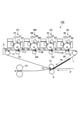
図1は、本実施例の画像形成装置100の概略断面図である。本実施例の画像形成装置100は、電子写真方式を用いてフルカラー画像を形成することのできる、中間転写方式を採用したタンデム型のレーザビームプリンタである。
[Example 1]
1. 1. Overall Configuration and Operation of the Image Forming Device FIG. 1 is a schematic cross-sectional view of the image forming apparatus 100 of the present embodiment. The image forming apparatus 100 of this embodiment is a tandem type laser beam printer that employs an intermediate transfer method and can form a full-color image by using an electrophotographic method.

画像形成装置100は、複数の画像形成部(ステーション)として、それぞれイエロー、マゼンタ、シアン、ブラックの各色の画像を形成する第1、第2、第3、第4の画像形成部SY、SM、SC、SKを有する。各画像形成部SY、SM、SC、SKにおける同一又は対応する機能あるいは構成を有する要素については、いずれかの色用の要素であることを表す符号の末尾のY、M、C、Kを省略して総括的に説明することがある。また、第1、第2、第3、第4の画像形成部SY、SM、SC、SKのそれぞれの要素を、語頭に「第1の」、「第2の」、「第3の」、「第4の」を付して区別することがある。図2は、画像形成部Sの模式的な断面図である。本実施例では、画像形成部Sは、後述する感光ドラム1、帯電ローラ2、露光装置3、現像装置4、一次転写ローラ5、ドラムクリーニング装置6などを有して構成される。 The image forming apparatus 100 has the first, second, third, and fourth image forming units SY, SM, which form images of each color of yellow, magenta, cyan, and black as a plurality of image forming units (stations), respectively. Has SC and SK. For elements having the same or corresponding functions or configurations in each image forming unit SY, SM, SC, SK, Y, M, C, K at the end of the code indicating that the element is for any color is omitted. And there is a general explanation. In addition, each element of the first, second, third, and fourth image forming units SY, SM, SC, and SK is added to the beginning of the word as "first", "second", "third", and so on. It may be distinguished by adding "fourth". FIG. 2 is a schematic cross-sectional view of the image forming unit S. In this embodiment, the image forming unit S includes a photosensitive drum 1, a charging roller 2, an exposure device 3, a developing device 4, a primary transfer roller 5, a drum cleaning device 6, and the like, which will be described later.

画像形成装置100は、回転可能な像担持体としての、ドラム型(円筒形)の感光体(電子写真感光体)である感光ドラム1を有する。本実施例では、感光ドラム1は、外径30mmのアルミニウム製のシリンダの外周面に、感光層としてOPC(有機光半導体)が塗布されて構成されており、硬化性の樹脂が電荷輸送層用の樹脂として使用されている。感光ドラム1は、後述する駆動モータによって、図中矢印R1方向(反時計回り)に所定の周速度(プロセススピード)で回転駆動される。 The image forming apparatus 100 has a photosensitive drum 1 which is a drum-shaped (cylindrical) photosensitive member (electrophotographic photosensitive member) as a rotatable image carrier. In this embodiment, the photosensitive drum 1 is configured by coating OPC (organic optical semiconductor) as a photosensitive layer on the outer peripheral surface of an aluminum cylinder having an outer diameter of 30 mm, and a curable resin is used for the charge transport layer. It is used as a resin for. The photosensitive drum 1 is rotationally driven at a predetermined peripheral speed (process speed) in the direction of arrow R1 (counterclockwise) in the figure by a drive motor described later.

回転する感光ドラム1の表面は、帯電手段としてのローラ型の帯電部材(接触帯電部材)である帯電ローラ2によって、所定の極性(本実施例では負極性)の所定の電位に一様に帯電させられる。本実施例では、帯電ローラ2は、導電性支持体上に、弾性層が設けられて構成されており、弾性層にはカーボンブラックなどの導電剤が適宜添加されて抵抗値が1010Ω未満に調整されて導電性を持たされている。また、本実施例では、帯電ローラ2は、外径が14mmであり、感光ドラム1の表面に所定の圧力で押圧されて接触させられており、感光ドラム1の回転に伴って従動して回転する。帯電工程時に、帯電ローラ2には、帯電電源(高圧電源回路)E1によって、直流電圧(DC電圧)と交流電圧(AC電圧)とが重畳された振動電圧である帯電電圧(帯電バイアス)が印加される。 The surface of the rotating photosensitive drum 1 is uniformly charged to a predetermined potential of a predetermined polarity (negative electrode property in this embodiment) by a charging roller 2 which is a roller-type charging member (contact charging member) as a charging means. Be made to. In this embodiment, the charging roller 2 is configured by providing an elastic layer on a conductive support, and a conductive agent such as carbon black is appropriately added to the elastic layer to have a resistance value of less than 10 10 Ω. It is adjusted to have conductivity. Further, in this embodiment, the charging roller 2 has an outer diameter of 14 mm, is pressed against the surface of the photosensitive drum 1 with a predetermined pressure, and is brought into contact with the surface of the photosensitive drum 1, and is driven to rotate as the photosensitive drum 1 rotates. do. During the charging process, a charging voltage (charging bias), which is a vibration voltage obtained by superimposing a DC voltage (DC voltage) and an AC voltage (AC voltage), is applied to the charging roller 2 by a charging power supply (high voltage power supply circuit) E1. Will be done.

帯電処理された感光ドラム1の表面は、露光手段としての露光装置3によって画像情報に応じて走査露光され、感光ドラム1上に静電像(静電潜像)が形成される。本実施例では、露光装置3は、波長780nmのレーザー光を画像情報に応じて感光ドラム1上に照射して感光ドラム1上に静電像を形成するレーザービームスキャナである。 The surface of the charged photosensitive drum 1 is scanned and exposed by an exposure apparatus 3 as an exposure means according to image information, and an electrostatic image (electrostatic latent image) is formed on the photosensitive drum 1. In this embodiment, the exposure apparatus 3 is a laser beam scanner that irradiates a photosensitive drum 1 with a laser beam having a wavelength of 780 nm according to image information to form an electrostatic image on the photosensitive drum 1.

感光ドラム1上に形成された静電像は、現像手段としての現像装置4によって現像剤としてのトナーが供給されて現像(可視化)され、感光ドラム1上にトナー像が形成される。本実施例では、現像装置4は、現像剤としてトナー(非磁性トナー粒子)とキャリア(磁性キャリア粒子)とを含む二成分現像剤を用いる二成分接触現像装置である。現像装置4は、現像剤担持体(現像部材)としての非磁性材料で形成された中空円筒状の現像スリーブ41と、現像剤を収容する現像容器42と、を有する。現像スリーブ41は、感光ドラム1と対向して現像容器42に回転可能に支持されている。現像スリーブ41は、図中矢印R3方向に回転駆動される。現像スリーブ41の内部(中空部)には、磁界発生手段としてのマグネットローラ43が、現像容器42に対して固定して配置されている。また、現像容器42には、現像スリーブ41と対向して、現像剤規制部材としての現像ブレード44が設けられている。 The electrostatic image formed on the photosensitive drum 1 is developed (visualized) by supplying toner as a developer by the developing apparatus 4 as a developing means, and a toner image is formed on the photosensitive drum 1. In this embodiment, the developing device 4 is a two-component contact developing device that uses a two-component developing agent containing a toner (non-magnetic toner particles) and a carrier (magnetic carrier particles) as a developing agent. The developing apparatus 4 has a hollow cylindrical developing sleeve 41 made of a non-magnetic material as a developing agent carrier (developing member), and a developing container 42 for accommodating the developing agent. The developing sleeve 41 is rotatably supported by the developing container 42 facing the photosensitive drum 1. The developing sleeve 41 is rotationally driven in the direction of arrow R3 in the drawing. Inside the developing sleeve 41 (hollow portion), a magnet roller 43 as a magnetic field generating means is fixedly arranged with respect to the developing container 42. Further, the developing container 42 is provided with a developing blade 44 as a developing agent regulating member facing the developing sleeve 41.

現像スリーブ41は、マグネットローラ43の発生する磁界の作用によりトナーとキャリアとを含む二成分現像剤を担持して、現像スリーブ41と感光ドラム1との対向部である現像部Dへと搬送する。現像スリーブ41上の現像剤は、現像部Dにおいてマグネットローラ43の発生する磁界の作用により穂立ちして磁気ブラシを形成する。本実施例では、現像スリーブ41上の現像剤による磁気ブラシは、現像部Dにおいて感光ドラム1の表面に接触する。また、現像工程時に、現像スリーブ41には、現像電源E2によって、直流電圧(DC電圧)と交流電圧(AC電圧)とが重畳された振動電圧である現像電圧(現像バイアス)が印加される。本実施例では、一様に帯電させられた後に露光されることで電位の絶対値が低下した感光ドラム1上の露光部に、感光ドラム1の帯電極性と同極性(本実施例では負極性)に帯電したトナーが付着する(反転現像)。本実施例では、現像時のトナーの帯電極性であるトナーの正規の帯電極性は負極性である。なお、トナーには、シリカなどの外添剤が外添されている。また、本実施例では、現像時のトナーの平均帯電量(単位重量当りの電荷量)は-1.0×10⁻²C/kg~-6.0×10-2C/kgである。 The developing sleeve 41 carries a two-component developer containing toner and a carrier by the action of the magnetic field generated by the magnet roller 43, and conveys the developing sleeve 41 to the developing unit D which is a facing portion between the developing sleeve 41 and the photosensitive drum 1. .. The developer on the developing sleeve 41 stands up in the developing unit D due to the action of the magnetic field generated by the magnet roller 43 to form a magnetic brush. In this embodiment, the magnetic brush with the developer on the developing sleeve 41 comes into contact with the surface of the photosensitive drum 1 in the developing unit D. Further, during the development process, a development voltage (development bias), which is a vibration voltage in which a DC voltage (DC voltage) and an AC voltage (AC voltage) are superimposed, is applied to the development sleeve 41 by the development power supply E2. In this embodiment, the exposed portion on the photosensitive drum 1 whose absolute potential value is lowered by being exposed after being uniformly charged has the same polarity as the charging polarity of the photosensitive drum 1 (negative electrode property in this embodiment). ) Is charged with toner (reversal development). In this embodiment, the normal charging polarity of the toner, which is the charging polarity of the toner at the time of development, is the negative electrode property. An external additive such as silica is externally added to the toner. Further, in this embodiment, the average charge amount (charge amount per unit weight) of the toner during development is −1.0 × 10 −2 C / kg to −6.0 × 10 −2 C / kg.

全ての感光ドラム1に対向するように、中間転写体としての無端状のベルトで構成された中間転写ベルト7が配置されている。中間転写ベルト7は、複数の支持部材(張架ローラ)としての駆動ローラ71、テンションローラ72及び二次転写対向ローラ73に掛け渡されて、所定の張力で張架されている。中間転写ベルト7は、図示しないベルト駆動モータによって駆動ローラ71が回転駆動されることで、図中矢印R2方向(時計回り)に回転(循環移動)する。本実施例では、中間転写ベルト7は、感光ドラム1の表面と中間転写ベルト7の表面との速度差が1~5%の範囲内となるように回転駆動される。本実施例では、中間転写ベルト7は、ポリイミド樹脂を用いて厚さ100μmに成型された無端ベルト状の基体を有して構成されている。なお、中間転写ベルト7は、厚さが50μm未満では、摩耗により十分な耐久性が得られないことがあり、厚さが500μmを超えると、中間転写ベルト7が支持軸で適当に曲がりにくくなり、走行が安定しなくなることがある。また、中間転写ベルト1の基体には、例えばカーボンブラックなどの電気抵抗値を調節するための導電剤が添加されている。本実施例では、中間転写ベルト7は、体積抵抗値が1.0×1010[Ω・cm]、表面抵抗値が6.0×1011[Ω/□]に調整されている。なお、本実施例では単層構造の中間転写ベルトを用いたが、弾性層を有する複層構造の中間転写ベルトを用いてもよい。 An intermediate transfer belt 7 composed of an endless belt as an intermediate transfer body is arranged so as to face all the photosensitive drums 1. The intermediate transfer belt 7 is stretched over a drive roller 71, a tension roller 72, and a secondary transfer facing roller 73 as a plurality of support members (tension rollers), and is tensioned with a predetermined tension. The intermediate transfer belt 7 is rotated (circulated) in the direction of arrow R2 (clockwise) in the figure by rotationally driving the drive roller 71 by a belt drive motor (not shown). In this embodiment, the intermediate transfer belt 7 is rotationally driven so that the speed difference between the surface of the photosensitive drum 1 and the surface of the intermediate transfer belt 7 is within the range of 1 to 5%. In this embodiment, the intermediate transfer belt 7 is configured to have an endless belt-shaped substrate molded to a thickness of 100 μm using a polyimide resin. If the thickness of the intermediate transfer belt 7 is less than 50 μm, sufficient durability may not be obtained due to wear, and if the thickness exceeds 500 μm, the intermediate transfer belt 7 becomes difficult to bend appropriately on the support shaft. , Running may not be stable. Further, a conductive agent for adjusting the electric resistance value such as carbon black is added to the substrate of the intermediate transfer belt 1. In this embodiment, the intermediate transfer belt 7 has a volume resistance value of 1.0 × 10 10 [Ω · cm] and a surface resistance value of 6.0 × 10 11 [Ω / □]. In this embodiment, a single-layer structure intermediate transfer belt is used, but a multi-layer structure intermediate transfer belt having an elastic layer may be used.

中間転写ベルト7の内周面側には、各感光ドラム1に対応して、一次転写手段としてのローラ型の一次転写部材である一次転写ローラ5が配置されている。一次転写ローラ5は、中間転写ベルト7を介して感光ドラム1に向けて押圧され、感光ドラム1と中間転写ベルト7とが接触する一次転写部(一次転写ニップ)T1を形成する。本実施例では、一次転写ローラ5は、外径が18mmであり、中間転写ベルト7の内周面に接触させられて、中間転写ベルト7の回転に伴って従動して回転する。なお、一次転写ローラ5と感光ドラム1とは、図示しない接離手段としての接離機構によって、適宜当接状態又は離間状態に切り替えることが可能である。一次転写ローラ5が感光ドラム1から離間されると、中間転写ベルト7が感光ドラム1から離間される。 On the inner peripheral surface side of the intermediate transfer belt 7, a primary transfer roller 5 which is a roller type primary transfer member as a primary transfer means is arranged corresponding to each photosensitive drum 1. The primary transfer roller 5 is pressed toward the photosensitive drum 1 via the intermediate transfer belt 7 to form a primary transfer portion (primary transfer nip) T1 in which the photosensitive drum 1 and the intermediate transfer belt 7 come into contact with each other. In this embodiment, the primary transfer roller 5 has an outer diameter of 18 mm, is brought into contact with the inner peripheral surface of the intermediate transfer belt 7, and is driven to rotate as the intermediate transfer belt 7 rotates. The primary transfer roller 5 and the photosensitive drum 1 can be appropriately switched to a contact state or a separation state by a contact / separation mechanism as a contact / separation means (not shown). When the primary transfer roller 5 is separated from the photosensitive drum 1, the intermediate transfer belt 7 is separated from the photosensitive drum 1.

上述のように感光ドラム1上に形成されたトナー像は、一次転写部T1において、一次転写ローラ5の作用によって、回転している被転写体としての中間転写ベルト7上に転写(一次転写)される。一次転写工程時に、一次転写ローラ5には、一次転写電源(高圧電源回路)E3によって、トナーの正規の帯電極性とは逆極性(本実施例では正極性)の直流電圧である一次転写電圧(一次転写バイアス)が印加される。例えば、フルカラー画像の形成時には、各感光ドラム1Y、1M、1C、1K上に形成されたイエロー、マゼンタ、シアン、ブラックの各色のトナー像が、中間転写ベルト7上に重ね合わされるようにして順次一次転写される。 The toner image formed on the photosensitive drum 1 as described above is transferred (primary transfer) on the intermediate transfer belt 7 as a rotating object to be transferred by the action of the primary transfer roller 5 in the primary transfer unit T1. Will be done. During the primary transfer step, the primary transfer roller 5 is subjected to a primary transfer voltage (high voltage power supply circuit) E3, which is a DC voltage having a polarity opposite to the normal charging polarity of the toner (positive electrode property in this embodiment). Primary transfer bias) is applied. For example, when forming a full-color image, the yellow, magenta, cyan, and black toner images formed on the photosensitive drums 1Y, 1M, 1C, and 1K are sequentially superimposed on the intermediate transfer belt 7. Primary transcription.

中間転写ベルト7の外周面側において、二次転写対向ローラ73と対向する位置には、二次転写手段としてのローラ型の二次転写部材である二次転写ローラ8が配置されている。二次転写ローラ8は、中間転写ベルト7を介して二次転写対向ローラ73に向けて押圧され、中間転写ベルト7と二次転写ローラ8とが接触する二次転写部(二次転写ニップ)T2を形成する。本実施例では、二次転写ローラ8は、外径が24mmであり、中間転写ベルト7の外周面に接触させられて、中間転写ベルト7の回転に伴って従動して回転する。上述のように中間転写ベルト7上に形成されたトナー像は、二次転写部T2において、二次転写ローラ8の作用によって、中間転写ベルト7と二次転写ローラ8とに挟持されて搬送される記録用紙などの記録材P上に転写(二次転写)される。二次転写工程時に、二次転写ローラ8には、図示しない二次転写電源(高圧電源回路)によって、トナーの正規の帯電極性とは逆極性(本実施例では正極性)の直流電圧である二次転写電圧(二次転写バイアス)が印加される。 On the outer peripheral surface side of the intermediate transfer belt 7, a secondary transfer roller 8 which is a roller type secondary transfer member as a secondary transfer means is arranged at a position facing the secondary transfer facing roller 73. The secondary transfer roller 8 is pressed toward the secondary transfer facing roller 73 via the intermediate transfer belt 7, and the secondary transfer portion (secondary transfer nip) in which the intermediate transfer belt 7 and the secondary transfer roller 8 come into contact with each other. Form T2. In this embodiment, the secondary transfer roller 8 has an outer diameter of 24 mm, is brought into contact with the outer peripheral surface of the intermediate transfer belt 7, and is driven to rotate as the intermediate transfer belt 7 rotates. The toner image formed on the intermediate transfer belt 7 as described above is sandwiched and conveyed between the intermediate transfer belt 7 and the secondary transfer roller 8 by the action of the secondary transfer roller 8 in the secondary transfer unit T2. It is transferred (secondary transfer) onto a recording material P such as a recording paper. During the secondary transfer step, the secondary transfer roller 8 has a DC voltage (positive electrode property in this embodiment) opposite to the normal charging polarity of the toner due to a secondary transfer power supply (high voltage power supply circuit) (not shown). A secondary transfer voltage (secondary transfer bias) is applied.

記録材(シート、転写材)Pは、図示しない給紙ローラや搬送ローラなどを備えた給送装置によって、中間転写ベルト7上のトナー像とタイミングが合わされて二次転写部T2に供給される。また、トナー像が転写された記録材Pは、定着手段としての定着装置10によって加熱及び加圧されることでトナー像が定着(溶融固着)された後に、画像形成物(プリント、コピー)として画像形成装置100の装置本体の外部に排出(出力)される。 The recording material (sheet, transfer material) P is supplied to the secondary transfer unit T2 at the same timing as the toner image on the intermediate transfer belt 7 by a feeding device equipped with a paper feed roller, a transfer roller, or the like (not shown). .. Further, the recording material P to which the toner image is transferred is heated and pressurized by the fixing device 10 as a fixing means to fix (melt and fix) the toner image, and then as an image forming object (print, copy). It is discharged (output) to the outside of the main body of the image forming apparatus 100.

一方、一次転写時に中間転写ベルト7に転写されずに感光ドラム1の表面に残留したトナー(一次転写残トナー)は、感光体クリーニング手段としてのドラムクリーニング装置6によって感光ドラム1の表面から除去されて回収される。ドラムクリーニング装置6は、感光ドラム1の表面に当接するクリーニング部材としてのクリーニングブレード61と、クリーニング容器62と、を有する。本実施例では、クリーニングブレード61は、ポリウレタンゴムで形成された平板状の部材であり、支持部材としての板金によって支持されている。クリーニングブレード61は、長手方向が感光ドラム1の回転軸線方向と略平行になるように配置される。また、クリーニングブレード61は、長手方向と略直交する短手方向における自由端部が感光ドラム1の回転方向の上流側を向くカウンター方向となるように、その自由端部のエッジ部が感光ドラム1の表面に当接させられている。そして、ドラムクリーニング装置6は、クリーニングブレード61によって、回転する感光ドラム1の表面から一次転写残トナーを掻き取り、クリーニング容器62内に収容する。また、中間転写ベルト7の外周面側において、駆動ローラ71と対向する位置に、中間転写体クリーニング手段としてのベルトクリーニング装置9が配置されている。二次転写時に記録材Pに転写されずに中間転写ベルト7の表面に残留したトナー(二次転写残トナー)は、ベルトクリーニング装置9によって中間転写ベルト7の表面から除去されて回収される。ベルトクリーニング装置9は、ドラムクリーニング装置6と同様に、クリーニングブレードによって、回転する中間転写ベルト7の表面から二次転写残トナーを掻き取り、クリーニング容器内に収容する。なお、本実施例では、ベルトクリーニング装置7のクリーニングブレードとしては、ドラムクリーニング装置6のクリーニングブレード61と同様のものを用いた。各クリーニング容器に収容された転写残トナーは、図示しないトナー搬送スクリューなどによって図示しない回収容器へと送られる。 On the other hand, the toner remaining on the surface of the photosensitive drum 1 without being transferred to the intermediate transfer belt 7 during the primary transfer (primary transfer residual toner) is removed from the surface of the photosensitive drum 1 by the drum cleaning device 6 as a photoconductor cleaning means. Will be collected. The drum cleaning device 6 has a cleaning blade 61 as a cleaning member that comes into contact with the surface of the photosensitive drum 1 and a cleaning container 62. In this embodiment, the cleaning blade 61 is a flat plate-shaped member made of polyurethane rubber, and is supported by a sheet metal as a support member. The cleaning blade 61 is arranged so that the longitudinal direction is substantially parallel to the rotation axis direction of the photosensitive drum 1. Further, the cleaning blade 61 has an edge portion of the free end portion of the photosensitive drum 1 so that the free end portion in the lateral direction substantially orthogonal to the longitudinal direction faces the upstream side in the rotation direction of the photosensitive drum 1. It is in contact with the surface of the. Then, the drum cleaning device 6 scrapes the primary transfer residual toner from the surface of the rotating photosensitive drum 1 by the cleaning blade 61 and stores it in the cleaning container 62. Further, on the outer peripheral surface side of the intermediate transfer belt 7, a belt cleaning device 9 as an intermediate transfer body cleaning means is arranged at a position facing the drive roller 71. The toner (secondary transfer residual toner) remaining on the surface of the intermediate transfer belt 7 without being transferred to the recording material P during the secondary transfer is removed from the surface of the intermediate transfer belt 7 by the belt cleaning device 9 and recovered. Similar to the drum cleaning device 6, the belt cleaning device 9 scrapes the secondary transfer residual toner from the surface of the rotating intermediate transfer belt 7 by the cleaning blade and stores it in the cleaning container. In this embodiment, the same cleaning blade as the cleaning blade 61 of the drum cleaning device 6 was used as the cleaning blade of the belt cleaning device 7. The transfer residual toner contained in each cleaning container is sent to a collection container (not shown) by a toner transfer screw (not shown) or the like.

ここで、本実施例では、画像形成装置100は、カラーモード(第1のモード)と、モノクロモード(第2のモード)と、で画像形成を行えるようになっている。カラーモードでは、第1~第4の画像形成部SY、SM、SC、SKでトナー像を形成してフルカラー画像を形成することができる。モノクロモードでは、第1~第4の画像形成部SY、SM、SC、SKのうち第4の画像形成部SKのみでトナー像を形成してブラック単色画像を形成することができる。カラーモード時には、全ての画像形成部SY、SM、SC、SKにおいて、一次転写ローラ5が中間転写ベルト7を介して感光ドラム1に向けて加圧され、感光ドラム1と中間転写ベルト7とが当接される。一方、モノクロモード時には、第1~第3の画像形成部SY、SM、SCにおいて、一次転写ローラ5が感光ドラム1から遠ざけられ、感光ドラム1から中間転写ベルト7が離間される。また、モノクロモード時には、第4の画像形成部SKにおいて、一次転写ローラ5が中間転写ベルト7を介して感光ドラム1に向けて加圧され、感光ドラム1と中間転写ベルト7とが当接される。そして、モノクロモード時には、画像形成に使用されない第1~第3の画像形成部PY、PM、PCでは、感光ドラム1、現像装置4の駆動が停止される。これにより、画像形成に使用されない画像形成部Sにおける感光ドラム1や現像剤の劣化を抑制することができる。 Here, in the present embodiment, the image forming apparatus 100 can form an image in a color mode (first mode) and a monochrome mode (second mode). In the color mode, a toner image can be formed by the first to fourth image forming units SY, SM, SC, and SK to form a full-color image. In the monochrome mode, a toner image can be formed only by the fourth image forming unit SK among the first to fourth image forming units SY, SM, SC, and SK to form a black monochromatic image. In the color mode, in all the image forming units SY, SM, SC, and SK, the primary transfer roller 5 is pressed toward the photosensitive drum 1 via the intermediate transfer belt 7, and the photosensitive drum 1 and the intermediate transfer belt 7 are pressed. Be abutted. On the other hand, in the monochrome mode, the primary transfer roller 5 is moved away from the photosensitive drum 1 and the intermediate transfer belt 7 is separated from the photosensitive drum 1 in the first to third image forming units SY, SM, and SC. Further, in the monochrome mode, in the fourth image forming unit SK, the primary transfer roller 5 is pressurized toward the photosensitive drum 1 via the intermediate transfer belt 7, and the photosensitive drum 1 and the intermediate transfer belt 7 are brought into contact with each other. To. Then, in the monochrome mode, the driving of the photosensitive drum 1 and the developing device 4 is stopped in the first to third image forming units PY, PM, and PC that are not used for image forming. This makes it possible to suppress deterioration of the photosensitive drum 1 and the developer in the image forming unit S that is not used for image forming.

2.感光ドラムの駆動構成
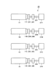
図3は、本実施例における感光ドラム1の駆動構成及び制御態様を示す概略ブロック図である。また、図4は、本実施例における感光ドラム1の駆動構成をより詳しく示す模式図である。なお、本実施例では、感光ドラム1は、実質的に単体で、又は帯電手段、現像手段、クリーニング手段などのプロセス手段の少なくとも1つと一緒に、画像形成装置100の装置本体に対して着脱可能とされている。
2. 2. Drive Configuration of Photosensitive Drum FIG. 3 is a schematic block diagram showing a drive configuration and a control mode of the photosensitive drum 1 in this embodiment. Further, FIG. 4 is a schematic diagram showing in more detail the drive configuration of the photosensitive drum 1 in this embodiment. In this embodiment, the photosensitive drum 1 can be attached to and detached from the main body of the image forming apparatus 100 substantially alone or together with at least one of process means such as a charging means, a developing means, and a cleaning means. It is said that.

図3に示すように、本実施例では、駆動手段としての駆動装置20は、第1、第2、第3、第4の感光ドラム1Y、1M、1C、1Kのそれぞれを駆動する独立した駆動源としての第1、第2、第3、第4の駆動モータ21Y、21M、21C、21Kを有する。また、図3に示すように、画像形成装置100の装置本体には、制御手段としてのCPU31、記憶手段としてのメモリ(不揮発メモリ)32、各駆動モータ21Y、21M、21C、21Kの駆動回路(ドライバ)である駆動制御部25が設けられている。 As shown in FIG. 3, in the present embodiment, the drive device 20 as the drive means is an independent drive for driving the first, second, third, and fourth photosensitive drums 1Y, 1M, 1C, and 1K, respectively. It has first, second, third, and fourth drive motors 21Y, 21M, 21C, and 21K as sources. Further, as shown in FIG. 3, the main body of the image forming apparatus 100 includes a CPU 31 as a control means, a memory (nonvolatile memory) 32 as a storage means, and drive circuits of drive motors 21Y, 21M, 21C, and 21K. A drive control unit 25 which is a driver) is provided.

図4に示すように、感光ドラム1の回転軸線方向(長手方向)の一端部には、駆動受け部としてのドラムカップリング11が設けられている。また、画像形成装置100の装置本体には、各駆動モータ21Y、21M、21C、21Kによって回転させられる駆動軸22Y、22M、22C、22Kが設けられている。また、各駆動軸22Y、22M、22C、22Kの回転軸線方向の一端部には、駆動伝達部材としての本体カップリング23Y、23M、23C、23Kが設けられている。各感光ドラム1Y、1M、1C、1Kに設けられた各ドラムカップリング11Y、11M、11C、11Kは、各駆動軸22Y、22M、22C、22Kに設けられた各本体カップリング23Y、23M、23C、23Kと係合する。これにより、各感光ドラム1Y、1M、1C、1Kは、各駆動軸22Y、22M、22C、22Kと連結されている各駆動モータ21Y、21M、21C、21Kから動力が伝達されて回転する。 As shown in FIG. 4, a drum coupling 11 as a drive receiving portion is provided at one end of the photosensitive drum 1 in the rotation axis direction (longitudinal direction). Further, the main body of the image forming apparatus 100 is provided with drive shafts 22Y, 22M, 22C, 22K rotated by the drive motors 21Y, 21M, 21C, 21K. Further, a main body coupling 23Y, 23M, 23C, 23K as a drive transmission member is provided at one end of each drive shaft 22Y, 22M, 22C, 22K in the rotation axis direction. The drum couplings 11Y, 11M, 11C, and 11K provided on the photosensitive drums 1Y, 1M, 1C, and 1K are the main body couplings 23Y, 23M, and 23C provided on the drive shafts 22Y, 22M, 22C, and 22K. , Engage with 23K. As a result, the photosensitive drums 1Y, 1M, 1C, and 1K rotate by transmitting power from the drive motors 21Y, 21M, 21C, and 21K connected to the drive shafts 22Y, 22M, 22C, and 22K.

また、各駆動軸22Y、22M、22C、22Kには、各駆動軸22Y、22M、22C、22K(すなわち、各感光ドラム1Y、1M、1C、1K)の回転速度を検知する速度検知手段としてのロータリーエンコーダ(以下、「エンコーダ」ともいう。)24Y、24M、24C、24Kが取り付けられている。CPU31は、駆動制御部25に対して、各駆動モータ21Y、21M、21C、21Kを所定の回転速度で回転させるように指令を出す。各駆動モータ21Y、21M、21C、21Kが回転し始めると、各感光ドラム1Y、1M、1C、1Kの回転速度が各駆動軸22Y、22M、22C、22Kに取り付けられた各エンコーダ24Y、24M、24C、24Kによって検知される。各エンコーダ24Y、24M、24C、24Kの検知信号は駆動制御部25へとフィードバックされ、駆動制御部25によって各感光ドラム1Y、1M、1C、1Kが所定の回転速度で回転するように各駆動モータ21Y、21M、21C、21Kが制御される。 Further, each drive shaft 22Y, 22M, 22C, 22K is used as a speed detecting means for detecting the rotation speed of each drive shaft 22Y, 22M, 22C, 22K (that is, each photosensitive drum 1Y, 1M, 1C, 1K). Rotary encoders (hereinafter, also referred to as "encoders") 24Y, 24M, 24C, 24K are attached. The CPU 31 issues a command to the drive control unit 25 to rotate each drive motor 21Y, 21M, 21C, 21K at a predetermined rotation speed. When the drive motors 21Y, 21M, 21C, 21K start to rotate, the rotation speeds of the photosensitive drums 1Y, 1M, 1C, and 1K change to the encoders 24Y, 24M, which are attached to the drive shafts 22Y, 22M, 22C, and 22K. Detected by 24C and 24K. The detection signals of the encoders 24Y, 24M, 24C, and 24K are fed back to the drive control unit 25, and each drive motor is rotated by the drive control unit 25 so that the photosensitive drums 1Y, 1M, 1C, and 1K rotate at a predetermined rotation speed. 21Y, 21M, 21C, 21K are controlled.

なお、本実施例では、CPU31は、メモリ32に記憶されているプログラムやデータに基づいて、駆動制御部25に指令を出して各感光ドラム1Y、1M、1C、1Kの回転を制御する他、画像形成装置100の各部の動作を統括的に制御する。CPU31は、パーソナルコンピュータや画像読み取り装置などの外部機器から入力される画像データ(電気的な画像情報)に対応した画像を記録材Pに形成して出力するように画像形成装置100の動作の制御を行う。また、本実施例では、CPU31は、後述する当接状態検知処理、及び摩擦力低減処理としての供給動作の制御を行う。 In this embodiment, the CPU 31 issues a command to the drive control unit 25 based on the program or data stored in the memory 32 to control the rotation of each photosensitive drum 1Y, 1M, 1C, 1K, and the like. The operation of each part of the image forming apparatus 100 is comprehensively controlled. The CPU 31 controls the operation of the image forming apparatus 100 so as to form an image corresponding to image data (electrical image information) input from an external device such as a personal computer or an image reading device on the recording material P and output the image. I do. Further, in this embodiment, the CPU 31 controls the supply operation as the contact state detection process and the frictional force reduction process, which will be described later.

ここで、画像形成装置100は、一の開始指示により開始される、単一又は複数の記録材Pに画像を形成して出力する一連の動作であるジョブ(プリント動作)を実行する。ジョブは、一般に、画像形成工程、前回転工程、複数の記録材Pに画像を形成する場合の紙間工程、及び後回転工程を有する。画像形成工程は、実際に記録材Pに形成して出力する画像の静電像の形成、トナー像の形成、トナー像の一次転写や二次転写を行う期間であり、画像形成時(画像形成期間)とはこの期間のことをいう。より詳細には、これら静電像の形成、トナー像の形成、トナー像の一次転写や二次転写の各工程を行う位置で、画像形成時のタイミングは異なる。前回転工程は、開始指示が入力されてから実際に画像を形成し始めるまでの、画像形成工程の前の準備動作を行う期間である。紙間工程は、複数の記録材Pに対する画像形成を連続して行う際(連続画像形成)の記録材Pと記録材Pとの間に対応する期間である。後回転工程は、画像形成工程の後の整理動作(準備動作)を行う期間である。非画像形成時(非画像形成期間)とは、画像形成時以外の期間であって、上記前回転工程、紙間工程、後回転工程、更には画像形成装置100の電源投入時又はスリープ状態からの復帰時の準備動作である前多回転工程などが含まれる。本実施例では、非画像形成時に、後述する当接状態検知処理、及び摩擦力低減処理としての供給動作が実行される。 Here, the image forming apparatus 100 executes a job (printing operation) which is a series of operations of forming and outputting an image on a single or a plurality of recording materials P, which is started by one start instruction. The job generally includes an image forming step, a front rotation step, a paper-to-paper step when forming an image on a plurality of recording materials P, and a back rotation step. The image forming step is a period during which an electrostatic image of an image actually formed and output on the recording material P is formed, a toner image is formed, and a primary transfer or a secondary transfer of the toner image is performed, and at the time of image formation (image formation). Period) means this period. More specifically, the timing at the time of image formation differs depending on the position where each of the steps of forming the electrostatic image, forming the toner image, and performing the primary transfer and the secondary transfer of the toner image is performed. The pre-rotation step is a period during which the preparatory operation before the image forming step is performed from the input of the start instruction to the actual start of forming the image. The paper-to-paper process is a period corresponding to the space between the recording material P and the recording material P when image formation is continuously performed on the plurality of recording materials P (continuous image formation). The post-rotation process is a period during which the rearranging operation (preparation operation) is performed after the image forming process. The non-image forming time (non-image forming period) is a period other than the image forming time, and is from the pre-rotation step, the paper-to-paper step, the back-rotation step, and further, when the power of the image forming apparatus 100 is turned on or from the sleep state. It includes a pre-multi-rotation process, which is a preparatory operation at the time of recovery. In this embodiment, at the time of non-image formation, the contact state detection process and the supply operation as the frictional force reduction process, which will be described later, are executed.

3.当接状態検知処理及び摩擦力低減処理
次に、本実施例における感光ドラム1に対するクリーニングブレード61の当接状態を検知する当接状態検知処理、及び感光ドラム1とクリーニングブレード61との間の摩擦力を低減する摩擦力低減処理について説明する。本実施例では、各画像形成部Sにおける当接状態検知処理及び摩擦力低減処理は実質的に同じであるので、ここでは1つの画像形成部Sに注目して説明する。
3. 3. Contact state detection process and friction force reduction process Next, the contact state detection process for detecting the contact state of the cleaning blade 61 with respect to the photosensitive drum 1 in this embodiment, and the friction between the photosensitive drum 1 and the cleaning blade 61. The frictional force reduction process for reducing the force will be described. In this embodiment, the contact state detection process and the frictional force reduction process in each image forming unit S are substantially the same, so here, one image forming unit S will be focused on.

図5(a)、(b)は、目標の回転速度(周速度)を200mm/secとして感光ドラム1を回転させた場合の、経過時間とエンコーダ24によって検知された回転速度(mm/sec)との関係(検知信号の推移)を示すグラフ図である。図5(a)は、クリーニングブレード61が安定して感光ドラム1に当接している状態、図5(b)はクリーニングブレード61のビビリにより異音が発生している状態で感光ドラム1を回転させた際の、5秒間にわたるエンコーダ24の検知信号である。また、図6(a)、(b)は、それぞれ図5(a)、(b)に示すエンコーダ24の検知信号をCPU31で高速フーリエ変換(以下、「FFT」ともいう。)処理して、感光ドラム1の回転速度変動を周波数ごとに抽出した結果を示すグラフ図である。図6(a)、(b)において、横軸は周波数、縦軸は速度周波数空間における信号値(周波数をパラメータに取ったときの回転速度変動の割合(%)に相当)を示す。 5 (a) and 5 (b) show the elapsed time and the rotation speed (mm / sec) detected by the encoder 24 when the photosensitive drum 1 is rotated with the target rotation speed (peripheral speed) of 200 mm / sec. It is a graph which shows the relationship (transition of a detection signal) with. FIG. 5A shows the state in which the cleaning blade 61 is stably in contact with the photosensitive drum 1, and FIG. 5B shows the photosensitive drum 1 being rotated in a state where abnormal noise is generated due to chattering of the cleaning blade 61. It is a detection signal of the encoder 24 for 5 seconds at the time of making it. Further, in FIGS. 6 (a) and 6 (b), the detection signals of the encoder 24 shown in FIGS. 5 (a) and 5 (b) are subjected to fast Fourier transform (hereinafter, also referred to as “FFT”) processing by the CPU 31. It is a graph which shows the result of extracting the rotation speed fluctuation of a photosensitive drum 1 for each frequency. In FIGS. 6A and 6B, the horizontal axis shows the frequency, and the vertical axis shows the signal value in the velocity frequency space (corresponding to the rate (%) of the rotation speed fluctuation when the frequency is taken as a parameter).

図6(b)に示すクリーニングブレード61のビビリにより異音が発生している状態では、43Hz辺りに最も信号強度(回転速度変動)の大きな点(以下、「ピーク値」ともいう。)が見られる。これは、およそ43Hzでクリーニングブレード61の当接状態が周期的に変動しており、それに伴ってほぼ同じ周期で感光ドラム1の回転速度が変動していることを示している。一方、図6(a)に示すクリーニングブレード61が感光ドラムに対して安定して当接している状態では、上述したような顕著なピークは見られない。 In a state where abnormal noise is generated due to chattering of the cleaning blade 61 shown in FIG. 6 (b), a point having the largest signal strength (rotational speed fluctuation) is seen around 43 Hz (hereinafter, also referred to as “peak value”). Be done. This indicates that the contact state of the cleaning blade 61 fluctuates periodically at about 43 Hz, and the rotation speed of the photosensitive drum 1 fluctuates with the same cycle. On the other hand, when the cleaning blade 61 shown in FIG. 6A is in stable contact with the photosensitive drum, the above-mentioned remarkable peak is not observed.

このように、感光ドラム1に対するクリーニングブレード61の当接状態が安定しているか否かを、感光ドラム1の回転速度を検知することで判断することができる。 In this way, whether or not the contact state of the cleaning blade 61 with the photosensitive drum 1 is stable can be determined by detecting the rotation speed of the photosensitive drum 1.

本実施例では、エンコーダ24の検知信号のFFT処理後の速度周波数空間におけるピーク値が予め設定された所定の閾値以上である場合には、感光ドラム1に対するクリーニングブレード61の当接状態が不安定化し始めた兆候があると判断する。そして、感光ドラム1に対するクリーニングブレード61の当接状態を安定化させるために、感光ドラム1とクリーニングブレード61との間の摩擦力を低減する摩擦力低減処理を実行する。これにより、感光ドラム1に対するクリーニングブレード61の周期的な当接状態の変化によるトナーすり抜けや色ずれなどの異常画像、ダウンタイムの発生を効率よく抑制する。 In this embodiment, when the peak value of the detection signal of the encoder 24 in the velocity frequency space after the FFT processing is equal to or higher than a preset predetermined threshold value, the contact state of the cleaning blade 61 with the photosensitive drum 1 is unstable. Judge that there are signs that it has begun to change. Then, in order to stabilize the contact state of the cleaning blade 61 with the photosensitive drum 1, a frictional force reducing process for reducing the frictional force between the photosensitive drum 1 and the cleaning blade 61 is executed. As a result, abnormal images such as toner slippage and color shift due to periodic changes in the contact state of the cleaning blade 61 with respect to the photosensitive drum 1 and the occurrence of downtime are efficiently suppressed.

具体的には、所定のタイミングで非画像形成時に感光ドラム1に対するクリーニングブレード61の当接状態を検知する当接状態検知処理を行う。これにより、エンコーダ24の検知信号のFFT処理後の速度周波数空間におけるピーク値が、閾値である0.10以上であるか否かを判断する。そして、ピーク値が閾値以上であると判断した場合には、非画像形成時に摩擦力低減処理を実行する。特に、本実施例では、摩擦力低減処理として、クリーニングブレード61と感光ドラム1との接触部(ブレードニップ部)Nに潤滑剤として機能するトナー(トナーの外添剤を含む。)を供給する供給動作を実行する。一方、ピーク値が閾値0.10未満であると判断した場合は、次回の当接状態検知処理のタミングまで摩擦力低減処理は実行しない。このように、本実施例では、当接状態検知処理は、感光ドラム1の回転速度を検知する処理(速度検知処理)、感光ドラム1の回転速度変動を検知する処理(変動検知処理)、当接状態を判断する処理(判断処理)を含む。本実施例では、エンコーダ24が速度検知処理を行う速度検知手段を構成する。また、本実施例では、CPU31が、変動検知処理を行う変動検知部、及び判断処理を行う判断処理部の機能を有する。変動検知部及び判断処理部は、CPU31がメモリ32に記憶されているプログラムを実行することで実現される。 Specifically, the contact state detection process for detecting the contact state of the cleaning blade 61 with the photosensitive drum 1 at the time of non-image formation is performed at a predetermined timing. Thereby, it is determined whether or not the peak value of the detection signal of the encoder 24 in the velocity frequency space after the FFT processing is 0.10 or more, which is the threshold value. Then, when it is determined that the peak value is equal to or higher than the threshold value, the frictional force reduction process is executed at the time of non-image formation. In particular, in this embodiment, as a frictional force reducing process, a toner (including a toner external additive) that functions as a lubricant is supplied to the contact portion (blade nip portion) N between the cleaning blade 61 and the photosensitive drum 1. Perform the supply operation. On the other hand, if it is determined that the peak value is less than the threshold value of 0.10, the frictional force reduction process is not executed until the timing of the next contact state detection process. As described above, in the present embodiment, the contact state detection process includes a process of detecting the rotational speed of the photosensitive drum 1 (speed detection process), a process of detecting a variation in the rotational speed of the photosensitive drum 1 (variation detection process), and the like. Includes processing to determine the contact state (judgment processing). In this embodiment, the encoder 24 constitutes a speed detection means for performing speed detection processing. Further, in this embodiment, the CPU 31 has a function of a fluctuation detection unit that performs fluctuation detection processing and a judgment processing unit that performs judgment processing. The fluctuation detection unit and the determination processing unit are realized by the CPU 31 executing a program stored in the memory 32.

当接状態検知処理における速度検知処理を実行するタイミングは、感光ドラム1の回転中であれば任意のタイミングでよい。ただし、クリーニングブレード61の当接状態が不安定になって感光ドラム1の回転速度変動が顕著になりやすいのは、次のような期間である。すなわち、画像形成が始まってトナーが感光ドラム1に供給され始める前の準備回転である前回転中や、画像形成が終了してトナーが感光ドラム1に供給されなくなる立ち下げ回転である後回転中である。つまり、画像形成中は、典型的には常にカブリトナーが感光ドラム1に供給され続けており、クリーニングブレード61のエッジ部から少しずつトナーの外添剤がすり抜けて感光ドラム1とクリーニングブレード61との間に供給される。そのため、感光ドラム1とクリーニングブレード61との間の摩擦力が低減されて、感光ドラム1に対するクリーニングブレード61の当接状態は比較的安定しやすい。なお、カブリトナーは、感光ドラム1の帯電電位と現像スリーブ41の電位(現像電圧の直流成分)との電位差で、帯電極性が正規の極性とは逆極性に反転したトナーなどが感光ドラム1上の非画像部に付着する現象である「カブリ」を起こしたトナーである。一方、前回転時や後回転時などでは、感光ドラム1にトナーが供給されない状態で感光ドラム1の回転が続き、クリーニングブレード61のエッジ部からすり抜けるトナーの外添剤が少ない。そのため、感光ドラム1とクリーニングブレード61との間の摩擦力が大きくなって、感光ドラム1に対するクリーニングブレード61の当接状態が不安定になりやすくなる。換言すれば、画像形成中は、感光ドラム1の表面の摩擦係数の上昇などにより実際に感光ドラム1に対するクリーニングブレード61の当接状態が不安定化しやすい状態か否かに拘わらず、該当接状態が安定しやすいため、該当接状態の判断精度が低下しやすい。したがって、当接状態検知処理における速度検知処理の実行タイミングは、前回転時や後回転時などの、感光ドラム1にトナーが供給されない状態で感光ドラム1が回転しているタイミングであることが望ましい。 The timing for executing the speed detection process in the contact state detection process may be any timing as long as the photosensitive drum 1 is rotating. However, it is during the following period that the contact state of the cleaning blade 61 becomes unstable and the rotational speed fluctuation of the photosensitive drum 1 tends to be remarkable. That is, during the pre-rotation, which is the preparatory rotation before the image formation starts and the toner starts to be supplied to the photosensitive drum 1, or during the post-rotation, which is the down rotation where the image formation is completed and the toner is not supplied to the photosensitive drum 1. Is. That is, typically, fog toner is constantly supplied to the photosensitive drum 1 during image formation, and the toner external additive gradually slips through the edge portion of the cleaning blade 61 to form the photosensitive drum 1 and the cleaning blade 61. Is supplied during. Therefore, the frictional force between the photosensitive drum 1 and the cleaning blade 61 is reduced, and the contact state of the cleaning blade 61 with the photosensitive drum 1 is relatively easy to be stable. In the fog toner, toner or the like whose charging polarity is reversed to the normal polarity due to the potential difference between the charging potential of the photosensitive drum 1 and the potential of the developing sleeve 41 (DC component of the developing voltage) is on the photosensitive drum 1. It is a toner that causes "fog", which is a phenomenon that adheres to the non-image area of the toner. On the other hand, during the forward rotation or the backward rotation, the photosensitive drum 1 continues to rotate in a state where the toner is not supplied to the photosensitive drum 1, and the amount of the toner external additive that slips through the edge portion of the cleaning blade 61 is small. Therefore, the frictional force between the photosensitive drum 1 and the cleaning blade 61 becomes large, and the contact state of the cleaning blade 61 with the photosensitive drum 1 tends to become unstable. In other words, during image formation, the contact state is irrespective of whether or not the contact state of the cleaning blade 61 with the photosensitive drum 1 is likely to become unstable due to an increase in the friction coefficient of the surface of the photosensitive drum 1. Is easy to stabilize, so the accuracy of determining the corresponding contact state is likely to decrease. Therefore, it is desirable that the execution timing of the speed detection process in the contact state detection process is the timing at which the photosensitive drum 1 is rotated in a state where the toner is not supplied to the photosensitive drum 1, such as during forward rotation or backward rotation. ..

また、供給動作を実行するタイミングは、感光ドラム1の回転中であれば任意のタイミングでよい。ただし、上記同様の理由により、前回転中や後回転中などの、トナーが供給されない状態で感光ドラム1が回転しているタイミングであることが望ましい。 Further, the timing for executing the supply operation may be any timing as long as the photosensitive drum 1 is rotating. However, for the same reason as described above, it is desirable that the photosensitive drum 1 is rotating at a timing in which the toner is not supplied, such as during forward rotation or backward rotation.

そこで、本実施例では、前回転中に当接状態検知処理における速度検知処理を実行し、エンコーダ24の検知信号を1秒間にわたり取得する。そして、画像形成中に、CPU31において当接状態検知処理における変動検知処理及び判断処理を実行する。つまり、エンコーダ24の検知信号をFFT処理してピーク値を算出し(変動検知処理)、ピーク値が閾値である0.10以上であるか否かを判断する(判断処理)。そして、ピーク値が閾値である0.10以上であると判断した場合には、後回転中に供給動作を実行する。本実施例では、上述の当接状態検知処理(速度検知処理、変動検知処理、判断処理)は、画像形成部Sごとに並行して実行し、当接状態検知処理においてピーク値が閾値以上である画像形成部Sがある場合には、その画像形成部Sにおいてのみ供給動作を実行する。 Therefore, in this embodiment, the speed detection process in the contact state detection process is executed during the forward rotation, and the detection signal of the encoder 24 is acquired for 1 second. Then, during the image formation, the CPU 31 executes the fluctuation detection process and the determination process in the contact state detection process. That is, the detection signal of the encoder 24 is FFT processed to calculate the peak value (variation detection processing), and it is determined whether or not the peak value is 0.10 or more, which is the threshold value (determination processing). Then, when it is determined that the peak value is 0.10 or more, which is the threshold value, the supply operation is executed during the rear rotation. In this embodiment, the above-mentioned contact state detection process (speed detection process, fluctuation detection process, judgment process) is executed in parallel for each image forming unit S, and the peak value is equal to or higher than the threshold value in the contact state detection process. If there is a certain image forming unit S, the supply operation is executed only in the image forming unit S.

供給動作を前回転中ではなく後回転中に実行するのは、前回転中に供給動作を実行するのに時間を要し、画像形成の開始タイミングが遅れてしまうことがあるためである。また、前回転中に供給動作を実行しても、その直後に画像形成が始まってブレードニップNにはカブリトナーや一次転写残トナーが供給され始めるので、効果が得られる時間が短いためである。なお、本実施例では、毎回のジョブの前回転中に、当接状態検知処理における速度検知処理を実行するが、複数回のジョブに1回などの所定の頻度で該速度検知処理を実行するようにしてもよい。 The reason why the supply operation is executed during the rear rotation instead of the front rotation is that it takes time to execute the supply operation during the front rotation, and the start timing of image formation may be delayed. Further, even if the supply operation is executed during the forward rotation, the image formation starts immediately after that, and the fog toner and the primary transfer residual toner start to be supplied to the blade nip N, so that the time for obtaining the effect is short. .. In this embodiment, the speed detection process in the contact state detection process is executed during the pre-rotation of each job, but the speed detection process is executed at a predetermined frequency such as once for a plurality of jobs. You may do so.

供給動作では、図7に示すように、感光ドラム1の回転軸線方向に延びる、ブレードニップ部Nに供給するトナーからなる帯状のトナー像(以下、「トナー帯」ともいう。)tを感光ドラム1上に形成する。本実施例では、トナー帯tは、感光ドラム1の回転軸線方向における現像装置4の現像幅(トナーを供給可能な領域の幅)の全域にわたって形成する。なお、本実施例では、この現像幅は、感光ドラム1の回転軸線方向における画像形成領域(トナー像を形成可能な領域)の幅と略同一であり、クリーニングブレード61の長手方向の長さと同等である。本実施例では、このトナー帯は、前述の画像形成時と同様にして帯電、露光、現像の各工程を経て感光ドラム1上に形成する。そして、このトナー帯を、一次転写部T1を通過させて、ブレードニップ部Nへと供給する。本実施例では、トナー帯が一次転写部T1を通過する際には、一次転写ローラ5には、画像形成時とは逆極性、すなわち、トナーの正規の帯電極性と同極性(本実施例では負極性)の直流電圧を印加する。これにより、トナー帯のトナーが中間転写ベルト7に転写される量が低減されて、効果的にトナーがブレードニップ部Nに供給される。 In the supply operation, as shown in FIG. 7, a band-shaped toner image (hereinafter, also referred to as “toner band”) t made of toner supplied to the blade nip portion N extending in the rotation axis direction of the photosensitive drum 1 is a photosensitive drum. 1 Form on top. In this embodiment, the toner band t is formed over the entire development width (width of the region where the toner can be supplied) of the developing device 4 in the rotation axis direction of the photosensitive drum 1. In this embodiment, the development width is substantially the same as the width of the image forming region (region in which the toner image can be formed) in the rotation axis direction of the photosensitive drum 1, and is equivalent to the length in the longitudinal direction of the cleaning blade 61. Is. In this embodiment, this toner band is formed on the photosensitive drum 1 through the steps of charging, exposure, and development in the same manner as in the case of image formation described above. Then, this toner band is passed through the primary transfer portion T1 and supplied to the blade nip portion N. In this embodiment, when the toner band passes through the primary transfer unit T1, the primary transfer roller 5 has the opposite polarity to that at the time of image formation, that is, the same polarity as the normal charging polarity of the toner (in this embodiment). Apply a DC voltage (negative polarity). As a result, the amount of toner in the toner band transferred to the intermediate transfer belt 7 is reduced, and the toner is effectively supplied to the blade nip portion N.

なお、本実施例では、トナー帯tのトナーの載り量(感光ドラム1の表面の単位面積あたりに付着するトナーの重量)は約0.50mg/cmである。また、トナー帯tの主走査方向(感光ドラム1の回転軸線方向)の幅は現像スリーブ41上のトナーを担持している領域の幅と同じ320mmである。また、トナー帯tの副走査方向(感光ドラム1の表面の移動方向)の長さは30mmである。ただし、供給動作においてブレードニップ部Nに供給するトナーの量は、本実施例のものに限定されるものではない。例えば、感光ドラム1の表面粗さ、帯電電圧のAC電圧の設定、クリーニングブレード61の設定角(当接角度)や線圧(当接圧力)の設定などに応じて適宜設定することができる。 In this embodiment, the amount of toner on the toner band t (the weight of the toner adhering to the surface of the photosensitive drum 1 per unit area) is about 0.50 mg / cm 2 . Further, the width of the toner band t in the main scanning direction (direction of the rotation axis of the photosensitive drum 1) is 320 mm, which is the same as the width of the region carrying the toner on the developing sleeve 41. Further, the length of the toner band t in the sub-scanning direction (moving direction of the surface of the photosensitive drum 1) is 30 mm. However, the amount of toner supplied to the blade nip portion N in the supply operation is not limited to that of the present embodiment. For example, it can be appropriately set according to the surface roughness of the photosensitive drum 1, the setting of the AC voltage of the charging voltage, the setting angle (contact angle) of the cleaning blade 61, the setting of the linear pressure (contact pressure), and the like.

なお、本実施例では当接状態検知処理における速度検知処理を前回転中に実行したが、後回転中に実行してもよい。また、本実施例では、帯電ローラ2に帯電電圧が印加されていない状態で感光ドラム1の回転中に感光ドラム1の回転速度変動を検知したが、画像形成中の回転速度変動を検知してもよい。 In this embodiment, the speed detection process in the contact state detection process is executed during the front rotation, but it may be executed during the rear rotation. Further, in this embodiment, the rotation speed fluctuation of the photosensitive drum 1 is detected during the rotation of the photosensitive drum 1 in a state where the charging voltage is not applied to the charging roller 2, but the rotation speed fluctuation during image formation is detected. May be good.

4.制御手順
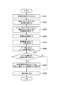
次に、本実施例における当接状態検知処理及び供給動作の制御手順について説明する。図8は、本実施例における当接状態検知処理及び供給動作を含むジョブの制御手順の概略を示すフローチャート図である。ここでは、カラーモードのジョブを例として説明する。
4. Control procedure Next, the control procedure of the contact state detection process and the supply operation in this embodiment will be described. FIG. 8 is a flowchart showing an outline of a job control procedure including a contact state detection process and a supply operation in this embodiment. Here, a job in color mode will be described as an example.

CPU31は、画像形成信号が入力されると(S101)、各感光ドラム1Y、1M、1C、1Kの回転を開始させて前回転を開始させる(S102)。CPU31は、前回転中に、各エンコーダ24Y、24M、24C、24Kによる各感光ドラム1Y、1M、1C、1Kの回転速度の検知結果を取得する(S103)。次に、CPU31は、所定の前回転工程の動作が終了ししだい、画像形成を開始させる(S104)。 When the image forming signal is input (S101), the CPU 31 starts the rotation of each photosensitive drum 1Y, 1M, 1C, and 1K to start the forward rotation (S102). The CPU 31 acquires the detection results of the rotation speeds of the photosensitive drums 1Y, 1M, 1C, and 1K by the encoders 24Y, 24M, 24C, and 24K during the forward rotation (S103). Next, the CPU 31 starts image formation as soon as the operation of the predetermined front rotation step is completed (S104).

CPU31は、画像形成中に、各エンコーダ24Y、24M、24C、24Kによる各感光ドラム1Y,1M、1C、1Kの回転速度の検知信号をFFT処理して、FFT処理後の速度周波数空間におけるピーク値を算出する(S105)。また、CPU31は、画像形成中に、算出したピーク値と閾値である0.10とを比較して、ピーク値が閾値以上である画像形成部Sがあるか否かを判断する(S106)。そして、CPU31は、S106でピーク値が閾値以上である画像形成部Sがあると判断した場合には、その画像形成部Sにおいてのみ、画像形成後の後回転中に供給動作を実行させる(S107)。その後、CPU31は、所定の後回転工程の動作が終了ししだい画像形成装置100の動作を終了させる(S108)。また、CPU31は、S106でピーク値が閾値以上である画像形成部Sがないと判断した場合には、いずれの画像形成部Sにおいても供給動作を実行させずに、所定の後回転工程の動作が終了ししだい画像形成装置100の動作を終了させる(S108)。 During image formation, the CPU 31 performs FFT processing on the detection signals of the rotation speeds of the photosensitive drums 1Y, 1M, 1C, and 1K by the encoders 24Y, 24M, 24C, and 24K, and the peak value in the speed frequency space after the FFT processing. Is calculated (S105). Further, the CPU 31 compares the calculated peak value with the threshold value of 0.10 during image formation, and determines whether or not there is an image forming unit S whose peak value is equal to or greater than the threshold value (S106). Then, when the CPU 31 determines in S106 that there is an image forming unit S whose peak value is equal to or higher than the threshold value, the CPU 31 executes a supply operation only in the image forming unit S during the post-rotation after image formation (S107). ). After that, the CPU 31 ends the operation of the image forming apparatus 100 as soon as the operation of the predetermined back rotation process is completed (S108). Further, when the CPU 31 determines in S106 that there is no image forming unit S whose peak value is equal to or higher than the threshold value, the CPU 31 does not execute the supply operation in any of the image forming units S, and operates the predetermined post-rotation process. The operation of the image forming apparatus 100 is terminated as soon as the operation is completed (S108).

5.効果
本実施例の画像形成装置100において、A4サイズの記録材Pに試験画像としてイエロー、マゼンタ、シアン、ブラックの単色ベタ縦帯画像を繰り返し形成する耐久試験を行った。試験は、温度32.5℃、湿度85%の環境で行った。試験画像は、各色とも画像形成時の感光ドラム1へのトナー供給量が少なくなるように、画像中央に主走査方向の長さが6mm、副走査方向の長さが210mmで、画像比率が2%の画像とした。また、試験は、100枚間欠の条件で200,000枚まで、すなわち、画像形成枚数が100枚のジョブを合計の画像形成枚数が200,000枚になるまで繰り返した。この耐久試験を、エンコーダ24の検知信号のFFT処理後の速度周波数空間におけるピーク値を確認しながら行った。その結果、クリーニングブレード61のビビリによる異音や異常画像は発生せず、安定して良好な画像を維持することができた。
5. Effect In the image forming apparatus 100 of this example, a durability test was conducted in which a single color solid vertical band image of yellow, magenta, cyan, and black was repeatedly formed as a test image on an A4 size recording material P. The test was conducted in an environment with a temperature of 32.5 ° C. and a humidity of 85%. The test image has a length of 6 mm in the main scanning direction, a length of 210 mm in the sub-scanning direction, and an image ratio of 2 in the center of the image so that the amount of toner supplied to the photosensitive drum 1 at the time of image formation is small for each color. % Image. Further, the test was repeated up to 200,000 images under the condition of intermittent images of 100 images, that is, a job with 100 images formed until the total number of images formed was 200,000. This durability test was performed while confirming the peak value of the detection signal of the encoder 24 in the velocity frequency space after the FFT processing. As a result, no abnormal noise or abnormal image due to chattering of the cleaning blade 61 was generated, and a stable and good image could be maintained.

以上説明したように、本実施例では、画像形成装置100は、感光ドラム1とクリーニングブレード61との間の摩擦力を低減する摩擦力低減処理を実行することが可能なCPU31を有する。そして、CPU31は、エンコーダ24の検知結果に基づいて取得した感光ドラム1の回転速度変動に関する情報に応じて、摩擦力低減処理を実行する。本実施例では、エンコーダ24は、感光ドラム1の駆動軸22に取り付けられている。特に、本実施例では、画像形成装置100は、複数の画像形成部Sの感光ドラム1のそれぞれに対応して設けられ、複数の画像形成部Sの感光ドラム1のそれぞれの回転速度を検知する複数のエンコーダ24を有する。また、本実施例では、CPU31は、複数の画像形成部Sの感光ドラム1とクリーニングブレード61との間の摩擦力を低減する摩擦力低減処理を実行することが可能である。このとき、CPU31は、複数のエンコーダ24の検知結果に基づいて取得した複数の画像形成部Sの感光ドラム1のそれぞれの回転速度変動に関する情報に応じて、複数の画像形成部Sのそれぞれに関する摩擦力低減処理を実行する。本実施例では、複数のエンコーダ24は、複数の画像形成部Sの感光ドラム1のそれぞれの駆動軸22に取り付けられている。また、本実施例では、CPU31は、感光ドラム1の回転速度変動に関する情報を、感光ドラム1にトナーが供給されない期間におけるエンコーダ24の検知結果に基づいて取得する。 As described above, in the present embodiment, the image forming apparatus 100 has a CPU 31 capable of executing a frictional force reducing process for reducing the frictional force between the photosensitive drum 1 and the cleaning blade 61. Then, the CPU 31 executes the frictional force reduction process according to the information regarding the rotation speed fluctuation of the photosensitive drum 1 acquired based on the detection result of the encoder 24. In this embodiment, the encoder 24 is attached to the drive shaft 22 of the photosensitive drum 1. In particular, in this embodiment, the image forming apparatus 100 is provided corresponding to each of the photosensitive drums 1 of the plurality of image forming portions S, and detects the rotation speed of each of the photosensitive drums 1 of the plurality of image forming portions S. It has a plurality of encoders 24. Further, in this embodiment, the CPU 31 can execute a frictional force reducing process for reducing the frictional force between the photosensitive drum 1 and the cleaning blade 61 of the plurality of image forming portions S. At this time, the CPU 31 receives friction regarding each of the plurality of image forming units S according to the information regarding the variation in the rotation speed of each of the photosensitive drums 1 of the plurality of image forming units S acquired based on the detection results of the plurality of encoders 24. Perform force reduction processing. In this embodiment, the plurality of encoders 24 are attached to the drive shafts 22 of the photosensitive drums 1 of the plurality of image forming units S. Further, in this embodiment, the CPU 31 acquires information on the rotation speed fluctuation of the photosensitive drum 1 based on the detection result of the encoder 24 during the period when the toner is not supplied to the photosensitive drum 1.

また、本実施例では、画像形成装置100は、感光ドラム1に潤滑剤を供給する供給手段を有する。そして、CPU31は、摩擦力低減処理として、非画像形成期間に供給手段により感光ドラム1に潤滑剤を供給して感光ドラム1とクリーニングブレード61との接触部Nに潤滑剤を供給する供給動作の設定を変更する。特に、本実施例では、CPU31は、供給動作の設定として、供給動作の実行の有無を変更する。また、本実施例では、CPU31は、エンコーダ24の検知結果に基づいて取得した感光ドラム1の回転速度変動の大きさと相関する指標値が所定の閾値以上の場合に供給動作を実行するようにする。また、本実施例では、CPU31は、エンコーダ24の検知結果を高速フーリエ変換処理して該指標値を取得する。特に、本実施例では、供給動作は、供給手段としての現像装置4により感光ドラム1に潤滑剤としてのトナーを供給し、該トナーを感光ドラム1の回転により上記接触部Nに到達させる動作である。 Further, in this embodiment, the image forming apparatus 100 has a supply means for supplying a lubricant to the photosensitive drum 1. Then, as a frictional force reducing process, the CPU 31 supplies the lubricant to the photosensitive drum 1 by the supply means during the non-image forming period, and supplies the lubricant to the contact portion N between the photosensitive drum 1 and the cleaning blade 61. Change the settings. In particular, in this embodiment, the CPU 31 changes whether or not the supply operation is executed as the setting of the supply operation. Further, in the present embodiment, the CPU 31 executes the supply operation when the index value that correlates with the magnitude of the rotation speed fluctuation of the photosensitive drum 1 acquired based on the detection result of the encoder 24 is equal to or more than a predetermined threshold value. .. Further, in this embodiment, the CPU 31 performs a fast Fourier transform process on the detection result of the encoder 24 to acquire the index value. In particular, in this embodiment, the supply operation is an operation in which the toner as a lubricant is supplied to the photosensitive drum 1 by the developing device 4 as the supply means, and the toner is brought to the contact portion N by the rotation of the photosensitive drum 1. be.

このように、本実施例によれば、各感光ドラム1の駆動軸22に設けられたエンコーダ24により感光ドラム1ごとに検知した回転速度のFFT処理結果に基づいて、必要な画像形成部Sにおいてのみ摩擦力低減処理を実行することができる。これにより、効率よく感光ドラム1に対するクリーニングブレード61の当接状態を安定化させて、異常画像やダウンタイムの発生を効率よく抑制することができる。つまり、本実施例によれば、感光ドラム1とクリーニングブレード61との間の摩擦力を低減する処理を精度良く必要時に実行することができる。特に、本実施例によれば、複数の感光ドラム1を共通の駆動源により駆動する構成であっても、各感光ドラム1とクリーニングブレード1との間の摩擦力を低減する処理を精度良く必要時に実行することができる。 As described above, according to the present embodiment, the required image forming unit S is based on the FFT processing result of the rotation speed detected for each photosensitive drum 1 by the encoder 24 provided on the drive shaft 22 of each photosensitive drum 1. Only the frictional force reduction process can be performed. As a result, the contact state of the cleaning blade 61 with the photosensitive drum 1 can be efficiently stabilized, and the occurrence of abnormal images and downtime can be efficiently suppressed. That is, according to this embodiment, the process of reducing the frictional force between the photosensitive drum 1 and the cleaning blade 61 can be accurately executed when necessary. In particular, according to this embodiment, even in a configuration in which a plurality of photosensitive drums 1 are driven by a common drive source, it is necessary to accurately perform a process of reducing the frictional force between each photosensitive drum 1 and the cleaning blade 1. Can be done at times.

[実施例2]
次に、本発明の他の実施例について説明する。本実施例の画像形成装置の基本的な構成及び動作は、実施例1のものと同じである。したがって、本実施例の画像形成装置において、実施例1の画像形成装置のものと同一又は対応する機能あるいは構成を有する要素については、実施例1と同一の符号を付して、詳しい説明は省略する。
[Example 2]
Next, another embodiment of the present invention will be described. The basic configuration and operation of the image forming apparatus of this embodiment are the same as those of the first embodiment. Therefore, in the image forming apparatus of the present embodiment, the elements having the same or corresponding functions or configurations as those of the image forming apparatus of the first embodiment are designated by the same reference numerals as those of the first embodiment, and detailed description thereof is omitted. do.

図9は、本実施例における感光ドラム1の駆動構成及び制御態様を示す概略ブロック図である。また、図10は、本実施例における感光ドラム1の駆動構成をより詳しく示す模式図である。 FIG. 9 is a schematic block diagram showing a drive configuration and a control mode of the photosensitive drum 1 in this embodiment. Further, FIG. 10 is a schematic diagram showing in more detail the drive configuration of the photosensitive drum 1 in this embodiment.

図9に示すように、本実施例では、駆動手段としての駆動装置20は、第1、第2、第3の感光ドラム1Y、1M、1Cを駆動する共通の駆動源としての第1の駆動モータ(以下、「カラーモータ」ともいう。)21aを有する。また、駆動装置20は、第4の感光ドラム1Kを駆動する独立した駆動源としての第2の駆動モータ(以下、「ブラックモータ」ともいう。)21bを有する。このように、本実施例では、第1、第2、第3の感光ドラム1Y、1M、1Kの駆動源が共通化されている。第1、第2、第3の感光ドラム1Y、1M、1Cに設けられた各ドラムカップリング11Y、11M、11Cは、各駆動軸22Y、22M、22Cに設けられた本体カップリング23Y、23M、23Cと係合する。そして、各駆動軸22Y、22M、22Cがギア(ギア列)26を介してカラーモータ21aと連結される。これにより、第1、第2、第3の感光ドラム1Y、1M、1Cは、それぞれカラーモータ21aから動力が伝達されて回転する。第4の感光ドラム1Kは、ブラックモータ21bによって実施例1と同様にして回転駆動される。 As shown in FIG. 9, in the present embodiment, the drive device 20 as the drive means is the first drive as a common drive source for driving the first, second, and third photosensitive drums 1Y, 1M, and 1C. It has a motor (hereinafter, also referred to as “color motor”) 21a. Further, the drive device 20 has a second drive motor (hereinafter, also referred to as “black motor”) 21b as an independent drive source for driving the fourth photosensitive drum 1K. As described above, in this embodiment, the drive sources of the first, second, and third photosensitive drums 1Y, 1M, and 1K are shared. The drum couplings 11Y, 11M, and 11C provided on the first, second, and third photosensitive drums 1Y, 1M, and 1C are the main body couplings 23Y, 23M provided on the drive shafts 22Y, 22M, and 22C. Engage with 23C. Then, the drive shafts 22Y, 22M, and 22C are connected to the color motor 21a via the gear (gear train) 26. As a result, the first, second, and third photosensitive drums 1Y, 1M, and 1C are rotated by transmitting power from the color motor 21a, respectively. The fourth photosensitive drum 1K is rotationally driven by the black motor 21b in the same manner as in the first embodiment.

そして、第1、第2、第3の感光ドラム1Y、1M、1Cの各駆動軸22Y、22M、22Cには、実施例1と同様にエンコーダ24Y、24M、24Cがそれぞれ取り付けられている。これにより、第1、第2、第3の感光ドラム1Y、1M、1Cは単一のカラーモータ21aで駆動されるが、第1、第2、第3の感光ドラム1Y、1M、1Cの回転速度は独立して検知することができる。また、第4の感光ドラム1Kの駆動軸22Kにも、エンコーダ27Kが取り付けられている。これにより、第4の感光ドラム1Kの回転速度も独立に検知することができる。 Encoders 24Y, 24M, and 24C are attached to the drive shafts 22Y, 22M, and 22C of the first, second, and third photosensitive drums 1Y, 1M, and 1C, respectively, as in the first embodiment. As a result, the first, second, and third photosensitive drums 1Y, 1M, and 1C are driven by a single color motor 21a, but the rotation of the first, second, and third photosensitive drums 1Y, 1M, and 1C. The speed can be detected independently. An encoder 27K is also attached to the drive shaft 22K of the fourth photosensitive drum 1K. Thereby, the rotation speed of the fourth photosensitive drum 1K can also be independently detected.

本実施例では、駆動制御部25は、CPU31の制御のもとで、各エンコーダ24Y、24M、24C、24Kの検知信号に基づいて第1、第2の駆動モータ21a、21bをフィードバック制御する。また、CPU31は、実施例1と同様にして、各エンコーダ24Y、24M、24C、24Kの検知信号をFTT処理して、各感光ドラム1Y、1M、1C、1Kの回転速度変動を周波数ごとに抽出してピーク値を算出する。 In this embodiment, the drive control unit 25 feedback-controls the first and second drive motors 21a and 21b based on the detection signals of the encoders 24Y, 24M, 24C and 24K under the control of the CPU 31. Further, the CPU 31 performs FTT processing on the detection signals of the encoders 24Y, 24M, 24C, and 24K in the same manner as in the first embodiment, and extracts the rotation speed fluctuations of the photosensitive drums 1Y, 1M, 1C, and 1K for each frequency. And calculate the peak value.

本実施例における当接状態検知処理及び供給動作を含むジョブの制御手順は実施例1(図8)と同様である。 The job control procedure including the contact state detection process and the supply operation in this embodiment is the same as that in the first embodiment (FIG. 8).

本実施例の画像形成装置100においても、実施例1に関して説明したものと同様の耐久試験を行った。その結果、200,000枚までクリーニングブレード61のビビリによる異音や異常画像は発生せず、安定して良好な画像を維持することができた。 In the image forming apparatus 100 of this example, the same durability test as that described for Example 1 was performed. As a result, no abnormal noise or abnormal image due to chattering of the cleaning blade 61 was generated up to 200,000 sheets, and a stable and good image could be maintained.

以上説明したように、本実施例によれば、実施例1と同様の効果を得ることができる。また、本実施例では、複数の感光ドラム1に対して駆動源を共通化することで、構成の簡易化や低コスト化を図ることができる。 As described above, according to the present embodiment, the same effect as that of the first embodiment can be obtained. Further, in the present embodiment, by sharing the drive source for the plurality of photosensitive drums 1, the configuration can be simplified and the cost can be reduced.

[実施例3]
次に、本発明の他の実施例について説明する。本実施例の画像形成装置の基本的な構成及び動作は、実施例1のものと同じである。したがって、本実施例の画像形成装置において、実施例1の画像形成装置のものと同一又は対応する機能あるいは構成を有する要素については、実施例1と同一の符号を付して、詳しい説明は省略する。
[Example 3]
Next, another embodiment of the present invention will be described. The basic configuration and operation of the image forming apparatus of this embodiment are the same as those of the first embodiment. Therefore, in the image forming apparatus of the present embodiment, the elements having the same or corresponding functions or configurations as those of the image forming apparatus of the first embodiment are designated by the same reference numerals as those of the first embodiment, and detailed description thereof is omitted. do.

なお、本実施例は、感光ドラム1の駆動構成として実施例1、2のいずれの駆動構成を採用する場合も適用することができる。 It should be noted that this embodiment can be applied to any of the drive configurations of Examples 1 and 2 as the drive configuration of the photosensitive drum 1.

本実施例では、エンコーダ24の検知信号をFFT処理して算出した速度周波数空間のピーク値に応じて、摩擦力低減処理の内容を変更する。具体的には、本実施例では、下記表1に示すように、算出したピーク値に応じて、摩擦力低減処理としての供給動作における感光ドラム1へのトナー供給量を変更する。つまり、本実施例では、感光ドラム1の回転速度変動の大きさと相関する指標値であるピーク値が大きいほど、感光ドラム1へのトナー供給量が多くなるように、トナー帯tの副走査方向の長さを変更する。表1に示すようなピーク値とトナー供給量との関係を示す情報は、予め設定されてメモリ32に記憶されている。なお、本実施例においても、実施例1、2と同様に、ピーク値が0.10未満である場合は、供給動作は実行しない(トナー帯tを形成しない)。 In this embodiment, the content of the frictional force reduction processing is changed according to the peak value of the velocity frequency space calculated by FFT processing the detection signal of the encoder 24. Specifically, in this embodiment, as shown in Table 1 below, the toner supply amount to the photosensitive drum 1 in the supply operation as the frictional force reduction process is changed according to the calculated peak value. That is, in this embodiment, the sub-scanning direction of the toner band t so that the larger the peak value, which is an index value that correlates with the magnitude of the rotation speed fluctuation of the photosensitive drum 1, the larger the amount of toner supplied to the photosensitive drum 1. Change the length of. Information indicating the relationship between the peak value and the toner supply amount as shown in Table 1 is preset and stored in the memory 32. Also in this embodiment, as in the first and second embodiments, if the peak value is less than 0.10, the supply operation is not executed (the toner band t is not formed).

Figure 0007016648000001

図11は、本実施例における当接状態検知処理及び供給動作を含むジョブの制御手順の概略を示すフローチャート図である。ここでは、カラーモードのジョブを例として説明する。図11のS201~S205、S209の処理は、それぞれ実施例1における図8のS101~S105、S108の処理と同様であるので、詳しい説明は省略する。 FIG. 11 is a flowchart showing an outline of a job control procedure including a contact state detection process and a supply operation in this embodiment. Here, a job in color mode will be described as an example. Since the processes of S201 to S205 and S209 of FIG. 11 are the same as the processes of S101 to S105 and S108 of FIG. 8 in Example 1, detailed description thereof will be omitted.

本実施例では、CPU31は、画像形成中に、S205で算出したピーク値から、メモリ32に記憶されている表1に示す情報を参照して、後回転時の感光ドラム1へのトナー供給量を画像形成部Sごとに決定する(S206)。また、CPU31は、画像形成中に、後回転時にトナーを供給する画像形成部Sがあるか否か(ピーク値が0.10以上の画像形成部Sがあるか否か)を判断する(S207)。そして、CPU31は、S207でトナーを供給する画像形成があると判断した場合には、その画像形成部Sについて画像形成後の後回転中にS206で決定した量のトナーを供給する供給動作を実行させる(S208)。その後、CPU31は、所定の後回転工程の動作が終了ししだい画像形成装置100の動作を終了させる(S209)。また、CPU31は、S207でトナーを供給する画像形成部Sがないと判断した場合には、いずれの画像形成部Sにおいても供給動作を実行させずに、所定の後回転工程の動作が終了ししだい画像形成装置100の動作を終了させる(S209)。 In this embodiment, the CPU 31 refers to the information shown in Table 1 stored in the memory 32 from the peak value calculated in S205 during image formation, and the toner supply amount to the photosensitive drum 1 during rear rotation. Is determined for each image forming unit S (S206). Further, the CPU 31 determines whether or not there is an image forming unit S that supplies toner during rear rotation (whether or not there is an image forming unit S having a peak value of 0.10 or more) during image formation (S207). ). Then, when the CPU 31 determines that there is an image formation for supplying toner in S207, the CPU 31 executes a supply operation for supplying the amount of toner determined in S206 during the post-rotation after image formation for the image forming unit S. (S208). After that, the CPU 31 ends the operation of the image forming apparatus 100 as soon as the operation of the predetermined back rotation process is completed (S209). Further, when the CPU 31 determines in S207 that there is no image forming unit S for supplying toner, the operation of the predetermined post-rotation process ends without executing the supply operation in any of the image forming units S. The operation of the image forming apparatus 100 is gradually terminated (S209).

本実施例の画像形成装置100においても、実施例1に関して説明したものと同様の耐久試験を行った。その結果、200,000枚までクリーニングブレード61のビビリによる異音や異常画像は発生せず、安定して良好な画像を維持することができた。 In the image forming apparatus 100 of this example, the same durability test as that described for Example 1 was performed. As a result, no abnormal noise or abnormal image due to chattering of the cleaning blade 61 was generated up to 200,000 sheets, and a stable and good image could be maintained.

このように、本実施例では、CPU31は、供給動作の設定として、供給動作における潤滑剤の供給量を変更する。また、本実施例では、CPU31は、エンコーダ24の検知結果に基づいて取得した感光ドラム1の回転速度変動の大きさと相関する指標値が第1の値である場合よりも、該第1の値より大きい第2の値の場合の方の供給量が多くなるようにする。 As described above, in this embodiment, the CPU 31 changes the supply amount of the lubricant in the supply operation as the setting of the supply operation. Further, in this embodiment, the CPU 31 has a first value as compared with the case where the index value that correlates with the magnitude of the rotation speed fluctuation of the photosensitive drum 1 acquired based on the detection result of the encoder 24 is the first value. Make sure that the supply is higher for the larger second value.

以上説明したように、本実施例によれば、実施例1、2と同様の効果を得ることができる。また、本実施例では、感光ドラム1に対するクリーニングブレード61の当接状態に応じて摩擦力低減処理の内容を変更することで、供給動作による材料の消費や部材の消耗、あるいはダウンタイムの低減を図ることができる。 As described above, according to the present embodiment, the same effects as those of the first and second embodiments can be obtained. Further, in this embodiment, by changing the content of the frictional force reducing process according to the contact state of the cleaning blade 61 with the photosensitive drum 1, the consumption of materials, the consumption of members, or the reduction of downtime due to the supply operation can be reduced. Can be planned.

[その他]
以上、本発明を具体的な実施例に即して説明したが、本発明は上述の実施例に限定されるものではない。
[others]
Although the present invention has been described above with reference to specific examples, the present invention is not limited to the above-mentioned examples.

上述の実施例では、供給動作において、トナー帯は、画像形成時と同様に帯電、露光、現像の各工程を経て感光ドラム上に形成されるものとして説明したが、本発明はこれに限定されるものではない。感光ドラムの表面電位と現像スリーブの電位との間の電位差の設定を調整することで、露光工程、又は帯電工程及び露光工程を経ずに、トナー帯を感光ドラム上に形成してもよい。例えば、感光ドラムを帯電処理せず、露光工程も行わずに、現像装置の現像スリーブを回転させ、現像電圧を印加することで、感光ドラムの表面電位と現像スリーブの電位との電位差でトナーを感光ドラム上に供給することができる。 In the above-described embodiment, the toner band is described as being formed on the photosensitive drum through the charging, exposure, and developing steps as in the image formation in the supply operation, but the present invention is limited thereto. It's not something. By adjusting the setting of the potential difference between the surface potential of the photosensitive drum and the potential of the developing sleeve, the toner band may be formed on the photosensitive drum without going through the exposure step or the charging step and the exposure step. For example, by rotating the developing sleeve of a developing device and applying a developing voltage without charging the photosensitive drum and performing an exposure process, toner is generated by the potential difference between the surface potential of the photosensitive drum and the potential of the developing sleeve. It can be supplied on a photosensitive drum.

上述の実施例では、摩擦力低減処理として、後回転中に感光ドラムにトナーを供給するタイミングを設けて、ブレードニップ部へのトナー供給量を増やした。しかし、本発明はこれに限定されるものではなく、摩擦力低減処理としては、感光ドラムとクリーニングブレードとの間の摩擦力を低減することのできる処理であれば、任意の処理を採用することができる。次に、摩擦力低減処理の他のいくつかの例を挙げる。上述の実施例のものを含み、ここで例示する摩擦力低減処理は、複数を組み合わせて実行してもよい。 In the above-described embodiment, as the frictional force reducing process, a timing for supplying toner to the photosensitive drum during the rear rotation is provided to increase the amount of toner supplied to the blade nip portion. However, the present invention is not limited to this, and as the frictional force reducing treatment, any treatment can be adopted as long as the frictional force between the photosensitive drum and the cleaning blade can be reduced. Can be done. Next, some other examples of frictional force reduction processing will be given. The frictional force reducing treatments exemplified here, including those of the above-described embodiment, may be performed in combination of two or more.

つまり、摩擦力低減処理として、ジョブの実行中に紙間で感光ドラム1にトナーを供給するタイミングを割り込ませる頻度を変更することで、単位時間(画像形成枚数)当たりのブレードニップ部へのトナー供給量を増やしてもよい。つまり、CPU31は、供給動作の設定として、供給動作の実行頻度(単位時間(画像形成枚数)当たりの実行回数)を変更することができる。この場合、CPU31は、エンコーダ24の検知結果に基づいて取得した感光ドラム1の回転速度変動の大きさと相関する指標値に応じて該実行頻度を変更することができる。具体的には、該指標値が第1の値である場合よりも、該第1の値よりも大きい第2の値の場合の方の実行頻度が多くなるようにすればよい。 That is, as a frictional force reduction process, by changing the frequency of interrupting the timing of supplying toner to the photosensitive drum 1 between papers during job execution, the toner to the blade nip portion per unit time (number of images formed) is changed. You may increase the supply. That is, the CPU 31 can change the execution frequency of the supply operation (the number of executions per unit time (number of image formations)) as the setting of the supply operation. In this case, the CPU 31 can change the execution frequency according to an index value that correlates with the magnitude of the rotation speed fluctuation of the photosensitive drum 1 acquired based on the detection result of the encoder 24. Specifically, the execution frequency may be higher when the index value is a second value larger than the first value than when the index value is the first value.

また、摩擦力低減処理として、画像形成時の現像電圧の直流成分(現像DC電圧)と帯電電圧の直流成分(帯電DC電圧)との差であるカブリ取り電位差Vbackの設定を変更することで、カブリトナー量を増やしてもよい。この電位差は、感光ドラムの帯電電位と現像スリーブの電位(現像電圧の直流成分)との間の電位差に対応する。なお、この電位差は、現像DC電圧と帯電DC電圧とのいずれを変更することで変更してもよく、現像DC電圧と帯電DC電圧との両方を変更することで変更してもよい。つまり、CPU31は、摩擦力低減処理として、帯電処理のために帯電ローラ2に印加される電圧と感光ドラム1にトナーを供給するために現像スリーブ41に印加される電圧との電位差の設定を変更することができる。この場合、CPU31は、エンコーダ24の検知結果に基づいて取得した感光ドラム1の回転速度変動の大きさと相関する指標値が所定の閾値以上になった場合に該電位差を小さくすることができる。あるいは、CPU31は、該指標値に応じて該電位差を変更することができる。具体的には、該指標値が第1の値である場合よりも、該第1の値よりも大きい第2の値の場合の方の該電位差が小さくなるようにすればよい。 In addition, as a frictional force reduction process, by changing the setting of the fog removal potential difference Vback, which is the difference between the DC component of the development voltage (development DC voltage) and the DC component of the charge voltage (charged DC voltage) at the time of image formation. The amount of fog toner may be increased. This potential difference corresponds to the potential difference between the charging potential of the photosensitive drum and the potential of the developing sleeve (DC component of the developing voltage). The potential difference may be changed by changing either the developed DC voltage or the charged DC voltage, or may be changed by changing both the developed DC voltage and the charged DC voltage. That is, the CPU 31 changes the setting of the potential difference between the voltage applied to the charging roller 2 for the charging process and the voltage applied to the developing sleeve 41 for supplying toner to the photosensitive drum 1 as the frictional force reducing process. can do. In this case, the CPU 31 can reduce the potential difference when the index value that correlates with the magnitude of the rotational speed fluctuation of the photosensitive drum 1 acquired based on the detection result of the encoder 24 becomes a predetermined threshold value or more. Alternatively, the CPU 31 can change the potential difference according to the index value. Specifically, the potential difference may be smaller when the index value is a second value larger than the first value than when the index value is the first value.

また、摩擦力低減処理として、画像形成時の帯電電圧のAC電圧の設定を変更して、帯電処理時の放電電流を変更することで、感光ドラムの表面の摩擦係数の上昇を抑制してもよい。つまり、CPU31は、摩擦力低減処理として、帯電処理時の放電電流の設定を変更することができる。この場合、CPU31は、エンコーダ24の検知結果に基づいて取得した感光ドラム1の回転速度変動の大きさと相関する指標値が所定の閾値以上になった場合に該設定としてのピーク間電圧を小さくして放電電流を少なくすることができる。あるいは、CPU31は、該指標値に応じて該設定としてのピーク間電圧を変更して放電電流を変更することができる。具体的には、該指標値が第1の値である場合よりも、該第1の値よりも大きい第2の値の場合の方のピーク間電圧を小さくして放電電流が少なくなるようにすればよい。 Further, as a friction force reduction process, even if the increase in the friction coefficient on the surface of the photosensitive drum is suppressed by changing the setting of the AC voltage of the charge voltage at the time of image formation and changing the discharge current at the time of the charge process. good. That is, the CPU 31 can change the setting of the discharge current during the charging process as the frictional force reducing process. In this case, the CPU 31 reduces the peak-to-peak voltage as the setting when the index value that correlates with the magnitude of the rotational speed fluctuation of the photosensitive drum 1 acquired based on the detection result of the encoder 24 becomes a predetermined threshold value or more. The discharge current can be reduced. Alternatively, the CPU 31 can change the discharge current by changing the peak voltage as the setting according to the index value. Specifically, the peak-to-peak voltage is smaller in the case of the second value larger than the first value than in the case where the index value is the first value so that the discharge current is reduced. do it.

さらに、摩擦力低減処理として、画像形成時の一次転写電圧(一次転写電流)の設定を変更することで、一次転写残トナーの量を増やしてもよい。つまり、CPU31は、摩擦力低減処理として、転写のために一次転写ローラ5に印加される電圧の設定を変更することができる。この場合、CPU31は、エンコーダ24の検知結果に基づいて取得した感光ドラム1の回転速度変動の大きさと相関する指標値が所定の閾値以上になった場合に一次転写電圧(一次転写電流)の絶対値を小さくすることができる。あるいは、CPU31は、該指標値に応じて一次転写電圧(一次転写電流)の絶対値を変更することができる。具体的には、該指標値が第1の値である場合よりも、該第1の値よりも大きい第2の値の場合の方の一次転写電圧(一次転写電流)の絶対値が小さくなるようにすればよい。 Further, as the frictional force reducing process, the amount of the primary transfer residual toner may be increased by changing the setting of the primary transfer voltage (primary transfer current) at the time of image formation. That is, the CPU 31 can change the setting of the voltage applied to the primary transfer roller 5 for transfer as the frictional force reduction process. In this case, the CPU 31 has an absolute primary transfer voltage (primary transfer current) when the index value that correlates with the magnitude of the rotational speed fluctuation of the photosensitive drum 1 acquired based on the detection result of the encoder 24 becomes a predetermined threshold value or more. The value can be reduced. Alternatively, the CPU 31 can change the absolute value of the primary transfer voltage (primary transfer current) according to the index value. Specifically, the absolute value of the primary transfer voltage (primary transfer current) becomes smaller when the index value is a second value larger than the first value than when the index value is the first value. You can do it.

上述の実施例では、摩擦力低減処理としての供給動作においてブレードニップ部に供給する潤滑剤がトナー(トナーの外添剤を含む。)である場合について説明した。潤滑剤としてトナーを用いることで、潤滑剤の供給手段として現像手段を用いることができ、別途供給手段を設ける場合よりも構成の簡易化、低コスト化に有利である。ただし、本発明はこれに限定されるものではなく、例えばトナーやトナーの外添剤と同様の微粒子などの潤滑剤をブレードニップ部に供給する供給手段を、現像手段とは別個に設けてもよい。 In the above-mentioned embodiment, the case where the lubricant supplied to the blade nip portion in the supply operation as the frictional force reducing treatment is toner (including the toner external additive) has been described. By using toner as a lubricant, a developing means can be used as a lubricant supply means, which is advantageous in terms of simplification of configuration and cost reduction as compared with the case where a separate supply means is provided. However, the present invention is not limited to this, and for example, a supply means for supplying a lubricant such as toner or fine particles similar to the toner's external additive to the blade nip portion may be provided separately from the developing means. good.

上述の実施例では、複数の感光ドラムとして3個の感光ドラムの駆動源が共通化される場合について例示したが、本発明はこれに限定されるものではなく、駆動源が共通化される感光ドラムの数は2個であっても、4個以上であってもよい。また、上述の実施例では、感光ドラムは、画像形成装置の装置本体に対し着脱可能であるものとして説明したが、感光ドラムは容易には画像形成装置の装置本体に対して着脱できない構成とされていてもよい。 In the above-described embodiment, the case where the drive sources of the three photosensitive drums are shared as a plurality of photosensitive drums has been illustrated, but the present invention is not limited to this, and the photosensitive drums have a common drive source. The number of drums may be two or four or more. Further, in the above-described embodiment, the photosensitive drum has been described as being removable from the device main body of the image forming apparatus, but the photosensitive drum is configured so as not to be easily attached to and detached from the device main body of the image forming apparatus. May be.

上述の実施例では、画像形成装置は中間転写方式を採用するものとして説明したが、本発明は直接転写方式の画像形成装置にも適用できるものである。当業者には周知のように、直接転写方式を採用したタンデム型の画像形成装置は、上述の実施例における中間転写体に代えて、無端状のベルトなどで構成される記録材担持体を有する。そして、各画像形成部の感光ドラムに形成されたトナー像は、中間転写方式の画像形成装置における一次転写と同様にして、記録材担持体に担持されて搬送される記録材に直接転写される。このような画像形成装置においても、本発明を適用することで、上述の実施例と同様の効果を得ることができる。また、本発明は、画像形成部を1つだけ有する画像形成装置にも適用できるものである。 In the above-described embodiment, the image forming apparatus has been described as adopting an intermediate transfer method, but the present invention can also be applied to a direct transfer type image forming apparatus. As is well known to those skilled in the art, a tandem type image forming apparatus adopting a direct transfer method has a recording material carrier composed of an endless belt or the like instead of the intermediate transfer body in the above-described embodiment. .. Then, the toner image formed on the photosensitive drum of each image forming portion is directly transferred to the recording material supported and conveyed on the recording material carrier in the same manner as the primary transfer in the image forming apparatus of the intermediate transfer method. .. By applying the present invention to such an image forming apparatus, the same effect as that of the above-described embodiment can be obtained. The present invention can also be applied to an image forming apparatus having only one image forming portion.

また、感光体はドラム状のもの(感光ドラム)に限定されるものではなく、無端ベルト状のもの(感光体ベルト)であってもよい。また、中間転写体や記録材担持体は無端ベルト状のものに限定されるものではなく、例えば枠体にフィルムを張設して形成したドラム状のものなどであってもよい。また、静電記録方式の画像形成装置であれば、像担持体はドラム状や無端ベルト状の静電記録誘電体であってよい。 Further, the photoconductor is not limited to a drum-shaped one (photosensitive drum), and may be an endless belt-shaped one (photoreceptor belt). Further, the intermediate transfer body and the recording material carrier are not limited to the endless belt-shaped body, and may be, for example, a drum-shaped body formed by stretching a film on a frame body. Further, in the case of an electrostatic recording type image forming apparatus, the image carrier may be a drum-shaped or endless belt-shaped electrostatic recording dielectric.

また、本発明はクリーニング部材がブレード状の部材である場合に特に好適に作用するものであるが、クリーニング部材はブレード状の部材に限定されるものではない。例えば、ブロック状(パッド状)やシート状の部材など、像担持体との間の摩擦力が大きくなることによる問題が生じる可能性のある部材であれば、本発明を適用することで上記実施例と同様の効果が期待できる。 Further, the present invention works particularly preferably when the cleaning member is a blade-shaped member, but the cleaning member is not limited to the blade-shaped member. For example, if it is a member such as a block-shaped (pad-shaped) or sheet-shaped member that may cause a problem due to an increase in frictional force with the image carrier, the above implementation can be performed by applying the present invention. The same effect as the example can be expected.

1 感光ドラム
2 帯電ローラ
3 露光装置
4 現像装置
5 一次転写ローラ
6 ドラムクリーニング装置
21 駆動モータ
22 駆動軸
24 ロータリーエンコーダ
31 制御部
1 Photosensitive drum 2 Charging roller 3 Exposure device 4 Developing device 5 Primary transfer roller 6 Drum cleaning device 21 Drive motor 22 Drive shaft 24 Rotary encoder 31 Control unit

Claims (6)

トナー像を担持する回転可能な第1像担持体
トナー像を担持する回転可能な第2像担持体と、
前記第1像担持体に接触し前記第1像担持体からトナーを除去する第1クリーニング部材
前記第2像担持体に接触し前記第2像担持体からトナーを除去する第2クリーニング部材と、
前記第1像担持体にトナーを供給して前記第1像担持体にトナー像を形成する第1現像手段
前記第2像担持体にトナーを供給して前記第2像担持体にトナー像を形成する第2現像手段と、
前記第1像担持体と前記第2像担持体を駆動する共通の駆動源と、
前記第1像担持体回転速度を検知する第1エンコーダと、
前記第2像担持体の回転速度を検知する第2エンコーダと、
前記第1現像手段から前記第1像担持体にトナーが供給されない非画像形成期間に検知される前記第1エンコーダの検知結果に基づいて、前記第1現像手段により前記第1像担持体にトナーを供給して前記第1像担持体と前記第1クリーニング部材との接触部にトナーを供給する第1供給動作を制御し、前記第2現像手段から前記第2像担持体にトナーが供給されない非画像形成期間に検知される前記第2エンコーダの検知結果に基づいて、前記第2現像手段により前記第2像担持体にトナーを供給して前記第2像担持体と前記第2クリーニング部材との接触部にトナーを供給する第2供給動作を制御する制御手段と、
を有することを特徴とする画像形成装置。
A rotatable first image carrier that supports the toner image, and
A rotatable second image carrier that supports the toner image and
A first cleaning member that comes into contact with the first image carrier and removes toner from the first image carrier.
A second cleaning member that comes into contact with the second image carrier and removes toner from the second image carrier.
A first developing means for supplying toner to the first image carrier to form a toner image on the first image carrier, and
A second developing means for supplying toner to the second image carrier to form a toner image on the second image carrier, and
A common drive source for driving the first image carrier and the second image carrier ,
A first encoder that detects the rotation speed of the first image carrier, and
A second encoder that detects the rotation speed of the second image carrier, and
Toner is supplied to the first image carrier by the first developing means based on the detection result of the first encoder detected during the non-image forming period in which the toner is not supplied from the first developing means to the first image carrier. To control the first supply operation of supplying toner to the contact portion between the first image carrier and the first cleaning member, and the toner is not supplied from the second developing means to the second image carrier. Based on the detection result of the second encoder detected during the non-image formation period, toner is supplied to the second image carrier by the second developing means to supply the second image carrier and the second cleaning member. A control means for controlling the second supply operation of supplying toner to the contact portion of the
An image forming apparatus characterized by having .
前記第1エンコーダは、前記第1像担持体駆動軸に取り付けられており、前記第2エンコーダは、前記第2像担持体の駆動軸に取り付けられていることを特徴とする請求項1に記載の画像形成装置。 The first aspect of claim 1 is characterized in that the first encoder is attached to a drive shaft of the first image carrier , and the second encoder is attached to the drive shaft of the second image carrier. The image forming apparatus according to the description. 前記制御手段は、前記第1供給動作及び前記第2供給動作のそれぞれの実行の有無、前記第1供給動作及び前記第2供給動作のそれぞれにおけるトナーの供給量、又は前記第1供給動作及び前記第2供給動作のそれぞれの実行頻度を変更することを特徴とする請求項1又は2に記載の画像形成装置。 The control means is the presence / absence of each execution of the first supply operation and the second supply operation, the amount of toner supplied in each of the first supply operation and the second supply operation, or the first supply operation and the said . The image forming apparatus according to claim 1 or 2, wherein the execution frequency of each of the second supply operations is changed. 前記制御手段は、前記第1供給動作及び前記第2供給動作のそれぞれの実行の有無を変更する場合は、前記第1エンコーダ及び前記第2エンコーダのそれぞれの検知結果に基づいて取得した前記第1像担持体及び前記第2像担持体のそれぞれの回転速度変動の大きさと相関する指標値が所定の閾値以上の場合にそれぞれ前記第1供給動作及び前記第2供給動作を実行するようにし、前記第1供給動作及び前記第2供給動作のそれぞれにおけるトナーの供給量を変更する場合は、前記第1像担持体及び前記第2像担持体のそれぞれの回転速度変動の大きさと相関する前記指標値が第1の値である場合よりも、前記第1の値より大きい第2の値の場合の方のそれぞれの供給量が多くなるようにし、前記第1供給動作及び前記第2供給動作のそれぞれの実行頻度を変更する場合は、前記第1像担持体及び前記第2像担持体のそれぞれの回転速度変動の大きさと相関する前記指標値が第1の値である場合よりも、前記第1の値よりも大きい第2の値の場合の方のそれぞれの実行頻度が多くなるようにすることを特徴とする請求項3に記載の画像形成装置。 When the control means changes the presence or absence of each execution of the first supply operation and the second supply operation, the first is acquired based on the detection results of the first encoder and the second encoder . When the index value correlating with the magnitude of the rotation speed fluctuation of each of the image carrier and the second image carrier is equal to or greater than a predetermined threshold value, the first supply operation and the second supply operation are executed, respectively . When changing the amount of toner supplied in each of the first supply operation and the second supply operation, the index value correlates with the magnitude of the rotation speed fluctuation of each of the first image carrier and the second image carrier. The supply amount of each of the second value larger than the first value is larger than that of the first value, and each of the first supply operation and the second supply operation is performed. When changing the execution frequency of, the first value is higher than the first value, which correlates with the magnitude of the rotation speed fluctuation of each of the first image carrier and the second image carrier. The image forming apparatus according to claim 3, wherein each execution frequency is increased in the case of a second value larger than the value of. 前記制御手段は、前記検知結果を高速フーリエ変換処理して前記指標値を取得することを特徴とする請求項4に記載の画像形成装置。 The image forming apparatus according to claim 4, wherein the control means obtains the index value by performing a fast Fourier transform process on the detection result. 前記制御手段は、画像形成開始前の前記第1像担持体及び前記第2像担持体を回転させる準備期間の前記非画像形成期間、もしくは、画像形成開始後で前記第1像担持体及び前記第2像担持体を停止させる前の準備期間の前記非画像形成期間に、前記第1エンコーダ及び前記第2エンコーダのそれぞれの検知結果を取得することを特徴とする請求項1乃至5のいずれか1項に記載の画像形成装置。 The control means is the non-image forming period of the preparation period for rotating the first image carrier and the second image carrier before the start of image formation, or the first image carrier and the said after the start of image formation. One of claims 1 to 5, wherein the detection results of the first encoder and the second encoder are acquired during the non-image formation period of the preparation period before stopping the second image carrier . The image forming apparatus according to item 1.
JP2017173403A 2017-09-08 2017-09-08 Image forming device Active JP7016648B2 (en)

Priority Applications (1)

Application Number Priority Date Filing Date Title
JP2017173403A JP7016648B2 (en) 2017-09-08 2017-09-08 Image forming device

Applications Claiming Priority (1)

Application Number Priority Date Filing Date Title
JP2017173403A JP7016648B2 (en) 2017-09-08 2017-09-08 Image forming device

Publications (3)

Publication Number Publication Date
JP2019049630A JP2019049630A (en) 2019-03-28
JP2019049630A5 JP2019049630A5 (en) 2020-10-15
JP7016648B2 true JP7016648B2 (en) 2022-02-07

Family

ID=65904996

Family Applications (1)

Application Number Title Priority Date Filing Date
JP2017173403A Active JP7016648B2 (en) 2017-09-08 2017-09-08 Image forming device

Country Status (1)

Country Link
JP (1) JP7016648B2 (en)

Families Citing this family (1)

* Cited by examiner, † Cited by third party
Publication number Priority date Publication date Assignee Title
WO2020188908A1 (en) 2019-03-18 2020-09-24 株式会社Jvcケンウッド Information delivery device, information delivery method, and information delivery program

Citations (8)

* Cited by examiner, † Cited by third party
Publication number Priority date Publication date Assignee Title
JP2007010947A (en) 2005-06-30 2007-01-18 Kyocera Mita Corp Color image forming apparatus
JP2007328175A (en) 2006-06-08 2007-12-20 Canon Inc Image forming apparatus
JP2009063771A (en) 2007-09-05 2009-03-26 Ricoh Co Ltd Image forming apparatus and drive control method
JP2010078996A (en) 2008-09-26 2010-04-08 Fuji Xerox Co Ltd Image forming apparatus, image formation system and image forming program
JP2010191182A (en) 2009-02-18 2010-09-02 Konica Minolta Business Technologies Inc Image forming apparatus
JP2011215605A (en) 2010-03-18 2011-10-27 Ricoh Co Ltd Electronic device, malfunction determining method, and program
JP2013020170A (en) 2011-07-13 2013-01-31 Canon Inc Image forming apparatus
JP2016001268A (en) 2014-06-12 2016-01-07 キヤノン株式会社 Image formation device

Patent Citations (8)

* Cited by examiner, † Cited by third party
Publication number Priority date Publication date Assignee Title
JP2007010947A (en) 2005-06-30 2007-01-18 Kyocera Mita Corp Color image forming apparatus
JP2007328175A (en) 2006-06-08 2007-12-20 Canon Inc Image forming apparatus
JP2009063771A (en) 2007-09-05 2009-03-26 Ricoh Co Ltd Image forming apparatus and drive control method
JP2010078996A (en) 2008-09-26 2010-04-08 Fuji Xerox Co Ltd Image forming apparatus, image formation system and image forming program
JP2010191182A (en) 2009-02-18 2010-09-02 Konica Minolta Business Technologies Inc Image forming apparatus
JP2011215605A (en) 2010-03-18 2011-10-27 Ricoh Co Ltd Electronic device, malfunction determining method, and program
JP2013020170A (en) 2011-07-13 2013-01-31 Canon Inc Image forming apparatus
JP2016001268A (en) 2014-06-12 2016-01-07 キヤノン株式会社 Image formation device

Also Published As

Publication number Publication date
JP2019049630A (en) 2019-03-28

Similar Documents

Publication Publication Date Title
JP5235432B2 (en) Image forming apparatus
JP7163063B2 (en) image forming device
JP5094445B2 (en) Image forming apparatus
US8571429B2 (en) Image forming apparatus with positively-charged single layer type electrophotographic photoreceptors
US9201379B2 (en) Image forming apparatus with lubricant supply
US20190179239A1 (en) Image forming apparatus
JP6478631B2 (en) Image forming apparatus
JP2008009192A (en) Image forming apparatus
JP7016648B2 (en) Image forming device
JP2015230474A (en) Image formation device
JP5187166B2 (en) Image forming apparatus
JP5822546B2 (en) Image forming apparatus
JP2016001249A (en) Image formation device
JP2010117636A (en) Image forming device
JP5100550B2 (en) Image forming apparatus
JP2008225253A (en) Image forming apparatus, control method of image forming apparatus, program, and recording medium
JP5920731B2 (en) Image forming apparatus
JP6531734B2 (en) Image forming device
US11892791B2 (en) Image forming apparatus
JP2015232586A (en) Image forming apparatus
JP2019015894A (en) Image forming apparatus
JP2015161921A (en) Image transfer auxiliary device and image transfer auxiliary method
JP7207941B2 (en) image forming device
JP2012234131A (en) Image forming apparatus
JP2010276668A (en) Image forming apparatus

Legal Events

Date Code Title Description
A521 Request for written amendment filed

Free format text: JAPANESE INTERMEDIATE CODE: A523

Effective date: 20200907

A621 Written request for application examination

Free format text: JAPANESE INTERMEDIATE CODE: A621

Effective date: 20200907

A977 Report on retrieval

Free format text: JAPANESE INTERMEDIATE CODE: A971007

Effective date: 20210706

A131 Notification of reasons for refusal

Free format text: JAPANESE INTERMEDIATE CODE: A131

Effective date: 20210720

A521 Request for written amendment filed

Free format text: JAPANESE INTERMEDIATE CODE: A523

Effective date: 20210921

TRDD Decision of grant or rejection written
A01 Written decision to grant a patent or to grant a registration (utility model)

Free format text: JAPANESE INTERMEDIATE CODE: A01

Effective date: 20211228

A61 First payment of annual fees (during grant procedure)

Free format text: JAPANESE INTERMEDIATE CODE: A61

Effective date: 20220126