JP7015609B2 - Heart valve replacement system and its method - Google Patents
Heart valve replacement system and its method Download PDFInfo
- Publication number
- JP7015609B2 JP7015609B2 JP2018548054A JP2018548054A JP7015609B2 JP 7015609 B2 JP7015609 B2 JP 7015609B2 JP 2018548054 A JP2018548054 A JP 2018548054A JP 2018548054 A JP2018548054 A JP 2018548054A JP 7015609 B2 JP7015609 B2 JP 7015609B2
- Authority
- JP
- Japan
- Prior art keywords
- valve
- stent
- heart valve
- artificial
- leaflet
- Prior art date
- Legal status (The legal status is an assumption and is not a legal conclusion. Google has not performed a legal analysis and makes no representation as to the accuracy of the status listed.)
- Active
Links
Images


Classifications
-
- A—HUMAN NECESSITIES
- A61—MEDICAL OR VETERINARY SCIENCE; HYGIENE
- A61F—FILTERS IMPLANTABLE INTO BLOOD VESSELS; PROSTHESES; DEVICES PROVIDING PATENCY TO, OR PREVENTING COLLAPSING OF, TUBULAR STRUCTURES OF THE BODY, e.g. STENTS; ORTHOPAEDIC, NURSING OR CONTRACEPTIVE DEVICES; FOMENTATION; TREATMENT OR PROTECTION OF EYES OR EARS; BANDAGES, DRESSINGS OR ABSORBENT PADS; FIRST-AID KITS
- A61F2/00—Filters implantable into blood vessels; Prostheses, i.e. artificial substitutes or replacements for parts of the body; Appliances for connecting them with the body; Devices providing patency to, or preventing collapsing of, tubular structures of the body, e.g. stents
- A61F2/02—Prostheses implantable into the body
- A61F2/24—Heart valves ; Vascular valves, e.g. venous valves; Heart implants, e.g. passive devices for improving the function of the native valve or the heart muscle; Transmyocardial revascularisation [TMR] devices; Valves implantable in the body
- A61F2/2442—Annuloplasty rings or inserts for correcting the valve shape; Implants for improving the function of a native heart valve
- A61F2/2445—Annuloplasty rings in direct contact with the valve annulus
-
- A—HUMAN NECESSITIES
- A61—MEDICAL OR VETERINARY SCIENCE; HYGIENE
- A61F—FILTERS IMPLANTABLE INTO BLOOD VESSELS; PROSTHESES; DEVICES PROVIDING PATENCY TO, OR PREVENTING COLLAPSING OF, TUBULAR STRUCTURES OF THE BODY, e.g. STENTS; ORTHOPAEDIC, NURSING OR CONTRACEPTIVE DEVICES; FOMENTATION; TREATMENT OR PROTECTION OF EYES OR EARS; BANDAGES, DRESSINGS OR ABSORBENT PADS; FIRST-AID KITS
- A61F2/00—Filters implantable into blood vessels; Prostheses, i.e. artificial substitutes or replacements for parts of the body; Appliances for connecting them with the body; Devices providing patency to, or preventing collapsing of, tubular structures of the body, e.g. stents
- A61F2/02—Prostheses implantable into the body
- A61F2/24—Heart valves ; Vascular valves, e.g. venous valves; Heart implants, e.g. passive devices for improving the function of the native valve or the heart muscle; Transmyocardial revascularisation [TMR] devices; Valves implantable in the body
- A61F2/2427—Devices for manipulating or deploying heart valves during implantation
- A61F2/243—Deployment by mechanical expansion
-
- A—HUMAN NECESSITIES
- A61—MEDICAL OR VETERINARY SCIENCE; HYGIENE
- A61B—DIAGNOSIS; SURGERY; IDENTIFICATION
- A61B17/00—Surgical instruments, devices or methods, e.g. tourniquets
- A61B17/04—Surgical instruments, devices or methods, e.g. tourniquets for suturing wounds; Holders or packages for needles or suture materials
- A61B17/0401—Suture anchors, buttons or pledgets, i.e. means for attaching sutures to bone, cartilage or soft tissue; Instruments for applying or removing suture anchors
-
- A—HUMAN NECESSITIES
- A61—MEDICAL OR VETERINARY SCIENCE; HYGIENE
- A61B—DIAGNOSIS; SURGERY; IDENTIFICATION
- A61B17/00—Surgical instruments, devices or methods, e.g. tourniquets
- A61B17/04—Surgical instruments, devices or methods, e.g. tourniquets for suturing wounds; Holders or packages for needles or suture materials
- A61B17/0487—Suture clamps, clips or locks, e.g. for replacing suture knots; Instruments for applying or removing suture clamps, clips or locks
-
- A—HUMAN NECESSITIES
- A61—MEDICAL OR VETERINARY SCIENCE; HYGIENE
- A61F—FILTERS IMPLANTABLE INTO BLOOD VESSELS; PROSTHESES; DEVICES PROVIDING PATENCY TO, OR PREVENTING COLLAPSING OF, TUBULAR STRUCTURES OF THE BODY, e.g. STENTS; ORTHOPAEDIC, NURSING OR CONTRACEPTIVE DEVICES; FOMENTATION; TREATMENT OR PROTECTION OF EYES OR EARS; BANDAGES, DRESSINGS OR ABSORBENT PADS; FIRST-AID KITS
- A61F2/00—Filters implantable into blood vessels; Prostheses, i.e. artificial substitutes or replacements for parts of the body; Appliances for connecting them with the body; Devices providing patency to, or preventing collapsing of, tubular structures of the body, e.g. stents
- A61F2/02—Prostheses implantable into the body
- A61F2/24—Heart valves ; Vascular valves, e.g. venous valves; Heart implants, e.g. passive devices for improving the function of the native valve or the heart muscle; Transmyocardial revascularisation [TMR] devices; Valves implantable in the body
- A61F2/2412—Heart valves ; Vascular valves, e.g. venous valves; Heart implants, e.g. passive devices for improving the function of the native valve or the heart muscle; Transmyocardial revascularisation [TMR] devices; Valves implantable in the body with soft flexible valve members, e.g. tissue valves shaped like natural valves
- A61F2/2418—Scaffolds therefor, e.g. support stents
-
- A—HUMAN NECESSITIES
- A61—MEDICAL OR VETERINARY SCIENCE; HYGIENE
- A61F—FILTERS IMPLANTABLE INTO BLOOD VESSELS; PROSTHESES; DEVICES PROVIDING PATENCY TO, OR PREVENTING COLLAPSING OF, TUBULAR STRUCTURES OF THE BODY, e.g. STENTS; ORTHOPAEDIC, NURSING OR CONTRACEPTIVE DEVICES; FOMENTATION; TREATMENT OR PROTECTION OF EYES OR EARS; BANDAGES, DRESSINGS OR ABSORBENT PADS; FIRST-AID KITS
- A61F2/00—Filters implantable into blood vessels; Prostheses, i.e. artificial substitutes or replacements for parts of the body; Appliances for connecting them with the body; Devices providing patency to, or preventing collapsing of, tubular structures of the body, e.g. stents
- A61F2/02—Prostheses implantable into the body
- A61F2/24—Heart valves ; Vascular valves, e.g. venous valves; Heart implants, e.g. passive devices for improving the function of the native valve or the heart muscle; Transmyocardial revascularisation [TMR] devices; Valves implantable in the body
- A61F2/2442—Annuloplasty rings or inserts for correcting the valve shape; Implants for improving the function of a native heart valve
- A61F2/246—Devices for obstructing a leak through a native valve in a closed condition
-
- A—HUMAN NECESSITIES
- A61—MEDICAL OR VETERINARY SCIENCE; HYGIENE
- A61F—FILTERS IMPLANTABLE INTO BLOOD VESSELS; PROSTHESES; DEVICES PROVIDING PATENCY TO, OR PREVENTING COLLAPSING OF, TUBULAR STRUCTURES OF THE BODY, e.g. STENTS; ORTHOPAEDIC, NURSING OR CONTRACEPTIVE DEVICES; FOMENTATION; TREATMENT OR PROTECTION OF EYES OR EARS; BANDAGES, DRESSINGS OR ABSORBENT PADS; FIRST-AID KITS
- A61F2/00—Filters implantable into blood vessels; Prostheses, i.e. artificial substitutes or replacements for parts of the body; Appliances for connecting them with the body; Devices providing patency to, or preventing collapsing of, tubular structures of the body, e.g. stents
- A61F2/02—Prostheses implantable into the body
- A61F2/24—Heart valves ; Vascular valves, e.g. venous valves; Heart implants, e.g. passive devices for improving the function of the native valve or the heart muscle; Transmyocardial revascularisation [TMR] devices; Valves implantable in the body
- A61F2/2442—Annuloplasty rings or inserts for correcting the valve shape; Implants for improving the function of a native heart valve
- A61F2/2463—Implants forming part of the valve leaflets
-
- A—HUMAN NECESSITIES
- A61—MEDICAL OR VETERINARY SCIENCE; HYGIENE
- A61B—DIAGNOSIS; SURGERY; IDENTIFICATION
- A61B17/00—Surgical instruments, devices or methods, e.g. tourniquets
- A61B17/04—Surgical instruments, devices or methods, e.g. tourniquets for suturing wounds; Holders or packages for needles or suture materials
- A61B17/0401—Suture anchors, buttons or pledgets, i.e. means for attaching sutures to bone, cartilage or soft tissue; Instruments for applying or removing suture anchors
- A61B2017/0409—Instruments for applying suture anchors
-
- A—HUMAN NECESSITIES
- A61—MEDICAL OR VETERINARY SCIENCE; HYGIENE
- A61B—DIAGNOSIS; SURGERY; IDENTIFICATION
- A61B17/00—Surgical instruments, devices or methods, e.g. tourniquets
- A61B17/04—Surgical instruments, devices or methods, e.g. tourniquets for suturing wounds; Holders or packages for needles or suture materials
- A61B17/0401—Suture anchors, buttons or pledgets, i.e. means for attaching sutures to bone, cartilage or soft tissue; Instruments for applying or removing suture anchors
- A61B2017/0414—Suture anchors, buttons or pledgets, i.e. means for attaching sutures to bone, cartilage or soft tissue; Instruments for applying or removing suture anchors having a suture-receiving opening, e.g. lateral opening
-
- A—HUMAN NECESSITIES
- A61—MEDICAL OR VETERINARY SCIENCE; HYGIENE
- A61B—DIAGNOSIS; SURGERY; IDENTIFICATION
- A61B17/00—Surgical instruments, devices or methods, e.g. tourniquets
- A61B17/04—Surgical instruments, devices or methods, e.g. tourniquets for suturing wounds; Holders or packages for needles or suture materials
- A61B17/0401—Suture anchors, buttons or pledgets, i.e. means for attaching sutures to bone, cartilage or soft tissue; Instruments for applying or removing suture anchors
- A61B2017/044—Suture anchors, buttons or pledgets, i.e. means for attaching sutures to bone, cartilage or soft tissue; Instruments for applying or removing suture anchors with a threaded shaft, e.g. screws
- A61B2017/0441—Suture anchors, buttons or pledgets, i.e. means for attaching sutures to bone, cartilage or soft tissue; Instruments for applying or removing suture anchors with a threaded shaft, e.g. screws the shaft being a rigid coil or spiral
-
- A—HUMAN NECESSITIES
- A61—MEDICAL OR VETERINARY SCIENCE; HYGIENE
- A61B—DIAGNOSIS; SURGERY; IDENTIFICATION
- A61B17/00—Surgical instruments, devices or methods, e.g. tourniquets
- A61B17/04—Surgical instruments, devices or methods, e.g. tourniquets for suturing wounds; Holders or packages for needles or suture materials
- A61B17/0401—Suture anchors, buttons or pledgets, i.e. means for attaching sutures to bone, cartilage or soft tissue; Instruments for applying or removing suture anchors
- A61B2017/0464—Suture anchors, buttons or pledgets, i.e. means for attaching sutures to bone, cartilage or soft tissue; Instruments for applying or removing suture anchors for soft tissue
-
- A—HUMAN NECESSITIES
- A61—MEDICAL OR VETERINARY SCIENCE; HYGIENE
- A61B—DIAGNOSIS; SURGERY; IDENTIFICATION
- A61B17/00—Surgical instruments, devices or methods, e.g. tourniquets
- A61B17/04—Surgical instruments, devices or methods, e.g. tourniquets for suturing wounds; Holders or packages for needles or suture materials
- A61B17/06—Needles ; Sutures; Needle-suture combinations; Holders or packages for needles or suture materials
- A61B17/06166—Sutures
- A61B2017/06176—Sutures with protrusions, e.g. barbs
-
- A—HUMAN NECESSITIES
- A61—MEDICAL OR VETERINARY SCIENCE; HYGIENE
- A61F—FILTERS IMPLANTABLE INTO BLOOD VESSELS; PROSTHESES; DEVICES PROVIDING PATENCY TO, OR PREVENTING COLLAPSING OF, TUBULAR STRUCTURES OF THE BODY, e.g. STENTS; ORTHOPAEDIC, NURSING OR CONTRACEPTIVE DEVICES; FOMENTATION; TREATMENT OR PROTECTION OF EYES OR EARS; BANDAGES, DRESSINGS OR ABSORBENT PADS; FIRST-AID KITS
- A61F2/00—Filters implantable into blood vessels; Prostheses, i.e. artificial substitutes or replacements for parts of the body; Appliances for connecting them with the body; Devices providing patency to, or preventing collapsing of, tubular structures of the body, e.g. stents
- A61F2/02—Prostheses implantable into the body
- A61F2/24—Heart valves ; Vascular valves, e.g. venous valves; Heart implants, e.g. passive devices for improving the function of the native valve or the heart muscle; Transmyocardial revascularisation [TMR] devices; Valves implantable in the body
- A61F2/2442—Annuloplasty rings or inserts for correcting the valve shape; Implants for improving the function of a native heart valve
- A61F2/2466—Delivery devices therefor
-
- A—HUMAN NECESSITIES
- A61—MEDICAL OR VETERINARY SCIENCE; HYGIENE
- A61F—FILTERS IMPLANTABLE INTO BLOOD VESSELS; PROSTHESES; DEVICES PROVIDING PATENCY TO, OR PREVENTING COLLAPSING OF, TUBULAR STRUCTURES OF THE BODY, e.g. STENTS; ORTHOPAEDIC, NURSING OR CONTRACEPTIVE DEVICES; FOMENTATION; TREATMENT OR PROTECTION OF EYES OR EARS; BANDAGES, DRESSINGS OR ABSORBENT PADS; FIRST-AID KITS
- A61F2220/00—Fixations or connections for prostheses classified in groups A61F2/00 - A61F2/26 or A61F2/82 or A61F9/00 or A61F11/00 or subgroups thereof
- A61F2220/0008—Fixation appliances for connecting prostheses to the body
-
- A—HUMAN NECESSITIES
- A61—MEDICAL OR VETERINARY SCIENCE; HYGIENE
- A61F—FILTERS IMPLANTABLE INTO BLOOD VESSELS; PROSTHESES; DEVICES PROVIDING PATENCY TO, OR PREVENTING COLLAPSING OF, TUBULAR STRUCTURES OF THE BODY, e.g. STENTS; ORTHOPAEDIC, NURSING OR CONTRACEPTIVE DEVICES; FOMENTATION; TREATMENT OR PROTECTION OF EYES OR EARS; BANDAGES, DRESSINGS OR ABSORBENT PADS; FIRST-AID KITS
- A61F2230/00—Geometry of prostheses classified in groups A61F2/00 - A61F2/26 or A61F2/82 or A61F9/00 or A61F11/00 or subgroups thereof
- A61F2230/0002—Two-dimensional shapes, e.g. cross-sections
- A61F2230/0004—Rounded shapes, e.g. with rounded corners
- A61F2230/0013—Horseshoe-shaped, e.g. crescent-shaped, C-shaped, U-shaped
-
- A—HUMAN NECESSITIES
- A61—MEDICAL OR VETERINARY SCIENCE; HYGIENE
- A61F—FILTERS IMPLANTABLE INTO BLOOD VESSELS; PROSTHESES; DEVICES PROVIDING PATENCY TO, OR PREVENTING COLLAPSING OF, TUBULAR STRUCTURES OF THE BODY, e.g. STENTS; ORTHOPAEDIC, NURSING OR CONTRACEPTIVE DEVICES; FOMENTATION; TREATMENT OR PROTECTION OF EYES OR EARS; BANDAGES, DRESSINGS OR ABSORBENT PADS; FIRST-AID KITS
- A61F2230/00—Geometry of prostheses classified in groups A61F2/00 - A61F2/26 or A61F2/82 or A61F9/00 or A61F11/00 or subgroups thereof
- A61F2230/0063—Three-dimensional shapes
- A61F2230/0067—Three-dimensional shapes conical
-
- A—HUMAN NECESSITIES
- A61—MEDICAL OR VETERINARY SCIENCE; HYGIENE
- A61F—FILTERS IMPLANTABLE INTO BLOOD VESSELS; PROSTHESES; DEVICES PROVIDING PATENCY TO, OR PREVENTING COLLAPSING OF, TUBULAR STRUCTURES OF THE BODY, e.g. STENTS; ORTHOPAEDIC, NURSING OR CONTRACEPTIVE DEVICES; FOMENTATION; TREATMENT OR PROTECTION OF EYES OR EARS; BANDAGES, DRESSINGS OR ABSORBENT PADS; FIRST-AID KITS
- A61F2230/00—Geometry of prostheses classified in groups A61F2/00 - A61F2/26 or A61F2/82 or A61F9/00 or A61F11/00 or subgroups thereof
- A61F2230/0063—Three-dimensional shapes
- A61F2230/0069—Three-dimensional shapes cylindrical
Description
本発明は、概して置換心臓弁に関し、好ましくは病的な僧帽弁および/または三尖弁膜の置換に関する。より具体的には、本主題の実施形態は、組織ベースの置換心臓弁、および置換心臓弁を動作可能に運ぶためのシステムと方法に関する。 The present invention relates generally to replacement heart valves, preferably to the replacement of pathological mitral valves and / or tricuspid valve membranes. More specifically, embodiments of this subject relate to tissue-based replacement heart valves, and systems and methods for operably carrying replacement heart valves.
図1を参照すると、僧帽弁(MV)はヒトの心臓の左心房(LA)と左心室(LV)の間に位置し、通常は僧帽弁輪(MA)、2つの弁尖、腱索(「腱」)、2つの乳頭筋、および左心室の心筋層から成る。僧帽弁輪は前部と後部に細分される。通常、僧帽弁前尖(AML)は、大動脈僧帽弁のカーテンを介して大動脈弁に連結され、および僧帽弁後尖(PML)は後部の僧帽弁輪に定められている。腱は、2つの大乳頭筋(PPM)または心室壁に付いている多数の小さな筋束から始まり、僧帽弁膜の遊離端につながる。腱は主としてコラーゲン束で構成されており、それは腱に高い剛性を付与し、かつ最小限の伸長を維持して弁尖が心収縮中に左心房の中にうねるのを防ぐ。さらに、正常な僧帽弁は右と左の三角部から成り、それは線維組織から成る厚みのある2つの領域である。右線維三角は大動脈輪と右房室輪の間にあり、および左線維三角は大動脈輪と左房室輪の間にある。 Referring to FIG. 1, the mitral valve (MV) is located between the left ventricle (LA) and left ventricle (LV) of the human heart, usually the mitral valve annulus (MA), two leaflets, and chordae tendineae. It consists of a cord (“chordae tendineae”), two papillary muscles, and a myocardial layer of the left ventricle. The mitral valve annulus is subdivided into anterior and posterior parts. Usually, the anterior leaflet of the mitral valve (AML) is connected to the aortic valve through the curtain of the aortic valve, and the posterior leaflet of the mitral valve (PML) is defined in the posterior mitral valve annulus. The tendon begins with two large papillary muscles (PPMs) or numerous small muscle bundles attached to the ventricular wall and leads to the free end of the trapezius valve membrane. The tendon is composed primarily of collagen bundles, which impart high rigidity to the tendon and maintain minimal elongation to prevent the leaflets from swelling into the left atrium during systole. In addition, the normal mitral valve consists of right and left trigone, which are two thick regions of fibrous tissue. The right fibrous triangle is between the vascular ring and the right atrioventricular ring, and the left fibrous triangle is between the aortic ring and the left atrioventricular ring.
僧帽弁が閉じている時、前尖と後尖のそれぞれは緊密に接触した状態にあり、単一の“zone of apposition”を形成する。当業者によって理解されるであろうように、正常な僧帽弁機能は適切な力平衡に関わり、その各構成要素が心周期中に合同的に機能する。腱索断裂、弁輪膨張、乳頭筋変位、弁尖石灰化および粘液腫の疾患などの、僧帽弁の構成要素のいずれかに影響を与える病的な変質は、僧帽弁機能に変化をもたらし、および僧帽弁逆流(MR)を引き起こし得る。 When the mitral valve is closed, the anterior and posterior leaflets are in close contact with each other, forming a single "zone of application". As will be appreciated by those skilled in the art, normal mitral valve function involves proper force balance and each component of it functions jointly during the cardiac cycle. Pathological alterations that affect any of the components of the mitral valve, such as chordae tendineae rupture, annulus swelling, papillary muscle displacement, leaflet calcification and myxoma disease, alter mitral valve function. Brings and can cause mitral regurgitation (MR).
僧帽弁逆流は、心収縮中(すなわち、血液が左心室から大動脈に移動する心臓サイクルの排出段階)に、左心室から左心房へと逆流する血液の異常な漏出を引き起こす僧帽弁の機能不全である。些細な僧帽弁逆流は健康な患者にも起こり得るが、中度から重度の僧帽弁逆流は心臓弁膜症の最もよく見られる形態の1つである。僧帽弁逆流の最も一般的な原因には、虚血性心疾患、非虚血性心疾患、および弁膜変性が含まれる。虚血性(主に冠動脈疾患に起因)および非虚血性(例えば特発性拡張型心筋症)の心臓疾患は、左心室壁運動不全、左心室膨張、および乳頭筋の変位と機能不全を含む様々なメカニズムを通じて機能性または二次性の僧帽弁逆流をもたらし得る。機能性僧帽弁逆流では、僧帽弁器官は正常なままである。弁尖の不完全な接合は、左心室拡張および場合によっては左心房拡大に付随して起こる僧帽弁輪の拡大に起因する。加えて、機能性僧帽弁逆流を有する患者は、左心室拡大による乳頭筋変位を示し得、それは結果として弁尖の過度の係留をもたらす。対照的に、変性による(または一次性)僧帽弁逆流は、僧帽弁膜および/または弁下の器官の構造的異常によって引き起こされ、腱索の伸長または断裂を含み得る。 Mitral valve regurgitation is the function of the mitral valve that causes abnormal leakage of blood that flows back from the left ventricle to the left atrium during cardiac contraction (ie, the drainage stage of the heart cycle where blood moves from the left ventricle to the aorta). It is incomplete. Although trivial mitral regurgitation can occur in healthy patients, moderate to severe mitral regurgitation is one of the most common forms of valvular heart disease. The most common causes of mitral regurgitation include ischemic heart disease, non-ischemic heart disease, and valvular degeneration. Ischemic (mainly due to coronary artery disease) and non-ischemic (eg, idiopathic dilated cardiomyopathy) heart disease can include left ventricular wall dyskinesia, left ventricular swelling, and papillary muscle displacement and dysfunction. It can result in functional or secondary mitral regurgitation through a mechanism. In functional mitral regurgitation, the mitral valve organ remains normal. Incomplete junctions of the leaflets result from dilation of the mitral annulus that accompanies left ventricular dilation and possibly left atrial dilation. In addition, patients with functional mitral regurgitation may exhibit papillary muscle displacement due to left ventricular dilation, which results in excessive mooring of the leaflets. In contrast, degenerative (or primary) mitral regurgitation is caused by structural abnormalities in the mitral valve membrane and / or subvalvular organs and can include chordae tendineae elongation or rupture.
僧帽弁疾患に対する現在の治療法には、僧帽弁の外科的修復および置換が含まれる。僧帽弁の力学と機能の理解が深まったことで、現在、完全な僧帽弁置換よりも僧帽弁修復が好まれる場合もある。しかしながら、僧帽弁とその周囲の構造の複雑な生理機能および3次元的な解剖学的構造は、これらの修復手術を行なう際に相当な難題を提示する。 Current treatments for mitral valve disease include surgical repair and replacement of the mitral valve. With a better understanding of the mechanics and function of the mitral valve, mitral valve repair may now be preferred over complete mitral valve replacement. However, the complex physiology and three-dimensional anatomy of the mitral valve and its surrounding structures present considerable challenges in performing these repair surgeries.
経カテーテル僧帽弁置換デバイスの初期の例の1つでは、Endovalve-Herrmann(Micro Interventional Devices,Inc.)が、ニチノールを主成分とし、シーリングスカート(sealing skirt)を伴う折りたたみ式の弁を有する僧帽弁人工器官を開発した。同様に、Tendyne Holdings,Inc.は、ウシの心膜を含み、自己拡張可能なニチノールステントを伴う人工僧帽弁置換デバイスを製造している。デバイスは経心尖デリバリー用に設計されており、および心室固定アンカーを有する。CardiAQは、僧帽弁置換デバイスに、自己拡張可能なニチノールステントと共にウシの心膜を使用している。最後に、Tiara(Neovasc,Inc.)は、アンカー構造を有する30Frカテーテルによって経心尖デリバリーが可能な僧帽弁置換システム、およびD形の心房部分と外側被膜を有する心室部分とを伴う自己拡張可能ステント上にウシの心膜を使用している。僧帽弁人工器官を動作位置へと送達するためのこれらのデバイスと技術は、依然として開発段階にあり、有望ではあるが、これらのデバイスの有効性に対する難題が存在し続けている。 In one of the earliest examples of transcatheter mitral valve replacement devices, Endovalve-Herrmann (Micro Interventional Devices, Inc.) is a nitinol-based monk with a folding valve with a sealing skirt. Developed a mitral valve prosthesis. Similarly, Tendyne Holdings, Inc. Manufactures an artificial mitral valve replacement device that includes the bovine pericardium and is accompanied by a self-expandable nitinol stent. The device is designed for transapical delivery and has a ventricular fixation anchor. CardiAQ uses the bovine pericardium with a self-expandable nitinol stent for the mitral valve replacement device. Finally, Tiara (Neovasc, Inc.) is self-expandable with a mitral valve replacement system that allows transapical delivery by a 30 Fr catheter with an anchor structure, and a D-shaped atrioventricular portion and a ventricular portion with a lateral capsule. A bovine pericardium is used on the stent. Although these devices and techniques for delivering mitral valve prostheses to operating positions are still in development and promising, challenges continue to exist for the effectiveness of these devices.
効果的な僧帽弁置換デバイスに対する有名な難題は、一般的に以下を含む:手術的な搬送に関する難題;位置づけと固着に関する難題;封着と弁傍の漏出に関する難題;および左心室流出路(LVOT)閉塞などの血行動態機能に関する難題。手術的な搬送の有名な難題に関しては、従来の僧帽弁人工器官は従来の大動脈人工器官より大きいため、より大きな僧帽弁人工器官を展開用のカテーテルに折りたたんで圧縮するのはより困難であり、また従来の経心尖デリバリーまたは経大腿動脈デリバリーのいずれの技術を用いても回収がより困難である。 Famous challenges for effective mitral valve replacement devices generally include: surgical transport challenges; positioning and fixation challenges; sealing and valveside leakage challenges; and left ventricular outflow tract ( LVOT) Difficulties related to hemodynamic functions such as obstruction. Regarding the famous challenge of surgical transport, traditional mitral valve prostheses are larger than traditional aortic prostheses, making it more difficult to fold and compress larger mitral valve prostheses into deployment catheters. Also, recovery is more difficult using either conventional transapical delivery or transfemoral artery delivery techniques.
位置づけと固着に関する難題に目を向けると、僧帽弁は心周期中に高度の反復的な負荷にさらされ、それは心拡張時は0に近く、および心収縮中に120mmHg以上に上昇し、および大動脈弁狭窄症と全身性高血圧を有する患者では150mmHgを超える収縮期圧に上昇し得る、高い弁内外圧力勾配を伴うことを考慮すると、不安定性と移動は最も顕著な障壁である。僧帽弁輪におけるカルシウム分布の不足はさらに、デバイスの安定性と固定に影響を与える。さらに、経カテーテル僧帽弁置換は、各鼓動サイクル中に心臓が動くのに伴って容易に移動し得る。 Looking at the challenges of positioning and fixation, the mitral valve is exposed to a high degree of repetitive loading during the cardiac cycle, which is close to zero during cardiac dilation and rises above 120 mmHg during systole, and Instability and migration are the most prominent barriers, given the high intravalvular and external pressure gradients that can increase systolic pressures above 150 mmHg in patients with aortic stenosis and systemic hypertension. Lack of calcium distribution in the mitral valve annulus further affects device stability and fixation. In addition, transcatheter mitral valve replacement can easily move as the heart moves during each beating cycle.
封着および弁傍の漏出に関しては、僧帽弁の弁輪が大きいため、弁傍の漏れを最小化する、生来の弁輪と人工器官との間の良好な適合が望ましい。典型的には、人工僧帽弁は、不確実ではあるが漏出を防ぎ得る大きくて張り出している心房部分またはフレアを有してもよく、さらに人工器官が生来の僧帽弁においてしっかりと嵌合し得るように心室レベルにおいて大きな弁膜サイズを必要とする。従来、人工僧帽弁は病的な生来の弁膜より小さく、および大きな生来の僧帽弁輪を補うために、追加の物質が人工弁の周囲に加えられる。不必要にも、人工弁により多くの物質を加えることでデリバリーシステムのサイズが増大する。 For sealing and valvular leakage, due to the large mitral valve annulus, a good fit between the innate annulus and the prosthesis that minimizes valve annulus leakage is desirable. Typically, the prosthetic mitral valve may have a large overhanging atrial portion or flare that is uncertain but can prevent leakage, and the prosthesis fits tightly in the natural mitral valve. It requires a large valvular size at the ventricular level so that it can. Traditionally, artificial mitral valves are smaller than the pathological innate valve membrane, and additional material is added around the artificial valve to supplement the larger innate mitral annulus. Unnecessarily, adding more material to the prosthesis increases the size of the delivery system.
最後に、血行動態機能の保全に関して、上記のように慣例的に大きな人工僧帽弁の効果的位置づけは、僧帽弁輪の前方部分においてLVOTを妨害すべきでなく、および生来の僧帽弁の関連付けられた構造に干渉すべきではない。 Finally, with respect to the maintenance of hemodynamic function, the effective positioning of the customarily large artificial mitral valve as described above should not interfere with the LVOT in the anterior portion of the mitral valve annulus, and the innate mitral valve. Should not interfere with the associated structure of.
従って、従来の人工弁の欠点および欠陥に悩まされない心臓弁膜置換システムがあれば有用であろう。生来の僧帽弁輪に人工の僧帽弁置換システムを固定することが望ましい。さらに、僧帽弁人工器官の配置を改善し、および僧帽弁人工器官と生来の僧帽弁との間の血液の漏出を防ぐことが望ましい。同様に、生来の僧帽弁輪のさらなる拡張を防ぐことが望ましい。さらに、他の望ましい特徴および特性は、添付の図面および先行技術分野と背景と合わせて、続く詳細な説明および添付の請求項から明白になるだろう。 Therefore, it would be useful to have a valvular replacement system that does not suffer from the shortcomings and defects of conventional prosthetic valves. It is desirable to secure an artificial mitral valve replacement system to the natural mitral valve annulus. In addition, it is desirable to improve the placement of the mitral valve prosthesis and prevent blood leakage between the mitral valve prosthesis and the innate mitral valve. Similarly, it is desirable to prevent further dilation of the natural mitral valve annulus. In addition, other desirable features and properties will become apparent from the accompanying detailed description and accompanying claims, along with the accompanying drawings and prior art prior art and background.
本明細書に記載されるのは、心臓弁膜置換システム、および生来の弁輪の1つに心臓弁膜置換システムを固定する方法である。生来の弁輪の1つに心臓弁膜置換システムを固定する方法は、弁輪から弁膜置換システムが移動するのを防ぎ、かつ植え込まれた人工弁尖と残存する生来の弁尖との間を確実に適切に接合をするように構成されることが熟慮される。弁膜置換デバイスは開放外科手術によって植え込み可能、またはカテーテルによって経管的に植え込み可能であることが熟慮される。一態様では、心臓弁膜置換システムは、生来の僧帽弁輪に人工の僧帽弁を固定するように構成され得る。さらなる態様では、関連方法は、人工置換弁を植え込み、かつ生来の僧帽弁輪のさらなる拡張を防ぐ一助となるように構成され得る。明確にするために、本開示は機能性僧帽弁逆流の処置に焦点を置くが、心臓弁膜置換システムおよび関連方法は、他の弁膜疾患の症状を処置し、かつヒト心臓の他の弁膜を置換するために使用され得ること、またはそうでなければ使用されるように構成される得ること、または弁膜の欠陥に苦しむ他の哺乳動物にも同様に使用されてもよいこと、またはそうでなければ使用されるように構成されてもよいことが熟慮されると理解されよう。 Described herein are a valvular heart replacement system, and a method of fixing the valvular heart replacement system to one of the innate annulus. The method of fixing the valvular heart replacement system to one of the innate annulus prevents the valvular replacement system from moving from the annulus and between the implanted prosthesis and the remaining innate annulus. Careful consideration should be given to ensuring proper bonding. It is considered that the valvular replacement device can be implanted by open surgery or transluminally by catheter. In one aspect, the valvular heart replacement system may be configured to secure an artificial mitral valve to the natural mitral annulus. In a further aspect, the relevant method may be configured to help implant an artificial replacement valve and prevent further dilation of the innate mitral annulus. For clarity, this disclosure focuses on the treatment of functional mitral regurgitation, but the valvular replacement system and related methods treat the symptoms of other valvular diseases and the other valvular hearts of the human heart. Can be used to replace, or otherwise configured to be used, or may or may not be used in other mammals suffering from valvular defects as well. It will be understood that it may be considered that it may be configured to be used.
一態様では、心臓弁膜置換システムは、デリバリーシース内にぴったり合うように巻縮(crimp)され、およびその後、いったん心臓内でデリバリーシースから取り除かれると動作可能な大きさと位置まで選択的に拡大するように構成可能な、または大きさにすることができる置換人工僧帽弁を含み得る。さらなる態様では、人工僧帽弁の少なくとも一部はステント形状を有し得、それは上部のフレア状の心房部分および下部の垂直な心室部分を含み得る。一態様では、上部のフレア状の部分は、ステントの固定を容易にするように構成され得、弁傍の漏出およびステントの移動を防止する一助となり得る。さらに、下部の心室部分は、血流路から病的な生来の弁尖を変位させ、および少なくとも1つの人工弁尖を収容することができる。別の態様では、人工僧帽弁は、ステントの内側および/または外側表面の少なくとも一部に連結可能な内側スカートを含み得る。1つの典型的な態様では、少なくとも1つの人工弁尖は、ステントの内側ルーメンに、および/またはステントの外側の少なくとも一部に据え付けることができ、それは正常な弁膜機能を修復するために、例えば僧帽弁逆流の防止機能を修復するために、少なくとも1つの生来の弁尖の代わりとして機能し得る。 In one aspect, the valvular replacement system is crimped to fit snugly within the delivery sheath and then selectively expands to a size and position that can be operated once removed from the delivery sheath within the heart. It may include a replacement artificial mitral valve that can be configured or sized. In a further aspect, at least a portion of the artificial mitral valve may have a stent shape, which may include an upper flared atrial portion and a lower vertical ventricular portion. In one aspect, the flared portion of the upper part may be configured to facilitate fixation of the stent and may help prevent valve side leakage and stent movement. In addition, the lower ventricular portion can displace the pathological innate valve leaflet from the blood flow channel and contain at least one artificial valve leaflet. In another aspect, the artificial mitral valve may include an inner skirt that can be connected to at least a portion of the medial and / or lateral surface of the stent. In one typical embodiment, at least one prosthesis can be placed in the medial lumen of the stent and / or at least part of the outside of the stent, for example to restore normal valve membrane function. It can serve as a replacement for at least one innate valve leaflet to repair the preventive function of mitral regurgitation.
一態様では、人工僧帽弁の少なくとも1つの弁尖は、弁膜が心房内へとうねり、かつ逸脱するのを防ぐ少なくとも1つの突起形の構造を有し得る。少なくとも1つの突起形の構造はさらに、心収縮中の弁尖接合の十分な長さと高さ、および適切な弁尖角度を伴った、生来の僧帽弁の十分な解剖学的閉鎖構造を再現するために、人工弁尖の圧力を減らし、かつ生来の僧帽弁膜の少なくとも1つとの接合を容易にするように作用する。 In one aspect, the at least one leaflet of the artificial mitral valve may have at least one protruding structure that prevents the valve membrane from swelling into and deviating from the atrium. The at least one protruding structure further reproduces the sufficient anatomical closure structure of the innate mitral valve, with sufficient length and height of the leaflet junction during cardiac contraction, and an appropriate leaflet angle. In order to do so, it acts to reduce the pressure on the prosthesis and facilitate attachment to at least one of the innate mitral valve membranes.
一態様では、人工僧帽弁の搬送は、例えば、限定されないが、外科的アプローチ、経中隔アプローチ、経心房アプローチ、または経心尖アプローチなどのいくつかの望ましいデリバリーアクセスアプローチを使用して行なうことができる。1つの典型的な態様では、経中隔アプローチは、心臓の右心房に流れ込む、上大静脈を通じた心臓弁膜置換システム部分の続く最小限の侵襲による搬送のために、内頚静脈または大腿静脈に開口部を形成することを含み得る。この典型的な態様では、経中隔アプローチのアクセス経路は心臓の心房中隔を横断し、およびいったん達すると、心臓弁膜置換システムのコンポーネントは左心房、生来の僧帽弁および左心室に動作可能に位置づけられ得る。一態様では、合併症なく、心臓弁膜置換システムの所望のコンポーネントが左心房内に動作可能に位置づけられることを可能にするアクセス経路内に、主要なデリバリーカテーテルが配置され得ることが熟慮される。 In one aspect, delivery of the artificial mitral valve is performed using several desirable delivery access approaches, such as, but not limited to, a surgical approach, a transseptal approach, a transatrial approach, or a transapical approach. Can be done. In one typical embodiment, the transmedian approach is to the internal jugular or femoral vein for subsequent minimally invasive transport of the part of the valvular replacement system through the superior vena cava that flows into the right atrium of the heart. It may include forming an opening. In this typical embodiment, the access pathway of the transseptal approach crosses the atrial septum of the heart, and once reached, the components of the cardiovalvular replacement system can operate into the left atrium, the innate mitral valve and the left ventricle. Can be positioned in. In one aspect, it is considered that the primary delivery catheter can be placed within an access pathway that allows the desired component of the valvular replacement system to be operably positioned within the left atrium without complications.
一態様では、複数の固定部材を、置換人工弁の搬送に先立って、生来の弁輪の所望の位置に動作可能に位置づけ、かつ植え込むことができる。この態様では、固定部材は、置換人工弁のその後の位置づけと固定を向上させることができる。さらなる態様では、複数の固定部材は、動作可能に位置づけられた人工僧帽弁と生来の僧帽弁との間の血液の漏出を防ぐ一助となり得る。 In one aspect, the plurality of fixing members can be operably positioned and implanted in the desired position of the innate annulus prior to delivery of the replacement prosthesis. In this aspect, the fixation member can improve the subsequent positioning and fixation of the replacement prosthesis. In a further aspect, the plurality of fixation members may help prevent blood leakage between the operably positioned artificial mitral valve and the innate mitral valve.
典型的な態様では、固定部材はアンカーでよく、近位部と遠位部を有する。さらなる態様では、各アンカーは環状組織に動作可能に挿入および植え込まれ得る。一態様では、アンカーの遠位部は、環状組織に完全にまたは部分的に植え込まれ得る。一態様では、遠位部はアンカーの近位部に連結可能である。この態様では、アンカーの遠位部は、アンカーに人工弁を連結する橋として作用する可撓性のコンポーネントを収容するように構成することができる。この態様では、可撓性のコンポーネントは、人工僧帽弁を生来の僧帽弁へと正確に誘導し、かつ安全に巧みに移動させるための手段として使用することができる。 In a typical embodiment, the anchoring member may be an anchor and has a proximal and a distal portion. In a further aspect, each anchor can be operably inserted and implanted in the annular tissue. In one aspect, the distal portion of the anchor can be completely or partially implanted in the annular tissue. In one aspect, the distal portion is connectable to the proximal portion of the anchor. In this aspect, the distal portion of the anchor can be configured to accommodate a flexible component that acts as a bridge connecting the prosthesis to the anchor. In this aspect, the flexible component can be used as a means to accurately guide the artificial mitral valve to the innate mitral valve and to safely and skillfully move it.
さらなる態様では、可撓性コンポーネントはテザーでもよく、テザーの一端がアンカーの近位部に取り付けられ、およびテザーの別の端部が体内から出ることができるように構成される。その後、人工僧帽弁は、ステントの上部のフレア状の部分がアンカーに近接するように、テザーをわたって運ばれ、およびアンカーの上に位置づけられ得る。 In a further aspect, the flexible component may be a tether, with one end of the tether attached to the proximal portion of the anchor and the other end of the tether configured to allow exit from the body. The artificial mitral valve can then be carried across the tether and positioned over the anchor so that the flared portion of the upper part of the stent is in close proximity to the anchor.
一態様では、複数のロック装置は複数のテザーを通じて運ばれ、および人工弁の搬送直後にステントの上部のフレア状の部分上に位置づけられることが熟慮される。この態様では、アンカーの近位部に連結されたテザーの一部は、人工弁の上部のフレア状の部分を通過し、そしてロック装置に入り、それはテザーに係合し、および複数のアンカーに対して動作位置のステントを固定する。ロック装置を出るテザーの部分はその後、従来の縫合に似た切断装置を使用して取り除くことができる。 In one aspect, it is considered that the locking device is carried through multiple tethers and is positioned on the flared portion of the upper part of the stent immediately after delivery of the prosthesis. In this aspect, a portion of the tether coupled to the proximal part of the anchor passes through the flared portion of the upper part of the prosthesis and enters the locking device, which engages the tether and onto multiple anchors. On the other hand, the stent in the operating position is fixed. The portion of the tether leaving the locking device can then be removed using a cutting device similar to a conventional suture.
したがって、この態様では、人工弁用のデリバリーシステムは、弁膜カテーテル用のデリバリー経路として収容および作動可能な主要な偏向可能デリバリーカテーテル、複数のアンカーのデリバリー用アセンブリ、および人工僧帽弁と複数のロック装置のデリバリー用アセンブリを含み得る。 Thus, in this aspect, the delivery system for the prosthetic valve is the primary deflectable delivery catheter that can be accommodated and actuated as a delivery path for the valvular catheter, multiple anchor delivery assemblies, and the prosthetic mitral valve and multiple locks. It may include a delivery assembly of the device.
一態様では、ロック装置は、ステントおよび固定部材とは別個の構造であり得る。1つの典型的な態様では、ロック装置は管状構造として構成することができ、それは、管状構造の1つの側から放射状に内側へ伸長し、および管状構造の反対側に対してきつく接触する1つ以上のタブを使用して、少なくとも1つのテザー上にきつく締めることができる。テザーは、テザーのずれを防ぐために摩擦と軸抵抗を増大させるように構成される一列になった雄突部を有し得る。この態様では、管状のロック装置は、ロックデリバリーシステムを使用して運ばれ、および解放され得る。 In one aspect, the locking device can be a structure separate from the stent and fixation member. In one typical embodiment, the locking device can be configured as a tubular structure, one that extends radially inward from one side of the tubular structure and makes tight contact with the other side of the tubular structure. These tabs can be used to tighten onto at least one tether. The tether may have a row of male bumps configured to increase friction and axial resistance to prevent tether misalignment. In this aspect, the tubular locking device can be carried and released using a lock delivery system.
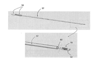
ロックデリバリーシステムは、ロック支持カテーテルおよびロックデリバリーカテーテルを含み得る。ロック支持カテーテルは堅い部分と可撓性の部分を含み得る。この態様では、堅い部分は1つ以上のタブを開くように、つまりテザーが通り抜けられるようにロック装置の壁の方にタブを押し、それによってテザーに沿ったロック装置の摺動を促進するように、構成され得る。ロック支持カテーテルの可撓性部分は、カテーテルが容易に屈曲し曲がることを可能にし、それは弁輪のまわりの異なる位置でのロック装置の搬送を促し得ることが理解されよう。この態様では、ロックデリバリーカテーテルは可撓性カテーテルであり得、それはロック支持カテーテルの堅い部分からロック装置を押し出すように従来の方式で操作され得、そうするとタブが解放され、およびロック装置の管状構造内のテザーにつかまることができ、テザーに沿った場所に効果的にロックする。 The lock delivery system may include a lock support catheter and a lock delivery catheter. The lock-supporting catheter may include a rigid portion and a flexible portion. In this aspect, the stiff part is to open one or more tabs, i.e. push the tabs towards the wall of the locking device to allow the tether to pass through, thereby facilitating sliding of the locking device along the tether. Can be configured. It will be appreciated that the flexible portion of the lock-supporting catheter allows the catheter to easily bend and bend, which may facilitate the transfer of the locking device at different locations around the annulus. In this embodiment, the lock delivery catheter can be a flexible catheter, which can be manipulated in a conventional manner to push the locking device out of the rigid portion of the locking supporting catheter, so that the tabs are released and the tubular structure of the locking device. It can be grabbed by the tether inside and effectively locks in place along the tether.
弁内外の流れを最小化し、それによって手術中の弁膜塞栓血症のリスクを減らすために、高頻度心室ペーシング(180-220拍/分)がしばしば経カテーテル心臓弁の植え込み中に行われることに留意されたい。高頻度ペーシングに使用される時間は最小であり、患者へのリスクを最小化するために通常14~29秒である。人工僧帽弁は、本発明のデリバリーシステムを使用して、25秒の高頻度ペーシング内で生来の僧帽弁に展開および固定され得ることが熟慮される。テザーに取り付けられた複数のアンカーの経カテーテル展開に続いて、デリバリーシステムは置換人工僧帽弁の正確な展開、複数のロック装置の同時搬送、および置換人工僧帽弁へのロック装置の確実な取り付けを25秒内に提供し、続いて後続テザーの容易な除去を提供する。 Frequent ventricular pacing (180-220 beats / min) is often performed during transcatheter heart valve implantation to minimize intravalvular flow and thereby reduce the risk of valvular embolism during surgery. Please note. The time used for high frequency pacing is minimal, usually 14-29 seconds to minimize risk to the patient. It is considered that the artificial mitral valve can be deployed and immobilized in the native mitral valve within 25 seconds of high frequency pacing using the delivery system of the present invention. Following transcatheter deployment of multiple anchors attached to the tether, the delivery system provides accurate deployment of the replacement artificial mitral valve, simultaneous delivery of multiple locking devices, and reliable locking of the replacement artificial mitral valve. Installation is provided within 25 seconds, followed by easy removal of subsequent tethers.
一態様では、複数のロック装置の同時搬送は、ロックハウジング構造を使用して達成することができる。この態様では、ロックハウジング構造は、複数のロックとロックカテーテルを収容するために、多数のルーメンを伴って構成され得る。この態様では、ロックハウジング構造はさらに、弁膜カテーテルに人工僧帽弁を装填するように構成され得ることが理解されよう。人工僧帽弁デバイスがより小さなサイズへと巻縮され、および弁膜デリバリーカテーテルに装填される場合、ロックハウジング構造は置換人工僧帽弁の上部のフレア状の部分の先端の最も近くに装填される。複数のロック装置およびロックカテーテルは、ロックハウジング構造に装填され得、置換人工弁の上部のフレア状の部分の先端に隣接して位置し、置換人工弁のすぐ後にロック装置が展開されることを可能にする。 In one aspect, simultaneous transfer of multiple locking devices can be achieved using a lock housing structure. In this aspect, the lock housing structure can be configured with a large number of lumens to accommodate multiple locks and lock catheters. In this aspect, it will be appreciated that the lock housing structure can be further configured to load the valvular catheter with an artificial mitral valve. When the artificial mitral valve device is rolled down to a smaller size and loaded into a valvular delivery catheter, the lock housing structure is loaded closest to the tip of the flared portion of the upper part of the replacement artificial mitral valve. .. Multiple locking devices and locking catheters can be loaded into the lock housing structure and are located adjacent to the tip of the flared portion of the upper part of the replacement prosthesis so that the locking device is deployed immediately after the replacement prosthesis. enable.
人工僧帽弁デリバリーの一態様では、テザーの一端に取り付けられた生来の弁輪へのアンカーの展開に続いて、依然として体外にあるテザーのもう1つの端部は、ステントの上部のフレア状の部分を通過し、およびロックカテーテル内に収容され得、それはその後、ロックハウジング構造に装填される。一態様では、ステントの上部のフレア状の部分内のテザーおよびロックカテーテルの収容は、テザー支持カテーテルを使用して容易に達成することができ、それは最終的には置換人工弁の解放に先立って体内から取り除かれる。 In one aspect of artificial mitral valve delivery, following the deployment of an anchor to the natural annulus attached to one end of the tether, the other end of the tether, still outside the body, is flared at the top of the stent. It can pass through a portion and be contained within a lock catheter, which is then loaded into the lock housing structure. In one aspect, containment of the tether and lock catheter within the flared portion of the upper part of the stent can be easily achieved using a tether-supported catheter, which ultimately precedes the release of the replacement prosthesis. Removed from the body.
ある随意の態様では、ロックハウジング構造は弁膜カテーテルに連結され、人工弁置換と弁膜カテーテルとの間の回転を防ぐ。付加的に、弁膜カテーテルは、搬送中に生来の僧帽弁内の標的とされた植え込み位置へと進むと共に回転することがないように構成され得る。この非回転機構の1つの利点は、主要な偏向可能デリバリーカテーテル内でテザーがもつれるのを防ぐことである。 In one optional aspect, the lock housing structure is coupled to the valvular catheter to prevent rotation between the prosthetic valve replacement and the valvular catheter. In addition, the valvular catheter may be configured so that it does not rotate with advancing to the targeted implantation position within the natural mitral valve during transport. One advantage of this non-rotating mechanism is that it prevents the tether from becoming entangled within the main deflectable delivery catheter.
弁膜カテーテルを引き戻すことで、置換人工弁が解放される。この態様では、人工弁置換の遠位端の解放は経環的に(trans-annularly)達成され得る。人工弁置換の遠位端が部分的に解放された時、弁膜カテーテル全体が弁膜の弁輪にわたって位置づけられ得る。完全な弁膜解放は高頻度ペーシング中に行なうことができる。ロックカテーテルは置換人工弁の解放直後に解放される。 By pulling back the valvular catheter, the replacement prosthesis is released. In this embodiment, the release of the distal end of the prosthetic valve replacement can be achieved transcyclically (trans-annularly). When the distal end of the prosthetic valve replacement is partially released, the entire valvular catheter can be positioned across the valvular annulus. Complete valvular release can be done during high frequency pacing. The lock catheter is released immediately after the replacement prosthesis is released.
ロックおよびロックカテーテルの解放は、ロックハウジング構造および主要なデリバリーシステムハンドルに連結された2つの連係構造の操作によって達成し得る。さらなる態様では、1つの連係構造は、ロックカテーテルからの同時の押し出しを可能にし、および第1の連係構造に隣接する第2連係構造は、置換人工僧帽弁の上部のフレア状の部分上にロック装置を解放することを可能にする。 Locking and unlocking of the lock catheter can be achieved by manipulating the lock housing structure and two coupled structures coupled to the main delivery system handle. In a further aspect, one linkage structure allows simultaneous extrusion from the lock catheter, and a second linkage structure adjacent to the first linkage structure is on the flared portion of the upper part of the replacement artificial mitral valve. Allows the locking device to be released.
任意の縫合に似た切断装置を、ロック装置の近位部から出ている残存するテザーを切断するために使用可能であることが熟慮される。デリバリーシステム全体を取り除くことができ、および中隔閉鎖装置を用いて心房中隔の穴を閉じることができる。 It is considered that any suture-like cutting device can be used to cut the remaining tether emerging from the proximal portion of the locking device. The entire delivery system can be removed, and a septal closure device can be used to close the hole in the atrial septum.
本開示に記載される様々な実装は、追加のシステム、方法、特徴および利点を含むことができ、必ずしもそれらを本明細書に明確に開示することはできないが、以下の詳細な説明および添付の図面を吟味すると当業者には明白になるだろう。全てのそのようなシステム、方法、特徴、および利点が本開示に含まれ、および添付の請求項によって保護されることが意図される。 The various implementations described in this disclosure may include additional systems, methods, features and advantages, which may not necessarily be explicitly disclosed herein, but with the following detailed description and attachments. Examination of the drawings will be obvious to those skilled in the art. All such systems, methods, features, and advantages are contained in this disclosure and are intended to be protected by the appended claims.
以下の図の特徴およびコンポーネントは、本開示の一般的な原則を強調するために例示される。図を通して対応する特徴およびコンポーネントは、一貫性と明確さのために、参照符号を一致させて示され得る。
本発明は、以下の詳細な説明、実施例、図面および請求項、およびそれらの前後の説明を参照することによってより容易に理解され得る。しかしながら、本発明のデバイス、システム、および/または方法が開示され記載される前に、本発明は別段の定めがない限り、開示される特定のデバイス、システム、および/または方法に制限されず、およびそれゆえに当然のこととして変化し得ることが理解される。さらに、本明細書において使用される用語は、特定の態様を記載する目的のみで使用され、限定を意図していないことが理解される。 The present invention may be more easily understood by reference to the following detailed description, examples, drawings and claims, and description before and after them. However, prior to the disclosure and description of the devices, systems, and / or methods of the invention, the invention is not limited to the particular devices, systems, and / or methods disclosed, unless otherwise specified. And therefore it is understood that it can change as a matter of course. Further, it is understood that the terms used herein are used solely for the purpose of describing particular embodiments and are not intended to be limiting.
本発明の以下の詳細な説明は、最良であり、現在知られている実施形態における本発明の可能な教示として提供される。この目的のために、当業者は、本明細書に記載の本発明の様々な態様に多くの変更を行うことができ、それでもなお本発明の有用な結果が得られることを認識しかつ理解するだろう。本発明の望ましい利点のいくつかは、他の特徴を利用することなく、本発明の特徴のいくつかを選択することによって得ることができることも明白であろう。 The following detailed description of the invention is best and is provided as a possible teaching of the invention in currently known embodiments. To this end, one of ordinary skill in the art recognizes and understands that many modifications can be made to the various aspects of the invention described herein and that useful results of the invention are still obtained. right. It will also be apparent that some of the desirable benefits of the invention can be obtained by selecting some of the features of the invention without utilizing other features.
従って、当業者は、本発明に対する多くの修正および改造が可能であり、特定の状況では望ましくさえ有り得、およびそれが本発明の一部であることを認識するだろう。したがって、以下の詳細な説明は、本発明の原則の例示として提供され、それを制限することはない。 Accordingly, one of ordinary skill in the art will recognize that many modifications and modifications to the invention are possible, even desirable in certain circumstances, and that they are part of the invention. Accordingly, the following detailed description is provided as an example of the principles of the invention and does not limit it.
明確にするために、本開示は機能性僧帽弁逆流の処置に焦点を置くが、心臓弁膜置換システムおよび関連方法は、他の種類の僧帽弁逆流を処置し、または三尖弁などのヒト心臓の他の不健全な弁膜を置換するために使用され得ること、またはそうでなければ使用されるように構成され得ること、または弁膜の欠陥に苦しむ他の哺乳動物にも同様に使用されてもよいこと、またはそうでなければ使用されるように構成されてもよいことが熟慮されると理解されよう。 For clarity, this disclosure focuses on the treatment of functional mitral regurgitation, but heart valve replacement systems and related methods treat other types of mitral regurgitation, or such as the tricuspid valve. It can be used to replace other unhealthy valvular membranes in the human heart, or it can be configured to be used otherwise, or it can be used in other mammals suffering from valvular defects as well. It will be understood that it may or may not be configured to be used.
本明細書を通じて使用されるように、単数形の「a」、「an」および「the」は、文脈が明確に指示しない限り、複数の指示物を含む。したがって、例えば「弁尖」への言及は、文脈がそうでないことを示さない限り、2つ以上の弁尖を含み得る。 As used throughout the specification, the singular forms "a", "an" and "the" include a plurality of referents unless the context explicitly indicates. Thus, for example, a reference to "valve" may include more than one flap, unless the context indicates otherwise.
本明細書において範囲は、「約」1つの特定の数値から、および/または「約」別の特定の数値までとして表現され得る。そのような範囲が表現される場合、別の態様は、1つの特定の数値から、および/または別の特定の数値までを含む。同様に、先行詞「約」を用いて数値を近似値として表現する場合、特定の数値は別の態様を形成することが理解されるだろう。各範囲のエンドポイントは、別のエンドポイントの関係において、および別のエンドポイントとは無関係に、有意であることがさらに理解されるだろう。 The range may be expressed herein from one particular number "about" and / or to another particular number "about". When such a range is represented, another embodiment includes from one particular number and / or to another particular number. Similarly, when expressing a number as an approximation using the antecedent "about", it will be understood that a particular number forms another aspect. It will be further understood that each range of endpoints is significant in relation to another endpoint and independently of another.
本明細書で使用されるように、用語「随意の」または「随意に」は、その後に記載される事象または状況が生じても生じなくてもよいこと、および記載が、前記事象または状況が生じる実例と生じない実例を含むことを意味している。 As used herein, the term "voluntary" or "voluntarily" means that the event or situation described thereafter may or may not occur, and that the description is such event or situation. It means that the example that occurs and the example that does not occur are included.
本明細書において使用される単語「または(or)」は、特定のリストのいずれか1つの構成員を指し、およびそのリストの構成員の任意の組み合わせも含む。さらに、とりわけ「できる」、「してもよい」、「だろう」、「し得る」などの条件付きの言葉は、特に別記しない限り、またはそうでなければ使用される文脈内で理解されるのであれば、特定の態様が特定の特徴、要素、および/または工程を含む一方で、他の態様はそれらを含まないことを伝えるように通常は意図されることに留意すべきである。したがって、そのような条件付きの言葉は通常は、特徴、要素および/または工程が1つ以上の特定の態様に何かしらの形で必要とされることを、またはこれらの特徴、要素および/または工程が特定の実施形態に包含または実施されるか否かを、ユーザーによる入力または誘発の有無に関わらず、決定するための論理を1つ以上の特定の態様が必然的に含むことを示唆するようには意図されない。 As used herein, the word "or" refers to any one member of a particular list, and includes any combination of members of that list. In addition, conditional words such as "can", "may", "may", and "can" are understood in the context in which they are used, unless otherwise noted. If so, it should be noted that certain embodiments are usually intended to convey that certain features, elements, and / or steps are included, while other embodiments do not. Therefore, such conditional terms usually indicate that a feature, element and / or process is required in some form in one or more particular embodiments, or these features, elements and / or process. To suggest that one or more specific embodiments necessarily include logic for determining whether or not is included or implemented in a particular embodiment, with or without user input or triggering. Not intended for.
開示された方法およびシステムを実施するために使用可能なコンポーネントが開示される。これらのコンポートと他のコンポーネントは本明細書に開示され、およびこれらのコンポーネントの組み合わせ、サブセット、相互作用、グループ等が開示される時に、これらの個々の様々な個別および集合的な組み合わせと入替が明確に開示され得ない一方で、全ての方法とシステムに関して、各々が具体的に熟慮され、および本明細書に記載されることが理解される。これは、開示された方法における工程を制限なく含む本発明の全ての態様に当てはまる。したがって、実施可能な様々な追加の工程がある場合、これらの追加の工程の各々は、特定の実施形態のいずれか、または開示された方法の実施形態の組み合わせによって実施し得ることが理解される。 The disclosed methods and components that can be used to implement the system are disclosed. These compotes and other components are disclosed herein, and when combinations, subsets, interactions, groups, etc. of these components are disclosed, they are replaced with various individual and collective combinations of these. While not expressly disclosed, it is understood that each method and system will be specifically considered and described herein. This applies to all aspects of the invention, including without limitation the steps in the disclosed method. Therefore, it is understood that if there are various additional steps that can be performed, each of these additional steps can be performed by any of the specific embodiments or a combination of embodiments of the disclosed methods. ..
本方法およびシステムは、好ましい実施形態についての以下の詳細な説明と、本明細書に含まれる実施例を参照することによって、および図とそれらの前後の説明を参照することによって、より容易に理解され得る。 The methods and systems are more easily understood by reference to the following detailed description of preferred embodiments and the examples contained herein, and by reference to the figures and their preceding and following description. Can be done.
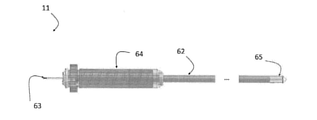
本明細書に記載されるのは、心臓弁膜置換システム、および生来の弁輪の1つに置換人工心臓弁(12)を固定する方法である。一態様では、心臓弁膜置換システムは、生来の僧帽弁輪に人工僧帽弁を固定するように構成され得ることが熟慮される。さらなる態様では、心臓弁膜置換システムおよび関連方法は、患者の心周期中に僧帽弁逆流を緩和するために、および/または生来の僧帽弁輪のさらなる拡張を防ぐ一助となるように、構成され得る。本明細書に記載される心臓弁膜置換システム(11)は、心臓内のいかなる病的な弁膜をも置換するために使用され得ることが熟慮されることに留意すべきである。例示を意図しているため、本発明における記載は、僧帽弁および僧帽弁の幾何学的形状による命名に焦点を置く。しかしながら、本明細書に記載される設計は、全ての他の心臓弁で適宜使用することができる。 Described herein are a valvular heart replacement system and a method of fixing a replacement artificial heart valve (12) to one of the innate annulus. In one aspect, it is considered that the valvular heart replacement system can be configured to secure the artificial mitral valve to the innate mitral annulus. In a further aspect, the valvular replacement system and related methods are configured to alleviate mitral regurgitation during the patient's cardiac cycle and / or to help prevent further dilation of the innate mitral annulus. Can be done. It should be noted that the heart valve replacement system (11) described herein can be used to replace any pathological valve membrane in the heart. For purposes of illustration, the description in the present invention focuses on the mitral valve and the geometric naming of the mitral valve. However, the designs described herein can optionally be used with all other heart valves.
図1を参照すると、僧帽弁(1)は心臓の左側、左心房(9)と左心室(10)の間に配置され、および僧帽弁輪によって含まれる前尖(1)と後尖(2)を有する。この態様では、僧帽弁輪はさらに線維部分(3)すなわち線維性を有し、それは右三角(6a)から左三角(6b)まで走り、かつ大動脈弁の一部および後部の筋肉部分(4)と一続きになっている。さらに、腱索(7a,b)は、左心室壁のそれぞれの大乳頭筋(8a,b)から始まり、それぞれの僧帽弁膜につながる。 Referring to FIG. 1, the mitral valve (1) is located on the left side of the heart, between the left atrium (9) and the left ventricle (10), and is contained by the mitral valve annulus, anterior leaflet (1) and posterior leaflet. It has (2). In this embodiment, the mitral valve annulus also has a fibrous portion (3) or fibrous, which runs from the right triangle (6a) to the left triangle (6b) and is part of the aortic valve and the posterior muscle portion (4). ) And so on. In addition, the chordae tendineae (7a, b) begin at the respective large papillary muscles (8a, b) of the left ventricular wall and connect to the respective trapezius valves.
一態様では、心臓弁膜置換システム(11)は、置換人工僧帽弁(12)および経カテーテルデリバリーシステムを含み得る。この態様では、および図2を参照すると、心臓弁膜置換システム(11)の典型的な態様が本明細書に開示され、コンポーネントおよび組み立てられた人工僧帽弁(12)が示される。この態様では、人工僧帽弁(12)は、選択的に圧縮され、またはそうでなければ圧縮位置に押さえつけられ、そしてデリバリーカテーテルに搭載されるように構成され得る。 In one aspect, the valvular heart replacement system (11) may include a replacement artificial mitral valve (12) and a transcatheter delivery system. In this aspect, and with reference to FIG. 2, a typical aspect of the valvular heart replacement system (11) is disclosed herein, showing components and an assembled artificial mitral valve (12). In this aspect, the artificial mitral valve (12) may be configured to be selectively compressed or otherwise pressed into a compressed position and mounted on a delivery catheter.
人工僧帽弁(12)は、半月形のステント(31)、少なくとも1つの可動性人工弁尖(16)、およびステント(14)の下部の心室部分に人工弁尖部分を動作可能に連結する少なくとも1つの突起構造(18)を含み得る。 The prosthetic mitral valve (12) operably connects a crescent-shaped stent (31), at least one mobile prosthetic valve leaflet (16), and an artificial valve leaflet portion to the ventricular portion below the stent (14). It may include at least one protruding structure (18).
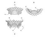
一態様では、置換人工僧帽弁(12)の半月形のステント(31)は、図2A-2Bを参照すると、上部のフレア状の部分(13)および下部の心室部分(14)を含み得る。少なくとも、上部のフレア状の部分(13)の一部、および/または下部の心室部分(14)の一部は、望ましい動作位置へと自己拡張可能またはバルーン拡張可能なように形成され得る。この態様では、ステント(31)は従来、放射状に折り畳み可能および拡張可能な望ましいステント設計へと、レーザーカットされ、または織り込まれ得ることが熟慮される。したがって、ステントは、限定されないがコバルトクロム、ステンレス鋼を含む金属、または限定されないがニチノールを含み固有の形状記憶特性を有する金属で作ることができる拡張可能な網状または非網状の本体を形成するために、複数の動作可能に連結されたコンポーネントを含み得ることがさらに熟慮される。随意に、ステントは、生体組織、ポリマーなどの合成素材などの柔らかい物質によって連結される複数の垂直な堅い構造を含み得ることが熟慮される。ステントは、残存する生来の弁尖の生来の動的運動が人工弁尖にきつく適合できるように構成され得る。 In one aspect, the crescent-shaped stent (31) of the replacement artificial mitral valve (12) may include an upper flared portion (13) and a lower ventricular portion (14) with reference to FIGS. 2A-2B. .. At least a portion of the upper flared portion (13) and / or a portion of the lower ventricular portion (14) can be formed to be self-expandable or balloon-expandable to the desired motion position. In this aspect, it is conventionally considered that the stent (31) can be laser cut or woven into a desirable stent design that is radially foldable and expandable. Thus, because the stent forms an expandable reticulated or non-reticulated body that can be made of a metal, including but not limited to cobalt chromium, stainless steel, or a metal that contains, but not limited to, nitinol and has unique shape memory properties. Further consideration is given to the possibility of including multiple operably linked components. Optionally, it is considered that the stent may contain multiple vertical rigid structures connected by soft materials such as biological tissue, synthetic materials such as polymers. The stent may be configured so that the innate dynamic movement of the remaining innate leaflet can be tightly fitted to the prosthesis.
一態様では、拡張した構成において、ステント(31)の内側表面は実質的に円形の断面プロフィールを画定し得ることが熟慮される。ステント(31)は変形するように構成され得、それによってステントの内側表面は、限定されないが楕円の断面プロフィールまたは非対称の断面プロフィールを含む非円形の断面プロフィールを画定することが、さらに熟慮される。明細書において使用されるように、用語「非対称の断面プロフィール」はいかなる非円形の断面形状をも含む。 In one aspect, it is considered that in the expanded configuration, the inner surface of the stent (31) can define a substantially circular cross-sectional profile. The stent (31) can be configured to deform, whereby the inner surface of the stent is further considered to define a non-circular cross-sectional profile including, but not limited to, an elliptical cross-section profile or an asymmetric cross-section profile. .. As used herein, the term "asymmetric cross-sectional profile" includes any non-circular cross-sectional shape.
一態様では、図3を参照すると、植え込まれた時、ステント(31)の上部のフレア状の部分(13)は生来の弁輪の上および/またはそれを超えて位置づけられるように構成され得ることが熟慮される。この態様では、ステント(31)の上部のフレア状の部分(13)は、ステントの固定、固着および封着を容易にするように構成され得、それは弁傍の漏出および植え込み後のステントの移動を防ぐ一助となり得る。僧帽弁輪は非対称であり、それは図3に例示される。人工僧帽弁(12)の上部のフレア状の部分(13)は、僧帽弁輪の後部部分をカバーする、または覆いかぶさり、それは3つのスカラップ、すなわち(P1)、(P2)および(P3)に分けられる。一態様では、上部のフレア状の部分(13)は2つの交連、すなわちAC前交連およびPC後交連に及び得る。別の態様では、動作可能に位置づけた時、上部のフレア状の部分(13)は僧帽弁の全円周をカバーし得る。 In one aspect, with reference to FIG. 3, the flared portion (13) above the stent (31) is configured to be positioned above and / or beyond the innate annulus when implanted. It is considered to get. In this embodiment, the flared portion (13) above the stent (31) may be configured to facilitate fixation, fixation and sealing of the stent, which is the valve paraleakage and post-implantation stent transfer. Can help prevent. The mitral valve annulus is asymmetric, which is illustrated in FIG. The flared portion (13) at the top of the artificial mitral valve (12) covers or covers the posterior portion of the mitral valve annulus, which is the three scallops, ie (P1), (P2) and (P3). ). In one aspect, the upper flared portion (13) may extend to two commissures, i.e. AC pre-commissure and PC post-commissure. In another aspect, the upper flared portion (13) may cover the entire circumference of the mitral valve when positioned operably.
一態様では、下部の心室部分(14)の少なくとも一部は、心臓の心室の空洞内に位置づけられ得、および/または少なくとも1つの生来の僧帽弁の弁尖の一部に接し得る。 In one aspect, at least a portion of the lower ventricular portion (14) may be located within the ventricular cavity of the heart and / or may contact a portion of the flap of at least one native mitral valve.
図4は、部分的な心臓のコンピューターモデルで覆われている、コンピューターで生成された人工僧帽弁(12)のステント(31)を示し、大動脈弁輪(80)、左心室の一部(10)、乳頭筋(8)、左心房(9)、および腱索(7)が含まれる。本発明における部分的な円周フレーム(31)は、図4に示されるように、左室流出路(81)閉塞(LVOTO)を防ぐ一助となり得ることを、当業者は理解するだろう。ステントの下部の心室部分(14)の部分的な円周構造の1つの潜在的利点は、動作可能に位置づけられた時、ステントのフレームが僧帽弁前尖(1)に干渉しないことである。生来の弁尖はステントによって押さえつけられず、および自由に動くことができ、それによってLVOTOのリスクを減らす。ステントの下部の心室部分(14)は、生来の前尖の平静な運動を可能にするように構成される。 FIG. 4 shows a computer-generated artificial mitral valve (12) stent (31) covered with a computer model of a partial heart, an aortic annulus (80), and a portion of the left ventricle ( 10), papillary muscle (8), left atrium (9), and chordae tendineae (7). Those skilled in the art will appreciate that the partial circumferential frame (31) in the present invention can help prevent left ventricular outflow tract (81) obstruction (LVOTO), as shown in FIG. One potential advantage of the partial circumferential structure of the lower ventricular portion (14) of the stent is that the frame of the stent does not interfere with the anterior leaflet of the mitral valve (1) when positioned operably. .. The innate leaflet is not held down by the stent and can move freely, thereby reducing the risk of LVOTO. The lower ventricular portion (14) of the stent is configured to allow for calm movement of the innate anterior leaflet.
1つの典型的な態様では、ステントの下部の心室部分(14)は部分的な円柱状または円錐形の形状を有し得、および随意に、変位した病的な生来の弁尖の放射長さの約0.5から約1.5倍の高さ範囲を有し得る。ステント(31)の下部の心室部分(14)は、生来の後部弁輪の円周の選択された部分のみをカバーする、または覆いかぶさるように構成され得、およびステントの拡張可能な性質の結果として、動作位置への拡張に際して病的な生来の弁尖を血流路の外に変位させ得る。下部の心室部分(14)が、生来の弁輪の円周の全体ではなくその選択した部分に重なるように構成され得るため、この「開く」構成は、残存する生来の弁尖、例えば僧帽弁前尖の動的運動を可能にし、および人工弁尖との接合を可能にする。一態様では、ステントが動作位置へ拡張する時、上部のフレア状の部分の外径は、下部の心室部分の内径より約5~15mm大きくなり得る。 In one typical embodiment, the ventricular portion (14) below the stent may have a partially columnar or conical shape, and optionally the radial length of the displaced pathological innate leaflet. Can have a height range of about 0.5 to about 1.5 times. The lower ventricular portion (14) of the stent (31) may be configured to cover or cover only a selected portion of the circumference of the innate posterior annulus, and as a result of the expandable nature of the stent. As such, the pathological innate valve leaflet can be displaced out of the blood flow channel upon expansion to the operating position. This "open" configuration is such that the lower ventricular portion (14) overlaps the selected portion of the natural annulus rather than the entire circumference, so this "open" configuration is the remaining innate valve leaflet, eg, the mitral cap. Allows dynamic movement of the anterior valve leaflet and allows joining with the artificial valve leaflet. In one aspect, when the stent expands to the operating position, the outer diameter of the upper flared portion can be about 5-15 mm larger than the inner diameter of the lower ventricular portion.
さらなる態様では、ステントの下部の心室部分(14)は、図3に例示されるように、前交連(5a)から後交連(5b)まで放射状に伸長し得る。さらなる態様では、図3に例示されるように、ステントの下部の心室部分(14)は「C」の形をした断面を有し得、ここで外側端部の1つ(26b)は前尖と前外側交連弁尖の間の裂け目に着地し、および他の外側端部(26a)は前尖と後内側交連弁尖の間の裂け目に着地する。 In a further aspect, the lower ventricular portion (14) of the stent can extend radially from the anterior commissure (5a) to the posterior commissure (5b), as illustrated in FIG. In a further embodiment, as illustrated in FIG. 3, the lower ventricular portion (14) of the stent may have a "C" shaped cross section, where one of the lateral ends (26b) is anterior apex. And the rift between the anterior-lateral commissure leaflet, and the other lateral end (26a) lands in the rift between the anterior and posterior medial commissure leaflets.
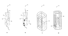
一態様では、図5Aに示されるように、ステント(31)の上部のフレア状の部分(13)に画定された開口部(24)は、円形、正方形、菱形、三角形または非対称の形状を有し得る。上部のフレア状の部分(13)の開口部(24)の区域は、約0.2mm2から2mm2の区域範囲を有し得る。 In one aspect, as shown in FIG. 5A, the opening (24) defined in the flared portion (13) above the stent (31) has a circular, square, rhombic, triangular or asymmetrical shape. Can be. The area of the opening (24) of the upper flared portion (13) may have an area range of about 0.2 mm 2 to 2 mm 2 .
一態様では、図5Bに示されるように、ステントの上部のフレア状の部分(13)と下部の心室部分(14)の間の角度は、90度から150度の間で変化可能であり、その結果ステントフレームを左心房の生来の湾曲に一致させることができる。 In one aspect, as shown in FIG. 5B, the angle between the flared portion (13) at the top of the stent and the ventricular portion (14) at the bottom can vary from 90 degrees to 150 degrees. As a result, the stent frame can be matched to the natural curvature of the left atrium.
一態様では、図6A-6Eに示されるように、ステントの下部の心室部分(14)の高さは、カバーされた弁輪の円周に沿って変化し得ることが熟慮される。随意に、僧帽弁後尖の中央部分(14b)をカバーするステントの下部の心室部分(14)の高さは、図5Aに示されるように僧帽弁後尖(14a,c)の2つの外側部分をカバーするステントの下部の心室部分(14)よりも、実質的に長い、またはそれと同じ高さであり得る。僧帽弁後尖(14a,c)の2つの外側部分をカバーするステントの下部の心室部分(14)は、動作可能に位置づけられた時、それが生来の前尖、腱および左心室に干渉しないように、軸方向においてより短くなり得ることが熟慮される。 In one aspect, it is considered that the height of the ventricular portion (14) below the stent can vary along the circumference of the covered annulus, as shown in FIGS. 6A-6E. Optionally, the height of the lower ventricular portion (14) of the stent covering the central portion (14b) of the posterior leaflet of the mitral valve is 2 of the posterior leaflet of the mitral valve (14a, c) as shown in FIG. 5A. It can be substantially longer or at the same height as the lower ventricular portion (14) of the stent covering the two lateral portions. The lower ventricular portion (14) of the stent, which covers the two lateral parts of the posterior leaflet of the mitral valve (14a, c), interferes with the innate anterior leaflet, tendon and left ventricle when positioned operably. It is considered that it can be shorter in the axial direction so as not to.
一態様では、図8Cに示されるように、ステントの下部の心室部分(14)は、ステント(31)の上部のフレア状の部分(13)の少なくとも1つの位置から伸長する、少なくとも1つの垂直材または細長い支柱(85)を伴って形成され得る。随意に、図8Dに例示されるように、細長い支柱(85)は、軸方向に伸長するまっすぐまたはカーブした区域であり得る。さらなる態様では、細長い支柱(85)は分岐して第2の支柱を形成し、連係スカートまたは弁尖物質の縫合を容易にする。図8Eに例示されるように、細長い支柱は、弁尖付着端のそれとして形成され得ることが熟慮される。 In one aspect, as shown in FIG. 8C, the lower ventricular portion (14) of the stent extends from at least one position of the flared portion (13) above the stent (31), at least one vertical. It can be formed with a material or an elongated strut (85). Optionally, as illustrated in FIG. 8D, the elongated strut (85) can be a straight or curved area that extends axially. In a further aspect, the elongated strut (85) branches to form a second strut, facilitating suturing of the interlocking skirt or valve leaflet material. It is considered that the elongated strut can be formed as that of the valve tip attachment end, as illustrated in FIG. 8E.
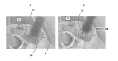
図7A-7Cに示されるように、ステントの心室部分の底部(27)は、動作可能に位置づけられた時、生来の弁尖を捕らえるフランジ、フック、コイル、クリップなどの機構(32)を伴って構成され得る。この態様では、デバイスはさらに、生来の弁膜に固着および固定され得る。この捕獲メカニズムはさらに、シール剤として作用し、および弁傍の漏出を防ぐパンヌス構成も可能にし得る。一態様では、図7Aに例示されるように、展開に際して少なくとも3つのフックに似たコンポーネント(32)が、ステントの支柱から放射状に伸長し、および生来の弁尖と腱を捕らえ得る。一態様では、図7Bに例示されるように、展開に際して、フックに似たコンポーネント(32)はステント(14b)の中央部分からのみ伸長し得る。別の態様では、図7Cに例示されるように、展開に際してフックに似たコンポーネント(32)はステント(31)の下部の心室部分(14)の外側部分(14a,c)からのみ伸長し得る。 As shown in FIGS. 7A-7C, the bottom (27) of the ventricular portion of the stent is accompanied by a mechanism (32) such as a flange, hook, coil, clip, etc. that captures the innate valve leaflet when positioned operably. Can be configured. In this aspect, the device can further be anchored and secured to the innate valve membrane. This capture mechanism may also allow for a pannus configuration that acts as a sealant and prevents valve side leakage. In one aspect, as illustrated in FIG. 7A, at least three hook-like components (32) can radiate from the struts of the stent and capture the innate valve leaflets and tendons upon deployment. In one aspect, upon deployment, the hook-like component (32) can only extend from the central portion of the stent (14b), as illustrated in FIG. 7B. In another embodiment, as illustrated in FIG. 7C, upon deployment the hook-like component (32) can only extend from the lateral portion (14a, c) of the ventricular portion (14) below the stent (31). ..
拡張した位置では、図5-9に典型的に示されるように、ステント(31)の下部の心室部分(14)は約20mmから約60mm、およびより好ましくは約30mmから約50mmの範囲の外径を有し得る。特定の典型的な態様では、および制限なく、ステント(31)の下部の心室部分(14)は約36mmの外径を有し得る。しかしながら、ステント(31)の下部の心室部分(14)は、被験体の心臓の選択されたチャネル内でのステントの適切な位置づけを可能にする効果的な外径を有し得ることが熟慮される。 In the dilated position, the lower ventricular portion (14) of the stent (31) is outside the range of about 20 mm to about 60 mm, and more preferably about 30 mm to about 50 mm, as typically shown in FIG. 5-9. Can have a diameter. In certain typical embodiments, and without limitation, the ventricular portion (14) below the stent (31) can have an outer diameter of approximately 36 mm. However, it has been considered that the lower ventricular portion (14) of the stent (31) may have an effective outer diameter that allows proper positioning of the stent within the selected channel of the subject's heart. To.
ステント(31)の直径、ステントの網目パターン内の平行した支柱間および/または隣接する開口部の間の間隔、およびステントの機械的特性は、被験体の心臓の選択された部屋内の所望の位置および/または所望の性能特性を達成するために、必要に応じて選択的に変化し得ることが熟慮される。典型的な態様では、ステント(31)の網目パターン内の、平行した支柱間の間隔および/または隣接する開口部の寸法は、ステント(31)全体にわたって非均一であり得る。ステント(31)は、楕円形状に変形するように構成され得ることがさらに熟慮される。ステント(31)のメッシュ構成は、限定されないが僧帽弁閉鎖を含む弁膜閉鎖中に、圧縮的な負荷にさらされる際にステントが崩壊するのを防ぐのに十分な構造的一体性を提供し得ることが、さらに熟慮される。加えて、ステント(31)は、被験体の心臓内で僧帽弁輪にステントを確実に位置づけることを可能にするために、放射状の拡張力を収容し、およびそれに耐えられるように構成され得る。 The diameter of the stent (31), the spacing between parallel struts and / or adjacent openings in the mesh pattern of the stent, and the mechanical properties of the stent are desired within the selected chamber of the subject's heart. It is considered that it can be selectively varied as needed to achieve the position and / or desired performance characteristics. In a typical embodiment, the spacing between parallel struts and / or the dimensions of adjacent openings within the mesh pattern of the stent (31) can be non-uniform throughout the stent (31). It is further considered that the stent (31) can be configured to deform into an elliptical shape. The mesh configuration of the stent (31) provides sufficient structural integrity to prevent the stent from collapsing when exposed to compressive loads during valvular closure, including but not limited to mitral valve closure. Getting is even more pondered. In addition, the stent (31) may be configured to contain and withstand radial diastolic forces to allow for reliable positioning of the stent in the mitral annulus within the subject's heart. ..
一態様では、図9に例示されるように、ステント(31)の下部の心室部分(14)は360度未満で円周方向に伸長し得る一方で、連結された上部のフレア状の部分(13)は円周方向に約360度伸長するように構成され得ることが熟慮される。 In one aspect, as illustrated in FIG. 9, the lower ventricular portion (14) of the stent (31) can extend circumferentially below 360 degrees, while the flared portion of the connected upper portion ( It is considered that 13) can be configured to extend about 360 degrees in the circumferential direction.
一態様では、置換人工僧帽弁(12)は、図2に示されるように、ステントの内側および外側表面の少なくとも一部に結合し得るスカート(28)を含み得る。1つの典型的な態様では、スカート(28)は、ステントの内側および外側表面の少なくとも一部に、非吸収性縫合糸を用いて縫合し得ることが熟慮される。典型的な態様では、スカート(28)は、生体適合性の物質、例えば限定されないが、生体適合性の布、ウシまたは豚の心膜などで形成され得る。 In one aspect, the replacement artificial mitral valve (12) may include a skirt (28) that may be attached to at least a portion of the medial and lateral surfaces of the stent, as shown in FIG. In one typical embodiment, it is considered that the skirt (28) can be sutured to at least a portion of the medial and lateral surfaces of the stent using non-absorbable sutures. In a typical embodiment, the skirt (28) may be formed of a biocompatible material, such as, but not limited to, a biocompatible cloth, bovine or porcine pericardium, and the like.
一態様では、少なくとも1つの人工弁尖(16)をステントの内側表面に据え付けることができる。一態様では、少なくとも1つの人工弁尖(16)をステント(31)の下部の心室部分(14)の内側表面に据え付けることができる。人工僧帽弁(12)は複数の人工弁尖(16)を含み得、すべての弁尖は同じ形状であり得る、または複数の弁尖の1つ以上は異なる形状であり得ることが熟慮される。様々な態様では、各弁尖は遊離端(17)、2つの交連付着領域(19)、付着端(18)、およびそれぞれの接合領域(21)と腹部領域(20)を含み得る。 In one aspect, at least one prosthesis (16) can be mounted on the medial surface of the stent. In one aspect, at least one prosthesis (16) can be mounted on the medial surface of the ventricular portion (14) below the stent (31). It is considered that the prosthetic mitral valve (12) can include multiple prostheses (16), all of which can have the same shape, or one or more of the prostheses can have different shapes. To. In various embodiments, each valve leaflet may include a free end (17), two commissural attachment regions (19), an attachment end (18), and a junction region (21) and abdominal region (20), respectively.
一態様では、少なくとも1つの人工弁尖(16)は、人工弁尖(16)が弁膜閉鎖中に少なくとも1つの生来の弁尖と接合して、弁膜を通って血液が逆流するのを防ぐことができるように、心周期全体にわたって可動性を有するように構成され得る。一態様では、人工弁尖(16)は、生来の弁尖を傷つけずに生来の弁尖(1)と接触するのに十分な可撓性と可動性を有し得、および弁膜を通る正常な血流を乱すことがないように、または狭窄を誘発することがないように、弁膜の開放中に完全に開くことができる。 In one aspect, the at least one prosthesis (16) is such that the prosthesis (16) joins with the at least one innate valve apex during valve membrane closure to prevent blood from flowing back through the valve membrane. Can be configured to have mobility throughout the cardiac cycle. In one aspect, the prosthetic valve leaflet (16) may have sufficient flexibility and mobility to contact the native valve leaflet (1) without damaging the natural valve leaflet, and is normal through the valve membrane. It can be fully opened during the opening of the valvular so as not to disturb the blood flow or induce stenosis.
一態様では、図10Aに例示されるように、各人工弁尖(16)は、人工弁尖と生来の前尖との間の接合ゾーンを増大させるように構成される、遊離端(17)上の追加の伸張組織(22)を有し得る。この態様では、複数の突起構造(23)は、接合を増強する伸張組織(22)に連結するように構成され得ることが熟慮される。各人工弁尖(16)の遊離端(17)にある追加の組織(22)は約1~約10mmであり得る。この態様では、突起構造は、最適な接合を確かなものにし、かつ弁膜を通じた血液の脱出と漏出を防ぐために圧縮された時、人工弁尖を生来の僧帽弁前尖に対する最適な接合表面の形にするように構成され得る。 In one aspect, as illustrated in FIG. 10A, each prosthesis (16) is configured to increase the junction zone between the prosthesis and the innate anterior leaflet, the free end (17). It may have the additional stretched tissue (22) above. In this aspect, it is considered that the plurality of process structures (23) can be configured to connect to the stretched tissue (22) that enhances the junction. The additional tissue (22) at the free end (17) of each prosthesis (16) can be from about 1 to about 10 mm. In this aspect, the process structure ensures the optimal junction and when compressed to prevent blood escape and leakage through the valve membrane, the prosthetic valve leaflet is optimally bonded to the innate mitral valve anterior leaflet. Can be configured to be in the form of.
一態様では、図10Bと10Cに例示されるように、人工弁置換は3つの人工弁尖(16)を含み得る:中央の弁尖(16b)および2つの側面の弁尖(16a,c)。中央の人工弁尖(16b)は複数の突起構造(23)を有し得、および2つの側面の人工弁尖(16a,c)には突起構造(23)がなくてもよい。別の態様では、人工弁尖(16)の交連付着領域(19)の高さは同じであり得る、または異なり得る。さらなる随意の態様では、図10Cに示されるように、2つの側面の人工弁尖(16a,c)の交連付着領域(19)は、ステント(31)の下部の心室部分(14)の2つの外側の端部(26a,b)において短くなり得る。 In one aspect, as illustrated in FIGS. 10B and 10C, the prosthetic valve replacement may include three prosthetic valve leaflets (16): a central valve leaflet (16b) and two lateral valve leaflets (16a, c). .. The central prosthesis (16b) may have a plurality of protrusion structures (23), and the two flanked prostheses (16a, c) may lack the protrusion structure (23). In another aspect, the heights of the commissural attachment regions (19) of the prosthetic valve leaflets (16) can be the same or different. In a further optional aspect, as shown in FIG. 10C, the commissural attachment regions (19) of the two lateral prostheses (16a, c) are two of the ventricular portion (14) below the stent (31). It can be shortened at the outer edges (26a, b).
図2に示される置換人工心臓弁の一実施形態では、2つの交連弁尖(16a,c)はステントの円周の約30°~60°に及び得る。1つの典型的な態様では、図10Aに示される交連弁尖(16a,c)は、最大で15.0~30.0mmの幅と10.0~20.0mmの高さを有し得、伸長した遊離端部分は、図15および16に例示される弁尖-ステント付着点の先端よりも約1.0~6.0mm高い。この態様では、動作可能に位置づけられた時、周囲の生来の構造、すなわち乳頭筋と心筋層にデバイスが干渉するのを防ぐためにステントの高さ全体を低く保ちながら、伸長した遊離端は、図3の(A1)と(A3)の領域において人工交連弁尖(16a,c)と生来の僧帽弁前尖との間の、および中央の人工弁尖(16b)との間の十分な接合を確実にし得る。さらにこの態様では、突起構造はその長さが5.0~15.0mmであり、および伸長した遊離端を安定させるように作用し、かつ約2.0~7.0mmの接合高さで生来の僧帽弁前尖の側面と人工交連弁尖が適切に接合するのを助け得る。突起構造(23)の先端は、同様の角度のあるステントの支柱と、図15と16に示される突起ステント付着点への付着を容易にするために、約20°の角度であるように構成され得る。図10Aを参照すると、中央の人工弁尖(16b)はステントの円周の約60°~120°に及び得る。優先的に、中央の弁尖(16b)は2つの側面交連弁尖(16a,c)よりも広い範囲のステント円周に及び得、その結果、弁膜閉鎖中に(A2)の領域において人工弁尖が生来の僧帽弁前尖とより完全に接合することができる。1つの典型的な態様では、中央の交連弁尖(16b)は、最大で20.0~35.0mmの幅と10.0~20.0mmの高さを有し得、伸長した遊離端部分は、図15および16に例示される弁尖-ステント付着点の先端よりも約1.0~7.0mm高い。この態様では、伸長した遊離端は、全体的なステントの高さを低く保ちながら約4.0~7.0mmの接合高さで、中央の人工弁尖(16b)と隣接する人工交連弁尖(16a,c)との間、および(A2)における生来の僧帽弁前尖との間の十分な接合を確実にし得る。さらにこの態様では、中央の人工弁尖(16b)は、伸長した遊離端を安定させ、および中央の人工弁尖(16b)と生来の僧帽弁前尖の適切な接合を助けるように作用し得る、長さ5.0~15.0mmの、伸長した遊離端(22)から伸長する2つの突起構造を有するように構成し得る。 In one embodiment of the replacement prosthesis shown in FIG. 2, the two commissural leaflets (16a, c) can extend from about 30 ° to 60 ° around the circumference of the stent. In one typical embodiment, the mating valve leaflets (16a, c) shown in FIG. 10A can have a width of up to 15.0 to 30.0 mm and a height of 10.0 to 20.0 mm. The elongated free end portion is approximately 1.0-6.0 mm higher than the tip of the leaflet-stent attachment point exemplified in FIGS. 15 and 16. In this aspect, when positioned operably, the elongated free end is shown, while keeping the entire height of the stent low to prevent the device from interfering with the surrounding innate structure, the papillary muscle and the myocardium. Sufficient junction between the artificial commissural valve leaflets (16a, c) and the innate mitral valve anterior leaflet and between the central artificial valve leaflet (16b) in the regions of 3 (A1) and (A3). Can be ensured. Further in this embodiment, the protruding structure is 5.0-15.0 mm in length and acts to stabilize the elongated free end and is naturally at a junction height of about 2.0-7.0 mm. It can help the lateral surface of the anterior leaflet of the mitral valve and the artificial commissure valve leaflet to join properly. The tip of the protrusion structure (23) is configured to be at an angle of about 20 ° to facilitate adhesion to the struts of the stent with similar angles and the protrusion stent attachment points shown in FIGS. 15 and 16. Can be done. Referring to FIG. 10A, the central prosthetic valve leaflet (16b) can extend from about 60 ° to 120 ° around the circumference of the stent. Preferentially, the central valve leaflet (16b) may extend over a wider stent circumference than the two lateral commissure valve leaflets (16a, c), resulting in an artificial valve in the region of (A2) during valve membrane closure. The apex can be more fully joined to the innate mitral valve anterior apex. In one typical embodiment, the central commissure valve apex (16b) can have a width of up to 20.0 to 35.0 mm and a height of 10.0 to 20.0 mm, with an elongated free end portion. Is about 1.0 to 7.0 mm higher than the tip of the leaflet-stent attachment point exemplified in FIGS. 15 and 16. In this embodiment, the extended free end has a junction height of approximately 4.0-7.0 mm, while keeping the overall stent height low, with an artificial commissural valve leaflet adjacent to the central artificial valve leaflet (16b). Sufficient junctions with (16a, c) and with the innate mitral valve anterior leaflet in (A2) can be ensured. Further in this aspect, the central prosthesis (16b) acts to stabilize the elongated free end and assist in proper junction of the central prosthesis (16b) with the innate mitral valve anterior leaflet. It may be configured to have two protruding structures extending from the extended free end (22), with a length of 5.0 to 15.0 mm.
一態様では、少なくとも1つの人工弁尖(16)を、ステント(31)の上部のフレア状の部分(13)の内側表面に据え付けることができる。随意に、人工弁尖(16)の選択的な部分はステント(31)の外側表面に据え付けることができ、例えば、人工弁尖は動作可能に位置づけられた時に、ステント(31)の側面に巻き付けられて、ステント(31)と生来の組織との間のクッションとして作用し得る。 In one aspect, at least one prosthesis (16) can be mounted on the medial surface of the flared portion (13) above the stent (31). Optionally, a selective portion of the prosthetic valve leaflet (16) can be mounted on the lateral surface of the stent (31), for example, the prosthetic valve leaflet is wrapped around the side surface of the stent (31) when positioned operably. It can act as a cushion between the stent (31) and the innate tissue.
図11を参照すると、複数の人工弁尖(16)は、弁尖遊離端(17)から伸長する突起構造(23)なしで構成され得る。一態様では、図11Aおよび11Bに示されるように、人工弁置換は2つの同一の弁尖を伴って構成され得る。図11Cおよび11Dに示される別の態様では、人工弁は3つの同一の弁尖(16)を伴って構成され得る。随意に、交連側面弁尖(16a,c)は、図11Eおよび11Fに示されるように中央の弁尖(16b)とは異なる形状であり得る。さらにこの態様では、複数の人工弁尖は、適切な接合と開放を可能にするために、図11Gおよび11Hに示されるように、多様な弁尖の数、サイズ、高さ、および長さで構成され得る。 Referring to FIG. 11, the plurality of prosthetic leaflets (16) can be configured without a protrusion structure (23) extending from the valve leaflet free end (17). In one aspect, the prosthetic valve replacement can be configured with two identical leaflets, as shown in FIGS. 11A and 11B. In another aspect shown in FIGS. 11C and 11D, the prosthetic valve may be configured with three identical leaflets (16). Optionally, the commissural flanks (16a, c) may have a different shape than the central leaflets (16b), as shown in FIGS. 11E and 11F. Further in this embodiment, the plurality of prosthetic leaflets are of varying number, size, height, and length of valve leaflets, as shown in FIGS. 11G and 11H, to allow proper joining and opening. Can be configured.
図12を参照すると、一態様では、突起構造(23)は弁尖遊離端(17)に接続され得る。別の典型的な態様では、突起構造(23)は、弁尖腹部(20)に、または随意に伸長した遊離端ゾーン(22)に結合され得る。突起構造(23)は、人工弁尖(16)とは異なる物質、例えば限定されないが、生体適合性の布、縫合糸または組織で構成され得、および人工弁尖(16)に様々な方法で、例えば接着剤または縫合によって、人工弁尖(16)の様々な領域に取り付けられ得ることが熟慮される。 Referring to FIG. 12, in one aspect, the process structure (23) may be connected to the leaflet free end (17). In another typical embodiment, the process structure (23) can be attached to the flap abdomen (20) or to the optionally extended free end zone (22). The protruding structure (23) can be composed of a material different from the prosthetic valve leaflet (16), such as, but not limited to, a biocompatible cloth, suture or tissue, and to the prosthetic valve leaflet (16) in various ways. It is considered that it can be attached to various areas of the prosthetic valve leaflet (16), for example by adhesive or suture.
図13を参照すると、人工弁置換の1つの態様では、複数の人工弁尖(16)は、弁尖付着端(18)に沿ってステント(14)の心室部分の内側表面に、および突起構造にある付着タブに、取り付けられ得る。 Referring to FIG. 13, in one aspect of prosthetic valve replacement, a plurality of prosthetic leaflets (16) are along the leaflet attachment end (18) to the medial surface of the ventricular portion of the stent (14) and a protruding structure. Can be attached to the attachment tab at.
別の態様では、図14を参照すると、複数の人工弁尖(16)は突起構造(23)なしで構成され、および弁尖付着端(18)に沿ってステント(14)の心室部分の内側表面のみに取り付けられ得る。随意に、交連弁尖(16a,c)は、側面でより短くなっているステント(14)の心室部分の1つの態様に対応して、中央の弁尖(16b)から離れる側面においてより短くなり得る。 In another aspect, referring to FIG. 14, the plurality of prosthetic leaflets (16) are configured without a protruding structure (23) and along the leaflet attachment end (18) inside the ventricular portion of the stent (14). Can be attached only to the surface. Optionally, the commissural valve leaflets (16a, c) become shorter on the sides away from the central valve leaflet (16b), corresponding to one aspect of the ventricular portion of the stent (14) that is shorter on the sides. obtain.
随意に、少なくとも1つの人工弁尖(16)は、人工弁(12)で置換することを意図されている生来の病的な弁膜に似た形状、または図10から12に例示されるものとは異なった形状を有し得、限定されないが、正方形、長方形、三角形、楕円形、円、または他の非対称の形状が含まれる。 Optionally, at least one prosthetic valve leaflet (16) is intended to be replaced by a prosthetic valve (12) with a naturally pathological valve membrane-like shape, or as exemplified in FIGS. 10-12. Can have different shapes and include, but is not limited to, squares, rectangles, triangles, ellipses, circles, or other asymmetric shapes.
1つの典型的な態様では、人工弁尖は、図15-16に示される2次元および3次元の弁尖-ステント付着曲線によって画定された接続点において、ステントに付着するように構成され得、塗りつぶされたドットは弁尖端(18)付着点を示し、および塗りつぶされていない三角形はステントへの突起構造(23)の付着点を示す。この弁尖と突起ステントとの特定の付着設計とその変形(例示された設計の曲線から+/-25%の派生)は、最適な弁尖接合のために、および弁膜の開放中にステントにぶつかることなく大きく有効な開口区域を有しながら心周期中に弁尖圧力を低減すために、最適化される。もしこれらの弁尖と突起の構造が、適切な接合を維持し、弁尖圧力を低減し、および弁膜の耐久性を増大させる目的で使用されるのであれば、この設計は、弁膜の異なるサイズに応じてサイズ調整され、または比例的な適合または不比例的な適合をされ得る。 In one typical embodiment, the prosthesis may be configured to adhere to the stent at the connection points defined by the two-dimensional and three-dimensional valve leaflets-stent attachment curves shown in FIGS. 15-16. Filled dots indicate the attachment point of the valve tip (18), and the unfilled triangle indicates the attachment point of the protruding structure (23) to the stent. This specific attachment design of the leaflet and the process stent and its deformation (+/-25% derivation from the illustrated design curve) is for optimal valve leaflet junction and to the stent during valve membrane opening. Optimized to reduce valve leaflet pressure during the cardiac cycle while having a large and effective opening area without collision. If these valvular and process structures are used to maintain proper bonding, reduce valvular pressure, and increase valvular durability, this design is a different size of valvular membrane. It can be sized according to the size, or can be proportionally or disproportionately fitted.
一態様では、生来の弁輪に人工弁(12)を誘導および固定するための手段は、可撓性の細長いコンポーネントに連結された複数の固着部材を含み得る。一態様では、固着部材は環状組織内に固着するアンカー、フックまたは逆刺であり得る。固着部材、例えばアンカー(30)は、操作可能なカテーテルによって所望の位置に連続して搬送および植え込まれ得る。さらなる態様では、アンカー(30)の植え込み方法は、人工僧帽弁(12)の搬送に先立って実行され得ることが熟慮される。別の態様では、複数のアンカー(30)は、動作可能に位置づけられた人工弁(12)と生来の僧帽弁輪との間の血液の漏出を防ぐ一助として構成され得る。別の態様では、複数のアンカー(30)は、環状寸法を縮小するために、円周方向に病的な弁輪をしっかりつかむことを促すように構成され得る。 In one aspect, the means for inducing and fixing the prosthetic valve (12) to the natural annulus may include a plurality of anchoring members connected to flexible elongated components. In one aspect, the anchoring member can be an anchor, hook or reverse puncture that anchors within the annular tissue. The anchoring member, eg, the anchor (30), can be continuously delivered and implanted in the desired position by an operable catheter. In a further aspect, it is considered that the method of implanting the anchor (30) can be performed prior to the delivery of the artificial mitral valve (12). In another aspect, the plurality of anchors (30) may be configured to help prevent blood leakage between the operably positioned prosthesis (12) and the innate mitral annulus. In another aspect, the plurality of anchors (30) may be configured to encourage a firm grip on the pathological annulus in the circumferential direction in order to reduce the annular dimension.
別の態様では、複数のアンカー(30)はステントに直接取り付けられ得る。この態様では、人工弁(12)はアンカー(30)と同時に展開され得、および一旦人工弁(12)が動作位置にあって生来の弁輪にデバイスを固着すると、アンカー(30)は生来の弁輪を係合するように選択的に構成され得ることが熟慮される。 In another aspect, the plurality of anchors (30) can be attached directly to the stent. In this embodiment, the prosthesis (12) can be deployed at the same time as the anchor (30), and once the prosthesis (12) is in the operating position and the device is attached to the innate annulus, the anchor (30) is innate. It is considered that it can be selectively configured to engage the annulus.
一態様では、図17-21に例示されるように、各アンカー(30)は遠位部(39)、近位部(40)、およびテザー部(44)を含み得る。各アンカー(30)の遠位部(39)は、生来の弁輪組織に植え込まれ、および植え込み後の分離に抵抗するように構成され得ることがさらに熟慮される。典型的な態様では、各アンカー(39)の遠位部は、制限されないが、渦巻き形状、コイル形状、突起形状、ねじ形状、および逆刺のついたフック形状を有し得る。アンカー(30)は、限定されないが、ニチノール、ステンレス鋼、コバルトクロム、ポリマーなどで形成され得る。 In one aspect, each anchor (30) may include a distal portion (39), a proximal portion (40), and a tether portion (44), as illustrated in FIG. 17-21. It is further considered that the distal portion (39) of each anchor (30) can be implanted in the innate annulus tissue and configured to resist separation after implantation. In a typical embodiment, the distal portion of each anchor (39) can have, but is not limited to, a spiral shape, a coil shape, a protrusion shape, a thread shape, and a hook shape with a reverse puncture. The anchor (30) can be made of, but not limited to, nitinol, stainless steel, cobalt chromium, polymers and the like.
当業者が理解するであろうように、本発明におけるアンカーは、僧帽弁の筋肉の環状部分に人工僧帽弁(12)を安全に固定するように特別に構成される。アンカー(30)は、図17に例示されるように、弁輪の筋肉部分から引き抜かれることなく、人工弁尖にかけられた全ての力に耐えるように構成される。図17の表1は、人工弁尖表面の合計面積と心室内圧を算出することによって、人工弁尖にかけられた全ての力を推定可能であることを示す。表1は、2つの典型的な人工弁のサイズ、および人工弁尖にかけられた算出された力を示す。一態様では、平均サイズ29mm直径の弁膜の場合、心室内圧を140mmHgと推定し、生来の弁膜に人工僧帽弁(12)を固定するには合計12.33Nの力が必要である。したがって、使用されるアンカーの数は、少なくとも合計12.33Nの力を支えることができるべきであることが熟慮される。 As will be appreciated by those skilled in the art, the anchors in the present invention are specifically configured to safely secure the artificial mitral valve (12) to the annular portion of the mitral valve muscle. As illustrated in FIG. 17, the anchor (30) is configured to withstand all forces exerted on the prosthetic valve leaflet without being pulled out of the muscular portion of the annulus. Table 1 of FIG. 17 shows that all forces applied to the prosthetic valve leaflet can be estimated by calculating the total area of the prosthetic valve leaflet surface and the intraventricular pressure. Table 1 shows the sizes of two typical prosthetic valves and the calculated force applied to the prosthesis apex. In one aspect, for a valve membrane with an average size of 29 mm, the intraventricular pressure is estimated to be 140 mmHg, and a total force of 12.33 N is required to secure the artificial mitral valve (12) to the native valve membrane. Therefore, it is considered that the number of anchors used should be able to support a force of at least 12.33N in total.
本発明における各アンカー構成は、図17-24に例示されるように、少なくとも3N、少なくとも4N、または少なくとも5Nに耐え得ることが熟慮される。一態様では、1つのアンカーは右の交連(僧帽弁の右の三角領域)に配置され、および別のアンカーは左の交連(僧帽弁の左の三角領域)に配置され得る。アンカー(30)の近位部(40)の高さは、約1から約3mmであり得、およびアンカーの遠位部(39)の長さは約3から約6mmであり得ることが熟慮される。典型的な態様では、図17-21に示されるように、遠位部(39)は約3~6個のコイルを有するコイル形状であり得る。この態様では、コイル状の遠位部(39)は、0.3~1mmのワイヤー直径を有し、およびコイル状の遠位部(39)の形成された外側直径は約2から約5mmであり得ることが熟慮される。 It is considered that each anchor configuration in the present invention can withstand at least 3N, at least 4N, or at least 5N, as illustrated in FIGS. 17-24. In one aspect, one anchor may be located in the right commissure (the right triangular region of the mitral valve) and another anchor may be located in the left commissure (the left triangular region of the mitral valve). It is considered that the height of the proximal part (40) of the anchor (30) can be about 1 to about 3 mm, and the length of the distal part (39) of the anchor can be about 3 to about 6 mm. To. In a typical embodiment, the distal portion (39) can be in coil shape with about 3-6 coils, as shown in FIG. 17-21. In this embodiment, the coiled distal portion (39) has a wire diameter of 0.3-1 mm, and the coiled distal portion (39) has a formed outer diameter of about 2 to about 5 mm. It is considered possible.
一態様では、アンカー(30)の遠位部(39)の先端(43)は、図18に例示されるように、環状組織への容易な貫入を促すために形作られおよび構成される先端を含み得る。1つの典型的な態様では、アンカー(30)の遠位部(39)の先端(43)は、アンカー(30)の遠位部(39)と同じ傾斜度に曲げられる。別の典型的な態様では、アンカー(30)の遠位部(39)の先端(43)は真っすぐであり得る。随意に、アンカー(30)の遠位部(39)の先端(43)は約1mmから3mmのアーク長を有し得る。 In one aspect, the tip (43) of the distal portion (39) of the anchor (30) is shaped and configured to facilitate easy penetration into the annular tissue, as illustrated in FIG. Can include. In one typical embodiment, the tip (43) of the distal portion (39) of the anchor (30) is bent to the same degree of inclination as the distal portion (39) of the anchor (30). In another typical embodiment, the tip (43) of the distal portion (39) of the anchor (30) can be straight. Optionally, the tip (43) of the distal portion (39) of the anchor (30) can have an arc length of about 1 mm to 3 mm.
別の態様では、図18に示されるように、アンカー(30)の近位部(40)は、テザーの取り付け用に構成されたスロット(47)を画定し得る。テザー(44)は、アンカー(30)の近位部(40)にあるスロット(47)を通ってループになり得ることが熟慮される。随意に、アンカー(30)の近位部(40)はさらに、図19A-19Cに示されるように、アンカーデリバリーカテーテル先端(49)の内部に、2つのピン(50)を受け入れるように構成される2つのL字形のスロット(72)を規定し得る。この態様では、アンカー(30)は、第1の回転方向にアンカーデリバリーカテーテル(48)を回転させることによって動作可能に植え込まれてもよいことが熟慮される。さらにこの典型的な態様では、および当業者が理解するであろうように、アンカー(30)はその後、第1の回転方向とは逆の第2の回転方向にアンカーデリバリーカテーテル(48)を回転させて、アンカー(30)の近位部においてスロットからピン(50)を取り除くことによって、アンカーデリバリーカテーテル先端(49)から分離され得る。 In another aspect, as shown in FIG. 18, the proximal portion (40) of the anchor (30) may define a slot (47) configured for mounting the tether. It is considered that the tether (44) can loop through the slot (47) in the proximal portion (40) of the anchor (30). Optionally, the proximal portion (40) of the anchor (30) is further configured to receive two pins (50) inside the anchor delivery catheter tip (49), as shown in FIGS. 19A-19C. Two L-shaped slots (72) may be defined. In this aspect, it is considered that the anchor (30) may be operably implanted by rotating the anchor delivery catheter (48) in the first direction of rotation. Further in this typical embodiment, and as those skilled in the art will understand, the anchor (30) then rotates the anchor delivery catheter (48) in a second direction of rotation opposite to the first direction of rotation. It can be separated from the anchor delivery catheter tip (49) by removing the pin (50) from the slot at the proximal portion of the anchor (30).
図20-21に示されるように、アンカー(30)にステント(31)をロックするための手段は、少なくとも1つのロック構造(45)を含み得、これには限定されないが、隆起に係合する歯、逆刺、ジップタイ、従順な逆刺またはキー要素、コーン状、正方形、矢の形状、円形の形状、三角形、またはドーム状などが含まれることが熟慮される。ロック構造(45)は、テザー部(44)を下って左心室(10)に向かう、ステント(31)の上部のフレア状の部分(13)の通過を可能にし、かつその後の反対方向への、ステント(31)の上部のフレア状の部分(13)の移動に抵抗するように構成され得ることが熟慮される。別の態様では、ロック構造(45)は、ステント(31)とアンカー(30)の間の距離の調整を可能にし、およびステント(31)とアンカー(30)との間に整合不良がある場合でもステント(31)が動作可能にロックされることを可能にするために、テザー部(44)に沿って連続して構成され得ることが熟慮される。典型的な態様では、1つ以上のロック構造(45)は、限定されないが、ポリマー、ポリテトラフルオロエチレン(PTFE)、金属材料、またはこれらの物質の組み合わせにより形成され得ることが熟慮される。 As shown in FIG. 20-21, the means for locking the stent (31) to the anchor (30) may include, but is not limited to, engage with at least one locking structure (45). It is considered to include teeth, reverse stabs, zip ties, obedient reverse stabs or key elements, cones, squares, arrow shapes, circular shapes, triangles, or domes. The locking structure (45) allows passage of the flared portion (13) above the stent (31) down the tether portion (44) towards the left ventricle (10) and subsequently in the opposite direction. It is considered that it can be configured to resist the movement of the flared portion (13) above the stent (31). In another aspect, the locking structure (45) allows adjustment of the distance between the stent (31) and the anchor (30), and if there is a misalignment between the stent (31) and the anchor (30). However, it is considered that the stent (31) can be configured continuously along the tethered portion (44) to allow it to be operably locked. In a typical embodiment, it is considered that one or more lock structures (45) can be formed by, but not limited to, polymers, polytetrafluoroethylene (PTFE), metallic materials, or combinations of these substances.
別の態様では、図22-24に示されるように、アンカーの遠位部(39)は、アンカーの長手方向軸に対して鋭角でカーブする、複数の逆刺のついた区域を含み得る。典型的な態様では、鋭角は約45~約90度であり得る。さらなる態様では、逆刺のついた区域はカーブした断面形状であり得る。一態様では、逆刺のついた区画は約3~5mmの長さを有し得る。 In another aspect, as shown in FIGS. 22-24, the distal portion (39) of the anchor may include a plurality of reverse puncture areas that curve at an acute angle with respect to the longitudinal axis of the anchor. In a typical embodiment, the acute angle can be from about 45 to about 90 degrees. In a further aspect, the area with the reverse spine can be a curved cross-sectional shape. In one aspect, the section with the reverse spine can have a length of about 3-5 mm.
図22に示されるように、アンカーの近位部(40)は堅固なロッド構造を含み得ることが熟慮される。 As shown in FIG. 22, it is considered that the proximal portion (40) of the anchor may include a rigid rod structure.
図23および24に示されるように、アンカーの近位部(40)は1つ以上の開口部を規定して、植え込み後の組織の内部成長と新生血管形成を可能にし、植え込まれたアンカーが生来の組織に恒久的に結合するのを助け、およびそれによってアンカーの遊離と移動を防ぎ得る。この態様では、アンカー(30)は、ステント(31)の上部のフレア状の部分(13)が使用される間常にロック位置にとどまるのを助けるように構成され得る。アンカー(30)は1つ以上の工程において、ガイドワイヤとアンカーデリバリーカテーテルに連結された拡張器を使用して、生来の僧帽弁輪へと搬送され得ることが熟慮される。この態様では、アンカー(30)は、僧帽弁輪に形成された穴に進み、アンカーデリバリーカテーテルからアンカーを取り出すことによって展開され、そして最後にテザー部(44)で引き戻すことによって位置にロックされ得ることが熟慮される。 As shown in FIGS. 23 and 24, the proximal portion (40) of the anchor defines one or more openings to allow internal growth of tissue and neovascularization after implantation, and the implanted anchor. Helps to permanently bind to the innate tissue, thereby preventing anchor release and migration. In this aspect, the anchor (30) may be configured to help the flared portion (13) above the stent (31) always stay in the locked position while in use. It is considered that the anchor (30) can be transported to the innate mitral annulus using a dilator coupled to a guide wire and an anchor delivery catheter in one or more steps. In this aspect, the anchor (30) is deployed by advancing into a hole formed in the mitral annulus, removing the anchor from the anchor delivery catheter, and finally being locked in position by pulling back at the tethered portion (44). It is considered to get.
随意に、ここで図25-26を参照すると、アンカーの近位部(40)は、アンカーデリバリーカテーテル(48)のネジ部分の内部で相補的に受け入れられるように構成されたねじ状の表面(46)を含み得る。この態様では、図27に例示されるように、アンカー(30)のコイル状の遠位部(39)は、第1の回転方向にアンカーデリバリーカテーテル(48)を回転させることによって植え込まれてもよいことが熟慮される。当業者が理解するであろうように、アンカー(30)はその後、第1の回転方向とは反対の第2の回転方向にアンカーデリバリーカテーテルを回転させ、アンカーデリバリーカテーテル(48)のネジ部分からアンカーの近位部(40)のねじ状の表面を抜くことによって、アンカーデリバリーカテーテル(48)のネジ部分(46)から分離され得る。 Optionally, with reference to FIGS. 25-26, the proximal portion (40) of the anchor is a threaded surface configured to be complementarily accepted within the threaded portion of the anchor delivery catheter (48). 46) may be included. In this embodiment, as illustrated in FIG. 27, the coiled distal portion (39) of the anchor (30) is implanted by rotating the anchor delivery catheter (48) in the first rotational direction. It is also considered good. As will be appreciated by those skilled in the art, the anchor (30) then rotates the anchor delivery catheter in a second direction of rotation opposite to the first direction of rotation, from the threaded portion of the anchor delivery catheter (48). It can be separated from the threaded portion (46) of the anchor delivery catheter (48) by removing the threaded surface of the proximal portion (40) of the anchor.
細長いテザー部(44)は、植え込まれたアンカー(30)に人工僧帽弁(12)を位置づけ、および固定するのを助けるように構成され得ることがさらに熟慮される。随意に、テザー部(44)は、アンカー(30)の近位部(40)に結合し、およびロックデリバリーシステムに連結された時に、患者の体外へと伸長するのに十分なだけ長いものであり得ることが熟慮される。別の態様では、図28Bに例示されるように、アンカーの近位部(40)に隣接するテザー部は、ロック装置内でのテザーのロックを促し、およびそれによって動作位置でステント(31)をロックするのを促すように構成される、少なくとも1つの雄突部を有し得る。一態様では、各雄突部は、テザー物質内のこぶによって、または随意に雄突部を形成するために追加の物質を加えることによって、形成され得る。テザー部(44)は、限定されないが、ポリマー、ポリテトラフルオロエチレン(PTFE)、金属材料、またはこれらの物質の組み合わせによって形成され得る。 It is further considered that the elongated tethered portion (44) may be configured to help locate and secure the artificial mitral valve (12) to the implanted anchor (30). Optionally, the tethered portion (44) is long enough to extend out of the patient's body when attached to the proximal portion (40) of the anchor (30) and connected to the lock delivery system. It is considered to get. In another embodiment, as illustrated in FIG. 28B, the tether portion adjacent to the proximal portion (40) of the anchor facilitates locking of the tether within the locking device, thereby the stent (31) in the operating position. May have at least one tether that is configured to encourage locking. In one aspect, each ridge can be formed by a hump within the tethered material or optionally by adding additional material to form the ridge. The tethered portion (44) can be formed by, but is not limited to, a polymer, polytetrafluoroethylene (PTFE), a metallic material, or a combination of these substances.
随意に、テザー(44)は縫合糸に似た部分と金属性の部分を含み得る。この態様では、縫合糸に似た部分は、アンカーの近位部(40)に予め取り付けられ、および金属性の部分は縫合糸に似た部分に予め取り付けられ得ることが熟慮される。金属性の部分は人工僧帽弁(12)の植え込み後に体内から取り除かれ、他方で縫合糸に似た部分は体内にとどまって僧帽弁輪に人工僧帽弁(12)を固定し得る。 Optionally, the tether (44) may include a suture-like portion and a metallic portion. In this aspect, it is considered that the suture-like portion can be pre-attached to the proximal portion (40) of the anchor, and the metallic portion can be pre-attached to the suture-like portion. The metallic portion may be removed from the body after implantation of the artificial mitral valve (12), while the suture-like portion may remain in the body to secure the artificial mitral valve (12) to the mitral valve annulus.
さらなる態様では、人工僧帽弁(12)を搬送する方法は、随意のデリバリーアクセスアプローチに基づき得る。1つの典型的な態様では、および以下でより詳細に記載されるように、該方法は経中隔アクセスアプローチを必要とし得る。この態様では、心臓の右心房に流れ込む上大静脈を通じた心臓弁膜置換システム部分の続く最小限の侵襲によるデリバリーのために、内頚静脈に開口部が形成され得る。この典型的な態様では、搬送経路は心臓の心房中隔を横断し、およびいったん達すると、心臓弁膜置換システムの人工僧帽弁(12)は左心房(9)、生来の僧帽弁、および左心室(10)に動作可能にアクセスし得る。この態様では、生来の僧帽弁への搬送経路には、大腿静脈に形成された開口部を通じて経中隔的にアクセスし得る、または生来の僧帽弁への搬送経路は経心尖的に行い得ることが熟慮される。一態様では、主要なデリバリーカテーテル(62)は搬送経路に沿って配置され、合併症なく、植え込み手術に必要とされる心臓弁膜置換システム(11)のデリバリーコンポーネントの全てを左心房(9)に入れることが可能であり得ることが熟慮される。 In a further aspect, the method of transporting the artificial mitral valve (12) may be based on a voluntary delivery access approach. In one typical embodiment, and as described in more detail below, the method may require a transseptal access approach. In this embodiment, an opening may be formed in the internal jugular vein for delivery with minimal invasiveness followed by a portion of the valve membrane replacement system portion through the superior vena cava that flows into the right atrium of the heart. In this typical embodiment, the transport pathway crosses the atrial septum of the heart, and once reached, the artificial mitral valve (12) of the heart valve membrane replacement system is the left atrium (9), the innate mitral valve, and Operable access to the left ventricle (10). In this embodiment, the transport route to the native mitral valve can be transseptally accessible through an opening formed in the femoral vein, or the transport route to the native mitral valve is transapex. It is considered to get. In one aspect, the primary delivery catheter (62) is placed along the transport route and, without complications, brings all of the delivery components of the valvular heart replacement system (11) required for implant surgery to the left atrium (9). It is considered that it may be possible to put it in.
一態様では、デリバリーカテーテル(62)は、予め植え込まれたアンカー(30)に人工僧帽弁(12)を搬送するために構成され得る。人工僧帽弁(12)の展開に先立って、アンカー(30)の各々から伸長するテザー部(44)は、人工僧帽弁(12)の上部のフレア状の部分(13)の開口部(24)を通過し得る。 In one aspect, the delivery catheter (62) may be configured to deliver the artificial mitral valve (12) to a pre-implanted anchor (30). Prior to deployment of the artificial mitral valve (12), the tethered portion (44) extending from each of the anchors (30) is an opening (13) of a flared portion (13) above the artificial mitral valve (12). 24) can pass.
一態様では、図30に例示されるように、デリバリーカテーテル(62)は、選択的に配向されるように構成された選択的に偏向可能な先端(65)に取り付けられたシースを含み得る。デリバリーカテーテル(62)はさらに、ガイドワイヤ(63)および偏向可能な先端(65)の方向付けを行うための従来の手法を収容するハンドル(64)を含み得る。 In one aspect, as illustrated in FIG. 30, the delivery catheter (62) may include a sheath attached to a selectively deflectable tip (65) configured to be selectively oriented. The delivery catheter (62) may further include a guide wire (63) and a handle (64) accommodating conventional techniques for orienting the deflectable tip (65).
図44を参照すると、複数のアンカー(30)は、生来の僧帽弁輪に連続的に植え込まれ得る。その後、ステント(31)の上部のフレア状の部分(13)がアンカー(30)に近接し得るように、人工弁(12)は搬送されおよび位置づけられ得る。随意に、デリバリーカテーテル(62)内に人工弁(12)を回収する方法は、生来の僧帽弁輪の内部での人工弁置換(12)の最適な搬送と位置づけを確実にするために実行され得ることが熟慮される。 Referring to FIG. 44, the plurality of anchors (30) can be continuously implanted in the innate mitral valve annulus. The prosthesis (12) can then be transported and positioned so that the flared portion (13) above the stent (31) can be in close proximity to the anchor (30). Optionally, the method of retrieving the prosthetic valve (12) within the delivery catheter (62) is performed to ensure optimal transport and positioning of the prosthetic valve replacement (12) within the innate mitral annulus. It is considered that it can be done.
一態様では、半月形のステント(31)を弁膜カテーテル内の圧縮された構成へと調製するために、2工程の巻縮手順を実行し得ることが熟慮される。第1の工程では、半月形のステントの両端(26a,b)は、ステント構造に組み込まれたロック機構を使用して、一緒に接合されて完全な円柱形状を形成し得る。ステント構造の両端(26a,b)は、限定されないがフック、歯およびスロットを含むロックコンポーネントを有し得る。第2の工程では、人工弁の一端は、所望の巻縮プロフィールに達するまで、一連の円錐および/またはチューブに圧搾されて挿入され、次に人工弁がデリバリーカテーテル(62)に装填され得る。人工僧帽弁(12)は経カテーテル弁クリンパを使用して圧縮され得る。 In one aspect, it is considered that a two-step winding procedure can be performed to prepare the crescent-shaped stent (31) into a compressed configuration within the valvular catheter. In the first step, both ends (26a, b) of the crescent-shaped stent can be joined together to form a perfect cylindrical shape using a locking mechanism incorporated into the stent structure. Both ends (26a, b) of the stent structure may have locking components including, but not limited to, hooks, teeth and slots. In the second step, one end of the prosthesis can be squeezed and inserted into a series of cones and / or tubes until the desired crimp profile is reached, and then the prosthesis can be loaded into the delivery catheter (62). The artificial mitral valve (12) can be compressed using a transcatheter valve crimper.
アンカー(30)の近位部(40)から伸長し、および体内を出るテザー部(44)は、人工僧帽弁(12)の巻縮に先立って、上部のフレア状の部分(13)の開口部(24)を通過し得る。その後、テザー(44)は人工僧帽弁(12)と共に圧搾および巻縮され得る。この典型的な態様では、および当業者が理解するであろうように、テザー部(44)はステントとデリバリーカテーテル(75)の内部壁の間にあり、ねじられ、およびからまり、したがって生来の位置に人工弁を導入するのを困難にし得る。デリバリーカテーテル(62)に沿って人工弁(12)を滑らかに摺動させるために、各テザー部(44)は、人工僧帽弁(12)と共に巻縮されながら管状のカテーテル内に収容され得ることが熟慮される。管状のカテーテルは、ステンレス鋼、ニチノール、ナイロン、ポリエステル、PTFE、EBAX(ナイロンコポリマー)、PET、PUR、EVA、または外注ブレンド材料などで作ることができる。管状のカテーテルは、人工僧帽弁(12)の上部のフレア状の部分(13)の開口部(24)内に嵌合するように寸法決めされ得ることがさらに熟慮される。管状のカテーテルは、生来の弁内でアンカー(30)に連結されたテザー(44)の遠位端へと伸長して、主要なデリバリーシース(62)内でテザーがからまるのを防ぎ得る。手術では、一旦人工僧帽弁(12)が生来の左心房(9)内で偏向可能なデリバリーシースの先端(65)に位置づけられると、管状のカテーテルは人工僧帽弁(12)の解放に先立って取り外され得る。 A tethered portion (44) that extends from the proximal portion (40) of the anchor (30) and exits the body of the upper flared portion (13) prior to the convolution of the artificial mitral valve (12). It can pass through the opening (24). The tether (44) can then be squeezed and crimped with the artificial mitral valve (12). In this typical embodiment, and as those skilled in the art will understand, the tether portion (44) is between the stent and the inner wall of the delivery catheter (75), twisted and entangled, and thus innate. It can be difficult to introduce an artificial valve at the location. Each tether portion (44) can be accommodated in a tubular catheter while being retracted with the artificial mitral valve (12) in order to smoothly slide the artificial valve (12) along the delivery catheter (62). Is considered. Tubular catheters can be made of stainless steel, nitinol, nylon, polyester, PTFE, EBAX (nylon copolymer), PET, PUR, EVA, or outsourced blended materials. It is further considered that the tubular catheter can be sized to fit within the opening (24) of the flared portion (13) above the artificial mitral valve (12). The tubular catheter can extend within the native valve to the distal end of the tether (44) attached to the anchor (30) and prevent the tether from becoming entangled within the primary delivery sheath (62). In surgery, once the artificial mitral valve (12) is positioned within the native left atrium (9) at the tip (65) of the deflectable delivery sheath, the tubular catheter releases the artificial mitral valve (12). Can be removed in advance.
図28に例示されるように、生来の弁輪にステント(31)をロックする方法はロック装置(70)を使用して達成可能であり、それはテザー部(44)に取り付けられ得る。ロック装置(70)は、人工僧帽弁(12)を展開させた後に、連続して個別に、または同時に搬送され得る。ロック装置(70)を使用して人工弁(12)を固定することにより、病的な弁の弁輪は、すでに生来の組織に植え込まれているアンカー(30)に連結された複数のテザーを引っ張ることによって人工器官(12)の形状に作り変えられ得ることが理解されるべきである。拡張輪に関する一実施例では、弁輪(4)上のアンカー(30)の間の距離は、ステント(31)の上部のフレア状の部分(13)上の中空構造(24)の間の距離よりも大きいだろう。したがって、ロック装置を運ぶ間にテザー(44)を引っ張ると、拡張した病的な弁輪の直径を引き締め得る、または減少させ得る。この態様では、テザーに沿った任意の好ましい位置にロック装置を配置するこのシステムは、弁輪上へのアンカー(30)の配置に関してわずかな誤差を許容する。 As illustrated in FIG. 28, a method of locking the stent (31) to the innate annulus is achievable using a locking device (70), which can be attached to the tethered portion (44). The locking device (70) may be delivered continuously, individually or simultaneously, after the artificial mitral valve (12) has been deployed. By immobilizing the artificial valve (12) using the locking device (70), the annulus of the pathological valve is connected to multiple tethers attached to the anchor (30) already implanted in the native tissue. It should be understood that the shape of the artificial organ (12) can be reshaped by pulling. In one embodiment of the expansion ring, the distance between the anchors (30) on the annulus (4) is the distance between the hollow structure (24) on the flared portion (13) above the stent (31). Would be bigger than. Therefore, pulling on the tether (44) while carrying the locking device can tighten or reduce the diameter of the dilated pathological annulus. In this aspect, the system in which the locking device is placed in any preferred position along the tether allows for slight errors in the placement of the anchor (30) on the annulus.
ロックハウジング構造(51)はその後、図32に例示されるように、デリバリーシース(62)内に装填され得る。一態様では、ロックハウジング構造(51)は、テザー(44)とロックデリバリーカテーテル(57)を動作可能に収容するように構成され得る。一態様では、ロックハウジング構造(51)は、近位部(53)と遠位部(52)を規定し得、遠位部(52)は、図32Aに示されるように、テザーが通過するための複数のルーメン(54)を含む。遠位部(52)は、ステント(31)の上部のフレア状の部分(13)に隣接して位置づけられる。随意に、ロックハウジング構造(51)の遠位先端の一部のみが、テザー(44)が通過するための複数のルーメン(54)を規定するように構成され得る。 The lock housing structure (51) can then be loaded into the delivery sheath (62), as illustrated in FIG. In one aspect, the lock housing structure (51) may be configured to operably contain the tether (44) and the lock delivery catheter (57). In one aspect, the lock housing structure (51) may define a proximal portion (53) and a distal portion (52) through which the tether passes, as shown in FIG. 32A. Includes multiple lumens (54) for. The distal portion (52) is positioned adjacent to the flared portion (13) above the stent (31). Optionally, only a portion of the distal tip of the lock housing structure (51) may be configured to define a plurality of lumens (54) for the tether (44) to pass through.
別の態様では、ロックハウジング構造カテーテル(51)は、図33A-33Bに例示される形状と構成をもった複数のルーメン(54)を有し得る。この態様では、これらのルーメンの寸法は、ロック装置デリバリーカテーテル(57)の全体を収容するように構成される。2つ以上のロック装置(70)は、高頻度ペーシングが適所にある間、人工弁の解放で同時に搬送されてもよいことが熟慮される。従って、ロックハウジング構造(51)の多数のルーメン(54)は、2つ以上のロック装置の迅速な搬送を可能にする。 In another aspect, the lock housing structure catheter (51) may have a plurality of lumens (54) having the shapes and configurations exemplified in FIGS. 33A-33B. In this aspect, the dimensions of these lumens are configured to accommodate the entire locking device delivery catheter (57). It is considered that the two or more locking devices (70) may be delivered simultaneously with the release of the prosthesis while the high frequency pacing is in place. Thus, the multiple lumens (54) of the lock housing structure (51) allow for rapid transfer of two or more locking devices.
図33を参照すると、ロックハウジング構造(51)の遠位部(52)の外部壁は、ステントの2つ以上の鳩目(77)を挿入するための2つ以上のくぼみ(76)を有することが熟慮される。この態様では、ステントの2つ以上の鳩目(77)は、図34に示されるように、ステントシース(75)にステントを装填するために使用され得る。巻縮されたデバイス(74)はその後、図31に例示されるように、ステントシース(75)内に装填され得る。ロックハウジング構造(51)、巻縮されたステント(74)、およびテザー(44)の断面図は、図35に例示される。 Referring to FIG. 33, the outer wall of the distal portion (52) of the lock housing structure (51) has two or more indentations (76) for inserting two or more eyelets (77) of the stent. Is considered. In this aspect, two or more eyelets (77) of the stent can be used to load the stent into the stent sheath (75), as shown in FIG. The rolled device (74) can then be loaded into the stent sheath (75), as illustrated in FIG. Sectional views of the lock housing structure (51), retracted stent (74), and tether (44) are illustrated in FIG.
ロック装置(70)は、少なくとも1つのテザー(44)が通過するのを可能にする通路を伴った構造を含み得ることが熟慮される。さらなる態様では、ロック装置(70)は、テザー(44)の指定の部分内にロックされるように操作され得る。一態様では、図28に例示されるように、ロック装置(70)は限定されないが管状構造として構成することができ、それは、管状構造の1つの側壁から放射状に内側へ伸長し、および管状構造の反対側に対してきつく接触する1つ以上のタブ(59)を使用して、少なくとも1つのテザー(44)上にきつく締めることができる。テザー(44)は、テザーのずれを防ぐために摩擦と軸抵抗を増大させるように構成される一列になった雄突部を有し得る。この態様では、管状のロック装置(70)は、ロックデリバリーシステムを使用して運ばれ、および解放され得る。 It is considered that the locking device (70) may include a structure with a passage that allows at least one tether (44) to pass through. In a further aspect, the locking device (70) can be operated to be locked within a designated portion of the tether (44). In one aspect, as illustrated in FIG. 28, the locking device (70) can be configured as a tubular structure, but it extends radially inward from one side wall of the tubular structure and the tubular structure. One or more tabs (59) that make tight contact with the opposite side of the can be used to tighten onto at least one tether (44). The tether (44) may have a row of male bumps configured to increase friction and axial resistance to prevent tether misalignment. In this aspect, the tubular locking device (70) can be carried and released using a lock delivery system.
一態様では、ロック装置(70)は、少なくとも1つのテザーが通過するための通路を伴った非円形の構造として構成され得る。典型的なロック装置では、図28Cに例示されるように、少なくとも1つのタブが、ロック装置の少なくとも1つの平らな側面から切られ、および内側へ曲げられる。この態様では、テザー(44)は、ロック装置の側壁に対してきつく接触し得る。この典型的なロック装置のさらなる態様では、タブ(59)の端部は、テザー内に食い込むことがないように鋭利であり得る、または電気研磨され得る。 In one aspect, the locking device (70) can be configured as a non-circular structure with a passage for at least one tether to pass through. In a typical locking device, at least one tab is cut from at least one flat side of the locking device and bent inward, as illustrated in FIG. 28C. In this aspect, the tether (44) may make tight contact with the sidewall of the locking device. In a further aspect of this typical locking device, the end of the tab (59) can be sharp or electropolished so that it does not bite into the tether.
追加の態様では、ロック装置(70)は、図28Dに例示されるように、各側壁に1つずつある2つのタブ(59)を伴って構成され得る。2つのタブ(59)は、内側へ曲がり、かつロック装置(70)の中心で出会うように構成される。この態様では、両方のタブがテザーを押し付け、テザーとロック装置とのよりきつい接触を可能にし得る。 In an additional aspect, the locking device (70) may be configured with two tabs (59), one on each side wall, as illustrated in FIG. 28D. The two tabs (59) are configured to bend inward and meet at the center of the locking device (70). In this aspect, both tabs may press against the tether, allowing tighter contact between the tether and the locking device.
一態様では、図34に示されるように、ロックデリバリーコンポーネントは、複数のロック(70)、ロックデリバリーカテーテル(57)、ロック支持チューブ(56)、およびロックデリバリーカテーテルハンドル(58)を含む。一態様では、ロック装置(70)の内径は、支持カテーテル(56)の外径よりわずかに大きくてもよく、2つのコンポーネント間の摺動はほとんどまたは全くない。ロック支持カテーテル(56)は堅い部分(82)と可撓性の部分(83)を含み得る。この態様では、堅い部分は、図29に例示されるように、1つ以上のタブ(59)を開くように、つまりロック装置の壁の方にタブ(59)を押し、それによってテザー(44)が通過できるようにし、それによってテザー(44)に沿ったロック装置(70)の摺動を促すように構成され得る。この態様では、ロック支持カテーテル(56)の可撓性の部分(83)は、カテーテルが用意に屈曲し曲がることを可能にするように構成され、それは弁輪のまわりの異なる位置でのロック装置(70)の搬送を容易にするであろうことが理解されよう。この態様では、ロックデリバリーカテーテル(58)は可撓性カテーテルであり、それはロック支持カテーテル(56)の堅い部分(82)からロック装置を押し出すように従来の方式で操作され、そうするとタブ(59)が解放され、およびロック装置(70)の管状構造内のテザー(44)に連結して、テザー(44)に沿った場所にロック装置を効果的にロックする。さらなる態様では、ロックデリバリーカテーテル(58)は、ロック装置(70)を押し、および搬送するのを促すために、ロック装置(70)に隣接する遠位部において、より小さい直径へと先細りし得る。 In one aspect, as shown in FIG. 34, the lock delivery component includes a plurality of locks (70), a lock delivery catheter (57), a lock support tube (56), and a lock delivery catheter handle (58). In one aspect, the inner diameter of the locking device (70) may be slightly larger than the outer diameter of the supporting catheter (56) with little or no sliding between the two components. The lock support catheter (56) may include a rigid portion (82) and a flexible portion (83). In this embodiment, the rigid portion is to open one or more tabs (59), i.e. push the tabs (59) towards the wall of the locking device, thereby tethering (44), as illustrated in FIG. ) Can be configured to allow passage, thereby facilitating sliding of the locking device (70) along the tether (44). In this aspect, the flexible portion (83) of the lock support catheter (56) is configured to allow the catheter to flex and bend easily, which is a locking device at different positions around the annulus. It will be appreciated that (70) will facilitate transport. In this aspect, the lock delivery catheter (58) is a flexible catheter, which is conventionally manipulated to push the locking device out of the rigid portion (82) of the lock supporting catheter (56), and then the tab (59). Is released and coupled to the tether (44) within the tubular structure of the locking device (70) to effectively lock the locking device in place along the tether (44). In a further aspect, the lock delivery catheter (58) may taper to a smaller diameter at the distal portion adjacent to the lock device (70) to facilitate pushing and delivery of the lock device (70). ..
別の態様では、ロック支持カテーテル(56)は、単一の物質で作られた単一の部分として構成され得る。この態様では、ロック支持カテーテル(56)は可撓性であるように構成され得、そのような構成は限定されないが、ジグザグパターンのレーザー切断、または壁を螺旋状に切り開くことを含む。 In another aspect, the lock-supporting catheter (56) can be configured as a single piece made of a single substance. In this aspect, the lock-supporting catheter (56) may be configured to be flexible, including, but not limited to, laser cutting of a zigzag pattern or spiral cutting through the wall.
随意の態様では、デリバリーシステムは、ステントの解放直後に全てのロック(70)が同時に解放されるように構成され得る。この態様では、図36に例示されるように、ロック(70)は連係機構によって一緒に連結され得、連係機構は、適所に複数のロック支持カテーテル(56)を固定およびロックするように構成された穴が画定されている、堅固な連係構造(78)であり得ることが熟慮される。この態様では、ロック(70)が同時に解放される必要もあるため、第2の連係構造(79)はさらに、複数のロックデリバリーカテーテル(57)を固定するように構成され得る。第1の連係構造(78)と第2の連係構造(79)の両方が、カテーテルシステムに連結して、ステントと同時の解放を可能にするように構成され得ることが熟慮される。 In an optional embodiment, the delivery system may be configured such that all locks (70) are released simultaneously immediately after release of the stent. In this embodiment, as illustrated in FIG. 36, the locks (70) can be coupled together by a coupling mechanism, which is configured to secure and lock a plurality of lock-supporting catheters (56) in place. It is considered that it can be a tightly coupled structure (78) in which the holes are defined. In this embodiment, the lock (70) also needs to be released simultaneously, so the second linkage structure (79) may be further configured to secure a plurality of lock delivery catheters (57). It is considered that both the first linkage structure (78) and the second linkage structure (79) can be configured to be coupled to the catheter system to allow simultaneous release with the stent.
動作可能に、人工の僧帽弁(12)のステント(31)とテザー(44)が絡まるのを防ぐ助けとなるように、デリバリーシース(62)の遠位部は、テザー部(44)を受け入れられる大きさに各々作られた、デリバリーカテーテルシース(62)内に形成された少なくとも4つのスロット(55)を有するように構成され得る。図38は、デリバリーカテーテル(62)の断面図であり、人工弁(12)のステントはデリバリーシース(62)の中央ルーメン内の圧縮位置に収容され、およびスロット(55)はデリバリーシース(62)の壁の厚み内に形成されている。形成されたスロット(55)は、収容されたステント(12)に沿うように、シース内部で均一に間隔を置き得る、または非対称的に間隔を置き得ることがさらに熟慮される。 The distal portion of the delivery sheath (62) should be tethered (44) to help prevent the stent (31) and tether (44) of the artificial mitral valve (12) from becoming entangled operably. It can be configured to have at least four slots (55) formed within the delivery catheter sheath (62), each made to an acceptable size. FIG. 38 is a cross-sectional view of the delivery catheter (62), where the stent of the prosthetic valve (12) is housed in a compressed position within the central lumen of the delivery sheath (62), and the slot (55) is the delivery sheath (62). It is formed within the thickness of the wall. It is further considered that the formed slots (55) can be evenly spaced or asymmetrically spaced within the sheath along the contained stent (12).
図47を参照すると、人工僧帽弁(12)は、内頚静脈から、上大静脈(66)を通って、そして心房中隔(68)をわたって生来の僧帽弁へと搬送され得る。この典型的な方法では、ガイドワイヤ(63)は内頚静脈の切り口を通じて体内に挿入され得る。ガイドワイヤ(63)は下大静脈(67)を通り、内頚静脈に沿って心臓の右心房へと進む。 Referring to FIG. 47, the artificial mitral valve (12) can be transported from the internal jugular vein through the superior vena cava (66) and across the atrial septum (68) to the native mitral valve. .. In this typical method, the guide wire (63) can be inserted into the body through the incision of the internal jugular vein. The guide wire (63) passes through the inferior vena cava (67) and along the internal jugular vein to the right atrium of the heart.
その後、ガイドワイヤ(63)は、中隔壁(68)を通過することによって左心房(9)内に向かい、次に生来の僧帽弁を通じて取り込まれ、そして左心室(10)に位置づけられる。この方法では、随意の態様において、1つ以上の拡張器は次にガイドワイヤ(63)に沿って進み、経中隔穿孔を開け、デリバリーカテーテル(62)が中隔(63)を通過するのを可能にし得る。 The guide wire (63) is then directed into the left atrium (9) by passing through the middle septum (68), then taken up through the innate mitral valve and located in the left ventricle (10). In this method, in an optional embodiment, one or more dilators then proceed along the guide wire (63), open a transseptal perforation, and the delivery catheter (62) passes through the septum (63). Can be made possible.
図39に例示されたように、いったん心房中隔(68)を超えると、アンカー(30)を展開するために操作可能カテーテルの先端(65)を僧帽弁輪内の第1の所望位置へと曲げることができ、および第1のアンカー(30)は第1の所望位置に植え込まれる。この態様では、第1の所望位置は、左(6b)または右(6a)の三角領域のいずれかにあるのが好ましい。一態様では、好ましい第1の所望位置の実施形態は、左の三角(6b)にある。所望のアンカー(30)がすべて、僧帽弁輪内の所望位置に植え込まれるまで、アンカー(30)は操作可能カテーテル(69)によって連続的に搬送され、および植え込まれる。各アンカー(30)が植え込まれた時、図40に例示されるように、アンカーデリバリーカテーテル(48)は取り除かれ、およびテザー部(44)は操作可能デリバリーカテーテル(69)内に保持される。 As illustrated in FIG. 39, once beyond the atrial septum (68), the tip (65) of the operable catheter to deploy the anchor (30) to a first desired position within the mitral annulus. And the first anchor (30) is implanted in the first desired position. In this embodiment, the first desired position is preferably in either the left (6b) or right (6a) triangular region. In one aspect, the preferred first desired position embodiment is in the left triangle (6b). Anchors (30) are continuously conveyed and implanted by an operable catheter (69) until all desired anchors (30) have been implanted in the desired position within the mitral annulus. When each anchor (30) is implanted, the anchor delivery catheter (48) is removed and the tethered portion (44) is held within the operable delivery catheter (69), as illustrated in FIG. ..
続く人工弁置換の展開手順中に、それぞれのアンカー押出カテーテル(51)が人工弁(12)に向かって進み人工弁(12)をアンカー(30)の方へ押すにつれて、アンカー押出カテーテル(51)を誘導するようにテザー部(44)はわずかに張力(tensioned)をかけられ得る。図41は、生来の僧帽弁における人工弁(12)の位置づけを概略的に例示する。高頻度ペーシングが適所にある間、人工弁(12)の展開手順が行われ得ることがさらに熟慮される。図42に示される1つの典型的な図では、デリバリーカテーテルの操作可能な先端が後尖の先端の隣りにある、または左心室深くにある場合、ステントデリバリーシース(75)を操作可能な先端(65)の外へと選択的に押すことができる。 During the subsequent deployment procedure of prosthesis replacement, as each anchor extruded catheter (51) advances towards the prosthesis (12) and pushes the prosthesis (12) towards the anchor (30), the anchor extruded catheter (51). The tethered portion (44) can be slightly tensioned to induce. FIG. 41 schematically illustrates the positioning of the artificial valve (12) in the natural mitral valve. It is further considered that the procedure for deploying the prosthesis (12) can be performed while the high frequency pacing is in place. In one typical figure shown in FIG. 42, if the operable tip of the delivery catheter is next to the tip of the posterior leaflet or deep in the left ventricle, the stent delivery sheath (75) can be operated at the tip ( It can be selectively pushed out of 65).
人工僧帽弁(12)は、ロックハウジング構造カテーテル(51)を押すことによって搬送され得ることが熟慮される。図43および44で異なる視点から例示されるように、一旦置換人工僧帽弁(12)のステントがデリバリーシースから完全に放出されると、人工僧帽弁(12)の上部のフレア状の部分(13)は、生来の弁輪の上に動作可能に位置し得る。 It is considered that the artificial mitral valve (12) can be delivered by pushing the lock housing structural catheter (51). As illustrated from different perspectives in FIGS. 43 and 44, once the stent of the replacement artificial mitral valve (12) is completely released from the delivery sheath, the flared portion of the upper part of the artificial mitral valve (12). (13) may be operably located on the natural annulus.
一態様では、2工程の展開手順は、半月形の人工僧帽弁(12)を正常な機能構成内に解放するために実行され得ることが熟慮される。第1の工程では、人工僧帽弁(12)は、生来の僧帽弁輪のレベルにおいて左心室(10)内へと展開され得、その間、人工僧帽弁(12)は、依然として適所にある両端(26a,b)のロック機構を用いて完全な円柱形状を維持し得る。ステント構造上のマーカーが生来の僧帽弁輪の2つの三角(6a,b)に対応し得る方法で、人工僧帽弁(12)は配向され得る。第2の工程では、ステントの両端(26a,b)のロック機構が解放され、および人工僧帽弁(12)は、設計された半円柱形状へと展開されて生来の僧帽弁後尖(2)と置換され得る。 In one aspect, it is considered that the two-step deployment procedure can be performed to release the half-moon shaped artificial mitral valve (12) into a normal functional configuration. In the first step, the artificial mitral valve (12) can be deployed into the left ventricle (10) at the level of the innate mitral valve annulus, while the artificial mitral valve (12) is still in place. A perfect cylindrical shape can be maintained using a locking mechanism at both ends (26a, b). The artificial mitral valve (12) can be oriented in such a way that markers on the stent structure can correspond to the two triangles (6a, b) of the natural mitral annulus. In the second step, the locking mechanism at both ends (26a, b) of the stent is released, and the artificial mitral valve (12) is deployed into the designed semi-cylindrical shape and the native mitral valve posterior leaflet ( Can be replaced with 2).
その後、人工弁(12)のステントは、アンカー(30)をロックすることによって生来の弁輪に関連する位置にロックされ、ステントの上部のフレア状の部分(13)の開口部が固定され得る。アンカーテザー(44)に張力をかけ、およびアンカーによってステント(31)を適所にロックすることによって、生来の弁輪をステント形状に作り変えることができる。アンカーが非最適な構成で展開された時、すなわちアンカー(30)が不均一な間隔にある、または互いに面外にある時でさえ、ステントをアンカー(30)にロックするための手段は、人工弁(12)のステント(31)が弁輪の適所にロックされ得るように可撓性を提供し得ることが熟慮される。 The stent of the prosthesis (12) can then be locked in a position associated with the innate annulus by locking the anchor (30) to secure the opening of the flared portion (13) above the stent. .. By tensioning the anchor tether (44) and locking the stent (31) in place with the anchor, the innate annulus can be reshaped into a stent shape. Means for locking the stent to the anchor (30) are artificial, even when the anchors are deployed in a non-optimal configuration, i.e., even when the anchors (30) are non-uniformly spaced or out of plane with each other. It is considered that the stent (31) of the valve (12) can provide flexibility so that it can be locked in place on the annulus.
さらなる態様では、人工弁(12)のステント(31)は、アンカーデリバリー部材を使用して、同時にアンカーにロックされ得る。わずかにアンカーデリバリー部材を押しながらテザーを引くことで、弁輪をさらに縮小させ、およびステント(31)を適所にロックした後に弁輪をしっかりつかむことを可能にし得る。 In a further aspect, the stent (31) of the prosthetic valve (12) can be locked to the anchor at the same time using the anchor delivery member. Pulling the tether while slightly pushing the anchor delivery member may allow the annulus to be further reduced and to grip the annulus firmly after locking the stent (31) in place.
一態様では、心臓弁膜置換システムを固着させる方法は、予め植え込まれたドッキングステーション内に人工弁(12)を展開させることにより達成され得、当該人工弁(12)はステントまたは適所に心臓弁膜置換システムを保持することを目的とする構造、輪状形成バンドまたはリング、または室帯またはリングから構成される。予め植え込まれたデバイスよりも大きい直径に拡張し得る心臓弁膜置換システムは、予め植え込まれたデバイス内で展開され得、および追加のアンカーまたは縫合を必要とすることなく動作位置に心臓弁膜置換システム(12)を固着させるのに十分な摩擦力を提供し得ることが、熟慮される。 In one aspect, the method of anchoring the valvular replacement system can be accomplished by deploying a prosthetic valve (12) within a pre-implanted docking station, the prosthetic valve (12) being a stent or a valvular heart valve in place. It consists of a structure intended to hold the replacement system, a ring-shaped band or ring, or a valvular band or ring. A valvular replacement system that can be expanded to a larger diameter than the pre-implanted device can be deployed within the pre-implanted device and replaces the valvular heart in the operating position without the need for additional anchors or sutures. It is considered that it may provide sufficient frictional force to anchor the system (12).
1つの態様では、僧帽弁輪を円周方向にしっかりつかむための随意の手段は図46に示される。しっかりとつかむためのこの手段は、僧帽弁輪に沿って円周方向に伸長するシンチングテザー(61)を必要とし得る。この態様では、追加のシンチングテザー(61)は、ステント(31)の上部のフレア状の部分(13)に予め取り付けられ得る。随意に、追加のシンチングテザー(61)はアンカー(30)に予め取り付けられ得る。操作上は、いったん人工僧帽弁(12)のステント(31)がアンカー(30)にロックされると、シンチング手順を実行することができる。一実施形態では、このシンチングテザー(61)のロック手段は、アンカー(30)にステントをロックするための手段に類似する設計であり得る。 In one embodiment, an optional means for firmly grasping the mitral valve annulus in the circumferential direction is shown in FIG. This means of gripping may require a shinching tether (61) extending circumferentially along the mitral valve annulus. In this embodiment, an additional cinching tether (61) may be pre-attached to the flared portion (13) above the stent (31). Optionally, an additional sinking tether (61) may be pre-attached to the anchor (30). Operationally, once the stent (31) of the artificial mitral valve (12) is locked to the anchor (30), the cinching procedure can be performed. In one embodiment, the locking means of the sinking tether (61) can be designed similar to the means for locking the stent to the anchor (30).
一態様では、図47に示されるように、人工弁置換を搬送する方法はさらに、必要であれば心房中隔(68)に形成された開口部を閉じる工程を含み得る。いったん中隔が成功裡に閉じられると、デリバリーカテーテル(62)は体内から取り除かれ、そして手順が完了する。 In one aspect, as shown in FIG. 47, the method of transporting the prosthetic valve replacement may further include closing the opening formed in the atrial septum (68), if desired. Once the septum is successfully closed, the delivery catheter (62) is removed from the body and the procedure is completed.
一態様では、人工弁(12)は、生来の弁膜の一部を外科的に置換するために構成され得る。人工弁(12)の上部のフレア状の部分(13)はさらに、生来の弁輪の上に置かれ、および生来の僧帽弁輪にそれを縫合することによって強化され得る。この態様では、弁輪(4)内での配置のために複数針の縫合、例えば限定されないが、少なくとも4針の縫合、少なくとも6針の縫合、少なくとも8針の縫合、および/または少なくとも4から10針の縫合が、必要であることが熟慮される。全ての縫合は、後部の弁輪(4)に沿って対照的に間隔を置き得る。全ての縫合は、弁尖-弁輪接合部または弁尖ヒンジから約1~3mm伸長し得る。第1の縫合は、前尖(1)と後内側交連(5b)の間の裂溝に配置され得る。最後の縫合は、前尖(1)と前外側交連(5a)の間の裂溝に配置され得る。縫合の各末端はその後、弁膜の上部のフレア状の部分(13)を通過し得る。一旦全ての縫合が配置されると、人工弁(12)は適所に展開され得る。一旦人工弁(12)が十分に位置づけられると、全ての縫合が結び付けられ得る。 In one aspect, the prosthetic valve (12) can be configured to surgically replace a portion of the innate valve membrane. The flared portion (13) above the prosthesis (12) can be further laid on the natural annulus and enhanced by suturing it onto the innate mitral annulus. In this embodiment, multiple needle sutures for placement within the annulus (4), such as, but not limited to, at least 4 sutures, at least 6 sutures, at least 8 sutures, and / or at least 4. It is considered necessary to suture 10 stitches. All sutures may be spaced in contrast along the posterior annulus (4). All sutures may extend approximately 1-3 mm from the leaflet-valley junction or leaflet hinge. The first suture may be placed in the fissure between the anterior leaflet (1) and the posterior medial commissure (5b). The final suture may be placed in the fissure between the anterior leaflet (1) and the anterolateral commissure (5a). Each end of the suture can then pass through the flared portion (13) of the upper part of the valve membrane. Once all sutures have been placed, the prosthetic valve (12) can be deployed in place. Once the prosthesis (12) is well positioned, all sutures can be tied together.
さらに、人工弁置換デバイスおよびシステムの機能性を実証するために、ブタの心臓を使用して生体外でのベンチトップテストを行った。人工弁(12)のプロトタイプを、生来の僧帽弁(1,2)内に植え込んだ。ステント(31)の上部のフレア状の部分(13)を、輪状形成術の方法で弁輪上に縫いつけた。図48Aは、左心室内に圧力のない、受動的な心臓に位置づけた人工弁を示す。人工弁尖(16)および生来の前尖(1)は自由にぶら下がっていた。人工弁の2つの外側端(26a,b)を、前部交連(5a)および後部交連(5b)に配置した。人工弁は、僧帽弁前尖(1)の近接部をカバーしなかった。図48Bは、囲まれた左心室(10)内に100~120mmHgの範囲の圧力を有する、加圧された心臓に位置づけた人工弁(12)を示す。左心室のレベルで100~120mmHgの圧力を達成することができるように、高架式水タンクを使用した静圧試験を使用して最大圧力を起こした。左心室への水の流入を可能にするために、大動脈をカニューレ処置した。3つの人工弁尖(16)すべてと生来の僧帽弁前尖(1)が、加圧に際して目視可能であった。示されるように、人工弁(12)は成功裡に弁尖の適切な接合をもたらし、それによって逆流性の流れを防いだ。人工弁尖(16)は生来の前尖と接合した。連続的な接合ライン(71)、(A1/16a、A2/16b、A3/16c)は、平面図で目視可能である。弁傍の漏出は加圧中には観察されなかった。 In addition, in vitro benchtop tests were performed using a pig heart to demonstrate the functionality of the prosthetic valve replacement device and system. A prototype of the artificial valve (12) was implanted in the native mitral valve (1, 2). The flared portion (13) above the stent (31) was sewn onto the annulus by the method of ring plasty. FIG. 48A shows a passive heart-positioned prosthesis with no pressure in the left ventricle. The prosthesis (16) and the innate anterior leaflet (1) were free to hang. The two outer ends (26a, b) of the prosthesis were placed at the anterior commissure (5a) and the posterior commissure (5b). The artificial valve did not cover the vicinity of the anterior leaflet of the mitral valve (1). FIG. 48B shows an artificial valve (12) positioned in a pressurized heart with a pressure in the range of 100-120 mmHg within the enclosed left ventricle (10). Maximum pressure was generated using a static pressure test using an elevated water tank so that a pressure of 100-120 mmHg could be achieved at the level of the left ventricle. The aorta was cannulated to allow water inflow into the left ventricle. All three prostheses (16) and the innate mitral valve anterior leaflet (1) were visible upon pressurization. As shown, the prosthesis (12) successfully resulted in proper junction of the leaflets, thereby preventing reflux flow. The prosthetic valve leaflet (16) was joined to the innate anterior leaflet. The continuous joining lines (71), (A1 / 16a, A2 / 16b, A3 / 16c) are visible in plan view. No leakage near the valve was observed during pressurization.
ロック装置の機能性を実証するために、ブタの心臓を使用して生体外でのベンチ試験を行った。人工弁の展開に先立ち、アンカーデリバリーカテーテル(48)を使用して5つのアンカー(30)を僧帽弁輪内に位置づけた。その後、人工弁(12)をロックアセンブリと共にカテーテル(62)上に巻縮した。図49Aに示されるように、弁膜カテーテルを引き戻すことによってまず人工弁を解放した。図49Bで弁膜を解放した直後に、図50Aに示されるように、ロックカテーテル(57)を瞬間的に押し出した。図50Bはロック装置(70)の解放後に撮られ、および90mmHgの圧力が適用され、人工弁(12)が僧帽弁輪に確実に固定されたことを示している。 To demonstrate the functionality of the locking device, an in vitro bench test was performed using a pig heart. Prior to deployment of the prosthesis, an anchor delivery catheter (48) was used to position the five anchors (30) within the mitral annulus. The prosthesis (12) was then rolled onto the catheter (62) with the lock assembly. As shown in FIG. 49A, the prosthetic valve was first released by pulling back the valvular catheter. Immediately after releasing the valve membrane in FIG. 49B, the lock catheter (57) was momentarily extruded as shown in FIG. 50A. FIG. 50B is taken after the locking device (70) is released and shows that a pressure of 90 mmHg was applied to ensure that the prosthetic valve (12) was securely fastened to the mitral valve annulus.
図51A-51Dに示される、デバイスの外科的な概念実証を、生きている動物(すなわちブタ)の試験によって実証した。第1の安全性エンドポイントは動物の健康状態と死からの自由であった。第2の安全性エンドポイントは、デバイスの塞栓または移動がないこと、および植え込み後7日と30日において僧帽弁逆流(MR)グレードの痕跡がないことであった。試験されたすべての動物(n=3)で、第1の安全性エンドポイントが満たされた。3分の2の動物で、第2の安全性エンドポイントが満たされた。特大のデバイスを使用した1匹の動物に人工弁欠陥が1つ起こり、結果として30日目の2+MR(前外側交連における逆流性の噴出)をもたらし、残りの2匹の動物はMRの痕跡がなく臨床的に健康であった。血行動態の評価を、個々の動物に対して、展開後の7日と30日に、コンピューター断層撮影(CT)、心臓透視、心臓内心エコー(ICE)、および経食道心エコー(TEE)を使用して行なった。
The surgical proof of concept of the device shown in FIGS. 51A-51D was demonstrated by testing live animals (ie pigs). The first safety endpoint was animal health and freedom from death. The second safety endpoint was the absence of embolization or migration of the device and no evidence of mitral regurgitation (MR)
CT画像は、人工弁(12)の人工弁尖(16)が生来の僧帽弁前尖(1)との適切な接合(71)を生み出したことを一貫して示した。生来の僧帽弁前尖(1)は3つのスカラップ、すなわち(A1)、(A2)および(A3)に分けられる。(A1)は前外側交連にあり、および(A3)は後内側交連にある。僧帽弁輪のレベルにおける僧帽弁の短軸像は、図51Aでは、生来の前尖(1)および後尖(2)が明確な接合ラインを見せたことを示す。人工弁(12)のすべての人工弁尖(16)と生来の心臓弁膜(1)との間の良好な接合(71)が、図51B-51Dにさらに示された。図51Bは、人工後尖(16b)と接合している(A2)における生来の前尖(1)を示し、図51Cは、人工前外側交連弁尖(16a)と接合している(A1)における生来の前尖(1)を示し、および図51Dは、人工後内側交連弁尖(16c)と接合している(A3)における生来の前尖(1)を示す。人工弁(12)のステントフレーム(31)は、これらの画像において明確に見ることができ、上部のフレア状の部分(13)と下部の心室部分(14)はそれぞれ弁輪(4)と左心室(10)内に位置づけられていた。30日目において、人工弁のステントフレームからの左心室への障害の形跡はなかった。
CT images consistently showed that the prosthetic valve leaflet (16) of the prosthetic valve (12) produced a proper junction (71) with the innate mitral valve anterior leaflet (1). The innate mitral valve anterior leaflet (1) is divided into three scallops, ie (A1), (A2) and (A3). (A1) is in the anterolateral commissure, and (A3) is in the posterior medial commissure. The short axis image of the mitral valve at the level of the mitral valve annulus shows that in FIG. 51A, the innate anterior leaflets (1) and posterior leaflets (2) showed clear junction lines. A good junction (71) between all prosthetic leaflets (16) of the prosthetic valve (12) and the innate heart valve membrane (1) is further shown in FIGS. 51B-51D. FIG. 51B shows the innate anterior apex (1) in (A2) joined to the artificial posterior apex (16b), and FIG. 51C shows the innate anterior-lateral commissural valve apex (16a) joined to the artificial posterior apex (16a) (A1). Shows the innate anterior apex (1) in, and FIG. 51D shows the innate anterior apex (1) in (A3) joined to the artificial posterior medial commissure valve apex (16c). The stent frame (31) of the prosthetic valve (12) is clearly visible in these images, with the upper flared portion (13) and lower ventricular portion (14) being the annulus (4) and left, respectively. It was located in the ventricle (10). On
人工弁尖(16)と生来の弁尖(1)の接合(71)は、さらに心エコー図で例示することができる。図52の、心収縮中の僧帽弁の心エコー図は、(A2)における生来の前尖(1)が人工弁尖(16b)と接合することができること、および人工弁(12)によるLVOTの閉塞はなかったことを示す。心臓透視は、左心室の収縮中に取り込まれた図53の一連の画像に示されるように、僧帽弁を通る逆流性の流れを検知するために行なわれた。逆流性の液量は、僧帽弁閉鎖中にほとんどもしくは全く観察されなかった。 The junction (71) between the artificial valve apex (16) and the natural valve apex (1) can be further exemplified by echocardiography. The echocardiographic view of the mitral valve during systole in FIG. 52 shows that the innate anterior leaflet (1) in (A2) can be joined to the artificial valve apex (16b) and that the LVOT by the artificial valve (12). Indicates that there was no obstruction. Cardiac fluoroscopy was performed to detect reflux flow through the mitral valve, as shown in the series of images in FIG. 53 taken during contraction of the left ventricle. Reflux fluid volume was observed with little or no during mitral valve closure.
人工弁(12)の初期の可能性試験は、人工弁(12)が生来の後尖(2)の機能を複製し得ることを示した。データが示すところによれば、人工弁の植え込みで、30日間の試験では、1匹を除いてすべての動物でほとんどもしくは全くMRがなかった。この人工弁(12)は、MRを伴う弁膜の後尖を置換するために使用されてもよく、MRは限定されないが以下のMR機能による区分を含む:輪状拡張または弁尖穿孔/断裂(正常な弁尖運動)を伴うタイプIのMR、乳頭筋と腱索の断裂および/または引き延ばされた腱索(過度の弁尖運動)を伴うタイプIIのMR、僧帽弁組織の厚化と融合に起因する心拡張と心収縮の両方における弁尖の運動制限を伴うタイプIIIaのMR、および頂端側(apico-lateral)の乳頭筋変位および腱の係留をもたらす左心室拡張に起因する、心収縮中の弁尖の運動制限を伴うタイプIIIbのMR。この人工弁(12)を使用することができるMRの病因は、制限されないが一次性または変性のMRを含む。 Early feasibility studies of the prosthetic valve (12) have shown that the prosthetic valve (12) can replicate the function of the innate posterior leaflet (2). Data indicate that with prosthetic valve implantation, all but one animal had little or no MR in a 30-day study. This prosthesis (12) may be used to replace the posterior leaflet of the valve membrane with MR, including, but not limited to, MR functional classification: ring dilation or valve leaflet perforation / rupture (normal). Type I MR with papillary muscle and chordae tendineae, type II MR with papillary and / or chordae tendineae (excessive leaflet movement), thickening of the mitral valve tissue MR of type IIIa with valvular movement limitation in both cardiac dilatation and systole due to fusion, and left ventricular dilation resulting in apico-lateral papillary muscle displacement and chordae tendineae. Type IIIb MR with restricted leaflet movement during systole. The etiology of MRs for which this prosthesis (12) can be used includes, but is not limited to, primary or degenerative MRs.
上記の態様は、実装の単なる可能性のある例であり、本開示の原則の明確な理解を単に明らかにしているだけであることが強調されるべきである。本開示の趣旨および原則から実質的に逸脱することなく、多くの変形および修正を上記の実施形態に行うことができる。そのような修正と変形はすべて、本明細書において本開示の範囲内に含まれるように意図され、および個々の態様、または要素または工程の組み合わせに対する全ての可能な請求は、本開示により支持されるように意図される。さらに、特定の用語が本明細書と続く請求項で使用されるが、それらは一般的および記述的な意味においてのみ使用され、記載される発明と続く請求項を制限する意図はない。 It should be emphasized that the above embodiments are merely possible examples of implementation and merely provide a clear understanding of the principles of the present disclosure. Many modifications and modifications can be made to the above embodiments without substantially departing from the spirit and principles of the present disclosure. All such modifications and variations are intended to be included within the scope of this disclosure herein, and all possible claims for individual aspects or combinations of elements or steps are endorsed by this disclosure. Is intended to be. Moreover, although certain terms are used herein and in subsequent claims, they are used only in a general and descriptive sense and are not intended to limit the invention and subsequent claims described.
Claims (21)
圧縮位置から拡張された動作位置へと選択的に拡張可能な半月形のステントであって、該ステントは、上部のフレア状の部分および下部の心室部分を有し、上部のフレア状の部分は、病的な心臓弁の生来の弁輪の後部に重なるように広がり、下部の心室部分の少なくとも一部は、上部のフレア状の部分から伸長して心臓の心室の部屋に入り、下部の心室部分の少なくとも一部は、少なくとも1つの生来の弁尖の部分に接して位置づけられ、動作位置への拡張で少なくとも1つの生来の弁尖を血流から変位させるように構成される、ステントと、
ステントの内側表面に据え付けられた少なくとも1つの人工弁尖であって、少なくとも1つの人工弁尖は遊離端、2つの交連付着領域、付着端、接合領域、腹部領域、および遊離端から伸長し、かつステントの下部の心室部分に直接連結された少なくとも1つの突起構造を含み、ここで、動作位置において少なくとも1つの人工弁尖とステントの接合部が、3次元の弁尖-ステント付着曲線を形成するように、少なくとも1つの人工弁尖はステントに据え付けられる、人工弁尖と、
を含む、人工心臓弁。 Artificial heart valve for the treatment of pathological heart valves with innate anterior and posterior leaflets that move between open and closed positions to regulate blood flow through the heart valve during the cardiac cycle of the heart And the artificial heart valve is
A crescent-shaped stent that is selectively expandable from a compressed position to an expanded operating position, the stent having an upper flared portion and a lower ventricular portion, the upper flared portion. At least part of the lower ventricular portion extends from the flared portion of the upper part into the ventricular chamber of the heart, extending over the posterior part of the natural annulus of the morbid heart valve, and the lower ventricle. With a stent, at least a portion of the portion is positioned in contact with the portion of the at least one native valve tip and is configured to displace the at least one native valve tip from the bloodstream by extension to the operating position.
At least one prosthesis mounted on the medial surface of the stent, the at least one prosthesis extending from the free end, two commissural attachment areas, attachment ends, junction areas, abdominal areas, and free ends. It also contains at least one protruding structure directly connected to the ventricular portion of the lower part of the stent, where at least one prosthesis-stent junction at the operating position forms a three-dimensional valve leaflet-stent attachment curve. As such, at least one prosthetic valve leaflet is placed on the stent, with the prosthetic valve leaflet,
Including artificial heart valve.
圧縮位置から拡張された動作位置へと選択的に拡張可能な半月形のステントであって、該ステントは、上部のフレア状の部分および下部の心室部分を有し、ここで、上部のフレア状の部分は、病的な心臓弁の生来の弁輪の後部に重なるように構成され、下部の心室部分の少なくとも一部は、上部のフレア状の部分から伸長して心臓の心室の部屋に入り、下部の心室部分の少なくとも一部は、少なくとも1つの生来の弁尖の部分に接して位置づけられ、動作位置への拡張で少なくとも1つの生来の弁尖を血流から変位させるように構成される、ステントと、
ステントの内側表面に据え付けられる中央の人工弁尖と、
中央の人工弁尖のいずれかの側にあるステントの内側表面に据え付けられる、側面交連弁尖と、
を含み、
ここで、中央の人工弁尖は遊離端、2つの交連付着領域、付着端、接合領域、腹部領域、および遊離端から伸長し、かつステントの下部の心室部分に直接連結するように構成された少なくとも1つの突起構造を含み、ここで、弁膜が閉鎖位置にある時、中央の人工弁尖と側面交連弁尖が生来の弁尖に接合して、弁膜を通って血液が逆流するのを防ぐように、中央の人工弁尖は心周期の全体にわたって可動性を有するように構成され、ここで、動作位置において中央の人工弁尖とステントの接合部が3次元の弁尖-ステント付着曲線を形成するように、中央の人工弁尖はステントに据え付けられる、
人工心臓弁。 Artificial heart valve for the treatment of pathological heart valves with innate anterior and posterior leaflets that move between open and closed positions to regulate blood flow through the heart valve during the cardiac cycle of the heart And the artificial heart valve is
A crescent-shaped stent that is selectively expandable from a compressed position to an expanded operating position, the stent having an upper flared portion and a lower ventricular portion, where the upper flared portion. The portion of the heart valve is configured to overlap the posterior part of the natural annulus of the morbid heart valve, and at least part of the lower ventricular portion extends from the flared portion of the upper part into the ventricular chamber of the heart. At least a portion of the lower ventricular portion is positioned in contact with the portion of at least one native valve tip and is configured to displace at least one native valve tip from the bloodstream with an extension to the operating position. , Stent and
A central prosthesis mounted on the medial surface of the stent,
With a lateral commissural valve leaflet mounted on the medial surface of the stent on either side of the central prosthesis,
Including
Here, the central prosthetic valve leaflet was configured to extend from the free end, two commissural attachment areas, attachment ends, junction areas, abdominal regions, and free ends and connect directly to the ventricular portion of the lower part of the stent. It contains at least one protruding structure, where the central prosthesis and lateral commissural valve leaflets join to the innate valve leaflet to prevent backflow of blood through the valve membrane when the valve membrane is in the closed position. Thus, the central prosthetic valve leaflet is configured to be mobile throughout the cardiac cycle, where the junction between the central prosthetic valve leaflet and the stent in the operating position forms a three-dimensional valve leaflet-stent attachment curve. The central prosthesis is placed on the stent to form,
Artificial heart valve.
圧縮位置から拡張された動作位置へと選択的に拡張可能な半月形のステントであって、該ステントは、上部のフレア状の部分および下部の心室部分を有し、ここで、上部のフレア状の部分は、病的な心臓弁の生来の弁輪の後部に重なるように構成され、下部の心室部分の少なくとも一部は、上部のフレア状の部分から伸長して心臓の心室の部屋に入り、下部の心室部分の少なくとも一部は、少なくとも1つの生来の弁尖の部分に接して位置づけられ、動作位置への拡張で少なくとも1つの生来の弁尖を血流から変位させるように構成される、ステントと、
ステントの内側表面に据え付けられる突起のある人工弁尖であって、ここで、突起のある人工弁尖は、遊離端、2つの交連付着領域、付着端、接合領域、腹部領域、および遊離端から伸長し、かつステントの下部の心室部分に直接連結された少なくとも1つの鼓形の突起構造を含み、ここで、弁膜が閉鎖位置にある時、突起のある人工弁尖が生来の弁尖に接合して、弁膜を通って血液が逆流するのを防ぐように、突起のある人工弁尖は心周期の全体にわたって可動性を有するように構成され、ここで、動作位置において突起のある人工弁尖とステントの接合部が3次元の弁尖-ステント付着曲線を形成するように、突起のある人工弁尖はステントに据え付けられる、人工弁尖と、
上部のフレア状の部分を通って伸長する複数の開口部と、
生来の弁輪内に固着させられ、複数の開口部を介して、上部のフレア状の部分を生来の弁輪に対して固着するように構成される、複数のアンカーと、
を含む、
人工心臓弁。 Artificial heart valve for the treatment of pathological heart valves with innate anterior and posterior leaflets that move between open and closed positions to regulate blood flow through the heart valve during the cardiac cycle of the heart And the artificial heart valve is
A crescent-shaped stent that is selectively expandable from a compressed position to an expanded operating position, the stent having an upper flared portion and a lower ventricular portion, where the upper flared portion. The portion of the heart valve is configured to overlap the posterior part of the natural annulus of the morbid heart valve, and at least part of the lower ventricular portion extends from the flared portion of the upper part into the ventricular chamber of the heart. At least a portion of the lower ventricular portion is positioned in contact with the portion of at least one native valve tip and is configured to displace at least one native valve tip from the bloodstream with an extension to the operating position. , Stent and
An artificial valve leaflet mounted on the medial surface of the stent, where the protruding artificial valve leaflet is from the free end, two commissural attachment regions, attachment ends, junction regions, abdominal regions, and free ends. It contains at least one heart-shaped protrusion structure that is elongated and directly connected to the ventricular portion of the lower part of the stent, where the protruding prosthesis joins the innate valve leaflet when the valve membrane is in the closed position. The protuberance with protrusions is configured to be mobile throughout the cardiac cycle so that blood does not flow back through the valve membrane, where the prosthesis with protrusions in the operating position. The prosthetic valve leaflet with protrusions is mounted on the stent so that the joint between the valve and the stent forms a three-dimensional valve leaflet-stent attachment curve.
With multiple openings extending through the flared top,
A plurality of anchors that are anchored within the native annulus and configured to anchor the upper flared portion to the native annulus through multiple openings.
including,
Artificial heart valve.
(1)3次元の弁尖-ステント付着曲線は3つの谷で構成され、
(2)少なくとも1つの鼓形の突起構造は5.0~15.0mmの長さを有し、および
(3)少なくとも1つの鼓形の突起構造の先端は約20°の角度である、
ことからなる群から選択される少なくとも1つの特徴を含むことを特徴とする、請求項1-6のいずれか1つに記載の人工心臓弁。 The artificial heart valve
(1) The three-dimensional valve leaflet-stent attachment curve is composed of three valleys.
(2) the at least one drum-shaped protrusion has a length of 5.0 to 15.0 mm, and (3) the tip of the at least one drum-shaped protrusion has an angle of about 20 °.
The artificial heart valve according to any one of claims 1-6, comprising at least one feature selected from the group consisting of.
Priority Applications (1)
| Application Number | Priority Date | Filing Date | Title |
|---|---|---|---|
| JP2022004461A JP7431459B2 (en) | 2016-03-08 | 2022-01-14 | Heart valve replacement system and method |
Applications Claiming Priority (7)
| Application Number | Priority Date | Filing Date | Title |
|---|---|---|---|
| US201662305204P | 2016-03-08 | 2016-03-08 | |
| US62/305,204 | 2016-03-08 | ||
| US201662413693P | 2016-10-27 | 2016-10-27 | |
| US62/413,693 | 2016-10-27 | ||
| US201662427551P | 2016-11-29 | 2016-11-29 | |
| US62/427,551 | 2016-11-29 | ||
| PCT/US2017/021369 WO2017156133A1 (en) | 2016-03-08 | 2017-03-08 | Heart valve leaflet replacement system and method for same |
Related Child Applications (1)
| Application Number | Title | Priority Date | Filing Date |
|---|---|---|---|
| JP2022004461A Division JP7431459B2 (en) | 2016-03-08 | 2022-01-14 | Heart valve replacement system and method |
Publications (3)
| Publication Number | Publication Date |
|---|---|
| JP2019507664A JP2019507664A (en) | 2019-03-22 |
| JP2019507664A5 JP2019507664A5 (en) | 2020-01-30 |
| JP7015609B2 true JP7015609B2 (en) | 2022-02-03 |
Family
ID=59788213
Family Applications (2)
| Application Number | Title | Priority Date | Filing Date |
|---|---|---|---|
| JP2018548054A Active JP7015609B2 (en) | 2016-03-08 | 2017-03-08 | Heart valve replacement system and its method |
| JP2022004461A Active JP7431459B2 (en) | 2016-03-08 | 2022-01-14 | Heart valve replacement system and method |
Family Applications After (1)
| Application Number | Title | Priority Date | Filing Date |
|---|---|---|---|
| JP2022004461A Active JP7431459B2 (en) | 2016-03-08 | 2022-01-14 | Heart valve replacement system and method |
Country Status (5)
| Country | Link |
|---|---|
| US (2) | US11007057B2 (en) |
| EP (1) | EP3426195A4 (en) |
| JP (2) | JP7015609B2 (en) |
| CN (2) | CN109069273B (en) |
| WO (1) | WO2017156133A1 (en) |
Families Citing this family (56)
| Publication number | Priority date | Publication date | Assignee | Title |
|---|---|---|---|---|
| US20090105813A1 (en) * | 2007-10-17 | 2009-04-23 | Sean Chambers | Implantable valve device |
| EP3708123A1 (en) | 2009-03-30 | 2020-09-16 | JC Medical, Inc. | Sutureless valve prostheses and devices and methods for delivery |
| CN105163687B (en) | 2013-03-14 | 2019-08-13 | 心肺医疗股份有限公司 | Embolus protection device and application method |
| US11259923B2 (en) | 2013-03-14 | 2022-03-01 | Jc Medical, Inc. | Methods and devices for delivery of a prosthetic valve |
| US11406497B2 (en) | 2013-03-14 | 2022-08-09 | Jc Medical, Inc. | Heart valve prosthesis |
| AU2015236516A1 (en) * | 2014-03-26 | 2016-09-22 | St. Jude Medical, Cardiology Division, Inc. | Transcatheter mitral valve stent frames |
| US11833034B2 (en) | 2016-01-13 | 2023-12-05 | Shifamed Holdings, Llc | Prosthetic cardiac valve devices, systems, and methods |
| CN109069273B (en) | 2016-03-08 | 2021-06-29 | 舒恰医疗公司 | Cardiac valve leaflet replacement system and method |
| US20200146854A1 (en) | 2016-05-16 | 2020-05-14 | Elixir Medical Corporation | Methods and devices for heart valve repair |
| CN106618798B (en) * | 2016-10-24 | 2019-10-11 | 宁波健世生物科技有限公司 | A kind of heart valve prosthesis and its conveying and method for releasing fixed by interventricular septum |
| EP3558164A1 (en) | 2016-12-21 | 2019-10-30 | Triflo Cardiovascular Inc. | Heart valve support device and methods for making and using the same |
| WO2018157177A1 (en) * | 2017-02-27 | 2018-08-30 | Thuy Pham | Novel transcatheter valve replacement device |
| US11458017B2 (en) | 2017-03-27 | 2022-10-04 | Vvital Biomed Ltd. | Device and method for transcatheter mitral and tricuspid valve repair |
| AU2018324358B2 (en) | 2017-08-31 | 2024-03-14 | Half Moon Medical, Inc. | Prosthetic leaflet device |
| CA3081357A1 (en) | 2018-01-07 | 2019-07-11 | Suzhou Jiecheng Medical Technology Co., Ltd. | Prosthetic heart valve delivery system |
| CN110013356B (en) | 2018-01-07 | 2023-08-01 | 苏州杰成医疗科技有限公司 | Heart valve prosthesis delivery system |
| WO2019195860A2 (en) | 2018-04-04 | 2019-10-10 | Vdyne, Llc | Devices and methods for anchoring transcatheter heart valve |
| CN110740686B (en) * | 2018-05-21 | 2023-10-27 | 佳能医疗系统株式会社 | Medical image processing device, medical image diagnostic device, and storage medium |
| JP2021529646A (en) * | 2018-06-15 | 2021-11-04 | スートラ メディカル, インコーポレイテッドSutra Medical, Inc. | Heart valve apex replacement device and multi-step multi-lumen heart valve delivery system and methods |
| US11071627B2 (en) | 2018-10-18 | 2021-07-27 | Vdyne, Inc. | Orthogonally delivered transcatheter heart valve frame for valve in valve prosthesis |
| US10595994B1 (en) | 2018-09-20 | 2020-03-24 | Vdyne, Llc | Side-delivered transcatheter heart valve replacement |
| US11344413B2 (en) | 2018-09-20 | 2022-05-31 | Vdyne, Inc. | Transcatheter deliverable prosthetic heart valves and methods of delivery |
| US10321995B1 (en) | 2018-09-20 | 2019-06-18 | Vdyne, Llc | Orthogonally delivered transcatheter heart valve replacement |
| US11278437B2 (en) | 2018-12-08 | 2022-03-22 | Vdyne, Inc. | Compression capable annular frames for side delivery of transcatheter heart valve replacement |
| CA3115270A1 (en) | 2018-10-05 | 2020-04-09 | Shifamed Holdings, Llc | Prosthetic cardiac valve devices, systems, and methods |
| US11109969B2 (en) | 2018-10-22 | 2021-09-07 | Vdyne, Inc. | Guidewire delivery of transcatheter heart valve |
| US20200188109A1 (en) * | 2018-12-13 | 2020-06-18 | Medtronic Vascular, Inc. | Coaptation zone curtain |
| US11253359B2 (en) | 2018-12-20 | 2022-02-22 | Vdyne, Inc. | Proximal tab for side-delivered transcatheter heart valves and methods of delivery |
| CN114502101A (en) | 2019-01-16 | 2022-05-13 | 半月医疗有限公司 | Implantable coaptation assistance devices with sensors and related systems and methods |
| US11185409B2 (en) | 2019-01-26 | 2021-11-30 | Vdyne, Inc. | Collapsible inner flow control component for side-delivered transcatheter heart valve prosthesis |
| US11273032B2 (en) | 2019-01-26 | 2022-03-15 | Vdyne, Inc. | Collapsible inner flow control component for side-deliverable transcatheter heart valve prosthesis |
| US20220142778A1 (en) * | 2019-01-28 | 2022-05-12 | Vesalius Cardiovascular Inc. | Apparatus for use in repairing mitral valves and method of use thereof |
| EP3920851A4 (en) * | 2019-02-06 | 2022-10-05 | Orsus, LLC | Anchored leaflet device and methods for transcatheter valve repair |
| CA3132162A1 (en) | 2019-03-05 | 2020-09-10 | Vdyne, Inc. | Tricuspid regurgitation control devices for orthogonal transcatheter heart valve prosthesis |
| JP2022524124A (en) | 2019-03-12 | 2022-04-27 | ハーフ ムーン メディカル インコーポレイテッド | Heart valve repair devices with annuloplasty features, as well as related systems and methods |
| US11173027B2 (en) | 2019-03-14 | 2021-11-16 | Vdyne, Inc. | Side-deliverable transcatheter prosthetic valves and methods for delivering and anchoring the same |
| US11076956B2 (en) | 2019-03-14 | 2021-08-03 | Vdyne, Inc. | Proximal, distal, and anterior anchoring tabs for side-delivered transcatheter mitral valve prosthesis |
| US11471282B2 (en) | 2019-03-19 | 2022-10-18 | Shifamed Holdings, Llc | Prosthetic cardiac valve devices, systems, and methods |
| JP2022530764A (en) | 2019-05-04 | 2022-07-01 | ブイダイン,インコーポレイテッド | Tightening device and method for deploying a laterally delivered artificial heart valve with a native annulus. |
| EP3972534A4 (en) | 2019-05-22 | 2023-08-02 | Triflo Cardiovascular Inc. | Heart valve support device |
| EP3811904A4 (en) * | 2019-07-29 | 2022-04-13 | Miyamoto, Shinka | Artificial valve forming template and artificial valve |
| JP2022544707A (en) | 2019-08-20 | 2022-10-20 | ブイダイン,インコーポレイテッド | Devices and methods for delivery and retrieval of laterally deliverable transcatheter valve prostheses |
| CN114630665A (en) | 2019-08-26 | 2022-06-14 | 维迪内股份有限公司 | Laterally deliverable transcatheter prosthetic valve and methods of delivery and anchoring thereof |
| JP2022549164A (en) * | 2019-09-19 | 2022-11-24 | ハーフ ムーン メディカル インコーポレイテッド | Valve repair device with coaptation structure and multiple leaflet capture clips |
| US11648110B2 (en) | 2019-12-05 | 2023-05-16 | Tendyne Holdings, Inc. | Braided anchor for mitral valve |
| US11234813B2 (en) | 2020-01-17 | 2022-02-01 | Vdyne, Inc. | Ventricular stability elements for side-deliverable prosthetic heart valves and methods of delivery |
| CN111329622B (en) * | 2020-03-05 | 2021-06-15 | 杭州金杭齐医疗科技有限公司 | Intervention type artificial heart valve |
| EP4117584A4 (en) * | 2020-03-11 | 2024-04-10 | Sutra Medical Inc | Transcatheter valve leaflet replacement device, delivery, guiding and fixation system and method for same |
| US11951002B2 (en) * | 2020-03-30 | 2024-04-09 | Tendyne Holdings, Inc. | Apparatus and methods for valve and tether fixation |
| JP2023521684A (en) * | 2020-04-09 | 2023-05-25 | スートラ メディカル,インコーポレイテッド | artificial heart valve |
| CN113662709B (en) * | 2020-05-14 | 2024-02-23 | 沛嘉医疗科技(苏州)有限公司 | Valve stent and valve prosthesis |
| WO2022109621A1 (en) * | 2020-11-20 | 2022-05-27 | Half Moon Medical, Inc. | Tricuspid valve repair devices and associated systems and methods |
| CN113712707A (en) * | 2021-06-25 | 2021-11-30 | 宁波健世科技股份有限公司 | Prosthetic device for preventing valve regurgitation |
| CN113813084B (en) * | 2021-09-14 | 2023-08-18 | 科通(上海)医疗器械有限公司 | Heart valve repair device |
| WO2023095095A1 (en) * | 2021-11-29 | 2023-06-01 | Bluesail New Valve Technology Asia Ltd. | Anchor delivery system with one-way valve and associated methods |
| CN113855337B (en) * | 2021-12-07 | 2022-02-18 | 科瑞迈吉(北京)医疗科技有限公司 | Mitral valve repair implantation system |
Citations (4)
| Publication number | Priority date | Publication date | Assignee | Title |
|---|---|---|---|---|
| US20070244558A1 (en) | 2006-04-14 | 2007-10-18 | Machiraju Venkat R | System and method for heart valve replacement |
| US20080234702A1 (en) | 2002-06-13 | 2008-09-25 | Guided Delivery Systems, Inc. | Devices and methods for heart valve repair |
| US20140309727A1 (en) | 2013-04-12 | 2014-10-16 | St. George Medical, Inc. (Bvi) | Mitral heart valve prosthesis and associated delivery catheter |
| JP2015516217A (en) | 2012-04-27 | 2015-06-11 | エピゴン・エスアーエスユ | Heart valve prosthesis |
Family Cites Families (15)
| Publication number | Priority date | Publication date | Assignee | Title |
|---|---|---|---|---|
| US6869444B2 (en) * | 2000-05-22 | 2005-03-22 | Shlomo Gabbay | Low invasive implantable cardiac prosthesis and method for helping improve operation of a heart valve |
| WO2003053289A1 (en) * | 2001-12-21 | 2003-07-03 | Simcha Milo | Implantation system for annuloplasty rings |
| EP1560545B1 (en) | 2002-10-10 | 2008-07-30 | The Cleveland Clinic Foundation | Apparatus for replacing a mitral valve with a stentless bioprosthetic valve having chordae |
| US8348998B2 (en) * | 2009-06-26 | 2013-01-08 | Edwards Lifesciences Corporation | Unitary quick connect prosthetic heart valve and deployment system and methods |
| US10321998B2 (en) * | 2010-09-23 | 2019-06-18 | Transmural Systems Llc | Methods and systems for delivering prostheses using rail techniques |
| US8845717B2 (en) | 2011-01-28 | 2014-09-30 | Middle Park Medical, Inc. | Coaptation enhancement implant, system, and method |
| US8888843B2 (en) | 2011-01-28 | 2014-11-18 | Middle Peak Medical, Inc. | Device, system, and method for transcatheter treatment of valve regurgitation |
| US9232996B2 (en) * | 2011-02-25 | 2016-01-12 | University Of Connecticut | Prosthetic heart valve |
| US8852272B2 (en) * | 2011-08-05 | 2014-10-07 | Mitraltech Ltd. | Techniques for percutaneous mitral valve replacement and sealing |
| US9549817B2 (en) | 2011-09-22 | 2017-01-24 | Transmural Systems Llc | Devices, systems and methods for repairing lumenal systems |
| WO2013131069A1 (en) * | 2012-03-02 | 2013-09-06 | Mehr Medical Llc | Prostheses |
| US9510946B2 (en) * | 2012-09-06 | 2016-12-06 | Edwards Lifesciences Corporation | Heart valve sealing devices |
| WO2015052570A1 (en) * | 2013-10-07 | 2015-04-16 | Medizinische Universität Wien | Implant and method for improving coaptation of an atrioventricular valve |
| US10166098B2 (en) * | 2013-10-25 | 2019-01-01 | Middle Peak Medical, Inc. | Systems and methods for transcatheter treatment of valve regurgitation |
| CN109069273B (en) | 2016-03-08 | 2021-06-29 | 舒恰医疗公司 | Cardiac valve leaflet replacement system and method |
-
2017
- 2017-03-08 CN CN201780028476.8A patent/CN109069273B/en active Active
- 2017-03-08 CN CN202110618538.9A patent/CN113331997A/en active Pending
- 2017-03-08 JP JP2018548054A patent/JP7015609B2/en active Active
- 2017-03-08 WO PCT/US2017/021369 patent/WO2017156133A1/en active Application Filing
- 2017-03-08 EP EP17764000.0A patent/EP3426195A4/en active Pending
- 2017-03-08 US US15/453,518 patent/US11007057B2/en active Active
-
2021
- 2021-05-17 US US17/322,733 patent/US20210275305A1/en active Pending
-
2022
- 2022-01-14 JP JP2022004461A patent/JP7431459B2/en active Active
Patent Citations (4)
| Publication number | Priority date | Publication date | Assignee | Title |
|---|---|---|---|---|
| US20080234702A1 (en) | 2002-06-13 | 2008-09-25 | Guided Delivery Systems, Inc. | Devices and methods for heart valve repair |
| US20070244558A1 (en) | 2006-04-14 | 2007-10-18 | Machiraju Venkat R | System and method for heart valve replacement |
| JP2015516217A (en) | 2012-04-27 | 2015-06-11 | エピゴン・エスアーエスユ | Heart valve prosthesis |
| US20140309727A1 (en) | 2013-04-12 | 2014-10-16 | St. George Medical, Inc. (Bvi) | Mitral heart valve prosthesis and associated delivery catheter |
Also Published As
| Publication number | Publication date |
|---|---|
| JP2022062062A (en) | 2022-04-19 |
| CN113331997A (en) | 2021-09-03 |
| EP3426195A1 (en) | 2019-01-16 |
| CN109069273A (en) | 2018-12-21 |
| WO2017156133A1 (en) | 2017-09-14 |
| CN109069273B (en) | 2021-06-29 |
| US20210275305A1 (en) | 2021-09-09 |
| US20170258589A1 (en) | 2017-09-14 |
| US11007057B2 (en) | 2021-05-18 |
| EP3426195A4 (en) | 2019-11-20 |
| JP7431459B2 (en) | 2024-02-15 |
| JP2019507664A (en) | 2019-03-22 |
Similar Documents
| Publication | Publication Date | Title |
|---|---|---|
| JP7015609B2 (en) | Heart valve replacement system and its method | |
| US11523900B2 (en) | Prosthetic heart valve devices and associated systems and methods | |
| US11925553B2 (en) | Valve docking devices, systems and methods | |
| US11786364B2 (en) | Delivery apparatuses for medical device implants | |
| CN106163452B (en) | Heart valve anchor | |
| CN107744416B (en) | Apparatus and method for implanting a replacement heart valve | |
| AU2021282497A1 (en) | Systems and methods for heart valve leaflet repair | |
| JP2022132585A (en) | Implantable heart valve devices, mitral valve repair devices, and associated systems and methods | |
| US20140358223A1 (en) | Prostheses | |
| CN112638326A (en) | Heart valve leaflet replacement devices and multi-stage, multi-lumen heart valve delivery systems and methods thereof | |
| US20210212824A1 (en) | Heart valve leaflet replacement devices and multi-stage, multi-lumen heart valve delivery systems and method for use |
Legal Events
| Date | Code | Title | Description |
|---|---|---|---|
| A521 | Request for written amendment filed |
Free format text: JAPANESE INTERMEDIATE CODE: A523 Effective date: 20180911 |
|
| A521 | Request for written amendment filed |
Free format text: JAPANESE INTERMEDIATE CODE: A523 Effective date: 20181214 |
|
| A521 | Request for written amendment filed |
Free format text: JAPANESE INTERMEDIATE CODE: A523 Effective date: 20191214 |
|
| A621 | Written request for application examination |
Free format text: JAPANESE INTERMEDIATE CODE: A621 Effective date: 20191217 |
|
| A131 | Notification of reasons for refusal |
Free format text: JAPANESE INTERMEDIATE CODE: A131 Effective date: 20201124 |
|
| A977 | Report on retrieval |
Free format text: JAPANESE INTERMEDIATE CODE: A971007 Effective date: 20201127 |
|
| A601 | Written request for extension of time |
Free format text: JAPANESE INTERMEDIATE CODE: A601 Effective date: 20210215 |
|
| A521 | Request for written amendment filed |
Free format text: JAPANESE INTERMEDIATE CODE: A523 Effective date: 20210423 |
|
| A131 | Notification of reasons for refusal |
Free format text: JAPANESE INTERMEDIATE CODE: A131 Effective date: 20211101 |
|
| A521 | Request for written amendment filed |
Free format text: JAPANESE INTERMEDIATE CODE: A523 Effective date: 20211126 |
|
| TRDD | Decision of grant or rejection written | ||
| A01 | Written decision to grant a patent or to grant a registration (utility model) |
Free format text: JAPANESE INTERMEDIATE CODE: A01 Effective date: 20211222 |
|
| A61 | First payment of annual fees (during grant procedure) |
Free format text: JAPANESE INTERMEDIATE CODE: A61 Effective date: 20220118 |