JP7015154B2 - Image forming device - Google Patents
Image forming device Download PDFInfo
- Publication number
- JP7015154B2 JP7015154B2 JP2017228307A JP2017228307A JP7015154B2 JP 7015154 B2 JP7015154 B2 JP 7015154B2 JP 2017228307 A JP2017228307 A JP 2017228307A JP 2017228307 A JP2017228307 A JP 2017228307A JP 7015154 B2 JP7015154 B2 JP 7015154B2
- Authority
- JP
- Japan
- Prior art keywords
- sheet
- roller
- motor
- transport path
- image
- Prior art date
- Legal status (The legal status is an assumption and is not a legal conclusion. Google has not performed a legal analysis and makes no representation as to the accuracy of the status listed.)
- Active
Links
Images


Classifications
-
- B—PERFORMING OPERATIONS; TRANSPORTING
- B65—CONVEYING; PACKING; STORING; HANDLING THIN OR FILAMENTARY MATERIAL
- B65H—HANDLING THIN OR FILAMENTARY MATERIAL, e.g. SHEETS, WEBS, CABLES
- B65H9/00—Registering, e.g. orientating, articles; Devices therefor
- B65H9/002—Registering, e.g. orientating, articles; Devices therefor changing orientation of sheet by only controlling movement of the forwarding means, i.e. without the use of stop or register wall
-
- G—PHYSICS
- G03—PHOTOGRAPHY; CINEMATOGRAPHY; ANALOGOUS TECHNIQUES USING WAVES OTHER THAN OPTICAL WAVES; ELECTROGRAPHY; HOLOGRAPHY
- G03G—ELECTROGRAPHY; ELECTROPHOTOGRAPHY; MAGNETOGRAPHY
- G03G15/00—Apparatus for electrographic processes using a charge pattern
- G03G15/65—Apparatus which relate to the handling of copy material
- G03G15/6529—Transporting
-
- B—PERFORMING OPERATIONS; TRANSPORTING
- B65—CONVEYING; PACKING; STORING; HANDLING THIN OR FILAMENTARY MATERIAL
- B65H—HANDLING THIN OR FILAMENTARY MATERIAL, e.g. SHEETS, WEBS, CABLES
- B65H7/00—Controlling article feeding, separating, pile-advancing, or associated apparatus, to take account of incorrect feeding, absence of articles, or presence of faulty articles
- B65H7/02—Controlling article feeding, separating, pile-advancing, or associated apparatus, to take account of incorrect feeding, absence of articles, or presence of faulty articles by feelers or detectors
- B65H7/06—Controlling article feeding, separating, pile-advancing, or associated apparatus, to take account of incorrect feeding, absence of articles, or presence of faulty articles by feelers or detectors responsive to presence of faulty articles or incorrect separation or feed
-
- B—PERFORMING OPERATIONS; TRANSPORTING
- B65—CONVEYING; PACKING; STORING; HANDLING THIN OR FILAMENTARY MATERIAL
- B65H—HANDLING THIN OR FILAMENTARY MATERIAL, e.g. SHEETS, WEBS, CABLES
- B65H85/00—Recirculating articles, i.e. feeding each article to, and delivering it from, the same machine work-station more than once
-
- B—PERFORMING OPERATIONS; TRANSPORTING
- B65—CONVEYING; PACKING; STORING; HANDLING THIN OR FILAMENTARY MATERIAL
- B65H—HANDLING THIN OR FILAMENTARY MATERIAL, e.g. SHEETS, WEBS, CABLES
- B65H9/00—Registering, e.g. orientating, articles; Devices therefor
- B65H9/004—Deskewing sheet by abutting against a stop, i.e. producing a buckling of the sheet
- B65H9/006—Deskewing sheet by abutting against a stop, i.e. producing a buckling of the sheet the stop being formed by forwarding means in stand-by
-
- G—PHYSICS
- G03—PHOTOGRAPHY; CINEMATOGRAPHY; ANALOGOUS TECHNIQUES USING WAVES OTHER THAN OPTICAL WAVES; ELECTROGRAPHY; HOLOGRAPHY
- G03G—ELECTROGRAPHY; ELECTROPHOTOGRAPHY; MAGNETOGRAPHY
- G03G15/00—Apparatus for electrographic processes using a charge pattern
- G03G15/22—Apparatus for electrographic processes using a charge pattern involving the combination of more than one step according to groups G03G13/02 - G03G13/20
- G03G15/23—Apparatus for electrographic processes using a charge pattern involving the combination of more than one step according to groups G03G13/02 - G03G13/20 specially adapted for copying both sides of an original or for copying on both sides of a recording or image-receiving material
- G03G15/231—Arrangements for copying on both sides of a recording or image-receiving material
- G03G15/232—Arrangements for copying on both sides of a recording or image-receiving material using a single reusable electrographic recording member
- G03G15/234—Arrangements for copying on both sides of a recording or image-receiving material using a single reusable electrographic recording member by inverting and refeeding the image receiving material with an image on one face to the recording member to transfer a second image on its second face, e.g. by using a duplex tray; Details of duplex trays or inverters
-
- B—PERFORMING OPERATIONS; TRANSPORTING
- B65—CONVEYING; PACKING; STORING; HANDLING THIN OR FILAMENTARY MATERIAL
- B65H—HANDLING THIN OR FILAMENTARY MATERIAL, e.g. SHEETS, WEBS, CABLES
- B65H2511/00—Dimensions; Position; Numbers; Identification; Occurrences
- B65H2511/50—Occurence
- B65H2511/51—Presence
-
- B—PERFORMING OPERATIONS; TRANSPORTING
- B65—CONVEYING; PACKING; STORING; HANDLING THIN OR FILAMENTARY MATERIAL
- B65H—HANDLING THIN OR FILAMENTARY MATERIAL, e.g. SHEETS, WEBS, CABLES
- B65H2513/00—Dynamic entities; Timing aspects
- B65H2513/10—Speed
-
- B—PERFORMING OPERATIONS; TRANSPORTING
- B65—CONVEYING; PACKING; STORING; HANDLING THIN OR FILAMENTARY MATERIAL
- B65H—HANDLING THIN OR FILAMENTARY MATERIAL, e.g. SHEETS, WEBS, CABLES
- B65H2513/00—Dynamic entities; Timing aspects
- B65H2513/50—Timing
-
- G—PHYSICS
- G03—PHOTOGRAPHY; CINEMATOGRAPHY; ANALOGOUS TECHNIQUES USING WAVES OTHER THAN OPTICAL WAVES; ELECTROGRAPHY; HOLOGRAPHY
- G03G—ELECTROGRAPHY; ELECTROPHOTOGRAPHY; MAGNETOGRAPHY
- G03G15/00—Apparatus for electrographic processes using a charge pattern
- G03G15/65—Apparatus which relate to the handling of copy material
- G03G15/6555—Handling of sheet copy material taking place in a specific part of the copy material feeding path
- G03G15/6558—Feeding path after the copy sheet preparation and up to the transfer point, e.g. registering; Deskewing; Correct timing of sheet feeding to the transfer point
- G03G15/6561—Feeding path after the copy sheet preparation and up to the transfer point, e.g. registering; Deskewing; Correct timing of sheet feeding to the transfer point for sheet registration
-
- G—PHYSICS
- G03—PHOTOGRAPHY; CINEMATOGRAPHY; ANALOGOUS TECHNIQUES USING WAVES OTHER THAN OPTICAL WAVES; ELECTROGRAPHY; HOLOGRAPHY
- G03G—ELECTROGRAPHY; ELECTROPHOTOGRAPHY; MAGNETOGRAPHY
- G03G2221/00—Processes not provided for by group G03G2215/00, e.g. cleaning or residual charge elimination
- G03G2221/16—Mechanical means for facilitating the maintenance of the apparatus, e.g. modular arrangements and complete machine concepts
- G03G2221/1651—Mechanical means for facilitating the maintenance of the apparatus, e.g. modular arrangements and complete machine concepts for connecting the different parts
- G03G2221/1657—Mechanical means for facilitating the maintenance of the apparatus, e.g. modular arrangements and complete machine concepts for connecting the different parts transmitting mechanical drive power
Description
本発明はシートに画像を形成する画像形成装置に関する。 The present invention relates to an image forming apparatus that forms an image on a sheet.
画像形成装置はシートの両面に画像を形成できる。排出口近傍に設けられた反転ローラは第一面に画像が形成されたシートをスイッチバックする。スイッチバックされたシートは画像形成装置内を循環し、画像形成部で第二面に画像を形成され、排出口から排出される。特許文献1によれば、第一面に画像を形成された三枚のシートを両面印刷用の搬送路で搬送するために三つローラと三つのモータとが設けられている。
The image forming apparatus can form an image on both sides of the sheet. The reversing roller provided near the discharge port switches back the sheet on which the image is formed on the first surface. The switched back sheet circulates in the image forming apparatus, an image is formed on the second surface in the image forming portion, and the image is discharged from the discharge port. According to
特許文献1では、両面印刷用の搬送路で同時に待機可能なシートの枚数と同数のモータが必要となるため、製造コストが増加する。そこで、本発明は、両面印刷用の搬送路で必要となるモータなどの駆動手段の数を削減しつつ、当該搬送路における搬送の失敗を削減することを目的とする。
In
本発明は、たとえば、
シートを収容する収容手段と、
前記シートに画像を形成する画像形成手段と、
画像が形成されたシートを排出する排出手段と、
前記収容手段から前記画像形成手段を経由して前記排出手段に至る主搬送路と、
前記主搬送路から分岐し、第一面に画像が形成されたシートの第二面に画像を形成するために当該シートを引き込む補助搬送路と、
前記補助搬送路に接続され、前記第一面に画像が形成されたシートの搬送方向を反転させる反転搬送路と、
前記反転搬送路から送り込まれてきた前記第一面に画像が形成されたシートを前記画像形成手段に再び送り込むために当該シートを前記主搬送路まで搬送する両面搬送路と、
前記主搬送路において前記シートの搬送方向で前記画像形成手段よりも上流側で、かつ、前記主搬送路と前記両面搬送路との合流部よりも下流側に設けられたレジストレーションローラと、
前記第一面に画像が形成されたシートを第一方向に搬送することで当該シートを前記反転搬送路に引き込み、前記第一方向とは反対の第二方向に当該シートを搬送することで当該シートを前記両面搬送路へ送り込む反転ローラと、
前記両面搬送路において前記反転搬送路と前記両面搬送路との接続点よりも下流側に設けられ、前記反転ローラから受け渡されたシートを搬送する第一ローラと、
前記反転ローラと前記第一ローラとを駆動する第一モータと、
前記反転ローラが前記第一方向にシートを搬送している間は前記第一モータから前記第一ローラへの駆動力の伝達を制限し、前記反転ローラが前記第二方向にシートを搬送している間は前記第一モータから前記第一ローラへの駆動力の伝達を許可するワンウェイクラッチと、
前記両面搬送路において前記シートの搬送方向で前記第一ローラよりも下流側に設けられた第二ローラと、
前記両面搬送路において前記シートの搬送方向で前記第二ローラよりも下流側に設けられた第三ローラと、
前記第二ローラと前記第三ローラとを駆動する第二モータと、
前記第一モータおよび前記第二モータを制御する制御手段と、を有し、
前記制御手段は、前記両面搬送路を搬送されるシートを前記第二ローラに突き当てて待機させた後で当該シートの搬送を再開するときに前記第一モータと前記第二モータとの両方を駆動することを特徴とする画像形成装置を提供する。
The present invention is, for example,
A storage means for accommodating seats and
An image forming means for forming an image on the sheet and
Discharge means for discharging the sheet on which the image is formed, and
A main transport path from the accommodating means to the discharging means via the image forming means, and
An auxiliary transport path that branches from the main transport path and pulls in the sheet to form an image on the second surface of the sheet on which the image is formed on the first surface.
An inverted transport path that is connected to the auxiliary transport path and reverses the transport direction of the sheet on which the image is formed on the first surface.
A double- sided transport path for transporting the sheet to the main transport path in order to feed the sheet having an image formed on the first surface, which has been fed from the reverse transport path, to the image forming means again.
A registration roller provided in the main transport path on the upstream side of the image forming means in the transport direction of the sheet and on the downstream side of the confluence of the main transport path and the double- sided transport path.
By transporting the sheet on which the image is formed on the first surface in the first direction, the sheet is drawn into the inverted transport path, and by transporting the sheet in the second direction opposite to the first direction, the sheet is conveyed. A reversing roller that feeds the sheet into the double- sided transport path,
A first roller that is provided on the downstream side of the connection point between the reversing transport path and the double-sided transport path in the double-sided transport path and that transports the sheet delivered from the reverse roller.
The first motor that drives the reversing roller and the first roller,
While the reversing roller conveys the sheet in the first direction, the transmission of the driving force from the first motor to the first roller is restricted, and the reversing roller conveys the sheet in the second direction. While there is a one-way clutch that allows the transmission of driving force from the first motor to the first roller,
A second roller provided on the downstream side of the first roller in the sheet transport direction in the double- sided transport path, and
A third roller provided on the downstream side of the second roller in the sheet transport direction in the double- sided transport path,
A second motor that drives the second roller and the third roller,
The first motor and the control means for controlling the second motor are provided.
The control means causes both the first motor and the second motor when the sheet to be conveyed on the double- sided transfer path is abutted against the second roller to stand by and then the transfer of the sheet is restarted. Provided is an image forming apparatus characterized by being driven.
本発明によれば、両面印刷用の搬送路で必要となる駆動手段の数が削減され、かつ、当該搬送路における搬送の失敗が減少する。 According to the present invention, the number of drive means required for a transport path for double-sided printing is reduced, and transport failures in the transport path are reduced.
[画像形成装置]
図1は画像形成装置1の構成を示している。参照符号の末尾の文字Y、M、C、Kは、それぞれトナー色である、イエロー、マゼンタ、シアン、ブラックを示している。色を区別する必要が無い場合、末尾の文字を除いた参照符号が使用される。画像形成部2はトナーを用いてトナー画像を形成する。帯電装置12は像担持体である感光体11の表面を帯電させる。露光装置13は、感光体11を露光して、感光体11に静電潜像を形成する。現像装置14は、感光体11上の静電潜像をトナーで現像し、感光体11にトナー画像を形成する。一次転写装置25は感光体11上のトナー画像を中間転写ベルト21に転写する。YMCKの各トナー画像を重ねて中間転写ベルト21に転写することで、中間転写ベルト21にはフルカラーのトナー画像が形成される。中間転写ベルト21は、駆動ローラ23、テンションローラ24および内ローラ22に張架され、矢印の方向に回転することで、トナー画像を二次転写部3に搬送する。二次転写部3は中間転写ベルト21、内ローラ22および外ローラ43により形成されている。二次転写部3はトナー画像をシートPに形成するため、画像形成部と呼ばれてもよい。
[Image forming device]
FIG. 1 shows the configuration of the
収容庫31は複数のシートPを収容する。給紙機構32は、給紙ローラや分離ローラ対などを含み、収容庫31に収容されているシートを主搬送路に送り出し、レジストレーションローラ42まで搬送する。このとき、シートPは、停止しているレジストレーションローラ42に突き当てられる。これによりシートPの先端部にはループ(たわみ)が形成され、シートPの斜行が補正される。このようにループはシートPの先端領域の搬送速度が後端領域の搬送速度よりも低下することで形成される。レジストレーションローラ42は、中間転写ベルト21上のトナー画像が二次転写部3に到達するタイミングと、シートPが二次転写部3に到達するタイミングとが一致するように、シートPを搬送する。外ローラ43および中間転写ベルト21はトナー画像を転写されたシートPを定着装置50へ搬送する。定着装置50は、シートPを加熱および加圧してトナー画像をシートPに定着させる。
The
シートPの片面(第一面)のみに画像を形成する場合、フラッパ64は、シートPを排出ローラ62へ誘導する。排出ローラ62はシートPを排出トレイ80に排出する。なお、収容庫31から画像形成部2を経由して排出ローラ62へ至る搬送路は主路r1と呼ばれてもよい。シートPの第二面にも画像を形成する場合、フラッパ64は、第一面に画像が形成されたシートPを、補助路r2を経由して反転ローラ70に誘導する。反転ローラ70は反転路r3においてシートPの先端をニップして第一方向に搬送する。シートPの後端が反転ローラ70によりニップされると、反転ローラ70は、その回転方向が反転し、シートPを第二方向へ搬送する。つまり、反転ローラ70はシートPを反転路r3から副路r4に送り出す。反転路r3と副路r4との接続部にはシートセンサ44bが設けられていてもよい。シートセンサ44bは、シートPを副路r4へ送り出すことが可能なほど十分にシートPを反転路r3に引き込んだことを検知するために利用される。
When forming an image on only one side (first side) of the sheet P, the
副路r4は、反転ローラ70により表裏が反転されたシートPが両面印刷の第2面印刷のために搬送される搬送路である。副路r4には第一ローラ71が設けられており、反転ローラ70により受け渡されたシートPを下流に向けて搬送する。シートPの搬送方向で第一ローラ71よりも下流側に設けられた第二ローラ72は第一ローラ71により受け渡されたシートPを下流に向けて搬送する。シートPの搬送方向で第二ローラ72よりも下流側に設けられた第三ローラ73は第二ローラ72により受け渡されたシートPを下流に向けて搬送し、レジストレーションローラ42へ受け渡す。レジストレーションローラ42は、第三ローラ73から受け渡されたシートPを再び二次転写部3に搬送する。二次転写部3はトナー画像をシートPの第二面に転写する。定着装置50は第二面にトナー画像を定着させる。フラッパ64はシートPを排出トレイ80へ誘導する。
The secondary path r4 is a transfer path in which the sheet P whose front and back sides are reversed by the reversing
主路r1においてレジストレーションローラ42の上流側にはシートセンサ44aが設けられている。シートセンサ44aは、給紙機構32または副路r4から給紙されたシートPを検知するセンサ(レジストレーションセンサ)である。シートセンサ44cは副路r4において第二ローラ72と第三ローラ73との間に設けられ、第二ローラ72を通過してきたシートPを検知するセンサ(両面センサ)である。
A
[制御部]
図2は画像形成装置1を制御する制御部200を示している。CPU201はメモリ202のROMに記憶されている制御プログラムを実行して画像形成装置1を制御する。メモリ202はRAMおよびROMを含み、制御プログラムや各種データを格納している。CPUはCentral Processing Unitの略称である。RAMはRandom Access Memoryの略称である。ROMはRead only memoryの略称である。操作部203はユーザインタフェースを提供する。操作者は、操作部203の入力装置を操作してプリントジョブを設定する。プリントジョブは、片面プリント/両面プリントの設定情報や、シートPの枚数を示す情報を含む。制御部200はホストコンピュータなどからプリントジョブを受信してもよい。画像処理部204はホストコンピュータから受信した画像データをラスタライズして画像信号を生成してもよい。CPU201はプリントジョブにしたがってシートPの搬送制御と画像形成制御とを実行する。たとえば、CPU201は、画像処理部204において生成された画像信号に基づき露光装置13を制御する。画像処理部204は画像信号の出力準備が整うと許可信号をCPU201に出力してもよい。駆動回路208はCPU201からの指示にしたがってモータM1~M4を駆動する。モータM1は反転ローラ70と第一ローラ71とを駆動する駆動源である。モータM2は第二ローラ72と第三ローラ73とを駆動する駆動源である。モータM3は給紙機構32を駆動するモータである。モータM4はレジストレーションローラ42を駆動するモータである。ここでは画像形成装置1に関連する一部のモータだけが例示されている。検知回路209はシートセンサ44a、44b、44cが出力する検知信号をCPU201が処理できるレベルの信号に変換する回路である。
[Control unit]
FIG. 2 shows a
[モータの数]
図3(A)は比較例におけるローラと駆動源との関係を示している。図3(B)は実施例におけるローラと駆動源との関係を示している。説明の簡明化のために、一部の機構や参照番号は省略されていている。図3(A)が示すように、反転ローラ70は、モータM1により駆動され、第一ローラ71はモータM5により駆動される。さらに、第二ローラ72と第三ローラ73はモータM2により駆動され、レジストレーションローラ42はモータM4により駆動される。一方、実施例では、モータM5は削除され、代わりに、モータM1が第一ローラ71も駆動する。モータM1から第一ローラ71へ駆動力を伝達する伝達機構にはワンウェイクラッチ76が設けられている。ワンウェイクラッチ76はモータM1が正転しているときは駆動力を遮断し、モータM1が逆転しているときは駆動力を伝達する。つまり、ワンウェイクラッチ76は、副路r4におけるシートPの搬送方向にシートPを搬送する駆動力を第一ローラ71に伝達する。ワンウェイクラッチ76は、副路r4におけるシートPの搬送方向(第二方向)とは逆方向(第一方向)にシートPを搬送する駆動力については第一ローラ71に伝達しない。
[Number of motors]
FIG. 3A shows the relationship between the roller and the drive source in the comparative example. FIG. 3B shows the relationship between the roller and the drive source in the embodiment. Some mechanisms and reference numbers have been omitted for the sake of brevity. As shown in FIG. 3A, the reversing
[画像形成間隔]
画像形成装置1は、通常の画像形成動作では、ある所定の間隔(以下、画像形成間隔と呼ばれる。)で複数のシートPを搬送しながら複数のシートPに画像を形成する。画像形成間隔が、単位時間当たりの画像形成枚数、つまり、生産性を決定する。ここで、種々の理由により、画像形成間隔が長くなり、生産性が低下することがあり得る。たとえば、定着装置50の温度が高くなりすぎると、定着装置50を冷却するため、CPU201は画像形成間隔を長くする。ホストコンピュータから転送された画像データに対する画像処理部204での処理時間が長くなるとCPU201は画像形成間隔を長くする。ここで、CPU201は、画像形成を遅延させる必要があるかどうかを、露光装置13による露光開始直前に判断せざるを得ない場合がある。また、画像の書き込み許可がなされてから露光を開始するまでのタイムラグは極力短いことが求められる。なぜなら当該シートの画像形成時間を最短にしたいためである。したがって、画像書き込み許可がなされていない場合、CPU201は、シートPをレジストレーションローラ42に待機させる。画像書き込みが許可されるとCPU201はレジストレーションローラ42を再駆動し、シートPを二次転写部3に送り込む。これにより画像形成までの待ち時間が短くなる。画像書き込みの可否はフラグ等により管理可能である。たとえば、CPU201は、定着装置50の温度が許容範囲外であればフラグを0(非許可)に設定する。CPU201は、画像処理部204が画像信号を出力可能でなければフラグを0(非許可)に設定する。画像処理部204が画像信号を出力可能で、かつ、定着装置50の温度が許容範囲内であれば、CPU201はフラグを1(許可)に設定する。画像書き込みの可否はより複雑な条件に基づいて判定されてもよい。
[Image formation interval]
In a normal image forming operation, the
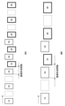
[画像形成順序]
図4(A)はスモールサイズ(A4又はレター)のシートPの画像形成順序を示している。図4(B)はラージサイズ(A3又はレジャー)のシートPの画像形成順序を示している。数字はシートPの番号(給紙順)を示す。文字Aは、シートPの第一面(表面)が画像の形成面であることを示す。文字BはシートPの第二面(裏面)が画像の形成面であることを示す。図4が示すように、両面印刷においては、第一面への画像形成と第二面への画像形成が交互に行われる区間がある。第一面への画像形成と第二面への画像形成を交互に行っているときの二枚のシート間の間隔が画像形成間隔である。つまり、画像形成間隔はシート長とシート間隔との和である。画像形成間隔は、通常は一定間隔である。本実施例において、スモールサイズとは、反転路r3および副路r4に三枚のシートPを待機させることが可能なサイズである。ラージサイズとは反転路r3および副路r4に三枚のシートPを待機させることができないサイズである。たとえば、前者であるA4サイズのシート長は210mmであり、レターサイズのシート長は215.9mmである。後者であるA3サイズのシート長は420mmであり、レジャーサイズのシート長は431.8mmである。
[Image formation order]
FIG. 4A shows the image formation order of the small size (A4 or letter) sheet P. FIG. 4B shows the image formation order of the large size (A3 or leisure) sheet P. The numbers indicate the sheet P numbers (paper feed order). The letter A indicates that the first surface (surface) of the sheet P is the image forming surface. The letter B indicates that the second surface (back surface) of the sheet P is the image forming surface. As shown in FIG. 4, in double-sided printing, there is a section in which image formation on the first surface and image formation on the second surface are alternately performed. The distance between two sheets when the image formation on the first surface and the image formation on the second surface are alternately performed is the image formation interval. That is, the image formation interval is the sum of the sheet length and the sheet interval. The image formation interval is usually a constant interval. In this embodiment, the small size is a size that allows three sheets P to stand by on the reversing road r3 and the sub road r4. The large size is a size in which three sheets P cannot be made to stand by on the reversing road r3 and the sub road r4. For example, the former A4 size sheet length is 210 mm, and the letter size sheet length is 215.9 mm. The latter, the A3 size sheet length is 420 mm, and the leisure size sheet length is 431.8 mm.
図4(A)は5枚のスモールサイズのシートに両面印刷を行う場合の画像形成順序を示している。図4(A)が示すように、画像形成装置1は三枚のシート1A、2A、3A(第一面)に画像を形成する。その後、画像形成装置1は一枚目のシート2B(第二面)、4枚目のシート4A(第一面)、二枚目のシート2B(第二面)にそれぞれ画像を形成する。つまり、あるシートの第一面と他のシートの第二面とに交互に画像が形成される。画像形成装置1は、三枚目のシート3B(第二面)に画像を形成した後、4枚目、5枚目のシート4B、5B(第二面)にそれぞれ画像を形成する。
FIG. 4A shows the image formation order when double-sided printing is performed on five small-sized sheets. As shown in FIG. 4A, the
ここで、実施例は、一枚目のシート1B(第二面)に形成される画像の書き込みが許可されずに、シート1Bがレジストレーションローラ42で待機(停止)することを仮定する。つまり、図4(A)においてシート3Aとシート1Bとの間の画像形成間隔が通常よりも長くなってしまう。シート1Bの待機時間が長くなることで、副路r4において後続する、シート2Bとシート3Bも待機しなければならない。これは、シート1Bに対してシート2Bが追突することを抑制するためである。
Here, in the embodiment, it is assumed that the
図5(A)はシート1B、シート2Bおよびシート3Bがそれぞれ待機している状態を示している。シート2Bは副路r4において待機している。シート3Bは反転路r3に待機している。シートへの画像書き込み許可は当該シートがレジストレーションローラ42の直前に位置しているときに発行される。そのため、CPU201は、シート1Bを停止してから、シート2Bを停止させ、その後、シート3Bを停止させる。つまり、三枚のシートは独立的に制御されなければならない。これを実現するため、図3(A)に示す比較例では、三つのモータM1、M2、M5が必要となる。これに対し、本実施例では、図3(B)が示すように、モータM5が不要となり、二つのモータM1、M2で実現可能となる。図4(B)および図5(B)が示すように、反転路r3および副路r4に待機できるラージサイズのシートの枚数は二枚である。二枚のシートを独立的に制御するためには2つのモータがあれば十分である。したがって、以下では、三枚のスモールサイズのシートを二つのモータM1、M2で搬送する方法が詳細に説明される。
FIG. 5A shows a state in which the
[三枚のシートの待機動作]
図6はメインの搬送処理を示すフローチャートである。図7は第二面への画像形成を示すフローチャートである。図8はリカバリ処理を示すフローチャートである。図9(A)および図9(B)はレジストレーションローラ42での待機が行われない通常動作における三枚のシートの搬送を示している。図10(A)、図10(B)、図10(C)はレジストレーションローラ42での待機が行われる待機動作における三枚のシートの搬送を示している。操作者が操作部203から、またはホストコンピュータからプリントジョブを設定して、CPU201にプリントジョブの実行を指示する。CPU201はプリントジョブを投入されると以下の処理を実行する。
[Standby operation of three sheets]
FIG. 6 is a flowchart showing the main transfer process. FIG. 7 is a flowchart showing image formation on the second surface. FIG. 8 is a flowchart showing the recovery process. 9 (A) and 9 (B) show the transfer of three sheets in a normal operation in which the
S601でCPU201は給紙機構32を駆動するモータM3を制御してシートPの給紙を開始する。これによりシートPは収容庫31からレジストレーションローラ42まで搬送される。CPU201はシートセンサ44aがシートPの先端を検知したことに応答してモータM4を減速させ、レジストレーションローラ42の搬送速度(周速度)の減速を開始する。給紙機構32は減速しないため、シートPにはループが形成される。
In S601, the
S602でCPU201は画像の書き込みが許可されているかどうかを判定する。画像の書き込み許可は、たとえば、メモリ202に保持されている上述したフラグにより管理されている。画像の書き込みが許可されていなければ、CPU201はS603に処理を進める。S603でCPU201はモータM3、M4を制御することで、シートPをレジストレーションローラ42で待機させる。これにより、シートPがレジストレーションローラ42に突き当たって停止し、シートPの先端付近にはループが形成される。その後、CPU201はS602に処理を進める。一方、S602で、画像の書き込みが許可されると、CPU201はS604に処理を進める。
In S602, the
S604でCPU201は画像形成部2を制御し、シートPの第一面に画像を形成し、定着させる。S605でCPU201はプリントジョブを解析し、両面印刷(第二面への画像形成)が指定されているかどうかを判定する。両面印刷が指定されていなければ、CPU201はS607に処理を進める。S607でCPU201はフラッパ64と排出ローラ62を制御して第一面に画像が形成されたシートPを排出トレイ80に排出する。S608でCPU201はプリントジョブを解析し、後続シートが存在するかどうかを判定する。後続シートがなければCPU201はプリントジョブを終了する。後続シートがあればCPU201はS601に戻り、後続シートの給紙などを実行する。一方で、S605で両面印刷が指定されていれば、CPU201はS606に処理を進める。S606は第二面への画像形成であり、この詳細が図7に示されている。ここでは、第二面に画像が形成されるシートPは注目シートと表記されている。注目シートよりも先行して搬送されている先行シートと、注目シートに後続して搬送されている後続シートとに対して注目シートを区別するためである。なお、後続シートから見て注目シートは先行シートである。先行シートから見て注目シートは後続シートである。
In S604, the
S701でCPU201はモータM1を正転および逆転させることで注目シートの表裏を反転する。上述したように、注目シートは補助路r2から反転路r3に引き込まれた後で、副路r4に搬送される。CPU201は注目シートの後端がシートセンサ44bにより検知されると、モータM1の回転方向を正転から逆転に切り替える。なお、表裏の反転とは、中間転写ベルト21に接触するシート面が第一面から第二面に変わることをいう。
In S701, the
S702でCPU201は注目シートが第二ローラ72に到達したときに先行シートがレジストレーションローラ42にて待機しているかどうかを判定する。CPU201は、モータM1の回転方向を正転から逆転に切り替えたときからの経過時間に基づき注目シートが第二ローラ72に到達したことを判定してもよい。あるいは、第二ローラ72の上流側に設けられた、不図示のシートセンサを用いて、CPU201は注目シートが第二ローラ72に到達したことを判定してもよい。CPU201はシートセンサ44aの検知結果に基づき先行シートがレジストレーションローラ42にて待機していることを判定してもよい。先行シートがレジストレーションローラ42にて待機していなければ、CPU201はS703に処理を進める。
In S702, the
S703でCPU201はモータM2を制御して第二ローラ72で注目シートを搬送する。図9(A)は先行シートであるシート1Bがレジストレーションローラ42にて待機していないときの注目シートであるシート2Bの搬送状態を示している。なお、CPU201は、主路r1を搬送されるシート3Aとシート1Bとの間の画像形成間隔が規定間隔となるように、シート1Bをレジストレーションローラ42へ搬送する。ここでは、シート1Bの第二面への画像の書き込みが許可されていることが前提となっている。S704でCPU201は画像形成部2を制御し、先行シートであるシート1Bの第二面に画像を形成し、定着させる。図9(B)は注目シートであるシート2Bが第二ローラ72に到達したときの各シートの位置を示している。注目シートであるシート2Bの先端は二次転写部3を通過済みである。一方、CPU201はS702で先行シートが待機していると判定すると、S711に処理を進める。
In S703, the
S711でCPU201はモータM2を制御して注目シートを待機させる。これにより、注目シートが先行シートに衝突しないようになる。先行シートであるシート1Bが図10(A)に示す位置(第三ローラ73の下流)に到達したときに、シート1Bへの画像書き込みが許可されていないことがある。この場合、図10(B)が示すように、シート1Bはレジストレーションローラ42に突き当たって待機する。ここで、シート1Bの先端領域にはループが形成される。これと並行して、注目シートであるシート2Bが第二ローラ72に到達すると、第二ローラ72は所定量だけ回転してから停止する。シート2Bの停止は、シート1Bの搬送の停止に起因している。いずれもモータM2により搬送されているからである。図10(B)が示すように、シート2Bの先端は第二ローラ72のニップに当接し、シート2Bの先端領域にもループが形成される。モータM2が停止してもモータM1が第一ローラ71を継続して駆動しているからである。
In S711, the
S712でCPU201は先行シートへの画像の書き込みが許可されているかどうかを判定する。所定時間が経過し、先行シート(シート1B)の画像書き込みが許可されると、CPU201はS713に処理を進める。S713でCPU201は先行シート(シート1B)および注目シート(シート2B)の搬送を再開する。図10(C)が示すように、CPU201はモータM2、M4を再び駆動することで、シート1Bとシート2Bの搬送を再開する。つまり、副路r4において待機していた二枚のシート1B、2Bは単一のモータM2により搬送可能となっている。
In S712, the
図11が示すように、第二ローラ72のニップ部の中心をシート2Bが超えていなくても、第二ローラ72はシート2Bを正しく搬送できる。後続シートであるシート3Aの搬送はシート2Bの搬送と独立的に制御可能である。つまり、図3(C)が示すように、シート3AはモータM1によって搬送され、シート1B、2BはモータM2によって副路r4を搬送される。よって、二つのモータM1、M2だけで反転路r3および副路r4において三枚のシートを待機およびリスタートさせることが可能となる。
As shown in FIG. 11, even if the
S714でCPU201は注目シートのリカバリ処理を実行する。リカバリ処理の詳細は後述される。
In S714, the
S715でCPU201は注目シートの第二面への画像の書き込みが許可されているかどうかを判定する。画像の書き込みが許可されていなければ、CPU201は、S716に処理を進める。S716でCPU201はレジストレーションローラ42を停止させて注目シートをレジストレーションローラ42に待機させる。このとき、モータM2が回転しているため、注目シートはレジストレーションローラ42に突き当たり、ループが形成される。画像の書き込みが許可されると、CPU201はS704に処理を進める。CPU201はレジストレーションローラ42で注目シートを搬送しながら、第二面に画像を形成する。
In S715, the
なお、S713でリスタートした注目シートであるシート2Bがシートセンサ44cに到達しないことがある。この場合、リカバリ処理が実行される。
The
図12(A)はS702でNoのケースにおけるモータM1、M2、M4の駆動タイミングを示している。まず、先行シート(シート1B)の動作が説明される。シート1Bをレジストレーションローラ42に突き当ててシート1Bにループを形成する際にモータM2によるシート1Bの搬送速度V1は220mm/sである。なお、シートセンサ44aがシート1Bを検知した時刻taから所定時間が経過した時刻tbにCPU201は画像書込みの可否を判定する。また、時刻tbにCPU201はモータM2による搬送速度を減速する。CPU201はモータM2を停止せず、時刻tcにモータM2を再加速させる。
FIG. 12A shows the drive timings of the motors M1, M2, and M4 in the case of No in S702. First, the operation of the preceding sheet (
次に注目シート(シート2B)の搬送が説明される。CPU201はモータM1を駆動することで第一ローラ71を回転させ、シート2Bを搬送させる。シート2Bが第二ローラ72へ突入する時刻tdに、CPU201は、モータM1の搬送速度を300mm/sをV2(=200mm/s)へ減速させる。ここで、V1≧V2であり、かつ、モータM1と第一ローラ71との間にはワンウェイクラッチ76が設けられている。そのため、時刻teでシート2Bは第二ローラ72に突入すると同時に第二ローラ72により第一ローラ71から引き抜かれる。よって、先行シート(シート1B)と注目シート(シート2B)がモータM2により搬送可能となる。シート1Bは時刻tfに二次転写部3に突入する。反転ローラ70が後続シート(シート3B)を受け入れるために、モータM1は逆転から正転に切り替わる。
Next, the transportation of the sheet of interest (
図12(B)はS702でYesのケースにおけるモータM1、M2、M4の駆動タイミングを示している。まず先行シート(シート1B)の動作が説明される。時刻taでシートセンサ44aがシート1Bを検知し、時刻tbでCPU201は画像書き込みの可否を判定する。画像書き込みが許可されていない場合、CPU201は、モータM2の搬送速度はV1(=300mm/s)に維持される。CPU201は、シート1Bに所定のループが形成されるであろう時刻tgにモータM2を一旦停止する。CPU201は、時刻tjにモータM2を再加速する。
FIG. 12B shows the drive timings of the motors M1, M2, and M4 in the case of Yes in S702. First, the operation of the preceding sheet (
次に注目シート(シート2B)の搬送が説明される。CPU201はモータM1を逆回転させることで第一ローラ71を駆動し、第一ローラ71よりシート2Bを搬送する。シート2Bが第二ローラ72へ突入する時刻thに、CPU201は、モータM1による搬送速度を300mm/sからV2(=200mm/s)に減速させる。シート2Bの先端が第二ローラ72から所定距離進んだ時刻tiに、CPU201はモータM1を停止させる。ここで、時刻tiにモータM2(第二ローラ72)が停止しているため、シート2Bの先端は第二ローラ72を突き抜けることなく停止する。
Next, the transportation of the sheet of interest (
すでに停止している先行シート(シート1B)の搬送を再開するために、時刻tjでCPU201はモータM4とモータM2の搬送速度を400mm/sに設定し、それぞれ再駆動する。これにより先行シート(シート1B)および注目シート(シート2B)の搬送がリスタートされる。
In order to resume the transfer of the preceding sheet (
[リカバリ処理]
図8はリカバリ処理の詳細を示している。図13(A)~図13(D)、図14(A)および図14(B)はリカバリ処理における各シートの位置を示している。図15はリカバリ処理における各モータの駆動タイミングを示している。
[Recovery process]
FIG. 8 shows the details of the recovery process. 13 (A) to 13 (D), FIGS. 14 (A) and 14 (B) show the position of each sheet in the recovery process. FIG. 15 shows the drive timing of each motor in the recovery process.
S801でCPU201は注目シートに後続して搬送されている後続シートがあるかどうかを判定する。図13(A)はこの判定タイミングでのシートの配置を示している。シート2Bに対して後続シートであるシート3Aが存在する。この場合、CPU201はS802に処理を進める。
In S801, the
S802でCPU201はシートセンサ44cの検知結果に基づき、注目シート(シート2B)に対して先行している先行シート(シート1B)の後端が所定位置を通過したかどうかを判定する。所定位置はシートセンサ44cによるシートPの検知位置である。CPU201はシートセンサ44cの検知結果がオンからオフに変わると、タイマーをスタートさせ、S803に処理を進める。
In S802, the
S803でCPU201はシートセンサ44cの検知結果に基づき、注目シート(シート2B)が所定位置を通過したかどうかを判定する。たとえば、シートセンサ44cの検知結果がオフからオンに変わっていなければ、CPU201はS804に処理を進める。シートセンサ44cの検知結果がオフからオンに変わると、CPU201はリカバリ処理を終了する。シート2Bのリスタートが成功すると、シート2Bは第二ローラ72により搬送されてシートセンサ44cに到着する。そのため、シートセンサ44cの検知結果がオフからオンに切り替わる。
In S803, the
S804でCPU201は所定時間Tが経過したかどうかを判定する。CPU201は、タイマーにより計測された時間が所定時間Tを超えると、S805に処理を進める。CPU201は、タイマーにより計測された時間が所定時間Tを超えていなければ、S803に戻る。つまり、所定時間Tが経過する前にシート2Bがシートセンサ44cに到着すると、シート2Bのリスタートは成功したとCPU201は判定する。このようにS803とS804は、シート2Bのリスタートの成功を判定する処理である。所定時間Tは、たとえば、シート2Bのリスタートを開始したときにシート2Bの先端が停止していた位置からシートセンサ44cの検知位置までの距離をモータM2による搬送速度で除算して求まる時間の2倍の時間である。
In S804, the
シート2Bのリスタートが失敗する要因はいくつかある。図13(A)が示すように、S711でシート2Bは第二ローラ72へ突き当てられる。図13(B)の拡大図が示すように、シート2Bの先端が第二ローラ72のニップ部侵入せずに、停止することがある。このように、シート2Bの先端が第二ローラ72にニップされていない場合、シート2Bのリスタートが失敗することがある。
There are several factors that cause the restart of
S805でCPU201はモータM2を停止させる。これにより第二ローラ72および第三ローラ73が停止する。S806でCPU201は、注目シートに対して後続する後続シート(シート3B)が反転位置p1に到着したかどうかを判定する。なお、シート3Aは搬送方向が第一方向から第二方向へ変更されるため、シート3Bと表記される。図13(C)は反転位置p1に到着したシート3Bを示している。CPU201は、シートセンサ44bの検知結果がオンからオフに切り替わると、後続シート(シート3B)が反転位置p1に到着したと判定し、S807に処理を進める。
In S805, the
S807でCPU201は、モータM2を再び駆動することでシート2Bのリスタートをリカバリする。S808でCPU201は、後続シート(シート3B)を副路r4に搬送するために、モータM1も駆動する(逆転)。S713で最初に実行されるリスタートではシート2BはモータM2のみで搬送される。つまり、第一ローラ71はシート2Bによって回転するにすぎず、第二ローラ72が単独でシート2Bを下流に向かって搬送する。一方、図13(D)が示すように、S807およびS808による二度目のリスタートではモータM2とモータM1がシート2Bを搬送する。つまり、第一ローラ71と第二ローラ72とがシート2Bを下流に向かって搬送する。そのため、シート2Bのリスタートの成功確率が向上する。
In S807, the
図14(A)は後続シートがないケースにおけるシートの配置を示している。S801でCPU201はシート2Bに対する後続シートがないと判定すると、S808に処理を進める。S808でモータM1を駆動する。S713でモータM2はすでに回転している。そのため、図14(B)が示すように、モータM1、M2(第一ローラ71および第二ローラ72)が協働してシート2Bの搬送をリスタートする。これによりシート2Bのリスタートの成功確率が向上する。
FIG. 14A shows the arrangement of the seats in the case where there is no subsequent seat. If the
図15は各モータの駆動タイミングを示している。
●先行シート(シート1B)
時刻tnにCPU201は、モータM2、M4の駆動を開始して先行シート(シート1B)をリスタートする。モータM2、M4による搬送速度は400mm/sに設定される。CPU201は、シート1Bの先端が二次転写部3に突入する直線の時刻toでモータM2、M4による搬送速度を300mm/sに設定する。
●注目シート(シート2B)
先行シート(シート1B)をリスタートするために起動したモータM2により第二ローラ72が回転する。これにより、第二ローラ72は第一ローラ71から注目シート(シート2B)を引き抜く。ここで、所定時間Tが経過するまでにシートセンサ44cの検知結果がオフからオフに切り替わらない。そのため、時刻tpでCPU201はS805でモータM2を停止させる。
●後続シート(シート3A)
後続シート(シート3A)が反転ローラ70に突入してくる時刻tmにおいて、CPU201はモータM1を-400mm/sで駆動する。シート3Aの後端から20mmがまだ反転ローラ70に突入していない時刻tqで、CPU201はモータM1を停止させる。
●リカバリ
時刻trでCPU201はモータM1、M2による搬送速度を300mm/sに設定し、モータM1、M2を駆動する。これにより、第二ローラ72と第一ローラ71によりシート2Bが搬送される。
FIG. 15 shows the drive timing of each motor.
● Leading sheet (
At time tun, the
● Attention sheet (
The
● Subsequent seat (
At the time tm when the succeeding sheet (
● At the recovery time tr, the
<まとめ>
収容庫31はシートPを収容する収容手段の一例である。中間転写ベルト21などにより形成された画像形成部2はシートPに画像を形成する画像形成手段の一例である。排出ローラ62は画像が形成されたシートPを排出する排出手段の一例である。主路r1は収容庫31から画像形成部2を経由して排出ローラ62に至る主搬送路の一例である。補助路r2は主路r1から分岐し、第一面に画像が形成されたシートPの第二面に画像を形成するために当該シートPを引き込む補助搬送路の一例である。反転路r3は補助路r2に接続され、第一面に画像が形成されたシートPの搬送方向を反転させる反転搬送路の一例である。副路r4は反転路r3から送り込まれてきた第一面に画像が形成されたシートを画像形成部2に再び送り込むためにシートPを主路r1まで搬送する副搬送路の一例である。レジストレーションローラ42は主路r1においてシートPの搬送方向で画像形成部2よりも上流側で、かつ、主路r1と副路r4との合流部よりも下流側に設けられたローラである。反転ローラ70は第一面に画像が形成されたシートPを第一方向に搬送することでシートPを反転路r3に引き込み、第一方向とは反対の第二方向にシートPを搬送することでシートPを副路r4へ送り込むローラである。第一ローラ71は副路r4において反転路r3と副路r4との接続点よりも下流側に設けられ、反転ローラ70から受け渡されたシートPを搬送するローラである。モータM1は反転ローラ70と第一ローラ71とを駆動する第一モータである。ワンウェイクラッチ76は反転ローラ70が第一方向にシートPを搬送している間はモータM1から第一ローラ71への駆動力の伝達を制限する。ワンウェイクラッチ76は反転ローラ70が第二方向にシートを搬送している間はモータM1から第一ローラ71への駆動力の伝達を許可する。第二ローラ72は副路r4においてシートPの搬送方向で第一ローラ71よりも下流側に設けられたローラである。第三ローラ73は副路r4においてシートPの搬送方向で第二ローラ72よりも下流側に設けられた第三ローラの一例である。モータM2は第二ローラ72と第三ローラ73とを駆動する第二モータである。シートセンサ44cは副路r4において第二ローラ72と第三ローラ73との間に設けられ、第二ローラ72を通過してきたシートPを検知する検知手段の一例である。CPU201はモータM1、M2を制御する制御手段である。CPU201は副路r4を搬送されるシートPを第二ローラ72に突き当てて待機させた後でシートPの搬送を再開するときにモータM1とモータM2との両方を駆動する。このようにシートPのリスタートはモータM1とモータM2との両方によって実行される。そのため、本実施例は、両面印刷用の搬送路で必要となる駆動手段の数を削減しつつ、当該搬送路における搬送の失敗を削減することができる。
<Summary>
The
CPU201はi+1番目のシートが第二ローラ72に向かっているときに当該i+1番目のシートに先行して搬送されているi番目のシートがレジストレーションローラ42に待機しているかどうかを判定する第一判定手段を有してもよい(S702)。CPU201は、i番目のシートがレジストレーションローラ42に待機している場合に、i+1番目のシートを第二ローラ72に突き当てて待機させてもよい(S711)。また、CPU201はi番目のシートがレジストレーションローラ42に待機していない場合に、i+1番目のシートを第二ローラ72で待機させずに第二ローラ72により搬送させてもよい(S703)。CPU201は、レジストレーションローラ42がi番目のシートの搬送を再開すると、第二ローラ72よるi+1番目のシートの搬送を再開してもよい(S713)。
The
CPU201はモータM2の駆動を再開して第二ローラ72よるi+1番目のシートの搬送を再開すると、i+1番目のシートに後続するi+2番目のシートが存在するかどうかを判定する第二判定手段を有してもよい(S801)。CPU201は、i+2番目のシートが存在しなければモータM1を再駆動してもよい(S808)。CPU201は、i+2番目のシートが存在すれば、シートセンサ44cの検知結果に基づきi+1番目のシートの搬送の再開が成功したかどうかを判定してもよい(S802)。さらに、CPU201は、i+1番目のシートの搬送の再開が成功していれば、モータM1を再駆動しないでモータM2によりi+1番目のシートの搬送を継続してもよい(S803でYes)。
When the
CPU201はシートセンサ44cの検知結果に基づきi+1番目のシートの搬送の再開が所定時間以内に成功したかどうかを判定する第三判定手段を有してもよい(S803、S804)。CPU201は、i+1番目のシートの搬送の再開が所定時間以内に成功しなければ、モータM2を停止させる(S805)。さらに、CPU201は、i+1番目のシートが反転路r3と副路r4との接続部に到着すると、モータM2の駆動を再開し、かつ、モータM1を駆動してもよい(S807、S808)。
The
CPU201は、i+1番目のシートを第二ローラ72に突き当てて待機させる場合に、i+1番目のシートの先端部にループが形成されるようにモータM1およびモータM2を制御してもよい(S711)。これによりi+1番目のシートの斜行が補正される。たとえば、CPU201は、i+1番目のシートの先端部にループが形成されるようにi+1番目のシートを第二ローラ72に突き当てる際にモータM2の回転速度を低下させてもよい。たとえば、CPU201は、i+1番目のシートを第二ローラ72に突き当てる際に、第二ローラ72の周速度が第一ローラ71の周速度よりも低下するように、モータM2の回転速度を低下させる。これによりシートの先端領域の搬送速度が後端領域の搬送速度よりも低下するため、ループが発生する。
The
反転路r3および副路r4の長さは三枚のA4サイズのシートまたはレターサイズのシートが待機可能な長さであってもよい。図7や図8において上述された先行シートはi番目のシートである。注目シートはi+1番目のシートである。後続シートはi+2番目のシートである。ここでiは収容庫31から給紙された順番を示す整数である。
The length of the reversing path r3 and the secondary path r4 may be such that three A4 size sheets or letter size sheets can stand by. The preceding sheet described above in FIGS. 7 and 8 is the i-th sheet. The attention sheet is the i + 1st sheet. The succeeding sheet is the i + second sheet. Here, i is an integer indicating the order in which the paper is fed from the
なお、レジストレーションローラ42は回転体の一例である。反転ローラ70は反転手段や第一回転体の一例である。第一ローラ71は第一搬送手段や第二回転体の一例である。第二ローラ72は第二搬送手段や第三回転体の一例である。第三ローラ73は第三搬送手段や第四回転体の一例である。モータM1は第一駆動手段の一例である。モータM2は第二駆動手段の一例である。ワンウェイクラッチ76は制限手段の一例である。
The
以上の実施例ではモータM1とモータM2により駆動される搬送ローラの数はそれぞれ二つであったが、本発明はそれぞれ三つ以上であってもよい。たとえば、第三ローラ73と第二ローラ72との間に、モータM2により駆動される他の搬送ローラが追加されてもよい。反転ローラ70と第一ローラ71との間にモータM1により駆動される他の搬送ローラが追加されてもよい。ただし、追加される他の搬送ローラと第二ローラ72との間の距離がシート長(シートの搬送方向におけるシートの長さ)よりも短ければ、ワンウェイクラッチ等の駆動遮断部材が必要となる。
In the above embodiment, the number of transfer rollers driven by the motor M1 and the motor M2 is two, but the present invention may be three or more. For example, another transfer roller driven by the motor M2 may be added between the
図12(A)および図12(B)には具体的な搬送速度が記載されているが、これは例示にすぎない。図12(A)では副路r4を搬送されてきたシートPがレジストレーションローラ42にて停止せずにループを形成されている。つまり、モータM2は搬送速度を一時的に低下させているにすぎない。また、時刻tcでシートPが加速されている。しかし、図12(B)が示すようにモータM2はシートPを一度停止させてもよい。
Specific transport speeds are described in FIGS. 12 (A) and 12 (B), but this is merely an example. In FIG. 12A, the sheet P conveyed on the subway r4 does not stop at the
反転路r3と副路r4に配置される搬送ローラの駆動源としてモータM1、M2が採用されているが、本発明はこれに限定されない。たとえば、モータM1、M2は共通のモータに置換されてもよい。この場合、副路r4に設けられた搬送ローラへ駆動力を伝達する伝達経路に単一の電磁クラッチが設けられる。CPU201はシートセンサの検知結果に基づき各シートの位置を把握し、各シートの位置に応じて電磁クラッチの接続/遮断を切り替える。電磁クラッチもモータと同様にアクチュエータの一つとしてカウントしたとしても、本発明では反転路r3と副路r4に待機するシートの枚数よりもアクチュエータの数は少ない。
Motors M1 and M2 are used as drive sources for the transport rollers arranged on the reversing path r3 and the sub-path r4, but the present invention is not limited thereto. For example, the motors M1 and M2 may be replaced with a common motor. In this case, a single electromagnetic clutch is provided in the transmission path for transmitting the driving force to the transfer roller provided in the secondary path r4. The
1...画像形成装置、70...両面ローラ1、71...第一ローラ、72...第二ローラ、73...第三ローラ、42...レジストレーションローラ、200...制御部
1 ... image forming apparatus, 70 ... double-
Claims (9)
前記シートに画像を形成する画像形成手段と、
画像が形成されたシートを排出する排出手段と、
前記収容手段から前記画像形成手段を経由して前記排出手段に至る主搬送路と、
前記主搬送路から分岐し、第一面に画像が形成されたシートの第二面に画像を形成するために当該シートを引き込む補助搬送路と、
前記補助搬送路に接続され、前記第一面に画像が形成されたシートの搬送方向を反転させる反転搬送路と、
前記反転搬送路から送り込まれてきた前記第一面に画像が形成されたシートを前記画像形成手段に再び送り込むために当該シートを前記主搬送路まで搬送する両面搬送路と、
前記主搬送路において前記シートの搬送方向で前記画像形成手段よりも上流側で、かつ、前記主搬送路と前記両面搬送路との合流部よりも下流側に設けられたレジストレーションローラと、
前記第一面に画像が形成されたシートを第一方向に搬送することで当該シートを前記反転搬送路に引き込み、前記第一方向とは反対の第二方向に当該シートを搬送することで当該シートを前記両面搬送路へ送り込む反転ローラと、
前記両面搬送路において前記反転搬送路と前記両面搬送路との接続点よりも下流側に設けられ、前記反転ローラから受け渡されたシートを搬送する第一ローラと、
前記反転ローラと前記第一ローラとを駆動する第一モータと、
前記反転ローラが前記第一方向にシートを搬送している間は前記第一モータから前記第一ローラへの駆動力の伝達を制限し、前記反転ローラが前記第二方向にシートを搬送している間は前記第一モータから前記第一ローラへの駆動力の伝達を許可するワンウェイクラッチと、
前記両面搬送路において前記シートの搬送方向で前記第一ローラよりも下流側に設けられた第二ローラと、
前記両面搬送路において前記シートの搬送方向で前記第二ローラよりも下流側に設けられた第三ローラと、
前記第二ローラと前記第三ローラとを駆動する第二モータと、
前記第一モータおよび前記第二モータを制御する制御手段と、を有し、
前記制御手段は、前記両面搬送路を搬送されるシートを前記第二ローラに突き当てて待機させた後で当該シートの搬送を再開するときに前記第一モータと前記第二モータとの両方を駆動することを特徴とする画像形成装置。 A storage means for accommodating seats and
An image forming means for forming an image on the sheet and
Discharge means for discharging the sheet on which the image is formed, and
A main transport path from the accommodating means to the discharging means via the image forming means, and
An auxiliary transport path that branches from the main transport path and pulls in the sheet to form an image on the second surface of the sheet on which the image is formed on the first surface.
An inverted transport path that is connected to the auxiliary transport path and reverses the transport direction of the sheet on which the image is formed on the first surface.
A double-sided transport path for transporting the sheet to the main transport path in order to feed the sheet having an image formed on the first surface, which has been fed from the reverse transport path, to the image forming means again.
A registration roller provided in the main transport path on the upstream side of the image forming means in the transport direction of the sheet and on the downstream side of the confluence of the main transport path and the double-sided transport path.
By transporting the sheet on which the image is formed on the first surface in the first direction, the sheet is drawn into the inverted transport path, and by transporting the sheet in the second direction opposite to the first direction, the sheet is conveyed. A reversing roller that feeds the sheet into the double-sided transport path,
A first roller that is provided on the downstream side of the connection point between the reversing transport path and the double-sided transport path in the double-sided transport path and that transports the sheet delivered from the reverse roller.
The first motor that drives the reversing roller and the first roller,
While the reversing roller conveys the sheet in the first direction, the transmission of the driving force from the first motor to the first roller is restricted, and the reversing roller conveys the sheet in the second direction. While there is a one-way clutch that allows the transmission of driving force from the first motor to the first roller,
A second roller provided on the downstream side of the first roller in the sheet transport direction in the double-sided transport path, and
A third roller provided on the downstream side of the second roller in the sheet transport direction in the double-sided transport path,
A second motor that drives the second roller and the third roller,
The first motor and the control means for controlling the second motor are provided.
The control means causes both the first motor and the second motor when the sheet to be conveyed on the double-sided transfer path is abutted against the second roller to stand by and then the transfer of the sheet is restarted. An image forming apparatus characterized by being driven.
前記制御手段は、前記第二モータの駆動を再開して前記第二ローラによる前記i+1番目のシートの搬送を再開したときに、前記i+1番目のシートに後続するi+2番目のシートが存在しない場合、前記第一モータを再駆動し、前記i+2番目のシートが存在する場合、前記検知手段の検知結果に基づき前記i+1番目のシートの搬送の再開が成功したかどうかを判定し、前記i+1番目のシートの搬送の再開が成功していれば、前記第一モータを再駆動しないで前記第二モータにより前記i+1番目のシートの搬送を継続することを特徴とする請求項3に記載の画像形成装置。 Further, it has a detecting means provided between the second roller and the third roller in the double-sided transport path and detects a sheet that has passed through the second roller.
When the control means restarts the driving of the second motor and restarts the transfer of the i + 1st sheet by the second roller, if the i + 2nd sheet following the i + 1th sheet does not exist, the control means does not exist. When the first motor is re-driven and the i + 2nd sheet is present, it is determined based on the detection result of the detection means whether or not the resumption of the transfer of the i + 1st sheet is successful, and the i + 1th sheet is determined. The image forming apparatus according to claim 3, wherein if the resumption of the transfer of the first sheet is successful, the transfer of the i + 1st sheet is continued by the second motor without redriving the first motor.
Priority Applications (2)
| Application Number | Priority Date | Filing Date | Title |
|---|---|---|---|
| JP2017228307A JP7015154B2 (en) | 2017-11-28 | 2017-11-28 | Image forming device |
| US16/200,953 US11299360B2 (en) | 2017-11-28 | 2018-11-27 | Image forming apparatus for forming image on sheet |
Applications Claiming Priority (1)
| Application Number | Priority Date | Filing Date | Title |
|---|---|---|---|
| JP2017228307A JP7015154B2 (en) | 2017-11-28 | 2017-11-28 | Image forming device |
Publications (3)
| Publication Number | Publication Date |
|---|---|
| JP2019101068A JP2019101068A (en) | 2019-06-24 |
| JP2019101068A5 JP2019101068A5 (en) | 2021-01-07 |
| JP7015154B2 true JP7015154B2 (en) | 2022-02-02 |
Family
ID=66634863
Family Applications (1)
| Application Number | Title | Priority Date | Filing Date |
|---|---|---|---|
| JP2017228307A Active JP7015154B2 (en) | 2017-11-28 | 2017-11-28 | Image forming device |
Country Status (2)
| Country | Link |
|---|---|
| US (1) | US11299360B2 (en) |
| JP (1) | JP7015154B2 (en) |
Families Citing this family (4)
| Publication number | Priority date | Publication date | Assignee | Title |
|---|---|---|---|---|
| WO2018203878A1 (en) * | 2017-05-01 | 2018-11-08 | Hewlett-Packard Development Company, L.P. | Conditioner modules with calender rollers |
| JP7282499B2 (en) * | 2018-10-17 | 2023-05-29 | キヤノン株式会社 | Sheet conveying device and image forming device |
| JP2021088426A (en) | 2019-12-02 | 2021-06-10 | キヤノン株式会社 | Sheet feeding device and image forming device |
| JP2021170071A (en) * | 2020-04-15 | 2021-10-28 | ブラザー工業株式会社 | Image forming apparatus |
Citations (5)
| Publication number | Priority date | Publication date | Assignee | Title |
|---|---|---|---|---|
| JP2001166663A (en) | 1999-12-10 | 2001-06-22 | Konica Corp | Image forming device |
| JP2001247233A (en) | 2000-03-07 | 2001-09-11 | Canon Inc | Image forming device, image forming method and storage medium |
| JP2007108587A (en) | 2005-10-17 | 2007-04-26 | Canon Inc | Image forming apparatus |
| JP2010102173A (en) | 2008-10-24 | 2010-05-06 | Oki Data Corp | Image forming apparatus |
| JP2013010601A (en) | 2011-06-29 | 2013-01-17 | Konica Minolta Business Technologies Inc | Image forming apparatus |
Family Cites Families (2)
| Publication number | Priority date | Publication date | Assignee | Title |
|---|---|---|---|---|
| JP2002154751A (en) * | 2000-11-17 | 2002-05-28 | Toshiba Tec Corp | Image forming device |
| JP6938287B2 (en) * | 2017-09-06 | 2021-09-22 | キヤノン株式会社 | Image forming device |
-
2017
- 2017-11-28 JP JP2017228307A patent/JP7015154B2/en active Active
-
2018
- 2018-11-27 US US16/200,953 patent/US11299360B2/en active Active
Patent Citations (5)
| Publication number | Priority date | Publication date | Assignee | Title |
|---|---|---|---|---|
| JP2001166663A (en) | 1999-12-10 | 2001-06-22 | Konica Corp | Image forming device |
| JP2001247233A (en) | 2000-03-07 | 2001-09-11 | Canon Inc | Image forming device, image forming method and storage medium |
| JP2007108587A (en) | 2005-10-17 | 2007-04-26 | Canon Inc | Image forming apparatus |
| JP2010102173A (en) | 2008-10-24 | 2010-05-06 | Oki Data Corp | Image forming apparatus |
| JP2013010601A (en) | 2011-06-29 | 2013-01-17 | Konica Minolta Business Technologies Inc | Image forming apparatus |
Also Published As
| Publication number | Publication date |
|---|---|
| US11299360B2 (en) | 2022-04-12 |
| US20190161300A1 (en) | 2019-05-30 |
| JP2019101068A (en) | 2019-06-24 |
Similar Documents
| Publication | Publication Date | Title |
|---|---|---|
| JP7015154B2 (en) | Image forming device | |
| US20030063936A1 (en) | Duplex image forming apparatus | |
| CN110647019B (en) | Image forming apparatus with a plurality of image forming units | |
| JP2006330420A (en) | Image forming apparatus | |
| JP6938287B2 (en) | Image forming device | |
| US6778787B2 (en) | Image forming apparatus with control to divert sheet to usable path | |
| KR20180064291A (en) | Image forming apparatus able to form images on both sides of sheet | |
| JP6743647B2 (en) | Image forming device | |
| JP2013242362A (en) | Image forming apparatus | |
| JP4926526B2 (en) | Image forming apparatus and control method thereof | |
| JP5441520B2 (en) | Sheet conveying apparatus and image forming apparatus | |
| JP3780193B2 (en) | Image forming apparatus | |
| JP2002029649A (en) | Sheet carrying device and image forming device | |
| JPH0635265A (en) | Both-side unit for image forming device | |
| JP2004163900A (en) | Double-sided image forming device | |
| JP6998743B2 (en) | Image forming device | |
| JP2004175482A (en) | Image forming device | |
| JP7327989B2 (en) | image forming device | |
| JP2004203496A (en) | Recording paper conveyance device and image forming device | |
| JP4261974B2 (en) | Sheet transport device | |
| JP4579456B2 (en) | Image forming apparatus | |
| JP2018136390A (en) | Image forming apparatus | |
| JP2009298528A (en) | Image forming device | |
| JP2019207289A (en) | Image forming apparatus | |
| JP2024053260A (en) | Image forming device |
Legal Events
| Date | Code | Title | Description |
|---|---|---|---|
| A521 | Request for written amendment filed |
Free format text: JAPANESE INTERMEDIATE CODE: A523 Effective date: 20201116 |
|
| A621 | Written request for application examination |
Free format text: JAPANESE INTERMEDIATE CODE: A621 Effective date: 20201116 |
|
| RD01 | Notification of change of attorney |
Free format text: JAPANESE INTERMEDIATE CODE: A7421 Effective date: 20210103 |
|
| A521 | Request for written amendment filed |
Free format text: JAPANESE INTERMEDIATE CODE: A523 Effective date: 20210113 |
|
| A977 | Report on retrieval |
Free format text: JAPANESE INTERMEDIATE CODE: A971007 Effective date: 20210914 |
|
| A131 | Notification of reasons for refusal |
Free format text: JAPANESE INTERMEDIATE CODE: A131 Effective date: 20210924 |
|
| A521 | Request for written amendment filed |
Free format text: JAPANESE INTERMEDIATE CODE: A523 Effective date: 20211118 |
|
| TRDD | Decision of grant or rejection written | ||
| A01 | Written decision to grant a patent or to grant a registration (utility model) |
Free format text: JAPANESE INTERMEDIATE CODE: A01 Effective date: 20211223 |
|
| A61 | First payment of annual fees (during grant procedure) |
Free format text: JAPANESE INTERMEDIATE CODE: A61 Effective date: 20220121 |