JP7012940B2 - Female terminal - Google Patents
Female terminal Download PDFInfo
- Publication number
- JP7012940B2 JP7012940B2 JP2018089453A JP2018089453A JP7012940B2 JP 7012940 B2 JP7012940 B2 JP 7012940B2 JP 2018089453 A JP2018089453 A JP 2018089453A JP 2018089453 A JP2018089453 A JP 2018089453A JP 7012940 B2 JP7012940 B2 JP 7012940B2
- Authority
- JP
- Japan
- Prior art keywords
- male terminal
- plate
- fitting
- insertion tube
- pair
- Prior art date
- Legal status (The legal status is an assumption and is not a legal conclusion. Google has not performed a legal analysis and makes no representation as to the accuracy of the status listed.)
- Active
Links
Images


Classifications
-
- H—ELECTRICITY
- H01—ELECTRIC ELEMENTS
- H01R—ELECTRICALLY-CONDUCTIVE CONNECTIONS; STRUCTURAL ASSOCIATIONS OF A PLURALITY OF MUTUALLY-INSULATED ELECTRICAL CONNECTING ELEMENTS; COUPLING DEVICES; CURRENT COLLECTORS
- H01R4/00—Electrically-conductive connections between two or more conductive members in direct contact, i.e. touching one another; Means for effecting or maintaining such contact; Electrically-conductive connections having two or more spaced connecting locations for conductors and using contact members penetrating insulation
- H01R4/28—Clamped connections, spring connections
- H01R4/48—Clamped connections, spring connections utilising a spring, clip, or other resilient member
- H01R4/4854—Clamped connections, spring connections utilising a spring, clip, or other resilient member using a wire spring
- H01R4/4863—Coil spring
-
- H—ELECTRICITY
- H01—ELECTRIC ELEMENTS
- H01R—ELECTRICALLY-CONDUCTIVE CONNECTIONS; STRUCTURAL ASSOCIATIONS OF A PLURALITY OF MUTUALLY-INSULATED ELECTRICAL CONNECTING ELEMENTS; COUPLING DEVICES; CURRENT COLLECTORS
- H01R13/00—Details of coupling devices of the kinds covered by groups H01R12/70 or H01R24/00 - H01R33/00
- H01R13/02—Contact members
- H01R13/10—Sockets for co-operation with pins or blades
- H01R13/11—Resilient sockets
- H01R13/111—Resilient sockets co-operating with pins having a circular transverse section
-
- H—ELECTRICITY
- H01—ELECTRIC ELEMENTS
- H01R—ELECTRICALLY-CONDUCTIVE CONNECTIONS; STRUCTURAL ASSOCIATIONS OF A PLURALITY OF MUTUALLY-INSULATED ELECTRICAL CONNECTING ELEMENTS; COUPLING DEVICES; CURRENT COLLECTORS
- H01R13/00—Details of coupling devices of the kinds covered by groups H01R12/70 or H01R24/00 - H01R33/00
- H01R13/02—Contact members
- H01R13/193—Means for increasing contact pressure at the end of engagement of coupling part, e.g. zero insertion force or no friction
-
- H—ELECTRICITY
- H01—ELECTRIC ELEMENTS
- H01R—ELECTRICALLY-CONDUCTIVE CONNECTIONS; STRUCTURAL ASSOCIATIONS OF A PLURALITY OF MUTUALLY-INSULATED ELECTRICAL CONNECTING ELEMENTS; COUPLING DEVICES; CURRENT COLLECTORS
- H01R13/00—Details of coupling devices of the kinds covered by groups H01R12/70 or H01R24/00 - H01R33/00
- H01R13/02—Contact members
- H01R13/20—Pins, blades, or sockets shaped, or provided with separate member, to retain co-operating parts together
-
- H—ELECTRICITY
- H01—ELECTRIC ELEMENTS
- H01R—ELECTRICALLY-CONDUCTIVE CONNECTIONS; STRUCTURAL ASSOCIATIONS OF A PLURALITY OF MUTUALLY-INSULATED ELECTRICAL CONNECTING ELEMENTS; COUPLING DEVICES; CURRENT COLLECTORS
- H01R13/00—Details of coupling devices of the kinds covered by groups H01R12/70 or H01R24/00 - H01R33/00
- H01R13/02—Contact members
- H01R13/22—Contacts for co-operating by abutting
- H01R13/24—Contacts for co-operating by abutting resilient; resiliently-mounted
- H01R13/2407—Contacts for co-operating by abutting resilient; resiliently-mounted characterized by the resilient means
- H01R13/2421—Contacts for co-operating by abutting resilient; resiliently-mounted characterized by the resilient means using coil springs
-
- H—ELECTRICITY
- H01—ELECTRIC ELEMENTS
- H01R—ELECTRICALLY-CONDUCTIVE CONNECTIONS; STRUCTURAL ASSOCIATIONS OF A PLURALITY OF MUTUALLY-INSULATED ELECTRICAL CONNECTING ELEMENTS; COUPLING DEVICES; CURRENT COLLECTORS
- H01R13/00—Details of coupling devices of the kinds covered by groups H01R12/70 or H01R24/00 - H01R33/00
- H01R13/46—Bases; Cases
- H01R13/502—Bases; Cases composed of different pieces
- H01R13/504—Bases; Cases composed of different pieces different pieces being moulded, cemented, welded, e.g. ultrasonic, or swaged together
- H01R13/5045—Bases; Cases composed of different pieces different pieces being moulded, cemented, welded, e.g. ultrasonic, or swaged together different pieces being assembled by press-fit
-
- H—ELECTRICITY
- H01—ELECTRIC ELEMENTS
- H01R—ELECTRICALLY-CONDUCTIVE CONNECTIONS; STRUCTURAL ASSOCIATIONS OF A PLURALITY OF MUTUALLY-INSULATED ELECTRICAL CONNECTING ELEMENTS; COUPLING DEVICES; CURRENT COLLECTORS
- H01R4/00—Electrically-conductive connections between two or more conductive members in direct contact, i.e. touching one another; Means for effecting or maintaining such contact; Electrically-conductive connections having two or more spaced connecting locations for conductors and using contact members penetrating insulation
- H01R4/02—Soldered or welded connections
- H01R4/023—Soldered or welded connections between cables or wires and terminals
Description
本発明は、雌端子に係り、特に、大きな接圧で雄端子との導通接続が可能な雌端子に関するものである。 The present invention relates to a female terminal, and more particularly to a female terminal capable of conducting conduction connection with a male terminal with a large contact pressure.
従来から、自動車等の電装系に使用される雌端子として、例えば、特開2011-238558号公報(特許文献1)に記載のように、側縁部に開口部を有する箱状のケースと、ケースの内部に向かって突出する撓み変形可能な一対の接続部を備えたものが知られている。このような雌端子は、特許文献1の図8に示されているように、雄端子を開口部からケースの内部に挿入した後に、一対の接続部に接近する方向の付勢力を付与する別体のばね部材を取り付けることにより、大きな接圧で雄端子と雌端子の接続部の電気的接続が図られるようになっている。 Conventionally, as female terminals used in electrical systems such as automobiles, for example, as described in Japanese Patent Application Laid-Open No. 2011-238558 (Patent Document 1), a box-shaped case having an opening at a side edge portion and a box-shaped case. It is known to have a pair of flexible and deformable connections that project toward the inside of the case. As shown in FIG. 8 of Patent Document 1, such a female terminal is provided with another urging force in a direction approaching the pair of connecting portions after the male terminal is inserted into the inside of the case through the opening. By attaching the spring member of the body, the connection between the male terminal and the female terminal can be electrically connected with a large contact pressure.
ところで、このような従来構造の雌端子においては、雄端子を開口部からケースの内部に挿入した後に別体のばね部材を取り付ける必要があることから、作業工程が増加して作業性が悪化するおそれがあった。そこで、例えば一対の接続部に接近する方向の大きな付勢力を予め与えておくことが考えられるが、この場合は雄端子を開口部からケースの一対の接続部に間に挿入する際の挿入力が大きくなることから、挿入が困難になったり挿入時に雌端子のケースや雄端子を損傷するおそれがあった。 By the way, in such a female terminal having a conventional structure, since it is necessary to attach a separate spring member after inserting the male terminal into the inside of the case through the opening, the work process increases and the workability deteriorates. There was a fear. Therefore, for example, it is conceivable to apply a large urging force in the direction of approaching the pair of connecting portions in advance. In this case, the insertion force when the male terminal is inserted between the opening and the pair of connecting portions of the case. There was a risk that it would be difficult to insert or the case of the female terminal or the male terminal would be damaged during insertion.
加えて、雄端子あるいは雌端子に何らかの外力が加わった際には、かかる外力がばね部材の弾性変形方向で伝達されるようになっていることから、雌端子の接続部と雄端子間の接圧が変動するおそれがあった。 In addition, when some external force is applied to the male terminal or female terminal, the applied external force is transmitted in the elastic deformation direction of the spring member, so that the connection between the female terminal and the male terminal are in contact with each other. There was a risk of pressure fluctuations.
本発明は、上述の事情を背景に為されたものであって、その解決課題は、雌雄端子間の大きな接圧を確保しつつ、挿入力の低減や作業の容易性を図ると共に接圧の変動を抑えることができる、新規な構造の雌端子を提供することにある。 The present invention has been made in the background of the above-mentioned circumstances, and the problem to be solved thereof is to secure a large contact pressure between the male and female terminals, reduce the insertion force, facilitate the work, and contact the pressure. The purpose is to provide a female terminal having a new structure capable of suppressing fluctuations.
本発明の第一の態様は、雄端子と導通接続される接続部を含む雌端子金具と、前記雌端子金具に設けられており、前記雄端子が圧入され内面によって前記接続部を構成する雄端子挿通筒部と、前記雄端子挿通筒部の周方向の一か所が軸方向全長に亘って分離されることによって設けられた一対の第一分離部に連接して相互に離隔して外方に突出する一対の重ね板部と、前記雌端子金具に保持されて、前記一対の重ね板部を相互に重ね合せる方向に付勢して前記雄端子挿通筒部を縮径状態に保持する付勢手段とを備え、前記付勢手段の付勢力により前記雄端子挿通筒部に縮径方向の力が加えられており、前記雄端子挿通筒部に前記雄端子が圧入される際には、前記付勢手段の付勢力に抗して前記雄端子挿通筒部が拡径方向に弾性変形されて前記雄端子の前記雄端子挿通筒部への圧入が許容されるようになっており、前記雌端子金具が、前記雄端子挿通筒部の前記周方向の他の一か所において、前記軸方向全長に亘って延びる第二分離部と、該第二分離部に連接して外方に突出する一対の延出板部とをさらに含んでおり、該一対の延出板部が相互に重ね合されることにより電線接続部が構成されている雌端子である。 The first aspect of the present invention is a female terminal fitting including a connection portion conductively connected to the male terminal, and a male terminal fitting provided on the female terminal fitting, and the male terminal is press-fitted to form the connection portion by an inner surface. The terminal insertion tube portion and one of the male terminal insertion tube portions in the circumferential direction are separated from each other by being connected to a pair of first separation portions provided by being separated over the entire length in the axial direction, and are separated from each other. It is held by the pair of stacked plate portions protruding toward the direction and the female terminal fitting, and is urged in the direction in which the pair of stacked plate portions are overlapped with each other to hold the male terminal insertion tube portion in a reduced diameter state. When a force in the diameter reduction direction is applied to the male terminal insertion tube portion by the urging force of the urging means and the male terminal is press-fitted into the male terminal insertion tube portion. The male terminal insertion tube portion is elastically deformed in the expansion direction against the urging force of the urging means, and the male terminal is allowed to be press-fitted into the male terminal insertion tube portion. The female terminal fitting is connected to the second separation portion extending over the entire length in the axial direction and outward at another location in the circumferential direction of the male terminal insertion tube portion. It is a female terminal that further includes a pair of projecting extension plate portions, and the wire connection portion is formed by superimposing the pair of extension plate portions on each other .
本態様の雌端子によれば、雌端子金具に設けられた雄端子挿通筒部が、周方向の一か所において軸方向全長に亘って分離された一対の第一分離部を備え、かかる第一分離部に連接して相互に離隔して外方に突出する一対の重ね板部を有している。そして、雌端子金具に保持された付勢手段により、かかる一対の重ね板部を相互に接近して重ね合される方向に付勢することにより、雄端子挿通筒部の一対の第一分離部が相互に接近して重ね合される方向に弾性変形され、付勢手段の付勢力によって、雄端子挿通筒部が縮径状態に保持されるようになっている。その上で、雄端子挿通筒部に雄端子が圧入される際には、付勢力に抗して、雄端子挿通筒部が拡径方向に弾性変形可能であることから、雄端子挿通筒部への雄端子の圧入が許容される。このような構造の本態様の雌端子においては、付勢手段の付勢力により、雄端子挿通筒部には縮径方向の力が加えられていることから、雄端子挿通筒部に圧入された雄端子に対して、雄端子挿通筒部の内面によって構成される接続部を、大きな接圧で圧接することが可能となるのである。 According to the female terminal of this embodiment, the male terminal insertion tube portion provided in the female terminal fitting is provided with a pair of first separation portions separated over the entire length in the axial direction at one position in the circumferential direction. It has a pair of stacked plate portions that are connected to one separation portion, separated from each other, and project outward. Then, by using the urging means held by the female terminal fitting to urge the pair of laminated plate portions in a direction in which they are close to each other and overlapped with each other, the pair of first separation portions of the male terminal insertion tube portion is used. Are elastically deformed in the direction in which they are close to each other and overlapped with each other, and the male terminal insertion tube portion is held in a reduced diameter state by the urging force of the urging means. On top of that, when the male terminal is press-fitted into the male terminal insertion tube, the male terminal insertion tube can be elastically deformed in the direction of expansion against the urging force. Press-fitting of the male terminal into is allowed. In the female terminal of this embodiment having such a structure, since a force in the radial direction is applied to the male terminal insertion tube portion by the urging force of the urging means, the female terminal is press-fitted into the male terminal insertion tube portion. It is possible to press-contact the male terminal with a large contact pressure at the connection portion formed by the inner surface of the male terminal insertion tube portion.
しかも、付勢手段は、雌端子金具に保持されていることから、従来構造のように雄端子を雌端子に導通接続した後に、別体のばね部材等を導通接続部分を挟持するように取り付ける必要がない。それゆえ、作業工程の簡素化を図ることができ、雌雄端子間の高い接圧を優れた作業性により実現することができる。 Moreover, since the urging means is held by the female terminal fitting, after the male terminal is conductively connected to the female terminal as in the conventional structure, another spring member or the like is attached so as to sandwich the conductive connection portion. There is no need. Therefore, the work process can be simplified, and high contact pressure between male and female terminals can be realized with excellent workability.
また、雄端子挿通筒部に雄端子が圧入される際に、付勢手段の付勢力に抗して雄端子挿通筒部の拡径方向の弾性変形が許容されるようになっていることから、雄端子を雌端子の接続部に向けて挿入する際の挿入力を有利に低減しつつ接圧状態を安定して保持することが可能となっている。 Further, when the male terminal is press-fitted into the male terminal insertion tube portion, elastic deformation in the diameter expansion direction of the male terminal insertion tube portion is allowed against the urging force of the urging means. It is possible to stably maintain the contact pressure state while advantageously reducing the insertion force when inserting the male terminal toward the connection portion of the female terminal.
加えて、雄端子に何らかの外力が加わった際には、かかる外力は雄端子挿通筒部の径方向外方に伝達されることとなる。したがって、付勢手段による一対の重ね板部の付勢方向である重ね合わせ方向とは外力の伝達方向が異ならされている。それゆえ、雄端子に伝達された外力により雌雄端子間の接圧が変動することを有利に低減乃至は防止することができ、雌雄端子間の導通安定性の向上も確保することができる。また、雄端子挿通筒部に設けられた第二分離部から延び出す一対の延出板部が相互に重ね合されることにより、電線接続部が設けられている。これにより、一対の第二分離部の両方から延び出す一対の延出板部を電流経路とすることができ、一対の延出板部が相互に重ね合されて構成された電線接続部の断面積を有利に確保することができ、より多くの電流を流すことができる。それゆえ、雄端子挿通筒部の板厚寸法を小さくしても、電線接続部の断面積を大きく確保することができることから、雄端子挿通筒部の板厚寸法を小さくして雄端子挿通筒部の弾性変形を容易にして雄端子の雄端子挿通筒部への挿入力の低減を図りつつ、導体断面積を大きく確保することが可能となる。なお、雄端子挿通筒部に設けられる第二分離部の周方向位置は雌端子の配設領域等の条件により任意に設定することができ、例えば、第一分離部に軸直角方向で対向する位置に設けられてもよいし、第一分離部と第二分離部が周方向で90°離隔する位置に設けられて、重ね板部と延出板部が直交方向に突出するように構成することも可能である。 In addition, when some external force is applied to the male terminal, the applied external force is transmitted outward in the radial direction of the male terminal insertion tube portion. Therefore, the transmission direction of the external force is different from the superposition direction, which is the urging direction of the pair of stacking plates by the urging means. Therefore, it is possible to advantageously reduce or prevent the contact pressure between the male and female terminals from fluctuating due to the external force transmitted to the male terminal, and it is also possible to secure the improvement of the conduction stability between the male and female terminals. Further, the electric wire connecting portion is provided by superimposing the pair of extending plate portions extending from the second separating portion provided on the male terminal insertion tube portion on each other. As a result, the pair of extension plate portions extending from both of the pair of second separation portions can be used as the current path, and the disconnection of the electric wire connection portion formed by superimposing the pair of extension plate portions on each other. The area can be secured advantageously, and more current can be passed. Therefore, even if the plate thickness dimension of the male terminal insertion cylinder portion is reduced, a large cross-sectional area of the electric wire connection portion can be secured. Therefore, the plate thickness dimension of the male terminal insertion cylinder portion is reduced to reduce the plate thickness dimension of the male terminal insertion cylinder portion. It is possible to secure a large cross-sectional area of the conductor while facilitating the elastic deformation of the portion and reducing the insertion force of the male terminal into the male terminal insertion tube portion. The circumferential position of the second separation portion provided in the male terminal insertion tube portion can be arbitrarily set depending on the conditions such as the arrangement region of the female terminal, and for example, it faces the first separation portion in the direction orthogonal to the axis. It may be provided at a position, or the first separation portion and the second separation portion are provided at a position separated by 90 ° in the circumferential direction, and the laminated plate portion and the extension plate portion are configured to project in the orthogonal direction. It is also possible.
本発明の第二の態様は、前記第一の態様に記載のものにおいて、前記雌端子金具が帯状の金属平板を含んで構成されており、前記一対の重ね板部の一方を構成する該金属平板の長手方向の一端部が他端部に向かって折り返されて、該他端部側に設けられた前記一対の重ね板部の他方に重ね合されることにより、該金属平板の長手方向の中間部分が湾曲されて前記雄端子挿通筒部が設けられているものである。 In the second aspect of the present invention, in the one described in the first aspect, the female terminal fitting is configured to include a strip-shaped metal flat plate, and the metal constituting one of the pair of laminated plate portions. One end of the flat plate in the longitudinal direction is folded back toward the other end and overlapped with the other of the pair of laminated plates provided on the other end side, whereby the metal flat plate is formed in the longitudinal direction. The intermediate portion is curved to provide the male terminal insertion tube portion.
本態様によれば、帯状の金属平板の一端部を他端部側に折り返すという簡単な構造により、周方向の一か所において軸方向全長に亘って分離された一対の第一分離部を備え、かかる第一分離部に連接して相互に離隔して外方に突出する一対の重ね板部が有する雄端子挿通筒部を備えた雌端子金具を容易且つ歩留まりよく製造することができる。 According to this aspect, a pair of first separation portions separated over the entire length in the axial direction is provided at one place in the circumferential direction by a simple structure in which one end of a strip-shaped metal flat plate is folded back toward the other end. It is possible to easily and yield a female terminal fitting having a male terminal insertion tube portion having a pair of stacked plate portions that are connected to the first separation portion and are separated from each other and protrude outward.
本発明の第三の態様は、前記第二の態様に記載のものにおいて、前記雌端子金具を構成する前記金属平板の前記他端部が電線接続部とされており、該電線接続部と前記雄端子挿通筒部の間に前記一対の重ね板部を接近方向に付勢する前記付勢手段が配設保持されるようになっているものである。 A third aspect of the present invention is described in the second aspect, wherein the other end of the metal flat plate constituting the female terminal fitting is a wire connecting portion, and the wire connecting portion and the said. The urging means for urging the pair of stacked plate portions in the approaching direction is arranged and held between the male terminal insertion cylinder portions.
本態様によれば、金属平板の他端部が電線接続部とされて、かかる電線接続部と雄端子挿通筒部の間に付勢手段を配設保持することにより、電線接続部からの雄端子挿通筒部の離隔距離が確保されるようになっている。これにより、電線接続部に対して外部電線の端末に露呈された芯線が溶接等により接続固定される際の熱影響から雄端子挿通筒部を有利に保護することができ、熱影響によるめっき特性への影響等を低減乃至は回避することができる。 According to this aspect, the other end of the metal flat plate is used as the electric wire connecting portion, and by disposing and holding the urging means between the electric wire connecting portion and the male terminal insertion tube portion, the male from the electric wire connecting portion is provided. The separation distance of the terminal insertion tube is secured. As a result, the male terminal insertion tube can be advantageously protected from the heat effect when the core wire exposed to the terminal of the external wire is connected and fixed to the wire connection part by welding or the like, and the plating characteristics due to the heat effect can be obtained. It is possible to reduce or avoid the influence on the equipment.
本発明の第四の態様は、前記第一の態様に記載のものにおいて、前記雌端子金具の長手方向において、前記電線接続部と前記一対の重ね板部の間に、前前記雄端子挿通筒部が設けられているものである。 A fourth aspect of the present invention is that in the one described in the first aspect, the front male terminal insertion tube is provided between the electric wire connecting portion and the pair of stacked plate portions in the longitudinal direction of the female terminal fitting. The part is provided.
本態様によれば、雌端子金具において、雄端子挿通筒部を間に挟んだ両側に電線接続部と一対の重ね板部が設けられていることから、雄端子が圧接される接続部と電線接続部の間に一対の重ね板部を付勢する付勢手段を配設する必要がなく、雌端子の接続部と電線接続部間の電流経路を短くすることができる。これにより、導体抵抗も小さくすることができ、雌端子の性能向上を図ることができる。 According to this aspect, in the female terminal fitting, since the electric wire connecting portion and the pair of overlapping plate portions are provided on both sides of the male terminal insertion tube portion in between, the connecting portion and the electric wire to which the male terminal is press-welded are provided. It is not necessary to dispose an urging means for urging a pair of overlapping plate portions between the connecting portions, and the current path between the connecting portion of the female terminal and the electric wire connecting portion can be shortened. As a result, the conductor resistance can be reduced, and the performance of the female terminal can be improved.
本発明の第五の態様は、前記第一または第四の態様に記載のものにおいて、前記雌端子金具が、前記第一分離部の一方に連接する前記一対の重ね板部の一方と、前記第一分離部の一方から前記第二分離部の一方に延びる前記雄端子挿通筒部の周壁と、前記第二分離部の一方から延び出す前記延出板部の一方とを一体的に構成する第一板金具と、前記第一分離部の他方に連接する前記一対の重ね板部の他方と、前記第一分離部の他方から前記第二分離部の他方に延びる前記雄端子挿通筒部の前記周壁と、前記第二分離部の他方から延び出す前記延出板部の他方とを一体的に構成する第二板金具とを含んでおり、前記第一板金具と前記第二板金具が相互に重ね合されることにより、前記第一および第二板金具の長手方向の中央部分に前記雄端子挿通筒部が構成され、前記長手方向の基端側に前記電線接続部が構成され、前記長手方向の先端側に前記一対の重ね板部を相互に重ね合せて付勢する前記付勢手段が配設されている一方、前記第一板金具と前記第二板金具の板厚寸法が相互に異なっているものである。 A fifth aspect of the present invention is the one described in the first or fourth aspect, wherein the female terminal fitting is connected to one of the first separation portions with one of the pair of laminated plate portions. The peripheral wall of the male terminal insertion tube portion extending from one of the first separation portions to one of the second separation portions and one of the extension plate portions extending from one of the second separation portions are integrally configured. The male terminal insertion tube portion extending from the other of the first separation portion to the other of the second separation portion and the other of the pair of laminated plate portions connected to the other of the first separation portion. The peripheral wall and the second plate metal fitting that integrally constitutes the other of the extension plate portion extending from the other of the second separation portion are included, and the first plate metal fitting and the second plate metal fitting are included. The male terminal insertion tube portion is formed in the central portion in the longitudinal direction of the first and second plate fittings, and the electric wire connecting portion is formed in the base end side in the longitudinal direction. , The urging means for urging the pair of stacked plate portions by superimposing each other on the tip side in the longitudinal direction is arranged, while the plate thickness dimension of the first plate fitting and the second plate fitting. Are different from each other.
本態様によれば、第一板金具と第二板金具を相互に重ね合せることにより、雄端子挿通筒部とその両側に設けた電線接続部と一対の重ね板部の付勢部分を設けることができることから、本発明の雌端子を容易に製造することができる。しかも、雌端子金具が第一板金具と第二板金具を含んで構成されていることから、各板金具の板厚寸法を相互に異ならせることができる。それゆえ、要求される特性に応じて第一板金具と第二板金具の板厚を調整することができ、雌端子の設計自由度の向上を図ることができる。 According to this aspect, by superimposing the first plate metal fitting and the second plate metal fitting on each other, the male terminal insertion tube portion, the electric wire connecting portion provided on both sides thereof, and the urging portion of the pair of overlapping plate portions are provided. Therefore, the female terminal of the present invention can be easily manufactured. Moreover, since the female terminal fitting is configured to include the first plate fitting and the second plate fitting, the plate thickness dimensions of each plate fitting can be made different from each other. Therefore, the plate thicknesses of the first plate fitting and the second plate fitting can be adjusted according to the required characteristics, and the degree of freedom in designing the female terminal can be improved.
本発明の第六の態様は、前記第五の態様に記載のものにおいて、前記第一板金具が平板形状とされ、該第一板金具に重ね合される前記第二板金具が、前記長手方向の両端部が平板形状で、前記長手方向の中央部分に前記雄端子挿通筒部の前記周壁を構成して前記第一板金具から離隔する方向に凸となる凸形断面で板幅方向に亘って突出する凸状部を含んでおり、前記第一板金具が前記第二板金具よりも板厚寸法が大きくされているものである。 In the sixth aspect of the present invention, in the fifth aspect, the first plate fitting has a flat plate shape, and the second plate fitting superposed on the first plate fitting has the longitudinal length. Both ends in the direction are flat plates, and the peripheral wall of the male terminal insertion tube is formed in the central portion in the longitudinal direction, and the convex cross section is convex in the direction away from the first plate fitting in the plate width direction. It includes a convex portion that protrudes over the entire surface, and the first plate fitting has a larger plate thickness than the second plate fitting.
本態様によれば、全体が平板形状とされて、板厚が大きい第一板金具に対して、板厚が小さく且つ長手方向両側が平板形状で長手方向中央部分が雄端子挿通筒部の周壁を構成する凸状部とされた第二板金具が重ね合されて、雌端子金具が構成されている。それゆえ、雄端子が雄端子挿通筒部に挿通された際に、板厚の小さい凸状部を優位に弾性変形させることができ、雄端子の挿入力の低減を有利に図ることができる。しかも、第一板金具の板厚寸法は大きく確保できることから、電線接続部の断面積は有利に保持することができ、電流量も確保することができる。 According to this aspect, the entire peripheral wall of the male terminal insertion tube portion is formed into a flat plate shape as a whole, and the plate thickness is small, both sides in the longitudinal direction are flat plates, and the central portion in the longitudinal direction is the peripheral wall of the male terminal insertion tube portion, as opposed to the first plate fitting having a large plate thickness. The female terminal fitting is formed by superimposing the second plate fitting which is the convex portion constituting the above. Therefore, when the male terminal is inserted into the male terminal insertion tube portion, the convex portion having a small plate thickness can be elastically deformed predominantly, and the insertion force of the male terminal can be advantageously reduced. Moreover, since the plate thickness dimension of the first plate fitting can be secured to be large, the cross-sectional area of the electric wire connecting portion can be advantageously maintained, and the amount of current can also be secured.
本発明の第七の態様は、前記第五の態様に記載のものにおいて、前記第一板金具が平板形状とされ、該第一板金具に重ね合される前記第二板金具が、前記長手方向の両端部が平板形状で、前記長手方向の中央部分に前記雄端子挿通筒部の前記周壁を構成して前記第一板金具から離隔する方向に凸となる凸形断面で板幅方向に亘って突出する凸状部を含んでおり、前記第一板金具が前記第二板金具よりも板厚寸法が小さくされているものである。 In the seventh aspect of the present invention, in the fifth aspect, the first plate fitting has a flat plate shape, and the second plate fitting superposed on the first plate fitting has the longitudinal length. Both ends in the direction are flat plates, and the peripheral wall of the male terminal insertion tube is formed in the central portion in the longitudinal direction, and the convex cross section is convex in the direction away from the first plate fitting in the plate width direction. It includes a convex portion that protrudes over the entire surface, and the first plate fitting has a smaller plate thickness than the second plate fitting.
本態様によれば、全体が平板形状とされて、板厚が小さい第一板金具に対して、板厚が大きく且つ長手方向両側が平板形状で長手方向中央部分が雄端子挿通筒部の周壁を構成する凸状部とされた第二板金具が重ね合されて、雌端子金具が構成されている。それゆえ、雄端子が雄端子挿通筒部に挿通された際に、板厚の大きい凸状部の雄端子への密着性を向上させることができ、雌雄端子間の低抵抗化を図ることができ、雌端子の性能向上を図ることができる。 According to this embodiment, the first plate fitting having a flat plate shape as a whole has a flat plate shape on both sides in the longitudinal direction and a male terminal insertion tube portion in the central portion in the longitudinal direction with respect to the first plate metal fitting having a small plate thickness. A female terminal fitting is formed by superimposing a second plate fitting which is a convex portion constituting the peripheral wall. Therefore, when the male terminal is inserted into the male terminal insertion tube portion, it is possible to improve the adhesion of the convex portion having a large plate thickness to the male terminal, and it is possible to reduce the resistance between the male and female terminals. It is possible to improve the performance of the female terminal.
本発明の第八の態様は、前記第一乃至第七の何れか1つの態様に記載のものにおいて、前記雄端子挿通筒部が菱形断面形状を有しているものである。 Eighth aspect of the present invention is the one described in any one of the first to seventh aspects, wherein the male terminal insertion tube portion has a rhombic cross-sectional shape.
本態様によれば、雄端子挿通筒部が菱形断面形状を有している。これにより、雄端子挿通筒部に挿通された雄端子を菱形の4辺で安定して保持できる。それゆえ、雄端子挿通筒部が円形断面形状である場合に比して接点の位置を固定することができることから、かかる位置で雄端子を安定保持でき且つかかる位置のバラツキを観測することにより製造管理を容易に行うことが可能となる。 According to this aspect, the male terminal insertion tube portion has a diamond-shaped cross-sectional shape. As a result, the male terminal inserted into the male terminal insertion tube portion can be stably held on the four sides of the rhombus. Therefore, since the position of the contact point can be fixed as compared with the case where the male terminal insertion tube has a circular cross-sectional shape, the male terminal can be stably held at such a position and manufactured by observing the variation of the position. It becomes possible to easily perform management.
本発明の第九の態様は、前記第一乃至第八の何れか1つの態様に記載のものにおいて、前記雄端子挿通筒部の前記内面が前記雄端子の圧入方向における先端側に向かって次第に小径となるテーパ形状とされているものである。 A ninth aspect of the present invention is described in any one of the first to eighth aspects, wherein the inner surface of the male terminal insertion tube portion gradually moves toward the tip end side in the press-fitting direction of the male terminal. It has a tapered shape with a small diameter.
本態様によれば、雄端子挿通筒部の内面が雄端子の圧入方向における先端側に向かって次第に小径となるテーパ形状を有していることから、雄端子の雄端子挿通筒部への挿入当初の挿入力を低減させることができる。特に、雄端子の先端部が雄端子挿通筒部の内面と相似のテーパ形状とされている場合には、雄端子が雄端子挿通筒部に完全に圧入されるまでは挿入力は発生しない一方、雄端子が雄端子挿通筒部から抜く際には少し引っ張るだけで可能であることから、雄端子の雄端子挿通筒部に対する挿抜力を大幅に低減することができる。 According to this aspect, since the inner surface of the male terminal insertion tube portion has a tapered shape in which the diameter gradually decreases toward the tip side in the press-fitting direction of the male terminal, the male terminal can be inserted into the male terminal insertion tube portion. The insertion force at the beginning of insertion can be reduced. In particular, when the tip of the male terminal has a tapered shape similar to the inner surface of the male terminal insertion tube, no insertion force is generated until the male terminal is completely press-fitted into the male terminal insertion tube. Since the male terminal can be pulled out from the male terminal insertion tube portion by pulling it slightly, the insertion force of the male terminal into the male terminal insertion tube portion can be significantly reduced.
本発明の第十の態様は、雄端子と導通接続される接続部を含む雌端子金具と、前記雌端子金具に設けられており、前記雄端子が圧入され内面によって前記接続部を構成する雄端子挿通筒部と、前記雄端子挿通筒部の周方向の一か所が軸方向全長に亘って分離されることによって設けられた一対の第一分離部に連接して相互に離隔して外方に突出する一対の重ね板部と、前記雌端子金具に保持されて、前記一対の重ね板部を相互に重ね合せる方向に付勢して前記雄端子挿通筒部を縮径状態に保持する付勢手段とを備え、前記付勢手段の付勢力により前記雄端子挿通筒部に縮径方向の力が加えられており、前記雄端子挿通筒部に前記雄端子が圧入される際には、前記付勢手段の付勢力に抗して前記雄端子挿通筒部が拡径方向に弾性変形されて前記雄端子の前記雄端子挿通筒部への圧入が許容されるようになっており、前記雌端子金具が、前記一対の第一分離部に連接して外方に突出する前記一対の重ね板部の突出端部からそれぞれさらに外方に延び出す一対の延出板部をさらに含んでおり、該一対の延出板部が相互に重ね合されることにより電線接続部が構成されており、前記雄端子挿通筒部の前記周方向の他の一か所において、前記軸方向全長に亘って延びる第二分離部が設けられている雌端子である。 A tenth aspect of the present invention is a male terminal fitting including a connection portion conductively connected to the male terminal, and a male terminal fitting provided on the female terminal fitting, and the male terminal is press-fitted to form the connection portion by an inner surface. The terminal insertion tube portion and one of the male terminal insertion tube portions in the circumferential direction are separated from each other by being connected to a pair of first separation portions provided by being separated over the entire length in the axial direction, and are separated from each other. It is held by the pair of stacked plate portions protruding toward the direction and the female terminal fitting, and is urged in the direction in which the pair of stacked plate portions are overlapped with each other to hold the male terminal insertion tube portion in a reduced diameter state. When a force in the diameter reduction direction is applied to the male terminal insertion tube portion by the urging force of the urging means and the male terminal is press-fitted into the male terminal insertion tube portion. The male terminal insertion tube portion is elastically deformed in the expansion direction against the urging force of the urging means, and the male terminal is allowed to be press-fitted into the male terminal insertion tube portion. The female terminal fitting further includes a pair of extension plate portions that extend outward from the protruding end portions of the pair of stacked plate portions that are connected to the pair of first separation portions and project outward. The wire connection portion is formed by superimposing the pair of extension plate portions on each other, and the male terminal insertion tube portion has the total length in the axial direction at another location in the circumferential direction. It is a female terminal provided with a second separation portion extending over.
本態様によれば、一対の重ね板部の突出端部からさらに一対の延出板部が延び出してそれらを重ね合されることにより、電線接続部が構成されている。加えて、重ね板部や電線接続部から離隔した雄端子挿通筒部の他の周方向の一か所に第二分離部が設けられて分離されている。それゆえ、優れた電線との導通安定性を確保しつつ、雄端子の雄端子挿通筒部への挿入力の低減を有利に図ることができる。 According to this aspect, a pair of extending plate portions extend from the protruding end portions of the pair of overlapping plate portions and are overlapped with each other to form an electric wire connecting portion. In addition, a second separation portion is provided at one place in the other circumferential direction of the male terminal insertion tube portion separated from the stacking plate portion and the electric wire connection portion to be separated. Therefore, it is possible to advantageously reduce the insertion force of the male terminal into the male terminal insertion tube portion while ensuring excellent conduction stability with the electric wire.
本発明の第十一の態様は、前記第一乃至第十の何れか1つの態様に記載のものにおいて、前記雌端子金具に組み付けられた収容空所を有するケースをさらに有しており、該収容空所が前記重ね板部の上方に配設されている一方、前記付勢手段がばね部材を含んで構成されて前記ケースの前記収容空所に収容されることにより、前記雌端子金具に保持されていると共に、前記重ね板部と前記ケースの前記重ね板部への対向壁との間で前記ばね部材が圧縮状態に保持されているものである。 The eleventh aspect of the present invention further includes, in the one described in any one of the first to tenth aspects, a case having a storage space assembled to the female terminal fitting. While the accommodation vacant space is arranged above the stacking plate portion, the urging means is configured to include a spring member and is housed in the storage vacant space of the case, whereby the female terminal fitting is provided. The spring member is held in a compressed state between the laminated plate portion and the facing wall of the case to the laminated plate portion.
本態様によれば、付勢手段をケースの収容空所内に収容したばね部材によって構成し、ケースの収容空所が雌端子金具の相互に重ね合された一対の重ね板部の上方に配設された状態で組み付けられていることから、雌端子に対して付勢手段を安定して保持することができる。しかも、かかる付勢手段は、雄端子と導通接続される雌端子の接続部の構造には影響を与えないことから、雌端子の接続部の構造の自由度を高めることができる。ここで、ばね部材としては、例えば、コイルばねや板ばねや皿ばねなどが利用可能である。 According to this aspect, the urging means is composed of a spring member accommodated in the accommodating space of the case, and the accommodating space of the case is arranged above the pair of stacked plate portions in which the female terminal fittings are overlapped with each other. Since it is assembled in the assembled state, the urging means can be stably held against the female terminal. Moreover, since the urging means does not affect the structure of the connecting portion of the female terminal that is electrically connected to the male terminal, it is possible to increase the degree of freedom in the structure of the connecting portion of the female terminal. Here, as the spring member, for example, a coil spring, a leaf spring, a disc spring, or the like can be used.
本発明の第十二の態様は、前記第一乃至第十一の何れか1つの態様に記載のものにおいて、前記付勢手段がコイルばねを含んでいるものである。 A twelfth aspect of the present invention is described in any one of the first to eleventh aspects, wherein the urging means includes a coil spring.
本態様によれば、付勢手段がコイルばねを含んで構成されていることから、一対の重ね板部を重ね合せ方向に付勢する付勢手段のたわみ量を大きく確保することができる。それゆえ、限られたケースの収容空間内に付勢手段を配設してコンパクトな構成を実現しつつばね定数を小さくすることができ、部品等の寸法誤差が生じても雌雄端子間の接圧の変化を小さく抑えることができる。 According to this aspect, since the urging means includes the coil spring, it is possible to secure a large amount of deflection of the urging means for urging the pair of laminated plate portions in the stacking direction. Therefore, it is possible to reduce the spring constant while realizing a compact configuration by arranging the urging means in the accommodation space of the limited case, and even if a dimensional error of parts or the like occurs, the contact between the male and female terminals can be achieved. The change in pressure can be kept small.
本発明によれば、雌端子金具に設けられた雄端子挿通筒部が、周方向の一か所において分離された一対の第一分離部を備え、かかる第一分離部に連接して相互に離隔して外方に突出する一対の重ね板部を有している。そして、雌端子金具に保持された付勢手段により、かかる一対の重ね板部を相互に接近して重ね合される方向に付勢することにより、雄端子挿通筒部の一対の第一分離部が相互に接近して重ね合される方向に弾性変形され、付勢手段の付勢力によって、雄端子挿通筒部が縮径状態に保持されている。その上で、雄端子挿通筒部に雄端子が圧入される際には、付勢力に抗して、雄端子挿通筒部が拡径方向に弾性変形可能であることから、雄端子挿通筒部への雄端子の圧入が許容される。本態様においては、付勢手段の付勢力により、雄端子挿通筒部には縮径方向の力が加えられていることから、雄端子挿通筒部に圧入された雄端子に対して、雄端子挿通筒部の内面によって構成される接続部を、大きな接圧で圧接することが可能となる。しかも、付勢手段は、雌端子金具に保持されていることから、従来の如き別体のばね部材等を取り付ける必要がないことから、雌雄端子間の高い接圧を優れた作業性により実現できる。加えて、雄端子に何らかの外力が加わった際には、かかる外力は雄端子挿通筒部の径方向外方に伝達されることから、付勢手段による一対の重ね板部の付勢方向である重ね合わせ方向とは外力の伝達方向が異ならされている。それゆえ、かかる外力により雌雄端子間の接圧が変動することを有利に低減乃至は防止でき、雌雄端子間の導通安定性の向上も確保できる。 According to the present invention, the male terminal insertion tube portion provided in the female terminal fitting is provided with a pair of first separation portions separated at one place in the circumferential direction, and is connected to and mutually connected to the first separation portion. It has a pair of stacked plates that are separated and project outward. Then, by using the urging means held by the female terminal fitting to urge the pair of laminated plate portions in a direction in which they are close to each other and overlapped with each other, the pair of first separation portions of the male terminal insertion tube portion is used. Are elastically deformed in the direction in which they are close to each other and overlapped with each other, and the male terminal insertion tube portion is held in a reduced diameter state by the urging force of the urging means. On top of that, when the male terminal is press-fitted into the male terminal insertion tube, the male terminal insertion tube can be elastically deformed in the direction of expansion against the urging force. Press-fitting of the male terminal into is allowed. In this embodiment, since the force in the diameter reduction direction is applied to the male terminal insertion tube portion by the urging force of the urging means, the male terminal is pressed against the male terminal inserted into the male terminal insertion tube portion. It is possible to press-contact the connection portion formed by the inner surface of the insertion tube portion with a large contact pressure. Moreover, since the urging means is held by the female terminal fitting, it is not necessary to attach a separate spring member or the like as in the conventional case, so that high contact pressure between the male and female terminals can be realized with excellent workability. .. In addition, when some external force is applied to the male terminal, the applied external force is transmitted outward in the radial direction of the male terminal insertion tube portion, so that it is the urging direction of the pair of laminated plate portions by the urging means. The transmission direction of the external force is different from the overlapping direction. Therefore, it is possible to advantageously reduce or prevent the contact pressure between the male and female terminals from fluctuating due to the external force, and it is possible to secure the improvement of the conduction stability between the male and female terminals.
以下、本発明の実施形態について、図面を参照しつつ説明する。 Hereinafter, embodiments of the present invention will be described with reference to the drawings.
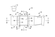
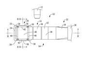
図1~6には、本発明の第一の実施形態としての雌端子10が、示されている。雌端子10は、略円筒状のピン形状を有する雄端子12と導通接続される接続部14を含む雌端子金具16を有している。さらに、雌端子10は、雌端子金具16に組み付けられる、収容空所18を有するケース20を有している。なお、以下の説明において、上方とは、図1,4~6中の上方、下方とは、図1,4~6中の下方を言い、また前方とは、図2~4中の左方、後方とは、図2~4中の右方を言い、さらに長手方向とは、図2~4中の左右方向、幅方向とは、図2~3中の上下方向を言うものとする。
FIGS. 1 to 6 show a
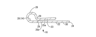
図1および図4に示されているように、雌端子金具16は、帯状の金属平板22を用いて構成されており、一対の重ね板部25a,25bの一方25aを構成する金属平板22の長手方向の一端部23が他端部24側(図4~5中、右側)に向かって折り返されている。かかる一端部23が他端部24側(図4~5中、中央部分)に設けられた一対の重ね板部25a,25bの他方25bに重ね合わされることにより金属平板22の長手方向(図4~5中、左右方向)の中間部分が湾曲されて、雄端子12の最大外径寸法:tよりも小さな最大内径寸法:rを有し幅方向(図4~5中、紙面に垂直な方向)両側に開口する略円筒状の雄端子挿通筒部26が形成されている。すなわち、雄端子挿通筒部26は、雄端子12が圧入されるように構成されている。そして、かかる雄端子挿通筒部26の内面28によって、接続部14が構成されている。また、この結果として、雄端子挿通筒部26の周方向の一か所(図4中、右斜め下方側)が軸方向(図4~5中、紙面に垂直な方向)全長に亘って分離されて一対の第一分離部29,29が形成されており、かかる一対の第一分離部29,29に連接して相互に離隔して外方(図4~5中、右方)に向かって突出する一対の重ね板部25a,25bが設けられているのである。さらに、金属平板22の長手方向の他端部24側(図4~5中、右側)には、電線接続部30が設けられている。このような構造とされた雌端子金具16は、導電性を有しており、かつプレス加工や打抜き加工等が可能な種々の金属材料、例えば真鍮や銅、銅合金、アルミニウム、アルミニウム合金等を用いて形成されている。
As shown in FIGS. 1 and 4, the female terminal fitting 16 is configured by using a strip-shaped metal
かかる雌端子金具16は、電線接続部30において、雌端子金具16に対して電線32の芯線34が導通接続されている。より詳細には、電線32は、導体である銅やアルミニウムその他の金属線の複数を束ね合わせた芯線34が、エチレン系樹脂やスチレン系樹脂等の電気絶縁性を有する絶縁被覆36で覆われた構造とされている。そして、電線32の端末において絶縁被覆36を剥いで露呈された芯線34を、例えば抵抗溶接等の公知の技術を用いて雌端子金具16の電線接続部30に固着することにより電線32の芯線34が雌端子金具16に対して導通接続されるようになっている。
In the female terminal fitting 16, the
一方、図1~3に示されているように、雌端子金具16を構成する金属平板22の一対の重ね板部25a,25bの他方25bにおける幅方向(図2~3中、上下方向)の両側縁部には、長手方向に離隔した2箇所において幅方向外方に向かって突出する略矩形平板状の一対の係合突起38,38が設けられている。
On the other hand, as shown in FIGS. 1 to 3, in the width direction (vertical direction in FIGS. 2 to 3) of the pair of
このような構成とされた雌端子金具16に対してケース20が組み付けられている(例えば、図4参照)。かかるケース20は、プレス加工や打抜き加工等が可能な種々の金属材料、例えば真鍮や銅、銅合金、アルミニウム、アルミニウム合金、ステンレス等を用いて形成されている。そして、ケース20は、雌端子金具16の一対の重ね板部25a,25bの一方25aの上方に収容空所18が配設されるように、雌端子金具16に対して組み付けられている。より詳細には、かかる組み付け状態において、ケース20は、収容空所18を介して一対の重ね板部25a,25bの一方25aに対向する略矩形平板形状の対向壁40を有している。また、ケース20は、対向壁40の幅方向(図2中、上下方向)の両側縁部から下方に向かって延び出す略矩形平板状の一対の壁部42,42を有しており、対向壁40と一対の壁部42,42によって収容空所18が構成されている。さらに、ケース20は、一対の壁部42,42の延出端部において、下方に向かって突設された略矩形平板状の加締め部44と、一方側(図2中、下側)の壁部42において一対の重ね板部25a,25bの他方25b上(図5参照)に位置する幅方向(図2中、左右方向)の両側縁部から幅方向外方に向かって突出後に板厚方向(図2中、上下方向)外方に向かって突出する略平板状の係合突起46と、を有している。加えて、対向壁40の長手方向(図2中、左右方向)の両側縁部には、幅方向(図2中、上下方向)の略全長に亘って下方に向かって突出するコイルばね保持壁48が設けられている(図1,4参照)。
The
このような構成とされたケース20は、収容空所18に対して付勢手段を構成するばね部材である金属製のコイルばね50が収容配置された状態で、一対の重ね板部25a,25bの一方25a上に保持されている(例えば、図4参照)。より詳細には、コイルばね50をケース20の収容空所18内に配置した状態で、ケース20が、雌端子金具16の一対の重ね板部25a,25bの一方25aの上方に載置されている。そして、ケース20の加締め部44を一対の重ね板部25a,25bの他方25bの側縁部に設けられた一対の係合突起38,38の間に挿通した後、幅方向(図3中、上下方向)内方に折り曲げて加締める。これにより、ケース20が、一対の壁部42,42の延出端部が一対の係合突起38,38上に載置された状態で固定されて、ケース20に収容されたコイルばね50が間接的に雌端子金具16に保持されるようになっている。しかも、一対の重ね板部25a,25bの一方25aとケース20の対向壁40との間でコイルばね50が圧縮状態に保持されている。このように圧縮状態に保持されているコイルばね50によって、一対の重ね板部25a,25bが相互に接近する方向(図4,6中、矢印の方向)に向かって付勢されている。すなわち、電線接続部30と雄端子挿通筒部26の間に一対の重ね板部25a,25bを接近方向に付勢する付勢手段であるコイルばね50が配設保持されるようになっている。
In the
本実施形態では、このように付勢手段を構成するばね部材がコイルばね50を用いて構成されていることから、たわみ量を大きく確保することができる。それゆえ、ばね定数の小さいコイルばね50を限られたケース20の収容空間である収容空所18内にコンパクトに配設することができることから、金属平板22の板厚、最大内径寸法:r等がばらついても雌端子10と雄端子12間の接圧の変化を小さく抑えることができる。また、電線接続部30と雄端子挿通筒部26の間に付勢手段であるコイルばね50が配設保持されていることから、電線接続部30からの雄端子挿通筒部26の離隔距離が確保されている。これにより、電線接続部30に対して電線32の端末に露呈された芯線34が溶接等により接続固定される際の熱影響から雄端子挿通筒部26を有利に保護することができ、熱影響による雄端子挿通筒部26のめっき特性への影響等を低減乃至は回避することができるようになっている。
In the present embodiment, since the spring member constituting the urging means is configured by using the
このような構成とされた雌端子10に対して、雄端子12が導通接続されるようになっている。より詳細には、雌端子10の雄端子挿通筒部26に対して雄端子12が圧入されると、まず、コイルばね50によって一対の重ね板部25a,25bを相互に接近する方向に付勢している付勢力に抗して、一対の重ね板部25a,25bの一方25aが他方25bに対して雄端子挿通筒部26側に向かってスライド変位される。これにより、雄端子挿通筒部26が拡径方向に弾性変形して雄端子12の雄端子挿通筒部26への圧入が許容される。そして、挿入後は、雄端子挿通筒部26の弾性復帰力によって、接続部14を構成する雄端子挿通筒部26の内面28が雄端子12に高い接圧をもって接続状態に圧接保持されるようになっている。すなわち、付勢手段を構成するコイルばね50によって、拡径方向に弾性変形可能な雄端子挿通筒部26が縮径状態に保持されているのである。なお、かかる雌端子10と雄端子12間の接圧は、コイルばね50の強さによって変えることができる。
The
このような構造とされた本実施形態の雌端子10によれば、付勢手段を構成するばね部材であるコイルばね50は、雌端子金具16に保持されていることから、従来のように雄端子12を雌端子10に導通接続した後に別体のばね部材等を取り付ける必要がない。それゆえ、作業工程の簡素化を図ることができ、雌端子10と雄端子12間の高い接圧を優れた作業性により実現することができる。また、雌端子10の雄端子挿通筒部26に雄端子12が圧入される際に、付勢手段であるコイルばね50の付勢力に抗して一対の重ね板部25a,25bの一方25aが他方25bに対して雄端子挿通筒部26側に向かってスライド変位されることにより、雄端子挿通筒部26が拡径方向に弾性変形して雄端子12の雄端子挿通筒部26への圧入が許容される。そして、雄端子挿通筒部26の弾性復帰力により雄端子挿通筒部26の内面28によって構成される接続部14が雄端子12に圧接されることとなり、雌端子10と雄端子12間の大きな接圧が確保されるようになっている。かかるスライド変位の方向(図4中、左方向)とコイルばね50による付勢方向(図4,6中、矢印の方向)が異ならされていることから、雄端子12を雌端子10の接続部14を構成する雄端子挿通筒部26の内面28に挿入する際の挿入力を有利に低減しつつ接圧状態を安定して保持することが可能となっている。さらに、雄端子12に何らかの外力が加わった場合でも、かかる外力は雌端子10の雄端子挿通筒部26の径方向外方に伝達され、一対の重ね板部25a,25bが相互にスライド変位する方向に伝達されることから、外力の伝達方向とコイルばね50による付勢方向(図4,6中、矢印の方向)が異ならされている。それゆえ、かかる外力によって雌端子10と雄端子12間の接圧が変動することを有利に低減乃至は防止することができることから、雌端子10と雄端子12間の導通安定性の向上も確保することができる。
According to the
加えて、ケース20が、収容空所18に対して付勢手段を構成するばね部材であるコイルばね50が収容配置された状態で、一対の重ね板部25a,25b上に保持されていることから、雌端子10に対して付勢手段を安定して保持することができるようになっている。しかも、かかる付勢手段は、雄端子12に対して導通接続される雌端子10の接続部14の構造には影響を与えないことから、雌端子10の接続部14の構造の設計自由度を高めることができる。
In addition, the
また、本実施形態では、帯状の金属平板22の一端部23を他端部24側に折り返すという簡単な構造により、雄端子挿通筒部26の周方向の一か所において軸方向全長に亘って分離された一対の第一分離部29,29を備えており、かかる一対の第一分離部29,29に連接して相互に離隔して外方に突出する一対の重ね板部25a,25bを有している。それゆえ、かかる雄端子挿通筒部26を備えた雌端子金具16を容易且つ歩留まりよく製造することができる。
Further, in the present embodiment, due to a simple structure in which one
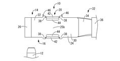
次に、図7~12を用いて、本発明の第二の実施形態としての雌端子52について詳述するが、上記実施形態と同様な構造とされた部材および部位については、図中に、上記実施形態と同一の符号を付することにより、それらの詳細な説明を省略する。本実施形態では、雌端子金具54が、雄端子挿通筒部56の周方向の他の一か所において、軸方向全長に亘って延びる一対の第二分離部58,58がさらに設けられている点に関して、上記第一の実施形態と異なる実施形態を示すものである。より詳細には、雌端子金具54において雄端子挿通筒部56の周方向の一か所(図10中、左側)に一対の第一分離部29,29が形成されており、かかる一対の第一分離部29,29に連接して外方(図10中、左方)に向かって突出する一対の重ね板部25a,25bが設けられている。一方、一対の第一分離部29,29に対して雄端子挿通筒部56の径方向で対向する雄端子挿通筒部56の周方向の他の一か所には一対の第二分離部58,58が形成されており、かかる一対の第二分離部58,58に連接して外方(図10中、右方)に向かって突出する一対の延出板部60,60がさらに設けられている。そして、一対の重ね板部25a,25bが相互に接近する方向(図10,12中、矢印の方向)に向かって付勢されている一方、一対の延出板部60,60が相互に重ね合されることにより電線接続部30が構成されている。本実施形態では、一対の延出板部60,60が抵抗溶接等の公知の任意の手段を用いて相互に固着されて一体化されている。この結果、雌端子金具54の長手方向(図10中、左右方向)において、電線接続部30と一対の重ね板部25a,25bの間に、雄端子挿通筒部56が配設されているのである。なお、本実施形態では、雌端子金具54は、帯状の金属平板22を用いて構成されており、金属平板22の長手方向の一端部23が他端部24(図10中、左側)上に向かって2つ折り状に折り重ねられている。かかる一端部23が他端部24(図10中、左側)上に折り重ねられた状態で重ね合わせ面の長手方向(図10中、左右方向)の中間部分が相互に離隔する方向に向かって湾曲されることにより、略円筒状の雄端子挿通筒部26が構成されるようになっている。なお、一対の延出板部60,60は相互に重ね合せた状態で電線接続部30を構成することができ、かかる電線接続部30に対して電線32の芯線34を溶接する際に、同時に相互に溶接することで作業性の効率化を図ることができる。
Next, the
このような構造とされた本実施形態の雌端子52においても、上記第一の実施形態と同様に、付勢手段を構成するばね部材であるコイルばね50は、雌端子金具54に保持されていることから、従来のように雄端子12を雌端子52に導通接続した後に別体のばね部材等を取り付ける必要がない。それゆえ、作業工程の簡素化を図ることができ、雌端子52と雄端子12間の高い接圧を優れた作業性により実現することができる。また、雌端子52の雄端子挿通筒部56に雄端子12が圧入される際に、付勢手段であるコイルばね50の付勢力に抗して一対の重ね板部25a,25bの一方25aが他方25bに対して雄端子挿通筒部56側に向かってスライド変位されることにより、雄端子挿通筒部56が拡径方向に弾性変形して雄端子12の雄端子挿通筒部56への圧入が許容される。そして、雄端子挿通筒部56の弾性復帰力により雄端子挿通筒部56の内面28によって構成される接続部14が雄端子12に圧接されることとなり、雌端子52と雄端子12間の大きな接圧が確保されるようになっている。
In the
本実施形態によれば、雄端子挿通筒部56に設けられた一対の第二分離部58,58から延び出す一対の延出板部60,60が相互に重ね合されることにより、電線接続部30が設けられている。これにより、一対の第二分離部58,58から延び出す一対の延出板部60,60の双方を電流経路とすることができることから、一対の延出板部60,60が相互に重ね合された電線接続部30の断面積を有利に確保することができ、より多くの電流を流すことができる。それゆえ、雄端子挿通筒部56の板厚寸法を薄くしつつ電線接続部30の断面積を確保することができることから、雄端子挿通筒部56の弾性変形を容易にして雄端子12の雄端子挿通筒部56への挿入力の低減を可能にしつつ電流経路の断面積を確保することが可能となる。また、電線接続部30と一対の重ね板部25a,25bの間に、雄端子挿通筒部56が構成配置されていることから、上記第一の実施形態のように雄端子12が圧接される雄端子挿通筒部56と電線接続部30の間に付勢手段であるコイルばね50を配設する必要がないことから、雌端子52の接続部14と電線接続部30間の電流経路を短くすることができ、抵抗の低減を図ることができる。
According to the present embodiment, the pair of
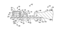
続いて、図13を用いて、本発明の第三の実施形態としての雌端子62について詳述するが、上記実施形態と同様な構造とされた部材および部位については、図中に、上記実施形態と同一の符号を付することにより、それらの詳細な説明を省略する。本実施形態では、雌端子金具64が第一板金具66と第二板金具68とを含んでおり、第一板金具66と第二板金具68の板厚寸法が相互に異なっている点に関して、上記第二の実施形態と異なる実施形態を示すものである。より詳細には、第一板金具66は、一対の第一分離部29,29の一方側(図13中、下側)に連接する一対の重ね板部25a,25bの一方25bと、一対の第一分離部29,29の一方側から一対の第二分離部58,58の一方側(図13中、下側)に延びる雄端子挿通筒部70の周壁と、一対の第二分離部58,58の一方側から延び出す一対の延出板部60,60の一方側(図13中、下側)とを一体的に構成することにより形成されている。一方、第二板金具68は、一対の第一分離部29,29の他方側(図13中、上側)に連接する一対の重ね板部25a,25bの一方25aと、一対の第一分離部29,29の他方側から一対の第二分離部58,58の他方側(図13中、上側)に延びる雄端子挿通筒部70の周壁と、一対の第二分離部58,58の他方側から延び出す一対の延出板部60,60の他方側(図13中、上側)とを一体的に構成することにより形成されている。そして、かかる第一板金具66と第二板金具68が相互に重ね合されることにより、第一板金具66と第二板金具68の長手方向(図13中、左右方向)の中央部分に雄端子挿通筒部70が構成され、長手方向の基端側(図13中、右側)に第一板金具66と第二板金具68が固着された電線接続部30が構成され、長手方向の先端側(図13中、左側)に一対の重ね板部25a,25bを相互に重ね合せて付勢する付勢手段を構成するコイルばね50が配設されている。なお、本実施形態では、第一板金具66と第二板金具68はそれぞれ平板状の金属平板72a,72bを用いて構成されており、金属平板72aが金属平板72bよりも板厚寸法が大きくされている。そして、第一板金具66が略平板形状のままとされている一方、かかる第一板金具66に重ね合される第二板金具68は、長手方向(図13中、左右方向)の両端部が平板形状のままとされていると共に、長手方向の中央部分において雄端子挿通筒部70の周壁を構成して第一板金具66から離隔する方向に凸となる凸形断面で板幅方向に亘って突出する凸状部74を含んで構成されている。
Subsequently, with reference to FIG. 13, the
このような構造とされた本実施形態の雌端子62においても、上記第一の実施形態と同様に、付勢手段を構成するばね部材であるコイルばね50は、雌端子金具64に保持されていることから、従来のように雄端子12を雌端子62に導通接続した後に別体のばね部材等を取り付ける必要がない。それゆえ、作業工程の簡素化を図ることができ、雌端子62と雄端子12間の高い接圧を優れた作業性により実現することができる。また、雌端子62の雄端子挿通筒部70に雄端子12が圧入される際に、付勢手段であるコイルばね50の付勢力に抗して一対の重ね板部25a,25bの一方25aが他方25bに対して雄端子挿通筒部70側に向かってスライド変位されることにより、雄端子挿通筒部70が拡径方向に弾性変形して雄端子12の雄端子挿通筒部70への圧入が許容される。そして、雄端子挿通筒部70の弾性復帰力により雄端子挿通筒部70の内面28によって構成される接続部14が雄端子12に圧接されることとなり、雌端子62と雄端子12間の大きな接圧が確保されるようになっている。
In the
本実施形態によれば、第一板金具66と第二板金具68を相互に重ね合せることにより、雄端子挿通筒部70とその両側に設けた電線接続部30および付勢手段であるコイルばね50を配設する一対の重ね板部25a,25bを設けることができることから、本発明の雌端子62を容易に製造することができる。また、第一板金具66と第二板金具68の板厚寸法を相互に異ならせることができることから、要求される特性に応じて第一板金具66と第二板金具68の板厚を調整することができ、雌端子62の設計自由度の向上を図ることができる。さらに、板厚寸法が大きい平板形状の第一板金具66に対して、板厚寸法が小さく且つ長手方向両側が平板形状で長手方向中央部分が雄端子挿通筒部70の周壁を構成する凸状部74とされた第二板金具68が重ね合されて、雌端子金具64が構成されている。それゆえ、雄端子12が雄端子挿通筒部70に挿通された際に、板厚寸法の小さい凸状部74を優位に弾性変形させることができることから、雄端子12の挿入力の低減を有利に図ることができる。しかも、第一板金具66の板厚寸法は大きく確保できることから、電線接続部30の断面積は有利に維持することができ、電流量も確保することができる。
According to the present embodiment, by superimposing the first plate metal fitting 66 and the second plate metal fitting 68 on each other, the male terminal
加えて、図14に示す本発明の第四の実施形態としての雌端子76のように、第一板金具78が第二板金具80よりも板厚寸法が小さくされていてもよい。すなわち、第一板金具78が平板形状とされている一方、かかる第一板金具78に重ね合される第二板金具80は、長手方向(図14中、左右方向)の両端部が平板形状されており、長手方向の中央部分に雄端子挿通筒部82の周壁を構成して第一板金具78から離隔する方向に凸となる凸形断面で板幅方向に亘って突出する凸状部84を含んで構成されていてもい。本実施形態のように、板厚寸法が大きい第二板金具80に雄端子挿通筒部82の周壁を構成する凸状部84が形成されている場合には、雄端子12を雄端子挿通筒部82に挿通した際に密着する凸状部84の板厚寸法が大きくされていることから、雌端子76と雄端子12間の低抵抗化を図ることができる。
In addition, the first plate fitting 78 may have a smaller plate thickness than the second plate fitting 80, as in the
さらに、図15に示す本発明の第五の実施形態としての雌端子86のように、雄端子挿通筒部88が角が丸くされた略菱形断面形状を有していてもよい。これにより、雄端子挿通筒部88に挿通された雄端子12を内面28を構成する菱形の4辺の中央部で安定して保持できる。すなわち、上記第二の実施形態のように雄端子挿通筒部56が円形断面形状である場合に比して、挿通された雄端子12を保持する接点の位置を固定することができることから、かかる位置で雄端子12を安定的に保持でき且つかかる位置のバラツキを観測することにより製造管理を容易に行うことが可能となっているのである。なお、さらに接点の位置を明確にするために、雄端子挿通筒部88の内面28に周知のエンボスを突出してもよく、本実施形態の場合、菱形の4辺の中央部にそれぞれエンボスを設けてもよい。
Further, as in the
あるいはまた、図16~17に示す本発明の第六の実施形態としての雌端子90のように、雄端子挿通筒部92の内面28が雄端子94の圧入方向(図17中、左方向)における先端側(図17中、左側)に向かって次第に小径となるテーパ形状とされていてもよい。これにより、雄端子94が雄端子挿通筒部92へ挿入された当初には内面28に当接しないようになっていることから、かかる挿入された当初の挿入力を低減させることができる。特に、本実施形態のように、雄端子94の先端部の先端面96が雄端子挿通筒部92の内面28と相似のテーパ形状とされている場合には、雄端子94が雄端子挿通筒部92に完全に圧入されるまでは挿入力は発生しない一方、雄端子94を雄端子挿通筒部92から引き抜く際には少し引っ張るだけで可能であり、雄端子94の雄端子挿通筒部92に対する挿抜力を大幅に低減することができるようになっている。
Alternatively, as in the
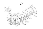
続いて、図18~20を用いて、本発明の第七の実施形態としての雌端子98について詳述するが、上記実施形態と同様な構造とされた部材および部位については、図中に、上記実施形態と同一の符号を付することにより、それらの詳細な説明を省略する。本実施形態では、雌端子金具100が、雄端子挿通筒部102の周方向の他の一か所において、軸方向全長に亘って延びる一対の第二分離部104,104が設けられている点に関して、上記第二の実施形態と異なる実施形態を示すものである。より詳細には、雌端子金具100が、一対の第一分離部29,29に連接して外方(図19中、右方)に突出する一対の重ね板部25a,25bが設けられており、一対の重ね板部25a,25b上にケース20に収容されたコイルばね50が配設保持されている。かかる一対の重ね板部25a,25bの突出端部からそれぞれさらに外方(図19中、右方)に延び出す一対の延出板部106,106をさらに含んでおり、かかる一対の延出板部106,106が相互に重ね合されており、例えば電線32の芯線34を電線接続部30に溶接する際に、一対の延出板部106,106も相互に固着されて一体化されている。しかも、雄端子挿通筒部102の周方向の他の一か所において、軸方向全長に亘って延びる一対の第二分離部104,104が設けられており、かかる一対の第二分離部104,104はいずれも自由端とされている。
Subsequently, the
このような構造とされた本実施形態の雌端子98においても、上記第一の実施形態と同様に、付勢手段を構成するばね部材であるコイルばね50は、雌端子金具100に保持されていることから、従来のように雄端子12を雌端子98に導通接続した後に別体のばね部材等を取り付ける必要がない。それゆえ、作業工程の簡素化を図ることができ、雌端子98と雄端子12間の高い接圧を優れた作業性により実現することができる。
In the
また、本実施形態によれば、雄端子挿通筒部102の周方向の他の一か所において、軸方向全長に亘って延びる一対の第二分離部104,104が設けられており、かかる一対の第二分離部104,104はいずれも自由端とされている。これにより、雄端子挿通筒部102に雄端子12が圧入される際に、一対の第二分離部104,104が離隔する方向に変位することにより雄端子挿通筒部102が拡径方向に弾性変形して雄端子12の雄端子挿通筒部102への圧入が許容されることから、雄端子12の雄端子挿通筒部102への挿入力の低減を有利に図ることができるようになっている。
Further, according to the present embodiment, a pair of
以上、本発明の複数の実施形態について詳述したが、本発明はこれらの具体的な記載によって限定されない。例えば、上記実施形態では、付勢手段としてコイルばね50を例示して説明を行ったが、付勢手段はこれに限定されず、例えば板ばねや皿ばね等のばね部材や、ゴム弾性体等の弾性体などの周知の付勢力を付与する部材の何れも採用可能である。また、上記実施形態では、コイルばね50はケース20を介して雌端子金具16,54,64,100に間接的に保持されていたが、直接的に保持されていてもよい。
Although the plurality of embodiments of the present invention have been described in detail above, the present invention is not limited by these specific descriptions. For example, in the above embodiment, the
さらに、上記実施形態では、雄端子挿通筒部26,56,70,82,88,92,102の軸方向に直交する方向に電線接続部30に固着された電線32が延び出していたが、雄端子挿通筒部26,56,70,82,88,92,102の軸方向に電線32が延び出すように電線接続部30に固着されていてもよい。加えて、上記実施形態においては、ケース20は金属製であったが、十分な剛性を有する部材であればよく、合成樹脂等の採用が可能である。
Further, in the above embodiment, the
また、上記実施形態では、雄端子挿通筒部26,56,70,82,92,102が略円筒状を有する例や雄端子挿通筒部88が略菱形状を有する例を示したが、これに限定されず、雄端子挿通筒部26,56,70,82,88,92,102の断面形状は、挿入される雄端子の断面形状に合わせて矩形や楕円形や多角形等で構成することも可能である。そして、それら任意の形状の雄端子挿通筒部26,56,70,82,88,92,102の内面28には、任意の箇所にエンボスを突設することにより雄端子12,94に対する接点の位置を明確化するようにしてもよい。
Further, in the above embodiment, an example in which the male terminal
さらに、上記第二~第七の実施形態では、第二分離部58,104の周方向位置は、第一分離部29に軸直角方向で対向する位置に設けられていたが、これに限定されない。例えば、第一分離部29と第二分離部58,104が周方向で90°離隔する位置に設けられて、重ね板部25a,25bと延出板部60,106が直交方向に突出するように構成されていてもよい。これにより、雌端子52,62,76,86,90の設計自由度を向上することができる。
Further, in the second to seventh embodiments, the circumferential positions of the
10,52,62,76,86,90,98:雌端子、12,94:雄端子、14:接続部、16,54,64,100:雌端子金具、18:収容空所、20:ケース、22,72a,b:金属平板、23:一端部、24:他端部、25a,b:重ね板部、26,56,70,82,88,92,102:雄端子挿通筒部、28:内面(接続部)、29:第一分離部、30:電線接続部、40:対向壁、50:コイルばね(付勢手段,ばね部材)、58,104:第二分離部、60,106:延出板部、66,78:第一板金具、68,80:第二板金具、74,84:凸状部 10,52,62,76,86,90,98: Female terminal, 12,94: Male terminal, 14: Connection part, 16,54,64,100: Female terminal metal fittings, 18: Storage vacant space, 20: Case , 22,72a, b: Metal flat plate, 23: One end, 24: End, 25a, b: Laminated plate , 26,56,70,82,88,92,102: Male terminal insertion tube, 28 : Inner surface (connection part), 29: First separation part, 30: Wire connection part, 40: Opposing wall, 50: Coil spring (urgency means, spring member), 58, 104: Second separation part, 60, 106 : Extended plate part, 66,78: First plate metal fitting, 68,80: Second plate metal fitting, 74,84: Convex part
Claims (12)
前記雌端子金具に設けられており、前記雄端子が圧入され内面によって前記接続部を構成する雄端子挿通筒部と、
前記雄端子挿通筒部の周方向の一か所が軸方向全長に亘って分離されることによって設けられた一対の第一分離部に連接して相互に離隔して外方に突出する一対の重ね板部と、
前記雌端子金具に保持されて、前記一対の重ね板部を相互に重ね合せる方向に付勢して前記雄端子挿通筒部を縮径状態に保持する付勢手段とを備え、
前記付勢手段の付勢力により前記雄端子挿通筒部に縮径方向の力が加えられており、
前記雄端子挿通筒部に前記雄端子が圧入される際には、前記付勢手段の付勢力に抗して前記雄端子挿通筒部が拡径方向に弾性変形されて前記雄端子の前記雄端子挿通筒部への圧入が許容されるようになっており、
前記雌端子金具が、前記雄端子挿通筒部の前記周方向の他の一か所において、前記軸方向全長に亘って延びる第二分離部と、該第二分離部に連接して外方に突出する一対の延出板部とをさらに含んでおり、該一対の延出板部が相互に重ね合されることにより電線接続部が構成されている雌端子。 Female terminal fittings including the connection part that is electrically connected to the male terminal,
A male terminal insertion tube portion provided on the female terminal fitting, to which the male terminal is press-fitted to form the connection portion by an inner surface, and a male terminal insertion tube portion.
A pair of male terminal insertion cylinders that are connected to a pair of first separation portions provided by being separated over the entire axial length, separated from each other, and project outwards. The stacking plate part and
It is provided with an urging means that is held by the female terminal fitting and urges the pair of laminated plate portions in a direction in which they are overlapped with each other to hold the male terminal insertion tube portion in a reduced diameter state.
A force in the diameter reduction direction is applied to the male terminal insertion tube portion by the urging force of the urging means.
When the male terminal is press-fitted into the male terminal insertion tube portion, the male terminal insertion tube portion is elastically deformed in the radial direction against the urging force of the urging means, and the male terminal is said to be male. Press-fitting into the terminal insertion tube is allowed ,
The female terminal fitting is connected to the second separation portion extending over the entire length in the axial direction and outward at another location in the circumferential direction of the male terminal insertion tube portion. A female terminal that further includes a pair of projecting extension plate portions, and the wire connection portion is formed by superimposing the pair of extension plate portions on each other .
前記第一板金具と前記第二板金具の板厚寸法が相互に異なっている請求項1または4に記載の雌端子。 The female terminal fitting of the male terminal insertion tube portion extending from one of the pair of laminated plate portions connected to one of the first separation portions and one of the first separation portions to one of the second separation portions. The peripheral wall, the first plate metal fitting that integrally constitutes one of the extension plate portions extending from one of the second separation portions, and the pair of laminated plate portions that are connected to the other of the first separation portions. The other, the peripheral wall of the male terminal insertion tube portion extending from the other of the first separation portion to the other of the second separation portion, and the other of the extension plate portion extending from the other of the second separation portion. It includes a second plate metal fitting that is integrally configured, and by superimposing the first plate metal fitting and the second plate metal fitting on each other, a central portion in the longitudinal direction of the first and second plate metal fittings. The male terminal insertion tube portion is configured in the above, the electric wire connecting portion is configured on the proximal end side in the longitudinal direction, and the pair of laminated plate portions are superposed on each other and urged on the tip end side in the longitudinal direction. The urging means are arranged,
The female terminal according to claim 1 or 4 , wherein the plate thickness dimensions of the first plate fitting and the second plate fitting are different from each other.
前記雌端子金具に設けられており、前記雄端子が圧入され内面によって前記接続部を構成する雄端子挿通筒部と、
前記雄端子挿通筒部の周方向の一か所が軸方向全長に亘って分離されることによって設けられた一対の第一分離部に連接して相互に離隔して外方に突出する一対の重ね板部と、
前記雌端子金具に保持されて、前記一対の重ね板部を相互に重ね合せる方向に付勢して前記雄端子挿通筒部を縮径状態に保持する付勢手段とを備え、
前記付勢手段の付勢力により前記雄端子挿通筒部に縮径方向の力が加えられており、
前記雄端子挿通筒部に前記雄端子が圧入される際には、前記付勢手段の付勢力に抗して前記雄端子挿通筒部が拡径方向に弾性変形されて前記雄端子の前記雄端子挿通筒部への圧入が許容されるようになっており、
前記雌端子金具が、前記一対の第一分離部に連接して外方に突出する前記一対の重ね板部の突出端部からそれぞれさらに外方に延び出す一対の延出板部をさらに含んでおり、該一対の延出板部が相互に重ね合されることにより電線接続部が構成されており、
前記雄端子挿通筒部の前記周方向の他の一か所において、前記軸方向全長に亘って延びる第二分離部が設けられている雌端子。 Female terminal fittings including the connection part that is electrically connected to the male terminal,
A male terminal insertion tube portion provided on the female terminal fitting, to which the male terminal is press-fitted to form the connection portion by an inner surface, and a male terminal insertion tube portion.
A pair of male terminal insertion cylinders that are connected to a pair of first separation portions provided by being separated over the entire length in the axial direction, separated from each other, and project outwards. The stacking plate part and
It is provided with an urging means that is held by the female terminal fitting and urges the pair of laminated plate portions in a direction in which they are overlapped with each other to hold the male terminal insertion tube portion in a reduced diameter state.
A force in the diameter reduction direction is applied to the male terminal insertion tube portion by the urging force of the urging means.
When the male terminal is press-fitted into the male terminal insertion tube portion, the male terminal insertion tube portion is elastically deformed in the radial direction against the urging force of the urging means, and the male terminal is said to be male. Press-fitting into the terminal insertion tube is allowed,
The female terminal fitting further includes a pair of extension plate portions that extend outward from the protruding end portions of the pair of stacked plate portions that are connected to the pair of first separation portions and project outward. The wire connection portion is formed by superimposing the pair of extension plate portions on each other.
A female terminal provided with a second separation portion extending over the entire length in the axial direction at another location in the circumferential direction of the male terminal insertion tube portion.
前記付勢手段がばね部材を含んで構成されて前記ケースの前記収容空所に収容されることにより、前記雌端子金具に保持され、前記重ね板部と前記ケースの前記重ね板部への対向壁との間で前記ばね部材が圧縮状態に保持されている請求項1~10の何れか1項に記載の雌端子。 It further has a case having a storage space assembled to the female terminal fitting, and the storage space is arranged above the stacking plate portion.
When the urging means is configured to include a spring member and is accommodated in the accommodation space of the case, it is held by the female terminal fitting and is attached to the laminated plate portion and the laminated plate portion of the case. The female terminal according to any one of claims 1 to 10, wherein the spring member is held in a compressed state with the facing wall.
Priority Applications (3)
| Application Number | Priority Date | Filing Date | Title |
|---|---|---|---|
| US16/970,277 US11101579B2 (en) | 2018-03-08 | 2019-02-15 | Spring biased female terminal |
| PCT/JP2019/005641 WO2019171914A1 (en) | 2018-03-08 | 2019-02-15 | Female terminal |
| CN201980016319.4A CN111801850B (en) | 2018-03-08 | 2019-02-15 | Female terminal |
Applications Claiming Priority (2)
| Application Number | Priority Date | Filing Date | Title |
|---|---|---|---|
| JP2018042166 | 2018-03-08 | ||
| JP2018042166 | 2018-03-08 |
Publications (3)
| Publication Number | Publication Date |
|---|---|
| JP2019160768A JP2019160768A (en) | 2019-09-19 |
| JP2019160768A5 JP2019160768A5 (en) | 2020-10-01 |
| JP7012940B2 true JP7012940B2 (en) | 2022-01-31 |
Family
ID=67996409
Family Applications (1)
| Application Number | Title | Priority Date | Filing Date |
|---|---|---|---|
| JP2018089453A Active JP7012940B2 (en) | 2018-03-08 | 2018-05-07 | Female terminal |
Country Status (2)
| Country | Link |
|---|---|
| US (1) | US11101579B2 (en) |
| JP (1) | JP7012940B2 (en) |
Families Citing this family (5)
| Publication number | Priority date | Publication date | Assignee | Title |
|---|---|---|---|---|
| JP6958642B2 (en) | 2020-01-10 | 2021-11-02 | トヨタ自動車株式会社 | Evaluation jig |
| JP6958644B2 (en) * | 2020-01-10 | 2021-11-02 | トヨタ自動車株式会社 | Evaluation jig and evaluation method |
| JP7402435B2 (en) * | 2020-12-11 | 2023-12-21 | 株式会社オートネットワーク技術研究所 | female terminal |
| JP7444043B2 (en) | 2020-12-16 | 2024-03-06 | 株式会社オートネットワーク技術研究所 | terminal unit |
| JP2022106197A (en) * | 2021-01-06 | 2022-07-19 | 株式会社オートネットワーク技術研究所 | Terminal unit |
Citations (1)
| Publication number | Priority date | Publication date | Assignee | Title |
|---|---|---|---|---|
| JP2017183270A (en) | 2016-03-24 | 2017-10-05 | 株式会社オートネットワーク技術研究所 | Terminal module |
Family Cites Families (10)
| Publication number | Priority date | Publication date | Assignee | Title |
|---|---|---|---|---|
| US3008114A (en) * | 1959-08-24 | 1961-11-07 | Mason B Adkins | Cable clip for positive and negative battery terminals |
| JPS4928186U (en) * | 1972-06-15 | 1974-03-11 | ||
| JP2882283B2 (en) * | 1994-06-03 | 1999-04-12 | 住友電装株式会社 | Battery terminal |
| JPH0850892A (en) * | 1994-08-04 | 1996-02-20 | Yazaki Corp | Battery terminal |
| US6062918A (en) * | 1996-07-01 | 2000-05-16 | The Whitaker Corporation | Electrical receptacle contact assembly |
| US6293833B1 (en) * | 2001-01-05 | 2001-09-25 | Yazaki North America | Low insertion force, high contact force terminal spring |
| KR20060064770A (en) | 2004-12-09 | 2006-06-14 | 기아자동차주식회사 | Battery terminal attachment structure |
| JP5522459B2 (en) | 2010-05-13 | 2014-06-18 | 住友電装株式会社 | Female terminals and connectors |
| JP6086244B2 (en) * | 2013-11-19 | 2017-03-01 | 住友電装株式会社 | Multi-contact terminal |
| JP7001961B2 (en) * | 2018-03-02 | 2022-01-20 | 株式会社オートネットワーク技術研究所 | Female terminal |
-
2018
- 2018-05-07 JP JP2018089453A patent/JP7012940B2/en active Active
-
2019
- 2019-02-15 US US16/970,277 patent/US11101579B2/en active Active
Patent Citations (1)
| Publication number | Priority date | Publication date | Assignee | Title |
|---|---|---|---|---|
| JP2017183270A (en) | 2016-03-24 | 2017-10-05 | 株式会社オートネットワーク技術研究所 | Terminal module |
Also Published As
| Publication number | Publication date |
|---|---|
| US20210143561A1 (en) | 2021-05-13 |
| US11101579B2 (en) | 2021-08-24 |
| JP2019160768A (en) | 2019-09-19 |
Similar Documents
| Publication | Publication Date | Title |
|---|---|---|
| JP7012940B2 (en) | Female terminal | |
| JP5433010B2 (en) | Terminal fitting and method of assembling the terminal fitting | |
| JP5723695B2 (en) | Female terminal | |
| JP7001961B2 (en) | Female terminal | |
| TWI243516B (en) | Semi-permanent connection between a bus bar and a connector contact | |
| JP5723694B2 (en) | Female terminal | |
| JP7395112B2 (en) | female terminal | |
| JP2019160768A5 (en) | ||
| WO2019171914A1 (en) | Female terminal | |
| JP6193122B2 (en) | Male electrical terminal | |
| JP2014002846A (en) | Joint connector extension structure and joint connector | |
| WO2021029189A1 (en) | Female terminal | |
| CN112018543B (en) | Electric wire with terminal and wire harness | |
| JP6613980B2 (en) | Terminal assembly and manufacturing method thereof | |
| JP2021028903A (en) | Female terminal | |
| WO2021029188A1 (en) | Female terminal | |
| JP6488835B2 (en) | Coil terminal connection structure | |
| JP7359571B2 (en) | Wires with terminals and wire harnesses | |
| US20230402769A1 (en) | Sensor contacting element, cell connector terminal and cell connector plate | |
| WO2023013488A1 (en) | Terminal | |
| JP2019003733A (en) | connector | |
| JP5388565B2 (en) | Female terminal structure | |
| JP5195191B2 (en) | Terminal fittings and electric wires with terminal fittings | |
| JP2009187833A (en) | Wire connection device | |
| JP6560695B2 (en) | Connection method |
Legal Events
| Date | Code | Title | Description |
|---|---|---|---|
| A521 | Request for written amendment filed |
Free format text: JAPANESE INTERMEDIATE CODE: A523 Effective date: 20180514 |
|
| A521 | Request for written amendment filed |
Free format text: JAPANESE INTERMEDIATE CODE: A523 Effective date: 20200819 |
|
| A621 | Written request for application examination |
Free format text: JAPANESE INTERMEDIATE CODE: A621 Effective date: 20200827 |
|
| A131 | Notification of reasons for refusal |
Free format text: JAPANESE INTERMEDIATE CODE: A131 Effective date: 20210803 |
|
| A521 | Request for written amendment filed |
Free format text: JAPANESE INTERMEDIATE CODE: A523 Effective date: 20210930 |
|
| TRDD | Decision of grant or rejection written | ||
| A01 | Written decision to grant a patent or to grant a registration (utility model) |
Free format text: JAPANESE INTERMEDIATE CODE: A01 Effective date: 20211220 |
|
| A61 | First payment of annual fees (during grant procedure) |
Free format text: JAPANESE INTERMEDIATE CODE: A61 Effective date: 20220102 |
|
| R150 | Certificate of patent or registration of utility model |
Ref document number: 7012940 Country of ref document: JP Free format text: JAPANESE INTERMEDIATE CODE: R150 |