JP7010860B2 - Wiring structure - Google Patents
Wiring structure Download PDFInfo
- Publication number
- JP7010860B2 JP7010860B2 JP2019019685A JP2019019685A JP7010860B2 JP 7010860 B2 JP7010860 B2 JP 7010860B2 JP 2019019685 A JP2019019685 A JP 2019019685A JP 2019019685 A JP2019019685 A JP 2019019685A JP 7010860 B2 JP7010860 B2 JP 7010860B2
- Authority
- JP
- Japan
- Prior art keywords
- wiring
- module
- power supply
- adjacent
- modules
- Prior art date
- Legal status (The legal status is an assumption and is not a legal conclusion. Google has not performed a legal analysis and makes no representation as to the accuracy of the status listed.)
- Active
Links
Images


Classifications
-
- H—ELECTRICITY
- H05—ELECTRIC TECHNIQUES NOT OTHERWISE PROVIDED FOR
- H05K—PRINTED CIRCUITS; CASINGS OR CONSTRUCTIONAL DETAILS OF ELECTRIC APPARATUS; MANUFACTURE OF ASSEMBLAGES OF ELECTRICAL COMPONENTS
- H05K7/00—Constructional details common to different types of electric apparatus
- H05K7/14—Mounting supporting structure in casing or on frame or rack
- H05K7/1462—Mounting supporting structure in casing or on frame or rack for programmable logic controllers [PLC] for automation or industrial process control
- H05K7/1475—Bus assemblies for establishing communication between PLC modules
- H05K7/1479—Bus assemblies for establishing communication between PLC modules including decentralized modules, e.g. connected to other modules using fieldbus
-
- H—ELECTRICITY
- H02—GENERATION; CONVERSION OR DISTRIBUTION OF ELECTRIC POWER
- H02B—BOARDS, SUBSTATIONS OR SWITCHING ARRANGEMENTS FOR THE SUPPLY OR DISTRIBUTION OF ELECTRIC POWER
- H02B1/00—Frameworks, boards, panels, desks, casings; Details of substations or switching arrangements
- H02B1/20—Bus-bar or other wiring layouts, e.g. in cubicles, in switchyards
- H02B1/202—Cable lay-outs
-
- H—ELECTRICITY
- H05—ELECTRIC TECHNIQUES NOT OTHERWISE PROVIDED FOR
- H05K—PRINTED CIRCUITS; CASINGS OR CONSTRUCTIONAL DETAILS OF ELECTRIC APPARATUS; MANUFACTURE OF ASSEMBLAGES OF ELECTRICAL COMPONENTS
- H05K7/00—Constructional details common to different types of electric apparatus
- H05K7/14—Mounting supporting structure in casing or on frame or rack
-
- H—ELECTRICITY
- H01—ELECTRIC ELEMENTS
- H01R—ELECTRICALLY-CONDUCTIVE CONNECTIONS; STRUCTURAL ASSOCIATIONS OF A PLURALITY OF MUTUALLY-INSULATED ELECTRICAL CONNECTING ELEMENTS; COUPLING DEVICES; CURRENT COLLECTORS
- H01R9/00—Structural associations of a plurality of mutually-insulated electrical connecting elements, e.g. terminal strips or terminal blocks; Terminals or binding posts mounted upon a base or in a case; Bases therefor
- H01R9/22—Bases, e.g. strip, block, panel
- H01R9/24—Terminal blocks
- H01R9/2416—Means for guiding or retaining wires or cables connected to terminal blocks
-
- H—ELECTRICITY
- H02—GENERATION; CONVERSION OR DISTRIBUTION OF ELECTRIC POWER
- H02B—BOARDS, SUBSTATIONS OR SWITCHING ARRANGEMENTS FOR THE SUPPLY OR DISTRIBUTION OF ELECTRIC POWER
- H02B1/00—Frameworks, boards, panels, desks, casings; Details of substations or switching arrangements
- H02B1/015—Boards, panels, desks; Parts thereof or accessories therefor
- H02B1/04—Mounting thereon of switches or of other devices in general, the switch or device having, or being without, casing
- H02B1/052—Mounting on rails
Description
本発明は、IOユニットを配線モジュールに電気的に接続するための配線構造に関する。 The present invention relates to a wiring structure for electrically connecting an IO unit to a wiring module.
下記に示す特許文献1に記載されているように、IOユニットを取り付けて固定するレールとして、DINレールが一般的によく利用されている。DINレールは、金属製のレールであり、施工が容易な上、ユニットの着脱が簡単なのでよく使用されている。 As described in Patent Document 1 shown below, a DIN rail is generally often used as a rail for attaching and fixing an IO unit. The DIN rail is a metal rail, which is often used because it is easy to install and the unit can be easily attached and detached.
しかし、従来、レールに取り付けられたIOユニットからレールに平行に設置されたケーブルダクトへの配線は、IOユニットの正面から延びるように接続される。したがって、配線がIOユニットの正面を覆ってしまい、排熱の妨げになったり、IOユニットの正面の表示を隠してしまうという欠点がある。また、IOユニットの交換などのメンテナンスの邪魔になるという問題も生ずる。 However, conventionally, the wiring from the IO unit mounted on the rail to the cable duct installed parallel to the rail is connected so as to extend from the front of the IO unit. Therefore, there is a drawback that the wiring covers the front surface of the IO unit, hinders the exhaust heat, and hides the display on the front surface of the IO unit. In addition, there is a problem that it interferes with maintenance such as replacement of the IO unit.
そこで、本発明は、レールに支持されるIOユニットの正面の視認性を高めると共にIOユニットのメンテナンスを容易にする配線構造を提供することを目的とする。 Therefore, it is an object of the present invention to provide a wiring structure that enhances the visibility of the front surface of the IO unit supported by the rail and facilitates the maintenance of the IO unit.
本発明の第1の態様の配線構造は、予め決められた第1方向に延びたレールに沿って互いに隣接するように、前記第1方向と直交する第2方向側から前記レールに設置される複数の配線モジュールと、複数の前記配線モジュールに前記第2方向側から取り付けられることで、複数の前記配線モジュールと電気的に接続されるIOユニットと、を備え、複数の前記配線モジュールの各々には、前記第1方向および前記第2方向と交差する第3方向側の第1面から前記第3方向に延びる導線が接続されるとともに、前記第3方向側の反対側の第2面から前記第3方向の反対方向に延びる導線が接続され、前記第1方向に沿って延出するケーブルダクトが、前記レールに対して前記第3方向側に設けられ、前記配線モジュールと隣接するように前記第2方向側から前記レールに設置され、隣接する一方の前記配線モジュールから供給された電源電圧を隣接する他方の前記配線モジュールに供給する送電線と、前記導線を貫通させる貫通スペースと、を有する配線スルー用モジュールをさらに備え、前記第1面から延びる前記導線は、前記ケーブルダクトまで少なくとも延び、前記第2面から延びる前記導線は、前記貫通スペースを貫通して前記ケーブルダクトまで延びている。
本発明の第2の態様の配線構造は、予め決められた第1方向に延びたレールに沿って互いに隣接するように、前記第1方向と直交する第2方向側から前記レールに設置される複数の配線モジュールと、複数の前記配線モジュールに前記第2方向側から取り付けられることで、複数の前記配線モジュールと電気的に接続されるIOユニットと、を備え、複数の前記配線モジュールの各々には、前記第1方向および前記第2方向と交差する第3方向側の第1面から前記第3方向に延びる導線が接続され、前記第1方向に沿って延出するケーブルダクトが、前記レールに対して前記第3方向側の反対側に設けられ、前記配線モジュールと隣接するように前記第2方向側から前記レールに設置され、隣接する一方の前記配線モジュールから供給された電源電圧を隣接する他方の前記配線モジュールに供給する送電線と、前記導線を貫通させる貫通スペースと、を有する配線スルー用モジュールをさらに備え、前記第1面から延びる前記導線は、前記貫通スペースを貫通して前記ケーブルダクトまで延びている。
The wiring structure of the first aspect of the present invention is installed on the rail from the second direction side orthogonal to the first direction so as to be adjacent to each other along a predetermined rail extending in the first direction. Each of the plurality of wiring modules includes a plurality of wiring modules and an IO unit that is electrically connected to the plurality of wiring modules by being attached to the plurality of wiring modules from the second direction side. Is connected to a lead wire extending in the third direction from the first surface on the third direction side intersecting the first direction and the second direction, and from the second surface on the opposite side of the third direction side. A cable duct extending in the opposite direction of the third direction is connected, and a cable duct extending along the first direction is provided on the third direction side of the rail so as to be adjacent to the wiring module. It has a transmission line installed on the rail from the second direction side and supplying a power supply voltage supplied from one of the adjacent wiring modules to the other adjacent wiring module, and a penetration space through which the lead wire penetrates. Further comprising a wiring through module, the lead wire extending from the first surface extends at least to the cable duct, and the lead wire extending from the second surface extends through the penetration space to the cable duct .
The wiring structure of the second aspect of the present invention is installed on the rail from the second direction side orthogonal to the first direction so as to be adjacent to each other along a predetermined rail extending in the first direction. Each of the plurality of wiring modules includes a plurality of wiring modules and an IO unit that is electrically connected to the plurality of wiring modules by being attached to the plurality of wiring modules from the second direction side. Is a cable duct to which a lead wire extending in the third direction is connected from the first surface on the third direction side intersecting the first direction and the second direction, and the cable duct extending along the first direction is the rail. It is provided on the opposite side of the third direction side, is installed on the rail from the second direction side so as to be adjacent to the wiring module, and is adjacent to the power supply voltage supplied from one of the adjacent wiring modules. A wiring through module having a transmission line to be supplied to the other wiring module and a through space for penetrating the lead wire is further provided, and the lead wire extending from the first surface penetrates the through space. It extends to the cable duct.
本発明によれば、レールに支持されるIOユニットの正面の視認性を高めると共にIOユニットのメンテナンスを容易にすることができる。 According to the present invention, it is possible to improve the visibility of the front surface of the IO unit supported by the rail and facilitate the maintenance of the IO unit.
本発明にかかる配線構造について、好適な実施の形態を掲げ、添付の図面を参照しながら以下、詳細に説明する。 The wiring structure according to the present invention will be described in detail below with reference to the accompanying drawings, with reference to preferred embodiments.
[実施の形態]
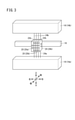
図1は、実施の形態にかかる配線構造10においてIOユニット12が接続された状態を示す斜視図である。図1に示すように、上方向、下方向、左方向、右方向、前方向、後ろ方向を定める。上下方向、左右方向および前後方向は、互いに直交しているものとする。図2は、実施の形態にかかる配線構造10においてIOユニット12が接続された状態を右側から観た右側面図である。配線構造10は、レール16に設置された複数の配線モジュール20およびIOユニット12を備える。レール16の具体例は、DINレールである。IOユニット12は外部との入出力を行うユニットである。図3は、配線構造10が備える複数の配線モジュール20を示す斜視図である。図3は、配線モジュール20にIOユニット12を取り付けていない状態を示している。
[Embodiment]
FIG. 1 is a perspective view showing a state in which the
図1~図3に示されるように、予め決められた第1方向(右方向または左方向)にレール16が延びている。ケーブルダクト14aは、レール16に対して下方向側に設けられ、ケーブルダクト14bは、レール16に対して上方向側に設けられている。そして、ケーブルダクト14(14a、14b)は第1方向に沿って延出している。図3に示されるように、複数の配線モジュール20は、レール16に沿って互いに隣接するように、レール16の前方向側(第2方向側)からレール16に設置されている。そして、IOユニット12は、複数の配線モジュール20に配線モジュール20の前方向側から取り付けられることで、複数の配線モジュール20と電気的に接続される。
As shown in FIGS. 1 to 3, the
さらに、複数の配線モジュール20の各々には、筐体22の下面22a(第1面)から下方向(第3方向)に延びる導線24aが接続されていて、筐体22の上面22b(第2面)から上方向(第3方向の反対方向)に延びる導線24bが接続されている。なお、本実施の形態において、第3方向は第1方向および第2方向と直交するとして説明しているが、第3方向は第1方向および第2方向と交差していれば、必ずしも直交していなくてもかまわない。なお、配線モジュール20に導線24aおよび導線24bの必ずしも両方が接続されている必要はなく、片方だけ接続されているのでもかまわない。
Further, a conducting
そして、下面22aから延びる導線24aは、ケーブルダクト14aまで少なくとも延びていて、上面22bから延びる導線24bは、ケーブルダクト14bまで少なくとも延びている。
The
図3の複数の配線モジュール20の1つは、IOユニット12に電源電圧を供給するための電源用配線モジュール20aである。また、図3の複数の配線モジュール20の残りの3つは、IOユニット12に入出力される信号を伝達するための信号用配線モジュール20bである。
One of the plurality of
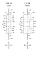
図4Aおよび図4Bは、電源用配線モジュール20aの構成を示す図である。図4Aは、電源用配線モジュール20aを前側から観た正面図であり、図4Bは、電源用配線モジュール20aを右側から観た右側面図である。
4A and 4B are diagrams showing the configuration of the power
電源用配線モジュール20aには、自己に接続された電源線である導線24a、24bから電源電圧が供給される。導線24aは、電源用配線モジュール20aの筐体22の下面22aから電源用配線モジュール20aの筐体22内部に挿入されていて、電源用配線モジュール20aの筐体22内の配線30aと電気的に接続されている。導線24aと配線30aとを電気的に接続する方法は限定されない。電源用配線モジュール20aの筐体22内部に挿入された導線24aを押し込まれたピンによって配線30aに機械的に接触させる方法でもよいし、スプリングを用いた方式であってもよいし、ねじで締めつけて結線してもよい。導線24bは、電源用配線モジュール20aの筐体22の上面22bから電源用配線モジュール20aの筐体22内部に挿入されていて、電源用配線モジュール20aの筐体22内の配線30bと電気的に接続されている。導線24bと配線30bとを電気的に接続する方法は、上記と同様に限定されない。
A power supply voltage is supplied to the power
電源用配線モジュール20aの正面22cには、IOユニット12と電気的に接続する電源端子32a、32bが設けられている。そして、電源端子32aと配線30aとを接続する第1供給線34a、および、電源端子32bと配線30bとを接続する第2供給線34bが電源用配線モジュール20aの筐体22内に設けられている。第1供給線34aおよび第2供給線34bからなる供給線34は、導線24a、24bから供給された電源電圧を、電源端子32a、32bを介してIOユニット12に供給する。なお、電源端子32a、32bおよび供給線34は、電源用配線モジュール20aに設けられていなくてもかまわない。
電源用配線モジュール20aの右側面22dには、隣接する配線モジュール20(図4Aおよび図4Bに示さず)の電源端子と電気的に接続する電源端子36a、36bが設けられている。そして、電源端子36aと配線30aとを接続する第1送電線38a、および、電源端子36bと配線30bとを接続する第2送電線38bが電源用配線モジュール20aの筐体22内に設けられている。第1送電線38aおよび第2送電線38bからなる送電線38は、導線24a、24bから供給された電源電圧を、電源端子36a、36bを介して隣接する配線モジュール20に供給する。なお、電源用配線モジュール20aは、電源端子36a、36bが左側面22eに設けられる構成であってもよい。
The
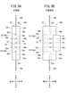
図5Aおよび図5Bは、信号用配線モジュール20bの構成を示す図である。図5Aは、信号用配線モジュール20bを前側から観た正面図であり、図5Bは、信号用配線モジュール20bを右側から観た右側面図である。
5A and 5B are diagrams showing the configuration of the
信号用配線モジュール20bに接続された導線24a、24bは信号線であり、IOユニット12に入出力される信号を伝達する。導線24aは、信号用配線モジュール20bの下面22aから信号用配線モジュール20bの筐体22内部に挿入されていて、信号用配線モジュール20bの筐体22内の配線40aと電気的に接続されている。導線24bは、信号用配線モジュール20bの上面22bから信号用配線モジュール20bの筐体22内部に挿入されていて、信号用配線モジュール20bの筐体22内の配線40bと電気的に接続されている。導線24aと配線40aとを電気的に接続する方法、および、導線24bと配線40bとを電気的に接続する方法は、導線24aと配線30aとを電気的に接続する方法と同様に限定されない。
The
信号用配線モジュール20bの正面22cには、IOユニット12と電気的に接続可能な電源端子32a、32bに加えて、IOユニット12と電気的に接続する信号端子42a、42bがさらに設けられている。そして、信号端子42aと配線40aとを接続する入出力線44a、および、信号端子42bと配線40bとを接続する入出力線44bが信号用配線モジュール20bの筐体22内に設けられている。したがって、入出力線44aは、導線24aとIOユニット12とを電気的に接続し、入出力線44bは、導線24bとIOユニット12とを電気的に接続している。
In addition to the
信号用配線モジュール20bの左側面22eには、左側に隣接する一方の配線モジュール20(図5Aおよび図5Bに示さず)の電源端子36a、36b、48a、48bと電気的に接続する電源端子46a、46bが設けられている。信号用配線モジュール20bの右側面22dには、右側に隣接する他方の配線モジュール20(図5Aおよび図5Bに示さず)の電源端子46a、46bと電気的に接続する電源端子48a、48bが設けられている。そして、電源端子46aと電源端子48aとを接続する第1送電線50a、および、電源端子46bと電源端子48bとを接続する第2送電線50bが信号用配線モジュール20bの筐体22内に設けられている。これにより、第1送電線50aおよび第2送電線50bからなる送電線50は、隣接する一方の配線モジュール20から供給された電源電圧を、隣接する他方の配線モジュール20に供給する。
On the
さらに、第1送電線50aの途中から分岐した第1供給線52aは電源端子32aに接続され、第2送電線50bの途中から分岐した第2供給線52bは電源端子32bに接続されている。これにより、第1供給線52aおよび第2供給線52bからなる供給線52は、隣接する一方の配線モジュール20から供給された電源電圧を、IOユニット12に電源端子32a、32bを介して供給する。
Further, the
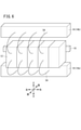
図6は、IOユニット12からケーブルダクト14への従来の配線構造の様子を説明する図である。図6に示すように、従来、レール16に設置されたIOユニット12からケーブルダクト14への配線54は、IOユニット12の正面から延びてケーブルダクト14まで延びていた。これに対して、上記説明した実施の形態にかかる配線構造10においては、図2および図3に示されるように、IOユニット12と電気的に接続される複数の配線モジュール20から上下方向に延びた導線24a、24bがケーブルダクト14a、14bまで延びている。これにより、レール16に支持されるIOユニット12の正面に導線を接続することが不要となり、IOユニット12からケーブルダクト14a、14bへの配線を短くすることができる。そして、IOユニット12からの配線がIOユニット12の正面を覆ったりしないので、排熱が適切に行われ、IOユニット12の正面の表示の視認性が高まる。また、交換などのIOユニット12のメンテナンスも容易に行うことが可能になる。
FIG. 6 is a diagram illustrating a state of a conventional wiring structure from the
[変形例]
上記実施の形態は、以下のように変形してもよい。
[Modification example]
The above embodiment may be modified as follows.
(変形例1)
配線構造10が備える複数の配線モジュール20の一つはコモン信号が供給されるコモン用配線モジュール20cであってもよい。コモン信号とは、複数のIOユニット12で共通に使用される信号である。図7Aおよび図7Bは、変形例1にかかるコモン用配線モジュール20cの構成を示す図である。図7Aは、変形例1にかかるコモン用配線モジュール20cを前側から観た正面図であり、図7Bは、変形例1にかかるコモン用配線モジュール20cを右側から観た右側面図である。
(Modification 1)
One of the plurality of
コモン用配線モジュール20cには、自己に接続されたコモン線である導線24a、24bからコモン信号が供給される。導線24aは、コモン用配線モジュール20cの筐体22の下面22aからコモン用配線モジュール20cの筐体22内部に挿入されていて、コモン用配線モジュール20cの筐体22内の配線60の一端と電気的に接続されている。導線24bは、コモン用配線モジュール20cの筐体22の上面22bからコモン用配線モジュール20cの筐体22内部に挿入されていて、コモン用配線モジュール20cの筐体22内の配線60の他端と電気的に接続されている。導線24aまたは導線24bと、配線60とを電気的に接続する方法は、導線24aと配線30aとを電気的に接続する方法と同様に限定されない。
A common signal is supplied to the
コモン用配線モジュール20cの左側面22eには、左側に隣接する一方の配線モジュール20(図7Aおよび図7Bに示さず)の電源端子36a、36b、48a、48bと電気的に接続する電源端子46a、46bが設けられている。コモン用配線モジュール20cの右側面22dには、右側に隣接する他方の配線モジュール20(図7Aおよび図7Bに示さず)の電源端子46a、46bと電気的に接続する電源端子48a、48bに加えて、右側に隣接する他方の配線モジュール20のコモン端子と電気的に接続するコモン端子62が設けられている。なお、ここでは、コモン端子62は、コモン用配線モジュール20cの右側面22dに設けられているとして説明するが、左側面22eに設けられていてもよく、以下の説明は同様に成り立つ。
On the
コモン端子62は、配線60の途中から分岐した配線64に接続されている。したがって、コモン用配線モジュール20cは、自己に接続された導線24a、24bから供給されたコモン信号を、右側に隣接する配線モジュール20にコモン端子62を介して供給することができる。
The
そして、電源端子46aと電源端子48aとを接続する第1送電線50a、および、電源端子46bと電源端子48bとを接続する第2送電線50bがコモン用配線モジュール20cの筐体22内に設けられている。第1送電線50aおよび第2送電線50bからなる送電線50は、隣接する一方の配線モジュール20から供給された電源電圧を、隣接する他方の配線モジュール20に供給する。
A
複数の配線モジュール20がコモン用配線モジュール20cを含んでいる場合、コモン信号は、信号用配線モジュール20bを介してIOユニット12に供給される。この場合の信号用配線モジュール20bの構成を説明する。図8Aおよび図8Bは、変形例1にかかる信号用配線モジュール20bの構成を示す図である。図8Aは、変形例1にかかる信号用配線モジュール20bを前側から観た正面図であり、図8Bは、変形例1にかかる信号用配線モジュール20bを右側から観た右側面図である。
When the plurality of
図8Aおよび図8Bの変形例1にかかる信号用配線モジュール20bは、図5Aおよび図5Bの信号用配線モジュール20bが備える構成要素にさらに構成要素が追加されている。以下では、図5Aおよび図5Bの信号用配線モジュール20bに追加された構成要素について説明する。
The
図8Aおよび図8Bの信号用配線モジュール20bの正面22cには、IOユニット12と電気的に接続可能なコモン端子70が設けられている。信号用配線モジュール20bの左側面22eには、左側に隣接する一方の配線モジュール20(図8Aおよび図8Bに示さず)のコモン端子62、74と電気的に接続するコモン端子72が設けられている。信号用配線モジュール20bの右側面22dには、右側に隣接する他方の配線モジュール20(図8Aおよび図8Bに示さず)のコモン端子72と電気的に接続するコモン端子74が設けられている。
A
そして、コモン端子72とコモン端子74とを接続するコモン送信線76が信号用配線モジュール20bの筐体22内に設けられている。これにより、コモン送信線76は、隣接する一方の配線モジュール20から供給されたコモン信号を、隣接する他方の配線モジュール20に供給する。さらに、コモン送信線76の途中から分岐したコモン供給線78はコモン端子70に接続されている。コモン供給線78は、隣接する一方の配線モジュール20から供給されたコモン信号を、IOユニット12にコモン端子70を介して供給する。これにより、コモン信号を使用する場合でも、レール16に支持されるIOユニット12の正面の視認性を高めると共にIOユニット12のメンテナンスを容易にすることができる。
A
(変形例2)
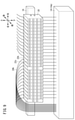
実施の形態では、ケーブルダクト14(14a、14b)がレール16の上下両側に1つずつ設けられているとしたが、片側のみにしか存在しない場合がある。図9は、ケーブルダクト14がレール16の下側のみに設けられている様子を示す斜視図である。図9のように、レール16の下側だけにケーブルダクト14aが設けられている場合、配線モジュール20の上面22bから延びる導線24bは、配線モジュール20の正面22cを避けてケーブルダクト14aまで配線することになる。この場合、導線24bの配線は長くなってしまう。
(Modification 2)
In the embodiment, it is assumed that one cable duct 14 (14a, 14b) is provided on each of the upper and lower sides of the
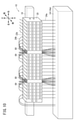
そこで、変形例2の配線構造10では、複数の配線モジュール20の間に配線モジュール20と隣接するように配線スルー用モジュール80を設ける。図10は、変形例2にかかる配線構造10からIOユニット12を外した様子を示す斜視図である。配線スルー用モジュール80は、配線モジュール20と隣接するようにレール16の前側からレール16に設置されている。
Therefore, in the
図11は、変形例2にかかる配線スルー用モジュール80を示す斜視図である。図12A~図12Cは、変形例2にかかる配線スルー用モジュール80の構成を示す図である。図12Aは、変形例2にかかる配線スルー用モジュール80を上側から観た上面図であり、図12Bは、変形例2にかかる配線スルー用モジュール80を前側から観た正面図であり、図12Cは、変形例2にかかる配線スルー用モジュール80を右側から観た右側面図である。配線スルー用モジュール80の筐体82は、本体部82a、前壁部82bおよび側壁部82cを有する。本体部82aの正面82dと前壁部82bとは適切に離間しており、正面82d、前壁部82bおよび側壁部82cに囲まれた空間が導線24bの貫通スペース84になっている。すなわち、配線スルー用モジュール80には、導線24bを上下方向に貫通させて通すことができる貫通スペース84が設けられている。貫通スペース84の構成は、配線スルー用モジュール80の左右側に配線モジュール20が隣接していても、導線24bを貫通させることができるのであれば、上記構成に限定されない。
FIG. 11 is a perspective view showing the wiring through
配線スルー用モジュール80の本体部82aの左側面82eには、左側に隣接する一方の配線モジュール20(図12A~図12Cに示さず)の電源端子36a、36b、48a、48bおよびコモン端子62、74と電気的に接続する電源端子46a、46bおよびコモン端子72が設けられている。配線スルー用モジュール80の本体部82aの右側面82fには、右側に隣接する他方の配線モジュール20(図12A~図12Cに示さず)の電源端子46a、46bおよびコモン端子72と電気的に接続する電源端子48a、48bおよびコモン端子74が設けられている。そして、電源端子46aと電源端子48aとを接続する第1送電線50a、および、電源端子46bと電源端子48bとを接続する第2送電線50bが配線スルー用モジュール80の本体部82aの左側面82eと右側面82fとの間に設けられている。第1送電線50aおよび第2送電線50bからなる送電線50は、隣接する一方の配線モジュール20から供給された電源電圧を、隣接する他方の配線モジュール20に供給することができる。さらに、コモン端子72とコモン端子74とを接続するコモン送信線76が配線スルー用モジュール80の本体部82aの左側面82eと右側面82fとの間に設けられている。コモン送信線76は、隣接する一方の配線モジュール20から供給されたコモン信号を、隣接する他方の配線モジュール20に供給する。なお、配線スルー用モジュール80にコモン端子72、74およびコモン送信線76が設けられていなくてもかまわない。
On the
配線構造10に配線スルー用モジュール80を設けたことにより、配線モジュール20の筐体22の上面22bから上方向に延びる導線24bを、図10に示すように、配線スルー用モジュール80の貫通スペース84を貫通させて、ケーブルダクト14aまで延ばすことができる。これにより、導線24bを短くすることができる。すなわち、変形例2の配線構造10によれば、レール16に対してケーブルダクト14の設置側とは反対側に延びた配線を、ケーブルダクト14まで接続しつつ、実施の形態の配線構造10の上記配線より短くすることができる。なお、配線モジュール20の筐体22の下面22aから下方向に延びる導線24aは存在しなくてもかまわない。この場合、上面22bを第1面とみなし、上方向を第3方向とみなしてもよい。
By providing the wiring through
(変形例3)
配線構造10が備える複数の配線モジュール20は、図3に示したものに限られない。図13は、変形例3にかかる複数の配線モジュール20を示す斜視図である。複数の配線モジュール20は、図13の(a)のように互いに隣接する1つの電源用配線モジュール20aおよび1つの信号用配線モジュール20bであってもよい。また、複数の配線モジュール20は、図13の(b)、(c)または(d)のように互いに隣接する2つ以上の信号用配線モジュール20bであってもよい。
(Modification 3)
The plurality of
(変形例4)
上記実施の形態および変形例1~3は、矛盾の生じない範囲で任意に組み合わされてもよい。
(Modification example 4)
The above-described embodiments and modifications 1 to 3 may be arbitrarily combined as long as there is no contradiction.
[実施の形態から得られる発明]
上記実施の形態から把握しうる発明について、以下に記載する。
[Invention obtained from the embodiment]
The inventions that can be grasped from the above embodiments are described below.
(第1の発明)
配線構造(10)は、予め決められた第1方向に延びたレール(16)に沿って互いに隣接するように、第1方向と直交する第2方向側からレール(16)に設置される複数の配線モジュール(20)と、複数の配線モジュール(20)に第2方向側から取り付けられることで、複数の配線モジュール(20)と電気的に接続されるIOユニット(12)と、を備え、複数の配線モジュール(20)の各々には、第1方向および第2方向と交差する第3方向側の第1面(22a)から第3方向に延びる導線(24a)が接続されている。
(First invention)
A plurality of wiring structures (10) are installed on the rail (16) from the second direction side orthogonal to the first direction so as to be adjacent to each other along a predetermined rail (16) extending in the first direction. Wiring module (20) and an IO unit (12) that is electrically connected to the plurality of wiring modules (20) by being attached to the plurality of wiring modules (20) from the second direction side. Each of the plurality of wiring modules (20) is connected to a lead wire (24a) extending in the third direction from the first surface (22a) on the third direction side intersecting the first direction and the second direction.
これにより、レール(16)に支持されるIOユニット(12)の正面に導線(24a)を接続することが不要となり、IOユニット(12)の正面の視認性を高めると共にIOユニット(12)のメンテナンスを容易にすることができる。 This eliminates the need to connect the conductor (24a) to the front of the IO unit (12) supported by the rail (16), improving the visibility of the front of the IO unit (12) and of the IO unit (12). Maintenance can be facilitated.
複数の配線モジュール(20)の少なくとも1つは、IOユニット(12)に電源電圧を供給するための電源用配線モジュール(20a)であってもよい。電源用配線モジュール(20a)は、自己に接続された導線(24a、24b)から供給された電源電圧を、IOユニット(12)に供給する供給線(34)および隣接する配線モジュール(20)に供給する送電線(38)を有してもよい。 At least one of the plurality of wiring modules (20) may be a power supply wiring module (20a) for supplying a power supply voltage to the IO unit (12). The power supply wiring module (20a) supplies the power supply voltage supplied from the lead wires (24a, 24b) connected to itself to the supply line (34) and the adjacent wiring module (20) to be supplied to the IO unit (12). It may have a power transmission line (38) to supply.
複数の配線モジュール(20)の少なくとも1つは、IOユニット(12)に入出力される信号を伝達するための信号用配線モジュール(20b)であってもよい。信号用配線モジュール(20b)は、自己に接続された(24a、24b)とIOユニット(12)とを接続する入出力線(44a、44b)と、隣接する一方の配線モジュール(20)から供給された電源電圧を、IOユニット(12)に供給する供給線(52)および隣接する他方の配線モジュール(20)に供給する送電線(50)とを有してもよい。 At least one of the plurality of wiring modules (20) may be a signal wiring module (20b) for transmitting signals input / output to / from the IO unit (12). The signal wiring module (20b) is supplied from the input / output lines (44a, 44b) connecting the self-connected (24a, 24b) and the IO unit (12), and one of the adjacent wiring modules (20). It may have a supply line (52) for supplying the generated power supply voltage to the IO unit (12) and a transmission line (50) for supplying the other adjacent wiring module (20).
信号用配線モジュール(20b)は、隣接する一方の配線モジュール(20)から供給されたコモン信号を、IOユニット(12)に供給するコモン供給線(78)および隣接する他方の配線モジュール(20)に供給するコモン送信線(76)を有してもよい。これにより、コモン信号を使用する場合でも、レール(16)に支持されるIOユニット(12)の正面の視認性を高めると共にIOユニット(12)のメンテナンスを容易にすることができる。 The signal wiring module (20b) is a common supply line (78) that supplies a common signal supplied from one of the adjacent wiring modules (20) to the IO unit (12) and the other adjacent wiring module (20). May have a common transmission line (76) to supply to. As a result, even when a common signal is used, the visibility of the front surface of the IO unit (12) supported by the rail (16) can be improved and the maintenance of the IO unit (12) can be facilitated.
配線モジュール(20)の1つは、自己に接続された導線(24a、24b)から供給されたコモン信号を、隣接する配線モジュール(20)に供給するコモン用配線モジュール(20c)であってもよい。 Even if one of the wiring modules (20) is a common wiring module (20c) that supplies a common signal supplied from the conducting wires (24a, 24b) connected to itself to the adjacent wiring module (20). good.
配線モジュール(20)には、第3方向側の反対側の第2面(22b)から第3方向の反対方向に延びる導線(24b)が接続されてもよい。第1方向に沿って延出するケーブルダクト(14a、14b)が、レール(16)に対して第3方向側および第3方向側の反対側にそれぞれ設けられてもよい。第1面(22a)から延びる導線(24a)は、レール(16)に対して第3方向側に設けられたケーブルダクト(14a)まで少なくとも延び、第2面(22b)から延びる導線(24b)は、レール(16)に対して第3方向側の反対側に設けられたケーブルダクト(14b)まで少なくとも延びていてもよい。 A conducting wire (24b) extending in the opposite direction of the third direction from the second surface (22b) on the opposite side of the third direction side may be connected to the wiring module (20). Cable ducts (14a, 14b) extending along the first direction may be provided on the opposite side of the rail (16) on the third direction side and the third direction side, respectively. The conductor (24a) extending from the first surface (22a) extends at least to the cable duct (14a) provided on the third direction side with respect to the rail (16), and the conductor (24b) extending from the second surface (22b). May extend at least to a cable duct (14b) provided on the opposite side of the third direction side with respect to the rail (16).
配線モジュール(20)には、第3方向側の反対側の第2面(22b)から第3方向の反対方向に延びる導線(24b)が接続されてもよい。第1方向に沿って延出するケーブルダクト(14a)が、レール(16)に対して第3方向側に設けられてもよい。配線モジュール(20)と隣接するように第2方向側からレール(16)に設置され、隣接する一方の配線モジュール(20)から供給された電源電圧を隣接する他方の配線モジュール(20)に供給する送電線(50)と、導線(24b)を貫通させる貫通スペース(84)と、を有する配線スルー用モジュール(80)をさらに備えてもよい。第1面(22a)から延びる導線(24a)は、ケーブルダクト(14a)まで少なくとも延び、第2面(22b)から延びる導線(24b)は、貫通スペース(84)を貫通してケーブルダクト(14a)まで延びていてもよい。これにより、レール(16)に対してケーブルダクト(14)の設置側とは反対側に延びた配線を、ケーブルダクト(14)まで接続しつつ、短くすることができる。 A conducting wire (24b) extending in the opposite direction of the third direction from the second surface (22b) on the opposite side of the third direction side may be connected to the wiring module (20). A cable duct (14a) extending along the first direction may be provided on the third direction side with respect to the rail (16). It is installed on the rail (16) from the second direction side so as to be adjacent to the wiring module (20), and the power supply voltage supplied from one of the adjacent wiring modules (20) is supplied to the other adjacent wiring module (20). Further may be provided with a wiring through module (80) having a transmission line (50) and a penetration space (84) through which the lead wire (24b) is penetrated. The conductor (24a) extending from the first surface (22a) extends at least to the cable duct (14a), and the conductor (24b) extending from the second surface (22b) penetrates the through space (84) and penetrates the cable duct (14a). ) May be extended. As a result, the wiring extending to the rail (16) on the side opposite to the installation side of the cable duct (14) can be shortened while being connected to the cable duct (14).
第1方向に沿って延出するケーブルダクト(14a)が、レール(16)に対して第3方向側の反対側に設けられてもよい。配線モジュール(20)と隣接するように第2方向側からレール(16)に設置され、隣接する一方の配線モジュール(20)から供給された電源電圧を隣接する他方の配線モジュール(20)に供給する送電線(50)と、導線(24b)を貫通させる貫通スペース(84)と、を有する配線スルー用モジュール(80)をさらに備えてもよい。第1面(22b)から延びる導線(24b)は、貫通スペース(84)を貫通してケーブルダクト(14a)まで延びていてもよい。これにより、レール(16)に対してケーブルダクト(14)の設置側とは反対側に延びた配線を、ケーブルダクト(14)まで接続しつつ、短くすることができる。 A cable duct (14a) extending along the first direction may be provided on the opposite side of the rail (16) from the third direction side. It is installed on the rail (16) from the second direction side so as to be adjacent to the wiring module (20), and the power supply voltage supplied from one of the adjacent wiring modules (20) is supplied to the other adjacent wiring module (20). Further may be provided with a wiring through module (80) having a transmission line (50) and a penetration space (84) through which the lead wire (24b) is penetrated. The conductor (24b) extending from the first surface (22b) may extend through the penetration space (84) to the cable duct (14a). As a result, the wiring extending to the rail (16) on the side opposite to the installation side of the cable duct (14) can be shortened while being connected to the cable duct (14).
10…配線構造 12…IOユニット
14、14a、14b…ケーブルダクト 16…レール
20…配線モジュール 20a…電源用配線モジュール
20b…信号用配線モジュール 20c…コモン用配線モジュール
22、82…筐体 22a…下面
22b…上面 22c、82d…正面
22d、82f…右側面 22e、82e…左側面
24a、24b…導線
30a、30b、40a、40b、54、60、64…配線
32a、32b、36a、36b、46a、46b、48a、48b…電源端子
34、52…供給線 34a、52a…第1供給線
34b、52b…第2供給線 38、50…送電線
38a、50a…第1送電線 38b、50b…第2送電線
42a、42b…信号端子 44a、44b…入出力線
62、70、72、74…コモン端子 76…コモン送信線
78…コモン供給線 80…配線スルー用モジュール
82a…本体部 82b…前壁部
82c…側壁部 84…貫通スペース
10 ...
Claims (6)
複数の前記配線モジュールに前記第2方向側から取り付けられることで、複数の前記配線モジュールと電気的に接続されるIOユニットと、
を備え、
複数の前記配線モジュールの各々には、前記第1方向および前記第2方向と交差する第3方向側の第1面から前記第3方向に延びる導線が接続されるとともに、前記第3方向側の反対側の第2面から前記第3方向の反対方向に延びる導線が接続され、
前記第1方向に沿って延出するケーブルダクトが、前記レールに対して前記第3方向側に設けられ、
前記配線モジュールと隣接するように前記第2方向側から前記レールに設置され、隣接する一方の前記配線モジュールから供給された電源電圧を隣接する他方の前記配線モジュールに供給する送電線と、前記導線を貫通させる貫通スペースと、を有する配線スルー用モジュールをさらに備え、
前記第1面から延びる前記導線は、前記ケーブルダクトまで少なくとも延び、前記第2面から延びる前記導線は、前記貫通スペースを貫通して前記ケーブルダクトまで延びている、配線構造。 A plurality of wiring modules installed on the rail from the second direction side orthogonal to the first direction so as to be adjacent to each other along a predetermined rail extending in the first direction.
An IO unit that is electrically connected to the plurality of wiring modules by being attached to the plurality of wiring modules from the second direction side,
Equipped with
A conducting wire extending in the third direction from the first surface on the third direction side intersecting the first direction and the second direction is connected to each of the plurality of wiring modules, and is connected to the third direction side. A conducting wire extending in the opposite direction of the third direction is connected from the second surface on the opposite side.
A cable duct extending along the first direction is provided on the third direction side with respect to the rail.
A transmission line installed on the rail from the second direction side so as to be adjacent to the wiring module, and supplying a power supply voltage supplied from one of the adjacent wiring modules to the other adjacent wiring module, and a lead wire. Further equipped with a wiring through module, which has a penetration space to penetrate,
A wiring structure in which the conductor extending from the first surface extends at least to the cable duct, and the conductor extending from the second surface penetrates the penetration space and extends to the cable duct .
複数の前記配線モジュールに前記第2方向側から取り付けられることで、複数の前記配線モジュールと電気的に接続されるIOユニットと、An IO unit that is electrically connected to the plurality of wiring modules by being attached to the plurality of wiring modules from the second direction side, and
を備え、Equipped with
複数の前記配線モジュールの各々には、前記第1方向および前記第2方向と交差する第3方向側の第1面から前記第3方向に延びる導線が接続され、A conducting wire extending in the third direction from the first surface on the third direction side intersecting the first direction and the second direction is connected to each of the plurality of wiring modules.
前記第1方向に沿って延出するケーブルダクトが、前記レールに対して前記第3方向側の反対側に設けられ、A cable duct extending along the first direction is provided on the opposite side of the rail on the third direction side.
前記配線モジュールと隣接するように前記第2方向側から前記レールに設置され、隣接する一方の前記配線モジュールから供給された電源電圧を隣接する他方の前記配線モジュールに供給する送電線と、前記導線を貫通させる貫通スペースと、を有する配線スルー用モジュールをさらに備え、A transmission line installed on the rail from the second direction side so as to be adjacent to the wiring module, and supplying a power supply voltage supplied from one of the adjacent wiring modules to the other adjacent wiring module, and a lead wire. Further equipped with a wiring through module, which has a penetration space to penetrate,
前記第1面から延びる前記導線は、前記貫通スペースを貫通して前記ケーブルダクトまで延びている、配線構造。A wiring structure in which the conductor extending from the first surface penetrates the penetration space and extends to the cable duct.
複数の前記配線モジュールの少なくとも1つは、前記IOユニットに電源電圧を供給するための電源用配線モジュールであり、
前記電源用配線モジュールは、自己に接続された前記導線から供給された電源電圧を、前記IOユニットに供給する供給線および隣接する前記配線モジュールに供給する送電線を有する、配線構造。 The wiring structure according to claim 1 or 2 .
At least one of the plurality of wiring modules is a power supply wiring module for supplying a power supply voltage to the IO unit.
The power supply wiring module has a wiring structure having a supply line for supplying a power supply voltage supplied from the lead wire connected to itself to the IO unit and a transmission line for supplying the power supply line to the adjacent wiring module.
複数の前記配線モジュールの少なくとも1つは、前記IOユニットに入出力される信号を伝達するための信号用配線モジュールであり、
前記信号用配線モジュールは、自己に接続された前記導線と前記IOユニットとを接続する入出力線と、隣接する一方の前記配線モジュールから供給された電源電圧を、前記IOユニットに供給する供給線および隣接する他方の前記配線モジュールに供給する送電線とを有する、配線構造。 The wiring structure according to any one of claims 1 to 3 .
At least one of the plurality of wiring modules is a signal wiring module for transmitting signals input / output to / from the IO unit.
The signal wiring module supplies an input / output line connecting the conducting wire connected to itself and the IO unit, and a power supply voltage supplied from one of the adjacent wiring modules to the IO unit. And a wiring structure having a transmission line to supply to the other adjacent wiring module.
前記信号用配線モジュールは、隣接する一方の前記配線モジュールから供給されたコモン信号を、前記IOユニットに供給するコモン供給線および隣接する他方の前記配線モジュールに供給するコモン送信線を有する、配線構造。 The wiring structure according to claim 4 .
The signal wiring module has a wiring structure having a common supply line for supplying a common signal supplied from one of the adjacent wiring modules to the IO unit and a common transmission line for supplying the common signal to the other adjacent wiring module. ..
前記配線モジュールの1つは、自己に接続された前記導線から供給された前記コモン信号を、隣接する前記配線モジュールに供給するコモン用配線モジュールである、配線構造。 The wiring structure according to claim 5 .
One of the wiring modules is a common wiring module that supplies the common signal supplied from the lead wire connected to itself to the adjacent wiring module.
Priority Applications (4)
| Application Number | Priority Date | Filing Date | Title |
|---|---|---|---|
| JP2019019685A JP7010860B2 (en) | 2019-02-06 | 2019-02-06 | Wiring structure |
| US16/780,536 US11581710B2 (en) | 2019-02-06 | 2020-02-03 | Wiring structure |
| DE102020000755.4A DE102020000755A1 (en) | 2019-02-06 | 2020-02-05 | Wiring structure |
| CN202010081176.XA CN111542195B (en) | 2019-02-06 | 2020-02-06 | Wiring structure |
Applications Claiming Priority (1)
| Application Number | Priority Date | Filing Date | Title |
|---|---|---|---|
| JP2019019685A JP7010860B2 (en) | 2019-02-06 | 2019-02-06 | Wiring structure |
Publications (2)
| Publication Number | Publication Date |
|---|---|
| JP2020126806A JP2020126806A (en) | 2020-08-20 |
| JP7010860B2 true JP7010860B2 (en) | 2022-02-10 |
Family
ID=71615204
Family Applications (1)
| Application Number | Title | Priority Date | Filing Date |
|---|---|---|---|
| JP2019019685A Active JP7010860B2 (en) | 2019-02-06 | 2019-02-06 | Wiring structure |
Country Status (4)
| Country | Link |
|---|---|
| US (1) | US11581710B2 (en) |
| JP (1) | JP7010860B2 (en) |
| CN (1) | CN111542195B (en) |
| DE (1) | DE102020000755A1 (en) |
Citations (2)
| Publication number | Priority date | Publication date | Assignee | Title |
|---|---|---|---|---|
| JP2000215931A (en) | 1999-01-21 | 2000-08-04 | Yamatake Corp | Electronic apparatus |
| JP2001217016A (en) | 2000-01-31 | 2001-08-10 | Omron Corp | Control device |
Family Cites Families (25)
| Publication number | Priority date | Publication date | Assignee | Title |
|---|---|---|---|---|
| JPS6391976A (en) | 1986-10-03 | 1988-04-22 | オムロン株式会社 | Terminal base apparatus |
| JP2526882Y2 (en) * | 1990-08-30 | 1997-02-26 | 東洋技研株式会社 | Electric stand support device |
| JPH0562726A (en) * | 1991-09-03 | 1993-03-12 | Fuji Electric Co Ltd | Block terminal board |
| JPH06351115A (en) * | 1993-06-10 | 1994-12-22 | Murata Mfg Co Ltd | Control apparatus board |
| JP2589695Y2 (en) | 1993-11-30 | 1999-02-03 | サンクス株式会社 | Terminal for detecting switch connection |
| DE4402001B4 (en) * | 1994-01-18 | 2007-02-22 | Wago Verwaltungsgesellschaft Mbh | I / O module for a data bus |
| DE19612575C2 (en) | 1996-03-29 | 1999-11-18 | Endress Hauser Gmbh Co | Device for the detachable fastening of devices and for their electrical connection |
| JPH11235021A (en) * | 1998-02-18 | 1999-08-27 | Omron Corp | Power supply |
| JP2001044662A (en) | 1999-08-04 | 2001-02-16 | Fuji Electric Co Ltd | Cable housing type rail |
| CA2448477C (en) * | 2003-11-06 | 2013-02-26 | Montel Inc. | Ground embedded wire tracks for a shelving system having mobile shelf units |
| DE102004056243A1 (en) * | 2004-11-22 | 2006-05-24 | Abb Patent Gmbh | Modular automation system |
| US8128027B2 (en) * | 2005-09-12 | 2012-03-06 | The Boeing Company | Plug-n-play power system for an accessory in an aircraft |
| JP4697472B2 (en) | 2007-04-13 | 2011-06-08 | オムロン株式会社 | DIN rail mounting type electronic equipment |
| US8217266B2 (en) * | 2008-02-12 | 2012-07-10 | Panduit Corp. | Rail wiring duct |
| FR2936908B1 (en) * | 2008-10-07 | 2011-09-23 | Areva T & D Prot Controle | DEVICE AND METHOD FOR PROTECTING A CONNECTION OF A MEDIUM, HIGH OR VERY HIGH VOLTAGE ELECTRICAL NETWORK. |
| JP5104827B2 (en) * | 2009-08-20 | 2012-12-19 | 富士電機機器制御株式会社 | Rail mounting structure for electrical equipment |
| EP2383623B1 (en) * | 2010-04-30 | 2012-12-05 | Rockwell Automation Germany GmbH & Co. KG | Modular safety switching device system with optical link |
| US8379398B2 (en) * | 2011-03-23 | 2013-02-19 | Phoenix Contact Development & Manufacturing, Inc. | DIN rail mountable base for process fieldbus redundant power conditioner |
| DE102012110173A1 (en) * | 2012-10-24 | 2014-06-12 | Phoenix Contact Gmbh & Co. Kg | Modular electronic system and bus participants |
| JP5655840B2 (en) * | 2012-10-26 | 2015-01-21 | 横河電機株式会社 | Single-use recorder / data logger shared I / O module |
| JP6044495B2 (en) * | 2013-09-10 | 2016-12-14 | 株式会社オートネットワーク技術研究所 | Wiring module |
| US9727098B2 (en) * | 2014-06-16 | 2017-08-08 | Phoenix Contact Development and Manufacturing, Inc. | Redundant power supply motherboard assembly |
| US10483663B2 (en) * | 2017-11-09 | 2019-11-19 | Rockwell Automation Asia Pacific Business Center Pte. Ltd. | Terminal block with retention features for a removable I/O module |
| DE102018129835A1 (en) * | 2018-11-26 | 2020-05-28 | Beckhoff Automation Gmbh | Control system, coupler module and method for assembling a control system |
| US11412632B2 (en) * | 2019-06-11 | 2022-08-09 | Rockwell Automation Asia Pacific Business Center Pte. Ltd. | Isolated power smart terminal block |
-
2019
- 2019-02-06 JP JP2019019685A patent/JP7010860B2/en active Active
-
2020
- 2020-02-03 US US16/780,536 patent/US11581710B2/en active Active
- 2020-02-05 DE DE102020000755.4A patent/DE102020000755A1/en active Pending
- 2020-02-06 CN CN202010081176.XA patent/CN111542195B/en active Active
Patent Citations (2)
| Publication number | Priority date | Publication date | Assignee | Title |
|---|---|---|---|---|
| JP2000215931A (en) | 1999-01-21 | 2000-08-04 | Yamatake Corp | Electronic apparatus |
| JP2001217016A (en) | 2000-01-31 | 2001-08-10 | Omron Corp | Control device |
Also Published As
| Publication number | Publication date |
|---|---|
| CN111542195B (en) | 2023-03-10 |
| JP2020126806A (en) | 2020-08-20 |
| US20200251888A1 (en) | 2020-08-06 |
| CN111542195A (en) | 2020-08-14 |
| US11581710B2 (en) | 2023-02-14 |
| DE102020000755A1 (en) | 2020-08-06 |
Similar Documents
| Publication | Publication Date | Title |
|---|---|---|
| US10040412B2 (en) | Utility vehicle power distribution module | |
| MX9806364A (en) | Door panel wiring system. | |
| JP2003009347A (en) | Electrical junction box | |
| US9615470B2 (en) | Wiring combiner box | |
| JP7180997B2 (en) | Wire harnesses, component modules for wire harnesses, and vehicle parts | |
| KR101091660B1 (en) | Combination connector for vehicle | |
| JP7010860B2 (en) | Wiring structure | |
| JP2010029018A (en) | Closed switchboard | |
| JP2007236150A (en) | Optical/power common lead-in board | |
| JP2006238562A (en) | Plug-in distribution board | |
| US11427142B2 (en) | Electrical connection box with bonder cap and shallow/deep bottom parts, and wire harness including same | |
| US8004826B2 (en) | Electrical switchgear assembly | |
| JP7154702B2 (en) | switchboard | |
| JP2009126286A (en) | On-vehicle junction box | |
| KR20100084891A (en) | Fuse box | |
| JP2010206894A (en) | Power-distribution board | |
| JP5989287B1 (en) | Electrical equipment | |
| JP7342368B2 (en) | Expansion unit for terminal board | |
| EP3270477A1 (en) | Electric apparatus | |
| JPH0317550Y2 (en) | ||
| JP2013226018A (en) | Electric connection box | |
| JP3125999U (en) | switchboard | |
| JP2023146234A (en) | controller | |
| KR20220026018A (en) | Bus-bar type terminal | |
| JP4134365B2 (en) | Control center |
Legal Events
| Date | Code | Title | Description |
|---|---|---|---|
| A621 | Written request for application examination |
Free format text: JAPANESE INTERMEDIATE CODE: A621 Effective date: 20200710 |
|
| A977 | Report on retrieval |
Free format text: JAPANESE INTERMEDIATE CODE: A971007 Effective date: 20210730 |
|
| A131 | Notification of reasons for refusal |
Free format text: JAPANESE INTERMEDIATE CODE: A131 Effective date: 20210803 |
|
| A521 | Request for written amendment filed |
Free format text: JAPANESE INTERMEDIATE CODE: A523 Effective date: 20210908 |
|
| TRDD | Decision of grant or rejection written | ||
| A01 | Written decision to grant a patent or to grant a registration (utility model) |
Free format text: JAPANESE INTERMEDIATE CODE: A01 Effective date: 20211214 |
|
| A61 | First payment of annual fees (during grant procedure) |
Free format text: JAPANESE INTERMEDIATE CODE: A61 Effective date: 20220113 |
|
| R150 | Certificate of patent or registration of utility model |
Ref document number: 7010860 Country of ref document: JP Free format text: JAPANESE INTERMEDIATE CODE: R150 |