JP7009168B2 - Belt transfer device and fixing device - Google Patents
Belt transfer device and fixing device Download PDFInfo
- Publication number
- JP7009168B2 JP7009168B2 JP2017218023A JP2017218023A JP7009168B2 JP 7009168 B2 JP7009168 B2 JP 7009168B2 JP 2017218023 A JP2017218023 A JP 2017218023A JP 2017218023 A JP2017218023 A JP 2017218023A JP 7009168 B2 JP7009168 B2 JP 7009168B2
- Authority
- JP
- Japan
- Prior art keywords
- belt
- unit
- image forming
- roller
- fixing roller
- Prior art date
- Legal status (The legal status is an assumption and is not a legal conclusion. Google has not performed a legal analysis and makes no representation as to the accuracy of the status listed.)
- Active
Links
Images


Classifications
-
- G—PHYSICS
- G03—PHOTOGRAPHY; CINEMATOGRAPHY; ANALOGOUS TECHNIQUES USING WAVES OTHER THAN OPTICAL WAVES; ELECTROGRAPHY; HOLOGRAPHY
- G03G—ELECTROGRAPHY; ELECTROPHOTOGRAPHY; MAGNETOGRAPHY
- G03G15/00—Apparatus for electrographic processes using a charge pattern
- G03G15/20—Apparatus for electrographic processes using a charge pattern for fixing, e.g. by using heat
- G03G15/2003—Apparatus for electrographic processes using a charge pattern for fixing, e.g. by using heat using heat
- G03G15/2014—Apparatus for electrographic processes using a charge pattern for fixing, e.g. by using heat using heat using contact heat
- G03G15/2017—Structural details of the fixing unit in general, e.g. cooling means, heat shielding means
- G03G15/2028—Structural details of the fixing unit in general, e.g. cooling means, heat shielding means with means for handling the copy material in the fixing nip, e.g. introduction guides, stripping means
-
- G—PHYSICS
- G03—PHOTOGRAPHY; CINEMATOGRAPHY; ANALOGOUS TECHNIQUES USING WAVES OTHER THAN OPTICAL WAVES; ELECTROGRAPHY; HOLOGRAPHY
- G03G—ELECTROGRAPHY; ELECTROPHOTOGRAPHY; MAGNETOGRAPHY
- G03G15/00—Apparatus for electrographic processes using a charge pattern
- G03G15/20—Apparatus for electrographic processes using a charge pattern for fixing, e.g. by using heat
- G03G15/2003—Apparatus for electrographic processes using a charge pattern for fixing, e.g. by using heat using heat
- G03G15/2014—Apparatus for electrographic processes using a charge pattern for fixing, e.g. by using heat using heat using contact heat
- G03G15/2039—Apparatus for electrographic processes using a charge pattern for fixing, e.g. by using heat using heat using contact heat with means for controlling the fixing temperature
- G03G15/205—Apparatus for electrographic processes using a charge pattern for fixing, e.g. by using heat using heat using contact heat with means for controlling the fixing temperature specially for the mode of operation, e.g. standby, warming-up, error
-
- G—PHYSICS
- G03—PHOTOGRAPHY; CINEMATOGRAPHY; ANALOGOUS TECHNIQUES USING WAVES OTHER THAN OPTICAL WAVES; ELECTROGRAPHY; HOLOGRAPHY
- G03G—ELECTROGRAPHY; ELECTROPHOTOGRAPHY; MAGNETOGRAPHY
- G03G15/00—Apparatus for electrographic processes using a charge pattern
- G03G15/20—Apparatus for electrographic processes using a charge pattern for fixing, e.g. by using heat
- G03G15/2003—Apparatus for electrographic processes using a charge pattern for fixing, e.g. by using heat using heat
- G03G15/2014—Apparatus for electrographic processes using a charge pattern for fixing, e.g. by using heat using heat using contact heat
- G03G15/2053—Structural details of heat elements, e.g. structure of roller or belt, eddy current, induction heating
-
- G—PHYSICS
- G03—PHOTOGRAPHY; CINEMATOGRAPHY; ANALOGOUS TECHNIQUES USING WAVES OTHER THAN OPTICAL WAVES; ELECTROGRAPHY; HOLOGRAPHY
- G03G—ELECTROGRAPHY; ELECTROPHOTOGRAPHY; MAGNETOGRAPHY
- G03G2215/00—Apparatus for electrophotographic processes
- G03G2215/20—Details of the fixing device or porcess
- G03G2215/2003—Structural features of the fixing device
- G03G2215/2016—Heating belt
- G03G2215/2025—Heating belt the fixing nip having a rotating belt support member opposing a pressure member
Description
本発明は、無端状のベルト(エンドレスベルト)を回転させる構成のベルト搬送装置及び回転されるベルトを有する定着装置に関する。 The present invention relates to a belt transport device having a configuration for rotating an endless belt (endless belt) and a fixing device having a rotated belt.
定着装置は用紙にトナー像を形成する画像形成装置において用いられ得る。画像形成装置としては、例えば、複写機、プリンタ、FAX、及びこれらの機能を複数備えた複合機等を挙げることができる。 The fixing device can be used in an image forming device that forms a toner image on paper. Examples of the image forming apparatus include a copying machine, a printer, a fax machine, and a multifunction device having a plurality of these functions.
電子写真装置、静電記録装置などの画像形成装置において、シート状の記録材上にトナー画像を形成し、これを定着装置により加熱、加圧して定着させることにより画像を形成している。定着装置はニップ部で加熱加圧して画像を記録材に定着させる方式が広く用いられ、加熱回転体、圧接回転体、外部加熱手段などには無端状ベルト部材(以下、ベルトと記す)が広く使用されている。 In an image forming apparatus such as an electrophotographic apparatus and an electrostatic recording apparatus, a toner image is formed on a sheet-shaped recording material, and the toner image is heated and pressed by the fixing apparatus to be fixed to form an image. As the fixing device, a method of heating and pressurizing at the nip part to fix the image on the recording material is widely used, and the endless belt member (hereinafter referred to as a belt) is widely used for the heating rotating body, the pressure contact rotating body, the external heating means, and the like. It is used.
特許文献1では圧接回転体として、特許文献2では加熱回転体及び圧接回転体として、特許文献3では加熱回転体として、特許文献4では外部加熱手段にベルトが用いられている例が示されている。
Patent Document 1 shows an example in which a belt is used as a pressure contact rotating body,
ベルトを回転させる構成の定着装置においては、回転走行時のベルトの寄りによってベルト端部が近傍の部材に接触して、変形および破損する懸念がある。そこでベルトを懸架するローラの1つを傾斜させる、所謂ステアリングローラを使用して、ベルトの寄りを調整する往復制御が広く行なわれている。 In a fixing device having a structure for rotating a belt, there is a concern that the end of the belt may come into contact with a nearby member due to the deviation of the belt during rotational running, resulting in deformation or breakage. Therefore, reciprocating control for adjusting the deviation of the belt is widely performed by using a so-called steering roller that inclines one of the rollers for suspending the belt.
ステアリングローラを傾斜させてベルトの寄りを調整する往復制御では、ベルトの回転軸方向に対する端部位置をセンサなどで検知し、その情報に基づいて行われるのが一般的である。このとき、センサがベルト位置を検知してからステアリングローラの角度を所定量動かす動作が完了するまでに一定の時間を要する。そのため、センサが検知したベルトの所定位置よりも幾分か移動してから往復方向が変化する挙動となる(以下、オーバーシュートと記載する)。 In the reciprocating control in which the steering roller is tilted to adjust the deviation of the belt, it is common to detect the position of the end of the belt with respect to the rotation axis direction by a sensor or the like and perform the reciprocating control based on the information. At this time, it takes a certain amount of time from the sensor detecting the belt position to the completion of the operation of moving the angle of the steering roller by a predetermined amount. Therefore, the behavior is such that the reciprocating direction changes after moving slightly from the predetermined position of the belt detected by the sensor (hereinafter referred to as overshoot).
オーバーシュート量はベルトに発生する寄り力、ベルトの内外周面と、それぞれに接触するローラとの摩擦係数、ベルトの回転速度、ステアリングローラの角度を所定量動かす動作が完了するまでの時間などに依存する。ベルトの内外周の表面粗さはベルトの成型条件などの変化により一定のばらつきを有する。そのため、それによってベルトとローラとの摩擦係数が変化する。 The amount of overshoot is the leaning force generated in the belt, the coefficient of friction between the inner and outer peripheral surfaces of the belt and the rollers in contact with each other, the rotation speed of the belt, the time required to move the steering roller angle by a predetermined amount, etc. Dependent. The surface roughness of the inner and outer circumferences of the belt has a certain variation due to changes in the molding conditions of the belt and the like. Therefore, the coefficient of friction between the belt and the roller changes accordingly.
ベルトが定期交換などにより内周面粗さが粗いものに交換された場合、ベルトが懸架されるローラとの接触面積が小さくなる結果、摩擦係数が小さくなる。するとオーバーシュート量が大きくなるため、場合によってはベルトが所定以上に寄り切った状態と判断されてエラーとなるか、ベルトの端部が筐体などに接触して、破損する可能性がある。 When the belt is replaced with one having a rough inner peripheral surface by periodic replacement or the like, the contact area with the roller on which the belt is suspended becomes small, and as a result, the friction coefficient becomes small. Then, since the amount of overshoot becomes large, in some cases, it may be determined that the belt is closer than a predetermined state and an error may occur, or the end of the belt may come into contact with the housing or the like and be damaged.
この場合、画像形成装置は動作を停止するため、ベルトの位置を適正な位置に戻すか、ベルトを交換するなどの復帰作業が完了するまで印刷を行うことができず、ユーザーは大きなダウンタイムを強いられることとなる。 In this case, since the image forming apparatus stops operating, printing cannot be performed until the return work such as returning the belt position to an appropriate position or replacing the belt is completed, and the user suffers a large downtime. You will be forced.
本発明の目的は、無端状のベルトを回転させる構成の装置において、成形条件のばらつきなどで表面性状の粗いベルトが設置されても、オーバーシュート量を押さえた往復制御動作を可能にしてベルトの寄り切りによるダウンタイム発生を抑制することにある。 An object of the present invention is to enable a reciprocating control operation in which an overshoot amount is suppressed even if a belt having a rough surface surface is installed due to variations in molding conditions in a device having a configuration for rotating an endless belt. The purpose is to suppress the occurrence of downtime due to close-up.
上記の目的を達成するための本発明に係る画像形成装置の代表的な構成は、記録材にトナー像を形成する画像形成部と、
前記画像形成部で記録材に形成されたトナー像を挟持するニップ部を形成し、該トナー像を加熱する第1回転体及び第2回転体と、
前記第1回転体を外部加熱する無端状のベルトと、前記ベルトを回転自在に支持する支持機構とを有するベルトユニットと、
前記ベルトを前記第1回転体に接触させる接触位置と、前記ベルトを前記第1回転体から離間させる離間位置との間で、前記ベルトユニットを移動させる移動機構と、
新品の無端状のベルトを有する前記ベルトユニットと、新品の無端状のベルトを有する新品のベルトユニットとの何れかを前記接触位置に移動させ、前記第1回転体によって前記新品の無端状のベルトを第1の回転速度で所定の時間回転させるプロセスを実行させる制御部と、を備え、
前記第1の回転速度は、記録材に形成されたトナー像を加熱することで画像が記録材に形成される画像形成時に前記ベルトを回転させる第2の回転速度よりも低速であることを特徴とする。
A typical configuration of the image forming apparatus according to the present invention for achieving the above object is an image forming unit that forms a toner image on a recording material, and an image forming unit.
The first rotating body and the second rotating body that form a nip portion that sandwiches the toner image formed on the recording material in the image forming portion and heat the toner image, and the second rotating body.
An endless belt that externally heats the first rotating body, a belt unit having a support mechanism that rotatably supports the belt, and a belt unit.
A moving mechanism for moving the belt unit between a contact position where the belt is brought into contact with the first rotating body and a separating position where the belt is separated from the first rotating body.
Either the belt unit having a new endless belt or the new belt unit having a new endless belt is moved to the contact position, and the new endless belt is moved by the first rotating body. A control unit, which executes a process of rotating the belt at a first rotation speed for a predetermined time, is provided.
The first rotation speed is characterized in that it is slower than the second rotation speed at which the belt is rotated when an image is formed on the recording material by heating the toner image formed on the recording material. And.
本発明によれば、成形条件のばらつきなどで表面性状の粗いベルトが設置されても、オーバーシュート量を押さえた往復制御動作を可能にしてベルトの寄り切りによるダウンタイム発生を抑制することができる。 According to the present invention, even if a belt having a rough surface texture is installed due to variations in molding conditions or the like, it is possible to enable a reciprocating control operation in which the amount of overshoot is suppressed and to suppress the occurrence of downtime due to the belt being cut off.
以下、本発明の実施の形態について図面を参照しながら、詳細に説明する。 Hereinafter, embodiments of the present invention will be described in detail with reference to the drawings.
《実施例1》
(画像形成装置の構成)
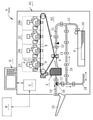
図2は本実施例における画像形成装置Aの概略構成を示す模式図であり、中間転写方式-タンデム型のフルカラー電子写真プリンタである。この画像形成装置Aはプリントサーバ等の外部装置Bから制御部Cに入力する画像情報に基づいて装置本体A1の内部の画像形成部A2が画像形成動作(プリント動作)してシート状の記録材Pにフルカラー又はモノカラーのトナー画像を形成することができる。
<< Example 1 >>
(Configuration of image forming apparatus)
FIG. 2 is a schematic diagram showing a schematic configuration of the image forming apparatus A in this embodiment, and is an intermediate transfer method-tandem type full-color electrophotographic printer. In this image forming apparatus A, the image forming unit A2 inside the apparatus main body A1 performs an image forming operation (printing operation) based on the image information input from the external device B such as a print server to the control unit C, and the sheet-shaped recording material. A full-color or monocolor toner image can be formed on P.
装置本体A1上には、タッチパネル(表示部)と物理ボタンとで構成される操作部(受信部)Dが備えられており、制御部Cとの間で各種の電気的情報の授受がなされる。ユーザー(使用者)及びメンテナンス作業者は操作部Dを用いて画像形成装置Aの各種設定の変更、画像形成動作、所定の装置制御モードの実行などを行なうことができる。制御部Cは画像形成装置Aを統括的に制御する。 An operation unit (reception unit) D composed of a touch panel (display unit) and physical buttons is provided on the device main body A1, and various electrical information is exchanged with the control unit C. .. The user (user) and the maintenance worker can change various settings of the image forming apparatus A, perform an image forming operation, execute a predetermined device control mode, and the like by using the operation unit D. The control unit C comprehensively controls the image forming apparatus A.
記録材(以下、用紙と記す)Pにトナー画像を形成する画像形成部A2は、それぞれ、イエロー(Y)、マゼンタ(M)、シアン(C)、ブラック(Bk)の色トナー像を形成する4つの作像ユニット1(Y・M・C・Bk)を有する。各作像ユニット1は、それぞれ、感光体ドラム(以下、ドラムと記す)2、帯電器3、レーザースキャナ(像露光器)4、現像器5、1次転写ローラ6、ドラムクリーナー7等の所定の電子写真プロセス機器を有する。なお、図の煩雑を避けるために、作像ユニット1Y以外の他の作像ユニット1M・1C・1Bkにおけるこれらの機器に対する符号の記入は省略した。
The image forming unit A2 that forms a toner image on the recording material (hereinafter referred to as paper) P forms yellow (Y), magenta (M), cyan (C), and black (Bk) color toner images, respectively. It has four image forming units 1 (Y, M, C, Bk). Each image forming unit 1 has a predetermined photoconductor drum (hereinafter referred to as a drum) 2, a charger 3, a laser scanner (image exposure device) 4, a
更に、画像形成部A2は、1次転写ローラ6により各ドラム2から転写したトナー像を担持して搬送する中間転写ベルト(以下、ITBと記す)8と、ITB8から用紙Pにトナー像を転写する2次転写ローラ9を有する。以上の構成の画像形成部A2の電子写真プロセスや画像形成動作は周知であるので詳細な説明は割愛する。
Further, the image forming unit A2 transfers the toner image from the
用紙Pはカセット10から所定の制御タイミングにて1枚分離給送される。そして、用紙Pは搬送パス11を通り、レジストレーションローラ(以下、RGローラと記す)12により所定の制御タイミングにてITB8と2次転写ローラ9とで形成される2次転写ニップ部(以下、N2ニップ部と記す)13に導入される。用紙PはN2ニップ部13で挟持搬送される過程でITB8側からトナー像の2次転写を受ける。そして、N2ニップ部13を出た用紙PはITB8から分離されて定着装置(定着部)Eに導入され、用紙P上のトナー像が固着像として熱圧定着される。定着装置Eについては後述する
定着装置Eを出た用紙Pは、画像形成ジョブ(プリントジョブ)が用紙の一方面だけに画像形成する片面画像形成ジョブである場合には、搬送パス14を通って排出トレイ15上に送り出される。
One sheet of paper P is separately fed from the
用紙の一方面と他方面の両面に画像形成する両面画像形成ジョブである場合には、定着装置Eを出た片面画像形成済みの用紙Pがフラッパ16の制御により搬送パス17の側に進路変更されて反転搬送パス18に導入される。そして、その用紙Pがスイッチバック搬送されて再搬送パス19に導入され、表裏反転された状態にて搬送パス11に再導入される。以後、用紙Pは片面画像形成時と同様に、RGローラ12、N2ニップ部13、定着装置E、搬送パス14の経路を搬送されて、両面画像形成物として排出トレイ15上に送り出される。
In the case of a double-sided image forming job in which an image is formed on one side and both sides of the paper, the paper P on which the one-sided image has been formed exits the fixing device E changes its course to the side of the
(定着装置の構成)
図3は本実施例における定着装置Eの横断面模式図である。この定着装置Eは、用紙上
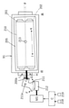
(記録材上:シート上)のトナー像を加熱する加熱回転体(定着部材、第1回転体)としての定着ローラ91と、定着ローラ91の外面に接触して定着ローラ91の外面を加熱する外部加熱ベルトユニット(ベルト搬送装置、ベルトユニット)200を有する。また、定着装置Eは、定着ローラ91と協働してトナー像tを担持した用紙Pを挟持搬送して加熱する定着ニップ部(ニップ部)Nを形成する加圧回転体(加圧部材、第2回転体)としての加圧ローラ92を有する。
(Structure of fixing device)
FIG. 3 is a schematic cross-sectional view of the fixing device E in this embodiment. The fixing device E comes into contact with the fixing
(1)定着ローラ
定着ローラ91は定着装置Eの装置フレーム90の長手方向(図3の紙面に垂直方向)の一端側(前側)と他端側(奥側)の側板間に回転可能に軸受けされて支持されている。定着ローラ91は制御部Cで制御されるモータ(駆動源)M1によって画像形成装置Aの画像形成動作時(プリント動作時)における所定の速度(第1の速度)、例えば500mm/secの周速で矢印R91の時計方向に回転駆動される。
(1) Fixing roller The fixing
定着ローラ91は、外径80mm、厚み3mm、長さ350mmの円筒状金属製(本実施例では、アルミニウム製)の芯金を備える。芯金上には、耐熱性の弾性層として、シリコーンゴムが1.5mmの厚さで被覆されている。弾性層上には、トナーとの離型性向上のために、耐熱性の離型層としてフッ素系樹脂(本実施例では、PFAチューブ)が50μmの厚さで被覆されている。
The fixing
定着ローラ91の芯金の内部には、発熱体として、例えば定格電力1200Wのハロゲンヒータ911が配置されている。ヒータ911は制御部Cで制御される給電部95からの給電により発熱する。定着ローラ91はこのヒータ911の発熱により内部から加熱される。そして、定着ローラ91の表面温度が定着ローラ91に接触する温度検知手段としてのサーミスタ93によって検出される。その検出温度情報が制御部Cに入力する。制御部Cは入力する検出温度情報に基づいて定着ローラ91の表面温度が所定の目標温度、例えば200℃となるよう給電部95からヒータ911への供給電力を制御する。
Inside the core metal of the fixing
(2)加圧ローラ
加圧ローラ92は定着ローラ91の下側においては定着ローラ91に実質平行に配列されて装置フレーム90の一端側と他端側の側板間に回転可能に軸受けされて支持され、かつ加圧手段(不図示)により定着ローラ91に対して所定の圧力で加圧されている。この加圧により定着ローラ91側の弾性層と加圧ローラ92側の弾性層の弾性たわみにより定着ローラ91と加圧ローラ92との間に用紙搬送方向aに関して所定幅の定着ニップ部Nが形成される。加圧ローラ92は定着ローラ91の回転駆動に従動して矢印R92の反時計方向に定着ローラ91の周速と実質同じ周速にて回転する。
(2) Pressurized roller The pressurizing
加圧ローラ92は、外径60mm、厚み4mm、長さ350mmの円筒状金属製(本実施例では、アルミニウム製)の芯金を備える。芯金上には、耐熱性の弾性層として、シリコーンゴムが2mmの厚さで被覆されている。弾性層上には、トナーとの離型性向上のために、耐熱性の離型層としてのフッ素系樹脂(本実施例では、PFAチューブ)が50μmの厚さで被覆されている。
The
加圧ローラ92の芯金の内部には、発熱体として、例えば定格電力300Wのハロゲンヒータ921が配置されている。ヒータ921は制御部Cで制御される給電部95からの給電により発熱する。加圧ローラ92はこのヒータ921の発熱により内部から加熱される。そして、加圧ローラ92の表面温度が加圧ローラ92に接触する温度検知手段としてのサーミスタ94によって検出され、その検出温度情報が制御部Cに入力する。制御部Cは入力する検出温度情報に基づいて加圧ローラ92の表面温度が所定の目標温度、例えば130℃となるよう給電部95からヒータ921への供給電力を制御する。
Inside the core metal of the pressurizing
(3)外部加熱ベルトユニット
定着ローラ91の上部には、連続通紙中においても定着ローラ91の表面温度を維持するために定着ローラ外周から定着ローラ91を加熱するための外部加熱ベルトユニット(ベルト搬送装置:以下、ベルトユニットと記す)200が備えられている。
(3) External heating belt unit On the upper part of the fixing
ベルトユニット200は、定着ローラ91の外面に接触して定着ローラ91の外面を加熱する外部加熱部材となる無端状の外部加熱ベルト(エンドレスベルト:以下、ベルトと記す)210を有する。また、このベルト210の内面を回転可能に支持するとともにベルト210を定着ローラ91に押し付けるベルト支持部材(支持機構)としての実質平行2本の第1及び第2支持ローラ201、202を有する。ベルト210はこの2本のローラ201、202に懸架されている。
The
ローラ201、202は枠体205にそれぞれ回転可能に支持されている。ローラ201、202は定着ローラ91の回転方向R91に関して第1支持ローラ201が上流側で第2支持ローラ201が下流側の関係にある。第2支持ローラ202はベルト210に張りを与えるテンションローラとしても機能している。
The
支持ローラ201、202はそれぞれ外径30mm、厚み2mm、長さ360mmの円筒状金属製(本実施例では、アルミニウム製)の芯金を備えている。ベルト210は、外径60mm、厚み100μm、幅350mmのポリイミド等の樹脂製の基材の層を有する耐熱性・可撓性ベルトである。トナーとの付着を防止するために、耐熱性の摺動層としてフッ素系樹脂(本実施例では、PFAチューブ)が20μmの厚さで被覆されている。
The
ローラ201、202の芯金の内部には、それぞれ、発熱体として、例えば定格電力1000Wのハロゲンヒータ203、204が配置されている。ヒータ203、204はそれぞれローラ201、202を加熱すように配光されている。ヒータ203、204は制御部Cで制御される給電部95からの給電により発熱する。ローラ201、202はそれぞれそのヒータ203、204の発熱により内部から加熱される。そのため、ローラ201、202に懸架されているベルト210がローラ201、202の熱により加熱される。
Inside the core metal of the
そして、ベルト210の表面温度がベルト210に接触する温度検知手段としてのサーミスタ209によって検出され、その検出温度情報が制御部Cにフィードバックされる。制御部Cは入力する検出温度情報に基づいてベルト210の表面温度が所定の目標温度となるように給電部95からヒータ203、204への供給電力を制御する。
Then, the surface temperature of the
枠体205は中間フレーム221に対して枠体回転軸205aを中心に回転可能に支持されている。中間フレーム221は加圧アーム206に対して縦軸213を中心に回転可能に支持されており、加圧アーム206に対して中間フレーム221と枠体205とが一体的に回転可能に支持されている。加圧アーム206は一端部が装置フレーム90の一端側と他端側の側板間に配設された軸206aに対してこの軸を中心に上下方向に回動動作可能に支持されている。
The
即ち、加圧アーム206と枠体205との間に中間フレーム221が存在する。加圧アーム206と中間フレーム221とが旋回軸(縦軸)213で連結されている。加圧アーム206に対して中間フレーム221と枠体205が一体となって縦軸213を中心に回転し、中間フレーム221と枠体205とが横軸205aで連結されている。中間フレーム221に対して枠体205が横軸205aを中心に回転する。
That is, there is an intermediate frame 221 between the pressurizing
加圧アーム206と当該加圧アームの上側に定置配設されたバネ受け座299との間には加圧バネ208が縮設されている。加圧アーム206はこの加圧バネ208の圧縮反力により軸206aを中心に定着ローラ91に向う方向に常に回動付勢される。そのため、加圧アーム206の自由状態時においては、ベルト210が定着ローラ91の上面に所定の加圧力で圧接する。
A
即ち、部材210、201、202を含む枠体205及び加圧アーム206の重量と加圧バネ208による加圧力により、ローラ201、202間のベルト210の下行側とローラ201、202がベルト210を挟んで定着ローラ91の上面に圧接する。これにより、図3のように、ベルト210が定着ローラ91の外面に対して定着ローラ91の曲率に倣って腹当て幅広に圧接して密着する。これにより、ベルト210と定着ローラ91との間に定着ローラ91の回転方向において幅広の加熱ニップ部(接触面)Neが形成される。
That is, due to the weight of the
本実施例においては、ローラ201、202を含む枠体205、中間フレーム221、加圧アーム206、加圧バネ208、バネ受け座299等がベルト210と対向部材としての定着ローラ91とを圧接する加圧機構を構成している。
In this embodiment, the
加圧アーム206の軸206aの側とは反対側の他端部の下方にはカム軸207aが装置フレーム90の一端側と他端側の側板間に回転可能に軸受けされて支持されている。このカム軸207aには偏心カム207が固定して配設されている。カム軸207aは制御部Cで制御されるモータM2により偏心カム207の大隆起部が図3のように横向きとなった第1回転角状態と大隆起部が上向きとなった第2回転角状態とに回転角が選択的に転換制御される。
A
そして、偏心カム207がその大隆起部が図3のように横向きとなった第1回転角状態に転換されて保持されることで、偏心カム207は加圧アーム206に対して非接触(非干渉)の姿勢に保持される。そのため、加圧アーム206が自由状態となり、加圧機構がベルト210と定着ローラ91により加熱ニップ部Neを形成する図3の圧接位置を取る(加圧機構の加圧状態)。
Then, the
一方、偏心カム207が上記の第1回転角状態から大隆起部が上向きときとなった第2回転角状態に転換されて保持される。そうすると、偏心カム207により加圧アーム206が加圧バネ208の圧縮反力に抗して軸206aを中心に持ち上げ回動されて所定の上昇位置に保持される。この状態においては加圧アーム206と共に中間フレーム221と枠体205が定着ローラ91から所定に持ち上げられてローラ201、202とベルト210が定着ローラ91から離間する。即ち、加圧機構がベルト210と定着ローラ91が離間される離間位置を取る(加圧機構の加圧解除状態)。
On the other hand, the
このように、枠体205は、加圧カム207が第1回転角状態と第2回転角状態とに回転することにより、加圧アーム206が軸206aを中心に下方又は上方に回転動作して、定着ローラ91から当接/退避可能に構成されている。上記において、軸207a、偏心カム207、モータM2等がベルト210と定着ローラ91により加熱ニップ部Neが形成される圧接位置(接触位置)と、その両者が離間される離間位置と、を加圧機構が取り得るように、加圧機構を移動させる移動機構を構成している。
In this way, in the
上記の加圧機構と移動機構とで、ベルトユニット200(ベルト210)を定着ローラ91に対して上記の圧接位置と離間位置とを取り得るように移動可能な接離機構を構成している。接離機構は定着ローラ91をベルトユニット200(ベルト210)に対して上記の圧接位置と離間位置とを取り得るように移動可能な構成とすることもできる。即ち、接離機構は、ベルトユニット200(ベルト210)と定着ローラ91が互いに所定の力で圧接する圧接位置と、この両者が互いに離間する離間位置と、を取り得るように、この両者の少なくとも一方を移動可能な機構である。制御部Cはその移動機構の動作を制御する。
The pressurizing mechanism and the moving mechanism constitute a contacting / separating mechanism in which the belt unit 200 (belt 210) can be moved so as to have the pressure contact position and the separation position with respect to the fixing
(4)定着動作
制御部Cは、画像形成装置Aが画像形成ジョブの入力待ちをしているスタンバイ状態時においては、定着装置EについてはモータM1をOFFにして定着ローラ91の駆動を回転停止している。また、偏心カム207を第2回転角状態にしてベルトユニット200(ベルト210)を定着ローラ91から離間させた離間位置に移動させている。
(4) Fixing operation When the image forming device A is in the standby state waiting for the input of the image forming job, the fixing operation control unit C turns off the motor M1 for the fixing device E and stops the drive of the fixing
本実施例においては、このスタンバイ状態時にはヒータ911、921、203、204に対する通電はONにしており、定着ローラ91、加圧ローラ92、ベルト210をそれぞれ所定の目標温度に温調している。このスタンバイ状態時の目標温調温度は画像形成動作時の所定の温度でもよいし、その温度よりも所定に低い設定のスタンバイ時用の温度であってもよい。なお、スタンバイ状態時にはヒータ911、921、203、204に対する通電はOFFにする制御であってもよい。
In this embodiment, the
制御部Cは、画像形成ジョブの入力に基づいて、画像形成装置Aをスタンバイ状態からウォームアップ動作(装置立ち上げ動作:前回転動作)に移行させる。定着装置Eについては、モータM1をONにして定着ローラ91を第1の速度で回転駆動させる。これに伴い加圧ローラ92が従動回転する。
The control unit C shifts the image forming apparatus A from the standby state to the warm-up operation (device start-up operation: forward rotation operation) based on the input of the image forming job. For the fixing device E, the motor M1 is turned on and the fixing
また、モータM2を制御して偏心カム207を第1回転角状態にしてベルトユニット200(ベルト210)を定着ローラ91に対して圧接させた圧接位置に転換させる。この加圧圧接状態において、ベルト210は定着ローラ91との加熱ニップ部Neにおける接触摩擦力で定着ローラ91の回転に伴って図3の矢印の反時計方向R210に従動回転する。ローラ201、202はベルト210の回転に従動回転する。
Further, the motor M2 is controlled to bring the
また、スタンバイ状態時の定着ローラ91、加圧ローラ92、ベルト210のそれぞれ目標温調温度が画像形成動作時の所定の温度よりも所定に低い設定のスタンバイ時用の所定の温度である場合には画像形成動作時の所定の目標温調温度に設定を切り換える。即ち、ベルト210の目標温度を第1の温度に、定着ローラ91の目標温度を第2の温度に切り換える。
Further, when the target temperature control temperature of each of the fixing
制御部Cは、所定のウォームアップ動作が終了したら、画像形成部A2を画像形成動作させる。これにより、画像形成動作している画像形成部A2の側から定着装置Eに未定着トナー像tを担持した用紙Pが搬送されて、ガイド板96でガイドされて定着ニップ部Nに導入される。用紙Pは未定着トナー像tを担持した面が定着ローラ91に対面して定着ニップ部Nを挟持搬送されていく。
When the predetermined warm-up operation is completed, the control unit C causes the image forming unit A2 to perform an image forming operation. As a result, the paper P carrying the unfixed toner image t is conveyed from the side of the image forming portion A2 in which the image forming operation is performed to the fixing device E, guided by the
そして、用紙Pが定着ニップ部Nを挟持搬送される過程において、未定着トナー像tが定着ローラ91の熱で加熱され、またニップ圧を受けて、用紙面に固着像として熱圧定着される。定着ニップ部Nを出た用紙Pは定着ローラ91の表面から分離されて装置内の排出ユニット97により定着装置Eから排出搬送されていく。
Then, in the process in which the paper P is sandwiched and conveyed by the fixing nip portion N, the unfixed toner image t is heated by the heat of the fixing
ベルトユニット200のベルト210の目標温度は定着ローラ91の目標温度よりも所定に高く設定してある。そのため、定着ローラ91の表面温度が定着ニップ部Nにおいて用紙Pとの接触により降下することに対してレスポンス(熱の感応精度)良くベルト210から定着ローラ91に熱が供給される。即ち、連続通紙中においても定着ローラ91の表面温度が良好に維持される。
The target temperature of the
制御部Cは、所定の画像形成ジョブが終了したら画像形成部A2の画像形成動作を終了させ、画像形成装置Aを所定の装置終了動作(後回転動作)に移行させる。そして、その装置終了動作の実行後に画像形成装置Aを次の画像形成ジョブが入力されるまでスタンバイ状態に移行させる。 When the predetermined image forming job is completed, the control unit C ends the image forming operation of the image forming unit A2, and shifts the image forming device A to the predetermined device ending operation (backward rotation operation). Then, after the execution of the device termination operation, the image forming apparatus A is shifted to the standby state until the next image forming job is input.
定着装置Eについては、モータM1をOFFにして定着ローラ91の駆動を停止させる。また、モータM2を制御して偏心カム207を第2回転角状態にしてベルトユニット200(ベルト210)を定着ローラ91から離間させた離間位置に転換させる。ヒータ911、921、203、204に対する通電はONにしており、定着ローラ91、加圧ローラ92、ベルト210をそれぞれ所定の目標温度(画像形成動作時の所定の温度、またはスタンバイ時用の所定の温度)に温調している。
For the fixing device E, the motor M1 is turned off to stop the driving of the fixing
なお、加圧ローラ92を定着ローラ91に向けて加圧する加圧機構について、該両ローラにより定着ニップ部Nが形成される第1の位置と、該両ローラが離間される第2の位置と、を取り得るように、加圧機構を移動させる移動機構を具備させることもできる。第2の位置は該両ローラ間に掛かる力が所定に減圧される位置であってもよい。そして、制御部Cは、画像形成装置Aの画像形成時は加圧機構が第1の位置を取るように、スタンバイ時等の非画像形成時は加圧機構が第2の位置を取るように、移動機構を制御する構成にすることもできる。
Regarding the pressurizing mechanism that pressurizes the pressurizing
(5)ベルトの往復制御
図4はベルトユニット200におけるベルト210のステアリング機構(往復動機構)の説明図である。このステアリング機構は、ベルト210の回転状態時(ベルト回転過程)においてベルト210が幅方向中央の所定のゾーンから外れた位置にあるときベルト210がゾーン内に戻るようにするベルト寄りを調整する機構である。ステアリング機構は制御部Cにより制御される。
(5) Belt reciprocating control FIG. 4 is an explanatory diagram of a steering mechanism (reciprocating movement mechanism) of the
本実施例では、ベルト210を張架しているローラ201、202を、回動軸213を中心にして枠体205とともに定着ローラ91に対して一体的に傾けて、定着ローラ91との間に意図的に交差角度θを設定する。これにより、ベルト210の幅方向(前奥方向)に関する移動方向を制御する。回動軸213は、ベルト210と定着ローラ91の交差角度θを変化させる回転中心である。
In this embodiment, the
回転軸211aの周りで回転可能な扇状のウォームホイール211は、ウォームギア212と噛み合っている。制御部Cで制御されるモータM3が順方向に回転してウォームホイール212を矢印F方向に回転させると、枠体205の長手一端部に固定された支持軸205bが矢印H方向に移動される。そうすると、定着ローラ91の回転に追従してベルト210にはJ方向への寄り力が働きその方向へ移動する。
The fan-shaped
逆に、モータM3が逆方向に回転してウォームホイール212を矢印G方向に回転させると支持軸205bが矢印I方向に移動し、ベルト210にはK方向への寄り力が働きその方向に移動する。
On the contrary, when the motor M3 rotates in the opposite direction and the
この繰り返し動作により、ベルト210の回転状態時においてベルト210を幅方向において所定の範囲(ゾーン内)で往復動作させることができる。即ち、ベルトが寄り移動制御される。
By this repeated operation, the
(6)ベルト寄り量検知センサ
図5は検出部として機能するベルト寄り検知センサの配置の説明図である。当接部として機能するコロ214は、枠体205に配置されて、ベルト210の幅方向一端(エッジ)に当接して、ベルト210とともにベルト幅方向へ移動できるように構成されている。コロ214は、アーム215に回転可能に取付けられている。
(6) Belt deviation detection sensor FIG. 5 is an explanatory diagram of an arrangement of a belt deviation detection sensor that functions as a detection unit. The
アーム215は、回転軸215aを中心にして回動可能であって、ねじりばねを内蔵した付勢部216によって2N(200gf)程度の力で矢印K方向に付勢されている。アーム215は扇状のセンサフラグ217とリンクしている。センサフラグ217は、コロ214、つまり、アーム215の動きに連動して回転する。センサフラグ217は、フォトインタラプタ218、219によって検知される。
The
図4と図5を参照して、ベルト210が矢印K方向に寄り移動して幅方向中央の所定のゾーンから外れた位置にあるときはそれがフォトインタラプタ219で検知され、その検知情報が制御部Cに入力する。制御部Cはその検知信号に基づいてステアリング機構のモータM3を順方向に回転させる。これによりベルト210にはJ方向への寄り力が働きその方向へ移動する。即ち、ベルト210は所定のゾーン内に戻されるJ方向へ移動制御される。
With reference to FIGS. 4 and 5, when the
また、ベルト210が矢印J方向に寄り移動して幅方向中央の所定のゾーンから外れた位置にあるときはそれがトインタラプタ218で検知され、その検知情報が制御部Cに入力する。制御部Cはその検知信号に基づいてステアリング機構のモータM3を逆方向に回転させる。これによりベルト210にはK方向への寄り力が働きその方向へ移動する。即ち、ベルト210は所定のゾーン内に戻されるK方向へ移動制御される。
Further, when the
この繰り返し動作(スイング型制御)により、ベルト210の回転状態時においてベルト210を所定の範囲(ゾーン内)で往復動作させることができる。
By this repetitive operation (swing type control), the
(7)ベルトの交換
ベルト210は、定着ローラ91と摺動回転するために使用を重ねるごとに表層が摩耗してくる。摩耗による表面粗さが一定以上に達すると、定着ローラ91の表層を傷つけてしまい、画像不良に至る可能性がある。そのため、積算通紙枚数が一定以上(本実施例ではA4サイズでの通紙枚数が10万枚)になると新品のベルトに交換することを推奨している。ここで、以下において、ベルトの交換には、ベルトを含むベルトユニット200のユニット全体の交換も含まれる。
(7) Belt replacement The surface layer of the
ベルト210の新旧交換は画像形成装置Aの開閉扉(不図示)を開いて装置本体A1の内部を開放し、定着装置Eを装置本体A1の所定の装着部から外部に引き出して露出させて、或いは装置本体A1から取り外して、所定の手順・要領にて行う。開閉扉が開かれるとキルスイッチ(不図示)がOFFになり、画像形成装置Aの電源回路(不図示)が開成される。これにより作業者の電気的保安が確保される。
To replace the old and
ベルトの交換を終えたらその定着装置Eを装置本体A1の所定の装着部に装着して開閉扉を閉じ込む。この開閉扉を閉じ込みによりキルスイッチがONになり、画像形成装置Aの電源回路が閉成される。制御部Cは電源回路の閉成に基づいて、画像形成装置Aのメインモータ(不図示)を起動させて、ウォームアップ動作を実行する。ウォームアップ動作を終了したら、画像形成ジョブが入力するまで画像形成装置Aをスタンバイ状態に移行させる。 After replacing the belt, the fixing device E is attached to a predetermined mounting portion of the device main body A1 and the opening / closing door is closed. By closing the open / close door, the kill switch is turned on and the power supply circuit of the image forming apparatus A is closed. Based on the closing of the power supply circuit, the control unit C activates the main motor (not shown) of the image forming apparatus A to execute the warm-up operation. After the warm-up operation is completed, the image forming apparatus A is put into the standby state until the image forming job is input.
定着装置Eについては、制御部Cは上記のウォームアップ動作(準備動作)においてモータM1をONにして定着ローラ91を回転駆動させる。これに伴い加圧ローラ92が従動回転する。また、偏心カム207を第2回転角状態にしてベルトユニット200(ベルト210)を定着ローラ91に対して離間させた離間位置に移動させている。ヒータ911、921、203、204に対する通電をONにして、定着ローラ91、加圧ローラ92、ベルト210をそれぞれ所定の目標温度に立ち上げて温調する。この状態においてスタンバイ状態に移行する。
Regarding the fixing device E, the control unit C turns on the motor M1 in the warm-up operation (preparatory operation) to rotate the fixing
(8)ベルト設置後のエイジング動作
図6はベルト210が懸架されるローラ201、202の回転中心を通る平面における概略断面図(模式図)である。ベルト210は型を用いて樹脂製の基材の層を成形しているため、その成型条件や型の表面性状などの影響を受けて内外周面の表面性状にばらつきを持つ。ローラ201、202と接触するベルト210の内周面が、図6の(a)のように、比較的凸凹している場合、ローラ201、202とベルト210の接触面積が少ないため、摩擦係数が小さい。その結果、ベルト210の寄り速度が高くなり、オーバーシュート量も大きくなる。
(8) Aging operation after belt installation FIG. 6 is a schematic cross-sectional view (schematic diagram) on a plane passing through the rotation centers of
初期は比較的凸凹していたが、ある程度往復動作が行われて、図6の(b)のように、凸部表面が摩耗して表面が平滑化されたり、初期から比較的平坦な表面性を有していたりする場合は、ローラ201、202とベルト210の接触面積が大きい。そのため、摩擦係数が大きい。その結果、ベルト210の寄り速度が低くなり、オーバーシュート量も小さくなる。
Initially, it was relatively uneven, but reciprocating motion was performed to some extent, and as shown in (b) of FIG. 6, the surface of the convex portion was worn and the surface was smoothed, or the surface surface was relatively flat from the initial stage. The contact area between the
新品のベルト210に交換した時に、内周面の粗さがおおよそRa0.5を超えるようなベルトが装着されるとローラ201、202との接触面積が小さくなり、摩擦力が小さくなることでベルトの往復速度が速くなる。その結果、オーバーシュート量が大きくなり、寄り切りエラーの状態に陥る可能性がある。
When a belt with a roughness of the inner peripheral surface exceeding Ra0.5 is attached when the belt is replaced with a
本実施例の画像形成装置Aは、ユーザーやサービスマンなどの作業者がベルト210を新品に交換した際には、操作部Dを使用して、制御部Cにおけるベルト210の積算通紙枚数カウンタ(不図示:ベルトの耐久カウンタ)の計数値を0にリセットできる。制御部Cはそのカウンタがリセットされたことに基づく情報により、定着装置Eについて、次のエイジング動作(慣らし運転)を実施する。即ち、ベルトユニット200を定着ローラ91に圧接した状態で定着ローラ91を画像形成時の回転速度よりも所定に低速で所定の一定時間回転する動作を実行する。
In the image forming apparatus A of the present embodiment, when a worker such as a user or a serviceman replaces the
つまり、制御部Cは、ベルトユニット200と定着ローラ91を圧接位置に移動させてベルト210を第1の速度(第2の回転速度)にて回転させる第1の制御モード(画像形成動作の制御モード)を実施可能である。また、同じくベルトユニット200と定着ローラ91を圧接位置に移動させてベルト210を前記第1の速度よりも低速の所定の第2の速度(第1の回転速度)にて所定の時間回転させる第2の制御モード(エイジング動作時の制御モード、プロセス)を実施可能である。そして、制御部Cは、ベルト交換に関わる所定の入力情報に基づいて直後における装置のウォームアップ動作若しくはスタンバイ時において前記第2の制御モードを実施する。
That is, the control unit C moves the
このように、制御部Cは、ベルト交換に関わる所定の入力情報に基づいてベルト210を定着ローラ91に圧接した状態で、画像形成時(印刷時)と比較して低速で一定時間回転する動作を追加で行う。そのため成形条件のばらつきなどで表面性状の粗いベルトが設置されてもオーバーシュートを押さえながら往復制御動作が行われつつ表面性状が平滑化される。その結果、その後の画像形成動作(印刷動作)においてもオーバーシュート量を押さえた動作が可能になり、ベルトの寄り切りによるダウンタイム発生を抑制することが可能になる。
In this way, the control unit C rotates at a lower speed for a certain period of time than during image formation (printing) in a state where the
つまり、ベルト210が新品ベルトであってもエイジング動作の実施実際によりそのベルトの内周面がローラ201、202と摺擦することで表面粗さが低減する。これにより、その後の画像形成動作においてオーバーシュート量が低下する為寄り切りエラーを抑制することができる。
That is, even if the
図7は、操作部Dに対して所定の操作を行うことで操作部Dの表示部(液晶タッチパネル)に表示される、画像形成装置内の様々な部品のそれまでにおける積算通紙枚数(耐久状況)が表示される画面である。表示部41に、ベルト210が前回交換されてから現在までに制御部Cのカウンタ部(不図示)でカウントされた積算通紙枚数が表示されている。ユーザーやサービスマンなどの作業者は、ベルト210を新品に交換した際に、リセットボタン42を押してOKボタン43を押す。これにより、ベルト210の積算通紙枚数が0にリセットされる。
FIG. 7 shows the cumulative number of sheets (durability) of various parts in the image forming apparatus displayed on the display unit (liquid crystal touch panel) of the operation unit D by performing a predetermined operation on the operation unit D. The status) is displayed on the screen. The
図1は本実施例においてエイジング動作が行われる状況を表すフローチャートである。本実施例においては、ベルト210を新品に交換した際(<7-1>)、操作部Dを操作してベルトの積算通紙枚数が0にリセットされた情報に基づいてエイジング動作が実施される(<7-2>)。このエイジング動作は、ベルト210が新品に交換した後、ベルト210交換後の最初の画像形成ジョブにて定着処理が開始される前に完了されることが好ましい。
FIG. 1 is a flowchart showing a situation in which an aging operation is performed in this embodiment. In this embodiment, when the
ここで、ユーザーやサービスマンなどの作業者のほとんどは、ベルト210の寿命管理のために、ベルト210を新品に交換した際に画像形成ジョブの開始前に積算通紙枚数をリセットする。これらを鑑み、本実施例では、ベルトの積算通紙枚数がリセットされた情報に基づいてエイジング動作を実施する構成としている。
Here, most of the workers such as users and servicemen reset the total number of sheets to be passed before the start of the image forming job when the
即ち、ベルトの交換を終えた定着装置Eが装置本体A1の所定の装着部に装着されて開閉扉が閉じられることで画像形成装置Aの電源回路が閉成される。これに基づいて、ウォームアップ動作(イニシャライズ動作)が実行された後、画像形成装置Aは定着装置Eも含めてスタンバイ状態に移行する。操作部Dも使用可能状態になる。作業者はこの操作部Dを操作して上記のようにベルト210の積算通紙枚数を0にリセットする。このリセット信号がベルト交換に関する信号として制御部Cに入力する(<7-2>)。
That is, the fixing device E after replacing the belt is attached to a predetermined mounting portion of the device main body A1 and the opening / closing door is closed, so that the power supply circuit of the image forming apparatus A is closed. Based on this, after the warm-up operation (initialization operation) is executed, the image forming apparatus A shifts to the standby state including the fixing apparatus E. The operation unit D is also ready for use. The operator operates the operation unit D to reset the total number of sheets to be passed through the
制御部Cは、エイジング動作の効果を安定にするために画像形成装置Aがスタンバイ状態になり、定着装置Eの温調が完了したことを確認した上で(<7-3>)、モータM2を駆動させることで加圧カム207を第2回転角状態から第1回転角状態に転換する。これにより、ベルトユニット200が定着ローラ91に圧接する状態に移行する(<7-4>)。
The control unit C confirms that the image forming apparatus A is in the standby state and the temperature control of the fixing apparatus E is completed in order to stabilize the effect of the aging operation (<7-3>), and then the motor M2. By driving the
続いて制御部CはモータM1を駆動させて定着ローラ91を所定の時間、所定の低速(第2の速度)で回転させる(エイジング動作)(<7-5>、<7-6>)。即ち、ベルト210の温度が第1の温度に到達すると共に定着ローラ91の温度が第2の温度に到達したときにエイジング動作を実行する。本実施例においては3分間、100mm/secの周速(画像形成動作時は500mm/sec)で定着ローラ91を回転させる。
Subsequently, the control unit C drives the motor M1 to rotate the fixing
この時、ベルトユニット200は定着ローラ91に圧接している状態のため、ベルト210は定着ローラ91に従動回転すると共にステアリング機構にて往復制御(スイング型制御)される。即ち、ベルト210は定着ローラ91の軸方向に対して往復動作を行なう。この時、定着ローラ91の周速は通常の画像形成時の500mm/sec(第1の速度)よりも低速の100mm/sec(第2の速度)である。そのため、ベルト内周面の表面粗さが仮に粗いベルトが設置されたとしてもオーバーシュート量を抑えて往復動作が行われる。
At this time, since the
所定時間の往復動作が完了すると(<7-6>)、制御部CはモータM2を駆動させて加圧カム207を逆方向に回転させて第1回転角状態から第2回転角状態に転換する。これにより、ベルトユニット200が定着ローラ91から離間される(<7-7>)。また、モータM1をOFFにして定着ローラ91の回転を停止させる。その後、定着装置Eがスタンバイ状態になっているかの状態判断を行ない(<7-8>)、動作を終了させる。
When the reciprocating operation for a predetermined time is completed (<7-6>), the control unit C drives the motor M2 to rotate the pressurizing
図8は、上記のエイジング動作前後における、ローラ201、202と接触するベルト210の内周面の表面粗さ(Ra)の変化を表したグラフの一例である。ベルト210の内周面に対して複数点表面粗さを測定し、その平均値がグラフであらわされている。
FIG. 8 is an example of a graph showing changes in the surface roughness (Ra) of the inner peripheral surface of the
図8の(a)は、ベルト210の初期内周面粗さがRa0.5程度の高いものに対してのエイジング動作前後の表面粗さの変化を表したものである。初期の粗さがRa0.5程度であったものがエイジング動作後での粗さはRa0.13程度まで低下しており、表面の凹凸が少なくなっていることが分かる。
FIG. 8A shows the change in surface roughness before and after the aging operation with respect to the
同図の(b)は、ベルト210の初期内周円粗さがRa0.11程度の比較的低いものに対してのエイジング動作前後の表面粗さの変化を表したものである。初期から表面粗さが低いものはエイジング動作を行なってもRaの値はほとんど変わらないことが分かる。すなわち、エイジング動作は初期の表面粗さの粗くないベルトに対しては影響を与えることなく、初期の表面粗さが粗く、ベルトの往復制御に対して寄り切りエラーが発生する可能性が高いベルトに対してのみ効果を発揮することができる。
(B) of the figure shows the change in the surface roughness before and after the aging operation with respect to the
図9は、図8の(a)で説明した、初期内周面粗さがRa0.5程度の高いものに対して、初期のベルト往復動作とエイジング動作した後の往復動作を表したものである。破線であらわされたものが初期のベルト210の往復動作であるが、移動速度が速いことが分かる。その結果、前奥の寄り検知位置からのオーバーシュート量が大きく、寄り切り位置まで到達しているものもある。なお、本来であれば寄り切り検知位置に到達した時点で定着装置Eの動作は停止するが、ここではその機能を停止させベルト210の動作を観察したものである。
FIG. 9 shows the initial belt reciprocating operation and the reciprocating operation after the aging operation with respect to the one having a high initial inner peripheral surface roughness of about Ra0.5 described in FIG. 8A. be. What is represented by the broken line is the reciprocating motion of the
エイジング動作を実施した後のベルト210の往復動作を実線で表している。初期のベルト往復動作と比較して往復動作の速度が低下し、オーバーシュート量も低減しており、寄り切り位置に対しても十分余裕が確保されていることが分かる。このようにベルト210を新品に交換した後にエイジング動作を実施することにより、ベルト設置直後のベルト寄り切りエラーの発生頻度を低減させることができる。
The reciprocating motion of the
本実施例1では、ベルト210のステアリング機構(図4)として、ベルトユニット200の定着ローラ91に対する交差角度θをウォームホイール211とモータM3により変化させる。これによりベルト210に寄り力を発生させて往復制御を行なう例を示した。しかし、ステアリング機構はこれに限られない。その他、例えば、ローラ201またはローラ202の中心軸を定着ローラ91の軸方向に対して傾けるように動作させることでベルト210に寄り力を発生させて往復制御を行なうステアリング構成でも同様の効果は得られる。
In the first embodiment, as the steering mechanism (FIG. 4) of the
ベルト210の内周面を摺擦するためのエイジング動作では、ベルト210を定着ローラ91に当接した状態でエイジング動作を行う。これにより、定着ローラ91とローラ201の間のニップ部、又は、定着ローラ91とローラ202の間のニップ部で、ベルト210の内周面をより効率よく摺擦することができる。
In the aging operation for rubbing the inner peripheral surface of the
尚、エイジング動作では、ベルト210を定着ローラ91に当接した状態にするとともに、ベルトユニット200を定着ローラ91に向けて加圧すると、より好ましい。すなわち、エイジング動作時に、定着ローラ91とローラ201が所定の圧でベルト210を挟み込むように、又は、定着ローラ91とローラ202が所定の圧でベルト210を挟み込む。これにより、ベルト210の内周面をより効率よく摺擦することができる。
In the aging operation, it is more preferable to bring the
また、本実施例で説明したように、エイジング動作中にベルト210のステアリング機構によるスイング制御を行うとより好ましい。これにより、定着ローラ91とローラ201の間のニップ部、又は、定着ローラ91とローラ202の間のニップ部にて、ベルト210の内周面がさらに効率よく摺擦される。
Further, as described in this embodiment, it is more preferable to perform swing control by the steering mechanism of the
また、本実施例では、エイジング動作において、ベルト210は定着ローラ91に当接した状態で、ローラ201、ローラ202が定着ローラ91に対して従動回転する構成につて説明したが、次の構成としてもよい。
Further, in the present embodiment, in the aging operation, the structure in which the
たとえば、ベルト210の回転駆動のために定着ローラ91の駆動とは別に設けられた駆動系によってローラ201またはローラ202を駆動させ、ベルト210を回転駆動させる。この構成にてエイジング動作を実行する場合にも、駆動が入っていない側のローラ(ローラ202又はローラ201)とベルト201の間で周速差が生まれるので、ベルト210の内周面を摺擦することができる。
For example, the
この構成においても、より好ましくは、ベルト210を定着ローラ91に対して所定の圧で加圧した状態でエイジング動作を実行する。さらに好ましくは、エイジング動作中にステアリング機構によるスイング制御を行う。
Also in this configuration, more preferably, the aging operation is executed in a state where the
また、本実施例1では定着装置9がスタンバイ状態になっていることを条件としてエイジング動作を実施している。本実施例のスタンバイ状態では、ベルトユニット200が定着ローラ91から離間しているので、ベルト210が回転しない。よって、スタンバイ中は、新品のベルト210によってベルト210の寄り切りエラーが発生する恐れがない。本実施例のスタンバイ状態では、ベルト210加熱されているので、ベルト210の内周面が少し柔らかくなっている。したがって、スタンバイ状態からエイジング動作を行うことで、ベルト210の内周面の摺擦効果が高められる。
Further, in the first embodiment, the aging operation is performed on condition that the fixing
また、本実施例1では、スタンバイ状態において、ベルト210を回転させない構成としたが、次の構成としてもよい。すなわち、スタンバイ状態において、ベルト210を所定のジョブでの定着処理の実行時の回転速度より遅い速度(例えば、エイジング動作時と同じ速度)で回転させる構成としてもよい。エイジング動作時と同程度の速度での回転であれば、エイジング動作前のスタンバイ状態での寄り切りエラーを抑制できる。
Further, in the first embodiment, the
尚、本実施例1では定着装置9がスタンバイ状態になっていることを条件としてエイジング動作を実施しているが、これに限られない。装置のウォームアップ状態時などその他の動作状態においてエイジング動作を行なっても良い。この場合、ウォームアップ状態時に新品のベルト210による寄り切りエラーの発生を抑制するために、ウォームアップ状態では、ベルト210を所定のジョブでの定着処理の実行時の回転速度より遅い速度で回転させる構成とする。例えば、エイジング動作時と同じ速度で回転させる構成とする。
In the first embodiment, the aging operation is performed on the condition that the fixing
《実施例2》
本実施例では図10に示されるように、操作部Dの表示部にはエイジングモード実行ボタンを表示することが可能である。操作部Dについて作業者が所定の操作を行うことによって表示されるエイジングモード実行ボタン44を押し、OKボタン45を押すと任意の状態において、エイジング動作を実施することも可能である。本実施例においては、このエイジングモード実行ボタン44とOKボタン45がエイジングモード(第2の制御モード)を実施するか否かを作業者が選択可能な操作部である。
<< Example 2 >>
In this embodiment, as shown in FIG. 10, it is possible to display the aging mode execution button on the display unit of the operation unit D. It is also possible to perform an aging operation in an arbitrary state by pressing the aging
図11は本実施例2においてエイジングモード実行ボタン44を押した際のエイジング動作が行われるときのフローチャートを表したものである。
FIG. 11 shows a flowchart when the aging operation is performed when the aging
操作部Dのエイジングモード実行ボタン44を押してOKボタン45を押すと(<10-1>)、制御部Cは画像形成装置がスタンバイ状態になっていることを確認する(<10-2>)。その条件において、ベルトユニット200を定着ローラ91に圧接する状態に移行し(<10-3>)、モータM1を駆動させて定着ローラ91を3分間、低速回転させる(エイジング動作)(<10-4>、<10-5>)。
When the aging
所定時間の往復動作が完了すると、制御部CはモータM2を駆動させて加圧カム207を逆方向に回転させてベルトユニット200を定着ローラ91から離間させる(<10-6>)。そして、定着装置Eがスタンバイ状態になっているかの状態判断を行ない(<10-7>)、動作を終了させる。問題なく動作完了すると、操作部Dの表示部にはステータスウィンドウ46(図10)に符号46のように“OK”と表示が表れる(<10-8>)。
When the reciprocating operation for a predetermined time is completed, the control unit C drives the motor M2 to rotate the pressurizing
ベルト210の初期設置後に自動的に動作するエイジング動作後に、追加してエイジング動作を実施したい場合に、上記作業をすることで実施が可能である。
If it is desired to additionally perform the aging operation after the aging operation that automatically operates after the initial installation of the
《実施例3》
図12、図13を用いて、本実施例3について説明する。なお、画像形成装置の主たる構成は実施例1と同様のため、説明を割愛する。
<< Example 3 >>
The third embodiment will be described with reference to FIGS. 12 and 13. Since the main configuration of the image forming apparatus is the same as that of the first embodiment, the description thereof will be omitted.
図12は本実施例3におけるベルト210である。ベルト210の両端部付近には一度所定温度以上で加熱処理を受けることにより発色状態から消色状態へと色相が変化する特性を備えた示温材210aが塗布されている。発色状態は様々な色が使用可能であるが、白色が望ましい。これにより、新品のベルトと使用済のベルトとの区別をつけることが可能となる。
FIG. 12 is the
図13は本実施例3におけるベルトユニット200の概略図である。実施例1の図4のベルトユニットとほぼ構成が同じであるが、本実施例3のベルトユニット200にはベルト210の示温材(識別部)210aに対向する位置の片側にベルト210の新旧判別機構(検出部)220が備えられている。新旧判別機構220は、発光部と受光部を備えたフォトセンサで構成されており、示温材210aが白の発色状態に対してのみ、所定以上の出力信号を返すよう構成されている。
FIG. 13 is a schematic view of the
ベルト210は、ユーザーやサービスマンなどの作業者によって、画像形成装置Aに電力を投入するための電源スイッチ(メインスイッチ)がOFFの状態で新品に交換される。そして、作業者はベルト210の交換が完了すると、電源スイッチをONに変更して画像形成装置Aを起動する。
The
そこで、新旧判別機構220は、電源スイッチがONされたことに応じて、ベルト210の示温材210aに対して発光し、その反射光を検知する。すなわち、新旧判別機構220は、電源スイッチがONされたことに応じて、ベルト210が新品であるか否かをチェックする。ベルト210が新品状態で設置されると、新旧判別機構220がそれを新品と判定し、その判断情報(ベルト交換に関する情報)が制御部Cに入力する。制御部Cはその判定情報の入力後の装置のスタンバイ状態時においてエイジング動作が自動実行するようになっている。
Therefore, the old /
制御部Cは、ベルト210が新品に交換されたと判定された後、ベルト210交換後の最初の画像形成ジョブにて定着処理が開始される前にエイジング動作が完了するようにエイジング動作を実行する。より好ましくは、制御部Cは、ベルト210が新品に交換されたと判定された後、ベルト210交換後の最初の画像形成ジョブの画像形成処理を開始する前にエイジング動作が完了するようにエイジング動作を実行する。
After it is determined that the
エイジング動作は実施例1で説明した動作と同様である。 The aging operation is the same as the operation described in the first embodiment.
これにより、サービスマン等の作業者がベルトを交換した後に、実施例1のようにベルトの積算通紙枚数カウンタを0にリセットする行為を行なわなくとも、確実にエイジング動作が実行される。即ち、より安定してベルト設置直後のベルト寄り切りエラーの発生頻度を低減させることができる。 As a result, after the belt is replaced by a worker such as a serviceman, the aging operation is surely executed without performing the act of resetting the total number of sheets of paper counter of the belt to 0 as in the first embodiment. That is, it is possible to more stably reduce the frequency of occurrence of the belt deviation error immediately after the belt is installed.
《実施例4》
実施例3では、ベルト210が単品交換される場合の例について説明した。本実施例4では、ベルトユニット200ごと交換される場合の例について説明する。
<< Example 4 >>
In Example 3, an example in which the
本実施例4のベルトユニット200には、新旧判別のための識別部が設けられている。新旧判別のための識別部とは、例えば、メモリである。新品のベルトユニット200には、新品のベルト210が搭載されており、新品のベルトユニット200に設けられたメモリには、新品であることに対応する情報が予め記憶されている。ベルトユニット200が画像形成装置Aの所定の装着部に装着されている状態において、制御部Cは、ベルトユニット200のメモリにアクセス可能である。
The
ベルトユニット200は、ユーザーやサービスマンなどの作業者によって、画像形成装置Aに電力を投入するための電源スイッチ(メインスイッチ)がOFFの状態で新品に交換される。そして、作業者はベルトユニット200の交換が完了すると、電源スイッチをONに変更して画像形成装置Aを起動する。
The
そこで、制御部Cは、電源スイッチがONされたことに応じて、ベルトユニット200のメモリにアクセスし、新品であることに対応する情報が記憶されているか否かを確認する。すなわち、制御部Cは、電源スイッチがONされたことに応じて、ベルトユニット200が新品であるか否かをチェックする。ベルトユニット200が新品状態で設置されると、制御部Cがメモリの情報を参照してそれを新品と判定する。制御部Cはその判定情報の入力後の装置のスタンバイ状態時においてエイジング動作が自動実行するようになっている。
Therefore, the control unit C accesses the memory of the
制御部Cは、ベルトユニット200が新品に交換されたと判定された後、ベルトユニット200交換後の最初の画像形成ジョブにて定着処理が開始される前にエイジング動作が完了するようにエイジング動作を実行する。より好ましくは、制御部Cは、ベルトユニット200が新品に交換されたと判定された後、ベルトユニット200交換後の最初の画像形成ジョブの画像形成処理を開始する前にエイジング動作が完了するようにエイジング動作を実行する。
After it is determined that the
エイジング動作は実施例1で説明した動作と同様である。 The aging operation is the same as the operation described in the first embodiment.
そして、エイジング動作の実行に伴い、ベルトユニット200に記憶されていたベルトユニット200が新品であることを示す情報を、ベルトユニット200が新品でないことを示す情報に書き換える。これにより、再度電源スイッチがOFFからONに切り替えられたときに、不要なエイジング動作の実行を防ぐことができる。ゆえに、無駄なエイジング動作の実行によりユーザーの待ち時間が増加するのを抑制することができる。
Then, with the execution of the aging operation, the information indicating that the
尚、本実施例では、新旧判別のための識別部として、新品であることに対応する情報が予め記憶されているメモリを例に説明したが、新旧判別のための識別部はこれに限らない。例えば、画像形成装置Aに装着可能な他のベルトユニット(例えば、新品交換する前のベルトユニット)と識別するための識別情報が記憶されているメモリをベルトユニット200に設ける構成としてもよい。
In this embodiment, a memory in which information corresponding to a new product is stored in advance has been described as an example of an identification unit for discriminating between old and new, but the identification unit for discriminating between old and new is not limited to this. .. For example, the
識別情報とは、例えば個体識別番号である。制御部Cは、電源スイッチがONされる毎にベルトユニット200のメモリの識別情報を読み出し、画像形成装置Aの本体に設けられているRAM、或いは、制御部C内のメモリに読み出した識別情報を記憶する。そして、前回電源スイッチがONされたときに読みだした識別情報と、今回電源スイッチがONされたときに読み出した識別情報とを比較する。これらの識別情報が異なるものであれば、新品のベルトユニット200が装着されたと判定する。
The identification information is, for example, an individual identification number. The control unit C reads out the identification information of the memory of the
尚、前回の電源スイッチON時の識別情報との比較に限らず、過去のベルトユニット200の装着履歴との比較によって、新品のベルトユニット200か否かを判定する構成としてもよい。また、ベルトユニット200の識別情報を示す識別部は、メモリに限らず、識別情報を示すバーコード、ディップスイッチ等の他の手段であってもよい。その他の構成、及び、効果は、上述の実施例1、3と同様である。
It should be noted that the configuration is not limited to the comparison with the identification information when the power switch is turned on last time, but may be configured to determine whether or not the
《実施例5》
図14を用いて、本実施例5における定着装置Eについて説明する。なお、画像形成装置の主たる構成は実施例1と同様のため、説明を割愛する。
<< Example 5 >>
The fixing device E in the fifth embodiment will be described with reference to FIG. Since the main configuration of the image forming apparatus is the same as that of the first embodiment, the description thereof will be omitted.
本実施例5における定着装置Eは、画像加熱回転体としての定着ローラ401、可撓性を有する無端状の定着ベルト404、加圧部材としての加圧ローラ405、ベルト404の往復動作を行なうためのステアリングローラ408から構成されている。
The fixing device E in the fifth embodiment reciprocates the fixing
ベルト404は定着ローラ401とステアリングローラ408との間に回転可能に懸回張設されており、定着ローラ401とステアリングローラ408がベルト404の内面を回転可能に支持するベルト支持部材として機能している。ステアリングローラ408はベルト404に張りを与えるテンションローラとしても機能している。加圧ローラ405がベルト404の外面に接触して用紙搬送方向aに関して所定幅の定着ニップ部(ニップ部)Nを形成する対向部材である。
The
本実施例においては、上記のベルト404、定着ローラ401、ステアリングローラ408、加圧ローラ405により、ベルト搬送装置が構成されている。
In this embodiment, the belt transport device is composed of the
定着ローラ401は、制御部Cで制御されるモータ410によって所定の速度、例えば500mm/secの周速(第1の速度)で矢印R401の時計方向に回転駆動される。定着ローラ401は、外径50mm、厚み3mm、長さ350mmの円筒状金属(本実施例では、アルミニウム製)で構成されている。定着ローラ401が回転駆動されることで、定着ベルト404およびステアリングローラ408の矢印の方向に定着ローラ401の回転速度に対応した速度にて従動回転する。
The fixing
定着ローラ401の内部には、発熱体として、例えば定格電力1200Wのハロゲンヒータ402が配置されて、定着ローラ401の表面温度が所定の温度となるように内部から加熱されている。定着ローラ401の表面温度は、定着ローラ401に接触する温度検知手段としてのサーミスタ403によって検出される。制御部Cはサーミスタ403から入力する検知温度情報に基づいて定着ローラ401の表面温度が所定の目標温度、例えば200℃となるように給電部95からヒータ402への供給電力を制御する。
A
ベルト404は、外径120mm、厚み100μm、幅350mmのポリイミド等の樹脂製の基材の層を有し、耐熱性の弾性層として、シリコーンゴムが150μmの厚さで被覆されている耐熱性・可撓性を有するベルトである。さらにシリコーンゴムの上にトナーとの付着を防止するために、耐熱性の摺動層としてフッ素系樹脂(本実施例では、PFAチューブ)が20μmの厚さで被覆されている。
The
ステアリングローラ408は、金属製(本実施例ではステンレス製)の軸に弾性層としてのシリコーンゴムなどが被覆されたもので、テンションバネ415によって20Nの力でベルト404に対して内側から外側へのテンションを与えている。
The steering
また、ステアリングローラ408は長手方向の奥側のローラ端部を回動中心として手前側のローラ端部をステアリング機構413により矢印X、Y方向に揺動可能に構成されており、ベルト404に寄り力を与えている。ベルト404の端部にはベルト寄り検知機構414が付勢されている。ベルト寄り検知機構414は実施例1の図5にて説明した寄り検知センサ構成と同様である。
Further, the steering
制御部Cはこのベルト寄り検知機構414によって検知されるベルト404の端部位置情報を元に、ステアリングローラ408をステアリング機構413により傾斜させて実施例1のベルト210と同様に往復制御(スイング型制御)を行なっている。
The control unit C tilts the
加圧ローラ405は軸412aを中心に回動可能な加圧アーム412に回転可能に支持されている。加圧アーム412は制御部Cで制御されるモータ411により駆動される着脱カム409で軸412aを中心に定着ローラ401に向う方向と離れる方向に上下動される。
The pressurizing
加圧アーム412の上昇動により加圧ローラ405がベルト404を挟んで定着ローラ401に対して所定の加圧力で圧接する圧接位置に移動される。これにより、ベルト404と加圧ローラ405との間に用紙搬送方向aにおいて所定幅の定着ニップ部Nが形成される。また、加圧アーム412の下降動により加圧ローラ405がベルト404から離間した離間位置に移動される。
By the ascending motion of the pressurizing
本実施例においては、上記のモータ411、着脱カム409、加圧アーム412が、加圧ローラ405をベルト404に対して圧接位置と離間位置に移動させる接離機構を構成している。
In this embodiment, the
加圧ローラ405はベルト404を介して定着ローラ401に圧接している状態にて定着ローラ401が回転駆動されることでベルト404の回転に従動してベルト404の回転速度に対応した周速で矢印R405の反時計方向に回転する。
The
加圧ローラ405は、外径40mm、厚み4mm、長さ350mmの円筒状金属製(本実施例では、アルミニウム製)の芯金を備える。芯金上には、耐熱性の弾性層として、シリコーンゴムが2mmの厚さで被覆されている。弾性層上には、トナーとの離型性向上のために、耐熱性の離型層としてのフッ素系樹脂(本実施例では、PFAチューブ)が50μmの厚さで被覆されている。
The
又、加圧ローラ405の芯金の内部には、発熱体として、例えば定格電力300Wのハロゲンヒータ406が配置されて、加圧ローラ405の表面温度が所定の温度となるように内部から加熱する。加圧ローラ405の表面温度は、加圧ローラ405に接触する温度検知手段としてのサーミスタ407によって検出される。制御部Cはサーミスタ407から入力する検知温度情報に基づいて加圧ローラ405の表面温度が所定の目標温度、例えば130℃となるように給電部95からヒータ406への供給電力を制御する。
Further, a
ニップ部Nに未定着トナーtを担持した用紙Pが導入されて挟持搬送されることにより、実施例1の定着装置Eと同様にトナーtの熱圧定着がなされる。 By introducing the paper P carrying the unfixed toner t into the nip portion N and sandwiching and transporting the paper P, the toner t is thermally and pressure-fixed in the same manner as in the fixing device E of the first embodiment.
装置のスタンバイ時等の画像形成動作を行なわない間は、制御部Cは接離機構により加圧ローラ405をベルト404~離間させた離間位置に移動させている。
While the image forming operation such as during standby of the apparatus is not performed, the control unit C moves the
実施例1と同様に、ベルト404が内面粗さの粗い新品に交換されると、定着ローラ401の外周面との接触面積が小さいために摩擦係数が低くなりベルト404の往復制御においてオーバーシュート量が多くなる。そのために、寄り切りエラーに至る可能性が高くなる。
Similar to the first embodiment, when the
従って、本実施例の定着装置Eのようにベルト404と加圧ローラ405にて定着ニップ部Nを形成する装置構成においてもベルト404が交換された際にはエイジング動作を実施する。これにより、オーバーシュート量を低減させることで、ベルト設置直後のベルト寄り切りエラーの発生頻度を低減させることができる。
Therefore, even in the device configuration in which the fixing nip portion N is formed by the
エイジング動作の実行は、実施例1や同2と同様に、ベルト404を交換した後にベルトの積算通紙枚数カウンタを0にリセットした後の定着装置Eがスタンバイ状態になっていることを条件として実行することができる。あるいは装置のウォームアップ状態時などその他の動作状態においてエイジング動作を行なっても良い。或いは、装置のスタンバイ中に実行することができる。或いは、操作部Dに表示されるエイジング動作実施ボタン44(図10)を押した時に実行することができる。
The execution of the aging operation is performed on the condition that the fixing device E is in the standby state after the integrated paper number counter of the belt is reset to 0 after the
また、実施例3のようにベルト404の端部に、一度所定温度以上で加熱処理を受けることにより発色状態から消色状態へと色相が変化する特性を備えた示温材を塗布する。そして、示温材の色相を検知して新旧判別を行なうフォトセンサを備えることで、ベルト404が新品と検知されたときにエイジング動作を自動で実行するよう構成しても良い。
Further, as in Example 3, a temperature indicating material having a characteristic that the hue changes from a color-developed state to a decolorized state by being heat-treated once at a predetermined temperature or higher is applied to the end portion of the
なお、定着装置Eは、トナー像が一旦定着された又は仮定着された用紙を再度導入することにより画像の光沢を増大させる光沢度増大装置(画像改質装置;この場合も定着装置と呼ぶ)としても使用できる。 The fixing device E is a glossiness increasing device (image modifying device; also referred to as a fixing device in this case) that increases the gloss of the image by re-introducing the paper on which the toner image is once fixed or hypothesized. Can also be used as.
E・・定着装置(ベルト搬送装置)、C・・制御部、210・404・・無端状のベルト(外部加熱ベルト、定着ベルト)、201・202・401・408・・ベルト支持部材、200・・ベルトユニット、91・405・・対向部材(加熱回転体、加圧回転体)、Ne・N・・ニップ部、205~208・221・213・299・M2・・接離機構、409・411・412・・接離機構、211~213・M3・・ステアリング機構、413・414・・ステアリング機構 E ... Fixing device (belt transport device), C ... Control unit, 210.404 ... Endless belt (external heating belt, fixing belt), 201, 202, 401, 408 ... Belt support member, 200 ...・ Belt unit, 91 ・ 405 ・ ・ Opposing member (heating rotating body, pressurized rotating body), Ne ・ N ・ ・ Nip part, 205 to 208 ・ 221 ・ 213 ・ 299 ・ M2 ・ ・ Contacting and separating mechanism, 409 ・ 411・ 412 ・ ・ Contact / detachment mechanism, 211-213 ・ M3 ・ ・ Steering mechanism, 413 ・ 414 ・ ・ Steering mechanism
Claims (7)
前記画像形成部で記録材に形成されたトナー像を挟持するニップ部を形成し、該トナー像を加熱する第1回転体及び第2回転体と、
前記第1回転体を外部加熱する無端状のベルトと、前記ベルトを回転自在に支持する支持機構とを有するベルトユニットと、
前記ベルトを前記第1回転体に接触させる接触位置と、前記ベルトを前記第1回転体から離間させる離間位置との間で、前記ベルトユニットを移動させる移動機構と、
新品の無端状のベルトを有する前記ベルトユニットと、新品の無端状のベルトを有する新品のベルトユニットとの何れかを前記接触位置に移動させ、前記第1回転体によって前記新品の無端状のベルトを第1の回転速度で所定の時間回転させるプロセスを実行させる制御部と、を備え、
前記第1の回転速度は、記録材に形成されたトナー像を加熱することで画像が記録材に形成される画像形成時に前記ベルトを回転させる第2の回転速度よりも低速であることを特徴とする画像形成装置。 An image forming part that forms a toner image on the recording material,
The first rotating body and the second rotating body that form a nip portion that sandwiches the toner image formed on the recording material in the image forming portion and heat the toner image, and the second rotating body.
An endless belt that externally heats the first rotating body, a belt unit having a support mechanism that rotatably supports the belt, and a belt unit.
A moving mechanism for moving the belt unit between a contact position where the belt is brought into contact with the first rotating body and a separating position where the belt is separated from the first rotating body.
Either the belt unit having a new endless belt or the new belt unit having a new endless belt is moved to the contact position, and the new endless belt is moved by the first rotating body. A control unit, which executes a process of rotating the belt at a first rotation speed for a predetermined time, is provided.
The first rotation speed is characterized in that it is slower than the second rotation speed at which the belt is rotated when an image is formed on the recording material by heating the toner image formed on the recording material. Image forming device.
前記制御部は、前記プロセスの実行時に前記往復動機構を動作させる請求項1に記載の画像形成装置。 A reciprocating mechanism for reciprocating the belt in the width direction of the belt is provided.
The image forming apparatus according to claim 1, wherein the control unit operates the reciprocating mechanism when the process is executed.
前記制御部は、前記受信部の出力に基づいて前記プロセスを実行することを特徴とする請求項1又は2に記載の画像形成装置。 It is equipped with a receiving unit that receives the information of the instruction to replace the belt and outputs the information.
The image forming apparatus according to claim 1 or 2, wherein the control unit executes the process based on the output of the receiving unit.
前記制御部は、前記検出部の出力に基づいて前記プロセスを実行することを特徴とする請求項1又は2に記載の画像形成装置。 It is provided with a detection unit that detects the information of the instruction to replace the belt and outputs the information.
The image forming apparatus according to claim 1 or 2, wherein the control unit executes the process based on the output of the detection unit.
Priority Applications (2)
| Application Number | Priority Date | Filing Date | Title |
|---|---|---|---|
| JP2017218023A JP7009168B2 (en) | 2017-11-13 | 2017-11-13 | Belt transfer device and fixing device |
| US16/184,268 US10564576B2 (en) | 2017-11-13 | 2018-11-08 | Image forming apparatus that performs a process of rotating a new endless belt before an image forming operation |
Applications Claiming Priority (1)
| Application Number | Priority Date | Filing Date | Title |
|---|---|---|---|
| JP2017218023A JP7009168B2 (en) | 2017-11-13 | 2017-11-13 | Belt transfer device and fixing device |
Publications (3)
| Publication Number | Publication Date |
|---|---|
| JP2019090872A JP2019090872A (en) | 2019-06-13 |
| JP2019090872A5 JP2019090872A5 (en) | 2021-01-14 |
| JP7009168B2 true JP7009168B2 (en) | 2022-01-25 |
Family
ID=66433291
Family Applications (1)
| Application Number | Title | Priority Date | Filing Date |
|---|---|---|---|
| JP2017218023A Active JP7009168B2 (en) | 2017-11-13 | 2017-11-13 | Belt transfer device and fixing device |
Country Status (2)
| Country | Link |
|---|---|
| US (1) | US10564576B2 (en) |
| JP (1) | JP7009168B2 (en) |
Families Citing this family (11)
| Publication number | Priority date | Publication date | Assignee | Title |
|---|---|---|---|---|
| JP2020112586A (en) | 2019-01-08 | 2020-07-27 | キヤノン株式会社 | Image forming apparatus |
| JP2021018284A (en) * | 2019-07-18 | 2021-02-15 | キヤノン株式会社 | Fixing device and image forming apparatus |
| JP2021140135A (en) | 2019-11-12 | 2021-09-16 | キヤノン株式会社 | Fixing device |
| JP2021096402A (en) | 2019-12-18 | 2021-06-24 | キヤノン株式会社 | Fixing device |
| JP2021096401A (en) | 2019-12-18 | 2021-06-24 | キヤノン株式会社 | Fixing device |
| JP7396027B2 (en) * | 2019-12-23 | 2023-12-12 | ブラザー工業株式会社 | Image forming device |
| US11307519B2 (en) | 2020-01-30 | 2022-04-19 | Canon Kabushiki Kaisha | Recording material cooling device |
| JP2021120734A (en) | 2020-01-30 | 2021-08-19 | キヤノン株式会社 | Recording material cooling device, and image forming apparatus |
| US11435681B2 (en) | 2020-05-26 | 2022-09-06 | Canon Kabushiki Kaisha | Recording material cooling device, image forming apparatus and image forming system |
| JP7438856B2 (en) | 2020-06-09 | 2024-02-27 | キヤノン株式会社 | Recording material cooling device, image forming device, and image forming system |
| JP2022122058A (en) | 2021-02-09 | 2022-08-22 | キヤノン株式会社 | Fixing device |
Citations (7)
| Publication number | Priority date | Publication date | Assignee | Title |
|---|---|---|---|---|
| JP2013190774A (en) | 2012-02-14 | 2013-09-26 | Canon Inc | Image heating device and image forming apparatus |
| JP2015049312A (en) | 2013-08-30 | 2015-03-16 | キヤノン株式会社 | Fixing member and fixing device |
| JP2015203848A (en) | 2014-04-16 | 2015-11-16 | シャープ株式会社 | image forming apparatus |
| JP2016006487A (en) | 2014-05-29 | 2016-01-14 | キヤノン株式会社 | Image forming apparatus |
| JP2017049295A (en) | 2015-08-31 | 2017-03-09 | キヤノン株式会社 | Image heating device and image forming apparatus |
| JP2017049296A (en) | 2015-08-31 | 2017-03-09 | キヤノン株式会社 | Image heating device and image forming apparatus |
| JP2017138423A (en) | 2016-02-03 | 2017-08-10 | キヤノン株式会社 | Fixation device |
Family Cites Families (6)
| Publication number | Priority date | Publication date | Assignee | Title |
|---|---|---|---|---|
| JP3612976B2 (en) * | 1998-01-07 | 2005-01-26 | 富士ゼロックス株式会社 | Fixing device |
| JP2004198659A (en) | 2002-12-17 | 2004-07-15 | Fuji Xerox Co Ltd | Image fixing device and image forming apparatus |
| JP4188385B2 (en) * | 2006-05-12 | 2008-11-26 | シャープ株式会社 | FIXING DEVICE, IMAGE FORMING DEVICE HAVING THE SAME, FIXING DEVICE CONTROL PROGRAM, AND COMPUTER-READABLE RECORDING MEDIUM CONTAINING THE PROGRAM |
| JP2008015291A (en) * | 2006-07-07 | 2008-01-24 | Fuji Xerox Co Ltd | Image forming apparatus |
| JP6049484B2 (en) * | 2013-02-13 | 2016-12-21 | キヤノン株式会社 | Image heating device |
| US10303093B2 (en) * | 2015-08-31 | 2019-05-28 | Canon Kabushiki Kaisha | Image forming apparatus that prompts exchange of a first rotatable member of a fixing portion based on a rotation time of the first rotatable member or a recording material length |
-
2017
- 2017-11-13 JP JP2017218023A patent/JP7009168B2/en active Active
-
2018
- 2018-11-08 US US16/184,268 patent/US10564576B2/en active Active
Patent Citations (7)
| Publication number | Priority date | Publication date | Assignee | Title |
|---|---|---|---|---|
| JP2013190774A (en) | 2012-02-14 | 2013-09-26 | Canon Inc | Image heating device and image forming apparatus |
| JP2015049312A (en) | 2013-08-30 | 2015-03-16 | キヤノン株式会社 | Fixing member and fixing device |
| JP2015203848A (en) | 2014-04-16 | 2015-11-16 | シャープ株式会社 | image forming apparatus |
| JP2016006487A (en) | 2014-05-29 | 2016-01-14 | キヤノン株式会社 | Image forming apparatus |
| JP2017049295A (en) | 2015-08-31 | 2017-03-09 | キヤノン株式会社 | Image heating device and image forming apparatus |
| JP2017049296A (en) | 2015-08-31 | 2017-03-09 | キヤノン株式会社 | Image heating device and image forming apparatus |
| JP2017138423A (en) | 2016-02-03 | 2017-08-10 | キヤノン株式会社 | Fixation device |
Also Published As
| Publication number | Publication date |
|---|---|
| US20190146386A1 (en) | 2019-05-16 |
| US10564576B2 (en) | 2020-02-18 |
| JP2019090872A (en) | 2019-06-13 |
Similar Documents
| Publication | Publication Date | Title |
|---|---|---|
| JP7009168B2 (en) | Belt transfer device and fixing device | |
| JP5901280B2 (en) | Image heating apparatus and image forming apparatus | |
| US8600253B2 (en) | Image forming apparatus, method of controlling fixing device, and device and method for detecting abnormality of the fixing device | |
| JP4917963B2 (en) | Fixing apparatus and electrophotographic apparatus having the same | |
| JP2005114959A (en) | Fixing device and image forming apparatus | |
| US8977172B2 (en) | Fixing apparatus having an air blowing mechanism | |
| JP5965883B2 (en) | Fixing apparatus and image forming apparatus | |
| WO2016056670A1 (en) | Image forming device | |
| JP4871633B2 (en) | Image forming apparatus | |
| US9207600B2 (en) | Fixing apparatus | |
| JP2011048166A (en) | Image forming apparatus | |
| JP6711693B2 (en) | Fixing device | |
| US10126691B2 (en) | Image forming device | |
| JP2013088498A (en) | Image heating device | |
| JP6805860B2 (en) | Fixing device and image forming device | |
| JP6668765B2 (en) | Fixing device and image forming device | |
| JP5486770B2 (en) | Image forming apparatus | |
| US20130121712A1 (en) | Image heating apparatus, image forming apparatus, and image heating system | |
| JP4677220B2 (en) | Image heating apparatus and image forming apparatus | |
| US20200195806A1 (en) | Image Forming Apparatus | |
| JP2021189285A (en) | Image forming apparatus | |
| US8693910B2 (en) | Image forming apparatus with heater | |
| US9244400B2 (en) | Image heating apparatus | |
| JP2005189599A (en) | Image forming apparatus | |
| US20230125938A1 (en) | Image forming apparatus |
Legal Events
| Date | Code | Title | Description |
|---|---|---|---|
| RD03 | Notification of appointment of power of attorney |
Free format text: JAPANESE INTERMEDIATE CODE: A7423 Effective date: 20181108 |
|
| RD04 | Notification of resignation of power of attorney |
Free format text: JAPANESE INTERMEDIATE CODE: A7424 Effective date: 20181116 |
|
| A521 | Written amendment |
Free format text: JAPANESE INTERMEDIATE CODE: A523 Effective date: 20190418 |
|
| RD02 | Notification of acceptance of power of attorney |
Free format text: JAPANESE INTERMEDIATE CODE: A7422 Effective date: 20200206 |
|
| RD04 | Notification of resignation of power of attorney |
Free format text: JAPANESE INTERMEDIATE CODE: A7424 Effective date: 20200207 |
|
| A621 | Written request for application examination |
Free format text: JAPANESE INTERMEDIATE CODE: A621 Effective date: 20201112 |
|
| A521 | Written amendment |
Free format text: JAPANESE INTERMEDIATE CODE: A523 Effective date: 20201125 |
|
| A977 | Report on retrieval |
Free format text: JAPANESE INTERMEDIATE CODE: A971007 Effective date: 20210825 |
|
| A131 | Notification of reasons for refusal |
Free format text: JAPANESE INTERMEDIATE CODE: A131 Effective date: 20210928 |
|
| A521 | Written amendment |
Free format text: JAPANESE INTERMEDIATE CODE: A523 Effective date: 20211124 |
|
| TRDD | Decision of grant or rejection written | ||
| A01 | Written decision to grant a patent or to grant a registration (utility model) |
Free format text: JAPANESE INTERMEDIATE CODE: A01 Effective date: 20211214 |
|
| A61 | First payment of annual fees (during grant procedure) |
Free format text: JAPANESE INTERMEDIATE CODE: A61 Effective date: 20220112 |