JP7008130B2 - Methods for sending and receiving data in wireless communication systems and devices that support them - Google Patents
Methods for sending and receiving data in wireless communication systems and devices that support them Download PDFInfo
- Publication number
- JP7008130B2 JP7008130B2 JP2020515670A JP2020515670A JP7008130B2 JP 7008130 B2 JP7008130 B2 JP 7008130B2 JP 2020515670 A JP2020515670 A JP 2020515670A JP 2020515670 A JP2020515670 A JP 2020515670A JP 7008130 B2 JP7008130 B2 JP 7008130B2
- Authority
- JP
- Japan
- Prior art keywords
- pdsch
- subslot
- dmrs
- terminal
- dci
- Prior art date
- Legal status (The legal status is an assumption and is not a legal conclusion. Google has not performed a legal analysis and makes no representation as to the accuracy of the status listed.)
- Active
Links
Images


Classifications
-
- H—ELECTRICITY
- H04—ELECTRIC COMMUNICATION TECHNIQUE
- H04W—WIRELESS COMMUNICATION NETWORKS
- H04W72/00—Local resource management
- H04W72/20—Control channels or signalling for resource management
- H04W72/23—Control channels or signalling for resource management in the downlink direction of a wireless link, i.e. towards a terminal
-
- H—ELECTRICITY
- H04—ELECTRIC COMMUNICATION TECHNIQUE
- H04L—TRANSMISSION OF DIGITAL INFORMATION, e.g. TELEGRAPHIC COMMUNICATION
- H04L5/00—Arrangements affording multiple use of the transmission path
- H04L5/0091—Signaling for the administration of the divided path
-
- H—ELECTRICITY
- H04—ELECTRIC COMMUNICATION TECHNIQUE
- H04L—TRANSMISSION OF DIGITAL INFORMATION, e.g. TELEGRAPHIC COMMUNICATION
- H04L5/00—Arrangements affording multiple use of the transmission path
- H04L5/003—Arrangements for allocating sub-channels of the transmission path
- H04L5/0048—Allocation of pilot signals, i.e. of signals known to the receiver
- H04L5/005—Allocation of pilot signals, i.e. of signals known to the receiver of common pilots, i.e. pilots destined for multiple users or terminals
-
- H—ELECTRICITY
- H04—ELECTRIC COMMUNICATION TECHNIQUE
- H04B—TRANSMISSION
- H04B7/00—Radio transmission systems, i.e. using radiation field
- H04B7/02—Diversity systems; Multi-antenna system, i.e. transmission or reception using multiple antennas
- H04B7/04—Diversity systems; Multi-antenna system, i.e. transmission or reception using multiple antennas using two or more spaced independent antennas
- H04B7/06—Diversity systems; Multi-antenna system, i.e. transmission or reception using multiple antennas using two or more spaced independent antennas at the transmitting station
- H04B7/0613—Diversity systems; Multi-antenna system, i.e. transmission or reception using multiple antennas using two or more spaced independent antennas at the transmitting station using simultaneous transmission
- H04B7/0615—Diversity systems; Multi-antenna system, i.e. transmission or reception using multiple antennas using two or more spaced independent antennas at the transmitting station using simultaneous transmission of weighted versions of same signal
- H04B7/0619—Diversity systems; Multi-antenna system, i.e. transmission or reception using multiple antennas using two or more spaced independent antennas at the transmitting station using simultaneous transmission of weighted versions of same signal using feedback from receiving side
- H04B7/0621—Feedback content
- H04B7/0626—Channel coefficients, e.g. channel state information [CSI]
-
- H—ELECTRICITY
- H04—ELECTRIC COMMUNICATION TECHNIQUE
- H04L—TRANSMISSION OF DIGITAL INFORMATION, e.g. TELEGRAPHIC COMMUNICATION
- H04L1/00—Arrangements for detecting or preventing errors in the information received
- H04L1/12—Arrangements for detecting or preventing errors in the information received by using return channel
- H04L1/16—Arrangements for detecting or preventing errors in the information received by using return channel in which the return channel carries supervisory signals, e.g. repetition request signals
- H04L1/18—Automatic repetition systems, e.g. Van Duuren systems
- H04L1/1812—Hybrid protocols; Hybrid automatic repeat request [HARQ]
-
- H—ELECTRICITY
- H04—ELECTRIC COMMUNICATION TECHNIQUE
- H04L—TRANSMISSION OF DIGITAL INFORMATION, e.g. TELEGRAPHIC COMMUNICATION
- H04L1/00—Arrangements for detecting or preventing errors in the information received
- H04L1/12—Arrangements for detecting or preventing errors in the information received by using return channel
- H04L1/16—Arrangements for detecting or preventing errors in the information received by using return channel in which the return channel carries supervisory signals, e.g. repetition request signals
- H04L1/18—Automatic repetition systems, e.g. Van Duuren systems
- H04L1/1829—Arrangements specially adapted for the receiver end
- H04L1/1861—Physical mapping arrangements
-
- H—ELECTRICITY
- H04—ELECTRIC COMMUNICATION TECHNIQUE
- H04L—TRANSMISSION OF DIGITAL INFORMATION, e.g. TELEGRAPHIC COMMUNICATION
- H04L5/00—Arrangements affording multiple use of the transmission path
- H04L5/003—Arrangements for allocating sub-channels of the transmission path
- H04L5/0044—Arrangements for allocating sub-channels of the transmission path allocation of payload
-
- H—ELECTRICITY
- H04—ELECTRIC COMMUNICATION TECHNIQUE
- H04L—TRANSMISSION OF DIGITAL INFORMATION, e.g. TELEGRAPHIC COMMUNICATION
- H04L5/00—Arrangements affording multiple use of the transmission path
- H04L5/003—Arrangements for allocating sub-channels of the transmission path
- H04L5/0048—Allocation of pilot signals, i.e. of signals known to the receiver
- H04L5/0051—Allocation of pilot signals, i.e. of signals known to the receiver of dedicated pilots, i.e. pilots destined for a single user or terminal
-
- H—ELECTRICITY
- H04—ELECTRIC COMMUNICATION TECHNIQUE
- H04L—TRANSMISSION OF DIGITAL INFORMATION, e.g. TELEGRAPHIC COMMUNICATION
- H04L5/00—Arrangements affording multiple use of the transmission path
- H04L5/003—Arrangements for allocating sub-channels of the transmission path
- H04L5/0053—Allocation of signaling, i.e. of overhead other than pilot signals
-
- H—ELECTRICITY
- H04—ELECTRIC COMMUNICATION TECHNIQUE
- H04L—TRANSMISSION OF DIGITAL INFORMATION, e.g. TELEGRAPHIC COMMUNICATION
- H04L5/00—Arrangements affording multiple use of the transmission path
- H04L5/14—Two-way operation using the same type of signal, i.e. duplex
-
- H—ELECTRICITY
- H04—ELECTRIC COMMUNICATION TECHNIQUE
- H04W—WIRELESS COMMUNICATION NETWORKS
- H04W72/00—Local resource management
- H04W72/04—Wireless resource allocation
- H04W72/044—Wireless resource allocation based on the type of the allocated resource
- H04W72/0446—Resources in time domain, e.g. slots or frames
-
- H—ELECTRICITY
- H04—ELECTRIC COMMUNICATION TECHNIQUE
- H04W—WIRELESS COMMUNICATION NETWORKS
- H04W72/00—Local resource management
- H04W72/12—Wireless traffic scheduling
-
- H—ELECTRICITY
- H04—ELECTRIC COMMUNICATION TECHNIQUE
- H04L—TRANSMISSION OF DIGITAL INFORMATION, e.g. TELEGRAPHIC COMMUNICATION
- H04L5/00—Arrangements affording multiple use of the transmission path
- H04L5/0001—Arrangements for dividing the transmission path
- H04L5/0003—Two-dimensional division
- H04L5/0005—Time-frequency
- H04L5/0007—Time-frequency the frequencies being orthogonal, e.g. OFDM(A), DMT
-
- H—ELECTRICITY
- H04—ELECTRIC COMMUNICATION TECHNIQUE
- H04L—TRANSMISSION OF DIGITAL INFORMATION, e.g. TELEGRAPHIC COMMUNICATION
- H04L5/00—Arrangements affording multiple use of the transmission path
- H04L5/0001—Arrangements for dividing the transmission path
- H04L5/0014—Three-dimensional division
- H04L5/0023—Time-frequency-space
-
- H—ELECTRICITY
- H04—ELECTRIC COMMUNICATION TECHNIQUE
- H04L—TRANSMISSION OF DIGITAL INFORMATION, e.g. TELEGRAPHIC COMMUNICATION
- H04L5/00—Arrangements affording multiple use of the transmission path
- H04L5/003—Arrangements for allocating sub-channels of the transmission path
- H04L5/0053—Allocation of signaling, i.e. of overhead other than pilot signals
- H04L5/0055—Physical resource allocation for ACK/NACK
-
- H—ELECTRICITY
- H04—ELECTRIC COMMUNICATION TECHNIQUE
- H04L—TRANSMISSION OF DIGITAL INFORMATION, e.g. TELEGRAPHIC COMMUNICATION
- H04L5/00—Arrangements affording multiple use of the transmission path
- H04L5/003—Arrangements for allocating sub-channels of the transmission path
- H04L5/0078—Timing of allocation
- H04L5/0082—Timing of allocation at predetermined intervals
Description
本明細書は、無線通信システムにおいてデータを送受信するための方法に関し、より詳細には、下向きリンクチャネル(downlink channel)及び/又は上向きリンクチャネル(uplink channel)を送受信する方法及びこれを支援する装置に関する。 The present specification relates to a method for transmitting and receiving data in a wireless communication system, and more particularly, a method for transmitting and receiving a downward link channel (downlink channel) and / or an upward link channel (uplink channel) and a device for supporting the transmission and reception thereof. Regarding.
移動通信システムは、ユーザの活動性を保障しながら音声サービスを提供するために開発された。しかしながら、移動通信システムは、音声だけでなくデータサービスまで領域を拡張し、現在では、爆発的なトラフィックの増加によって資源の不足現象が引き起こされ、ユーザがより高速のサービスを要求するので、より発展した移動通信システムが要求されている。 Mobile communication systems have been developed to provide voice services while ensuring user activity. However, mobile communication systems have expanded their territory not only to voice but also to data services, and are now more developed as explosive increases in traffic cause resource shortages and users demand faster services. Mobile communication system is required.
次世代移動通信システムの要求条件は、大きく爆発的なデータトラフィックの収容、ユーザ当たりの送信率の画期的な増加、大幅増加した接続デバイス数の収容、非常に低いエンドツーエンド遅延(End-to-End Latency)、高エネルギー効率をサポートできなければならない。このために、多重接続(Dual Connectivity)、大規模多重入出力(Massive MIMO:Massive Multiple Input Multiple Output)、全二重(In-band Full Duplex)、非直交多重接続(NOMA:Non-Orthogonal Multiple Access)、超広帯域(Super wideband)サポート、端末ネットワーキング(Device Networking)等、様々な技術が研究されている。 The requirements for next-generation mobile communication systems are large and explosive data traffic capacity, breakthrough increase in transmission rate per user, significantly increased capacity of connected devices, and very low end-to-end latency (End-). To-End Latency), it must be able to support high energy efficiency. For this purpose, multiple connection (Dual Network), large-scale multiple input / output (Massive MIMO: Massive Multiple Input Multiple Output), full duplex (In-band Full Duplex), non-orthogonal multiple access (NOMA: Non-Max) ), Super wideband support, terminal networking, and various other technologies are being researched.
本明細書は、下向きリンクチャネル及び/又は上向きリンクチャネルの送受信を行う方法を提供することに目的がある。 It is an object of the present specification to provide a method for transmitting and receiving a downward link channel and / or an upward link channel.
具体的に、本明細書は、下向きリンクチャネルの送受信と関連して、DMRS(demodulation reference signal)の共有(sharing)及び/又は繰り返し(repetition)を考慮して、下向きリンクチャネルをスケジューリング(scheduling)及び/又は送受信する方法を提供することに目的がある。 Specifically, the present specification schedules a downward link channel in consideration of sharing and / or repetition of DMRS (demodulation reference signal) in relation to transmission / reception of the downward link channel. And / or the purpose is to provide a method of sending and receiving.
本発明で解決しようとする技術的課題は、以上で言及した技術的課題に制限されず、言及しないまた別の技術的課題は、以下の記載から本発明が属する技術分野で通常の知識を有する者にとって明確に理解されるべきである。 The technical problem to be solved by the present invention is not limited to the technical problem mentioned above, and another technical problem not mentioned above has ordinary knowledge in the technical field to which the present invention belongs from the following description. It should be clearly understood by the person.
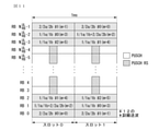
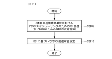
本発明の実施形態に係る無線通信システムにおいて端末(user equipment)がPDSCH(physical downlink shared channel)を受信する方法において、前記方法は、基地局から、n番目の送信時間単位(transmission time unit)における前記PDSCHをスケジューリングするための下向きリンク制御情報(downlink control information、DCI)を受信するステップと、前記DCIに基づいて、前記PDSCHの受信可否を決定するステップとを含み、前記DCIは、前記n番目の送信時間単位に前記PDSCHのためのDMRS(demodulation reference signal)が存在するか否かを表す情報を含むことができる。 In a method in which a terminal (user uplink) receives a PDSCH (physical downlink shared channel) in a wireless communication system according to an embodiment of the present invention, the method is described in the nth transmission time unit (transmission time unit) from a base station. The DCI includes a step of receiving downward link control information (downlink control information, DCI) for scheduling the PDSCH and a step of determining whether or not the PDSCH can be received based on the DCI, and the DCI is the nth position. Information indicating whether or not DMRS (demodulation reference signal) for the PDSCH exists in the transmission time unit of the above can be included.
また、本発明の実施形態に係る前記方法において、前記方法は、基地局から、n-1番目の送信時間単位における他の(another)PDSCHをスケジューリングするための他の(another)DCIを受信するステップをさらに含み、前記他のDCIは、前記n-1番目の送信時間単位に前記他のPDSCHのためのDMRSが存在するか否かを表す情報を含み、前記PDSCHの受信可否は、前記DCI及び前記他のDCIに基づいて決定されることができる。 Further, in the method according to the embodiment of the present invention, the method receives another (another) DCI for scheduling another (another) PDSCH in the n-1th transmission time unit from the base station. Further including a step, the other DCI includes information indicating whether or not a DMRS for the other PDSCH exists in the n-1th transmission time unit, and whether or not the PDSCH can be received is determined by the DCI. And can be determined based on the other DCI.
また、本発明の実施形態に係る前記方法において、(i)前記n番目の送信時間単位で前記PDSCHのためのDMRSの不在(absence)が前記DCIにより設定され、(ii)前記n-1番目の送信時間単位で前記他のPDSCHのためのDMRSの不在が前記他のDCIにより設定される場合、前記PDSCHは、前記端末により受信されないことができる。 Further, in the method according to the embodiment of the present invention, (i) the absence of DMRS for the PDSCH is set by the DCI in the nth transmission time unit, and (ii) the n-1th transmission time unit. When the absence of DMRS for the other PDSCH is set by the other DCI in units of transmission time, the PDSCH may not be received by the terminal.
また、本発明の実施形態に係る前記方法において、前記方法は、前記PDSCHが受信されなかった場合、予め定義された規則にしたがって前記PDSCHに対するHARQ-ACK情報を報告するステップをさらに含むことができる。 Further, in the method according to the embodiment of the present invention, the method can further include a step of reporting HARQ-ACK information for the PDSCH according to a predefined rule when the PDSCH is not received. ..
また、本発明の実施形態に係る前記方法において、前記方法は、基地局から、n-1番目の送信時間単位で他の(another)PDSCHのスケジューリングのための他のDCIを受信するステップをさらに含み、前記DCIは、前記n番目の送信時間単位における前記PDSCHのための資源割当情報を含み、前記他のDCIは、前記n-1番目の送信時間単位における前記他のPDSCHのための資源割当情報を含み、前記PDSCHの受信可否は、前記DCI及び前記他のDCIに基づいて決定されることができる。 Further, in the method according to the embodiment of the present invention, the method further includes a step of receiving another DCI for scheduling another PDSCH from the base station in the n-1th transmission time unit. The DCI includes resource allocation information for the PDSCH in the nth transmission time unit, and the other DCI includes resource allocation for the other PDSCH in the n-1th transmission time unit. Whether or not the PDSCH can be received, including information, can be determined based on the DCI and other DCIs.
また、本発明の実施形態に係る前記方法において、(i)前記n番目の送信時間単位で前記PDSCHのためのDMRSの不在(absence)が前記DCIにより設定され、(ii)前記n番目の送信時間単位における前記PDSCHのための資源割当情報が前記n-1番目の送信時間単位における前記他のPDSCHのための資源割当情報を含まない場合、前記PDSCHは、前記端末により受信されないことができる。 Further, in the method according to the embodiment of the present invention, (i) the absence of DMRS for the PDSCH is set by the DCI in the nth transmission time unit, and (ii) the nth transmission is performed. When the resource allocation information for the PDSCH in the time unit does not include the resource allocation information for the other PDSCH in the n-1th transmission time unit, the PDSCH may not be received by the terminal.
また、本発明の実施形態に係る前記方法において、前記方法は、前記PDSCHが受信されなかった場合、予め定義された規則にしたがって前記PDSCHに対するHARQ-ACK情報を報告するステップをさらに含むことができる。 Further, in the method according to the embodiment of the present invention, the method can further include a step of reporting HARQ-ACK information for the PDSCH according to a predefined rule when the PDSCH is not received. ..
また、本発明の実施形態に係る前記方法において、前記端末は、連続したサブフレームにわたって配置された送信時間単位でスケジューリングされるPDSCH間のDMRS共有(DMRS sharing)を支援しないことができる。 Further, in the method according to the embodiment of the present invention, the terminal may not support DMRS sharing (DMRS sharing) between PDSCHs scheduled in transmission time units arranged over consecutive subframes.
また、本発明の実施形態に係る前記方法において、(i)前記1番目のサブスロットで前記PDSCHのためのDMRSの不在(absence)が前記DCIにより設定され、(ii)前記n番目の送信時間単位は、特定サブフレーム(subframe)内での1番目のサブスロット(subslot)であれば、前記PDSCHは、前記端末により受信されないことができる。 Further, in the method according to the embodiment of the present invention, (i) the absence of DMRS for the PDSCH in the first subslot is set by the DCI, and (ii) the nth transmission time. If the unit is the first subslot in a specific subframe, the PDSCH may not be received by the terminal.
また、本発明の実施形態に係る前記方法において、前記方法は、前記PDSCHが受信されなかった場合、予め定義された規則にしたがって前記PDSCHに対するHARQ-ACK情報を報告するステップをさらに含むことができる。 Further, in the method according to the embodiment of the present invention, the method can further include a step of reporting HARQ-ACK information for the PDSCH according to a predefined rule when the PDSCH is not received. ..
また、本発明の実施形態に係る前記方法において、前記端末は、連続したサブフレームにわたって配置された送信時間単位でスケジューリングされる3-レイヤ(layer)以上のPDSCHに対するDMRS受信(DMRS reception)を支援しないことができる。 Further, in the method according to the embodiment of the present invention, the terminal supports DMRS reception for PDSCHs of 3-layer (layer) or higher scheduled in units of transmission time arranged over continuous subframes. Can not be.
また、本発明の実施形態に係る前記方法において、前記方法は、前記基地局から、n-1番目の送信時間単位で3-レイヤ以上の他の(another)PDSCHのための他の(another)DMRSを受信するステップをさらに含み、(i)前記n-1番目の送信時間単位は、m番目のサブフレーム(subframe)内での最後のサブスロット(subslot)であり、(ii)前記n番目の送信時間単位は、m+1番目のサブフレーム(subframe)内での1番目のサブスロット(subslot)であり、(iii)前記PDSCHが3-レイヤ以上のPDSCHである場合、前記DMRSは、前記端末により受信されないことができる。 Further, in the method according to the embodiment of the present invention, the method is another (another) for another (another) PDSCH having a 3-layer or higher in the n-1th transmission time unit from the base station. Further including the step of receiving the DMRS, (i) the n-1st transmission time unit is the last subslot in the mth subframe (subframe), and (ii) the nth. The transmission time unit of is the first subslot in the m + 1th subframe, and (iii) when the PDSCH is a PDSCH of 3-layer or higher, the DMRS is the terminal. Can not be received by.
また、本発明の実施形態に係る前記方法において、前記送信時間単位は、2つ以上のOFDM(Orthogonal Frequency Division Multiplexing)シンボル(symbol)を含むサブスロット(subslot)でありうる。 Further, in the method according to the embodiment of the present invention, the transmission time unit may be a subslot containing two or more OFDM (Orthogonal Frequency Division Multiplexing) symbols.
本発明の実施形態に係る無線通信システムにおいてPDSCH(physical downlink shared channel)を受信する端末(user equipment)において、前記端末は、無線信号を送受信するための送受信部と、前記送受信部と機能的に連結されているプロセッサとを備え、前記プロセッサは、前記送受信部を利用して、基地局から、n番目の送信時間単位(transmission time unit)における前記PDSCHをスケジューリングするための下向きリンク制御情報(downlink control information、DCI)を受信し、前記DCIに基づいて、前記PDSCHの受信可否を決定するように制御し、前記DCIは、前記n番目の送信時間単位に前記PDSCHのためのDMRS(demodulation reference signal)が存在するか否かを表す情報を含むことができる。 In a terminal (user uplink) that receives a PDSCH (physical downlink shared channel) in the wireless communication system according to the embodiment of the present invention, the terminal functionally includes a transmission / reception unit for transmitting / receiving a radio signal and the transmission / reception unit. The processor includes a connected processor, and the processor utilizes the transmission / reception unit to schedule the PDSCH in the nth transmission time unit (transmission time unit) from the base station. Downlink control information (downlink). Control information (DCI) is received and controlled to determine whether or not the PDSCH can be received based on the DCI, and the DCI is a DMRS (demodulation reference signal) for the PDSCH in the nth transmission time unit. ) Can include information indicating whether or not it exists.
本発明の実施形態に係る無線通信システムにおいてPDSCH(physical downlink shared channel)を送信する基地局(base station)において、前記基地局は、無線信号を送受信するための送受信部と、前記送受信部と機能的に連結されているプロセッサとを備え、前記プロセッサは、前記送受信部を利用して、端末に、n番目の送信時間単位(transmission time unit)における前記PDSCHをスケジューリングするための下向きリンク制御情報(downlink control information、DCI)を送信し、前記DCIに基づいて、前記PDSCHの送信可否を決定するように制御し、前記DCIは、前記n番目の送信時間単位に前記PDSCHのためのDMRS(demodulation reference signal)が存在するか否かを表す情報を含むことができる。 In a base station that transmits a PDSCH (physical downlink shared channel) in a wireless communication system according to an embodiment of the present invention, the base station has a transmission / reception unit for transmitting / receiving a radio signal, and a transmission / reception unit and a function thereof. The processor comprises a processor that is connected to the terminal, and the processor utilizes the transmission / reception unit to schedule the PDSCH in the nth transmission time unit (transmission time unit) to the terminal. A weaklink control information (DCI) is transmitted, and the DCI is controlled to determine whether or not the PDSCH can be transmitted, and the DCI controls the DMRS (demodulation reference) for the PDSCH in the nth transmission time unit. Information indicating whether or not a signal) exists can be included.
本明細書の実施形態によれば、DMRS共有(DMRS sharing)と関連した端末の動作を明確化して、DCIなどにより指示されるDMRS不在または存在の場合に発生され得る端末動作の曖昧性(ambiguity)が除去され得るという効果がある。 According to the embodiments of the present specification, the operation of the terminal associated with DMRS sharing is clarified, and the ambiguity of the terminal operation that can occur in the absence or existence of DMRS indicated by DCI or the like is defined. ) Can be removed.
また、本明細書の実施形態によれば、DMRS繰り返し(DMRS repetition)と関連した端末の動作を明確化して、3-レイヤ以上のPDSCHに対する動作を可能なようにしたり、及び/又はデータレート(data rate)の減少を防止できるという効果がある。 Further, according to the embodiment of the present specification, the operation of the terminal related to DMRS repetition is clarified so that the operation for PDSCH of 3 layers or higher is possible, and / or the data rate ( It has the effect of preventing a decrease in data rate).
本明細書において得ることができる効果は以上で言及した効果に制限されず、言及しないまた別の効果は以下の記載から本発明が属する技術分野で通常の知識を有する者に明確に理解できるはずである。 The effects that can be obtained herein are not limited to the effects mentioned above, and other effects not mentioned above should be clearly understood by those who have ordinary knowledge in the technical field to which the present invention belongs from the following description. Is.
本発明に関する理解を助けるために詳細な説明の一部に含まれる添付図面は本発明に対する実施形態を提供し、詳細な説明と共に本発明の技術的特徴を説明する。 The accompanying drawings included in part of the detailed description to aid in understanding of the invention provide embodiments to the invention and illustrate the technical features of the invention with the detailed description.
以下、本発明にかかる好ましい実施の形態を添付された図面を参照して詳細に説明する。添付された図面と共に以下に開示する詳細な説明は、本発明の例示的な実施の形態を説明するためのものであり、本発明が実施されうる唯一の実施の形態を示すためのものではない。以下の詳細な説明は、本発明の完全な理解を提供するために具体的細部事項を含む。しかしながら、当業者は、本発明がこのような具体的細部事項がなくても実施できることを理解すべきである。 Hereinafter, preferred embodiments of the present invention will be described in detail with reference to the accompanying drawings. The detailed description disclosed below, along with the accompanying drawings, is intended to illustrate exemplary embodiments of the invention and is not intended to indicate the only embodiment in which the invention can be practiced. .. The following detailed description includes specific details to provide a complete understanding of the invention. However, one of ordinary skill in the art should understand that the present invention can be practiced without such specific details.
いくつかの場合、本発明の概念が曖昧になることを避けるために、公知の構造及び装置は省略されるか、または各構造及び装置の核心機能を中心にしたブロック図形式で示されることができる。 In some cases, known structures and devices may be omitted or shown in block diagram format centered on the core functions of each structure and device to avoid obscuring the concepts of the invention. can.
本明細書において、基地局は端末と直接的に通信を遂行するネットワークの終端ノード(terminal node)としての意味を有する。本文書で基地局により行われるものとして説明された特定動作は、場合によっては、基地局の上位ノード(upper node)により行われることもできる。即ち、基地局を含む複数のネットワークノード(network nodes)からなるネットワークで端末との通信のために行われる様々な動作は基地局または基地局以外の他のネットワークノードにより行われることができることは自明である。「基地局(BS:Base Station)」は固定局(fixed station)、Node B、eNB(evolved-Node B)、BTS(base transceiver system)、アクセスポイント(AP:Access Point)などの用語により代替できる。また、「端末(Terminal)」は固定されるか、または移動性を有することができ、UE(User Equipment)、MS(Mobile Station)、UT(user terminal)、MSS(Mobile Subscriber Station)、SS(Subscriber Station)、AMS(Advanced Mobile Station)、WT(Wireless terminal)、MTC(Machine-Type Communication)装置、M2M(Machine-to-Machine)装置、D2D(Device-to-Device)装置などの用語に代替できる。 In the present specification, the base station has a meaning as a terminal node of a network that directly performs communication with a terminal. In some cases, the specific operation described as being performed by the base station in this document may also be performed by an upper node of the base station. That is, it is self-evident that various operations performed for communication with a terminal in a network consisting of a plurality of network nodes including a base station can be performed by the base station or a network node other than the base station. Is. "Base station (BS)" can be replaced by terms such as fixed station (fixed station), Node B, eNB (evolved-Node B), BTS (base transceiver system), and access point (AP: Access Point). .. In addition, the "terminal" can be fixed or mobile, and can be UE (User Appliance), MS (Machine Station), UT (user terminal), MSS (Mobile Subscriber Station), SS ( Subscriber Station), AMS (Advanced Mobile Station), WT (Wireless Terminal), MTC (Machine-Type Communication) device, M2M (Machine-to-Machine) device, M2M (Machine-to-Machine) device, D2D (D2D-to-Machine) device, etc. can.
以下、下向きリンク(DL:downlink)は基地局から端末への通信を意味し、上向きリンク(UL:uplink)は端末から基地局への通信を意味する。下向きリンクで、送信機は基地局の一部であり、受信機は端末の一部でありうる。上向きリンクで、送信機は端末の一部であり、受信機は基地局の一部でありうる。 Hereinafter, the downward link (DL: downlink) means the communication from the base station to the terminal, and the upward link (UL: uplink) means the communication from the terminal to the base station. With a downward link, the transmitter can be part of the base station and the receiver can be part of the terminal. With an upward link, the transmitter can be part of the terminal and the receiver can be part of the base station.
以下の説明において用いられる特定用語は、本発明の理解に役立つために提供されたものであり、このような特定用語の使用は、本発明の技術的思想から外れない範囲内で他の形態に変更されることができる。 The specific terms used in the following description are provided to aid in the understanding of the present invention, and the use of such specific terms may be used in other forms within the scope of the technical idea of the present invention. Can be changed.
以下の技術は、CDMA(code division multiple access)、FDMA(frequency division multiple access)、TDMA(time division multiple access)、OFDMA(orthogonal frequency division multiple access)、SC-FDMA(single carrier frequency division multiple access)、NOMA(non-orthogonal multiple access)などのような様々な無線接続システムに用いられることができる。CDMAは、UTRA(universal terrestrial radio access)またはCDMA2000のような無線技術(radio technology)により実現化されることができる。TDMAは、GSM(global system for mobile communications)/GPRS(general packet radio service)/EDGE(enhanced data rates for GSM evolution)のような無線技術により実現化されることができる。OFDMAは、IEEE 802.11(Wi-Fi)、IEEE 802.16(WiMAX)、IEEE 802-20、E-UTRA(evolved UTRA)などのような無線技術により実現化されることができる。UTRAは、UMTS(universal mobile telecommunications system)の一部である。3GPP(3rd generation partnership project)LTE(long term evolution)は、E-UTRAを使用するE-UMTS(evolved UMTS)の一部であり、下向きリンクにおいてOFDMAを採用し、上向きリンクにおいてSC-FDMAを採用する。LTE-A(advanced)は、3GPP LTEの進化である。 The following technologies, CDMA (code division multiple access), FDMA (frequency division multiple access), TDMA (time division multiple access), OFDMA (orthogonal frequency division multiple access), SC-FDMA (single carrier frequency division multiple access), It can be used in various wireless connection systems such as NOMA (non-orthogonal multiple access). CDMA can be realized by radio technology (radio technology) such as UTRA (universal terrestrial radio access) or CDMA2000. TDMA is a wireless technology that can be realized by GSM (global system for mobile communications) / GPRS (general packet radio service) / EDGE (enhanced data rates for GSM evolution). OFDMA can be realized by wireless technologies such as IEEE 802.11 (Wi-Fi), IEEE 802.16 (WiMAX), IEEE 802-20, E-UTRA (evolved UTRA), and the like. UTRA is part of UMTS (universal mobile telecommunications system). 3GPP (3rd generation partitionship project) LTE (long term evolution) is a part of E-UMTS (evolved UMTS) that uses E-UTRA, adopts OFDMA in the downward link, and SC-FDMA in the upward link. do. LTE-A (advanced) is an evolution of 3GPP LTE.
本発明の実施形態は、無線アクセスシステムであるIEEE 802、3GPP及び3GPP2のうち、少なくとも1つに開示された標準文書により裏付けられることができる。即ち、本発明の実施形態のうち、本発明の技術的思想を明確にあらわすために、説明しないステップまたは部分は、前記文書により裏付けられることができる。また、本文書に開示しているすべての用語は、前記標準文書により説明されることができる。 Embodiments of the present invention can be supported by standard documents disclosed in at least one of the wireless access systems IEEE 802, 3GPP and 3GPP2. That is, in the embodiments of the present invention, steps or parts not described may be supported by the above documents in order to clearly express the technical idea of the present invention. In addition, all terms disclosed in this document can be explained by the standard document.
説明を明確にするために、3GPP LTE/LTE-A/NRシステムを中心に述べるが、本発明の技術的特徴がこれに制限されるわけではない。 For the sake of clarity, the 3GPP LTE / LTE-A / NR system will be mainly described, but the technical features of the present invention are not limited thereto.
システム一般 System in general
図1は、本発明が適用できる無線通信システムにおける無線フレームの構造を示す。 FIG. 1 shows the structure of a wireless frame in a wireless communication system to which the present invention can be applied.
3GPP LTE/LTE-AではFDD(Frequency Division Duplex)に適用可能なタイプ1の無線フレーム(radio frame)の構造とTDD(Time Division Duplex)に適用可能なタイプ2の無線フレームの構造を支援する。
3GPP LTE / LTE-A supports a
図1で、無線フレームの時間領域でのサイズはT_s=1/(15000*2048)の時間単位の倍数で表現される。下向きリンク及び上向きリンク送信はT_f=307200*T_s=10msの区間を有する無線フレームで構成される。 In FIG. 1, the size of the radio frame in the time domain is expressed as a multiple of the time unit of T_s = 1 / (15000 * 2048). The downward link and the upward link transmission are composed of radio frames having a section of T_f = 307200 * T_s = 10 ms.
図1の(a)は、タイプ1の無線フレームの構造を例示する。タイプ1の無線フレームは、全二重(full duplex)及び半二重(half duplex)FDDに全て適用できる。
FIG. 1A exemplifies the structure of a
無線フレーム(radio frame)は10個のサブフレーム(subframe)から構成される。1つの無線フレームはT_slot=15360*T_s=0.5ms長さの20個のスロットから構成され、各スロットは0から19までのインデックスが与えられる。1つのサブフレームは時間領域(time domain)で連続的な2つのスロット(slot)から構成され、サブフレームiはスロット2i及びスロット2i+1で構成される。1つのサブフレームを送信するのにかかる時間をTTI(transmission time interval)という。例えば、1つのサブフレームの長さは1msであり、1つのスロットの長さは0.5msでありうる。 A radio frame is composed of 10 subframes. One radio frame is composed of 20 slots having a length of T_slot = 15360 * T_s = 0.5 ms, and each slot is given an index from 0 to 19. One subframe is composed of two consecutive slots in the time domain, and the subframe i is composed of slot 2i and slot 2i + 1. The time required to transmit one subframe is called TTI (transmission time interval). For example, the length of one subframe can be 1 ms and the length of one slot can be 0.5 ms.
FDDで上向きリンク送信及び下向きリンク送信は、周波数ドメインで区分される。全二重FDDに制限がないのに対し、半二重FDD動作で端末は同時に送信及び受信をすることができない。 In FDD, upward link transmission and downward link transmission are classified by frequency domain. While there are no restrictions on full-duplex FDD, the terminal cannot transmit and receive at the same time in half-duplex FDD operation.
1つのスロットは時間領域で複数のOFDM(orthogonal frequency division multiplexing)シンボルを含み、周波数領域で複数の資源ブロック(RB:Resource Block)を含む。3GPP LTEは下向きリンクでOFDMAを使用するのでOFDMシンボルは1つのシンボル区間(symbol period)を表現するためのものである。OFDMシンボルは1つのSC-FDMAシンボルまたはシンボル区間ということができる。資源ブロック(resource block)は資源割り当て単位であり、1つのスロットで複数の連続的な副搬送波(subcarrier)を含む。 One slot contains a plurality of OFDM (orthogonal frequency multiplexing) symbols in the time domain and a plurality of resource blocks (RBs) in the frequency domain. Since 3GPP LTE uses OFDMA on the downward link, the OFDM symbol is for expressing one symbol interval (symbol period). The OFDM symbol can be said to be one SC-FDMA symbol or a symbol interval. A resource block is a resource allocation unit and includes a plurality of continuous subcarriers in one slot.
図1の(b)は、タイプ2フレーム構造(frame structure type2)を示す。
FIG. 1B shows a
タイプ2の無線フレームは、各153600*T_s=5msの長さの2つのハーフフレーム(half frame)から構成される。各ハーフフレームは30720*T_s=1ms長さの5個のサブフレームから構成される。
A
TDDシステムのタイプ2のフレーム構造で上向きリンク-下向きリンク構成(uplink-downlink configuration)は全てのサブフレームに対して上向きリンクと下向きリンクが割り当て(または、予約)されるかを示す規則である。
In the
表1は、上向きリンク-下向きリンク構成を示す。 Table 1 shows an upward link-downward link configuration.

表1を参照すると、無線フレームの各サブフレーム別に、‘D’は下向きリンク送信のためのサブフレームを示し、‘U’は上向きリンク送信のためのサブフレームを示し、‘S’はDwPTS(Downlink Pilot Time Slot)、保護区間(GP:Guard Period)、UpPTS(Uplink Pilot Time Slot)の3種類のフィールドから構成されるスペシャルサブフレーム(special subframe)を示す。DwPTSは、端末での初期セル探索、同期化、またはチャネル推定に使われる。UpPTSは、基地局でのチャネル推定と端末の上向きリンク送信同期を合せるのに使われる。GPは、上向きリンクと下向きリンクの間に下向きリンク信号の多重経路遅延によって上向きリンクで生じる干渉を除去するための区間である。 Referring to Table 1, for each subframe of the radio frame,'D' indicates a subframe for downward link transmission,'U' indicates a subframe for upward link transmission, and'S' indicates DwPTS ( A special subframe composed of three types of fields: Downlink Pilot Time Slot), protected section (GP: Guard Period), and UpPTS (Uplink Pilot Time Slot) is shown. DwPTS is used for initial cell search, synchronization, or channel estimation at the terminal. UpPTS is used to match channel estimation at the base station with upward link transmission synchronization at the terminal. The GP is a section for removing the interference caused by the upward link due to the multiple path delay of the downward link signal between the upward link and the downward link.
各サブフレームiは、各T_slot=15360*T_s=0.5ms長さのスロット2i及びスロット2i+1で構成される。 Each subframe i is composed of a slot 2i and a slot 2i + 1 having a length of each T_slot = 15360 * T_s = 0.5 ms.
上向きリンク-下向きリンク構成は7種類に区分されることができ、各構成別に下向きリンクサブフレーム、スペシャルサブフレーム、上向きリンクサブフレームの位置及び/又は個数が異なる。 The upward link-downward link configuration can be divided into seven types, and the positions and / or numbers of the downward link subframe, the special subframe, and the upward link subframe are different for each configuration.
下向きリンクから上向きリンクに変更される時点、または上向きリンクから下向きリンクに切り換えられる時点を切換時点(switching point)という。切換時点の周期性(Switch-point periodicity)は上向きリンクサブフレームと下向きリンクサブフレームが切り換えられる様相が同一に繰り返される周期を意味し、5msまたは10msが全て支援される。5ms下向きリンク-上向きリンク切換時点の周期を有する場合には、スペシャルサブフレーム(S)はハーフ-フレーム毎に存在し、5msの下向きリンク-上向きリンク切換時点の周期を有する場合には最初のハーフ-フレームのみに存在する。 The time point at which the downward link is changed to the upward link or the time point at which the upward link is switched to the downward link is referred to as a switching point. The periodicity at the time of switching means a cycle in which the upward link subframe and the downward link subframe are switched in the same manner, and 5 ms or 10 ms are all supported. A special subframe (S) exists for each half-frame when it has a period of 5 ms downward link-upward link switching, and the first half when it has a 5 ms downward link-upward link switching period. -Present only in the frame.
全ての構成において、0番、5番サブフレーム、及びDwPTSは、下向きリンク送信のみのための区間である。UpPTS及びサブフレームサブフレームに直ぐ繋がるサブフレームは常に上向きリンク送信のための区間である。 In all configurations, the 0th and 5th subframes and DwPTS are sections for downward link transmission only. UpPTS and subframes Subframes that are directly connected to subframes are always sections for upward link transmission.
このような上向きリンク-下向きリンク構成は、システム情報として基地局と端末が全て知っていることができる。基地局は上向きリンク-下向きリンク構成情報が変わる度に構成情報のインデックスのみを送信することによって、無線フレームの上向きリンク-下向きリンク割り当て状態の変更を端末に知らせることができる。また、構成情報は一種の下向きリンク制御情報として他のスケジューリング情報と同様にPDCCH(Physical Downlink Control Channel)を通じて送信されることができ、放送情報としてブロードキャストチャネル(broadcast channel)を介してセル内の全ての端末に共通に送信されることもできる。 Such an upward link-downward link configuration can be known by the base station and the terminal as system information. The base station can notify the terminal of the change in the upward link-downward link allocation state of the wireless frame by transmitting only the index of the configuration information each time the upward link-downward link configuration information changes. Further, the configuration information can be transmitted as a kind of downward link control information through the PDCCH (Physical Downlink Control Channel) like other scheduling information, and as broadcast information, all in the cell via the broadcast channel (broadcast channel). It can also be sent to all terminals in common.
表2は、スペシャルサブフレームの構成(DwPTS/GP/UpPTSの長さ)を示す。 Table 2 shows the configuration of the special subframe (length of DwPTS / GP / UpPTS).

図1の例示に従う無線フレームの構造は1つの例示に過ぎず、無線フレームに含まれる副搬送波の数またはサブフレームに含まれるスロットの数、スロットに含まれるOFDMシンボルの数は様々に変更できる。 The structure of the radio frame according to the example of FIG. 1 is only one example, and the number of subcarriers included in the radio frame, the number of slots included in the subframe, and the number of OFDM symbols contained in the slots can be variously changed.
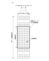
図2は、本発明が適用できる無線通信システムにおける1つの下向きリンクスロットに対する資源グリッド(resource grid)を例示した図である。 FIG. 2 is a diagram illustrating a resource grid for one downward link slot in a wireless communication system to which the present invention can be applied.
図2を参照すると、1つの下向きリンクスロットは時間領域で複数のOFDMシンボルを含む。ここで、1つの下向きリンクスロットは7個のOFDMシンボルを含み、1つの資源ブロックは周波数領域で12個の副搬送波を含むことを例示的に記述するが、これに限定されるものではない。 Referring to FIG. 2, one downward link slot contains a plurality of OFDM symbols in the time domain. Here, it is exemplified, but not limited to, that one downward link slot contains 7 OFDM symbols and one resource block contains 12 subcarriers in the frequency domain.
資源グリッド上で各要素(element)を資源要素(resource element)といい、1つの資源ブロック(RB:resource block)は12×7個の資源要素を含む。下向きリンクスロットに含まれる資源ブロックの数NDLは下向きリンク送信帯域幅(bandwidth)に従属する。 Each element on the resource grid is called a resource element, and one resource block (RB: resource block) contains 12 × 7 resource elements. The number of resource blocks contained in the downward link slot NDL is dependent on the downward link transmit bandwidth (bandwidth).
上向きリンクスロットの構造は下向きリンクスロットの構造と同一でありうる。 The structure of the upward link slot can be the same as the structure of the downward link slot.
図3は、本発明が適用できる無線通信システムにおける下向きリンクサブフレームの構造を示す。 FIG. 3 shows the structure of a downward link subframe in a wireless communication system to which the present invention can be applied.
図3を参照すると、サブフレーム内の一番目のスロットで前の最大3個のOFDMシンボルは制御チャネルが割り当てられる制御領域(control region)であり、残りのOFDMシンボルはPDSCH(Physical Downlink Shared Channel)が割り当てられるデータ領域(data region)である。3GPP LTEで使われる下向きリンク制御チャネルの一例として、PCFICH(Physical Control Format Indicator Channel)、PDCCH(Physical Downlink Control Channel)、PHICH(Physical Hybrid-ARQ Indicator Channel)などがある。 Referring to FIG. 3, in the first slot in the subframe, the previous maximum three OFDM symbols are the control region to which the control channel is allocated, and the remaining OFDM symbols are PDSCH (Physical Downlink Shared Channel). Is a data region to which is allocated. Examples of the downward link control channel used in 3GPP LTE include PCFICH (Physical Control Forum Indicator Channel), PDCCH (Physical Downlink Control Channel), PHICH (Physical Standard Channel), and PHICH (Physical Hybrid).
PCFICHは、サブフレームの一番目のOFDMシンボルで送信され、サブフレーム内に制御チャネルの送信のために使われるOFDMシンボルの数(即ち、制御領域のサイズ)に関する情報を運ぶ。PHICHは上向きリンクに対する応答チャネルであり、HARQ(Hybrid Automatic Repeat Request)に対するACK(Acknowledgement)/NACK(Not-Acknowledgement)信号を運ぶ。PDCCHを介して送信される制御情報を下向きリンク制御情報(DCI:downlink control information)という。下向きリンク制御情報は、上向きリンク資源割り当て情報、下向きリンク資源割り当て情報、または任意の端末グループに対する上向きリンク送信(Tx)パワー制御命令を含む。 The PCFICH carries information about the number of OFDM symbols (ie, the size of the control area) transmitted in the first OFDM symbol of the subframe and used for transmission of the control channel within the subframe. PHICH is a response channel for an upward link and carries an ACK (Acknowledgedgement) / NACK (Not-Acknowledgement) signal for HARQ (Hybrid Automatic Repeat Request). The control information transmitted via the PDCCH is referred to as downward link control information (DCI: downlink control information). The downward link control information includes upward link resource allocation information, downward link resource allocation information, or an upward link transmission (Tx) power control instruction for any terminal group.
PDCCHはDL-SCH(Downlink Shared Channel)の資源割り当て及び送信フォーマット(これを下向きリンクグラントともいう。)、UL-SCH(Uplink Shared Channel)の資源割り当て情報(これを上向きリンクグラントともいう。)、PCH(Paging Channel)でのページング(paging)情報、DL-SCHでのシステム情報、PDSCHで送信されるランダムアクセス応答(random access response)のような上位層(upper-layer)制御メッセージに対する資源割り当て、任意の端末グループ内の個別端末に対する送信パワー制御命令の集合、VoIP(Voice over IP)の活性化などを運ぶことができる。複数のPDCCHは制御領域内で送信されることができ、端末は複数のPDCCHをモニタリングすることができる。PDCCHは1つまたは複数の連続的なCCE(control channel elements)の集合で構成される。CCEは無線チャネルの状態に従う符号化率(coding rate)をPDCCHに提供するために使われる論理的割り当て単位である。CCEは複数の資源要素グループ(resource element group)に対応する。PDCCHのフォーマット及び使用可能なPDCCHのビット数はCCEの数とCCEにより提供される符号化率の間の関連関係によって決定される。 PDCCH is a DL-SCH (Downlink Shared Channel) resource allocation and transmission format (also referred to as a downward link grant), UL-SCH (Uplink Shared Channel) resource allocation information (this is also referred to as an upward link grant), and a resource allocation information. Resource allocation for upper-layer control messages such as paging information on PCH (Paging Channel), system information on DL-SCH, and random access response transmitted by PDSCH, It can carry a set of transmission power control instructions for individual terminals in any terminal group, activation of VoIP (Voice over IP), and the like. Multiple PDCCHs can be transmitted within the control area and the terminal can monitor multiple PDCCHs. PDCCH is composed of a set of one or more continuous CCEs (control channel elements). CCE is a logical allocation unit used to provide the PDCCH with a coding rate according to the state of the radio channel. CCE corresponds to multiple resource element groups. The format of the PDCCH and the number of bits of the PDCCH that can be used are determined by the relationship between the number of CCEs and the code rate provided by the CCEs.
基地局は端末に送信しようとするDCIによってPDCCHのフォーマットを決定し、制御情報にCRC(Cyclic Redundancy Check)を付ける。CRCにはPDCCHの所有者(owner)や用途によって固有の識別子(これをRNTI(Radio Network Temporary Identifier)という。)がマスキングされる。特定の端末のためのPDCCHであれば、端末固有の識別子、例えばC-RNTI(Cell-RNTI)がCRCにマスキングできる。または、ページングメッセージのためのPDCCHであれば、ページング指示識別子、例えばP-RNTI(Paging-RNTI)がCRCにマスキングできる。システム情報、より具体的にシステム情報ブロック(SIB:system information block)のためのPDCCHであれば、システム情報識別子、SI-RNTI(system information RNTI)がCRCにマスキングできる。端末のランダムアクセスプリアンブルの送信に対する応答であるランダムアクセス応答を指示するために、RA-RNTI(random access-RNTI)がCRCにマスキングできる。 The base station determines the format of the PDCCH by the DCI to be transmitted to the terminal, and attaches a CRC (Cyclic Redundancy Check) to the control information. A unique identifier (this is called RNTI (Radio Network Strength Identity)) is masked in the CRC depending on the owner of the PDCCH and the purpose of use. If it is a PDCCH for a specific terminal, a terminal-specific identifier, for example, C-RNTI (Cell-RNTI) can be masked to CRC. Alternatively, if it is a PDCCH for a paging message, a paging instruction identifier, for example, P-RNTI (Paging-RNTI) can be masked to CRC. If it is a PDCCH for system information, more specifically, a system information block (SIB), the system information identifier, SI-RNTI (system information RNTI), can be masked on the CRC. RA-RNTI (random access-RNTI) can mask the CRC to indicate a random access response, which is the response to the transmission of the terminal's random access preamble.
EPDCCH(enhanced PDCCH)は、端末特定(UE-specific)のシグナリングを運ぶ。EPDCCHは、端末特定的に設定された物理資源ブロック(PRB:physical resource block)に位置する。言い換えると、前述したように、PDCCHはサブフレーム内の一番目のスロットで以前の最大3個のOFDMシンボルで送信されることができるが、EPDCCHはPDCCH以外の資源領域で送信されることができる。サブフレーム内EPDCCHが開始される時点(即ち、シンボル)は、上位層のシグナリング(例えば、RRCシグナリング等)を介して端末に設定されることができる。 EPDCCH (enhanced PDCCH) carries signal for terminal identification (UE-specific). The EPDCCH is located in a physical resource block (PRB) specifically set for the terminal. In other words, as mentioned above, the PDCCH can be transmitted in the first slot in the subframe with up to three previous OFDM symbols, while the EPDCCH can be transmitted in a resource area other than the PDCCH. .. The time point at which the intra-subframe EPDCCH is initiated (ie, the symbol) can be set at the terminal via higher layer signaling (eg, RRC signaling, etc.).
EPDCCHは、DL-SCHと関連した送信フォーマット、資源割り当て及びHARQ情報、UL-SCHと関連した送信フォーマット、資源割り当て及びHARQ情報、SL-SCH(Sidelink Shared Channel)及びPSCCH(Physical Sidelink Control Channel)と関連した資源割り当て情報等を運ぶことができる。多重のEPDCCHが支援されることができ、端末はEPCCHのセットをモニタリングすることができる。 EPDCCH includes transmission format, resource allocation and HARQ information related to DL-SCH, transmission format, resource allocation and HARQ information related to UL-SCH, SL-SCH (Sidelink Shared Channel) and PSCCH (Physical Sidelink Control Channel). It can carry related resource allocation information, etc. Multiple EPDCCHs can be assisted and the terminal can monitor a set of EPCCHs.
EPDCCHは、1つまたそれ以上の連続した進歩したCCE(ECCE:enhanced CCE)を用いて送信されることができ、各EPDCCHフォーマット別に単一のEPDCCH当たりのECCEの個数が決められることができる。 The EPDCCH can be transmitted using one or more continuous advanced CCEs (ECCEs: enhanced CCEs), and the number of ECCEs per single EPDCCH can be determined for each EPDCCH format.
各ECCEは、複数の資源要素グループ(EREG:enhanced resource element group)で構成されることができる。EREGは、ECCEのREへのマッピングを定義するために使用される。PRB対別に16個のEREGが存在する。各PRB対内でDMRSを運ぶREを除き、全てのREは、周波数が増加する順にその次の時間が増加する順に0乃至15までの番号が付与される。 Each ECCE can be composed of a plurality of resource element groups (EREG: enhanced resource element group). ERREG is used to define the mapping of ECCE to RE. There are 16 EREGs for each PRB. Except for REs that carry DMRS within each PRB pair, all REs are numbered from 0 to 15 in order of increasing frequency and then increasing in time.
端末は、複数のEPDCCHをモニタリングすることができる。例えば、端末がEPDCCH送信をモニタリングする1つのPRB対内の1つ又は二つのEPDCCHセットが設定されることができる。 The terminal can monitor multiple EPDCCHs. For example, one or two EPDCCH sets within one PRB pair in which the terminal monitors EPDCCH transmission can be configured.
互いに異なる個数のECCEが併合されることによって、EPCCHのための互いに異なる符号化率(coding rate)が実現できる。EPCCHは、地域的送信(localized transmission)又は分散的送信(distributed transmission)を使用することができ、これによってPRB内REにECCEのマッピングが変わり得る。 By merging different numbers of ECCEs, different coding rates for EPCCH can be realized. The EPCCH can use localized transmission or distributed transmission, which can change the ECCE mapping to RE within the PRB.
図4は、本発明が適用できる無線通信システムにおける上向きリンクサブフレームの構造を示す。 FIG. 4 shows the structure of an upward link subframe in a wireless communication system to which the present invention can be applied.
図4を参照すると、上向きリンクサブフレームは周波数領域で制御領域とデータ領域とに分けられる。制御領域には上向きリンク制御情報を運ぶPUCCH(Physical Uplink Control Channel)が割り当てられる。データ領域はユーザデータを運ぶPUSCH(Physical Uplink Shared Channel)が割り当てられる。単一搬送波の特性を維持するために1つの端末はPUCCHとPUSCHを同時に送信しない。 Referring to FIG. 4, the upward link subframe is divided into a control area and a data area in the frequency domain. A PUCCH (Physical Uplink Control Channel) that carries upward link control information is assigned to the control area. A PUSCH (Physical Uplink Shared Channel) that carries user data is assigned to the data area. To maintain the characteristics of a single carrier, one terminal does not transmit PUCCH and PUSCH at the same time.
1つの端末に対するPUCCHにはサブフレーム内に資源ブロック(RB:Resource Block)対が割り当てられる。RB対に属するRBは2つのスロットの各々で互いに異なる副搬送波を占める。これをPUCCHに割り当てられたRB対はスロット境界(slot boundary)で周波数跳躍(frequency hopping)されるという。 A resource block (RB: Resource Block) pair is assigned to the PUCCH for one terminal in a subframe. The RBs belonging to the RB pair occupy different subcarriers in each of the two slots. It is said that the RB pair assigned to the PUCCH is frequency-popped at the slot boundary.
また、以下、本明細書において提案する発明は、LTE/LTE-Aシステム(又は、装置)だけでなく、5G NRシステム(又は、装置)にも適用できる。 Further, the invention proposed herein can be applied not only to an LTE / LTE-A system (or an apparatus) but also to a 5G NR system (or an apparatus).
以下、図5乃至図10を参考し、5G NRシステムの通信について説明する。 Hereinafter, the communication of the 5G NR system will be described with reference to FIGS. 5 to 10.
5G NRシステムは、使用シナリオ(usage scenario)(例:サービス類型)によってeMBB(enhanced Mobile Broadband)、mMTC(massive Machine Type Communications)、URLLC(Ultra-Reliable and Low Latency Communications)、V2X(vehicle-to-everything)を定義する。 The 5G NR system is equipped with eMBB (enhanced Mobile Broadband), mMTC (massive Machine Type Communications), URLLC (Ultra-Relay) Everything) is defined.
また、5G NRの規格(standard)は、NRシステムとLTEシステム間の共存(co-existence)によって、スタンドアローン(SA)と非スタンドアローン(NSA)とに区分する。 In addition, the 5G NR standard (standard) is divided into stand-alone (SA) and non-stand-alone (NSA) according to the co-existence between the NR system and the LTE system.
また、5G NRシステムは、様々なサブキャリア間隔(subcarrier spacing)を支援し、下向きリンクでCP-OFDMを、上向きリンクでCP-OFDM及びDFT-s-OFDM(SC-OFDM)を支援する。 The 5G NR system also supports various subcarrier spacings, supporting CP-OFDM on downward links and CP-OFDM and DFT-s-OFDM (SC-OFDM) on upward links.
本発明の実施形態は、無線接続システムであるIEEE 802、3GPP及び3GPP2の少なくとも1つに開示された標準文書によって裏付けられることができる。即ち、本発明の実施形態のうち、本発明の技術的思想を明確に示すために、説明しない段階又は部分は、前記文書によって裏付けられることができる。また、本文書で開示している全ての用語は、前記標準文書によって説明されることができる。 Embodiments of the invention can be supported by standard documents disclosed in at least one of the wireless connection systems IEEE 802, 3GPP and 3GPP2. That is, in the embodiments of the present invention, unexplained steps or parts can be supported by the above documents in order to clearly show the technical idea of the present invention. In addition, all terms disclosed in this document can be explained by the standard document.
スマートフォン(smartphone)及びIoT(Internet Of Things)端末の普及が速く拡散されるにしたがって、通信網を介してやり取りする情報の量が増加している。これによって、次世代無線アクセス技術では、既存の通信システム(又は既存の無線アクセス技術(radio access technology))より、さらに多くのユーザにさらに早いサービスを提供する環境(例:向上した移動広帯域通信(enhanced mobile broadband communication))が考慮される必要がある。 As the spread of smartphones (smartphones) and IoT (Internet Of Things) terminals has spread rapidly, the amount of information exchanged via communication networks has increased. As a result, in next-generation wireless access technology, an environment that provides faster services to more users than existing communication systems (or existing radio access technology) (eg, improved mobile broadband communication (eg, improved mobile broadband communication). enhanced mobile broadband communication)) needs to be considered.
このため、複数の機器及び物(object)を連結してサービスを提供するMTC(Machine Type Communication)を考慮する通信システムのデザインが議論されている。また、通信の信頼性(reliability)及び/又は遅延(latency)に敏感なサービス(service)及び/又は端末(terminal)等を考慮する通信システム(例:URLLC(Ultra-Reliable and Low Latency Communication)のデザインも議論されている。 Therefore, the design of a communication system considering MTC (Machine Type Communication) that provides a service by connecting a plurality of devices and objects is being discussed. In addition, a communication system (eg, URLLC (Ultra-Reliable and Low Latency Communication)) that considers a service and / or a terminal that is sensitive to communication reliability and / or latency. Design is also being discussed.
以下、本明細書において、説明の都合のために、前記次世代無線アクセス技術は、NR(New RAT、Radio Access Technology)と称され、前記NRが適用される無線通信システムはNRシステムと称される。 Hereinafter, in the present specification, for convenience of explanation, the next-generation radio access technology is referred to as NR (New RAT, Radio Access Technology), and the radio communication system to which the NR is applied is referred to as an NR system. To.
NRシステムに関する用語の定義 Definition of terms related to NR system
eLTE eNB:eLTE eNBは、EPC及びNGCに対する連結を支援するeNBの進化(evolution)である。 eLTE eNB: eLTE eNB is an evolution of eNB that supports the connection to EPC and NGC.
gNB:NGCとの連結だけでなく、NRを支援するノード。 gNB: A node that supports NR as well as connection with NGC.
新しいRAN:NR又はE-UTRAを支援するか、NGCと相互作用する無線アクセスネットワーク。 New RAN: A radio access network that supports or interacts with the NR or E-UTRA.
ネットワークスライス(network slice):ネットワークスライスは、終端間の範囲と共に特定の要求事項を要求する特定の市場シナリオに対して最適化されたソリューションを提供するようにオペレータによって定義されたネットワーク。 Network slice: A network slice is a network defined by an operator to provide an optimized solution for a particular market scenario that requires a particular requirement along with a range between terminations.
ネットワーク機能(network function):ネットワーク機能は、よく定義された外部のインターフェースと、よく定義された機能的動作を有するネットワークインフラ内での論理的ノード。 Network function: A network function is a logical node within a network infrastructure that has a well-defined external interface and well-defined functional behavior.
NG-C:新しいRANとNGC間のNG2リファレンスポイント(reference point)に使用されるコントロールプレーンインターフェース。 NG-C: A control plane interface used for the NG2 reference point between the new RAN and NGC.
NG-U:新しいRANとNGC間のNG3リファレンスポイント(reference point)に使用されるユーザプレーンインターフェース。 NG-U: User plane interface used for the NG3 reference point between the new RAN and NGC.
非独立型(Non-standalone)NR:gNBがLTE eNBをEPCにコントロールプレーンの連結のためのアンカーとして要求するか、又はeLTE eNBをNGCにコントロールプレーンの連結のためのアンカーとして要求する配置構成。 Non-standalone NR: An arrangement configuration in which the gNB requires the LTE eNB as an anchor for connecting the control planes to the EPC, or the eLTE eNB as an anchor for connecting the control planes to the NGC.
非独立型E-UTRA:eLTE eNBがNGCにコントロールプレーンの連結のためのアンカーとしてgNBを要求する配置構成。 Non-independent E-UTRA: An arrangement configuration in which the eLTE eNB requires the NGC to gNB as an anchor for connecting the control plane.
ユーザプレーンゲートウェイ:NG-Uインターフェースの終端点。 User plane gateway: The end point of the NG-U interface.
図5は、本明細書において提案する方法が適用できるNRの全体的なシステム構造の一例を示す。 FIG. 5 shows an example of the overall system structure of NR to which the method proposed herein is applicable.
図5を参照すると、NG-RANはNG-RAユーザプレーン(新しいAS sublayer/PDCP/RLC/MAC/PHY)及びUE(User Equipment)に対するコントロールプレーン(RRC)プロトコル終端を提供するgNBで構成される。 Referring to FIG. 5, the NG-RAN consists of an NG-RA user plane (new AS slaver / PDCP / RLC / MAC / PHY) and a gNB that provides a control plane (RRC) protocol termination for the UE (User Equipment). ..
前記gNBは、Xnインターフェースを介して相互連結される。 The gNBs are interconnected via an Xn interface.
前記gNBは、また、NGインターフェースを介してNGCに連結される。 The gNB is also linked to the NGC via the NG interface.
より具体的には、前記gNBはN2インターフェースを介してAMF(Access and Mobility Management Function)に、N3インターフェースを介してUPF(User Plane Function)に連結される。 More specifically, the gNB is linked to an AMF (Access and Mobility Management Function) via an N2 interface and to an UPF (User Plane Function) via an N3 interface.
NR(New Rat)ヌメロロジー(Numerology)及びフレーム(frame)構造 NR (New Rat) numerology and frame structure
NRシステムでは、複数のヌメロロジー(numerology)が支援できる。ここで、ヌメロロジーはサブキャリア間隔(subcarrier spacing)とCP(Cyclic Prefix)のオーバーヘッドにより定義されることができる。このとき、複数のサブキャリア間隔は基本サブキャリア間隔を整数N(または、μ)にスケーリング(scaling)することにより誘導できる。また、非常に高い搬送波周波数で非常に低いサブキャリア間隔を用いないと仮定されても、用いられるヌメロロジーは周波数帯域と独立に選択されることができる。 In the NR system, multiple numerologies can be supported. Here, numerology can be defined by the overhead of subcarrier spacing and CP (Cyclic Prefix). At this time, the plurality of subcarrier intervals can be derived by scaling the basic subcarrier interval to an integer N (or μ). Also, the numerology used can be selected independently of the frequency band, even if it is assumed that very high carrier frequencies do not use very low subcarrier spacing.
また、NRシステムでは複数のヌメロロジーに従う様々なフレーム構造が支援できる。 In addition, the NR system can support various frame structures that follow multiple numerologies.
以下、NRシステムで考慮されることができるOFDM(Orthogonal Frequency Division Multiplexing)ヌメロロジー及びフレーム構造を見る。 In the following, we will look at OFDM (Orthogonal Frequency Division Multiplexing) numerology and frame structure that can be considered in the NR system.
NRシステムで支援される複数のOFDMヌメロロジーは、表3のように定義されることができる。 Multiple OFDM numerologies supported by the NR system can be defined as shown in Table 3.

NRシステムにおけるフレーム構造(frame structure)と関連して、時間領域の様々なフィールドのサイズは
![]()
![]()
![]()
![]()
![]()
![]()
![]()
![]()
![]()
![]()
図6に示すように、端末(User Equipment、UE)からの上向きリンクフレーム番号iの送信は、当該端末における該当下向きリンクフレームの開始より
![]()
![]()
ヌメロロジーμに対して、スロット(slot)はサブフレーム内で
![]()
![]()
![]()
![]()
![]()
![]()
![]()
![]()
![]()
![]()
![]()
![]()
全ての端末が同時に送信及び受信できるものではなく、これは下向きリンクスロット(downlink slot)又は上向きリンクスロット(uplink slot)の全てのOFDMシンボルが用いられることはできないということを意味する。 Not all terminals can transmit and receive at the same time, which means that not all OFDM symbols in the downlink slot or the uplink slot can be used.
表4は一般(normal)CPにおけるスロット別OFDMシンボルの個数
![]()
![]()
![]()
![]()
![]()
![]()


図7は、NRシステムにおけるフレーム構造の一例を示す。図7は、単に説明の都合のためのものであるだけで、本発明の範囲を制限するものではない。
表5の場合、
![]()
In the case of Table 5,
![]()
また、ミニ-スロット(mini-slot)は2、4又は7シンボル(symbol)で構成されてもよく、より多いか又はより少ないシンボルで構成されてもよい。 Also, the mini-slot may be composed of 2, 4 or 7 symbols (symbols) and may be composed of more or less symbols.
NRシステムにおける物理資源(physical resource)と関連して、アンテナポート(antenna port)、資源グリッド(resource grid)、資源要素(resource element)、資源ブロック(resource block)、キャリアパート(carrier part)などが考慮され得る。 In relation to physical resources in the NR system, antenna ports, resource grids, resource resources, resource blocks, carrier parts, etc. Can be considered.
以下、NRシステムで考慮できる前記物理資源について具体的に見てみる。 Hereinafter, the physical resources that can be considered in the NR system will be specifically examined.
まず、アンテナポートと関連して、アンテナポートはアンテナポート上のシンボルが運搬されるチャネルが同一なアンテナポート上の他のシンボルが運搬されるチャネルから推論できるように定義される。1本のアンテナポート上のシンボルが運搬されるチャネルの広範囲特性(large-scale property)が他のアンテナポート上のシンボルが運搬されるチャネルから類推できる場合、2本のアンテナポートはQC/QCL(quasico-locatedまたはquasi co-location)関係にあるといえる。ここで、前記広範囲特性は遅延拡散(Delay spread)、ドップラー拡散(Doppler spread)、周波数シフト(Frequency shift)、平均受信パワー(Average received power)、受信タイミング(Received Timing)のうち、1つ以上を含む。 First, in connection with the antenna port, the antenna port is defined so that the channel on which the symbol on the antenna port is carried can be inferred from the channel on which other symbols are carried on the same antenna port. Two antenna ports are QC / QCL (2 antenna ports) if the wide-scale property of the channel carrying the symbols on one antenna port can be inferred from the channels carrying the symbols on the other antenna port. It can be said that there is a quasico-localized or quasico-location) relationship. Here, the wide range characteristic includes one or more of delay spread, Doppler spread, frequency shift, average received power, and received timing. include.
図8は、本明細書において提案する方法が適用できる無線通信システムで支援する資源グリッド(resource grid)の一例を示す。 FIG. 8 shows an example of a resource grid supported by a wireless communication system to which the method proposed herein can be applied.
図8を参考すると、資源グリッドが周波数領域上に
![]()
![]()
NRシステムにおいて、伝送される信号(transmitted signal)は、
![]()
![]()
![]()
![]()
![]()
![]()
![]()
![]()
この場合、図9のように、ヌメロロジーμ及びアンテナポートp別に1つの資源グリッドが設定されることができる。 In this case, as shown in FIG. 9, one resource grid can be set for each of the numerology μ and the antenna port p.
図9は、本明細書において提案する方法が適用できるアンテナポート及びヌメロロジー別の資源グリッドの例を示す。 FIG. 9 shows an example of an antenna port and a resource grid by numerology to which the method proposed herein can be applied.
ヌメロロジーμ及びアンテナポートpに対する資源グリッドの各要素は、資源要素(resource element)と称され、インデックス対
![]()
![]()
![]()
![]()
![]()
![]()
![]()
![]()
![]()
![]()
ヌメロロジーμ及びアンテナポートpに対する資源要素
![]()
![]()
![]()
![]()
![]()
![]()
![]()
![]()
また、物理資源ブロック(physical resource block)は周波数領域上の
![]()
![]()
Point Aは資源ブロックグリッドの共通参照点(common reference point)としての役割をし、次のように取得されることができる。 Point A serves as a common reference point of the resource block grid and can be acquired as follows.
- PCell下向きリンクに対するoffsetToPointAは、初期セルの選択のためにUEによって使用されたSS/PBCHブロックと重なる最も低い資源ブロックの最も低いサブキャリアとpoint A間の周波数オフセットを示し、FR1に対して15kHzのサブキャリア間隔及びFR2に対して60kHzのサブキャリア間隔を仮定したリソースブロック単位(unit)で表現され; -OffsetToPointA for PCell downlink indicates the frequency offset between pointA and the lowest subcarrier of the lowest resource block that overlaps the SS / PBCH block used by the UE for initial cell selection, 15 kHz with respect to FR1. It is expressed in resource block units (units) assuming a subcarrier interval of 60 kHz with respect to the subcarrier interval of FR2;
- absoluteFrequencyPointAはARFCN(absolute radio-frequency channel number)でのように表現されたpoint Aの周波数-位置を示す。 -AbsoluteFreequencyPointA indicates the frequency-position of pointA expressed as in ARFCN (absolute radio-frequency channel number).
共通資源ブロック(common resource block)はサブキャリア間隔の設定
![]()
![]()
サブキャリア間隔の設定
![]()
![]()
![]()
![]()
![]()
![]()
![]()
![]()
ここで、
![]()
![]()
![]()
![]()
![]()
![]()
![]()
![]()
![]()
![]()
![]()
![]()
![]()
![]()
ここで、
![]()
![]()
自己完結型(Self-contained)構造 Self-contined structure
NRシステムで考慮されるTDD(Time Division Duplexing)構造は、上向きリンク(Uplink、UL)と下向きリンク(Downlink、DL)を1つのスロット(slot)(又はサブフレーム(subframe))で全て処理する構造である。これは、TDDシステムでデータ伝送の遅延(latency)を最小化するためのものであり、前記構造は自己完結型(self-contained)構造又は自己完結型(self-contained)スロットと称され得る。 The TDD (Time Division Duplexing) structure considered in the NR system is a structure in which an upward link (Uplink, UL) and a downward link (Downlink, DL) are all processed in one slot (or subframe). Is. This is for minimizing the latency of data transmission in the TDD system, and the structure may be referred to as a self-contined structure or a self-contined slot.
図10は、本明細書において提案する方法が適用できる自己完結型(self-contained)構造の一例を示す。図10は単に説明の都合のためのものであるだけで、本発明の範囲を制限するものではない。 FIG. 10 shows an example of a self-controlled structure to which the method proposed herein can be applied. FIG. 10 is for convenience of explanation only and does not limit the scope of the present invention.
図10を参考すると、legacy LTEの場合のように、1つの送信単位(例:スロット、サブフレーム)が14個のOFDM(Orthogonal Frequency Division Multiplexing)シンボル(symbol)で構成される場合が仮定される。 With reference to FIG. 10, it is assumed that one transmission unit (eg, slot, subframe) is composed of 14 OFDM (Orthogonal Frequency Division Multiplexing) symbols as in the case of legacy LTE. ..
図10において、領域1002は下向きリンク制御領域(downlink control region)を意味し、領域1004は上向きリンク制御領域(uplink control region)を意味する。また、領域1002及び領域1004以外の領域(即ち、別途の表示がない領域)は、下向きリンクデータ(downlink data)又は上向きリンクデータ(uplink data)の送信のために用いられることができる。
In FIG. 10, the
即ち、上向きリンク制御情報(uplink control information)及び下向きリンク制御情報(downlink control information)は1つの自己完結型(self-contained)スロットで送信されることができる。これに対し、データ(data)の場合、上向きリンクデータ又は下向きリンクデータが1つの自己完結型(self-contained)スロットで送信されることができる。 That is, the upward link control information (uplink control information) and the downward link control information (downlink control information) can be transmitted in one self-controlled slot. On the other hand, in the case of data, upward link data or downward link data can be transmitted in one self-controlled slot.
図10に示されている構造を用いる場合、1つの自己完結型(self-contained)スロット内で、下向きリンク送信と上向きリンク送信が順次進められ、下向きリンクデータの送信及び上向きリンクのACK/NACKの受信が行われることができる。 When using the structure shown in FIG. 10, in one self-contained slot, downward link transmission and upward link transmission are sequentially advanced, and downward link data transmission and upward link ACK / NACK are performed. Can be received.
結果、データ伝送のエラーが発生する場合、データの再伝送までかかる時間が減少し得る。これを通じて、データ伝達に関する遅延が最小化し得る。 As a result, if a data transmission error occurs, the time it takes to retransmit the data can be reduced. Through this, the delay in data transmission can be minimized.
図10のような自己完結型(self-contained)スロット構造で、基地局(eNodeB、eNB、gNB)及び/又は端末(terminal、UE(User Equipment))が送信モード(transmission mode)から受信モード(reception mode)へ切り換える過程又は受信モードから送信モードへ切り換える過程のための時間ギャップ(time gap)が要求される。前記時間ギャップに関して、前記自己完結型(self-contained)スロットで下向きリンク送信以降に上向きリンク送信が行われる場合、一部OFDMシンボルが保護区間(Guard Period、GP)に設定されることができる。 In a self-contained slot structure as shown in FIG. 10, a base station (eNodeB, eNB, gNB) and / or a terminal (terminal, UE (User Equipment)) is set from a transmission mode (transmission mode) to a reception mode (transmission mode). A time gap (time gap) for the process of switching to the reception mode) or the process of switching from the reception mode to the transmission mode is required. With respect to the time gap, if the upward link transmission is performed after the downward link transmission in the self-contined slot, some OFDM symbols can be set in the protected section (Guard Period, GP).
物理上向きリンク制御チャネル(PUCCH) Physical upward link control channel (PUCCH)
PUCCHを介して送信される上向きリンク制御情報(UCI)は、スケジューリング要求(SR:Scheduling Request)、HARQ ACK/NACK情報及び下向きリンクチャネル測定情報を含むことができる。 The upward link control information (UCI) transmitted via the PUCCH can include a scheduling request (SR), HARQ ACK / NACK information, and downward link channel measurement information.
HARQ ACK/NACK情報は、PDSCH上の下向きリンクデータパケットのデコーディングの成功可否に応じて生成されることができる。既存の無線通信システムで、下向きリンクの単一コードワード(codeword)の送信に対しては、ACK/NACK情報として1ビットが送信され、下向きリンクの2コードワードの送信に対しては、ACK/NACK情報として2ビットが送信される。 HARQ ACK / NACK information can be generated depending on the success or failure of decoding the downward link data packet on the PDSCH. In an existing wireless communication system, one bit is transmitted as ACK / NACK information for transmission of a single codeword of a downward link, and ACK / for transmission of two codewords of a downward link. Two bits are transmitted as NACK information.
チャネル測定情報は、多重入出力(MIMO:Multiple Input Multiple Output)技法と関連したフィードバック情報を称し、チャネル品質指示子(CQI:Channel Quality Indicator)、プリコーディングマトリックスインデックス(PMI:Precoding Matrix Index)及びランク指示子(RI:Rank Indicator)を含むことができる。これらのチャネル測定情報を通称しCQIと表現してもよい。 Channel measurement information refers to feedback information associated with multiple input / output (MIMO) techniques, such as Channel Quality Indicator (CQI), Precoding Matrix Index (PMI), and Rank. An indicator (RI: Rank Indicator) can be included. These channel measurement information may be commonly referred to as CQI.
CQIの送信のために、サブフレーム当たりの20ビットが使用されることができる。 20 bits per subframe can be used for CQI transmission.
PUCCHは、BPSK(Binary Phase Shift Keying)とQPSK(Quadrature Phase Shift Keying)技法を使用して変調されることができる。PUCCHを介して複数の端末の制御情報が送信されることができ、各端末の信号を区別するためにコード分割多重化(CDM:Code Division Multiplexing)を行う場合に長さ12のCAZAC(Constant Amplitude Zero Autocorrelation)シーケンスを主に使用する。CAZACシーケンスは、時間領域(time domain)及び周波数領域(frequency domain)において一定のサイズ(amplitude)を維持する特性を有するので、端末のPAPR(Peak-to-Average Power Ratio)またはCM(Cubic Metric)を低くしてカバレッジを増加させるのに適した性質を有する。また、PUCCHを介して送信される下向きリンクデータ送信に対するACK/NACK情報は、直交シーケンス(orthgonal sequence)または直交カバー(OC:orthogonal cover)を利用してカバーリングされる。 PUCCH can be modulated using BPSK (Binary Phase Shift Keying) and QPSK (Quadrature Phase Shift Keying) techniques. Control information of a plurality of terminals can be transmitted via the PUCCH, and CAZAC (Constant Amplitude) having a length of 12 is performed when code division multiplexing (CDM) is performed to distinguish the signals of each terminal. Zero Amplitude) sequences are mainly used. Since the CAZAC sequence has the property of maintaining a constant size (amplitude) in the time domain (time domain) and the frequency domain (frequency domain), the PAPR (Peek-to-Average Power Radio) or CM (Cubic Mic) of the terminal is used. Has properties suitable for lowering and increasing coverage. Further, the ACK / NACK information for the downward link data transmission transmitted via the PUCCH is covered by using an orthogonal sequence (orthogonal sequence) or an orthogonal cover (OC: orthogonal cover).
また、PUCCH上に送信される制御情報は、互いに異なる循環シフト(CS:cyclic shift)値を有する循環シフトされたシーケンス(cyclically shifted sequence)を利用して区別されることができる。循環シフトされたシーケンスは、基本シーケンス(base sequence)を特定のCS量(cyclic shift amount)だけ循環シフトさせて生成できる。特定のCS量は、循環シフトインデックス(CS index)により指示される。チャネルの遅延拡散(delay spread)によって使用可能な循環シフトの数は変わり得る。様々な種類のシーケンスが基本シーケンスとして使用されることができ、前述のCAZACシーケンスは、その一例である。 Further, the control information transmitted on the PUCCH can be distinguished by utilizing a cyclically shifted sequence having different cyclic shift (CS) values. A cyclically shifted sequence can be generated by cyclically shifting a basic sequence (base sequence) by a specific CS amount (cyclic shift amount). The specific amount of CS is indicated by the cyclic shift index (CS index). The number of cyclic shifts available can vary depending on the delay spread of the channel. Various types of sequences can be used as basic sequences, the CAZAC sequence described above being an example.
また、端末が1つのサブフレームにおいて送信できる制御情報の量は、制御情報の送信に利用可能なSC-FDMAシンボルの数(すなわち、PUCCHのコヒーレント(coherent)検出のための参照信号(RS)の送信に用いられるSC-FDMAシンボルを除いたSC-FDMAシンボル)に応じて決定されることができる。 Also, the amount of control information that a terminal can transmit in one subframe is the number of SC-FDMA symbols available for transmission of control information (ie, the reference signal (RS) for PUCCH coherent detection. It can be determined according to the SC-FDMA symbol excluding the SC-FDMA symbol used for transmission).
3GPP LTEシステムにおけるPUCCHは、送信される制御情報、変調技法、制御情報の量などによって計7種の異なるフォーマットで定義され、それぞれのPUCCHフォーマットに従って送信される上向きリンク制御情報(UCI:uplink control information)の属性は、以下の表6のように要約できる。 The PUCCH in the 3GPP LTE system is defined in a total of 7 different formats depending on the control information transmitted, the modulation technique, the amount of control information, etc., and the upward link control information (UCI: uplink control information) transmitted according to each PUCCH format. ) Attribute can be summarized as shown in Table 6 below.

PUCCHフォーマット1は、SRの単独送信に使用される。SR単独送信の場合には、変調されない波形が適用され、これについては詳細に後述する。PUCCHフォーマット1aまたは1bは、HARQ ACK/NACKの送信に使用される。任意のサブフレームにおいてHARQ ACK/NACKが単独で送信される場合には、PUCCHフォーマット1aまたは1bを使用することができる。または、PUCCHフォーマット1aまたは1bを使用してHARQ ACK/NACK及びSRが同一サブフレームにおいて送信されることもできる。
PUCCHフォーマット2は、CQIの送信に使用され、PUCCHフォーマット2aまたは2bは、CQI及びHARQ ACK/NACKの送信に使用される。
拡張されたCPの場合には、PUCCHフォーマット2がCQI及びHARQ ACK/NACKの送信に使用されることもできる。
In the case of extended CP,
図11は、本発明が適用できる無線通信システムにおけるPUCCHフォーマットが上向きリンク物理資源ブロックのPUCCH領域にマッピングされる形態の一例を示す。 FIG. 11 shows an example of a mode in which the PUCCH format in the wireless communication system to which the present invention can be applied is mapped to the PUCCH region of the upward link physical resource block.
図11において、
![]()
![]()
![]()
![]()
![]()
![]()
PUCCHフォーマット2/2a/2bについて説明する。PUCCHフォーマット2/2a/2bは、チャネル測定フィードバック(CQI、PMI、RI)を送信するための制御チャネルである。
The
チャネル測定フィードバック(以下、通称してCQI情報と表現)の報告周期及び測定の対象になる周波数単位(または周波数解像度(resolution))は、基地局によって制御されることができる。時間領域において周期的及び非周期的CQI報告が支援できる。PUCCHフォーマット2は、周期的報告のみに使用され、非周期的報告のためには、PUSCHが使用できる。非周期的報告の場合に、基地局は、端末に上向きリンクデータ送信のためにスケジューリングされた資源に個別CQI報告をピギーバックして送信するようと称されることができる。
The reporting cycle of the channel measurement feedback (hereinafter, commonly referred to as CQI information) and the frequency unit (or frequency resolution) to be measured can be controlled by the base station. Periodic and aperiodic CQI reporting can be assisted in the time domain.
図12は、本発明が適用できる無線通信システムにおける一般CPの場合のCQIチャネルの構造を示す。 FIG. 12 shows the structure of a CQI channel in the case of a general CP in a wireless communication system to which the present invention can be applied.
1つのスロットのSC-FDMAシンボル0~6のうち、SC-FDMAシンボル1及び5(2番目及び6番目のシンボル)は、復調参照信号(DMRS:Demodulation Reference Signal)の送信に使用され、残りのSC-FDMAシンボルでCQI情報が送信されることができる。一方、拡張されたCPの場合には、1つのSC-FDMAシンボル(SC-FDMAシンボル3)がDMRSの送信に使用される。
Of the SC-
PUCCHフォーマット2/2a/2bでは、CAZACシーケンスによる変調を支援し、QPSK変調されたシンボルが長さ12のCAZACシーケンスで乗算される。シーケンスの循環シフト(CS)は、シンボル及びスロットの間で変更される。DMRSに対して直交カバーリングが使用される。
The
1つのスロットに含まれる7個のSC-FDMAシンボルのうち、3個のSC-FDMAシンボル間隔だけ離れた2個のSC-FDMAシンボルには、参照信号(DMRS)がピギーバックされ、残りの5個のSC-FDMAシンボルには、CQI情報がピギーバックされる。1つのスロット内に2個のRSが使用されたことは、高速端末を支援するためである。また、各端末は、循環シフト(CS)シーケンスを使用して区分される。CQI情報のシンボルは、SC-FDMAシンボル全体に変調されて伝達され、SC-FDMAシンボルは、1つのシーケンスから構成されている。すなわち、端末は、各シーケンスにCQIを変調して送信する。 Of the seven SC-FDMA symbols contained in one slot, two SC-FDMA symbols separated by three SC-FDMA symbols are piggybacked with a reference signal (DMRS), and the remaining five. CQI information is piggybacked on each SC-FDMA symbol. The use of two RSs in one slot is to assist high-speed terminals. Also, each terminal is classified using a circular shift (CS) sequence. The symbol of CQI information is modulated and transmitted over the entire SC-FDMA symbol, and the SC-FDMA symbol is composed of one sequence. That is, the terminal modulates the CQI for each sequence and transmits it.
1つのTTIに送信できるシンボル数は10個であり、CQI情報の変調は、QPSKまで決まっている。SC-FDMAシンボルに対してQPSKマッピングを使用する場合、2ビットのCQI値がピギーバックできるので、1つのスロットに10ビットのCQI値をピギーバックすることができる。したがって、1つのサブフレームに最大20ビットのCQI値をピギーバックすることができる。CQI情報を周波数領域で拡散させるために周波数領域拡散符号を使用する。 The number of symbols that can be transmitted to one TTI is 10, and the modulation of CQI information is fixed up to QPSK. When QPSK mapping is used for SC-FDMA symbols, the 2-bit CQI value can be piggybacked, so that the 10-bit CQI value can be piggybacked in one slot. Therefore, a maximum of 20 bits of CQI value can be piggybacked in one subframe. A frequency domain spreading code is used to spread the CQI information in the frequency domain.
周波数領域拡散符号としては、長さ-12のCAZACシーケンス(例えば、ZCシーケンス)を使用することができる。各制御チャネルは、互いに異なる循環シフト(cyclic shift)値を有するCAZACシーケンスを適用して区分できる。周波数領域拡散されたCQI情報にIFFTが行われる。 As the frequency domain spreading code, a CAZAC sequence having a length of -12 (for example, a ZC sequence) can be used. Each control channel can be segmented by applying a CAZAC sequence with different cyclic shift values. The IFF is performed on the CQI information diffused in the frequency domain.
12個の同等な間隔を有する循環シフトによって12個の異なる端末が同じPUCCH RB上において直交多重化されることができる。一般CPの場合に、SC-FDMAシンボル1及び5上の(拡張されたCPの場合にSC-FDMAシンボル3上の)DMRSシーケンスは、周波数領域上のCQI信号シーケンスと似ているが、CQI情報のような変調は適用されない。
Twelve different terminals can be orthogonally multiplexed on the same PUCCH RB by a circular shift with twelve equidistant intervals. For general CP, the DMRS sequence on SC-
端末は、PUCCH資源インデックス
![]()
![]()
![]()
![]()
PUCCHチャネル構造 PUCCH channel structure
PUCCHフォーマット1a及び1bについて説明する。 The PUCCH formats 1a and 1b will be described.
PUCCHフォーマット1a/1bにおいてBPSKまたはQPSK変調方式を利用して変調されたシンボルは、長さ12のCAZACシーケンスで乗算(multiply)される。例えば、変調シンボルd(0)に長さNのCAZACシーケンスr(n)(n=0、1、2、...、N-1)が乗算された結果は、y(0)、y(1)、y(2)、...、y(N-1)になる。y(0)、...、y(N-1)のシンボルをシンボルブロック(block of symbol)と称することができる。変調シンボルにCAZACシーケンスを掛け算した後に、直交シーケンスを利用したブロック-単位(block-wise)拡散が適用される。
Symbols modulated using the BPSK or QPSK modulation scheme in
一般ACK/NACK情報に対しては、長さ4のアダマール(Hadamard)シーケンスが使用され、短い(shortened)ACK/NACK情報及び参照信号(Reference signal)に対しては、長さ3のDFT(Discrete Fourier Transform)シーケンスが使用される。
For general ACK / NACK information, a Hadamard sequence of
拡張されたCPの場合の参照信号に対しては、長さ2のアダマールシーケンスが使用される。
For the reference signal in the case of the extended CP, a Hadamard sequence of
図13は、本発明が適用できる無線通信システムにおける一般CPの場合にACK/NACKチャネルの構造を示す。 FIG. 13 shows the structure of an ACK / NACK channel in the case of a general CP in a wireless communication system to which the present invention can be applied.
図13では、CQIなしでHARQ ACK/NACK送信のためのPUCCHチャネルの構造を例示的に示す。 FIG. 13 schematically shows the structure of a PUCCH channel for HARQ ACK / NACK transmission without CQI.
1つのスロットに含まれる7個のSC-FDMAシンボルのうち、中間部分の3個の連続するSC-FDMAシンボルには参照信号(RS)がピギーバックされ、残りの4個のSC-FDMAシンボルにはACK/NACK信号がピギーバックされる。 Of the seven SC-FDMA symbols contained in one slot, the reference signal (RS) is piggybacked on the three consecutive SC-FDMA symbols in the middle part, and the remaining four SC-FDMA symbols are used. The ACK / NACK signal is piggybacked.
一方、拡張されたCPの場合には、中間の2個の連続するシンボルにRSがピギーバックされることができる。RSに使用されるシンボルの個数及び位置は、制御チャネルに応じて変わり得、これと関連したACK/NACK信号に使用されるシンボルの個数及び位置も、それに応じて変わり得る。 On the other hand, in the case of the extended CP, RS can be piggybacked to two consecutive symbols in the middle. The number and position of symbols used in the RS may vary depending on the control channel, and the number and position of symbols used in the associated ACK / NACK signal may vary accordingly.
1ビット及び2ビットの確認応答情報(スクランブリングされていない状態)は、各々BPSK及びQPSK変調技法を使用し、1つのHARQ ACK/NACK変調シンボルで表されることができる。肯定確認応答(ACK)は、「1」でエンコーディングされてもよく、否定確認応答(NACK)は、「0」でエンコーディングされてもよい。 The 1-bit and 2-bit acknowledgment information (unscrambled state) can be represented by one HARQ ACK / NACK modulation symbol using BPSK and QPSK modulation techniques, respectively. The acknowledgment (ACK) may be encoded with "1" and the negative acknowledgment (NACK) may be encoded with "0".
割り当てられる帯域内で制御信号を送信する時、多重化容量を高めるために2次元の拡散が適用される。即ち、多重化できる端末の数又は制御チャネルの数を高めるために、周波数領域の拡散と時間領域の拡散を同時に適用する。 When transmitting control signals within the allotted band, two-dimensional spreading is applied to increase the multiplexing capacitance. That is, in order to increase the number of terminals that can be multiplexed or the number of control channels, the diffusion in the frequency domain and the diffusion in the time domain are applied at the same time.
ACK/NACK信号を周波数領域で拡散させるために、周波数領域のシーケンスを基本シーケンスとして用いる。周波数領域のシーケンスとしては、CAZACシーケンスのうちの1つであるZadoff-Chu(ZC)シーケンスを使用してもよい。例えば、基本シーケンスであるZCシーケンスに互いに異なる循環シフト(CS:Cyclic Shift)が適用されることによって、互いに異なる端末又は互いに異なる制御チャネルの多重化が適用されることができる。HARQ ACK/NACK送信のためのPUCCH RBのためのSC-FDMAシンボルで支援されるCS資源の個数は、セル特定の上位層のシグナリングパラメータ
![]()
![]()
周波数領域拡散されたACK/NACK信号は、直交拡散(spreading)コードを使用して時間領域で拡散される。直交拡散コードとしては、ウォルシュ-アダマール(Walsh-Hadamard)シーケンス又はDFTシーケンスが使用できる。例えば、ACK/NACK信号は、4シンボルに対して長さ4の直交シーケンス(w0、w1、w2、w3)を用いて拡散されることができる。また、RSも、長さ3又は長さ2の直交シーケンスを介して拡散させる。これを直交カバーリング(OC:Orthogonal Covering)という。
The frequency domain spread ACK / NACK signal is spread in the time domain using a quadrature spreading code. As the orthogonal diffusion code, a Walsh-Hadamard sequence or a DFT sequence can be used. For example, the ACK / NACK signal can be spread using an orthogonal sequence of length 4 (w0, w1, w2, w3) for 4 symbols. RS is also diffused via an orthogonal sequence of
前述したような周波数領域におけるCS資源及び時間領域におけるOC資源を用いて、複数の端末がコード分割多重化(CDM:Code Division Multiplexing)方式で多重化されることができる。即ち、同じPUCCH RB上で多くの数の端末のACK/NACK情報及びRSが多重化されることができる。 Using the CS resource in the frequency domain and the OC resource in the time domain as described above, a plurality of terminals can be multiplexed by a code division multiplexing (CDM) method. That is, the ACK / NACK information and RS of a large number of terminals can be multiplexed on the same PUCCH RB.
このような時間領域拡散CDMに対して、ACK/NACK情報に対して支援される拡散コードの個数は、RSシンボルの個数によって制限される。即ち、RS送信のSC-FDMAシンボルの個数は、ACK/NACK情報送信のSC-FDMAシンボルの数よりも少ないため、RSの多重化容量(capacity)がACK/NACK情報の多重化容量に比べて少なくなる。 For such a time domain spreading CDM, the number of spreading codes supported for ACK / NACK information is limited by the number of RS symbols. That is, since the number of SC-FDMA symbols for RS transmission is smaller than the number of SC-FDMA symbols for ACK / NACK information transmission, the multiplexing capacity of RS is larger than the multiplexing capacity of ACK / NACK information. It will be less.
例えば、一般CPの場合に、4個のシンボルでACK/NACK情報が送信されることができるが、ACK/NACK情報のために4個ではなく3個の直交拡散コードが使用され、これは、RS送信シンボルの個数が3個に制限されて、RSのために3個の直交拡散コードのみが使用されるためである。 For example, in the case of a general CP, ACK / NACK information can be transmitted with 4 symbols, but 3 orthogonal diffusion codes are used for ACK / NACK information instead of 4. This is because the number of RS transmit symbols is limited to three and only three orthogonal spread codes are used for RS.
一般CPのサブフレームにおいて、1つのスロットで3個のシンボルがRS送信のために使用され、4個のシンボルがACK/NACK情報の送信のために使用される場合に、例えば、周波数領域で6個の循環シフト(CS)及び時間領域で3個の直交カバー(OC)資源を使用することができるならば、計18個の異なる端末からのHARQ確認応答が1つのPUCCH RB内で多重化されることができる。もし、拡張されたCPのサブフレームにおいて、1つのスロットで2個のシンボルがRS送信のために使用され、4個のシンボルがACK/NACK情報の送信のために使用される場合に、例えば、周波数領域で6個の循環シフト(CS)及び時間領域で2個の直交カバー(OC)資源を使用することができるならば、計12個の異なる端末からのHARQ確認応答が1つのPUCCH RB内で多重化されることができる。 In a general CP subframe, when three symbols are used for RS transmission in one slot and four symbols are used for transmission of ACK / NACK information, for example, 6 in the frequency domain. If three quadrature shift (CS) and three orthogonal cover (OC) resources can be used in the time domain, HARQ acknowledgments from a total of 18 different terminals are multiplexed within one PUCCH RB. Can be If, for example, in the expanded CP subframe, two symbols are used for RS transmission and four symbols are used for ACK / NACK information transmission in one slot, for example. If 6 cyclic shift (CS) in the frequency domain and 2 orthogonal cover (OC) resources can be used in the time domain, HARQ acknowledgments from a total of 12 different terminals are within one PUCCH RB. Can be multiplexed with.
次に、PUCCHフォーマット1について説明する。スケジューリング要求(SR)は、端末がスケジューリングされるように要求するか、又は要求しない方式で送信される。SRチャネルは、PUCCHフォーマット1a/1bでのACK/NACKチャネルの構造を再使用し、ACK/NACKチャネルの設計に基づいてOOK(On-Off Keying)方式で構成される。SRチャネルでは、参照信号が送信されない。従って、一般CPの場合には、長さ7のシーケンスが用いられ、拡張されたCPの場合には、長さ6のシーケンスが用いられる。SR及びACK/NACKに対して異なる循環シフト又は直交カバーが割り当てられ得る。即ち、肯定(positive)SR送信のために、端末はSR用に割り当てられた資源を介して、HARQ ACK/NACKを送信する。否定(negative)SR送信のためには、端末はACK/NACK用に割り当てられた資源を介して、HARQ ACK/NACKを送信する。
Next,
次に、改善したPUCCH(e-PUCCH)フォーマットについて説明する。e-PUCCHは、LTE-AシステムのPUCCHフォーマット3に対応し得る。PUCCHフォーマット3を用いたACK/NACK送信には、ブロック拡散(block spreading)技法が適用できる。
Next, the improved PUCCH (e-PUCCH) format will be described. The e-PUCCH may correspond to the
PUCCH piggybacking in Rel-8 LTE PUCCH piggybacking in Rel-8 LTE
図14は、本発明が適用できる無線通信システムにおけるUL-SCHの送信チャネルプロセッシングの一例を示す。 FIG. 14 shows an example of UL-SCH transmission channel processing in a wireless communication system to which the present invention can be applied.
3GPP LTEシステム(=E-UTRA、Rel.8)では、ULの場合、端末機のパワーアンプの効率的な活用のために、パワーアンプの性能に影響を与えるPAPR(Peak-to-Average Power Ratio)特性や、CM(Cubic Metric)特性が良い単一キャリア送信を維持するようになっている。即ち、既存のLTEシステムのPUSCH送信の場合、送信しようとするデータをDFT-プリコーディングを介して単一キャリア特性を維持し、PUCCH送信の場合は、単一キャリア特性を有しているシーケンスに情報をピギーバックして送信することによって、単一キャリア特性を維持することができる。しかし、DFT-プリコーディングをしたデータを周波数軸で非連続的に割り当てるか、PUSCHとPUCCHが同時に送信するようになる場合には、このような単一キャリア特性がなくなる。従って、図8のように、PUCCH送信と同じサブフレームにPUSCH送信がある場合、単一キャリア特性を維持するために、PUCCHに送信するUCI(uplink control information)情報をPUSCHを介してデータと共に送信(Piggyback)するようになっている。 In the 3GPP LTE system (= E-UTRA, Rel.8), in the case of UL, in order to efficiently utilize the power amplifier of the terminal, PAPR (Peak-to-Average Power Ratio) that affects the performance of the power amplifier is used. ) Characteristics and CM (Cubic Metric) characteristics are designed to maintain good single carrier transmission. That is, in the case of PUSCH transmission of an existing LTE system, the data to be transmitted is maintained in a single carrier characteristic via DFT-precoding, and in the case of PUCCH transmission, the sequence has a single carrier characteristic. By piggybacking and transmitting information, single carrier characteristics can be maintained. However, when the DFT-precoded data is allocated discontinuously on the frequency axis or the PUSCH and PUCCH are transmitted at the same time, such a single carrier characteristic disappears. Therefore, as shown in FIG. 8, when the PUSCH transmission is in the same subframe as the PUCCH transmission, the UCI (uplink control information) information to be transmitted to the PUCCH is transmitted together with the data via the PUSCH in order to maintain the single carrier characteristic. (Piggyback).
前記で説明したように、既存のLTE端末は、PUCCHとPUSCHが同時に送信できないため、PUSCHが送信されるサブフレームでは、上向きリンク制御情報(UCI)(CQI/PMI、HARQ-ACK、RI等)をPUSCH領域に多重化する方法を使用する。 As described above, since the existing LTE terminal cannot transmit PUCCH and PUSCH at the same time, the upward link control information (UCI) (CQI / PMI, HARQ-ACK, RI, etc.) is used in the subframe in which the PUSCH is transmitted. Is multiplexed into the PUSCH region.
一例として、PUSCHを送信するように割り当てられたサブフレームでチャネル品質指示子(CQI)及び/又はプリコーディングマトリックス指示子(PMI)を送信すべき場合、UL-SCHデータとCQI/PMIをDFT-拡散する前に多重化して、制御情報とデータを共に送信することができる。この場合、UL-SCHデータは、CQI/PMI資源を考慮し、レートマッチング(rate-matching)を行うことになる。また、HARQ ACK、RI等の制御情報は、UL-SCHデータをパンクチャリング(puncturing)し、PUSCH領域に多重化される方式が使用されている。 As an example, if the channel quality indicator (CQI) and / or the precoding matrix indicator (PMI) should be transmitted in the subframe assigned to transmit the PUSCH, the UL-SCH data and CQI / PMI should be DFT-. Control information and data can be transmitted together by multiplexing before spreading. In this case, the UL-SCH data will be rate-matched in consideration of the CQI / PMI resource. Further, for control information such as HARQ ACK and RI, a method is used in which UL-SCH data is punctured and multiplexed in the PUSCH region.
図15は、本発明が適用できる無線通信システムにおける送信チャネル(transport channel)である上向きリンク共有チャネルの信号処理過程の一例を示す。 FIG. 15 shows an example of a signal processing process of an upward link shared channel which is a transmission channel in a wireless communication system to which the present invention can be applied.
以下、上向きリンク共有チャネル(以下、「UL-SCH」という)の信号処理過程は、1つ以上の送信チャネル又は制御情報タイプに適用されることができる。 Hereinafter, the signal processing process of the upward link shared channel (hereinafter referred to as "UL-SCH") can be applied to one or more transmission channels or control information types.
図15を参照すると、UL-SCHは、送信時間区間(TTI:transmission time interval)毎に一度ずつデータを送信ブロック(TB:Transport Block)の形態で符号化ユニット(coding unit)に伝達される。 Referring to FIG. 15, UL-SCH transmits data to a coding unit in the form of a transmission block (TB) once for each transmission time interval (TTI).
上位層から伝達された送信ブロックのビット
![]()
![]()
![]()
![]()
![]()
![]()
![]()
![]()
![]()
![]()
次いで、チャネル符号化(channel coding)が行われる。チャネル符号化後の出力ビットは、
![]()
![]()
次いで、レートマッチング(Rate Matching)が行われる。レートマッチングを経た後のビットは、
![]()
![]()
次いで、再度コードブロック間の結合(concatenation)が行われる。コードブロックの結合が行われた後のビットは、
![]()
![]()
一方、PUSCHで制御情報が送信されるとき、制御情報であるCQI/PMI、RI、ACK/NACKは、各々独立にチャネルの符号化が行われる。各制御情報の送信のために各々互いに異なる符号化されたシンボルが割り当てられるため、各々の制御情報は互いに異なるコーディング率(coding rate)を有する。 On the other hand, when the control information is transmitted by PUSCH, the channels of the control information CQI / PMI, RI, and ACK / NACK are independently coded. Since each control information is assigned a different coded symbol for transmission of each control information, each control information has a different coding rate.
TDD(Time Division Duplex)でACK/NACKフィードバック(feedback)モードは、上位層の設定によってACK/NACKバンドリング(bundling)及びACK/NACK多重化(multiplexing)の二つのモードが支援される。ACK/NACKバンドリングのために、ACK/NACK情報のビットは、1ビット又は2ビットで構成され、ACK/NACK多重化のために、ACK/NACK情報のビットは、1ビットから4ビットの間で構成される。 In TDD (Time Division Duplex), the ACK / NACK feedback (fedback) mode is supported by two modes, ACK / NACK bundling and ACK / NACK multiplexing, depending on the setting of the upper layer. For ACK / NACK bundling, the ACK / NACK information bits consist of 1 or 2 bits, and for ACK / NACK multiplexing, the ACK / NACK information bits are between 1 and 4 bits. Consists of.
コードブロック間の結合段階後に、UL-SCHデータの符号化されたビット
![]()
![]()
![]()
![]()
![]()
![]()
![]()
![]()
![]()
![]()
![]()
![]()
![]()
![]()
![]()
![]()
![]()
![]()
次いで、多重化されたデータとCQI/PMI、別にチャネル符号化されたRI、ACK/NACKは、チャネルインターリービングされて出力信号が生成される。 Next, the multiplexed data and CQI / PMI, separately channel-encoded RI, and ACK / NACK are channel interleaved to generate an output signal.
PDCCH割り当て手続(assignment procedure) PDCCH assignment procedure (assignment procedure)
1つのサブフレーム内で複数のPDCCHが送信されることができる。即ち、1つのサブフレームの制御領域は、インデックス
![]()
![]()
![]()
![]()
活性モード(active mode)において、端末は自身に送信されるデータを受信するために、毎サブフレームのPDCCHをモニタリングする。DRXモードにおいて、端末は毎DRX周期のモニタリング区間で起床(wake up)し、モニタリング区間に該当するサブフレームでPDCCHをモニタリングする。PDCCHのモニタリングが行われるサブフレームを非DRX(non-DRX)サブフレームという。 In the active mode, the terminal monitors the PDCCH of each subframe in order to receive the data transmitted to itself. In the DRX mode, the terminal wakes up in the monitoring section of each DRX cycle and monitors the PDCCH in the subframe corresponding to the monitoring section. A subframe in which PDCCH is monitored is called a non-DRX (non-DRX) subframe.
端末は、自身に送信されるPDCCHを受信するためには、非DRXサブフレームの制御領域に存在する全てのCCEに対してブラインドデコーディングを行わなければならない。端末は、いずれのPDCCHフォーマットが送信されるか分からないので、毎非DRXサブフレーム内でPDCCHのブラインドデコーディングに成功するまで、可能なCCE集団レベルでPDCCHを全てデコーディングしなければならない。端末は、自身のためのPDCCHがいくつかのCCEを使用するか分からないので、PDCCHのブラインドデコーディングに成功するまで、可能な全てのCCE集団レベルで検出を試みなければならない。即ち、端末は、CCE集合レベル別にブラインドデコーディングを行う。即ち、端末は、まずCCE集合レベルの単位を1としてデコーディングを試みる。デコーディングが全て失敗すると、CCE集合レベルの単位を2としてデコーディングを試みる。その後、再度CCE集合レベルの単位を4、CCE集合レベルの単位を8としてデコーディングを試みる。また、端末は、C-RNTI、P-RNTI、SI-RNTI、RA-RNTIの4個に対して全てブラインドデコーディグを試みることになる。また、端末は、モニタリングすべき全てのDCIフォーマットに対してブラインドデコーディングを試みることになる。 In order to receive the PDCCH transmitted to itself, the terminal must perform blind decoding for all CCEs existing in the control area of the non-DRX subframe. Since the terminal does not know which PDCCH format will be transmitted, it must decode all PDCCH at the possible CCE population level until it succeeds in blind decoding the PDCCH within each non-DRX subframe. Since the terminal does not know if the PDCCH for itself uses some CCE, it must attempt detection at all possible CCE population levels until the blind decoding of the PDCCH is successful. That is, the terminal performs blind decoding for each CCE set level. That is, the terminal first attempts decoding with the unit of the CCE set level as 1. If all decoding fails, the unit of CCE set level is set to 2 and decoding is attempted. After that, again, the unit of the CCE set level is set to 4, and the unit of the CCE set level is set to 8, and decoding is tried again. In addition, the terminal will try blind coding for all four of C-RNTI, P-RNTI, SI-RNTI, and RA-RNTI. The terminal will also attempt blind decoding for all DCI formats to be monitored.
このように、端末が可能な全てのRNTIに対して、モニタリングすべき全てのDCIフォーマットに対して、全てのCCE集合レベル別にブラインドデコーディングを試みれば、検出試み(detection attempt)の回数が過度に多くなるので、LTEシステムでは端末のブラインドデコーディングのために検索空間(SS:Search Space)の概念を定義する。検索空間は、モニターするためのPDCCHの候補セットを意味し、各PDCCHフォーマットに応じて異なるサイズを有し得る。 In this way, if blind decoding is attempted for all RNTIs possible by the terminal for all DCI formats to be monitored for each CCE set level, the number of detection attempts is excessive. The LTE system defines the concept of search space (SS) for blind decoding of terminals. The search space means a set of PDCCH candidates for monitoring and may have different sizes depending on each PDCCH format.
検索空間は、共用検索空間(CSS:Common Search Space)と端末特定検索空間(USS:UE-specific/Dedicated Search Space)で構成されることができる。共用検索空間の場合、全ての端末が共用検索空間のサイズについて分かるが、端末特定検索空間は、各端末毎に個別的に設定されることができる。従って、端末はPDCCHをデコーディングするために端末特定検索空間及び共用検索空間を全てモニタリングすべき、よって、1つのサブフレームで最大44回のブラインドデコーディング(BD)を行うことになる。ここには、異なるCRC値(例えば、C-RNTI、P-RNTI、SI-RNTI、RA-RNTI)に応じて行うブラインドデコーディングは含まれない。 The search space can be composed of a shared search space (CSS: Comon Search Space) and a terminal specific search space (USS: UE-specific / Distributed Search Space). In the case of the shared search space, all terminals know about the size of the shared search space, but the terminal specific search space can be set individually for each terminal. Therefore, the terminal should monitor all the terminal specific search space and the shared search space in order to decode the PDCCH, and thus perform blind decoding (BD) up to 44 times in one subframe. This does not include blind decoding performed according to different CRC values (eg, C-RNTI, P-RNTI, SI-RNTI, RA-RNTI).
小さい検索空間によって、基地局は与えられたサブフレーム内でPDCCHを送信しようとする端末の全てにPDCCHを送信するためのCCE資源が確保できない場合が発生し得る。何故なら、CCEの位置が割り当てられて残った資源は、特定端末の検索空間内に含まれないことがあるためである。次のサブフレームにも続くことができるこのような壁を最小化するために、端末特定ホッピング(hopping)シーケンスが端末特定検索空間の開始地点に適用され得る。 Due to the small search space, it may happen that the base station cannot secure the CCE resource for transmitting the PDCCH to all the terminals that try to transmit the PDCCH within a given subframe. This is because the resources remaining after the CCE position is assigned may not be included in the search space of the specific terminal. To minimize such a wall that can continue to the next subframe, a terminal-specific hopping sequence can be applied to the starting point of the terminal-specific search space.
表7は、共用検索空間と端末特定検索空間のサイズを示す。 Table 7 shows the sizes of the shared search space and the terminal specific search space.

ブラインドデコーディングを試みる回数による端末の計算的ロード(load)を軽減するために、端末は定義された全てのDCIフォーマットによる検索を同時に行わない。具体的に、端末は、端末特定検索空間で常時DCIフォーマット0と1Aに関する検索を行うことができる。このとき、DCIフォーマット0と1Aは同一のサイズを有するが、端末はPDCCHに含まれたDCIフォーマット0と1Aを区分するのに使用されるフラグ(flag for format 0/format 1A differentiation)を用いて、DCIフォーマットを区分することができる。また、基地局によって設定されたPDSCH送信モードに応じて、端末に0と1A以外に他のDCIフォーマットが要求できるが、その一例として、DCIフォーマット1、1B、2がある。
To reduce the computational load of the terminal due to the number of blind decoding attempts, the terminal does not search in all defined DCI formats at the same time. Specifically, the terminal can always search for
共用検索空間で、端末はDCIフォーマット1Aと1Cを検索することができる。また、端末は、DCIフォーマット3又は3Aを検索するように設定されることができ、DCIフォーマット3と3Aは、DCIフォーマット0と1Aと同一のサイズを有するが、端末は端末特定の識別子ではなく、他の識別子によってスクランブル(scrambling)されたCRCを用いてDCIフォーマットを区別することができる。
In the shared search space, the terminal can search for DCI formats 1A and 1C. Also, the terminal can be configured to search for
検索空間
![]()
![]()
![]()
![]()
![]()
![]()
![]()
![]()
ここで、
![]()
![]()
![]()
![]()
![]()
![]()
![]()
![]()
前述したように、端末はPDCCHをデコーディングするために、端末特定検索空間及び共用検索空間を全てモニタリングする。ここで、共用検索空間(CSS)は、{4、8}の集合レベルを有するPDCCHを支援し、端末特定検索空間(USS)は、{1、2、4、8}の集合レベルを有するPDCCHを支援する。 As described above, the terminal monitors all the terminal specific search space and the shared search space in order to decode the PDCCH. Here, the shared search space (CSS) supports a PDCCH having a set level of {4, 8}, and the terminal specific search space (USS) supports a PDCCH having a set level of {1, 2, 4, 8}. To support.
表8は、端末によってモニタリングされるPDCCH候補を示す。 Table 8 shows PDCCH candidates monitored by the terminal.

数式3を参照すると、共用検索空間の場合、2個の集合レベル、L=4及びL=8に対して、
![]()
![]()
![]()
![]()
![]()
![]()
ここで、
![]()
![]()
![]()
![]()
![]()
![]()
![]()
![]()
![]()
![]()
![]()
![]()
一般的なACK/NACK多重化方法 General ACK / NACK multiplexing method
端末がeNBから受信される複数のデータユニットに該当する複数のACK/NACKを同時に送信すべき状況で、ACK/NACK信号の単一-周波数特性を維持し、ACK/NACK送信の電力を減らすために、PUCCH資源の選択に基づいたACK/NACK多重化方法が考慮され得る。 To maintain the single-frequency characteristics of the ACK / NACK signal and reduce the power of the ACK / NACK transmission in situations where the terminal should simultaneously transmit multiple ACKs / NACKs corresponding to multiple data units received from the eNB. In addition, an ACK / NACK multiplexing method based on the selection of PUCCH resources can be considered.
ACK/NACK多重化と共に、複数のデータユニットに対するACK/NACK応答の内容は、実際のACK/NACK送信に使用されるPUCCH資源とQPSK変調シンボルの資源との結合によって識別される。 With ACK / NACK multiplexing, the content of the ACK / NACK response to multiple data units is identified by the combination of the PUCCH resource used for the actual ACK / NACK transmission and the resource of the QPSK modulation symbol.
例えば、万が一1つのPUCCH資源が4ビットを送信し、4個のデータユニットが最大に送信できる場合、ACK/NACKの結果は、下記表9のようにeNBで識別されることができる。 For example, in the unlikely event that one PUCCH resource transmits 4 bits and 4 data units can transmit at maximum, the result of ACK / NACK can be identified by eNB as shown in Table 9 below.

前記表9において、HARQ-ACK(i)は、i番目のデータユニット(data unit)に対するACK/NACKの結果を表す。前記表9において、DTX(DTX(Discontinuous Transmission)は、該当するHARQ-ACK(i)のために送信されるデータユニットがないか、端末がHARQ-ACK(i)に対応するデータユニットを検出することができないということを意味する。前記表9によると、最大4個のPUCCH資源
![]()
![]()
例えば、端末が4個のデータユニットを全て成功的に受信すると、端末は
![]()
![]()
端末が一番目及び三番目のデータユニットでデコーディングに失敗し、二番目及び四番目のデータユニットでデコーディングに成功すると、端末は
![]()
![]()
ACK/NACKチャネルの選択で、少なくとも1つのACKがあれば、NACKとDTXは連結される(couple)。これは、予約された(reserved)PUCCH資源とQPSKシンボルの組み合わせでは、全てのACK/NACKの状態を示すことができないためである。しかし、ACKがなければ、DTXはNACKと分離される(decouple)。 In the ACK / NACK channel selection, if there is at least one ACK, the NACK and DTX are couple. This is because the combination of the reserved PUCCH resource and the QPSK symbol cannot indicate all ACK / NACK states. However, without ACK, DTX is decoupled with NACK.
この場合、1つの明確なNACKに該当するデータユニットにリンクされたPUCCH資源は、複数のACK/NACKの信号を送信するために、また予約されることができる。 In this case, the PUCCH resource linked to the data unit corresponding to one explicit NACK can also be reserved for transmitting multiple ACK / NACK signals.
一般的なACK/NACK送信(transmission) General ACK / NACK transmission (transmission)
LTE-Aシステムでは、複数のDL CCを介して送信された複数のPDSCHに対する複数のACK/NACK情報/信号を特定のUL CC(component carrier)を介して送信することを考慮している。このため、既存のRel-8 LTEにおけるPUCCHフォーマット1a/1bを用いたACK/NACK送信とは異なり、複数のACK/NACK情報をチャネルコーディング(例、Reed-Muller code、Tail-biting convolutional code等)した後、PUCCHフォーマット2、又は下記のようなブロック拡散(Block-spreading)ベースの変形された形態の新しいPUCCHフォーマット(即ち、E-PUCCHフォーマット)を用いて、複数のACK/NACK情報/信号を送信することが考慮され得る。
The LTE-A system considers transmitting a plurality of ACK / NACK information / signals for a plurality of PDSCHs transmitted via a plurality of DL CCs via a specific UL CC (component carrier). Therefore, unlike the ACK / NACK transmission using the
ブロック拡散技法は、既存のPUCCHフォーマット1系列又は2系列とは異なり、制御信号の送信をSC-FDMA方式を用いて変調する方式である。図8に示すように、シンボルシーケンスがOCC(Orthogonal Cover Code)を用いて時間領域(domain)上で拡散して送信されることができる。OCCを用いることによって、同じRB上に複数個の端末の制御信号が多重化できる。前述したPUCCHフォーマット2の場合には、1つのシンボルシーケンスが時間領域にわたって送信され、CAZACシーケンスのCS(cyclic shift)を用いて複数個の端末の制御信号が多重化されるのに対し、ブロック拡散ベースのPUCCHフォーマット(例えば、PUCCHフォーマット3)の場合には、1つのシンボルシーケンスが周波数領域にわたって送信され、OCCを用いた時間領域拡散を用いて複数個の端末の制御信号が多重化される。
The block diffusion technique is a method of modulating the transmission of a control signal by using the SC-FDMA method, unlike the existing PUCCH format 1-series or 2-series. As shown in FIG. 8, the symbol sequence can be diffused and transmitted on the time domain (domine) by using OCC (Orthogonal Cover Code). By using OCC, control signals of a plurality of terminals can be multiplexed on the same RB. In the case of the
図16は、本発明が適用できる無線通信システムにおける1つのスロットの間に5個のSC-FDMAシンボルを生成して送信する一例を示す。 FIG. 16 shows an example of generating and transmitting five SC-FDMA symbols in one slot in a wireless communication system to which the present invention can be applied.
図16では、1スロットの間に1つのシンボルシーケンスに長さ=5(又はSF=5)のOCCを用いて、5個のSC-FDMAシンボル(すなわち、データ部分)を生成して送信する例を示す。この場合、1スロットの間に2個のRSシンボルが使用できる。 In FIG. 16, an example in which five SC-FDMA symbols (that is, data portions) are generated and transmitted by using OCC of length = 5 (or SF = 5) for one symbol sequence in one slot. Is shown. In this case, two RS symbols can be used in one slot.
図16の例示において、RSシンボルは、特定の循環シフト値が適用されたCAZACシーケンスから生成でき、複数個のRSシンボルにわたって所定のOCCが適用された(又は掛けられた)形態で送信できる。また、図16の例示において、それぞれのOFDMシンボル(又はSC-FDMAシンボル)別に12個の変調シンボルが使用され、それぞれの変調シンボルはQPSKによって生成されると仮定すれば、1つのスロットで送信可能な最大のビット数は12×2=24ビットとなる。よって、2個のスロットで送信可能なビット数は計48ビットとなる。このようにブロック拡散方式のPUCCHチャネルの構造を使用する場合、既存のPUCCHフォーマット1系列及び2系列に比べて拡張されたサイズの制御情報の送信が可能になる。
In the illustration of FIG. 16, RS symbols can be generated from a CAZAC sequence to which a particular circular shift value is applied and can be transmitted in a predetermined OCC applied (or multiplied) form across multiple RS symbols. Further, in the example of FIG. 16, if it is assumed that 12 modulation symbols are used for each OFDM symbol (or SC-FDMA symbol) and each modulation symbol is generated by QPSK, transmission is possible in one slot. The maximum number of bits is 12 × 2 = 24 bits. Therefore, the total number of bits that can be transmitted in the two slots is 48 bits. When the block diffusion type PUCCH channel structure is used in this way, it is possible to transmit control information having an expanded size as compared with the existing
説明の都合のために、PUCCHフォーマット2又はE-PUCCHフォーマットを使用する、このようなチャネルコーディングベースの複数のACK/NACK送信方式をマルチビットACK/NACK符号化(multi-bit ACK/NACK coding)送信方法と称する。この方法は、複数のDL CCのPDSCHに対するACK/NACK又はDTX(discontinuous transmission)情報(PDCCHを受信/検出できないということを意味)をチャネルコーディングして生成されたACK/NACKコードされたブロックを送信する方法を示す。例えば、端末があるDL CCでSU-MIMOモード(mode)で動作し、2個のコードワード(CW)を受信すれば、そのCCに対してCW別にACK/ACK、ACK/NACK、NACK/ACK、NACK/NACKの計4個のフィードバック状態(feedback state)を送信するか、DTXまで含めて最大5個のフィードバック状態を有することができる。また、もし端末が単一(single)CW受信をすれば、ACK、NACK、DTXの最大3個の状態(state)を有することができる(もし、NACKをDTXと同様に処理すれば、ACK、NACK/DTXの計2個の状態を有することができる)。従って、もし端末が最大5個のDL CCを併合(aggregation)し、全てのCCでSU-MIMOモードで動作すれば、最大55個の送信可能なフィードバック状態を有することができ、これを表現するためのACK/NACKのペイロード(payload)のサイズは計12ビット(bits)になる(もし、DTXをNACKと同様に処理すれば、フィードバック状態の数は45個となり、これを表現するためのACK/NACKのペイロードのサイズは計10ビットになる)。
For convenience of explanation, multiple such channel coding based ACK / NACK transmission schemes using
既存のRel-8 TDDシステムに適用される前記ACK/NACK多重化(multiplexing)(即ち、ACK/NACK選択)方法では、基本的に各UEのPUCCH資源確保のために該当UEの各PDSCHをスケジューリングするPDCCHに対応する(即ち、最下位(lowest)のCCEインデックスとリンクされている)暗示的(implicit)PUCCH資源を使用する暗示的ACK/NACK選択(selection)方式を考慮している。一方、LTE-A FDDシステムでは、基本的にUE-特定的(specific)に設定される1つの特定UL CCを介して複数のDL CCを介して送信された複数のPDSCHに対する複数のACK/NACK送信を考慮しており、このため、特定又は一部又は全てのDL CCをスケジューリングするPDCCHにリンクされている(即ち、最下位(lowest)のCCEインデックスn_CCEにリンクされている、或いはn_CCEとn_CCE+1にリンクされている)暗示的PUCCH資源又は該当暗示的PUCCH資源とRRCシグナリング(signaling)を介して各UEに予め予約された明示的(explicit)PUCCH資源との組み合わせを使用するACK/NACK選択(selection)方式を考慮している。 In the ACK / NACK multiplexing (ie, ACK / NACK selection) method applied to the existing Rel-8 TDD system, each PDSCH of the corresponding UE is basically scheduled to secure the PUCCH resource of each UE. It considers an implicit ACK / NACK selection method that uses an implicit PUCCH resource that corresponds to the PDCCH (ie, linked to the lowest CCE index). On the other hand, in the LTE-A FDD system, multiple ACKs / NACKs for multiple PDSCHs transmitted via multiple DL CCs via one specific UL CC, which is basically set to UE-specific. It considers transmission and is therefore linked to a PDCCH that schedules specific or partial or all DL CCs (ie, linked to the lowest CCE index n_CCE, or n_CCE and n_CCE + 1). ACK / NACK selection using an implicit PUCCH resource (linked to) or a combination of the implied PUCCH resource and an explicit PUCCH resource pre-reserved for each UE via RRC signaling (signaling). The selection) method is considered.
一方、LTE-A TDDシステムでも、複数のCCが併合(aggregation)(即ち、CA)された状況が考慮でき、これによって、複数のDLサブフレーム(subframe)と複数のCCを介して送信された複数のPDSCHに対する複数のACK/NACK情報/信号を、該当複数のDLサブフレームに対応するULサブフレームで特定CC(即ち、A/N CC)を介して送信することを考慮している。ここでは、前記LTE-A FDDとは異なり、UEに割り当てられた全てのCCを介して送信されることができる最大CWの数に対応する複数のACK/NACKを、複数のDLサブフレーム(即ち、SF)のすべてに対して送信する方式(即ち、フル(full)ACK/NACK)を考慮するか、又はCW及び/又はCC及び/又はSF領域(domain)に対してACK/NACKバンドリング(bundling)を適用し、全体送信のACK/NACKの数を減らして送信する方式(即ち、バンドリングされた(bundled)ACK/NACK)が考慮され得る(ここで、CWバンドリングの場合、各DL SFに対してCC別にCWに対するACK/NACKバンドリングを適用することを意味し、CCバンドリンクの場合、各DL SFに対して全ての又は一部CCに対するACK/NACKバンドリングを適用することを意味し、SFバンドリングの場合、各CCに対して全ての又は一部DL SFに対するACK/NACKバンドリングを適用することを意味する。特徴的に、SFバンドリング方法として、CCそれぞれに対して受信された全てのPDSCH又はDLグラント(grant)PDCCHに対して、CC別ACKの合計数(或いは、一部ACKの個数)を知らせるACK-カウンター(counter)方式を考慮することができる)。このとき、UE別ACK/NACKペイロード(payload)、即ち、各UE別に設定されたフル(full)又はバンドルされた(bundled)ACK/NACK送信のためのACK/NACKのペイロードのサイズに応じて、マルチビットACK/NACK符号化(multi-bit ACK/NACK coding)或いはACK/NACK選択(selection)ベースのACK/NACK送信技法を構成可能(configurable)に適用することができる。 On the other hand, the LTE-A TDD system can also take into account the situation where multiple CCs are aggregated (ie, CA), thereby transmitting via multiple DL subframes (subframes) and multiple CCs. It is considered that a plurality of ACK / NACK information / signals for a plurality of PDSCHs are transmitted via a specific CC (that is, A / N CC) in a UL subframe corresponding to the plurality of DL subframes. Here, unlike the LTE-A FDD, a plurality of ACKs / NACKs corresponding to the maximum number of CWs that can be transmitted via all CCs assigned to the UE are subjected to a plurality of DL subframes (that is, a plurality of DL subframes). , SF) all transmission methods (ie, full ACK / NACK) are considered, or CW and / or CC and / or ACK / NACK bundling for the SF region (domine) (ie, SF). Bundling) may be applied to reduce the number of ACKs / NACKs in the overall transmission (ie, boundled ACK / NACK) (where, in the case of CW bundling, each DL). It means applying ACK / NACK bundling to CW for each CC to SF, and in the case of CC band link, applying ACK / NACK bundling to all or part of CC for each DL SF. Meaning, in the case of SF bundling, it means applying ACK / NACK bundling for all or part of DL SF to each CC. Characteristically, as an SF bundling method, for each CC. An ACK-counter method that informs the total number of ACKs by CC (or the number of partial ACKs) for all received PDSCHs or DL grant PDCCHs can be considered). At this time, depending on the size of the ACK / NACK payload (payload) for each UE, that is, the ACK / NACK payload for full or bundled ACK / NACK transmission set for each UE. Multi-bit ACK / NACK coding or ACK / NACK selection-based ACK / NACK transmission techniques can be applied configurable.
ACK/NACK transmission for LTE-A ACK / NACK transmission for LTE-A
LTE-Aシステムでは、複数のDL CCを介して送信された複数のPDSCHに対する複数のACK/NACK情報/信号を特定UL CCを介して送信することを支援する。このため、既存のRel-8 LTEにおけるPUCCHフォーマット1a/1bを用いたACK/NACK送信とは異なり、PUCCHフォーマット3を介して複数のACK/NACK情報を送信することができる。
The LTE-A system assists in transmitting multiple ACK / NACK information / signals for multiple PDSCHs transmitted via multiple DL CCs via a specific UL CC. Therefore, unlike the ACK / NACK transmission using the
図17は、一般CP(cyclic prefix)を有するPUCCHフォーマット3にACK/NACKチャネルの構造を示す。
FIG. 17 shows the structure of an ACK / NACK channel in
図17でのように、シンボルシーケンス(sequence)がOCC(Orthogonal Cover Code)によって時間領域拡散(time-domain spreading)されて送信される形態であり、OCCを用いて同じRBに種々のUEの制御信号を多重化させることができる。前記のPUCCHフォーマット2では、1つのシンボルシーケンスが時間領域にわたって送信され、CAZACシーケンスの循環シフトを用いて、UE多重化を行うそれに対し、PUCCHフォーマット3の場合、1つのシンボルシーケンスが周波数領域にわたって送信され、OCCベースの時間領域拡散(time-domain spreading)を用いてUE多重化(UE multiplexing)を行う。図17では、1つのシンボルシーケンスを長さ-5(spreading factor=5)のOCCを用いて5個のSC-FDMAシンボルを生成させて送信する方法を示す。図17の例題では、1スロットの間に計2個のRSシンボルを使用したが、3個のRSシンボルを使用し、spreading factor=4のOCCを用いる方式等様々な応用も考慮できる。ここで、RSシンボルは、特定の循環シフトを有するCAZACシーケンスから生成でき、時間領域の複数のRSシンボルに特定のOCCが適用された(即ち、掛けられた)形態で送信できる。図の例示で各SC-FDMAシンボル別に12個の変調シンボルが使用され、各変調シンボルはQPSKを使用すると仮定する場合、各スロット別に送信できる最大のビット数は、12×2=24ビットとなる。従って、2個のスロットで送信できるビット数は、計48ビットとなる。
As shown in FIG. 17, the symbol sequence (sequence) is transmitted by time domain spreading by OCC (Orthogonal Cover Code), and various UEs are controlled to the same RB by using OCC. The signal can be multiplexed. In the
説明の都合のために、PUCCHフォーマット2又はE-PUCCHフォーマットを使用する、このようなチャネルコーディングベースの複数のACK/NACK送信方式を「マルチビットACK/NACKコーディング」送信方法と称する。この方法は、複数のDL CCのPDSCHに対するACK/NACK又はDTX情報(PDCCHを受信/検出できないということを意味)をチャネルコーディングして生成されたACK/NACKコードされたブロックを送信する方法を示す。例えば、端末があるDL CCでSU-MIMOモードで動作し、2個のコードワード(CW)を受信すれば、そのCCに対してCW別にACK/ACK、ACK/NACK、NACK/ACK、NACK/NACKの計4個のフィードバック状態を送信するか、DTXまで含めて最大5個のフィードバック状態を有することができる。また、もし端末が単一のCW受信をすれば、ACK、NACK、DTXの最大3個の状態を有することができる(もし、NACKをDTXと同様に処理すれば、ACK、NACK/DTXの計2個の状態を有することができる)。従って、もし端末が最大5個のDL CCを併合(aggregation)し、全てのCCでSU-MIMOモードで動作すれば、最大55個の送信可能なフィードバック状態を有することができ、これを表現するためのACK/NACKのペイロードのサイズは、計12ビットとなる(もし、DTXをNACKと同様に処理すれば、フィードバック状態の数は45個となり、これを表現するためのACK/NACKのペイロードのサイズは、計10ビットとなる)。
For convenience of explanation, such a channel coding-based plurality of ACK / NACK transmission methods using the
既存のRel-8 TDDシステムに適用される前記のACK/NACK多重化(即ち、ACK/NACK選択)方法では、基本的に各UEのPUCCH資源の確保のために、該当UEの各PDSCHをスケジューリングするPDCCHに対応する(即ち、最下位のCCEインデックスとリンクされている)暗示的PUCCH資源を使用する暗示的ACK/NACK選択の方式を考慮している。一方、LTE-A FDDシステムでは、基本的にUE-特定的に設定される1つの特定UL CCを介して複数のDL CCを介して送信された複数のPDSCHに対する複数のACK/NACK送信を考慮しており、このため、特定又は一部又は全てのDL CCをスケジューリングするPDCCHにリンクされている(即ち、最下位のCCEインデックスn_CCEにリンクされている、又はn_CCEとn_CCE+1にリンクされている)暗示的PUCCH資源又は該当暗示的PUCCH資源とRRCシグナリングを介して各UEに予め予約された明示的PUCCH資源との組み合わせを使用する「ACK/NACK選択」方式を考慮している。 In the above-mentioned ACK / NACK multiplexing (that is, ACK / NACK selection) method applied to the existing Rel-8 TDD system, each PDSCH of the corresponding UE is basically scheduled to secure the PUCCH resource of each UE. It considers an implicit ACK / NACK selection scheme that uses an implicit PUCCH resource that corresponds to the PDCCH (ie, linked to the lowest CCE index). On the other hand, the LTE-A FDD system considers multiple ACK / NACK transmissions for multiple PDSCHs transmitted via multiple DL CCs via one specific UL CC that is basically UE-specifically configured. And therefore linked to a PDCCH that schedules a specific or partial or all DL CC (ie, linked to the lowest CCE index n_CCE, or linked to n_CCE and n_CCE + 1). It considers an "ACK / NACK selection" method that uses an implicit PUCCH resource or a combination of the implied PUCCH resource and an explicit PUCCH resource pre-reserved for each UE via RRC signaling.
一方、LTE-A TDDシステムでも、複数のCCが併合(aggregation)(CA)された状況を考慮することができ、これによって複数のDLサブフレームと複数のCCを介して送信された複数のPDSCHに対する複数のACK/NACK情報/信号を、該当複数のDLサブフレームに対応するULサブフレームで特定CC(即ち、A/N CC)を介して送信することを考慮している。ここでは、前記のLTE-A FDDとは異なり、UEに割り当てられた全てのCCを介して送信されることができる最大CWの数に対応する複数のACK/NACKを、複数のDLサブフレーム(即ち、SF)の全てに対して送信する方式(即ち、フルACK/NACK)を考慮するか、又はCW及び/又はCC及び/又はSF領域に対してACK/NACKバンドリングを適用して全体送信のACK/NACKの数を減らして送信する方式(即ち、バンドルされたACK/NACK)を考慮することができる(ここで、CWバンドリングの場合、各DL SFに対してCC別にCWに対するACK/NACKバンドリングを適用することを意味し、CCバンドリングの場合、各DL SFに対して全ての又は一部CCに対するACK/NACKバンドリングを適用することを意味し、SFバンドリングの場合、各CCに対して全ての又は一部DL SFに対するACK/NACKバンドリングを適用することを意味する。特徴的に、SFバンドリングの方法として、CCのそれぞれに対して受信された全てのPDSCH又はDLグラントPDCCHに対して、CC別ACKの合計数(又は、一部ACKの個数)を知らせる「ACK-カウンター」方式を考慮することができる)。このとき、UE別ACK/NACKのペイロード、即ち、各UE別に設定されたフル又はバンドルされた(full or bundled)ACK/NACK送信のためのACK/NACKのペイロードのサイズに応じて、「マルチビットACK/NACKコーディング」又は「ACK/NACK選択」ベースのACK/NACK送信技法を構成可能に適用することができる。 On the other hand, the LTE-A TDD system can also consider the situation where multiple CCs are aggregated (CA), thereby allowing multiple DL subframes and multiple PDSCHs transmitted via multiple CCs. It is considered to transmit a plurality of ACK / NACK information / signals for a plurality of ACK / NACK information / signals via a specific CC (that is, A / N CC) in UL subframes corresponding to the plurality of DL subframes. Here, unlike the LTE-A FDD described above, a plurality of ACKs / NACKs corresponding to the maximum number of CWs that can be transmitted via all the CCs assigned to the UE are subjected to a plurality of DL subframes ( That is, consider the method of transmitting to all of SF) (that is, full ACK / NACK), or apply ACK / NACK bundling to the CW and / or CC and / or SF area to transmit the whole. It is possible to consider a method of reducing the number of ACKs / NACKs to be transmitted (that is, bundled ACKs / NACKs) (here, in the case of CW bundling, ACK / for CW for each DL SF for each CC. It means applying NACK bundling, in the case of CC bundling, it means applying ACK / NACK bundling to all or part of CC for each DL SF, and in the case of SF bundling, each. Means applying ACK / NACK bundling to all or part of the DL SF for the CC. Characteristically, as a method of SF bundling, all PDSCHs or DLs received for each of the CCs. A "ACK-counter" method that informs the grant PDCCH of the total number of ACKs by CC (or the number of partial ACKs) can be considered). At this time, depending on the size of the ACK / NACK payload for each UE, that is, the ACK / NACK payload for full or bundled ACK / NACK transmission set for each UE, "multi-bit". A "ACK / NACK coding" or "ACK / NACK selection" based ACK / NACK transmission technique can be configurable.
次世代システムでは、様々な適用分野における要求事項を充足するために、全てのまたは特定物理チャネル(physical channel)及び/又は物理信号(physical signal)に対して送信時間間隔(transmission time interval、TTI)を様々に設定できる状況(等)が考慮され得る。 In next-generation systems, transmission time intervals (TTI) for all or specific physical channels and / or physical signals to meet the requirements of various application areas. Can be considered in various situations (etc.).
一例として、シナリオ(scenario)にしたがって基地局(例:eNB、gNB等)と端末(user equipment、UE)との間に通信を行うとき、遅延(latency)を減らすための目的としてPDCCH/PDSCH/PUSCH/PUCCHなどのような物理チャネルの送信に用いられるTTIを1サブフレーム(すなわち、1msec)より小さく設定することもできる。以下、本明細書においては、既存に利用された送信時間単位(例:1サブフレーム)より短い送信時間単位が適用される物理チャネルは、既存のチャネルに(s)を追加した形態で表現されることができる(例:sPDCCH/sPDSCH/sPUSCH/sPUCCH等)。また、単一端末または複数のUEに対して、単一サブフレーム(例:1msec)内で複数の物理チャネルが存在することができ、これらの各々に対してTTIが異なるように設定されることもできる。 As an example, PDCCH / PDSCH / for the purpose of reducing latency when communicating between a base station (eg, eNB, gNB, etc.) and a terminal (user equipment, UE) according to a scenario. The TTI used for transmission of physical channels such as PUSCH / PUCCH can also be set to be less than one subframe (ie, 1 msec). Hereinafter, in the present specification, a physical channel to which a transmission time unit shorter than an existing transmission time unit (example: 1 subframe) is applied is expressed in a form in which (s) is added to the existing channel. (Example: sPDCCH / sPDSCH / sPUSCH / sPUCCH, etc.). Also, for a single terminal or multiple UEs, there can be multiple physical channels within a single subframe (eg: 1 msec), each of which is set to have a different TTI. You can also.
以下、本明細書において提案する実施形態では、説明の都合上、既存のLTEシステム(LTE system)の場合を基準に提案方法及び例示が説明される。このとき、TTIは、LTEシステムにおける一般的なサブフレームサイズ(subframe size)であって、1msecでありうる(以下、一般TTI(normal TTI))。また、短いTTI(short TTI、sTTI)は、これより小さい値を指し、単一または複数のOFDM(Orthogonal Frequency-Division Multiplexing)シンボルまたはSC-FDMA(Single Carrier-Frequency Division Multiple Access)シンボル単位でありうる。 Hereinafter, in the embodiment proposed in the present specification, for convenience of explanation, a proposed method and an example will be described with reference to the case of an existing LTE system (LTE system). At this time, the TTI is a general subframe size (subframe size) in the LTE system and can be 1 msec (hereinafter, general TTI (normal TTI)). Also, short TTI (short TTI, sTTI) refers to a smaller value, and is a single or multiple OFDM (Orthogonal Frequency-Division Multiplexing) symbol or SC-FDMA (Single Carrier-Frequency Division) symbol unit. sell.
例えば、サブキャリア間隔が15kHzであるサブフレームの場合、サブフレームは、下記の表10によって6個のサブスロット(subslot)に分割されることができる。ここで、サブスロット単位は、上述したsTTI単位に該当することができる。 For example, in the case of a subframe having a subcarrier spacing of 15 kHz, the subframe can be divided into 6 subslots according to Table 10 below. Here, the subslot unit can correspond to the above-mentioned sTTI unit.
表10は、i番目のサブフレーム(subframe i)の他のサブスロットにおける(OFDM)シンボル数の一例を表す。 Table 10 shows an example of the number of (OFDM) symbols in the other subslots of the i-th subframe (subframe i).

具体的に、LTEシステムにおけるFDDの場合、各10msec間隔内で、10個のサブフレーム、20個のスロット、または60個のサブスロットまで下向きリンク送信のために用いられることができ、10個のサブフレーム、20個のスロット、または60個のサブスロットまで上向きリンク送信のために用いられることができる。この場合、上向きリンク送信及び下向きリンク送信は、周波数領域(frequency domain)上で分離されることができる。Half-duplex FDD動作の場合、端末は、同時に送受信を行うことができないことに対し、full-duplex FDD動作の場合、このような制限がない。 Specifically, in the case of FDD in LTE systems, up to 10 subframes, 20 slots, or 60 subslots can be used for downward link transmission within each 10 msec interval, with 10 subframes. Subframes, up to 20 slots, or up to 60 subslots can be used for upward link transmission. In this case, the upward link transmission and the downward link transmission can be separated on the frequency domain (frequency domain). In the case of the Half-duplex FDD operation, the terminal cannot transmit and receive at the same time, whereas in the case of the full-duplex FDD operation, there is no such limitation.
以下、本明細書において提案する実施形態では、説明の都合上、提案方法を説明するにあたってshort TTI(すなわち、TTI長さがサブフレームより小さい場合)である場合を仮定したが、TTIがサブフレームより長くなる場合または1msec以上である場合に対しても本明細書において提案する方法が拡張されて適用され得ることはもちろんである。また、特に、次世代システム(例:上述したNRシステム)でヌメロロジー(numerology)(例:サブキャリア間隔(subcarrier spacing)等)を増加させる形態でshort TTIが導入され得るし、この場合にも、本明細書において提案する方法が拡張されて適用されることもできる。 Hereinafter, in the embodiment proposed in the present specification, for convenience of explanation, it is assumed that the proposed method is a short TTI (that is, when the TTI length is smaller than the subframe), but the TTI is a subframe. Of course, the method proposed herein can be extended and applied even if it is longer or longer than 1 msec. In particular, short TTI can be introduced in a form that increases numerology (eg, subcarrier spacing, etc.) in a next-generation system (eg, the NR system described above), and also in this case. The methods proposed herein may also be extended and applied.
すなわち、以下、説明の都合上、発明をLTEシステムに基づいて説明するか、当該内容は、新しい無線接続技術(new radio access technology、new RAT、NR)など、他の波形(waveform)及び/又はフレーム構造(frame structure)が利用される技術にも適用されることができる。一般的に、本発明では、sTTI(<1msec)、longTTI(=1msec)、longerTTI(>1msec)である場合を仮定する。 That is, for convenience of explanation, the invention will be described below based on the LTE system, or the content thereof will be described in other waveforms (waveforms) such as new radio access technology (new LAT, NR) and / or. It can also be applied to techniques in which a frame structure is utilized. Generally, in the present invention, it is assumed that sTTI (<1 msec), longTTI (= 1 msec), and longerTTI (> 1 msec).
また、以下、本明細書において説明される実施形態で言及されるシンボル(symbol)、サブスロット(subslot)、スロット(slot)、サブフレーム(subframe)、フレーム(frame)などは、無線通信システムで利用される一定時間単位(例:送信時間単位)の具体的な例に該当することができる。すなわち、本明細書において提案する方法を適用するにあたって、本明細書において言及される時間単位などは、さらに他の無線通信システムで適用される他の時間単位に代えられて適用されることもできる。 Further, hereinafter, the symbol (symbol), the subslot (subslot), the slot (slot), the subframe (subframe), the frame (frame), etc. referred to in the embodiments described in the present specification are referred to in a wireless communication system. It can correspond to a specific example of a fixed time unit (example: transmission time unit) used. That is, in applying the method proposed herein, the time units referred to herein may be applied in place of other time units applied in other wireless communication systems. ..
また、以下、本明細書において説明される実施形態は、説明の都合のために区分されたものであり、ある実施形態の一部方法及び/又は一部構成などが他の実施形態の方法及び/又は構成などと置き換えられるか、相互間組み合わせられて適用され得ることはもちろんである。 In addition, the embodiments described in the present specification are classified below for convenience of explanation, and a partial method and / or a partial configuration of one embodiment may be a method and / or a method of another embodiment. Of course, it can be replaced with / or a configuration or the like, or can be applied in combination with each other.
第1実施形態1st Embodiment
まず、subslot単位の送信がスケジューリングされる場合、DMRS共有(以下、DMRS sharing)を考慮して、PDSCHを送受信する方法について説明する。本明細書において、DMRS sharingは、(連続してスケジューリング、配置、または割り当てられる)PDSCH間にDMRSを共有する方式を意味できる。 First, when transmission in units of subslot is scheduled, a method of transmitting and receiving PDSCH will be described in consideration of DMRS sharing (hereinafter referred to as DMRS sharing). As used herein, DMRS sharing can mean a method of sharing DMRS between PDSCHs (consecutively scheduled, placed, or assigned).
具体的に、Subslot-PDSCH(すなわち、subslot単位でスケジューリングされるPDSCH)の場合、DMRSによるオーバーヘッドの軽減のために、DMRS sharingが許容され得る。このとき、チャネル推定の性能低下を防止するために、DMRS sharingは、2つのsubslot間にのみ許容されることができる。DMRS sharingが適用される場合、端末の処理時間(processing time)を考慮して、当該DMRSは、常に2つのsubslotのうち、前のsubslotにマッピングされるように規則が定義されている。 Specifically, in the case of Subslot-PDSCH (that is, PDSCH scheduled in units of subslot), DMRS sharing may be tolerated in order to reduce the overhead due to DMRS. At this time, DMRS sharing can only be allowed between the two subslots in order to prevent performance degradation of channel estimation. When DMRS sharing is applied, the rules are defined so that the DMRS is always mapped to the previous subslot of the two subslots in consideration of the processing time of the terminal.
現在規格(例:3GPP標準)によれば、端末がn-1番目のsubslot(以下、subslot#n-1)でsDCIを検出できず、n番目のsubslot(以下、subslot#n)から検出したsDCIでsubslot#nにDMRSが不在すると指示する場合、端末は、subslot#nにおけるsubslot-PDSCHに対するデコーディング(decoding)を期待しない。 According to the current standard (eg, 3GPP standard), the terminal cannot detect sDCI at the n-1st subslot (hereinafter, subslot # n-1), but detects it from the nth subslot (hereinafter, subslot # n). If the sDCI indicates that DMRS is absent in subslot # n, the terminal does not expect decoding to the subslot-PDSCH in subslot # n.
本明細書において、subslot#n及び/又はsubslot#n-1で送信(または、伝達)及び検出されるsDCIは、DL割当用途のsDCI、すなわち、DL assignment sDCIを意味できる。また、当該sDCIは、subslot#n及び/又はsubslot#n-1で送信(または、伝達)及び検出される制御チャネル(例:PDCCH、subslot-PDCCH)に対応することもできる。 As used herein, sDCI transmitted (or transmitted) and detected by subslot # n and / or subslot # n-1 can mean sDCI for DL allocation use, that is, DL assert sDCI. The sDCI can also correspond to a control channel (eg, PDCCH, subslot-PDCCH) transmitted (or transmitted) and detected by subslot # n and / or subslot # n-1.
ただし、上述したように規則が定義された場合を仮定すれば、端末がsubslot#n-1から検出したsDCIがsubslot#n-1でDMRSが不在すると指示し、subslot#nから検出したsDCIがsubslot#nでDMRSが不在すると指示する場合、端末の動作(behavior)に対する曖昧性(ambiguity)が発生され得る。このような場合は、端末がsubslot#n及び/又はsubslot#n-1におけるsDCIを誤って検出(mis-detection)したか、基地局の誤ったスケジューリングにより発生されることもできる。 However, assuming that the rule is defined as described above, the sDCI detected by the terminal from subslot # n-1 indicates that DMRS is absent in subslot # n-1, and the sDCI detected from subslot # n is When subslot # n indicates that DMRS is absent, ambiguity may occur for the behavior of the terminal. In such a case, the terminal may erroneously detect (mis-detection) sDCI in subslot # n and / or subslot # n-1, or it may be caused by erroneous scheduling of the base station.
したがって、端末は、上記の場合のようなスケジューリングを期待しないように規則が定義され得る。言い換えれば、端末は、連続したsubslotから検出されたsDCIで各々DMRSが不在することを期待しないように規則が定義され得る。すなわち、端末は、subslot#n及びsubslot#n-1から検出されたそれぞれのsDCIがsubslot#nにおけるDMRS不在及びsubslot#n-1におけるDMRS不在を指示することを期待しないように設定されることができる。これは、基地局がsubslot#n及びsubslot#n-1から検出されたsDCIが各々subslot#nにおけるDMRS不在及びsubslot#n-1におけるDMRS不在を指示するようにスケジューリングしないということを意味することもできる。 Therefore, the rules may be defined so that the terminal does not expect scheduling as in the above case. In other words, the rules may be defined so that the terminal does not expect the DMRS to be absent in each sDCI detected from consecutive subslots. That is, the terminal is configured not to expect each sDCI detected from subslot # n and subslot # n-1 to indicate the absence of DMRS in subslot # n and the absence of DMRS in subslot # n-1. Can be done. This means that the base station does not schedule the sDCI detected from subslot # n and subslot # n-1 to indicate the absence of DMRS in subslot # n and the absence of DMRS in subslot # n-1, respectively. You can also.
そして/または、端末が連続したsubslot(すなわち、subslot#n及びsubslot#n-1)から検出されたsDCIによりそれぞれのsubslotにおけるDMRSが不在するということを指示または設定された場合、端末は、当該subslot(すなわち、subslot#n)におけるPDSCHをデコーディングすることを期待しない(または、要求されない)ように設定されることができる。または、上記の場合、端末は、当該subslot#nにおけるPDSCHデコーディングをスキップ(skip)するように設定されることもできる。このとき、端末は、当該PDSCH(すなわち、subslot#nにおけるPDSCH)に対するHARQ-ACK情報を(基地局に)報告するように規則が定義されることもできる。一例として、前記HARQ-ACK情報は、当該PDSCHに対するNACK情報でありうる。 And / or if the terminal is instructed or set by sDCI detected from consecutive subslots (ie, subslot # n and subslot # n-1) that the DMRS in each subslot is absent, the terminal is said to be said. It can be set so that the PDSCH in the subslot (ie, subslot # n) is not expected (or required) to be decoded. Alternatively, in the above case, the terminal may be set to skip the PDSCH decoding in the subslot # n. At this time, the terminal can also be defined to report HARQ-ACK information (to the base station) for the PDSCH (that is, the PDSCH in subslot # n). As an example, the HARQ-ACK information may be NACK information for the PDSCH.
また、前述した場合のように、端末がsubslot#nから検出したsDCIでsubslot#nにDMRSが不在すると指示された場合を仮定しよう。このとき、subslot#n-1から検出されたsDCIによる資源割当(resource allocation)(例:PRG(physical resource block group)、PRB(physical resource block)等)がsubslot#nから検出されたsDCIによる資源割当を含まない場合、端末は、subslot#nにおけるPDSCH処理(processing)と関連してDMRS不在による問題が発生し得る。すなわち、subslot#n-1におけるPDSCH資源(等)がsubslot#nにおけるPDSCH資源を含まない場合、subslot#nでDMRSが存在しないことにより、当該subslotにおけるPDSCH処理が問題になることができる。 Also, as in the case described above, it is assumed that the terminal is instructed by sDCI detected from subslot # n that DMRS is absent in subslot # n. At this time, resource allocation by sDCI detected from subslot # n-1 (eg, PRG (physical resource block group), PRB (physical resource block), etc.) was detected from resource # n by subslot # n. If the allocation is not included, the terminal may experience problems due to the absence of DMRS in connection with PDSCH processing in subslot # n. That is, when the PDSCH resource (etc.) in subslot # n-1 does not include the PDSCH resource in subslot # n, the absence of DMRS in subslot # n can cause a problem in PDSCH processing in the subslot.
このような点を考慮して、端末がsubslot#nから検出したsDCIを介してsubslot#nにDMRSが不在すると指示された状況で、subslot#nにおける資源割当がsubslot#n-1の資源割当に対比してサブセット(subset)関係に該当するように規則が定義され得る。一例として、サブセット関係は、subslot#nの資源割当がsubslot#n-1の資源割当と同一であるか、subslot#n-1の資源割当に含まれるように設定することを意味できる。 In consideration of such a point, the resource allocation in subslot # n is the resource allocation of subslot # n-1 in the situation where the terminal is instructed that DMRS is absent in subslot # n via sDCI detected from subslot # n. The rules may be defined to correspond to a subset relationship as opposed to. As an example, a subset relationship can mean that the resource allocation of subslot # n is the same as the resource allocation of subslot # n-1, or is set to be included in the resource allocation of subslot # n-1.
そして/または、端末がsubslot#nから検出したsDCIを介してsubslot#nにDMRSが不在すると指示された状況で、subslot#n-1から検出されたsDCIによる資源割当がsubslot#nから検出されたsDCIによる資源割当と同一でないか、これを含まない場合、端末は、当該subslot(すなわち、subslot#n)におけるPDSCHをデコーディングすることを期待しない(または、要求されない)ように設定されることができる。または、上記の場合、端末は、当該subslot#nにおけるPDSCHデコーディングをスキップ(skip)するように設定されることもできる。このとき、端末は、当該PDSCH(すなわち、subslot#nにおけるPDSCH)に対するHARQ-ACK情報を(基地局に)報告するように規則が定義されることもできる。一例として、前記HARQ-ACK情報は、当該PDSCHに対するNACK情報でありうる。 And / or, in the situation where the terminal is instructed that DMRS is absent in subslot # n via sDCI detected from subslot # n, the resource allocation by sDCI detected from subslot # n-1 is detected from subslot # n. If it is not the same as or does not include the resource allocation by sDCI, the terminal shall not be expected (or required) to decode the PDSCH in the subslot (ie, subslot # n). Can be done. Alternatively, in the above case, the terminal may be set to skip the PDSCH decoding in the subslot # n. At this time, the terminal can also be defined to report HARQ-ACK information (to the base station) for the PDSCH (that is, the PDSCH in subslot # n). As an example, the HARQ-ACK information may be NACK information for the PDSCH.
また、端末がsubslot#nから検出したsDCIを介してsubslot#nにDMRSが不在すると指示された状況で、subslot#n-1の資源割当とsubslot#nの資源割当との間に重ならない(non-overlapped)資源数(例:RB(resource block)数)を考慮して、PDSCHのデコーディング可否を決定する方法が考慮されることもできる。 Also, in the situation where the terminal is instructed that DMRS is absent in subslot # n via sDCI detected from subslot # n, there is no overlap between the resource allocation of subslot # n-1 and the resource allocation of subslot # n ( A method of determining whether or not PDSCH can be decoded can also be considered in consideration of the number of non-overlapped) resources (eg, the number of RB (reserve block)).
例えば、subslot#n-1の資源割当とsubslot#nの資源割当との間に重なる資源の数が一定未満である場合、端末は、subslot#nのPDSCHをデコーディングするように設定されることができる。 For example, if the number of resources overlapping between the resource allocation of subslot # n-1 and the resource allocation of subslot # n is less than a certain number, the terminal is set to decode the PDSCH of subslot # n. Can be done.
それに対し、subslot#n-1の資源割当とsubslot#nの資源割当との間に重なる資源の数が一定以上である場合、端末は、当該subslot(すなわち、subslot#n)におけるPDSCHをデコーディングすることを期待しない(または、要求されない)ように設定されることができる。または、上記の場合、端末は、当該subslot#nにおけるPDSCHデコーディングをスキップ(skip)するように設定されることもできる。このとき、端末は、当該PDSCH(すなわち、subslot#nにおけるPDSCH)に対するHARQ-ACK情報(例:NACK情報)を(基地局に)報告するように規則が定義されることもできる。 On the other hand, when the number of resources overlapping between the resource allocation of subslot # n-1 and the resource allocation of subslot # n is more than a certain number, the terminal decodes the PDSCH in the subslot (that is, subslot # n). It can be set to not expect (or be required to) to do. Alternatively, in the above case, the terminal may be set to skip the PDSCH decoding in the subslot # n. At this time, a rule may be defined so that the terminal reports HARQ-ACK information (eg, NACK information) for the PDSCH (that is, PDSCH in subslot # n) (to the base station).
また、LTEシステムによれば(特に、現在のLTEシステムの標準によれば)、互いに異なるサブフレームに属したsubslot間の(DL)DMRS sharingは許容されないことができる。したがって、端末がsubslot#0から検出されたsDCIを介してsubslot#0にDMRSが不在すると指示された場合、当該端末は、subslot#0で受信したPDSCHを復調(demodulation)するためのDMRSを取得できないようになる。
Also, according to LTE systems (especially according to current LTE system standards), (DL) DMRS sharing between subslots belonging to different subframes can be unacceptable. Therefore, when the terminal is instructed that DMRS is absent in
このような点を考慮して、端末は、subslot#0から検出されたsDCIによりDMRSが不在するということが指示されることを期待しないように規則が定義され得る。言い換えれば、端末は、subslot#0から検出されたsDCIでは、DMRSが存在すると仮定するように規則が定義され得る。すなわち、当該端末は、subslot#0から検出されたsDCIによっては、subslot#0にDMRSが存在すると指示されることを仮定するように設定されることができる。
With this in mind, the rules may be defined so that the terminal does not expect the sDCI detected from
そして/または、端末がsubslot#0から検出したsDCIを介してsubslot#0にDMRSが不在すると指示された状況で、当該端末は、subslot#0におけるPDSCHをデコーディングすることを期待しない(または、要求されない)ように設定されることができる。または、上記の場合、端末は、当該subslot#0におけるPDSCHデコーディングをスキップ(skip)するように設定されることもできる。このとき、端末は、当該PDSCH(すなわち、subslot#0におけるPDSCH)に対するHARQ-ACK情報を(基地局に)報告するように規則が定義されることもできる。一例として、前記HARQ-ACK情報は、当該PDSCHに対するNACK情報でありうる。
And / or in the situation where the terminal is instructed to absent DMRS in
また、LTEシステムによれば(特に、現在のLTEシステムの標準によれば)、DL subslotパターン(subslot pattern)は、PDCCH制御領域(PDCCH control region)のシンボル数によって相違するように構成(または、設定)されることができる。ここで、subslotパターンは、上述した表10のように表現されることができる。具体的な例として、PDCCH制御領域のシンボル数が1または3である場合、DL subslotパターンは、前記表10のDL subslotパターン1にしたがい、PDCCH制御領域のシンボル数が2である場合、DL subslotパターンは、前記表10のDL subslotパターン2にしたがうことができる。また、PDCCH制御領域のシンボル数が1である場合に限ってのみ、subslot#0でDMRS基盤PDSCHがスケジューリングされ得る。したがって、subslot#1のPDSCHに対するDMRSがsubslot#0から共有されるためには、上述した条件が成立する場合にのみ可能であり、そうでない場合、端末は、subslot#1のPDSCHに対する復調(demodulation)のためのDMRSを取得できないようになる。
Also, according to the LTE system (especially according to the current LTE system standards), the DL subslot pattern (subslot pattern) is configured (or) to differ depending on the number of symbols in the PDCCH control region (PDCCH control region). Can be set). Here, the subslot pattern can be expressed as shown in Table 10 described above. As a specific example, when the number of symbols in the PDCCH control area is 1 or 3, the DL subslot pattern follows the
このような点を考慮して、PDCCH制御領域のシンボル数が2または3である場合、端末がsubslot#1から検出されたsDCIを介して当該subslotにおけるDMRSの不在を指示されることを期待しないように規則が定義され得る。言い換えれば、端末は、subslot#1から検出されたsDCIでは、DMRSが存在すると仮定するように規則が定義され得る。すなわち、端末は、subslot#1から検出されたsDCIを介して、当該subslotにおけるDMRSの存在を指示されることを仮定するように設定されることができる。
Considering these points, when the number of symbols in the PDCCH control area is 2 or 3, the terminal is not expected to be instructed to be absent of DMRS in the subslot via the sDCI detected from the
そして/または、PDCCH制御領域のシンボル数が2または3である状況で端末がsubslot#1から検出したsDCIを介してsubslot#1にDMRSが不在すると指示された場合、当該端末は、subslot#1におけるPDSCHをデコーディングすることを期待しない(または、要求されない)ように設定されることができる。または、上記の場合、端末は、当該subslot#1におけるPDSCHデコーディングをスキップ(skip)するように設定されることもできる。このとき、端末は、当該PDSCH(すなわち、subslot#1におけるPDSCH)に対するHARQ-ACK情報を(基地局に)報告するように規則が定義されることもできる。一例として、前記HARQ-ACK情報は、当該PDSCHに対するNACK情報でありうる。
And / or when the terminal is instructed via sDCI detected from
図18は、本明細書において提案する方法が適用され得るデータチャネルの受信可否を決定する端末の動作順序図の一例を示す。図18は、単に説明の都合のためのものであり、本発明の範囲を制限するものではない。 FIG. 18 shows an example of an operation sequence diagram of a terminal that determines whether or not a data channel can be received, to which the method proposed herein can be applied. FIG. 18 is for convenience of explanation only and does not limit the scope of the present invention.
図18に示すように、本実施形態において説明された方法(等)に基づいて、端末が特定subslot(すなわち、特定TTI)におけるPDSCHを受信するか、受信しないように設定される場合が仮定される。また、図18において説明される方法では、subslot単位でDCI(ここで、DCIは、PDCCHに対応することができる)及び/又はPDSCHがスケジューリングされる場合が仮定される。 As shown in FIG. 18, it is assumed that the terminal is set to receive or not receive PDSCH in a specific subslot (ie, specific TTI) based on the method (etc.) described in this embodiment. To. Also, in the method described in FIG. 18, it is assumed that DCI (where DCI can correspond to PDCCH) and / or PDSCH is scheduled in subslot units.
まず、端末は、第1のTTI(例:上述したsubslot#n-1)で、第1のPDSCHのスケジューリングのための第1のDCI(例:上述したsDCI)を受信することができる(S1805)。一例として、第1のDCIは、第1のPDSCHのためのDMRSが第1のTTIに存在するか否かを表す情報、第1のPDSCHのための資源割当(例:PRB、PRG等)に関する情報などを含むことができる。 First, the terminal can receive the first DCI (eg, the above-mentioned sDCI) for scheduling the first PDSCH at the first TTI (eg, the above-mentioned subslot # n-1) (S1805). ). As an example, the first DCI relates to information indicating whether DMRS for the first PDSCH exists in the first TTI, resource allocation for the first PDSCH (eg, PRB, PRG, etc.). It can contain information and the like.
その後、端末は、第2のTTI(例:上述したsubslot#n)で、第2のPDSCHのスケジューリングのための第2のDCI(例:上述したsDCI)を受信することができる(S1810)。一例として、第2のDCIは、第2のPDSCHのためのDMRSが第2のTTIに存在するか否かを表す情報、第2のPDSCHのための資源割当(例:PRB、PRG等)に関する情報などを含むことができる。このとき、第2のTTIは、第1のTTIと時間領域(time domain)上で連続して配置される時間単位を意味できる。 The terminal can then receive a second DCI (eg, sDCI described above) for scheduling the second PDSCH at the second TTI (eg, subslot # n described above) (S1810). As an example, the second DCI relates to information indicating whether DMRS for the second PDSCH exists in the second TTI, resource allocation for the second PDSCH (eg, PRB, PRG, etc.). It can contain information and the like. At this time, the second TTI can mean a time unit that is continuously arranged on the time domain (time domain) with the first TTI.
このとき、端末は、第1のDCI及び第2のDCIに基づいて第2のPDSCHを受信するか(すなわち、デコーディングするか)否かを決定できる(S1815)。具体的に、第2のDCIにより第2のTTIで第2のPDSCHのDMRS不在(absence)が指示または設定される場合、端末は、第1のDCIに含まれた情報及び第2のDCIに含まれた情報を(全て)考慮して、第2のPDSCHの受信可否を決定するように設定されることができる。 At this time, the terminal can determine whether to receive (ie, decode) the second PDSCH based on the first DCI and the second DCI (S1815). Specifically, if the second DCI indicates or sets the DMRS absence of the second PDSCH in the second TTI, the terminal will send the information contained in the first DCI and the second DCI. It can be set to determine whether or not to receive the second PDSCH, taking into account (all) the information contained.
例えば、本実施形態において上述したように、端末が連続した第1のTTI(例:subslot#n-1)及び第2のTTI(例:subslot#n)から検出された(s)DCIによりそれぞれのTTIでDMRSが不在するということを指示または設定された場合、当該端末は、第2のTTI(例:subslot#n)におけるPDSCH(すなわち、第2のPDSCH)をデコーディングすることを期待しないように設定されることができる。または、上記の場合、当該端末は、第2のPDSCHデコーディングをスキップ(skip)するように設定されることもできる。このとき、当該端末は、第2のPDSCHに対するHARQ-ACK情報(例:NACK情報)を基地局に報告するように規則が定義されることもできる。 For example, as described above in this embodiment, the terminal is detected by a continuous first TTI (eg, subslot # n-1) and a second TTI (eg, subslot # n), respectively. If the TTI of TTI indicates or is set to absent DMRS, the terminal does not expect to decode the PDSCH (ie, the second PDSCH) in the second TTI (eg, subslot # n). Can be set as. Alternatively, in the above case, the terminal may be set to skip the second PDSCH decoding. At this time, a rule may be defined so that the terminal reports HARQ-ACK information (eg, NACK information) for the second PDSCH to the base station.
他に、例えば、本実施形態において上述したように、端末が第2のTTI(例:subslot#n)から検出した(s)DCIを介して第2のTTIにDMRSが不在すると指示された状況で、第1のTTI(例:subslot#n-1)から検出された(s)DCIによる資源割当が第2のTTIから検出された(s)DCIによる資源割当と同一でないか、これを含まない場合、端末は、第2のTTIにおけるPDSCH(すなわち、第2のPDSCH)をデコーディングすることを期待しない(または、要求されない)ように設定されることができる。または、上記の場合、端末は、第2のPDSCHデコーディングをスキップ(skip)するように設定されることもできる。このとき、端末は、第2のPDSCHに対するHARQ-ACK情報(例:NACK情報)を基地局に報告するように規則が定義されることもできる。 Alternatively, for example, as described above in the present embodiment, a situation in which the terminal is instructed to be absent from the second TTI via the (s) DCI detected from the second TTI (eg, subslot # n). In, the resource allocation by (s) DCI detected from the first TTI (eg, subslot # n-1) is not the same as or includes the resource allocation by (s) DCI detected from the second TTI. If not, the terminal can be configured to not expect (or be required to) decode the PDSCH (ie, the second PDSCH) in the second TTI. Alternatively, in the above case, the terminal may be set to skip the second PDSCH decoding. At this time, a rule may be defined so that the terminal reports HARQ-ACK information (eg, NACK information) for the second PDSCH to the base station.
第2実施形態Second Embodiment
上述したようなsubslot-PDSCHに対する(DL)DMRS sharing動作が複数の連続したサブフレームにわたる(s)TTIに対して許容(及び/又は、適用、設定、指示)されるか否かが上位階層信号を介して設定されることができる。すなわち、基地局及び端末間の上位階層シグナリングを介して、subslot-PDSCHに対するDMRS sharing動作が連続したサブフレームにわたるshort TTI(すなわち、subslots)(例:subslot#0 of subframe#m及びsubslot#5 of subframe#m-1)間にも設定されることができるか否かに関する情報が伝達され得る。
Upper layer signal whether (DL) DMRS sharing operation for subslot-PDSCH as described above is allowed (and / or applied, set, instructed) for (s) TTI over multiple consecutive subframes. Can be set via. That is, short TTI (ie, subframes) (eg,
また、上述した動作(すなわち、複数の連続したサブフレームにわたるTTIにおけるDMRS sharing動作)を支援するか否かに対する端末の能力(UE capability)が定義され得る。一例として、当該端末能力は、複数の連続したサブフレームにわたるTTIに対してDMRSチャネル推定(DMRS channel estimation)結果を(バッファ(buffer)等に)格納することができるか否かに対する動作などを考慮して導かれるものでありうる。 Also, the ability of the terminal (UE capacity) to support or not support the above-mentioned operation (that is, DMRS sharing operation in TTI over a plurality of consecutive subframes) can be defined. As an example, the terminal capability considers the operation regarding whether or not the DMRS channel estimation result (in a buffer or the like) can be stored for TTI over a plurality of consecutive subframes. Can be guided by
この場合、上述した基地局の設定(configuration)及び/又は端末の能力(UE capability)は、(DL)DMRS sharingがいくつのTTIに対して許容(及び/又は適用、設定、指示)されるかに関する情報を含むか、許容(及び/又は適用、設定、指示)されるTTI個数別に(すなわち、subslot個数別に)定義されることもできる。 In this case, the above-mentioned base station configuration and / or terminal capability (UE capacity) is (and / or applied, set, instructed) for how many TTIs (DL) DMRS sharing is allowed. It can also contain information about or be defined by the number of TTIs allowed (and / or applied, set, indicated) (ie, by the number of subslots).
例えば、端末が上述した動作に対する端末の能力情報を支援しないと(基地局に)報告し、及び/又は基地局が上述した動作に対して設定しなかった場合に限って、当該端末は、subslot#0から検出されたsDCIを介してDMRSが不在するということが指示されることを期待しないように規則が定義され得る。言い換えれば、端末は、subslot#0から検出されたsDCIではDMRSが存在すると仮定するように規則が定義され得る。すなわち、端末は、subslot#0から検出されたsDCIを介して、当該subslotにおけるDMRSの存在を指示されることを仮定するように設定されることができる。
For example, only if the terminal reports (to the base station) that it does not support the terminal's capability information for the above-mentioned actions and / or the base station does not set for the above-mentioned actions, the terminal will subslot. The rules can be defined so as not to expect the DMRS to be indicated to be absent via the sDCI detected from # 0. In other words, the terminal may be ruled to assume that DMRS is present in the sDCI detected from
そして/または、端末がsubslot#0から検出したsDCIを介してsubslot#0にDMRSが不在すると指示された場合、当該端末は、subslot#0におけるPDSCHをデコーディング(または、受信)することを期待しない(または、要求されない)ように設定されることができる。または、上記の場合、端末は、当該subslot#0におけるPDSCHデコーディングをスキップ(skip)するように設定されることもできる。このとき、端末は、当該PDSCH(すなわち、subslot#0におけるPDSCH)に対するHARQ-ACK情報を(基地局に)報告するように規則が定義されることもできる。一例として、前記HARQ-ACK情報は、当該PDSCHに対するNACK情報でありうる。
And / or if the terminal is instructed via sDCI detected from
図19は、本明細書において提案する方法が適用され得るデータチャネルの受信可否を決定する端末の動作順序図を示す。図19は、単に説明の都合のためのものであり、本発明の範囲を制限するものではない。 FIG. 19 shows an operation sequence diagram of a terminal that determines whether or not a data channel can be received, to which the method proposed herein can be applied. FIG. 19 is for convenience of explanation only and does not limit the scope of the present invention.
図19に示すように、本実施形態において説明された方法(等)に基づいて、端末が特定subslot(すなわち、特定TTI)におけるPDSCHを受信するか、受信しないように設定される場合が仮定される。また、図19において説明される方法では、subslot単位でDCI(ここで、DCIは、PDCCHに対応することができる)及び/又はPDSCHがスケジューリングされる場合が仮定される。 As shown in FIG. 19, it is assumed that the terminal is set to receive or not receive PDSCH in a specific subslot (ie, specific TTI) based on the method (etc.) described in this embodiment. To. Also, in the method described in FIG. 19, it is assumed that DCI (where DCI can correspond to PDCCH) and / or PDSCH is scheduled in subslot units.
まず、端末は、DMRS sharing関連端末の能力情報を(基地局に)報告することができる(S1905)。一例として、前記端末の能力情報は、複数の連続したサブフレームにわたるsubslotにおけるDMRS sharing動作を端末が支援するか否かに対する端末の能力情報でありうる。 First, the terminal can report the capability information (to the base station) of the DMRS sharing-related terminal (S1905). As an example, the ability information of the terminal may be the ability information of the terminal as to whether or not the terminal supports the DMRS sharing operation in the subframe over a plurality of consecutive subframes.
その後、端末は、特定TTIでPDSCHのスケジューリングのためのDCIを受信することができる(S1910)。一例として、上述したように、DCIは、特定TTIでPDSCHのDMRSが存在するか否かを表す情報を含むことができる。 After that, the terminal can receive the DCI for scheduling the PDSCH at the specific TTI (S1910). As an example, as described above, the DCI can include information indicating whether or not the PDSCH DMRS is present at a particular TTI.
その後、端末は、DMRS sharing関連端末の能力情報及びDCIに基づいて特定TTIにおけるPDSCH受信可否を決定できる(S1915)。 After that, the terminal can determine whether or not PDSCH can be received in the specific TTI based on the capability information and DCI of the DMRS sharing-related terminal (S1915).
このとき、複数の連続したサブフレームにわたって前記特定TTIと連続して配置されるTTIに対してPDSCH及び/又はそれに対するDMRSがスケジューリングされる場合、前記端末の能力情報及び前記DCIに基づいて、前記特定TTIにおけるPDSCH受信可否が決定され得る。 At this time, when PDSCH and / or DMRS for the PDSCH and / or DMRS for the TTI arranged consecutively with the specific TTI is scheduled over a plurality of consecutive subframes, the said, based on the capability information of the terminal and the DCI. Whether or not PDSCH can be received in a specific TTI can be determined.
例えば、本実施形態において上述したように、端末が複数のサブフレームにわたるsubslotに対してDMRS sharing動作を支援しないと(基地局に)報告した場合を仮定しよう。このとき、端末が特定TTI(例:subslot#0)から検出した(すなわち、受信した)(s)DCIを介して特定TTIにDMRSが不在すると指示された場合、当該端末は、特定TTIにおけるPDSCHをデコーディング(または、受信)することを期待しない(または、要求されない)ように設定されることができる。または、上記の場合、端末は、特定TTIにおけるPDSCHデコーディングをスキップ(skip)するように設定されることもできる。このとき、端末は、特定TTIにおけるPDSCHに対するHARQ-ACK情報(例:NACK情報)を基地局に報告するように規則が定義されることもできる。 For example, suppose, as described above in this embodiment, the terminal reports (to the base station) that it does not support the DMRS sharing operation for subframes across multiple subframes. At this time, if the terminal is instructed via the (s) DCI detected (that is, received) from the specific TTI (eg, subslot # 0) that DMRS is absent in the specific TTI, the terminal is instructed to be absent from the specific TTI PDSCH in the specific TTI. Can be set to not expect (or be required to) decode (or receive). Alternatively, in the above case, the terminal may be set to skip PDSCH decoding in a specific TTI. At this time, the terminal may also define a rule to report HARQ-ACK information (eg, NACK information) for PDSCH in a specific TTI to the base station.
第3実施形態Third Embodiment
また、無線通信システム(例:LTEシステム)の標準によれば、(DL)DMRS sharingに対する端末の動作は、次のように定義されている。 Further, according to the standard of a wireless communication system (eg, LTE system), the operation of the terminal for (DL) DMRS sharing is defined as follows.
まず、端末が上位階層パラメータshort TTIに設定され、DCIフォーマット7-1F/7-1GでサービングセルのPDCCH/sPDCCHを介してシグナリングされるsubslot#nにおけるPDSCHデータ送信を行うように設定された場合を仮定しよう。このとき、subslot#nとsubslot#n-1とが同じサブフレームに属する場合、subslot-PDSCHと連関したDCIがsubslot#nにおける端末-特定参照信号の不在を指示すれば、端末は、subslot#n-1でPDSCHがマッピングされたPRG(physical resource block group)(等)に存在する端末-特定参照信号を仮定できる。 First, when the terminal is set to the upper layer parameter short TTI and is set to perform PDSCH data transmission in subslot # n signaled via PDCCH / sPDCCH of the serving cell in DCI format 7-1F / 7-1G. Let's assume. At this time, when subslot # n and subslot # n-1 belong to the same subframe, if the DCI associated with subslot-PDSCH indicates the absence of the terminal-specific reference signal in subslot # n, the terminal is subslot #. It is possible to assume a terminal-specific reference signal existing in a PRG (physical resource block group) (etc.) to which a PDSCH is mapped in n-1.
言い換えれば、端末がsubslot#nでDMRS基盤のPDSCHをスケジューリングされ、DMRSが当該subslot(すなわち、subslot#n)に存在しないと指示された場合、当該端末がsubslot#nのPDSCH PRGに対する復調のために、subslot#n-1の当該PRGに送信されたDMRSを活用できるように規則が定義され得る。 In other words, if a terminal is scheduled for DMRS-based PDSCH on subslot # n and DMRS is instructed not to be present on that subslot (ie, subslot # n), then the terminal is for demodulation of subslot # n to PDSCH PRG. In addition, a rule may be defined so that the DMRS transmitted to the PRG of subslot # n-1 can be utilized.
また、端末が上位階層パラメータshort TTIに設定され、DCIフォーマット7-1A/7-1B/7-1C/7-1D/7-1F/7-1GでサービングセルのPDCCH/sPDCCHを介してシグナリングされるsubslot#nにおけるPDSCHデータ送信を行うように設定された場合を仮定しよう。このとき、端末がsubslot#n-1で2-階層(layer)より多い空間多重化(spatial multiplexing)にマッピングされた送信ブロック(transport block、TB)に対応する端末-特定参照信号(UE-specific reference signal)(等)を受信すれば、当該端末は、2-layerより多い空間多重化にマッピングされたTBに対応する端末-特定参照信号を受信することが予想されない。 Further, the terminal is set to the upper layer parameter short TTI, and is signaled via the serving cell PDCCH / sPDCCH in the DCI format 7-1A / 7-1B / 7-1C / 7-1D / 7-1F / 7-1G. Let's assume that it is set to transmit PDSCH data in subslot # n. At this time, the terminal corresponds to the transmission block (transport block, TB) mapped to spatial multiplexing that is more than 2-layer (layer) in subslot # n-1, and the terminal-specific reference signal (UE-specific). Upon receiving a reference signal (etc.), the terminal is not expected to receive a terminal-specific reference signal corresponding to the TB mapped to more spatial multiplexing than 2-layer.
言い換えれば、端末がsubslot#n-1で3-layer以上のTBを含むPDSCHに対するDMRSを受信した場合、当該端末は、subslot#nで、3-layer以上のTBを含むPDSCHに対するDMRSを受信することを期待しない。これは、端末が2つのsubslotに連続的に3-layer以上のPDSCHに対するDMRSを受信してチャネル推定を行うことが端末動作側面のオーバーヘッド(overhead)として作用できるためである。 In other words, when the terminal receives the DMRS for the PDSCH containing the TB of 3-layer or more at the subslot # n-1, the terminal receives the DMRS for the PDSCH containing the TB of the 3-layer or more at the subslot # n. I don't expect that. This is because the terminal continuously receives DMRS for the PDSCH of 3-layer or more in two subslots and performs channel estimation, which can act as an overhead of the terminal operation side.
端末が、上述したsubslot-PDSCHに対する(DL)DMRS sharing動作が複数の連続したサブフレームにわたる(s)TTI(例:subslot#5 of subframe#m及びsubslot#0 of subframe#m+1)に対して許容(及び/又は、適用、設定、指示)されるか否かに対する端末能力を支援しないと報告する場合、そして/または基地局が上述した動作(すなわち、複数の連続したサブフレームにわたるTTIにおけるDMRS sharing動作)に対して設定しなかった場合を仮定しよう。このとき、基地局がsubframe#mにおけるsubslot#5(すなわち、連続する2つのサブフレームのうち、1番目のサブフレームの最後のsubslot)で3-layer以上のPDSCHをスケジューリングした場合、当該基地局は、subframe#m+1におけるsubslot#0(すなわち、連続する2つのサブフレームのうち、2番目のサブフレームの1番目のsubslot)で3-layer以上のPDSCHをスケジューリングすることができない。これは、データレート(data rate)の減少を引き起こすことができる。
The terminal allows the (DL) DMRS sharing operation for the above-mentioned subslot-PDSCH for (s) TTI (eg,
したがって、これを防止するために、複数の連続したサブフレームにわたる(s)TTI(例:subslot#5 of subframe#m及びsubslot#0 of subframe#m+1)に限っては、3-layer以上のPDSCH(等)に対するDMRSが連続的に送信される(または、スケジューリングされる)ことができるように規則が定義され得る。すなわち、端末は、複数の連続したサブフレームにわたる(s)TTI(例:subslot#5 of subframe#m及びsubslot#0 of subframe#m+1)に対しては、3-layer以上のPDSCH(等)に対するDMRSを期待するように設定されることができる。
Therefore, in order to prevent this, only the (s) TTI (eg,
上述したような例外規則は、端末が、上述したsubslot-PDSCHに対する(DL)DMRS sharing動作が複数の連続したサブフレームにわたる(s)TTI(例:subslot#5 of subframe#m及びsubslot#0 of subframe#m+1)に対して許容(及び/又は、適用、設定、指示)されるか否かに対する端末能力を支援しないと報告する場合、そして/または基地局が上述した動作(すなわち、複数の連続したサブフレームにわたるTTIにおけるDMRS sharing動作)に対して設定しなかった場合に限って適用されることでありうる。または、上述したような例外規則は、上述した端末能力及び/又は上述した基地局設定と関係なく適用されることもできる。
The exception rule as described above is that the terminal has a (DL) DMRS sharing operation against the above-mentioned subslot-PDSCH over a plurality of consecutive subframes (s) TTI (eg,
また、複数の連続したサブフレームにわたる(s)TTI(例:subslot#5 of subframe#m及びsubslot#0 of subframe#m+1)に対して、3-layer以上のPDSCH(等)及び/又はそれに対するDMRSを受信して処理できるか否かに対する端末能力情報を端末が報告するように規則が定義され得る。ここで、それに対するDMRSを受信して処理できるか否かは、2つの(s)TTIに対する復調を行うことができるか否かを意味できる。そして/または、基地局が上述した動作の可能(enable)(または、活性化)可否を設定するように規則が定義されることもできる。
Also, for (s) TTI (eg,
例えば、複数の連続したサブフレームにわたる(s)TTI(例:subslot#5 of subframe#m及びsubslot#0 of subframe#m+1)に対して、3-layer以上のPDSCH(等)及び/又はそれに対するDMRSを受信して処理できるか否かに対して端末が支援できると報告するか、そして/または基地局が上述した動作を設定した場合を仮定しよう。この場合、当該端末は、複数の連続したサブフレームにわたる(s)TTI(例:subslot#5 of subframe#m及びsubslot#0 of subframe#m+1)に対しては、3-layer以上のPDSCH(等)及び/又はそれに対するDMRSを期待することができる。すなわち、上記の場合、複数の連続したサブフレームにわたる(s)TTI(例:subslot#5 of subframe#m及びsubslot#0 of subframe#m+1)に対しては、3-layer以上のPDSCH(等)及び/又はそれに対するDMRSが設定、指示、割当、及び/又は送信されることができる。
For example, for (s) TTI (eg,
それに対し、他に、例えば、複数の連続したサブフレームにわたる(s)TTI(例:subslot#5 of subframe#m及びsubslot#0 of subframe#m+1)に対して、3-layer以上のPDSCH(等)及び/又はそれに対するDMRSを受信して処理できるか否かに対して端末が支援できないと報告するか、そして/または基地局が上述した動作を設定しなかった場合を仮定しよう。この場合、当該端末は、複数の連続したサブフレームにわたる(s)TTI(例:subslot#5 of subframe#m及びsubslot#0 of subframe#m+1)に対しては、3-layer以上のPDSCH(等)及び/又はそれに対するDMRSを期待しないことができる。すなわち、上記の場合、複数の連続したサブフレームにわたる(s)TTI(例:subslot#5 of subframe#m及びsubslot#0 of subframe#m+1)に対しては、3-layer以上のPDSCH(等)及び/又はそれに対するDMRSが設定、指示、割当、及び/又は送信されることができない。
On the other hand, for example, for (s) TTI (eg,
仮に、端末が複数の連続したサブフレームにわたる(s)TTI(例:subslot#5 of subframe#m及びsubslot#0 of subframe#m+1)に対して、3-layer以上のPDSCH(等)及び/又はそれに対するDMRSを受信した場合、当該端末は、2つのうち1つのPDSCH(例:2つのうち、後のsubslotに対するPDSCH)に対する受信またはデコーディングを要求されないことができる。また、端末は、受信またはデコーディングされなかったTBに該当するPDSCHに対するHARQ-ACK情報(例:NACK情報)を送信することもできる。そして/または、2つのうち、後のsubslotに対するPDSCHに対しては、以前のsubslotに対するPDSCHと異なる処理時間(processing time)が適用されることもできる。そして/または、2つのPDSCHに対しては、既存に定義または設定された値と異なる処理時間(例:より長く設定された処理時間など)が適用されることもできる。
Temporarily, for (s) TTI (eg,
より一般的な方式として、subslotのサブフレーム内の位置と関係なく、連続した2つのsubslotに対して、x-layer(ここで、xは、自然数)(例:x=3)以上のPDSCH(等)及び/又はそれに対するDMRSを受信して処理できるか否かに対する端末能力情報を端末が報告するように規則が定義され得る。ここで、それに対するDMRSを受信して処理できるか否かは、2つの(s)TTIに対する復調を行うことができるか否かを意味できる。そして/または、基地局が上述した動作の可能(enable)(または、活性化)可否を設定するように規則が定義されることもできる。 As a more general method, a PDSCH (eg, x = 3) or more for two consecutive subframes, regardless of their position in the subframe of the subframe, is x-layer (where x is a natural number) (eg, x = 3). Etc.) and / or rules may be defined for the terminal to report terminal capability information as to whether it can receive and process DMRS for it. Here, whether or not the DMRS for that can be received and processed can mean whether or not the demodulation for the two (s) TTIs can be performed. And / or rules can be defined so that the base station sets the enable (or activation) enablement described above.
例えば、連続した2つのsubslotに対して、x-layer以上のPDSCH(等)及び/又はそれに対するDMRSを受信して処理できるか否かに対して端末が支援できると報告するか、そして/または基地局が上述した動作を設定した場合を仮定しよう。この場合、当該端末は、連続した2つのsubslotに対しては、x-layer以上のPDSCH(等)及び/又はそれに対するDMRSを期待することができる。すなわち、上記の場合、連続した2つのsubslotに対しては、x-layer以上のPDSCH(等)及び/又はそれに対するDMRSが設定、指示、割当、及び/又は送信されることができる。 For example, for two consecutive subslots, report that the terminal can assist in receiving and processing the x-layer or higher PDSCH (etc.) and / or DMRS for it, and / or Let's assume that the base station has set the above behavior. In this case, the terminal can expect PDSCH (etc.) of x-layer or higher and / or DMRS for it for two consecutive subslots. That is, in the above case, PDSCH (etc.) of x-layer or higher and / or DMRS for it can be set, instructed, assigned, and / or transmitted to two consecutive subslots.
それに対し、他に、例えば、連続した2つのsubslotに対して、x-layer以上のPDSCH(等)及び/又はそれに対するDMRSを受信して処理できるか否かに対して端末が支援できないと報告するか、そして/または基地局が上述した動作を設定しなかった場合を仮定しよう。この場合、連続した2つのsubslotに対しては、x-layer以上のPDSCH(等)及び/又はそれに対するDMRSを期待しないことができる。すなわち、上記の場合、連続した2つのsubslotに対しては、x-layer以上のPDSCH(等)及び/又はそれに対するDMRSが設定、指示、割当、及び/又は送信されることができない。 On the other hand, for example, it is reported that the terminal cannot support whether or not the PDSCH (etc.) of x-layer or higher and / or the DMRS for it can be received and processed for two consecutive subslots. Let's assume that you do and / or the base station does not set the above behavior. In this case, it is not possible to expect a PDSCH (etc.) of x-layer or higher and / or a DMRS for it for two consecutive subslots. That is, in the above case, PDSCH (etc.) of x-layer or higher and / or DMRS for it cannot be set, instructed, assigned, and / or transmitted to two consecutive subslots.
仮に、端末が連続した2つのsubslotに対しては、x-layer以上のPDSCH(等)及び/又はそれに対するDMRSを受信した場合、当該端末は、2つのうち1つのPDSCH(例:2つのうち、後のsubslotに対するPDSCH)に対する受信またはデコーディングを要求されないことができる。また、端末は、受信またはデコーディングされなかったTBに該当するPDSCHに対するHARQ-ACK情報(例:NACK情報)を送信することもできる。そして/または、2つのうち、後のsubslotに対するPDSCHに対しては、以前のsubslotに対するPDSCHと異なる処理時間(processing time)が適用されることもできる。そして/または、2つのPDSCHに対しては、既存に定義または設定された値と異なる処理時間(例:より長く設定された処理時間など)が適用されることもできる。 If the terminal receives a PDSCH (etc.) of x-layer or higher and / or a DMRS for it for two consecutive subslots, the terminal receives one of the two PDSCHs (eg, of the two). , Can not be required to receive or decode for PDSCH) for later subslot. The terminal can also transmit HARQ-ACK information (eg, NACK information) to the PDSCH corresponding to the TB that has not been received or decoded. And / or, of the two, a different processing time (processing time) from the PDSCH for the previous subslot may be applied to the PDSCH for the later subslot. And / or for the two PDSCHs, a processing time different from the existing defined or set value (eg, a longer set processing time, etc.) may be applied.
図20は、本明細書において提案する方法が適用され得るデータチャネルの受信可否を決定する端末の動作順序図を示す。図20は、単に説明の都合のためのものであり、本発明の範囲を制限するものではない。 FIG. 20 shows an operation sequence diagram of a terminal that determines whether or not a data channel can be received, to which the method proposed herein can be applied. FIG. 20 is for convenience of explanation only and does not limit the scope of the present invention.
図20に示すように、本実施形態において説明された方法(等)に基づいて、端末が特定subslot(すなわち、特定TTI)におけるPDSCHを受信するか、受信しないように設定される場合が仮定される。また、図20において説明される方法では、subslot単位でDCI(ここで、DCIは、PDCCHに対応することができる)及び/又はPDSCHがスケジューリングされる場合が仮定される。 As shown in FIG. 20, it is assumed that the terminal receives or does not receive the PDSCH in the specific subslot (that is, the specific TTI) based on the method (etc.) described in the present embodiment. To. Also, in the method described in FIG. 20, it is assumed that DCI (where DCI can correspond to PDCCH) and / or PDSCH is scheduled in subslot units.
まず、端末は、DMRS sharing関連端末の能力情報を(基地局に)報告することができる(S2005)。例えば、前記端末の能力情報は、複数の連続したサブフレームにわたる(s)TTI(例:subslot#5 of subframe#m及びsubslot#0 of subframe#m+1)に対してx-layer(例:x=3)以上のPDSCH(等)及び/又はそれに対するDMRSを受信して処理できるか否かに関するものでありうる。
First, the terminal can report the capability information (to the base station) of the DMRS sharing-related terminal (S2005). For example, the capability information of the terminal is x-layer (eg x =) for (s) TTI (eg,
その後、端末は、特定TTIでPDSCHのスケジューリングのためのDCIを受信することができる(S2010)。一例として、上述したように、DCIは、特定TTIにおけるPDSCHに対するlayerの数に関する情報、当該PDSCHに対するDMRS関連情報などを含むことができる。 After that, the terminal can receive the DCI for scheduling the PDSCH at the specific TTI (S2010). As an example, as described above, the DCI can include information about the number of layerers for the PDSCH in a particular TTI, DMRS related information for the PDSCH, and so on.
その後、端末は、DMRS sharing関連端末の能力情報及びDCIに基づいて特定TTIにおけるPDSCH受信可否を決定できる(S2015)。 After that, the terminal can determine whether or not PDSCH can be received in the specific TTI based on the capability information and DCI of the DMRS sharing-related terminal (S2015).
このとき、複数の連続したサブフレームにわたって前記特定TTIと連続して配置されるTTIに対してPDSCH及び/又はそれに対するDMRSがスケジューリングされる場合、前記端末の能力情報及び前記DCIに基づいて前記特定TTIにおけるPDSCH受信可否が決定され得る。 At this time, when PDSCH and / or DMRS for the PDSCH and / or DMRS for the TTI are scheduled for the TTI arranged continuously with the specific TTI over a plurality of consecutive subframes, the specification is based on the capability information of the terminal and the DCI. Whether or not PDSCH can be received in TTI can be determined.
例えば、本実施形態において上述したように、複数の連続したサブフレームにわたる(s)TTI(例:subslot#5 of subframe#m及びsubslot#0 of subframe#m+1)に対して、3-layer以上のPDSCH(等)及び/又はそれに対するDMRSを受信して処理できるか否かに対して端末が支援できないと報告する場合を仮定しよう。この場合、当該端末は、複数の連続したサブフレームにわたる(s)TTI(例:subslot#5 of subframe#m及びsubslot#0 of subframe#m+1)に対しては、3-layer以上のPDSCH(等)及び/又はそれに対するDMRSを期待しないことができる。すなわち、上記の場合、複数の連続したサブフレームにわたる(s)TTI(例:subslot#5 of subframe#m及びsubslot#0 of subframe#m+1)に対しては、3-layer以上のPDSCH(等)及び/又はそれに対するDMRSが設定、指示、割当、及び/又は受信されることができない。
For example, as described above in the present embodiment, for (s) TTI (eg,
また、本明細書において説明した提案方式に対する一例等も、本発明の実現方法のうち1つとして含まれることができるので、一種の提案方式と見なされることができることは明らかな事実である。また、本明細書において説明した提案方式は、独立的に実現されることができるが、一部提案方式の組み合わせ(または、併合)形態で実現されることもできる。また、本明細書において説明した提案方式の適用可否に関する情報(及び/又は前記提案方法の規則に関する情報)は、基地局が端末に予め定義されたシグナリング(例:物理階層シグナリング及び/又は上位階層シグナリング等)を介して知らせるように規則が定義されることもできる。 Further, it is a clear fact that an example or the like for the proposed method described in the present specification can be included as one of the methods for realizing the present invention, and thus can be regarded as a kind of proposed method. Further, although the proposed method described in the present specification can be realized independently, it can also be realized in a combination (or merged) form of some proposed methods. In addition, the information regarding the applicability of the proposed method described in the present specification (and / or the information regarding the rules of the proposed method) is the signaling (eg, physical hierarchy signaling and / or higher hierarchy) in which the base station is predefined in the terminal. Rules can also be defined to inform via signaling, etc.).
以下、図21及び図22と、これについての説明は、本明細書において提案するデータチャネル(例:PDSCH)の送受信を行う端末の動作方法及び装置と基地局の動作方法及び装置についてのものである。図21及び図22における方法は、説明の都合のために、PDSCHの場合を基準に説明されるが、このような方法が無線通信システムで用いられる様々なデータチャネル及び/又は復調参照信号に対しても拡張して適用され得ることはもちろんである。 Hereinafter, FIGS. 21 and 22 and the description thereof will be about an operation method and an apparatus of a terminal for transmitting and receiving a data channel (eg, PDSCH) proposed in the present specification, and an operation method and an apparatus of a base station. be. The methods in FIGS. 21 and 22 will be described with reference to the PDSCH case for convenience of explanation, but such methods are for various data channels and / or demodulation reference signals used in wireless communication systems. Of course, it can be extended and applied.
図21は、本明細書において提案する無線通信システムにおいてデータチャネル及び/又は復調参照信号の受信可否を決定する端末の動作順序図の一例を示す。図21は、単に説明の都合のためのものであり、本発明の範囲を制限するものではない。 FIG. 21 shows an example of an operation sequence diagram of a terminal that determines whether or not to receive a data channel and / or a demodulation reference signal in the wireless communication system proposed in the present specification. FIG. 21 is for convenience of explanation only and does not limit the scope of the present invention.
図21に示すように、基地局及び/又は端末が本明細書において上述した実施形態で提案する方法(等)に基づいて、データチャネル(例:PDSCH)及び/又は復調参照信号(すなわち、DMRS)の送受信可否を決定する場合が仮定される。一例として、上述した第1実施形態の図18及びそれについての説明、上述した第2実施形態の図19及びそれについての説明、及び/又は上述した第3実施形態の図20及びそれについての説明に基づいて、当該PDSCHの受信可否が決定され得る。 As shown in FIG. 21, a data channel (eg, PDSCH) and / or a demodulation reference signal (ie, DMRS) is based on the method (etc.) that the base station and / or terminal proposes in the embodiments described above herein. ) Is assumed to be determined. As an example, FIG. 18 of the first embodiment described above and a description thereof, FIG. 19 of the second embodiment described above and a description thereof, and / or FIG. 20 of the third embodiment described above and a description thereof. Whether or not the PDSCH can be received can be determined based on the above.
まず、端末は、(基地局から)n番目の送信時間単位(transmission time unit)(例:subslot#n)におけるPDSCHをスケジューリングするためのDCI(例:上述したsDCI)を受信することができる(S2105)。 First, the terminal can receive a DCI (eg, sDCI described above) for scheduling PDSCH in the nth transmission time unit (eg, subslot # n) (from the base station). S2105).
その後、端末は、前記DCIに基づいて前記PDSCHの受信可否を決定できる(S2110)。言い換えれば、当該端末は、前記DCIの情報に基づいて前記PDSCHの受信を期待するか、期待しないことができる。すなわち、前記PDSCHの送信可否が前記DCIにより決定されることができる。 After that, the terminal can determine whether or not the PDSCH can be received based on the DCI (S2110). In other words, the terminal may or may not expect to receive the PDSCH based on the DCI information. That is, whether or not the PDSCH can be transmitted can be determined by the DCI.
ここで、前記DCIは、前記n番目の送信時間単位に前記PDSCHのためのDMRSが存在するか否かを表す情報(例:DMRS position indicator等)を含むことができる。 Here, the DCI can include information (eg, DMRS position indicator, etc.) indicating whether or not DMRS for the PDSCH exists in the nth transmission time unit.
また、例えば、上述したように(例:上述した図18及びそれについての説明)、前記端末は、基地局から、n-1番目の送信時間単位における他の(another)PDSCHをスケジューリングするための他の(another)DCIを受信することができる。ここで、前記他のDCIは、前記n-1番目の送信時間単位に前記他のPDSCHのためのDMRSが存在するか否かを表す情報を含むことができ、この場合、前記PDSCHの受信可否は、前記DCI及び前記他のDCIに基づいて決定されることができる。 Also, for example, as described above (eg, FIG. 18 and description thereof above), the terminal is for scheduling another PDSCH in the n-1th transmission time unit from the base station. Other (other) DCIs can be received. Here, the other DCI can include information indicating whether or not DMRS for the other PDSCH exists in the n-1th transmission time unit, and in this case, whether or not the PDSCH can be received. Can be determined on the basis of said DCI and said other DCI.
より具体的に、前記n番目の送信時間単位で前記PDSCHのためのDMRSの不在(absence)が前記DCIにより設定され、前記n-1番目の送信時間単位で前記他のPDSCHのためのDMRSの不在が前記他のDCIにより設定される場合、前記PDSCHは、前記端末により受信されない(すなわち、受信されることが期待されない)ように設定されることができる。このとき、前記PDSCHが受信されなかった場合、前記端末は、予め定義された規則にしたがって前記PDSCHに対するHARQ-ACK情報を(基地局に)報告することもできる。 More specifically, the absence of the DMRS for the PDSCH is set by the DCI in the nth transmission time unit, and the DMRS for the other PDSCH in the n-1th transmission time unit. If the absence is set by the other DCI, the PDSCH can be set so that it is not received (ie, not expected to be received) by the terminal. At this time, if the PDSCH is not received, the terminal can also report HARQ-ACK information (to the base station) for the PDSCH according to a predefined rule.
または、前記端末は、基地局から、n-1番目の送信時間単位で他の(another)PDSCHのスケジューリングのための他のDCIを受信することができる。ここで、前記DCIは、前記n番目の送信時間単位における前記PDSCHのための資源割当情報を含み、前記他のDCIは、前記n-1番目の送信時間単位における前記他のPDSCHのための資源割当情報を含むことができ、この場合、前記PDSCHの受信可否は、前記DCI及び前記他のDCIに基づいて決定されることができる。 Alternatively, the terminal can receive another DCI for scheduling another PDSCH from the base station in n-1th transmission time units. Here, the DCI includes resource allocation information for the PDSCH in the nth transmission time unit, and the other DCI is a resource for the other PDSCH in the n-1th transmission time unit. Allocation information can be included, in which case the availability of the PDSCH can be determined based on the DCI and other DCIs.
より具体的に、前記n番目の送信時間単位で前記PDSCHのためのDMRSの不在(absence)が前記DCIにより設定され、前記n番目の送信時間単位における前記PDSCHのための資源割当情報が前記n-1番目の送信時間単位における前記他のPDSCHのための資源割当情報を含まない場合、前記PDSCHは、前記端末により受信されないように設定されることができる。このとき、前記PDSCHが受信されなかった場合、前記端末は、予め定義された規則にしたがって前記PDSCHに対するHARQ-ACK情報を(基地局に)報告することもできる。 More specifically, the absence of DMRS for the PDSCH is set by the DCI in the nth transmission time unit, and the resource allocation information for the PDSCH in the nth transmission time unit is the nth. -If the resource allocation information for the other PDSCH in the first transmission time unit is not included, the PDSCH may be set not to be received by the terminal. At this time, if the PDSCH is not received, the terminal can also report HARQ-ACK information (to the base station) for the PDSCH according to a predefined rule.
また、他に、例えば、上述したように(例:上述した図19及びそれについての説明)、前記端末は、連続したサブフレームにわたって配置された送信時間単位でスケジューリングされるPDSCH間のDMRS共有(DMRS sharing)を支援しないこともできる。一例として、このような端末能力は、上位階層パラメータであるdmrs-SharingSubslotPDSCHを介して報告及び/又は設定されることができる。 In addition, for example, as described above (eg, FIG. 19 and description thereof described above), the terminal shares DMRS between PDSCHs scheduled in transmission time units arranged over consecutive subframes (eg, FIG. 19 and description thereof). It is also possible not to support DMRS sharing). As an example, such terminal capabilities can be reported and / or set via the higher hierarchy parameter dmrs-SharingSubslot PDSCH.
この場合、前記1番目のサブスロットで前記PDSCHのためのDMRSの不在(absence)が前記DCIにより設定され、前記n番目の送信時間単位は、特定サブフレーム(subframe)内での1番目のサブスロット(subslot)(例:subslot#0)であれば、前記PDSCHは、前記端末により受信されないように設定されることができる。このとき、前記PDSCHが受信されなかった場合、前記端末は、予め定義された規則にしたがって前記PDSCHに対するHARQ-ACK情報を(基地局に)報告することもできる。 In this case, the absence of DMRS for the PDSCH is set by the DCI in the first subslot, and the nth transmission time unit is the first sub in a specific subframe. If it is a slot (eg, subslot # 0), the PDSCH can be set so that it is not received by the terminal. At this time, if the PDSCH is not received, the terminal can also report HARQ-ACK information (to the base station) for the PDSCH according to a predefined rule.
また、さらに他に、例えば、上述したように(例:上述した図20及びそれについての説明)、前記端末は、連続したサブフレームにわたって配置された送信時間単位でスケジューリングされる3-レイヤ(layer)以上のPDSCHに対するDMRS受信(DMRS reception)を支援しないこともできる。一例として、このような端末能力は、上位階層パラメータであるdmrs-RepetitionSubslotPDSCHを介して報告及び/又は設定されることができる。 Yet another, for example, as described above (eg, FIG. 20 and description thereof above), the terminal is a 3-layer (layer) scheduled in transmission time units arranged over consecutive subframes. ) It is also possible not to support DMRS reception (DMRS reception) for the above PDSCH. As an example, such terminal capabilities can be reported and / or set via the higher hierarchy parameter dmrs-RepetitionSubslot PDSCH.
このとき、前記端末が前記基地局から、n-1番目の送信時間単位で3-レイヤ以上の他の(another)PDSCHのための他の(another)DMRSを受信する場合を仮定しよう。この場合、前記n-1番目の送信時間単位は、m番目のサブフレーム(subframe)内での最後のサブスロット(subslot)であり、前記n番目の送信時間単位は、m+1番目のサブフレーム(subframe)内での1番目のサブスロット(subslot)であり、前記PDSCHが3-レイヤ以上のPDSCHである場合、前記DMRSは、前記端末により受信されないように設定されることができる。 At this time, it is assumed that the terminal receives another DMRS for another (another) PDSCH of 3-layer or higher from the base station in the n-1th transmission time unit. In this case, the n-1st transmission time unit is the last subslot in the mth subframe (subframe), and the nth transmission time unit is the m + 1th subframe (subframe). When it is the first subslot in the subframe) and the PDSCH is a PDSCH of 3-layer or higher, the DMRS can be set not to be received by the terminal.
これと関連して、実現的な側面において、上述した端末の動作は、本明細書の図23及び図24に示された端末装置2320、2420により具体的に実現されることができる。例えば、上述した端末の動作は、プロセッサ2321、2421及び/又はRF(Radio Frequency)ユニット(または、モジュール)2323、2425により行われることができる。
In this connection, in a practical aspect, the operation of the terminal described above can be specifically realized by the
無線通信システムにおいてデータチャネル(例:PDSCH)を受信する端末は、無線信号を送信するための送信部(transmitter)、無線信号を受信するための受信部(receiver)、及び前記送信部及び受信部と機能的に連結されるプロセッサを備えることができる。ここで、前記送信部及び前記受信部(または、送受信部)は、無線信号を送受信するためのRFユニット(または、モジュール)と称されることができる。 In a wireless communication system, a terminal that receives a data channel (eg, PDSCH) is a transmitter for transmitting a wireless signal, a receiver for receiving the wireless signal, and the transmitter and the receiver. It can be equipped with a processor that is functionally linked to. Here, the transmitting unit and the receiving unit (or transmitting / receiving unit) can be referred to as an RF unit (or module) for transmitting / receiving a radio signal.
具体的な例として、プロセッサは、(基地局から)n番目の送信時間単位(transmission time unit)(例:subslot#n)におけるPDSCHをスケジューリングするためのDCI(例:上述したsDCI)を受信するようにRFユニットを制御できる。 As a specific example, the processor receives a DCI (eg, sDCI described above) for scheduling a PDSCH in the nth transmission time unit (eg, subslot # n) (from a base station). The RF unit can be controlled as such.
その後、プロセッサは、前記DCIに基づいて前記PDSCHの受信可否を決定するように制御することができる。言い換えれば、当該プロセッサは、前記DCIの情報に基づいて前記PDSCHの受信を期待するか、期待しないように制御することができる。すなわち、前記PDSCHの送信可否が前記DCIにより決定されることができる。 After that, the processor can be controlled to determine whether or not the PDSCH can be received based on the DCI. In other words, the processor can control the reception of the PDSCH with or without expectation based on the information of the DCI. That is, whether or not the PDSCH can be transmitted can be determined by the DCI.
ここで、前記DCIは、前記n番目の送信時間単位に前記PDSCHのためのDMRSが存在するか否かを表す情報(例:DMRS position indicator等)を含むことができる。 Here, the DCI can include information (eg, DMRS position indicator, etc.) indicating whether or not DMRS for the PDSCH exists in the nth transmission time unit.
また、例えば、上述したように(例:上述した図18及びそれについての説明)、前記プロセッサは、基地局から、n-1番目の送信時間単位における他の(another)PDSCHをスケジューリングするための他の(another)DCIを受信するようにRFユニットを制御できる。ここで、前記他のDCIは、前記n-1番目の送信時間単位に前記他のPDSCHのためのDMRSが存在するか否かを表す情報を含むことができ、この場合、前記PDSCHの受信可否は、前記DCI及び前記他のDCIに基づいて決定されることができる。 Also, for example, as described above (eg, FIG. 18 and description thereof above), the processor is for scheduling another PDSCH in the n-1th transmission time unit from the base station. The RF unit can be controlled to receive another DCI. Here, the other DCI can include information indicating whether or not DMRS for the other PDSCH exists in the n-1th transmission time unit, and in this case, whether or not the PDSCH can be received. Can be determined on the basis of said DCI and said other DCI.
より具体的に、前記n番目の送信時間単位で前記PDSCHのためのDMRSの不在(absence)が前記DCIにより設定され、前記n-1番目の送信時間単位で前記他のPDSCHのためのDMRSの不在が前記他のDCIにより設定される場合、前記PDSCHは、前記端末により受信されない(すなわち、受信されることが期待されない)ように設定されることができる。このとき、前記PDSCHが受信されなかった場合、前記プロセッサは、予め定義された規則にしたがって前記PDSCHに対するHARQ-ACK情報を(基地局に)報告するようにRFユニットを制御することもできる。 More specifically, the absence of the DMRS for the PDSCH is set by the DCI in the nth transmission time unit, and the DMRS for the other PDSCH in the n-1th transmission time unit. If the absence is set by the other DCI, the PDSCH can be set so that it is not received (ie, not expected to be received) by the terminal. At this time, if the PDSCH is not received, the processor can also control the RF unit to report HARQ-ACK information (to the base station) for the PDSCH according to a predefined rule.
または、前記プロセッサは、基地局から、n-1番目の送信時間単位で他の(another)PDSCHのスケジューリングのための他のDCIを受信するようにRFユニットを制御できる。ここで、前記DCIは、前記n番目の送信時間単位における前記PDSCHのための資源割当情報を含み、前記他のDCIは、前記n-1番目の送信時間単位における前記他のPDSCHのための資源割当情報を含むことができ、この場合、前記PDSCHの受信可否は、前記DCI及び前記他のDCIに基づいて決定されることができる。 Alternatively, the processor can control the RF unit to receive another DCI for scheduling another PDSCH from the base station in n-1th transmission time units. Here, the DCI includes resource allocation information for the PDSCH in the nth transmission time unit, and the other DCI is a resource for the other PDSCH in the n-1th transmission time unit. Allocation information can be included, in which case the availability of the PDSCH can be determined based on the DCI and other DCIs.
より具体的に、前記n番目の送信時間単位で前記PDSCHのためのDMRSの不在(absence)が前記DCIにより設定され、前記n番目の送信時間単位における前記PDSCHのための資源割当情報が前記n-1番目の送信時間単位における前記他のPDSCHのための資源割当情報を含まない場合、前記PDSCHは、前記端末により受信されないように設定されることができる。このとき、前記PDSCHが受信されなかった場合、前記プロセッサは、予め定義された規則にしたがって前記PDSCHに対するHARQ-ACK情報を(基地局に)報告するようにRFユニットを制御することもできる。 More specifically, the absence of DMRS for the PDSCH is set by the DCI in the nth transmission time unit, and the resource allocation information for the PDSCH in the nth transmission time unit is the nth. -If the resource allocation information for the other PDSCH in the first transmission time unit is not included, the PDSCH may be set not to be received by the terminal. At this time, if the PDSCH is not received, the processor can also control the RF unit to report HARQ-ACK information (to the base station) for the PDSCH according to a predefined rule.
また、他に、例えば、上述したように(例:上述した図19及びそれについての説明)、前記端末は、連続したサブフレームにわたって配置された送信時間単位でスケジューリングされるPDSCH間のDMRS共有(DMRS sharing)を支援しないこともできる。一例として、このような端末能力は、上位階層パラメータであるdmrs-SharingSubslotPDSCHを介して報告及び/又は設定されることができる。 In addition, for example, as described above (eg, FIG. 19 and description thereof described above), the terminal shares DMRS between PDSCHs scheduled in transmission time units arranged over consecutive subframes (eg, FIG. 19 and description thereof). It is also possible not to support DMRS sharing). As an example, such terminal capabilities can be reported and / or set via the higher hierarchy parameter dmrs-SharingSubslot PDSCH.
この場合、前記1番目のサブスロットで前記PDSCHのためのDMRSの不在(absence)が前記DCIにより設定され、前記n番目の送信時間単位は、特定サブフレーム(subframe)内での1番目のサブスロット(subslot)(例:subslot#0)であれば、前記PDSCHは、前記端末により受信されないように設定されることができる。このとき、前記PDSCHが受信されなかった場合、前記プロセッサは、予め定義された規則にしたがって前記PDSCHに対するHARQ-ACK情報を(基地局に)報告するようにRFユニットを制御することもできる。 In this case, the absence of DMRS for the PDSCH is set by the DCI in the first subslot, and the nth transmission time unit is the first sub in a specific subframe. If it is a slot (eg, subslot # 0), the PDSCH can be set so that it is not received by the terminal. At this time, if the PDSCH is not received, the processor can also control the RF unit to report HARQ-ACK information (to the base station) for the PDSCH according to a predefined rule.
また、さらに他に、例えば、上述したように(例:上述した図20及びそれについての説明)、前記端末は、連続したサブフレームにわたって配置された送信時間単位でスケジューリングされる3-レイヤ(layer)以上のPDSCHに対するDMRS受信(DMRS reception)を支援しないこともできる。一例として、このような端末能力は、上位階層パラメータであるdmrs-RepetitionSubslotPDSCHを介して報告及び/又は設定されることができる。 Yet another, for example, as described above (eg, FIG. 20 and description thereof above), the terminal is a 3-layer (layer) scheduled in transmission time units arranged over consecutive subframes. ) It is also possible not to support DMRS reception (DMRS reception) for the above PDSCH. As an example, such terminal capabilities can be reported and / or set via the higher hierarchy parameter dmrs-RepetitionSubslot PDSCH.
このとき、前記プロセッサが前記RFユニットを制御して前記基地局から、n-1番目の送信時間単位で3-レイヤ以上の他の(another)PDSCHのための他の(another)DMRSを受信する場合を仮定しよう。この場合、前記n-1番目の送信時間単位は、m番目のサブフレーム(subframe)内での最後のサブスロット(subslot)であり、前記n番目の送信時間単位は、m+1番目のサブフレーム(subframe)内での1番目のサブスロット(subslot)であり、前記PDSCHが3-レイヤ以上のPDSCHである場合、前記DMRSは、前記端末により受信されないように設定されることができる。 At this time, the processor controls the RF unit to receive another DMRS for another (another) PDSCH of 3-layer or higher in the n-1th transmission time unit from the base station. Let's assume the case. In this case, the n-1st transmission time unit is the last subslot in the mth subframe (subframe), and the nth transmission time unit is the m + 1th subframe (subframe). When it is the first subslot in the subframe) and the PDSCH is a PDSCH of 3-layer or higher, the DMRS can be set not to be received by the terminal.
図22は、本明細書において提案する無線通信システムにおいてデータチャネル及び/又は復調参照信号の送信可否を決定する基地局の動作順序図の一例を示す。図22は、単に説明の都合のためのものであり、本発明の範囲を制限するものではない。 FIG. 22 shows an example of an operation sequence diagram of a base station that determines whether or not to transmit a data channel and / or a demodulation reference signal in the wireless communication system proposed in the present specification. FIG. 22 is for convenience of explanation only and does not limit the scope of the present invention.
図22に示すように、基地局及び/又は端末が本明細書において上述した実施形態で提案する方法(等)に基づいて、データチャネル(例:PDSCH)及び/又は復調参照信号(すなわち、DMRS)の送受信可否を決定する場合が仮定される。一例として、上述した第1実施形態の図18及びそれについての説明、上述した第2実施形態の図19及びそれについての説明、及び/又は上述した第3実施形態の図20及びそれについての説明に基づいて、当該PDSCHの送信可否が決定され得る。 As shown in FIG. 22, a data channel (eg, PDSCH) and / or a demodulation reference signal (ie, DMRS) is based on the method (etc.) that the base station and / or terminal proposes in the embodiments described above herein. ) Is assumed to be determined. As an example, FIG. 18 of the first embodiment described above and a description thereof, FIG. 19 of the second embodiment described above and a description thereof, and / or FIG. 20 of the third embodiment described above and a description thereof. Based on the above, whether or not the PDSCH can be transmitted can be determined.
まず、基地局は、(端末に)n番目の送信時間単位(transmission time unit)(例:subslot#n)におけるPDSCHをスケジューリングするためのDCI(例:上述したsDCI)を送信できる(S2205)。 First, the base station can transmit (to the terminal) DCI (eg, sDCI described above) for scheduling PDSCH in the nth transmission time unit (eg, subslot # n) (S2205).
その後、基地局は、前記DCIに基づいて前記PDSCHの送信可否を決定できる(S2210)。言い換えれば、当該端末は、前記DCIの情報に基づいて前記PDSCHの受信を期待するか、期待しないことができる。すなわち、前記PDSCHの受信可否が前記DCIにより決定されることができる。 After that, the base station can determine whether or not to transmit the PDSCH based on the DCI (S2210). In other words, the terminal may or may not expect to receive the PDSCH based on the DCI information. That is, whether or not the PDSCH can be received can be determined by the DCI.
ここで、前記DCIは、前記n番目の送信時間単位に前記PDSCHのためのDMRSが存在するか否かを表す情報(例:DMRS position indicator等)を含むことができる。 Here, the DCI can include information (eg, DMRS position indicator, etc.) indicating whether or not DMRS for the PDSCH exists in the nth transmission time unit.
また、例えば、上述したように(例:上述した図18及びそれについての説明)、前記基地局は、端末に、n-1番目の送信時間単位における他の(another)PDSCHをスケジューリングするための他の(another)DCIを送信できる。ここで、前記他のDCIは、前記n-1番目の送信時間単位に前記他のPDSCHのためのDMRSが存在するか否かを表す情報を含むことができ、この場合、前記PDSCHの送信可否は、前記DCI及び前記他のDCIに基づいて決定されることができる。 Also, for example, as described above (eg, FIG. 18 and description thereof above), the base station is for scheduling the terminal with another PDSCH in the n-1th transmission time unit. Other (other) DCIs can be sent. Here, the other DCI can include information indicating whether or not DMRS for the other PDSCH exists in the n-1th transmission time unit, and in this case, whether or not the PDSCH can be transmitted. Can be determined on the basis of said DCI and said other DCI.
より具体的に、前記n番目の送信時間単位で前記PDSCHのためのDMRSの不在(absence)が前記DCIにより設定され、前記n-1番目の送信時間単位で前記他のPDSCHのためのDMRSの不在が前記他のDCIにより設定される場合、前記PDSCHは、前記端末により受信されない(すなわち、受信されることが期待されない)ように設定されることができる。すなわち、この場合、前記PDSCHは、前記基地局により送信されないように設定されることができる。このとき、前記基地局は、予め定義された規則にしたがって前記PDSCHに対するHARQ-ACK情報を(端末から)報告されることもできる。 More specifically, the absence of the DMRS for the PDSCH is set by the DCI in the nth transmission time unit, and the DMRS for the other PDSCH in the n-1th transmission time unit. If the absence is set by the other DCI, the PDSCH can be set so that it is not received (ie, not expected to be received) by the terminal. That is, in this case, the PDSCH can be set so as not to be transmitted by the base station. At this time, the base station may also report HARQ-ACK information (from the terminal) for the PDSCH according to a predefined rule.
または、前記基地局は、端末に、n-1番目の送信時間単位で他の(another)PDSCHのスケジューリングのための他のDCIを送信できる。ここで、前記DCIは、前記n番目の送信時間単位における前記PDSCHのための資源割当情報を含み、前記他のDCIは、前記n-1番目の送信時間単位における前記他のPDSCHのための資源割当情報を含むことができ、この場合、前記PDSCHの送信可否は、前記DCI及び前記他のDCIに基づいて決定されることができる。 Alternatively, the base station may transmit to the terminal another DCI for scheduling another PDSCH in n-1th transmission time units. Here, the DCI includes resource allocation information for the PDSCH in the nth transmission time unit, and the other DCI is a resource for the other PDSCH in the n-1th transmission time unit. Allocation information can be included, in which case transmission availability of the PDSCH can be determined based on the DCI and other DCIs.
より具体的に、前記n番目の送信時間単位で前記PDSCHのためのDMRSの不在(absence)が前記DCIにより設定され、前記n番目の送信時間単位における前記PDSCHのための資源割当情報が前記n-1番目の送信時間単位における前記他のPDSCHのための資源割当情報を含まない場合、前記PDSCHは、前記端末により受信されないように設定されることができる。すなわち、この場合、前記PDSCHは、前記基地局により送信されないように設定されることができる。このとき、前記基地局は、予め定義された規則にしたがって前記PDSCHに対するHARQ-ACK情報を(端末から)報告されることもできる。 More specifically, the absence of DMRS for the PDSCH is set by the DCI in the nth transmission time unit, and the resource allocation information for the PDSCH in the nth transmission time unit is the nth. -If the resource allocation information for the other PDSCH in the first transmission time unit is not included, the PDSCH may be set not to be received by the terminal. That is, in this case, the PDSCH can be set so as not to be transmitted by the base station. At this time, the base station may also report HARQ-ACK information (from the terminal) for the PDSCH according to a predefined rule.
また、他に、例えば、上述したように(例:上述した図19及びそれについての説明)、前記端末は、連続したサブフレームにわたって配置された送信時間単位でスケジューリングされるPDSCH間のDMRS共有(DMRS sharing)を支援しないこともできる。一例として、このような端末能力は、上位階層パラメータであるdmrs-SharingSubslotPDSCHを介して報告及び/又は設定されることができる。 In addition, for example, as described above (eg, FIG. 19 and description thereof described above), the terminal shares DMRS between PDSCHs scheduled in transmission time units arranged over consecutive subframes (eg, FIG. 19 and description thereof). It is also possible not to support DMRS sharing). As an example, such terminal capabilities can be reported and / or set via the higher hierarchy parameter dmrs-SharingSubslot PDSCH.
この場合、前記1番目のサブスロットで前記PDSCHのためのDMRSの不在(absence)が前記DCIにより設定され、前記n番目の送信時間単位は、特定サブフレーム(subframe)内での1番目のサブスロット(subslot)(例:subslot#0)であれば、前記PDSCHは、前記端末により受信されないように設定されることができる。すなわち、この場合、前記PDSCHは、前記基地局により送信されないように設定されることができる。このとき、前記基地局は、予め定義された規則にしたがって前記PDSCHに対するHARQ-ACK情報を(端末から)報告されることもできる。 In this case, the absence of DMRS for the PDSCH is set by the DCI in the first subslot, and the nth transmission time unit is the first sub in a specific subframe. If it is a slot (eg, subslot # 0), the PDSCH can be set so that it is not received by the terminal. That is, in this case, the PDSCH can be set so as not to be transmitted by the base station. At this time, the base station may also report HARQ-ACK information (from the terminal) for the PDSCH according to a predefined rule.
また、さらに他に、例えば、上述したように(例:上述した図20及びそれについての説明)、前記端末は、連続したサブフレームにわたって配置された送信時間単位でスケジューリングされる3-レイヤ(layer)以上のPDSCHに対するDMRS受信(DMRS reception)を支援しないこともできる。一例として、このような端末能力は、上位階層パラメータであるdmrs-RepetitionSubslotPDSCHを介して報告及び/又は設定されることができる。 Yet another, for example, as described above (eg, FIG. 20 and description thereof above), the terminal is a 3-layer (layer) scheduled in transmission time units arranged over consecutive subframes. ) It is also possible not to support DMRS reception (DMRS reception) for the above PDSCH. As an example, such terminal capabilities can be reported and / or set via the higher hierarchy parameter dmrs-RepetitionSubslot PDSCH.
このとき、前記基地局が前記端末に、n-1番目の送信時間単位で3-レイヤ以上の他の(another)PDSCHのための他の(another)DMRSを送信する場合を仮定しよう。この場合、前記n-1番目の送信時間単位は、m番目のサブフレーム(subframe)内での最後のサブスロット(subslot)であり、前記n番目の送信時間単位は、m+1番目のサブフレーム(subframe)内での1番目のサブスロット(subslot)であり、前記PDSCHが3-レイヤ以上のPDSCHである場合、前記DMRSは、前記端末により受信されないように設定されることができる。すなわち、この場合、前記DMRSは、前記基地局により送信されないように設定されることができる。 At this time, it is assumed that the base station transmits another (another) DMRS for another (another) PDSCH of 3-layer or higher to the terminal in the n-1th transmission time unit. In this case, the n-1st transmission time unit is the last subslot in the mth subframe (subframe), and the nth transmission time unit is the m + 1th subframe (subframe). When it is the first subslot in the subframe) and the PDSCH is a PDSCH of 3-layer or higher, the DMRS can be set not to be received by the terminal. That is, in this case, the DMRS can be set so as not to be transmitted by the base station.
これと関連して、実現的な側面において、上述した基地局の動作は、本明細書の図23及び図24に示された基地局装置2310、2410により具体的に実現されることができる。例えば、上述した基地局の動作は、プロセッサ2311、2411及び/又はRF(Radio Frequency)ユニット(または、モジュール)2313、2415により行われることができる。
In this connection, in a practical aspect, the above-mentioned base station operation can be specifically realized by the
無線通信システムにおいてデータチャネル(例:PDSCH)を送信する基地局は、無線信号を送信するための送信部(transmitter)、無線信号を受信するための受信部(receiver)、及び前記送信部及び受信部と機能的に連結されるプロセッサを備えることができる。ここで、前記送信部及び前記受信部(または、送受信部)は、無線信号を送受信するためのRFユニット(または、モジュール)と称されることができる。 A base station that transmits a data channel (eg, PDSCH) in a wireless communication system includes a transmitter for transmitting a wireless signal, a receiver for receiving the wireless signal, and the transmitter and the receiver. It can be equipped with a processor that is functionally linked to the unit. Here, the transmitting unit and the receiving unit (or transmitting / receiving unit) can be referred to as an RF unit (or module) for transmitting / receiving a radio signal.
具体的な例として、プロセッサは、(端末に)n番目の送信時間単位(transmission time unit)(例:subslot#n)におけるPDSCHをスケジューリングするためのDCI(例:上述したsDCI)を送信するようにRFユニットを制御できる。 As a specific example, the processor may transmit (to the terminal) a DCI (eg, sDCI described above) for scheduling PDSCH in the nth transmission time unit (eg, subslot # n). RF unit can be controlled.
その後、プロセッサは、前記DCIに基づいて前記PDSCHの送信可否を決定するように制御することができる。言い換えれば、当該端末は、前記DCIの情報に基づいて前記PDSCHの受信を期待するか、期待しないことができる。すなわち、前記PDSCHの受信可否が前記DCIにより決定されることができる。 After that, the processor can be controlled to determine whether or not to transmit the PDSCH based on the DCI. In other words, the terminal may or may not expect to receive the PDSCH based on the DCI information. That is, whether or not the PDSCH can be received can be determined by the DCI.
ここで、前記DCIは、前記n番目の送信時間単位に前記PDSCHのためのDMRSが存在するか否かを表す情報(例:DMRS position indicator等)を含むことができる。 Here, the DCI can include information (eg, DMRS position indicator, etc.) indicating whether or not DMRS for the PDSCH exists in the nth transmission time unit.
また、例えば、上述したように(例:上述した図18及びそれについての説明)、前記プロセッサは、端末に、n-1番目の送信時間単位における他の(another)PDSCHをスケジューリングするための他の(another)DCIを送信するようにRFユニットを制御できる。ここで、前記他のDCIは、前記n-1番目の送信時間単位に前記他のPDSCHのためのDMRSが存在するか否かを表す情報を含むことができ、この場合、前記PDSCHの送信可否は、前記DCI及び前記他のDCIに基づいて決定されることができる。 Also, for example, as described above (eg, FIG. 18 and description thereof above), the processor is for scheduling the terminal with another PDSCH in the n-1th transmission time unit. The RF unit can be controlled to send an other DCI. Here, the other DCI can include information indicating whether or not DMRS for the other PDSCH exists in the n-1th transmission time unit, and in this case, whether or not the PDSCH can be transmitted. Can be determined on the basis of said DCI and said other DCI.
より具体的に、前記n番目の送信時間単位で前記PDSCHのためのDMRSの不在(absence)が前記DCIにより設定され、前記n-1番目の送信時間単位で前記他のPDSCHのためのDMRSの不在が前記他のDCIにより設定される場合、前記PDSCHは、前記端末により受信されない(すなわち、受信されることが期待されない)ように設定されることができる。すなわち、この場合、前記PDSCHは、前記プロセッサ及びRFユニットにより送信されないように設定されることができる。このとき、前記プロセッサは、予め定義された規則にしたがって前記PDSCHに対するHARQ-ACK情報を(端末から)報告されるようにRFユニットを制御することもできる。 More specifically, the absence of the DMRS for the PDSCH is set by the DCI in the nth transmission time unit, and the DMRS for the other PDSCH in the n-1th transmission time unit. If the absence is set by the other DCI, the PDSCH can be set so that it is not received (ie, not expected to be received) by the terminal. That is, in this case, the PDSCH can be set so as not to be transmitted by the processor and the RF unit. At this time, the processor can also control the RF unit so that HARQ-ACK information for the PDSCH is reported (from the terminal) according to a predefined rule.
または、前記プロセッサは、端末に、n-1番目の送信時間単位で他の(another)PDSCHのスケジューリングのための他のDCIを送信するようにRFユニットを制御できる。ここで、前記DCIは、前記n番目の送信時間単位における前記PDSCHのための資源割当情報を含み、前記他のDCIは、前記n-1番目の送信時間単位における前記他のPDSCHのための資源割当情報を含むことができ、この場合、前記PDSCHの送信可否は、前記DCI及び前記他のDCIに基づいて決定されることができる。 Alternatively, the processor can control the RF unit to transmit to the terminal another DCI for scheduling another PDSCH in n-1th transmission time units. Here, the DCI includes resource allocation information for the PDSCH in the nth transmission time unit, and the other DCI is a resource for the other PDSCH in the n-1th transmission time unit. Allocation information can be included, in which case transmission availability of the PDSCH can be determined based on the DCI and other DCIs.
より具体的に、前記n番目の送信時間単位で前記PDSCHのためのDMRSの不在(absence)が前記DCIにより設定され、前記n番目の送信時間単位における前記PDSCHのための資源割当情報が前記n-1番目の送信時間単位における前記他のPDSCHのための資源割当情報を含まない場合、前記PDSCHは、前記端末により受信されないように設定されることができる。すなわち、この場合、前記PDSCHは、前記プロセッサ及びRFユニットにより送信されないように設定されることができる。このとき、前記プロセッサは、予め定義された規則にしたがって前記PDSCHに対するHARQ-ACK情報を(端末から)報告されるようにRFユニットを制御することもできる。 More specifically, the absence of DMRS for the PDSCH is set by the DCI in the nth transmission time unit, and the resource allocation information for the PDSCH in the nth transmission time unit is the nth. -If the resource allocation information for the other PDSCH in the first transmission time unit is not included, the PDSCH may be set not to be received by the terminal. That is, in this case, the PDSCH can be set so as not to be transmitted by the processor and the RF unit. At this time, the processor can also control the RF unit so that HARQ-ACK information for the PDSCH is reported (from the terminal) according to a predefined rule.
また、他に、例えば、上述したように(例:上述した図19及びそれについての説明)、前記端末は、連続したサブフレームにわたって配置された送信時間単位でスケジューリングされるPDSCH間のDMRS共有(DMRS sharing)を支援しないこともできる。一例として、このような端末能力は、上位階層パラメータであるdmrs-SharingSubslotPDSCHを介して報告及び/又は設定されることができる。 In addition, for example, as described above (eg, FIG. 19 and description thereof described above), the terminal shares DMRS between PDSCHs scheduled in transmission time units arranged over consecutive subframes (eg, FIG. 19 and description thereof). It is also possible not to support DMRS sharing). As an example, such terminal capabilities can be reported and / or set via the higher hierarchy parameter dmrs-SharingSubslot PDSCH.
この場合、前記1番目のサブスロットで前記PDSCHのためのDMRSの不在(absence)が前記DCIにより設定され、前記n番目の送信時間単位は、特定サブフレーム(subframe)内での1番目のサブスロット(subslot)(例:subslot#0)であれば、前記PDSCHは、前記端末により受信されないように設定されることができる。すなわち、この場合、前記PDSCHは、前記プロセッサ及びRFユニットにより送信されないように設定されることができる。このとき、前記プロセッサは、予め定義された規則にしたがって前記PDSCHに対するHARQ-ACK情報を(端末から)報告されるようにRFユニットを制御することもできる。 In this case, the absence of DMRS for the PDSCH is set by the DCI in the first subslot, and the nth transmission time unit is the first sub in a specific subframe. If it is a slot (eg, subslot # 0), the PDSCH can be set so that it is not received by the terminal. That is, in this case, the PDSCH can be set so as not to be transmitted by the processor and the RF unit. At this time, the processor can also control the RF unit so that HARQ-ACK information for the PDSCH is reported (from the terminal) according to a predefined rule.
また、他に、例えば、上述したように(例:上述した図20及びそれについての説明)、前記端末は、連続したサブフレームにわたって配置された送信時間単位でスケジューリングされる3-レイヤ(layer)以上のPDSCHに対するDMRS受信(DMRS reception)を支援しないこともできる。一例として、このような端末能力は、上位階層パラメータであるdmrs-RepetitionSubslotPDSCHを介して報告及び/又は設定されることができる。 In addition, for example, as described above (eg, FIG. 20 and description thereof described above), the terminal is a 3-layer (layer) scheduled in transmission time units arranged over consecutive subframes. It is also possible not to support DMRS reception (DMRS reception) for the above PDSCH. As an example, such terminal capabilities can be reported and / or set via the higher hierarchy parameter dmrs-RepetitionSubslot PDSCH.
このとき、前記プロセッサが前記RFユニットを制御して前記端末に、n-1番目の送信時間単位で3-レイヤ以上の他の(another)PDSCHのための他の(another)DMRSを送信する場合を仮定しよう。この場合、前記n-1番目の送信時間単位は、m番目のサブフレーム(subframe)内での最後のサブスロット(subslot)であり、前記n番目の送信時間単位は、m+1番目のサブフレーム(subframe)内での1番目のサブスロット(subslot)であり、前記PDSCHが3-レイヤ以上のPDSCHである場合、前記DMRSは、前記端末により受信されないように設定されることができる。すなわち、この場合、前記DMRSは、前記プロセッサ及びRFユニットにより送信されないように設定されることができる。 At this time, when the processor controls the RF unit and transmits another (another) DMRS for another (another) PDSCH of 3-layer or higher to the terminal in the n-1th transmission time unit. Let's assume. In this case, the n-1st transmission time unit is the last subslot in the mth subframe (subframe), and the nth transmission time unit is the m + 1th subframe (subframe). When it is the first subslot in the subframe) and the PDSCH is a PDSCH of 3-layer or higher, the DMRS can be set not to be received by the terminal. That is, in this case, the DMRS can be set so as not to be transmitted by the processor and the RF unit.
本発明が適用され得る装置一般Devices to which the present invention can be applied in general
図23は、本明細書において提案する方法が適用され得る無線通信装置のブロック構成図を例示する。 FIG. 23 illustrates a block configuration diagram of a wireless communication device to which the method proposed herein can be applied.
図23に示すように、無線通信システムは、基地局2310と基地局領域内に位置した複数の端末2320とを備える。
As shown in FIG. 23, the wireless communication system includes a
前記基地局と端末とは、各々無線装置で表現されることもできる。 The base station and the terminal can also be represented by a wireless device, respectively.
基地局は、プロセッサ(processor、2311)、メモリ(memory、2312)、及びRFモジュール(Radio Frequencymodule、2313)を備える。プロセッサ2311は、先に図1~図22において提案された機能、過程、及び/又は方法を実現する。無線インターフェースプロトコルの階層は、プロセッサにより実現されることができる。メモリは、プロセッサと連結されて、プロセッサを駆動するための様々な情報を格納する。RFモジュールは、プロセッサと連結されて、無線信号を送信及び/又は受信する。
The base station includes a processor (processor, 2311), a memory (memory, 2312), and an RF module (Radio Frequency module, 2313).
端末は、プロセッサ2321、メモリ2322、及びRFモジュール2323を備える。
The terminal comprises a
プロセッサは、先に図1~図22において提案された機能、過程、及び/又は方法を実現する。無線インターフェースプロトコルの階層は、プロセッサにより実現されることができる。メモリは、プロセッサと連結されて、プロセッサを駆動するための様々な情報を格納する。RFモジュールは、プロセッサと連結されて、無線信号を送信及び/又は受信する。 The processor realizes the functions, processes, and / or methods previously proposed in FIGS. 1 to 22. The hierarchy of wireless interface protocols can be realized by the processor. The memory is connected to the processor and stores various information for driving the processor. The RF module is coupled with a processor to transmit and / or receive radio signals.
メモリ2312、2322は、プロセッサ2311、2321の内部または外部にあることができ、よく知られた様々な手段でプロセッサと連結されることができる。
The
また、基地局及び/又は端末は、1個のアンテナ(single antenna)または多重アンテナ(multiple antenna)を有することができる。 In addition, the base station and / or the terminal can have one antenna (single antenna) or multiple antennas (multiple antenna).
アンテナ2314、2324は、無線信号を送信及び受信する機能をする。 The antennas 2314 and 2324 have a function of transmitting and receiving radio signals.
図24は、本明細書において提案する方法が適用され得る無線通信装置のブロック構成図のさらに他の例示である。 FIG. 24 is still another example of a block configuration diagram of a wireless communication device to which the method proposed herein can be applied.
図24に示すように、無線通信システムは、基地局2410と基地局領域内に位置した複数の端末2420とを備える。基地局は、送信装置で、端末は、受信装置で表現されることができ、その逆も可能である。基地局と端末とは、プロセッサ(processor、2411、2421)、メモリ(memory、2414、2424)、1つ以上のTx/Rx RFモジュール(Radio Frequency module、2415、2425)、Txプロセッサ2412、2422、Rxプロセッサ2413、2423、アンテナ2416、2426を備える。プロセッサは、先に説明した機能、過程、及び/又は方法を実現する。より具体的に、DL(基地局から端末への通信)において、コアネットワークからの上位階層パケットは、プロセッサ2411に提供される。プロセッサは、L2階層の機能を実現する。DLにおいて、プロセッサは、論理チャネルと送信チャネルとの間の多重化(multiplexing)、無線資源割当を端末2420に提供し、端末へのシグナリングを担当する。送信(TX)プロセッサ2412は、L1階層(すなわち、物理階層)に対する様々な信号処理機能を実現する。信号処理機能は、端末でFEC(forward error correction)を容易なようにし、コーディング及びインターリービング(coding and interleaving)を含む。符号化及び変調されたシンボルは、並列ストリームに分割され、それぞれのストリームは、OFDM副搬送波にマッピングされ、時間及び/又は周波数領域で基準信号(Reference Signal、RS)とマルチプレキシングされ、IFFT(Inverse Fast Fourier Transform)を使用して共に結合されて時間領域OFDMAシンボルストリームを運搬する物理的チャネルを生成する。OFDMストリームは、多重空間ストリームを生成するために空間的にプリコーディングされる。それぞれの空間ストリームは、個別Tx/Rxモジュール(または、送受信機、2415)を介して相違したアンテナ2416に提供されることができる。それぞれのTx/Rxモジュールは、送信のために、それぞれの空間ストリームでRF搬送波を変調することができる。端末において、それぞれのTx/Rxモジュール(または、送受信機、2425)は、各Tx/Rxモジュールの各アンテナ2426を介して信号を受信する。それぞれのTx/Rxモジュールは、RFキャリアで変調された情報を復元して、受信(RX)プロセッサ2423に提供する。RXプロセッサは、layer1の様々な信号プロセッシング機能を実現する。RXプロセッサは、端末へ向かう任意の空間ストリームを復旧するために、情報に空間プロセッシングを行うことができる。仮に、複数の空間ストリームが端末へ向かう場合、複数のRXプロセッサにより単一OFDMAシンボルストリームで結合されることができる。RXプロセッサは、高速フーリエ変換(FFT)を使用してOFDMAシンボルストリームを時間領域から周波数領域に変換する。周波数領域信号は、OFDM信号のそれぞれのサブキャリアに対する個別的なOFDMAシンボルストリームを含む。それぞれのサブキャリア上のシンボル及び基準信号は、基地局により送信された最も可能性のある信号配置ポイントを決定することによって復元され、復調される。このような軟判定(soft decision)は、チャネル推定値に基づくことができる。軟判定は、物理チャネル上で基地局により元々送信されたデータ及び制御信号を復元するために、デコーディング及びデインターリービングされる。当該データ及び制御信号は、プロセッサ2421に提供される。
As shown in FIG. 24, the wireless communication system includes a
UL(端末から基地局への通信)は、端末2420において受信機機能と関連して記述されたことと類似した方式にて基地局2410で処理される。それぞれのTx/Rxモジュール2425は、それぞれのアンテナ2426を介して信号を受信する。それぞれのTx/Rxモジュールは、RF搬送波及び情報をRXプロセッサ2423に提供する。プロセッサ2421は、プログラムコード及びデータを格納するメモリ2424と関連することができる。メモリは、コンピュータ読み取り可能媒体として称されることができる。
UL (communication from the terminal to the base station) is processed by the
以上で説明された実施形態は、本発明の構成要素と特徴が所定の形態で結合されたものである。各構成要素または特徴は、別途の明示的な言及がない限り、選択的なものとして考慮されなければならない。各構成要素または特徴は、他の構成要素や特徴と結合されない形態で実施できる。また、一部の構成要素及び/又は特徴を結合して本発明の実施形態を構成することも可能である。本発明の実施形態で説明される動作の順序は変更され得る。ある実施形態の一部の構成や特徴は、他の実施形態に含まれることができ、または他の実施形態の対応する構成または特徴と取り替えることができる。特許請求範囲で明示的な引用関係がない請求項を結合して実施形態を構成するか、または出願後の補正により新たな請求項に含めることができることは自明である。 The embodiments described above are those in which the components and features of the present invention are combined in a predetermined manner. Each component or feature shall be considered selective unless otherwise explicitly stated. Each component or feature can be implemented in a form that is not combined with other components or features. It is also possible to combine some components and / or features to form an embodiment of the present invention. The order of operations described in the embodiments of the present invention may be changed. Some configurations or features of one embodiment may be included in other embodiments or may be replaced with corresponding configurations or features of other embodiments. It is self-evident that claims that are not explicitly cited in the claims can be combined to form an embodiment or can be included in a new claim by post-application amendment.
本発明に係る実施形態は、多様な手段、例えば、ハードウェア、ファームウェア(firmware)、ソフトウェア、またはそれらの結合などにより具現できる。ハードウェアによる具現の場合、本発明の一実施形態は1つまたはそれ以上のASICs(application specific integrated circuits)、DSPs(digital signal processors)、DSPDs(digital signal processing devices)、PLDs(programmable logic devices)、FPGAs(field programmable gate arrays)、プロセッサ、コントローラー、マイクロコントローラー、マイクロプロセッサなどにより具現できる。 The embodiments according to the present invention can be embodied by various means such as hardware, firmware, software, or a combination thereof. When embodied by hardware, one embodiment of the present invention includes one or more ASICs (application specific integrated circuits), DSPs (digital signal processors), DSPDs (digital siginal processors). It can be embodied by FPGAs (field programmable gate arrays), processors, controllers, microprocessors, microprocessors and the like.
ファームウェアやソフトウェアによる具現の場合、本発明の一実施形態は以上で説明された機能または動作を行うモジュール、手続、関数などの形態で具現できる。ソフトウェアコードはメモリに格納されてプロセッサにより駆動できる。前記メモリは前記プロセッサの内部または外部に位置し、既に公知となっている多様な手段により前記プロセッサとデータをやり取りすることができる。 In the case of realization by firmware or software, one embodiment of the present invention can be embodied in the form of modules, procedures, functions, etc. that perform the functions or operations described above. The software code is stored in memory and can be driven by the processor. The memory is located inside or outside the processor and can exchange data with the processor by various means already known.
本発明は、本発明の必須的な特徴を逸脱しない範囲で他の特定の形態で具体化できることは当業者にとって自明である。したがって、前述した詳細な説明は、全ての面で制限的に解釈されてはならず、例示的なものと考慮されなければならない。本発明の範囲は、添付した請求項の合理的な解釈により決定されなければならず、本発明の等価的な範囲内での全ての変更は、本発明の範囲に含まれる。 It is obvious to those skilled in the art that the present invention can be embodied in other specific forms without departing from the essential features of the present invention. Therefore, the detailed description described above should not be construed in a restrictive manner in all respects and should be considered exemplary. The scope of the invention must be determined by reasonable interpretation of the appended claims, and all modifications within the equivalent scope of the invention are within the scope of the invention.
本明細書の無線通信システムにおけるデータを送受信するための案は、3GPP LTE/LTE-Aシステムに適用される例を中心として説明したが、3GPP LTE/LTE-Aシステム以外にも、5Gシステム等の多様な無線通信システムに適用することが可能である。 The proposal for transmitting and receiving data in the wireless communication system of the present specification has been described focusing on an example applied to a 3GPP LTE / LTE-A system, but in addition to the 3GPP LTE / LTE-A system, a 5G system or the like has been described. It can be applied to various wireless communication systems of.
Claims (12)
基地局に、前記端末が前記PDSCHに対する複数の連続するサブフレーム上でサブスロット内の復調参照信号(DMRS)共有を支援するか否かを表す能力情報を送信するステップと、
前記基地局から、前記PDSCHをスケジューリングするための下向きリンク制御情報(DCI)を受信するステップであって、前記DCIは、前記PDSCHのためのDMRSがサブスロット0に存在するか否かを表すDMRS関連情報を含む、ステップと、
前記基地局から、DCIに基づく前記PDSCHを受信するステップと、
を含み、
(i)前記端末が前記PDSCHに対する前記複数の連続するサブフレーム上で前記サブスロット内のDMRS共有を支援しないことを表す前記能力情報、及び(ii)前記サブスロット0における前記PDSCHのための前記DMRSの不在を表す前記DMRS関連情報に基づいて、前記PDSCHは前記サブスロット0において受信されない、方法。 In the method by which a terminal receives a PDSCH in a wireless communication system,
A step of transmitting to the base station capability information indicating whether the terminal supports demodulation reference signal (DMRS) sharing in a subslot on a plurality of consecutive subframes for the PDSCH.
A step of receiving downward link control information (DCI) for scheduling the PDSCH from the base station, wherein the DCI is a DMRS indicating whether or not a DMRS for the PDSCH is present in subslot 0 . Steps and steps , including relevant information ,
The step of receiving the PDSCH based on DCI from the base station and
Including
The capability information indicating that the terminal does not support DMRS sharing within the subslot on the plurality of consecutive subframes to the PDSCH, and (ii) the PDSCH in the subslot 0 . A method in which the PDSCH is not received in the subslot 0 based on the DMRS related information indicating the absence of the DMRS.
送受信部と、
少なくとも1つのプロセッサと、
前記少なくとも1つのプロセッサと動作可能に接続される少なくとも1つのメモリと、を備え、
前記少なくとも1つのメモリは、前記少なくとも1つのプロセッサにより実行されることに基づいて、
基地局に、前記端末が前記PDSCHに対する複数の連続するサブフレーム上でサブスロット内の復調参照信号(DMRS)共有を支援するか否かを表す能力情報を送信し、
前記基地局から、前記PDSCHをスケジューリングするための下向きリンク制御情報(DCI)を受信し、前記DCIは、前記PDSCHのためのDMRSがサブスロット0に存在するか否かを表すDMRS関連情報を含み、
前記基地局から、DCIに基づく前記PDSCHを受信することを含む動作を実行する命令を格納し、
(i)前記端末が前記PDSCHに対する前記複数の連続するサブフレーム上で前記サブスロット内のDMRS共有を支援しないことを表す前記能力情報、及び(ii)前記サブスロット0における前記PDSCHのための前記DMRSの不在を表す前記DMRS関連情報に基づいて、前記PDSCHは前記サブスロット0において受信されない、端末。 In a terminal configured to receive PDSCH in a wireless communication system
Transmitter / receiver and
With at least one processor
It comprises the at least one processor and at least one memory operably connected.
The at least one memory is based on being executed by the at least one processor.
Capability information indicating whether the terminal supports demodulation reference signal (DMRS) sharing in a subslot on a plurality of consecutive subframes for the PDSCH is transmitted to the base station.
The downward link control information (DCI) for scheduling the PDSCH is received from the base station, and the DCI provides DMRS-related information indicating whether or not the DMRS for the PDSCH exists in the subslot 0 . Including ,
Stores an instruction to execute an operation including receiving the PDSCH based on DCI from the base station .
The capability information indicating that the terminal does not support DMRS sharing within the subslot on the plurality of consecutive subframes to the PDSCH, and (ii) the PDSCH in the subslot 0 . A terminal on which the PDSCH is not received in the subslot 0 based on the DMRS related information indicating the absence of the DMRS.
少なくとも1つのプロセッサと、
前記少なくとも1つのプロセッサと動作可能に接続される少なくとも1つのメモリと、を備え、
前記少なくとも1つのプロセッサは、
基地局に、前記装置が前記PDSCHに対する複数の連続するサブフレーム上でサブスロット内の復調参照信号(DMRS)共有を支援するか否かを表す能力情報を送信し、
前記基地局から、前記PDSCHをスケジューリングするための下向きリンク制御情報(DCI)を受信し、前記DCIは、前記PDSCHのためのDMRSがサブスロット0に存在するか否かを表すDMRS関連情報を含み、
前記基地局から、DCIに基づく前記PDSCHを受信するよう構成され、
(i)前記装置が前記PDSCHに対する前記複数の連続するサブフレーム上で前記サブスロット内のDMRS共有を支援しないことを表す前記能力情報、及び(ii)前記サブスロット0における前記PDSCHのための前記DMRSの不在を表す前記DMRS関連情報に基づいて、前記PDSCHは前記サブスロット0において受信されない、装置。 In a device configured to receive PDSCH in a wireless communication system
With at least one processor
It comprises the at least one processor and at least one memory operably connected.
The at least one processor
Capability information indicating whether the device supports demodulation reference signal (DMRS) sharing in subslots on a plurality of consecutive subframes for the PDSCH is transmitted to the base station.
The downward link control information (DCI) for scheduling the PDSCH is received from the base station, and the DCI provides DMRS-related information indicating whether or not the DMRS for the PDSCH exists in the subslot 0 . Including ,
It is configured to receive the PDSCH based on DCI from the base station.
(I) The capability information indicating that the device does not support DMRS sharing within the subslot on the plurality of consecutive subframes for the PDSCH, and (ii) said for the PDSCH in the subslot 0 . A device in which the PDSCH is not received in the subslot 0 based on the DMRS related information indicating the absence of the DMRS.
Applications Claiming Priority (7)
| Application Number | Priority Date | Filing Date | Title |
|---|---|---|---|
| KR10-2018-0030770 | 2018-03-16 | ||
| KR20180030770 | 2018-03-16 | ||
| KR10-2018-0053377 | 2018-05-09 | ||
| KR20180053377 | 2018-05-09 | ||
| US201862672035P | 2018-05-15 | 2018-05-15 | |
| US62/672,035 | 2018-05-15 | ||
| PCT/KR2019/003052 WO2019177421A1 (en) | 2018-03-16 | 2019-03-15 | Method for transmitting/receiving data in wireless communication system, and device for supporting same |
Publications (3)
| Publication Number | Publication Date |
|---|---|
| JP2020534742A JP2020534742A (en) | 2020-11-26 |
| JP2020534742A5 JP2020534742A5 (en) | 2021-01-14 |
| JP7008130B2 true JP7008130B2 (en) | 2022-01-25 |
Family
ID=67907986
Family Applications (1)
| Application Number | Title | Priority Date | Filing Date |
|---|---|---|---|
| JP2020515670A Active JP7008130B2 (en) | 2018-03-16 | 2019-03-15 | Methods for sending and receiving data in wireless communication systems and devices that support them |
Country Status (7)
| Country | Link |
|---|---|
| US (2) | US11197289B2 (en) |
| EP (2) | EP3979546B1 (en) |
| JP (1) | JP7008130B2 (en) |
| KR (2) | KR102054949B1 (en) |
| CN (1) | CN111149321B (en) |
| BR (1) | BR112020006508B1 (en) |
| WO (1) | WO2019177421A1 (en) |
Families Citing this family (8)
| Publication number | Priority date | Publication date | Assignee | Title |
|---|---|---|---|---|
| JP7008130B2 (en) * | 2018-03-16 | 2022-01-25 | エルジー エレクトロニクス インコーポレイティド | Methods for sending and receiving data in wireless communication systems and devices that support them |
| CN110351739B (en) * | 2018-04-04 | 2022-03-25 | 展讯通信(上海)有限公司 | Method, device, base station and user equipment for monitoring PDCCH |
| KR102654120B1 (en) * | 2018-09-05 | 2024-04-04 | 삼성전자주식회사 | Method and apparatus for reference signal sequence generation for reducing peak-to-average-power-ratio in wireless communication systems |
| US20210306122A1 (en) * | 2020-03-25 | 2021-09-30 | Qualcomm Incorporated | Demodulation reference signal sharing pattern selection in a wireless communication system |
| US11653371B2 (en) * | 2020-05-29 | 2023-05-16 | Qualcomm Incorporated | Transmission configurations for full duplex transmissions |
| CN114258115A (en) * | 2020-09-24 | 2022-03-29 | 中国移动通信有限公司研究院 | Determining method, sending method, terminal equipment and network equipment |
| US11910365B2 (en) * | 2021-03-19 | 2024-02-20 | Qualcomm Incorporated | Slot format for low latency sidelink communications |
| US20230224120A1 (en) * | 2022-01-13 | 2023-07-13 | Qualcomm Incorporated | Dmrs sharing for downlink control information scheduling |
Citations (1)
| Publication number | Priority date | Publication date | Assignee | Title |
|---|---|---|---|---|
| JP2016536932A (en) | 2013-11-15 | 2016-11-24 | 富士通株式会社 | Reference signal in wireless communication |
Family Cites Families (12)
| Publication number | Priority date | Publication date | Assignee | Title |
|---|---|---|---|---|
| CN101677454B (en) * | 2008-09-19 | 2013-01-16 | 中兴通讯股份有限公司 | MIMO mode supported high speed share control channel indication information transmission method |
| CN102577294B (en) * | 2009-10-16 | 2014-12-10 | Lg电子株式会社 | Method and apparatus for transmitting multi-user mimo reference signal in wireless communication system for supporting relay |
| CN103259635B (en) * | 2012-02-15 | 2016-06-08 | 电信科学技术研究院 | A kind of generation method of DMRS scramble sequence and device |
| CN103312398B (en) * | 2012-03-16 | 2018-01-19 | 中兴通讯股份有限公司 | A kind of transmission method and Transmission system and user equipment for strengthening Downlink Control Information |
| US9307521B2 (en) * | 2012-11-01 | 2016-04-05 | Samsung Electronics Co., Ltd. | Transmission scheme and quasi co-location assumption of antenna ports for PDSCH of transmission mode 10 for LTE advanced |
| KR20140078236A (en) * | 2012-12-17 | 2014-06-25 | 주식회사 팬택 | Apparatus and method of configuring or transmitting resource element in multiple antenna system |
| EP2975894A1 (en) | 2013-03-13 | 2016-01-20 | Sharp Kabushiki Kaisha | Terminal, base station, communication system, communication method and integrated circuit |
| EP3117823A1 (en) | 2015-07-17 | 2017-01-18 | Quimica Sintetica, S.A. | Amorphous solid dispersion comprising an angiotensin receptor blocker and a neutral endopeptidase inhibitor |
| KR20210080588A (en) * | 2016-02-02 | 2021-06-30 | 닛본 덴끼 가부시끼가이샤 | Method and apparatus for communication based on short transmission time intervals in wireless communication system |
| GB2565352A (en) * | 2017-08-11 | 2019-02-13 | Tcl Communication Ltd | Shared pilot signals |
| JP7008130B2 (en) * | 2018-03-16 | 2022-01-25 | エルジー エレクトロニクス インコーポレイティド | Methods for sending and receiving data in wireless communication systems and devices that support them |
| US11025373B2 (en) * | 2018-05-11 | 2021-06-01 | Qualcomm Incorporated | Repetition-based transmission |
-
2019
- 2019-03-15 JP JP2020515670A patent/JP7008130B2/en active Active
- 2019-03-15 KR KR1020190030192A patent/KR102054949B1/en active Application Filing
- 2019-03-15 WO PCT/KR2019/003052 patent/WO2019177421A1/en unknown
- 2019-03-15 CN CN201980004685.8A patent/CN111149321B/en active Active
- 2019-03-15 EP EP21209346.2A patent/EP3979546B1/en active Active
- 2019-03-15 BR BR112020006508-0A patent/BR112020006508B1/en active IP Right Grant
- 2019-03-15 EP EP19768357.6A patent/EP3675409B1/en active Active
- 2019-12-05 KR KR1020190160838A patent/KR102086576B1/en active IP Right Grant
-
2020
- 2020-03-19 US US16/824,309 patent/US11197289B2/en active Active
-
2021
- 2021-11-05 US US17/519,941 patent/US11864197B2/en active Active
Patent Citations (1)
| Publication number | Priority date | Publication date | Assignee | Title |
|---|---|---|---|---|
| JP2016536932A (en) | 2013-11-15 | 2016-11-24 | 富士通株式会社 | Reference signal in wireless communication |
Non-Patent Citations (2)
| Title |
|---|
| LG Electronics, Ericsson, Nokia, Nokia Shanghai Bell, Intel Corporation,Corrections related to DL data channel for sTTI operation[online],3GPP TSG RAN WG1 #92b R1-1805399,Internet<URL:http://www.3gpp.org/ftp/tsg_ran/WG1_RL1/TSGR1_92b/Docs/R1-1805399%20.zip>,2018年04月24日 |
| LG Electronics,Corrections related to DL data channel for sTTI[online],3GPP TSG RAN WG1 #93 R1-1806577,Internet<URL:http://www.3gpp.org/ftp/tsg_ran/WG1_RL1/TSGR1_93/Docs/R1-1806577.zip>,2018年05月12日 |
Also Published As
| Publication number | Publication date |
|---|---|
| BR112020006508A2 (en) | 2020-09-29 |
| EP3675409B1 (en) | 2022-02-23 |
| EP3675409A4 (en) | 2020-12-16 |
| KR102086576B1 (en) | 2020-05-15 |
| CN111149321B (en) | 2022-08-02 |
| BR112020006508B1 (en) | 2021-11-03 |
| EP3979546A1 (en) | 2022-04-06 |
| CN111149321A (en) | 2020-05-12 |
| WO2019177421A1 (en) | 2019-09-19 |
| US11864197B2 (en) | 2024-01-02 |
| US20210212032A1 (en) | 2021-07-08 |
| EP3979546B1 (en) | 2023-08-09 |
| US20220061037A1 (en) | 2022-02-24 |
| KR20190137759A (en) | 2019-12-11 |
| KR102054949B1 (en) | 2020-01-22 |
| JP2020534742A (en) | 2020-11-26 |
| US11197289B2 (en) | 2021-12-07 |
| KR20190109312A (en) | 2019-09-25 |
| EP3675409A1 (en) | 2020-07-01 |
Similar Documents
| Publication | Publication Date | Title |
|---|---|---|
| JP6914366B2 (en) | Methods for transmitting and receiving physical downlink shared channels in wireless communication systems, and devices that support them. | |
| US10855408B2 (en) | Method for transmitting uplink signals in wireless communication system for supporting short transmission time interval, and device for supporting same | |
| JP7008130B2 (en) | Methods for sending and receiving data in wireless communication systems and devices that support them | |
| US20170223695A1 (en) | Method and apparatus for transmitting an uplink channel in a wireless communication system | |
| JP7024064B2 (en) | Methods for transmitting and receiving physical downlink shared channels in wireless communication systems, and devices that support them. | |
| JP6992172B2 (en) | Methods for sending and receiving data in wireless communication systems and devices that support them |
Legal Events
| Date | Code | Title | Description |
|---|---|---|---|
| A521 | Request for written amendment filed |
Free format text: JAPANESE INTERMEDIATE CODE: A523 Effective date: 20200316 |
|
| A621 | Written request for application examination |
Free format text: JAPANESE INTERMEDIATE CODE: A621 Effective date: 20200316 |
|
| A977 | Report on retrieval |
Free format text: JAPANESE INTERMEDIATE CODE: A971007 Effective date: 20210301 |
|
| A131 | Notification of reasons for refusal |
Free format text: JAPANESE INTERMEDIATE CODE: A131 Effective date: 20210309 |
|
| A521 | Request for written amendment filed |
Free format text: JAPANESE INTERMEDIATE CODE: A523 Effective date: 20210608 |
|
| TRDD | Decision of grant or rejection written | ||
| A01 | Written decision to grant a patent or to grant a registration (utility model) |
Free format text: JAPANESE INTERMEDIATE CODE: A01 Effective date: 20211214 |
|
| A61 | First payment of annual fees (during grant procedure) |
Free format text: JAPANESE INTERMEDIATE CODE: A61 Effective date: 20220107 |
|
| R150 | Certificate of patent or registration of utility model |
Ref document number: 7008130 Country of ref document: JP Free format text: JAPANESE INTERMEDIATE CODE: R150 |