JP7008042B2 - Capsules for preparing beverages - Google Patents
Capsules for preparing beverages Download PDFInfo
- Publication number
- JP7008042B2 JP7008042B2 JP2018566541A JP2018566541A JP7008042B2 JP 7008042 B2 JP7008042 B2 JP 7008042B2 JP 2018566541 A JP2018566541 A JP 2018566541A JP 2018566541 A JP2018566541 A JP 2018566541A JP 7008042 B2 JP7008042 B2 JP 7008042B2
- Authority
- JP
- Japan
- Prior art keywords
- capsule
- housing
- engaging member
- beverage
- hole
- Prior art date
- Legal status (The legal status is an assumption and is not a legal conclusion. Google has not performed a legal analysis and makes no representation as to the accuracy of the status listed.)
- Active
Links
Images


Classifications
-
- B—PERFORMING OPERATIONS; TRANSPORTING
- B65—CONVEYING; PACKING; STORING; HANDLING THIN OR FILAMENTARY MATERIAL
- B65D—CONTAINERS FOR STORAGE OR TRANSPORT OF ARTICLES OR MATERIALS, e.g. BAGS, BARRELS, BOTTLES, BOXES, CANS, CARTONS, CRATES, DRUMS, JARS, TANKS, HOPPERS, FORWARDING CONTAINERS; ACCESSORIES, CLOSURES, OR FITTINGS THEREFOR; PACKAGING ELEMENTS; PACKAGES
- B65D85/00—Containers, packaging elements or packages, specially adapted for particular articles or materials
- B65D85/70—Containers, packaging elements or packages, specially adapted for particular articles or materials for materials not otherwise provided for
- B65D85/804—Disposable containers or packages with contents which are mixed, infused or dissolved in situ, i.e. without having been previously removed from the package
- B65D85/8043—Packages adapted to allow liquid to pass through the contents
- B65D85/8049—Details of the inlet
-
- B—PERFORMING OPERATIONS; TRANSPORTING
- B65—CONVEYING; PACKING; STORING; HANDLING THIN OR FILAMENTARY MATERIAL
- B65D—CONTAINERS FOR STORAGE OR TRANSPORT OF ARTICLES OR MATERIALS, e.g. BAGS, BARRELS, BOTTLES, BOXES, CANS, CARTONS, CRATES, DRUMS, JARS, TANKS, HOPPERS, FORWARDING CONTAINERS; ACCESSORIES, CLOSURES, OR FITTINGS THEREFOR; PACKAGING ELEMENTS; PACKAGES
- B65D85/00—Containers, packaging elements or packages, specially adapted for particular articles or materials
- B65D85/70—Containers, packaging elements or packages, specially adapted for particular articles or materials for materials not otherwise provided for
- B65D85/804—Disposable containers or packages with contents which are mixed, infused or dissolved in situ, i.e. without having been previously removed from the package
- B65D85/8043—Packages adapted to allow liquid to pass through the contents
-
- A—HUMAN NECESSITIES
- A47—FURNITURE; DOMESTIC ARTICLES OR APPLIANCES; COFFEE MILLS; SPICE MILLS; SUCTION CLEANERS IN GENERAL
- A47J—KITCHEN EQUIPMENT; COFFEE MILLS; SPICE MILLS; APPARATUS FOR MAKING BEVERAGES
- A47J31/00—Apparatus for making beverages
- A47J31/24—Coffee-making apparatus in which hot water is passed through the filter under pressure, i.e. in which the coffee grounds are extracted under pressure
- A47J31/34—Coffee-making apparatus in which hot water is passed through the filter under pressure, i.e. in which the coffee grounds are extracted under pressure with hot water under liquid pressure
- A47J31/36—Coffee-making apparatus in which hot water is passed through the filter under pressure, i.e. in which the coffee grounds are extracted under pressure with hot water under liquid pressure with mechanical pressure-producing means
- A47J31/3604—Coffee-making apparatus in which hot water is passed through the filter under pressure, i.e. in which the coffee grounds are extracted under pressure with hot water under liquid pressure with mechanical pressure-producing means with a mechanism arranged to move the brewing chamber between loading, infusing and ejecting stations
- A47J31/3623—Cartridges being employed
- A47J31/3633—Means to perform transfer from a loading position to an infusing position
-
- B—PERFORMING OPERATIONS; TRANSPORTING
- B29—WORKING OF PLASTICS; WORKING OF SUBSTANCES IN A PLASTIC STATE IN GENERAL
- B29C—SHAPING OR JOINING OF PLASTICS; SHAPING OF MATERIAL IN A PLASTIC STATE, NOT OTHERWISE PROVIDED FOR; AFTER-TREATMENT OF THE SHAPED PRODUCTS, e.g. REPAIRING
- B29C51/00—Shaping by thermoforming, i.e. shaping sheets or sheet like preforms after heating, e.g. shaping sheets in matched moulds or by deep-drawing; Apparatus therefor
- B29C51/26—Component parts, details or accessories; Auxiliary operations
- B29C51/266—Auxiliary operations after the thermoforming operation
- B29C51/268—Cutting, rearranging and joining the cut parts
-
- C—CHEMISTRY; METALLURGY
- C08—ORGANIC MACROMOLECULAR COMPOUNDS; THEIR PREPARATION OR CHEMICAL WORKING-UP; COMPOSITIONS BASED THEREON
- C08L—COMPOSITIONS OF MACROMOLECULAR COMPOUNDS
- C08L23/00—Compositions of homopolymers or copolymers of unsaturated aliphatic hydrocarbons having only one carbon-to-carbon double bond; Compositions of derivatives of such polymers
- C08L23/02—Compositions of homopolymers or copolymers of unsaturated aliphatic hydrocarbons having only one carbon-to-carbon double bond; Compositions of derivatives of such polymers not modified by chemical after-treatment
- C08L23/10—Homopolymers or copolymers of propene
- C08L23/12—Polypropene
Description
本発明は、カプセル内に収容された原材料をベースにする飲料又は他の液体食料品の生成の分野に関する。 The present invention relates to the field of producing beverages or other liquid foodstuffs based on raw materials encapsulated.
本発明は、特に、第1のカプセル係合部材を備えたモジュールを含む飲料生成マシンに関し、第1のカプセル係合部材は、協働する第2のカプセル係合部材に対して、開放したカプセル挿入位置と閉鎖されたカプセル密閉位置との間を移動することができる。このモジュールは、飲料生成位置から、カプセルがモジュールから排出されるカプセル排出位置にカプセルを能動的に後退させる手段を備える。このようなマシンは、カプセル排出位置が飲料生成位置に対してずれているという利点を示す。この利点は、飲料がマシンに接触することなく、マシン及びカプセルが飲料をカプセルからカップに直接送出することが想定される場合に重要である。なぜならこれによりカプセルの排出が、飲料流路の垂直線に対してずれている位置において可能となるからである。このような飲料生成マシンは、欧州特許出願公開第2033551号、国際公開第2011/144479号又は国際公開第2015/032651号に記載されている。 The present invention particularly relates to a beverage generation machine comprising a module with a first capsule engaging member, wherein the first capsule engaging member is an open capsule with respect to a cooperating second capsule engaging member. It is possible to move between the insertion position and the closed capsule sealing position. The module comprises means for actively retracting the capsule from the beverage production position to the capsule ejection position where the capsule is ejected from the module. Such a machine exhibits the advantage that the capsule discharge position is offset from the beverage production position. This advantage is important when the machine and capsule are expected to deliver the beverage directly from the capsule to the cup without the beverage coming into contact with the machine. This is because the capsule can be ejected at a position deviated from the vertical line of the beverage flow path. Such beverage brewing machines are described in European Patent Application Publication No. 2033551, International Publication No. 2011/144479 or International Publication No. 2015/032651.
このようなマシンにおいては、カプセルは飲料生成モジュール内に導入され、事前固定アームによって事前係合位置に保持され、その後、カプセル形状に一致する第1の係合部材によって係合され、更に、カプセルに対し第1の係合部材を移動させる。この移動の終了時に、カプセルは第1及び第2の係合部材間に固定され、一般的に、温水(hot water)である希釈剤を、カプセル内の原材料との相互作用のために導入することができる。得られた飲料は、カプセル内に設けられている又は/及びカプセル係合時にマシンによって作製される、のいずれかである出口を通じてカプセルから流れ出て、重力によってカップ内に落下する。飲料が送出されると第1の係合部材は、飲料流路の垂直線に対してずれた位置に向かってカプセルを移動し、カプセル排出位置に復帰する。第1の係合部材の動きは、直線状の動きと先端を振り回す動きとの組み合わせであり、これによりカプセルは第1の係合部材から重力によって落下し得る。 In such machines, the capsule is introduced into the beverage generation module, held in a pre-engagement position by a pre-fixing arm, then engaged by a first engaging member that matches the capsule shape, and further the capsule. The first engaging member is moved relative to the target. At the end of this transfer, the capsule is secured between the first and second engaging members and a diluent, generally hot water, is introduced for interaction with the raw material in the capsule. be able to. The resulting beverage flows out of the capsule through an outlet that is either provided in the capsule or / or made by the machine upon engagement of the capsule and falls into the cup by gravity. When the beverage is delivered, the first engaging member moves the capsule toward a position deviated from the vertical line of the beverage flow path and returns to the capsule discharge position. The movement of the first engaging member is a combination of a linear movement and a tip-wielding movement, which allows the capsule to fall from the first engaging member by gravity.
このモジュールは、第1のカプセル係合部材が飲料生成位置からそのカプセル排出位置へと移動するときに、第1のカプセル係合部材を越えて延びているカプセルの周縁部を保持する手段を含む。これらの手段は、モジュールのフレームの側壁上に対称に配置された、又はわずかにずらされた2つのタブからなり、カプセルの周縁部を保持することができる。 The module includes means for holding the peripheral edge of the capsule extending beyond the first capsule engaging member as the first capsule engaging member moves from the beverage production position to its capsule ejection position. .. These means consist of two tabs symmetrically arranged or slightly offset on the side wall of the frame of the module and can hold the periphery of the capsule.
しばしば、Nestleによって商標Special-Tの下で商品化されたこのマシンとともに使用されるカプセルは、アルミニウム製である。 Often, the capsules used with this machine commercialized by Nestlé under the trademark Special-T are made of aluminum.
これらのカプセルは、保存中に、特にばら積みで保存された場合には、容易に回復不能なほど変形することがあることに留意されている。実は、カプセルは抽出チャンバとして使用されるので茶葉の開きを可能にしなければならないことから、これらのカプセルは、寸法がかなり大きく、茶葉は、内側では突き固められない。結果として、アルミ箔に及ぼされる外力によってカプセル壁の塑性変形が生じ、魅力の劣る様相となる。 It has been noted that these capsules can easily become irreparably deformed during storage, especially if stored in bulk. In fact, since the capsules are used as an extraction chamber, they must allow the tea leaves to open, so these capsules are quite large in size and the tea leaves cannot be tamped inside. As a result, the external force exerted on the aluminum foil causes plastic deformation of the capsule wall, resulting in an unattractive appearance.
変形を回避するために、カプセルはトレイを備える特定のパッケージに保存され、各カプセルは他のカプセルとの接触が防止される。この解決策は有効的であるが、そのようなパッケージは保存量が増す上にコストがかかる。 To avoid deformation, the capsules are stored in a specific package with a tray, and each capsule is prevented from coming into contact with other capsules. While this solution is effective, such packages are costly as well as conserved.
非変形可能なカプセルを提供するために、カプセルをプラスチック材料で作製することが提案されている。更に、カプセルが作製される材料の性質によっては、種々の予知できない問題が飲料調製中に生じたことに留意されている。 In order to provide non-deformable capsules, it has been proposed to make the capsules out of plastic material. Furthermore, it has been noted that various unpredictable problems have arisen during beverage preparation, depending on the nature of the material from which the capsule is made.
第1に、カプセルが完全にプラスチック材料製である場合、ユーザがマシンを手動で作動させるのが困難になることに留意されている。実際には、このマシンでは、カプセル係合部材の動きは、ユーザによるレバーの手動の作動に起因している。手動の操作は、プラスチック製のカプセルの方がより困難である。というのも、ユーザがカプセル係合部材の機械的運動を開始する場合、プラスチック製のカプセルの後面を刺通すには、より強い力が必要であり、これは激しい動きと受け止められるからである。同様に、カプセルの排出は、プラスチックと水針との間の摩擦により困難になる可能性がある。最後に、人間工学的な感覚は、気持ちのいいものではない。 First, it is noted that if the capsule is made entirely of plastic material, it will be difficult for the user to manually operate the machine. In practice, in this machine, the movement of the capsule engaging member is due to the manual actuation of the lever by the user. Manual operation is more difficult with plastic capsules. This is because when the user initiates a mechanical movement of the capsule engagement member, a stronger force is required to pierce the back surface of the plastic capsule, which is perceived as a violent movement. Similarly, ejection of capsules can be difficult due to friction between the plastic and the water needle. Finally, the ergonomic sense is unpleasant.
第2に、カプセルをプラスチック材料から作製する場合、飲料の生成に一度使用されると、抽出されたカプセルは変形し、もはや原形を留めていないことに留意されている。正確にいえば、使用前には元々凸状のカプセルの円形の側部は、カプセルに内部で吸い込みがあったかのように抽出後には凹状になる。この形状の変化は、最終的な飲料の品質に関するユーザの感覚に悪影響を与えかねず、問題はないが、特にプラスチック材料と温水との反応の可能性に関して疑いの念が持ち上がる。この変形は、抽出中に生じ、材料の性質を単に変化させるだけでそのような変形に直面するとは想定外であった。 Second, it is noted that when capsules are made from plastic materials, once used in the production of beverages, the extracted capsules are deformed and no longer retain their original shape. To be precise, the circular side of the originally convex capsule before use becomes concave after extraction as if the capsule had internal suction. This change in shape can adversely affect the user's perception of the final beverage quality and is not a problem, but raises doubts, especially regarding the potential reaction between the plastic material and hot water. It was unexpected that this deformation would occur during extraction and face such deformation simply by changing the properties of the material.
本発明の目的は、マシンの手動操作中に心地よい人間工学的感覚を提供する、上記マシン用のプラスチック製のカプセルを提供することである。 An object of the present invention is to provide a plastic capsule for the machine, which provides a pleasing ergonomic sensation during manual operation of the machine.
温水抽出中に変形しない上記マシン用のプラスチック製のカプセルを提供することは有利であろう。 It would be advantageous to provide plastic capsules for the above machines that do not deform during hot water extraction.
本発明の第1の態様では、茶葉などの飲料原材料を収容する、温水の注入によって茶などの飲料を調製するように構成されたカプセルを提供し、カプセルは、
該飲料原材料を保存するためのハウジングであって、
開口した前面と、
注水領域を含む後面と、
開口した前面から延びる周縁部とを備え、
ハウジングは、後面から前面へと、円形の断面から滑らかな丸い角部を有する概ね三角形の断面へと変化する断面を有し、
ハウジングの開口した前面を閉鎖する前カバー及び/又は壁と
を備え、
ハウジングは、プラスチック材料から作製されており、
ハウジングの後面の注水領域は、ハウジングの孔を含み、この孔は、後カバーによって覆われており、この孔は、少なくとも4mmの直径を有する。
In the first aspect of the present invention, a capsule is provided which contains a beverage raw material such as tea leaves and is configured to prepare a beverage such as tea by injecting warm water.
A housing for storing the beverage raw material.
With an open front
The rear surface including the water injection area and
With a peripheral edge extending from the open front
The housing has a cross section that changes from the rear surface to the front surface from a circular cross section to a generally triangular cross section with smooth rounded corners.
With a front cover and / or wall that closes the open front of the housing,
The housing is made of plastic material
The water injection area on the rear surface of the housing includes a hole in the housing, which is covered by a back cover, which has a diameter of at least 4 mm.
カプセルは、温水の注入によって飲料、好ましくは茶を調製するように構成されている。水が、ハウジングを満たし、カプセル内の飲料原材料を抽出するように、注水領域を通して注入される。結果的に得られた飲料は、調製のプロセス中に、前面を介して、好ましくは前カバー及び/又は壁に刺通された開口部を介して注出される。 Capsules are configured to prepare beverages, preferably tea, by injecting warm water. Water is injected through the water injection area to fill the housing and extract the beverage ingredient in the capsule. The resulting beverage is dispensed during the preparation process through the anterior surface, preferably through an opening pierced into the anterior cover and / or wall.
カプセルのハウジングは、円形から滑らかな丸い角部を有する三角形輪郭へと変化する断面形状を有する容器である。好ましくは、三角形の外形は二等辺であり、2つの等辺は、第3の辺よりも長い。 The housing of the capsule is a container with a cross-sectional shape that changes from a circular shape to a triangular contour with smooth rounded corners. Preferably, the outer shape of the triangle is isosceles, and the two isosceles are longer than the third.
一般的に、注水領域は、平面である。 Generally, the water injection area is flat.
そのような形状を有するカプセルは、Nestleによって商標Special-Tの下で商品化されている。これらの商品化されたカプセルのハウジングは、アルミニウム製である。 Capsules with such a shape are commercialized by Nestlé under the trademark Special-T. The housings of these commercialized capsules are made of aluminum.
カプセルは、少なくとも1つの飲料原材料を収容する。飲料原材料は、例えば、以下のリスト、つまり、茶葉、ハーブ又は果実茶葉、焙煎して挽いたコーヒー、可溶性飲料原材料から選択され得る。好ましくは茶又はハーブ又は果実茶葉である。 Capsules contain at least one beverage ingredient. Beverage ingredients may be selected, for example, from the following list: tea leaves, herbal or fruit tea leaves, roasted and ground coffee, soluble beverage ingredients. It is preferably tea or herbs or fruit tea leaves.
本発明のカプセルでは、ハウジングは、プラスチック材料から作製される。特に、このプラスチック材料は、熱成形又は射出成形によって成形することができる。このプラスチック材料は、通常、熱可塑性材料又は熱硬化性ポリマーである。このプラスチック材料は、ポリプロピレン(PP)のように、飲料調製に使用されるために食物に合う。 In the capsule of the present invention, the housing is made of a plastic material. In particular, this plastic material can be molded by thermoforming or injection molding. This plastic material is usually a thermoplastic material or a thermosetting polymer. This plastic material, like polypropylene (PP), is suitable for food to be used in beverage preparation.
好適な実施形態である熱成形によって作製される場合、この材料は、PP系(ポリプロピレン)層材、特にPP-EVOH-PP層状物質(EVOHはエチレンビニルアルコールを意味する)のリストにおいて選択することができる。異なる層は、粉砕再生プラスチック材料層、結合材層及び/又は着色材層も備えることができる。 When made by thermoforming, which is a preferred embodiment, this material should be selected in the list of PP-based (polypropylene) layers, especially PP-EVOH-PP layered materials (EVOH means ethylene vinyl alcohol). Can be done. The different layers can also include a ground and recycled plastic material layer, a binder layer and / or a colorant layer.
本発明は、特にプラスチック製のカプセルに適用され、ハウジングのプラスチック材料は、加熱されると同時に圧縮力を受けると変形する、すなわち、プラスチック材料は、バックリングによって変形することができる。 The present invention is particularly applied to plastic capsules, where the plastic material of the housing deforms when heated and simultaneously subjected to compressive forces, i.e., the plastic material can be deformed by buckling.
ハウジングの後面にある注水領域は、ハウジングの孔を含む。後面は、通常、1つの単一の孔を有する。この孔は、カプセルが飲料調製マシン内で使用されるときに注水針を受容するように構成されている。 The water injection area on the back surface of the housing includes a hole in the housing. The back surface usually has one single hole. This hole is configured to receive a water injection needle when the capsule is used in a beverage preparation machine.
この孔は、後カバーによって覆われている。後カバーは、好ましくはハウジングの内側に装着されている。一般的に、この後カバーは、針によって刺通可能である。この後カバーは、好ましくはアルミニウム製である。AlOxがコーティングされたPET膜、又は、任意の他の食物に合った刺通可能なカバーも使用され得る。 This hole is covered by a back cover. The rear cover is preferably mounted inside the housing. Generally, the rear cover can be pierced by a needle. The rear cover is preferably made of aluminum. A PET membrane coated with AlOx, or a piercing cover suitable for any other food product may also be used.
好ましくは、孔の周りの注水領域の一部は、平坦である。したがって、後カバーは、孔を閉鎖するために、より効率的にハウジングに装着することができる。 Preferably, the portion of the water injection area around the hole is flat. Therefore, the rear cover can be more efficiently attached to the housing to close the holes.
一般的に、ハウジングの後面にある孔は、円の形状を有する。 Generally, the holes on the back of the housing have a circular shape.
通常、孔は、少なくとも4mm、好ましくは少なくとも5mm、更に一層好ましくは6mm以上の直径を有する。 Generally, the holes have a diameter of at least 4 mm, preferably at least 5 mm, even more preferably 6 mm or more.
したがって、カプセルが飲料調製マシンの針によって刺通されるときに、刺通の運動は、オペレータにはソフトであり、針がハウジングの後面の孔の縁部に対して不適切にスライドする恐れがなく、そのような運動は、カプセルのプラスチック製の壁によって妨げられている。それは、カプセル排出ステップ中にカプセルから針を後退させる際も同様である。針が孔を出入りするときに、たとえカプセルが完全に不動ではないとしても、この孔の寸法は、針がカプセルのプラスチック製の壁と相互作用して、マシン内のカプセルのソフトな運動に影響を与えたりしないことを保証する。特に、この孔は、Nestleによって商標Special-Tの下で商品化された形式のマシン内でのプラスチック製のカプセルの運動のあらゆる問題を回避するのに十分である。 Therefore, when the capsule is pierced by the needle of the beverage preparation machine, the piercing movement is soft to the operator and the needle may slide improperly against the edge of the hole on the back of the housing. No such movement is hampered by the plastic walls of the capsule. The same is true when retracting the needle from the capsule during the capsule ejection step. The dimensions of this hole affect the soft movement of the capsule in the machine as the needle interacts with the plastic wall of the capsule, even if the capsule is not completely immobile as the needle moves in and out of the hole. Guarantee not to give. In particular, this hole is sufficient to avoid any problems with the movement of the plastic capsule in the machine of the form commercialized by Nestlé under the trademark Special-T.
1つの好適な実施形態によれば、ハウジングは、以下を有する。 According to one preferred embodiment, the housing has the following:
47.9~48.5mm、好ましくは約48.2mmの最大高さ、
36.7~37.3mm、好ましくは約37mmの最大幅、及び
24.1~24.3mm、好ましくは約24.4mmの最大深さ。
Maximum height of 47.9-48.5 mm, preferably about 48.2 mm,
A maximum width of 36.7 to 37.3 mm, preferably about 37 mm, and a maximum depth of 24.1 to 24.3 mm, preferably about 24.4 mm.
好ましくは、ハウジングの後面は、注水領域の周りに凹みを備え、上記凹みは、ハウジングの内容積部の内側に延びており、上記凹みは、注水領域の孔を取り囲む環状部分に少なくとも沿って延びている。 Preferably, the rear surface of the housing has a recess around the water injection area, the recess extending inward of the internal volume of the housing, the recess extending at least along an annular portion surrounding the hole in the water injection region. ing.
ハウジングは、外面上にこの凹み又はこの溝を備えるように成形される。 The housing is formed so as to have this recess or groove on the outer surface.
この凹みは、ハウジングの後面の注水領域を取り囲む。 This recess surrounds the water injection area on the rear surface of the housing.
1つの寸法では、この凹みは、ハウジングの内容積部内に延びる。 In one dimension, this recess extends into the internal volume of the housing.
別の寸法では、この凹みは、注水領域の孔を囲む環状部分に少なくとも沿って延びる。 In another dimension, this recess extends at least along the annular portion surrounding the hole in the water injection area.
好適な態様によれば、凹みは、注水領域の孔を取り囲むリングの形状を有することができる。 According to a preferred embodiment, the recess can have the shape of a ring surrounding the hole in the water injection region.
代替の態様によれば、凹みは、注水領域の孔を備える円の形状を有することができる。 According to an alternative embodiment, the recess can have the shape of a circle with a hole in the water injection area.
好適度が劣る態様によれば、凹みは、上記凹みが注水領域の孔を取り囲む環状部分に少なくとも沿って延びる限り、任意の形状(卵形、正方形、...)を有することができる。 According to the less preferred embodiment, the recess can have any shape (egg-shaped, square, ...) as long as the recess extends at least along the annular portion surrounding the hole in the water injection region.
好ましくは、カプセルハウジングの上記の好適な寸法により、注水領域の孔を取り囲む環状部分は、その周囲に沿って凹みが延びており、10mmの内径及び14mmの外径を有する。 Preferably, due to the above-mentioned preferred dimensions of the capsule housing, the annular portion surrounding the hole in the water injection region has a recess extending along its perimeter and has an inner diameter of 10 mm and an outer diameter of 14 mm.
注水領域の孔を取り囲む環状部分に少なくとも沿って延びているこの凹みは、Nestleによって商標Special-Tの下で商品化された形式のマシンによってハウジング内に(一般的に少なくとも70℃の)温水を導入するために、プラスチックで作製されたハウジングの形状変形を回避するのに十分である。 This recess, which extends at least along the annular portion surrounding the hole in the water injection area, allows hot water (generally at least 70 ° C.) to be introduced into the housing by a machine of the type commercialized under the trademark Special-T by Nestlé. It is sufficient to avoid deformation of the housing made of plastic for introduction.
一般的に、注水領域の孔を取り囲む環状部分に少なくとも沿って、凹みの深さは、少なくとも0.7mmであり、好ましくは、約0.9mmである。 Generally, the depth of the recess is at least 0.7 mm, preferably about 0.9 mm, at least along the annular portion surrounding the hole in the water injection region.
上述したように、好適な態様では、凹みは、注水領域の孔を取り囲む環状部分、つまりリングの形状を有する。 As mentioned above, in a preferred embodiment, the recess has the shape of an annular portion, or ring, that surrounds the hole in the water injection region.
溝が通常はハウジングの内容積部の内側でハウジングの外面から延びるので、溝の容積は、(代替の態様の)円形の溝と比較するとハウジングの内容積部を若干損なう。実際には、ハウジングの内容積部をできるだけ大きく保つことは、カプセルの内部での茶葉の最適な抽出を維持するのに極めて重要である。しかしながら、ハウジングの上記の好適な寸法で、14mmの直径を有する円をハウジングの後面に設けることは、アルミニウムで作製された既存カプセルと比較すると、6%の減少分だけ、カプセルの内容積部を損なう。したがって、環状部分つまりリングの形状の凹みは、内容積部をできるだけ大きく保つために好適である。 Since the groove extends from the outer surface of the housing, usually inside the inner volume of the housing, the volume of the groove slightly impairs the inner volume of the housing as compared to the circular groove (in the alternative embodiment). In practice, keeping the internal volume of the housing as large as possible is crucial for maintaining optimal extraction of tea leaves inside the capsule. However, providing a circle with a diameter of 14 mm on the back surface of the housing with the above-mentioned suitable dimensions of the housing reduces the internal volume of the capsule by 6% compared to the existing capsule made of aluminum. To spoil. Therefore, the annular portion, that is, the ring-shaped recess, is suitable for keeping the internal volume portion as large as possible.
通常、カプセルのハウジングは、熱成形し、その後、後面に孔をパンチングすることによって製造されている。 Capsule housings are typically manufactured by thermoforming and then punching holes in the back surface.
好ましくは、カプセルのハウジングは、プラスチックシートから始まる熱成形のプロセスによって作製され、このプロセスは、
プラスチックシートを撓みやすい成形温度に加熱するステップと、
いくつかのハウジングをプラスチックシートで所望の形状に形成するステップと、
ハウジングをトリミングするステップとを含む。
Preferably, the capsule housing is made by a thermoforming process starting from a plastic sheet, which process
Steps to heat the plastic sheet to a flexible molding temperature,
With the steps of forming several housings into the desired shape with a plastic sheet,
Includes steps to trim the housing.
後面の孔は、通常、更なるステップにおいてハウジングの後面にパンチングすることによって形成される。カプセルの後面を正確にパンチングすることは、常に可能であるわけではなく、ハウジングの後面の中心に高精度に孔を配置することが所望されるが、孔がセンタリングされないことが頻繁に生じる。実際には、パンチング又はカッティングから結果的に得られる孔の位置の許容差は約±0.2mmである。カプセルの後面の孔のこの不正確なセンタリングの結果として、裏孔が飲料生成中に飲料生成モジュール内の水針に対して良好には配置されず、水針の運動に影響を与えるというリスクが増大する。しかしながら、上述したようなプラスチック製のカプセルによって、このリスクは制限される。特に、裏孔の寸法によって、いかに良好ではない許容差で生成されたカプセルでも飲料生成モジュールにおいて良好に取り扱われることが保証される。 The holes in the rear surface are usually formed by punching the rear surface of the housing in a further step. Accurate punching of the back surface of the capsule is not always possible and it is desirable to place the holes in the center of the back surface of the housing with high precision, but it often happens that the holes are not centered. In practice, the hole position tolerance resulting from punching or cutting is about ± 0.2 mm. As a result of this inaccurate centering of the holes in the back of the capsule, there is a risk that the back holes will not be well placed with respect to the water needles in the beverage generation module during beverage production and will affect the movement of the water needles. Increase. However, plastic capsules such as those mentioned above limit this risk. In particular, the dimensions of the back holes ensure that capsules produced with poor tolerances are handled well in the beverage production module.
以下の製造のステップでは、後カバーは、後面孔を閉鎖するためにハウジングの後面に装着される。好ましくは、このカバーは、孔を取り囲むハウジングの内面に装着される。装着は、接着剤で、超音波溶接によって、又は熱封によって行われ得る。良好な装着を得るためには、カバーの縁部が、孔の周りでハウジングに強力に装着されることが好ましい。こういう理由で、孔は、カバーをむしろ平坦な領域上で装着することができるようにあまり大きくしてはならない。好ましくは、少なくとも2mmの幅を孔の周りに有する環状領域が好適である。したがって、好ましくは、ハウジングの後面の孔の直径は、最大12mm、好ましくは最大11mm、更に一層好ましくは最大10mmである。 In the following manufacturing steps, the rear cover is mounted on the rear surface of the housing to close the rear surface holes. Preferably, the cover is mounted on the inner surface of the housing surrounding the hole. Mounting can be done by adhesive, ultrasonic welding, or heat sealing. For good mounting, it is preferred that the edges of the cover be firmly mounted to the housing around the holes. For this reason, the holes should not be too large so that the cover can be mounted on a rather flat area. Preferably, an annular region having a width of at least 2 mm around the hole is preferred. Therefore, the diameter of the hole on the rear surface of the housing is preferably up to 12 mm, preferably up to 11 mm, and even more preferably up to 10 mm.
以下の製造のステップでは、ハウジングは、本明細書で説明するように、カバー及び/又は壁により前面を閉鎖する前に、飲料原材料により満たすことができる。 In the following manufacturing steps, the housing can be filled with beverage ingredients prior to closing the front with a cover and / or wall, as described herein.
カプセルは、ハウジングの開口した前面に壁を備えることができる。この壁は、飲料をカプセルの外に案内する機能、及び/又は、カプセルから飲料出口を開放することを促進する機能、及び/又は識別機能を提供することができる。機能が何であれ、壁は、カプセルにおいて調製された飲料の出口経路を提供する開口部を常に備える。開口部は、壁を通ることができ、又は、部分的に切り取った壁を使用することができる。 The capsule can be provided with a wall in front of the opening of the housing. This wall can provide a function of guiding the beverage out of the capsule and / or a function of facilitating the opening of the beverage outlet from the capsule and / or an identification function. Whatever the function, the wall always comprises an opening that provides an outlet route for the beverage prepared in the capsule. The opening can pass through the wall, or a partially cut wall can be used.
カプセルは、壁をハウジングの前面に備えることができる。上記壁は、少なくとも1つの飲料オーバーフロー孔を備える。 The capsule can have a wall on the front of the housing. The wall comprises at least one beverage overflow hole.
好ましくは、フィルターは、フィルターが少なくとも1つの飲料オーバーフロー孔を覆うように上記壁に装着されている。 Preferably, the filter is mounted on the wall such that the filter covers at least one beverage overflow hole.
好ましくは、フィルターは、ハウジングの内部封入に面する壁の側面に装着されている。 Preferably, the filter is mounted on the side of the wall facing the internal enclosure of the housing.
特定の実施形態では、そのような壁は、国際公開第2007/042414号の教示に従い設計することができる。 In certain embodiments, such walls can be designed according to the teachings of WO 2007/042414.
したがって、カプセルが茶葉を備えるとき、最適化された品質の、茶葉微紛が取り除かれた茶飲料が生成される。 Therefore, when the capsule comprises tea leaves, an optimized quality tea beverage with the tea leaf fine powder removed is produced.
カプセルは、壁をハウジングの前面に備えることができ、上記壁は、識別部材を外面上に備え、上記識別部材は、物理的に接触されるように設計されている。 The capsule may include a wall on the front surface of the housing, the wall comprising an identification member on an outer surface, the identification member being designed to be in physical contact.
識別部材を備えるそのような壁は、欧州特許出願公開第1950150号の教示に従い設計することができる。 Such walls with identification members can be designed in accordance with the teachings of European Patent Application Publication No. 1950150.
したがって、飲料原材料からの飲料の最適調製に関する情報は、識別部材を介してコード化することができる。 Therefore, information about the optimal preparation of beverages from beverage ingredients can be encoded via identification members.
好ましくは、カプセルは、壁をハウジングの前面に備え、上記壁は、少なくとも1つの飲料オーバーフロー孔及び識別部材を外面上に備える。好ましくは、フィルターは、フィルターが少なくとも1つの飲料オーバーフロー孔を覆うように上記壁に装着されている。 Preferably, the capsule comprises a wall on the front surface of the housing, which wall comprises at least one beverage overflow hole and identification member on the outer surface. Preferably, the filter is mounted on the wall such that the filter covers at least one beverage overflow hole.
カプセルは、カバーを備えることができ、このカバーは、ハウジングの前面を閉鎖する。通常、カバーは、平面カバーである。カバーの少なくとも一部は、好ましくは刺通可能又は裂断可能である。 The capsule can be provided with a cover, which closes the front of the housing. Usually, the cover is a flat cover. At least a portion of the cover is preferably piercable or tearable.
好ましくは、カバーは、以下から作製される。
アルミニウムのような単層膜、又は、
PET/アルミニウム/PP(PET=ポリエチレンテレフタレート)、PE/EVOH/PP、PET/金属/PP、アルミニウム/PPの積層体、紙の積層体、のような多層膜。
Preferably, the cover is made from:
Single layer film such as aluminum, or
Multilayer films such as PET / aluminum / PP (PET = polyethylene terephthalate), PE / EVOH / PP, PET / metal / PP, aluminum / PP laminates, paper laminates.
前カバーは、カプセルに保存された飲料原材料の新鮮さ及び清潔を保証する。前カバーは、通常、食物に適合している。 The front cover ensures the freshness and cleanliness of the beverage ingredients stored in the capsule. The front cover is usually food compatible.
前カバーは、カプセルに保存された飲料原材料の新鮮さ及び清潔を保証する。 The front cover ensures the freshness and cleanliness of the beverage ingredients stored in the capsule.
カバーは、カプセルに保存された飲料原材料の新鮮さ及び清潔を保証する。 The cover ensures the freshness and cleanliness of the beverage ingredients stored in the capsule.
好適な実施形態によれば、カプセルは、ハウジングの前面に壁を備え、壁より上方にハウジングの前面を閉鎖するカバーを備える。 According to a preferred embodiment, the capsule comprises a wall on the front surface of the housing and a cover above the wall that closes the front surface of the housing.
上記実施形態では、好ましくは、壁は、剪断部材を外面上に備え、上記剪断部材は、カプセルが飲料調製マシンに固定されるときにカバーを裂断するように設計されている。 In the above embodiment, preferably the wall is provided with a shearing member on the outer surface, which is designed to tear the cover as the capsule is secured to the beverage preparation machine.
したがって、飲料出口は、カプセルがマシンに固定されるときにカバーに形成することができる。 Thus, the beverage outlet can be formed on the cover when the capsule is secured to the machine.
本発明のカプセルは、通常、前面の縁部から延びる周縁部を有する。好ましくは、周縁部は、平面を有する。好ましくは、カバーは、この周縁部上に固定される。 Capsules of the invention typically have a peripheral edge extending from the anterior edge. Preferably, the peripheral edge has a flat surface. Preferably, the cover is secured on this periphery.
好ましくは、カプセルは、上述したなどの識別部材をカバーの下に備える。 Preferably, the capsule comprises an identification member, such as those described above, under the cover.
好ましくは、カプセルは、フィルターをカバーの下に備える。 Preferably, the capsule comprises a filter under the cover.
好ましくは、カプセルは、オーバーフロー壁をカバーの下に備える。 Preferably, the capsule comprises an overflow wall under the cover.
好ましくは、カプセルは、飲料を調製して注出するように構成されており、前面は、飲料調製マシン内に垂直に配置される。 Preferably, the capsule is configured to prepare and dispense the beverage, with the front surface placed vertically within the beverage preparation machine.
第2の態様によれば、上述したようなカプセルと、飲料をカプセルから生成するためのモジュールとを備える飲料生成システムが提供される。 According to the second aspect, a beverage generation system including the capsule as described above and a module for producing a beverage from the capsule is provided.
モジュールは、
協働する第2のカプセル係合部材に対して、カプセル排出位置と飲料生成位置との間で移動可能な第1のカプセル係合部材と、
飲料生成位置と、カプセルが第1のカプセル係合部材から排出されるカプセル排出位置との間で第1のカプセル係合部材を能動的に移動させる手段とを備え、
カプセルは、カプセルが第1のカプセル係合部材内に係合されるとカプセルの周縁部の少なくとも一部が第1のカプセル係合部材の少なくとも一部を越えて延びるような周縁部サイズを有し、
移動可能な第1のカプセル係合部材は、
カプセルのハウジングの外形の少なくとも一部に適合する形状を備えるカプセル受器と、
カプセルハウジングの後面の孔を通ってカプセルに進入し、水をカプセルに注入するための水針と、
カプセル受器内のカプセルを把持するように構成された把持手段とを備え、把持手段は、カプセルの周縁部と係合するように構成された別個のフックであり、
モジュールは、第1のカプセル係合部材が飲料生成位置からカプセル排出位置まで移動されるときにカプセルの周縁部を保持する少なくとも2つの手段を備え、カプセルの周縁部を保持する上記2つの手段は、飲料生成位置からカプセル排出位置への第1のカプセル係合部材の移動中、2つの保持手段の一方が他方の保持手段の前にカプセルの周縁部に係合するように構成されている。
The module is
A first capsule engagement member that is movable between the capsule discharge position and the beverage generation position with respect to the cooperating second capsule engagement member.
A means for actively moving the first capsule engaging member between the beverage generation position and the capsule discharging position where the capsule is discharged from the first capsule engaging member.
The capsule has a peripheral size such that when the capsule is engaged within the first capsule engaging member, at least a portion of the peripheral edge of the capsule extends beyond at least a portion of the first capsule engaging member. death,
The movable first capsule engaging member is
A capsule receiver with a shape that fits at least part of the outer shape of the capsule housing,
A water needle for injecting water into the capsule by entering the capsule through a hole in the back of the capsule housing,
It comprises a gripping means configured to grip the capsule within the capsule receiver, the gripping means being a separate hook configured to engage the peripheral edge of the capsule.
The module comprises at least two means of holding the peripheral edge of the capsule as the first capsule engaging member is moved from the beverage production position to the capsule ejection position, the two means of holding the peripheral edge of the capsule. During the movement of the first capsule engaging member from the beverage producing position to the capsule discharging position, one of the two holding means is configured to engage the peripheral edge of the capsule in front of the other holding means.
システムの飲料を生成するためのモジュールは、欧州特許出願公開第2033551号に記載されているモジュールの特徴を有し得る。モジュールは2つの協働するカプセル係合部材を含み、第1の部材は、これらの2つの部材間でカプセルが係合される、飲料生成位置と呼ばれる閉鎖位置と、これら部材によってカプセルが係合されていない、カプセル排出位置と呼ばれる開放位置との間で移動することができる。 The module for producing the beverage of the system may have the characteristics of the module described in European Patent Application Publication No. 2033551. The module contains two cooperating capsule engagement members, the first member being a closed position, called the beverage production position, where the capsule is engaged between these two members, and the capsule being engaged by these members. It can move to and from an open position called the capsule discharge position, which is not.
第1の部材が飲料生成位置にあるときに、カプセルから飲料を抽出し、飲料容器に注出することができる。 When the first member is in the beverage production position, the beverage can be extracted from the capsule and poured into the beverage container.
カプセル排出位置は飲料生成位置とは異なる。したがってカプセル排出位置は、飲料流路の垂直線にある飲料生成位置に対してずれている。 The capsule discharge position is different from the beverage production position. Therefore, the capsule discharge position is deviated from the beverage production position on the vertical line of the beverage flow path.
移動可能な第1のカプセル係合部材は、カプセル受器を備える。受器の内面は、カプセルのハウジングの外形の少なくとも一部に適合する。これは、カプセル受器は、カプセルに関して、後面から前面へと、円形の断面から滑らかな丸い角部を有する概ね三角形の断面へと変化する断面を有することを意味する。好ましくは、受器の内面は、カプセルのハウジングの後部の外形に少なくとも適合する。 The movable first capsule engaging member comprises a capsule receiver. The inner surface of the receiver fits at least part of the outer shape of the capsule housing. This means that the capsule receiver has a cross section that changes from the back to the front with respect to the capsule, from a circular cross section to a generally triangular cross section with smooth rounded corners. Preferably, the inner surface of the receiver fits at least the outer shape of the rear part of the capsule housing.
この受器は、側壁と、カプセルを収容するための淹出チャンバの少なくとも一部を第2のカプセル係合部材と共に画定する口部とを有する。 The receiver has a side wall and a mouth portion that defines at least a portion of the brewing chamber for accommodating the capsule with a second capsule engaging member.
モジュールは、第1のカプセル係合部材を2つの位置間で移動させる手段を備える。これは好ましくはハンドルである。例えば、国際公開第2015/032651号、又は、国際公開第2007/134960号に記載されているようなハンドルである。 The module comprises means for moving the first capsule engaging member between two positions. This is preferably a handle. For example, a handle as described in International Publication No. 2015/032651 or International Publication No. 2007/134960.
モジュールは、カプセルに水を注入し、カプセルが飲料生成位置にある間にカプセルから吐出される飲料を有するように設計されている。 The module is designed to inject water into the capsule and have the beverage ejected from the capsule while the capsule is in the beverage production position.
移動可能な第1のカプセル係合部材は、注水領域の孔に進入する水針を備え、水針は、上記孔を覆う後カバーを刺通して、水をカプセルに注入する。この針は、第1のカプセル係合部材の内面から突出する。 The movable first capsule engaging member comprises a water needle that enters the hole in the water injection region, which injects water into the capsule through a rear cover covering the hole. This needle projects from the inner surface of the first capsule engaging member.
好ましくは、第2の係合部材は、第1の部材がカプセルを押し付けることのできる前壁である。前壁に押し付けられている間に、カプセルにある出口が開放され、飲料はこの出口から流れることができ、その後、前壁に沿って飲料容器に流れることができる。 Preferably, the second engaging member is a front wall on which the first member can press the capsule. While pressed against the anterior wall, an outlet in the capsule is opened and the beverage can flow from this outlet and then along the anterior wall into the beverage container.
したがって、モジュール、好ましくは第2のカプセルの係合部材は、カプセルを刺通して飲料出口をカプセルの前面に生成するための開放手段を備えることができる。この開放手段は、国際公開第2010/146101号に記載されるとおりのパンチャであってもよい。この開放手段は、一般的に第2のカプセル係合部材に隣接して配置され、又はこの第2のカプセル係合部材の一部であってもよい。 Thus, the module, preferably the engaging member of the second capsule, can be provided with opening means for penetrating the capsule and creating a beverage outlet in front of the capsule. This opening means may be a puncher as described in International Publication No. 2010/146101. The opening means may be generally arranged adjacent to the second capsule engaging member or may be part of the second capsule engaging member.
別の実施形態によれば、カプセルは、モジュールへの導入前に開放している飲料出口を有してもよい。 According to another embodiment, the capsule may have a beverage outlet that is open prior to introduction into the module.
好ましい実施形態において、第2の係合部材は、実質的に飲料流路の垂直線に配置される。 In a preferred embodiment, the second engaging member is located substantially in the vertical line of the beverage flow path.
カプセルは、カプセルが第1のカプセル係合部材内に係合されるとカプセルの周縁部の少なくとも一部が第1のカプセル係合部材の少なくとも一部を越えて延びるような周縁部サイズを有する。 The capsule has a peripheral size such that when the capsule is engaged within the first capsule engaging member, at least a portion of the peripheral edge of the capsule extends beyond at least a portion of the first capsule engaging member. ..
好ましくは、モジュールはまた、第1のカプセル係合部材が飲料生成位置からそのカプセル排出位置に移動されるとき、第1のカプセル係合部材を越えて延びるカプセルの周縁部を保持する少なくとも2つの手段も備える。 Preferably, the module also holds at least two capsule edges that extend beyond the first capsule engagement member as the first capsule engagement member is moved from the beverage production position to its capsule ejection position. It also has means.
1つの好ましい実施形態によれば、モジュールは、第1のカプセル係合部材の経路の各側に側壁を備え、保持手段は、上記側壁から突出するタブである。 According to one preferred embodiment, the module comprises side walls on each side of the path of the first capsule engaging member and the holding means is a tab protruding from the side wall.
タブは、各タブが他方のタブによって係合されたカプセルの側部とは反対側にあるカプセルの側部に係合することができるように各側壁にある。したがって、カプセル周縁部の異なる部分が、係合される。 The tabs are on each side wall so that each tab can engage the side of the capsule on the opposite side of the capsule engaged by the other tab. Therefore, different parts of the capsule periphery are engaged.
タブは、第1の係合部材とのカプセルの動きの間にカプセルの周縁部に係合するほどの高さだけ第1のカプセル係合部材の経路内で突出する。 The tabs project within the path of the first capsule engaging member by a height sufficient to engage the peripheral edge of the capsule during the movement of the capsule with the first engaging member.
タブは、モジュールのフレームの側壁と一体とすることができ、例えば、モジュールのフレームがプラスチックであれば、タブは一緒に成形することができる。 The tabs can be integrated with the sidewalls of the frame of the module, for example if the frame of the module is plastic, the tabs can be molded together.
移動可能な第1のカプセル係合部材は、カプセルをカプセル受器内に把持するように構成された把持手段を含む。これらの把持手段は、第1のカプセル係合部材が飲料生成位置からカプセル排出位置へと能動的に後退させるときにカプセルをカプセル受器内に把持することを目的としている。これらの把持手段は、第1の係合部材を後退させている間に、カプセルが第2の係合部材に付着したまま残ることがないことを確実にする。これらの把持手段は、カプセルの周縁部と係合するように構成された別個のフックである。 The movable first capsule engaging member includes gripping means configured to grip the capsule within the capsule receiver. These gripping means are intended to grip the capsule into the capsule receiver as the first capsule engaging member actively retracts from the beverage production position to the capsule discharge position. These gripping means ensure that the capsule does not remain attached to the second engaging member while retracting the first engaging member. These gripping means are separate hooks configured to engage the perimeter of the capsule.
好ましくは、移動可能な第1のカプセル係合部材は、カプセルの周縁部と係合するように構成された2つのフックを含み、当該フックはカプセル受器の前面の側部に配置されている。好ましくは、これらの2つのフックはカプセル受器の前面の側部に配置されている。 Preferably, the movable first capsule engaging member comprises two hooks configured to engage the peripheral edge of the capsule, the hooks being located on the front side of the capsule receiver. .. Preferably, these two hooks are located on the front side of the capsule receiver.
フックと第1のカプセル係合部材とは同じプラスチック材料から作製してもよく、フックを当該第1のカプセル係合部材との1つのシングルピースとして成形することができる。 The hook and the first capsule engaging member may be made of the same plastic material, and the hook can be molded as one single piece with the first capsule engaging member.
好ましい一実施形態によれば、各フックは、カプセル受器の前面の側部から延びるアームであり、当該アームは傾斜端を有し、かつ垂直方向スリットを含む。傾斜端により、第1のカプセル係合部材がカプセルまで移動し、それを取り囲み、カプセルを第2の係合部材に押し付けるときに、各フックがカプセルの周縁部と徐々に係合することが可能になる。カプセルの周縁部は傾斜端に沿って摺動し、当該周縁部を把持するように構成された垂直方向スリットへと導かれる。 According to a preferred embodiment, each hook is an arm extending from the side of the anterior surface of the capsule receiver, the arm having an inclined end and comprising a vertical slit. The tilted end allows each hook to gradually engage the peripheral edge of the capsule as the first capsule engaging member moves to the capsule, surrounds it, and presses the capsule against the second engaging member. become. The peripheral edge of the capsule slides along the inclined end and is guided to a vertical slit configured to grip the peripheral edge.
上記特定の実施形態によれば、カプセルの周縁部を保持する2つの手段は、飲料生成位置からカプセル排出位置への第1のカプセル係合部材の移動中に、2つの保持手段のうちの一方は、他方の保持手段がカプセル周縁部に係合するよりも前に、カプセルの周縁部に係合するように構成されている。 According to the particular embodiment, the two means of holding the peripheral edge of the capsule are one of the two holding means during the movement of the first capsule engaging member from the beverage production position to the capsule discharge position. Is configured to engage the peripheral edge of the capsule before the other retaining means engages the peripheral edge of the capsule.
したがってカプセルは、以下の2つの短い接近したステップで第1のカプセル係合部材から離脱する。 Thus, the capsule disengages from the first capsule engaging member in two short, close steps:
初めに、カプセルの一方の側方周縁部が第1の保持手段によって係合されるステップ。この第1の保持手段は、カプセルの周縁部を把持し、カプセルの周縁部を第1のカプセル係合部材の第1のフックから取り外す。 First, the step in which one lateral peripheral edge of the capsule is engaged by the first holding means. The first holding means grips the peripheral edge of the capsule and removes the peripheral edge of the capsule from the first hook of the first capsule engaging member.
次に、カプセルの他方の側方周縁部が第2の保持手段によって係合されるステップ。この第2の保持手段は、カプセルの周縁部を把持して、カプセルの周縁部を第1のカプセル係合部材を有する部材の第2のフックから取り外す。 Next, the step in which the other lateral peripheral edge of the capsule is engaged by the second holding means. The second holding means grips the peripheral edge of the capsule and removes the peripheral edge of the capsule from the second hook of the member having the first capsule engaging member.
結果的に、これらの2つのフックからのカプセル周縁部の取り外しは2つのステップに分けられる。周縁部を各フックから順次取り外すのに必要な力は、周縁部を両方のフックから同時に取り外すのに必要な力よりも小さいため、より少ない力で第1の係合部材からカプセルを取り外すことができる。結果的に、カプセルが第1のカプセル係合部材からモジュールの前面に向かって水平方向に投げ出され、単純にカプセルビンに引きずり下ろす代わりにマシン内に詰まったまま残り、モジュール内に新しいカプセルを導入する妨げとなるリスクがない。 As a result, removal of the capsule periphery from these two hooks is divided into two steps. The force required to sequentially remove the perimeter from each hook is less than the force required to remove the perimeter from both hooks at the same time, so less force can be used to remove the capsule from the first engaging member. can. As a result, the capsule is thrown horizontally from the first capsule engagement member towards the front of the module and remains stuck in the machine instead of simply dragging it down into the capsule bin, introducing a new capsule inside the module. There is no risk of hindering.
次にカプセルがその周縁部で両方の保持手段によって保持されつつ、第1の係合部材はその一連の運動を終了する。この運動の終了時に、第1の係合部材は、特に、針をカプセルから取り外すことによって、カプセル受器からカプセルを完全に放出し、カプセルは下方へと、好ましくはカプセル回収ビン内に自然落下する。 The first engaging member ends its series of movements while the capsule is then held by both holding means at its periphery. At the end of this movement, the first engaging member will completely release the capsule from the capsule receiver, especially by removing the needle from the capsule, and the capsule will fall naturally, preferably into the capsule collection bin. do.
好ましくは第1のカプセル係合部材が長手方向移動軸線の各側に1つの保持手段が配置されており、長手方向移動軸線に沿ったこれらの2つの保持手段の位置は互いに対してずれている。 Preferably, the first capsule engaging member has one holding means arranged on each side of the longitudinal moving axis, and the positions of these two holding means along the longitudinal moving axis are offset from each other. ..
一般的に、モジュールのフレームの長手方向軸線に沿ったこれらの2つの保持手段の位置は、少なくとも1mm、好ましくは最大5mm、更により好ましくは3、4mmだけ互いに対してずれている。 In general, the positions of these two retaining means along the longitudinal axis of the frame of the module are offset from each other by at least 1 mm, preferably up to 5 mm, and even more preferably 3 or 4 mm.
好ましくはタブは、カプセルの周縁部の一部と係合するようにモジュールの側壁に配置されており、当該一部は、周縁部のうち一方のフックで係合される部分に近接している。 Preferably the tabs are placed on the side wall of the module so that they engage a portion of the peripheral edge of the capsule, which portion is in close proximity to the portion of the peripheral edge that is engaged by one of the hooks. ..
カプセルを第1のカプセル係合部材から取り外す運動の間、カプセル周縁部が第1の保持手段と、そしてその後に、第2の保持手段と連続して係合するので、カプセルは側方に傾動する。このステップ及び配向がこのように変化している間、ハウジングの後面にある孔を通って延びる水針は、上記孔の軸線と整列されていない。しかしながら上述したようなカプセルでは、孔の寸法は、カプセルが針とこのように位置ずれしている間は、針が孔の縁部と摩擦するのを防止するようになっている。 During the movement of removing the capsule from the first capsule engaging member, the capsule peripheral portion continuously engages with the first holding means and then with the second holding means, so that the capsule tilts laterally. do. While this step and orientation is thus changing, the water needle extending through the hole in the rear surface of the housing is not aligned with the axis of the hole. However, in capsules such as those described above, the dimensions of the hole are designed to prevent the needle from rubbing against the edge of the hole while the capsule is thus misaligned with the needle.
移動可能な第1のカプセル係合部材は、突出する水針の基部にシールを備える。シールは、上流側にあるカプセルの注水領域に刺通された孔からマシンの内部への、水又は飲料の漏出を回避することを目的とする。 The movable first capsule engaging member comprises a seal at the base of the protruding water needle. The seal is intended to prevent water or beverage leakage into the machine from the hole pierced into the water injection area of the capsule on the upstream side.
このシールは、一般的にエラストマのような可撓性で弾力性のある材料で作製されている。このシールは、シリコーン製であり得る。 This seal is generally made of a flexible and elastic material such as an elastomer. This seal can be made of silicone.
一般に、シールは、少なくとも1つの環状リングを備える。この環状リングは、全体的に針の基部にセンタリングされている。 Generally, the seal comprises at least one annular ring. The annular ring is entirely centered at the base of the needle.
システムの1つの特定の実施形態によれば、
モジュールでは、移動可能な第1のカプセル係合部材は、シールを水針の基部に備え、上記シールは、少なくとも1つの環状部を備え、
カプセルでは、ハウジングの後面は、注水領域の周りに凹みを備え、上記凹みは、ハウジングの内容積部の内側に延びており、上記凹みは、注水領域の孔を取り囲む環状部分に少なくとも沿って延びており、上記環状部分は、カプセルが飲料生成位置でモジュールの第1のカプセル係合部材内に封入されているときに、水針の基部にあるシールの環状部の形状に適合する。
According to one particular embodiment of the system
In the module, the movable first capsule engaging member comprises a seal at the base of the water needle, the seal comprising at least one annular portion.
In the capsule, the rear surface of the housing has a recess around the water injection area, the recess extending inside the internal volume of the housing, and the recess extending at least along the annular portion surrounding the hole in the water injection area. The annular portion conforms to the shape of the annular portion of the seal at the base of the water needle when the capsule is encapsulated in the first capsule engaging member of the module at the beverage production position.
したがって、飲料生成位置への第1のカプセル係合部材の移動中に、第1のカプセル係合部材は、カプセルを取り囲み、針は、カバーをカプセルの注水領域で刺通してカプセルの内側に突出する。同時に、針の基部にある環状シールがカプセルのハウジングの後面にある凹みと協働し、カプセルが凹んでいるので、針の環状シールはこの凹みに入る。 Thus, during the movement of the first capsule engagement member to the beverage production position, the first capsule engagement member surrounds the capsule and the needle pierces the cover in the water injection area of the capsule and projects inside the capsule. .. At the same time, the annular seal at the base of the needle collaborates with the recess on the back surface of the capsule housing, and the capsule is recessed so that the annular seal of the needle enters this recess.
この位置で、飲料原材料を抽出するために温水を、針を通してプラスチック製のカプセルに導入することができる。更に、カプセルがマシンから一旦抜き取られると、プラスチック製のカプセルは、飲料の調製前にマシンに導入された時と同じ形状を有するが、内部には温水が既に注入されている。 At this position, hot water can be introduced into the plastic capsule through the needle to extract the beverage ingredients. Further, once the capsule is removed from the machine, the plastic capsule has the same shape as when it was introduced into the machine before the preparation of the beverage, but with warm water already injected inside.
第3の態様によれば、先に定義したような飲料生成システムにおける上述したようなカプセルの使用を提供し、
水針は、カプセルハウジングの後面の注水領域に含まれた孔に進入し、
フックは、第1のカプセル係合部材が、協働する第2のカプセル係合部材へ移動されるときに、カプセルの周縁部と係合し、
モジュールの2つの保持手段は、飲料生成位置からカプセル排出位置への第1のカプセル係合部材の移動中にカプセルの周縁部を立て続けに保持する。
According to a third aspect, the use of capsules as described above in a beverage production system as defined above is provided.
The water needle enters the hole contained in the water injection area on the rear surface of the capsule housing and enters.
The hook engages the peripheral edge of the capsule as the first capsule engaging member is moved to the cooperating second capsule engaging member.
The two holding means of the module hold the peripheral edge of the capsule upright during the movement of the first capsule engaging member from the beverage producing position to the capsule discharging position.
第4の態様によれば、上記飲料原材料を保存するためのカプセルのハウジングを提供し、上記ハウジングは、
開口した前面と、
注水射領域を含む後面と、
開口した前面から延びる周縁部とを備え、
上記ハウジングは、後面から前面へと、円形の断面から滑らかな丸い角部を有する概ね三角形の断面へと変化する断面を有し、
ハウジングは、プラスチック材料から作製されており、
ハウジングの後面の注水領域は、ハウジングの孔を含み、この孔は、少なくとも4mmの直径を有する。
According to the fourth aspect, the housing of the capsule for storing the beverage raw material is provided, and the housing is
With an open front
The rear surface including the water injection area and
With a peripheral edge extending from the open front
The housing has a cross section that changes from a rear surface to a front surface, from a circular cross section to a generally triangular cross section with smooth rounded corners.
The housing is made of plastic material
The water injection area on the back surface of the housing includes a hole in the housing, which has a diameter of at least 4 mm.
この孔は、後カバーによって覆うことができる。 This hole can be covered by a back cover.
本明細書では、「内」、「外」、「後」、「前」、「底」及び「横」という用語は、本発明の特徴位置関係を説明するために用いられる。これらの用語は、図8、図9、図12a~図12f、図13a~図13cに示すように、飲料を生成するためのモジュール内に配置されたときの通常の向きにあるカプセル、又は、飲料を生成するために使用されるときの通常の向きにあるモジュールを指すことを理解されたい。 In the present specification, the terms "inside", "outside", "rear", "front", "bottom" and "horizontal" are used to describe the characteristic positional relationship of the present invention. These terms are capsules in their normal orientation when placed within a module for producing a beverage, or capsules, as shown in FIGS. 8, 9, 12a-12f, 13a-13c. It should be understood that it refers to a module in its normal orientation when used to produce a beverage.
本発明の上記の諸態様は、任意の好適な組み合わせで組み合わせることができる。更には、本明細書における様々な特徴を、上記の諸態様のうちの1つ以上と組み合わせることにより、具体的に図示及び説明されたもの以外の組み合わせを提供することができる。本発明の更なる目的及び有利な特徴は、「特許請求の範囲」、「発明を実施するための形態」、及び添付図面から明らかとなるであろう。 The above embodiments of the present invention can be combined in any suitable combination. Furthermore, by combining various features herein with one or more of the above embodiments, combinations other than those specifically illustrated and described can be provided. Further objectives and advantageous features of the invention will become apparent from the "claims", "forms for carrying out the invention" and the accompanying drawings.
本発明の特徴及び利点は、以下の図との関連で、より良好に理解されるであろう。 The features and advantages of the present invention will be better understood in the context of the figures below.
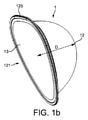
図1a及び図1bは、本発明によるカプセル1の図である。カプセルは、飲料原材料を保存するための内容積部を画成するハウジング12を備える。このハウジングは、プラスチック材料、好ましくは、熱成形することができるプラスチック材料、更に一層好ましくはポリプロピレンポリマーから作製されたプラスチックで作製されている。
1a and 1b are views of the
図1aは、上記ハウジングの後面122を示す。本発明では、後面は、水がカプセルに導入される側を指し、一方、前面は、飲料が注出される側を指す。上記後面で、ハウジングは、ハウジングの孔124を備える注水領域123を有する。この孔は、飲料をカプセルから生成するモジュールと協働して、モジュールの注水針の通過を可能にするように構成されており、図8、図9に本明細書に基づいて示されている。好ましくは、この孔は、カバー15によって閉鎖されている。このカバーは、注水針によって刺通可能な材料で作製されている。このカバーは、通常、アルミニウム膜である。
FIG. 1a shows the
図1bは、ハウジングの前面121を示す。上記前面で、ハウジングは、前カバー13によって閉鎖されている。カバー13は、ハウジングの開口した前面から延びる周縁部125に装着されている。好ましくは、カバーの少なくとも一部は、飲料出口を飲料調製中に形成することができるように刺通可能又は裂断可能である。カバーは、カプセルに保存された飲料原材料の新鮮さ及び清潔を保証する。前カバー13は、好ましくは、可撓性かつ刺通可能である。
FIG. 1b shows the
図2は、飲料原材料が内部に導入される前、及び、開口した前面121が前カバー13によって閉鎖される前のハウジングを示す。後面で、後カバー13は、ハウジングの内面に装着され、孔124(点線で図示)を隠すとともに閉鎖する。
FIG. 2 shows the housing before the beverage raw material is introduced inside and before the opened
図4a~図4eは、図3でカプセルの側面図に示すように、ハウジングの前面から後面までの、それぞれ異なる平面A-A、B-B、C-C、D-D及びE-Eによるハウジング12の断面を示す。これらの図は、滑らかな丸い角部(図4a)を有する概ね三角形の断面から円形の断面(図4e)へと、断面がどのように徐々に変化するかを示す。断面が何であれ、ハウジング12は、好ましくは、滑らかな丸い角部及び線を常に有する。図4aでは、三角形の外形が2等辺であり、両方の等しい辺のどちらか一方の長さが第3の辺(図3aの上側)の長さよりも大きいことが明らかである。
4a-4e are based on different planes AA, BB, CC, DD and EE from the front to the back of the housing, as shown in the side view of the capsule in FIG. The cross section of the
図1a、図5、及び図5aに示すように、ハウジング12は、ハウジングの孔124を含む注水領域123を備える。
As shown in FIGS. 1a, 5 and 5a, the
好ましくは、注水領域の孔15は円形であり、最適には、直径dhは少なくとも4mmである。
Preferably, the
孔の寸法は、少なくともカプセルのハウジングの寸法に左右され得る。一例として、図示するカプセルは、通常、以下を有するハウジングを備える。
47.9~48.5mmの最大高さH、及び
36.7~37.3mmの最大幅W、及び
24.1~24.7mmの最大深さD、
少なくとも6mmの直径dh。
The dimensions of the holes can depend at least on the dimensions of the capsule housing. As an example, the illustrated capsule typically comprises a housing with:
A maximum height H of 47.9 to 48.5 mm, a maximum width W of 36.7 to 37.3 mm, and a maximum depth D of 24.1 to 24.7 mm,
Diameter d h of at least 6 mm.
これらの寸法H、W、Dを図1b及び図2に示す。 These dimensions H, W, D are shown in FIGS. 1b and 2.
図1a、図5及び図5aの図示する実施形態では、凹み126が、注水領域123を取り囲む。1つの寸法では、この凹みは、図5aの断面図で明らかであるように、窪みのようにハウジングの内容積部の内側に延びている。この実施形態では、この凹みは、溝のように、注水領域123を取り囲むリングの形状を有する。図1a、図5及び図5aの図示する実施形態では、このリングは、孔124を取り囲む。
In the illustrated embodiment of FIGS. 1a, 5 and 5a, the
別の寸法では、凹み126は、図1a及び図5で明らかであるように、注水領域の孔124を取り囲む環状部分に沿って少なくとも延びる。
In another dimension, the
凹み126は、この環状部分よりも大きくてよい。1つの特定の実施形態では、凹み126は、図5b~図5dに示すように円の形状を有し得る。この円は、注水領域の孔124を取り囲む環状部分を包含する。
The
カプセル1がプラスチック製であるとき、更には、温水がハウジング内で注入されるとき、この凹み126は、カプセルの形状が変形しないことを保証する。
This
環状リングの形状を有する凹み126は、円の形状を有する凹み126ほどはハウジングの内容積部を減少させないという理由から好適である。実際には、ハウジングが作製されているプラスチック製の壁に厚さt(図5aを参照)があるため、カプセルの内容積部は、アルミ薄板で作製された現在のハウジングよりも小さい。実際には、アルミ薄板が約0.1mmの厚さを有するのに対して、好ましくはポリプロピレンポリマー製の熱成形したプラスチック製のカプセルの厚さは、約0.65mmである。アルミニウムからプラスチックへのカプセル材料の性質の変更は、これらの材料の厚さの差のためにカプセルの内容積部に直接に影響を与える。結果として、同じ外形を保つと、プラスチック製のカプセルの内容積部は、アルミニウムカプセルの内容積部と比較すると6%減少する。そのような差は、飲料が茶葉から調製された茶であるときに飲料調製の品質に直接に影響を与え得る。実際には、茶葉を小さい容積のカプセルで浸出させることは、茶葉が温水で膨潤するために困難であり得、熱湯で茶葉を開かせるための空間が少ない。カプセル容積がいくらかでも減少すれば、重大なことになり得る。結果として、溝のデザインは、この点を考慮するために決定することができる。特に、環状リングは、温水による形状変形を回避すると同時に茶葉抽出に必要な容積を保つのに十分である。そのような設計により、アルミ薄板製カプセルと熱成形プラスチック製のカプセルとでの減少は僅か4.5%内容積部であった。
The
環状部分の寸法は、通常、少なくともカプセルのハウジングの寸法に左右される。 The dimensions of the annular portion usually depend at least on the dimensions of the capsule housing.
次に、一例として、上述した寸法(H、W、D)で、凹み126は、好ましくは、少なくとも注水領域の孔15を取り囲む環状部分に沿って延びており、上記環状部分は、10mmの内径Φi及び14mmの外径Φeを有する。直径とは、図5aに示すように、環状部分の内縁部及び外縁部での寸法を意味する。
Next, as an example, in the dimensions (H, W, D) described above, the
凹み126は、上記の内径及び外径を有する環状部分に限定された形状を有し得るか、又は、この環状部分よりも大きい環形を有し得るか、又は、円の形状を有し得、リング及び円は、環状部分を含む。
The
図5dでは、凹み126は、環状部分を包含する円である、つまり、この円は、少なくとも14mmの直径Φを有する。
In FIG. 5d, the
好ましくは、凹み126の深さdは、図5a又は5dでは少なくとも0.7mm、好ましくは約0.9mmである。
Preferably, the depth d of the
これらの寸法H、W、Dは、図1b及び図1cに示されており、これらの寸法Φi、Φe、Φ、w、t、及びdは、図5a及び図5dに示されている。 These dimensions H, W, D are shown in FIGS. 1b and 1c, and these dimensions Φi, Φe, Φ, w, t, and d are shown in FIGS. 5a and 5d.
図6は、前壁14をハウジングの前面に備えるカプセルを示す。
FIG. 6 shows a capsule with a
前壁14は、2つの飲料オーバーフロー孔141を備える。これらのオーバーフロー孔141は、飲料があまりに急速に、茶葉が十分に抽出される前にカプセルを出るのを防止する。
The
好適なモードでは、前壁14は、飲料調製モジュールの識別ユニットによって物理的に接触されるように設計された識別部材142を備えることができ、ここでは孔の存在又は不存在である。識別部材を備えるそのような前壁14は、欧州特許出願公開第1950150号の教示により設計することができる。したがって、飲料原材料からの飲料の最適調製に関する情報は、識別部材を介してコード化することができる。
In a preferred mode, the
前壁14は、通常、カプセルの前カバー13の真下に配置される。
The
好適なモードでは、前壁14は、剪断部材143を正面上に備えることができ、上記剪断部材は、カプセルが飲料調製マシン内に固定され、更に飲料調製モジュールの開放部材と剪断部材が相互作用するときに、前カバー13を裂断するように設計されている。したがって、飲料出口は、カプセルがマシン内に固定されているときに前カバー13に形成することができる。そのような剪断部材は、国際公開第2010/146101号に記載されている。
In a preferred mode, the
図7は、フィルター16をハウジングの前面121に備えるカプセルを示す。フィルターは、茶葉がカプセルを出るのを防止する。好適な実施形態では、フィルターは、オーバーフロー孔141を備える壁14の後面に装着され、その結果、フィルターはこれらの孔を覆う。
FIG. 7 shows a capsule with a
特定の実施形態では、そのような壁は、国際公開第2007/042414号の教示に従い設計することができる。 In certain embodiments, such walls can be designed according to the teachings of WO 2007/042414.
したがって、カプセルが茶葉を備える場合には、最適化された品質の、茶葉微紛が取り除かれた茶飲料が生成される。 Therefore, if the capsule comprises tea leaves, an optimized quality tea beverage with the tea leaf fine powder removed is produced.
図8及び図9は、飲料を本発明によるカプセルから生成するモジュール2を示す。モジュール2によって、飲料を調製し、カプセルを放出するために、カプセルを導入し、位置決めすることができる。
8 and 9
図8では、モジュールは、開放位置、すなわち、カプセルがまだ導入されていない位置で示されている。モジュール2は、カプセルを受け入れる準備ができている。モジュール2は、フレーム21を備える。モジュールは、第1のカプセル係合部材3及び第2のカプセル係合部材4を備える。第2の部材4は固定されており、一方、第1の部材3は、移動式であり、カプセル排出位置(図8に図示)と飲料生成位置(図9に図示)との間で移動可能である。
In FIG. 8, the module is shown in the open position, i.e., where the capsule has not yet been introduced.
モジュールは、カプセルが開口部7を介してモジュールに導入されると飲料調製を開始するためにオペレータが手動で作動させるアクチュエータ5を備える。オペレータが開口部7を介してモジュール2にカプセルを導入すると、カプセルは、カプセルの縁部が寄り掛かる支持手段71によって第2のカプセル係合部材4の前方に保持される。
The module comprises an
アクチュエータ5は、支持手段71によって保持されたカプセルを図9に示すように2つのカプセル係合部材3、4間に封入する作用と共に、アクチュエータ5を押し下げることによって、第2のカプセル係合部材4への第1のカプセル係合部材3の運動を引き起こす。
As shown in FIG. 9, the
移動可能な第1のカプセル係合部材3はカプセル受器31を備え、上記カプセル受器の形状は、上記カプセル受器が飲料生成位置に移動された(図9)ときに、カプセルのハウジングの外形の一部に少なくとも適合する。
The movable first
移動可能な第1のカプセル係合部材3は、カプセルの後カバーを刺通し、カプセルに進入し、水をカプセルに注入するための水針6を備える。針は、温水供給部(図示せず)と流体接続している。
The movable first
移動可能な第1のカプセル係合部材3は、シール32を水針6の基部に備える。このシールは、飲料調製中にカプセルの後面から水が漏出しないことを保証する。実際には、飲料調製中、カプセルは完全に温水で満たされており、この温水は、カプセルの後カバー15に針によって形成された孔から漏出する恐れがある。水漏れがあればマシンが汚れ、水の一部が飲料原材料と接触しなくなるので、正しい飲料調製が行われない。
The movable first
図8aは、図8のシール32及び針6の抽出拡大図である。シールは、径の異なる2つの環状部321、322を備える。一方の環状部321は、針の上流側で飲料調製マシンの部品内に液体漏れがないことを保証し、他方の環状部322は、第1のカプセル係合部材の開口した口部へ液体が流れないことを保証する。
FIG. 8a is an enlarged extraction view of the
シールは、通常、弾力性及び可撓性の特質を有するエラストマ又はゴム材料で作製される。図8aは、静止状態、すなわち、カプセルによって圧縮されていないシールを示す。 Seals are usually made of an elastomer or rubber material with elastic and flexible properties. FIG. 8a shows a resting state, i.e., a seal that is not compressed by the capsule.
図9aは、図9のカプセルの後面、シール32、及び針6の抽出拡大図である。カプセルの後面は、最小環状部321の形状に適合する窪み126がカプセルの後面にあるため、シールの大きい方の環状部322には押し付けられるが、小さい方の環状部321には押し付けられない。シールは、水漏れに関連してその作用を提供する。というのも、シールは、最大環状部322により効果的な封止を保証するからである。しかしこの封止は、温水の注入程にはカプセルの形状の変形には影響を与えない。
9a is an expanded view of the rear surface of the capsule of FIG. 9, the
実際には、プラスチック製のカプセルの後面とシールの最小環状部321との特定の相互作用だけが、温水による形状変形に影響を与えることが判明した。したがって、針の環状シールの領域に適合する凹んだ環状部分126を有するプラスチッ製のクカプセルを設計することによって、カプセル変形の問題を解決した。
In fact, it has been found that only certain interactions between the back surface of the plastic capsule and the smallest
小さい方の環状部321だけを備える環状シール32を備えるモジュール2については、変形は観察されなかったという同じ効果が、本発明によるカプセルで得られたことが留意されている。
It is noted that for the
図10aは、移動可能な第1のカプセル係合部材3を示す。この部材は、カプセル受器31を備える。カプセルを刺通して水を内部に注入するための水針6は、カプセル受器の後面から出ている。第1の係合部材3はまた、中空部材3の前部の各側に保持手段33a、33bも備える。例示する実施形態では、上記保持手段はフックである。
FIG. 10a shows a movable first
図10bは、図10aのフック33aのうちの1つの拡大上面図である。フック33aは、カプセル受器3の側面に配置されていて上記カプセル受器の前面から垂直に延びているアーム部331aを備える。アーム331aは、傾斜した自由端331bを有する。この端部はカプセル受器3の中心に向かって傾斜しているため、第1の係合部材がカプセルの方に移動すると、傾斜端部331bがカプセルの周縁部に沿って摺動し、この周縁部を僅かに圧迫してそれをアームのスリット331cに押し込み、そこに保持する。同じ動作が、カプセルの周縁部の反対側の他方のアーム部33bにも同時に生じる。
FIG. 10b is an enlarged top view of one of the
図11aは、カプセル1がカプセル受器内で係合した第1のカプセル係合部材3の背面図を示す。カプセルの周縁部125のいくつかの部分は、第1のカプセル係合部材の正面の縁部311を越えて延びる。カプセルの周縁部125の少なくとも実質的に垂直の部分は、第1のカプセル係合部材の正面の縁部311を越えて延びることが好ましい。用語の垂直とは、飲料の生成に関するその通常の向きに従うモジュール内のカプセルの位置に基づき解釈されるべきである。
FIG. 11a shows a rear view of the first
第1のカプセル係合部材3はまた、この部材を案内ピン34である移動手段に結合する手段も備え、これらはカプセル受器の側面に設けられている。これらの案内ピンは、第1のカプセル係合部材の運動を案内するために、モジュール2(図8で参照番号211と図示)のフレームの対応する案内湾曲部と協働する。
The first
図11bは、第1のカプセル係合部材3、及び、カプセル受器に係合したカプセル1の背面図を示し、周縁部125はフック33a、33bによって把持されている。
FIG. 11b shows a rear view of the first
図12a~図12fは、モジュールへの導入からモジュールの外への放出までのモジュール2内でのカプセル1の運動を示すモジュール2の概略図である。これらの図は、モジュールの上面図であり、第1及び第2のカプセル係合部材3、4、カプセル1、タブ8a、8b、事前固定部材9a、9b、及びフック33a、33bの相対的運動を明らかにする。
12a-12f are schematic views of the
図12aでは、カプセル1は、ちょうどモジュール2に導入されたところである。カプセルは、後カバー15によって閉鎖された後面孔124を備える。カプセルの周縁部125は、第2のカプセル係合部材4に対応するモジュールの前端と事前固定部材9a、9bの端部との間に画定された空間s内に配置されている。これらの事前固定部材9a、9bは、カプセルがモジュールの後面の方向に落下するのを防止する。周縁部125の下部は、カプセルが下に落下することを回避するために支持手段上で傾斜している(図8に図示)。したがって、カプセルは、この位置に周縁部125によって保持される。
In FIG. 12a, the
第1の係合部材3は、カプセル1及び第2の係合部材4から離れて配置されている。第1の係合部材3は、長手方向軸線XX’に沿って第2の係合部材4に向かって移動し、これから離れることができる。
The first engaging
図12aは、モジュールの側部に2つのタブ8a、8bが存在していることを示す。一般的に、これらのタブは、モジュールのフレームの側壁内に固定され、カプセルが排出位置に移動されるときに、カプセルの周縁部125に接触することができるように配置されている。長手方向軸線XX’に沿ったタブの位置は距離lだけ互いに対してずれている。
FIG. 12a shows that there are two
図12bでは、第1の係合部材3は、第2の係合部材4の方向に移動される。同時に、事前固定部材9a、9bが、矢印で示されるようにカプセルの周縁部から離れ始める。
In FIG. 12b, the first engaging
図12cでは、第1の係合部材3は、第2の係合部材4の方向への運動を完了している。事前固定部材9a、9bは、カプセルの周縁部から完全に離れており、カプセルは、第1の係合部材のカプセル受器31内に、第2の係合部材4に対して維持されている。水針6はカバー15を刺通してカプセルの孔124に進入している。水は、針を通して導入することができ、飲料調製を行うことができる。カプセルの周縁部125は、フック33a、33b(カプセル及び第2のカプセル係合部材によって隠されているので図示せず)によって係合されている。
In FIG. 12c, the first engaging
図12dでは、放出運動が開始する。第1の係合部材3は、第2の係合部材4から後退して離れながらカプセルを連行する。事前固定部材9a、9bは、矢印で示されるとおり、その初期位置に復帰することができる。
In FIG. 12d, the release motion begins. The first engaging
図12eでは、第1の係合部材3が後退する間、カプセルの周縁部125の一側は第1のタブ8aによって保持され、これによって、カプセル受器31からのカプセルの横方向の分離が引き起こされる。特に、周縁部125は、フック33aから分離されており(このフックは、カプセルによって隠されているので図12eでは見えない)。他側では、他方のフック33bが周縁部125をまだ保持している。
In FIG. 12e, one side of the
図12fでは、第1の係合部材3が後退し続ける間、カプセルの周縁部の他方の側方部分125が、第2のタブ8bによって保持されており、これによって、カプセル受器31からのカプセルの完全な分離が引き起こされ、周縁部125は第2のフック33bから分離される。第1の係合部材3は、その初期位置への運動を終了することができ、一方、カプセルは、モジュール2の下に重力によって落下することができる。
In FIG. 12f, the other
図12eに示すステップでは、カプセル1は、カプセルの孔124が第1のカプセル係合部材3の線形運動、すなわち上記部材に装着された水針6の線形運動に対応する軸線XX’上に整列されていない位置に保持されている。結果として、図12c及び図12dで当初は孔124にセンタリングされていた針6が、図12eでカプセルの周縁部125が第1のタブ8aによって保持される時点ではもはやこの孔の中心にはない。孔がたまたま過度に小さいか、又は、製造ステップで良好にセンタリングされていなかった場合、針は、孔124の縁部に沿って摩擦することがあり、ハンドルが初期位置に戻る途中で直に突き当たることがある。オペレータは、ハンドルの動きに対する制動を感じる場合がある。
In the step shown in FIG. 12e, the
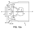
図13a~図13cは、カプセルがモジュール内で封止された位置からモジュールの外へ放出される途中のモジュール内でのカプセル1の動きを示す、モジュール2の水平断面図である。これらの図は、モジュールの上面図であり、第1及び第2のカプセル係合部材3、4及びカプセル1の相対的運動を明らかにする。
13a to 13c are horizontal cross-sectional views of the
図13aは、図12cに類似しており、ここではカプセル受器31は、第2の係合部材4の方向への運動を完了しており、カプセル1は、第1の係合部材と第2の係合部材との間に固定されている。水針6はカバー15を刺通してカプセルの孔124に進入しており、抽出を行うことができる。
13a is similar to FIG. 12c, where the
図13bは、図12dに類似しており、カプセル放出の運動が開始する。第1の係合部材3は、長手方向軸線XX’に沿って第2の係合部材4に向かって移動し、第2の係合部材4から離れることができる。第1の係合部材3は、第2の係合部材4から後退して離れながらカプセル1を連行する。モジュールのフレーム21の垂直壁は、タブ8a、8bの形の保持手段を備える。これらのタブは、ハウジングの側壁から、タブが第1のカプセル係合部材の受器31と相互作用しないような長さまで延びる。しかしながら、これらのタブは、カプセルが第1のカプセル係合部材3と共に後退するときに、カプセルの周縁部125の経路上に配置される。長手方向軸線XX’に沿ったタブの位置は距離lだけ互いに対してずれている。
FIG. 13b is similar to FIG. 12d, where the capsule release movement begins. The first engaging
図13cは、図12eに類似している。第1の係合部材3が後退する間、カプセルの周縁部の側部125は、第1のタブ8aによって保持され、これによって、カプセル受器32からのカプセルの横方向の分離が引き起こされ、特に周縁部125aの一部は、フック33aから分離される。運動のこの時点で、カプセルは傾動され、孔124がカプセルの後面にセンタリングされている軸線YY’は、もはや軸線XX’と整列されていない。
FIG. 13c is similar to FIG. 12e. While the first engaging
図14は、図13cの位置にある孔124の拡大図であり、カプセルと軸線XX’との位置ずれは、針6が、カプセルの孔124の中心にセンタリングされておらず、孔124の一方の側に更に接近するようになっている。この図は、孔の縁部、又は孔の周囲のカプセル壁にさえも衝突することなく針が貫通することができるように、十分に大きい裏孔124をカプセルに設けることの重要性を示す。
FIG. 14 is an enlarged view of the
図15は、本発明の飲料生成システムを備える飲料調製マシン100を示す。マシンは、図8a及び図8bに示すようなモジュール2を備える。中空針31は、逆止弁101、加熱器102、ポンプ103、及び流体供給部(通常、水タンク104)を連続して備える流体供給部に接続されている。マシンの異なる要素は、フレーム105によって取り囲むことができる。このマシンは、カップ109をモジュール2の下に支持して位置決めするためのドリップトレイ108を含むことができる。飲料調製を制御するユーザインターフェース106を設けてもよい。
FIG. 15 shows a
図16は、ハウジングの後面が実質的に平坦であることを除き、図1aのカプセルと類似するカプセル1を図示する。図1aのカプセルと比較すると、後面は、端部が切り落とされており、したがって、ハウジングの深さDはより小さくなっている。結果として、このカプセルが図8に示すモジュールに導入されるときに、針の基部にあるシール32及びカプセルの後面は互いに押し潰されないので、カプセルの形状変形は、抽出及び放出後に観察されない。
FIG. 16 illustrates a
それでも、そのようなカプセルは、図1a及び図5bに示すカプセルと比較するとより小さい内容積部を有する。したがって、茶葉抽出に設けられている空間が小さくなっている。 Nevertheless, such capsules have a smaller internal volume compared to the capsules shown in FIGS. 1a and 5b. Therefore, the space provided for tea leaf extraction is small.
本発明は、上記で例示された実施形態を参照して説明されているが、特許請求される本発明は、決してこれらの例示された実施形態によって限定されるものではないことが理解されるであろう。 Although the invention has been described with reference to the embodiments exemplified above, it is understood that the claimed invention is by no means limited by these exemplary embodiments. There will be.
「特許請求の範囲」で定義されるような、本発明の範囲を逸脱することなく、変形及び修正が実施可能である。更に、特定の特徴に対して既知の均等物が存在する場合、かかる均等物は、本明細書中で具体的に言及されているかのように組み込まれるものである。 Modifications and modifications can be made without departing from the scope of the invention as defined in the "Claims". Further, if there are known equivalents for a particular feature, such equivalents are incorporated as if specifically referred to herein.
本明細書で使用するとき、用語「備える」、「備えている」、及び同様の語は、排他的又は包括的な意味で解釈されるべきではない。換言すれば、これらは、「~を含むが、それらに限定されない」ことを意味するものとする。 As used herein, the terms "prepared", "prepared", and similar terms should not be construed in an exclusive or comprehensive sense. In other words, these shall mean "including, but not limited to,".
1 カプセル
11 飲料原材料
12 ハウジング
121 前面
122 後面
123 注水領域
124 孔
125 周縁部
126 凹み
13 前カバー
14 前壁
141 オーバーフロー部
142 識別部材
143 剪断部材
15 後カバー
16 フィルター
2 モジュール
21 フレーム
211 案内カーブ
3 第1のカプセル係合部材
31 カプセル受器
311 カプセル受器の前面にある縁部
32 シール
321、322 環状部
33a、33b フック
34 案内ピン
4 第2のカプセル係合部材
5 アクチュエータ
6 水針
7 開口部
71 支持手段
8a、8b 保持手段
9a、9b 事前固定部材
100 飲料マシン
101 逆止弁
102 加熱器
103 ポンプ
104 タンク
105 ハウジング
106 ユーザインターフェース
107 ドリップトレイ
108 カップ
1
Claims (19)
前記飲料原材料を保存するためのハウジング(12)であって、
開口した前面(121)と、
注水領域(123)を含む後面(122)と、
前記開口した前面から延びる周縁部(125)とを備え、
前記後面から前記前面へと、円形の断面から滑らかな丸い角部を有する概ね三角形の断面へと変化する断面を有するハウジング(12)と、
前記ハウジングの前記開口した前面を閉鎖する前カバー(13)及び/又は壁(14)と、
を備え、
前記ハウジング(12)は、プラスチック材料から作製されており、
前記ハウジングの前記後面(122)の前記注水領域(123)は、前記ハウジングの孔(124)を含み、前記孔は、後カバー(15)によって覆われており、前記孔は、少なくとも4mmの直径を有する、カプセル(1)。 A capsule (1) that contains a beverage raw material (11) such as tea leaves and is configured to prepare a beverage such as tea by injecting warm water.
A housing (12) for storing the beverage raw material.
The open front (121) and
The rear surface (122) including the water injection area (123) and
With a peripheral edge (125) extending from the opened front surface,
A housing (12) having a cross section that changes from the rear surface to the front surface, from a circular cross section to a generally triangular cross section with smooth rounded corners.
A front cover (13) and / or a wall (14) that closes the open front surface of the housing .
Equipped with
The housing (12) is made of a plastic material and is made of a plastic material.
The water injection region (123) of the rear surface (122) of the housing includes a hole (124) of the housing, the hole is covered by a rear cover (15), and the hole has a diameter of at least 4 mm. Capsule (1).
47.9~48.5mmの最大高さ、
36.7~37.3mmの最大幅、及び、
24.1~24.3mmの最大深さを有する、請求項1~7のいずれか一項に記載のカプセル。 The housing (12) is
Maximum height of 47.9-48.5 mm ,
Maximum width of 36.7 to 37.3 mm and
The capsule according to any one of claims 1 to 7, which has a maximum depth of 24.1 to 24.3 mm .
前記ハウジング(12)を熱成形し、その後、
前記ハウジングの前記後面(122)に前記孔(124)をパンチングすることによって製造されている、請求項1~11のいずれか一項に記載のカプセル。 The housing (12) of the capsule is
The housing (12) is thermoformed and then
The capsule according to any one of claims 1 to 11, which is manufactured by punching the hole (124) into the rear surface (122) of the housing.
前記モジュール(2)は、
協働する第2のカプセル係合部材(2)に対して、カプセル排出位置と飲料生成位置との間で移動可能な第1のカプセル係合部材(3)と、
前記飲料生成位置から、前記カプセル(1)が前記第1のカプセル係合部材(3)から排出される前記カプセル排出位置まで、前記第1のカプセル係合部材(3)を後退移動させる手段(5)とを備え、
前記カプセル(1)は、前記カプセルが前記第1のカプセル係合部材内に係合されると前記カプセルの周縁部(125)の少なくとも一部が前記第1のカプセル係合部材(3)の少なくとも一部を越えて延びるような周縁部サイズを有し、
移動可能な前記第1のカプセル係合部材(3)は、
前記カプセルの前記ハウジング(12)の外形の少なくとも一部に適合する形状を備えるカプセル受器(31)と、
前記ハウジングの前記後面の前記孔(124)を通って前記カプセルに進入し、水を前記カプセルに注入するための水針(6)と、
前記カプセル受器(31)内の前記カプセルを把持するように構成された把持手段とを備え、前記把持手段は、前記カプセルの前記周縁部(125)と係合するように構成された別個のフック(33a、33b)であり、
前記モジュールは、前記第1のカプセル係合部材(3)が前記飲料生成位置から前記カプセル排出位置まで移動されるときに前記カプセルの前記周縁部(125)を保持する少なくとも2つの手段(8a、8b)を備え、前記カプセルの前記周縁部を保持する前記2つの手段(8a、8b)は、前記飲料生成位置から前記カプセル排出位置への前記第1のカプセル係合部材(3)の移動中、前記2つの保持手段の一方(8b)が他方の保持手段(8a)の前に前記カプセルの前記周縁部に係合するように構成されている、飲料生成システム。 A beverage generation system comprising the capsule according to any one of claims 1 to 12 and a module (2) for producing a beverage from the capsule.
The module (2) is
With respect to the second capsule engaging member (2) that cooperates, the first capsule engaging member (3) that can move between the capsule discharge position and the beverage generation position, and the first capsule engaging member (3).
A means for retracting the first capsule engaging member (3) from the beverage producing position to the capsule discharging position where the capsule (1) is discharged from the first capsule engaging member (3). 5) and
In the capsule (1), when the capsule is engaged in the first capsule engaging member, at least a part of the peripheral portion (125) of the capsule is of the first capsule engaging member (3). It has a peripheral size that extends beyond at least part of it,
The movable first capsule engaging member (3) is
A capsule receiver (31) having a shape that fits at least a part of the outer shape of the housing (12) of the capsule.
A water needle (6) for entering the capsule through the hole (124) on the rear surface of the housing and injecting water into the capsule.
A separate gripping means configured to grip the capsule in the capsule receiver (31), wherein the gripping means is configured to engage the peripheral portion (125) of the capsule. Hooks (33a, 33b)
The module has at least two means (8a, The two means (8a, 8b) comprising 8b) and holding the peripheral edge of the capsule are moving the first capsule engaging member (3) from the beverage producing position to the capsule discharging position. , A beverage generation system configured such that one (8b) of the two holding means engages the peripheral portion of the capsule in front of the other holding means (8a).
前記長手方向移動軸線に沿った前記2つの保持手段の位置は、互いに対してずれている、請求項13に記載の飲料生成システム。 One holding means (8a, 8b) is arranged on each side of the longitudinal movement axis (XX') of the first capsule engaging member (3).
13. The beverage generation system according to claim 13, wherein the positions of the two holding means along the longitudinal movement axis are offset from each other.
前記カプセルでは、前記ハウジングの前記後面は、前記注水領域の周りに凹み(126)を備え、前記凹みは、前記ハウジングの内容積部の内側に延びており、前記凹みは、前記注水領域の前記孔を取り囲む環状部分に少なくとも沿って延びており、前記環状部分は、前記カプセルが前記飲料生成位置で前記モジュールの前記第1のカプセル係合部材内に封入されているときに、前記水針の前記基部にある前記シールの前記環状部の形状に適合する、請求項13~15のいずれか一項に記載の飲料生成システム。 In the module (2), the movable first capsule engaging member (3) comprises a seal (32) at the base of the water needle (6), the seal having at least one annular portion (321). )
In the capsule, the rear surface of the housing comprises a recess (126) around the water injection region, the recess extending inward of the internal volume portion of the housing, and the recess being the recess in the water injection region. Extending at least along an annular portion surrounding the hole, the annular portion of the water needle when the capsule is encapsulated within the first capsule engaging member of the module at the beverage production position. The beverage generation system according to any one of claims 13 to 15, which conforms to the shape of the annular portion of the seal at the base.
前記水針(6)は、前記ハウジングの前記後面の前記注水領域に含まれた前記孔(124)に進入し、
前記フック(33a、33b)は、前記第1のカプセル係合部材(3)が、協働する前記第2のカプセル係合部材(2)へ移動されるときに、前記カプセルの前記周縁部(125)と係合し、
前記モジュールの前記2つの保持手段(8a、8b)は、前記飲料生成位置から前記カプセル排出位置への前記第1のカプセル係合部材(3)の移動中に前記カプセルの前記周縁部(125)を立て続けに保持する、カプセルの使用。 The use of the capsule according to any one of claims 1 to 12 in the beverage generation system according to any one of claims 14 to 16.
The water needle (6) enters the hole (124) included in the water injection region on the rear surface of the housing .
The hooks (33a, 33b) are provided with the peripheral portion (3) of the capsule when the first capsule engaging member (3) is moved to the cooperating second capsule engaging member (2). Engage with 125) and
The two holding means (8a, 8b) of the module are the peripheral portion (125) of the capsule during the movement of the first capsule engaging member (3) from the beverage producing position to the capsule discharging position. Use of capsules to hold in quick succession.
開口した前面(121)と、
注水領域(123)を含む後面(122)と、
前記開口した前面から延びる周縁部(125)とを備え、
前記ハウジング(12)は、前記後面から前記前面へと、円形の断面から滑らかな丸い角部を有する概ね三角形の断面へと変化する断面を有し、
前記ハウジング(12)は、プラスチック材料から作製されており、
前記ハウジングの前記後面(122)の前記注水領域(123)は、前記ハウジングの孔(124)を含み、前記孔は、少なくとも4mmの直径を有する、ハウジング(12)。 Capsule housing (12) for storing beverage raw materials.
The open front (121) and
The rear surface (122) including the water injection area (123) and
With a peripheral edge (125) extending from the opened front surface,
The housing (12) has a cross section that changes from the rear surface to the front surface, from a circular cross section to a generally triangular cross section with smooth rounded corners.
The housing (12) is made of a plastic material and is made of a plastic material.
The water injection region (123) on the rear surface (122) of the housing includes a hole (124) in the housing, the hole having a diameter of at least 4 mm, the housing (12).
Applications Claiming Priority (3)
| Application Number | Priority Date | Filing Date | Title |
|---|---|---|---|
| EP16181236.7 | 2016-07-26 | ||
| EP16181236 | 2016-07-26 | ||
| PCT/EP2017/067371 WO2018019569A1 (en) | 2016-07-26 | 2017-07-11 | Capsule for preparing beverage |
Publications (2)
| Publication Number | Publication Date |
|---|---|
| JP2019523039A JP2019523039A (en) | 2019-08-22 |
| JP7008042B2 true JP7008042B2 (en) | 2022-01-25 |
Family
ID=56550777
Family Applications (1)
| Application Number | Title | Priority Date | Filing Date |
|---|---|---|---|
| JP2018566541A Active JP7008042B2 (en) | 2016-07-26 | 2017-07-11 | Capsules for preparing beverages |
Country Status (4)
| Country | Link |
|---|---|
| EP (1) | EP3490907B1 (en) |
| JP (1) | JP7008042B2 (en) |
| KR (1) | KR102422867B1 (en) |
| WO (1) | WO2018019569A1 (en) |
Citations (4)
| Publication number | Priority date | Publication date | Assignee | Title |
|---|---|---|---|---|
| JP2011104358A (en) | 2009-10-30 | 2011-06-02 | Nestec Sa | Capsule for preparation of coffee extract having structure facilitating perforation for injection of water |
| JP2013526355A (en) | 2010-05-19 | 2013-06-24 | ネステク ソシエテ アノニム | Beverage production system using capsules |
| JP2014515297A (en) | 2011-06-01 | 2014-06-30 | フライドマン,アラン | Pressurized beverage extraction capsule |
| WO2015136433A1 (en) | 2014-03-12 | 2015-09-17 | Sarong Societa' Per Azioni | Capsule for beverages |
Family Cites Families (9)
| Publication number | Priority date | Publication date | Assignee | Title |
|---|---|---|---|---|
| JP4865697B2 (en) * | 2004-03-26 | 2012-02-01 | イリカフェ エス ピー エー | Integrated cartridge for extracting beverages from fine particulate matter |
| PT1775234E (en) | 2005-10-14 | 2008-08-29 | Nestec Sa | Capsule for the preparation of a beverage |
| ES2319679T5 (en) | 2006-05-24 | 2014-11-27 | Nestec S.A. | Capsule drilling module |
| ES2399098T3 (en) * | 2006-08-30 | 2013-03-25 | Nestec S.A. | Capsule for the preparation of a drink |
| EP1950150B1 (en) | 2007-01-24 | 2010-03-03 | Nestec S.A. | Identification of beverage ingredient containing capsules |
| US8967038B2 (en) * | 2007-07-13 | 2015-03-03 | Adrian Rivera | Cartridge for use in coffee maker |
| DK2263501T3 (en) | 2009-06-17 | 2016-01-11 | Nestec Sa | Means for opening a capsule-based device for preparing a beverage |
| EP2592021B1 (en) * | 2009-08-19 | 2015-03-04 | Nestec S.A. | Capsule for the preparation of a coffee extract having a structure facilitating perforation for injection of water |
| RU2664248C2 (en) | 2013-09-03 | 2018-08-15 | Нестек С.А. | Beverage production machine using capsules |
-
2017
- 2017-07-11 WO PCT/EP2017/067371 patent/WO2018019569A1/en unknown
- 2017-07-11 EP EP17742680.6A patent/EP3490907B1/en active Active
- 2017-07-11 JP JP2018566541A patent/JP7008042B2/en active Active
- 2017-07-11 KR KR1020187035826A patent/KR102422867B1/en active IP Right Grant
Patent Citations (4)
| Publication number | Priority date | Publication date | Assignee | Title |
|---|---|---|---|---|
| JP2011104358A (en) | 2009-10-30 | 2011-06-02 | Nestec Sa | Capsule for preparation of coffee extract having structure facilitating perforation for injection of water |
| JP2013526355A (en) | 2010-05-19 | 2013-06-24 | ネステク ソシエテ アノニム | Beverage production system using capsules |
| JP2014515297A (en) | 2011-06-01 | 2014-06-30 | フライドマン,アラン | Pressurized beverage extraction capsule |
| WO2015136433A1 (en) | 2014-03-12 | 2015-09-17 | Sarong Societa' Per Azioni | Capsule for beverages |
Also Published As
| Publication number | Publication date |
|---|---|
| JP2019523039A (en) | 2019-08-22 |
| WO2018019569A1 (en) | 2018-02-01 |
| EP3490907B1 (en) | 2020-08-26 |
| KR102422867B1 (en) | 2022-07-19 |
| KR20190033474A (en) | 2019-03-29 |
| EP3490907A1 (en) | 2019-06-05 |
Similar Documents
| Publication | Publication Date | Title |
|---|---|---|
| JP6731018B2 (en) | Beverage preparation system, capsule and method for producing a beverage | |
| KR102377587B1 (en) | A system for preparing a certain quantity of beverage suitable for consumption | |
| KR102027583B1 (en) | Capsule for an extraction product, method for the production thereof, and device for brewing coffee | |
| EP2817245B1 (en) | Cartridge and assembly for obtaining a beverage | |
| EP2802520B1 (en) | Capsule for beverage | |
| US11197574B2 (en) | System and method for preparing a beverage field and background | |
| US8613247B2 (en) | Device and arrangement for preparing a liquid foodstuff or semi-luxury product and portioned packaging | |
| KR102378117B1 (en) | Apparatus and method for preparing beverage and system comprising apparatus and exchangeable capsules | |
| KR102377601B1 (en) | Systems, devices, methods, capsules, and kits of capsules for the manufacture of beverages | |
| KR102282610B1 (en) | Portion capsule for preparing a brewed product | |
| KR20190034556A (en) | Kits of systems, apparatus, methods, capsules, and capsules for making beverages | |
| JP7008038B2 (en) | Capsule and beverage generation system | |
| JP7008042B2 (en) | Capsules for preparing beverages | |
| JP7039547B2 (en) | Capsule and beverage generation system | |
| EP2607269B1 (en) | Capsule and method for preparing drinks | |
| JP2018532462A (en) | Single dose capsule, method for making a single dose capsule, system and method for making a beverage | |
| KR20180018518A (en) | Beverage production system using capsules |
Legal Events
| Date | Code | Title | Description |
|---|---|---|---|
| A711 | Notification of change in applicant |
Free format text: JAPANESE INTERMEDIATE CODE: A712 Effective date: 20190614 |
|
| A621 | Written request for application examination |
Free format text: JAPANESE INTERMEDIATE CODE: A621 Effective date: 20200709 |
|
| A977 | Report on retrieval |
Free format text: JAPANESE INTERMEDIATE CODE: A971007 Effective date: 20210727 |
|
| A131 | Notification of reasons for refusal |
Free format text: JAPANESE INTERMEDIATE CODE: A131 Effective date: 20210803 |
|
| A521 | Request for written amendment filed |
Free format text: JAPANESE INTERMEDIATE CODE: A523 Effective date: 20211104 |
|
| TRDD | Decision of grant or rejection written | ||
| A01 | Written decision to grant a patent or to grant a registration (utility model) |
Free format text: JAPANESE INTERMEDIATE CODE: A01 Effective date: 20220104 |
|
| A61 | First payment of annual fees (during grant procedure) |
Free format text: JAPANESE INTERMEDIATE CODE: A61 Effective date: 20220107 |
|
| R150 | Certificate of patent or registration of utility model |
Ref document number: 7008042 Country of ref document: JP Free format text: JAPANESE INTERMEDIATE CODE: R150 |