JP7006340B2 - Support structure and front structure of high voltage unit for vehicle - Google Patents
Support structure and front structure of high voltage unit for vehicle Download PDFInfo
- Publication number
- JP7006340B2 JP7006340B2 JP2018021775A JP2018021775A JP7006340B2 JP 7006340 B2 JP7006340 B2 JP 7006340B2 JP 2018021775 A JP2018021775 A JP 2018021775A JP 2018021775 A JP2018021775 A JP 2018021775A JP 7006340 B2 JP7006340 B2 JP 7006340B2
- Authority
- JP
- Japan
- Prior art keywords
- vehicle
- cross
- width direction
- cross member
- front side
- Prior art date
- Legal status (The legal status is an assumption and is not a legal conclusion. Google has not performed a legal analysis and makes no representation as to the accuracy of the status listed.)
- Active
Links
Images


Description
本明細書では、高電圧ユニットの支持構造、および支持構造を含んだ車両前部構造を開示する。 This specification discloses a support structure of a high voltage unit and a vehicle front structure including the support structure.
例えば特許文献1に記載されているように、電気自動車の車両前部には、駆動源である回転電機が搭載されるパワーユニット室(モータコンパートメントともいう)が設けられる。
For example, as described in
パワーユニット室では、車両の骨格部材に回転電機が支持される。例えば、MGコンパートメントには、骨格部材として、車両の前後方向に沿って一対のフロントサイドメンバが延設される。さらに、一対のフロントサイドメンバに車両幅方向に掛け渡されるようにして、モータコンパートメントクロスメンバ(以下適宜MCクロスメンバと記載する)が設けられる。MCクロスメンバに回転電機(駆動機器)が搭載される。 In the power unit room, the rotary electric machine is supported by the skeleton member of the vehicle. For example, in the MG compartment, a pair of front side members are extended as skeletal members along the front-rear direction of the vehicle. Further, a motor compartment cross member (hereinafter, appropriately referred to as MC cross member) is provided so as to be hung on the pair of front side members in the vehicle width direction. A rotary electric machine (drive device) is mounted on the MC cross member.
図10に例示されるように、MCクロスメンバ120は、略ロ字形状であって、中央に開口部121が形成される。例えば、このMCクロスメンバ120の下方に回転電機122が取り付けられる。さらにMCクロスメンバ120の上方には、電力変換を行うパワーコントロールユニット124(以下適宜PCUと記載する)や充電器126等が搭載される。MCクロスメンバ120の開口部121には、PCU104と回転電機122とを接続する高電圧ケーブル(図示せず)が配索される。この回転電機122、PCU104、充電器126等をMCクロスメンバ120に組み付けて高電圧ユニットとし、当該ユニットを、MCクロスメンバ120を介して、フロントサイドメンバ112A,112Bに締結させる。
As illustrated in FIG. 10, the
ところで、車両の前方衝突時、特に、車両全面のほぼ前幅が衝突体に衝突するフルラップ衝突時に、MCクロスメンバに衝撃荷重が加わって変形するおそれがある。例えば衝撃荷重の入力に伴いMCクロスメンバの開口部が潰れるようにして変形する。開口部の潰れにより、当該開口部に配置(配索)された高電圧ケーブルが圧迫されるおそれがある。また、自身に搭載された高電圧部品の保護のため、MCクロスメンバの剛性を向上させたいとの要求がある。そこで本明細書では、従来よりもMCクロスメンバの変形を抑えることの可能な、高電圧ユニットの支持構造および車両前部構造を開示する。 By the way, at the time of a frontal collision of a vehicle, particularly at the time of a full-wrap collision in which a substantially front width of the entire surface of the vehicle collides with a colliding body, an impact load may be applied to the MC cross member to cause deformation. For example, the opening of the MC cross member is crushed and deformed with the input of an impact load. The crushing of the opening may put pressure on the high-voltage cable arranged (arranged) in the opening. In addition, there is a demand to improve the rigidity of the MC cross member in order to protect the high-voltage components mounted on it. Therefore, this specification discloses a support structure of a high voltage unit and a vehicle front structure capable of suppressing deformation of the MC cross member as compared with the conventional case.
本明細書で開示する車両前部構造は、車幅方向に間隔を開けて配され、それぞれが車両前後方向に延びる一対のフロントサイドメンバと、前記一対のフロントサイドメンバの間に掛け渡されるクロスメンバであって、車幅方向に延びる前側クロス部と、前記前側クロス部よりも後方に設けられるとともに車幅方向に延びる後側クロス部と、を含むクロスメンバと、高電圧部品を前記クロスメンバに連結するマウントであって、前記前側クロス部および前記後側クロス部の間に掛け渡されるマウントと、を備え、前記クロスメンバの中央には、上下方向に貫通する開口部が形成され、前記マウントの前後端部は、前記クロスメンバの前記開口部を車両前後方向に跨いで前記クロスメンバに締結される、ことを特徴とする。 The vehicle front structures disclosed herein are spaced apart in the vehicle width direction and are crossed between a pair of front side members, each extending in the vehicle front-rear direction, and the pair of front side members. A cross member including a front cross portion extending in the vehicle width direction, a rear cross portion provided behind the front cross portion and extending in the vehicle width direction, and a high-voltage component. A mount that is connected to the cross member and includes a mount that is hung between the front cross portion and the rear cross portion, and an opening that penetrates in the vertical direction is formed in the center of the cross member. The front and rear ends of the mount are characterized in that the opening of the cross member is straddled in the front-rear direction of the vehicle and fastened to the cross member .
かかる構成とすれば、マウントが、前側クロス部および後側クロス部の間に掛け渡されるため、前側クロス部の後側クロス部に近づく方向への変形が効果的に防止される。結果として、従来よりもMCクロスメンバの変形を抑えることが可能となる。 With such a configuration, since the mount is hung between the front cross portion and the rear cross portion, deformation in the direction approaching the rear cross portion of the front cross portion is effectively prevented. As a result, it is possible to suppress the deformation of the MC cross member as compared with the conventional case.
本明細書で開示する他の車両前部構造は、車幅方向に間隔を開けて配され、それぞれが車両前後方向に延びる一対のフロントサイドメンバと、前記一対のフロントサイドメンバの間に掛け渡されるクロスメンバであって、車幅方向に延びる前側クロス部と、前記前側クロス部よりも後方に設けられるとともに車幅方向に延びる後側クロス部と、を含むクロスメンバと、高電圧部品を前記クロスメンバに連結するマウントであって、前記前側クロス部および前記後側クロス部の間に掛け渡されるマウントと、各フロントサイドメンバの車幅方向外側面に取り付けられ、前記フロントサイドメンバよりも車幅方向外側に突出するとともに、車両後方に進むにつれ車幅方向寸法が小さくなるガセットと、を備え、前記ガセットの後端と同じ車両前後方向位置において、前記クロスメンバと前記フロントサイドメンバが、車幅方向に離間した状態で正対しており、前記ガセットの後端と同じまたは前記ガセットの後端より後方となる車両前後方向位置において、前記クロスメンバの車幅方向外側面には、1以上の張出壁が設けられており、前記張出壁は、当該張出壁の前方よりも車幅方向外側に張り出している、ことを特徴とする。
前記クロスメンバは、当該クロスメンバの上面を形成するアッパー部材と、当該クロスメンバの底面を形成するロア部材と、を備え、前記アッパー部材と前記ロア部材とは、互いに連結されることで、閉断面を形成しており、前記マウント、前記アッパー部材および前記ロア部材が、前記閉断面を貫通するボルトと、当該ボルトに螺合するナットと、で共締めされてもよい。
The other vehicle front structures disclosed herein are spaced apart in the vehicle width direction and spanned between a pair of front side members, each extending in the vehicle front-rear direction, and the pair of front side members. A cross member including a front cross portion extending in the vehicle width direction, a rear cross portion provided behind the front cross portion and extending in the vehicle width direction, and a high-voltage component. A mount that is connected to the cross member, and is attached to the mount that is hung between the front cross portion and the rear cross portion and the outer surface of each front side member in the vehicle width direction, and is more vehicle than the front side member. The cross member and the front side member are provided with a gusset that protrudes outward in the width direction and whose dimension in the vehicle width direction becomes smaller as the vehicle moves backward, and the cross member and the front side member are at the same vehicle front-rear position as the rear end of the gusset. At a position in the vehicle front-rear direction that faces the vehicle in a state of being separated in the width direction and is the same as the rear end of the gusset or behind the rear end of the gusset, one or more on the outer surface of the cross member in the vehicle width direction. An overhanging wall is provided, and the overhanging wall is characterized in that it overhangs outward in the vehicle width direction from the front of the overhanging wall.
The cross member includes an upper member forming the upper surface of the cross member and a lower member forming the bottom surface of the cross member, and the upper member and the lower member are closed by being connected to each other. A cross section is formed, and the mount, the upper member, and the lower member may be jointly fastened with a bolt penetrating the closed cross section and a nut screwed to the bolt.
この場合、ボルトが閉断面を貫通することで、ボルトの取り付け剛性およびクロスメンバのねじり剛性が向上する。 In this case, the bolt penetrates the closed cross section, so that the mounting rigidity of the bolt and the torsional rigidity of the cross member are improved.
また、前記マウントは、前記前側クロス部および前記後側クロス部の底面または上面に締結されるベース部と、前記ベース部の中央から車両高さ方向に突出する突出部と、を備え、前記ベース部を、前記前側クロス部および前記後側クロス部に締結した際、前記突出部が、前記前側クロス部および後側クロス部間の間隙内に位置してもよい。 Further, the mount includes a base portion fastened to the bottom surface or the upper surface of the front cross portion and the rear cross portion, and a protruding portion protruding from the center of the base portion in the vehicle height direction, and the base. When the portions are fastened to the front cross portion and the rear cross portion, the protruding portion may be located in the gap between the front cross portion and the rear cross portion.
かかる構成とすることで、前側クロス部が車両後方に変形しようとしても、突出部に当接するため、前側クロス部の変形、ひいては、クロスメンバの変形が効果的に防止される。 With such a configuration, even if the front cross portion tries to be deformed to the rear of the vehicle, it comes into contact with the protruding portion, so that the deformation of the front cross portion and the deformation of the cross member are effectively prevented.
ここで、フロントサイドメンバのうち、ガセットの後端と同じ車両前後方向位置は、微小ラップ衝突またはオブリーク衝突時に、応力が集中しやすい箇所でありフロントサイドメンバが屈曲しやすい箇所である。かかるフロントサイドメンバが屈曲しやすい位置において、クロスメンバとフロントサイドメンバが、車幅方向に離間した状態で正対することで、フロントサイドメンバが確実に屈曲することができる。そして、フロントサイドメンバが屈曲することで、衝突荷重が、このフロントサイドメンバから、クロスメンバを介して、反対側のフロントサイドメンバへと伝達できる。すなわち、微小ラップ衝突またはオブリーク衝突時の衝突荷重を、パワーユニットを介することなく、反対側のフロントサイドメンバに伝達できる。 Here, among the front side members, the same vehicle front-rear direction position as the rear end of the gusset is a place where stress tends to concentrate and the front side member tends to bend at the time of a minute lap collision or an oblique collision. At a position where the front side member is likely to bend, the cross member and the front side member face each other in a state of being separated from each other in the vehicle width direction, so that the front side member can be reliably bent. Then, by bending the front side member, the collision load can be transmitted from this front side member to the opposite front side member via the cross member. That is, the collision load at the time of a minute lap collision or an oblique collision can be transmitted to the front side member on the opposite side without going through the power unit.
かかる構成とすれば、屈曲したフロントサイドメンバの後方移動が、張出壁により規制される。その結果、衝突荷重が車両後方に逃げにくくなるため、フロントサイドメンバからクロスメンバに、衝突荷重をより確実に伝達できる。 With such a configuration, the backward movement of the bent front side member is restricted by the overhanging wall. As a result, the collision load is less likely to escape to the rear of the vehicle, so that the collision load can be more reliably transmitted from the front side member to the cross member.
また、前記フロントサイドメンバの車幅方向端面には、車両前後方向に延びる補強ビードであって、途中で一時的に途切れる補強ビードが設けられており、前記張出壁は、前記補強ビードの途切れ箇所と同じ、または、前記補強ビードの途切れ箇所より後方となる車両前後方向位置に、設けられていてもよい。 Further, the end face of the front side member in the vehicle width direction is provided with a reinforcing bead extending in the front-rear direction of the vehicle, which is temporarily interrupted in the middle, and the overhanging wall is interrupted by the reinforcing bead. It may be provided at the same position as the location, or at a position in the vehicle front-rear direction behind the interrupted portion of the reinforcing bead.
補強ビードの途切れ箇所も、微小ラップ衝突またはオブリーク衝突時に、応力が集中しやすい箇所でありフロントサイドメンバが屈曲しやすい箇所である。かかるフロントサイドメンバが屈曲しやすい位置と同じ、または、屈曲しやすい位置より後方となる車両前後方向位置に、張出壁を設けることで、フロントサイドメンバの後方移動がより確実に抑制され、フロントサイドメンバからクロスメンバに、衝突荷重をより確実に伝達できる。 The break point of the reinforcing bead is also a place where stress is likely to be concentrated and a place where the front side member is easily bent at the time of a minute lap collision or an oblique collision. By providing the overhanging wall at the same position where the front side member is easily bent or at a position in the vehicle front-rear direction behind the position where the front side member is easily bent, the rear movement of the front side member is more reliably suppressed and the front is fronted. The collision load can be transmitted more reliably from the side member to the cross member.
また、前記クロスメンバは、車幅方向端部における高さ方向寸法が、車幅方向中央における高さ方向寸法よりも大きくてもよい。 Further, the cross member may have a height direction dimension at the end portion in the vehicle width direction larger than the height direction dimension at the center in the vehicle width direction.
かかる構成とすることで、クロスメンバの車幅方向端面の面積が大きくなりやすく、フロントサイドメンバが屈曲した際、当該フロントサイドメンバとクロスメンバとが、より確実に接触する。 With such a configuration, the area of the end face of the cross member in the vehicle width direction tends to be large, and when the front side member is bent, the front side member and the cross member come into contact with each other more reliably.
さらに、前記クロスメンバと前記フロントサイドメンバとを車幅方向に離間させた状態で、前記クロスメンバと前記フロントサイドメンバとを連結するブラケットを備えてもよい。 Further, a bracket for connecting the cross member and the front side member may be provided with the cross member and the front side member separated from each other in the vehicle width direction.
かかるブラケットを用いることで、クロスメンバとフロントサイドメンバとの間に、フロントサイドメンバが屈曲できるスペースを容易に確保できる。 By using such a bracket, a space where the front side member can bend can be easily secured between the cross member and the front side member.
この場合、前記クロスメンバは、当該クロスメンバの上面を形成するアッパー部材と、当該クロスメンバの底面を形成するロア部材と、を備え、前記アッパー部材と前記ロア部材とは、互いに連結されることで、閉断面を形成しており、前記ブラケット、前記アッパー部材および前記ロア部材が、前記閉断面を貫通する第一締結ボルトと、当該第一締結ボルトに螺合するナットと、で共締めされてもよい。 In this case, the cross member includes an upper member forming the upper surface of the cross member and a lower member forming the bottom surface of the cross member, and the upper member and the lower member are connected to each other. The bracket, the upper member, and the lower member are fastened together with a first fastening bolt penetrating the closed cross section and a nut screwed into the first fastening bolt. You may.
第一締結ボルトが閉断面を貫通することで、第一締結ボルトの取り付け剛性およびクロスメンバのねじり剛性が向上する。 By penetrating the closed cross section of the first fastening bolt, the mounting rigidity of the first fastening bolt and the torsional rigidity of the cross member are improved.
また、前記ブラケットは、前記ガセットの後端より後方となる車両前後方向位置において、前記クロスメンバおよび前記フロントサイドメンバに締結されており、前記ブラケットは、前記クロスメンバとの締結に用いられ、車両前後方向に並ぶ複数の第一締結穴を有し、各第一締結穴と前記ブラケットの車幅方向内側端部との間には、所定の間隙である耐負荷部が介在しており、最も前方に位置する耐負荷部は、他の耐負荷部に比べて強度が高くてもよい。 Further, the bracket is fastened to the cross member and the front side member at a position in the vehicle front-rear direction rearward from the rear end of the gusset, and the bracket is used for fastening to the cross member and is used for the vehicle. It has a plurality of first fastening holes arranged in the front-rear direction, and a load-bearing portion, which is a predetermined gap, is interposed between each first fastening hole and the inner end portion of the bracket in the vehicle width direction. The load-bearing portion located in front may have higher strength than other load-bearing portions.
かかる構成とすることで、ブラケットが、フロントサイドメンバの屈曲に追従して、容易に回転できる。 With such a configuration, the bracket can easily rotate following the bending of the front side member.
また、前記クロスメンバは、さらに、前記前側クロス部および前記後側クロス部の端部同士を連結する一対のサイド部を備えてもよい。 Further, the cross member may further include a pair of side portions for connecting the ends of the front cross portion and the rear cross portion.
かかる構成とすることで、クロスメンバの車幅方向端面の面積が大きくなりやすく、フロントサイドメンバが屈曲した際、当該フロントサイドメンバとクロスメンバとが、より確実に接触する。 With such a configuration, the area of the end face of the cross member in the vehicle width direction tends to be large, and when the front side member is bent, the front side member and the cross member come into contact with each other more reliably.
本明細書で開示されている車両用高電圧ユニットの支持構造は、回転電機ユニットの幅方向両端に組み付けられる、一対のマウントと、車両前後方向に延設される一対のフロントサイドメンバに車両幅方向両端が締結されるとともに、下方に前記一対のマウントを介して前記回転電機ユニットが組み付けられ、上方に高電圧機器が組み付けられる、クロスメンバと、を備える、車両用高電圧ユニットの支持構造であって、前記クロスメンバの中央には、上下方向に貫通する開口部が形成され、前記一対のマウントの前後端部は、前記クロスメンバの前記開口部を車両前後方向に跨いで前記クロスメンバに締結される。 The support structure of the high voltage unit for a vehicle disclosed in the present specification is a pair of mounts assembled at both ends in the width direction of the rotary electric machine unit and a pair of front side members extending in the front-rear direction of the vehicle. A support structure for a high-voltage unit for a vehicle, comprising a cross member, which is fastened at both ends in a direction and has a cross member to which the rotary electric machine unit is assembled below via the pair of mounts and a high-voltage device is assembled above. An opening that penetrates in the vertical direction is formed in the center of the cross member, and the front and rear ends of the pair of mounts straddle the opening of the cross member in the front and rear direction of the vehicle to form the cross member. To be concluded.
かかる構成とすることで、一対のモータマウントの前後端部が、MCクロスメンバの開口部を車両前後方向に跨いでMCクロスメンバに締結される。したがって車両の前方衝突時に、MCクロスメンバに衝突荷重が加えられると、MCクロスメンバとの締結部を介して、一対のモータマウントに圧縮荷重が加わる。この圧縮荷重に抗するように、モータマウントには圧縮応力が生じる。このようにモータマウントが圧縮荷重に対して突っ張ることで、MCクロスメンバの開口部の潰れが抑制される。
本明細書で開示する他の車両前部構造は、車幅方向に間隔を開けて配され、それぞれが車両前後方向に延びる一対のフロントサイドメンバと、前記一対のフロントサイドメンバの間に掛け渡されるクロスメンバであって、車幅方向に延びる前側クロス部と、前記前側クロス部よりも後方に設けられるとともに車幅方向に延びる後側クロス部と、を含むクロスメンバと、高電圧部品を前記クロスメンバに連結するマウントであって、前記前側クロス部および前記後側クロス部の間に掛け渡されるマウントと、各フロントサイドメンバの車幅方向外側面に取り付けられ、前記フロントサイドメンバよりも車幅方向外側に突出するとともに、車両後方に進むにつれ車幅方向寸法が小さくなるガセットと、前記クロスメンバと前記フロントサイドメンバとを車幅方向に離間させた状態で、前記クロスメンバと前記フロントサイドメンバとを連結するブラケットと、を備え、前記ガセットの後端と同じ車両前後方向位置において、前記クロスメンバと前記フロントサイドメンバが、車幅方向に離間した状態で正対しており、前記ブラケットは、前記ガセットの後端より後方となる車両前後方向位置において、前記クロスメンバおよび前記フロントサイドメンバに締結されており、前記ブラケットは、前記クロスメンバとの締結に用いられ、車両前後方向に並ぶ複数の第一締結穴を有し、各第一締結穴と前記ブラケットの車幅方向内側端部との間には、所定の間隙である耐負荷部が介在しており、最も前方に位置する耐負荷部は、他の耐負荷部に比べて強度が高い、ことを特徴とする。
With this configuration, the front and rear ends of the pair of motor mounts are fastened to the MC cross member across the opening of the MC cross member in the front-rear direction of the vehicle. Therefore, when a collision load is applied to the MC cross member at the time of a frontal collision of the vehicle, a compressive load is applied to the pair of motor mounts via the fastening portion with the MC cross member. Compressive stress is generated in the motor mount to withstand this compressive load. By stretching the motor mount against the compressive load in this way, the crushing of the opening of the MC cross member is suppressed.
The other vehicle front structures disclosed herein are spaced apart in the vehicle width direction and spanned between a pair of front side members, each extending in the vehicle front-rear direction, and the pair of front side members. A cross member including a front cross portion extending in the vehicle width direction, a rear cross portion provided behind the front cross portion and extending in the vehicle width direction, and a high-voltage component. A mount that is connected to the cross member, and is attached to the mount that is hung between the front cross portion and the rear cross portion and the outer surface of each front side member in the vehicle width direction, and is more vehicle than the front side member. The cross member and the front side are in a state where the cross member and the front side member are separated from each other in the width direction of the gusset, which protrudes outward in the width direction and whose dimension in the vehicle width direction becomes smaller as the vehicle moves backward. A bracket for connecting the members is provided, and the cross member and the front side member face each other in the same vehicle front-rear direction position as the rear end of the gusset, with the cross member and the front side member facing each other in a state of being separated from each other in the vehicle width direction. , A plurality of brackets are fastened to the cross member and the front side member at a position in the vehicle front-rear direction rearward from the rear end of the gusset, and the brackets are used for fastening to the cross member and are arranged in the vehicle front-rear direction. The first fastening hole of the above is provided, and a load-bearing portion, which is a predetermined gap, is interposed between each first fastening hole and the inner end portion of the bracket in the vehicle width direction. The load section is characterized in that it has a higher strength than other load-bearing sections.
本明細書で開示の車両前部構造、および、車両用高電圧部品の支持構造によれば、従来よりもMCクロスメンバの変形を抑えることができる。 According to the vehicle front structure and the support structure of the high voltage component for the vehicle disclosed in the present specification, the deformation of the MC cross member can be suppressed as compared with the conventional case.
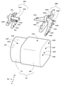
図1には、車両用高電圧ユニット9を構成する機器や部材が例示されている。なお、図1~図9において、車両前後方向を記号Frで表される軸で示し、車両幅方向を記号Rwで表される軸で示し、鉛直方向を記号Upで表される軸で示す。記号FrはFrontの略であり、前後方向軸Frは車両前方方向を正方向とする。記号RwはRight Widthの略であり、幅方向軸Rwは右幅方向を正方向とする。また高さ軸Upは上方向を正方向とする。また、以下の説明における左右は、特に、説明のない限り、車両の乗員からみての左右を意味する。
FIG. 1 illustrates devices and members constituting the vehicle
図1に示されているように、これらFr軸、Rw軸、Up軸は互いに直交する。以下の説明においては、これら3軸を基準に適宜説明する。例えば「前端」は任意の部材のFR軸正方向側の端部を指し、「後端」は任意の部材のFr軸負方向側の端部を指す。「幅方向内側」はRw軸に沿って相対的に車両の幅方向内側を指すものとし、「幅方向外側」はRw軸に沿って相対的に車両の幅方向外側を指すものとする。さらに「上側」は相対的にUp軸の正方向側を指し、「下側」は相対的にUp軸の負方向側を指す。 As shown in FIG. 1, these Fr axis, Rw axis, and Up axis are orthogonal to each other. In the following description, these three axes will be used as a reference as appropriate. For example, the "front end" refers to the end of any member on the positive direction of the FR axis, and the "rear end" refers to the end of any member on the negative direction of the Fr axis. "Inside in the width direction" refers to the inside in the width direction of the vehicle relative to the Rw axis, and "outside in the width direction" refers to the outside in the width direction of the vehicle relative to the Rw axis. Further, "upper side" relatively refers to the positive direction side of the Up axis, and "lower side" relatively refers to the negative direction side of the Up axis.
車両用高電圧ユニット9は、回転電機ユニット22、PCU24、及び充電器26を備える。さらにその支持構造として、MCクロスメンバ20及び一対のモータマウント28A,28Bを備える。例えば車両用高電圧ユニット9は、電気自動車の車両前部に設けられたパワーユニット室に搭載される。
The vehicle
パワーユニット室には、一対のフロントサイドメンバ12A,12Bが車両前後方向に延設される。車両用高電圧ユニット9は、この一対のフロントサイドメンバ12A,12Bに組み付けられる。例えば後述するように、支持ブラケット32A,32Bを介して、MCクロスメンバ20の幅方向両端がフロントサイドメンバ12A,12Bに締結される。
In the power unit room, a pair of
回転電機ユニット22は、車両の駆動源となる回転電機MGと変速機TA(トランスアクスル)を備える。図1に示される例では、回転電機ユニット22の配置はいわゆる横置きであり、回転電機ユニット22の長手方向が車両幅方向を向くようにしてパワーユニット室に配置される。
The rotary
図2を参照すると、回転電機ユニット22の幅方向両端には締結穴が複数設けられている。具体的には、回転電機MGの幅方向端部及び上面に締結穴23A~23Eが形成される。また変速機TAの幅方向端部及び上面に締結穴23F~23Iが形成される。後述するように、これら締結穴23A~23Iとモータマウント28A,28Bの締結穴53A~53Iとが位置合わせされボルト留めされることで、モータマウント28A,28Bが回転電機ユニット22に締結される。
Referring to FIG. 2, a plurality of fastening holes are provided at both ends of the rotary
図1に戻り、PCU24は回転電機MGとバッテリ(図示せず)とを結ぶ電路に設けられた電力変換器である。PCU24は、例えばDC/DCコンバータやインバータ等の電力変換回路を備える。また、図6を参照して、PCU24の前端部から絶縁部材等を介して下方に延設された脚部24Aに、締結穴83B~83Eが形成される。同様にして、PCU24の後端部から絶縁部材等を介して下方に延設された脚部24Bに、締結穴83N~83Qが形成される。
Returning to FIG. 1, the
充電器26はバッテリ(図示せず)に接続され、電力変換用の昇圧回路や直流成分を遮断するためのトランス回路等を備える。また、充電器26の前端部から絶縁部材等を介して下方に延設された脚部26Aに、締結穴83F,83Hが形成される。同様にして、充電器26の後端部から絶縁部材等を介して下方に延設された脚部26Bに、締結穴83K,83Mが形成される。
The
MCクロスメンバ20は、車両用高電圧ユニット9の支持部材である。MCクロスメンバ20は、図1に示されるように長手方向を車両幅方向に向けられるようにしてパワーユニット室に配置される。MCクロスメンバ20は、略ロ字形状であって、中央に、上下方向に貫通する開口部34が形成される。別の見方をすると、MCクロスメンバ20は、車幅方向に延びる前側クロス部20Fと、前側クロス部20Fの後方において車幅方向に延びる後側クロス部20Rと、前側クロス部20Fおよび後側クロス部20Rの幅方向両端を接続する一対のサイド部20Sを有するといえる。そして、この前側クロス部20F、後側クロス部20R、一対のサイド部20Sで囲まれる箇所が開口部34となる。開口部34には、図7に例示するように、PCU24と回転電機MGとを結ぶ高電圧ケーブル19が配索される。開口部34を取り囲む骨格部材は、例えば閉断面構造を採っている。
The
図1に図示されるように、MCクロスメンバ20の上方にはPCU24及び充電器26等の高電圧機器が組み付けられる。また、MCクロスメンバ20の下方には回転電機ユニット22が組み付けられる。後述するように、回転電機ユニット22は、モータマウント28A,28Bを介して、MCクロスメンバ20に組み付けられる。
As shown in FIG. 1, a high voltage device such as a
図4に示すように、MCクロスメンバ20には複数の締結穴21A~21Vが設けられる。この複数の締結穴と、充電器26、PCU24、及びモータマウント28A,28Bに設けられた締結穴やスタッドボルトとが位置合わせされてボルト留め等されることによって、MCクロスメンバ20に充電器26、PCU24、及び回転電機ユニット22が組み付けられる。
As shown in FIG. 4, the
図2を参照すると、モータマウント28Aは、回転電機ユニット22に締結されるMG側締結部52Aと、MCクロスメンバ20に締結されるメンバ側締結部54Aを備える。MG側締結部52Aは、前後方向に沿って延設され、その延設方向に沿って複数の締結穴53F~53Iが形成される。メンバ側締結部54AもMG側締結部52Aと同様に、前後方向に沿って延設される。さらにその延設方向に沿って締結穴83G,83Lが設けられる。後述するように、メンバ側締結部54Aの前後両端の締結穴83G,83Lは、MCクロスメンバ20の開口部34を前後方向に跨いでMCクロスメンバ20の締結穴21G,21Lと位置合わせされボルト留めされる。換言すれば、メンバ側締結部54A(モータマウント28A)は、前側クロス部20Fおよび後側クロス部20Rの間に掛け渡される。
Referring to FIG. 2, the
モータマウント28Bは、回転電機ユニット22に締結されるMG側締結部52Bと、MCクロスメンバ20に締結されるメンバ側締結部54Bを備える。MG側締結部52Bは、前後方向に沿って延設され、その延設方向に沿って複数の締結穴53A~53Eが形成される。メンバ側締結部54BもMG側締結部52Bと同様に、前後方向に沿って延設される。さらにその延設方向に沿ってスタッドボルト86A,86S及び締結穴83R,83Tが設けられる。後述するように、メンバ側締結部54Bの前後両端のスタッドボルト86A,86S及び締結穴83R,83Tは、MCクロスメンバ20の開口部34を前後方向に跨いでMCクロスメンバ20の締結穴21A,21S,21R,21Tと位置合わせされボルト留めされる。換言すれば、メンバ側締結部54B(モータマウント28B)は、前側クロス部20Fおよび後側クロス部20Rの間に掛け渡される。
The
<車両用高電圧ユニットの組み立てプロセス>
図3~図8には、本実施形態に係る車両用高電圧ユニット9の組み立てプロセスが例示されている。図3に例示されるように、回転電機ユニット22の幅方向一端にモータマウント28Aを配置し、他端にモータマウント28Bを配置する。モータマウント28Aの締結穴53F~53Iを、回転電機ユニット22の変速機TAの上方及び幅方向端部に設けられた締結穴23F~23Iに位置合わせして、両締結穴23,53にボルト92を螺入させる。これにより、回転電機ユニット22にモータマウント28Aが締結される。
<Assembly process of high voltage unit for vehicle>
3 to 8 illustrate the assembly process of the vehicle
同様にして、モータマウント28Bの締結穴53A~53Eを、回転電機ユニット22の回転電機MGの上方及び幅方向端部に設けられた締結穴23A~23Eに位置合わせして、両締結穴23,53にボルト92を螺入させる。これにより、回転電機ユニット22にモータマウント28Bが締結される。
Similarly, the fastening holes 53A to 53E of the
次に図4に例示するように、モータマウント28A,28Bを介して、回転電機ユニット22がMCクロスメンバ20に組み付けられる。まずモータマウント28Aのメンバ側締結部54Aの前後両端に形成された締結穴83G,83Lを、MCクロスメンバ20の締結穴21G,21Lに位置合わせして、両締結穴21,83にボルト92を螺入させ、その先端をナット88で留める。
Next, as illustrated in FIG. 4, the rotary
同様にして、モータマウント28Bのメンバ側締結部54Bの前後両端に形成されたスタッドボルト86A,86SをMCクロスメンバ20の締結穴21A,21Sに挿入して、その先端をナット88で留める。これによりメンバ側締結部54Bの締結穴83R,83Tと、MCクロスメンバ20の締結穴21R,21Tが位置合わせされる。両締結穴21,83にボルト92が螺入される。
Similarly, the
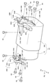
図5には、回転電機ユニット22、MCクロスメンバ20、及びモータマウント28A,28Bから構成される組立体の平面図が例示されている。MCクロスメンバ20の前端部(Fr軸正方向端部)は、回転電機ユニット22の前端部よりも前方に張り出しており、前方衝突時には、回転電機ユニット22より先にMCクロスメンバ20に衝突荷重が加えられるような構造となっている。
FIG. 5 illustrates a plan view of an assembly including a rotary
また、モータマウント28A,28Bのメンバ側締結部54A,54Bが、MCクロスメンバ20の開口部34を前後方向に跨いでMCクロスメンバ20に締結される。別の言い方をすれば、モータマウント28A,28Bのメンバ側締結部54A,54Bが、前側クロス部20Fおよび後側クロス部20Rの間に掛け渡される。このような構造を備えることで、モータマウント28A,28BがMCクロスメンバ20の補強部材として機能する。つまり、前方衝突時にモータマウント28A,28Bに圧縮応力が生じる(突っ張る)ことで、MCクロスメンバ20の開口部34の潰れが抑制される。
Further, the member-
図6及び図7には、MCクロスメンバ20にPCU24及び充電器26を組み付けるプロセスが例示されている。PCU24の脚部24A,24Bの締結穴83B~83E,83N~83Qは、MCクロスメンバ20の締結穴21B~21E,21N~21Qに位置合わせされる。さらに両締結穴21,83にボルト(図示せず)が挿入される。これによりPCU24がMCクロスメンバ20に締結される。なお、この締結の際に、MCクロスメンバ20の開口部34に高電圧ケーブル19(図7参照)が配索され、PCU24と回転電機MGとが電気的に接続される。
6 and 7 illustrate the process of assembling the
また、充電器26の脚部26A,26Bの締結穴83F,83H、83K,83Mは、MCクロスメンバ20の締結穴21F,21H,21K,21Mに位置合わせされる。さらに両締結穴21,83にボルト(図示せず)が挿入される。これにより充電器26がMCクロスメンバ20に締結される。
Further, the fastening holes 83F, 83H, 83K, 83M of the
MCクロスメンバ20に回転電機ユニット22、PCU24、及び充電器26が組み付けられ、車両用高電圧ユニット9が構成される。図7に示されるように、MCクロスメンバ20の前端部(Fr軸正側端部)は、PCU24及び充電器26の前端部よりも前方に張り出しており、前方衝突時には、回転電機ユニット22、PCU24及び充電器26より先にMCクロスメンバ20に衝突荷重が加えられるような構造となっている。
A rotary
図7、図8には、支持ブラケット32A,32Bを介して、車両用高電圧ユニット9をフロントサイドメンバ12A,12Bに締結する工程の例が示されている。支持ブラケット32Aは、フロントサイドメンバ12Aの締結穴15A,15Bと位置合わせされボルト留めされる締結穴74A,74Cと、そこから車両幅方向内側に張り出してMCクロスメンバ20の締結穴21I,21Jと位置合わせされボルト留めされる締結穴74B,74Dを備える。
7 and 8 show an example of a process of fastening the vehicle
同様にして、支持ブラケット32Bは、フロントサイドメンバ12Bの締結穴15C,15Dと位置合わせされボルト留めされる締結穴74F,74Hと、そこから車両幅方向内側に張り出してMCクロスメンバ20の締結穴21U,21Vと位置合わせされボルト留めされる締結穴74G,74Eを備える。
Similarly, the
組み立てに際して、予め支持ブラケット32A,32Bがフロントサイドメンバ12A,12Bに締結される。この状態で車両用高電圧ユニット9を下からリフトアップして、図8に示すように、支持ブラケット32A,32Bに締結させる。これにより、車両用高電圧ユニット9が支持ブラケット32A,32Bを介してフロントサイドメンバ12A,12Bに締結される。
At the time of assembly, the
<前方衝突時の挙動>
図9には、車両用高電圧ユニット9の平面図が例示されている。なお便宜上、PCU24及び充電器26は図示を省略している。車両の前方衝突時に、MCクロスメンバ20に車両後方に向かう衝突荷重F1が加えられる。このとき、モータマウント28Aのメンバ側締結部54Aには、その締結穴83G,83Lに螺入されたボルトを介して車両前後方向に沿った圧縮荷重が加えられる。これに伴ってメンバ側締結部54Aには圧縮応力σ1が発生する。
<Behavior during a forward collision>
FIG. 9 illustrates a plan view of the vehicle
同様にして、衝突荷重F1がMCクロスメンバ20に加えられると、モータマウント28Bのメンバ側締結部54Bには、そのスタッドボルト86A,86Sや締結穴83R,83Tに螺入されたボルトを介して車両前後方向に沿った圧縮荷重が加えられる。これに伴ってメンバ側締結部54Bには圧縮応力σ1が発生する。
Similarly, when the collision load F1 is applied to the
モータマウント28A,28Bから生じた圧縮応力が衝突荷重に対して突っ張るように作用し、その結果、MCクロスメンバ20の変形が抑制される。このように、開口部34を跨って前後方向にモータマウント28A,28Bを締結させることで、MCクロスメンバ20の前後方向の剛性が向上し、前方衝突時の変形が抑制される。加えて、いわゆるねじれ剛性が向上することで、通常運転におけるMCクロスメンバ20の振動やこれに伴うノイズの発生が抑制される。
The compressive stress generated from the motor mounts 28A and 28B acts to stretch against the collision load, and as a result, the deformation of the
次に、他の支持構造と、当該他の支持構造を有した車両前部構造について説明する。図11は、車両前部構造10の概略平面図である。また、図12は、MCクロスメンバ20周辺の分解斜視図である。
Next, another support structure and a vehicle front structure having the other support structure will be described. FIG. 11 is a schematic plan view of the
はじめに、車両前部構造10の全体構成について簡単に説明する。この車両前部構造10は、回転電機MGで生成された動力で走行する電動車両(例えば電気自動車や燃料電池自動車等)に組み込まれる。車両前部には、パワーユニットが設置されるパワーユニット室11が設けられている。パワーユニットは、車両の走行動力を生成するもので、本例では、後述する回転電機ユニット22がパワーユニットとして機能する。
First, the overall configuration of the
パワーユニット室11の前端には、車幅方向に延びるバンパリーンフォースメント(以下「バンパRF」と略す)14が設けられている。このバンパRF14は、車両前方に凸になるように平面視で湾曲している。このバンパRF14の車幅方向両端付近には、クラッシュボックス16を介してフロントサイドメンバ12が接続されている。クラッシュボックス16は、車両前後方向に圧縮変形することで車両衝突時の衝突エネルギを吸収する。そのため、クラッシュボックス16は、通常、車両前後方向に圧縮変形しやすい形態、例えば、外周面に複数の凹ビードが形成されたような形態となっている。
A bumper reinforcement (hereinafter abbreviated as "bumper RF") 14 extending in the vehicle width direction is provided at the front end of the
クラッシュボックス16の後方には、フロントサイドメンバ12が接続されている。フロントサイドメンバ12は、車両前後方向に延びる骨格部材である。図11に示すように、二つのフロントサイドメンバ12が、車幅方向に十分な間隔を開けて、略平行に配されている。このフロントサイドメンバ12には、その側面に荷重を受けた際に、応力が集中する応力集中部が設定されているが、これについては、後述する。
A
各フロントサイドメンバ12の車幅方向外側面には、ガセット18が取り付けられている。ガセット18は、車両後方に進むにつれ車幅方向寸法が小さくなる、平面視で略三角形状の部材である。このガセット18の前端は、フロントサイドメンバ12の前端とほぼ同じである。ガセット18は、フロントサイドメンバ12よりも車幅方向外側に張り出しており、フロントサイドメンバ12より車幅方向外側から入力される荷重を受ける。
A
一対のフロントサイドメンバ12の間には、MCクロスメンバ20が設けられている。MCクロスメンバ20は、上述の例と同様に、支持ブラケットを介してフロントサイドメンバ12に連結されている。換言すれば、MCクロスメンバ20は、一対のフロントサイドメンバ12の間に掛け渡されている。ただし、MCクロスメンバ20は、フロントサイドメンバ12と接触しておらず、両者12,20は、車幅方向に離間した状態で正対している。換言すれば、MCクロスメンバ20とフロントサイドメンバ12との間には、若干の間隙が存在する。これは、フロントサイドメンバ12の屈曲を許容するためであるが、これについては、後述する。
An
図12に示すように、MCクロスメンバ20の上面には、充電器26およびPCU24が載置され、締結される。また、MCクロスメンバ20の下方には、左側モータマウント28L,右側モータマウント28R(以下、左右を区別しない場合は、添字L,Rを省略して「モータマウント28」という)を介して回転電機ユニット22が吊り下げ保持される。回転電機ユニット22は、上述の例と同様に、車両の駆動源となる回転電機MGと変速機(トランスアクスル)TAを備える。回転電機ユニット22の上面および幅方向両端面には締結穴23が複数設けられている。これら締結穴23とモータマウント28の締結穴53とが位置合わせされボルト留めされることで、モータマウント28が回転電機ユニット22に締結される。
As shown in FIG. 12, the
モータマウント28は、回転電機ユニット22に締結されるMG側締結部52と、MCクロスメンバ20に締結されるメンバ側締結部54と、を備える。このモータマウント28と、回転電機ユニット22およびMCクロスメンバ20と、の締結については、後に詳説する。このモータマウント28と、MCクロスメンバ20が、車両用高電圧ユニット(回転電機ユニット22、PCU24、充電器26)を支持する支持構造を構成する。
The motor mount 28 includes an MG-
PCU24は、上述の例と同様に、複数の締結穴25に挿通される締結ボルト(図示せず)を介して、MCクロスメンバ20の上面に締結される。また、充電器26も、上述の例と同様に、複数の締結穴27に挿通される締結ボルト(図示せず)を介して、MCクロスメンバ20の上面に締結される。
The
回転電機ユニット22、PCU24、充電器26、およびバッテリ(図示せず)の間には、電力を授受するための高電圧ケーブル(図示せず)が配策されている。この高電圧ケーブルの一部は、MCクロスメンバ20の中央に設けられた開口部34に通される。
A high-voltage cable (not shown) for transmitting and receiving electric power is arranged between the rotary
次に、この車両前部構造10を有した車両が前面衝突した場合について簡単に説明する。前面衝突としては、車体前面の幅の全てが衝突体に衝突するフルラップ衝突、車体前面の端部(例えば車体前面の外側25%等)にのみ衝突体が衝突する微小ラップ衝突、および、高速の衝突体が車両の斜め前方から衝突するオブリーク衝突などがある。
Next, a case where a vehicle having the
フルラップ衝突した際、衝突荷重は、バンパRF14を介して左右一対のクラッシュボックス16に入力される。この衝突荷重を受けてクラッシュボックス16が圧縮変形し、衝突荷重の一部が吸収される。クラッシュボックス16で吸収しきれない荷重は、さらに、左右一対のフロントサイドメンバ12に伝達される。フロントサイドメンバ12は、必要に応じて、屈曲・変形などしながら、荷重を吸収・分散する。この過程で、後方移動したバンパRF14、あるいは、バンパRF14とMCクロスメンバ20との間に介在する他部材が、MCクロスメンバ20の前端まで達し、MCクロスメンバ20にも車両後ろ向きの荷重が印加される場合がある。この後ろ向きの荷重によりMCクロスメンバ20が変形することを防止するために、本例では、開口部34を車両前後方向に横断するモータマウント28が、MCクロスメンバ20に取り付けられているが、これについても、後述する。
In the case of a full-wrap collision, the collision load is input to the pair of left and
一方、微小ラップ衝突またはオブリーク衝突した場合について図13を参照して説明する。この場合、衝突体は、フロントサイドメンバ12より車幅方向外側において車両に衝突する。そのため、この場合の衝突荷重は、バンパRF14を介して、または、バンパRF14を介することなく、直接、ガセット18に印加される。ガセット18に印加された衝突荷重は、当該ガセット18を介して、フロントサイドメンバ12の外側面に伝達される。そして、この衝突荷重を受けて、フロントサイドメンバ12は、図13に示すように、ガセット18の後端近傍において、内側に屈曲し、車幅方向内側に入り込む。そして、これにより、フロントサイドメンバ12が、MCクロスメンバ20の側面に当接し、衝突荷重が、さらに、MCクロスメンバ20に伝達される。MCクロスメンバ20は、この衝突荷重を受けて、車幅方向に移動し、反対側(図示例では車両右側)のフロントサイドメンバ12に当接する。
On the other hand, the case of a minute lap collision or an oblique collision will be described with reference to FIG. In this case, the colliding body collides with the vehicle outside the
つまり、微小ラップ衝突またはオブリーク衝突の際の衝突荷重は、片側のガセット18、片側のフロントサイドメンバ12、MCクロスメンバ20、反対側のフロントサイドメンバ12へと、順次、伝達される。そして、この伝達の過程で、衝突荷重が、吸収・分散される。また、衝突荷重が、最終的に、反対側のフロントサイドメンバ12に伝達されることで、車体全体は、衝突荷重から逃げる方向に移動しやすくなり、衝突荷重による車両各部の変形や破損を低減できる。
That is, the collision load at the time of a minute lap collision or an oblique collision is sequentially transmitted to the
以上の説明から明らかなとおり、フルラップ衝突では、MCクロスメンバ20が変形しないことが求められ、微小ラップ衝突およびオブリーク衝突では、衝突荷重が、フロントサイドメンバ12からMCクロスメンバ20に効率的に伝達されることが求められている。本例では、各部の構成を、こうした要望を満たせるような構成としている。以下、各部の構成について、より詳細に説明する。
As is clear from the above explanation, in the full lap collision, the
はじめに、MCクロスメンバ20の構成について図14~図16を参照して説明する。図14は、MCクロスメンバ20の平面図であり、図15は、MCクロスメンバ20の分解斜視図である。また、図16は、図14のA-A線での端面図である。
First, the configuration of the
既述したとおり、MCクロスメンバ20は、一対のフロントサイドメンバ12の間に掛け渡される部材であって、PCU24および充電器26が載置され、回転電機ユニット22を吊り下げ保持する部材である。このMCクロスメンバ20は、図14に示す通り、平面視では、車幅方向に長尺な略長方形である。MCクロスメンバ20の中央には、車幅方向に長尺な開口部34が形成されており、MCクロスメンバ20は、全体としては、略ロ字状となっている。この開口部34には、回転電機ユニット22やPCU24、充電器26に接続される高電圧ケーブルの一部が配策される。
As described above, the
図15に示す通り、MCクロスメンバ20は、一つのアッパー部材36と、二つのロア部材38F,38Rと、を組み合わせて構成される。アッパー部材36は、中央に大きな開口が形成された上面と、当該上面の周縁から下方に垂れ下がる周面と、を備えており、底面は、完全開口されている。前側ロア部材38Fおよび後側ロア部材38Rは、このアッパー部材36の下側に取り付けられる部材で、車両前後方向に、いくつかの段差が形成されている。なお、以下では、前側および後側を区別しない場合は、添字F,Rを省略して、単に「ロア部材38」と呼ぶ。
As shown in FIG. 15, the
前側ロア部材38Fおよび後側ロア部材38Rは、図16に示す通り、アッパー部材36との間に閉断面を形成する。すなわち、前側ロア部材38Fは、その最上面および前端面において、アッパー部材36に近接または接触するものの、それ以外の箇所では、アッパー部材36と十分に離間している。同様に、後側ロア部材38Rは、その最上面および後端面において、アッパー部材36に近接または接触するものの、それ以外の箇所では、アッパー部材36と十分に離間している。
As shown in FIG. 16, the front
このようにMCクロスメンバ20を、アッパー部材36とロア部材38とで構成される中空形状とすることで、一枚の板材で構成する場合に比べて、MCクロスメンバ20の強度を大幅に向上できる。特に、かかる構成とすることで、MCクロスメンバ20の車幅方向の圧縮変形が効果的に防止される。つまり、微小ラップ衝突またはオブリーク衝突の際、フロントサイドメンバ12から車幅方向の衝突荷重を受けたとしても、MCクロスメンバ20が圧縮変形しにくい。その結果、衝突荷重を反対側のフロントサイドメンバ12により確実に伝達できる。なお、図15では、アッパー部材36およびロア部材38を、ビードや凹部のない単純形状として図示しているが、これら部材36,38に、複数のビードや凹部を設けてもよい。ビードや凹部を適宜、設けることで、MCクロスメンバ20の強度をより向上できる。
By forming the
MCクロスメンバ20は、別の見方をすると、車幅方向に延びる前側クロス部20Fと、前側クロス部20Fより後方において車幅方向に延びる後側クロス部20Rと、前側クロス部20Fの左右両端と後側クロス部20Rの左右両端とを接続する一対のサイド部20Sと、に大別できる。微小ラップ衝突またはオブリーク衝突の際、サイド部20Sは、衝突荷重の入力部および出力部として機能する。すなわち、衝突荷重は、片側のガセット18、片側のフロントサイドメンバ12を、介して、片側のサイド部20Sに入力される。この片側のサイド部20Sから入力された衝突荷重は、前側クロス部20Fおよび後側クロス部20Rを介して、反対側のサイド部20Sに伝達され、さらに、この反対側のサイド部20Sから反対側のフロントサイドメンバ12に出力される。このように、荷重の入力部および出力部として機能するサイド部20Sは、フロントサイドメンバ12との対向面(サイド部20Sの車幅方向外側面)の面積が、極力、大きいことが望ましい。
From another point of view, the
そこで、本例では、図15に示すように、MCクロスメンバ20の、車幅方向端部における高さ方向寸法(厚み)Deを、車幅方向中央における車両高さ方向寸法Dcよりも大きくなるようにしている。そして、かかる寸法を実現するために、MCクロスメンバ20の前端面および後端面の下端辺60を、上方に凸のアーチ状としている。これにより、サイド部20Sの車幅方向外側面が大きくなり、屈曲したフロントサイドメンバ12が、より確実にサイド部20Sに接触できる。
Therefore, in this example, as shown in FIG. 15, the height direction dimension (thickness) De of the
本例では、このサイド部20Sの外側面に、張出壁62を二つ設けている。張出壁62は、その前方位置に比べて車幅方向外側に張り出す部位である。この張出壁62は、サイド部20Sに、段差や、車幅方向内側に凹んだ凹部を設けることで形成できる。こうした張出壁62は、微小ラップ衝突またはオブリーク衝突の際、屈曲したフロントサイドメンバ12を引っ掛けて、当該フロントサイドメンバ12の後方移動を規制する。
In this example, two overhanging
すなわち、微小ラップ衝突またはオブリーク衝突の際には、フロントサイドメンバ12の屈曲だけでなく、当該フロントサイドメンバ12の車両後方への移動も生じる。フロントサイドメンバ12が、後方に自由に移動すると、衝突荷重が、MCクロスメンバ20に伝達されにくくなる。一方、サイド部20Sに、車幅方向外側に張り出した張出壁62を設けておけば、屈曲したフロントサイドメンバ12が、張出壁62に当接し、これにより、フロントサイドメンバ12の当該張出壁62より後方への移動が規制される。そして、結果として、微小ラップ衝突またはオブリーク衝突時の衝突荷重を、より確実に、MCクロスメンバ20に伝達できる。
That is, in the event of a minute lap collision or an oblique collision, not only the
ここで、微小ラップ衝突またはオブリーク衝突の際、フロントサイドメンバ12は、ガセット18の後端、あるいは、後端より僅かに後方において屈曲しやすい。張出壁62は、車両前後方向位置が、この屈曲が生じやすい箇所(ガセット18の後端、あるいは、後端より僅かに後方)と同じ、あるいは、屈曲が生じやすい箇所よりやや後方に設けられることが望ましい。かかる位置に張出壁62を設けることで、屈曲したフロントサイドメンバ12をより確実に引っ掛けることができる。
Here, at the time of a minute lap collision or an oblique collision, the
ただし、フロントサイドメンバ12の屈曲位置は、入力される衝突荷重の向きや大きさによって、適宜、異なる。例えば、微小ラップ衝突時とオブリーク衝突時では、フロントサイドメンバ12の屈曲位置が若干変化する。そこで、フロントサイドメンバ12の屈曲位置が変化してもよいように、一つのサイド部20Sに、張出壁62は、2以上設けられていることが望ましい。
However, the bending position of the
ところで、微小ラップ衝突およびオブリーク衝突の際には、フロントサイドメンバ12が、車幅方向内側に屈曲することが望ましい。しかし、フロントサイドメンバ12とMCクロスメンバ20が、車幅方向に隙間無く接触していると、フロントサイドメンバ12の屈曲が、MCクロスメンバ20により阻害される。そこで、本例では、フロントサイドメンバ12の屈曲が予想される箇所と同じ車両前後方向位置において、MCクロスメンバ20とフロントサイドメンバ12とを、車幅方向に離間させている。これにより、フロントサイドメンバ12が屈曲変形するためのスペースを確保でき、フロントサイドメンバ12をより確実に屈曲させることができる。なお、屈曲が予想される箇所とは、後に詳説するが、MCクロスメンバ20の応力集中部であり、ガセット18の後端、あるいは、補強ビード40の途切れ箇所42(図17参照)である。
By the way, in the case of a minute lap collision and an oblique collision, it is desirable that the
次に、フロントサイドメンバ12およびガセット18について図17を参照して説明する。図17は、フロントサイドメンバ12の前端周辺の斜視図である。フロントサイドメンバ12は、車両前後方向に延びる骨格部材であり、中空の角パイプ状部材である。このフロントサイドメンバ12には、応力が集中しやすく、屈曲しやすい応力集中部がいくつか、設定されている。応力集中部の一つは、ガセット18の後端付近である。ガセット18の後端付近は、当該ガセット18を介して入力された荷重が集中しやすい。そして、フロントサイドメンバ12は、このガセット18の後端付近において、車幅方向内側に屈曲しやすい。また、フロントサイドメンバ12の車幅方向の外側面12oには、補強ビード40が設けられているが、この補強ビード40の途切れ箇所42も、応力集中部として機能する。すなわち、補強ビード40は、フロントサイドメンバ12の強度向上のために設けられるもので、車両前後方向に長尺な直線状ビードである。ただし、補強ビード40は、車両前後方向に連続しておらず、途中で、途切れている。この補強ビード40が形成されている箇所では、フロントサイドメンバ12は、屈曲しにくい。一方、補強ビード40の途切れ箇所42は、強度が局所的に低下しており、応力が集中しやすい。したがって、この補強ビード40の途切れ箇所42は、応力が集中しやすく、フロントサイドメンバ12が屈曲しやすい応力集中部となる。
Next, the
本例では、この補強ビード40の途切れ箇所42を、ガセット18の後端より後方に設けている。そのため、応力の入力形態によっては、フロントサイドメンバ12は、当該補強ビード40の途切れ箇所42(ガセット18の後端より後方)において、屈曲することがある。この場合でも、フロントサイドメンバ12が、確実に屈曲できるように、補強ビード40の途切れ箇所42と同じ車両前後方向位置において、フロントサイドメンバ12とMCクロスメンバ20とを車幅方向に離間させている。また、上述した張出壁62の少なくとも一つは、この補強ビード40の途切れ箇所42と同じ、または、補強ビード40の途切れ箇所42より後方となる車両前後方向位置に設けられている。ガセット18は、図17において、二点鎖線で示すように、フロントサイドメンバ12の外側面12oに取り付けられている。このガセット18の構成は、適宜、従来技術を利用できるため、ここでの詳説は省略する。
In this example, the
フロントサイドメンバ12とMCクロスメンバ20は、支持ブラケットを介して互いに連結される。図18は、支持ブラケットの分解斜視図である。また、図19は、支持ブラケットの取り付けの様子を示す斜視図である。支持ブラケットは、二つのブラケット片44,46を有している。この二つのブラケット片44,46は、上下に重ねられて、支持ブラケットを構成する。この支持ブラケットは、図1、図13に示す通り、フロントサイドメンバ12の屈曲が予想される応力集中部(ガセット18の後端、または、補強ビード40の途切れ箇所42)よりも車両後方に取り付けられる。また、この支持ブラケットは、フロントサイドメンバ12とMCクロスメンバ20とを、車幅方向に離間させた状態で、両者12,20を連結する。
The
第一ブラケット片44は、MCクロスメンバ20の上面と、フロントサイドメンバ12の車幅方向の内側面12iと、を連結する。そのため、第一ブラケット片44は、MCクロスメンバ20の上面に沿うべく略水平方向に延びる面と、フロントサイドメンバ12の内側面12iに沿うべく略鉛直方向に延びる面とを有した略L字状となっている。第一ブラケット片44の水平面には、三つの第一締結穴64a~64cが前後方向に並んで形成されている。この第一締結穴64a~64cは、第一締結ボルト66a~66cが挿通される孔であり、MCクロスメンバ20に形成された締結穴21a~21cに対応する位置に設けられている。また、第一ブラケット片44の鉛直面には、二つの第二締結穴70a(図18、図19では、一つしか見えず)が前後方向に並んで形成されている。第二締結穴70aは、第二締結ボルト(図示せず)が挿通される孔であり、フロントサイドメンバ12の内側面に形成された締結穴13a,13bに対応する位置に設けられている。
The
第二ブラケット片46は、MCクロスメンバ20の上面と、フロントサイドメンバ12の上面12tと、を連結する。そのため、第二ブラケット片46は、MCクロスメンバ20の上面およびフロントサイドメンバ12の上面12tに沿うべく略水平方向に延びる面を有している。また、第二ブラケット片46は、他部材(例えばサスペンションタワー等)にも締結できるように、外側に大きく延びる延長部46aも有している。
The
第二ブラケット片46のうち、車幅方向内側の端部近傍には、一つの挿通孔72と、二つの第一締結穴74a,74cと、が設けられている。二つの第一締結穴74a,74cは、挿通孔72の前後方向両側に配されている。この第一締結穴74a,74cおよび挿通孔72の位置は、第一ブラケット片44の第一締結穴64a~64cの位置とほぼ同じである。ただし、挿通孔72は、第一締結ボルト66a~66cの頭部よりも大径となっている。
Of the
第二ブラケット片46の車幅方向外側の端部近傍には、二つの第三締結穴76a,76bが前後方向に並んで形成されている。この第三締結穴76a,76bは、フロントサイドメンバ12の上面12tに形成された締結穴15a,15bに対応する位置に設けられている。
Two
MCクロスメンバ20とフロントサイドメンバ12を連結する際には、まず、第一ブラケット片44を、フロントサイドメンバ12の内側面12iに螺合締結する。続いて、第一ブラケット片44の上に、第二ブラケット片46を載置し、当該第二ブラケット片46を、フロントサイドメンバ12の上面12tに螺合締結する。その後、回転電機ユニット22、PCU24、充電器26が組みつけられたMCクロスメンバ20をリフトアップして、支持ブラケットの下側にMCクロスメンバ20の上面を配置する。その状態になれば、そして、第一締結ボルト66a~66cおよびナット68a~68cを用いて、第一、第二ブラケット片44,46を、MCクロスメンバ20に螺合締結する。
When connecting the
ここで、MCクロスメンバ20に形成された三つの締結穴21a~21cのうち、前側および後側の締結穴21a,21cは、アッパー部材36およびロア部材38の双方に形成されている。そして、この締結穴21a,21cに挿通される第一締結ボルト66a,66cは、MCクロスメンバ20の閉断面を貫通する。これについて、図20を参照して説明する。図20は、第一締結ボルト66aを通る切断線における概略端面図である。
Here, of the three
図20に示す通り、MCクロスメンバ20の内部(閉断面内)には、厚み方向に延びるカラー50が設けられている。このカラー50は、アッパー部材36およびロア部材38に形成された締結穴21aと同軸上に配されており、その高さは、閉断面の高さとほぼ同じか、僅かに小さい。MCクロスメンバ20と第一、第二ブラケット片44,46とを締結する際には、第一締結ボルト66aを、ロア部材38の締結穴21a、カラー50、アッパー部材36の締結穴21a、第一ブラケット片44の第一締結穴64a、第二ブラケット片46の第一締結穴74aに挿通させる。そして、第二ブラケット片46の上面から突出する雄ネジに、ナット68aを螺合して、締め付ける。すなわち、ロア部材38、カラー50、アッパー部材36、第一ブラケット片44、第二ブラケット片46を、第一締結ボルト66aとナット68aで、このように第一締結ボルト66a,66cを、MCクロスメンバ20の閉断面を貫通させることで、第一締結ボルト66a,66cの取付剛性を向上できる。また、この場合、MCクロスメンバ20のねじり剛性が向上するため、トランスアクスルや高電圧部品の振動を受けてMCクロスメンバ20が振動しても、MCクロスメンバ20の撓みや変形を効果的に防止できる。
As shown in FIG. 20, a
ここで、第一締結穴64a~64cと第一ブラケット片44の車幅方向の内側端辺との間の間隙部、および、第一締結穴74a,74cと第二ブラケット片46の車幅方向の内側端辺との間の間隙部は、第一、第二ブラケット片44,46が、車幅方向外側に引っ張られた際に第一締結ボルト66a~66cから荷重を受ける耐負荷部65a~65c,75a,75c(図18参照)となる。本例では、この複数の耐負荷部65a~65c,75a,75cのうち、最も前方に位置する耐負荷部65a,75aの強度を、他の耐負荷部65b,65c,75cの強度よりも高くしている。具体的には、図18から明らかなとおり、第一ブラケット片44に設けられた三つの第一締結穴64a~64cのうち、中央および後側の第一締結穴64a,64cは、車幅方向内側の周縁が途中で途切れた略C字状となっている。同様に、第二ブラケット片46に設けられた二つの第一締結穴74a,74cのうち、後側の第一締結穴74cも、車幅方向内側の周縁が途中で途切れた略C字状となっている。そのため、中央および後側の耐負荷部65b,65c,75cの強度が、前側の耐負荷部65a,75aに比べて、大幅に低下している。そして、かかる構成とすることで、フロントサイドメンバ12が、屈曲した場合に、第一、第二ブラケット片44,46の回転移動が許容される。
Here, the gap between the
すなわち、上述したとおり、また、図13に示す通り、微小ラップ衝突またはオブリーク衝突の際、フロントサイドメンバ12は、支持ブラケットよりも前方位置において、車幅方向内側に屈曲する。支持ブラケットが、このフロントサイドメンバ12の屈曲に追従するためには、図13に示すとおり、その後端が車幅方向外側に変位するように鉛直軸周りに回転する必要がある。このとき、支持ブラケットの中央の第一締結穴64bの周辺、および、後側の第一締結穴64c,74cの周辺が、MCクロスメンバ20に強固に連結されていると、支持ブラケットが回転できない。そこで、本例では、中央の第一締結穴64bの周縁、および、後側の第一締結穴64c,74cの周縁を、車幅方向内側で途切れる略C字状としている。これにより、支持ブラケットに、車幅方向外側に引っ張る力がかかると、中央および後側の耐負荷部65b,65c,75cが容易に破壊され、中央および後側の第一締結穴64b,64c,74cから第一締結ボルト66b,66cが抜ける。そして、これにより、支持ブラケットが、前側の第一締結穴64b,74aを中心として、容易に回転できる。
That is, as described above, and as shown in FIG. 13, the
なお、本例では、耐負荷部65a~65c,75a,75cの強度差を設けるために、一部の第一締結穴64b,64c,74cの周縁を略C字状にしている。しかし、最も前側の耐負荷部65a,75aが、他の耐負荷部65b,65c,75cよりも強度が高くなるのであれば、他の形態でもよい。例えば、中央および後側の耐負荷部65b,65c,75cに、車幅方向に延びる切れ目や溝などを設けてもよい。また、中央および後側の耐負荷部65b,65c,75cの幅を、前側の耐負荷部65a,75aに比べて、小さくしてもよい。
In this example, in order to provide a strength difference between the load-bearing
次に、回転電機ユニット22およびモータマウント28について説明する。図21は、回転電機ユニット22およびモータマウント28の斜視図である。上述したとおり、回転電機ユニット22は、車両の駆動源である回転電機MGと、変速機TAを備える。回転電機ユニット22の幅方向両端および上面には、モータマウント28と締結されるための締結穴23が形成されている。この回転電機ユニット22は、右側モータマウント28Rおよび左側モータマウント28Lを介して、MCクロスメンバ20に連結される。
Next, the rotary
モータマウント28は、回転電機ユニット22に締結されるMG側締結部52と、MCクロスメンバ20に締結されるメンバ側締結部54と、に大別される。MG側締結部52には、回転電機ユニット22と締結されるための締結穴53が形成されている。
The motor mount 28 is roughly classified into an MG
メンバ側締結部54は、MCクロスメンバ20の開口部34を車両前後方向に横断して、当該MCクロスメンバ20の底面に締結される。メンバ側締結部54は、MCクロスメンバ20の底面に締結されるベース部80と、当該ベース部80の中央から上方に突出する突出部82と、この突出部82の中央からさらに上方に突出する円弧部84と、に大別できる。
The member-
ベース部80の車両前後方向寸法は、MCクロスメンバ20の前側クロス部20Fの後端から後側クロス部20Rの前端までの距離よりも大きくなっており、当該ベース部80は、前側クロス部20Fの底面および後側クロス部20Rの底面に、締結される。ベース部80の上面からは、この締結に用いられるスタッドボルト86が突出している。突出部82の車両前後方向寸法は、前側クロス部20Fの後端から後側クロス部20Rの後端までの距離よりも小さく、かつ、開口部34の前後方向寸法よりも大きい。なお、左側モータマウント28Lは、この突出部82に形成された締結穴83を介して、開口部34の周縁に締結される。円弧部は、MG側締結部52の挿通を許容する空間を形成する。
The vehicle front-rear dimension of the
図22は、左側モータマウント28Lのメンバ側締結部54をMCクロスメンバ20に締結した様子を示す概略断面図である。ここで、図22から明らかなとおり、ベース部80は、MCクロスメンバ20の開口部34を前後方向に跨いでMCクロスメンバ20に締結される。このような構造を備えることで、モータマウント28がMCクロスメンバ20の補強部材として機能する。すなわち、フルラップ衝突時には、MCクロスメンバ20の前端に、後ろ向きの衝突荷重がかかることがある。この衝突荷重を受けて、前側クロス部20Fが、開口部34を潰す方向に変形しようとする。前側クロス部20Fが、車両後方に変形するためには、当該前側クロス部20Fおよび後側クロス部20Rに連結されたメンバ側締結部54が車両前後方向に圧縮変形する必要があるが、メンバ側締結部54は、その形状からして、車両前後方向の圧縮は、生じにくい。そのため、本例によれば、フルラップ衝突時におけるMCクロスメンバ20の変形が効果的に抑制される。加えて、開口部34を横断するようにメンバ側締結部54をMCクロスメンバ20に締結すれば、当該MCクロスメンバ20のねじれ剛性が向上する。これにより、通常運転におけるMCクロスメンバ20の振動やこれに伴うノイズの発生が抑制される。
FIG. 22 is a schematic cross-sectional view showing a state in which the member-
また、図22から明らかなとおり、前後に離間して配置された前側クロス部20Fと後側クロス部20Rとの間に、メンバ側締結部54の突出部82が配されている。そのため、フルラップ衝突時に、前側クロス部20Fが、後方に変形しようとすると、当該前側クロス部20Fが突出部82に当接する。この当接により、前側クロス部20Fの更なる後方移動が規制され、前側クロス部20Fの変形が阻害される。すなわち、前側クロス部20Fおよび後側クロス部20Rの間に、メンバ側締結部54の突出部82を配することで、MCクロスメンバ20の変形(特に開口部34が潰れるような変形)がより効果的に防止される。
Further, as is clear from FIG. 22, a protruding
さらに、図22から明らかなとおり、ベース部80と、前側および後側クロス部20F,20Rと、を締結するスタッドボルト86は、支持ブラケットに締結された第一締結ボルト66a,66cと同様に、前側および後側クロス部20F,20Rの閉断面を貫通する。すなわち、前側および後側クロス部20F,20Rの閉断面内には、カラー90が配置されており、スタッドボルト86およびナット88は、ベース部80(モータマウント28)、ロア部材38、カラー90およびアッパー部材36を共締めする。これにより、スタッドボルト86の取り付け剛性を向上できる。また、MCクロスメンバ20のねじれ剛性が向上するため、MCクロスメンバ20の撓みや変形を効果的に防止できる。
Further, as is clear from FIG. 22, the
なお、回転電機ユニット22、充電器26、PCU24といった高電圧部品は、いずれも、その前端が、MCクロスメンバ20の前端より後方になるように、取り付けられている。そのため、フルラップ衝突時の衝突荷重は、回転電機ユニット22、充電器26、PCU24よりも先に、MCクロスメンバ20に加わるようになっている。また、上述の説明では、メンバ側締結部54が車両前後方向と平行な方向に延びているが、メンバ側締結部54は、前側クロス部20Fおよび後側クロス部20Rの間に掛け渡されるのであれば、車両前後方向に対して傾斜した方向に延びてもよい。例えば、二つのメンバ側締結部54が、略ハ字状に、MCクロスメンバ20に締結されてもよい。
The high-voltage components such as the rotary
次に、前面衝突時における各部の挙動について説明する。はじめに、車両のほぼ全幅が衝突体に衝突するフルラップ衝突時の挙動について説明する。フルラップ衝突した場合、バンパRF14のほぼ全面に衝突荷重が入力される。この衝突荷重の一部は、クラッシュボックス16が圧縮変形することで吸収される。クラッシュボックス16で吸収しきれない衝突荷重は、さらに、フロントサイドメンバ12の前端に伝達される。フロントサイドメンバ12は、この衝突荷重に耐えようとするが、衝突荷重が、フロントサイドメンバ12で受けきれないほど大きい場合には、当該衝突荷重から逃げるように、フロントサイドメンバ12が変形(屈曲・湾曲)する。この過程で、バンパRF14は、車両後方に移動し、衝突荷重の一部が、バンパRF14から直接、あるいは、バンパRF14とMCクロスメンバ20の間に介在する他部材を介して、MCクロスメンバ20にも入力されることがある。
Next, the behavior of each part at the time of a frontal collision will be described. First, the behavior during a full-wrap collision in which almost the entire width of the vehicle collides with the colliding body will be described. In the case of a full-wrap collision, the collision load is input to almost the entire surface of the bumper RF14. A part of this collision load is absorbed by compressing and deforming the
MCクロスメンバ20に、車両後ろ向きの衝突荷重が印加されると、MCクロスメンバ20の前側クロス部20Fが、開口部34を潰す方向に変形しようとする。しかしながら、モータマウント28のメンバ側締結部54が、開口部34を横断するように、前側クロス部20Fと後側クロス部20Rとに連結されている。このメンバ側締結部54は、MCクロスメンバ20の前後方向の変形を規制する補強部材として機能する。メンバ側締結部54が、前側クロス部20Fおよび後側クロス部20Rに連結されることで、この二つのクロス部20F,20Rの相対変位が規制され、MCクロスメンバ20の変形が抑制される。
When a vehicle rearward collision load is applied to the
また、万一、前側クロス部20Fとメンバ側締結部54とを連結するスタッドボルト86や締結ボルト92が破損する等して、前側クロス部20Fとメンバ側締結部54との連結が解除されたとしても、前側クロス部20Fと後側クロス部20Rとの間には、メンバ側締結部54の突出部82が介在する。そのため、前側クロス部20Fが後方に移動しようとしても、前側クロス部20Fが突出部82に当接して、更なる後方移動が規制される。結果として、MCクロスメンバ20の変形が抑制される。
Further, by any chance, the
そして、MCクロスメンバ20の変形が抑制されることで、開口部34に通された高電圧ケーブルの挟み込みが効果的に防止される。また、MCクロスメンバ20に搭載された回転電機ユニット22やPCU24、充電器26といった高電圧部品も、より適切に保護される。
Then, by suppressing the deformation of the
次に、微小ラップ衝突またはオブリーク衝突時の挙動について説明する。この場合、衝突荷重は、フロントサイドメンバ12よりも外側に突出したガセット18に印加される。ガセット18に印加された衝突荷重は、当該ガセット18を介して、フロントサイドメンバ12の側面に伝達される。このとき、衝突荷重に起因する応力は、ガセット18の後端、あるいは、補強ビード40の途切れ箇所42に集中しやすい。その結果、フロントサイドメンバ12は、ガセット18の後端あるいは補強ビード40の途切れ箇所42付近で、車幅方向内側に屈曲する。このとき、この応力集中部(ガセット18の後端および補強ビード40の途切れ箇所42)と同じ車両前後方向位置において、MCクロスメンバ20とフロントサイドメンバ12は、車幅方向に離間した状態で正対している。換言すれば、MCクロスメンバ20との間に、フロントサイドメンバ12が、車幅方向内側に屈曲するためのスペースが十分に確保されている。そのため、本例によれば、フロントサイドメンバ12が車幅方向内側に確実に屈曲できる。
Next, the behavior at the time of a minute lap collision or an oblique collision will be described. In this case, the impact load is applied to the
また、フロントサイドメンバ12が、屈曲すると、図13に示すように、フロントサイドメンバ12と支持ブラケットの締結位置も変化する。この締結位置の変化にともない、真ん中および後側の第一締結穴64b,64c,74cの周縁が破断し、締結ボルトから離間する。これにより、支持ブラケットが、フロントサイドメンバ12の締結位置の変位に追従するように、最も前側の第一締結穴64a,74aを中心として回転できる。そして、これにより、フロントサイドメンバ12がより確実に屈曲できる。
Further, when the
フロントサイドメンバが、車幅方向内側に屈曲することで、MCクロスメンバ20の側面が、フロントサイドメンバ12の屈曲部で車幅方向内側に押圧される。なお、このとき、フロントサイドメンバ12は、車幅方向内側だけでなく、車両後方にも移動しようとする。しかし、フロントサイドメンバ12の屈曲部が、MCクロスメンバ20の側面に設けられた張出壁62に引っかかることで、フロントサイドメンバ12の後方移動が効果的に規制される。そして、これにより、衝突荷重が、フロントサイドメンバ12からMCクロスメンバ20に、より確実に伝達される。
When the front side member bends inward in the vehicle width direction, the side surface of the
MCクロスメンバ20の片側のサイド部20Sに入力された衝突荷重は、前側クロス部20Fおよび後側クロス部20Rを介して、反対側のサイド部20Sへと伝達される。反対側のサイド部20Sは、反対側のフロントサイドメンバ12に当接し、押圧する。そして、これにより、衝突荷重が、反対側のフロントサイドメンバ12へと伝達される。反対側のフロントサイドメンバ12は、衝突荷重の一部を吸収するとともに、当該衝突荷重を避けるように車幅方向へ変位する。すなわち、車体全体が、衝突荷重から逃げるように車幅方向に変位する。そして、結果として、乗員や高電圧部品を効果的に保護できる。
The impact load input to the
以上の説明から明らかなとおり、本明細書で開示の支持構造、および、車両前部構造10によれば、モータマウント28が、前側クロス部20Fおよび後側クロス部20Rの間に掛け渡されている。これにより、前側クロス部20Fの変形、特に、開口部34が潰れるような変形が効果的に防止される。さらに、モータマウント28の一部である突出部82が、前側クロス部20Fおよび後側クロス部20R間の間隙内に位置する構成とすれば、万一、モータマウント28と前側クロス部20Fとの連結が解除されたとしても、前側クロス部20Fの変形が、当該突出部82により抑制される。なお、ここまで説明した構成は、一例であり、モータマウント28が、前側クロス部20Fおよび後側クロス部20Rの間に掛け渡されているのであれば、他の構成は、適宜、変更されてもよい。
As is clear from the above description, according to the support structure disclosed herein and the
例えば、上述の例では、MCクロスメンバ20は、その中央に開口部34を有した略ロ字であるが、MCクロスメンバ20は、前側クロス部20Fおよび後側クロス部20Rを有するのであれば、他の形状でもよい。したがって、MCクロスメンバ20は、サイド部20Sに替えて、前側クロス部20Fと後側クロス部20Rの間に、略X状に掛け渡される二つの渡り部を有したような形状であってもよい。また、上述の説明では、モータマウント28は、MCクロスメンバ20の底面に締結されているが、上面に締結されてもよい。例えば、モータマウント28が、MCクロスメンバ20の上面に連結され、このモータマウント28を介して、回転電機ユニット22がMCクロスメンバ20の上方に連結されてもよい。
For example, in the above example, the
9 車両用高電圧ユニット、10 車両前部構造、11 パワーユニット室、12,112 フロントサイドメンバ、16 クラッシュボックス、18 ガセット、19 高電圧ケーブル、20,120 MCクロスメンバ、20F 前側クロス部、20R 後側クロス部、20S サイド部、22 回転電機ユニット、24,124 PCU、26,126 充電器、28 モータマウント、32 支持ブラケット、34,121 開口部、36 アッパー部材、38 ロア部材、40 補強ビード、44 第一ブラケット片、46 第二ブラケット片、50 カラー、52 MG側締結部、54 メンバ側締結部、62 張出壁、64a~64c,74a,74c 第一締結孔、65a~65c,75a,75c 耐負荷部、80 ベース部、82 突出部、86 スタッドボルト、90 カラー、122 回転電機。 9 High voltage unit for vehicle, 10 Vehicle front structure, 11 Power unit room, 12, 112 Front side member, 16 Crash box, 18 gusset, 19 High voltage cable, 20, 120 MC cross member, 20F front cross member, 20R rear Side cross part, 20S side part, 22 rotary electric unit, 24,124 PCU, 26,126 charger, 28 motor mount, 32 support bracket, 34,121 opening, 36 upper member, 38 lower member, 40 reinforcement bead, 44 1st bracket piece, 46 2nd bracket piece, 50 collar, 52 MG side fastening part, 54 member side fastening part, 62 overhanging wall, 64a-64c, 74a, 74c first fastening hole, 65a-65c, 75a, 75c load-bearing part, 80 base part, 82 protrusion, 86 stud bolt, 90 collar, 122 rotary electric machine.
Claims (12)
前記一対のフロントサイドメンバの間に掛け渡されるクロスメンバであって、車幅方向に延びる前側クロス部と、前記前側クロス部よりも後方に設けられるとともに車幅方向に延びる後側クロス部と、を含むクロスメンバと、
高電圧部品を前記クロスメンバに連結するマウントであって、前記前側クロス部および前記後側クロス部の間に掛け渡されるマウントと、
を備え、
前記クロスメンバの中央には、上下方向に貫通する開口部が形成され、
前記マウントの前後端部は、前記クロスメンバの前記開口部を車両前後方向に跨いで前記クロスメンバに締結される、
ことを特徴とする車両前部構造。 A pair of front side members, each of which is spaced apart in the width direction of the vehicle and extends in the front-rear direction of the vehicle.
A cross member spanned between the pair of front side members, a front cross portion extending in the vehicle width direction, a rear cross portion provided behind the front cross portion and extending in the vehicle width direction, and a rear cross portion. With cross members including
A mount that connects a high-voltage component to the cross member, and a mount that is hung between the front cross portion and the rear cross portion.
Equipped with
An opening that penetrates in the vertical direction is formed in the center of the cross member.
The front and rear ends of the mount straddle the opening of the cross member in the front-rear direction of the vehicle and are fastened to the cross member.
The vehicle front structure is characterized by that.
前記一対のフロントサイドメンバの間に掛け渡されるクロスメンバであって、車幅方向に延びる前側クロス部と、前記前側クロス部よりも後方に設けられるとともに車幅方向に延びる後側クロス部と、を含むクロスメンバと、
高電圧部品を前記クロスメンバに連結するマウントであって、前記前側クロス部および前記後側クロス部の間に掛け渡されるマウントと、
各フロントサイドメンバの車幅方向外側面に取り付けられ、前記フロントサイドメンバよりも車幅方向外側に突出するとともに、車両後方に進むにつれ車幅方向寸法が小さくなるガセットと、
を備え、
前記ガセットの後端と同じ車両前後方向位置において、前記クロスメンバと前記フロントサイドメンバが、車幅方向に離間した状態で正対しており、
前記ガセットの後端と同じまたは前記ガセットの後端より後方となる車両前後方向位置において、前記クロスメンバの車幅方向外側面には、1以上の張出壁が設けられており、
前記張出壁は、当該張出壁の前方よりも車幅方向外側に張り出している、
ことを特徴とする車両前部構造。 A pair of front side members, each of which is spaced apart in the width direction of the vehicle and extends in the front-rear direction of the vehicle.
A cross member spanned between the pair of front side members, a front cross portion extending in the vehicle width direction, a rear cross portion provided behind the front cross portion and extending in the vehicle width direction, and a rear cross portion. With cross members including
A mount that connects a high-voltage component to the cross member, and a mount that is hung between the front cross portion and the rear cross portion.
A gusset that is attached to the outer surface of each front side member in the vehicle width direction and protrudes outward in the vehicle width direction from the front side member, and the dimension in the vehicle width direction becomes smaller as the vehicle moves backward.
Equipped with
At the same vehicle front-rear direction position as the rear end of the gusset, the cross member and the front side member face each other in a state of being separated in the vehicle width direction.
At a position in the vehicle front-rear direction that is the same as the rear end of the gusset or behind the rear end of the gusset, one or more overhanging walls are provided on the outer surface of the cross member in the vehicle width direction.
The overhanging wall projects outward in the vehicle width direction from the front of the overhanging wall.
The vehicle front structure is characterized by that.
前記クロスメンバは、当該クロスメンバの上面を形成するアッパー部材と、当該クロスメンバの底面を形成するロア部材と、を備え、
前記アッパー部材と前記ロア部材とは、互いに連結されることで、閉断面を形成しており、
前記マウント、前記アッパー部材および前記ロア部材が、前記閉断面を貫通するボルトと、当該ボルトに螺合するナットと、で共締めされている、
ことを特徴とする車両前部構造。 The vehicle front structure according to claim 2 .
The cross member includes an upper member forming the upper surface of the cross member and a lower member forming the bottom surface of the cross member.
The upper member and the lower member are connected to each other to form a closed cross section.
The mount, the upper member, and the lower member are co-tightened with a bolt penetrating the closed cross section and a nut screwed onto the bolt.
The vehicle front structure is characterized by that.
前記マウントは、
前記前側クロス部および前記後側クロス部の底面または上面に締結されるベース部と、
前記ベース部の中央から車両高さ方向に突出する突出部と、
を備え、
前記ベース部を、前記前側クロス部および前記後側クロス部に締結した際、前記突出部が、前記前側クロス部および後側クロス部間の間隙内に位置する、
ことを特徴とする車両前部構造。 The vehicle front structure according to claim 2 or 3 .
The mount is
A base portion fastened to the bottom surface or the upper surface of the front cross portion and the rear cross portion,
A protrusion protruding from the center of the base in the vehicle height direction,
Equipped with
When the base portion is fastened to the front cross portion and the rear cross portion, the protruding portion is located in the gap between the front cross portion and the rear cross portion.
The vehicle front structure is characterized by that.
前記フロントサイドメンバの車幅方向端面には、車両前後方向に延びる補強ビードであって、途中で一時的に途切れる補強ビードが設けられており、
前記張出壁は、前記補強ビードの途切れ箇所と同じ、または、前記補強ビードの途切れ箇所より後方となる車両前後方向位置に、設けられている、
ことを特徴とする車両前部構造。 The vehicle front structure according to any one of claims 2 to 4 .
A reinforcing bead that extends in the front-rear direction of the vehicle and is temporarily interrupted in the middle is provided on the end face of the front side member in the vehicle width direction.
The overhanging wall is provided at the same position as the break point of the reinforcing bead, or at a position in the vehicle front-rear direction behind the break point of the reinforcing bead.
The vehicle front structure is characterized by that.
前記クロスメンバは、車幅方向端部における高さ方向寸法が、車幅方向中央における高さ方向寸法よりも大きい、ことを特徴とする車両前部構造。 The vehicle front structure according to any one of claims 2 to 5 .
The cross member has a vehicle front structure in which the height direction dimension at the end portion in the vehicle width direction is larger than the height direction dimension at the center in the vehicle width direction.
前記クロスメンバと前記フロントサイドメンバとを車幅方向に離間させた状態で、前記クロスメンバと前記フロントサイドメンバとを連結するブラケットを備える、
ことを特徴とする車両前部構造。 The vehicle front structure according to any one of claims 2 to 6 , further comprising:
A bracket for connecting the cross member and the front side member is provided with the cross member and the front side member separated from each other in the vehicle width direction.
The vehicle front structure is characterized by that.
前記クロスメンバは、当該クロスメンバの上面を形成するアッパー部材と、当該クロスメンバの底面を形成するロア部材と、を備え、
前記アッパー部材と前記ロア部材とは、互いに連結されることで、閉断面を形成しており、
前記ブラケット、前記アッパー部材および前記ロア部材が、前記閉断面を貫通する第一締結ボルトと、当該第一締結ボルトに螺合するナットと、で共締めされている、
ことを特徴とする車両前部構造。 The vehicle front structure according to claim 7 .
The cross member includes an upper member forming the upper surface of the cross member and a lower member forming the bottom surface of the cross member.
The upper member and the lower member are connected to each other to form a closed cross section.
The bracket, the upper member, and the lower member are jointly fastened with a first fastening bolt penetrating the closed cross section and a nut screwed to the first fastening bolt.
The vehicle front structure is characterized by that.
前記ブラケットは、前記ガセットの後端より後方となる車両前後方向位置において、前記クロスメンバおよび前記フロントサイドメンバに締結されており、
前記ブラケットは、前記クロスメンバとの締結に用いられ、車両前後方向に並ぶ複数の第一締結穴を有し、
各第一締結穴と前記ブラケットの車幅方向内側端部との間には、所定の間隙である耐負荷部が介在しており、
最も前方に位置する耐負荷部は、他の耐負荷部に比べて強度が高い、
ことを特徴とする車両前部構造。 The vehicle front structure according to claim 7 or 8 .
The bracket is fastened to the cross member and the front side member at a position in the vehicle front-rear direction behind the rear end of the gusset.
The bracket is used for fastening to the cross member and has a plurality of first fastening holes arranged in the front-rear direction of the vehicle.
A load-bearing portion, which is a predetermined gap, is interposed between each first fastening hole and the inner end portion of the bracket in the vehicle width direction.
The load-bearing part located at the front has higher strength than other load-bearing parts.
The vehicle front structure is characterized by that.
前記クロスメンバは、さらに、前記前側クロス部および前記後側クロス部の端部同士を連結する一対のサイド部を備える、ことを特徴とする車両前部構造。 The vehicle front structure according to any one of claims 2 to 9 .
The vehicle front structure is characterized in that the cross member further includes a pair of side portions that connect the ends of the front cross portion and the rear cross portion to each other.
車両前後方向に延設される一対のフロントサイドメンバに車両幅方向両端が締結されるとともに、下方に前記一対のマウントを介して前記回転電機ユニットが組み付けられ、上方に高電圧機器が組み付けられる、クロスメンバと、
を備える、車両用高電圧ユニットの支持構造であって、
前記クロスメンバの中央には、上下方向に貫通する開口部が形成され、
前記一対のマウントの前後端部は、前記クロスメンバの前記開口部を車両前後方向に跨いで前記クロスメンバに締結される、
車両用高電圧ユニットの支持構造。 A pair of mounts that can be attached to both ends of the rotary electric machine unit in the width direction,
Both ends in the vehicle width direction are fastened to a pair of front side members extending in the front-rear direction of the vehicle, the rotary electric machine unit is attached to the lower part via the pair of mounts, and a high voltage device is attached to the upper part. With cross members,
It is a support structure of a high voltage unit for vehicles, which is equipped with.
An opening that penetrates in the vertical direction is formed in the center of the cross member.
The front and rear ends of the pair of mounts are fastened to the cross member across the opening of the cross member in the front-rear direction of the vehicle.
Support structure for high voltage unit for vehicles.
前記一対のフロントサイドメンバの間に掛け渡されるクロスメンバであって、車幅方向に延びる前側クロス部と、前記前側クロス部よりも後方に設けられるとともに車幅方向に延びる後側クロス部と、を含むクロスメンバと、 A cross member spanned between the pair of front side members, a front cross portion extending in the vehicle width direction, a rear cross portion provided behind the front cross portion and extending in the vehicle width direction, and a rear cross portion. With cross members including
高電圧部品を前記クロスメンバに連結するマウントであって、前記前側クロス部および前記後側クロス部の間に掛け渡されるマウントと、 A mount that connects a high-voltage component to the cross member, and a mount that is hung between the front cross portion and the rear cross portion.
各フロントサイドメンバの車幅方向外側面に取り付けられ、前記フロントサイドメンバよりも車幅方向外側に突出するとともに、車両後方に進むにつれ車幅方向寸法が小さくなるガセットと、 A gusset that is attached to the outer surface of each front side member in the vehicle width direction and protrudes outward in the vehicle width direction from the front side member, and the dimension in the vehicle width direction becomes smaller as the vehicle moves backward.
前記クロスメンバと前記フロントサイドメンバとを車幅方向に離間させた状態で、前記クロスメンバと前記フロントサイドメンバとを連結するブラケットと、 A bracket that connects the cross member and the front side member with the cross member and the front side member separated from each other in the vehicle width direction.
を備え、 Equipped with
前記ガセットの後端と同じ車両前後方向位置において、前記クロスメンバと前記フロントサイドメンバが、車幅方向に離間した状態で正対しており、 At the same vehicle front-rear direction position as the rear end of the gusset, the cross member and the front side member face each other in a state of being separated in the vehicle width direction.
前記ブラケットは、前記ガセットの後端より後方となる車両前後方向位置において、前記クロスメンバおよび前記フロントサイドメンバに締結されており、 The bracket is fastened to the cross member and the front side member at a position in the vehicle front-rear direction behind the rear end of the gusset.
前記ブラケットは、前記クロスメンバとの締結に用いられ、車両前後方向に並ぶ複数の第一締結穴を有し、 The bracket is used for fastening to the cross member and has a plurality of first fastening holes arranged in the front-rear direction of the vehicle.
各第一締結穴と前記ブラケットの車幅方向内側端部との間には、所定の間隙である耐負荷部が介在しており、 A load-bearing portion, which is a predetermined gap, is interposed between each first fastening hole and the inner end portion of the bracket in the vehicle width direction.
最も前方に位置する耐負荷部は、他の耐負荷部に比べて強度が高い、 The load-bearing part located at the front has higher strength than other load-bearing parts.
ことを特徴とする車両前部構造。 The vehicle front structure is characterized by that.
Priority Applications (3)
| Application Number | Priority Date | Filing Date | Title |
|---|---|---|---|
| CN201811273643.8A CN109747401B (en) | 2017-11-02 | 2018-10-30 | Support structure for high-voltage unit for vehicle and vehicle front structure |
| EP18203298.7A EP3483041B1 (en) | 2017-11-02 | 2018-10-30 | Supporting structure for vehicle high-voltage unit and vehicle front portion structure |
| US16/175,839 US10464613B2 (en) | 2017-11-02 | 2018-10-31 | Supporting structure for vehicle high-voltage unit and vehicle front portion structure |
Applications Claiming Priority (2)
| Application Number | Priority Date | Filing Date | Title |
|---|---|---|---|
| JP2017212452 | 2017-11-02 | ||
| JP2017212452 | 2017-11-02 |
Publications (2)
| Publication Number | Publication Date |
|---|---|
| JP2019085088A JP2019085088A (en) | 2019-06-06 |
| JP7006340B2 true JP7006340B2 (en) | 2022-01-24 |
Family
ID=66762188
Family Applications (2)
| Application Number | Title | Priority Date | Filing Date |
|---|---|---|---|
| JP2018021775A Active JP7006340B2 (en) | 2017-11-02 | 2018-02-09 | Support structure and front structure of high voltage unit for vehicle |
| JP2018021774A Active JP6965777B2 (en) | 2017-11-02 | 2018-02-09 | Vehicle front structure |
Family Applications After (1)
| Application Number | Title | Priority Date | Filing Date |
|---|---|---|---|
| JP2018021774A Active JP6965777B2 (en) | 2017-11-02 | 2018-02-09 | Vehicle front structure |
Country Status (1)
| Country | Link |
|---|---|
| JP (2) | JP7006340B2 (en) |
Families Citing this family (6)
| Publication number | Priority date | Publication date | Assignee | Title |
|---|---|---|---|---|
| JP7272133B2 (en) * | 2019-06-25 | 2023-05-12 | スズキ株式会社 | Vehicle cable mounting structure |
| JP7247815B2 (en) * | 2019-08-23 | 2023-03-29 | マツダ株式会社 | In-vehicle structure of electrical equipment |
| JP7432136B2 (en) * | 2019-09-17 | 2024-02-16 | スズキ株式会社 | Electric vehicle power unit mounting structure |
| JP7221844B2 (en) * | 2019-10-24 | 2023-02-14 | トヨタ自動車株式会社 | electric vehicle |
| JP7255546B2 (en) * | 2020-04-28 | 2023-04-11 | トヨタ自動車株式会社 | vehicle |
| WO2023181195A1 (en) * | 2022-03-23 | 2023-09-28 | 三菱自動車工業株式会社 | Attachment structure for vehicle-mounted device |
Citations (3)
| Publication number | Priority date | Publication date | Assignee | Title |
|---|---|---|---|---|
| KR20030039749A (en) | 2001-11-14 | 2003-05-22 | 현대자동차주식회사 | Automobile Sub-frame |
| JP2014058190A (en) | 2012-09-14 | 2014-04-03 | Toyota Motor Corp | Vehicle body front part structure |
| JP2015089750A (en) | 2013-11-06 | 2015-05-11 | トヨタ自動車株式会社 | Vehicle motor support structure |
Family Cites Families (1)
| Publication number | Priority date | Publication date | Assignee | Title |
|---|---|---|---|---|
| JP3356978B2 (en) * | 1997-10-30 | 2002-12-16 | ダイハツ工業株式会社 | Power unit mounting structure |
-
2018
- 2018-02-09 JP JP2018021775A patent/JP7006340B2/en active Active
- 2018-02-09 JP JP2018021774A patent/JP6965777B2/en active Active
Patent Citations (3)
| Publication number | Priority date | Publication date | Assignee | Title |
|---|---|---|---|---|
| KR20030039749A (en) | 2001-11-14 | 2003-05-22 | 현대자동차주식회사 | Automobile Sub-frame |
| JP2014058190A (en) | 2012-09-14 | 2014-04-03 | Toyota Motor Corp | Vehicle body front part structure |
| JP2015089750A (en) | 2013-11-06 | 2015-05-11 | トヨタ自動車株式会社 | Vehicle motor support structure |
Also Published As
| Publication number | Publication date |
|---|---|
| JP2019085087A (en) | 2019-06-06 |
| JP2019085088A (en) | 2019-06-06 |
| JP6965777B2 (en) | 2021-11-10 |
Similar Documents
| Publication | Publication Date | Title |
|---|---|---|
| CN109747401B (en) | Support structure for high-voltage unit for vehicle and vehicle front structure | |
| JP7006340B2 (en) | Support structure and front structure of high voltage unit for vehicle | |
| CN109747717B (en) | Vehicle front structure | |
| US10486515B2 (en) | Vehicle lower section structure | |
| US8863877B2 (en) | Vehicle battery mounting structure | |
| US8657365B2 (en) | Vehicle body front structure of electric vehicle | |
| EP3064389B1 (en) | Battery unit mounting structure | |
| US9539968B2 (en) | Vehicle front section structure | |
| EP3069962B1 (en) | Automobile vehicle body structure | |
| CN103826893B (en) | Vehicle battery mounting structure | |
| JP6791076B2 (en) | Vehicle front structure and vehicle bracket | |
| CN106347090A (en) | Vehicle | |
| US9415806B2 (en) | Vehicle front portion structure | |
| JP5652604B2 (en) | Electric vehicle body structure | |
| US9073428B2 (en) | Supporting structure for vehicle control unit | |
| CN109421805B (en) | Vehicle body structure of electric vehicle | |
| JP5414387B2 (en) | Vehicle-mounted frame structure for vehicle battery module | |
| US20180222535A1 (en) | Vehicle framework structure | |
| JP6801601B2 (en) | Vehicle front structure | |
| EP3079972A1 (en) | Vehicle front structure | |
| JP2023039627A (en) | vehicle | |
| JP2021113007A (en) | Floor structure of vehicle | |
| EP4063157B1 (en) | Electric vehicle and its lower structure | |
| JP2024007745A (en) | Fuel cell vehicle | |
| JP7331594B2 (en) | Electrical component support structure |
Legal Events
| Date | Code | Title | Description |
|---|---|---|---|
| A621 | Written request for application examination |
Free format text: JAPANESE INTERMEDIATE CODE: A621 Effective date: 20200924 |
|
| A977 | Report on retrieval |
Free format text: JAPANESE INTERMEDIATE CODE: A971007 Effective date: 20210716 |
|
| A131 | Notification of reasons for refusal |
Free format text: JAPANESE INTERMEDIATE CODE: A131 Effective date: 20210817 |
|
| A521 | Written amendment |
Free format text: JAPANESE INTERMEDIATE CODE: A523 Effective date: 20211004 |
|
| TRDD | Decision of grant or rejection written | ||
| A01 | Written decision to grant a patent or to grant a registration (utility model) |
Free format text: JAPANESE INTERMEDIATE CODE: A01 Effective date: 20211207 |
|
| A61 | First payment of annual fees (during grant procedure) |
Free format text: JAPANESE INTERMEDIATE CODE: A61 Effective date: 20211220 |