JP7005595B2 - Corona igniter and assembly method - Google Patents
Corona igniter and assembly method Download PDFInfo
- Publication number
- JP7005595B2 JP7005595B2 JP2019509459A JP2019509459A JP7005595B2 JP 7005595 B2 JP7005595 B2 JP 7005595B2 JP 2019509459 A JP2019509459 A JP 2019509459A JP 2019509459 A JP2019509459 A JP 2019509459A JP 7005595 B2 JP7005595 B2 JP 7005595B2
- Authority
- JP
- Japan
- Prior art keywords
- insulator
- shell
- intermediate member
- lower shoulder
- outer diameter
- Prior art date
- Legal status (The legal status is an assumption and is not a legal conclusion. Google has not performed a legal analysis and makes no representation as to the accuracy of the status listed.)
- Active
Links
Images


Classifications
-
- H—ELECTRICITY
- H01—ELECTRIC ELEMENTS
- H01T—SPARK GAPS; OVERVOLTAGE ARRESTERS USING SPARK GAPS; SPARKING PLUGS; CORONA DEVICES; GENERATING IONS TO BE INTRODUCED INTO NON-ENCLOSED GASES
- H01T13/00—Sparking plugs
- H01T13/50—Sparking plugs having means for ionisation of gap
-
- H—ELECTRICITY
- H01—ELECTRIC ELEMENTS
- H01T—SPARK GAPS; OVERVOLTAGE ARRESTERS USING SPARK GAPS; SPARKING PLUGS; CORONA DEVICES; GENERATING IONS TO BE INTRODUCED INTO NON-ENCLOSED GASES
- H01T13/00—Sparking plugs
- H01T13/20—Sparking plugs characterised by features of the electrodes or insulation
- H01T13/36—Sparking plugs characterised by features of the electrodes or insulation characterised by the joint between insulation and body, e.g. using cement
-
- H—ELECTRICITY
- H01—ELECTRIC ELEMENTS
- H01T—SPARK GAPS; OVERVOLTAGE ARRESTERS USING SPARK GAPS; SPARKING PLUGS; CORONA DEVICES; GENERATING IONS TO BE INTRODUCED INTO NON-ENCLOSED GASES
- H01T13/00—Sparking plugs
- H01T13/20—Sparking plugs characterised by features of the electrodes or insulation
- H01T13/38—Selection of materials for insulation
-
- H—ELECTRICITY
- H01—ELECTRIC ELEMENTS
- H01T—SPARK GAPS; OVERVOLTAGE ARRESTERS USING SPARK GAPS; SPARKING PLUGS; CORONA DEVICES; GENERATING IONS TO BE INTRODUCED INTO NON-ENCLOSED GASES
- H01T13/00—Sparking plugs
- H01T13/40—Sparking plugs structurally combined with other devices
- H01T13/44—Sparking plugs structurally combined with other devices with transformers, e.g. for high-frequency ignition
-
- H—ELECTRICITY
- H01—ELECTRIC ELEMENTS
- H01T—SPARK GAPS; OVERVOLTAGE ARRESTERS USING SPARK GAPS; SPARKING PLUGS; CORONA DEVICES; GENERATING IONS TO BE INTRODUCED INTO NON-ENCLOSED GASES
- H01T21/00—Apparatus or processes specially adapted for the manufacture or maintenance of spark gaps or sparking plugs
- H01T21/02—Apparatus or processes specially adapted for the manufacture or maintenance of spark gaps or sparking plugs of sparking plugs
Description
本願は、2016年8月18日に出願された米国一部継続出願第15/240502号の利益を主張し、その開示の全体が本願の開示の一部とみなされ、引用によって本明細書に援用される。 The present application claims the benefit of US Partial Continuation Application No. 15/240502 filed on August 18, 2016, the entire disclosure of which is considered part of the disclosure of the present application and is hereby cited by reference. It will be used.
発明の背景
1.発明の分野
本発明は、一般的には、高周波電場を出射することによって、燃料空気混合物を電離し、コロナ放電を形成するためのコロナ点火装置、および当該点火装置を形成する方法に関する。
Background of the invention 1. INDUSTRIAL APPLICABILITY The present invention generally relates to a corona igniter for ionizing a fuel-air mixture by emitting a high-frequency electric field to form a corona discharge, and a method for forming the igniter.
2.関連技術
コロナ点火システムは、中心電極を備える点火装置を含み、この中心電極は、高周波電圧電位に帯電させられ、燃焼室に強力な高周波電場を発生する。この電場は、燃焼室内の燃料空気混合物の一部を電離し、絶縁破壊を開始することによって、燃料空気混合物の燃焼を促進する。好ましくは、電場は、燃料空気混合物が誘電特性を維持しながら、非熱プラズマとも呼ばれるコロナ放電を生成するように制御される。燃料空気混合物の電離された部分は、火炎前面を形成し、その後、火炎前面は、自立になり、燃料空気混合物の残り部分を燃焼させる。好ましくは、電場は、燃料空気混合物がすべての誘電特性を失わないように制御される。これによって、点火装置の電極と接地したシリンダ壁、ピストンまたは他の部分との間に熱プラズマおよび電気アークが生成される。コロナ放電点火システムの例は、Freenに付与された米国特許第6883507号に開示されている。
2. 2. Related Techniques Corona ignition systems include an igniter equipped with a center electrode, which is charged with a high frequency voltage potential to generate a strong high frequency electric field in the combustion chamber. This electric field promotes combustion of the fuel-air mixture by ionizing a portion of the fuel-air mixture in the combustion chamber and initiating dielectric breakdown. Preferably, the electric field is controlled so that the fuel-air mixture produces a corona discharge, also known as a non-thermal plasma, while maintaining dielectric properties. The ionized portion of the fuel-air mixture forms the flame front, after which the flame front becomes self-sustaining and burns the rest of the fuel-air mixture. Preferably, the electric field is controlled so that the fuel-air mixture does not lose all dielectric properties. This creates a thermal plasma and electric arc between the electrodes of the igniter and the grounded cylinder wall, piston or other part. An example of a corona discharge ignition system is disclosed in US Pat. No. 6,83507, granted to Freen.
コロナ点火装置の中心電極は、典型的には、導電性材料から形成され、高周波電圧を受け、高周波電場を出射することによって、燃料空気混合物を電離し、コロナ放電を形成する。電極は、一般的に、電場を出射する高電圧コロナ増強電極先端を含む。また、点火装置は、金属材料から形成されたシェルと、電気絶縁材料から形成され、シェルと中心電極との間に配置された絶縁体とを含む。コロナ放電点火システムの点火装置は、中心電極の点火端に近接して意図的に配置された接地の電極要素を一切含まない。むしろ、接地は、好ましくは、点火システムのシリンダ壁またはピストンによって提供される。コロナ点火装置の例は、LykowskiおよびHamptonによる米国特許出願公開第2010/0083942号に開示されている。 The center electrode of the corona igniter is typically formed of a conductive material, receives a high frequency voltage and emits a high frequency electric field to ionize the fuel-air mixture and form a corona discharge. The electrode generally includes a high voltage corona augmented electrode tip that emits an electric field. The igniter also includes a shell made of a metallic material and an insulator made of an electrically insulating material and located between the shell and the center electrode. The igniter of a corona discharge ignition system does not include any grounded electrode elements that are intentionally placed in close proximity to the ignition end of the center electrode. Rather, grounding is preferably provided by the cylinder wall or piston of the ignition system. An example of a corona igniter is disclosed in US Patent Application Publication No. 2010/0083942 by Lykowski and Hampton.
高周波コロナ点火装置の動作中、接地金属シェルから離れて高電圧電極先端に向かう方向に絶縁体外径が大きくなる場合に、電気的利点がある。このような設計の一例は、米国特許出願公開第2012/0181916号に開示されている。最大の利益を得るために、絶縁体の外径を接地金属シェルの内径よりも大きくすることがしばしば望ましい。この設計は、燃焼室の方向から絶縁体をシェルに挿入することによって、点火装置を組み立てる(「逆方向に組み立てる」とも呼ばれる)必要がある。しかしながら、逆方向に組み立てる方法は、許容できない一連の操作上および製造上の妥協をもたらす。例えば、組立体を内燃エンジンに設置するときに、絶縁体が張力のかかった状態にされずに、絶縁体をシェル内に保持することは困難である。典型的には、組立体をエンジンに設置すると、絶縁体の張力が増加する。 During operation of the high frequency corona igniter, there is an electrical advantage when the outer diameter of the insulator increases in the direction away from the ground metal shell toward the tip of the high voltage electrode. An example of such a design is disclosed in US Patent Application Publication No. 2012/0181916. For maximum benefit, it is often desirable to make the outer diameter of the insulator larger than the inner diameter of the grounded metal shell. This design requires the igniter to be assembled (also known as "assembled in the opposite direction") by inserting an insulator into the shell from the direction of the combustion chamber. However, the reverse assembly method results in an unacceptable sequence of operational and manufacturing compromises. For example, when the assembly is installed in an internal combustion engine, it is difficult to keep the insulator in the shell without the insulator being under tension. Typically, installing the assembly in the engine increases the tension of the insulator.
発明の要約
本発明の一態様は、高周波電場を出射することによって、燃料-空気混合物を電離し、コロナ放電を提供するための逆方向に組み立てられたコロナ点火装置を提供する。
Abstract of the Invention One aspect of the invention provides a reversely assembled corona igniter for ionizing a fuel-air mixture by emitting a high frequency electric field to provide a corona discharge.
このコロナ点火装置は、導電性材料から形成され、高周波電圧を受け、高周波電場を出射するための中心電極を含む。電気絶縁材料から形成された絶縁体は、中心電極を取り囲む。コロナ点火装置は、組み立て中またはエンジンに設置された後、絶縁体が張力のかかった状態にされないように設計されている。絶縁体は、絶縁体上方端部から絶縁体ノーズ端部まで長手方向に延在する。また、絶縁体は、絶縁体上方端部から絶縁体ノーズ端部まで延在する絶縁体外面を含み、絶縁体外面は、絶縁体外径を呈する。絶縁体外面は、外側に延在し且つ絶縁体上方端部と絶縁体ノーズ端部との間に位置する絶縁体下方肩部を含み、絶縁体下方肩部は、絶縁体外径の増加を呈する。シェルは、絶縁体の少なくとも一部を取り囲み且つシェル上方端部からシェル点火端まで延在する。シェルは、絶縁体外面に面し且つ絶縁体外面に沿ってシェル上方端部からシェル点火端まで延在するシェル内面を呈する。シェル内面は、シェル内径を呈する。シェルの少なくとも1つの場所におけるシェル内径は、絶縁体下方肩部における絶縁体外径よりも小さい。導電性材料から形成された中間部材は、絶縁体外面とシェル内面との間および絶縁体上方端部と絶縁体下方肩部との間に配置されている。 This corona igniter is made of a conductive material and includes a center electrode for receiving a high frequency voltage and emitting a high frequency electric field. An insulator made of an electrically insulating material surrounds the center electrode. The corona igniter is designed to prevent the insulator from being tensioned during assembly or after installation in the engine. The insulator extends longitudinally from the upper end of the insulator to the end of the nose of the insulator. Further, the insulator includes an insulator outer surface extending from the upper end portion of the insulator to the insulator nose end portion, and the insulator outer surface exhibits an insulator outer diameter. The outer surface of the insulator includes the lower shoulder of the insulator which extends outward and is located between the upper end of the insulator and the end of the nose of the insulator, and the lower shoulder of the insulator exhibits an increase in the outer diameter of the insulator. .. The shell surrounds at least a portion of the insulator and extends from the upper end of the shell to the ignition end of the shell. The shell faces the outer surface of the insulator and exhibits an inner surface of the shell extending along the outer surface of the insulator from the upper end of the shell to the ignition end of the shell. The inner surface of the shell exhibits the inner diameter of the shell. The inner diameter of the shell at at least one location of the shell is smaller than the outer diameter of the insulator at the lower shoulder of the insulator. Intermediate members made of conductive materials are arranged between the outer surface of the insulator and the inner surface of the shell and between the upper end of the insulator and the lower shoulder of the insulator.
また、コロナ点火装置を形成する方法、具体的には、逆方向に組み立てる方法が提供される。この方法は、電気絶縁材料から形成され、絶縁体上方端部から絶縁体ノーズ端部まで延在する絶縁体を提供するステップを含む。絶縁体は、絶縁体上方端部から絶縁体ノーズ端部まで延在し且つ絶縁体外径を呈する絶縁体外面を含む。絶縁体外面は、外側に延在し且つ絶縁体上方端部と絶縁体ノーズ端部との間に位置する絶縁体下方肩部を呈する。絶縁体下方肩部は、絶縁体外径の増加を呈する。また、この方法は、シェル上方端部からシェル点火端まで延在し、シェルボアを呈するシェル内面を含むシェルを提供するステップを含む。シェル内面は、シェル内径を呈する。シェルの少なくとも1つの場所におけるシェル内径は、絶縁体下方肩部における絶縁体外径よりも小さい。さらに、この方法は、シェル点火端から、絶縁体上方端部をシェルボアに挿入するステップと、導電性材料から形成された中間部材を絶縁体外面とシェル内面との間に配置するステップとを含む。 Also provided is a method of forming a corona igniter, specifically a method of assembling in the opposite direction. The method comprises providing an insulator that is formed from an electrically insulating material and extends from the upper end of the insulator to the end of the nose of the insulator. The insulator includes an insulator outer surface that extends from the upper end of the insulator to the end of the nose of the insulator and exhibits an outer diameter of the insulator. The outer surface of the insulator exhibits an insulator lower shoulder that extends outward and is located between the insulator upper end and the insulator nose end. The lower shoulder of the insulator exhibits an increase in the outer diameter of the insulator. The method also comprises the step of providing a shell that extends from the upper end of the shell to the ignition end of the shell and includes an inner surface of the shell that exhibits a shell bore. The inner surface of the shell exhibits the inner diameter of the shell. The inner diameter of the shell at at least one location of the shell is smaller than the outer diameter of the insulator at the lower shoulder of the insulator. Further, this method includes a step of inserting the upper end of the insulator into the shell bore from the shell ignition end and a step of placing an intermediate member formed of a conductive material between the outer surface of the insulator and the inner surface of the shell. ..
本発明のコロナ点火装置は、絶縁体下方肩部における絶縁体外径が増大しているため、優れた電気性能を提供する。さらに、絶縁体は、張力下になく維持されるため、張力下にある絶縁体よりも大きな強度を達成することができる。 The corona igniter of the present invention provides excellent electrical performance due to the increased outer diameter of the insulator at the lower shoulder of the insulator. In addition, the insulator is maintained under tension so that it can achieve greater strength than the insulator under tension.
本発明の他の利点は、添付の図面に関連して以下の詳細な説明を参照することによく理解されるので、容易に理解されるであろう。 Other advantages of the present invention will be readily appreciated as they are well understood in reference to the following detailed description in connection with the accompanying drawings.
例示的な実施形態の詳細な説明
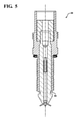
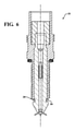
図1~17は、逆方向に組み立てられたコロナ点火装置20の例示的な実施形態を示している。コロナ点火装置20は、高周波電圧を受け、高周波電場を出射することによって、燃料-空気混合物を電離し、内燃エンジンの燃焼室内にコロナ放電を提供する。コロナ点火装置20は、高周波電圧を受け、高周波電場を出射するための中心電極22と、中心電極22を取り囲む絶縁体24と、絶縁体24を取り囲む導電要素とを含む。導電要素は、金属シェル26を含み、必要に応じて中間部材28を含む。いくつかの実施形態、例えば図1~9の実施形態において、導電要素および絶縁体24は、絶縁体24が圧縮下にあるように配置され、張力のかかった状態にある絶縁体よりも、絶縁体24の強度を高めることができる。図17の実施形態において、絶縁体24は、圧縮下または張力下にないため、張力のかかった状態にある絶縁体よりも、高い強度を有する。
Detailed Description of Exemplary Embodiments FIGS. 1-17 show exemplary embodiments of a
図示のように、コロナ点火装置20の中心電極22は、中心軸Aに沿って、終端30から電極点火端32まで長手方向に延在している。中心電極22は、導電性材料から形成され、典型的には20~75KVピーク/ピーク範囲の高周波電圧を受け、典型的には0.8~1.2MHz範囲の高周波電場を出射する。例示の実施形態において、中心電極22は、電極点火端32に設けられたコロナ増強先端34、例えば図1~10および図17に示すように複数のプロングを含む先端を含む。中心電極22の終端30は、通常電気端子36に接続され、この電気端子は、最終的には点火コイル(図示せず)に接続されている。点火コイルは、高周波電圧を供給するためのエネルギー源に接続されている。
As shown, the
また、コロナ点火装置20の絶縁体24は、中心軸Aに沿って、絶縁体上方端部38から絶縁体ノーズ端部40まで長手方向に延在する。絶縁体24は、典型的には中心電極22を取り囲む。図1~10および図17に示すように、電極点火端32は、絶縁体ノーズ端部40の外側に配置されている。絶縁体内面42は、中心電極22を受け入れるためのボアを取り囲む。シール44を電気端子36の周りのボアに配置することによって、中心電極22は、電気端子36に固定される。
Further, the
絶縁体内面42は、中心軸Aを横切って垂直に延在する絶縁体内径Diiを呈する。また、絶縁体24は、絶縁体上方端部38から絶縁体ノーズ端部40まで延在する絶縁体外面46を含む。絶縁体外面46は、中心軸Aを横切って垂直に延在する絶縁体外径Dioを呈する。絶縁体内径Diiは、好ましくは、絶縁体外径Dioの15~40%である。
The insulating
図1~9の実施形態において、絶縁体外面46は、絶縁体上方端部38と絶縁体ノーズ端部40との間にそれぞれ位置し、中心軸Aに対してそれぞれ径方向に延在する絶縁体上方肩部48および絶縁体下方肩部50を呈する。絶縁体上方肩部48および絶縁体下方肩部50の両方は、絶縁体上方端部38に面しており、絶縁体外径Dioの増加を呈する。図1~8に示すように、絶縁体下方肩部50における絶縁体外径Dioの増加は、一般的に絶縁体上方肩部48における増加よりも大きい。代替的に、図9に示すように、絶縁体下方肩部50における絶縁体外径Dioの増加は、相対的に小さくてもよい。
In the embodiments of FIGS. 1 to 9, the insulator
図17の実施形態において、絶縁体24は、絶縁体上方端部38から絶縁体上方肩部48まで長手方向に延在し、その後、絶縁体上方肩部48から絶縁体下方肩部50まで長手方向に延在している。この実施形態において、絶縁体外径Dioは、絶縁体上方端部38から絶縁体上方肩部48まで一定である。絶縁体上方肩部48は、絶縁体上方端部38から絶縁体ノーズ端部40に向かう方向に絶縁体外径Dioの増加を呈する。これによって、絶縁体上方肩部40における絶縁体外径Dioは、絶縁体上方端部38における絶縁体外径Dioよりも大きい。同様に、絶縁体外径Dioは、絶縁体上方肩部48から絶縁体下方肩部50まで一定である。絶縁体下方肩部50は、絶縁体上方端部38から絶縁体ノーズ端部40に向かう方向に絶縁体外径Dioの別の増加を呈する。これによって、絶縁体下方肩部50における絶縁体外径Dioは、絶縁体上方肩部48における絶縁体外径Dioよりも大きい。その後、絶縁体外径Dioは、絶縁体下方肩部50から絶縁体ノーズ端部40に向かって減少する。以下でさらに説明するように、この実施形態において、絶縁体24は、1つの場所のみ、具体的には、絶縁体上方肩部48と絶縁体下方肩部50との間にある場所において支持されている。したがって、絶縁体24は、組み立て中、組み立て後またはエンジンに配置された後、張力のかかった状態にも圧縮のかかった状態にもない。
In the embodiment of FIG. 17, the
特定の実施形態において、図1、図2および図4~8に示すように、絶縁体外径Dioは、絶縁体上方肩部48と絶縁体下方肩部50との間に位置する中央レッジ52を呈するように、(絶縁体上方端部38から絶縁体ノーズ端部40に向かう方向に)減少し、その後、絶縁体下方肩部50から再び増加する。例えば、絶縁体24は、中央レッジ52と絶縁体下方肩部50との間に位置する絶縁体溝54を含むことができる。絶縁体溝54は、凹状であってもよく、様々な長さおよび深さで延在してもよい。例えば、図1、図7および図8の絶縁体溝54は、図2および図4~6の絶縁体溝54よりも長い。図3の実施形態において、図3Aに最もよく示されているように、絶縁体溝54の代わりに、絶縁体外面46は、凹部58によって離間された複数のリブ56を呈する。リブ56および凹部58は、絶縁体下方肩部50に隣接して設けられる。
In a particular embodiment, as shown in FIGS. 1, 2 and 4-8, the insulator outer diameter Dio is a
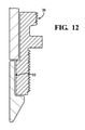
絶縁体24は、アルミナまたはセラミックなどの絶縁材料からなる1つまたは複数個の部品から形成されてもよい。図1~9の実施形態において、絶縁体24は、1つの材料部品から形成されている。しかしながら、図10~12の実施形態において、絶縁体24は、2つの材料部品から形成されている。一般的に、2つの部品は、圧入された後、ガラスシール60を用いて固定される。図10の実施形態において、中心電極22は、絶縁体ノーズ端部40を支持するように配置される。図11および図12の実施形態において、絶縁体上方端部38から絶縁体ノーズ端部40に向かって延在する第2の部品は、外側金型または別個のキャップ端として設けられてもよい。
The
図示のように、コロナ点火装置20の導電要素は、絶縁体ノーズ端部40に隣接する絶縁体ノーズ領域が導電要素の外側に延在するように、絶縁体24の少なくとも一部を取り囲む。導電要素は、シェル26を含み、中間部材28を含んでもよい。シェル26および中間部材28は、同様の導電性材料から形成されてもよく、異なる導電性材料から形成されてもよい。例えば、シェル26は、鋼から形成されてもよく、中間部材28は、ニッケル、コバルト、鉄、銅、錫、亜鉛、銀および金のうち1つ以上を含む金属または合金から形成されてもよい。
As shown, the conductive element of the
コロナ点火装置20のシェル26は、中心軸Aに沿って、シェル上方端部62からシェル点火端64まで延在する。シェル26は、中心軸Aに面し且つ絶縁体外面46に沿ってシェル上方端部62からシェル点火端64まで延在するシェル内面66を呈する。また、シェル26は、シェル内面66の反対側に面し且つシェル外径Dsoを呈するシェル外面68を含む。シェル内面66は、中心軸Aを取り囲むボアと、中心軸Aを横切って垂直に延在するシェル内径Dsiとを呈する。
The
図1~8および図17に示すように、シェル内面66は、一般的には、中心軸線Aに対して径方向に延在し、シェル上方端部62とシェル点火端64との間に位置するシェル上方肩部70を呈する。上方肩部70は、絶縁体上方肩部48と係合することによって、絶縁体24を圧縮して、絶縁体24の強度を高める。図1~8の実施形態において、必要に応じて、可撓性絶縁要素72は、シェル上方肩部70の上方のシェル26のボアに配置され、絶縁体上方端部38を取り囲む。
As shown in FIGS. 1-8 and 17, the shell
図1~8に示すように、シェル上方肩部70におけるシェル内径Dsiが絶縁体上方肩部48における絶縁体外径Dio以下であるため、コロナ点火装置20は、逆方向に組み立てられる。「逆方向に組み立てる」という用語は、シェル点火端64から絶縁体上方端部38をシェル26のボアに挿入することを意味する。代替的に、コロナ点火装置20を順方向に組み立てるように設計することもできる。「順方向に組み立てる」という用語は、シェル上方端部62から絶縁体ノーズ端部40をシェル26のボアに挿入することを意味する。
As shown in FIGS. 1 to 8, since the shell inner diameter D si in the shell
図17の実施形態において、シェル内径Dsiは、シェル上方肩部70を呈するように絶縁体上方肩部48の上方からわずかに増加し、その後、シェル上方肩部70からシェル点火端64まで一定になる。シェル上方肩部70と絶縁体上方肩部48との間には間隙が存在する。シェル点火端64におけるシェル内径Dsiは、絶縁体下方肩部50における絶縁体外径Dioよりも小さい。シェル点火端64は、絶縁体下方肩部50に載置される。したがって、図17のコロナ点火装置20は、逆方向に組み立てられなければならない。この場合、絶縁体上部端38は、シェル点火端64が絶縁体上方肩部48と係合するまでシェル点火端64から挿入される。
In the embodiment of FIG. 17, the shell inner diameter D si increases slightly from above the insulator
図9および図14の実施形態において、シェル26は、シェル上方肩部70の代わりに、シェル上方端部62に設けられた上方折返(turnover)フランジ74を含む。上方折返フランジ74は、中心軸Aに向かって径方向内側に延在し、絶縁体上方肩部48と係合することによって、絶縁体24を圧縮して、絶縁体24の強度を高める。図9の実施形態において、シェル外面68は、シェル上方端部62の近傍に設けられた一対のシェルリブ76および77と、シェル点火端64の近傍に設けられたノッチ78とを呈する。上方シェルリブ76は、六角形と呼ばれ、下方シェルリブ77は、ガスケットシートと呼ばれる。シェルリブ76および77は、溝によって互いに離間される。下方シェルリブ77は、シェル26のねじ領域の真上に配置されている。この実施形態において、シェル内面66は、ノッチの反対側に位置するビード80を呈する。図14の実施形態において、絶縁体24とシェル26の上方折返フランジ74との間には、樹脂82が射出成形されている。
In embodiments of FIGS. 9 and 14, the
シェル26は、好ましくは、シェル上方肩部70とシェル点火端64との間に溝86を有するように設計される。溝86は、シェル26の一部の厚さを減少することによって、シェル26の可撓性を高める。コロナ点火装置20を内燃エンジンに挿入するときに、シェル26は、絶縁体24に張力をかけることなく伸縮することができる。図15および図16は、逆方向に組み立てられ、溝86を含むコロナ点火装置20の例を示している。これらの実施形態において、溝86は、シェル内面66の一部に沿ってまたはガスケットシート88の上方のシェル内面68に沿って形成される。
The
図1、図3、図6~8、図9および図13に示すように、絶縁体24を圧縮するために、導電要素は、上方折返フランジ74に加えて、シェル点火端64に隣接する中間部材28を含むことができる。図1の実施形態において、中間部材28は、絶縁体溝54に配置された割れ目のある鋼製スリーブである。この実施形態において、中間部材28は、中央レッジ52と係合しており、絶縁体下方肩部50から離れている。代替的に、中間部材28は、中央レッジ52に加えてまたはその代わりに、絶縁体下方肩部50と係合してもよい。また、図1の中間部材28は、シェル点火端64に隣接して、金属層を介して絶縁体24および/またはシェル26に溶接またはろう付けされる。図3の実施形態において、中間部材28を用いて、絶縁体下方肩部50およびシェル点火端64に隣接して、絶縁体24をシェル26にろう付けする。図3Aに最もよく示されているように、中間部材28は、絶縁体リブ56および凹部58に沿って配置された薄い金属層である。この金属層は、液体で塗布され、その後、絶縁体24とシェル26との間で固化する。図6の実施形態において、中間部材28は、絶縁体24の中央レッジ52およびシェル点火端64に当接して配置された割れ目のあるリングガスケットである。図7の実施形態において、中間部材28は、中央レッジ52とシェル点火端64との間に配置された割れ目のある銅インサートまたは中実の銅インサートである。図8の実施形態において、中間部材28は、シェル点火端64に隣接して中央レッジ52と係合する中実の鋼製スリーブまたは割れ目のある鋼製スリーブである。この鋼製スリーブは、図1の鋼製スリーブと同様に絶縁体下方肩部50から離れている。図8の実施形態において、鋼製スリーブは、例えば銀半田を介して、シェル26および/または絶縁体24にレーザ溶接または半田付けされる。図9の実施形態において、中間部材28は、ガスケットまたは銅製リングであり、絶縁体24の中央レッジ52と係合している。絶縁体外面46は、絶縁体溝54に沿って金属でメッキされている。図13の実施形態において、中間部材28は、銅または同様の材料から形成され、絶縁体下方肩部50に圧入される。中間部材28は、固体材料部品を含んでもよい。その後、固体材料部品に追加のろう付け合金または半田を適用することによって、固体材料部品を絶縁体24およびシェル26に固定することができる。例えば、図13の中間部材28は、ろう付け、溶接、接着、半田付けまたは圧入によって、シェル内面66に取り付けられる。
As shown in FIGS. 1, 3, 6-8, 9 and 13, in order to compress the
図17の実施形態において、中間部材28は、絶縁体24を金属シェル26に固定またはろう付けするための金属層である。例示的な実施形態において、金属は、ニッケル、コバルト、鉄、銅、錫、亜鉛、銀および金のうち1つ以上を含む。この金属層を用いて、絶縁体24をシェル26にろう付けする。
In the embodiment of FIG. 17, the
別の例示的な実施形態において、中間部材28は、固体金属部品、具体的には絶縁体24の周りに配置された銀(Ag)および/または銅(Cu)合金から形成された固体リングから形成される。次に、シェル26を絶縁体24の周りに配置し、組立体を加熱する。加熱によって、ろう付け合金と呼ばれる固体リングは、液体になり、毛管作用によって「ろう付け領域」と呼ばれる領域に吸い上げられる。部品が冷却すると、液体合金が凝固して、中間部材28を絶縁体24およびシェル26にろう付けする。このプロセスによって、部品が冷却して合金が凝固すると、要素間の収縮差によって、セラミック絶縁体24が圧縮される。エンジン運転中、エンジン温度が中間部材28を形成するために使用されたろう付け合金の融点には達さないため、中間部材28は、エンジン運転中に固体のままである。代替的に、上述したろう付けプロセスを用いて、別の金属材料、例えば固体リングよりも低い融点を有する別の金属を介して、固体リングを絶縁体24およびシェル26にろう付けすることによって、中間部材28を形成することができる。
In another exemplary embodiment, the
図2および図4~7に示すように、中間部材28に加えてまたはその代わりに、シェル26は、シェル点火端64に下方折返フランジ84を含むことによって、絶縁体24を圧縮することができる。図2の実施形態において、下方折返フランジ84は、比較的厚く、絶縁体24の中央レッジ52と係合する。この実施形態において、中央レッジ52と下方折返フランジ84との間には、中間部材28が配置されておらず、絶縁体ノーズ領域の長さが比較的長い。図4の実施形態において、下方折返フランジ84も比較的厚く、絶縁体24の中央レッジ52と係合するが、絶縁体ノーズ領域の長さが短い。図5の実施形態において、下方折返フランジ84は、絶縁体24の中央レッジ52と係合するが、両者の間には中間部材28が配置されていない。この実施形態において、下方折返フランジ84は、より太いため、他の実施形態よりもやや長くて厚い。図6および図7の実施形態において、シェル26の下方折返フランジ84は、中間部材28の下方端部と係合する。シェル26が下方折返フランジ84を含むいずれかの場合において、シェル点火端64は、絶縁体溝54に配置され、絶縁体下方肩部50から離れている。代替的に、シェル点火端64は、絶縁体下方肩部50と係合してもよい。
As shown in FIGS. 2 and 4-7, in addition to or in place of the
上述したように、シェル上方肩部70または上方折返フランジ74は、図1~9の実施形態の溝86、中間部材28および/または下方折返フランジ84と共に、絶縁体24を圧縮する。一般的には、絶縁体24を内燃エンジンの開口部に配置する前に、2kN~15kN範囲の圧縮荷重を絶縁体24に加える。絶縁体24は、内燃エンジンに設置された後も圧縮下に維持される。の絶縁体24の機械強度は、張力下の絶縁体の機械強度よりも高い。例えば、絶縁体24の強度は、一般的に張力下の場合に200MPa~600MPaであるが、圧縮下の場合に3000MPa~4000MPaである。したがって、絶縁体24をエンジン内に配置した後に絶縁体24に加えられた荷重は、圧縮から張力まで変動できるが、動作範囲の全体において絶縁体24を圧縮力のかけられた状態に保つことが望ましい。図17の実施形態において、絶縁体24は、絶縁体下方肩部50と絶縁体上方肩部48との間の1つの場所のみでシェル26に支持されまたは機械的に固定されているため、組み立て中またはエンジンに設置された後に圧縮力のかけられた状態にも張力のかけられた状態にもない。したがって、図17の絶縁体24は、優れた強度を有する。
As described above, the shell
本発明の他の態様は、上述の逆方向に組み立てられたコロナ点火装置20を製造する方法を提供する。コロナ点火装置20は、通常、逆方向に組み立てられる。この場合、方法は、シェル点火端64から絶縁体上方端部38を挿入するステップを含む。図1~8の実施形態において、絶縁体上方肩部48は、シェル上方肩部70に対して押し付けられる。図17の実施形態において、絶縁体24は、絶縁体下方肩部50がシェル点火端64と係合するまでシェル点火端64から挿入される。図9および図14の実施形態において、シェル上方端部62は、絶縁体上方肩部48の上方で中心軸Aに向かって内側に曲げられ、シェル26の上方折返フランジ74を形成する。このステップは、絶縁体24をシェル26内に設置した後に行われる。代替的な実施形態において、コロナ点火装置20を順方向に組み立てるように設計することができる。この場合、方法は、シェル上方端部62から絶縁体上方端部38を挿入する前に、シェル上方端部62から絶縁体ノーズ端部40を挿入するステップを含む。
Another aspect of the invention provides a method of manufacturing the
図1、図3、図6~9および図13に示された、中間部材28を含むコロナ点火装置20の実施形態を形成するために、方法は、絶縁体24をシェル26内に設置する前または後に、中間部材28を絶縁体24および/またはシェル26に固定するステップを含む。例えば、図1のコロナ点火装置20を形成する方法は、単に中間部材28を絶縁体24の溝54に配置し、その後、シェル26の下方端部から、中間部材28および絶縁体24を同時に挿入するステップを含むことができる。中間部材28および絶縁体24をシェル26に挿入した後、中間部材28は、例えばろう付け、溶接または圧入によって、シェル内面66に固定される。図6~8のコロナ点火装置20を形成する方法は、絶縁体24をシェル26に挿入する前に、中間部材28を絶縁体24にろう付け、半田付けまたは溶接し、その後、必要に応じて中間部材28をろう付け、半田付けまたは溶接するステップを含むことができる。上述したように、中間部材28は、固体部品および当該固体部品を絶縁体24およびシェル26に固定するための追加のろう付け合金を含むことができる。図3のコロナ点火装置20を形成する方法は、絶縁体24をシェル26に設置した後、中間部材28を用いて、絶縁体24をシェル26に固定するステップを含む。この実施形態において、方法は、液体金属の中間部材28を絶縁体24とシェル26との間の小さな間隙に適用し、その後、液体金属を凝固させるステップを含む。代替的に、方法は、絶縁体24をシェル26に挿入する直前に、液体金属を絶縁体24に適用し、その後、液体金属を凝固させることによって絶縁体24をシェル26にろう付けするステップを含むことができる。
In order to form the embodiment of the
図1、図4および図5のコロナ点火装置20を形成するために、方法は、絶縁体下方肩部50に対してシェル点火端64を中心軸Aに向かって内側に曲げることによって、シェル26の下方折返フランジ84を形成することをさらに含む。このステップは、絶縁体24をシェル26に配置した後に行われる。代替的に、図6および図8に示すように、方法は、シェル点火端64を中間部材28の下方端部に対して曲げることによって、下方折返フランジ84を形成するステップを含むことができる。
To form the
図17の実施形態において、絶縁体24をシェル26に挿入した後、絶縁体外面46とシェル内面66との間および絶縁体下方肩部50と絶縁体上方肩部52との間に、液体形態の金属からなる層を適用する。典型的には、金属を溶融して、絶縁体24とシェル26との間の小さな間隙に流れ込む。次に、液体金属は、冷却し凝固することによって、中間部材28を形成して、絶縁体24をシェル26にろう付けする。
In the embodiment of FIG. 17, after the
明らかには、上記の教示に鑑みて、本発明の多くの変形例および変更例が可能であり、添付の特許請求の範囲の範囲内であれば、具体的に記載されている態様とは異なる態様で実施されてもよい。全ての請求項および全ての実施形態の全ての特徴は、互いに矛盾しない限り互いに組み合わせられてもよいと考えられる。 Obviously, in view of the above teachings, many modifications and modifications of the present invention are possible and differ from the specifically described embodiments within the scope of the appended claims. It may be carried out in an embodiment. It is believed that all claims and all features of all embodiments may be combined with each other as long as they do not contradict each other.
Claims (20)
導電性材料から形成され、高周波電圧を受け、前記高周波電場を出射するための中心電極と、
電気絶縁材料から形成され、前記中心電極を取り囲み且つ絶縁体上方端部から絶縁体ノーズ端部まで長手方向に延在する絶縁体とを備え、
前記絶縁体は、前記絶縁体上方端部から前記絶縁体ノーズ端部まで延在する絶縁体外面を含み、
前記絶縁体外面は、絶縁体外径を呈し、
前記絶縁体外面は、外側に延在し且つ前記絶縁体上方端部と前記絶縁体ノーズ端部との間に位置する絶縁体下方肩部を含み、
前記絶縁体下方肩部は、前記絶縁体外径の増加を呈し、
前記コロナ点火装置は、
前記絶縁体の少なくとも一部を取り囲み且つシェル上方端部からシェル点火端まで延在するシェルを備え、
前記シェルは、前記絶縁体外面に面し且つ前記絶縁体外面に沿って前記シェル上方端部から前記シェル点火端まで延在するシェル内面を呈し、
前記シェル内面は、シェル内径を呈し、
前記シェルの少なくとも1つの場所における前記シェル内径は、前記絶縁体下方肩部における前記絶縁体外径よりも小さく、
前記コロナ点火装置は、
導電性材料から形成され、前記絶縁体外面と前記シェル内面との間および前記絶縁体上方端部と前記絶縁体下方肩部との間に配置された中間部材を備え、
前記中間部材は、前記絶縁体下方肩部から離れている、コロナ点火装置。 A corona igniter for ionizing a fuel-air mixture and providing a corona discharge by emitting a high frequency electric field.
A center electrode formed of a conductive material, which receives a high frequency voltage and emits the high frequency electric field,
It comprises an insulator formed of an electrically insulating material that surrounds the center electrode and extends longitudinally from the upper end of the insulator to the end of the nose of the insulator.
The insulator includes an insulator outer surface extending from the upper end of the insulator to the end of the nose of the insulator.
The outer surface of the insulator exhibits an outer diameter of the insulator.
The outer surface of the insulator comprises an insulator lower shoulder that extends outward and is located between the insulator upper end and the insulator nose end.
The lower shoulder of the insulator exhibits an increase in the outer diameter of the insulator.
The corona igniter is
It comprises a shell that surrounds at least a portion of the insulator and extends from the upper end of the shell to the ignition end of the shell.
The shell faces the outer surface of the insulator and exhibits an inner surface of the shell extending from the upper end of the shell to the ignition end of the shell along the outer surface of the insulator.
The inner surface of the shell exhibits an inner diameter of the shell.
The inner diameter of the shell at at least one place of the shell is smaller than the outer diameter of the insulator at the lower shoulder of the insulator.
The corona igniter is
It comprises an intermediate member formed of a conductive material and disposed between the outer surface of the insulator and the inner surface of the shell and between the upper end of the insulator and the lower shoulder of the insulator.
The intermediate member is a corona igniter that is separated from the lower shoulder of the insulator .
前記絶縁体は、前記中央レッジと前記絶縁体下方肩部との間に位置する溝を含み、
前記中間部材は、前記溝に配置されている、請求項1記載のコロナ点火装置。 The insulator outer diameter exhibits a central ledge away from the increase in the insulator outer diameter at the lower shoulder of the insulator by decreasing.
The insulator includes a groove located between the central ledge and the lower shoulder of the insulator.
The corona ignition device according to claim 1, wherein the intermediate member is arranged in the groove.
前記下方折返フランジは、前記絶縁体の径方向内側および前記溝内に延在し、
前記中間部材は、前記下方折返フランジと前記絶縁体外面との間に位置する前記溝内に配置されている、請求項8に記載のコロナ点火装置。 The shell includes a downward folding flange at the shell ignition end.
The downward folded flange extends radially inside the insulator and into the groove.
The corona ignition device according to claim 8 , wherein the intermediate member is arranged in the groove located between the lower folded flange and the outer surface of the insulator.
導電性材料から形成され、高周波電圧を受け、前記高周波電場を出射するための中心電極と、
電気絶縁材料から形成され、前記中心電極を取り囲み且つ絶縁体上方端部から絶縁体ノーズ端部まで長手方向に延在する絶縁体とを備え、
前記絶縁体は、前記絶縁体上方端部から前記絶縁体ノーズ端部まで延在する絶縁体外面を含み、
前記絶縁体外面は、絶縁体外径を呈し、
前記絶縁体外面は、外側に延在し且つ前記絶縁体上方端部と前記絶縁体ノーズ端部との間に位置する絶縁体下方肩部を含み、
前記絶縁体下方肩部は、前記絶縁体外径の増加を呈し、
前記コロナ点火装置は、
前記絶縁体の少なくとも一部を取り囲み且つシェル上方端部からシェル点火端まで延在するシェルを備え、
前記シェルは、前記絶縁体外面に面し且つ前記絶縁体外面に沿って前記シェル上方端部から前記シェル点火端まで延在するシェル内面を呈し、
前記シェル内面は、シェル内径を呈し、
前記シェルの少なくとも1つの場所における前記シェル内径は、前記絶縁体下方肩部における前記絶縁体外径よりも小さく、
前記コロナ点火装置は、
導電性材料から形成され、前記絶縁体外面と前記シェル内面との間および前記絶縁体上方端部と前記絶縁体下方肩部との間に配置された中間部材を備え、
前記中間部材は、金属層であり、
前記絶縁体外面は、前記中間部材に沿って、凹部によって離間された複数のリブを呈する、コロナ点火装置。 A corona igniter for ionizing a fuel-air mixture and providing a corona discharge by emitting a high frequency electric field.
A center electrode formed of a conductive material, which receives a high frequency voltage and emits the high frequency electric field,
It comprises an insulator formed of an electrically insulating material that surrounds the center electrode and extends longitudinally from the upper end of the insulator to the end of the nose of the insulator.
The insulator includes an insulator outer surface extending from the upper end of the insulator to the end of the nose of the insulator.
The outer surface of the insulator exhibits an outer diameter of the insulator.
The outer surface of the insulator comprises an insulator lower shoulder that extends outward and is located between the insulator upper end and the insulator nose end.
The lower shoulder of the insulator exhibits an increase in the outer diameter of the insulator.
The corona igniter is
It comprises a shell that surrounds at least a portion of the insulator and extends from the upper end of the shell to the ignition end of the shell.
The shell faces the outer surface of the insulator and exhibits an inner surface of the shell extending from the upper end of the shell to the ignition end of the shell along the outer surface of the insulator.
The inner surface of the shell exhibits an inner diameter of the shell.
The inner diameter of the shell at at least one place of the shell is smaller than the outer diameter of the insulator at the lower shoulder of the insulator.
The corona igniter is
It comprises an intermediate member formed of a conductive material and disposed between the outer surface of the insulator and the inner surface of the shell and between the upper end of the insulator and the lower shoulder of the insulator.
The intermediate member is a metal layer and
A corona igniter whose outer surface of the insulator exhibits a plurality of ribs separated by recesses along the intermediate member.
導電性材料から形成され、高周波電圧を受け、前記高周波電場を出射するための中心電極と、
電気絶縁材料から形成され、前記中心電極を取り囲み且つ絶縁体上方端部から絶縁体ノーズ端部まで長手方向に延在する絶縁体とを備え、
前記絶縁体は、前記絶縁体上方端部から前記絶縁体ノーズ端部まで延在する絶縁体外面を含み、
前記絶縁体外面は、絶縁体外径を呈し、
前記絶縁体外面は、外側に延在し且つ前記絶縁体上方端部と前記絶縁体ノーズ端部との間に位置する絶縁体下方肩部を含み、
前記絶縁体下方肩部は、前記絶縁体外径の増加を呈し、
前記コロナ点火装置は、
前記絶縁体の少なくとも一部を取り囲み且つシェル上方端部からシェル点火端まで延在するシェルを備え、
前記シェルは、前記絶縁体外面に面し且つ前記絶縁体外面に沿って前記シェル上方端部から前記シェル点火端まで延在するシェル内面を呈し、
前記シェル内面は、シェル内径を呈し、
前記シェルの少なくとも1つの場所における前記シェル内径は、前記絶縁体下方肩部における前記絶縁体外径よりも小さく、
前記コロナ点火装置は、
導電性材料から形成され、前記絶縁体外面と前記シェル内面との間および前記絶縁体上方端部と前記絶縁体下方肩部との間に配置された中間部材を備え、
前記絶縁体は、前記絶縁体上方端部から絶縁体上方肩部までおよび前記絶縁体上方肩部から前記絶縁体下方肩部まで長手方向に延在し、
前記絶縁体上方肩部は、前記絶縁体外径の増加を呈し、
前記絶縁体外径は、前記絶縁体上方端部から前記絶縁体上方肩部まで一定であり、
前記絶縁体上方肩部における前記絶縁体外径は、前記絶縁体上方端部における前記絶縁体外径よりも大きく、
前記絶縁体下方肩部における前記絶縁体外径は、前記絶縁体上方肩部における前記絶縁体外径よりも大きく、
前記絶縁体外径は、前記絶縁体下方肩部から前記絶縁体ノーズ端部まで減少し、
前記絶縁体が張力のかかった状態ではなく、圧縮された状態でもないように、前記絶縁体は、前記中間部材のみに沿って支持され、
前記シェル点火端は、前記絶縁体下方肩部と係合し、
前記シェル点火端における前記シェル内径は、前記絶縁体下方肩部における前記絶縁体外径よりも小さく、
前記中間部材は、前記絶縁体を前記シェルに固定するための金属層であり、前記金属層は、ニッケル、コバルト、鉄、銅、錫、亜鉛、銀および金のうち1つ以上を含み、
前記中心電極は、前記絶縁体ノーズ端部の外側に配置され、径方向外側に延在する複数のプロングを有するコロナ増強先端を含む、コロナ点火装置。 A corona igniter for ionizing a fuel-air mixture and providing a corona discharge by emitting a high frequency electric field.
A center electrode formed of a conductive material, which receives a high frequency voltage and emits the high frequency electric field,
It comprises an insulator formed of an electrically insulating material that surrounds the center electrode and extends longitudinally from the upper end of the insulator to the end of the nose of the insulator.
The insulator includes an insulator outer surface extending from the upper end of the insulator to the end of the nose of the insulator.
The outer surface of the insulator exhibits an outer diameter of the insulator.
The outer surface of the insulator comprises an insulator lower shoulder that extends outward and is located between the insulator upper end and the insulator nose end.
The lower shoulder of the insulator exhibits an increase in the outer diameter of the insulator.
The corona igniter is
It comprises a shell that surrounds at least a portion of the insulator and extends from the upper end of the shell to the ignition end of the shell.
The shell faces the outer surface of the insulator and exhibits an inner surface of the shell extending from the upper end of the shell to the ignition end of the shell along the outer surface of the insulator.
The inner surface of the shell exhibits an inner diameter of the shell.
The inner diameter of the shell at at least one place of the shell is smaller than the outer diameter of the insulator at the lower shoulder of the insulator.
The corona igniter is
It comprises an intermediate member formed of a conductive material and disposed between the outer surface of the insulator and the inner surface of the shell and between the upper end of the insulator and the lower shoulder of the insulator.
The insulator extends longitudinally from the upper end of the insulator to the upper shoulder of the insulator and from the upper shoulder of the insulator to the lower shoulder of the insulator.
The upper shoulder of the insulator exhibits an increase in the outer diameter of the insulator.
The outer diameter of the insulator is constant from the upper end of the insulator to the upper shoulder of the insulator.
The insulator outer diameter at the insulator upper shoulder portion is larger than the insulator outer diameter at the insulator upper end portion.
The insulator outer diameter in the insulator lower shoulder portion is larger than the insulator outer diameter in the insulator upper shoulder portion.
The outer diameter of the insulator is reduced from the lower shoulder of the insulator to the end of the nose of the insulator.
The insulator is supported only along the intermediate member so that the insulator is neither in a tensioned state nor in a compressed state.
The shell ignition end engages with the insulator lower shoulder and
The inner diameter of the shell at the ignition end of the shell is smaller than the outer diameter of the insulator at the lower shoulder of the insulator.
The intermediate member is a metal layer for fixing the insulator to the shell, and the metal layer contains one or more of nickel, cobalt, iron, copper, tin, zinc, silver and gold.
A corona igniter comprising a corona-enhanced tip located outside the insulator nose end and having a plurality of prongs extending radially outward.
電気絶縁材料から形成され、絶縁体上方端部から絶縁体ノーズ端部まで延在する絶縁体を提供するステップを含み、
前記絶縁体は、前記絶縁体上方端部から前記絶縁体ノーズ端部まで延在し且つ絶縁体外径を呈する絶縁体外面を含み、前記絶縁体外面は、外側に延在し且つ前記絶縁体上方端部と前記絶縁体ノーズ端部との間に位置する絶縁体下方肩部を呈し、前記絶縁体下方肩部は、前記絶縁体外径の増加を呈し、
シェル上方端部からシェル点火端まで延在し、シェルボアを呈するシェル内面を含むシェルを提供するステップを含み、前記シェル内面は、シェル内径を呈し、前記シェルの少なくとも1つの場所における前記シェル内径は、前記絶縁体下方肩部における前記絶縁体外径よりも小さく、
前記シェル点火端から、前記絶縁体上方端部を前記シェルボアに挿入するステップと、
導電性材料から形成された中間部材を前記絶縁体外面と前記シェル内面との間に配置するステップとを含み、
前記シェル点火端を前記絶縁体下方肩部に係合させることを含む、方法。 A method of forming a corona igniter,
Including the step of providing an insulator formed from an electrically insulating material and extending from the upper end of the insulator to the end of the nose of the insulator.
The insulator includes an insulator outer surface that extends from the insulator upper end to the insulator nose end and exhibits an insulator outer diameter, and the insulator outer surface extends outward and is above the insulator. The lower shoulder of the insulator is located between the end and the end of the nose of the insulator, and the lower shoulder of the insulator exhibits an increase in the outer diameter of the insulator.
The shell inner surface comprises a step of providing a shell extending from the upper end of the shell to the shell ignition end and comprising a shell inner surface exhibiting a shell bore, wherein the shell inner surface exhibits a shell inner diameter and the shell inner diameter at at least one location of the shell. , Smaller than the outer diameter of the insulator at the lower shoulder of the insulator,
A step of inserting the upper end of the insulator into the shell bore from the shell ignition end,
Including a step of arranging an intermediate member formed of a conductive material between the outer surface of the insulator and the inner surface of the shell.
A method comprising engaging the shell ignition end with the insulator lower shoulder .
前記絶縁体は、前記中央レッジと前記絶縁体下方肩部との間に位置する溝を含み、
前記中間部材を前記絶縁体外面と前記シェル内面との間に配置するステップは、前記中間部材を前記溝に配置することを含む、請求項15に記載の方法。 By reducing the outer diameter of the insulator, it exhibits a central ledge away from the lower shoulder of the insulator.
The insulator includes a groove located between the central ledge and the lower shoulder of the insulator.
15. The method of claim 15 , wherein the step of arranging the intermediate member between the outer surface of the insulator and the inner surface of the shell comprises arranging the intermediate member in the groove.
前記下方折返フランジを前記溝内に弯曲させることを含む、請求項19に記載の方法。 The shell includes a downward folding flange at the shell ignition end.
19. The method of claim 19 , comprising bending the lower folded flange into the groove.
Applications Claiming Priority (3)
| Application Number | Priority Date | Filing Date | Title |
|---|---|---|---|
| US15/240,502 | 2016-08-18 | ||
| US15/240,502 US10056737B2 (en) | 2012-03-23 | 2016-08-18 | Corona ignition device and assembly method |
| PCT/US2017/046344 WO2018034943A1 (en) | 2016-08-18 | 2017-08-10 | Corona ignition device and assembly method |
Publications (3)
| Publication Number | Publication Date |
|---|---|
| JP2019525430A JP2019525430A (en) | 2019-09-05 |
| JP2019525430A5 JP2019525430A5 (en) | 2020-09-17 |
| JP7005595B2 true JP7005595B2 (en) | 2022-01-21 |
Family
ID=59677397
Family Applications (1)
| Application Number | Title | Priority Date | Filing Date |
|---|---|---|---|
| JP2019509459A Active JP7005595B2 (en) | 2016-08-18 | 2017-08-10 | Corona igniter and assembly method |
Country Status (5)
| Country | Link |
|---|---|
| EP (1) | EP3501072A1 (en) |
| JP (1) | JP7005595B2 (en) |
| KR (1) | KR20190039228A (en) |
| CN (1) | CN109964376A (en) |
| WO (1) | WO2018034943A1 (en) |
Families Citing this family (1)
| Publication number | Priority date | Publication date | Assignee | Title |
|---|---|---|---|---|
| JP6678199B2 (en) * | 2018-05-23 | 2020-04-08 | 日本特殊陶業株式会社 | Spark plug |
Citations (2)
| Publication number | Priority date | Publication date | Assignee | Title |
|---|---|---|---|---|
| JP2015512556A (en) | 2012-03-23 | 2015-04-27 | フェデラル−モーグル・イグニション・カンパニーFederal−Mogul Ignition Company | Corona igniter with improved electrical performance |
| JP2016522544A (en) | 2013-05-03 | 2016-07-28 | フェデラル−モーグル・イグニション・カンパニーFederal−Mogul Ignition Company | Corona igniter with hermetic combustion seal |
Family Cites Families (7)
| Publication number | Priority date | Publication date | Assignee | Title |
|---|---|---|---|---|
| US6883507B2 (en) | 2003-01-06 | 2005-04-26 | Etatech, Inc. | System and method for generating and sustaining a corona electric discharge for igniting a combustible gaseous mixture |
| FR2884365B1 (en) * | 2005-04-08 | 2013-10-11 | Renault Sas | MULTI-SPARK CANDLE WITH OPEN BEDROOM |
| JP5688368B2 (en) | 2008-10-03 | 2015-03-25 | フェデラル−モーグル・イグニション・カンパニーFederal−Mogul Ignition Company | Ignition device for air-fuel mixture, engine including the same, and method for assembling the cylinder head |
| FR2965984B1 (en) * | 2010-10-12 | 2012-10-12 | Renault Sa | PREVENTION AGAINST A SHORT CIRCUIT OF THE RF CANDLE |
| EP2652848B1 (en) | 2010-12-14 | 2018-09-19 | Federal-Mogul Ignition Company | Corona igniter having shaped insulator |
| DE102014111897B4 (en) * | 2013-10-31 | 2020-06-25 | Borgwarner Ludwigsburg Gmbh | Ignition device for igniting fuel-air mixtures in a combustion chamber of an internal combustion engine by means of a corona discharge |
| DE102014111684B3 (en) * | 2014-08-15 | 2015-10-01 | Borgwarner Ludwigsburg Gmbh | Koronazündeinrichtung |
-
2017
- 2017-08-10 CN CN201780064442.4A patent/CN109964376A/en active Pending
- 2017-08-10 WO PCT/US2017/046344 patent/WO2018034943A1/en unknown
- 2017-08-10 KR KR1020197007037A patent/KR20190039228A/en not_active Application Discontinuation
- 2017-08-10 EP EP17754969.8A patent/EP3501072A1/en active Pending
- 2017-08-10 JP JP2019509459A patent/JP7005595B2/en active Active
Patent Citations (2)
| Publication number | Priority date | Publication date | Assignee | Title |
|---|---|---|---|---|
| JP2015512556A (en) | 2012-03-23 | 2015-04-27 | フェデラル−モーグル・イグニション・カンパニーFederal−Mogul Ignition Company | Corona igniter with improved electrical performance |
| JP2016522544A (en) | 2013-05-03 | 2016-07-28 | フェデラル−モーグル・イグニション・カンパニーFederal−Mogul Ignition Company | Corona igniter with hermetic combustion seal |
Also Published As
| Publication number | Publication date |
|---|---|
| WO2018034943A1 (en) | 2018-02-22 |
| EP3501072A1 (en) | 2019-06-26 |
| KR20190039228A (en) | 2019-04-10 |
| JP2019525430A (en) | 2019-09-05 |
| WO2018034943A8 (en) | 2019-03-14 |
| CN109964376A (en) | 2019-07-02 |
Similar Documents
| Publication | Publication Date | Title |
|---|---|---|
| JP6757762B2 (en) | Corona igniter with improved electrical performance | |
| US10056737B2 (en) | Corona ignition device and assembly method | |
| US11557882B2 (en) | Corona ignition device with improved electrical performance | |
| JP6401246B2 (en) | Corona igniter with hermetic combustion seal | |
| JP2013539903A (en) | RF spark plug short circuit prevention | |
| JP7005595B2 (en) | Corona igniter and assembly method | |
| EP3338332B1 (en) | Corona ignition device and assembly method | |
| US20170214221A1 (en) | Corona igniter with hermetic combustion seal on insulator inner diameter | |
| JP7086052B2 (en) | Corona igniter with improved electrical performance |
Legal Events
| Date | Code | Title | Description |
|---|---|---|---|
| A521 | Written amendment |
Free format text: JAPANESE INTERMEDIATE CODE: A523 Effective date: 20200807 |
|
| A621 | Written request for application examination |
Free format text: JAPANESE INTERMEDIATE CODE: A621 Effective date: 20200807 |
|
| A977 | Report on retrieval |
Free format text: JAPANESE INTERMEDIATE CODE: A971007 Effective date: 20210730 |
|
| A131 | Notification of reasons for refusal |
Free format text: JAPANESE INTERMEDIATE CODE: A131 Effective date: 20210817 |
|
| A521 | Written amendment |
Free format text: JAPANESE INTERMEDIATE CODE: A523 Effective date: 20211116 |
|
| TRDD | Decision of grant or rejection written | ||
| A01 | Written decision to grant a patent or to grant a registration (utility model) |
Free format text: JAPANESE INTERMEDIATE CODE: A01 Effective date: 20211207 |
|
| A61 | First payment of annual fees (during grant procedure) |
Free format text: JAPANESE INTERMEDIATE CODE: A61 Effective date: 20220105 |
|
| R150 | Certificate of patent or registration of utility model |
Ref document number: 7005595 Country of ref document: JP Free format text: JAPANESE INTERMEDIATE CODE: R150 |