JP7005586B2 - Improvements in or related to connecting devices - Google Patents
Improvements in or related to connecting devices Download PDFInfo
- Publication number
- JP7005586B2 JP7005586B2 JP2019501505A JP2019501505A JP7005586B2 JP 7005586 B2 JP7005586 B2 JP 7005586B2 JP 2019501505 A JP2019501505 A JP 2019501505A JP 2019501505 A JP2019501505 A JP 2019501505A JP 7005586 B2 JP7005586 B2 JP 7005586B2
- Authority
- JP
- Japan
- Prior art keywords
- configuration
- mounting
- article
- protrusion
- connecting device
- Prior art date
- Legal status (The legal status is an assumption and is not a legal conclusion. Google has not performed a legal analysis and makes no representation as to the accuracy of the status listed.)
- Active
Links
- 125000006850 spacer group Chemical group 0.000 claims description 29
- 238000000034 method Methods 0.000 claims description 16
- 238000009434 installation Methods 0.000 claims description 6
- 238000010586 diagram Methods 0.000 description 3
- 238000003780 insertion Methods 0.000 description 3
- 230000037431 insertion Effects 0.000 description 3
- 238000012986 modification Methods 0.000 description 1
- 230000004048 modification Effects 0.000 description 1
Images


Classifications
-
- F—MECHANICAL ENGINEERING; LIGHTING; HEATING; WEAPONS; BLASTING
- F16—ENGINEERING ELEMENTS AND UNITS; GENERAL MEASURES FOR PRODUCING AND MAINTAINING EFFECTIVE FUNCTIONING OF MACHINES OR INSTALLATIONS; THERMAL INSULATION IN GENERAL
- F16B—DEVICES FOR FASTENING OR SECURING CONSTRUCTIONAL ELEMENTS OR MACHINE PARTS TOGETHER, e.g. NAILS, BOLTS, CIRCLIPS, CLAMPS, CLIPS OR WEDGES; JOINTS OR JOINTING
- F16B37/00—Nuts or like thread-engaging members
- F16B37/04—Devices for fastening nuts to surfaces, e.g. sheets, plates
- F16B37/045—Devices for fastening nuts to surfaces, e.g. sheets, plates specially adapted for fastening in channels, e.g. sliding bolts, channel nuts
- F16B37/046—Devices for fastening nuts to surfaces, e.g. sheets, plates specially adapted for fastening in channels, e.g. sliding bolts, channel nuts with resilient means for urging the nut inside the channel
-
- F—MECHANICAL ENGINEERING; LIGHTING; HEATING; WEAPONS; BLASTING
- F16—ENGINEERING ELEMENTS AND UNITS; GENERAL MEASURES FOR PRODUCING AND MAINTAINING EFFECTIVE FUNCTIONING OF MACHINES OR INSTALLATIONS; THERMAL INSULATION IN GENERAL
- F16B—DEVICES FOR FASTENING OR SECURING CONSTRUCTIONAL ELEMENTS OR MACHINE PARTS TOGETHER, e.g. NAILS, BOLTS, CIRCLIPS, CLAMPS, CLIPS OR WEDGES; JOINTS OR JOINTING
- F16B21/00—Means for preventing relative axial movement of a pin, spigot, shaft or the like and a member surrounding it; Stud-and-socket releasable fastenings
- F16B21/02—Releasable fastening devices locking by rotation
-
- F—MECHANICAL ENGINEERING; LIGHTING; HEATING; WEAPONS; BLASTING
- F16—ENGINEERING ELEMENTS AND UNITS; GENERAL MEASURES FOR PRODUCING AND MAINTAINING EFFECTIVE FUNCTIONING OF MACHINES OR INSTALLATIONS; THERMAL INSULATION IN GENERAL
- F16B—DEVICES FOR FASTENING OR SECURING CONSTRUCTIONAL ELEMENTS OR MACHINE PARTS TOGETHER, e.g. NAILS, BOLTS, CIRCLIPS, CLAMPS, CLIPS OR WEDGES; JOINTS OR JOINTING
- F16B13/00—Dowels or other devices fastened in walls or the like by inserting them in holes made therein for that purpose
- F16B13/04—Dowels or other devices fastened in walls or the like by inserting them in holes made therein for that purpose with parts gripping in the hole or behind the reverse side of the wall after inserting from the front
- F16B13/10—Dowels or other devices fastened in walls or the like by inserting them in holes made therein for that purpose with parts gripping in the hole or behind the reverse side of the wall after inserting from the front with separate gripping parts moved into their final position in relation to the body of the device by a separate operation
-
- F—MECHANICAL ENGINEERING; LIGHTING; HEATING; WEAPONS; BLASTING
- F16—ENGINEERING ELEMENTS AND UNITS; GENERAL MEASURES FOR PRODUCING AND MAINTAINING EFFECTIVE FUNCTIONING OF MACHINES OR INSTALLATIONS; THERMAL INSULATION IN GENERAL
- F16B—DEVICES FOR FASTENING OR SECURING CONSTRUCTIONAL ELEMENTS OR MACHINE PARTS TOGETHER, e.g. NAILS, BOLTS, CIRCLIPS, CLAMPS, CLIPS OR WEDGES; JOINTS OR JOINTING
- F16B39/00—Locking of screws, bolts or nuts
- F16B39/02—Locking of screws, bolts or nuts in which the locking takes place after screwing down
- F16B39/10—Locking of screws, bolts or nuts in which the locking takes place after screwing down by a plate, spring, wire or ring immovable with regard to the bolt or object and mainly perpendicular to the axis of the bolt
- F16B39/108—Locking of screws, bolts or nuts in which the locking takes place after screwing down by a plate, spring, wire or ring immovable with regard to the bolt or object and mainly perpendicular to the axis of the bolt with a locking washer under the nut or bolt head having at least one tongue or lug folded against the nut or bolt head, or against the object itself
-
- F—MECHANICAL ENGINEERING; LIGHTING; HEATING; WEAPONS; BLASTING
- F16—ENGINEERING ELEMENTS AND UNITS; GENERAL MEASURES FOR PRODUCING AND MAINTAINING EFFECTIVE FUNCTIONING OF MACHINES OR INSTALLATIONS; THERMAL INSULATION IN GENERAL
- F16G—BELTS, CABLES, OR ROPES, PREDOMINANTLY USED FOR DRIVING PURPOSES; CHAINS; FITTINGS PREDOMINANTLY USED THEREFOR
- F16G11/00—Means for fastening cables or ropes to one another or to other objects; Caps or sleeves for fixing on cables or ropes
- F16G11/10—Quick-acting fastenings; Clamps holding in one direction only
- F16G11/105—Clamps holding in one direction only
- F16G11/108—Clamps holding in one direction only using a ball or a cylinder
-
- F—MECHANICAL ENGINEERING; LIGHTING; HEATING; WEAPONS; BLASTING
- F16—ENGINEERING ELEMENTS AND UNITS; GENERAL MEASURES FOR PRODUCING AND MAINTAINING EFFECTIVE FUNCTIONING OF MACHINES OR INSTALLATIONS; THERMAL INSULATION IN GENERAL
- F16M—FRAMES, CASINGS OR BEDS OF ENGINES, MACHINES OR APPARATUS, NOT SPECIFIC TO ENGINES, MACHINES OR APPARATUS PROVIDED FOR ELSEWHERE; STANDS; SUPPORTS
- F16M11/00—Stands or trestles as supports for apparatus or articles placed thereon ; Stands for scientific apparatus such as gravitational force meters
- F16M11/02—Heads
- F16M11/04—Means for attachment of apparatus; Means allowing adjustment of the apparatus relatively to the stand
- F16M11/041—Allowing quick release of the apparatus
-
- F—MECHANICAL ENGINEERING; LIGHTING; HEATING; WEAPONS; BLASTING
- F16—ENGINEERING ELEMENTS AND UNITS; GENERAL MEASURES FOR PRODUCING AND MAINTAINING EFFECTIVE FUNCTIONING OF MACHINES OR INSTALLATIONS; THERMAL INSULATION IN GENERAL
- F16M—FRAMES, CASINGS OR BEDS OF ENGINES, MACHINES OR APPARATUS, NOT SPECIFIC TO ENGINES, MACHINES OR APPARATUS PROVIDED FOR ELSEWHERE; STANDS; SUPPORTS
- F16M13/00—Other supports for positioning apparatus or articles; Means for steadying hand-held apparatus or articles
- F16M13/02—Other supports for positioning apparatus or articles; Means for steadying hand-held apparatus or articles for supporting on, or attaching to, an object, e.g. tree, gate, window-frame, cycle
- F16M13/027—Ceiling supports
Landscapes
- Engineering & Computer Science (AREA)
- General Engineering & Computer Science (AREA)
- Mechanical Engineering (AREA)
- Clamps And Clips (AREA)
- Supports For Pipes And Cables (AREA)
- Quick-Acting Or Multi-Walled Pipe Joints (AREA)
- Joining Of Building Structures In Genera (AREA)
- Glass Compositions (AREA)
- Adhesive Tapes (AREA)
- Organic Insulating Materials (AREA)
- Hooks, Suction Cups, And Attachment By Adhesive Means (AREA)
- Mutual Connection Of Rods And Tubes (AREA)
Description
本発明は、接続装置に関する。本発明はまた、接続装置及びキャリアを備える接続構成に関する。排他的ではないが、より具体的には、本発明は、物品を支持体から吊り下げるための接続装置に関する。 The present invention relates to a connecting device. The present invention also relates to a connection configuration comprising a connection device and a carrier. More specifically, but not exclusively, the present invention relates to a connecting device for suspending an article from a support.
天井又は屋根からキャリアを吊り下げることが必要であることが多い。ワイヤ又はケーブルの一端を、屋根の適切な固定ポイントに固定でき、対向端を接続装置に固定できる。接続装置は、キャリアに取り付けられる。接続装置は、キャリアに対してねじれる傾向を有し、結局はそれ自体を緩めることがある。 It is often necessary to suspend the carrier from the ceiling or roof. One end of the wire or cable can be fixed to a suitable fixing point on the roof and the opposite end can be fixed to the connecting device. The connecting device is attached to the carrier. The connecting device tends to twist with respect to the carrier and may eventually loosen itself.
本発明の1つの態様にしたがうと、接続装置を第1の物品に取り付けるための取り付け構成が提供され、取り付け構成は、第1の物品中の開口部を通して収容可能であり、取り付け構成は、接続装置を第1の物品にロックするためのロック構成を備え、ロック構成は、第1の物品中の開口部によって収容されるように構成されている戻り止め構造を備える。 According to one aspect of the invention, an attachment configuration for attaching the connecting device to the first article is provided, the attachment configuration can be accommodated through an opening in the first article, and the attachment configuration is a connection. It comprises a locking configuration for locking the device to the first article, the locking configuration comprising a detent structure configured to be accommodated by an opening in the first article.
本発明のさらなる態様にしたがうと、第1の物品を細長い第2の物品に接続するための接続装置が提供され、接続装置は、装置を細長い第2の物品に固定するための固定構成と、接続装置を第1の物品に取り付けるための取り付け構成とを備え、取り付け構成は、第1の物品中の開口部を通して収容可能であり、取り付け構成は、接続装置を第1の物品にロックするためのロック構成を備え、ロック構成は、第1の物品中の開口部によって収容されるように構成されている戻り止め構造を備える。 According to a further aspect of the present invention, a connecting device for connecting the first article to the elongated second article is provided, and the connecting device includes a fixing configuration for fixing the device to the elongated second article. The attachment configuration comprises a mounting configuration for attaching the connecting device to the first article, the mounting configuration is accommodating through an opening in the first article, and the mounting configuration is for locking the connecting device to the first article. The lock configuration comprises a detent structure configured to be accommodated by an opening in the first article.
本発明の別の態様にしたがうと、接続装置と第1の物品を備える接続構成が提供され、接続装置は、接続装置を細長い第2の物品に固定するための固定構成と、接続装置を第1の物品に取り付けるための取り付け構成とを備え、取り付け構成は、第1の物品中の開口部を通して収容可能であり、取り付け構成は、接続装置を第1の物品にロックするためのロック構成を備え、ロック構成は、第1の物品中の開口部によって収容されるように構成されている戻り止め構造を備える。 According to another aspect of the present invention, a connection configuration including a connection device and a first article is provided, in which the connection device includes a fixation configuration for fixing the connection device to an elongated second article, and a connection device. The attachment configuration comprises an attachment configuration for attachment to one article, the attachment configuration can be accommodated through an opening in the first article, and the attachment configuration provides a locking configuration for locking the connecting device to the first article. The locking configuration comprises a detent structure configured to be accommodated by an opening in the first article.
本発明の別の態様にしたがうと、第1の物品を細長い第2の物品に接続する方法が提供され、方法は、上記で説明した接続構成を提供することと、第1の物品中の開口部を通して前記取り付け構成を挿入することと、接続装置を第1の物品にロックするために、第1の物品中の開口部中に戻り止め構造を構成することとを備える。 According to another aspect of the invention, a method of connecting a first article to an elongated second article is provided, the method of providing the connection configuration described above and an opening in the first article. It comprises inserting the mounting configuration through the portion and configuring a detent structure in the opening in the first article to lock the connecting device to the first article.
第1の物品は、キャリアを備えていてよい。1つの実施形態において、キャリアは、細長くてよい支持体を備えていてよい。キャリアは、細長いストラットを備えていてよい。細長い第2の物品は、ケーブル、ワイヤ、又は、他の類似する物品を備えていてよい。 The first article may include a carrier. In one embodiment, the carrier may be provided with a support that may be elongated. The carrier may include elongated struts. The elongated second article may comprise a cable, wire, or other similar article.
取り付け構成は、接続装置を第1の物品に取り付けるために、第1の物品に対して取り付け位置に回転可能であってよい。取り付け構成がこのように回転するとき、戻り止め構造は、開口部中に収容可能であってよい。方法は、第1の物品に対する取り付け構成を回転されることを備えていてよく、戻り止め構造は、第1の物品中の開口部中に収容される。 The mounting configuration may be rotatable in a mounting position with respect to the first article in order to mount the connecting device to the first article. When the mounting configuration is rotated in this way, the detent structure may be accommodating in the opening. The method may comprise rotating the attachment configuration to the first article, the detent structure being housed in an opening in the first article.
戻り止め構造は、弾性部材を備えてよい。弾性部材は、第1の物品中の開口部中に収容可能であってよい。 The detent structure may include an elastic member. The elastic member may be accommodating in the opening in the first article.
弾性部材は、実質的にV字形であってよい。弾性部材は、V字を形成する対向アームを有していてよい。アームは、互いから離れて、及び、互いに対して、弾性的に変形可能であってよい。 The elastic member may be substantially V-shaped. The elastic member may have an opposed arm forming a V-shape. The arms may be elastically deformable away from and with respect to each other.
ロック構成は、ロック構成を取り付け構成上に据え付けるための据え付け部材を含んでいてよい。据え付け部材は、アームのうちの一方に取り付けられていてよい。 The lock configuration may include an installation member for mounting the lock configuration on the mounting configuration. The mounting member may be attached to one of the arms.
取り付け構成が取り付け位置に動かされるとき、据え付け部材に取り付けられているアームは、弾性的変形位置から非変形位置に動かされてよい。変形位置から非変形位置への前記アームの移動は、変形位置から非変形位置への前記弾性部材の移動であってよい。 When the mounting configuration is moved to the mounting position, the arm attached to the mounting member may be moved from the elastically deformed position to the non-deformed position. The movement of the arm from the deformed position to the non-deformed position may be the movement of the elastic member from the deformed position to the non-deformed position.
据え付け部材は、取り付け構成の一部分が伸長できる穴を規定してよい。取り付け構成は、取り付け構成を固定構成に締結するための締結要素を有していてよい。締結要素は、ロック構成を取り付け構成上に据え付けるように、穴を通して伸長してよい。 The mounting member may define a hole through which a portion of the mounting configuration can extend. The mounting configuration may have fastening elements for fastening the mounting configuration to a fixed configuration. The fastening element may extend through the hole so that the locking configuration is mounted on the mounting configuration.
ロック構成は、アームを互いに向けて動かすことを促進するように、前記アームの他方に取り付けられている解放タブをさらに含んでいてよい。方法は、弾性部材が収容されている開口部から弾性部材を解放するために、そこに取り付けられている前記アームを非変形位置から変形位置に動かすための前記タブを操作することを備えていてよい。 The locking configuration may further include a release tab attached to the other side of the arm to facilitate the movement of the arms towards each other. The method comprises manipulating the tab for moving the arm attached therein from a non-deformed position to a deformed position in order to release the elastic member from the opening in which the elastic member is housed. good.
弾性部材が挿入される開口部は、取り付け構成が収容される開口部と同じであってよい。代替的に、弾性部材が挿入される開口部は、取り付け構成が収容される開口部と異なってよい。 The opening into which the elastic member is inserted may be the same as the opening in which the mounting configuration is housed. Alternatively, the opening into which the elastic member is inserted may be different from the opening in which the mounting configuration is housed.
取り付け構成は、取り付け部材を備えていてよい。取り付け部材は、第1の物品を係合するための第1の突出部と第1の物品を通した挿入のための第2の突出部とを備えていてよい。第2の突出部が第1の物品を通して挿入されるとき、第1の物品の領域は、第1及び第2の突出部間に収容されることができ、それによって、接続装置を第1の物品に取り付ける。 The mounting configuration may include mounting members. The mounting member may include a first protrusion for engaging the first article and a second protrusion for insertion through the first article. When the second protrusion is inserted through the first article, the area of the first article can be accommodated between the first and second protrusions, thereby connecting the connecting device to the first. Attach to the article.
第1の突出部は、第1の物品の前記領域の第1の面を係合してよい。第2の突出部は、第1の物品の前記領域の対向する第2の面を係合してよい。 The first protrusion may engage the first surface of the region of the first article. The second protrusion may engage the opposing second surface of the region of the first article.
開口部を規定する第1の物品と共に使用するための接続装置の1つの実施形態では、第2の突出部は、使用する際に開口部を通して挿入されてよい。 In one embodiment of the connecting device for use with a first article defining an opening, the second protrusion may be inserted through the opening during use.
第1の物品は、開口部を規定してよい主要部を備えてよい。第2の突出部は、開口部を通して挿入されてよく、第2の突出部が前記開口部を通して挿入されるとき、第1の物品の領域は、第1及び第2の突出部の間に収容されることができ、それにより、接続装置を第1の物品に取り付ける。 The first article may include a main part that may define an opening. The second protrusion may be inserted through the opening, and when the second protrusion is inserted through the opening, the area of the first article is contained between the first and second protrusions. The connection device can be attached to the first article.
接続構成は、第1の物品に取り付けられることができる複数の接続装置を備えてよい。 The connection configuration may include a plurality of connection devices that can be attached to the first article.
第2の突出部が第1の物品を通して挿入されるとき、第1の物品の前述の領域は、取り付け構成が取り付け位置へと回転すると、第1及び第2の突出部の間に収容されてよい。第2の突出部は、第1の突出部にわたって伸長してよい。 When the second protrusion is inserted through the first article, the aforementioned area of the first article is accommodated between the first and second protrusions as the mounting configuration rotates to the mounting position. good. The second protrusion may extend over the first protrusion.
取り付け部材は、第1及び第2の突出部の間に伸長するスペーサ部をさらに含んでよい。間隙は、第1及び第2の突出部の間に規定されてよい。 The mounting member may further include a spacer portion extending between the first and second protrusions. The gap may be defined between the first and second protrusions.
取り付け構成は、第1及び第2の突出部を通して伸長する回転軸の周りを、取り付け位置に回転してよい。取り付け構成が回転軸の周りを回転するとき、第1の物品の領域は第1及び第2の突出部の間に収容されてよい。取り付け構成の回転は、前述の回転軸の周りを接続装置が回転することによってもたらされてよい。 The mounting configuration may rotate to the mounting position around a rotation axis extending through the first and second protrusions. When the mounting configuration rotates around a axis of rotation, the area of the first article may be accommodated between the first and second protrusions. The rotation of the mounting configuration may be brought about by the connecting device rotating around the aforementioned axis of rotation.
取り付け部材は、取り付け構成を固定構成に締結するための締結要素を有してよい。締結要素は、第1の突出部と固定構成との間に伸長してよい。締結要素は、固定構成上の対応するねじと協同するようにねじ留めされてよい。 The mounting member may have a fastening element for fastening the mounting configuration to a fixed configuration. The fastening element may extend between the first protrusion and the fixed configuration. Fastening elements may be screwed together to cooperate with the corresponding screws in the fixation configuration.
第1の突出部は、締結要素から外側に伸長してよい。第2の突出部は、スペーサ部から外側に伸長してよい。第2の突出部は、それに対して反対方向にスペーサ部から伸長してよい。 The first protrusion may extend outward from the fastening element. The second protrusion may extend outward from the spacer portion. The second protrusion may extend from the spacer in the opposite direction.
第2の突出部は、先端面と固定領域を有してよい。取り付け構成が取り付け位置に回転されるとき、先端面は、第1の物品の前述の領域を横切るための第2の突出部の第1の領域であってよい。取り付け構成が取り付け位置にあるとき、第2の突出部は、第1の物品を係合するための取り付け面を有してよい。 The second protrusion may have a tip surface and a fixed area. When the mounting configuration is rotated to the mounting position, the tip surface may be the first region of the second protrusion for traversing the aforementioned region of the first article. When the mounting configuration is in the mounting position, the second protrusion may have a mounting surface for engaging the first article.
間隙は、取り付け面においてよりも、先端面において、より大きくてよい。先端面は、取り付け面に向かって先細になってよい。 The gap may be larger on the tip surface than on the mounting surface. The tip surface may be tapered towards the mounting surface.
第1の突出部は、締結要素から放射状に伸長し、実質的に円形であってよい。第2の突出部は、その長さよりも長い幅を有する実質的に長方形であってよい。 The first protrusion may extend radially from the fastening element and may be substantially circular. The second protrusion may be substantially rectangular with a width longer than its length.
第1の物品における開口部は、細長く、第2の突出部の長さよりも長い長さを有してよい。第1の物品中の開口部の幅は、第2の突出部の幅よりも長くてよい。
第2の突出部の長さは、開口部の幅よりも長くてよい。
The opening in the first article may be elongated and may have a length greater than the length of the second protrusion. The width of the opening in the first article may be longer than the width of the second protrusion.
The length of the second protrusion may be longer than the width of the opening.
スペーサ部は、取り付け構成の一方向への回転を防止するための停止構造を有してよい。停止構造は、取り付け構成が前述の方向に回転するとき、第1の物品を係合するように構成されているスペーサ部の領域を備えてよい。停止構造は、スペーサ部の対角線上に対向する領域を備えてよく、前記領域間の距離は、開口部の幅よりも長い。 The spacer portion may have a stop structure to prevent rotation of the mounting configuration in one direction. The stop structure may include a region of spacers that are configured to engage the first article as the mounting configuration rotates in the aforementioned directions. The stop structure may include diagonally opposed regions of the spacer, the distance between the regions being longer than the width of the opening.
スペーサ部は、第1の物品に対する取り付け構成の回転を可能にするための曲がった縁部を有してよい。スペーサ部は、直径に対向する曲がった縁部を有してよく、曲がった縁部間の直径距離は、第1の物品における開口部の幅よりも短い。 The spacer portion may have a curved edge to allow rotation of the mounting configuration with respect to the first article. The spacer portion may have a curved edge facing the diameter, and the diameter distance between the curved edges is shorter than the width of the opening in the first article.
固定構成は、物品を接続装置に固定するための任意の適切な固定構成を備えてよい。 The fixed configuration may include any suitable fixed configuration for fixing the article to the connecting device.
本発明の少なくともの実施形態を、添付の図面を参照して、単なる一例として、これから説明する。 At least embodiments of the present invention will now be described as merely examples, with reference to the accompanying drawings.
図1から3は、接続構成12(図4Aから4C、5Aから5C参照)の一部として使用するための接続装置10を示している。接続構成12は、接続装置10と、細長い支持体14を備えるキャリアの形態の第1の物品とを備えている。
1 to 3 show a connecting
支持体14は、細長い中央ストリップ18の形態の主要部16と中央ストリップ18の対向縁から伸長する2つの細長い実質的に平行な横ストリップ20とを備える、細長いストラットの形態であり、したがって、支持体14は実質的にU字形の端部プロフィールを有する。
The
細長いスロット22の形態の開口部は、横ストリップ20中及び中央ストリップ18中に規定される。支持体14は、建物の屋根又は天井から吊下げられることができ、アイテムを、例えばパイプをそこに取り付けることができる。
The openings in the form of
接続装置10は、ケーブル24の形態で、細長い第2の物品を支持体14に接続するために設けられ、ケーブル24を接続装置10に固定するための固定構成25と、接続装置10を支持体に取り付けるための取り付け構成26とを備えている。固定構成25は任意の適切な固定構成であることができ、1つの例を以下でより詳細に説明する。
The connecting
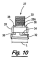
取り付け構成26は、上面28Aとともに第1の突出部28を有する取り付け部材27を備えている。取り付け構成26は、第1の突出部28の上面28Aから固定構成25に伸長するねじ締結要素30(図6、9、及び10参照)をさらに含んでいる。
The mounting
ねじ締結要素30は、固定構成25中の対応するねじ凹部31にねじ留めされ、それにより、固定構成25を取り付け部材27に固定する。
The
第1の突出部28は、直さL(図6参照)を有し、これは、支持体14中のスロット22の幅Aよりも長い。したがって、以下で説明するように、取り付け部材27がその取り付け位置にあるとき、第1の突出部は、スロット22の対抗縁を超えて突出する。
The
取り付け部材27は、第2の突出部32と、第1及び第2の突出部28、32の間にスペーサ部34とをさらに含み、これにより、スペーサ部34の各側上で、第1及び第2の突出部28、32の間に間隙36が規定される。各間隙36のサイズは、実質的に、中央ストリップ18及び横ストリップ20の厚さに等しく、又はこれより大きく、これにより、支持体14の領域を間隙36中に収容できるようにする。
The mounting
第2の突出部32は、実質的に長方形であり、第1の突出部28にわたるその対向する側のスペーサ部34から突出している。第2の突出部32は、支持体14中の細長いスロット22の幅Aよりも短い幅B(図2参照)を有し、長さC(図1参照)は、支持体14中の細長いスロット22の幅Aよりも長い。
The
取り付け部材27は、第1の突出部28の上面28Aに直立する突起38をさらに含んでいる。突起38の目的を以下で説明する。
The mounting
取り付け構成26は、接続装置10を支持体14にロックするためのロック構成40(図7及び8参照)をさらに含んでいる。ロック構成40は、戻り止め構造42と支持体14からロック構成14を解放するための解放タブ44を備えている。戻り止め構造42は、V字型の弾性部材の形態である。接続構成10が開口部22のうちの1つにおける取り付け位置にあるとき、戻り止め構造42は、同じ開口部22中に収容される。
The mounting
戻り止め構造42は、V字を形成する対向アーム48、50を備えている。アームのうちの1つ48は、据え付け部材52に取り付けられる。他のアーム50は、解放タブ44に取り付けられる。据え付け部材52は、取り付け構成26上のロック構成40に据え付けるように提供される。
The
据え付け部材52は、実質的に平らであり、取り付け構成26上の締結要素30が収容される実質的に楕円の主穴54を規定する。据え付け部材は、対向補助穴56のペアも規定して、突起38を収容し、これにより、締結要素30が主穴54中に収容されるとき、据え付け部材を第1の突出部28上に位置付ける。したがって、取り付け構成26を固定構成に締結するために、締結要素30がねじ凹部31にねじ留めされるとき、据え付け部材52は、固定構成25と取り付け構成26との間に保持される。これは、ロック構成40を取り付け構成26上に固く据え付ける。
The mounting
使用する際に、取り付け構成26は、細長いスロット22のうちの1つに、例えば、支持体14の横ストリップ20のうちの1つに挿入され、第1及び第2の突出部28、32は、横ストリップ20の対向する側に配置される(図4Aと5Aを参照)。この位置において、スペーサ部34はスロット22を通して伸長し、第2の突出部32は、図4A及び5A中に示すように、細長いスロット22と平行して伸長する。この位置において、ロック構成40の弾性部材42は、横ストリップ20の最上面を係合し、アーム48は、図5A中に示すように、上方向に変形される。
In use, the mounting
固定装置25は、取り付け位置へと、矢印29によって示した方向に、回転軸Rの周りを回転する(図4C及び5C参照)。固定構成25は、締結要素30によって取り付け構成26上に固定的に据え付けられている。したがって、軸Rの周りを固定装置25が回転することは、取り付け位置へと同じ方向に、取り付け構成26も回転させる。取り付け位置において、第2の突出部32は、スロット22に渡って配置され、スロット22の縁を超えて突出する。
The fixing
接続装置10が上記で説明したように回転するとき、第2の突出部32は、図4C及び5C中に示すように、細長いスロット22へとそれが直角に伸長する位置に動かされる。接続装置10の回転の間、V字型の弾性部材42は、それがスロット22中に収容される、図4C及び5C中に示す位置に動かされる。
When the connecting
図4C及び5C中に示す位置において、弾性部材42がスロット22中に収容されると、V字型の弾性部材42は、非変形位置に動く。弾性部材42の非変形位置は、図2中に示されている。接続装置10は、スロット22の縁を係合するV字型の弾性部材によりさらなる回転を防ぎ、これにより、取り付け構成26の支持体14からの偶然の解放を防ぐ。
At the positions shown in FIGS. 4C and 5C, when the
スロット22から取り付け構成26を解放することを望む場合、ユーザは、タブ44を係合し、図5A中に示すように、弾性部材42をその変形位置に動かすことができ、これにより、弾性部材42をスロット22から取り除く。接続装置10は、その後、スロット22から取り付け構成26を取り除くように回転できる。
If the user wishes to release the mounting
図11は、固定構成25の例をより詳細に示す、接続装置10の断面図である。固定構成25は、第1の貫通孔62を規定する本体60を備えている。取り付け部材27は、図11中に示すように、取り付け構成27が固定構成25に締結されるとき、第1の貫通孔62と並ぶ第2の貫通孔54を規定する。
FIG. 11 is a cross-sectional view of the connecting
固定装置25は、ボール68の形態の複数のクランプ部材を運ぶキャリッジ66を備えるクランプメカニズムをさらに含んでいる。本体は、第1の貫通孔62の周りに伸長する肩70をさらに含んでいる。クランプメカニズムは、キャリッジを矢印74で示す方向に付勢するように、肩からキャリッジに伸長するばね72を含んでいる。第1の貫通孔62は、テーパリング領域76において内側にテーパリングする。したがって、キャリッジを矢印74で示す方向に付勢することは、ボール68を互いに付勢する。
The fixing
ケーブル80は、矢印74と反対方向に、第1の貫通孔62を通して挿入されることができる。ケーブル80は、ボール68を係合し、キャリッジ66を矢印74と反対方向に押し、これにより、ボール68を互いに離れて動かす。最終的に、キャリッジは、ケーブル80がボール68を押しのけ、第1の貫通孔62を通し、第2の貫通孔64を通した位置に達する。ケーブル80を矢印74の方向に引くことは、キャリッジ66を矢印74の方向に付勢させ、これにより、ケーブル80をクランプするように、ボール68を互いに向かって内側に付勢させる。ケーブル80は、したがって、固定構成25に固定される。
The
キャリッジ66は、矢印74と反対方向に内側に押されるボタン部を含んでおり、これにより、キャリッジ66を矢印74の反対方向に動かす。これは、ボール68をケーブルから解放し、固定構成25内のケーブル80の位置を調整することを可能にする。
The
接続装置と取り付け構成26に取り付けされている支持体14とを吊り下げるために、ケーブル80は、建物の屋根の適切な固定ポイントに取り付けられることができる。
To suspend the connection device and the
上記で説明したメカニズムに類似したクランプメカニズムは、特許明細書番号US5417400A中に開示されている。 A clamping mechanism similar to the mechanism described above is disclosed in Japanese Patent Application Laid-Open No. US5417400A.
図12は、2本のケーブル80によって吊り下げられる支持体14の例を示している。ケーブル80は、(示していない)建物の屋根中の適切な固定ポイントへのその上端に、取り付けられることができる。
FIG. 12 shows an example of a
ケーブル80の下端領域は、上記で説明した方法で、それぞれの接続装置10の固定構成25に固定される。接続装置10のそれぞれは、支持体14に取り付けられる。各取り付け構成26の第2の突出部32は、スロット22のうちのそれぞれ1つを通して収容され、戻り止め構造42は、スロット22中に収容され、これにより、接続装置10を図12中に示す位置にある支持体14にロックする。
The lower end region of the
配管又は他の適切な装置を支持体14に取り付けることができる。
Piping or other suitable device can be attached to the
したがって、支持体14に取り付けられ、建物の屋根から吊り下げられることができる取り付け構成26を有する接続装置10があり、接続装置10は、ロック構成26によって支持体14への取り付けにロックされる。
Therefore, there is a connecting
本発明の範囲から逸脱することなく、さまざまな修正を行うことができる。
例えば、他の適切なタイプの固定構成を固定構成25の代わりに使用できる。
以下に、出願当初の特許請求の範囲に記載の事項を、付記する。
[1] 接続装置を第1の物品に取り付けるための取り付け構成であって、
前記取り付け構成は、前記第1の物品中の開口部を通して収容可能であり、
前記取り付け構成は、前記接続装置を前記第1の物品にロックするためのロック構成を備え、
前記ロック構成は、前記第1の物品中の開口部によって収容されるように構成されている戻り止め構造を備える、取り付け構成。
[2] 前記戻り止め構造は、弾性部材を備え、
前記弾性部材は、前記第1の物品中の開口部中に収容可能である、[1]に記載の取り付け構成。
[3] 前記弾性部材は、実質的にV字型であり、前記V字を形成する対向アームを有する、[2]に記載の取り付け構成。
[4] 前記アームは、互いから離れて、及び、互いに対して、弾性的に変形可能である、[3]に記載の取り付け構成。
[5] 前記ロック構成は、前記ロック構成を前記取り付け構成上に据え付けるための据え付け部材を含み、
前記据え付け部材は、前記アームのうちの一方に取り付けられている、[3]又は[4]に記載の取り付け構成。
[6] 前記取り付け構成が前記取り付け位置に動かされるとき、前記据え付け部材に取り付けられている前記アームは、弾性的変形位置から非変形位置に移動可能であり、
前記変形位置から前記非変形位置への前記アームの移動は、変形位置から非変形位置への前記弾性部材の移動である、[5]に記載の取り付け構成。
[7] 前記ロック構成は、前記アームを互いに対して動かすことを促進するように、前記アームのうちの他方に取り付けられている解放タブをさらに含む、[5]又は[6]に記載の取り付け構成。
[8] 前記据え付け部材は、前記取り付け構成の一部分が伸長できる穴を規定し、
前記取り付け構成は、前記取り付け構成を固定構成に締結するための締結要素を有し、 前記締結要素は、前記ロック構成を前記取り付け構成上に据え付けるように、前記穴を通して伸長する、[5]、[6]、又は[7]に記載の取り付け構成。
[9] 前記取り付け構成は、取り付け部材を備え、
前記取り付け部材は、前記第1の物品を係合するための第1の突出部と前記第1の物品を通した挿入のための第2の突出部とを備え、
それにより、前記第2の突出部が前記第1の物品を通して挿入されるとき、前記第1の物品の領域は、前記第1及び第2の突出部間に収容されることができ、それによって、前記接続装置を前記第1の物品に取り付ける、[8]に記載の取り付け構成。
[10] 前記締結要素は、前記第1の突出部と前記固定構成との間に伸長する、[9]に記載の取り付け構成。
[11] 前記締結要素は、前記固定構成上の対応するねじと協同するようにねじ留めされる、[10]に記載の取り付け構成。
[12] 前記第1の突出部は、前記第1の物品の前記領域の第1の面を係合し、
前記第2の突出部は、前記第1の物品の前記領域の対向する第2の面を係合する、[9]、[10]、又は、[11]に記載の取り付け構成。
[13] 前記取り付け構成は、前記第1及び第2の突出部を通して伸長する回転軸を有し、
前記取り付け構成は、前記接続装置を前記第1の物品に取り付けるために、前記軸の周りを、取り付け位置に回転可能であり、
それにより、前記取り付け構成が前記回転軸の周りを回転するとき、前記戻り止め構造は、前記開口部内に収容され、
前記取り付け構成がこのように回転するとき、前記第1の物品の領域は、前記第1及び第2の突出部間に収容されることができる、[9]から[12]のうちのいずれか1項に記載の取り付け構成。
[14] 前記第2の突出部は、先端面と固定領域を有し、
前記取り付け構成が前記取り付け位置に回転されるとき、前記先端面は、前記第1の物品の前述の領域を横切るための前記第2の突出部の第1の領域であり、
前記取り付け構成が前記取り付け位置にあるとき、前記第2の突出部は、前記第1の物品を係合するための取り付け面を有する、[13]に記載の取り付け構成。
[15] 前記取り付け部材は、前記第1及び第2の突出部の間に伸長するスペーサ部と、前記第1及び第2の突出部の間に規定される間隙をさらに含む、[14]に記載の取り付け構成。
[16] 前記第1及び第2の突出部は、前記締結要素から外側に伸長し、
前記第2の突出部は、それに対して反対方向に前記スペーサ部から伸長する、[15]に記載の取り付け構成。
[17] 前記第1の突出部は、前記締結要素から放射状に伸長し、実質的に円形であり、
前記第2の突出部は、その長さよりも長い幅を有する実質的に長方形である、[16]に記載の取り付け構成。
[18] 前記スペーサ部は、前記取り付け構成の一方向への回転を防止するための停止構造を有する、[15]から[17]のうちのいずれか1項に記載の取り付け構成。
[19] 前記取り付け構成が前述の方向に回転するとき、前記停止構造は、前記第1の物品を係合するように構成されている前記スペーサ部の領域を備える、[18]に記載の取り付け構成。
[20] 前記停止構造は、前記スペーサ部の対角線上に対向する領域を備え、
前記領域間の距離は、開口部の幅よりも長い、[19]に記載の取り付け構成。
[21] 前記スペーサ部は、前記第1の物品に対する前記取り付け構成の回転を可能にするための曲がった縁部を有し、
前記スペーサ部は、直径に対向する曲がった縁部を有し、
前記曲がった縁部間の直径距離は、前記第1の物品における前記開口部の幅よりも短い、[15]から[20]のうちのいずれか1項に記載の取り付け構成。
[22] 第1の物品を細長い第2の物品に接続するための接続装置であって、
前記接続装置は、
前記接続装置を前記細長い第2の物品に固定するための固定構成と、
前記接続装置を前記第1の物品に取り付けるための取り付け構成とを備え、
前記取り付け構成は、前記第1の物品中の開口部を通して収容可能であり、
前記取り付け構成は、前記接続装置を前記第1の物品にロックするためのロック構成を備え、
前記ロック構成は、前記第1の物品中の開口部によって収容されるように構成されている戻り止め構造を備える、接続装置。
[23] 前記取り付け構成は、[1]から[21]のうちのいずれか1項に記載されているものである、[22]に記載の接続装置。
[24] 接続装置と第1の物品を備える接続構成であって、
前記接続装置は、
前記接続装置を細長い第2の物品に固定するための固定構成と、
前記接続装置を前記第1の物品に取り付けるための取り付け構成とを備え、
前記取り付け構成は、前記第1の物品中の開口部を通して収容可能であり、
前記取り付け構成は、前記接続装置を前記第1の物品にロックするためのロック構成を備え、
前記ロック構成は、前記第1の物品中の開口部によって収容されるように構成されている戻り止め構造を備える、接続構成。
[25] 前記第1の物品に取り付けられることができる、複数の接続装置を備える、[24]に記載の接続構成。
[26] 前記第1の物品は、細長い支持体を備える、[24]又は[25]に記載の接続構成。
[27] 前記戻り止め構造は、弾性部材を備え、
前記弾性部材は、前記第1の物品中の開口部中に収容可能である、[24]、[25]、又は、[26]に記載の接続構成。
[28] 前記弾性部材は、実質的にV字型であり、前記V字を形成する対向アームを有する、[27]に記載の接続構成。
[29] 前記アームは、互いから離れて、及び、互いに対して、弾性的に変形可能である、[28]に記載の接続構成。
[30] 前記ロック構成は、前記ロック構成を前記取り付け構成上に据え付けるための据え付け部材を含み、
前記据え付け部材は、前記アームのうちの一方に取り付けられている、[28]又は[29]に記載の接続構成。
[31] 前記取り付け構成が前記取り付け位置に動かされるとき、前記据え付け部材に取り付けられている前記アームは、弾性的変形位置から非変形位置に移動可能であり、
前記変形位置から前記非変形位置への前記アームの移動は、変形位置から非変形位置への前記弾性部材の移動である、[30]に記載の接続構成。
[32] 前記ロック構成は、前記アームを互いに対して動かすことを促進するように、前記アームのうちの他方に取り付けられている解放タブをさらに含む、[30]又は[31]に記載の接続構成。
[33] 前記据え付け部材は、前記取り付け構成の一部分が伸長できる穴を規定し、
前記取り付け構成は、前記取り付け構成を固定構成に締結するための締結要素を有し、 前記締結要素は、前記ロック構成を前記取り付け構成上に据え付けるように、前記穴を通して伸長する、[30]、[31]、又は[32]に記載の接続構成。
[34] 前記取り付け構成は、取り付け部材を備え、
前記取り付け部材は、前記第1の物品を係合するための第1の突出部と前記第1の物品を通した挿入のための第2の突出部とを備え、
それにより、前記第2の突出部が前記第1の物品に挿入されるとき、前記第1の物品の領域は、前記第1及び第2の突出部間に収容されることができ、それによって、前記接続装置を前記第1の物品に取り付ける、[33]に記載の接続構成。
[35] 前記締結要素は、前記第1の突出部と前記固定構成との間に伸長する、[34]に記載の接続構成。
[36] 前記締結要素は、前記固定構成上の対応するねじと協同するようにねじ留めされる、[35]に記載の接続構成。
[37] 前記第1の突出部は、前記第1の物品の前記領域の第1の面を係合し、
前記第2の突出部は、前記第1の物品の前記領域の対向する第2の面を係合する、[34]、[35]、又は、[36]に記載の接続構成。
[38] 前記取り付け構成は、前記第1及び第2の突出部を通して伸長する回転軸を有し、
前記取り付け構成は、前記接続装置を前記第1の物品に取り付けるために、前記軸の周りを、取り付け位置に回転可能であり、
それにより、前記取り付け構成が前記回転軸の周りを回転するとき、前記戻り止め構造は、前記開口部内に収容され、
前記取り付け構成がこのように回転するとき、前記第1の物品の領域は、前記第1及び第2の突出部間に収容されることができる、[34]から[37]のうちのいずれか1項に記載の接続構成。
[39] 前記第2の突出部は、使用する際に、前記開口部を通して挿入されてよい、[34]から[38]のうちのいずれか1項に記載の接続構成。
[40] 前記第1の物品は、開口部を規定する主要部を備え、
前記第2の突出部は、前記開口部を通して挿入可能であり、
前記第2の突出部が前記開口部を通して挿入されるとき、前記第1の物品の領域は、前記第1及び第2の突出部の間に収容され、
それにより、前記接続装置を前記第1の物品に取り付ける、[34]から[39]のうちのいずれか1項に記載の接続構成。
[41] 前記第2の突出部が前記第1の物品を通して挿入されるとき、前記第1の物品の前述の領域は、前記取り付け構成が前記取り付け位置へと回転すると、前記第1及び第2の突出部の間に収容される、[34]から[40]のうちのいずれか1項に記載の接続構成。
[42] 前記第2の突出部は、前記第1の突出部にわたって伸長する、[34]から[41]のうちのいずれか1項に記載の接続構成。
[43] 前記取り付け構成は、前記第1及び第2の突出部を通して伸長する回転軸の周りを、前記取り付け位置に回転でき、それによって、前記取り付け構成が前記回転軸の周りを回転するとき、前記第1の物品の領域は第1及び第2の突出部の間に収容される、[34]から[42]のうちのいずれか1項に記載の接続構成。
[44] 前記取り付け構成の回転は、前述の回転軸の周りを接続装置が回転することによってもたらすことができる、[43]に記載の接続構成。
[45] 前記第2の突出部は、先端面と固定領域を有し、
前記取り付け構成が前記取り付け位置に回転されるとき、前記先端面は、前記第1の物品の前述の領域を横切るための前記第2の突出部の第1の領域であり、
前記取り付け構成が前記取り付け位置にあるとき、前記第2の突出部は、前記第1の物品を係合するための取り付け面を有する、[34]から[44]のうちのいずれか1項に記載の接続構成。
[46] 前記取り付け部材は、前記第1及び第2の突出部の間に伸長するスペーサ部と、前記第1及び第2の突出部の間に規定される間隙をさらに含む、[45]に記載の接続構成。
[47] 前記第1及び第2の突出部は、前記締結要素から外側に伸長し、
前記第2の突出部は、それに対して反対方向に前記スペーサ部から伸長する、[46]に記載の接続構成。
[48] 前記第1の突出部は、前記締結要素から放射状に伸長し、実質的に円形であり、
前記第2の突出部は、その長さよりも長い幅を有する実質的に長方形である、
[47]に記載の接続構成。
[49] 前記スペーサ部は、前記取り付け構成の一方向への回転を防止するための停止構造を有する、[46]から[48]のうちのいずれか1項に記載の接続構成。
[50] 前記停止構造は、前記取り付け構成が前述の方向に回転するとき、前記第1の物品を係合するように構成されている前記スペーサ部の領域を備える、[49]に記載の接続構成。
[51] 前記停止構造は、前記スペーサ部の対角線上に対向する領域を備え、
前記領域間の距離は、開口部の幅よりも長い、[50]に記載の接続構成。
[52] 前記スペーサ部は、前記第1の物品に対する前記取り付け構成の回転を可能にするための曲がった縁部を有し、
前記スペーサ部は、直径に対向する曲がった縁部を有し、
前記曲がった縁部間の直径距離は、前記第1の物品における前記開口部の幅よりも短い、[46]から[51]のうちのいずれか1項に記載の接続構成。
[53] 前記間隙は、前記取り付け面においてよりも、前記先端面においてより大きく、前記先端面は、前記取り付け面に向かって先細になる、[46]から[52]のうちのいずれか1項に記載の接続構成。
[54] 前記第1の物品における前記開口部は、細長く、前記第2の突出部の長さよりも長い長さを有し、
前記第1の物品中の前記開口部の幅は、前記第2の突出部の幅よりも長く、
前記第2の突出部の長さは、前記開口部の幅よりも長い、[34]から[53]のうちのいずれか1項に記載の接続構成。
[55] 第1の物品を細長い第2の物品に接続する方法であって、
前記方法は、
[24]に記載されている接続構成を提供することと、
前記第1の物品中の開口部を通して前記取り付け構成を挿入することと、
前記接続装置を前記第1の物品にロックするために、前記第1の物品中の開口部中に前記戻り止め構造を構成することとを備える、方法。
[56] 前記取り付け構成は、前記接続装置を前記第1の物品に取り付けるために、前記第1の物品に対して取り付け位置に回転可能であり、
前記取り付け構成がこのように回転するとき、前記戻り止め構造は、前記開口部中に収容可能であり、
前記方法は、前記戻り止め構造が前記第1の物品中の前記開口部中に収容されるように、前記取り付け構成を前記第1の物品に対して回転させることを備える、[55]に記載の方法。
[57] 前記ロック構成は、アームを互いに向けて動かすことを促進するように、前記アームの他方に取り付けられている解放タブをさらに含み、
前記方法は、弾性部材が収容されている前記開口部から前記弾性部材を解放するために、そこに取り付けられている前記アームを非変形位置から変形位置に動かすための前記タブを操作することを備える、[55]又は[56]に記載の方法。
Various modifications can be made without departing from the scope of the present invention.
For example, other suitable types of fixed configurations can be used in place of the fixed
The matters described in the claims at the time of filing are added below.
[1] An attachment configuration for attaching the connection device to the first article.
The mounting configuration can be accommodated through an opening in the first article.
The mounting configuration comprises a locking configuration for locking the connecting device to the first article.
The locking configuration comprises a detent structure configured to be accommodated by an opening in the first article.
[2] The detent structure includes an elastic member and has an elastic member.
The mounting configuration according to [1], wherein the elastic member can be accommodated in an opening in the first article.
[3] The mounting configuration according to [2], wherein the elastic member is substantially V-shaped and has an opposed arm forming the V-shape.
[4] The mounting configuration according to [3], wherein the arms are elastically deformable with respect to each other and away from each other.
[5] The lock configuration includes an installation member for mounting the lock configuration on the mounting configuration.
The mounting configuration according to [3] or [4], wherein the mounting member is mounted on one of the arms.
[6] When the mounting configuration is moved to the mounting position, the arm mounted on the mounting member can move from the elastically deformed position to the non-deformed position.
The mounting configuration according to [5], wherein the movement of the arm from the deformed position to the non-deformed position is the movement of the elastic member from the deformed position to the non-deformed position.
[7] The attachment according to [5] or [6], wherein the locking configuration further includes a release tab attached to the other of the arms to facilitate movement of the arms with respect to each other. Constitution.
[8] The mounting member defines a hole into which a part of the mounting configuration can be extended.
The mounting configuration has a fastening element for fastening the mounting configuration to a fixed configuration, the fastening element extending through the hole so as to install the lock configuration on the mounting configuration, [5]. The mounting configuration according to [6] or [7].
[9] The mounting configuration includes mounting members.
The mounting member comprises a first protrusion for engaging the first article and a second protrusion for insertion through the first article.
Thereby, when the second protrusion is inserted through the first article, the area of the first article can be accommodated between the first and second protrusions, thereby. , The mounting configuration according to [8], wherein the connecting device is mounted on the first article.
[10] The mounting configuration according to [9], wherein the fastening element extends between the first protrusion and the fixed configuration.
[11] The mounting configuration according to [10], wherein the fastening element is screwed so as to cooperate with the corresponding screw in the fixed configuration.
[12] The first protrusion engages the first surface of the region of the first article.
The mounting configuration according to [9], [10], or [11], wherein the second protrusion engages an opposing second surface of the region of the first article.
[13] The mounting configuration has a rotation axis extending through the first and second protrusions.
The mounting configuration is rotatable around the shaft to a mounting position for mounting the connecting device to the first article.
Thereby, when the mounting configuration rotates around the axis of rotation, the detent structure is housed in the opening.
When the mounting configuration is rotated in this way, the area of the first article can be accommodated between the first and second protrusions, any of [9] to [12]. The mounting configuration described in item 1.
[14] The second protrusion has a tip surface and a fixed region, and has a fixed region.
When the mounting configuration is rotated to the mounting position, the tip surface is a first region of the second protrusion for traversing the aforementioned region of the first article.
13. The mounting configuration according to [13], wherein when the mounting configuration is in the mounting position, the second protrusion has a mounting surface for engaging the first article.
[15] The mounting member further comprises a spacer portion extending between the first and second protrusions and a gap defined between the first and second protrusions [14]. The mounting configuration described.
[16] The first and second protrusions extend outward from the fastening element and extend outward.
The mounting configuration according to [15], wherein the second protruding portion extends from the spacer portion in the opposite direction to the protruding portion.
[17] The first protrusion extends radially from the fastening element and is substantially circular.
The mounting configuration according to [16], wherein the second protrusion is substantially rectangular with a width longer than its length.
[18] The mounting configuration according to any one of [15] to [17], wherein the spacer portion has a stop structure for preventing rotation of the mounting configuration in one direction.
[19] The attachment according to [18], wherein the stop structure comprises a region of the spacer portion configured to engage the first article when the attachment configuration rotates in the aforementioned direction. Constitution.
[20] The stop structure includes regions facing each other on the diagonal line of the spacer portion.
The mounting configuration according to [19], wherein the distance between the regions is longer than the width of the opening.
[21] The spacer portion has a curved edge portion for allowing rotation of the mounting configuration with respect to the first article.
The spacer portion has a curved edge facing the diameter.
The mounting configuration according to any one of [15] to [20], wherein the diameter distance between the curved edges is shorter than the width of the opening in the first article.
[22] A connecting device for connecting a first article to an elongated second article.
The connecting device is
A fixing configuration for fixing the connecting device to the elongated second article, and
A mounting configuration for mounting the connecting device to the first article is provided.
The mounting configuration can be accommodated through an opening in the first article.
The mounting configuration comprises a locking configuration for locking the connecting device to the first article.
The locking configuration comprises a detent structure configured to be accommodated by an opening in the first article.
[23] The connecting device according to [22], wherein the mounting configuration is the one described in any one of [1] to [21].
[24] A connection configuration including a connection device and a first article.
The connecting device is
A fixing configuration for fixing the connecting device to the elongated second article, and
A mounting configuration for mounting the connecting device to the first article is provided.
The mounting configuration can be accommodated through an opening in the first article.
The mounting configuration comprises a locking configuration for locking the connecting device to the first article.
The lock configuration comprises a detent structure configured to be accommodated by an opening in the first article.
[25] The connection configuration according to [24], comprising a plurality of connection devices that can be attached to the first article.
[26] The connection configuration according to [24] or [25], wherein the first article comprises an elongated support.
[27] The detent structure includes an elastic member and has an elastic member.
The connection configuration according to [24], [25], or [26], wherein the elastic member can be accommodated in the opening in the first article.
[28] The connection configuration according to [27], wherein the elastic member is substantially V-shaped and has an opposed arm forming the V-shape.
[29] The connection configuration according to [28], wherein the arms are elastically deformable with respect to each other and away from each other.
[30] The lock configuration includes an installation member for mounting the lock configuration on the mounting configuration.
The connection configuration according to [28] or [29], wherein the mounting member is attached to one of the arms.
[31] When the mounting configuration is moved to the mounting position, the arm mounted on the mounting member is movable from the elastically deformed position to the non-deformed position.
The connection configuration according to [30], wherein the movement of the arm from the deformed position to the non-deformed position is the movement of the elastic member from the deformed position to the non-deformed position.
[32] The connection according to [30] or [31], wherein the locking configuration further comprises a release tab attached to the other of the arms to facilitate movement of the arms with respect to each other. Constitution.
[33] The mounting member defines a hole through which a portion of the mounting configuration can be extended.
The mounting configuration has a fastening element for fastening the mounting configuration to a fixed configuration, the fastening element extending through the hole so as to install the lock configuration on the mounting configuration, [30]. The connection configuration according to [31] or [32].
[34] The mounting configuration comprises a mounting member.
The mounting member comprises a first protrusion for engaging the first article and a second protrusion for insertion through the first article.
Thereby, when the second protrusion is inserted into the first article, the area of the first article can be accommodated between the first and second protrusions, thereby. , The connection configuration according to [33], wherein the connection device is attached to the first article.
[35] The connection configuration according to [34], wherein the fastening element extends between the first protrusion and the fixed configuration.
[36] The connection configuration according to [35], wherein the fastening element is screwed so as to cooperate with the corresponding screw in the fixed configuration.
[37] The first protrusion engages the first surface of the region of the first article.
The connection configuration according to [34], [35], or [36], wherein the second protrusion engages an opposing second surface of the region of the first article.
[38] The mounting configuration has a rotation axis extending through the first and second protrusions.
The mounting configuration is rotatable around the shaft to a mounting position for mounting the connecting device to the first article.
Thereby, when the mounting configuration rotates around the axis of rotation, the detent structure is housed in the opening.
When the mounting configuration is rotated in this way, the area of the first article can be accommodated between the first and second protrusions, any of [34] to [37]. The connection configuration described in item 1.
[39] The connection configuration according to any one of [34] to [38], wherein the second protrusion may be inserted through the opening when used.
[40] The first article comprises a main portion defining an opening.
The second protrusion can be inserted through the opening and
When the second protrusion is inserted through the opening, the area of the first article is accommodated between the first and second protrusions.
The connection configuration according to any one of [34] to [39], wherein the connection device is attached to the first article.
[41] When the second protrusion is inserted through the first article, the aforementioned area of the first article is the first and second as the mounting configuration rotates to the mounting position. The connection configuration according to any one of [34] to [40], which is accommodated between the protrusions of the above.
[42] The connection configuration according to any one of [34] to [41], wherein the second protrusion extends over the first protrusion.
[43] The mounting configuration can rotate to the mounting position around a rotating shaft extending through the first and second protrusions, whereby when the mounting configuration rotates around the rotating shaft. The connection configuration according to any one of [34] to [42], wherein the area of the first article is accommodated between the first and second protrusions.
[44] The connection configuration according to [43], wherein the rotation of the mounting configuration can be brought about by rotating the connecting device around the rotation axis described above.
[45] The second protruding portion has a tip surface and a fixed region, and has a fixed region.
When the mounting configuration is rotated to the mounting position, the tip surface is a first region of the second protrusion for traversing the aforementioned region of the first article.
In any one of [34] to [44], the second projection has a mounting surface for engaging the first article when the mounting configuration is in the mounting position. The connection configuration described.
[46] The mounting member further comprises a spacer portion extending between the first and second protrusions and a gap defined between the first and second protrusions [45]. The connection configuration described.
[47] The first and second protrusions extend outward from the fastening element and extend outward.
The connection configuration according to [46], wherein the second protrusion extends from the spacer portion in the opposite direction to the second protrusion.
[48] The first protrusion extends radially from the fastening element and is substantially circular.
The second protrusion is substantially rectangular with a width longer than its length.
The connection configuration according to [47].
[49] The connection configuration according to any one of [46] to [48], wherein the spacer portion has a stop structure for preventing rotation in one direction of the mounting configuration.
[50] The connection according to [49], wherein the stop structure comprises a region of the spacer portion configured to engage the first article when the mounting configuration rotates in the aforementioned direction. Constitution.
[51] The stop structure includes regions that face each other on the diagonal line of the spacer portion.
The connection configuration according to [50], wherein the distance between the regions is longer than the width of the opening.
[52] The spacer portion has a curved edge portion to allow rotation of the mounting configuration with respect to the first article.
The spacer portion has a curved edge facing the diameter.
The connection configuration according to any one of [46] to [51], wherein the diameter distance between the curved edges is shorter than the width of the opening in the first article.
[53] Any one of [46] to [52], wherein the gap is larger on the tip surface than on the mounting surface, and the tip surface tapers toward the mounting surface. The connection configuration described in.
[54] The opening in the first article is elongated and has a length longer than the length of the second protrusion.
The width of the opening in the first article is longer than the width of the second protrusion.
The connection configuration according to any one of [34] to [53], wherein the length of the second protrusion is longer than the width of the opening.
[55] A method of connecting a first article to an elongated second article.
The method is
To provide the connection configuration described in [24] and
Inserting the mounting configuration through the opening in the first article and
A method comprising configuring the detent structure in an opening in the first article in order to lock the connecting device to the first article.
[56] The mounting configuration is rotatable in a mounting position with respect to the first article in order to mount the connecting device to the first article.
When the mounting configuration is rotated in this way, the detent structure can be accommodated in the opening.
55. The method comprises rotating the attachment configuration with respect to the first article such that the detent structure is housed in the opening in the first article. the method of.
[57] The locking configuration further includes a release tab attached to the other side of the arm to facilitate movement of the arms towards each other.
The method comprises operating the tab for moving the arm attached thereto from a non-deformed position to a deformed position in order to release the elastic member from the opening in which the elastic member is housed. The method according to [55] or [56].
Claims (11)
前記取り付け構成(26)は、
前記第1の物品(14)中の開口部(22)を通して収容可能な取り付け部材(27)と、
前記接続装置(10)を前記第1の物品(14)にロックするためのロック構成(40)と、前記ロック構成(40)は、前記第1の物品(14)中の前記開口部によって収容されるように構成されている戻り止め構造(42)を備えるものであり、
を備え、
ここにおいて、前記戻り止め構造(42)は、弾性部材を備え、前記弾性部材は、前記第1の物品(14)中の前記開口部中に収容可能であり、前記弾性部材は、実質的にV字型であり、前記V字を形成する対向アーム(48,50)を有するものにおいて、
前記ロック構成(40)は、前記ロック構成(40)を前記取り付け構成(26)上に据え付けるための据え付け部材(52)を含み、前記据え付け部材(52)は、前記アーム(48)のうちの一方に取り付けられ、
前記取り付け構成(26)は、前記取り付け構成(26)を固定構成(25)に締結するための締結要素(30)を有し、前記据え付け部材(52)は、前記締結要素(30)が、前記ロック構成(40)を前記取り付け構成(26)上に据え付けるように通して伸長する、穴(54)及び対向補助穴(56)を備え、
前記ロック構成(40)は、前記アーム(48,50)を互いに対して動かすことを促進するように、前記アーム(50)のうちの他方に取り付けられている解放タブ(44)をさらに含み、
前記取り付け構成(26)は、取り付け部材(27)を備え、前記取り付け部材(27)の上面には前記対向補助穴(56)に収容される突起(38)を有し、
前記取り付け部材(27)は、前記第1の物品(14)を係合するための第1の突出部(28)と前記第1の物品(14)の前記開口部(22)を通した挿入のための第2の突出部(32)とを備え、それにより、前記第2の突出部(32)が前記第1の物品(14)の前記開口部(22)を通して挿入されるとき、前記第1の物品(14)の領域は、前記第1及び第2の突出部(28,32)間に収容されることができ、それによって、前記接続装置(10)を前記第1の物品(14)に取り付ける、
取り付け構成(26)。 It is a mounting configuration (26) for mounting the connecting device (10) to the first article (14).
The mounting configuration (26) is
A mounting member (27) that can be accommodated through an opening (22) in the first article (14).
The locking configuration (40) for locking the connecting device (10) to the first article (14) and the locking configuration (40) are accommodated by the opening in the first article (14). It is provided with a detent structure (42) configured to be used.
Equipped with
Here, the detent structure (42) includes an elastic member, the elastic member can be accommodated in the opening in the first article (14), and the elastic member is substantially. In the V-shaped one having the facing arms (48, 50) forming the V-shape,
The lock configuration (40) includes an installation member (52) for mounting the lock configuration (40) on the mounting configuration (26), and the installation member (52) is of the arm (48). Attached to one side,
The mounting configuration (26) has a fastening element (30) for fastening the mounting configuration (26) to the fixed configuration (25), and the mounting member (52) has the fastening element (30). It comprises a hole (54) and an opposed auxiliary hole (56) extending through the locking configuration (40) so as to be mounted on the mounting configuration (26).
The locking configuration (40) further includes a release tab (44) attached to the other of the arms (50) to facilitate movement of the arms (48, 50) with respect to each other.
The mounting configuration (26) includes a mounting member (27), and has a protrusion (38) accommodated in the facing auxiliary hole (56) on the upper surface of the mounting member (27).
The mounting member (27) is inserted through a first protrusion (28) for engaging the first article (14) and an opening (22) of the first article (14). With a second protrusion (32) for, thereby said when the second protrusion (32) is inserted through the opening (22) of the first article (14). The area of the first article (14) can be accommodated between the first and second protrusions (28, 32), whereby the connecting device (10) can be accommodated in the first article (10). Attach to 14),
Mounting configuration (26).
前記取り付け構成(26)が前記取り付け位置に動かされるとき、前記据え付け部材(52)に取り付けられている前記アーム(48)は、弾性的変形位置から非変形位置に移動可能であり、
前記変形位置から前記非変形位置への前記アーム(48)の移動は、変形位置から非変形位置への前記弾性部材の移動である、請求項1に記載の取り付け構成(26)。 The mounting configuration (26) is rotatable in a mounting position with respect to the first article (14) in order to mount the connecting device (10) to the first article (14).
When the mounting configuration (26) is moved to the mounting position, the arm (48) mounted on the mounting member (52) is movable from the elastically deformed position to the non-deformed position.
The mounting configuration (26) according to claim 1, wherein the movement of the arm (48) from the deformed position to the non-deformed position is a movement of the elastic member from the deformed position to the non-deformed position.
前記取り付け構成(26)は、前記接続装置(10)を前記第1の物品(14)に取り付けるために、前記軸の周りを、取り付け位置に回転可能であり、
それにより、前記取り付け構成(26)が前記回転軸(R)の周りを回転するとき、前記戻り止め構造(42)は、前記開口部内に収容され、
前記取り付け構成(26)がこのように回転するとき、前記第1の物品(14)の領域は、前記第1及び第2の突出部(28,32)間に収容されることができる、請求項1から3のいずれか1項に記載の取り付け構成(26)。 The mounting configuration (26) has a rotating shaft (R) extending through the first and second protrusions (28, 32).
The mounting configuration (26) is rotatable around the shaft to a mounting position for mounting the connecting device (10) to the first article (14).
Thereby, when the mounting configuration (26) rotates around the rotating shaft (R), the detent structure (42) is accommodated in the opening.
When the mounting configuration (26) is rotated in this way, the area of the first article (14) can be accommodated between the first and second protrusions (28, 32), claim. The mounting configuration (26) according to any one of Items 1 to 3.
前記第2の突出部(32)は、前記スペーサ部(34)から前記スペーサ部(34)を基準として互いに反対方向である両方向へ伸長する、請求項6に記載の取り付け構成(26)。 The first and second protrusions (28, 32) extend outward from the fastening element (30) and extend outward.
The mounting configuration (26) according to claim 6, wherein the second protruding portion (32) extends from the spacer portion (34) in both directions opposite to each other with respect to the spacer portion (34).
前記第2の突出部(32)は、その長さよりも長い幅を有する実質的に長方形である、請求項7に記載の取り付け構成(26)。 The first protrusion (28) extends radially from the fastening element (30) and is substantially circular.
The mounting configuration (26) according to claim 7, wherein the second protrusion (32) is substantially rectangular with a width longer than its length.
前記接続装置(10)は、前記細長い第2の物品(80)に固定するための固定構成(25)と、請求項1から8のうちのいずれか1項に記載された取り付け構成(26)と
を備える、接続装置(10)。 A connecting device (10) for connecting the first article (14) to the elongated second article (80).
The connecting device (10) has a fixed configuration (25) for fixing to the elongated second article (80) and a mounting configuration (26) according to any one of claims 1 to 8. A connecting device (10).
前記接続装置(10)は、
前記接続装置(10)を細長い第2の物品(80)に固定するための固定構成(25)と、請求項1から8のうちのいずれか1項に記載された取り付け構成(26)と
を備える、接続構成(12)。 A connection configuration (12) including a connection device (10) and a first article (14).
The connecting device (10) is
The fixing configuration (25) for fixing the connecting device (10) to the elongated second article (80) and the mounting configuration (26) according to any one of claims 1 to 8 are provided. A connection configuration (12).
前記方法は、
請求項10に記載されている接続構成(12)を提供することと、
前記第1の物品(14)中の開口部を通して前記取り付け構成(26)を挿入することと、
前記接続装置(10)を前記第1の物品(14)にロックするために、前記第1の物品(14)中の前記開口部中に前記戻り止め構造(42)を構成することと、を備え、
ここにおいて、前記方法は、弾性部材が収容されている前記開口部から前記弾性部材を解放するために、そこに取り付けられている前記アーム(50)を非変形位置から変形位置に動かすための前記タブ(44)を操作することを備える、方法。 A method of connecting a first article (14) to an elongated second article (80) and releasing the first article (14) and the second article (80) from each other.
The method is
To provide the connection configuration (12) according to claim 10,
Inserting the mounting configuration (26) through the opening in the first article (14) and
In order to lock the connecting device (10) to the first article (14), the detent structure (42) is configured in the opening in the first article (14). Prepare,
Here, the method is for moving the arm (50) attached to the elastic member from the non-deformed position to the deformed position in order to release the elastic member from the opening in which the elastic member is housed. A method comprising manipulating a tab (44).
Applications Claiming Priority (3)
| Application Number | Priority Date | Filing Date | Title |
|---|---|---|---|
| GB1612234.3 | 2016-07-14 | ||
| GBGB1612234.3A GB201612234D0 (en) | 2016-07-14 | 2016-07-14 | Improvements in or relating to connecting devices |
| PCT/GB2017/000104 WO2018011533A1 (en) | 2016-07-14 | 2017-07-06 | Improvements in or relating to connecting devices |
Publications (3)
| Publication Number | Publication Date |
|---|---|
| JP2019521302A JP2019521302A (en) | 2019-07-25 |
| JP2019521302A5 JP2019521302A5 (en) | 2020-07-09 |
| JP7005586B2 true JP7005586B2 (en) | 2022-01-21 |
Family
ID=56890444
Family Applications (1)
| Application Number | Title | Priority Date | Filing Date |
|---|---|---|---|
| JP2019501505A Active JP7005586B2 (en) | 2016-07-14 | 2017-07-06 | Improvements in or related to connecting devices |
Country Status (13)
| Country | Link |
|---|---|
| US (1) | US11572913B2 (en) |
| EP (1) | EP3485181B1 (en) |
| JP (1) | JP7005586B2 (en) |
| AU (1) | AU2017294638B2 (en) |
| CA (1) | CA3029807A1 (en) |
| DK (1) | DK3485181T3 (en) |
| ES (1) | ES2945734T3 (en) |
| GB (2) | GB201612234D0 (en) |
| MX (1) | MX2018015646A (en) |
| PL (1) | PL3485181T3 (en) |
| PT (1) | PT3485181T (en) |
| WO (1) | WO2018011533A1 (en) |
| ZA (1) | ZA201808059B (en) |
Families Citing this family (5)
| Publication number | Priority date | Publication date | Assignee | Title |
|---|---|---|---|---|
| GB201701736D0 (en) * | 2017-02-02 | 2017-03-22 | Gripple Ltd | Securing assembly |
| US20210404504A1 (en) * | 2018-07-19 | 2021-12-30 | Mag Daddy, LLC | Structural Fastener |
| US10663110B1 (en) * | 2018-12-17 | 2020-05-26 | Divergent Technologies, Inc. | Metrology apparatus to facilitate capture of metrology data |
| CN111486165A (en) * | 2020-05-01 | 2020-08-04 | 深圳市佛光照明有限公司 | Splicing structure |
| TWM629954U (en) * | 2022-03-30 | 2022-07-21 | 艾維克科技股份有限公司 | Suspension type supporting device |
Citations (3)
| Publication number | Priority date | Publication date | Assignee | Title |
|---|---|---|---|---|
| US20030185643A1 (en) | 2002-04-02 | 2003-10-02 | Thompson William J. | Flexible bridge for a strut nut |
| JP2008258363A (en) | 2007-04-04 | 2008-10-23 | Kyoshin Kogyo Co Ltd | Engaging device |
| JP2013104536A (en) | 2011-11-16 | 2013-05-30 | Kitagawa Ind Co Ltd | Fixture |
Family Cites Families (15)
| Publication number | Priority date | Publication date | Assignee | Title |
|---|---|---|---|---|
| US1528777A (en) | 1923-12-06 | 1925-03-10 | Western Electric Co | Nut and bolt locking device |
| FR77710E (en) | 1960-05-12 | 1962-04-13 | Raymond A | Removable fixing device for electric cables or other elements on supports |
| US4263952A (en) * | 1979-06-28 | 1981-04-28 | B-Line Systems, Inc. | Fastener for metal framing |
| EP0486981B1 (en) | 1990-11-21 | 1995-06-14 | ARAKAWA & CO., LTD. | Wire Holder |
| JPH0754894Y2 (en) * | 1990-11-21 | 1995-12-18 | 荒川技研工業株式会社 | Wire suspension |
| DE4421252A1 (en) * | 1994-06-17 | 1995-12-21 | Hilti Ag | Fastening device |
| JP3978076B2 (en) * | 2002-05-14 | 2007-09-19 | 竹内工業株式会社 | Fixture |
| FR2846398B1 (en) | 2002-10-23 | 2007-05-11 | Driver | FIXING DEVICE FOR COOPERATING WITH A GROOVE OF A GROOVED ELEMENT |
| US7621487B2 (en) * | 2005-12-21 | 2009-11-24 | Securus, Inc. | Twist-lock base for pipe holders |
| US9200660B2 (en) * | 2012-05-01 | 2015-12-01 | Illinois Tool Works, Inc. | Quarter turn fastener |
| US20150030386A1 (en) * | 2013-07-28 | 2015-01-29 | Jeffrey D. Carnevali | Track mount base with momentary release |
| CA2890064C (en) * | 2014-04-30 | 2022-08-16 | Cooper Technologies Company | Trapeze hanger system including twist-locking fitting |
| GB2533682A (en) * | 2014-10-22 | 2016-06-29 | Gripple Ltd | Improvements in or relating to connecting devices |
| US9556614B2 (en) * | 2015-05-13 | 2017-01-31 | Awi Licensing Llc | Mounting apparatus for suspended ceiling system |
| GB2560418B (en) * | 2017-01-16 | 2020-06-17 | Gripple Ltd | Securing device |
-
2016
- 2016-07-14 GB GBGB1612234.3A patent/GB201612234D0/en not_active Ceased
-
2017
- 2017-07-06 DK DK17754770.0T patent/DK3485181T3/en active
- 2017-07-06 PL PL17754770.0T patent/PL3485181T3/en unknown
- 2017-07-06 PT PT177547700T patent/PT3485181T/en unknown
- 2017-07-06 EP EP17754770.0A patent/EP3485181B1/en active Active
- 2017-07-06 ES ES17754770T patent/ES2945734T3/en active Active
- 2017-07-06 JP JP2019501505A patent/JP7005586B2/en active Active
- 2017-07-06 WO PCT/GB2017/000104 patent/WO2018011533A1/en unknown
- 2017-07-06 GB GB1710888.7A patent/GB2554145B/en active Active
- 2017-07-06 MX MX2018015646A patent/MX2018015646A/en unknown
- 2017-07-06 AU AU2017294638A patent/AU2017294638B2/en active Active
- 2017-07-06 CA CA3029807A patent/CA3029807A1/en active Pending
- 2017-07-06 US US16/307,872 patent/US11572913B2/en active Active
-
2018
- 2018-11-28 ZA ZA2018/08059A patent/ZA201808059B/en unknown
Patent Citations (3)
| Publication number | Priority date | Publication date | Assignee | Title |
|---|---|---|---|---|
| US20030185643A1 (en) | 2002-04-02 | 2003-10-02 | Thompson William J. | Flexible bridge for a strut nut |
| JP2008258363A (en) | 2007-04-04 | 2008-10-23 | Kyoshin Kogyo Co Ltd | Engaging device |
| JP2013104536A (en) | 2011-11-16 | 2013-05-30 | Kitagawa Ind Co Ltd | Fixture |
Also Published As
| Publication number | Publication date |
|---|---|
| GB201710888D0 (en) | 2017-08-23 |
| ES2945734T3 (en) | 2023-07-06 |
| EP3485181B1 (en) | 2023-03-01 |
| GB2554145A (en) | 2018-03-28 |
| GB201612234D0 (en) | 2016-08-31 |
| GB2554145B (en) | 2020-06-24 |
| US20190211863A1 (en) | 2019-07-11 |
| CA3029807A1 (en) | 2018-01-18 |
| US11572913B2 (en) | 2023-02-07 |
| DK3485181T3 (en) | 2023-05-15 |
| JP2019521302A (en) | 2019-07-25 |
| AU2017294638B2 (en) | 2022-10-13 |
| WO2018011533A1 (en) | 2018-01-18 |
| ZA201808059B (en) | 2021-07-28 |
| MX2018015646A (en) | 2019-04-11 |
| PL3485181T3 (en) | 2023-07-10 |
| AU2017294638A1 (en) | 2018-12-13 |
| EP3485181A1 (en) | 2019-05-22 |
| PT3485181T (en) | 2023-05-22 |
Similar Documents
| Publication | Publication Date | Title |
|---|---|---|
| JP7005586B2 (en) | Improvements in or related to connecting devices | |
| US20190390796A1 (en) | Adapter for mounting cable hangers | |
| US7740211B2 (en) | Conduit attachment apparatus | |
| EP3366358B1 (en) | Fire protection sprinkler support system | |
| US11821549B2 (en) | Brackets for microducts and cables | |
| US20210033220A1 (en) | Support Clip | |
| US9376812B2 (en) | Ceiling panel mounting system | |
| JP2019521302A5 (en) | ||
| KR200473365Y1 (en) | Band cable | |
| US6222128B1 (en) | Cable support | |
| CA3128720A1 (en) | Securing device | |
| JP2017533389A (en) | Improvements in or on connecting devices | |
| EP3688357B1 (en) | Cable clips | |
| JP2017533389A5 (en) | ||
| EP3563078B1 (en) | Method of attaching a line to a support structure | |
| KR200266438Y1 (en) | A Clip Structure For Fixing The Wire Harness | |
| US20240288115A1 (en) | Anchor assembly | |
| US20220034431A1 (en) | Bracket for cable installations | |
| KR101723046B1 (en) | Fixing Clip | |
| NZ730682B2 (en) | Improvements in or relating to connecting devices | |
| GB2610048A (en) | Anchor assembly | |
| JP6258028B2 (en) | Wiring tool for ceiling penetration and its mounting structure | |
| EP3082517B1 (en) | Kit of a hanging system | |
| CN111010839A (en) | Wire management bracket | |
| JPH0785713A (en) | Fixing device of illumination cover |
Legal Events
| Date | Code | Title | Description |
|---|---|---|---|
| A521 | Request for written amendment filed |
Free format text: JAPANESE INTERMEDIATE CODE: A523 Effective date: 20200528 |
|
| A621 | Written request for application examination |
Free format text: JAPANESE INTERMEDIATE CODE: A621 Effective date: 20200528 |
|
| A977 | Report on retrieval |
Free format text: JAPANESE INTERMEDIATE CODE: A971007 Effective date: 20210218 |
|
| A131 | Notification of reasons for refusal |
Free format text: JAPANESE INTERMEDIATE CODE: A131 Effective date: 20210224 |
|
| A521 | Request for written amendment filed |
Free format text: JAPANESE INTERMEDIATE CODE: A523 Effective date: 20210414 |
|
| A131 | Notification of reasons for refusal |
Free format text: JAPANESE INTERMEDIATE CODE: A131 Effective date: 20210622 |
|
| A521 | Request for written amendment filed |
Free format text: JAPANESE INTERMEDIATE CODE: A523 Effective date: 20210813 |
|
| TRDD | Decision of grant or rejection written | ||
| A01 | Written decision to grant a patent or to grant a registration (utility model) |
Free format text: JAPANESE INTERMEDIATE CODE: A01 Effective date: 20211207 |
|
| A61 | First payment of annual fees (during grant procedure) |
Free format text: JAPANESE INTERMEDIATE CODE: A61 Effective date: 20220105 |
|
| R150 | Certificate of patent or registration of utility model |
Ref document number: 7005586 Country of ref document: JP Free format text: JAPANESE INTERMEDIATE CODE: R150 |