JP7004710B2 - Unified synchronization channel design used in different communication modes - Google Patents
Unified synchronization channel design used in different communication modes Download PDFInfo
- Publication number
- JP7004710B2 JP7004710B2 JP2019522425A JP2019522425A JP7004710B2 JP 7004710 B2 JP7004710 B2 JP 7004710B2 JP 2019522425 A JP2019522425 A JP 2019522425A JP 2019522425 A JP2019522425 A JP 2019522425A JP 7004710 B2 JP7004710 B2 JP 7004710B2
- Authority
- JP
- Japan
- Prior art keywords
- communication
- signals
- sync signal
- arrangement
- sync
- Prior art date
- Legal status (The legal status is an assumption and is not a legal conclusion. Google has not performed a legal analysis and makes no representation as to the accuracy of the status listed.)
- Active
Links
Images


Classifications
-
- H—ELECTRICITY
- H04—ELECTRIC COMMUNICATION TECHNIQUE
- H04W—WIRELESS COMMUNICATION NETWORKS
- H04W72/00—Local resource management
- H04W72/04—Wireless resource allocation
- H04W72/044—Wireless resource allocation based on the type of the allocated resource
- H04W72/0453—Resources in frequency domain, e.g. a carrier in FDMA
-
- H—ELECTRICITY
- H04—ELECTRIC COMMUNICATION TECHNIQUE
- H04W—WIRELESS COMMUNICATION NETWORKS
- H04W56/00—Synchronisation arrangements
- H04W56/0005—Synchronisation arrangements synchronizing of arrival of multiple uplinks
-
- H—ELECTRICITY
- H04—ELECTRIC COMMUNICATION TECHNIQUE
- H04J—MULTIPLEX COMMUNICATION
- H04J11/00—Orthogonal multiplex systems, e.g. using WALSH codes
- H04J11/0069—Cell search, i.e. determining cell identity [cell-ID]
- H04J11/0083—Multi-mode cell search, i.e. where several modes or systems can be used, e.g. backwards compatible, dual mode or flexible systems
-
- H—ELECTRICITY
- H04—ELECTRIC COMMUNICATION TECHNIQUE
- H04L—TRANSMISSION OF DIGITAL INFORMATION, e.g. TELEGRAPHIC COMMUNICATION
- H04L27/00—Modulated-carrier systems
- H04L27/26—Systems using multi-frequency codes
- H04L27/2601—Multicarrier modulation systems
- H04L27/2602—Signal structure
-
- H—ELECTRICITY
- H04—ELECTRIC COMMUNICATION TECHNIQUE
- H04L—TRANSMISSION OF DIGITAL INFORMATION, e.g. TELEGRAPHIC COMMUNICATION
- H04L27/00—Modulated-carrier systems
- H04L27/26—Systems using multi-frequency codes
- H04L27/2601—Multicarrier modulation systems
- H04L27/2602—Signal structure
- H04L27/26025—Numerology, i.e. varying one or more of symbol duration, subcarrier spacing, Fourier transform size, sampling rate or down-clocking
-
- H—ELECTRICITY
- H04—ELECTRIC COMMUNICATION TECHNIQUE
- H04L—TRANSMISSION OF DIGITAL INFORMATION, e.g. TELEGRAPHIC COMMUNICATION
- H04L27/00—Modulated-carrier systems
- H04L27/26—Systems using multi-frequency codes
- H04L27/2601—Multicarrier modulation systems
- H04L27/2602—Signal structure
- H04L27/261—Details of reference signals
- H04L27/2613—Structure of the reference signals
-
- H—ELECTRICITY
- H04—ELECTRIC COMMUNICATION TECHNIQUE
- H04L—TRANSMISSION OF DIGITAL INFORMATION, e.g. TELEGRAPHIC COMMUNICATION
- H04L27/00—Modulated-carrier systems
- H04L27/26—Systems using multi-frequency codes
- H04L27/2601—Multicarrier modulation systems
- H04L27/2647—Arrangements specific to the receiver only
- H04L27/2655—Synchronisation arrangements
- H04L27/2656—Frame synchronisation, e.g. packet synchronisation, time division duplex [TDD] switching point detection or subframe synchronisation
-
- H—ELECTRICITY
- H04—ELECTRIC COMMUNICATION TECHNIQUE
- H04L—TRANSMISSION OF DIGITAL INFORMATION, e.g. TELEGRAPHIC COMMUNICATION
- H04L27/00—Modulated-carrier systems
- H04L27/26—Systems using multi-frequency codes
- H04L27/2601—Multicarrier modulation systems
- H04L27/2647—Arrangements specific to the receiver only
- H04L27/2655—Synchronisation arrangements
- H04L27/2666—Acquisition of further OFDM parameters, e.g. bandwidth, subcarrier spacing, or guard interval length
-
- H—ELECTRICITY
- H04—ELECTRIC COMMUNICATION TECHNIQUE
- H04L—TRANSMISSION OF DIGITAL INFORMATION, e.g. TELEGRAPHIC COMMUNICATION
- H04L27/00—Modulated-carrier systems
- H04L27/26—Systems using multi-frequency codes
- H04L27/2601—Multicarrier modulation systems
- H04L27/2647—Arrangements specific to the receiver only
- H04L27/2655—Synchronisation arrangements
- H04L27/2689—Link with other circuits, i.e. special connections between synchronisation arrangements and other circuits for achieving synchronisation
- H04L27/2692—Link with other circuits, i.e. special connections between synchronisation arrangements and other circuits for achieving synchronisation with preamble design, i.e. with negotiation of the synchronisation sequence with transmitter or sequence linked to the algorithm used at the receiver
-
- H—ELECTRICITY
- H04—ELECTRIC COMMUNICATION TECHNIQUE
- H04L—TRANSMISSION OF DIGITAL INFORMATION, e.g. TELEGRAPHIC COMMUNICATION
- H04L5/00—Arrangements affording multiple use of the transmission path
- H04L5/0001—Arrangements for dividing the transmission path
- H04L5/0003—Two-dimensional division
- H04L5/0005—Time-frequency
- H04L5/0007—Time-frequency the frequencies being orthogonal, e.g. OFDM(A), DMT
-
- H—ELECTRICITY
- H04—ELECTRIC COMMUNICATION TECHNIQUE
- H04L—TRANSMISSION OF DIGITAL INFORMATION, e.g. TELEGRAPHIC COMMUNICATION
- H04L5/00—Arrangements affording multiple use of the transmission path
- H04L5/003—Arrangements for allocating sub-channels of the transmission path
- H04L5/0048—Allocation of pilot signals, i.e. of signals known to the receiver
- H04L5/005—Allocation of pilot signals, i.e. of signals known to the receiver of common pilots, i.e. pilots destined for multiple users or terminals
-
- H—ELECTRICITY
- H04—ELECTRIC COMMUNICATION TECHNIQUE
- H04L—TRANSMISSION OF DIGITAL INFORMATION, e.g. TELEGRAPHIC COMMUNICATION
- H04L5/00—Arrangements affording multiple use of the transmission path
- H04L5/0091—Signaling for the administration of the divided path
- H04L5/0092—Indication of how the channel is divided
Description
関連出願の相互参照
本出願は、2016年11月8日に出願された「BOUNDARY INDICATION IN UNIFIED SYNCHRONIZATION CHANNEL DESIGN」という名称の米国仮特許出願第62/419,409号、2016年11月8日に出願された「SPLIT SYNCHRONIZATION SIGNAL CONFIGURATION FOR UNIFIED SYNCHRONIZATION USED IN DIFFERENT COMMUNICATION MODES」という名称の米国仮特許出願第62/419, 398号、2017年11月7日に出願された「UNIFIED SYNCHRONIZATION CHANNEL DESIGN USED IN DIFFERENT COMMUNICATION MODES」という名称の米国非仮特許出願第15/806,210号の利益を主張し、それらの開示は、以下に完全に記載されるかのように、かつすべての適用可能な目的のために、その全体が参照により本明細書に組み込まれる。
Mutual reference to related applications This application was filed on November 8, 2016, US Provisional Patent Application No. 62 / 419,409, entitled "BOUNDARY INDICATION IN UNIFIED SYNCHRONIZATION CHANNEL DESIGN", filed on November 8, 2016. "UNIFIED SYNCHRONIZATION CHANNEL DESIGN USED IN DIFFERENT COMMUNICATION MODES", US provisional patent application No. 62/419, 398, filed on November 7, 2017. Claiming the interests of US Non-Provisional Patent Application No. 15 / 806,210, the disclosure thereof, as if fully described below, and for all applicable purposes in its entirety. Is incorporated herein by reference.
本開示の態様は、一般にワイヤレス通信システムに関し、より詳細には、ワイヤレス通信システムにおける、統一同期チャネルのための同期信号設計および通信ブロック境界の表示に関する。以下で説明する技術のいくつかの実施形態は、異なる通信モード(またはヌメロロジー(numerology))で同じ同期信号設計が使用されることを可能にし、ワイヤレス通信システムにおいて効率的な信号検出および処理を実現することができる。 Aspects of the present disclosure relate generally to wireless communication systems, and more particularly to synchronization signal design for unified synchronization channels and display of communication block boundaries in wireless communication systems. Some embodiments of the techniques described below allow the same sync signal design to be used in different communication modes (or numerology), enabling efficient signal detection and processing in wireless communication systems. can do.
ワイヤレス通信ネットワークは、音声、ビデオ、パケットデータ、メッセージング、ブロードキャストなどの様々な通信サービスを提供するために広く展開されている。これらのワイヤレスネットワークは、利用可能なネットワークリソースを共有することによって複数のユーザをサポートすることのできる多元接続ネットワークであり得る。通常は多元接続ネットワークであるそのようなネットワークは、利用可能なネットワークリソースを共有することによって、複数のユーザのための通信をサポートする。 Wireless communication networks are widely deployed to provide various communication services such as voice, video, packet data, messaging and broadcasting. These wireless networks can be multiple access networks that can support multiple users by sharing available network resources. Such networks, which are usually multiple access networks, support communication for multiple users by sharing available network resources.
ワイヤレス通信ネットワークは、いくつかのユーザ機器(UE)のための通信をサポートすることができる、いくつかの基地局またはノードBを含み得る。UEは、ダウンリンクおよびアップリンクを介して基地局と通信し得る。ダウンリンク(または順方向リンク)は基地局からUEへの通信リンクを指し、アップリンク(または逆方向リンク)はUEから基地局への通信リンクを指す。 The wireless communication network may include several base stations or node B capable of supporting communication for some user equipment (UE). The UE may communicate with the base station via downlinks and uplinks. A downlink (or forward link) refers to a communication link from a base station to a UE, and an uplink (or reverse link) refers to a communication link from a UE to a base station.
基地局は、ダウンリンク上でUEにデータおよび制御情報を送信してもよく、かつ/またはアップリンク上でUEからデータおよび制御情報を受信してもよい。ダウンリンク上で、基地局からの送信は、ネイバー基地局からの、または他のワイヤレス無線周波数(RF)送信機からの送信に起因する干渉を受ける場合がある。アップリンク上で、UEからの送信は、ネイバー基地局と通信する他のUEのアップリンク送信からの、または他のワイヤレスRF送信機からの干渉を受ける場合がある。この干渉は、ダウンリンクとアップリンクの両方に関する性能を低下させる場合がある。 The base station may transmit data and control information to the UE on the downlink and / or may receive data and control information from the UE on the uplink. On the downlink, transmissions from base stations may be subject to interference due to transmissions from neighboring base stations or from other wireless radio frequency (RF) transmitters. On the uplink, transmissions from the UE may be interfered with by other UE uplink transmissions communicating with the neighbor base station or from other wireless RF transmitters. This interference can degrade both downlink and uplink performance.
モバイルブロードバンドアクセスに対する需要が増加し続けるにつれて、より多くのUEが長距離ワイヤレス通信ネットワークにアクセスし、より多くの短距離ワイヤレスシステムがコミュニティにおいて展開されて、干渉および輻輳ネットワークの可能性が増大する。モバイルブロードバンドアクセスへの増大する需要を満たすためだけではなく、モバイル通信のユーザエクスペリエンスを進化および向上させるために、研究開発がワイヤレス通信技術を進化させ続けている。 As the demand for mobile broadband access continues to grow, more UEs will access long-range wireless communication networks and more short-range wireless systems will be deployed in the community, increasing the potential for interference and congestion networks. Research and development continues to evolve wireless communication technologies not only to meet the growing demand for mobile broadband access, but also to evolve and improve the user experience of mobile communications.
以下では、説明する技術の基本的理解を与えるために本開示のいくつかの態様を要約する。この要約は、本開示のすべての企図された特徴の広範な概観ではなく、本開示のすべての態様の主要または重要な要素を識別するものでもなく、本開示のいずれかまたはすべての態様の範囲を定めるものでもない。その唯一の目的は、後で提示するより詳細な説明の前置きとして、本開示の1つまたは複数の態様のいくつかの概念を概要の形で提示することである。 The following summarizes some aspects of the present disclosure to provide a basic understanding of the techniques described. This summary is not an extensive overview of all the intended features of this disclosure, nor does it identify any major or important element of any aspect of this disclosure, and is the scope of any or all aspects of this disclosure. It does not define. Its sole purpose is to present, in the form of a summary, some concepts of one or more aspects of the present disclosure as a prelude to a more detailed description presented later.
本開示の一態様では、ワイヤレス通信のための方法が開示される。たとえば、方法は、2つ以上のノード間のワイヤレス通信のために複数の同期信号の配置を決定することを含むことができ、複数の同期信号の配置は、複数の通信モードのために構成される。方法は、複数の同期信号の配置の少なくとも1つの同期信号により、複数の同期信号の配置の始まりと、複数の同期信号の配置を含む通信ブロックの始まりとの間の距離を示すことをさらに含むことができる。 In one aspect of the present disclosure, a method for wireless communication is disclosed. For example, a method can include determining the placement of multiple sync signals for wireless communication between two or more nodes, and the placement of multiple sync signals is configured for multiple modes of communication. The node. The method further comprises indicating the distance between the beginning of a plurality of synchronization signal arrangements and the beginning of a communication block comprising multiple synchronization signal arrangements by at least one synchronization signal of the plurality of synchronization signal arrangements. be able to.
本開示の追加の態様では、ワイヤレス通信のために構成された装置が提供される。装置は、少なくとも1つのプロセッサと、プロセッサに結合されたメモリとを含む。たとえば、少なくとも1つのプロセッサは、2つ以上のノード間のワイヤレス通信のために複数の同期信号の配置を決定するように構成することができ、複数の同期信号の配置は、複数の通信モードのために構成される。少なくとも1つのプロセッサは、複数の同期信号の配置の少なくとも1つの同期信号により、複数の同期信号の配置の始まりと、複数の同期信号の配置を含む通信ブロックの始まりとの間の距離を示すようにさらに構成することができる。 In an additional aspect of the present disclosure, a device configured for wireless communication is provided. The device includes at least one processor and memory coupled to the processor. For example, at least one processor can be configured to determine the placement of multiple sync signals for wireless communication between two or more nodes, and multiple sync signal placements can be in multiple communication modes. Is configured for. At least one processor so that at least one sync signal in a multiple sync signal arrangement indicates the distance between the beginning of the multiple sync signal arrangements and the beginning of the communication block containing the multiple sync signal arrangements. Can be further configured.
本開示の追加の態様では、ワイヤレス通信のために構成されたシステムが提供される。たとえば、システムは、2つ以上のノード間のワイヤレス通信のために複数の同期信号の配置を決定するための手段を含むことができ、複数の同期信号の配置は、複数の通信モードのために構成される。システムは、複数の同期信号の配置の少なくとも1つの同期信号により、複数の同期信号の配置の始まりと、複数の同期信号の配置を含む通信ブロックの始まりとの間の距離を示すための手段をさらに含むことができる。 In an additional aspect of the present disclosure, a system configured for wireless communication is provided. For example, a system can include means for determining the placement of multiple sync signals for wireless communication between two or more nodes, and multiple sync signal placements for multiple communication modes. It is composed. The system provides a means for indicating the distance between the beginning of a plurality of sync signal arrangements and the beginning of a communication block containing multiple sync signal arrangements by means of at least one of the multiple sync signal arrangements. Further can be included.
本開示の追加の態様では、プログラムコードを記録した非一時的コンピュータ可読媒体が提供される。プログラムコードは、1つまたは複数のコンピュータに、2つ以上のノード間のワイヤレス通信のために複数の同期信号の配置を決定させるためのコードを含むことができ、複数の同期信号の配置は、複数の通信モードのために構成される。プログラムコードは、1つまたは複数のコンピュータに、複数の同期信号の配置の少なくとも1つの同期信号により、複数の同期信号の配置の始まりと、複数の同期信号の配置を含む通信ブロックの始まりとの間の距離を表示させるためのコードをさらに含むことができる。 In an additional aspect of the present disclosure, a non-temporary computer-readable medium on which the program code is recorded is provided. The program code can include a code that allows one or more computers to determine the placement of multiple sync signals for wireless communication between two or more nodes. Configured for multiple communication modes. The program code is the beginning of a plurality of sync signal arrangements and the beginning of a communication block containing multiple sync signal arrangements on one or more computers, with at least one sync signal in the multiple sync signal arrangements. Further codes can be included to display the distance between them.
本開示の一態様では、ワイヤレス通信の方法が提供される。たとえば、方法は、2つ以上のノード間のワイヤレス通信において複数の同期信号の配置を検出することを含むことができ、複数の同期信号の配置は、複数の通信モードのために構成される。方法は、複数の同期信号の配置の少なくとも1つの同期信号によって搬送される境界情報を使用して、複数の同期信号の配置の始まりと、複数の同期信号の配置を含む通信ブロックの始まりとの間の距離を決定することをさらに含むことができる。 In one aspect of the disclosure, a method of wireless communication is provided. For example, a method can include detecting the placement of multiple sync signals in wireless communication between two or more nodes, and the placement of multiple sync signals is configured for multiple modes of communication. The method uses the boundary information carried by at least one of the synchronization signal arrangements to be the beginning of the multiple synchronization signal arrangements and the beginning of the communication block containing the multiple synchronization signal arrangements. It can further include determining the distance between.
本開示の追加の態様では、ワイヤレス通信のために構成された装置が提供される。装置は、少なくとも1つのプロセッサと、プロセッサに結合されたメモリとを含む。たとえば、少なくとも1つのプロセッサは、2つ以上のノード間のワイヤレス通信において複数の同期信号の配置を検出するように構成することができ、複数の同期信号の配置は、複数の通信モードのために構成される。少なくとも1つのプロセッサは、複数の同期信号の配置の少なくとも1つの同期信号によって搬送される境界情報を使用して、複数の同期信号の配置の始まりと、複数の同期信号の配置を含む通信ブロックの始まりとの間の距離を決定するようにさらに構成することができる。 In an additional aspect of the present disclosure, a device configured for wireless communication is provided. The device includes at least one processor and memory coupled to the processor. For example, at least one processor can be configured to detect multiple sync signal placements in wireless communication between two or more nodes, and multiple sync signal placements are for multiple communication modes. It is composed. At least one processor uses the boundary information carried by at least one sync signal arrangement of multiple sync signal arrangements to include the beginning of multiple sync signal arrangements and the arrangement of multiple sync signals in a communication block. It can be further configured to determine the distance to the beginning.
本開示の追加の態様では、ワイヤレス通信のために構成されたシステムが提供される。たとえば、システムは、2つ以上のノード間のワイヤレス通信において複数の同期信号の配置を検出するための手段を含むことができ、複数の同期信号の配置は、複数の通信モードのために構成される。システムは、複数の同期信号の配置の少なくとも1つの同期信号によって搬送される境界情報を使用して、複数の同期信号の配置の始まりと、複数の同期信号の配置を含む通信ブロックの始まりとの間の距離を決定するための手段をさらに含むことができる。 In an additional aspect of the present disclosure, a system configured for wireless communication is provided. For example, a system can include means for detecting the placement of multiple sync signals in wireless communication between two or more nodes, and the placement of multiple sync signals is configured for multiple modes of communication. Ru. The system uses the boundary information carried by at least one of the synchronization signal arrangements to the beginning of the multiple synchronization signal arrangements and the beginning of the communication block containing the multiple synchronization signal arrangements. Further means may be included to determine the distance between them.
本開示の追加の態様では、プログラムコードを記録した非一時的コンピュータ可読媒体が提供される。プログラムコードは、1つまたは複数のコンピュータに、2つ以上のノード間のワイヤレス通信において複数の同期信号の配置を検出させるためのコードを含むことができ、複数の同期信号の配置は、複数の通信モードのために構成される。プログラムコードは、1つまたは複数のコンピュータに、複数の同期信号の配置の少なくとも1つの同期信号によって搬送される境界情報を使用して、複数の同期信号の配置の始まりと、複数の同期信号の配置を含む通信ブロックの始まりとの間の距離を決定させるためのコードをさらに含むことができる。 In an additional aspect of the present disclosure, a non-temporary computer-readable medium on which the program code is recorded is provided. The program code may include a code for causing one or more computers to detect the placement of multiple sync signals in wireless communication between two or more nodes, and the placement of multiple sync signals may be multiple. Configured for communication mode. The program code uses the boundary information carried by at least one sync signal of the multiple sync signal arrangements to one or more computers at the beginning of the multiple sync signal arrangements and of the multiple sync signals. Further code can be included to determine the distance from the beginning of the communication block, including the placement.
本開示の一態様では、ワイヤレス通信のための方法が提供される。たとえば、方法は、2つ以上のノード間のワイヤレス通信のために複数の同期信号の配置を決定するステップを含むことができる。方法は、複数の通信モードのうちのいずれかの通信モードによる送信のために複数の同期信号の配置を構成するために、複数の同期信号の配置の同期信号間の少なくとも1つのギャップを決定するステップをさらに含むことができ、複数の通信モードの各通信モードは、異なるヌメロロジーを実装する。 In one aspect of the disclosure, a method for wireless communication is provided. For example, a method can include determining the placement of multiple sync signals for wireless communication between two or more nodes. The method determines at least one gap between sync signals in a configuration of multiple sync signals to configure multiple sync signal arrangements for transmission in any of the multiple communication modes. Further steps can be included, and each communication mode of multiple communication modes implements a different numerology.
本開示の追加の態様では、ワイヤレス通信のために構成された装置が提供される。装置は、少なくとも1つのプロセッサと、プロセッサに結合されたメモリとを含む。たとえば、少なくとも1つのプロセッサは、2つ以上のノード間のワイヤレス通信のために複数の同期信号の配置を決定するように構成することができる。少なくとも1つのプロセッサは、複数の通信モードのうちのいずれかの通信モードによる送信のために複数の同期信号の配置を構成するために、複数の同期信号の配置の同期信号間の少なくとも1つのギャップを決定するようにさらに構成することができ、複数の通信モードの各通信モードは、異なるヌメロロジーを実装する。 In an additional aspect of the present disclosure, a device configured for wireless communication is provided. The device includes at least one processor and memory coupled to the processor. For example, at least one processor can be configured to determine the placement of multiple sync signals for wireless communication between two or more nodes. At least one processor has at least one gap between sync signals in a configuration of multiple sync signals to configure multiple sync signal arrangements for transmission in any of multiple communication modes. Each communication mode of multiple communication modes implements a different numerology, which can be further configured to determine.
本開示の追加の態様では、ワイヤレス通信のために構成されたシステムが提供される。たとえば、システムは、2つ以上のノード間のワイヤレス通信のために複数の同期信号の配置を決定するための手段を含むことができる。システムは、複数の通信モードのうちのいずれかの通信モードによる送信のために複数の同期信号の配置を構成するために、複数の同期信号の配置の同期信号間の少なくとも1つのギャップを決定するための手段をさらに含むことができ、複数の通信モードの各通信モードは、異なるヌメロロジーを実装する。 In an additional aspect of the present disclosure, a system configured for wireless communication is provided. For example, a system can include means for determining the placement of multiple sync signals for wireless communication between two or more nodes. The system determines at least one gap between the sync signals in the configuration of the plurality of synchronization signals in order to configure the deployment of the synchronization signals for transmission in any of the communication modes. Each communication mode of the plurality of communication modes implements a different numerology.
本開示の追加の態様では、プログラムコードを記録した非一時的コンピュータ可読媒体が提供される。プログラムコードは、1つまたは複数のコンピュータに、2つ以上のノード間のワイヤレス通信のために複数の同期信号の配置を決定させるためのコードを含むことができる。プログラムコードは、1つまたは複数のコンピュータに、複数の通信モードのうちのいずれかの通信モードによる送信のために複数の同期信号の配置を構成するために、複数の同期信号の配置の同期信号間の少なくとも1つのギャップを決定させるためのコードをさらに含むことができ、複数の通信モードの各通信モードは、異なるヌメロロジーを実装する。 In an additional aspect of the present disclosure, a non-temporary computer-readable medium on which the program code is recorded is provided. The program code can include a code that allows one or more computers to determine the placement of multiple sync signals for wireless communication between two or more nodes. The program code is a synchronization signal of multiple synchronization signal arrangements to configure multiple synchronization signal arrangements for transmission in one of multiple communication modes to one or more computers. Each communication mode of multiple communication modes can further contain code for determining at least one gap between them, implementing different numerologies.
添付の図とともに本発明の特定の例示的な実施形態の以下の説明を検討すれば、本発明の他の態様、特徴、および実施形態が当業者に明らかとなろう。本発明の特徴について、以下のいくつかの実施形態および図に対して説明する場合があるが、本発明のすべての実施形態は、本明細書で説明する有利な特徴のうちの1つまたは複数を含むことができる。言い換えれば、1つまたは複数の実施形態がいくつかの有利な特徴を有するものとして説明されることがあるが、そのような特徴のうちの1つまたは複数はまた、本明細書で説明する本発明の様々な実施形態に従って使用され得る。同様に、例示的な実施形態がデバイス実施形態、システム実施形態、または方法実施形態として以下で説明されることがあるが、そのような例示的な実施形態が、様々なデバイス、システム、および方法で実装され得ることを理解されたい。 Other embodiments, features, and embodiments of the invention will be apparent to those skilled in the art by considering the following description of certain exemplary embodiments of the invention with the accompanying figures. The features of the invention may be described for some of the following embodiments and figures, but all embodiments of the invention are one or more of the advantageous features described herein. Can be included. In other words, one or more embodiments may be described as having some advantageous features, one or more of which are also described herein in the book. It can be used according to various embodiments of the invention. Similarly, exemplary embodiments may be described below as device embodiments, system embodiments, or method embodiments, but such exemplary embodiments are various devices, systems, and methods. Please understand that it can be implemented in.
以下の図面を参照することによって、本開示の本質および利点のより一層の理解が実現され得る。添付の図面では、同様の構成要素または特徴は、同じ参照ラベルを有することがある。さらに、同じタイプの様々な構成要素が、参照ラベルの後に、ダッシュおよび類似の構成要素を区別する第2のラベルを続けることによって区別されることがある。第1の参照ラベルのみが本明細書において使用される場合、説明は、第2の参照ラベルにかかわらず、同じ第1の参照ラベルを有する類似の構成要素のうちのいずれにも適用可能である。
添付の図面に関して以下に記載する発明を実施するための形態は、様々な可能な構成を説明するものであり、本開示の範囲を限定するものではない。むしろ、発明を実施するための形態は、本発明の主題の完全な理解を与えるための具体的な詳細を含む。これらの具体的な詳細がすべての場合に必要であるとは限らないこと、および場合によっては、提示を明快にするために、よく知られている構造および構成要素がブロック図の形態で示されることは当業者には明らかであろう。 The embodiments described below with respect to the accompanying drawings illustrate various possible configurations and do not limit the scope of the present disclosure. Rather, the embodiments for carrying out the invention include specific details to give a complete understanding of the subject matter of the invention. Well-known structures and components are shown in the form of block diagrams, where these specific details may not be necessary in all cases, and in some cases, for clarity of presentation. That will be obvious to those skilled in the art.
本開示は、一般に、ワイヤレス通信ネットワークとも呼ばれる、1つまたは複数のワイヤレス通信システムにおける2つ以上のワイヤレスノード(たとえば、基地局、ユーザデバイス、アクセスポイント、端末デバイスなど)の間の通信を実現すること、またはそれに参加することに関する。様々な実施形態では、技法および装置は、符号分割多元接続(CDMA)ネットワーク、時分割多元接続(TDMA)ネットワーク、周波数分割多元接続(FDMA)ネットワーク、直交FDMA(OFDMA)ネットワーク、シングルキャリアFDMA(SC-FDMA)ネットワーク、ロングタームエボリューション(LTE)ネットワーク、モバイル通信用グローバルシステム(GSM(登録商標))ネットワーク、ならびに他の通信ネットワークなどのワイヤレス通信ネットワークに使用され得る。本明細書で説明する「ネットワーク」および「システム」という用語は、特定の文脈に従って互換的に使用され得る。 The present disclosure provides communication between two or more wireless nodes (eg, base stations, user devices, access points, terminal devices, etc.) in one or more wireless communication systems, also commonly referred to as wireless communication networks. About that, or about participating in it. In various embodiments, the techniques and devices are code division multiple access (CDMA) networks, time division multiple access (TDMA) networks, frequency division multiple access (FDMA) networks, orthogonal FDMA (OFDMA) networks, and single carrier FDMA (SC). -Can be used for wireless communication networks such as FDMA) networks, Long Term Evolution (LTE) networks, Global Systems for Mobile Communications (GSM®) networks, and other communication networks. The terms "network" and "system" as described herein may be used interchangeably according to a particular context.
たとえば、CDMAネットワークは、ユニバーサル地上波無線アクセス(UTRA)、cdma2000などの無線技術を実装し得る。UTRAは、ワイドバンドCDMA(W-CDMA)および低チップレート(LCR)を含む。CDMA2000は、IS-2000規格、IS-95規格、およびIS-856規格を対象とする。 For example, CDMA networks may implement wireless technologies such as Universal Terrestrial Radio Access (UTRA), cdma2000. UTRA includes wideband CDMA (W-CDMA) and low chip rate (LCR). CDMA2000 covers the IS-2000, IS-95, and IS-856 standards.
TDMAネットワークは、たとえば、GSMのような無線技術を実装し得る。3GPPは、GERANとしても示される、GSM(登録商標) EDGE(GSM(登録商標)進化型高速データレート)無線アクセスネットワーク(RAN)のための規格を定義する。GERANは、基地局(たとえば、AterインターフェースおよびAbisインターフェース)と基地局コントローラ(Aインターフェースなど)とを結合するネットワークとともに、GSM(登録商標)/EDGEの無線構成要素である。無線アクセスネットワークは、GSM(登録商標)ネットワークの構成要素を表し、GSM(登録商標)ネットワークを通じて、電話呼およびパケットデータが、公衆交換電話網(PSTN)およびインターネットと、ユーザ端末またはユーザ機器(UE)としても知られる加入者ハンドセットとの間でルーティングされる。モバイルフォン事業者のネットワークは、UMTS/GSM(登録商標)ネットワークの場合にユニバーサル地上波無線アクセスネットワーク(UTRAN)と結合され得る、1つまたは複数のGERANを含む場合がある。事業者ネットワークは、1つもしくは複数のLTEネットワークおよび/または1つもしくは複数の他のネットワークを含む場合もある。様々な異なるネットワークタイプは、異なる無線アクセス技術(RAT)および無線アクセスネットワーク(RAN)を使用する場合がある。 TDMA networks can implement wireless technologies such as GSM. 3GPP defines a standard for the GSM® EDGE (GSM® Evolved High Speed Data Rate) Radio Access Network (RAN), also referred to as GERAN. GERAN is a GSM® / EDGE radio component, along with a network that connects base stations (eg, Ater and Abis interfaces) to base station controllers (such as A interfaces). A wireless access network represents a component of a GSM (registered trademark) network, through which telephone calls and packet data can be sent to the public switched telephone network (PSTN) and the Internet, and to user terminals or equipment (UE). ) Is also routed to and from the subscriber handset. The mobile phone operator's network may include one or more GERANs that may be combined with the Universal Terrestrial Radio Access Network (UTRAN) in the case of UMTS / GSM® networks. The operator network may include one or more LTE networks and / or one or more other networks. Various different network types may use different radio access technologies (RAT) and radio access networks (RAN).
OFDMAネットワークは、たとえば、発展型UTRA(E-UTRA)、IEEE802.11、IEEE802.16、IEEE802.20、フラッシュOFDMなどの無線技術を実装し得る。UTRA、E-UTRA、およびGSM(登録商標)は、ユニバーサルモバイルテレコミュニケーションシステム(UMTS)の一部である。詳細には、LTEは、E-UTRAを使用するUMTSのリリースである。UTRA、E-UTRA、GSM(登録商標)、UMTSおよびLTEは、「第3世代パートナーシッププロジェクト」(3GPP)という名称の組織から提供された文書に記載されており、cdma2000は、「第3世代パートナーシッププロジェクト2」(3GPP2)という名称の組織からの文書に記載されている。これらの様々な無線技術および規格は、知られているか、または開発中である。たとえば、第3世代パートナーシッププロジェクト(3GPP)は、世界的に適用可能な第3世代(3G)モバイルフォン仕様を定義することを目的とする電気通信協会のグループ間の共同作業である。3GPPロングタームエボリューション(LTE)は、ユニバーサルモバイルテレコミュニケーションシステム(UMTS)モバイルフォン規格を改善することを目的とする3GPPプロジェクトである。3GPPは、次世代のモバイルネットワーク、モバイルシステム、およびモバイルデバイスのための仕様を定義し得る。
OFDMA networks can implement wireless technologies such as advanced UTRA (E-UTRA), IEEE802.11, IEEE802.16, IEEE802.20, and flash OFDM. UTRA, E-UTRA, and GSM® are part of the Universal Mobile Telecommunications System (UMTS). In particular, LTE is the release of UMTS using E-UTRA. UTRA, E-UTRA, GSM®, UMTS and LTE are described in documents provided by an organization named "3rd Generation Partnership Project" (3GPP), and cdma2000 is "3rd Generation Partnership". It is described in a document from an organization named "
明快にするために、装置および技法のいくつかの態様について、例示的なLTE実装形態に関して、またはLTEを中心として以下で説明する場合があり、以下の説明の部分においてLTE用語が説明のための例として使用される場合があるが、説明はLTE適用例に限定されるものではない。実際には、本開示は、様々な無線アクセス技術または無線エアインターフェースを使用するネットワーク間のワイヤレススペクトルへの共有アクセスに関係する。 For clarity, some aspects of the device and technique may be described below with respect to exemplary LTE implementations or with a focus on LTE, where LTE terminology is used for explanation. It may be used as an example, but the description is not limited to LTE application examples. In practice, the present disclosure relates to shared access to the wireless spectrum between networks using various wireless access technologies or wireless air interfaces.
さらに、動作時、本明細書の概念に従って適合されたワイヤレス通信ネットワークは、負荷および利用可能度に応じてライセンスまたはアンライセンススペクトルの任意の組合せで動作する場合があることを理解されたい。したがって、本明細書で説明するシステム、装置、および方法が、示される特定の例以外の他の通信システムおよび適用例に適用され得ることが、当業者には明らかであろう。 Further, it should be appreciated that in operation, wireless communication networks adapted according to the concepts herein may operate in any combination of licensed or unlicensed spectra, depending on load and availability. Accordingly, it will be apparent to those skilled in the art that the systems, devices, and methods described herein may apply to other communication systems and applications other than the particular examples shown.
本出願ではいくつかの例への説明によって態様および実施形態を記述するが、さらなる実装形態および使用事例が多くの異なる構成およびシナリオにおいて発生する場合があることを当業者には理解されよう。本明細書で説明する新機軸は、多くの異なるプラットフォーム型、デバイス、システム、形状、サイズ、パッケージング構成にわたって実装されてもよい。たとえば、実施形態および/または用途は、集積チップ実施形態および/または他の非モジュールコンポーネントベースのデバイス(non-module-component based device)(たとえば、エンドユーザのデバイス、車両、通信デバイス、コンピューティングデバイス、産業機器、小売り/購買デバイス、医療デバイス、AI対応デバイスなど)によって発生し得る。いくつかの例は、詳細には使用事例または適用例を対象とする、または対象としない場合があるが、説明する新機軸の幅広い種類の適用可能性が生じ得る。実装形態は、チップレベルまたはモジュール式のコンポーネントから、非モジュール式、非チップレベルの実装形態まで、さらに1つまたは複数の説明する態様を組み込んだ集約型、分散型、またはOEMデバイスまたはシステムまで多岐にわたり得る。いくつかの実際の設定では、説明する態様および特徴を組み込んだデバイスは、請求および説明する実施形態を実装および実践するための追加の構成要素および特徴もまた、必然的に含み得る。本明細書で説明する新機軸は、様々なサイズ、形状、および構造の、大規模/小規模デバイスの両方、チップレベルコンポーネント、マルチコンポーネントシステム(たとえば、RFチェーン、通信インターフェース、プロセッサ)、分散型構成、エンドユーザのデバイスなど、多種多様な実装形態において実践され得るものとする。 Although embodiments and embodiments are described in this application by description to some examples, it will be appreciated by those skilled in the art that additional implementations and use cases may occur in many different configurations and scenarios. The innovations described herein may be implemented across many different platform types, devices, systems, shapes, sizes, and packaging configurations. For example, embodiments and / or uses include integrated chip embodiments and / or other non-module-component based devices (eg, end-user devices, vehicles, communication devices, computing devices). , Industrial equipment, retail / purchasing devices, medical devices, AI-enabled devices, etc.). Some examples may or may not specifically target use cases or applications, but the applicability of a wide variety of innovations described may arise. Implementations range from chip-level or modular components to non-modular, non-chip-level implementations, as well as centralized, distributed, or OEM devices or systems that incorporate one or more described embodiments. Get over. In some practical settings, the device incorporating the embodiments and features described may necessarily also include additional components and features for implementing and practicing the embodiments described and described. The innovations described herein are both large and small devices of various sizes, shapes, and structures, chip-level components, multi-component systems (eg RF chains, communication interfaces, processors), and decentralized. It can be practiced in a wide variety of implementations such as configurations and end-user devices.
図1は、いくつかの実施形態による通信のためのワイヤレスネットワーク100を示す。本開示の技術の説明は、(図1に示す)LTE-Aネットワークに対して行われるが、これは例示のためである。開示される技術の原理は、第5世代(5G)ネットワークを含む、他のネットワーク展開において使用されてよい。当業者に諒解されるように、図1に表示する構成要素は、他のネットワーク構成、たとえば、セルラー型ネットワーク構成および非セルラー型ネットワーク構成(たとえば、ノードツーノードまたはピアツーピアまたはアドホックネットワーク構成など)を含む関係する対応部分を有する可能性がある。
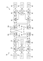
FIG. 1 shows a
図1に戻ると、ワイヤレスネットワーク100は、いくつかの基地局を含み、たとえば、発展型ノードB(eNB)またはGノードB(gNB)を含む場合がある。これらは、gNB105と呼ばれることがある。gNBは、UEと通信する局であってよく、基地局、ノードB、アクセスポイントなどと呼ばれることもある。各gNB105は、特定の地理的エリアに通信カバレージを提供することがある。3GPPでは、「セル」という用語は、この用語が使用される文脈に応じて、カバレージエリアにサービスするgNBおよび/またはgNBサブシステムのこの特定の地理的カバレージエリアを指すことがある。本明細書におけるワイヤレスネットワーク100の実装形態では、gNB105は、同じ事業者または異なる事業者に関連している場合があり(たとえば、ワイヤレスネットワーク100は、複数の事業者のワイヤレスネットワークを含む場合がある)、隣接セルと、同じ周波数の1つまたは複数(たとえば、ライセンススペクトル、アンライセンススペクトル、またはそれらの組合せの1つまたは複数の同じ周波数帯)を使用してワイヤレス通信を提供する場合がある。
Returning to FIG. 1, the
gNBは、マクロセル、またはピコセルもしくはフェムトセルなどのスモールセル、および/または他のタイプのセルに通信カバレージを提供することができる。マクロセルは一般に、比較的大きい地理的エリア(たとえば、半径数キロメートル)をカバーし、ネットワークプロバイダのサービスに加入しているUEによる無制限アクセスを可能にし得る。ピコセルなどのスモールセルは、一般に、比較的小さい地理的エリアをカバーし、ネットワークプロバイダのサービスに加入しているUEによる無制限アクセスを可能にすることができる。フェムトセルなどのスモールセルも、一般に、比較的小さい地理的エリア(たとえば、自宅)をカバーし、無制限アクセスに加えて、フェムトセルとの関連付けを有するUE(たとえば、限定加入者グループ(CSG)内のUE、自宅内のユーザのためのUEなど)による制限付きアクセスも提供することができる。マクロセルのためのgNBは、マクロgNBと呼ばれることがある。スモールセルのためのgNBは、スモールセルgNB、ピコgNB、フェムトgNB、またはホームgNBと呼ばれることがある。図1に示す例では、gNB105a、105b、および105cは、それぞれ、マクロセル110a、110b、および110cのためのマクロgNBである。gNB105x、105y、および105zは、それぞれ、スモールセル110x、110y、および110zにサービスを提供するピコgNBまたはフェムトgNBを含み得る、スモールセルgNBである。gNBは、1つまたは複数(たとえば、2つ、3つ、4つなど)のセルをサポートしてもよい。
The gNB can provide communication coverage for macrocells, or small cells such as picocells or femtocells, and / or other types of cells. Macrocells generally cover a relatively large geographic area (eg, a few kilometers in radius) and may allow unlimited access by UEs subscribed to the services of network providers. Small cells, such as pico cells, can generally cover a relatively small geographic area and allow unlimited access by UEs subscribed to the services of network providers. Small cells, such as femtocells, also generally cover a relatively small geographic area (eg, home) and, in addition to unlimited access, are within a UE (eg, a limited subscriber group (CSG)) that has an association with the femtocell. It can also provide restricted access by UE, UE for users at home, etc.). The gNB for the macro cell is sometimes referred to as the macro gNB. The gNB for a small cell may be referred to as a small cell gNB, pico gNB, femto gNB, or home gNB. In the example shown in FIG. 1,
ワイヤレスネットワーク100は、同期動作または非同期動作をサポートし得る。同期動作の場合、gNBは、同様のフレームタイミングを有することができ、異なるgNBからの送信は、時間的にほぼ整合し得る。非同期動作の場合、gNBは、異なるフレームタイミングを有することがあり、異なるgNBからの送信は、時間的に整合していないことがある。いくつかのシナリオでは、ネットワークが、同期または非同期動作間で動的切替えを処理することを可能にされる、またはそのように構成されることがある。
The
UE115は、ワイヤレスネットワーク100全体にわたって分散され、各UEは固定またはモバイルであり得る。モバイル装置は、第3世代パートナーシッププロジェクト(3GPP)によって公表された規格および仕様では、一般にユーザ機器(UE)と呼ばれるが、そのような装置は、当業者によって、移動局(MS)、加入者局、モバイルユニット、加入者ユニット、ワイヤレスユニット、リモートユニット、モバイルデバイス、ワイヤレスデバイス、ワイヤレス通信デバイス、リモートデバイス、モバイル加入者局、アクセス端末(AT)、モバイル端末、ワイヤレス端末、リモート端末、ハンドセット、端末、ユーザエージェント、モバイルクライアント、クライアント、または何らかの他の適切な用語で呼ばれることもあることを諒解されたい。本書内では、「モバイル」装置またはUEは、必ずしも移動するための能力を有する必要があるとは限らず、固定されていてもよい。UE115のうちの1つまたは複数の実施形態を含み得るようなモバイル装置のいくつかの非限定的な例には、モバイル、セルラー(セル)フォン、スマートフォン、セッション開始プロトコル(SIP)フォン、ラップトップ、パーソナルコンピュータ(PC)、ノートブック、ネットブック、スマートブック、タブレット、および携帯情報端末(PDA)が含まれる。モバイル装置は、加えて、自動車もしくは他の輸送車両、衛星無線、全地球測位システム(GPS)デバイス、物流コントローラ、ドローン、マルチコプター、クアッドコプター、スマートエネルギーもしくはセキュリティデバイス、ソーラーパネルもしくはソーラーアレイ、都市照明、用水、または他のインフラストラクチャなどの「モノのインターネット」(IoT)デバイス、工業オートメーションおよびエンタープライズデバイス、アイウェア、ウェアラブルカメラ、スマートウォッチ、ヘルスまたはフィットネストラッカー、哺乳類埋込み可能デバイス、ジェスチャー追跡デバイス、医療デバイス、デジタルオーディオプレーヤ(たとえば、MP3プレーヤ)、カメラ、ゲームコンソールなどのコンシューマおよびウェアラブルデバイス、ならびに、ホームオーディオ、ビデオおよびマルチメディアデバイス、アプライアンス、センサー、自動販売機、インテリジェント照明、ホームセキュリティシステム、スマートメーターなどのデジタルホー
ムまたはスマートホームデバイスであり得る。UE115などのモバイル装置は、マクロgNB、ピコgNB、フェムトgNB、リレーなどと通信することが可能であり得る。図1では、稲妻(たとえば、通信リンク125)は、UEとサービングgNBとの間のワイヤレス送信、またはeNB間の所望の送信を示し、サービングgNBは、ダウンリンクおよび/またはアップリンク上でUEにサービスするように指定されたeNBである。バックホール通信134は、gNB間で発生し得るワイヤードバックホール通信として示されているが、バックホール通信が追加または代替としてワイヤレス通信によって実現されてもよいことを諒解されたい。
UE115 is distributed across the
図2は、基地局/gNB105およびUE115の設計のブロック図を示す。これらは、図1の基地局/gNBのうちの1つおよびUEのうちの1つとすることができる。(上述のように)制限付き関連付けシナリオの場合、gNB105は図1のスモールセルgNB105zであってもよく、UE115はUE115zであってもよく、UE115zは、スモールセルgNB105zにアクセスするために、スモールセルgNB105zに対するアクセス可能UEのリストに含まれることになろう。gNB105はまた、何らかの他のタイプの基地局であり得る。gNB105は、アンテナ234a~234tを備えてもよく、UE115は、アンテナ252a~252rを備えてもよい。
FIG. 2 shows a block diagram of the design of the base station / gNB105 and UE115. These can be one of the base stations / gNB and one of the UEs in FIG. For a restricted association scenario (as described above), gNB105 may be the small cell gNB105z in Figure 1, UE115 may be UE115z, and UE115z may be the small cell to access the small cell gNB105z. It will be included in the list of accessible UEs for gNB105z. The gNB105 can also be some other type of base station. The gNB105 may be provided with
gNB105において、送信プロセッサ220は、データソース212からデータを受信し、コントローラ/プロセッサ240から制御情報を受信することができる。制御情報は、物理ブロードキャストチャネル(PBCH)、物理ダウンリンク制御チャネル(PDCCH)などに対するものであってもよい。データは、物理ダウンリンク共有チャネル(PDSCH)に関するデータなどであってもよい。送信プロセッサ220は、データおよび制御情報を処理(たとえば、符号化およびシンボルマッピング)して、それぞれ、データシンボルおよび制御シンボルを取得することができる。また、送信プロセッサ220は、たとえば、プライマリ同期信号(PSS)、およびセカンダリ同期信号(SSS)に関する基準シンボルなどを生成してもよい。送信(TX)多入力多出力(MIMO)プロセッサ230は、該当する場合、データシンボル、制御シンボル、および/または基準シンボルに対して空間処理(たとえば、プリコーディング)を行ってもよく、出力シンボルストリームを変調器(MOD)232a~232tを供給してもよい。各変調器232は、(たとえば、OFDM用などに)それぞれの出力シンボルストリームを処理して出力サンプルストリームを取得し得る。各変調器232は、追加または代替として、出力サンプルストリームを処理(たとえば、アナログに変換、増幅、フィルタ処理、およびアップコンバート)して、ダウンリンク信号を取得し得る。変調器232a~232tからのダウンリンク信号は、それぞれ、アンテナ234a~234tを介して送信され得る。
In the
UE115において、アンテナ252a~252rは、gNB105からダウンリンク信号を受信することができ、受信信号を、それぞれ復調器(DEMOD)254a~254rに供給することができる。各復調器254は、それぞれの受信信号を調整(たとえば、フィルタリング、増幅、ダウンコンバート、およびデジタル化)して、入力サンプルを取得することができる。各復調器254は、(たとえば、OFDMなどのために)入力サンプルをさらに処理して、受信シンボルを取得することができる。MIMO検出器256は、すべての復調器254a~254rから受信シンボルを取得し、適用可能な場合、受信シンボルに対してMIMO検出を実行し、検出されたシンボルを提供することができる。受信プロセッサ258は、検出されたシンボルを処理(たとえば、復調、デインターリーブ、および復号)し、UE115のための復号されたデータをデータシンク260に供給し、復号された制御情報をコントローラ/プロセッサ280に供給することができる。
In UE115, the
アップリンク上で、UE115において、送信プロセッサ264は、データソース262から(たとえば、PUSCH用の)データを受信および処理し、コントローラ/プロセッサ280から(たとえば、PUCCH用の)制御情報を受信および処理することができる。送信プロセッサ264はまた、基準信号のための基準シンボルを生成することができる。送信プロセッサ264からのシンボルは、該当する場合はTX MIMOプロセッサ266によってプリコーディングされ、(たとえば、SC-FDMなどのために)変調器254a~254rによってさらに処理され、gNB105に送信され得る。gNB105において、UE115からのアップリンク信号は、アンテナ234によって受信され、復調器232によって処理され、該当する場合はMIMO検出器236によって検出され、受信プロセッサ238によってさらに処理されて、UE115によって送られた復号されたデータおよび制御情報を取得することができる。プロセッサ238は、復号されたデータをデータシンク239に、復号された制御情報をコントローラ/プロセッサ240に提供し得る。
On the uplink, on the
コントローラ/プロセッサ240および280は、それぞれ、gNB105およびUE115における動作を指示することができる。gNB105におけるコントローラ/プロセッサ240および/もしくは他のプロセッサおよびモジュールならびに/またはUE115におけるコントローラ/プロセッサ280および/もしくは他のプロセッサおよびモジュールは、図4、図6および図7に示す実行および/または本明細書で説明する技法のための他のプロセスを行う、または指示するためなどに、本明細書で説明する技法のための様々なプロセスの実行を行う、または指示することができる。メモリ242および282は、それぞれ、gNB105およびUE115のためのデータおよびプログラムコードを記憶し得る。スケジューラ244は、ダウンリンクおよび/またはアップリンク上でのデータ送信のためにUEをスケジュールし得る。
Controllers /
容量の増加、干渉への耐性、ロバスト性能などを促進する際に、ワイヤレスネットワークは、様々なネットワークノードによる、およびそれらの間の通信のために複数の通信モードをサポートしてもよい。たとえば、ワイヤレスネットワーク100は、複数の異なる通信モードをサポートしてもよく、それらの通信モードは1つまたは複数の異なるパラメータ(サブキャリア間隔、周波数、フレーム構造、シンボル長、OFDMシンボル時間、サンプルレートなど)を利用してもよい。状況(たとえば、チャネル状態、受信信号強度、干渉環境など)の様々な態様に応じてgNBとUEとの間の通信リンクで使用するために、特定の通信モードが選択されてもよい。通信モードに関して利用される異なるパラメータは、本明細書ではヌメロロジーと呼ぶ。本開示の実施形態による実装され得る異なるヌメロロジーの一例として、現在開発中の5Gプロトコルに従って動作可能なワイヤレスネットワーク100が、異なるサブキャリア間隔(たとえば、15kHz、30kHz、60kHzなどのサブキャリア間隔)を有する通信モードをサポートしてもよい。
In promoting increased capacity, resistance to interference, robustness, etc., wireless networks may support multiple modes of communication for communication by and between various network nodes. For example, the
通信モードは上記のヌメロロジーによって異なり得るが、本明細書における概念に従って動作可能な実施形態は、それでも、異なる通信モードの2つ以上(たとえば、全部)に対して同じ同期信号構成(本明細書では統一同期信号構成と呼ぶ)を利用し得る。たとえば、ネットワークノード(たとえば、UE)が、最初に特定の通信モードを知ることなく、複数の通信モードのいずれかに従って送信された同期信号(たとえば、上述の15kHz、30kHz、60kHzのサブキャリア間隔のいずれかを有する信号)を検出できることを促進するために、本開示の実施形態は、そのような各通信モードの信号によって運ばれ得る統一同期信号構成を提供する。しかしながら、異なる通信モード(たとえば、サブキャリア間隔、シンボルサイズ、データペイロードなど)の信号の違いのために、本明細書における実施形態による統一同期信号構成は、分割構成(split configuration)を含み、複数の通信モードの信号での同じ同期信号構成の使用を容易にするために適合された同期信号スイート内に、所定のギャップが設けられる。たとえば、実施形態の同期信号スイートは、PSS、SSS、PBCH上で送信される1つもしくは複数の信号、および/または基準信号(RS)(たとえば、PBCH信号用の測定RSもしくは復調RS(demod RS)として使用され得る)のうちの2つ以上などの、複数の信号を含んでもよい。同期信号スイートは、所定の配置で、同期信号スイートの2つ以上の信号間に所定のギャップを配設して、送信されてもよい。 Although communication modes may vary depending on the numerology described above, embodiments that can operate according to the concepts herein will still have the same sync signal configuration (eg, all) for two or more (eg, all) of different communication modes (as used herein). (Called a unified sync signal configuration) can be used. For example, a network node (eg, UE) has a sync signal (eg, 15kHz, 30kHz, 60kHz subcarrier spacing described above) transmitted according to one of multiple communication modes without first knowing the particular communication mode. In order to facilitate the detection of a signal having either), embodiments of the present disclosure provide a unified sync signal configuration that can be carried by the signals of each such mode of communication. However, due to differences in signals in different communication modes (eg, subcarrier spacing, symbol size, data payload, etc.), the unified sync signal configuration according to embodiments herein includes a plurality of split configurations. A predetermined gap is provided within the sync signal suite adapted to facilitate the use of the same sync signal configuration with signals in the same mode of communication. For example, the sync signal suite of an embodiment may be one or more signals transmitted over a PSS, SSS, PBCH, and / or a reference signal (RS) (eg, a measured RS or demodulated RS (demod RS) for a PBCH signal. ) May contain multiple signals, such as two or more of them. The sync signal suite may be transmitted in a predetermined arrangement with a predetermined gap between two or more signals in the sync signal suite.
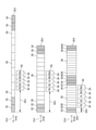
図3は、ワイヤレスネットワーク100において使用される場合があるいくつかの実施形態の統一同期信号構成のブロックを示す。統一同期信号構成は、たとえば、gNB105とUE115との通信、gNB105a~c間の通信、または複数のUE間の通信に使用されてもよい。図3は、ワイヤレス通信ネットワークにおいて異なる通信モード310-2、310-4、および310-6に同じ同期信号構成302を使用することができる統一同期信号構成を示す。図示の実施形態の各通信モードにおいて、2つのノード間のデータ通信はブロック、たとえば、フレーム(またはサブフレームもしくはスロット)320-2、320-4、320-6、および320-8に分割される。各通信ブロックは、制御信号(たとえば、制御シンボル322、324)のための1つまたは複数のユニット、および制御信号ユニット間に位置するデータ信号(たとえば、データシンボル326)のための1つまたは複数のユニットを含んでもよい。いくつかの実施形態では、通信ブロック320-2、320-4、320-6、および320-8中の制御信号は、ダウンリンク(gNBからUEへの)制御信号のための1つまたは複数のユニット(たとえば、322)、および/またはアップリンク(UEからgNBへの)制御信号のための1つまたは複数のユニット(たとえば、324)を含んでもよい。いくつかのワイヤレス通信システムにおいて、通信ブロックがフレームを表してもよく、(たとえば、時分割複信(TDD)または周波数分割複信(FDD)システムでは)通信ブロック中の2つの連続するユニットがサブフレームを表してもよく、(たとえば、FDDシステムでは)通信ブロック中の1つのユニットがスロットを表してもよい。いくつかの実施形態では、通信ブロックが、サブフレームまたはスロットを表してもよい。
FIG. 3 shows a block of unified sync signal configurations of some embodiments that may be used in the
図示の例では、各通信モードが、異なるサブキャリア間隔を利用して動作し、たとえば、通信モード310-2は、15kHzサブキャリア間隔を利用して動作し、通信モード310-4は、30kHzサブキャリア間隔を利用して動作し、通信モード310-6は、60kHzサブキャリア間隔を利用して動作する。したがって、図示の例における通信モードのヌメロロジーは、サブキャリア間隔を含む。結果として、これらの異なる通信モードのための通信ブロック320-2、320-4、320-6、および320-8は、異なるシンボルサイズおよび異なる間隔を提供する。たとえば、図示の実施形態では、同期信号304は、モード310-2ではユニットの半分(たとえば、シンボルの2分の1)、モード310-4では1ユニット(たとえば、1シンボル)、モード310-6では2ユニット(たとえば、2シンボル)を占有する。
In the illustrated example, each communication mode operates with a different subcarrier interval, for example, communication mode 310-2 operates with a 15kHz subcarrier interval, and communication mode 310-4 operates with a 30kHz sub. It operates using the carrier interval, and the communication mode 310-6 operates using the 60 kHz subcarrier interval. Therefore, the numerology of the communication mode in the illustrated example includes the subcarrier interval. As a result, the communication blocks 320-2, 320-4, 320-6, and 320-8 for these different communication modes provide different symbol sizes and different spacing. For example, in the illustrated embodiment, the
図示の実施形態では、同期信号構成302は、同期信号ブロック(SSB)とも呼ばれる複数の同期信号304の配置を含み、たとえば、PSS、SSS、RS、およびPBCH上で送信される信号を含み得る。たとえば、図示の実施形態では、同期信号構成302のSSBは、PSS、続いてSSSおよびRS(たとえば、本明細書では測定基準信号またはMRSと呼ぶ、セル測定にも使用され得るPBCH用の復調RS)を含む同期信号のスイートを含み、これに2つのPBCH、RS、次いで2つのPBCH信号が続く。いくつかの他の実施形態では、同期信号構成302のSSBは、任意の数の同期信号の任意の他の組合せを任意の好適な順序で含む同期信号のスイートを含む場合があることに留意されたい。
In the illustrated embodiment, the
いくつかの実施形態では、同期信号304が通信ブロック320-2、320-4、320-6、および320-8においてデータ信号に割り当てられたユニット(すなわち、全体的に326と標示された任意の空のユニット)のみを占有し、制御信号に割り当てられたユニット(ユニット322および324)との重複を避けることが望ましい。しかしながら、同期信号のいくつかの連続した配置では、同期信号の連続したブロックを、いくつかの通信モードにおいて通信ブロックのデータユニットに埋めることができない。たとえば、図示の例では、同期信号304の連続した配置を、通信ブロック320-6のデータユニット326にすべて埋めること、または通信ブロック320-8にすべて埋めることができない。結果として、異なる通信モードに同じ同期信号構成302を適合させるために、実施形態は、同期信号構成302のSSBの同期信号304間に1つまたは複数のギャップ(たとえば、ギャップ306)を挿入する。図3に示すように、ギャップ306は、同期信号304を2つのグループに分けるように設計されてもよく、同期信号の1つのグループが、通信ブロック320-6のデータユニット326に適合し、同期信号の別のグループが、通信ブロック320-8のデータユニット326に適合するようにする。分割同期信号構成302が、通信モード320-2および320-4などの他の通信モードで使用されるとき、データユニット326に十分なスペースがあるので、すべての同期信号304が1つの通信ブロック(たとえば、通信ブロック320-2または320-4)のデータユニットに適合され得る。そのような分割同期信号構成302を用いて、複数の同期信号の同じ配置は、異なる通信モードに使用されてもよく、同期信号構成302からの同期信号のいずれも、任意の通信モードで制御信号用に確保された任意のユニット(すなわち、ユニット322、324)を占有しない。
In some embodiments, any unit in which the
いくつかの実施形態では、同期信号の様々なグループが異なる通信モードのデータユニットに適合するように、SSBの同期信号を3つ以上のグループに分けるために、複数のギャップが利用される場合があることに留意されたい。たとえば、4つ以上の通信モードがあってもよく、同期信号構成302に複数のギャップがあってもよい。この例を上記で説明したように異なるサブキャリア間隔を含むヌメロロジーに拡大すると、120kHzサブキャリア間隔を利用するために動作する第4の通信モードがある場合があり、SSBの同期信号304が3つのグループに分けられ、3つの連続する通信ブロックのデータユニットに適合されるように、同期信号構成302に2つのギャップを有することが望ましい場合がある。さらに、同期信号構成302は、周波数分割複信(FDD)または時分割複信(TDD)のいずれかを使用するワイヤレス通信システムにおいて使用されてもよい。
In some embodiments, multiple gaps may be utilized to divide the SSB sync signal into three or more groups so that different groups of sync signals fit data units in different communication modes. Please note that there is. For example, there may be four or more communication modes, and there may be multiple gaps in the
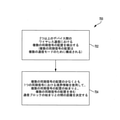
図4は、本開示の実施形態による統一同期信号配置を決定する方法400のブロック図を示す。図示の実施形態では、ブロック402において、ネットワークノードの統一同期信号論理(たとえば、メモリ242に記憶され、gNB105のコントローラ/プロセッサ240上で実行可能な命令セット)が、2つ以上のノード間のワイヤレス通信のための複数の同期信号の配置を決定する。ノードは、図1に関して上記で説明したようにワイヤレス通信ネットワーク100内のgNB、UE、または他のノードを含んでもよい。同期信号は、たとえば、以下の信号、すなわちPSS、SSS、RS、およびPBCH信号のうちの1つまたは複数を含んでもよい。ブロック404において、統一同期信号論理は、1つまたは複数のギャップが、配置の2つ以上の同期信号間に挿入されるようにしてもよい(たとえば、メモリ242に記憶され、gNB105のコントローラ/プロセッサ240上で実行可能な命令セットが、gNB105によって送信される2つ以上の同期信号間に1つまたは複数のギャップを挿入するように、送信プロセッサ220を制御してもよい)。1つまたは複数のギャップは、複数の同期信号の同じ配置が、図3に関して上記で説明した通信モード320-2、310-4、310-6など、異なるヌメロロジーを利用して動作する複数の通信モードで使用されることを可能にし得る。複数の同期信号の配置の同期信号間の1つまたは複数のギャップは、複数の同期信号が、1つまたは複数の通信ブロック(図3に記載する通信ブロック320-2、320-4、320-6、320-8など)のデータユニットに適合され、1つまたは複数の通信ブロックにおいて他の制御信号に確保されたユニットとの重複を避けることを可能にし得る。
FIG. 4 shows a block diagram of a
通信モードによって利用される上記の異なるヌメロロジーは、送信される様々なブロック(たとえば、フレーム)の違いを生じることがある。たとえば、サブキャリア間隔に対応する異なるヌメロロジーが、通信モードによって送信される信号間でのシンボル長の違いをもたらすことがある。したがって、図3に示す例示的な実施形態に示すような統一同期信号が、複数の通信モードの各々に利用される場合があるが、統一同期信号はそれでも、そのような各通信モードのブロックに配設されるような違いを有する場合がある。たとえば、統一同期信号は、各通信モードを使用して送信される同期信号の同じ所定の配置を有するが、異なる通信モードでは異なる境界オフセットを有して配設される場合がある。したがって、ネットワークノード(たとえば、UE)による同期信号の検出を容易にし得る、実施形態の統一同期信号構成は、通信モードの通信ブロックの検出を容易にするように適合され得る。 The different numerologies utilized by the communication mode can result in differences in the various blocks (eg, frames) transmitted. For example, different numerologies corresponding to subcarrier intervals can result in differences in symbol length between signals transmitted by the communication mode. Therefore, a unified sync signal as shown in the exemplary embodiment shown in FIG. 3 may be used for each of the plurality of communication modes, but the unified sync signal is still a block of each such communication mode. May have differences such as being disposed. For example, a unified sync signal may have the same predetermined arrangement of sync signals transmitted using each communication mode, but may have different boundary offsets in different communication modes. Thus, the unified sync signal configuration of embodiments that may facilitate the detection of sync signals by network nodes (eg, UE) may be adapted to facilitate the detection of communication blocks in communication mode.
図5は、ワイヤレスネットワーク100で使用される場合がある統一同期チャネル構成の通信ブロックの境界を示すためのブロック図を示す。実施形態の構成を示す境界は、たとえば、gNB105とUE115との通信、gNB105a~c間の通信、または複数のUE間の通信に使用されてもよい。図5は、ワイヤレス通信ネットワークにおいて異なる通信モード510-2、510-4、および510-6に同じ同期信号構成502が使用される統一同期信号構成の通信ブロック(たとえば、フレーム、サブフレーム、またはスロット)の境界を示すための構成を示す。同期信号構成は、たとえば、複数の通信モードで使用されるとき、時間的に固定長を有してもよく、固定長は、複数の通信モードのための同期信号構成を構成するために選択される。同期信号構成の実施形態は、複数の通信モードのための同期信号構成を構成するために図3に関して上記で説明したような、1つまたは複数のギャップを利用してもよい。
FIG. 5 shows a block diagram to show the boundaries of communication blocks in a unified sync channel configuration that may be used in
各通信モードでは、2つのノード間のデータ通信は、ブロック、たとえばフレーム(またはサブフレームもしくはスロット)520-2、520-4、520-6、および520-8に分割される。各通信ブロックは、制御信号(たとえば、制御シンボル522、524)のための1つまたは複数のユニット、および制御信号ユニット間に位置するデータ信号(たとえば、データシンボル526)のための1つまたは複数のユニットを含んでもよい。いくつかの実施形態では、通信ブロック520-2、520-4、520-6、および520-8中の制御信号は、ダウンリンク(gNBからUEへの)制御信号のための1つまたは複数のユニット(たとえば、522)、および/またはアップリンク(UEからgNBへの)制御信号のための1つまたは複数のユニット(たとえば、524)を含んでもよい。いくつかのワイヤレス通信システムにおいて、通信ブロックがフレームを表してもよく、(たとえば、時分割複信(TDD)または周波数分割複信(FDD)システムでは)通信ブロック中の2つの連続するユニットがサブフレームを表してもよく、(たとえば、FDDシステムでは)通信ブロック中の1つのユニットがスロットを表してもよい。いくつかの実施形態では、通信ブロックが、サブフレームまたはスロットを表してもよい。 In each communication mode, data communication between the two nodes is divided into blocks, eg frames (or subframes or slots) 520-2, 520-4, 520-6, and 520-8. Each communication block is one or more units for control signals (eg, control symbols 522, 524) and one or more for data signals located between control signal units (eg, data symbol 526). Units may be included. In some embodiments, the control signals in the communication blocks 520-2, 520-4, 520-6, and 520-8 are one or more for the downlink (gNB to UE) control signal. It may include units (eg, 522) and / or one or more units (eg, 524) for uplink (UE to gNB) control signals. In some wireless communication systems, a communication block may represent a frame, for example, in a Time Division Duplex (TDD) or Frequency Division Duplex (FDD) system, two contiguous units in the communication block are sub. It may represent a frame, or one unit in a communication block (for example, in an FDD system) may represent a slot. In some embodiments, the communication block may represent a subframe or slot.
図5に示す実施形態は、SSB同期信号の連続的な構成を示すが、本開示の境界表示実装形態とともに同期信号の他の構成が利用される場合があることを諒解されたい。たとえば、図3に示す例示的な実施形態の構成などの分割SSB同期信号構成が、本開示の通信ブロック境界表示実装形態とともに利用される場合がある。 Although the embodiment shown in FIG. 5 shows a continuous configuration of the SSB synchronization signal, it should be understood that other configurations of the synchronization signal may be used together with the boundary display implementation of the present disclosure. For example, a split SSB sync signal configuration, such as the configuration of the exemplary embodiment shown in FIG. 3, may be used in conjunction with the communication block boundary display implementation of the present disclosure.
上記の図3の例と同様に、図示の例では、各通信モードが、異なるサブキャリア間隔を利用して動作し、たとえば、通信モード510-2は、15kHzサブキャリア間隔を利用して動作し、通信モード510-4は、30kHzサブキャリア間隔を利用して動作し、通信モード510-6は、60kHzサブキャリア間隔を利用して動作する。結果として、これらの異なる通信モードのための通信ブロック520-2、520-4、520-6、および520-8は、異なるシンボルサイズおよび通信ブロック境界からの異なるオフセットを提供する。 Similar to the example in FIG. 3 above, in the illustrated example, each communication mode operates with a different subcarrier spacing, for example, communication mode 510-2 operates with a 15kHz subcarrier spacing. , Communication mode 510-4 operates using the 30kHz subcarrier interval, and communication mode 510-6 operates using the 60kHz subcarrier interval. As a result, the communication blocks 520-2, 520-4, 520-6, and 520-8 for these different communication modes provide different symbol sizes and different offsets from the communication block boundaries.
図示の実施形態では、同期信号構成502は、SSBを含む複数の同期信号504の配置を含んでもよく、SSBはたとえば、PSS、SSS、RS、およびPBCH上で送信される信号を含んでもよい。たとえば、図示の実施形態では、同期信号構成502のSSBは、PSS、続いてSSSおよびRS(たとえば、MRS)を含み、次に2つのPBCH信号が続く、同期信号のスイートを含む。同期信号構成502は図示の例ではPSSから始めるが、いくつかの他の実施形態では、同期信号構成502のSSBは、SSS、RS、PBCHなどの、同期信号の任意の他のタイプから始める場合があることに留意されたい。さらに、いくつかの他の実施形態では、同期信号構成502のSSBは、任意の数の同期信号の任意の組合せを任意の好適な順序で含む同期信号のスイートを含む場合があることに留意されたい。
In the illustrated embodiment, the
同じ同期信号構成502をデータユニット526に適合させるために、同期信号構成502のSSBは、異なる通信モード510-2、510-4、および510-6の通信ブロック520-2、520-4、520-6、520-8の始まりに対して異なる位置に置かれてもよい。いくつかのワイヤレス通信システムでは、同期信号が最初に検出され、次いで、同期信号を含む通信ブロックの境界(すなわち、通信ブロックの始まり)が、同期信号の位置に対して決定される。したがって、異なる通信モードでの通信ブロックの境界を明確に示す本明細書の実施形態の機構は、効率的な処理を実現し、システムにおける計算の複雑度を下げ得る。
To adapt the same
本開示のいくつかの実施形態による境界識別のための技法は、同期信号の少なくとも1つにより、通信ブロック境界と同期信号の始まりとの相対的距離を示す情報(本明細書では境界情報と呼ぶ)を提供する。そのような構成において、受信ノード(たとえば、UE)が通信ブロックを受信し、同期信号を検出すると、受信ノードは、同期信号から境界情報を引き出し、次いで通信ブロックの境界を決定することができる。 The technique for boundary identification according to some embodiments of the present disclosure is information indicating the relative distance between the communication block boundary and the beginning of the synchronization signal by at least one of the synchronization signals (referred to herein as boundary information). )I will provide a. In such a configuration, when the receiving node (eg, UE) receives the communication block and detects the synchronization signal, the receiving node can extract the boundary information from the synchronization signal and then determine the boundary of the communication block.
実施形態による動作中、通信ブロック520-2、520-4、520-6の始まりと、同期信号構成502のSSBの始まりとの間の距離530-2、530-4、530-6が、通信モードの各々に対してあらかじめ決定され得る。通信ブロックの通信モードは、本開示の実施形態による、同期信号構成502のSSBの同期信号(たとえば、PSS、SSS、RS、およびPBCHのうちの1つまたは複数)の少なくとも1つに含まれる境界情報において示されてもよい。たとえば、図示の例では、距離530-2は、通信ブロック520-2の始まりが、通信モード510-2の同期信号構成502のSSBの始まりから3ユニット(たとえば、シンボル)であることを表し、距離530-4は、通信ブロック520-4の始まりが、通信モード510-4の同期信号構成502のSSBの始まりから5ユニット(たとえば、シンボル)であることを表し、距離530-6は、通信ブロック520-6の始まりが、通信モード510-6の同期信号構成502のSSBの始まりから2ユニット(たとえば、シンボル)であることを表す。本開示の実施形態によれば、通信ブロックの始まりとSSBの始まりとの上記の距離(たとえば、通信モード510-2では3ユニット、通信モード510-4では5ユニット、および通信モード510-6では2ユニット)は、あらかじめ決定され、したがってネットワークの様々なノード(たとえば、gNB、UEなど)によってアプリオリに知られ得る。したがって、受信機が、受信された通信ブロックに同期信号構成502のSSBを検出し、同期信号の1つまたは複数に含まれる境界情報から、使用中の通信モードが通信モード510-2であると決定するとき、受信機は、通信ブロックが同期信号構成502のSSBの始まり(図示の例ではPSSの始まりである)より3ユニット前に開始することを決定し得る。代替的に、受信機が、受信された通信ブロックに同期信号構成502を検出し、同期信号の1つまたは複数に含まれる境界情報から、使用中の通信モードが通信モード510-4であると決定するとき、受信機は、通信ブロックが同期信号構成502のSSBの始まりより5ユニット前に開始することを決定し得る。
During operation according to the embodiment, the distance 530-2, 530-4, 530-6 between the beginning of the communication blocks 520-2, 520-4, 520-6 and the beginning of the SSB of the
代替的に、通信ブロック520-2、520-4、520-6の始まりと、同期信号構成502のSSBの始まりとの間の距離530-2、530-4、530-6は、同期信号構成502のSSBを通信ブロックの任意の位置に配置する際の柔軟性がサポートされる実施形態などでは、各通信モードに対してあらかじめ決定されない場合がある。異なる通信モードに関する距離530-2、530-4、530-6の値は、同期信号構成502のSSBの同期信号(たとえば、PBCH、PSS、SSS、およびRSのうちの1つまたは複数)の少なくとも1つに含まれる境界情報において示されてもよい。距離530-2、530-4、530-6は各通信モードに対してあらかじめ決定されていないので、この解決策は、通信ブロックの任意の位置に、同期信号構成502のSSBを柔軟に配置するという利点を有する。たとえば、一実施形態では、同期信号構成502のSSBの始まりは、通信ブロックの始まりの6ユニット後に置かれてもよく、そのような相対的距離は、SSBの同期信号(たとえば、PBCH信号)のうちの1つまたは複数に含まれる境界情報を通して示される。受信ノードが通信ブロックを受信すると、受信ノードは、同期信号構成502のSSBの始まりを検出し、PBCH信号から上記の距離情報を含む境界情報を引き出すことによって、通信ブロックの始まりを決定することができる。
Alternatively, the distance between the beginning of communication blocks 520-2, 520-4, 520-6 and the beginning of the SSB of
実施形態による動作中、受信ノードが、(たとえば、キャリア周波数に応じて)SSBヌメロロジーを使用する通信ブロックに関して使用中の特定の通信モード(たとえば、通信モード510-2、通信モード510-4、または通信モード510-6)を決定してもよい。上記のシナリオにおいて、使用中の通信モードは、同期信号の1つにおいて示される必要がないことを諒解されたい。しかしながら、実施形態はそれでも、同期信号構成502の同期信号の少なくとも1つに含まれる境界情報において通信ブロックの通信モードを示してもよい。たとえば、境界情報は、SSBインデックスにより、各通信モードに対して取り出されてもよく、SSBインデックスは、たとえば、RSおよびPBCHによって決定されてもよい。
During operation according to an embodiment, the receiving node is using a particular communication mode (eg, communication mode 510-2, communication mode 510-4, or) for a communication block that uses SSB numerology (eg, depending on carrier frequency). The communication mode 510-6) may be determined. It should be noted that in the above scenario, the communication mode in use does not need to be indicated in one of the sync signals. However, the embodiment may still indicate the communication mode of the communication block in the boundary information contained in at least one of the synchronization signals of the
図6は、統一同期信号配置を含む通信ブロックの境界を示す方法600のブロック図を示す。図示の実施形態では、ブロック602において、ネットワークノードの統一同期信号論理(たとえば、メモリ242に記憶され、gNB105のコントローラ/プロセッサ240上で実行可能な命令セット)が、2つ以上のノード間のワイヤレス通信のための複数の同期信号の配置を決定し、複数の同期信号の配置は、複数の通信モードのために構成される(たとえば、1つまたは複数のギャップのあるまたはない、同期信号の特定の配置と、複数の通信モードの各々の通信ブロックの始まりと、複数の通信モードの各々の通信ブロックにおける同期信号配置を適応させる同期信号配置の始まりとの相対的距離とを含む)。複数の通信モードの各通信モードは、たとえば、異なるサブキャリア間隔を使用して動作する場合がある。ノードは、図1に関して上記で説明したようにワイヤレス通信ネットワーク100内のgNB、UE、および/または他のデバイスを含んでもよい。統一同期信号配置は、図3および図5において上記で説明したようにSSBを提供する同期信号構成302、502、または対応されている複数の通信モードに関して使用するのに適した任意の他の構成を含んでもよい。同期信号配置のSSB中の同期信号は、以下の信号、すなわちPSS、SSS、RS、および/またはPBCH信号のうちの1つまたは複数を含んでもよい。
FIG. 6 shows a block diagram of
実施形態による動作中、ブロック604において統一同期信号論理は、複数の同期信号の配置の始まりと複数の同期信号の配置を含む通信ブロックの始まりとの相対的距離が、複数の同期信号の配置のうちの少なくとも1つの同期信号により示されるようにする。たとえば、メモリ242に記憶され、gNB105のコントローラ/プロセッサ240上で実行可能な命令セットは、送信プロセッサ220が相対的距離を示す境界情報を、同期信号配置の1つまたは複数の同期信号(たとえば、PSS、SSS、RS、および/またはPBCH信号)に挿入するように制御してもよい。例示的な実施形態による動作中、SSBヌメロロジーとともにRSおよびPBCHは、各通信モードのための境界情報が、RSおよびPBCHコンテンツによってSSBインデックスが決定される場合、SSBインデックスを介して導出されることを可能にするなどのために、境界情報を搬送するのに使用されてもよい。
During operation according to the embodiment, in
いくつかの実施形態では、相対的距離(たとえば、図5に記載する距離530-2、530-4、530-6、または図3の構成にある同様の距離)は、各通信モード(たとえば、図5に関して上記で説明した通信モード510-2、510-4、510-6、または図3の構成にある同様の通信モード)に対してあらかじめ決定されてもよい。したがって、1つまたは複数の同期信号に挿入される境界情報は、使用中の通信モードを示してもよく、それにより受信ノードは、通信モード情報および対応するあらかじめ決定された相対的距離の知識から、相対的距離を導出してもよい。たとえば、統一同期信号論理(たとえば、メモリ242によって記憶され、gNB105のコントローラ/プロセッサ240上で実行可能な命令セット)は、通信に関して使用中の通信モード(たとえば、通信モード510-2、510-4、もしくは510-6、または図3の構成にある同様の通信モードのうちの1つ)を決定し、その特定の通信モードを示す境界情報を同期信号配置の1つまたは複数の同期信号に挿入するために送信信号プロセッサ(たとえば、gNB105の送信プロセッサ220)を制御してもよい。例示的な実施形態による動作中、RSおよびPBCHのコンテンツは、情報を提供されてもよく、情報からSSBインデックスは受信ノードによって決定されてもよく、それによってSSBインデックスおよびSSBヌメロロジーは、使用中の通信モードを示す。対応して、統一同期信号論理は、同期信号配置の始まりと通信ブロックの始まりとの適切な相対的距離で通信ブロック(たとえば、フレーム)内に同期信号配置を含むように、送信信号プロセッサを制御してもよい。たとえば、統一同期信号論理は、使用中の通信モードのための同期信号配置に対して適切な相対的距離(たとえば、図5に記載する距離530-2、530-4、530-6、または図3の構成にある同様の距離)を決定するために、1つまたは複数のデータベース(対応される複数の通信モードの各々に対して、同期信号配置の始まりおよび同期信号配置を含む通信ブロックの始まりからの相対的距離に関する知識ベースを提供する、gNB105のメモリ242によって記憶された、通信モード統一同期信号相対的距離ルックアップテーブル)にアクセスし、次いで、通信ブロックに同期信号配置の同期信号を配設するとき、相対的距離を実装するための適切な制御を行ってもよい。
In some embodiments, the relative distances (eg, distances 530-2, 530-4, 530-6, shown in FIG. 5, or similar distances in the configuration of FIG. 3) are for each communication mode (eg, for example). It may be predetermined for the communication modes 510-2, 510-4, 510-6 described above with respect to FIG. 5 or similar communication modes in the configuration of FIG. Therefore, the boundary information inserted in one or more synchronization signals may indicate the mode of communication in use, whereby the receiving node is aware of the communication mode information and the corresponding predetermined relative distance. , Relative distance may be derived. For example, a unified sync signal logic (eg, an instruction set stored in
いくつかの実施形態では、相対的距離(たとえば、図5に記載する距離530-2、530-4、530-6、または図3の構成にある同様の距離)は、あらかじめ決定されない。したがって、1つまたは複数の同期信号に挿入された境界情報は、相対的距離の値を示し得る。たとえば、統一同期信号論理(たとえば、メモリ242によって記憶され、gNB105のコントローラ/プロセッサ240上で実行可能な命令セット)は、通信に関して使用中の通信モード(たとえば、通信モード510-2、510-4、もしくは510-6、または図3の構成にある同様の通信モードのうちの1つ)を決定し、その特定の通信モードに対する対応する相対的距離(たとえば、図5に記載する距離530-2、530-4、530-6、または図3の構成にある同様の距離)値を、ブロック602において決定される同期信号配置から導出してもよい。その後、統一同期信号論理は、その特定の相対的距離を示す境界情報を、同期信号配置の1つまたは複数の同期信号に挿入するために、送信信号プロセッサ(たとえば、gNB105の送信プロセッサ220)を制御してもよい。例示的な実施形態による動作中、RSおよびPBCHは、相対的距離を示すなどの境界情報を搬送するために利用されてもよい。対応して、統一同期信号論理は、あらかじめ決定された、同期信号配置の始まりと通信ブロックの始まりとの適切な相対的距離とともに通信ブロック(たとえば、フレーム)内に同期信号配置を含むために、送信信号プロセッサを制御してもよい。
In some embodiments, the relative distances (eg, distances 530-2, 530-4, 530-6 shown in FIG. 5, or similar distances in the configuration of FIG. 3) are not predetermined. Therefore, the boundary information inserted in one or more synchronization signals can indicate a relative distance value. For example, a unified sync signal logic (eg, an instruction set stored in
図7は、統一同期信号配置を含む通信ブロックの境界を決定する方法700のブロック図を示す。図示の実施形態では、ブロック702において、ネットワークノードの統一同期信号論理(たとえば、メモリ282によって記憶され、UE115のコントローラ/プロセッサ280上で実行可能な命令セット)が、送信において同期信号配置の存在を検出するために複数の同期信号の配置の同期信号(たとえば、PSS、SSS、RS、および/またはPBCH信号)のために1つまたは複数のチャネルを監視する。たとえば、受信プロセッサ(たとえば、受信プロセッサ258)が、1つまたは複数の同期信号を検出するために、受信した信号を処理し、分析してもよく、それによって受信プロセッサは、複数の同期信号の特定の配置が受信した信号に存在する(たとえば、同期信号配置が受信した通信ブロックにおいて搬送される)かどうかを決定するために、検出された同期信号に関する情報を、受信ノードのコントローラ(たとえば、コントローラ/プロセッサ280)に提供する。
FIG. 7 shows a block diagram of the
実施形態による動作中、ブロック704において、同期信号配置が受信した信号に存在すると決定され、統一同期信号論理が、複数の同期信号の配置の少なくとも1つの同期信号により示される、複数の同期信号の配置の始まりと、複数の同期信号の配置を含む通信ブロックの始まりとの相対的距離を決定する。たとえば、メモリ282によって記憶され、UE115のコントローラ/プロセッサ280上で実行可能な命令セットが、同期信号配置の1つまたは複数の同期信号(たとえば、PSS、SSS、RS、および/またはPBCH信号)から相対的距離を示す境界情報を引き出し、境界情報をコントローラ/プロセッサ280に提供するために受信プロセッサ258を制御してもよい。統一同期信号論理は、検出される同期信号配置の始まりと、同期信号配置が受信された通信ブロックの始まりとの相対的距離を決定するために、1つまたは複数の同期信号から引き出された境界情報を利用してもよい。
During operation according to the embodiment, in
いくつかの実施形態では、相対的距離(たとえば、図5に記載する距離530-2、530-4、530-6、または図3の構成にある同様の距離)は、各通信モード(たとえば、図5に関して上記で説明した通信モード510-2、510-4、510-6、または図3の構成にある同様の通信モード)に対してあらかじめ決定されてもよい。したがって、1つまたは複数の同期信号から引き出される境界情報は、使用中の通信モードを示してもよく、それにより受信ノードは、通信モード情報および対応するあらかじめ決定された相対的距離の知識から、相対的距離を導出してもよい。たとえば、統一同期信号論理(たとえば、メモリ282によって記憶され、UE115のコントローラ/プロセッサ280上で実行可能な命令セット)は、受信した通信ブロックに関して使用中の通信モード(たとえば、通信モード510-2、510-4、もしくは510-6、または図3の構成にある同様の通信モードのうちの1つ)を決定するために引き出された境界情報を分析し、使用中の通信モードに対して、検出された同期信号配置の始まりおよび通信ブロックの始まりから相対的距離(たとえば、図5に記載した距離530-2、530-4、530-6、または図3の構成にある同様の距離)を決定するために、1つまたは複数のデータベース(たとえば、対応される複数の通信モードの各々に対して、同期信号配置の始まりおよび同期信号配置を含む通信ブロックの始まりから相対的距離に関する知識ベースを提供する、UE115のメモリ282によって記憶された通信モード統一同期信号相対的距離ルックアップテーブル)にアクセスしてもよい。その後、統一同期信号論理は、そこからデータを引き出すなどのために、通信ブロックの始まりを検出するために相対的距離情報を利用するための適切な制御を行ってもよい。
In some embodiments, the relative distances (eg, distances 530-2, 530-4, 530-6, shown in FIG. 5, or similar distances in the configuration of FIG. 3) are for each communication mode (eg, for example). It may be predetermined for the communication modes 510-2, 510-4, 510-6 described above with respect to FIG. 5 or similar communication modes in the configuration of FIG. Thus, the boundary information extracted from one or more synchronization signals may indicate the mode of communication in use, whereby the receiving node will be aware of the communication mode information and the corresponding predetermined relative distance. Relative distance may be derived. For example, a unified sync signal logic (eg, an instruction set stored by
いくつかの実施形態では、相対的距離(たとえば、図5に記載する距離530-2、530-4、530-6、または図3の構成にある同様の距離)は、あらかじめ決定されない。したがって、1つまたは複数の同期信号から引き出された境界情報は、相対的距離の値を示し得る。実施形態の統一同期信号論理(たとえば、メモリ282に記憶され、UE115のコントローラ/プロセッサ280上で実行可能な命令セット)は、したがって、受信プロセッサ(たとえば、受信プロセッサ258)によって1つまたは複数の同期信号から引き出された境界情報から直接、同期信号配置の始まりと通信ブロックの始まりとの相対的距離を取得してもよい。その後、統一同期信号論理は、そこからデータを引き出すなどのために、通信ブロックの始まりを検出するために相対的距離情報を利用するための適切な制御を行ってもよい。
In some embodiments, the relative distances (eg, distances 530-2, 530-4, 530-6 shown in FIG. 5, or similar distances in the configuration of FIG. 3) are not predetermined. Therefore, the boundary information extracted from one or more synchronization signals can indicate a relative distance value. The unified sync signal logic of the embodiment (eg, an instruction set stored in
情報および信号は、多種多様な技術および技法のいずれかを使用して表されてもよいことを、当業者は理解するであろう。たとえば、上記の説明全体にわたって参照される場合があるデータ、命令、コマンド、情報、信号、ビット、シンボル、およびチップは、電圧、電流、電磁波、磁場もしくは粒子、光場もしくは光粒子、またはそれらの任意の組合せによって表されてもよい。 Those skilled in the art will appreciate that information and signals may be represented using any of a wide variety of techniques and techniques. For example, data, instructions, commands, information, signals, bits, symbols, and chips that may be referred to throughout the above description are voltages, currents, electromagnetic waves, magnetic fields or particles, light fields or light particles, or theirs. It may be represented by any combination.
本明細書で説明する機能ブロックおよびモジュール(たとえば、図2の機能ブロックおよびモジュール)は、プロセッサ、電子デバイス、ハードウェアデバイス、電子構成要素、論理回路、メモリ、ソフトウェアコード、ファームウェアコードなど、またはそれらの任意の組合せを備え得る。 The functional blocks and modules described herein (eg, functional blocks and modules of FIG. 2) are processors, electronic devices, hardware devices, electronic components, logic circuits, memory, software codes, firmware codes, etc., or them. Can be equipped with any combination of.
本明細書で本開示に関連して説明した様々な例示的論理ブロック、モジュール、回路、およびアルゴリズムステップが、電子ハードウェア、コンピュータソフトウェア、または両方の組合せとして実装され得ることを当業者ならさらに理解されよう。ハードウェアとソフトウェアとのこの互換性を明確に示すために、様々な例示的な構成要素、ブロック、モジュール、回路、およびステップについて、上記では概してそれらの機能に関して説明した。そのような機能が、ハードウェアとして実現されるか、ソフトウェアとして実現されるかは、特定の適用例と、システム全体に課される設計制約とによって決まる。当業者は説明した機能を特定の適用例ごとに様々な方法で実装してもよいが、そのような実装の決定は、本開示の範囲からの逸脱を引き起こすものと解釈されるべきでない。当業者はまた、本明細書で説明する構成要素、方法、または相互作用の順序または組合せは例にすぎないこと、および、本開示の様々な態様の構成要素、方法、または相互作用は、本明細書で図示および説明する方法とは異なる方法において組み合わされるか、または実行される場合があることを容易に認識されよう。 Those skilled in the art will further understand that the various exemplary logic blocks, modules, circuits, and algorithm steps described herein in connection with this disclosure may be implemented as electronic hardware, computer software, or a combination of both. Will be done. To articulate this compatibility between hardware and software, various exemplary components, blocks, modules, circuits, and steps have been generally described above with respect to their functionality. Whether such a function is realized as hardware or software depends on a specific application example and design constraints imposed on the entire system. Those skilled in the art may implement the described functionality in various ways for each particular application, but such implementation decisions should not be construed as causing deviations from the scope of the present disclosure. Those skilled in the art will also appreciate that the order or combination of components, methods, or interactions described herein is merely an example, and that the components, methods, or interactions of the various aspects of the present disclosure are the present. It will be readily appreciated that they may be combined or practiced in a manner different from that illustrated and described herein.
本明細書の開示と関連して説明する様々な例示的論理ブロック、モジュール、および回路は、汎用プロセッサ、デジタルシグナルプロセッサ(DSP)、特定用途用集積回路(ASIC)、フィールドプログラマブルゲートアレイ(FPGA:field programmable gate array)もしくは他のプログラマブルロジックデバイス(programmable logic device)、個別のゲートもしくはトランジスタロジック、個別のハードウェア構成要素、または、本明細書で説明した機能を行うように設計された、これらの任意の組合せで、実装または実行され得る。汎用プロセッサはマイクロプロセッサであってもよいが、代替として、プロセッサは任意の従来のプロセッサ、コントローラ、マイクロコントローラ、またはステートマシーンであってもよい。プロセッサはまた、コンピューティングデバイスの組合せ、たとえば、DSPおよびマイクロプロセッサの組合せ、複数のマイクロプロセッサ、DSPコアと連携する1つもしくは複数のマイクロプロセッサ、または任意の他のそのような構成、として実装されてもよい。 The various exemplary logic blocks, modules, and circuits described in connection with the disclosure herein are general purpose processors, digital signal processors (DSPs), application specific integrated circuits (ASICs), and field programmable gate arrays (FPGAs:). Field programmable gate array or other programmable logic device, individual gate or transistor logic, individual hardware components, or these designed to perform the functions described herein. It can be implemented or implemented in any combination. The general purpose processor may be a microprocessor, but as an alternative, the processor may be any conventional processor, controller, microcontroller, or state machine. Processors are also implemented as a combination of computing devices, such as a combination of DSPs and microprocessors, multiple microprocessors, one or more microprocessors that work with a DSP core, or any other such configuration. You may.
本明細書の開示と関連して記載した方法またはアルゴリズムのステップは、直接ハードウェアで、プロセッサで実行されるソフトウェアモジュールで、またはこの2つの組合せで、具体化され得る。ソフトウェアモジュールは、RAMメモリ、フラッシュメモリ、ROMメモリ、EPROMメモリ、EEPROMメモリ、レジスタ、ハードディスク、リムーバブルディスク、CD-ROM、または当技術分野において知られている任意の他の形態の記憶媒体に存在する場合がある。例示的な記憶媒体は、プロセッサが記憶媒体から情報を読み取ること、および記憶媒体に情報を書き込むことができるように、プロセッサに結合される。代替として、記憶媒体は、プロセッサと一体化してよい。プロセッサおよび記憶媒体は、ASICの中に存在する場合がある。ASICはユーザ端末に存在する場合がある。代替として、プロセッサおよび記憶媒体は、個別の構成要素としてユーザ端末に存在する場合がある。 The steps of methods or algorithms described in connection with the disclosure herein can be embodied directly in hardware, in software modules running on a processor, or in combination of the two. Software modules reside in RAM memory, flash memory, ROM memory, EPROM memory, EEPROM memory, registers, hard disks, removable disks, CD-ROMs, or any other form of storage medium known in the art. In some cases. An exemplary storage medium is coupled to the processor so that the processor can read information from the storage medium and write information to the storage medium. Alternatively, the storage medium may be integrated with the processor. Processors and storage media may reside in the ASIC. The ASIC may be present on the user terminal. Alternatively, the processor and storage medium may be present in the user terminal as separate components.
1つまたは複数の例示的設計では、記載した機能は、ハードウェア、ソフトウェア、ファームウェア、またはこれらの任意の組合せで実装され得る。ソフトウェアで実装される場合、機能は、1つまたは複数の命令またはコードとしてコンピュータ可読媒体上に記憶され得るか、またはコンピュータ可読媒体を介して送信され得る。コンピュータ可読媒体は、コンピュータ記憶媒体と、ある場所から別の場所へのコンピュータプログラムの転送を容易にする任意の媒体を含む通信媒体の両方を含む。コンピュータ可読記憶媒体は、汎用または専用コンピュータによってアクセスされ得る任意の利用可能な媒体であり得る。限定ではなく例として、そのようなコンピュータ可読媒体は、RAM、ROM、EEPROM、CD-ROMもしくは他の光ディスクストレージ、磁気ディスクストレージもしくは他の磁気ストレージデバイス、あるいは命令もしくはデータ構造の形態の所望のプログラムコード手段を搬送もしくは記憶するために使用され得、汎用もしくは専用コンピュータ、または汎用もしくは専用プロセッサによってアクセスされ得る任意の他の媒体を備えることができる。また、接続は、コンピュータ可読媒体と適切に呼ばれる場合がある。たとえば、ソフトウェアが、同軸ケーブル、光ファイバケーブル、ツイストペア、またはデジタル加入者回線(DSL)を使用して、ウェブサイト、サーバ、または他のリモートソースから送信される場合、同軸ケーブル、光ファイバケーブル、ツイストペア、またはDSLは、媒体の定義に含まれる。本明細書で使用するディスク(disk)およびディスク(disc)は、コンパクトディスク(disc)(CD)、レーザーディスク(登録商標)(disc)、光ディスク(disc)、デジタル多用途ディスク(disc)(DVD)、ハードディスク(disk)、ソリッドステートディスク(disk)、およびblu-rayディスク(disc)を含み、ディスク(disk)は通常、データを磁気的に再生し、ディスク(disc)は、レーザーを用いてデータを光学的に再生する。上記の組合せもまた、コンピュータ可読媒体の範囲内に含まれるべきである。 In one or more exemplary designs, the features described may be implemented in hardware, software, firmware, or any combination thereof. When implemented in software, a function may be stored on a computer-readable medium as one or more instructions or codes, or may be transmitted via a computer-readable medium. Computer-readable media include both computer storage media and communication media, including any medium that facilitates the transfer of computer programs from one location to another. The computer-readable storage medium can be any available medium that can be accessed by a general purpose or dedicated computer. By way of example, but not by limitation, such computer-readable media are RAM, ROM, EEPROM, CD-ROM or other optical disk storage, magnetic disk storage or other magnetic storage devices, or desired programs in the form of instructions or data structures. It can be used to carry or store coding means and can include a general purpose or dedicated computer, or any other medium that can be accessed by a general purpose or dedicated processor. Also, the connection is sometimes referred to as a computer-readable medium. For example, if the software is sent from a website, server, or other remote source using coaxial cable, fiber optic cable, twisted pair, or digital subscriber line (DSL), coaxial cable, fiber optic cable, Twisted pair, or DSL, is included in the definition of medium. The discs and discs used herein are compact discs (CDs), laser discs (registered trademarks) (discs), optical discs, and digital versatile discs (DVDs). ), Hard disk (disk), solid state disk (disk), and blu-ray disk (disc), the disk (disk) usually plays data magnetically, and the disk (disc) uses a laser. Play back the data optically. The above combinations should also be included within the scope of computer readable media.
特許請求の範囲内を含めて、本明細書で使用する場合、「および/または」という用語は、2つ以上の項目のリストにおいて使用されるとき、列挙される項目のうちのいずれか1つが単独で用いられ得ること、または列挙される項目のうちの2つ以上の任意の組合せが用いられ得ることを意味する。たとえば、組成物が構成要素A、B、および/またはCを含むものとして説明される場合、組成物は、Aのみ、Bのみ、Cのみ、AとBの組合せ、AとCの組合せ、BとCの組合せ、またはAとBとCの組合せを含むことができる。また、特許請求の範囲内を含む本明細書で使用する「のうちの少なくとも1つ」で終わる項目の列挙において使用される「または」は、たとえば、「A、B、またはCのうちの少なくとも1つ」という列挙が、AまたはBまたはCまたはABまたはACまたはBCまたはABC(すなわち、AおよびBおよびC)、あるいはそれらの任意の組合せにおけるこれらのいずれかを意味するような、選言的な列挙を示す。 As used herein, including within the claims, the term "and / or" is used in a list of two or more items and any one of the items listed is used. It means that it can be used alone or in any combination of two or more of the listed items. For example, if the composition is described as comprising components A, B, and / or C, the composition is A only, B only, C only, A and B combination, A and C combination, B. Can include combinations of C and C, or combinations of A and B and C. Also, the "or" used in the enumeration of items ending in "at least one" as used herein, including the claims, is, for example, "at least one of A, B, or C." The enumeration "one" is selective, such that A or B or C or AB or AC or BC or ABC (ie, A and B and C), or any of these in any combination thereof. An enumeration is shown.
本開示の以上の説明は、いかなる当業者も本開示を作成または使用することが可能となるように提供される。本開示の様々な変更が当業者に容易に明らかになり、本明細書で定義する一般原理は、本開示の趣旨または範囲から逸脱することなく他の変形形態に適用されてもよい。したがって、本開示は、本明細書で説明した例および設計に限定されるものでなく、本明細書で開示した原理および新規の特徴と一致する最も広い範囲を与えられるべきである。 The above description of this disclosure is provided to allow any person skilled in the art to create or use this disclosure. Various modifications of the present disclosure will be readily apparent to those of skill in the art, and the general principles defined herein may be applied to other variants without departing from the spirit or scope of the present disclosure. Accordingly, this disclosure is not limited to the examples and designs described herein, but should be given the broadest scope consistent with the principles and novel features disclosed herein.
100 ワイヤレスネットワーク
105 gNB
110a~c マクロセル
110x~z スモールセル
115 ユーザ機器(UE)
125 通信リンク
134 バックホール通信
212 データソース
220 送信プロセッサ
230 送信(TX)多入力多出力(MIMO)プロセッサ
232 変調器(MOD)
234 アンテナ
236 MIMO検出器
238 受信プロセッサ
239 データシンク
240 コントローラ/プロセッサ
242 メモリ
244 スケジューラ
252 アンテナ
254 復調器(DEMOD)
256 MIMO検出器
258 受信プロセッサ
260 データシンク
262 データソース
264 送信プロセッサ
266 TX MIMOプロセッサ
280 コントローラ/プロセッサ
282 メモリ
302 同期信号構成
304 同期信号
306 ギャップ
310 通信モード
320 通信ブロック
322 ユニット(制御シンボル)
324 ユニット(制御シンボル)
326 データユニット(データシンボル)
502 同期信号構成
504 同期信号
510 通信モード
520 通信ブロック
530 距離
100 wireless network
105 gNB
110a-c macro cell
110x ~ z Small cell
115 User Equipment (UE)
125 communication link
134 Backhaul communication
212 data source
220 transmit processor
230 Transmit (TX) Multi-Input Multi-Output (MIMO) Processor
232 Modulator (MOD)
234 antenna
236 MIMO detector
238 Receiving processor
239 Data sync
240 controller / processor
242 memory
244 Scheduler
252 antenna
254 Demodulator (DEMOD)
256 MIMO detector
258 receiving processor
260 data sync
262 data source
264 transmit processor
266 TX MIMO processor
280 controller / processor
282 memory
302 Synchronous signal configuration
304 Sync signal
306 gap
310 communication mode
320 communication block
322 units (control symbol)
324 units (control symbol)
326 Data unit (data symbol)
502 Synchronous signal configuration
504 Sync signal
510 communication mode
520 Communication block
530 distance
Claims (11)
2つ以上のノード間のワイヤレス通信のために複数の同期信号の配置を決定するステップと、
複数の通信モードのうちのいずれかの通信モードによる送信のために複数の同期信号の前記配置を構成するために、複数の同期信号の前記配置の同期信号間の少なくとも1つのギャップを決定するステップであって、
前記複数の通信モードの各通信モードが、異なるヌメロロジーを実装し、
前記少なくとも1つのギャップが、前記ワイヤレス通信のための別の制御信号との、前記複数の同期信号のいずれかの重複を回避するように、同期信号の前記配置の前記同期信号を構成する、ステップと
を含む、方法。 It ’s a wireless communication method.
Steps to determine the placement of multiple sync signals for wireless communication between two or more nodes,
A step of determining at least one gap between the sync signals of the configuration of the plurality of sync signals in order to configure said arrangement of the plurality of sync signals for transmission in any of the plurality of communication modes. And,
Each communication mode of the plurality of communication modes implements a different numerology.
The step of configuring the synchronization signal in the arrangement of the synchronization signals such that the at least one gap avoids duplication of any of the synchronization signals with another control signal for the wireless communication. And including methods.
をさらに含む、請求項1に記載の方法。 At least one synchronization signal of the arrangement of the plurality of synchronization signals further comprises a step indicating the distance between the beginning of the arrangement of the plurality of synchronization signals and the beginning of the communication block comprising the arrangement of the plurality of synchronization signals. , The method according to claim 1 .
2つ以上のノード間のワイヤレス通信のために複数の同期信号の配置を決定するための手段と、
複数の通信モードのうちのいずれかの通信モードによる送信のために複数の同期信号の前記配置を構成するために、複数の同期信号の前記配置の同期信号間の少なくとも1つのギャップを決定するための手段であって、
前記複数の通信モードの各通信モードが、異なるヌメロロジーを実装し、
前記少なくとも1つのギャップが、前記ワイヤレス通信のための別の制御信号との、前記複数の同期信号のいずれかの重複を回避するように、同期信号の前記配置の前記同期信号を構成する、手段と
を備える、装置。 A device configured for wireless communication
A means for determining the placement of multiple sync signals for wireless communication between two or more nodes,
To determine at least one gap between the sync signals of the configuration of the plurality of sync signals in order to configure said arrangement of the plurality of sync signals for transmission in any of the communication modes of the plurality of communication modes. By the means of
Each communication mode of the plurality of communication modes implements a different numerology.
A means of configuring the synchronization signal in the arrangement of the synchronization signals such that the at least one gap avoids duplication of any of the synchronization signals with another control signal for the wireless communication. And equipped with a device.
をさらに備える、請求項6に記載の装置。 A means for indicating the distance between the beginning of the arrangement of the plurality of synchronization signals and the beginning of the communication block including the arrangement of the plurality of synchronization signals by at least one synchronization signal of the arrangement of the plurality of synchronization signals.
6. The apparatus according to claim 6 .
Priority Applications (1)
| Application Number | Priority Date | Filing Date | Title |
|---|---|---|---|
| JP2021214393A JP7384892B2 (en) | 2016-11-08 | 2021-12-28 | Unified synchronous channel design used in different communication modes |
Applications Claiming Priority (7)
| Application Number | Priority Date | Filing Date | Title |
|---|---|---|---|
| US201662419409P | 2016-11-08 | 2016-11-08 | |
| US201662419398P | 2016-11-08 | 2016-11-08 | |
| US62/419,409 | 2016-11-08 | ||
| US62/419,398 | 2016-11-08 | ||
| US15/806,210 US10531410B2 (en) | 2016-11-08 | 2017-11-07 | Unified synchronization channel design used in different communication modes |
| US15/806,210 | 2017-11-07 | ||
| PCT/US2017/060653 WO2018089505A1 (en) | 2016-11-08 | 2017-11-08 | Unified synchronization channel design used in different communication modes |
Related Child Applications (1)
| Application Number | Title | Priority Date | Filing Date |
|---|---|---|---|
| JP2021214393A Division JP7384892B2 (en) | 2016-11-08 | 2021-12-28 | Unified synchronous channel design used in different communication modes |
Publications (3)
| Publication Number | Publication Date |
|---|---|
| JP2020502868A JP2020502868A (en) | 2020-01-23 |
| JP2020502868A5 JP2020502868A5 (en) | 2020-12-03 |
| JP7004710B2 true JP7004710B2 (en) | 2022-01-21 |
Family
ID=62108968
Family Applications (2)
| Application Number | Title | Priority Date | Filing Date |
|---|---|---|---|
| JP2019522425A Active JP7004710B2 (en) | 2016-11-08 | 2017-11-08 | Unified synchronization channel design used in different communication modes |
| JP2021214393A Active JP7384892B2 (en) | 2016-11-08 | 2021-12-28 | Unified synchronous channel design used in different communication modes |
Family Applications After (1)
| Application Number | Title | Priority Date | Filing Date |
|---|---|---|---|
| JP2021214393A Active JP7384892B2 (en) | 2016-11-08 | 2021-12-28 | Unified synchronous channel design used in different communication modes |
Country Status (13)
| Country | Link |
|---|---|
| US (1) | US10531410B2 (en) |
| EP (2) | EP3855672B1 (en) |
| JP (2) | JP7004710B2 (en) |
| KR (2) | KR102596588B1 (en) |
| CN (2) | CN109952737B (en) |
| BR (1) | BR112019009225A2 (en) |
| CA (1) | CA3039067A1 (en) |
| DK (1) | DK3539249T3 (en) |
| ES (1) | ES2890243T3 (en) |
| HU (1) | HUE055995T2 (en) |
| SI (1) | SI3539249T1 (en) |
| TW (1) | TWI761388B (en) |
| WO (1) | WO2018089505A1 (en) |
Families Citing this family (11)
| Publication number | Priority date | Publication date | Assignee | Title |
|---|---|---|---|---|
| US10177957B1 (en) | 2012-07-06 | 2019-01-08 | Cradlepoint, Inc. | Connecting a cloud network to the internet |
| US10560343B1 (en) | 2012-07-06 | 2020-02-11 | Cradlepoint, Inc. | People centric management of cloud networks via GUI |
| US10601653B2 (en) | 2012-07-06 | 2020-03-24 | Cradlepoint, Inc. | Implicit traffic engineering |
| US10880162B1 (en) | 2012-07-06 | 2020-12-29 | Cradlepoint, Inc. | Linking logical broadcast domains |
| US10110417B1 (en) | 2012-07-06 | 2018-10-23 | Cradlepoint, Inc. | Private networks overlaid on cloud infrastructure |
| US10135677B1 (en) | 2012-07-06 | 2018-11-20 | Cradlepoint, Inc. | Deployment of network-related features over cloud network |
| US11419083B2 (en) | 2016-11-08 | 2022-08-16 | Qualcomm Incorporated | Unified synchronization channel design used in different communication modes |
| US10356734B2 (en) * | 2016-11-30 | 2019-07-16 | Qualcomm Incorporated | Synchronization signal options for 5G/new radio |
| WO2018137231A1 (en) * | 2017-01-26 | 2018-08-02 | Qualcomm Incorporated | Broadcast channel encoding and decoding |
| US11140613B2 (en) | 2018-07-25 | 2021-10-05 | Industrial Technology Research Institute | Network access method and UE using the same |
| CN112578692B (en) * | 2019-09-27 | 2022-04-15 | 北京东土科技股份有限公司 | Industrial bus communication method and device, computer equipment and storage medium |
Citations (2)
| Publication number | Priority date | Publication date | Assignee | Title |
|---|---|---|---|---|
| WO2016047628A1 (en) | 2014-09-26 | 2016-03-31 | 京セラ株式会社 | Base station and mobile station |
| JP2018535570A (en) | 2015-09-08 | 2018-11-29 | エルジー エレクトロニクス インコーポレイティド | Method and apparatus for receiving downlink physical broadcast channel in wireless connection system for supporting narrow band Internet |
Family Cites Families (8)
| Publication number | Priority date | Publication date | Assignee | Title |
|---|---|---|---|---|
| US8908504B2 (en) * | 2011-07-01 | 2014-12-09 | Qualcomm Incorporated | Pre-agreed radio link failure recovery channel sequence |
| US9755880B2 (en) | 2013-05-10 | 2017-09-05 | Telefonaktiebolaget L M Ericsson (Publ) | Synchronization sequences and carrier type detection |
| RU2617834C2 (en) * | 2013-06-13 | 2017-04-28 | ЭлДжи ЭЛЕКТРОНИКС ИНК. | Method of transmit/ receive of sinchronization signal for direct communication between terminals in a wireless communication system |
| US9680682B2 (en) * | 2013-08-29 | 2017-06-13 | Lg Electronics Inc. | Method and device for detecting uplink synchronization signal in each step in wireless access system supporting high frequency band |
| WO2015111908A1 (en) * | 2014-01-26 | 2015-07-30 | 엘지전자(주) | Method for transmitting synchronization signal and synchronization channel in wireless communication system supporting device-to-device communication and apparatus for same |
| NO2705215T3 (en) * | 2014-01-31 | 2018-02-17 | ||
| CN106797551A (en) * | 2014-03-12 | 2017-05-31 | 瑞典爱立信有限公司 | Device in cellular communication system communicates to device |
| WO2018031644A1 (en) * | 2016-08-10 | 2018-02-15 | Intel IP Corporation | Synchronization signals for multiple numerologies |
-
2017
- 2017-11-07 US US15/806,210 patent/US10531410B2/en active Active
- 2017-11-08 EP EP21162065.3A patent/EP3855672B1/en active Active
- 2017-11-08 CN CN201780068483.0A patent/CN109952737B/en active Active
- 2017-11-08 DK DK17804380.8T patent/DK3539249T3/en active
- 2017-11-08 KR KR1020227045734A patent/KR102596588B1/en active IP Right Grant
- 2017-11-08 WO PCT/US2017/060653 patent/WO2018089505A1/en unknown
- 2017-11-08 JP JP2019522425A patent/JP7004710B2/en active Active
- 2017-11-08 CA CA3039067A patent/CA3039067A1/en active Pending
- 2017-11-08 BR BR112019009225A patent/BR112019009225A2/en unknown
- 2017-11-08 ES ES17804380T patent/ES2890243T3/en active Active
- 2017-11-08 HU HUE17804380A patent/HUE055995T2/en unknown
- 2017-11-08 EP EP17804380.8A patent/EP3539249B1/en active Active
- 2017-11-08 CN CN202210817611.XA patent/CN115103435B/en active Active
- 2017-11-08 SI SI201730901T patent/SI3539249T1/en unknown
- 2017-11-08 KR KR1020197012644A patent/KR102553415B1/en active IP Right Grant
- 2017-11-09 TW TW106138753A patent/TWI761388B/en active
-
2021
- 2021-12-28 JP JP2021214393A patent/JP7384892B2/en active Active
Patent Citations (2)
| Publication number | Priority date | Publication date | Assignee | Title |
|---|---|---|---|---|
| WO2016047628A1 (en) | 2014-09-26 | 2016-03-31 | 京セラ株式会社 | Base station and mobile station |
| JP2018535570A (en) | 2015-09-08 | 2018-11-29 | エルジー エレクトロニクス インコーポレイティド | Method and apparatus for receiving downlink physical broadcast channel in wireless connection system for supporting narrow band Internet |
Non-Patent Citations (1)
| Title |
|---|
| Coolpad,Discussion on the design for synchronization signal[online],3GPP TSG RAN WG1 #87 R1-1612755,Internet<URL:http://www.3gpp.org/ftp/tsg_ran/WG1_RL1/TSGR1_87/Docs/R1-1612755.zip>,2016年11月04日 |
Also Published As
| Publication number | Publication date |
|---|---|
| WO2018089505A1 (en) | 2018-05-17 |
| BR112019009225A2 (en) | 2019-07-16 |
| KR20230007549A (en) | 2023-01-12 |
| CN115103435A (en) | 2022-09-23 |
| EP3539249B1 (en) | 2021-08-25 |
| CN109952737B (en) | 2022-07-19 |
| JP2022058463A (en) | 2022-04-12 |
| KR20190073407A (en) | 2019-06-26 |
| KR102596588B1 (en) | 2023-10-31 |
| TWI761388B (en) | 2022-04-21 |
| DK3539249T3 (en) | 2021-09-20 |
| EP3855672A1 (en) | 2021-07-28 |
| JP7384892B2 (en) | 2023-11-21 |
| EP3539249A1 (en) | 2019-09-18 |
| ES2890243T3 (en) | 2022-01-18 |
| CN115103435B (en) | 2024-03-15 |
| US10531410B2 (en) | 2020-01-07 |
| CA3039067A1 (en) | 2018-05-17 |
| KR102553415B1 (en) | 2023-07-07 |
| HUE055995T2 (en) | 2022-01-28 |
| US20180139713A1 (en) | 2018-05-17 |
| TW201919424A (en) | 2019-05-16 |
| SI3539249T1 (en) | 2021-11-30 |
| CN109952737A (en) | 2019-06-28 |
| JP2020502868A (en) | 2020-01-23 |
| EP3855672B1 (en) | 2023-08-30 |
Similar Documents
| Publication | Publication Date | Title |
|---|---|---|
| JP7004710B2 (en) | Unified synchronization channel design used in different communication modes | |
| JP7138648B2 (en) | Controlled resource set group design for improved communication devices, systems and networks | |
| JP6903118B2 (en) | Adaptive waveform selection in wireless communication | |
| US11032048B2 (en) | Use-cases and constraints on multiple SRS resource sets for antenna switching in NR REL-15 | |
| JP6692990B2 (en) | UL waveform during RACH procedure and autonomous UL transmission | |
| JP2021180501A (en) | Csi request procedure in lte/lte-a with unlicensed spectrum | |
| JP6884277B2 (en) | Uplink beam training | |
| CN110291749B (en) | Method and apparatus for reference signal design for interference cancellation | |
| US11419083B2 (en) | Unified synchronization channel design used in different communication modes | |
| EP3665991B1 (en) | Transmission, reception, and configuration of a csirs with a configurable bandwidth | |
| US11917697B2 (en) | Interlace PRACH design in NR-U | |
| JP7361690B2 (en) | New Radio (NR) Remaining Minimum System Information (RMSI) multiplexing and periodic considerations | |
| JP7091352B2 (en) | Future compatible group common downlink control channel | |
| TWI816928B (en) | Support of wideband physical resource group (prg) in long term evolution (lte) |
Legal Events
| Date | Code | Title | Description |
|---|---|---|---|
| A521 | Request for written amendment filed |
Free format text: JAPANESE INTERMEDIATE CODE: A523 Effective date: 20201021 |
|
| A621 | Written request for application examination |
Free format text: JAPANESE INTERMEDIATE CODE: A621 Effective date: 20201021 |
|
| A977 | Report on retrieval |
Free format text: JAPANESE INTERMEDIATE CODE: A971007 Effective date: 20211028 |
|
| TRDD | Decision of grant or rejection written | ||
| A01 | Written decision to grant a patent or to grant a registration (utility model) |
Free format text: JAPANESE INTERMEDIATE CODE: A01 Effective date: 20211129 |
|
| A61 | First payment of annual fees (during grant procedure) |
Free format text: JAPANESE INTERMEDIATE CODE: A61 Effective date: 20220104 |
|
| R150 | Certificate of patent or registration of utility model |
Ref document number: 7004710 Country of ref document: JP Free format text: JAPANESE INTERMEDIATE CODE: R150 |