JP7003157B2 - A cart for the robot arm, as well as a method and device for aligning the cart with respect to the operating table. - Google Patents
A cart for the robot arm, as well as a method and device for aligning the cart with respect to the operating table. Download PDFInfo
- Publication number
- JP7003157B2 JP7003157B2 JP2019563290A JP2019563290A JP7003157B2 JP 7003157 B2 JP7003157 B2 JP 7003157B2 JP 2019563290 A JP2019563290 A JP 2019563290A JP 2019563290 A JP2019563290 A JP 2019563290A JP 7003157 B2 JP7003157 B2 JP 7003157B2
- Authority
- JP
- Japan
- Prior art keywords
- operating table
- cart
- coupler
- arm
- robot arm
- Prior art date
- Legal status (The legal status is an assumption and is not a legal conclusion. Google has not performed a legal analysis and makes no representation as to the accuracy of the status listed.)
- Active
Links
Images


Classifications
-
- A—HUMAN NECESSITIES
- A61—MEDICAL OR VETERINARY SCIENCE; HYGIENE
- A61B—DIAGNOSIS; SURGERY; IDENTIFICATION
- A61B50/00—Containers, covers, furniture or holders specially adapted for surgical or diagnostic appliances or instruments, e.g. sterile covers
- A61B50/10—Furniture specially adapted for surgical or diagnostic appliances or instruments
- A61B50/13—Trolleys, e.g. carts
-
- A—HUMAN NECESSITIES
- A61—MEDICAL OR VETERINARY SCIENCE; HYGIENE
- A61B—DIAGNOSIS; SURGERY; IDENTIFICATION
- A61B34/00—Computer-aided surgery; Manipulators or robots specially adapted for use in surgery
- A61B34/30—Surgical robots
-
- A—HUMAN NECESSITIES
- A61—MEDICAL OR VETERINARY SCIENCE; HYGIENE
- A61B—DIAGNOSIS; SURGERY; IDENTIFICATION
- A61B90/00—Instruments, implements or accessories specially adapted for surgery or diagnosis and not covered by any of the groups A61B1/00 - A61B50/00, e.g. for luxation treatment or for protecting wound edges
- A61B90/50—Supports for surgical instruments, e.g. articulated arms
- A61B90/57—Accessory clamps
-
- A—HUMAN NECESSITIES
- A61—MEDICAL OR VETERINARY SCIENCE; HYGIENE
- A61G—TRANSPORT, PERSONAL CONVEYANCES, OR ACCOMMODATION SPECIALLY ADAPTED FOR PATIENTS OR DISABLED PERSONS; OPERATING TABLES OR CHAIRS; CHAIRS FOR DENTISTRY; FUNERAL DEVICES
- A61G13/00—Operating tables; Auxiliary appliances therefor
- A61G13/10—Parts, details or accessories
- A61G13/101—Clamping means for connecting accessories to the operating table
-
- B—PERFORMING OPERATIONS; TRANSPORTING
- B25—HAND TOOLS; PORTABLE POWER-DRIVEN TOOLS; MANIPULATORS
- B25J—MANIPULATORS; CHAMBERS PROVIDED WITH MANIPULATION DEVICES
- B25J9/00—Programme-controlled manipulators
- B25J9/0009—Constructional details, e.g. manipulator supports, bases
-
- F—MECHANICAL ENGINEERING; LIGHTING; HEATING; WEAPONS; BLASTING
- F21—LIGHTING
- F21V—FUNCTIONAL FEATURES OR DETAILS OF LIGHTING DEVICES OR SYSTEMS THEREOF; STRUCTURAL COMBINATIONS OF LIGHTING DEVICES WITH OTHER ARTICLES, NOT OTHERWISE PROVIDED FOR
- F21V23/00—Arrangement of electric circuit elements in or on lighting devices
- F21V23/04—Arrangement of electric circuit elements in or on lighting devices the elements being switches
- F21V23/0442—Arrangement of electric circuit elements in or on lighting devices the elements being switches activated by means of a sensor, e.g. motion or photodetectors
-
- A—HUMAN NECESSITIES
- A61—MEDICAL OR VETERINARY SCIENCE; HYGIENE
- A61B—DIAGNOSIS; SURGERY; IDENTIFICATION
- A61B17/00—Surgical instruments, devices or methods, e.g. tourniquets
- A61B2017/00477—Coupling
-
- A—HUMAN NECESSITIES
- A61—MEDICAL OR VETERINARY SCIENCE; HYGIENE
- A61B—DIAGNOSIS; SURGERY; IDENTIFICATION
- A61B90/00—Instruments, implements or accessories specially adapted for surgery or diagnosis and not covered by any of the groups A61B1/00 - A61B50/00, e.g. for luxation treatment or for protecting wound edges
- A61B90/08—Accessories or related features not otherwise provided for
- A61B2090/0807—Indication means
-
- A—HUMAN NECESSITIES
- A61—MEDICAL OR VETERINARY SCIENCE; HYGIENE
- A61B—DIAGNOSIS; SURGERY; IDENTIFICATION
- A61B90/00—Instruments, implements or accessories specially adapted for surgery or diagnosis and not covered by any of the groups A61B1/00 - A61B50/00, e.g. for luxation treatment or for protecting wound edges
- A61B90/50—Supports for surgical instruments, e.g. articulated arms
- A61B90/57—Accessory clamps
- A61B2090/571—Accessory clamps for clamping a support arm to a bed or other supports
-
- A—HUMAN NECESSITIES
- A61—MEDICAL OR VETERINARY SCIENCE; HYGIENE
- A61B—DIAGNOSIS; SURGERY; IDENTIFICATION
- A61B2560/00—Constructional details of operational features of apparatus; Accessories for medical measuring apparatus
- A61B2560/04—Constructional details of apparatus
- A61B2560/0437—Trolley or cart-type apparatus
-
- A—HUMAN NECESSITIES
- A61—MEDICAL OR VETERINARY SCIENCE; HYGIENE
- A61B—DIAGNOSIS; SURGERY; IDENTIFICATION
- A61B2560/00—Constructional details of operational features of apparatus; Accessories for medical measuring apparatus
- A61B2560/04—Constructional details of apparatus
- A61B2560/0456—Apparatus provided with a docking unit
Description
(関連出願に対する相互参照)
本出願は、参照によりその全体が本明細書に組み込まれる、2017年5月31日出願の米国仮特許出願第62/513,327号、名称「Cart for Robotic Arms and Method and Apparatus for Regising Cart to Surgical Table」に対する優先権及び利益を主張する。
(Mutual reference to related applications)
This application is incorporated herein by reference in its entirety, US Provisional Patent Application No. 62 / 513,327, filed May 31, 2017, entitled "Cart for Robotic Arms and Methods and Priority Cart to". Claim priority and interests in "Surgical Table".
本明細書に記載の実施形態は、ロボットアームを、例えば手術台に移送し、送達し、固定するためのロボットアームカートのための装置及び方法に関する。 The embodiments described herein relate to a device and method for a robot arm cart for transferring, delivering, and immobilizing a robot arm, eg, to an operating table.
本明細書には、患者が配置され得るテーブルトップを有する手術台にロボットアームを移送し、送達し、固定するためのロボットアームカートを提供するための装置及び方法が記載されており、また、ロボットアームの移動に備えて、カートを手術台と位置合わせするため。いくつかの実施形態では、装置は、手術台上の連結部位に解放可能に連結できるカプラを有する手術ロボットアーム用のカートを含み得る。カートは、基部と、第1の係合機構と、を含み得る。基部は、手術台から離れた第1の位置と手術台に隣接する第2の位置との間で支持面上を自由に移動可能であり得る。第1の係合機構は、第1の係合機構及び第2の係合機構が係合されると、ロボットアームのカプラが手術台のカプラによって係合され得る位置にロボットアームのカプラが配置されるように、手術台に関連する第2の係合機構と係合するように構成され得る。 This specification describes a device and a method for providing a robot arm cart for transferring, delivering, and immobilizing a robot arm to an operating table having a table top on which a patient can be placed. To align the cart with the operating table in preparation for the movement of the robot arm. In some embodiments, the device may include a cart for a surgical robot arm having a coupler that can be releasably coupled to a coupling site on the operating table. The cart may include a base and a first engaging mechanism. The base may be freely movable on the support surface between a first position away from the operating table and a second position adjacent to the operating table. In the first engagement mechanism, when the first engagement mechanism and the second engagement mechanism are engaged, the coupler of the robot arm is arranged at a position where the coupler of the robot arm can be engaged by the coupler of the operating table. As such, it may be configured to engage a second engagement mechanism associated with the operating table.
本明細書には、患者が配置され得るテーブルトップを有する手術台にロボットアームを移送し、送達し、取り付けるためのロボットアームカートを提供する装置及び方法が記載される。いくつかの実施形態では、装置は、手術台上の連結部位に解放可能に連結できるカプラを有する手術ロボットアーム用のカートを含み得る。カートは、基部と、第1の係合機構と、を含み得る。基部は、手術台から離れた第1の位置と手術台に隣接する第2の位置との間で支持面上を自由に移動可能であり得る。第1の係合機構は、第1の係合機構及び第2の係合機構が係合されると、ロボットアームのカプラが手術台のカプラによって係合され得る位置にロボットアームのカプラが配置されるように、手術台に関連する第2の係合機構と係合するように構成され得る。 This specification describes a device and a method for providing a robot arm cart for transferring, delivering, and mounting a robot arm to an operating table having a table top on which a patient can be placed. In some embodiments, the device may include a cart for a surgical robot arm having a coupler that can be releasably coupled to a coupling site on the operating table. The cart may include a base and a first engaging mechanism. The base may be freely movable on the support surface between a first position away from the operating table and a second position adjacent to the operating table. In the first engagement mechanism, when the first engagement mechanism and the second engagement mechanism are engaged, the coupler of the robot arm is arranged at a position where the coupler of the robot arm can be engaged by the coupler of the operating table. As such, it may be configured to engage a second engagement mechanism associated with the operating table.
図1A~図1Bに概略的に示すように、手術台100は、テーブルトップ120と、台支持部122と、台基部124と、を含む。図1Aに概略的に示すように、テーブルトップ120は、患者Pが外科手術中に配設され得る上面を有する。テーブルトップ120は、例えば、床面の上方の好適な高さで基台となり得る支持部122上に配置される。支持部122(本明細書では基台とも称される)は、Z軸(床面の上方の高さ)、Y軸(台の長手方向軸に沿う)、及び/若しくはX軸(台の横方向軸に沿う)における並進、並びに/又はZ、Y、及び/若しくはX軸の周りでの回転など所望の自由度の数で、テーブルトップ120の移動を提供してよい。テーブルトップ120はまた、任意の好適な軸に沿って/その周りに互いに対して移動可能である複数の区分、例えば、胴体、一方又は両方の脚部、及び/又は一方若しくは両方の腕、並びに頭部支持区分の各々に対して別個の区分を含んでもよい。テーブルトップ120及び/又はその構成区分の移動は、手動で実行されてよい、モータによって駆動されてよい、遠隔で制御されてよい、又は任意の他の好適な手段を介して達成されてよい。テーブルトップ120用の支持部122は、手術室の床面に固定され得る基部124に装着されてよい、又は、例えば、基部124上の車輪の使用によって床面に対して移動可能であり得る。いくつかの実施形態において、支持部122の高さは、例えば、テーブルトップ120の運動(例えば、軸方向(縦方向)又は横方向運動)に合わせて調節され得、テーブルトップ120が、床面の上方のある高さ(例えば、外科医のアクセスを可能にするため)及び基部124からのある距離で、所望の手術部位において位置決めされることを可能にし得る。これはまた、台100に連結されたロボットアーム(例えば、下記で考察されるアーム130)が、テーブルトップ120上に配置された患者P上の所望の治療目標に到達することを可能にし得る。
As schematically shown in FIGS. 1A-1B, the operating table 100 includes a
(図1C及び図1Dに概略的に示すように)ロボット支援外科手術において、1つ以上のロボットアーム130は、手術台100(本明細書では「台」とも称される)のテーブルトップ120上に配置された患者に対して所望の動作位置に配置され得る。このロボットアーム(複数可)130を使用して、手術台100上に配置された患者に対して外科手術を実行できる。具体的には、各ロボットアーム130の遠位端部は、ロボットアーム130の遠位端部に連結された医療機器が所望の機能を実行できるように、所望の動作位置に配置され得る。
In robot-assisted surgery (as schematically shown in FIGS. 1C and 1D), one or
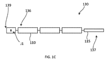
図1C及び図1Dに概略的に示すように、各ロボットアーム130は、遠位端部分137と、近位端部分136と、を含み得る。遠位端部分137(また本明細書では、「動作端」とも称される)は、医療機器又はツール115を含み得、又はそれらに結合され得る。近位端部分136(本明細書では「装着端部分」又は「装着端部」とも称される)は、ロボットアーム130が台100に連結可能にするための連結部分を含み得る。ロボットアーム130は、X、Y、及び/若しくはZ軸(例えば図1A及び図1Bに示す)のうちの1つ以上に沿った並進、並びに/又はこれらの1つ以上の周りでの回転を提供し得る、接合部で共に連結された2つ以上のリンク部材、つまりセグメント110を含み得る。ロボットアーム130の連結部分は、連結機構139を含むことができる。連結機構139は、アーム130の取り付け端部136に配置することができ、セグメント110に連結されてもよく、又はセグメント110内に組み込まれてもよい。ロボットアーム130はまた、ロボットアーム130の装着端136において又はその近くで配置された目標接合部J1も含み、その目標接合部は、連結機構139内に含まれ得、及び/又は連結部分に連結されたロボットアーム130のリンク若しくはセグメント110上に配置され得る。目標接合部J1は、ロボットアーム130の遠位セグメントが台100に対して枢動することを可能とするための、枢動接合部を提供することができる。ロボットアーム130は、図1Cに示すように、外科手術中に使用するための様々な拡張構成と、図1Dに示すように、使用しないときに保管するための様々な折り重ね、つまり折り畳み構成との間を移行し得る。
As schematically shown in FIGS. 1C and 1D, each
図2A~13Cは、ロボットアームを手術台に移送し、送達し、固定するための装置及び方法を説明する様々な実施形態を示す。上述したように、また以下により詳細に開示される様々な実施形態によれば、外科手術を実施する際に使用するロボットアームは、手術台に解放可能に連結されてもよい。いくつかの実施形態では、ロボットアームは、台上の固定箇所で連結することができ、又はロボットアームがテーブルトップに対して複数の箇所に移動可能であり得るように連結することができる。例えば、図2Aに概略的に示すように、ロボットアーム230は、手術台200のテーブルトップ220に連結され得る。手術台200は、上述した手術台100と構造及び機能が同じか又は同様とすることができる。例えば、テーブルトップ220は、患者Pが外科手術中に配置され得る上面を有する。いくつかの実施形態では、ロボットアーム230は、固定位置又は可動位置において、手術台に連結される、又は手術台から分離したアームアダプタ(「アーム支持部」とも称される)に、恒久的に又は解放可能に連結され得る。例えば、図2Bに概略的に示すように、アームアダプタ246は、テーブルトップ220に連結され得る、又はテーブルトップ220から分離しているが係合可能であり得る、若しくは連結可能であり得る。ロボットアーム230は、アームアダプタ246に連結することができる。
2A-13C show various embodiments illustrating devices and methods for transferring, delivering, and immobilizing a robotic arm to an operating table. As described above, and according to various embodiments disclosed in more detail below, the robotic arm used in performing the surgery may be releasably coupled to the operating table. In some embodiments, the robot arm can be connected at a fixed location on the tabletop, or the robot arm can be coupled such that it can be moved to multiple locations with respect to the table top. For example, as schematically shown in FIG. 2A, the
図2A及び図2Bに関連して説明するように、1つ以上のロボットアームが手術台及び/又はアームアダプタに解放可能に連結される、ロボット支援外科手術に備えて、各ロボットアームは、アームカートを介して手術台及び/又はアームアダプタに送達され、接続されてよい。図3に概略的に示すように、アームカート350は、1つ以上のロボットアーム330を支持するように構成され得る。具体的には、アームカート350は第1のロボットアーム330Aを含み、任意選択の第2のロボットアーム330Bを含み得る。2つのロボットアーム330を示しているが、アームカート350は、例えば、1つのロボットアーム、3つのロボットアーム、又は4つのロボットアームなど任意の好適な数のロボットアーム330を収容し、移送し、かつ/又は送達するように構成され得る。
As described in connection with FIGS. 2A and 2B, each robot arm is arm It may be delivered and connected to the operating table and / or arm adapter via the cart. As schematically shown in FIG. 3, the
アームカート350は、様々な構成の第1のロボットアーム330A(及び任意選択の第2のロボットアーム330B)を支持できる。いくつかの実施形態では、アームカート350は、ロボットアーム330Aの重心がアームカート350の1つ以上の支持構造位置(例えば、クレードル)の下になるようにロボットアーム330Aを支持でき、その結果、ロボットアーム330A及びアームカート350の安定性が増加する。いくつかの実施形態では、アームカート350は、アームカート350がロボットアーム330Aの重量の大部分又は全てを支えるようにロボットアーム330Aを支持でき、ロボットアーム330Aの連結機構(図示せず)は、ユーザーがロボットアームの重量の大部分又は全てを支持することなく、ユーザーによって手動で操作され得る。例えば、ロボットアーム330Aは、アームカート350の構造から懸架され得、又はアームカート350の構造上に載置され得る。いくつかの実施形態では、アームカート350は、ロボットアーム330をアームカート350に固定するように構成され得る。
The
アームカート330は、例えば車輪を含むことなどによって移動するように構成され得る。アームカート350は、例えば移送中又は保管中にアームカート350の周囲の潜在的な影響からロボットアーム330Aを保護するように構成され得る。いくつかの実施形態では、アームカート350は、例えば、折り畳まれた保管位置、つまり移送位置と、展開位置、つまり連結位置など1つ以上の位置間及び/又は1つ以上の方向間でロボットアーム330を移動させるように構成され得る。
The arm cart 330 may be configured to move, for example by including wheels. The
アームカート350は、アームコンテナ352と、基部354と、を含み得る。アームコンテナ352は、例えば、保管領域から動作領域へのロボットアーム330の移送中、及び外科手術中に使用するための、アームカート350から手術台(例えば、手術台100及び/又は手術台200)への1つ以上のロボットアーム330の移動中に、1つ以上のロボットアーム330(例えば、第1のロボットアーム330A及び任意選択の第2のロボットアーム330B)の無菌性を支援、保護、及び促進するように構成されている。1つ以上のロボットアーム330は、アームカート350によって保管され、かつ/又は移送されるが、1つ以上のロボットアーム330は、1つ以上のロボットアーム330が偶発的に衝突される、又は損傷される可能性を低減するように、アームカート350の設置面積内に大部分、ほぼ完全に、又は完全に維持され得る。いくつかの実施形態では、アームコンテナ352は、1つ以上のロボットアーム330を保管する空間を基部354と共に画定する、垂直に延在する保護フレームとして構成され得る。いくつかの実施形態では、1つ以上のロボットアーム330がアームカート350内に保管されるとき、ロボットアームは基部354の外周内に維持され得るが、アームコンテナ352の外周を越えて延在してもよい。
The
アームコンテナ352は、1つ以上のロボットアーム330の手術台及び/又はアームアダプタへの安全、効率的、無菌状態、かつ反復可能な移送を容易にするように更に構成され得る。いくつかの実施形態では、アームカート350から手術台への1つ以上のロボットアーム330の移動は、手動で実行され得る。
The
基部354は、アームコンテナ352を支持し、手術領域へのアームカート350の移送を提供するように構成され得る。基部354は、床面に対してアームカート350を移動させるための任意の好適な手段を含み得る。例えば、基部354は、医療提供者が動作領域に対してアームカートを押し引きできるように、車輪を含み得る。
The base 354 may be configured to support the
アームカート350は、X、Y、及び/若しくはZ軸に沿って、並びに/又はX、Y、及び/若しくはZ軸の周りを回転して手術台へと移動するために、1つ以上のロボットアーム330の位置合わせを支援する機構を含み得る。例えば、上述のように、基部354は、アームカート350が手術台に対してX軸及び/又はY軸に沿って移動され得るように、アームカート350を移動させるための任意の好適な手段を含み得る。加えて、アームカート350は、1つ以上のロボットアーム330の高さが手術台に対して調節され得るように、アームカート350及び/又は1つ以上のロボットアーム330の高さを調節するための任意の好適な手段を含み得る。したがって、アームカート350は、1つ以上のロボットアーム330の少なくとも1つの連結部分が位置合わせされて、台又は台アダプタ上の嵌合連結部分と係合するように、1つ以上のロボットアーム330をX、Y、及び/若しくはZ軸に沿って、並びに/又はX、Y、及び/若しくはZ軸の周りを回転して移動できる。
The
いくつかの実施形態では、アームカート350は、アームカート350が手術台に接近し、1つ以上のロボットアーム330が手術台に移動される間、アームカート350の操作者から、1つ以上のロボットアーム330の移動先である手術台の部分まで視線が維持され得るように、1つ以上のロボットアーム330を収容する。
In some embodiments, the
図3に示すように、アームカート350は、手術台及び/又は手術台に接続されたアーム支持部に解放可能に取り付けられるように構成されている1つ以上のドッキングステーション356を任意選択的に含んでよい。このようにして、アームカート350は、アームカート350からの1つ以上のロボットアーム330の移動中に手術台及び/又はアーム支持部に固定され得、次いでアームカート350は動作領域から取り外され得る。
As shown in FIG. 3, the
1つ以上のロボットアーム330は、様々な異なる種類の連結及び/又は装着の方法及び機構を使用して、手術台300にドッキング及び/又は装着され得る。アームカート350は、対応する連結方法及び機構を用いて、アームカート350から手術台300上及び/又は手術台300に関連するアーム支持部上の任意の好適な位置へのロボットアーム330の効率的な移動を提供できる。このようにして、アームカート350及び手術台300は、ロボットアーム330が手術台300及びアームカート350に対して効率的かつ反復的に連結され得る、かつ/又は取り外され得るように、共通のインターフェースを含み得る。
One or more robot arms 330 may be docked and / or mounted on the operating table 300 using a variety of different types of coupling and / or mounting methods and mechanisms. The
いくつかの実施形態では、ロボットアームに関連する第1の連結部材は、手術台に関連する第2の連結部材と係合するように構成され得る。 In some embodiments, the first connecting member associated with the robot arm may be configured to engage the second connecting member associated with the operating table.
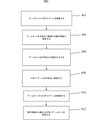
図4は、アームカートを使用してロボットアームを手術台に移送し、カートから手術台へのロボットアームの移動に備えて、アームカートを台と位置合わせする方法400のフローチャートである。方法400のアームカートは、例えば、本明細書に記載のアームカートのいずれかであり得る。方法400は、402において、1つ以上のロボットアームをアームカートに装着することを含む。例えば、1つ以上のロボットアームは、アームカートのアーム支持部に解放可能に連結され得る。アーム支持部は、アームカートの基部に連結されて、基部の上方で1つ以上のロボットアームを支持し得る。基部は、支持面上を自由に移動可能であり得る。次いで、404において、アームカートは、手術台に隣接する動作領域に移送される。アームカートは、406において、例えば、機械的又は電子的位置合わせにより手術台と位置合わせされる。いくつかの実施形態では、アームカートと手術台との位置合わせにより、1つ以上のロボットアームのうちの少なくとも1つは、1つ以上のロボットアームのうちの少なくとも1つの上に配置されたカプラのアーム部分が、手術台上に配置されたカプラの台部分と動作可能な関係に配置される(すなわち、位置合わせされる)ように位置決めされる。いくつかの実施形態ではカートと手術台との位置合わせにより、1つ以上のロボットアームのうちの少なくとも1つは、1つ以上のロボットアームが、アームカート及び手術台に対して、1つ以上のロボットアームのうちの少なくとも1つの上に配置されたカプラのアーム部分が、手術台上に配置されたカプラの台部分と動作可能な関係にある構成及び/又は位置へと移動し得る、又は移動され得るように、位置決めされる。408において、1つ以上のロボットアームは手術台に連結される。例えば、いくつかの実施形態では、カプラのアーム部分は、カプラの台部分に解放可能に連結され得る。410において、1つ以上のロボットアームはアームカートから解放される。412において、アームカートは動作領域から離れる方向に移送される。
FIG. 4 is a flowchart of a
いくつかの実施形態では、第2のロボットアームがアームカート上に装着された場合、アームカートは、第1のロボットアームを手術台に連結し、第1のロボットアームをアームカートから解放し、次いで、手術台の別の部分に近接する位置に移送され、第2の部位において手術台と位置合わせされ得る。まだ手術台と適切に位置合わせされていない場合、第2のロボットアーム上に配置された第2のカプラのアーム部分は、手術台上に配置された第2のカプラの台部分と動作可能な関係に配置され得る(すなわち、位置合わせされ得る)。第2のロボットアームは、次いで、例えば、第2のカプラのアーム部分が第2のカプラの台部分に解放可能に連結されることによって、手術台に連結され得る。第2のロボットアームは、アームカートから解放され得、アームカートは動作領域から離れる方向に移送され得る。 In some embodiments, when the second robot arm is mounted on the arm cart, the arm cart connects the first robot arm to the operating table and releases the first robot arm from the arm cart. It can then be transferred to a location close to another portion of the operating table and aligned with the operating table at a second site. If not yet properly aligned with the operating table, the arm portion of the second coupler placed on the second robot arm can operate with the base portion of the second coupler placed on the operating table. Can be placed in a relationship (ie, can be aligned). The second robot arm can then be coupled to the operating table, for example, by the arm portion of the second coupler being releasably coupled to the platform portion of the second coupler. The second robot arm may be released from the arm cart and the arm cart may be transferred away from the operating area.
いくつかの実施形態では、アームカートは、アームカートによって/アームカート内に支持されるロボットアームに関連する連結部材が、台に関連する相補的な連結部材との係合に好適な位置おいて示され得るように移動され得る。例えば、アームカートは、ロボットアームが様々な手術台及び/又は様々な高さにある手術台の様々な連結部分と協働できるように、様々な高さ設定に調節され得る。例えば、いくつかの実施形態では、アームカートは、ロボットアームの連結部材が、X軸及び/又はY軸に対して、手術台に関連する連結部材と位置合わせされるように、手術台に対して適所に移動され得る。次いで、アームカートは、ロボットアームカートが高、中、又は低の高さ範囲に設定される高さ調整の第1のマクロ段階を実行できる。次いで、高さ調整の第2のマイクロ段階において、アームカートは、ロボットアームカートの連結部材をZ軸に沿って上下動させて、手術台の相補的な連結部材と係合できる。いくつかの実施形態では、アームカートは、アームカートがロボットアームの連結部材に対して適切に位置決めされて連結される、又は手術台と連結される構成及び/若しくは位置に移行するように、手術台と機械的又は電子的に位置合わせされ得る。 In some embodiments, the arm cart is positioned such that the coupling member associated with the robot arm supported by / within the arm cart is suitable for engagement with the complementary coupling member associated with the pedestal. Can be moved as shown. For example, the arm cart can be adjusted to different height settings so that the robot arm can work with different operating tables and / or different connecting parts of the operating table at different heights. For example, in some embodiments, the arm cart is relative to the operating table such that the connecting member of the robot arm is aligned with the connecting member associated with the operating table with respect to the X-axis and / or the Y-axis. Can be moved to the right place. The arm cart can then perform a first macro step of height adjustment in which the robot arm cart is set to a high, medium or low height range. Then, in the second microstep of height adjustment, the arm cart can move the connecting member of the robot arm cart up and down along the Z axis to engage with the complementary connecting member of the operating table. In some embodiments, the arm cart is operated so that the arm cart shifts to a configuration and / or position where it is properly positioned and coupled to the connecting member of the robot arm or coupled to the operating table. It can be mechanically or electronically aligned with the table.
図5Aは、係合解除構成にあるアームカート550及び手術台500の斜視図の実例である。アームカート550は、本明細書に記載のアームカート(例えば、アームカート350)のいずれかに構造及び/又は機能の点で同じ又は類似であり得る。例えば、アームカート550は、アームコンテナ552(二重鎖線で示す)と、基部554と、を含み得る。アームコンテナ552は、1つ以上のロボットアームの(例えば、保管領域から動作領域への)移送中、及び外科手術中に使用するための、アームカート550から手術台500への1つ以上のロボットアームの移動中に、1つ以上のロボットアーム(図示せず)の無菌性を支援、保護、及び促進するように構成されている。アームコンテナ552は、1つ以上のロボットアームの手術台500への安全、効率的、無菌状態、かつ反復可能な移送を容易にするように更に構成されている。アームカート550から手術台500へのロボットアーム530の移動は、手動で実行されてよい、モータによって駆動されてよい、遠隔で制御されてよい、又は任意の他の好適な手段を介して達成されてよい。手術台500は、本明細書に記載の手術台のいずれか(例えば、手術台100)と同じ又は類似であり得る。例えば、手術台500は、テーブルトップ520と、支持部522と、基部524と、を含む。患者(図示せず)は、テーブルトップ520上に配置され得る。
FIG. 5A is an example of a perspective view of the
アームカート550及び手術台500はそれぞれ、アームカート550が手術台500と位置合わせし、係合し得るように、相補的な嵌合機構を含み得る。例えば、図6Aに示すように、アームカート550の基部554は第1の嵌合機構555を含み得、手術台500の台基部524は第2の嵌合機構525を含み得る。第1の嵌合機構555は、図6Aに示すように、三角形、つまり傾斜したリードインを含むなど、任意の好適な形状を有し得る。第2の嵌合機構525は、相補的な三角形、つまり傾斜した切り欠きなど第1の嵌合機構555を受容するように構成されている任意の好適な形状を有し得る。第1の嵌合機構555及び第2の嵌合機構525は係合されて、アームカート550と手術台500との間での適切な位置合わせ(例えば、X軸、Y軸、及び/若しくはZ軸に沿って、並びに/又はX軸、Y軸、及び/若しくはZ軸の周りで)を達成し得る。
The
いくつかの実施形態では、アームカート550の第1の嵌合機構555は、第1の嵌合機構555が衝撃抵抗器及び/又は緩衝装置として機能できるように、アームコンテナ552から十分に突出し得る。例えば、第1の嵌合機構555は、アームカート550が障害物(例えば、壁又はドアフレーム)に衝突する場合に、衝撃による力が第1の嵌合機構555によって消散されるように、アームカート550によって支持されるロボットアームの連結部材よりもアームコンテナ552の外側輪郭を越えて延在し得る。したがって、ロボットアーム及び/又はアームカート550への接触及び損傷は阻止され得る。
In some embodiments, the first
図5Aにおいて、第1の嵌合機構555は2つの三角形状の突出部として成形されているものとして示しており、第2の嵌合機構525は2つの三角形状の切り欠きとして成形されているものとして示しているが、第1の嵌合機構555及び第2の嵌合機構525は、任意の好適な形状であり得る。例えば、第1の嵌合機構555は、単一の三角形状の突出部として成形され得、第2の嵌合機構525は、単一の三角形状の切り欠きとして成形され得る。いくつかの実施形態では、第1の嵌合機構555及び第2の嵌合機構525は、湾曲形状、矩形、若しくは任意の他の好適な形状、又は形状の組み合わせである相補的な形状を含み得る。
In FIG. 5A, the first
第1の嵌合機構555及び第2の嵌合機構525は、アームカート550の基部554上及び手術台500の台基部524上にそれぞれ位置するように示しているが、これらは、第1の嵌合機構555と第2の嵌合機構525との係合が、例えばX-Y面における、ロボットアームの移動のためのアームカート550と手術台500との間の適切な位置合わせに対応するように、アームカート550及び/又は手術台500上の任意の好適な位置に配置され得る。例えば、第1の嵌合機構555はアームコンテナ552上に配置され得、第2の嵌合機構525は、第1の嵌合機構555に類似の高さで、台支持部522又はテーブルトップ520上に配置され得る。
The first
いくつかの実施形態では、第1の嵌合機構555及び/又は第2の嵌合機構525は、アームカート550と台500との位置合わせ及び/又は係合を支援する、磁石及び/又はセンサを含み得る。例えば、第1の嵌合機構555及び/又は第2の嵌合機構525は、ホール効果センサ、静電容量センサ、ボタン、又は台500の付近若しくはそれに隣接するアームカート550の存在を検出できる他のセンサを含み得る。
In some embodiments, the first
使用中、アームカート550は、手術台500の第2の嵌合機構525に向かって移動され得る(例えば、押され得る)。アームカート550が手術台500の付近にあるとき、第1の嵌合機構555は、例えば、アームカート550の位置を操作することによって、第2の嵌合機構525に挿入されて係合し得る。いくつかの実施形態では、第1の嵌合機構555及び第2の嵌合機構525のそれぞれの形状及びサイズは、アームカート550が手術台500に対して特定の位置に誘導され得るように、十分に相補的かつ固有であり得る。例えば、第1の嵌合機構555及び第2の嵌合機構525は、第1の嵌合機構555が第2の嵌合機構525と完全に係合されると、アームカート550によって支持されるロボットアームに関連する連結部材が、手術台500に関連する相補的な連結部材と位置合わせされ(aligned)、かつ/又は位置合わせされて(registered)、手術台500へのロボットアームの移動を容易にするように成形され、サイズ決めされ得る。
During use, the
いくつかの実施形態では、手術台は、手術台の外周の周囲の離間位置に複数の別個の嵌合機構を含み得る。例えば、図5Bは、台基部624及びアームカート基部654の上面図である。表基部624は、図5Aに関して記載した台基部524など、本明細書に記載の台基部のいずれかに構造及び/又は機能の点で同じ又は類似であり得る。アームカート基部654は、図5Aに関して記載した基部554など、本明細書に記載のアームカート基部のいずれかと構造及び/又は機能の点で同じ又は類似であり得る。台基部624は、第1の台嵌合機構625A、第2の台嵌合機構625B、第3の台嵌合機構625C、及び第4の台嵌合機構625Dなど多数の嵌合機構625を含み得る。いくつかの実施形態では、台基部624の嵌合機構625のそれぞれは、台基部624に関連するテーブルトップ上のロボットアーム係合位置と関連し得る。アームカート基部654は、アームカート嵌合機構655を含み得る。アームカート嵌合機構655は、アームカート嵌合機構655が第1の台嵌合機構625A、第2の台嵌合機構625B、第3の台嵌合機構625C、及び/又は第4の台嵌合機構625Dと係合するように構成されるように成形され、サイズ決めされ得る。いくつかの実施形態では、アームカート嵌合機構655及び台基部624の嵌合機構は、アームカート嵌合機構655が、台基部624の嵌合機構625(例えば、第1の台嵌合機構625A、第2の台嵌合機構625B、第3の台嵌合機構625C、及び第4の台嵌合機構625D)のいずれかと相補的に成形され、かつ/又は係合するように構成されるように成形され、サイズ決めされ得る。いくつかの実施形態では、アームカート嵌合機構655及び台基部624の嵌合機構625は、アームカート嵌合特徴部655が、台基部624の嵌合機構625のうちの1つのみ又は一部のみと係合するように構成されるように成形され、サイズ決めされ得る。図5Bに示すように、アームカート嵌合機構655は三角形状であってもよく、台嵌合機構は、相補的な三角形状の切り欠きを含み得る。4つの台嵌合機構625を示しているが、台基部624は、アームカート基部654を含むアームカートと台基部624を含む手術台の任意の好適な数の位置との位置合わせのために任意の好適な数の台嵌合機構を含み得る。
In some embodiments, the operating table may include multiple separate fitting mechanisms at distances around the perimeter of the operating table. For example, FIG. 5B is a top view of the
いくつかの実施形態では、光学照準システムを使用して、アームカートから手術台への1つ以上のロボットアームの移送前及び移送中の、アームカートと手術台との位置合わせの速度及び精度を改善できる。図6は、アームカート750と、光ビーコンアセンブリ760と、を含む光学照準システム700の概略図である。アームカート750は、本明細書に記載のアームカートのいずれかに構造及び/又は機能の点で同じ又は類似であり得る。アームカート750は、1つ以上の目標757(例えば、第1の目標757A及び第2の目標757B)を含み得る。1つ以上の目標757は、例えば、アームカート750の上面上の十字マークであり得る。光ビーコンアセンブリ760は、手術台(図示せず)に連結され得、又は付近に配置され、手術台に対して固定され得る。光ビーコンアセンブリ760は、1つ以上の光線を投射するように構成されている発光器を含み得る。この発光器は、アームカート750から手術台に1つ以上のロボットアームを移動させるためにアームカート750が手術台と適切に位置合わせされるときに、アームカート750上の1つ以上の目標757が位置する場所に向かって1つ以上の光ビームを投射できる。
In some embodiments, an optical sighting system is used to determine the speed and accuracy of alignment between the arm cart and the operating table before and during the transfer of one or more robot arms from the arm cart to the operating table. Can be improved. FIG. 6 is a schematic diagram of an
アームカート750が移動されて光ビームと適切に位置合わせされる(したがって、手術台と適切に位置合わせされる)と、1つ以上の光ビームは、1つ以上の目標757に集中し得る。いくつかの実施形態では、ユーザーは、1つ以上の光ビームと1つ以上の目標との適切な位置合わせを観察することに応じて、ユーザーが1つ以上のロボットアームの移動を手動で開始できるように、1つ以上の目標上での1つ以上の光ビームの集中を観察できる。いくつかの実施形態では、アームカート750、光ビーコンアセンブリ760、及び/又は手術台は、1つ以上の光線が1つ以上の目標757と適切に位置合わせされる時点を認識するように構成されているセンサ(図示せず)及び/又はレセプタ(図示せず)を含み得る。センサは、アームカート750の適切な位置決め時に、アームカート750が適切に位置決めされたことをユーザーに示し、かつ/又は1つ以上のロボットアームの自動移送を開始する信号を送信できる。いくつかの実施形態では、光ビーコンアセンブリ760は、十字又は他の位置決めマークが、アームカート750の1つ以上の目標757のうちの1つと位置合わせされ得るように、十字又は他の位置決めマークを投射できる。かかる実施形態は、位置決め誤差を排除し、1つ以上のロボットアームを移動するためにアームカート750と手術台とを位置合わせする、特別に熟練した操作者の必要性を低減するのに役立ち得る。
When the
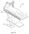
いくつかの実施形態では、手術台は、床面上に画像を投影するように構成され得、1つ以上のロボットアームの移動のためのアームカートの位置合わせに役立つ。例えば、図7Aは、プロジェクタ826を有する手術台800の斜視図である。プロジェクタ826は、床面上に一時的な床面マーク827を投影できる。一時的な床面マーク827は、例えば箱状の目標であり得る。一時的な床面マーク827は、画像及び/又は追加の誘導特徴を含み得る。矩形状の箱として示しているが、いくつかの実施形態では、一時的な床面マーク827は、円又は十字など任意の好適な形状であり得る。
In some embodiments, the operating table may be configured to project an image onto the floor surface, helping to align the arm cart for the movement of one or more robot arms. For example, FIG. 7A is a perspective view of an operating table 800 having a
図7Bは、プロジェクタ926と、ロボットアーム930を支持するアームカート950と、を有する手術台900の斜視図である。手術台900及びプロジェクタ926は、図7Aを参照して上述した手術台800及びプロジェクタ826と構造及び/又は機能の点で同じ又は類似であり得る。例えば、プロジェクタ926は、手術台900付近の床面に一時的な床面マーク927を投影できる。使用中、アームカート950は、一時的な床面マーク927に対して移動され得る。いくつかの実施形態では、ユーザーが一時的な床面マーク927をガイドとして使用し、アームカート950を一時的な床面マーク927と位置合わせできるように、一時的な床面マーク927は「ランディングゾーン」を提供し得る。アームカート950と一時的な床面マーク927との適切な位置合わせをユーザーが視覚的に確認すると、ユーザーは、アームカート950から手術台900にロボットアーム930を移動させるプロセスを開始できる。例えば、いくつかの実施形態では、ユーザーは、グラフィックユーザーインターフェースを使用してロボットアーム930の移動を開始できる。いくつかの実施形態では、アームカート950及び/又は手術台900は、ロボットアーム930を手術台900に移動させるために、アームカート950が一時的な床面マーク927(したがって手術台900)に対して正しく位置決めされる時点を検知するように構成されている1つ以上のセンサ(図示せず)を含み得る。いくつかの実施形態では、1つ以上のセンサは、一時的な床面マーク927を変化させて、例えば、一時的な床面マーク927の色を変化させることによってアームカート950の適切な位置決めを示す信号をプロジェクタ926に送信し得る。いくつかの実施形態では、台900に対するアームカート950の適切な位置決めを示すことにより、後述するように、1つ以上のロボットアームは自動的に自動操縦し、台900との係合を開始し得る。プロジェクタ926は、アームカート950が一時的な床面マーク927との適切な位置合わせ状態を脱した場合、一時的な床面マーク927の色を2回目に変化させる(例えば、元の色に戻る)ように構成され得る。
FIG. 7B is a perspective view of an operating table 900 having a
いくつかの実施形態では、アームカートは、自動的に誘導されて、手術台と適切に位置合わせされるように構成され得る。図8Aは、手術台1000、アームカート1050、及びロボットアーム1030の斜視図である。手術台1000、アームカート1050、及びロボットアーム1030は、それぞれ本明細書に記載の手術台、アームカート、及びロボットアームのいずれかに構造及び/又は機能の点で同じ又は類似であり得る。手術台1000は、取り付けインターフェース1021を含み得る。手術台1000はまた、発光器1023(例えば、第1の発光器1023A及び第2の発行器1023B)を含み得る。第1の発光器1023A及び第2の発光器1023Bは、それぞれ光信号を発して、それぞれ光壁バリア1028A及び1028Bを生成する。光壁バリア1028A及び1028Bは、光壁バリア1028A及び1028Bが取り付けインターフェース1021から離れる方向に発散するように角度付けされ得る。放射された光は、電磁スペクトルの任意の好適な部分、例えば、可視、紫外線、又は赤外線であってよい。
In some embodiments, the arm cart may be configured to be automatically guided and properly aligned with the operating table. FIG. 8A is a perspective view of the operating table 1000, the
アームカート1050は、例えば3つ又は4つなど任意の好適な数の車輪を含み得る。アームカート1050は、手動で(例えば、ユーザーによって押されることにより)動力を供給され得る。いくつかの実施形態では、アームカート1050は、アームカート1050が車輪のそれぞれに独立して抵抗又は制動力を適用できるように、電子ブレーキを含み得る。したがって、電子ブレーキは、ユーザーが取り付けインターフェース1021に向かってアームカート1050を押すときに、アームカート1050(及びロボットアーム1030の連結機構1039)が手術台1000の取り付けインターフェース1021に向けられるように、アームカート1050の経路を制御できる。いくつかの実施形態では、カート1050はまた、制限速度(すなわち、上限速度)を有し得る。
The
アームカート1050は、1つ以上の光センサ1051を含み得る。1つ以上の光センサ1051は、ビーコンを放射し、光壁バリア1028A及び1028Bの一方又は両方を離れるビーコンの反射を検知し得る。したがって、アームカート1050は、例えば、電子制動を使用して、光壁バリア1028A及び1028Bの一方若しくは両方の検知された位置、並びに/又はアームカート1050と光壁バリア1028A及び1028Bの一方若しくは両方との検知された距離に基づいて、取り付けインターフェース1021に向けてアームカート1050を自動操作し得る。上述のように、光壁バリア1028A及び1028Bは、取り付けインターフェース1021から離れる方向に発散し、三角形状のバリアをもたらし得る。したがって、光壁バリア1028A及び1028Bは、アームカート1050が手術台1000により接近するように操作され、光壁バリア1028Aと1028Bとの間の距離が減少するにつれて、より高い精度でアームカート1050を誘導できる。
The
アームカート1050及び手術台1000は、1つ以上の光センサ1051がアームカート1050上に配置され、第1の発光器1023A及び第2の発光器1023Bが手術台1000上に配置されるように記載したが、いくつかの実施形態では、これらの構成要素の位置は、1つ以上の光センサ1051が手術台1000上に配置され、第1の発光器1023A及び第2の発光器1023Bがアームカート1050上に配置されるように入れ替え可能である。
The
手術台1000はまた、近距離運動センサ1083を含み得る。近距離運動センサ1083は、取り付けインターフェース1021内又はその付近に装着され得る。近距離運動センサ1083は、取り付けインターフェース1021へのロボットアーム1030の連結機構1039の取り付けを異物が阻止するかどうかを判定できる。次いで、近距離運動センサ1083は、ロボットアーム1030の取り付けが妨害される(例えば、ドレープによってブロックされる)ことをアームカート1050に伝達できる。いくつかの実施形態では、近距離運動センサ1083は、取り付けインターフェース1021への連結機構1039の連結に対する潜在的な妨害を検知すると、取り付けインターフェース1021に向けての移動を停止する(又はロボットアーム1030の移動を停止する)ようにアームカート1050に信号を送信できる。次いで、近距離運動センサ1083は、連結動作を休止でき、ユーザーに潜在的な妨害物について警告できる。いくつかの実施形態では、近距離運動センサ1083はまた、潜在的な妨害物の除去を検知し、アームカート1050に信号を送信して連結動作を再開できる。
The operating table 1000 may also include a short
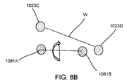
図8Bに概略的に示すように、手術台1000はまた、第3の発光器1023C及び第4の発光器1023Dを含み得る。これらの発光器1023C、1023Dは、図8Bに示す軸Wによって示すように、手術台1000の頂部の向き、すなわち取り付けインターフェース1021の向きを示すために使用され得る。アームカート1050及び/又はロボットアーム1030は、検出器1081A及び1081Bなど検出器を含んで発光器からの光を検知し得、連結機構1039の向きが取り付けインターフェース1021の向きと一致するように、内部標定ハードウェアを使用してロボットアーム1030の連結機構1039を回転させ、かつ/又は並進させる。図8Bの要素1081A及び1081Bは検出器として記載しているが、いくつかの実施形態では、要素1081A及び1081Bは連結機構の2つの部分を示し、検出器は、連結機構1039とは異なるアームカート1050及び/又はロボットアーム1030の異なる部分に配置される。かかる実施形態では、検出器は、要素1081A及び1081Bと取り付けインターフェース1021との位置合わせに使用され得る。
As schematically shown in FIG. 8B, the operating table 1000 may also include a
いくつかの実施形態では、図8A及び図8Bを参照して上述したマクロ位置合わせ手順後に、手術台1000並びにアームカート1050及び/又はロボットアーム1030は、例えば、短距離で動作可能な検知機構を使用して、マイクロ位置合わせ手順によって更に位置合わせされ得る。例えば、ロボットアーム1030が、上述のようにアームカート1050の位置合わせによって取り付けインターフェース1021に近接して配置された後、センサは、ロボットアーム1030の連結機構1039及び/又は手術台1000の取り付けインターフェース1021上で使用され得、ロボットアーム1030の連結機構1039を精密に誘導して取り付けインターフェース1021と係合させる。好適なセンサとしては、例えば、ホール効果センサを挙げることができる。
In some embodiments, after the macro alignment procedure described above with reference to FIGS. 8A and 8B, the operating table 1000 and the
図9A~図9Cは、手術台1200及びアームカート1250の概略図である。アームカート1250は、本明細書に記載のアームカートのいずれかに構造及び/又は機能の点で同じ又は類似であり得る。例えば、アームカート1250は、アームコンテナ1252と、基部1254と、を含み得る。アームコンテナ1252は、1つ以上のロボットアーム1230(例えば、第1のロボットアーム1230A及び任意選択の第2のロボットアーム1230B)の(例えば、保管領域から動作領域への)移送中、及び外科手術中に使用するための、アームカート1250から手術台1200への1つ以上のロボットアーム1230の移動中に、1つ以上のロボットアーム1230の無菌性を支援、保護、及び促進するように構成されている。1つ以上のロボットアーム1230は、本明細書に記載のロボットアームのいずれかに構造及び/又は機能の点で同じ又は類似であり得る。1つ以上のロボットアーム1230はそれぞれ、アーム連結機構1239(例えば、第1のアーム連結機構1239A及び第2のアーム連結機構1239B)を含み得る。1つ以上のロボットアーム1230は、アームカート1250によって保管及び/又は移送されるが、1つ以上のロボットアーム330は、1つ以上のロボットアーム1230が偶発的に衝突される、又は損傷される可能性を低減するように、アームカート1250の設置面積内に大部分、ほぼ完全に、又は完全に維持され得る。いくつかの実施形態では、アームコンテナ1252は、1つ以上のロボットアーム1230を保管する空間を基部1254と共に画定する、垂直に延在する保護フレームとして構成され得る。いくつかの実施形態では、1つ以上のロボットアーム1230がアームカート1250内に保管されるとき、ロボットアームは基部1254の外周内に維持され得るが、アームコンテナ1252の外周を越えて延在してもよい。
9A-9C are schematic views of the operating table 1200 and the
手術台1200は、本明細書に記載の手術台のいずれかに構造及び/及び機能の点で同じ又は類似であり得る。例えば、手術台1200は、テーブルトップ1220と、台支持部1222と、台基部1224と、を含み得る。テーブルトップ1220は、外科手術中に患者が配置され得る上面を有する。テーブルトップ1220は、床面の上方の好適な高さにおいて、例えば基台となり得る支持部1222上に配置される。支持部1222(本明細書では基台とも称される)は、Z軸(床面の上方の高さ)、Y軸(台の長手方向軸に沿う)、及び/若しくはX軸(台の横方向軸に沿う)における並進、並びに/又はZ、Y、及び/若しくはX軸の周りでの回転など所望の自由度の数で、テーブルトップ1220の移動を提供してよい。テーブルトップ1220はまた、任意の好適な軸に沿って/その周りで互いに対して移動可能である複数の区分、例えば、胴体、片方若しくは両方の脚、及び/又は片方若しくは両方の腕のそれぞれに対する別個の区分、並びに頭部支持区分を含んでよい。テーブルトップ1220及び/又はその構成区分の移動は、手動で実行され、モータによって駆動され、遠隔で制御され、又は任意の他の好適な手段を介してよい。テーブルトップ用の支持部1222は、手術室の床面に固定され得る基部1224に装着されてよい、又は、例えば、基部1224上の車輪(図示せず)の使用によって床面に対して移動可能であり得る。支持部1222の高さは、例えば、テーブルトップ1220の運動(例えば、軸方向(縦方向)又は横方向運動)に合わせて調節でき、テーブルトップ1220が、床面の上方のある高さ(例えば、外科医のアクセスを可能にするための)及び支持部1220からのある距離で、所望の手術部位において位置決めされることを可能にし得る。加えて、支持部1222の高さの調節はまた、支持部1222に関連する取り付け部材(例えば、後述する取り付け部材1247)を1つ以上のロボットアーム1230と係合し、アームカート1250から持ち上げることができる。
The operating table 1200 may be the same or similar in structure and / and function to any of the operating tables described herein. For example, the operating table 1200 may include a
図9Aに示すように、アームカート1250はまた、図5Aを参照して上述した第1の嵌合機構555に構造及び/又は機能の点で同じ又は類似であり得る、第1の嵌合機構1255を含み得る。同様に、手術台1200は、図5Aを参照して上述した第2の嵌合機構525に構造及び/又は機能の点で同じ又は類似であり得る、対応する第2の嵌合機構1225を含み得る。したがって、アームカート1250は、第1の嵌合機構1255が第2の嵌合機構1225と連結されるように誘導されて、手術台1200と係合し得る。第1の嵌合機構1255が第2の嵌合機構1225と連結された結果、アームカート1250は、アームカート1250から手術台1200への1つ以上のロボットアーム1230の移動のために、手術台1200に対して特定の位置に位置決めされ、維持され得る。
As shown in FIG. 9A, the
手術台1200は、1つ以上の取り付け部材1247(例えば、第1の取り付け部材1247A及び第2の取り付け部材1247B)を含み得る。1つ以上の取り付け部材1247のそれぞれは、例えば、延長アームを含み得る。1つ以上の取り付け部材1247のそれぞれの第1の端部は、支持部1222に連結され得る。1つ以上の取り付け部材1247はそれぞれ、1つ以上の取り付け部材1247のそれぞれの第2の端部に配置された取り付けインターフェース1221を含み得る。具体的には、図9Aに示すように、第1の取り付け部材1247Aは第1の取り付けインターフェース1221Aを含み得、第2の取り付け部材1247Bは第2の取り付けインターフェース1221Bを含み得る。取り付けインターフェース1221は、取り付けインターフェース1221がアーム連結部材1239(例えば、第1のアーム連結部材1239A及び第2のアーム連結部材1239B)と解放可能に係合できるように構成され得る。例えば、取り付けインターフェース1221は、ループ形状又はバスケット形状の構成要素を含み得る。いくつかの実施形態では、取り付けインターフェース1221は、1つ以上のロボットアーム1230のアーム連結部材1239のいずれかと係合するように成形され、サイズ決めされ得る。
The operating table 1200 may include one or more mounting members 1247 (eg, first mounting
ロボットアーム1230のアーム連結部材1239は、取り付けインターフェース1221のうちの1つ以上がアーム連結部材1239と解放可能に係合し、アーム連結部材1239のそれぞれを移動させ得るように成形され、サイズ決めされ得る。例えば、第1の取り付けインターフェース1221Aは、第1の取り付け部材1221Aが、X及びY方向で第1のアーム連結部材1239Aと位置合わせされるように、第1のアーム連結部材1239Aの下に位置決めされ得る。次いで、第1の取り付けインターフェース1221Aは垂直方向に移動されて(例えば、支持部1222の垂直運動によって)、第1のアーム連結部材1239Aと係合し得る。例えば、第1の取り付けインターフェース1221Aは開口部を画定し得、第1の取り付けインターフェース1221Aが第1のアーム連結部材1239Aの第1の部分との周囲関係に配置されるまで上昇させられ得る。第1の取り付けインターフェース1221Aは、第1の取り付けインターフェース1221Aの更なる垂直運動が、第1のアーム連結部材1239A(したがって、第1のロボットアーム1230A)の移動を生じさせるように、第1のアーム連結部材1239Aの第2の部分と係合し得る。
The arm coupling member 1239 of the robot arm 1230 is shaped and sized so that one or more of the mounting interfaces 1221 can be releasably engaged with the arm coupling member 1239 and each of the arm coupling members 1239 can be moved. obtain. For example, the first mounting
図9Aには2つの取り付け部材1247を示しているが、例えば、1つ、3つ、又は4つなど、任意の好適な数の取り付け部材が含まれ得る。加えて、取り付けインターフェース1221の構造は、ループ又はバスケットとして記載するが、取り付けインターフェース1221は、任意の好適な形状であり得、取り付けインターフェース1221がアーム連結部材1239などアーム連結部材を捕捉できるように、任意の好適な係合機構を含み得る。 FIG. 9A shows two mounting members 1247, which may include any suitable number of mounting members, for example one, three, or four. In addition, although the structure of the mounting interface 1221 is described as a loop or basket, the mounting interface 1221 can be of any suitable shape so that the mounting interface 1221 can capture an arm connecting member such as an arm connecting member 1239. Any suitable engagement mechanism may be included.
使用中、図9Aに示すように、手術台1200は、取り付け部材1247(したがって取り付けインターフェース1221)がロボットアーム1230のアーム連結部材1239よりも鉛直下方に位置決めされる、第1のニーリング構成にあり得る。アームカート1250は、手術台1200から離れた第1の位置にあり得る。第1のロボットアーム1230A及び第2のロボットアーム1230Bは、第1の連結機構1239A及び第2の連結機構1239Bが、X軸及びY軸に沿って位置合わせされたときに第1の取り付けインターフェース1221A及び第2の取り付けインターフェース1221Bとそれぞれ係合するように配置されるように、展開構成でカート1250上に配置され得る。
In use, as shown in FIG. 9A, the operating table 1200 may be in a first kneeling configuration in which the mounting member 1247 (and thus the mounting interface 1221) is positioned vertically below the arm connecting member 1239 of the robot arm 1230. .. The
アームカート1250は、手術台1200に向かって移動され得る。図9Bに示すように、アームカート1250が取り付け部材1247に対して適切に位置決めされると(例えば、第1の嵌合機構1255が第2の嵌合機構1225と係合される)と、支持部1222は、線B-Bに沿って垂直方向に操作され得る(すなわち、ニーリング位置から係合位置へと移動する)。したがって、取り付け部材1247は、支持部1222が移動してアーム連結部材1239と係合することによって、線B-Bに沿って垂直方向に移動され得る。より具体的には、第1の取り付けインターフェース1221Aは第1のアーム連結部材1239Aと係合し得、第2の取り付けインターフェース1221Bは第2のアーム連結部材1239Bと係合し得る。いくつかの実施形態では、取り付け部材1247は、支持部1222が伸縮する結果として、テーブルトップ1220の全ての垂直位置にわたってテーブルトップ1220に対して同じ位置に留まる。
The
取り付け部材1247がアーム連結部材1239と係合された後、支持部1222は、取り付け部材1247が基部1224及びアームカート1250に対して垂直に上昇する(すなわち、係合位置から動作位置へと移動する)ように操作されて、線B-Bに沿って垂直に延在し得る。取り付けインターフェース1221を介してアーム連結部材1239と係合される取り付け部材1247の上向きの垂直移動は、図9Cに示すように、ロボットアーム1230を持ち上げてアームカート1250から外す。ロボットアーム1230は次いで、取り付け部材1247を介して手術台1200と係合され、外科手術に使用され得る。図10Cに示すように、アームカート1250は、次いで、手術台1200から離れる方向に移動され得る。
After the mounting member 1247 is engaged with the arm connecting member 1239, the
図9Aでは、ロボットアーム1230は、アームカート1250を介して手術台1200へと移送するために、展開構成(すなわち、連結機構1239は、取り付け機構1247によって係合されるために露出している)でアームカート1250に装着されているものとして示しているが、いくつかの実施形態では、ロボットアーム1230は、アームカート1250内に保管され、展開構成に移動され得る。いくつかの実施形態では、アームカート1250は、アーム連結部材1239が露出し、取り付け部材1247によってアクセス可能であるように、ロボットアーム1230の構成を操作し得る。いくつかの実施形態では、取り付け部材1247は、移動してアーム連結部材1239と係合する前に、収容位置から使用位置まで枢動又は回転し得る。図9A~9Cは、取り付け部材1247によってアームカート1250から同時に持ち上げられる両方のロボットアーム(すなわち、ロボットアーム1230A及びロボットアーム1230B)を示すが、いくつかの実施形態では、1つのロボットアーム1230のみがアームカート1250と係合し、持ち上げられ得る。例えば、1つのロボットアーム1230のみが、取り付け部材1247によって係合するために展開構成で位置決めされ得、又はアームカート1250は、取り付け部材1247とのX軸及びY軸での位置合わせにおいて、1つの連結機構1239のみを位置付けることができる。1つ以上の追加のロボットアーム1230は、後の時点で使用されるアームカート1250内に留まり得る。
In FIG. 9A, the robot arm 1230 is deployed to the operating table 1200 via the arm cart 1250 (ie, the coupling mechanism 1239 is exposed to be engaged by the mounting mechanism 1247). Although shown as being mounted on the
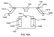
いくつかの実施形態では、手術台は、アームカートとの位置合わせ機構と、枢動して1つ以上のロボットアームと係合できる取り付け部材と、を含み得る。例えば、図10A、10B、及び10Cは、それぞれ係合解除構成、位置合わせ構成、及びラッチ構成にある手術台1300、アームカート1350、及びロボットアーム1330(例えば、第1のロボットアーム1330A及び第2のロボットアーム1330B)である。手術台1300及びアームカート1350は、それぞれ本明細書に記載の手術台及びアームカートのいずれかに構造及び/又は機能の点で同じ又は類似であり得る。同様に、第1及び第2のロボットアーム1330A及び1330Bは、本明細書に記載のロボットアームのいずれかと同じ又は類似であり得る。手術台1300は、第1の嵌合機構1325を含み得、アームカート1350は相補的な第2の嵌合機構1355を含み得る。第1の嵌合機構1325は、第2の嵌合機構1355と係合する、かつ/又はそれを受容するように構成され得る。
In some embodiments, the operating table may include an alignment mechanism with an arm cart and a mounting member that can be pivotally engaged with one or more robot arms. For example, FIGS. 10A, 10B, and 10C show the operating table 1300,
第1のロボットアーム1330Aは第1の連結機構1339Aを含み得、第2のロボットアーム1330Bは第2の連結機構1339を含み得る。手術台1300は、第1の取り付け部材1321Aと、第2の取り付け部材1321Bと、を含み得る。第1の取り付け部材1321A及び第2の取り付け部材1321Bは、それぞれ第1の枢動接合部1363A及び第2の枢動接合部1363Bを介して手術台1300に回転連結され得る。第1の取り付け部材1321Aは、第1の係合機構1329Aを画定し得、かつ/又は含み得る。第2の取り付け部材1321Bは、第2の係合機構1329Bを画定し得、かつ/又は含み得る。第1の係合機構1329Aは、第1の係合機構1329Aが第1の結合機構1339Aと係合でき、かつ/又はそれを受容しできるように成形され、サイズ決めされ得る。第2の係合機構1329Bは、第2の係合機構1329Bが第2の結合機構1339Bと係合でき、かつ/又はそれを受容できるように成形され、サイズ決めされ得る。したがって、第1の取り付け部材1321A及び第2の取り付け部材1321Bは、第1の枢動接合部1363A及び第2の枢動接合部1363Bを介して、線C-C及び線D-Dに沿って回転して、それぞれ第1のロボットアーム1330Aの第1の連結機構1339A及び第2のロボットアーム1330Bの第2の連結機構1339Bと係合できる。いくつかの実施形態では、第1の取り付け部材1321A及び第2の取り付け部材1321Bの枢動位置は、例えば、センサを介してなど電子的に制御され得る。例えば、第1の嵌合機構1325は、第1の取り付け部材1321A及び第2の取り付け部材1321Bが、第1の嵌合機構1325と第2の嵌合機構1355との係合時に線C-C及び線D-Dに沿って自動的に枢動するように、連結部材である第1の嵌合機構1325と第2の嵌合機構1355との係合を検知するように構成されているセンサを含み得る。いくつかの実施形態では、第1の取り付け部材1321A及び第2の取り付け部材1321Bの枢動位置は、ユーザーによって手動で制御され得る。いくつかの実施形態では、第1の取り付け部材1321A及び第2の取り付け部材1321Bは、第1の取り付け部材1321A及び第2の取り付け部材1321Bが図10Bに示す構成から解放されると、第1の取り付け部材1321A及び第2の取り付け部材1321Bが、図10Cに示す位置へと回転するように付勢され得る。
The
使用中、アームカート1350は、例えば、アームカート1350の底部に連結された車輪を介して、図10Aに示すように手術台1300付近で移動され得る。アームカート1350は、図10Bに示すように、アームカート1350の第2の嵌合機構1355を、手術台1300の第1の嵌合機構1325と位置合わせして、係合するように操作され得る。アームカート1350の第2の嵌合機構1355と手術台1300の第1の嵌合機構1325とが係合すると、第1の取り付け部材1321Aは、図10Cに示すように、第1の係合機構1329Aが第1のロボットアーム1330Aの第1の連結機構1339Aとラッチするように、線C-Cに沿って回転され得る。同様に、第2の取り付け部材1321Bは、第2の係合機構1329Bが第2のロボットアーム1330Bの第2の連結機構1339Bとラッチするように、線D-Dに沿って回転され得る。ラッチ後、第1の取り付け部材1321Aは、第1のロボットアーム1330Aを回転させてアームカート1350上の収容位置から出すことができ、第2の取り付け部材1321Bは、第2のロボットアーム1330Bを回転させてアームカート1350上の収容位置から出すことができる。したがって、第1のロボットアーム1330A及び/又は第2のロボットアーム1330Bは、手術台1300にしっかり連結され得、アームカート1350上の収容位置から動作位置(すなわち、アームカートから係合解除されている)に移行され得る。いくつかの実施形態では、第1の取り付け部材1321A及び第2の取り付け部材1321Bは、それぞれ第1のロボットアーム1330A及び第2のロボットアーム1330Bと同時に又は順次係合し、回転させ得る。
In use, the
図11は、手術台1700の下で入れ子構成にある第1のアームカート1750A及び第2のアームカート1750Bを有する手術台1700の側面図である。手術台1700は、本明細書に記載の手術台のいずれかに構造及び/及び機能の点で同じ又は類似であり得る。例えば、手術台1700は、テーブルトップ1720と、支持部1722と、基部1724と、を含み得る。第1のアームカート1750A及び第2のアームカート1750Bは、本明細書に記載のアームカートのいずれかに構造及び/又は機能の点で同じ又は類似であり得る。例えば、ロボットアーム1730を含む第1のアームカート1750Aを示している。台1700のテーブルトップ1720の下で、アームカート1750A、1750Bを容易に保管、つまり入れ子構成にできるようにするために、台の基部1724は、傾斜上面を有するように構成されている。したがって、第1のアームカート1750A及び第2のアームカート1750Bのそれぞれは、基部1724の傾斜面に乗り入れて、テーブルトップ1720の下でそれぞれの保管構成になり得る。例えば、1つ以上の戻り止めなど好適な保持機構(図11には図示せず)が使用されて、各アームカートは保管構成で保持され得る(すなわち、アームカートが基部1724の傾斜上面を転がり落ちないようにできる)。いくつかの実施形態では、各アームカート及び台は、図11の第1のアームカート1750A及びアーム1730に示すように、アームをカート内に収容する保管構成にできるように構成され得る。したがって、カート及びアームは、手術前にテーブルトップ1720の下に配置され、次いで、上述のように、台とドッキングし、アーム1730を台1700に取り付けるのに好適な位置に移動されてよい。次いで、空のカートは、保管構成に戻されてよい。他の実施形態では、カートは、アームを収容している間は台の下に保管されるように構成されず、代わりに、空のときにのみ保管構成で配置されてよい。
FIG. 11 is a side view of the operating table 1700 having the
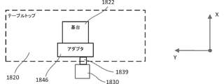
いくつかの実施形態では、ロボットアームは、ロボットアームが手術台に移送され、手術台の下に収容され得る同じ姿勢及び/又は向きで、アームカートを介して移送され得る。したがって、いくつかの実施形態では、ロボットアームの姿勢及び/又は向きは、保管中及び手術台へのロボットアームの移送に備えて同一に留まり得る。例えば、図12A~12Hは、手術台1800及びアームカート1850の概略図である。図12Aに示すように、アームカート1850は、ロボットアーム1830を収容し、支持する。手術台1800、アームカート1850、及びロボットアーム1830は、それぞれ本明細書に記載の手術台、アームカート、及びロボットアームのいずれかに構造及び/又は機能の点で同じ又は類似であり得る。例えば、アームカート1850は、アームコンテナ1852と、基部1854と、を含み得る。手術台1800は、テーブルトップ1820と、台支持部1822と、台基部1824と、を含み得る。図12Aに概略的に示すように、テーブルトップ1820は、患者Pが外科手術中に配置され得る上面を有する。テーブルトップ1820は、床面の上方の好適な高さにおいて、例えば基台となり得る支持部1822上に配置される。支持部1822は、手術室の床面に固定され得る基部1824に装着され得、又は、例えば、基部上の車輪の使用によって床面に対して移動可能であり得る。加えて、アダプタ1846は、手術台1800に連結され得る、又は手術台1800から分離され得る。例えば、図12Aに概略的に示すように、アダプタ1846は、テーブルトップ1820に連結され得る、又はテーブルトップ1820から分離しているが係合可能であり得る、若しくはテーブルトップ1820に連結可能であり得る。ロボットアーム1830は、アダプタ1846に解放可能に連結され得る。ロボットアーム1830は、ロボットアーム1830が連結機構1839を介してアダプタ1846の係合機構(図示せず)に連結できるように連結機構1839を含み得る。加えて、アダプタ1846は、ロボットアーム1830が連結機構1830に対して構成又は向きを変えることなく、連結機構1839を介してロボットアーム1830を移動させるように構成され得る。例えば、アダプタ1846は、アームカート1850からZ軸の周りでロボットアーム1830を回転させて、(図12Eに示すように)テーブルトップ1820の下の収容位置に入れることができ、並びに/又はZ軸及び/若しくはX軸の周りでロボットアーム1830を回転させて、(図12Gに示すように)動作位置に入れることができる。
In some embodiments, the robot arm can be transferred via the arm cart in the same posture and / or orientation in which the robot arm is transferred to the operating table and can be accommodated under the operating table. Thus, in some embodiments, the posture and / or orientation of the robot arm may remain the same during storage and in preparation for transfer of the robot arm to the operating table. For example, FIGS. 12A-12H are schematic views of the operating table 1800 and the
アームカート1850は、手術台1800に対して支持面上を移動可能であり得る。例えば、図12Aに示すように、アームカート1850は、手術台1800付近に配置され得る。ロボットアーム1830は、アームカート1850を手術台1800と適切に位置合わせすると、連結機構1839がアダプタ1846と係合するために適切に位置決めされるように、アームカート1850の中又は上に配置され得る。図12Bに示すように、次いで、アームカート1850から手術台1800のアダプタ1846にロボットアーム1830を移動させるために、アームカート1850は移動されて、手術台1800と位置合わせされ得る、及び/又は手術台1800と係合され得る。かかる位置では、連結機構1839は、ロボットアーム1830がアームカート1850に対する構成又は向きを変えることなく、アダプタ1846の係合機構に連結され得る。
The
連結機構1839とアダプタ1846との係合後、アームカート1850は、図12Cに示すように、手術台1800及びロボットアーム1830から離れる方向に移動され得る。手術台1800及びロボットアーム1830の上面図であり、テーブルトップ1820を二重鎖線で示す図12Dに示すように、アームカート1850が手術台1800から離れる方向に移動すると、ロボットアーム1830は、ロボットアーム1830がX軸に沿って台から離れる方向に延在する移送位置で、アダプタ1846によって支持され得る。
After engaging the
それぞれ手術台1800及びロボットアーム1830の正面図及び上面図である図12E及び図12Fに示すように、アダプタ1846は、図12C及び図12Dに示す移送位置からテーブルトップ1820の下の収容位置へとロボットアーム1830を回転させ得る。移送位置から収容位置へのロボットアーム1830の回転の間、及び収容位置に維持される間、ロボットアーム1830は同じ構成を維持し得る。
As shown in FIGS. 12E and 12F, which are front and top views of the operating table 1800 and the
それぞれ手術台1800及びロボットアーム1830の側面図及び上面図である図12G及び図12Hに示すように、アダプタ1846はまた、収容位置から動作位置へとロボットアーム1830を回転させ得る。いくつかの実施形態では、アダプタ1846は、ロボットアーム1830が元の移送位置になるまで、まずZ軸の周りでロボットアーム1830を回転させ得る。次いで、アダプタ1846は、ロボットアーム1830がテーブルトップ1820の上方に延在するように、ロボットアーム1830をX軸の周りで回転させ得る。Z軸及びX軸の周りでの回転中、ロボットアーム1830は、同じ構成を維持し得る。いくつかの実施形態では、アダプタ1846は、ロボットアーム1830が元の移送位置になるまで、まずZ軸の周りでロボットアーム1830を回転させ得る。次に、ロボットアームの構成は、ロボットアーム1830がテーブルトップ1820の上面及び/又はテーブルトップ1820上に配置された患者Pにアクセスできるように変化し得る。
As shown in FIGS. 12G and 12H, which are side views and top views of the operating table 1800 and the
様々な実施形態が上記に記載される一方で、それらが単なる実施例として提示されており、限定するものではないということが理解されるはずである。上記の方法が、特定の順序で発生する特定の事象を示す場合、特定の事象の順序は修正されてもよい。更に、特定の事象は、それが可能であるとき、並列処理で同時に実行されてもよく、並びに上記のように順次実行されてもよい。 While various embodiments are described above, it should be understood that they are presented as examples only and are not limiting. If the above method indicates a particular event that occurs in a particular order, the order of the particular event may be modified. Further, certain events may be executed simultaneously in parallel processing when it is possible, as well as sequentially as described above.
上記の概略図及び/又は実施形態が、特定の配向又は位置で配設された特定の構成要素を示す場合、構成要素の配設は修正されてもよい。実施形態が詳細に示され、記載される一方で、形態及び詳細において様々な変更がなされ得ることが理解されるであろう。本明細書に記載の装置及び/又は方法のいずれの部分も、相互に排他的な組み合わせを除いて、任意の組み合わせで組み合わせられ得る。本明細書に記載された実施形態は、記載された異なる実施形態の機能、構成要素、及び/又は特徴の様々な組み合わせ及び/又はサブの組み合わせを含むことができる。 If the above schematic and / or embodiment show a particular component arranged in a particular orientation or position, the arrangement of the components may be modified. It will be appreciated that while embodiments are shown and described in detail, various changes can be made in the embodiments and details. Any part of the apparatus and / or method described herein may be combined in any combination, except for mutually exclusive combinations. The embodiments described herein can include various combinations and / or sub-combinations of the functions, components, and / or features of the different embodiments described.
Claims (15)
第1のカプラを備えたロボットアームと、
前記ロボットアームの前記第1のカプラと解放可能に連結するための第2のカプラを備えた手術台と、
カートであって、
前記手術台から離れた第1の位置と前記手術台に隣接する第2の位置との間で支持面上を自由に移動可能である基部と、
第1の係合機構であって、前記第1の係合機構及び第2の係合機構が係合されると、前記ロボットアームの前記第1のカプラが、前記ロボットアームの前記第1のカプラが前記手術台の前記第2のカプラと係合可能な位置に配置されるように、前記第1の係合機構は前記手術台に関連する前記第2の係合機構と係合するように構成されている、第1の係合機構と、を備える、システム。 It is a system , and the system is
A robot arm with a first coupler and
An operating table with a second coupler for releasably connecting to the first coupler of the robot arm.
It ’s a cart,
A base that is freely movable on the support surface between a first position away from the operating table and a second position adjacent to the operating table.
In the first engaging mechanism, when the first engaging mechanism and the second engaging mechanism are engaged, the first coupler of the robot arm causes the first coupler of the robot arm . The first engaging mechanism engages with the second engaging mechanism associated with the operating table so that the coupler is located in a position capable of engaging with the second coupler on the operating table. A system comprising a first engaging mechanism, configured as such.
前記手術台から離れた第1の位置と前記手術台に隣接する第2の位置との間で支持面上を自由に移動可能である基部と、
第1の係合機構であって、前記第1の係合機構及び第2の係合機構が係合されると、前記ロボットアームの前記カプラは、前記ロボットアームの前記カプラが前記手術台の前記連結部位と係合可能な位置に配置されるように、前記第1の係合機構は前記手術台に関連する前記第2の係合機構と係合するように構成されている、第1の係合機構と、を備えており、
前記第1の係合機構が前記第2の係合機構と係合されるとき、前記手術台に関連するカプラは、回転されて前記ロボットアームの前記カプラと解放可能に係合され得る、カート。 A cart for a robot arm having a coupler that can be releasably connected to a connecting site of an operating table.
A base that is freely movable on the support surface between a first position away from the operating table and a second position adjacent to the operating table.
In the first engaging mechanism, when the first engaging mechanism and the second engaging mechanism are engaged, the coupler of the robot arm has the coupler of the robot arm of the operating table. The first engaging mechanism is configured to engage the second engaging mechanism associated with the operating table so that it is located in a position capable of engaging with the connecting site. Equipped with an engaging mechanism,
When the first engagement mechanism is engaged with the second engagement mechanism, the coupler associated with the operating table can be rotated and releasably engaged with the coupler of the robot arm. To.
前記手術台から離れた第1の位置と前記手術台に隣接する第2の位置との間で支持面上を自由に移動可能である基部と、
第1の係合機構であって、前記第1の係合機構及び第2の係合機構が係合されると、前記ロボットアームの前記カプラは、前記ロボットアームの前記カプラが前記手術台の前記連結部位と係合可能な位置に配置されるように、前記第1の係合機構は前記手術台に関連する前記第2の係合機構と係合するように構成されている、第1の係合機構と、を備えており、
前記第1の係合機構が前記第2の係合機構と係合するとき、前記手術台に関連するカプラは、前記手術台に関連する前記カプラが上方に並進して、前記ロボットアームに関連する前記カプラと係合し得るように前記ロボットアームに関連する前記カプラと垂直に位置合わせされる、カート。 A cart for a robot arm having a coupler that can be releasably connected to a connecting site of an operating table.
A base that is freely movable on the support surface between a first position away from the operating table and a second position adjacent to the operating table.
In the first engaging mechanism, when the first engaging mechanism and the second engaging mechanism are engaged, the coupler of the robot arm has the coupler of the robot arm of the operating table. The first engaging mechanism is configured to engage the second engaging mechanism associated with the operating table so that it is located in a position capable of engaging with the connecting site. Equipped with an engaging mechanism,
When the first engaging mechanism engages with the second engaging mechanism, the coupler associated with the operating table is associated with the robot arm with the coupler associated with the operating table translated upwards. A cart that is vertically aligned with the coupler associated with the robot arm so that it can engage with the coupler.
前記カートを、前記手術台から離れた第1の位置から前記手術台に近接する第2の位置まで支持面上を移動させることと、
前記カートによって支持される手術用ロボットアーム上に配置された第1のカプラが、前記手術台に配置された第2のカプラと動作可能な関係で配置されるように、前記カートの第1の係合機構を前記手術台の第2の係合機構と係合させることと、
前記第1のカプラを前記第2のカプラに解放可能に連結することと、
前記手術用ロボットアームを前記カートから連結解除することと、
前記第2の位置から離れる方向に前記支持面上で前記カートを移動させることと、を含む、方法。 It is a method of engaging the operating table and the cart .
To move the cart from a first position away from the operating table to a second position close to the operating table on the support surface.
The first coupler of the cart is arranged so that the first coupler arranged on the surgical robot arm supported by the cart is arranged in an operable relationship with the second coupler arranged on the operating table . Engaging the engaging mechanism of 1 with the second engaging mechanism of the operating table,
To releasably connect the first coupler to the second coupler ,
Disconnecting the surgical robot arm from the cart and
A method comprising moving the cart on the support surface in a direction away from the second position.
カートを、手術台から離れた第1の位置から前記手術台に近接する第2の位置まで支持面上を移動させることと、
前記カートによって支持される手術用ロボットアーム上に配置された第1のカプラが、前記手術台上に配置された第2のカプラと動作可能な関係で配置されるように、前記カートの第1の係合機構を前記手術台の第2の係合機構と係合させることと、
前記第1のカプラを前記第2のカプラに解放可能に連結することと、
前記手術用ロボットアームを前記カートから連結解除することと、
前記第2の位置から離れる方向に前記支持面上で前記カートを移動させることと、を含んでおり、
解放可能に連結することは、前記第2のカプラを回転させて前記第1のカプラと係合させることを含む、方法。 It ’s a method,
Moving the cart from a first position away from the operating table to a second position close to the operating table on the support surface.
The first coupler of the cart is arranged so that the first coupler arranged on the surgical robot arm supported by the cart is arranged in an operable relationship with the second coupler arranged on the operating table. To engage the engaging mechanism of the operating table with the second engaging mechanism of the operating table.
To releasably connect the first coupler to the second coupler,
Disconnecting the surgical robot arm from the cart and
It comprises moving the cart on the support surface in a direction away from the second position.
Releasable coupling comprises rotating the second coupler to engage it with the first coupler .
前記手術台から離れた第1の位置と前記手術台に隣接する第2の位置との間で支持面上を自由に移動可能である基部を備え、
前記カートは、前記手術台から発せられる光信号を受信するように構成されている光センサを有し、前記光信号は、前記光センサによって受信された前記光信号に基づいて前記ロボットアームの前記カプラを前記手術台のカプラと係合するために、前記手術台に対する前記カートの位置を伝える、カート。 A cart for a robot arm having a coupler that can be releasably connected to a connecting site on an operating table.
It has a base that is freely movable on the support surface between a first position away from the operating table and a second position adjacent to the operating table.
The cart has an optical sensor configured to receive an optical signal emitted from the operating table, wherein the optical signal of the robot arm is based on the optical signal received by the optical sensor. A cart that conveys the position of the cart with respect to the operating table in order to engage the coupler with the coupler of the operating table.
前記カートは、前記光センサによって受信された前記光信号に基づいて、前記ロボットアームの前記カプラの軸を前記手術台の前記カプラの軸と位置合わせするように構成されている、請求項13に記載のカート。 The cart is configured to move towards the coupler of the operating table based on the optical signal received by the optical sensor.
13. The cart is configured to align the axis of the coupler of the robot arm with the axis of the coupler of the operating table based on the optical signal received by the optical sensor. The listed cart.
Applications Claiming Priority (5)
| Application Number | Priority Date | Filing Date | Title |
|---|---|---|---|
| US201762513327P | 2017-05-31 | 2017-05-31 | |
| US62/513,327 | 2017-05-31 | ||
| US15/785,331 | 2017-10-16 | ||
| US15/785,331 US10856948B2 (en) | 2017-05-31 | 2017-10-16 | Cart for robotic arms and method and apparatus for registering cart to surgical table |
| PCT/US2018/034229 WO2018222470A1 (en) | 2017-05-31 | 2018-05-23 | Cart for robotic arms and method and apparatus for registering cart to surgical table |
Publications (2)
| Publication Number | Publication Date |
|---|---|
| JP2020521533A JP2020521533A (en) | 2020-07-27 |
| JP7003157B2 true JP7003157B2 (en) | 2022-01-20 |
Family
ID=64456491
Family Applications (1)
| Application Number | Title | Priority Date | Filing Date |
|---|---|---|---|
| JP2019563290A Active JP7003157B2 (en) | 2017-05-31 | 2018-05-23 | A cart for the robot arm, as well as a method and device for aligning the cart with respect to the operating table. |
Country Status (9)
| Country | Link |
|---|---|
| US (2) | US10856948B2 (en) |
| EP (1) | EP3600122B1 (en) |
| JP (1) | JP7003157B2 (en) |
| KR (1) | KR102366888B1 (en) |
| CN (1) | CN110868956B (en) |
| AU (1) | AU2018276946B2 (en) |
| BR (1) | BR112019022105A2 (en) |
| CA (1) | CA3060359C (en) |
| WO (1) | WO2018222470A1 (en) |
Families Citing this family (22)
| Publication number | Priority date | Publication date | Assignee | Title |
|---|---|---|---|---|
| US10272569B2 (en) | 2014-10-27 | 2019-04-30 | Intuitive Surgical Operations, Inc. | System and method for instrument disturbance compensation |
| WO2016069648A1 (en) * | 2014-10-27 | 2016-05-06 | Intuitive Surgical Operations, Inc. | System and method for integrated surgical table |
| US10792119B2 (en) * | 2017-05-22 | 2020-10-06 | Ethicon Llc | Robotic arm cart and uses therefor |
| US10856948B2 (en) * | 2017-05-31 | 2020-12-08 | Verb Surgical Inc. | Cart for robotic arms and method and apparatus for registering cart to surgical table |
| US10485623B2 (en) * | 2017-06-01 | 2019-11-26 | Verb Surgical Inc. | Robotic arm cart with fine position adjustment features and uses therefor |
| US10913145B2 (en) * | 2017-06-20 | 2021-02-09 | Verb Surgical Inc. | Cart for robotic arms and method and apparatus for cartridge or magazine loading of arms |
| US11896318B2 (en) | 2018-04-19 | 2024-02-13 | Mobius Imaging, Llc | Methods and systems for controlling a surgical robot |
| WO2019204013A1 (en) * | 2018-04-20 | 2019-10-24 | Covidien Lp | Systems and methods for surgical robotic cart placement |
| US10611391B1 (en) * | 2018-10-05 | 2020-04-07 | Corindus, Inc. | Mobile support and storage system for a medical device |
| TWI725349B (en) * | 2018-10-26 | 2021-04-21 | 緯創資通股份有限公司 | Overload protection mechanism and image detection device |
| FR3092747A1 (en) * | 2019-02-14 | 2020-08-21 | Sylorus Robotics | Facility for robotic spine surgery |
| JP2022529110A (en) * | 2019-04-15 | 2022-06-17 | コヴィディエン リミテッド パートナーシップ | Systems and methods for aligning surgical robot arms |
| US11548140B2 (en) * | 2019-08-15 | 2023-01-10 | Covidien Lp | System and method for radio based location of modular arm carts in a surgical robotic system |
| CN110974577A (en) * | 2019-11-23 | 2020-04-10 | 杭州凯尔瑞宝特智能科技有限公司 | Automatic nursing robot |
| CN115697239A (en) * | 2020-06-03 | 2023-02-03 | 柯惠Lp公司 | Surgical robotic system user interface |
| CN111839974A (en) * | 2020-07-16 | 2020-10-30 | 杨猛 | Multifunctional diagnosis and treatment table for dermatology department |
| KR20230169992A (en) * | 2021-03-16 | 2023-12-18 | 엘이엠 써지컬 아게 | Bilateral surgical robot system |
| CN113545795A (en) * | 2021-07-28 | 2021-10-26 | 深圳市尚荣医疗股份有限公司 | Auxiliary positioning device based on digital medical X-ray photography system |
| US11839440B2 (en) | 2021-07-30 | 2023-12-12 | Corindus, Inc. | Attachment for robotic medical system |
| CN113768631A (en) * | 2021-08-02 | 2021-12-10 | 武汉联影智融医疗科技有限公司 | Auxiliary positioning device, auxiliary positioning method and mobile medical system |
| US20230248453A1 (en) * | 2022-02-10 | 2023-08-10 | Covidien Lp | Surgical robotic systems and robotic arm carts thereof |
| WO2023225096A1 (en) * | 2022-05-17 | 2023-11-23 | Definitive Technology Group, Llc | Load planner station devices, systems, and methods |
Citations (3)
| Publication number | Priority date | Publication date | Assignee | Title |
|---|---|---|---|---|
| US20100012798A1 (en) | 2008-07-16 | 2010-01-21 | Stefanie Blum | Adaptor for fixing a medical apparatus |
| WO2016048738A1 (en) | 2014-09-23 | 2016-03-31 | Covidien Lp | Surgical robotic arm support systems and methods of use |
| WO2017085094A1 (en) | 2015-11-19 | 2017-05-26 | Kuka Roboter Gmbh | Coupling device and coupling method |
Family Cites Families (170)
| Publication number | Priority date | Publication date | Assignee | Title |
|---|---|---|---|---|
| JPS61173822A (en) | 1985-01-25 | 1986-08-05 | Tohoku Metal Ind Ltd | Robot hand |
| JPH0645505B2 (en) | 1988-08-23 | 1994-06-15 | 東海カーボン株式会社 | Manufacturing method of isotropic graphite material with high resistivity |
| JPH0419729A (en) | 1990-05-15 | 1992-01-23 | Sharp Corp | Light source unit for copying machine |
| CA2078295C (en) * | 1991-08-05 | 1995-11-21 | John Michael Putman | Endoscope stabilizer |
| US5597146A (en) | 1991-08-05 | 1997-01-28 | Putman; J. Michael | Rail-mounted stabilizer for surgical instrument |
| US5657429A (en) | 1992-08-10 | 1997-08-12 | Computer Motion, Inc. | Automated endoscope system optimal positioning |
| JPH0790488B2 (en) | 1993-04-20 | 1995-10-04 | 日本電気株式会社 | Compliance mechanism |
| US5876325A (en) * | 1993-11-02 | 1999-03-02 | Olympus Optical Co., Ltd. | Surgical manipulation system |
| JPH08224243A (en) | 1995-02-22 | 1996-09-03 | Olympus Optical Co Ltd | Medical manipulator |
| US7727244B2 (en) | 1997-11-21 | 2010-06-01 | Intuitive Surgical Operation, Inc. | Sterile surgical drape |
| US6331181B1 (en) | 1998-12-08 | 2001-12-18 | Intuitive Surgical, Inc. | Surgical robotic tools, data architecture, and use |
| US7699855B2 (en) | 1996-12-12 | 2010-04-20 | Intuitive Surgical Operations, Inc. | Sterile surgical adaptor |
| US6132368A (en) | 1996-12-12 | 2000-10-17 | Intuitive Surgical, Inc. | Multi-component telepresence system and method |
| US8182469B2 (en) * | 1997-11-21 | 2012-05-22 | Intuitive Surgical Operations, Inc. | Surgical accessory clamp and method |
| US8206406B2 (en) | 1996-12-12 | 2012-06-26 | Intuitive Surgical Operations, Inc. | Disposable sterile surgical adaptor |
| US7666191B2 (en) | 1996-12-12 | 2010-02-23 | Intuitive Surgical, Inc. | Robotic surgical system with sterile surgical adaptor |
| US7789875B2 (en) | 1998-02-24 | 2010-09-07 | Hansen Medical, Inc. | Surgical instruments |
| EP1437100A1 (en) | 1998-05-28 | 2004-07-14 | Orthosoft Inc. | Interactive user interface for a computer system to assist in surgery |
| AU5391999A (en) * | 1998-08-04 | 2000-02-28 | Intuitive Surgical, Inc. | Manipulator positioning linkage for robotic surgery |
| US6608628B1 (en) | 1998-11-06 | 2003-08-19 | The United States Of America As Represented By The Administrator Of The National Aeronautics And Space Administration (Nasa) | Method and apparatus for virtual interactive medical imaging by multiple remotely-located users |
| US8600551B2 (en) | 1998-11-20 | 2013-12-03 | Intuitive Surgical Operations, Inc. | Medical robotic system with operatively couplable simulator unit for surgeon training |
| US8527094B2 (en) | 1998-11-20 | 2013-09-03 | Intuitive Surgical Operations, Inc. | Multi-user medical robotic system for collaboration or training in minimally invasive surgical procedures |
| US6659939B2 (en) | 1998-11-20 | 2003-12-09 | Intuitive Surgical, Inc. | Cooperative minimally invasive telesurgical system |
| US6720988B1 (en) | 1998-12-08 | 2004-04-13 | Intuitive Surgical, Inc. | Stereo imaging system and method for use in telerobotic systems |
| US6451027B1 (en) | 1998-12-16 | 2002-09-17 | Intuitive Surgical, Inc. | Devices and methods for moving an image capture device in telesurgical systems |
| JP3583940B2 (en) | 1999-03-03 | 2004-11-04 | 財団法人鉄道総合技術研究所 | Shock absorber for vehicle coupler |
| SE522010C2 (en) | 1999-03-17 | 2004-01-07 | Dart Engineering Ag | Device at quick-connect part connectable to systems with pressureable media and such quick-connect part |
| US8944070B2 (en) | 1999-04-07 | 2015-02-03 | Intuitive Surgical Operations, Inc. | Non-force reflecting method for providing tool force information to a user of a telesurgical system |
| US6788018B1 (en) | 1999-08-03 | 2004-09-07 | Intuitive Surgical, Inc. | Ceiling and floor mounted surgical robot set-up arms |
| US8004229B2 (en) | 2005-05-19 | 2011-08-23 | Intuitive Surgical Operations, Inc. | Software center and highly configurable robotic systems for surgery and other uses |
| US7594912B2 (en) | 2004-09-30 | 2009-09-29 | Intuitive Surgical, Inc. | Offset remote center manipulator for robotic surgery |
| DE10015826A1 (en) | 2000-03-30 | 2001-10-11 | Siemens Ag | Image generating system for medical surgery |
| US6535756B1 (en) | 2000-04-07 | 2003-03-18 | Surgical Navigation Technologies, Inc. | Trajectory storage apparatus and method for surgical navigation system |
| US6995744B1 (en) | 2000-09-28 | 2006-02-07 | Immersion Corporation | Device and assembly for providing linear tactile sensations |
| AU2002248360A1 (en) | 2001-01-16 | 2002-08-19 | Microdexterity Systems, Inc. | Surgical manipulator |
| US7012203B2 (en) | 2001-09-07 | 2006-03-14 | Carl Zeiss Surgical Gmbh | Foot switch pedal controller for a surgical instrument |
| US6587750B2 (en) | 2001-09-25 | 2003-07-01 | Intuitive Surgical, Inc. | Removable infinite roll master grip handle and touch sensor for robotic surgery |
| DE60236445D1 (en) | 2001-10-05 | 2010-07-01 | Draeger Medical Systems Inc | PATIENT LIEGEVORRICHTUNG WITH COUPLED TRANSPORT WAGEN |
| US7747311B2 (en) | 2002-03-06 | 2010-06-29 | Mako Surgical Corp. | System and method for interactive haptic positioning of a medical device |
| US7331967B2 (en) | 2002-09-09 | 2008-02-19 | Hansen Medical, Inc. | Surgical instrument coupling mechanism |
| US6962581B2 (en) | 2002-12-03 | 2005-11-08 | Alcon, Inc. | Foot controller for microsurgical system |
| GB2397234A (en) | 2003-01-20 | 2004-07-21 | Armstrong Healthcare Ltd | A tool holder arrangement |
| FR2855292B1 (en) | 2003-05-22 | 2005-12-09 | Inst Nat Rech Inf Automat | DEVICE AND METHOD FOR REAL TIME REASONING OF PATTERNS ON IMAGES, IN PARTICULAR FOR LOCALIZATION GUIDANCE |
| US7883458B2 (en) | 2003-06-27 | 2011-02-08 | Stryker Corporation | System for remotely controlling two or more medical devices |
| US7554526B2 (en) | 2003-10-23 | 2009-06-30 | Beckmer Products, Inc. | Foot-operated key pad |
| US7369116B2 (en) | 2003-10-23 | 2008-05-06 | Beckmer Products, Inc | Foot-operated key pad |
| AU2004285224A1 (en) | 2003-10-28 | 2005-05-12 | The Uab Research Foundation | Electrosurgical control system |
| DE10351199B3 (en) | 2003-11-03 | 2005-06-30 | Erbe Elektromedizin Gmbh | Control device for controlling electromedical devices |
| US7317955B2 (en) | 2003-12-12 | 2008-01-08 | Conmed Corporation | Virtual operating room integration |
| DE502004000710D1 (en) | 2004-03-12 | 2006-07-20 | Trumpf Kreuzer Med Sys Gmbh | Medical equipment cart with a docking device |
| US7379790B2 (en) | 2004-05-04 | 2008-05-27 | Intuitive Surgical, Inc. | Tool memory-based software upgrades for robotic surgery |
| US8496647B2 (en) | 2007-12-18 | 2013-07-30 | Intuitive Surgical Operations, Inc. | Ribbed force sensor |
| CA2803828C (en) | 2005-03-31 | 2015-11-24 | Alcon, Inc. | Footswitch operable to control a surgical system |
| US7789874B2 (en) | 2005-05-03 | 2010-09-07 | Hansen Medical, Inc. | Support assembly for robotic catheter system |
| US8147503B2 (en) | 2007-09-30 | 2012-04-03 | Intuitive Surgical Operations Inc. | Methods of locating and tracking robotic instruments in robotic surgical systems |
| US8398541B2 (en) | 2006-06-06 | 2013-03-19 | Intuitive Surgical Operations, Inc. | Interactive user interfaces for robotic minimally invasive surgical systems |
| WO2006131373A2 (en) | 2005-06-09 | 2006-12-14 | Ife Industrielle Forschung Und Entwicklung Gmbh | Device for the contactless determination and measurement of a spatial position and/or a spatial orientation of bodies |
| KR101298492B1 (en) | 2005-06-30 | 2013-08-21 | 인튜어티브 서지컬 인코포레이티드 | Indicator for tool state and communication in multiarm robotic telesurgery |
| EP1763258B1 (en) | 2005-09-09 | 2010-11-03 | Olympus Medical Systems Corp. | Medical stereo observation system |
| US8079950B2 (en) | 2005-09-29 | 2011-12-20 | Intuitive Surgical Operations, Inc. | Autofocus and/or autoscaling in telesurgery |
| US8190238B2 (en) | 2005-12-09 | 2012-05-29 | Hansen Medical, Inc. | Robotic catheter system and methods |
| US8672922B2 (en) | 2005-12-20 | 2014-03-18 | Intuitive Surgical Operations, Inc. | Wireless communication in a robotic surgical system |
| WO2007075844A1 (en) | 2005-12-20 | 2007-07-05 | Intuitive Surgical, Inc. | Telescoping insertion axis of a robotic surgical system |
| US8628518B2 (en) | 2005-12-30 | 2014-01-14 | Intuitive Surgical Operations, Inc. | Wireless force sensor on a distal portion of a surgical instrument and method |
| US7907166B2 (en) | 2005-12-30 | 2011-03-15 | Intuitive Surgical Operations, Inc. | Stereo telestration for robotic surgery |
| US7813591B2 (en) | 2006-01-20 | 2010-10-12 | 3M Innovative Properties Company | Visual feedback of 3D scan parameters |
| EP1815950A1 (en) | 2006-02-03 | 2007-08-08 | The European Atomic Energy Community (EURATOM), represented by the European Commission | Robotic surgical system for performing minimally invasive medical procedures |
| US8734720B2 (en) | 2006-03-29 | 2014-05-27 | Michael J. Nichols | Automated testing system arrangements using docking station |
| JP2007276063A (en) | 2006-04-07 | 2007-10-25 | Toyota Motor Corp | Fixing device for robot |
| US7747960B2 (en) | 2006-09-06 | 2010-06-29 | Stereotaxis, Inc. | Control for, and method of, operating at least two medical systems |
| US20100243344A1 (en) | 2006-09-25 | 2010-09-30 | Board Of Trustees Of Leland Stanford Junior University | Electromechanically counterbalanced humanoid robotic system |
| US8131031B2 (en) | 2006-11-15 | 2012-03-06 | General Electric Company | Systems and methods for inferred patient annotation |
| US7783133B2 (en) | 2006-12-28 | 2010-08-24 | Microvision, Inc. | Rotation compensation and image stabilization system |
| BRPI0720394A2 (en) | 2007-02-21 | 2014-01-14 | Lockheed Corp | ARTICULATED ROBOT FOR LASER ULTRASONIC INSPECTION |
| US20130085389A1 (en) | 2007-03-16 | 2013-04-04 | Charles Bih Shiou Tsang | Method and apparatus for anorectal examination |
| US8620473B2 (en) | 2007-06-13 | 2013-12-31 | Intuitive Surgical Operations, Inc. | Medical robotic system with coupled control modes |
| EP2214577A4 (en) | 2007-11-01 | 2012-12-19 | Univ Utah Res Found | Integrated surgical cutting system |
| JP2009142933A (en) | 2007-12-13 | 2009-07-02 | Denso Wave Inc | Robot |
| US8400094B2 (en) | 2007-12-21 | 2013-03-19 | Intuitive Surgical Operations, Inc. | Robotic surgical system with patient support |
| US8473031B2 (en) | 2007-12-26 | 2013-06-25 | Intuitive Surgical Operations, Inc. | Medical robotic system with functionality to determine and display a distance indicated by movement of a tool robotically manipulated by an operator |
| KR100961428B1 (en) | 2008-02-20 | 2010-06-09 | (주)미래컴퍼니 | Bed integrated surgical robot |
| US9241768B2 (en) | 2008-03-27 | 2016-01-26 | St. Jude Medical, Atrial Fibrillation Division, Inc. | Intelligent input device controller for a robotic catheter system |
| US8343096B2 (en) | 2008-03-27 | 2013-01-01 | St. Jude Medical, Atrial Fibrillation Division, Inc. | Robotic catheter system |
| US8155479B2 (en) | 2008-03-28 | 2012-04-10 | Intuitive Surgical Operations Inc. | Automated panning and digital zooming for robotic surgical systems |
| US10368838B2 (en) | 2008-03-31 | 2019-08-06 | Intuitive Surgical Operations, Inc. | Surgical tools for laser marking and laser cutting |
| US7843158B2 (en) | 2008-03-31 | 2010-11-30 | Intuitive Surgical Operations, Inc. | Medical robotic system adapted to inhibit motions resulting in excessive end effector forces |
| US9675411B2 (en) | 2008-07-15 | 2017-06-13 | Biosense Webster, Inc. | Catheter with perforated tip |
| US8332072B1 (en) | 2008-08-22 | 2012-12-11 | Titan Medical Inc. | Robotic hand controller |
| US8126114B2 (en) | 2008-09-12 | 2012-02-28 | Accuray Incorporated | Seven or more degrees of freedom robotic manipulator having at least one redundant joint |
| WO2010068005A2 (en) | 2008-12-12 | 2010-06-17 | Rebo | Surgical robot |
| KR101061987B1 (en) | 2008-12-12 | 2011-09-05 | 주식회사 이턴 | Bed-Mounted Surgical Robot |
| US8594841B2 (en) | 2008-12-31 | 2013-11-26 | Intuitive Surgical Operations, Inc. | Visual force feedback in a minimally invasive surgical procedure |
| US8747288B2 (en) | 2009-02-04 | 2014-06-10 | Ati Industrial Automation, Inc. | Power control of a robotic tool changer |
| US9254572B2 (en) | 2009-02-04 | 2016-02-09 | Ati Industrial Automation, Inc. | Power control of a robotic tool changer |
| EP2898898A1 (en) | 2009-03-05 | 2015-07-29 | President and Fellows of Harvard College | Secreted AP2 and methods of inhibiting same |
| US8418073B2 (en) | 2009-03-09 | 2013-04-09 | Intuitive Surgical Operations, Inc. | User interfaces for electrosurgical tools in robotic surgical systems |
| US8120301B2 (en) | 2009-03-09 | 2012-02-21 | Intuitive Surgical Operations, Inc. | Ergonomic surgeon control console in robotic surgical systems |
| US8504136B1 (en) | 2009-10-06 | 2013-08-06 | University Of South Florida | See-through abdomen display for minimally invasive surgery |
| US8706184B2 (en) | 2009-10-07 | 2014-04-22 | Intuitive Surgical Operations, Inc. | Methods and apparatus for displaying enhanced imaging data on a clinical image |
| US8996173B2 (en) | 2010-09-21 | 2015-03-31 | Intuitive Surgical Operations, Inc. | Method and apparatus for hand gesture control in a minimally invasive surgical system |
| US8682489B2 (en) | 2009-11-13 | 2014-03-25 | Intuitive Sugical Operations, Inc. | Method and system for hand control of a teleoperated minimally invasive slave surgical instrument |
| US8521331B2 (en) | 2009-11-13 | 2013-08-27 | Intuitive Surgical Operations, Inc. | Patient-side surgeon interface for a minimally invasive, teleoperated surgical instrument |
| DE102010043584A1 (en) | 2010-11-08 | 2012-05-10 | Kuka Laboratories Gmbh | Medical workstation |
| US8918214B2 (en) | 2011-01-19 | 2014-12-23 | Harris Corporation | Telematic interface with directional translation |
| CN106473789B (en) | 2011-02-15 | 2020-07-24 | 直观外科手术操作公司 | System for indicating clamping prediction |
| KR101181613B1 (en) | 2011-02-21 | 2012-09-10 | 윤상진 | Surgical robot system for performing surgery based on displacement information determined by user designation and control method therefor |
| US9026247B2 (en) | 2011-03-30 | 2015-05-05 | University of Washington through its Center for Communication | Motion and video capture for tracking and evaluating robotic surgery and associated systems and methods |
| EP2721463B1 (en) | 2011-06-15 | 2017-03-08 | University Of Washington Through Its Center For Commercialization | Methods and systems for haptic rendering and creating virtual fixtures from point clouds |
| US20130085510A1 (en) * | 2011-09-30 | 2013-04-04 | Ethicon Endo-Surgery, Inc. | Robot-mounted surgical tables |
| AU2012348348B2 (en) | 2011-10-28 | 2017-03-30 | Magic Leap, Inc. | System and method for augmented and virtual reality |
| EP3760389A1 (en) | 2012-02-15 | 2021-01-06 | Intuitive Surgical Operations, Inc. | Switching control of an instrument to an input device upon the instrument entering a display area viewable by an operator of the input device |
| KR102186510B1 (en) | 2012-06-01 | 2020-12-03 | 인튜어티브 서지컬 오퍼레이션즈 인코포레이티드 | Redundant axis and degree of freedom for hardware-constrained remote center robotic manipulator |
| US9820818B2 (en) | 2012-08-03 | 2017-11-21 | Stryker Corporation | System and method for controlling a surgical manipulator based on implant parameters |
| EP2884933B1 (en) | 2012-08-15 | 2020-10-07 | Intuitive Surgical Operations, Inc. | User initiated break-away clutching of a surgical mounting platform |
| RU122281U1 (en) | 2012-09-05 | 2012-11-27 | Открытое акционерное общество "Медицина" (ОАО "Медицина") | ROBOTIZED DEVICE FOR MINIMALLY INVASIVE ENDOSCOPIC OPERATIONS |
| EP2895305B1 (en) | 2012-09-17 | 2017-12-20 | Rethink Robotics Inc. | Constraining robotic manipulators with redundant degrees of freedom |
| CN104780862A (en) | 2012-11-14 | 2015-07-15 | 直观外科手术操作公司 | Smart drapes for collision avoidance |
| CN104661612B (en) | 2012-11-30 | 2017-04-05 | 奥林巴斯株式会社 | The control method of operation support system and operation support system |
| KR102218244B1 (en) | 2012-12-10 | 2021-02-22 | 인튜어티브 서지컬 오퍼레이션즈 인코포레이티드 | Collision avoidance during controlled movement of image capturing device and manipulatable device movable arms |
| EP2757528B1 (en) | 2013-01-22 | 2015-06-24 | Pie Medical Imaging BV | Method and apparatus for tracking objects in a target area of a moving organ |
| US9129422B2 (en) | 2013-02-25 | 2015-09-08 | Siemens Aktiengesellschaft | Combined surface reconstruction and registration for laparoscopic surgery |
| KR20220010765A (en) | 2013-03-14 | 2022-01-26 | 씽크 써지컬, 인크. | Systems and methods for monitoring a surgical procedure with critical regions |
| ES2409529B1 (en) | 2013-03-14 | 2014-04-28 | Araven, S.L. | Shopping cart |
| WO2014151744A1 (en) | 2013-03-15 | 2014-09-25 | Intuitive Surgical Operations, Inc. | Surgical patient side cart with drive system and method of moving a patient side cart |
| US11747895B2 (en) | 2013-03-15 | 2023-09-05 | Intuitive Surgical Operations, Inc. | Robotic system providing user selectable actions associated with gaze tracking |
| KR102260294B1 (en) | 2013-03-15 | 2021-06-04 | 스트리커 코포레이션 | End effector of a surgical robotic manipulator |
| JP6478972B2 (en) | 2013-03-15 | 2019-03-06 | エスヴィ トゥール コーポレイションSv Tool Corporation | An ergonomically efficient workstation with headrest, backrest, seat, legrest, armrest, monitor support and work tray movements in a sitting, standing and reclining position |
| US10383699B2 (en) | 2013-03-15 | 2019-08-20 | Sri International | Hyperdexterous surgical system |
| EP2996613B1 (en) | 2013-06-19 | 2017-06-07 | Titan Medical Inc. | Articulated tool positioner and system employing same |
| KR20150017129A (en) | 2013-08-06 | 2015-02-16 | 삼성전자주식회사 | Surgical robot system and control method for the same |
| CN109247987B (en) | 2013-08-15 | 2021-07-23 | 直观外科手术操作公司 | Preloaded surgical instrument interface |
| CN103448643A (en) | 2013-09-13 | 2013-12-18 | 重庆民发汽车配件有限责任公司 | Spring automobile bumper |
| US9820819B2 (en) * | 2014-01-09 | 2017-11-21 | St. Jude Medical, Cardiology Division, Inc. | Suspension system for remote catheter guidance |
| EP3104803B1 (en) | 2014-02-11 | 2021-09-15 | KB Medical SA | Sterile handle for controlling a robotic surgical system from a sterile field |
| WO2015142798A1 (en) | 2014-03-17 | 2015-09-24 | Intuitive Surgical Operations, Inc. | Methods and devices for tele-surgical table registration |
| EP3753523B1 (en) | 2014-03-17 | 2024-05-01 | Intuitive Surgical Operations, Inc. | Wheeled cart with stabilization |
| CN106456258B (en) | 2014-03-17 | 2019-05-10 | 直观外科手术操作公司 | Remotely operate the automatic structure with pre-established arm position in medical system |
| CN106132335B (en) | 2014-03-17 | 2019-08-30 | 直观外科手术操作公司 | The method of the movement of unactuated joint in control operation assembling structure |
| CN106456259B (en) | 2014-05-13 | 2019-06-04 | 柯惠Lp公司 | Robot arm for operation support system and application method |
| CN106456257B (en) | 2014-05-13 | 2019-11-05 | 柯惠Lp公司 | Robot arm for operation support system and application method |
| KR101630794B1 (en) | 2014-07-02 | 2016-06-15 | (주)미래컴퍼니 | Surgical robot system and active guide unit therewith |
| CN105310775B (en) | 2014-07-31 | 2018-01-30 | 乐普(北京)医疗器械股份有限公司 | Mechanical arm |
| US20160076992A1 (en) | 2014-09-14 | 2016-03-17 | Astronics Test Systems Inc. | Robotically assisted flexible test and inspection system |
| CN107427327A (en) | 2014-09-30 | 2017-12-01 | 奥瑞斯外科手术机器人公司 | Configurable robotic surgical system with virtual track and soft endoscope |
| US9694839B2 (en) | 2014-10-06 | 2017-07-04 | U.S. Patent Innovations Llc | Medical trolley cart |
| US20170251990A1 (en) | 2014-10-17 | 2017-09-07 | Leila KHERADPIR | Navigation carts for a medical procedure |
| CN107072727B (en) | 2014-10-27 | 2020-01-24 | 直观外科手术操作公司 | Medical device with active brake release control |
| US10123842B2 (en) | 2015-03-11 | 2018-11-13 | Covidien Lp | Surgical robotic cart immobilizer |
| WO2016154709A1 (en) | 2015-03-31 | 2016-10-06 | Centre For Imaging Technology Commercialization (Cimtec) | A counterbalancing apparatus for gimbal joints and/or a method for counterbalancing a load on a gimbal joint |
| US10136949B2 (en) | 2015-08-17 | 2018-11-27 | Ethicon Llc | Gathering and analyzing data for robotic surgical systems |
| EP3344145B1 (en) | 2015-09-04 | 2023-07-26 | MAKO Surgical Corp. | Steering mechanism for portable surgical robot |
| US9419648B1 (en) | 2015-09-18 | 2016-08-16 | Intel Corporation | Supporting data compression using match scoring |
| JP6832922B2 (en) | 2015-10-09 | 2021-02-24 | コヴィディエン リミテッド パートナーシップ | Surgical robot cart with selective wheel alignment |
| CN205073024U (en) | 2015-11-06 | 2016-03-09 | 郑州人民医院 | Modular surgical instruments car |
| CN108348296B (en) | 2015-11-12 | 2021-06-11 | 柯惠Lp公司 | Robotic surgical system and method of monitoring applied force |
| US10500739B2 (en) | 2015-11-13 | 2019-12-10 | Ethicon Llc | Robotic surgical system |
| JP6547682B2 (en) | 2015-11-18 | 2019-07-24 | カシオ計算機株式会社 | Structure formation method, structure formation apparatus, structure formation program, and processing medium for structure formation |
| CN108366831B (en) * | 2016-09-16 | 2022-03-18 | 威博外科公司 | Operating table adapter for mounting a robot arm to an operating table |
| CN109862845B (en) | 2016-09-16 | 2022-12-30 | 莫比乌斯成像公司 | System and method for mounting a robotic arm in a surgical robotic system |
| US11389360B2 (en) | 2016-09-16 | 2022-07-19 | Verb Surgical Inc. | Linkage mechanisms for mounting robotic arms to a surgical table |
| CA3042732C (en) * | 2016-11-28 | 2021-12-14 | Verb Surgical Inc. | Robotic surgical system to reduce unwanted vibration |
| AU2018221456A1 (en) | 2017-02-15 | 2019-07-11 | Covidien Lp | System and apparatus for crush prevention for medical robot applications |
| US11078945B2 (en) * | 2017-03-26 | 2021-08-03 | Verb Surgical Inc. | Coupler to attach robotic arm to surgical table |
| US10792119B2 (en) * | 2017-05-22 | 2020-10-06 | Ethicon Llc | Robotic arm cart and uses therefor |
| US10856948B2 (en) | 2017-05-31 | 2020-12-08 | Verb Surgical Inc. | Cart for robotic arms and method and apparatus for registering cart to surgical table |
| US10485623B2 (en) | 2017-06-01 | 2019-11-26 | Verb Surgical Inc. | Robotic arm cart with fine position adjustment features and uses therefor |
| US11052930B2 (en) | 2017-06-16 | 2021-07-06 | Verb Surgical Inc. | Robotic arm cart having locking swivel joints and other position adjustment features and uses therefor |
| US10913145B2 (en) * | 2017-06-20 | 2021-02-09 | Verb Surgical Inc. | Cart for robotic arms and method and apparatus for cartridge or magazine loading of arms |
| US10034721B1 (en) * | 2017-09-27 | 2018-07-31 | Verb Surgical Inc. | Robotic arm cart having shock absorbing mechanisms and uses therefor |
| US10333296B1 (en) | 2018-04-20 | 2019-06-25 | Verb Surgical Inc. | Surgical robotic arm with wireless power supply interface |
-
2017
- 2017-10-16 US US15/785,331 patent/US10856948B2/en active Active
-
2018
- 2018-05-23 EP EP18808974.2A patent/EP3600122B1/en active Active
- 2018-05-23 AU AU2018276946A patent/AU2018276946B2/en active Active
- 2018-05-23 CN CN201880035692.XA patent/CN110868956B/en active Active
- 2018-05-23 CA CA3060359A patent/CA3060359C/en active Active
- 2018-05-23 KR KR1020197033930A patent/KR102366888B1/en active IP Right Grant
- 2018-05-23 WO PCT/US2018/034229 patent/WO2018222470A1/en unknown
- 2018-05-23 BR BR112019022105A patent/BR112019022105A2/en not_active Application Discontinuation
- 2018-05-23 JP JP2019563290A patent/JP7003157B2/en active Active
-
2020
- 2020-10-09 US US17/067,527 patent/US11564764B2/en active Active
Patent Citations (3)
| Publication number | Priority date | Publication date | Assignee | Title |
|---|---|---|---|---|
| US20100012798A1 (en) | 2008-07-16 | 2010-01-21 | Stefanie Blum | Adaptor for fixing a medical apparatus |
| WO2016048738A1 (en) | 2014-09-23 | 2016-03-31 | Covidien Lp | Surgical robotic arm support systems and methods of use |
| WO2017085094A1 (en) | 2015-11-19 | 2017-05-26 | Kuka Roboter Gmbh | Coupling device and coupling method |
Also Published As
| Publication number | Publication date |
|---|---|
| WO2018222470A1 (en) | 2018-12-06 |
| CA3060359A1 (en) | 2018-12-06 |
| AU2018276946A1 (en) | 2019-10-31 |
| BR112019022105A2 (en) | 2020-05-05 |
| EP3600122A4 (en) | 2020-12-23 |
| KR20190141193A (en) | 2019-12-23 |
| US10856948B2 (en) | 2020-12-08 |
| CA3060359C (en) | 2022-09-27 |
| US20180344421A1 (en) | 2018-12-06 |
| US11564764B2 (en) | 2023-01-31 |
| EP3600122A1 (en) | 2020-02-05 |
| US20210022822A1 (en) | 2021-01-28 |
| CN110868956A (en) | 2020-03-06 |
| CN110868956B (en) | 2023-06-13 |
| KR102366888B1 (en) | 2022-02-25 |
| JP2020521533A (en) | 2020-07-27 |
| AU2018276946B2 (en) | 2020-05-28 |
| EP3600122B1 (en) | 2024-04-10 |
Similar Documents
| Publication | Publication Date | Title |
|---|---|---|
| JP7003157B2 (en) | A cart for the robot arm, as well as a method and device for aligning the cart with respect to the operating table. | |
| JP7314233B2 (en) | Robot arm cart and its use | |
| KR102501830B1 (en) | Robot arm cart with shock absorbing mechanism and its use | |
| JP6918975B2 (en) | Robot arm carts with lock swivel joints and other positioning adjustment features, and their use | |
| US11872001B2 (en) | Articulating camera stand | |
| JP6995884B2 (en) | Carts for robotic arms, and methods and equipment for loading arm cartridges or magazines. |
Legal Events
| Date | Code | Title | Description |
|---|---|---|---|
| A521 | Request for written amendment filed |
Free format text: JAPANESE INTERMEDIATE CODE: A523 Effective date: 20191114 |
|
| A621 | Written request for application examination |
Free format text: JAPANESE INTERMEDIATE CODE: A621 Effective date: 20191114 |
|
| A977 | Report on retrieval |
Free format text: JAPANESE INTERMEDIATE CODE: A971007 Effective date: 20201119 |
|
| A131 | Notification of reasons for refusal |
Free format text: JAPANESE INTERMEDIATE CODE: A131 Effective date: 20201208 |
|
| A521 | Request for written amendment filed |
Free format text: JAPANESE INTERMEDIATE CODE: A523 Effective date: 20210308 |
|
| A521 | Request for written amendment filed |
Free format text: JAPANESE INTERMEDIATE CODE: A821 Effective date: 20210415 |
|
| RD02 | Notification of acceptance of power of attorney |
Free format text: JAPANESE INTERMEDIATE CODE: A7422 Effective date: 20210415 |
|
| RD04 | Notification of resignation of power of attorney |
Free format text: JAPANESE INTERMEDIATE CODE: A7424 Effective date: 20210420 |
|
| A131 | Notification of reasons for refusal |
Free format text: JAPANESE INTERMEDIATE CODE: A131 Effective date: 20210629 |
|
| A521 | Request for written amendment filed |
Free format text: JAPANESE INTERMEDIATE CODE: A523 Effective date: 20210929 |
|
| TRDD | Decision of grant or rejection written | ||
| A01 | Written decision to grant a patent or to grant a registration (utility model) |
Free format text: JAPANESE INTERMEDIATE CODE: A01 Effective date: 20211130 |
|
| A61 | First payment of annual fees (during grant procedure) |
Free format text: JAPANESE INTERMEDIATE CODE: A61 Effective date: 20211228 |
|
| R150 | Certificate of patent or registration of utility model |
Ref document number: 7003157 Country of ref document: JP Free format text: JAPANESE INTERMEDIATE CODE: R150 |